/


Tags: weapons military affairs machine gun
Year: 1983
Similar


Text
TM 9-1005-313-23
TECHNICAL MANUAL
ORGANIZATIONAL AND DIRECT SUPPORT
MAINTENANCE MANUAL
FOR
MACHINE GUN, 7.62MM, M240
(1005-01-025-8095)
AND
MACHINE GUN, 7.62MM, M240C
(1005-01-085-4758)
1005
I
M240C
HEADQUARTERS, DEPARTMENT OF THE ARMY
APRIL 1983
WARNING
Before starting an inspection, be sure to clear the weapon. Do not actuate the trigger until the weapon has been cleared.
Inspect the chamber to be sure that it is empty, and check to see that there are no obstructions in barrel.
Keep bolt assembly pointed downward at all times during assembly of ejector and extractor parts.
For additional first aid data, see FM 21-11.
TECHNICAL MANUAL
NO. 9-1005-313-23
Organizational and Direct Support Maintenance Manual
for
MACHINE GUN, 7.62MM, M240
(1005-01-025-8095)
AND
MACHINE GUN, 7.62MM, M240C
(1005-01-085-4758)
*TM 9-1005-313-23
HEADQUARTERS
DEPARTMENT OF THE ARMY
Washington, DC, 29 April 1983
REPORTING ERRORS AND RECOMMENDING IMPROVEMENTS
You can help improve this manual. If you find any mistakes or if you know of a way to improve the procedures,
please let us know. Mail your letter, DA Form 2028 (Recommended Changes to Publications and Blank Forms),
or DA Form 2028-2 located in the back of this manual direct to: Commander, US Army Armament Materiel
Readiness Command, ATTN: DRSAR-MAS, Rock Island, IL 61299. A reply will be furnished to you.
HOW TO USE THIS MANUAL ......................................................нГ*
CHAPTER 1 INTRODUCTION.................................................................1-1
Chapter Overview ............................................................1-1
Section I General Information .........................................................1-1
II Equipment Description and Data ..............................................1-2
III Principles of Operation .....................................................1-3
CHAPTER 2 ORGANIZATIONAL MAINTENANCE INSTRUCTIONS......................................2-0
Chapter Overview ............................................................2-0
Section I Repair Parts, Special Tools, TMDE, and Support Equipment ....................2-0
II Service Upon Receipt ........................................................2-0
•This manual supersedes TM 9-1005-313-20, 10 April 1978, and TM 9-1005-313-34, 10 April 1978.
I
il
TM 9*1005*313-23
Section III Preventive Maintenance Checks and Services (PMCS) ...............................
IV Troubleshooting ..........................................................................
V Maintenance Procedures .............................................................
Page
2-2
2-8
| 2-12 |
CHAPTER 3 DIRECT SUPPORT MAINTENANCE INSTRUCTIONS ...............................................3-0
Chapter Overview ................................................................3-0
Section I Repair Parts, Special Tools, TMDE, and Support Equipment ........................3-0
II Service Upon Receipt ............................................................3-0
III Troubleshooting |............................................................... 3-1 |
IV | Maintenance Procedures ....................................................... 3-2
V Preparation for Storage or Shipment .............................................3-47
VI Preembarkation Inspection of Materiel in Units Alerted for Overseas Movement .3-48
APPENDIX A REFERENCES ..............................................................A-0
В MAINTENANCE ALLOCATION CHART ...............................................B-1
Section I Introduction ...............................................................B-1
II Maintenance Allocation Chart ...............................................B-3
III Tool and Test Equipment Requirements for Machine Gun .......................B-5
IV Remarks ....................................................................B-6
APPENDIX C EXPENDABLE SUPPLIES AND MATERIALS LIST .........................................C-1
Section I Introduction ...............................................................C-1
II Expendable Supplies and Materials List .....................................C-1
ALPHABETICAL INDEX..........................................................Index-0
HOW TO USE THIS MANUAL
GENERAL
In order to use this manual efficiently, there are several things you need to know.
1. All references in the manual are to pages or to another manual.
2. Whenever the male gender is mentioned (i.e., crewman, repairman) in
the manual, it also pertains to females.
INDEXES
This manual is organized to help you quickly find the information you need.
There are several useful indexes.
1. Front Cover Index. Is a tabbed index of items used often. Keyed to
tabbed pages in the manual.
2. Table of Contents. Lists in order all chapters, sections, and appen*
dixes. Gives page references.
3. Nomenclature Cross-Reference List. Gives an alphabetical list of the
common names that are substituted tor the official nomenclature in the manual.
4. Chapter Overviews. Summarize material covered in the chapter.
5. Troubleshooting Symptom Index. Lists in alphabetical order parts of
the weapon with possible malfunctions. References pages of the troubleshoot*
ing table.
6. Alphabetical Index. Located at the end of the manual. An extensive
subject index for everything in the manual. It gives page references.
MAINTENANCE PROCEDURES
There are two maintenance chapters, one for organizational and one for direct
support. Each has an initial setup containing a list of the following things you will
need in order to do your maintenance task:
1. Tools and Special Tools. List tools not found in your tool kit.
2. MaterialsIParts. List expendable materials and 100% replaceable
parts. Each material or part is followed by a part number or appendix reference.
If more than one part is needed, the quantity needed precedes the part number
or reference.
3. References. List other publications containing necessary information.
4. Equipment Condition. Lists conditions to be met before starting the
procedure. The reference on the left of the condition is a page reference to
instructions for setting up the condition.
Step-by-step procedures are illustrated procedures for maintenance authorized
by the MAC, appendix B.
ill
TM 9-1005-313-23
ТМ 9-1005-313-23
М240
М240С
EXTERNAL VIEW OF M240 AND M240C 7.62MM MACHINE GUN
CHAPTER 1
INTRODUCTION
This chapter contains general information, equipment description and data, and principles of operation for the machine gun.
Section I. GENERAL INFORMATION
1-1. SCOPE.
a. Type of Manual: Organizational and Direct Support Maintenance
Manual
b. Model Numbers and Equipment Name: M240 and M240C 7.62mm
Machine Gun
c. Purpose of Equipment: Designed as coaxial machine gun for tanks and
7.62mm fire power on light armored vehicles.
1-2. MAINTENANCE FORMS, RECORDS, AND REPORTS. Department of
the Army forms and procedures used for equipment maintenance will be those
prescribed by TM 38-750, The Army Maintenance Management System.
1-3. DESTRUCTION OF ARMY MATERIEL TO PREVENT ENEMY
USE. Procedures and materials used for the destruction of the machine gun to
prevent enemy use will be found in TM 750-244-7.
1-4. PREPARATION FOR STORAGE OR SHIPMENT. Requirements for
storage and shipment are listed on page 3-47.
1-5. OFFICIAL NOMENCLATURE, NAMES, AND DESIGNATIONS.
NOMENCLATURE CROSS-REFERENCE LIST
This listing includes nomenclature cross-references used in this manual.
Common Name Official Nomenclature
Access Cover ................Cover, Access, Front
Back Plate...................Plate, Back Buffer
Barrel ......................Barrel, Gun
Barrel Latch ................Latch, Barrel Locking
Bolt Body....................Bolt, Breech Body
Collar ......................Collar, Gas Regulator
Combination Tool.............Combination Scraper And Extractor Tool
Cover .......................Cover Frame
Driving Spring Assembly .....Rod Assembly, Driving Spring
Ejector .....................Ejector, Cartridge
Extractor ...................Extractor, Cartridge
Feed Pawl Spring ............Spring, Helical Compression, Feed Pawl
Holding Pawls Spring ........Spring, Helical Compression, Holding Pawls
Left Grip....................Grip, Machine Gun Left
Machine Gun .................Machine Gun, 7.62mm, M240
Machine Gun .................Machine Gun, 7.62mm, M240C
Machine Plug ................Plug, Machine Thread
Operating Rod ...............Rod, Assembly, Operating
Plug ........................Plug, Gas Regulator
Reamer ......................Reamers, Cleaning
Right Grip ..................Grip, Machine Gun Right
Safety.......................Safety, Small Arms
Scraper .....................Scraper, Combination Regulator
Sear Spring..................Spring, Helical, Torsion Sear
1-1
TM 9-1005-313-23
1-2
Section II. EQUIPMENT DESCRIPTION AND DATA
TM 9*1005-313-23
1-6. REPORTING EQUIPMENT IMPROVEMENT RECOMMENDATIONS
(EIR). If your machine gun needs improvement, let us know. Send us an EIR.
You, the user, are the only one who can tell us what you don’t like about the
design. Put it on an SF 368 (Quality Deficiency Report). Mail it to us at:
Commander, US Army Armament Materiel Readiness Command, ATTN:
DRSAR-MAF-AA, Rock Island, IL 61299. We’ll send you a reply.
1-7. EQUIPMENT CHARACTERISTICS, CAPABILITIES, AND FEATURES.
See TM 9-1005-313-10.
1-8. LOCATION AND DESCRIPTION OF MAJOR COMPONENTS.
M240
©©©© @©
BARREL ASSEMBLY. Houses cartridge for firing and directs
projectile.
BUFFER ASSEMBLY. Absorbs recoil for bolt and operating rod
assembly at the end of recoil movement.
DRIVING SPRING ROD ASSEMBLY. Provides energy for returning
bolt and operating rod assembly to firing position.
BOLT AND OPERATING ROD ASSEMBLY. Provides feeding, strip-
ping, chambering, firing, extraction and ejection
of cartridges using the projectile propelling gases
for power.
TRIGGER HOUSING ASSEMBLY. Controls the firing of the machine
gun.
COVER ASSEMBLY. Feeds linked belt and holds cartridges in posi-
tion for stripping, feeding, and chambering.
(g) FEED TRAY. Serves as a guide for positioning cartridges to assist in
chambering.
Q-IJ RECEIVER ASSEMBLY. Serves as a support for all major compo-
nents. Houses action of weapon and, through a
series of cam ways, controls functioning of the
weapon.
1-9. DIFFERENCES BETWEEN MODELS. The difference in models is the
direction of feed for ammunition. The M240 feeds ammunition from the left and
the M240C feeds ammunition from the right. All parts are interchangeable
between the two models except the cover assembly (including feed pawl
assembly), feed tray, and receiver. This manual is written for the M240 machine
gun; however, the procedures are the same for the M240C machine gun.
Section III. PRINCIPLES OF OPERATION
1-10. GENERAL.
a. Mounted on a Coaxial Mount.
(1) Fires parallel to turret main gun.
(2) Requires no sights on machine gun.
(3) Can be fired manually or electrically.
b. Gas-operated. Recoils with a gas-assist boost. Three gas settings to
maintain a consistent rate of fire.
c. Positive Locking of Bolt Body. Firing pin is part of bolt and operating rod
assembly and cannot strike primer until bolt is fully locked.
d. Fires from Open Bolt Position. Prevents explosion of cartridge
(cookoff) after prolonged firing.
1-3
TM 9-1005-313-23
2-0
TM 9-1005-313-23
CHAPTER 2
ORGANIZATIONAL MAINTENANCE INSTRUCTIONS
CHAPTER OVERVIEW
This chapter contains information regarding repair parts, special tools, and support equipment and instructions for
service upon receipt. PMCS. troubleshooting, and maintenance to keep the machine gun in good repair.
Section I. REPAIR PARTS, SPECIAL TOOLS, TMDE, AND SUPPORT EQUIPMENT
2-1. COMMON TOOLS AND EQUIPMENT. For authorized common tools
and equipment refer to the Modified Table of Organization and Equipment
(MTOE) applicable to your unit.
2-2. SPECIAL TOOLS, TMDE, AND SUPPORT EQUIPMENT. Special tools
are listed in TM 9-1005-313-23P. Tools and test equipment are listed in
appendix В of this manual. There is no Test, Measurement, and Diagnostic
Equipment (TMDE) for this item.
2-3. REPAIR PARTS. Repair parts are listed and illustrated in the repair parts
and special tools list (TM 9-1005-313-23P) covering organizational and direct
support maintenance for this equipment.
Section II. SERVICE UPON RECEIPT
2-4. GENERAL- When a machine gun is received, it is the responsibility of the
user to determine whether the machine gun has been properly prepared for
service by the supplying organization and whether it is in condition to perform its
mission.
2-5. SERVICE UPON RECEIPT OF MATERIEL.
WARNING
Before starting an inspection, be sure to clear the weapon. Do not
actuate the trigger until the weapon has been cleared. Inspect the
chamber to be sure that it is empty. Check to see that there are no
obstructions in barrel.
SERVICE UPON RECEIPT
LOCATION ITEM ACTION REMARKS
1. Container Basic issue items Check unpacked equipment. TM 9-1005-313-10 a. Inspect the equipment for damage incurred during shipment. If the equipment has been damaged, report the damage on SF Form 364, Report of Discrepancy (ROD). b. Check the equipment against the packing slip to see if the shipment is complete. Report all dis- crepancies in accordance with the instructions of TM 38-750. c. Check to see whether the equipment has been modified.
2. Machine Gun Barrel assembly Remove volatile corrosion inhibitor (VCI) from bar- TM 9-1005-313-10 rels. Discard.
3. Machine gun a. Field-strip machine gun and inspect for missing TM 9-1005-313-10 parts. b. Clean and lubricate. TM 9-1005-313-10 c. Reassemble. TM 9-1005-313-10 d. Function, using belted dummy cartridges. TM 9-1005-313-10
2-1
TM 9-1005-313-23
2-2
ТМ 9-1005-313-23
Section III. PREVENTIVE MAINTENANCE CHECKS AND SERVICES (PMCS)
2-6. GENERAL.
a. Perform PMCS every 90 days to keep the weapon ready for use.
b. If the weapon has not been used for 90 days, PMCS in the operator’s
manual (TM 9-1005-313-10) should also be performed. If you see rust on a
weapon, the PMCS must be done immediately.
ORGANIZATIONAL PREVENTIVE MAINTENANCE CHECKS AND SERVICES (PMCS)
QUARTERLY SCHEDULE
Item No. Item To Be Inspected Procedures
1 Machine Gun WARNING Before starting an inspection, be sure to dear the weapon Do not actuate the tngger until the weapon has been cleared. Inspect the chamber to be sure it s empty, and check to see that there are no obstructions in the barrel GENERAL: Inspect all assemblies for missing, broken, or loose parts. Inspect parts for cracks, dents, burrs, excessive wear, rust, or corrosion. Make sure all items are cleaned and lubricated (TM 9-1005-313-10). Inspect external surfaces for adequate finish. Refinish if necessary (p 2-14). Repair or replace authorized defective parts or notify direct support if repair or replacement is not authorized (TM 9-1005-313-23P). Field-strip weapon (TM 9-1005-313-10).
Item
No
Item
To Be
Inspected
Procedures
2
Barrel Assembly
Check barrel (1) for bulges, bends, burrs, and obstructions or pits in chamber or bore. Notify
direct support if bulged, bent, burred, or if pitting causes extraction problems or appears to be
excessive. Disassemble (p 2-14), inspect, clean (if necessary), and reassemble collar (2) and
plug (3). Make sure flash hider (4) is fastened securely.
3
Buffer Assembly
Check for burrs or rough edges on mating grooves and flanges. Notify
direct support if burred or rough. Check to make sure that back plate
latch (1) locks buffer assembly securely to receiver assembly when
installed. Make sure buffer plug (2) sticks out through back plate (3).
Make sure machine plug (4) is tight.
Driving Spring Assembly
Check spring (1) for broken strands. Replace driving spring assembly (2) if two strands are
broken on the same coil or if three or more strands are broken, regardless of location, on the
2-3
TM 9-1005*313-23
TM 9-1005-313-23
2-4
ORGANIZATIONAL PREVENTIVE MAINTENANCE CHECKS AND SERVICES (PMCS)
QUARTERLY SCHEDULE - Continued
Item
No.
Item
To Be
Inspected
Procedures
Bolt and Operating Rod
Assembly
Remove pin (1) and bolt body assembly (2) from operating rod (3) (p 2-20). Check firing pin (4)
to make sure it is straight and has a smooth, round tip. Make sure ball end is installed between
spring pin (5) and bottom of groove (p 2-24). Check extractor engagement and clearance
(p 2-29, TESTING). Clean and remove carbon, if necessary (p 2-27). Reassemble pin (1) and
bolt body assembly (2) to operating rod (3).
6
Trigger Spring Pin and
Cover Hinge Spring Pin
Inspect trigger spring pin (1) and cover hinge spring pin (2) for bends and
for broken or missing springs (3 and 4). Replace pins (1 and 2) if bent or if
springs are broken or missing.
Item No. Item To Be Inspected Procedures
7 Trigger Housing Assembly Inspect tripping lever (1) and sear (2) for burrs on edges or shoulders. Notify direct support if
burred. Push back on tripping lever to raise sear. Place safety (3) to safe (S). Pull trigger. Sear
should not drop down far enough to lock in the downward position. Place safety to fire (F). Pull
trigger. Sear should drop down and lock in the downward position. Make sure the charger cable
guide (4) is securely attached to the trigger housing (5). Check for cracked grips (6). Check sear
spring (7) to make sure the leg of the spring is behind the trigger pin (8) and not between the
trigger and the pin.
2-5
TM 9-1005-313-23
2-6
TM 9-1005-313-23
ORGANIZATIONAL PREVENTIVE MAINTENANCE CHECKS AND SERVICES (PMCS)
QUARTERLY SCHEDULE - Continued
Item
No.
Item
To Be
Inspected
Procedures
Cover Assembly
Pivot the feed lever (1) back and forth to make sure the feed mechanism operates smoothly
without binding. Push in on the cover latches (2) to make sure retaining catch clip (3) is not weak
or missing and the latches do not bind in the housing. Push down on the cartridge guides (4) and
feed pawls (5) to make sure the springs (6 and 7) are not weak or missing.
M240
M240C
Feed Tray
Check feed tray (1) for cracks, deformation, broken welds, and loose rivets.
M240
M240G
8
1
О
10 Receiver Assembly
Check charger cable (1) for broken strands and for tom or missing rubber handle (2). Make sure
charger slide pin (3) and spring plate cotter pins (4) are present and serviceable. Pull charger
handle (2) to rear and slowly allow it to return to the forward position to make sure slide (5) does
not bind in receiver and extension spring (6) is notweak. Push in on barrel latch (7) to make sure
the latch spring is not missing or weak. Check receiver for loose or missing rivets. Check to
make sure access cover (8) is in place in the bottom of the receiver (p 2-37). Clean receiver if
necessary (p 2-35).
11
Machine Gun
Assemble weapon (TM 9-1005-313-10). Be sure parts are installed correctly and are in good
working condition. When installing the barrel assembly in the receiver, move the barrel release
firmly to the right and count the clicks. Fewer than 2 or more than 7 clicks indicate defective
parts. Notify direct support. (Make this check with spare barrel also). Check weapon functioning
with belted dummy ammo (TM 9-1005-313-10). If weapon does not function properly and the
cause cannot be determined by using the troubleshooting procedures (p 2-8), notify direct
support maintenance.
2-7
TM 9-1005-313-23
2-8
TM 9-1005-313-23
Section IV. TROUBLESHOOTING
2-7. ORGANIZATIONAL MAINTENANCE TROUBLESHOOTING.
a. This section contains troubleshooting information for locating and cor-
recting most of the operating troubles which may develop in the machine gun.
Each malfunction for a part, assembly, or subassembly is followed by a list of
tests or inspections which will help you to determine corrective actions to take.
You should perform the tests/inspections and corrective actions in the order
listed.
b. This manual cannot list all possible malfunctions that may occur, nor all
tests or inspections and corrective actions. If a malfunction is not listed (except
when malfunction and cause are obvious) or is not corrected by listed corrective
actions, notify direct support maintenance.
2-8. TROUBLESHOOTING PROCEDURES.
SYMPTOM INDEX
Troubleshooting
Procedure
Page
Double feed ................................................................................................2-10
Failure to chamber..........................................................................................2-8
Failure to cock or runaway gun..............................................................................2-12
Failure to eject ...........................................................................................2-11
Failure to extract .........................................................................................2-11
Failure to feed ............................................................................................2-10
Failure to fire.............................................................................................2-9
Sluggish operation .........................................................................................2-10
TROUBLESHOOTING TABLE
MALFUNCTION
TEST OR INSPECTION
CORRECTIVE ACTION
1. FAILURE TO CHAMBER.
Step 1. Check for damaged driving spring assembly (1).
Replace driving spring assembly (p 2-13).
1
TEST OR INSPECTION
CORRECTIVE ACTION
Step 2. Check for damaged plug (2).
Replace plug (p 2-18).
Step 3. Check for caked carbon in plug (2), gas cylinder piston (3), or
receiver (4).
Remove carbon and clean (p 2-16, 2-21, and 2-35).
2. FAILURE TO FIRE.
Step 1. Check for damaged driving spring assembly (1).
Replace driving spring assembly (p 2-13).
Step 2. Check for broken or damaged firing pin (2).
Replace firing pin (p 2-24).
2-9
3
TM 9*1005-313-23
2-10
TM 9-1005-313-23
TROUBLESHOOTING TABLE - Continued
MALFUNCTION
TEST OR INSPECTION
CORRECTIVE ACTION
3 SLUGGISH OPERATION
Check for dirty receiver (1) and lack of lubricant.
Clean and lubricate (p 2*35).
Ч. UL7UULL I LLU.
Check for broken extractor (1) or extractor spring assembly (2).
Replace unserviceable parts (p 2-27).
5. FAILURE TO FEED.
Step 1. Insufficient gas pressure.
Clean gas port hole (1), gas inlets (2), and plug (3) (p 2-16).
Step 2. Check for broken or damaged feed tray (4) and cover assembly (5).
If defective, notify direct support maintenance.
Step 3. Check for damaged driving spring assembly (6).
Replace driving spring assembly (p 2-13).
MALI-UNCIION
TEST OR INSPECTION
CORRECTIVE ACTION
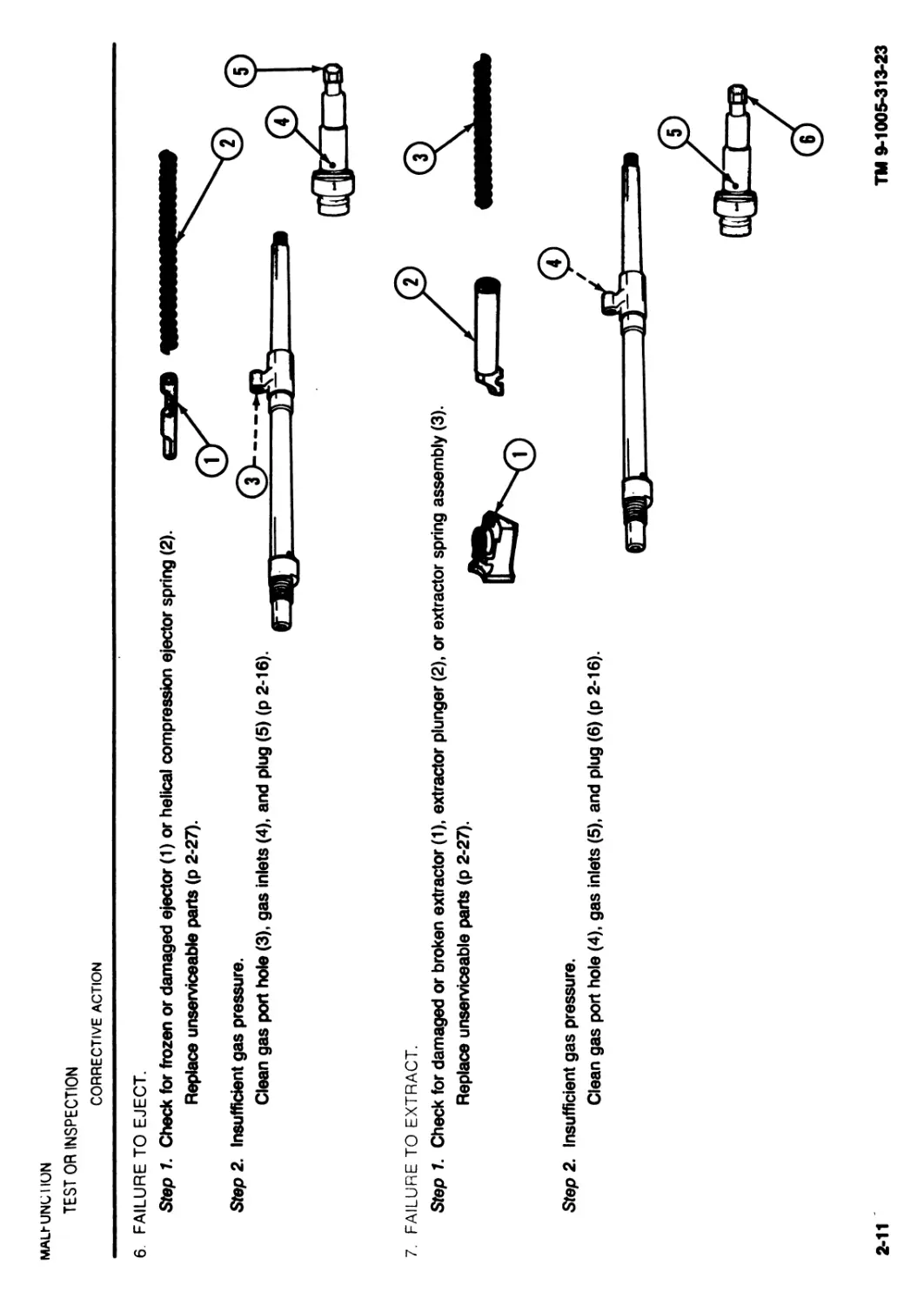
6 FAILURE TO EJECT.
Step 1. Check for frozen or damaged ejector (1) or helical compression ejector spring (2).
Replace unserviceable parts (p 2-27).
Step 2. Insufficient gas pressure.
Clean gas port hole (3), gas inlets (4), and plug (5) (p 2-16).
7. FAILURE TO EXTRACT.
Step 1. Check for damaged or broken extractor (1), extractor plunger (2), or extractor spring assembly (3).
Replace unserviceable parts (p 2-27).
Step 2. Insufficient gas pressure.
Clean gas port hole (4), gas inlets (5), and plug (6) (p 2-16).
2-11
TM 9-1005-313-23
2-12
TROUBLESHOOTING TABLE - Continued
TM 9-1005-313-23
MALFUNCTION
TEST OR INSPECTION
CORRECTIVE ACTION
8. FAILURE TO COCK OR RUNAWAY GUN.
Step 1. Check for broken, stuck, or worn sear (1).
If defective, notify direct support maintenance.
Step 2. Check for broken, stuck, or worn tripping lever (2).
If defective, notify direct support maintenance.
Step 3. Check for broken or damaged sear spring (3).
If defective, notify direct support maintenance.
Section V. MAINTENANCE PROCEDURES
NOTE
When a machine gun is received at organizational maintenance, all gaging requirements must be checked as standing
maintenance procedure. In addition, the machine gun must be inspected and, if any deficiencies are found, repaired or noted
for repair at the direct support level.
2-9. MAINTENANCE CF MACHINE GUN.
This task covers:
a. Disassembly
b. Cleaning
c. Inspection
INITIAL SETUP
Matehals/Parts
Crocus abrasive cloth (item 6, app C)
Lubricant and preservative cleaner CLP (item 4, app C)
Solid film lubricant (item 8, app C)
Solvent cleaning compound - RBC (item 5, app C)
Weapons lubricating oil - LAW (item 10, app C)
Weapons lubricating oil - LSA (item 11, app C)
d. Repair
e. Reassembly
Wiping rag (item 14, app C)
Personnel Required
MOS 76Y-10 Supply Clerk/Unit Armorer
References
TM 9-1005-313-10
TM 9-1005-313-23P
DISASSEMBLY
CLEANING
INSPECTION
WARNING
Make certain weapon is cleared and that there
is no obstruction in the barrel or chamber.
Field-strip (TM 9-1005-313-10).
Remove dirt and corrosion or powder residue from
parts with wiping rag (item 14, app C) dampened
with RBC (item 5, app C). Lightly oil (item 10 or 11,
app C) after cleaning.
1 Visually inspect all parts for damage.
2 Inspect external surfaces for proper finish
(black surfaces should not reflect light).
REPAIR
1 Replace driving spring assembly (1) if two or more strands of a coil are
broken on the same coil or if there are three or more broken strands,
regardless of location on the entire spring.
2-13
TM 9-1005-313-23
2-14
TM 9-1005-313-23
2-9. MAINTENANCE OF MACHINE GUN - Continued.
REPAIR - Continued
3 Replace cover hinge spring pin (3),
4 Clean rusted or shiny surfaces with crocus cloth (item 6, app C). Wash thoroughly with RBC (item 5,
app C).
CAUTION
If solid film lubricant comes in contact with any moving or internal part, clean part with RBC.
5 Apply solid film lubricant (item 8, app C) to all external surfaces showing wear. Allow to dry 12 hours before
using weapon.
if bent or damaged.
REASSEMBLY
1 Reassemble (TM 9-1005-313-10).
2 Check out machine gun using dummy ammo (TM 9-1005-313-10).
2-10. MAINTENANCE OF BARREL ASSEMBLY.
This task covers:
a. Disassembly
b. Cleaning
c. Inspection and Repair
d. Reassembly
INITIAL SETUP
Tools and Special Tools
Small Anns Repairman Tool Kit SC5180-95-CL*A07
Combination wrench with brass hammer 11826058
Reamer 11826036
Scraper 11826005
Small arms cleaning rod swab holder section 7266110
Handle assembly cleaning rod 7266115
Small arms cleaning rod section 7266109
Materials/Parts
Small arms cleaning swab (item 17, app C)
Solvent cleaning compound - RBC (item 5, app C)
Weapons lubricating oil * LAW (item 10, app C)
Weapons lubricating oil - LSA (item 11, app C)
Wiping rag (item 14, app C)
Personnel Required
MOS 76Y-10 Supply Clerk/Unit Armorer
References
TM 9-1005-313-10
TM 9-1005-313-23P
Equipment Condition
Barrel removed (TM 9-1005-313-10)
2-15
TM 9-1005-313-23
2-16
TM 9-1005-313-23
2-10. MAINTENANCE OF BARREL ASSEMBLY - Continued.
DISASSEMBLY - Continued
4 Drive out plug (9) using brass hammer on combination wrench (6). Catch
plug to prevent damage.
5 Remove barrel (10) from vise (3).
CLEANING
2 Fold scraper (2) and press point into groove (5). Twist plug (4) back and
forth to remove carbon from groove (5) on plug (4).
4 With tip (8) of scraper (2), scrape carbon from surfaces (9) of plug (4).
3 Pivot scraper blade and place groove tip (6) of scraper into groove (7) of
plug (4) and twist back and forth to remove carbon from groove (7) on plug.
USING REAMER TO REMOVE CARBON
5 Insert small reamer (10) into each gas inlet hole of plug (4) and twist back
and forth to remove carbon.
2-18
1 Inspect flash hider (1), collar (2), and plug (3) for dents or burrs. Replace if
damaged.
2 If other parts of barrel assembly are damaged, notify direct support
maintenance.
TM 9-1005-313-23
CAUTION
Do not oil plug or recess in barrel for plug.
Do not use abrasives to clean plug.
7 Remove dirt and corrosion from bore using cleaning rod (14) and swab (15)
(item 17, app C) dampened with RBC (item 5, app C) and from other parts
using wiping rag (item 14, app C) dampened with RBC (item 5, app C).
Lightly oil (item 10 or 11, app C) after cleaning.
REASSEMBLY
NOTE
Clamp in gas port area only.
1 Secure barrel (1) in a vise (2) with protective jaws (3) with gas regulator
area (4) up.
NOTE
The plug (5) Is designed with three gas inlet settings to maintain
the rate of fire. This design is intended to maintain a consistent
rate of fire under adverse conditions and NOT TO INCREASE
YOUR RATE OF FIRE. Gas inlet setting number 1 (6) (number
facing the barrel) is preferred for normal conditions.
Setting number 1 = 650 rds/m approx
Setting number 2 = average (mean)
Setting number 3 = 950 rds/m approx
3 Install collar (7) on plug (5). Rotate collar (7) until it slips onto plug (5). Press
in and rotate to lock in place (pull collar to be sure it is in the locked position).
2 Place plug (5) with gas inlet setting number 1 (6) hole facing the barrel.
4 Install flash hider (8) on barrel and tighten securely using combination
wrench with brass hammer (9).
5 Remove barrel assembly (10) from vise (2).
2-20
TM 9-1005-313-23
| 2-11. MAINTENANCE OF BOLT AND OPERATING ROD ASSEMBLY.
This task covers:
a. Disassembly b. Cleaning c. Inspection d. Repair e. Reassembly
NITIAL SETUP
Tools and Special Tools Weapons lubricating oil - LSA (item 11, app C)
Combination tool 11826059 Wiping rag (item 14, app C)
Firing pin length gage 11826071 Personnel Required
Small Arms Repairman Tool Kit SC5180-95-CL-A07 MOS 76Y-10 Supply Clerk/Unit Armorer
MaterialsIParts References
Crocus abrasive cloth (item 6, app C) TM 9-1005-313-10
Solvent cleaning compound - RBC (item 5, app C) TM 9-1005-313-23P
Weapons lubricating oil - LAW (item 10, app C) Equipment Condition
I : Bolt and operating rod assembly removed (TM 9-1005-313-10)
2 Remove spring pin (4). Remove firing pin (5) from operating rod (3).
2-21
CLEANING
2 Insert screwdriver end (4) of combination tool (1) into cavity (2) of piston
end of operating rod (3) to remove carbon residue in bottom of cavity.
TM 9-1005-313-23
2-22
TM 9-1005-313-23
[ 2-11. MAINTENANCE OF BOLT AND OPERATING ROD ASSEMBLY - Continued.
CLEANING - Continued
3 Clean all other areas of the operating rod (3), firing pin (5), and
spring pin (6) with wiping rag (item 14, app C) dampened with RBC
(item 5, app C). For caked carbon deposits, use more RBC.
4 Lightly oil (item 10 or 11, app C) after cleaning.
INSPECTION
USING FIRING PIN LENGTH GAGE TO INSPECT FIRING PIN
1 Place gage on flat surface to measure firing pin.
2 If firing pin (1) length exceeds GO (2), replace.
3 If firing pin (1) length is less than NO GO (3), replace.
1 Remove burrs from spring-loaded pin (1) with crocus cloth (item 6,
app C). Replace if burrs cannot be removed.
2 Replace spring pin (2) if damaged.
3 Replace firing pin (3) if too short, bent, or broken.
NOTE
Slight rotation of piston end (4) of operating rod (5) in its housing is
normal and is not cause for rejection.
4 Remove burrs from operating rod (5) with crocus cloth (item 6, app C). Notify direct support mainte-
nance if operating rod (5) is damaged.
2-23
TM 9-1005-313-23
2-24
TM 9-1005-313-23
2-11. MAINTENANCE OF BOLT AND OPERATING ROD ASSEMBLY - Continued.
REASSEMBLY
NOTE
The ball end of the firing pin must be positioned in
groove between the spring pin and the bottom of
the groove in the operating rod.
1 Install ball end (1) of firing pin (2) into groove (3) in
operating rod (4).
2 Install spring pin (5) so that ball end (1) of firing pin (2) is
properly seated in groove (3) of operating rod (4).
3 Install bolt assembly (6) in operating rod (4) and secure with
spring-loaded pin (7).
4 Be sure bolt linkage moves freely by moving bolt assembly (6)
through range of operation. If movement is not free, check spring-
loaded pin (7) and mating surfaces for damage.
2-12. MAINTENANCE OF BOLT ASSEMBLY.
This task covers:
a. Disassembly d. Reassembly
b. Cleaning e. Testing
c. Inspection and Repair
INITIAL SETUP
Tools and Special Tools
Combination tool 11826059
Ejector removing tool 11826076
Breech bolt extractor engagement gage 11826305
Breech bolt extractor clearance gage 11826306
Small Arms Repairman Tool Kit SC5180-95-CL-A07
MaterialsIParts
Solvent cleaning compound * RBC (item 5, app C)
Weapons lubricating oil * LAW (item 10, app C)
Weapons lubricating oil * LSA (item 11, app C)
Wiping rag (item 14, app C)
Personnel Required
MOS 76Y-10 Supply Clerk/Unit Armorer
References
TM 9-1005-313-23P
Equipment Condition
Bolt assembly removed (p 2-20)
DISASSEMBLY
2-25
TM 9-1005-313-23
2-26
TM 9-1005-313-23
2-12. MAINTENANCE OF BOLT ASSEMBLY - Continued.
DISASSEMBLY - Continued
2
3
Insert stud (5) into locking recess (6) of locking lever (7).
Apply pressure to ejector (3) by pushing up on locking lever (7) to relieve spring tension on helical
compression ejector spring (9) and drive out spring pin (8).
WARNING
Point bolt face away from yourface and away from other soldiers. The spring can fly out and
cause injury.
4 Release and remove ejector removing tool (2).
5 Remove ejector (3) and helical compression
ejector spring (9).
USING COMBINATION TOOL TO REMOVE EXTRACTOR
6 Insert thin edge (10) of combination tool (11) in groove (12) of
extractor plunger and thick edge (13) in locking recess (6) in bottom
side of bolt body (4).
7 H<
ward to compress the extractor spring assembly (14).
8 Maintaining pressure on the combination tool (11), remove
extractor (15) by pushing down on front of it.
CLEANING
WARNING
Point bolt face away from your face and away from other soldiers The spring can fly out and
cause injury
9 Remove combination tool. Remove extractor plunger (16) and extractor spring (17) from bolt
body (4).
CAUTION
Do not lubricate top or face of bolt body.
Remove dirt and corrosion from all parts using
wiping rag (item 14, app C) dampened with RBC
(item 5, app C). Lightly oil (item 10, or 11, app C)
all parts, except top or face of bolt body after
cleaning.
INSPECTION AND REPAIR
1
2
3
Inspect roller (1) on top of bolt body (2) for free movement.
Be sure bolt linkage moves freely through range of operation. If it does not move freely,
notify direct support maintenance.
Replace all broken authorized parts. If bolt body (2) is damaged, notify direct support
maintenance.
2-27
TM 9-1005-313-23
2-28
TM 9-1005-313-23
2-12. MAINTENANCE OF BOLT ASSEMBLY - Continued.
REASSEMBLY
USING COMBINATION TOOL TO INSTALL EXTRACTOR
WARNING
Point bolt face away from your face and away from other
soldiers. The spring can fly out and cause injury.
1 Make sure the first coil on one end of the extractor spring (1) is opened slightly. Place the open end of the extractor spring (1)
in the extractor plunger (2). (The open end of the extractor spring should hold the extractor spring in the extractor plunger.)
Place extractor spring (1) and extractor plunger (2) in hole in bolt face (3) of bolt body (4) (extractor spring end goes in first).
2 Insert thin edge (5) of combination tool (6) in groove (7) of
extractor plunger (2) and thick edge (8) in locking recess (9) in
bottom side of bolt body (4).
3 Hold the combination tool (6) and push locking lever (10) down-
ward to compress the extractor spring (1) and extractor
plunger (2).
4 Insert extractor (11) in bolt body (4). Release combination
tool (6) until extractor plunger (2) makes contact with extrac-
tor (11).
5 Remove combination tool (6).
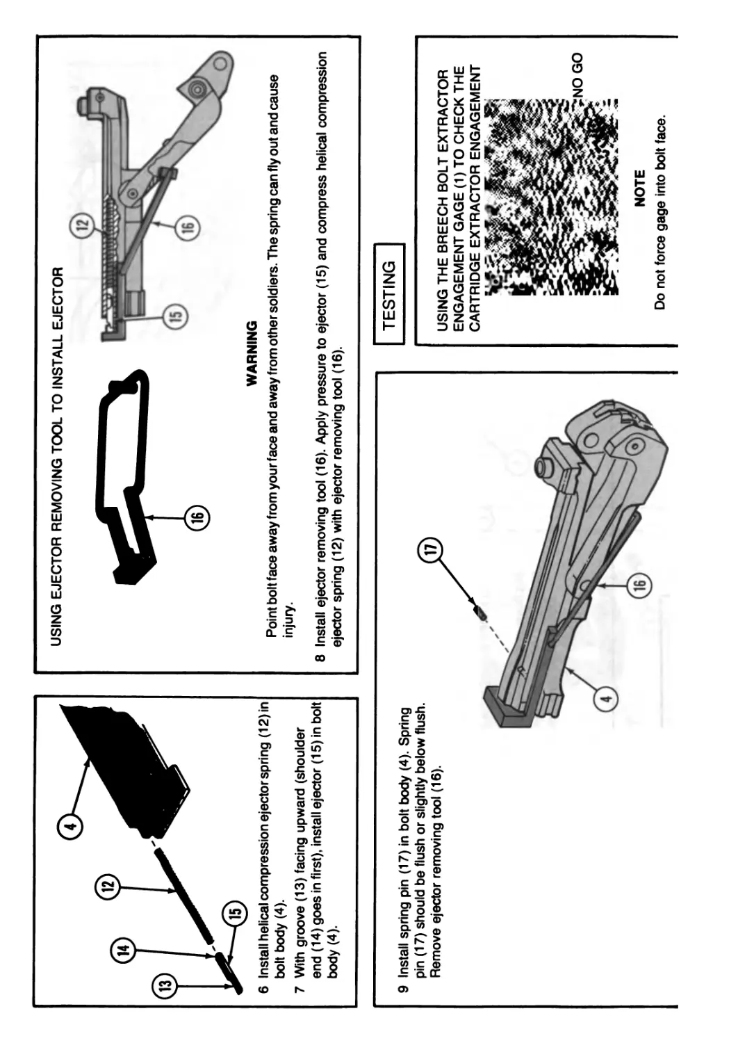
USING EJECTOR REMOVING TOOL TO INSTALL EJECTOR
6 Install helical compression ejector spring (12) in
bolt body (4).
7 With groove (13) facing upward (shoulder
end (14) goes in first), install ejector (15) in bolt
body (4).
WARNING
Point bolt face away from your face and away from other soldiers. The spring can fly out and cause
injury.
8 Install ejector removing tool (16). Apply pressure to ejector (15) and compress helical compression
ejector spring (12) with ejector removing tool (16).
9 Install spring pin (17) in bolt body (4). Spring
pin (17) should be flush or slightly below flush.
Remove ejector removing tool (16).
TESTING
USING THE BREECH BOLT EXTRACTOR
ENGAGEMENT GAGE (1) TO CHECK THE
CARTRIDGE EXTRACTOR ENGAGEMENT
NOTE
Do not force gage into bolt face.
2-30
TM 9-1005-313-23
2-12. MAINTENANCE OF BOLT ASSEMBLY - Continued.
TESTING - Continued
1 Place the GO end (2) of the breech bolt extractor engagement
gage (1) against the bolt face (3) with the cutout portion (4) toward
ejector (5). The gage must seat on the bolt face (3) without lifting the
extractor (6).
2 Place the NO GO end (7) of the extractor engagement gage (1)
against the bolt face (3) with cutout portion (4) toward the ejector (5).
The NO GO end (7) must not touch the bolt face (3).
3 If these conditions are not met, replace the extractor (6).
USING THE BREECH BOLT EXTRACTOR CLEARANCE GAGE TO
CHECK THE CARTRIDGE EXTRACTOR CLEARANCE
4 Place the breech bolt extractor clearance gage (8) squarely against the
bolt face (3) and, keeping this contact, bring the clearance gage down
behind the extractor claw (9). The GO end (10) must seat.
5 Place the NO GO end (11) in the same way. The NO GO end (11)
must not seat.
6 If these conditions are not met, replace the extractor.
2-13. MAINTENANCE OF TRIGGER HOUSING ASSEMBLY.
This task covers:
a. Disassembly b. Cleaning/lnspection/Repair c. Reassembly
INITIAL SETUP
Tools and Special Tools Small Arms Repairman Tool Kit SC5180-95-CL-A07 Materials/Parts Bar laundry soap (item 15, app C) Solvent cleaning compound - RBC (item 5, app C) Weapons lubricating oil - LAW (item 10, app C) Weapons lubricating oil - LSA (item 11, app C) Wiping rag (item 14, app C) Equipment Condition Trigger housing assembly removed (TM 9-1005-313-10) Personnel Required MOS 76Y-10 Supply Clerk/Unit Armorer References TM 9-1005-313-10
2 Remove hex head machine bolt (6), lock
washer (7), flat washer (8), and left
grip (9) from trigger housing assem-
bly (5).
2-31
TM 9-1005-313-23
2-32
TM 9-1005-313-23
2-13. MAINTENANCE OF TRIGGER HOUSING ASSEMBLY - Continued.
CLEANING/INSPECTION/REPAIR
1
2
3
Remove dirt and corrosion on grips (1 and 2) with soap (item 15, app C) and water and wipe dry with
wiping rag (item 14, app C).
Clean all other parts with rag dampened with RBC (item 5, app C).
Visually inspect parts for damage. Inspect grips (1 and 2) for breaks and cracks.
4 Inspect charger cable guide (3) for bends.
5 Replace damaged authorized parts.
6 If trigger housing assembly (4) is damaged,
notify direct support maintenance.
7 Lightly oil (item 10 or 11, app C) after cleaning.
2 Install left grip (4) on left side of trigger housing
assembly (5).
3 Insert assembled bolt and washers (6) through
left grip (4) and into trigger housing assem-
bly (5).
4 Install right grip (7) on hex head machine bolt (3) on right side of trigger housing assembly (5).
5 Install charger cable guide (8) against right grip (7).
6 Secure with lock washer (9) and hexagon plain nut (10).
3
2-14. MAINTENANCE OF RECEIVER ASSEMBLY.
This task covers: a. Disassembly b. Cleaning c. Inspection/Repair d. Reassembly
INITIAL SETUP
Tools and Special Tools Combination tool 11826059 Gas cylinder cleaning brush (item 3, app C) Small Arms Repairman Tool Kit SC5180-95-CL-A07 Materials/Parts Solvent cleaning compound - RBC (item 5, app C) Weapons lubricating oil - LAW (item 10, app C) Weapons lubricating oil - LSA (item 11, app C) Wiping rag (item 14, app C) Cotter pin AS 3258-67 Cotter pin AS 3258-53 Personnel Required MOS 76Y-10 Supply Clerk/Unit Armorer References Appendix C TM 9-1005-313-10 TM 9-1005-313 23P
2-34
2-14, MAINTENANCE OF RECEIVER ASSEMBLY - Continued.
DISASSEMBLY
1 Remove cotter pin (1) securing extension spring (2) to spring mounting
plate (3). Discard cotter pin (1).
2 Spread coil at slide end (4) of extension spring (2) and rotate to remove.
4 Turn receiver (8) upside down, depress rear tang of access cover (9), and
slightly move it toward breech end.
TM 9-1005-313-23
3 Remove cotter pin (5) securing charger cable (6) to charger slide (7) and
remove charger cable (6). Discard cotter pin (5).
5 Turn receiver (8) over and slide access cover (9) out through breech end of
receiver.
CLEANING
USING COMBINATION SCRAPER AND EXTRACTOR TOOL TO CLEAN GAS CYLINDER END OF RECEIVER BODY
CAUTION
Do not use an abrasive to dean gas cylinder end of receiver.
Be sure combination tool shoulder (1) is seated fully against fore end of gas cylinder (2) before rotating combination tool (3). IF
IT IS NOT PROPERLY SEATED, IT COULD CAUSE DAMAGE TO SMALLER DIAMETER OF GAS CYLINDER.
1 Insert combination tool (3) carefully into the fore end of the gas cylinder (2) of the receiver body (4).
2 Be sure the combination tool (3) is fully inserted and seated against the fore end of gas cylinder (2) in receiver body (4).
3 Apply slight pressure to handles and twist back and forth to remove carbon.
4 Clean gas cylinder bore (5) with gas cylinder cleaning brush (6)
dampened with RBC (item 5, app C).
| 2-14. MAINTENANCE OF RECEIVER ASSEMBLY - Continued. |
CLEANING - Continued
5 With wiping rag (item 14, app C), dampened with RBC (item 5,
app C), remove dirt and corrosion from area under front
access cover of receiver (7) and all other parts and areas.
6 For caked carbon deposits, use RBC (item 5, app C).
INSPECTION/REPAIR
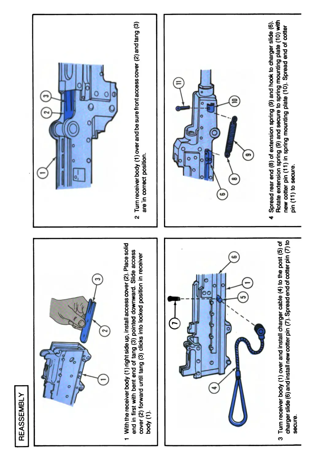
REASSEMBLY
1 With the receiver body (1) right side up, install access cover (2). Place solid
end in first with bent end of tang (3) pointed downward. Slide access
cover (2) forward until tang (3) clicks into locked position in receiver
body (1).
3 Turn receiver body (1) over and install charger cable (4) to the post (5) of
charger slide (6) and install new cotter pin (7). Spread end of cotter pin (7) to
secure.
2 Turn receiver body (1) over and be sure front access cover (2)andtang (3)
are In correct position.
4 Spread rear end (8) of extension spring (9) and hook to charger slide (6).
Rotate extension spring (9) and secure to spring mounting plate (10) with
new cotter pin (11) in spring mounting plate (10). Spread end of cotter
pin (11) to secure.
3-0
TM 9-1005-313-23
CHAPTER 3
DIRECT SUPPORT MAINTENANCE INSTRUCTIONS
This chapter contains information and instructions for the repairman to help keep the machine gun in good repair.
The chapter consists of repair parts, special tools, and support equipment; service upon receipt; troubleshooting;
and maintenance procedures
Section I. REPAIR PARTS, SPECIAL TOOLS, TMDE, AND SUPPORT EQUIPMENT
3-1. COMMON TOOLS AND EQUIPMENT. For authorized common tools
and equipment refer to the Modified Table of Organization and Equipment
(MTOE) applicable to your unit.
3-3. REPAIR PARTS. Repair parts are listed and illustrated in the repair parts
and special tools list (TM 9-1005-313-23P) covering organizational and direct
support maintenance for this equipment.
3-2. SPECIAL TOOLS, TMDE, AND SUPPORT EQUIPMENT. Special tools
are listed in TM 9-1005-313-23P. Tools and test equipment are listed in appen-
dix В of this manual. There is no TMDE for this item.
Section II. SERVICE UPON RECEIPT
3-4. GENERAL. When a new or reconditioned machine gun is first received, been properly prepared for service by the supplying organization and whether it
it is the responsibility of the user to determine whether the machine gun has is in condition to perform its mission.
Section ill. TROUBLESHOOTING
3-5. DIRECT SUPPORT TROUBLESHOOTING. Refer to troubleshooting
table for malfunctions, tests, and corrective actions.
TROUBLESHOOTING TABLE
MALFUNCTION
TEST OR INSPECTION
CORRECTIVE ACTION
1. FAILURE TO COCK OR RUNAWAY GUN.
Defective or broken parts in the trigger (1), sear (2), or sear spring (3)
Replace trigger, sear, or sear spring (p 3-19).
2. SAFETY DOES NOT FUNCTION.
Step 1. Safety fails to hold positively in either the “S” (1) or “F” (2) position.
Replace (p 3-19).
Step 2. Safety fails to slide properly.
Clean and lubricate safety (3), or replace (p 3-19).
3. GUN RUPTURES CARTRIDGE CASES.
Check for excessive headspace (p 3-40).
Replace barrel (1) (p 3-6), bolt (2) (p 3-16), or both. If excessive headspace still exists, the weapon is
unserviceable.
1
3-2
TM 9-1005-313-23
Section IV. MAINTENANCE PROCEDURES
NOTE
When a machine is received at direct support maintenance, all gaging requirements must be checked as a standing
maintenance procedure.
3-6. MAINTENANCE OF MACHINE GUN.
This task covers:
a. Disassembly
INITIAL SETUP
Materials/Parts
Solvent cleaning compound - RBC (item 5, app C)
Wiping rag (item 14, app C)
Personnel Required
MOS 458-10 Small Arms Repairer
b. Inspection/Repair/Reassembly
References
TM 9-1005-313-10
TM 9-1005-313-23P
DISASSEMBLY
WARNING
Make certain weapon is cleared and that there is no obstruction in the barrel or chamber.
Field-strip (TM 9-1005-313-10).
INSPECTION/REPAIR/REASSEMBLY
•B--7л i h M240C »
/ ж* /
। М240 СЙЯ 1 Visually inspect assemblies for damage. CB h<x note *r Inspect feed tray (1) for cracks, breaks, and weld. Replace feed tray (1) if damaged. 2 Reassemble (TM 9-1005-313-10).
3-7. MAINTENANCE OF BARREL ASSEMBLY.
This task covers: a. Testing b. Disassembly c. Inspection and Repair d. Reassembly
INITIAL SETUP
Materials/Parts Spring release pin MS16562-122 Tools and Special Tools Breech bore erosion gage 11826298 Muzzle and breechbore wear gage 11826276 Combination wrench with brass hammer 11826058 Small Arms Repairman Tool Kit SC 5180-95-CL-A07 Small Arms Shop Set SC 4933-95-CL-A11 Personnel Required MOS 45B-10 Small Arms Repairer Equipment Condition Barrel removed (TM 9-1005-313-10) References TM 9-1005-313-23P
3-3
TM 9-1005-313-23
3-4
<М 9-1005-313-23
3-7. MAINTENANCE OF BARREL ASSEMBLY - Continued.
TESTING
USING BREECH BORE EROSION GAGE TO TEST BARREL
NOTE
A clean bore is not necessarily a shiny bore and frequently may have a
dull gray appearance. A shiny, polished bore may indicate abrasives
have been used. Abrasives will NOT be used on the bore, piston, or
inside of the gas cylinder.
1 Gently but firmly insert breech bore erosion gage (1) into the breech end (2)
of barrel (3) as far as it will go.
2 Read the gage (1) at the end of the barrel breech (2). Replace barrel (3) if
the rejection mark (4) on the gage enters the breech. The barrel is not
suitable for overseas shipment if the reading exceeds the preembarkation
warning mark (5).
USING MUZZLE AND BREECHBORE WEAR GAGES TO TEST BARREL
3 Use muzzle and breechbore wear gage (6) to test barrel (3). Gently but
firmly insert gage (6) into the breech end (2) of barrel (3) as far as it will go.
4 Read the gage (6) at the end of the barrel breech (2). Replace barrel (3) if the rejection mark (4) on the gage
breech. The barrel is not suitable for overseas shipment if the reading exceeds the preembarkation warning mark (5).
5 Gently but firmly insert gage (6) into the muzzle end (7) of the
barrel (3) as far as it will go.
6 Read the gage (6) at the end of the flash hider (8). Replace
barrel (3) if the rejection mark (4) on the gage.enters the flash
hider (8). The barrel is not suitable for overseas shipment if the
reading exceeds the preembarkation warning mark (5).
DISASSEMBLY
1 Remove flash hider (p 2-15). Remove collar and plug
(P2-16).
2 Clamp barrel (1) in vise (2) with protective jaws (3) above
the gas regulator area with regulator (4) pointed down.
CAUTION
Barrel and barrel adapter have left-hand threads.
3 Drive spring release pin (5) out of barrel release (6). Move
barrel release latch (7) to stop. Unscrew barrel adapter (8)
(left-hand thread). Remove barrel release (6) from bar-
rel (1). Remove barrel release latch (7) from barrel re-
lease (6). Discard spring release pin (5).
3-5
TM 9-1005-313-23
3-6
TM 9-1005-313-23
3 Take off excess matter on the cylindrical part (4) of the breech.
4 Take off excess matter on the rear section (5).
5 Inspect threads for damage.
6 Barrel (2).
a. Pits in the chamber of the breech (3) are allowable if
they are not large enough to cause extraction
difficulties.
b. Pits as wide as a land or groove or less in length are allowable. Replace if pits greater than the width
of a land or groove are present.
c. Scattered or uniformly fine pits are allowable.
d. Tool marks or scratches are acceptable regardless of length. Tool marks will appear as lines running
laterally in the grooves or may run spirally across the top of the lands.
e. Definitely ringed bores or bores ringed sufficiently to bulge the outside surface barrel are cause for
rejection. However, faint rings or shadowy depressions do not indicate an unserviceable barrel and
should not be cause for rejection.
f. Lands that appear dark due to a coating of gilding metal from projectiles should not be cause for
rejection.
h. Inspect barrel release latch (7) for breaks or
cracks. Replace if damaged.
reassembly]
NOTE
Clamp in gas port area only.
1 Place barrel (1) in vise (2) with protective jaws (3) above the gas regulator
area (4) with regulator pointed down.
3-7
TM 9-1005-313-23
3-8
TM 9-1005-313-23
3-7. MAINTENANCE OF BARREL ASSEMBLY - Continued.
REASSEMBLY - Continued
CAUTION
Barrel and barrel adapter have left-hand threads.
2 Place barrel release latch (5) in barrel release (6). Hold them vertically and place
firmly against front shoulder of barrel (1).
3 Screw barrel adapter (7) onto barrel (1) fingertight.
4 Unscrew barrel adapter (7) until barrel release latch (5) engages the recess in barrel
adapter (7).
5 Secure barrel release latch (5) to barrel release (6) with new spring release pin (8).
NOTE
The plug (9) is designed with three gas inlet settings to maintain the
rate of fire. This design is intended to maintain a consistent rate of fire
under adverse conditions. NOT TO INCREASE YOUR RATE OF
FIRE. Gas setting number 1 (10) (number facing the barrel) is pre-
ferred for normal conditions.
Setting number 1 = 650 rds/m approx
Setting number 2 = average (means)
Setting number 3 = 950 rds/m approx
6
7
8
9
Clamp barrel (1) in vise (2) with x-x
protective jaws (3) below the gas
regulator area with gas regulator
area (4) pointed up.
Place plug (9) with gas inlet hole
number 1 (11) lacing the
barrel (1).
Install collar (p 2-19) and flash
hider (p 2-19).
Remove barrel assembly from
vise.
3-8. MAINTENANCE OF BUFFER ASSEMBLY.
This task covers: a. Disassembly b. Cleaning c. Inspection and Repair d. Reassembly
INITIAL SETUP
Special Tools Combination wrench with brass hammer 11826058 Small Arms Repairman Tool Kit SC5180-95-CL-A07 Box and open end combination wrench OEXM230 Materials/Parts Solvent cleaning compound - RBC (item 5, app C) Weapons lubricating oil - LAW (item 10, app C) Weapons lubricating oil - LSA (item 11, app C) Wiping rag (item 14, app C) Key washer 11826224 Personnel Required MOS 45B-10 Small Arms Repairer Equipment Condition Buffer assembly removed (TM 9-1005-313-10). References TM 9-1005-313-10 TM 9-1005-313-23P
DISASSEMBLY
CAUTION
Do not overtighten vise on plate.
1
2
3
Clamp buffer assembly (1) in vise (2) (with protective jaws) at the two forward
ribs (3). Be sure that vise jaws do not cover headed straight pin (4).
Back plate latch (5) is under tension. So hold hand over back plate latch when
removing headed straight pin (4) or helical compression spring (6) and detent
plunger (7) will fly out.
Use brass hammer on combination wrench (8) and punch to drive headed
straight pin (4) out from left to right.
NOTE
Catch stop spring pin (9) need not be removed unless damaged.
3-9
TM 9-1005-313-23
3-10
TM 9-1005-313-23
3-8. MAINTENANCE OF BUFFER ASSEMBLY - Continued.
DISASSEMBLY - Continued
5 Reposition back plate (12) in vise (2) for
more support and, using a box and open end
combination wrench (13), loosen machine
plug (11).
6 Remove from vise.
CLEANING
Remove dirt and corrosion from all parts with rags
(item 14, app C) dampened with RBC (item 5,
app C). Lightly oil (item 10 or 11, app C) all parts
after cleaning.
NOTE
If necessary, use the brass hammer on combination wrench to loosen buffer plug (14).
7 Unscrew machine plug (11) and remove key washer (10), eleven spring tension washers (15), sleeve
washer support spacer (16), expansion braking ring (17), braking buffer cone (18), and buffer plug (14)
from back plate (12). Discard key washer (10).
INSPECTION AND REPAIR
1 Check headed straight pin (1). Replace if bent or broken.
2 Replace detent plunger (2) if bent or broken.
3 Check helical compression spring (3) for deformation or breaks. Replace if damaged,
broken, or deformed.
4 Check back plate latch (4) for cracks or breaks. Replace if damaged.
5 Check back plate (5) for damaged threads and burrs and remove burrs with file.
6 Check machine plug (6) for deformed
threads or rounded shoulders of octagon
head. Replace if damaged.
7 Check eleven spring tension washers (7)
for cracks, deformation, or permanent set.
Replace as a set if damaged, broken, or
deformed.
8 Replace sleeve washer support
spacer (8) and buffer plug (11) if distorted,
bent, or burred.
9 Check expansion braking ring (9) and braking buffer cone (10) for damaged mating surfaces. Replace if damaged, broken,
or deformed.
3-11
TM 9-1005-313-23
3-12
TM 9-1005-313-23
2 Place sleeve washer support spacer (2)
into buffer plug (3). Install braking buffer
cone (4) with its base against buffer
Plug (3).
3 Place tapered surface of expansion brak-
ing ring (5) against tapered surface on
braking buffer cone (4).
4
5
6
7
Apply light coat of oil (item 10 or 11, app C) to all eleven spring tension washers (6).
Install eleven spring tension washers (6) on sleeve washer support spacer (2). Place the concave surface of the first washer
against the expansion braking ring (5). Check washer sequence diagram. Place second washer in the opposite direction
with its convex surface against the first washer.
Place the concave surface of the third washer against the concave surface of the second washer.
Continue this sequence until all eleven spring tension washers are assembled on sleeve washer support spacer (2). Check
assembled washers with spring tension washer sequence diagram.
10 Install a new key washer (9) alining notch in key washer with notch
in back plate (1). Install machine plug (10).
3-14
3-8. MAINTENANCE OF BUFFER ASSEMBLY - Continued.
REASSEMBLY - Continued
13 Place the helical compression spring (13), with open coil first, into
detent plunger (14).
NOTE
If a new helical compression spring is installed, open end of first
coil.
14 Place helical compression spring (13) and detent plunger (14) into
hole in back plate latch (15).
TM 9-1005-313-23
CAUTION
Be sure headed straight pin
does not stick out into chan-
nels of back plate.
15 Install back plate latch (15) with helical compression spring and detent
plunger into back plate (1). Aline holes in back plate (1) and back plate
latch (15). Install headed straight pin (16) from right to left (smooth end of
pin is installed first).
3-9. MAINTENANCE OF BOLT AND OPERATING ROD ASSEMBLY.
This task covers:
a. Inspection and Repair
INITIAL SETUP
Personnel Required
MOS 45B-10 Small Arms Repairer
References
TM 9-1005-313-10
TM 9-1005-313-23P
Equipment Condition
Bolt and operating rod assembly removed (TM 9-1005-313-10)
Bolt and operating rod assembly disassembled (p 2-20)
3-16
TM 9-1005-313-23
3-10. MAINTENANCE OF BOLT ASSEMBLY.
This task covers: a. Inspection b. Repair
INITIAL SETUP
MaterialsIParts Inspection Penetrant (item 7, app C) Personnel Required MOS 45B-10 Small Arms Repairer References TM 9-1005-313-10 TM 9-1005-313-23P Equipment Condition Bolt assembly removed (p 2-20) Bolt assembly disassembled (p 2-25)
INSPECTION ® Z>\ Inspect bolt body (1) for cracks using - / \ inspection penetrant (item 7, app C) / Roller (2) must rotate freely (p 2-27) s' REPAIR If damaged, replace with new bolt body.
3-11. MAINTENANCE OF TRIGGER HOUSING ASSEMBLY.
This task covers:
a. Disassembly
b. Cleaning
c. Inspection and Repair
d. Lubrication
e. Reassembly
INITIAL SETUP
Tools and Special Tools
Small Arms Repairman Tool Kit SC5180-95-CL-A07
Materials/Parts
Crocus abrasive cloth (item 6, app C)
Lubricating oil - LAW (item 10, app C)
Lubricating oil - LSA (item 11, app C)
Solvent cleaning compound - RBC (item 5, app C)
Wiping rag (item 14, app C)
Personnel Required
MOS 45B-10 Small Arms Repairer
References
TM 9-1005-313-10
TM 9-1005-313-23P
Equipment Condition
Trigger housing assembly removed (TM 9-1005-313-10)
DISASSEMBLY
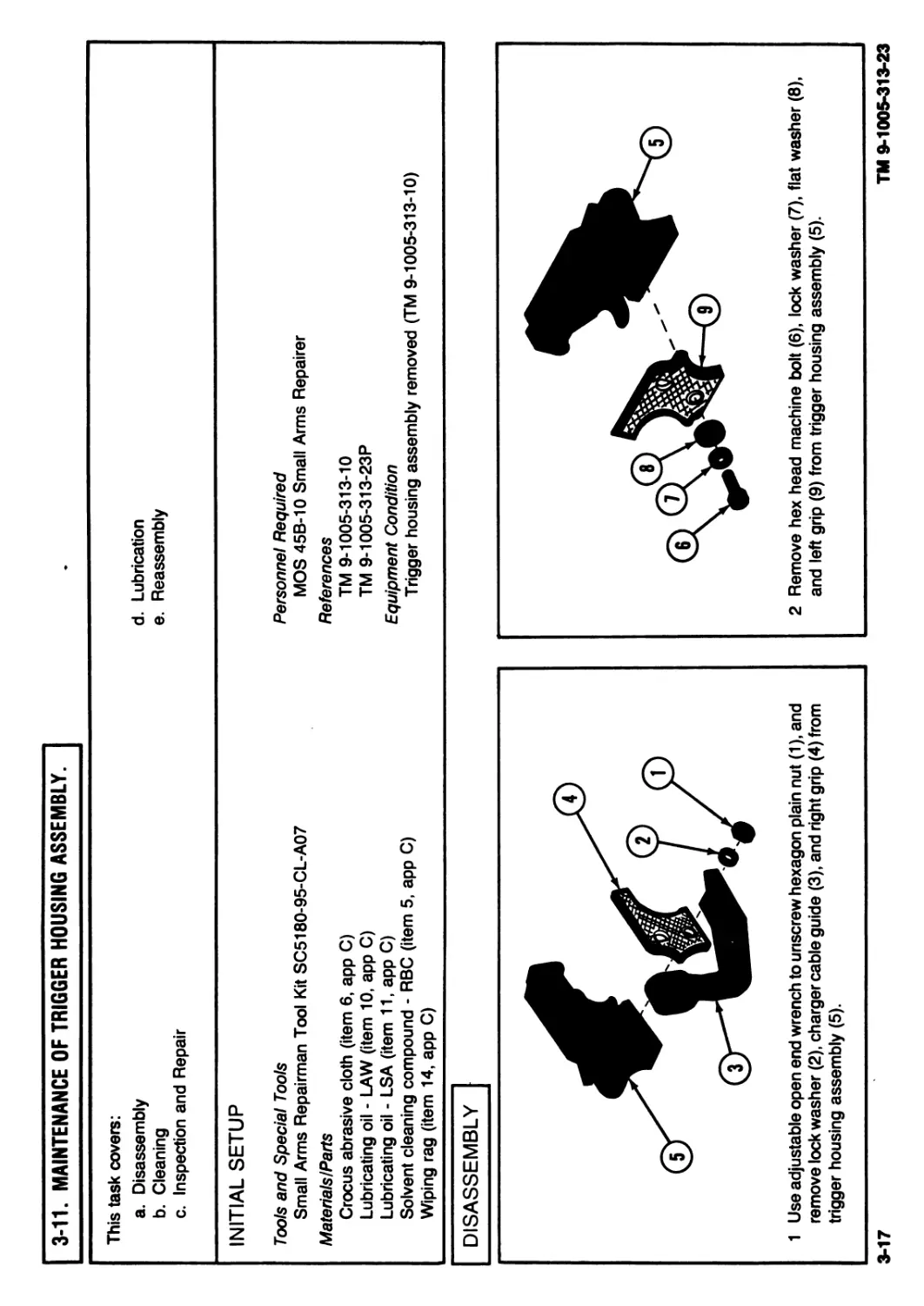
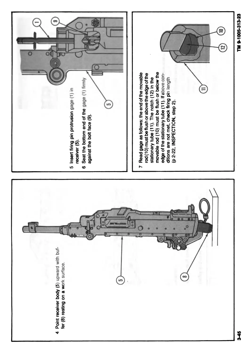
1 Use adjustable open end wrench to unscrew hexagon plain nut (1), and
remove lock washer (2), charger cable guide (3), and right grip (4) from
trigger housing assembly (5).
2 Remove hex head machine bolt (6), lock washer (7), flat washer (8),
and left grip (9) from trigger housing assembly (5).
3-17
TM 9-1005-313-23
3-18
TM 9-1005-313-23
3-11. MAINTENANCE OF TRIGGER HOUSING ASSEMBLY - Continued.
DISASSEMBLY - Continued
5 Remove three headless straight pins (14
and 15), and remove sear (12), sear
spring (16), and trigger (17) from trigger
housing (11).
CLEANING
Using wiping rag (item 14, app C) dampened
with RBC (item 5, app C), remove dirt and
corrosion on powder-fouled parts.
INSPECTION AND REPAIR
1
2
3
4
5
6
7
Inspect front edge of trigger (1). Replace if chipped or if burrs cannot
be removed.
Pull tripping lever (2) rearward. Replace trigger (1) if tripping lever
does not return to position without binding.
Check safety (3) for burrs, damaged detent, or distorted lettering.
Replace if burrs cannot be removed with crocus cloth (item 6, app C)
or safety is damaged.
Check headless straight pins (4 and 5) and replace if bent.
Check sear (6) and replace if broken, cracked, or worn.
Replace sear spring (7) if broken or distorted.
Check trigger housing (8) and replace if broken or cracked
LUBRICATION
REASSEMBLY
1 Insert sear (1) into lever slot in trigger (2) sideways. Give the sear a quarter turn, as viewed from left side, polished end
upward.
3-20
TM 9-1005-313-23
: ". of t~i:; ‘.го v?5L<jly -
F'lASSEMBLY - Continued
2 Place trigger housing (3) on its side on a flat surface.
3 Lower sear (1) and trigger (2) into trigger housing (3). Grasping trigger, press it forward
against the inner front edge of housing. This action will push backward on the lever allowing
the trigger to slide into place. Aline holes in trigger (2) and trigger housing (3). Insert
headless straight pin (4).
4 Insert sear spring (5), with leg pointing for-
ward, into trigger housing (3). The lower tip
of the sear spring must bear against the
riveted pin (6) across the back of the
trigger (2).
NOTE
Be sure leg of sear spring (5) is in groove
of sear (1) and behind riveted pin (6) as
shown.
NOTE
This illustration is a cutaway view of the trigger housing.
5 Install one headless straight pin (7) in pin hole (8) in trigger housing (3)
and through sear spring (5).
6 Lower sear (1) compressing sear
spring and install headless
straight pin (9).
7 Pick up trigger housing (3) and insert
safety (10) from left to right with letter
“S” first and facing down. Detent
remains outside housing.
8 Rotate safety (10) a quarter turn so
letters “S” and “F” face rearward.
10 Install left grip (14) on left side of trigger
housing (3).
11 Insert assembled bolt and washers (15)
through left grip (14) and into trigger
housing (3).
12 Install right grip (16) on hex head machine
bolt (13) on right side of trigger housing (3).
13 Install charger cable guide (17) against right
grip (16).
14 Secure with lock washer (18) and hexagon
plain nut (19).
This task covers:
a. Disassembly
b. Cleaning
c. Inspection and Repair
d. Reassembly
INITIAL SETUP
Tools and Special Tools
Small Arms Repairman Tool Kit SC5180-95-CL-A07
MaterialsIParts
Crocus abrasive cloth (item 6, app C)
Solvent cleaning compound - RBC (item 5, app C)
Weapons lubricating oil - LAW (item 10, app C)
Weapons lubricating oil - LSA (item 11, app C)
Wiping rag (item 14, app C)
Personnel Required
MOS 45B-10 Small Arms Repairer
References
TM 9-1005-313-10
Equipment Condition
Cover assembly removed (TM 9-1005-313-10)
3-22
TM 9-1005-313-23
3-12. MAINTENANCE OF COVER ASSEMBLY - Continued.
NOTE
Procedures are written for M240 cover
assembly but apply to both M240 and
M240C cover assemblies.
1 Hold retaining clip (1) so it will not rotate. Lift
straight leg (2) and engage it in the hook of its
opposite leg.
2 Use screwdriver to remove spring tension lock
pin (3).
3 Remove feed lever (4).
4 Disengage straight leg (2) of retaining clip (1)
from hooked leg and remove.
WARNING
Hold hand over retaining clip when
engaging or disengaging leg, or retaining
clip will fly off pivot post.
5 Insert the blade of screwdriver under one leg of
retaining catch clip (5). Apply slight pressure on
the leg of the clip and raise it by turning the
screwdriver against the wall of the cover to re-
move retaining catch clip (5).
6 Remove two cover latches (6).
7 Unlock pawl retaining pin (7) from notch in
cover.
8 Apply slight pressure downward between front
and rear cartridge guides (8 and 9) and remove
pawl retaining pin (7), rear cartridge guide (9),
one helical compression spring (10), front car-
tridge guide (8), and other helical compression
spring (11).
9 Remove retaining ring (12) and lift feed pawl
assembly (13) off feed pawl pivot post (14).
3-24
TM 9-1005-313-23
3-12. MAINTENANCE OF COVER ASSEMBLY - Continued.
CLEANING
Using wiping rag (item 14, app C) dampened with
RBC (item 5, app C), remove dirt and corrosion on
powder-fouled parts.
2 Replace retaining clip (2) and retaining catch
clip (3) if either is deformed or has lost its spring
tension.
4 Replace two helical compression springs (5) if springs are cracked, broken,
or have taken a permanent set. Replace retaining ring (6) if broken or
cracked.
7 Replace rear cartridge guide (10) and front cartridge guide (11) if they are
bent or broken or have burrs or cracks.
8 Replace cover (12) if cover has distortion, cracks, or burrs which cannot be
removed; if posts (13) or pivots (14) are loose; or if roller (15) binds or has
burrs which cannot be removed.
3-25
TM 9-1005-313-23
3-26
TM 9-1005-313-23
3-12. MAINTENANCE OF СОУёЯ ASSEMBLY - Continued.
REASSEMBLY - Continued .
2 Insert two helical compression springs (7) on
spring guide posts (8) in cover (3).
NOTE
Front cartridge guide (9) must overlap rear cartridge
guide (10).
3 Place the rear cartridge guide (10) and front cartridge
guide (9) in cover opening with spring wells toward
cover (3) and over helical compression springs (7).
4 Aline pawl retaining pin hole in cartridge guides (9 and
10) and cover (3). Apply pressure downward, and insert
pawl retaining pin (11) through cover (3) and cartridge
guides (9 and 10) from front to rear. Lock pawl retaining
pin (11) into slot (12) of cover (3).
5 Insert two cover latches (13) into slots (14) at
rear of cover (3).
WARNING
Hold hand over retaining catch clip when engaging
or disengaging leg or retaining catch clip will fly off
pivot post.
6 Place one leg of retaining catch clip (15) in slot of cover
latch (13) and place loop over pivot post (16). Push the
other leg into the slot of other cover latch (13).
NOTE
Be sure loop of retaining catch clip (15) is seated
properly in pivot post and legs are seated in
cover latches.
7 Install loop of retaining clip (17) over the feed lever
pivot (18) with legs pointing rearward. Hook straight
leg (19) of retaining clip behind the hooked leg making
sure loop is tightened around feed lever pivot.
NOTE
Be sure loop of retaining clip (17) is seated properly in well
8 Install feed lever (20) on feed lever pivot (18).
At the same time, engage fork into feed pawl
roller (4). Be sure feed lever is flush with top of
feed lever pivot (18).
3-27
TM 9-1005-313-23
3-28
TM 9-1005-313-23
3-12. MAINTENANCE OF COVER ASSEMBLY - Continued.
REASSEMBLY - Continued
9 Install spring tension lock pin (21) with legs pointed rearward and the loop of clip
toward feed lever (20), and push into position on feed lever pivot (18).
NOTE
Spring tension lock pin (21) will dick when properly secured.
10 Unhook the straight leg (19) of retaining clip (17) from hooked leg. Position straight
leg in groove of feed lever (20).
3-13. MAINTENANCE OF FEED PAWL ASSEMBLY.
This task covers:
a. Disassembly
b. Cleaning
c. Inspection and Repair
INITIAL SETUP
Tools and Special Tools
Small Arms Repairman Tool Kit SC5180-95-CL-A07
MaterialsIParts
Solvent cleaning compound - RBC (item 5, app C)
Weapons lubricating oil - LAW (item 10, app C)
Weapons lubricating oil - LSA (item 11, app C)
Wiping rag (item 14, app C)
d. Lubrication
e. Reassembly
Personnel Required
MOS 45B-10 Small Arms Repairer
References
TM 9-1005-313-23P
Equipment Condition
Feed pawl assembly removed (p 3-23)
DISASSEMBLY
1 Spread feed pawl assembly (1) and separate
feed pawl (2) from holding pawls (3).
NOTE
Feed and holding pawl springs are removed and
installed the same way. Remove and assemble one
set of springs before removing other set.
2 Holding onto the feed pawl (2), insert the tip of a screw-
driver (4) between the first and second coils of spring (5)
just below the feed pawl (2).
3 Apply slight pressure with screwdriver (4) and remove spring (5).
CLEANING
INSPECTION AND REPAIR
Remove dirt and corrosion on powder-fouled parts
with wiping rag (item 14, app C) dampened with
RBC (item 5, app C).
1 Check feed pawl assembly (1) for completeness. Rollers (2 and 3)
must be free of burrs. Pawls (4 and 5) must be free of burrs and
cracks. Linkage arms (6) must be free of distortion and cracks. If
not, replace feed pawl assembly (1).
2 Replace springs (7 and 8) that are cracked, broken, or have taken a
permanent set.
LUBRICATION
Lightly oil (item 10 or 11, app C) all parts after cleaning.
3-30
TM 0-1005-313-23
3-13. MAINTENANCE OF FEED PAWL ASSEMBLY - Continued.
REASSEMBLY
NOTE
1
2
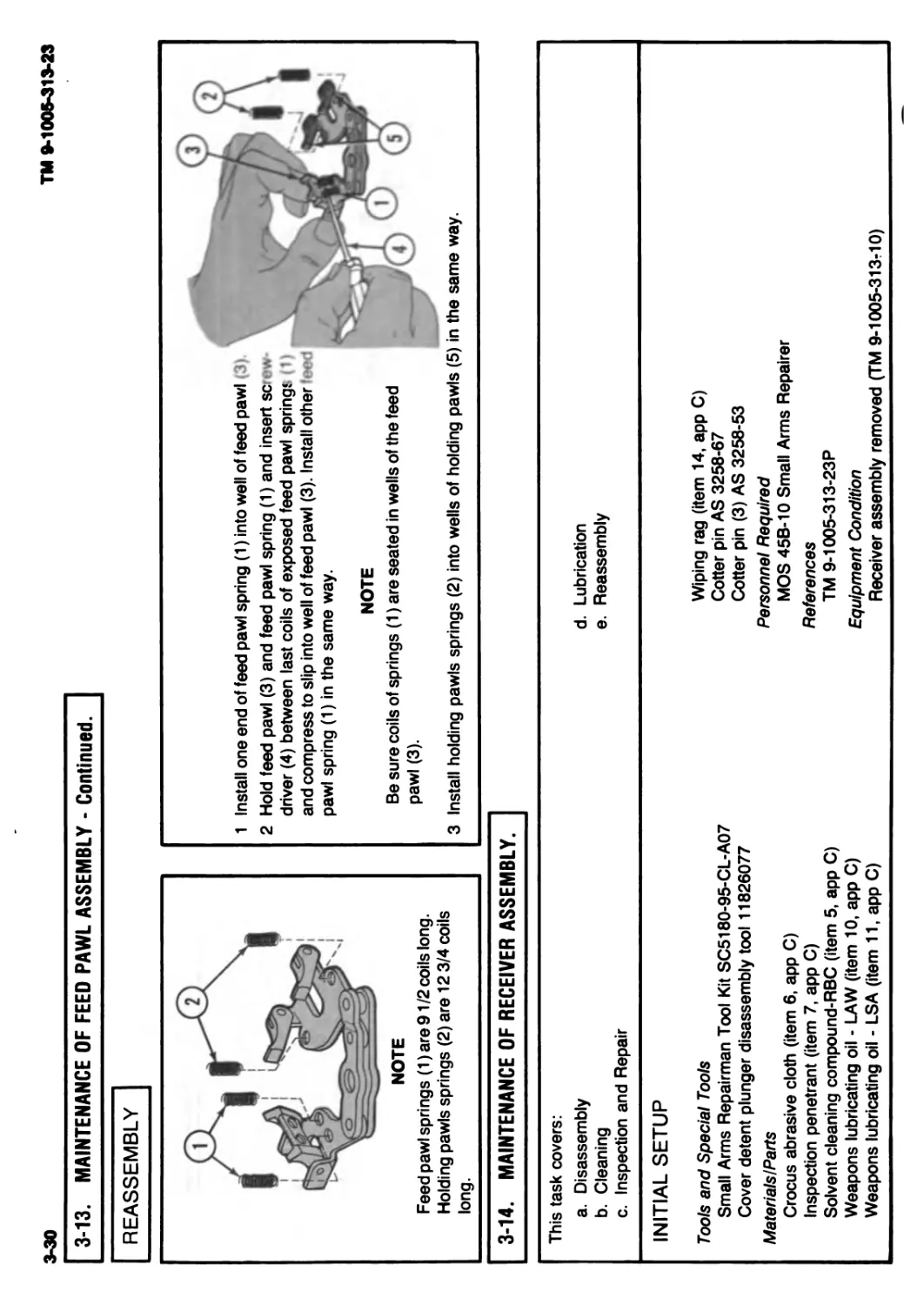
Feed pawl springs (1) are 91/2 coils long.
Holding pawls springs (2) are 12 3/4 coils
long.
Install one end of feed pawl spring (1) into well of feed pawl <3)
Hold feed pawl (3) and feed pawl spring (1) and insert screw
driver (4) between last coils of exposed feed pawl spring? (1)
and compress to slip into well of feed pawl (3). Install other
pawl spring (1) in the same way.
NOTE
Be sure coils of springs (1) are seated in wells of the feed
pawl (3).
3 Install holding pawls springs (2) into wells of holding pawls (5) in the same way.
3-14. MAINTENANCE OF RECEIVER ASSEMBLY.
This task covers:
a. Disassembly
b. Cleaning
c. Inspection and Repair
INITIAL SETUP
Tools and Special Tools
Small Arms Repairman Tool Kit SC5180-95-CL-A07
Cover detent plunger disassembly tool 11826077
Materials I Parts
Crocus abrasive cloth (item 6. app C)
Inspection penetrant (item 7, app C)
Solvent cleaning compound-RBC (item 5, app C)
Weapons lubricating oil - LAW (item 10, app C)
Weapons lubricating oil - LSA (item 11, app C)
d. Lubrication
e. Reassembly
Wiping rag (item 14, app C)
Cotter pin AS 3258-67
Cotter pin (3) AS 3258-53
Personnel Required
MOS 45B-10 Small Arms Repairer
References
TM 9-1005-313-23P
Equipment Condition
Receiver assembly removed (TM 9-1005-313-10)
DISASSEMBLY
1 Turn receiver body (1) upside down, depress access cover (2), and slightly
move it toward breech end.
3 Apply pressure on barrel latch (3), hold in
place, and remove headed grooved pin (4).
Remove barrel latch (3), and grasp barrel
latch helical compression spring (5) to pre-
vent it from springing away.
10
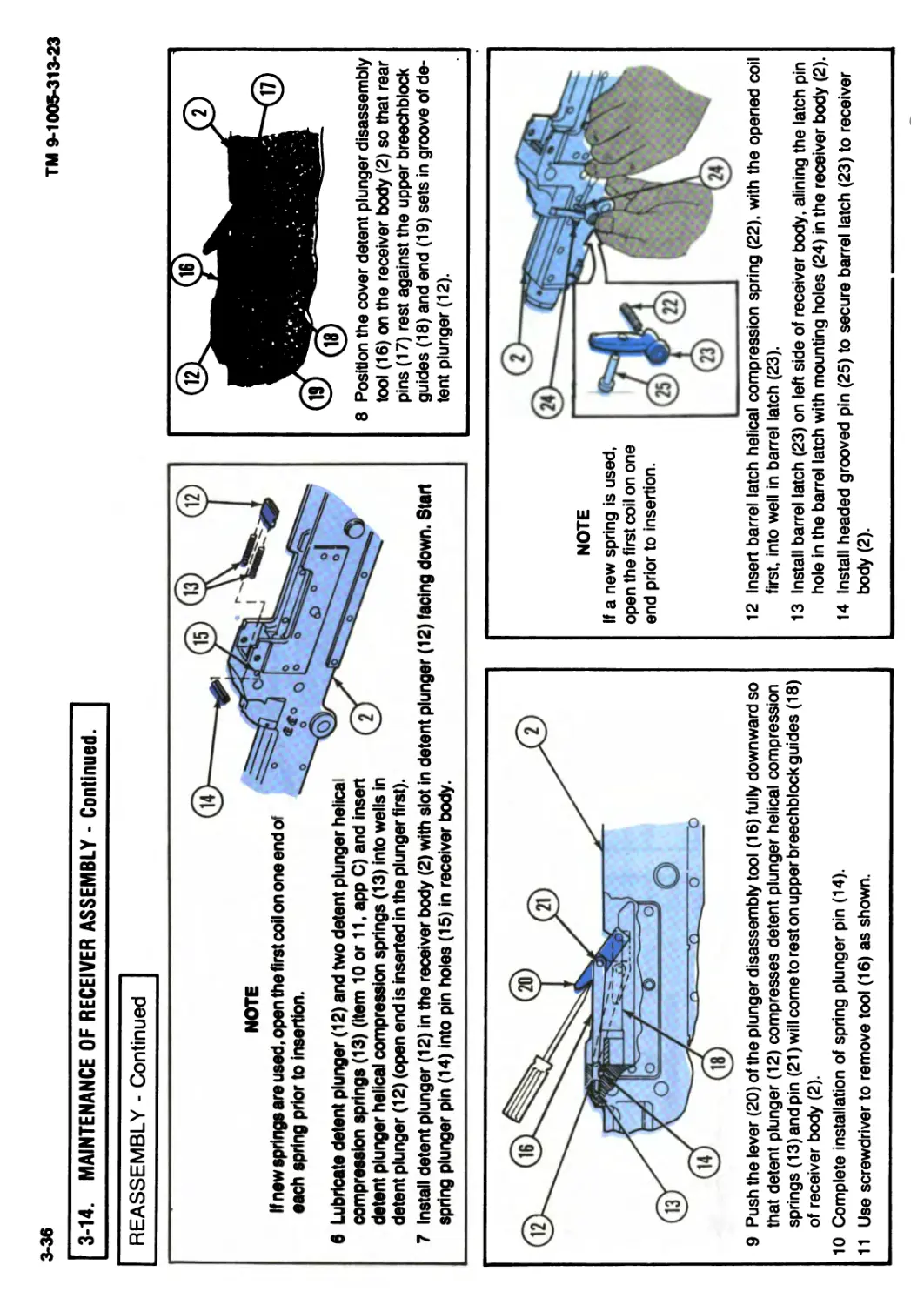
4 Position the cover detent plunger disassembly tool (6) in the opening for the
feed tray (7) in the receiver body (1) so that its rear pins (8) rest against the
upper breechblock guides (9) and its nose (10) rests in groove of detent
plunger (11).
2 Turn receiver body (1) over and slide access cover (2) out through breech
end of receiver body.
3-32
3-14. MAINTENANCE OF RECEIVER ASSEMBLY - Continued.
DISASSEMBLY - Continued
5 Push the lever (12) of the cover detent plunger disassembly tool (6) fully
downward so that pin (14) will come to rest on upper breechblock guides (9)
and detent plunger (11) compresses detent plunger helical compression
springs (13) removing pressure on spring plunger pin (15).
9 Remove cotter pin (16) securing helical extension spring (17) to spring
mounting plate (18). Discard cotter pin (16).
10 Rotate helical extension spring (17) to remove.
TM 9-1005-313-23
6 Remove spring plunger pin (15).
7 Place one hand on cover detent plunger disassembly tool (6) to steady it.
Then lift the lever (12) and remove the tool (6).
8 Remove detent plunger (11) and detent plunger helical compression
springs (13).
11 Remove cotter pin (20) securing charger cable (21) to charger slide (22)
and remove charger cable (21). Discard cotter pin (20).
12 Remove two cotter pins (23) and discard.
Slide out spring mounting plate (18).
13 Drive out spring pin (24). Press headed straight pin (25) outward from inside of receiver
body(1).
NOTE
Be sure that the four panhead machine
screws (26) and flat washers (27) are
present. Removal and inspection are
not necessary since these items are
not critical to weapon functioning and
are present only to protect the receiver
body threads.
3-33
TM 3-1005-313-23
3-34
TM 9-1005-313-23
3-14. MAINTENANCE OF RECEIVER ASSEMBLY - Continued.
CLEANING
Remove dirt and corrosion on powder-fouled parts with wiping rag (item 14, app C) dampened with RBC (item 5, app C).
INSPECTION AND REPAIR
NOTE
Remove burrs from parts with a fine file or crocus cloth (item 6, app C).
1 Check pins (1,2,3, and 4) for distortion, cracks, or excessive wear. Replace
if distorted, cracked, or worn excessively.
2 Check springs (5, 6, and 7) for breaks, cracks, or distortion. Replace
broken, cracked, or permanently set springs.
3 Check spring mounting plate (8) for distortion or cracks. Replace if distorted
or cracked.
4 Check charger slide (9) for distortion, cracks, or burrs. Replace if distorted,
cracked, or if slide does not operate freely in receiver body.
5 Check receiver body (10) for distortion and burrs. Remove burrs. If receiver
body is distorted, receiver is unserviceable.
6 Check receiver body (10) for cracks using inspection penetrant (item 7, app
C). If receiver body is cracked, receiver is unserviceable.
7 Replace barrel latch (11) if it has cracks or breaks.
8 Check detent plunger (12) for cracks, wear, or burrs. Replace if burrs cannot
be removed or if it is otherwise damaged.
9 Check charger handle (13) for broken wire strands, missing rubber handle,
or torn handle exposing wire rope. Replace if wire strands are broken or if
rubber handle is tom.
10 Check access cover (14) for cracks, burrs, or distortion. Replace if cracked
or distorted.
LUBRICATION
Lightly oil (item 10 or 11, app C) all parts after cleaning.
REASSEMBLY
1 Install charger slide (1) into right front side of
receiver body (2) and slide rearward.
2 Install headed straight pin (3) in charger slide (1). Aline headed straight pin (3) slot with slide spring
pin hole and secure with spring pin (4). Spring pin (4) must be flush on both sides.
3 Install spring mounting plate (5) from right side
with curved end up. Install new cotter pins (6)
with head up. Spread legs of cotter pins (6) to
secure.
4 Secure charger cable (7) to charger slide (1)
with new cotter pin (8). Spread legs of cotter
pin (8) to secure.
5 Spread rear end (9) of helical extension
spring (10) and twist onto charger slide (1).
Extend spring and secure other end to spring
mounting plate (5) with new cotter pin (11) head
up. Spread legs of cotter pin to secure.
3-35
TM 9-1005-313-23
3-36
TM 9-1005-313-23
3-14. MAINTENANCE OF RECEIVER ASSEMBLY - Continued.
REASSEMBLY - Continued
NOTE
If new springe are used, open the first coil on one end of
each spring prior to insertion.
6 Lubricate detent plunger (12) and two detent plunger helical
compression springs (13) (Item 10 or 11, app C) and insen
detent plunger helical compression springs (13) into wells in
8 Position the cover detent plunger disassembly
tool (16) on the receiver body (2) so that rear
pins (17) rest against the upper breechblock
guides (18) and end (19) sets in groove of de-
tent plunger (12).
detent plunger (12) (open end is inserted in the plunger first).
7 Install detent plunger (12) in the receiver body (2) with slot in detent plunger (12) facing down. Start
spring plunger pin (14) into pin holes (15) in receiver body.
9 Push the lever (20) of the plunger disassembly tool (16) fully downward so
that detent plunger (12) compresses detent plunger helical compression
springs (13)andpin (21) will come to rest on upper breechblock guides (18)
of receiver body (2).
10 Complete installation of spring plunger pin (14).
11 Use screwdriver to remove tool (16) as shown.
NOTE
If a new spring is used,
open the first coil on one
end prior to insertion.
12 Insert barrel latch helical compression spring (22), with the opened coil
first, into well in barrel latch (23).
13 Install barrel latch (23) on left side of receiver body, alining the latch pin
hole in the barrel latch with mounting holes (24) in the receiver body (2).
14 Install headed grooved pin (25) to secure barrel latch (23) to receiver
body (2).
15 Install access cover (26). Place solid end in first (bent end of tang pointed
downward). Slide access cover forward until it clicks into locked position in
receiver body (2).
3-15. FINAL INSPECTION.
This task covers:
a. Testing
INITIAL SETUP
Tools and Special Tools
Firing pin protrusion gage 11826304
Headspace warning gage 11826299
Headspace reject gage 11826274
Direct Support and General Support Maintenance
Small Arms Shop Set SC4933-95-CL-A11
Trigger pull test fixture
3-37
16 Turn receiver body (2) upside down and make sure access cover (26) is in
locked position.
b. Anal Inspection
Personnel Required
MOS 45B-10 Small Arms Repairer
References
TM 9-1005-313-10
TM 9-1005-313-23P
Equipment Condition
Machine gun assembled (TM 9-1005-313-10)
TM 9*1005-313-23
3-38
3-15. FINAL INSPECTION - Continued.
TESTING
WARNING
Make certain weapon is cleared and that there is no obstruction in the
barrel or chamber.
1 Check operation and position of barrel release latch (1), barrel release (2),
and barrel latch (3). Barrel (4) must be locked securely in receiver.
3 Open and close cover (8). Locking in the closed position must be positive.
Depress cover latches (9) and open cover. The plunger action must hold the
cover open.
TM 9-1005-313-zJ
2 Charge the weapon with charger cable (5). Charging action must be smooth
and positive. Operate the safety (6). It must be smooth and positive, locking
in either the safe or fire position. When safety is in “F” position, pull
trigger (7). Weapon must fire. When safety is in “S” position, weapon must
not fire.
4 Check buffer assembly (10). Buffer assembly must be flush with top of
receiver (11).
3-39
3 Hold machine gun (4) in vertical position. Hook
end of test fixture (1) over trigger (5) and slowly
raise machine gun (4) in a line parallel to the
barrel bore (6) until test weights (2) are sus-
pended. The bolt assembly (7) should not move
forward to firing position.
4 Remove fixture (1) and add weights (2) until
maximum load 7.045 kg (151/2 lb) is reached.
Repeat above procedures. Bolt assembly (7)
should move forward to firing position. If
machine gun fails trigger pull test, replace de-
fective parts and repeat test.
TM 9-1005-313-23
3-40
TM 9-1005-313-23
3-15. FINAL INSPECTION - Continued.
TESTING - Continued
1 Remove buffer assembly (1).
5 Release barrel locking latch (6) and turn barrel release latch (7) to upright
position and move barrel assembly (8) slightly forward.
NOTE
The notch (9) in the headspace gage (11) must face upward and
toward the rear of chamber (10) to provide clearance for ejector.
6 Insert headspace gage (11) (warning or reject) with notch up in
chamber (10).
8 Slide bolt and operating rod assembly (5) forward and exert slight pressure
to determine if weapon is in locked or unlocked position.
NOTE
The headspace warning gage (11) should not allow locking of the weapon.
In the event of locking with headspace warning gage inserted, the weapon may be kept in service if it is needed for
immediate use, as long as the headspace reject gage does not allow locking of the weapon.
3-41
TM 9-1005-313-23
3-42
TM 9-1005-313-23
3-15. FINAL INSPECTION - Continued.
TESTING - Continued
WARNING
If it is necessary to replace parts, headspace warning and reject gaging procedures must be repeated to be sure
weapon is serviceable.
WARNING
The headspace reject gage must never allow locking of the weapon.
9 Perform testing with the headspace reject gage (11) in the same way as with the headspace warning gage. If the weapon
locks with the headspace reject gage (11); do not use the weapon until it is repaired. Tо repair, replace bolt assembly (13),
replace barrel assembly (8), or replace both bolt assembly and barrel assembly.
REMOVING HEADSPACE GAGES AtTxWl ROT I ''' /) MS® \T) 1 Slide bolt and operating rod assembly (1) slightly rearward. 2 Release barrel locking latch (2) and turn barrel release I^L ЛЛ latch (3) to upright position and I Ч-У move barrel assembly (4) slightly forward. • Ллр — _/ / U-! s’ z-/ ©—
5 Install driving spring assembly (8).
3 Remove headspace gage (5) from
chamber (6).
4 Place barrel assembly (4) back into receiver (7)
and lock in position.
6 Install buffer assembly (9).
8 Charge weapon to the rear and release charger
cable (12) to function check the sear action.
Bolt and operating rod assembly (1) should re-
main rearward.
3-43
TM 9-1005-313-23
3-44
TM 9-1005-313-23
3-15. FINAL INSPECTION - Continued.
TESTING - Continued
USING FIRING PIN PROTRUSION GAGE TO MEASURE FIRING PIN
PROTRUSION
WARNING
This test shall not be made with live ammunition.
1 The first step in using the firing pin protrusion gage (1) is to function check
the machine gun. The bolt and operating rod must go forward freely to firing
position when trigger is pulled. (Safety must be in “F’ position.)
2 Release barrel locking latch (2) and turn barrel release latch (3) to upright
position and remove barrel assembly (4) from receiver (5).
4 Point receiver body (5) upward with buf-
fer (8) resting on a work surface
3-45
7 Read gage as follows: the end of the movable
rod (10) must be flush or above the edge of the
stationary tube (11). The notch (12) in the
movable rod (10) must be flush or below the
edge of the stationary tube (11). If above con-
ditions are not met, check firing pin length
(p 2-22, INSPECTION, step 2).
TM 9-1005-313-23
3-46
TM 9-1005-313-23
3-15. FINAL INSPECTION - Continued.
FINAL INSPECTION
1 Check the overall machine gun and make sure black finish surfaces do
not reflect light.
2 Check the tightness of all attaching screws, bolts, nuts, and cotter
pins.
3 Check for adequate lubrication.
4 Check for missing parts.
5 A machine gun that has been repaired should be function fired
whenever possible to be sure it operates properly. If a machine gun
fails the functioning-firing test, it must be reinspected to determine the
cause of the failure and corrective action must be taken.
6 Upon completion of firing, machine gun should be cleaned and
lubricated.
7 Make an overall inspection of the machine gun for cleanliness and
general appearance.
M240
M240C
Section V. PREPARATION FOR STORAGE OR SHIPMENT
3-16. PREPARATION FOR STORAGE OR SHIPMENT. M240 machine gun
cleaning, preservation, packaging, packing and marking.
a. Packing. Disassemble, clean, dry, preserve, and package the machine
gun as follows:
(1) Remove the barrel assembly from the weapon.
(2) Clean weapon and barrel with solvent cleaning compound (item 5,
app C) and dry both items with clean wiping rags (item 14, app C).
(3) Preserve the barrel and weapon with lubricating oil (item 9, app C).
(4) Wrap barrel and weapon with packaging volatile paper (item 13,
app C), with treated side touching the metal surfaces.
(5) Secure paper with pressure sensitive tape (item 18, app C).
(6) Place the wrapped barrel and weapon in a 9 x 6 1/2 x 32 inch
fiberboard box (item 1, app C).
(7) Close box with water-resistant paperback pressure sensitive
tape (item 19, app C).
(8) Preserve metal BII parts with lubricating oil (item 9, app C).
(9) Wrap metal BII parts with packaging volatile paper (item 13, app C),
with treated side touching the metal surfaces.
(10) Secure paper with pressure sensitive tape (item 18, app C).
(11) Place BII items in another 9 x 61 /2 x 32 inch fiberboard box (item 1,
app C).
(12) Close box with water-resistant paperback pressure sensitive
tape (item 19, app C).
(13) Place the two packed 9 x 61/2 x 32 inch fiberboard boxes in a 36 x
14 x 14 inch fiberboard box (item 1, app C).
(14) Place fiberboard blocking in the box to fill the empty space and to
keep the packaged items from moving.
(15) Close the 36 x 14 x 14 inch fiberboard box with water-resistant
paperback pressure sensitive tape (item 19, app C).
(16) Apply the following marking on each 36 x 14 x 14 inch fiberboard
box:
NATIONAL STOCK NUMBER
FEDERAL ITEM NAME
1 EACH
PRESERVED ON (MONTH, YEAR)
GROSS WEIGHT: CUBE:
NOTE
Package one to three machine guns individually in a 37 1/4 x
21 1/4x151/4 inch shipping box (item 2, app C). Package more
than three and up to six machine guns in a 45 1/2 x 37 1/4 x 33 1/4
inch shipping box (item 2, app C).
(17) Place a quantity of packaged machine guns in a shipping
box (item 2, app C).
(18) Use fiberboard blocking as required to keep packaged machine
guns from moving within shipping container.
(19) Use common nails (item 12, app C) as required to fasten top to
shipping container.
(20) Secure container with flat steel strapping (item 16, appendix C).
NOTE
The following marking shall be omitted from the outside of exterior
shipping container:
NATIONAL STOCK NUMBER
FEDERAL ITEM NAME
LIST OF SERIAL NUMBERS
PACKING LIST
b. Marking. Apply the following markings to the exterior of the shipping
container, using stencil or label:
ADDRESS OF DESTINATION
WEIGHT AND CUBE
3-47
TM 9-1005-313-23
3-48
TM 9-1005-313-23
Section VI. PREEMBARKATION INSPECTION OF MATERIEL IN UNITS
ALERTED FOR OVERSEAS MOVEMENT
3-17. PREEMBARKATION INSPECTION OF MATERIEL IN UNITS
ALERTED FOR OVERSEAS MOVEMENT.
a. General. This inspection is conducted on materiel in alerted units
scheduled for overseas duty to be sure that such materiel will not become
unserviceable in a relatively short time. It prescribes a higher percentage of
remaining usable life in serviceable materiel to meet a specific need beyond
minimum serviceability.
b. Preinspection Points.
WARNING
Before starting an inspection, be sure to clear the weapon Do not
actuate the tngger until the weapon has been cleared Inspect the
bore and chamber to be sure they are empty and free from
obst ructions ।
(1) Before inspection, the materiel must be thoroughly cleaned of all
grease, dirt, or other foreign matter that might interfere with its proper function or
the use of gages and tools during inspection.
(2) Materiel must be free of burrs, rust, or corrosion on functional
surfaces.
(3) Parts must not be cracked, bent, distorted, or damaged and must be
free of excessive wear or looseness.
(4) Minor defects in metal components do not normally affect their
acceptability. For example, scratches and tool marks are ordinarily of no
importance.
(5) Inspect finish of metal surface. Satisfactory metal surfaces for
weapons range from black to light gray. A shiny metal surface is objectionable
only when it is capable of reflecting light. No weapon will be rejected unless
exterior parts have a shine.
c. Inspection Points.
(1) Springs must be free of distortion and broken coils. Springs must
have sufficient tension to perform their intended function.
(2) Barrels.
(a) Barrels must be clean and free of rust and corrosion which is
caused by moisture and powder fouling.
(b) Barrels must not be bulged.
(c) Barrels may have small amounts of flaking or small cracks in the
chrome plating in the chamber and bore.
(d) Flash hider must not be dented.
NOTE
If the condition of the chrome plate appears difficult to determine,
test fire 50 rounds in short bursts at a target, 50 meters away. The
imprint of each shot must be a clearly defined circle. Reject the
barrel when the imprints of the shots are oblong instead of circu-
lar. Be sure the target is reasonably perpendicular to the line of
fire.
(e) Pits in the chamber are allowable if they do not cause extraction
difficulties.
(f) Scattered or uniformly fine pits, or fine pits in a densely pitted
area are allowable.
(g) Tool marks are acceptable, regardless of length. They may
appear as lines running longitudinally in the grooves or may run spirally across
the tops of lands.
(h) Lands that appear dark, due to coating of gilding metal from
projectiles, will not be cause for rejection.
(3) The sear and cocking notches must be in good condition. Chipped
engaging corners will be cause for rejection. Slight wear on functional surfaces,
including engaging corners, shall be acceptable, providing the minimum trigger
pull requirements are met.
(4) Chips, flat spots, or bent strike points on firing pins will be cause for
rejection.
(5) The cartridge engaging surfaces on extractors must not be chipped
or deformed.
(6) Safety must positively position in both the “S” and “F” position.
When in the “S” or safe position, the weapon must not fire when the trigger is
squeezed; when in the “F” or fire position, the weapon must fire when the trigger
is squeezed.
(7) Each weapon must be hand functioned to check for unusual binding,
positive cocking action, and general operation. Dummy ammunition may be
used to be sure of positive chambering, extraction, and ejection action.
(8) Rivets must be tight.
(9) All markings must be legible.
d. Specific Standards. Refer to the following table.
STANDARDS FOR PREEMBARKATION INSPECTION OF 7.62MM MACHINE GUN M240/M240C
IN UNITS ALERTED FOR OVERSEAS MOVEMENT
hem Standard
Barrel Must pass barrel erosion check (warning mark on gage). Must pass headspace check using headspace warning gage (app B).
Trigger Pull Minimum - 2.7 kg (6 lb) Maximum - 7.045 kg (15 1/2 lb). Use trigger pull measuring fixture.
Firing Pin Protrusion Barrel Release (with barrel mounted in receiver) Buffer Assembly Cartridge Feed System Charger Assembly Must pass firing pin protrusion test. Barrel latch must lock barrel securely. Barrel latch must lock correctly, which is from 2 to 7 clicks. The buffer plug must protrude through the base of buffer block. All rollers and links must operate smoothly and freely. No binding is permitted. Must operate smoothly and freely. No binding is permitted.
3-49
TM 9-1005-313-23
А-0
TM 9-1005-313-23
APPENDIX A
REFERENCES
A-1. TECHNICAL MANUALS.
TM 38-750 .................. The Army Maintenance Management System (TAMMS)
TM 9-1005-313-10 ........... Operator’s Manual, Machine Gun, 7.62mm, M240 (1005-01 -025-8095) and Machine
Gun, 7.62mm, M240C (1005-01-085-4758)
TM 9-1005-313-23P .......... Organizational and Direct Support Maintenance Repair Parts and Special Tools List,
Machine Gun, 7.62mm, M240 (1005-01-025-8095) and Machine Gun, 7.62mm,
M240C (1005-01-085-4758)
TM 750-244-7 ............... Procedures for Destruction of Equipment in Federal Supply Classification 1000,
1005,1010,1015,1020,1025,1030,1055,1090, and 1095 to Prevent Enemy Use
A-2. FIELD MANUAL.
FM 21-11 ................. First Aid for Soldiers
A-3. TECHNICAL BULLETIN.
ТВ 43-0196 .............. Inspection and Certification of Gages - Small Arms
A-4. SUPPLY CATALOGS.
SC 4933-95-CL-A11 .......... Shop Set, Small Arms: Field Maintenance, Basic Less Power
SC 5180-95-CL-A07 .......... Tool Kit, Small Arms Repairman
(to be published)
APPENDIX В
MAINTENANCE ALLOCATION CHART
Section!. INTRODUCTION
B-1. GENERAL.
a. This section provides a general explanation of all maintenance and
repair functions authorized at various maintenance categories.
b. The Maintenance Allocation Chart (MAC) in section II designates over-
all responsibility for the performance of maintenance functions on the identified
end item or component. The implementation of the maintenance functions upon
the end item or component will be consistent with the assigned maintenance
functions.
c. Section III lists the special tools and test equipment required for each
maintenance function as referenced from section II.
d. Section IV contains supplemental instructions and explanatory notes for
a particular maintenance function.
B-2. MAINTENANCE FUNCTIONS. Maintenance functions will be limited to
and defined as follows (except for ammunition MAC1).
a. Inspect. To determine the serviceability of an item by comparing its
physical, mechanical, and/or electrical characteristics with established stan-
dards through examination.
b. Test. To verify serviceability by measuring the mechanical or electrical
characteristics of an item and comparing those characteristics with prescribed
standards.
c. Service. Operations required periodically to keep an item in proper
operating condition, i.e., to clean (includes decontaminate, when required), to
preserve, to drain, to paint, or to replenish fuel, lubricants, hydraulic fluids, or
gases.
d. Adjust. To maintain, within prescribed limits, by bringing into proper or
exact position, or by setting the operating characteristics to specified paramet-
ers.
e. Aline. To adjust specified variable elements of an item to bring about
optimum or desired performance.
f. Calibrate. To determine and cause corrections to be made or to be
adjusted on instruments or test, measuring, and diagnostic equipments used in
precision measurement. Consists of comparisons of two instruments, one of
which is a certified standard of known accuracy, to detect and adjust any
discrepancy in the accuracy of the instrument being compared.
g. Install. The act of emplacing, seating, or fixing into position an item,
part, or module (component or assembly) in a manner to allow the proper
functioning of an equipment or system.
h. Replace. The act of substituting a serviceable like type part, subas-
sembly, or module (component or assembly) for an unserviceable counterpart.
i. Repair. The application of maintenance services2 or other mainte-
nance actions3 to restore serviceability to an item by correcting specific dam-
age, fault, malfunction, or failure in a part, subassembly, module (component or
assembly), end item, or system.
j. Overhaul. That maintenance effort (service/action) necessary to re-
store an item to a completely serviceable/operational condition as prescribed by
maintenance standards in appropriate technical publications (i.e., DMWR).
Overhaul is normally the highest degree of maintenance performed by the
Army. Overhaul does not normally return an item to like new condition.
1 Exception is authorized for ammunition MAC to permit the redesignation/redefinition of maintenance function headings to more adequately identify
ammunition maintenance functions. The heading designations and definitions will be included in the appropriate technical manual for each category of
ammunition.
2Services * inspect, test, service, adjust, aline, calibrate, or replace.
3Actions - welding, grinding, riveting, straightening, facing, remachining, or resurfacing.
B-1
TM 9-1005-313-23
В-2
к. Rebuild. Consists of those services/actions necessary for the restora-
tion of unserviceable equipment to a like new condition in accordance with
original manufacturing standards. Rebuild is the highest degree of materiel
maintenance applied to Army equipment. The rebuild operation includes the act
of returning to zero those age measurements (hours/miles, etc.) considered in
classifying Army equipments/components.
B-3. EXPLANATION OF COLUMNS IN THE MAC, SECTION II.
a. Column 1, Group Number. Column 1 lists functional group code num-
bers, the purpose of which is to identify components, assemblies, subas-
semblies, and modules with the next higher assembly.
b. Column 2, ComponentlAssembly. Column 2 contains the names of
components, assemblies, subassemblies, and modules for which maintenance
is authorized.
c. Column 3, Maintenance Function. Column 3 lists the functions to be
performed on the item listed in Column 2. (For detailed explanation of these
functions, see paragraph B-2.)
d. Column 4, Maintenance Category. Column 4 specifies, by the listing of
a work time figure in the appropriate subcolumn(s), the category of maintenance
authorized to perform the function listed in Column 3. This figure represents the
active time required to perform that maintenance function at the indicated
category of maintenance. If the number or complexity of the tasks within the
listed maintenance function vary at different maintenance categories, appro-
priate work time figures will be shown for each category. The work time figure
represents the average time required to restore an item (assembly, subassem-
bly, component, module, end item, or system) to a serviceable condition under
typical field operating conditions. This time includes preparation time, trou-
bleshooting time, and quality assurance/quality control time in addition to the
time required to perform the specific tasks identified for the maintenance func-
tions authorized in the maintenance allocation chart. The symbol designations
for the various maintenance categories are as follows:
TM 9-1005-313-23
С ...........................................Operator or crew.
О ................................Organizational maintenance.
F..................................Direct support maintenance.
H................................General support maintenance.
D .........................................Depot maintenance.
e. Column 5, Tools and Equipment. Column 5 specifies, by code, those
common tool sets (not individual tools) and special tools, TMDE, and support
equipment required to perform the designated function.
f. Column 6, Remarks. This column shall, when applicable, contain a
letter code, in alphabetic order, which shall be keyed to the remarks contained in
Section IV.
B-4. EXPLANATION OF COLUMNS IN TOOL AND TEST EQUIPMENT
REQUIREMENTS, SECTION III.
a. Column 1, Reference Code. The tool and test equipment reference
code correlates with a code used in the MAC, Section II, Column 5.
b. Column 2, Maintenance Category. The lowest category of mainte-
nance authorized to use the tool or test equipment.
c. Column 3, Nomenclature. Name or identification of the tool or test
equipment.
d. Column 4, National Stock Number. The National Stock number of the
tool or test equipment.
e. Column 5, Tool Number. The manufacturer’s part number.
B-5. EXPLANATION OF COLUMNS IN REMARKS, SECTION IV.
a. Column 1, Reference Code. The code recorded in column 6, section II.
b. Column 2, Remarks. This column lists information pertinent to the
maintenance function being performed as indicated in the MAC, Section II.
Section II. MAINTENANCE ALLOCATION CHART
(1) GROUP NUMBER (2) COMPONENT/ ASSEMBLY (3) MAINTENANCE FUNCTION (4) MAINTENANCE CATEGORY (5) TOOLS AND EQPT (6) REMARKS
c 0 F H D
00 MACHINE GUN, 7.62MM, Inspect 0.2 0.2 0.2 1,2, 3,4
M240 AND MACHINE GUN, Test 0.3
7.62MM, M240C Service 0.2 0.3 0.2
Repair 0.1 0.1
Overhaul 16.0
01 BARREL ASSEMBLY Inspect 0.1 0.1 0.1
Test 0.1 5,6
Service 0.2 0.3 0.2 7,8
Install 0.1
Replace 0.1
Repair 0.1 0.3 9, 10
Overhaul 0.5
02 BUFFER ASSEMBLY Inspect 0.1 0.1 0.1
Service 0.1 0.1 0.3
Replace 0.2
Repair 0.3 9, 10, 11
Overhaul 1.0
03 BOLT AND OPERATING Inspect 0.1 0.1 0.1 12
ROD ASSEMBLY Service 0.1 0.1 13
Replace 0.2
Repair 0.2 0.2 10
Overhaul 2.0 •
B-3
TM 9-1005-313-23
B-4
(1) GROUP NUMBER (2) COMPONENT/ ASSEMBLY (3) MAINTENANCE FUNCTION
0301 Bolt Assembly Inspect Test Service Replace Repair Overhaul
04 TRIGGER HOUSING ASSEMBLY Inspect Service Replace Repair Overhaul
05 COVER ASSEMBLY Inspect Service Replace Repair Overhaul
0501 Pawl Assembly, Feed Inspect Service Replace Repair
06 RECEIVER ASSEMBLY Inspect Service Repair Overhaul
TM 9-1005-313-23
(4) MAINTENANCE CATEGORY (5) (6)
c 0 F H D TOOLSAND EQPT REMARKS
0.1 0.1 0.1
0.1 14, 15
0.2 0.2
0.1
0.3 0.3 1.0 10, 13, 16
0.1 0.1 0.1
0.1 0.1 0.2
0.2
0.2 0.3 1.0 10
0.1 0.1 0.1
0.1 0.1 0.1
0.1
0.3 1.2 10
0.1 0.1 0.1
0.1 0.1 0.1
0.2
0.1
0.1 0.1 0.1 A
0.2 0.2 0.3 13
0.2 0.3 1.5 10, 17
Section III. TOOL AND TEST EQUIPMENT REQUIREMENTS FOR MACHINE GUN
(1) TOOL OR TEST EQUIPMENT REF CODE (2) MAINTENANCE CATEGORY (3) NOMENCLATURE (4) NATIONAL/NATO STOCK NUMBER (5) TOOL NUMBER
1 F Gage, Headspace Warning 4933-01-043-8211 11826299 (CB39)
2 F Gage, Headspace Reject 4933-01-043-8212 11826274 (CB40)
3 F Gage, Firing Pin Protrusion 4933-01-043-9450 11826304 (CB189)
4 F Shop Set, Small Arms: Field Maintenance, Basic Less Power 4933-00-754-0664 SC4933-95-CL-A11
5 F Gage, Breech Bore Erosion 5210-01-082-1714 11826298
6 F Gage, Muzzle and Breechbore Wear 5220-01-082-5564 11826276
7 0 Scraper, Combination Regulator 4933-01-033-1504 11826005
8 0 Reamer, Cleaning 4933-01-047-3394 11826036
9 0 Wrench, Combination w/ Brass Hammer 4933-01-033-8324 11826058
10 0 Tool Kit, Small Arms Repairman 5180-00-357-7770 SC5180-95-CL-A07
11 F Wrench, Combination, Box and Open End 5120-00-077-2219 OEXM230
B-5
TM 9*1005-313-23
В-6
TM 9-1005-313-23
(1) TOOL OR TEST EQUIPMENT REF CODE (2) MAINTENANCE CATEGORY (3) NOMENCLATURE (4) NA1TONAL/NATO STOCK NUMBER (5) TOOL NUMBER
12 0 Gage, Firing Pin Length 4933-01-043-9451 11826071
13 0 Tool, Combination Scraper and Extractor 4933-01-033-1503 11826059
14 0 Gage, Breech Bolt Extractor Engagement 4933-01-043-9449 11826305
15 0 Gage, Breech Bolt Extractor Clearance 4933-01-043-9448 11826306
16 0 Tool, Removing, Ejector 4933-01-038-7179 11826076
17 F Tool, Disassembly, Cover Detent Plunger 4933-014)38-7183 11826077
Section IV. REMARKS
Reference Code
Remarks
The A in the 5th position of the SMR Code indicates special handling. The item meets security requirements and is
serialized for accountability purposes.
APPENDIX С
EXPENDABLE SUPPLIES AND MATERIALS LIST
Section I. INTRODUCTION
C-1. SCOPE. This appendix lists expendable supplies and materials you will
need to operate and maintain the machine gun. These items are authorized to
you by СТА 50- 970, Expendable Items (Except Medical, Class V, Repair Parts,
and Heraldic Items).
02. EXPLANATION OF COLUMNS.
a. Column 1, Item Number. This number is assigned to the entry in the
listing and is referenced in the narrative instructions to identify the material (e.g.,
“Use solvent cleaning compound, item 5, app C”).
b. Column 2, Level. This column identifies the lowest level of mainte-
nance that requires the listed item.
C-Operator/Crew
□-Organizational Maintenance
F-Direct Support Maintenance
c. Column 3, National Stock Number. This is the National stock number
assigned to the item; use it to request or requisition the item.
d. Column 4, Description. Indicates the Federal item name and, if re-
quired, a description to identify the item. The last line for each item indicates the
Federal Supply Code for Manufacturer (FSCM) in parentheses followed by the
part number.
e. Column 5, Unit of Measure (U/M). Indicates the measure used in
performing the actual maintenance function. This measure is expressed by a
two character alphabetical abbreviation (e.g., ea, in., pr). If the unit of measure
differs from the unit of issue, requisition the lowest unit of issue that will satisfy
your requirements.
Section II. EXPENDABLE SUPPLIES AND MATERIALS LIST
(1) ITEM NUMBER (2) LEVEL (3) NATIONAL STOCK NUMBER (4) DESCRIPTION (5) U/M
1 0 8115-00-190-4858 8115-00-190-5020 BOX, FIBERBOARD (81348) PPP-B-636, PPPB636 15 ea bdl - 9 x 6 1/2 x 32” 10 ea bdl - 36 x 14 x 14” EA EA
2 0 8115-01-019-1632 8115-01-023-0301 BOX, SHIPPING (81348) PPP-B-601 45 1/2 x 37 1/4 x 33 1/4" 37 1/4 x 21 1/4x15 1/4" EA EA
3 0 1005-01-033-3925 BRUSH, CLEANING, GAS CYLINDER (19200) 11826118 EA
C-1
TM 9-1005-313-23
С-2
TM 9*1005-313-23
(1) ITEM NUMBER (2) LEVEL (3) NATIONAL STOCK NUMBER (4) DESCRIPTION (5) U/M
4 0 9150-01-054-6453 9150-01-053-6688 CLEANER, LUBRICANT AND PRESERVATIVE: grade 2 (CLP) (27412) CLP-5, CLP-7 1 pint bottle 1 gal bottle PT GL
5 0 6850-00-224-6657 6850-00-224-6663 CLEANING COMPOUND, SOLVENT: rifle bore cleaner (RBC) (81349) MIL-C-372, MILC372 8 oz can 1 gal can OZ GL
6 0 5350-00-221-0872 CLOTH, ABRASIVE, CROCUS (81348) P-C-458 50 sheet package SH
7 F 6850-00-826-0981 INSPECTION PENETRANT (81349) MIL-I-25135 KT
8 0 9150-00-168-2000 LUBRICANT, SOLID FILM (81349) MIL-L-46147 16 oz aerosol can OZ
9 0 9150-00-231-6689 9150-00-231-9062 LUBRICATING OIL, P-9 (81349) WL800 1 qt can 5 gal can QT GL
10 c 9150-00-292-9689 LUBRICATING OIL, WEAPONS, (LAW) (81349) MIL-L-14107 1 qt can QT
11 0 9150-00-753-4686 LUBRICATING OIL, WEAPONS, (LSA) (81349) MIL-L-46000 1 gal can GL
(1) ITEM NUMBER (2) LEVEL (3) NATIONAL STOCK NUMBER (4) DESCRIPTION (5) U/M
12 0 5315-00-010-4657 NAIL, COMMON, 6D 2 in. (96906) 55907135 50 lb box LB
13 о 8135-00-985-7242 PAPER, VOLATILE, PACKAGING (81349) MIL-P-3420 36 in. wide, 100 ft roll FT
14 c 7920-00-205-1711 RAG, WIPING (58536) A-A-531 50 lb bale LB
15 о 7930-00-965-4868 SOAP, LAUNDRY (81348) P-S-591 120 bars to box EA
16 0 8135-00-286-8565 STEEL STRAPPING, FLAT, 5/8" W (81348) QQ-S-781 100 lb coil LB
17 c 1005-00-288-3565 SWAB, SMALL ARMS CLEANING: cotton (19204) 5019316 1 pk (1000 per pkg) EA
18 о 8135-00-269-8088 TAPE, PRESSURE SENSITIVE (81348) PPP-T-60 2 in. wide, 60 yd roll YD
19 0 7510-00-297-6655 TAPE, PRESSURE SENSITIVE, PAPERBACK, WATER-RESISTANT (81348) PPP-T-76 2 in. wide, 120 yd roll YD
С-3
TM 9-1005-313-23
Index-0
TM «-1005-313-23
ALPHABETICAL INDEX
Subject Page(s)
В
Barrel Assembly
Cleaning ............................................ 2-16
Disassembly ....................................... 2-15,3-5
Inspection ........................................ 2-18,3-6
Reassembly......................................... 2-18, 3-7
Repair ............................................ 2-18, 3-6
Testing ........................................... 3-4
Bolt and Operating Rod Assembly
Cleaning ........................................... 2-21
Disassembly ....................................... 2-20
Inspection ........................................ 2-22,3-15
Reassembly......................................... 2-24
Repair............................................. 2-23, 3-15
Bolt Assembly
Cleaning ........................................... 2-27
Disassembly ....................................... 2-25
Inspection ........................................ 2-27,3-16
Reassembly......................................... 2-28
Repair............................................. 2-27, 3-16
Testing ........................................... 2-29
Buffer Assembly
Cleaning ........................................... 3-10
Disassembly ....................................... 3-9
Inspection ........................................ 3-11
Reassembly......................................... 3-12
Repair............................................. 3-11
C
Checks and Services, Preventive Maintenance ......... 2-2
Cleaning
Barrel Assembly .................................. 2-16
Bolt and Operating Rod Assembly ................... 2-21
Bolt Assembly ..................................... 2-27
Buffer Assembly ................................... 3-10
Cover Assembly .................................... 3-24
Subject Pegefs)
Feed Pawl Assembly.................................. 3-29
Machine Gun......................................... 2-13
Receiver Assembly .................................. 2-35, 3-34
Trigger Housing Assembly ........................... 2-32, 3-18
Common Tools and Equipment............................ 2-0, 3-0
Cover Assembly
Cleaning ............................................. 3-24
Disassembly ........................................ 3-22
Inspection ......................................... 3-24
Reassembly.......................................... 3-25
Repair.............................................. 3-24
D
Data, Equipment....................................... 1-2
Destruction of Army Materiel to Prevent Enemy Use .... 1-1
Differences Between Models ........................... 1-3
Direct Support Maintenance Instructions............... 3-0
Disassembly
Barrel Assembly ..................................... 2-15,3-5
Bolt and Operating Rod Assembly .................... 2-20
Bolt Assembly ...................................... 2-25
Buffer Assembly .................................... 3-9
Cover Assembly ..................................... 3-22
Feed Pawl Assembly.................................. 3-29
Machine Gun......................................... 2-13, 3-2
Receiver Assembly .................................. 2-34, 3-31
Trigger Housing Assembly ............................. 2-31, 3-17
Double Feed .......................................... 2-10
E
Enemy Use, Destruction of Army Materiel to Prevent ... 1-1
Equipment Characteristics, Capabilities, and Features .... 1-2
Equipment Description and Data ....................... 1-2
Subject Page(s)
Equipment Improvement Recommendations (EIR),
Reporting ............................................ 1-2
Equipment, Purpose of ................................. 1-1
Expendable Supplies and Materials List ................ C-1
F
Failure to Chamber .......................... 2-8
Failure to Cock or Runaway Gun ........................ 2-12,3-1
Failure to Eject ...................................... 2-11
Failure to Extract .................................... 2-11
Failure to Feed ....................................... 2-10
Failure to Fire ....................................... 2-9
Feed Pawl Assembly
Cleaning .............................................. 3-29
Disassembly ......................................... 3-29
Inspection .......................................... 3-29
Lubrication ......................................... 3-29
Reassembly........................................... 3-30
Repair............................................... 3-29
Final Inspection
Initial Setup ......................................... 3-37
Inspection .......................................... 3-46
Testing ............................................. 3-37
Firing Pin Protrusion Gaging .......................... 3-44
Forms, Records, and Reports, Maintenance .............. 1-1
G
Gaging
Breech Bore Erosion .............................. 3-4
Extractor Clearance .............................. 2-30
Extractor Engagement.............................. 2-29
Index-1
Subject Page(s)
Firing Pin Length .................................. 2-22
Firing Pin Protrusion .............................. 3-44
Headspace .......................................... 3-40
Gun Ruptures Cartridge Cases .......................... 3-1
H
Headspace Gaging ...................................... 3-40
I
Initial Setup
Barrel Assembly ...................................... 2-15,3-3
Bolt and Operating Rod Assembly .................... 2-20, 3-15
Bolt Assembly ...................................... 2-25, 3-16
Buffer Assembly .................................... 3-9
Cover Assembly ..................................... 3-21
Feed Pawl Assembly.................................. 3-28
Final Inspection ................................... 3-37
Machine Gun......................................... 2-12,3-2
Receiver Assembly .................................. 2-33, 3-30
Trigger Housing Assembly ........................... 2-31,3-17
Inspection
Barrel Assembly ...................................... 2-18, 3-6
Bolt and Operating Rod Assembly .................... 2-22, 3-15
Bolt Assembly ...................................... 2-27,3-16
Buffer Assembly .................................... 3-11
Cover Assembly ..................................... 3-24
Feed Pawl Assembly.................................. 3-29
Final Inspection ................................... 3-37
Machine Gun......................................... 2-13, 3-3
Receiver Assembly .................................. 2-36, 3-34
Trigger Housing Assembly ........................... 2-32, 3-19
Inspection, Preembarkation of Materiel in Units Alerted for
Overseas Movement..................................... 3-48
Instructions, Direct Support Maintenance .............. 3-0
Instructions, Organizational Maintenance .............. 2-0
TM 9-1005-313-23
Index-2
Subject
Page(s)
L
Location and Description of Major Components ......... 1-2
Lubrication
Barrel Assembly .................................... 2-18
Bolt and Operating Rod Assembly .................... 2-22
Bolt Assembly ...................................... 2-27
Buffer Assembly .................................... 3-10
Cover Assembly ..................................... 3-25
Feed Pawl Assembly ................................. 3-29
Final Inspection ................................... 3-46
Receiver Assembly .................................. 2-36, 3-34
Trigger Housing Assembly ............................ 2-32,3-19
M
Machine Gun, Maintenance of........................... 2-12, 3-2
Maintenance Allocation Chart .......................... B-0
Maintenance Forms, Records and Reports ............... 1-1
Major Components
Description......................................... 1-2
Location .......................................... 1-2
Maintenance of Barrel Assembly
Cleaning .......................................... 2-16
Disassembly ....................................... 2-15,3-5
Initial Setup ..................................... 2-15,3-3
Inspection ........................................ 2-18, 3-6
Reassembly......................................... 2-18, 3-7
Repair ............................................ 2-18, 3-6
Testing ........................................... 3-4
Maintenance of Bolt and Operating Rod Assembly
Cleaning .......................................... 2-21
Disassembly ....................................... 2-20
Initial Setup ..................................... 2-20, 3-15
Inspection ........................................ 2-22, 3-15
Reassembly......................................... 2-24
Repair ............................................ 2-23, 3-15
Maintenance of Bolt Assembly
Cleaning .......................................... 2-27
TM 9-1005-313-23
Pege(s)
Subject
Disassembly ...........................................
Initial Setup .........................................
Inspection ............................................
Reassembly.............................................
Repair.................................................
Testing ...............................................
Maintenance of Buffer Assembly
Cleaning ...............................................
Disassembly ...........................................
Initial Setup .........................................
Inspection ............................................
Reassembly.............................................
Repair.................................................
Maintenance of Cover Assembly
Cleaning ...............................................
Disassembly ...........................................
Initial Setup .........................................
Inspection ............................................
Reassembly.............................................
Repair.................................................
Maintenance of Feed Pawl Assembly
Cleaning ...............................................
Disassembly ...........................................
Initial Setup .........................................
Inspection ............................................
Lubrication ...........................................
2-25
2-25,
2-27,
2-28
2-27,
2-29
3-10
3-9
3-9
3-11
3-12
3-11
3-24
3-22
3-21
3-24
3-25
3-24
3-29
3-29
3-28
3-29
3-29
3-16
3-16
3-16
Reassembly....................................... 3-30
Repair .......................................... 3-29
Maintenance of Machine Gun
Cleaning ..............................................
Disassembly ...........................................
Initial Setup .........................................
Inspection ............................................
Reassembly.............................................
Repair.................................................
2-13
2-13, 3-2
2-12, 3-2
2-13, 3-3
2-14, 3-3
2-13, 3-3
Subject Page(s)
Maintenance of Receiver Assembly
Cleaning ............................................... 2-35, 3-34
Disassembly .......................................... 2-34,3-31
Initial Setup ........................................ 2-33, 3-30
Inspection ........................................... 2-36,3-34
Lubrication .......................................... 3-34
Reassembly............................................ 2-37, 3-35
Repair ............................................... 2-36, 3-34
Maintenance of Trigger Housing Assembly
Cleaning ............................................... 2-32, 3-18
Disassembly .......................................... 2-31,3-17
Initial Setup .......................................... 2-31,3-17
Inspection ........................................... 2-32,3-19
Lubrication .......................................... 3-19
Reassembly............................................. 2-32, 3-19
Repair ................................................ 2-32, 3-19
Troubleshooting ...................................... 2-8, 3-1
Maintenance Instructions, Direct Support ............... 3-0
Maintenance Instructions, Organizational ............... 2-0
Materials List, Expendable Supplies and................. C-1
О
Official Nomenclature, Names, and Designations ......... 1-1
Operation, Principles of................................ 1-3
Organizational Preventive Maintenance Checks and Services
(PMCS) ................................................ 2-2
Organizational Maintenance Instructions................. 2-0
Organizational Maintenance Troubleshooting.............. 2-8
P
Parts, Repair, Special Tools, TMDE, and Support
Equipment.............................................. 2-0, 3-0
Preembarkation Inspection of Materiel in Units Alerted for
Overseas Movement.................................... 3-48
Inspection Points ................................... 3-48
Preinspection Points ................................ 3-48
Specific Standards .................................. 3-49
Index-3
Subject Page(s)
Preparation for Storage or Shipment ................. 1-1, 3-47
Preventive Maintenance Checks and Services ............ 2-2
Principles of Operation ............................. 1-3
Procedures, Troubleshooting .......................... 2-8, 3-1
Purpose of Equipment................................. 1-1
Q
Quarterly Schedule, Organizational Preventive Maintenance
Checks and Services ............................... 2-2
R
Reassembly
Barrel Assembly ..................................... 2-18, 3-7
Bolt and Operating Rod Assembly ................... 2-24
Bolt Assembly ..................................... 2-28
Buffer Assembly ................................... 3-12
Cover Assembly .................................... 3-25
Feed Pawl Assembly ................................ 3-30
Machine Gun........................................ 2-14, 3-3
Receiver Assembly ................................. 2-37, 3-35
Trigger Housing Assembly .......................... 2-32, 3-19
Receiver Assembly
Cleaning ............................................ 2-35, 3-34
Disassembly ....................................... 2-34,3-31
Inspection ........................................ 2-36,3-34
Lubrication ....................................... 3-34
Reassembly......................................... 2-37, 3-35
Repair............................................. 2-36, 3-34
Records, Maintenance Forms, and Reports ............. 1-1
References .......................................... A-0
Repair
Barrel Assembly ..................................... 2-18, 3-6
Bolt and Operating Rod Assembly ................... 2-23, 3-15
Bolt Assembly ..................................... 2-27,3-16
Buffer Assembly ................................... 3-11
TM 9-1005-313-23
Index-4
Subject Page(s)
Cover Assembly .................................... 3-24
Feed Pawl Assembly................................. 3-29
Machine Gun........................................ 2-13, 3-3
Receiver Assembly ................................. 2-36, 3-34
Trigger Housing Assembly .......................... 2-32,3-19
Repair Parts, Special Tools, TMDE, and Support
Equipment............................................ 2-0, 3-0
Reporting Equipment Improvement Recommendations
(EIR) ............................................. 1-2
S
Safety Does Not Function ............................ 3-1
Scope ............................................... 1-1
Service Upon Receipt of Materiel .................... 2-0, 3-0
Sluggish Operation .................................. 2-10
Solid Film Lubricant ................................ 2-14
Special Tools, TMDE, and Support Equipment .......... 2-0, 3-0
Supplies and Materials List, Expendable.............. C-1
Support Equipment, Repair Parts, Special Tools, TMDE ... 2-0, 3-0
TM 9-1005-313-23
Subject Paged)
T
Testing
Barrel Assembly ..................................... 3-4
Bolt Assembly ....................................... 3-40
Final Inspection .................................... 3-37
Trigger Pull ........................................ 3-39
TMDE and Support Equipment, Repair Parts, Special
Tools ................................................. 2-0,3-0
Tools, Special, TMDE and Support Equipment, Repair
Parts ................................................. 2-0,3-0
Trigger Housing Assembly
Cleaning .............................................. 2-32, 3-18
Disassembly ......................................... 2-31,3-17
Inspection .......................................... 2-32,3-19
Lubrication ......................................... 3-19
Reassembly........................................... 2-32, 3-19
Repair .............................................. 2-32, 3-19
Troubleshooting ....................................... 2-8, 3-1
TM 9-1005-313-23
By Order of the Secretary of the Army:
Official:
E. C. MEYER
General, United State» Army
Chief of Staff
ROBERT M. JOYCE
Motor General, United State» Army
The Adjutant General
Distribution:
To be distributed in accordance with DA Form 12-37, Direct and General Support
maintenance requirements for Machine Gun, 7.62mm, M240, Machine Gun, 7.62, M240C.
e U.S. GOVERNMENT PRINTING OFFICE: 1983-654-002/4040
REVERSE OF DA FORM 2028-2
FILL IN YOUR
UNIT S ADDRESS
FOLD BACK
DEPARTMENT OF THE ARMY
POSTAGE AND FEES PAID
DEPARTMENT OF THE ARMY
DOO-314
OFFICIAL BUSINESS
PENALTY FOR PRIVATE USE. $300
TEAR ALONG DOTTED UNE
Commander
US Army Armament Materiel Readiness Command
ATTN: DRSAR-MAS
Rock Island, IL 61299
RECOMMENDED CHANGES TO EQUIPMENT TECHNICAL PUBLICATIONS
ии® wm WITH THIS PUBLICATION?
FROM: (PRINT YOUR UNITS COMPLETE ADDRESS)
THEN.. .JOT DOWN THE DOPE ABOUT IT ON THIS FORM, CAREFULLY TEAR IT OUT, FOLD IT AND DROP IT IN THE MAIL!
DATE SENT
PUBLICATION NUMBER
TM 9-1005-313-23
TEAR ALONG DOTTED LINE
BE EXACT...PIN-POINT WHERE IT IS
PAGE PARA- FIGURE TABLE
NO. GRAPH NO. NO.
IN THIS SPACE TELL WHAT IS WRONG
AND WHAT SHOULD BE DONE ABOUT IT:
printed name, grade or title, and telephone number
DA ЛЗЯ» 2028-2
PUBLICATION DATE
29 Apr 83
PUBLICATION TITLE ORGANIZATIONAL AND DIRECT
SUPPORT MAINTENANCE MANUAL FOR MACHINE GUN,
7.62MM. M240 AND MACHINE GUN. 7.62MM. M240C
SIGN HERE
PREVIOUS EDITIONS
ARE OBSOLETE.
P.S. -IF YOUR OUTFIT WANTS TO KNOW ABOUT YOUR
RECOMMENDATION MAKE A CARBON COPY OF THIS
AND GIVE IT TO YOUR HEADQUARTERS.
REVERSE OF DA FORM 2028-2
FILL IN YOUR
UNIT’S ADDRESS
FOLD BACK
DEPARTMENT OF THE ARMY
POSTAGE AND FEES PAID
DEPARTMENT OF THE ARMY
OOD-314
OFFICIAL BUSINESS
PENALTY FOR PRIVATE USE, $300
TEAR ALONG DOTTED UNE
Commander
US Army Armament Materiel Readiness Command
ATTN: DRSAR-MAS
Rock Island, IL 61299
RECOMMENDED CHANGES TO EQUIPMENT TECHNICAL PUBLICATIONS
THEN. . JOT DOWN THE
DOPE ABOUT IT ON THIS
FORM. CAREFULLY TEAR IT
OUT. FOLD IT AND DROP IT
IN THE MAIL' .
FROM: (PRINT YOUR UNIT'S COMPLETE ADDRESS)
DATE SENT
publication number
TM 9-1005-313-23
PUBLICATION DATE
29 Apr 83
publica । ion title Machine Gun
7.62MM, М240
BE EXACT PIN-POINT WHERE IT IS IN THIS SPACE TELL WHAT IS WRONG
PAGE PARA* FIGURE TABLE ANO WHAT SHOULD BE DONS ABOUT IT:
NO GRAPH NO NO I i 1 i ) i
SIGN HERE:
PRINTED NAME. GRADE OR TITLE. ANO TELEPHONE NUMBER
previous editions
are obsolete.
DA,STU 2028-2
PS—IF YOUR OUTFIT WANTS TO KNOW ABOUT YOUR
RECOMMENDATION MAKE A CARBON COPY OF THIS
ANO GIVE IT TO YOUR HEADQUARTERS
REVERSE OF DA FORM 2028-2
FILL IN YOUR
UNIT’S ADDRESS
FOLD BACK
DEPARTMENT OF THE ARMY
POSTAGE AND FEES PAID
DEPARTMENT OF THE ARMY
DOD-314
OFFICIAL BUSINESS
PENALTY FOR PRIVATE USE. $300
TEAR ALONG DOTTED LINE
Commander
US Army Armament Materiel Readiness Command
ATTN: DRSAR-MAS
Rock Island, IL 61299
RECOMMENDED CHANGES TO EQUIPMENT TECHNICAL PUBLICATIONS
THEN. . JOT DOWN THE
DOPE ABOUT IT ON THIS
FORM. CAREFULLY TEAR IT
OUT. FOLD IT AND DROP IT
IN THE MAIL' j
FROM: (PRINT YOUR UNIT'S COMPLETE ADDRESS)
DATE SENT
PUBLICATION NUMBER
TM 9-1005-313-23
BE EXACT. . PIN-POINT WHERE IT IS
PAGE PARA- FIGURE TASLC
NO GRAPH NO NO
PUBLICATION DATE
29 Apr 83
publicaiiontitle Machine Gun,
7.62MM, М2 40
IN THIS SPACE TELL WHAT IB WRONG
ANO WHAT SHOULD BE DONE ABOUT IT:
PRWTCO NAME. GRADE OR TITLE. ANO TELEPHONE HUNGER
SION HERE:
PREVIOUS EDITIONS
ARE OBSOLETE.
DA,^. 2028-2
PS—IF your outfit wants to know about your
RECOMMENDATION MAKE A CARBON COPY OF THIS
ANO GIVE IT TO YOUR HEADQUARTERS
REVERSE OF DA FORM 2028-2
FILL IN YOUR
UNIT’S ADDRESS
FOLD BACK
DEPARTMENT OF THE ARMY
POSTAGE AND FEES PAID
DEPARTMENT OF THE ARMY
DOD-314
OFFICIAL BUSINESS
PENALTY FOR PRIVATE USE, $300
TEAR ALONG DOTTED UNE
Commander
US Army Armament Materiel Readiness Command
ATTN: DRSAR-MAS
Rock Island, IL 61299
LINEAR MEASURE
1 Centimeter = 10 Millimeters = 0.01 Meters = 0.3937 Inches
1 Meter = 100 Centimeters = 1000 Millimeters = 39.37 Inches
1 Kilometer = 1000 Meters = 0.621 Miles
WEIGHTS
1 Gram = 0.001 Kilograms = 1000 Milligrams = 0.035 Ounces
1 Kilogram - 1000 Grams = 2.2 Lb
1 Metric Ton = 1000 Kilograms = 1 Megagram = 1.1 Short Tons
LIQUID MEASURE
1 Milliliter = 0.001 Liters = 0.0338 Fluid Ounces
1 Liter = 1000 Milliliters = 33.82 Fluid Ounces
THE METRIC SYSTEM AND EQUIVALENTS
SQUARE MEASURE
1 Sq Centimeter = 100 Sq Millimeters = 0.155 Sq Inches
1 Sq Meter = 10,000 Sq Centimeters = 10.76 Sq Feet
1 Sq Kilometer = 1,000,000 Sq Meters = 0.386 Sq Miles
CUBIC MEASURE
1 Cu Centimeter = 1000 Cu Millimeters = 0.06 Cu Inches
1 Cu Meter = 1,000,000 Cu Centimeters = 35.31 Cu Feet
TEMPERATURE
5/9 (°F - 32) = °C
212° Fahrenheit is equivalent to 100° Celsius
90° Fahrenheit is equivalent to 32.2° Celsius
32° Fahrenheit is equivalent to 0° Celsius
9/5 C° + 32 = F°
APPROXIMATE CONVERSION FACTORS
TO CHANGE TO MULTIPLY BY
TO CHANGE
TO
MULTIPLY BY
Inches
Feet .
Yards
Centimeters
Meters ....
Meters ....
2.540
0.305
0.914
Miles .........................
Square Inches..................
Square Feet ...................
Square Yards ..................
..................
quare Inch .........
Miles per Gallon ................
Miles per Hour ..................
Kilometers .............................1.609
Square Centimeters .....................6.451
Square Meters ..........................0.093
Square Meters ..........................0.836
Square Kilometers.......................2.590
Square Hectometers .....................0.405
Cubic Meters ...........................0.028
Cubic Meters ...........................0.765
Milliliters ...........................29.573
Liters .................................0.473
Liters .................................0.946
Liters .................................3.785
Grams .................................28.349
Kilograms ..............................0.454
Metric Tons.............................0.907
Newton-Meters...........................1.356
Kilopascals ............................6.895
Kilometers per Liter....................0.425
Kilometers per Hour ....................1.609
Centimeters .....................
Meters ..........................
Meters ..........................
Kilometers ......................
Square Centimeters ..............
Square Meters ...................
Square Meters ...................
Square Kilometers ...............
Square Hectometers ..............
Cubic Meters ....................
Cubic Meters ....................
Milliliters .....................
Liters ..........................
Liters ..........................
Liters ..........................
Grams............................
Kilograms .......................
Metric Tons .....................
Newton-Meters ...................
Kilopascals .....................
Kilometers per Liter ............
Kilometers per Hour..............
Inches .............................0.394
Feet ...............................3.280
Yards ..............................1.094
Miles .............................0.621
Square Inches ......................0.155
Square Feet ......................10.764
Square Yards .......................1.196
Square Miles .......................0.386
Acres .............................2.471
Cubic Feet ........................35.315
Cubic Yards ........................1.308
Fluid Ounces ......................0.034
Pints..............................2.113
Quarts .............................1.057
Gallons ...........................0.264
Ounces ............................0.035
Pounds ............................2.205
Short Tons ........................1.102
Pound-Feet ........................0.738
Pounds per Square Inch ............0.145
Miles per Gallon ..................2.354
Miles per Hour ....................0.621