/


Tags: weapons military affairs
Similar

Text
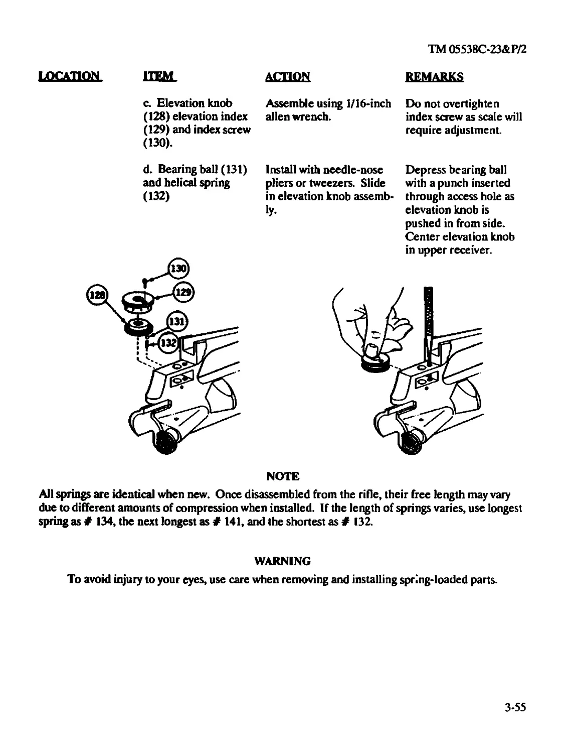
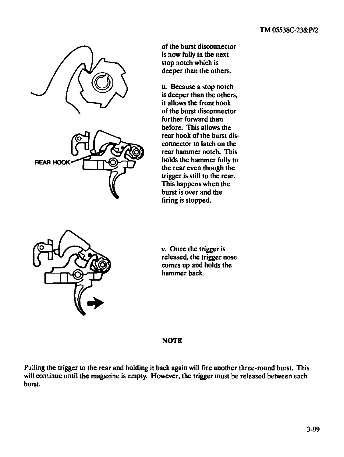
Warning!!!
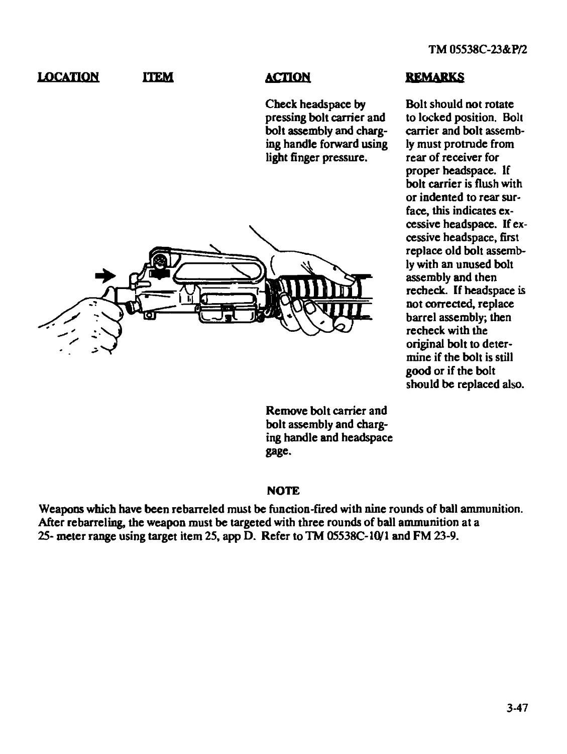
Before starting an inspection, be sure to clear the rifle. Do not actuate the trigger until the
rifle has been cleared. Inspect the chamber to ensure that it is empty and no ammunition
is in position to be chambered. Do not keep live ammunition near work area.
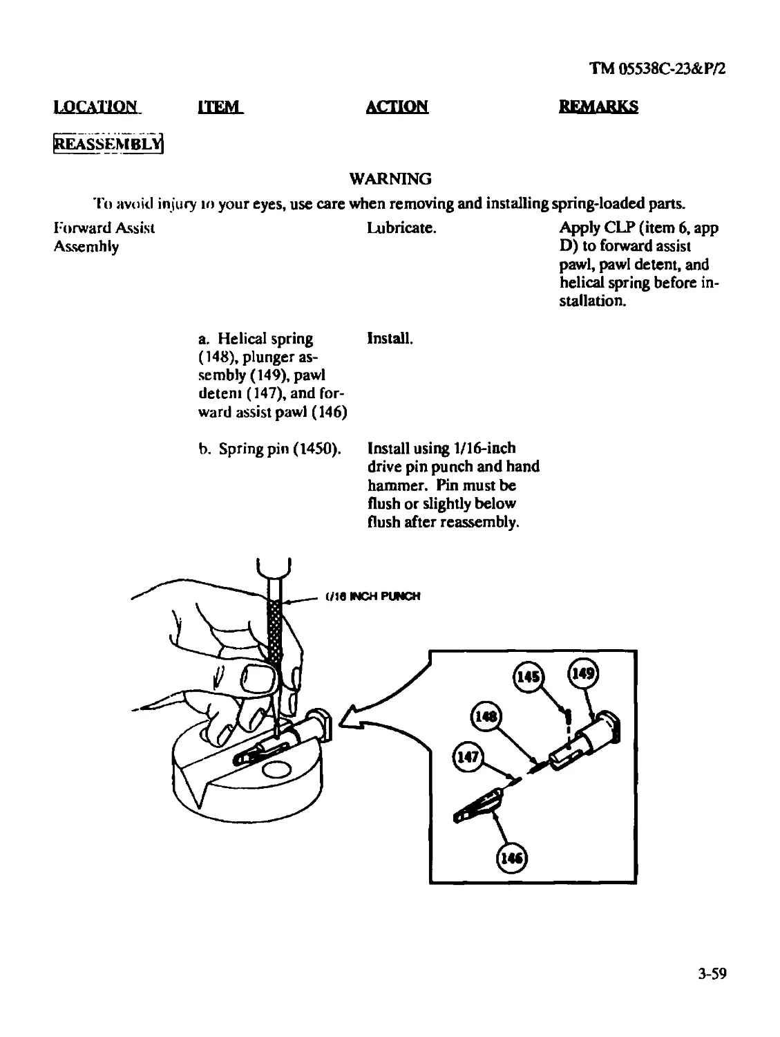
To avoid injury to your eyes, use care when removing and installing spring-loaded parts.
Do not interchange bolt assemblies or components from one weapon to another: doing so
may result in injury to, or death of, personnel.
АП M16A2 rifles must be inspected and gauged at least once annually for safety and
serviceability.
Bolt cam pin must be installed or weapon will blow up while firing the first round. If the
bolt cam pin is not installed, injury to. or death of. personnel may result.
When using carbon removing compound, P-C-ll 1, avoid skin contact. If it comes in contact
with the skin, wash off thoroughly with running water. The use of a good lanolin base
cream after exposure to compound is helpful. The use of gloves and protective equipment
is required. For additional first aid data, see FM 21-11.
ТМ 05538С-23&Р/2
Organizational and Intermediate
Maintenance
(Including Repair Parts and Special Tools List)
RIFLE, 5.56-MM, M16A2 W/E
NSN 1005-01-128-9936
Page
HOW TO USE THIS MANUAL...........................iii
CHAPTER 1 INTRODUCTION.....................................1-1
Chapter Overview.................................1-1
Section I General Information..............................1-1
Section П Equipment Description and Data...................1-2
Section П1 Principles of Operation..........................1-5
CHAPTER 2 ORGANIZATIONAL MAINTENANCE INSTRUCTIONS 2-1
Chapter Overview.................................2-1
Section I Repair Parts and Special Tools...................2-1
Section П Service Upon Receipt ............................2-1
Section Ш Organizational Preventive Maintenance Checks and
Services (PMCS) .................................2-3
Section IV Organizational Troubleshooting...................2-11
Section V Organizational Maintenance Procedures ...........2-19
Section VI Decontamination of Rifles and Arms Rooms.........2-55
CHAPTER 3 INTERMEDIATE MAINTENANCE INSTRUCTION ... .3-1
Chapter Overview.................................3-1
Section I Repair Parts and Special Tools...................3-1
Section П Service Upon Receipt.............................3-1
Section П1 Intermediate Maintenance Troubleshooting ........3 3
Section IV Intermediate Maintenance Procedures for the
M16A2 Rifle......................................3-15
Section V Preparation for Storage or Shipment..............3-102
Section VI Preembarkation Inspection of Material in Units
Slated for Overseas Movement ....................3-102
CHAPTER 4 MAINTENANCE OF AUXILIARY EQUIPMENT...............4-1
Chapter Overview.................................4-1
Section I Organizational Level Auxiliary Equipment Repair..4-1
Section П Intermediate Level Auxiliary Equipment Repair....4-11
£
ТМ 05538С-23&Р/2
Page
APPENDIX A REFERENCES.....................................A-l
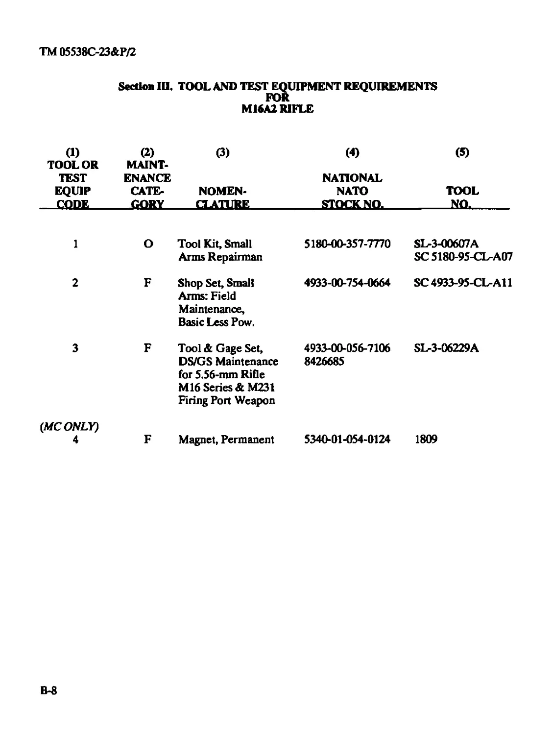
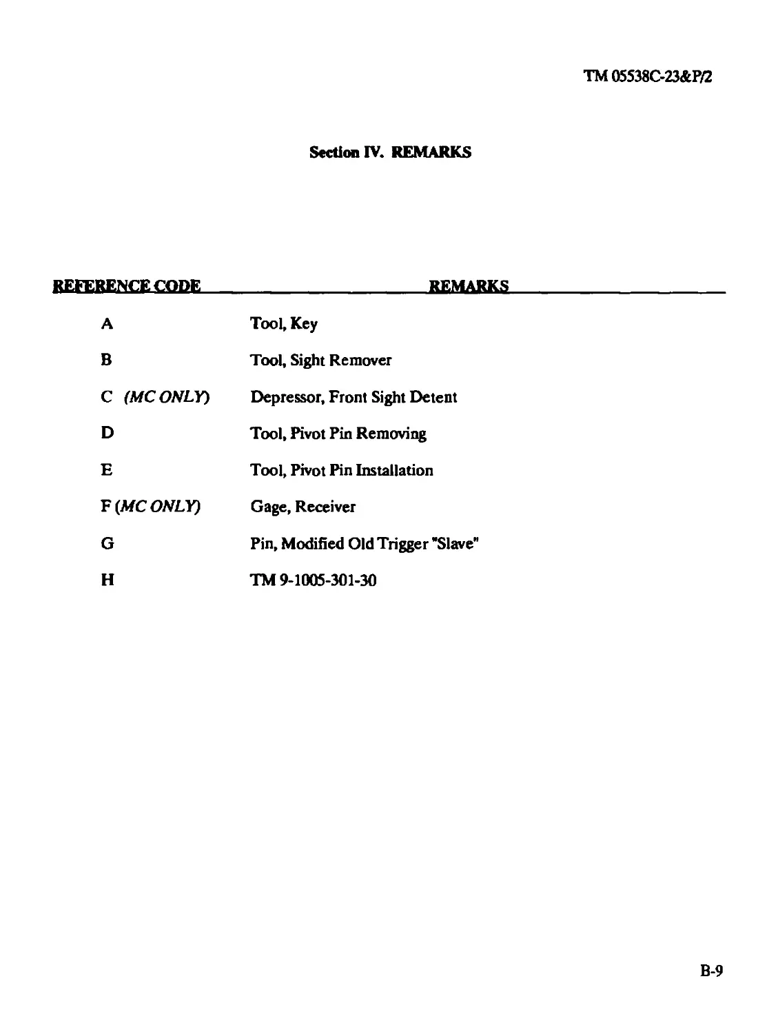
APPENDIX В MAINTENANCE ALLOCATION CHART...................B-l
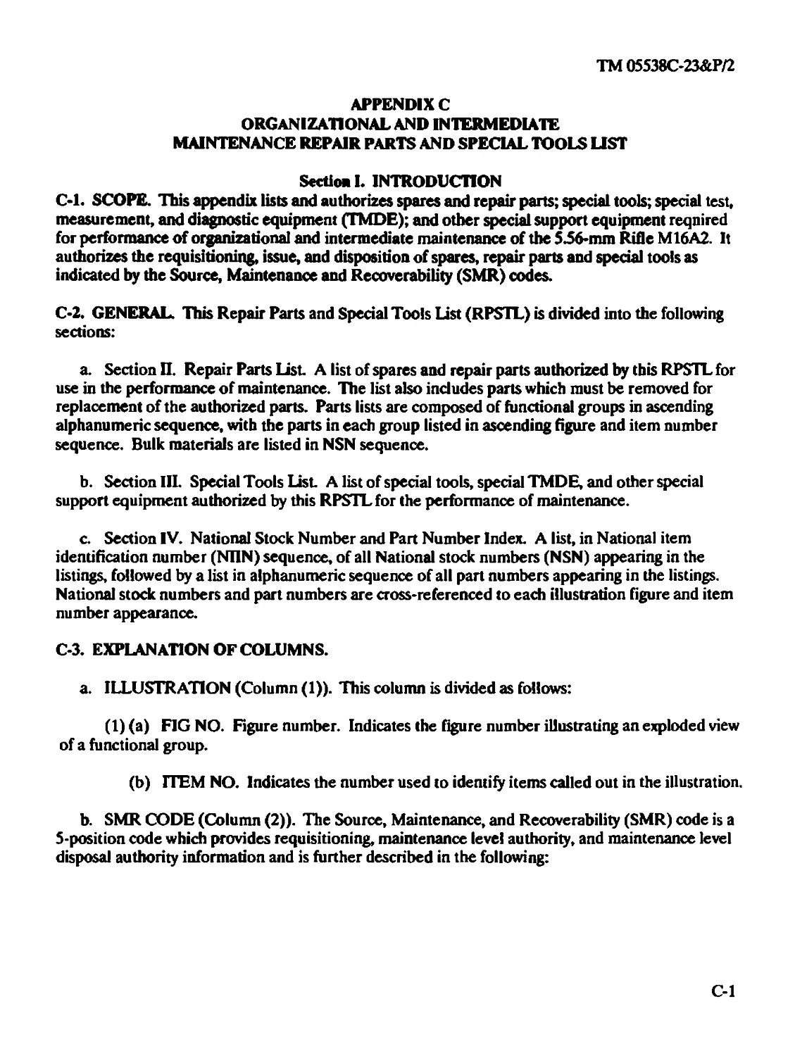
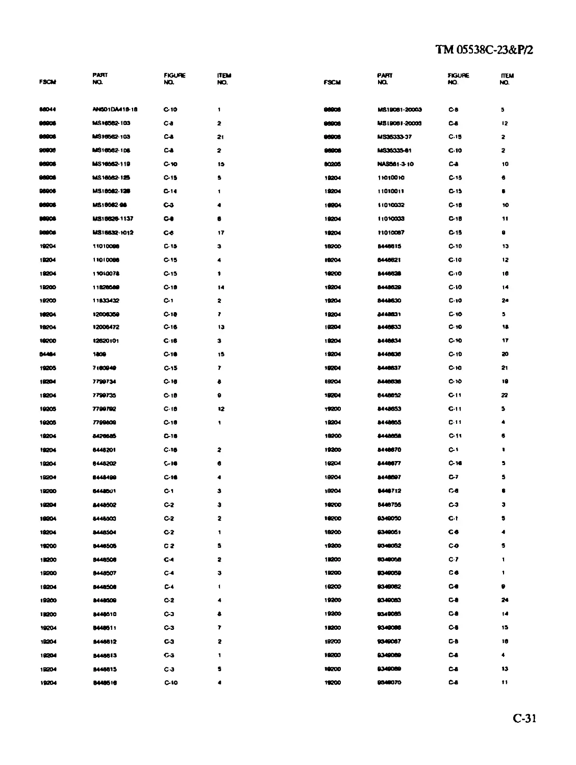
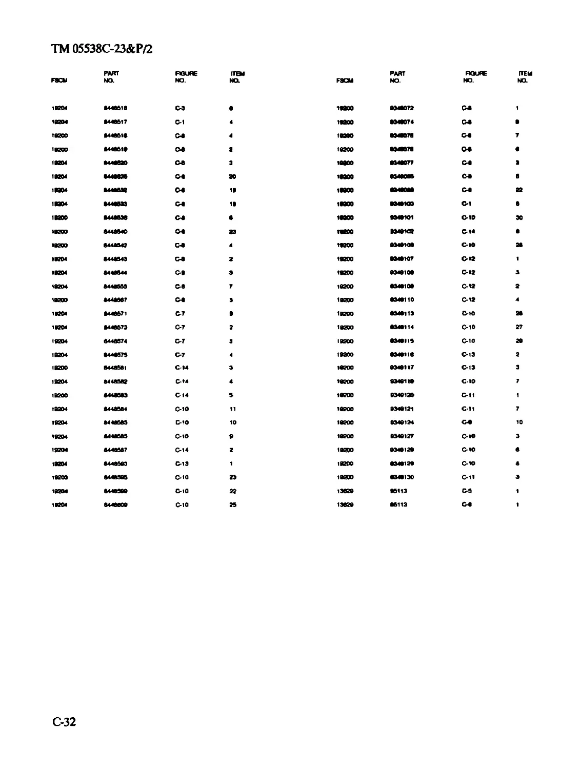
APPENDIX C REPAIR PARTS AND SPECIAL TOOLS LIST............C-l
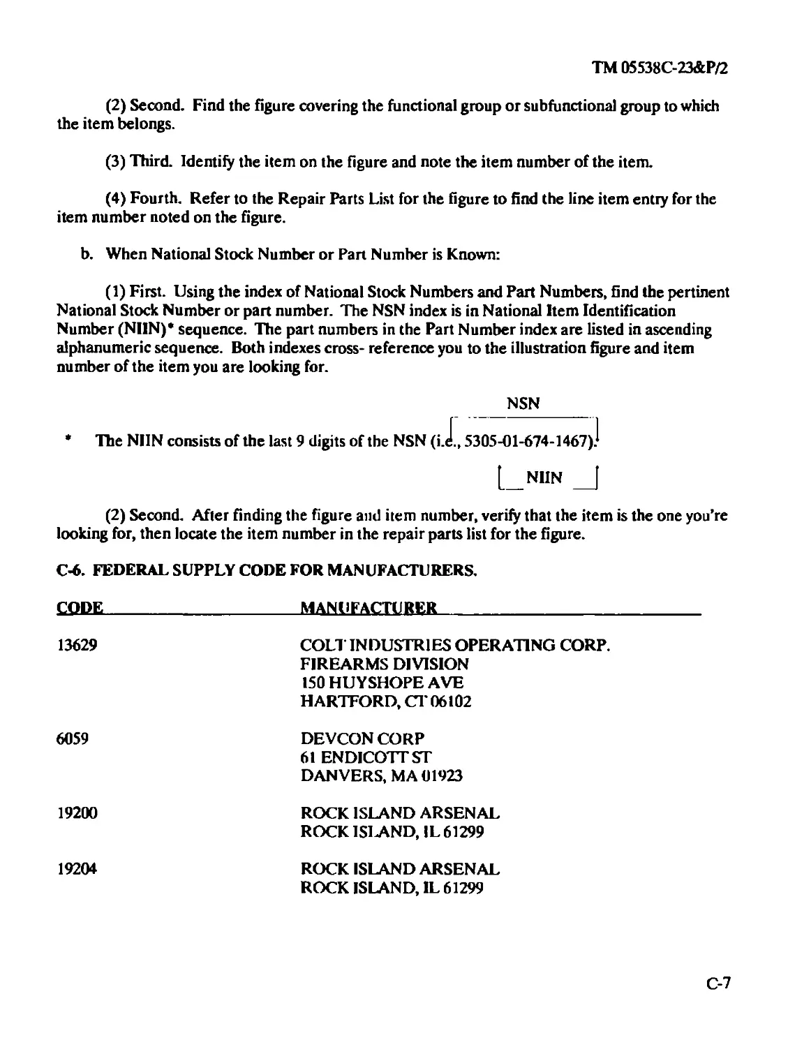
Section I Introduction...................................C-l
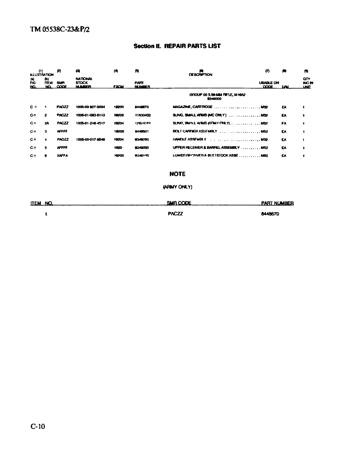
Section II Repair Parts List .............................C-10
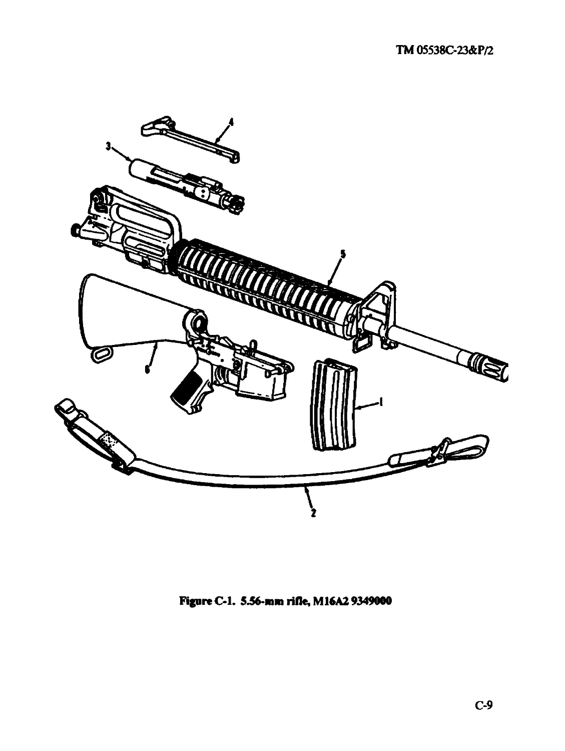
Group 00 5.56-mm Rifle M16A2 9349000 ...................C-10
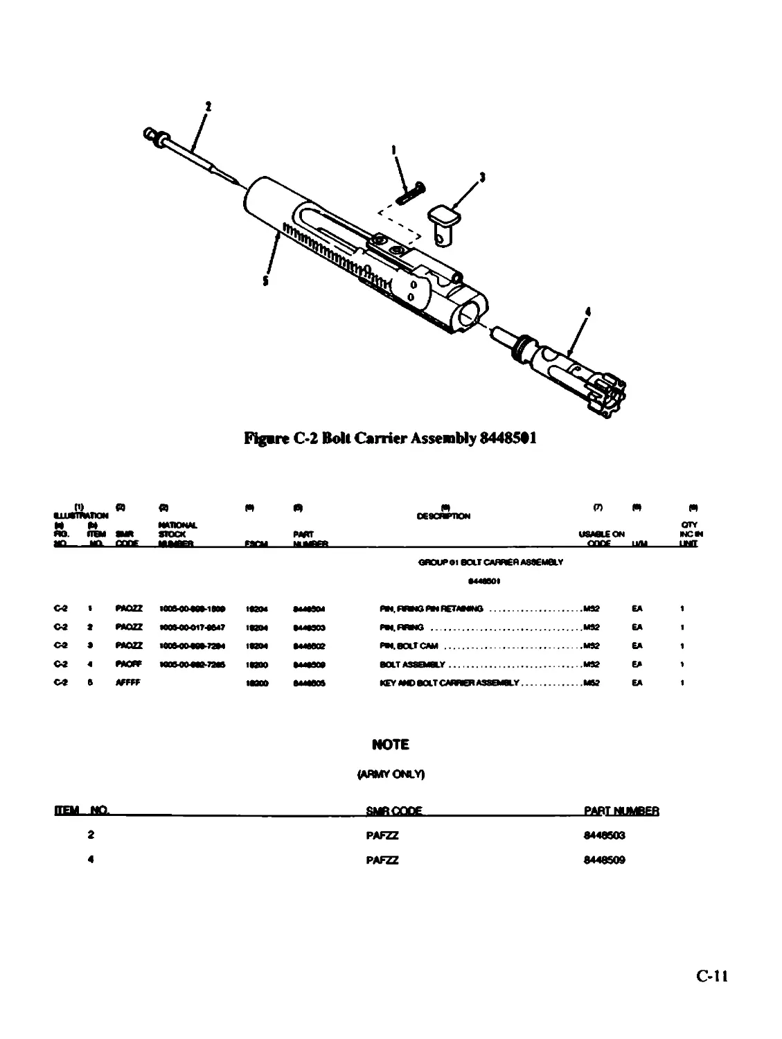
Group 01 Bolt carrier assembly 8448501..................C-ll
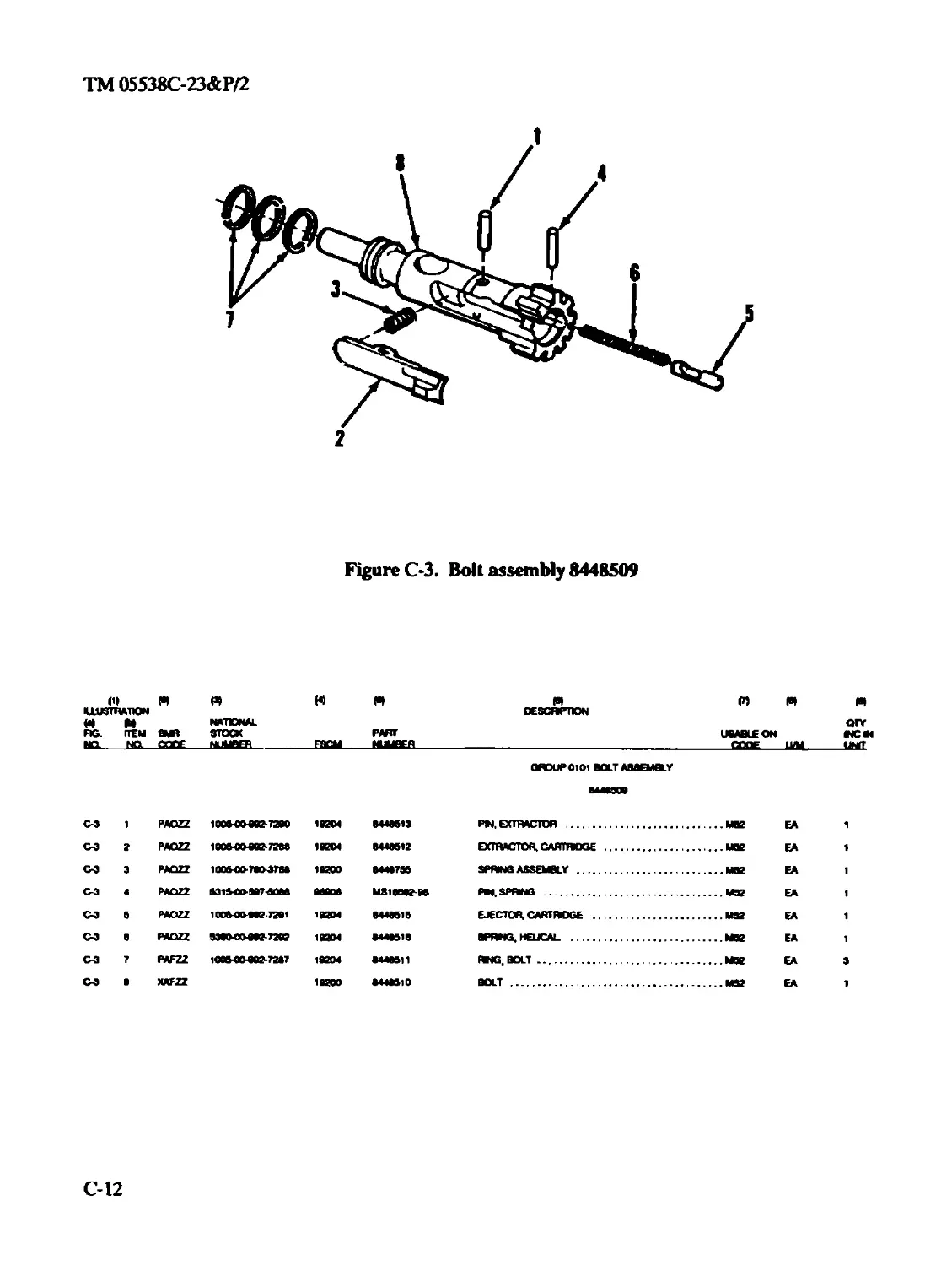
0101 Bol t assembly 8448509 ...................С-12
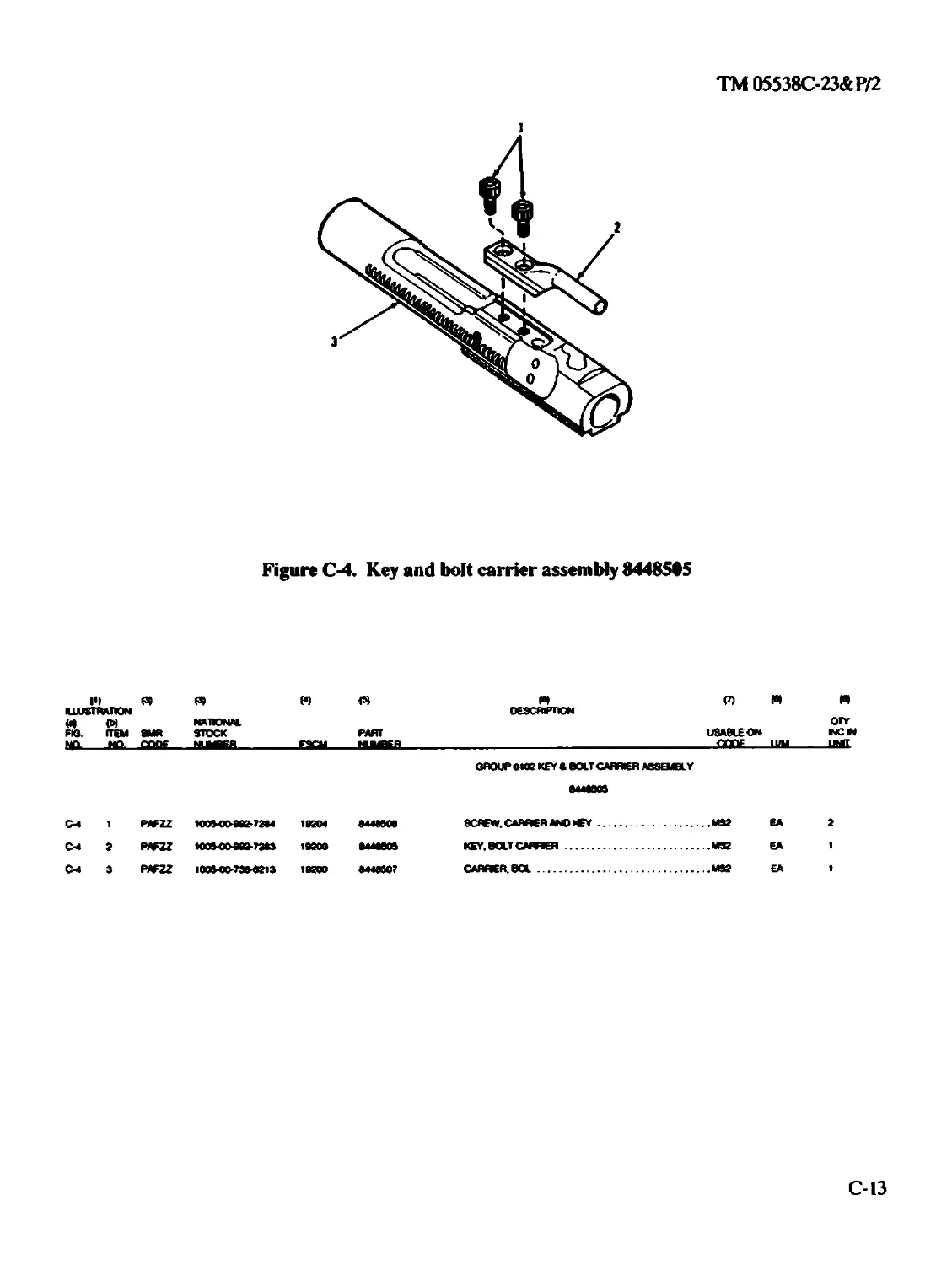
0102 Key and bolt carrier assembly 8448505 ....C-13
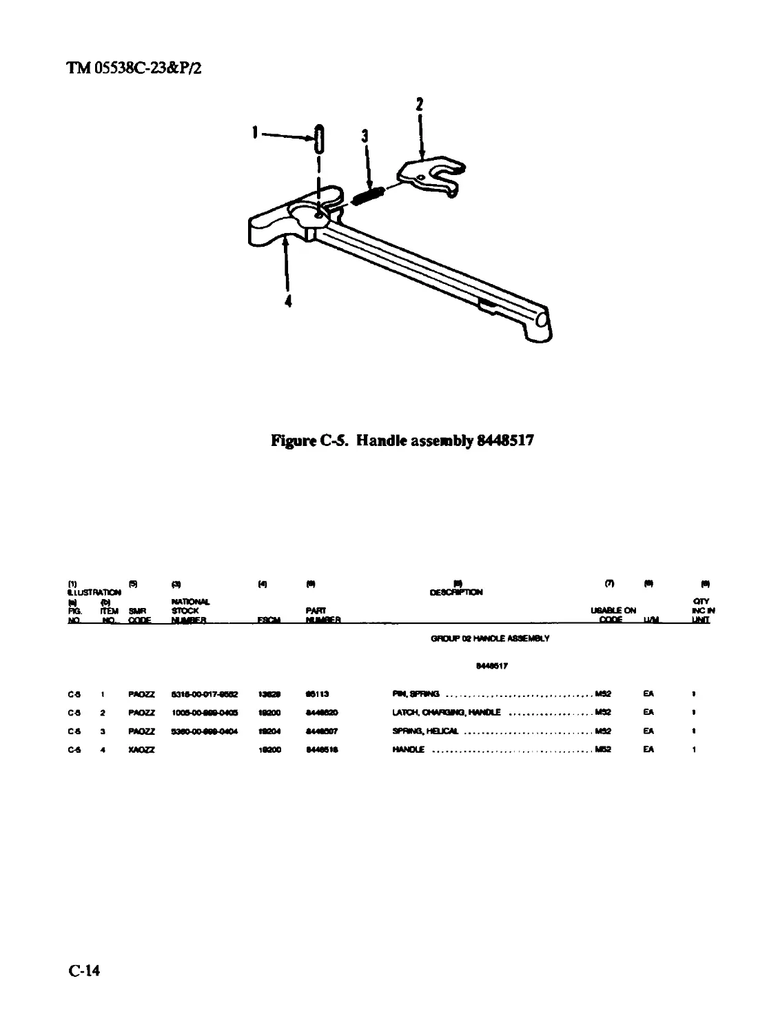
Group 02 Handle assembly 8448517 ........................C-14
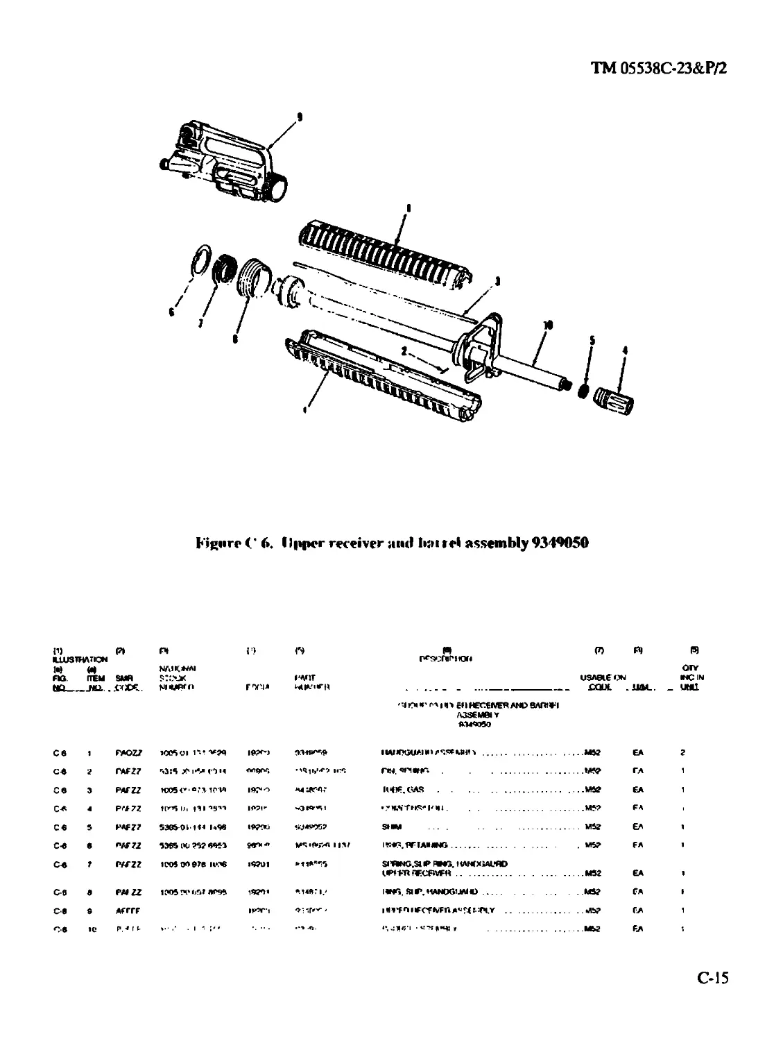
Group 03 Upper receiver and barrel assembly 9349050 .....C-15
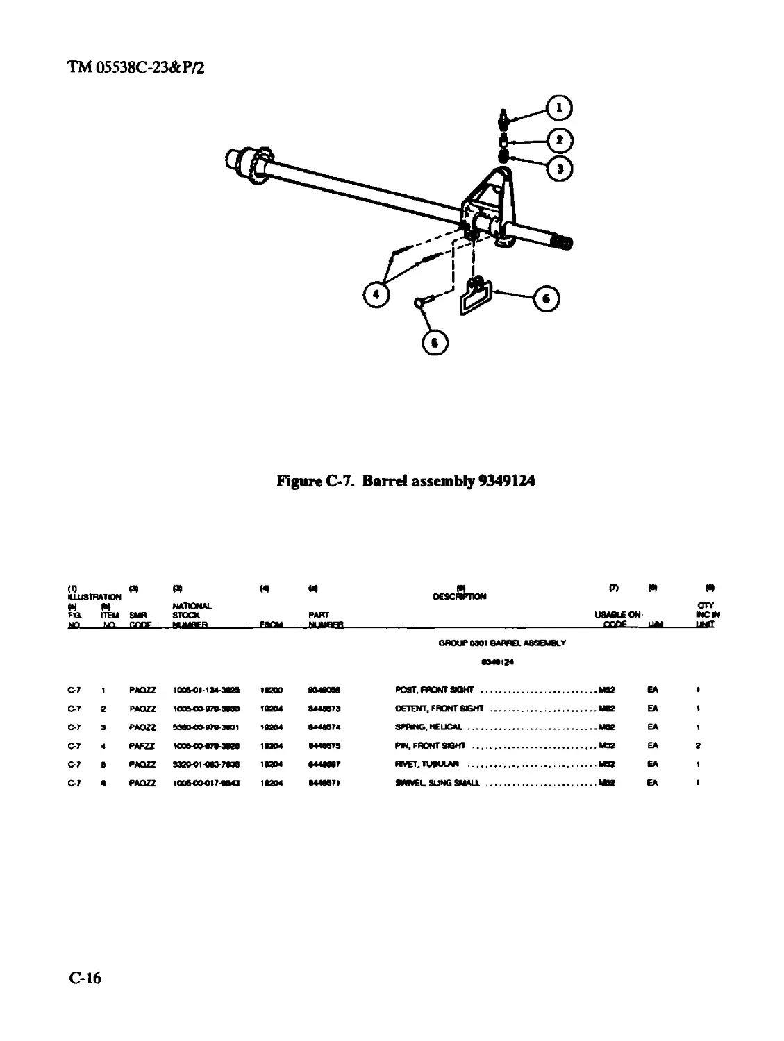
0301 Barrel assembly 9349124 ..................C-16
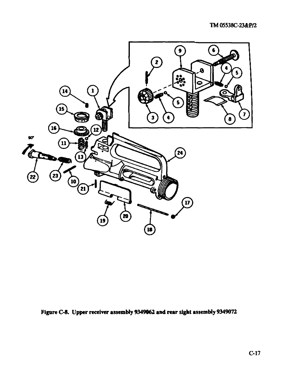
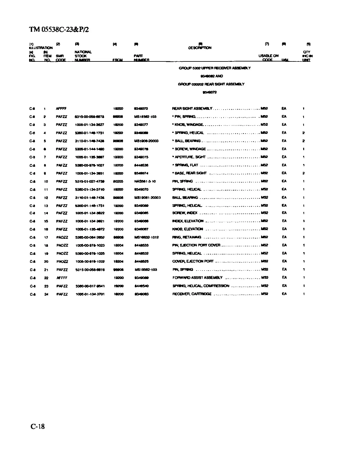
0302 and 030202 Upper receiver assembly 9349062 and rear
sight assembly 9349072.........................C-17
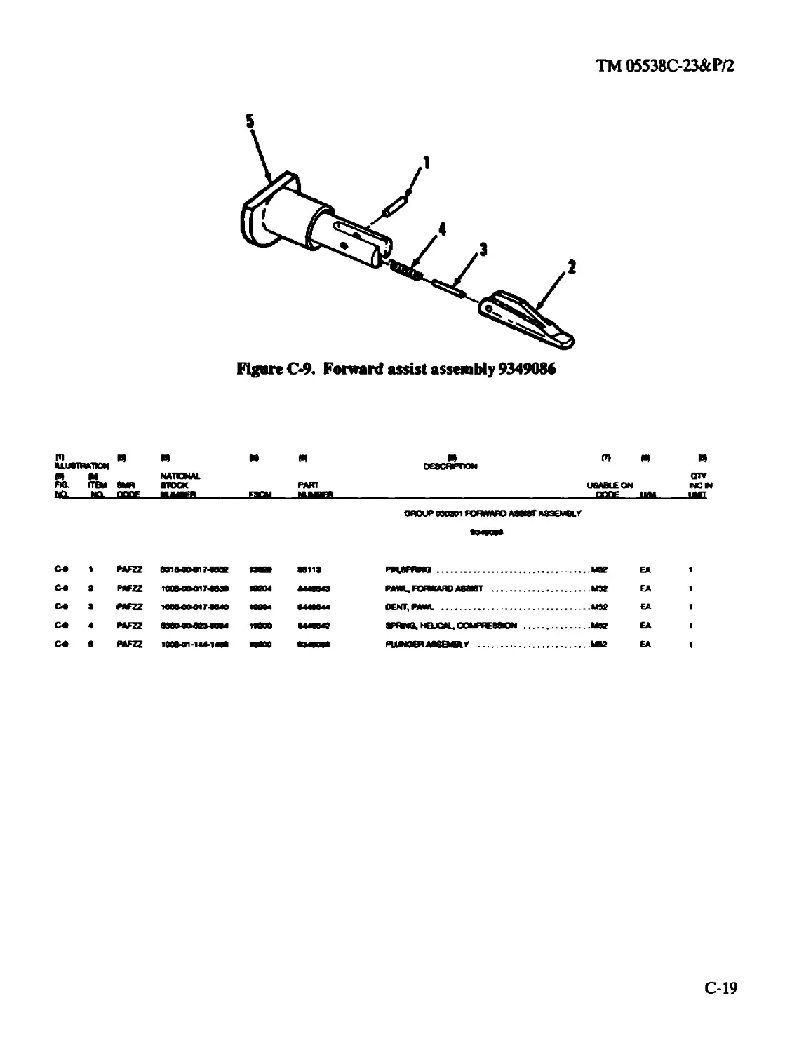
030201 Forward assist assembly 9349086 ........C-19
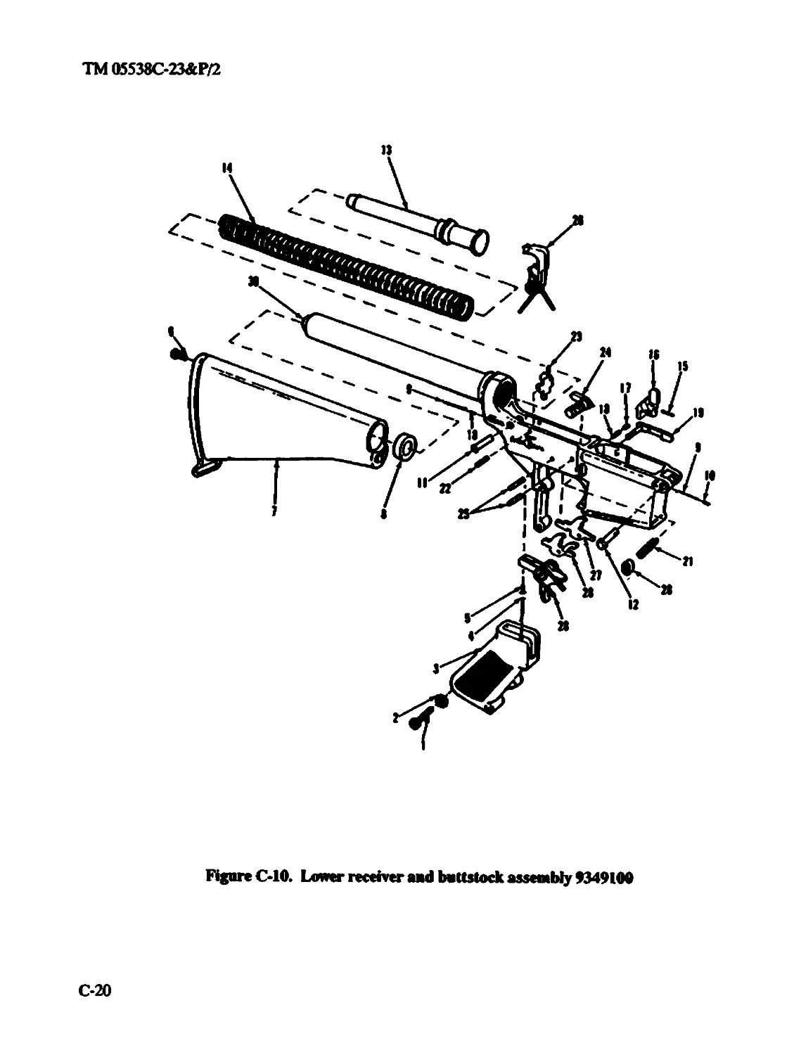
Group 04 Lower receiver and buttstock assembly 9349100 .....C-20
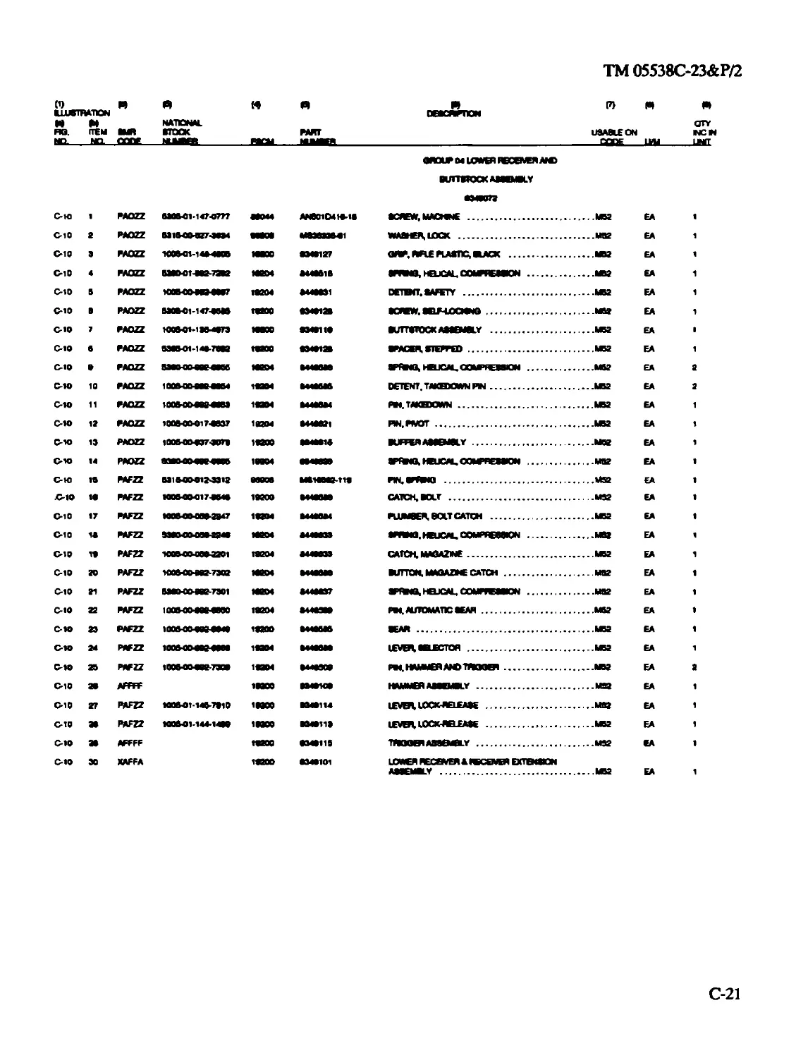
0401 Buttstock assembly 9349119 ...............C-22
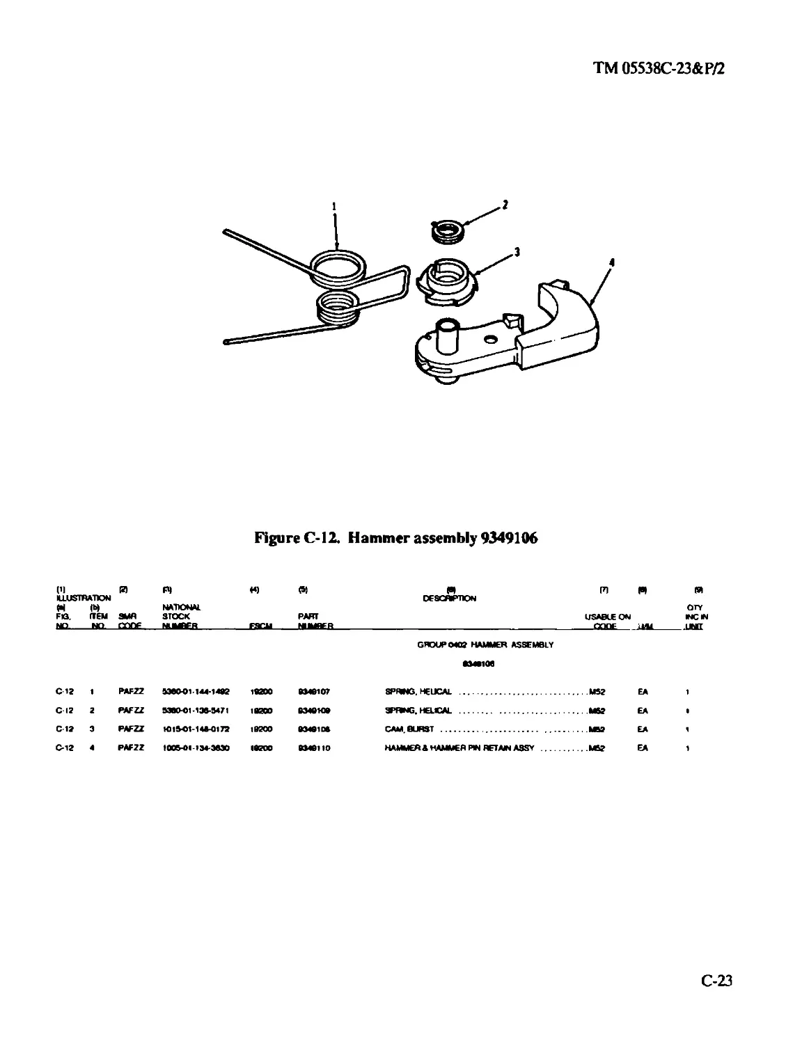
0402 Hammer assembly 9349106 ..................C-23
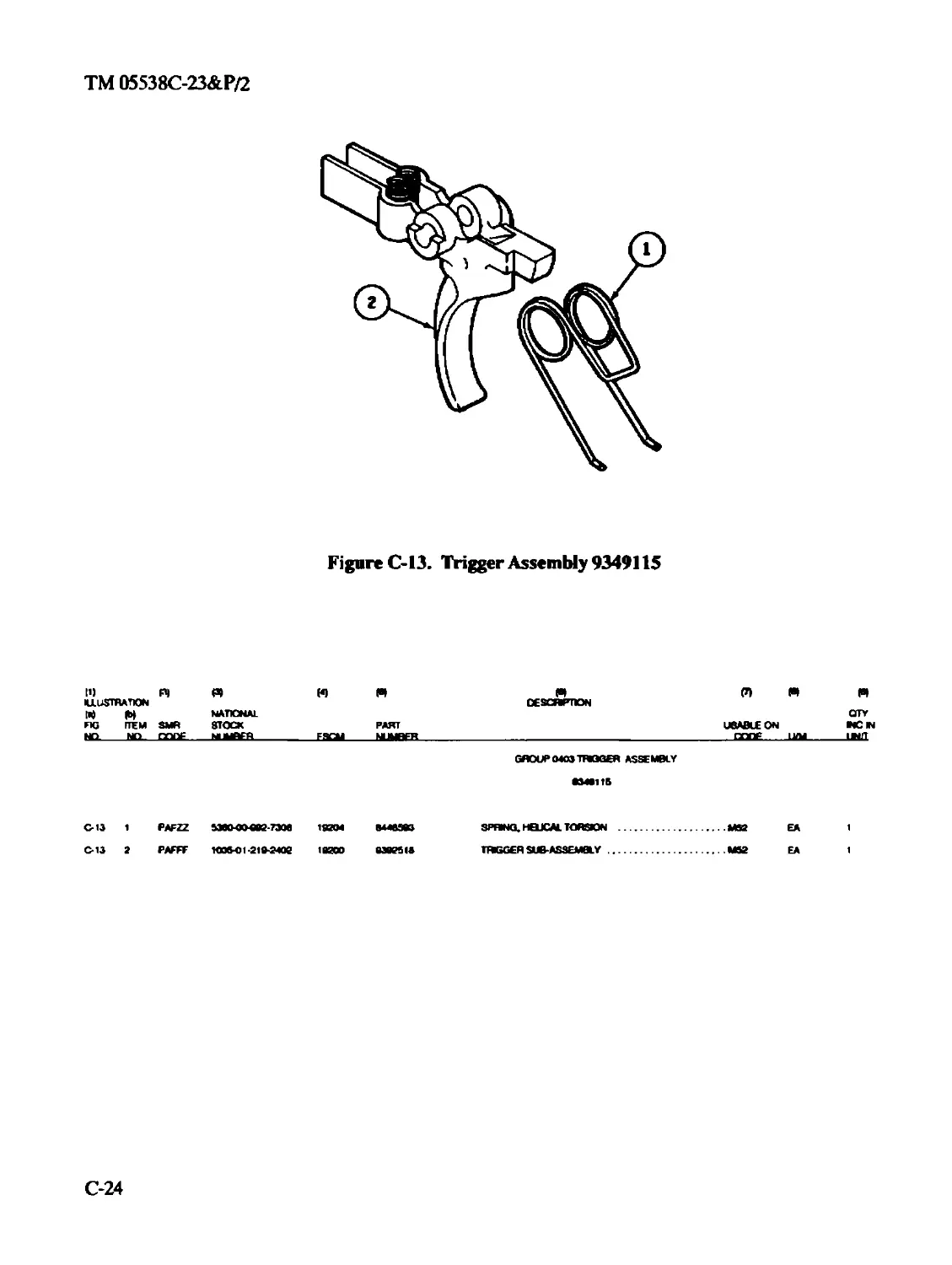
0403 Trigger assembly 9349115..................C-24
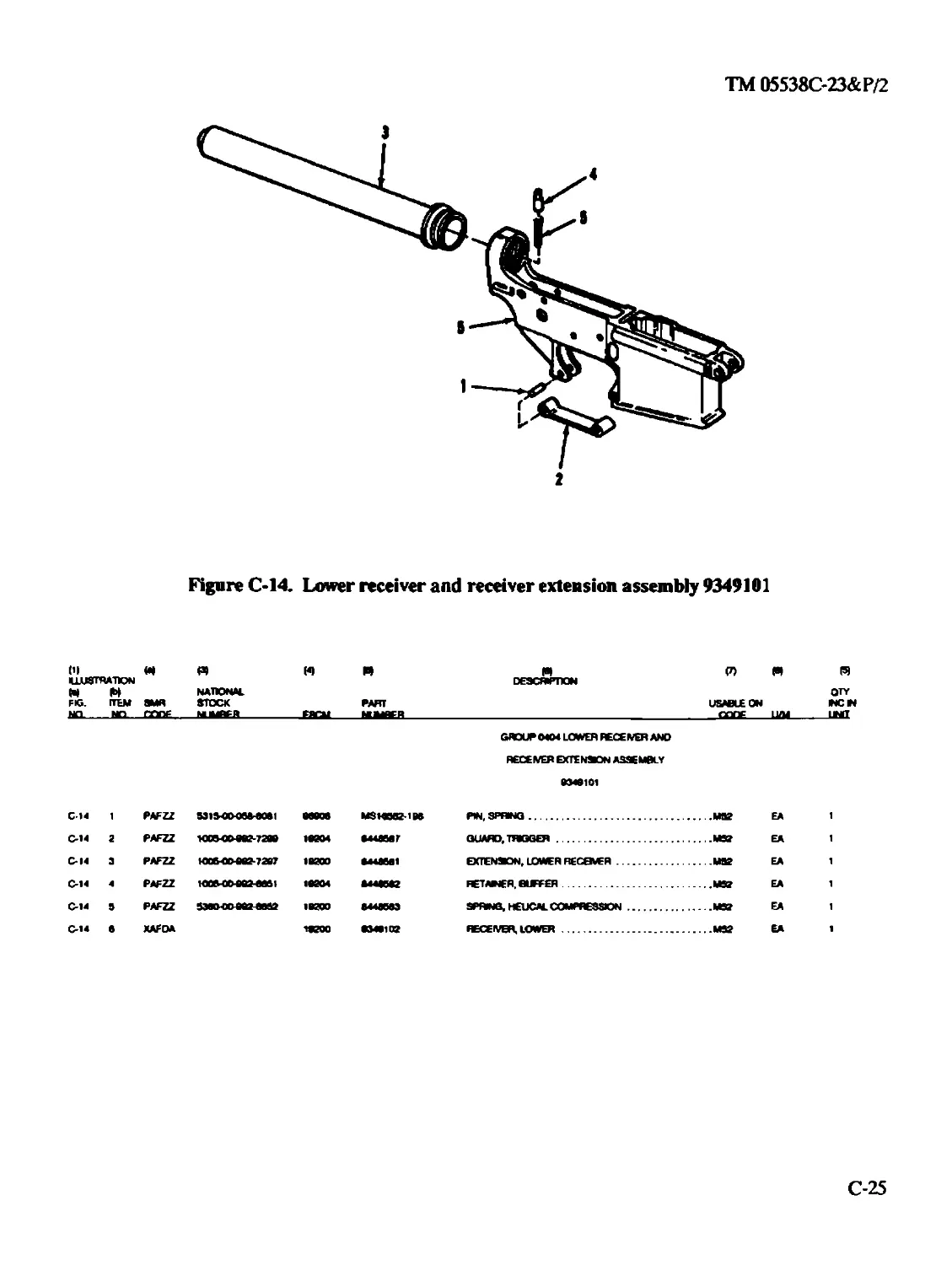
0404 Lower receiver and receiver extension sub
-assembly 9349101..............................C-25
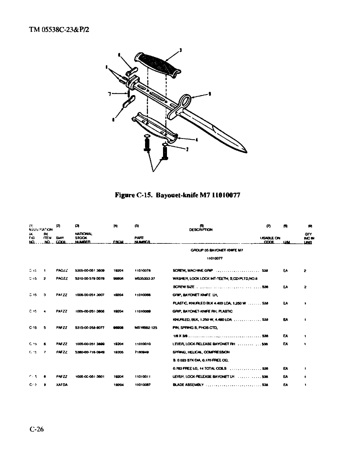
Group 05 Bayonet-Knife M7...............................C-26
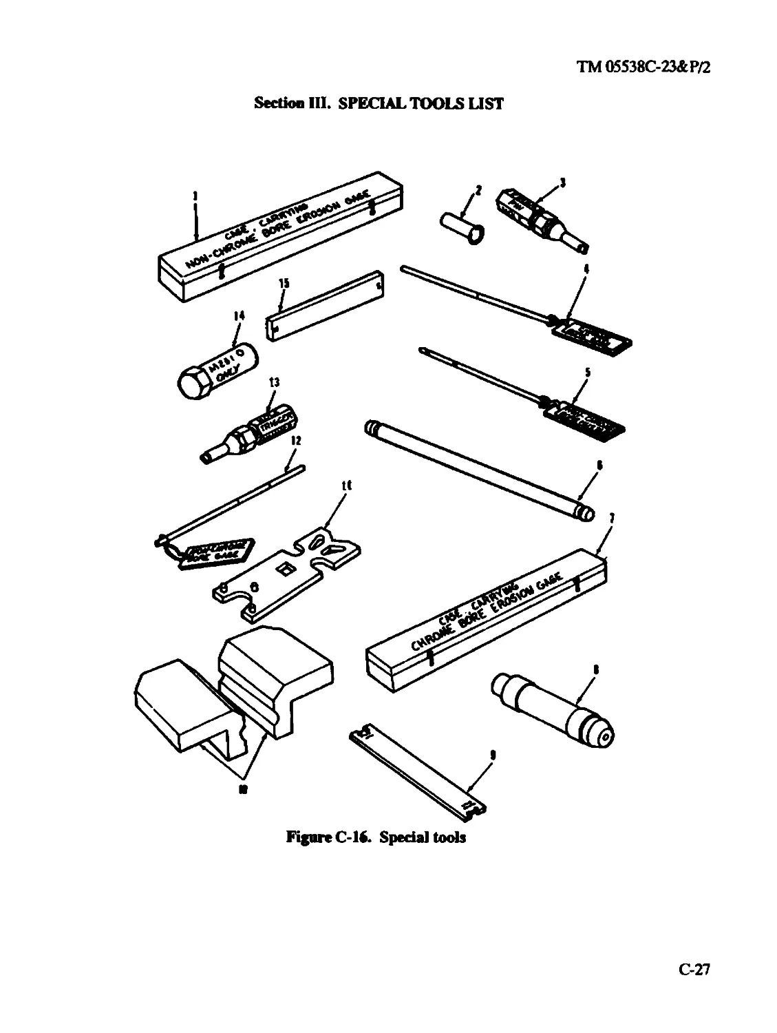
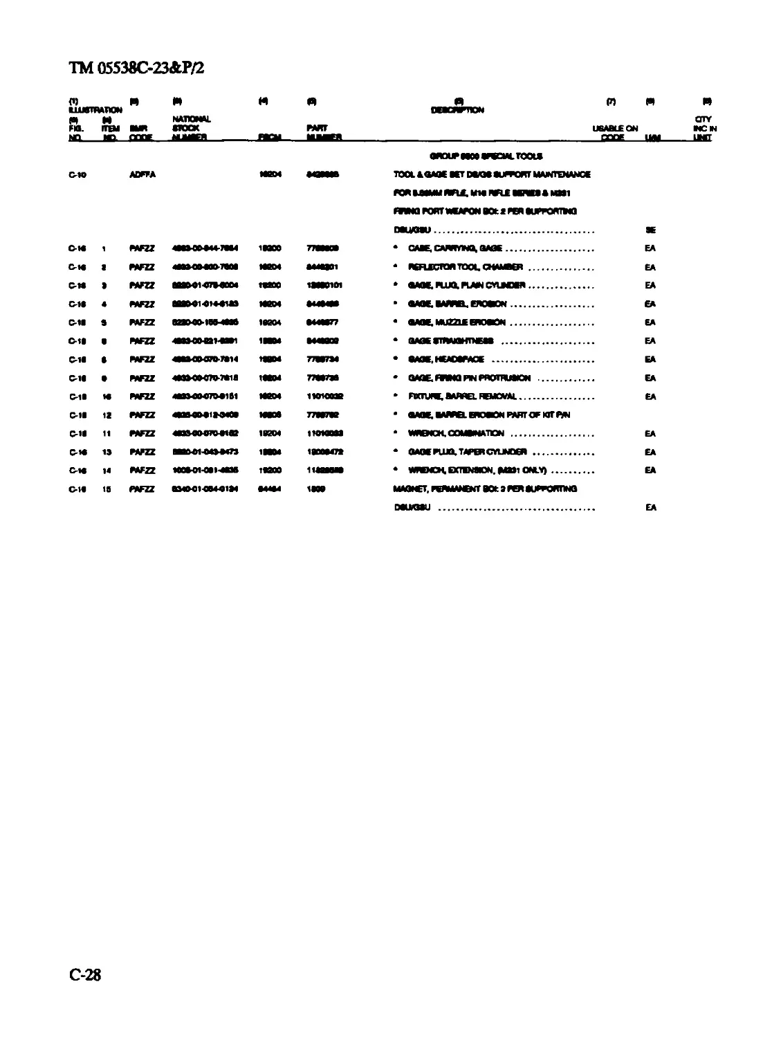
Section П1 Special Tools List ............................C-27
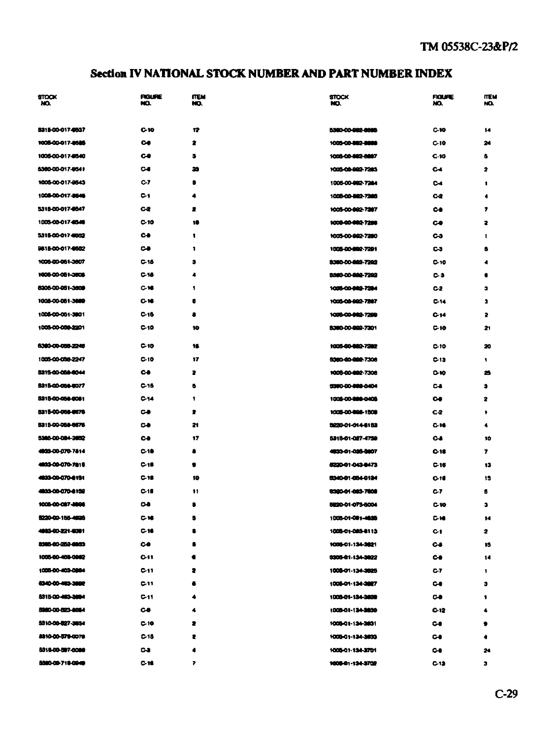
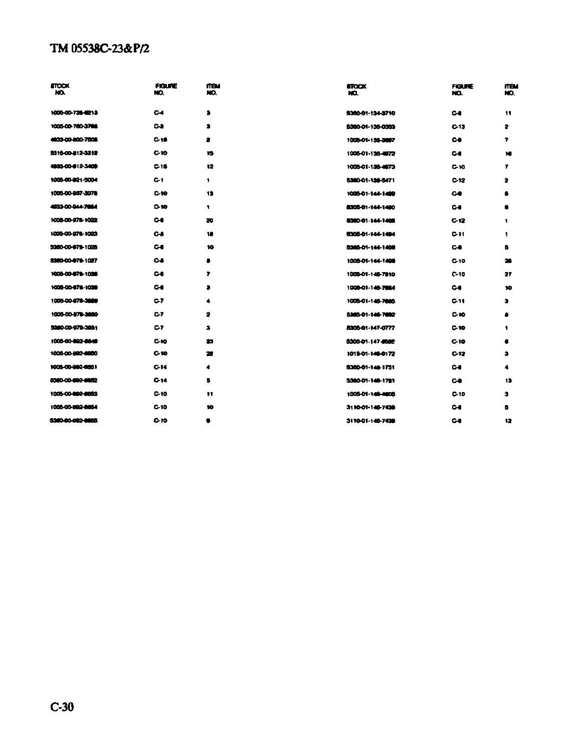
Section IV National Stock Number and Part Number Index....C-29
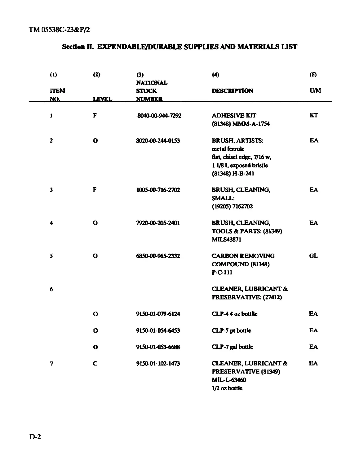
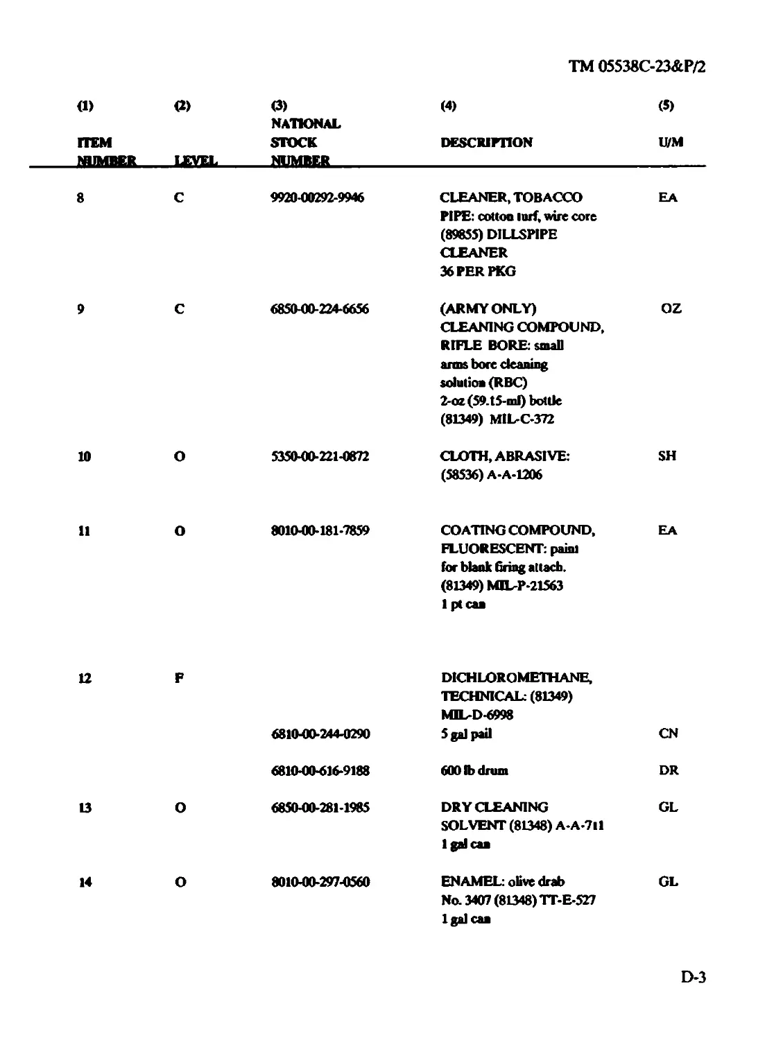
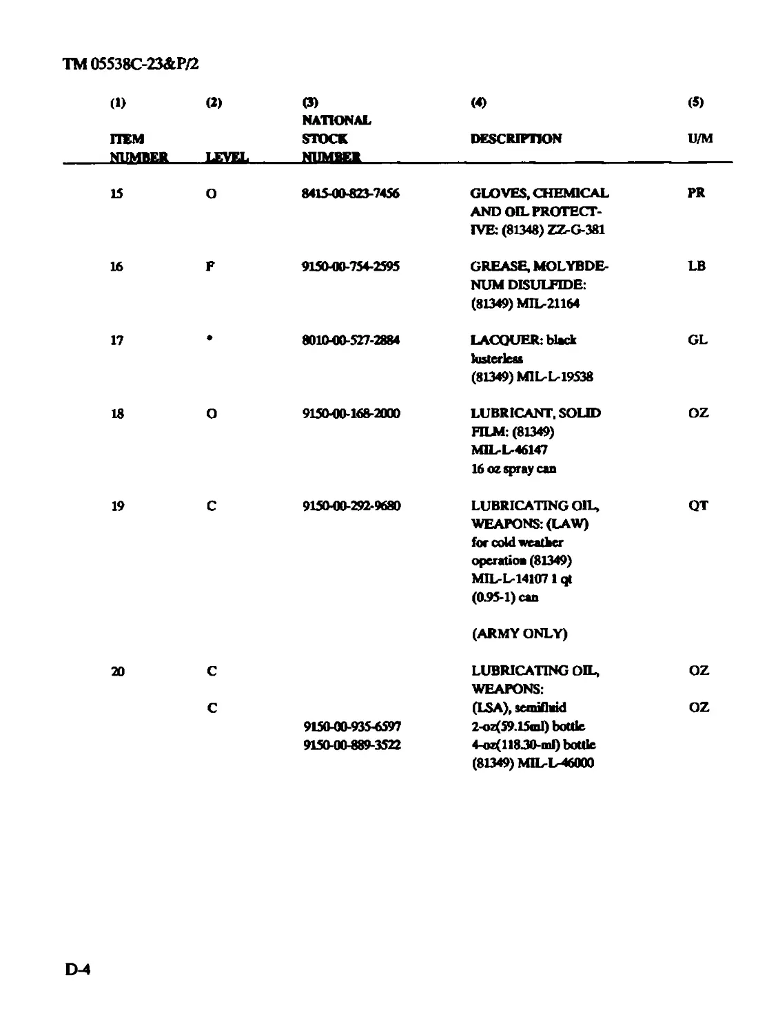
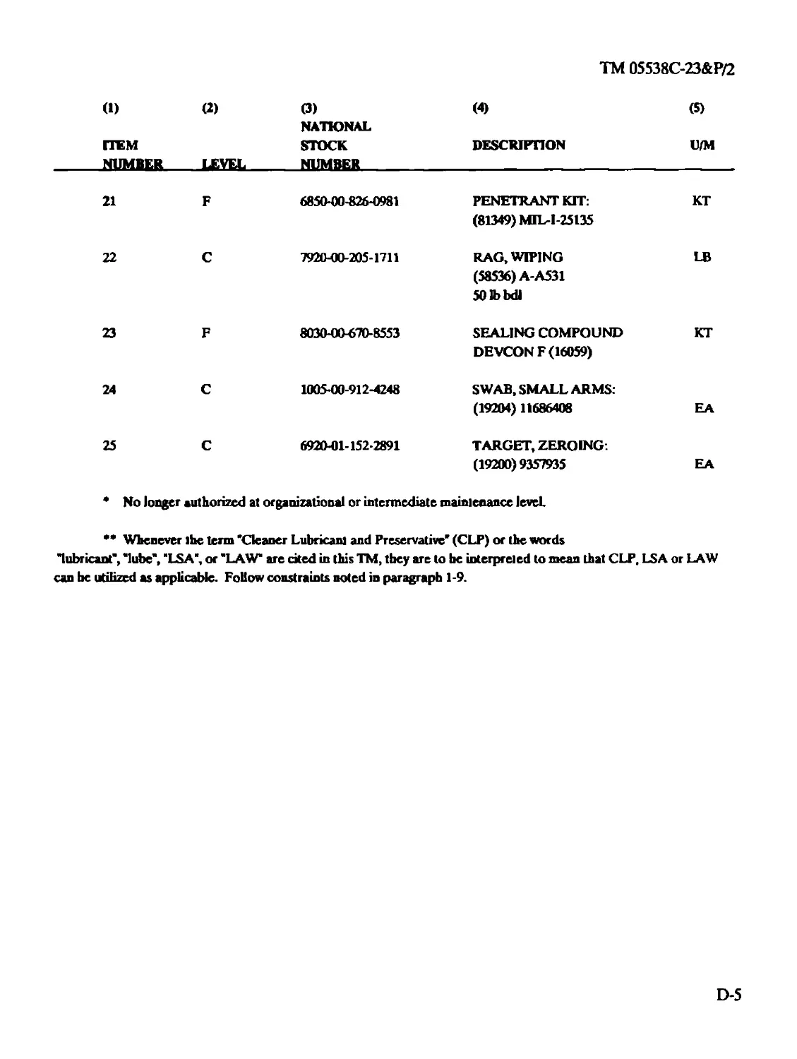
APPENDIX D EXPENDABLE/DURABLE SUPPLIES AND
MATERIALS LIST...................................................D-l
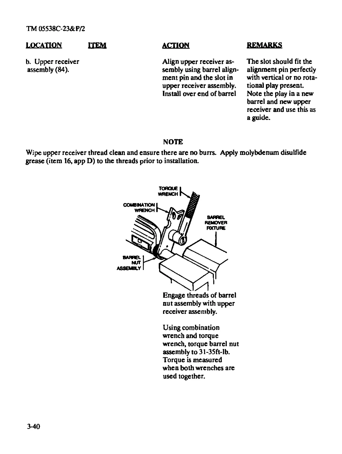
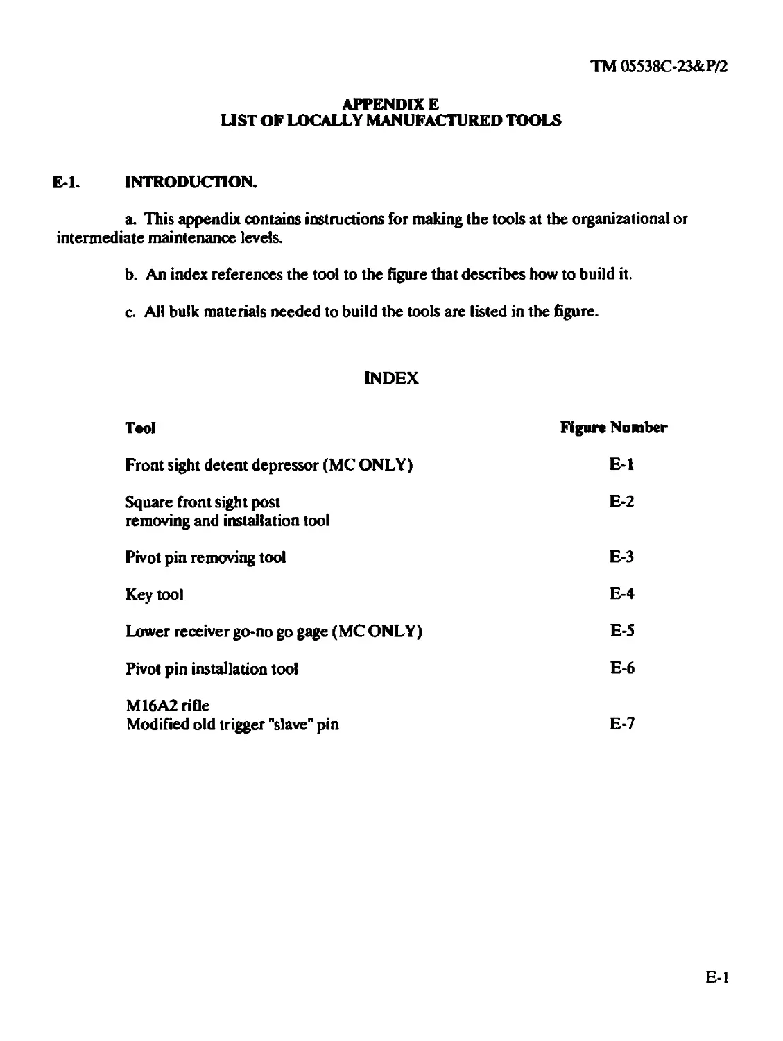
APPENDIX E ILLUSTRATED LIST OF MANUFACTURED ITEMS
MANUFACTURED ITEMS ..............................................E-l
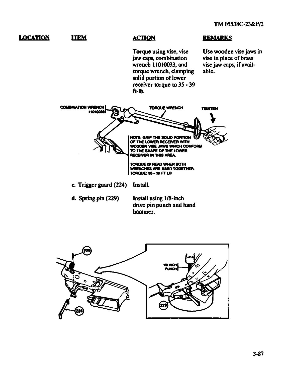
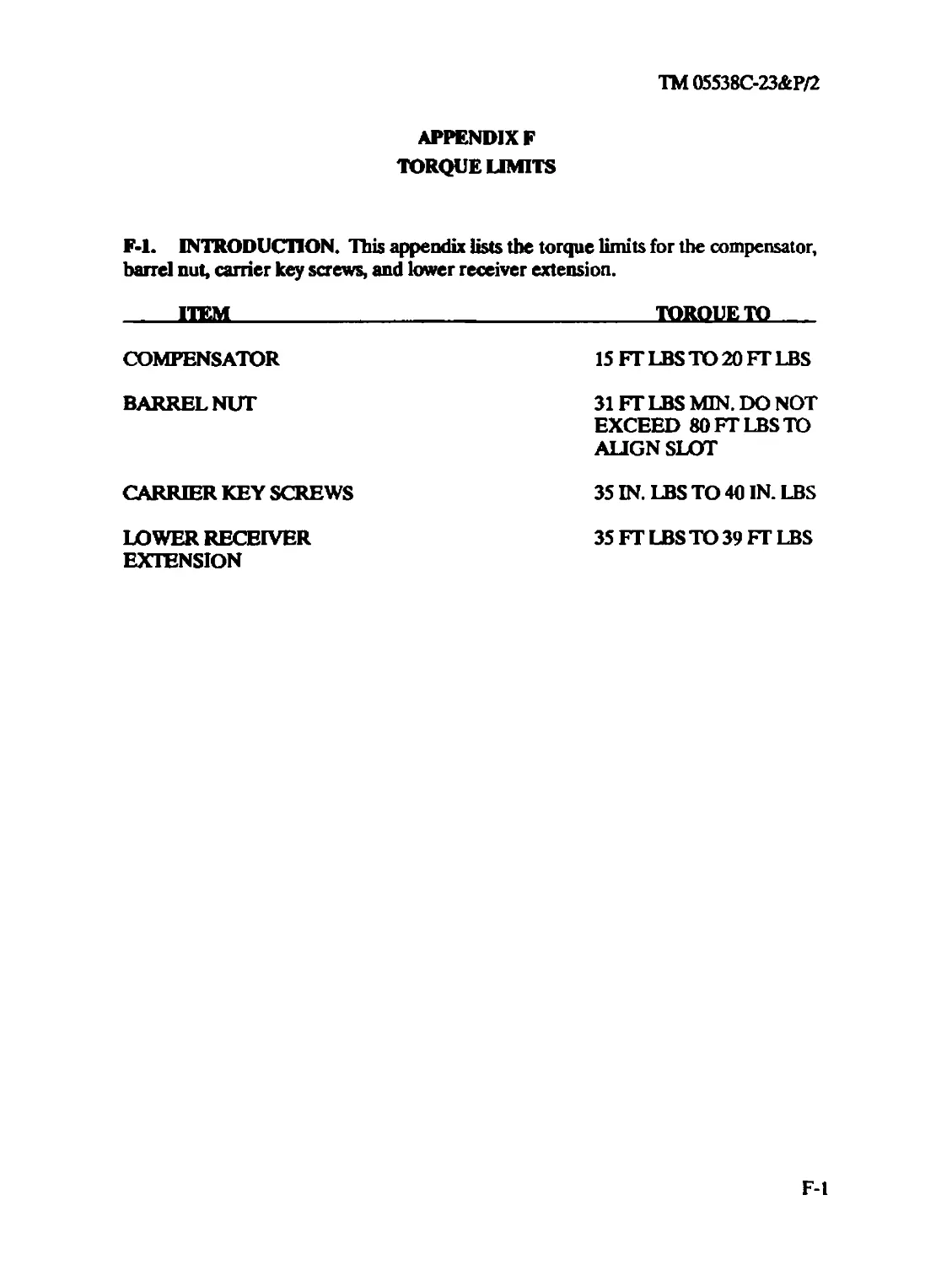
APPENDIX F TORQUE LIMITS.........................................F-l
ALPHABETICAL INDEX.............................Index-1
ТМ05538С-23&Р/2
HOW TO USE THIS MANUAL
IgeneraU
In order to use this manual efficiently, you need to know:
1. Illustrations for the maintenance procedures show only those parts affected by the
operation being performed.
2. Whenever the male gender is mentioned in the manual (i.e., crewmen, repairman), it
also pertains to females.
Indexes!
This manual is organized to help you find the information you need quickly. There are several use-
ful indexes and lists.
1. Table of Contents. Lists, in order, all chapters, sections, and appendices, gives page
references.
2. Nomenclature Cross-Reference List
3. Chapter Overviews. A summary of the chapter content is located at the
beginning of each chapter.
4. Symptom Index. Located before the troubleshooting table in each maintenance chapter, they
list possible rifle malfunctions and the page which describes the troubleshooting procedures.
5. Alphabetical Index. Located at the end of the manual It is a subject-to-page list of
everything in the manual
REPORTING ERRORS AND RECOMMENDING IMPROVEMENTS!
You can help improve this manual. If you find any mistakes, or if you know of a way to improve
the procedures, please let us know. MARINE CORPS USERS, submit NAVMC10772 (Recom-
mended Changes to Technical Publications) to: Commanding General, Marine Corps Logistics
Base (Code 850) Albany, Georgia 31704- 5000. A reply will be furnished direct to you. ARMY
USERS, mail your letter, DA Form 2028 (Recommended Changes to Publications and Blank
Forms), or DA Form 2028-2 direct to: Commander, US Army Armament, Munitions and Chemi-
cal Command, ATTN: AMSMC-MAS, Rock Island, IL 61299-6000. A reply will be furnished to
you.
[REPORTING EQUIPMENT IMPROVEMENT RECOMMENDATION (EIRJl
If your rifle needs improvement, let us know. Send us an EIR. You, the user, are the only one
who can tell us what you don’t tike about your equipment Let us know why you don't like the
design. MARINE CORPS PERSONNEL, submit EIRs in accordance with MCO 1650.17.
ARMY PERSONNEL, submit a SF 368 (Quality Deficiency Report). Mail to Commander, US
ill
ТМ 05538С-23&Р/2
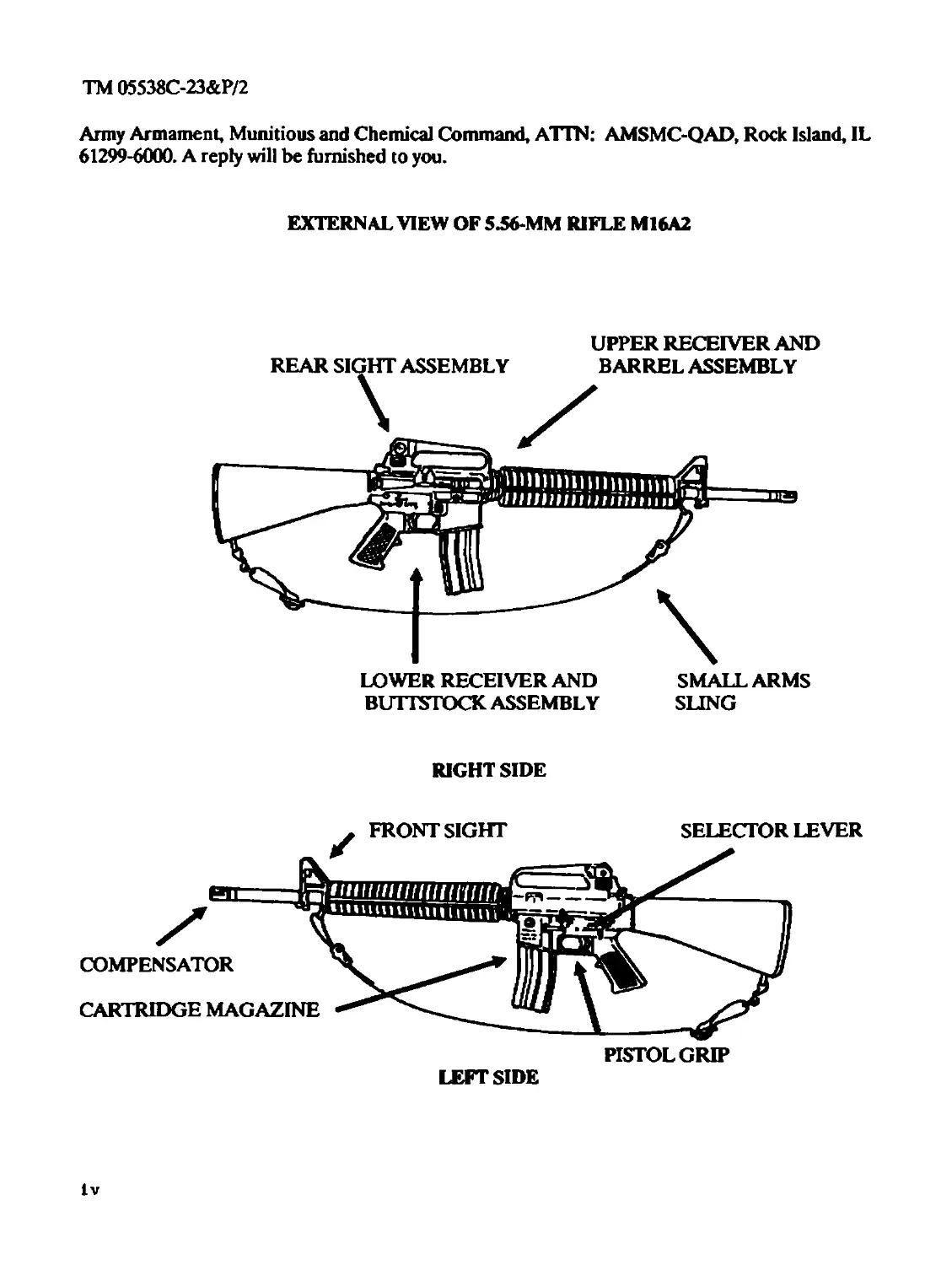
Army Armament, Munitions and Chemical Command, A11N: AMSMC-QAD, Rock Island, IL
61299-6000. A reply will be furnished to you.
EXTERNAL VIEW OF 5.56-MM RIFLE M16A2
UPPER RECEIVER AND
LOWER RECEIVER AND
BUTTSTOCK ASSEMBLY
SMALL ARMS
SLING
RIGHT SIDE
lv
ТМ 05538С-23&Р/2
CHAPTER!
INTRODUCTION
CHAPTER OVERVIEW
This chapter contains general information, equipment description and data, and principles of
operation for the M16A2 rifle.
Section I. GENERAL INFORMATION
1-1. SCOPE.
a. Type of Manual. Organizational and Intermediate Maintenance.
b. Model Number and Equipment Name. 5.56-mm Rifle M16A2.
c. Purpose of Equipment. Provides personnel an offensive/defensive capability to engage
targets with small arms fire.
1-2. MAINTENANCE FORMS, RECORDS, AND REPORTS.
Refer to: TM 4700- 15/1 (Marine Corps), DA PAM 738-750, (ARMY).
1-3. DESTRUCTION OF MATERIEL TO PREVENT ENEMY USE.
Refer to: TM 750-244-7.
1-4. PREPARATION FOR STORAGE OR SHIPMENT.
Refer to: MCO P4450.7 (Marine Corps), TM 740-90-1 (ARMY).
1-5. NOMENCLATURE, CROSS-REFERENCE LIST.
Common Name/Nomenr.lature
Action Spring/Compresrion Helical Spring (8448629)
Bolt Catch Spriag/Compression Helical Spring (8448633)
Burst Disconnector/Lock-Release Lever (9349113)
Cam Clutch Spring/Helical Spring (9349109)
Charging Handle Assembly/Handle Assembly (8448517)
Disconnector Springp/Compression Helical Spring (9349116)
Ejector Spring/Helical Spring (8448516)
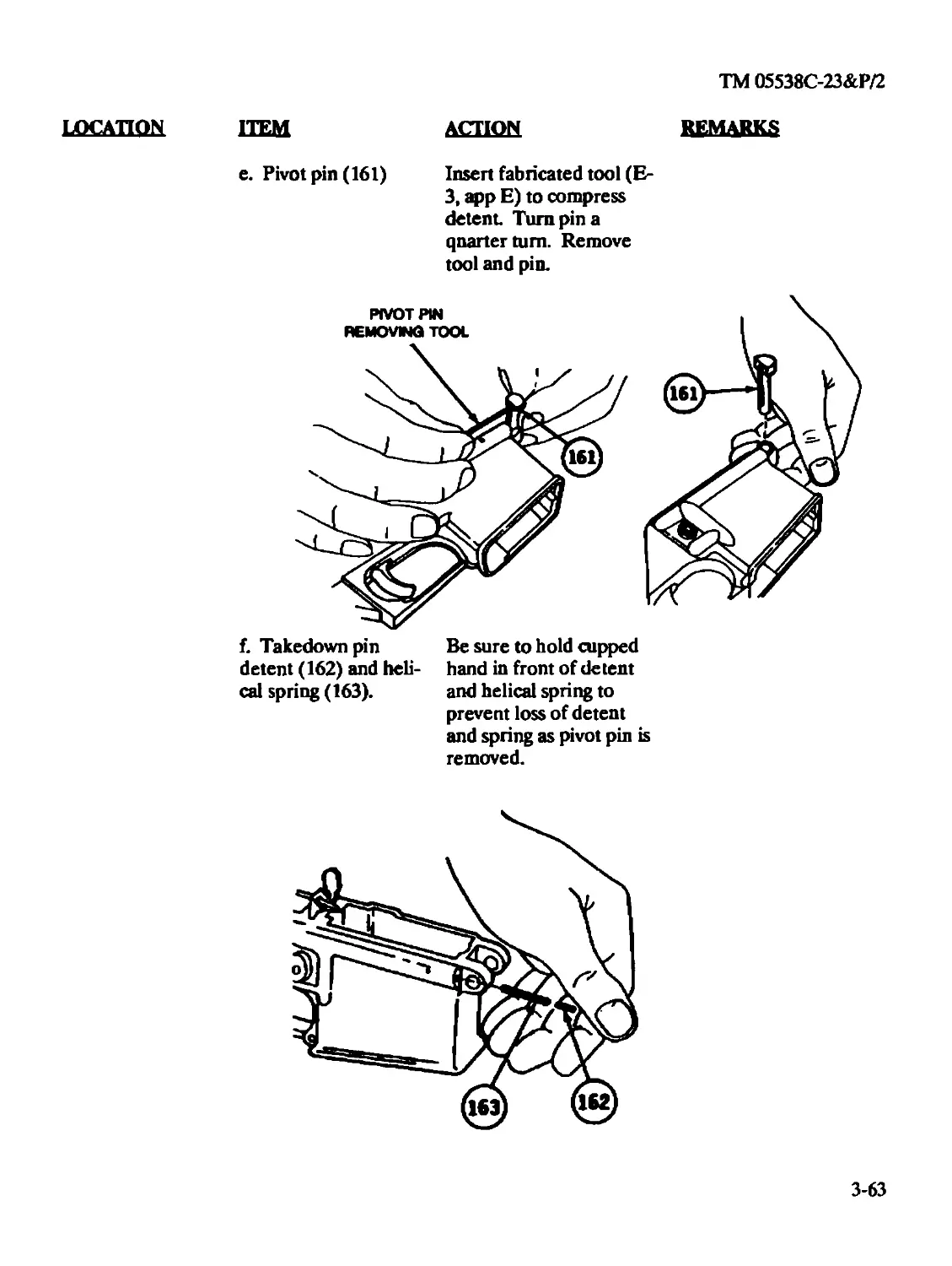
Extractor Spring Assembly/Spring Assembly (8448755)
Hammer Spring/Torsion Helical Spring (9349107)
Magazine Catch Spring/Compression Helical Spring (8448637)
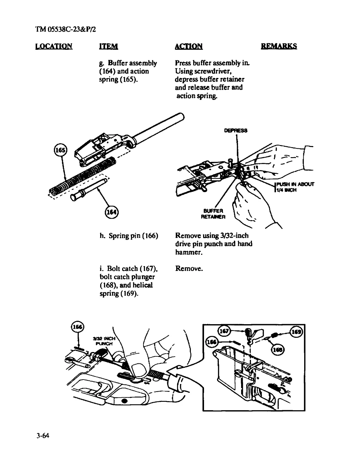
Peel Washer/SWm (9349051)
Pivot Pin Detent/Takedown Pin Detent (8448585)
Rifle Barrel AssenMy/Bamel Assembly (9349124)
Semiautomatic Disconnector/Lock-Release Level (9349114)
Trigger Spring/Torsion Helical Spring (8448593)
Weapon/Ri/le, 5.56-mm, M16A2
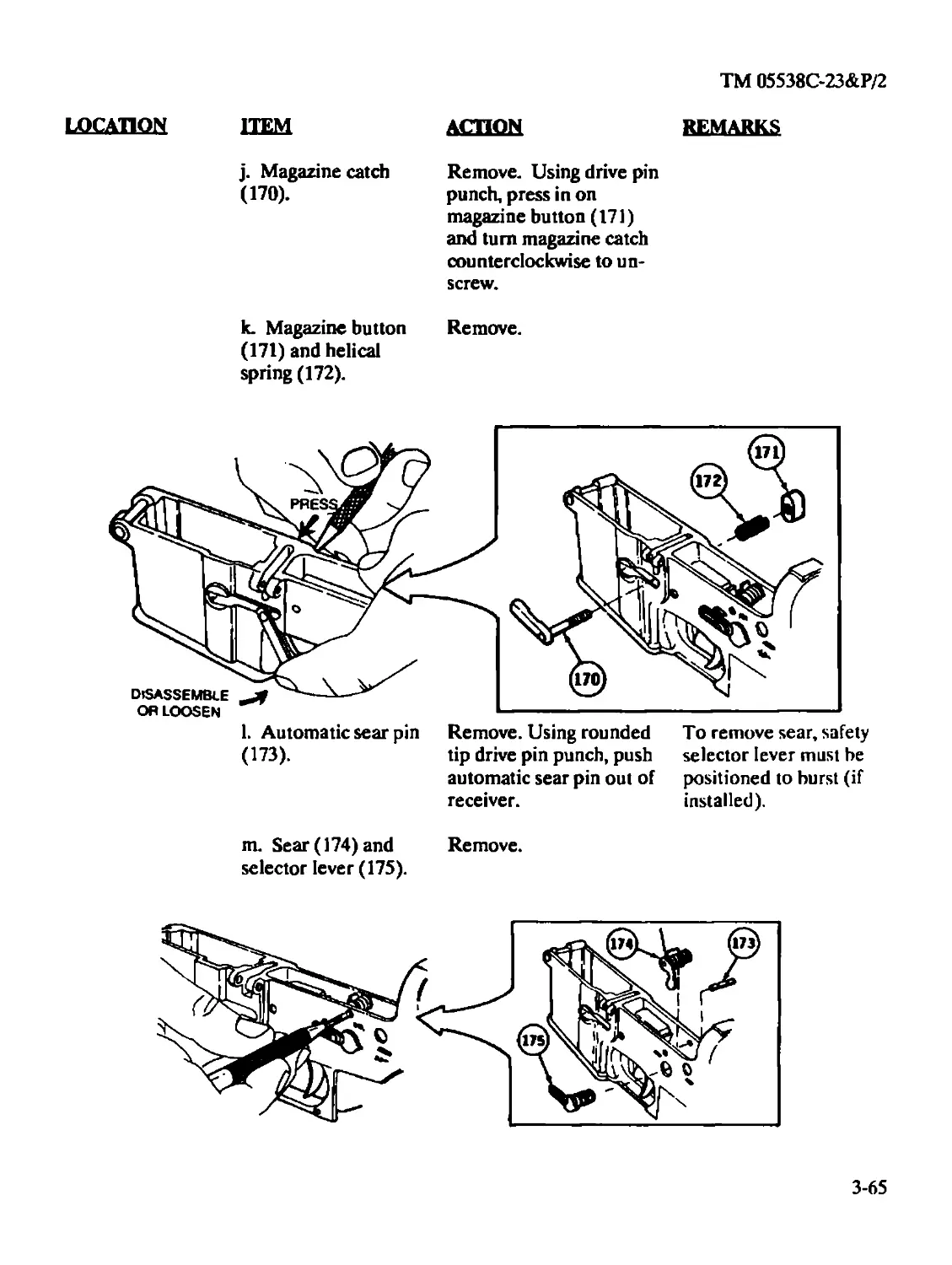
1-6. REPORTING OF UNSATISFACTORY EQUIPMENT.
Refer to: MCO 4855.10.
1-1
ТМ 05538С-23&Р/2
Section II. EQUIPMENT DESCRIPTION AND DATA
1-7. EQUIPMENT CHARACTERISTICS, CAPABILITIES, AND FEATURES.
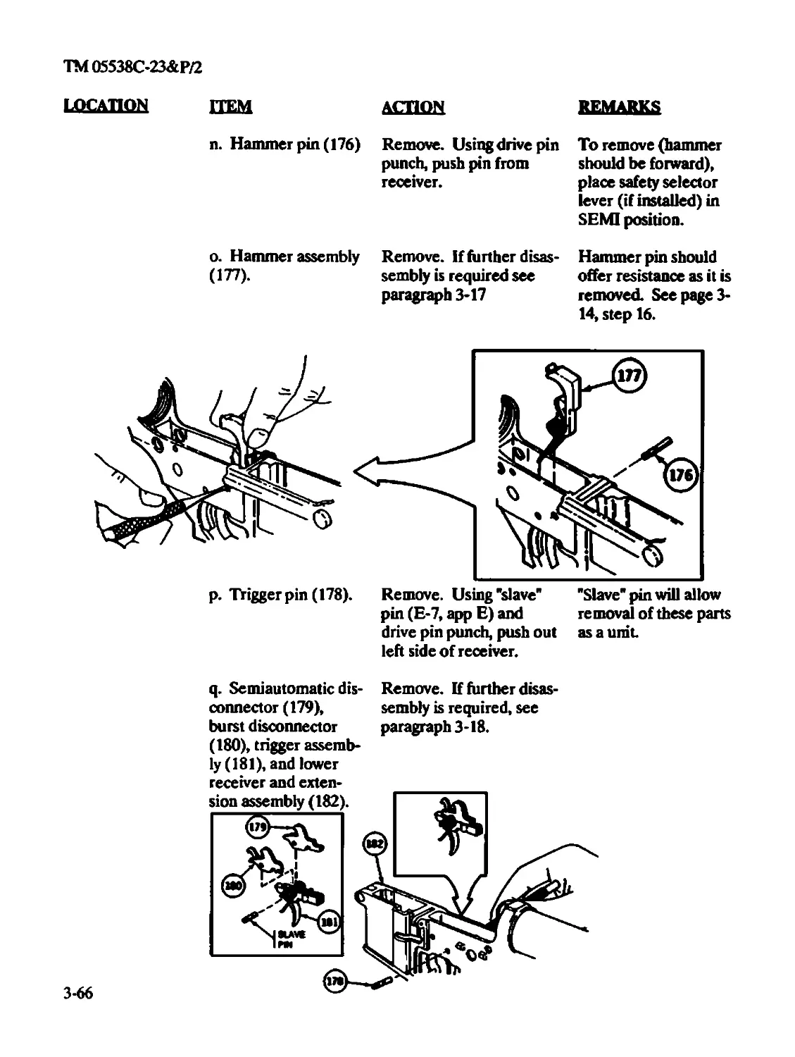
a. Characteristics.
(1) Lightweight
(2) Air-cooled
(3) Gas-operated
(4) Magazine-fed
(5) Semiautomatic or hurst fire
b. Capabilities. Provide an offensive/defensive capability to engage targets with direct small
arms fire.
c. Features
(1) The bolt locking action is one of the mechanical features of the weapon. The bolt
and barrel extension contain locking lugs which engage and lock the bolt firmly in the barrel exten-
sion. The initial force of the explosion of the canridge is absorbed by the barrel, barrel extension,
and bolt.
(2) The trigger guard is easily adaptable to winter operations. A spring-loaded
retaining pin is depressed to allow ready access to the trigger when wearing arctic mittens.
(3) The ejection pori cover prevents din or sand from getting into the ejection port.
The cover must be closed during periods when firing is not anticipated. It opens automatically by
the forward or rearward movement of the bolt carrier.
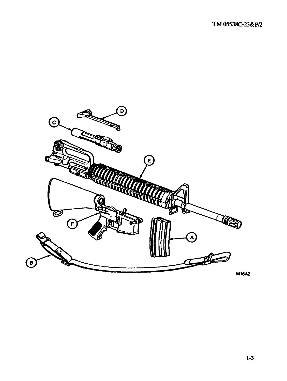
1-8. DESCRIPTION OF MAJOR COMPONENTS.
A CARTRIDGE MAGAZINE. 30 cartridge capacity.
В SMALL ARMS SLING. The small arms sling is adjustable and provides a means to
carry the weapon.
C BOLT CARRIER ASSEMBLY. Carries bolt to chamber and fires the weapon.
Contains the firing pin, extractor, bolt, ejector, and cam pin.
D HANDLE ASSEMBLY. Provides a means of charging the weapon.
E UPPER RECEIVER AND BARREL ASSEMBLY. Upper receiver contains rear sight,
ejection port, ejection port cover, and a housing for the bolt carrier and bolt assembly.
Rifle barrel assembly is aircooled, contains compensator and front sight assembly, and
holds the two handguards and the sling swivel.
F LOWER RECEIVER AND BUTTSTOCK ASSEMBLY. Lower receiver contains
the trigger assembly, sear, hammer assembly, selector lever, rifle grip, bolt catch, and
huttstock assembly. The buttstock assembly houses the action spring, buffer assembly,
and extension assembly.
1-2
ТМ 05538С-23&Р/2
1-3
ТМ 05538С-23&Р/2
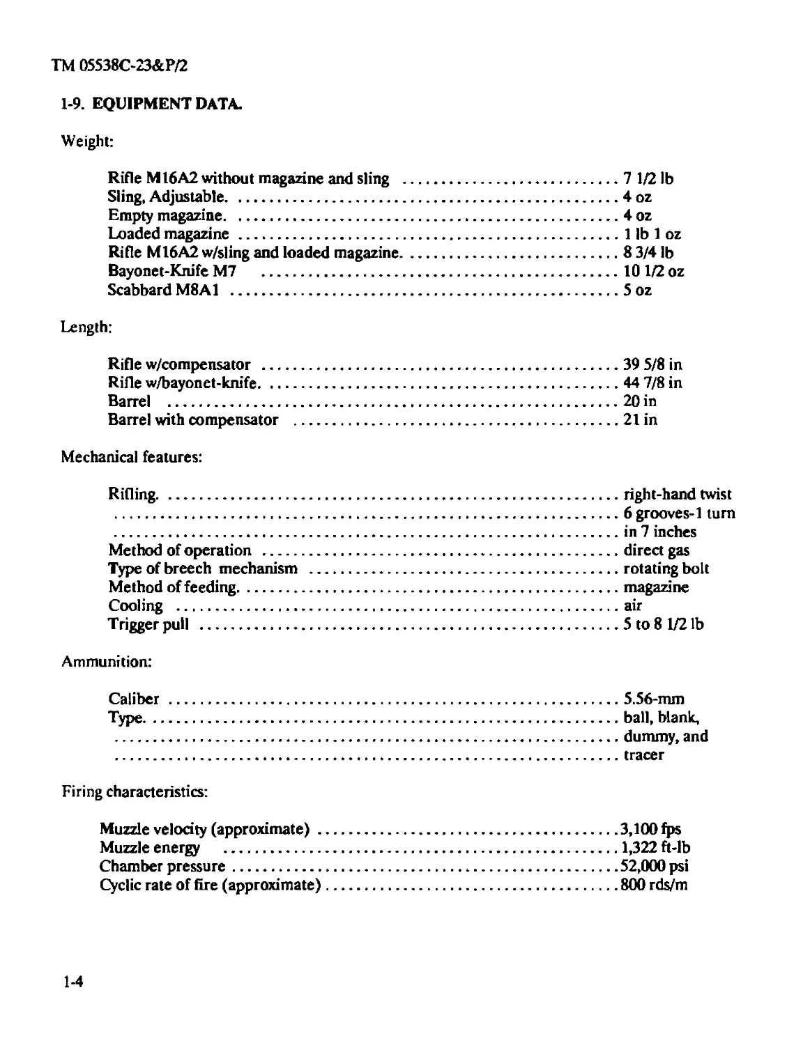
1-9. EQUIPMENT DATA.
Weight:
Rifle M16A2 without magazine and sling ...........................7 1/2 lb
Sling, Adjustable.................................................4 oz
Empty magazine....................................................4 oz
Loaded magazine ..................................................1 lb 1 oz
Rifle M16A2 w/sling and loaded magazine...........................8 3/4 lb
Bayonet-Knife M7 .................................................10 1/2 oz
Scabbard M8A1 ....................................................5 oz
Length:
Rifle w/compensator .............................................. 39 5/8 in
Rifle w/bayonet-knife............................................. 44 7/8 in
Barrel ...........................................................20 in
Barrel with compensator ..........................................21 in
Mechanical features:
Rifling...........................................................right-hand twist
..................................................................6 grooves-1 tum
.................................................................................in 7 inches
Method of operation .............................................................direct gas
Type of breech mechanism .........................................rotating bolt
Method of feeding.................................................magazine
Cooling ..........................................................air
Trigger pull .....................................................5 to 8 1/2 lb
Ammunition:
Caliber ..........................................................5.56-mm
Type..............................................................ball, blank,
.................................................................dummy, and
................................................................. tracer
Firing characteristics:
Muzzle velocity (approximate)......................................3,100 fps
Muzzle energy .....................................................1,322 fi-lb
Chamber pressure...................................................52,000 psi
Cyclic rate of fire (approximate)..................................800 rds/m
1-4
ТМ 05538С-23&Р/2
Maximum rate of fire:
Semiautomatic......................................................45 rds/m
Burst .............................................................90 rds/m
Sustained rate of fire ...................................................12/15 rds/m
Maximum range.............................................................3,534 meters
Maximum effective range:
Individual/point targets ..........................................550 meters
Area targets.......................................................800 meters
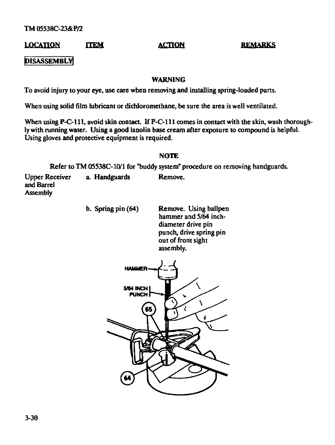
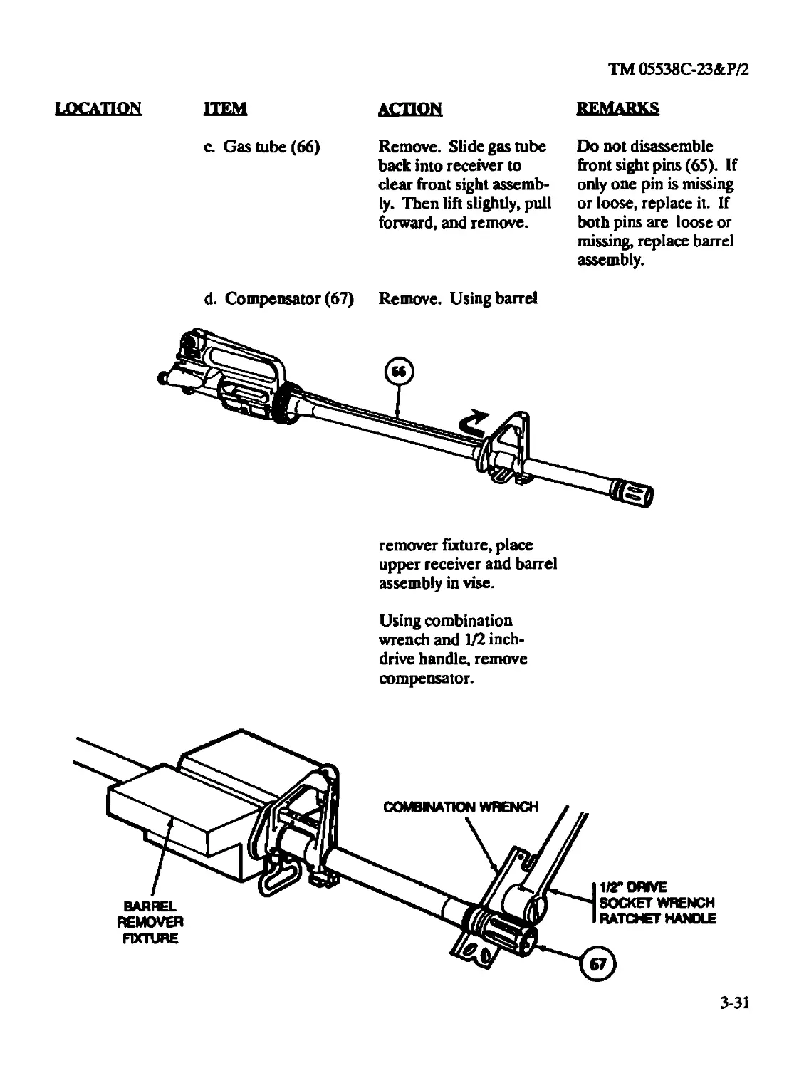
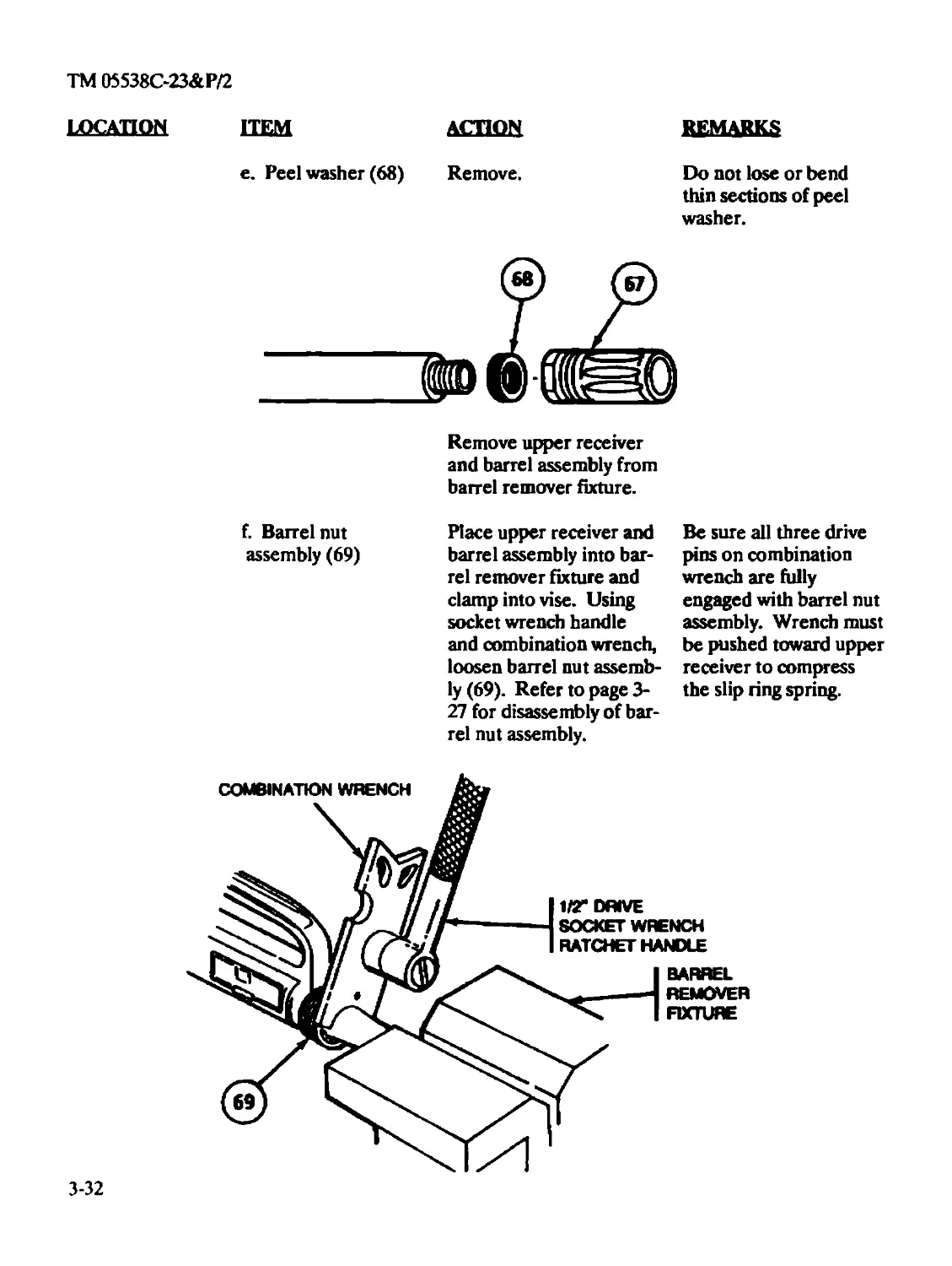
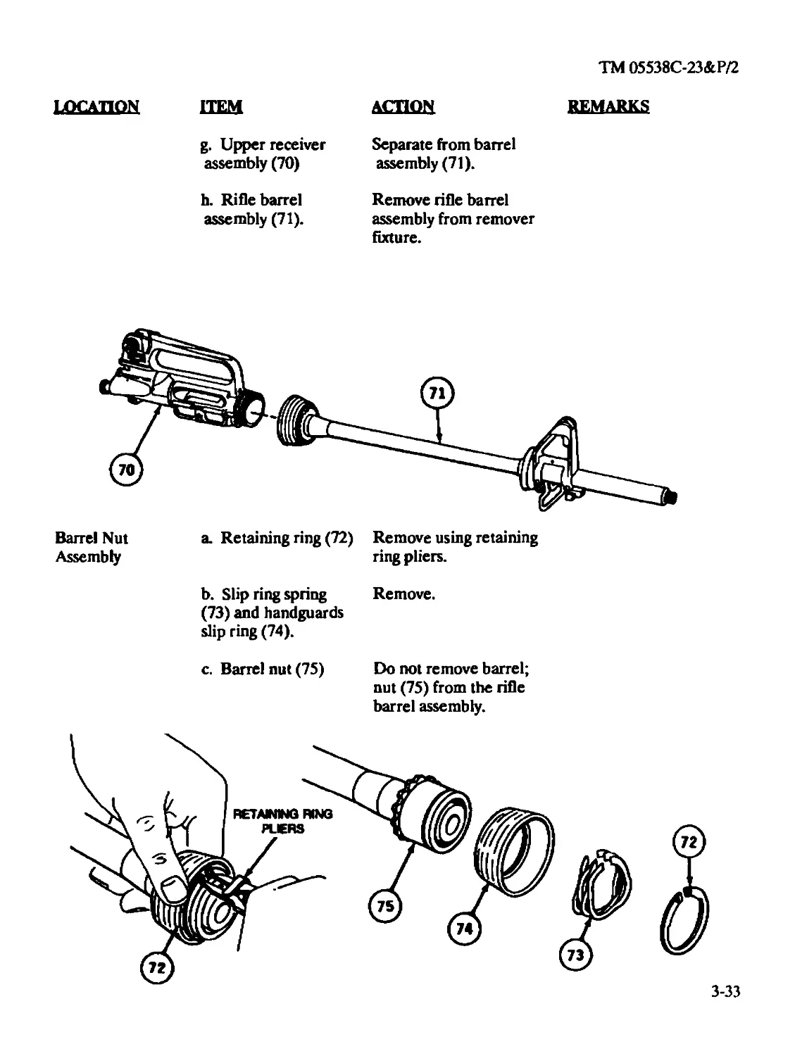
NOTE
Some weights and measures are approximations using M855 ammunition.
Whenever the term 'Cleaner Lubricant and Preservative" (CLP) or the words "lubricant", "lube",
"LSA", or "LAW" are cited in this TM, they are to be interpreted to mean that CLP, LSA and LAW
can be utilized as applicable. The following constraints must be adhered to:
a. Under all but the coldest arctic conditions, LSA or CLP are the lubricants to use on your
weapon. Either may be used at - 10°F and above. However, do not use both on the same weapon
at the same time.
b. LAW is the lubricant to use during cold arctic conditions, + 10°F and below.
c. Any of the lubricants may be used from -10°F to + 10°F.
d. Do not mix lubricants on the same weapon. The weapon must be thoroughly cleaned
during change from one lubricant to another. Dry Cleaning Solvent (SD) is recommended for
cleaning during change from one lubricant to another.
Rifle Bore Cleaner (RBC) may be used to remove carbon buildup in the bore and other portions
of the weapon.
Section Ш. PRINCIPLES OF OPERATION
1-10. GENERAL. The weapon:
a. Is gas-operated. It fires in either the semiautomatic or burst mode.
b. Has positive locking of the bolt. Firing pin is part of the bolt and carrier assembly and
cannot strike the primer until the bolt is fully locked.
1-5
ТМ05538С-23&Р/2
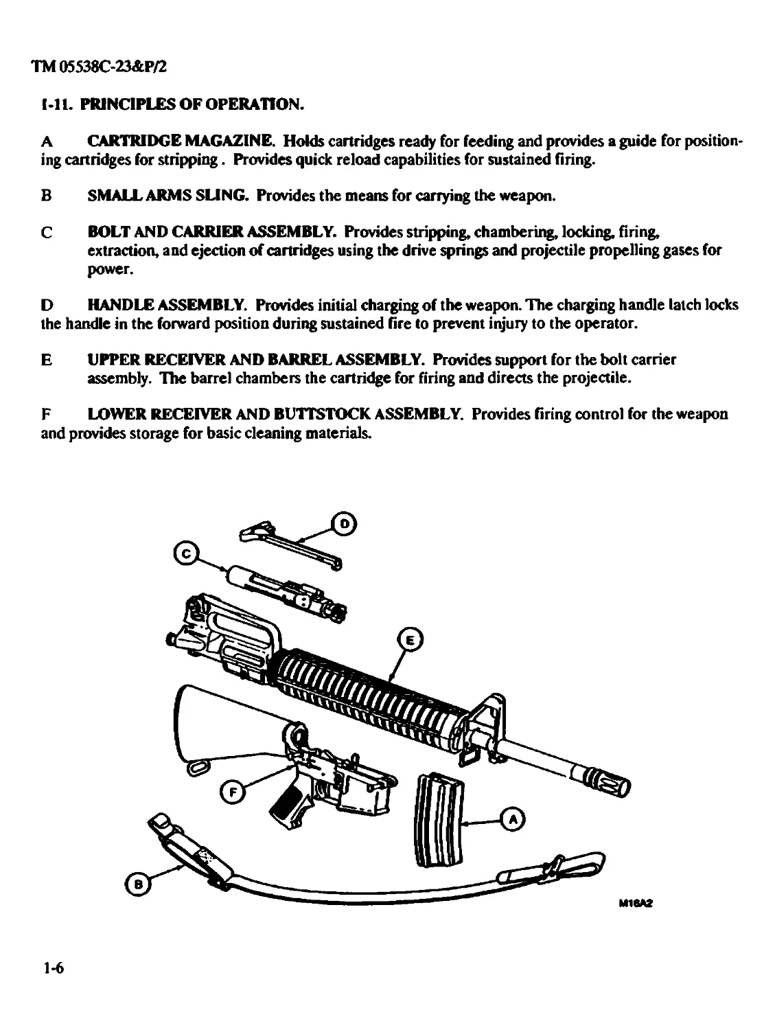
I-11. PRINCIPLES OF OPERATION.
A CARTRIDGE MAGAZINE. Holds cartridges ready for feeding and provides a guide for position-
ing cartridges for stripping. Provides quick reload capabilities for sustained firing.
В SMALL ARMS SLING. Provides the means for carrying the weapon.
C BOLT AND CARRIER ASSEMBLY. Provides stripping, chambering, locking, firing,
extraction, and ejection of cartridges using the drive springs and projectile propelling gases for
power.
D HANDLE ASSEMBLY. Provides initial charging of the weapon. The charging handle latch locks
the handle in the forward position during sustained fire to prevent injury to the operator.
E UPPER RECEIVER AND BARREL ASSEMBLY. Provides support for the bolt carrier
assembly. The barrel chambers the cartridge for firing and directs the projectile.
F LOWER RECEIVER AND BUTTSTOCK ASSEMBLY. Provides firing control for the weapon
and provides storage for basic cleaning materials.
1-6
TM 05538C-23&P/2
ALPHABETICAL INDEX
Subject Page
A
Assemblies
Barrel Assembly................................................2-31,3-29
Bolt Assembly..................................................2-24,3-21
Bolt Carrier Assembly..........................................2-20,3-16
Buttstock Assembly ...........................................2-50,3-78
Charging Handle Assembly.......................................2-29
Forward Assist Assembly .......................................3-57
Hammer Assembly................................................3-78
Key and Bolt Carrier Assembly .................................3-23
Lower Receiver and Buttstock Assembly..........................2-41,3-60
Lower Receiver and Receiver Extension Assembly.................3-82
Trigger Assembly ..............................................3-80
Upper Receiver and Barrel Assembly.............................2-34,3-29
Upper Receiver Assembly and Rear Sight Assembly................3-48
Auxiliary Equipment
Bayonet-Knife M7 ..............................................4-1,4-11
Bayonet-Knife Scabbard M8A1 or MIO.............................4-3
Blank Firing Attachment M15A2..................................4-8
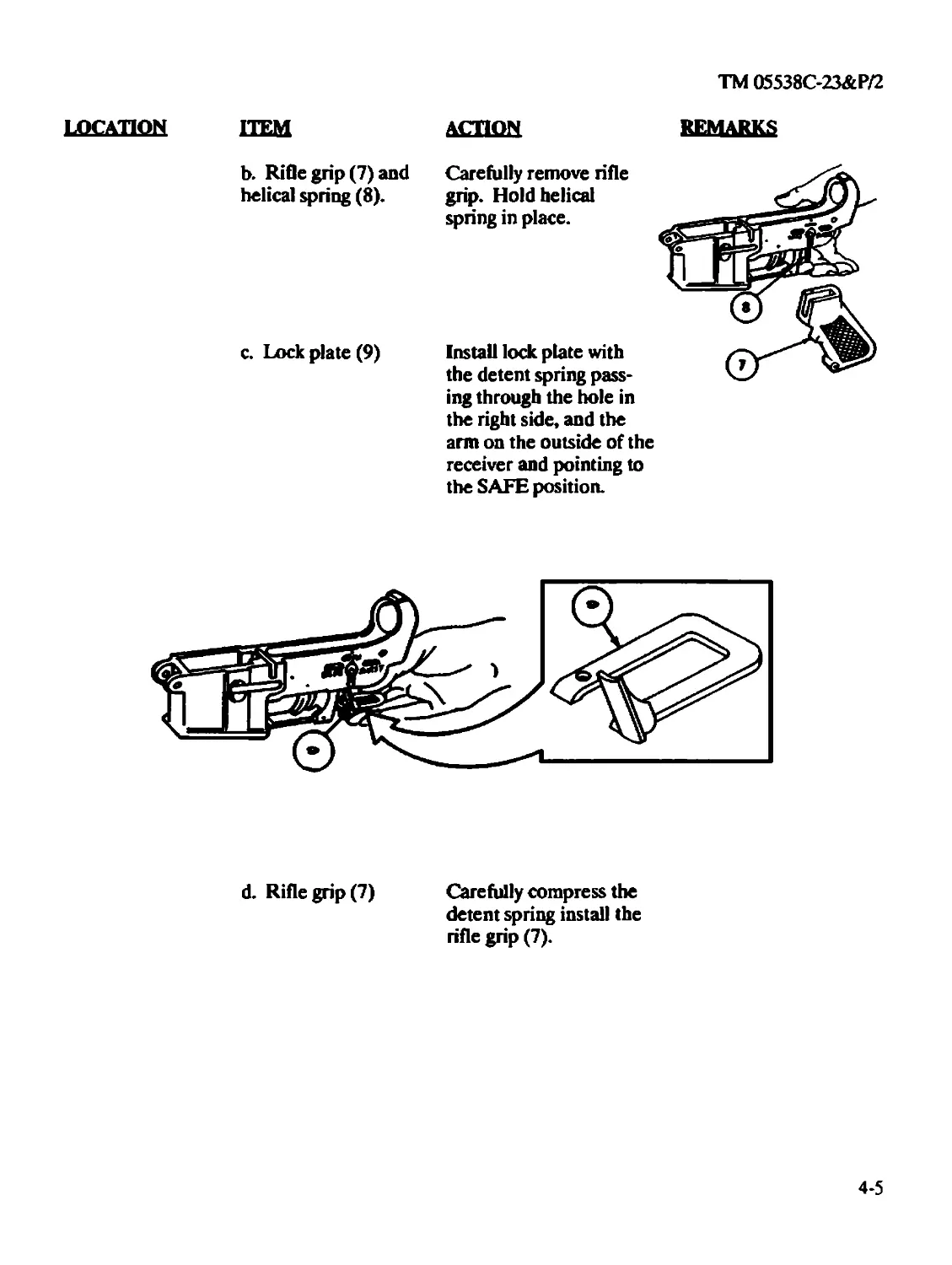
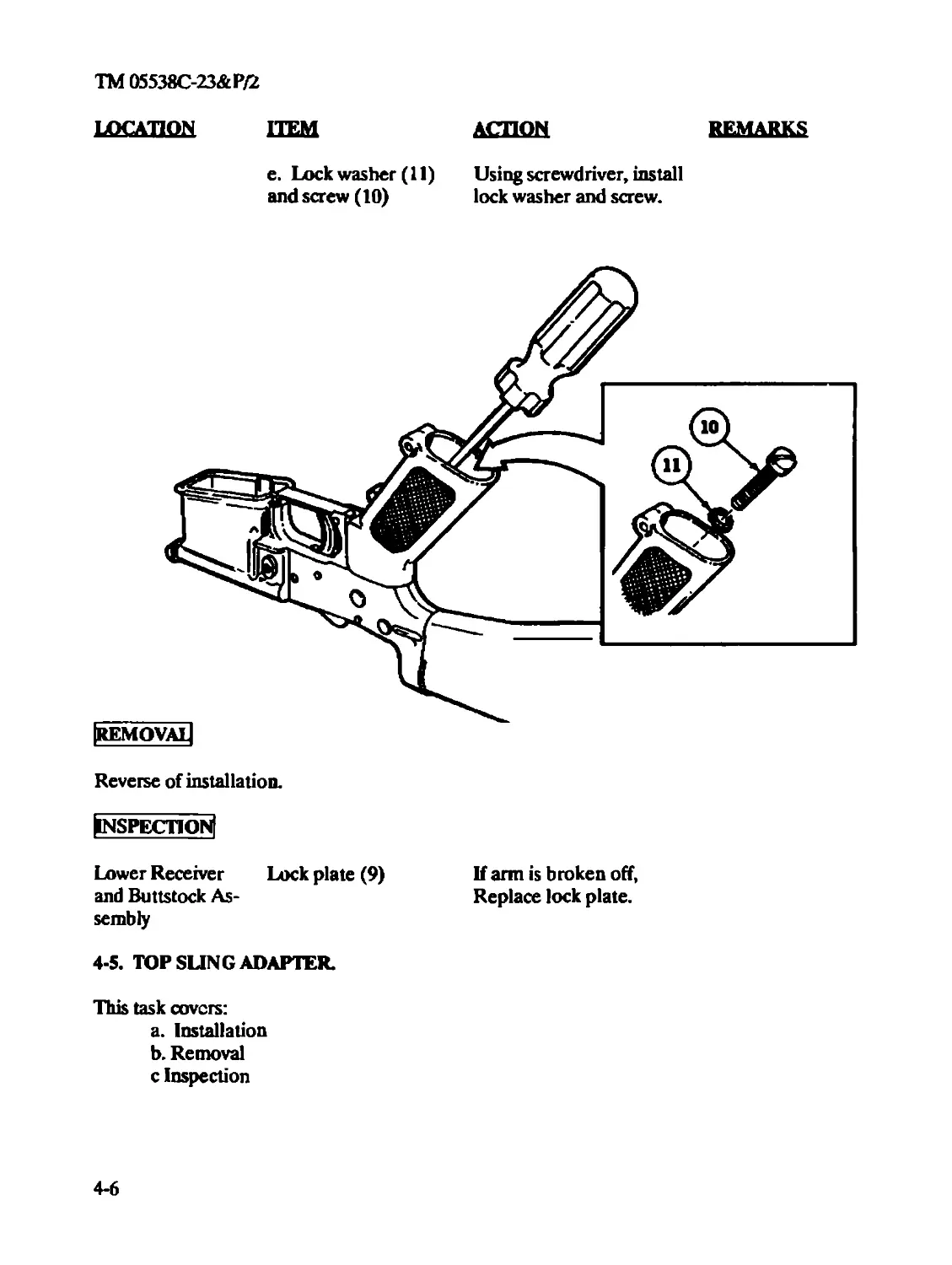
Lock Plate ....................................................4-4
Index 1
TM 05538C-23&PZ2
Subject Page
Repair..........................................................2-22
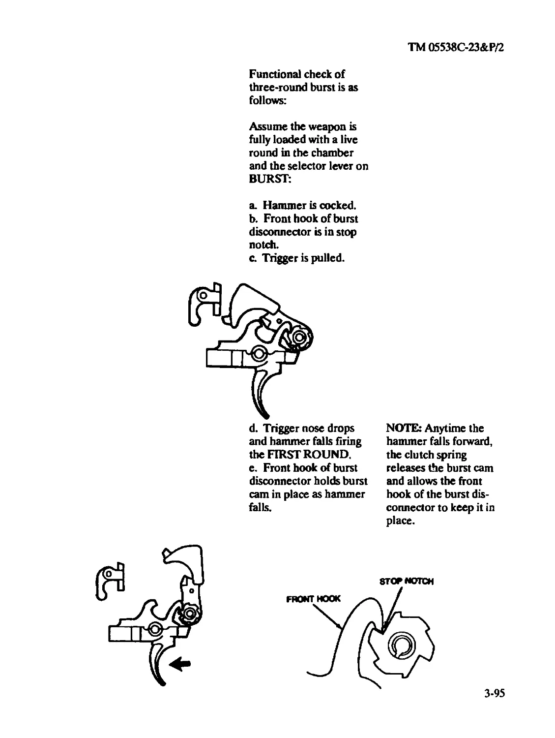
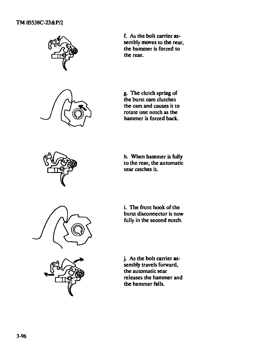
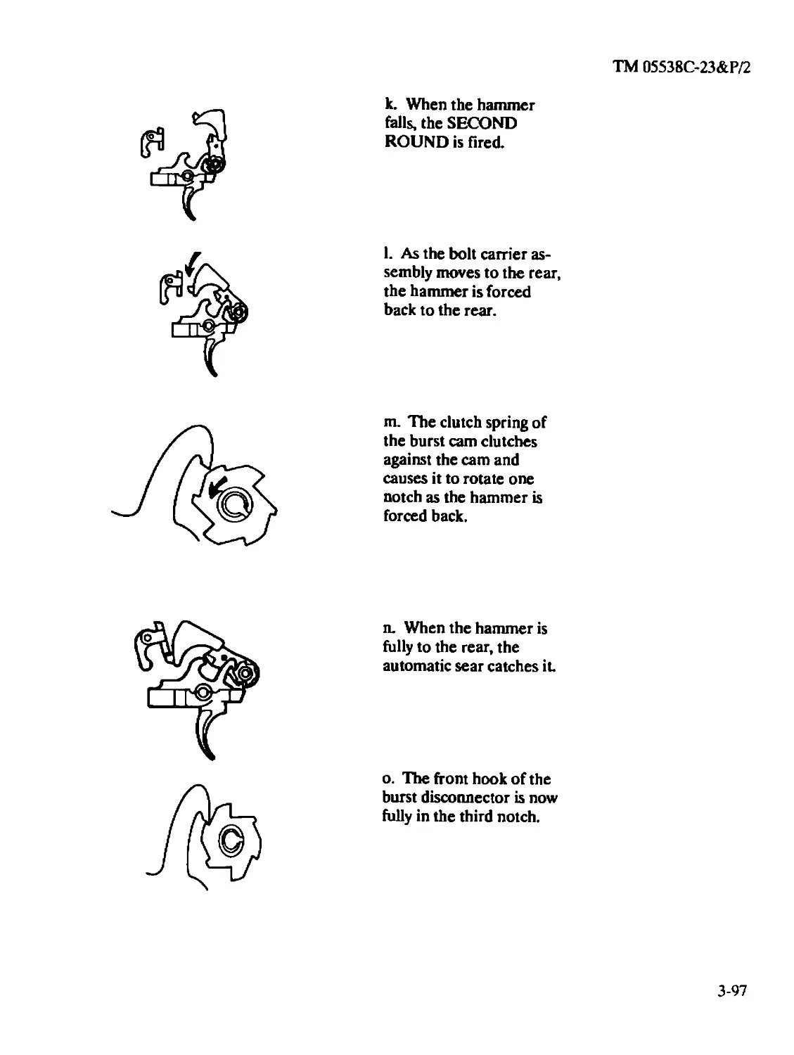
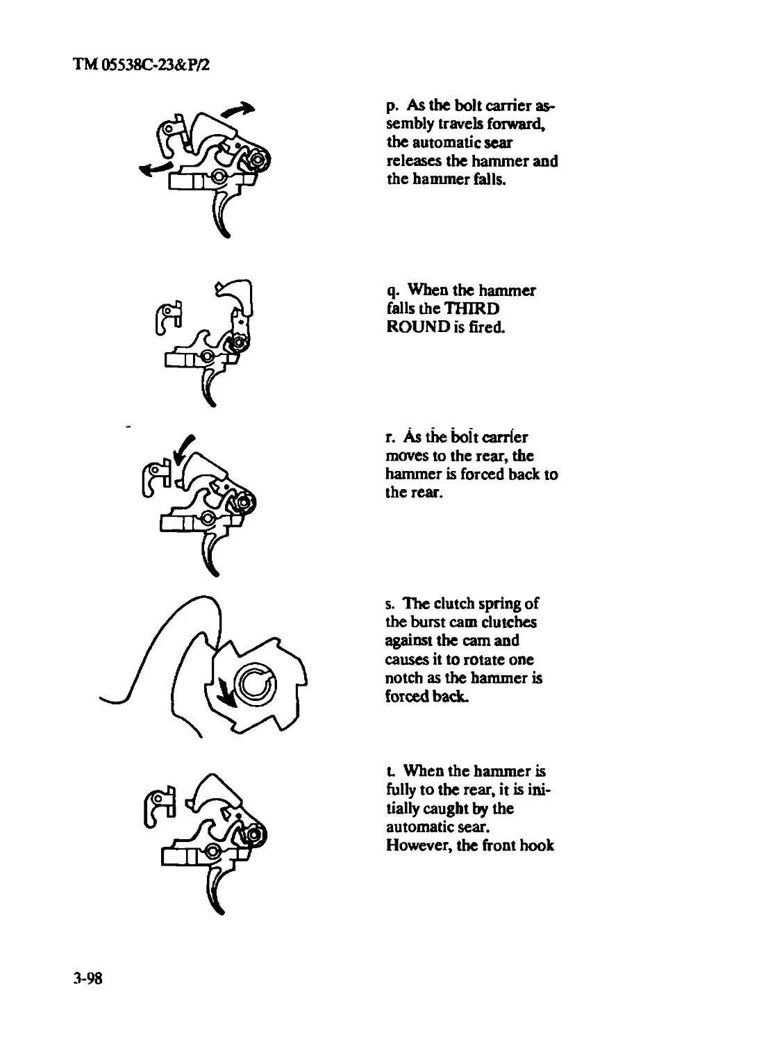
Burst Control, Functional Theory of Three-Round.......................3-94
Buttstock Assembly (Intermediate).....................................3-78
Inspection......................................................3-78
Repair..........................................................3-78
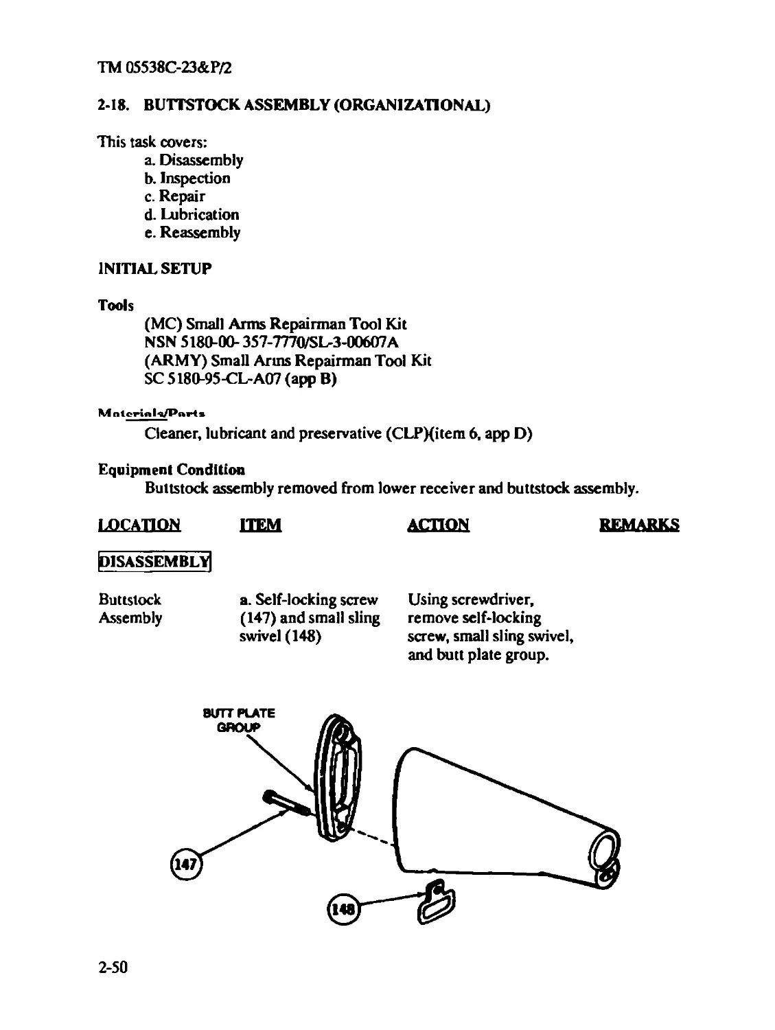
Buttstock Assembly (Organizational)...................................2-50
Disassembly.....................................................2-50
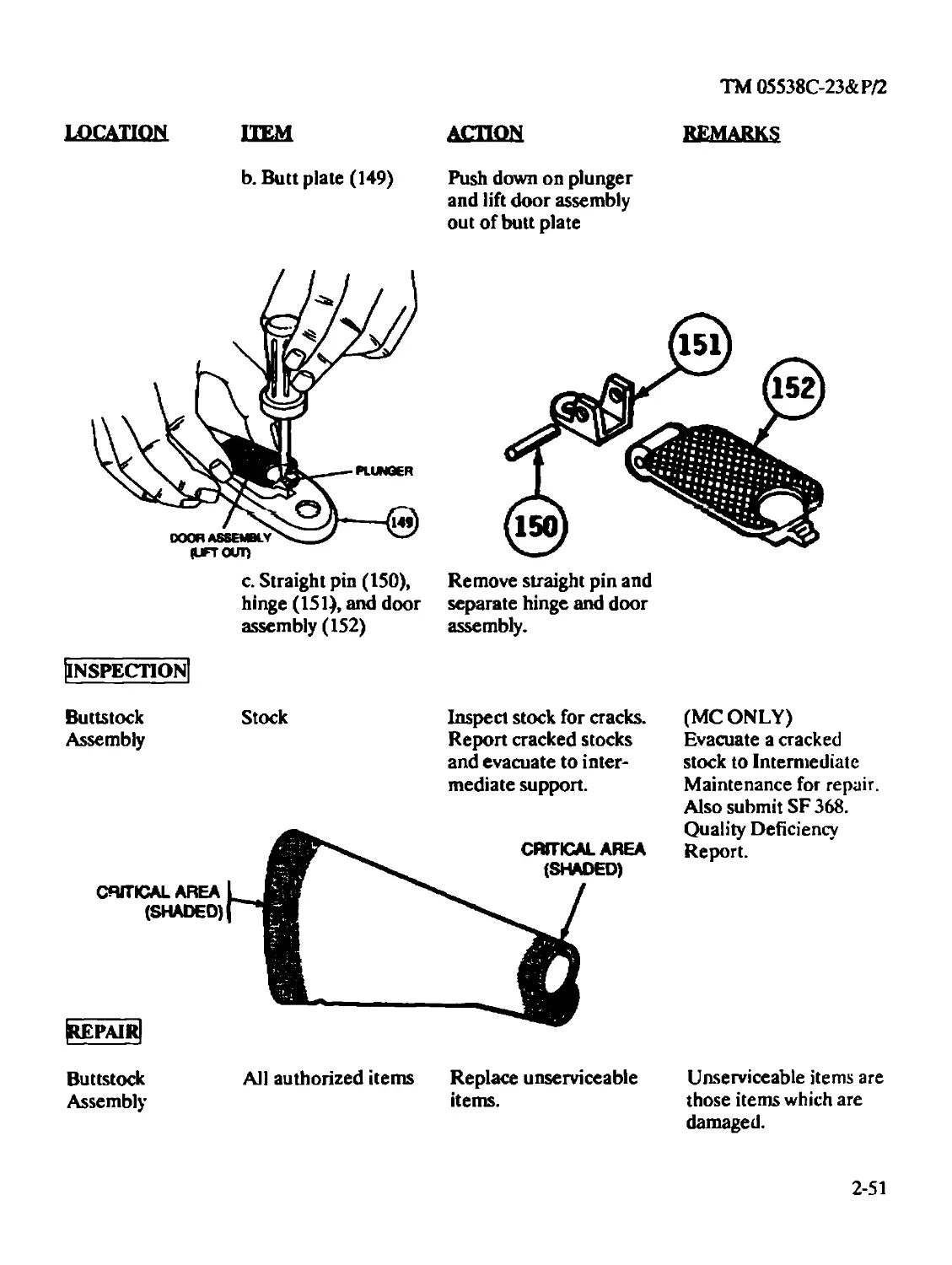
Inspection......................................................2-51
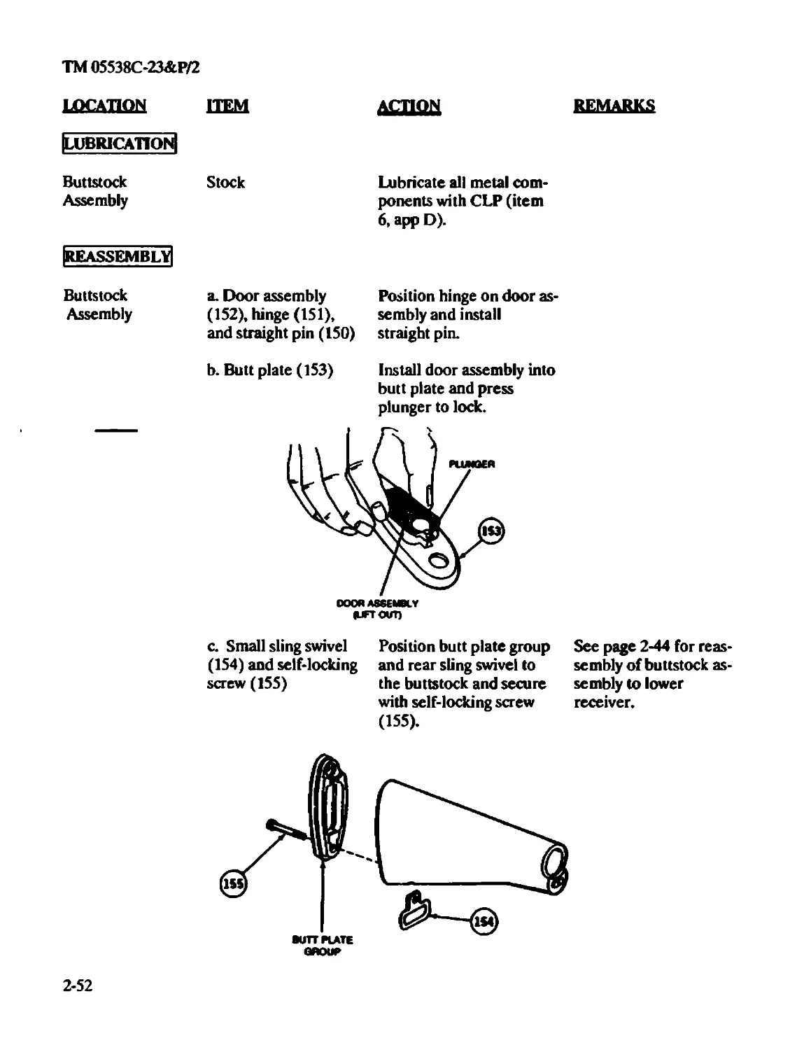
Lubrication.....................................................2-52
Reassembly .....................................................2-52
Repair..........................................................2-51
C
Charging Handle Assembly (Organizational).............................2-29
Disassembly.....................................................2-30
Inspection/Repair...............................................2-30
Lubrication.....................................................2-30
Reassembly .....................................................2-31
Cleaning
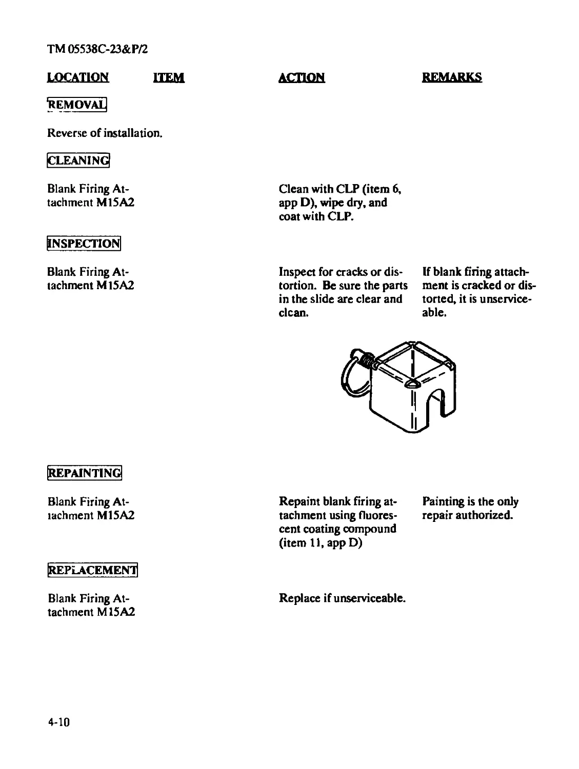
Blank Firing Attachment M15A2...................................4-10
Bolt Assembly (Organizational)..................................2-26
Bolt Carrier Assembly (Intermediate)............................3-17
Index 4
ТМ 05538С-23&Р/2
Subject Page
Bolt Carrier Assembly (Organizational)...........................2-22
D
Data Equipment ..........................................................1-4
Decontamination of Rifles and Arms Rooms.................................2-55
Destruction of Material to Prevent Enemy Use.............................1-1
Disassembly
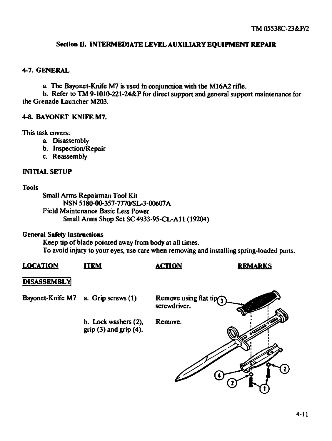
Bayonet-Knife M7 (Intermediate)..................................4-11
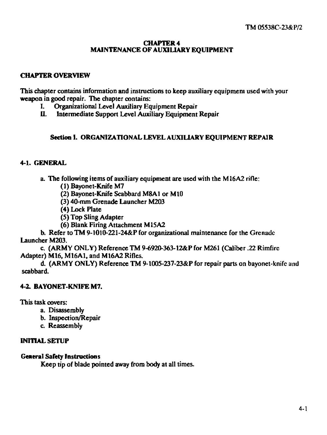
Bayonet-Knife M7 (Organizational)................................4-2
Bolt Assembly (Intermediate) .....................................3-21
Bolt Assembly (Organizational)....................................2-25
Bolt Carrier Assembly (Intermediate) .............................3-16
Bolt Carrier Assembly (Organizational)............................2-21
Buttstock Assembly (Organizational)...............................2-50
Charging Handle Assembly (Organizational) ........................2-30
Forward Assist Assembly (Intermediate)............................3-57
Hammer Assembly (Intermediate)....................................3-78
Key and Bolt Carrier Assembly (Intermediate)......................3-24
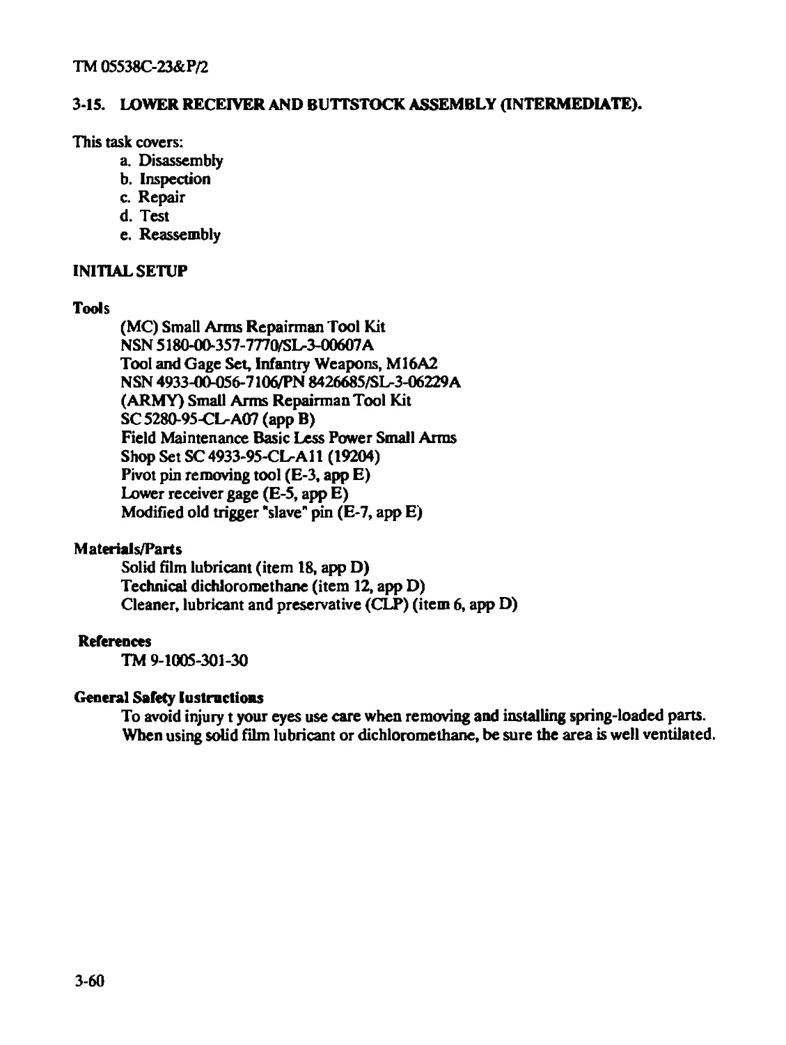
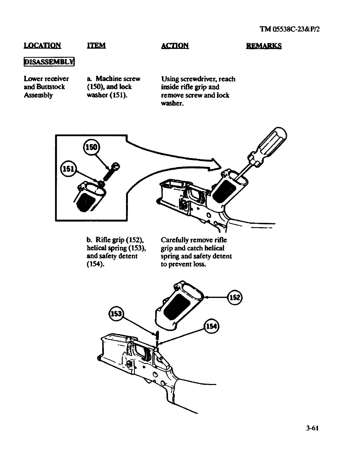
Lower Receiver and Buttstock Assembly (Intermediate) .............3-61
Lower Receiver and Buttstock Assembly (Organizational)............2-41
Lower Receiver and Receiver Extension Assembly (Intermediate) .. .3-83
Major Components of M16A2 Rifle (Intermediate)....................3-15
Index 5
TM 05538C-23&P/2
Subject Page
Major Components of M16A2 Rifle (Organizational).................3-1
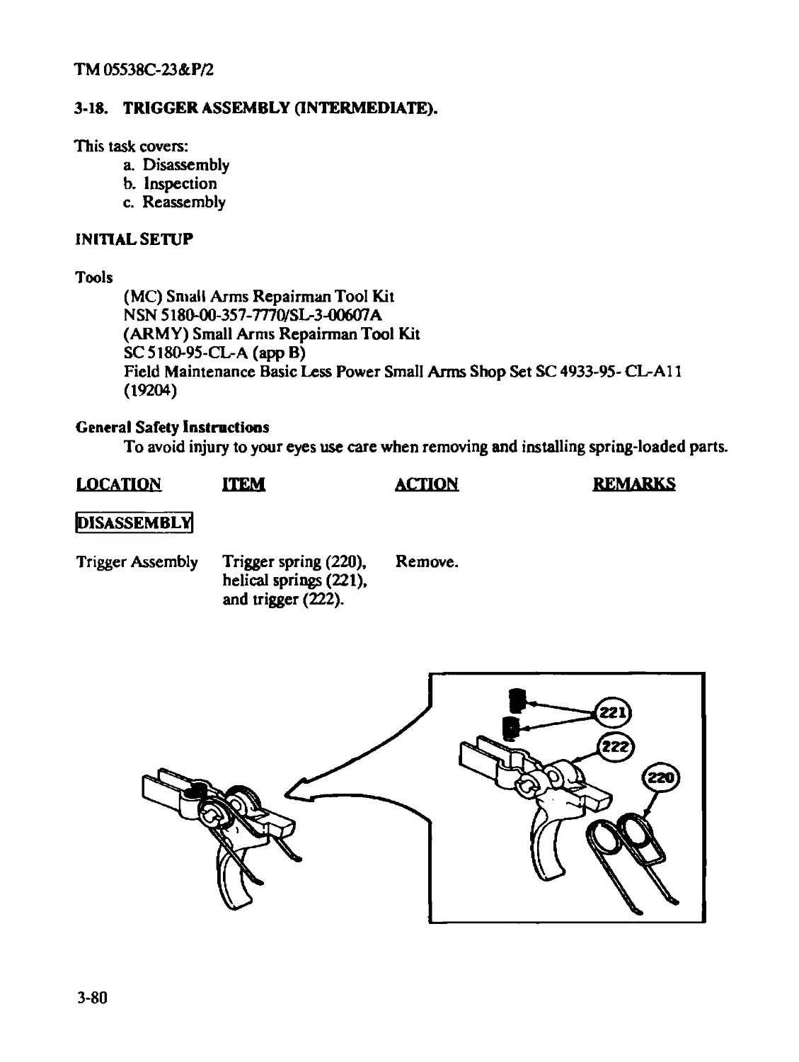
Trigger Assembly (Intermediate)..................................3-80
Upper Receiver and Barrel Assembly (Intermediate) ...............3-30
Upper Receiver and Barrel Assembly (Organizational)..............3-31
Upper Receiver Assembly and Rear Sight Assembly (Intermediate) . 3-49
E
Equipment Characteristics, Capabilities and Features....................1-2
Equipment Data .........................................................1-4
Expendable/Durable Supplies and Material List...........................D-l
F
Features, Equipment Characteristics, Capabilities and...................1-2
Forward Assist Assembly (Intermediate) .................................3-57
Disassembly......................................................3-57
Inspection.......................................................3-58
Repair...........................................................3-58
Reassembly .......................................................3-59
Functional Theory of Three-Ronnd Burst Control
M16A2 Rifle Final Inspection for Intermediate Support Units ......3-90
Index 6
ТМ 05538С-23&Р/2
Subject Page
G
Gages ...................................................................C-28
Gaging
(See applicable module)
H
Hammer Assembly (Intermediate) ..........................................3-78
Disassembly......................................................3-78
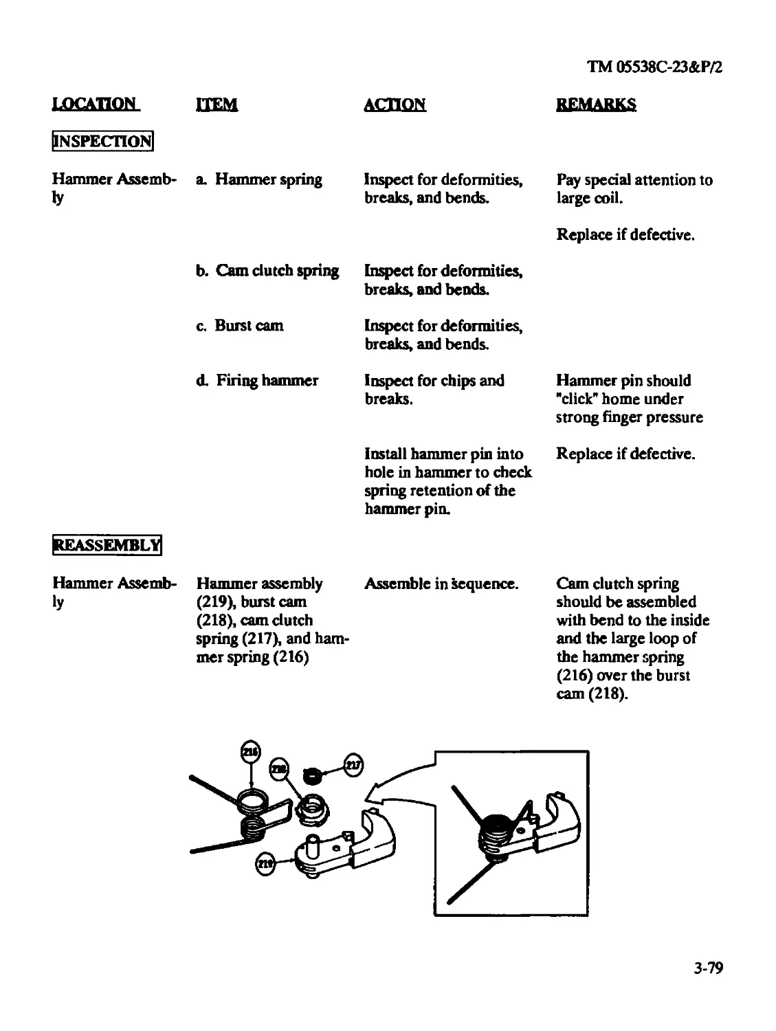
Inspection.......................................................3-79
Reassembly.......................................................3-79
I
Illustrated List Manufactured Items.......................................E-l
Initial Setup............................................................2-19
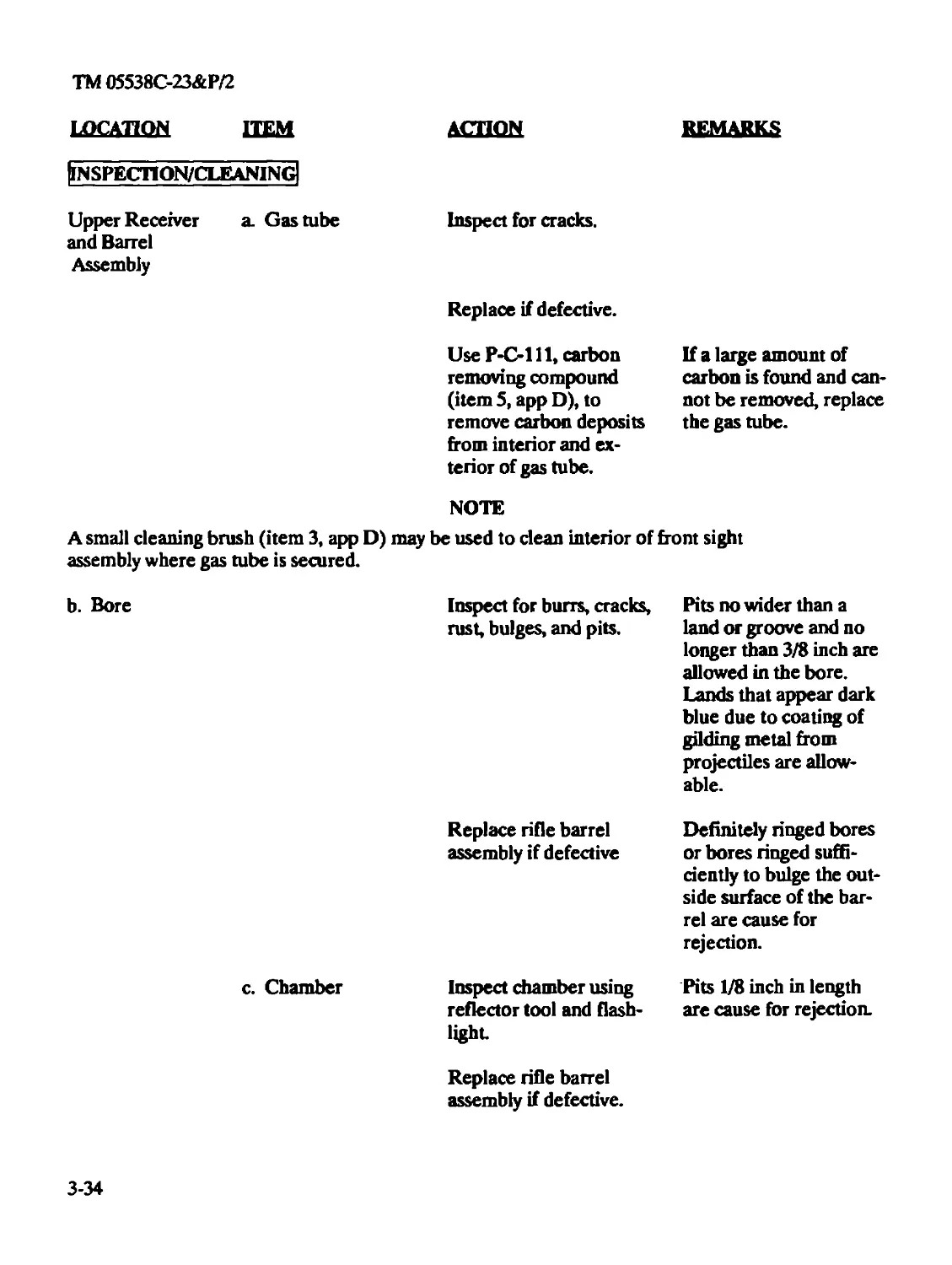
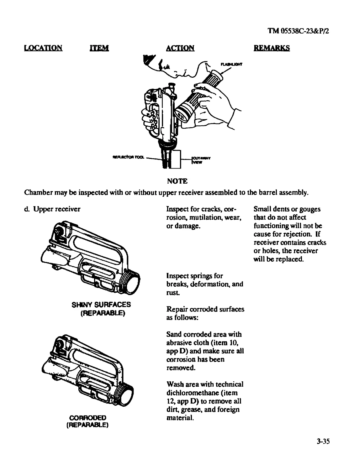
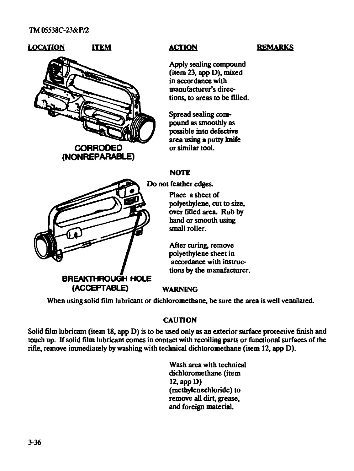
Inspection/Cleaning
Upper Receiver and Barrel Assembly (Intermediate)................3-34
Inspection/Repair
Bayonet-Knife M7 (Organizational).................................4-2
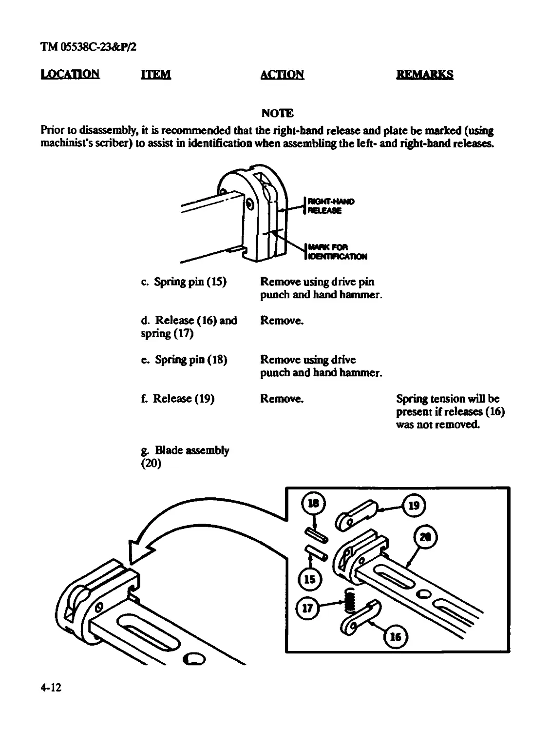
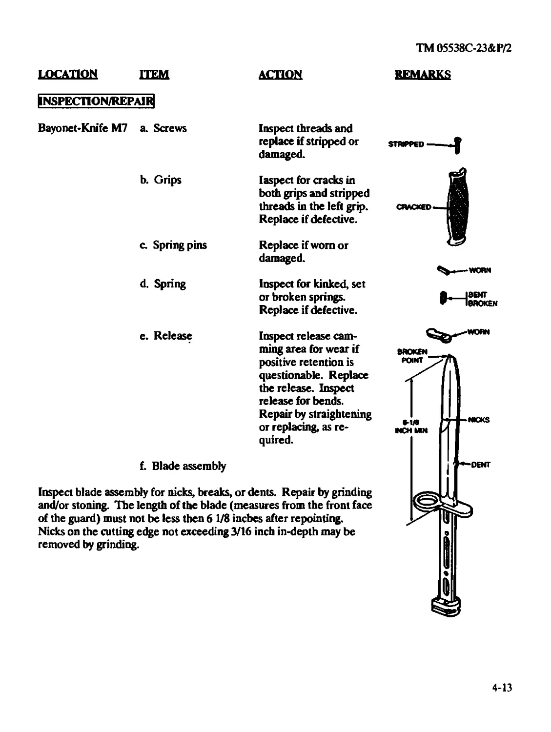
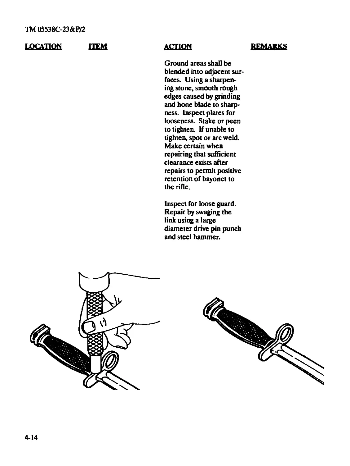
Bayonet-Knife M7 (Intermediate)..................................4-13
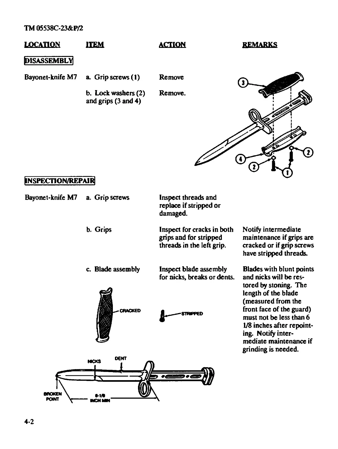
Bayonet-Knife Scabbard M8A1 or MIO (Organizational)...............4-3
Bolt Assembly (Intermediate) ....................................3-22
Charging Handle Assembly (Organizational) .......................2-30
Key and Bolt Carrier Assembly (Intermediate).....................3-25
Index 7
ТМ 05538С-23&Р/2
Subject Page
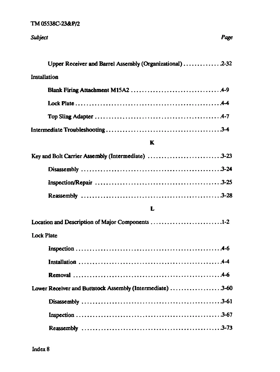
Upper Receiver and Barrel Assembly (Organizational)..............2-32
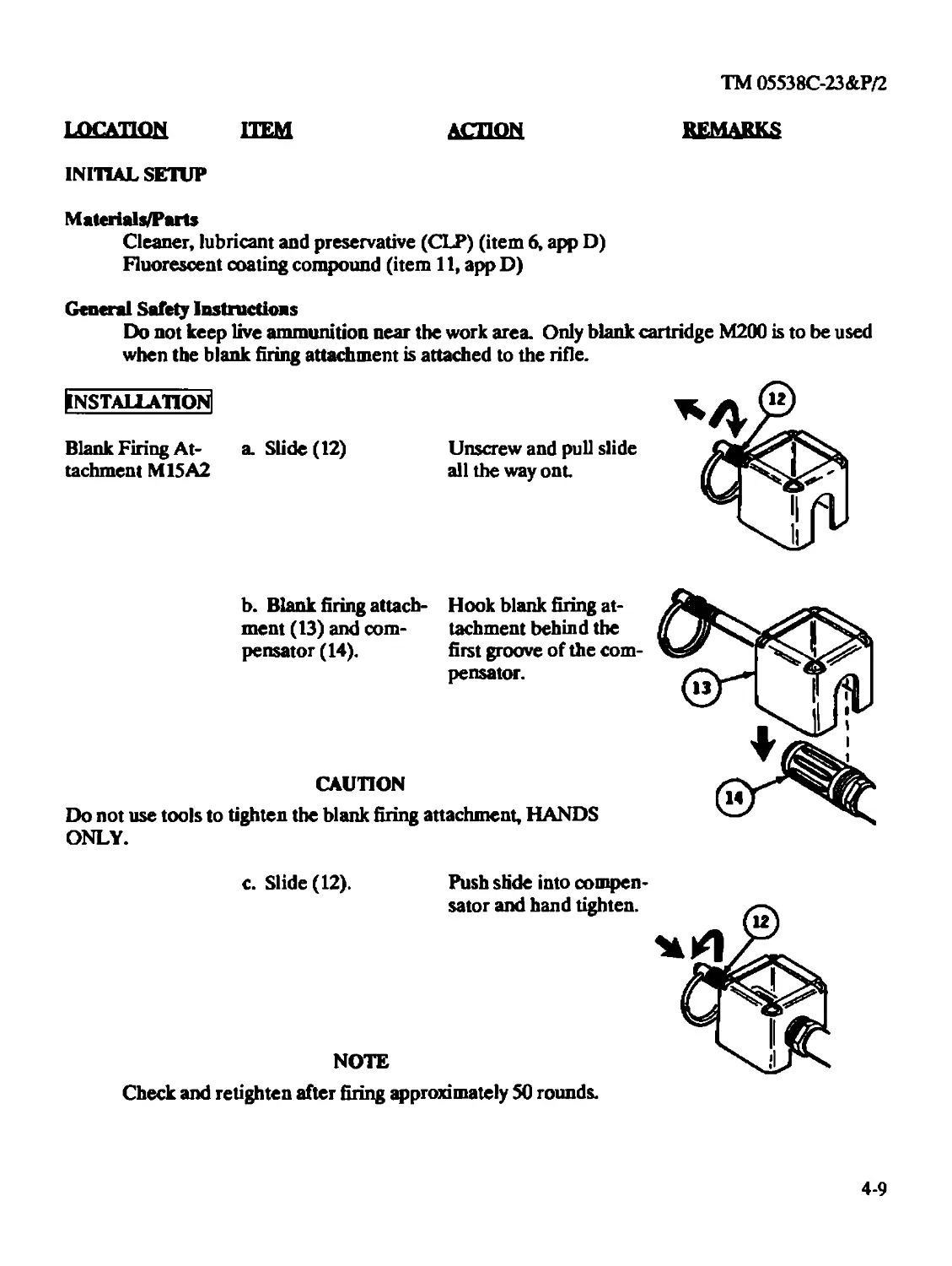
Installation
Blank Firing Attachment M15A2....................................4-9
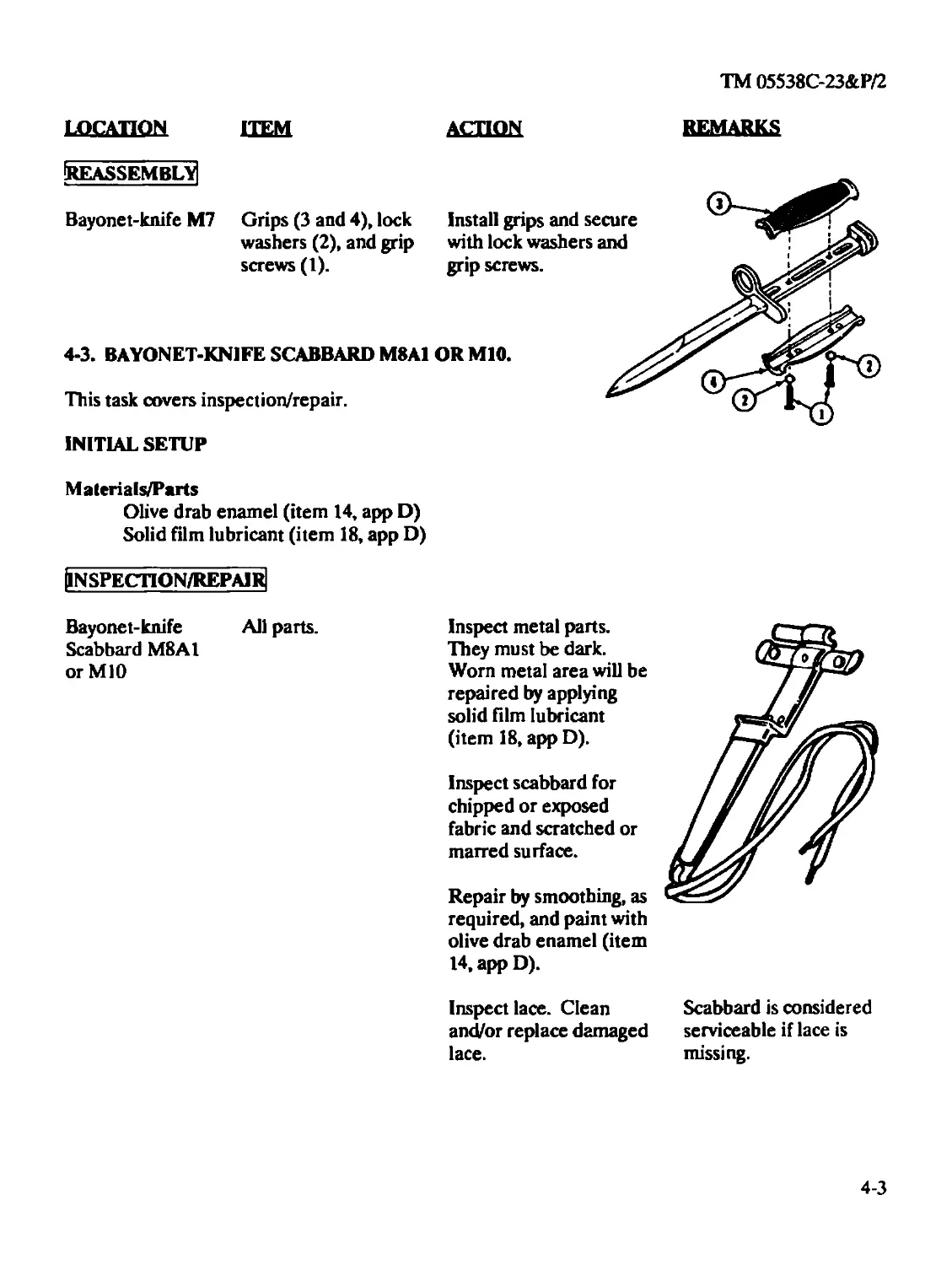
Lock Plate.......................................................4-4
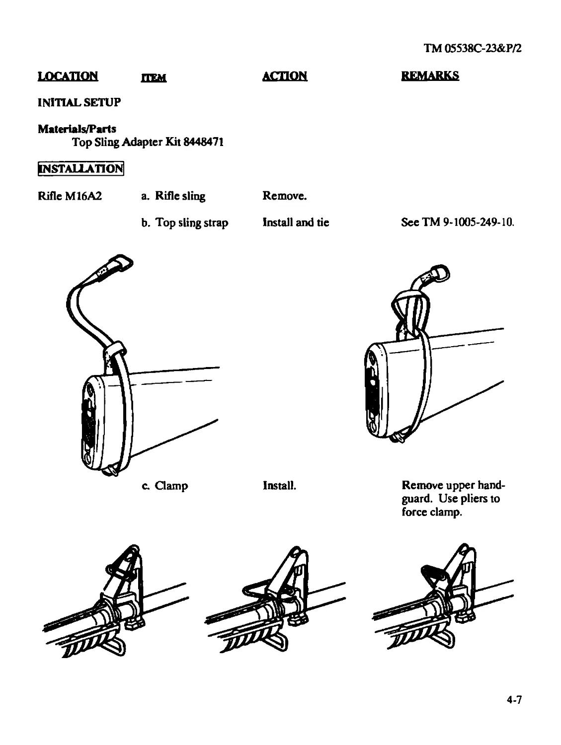
Top Sling Adapter................................................4-7
Intermediate Troubleshooting..........................................3-4
К
Key and Bolt Carrier Assembly (Intermediate)...........................3-23
Disassembly.....................................................3-24
Inspection/Repair...............................................3-25
Reassembly .....................................................3-28
L
Location and Description of Major Components...........................1-2
Lock Plate
Inspection.......................................................4-6
Installation.....................................................4-4
Removal..........................................................4-6
Lower Receiver and Buttstock Assembly (Intermediate)..................3-60
Disassembly.....................................................3-61
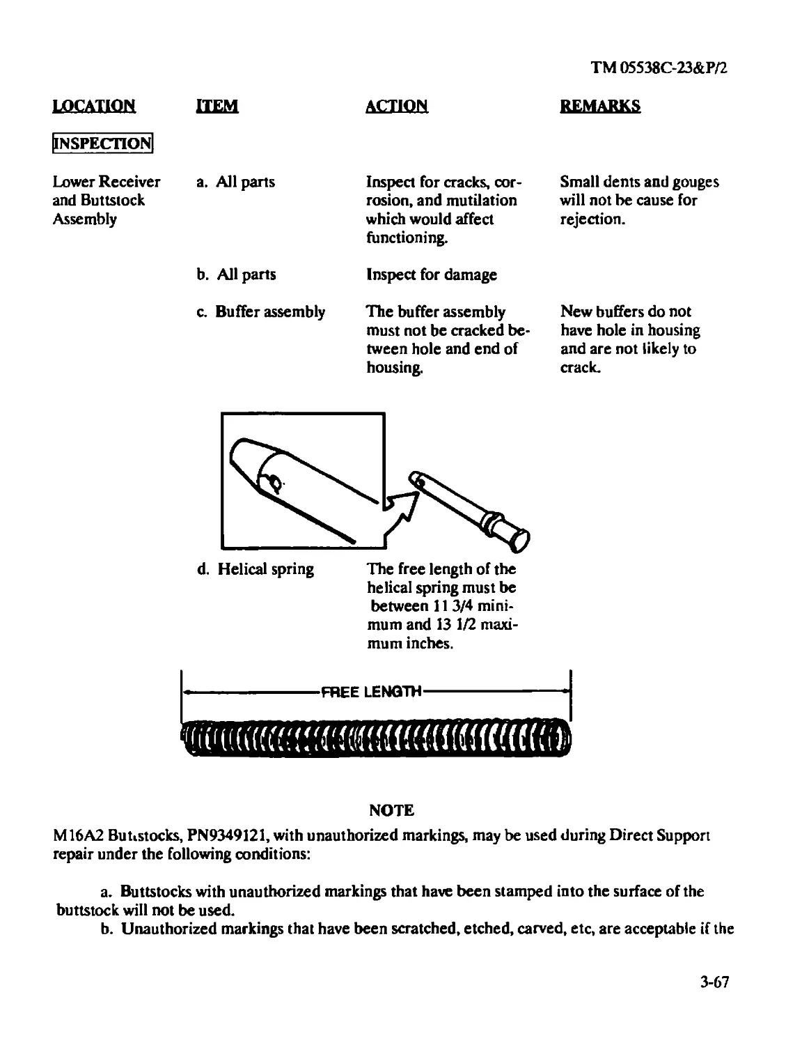
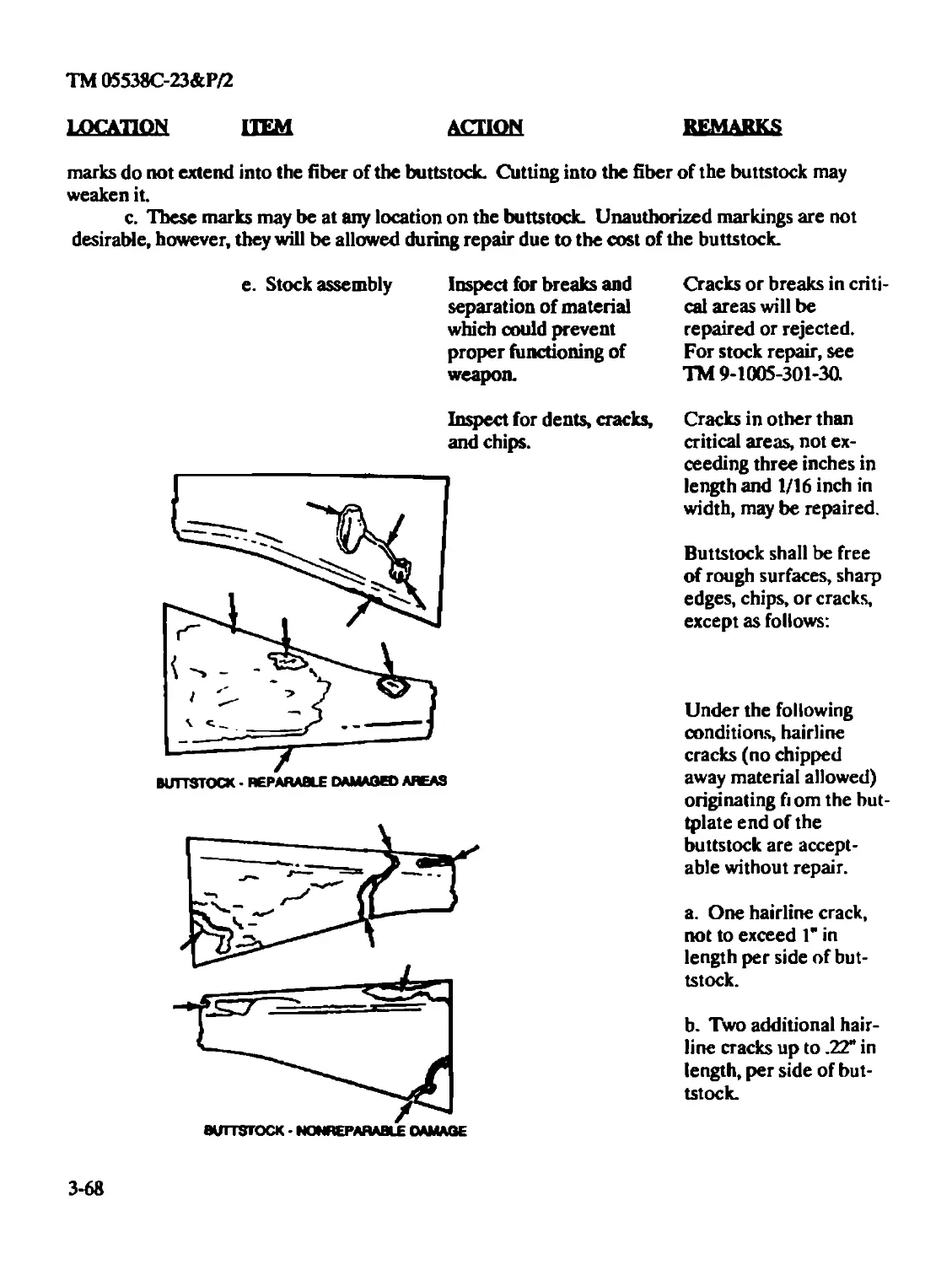
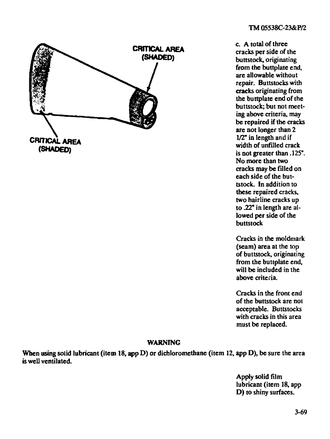
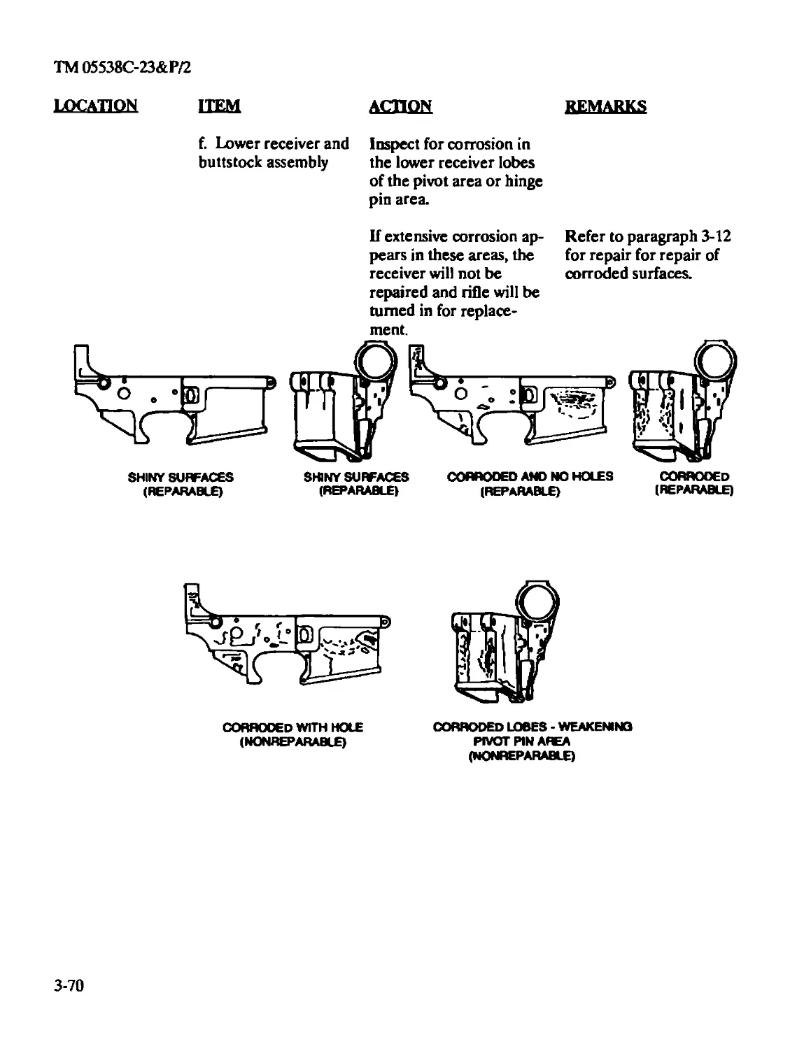
Inspection......................................................3-67
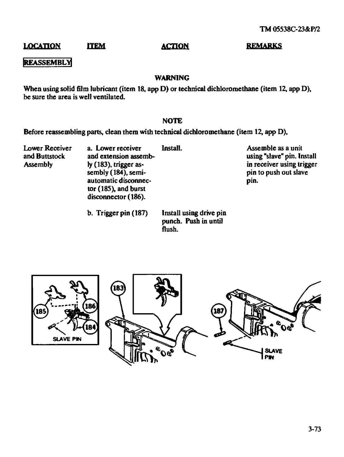
Reassembly .....................................................3-73
Index 8
TM 05538C-23&P/2
Subject Page
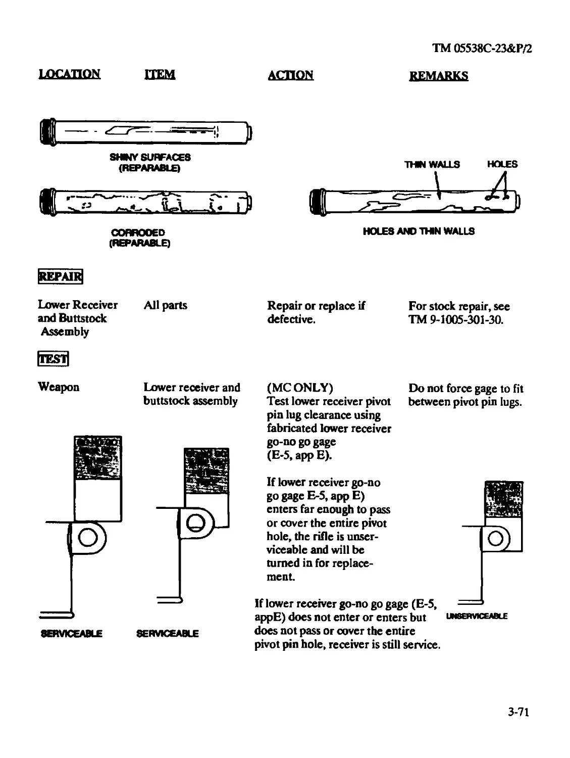
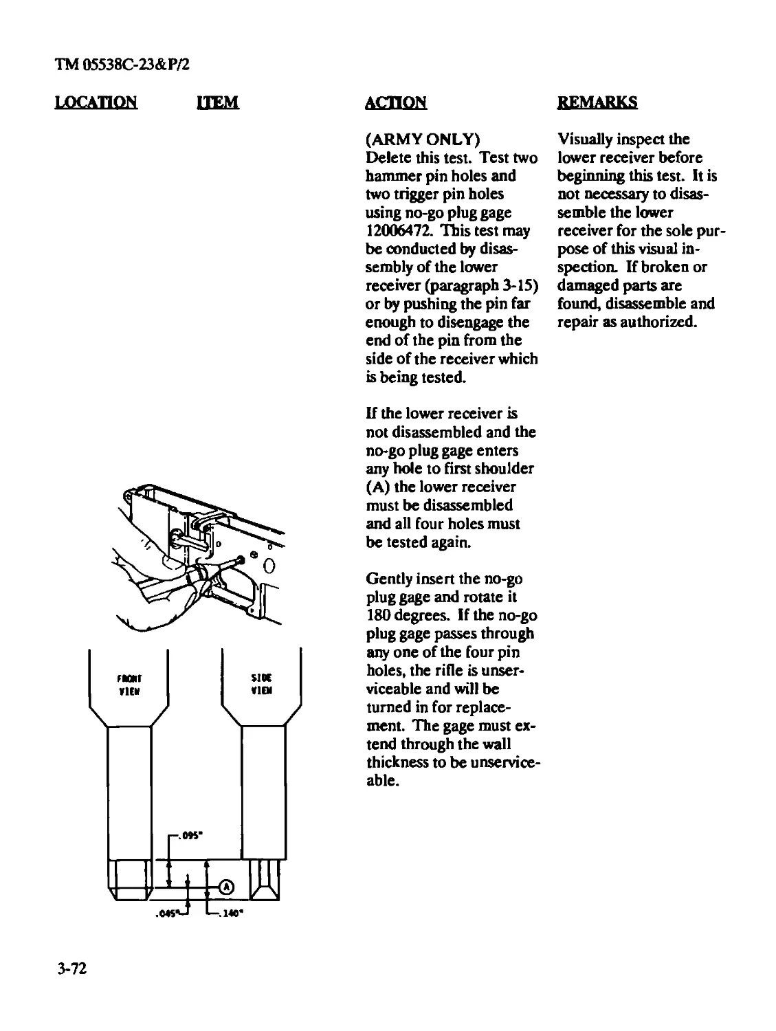
Repair...........................................................3-71
Test.............................................................3-71
Lower Receiver and Buttstock Assembly (Organizational)...................2-41
Disassembly......................................................2-41
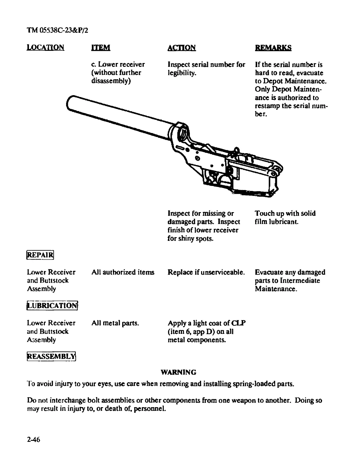
Inspection.......................................................2-45
Lubrication .....................................................2-46
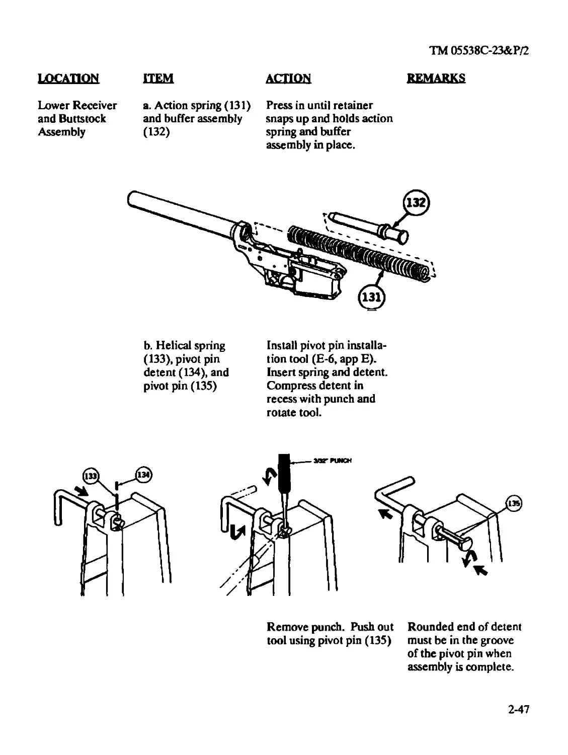
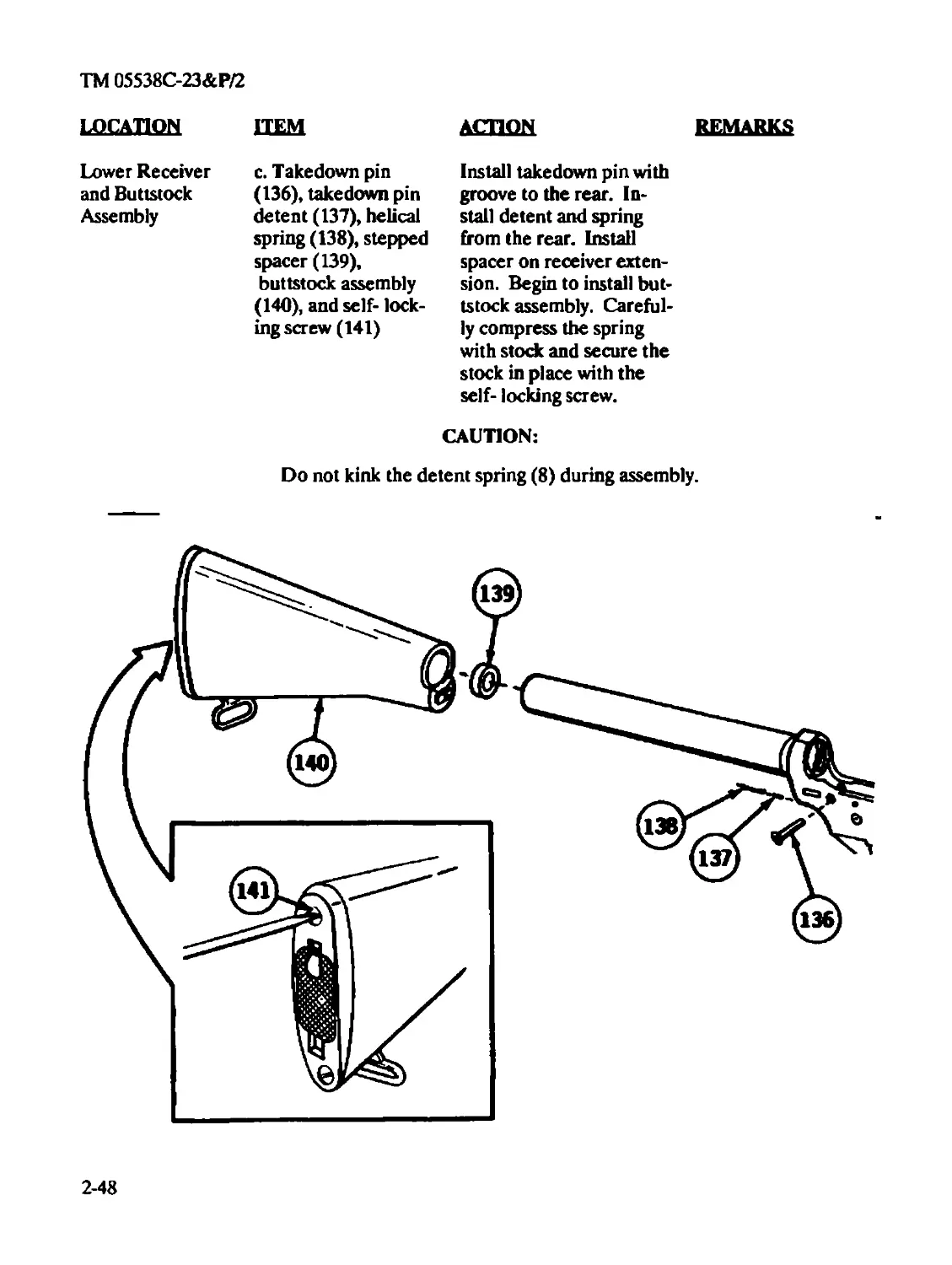
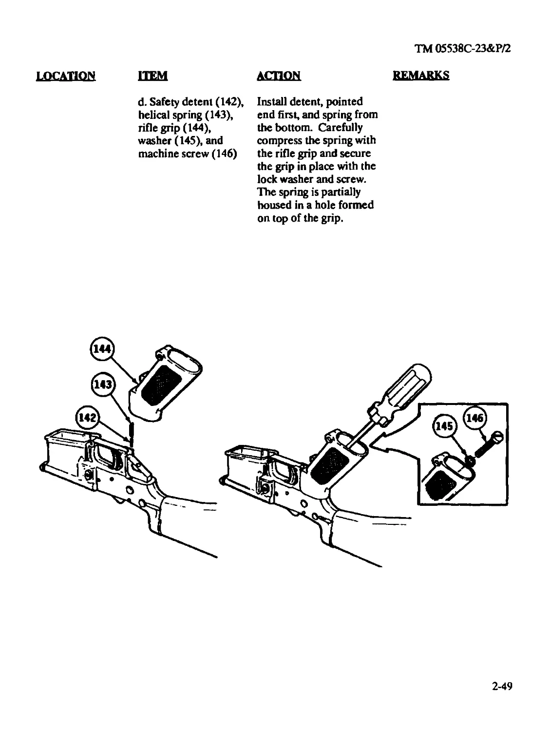
Reassembly ......................................................2-46
Repair...........................................................2-46
Lower Receiver and Receiver Extension Assembly (Intermediate)............3-82
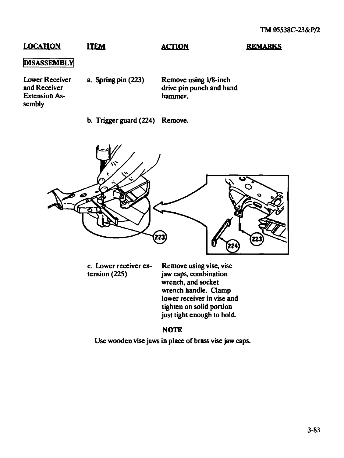
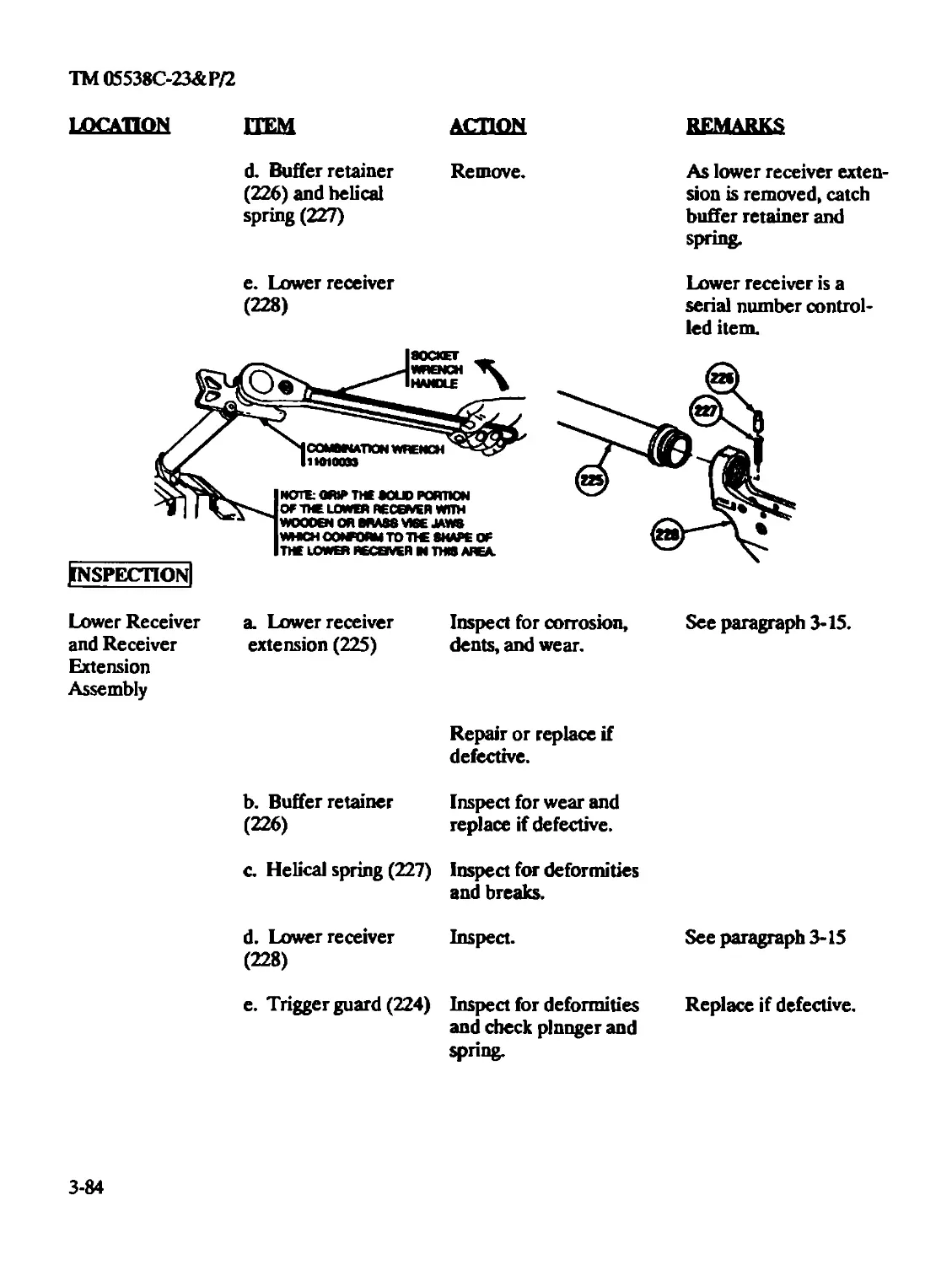
Disassembly......................................................3-83
Inspection.......................................................3-84
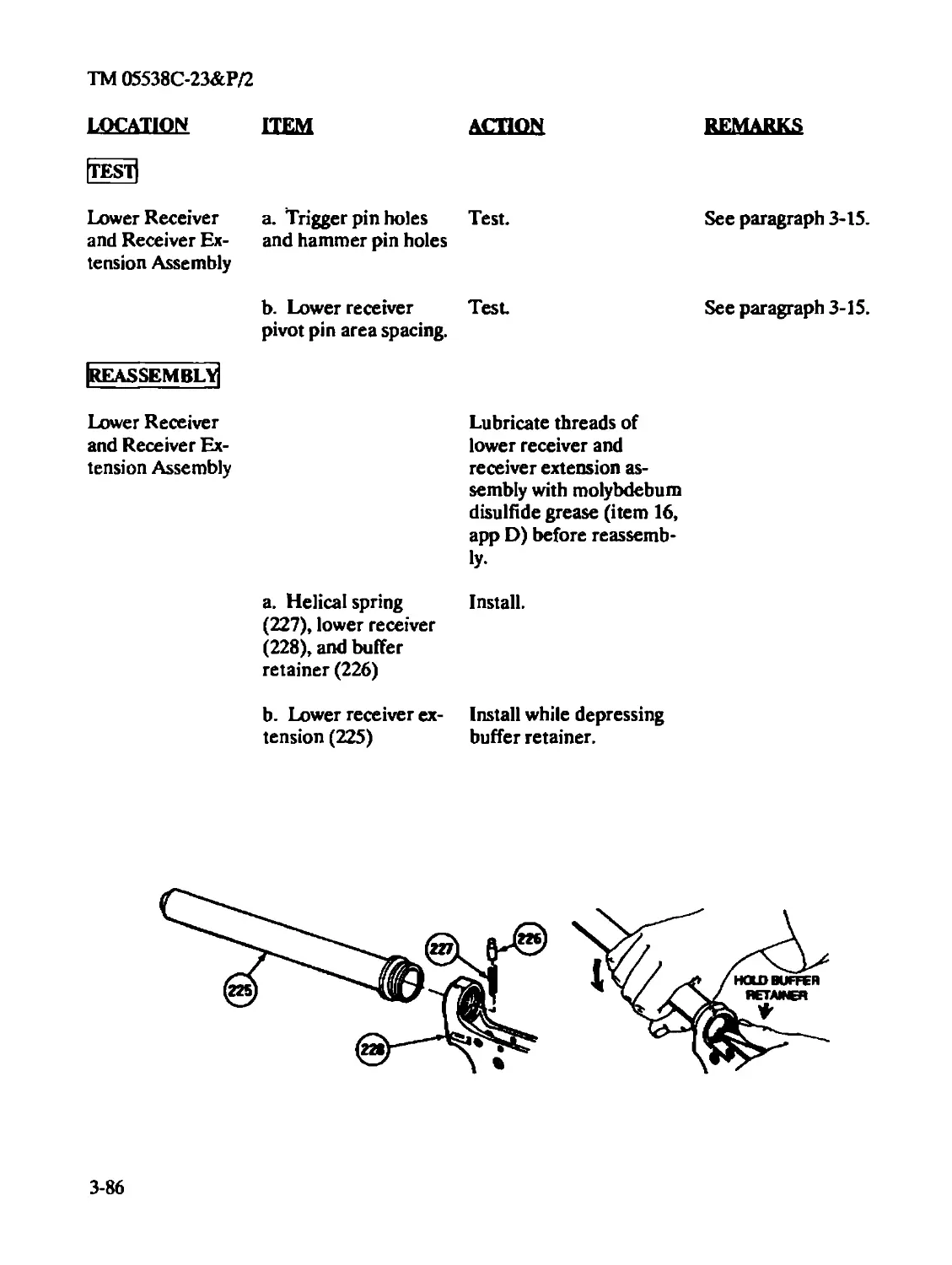
Reassembly.......................................................3-84
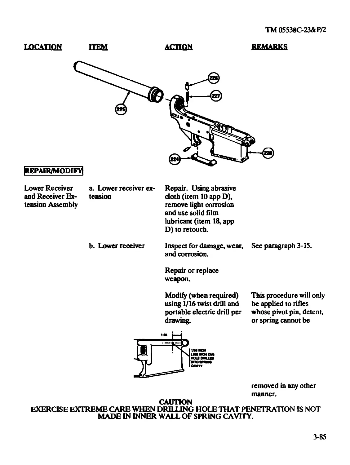
Repair/Modify....................................................3-85
Test.............................................................3-86
Lubrication
Bolt Assembly (Organizational)...................................2-27
Bolt Carrier Assembly (Organizational)...........................2-23
Buttstock Assembly (Organizational)..............................2-52
Charging Handle Assembly (Organizational) .......................2-30
Lower Receiver and Buttstock Assembly (Organizational)...........2-46
Upper Receiver and Rear Sight Assembly (Intermediate)............3-54
Index 9
ТМ 05538С-23&Р/2
Subject Page
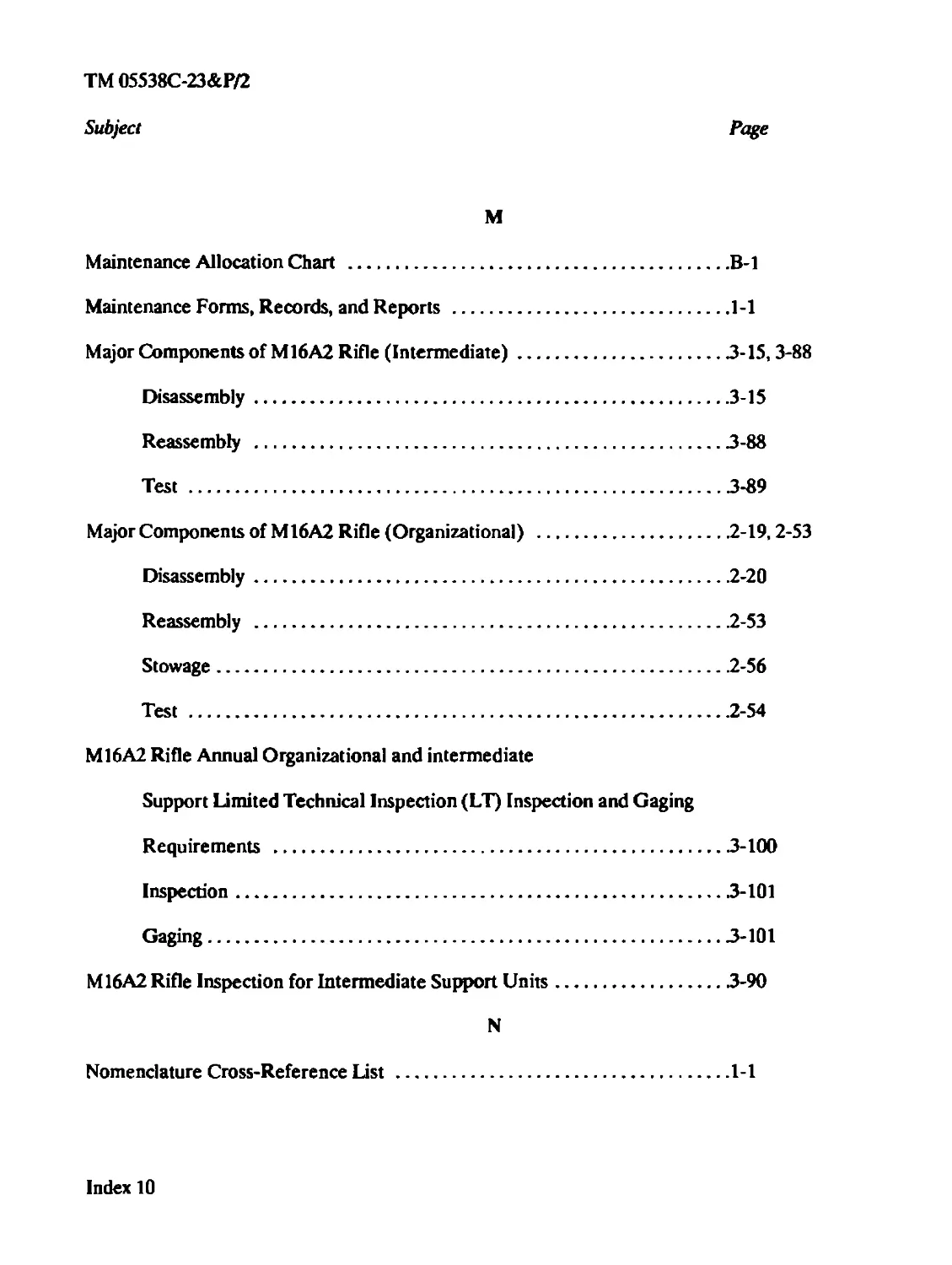
M
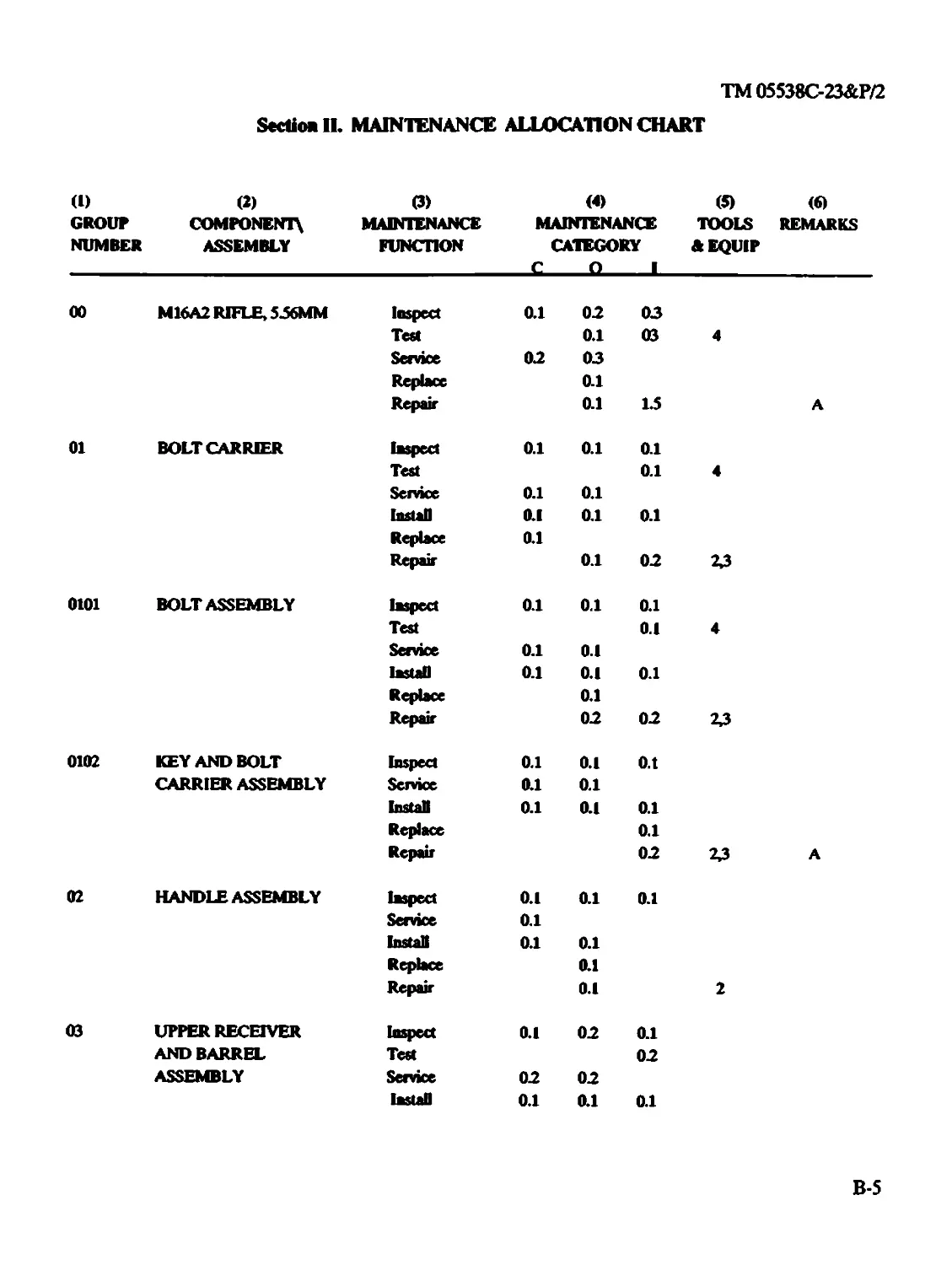
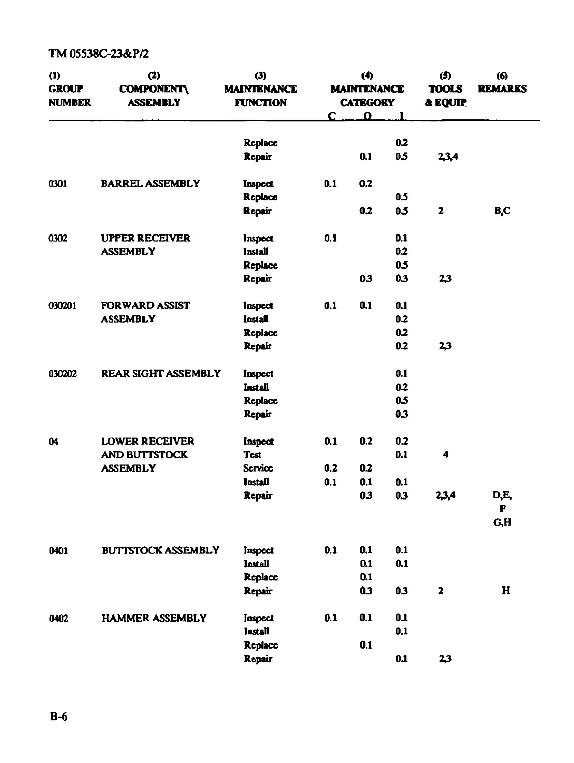
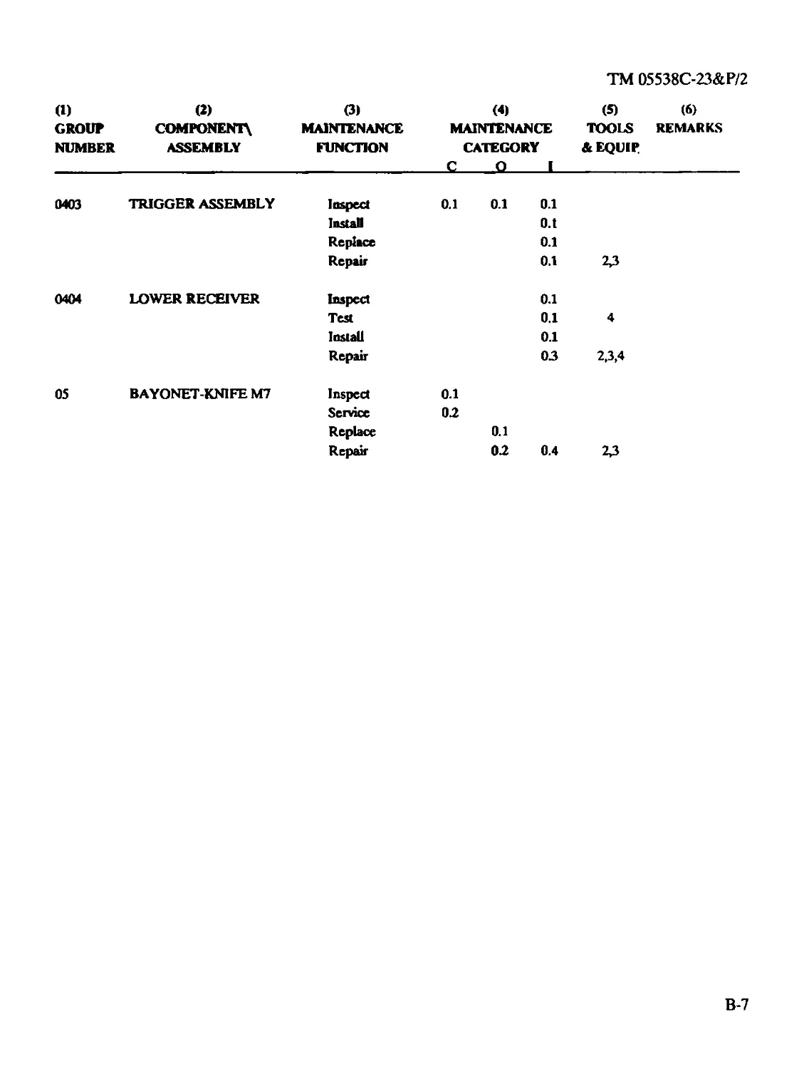
Maintenance Allocation Chart ........................................B-l
Maintenance Forms, Records, and Reports .............................1-1
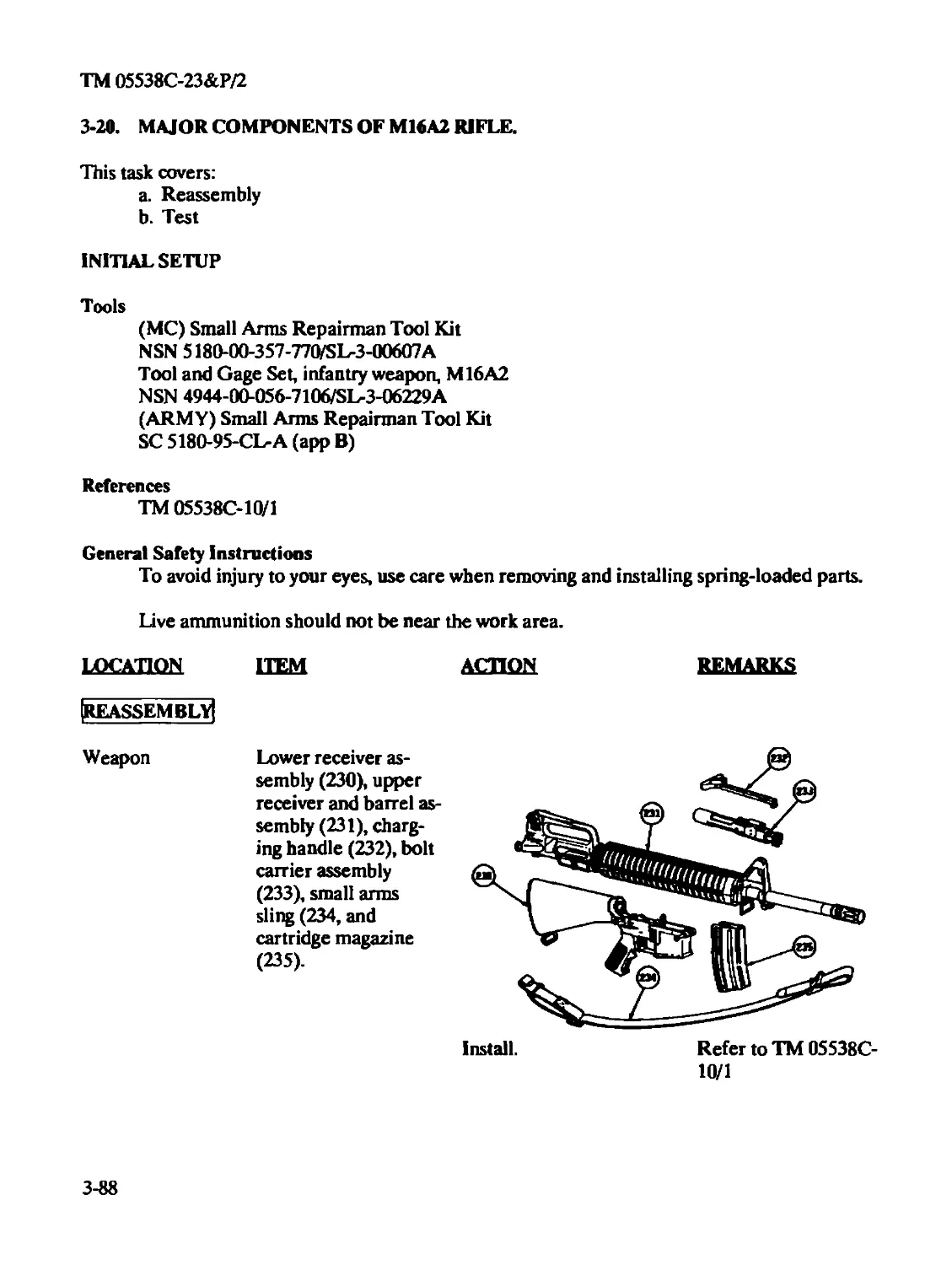
Major Components of M16A2 Rifle (Intermediate).......................3-15, 3-88
Disassembly....................................................3-15
Reassembly ....................................................3-88
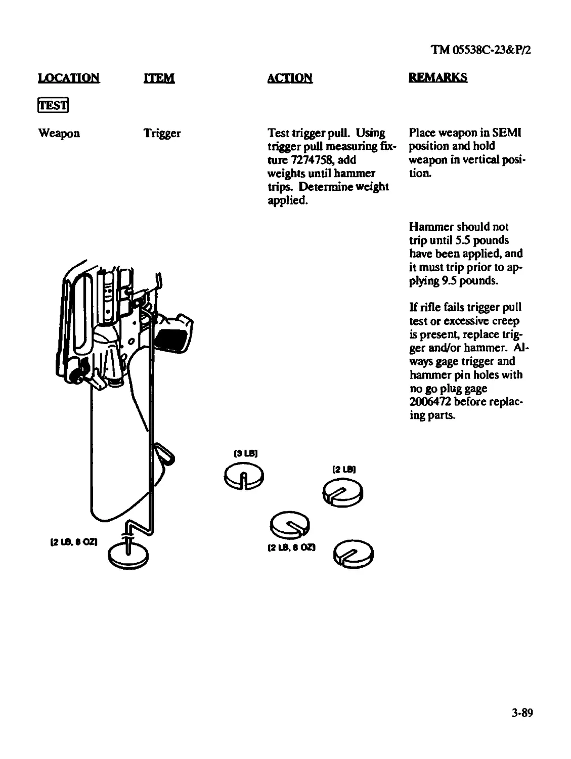
Test ..........................................................3-89
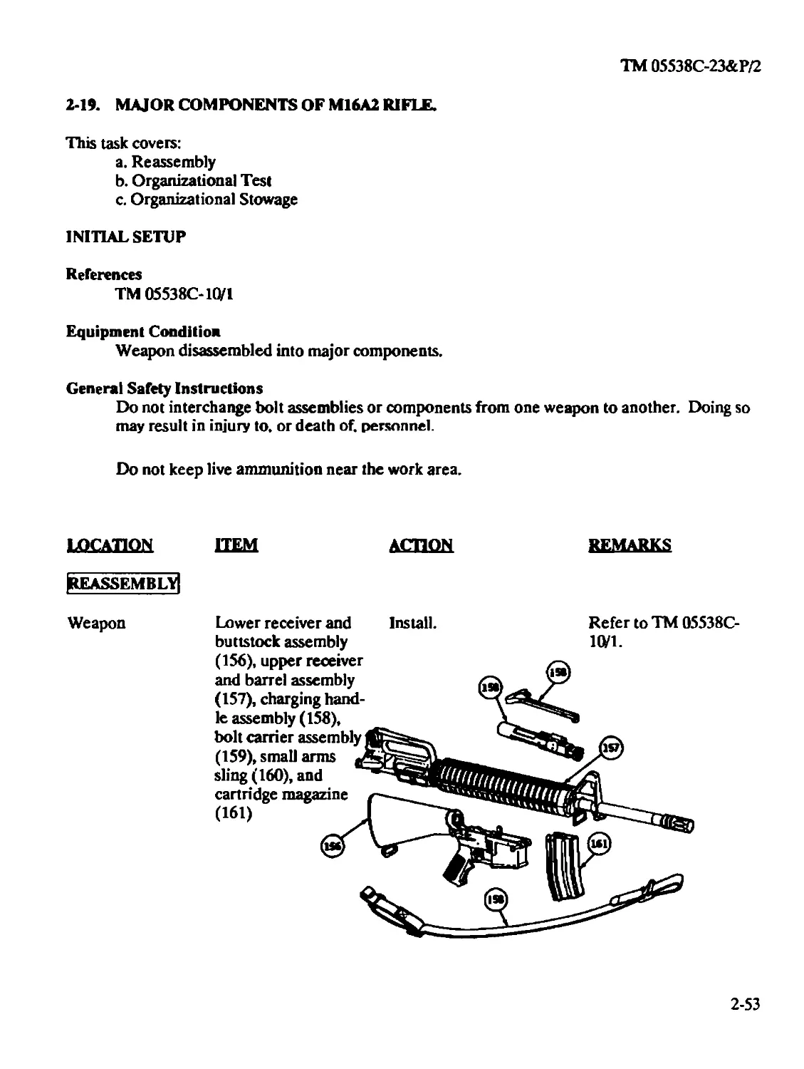
Major Components of M16A2 Rifle (Organizational) ....................2-19,2-53
Disassembly....................................................2-20
Reassembly ....................................................2-53
Stowage........................................................2-56
Test ..........................................................2-54
M16A2 Rifle Annual Organizational and intermediate
Support Limited Technical Inspection (LT) Inspection and Gaging
Requirements .................................................3-100
Inspection.....................................................3-101
Gaging........................................................3-101
M16A2 Rifle Inspection for Intermediate Support Units................3-90
N
Nomenclature Cross-Reference List ...................................1-1
Index 10
ТМ 05538С-23&Р/2
Subject Page
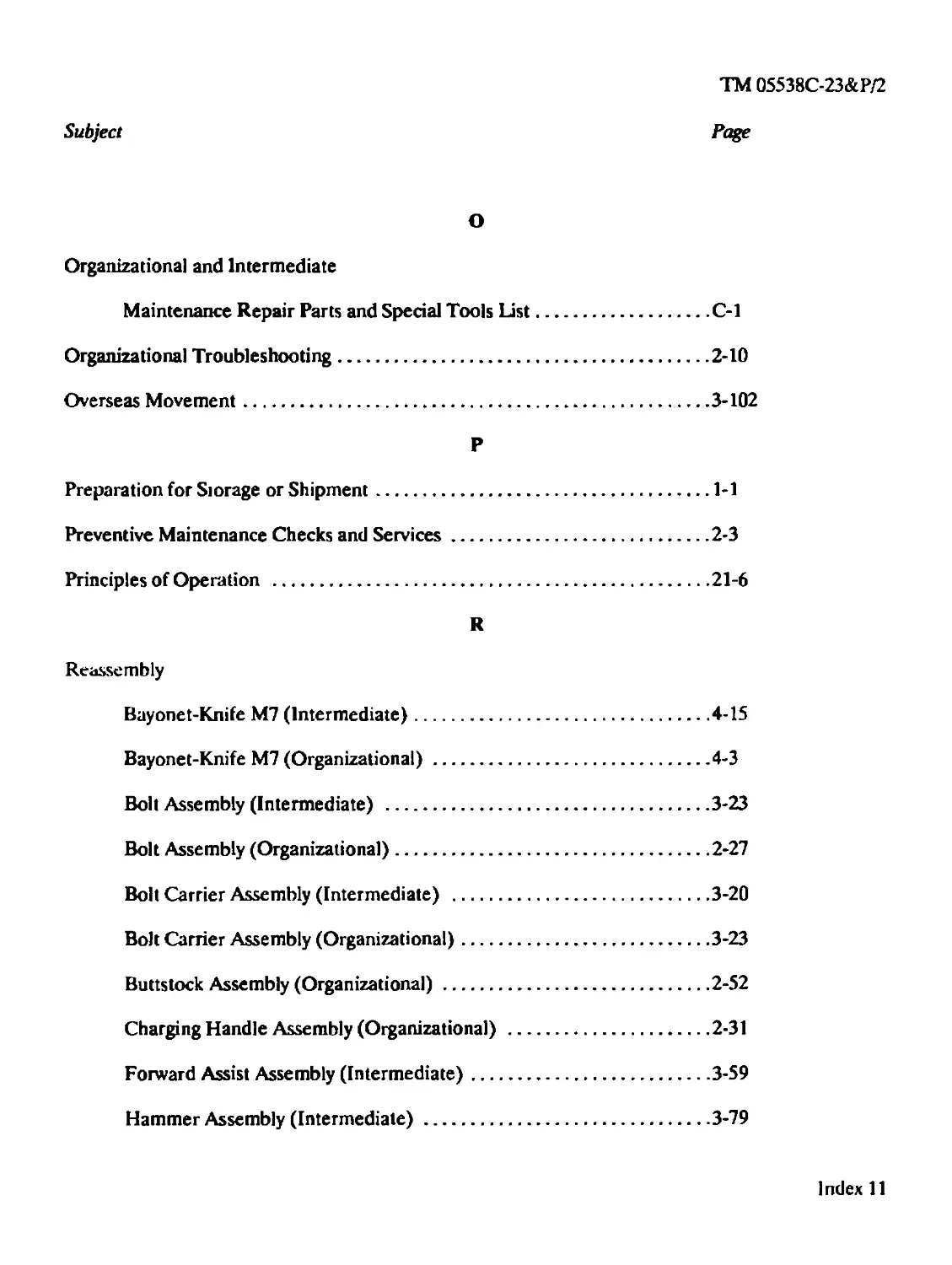
О
Organizational and Intermediate
Maintenance Repair Parts and Special Tools List..................C-l
Organizational Troubleshooting...........................................2-10
Overseas Movement........................................................3-102
P
Preparation for Storage or Shipment......................................1-1
Preventive Maintenance Checks and Services...............................2-3
Principles of Operation .................................................21-6
R
Reassembly
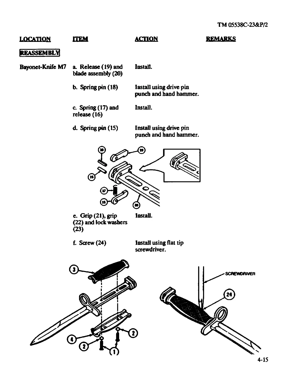
Bayonet-Knife M7 (Intermediate)..................................4-15
Bayonet-Knife M7 (Organizational).................................4-3
Bolt Assembly (Intermediate) ....................................3-23
Bolt Assembly (Organizational)...................................2-27
Bolt Carrier Assembly (Intermediate) ............................3-20
Bolt Carrier Assembly (Organizational)...........................3-23
Buttstock Assembly (Organizational)..............................2-52
Charging Handle Assembly (Organizational) .......................2-31
Forward Assist Assembly (Intermediate)...........................3-59
Hammer Assembly (Intermediate)...................................3-79
Index 11
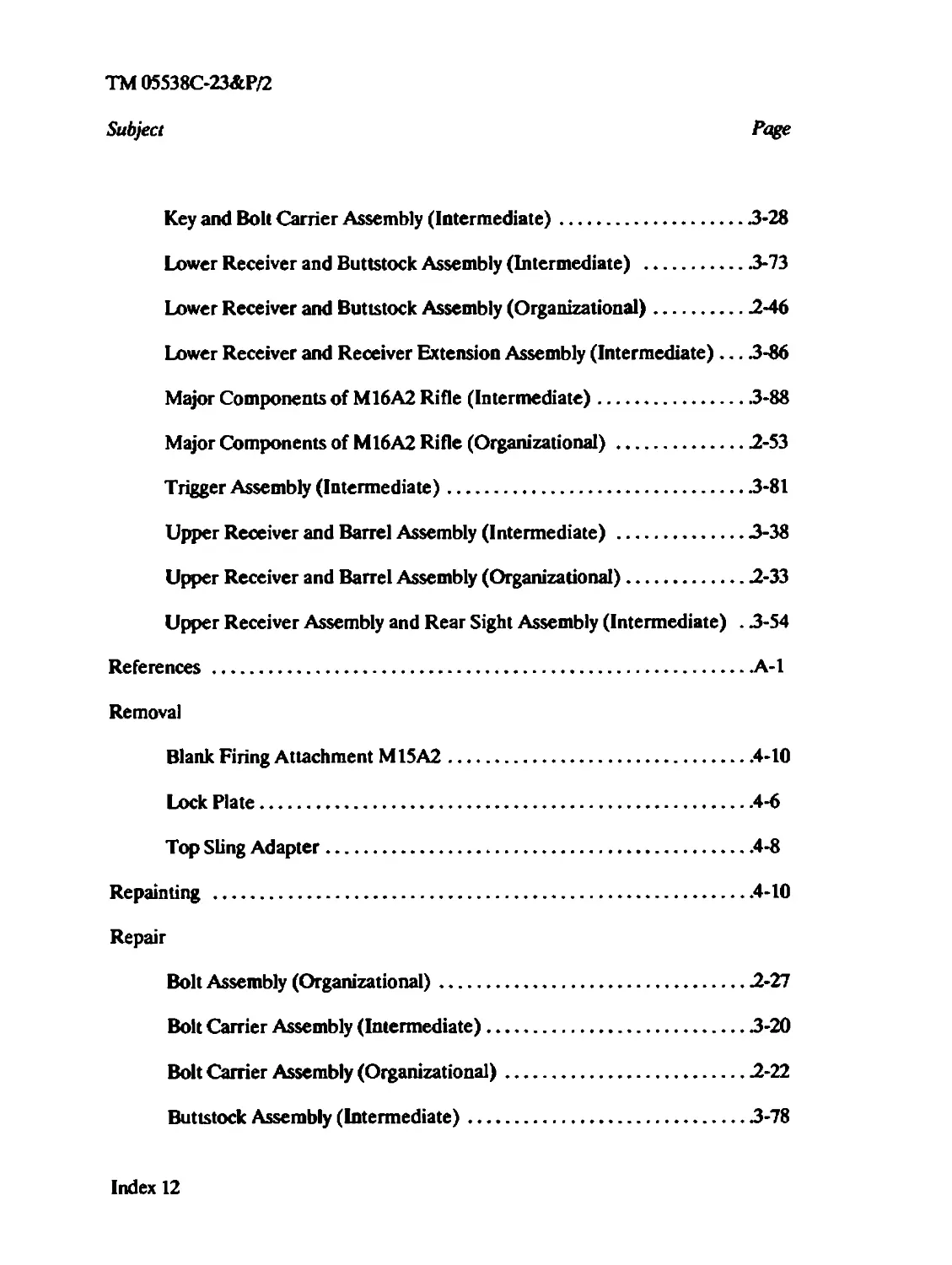
TM 05538C-23&P/2
Subject Page
Key and Bolt Carrier Assembly (Intermediate)......................3-28
Lower Receiver and Buttstock Assembly (Intermediate) ............3-73
Lower Receiver and Buttstock Assembly (Organizational)...........2-46
Lower Receiver and Receiver Extension Assembly (Intermediate) ... .3-86
Major Components of M16A2 Rifle (Intermediate)...................3-88
Major Components of M16A2 Rifle (Organizational).................2-53
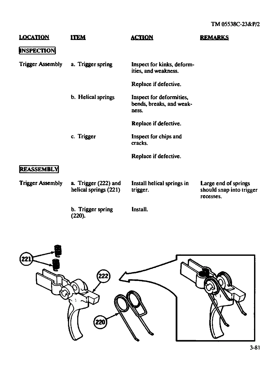
Trigger Assembly (Intermediate)..................................3-81
Upper Receiver and Barrel Assembly (Intermediate) ...............3-38
Upper Receiver and Barrel Assembly (Organizational)..............2-33
Upper Receiver Assembly and Rear Sight Assembly (Intermediate) . 3-54
References.............................................................A-l
Removal
Blank Firing Attachment M15A2....................................4-10
Lock Plate.......................................................4-6
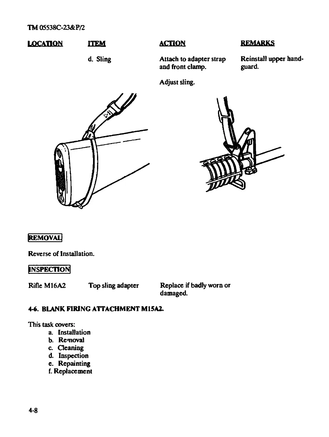
Top Sling Adapter.................................................4-8
Repainting ............................................................4-10
Repair
Bolt Assembly (Organizational)...................................2-27
Bolt Carrier Assembly (Intermediate).............................3-20
Bolt Carrier Assembly (Organizational)...........................2-22
Buttstock Assembly (Intermediate)................................3-78
Index 12
ТМ 05538С-23&Р/2
Subject Page
Buttstock Assembly (Organizational)...............................2-51
Forward Assist Assembly (Intermediate)............................3-58
Lower Receiver and Buttstock Assembly (Intermediate) .............3-71
Lower Receiver and Buttstock Assembly (Organizational)....................2-46
Upper Receiver and Barrel Assembly (Intermediate).................3-37
Upper Receiver and Barrel Assembly (Organizational) ..............3-38
Upper Receiver and Rear Sight Assembly (Intermediate) ....................3-53
Repair/Modify
Lower Receiver and Receiver Extension Assembly (Intermediate) .. .3-85
Replacement
Blank Firing Attachment M15A2.....................................4-10
Reporting of Unsatisfactory Equipment.....................................1-1
S
Scope.....................................................................1-1
Service Upon Receipt of Materiel (Intermediate) ..........................3-2
Service Upon Receipt of Material (Organizational).........................2-2
SpecialTools..............................................................2-1,3-1
Stowage
Major Components of M16A2 Rifle (Organizational).........................2-56
Index 13
ТМ 05538С-23&Р/2
Subject Page
T
Test
Bolt Carrier Assembly (Intermediate)............................3-19
Lower Receiver and Buttstock Assembly (Intermediate) ...........3-71
Lower Receiver and Receiver Extension Assembly (Intermediate) ... 3-86
Major Components of M16A2 Rifle (Intermediate)...................3-89
Major Components of M16A2 Rifle (Organizational) ...............2-54
M16A2 Rifle Final Inspection for Intermediate Support Units ....3-94
Upper Receiver and Barrel Assembly (Intermediate) ...............3-45
Three-Round Burst Control, Functional Theory...........................3-94
Top Sling Adapter.......................................................4-6
Inspection........................................................4-8
Installation......................................................4-7
Removal...........................................................4-8
Torque Limits..........................................................J-l
Trigger Assembly (Intermediate)........................................3-80
Disassembly......................................................3-80
Inspection.......................................................3-81
Reassembly ......................................................3-81
Troubleshooting, Intermediate..........................................3-4
Troubleshooting, Organizational .......................................2-11
Index 14
TM 05538C-23&P/2
Subject Page
U
Unsatisfactory Equipment, Reporting of ................................1-1
Upper Receiver and Barrel Assembly (Intermediate) ......................3-29
Disassembly.....................................................3-30
Inspection/Cleaning.............................................3-34
Reassembly......................................................3-38
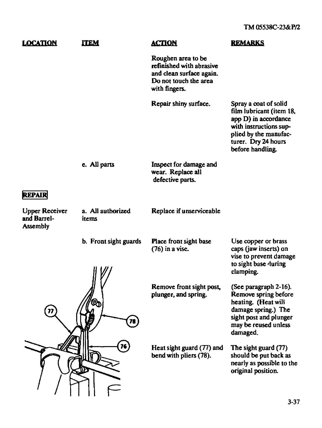
Repair..........................................................33-37
Test............................................................3-45
Upper Receiver and Barrel Assembly (Organizational).....................2-31
Disassembly.....................................................2-31
Inspection/Repair...............................................2-32
Reassembly......................................................2-33
Upper Receiver Assembly and Rear Sight Assembly (Intermediate) .........3-48
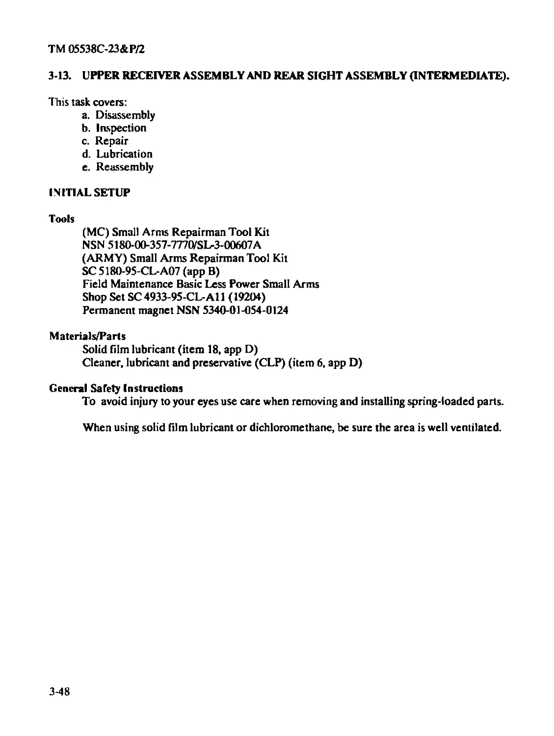
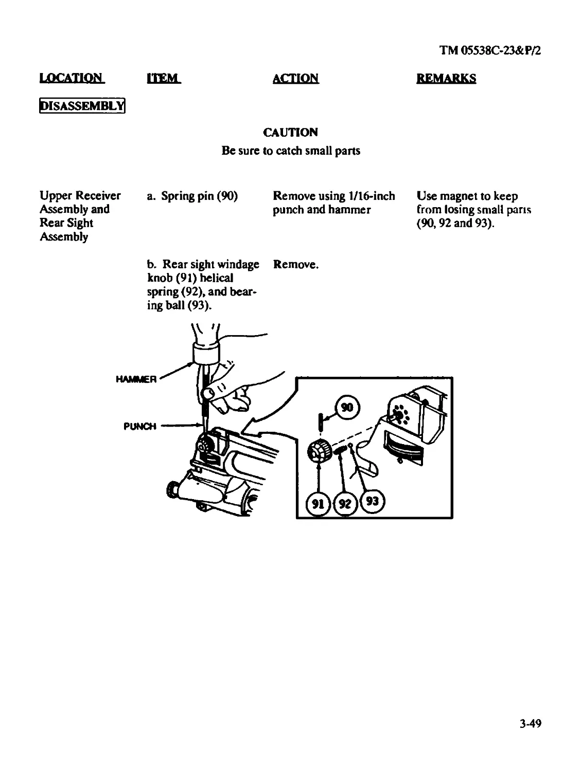
Disassembly.....................................................3-49
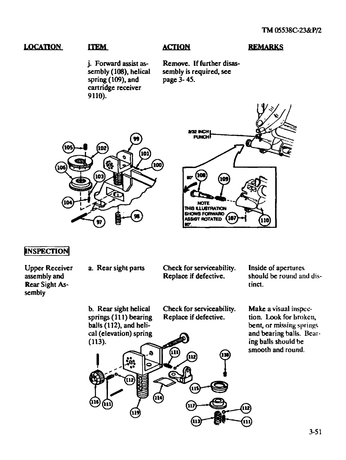
Inspection......................................................3-51
Lubrication ....................................................3-54
Reassembly......................................................3-54
Repair..........................................................3-53
•u s. GOvtRNMDfmwnecomcE: i n и * в i ia ♦ 2 ? 5
Index 15
ТМ 05538С-23&Р/2
CHAPTER2
ORGANIZATIONAL MAINTENANCE INSTRUCTIONS
CHAPTER OVERVIEW
This chapter provides information and instructions to help keep the rifle in good repair and
contains the following sections:
I. Repair Parts and Special Tools
II. Service Upon Receipt
III. Organizational Preventive Maintenance Checks and Services (PMCS)
IV. Organizational Troubleshooting
V. Organizational Maintenance Procedures
VI. Decontamination of Rifles and Arms Rooms
Section I. REPAIR PARTS AND SPECIAL TOOLS
2-1. COMMON TOOLS AND EQUIPMENT. For authorized common tools and equipment, see
(MC) SL-3-00607A.
For Army authorized common tools and equipment refer to the Modified Table of Organization
and Equipment (TOE/MTOE) applicable to your unit.
2-2. SPECIAL TOOLS. Special tools required for organizational support are listed in appendix C.
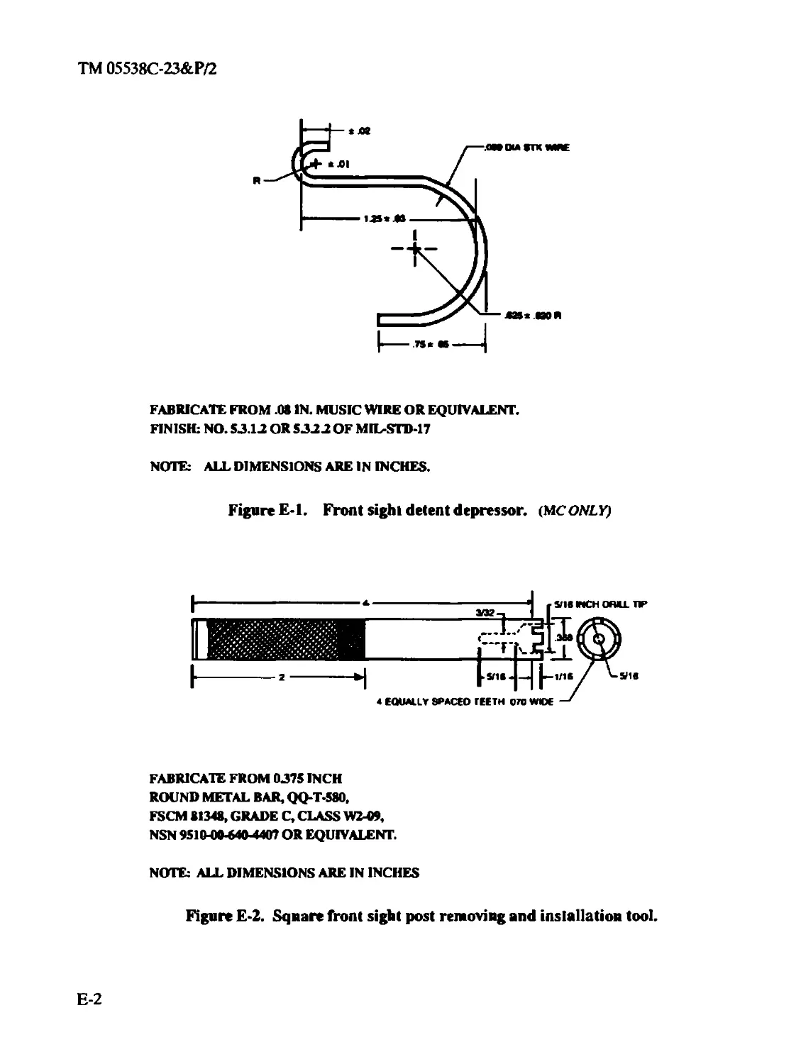
Fabricated tools are listed and illustrated in appendix E.
2-3. REPAIR PARTS. Repair parts are listed and illustrated in appendix C of this manual.
Section II. SERVICE UPON RECEIPT
2-4. GENERAL.
a. (MC ONLY) Check the weapon against the packing slip to see if the shipment is complete.
Report all discrepancies in accordance with MCO P4610.19C.
b. Check to see if all modification instructions have been applied.
c. Inspect the rifle for shipping damage. If it has been damaged, submit an SF 364, Report of
Discrepancy (ROD).
d. (ARMY ONLY) Report all discrepancies in accordance with DA PAM 738-750.
2-1
ТМ 05538С-23&Р/2
2-5. ORGANIZATIONAL SERVICE UPON RECEIPT OF MATERIAL. Refer to the following
table.
Table 2-1
SERVICE UPON RECEIPT • M16A2 RIFLE
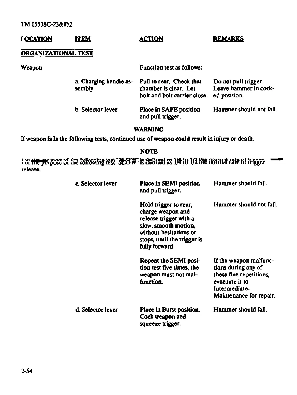
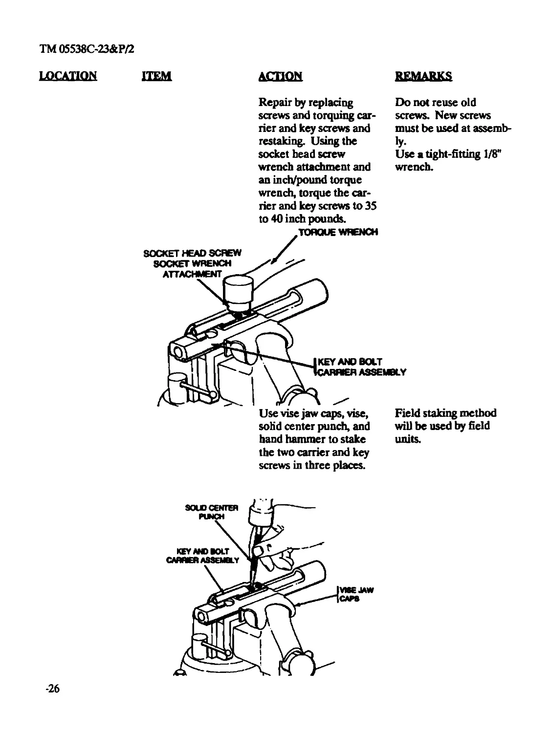
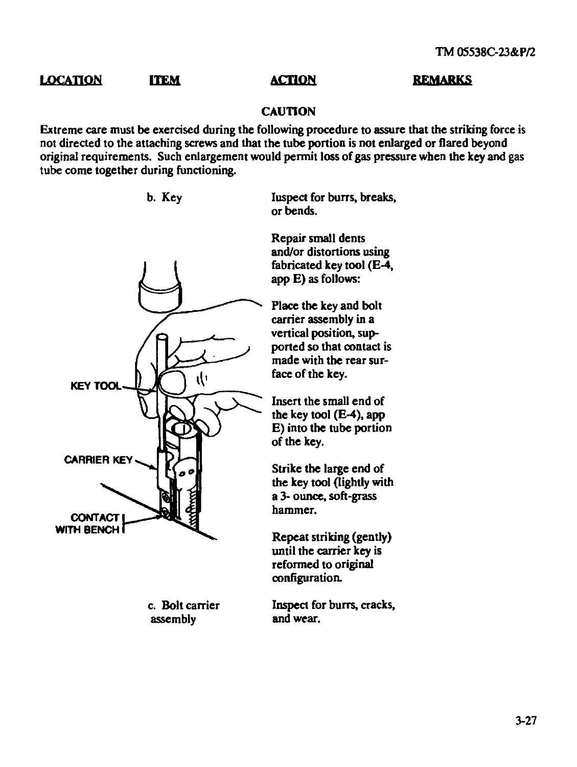
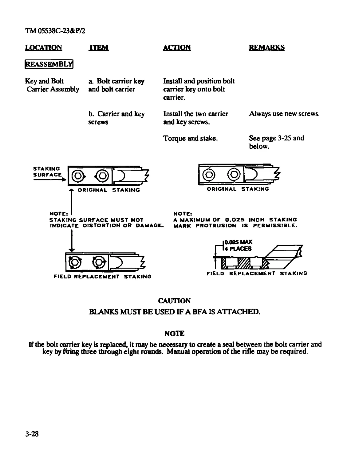
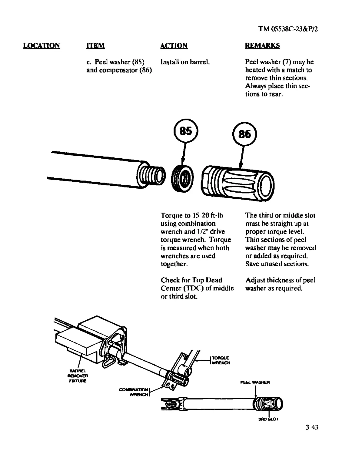
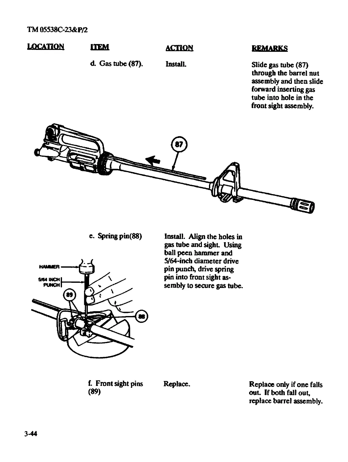
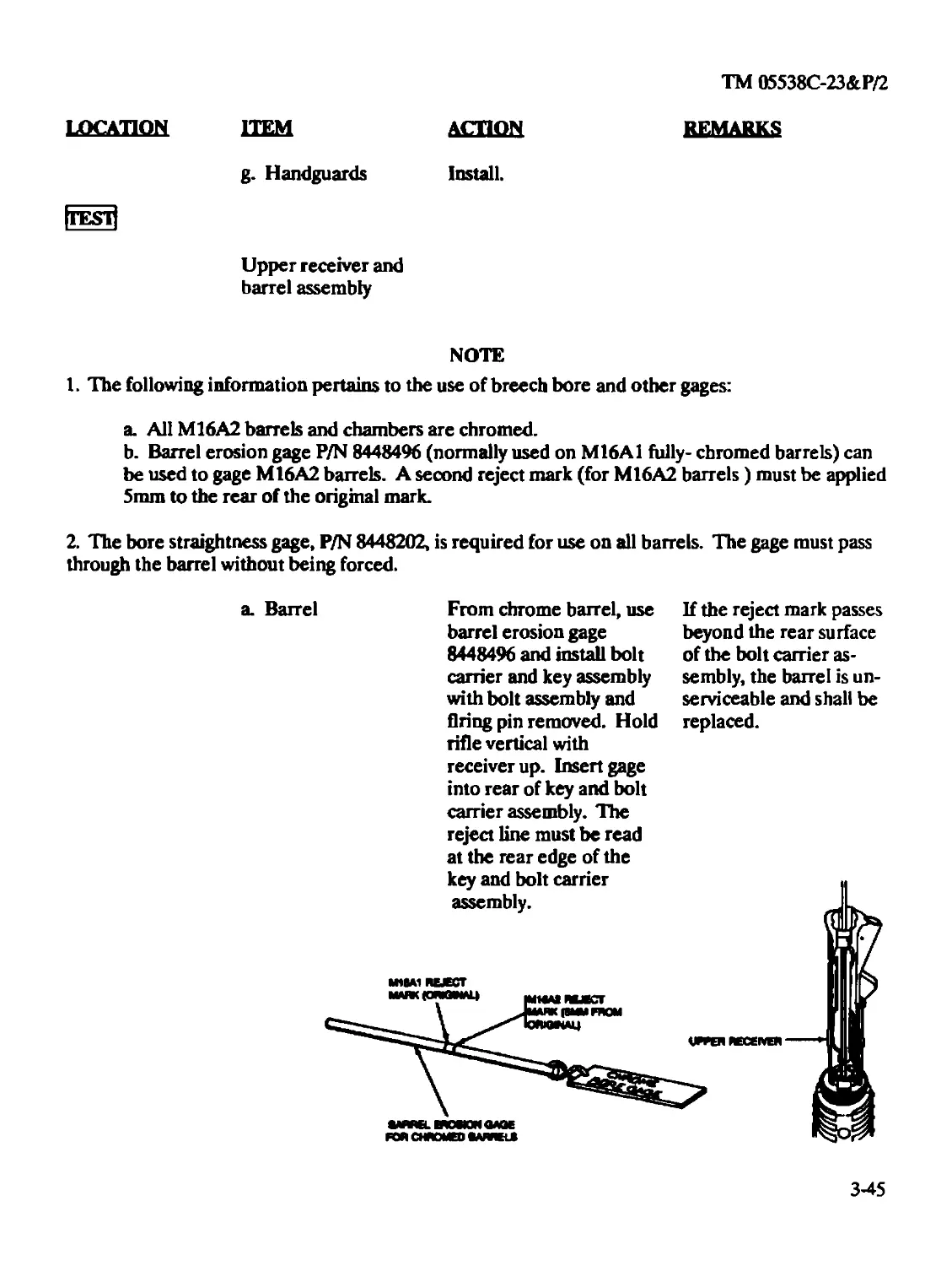
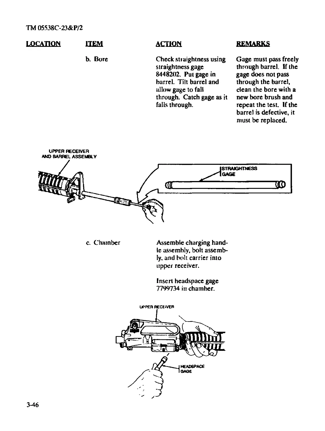
LOCATION ITEM ACTION
REMARKS
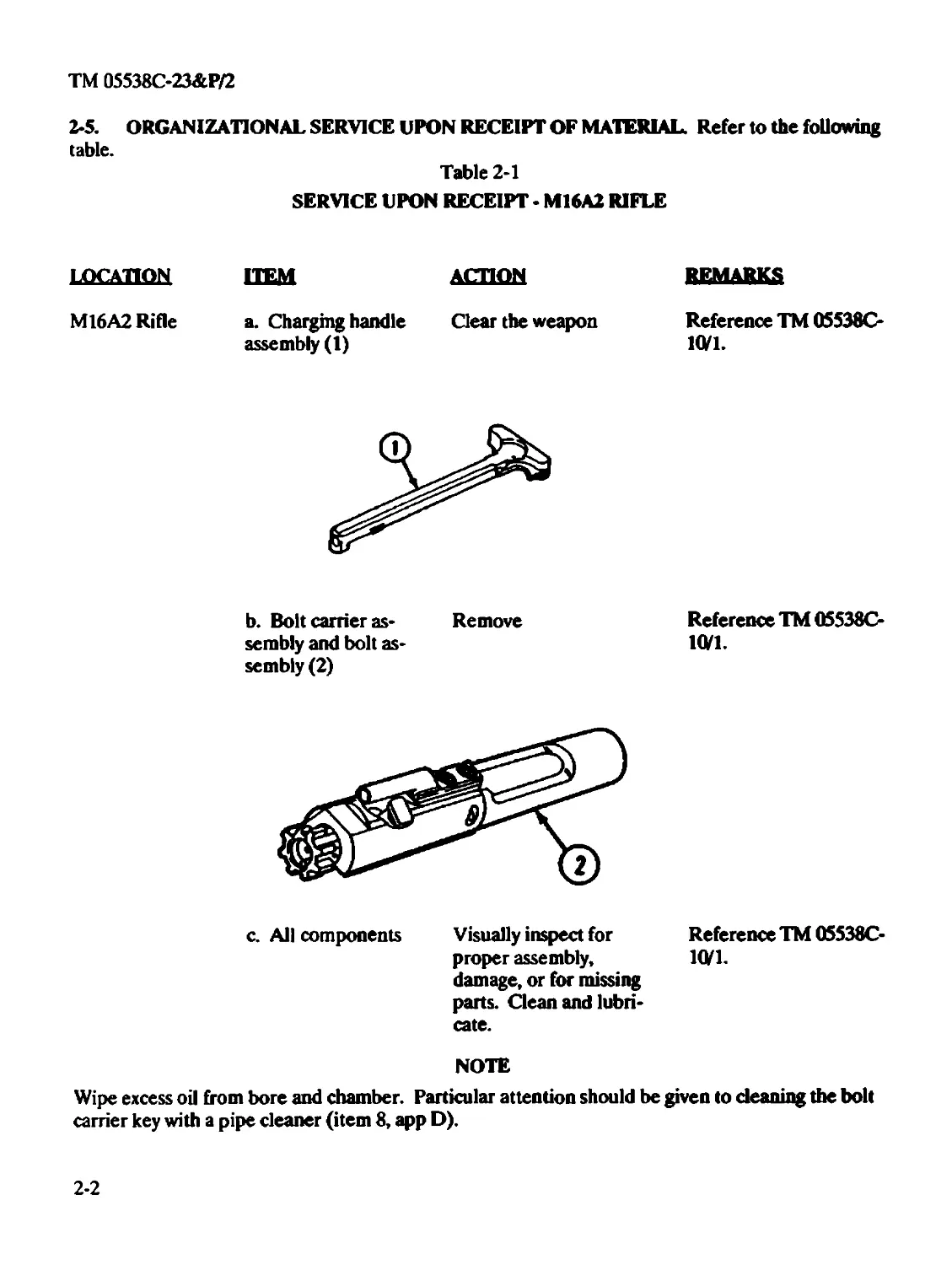
M16A2 Rifle a. Charging handle Clear the weapon
assembly (1)
Reference TM 05538C-
10/1.
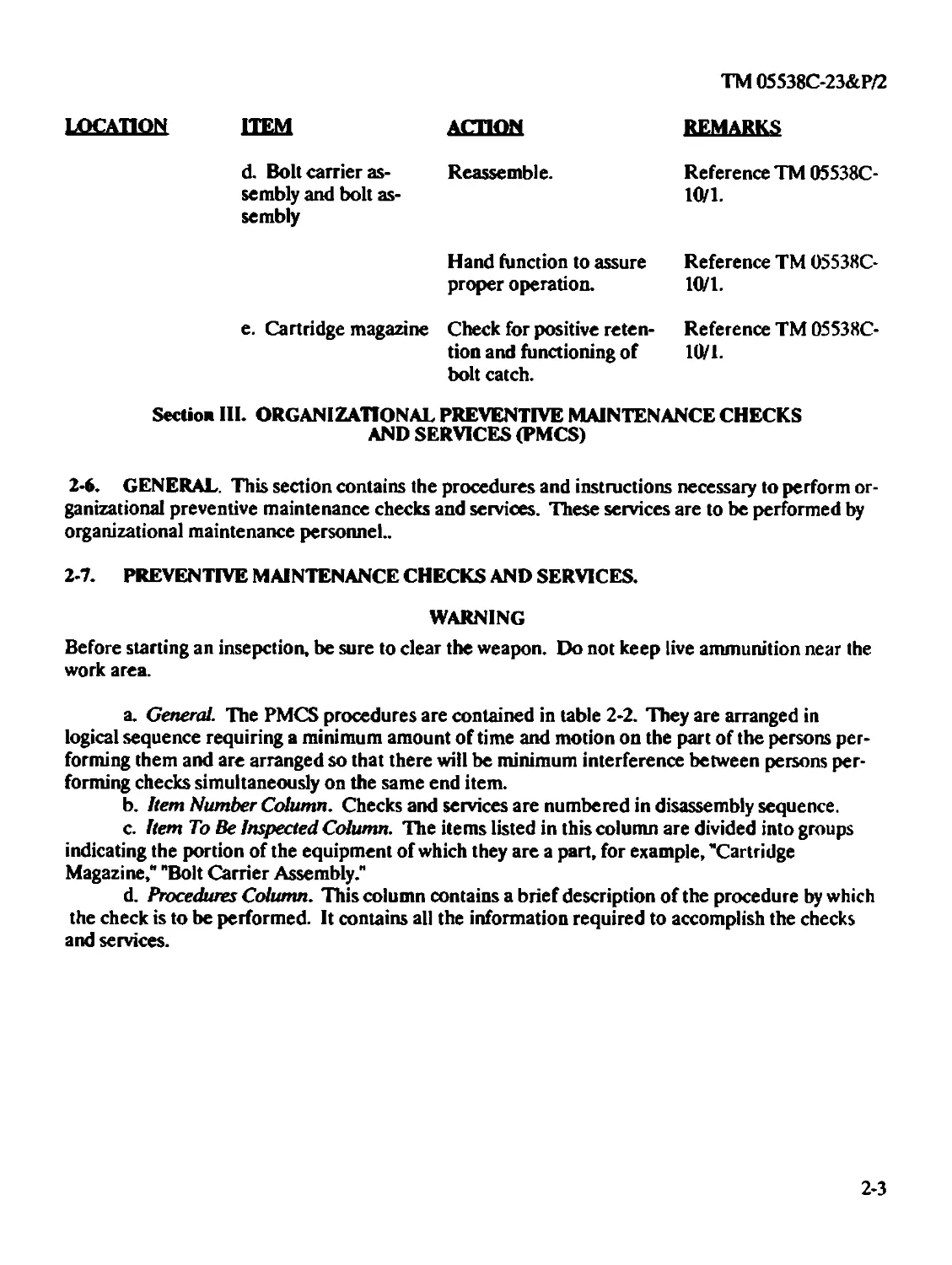
b. Bolt carrier as- Remove
sembly and bolt as-
sembly (2)
Reference TM 05538C-
1(V1.
c. All components
Visually inspect for
proper assembly,
damage, or for missing
parts. Clean and lubri-
cate.
Reference TM 05538C-
10/1.
NOTE
Wipe excess oil from bore and chamber. Particular attention should be given to cleaning the bolt
carrier key with a pipe cleaner (item 8, app D).
2-2
TM 05538C-23&P/2
location
HEM ACTION
d. Bolt carrier as- Reassemble,
sembly and bolt as-
sembly
REMARKS
Reference TM 05538C-
10/1.
Hand function to assure
proper operation.
e. Cartridge magazine Check for positive reten-
tion and functioning of
bolt catch.
Reference TM 05538C-
10/1.
Reference TM 05538C-
10/1.
Section III. ORGANIZATIONAL PREVENTIVE MAINTENANCE CHECKS
AND SERVICES (PMCS)
2-6. GENERAL. This section contains the procedures and instructions necessary to perform or-
ganizational preventive maintenance checks and services. These services are to be performed by
organizational maintenance personnel..
2-7. PREVENTIVE MAINTENANCE CHECKS AND SERVICES.
WARNING
Before starting an insepction, be sure to clear the weapon. Do not keep live ammunition near the
work area.
a. General. The PMCS procedures are contained in table 2-2. They are arranged in
logical sequence requiring a minimum amount of time and motion on the part of the persons per-
forming them and are arranged so that there will be minimum interference between persons per-
forming checks simultaneously on the same end item.
b. Item Number Column. Checks and services are numbered in disassembly sequence.
c. Item To Be Inspected Column. The items listed in this column are divided into groups
indicating the portion of the equipment of which they are a part, for example, 'Cartridge
Magazine," "Bolt Carrier Assembly."
d. Procedures Column. This column contains a brief description of the procedure by which
the check is to be performed. It contains all the information required to accomplish the checks
and services.
2-3
ТМ 05538С-23&Р/2
Table 2-2
ORGANIZATIONAL PREVENTIVE MAINTENANCE CHECKS AND SERVICES
QUARTERLY SCHEDULE
Item
Na
Item To Be Inspected
Procedures
WARNING
Before starting an inspection, be sure to clear the rifle. Do not actuate the trigger until the rifle
has been cleared. Inspect the chamber to ensure that it is empty and no ammunition is in position
to be chambered. Do not keep live ammunition near work area.
NOTE
Whenever the term "Cleaner Lubricant and Preservative" (CLP) or the words "lubricant", "lube",
"LSA", or "LAW" are cited in this TM, they arc to be interpreted to mean that CLP, LSA or LAW
can be utilized as applicable. Follow constraints noted on page 1-5.
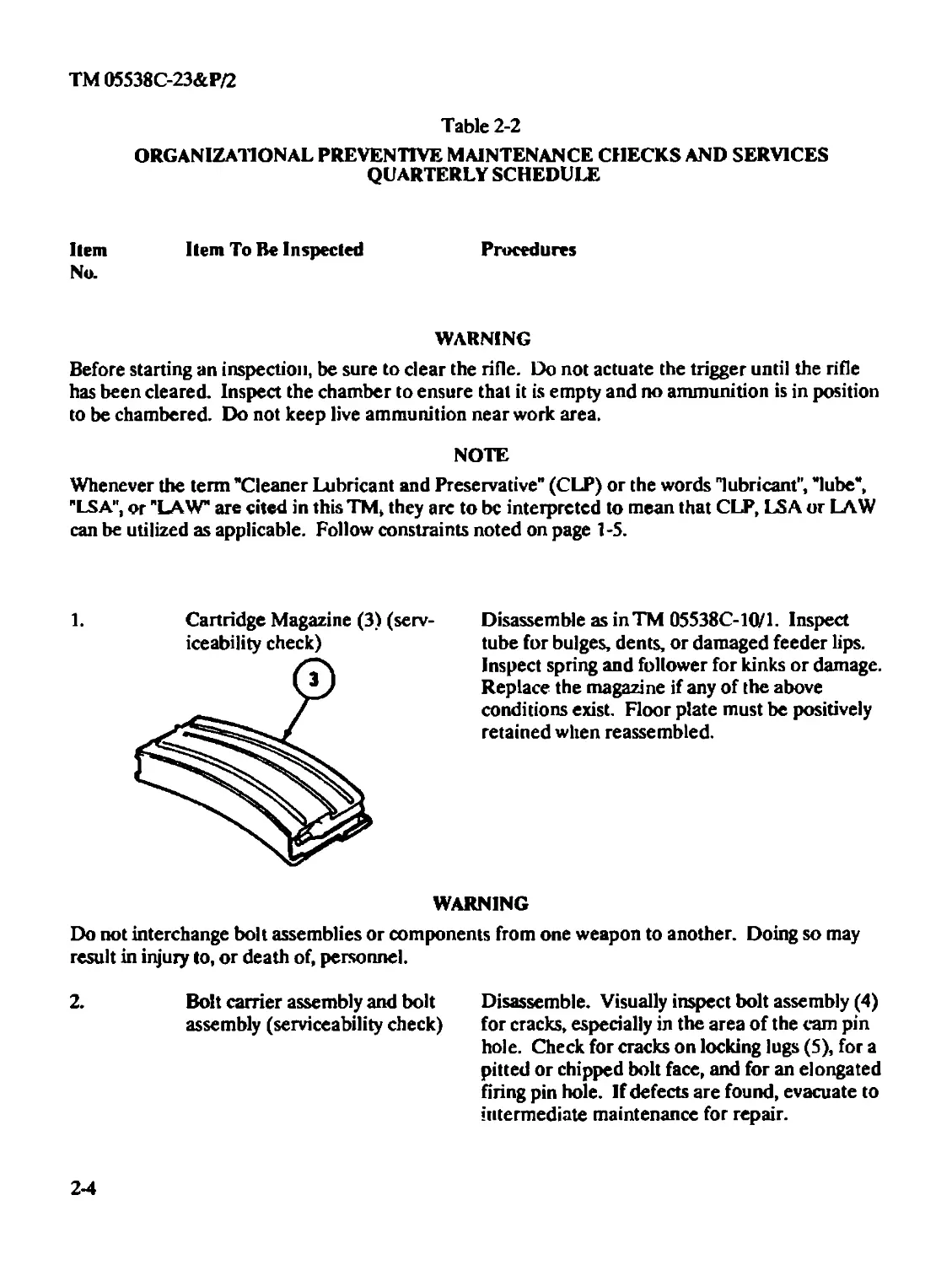
1. Cartridge Magazine (3) (serv-
iceability check)
Disassemble as inTM 05538C-10/1. Inspect
tube for bulges, dents, or damaged feeder lips.
Inspect spring and follower for kinks or damage.
Replace the magazine if any of the above
conditions exist. Floor plate must be positively
retained when reassembled.
WARNING
Do not interchange bolt assemblies or components from one weapon to another. Doing so may
result in injury to, or death of, personnel.
2. Bolt carrier assembly and bolt
assembly (serviceability check)
Disassemble. Visually inspect bolt assembly (4)
for cracks, especially in the area of the cam pin
hole. Check for cracks on locking lugs (5), for a
pitted or chipped bolt face, and for an elongated
firing pin hole. If defects are found, evacuate to
intermediate maintenance for repair.
2-4
TM 05538C-23&P/2
Item- Item To Be Inspected
No.
Procedures
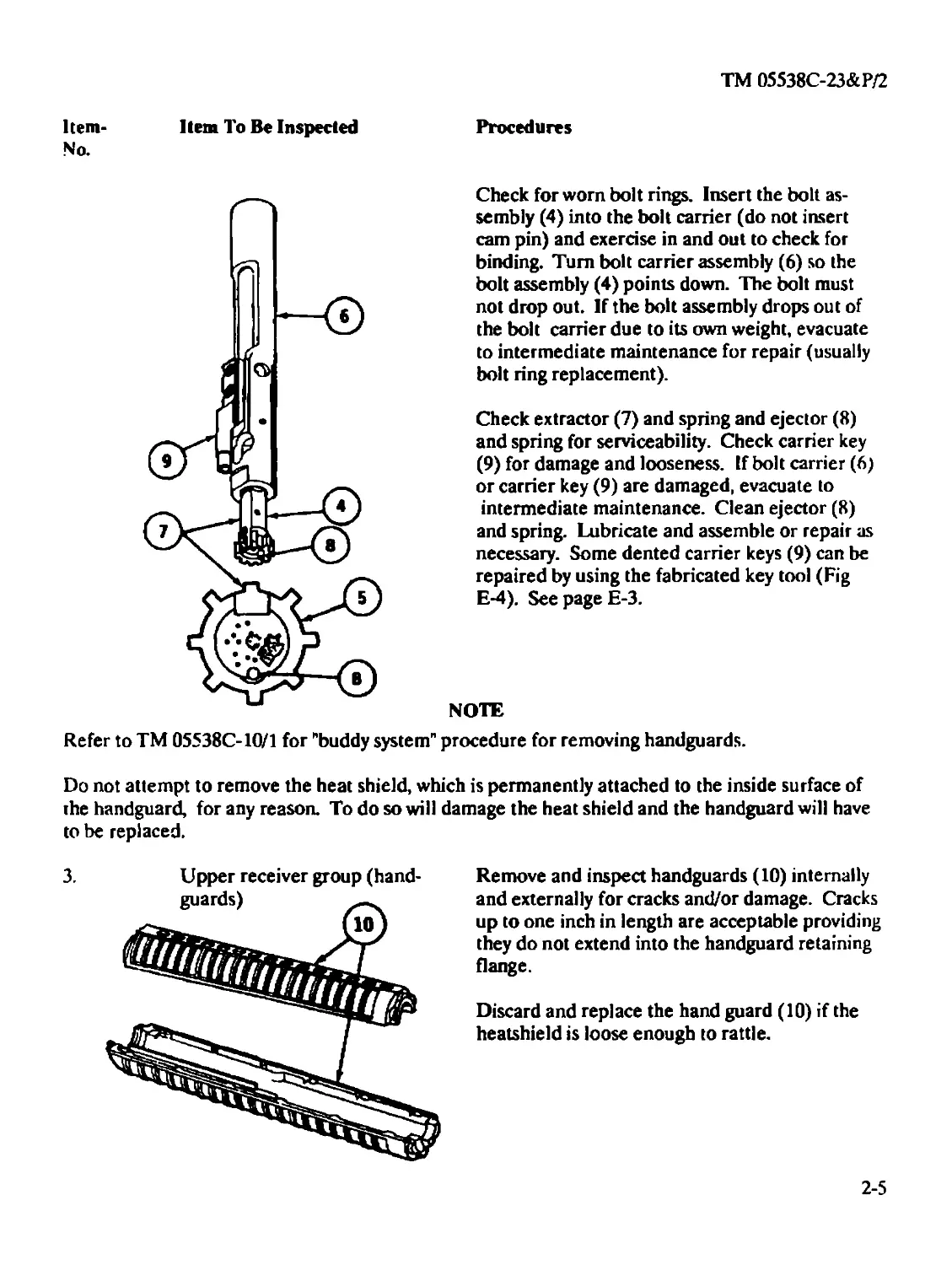
Check for worn bolt rings. Insert the bolt as-
sembly (4) into the bolt carrier (do not insert
cam pin) and exercise in and out to check for
binding. Turn bolt carrier assembly (6) so the
bolt assembly (4) points down. The bolt must
not drop out. If the bolt assembly drops out of
the bolt carrier due to its own weight, evacuate
to intermediate maintenance for repair (usually
bolt ring replacement).
Check extractor (7) and spring and ejector (8)
and spring for serviceability. Check carrier key
(9) for damage and looseness. If bolt carrier (6)
or carrier key (9) are damaged, evacuate to
intermediate maintenance. Clean ejector (8)
and spring. Lubricate and assemble or repair as
necessary. Some dented carrier keys (9) can be
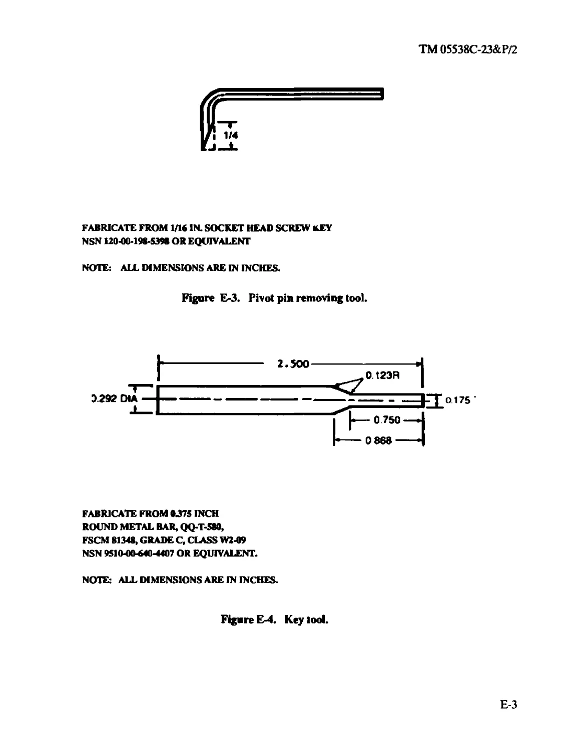
repaired by using the fabricated key tool (Fig
E-4). See page E-3.
NOTE
Refer to TM 05538C-10/1 for "buddy system" procedure for removing handguards.
Do not attempt to remove the heat shield, which is permanently attached to the inside surface of
the handguard, for any reason. To do so will damage the heat shield and the handguard will have
to be replaced.
3. Upper receiver group (hand-
Remove and inspect handguards (10) internally
and externally for cracks and/or damage. Cracks
up to one inch in length are acceptable providing
they do not extend into the handguard retaining
flange.
Discard and replace the hand guard (10) if the
heatshield is loose enough to rattle.
2-5
TM 05538C-23&P/2
Item Item To Be Inspected Procedures
No.
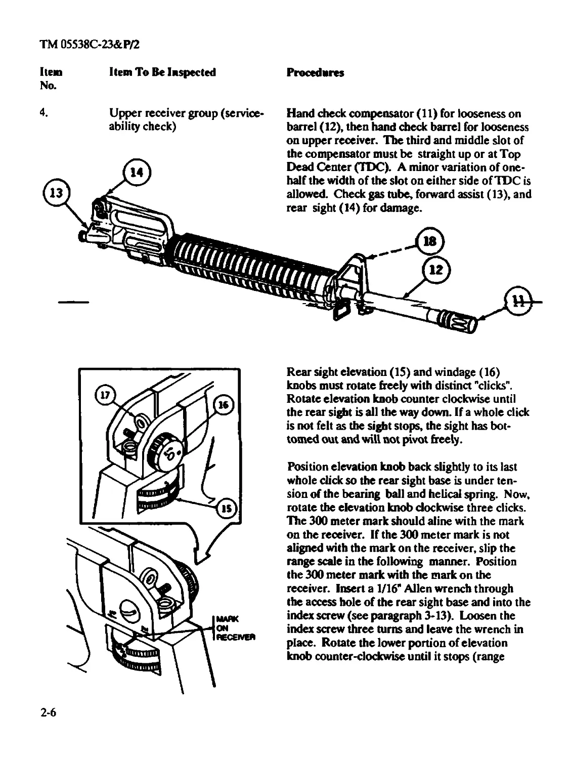
Upper receiver group (service-
ability check)
Hand check compensator (11) for looseness on
barrel (12), then hand check barrel for looseness
on upper receiver. The third and middle slot of
Rear sight elevation (15) and windage (16)
knobs must rotate freely with distinct "clicks".
Rotate elevation knob counter clockwise until
the rear sight is all the way down. If a whole click
is not felt as the sight stops, the sight has bot-
tomed out and will not pivot freely.
Position elevation knob back slightly to its last
whole click so the rear sight base is under ten-
sion of the bearing ball and helical spring. Now,
rotate the elevation knob clockwise three clicks.
The 300 meter mark should aline with the mark
on the receiver. If the 300 meter mark is not
aligned with the mark on the receiver, slip the
range scale in the following manner. Position
the 300 meter mark with the mark on the
receiver. Insert a 1/16* Allen wrench through
the access hole of the rear sight base and into the
index screw (see paragraph 3-13). Loosen the
index screw three turns and leave the wrench in
place. Rotate the lower portion of elevation
knob counter-clockwise until it stops (range
2-6
TM 05538C-23&P/2
Item
No.
Item To Be Inspected
Procedures
scale should not have moved). Knob should be
positioned on its last whole click. Now, rotate
lower portion of elevation knob clockwise three
clicks. Tighten index screw. Do nnt attempt to
remove the index screw as this is an intermediate
maintenance function.
ARMY (NOTE)
If the rear sight fails the above inspection, forward the weapon to Intermediate Maintenance for
repair.
Check front sight plunger and spring (18) for
damage and corrosion. Clean and lubricate.
Check charging handle assembly, ejection port
cover, sling swivel and pin/rivet for damage and
proper functioning. Replace defective com-
ponents as necessary.
WARNING
Dry cleaning solvent is flammable and toxic and should be used in a well-ventilated area. The use
of rubber gloves is necessary to protect the skin when washing rifle parts.
CAUTION
Do not use wire brush to roughen surfaces. Use a well-ventilated area during cleaning and applica-
tion of solid film lubricant (item 8, app D). If solid film lubricant comes in contact with recoiling
parts of functioning surfaces of the rifle, remove lubricant immediately by washing with dry clean-
ing solvent (item 3, app D).
Upper receiver group
Inspect upper receiver finish. If scratched or
worn shiny in spots, disassemble and remove all
lubricant from surface with dry cleaning solvent
(item 13, app D) and let dry. Always wear rub-
ber gloves (item 15, app D) when using dry dean
ing solvent. Roughen the surface using abrasive
cloth (item 10, app D) and apply solid film
lubricant (item 18, app D). Allow 16 to 24 hours
to dry before handling. Release takedown pin
2-7
TM 05538C-23&P/2
Item No. Item To Be Inspected Procedures
and open receiver. Hold barrel at 40-degree angle (muzzle down). Pull charging handle as- sembly to rear. Hold bolt carrier to rear and push charging handle forward. Release bolt car- rier. The bolt carrier should close and lock under its own weight. If it does not, remove the bolt from the carrier and slide the carrier and key assembly (without bolt) back and forth in the upper receiver and barrel assembly.
6. Upper receiver group (bent gas tube extension) If the gas tube hits the carrier key, or if the gas tube binds in the carrier key, try to correct the malfunction by adjusting (slightly bending) the gas tube in the area of the handguards. If this does not correct the malfunction, evacuate to In- termediate Maintenance.
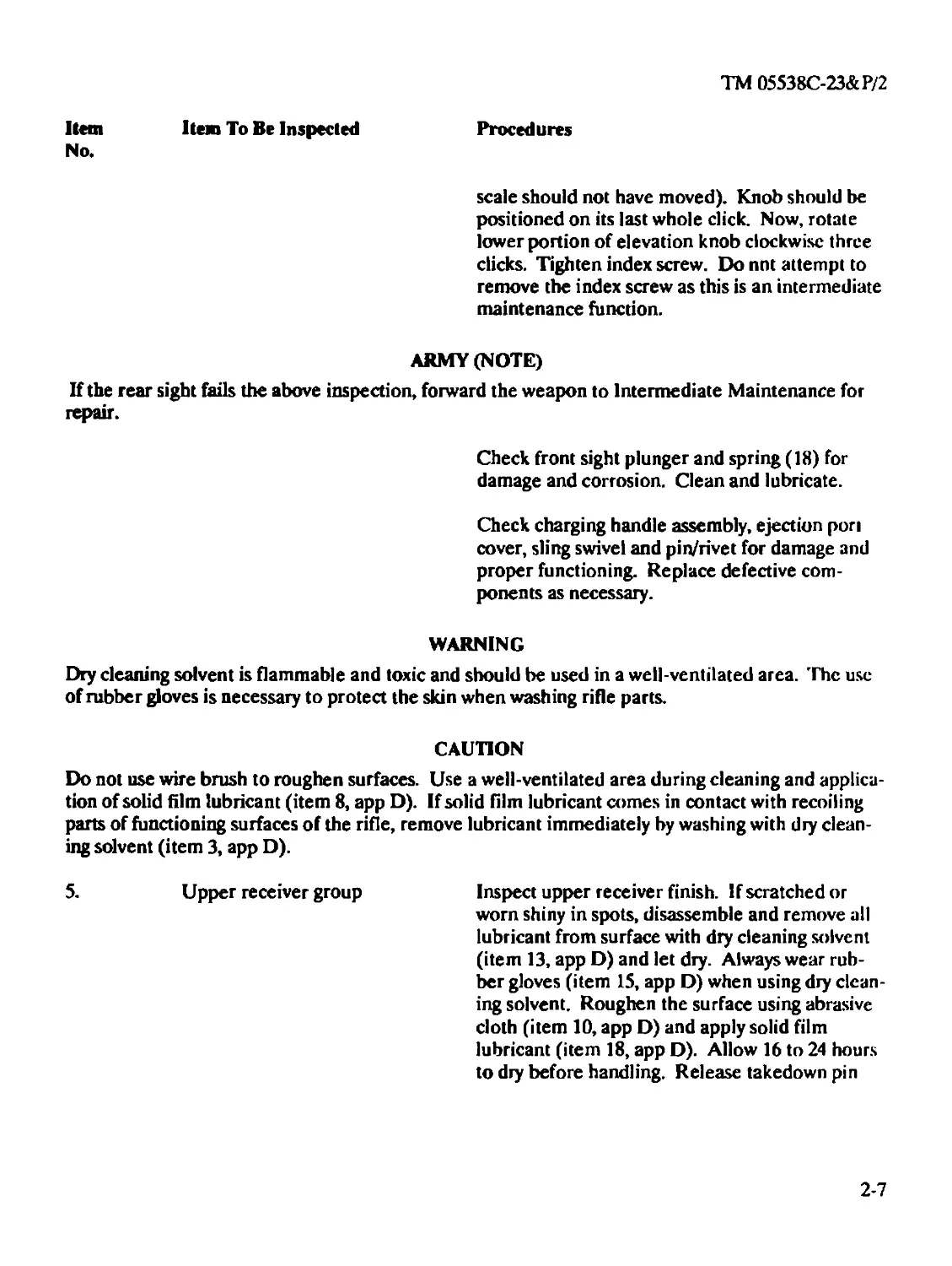
7. Lower receiver group (service- ability check) Remove buffer (19) and action spring (20). Check buffer for cracks. Replace if cracked. Check action spring for kinks and free length. Free length should be 11 3/4 minimum to 13 1/2 maximum inches; if not, replace. Do not attempt to adjust the length by stretching the spring.
2-8
TM 05538C-23&P/2
Item Item To Be Inspected Procedures
No.
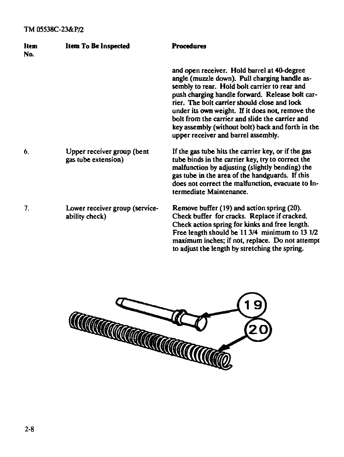
Remove butt cap screw and buttstock assembly
(21), taking care not to lose the takedown pin
(22), detent (23), and spring (24). Clean and
lubricate the takedown pin, detent, spring, and
bole in the receiver. Check buttstock assembly
components for damage. Replace damaged com-
ponents as necessary. A cracked buttstock can
be repaired at Intermediate Maintenance.
Check the amount of gap between the buttstock
assembly and the lower receiver. If a gap of 1/32"
exists or a forward to rear movement is notice-
able, remove the buttstock assembly and hand
check lower receiver extension for looseness and
corrosion. If loose, evacuate to Intermediate
Maintenance. Clean and lubricate the extension.
Remove pistol grip (25), spring (26), and safety
detent (27). Clean and lubricate pivot pin (28),
detent (29), spring (30), and receiver holes.
Replace defective components as necessary.
Clean and lubricate selector lever (31). Reas-
semble.
2-9
TM 05538C-23&P/2
Item
No.
Item To Be Inspected
Procedures
NOTE
If the buttcap screw is removed, it must be replaced with a new one.
Function check the magazine catch, bolt catch, automatic sear, hammer, trigger, and disconnec-
tors. If defective, evacuate to intermediate maintenance. Check lower receiver finish. If
scratched or woru shiny in spots, repair in the same manner as outlined for upper receiver.
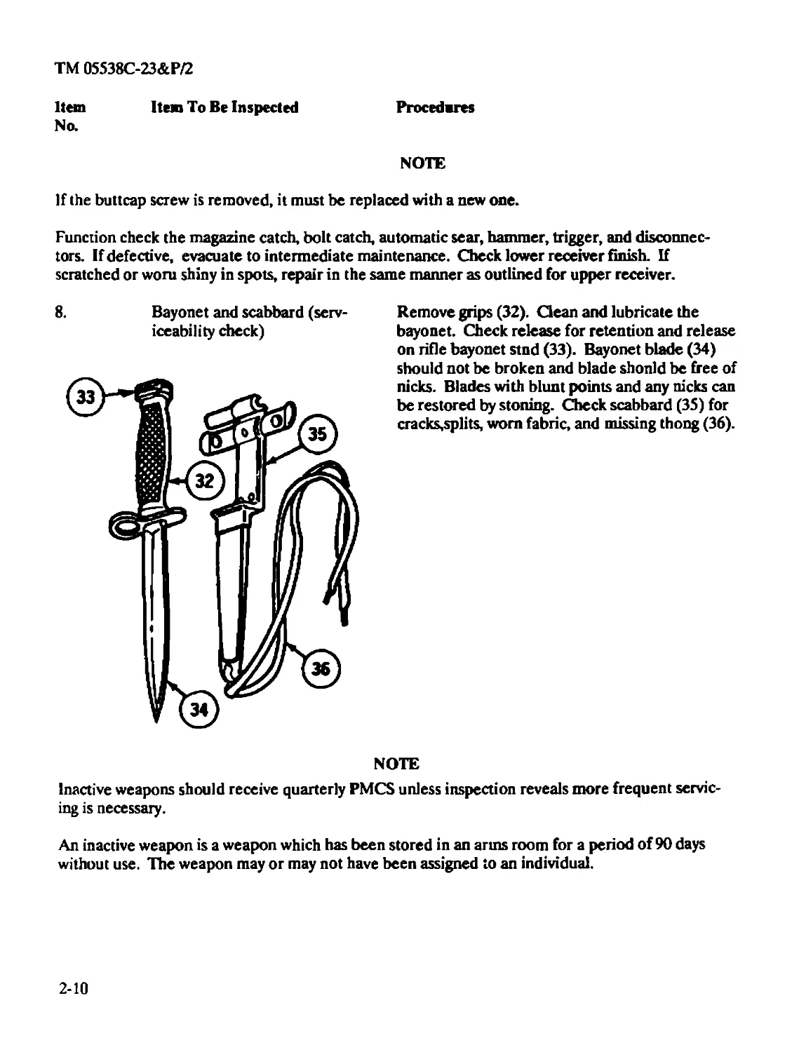
8. Bayonet and scabbard (serv-
iceability check)
Remove grips (32). Clean and lubricate the
bayonet. Check release for retention and release
on rifle bayonet stnd (33). Bayonet blade (34)
should not be broken and blade shonld be free of
nicks. Blades with blunt points and any nicks can
be restored by stoning. Check scabbard (35) for
cracks,splits, worn fabric, and missing thong (36).
NOTE
Inactive weapons should receive quarterly PMCS unless inspection reveals more frequent servic-
ing is necessary.
An inactive weapon is a weapon which has been stored in an arms room for a period of 90 days
without use. The weapon may or may not have been assigned to an individual.
2-10
TM 05538C-23&P/2
Section IV. ORGANIZATIONAL TROUBLESHOOTING
2-8. GENERAL.
a. This section contains organizational level troubleshooting information for locating and
correcting most of the operating troubles which may develop in the weapon. Each malfunction for
the individual part or assembly is followed by a list of tests or inspections which will help you to
determine the corrective actions to take. You should perform the tests/inspections and corrective
actions in the order listed.
b. This manual cannot list all malfunctions that may occur, nor all tests or inspections and
corrective actions. If a malfunction is not listed or is not corrected by listed corrective actions, see
individual repair sections for maintenance instructions on each major assembly.
2-9. TROUBLESHOOTING PROCEDURES. Refer to Table 2-4 for malfunctions, tests, and
corrective actions. The following symptom index. Table 2-3, is provided for a quick reference of
the malfunctions covered in Table 2-4.
Table 2-3
SYMPTOM INDEX
Malfunction
Page
Bolt fails to lock to rear after firing last round....................................2-11
Failure to chamber....................................................................2-15
Failure to cock...................................................................... 2-13
Failure to cycle with selector lever set on BURST.....................................2-17
Failure to eject......................................................................2-13
Failure to extract....................................................................2-12
Failure to feed.......................................................................2-13
Failure to fire.......................................................................2-11
Failure to lock.......................................................................2-15
Fires two rounds with one squeeze of trigger with selector lever set
on SEMI (double firing)...............................................................2-17
Fires with selector lever on SAFE or when trigger is released with
selector lever on SEMI................................................................2-17
Short recoil..........................................................................2-16
2-11
TM 05538C-23&P/2
Table 2-4
ORGANIZATIONAL TROUBLESHOOTING
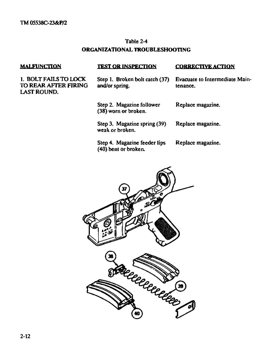
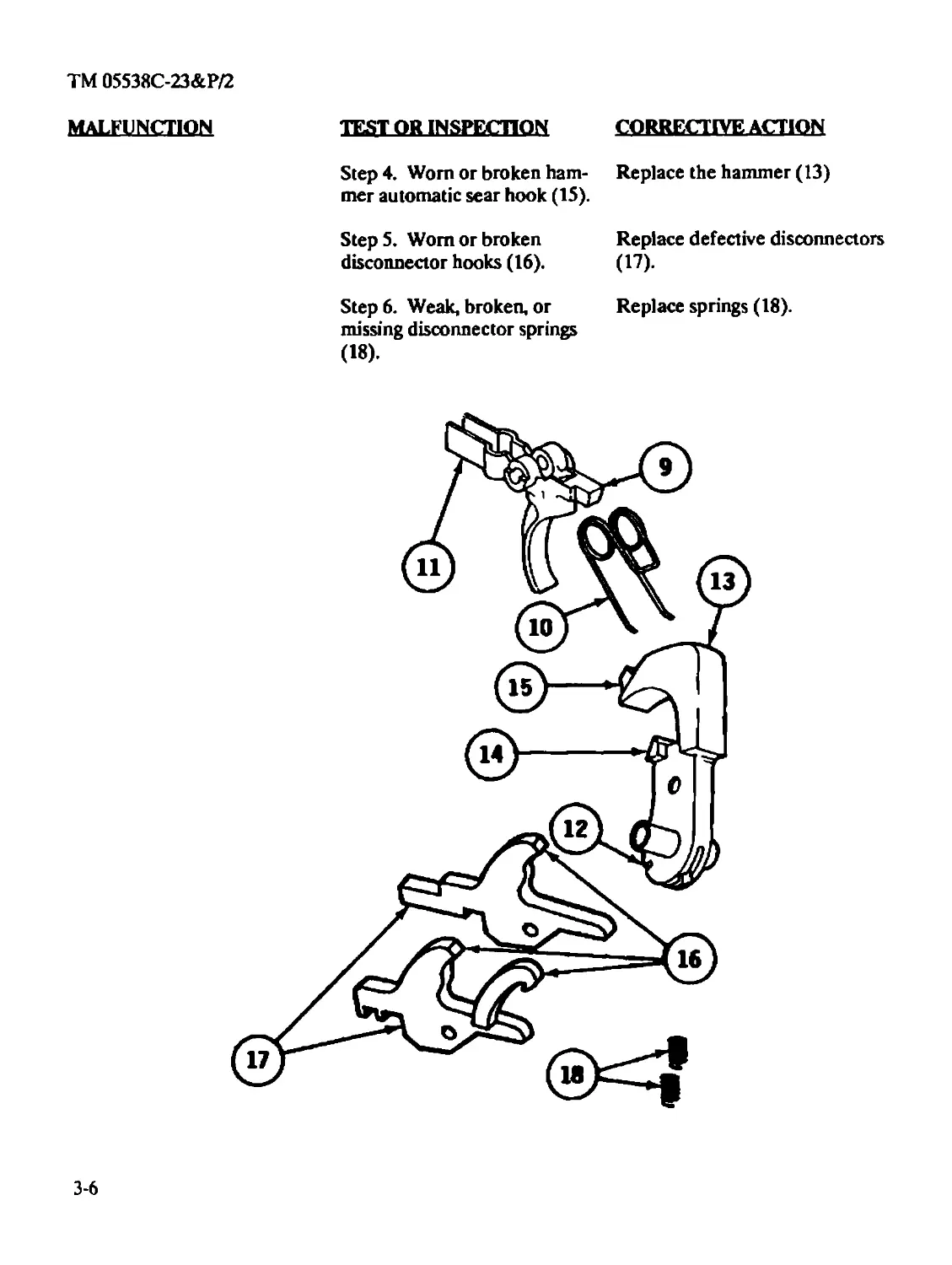
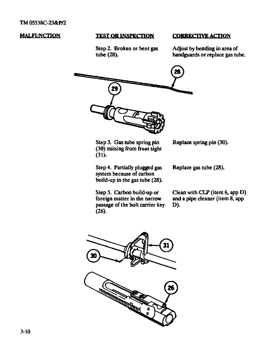
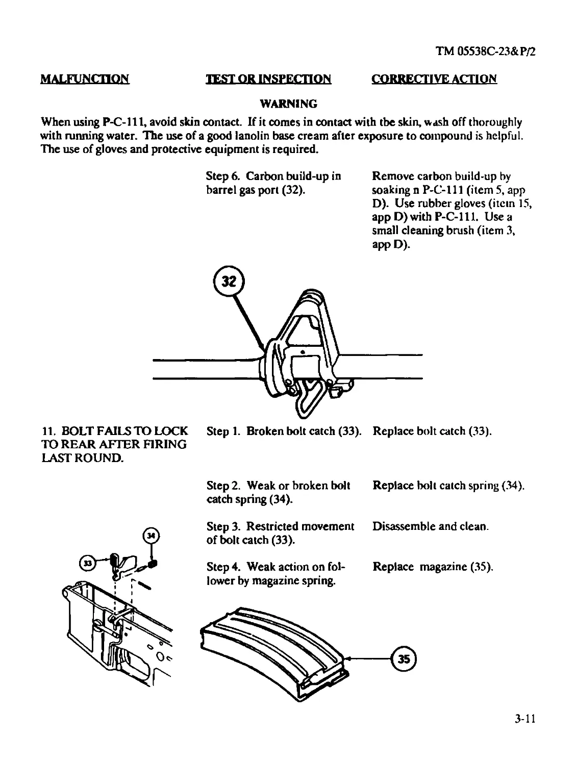
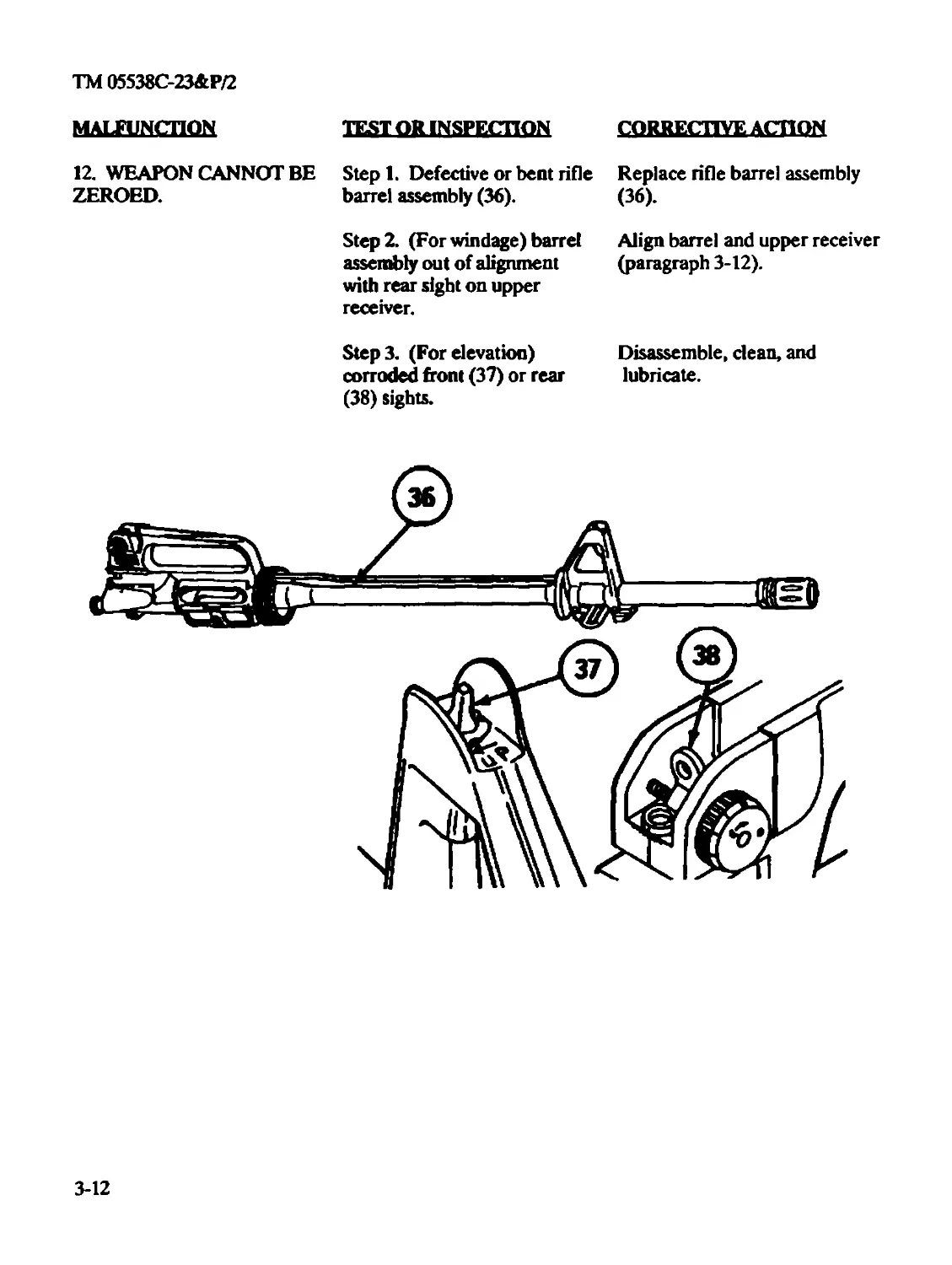
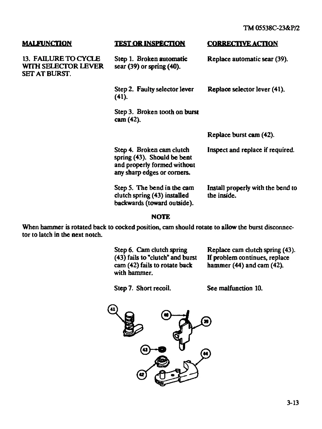
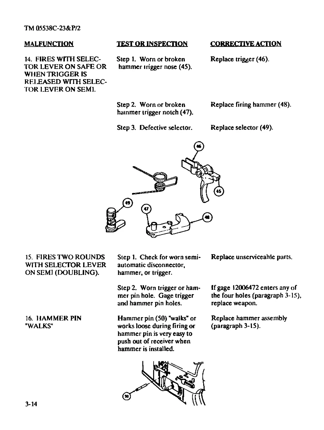
MALFUNCTION
I. BOLT FAILS TO LOCK
TO REAR AFTER FIRING
LAST ROUND.
TEST OR INSPECTION
Step 1. Broken bolt catch (37)
and/or spring.
Step 2. Magazine follower
(38) worn or broken.
Step 3. Magazine spring (39)
weak or broken.
Step 4. Magazine feeder lips
(40) bent or broken.
CORRECTIVE ACTION
Evacuate to Intermediate Main-
tenance.
Replace magazine.
Replace magazine.
Replace magazine.
2-12
TM 05538C-23&P/2
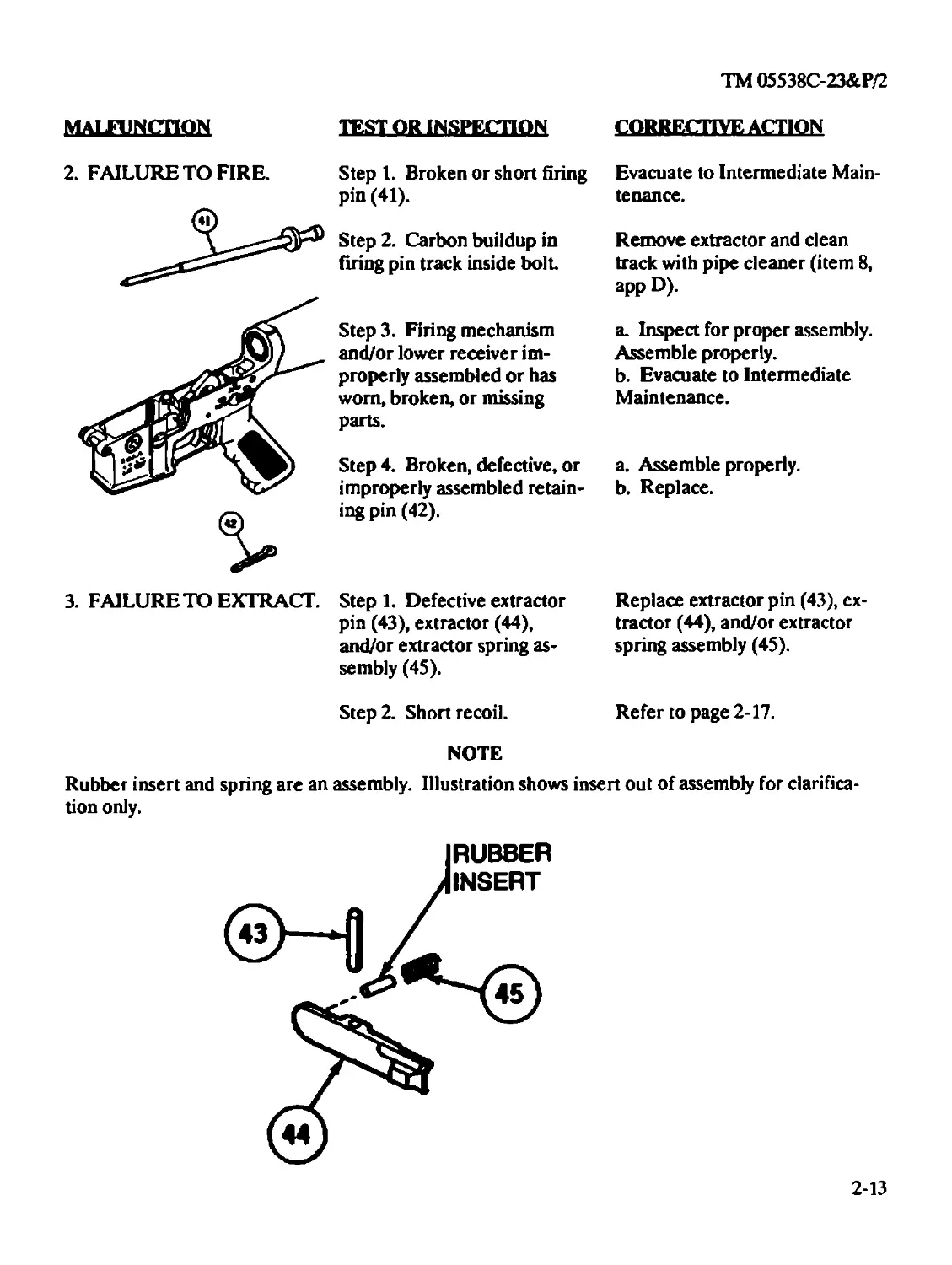
MALFUNCTION
TEST OR INSPECTION
2. FAILURE TO FIRE.
3. FAILURE TO EXTRACT.
Step 1. Broken or short firing
pin (41).
Step 2. Carbon buildup in
firing pin track inside bolt
Step3. Firing mechanism
and/or lower receiver im-
properly assembled or has
worn, broken, or missing
parts.
Step 4. Broken, defective, or
improperly assembled retain-
ing pin (42).
CORRECTIVE ACTION
Evacuate to Intermediate Main-
tenance.
Remove extractor and clean
track with pipe cleaner (item 8,
app D).
a. Inspect for proper assembly.
Assemble properly.
b. Evacuate to Intermediate
Maintenance.
a. Assemble properly,
b. Replace.
Step 1. Defective extractor
pin (43), extractor (44),
and/or extractor spring as-
sembly (45).
Replace extractor pin (43), ex-
tractor (44), and/or extractor
spring assembly (45).
Step 2. Short recoil.
Refer to page 2-17.
NOTE
Rubber insert and spring are an assembly. Illustration shows insert out of assembly for clarifica-
tion only.
2-13
TM 05538C-23&P/2
MALFUNCTION
TEST OR INSPECTION
'И11Г
ACTION
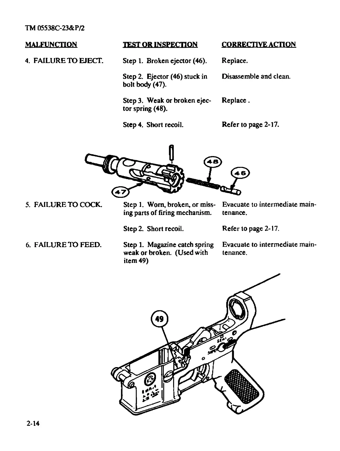
4. FAILURE TO EJECT.
Step 1. Broken ejector (46).
Replace.
Step 2. Ejector (46) stuck in
bolt body (47).
Disassemble and clean.
Step 3. Weak or broken ejec-
tor spring (48).
Replace.
Step 4. Short recoil.
Refer to page 2-17.
5. FAILURE TO COCK.
Step 1. Worn, broken, or miss-
ing parts of firing mechanism.
Evacuate to intermediate main-
tenance.
Step 2. Short recoil.
Refer to page 2-17.
6. FAILURE TO FEED.
Step 1. Magazine catch spring
weak or broken. (Used with
item 49)
Evacuate to intermediate main-
tenance.
2-14
TM 05538С-23&Р/2
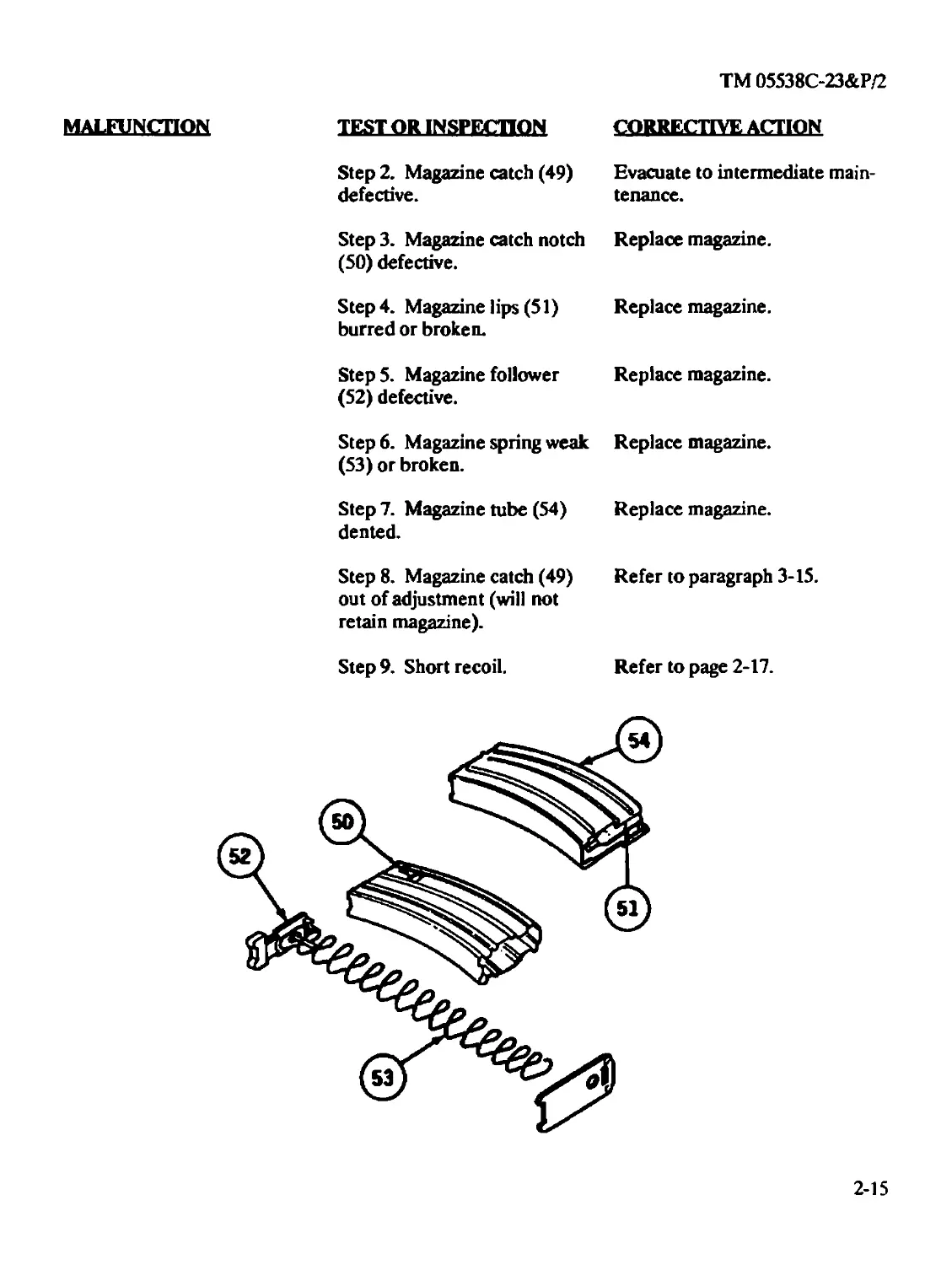
MALFUNCTION TEST OR INSPECTION CORRECTIVE ACTION Step 2. Magazine catch (49) Evacuate to intermediate main- defective. tenance. Step 3. Magazine catch notch Replace magazine. (50) defective. Step 4. Magazine lips (51) Replace magazine, burred or broken. Step 5. Magazine follower Replace magazine. (52) defective. Step 6. Magazine spring weak Replace magazine. (53) or broken. Step 7. Magazine tube (54) Replace magazine, dented. Step 8. Magazine catch (49) Refer to paragraph 3-15. out of adjustment (will not retain magazine). Step 9. Short recoil. Refer to page 2-17.
2-15
TM 05538C-23&P/2
MALFUNCTION TEST OR INSPECTION CORRECTIVE ACTION
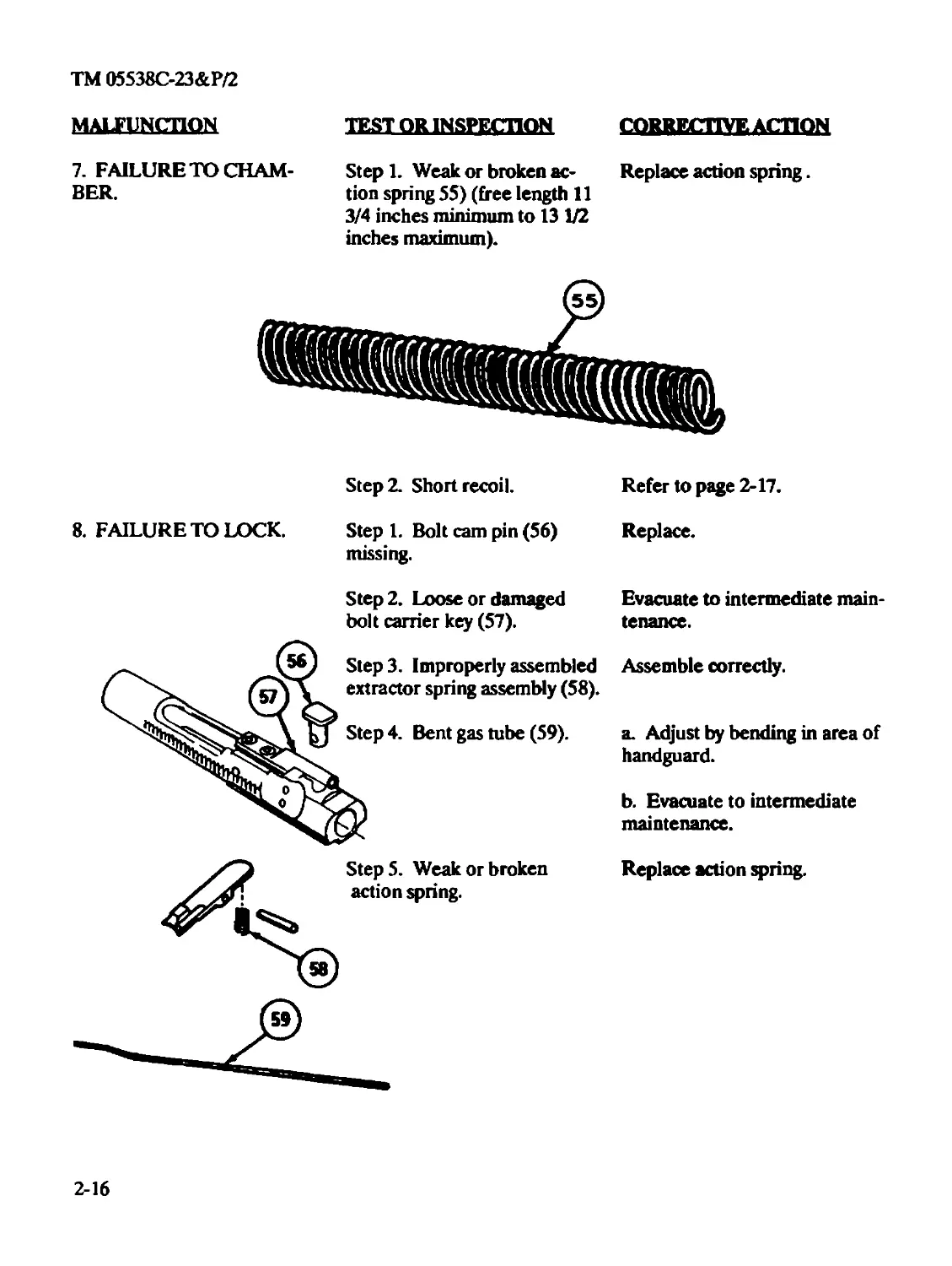
7. FAILURE TO CHAM-
BER.
Step 1. Weak or broken ac-
tion spring 55) (free length 11
3/4 inches minimum to 13 1/2
inches maximum).
Replace action spring.
Step 2. Short recoil.
Refer to page 2-17.
8. FAILURE TO LOCK.
Step 1. Bolt cam pin (56) Replace,
missing.
Step 2. Loose or damaged
bolt carrier key (57).
Step 4. Bent gas tube (59).
Step3. Improperly assembled
extractor spring assembly (58).
Step 5. Weak or broken
action spring.
Evacuate to intermediate main-
tenance.
Assemble correctly.
a. Adjust by bending in area of
handguard.
b. Evacuate to intermediate
maintenance.
Replace action spring.
2-16
TM 05538C-23&P/2
MALFUNCTION
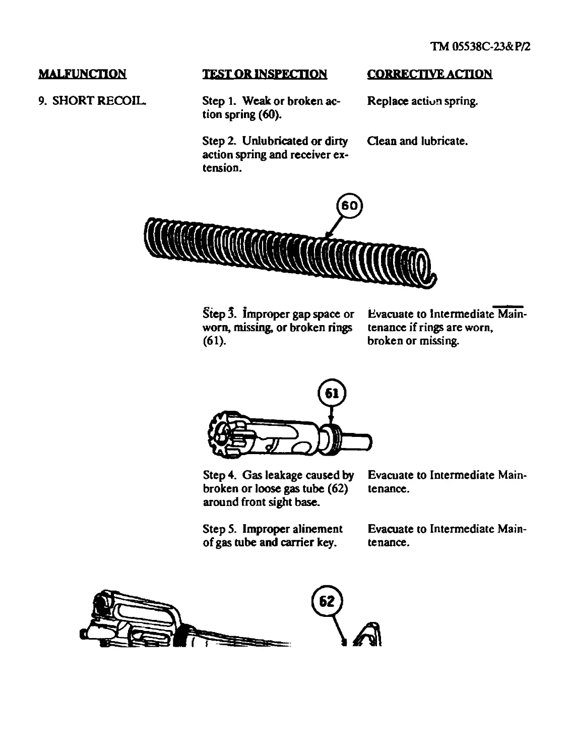
9. SHORT RECOIL.
TEST OR INSPECTION
Step 1. Weak or broken ac-
tion spring (60).
Step 2. Unlubricated or dirty
action spring and receiver ex-
tension.
CORRECTIVE ACTION
Replace action spring.
Clean and lubricate.
Step 3. improper gap space or
worn, missing, or broken rings
(61).
Evacuate to Intermediate Main-
tenance if rings are worn,
broken or missing.
Step 4. Gas leakage caused by
broken or loose gas tube (62)
around front sight base.
Evacuate to Intermediate Main-
tenance.
Step 5. Improper alinement
of gas tube and carrier key.
Evacuate to Intermediate Main-
tenance.
TM 05538C-23&P/2
MALFUNCTION TEST OR INSPECTION CORRECTIVE ACTION
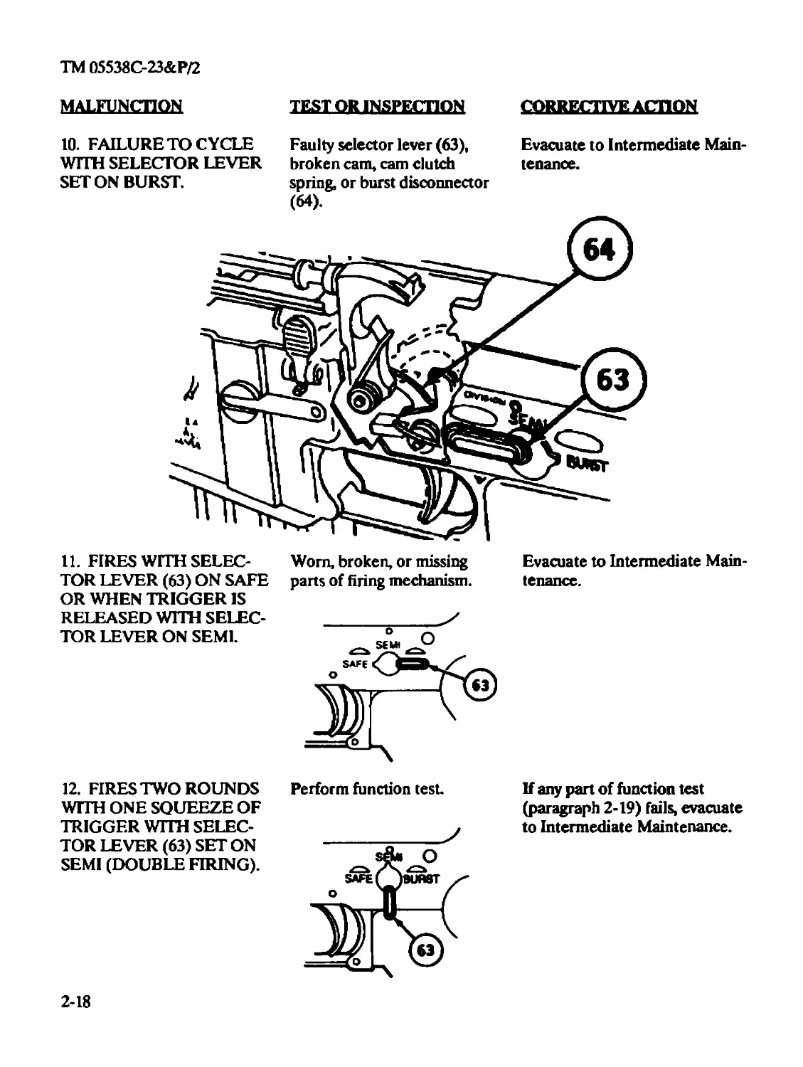
10. FAILURE TO CYCLE
WITH SELECTOR LEVER
SET ON BURST.
Faulty selector lever (63),
broken cam, cam clutch
spring, or burst disconnector
(64).
Evacuate to Intermediate Main-
tenance.
11. FIRES WITH SELEC-
TOR LEVER (63) ON SAFE
OR WHEN TRIGGER IS
RELEASED WITH SELEC-
TOR LEVER ON SEMI.
Worn, broken, or missing
parts of firing mechanism.
Evacuate to Intermediate Main-
tenance.
12. FIRES TWO ROUNDS
WITH ONE SQUEEZE OF
TRIGGER WITH SELEC-
TOR LEVER (63) SET ON
SEMI (DOUBLE FIRING).
Perform function test
If any part of function test
(paragraph 2-19) fails, evacuate
to Intermediate Maintenance.
2-18
TM 05538C-23&P/2
Section V. ORGANIZATIONAL MAINTENANCE PROCEDURES
2-10. INITIAL SETUP. The following will reduce the space required for the initial setup portion
of the maintenance procedures.
a. Resources required are not listed unless they apply to the procedure.
b. Personnel Required is listed only if the task requires more than one person. If
Personnel Required is not listed, it means one person can do the job.
c. The normal standard equipment condition is that the item is removed from the end item
or next higher assembly and is in the assembled condition. Equipment Condition is not listed un-
less some other condition is required.
d. The approximate time required is listed on the applicable Maintenance Allocation Chart
(MAC) in Appendix B.
2-11. MAJOR COMPONENTS OF M16A2 RIFLE.
This task covers disassembly.
INITIAL SETUP
References
TM 05538C-10/1
Equipment Condition
Weapon assembled.
General Safety Instructions
Before starting an inspection, be sure to clear the weapon. Do not keep live ammunition
near the work area.
To avoid injury to your eyes, use care when removing and installing spring-loaded parts.
Do not interchange bolt assemblies or components from one weapon to another. Doing so
may result in injury to, or death of, personnel.
2-19
TM 05538C-23&P/2
LQCAUQM НЕМ. АСПШ REMARKS
01SASSEMBLY1
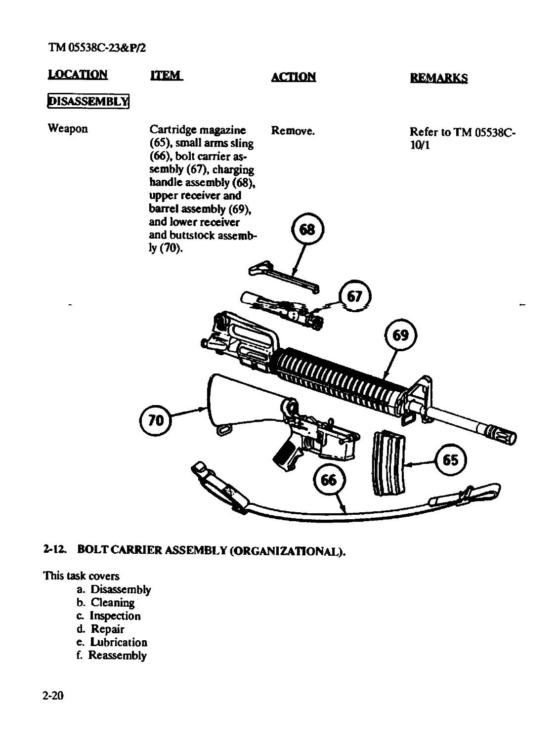
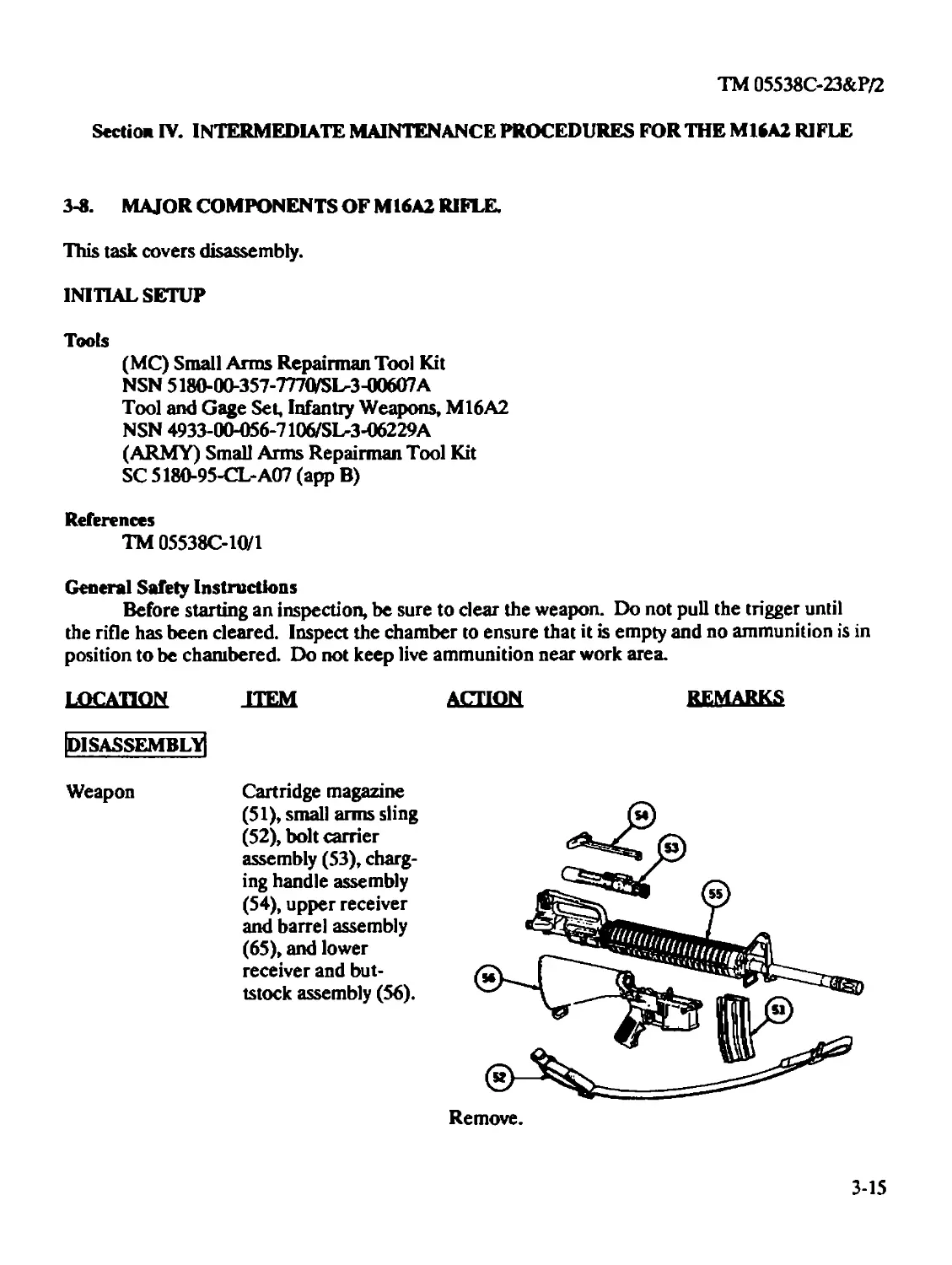
Weapon Cartridge magazine Remove. Refer to TM 05538C-
(65), small arms sling 10/1
(66), bolt carrier as-
sembly (67), charging
handle assembly (68),
upper receiver and
2-12. BOLT CARRIER ASSEMBLY (ORGANIZATIONAL).
This task covers
a. Disassembly
b. Cleaning
c. Inspection
d. Repair
e. Lubrication
f. Reassembly
2-20
TM 05538C-23&P/2
INITIAL SETUP
Tools
(MC) Small Arms Repairman Tool Kit
NSN 5180-00-3.57-7770/SL-3-00607A
Key tool (E-4, app E)
(ARMY) Small Arms Repairman Tool Kit
SC 5180-95-CL-A07 (app B)
Materials/Parts
Cleaner, lubricant, and preservative (CLP) (item 6, app D)
General Safety Instructions
Bolt cam pin must be installed or weapon will blow up while firing the first round. If the bolt
cam pin is not installed, injury to, or death of, personnel may result.
Do not interchange bolt assemblies or components from one weapon to another. Doing so
may result in injury to, or death of, personnel.
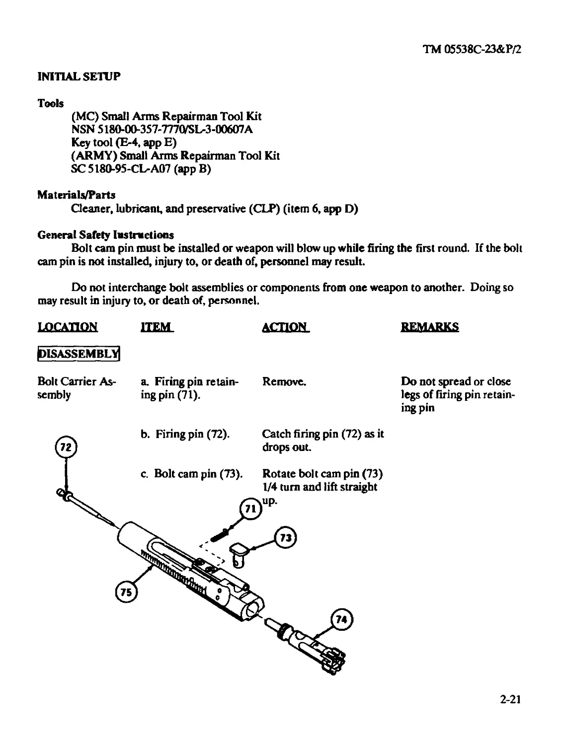
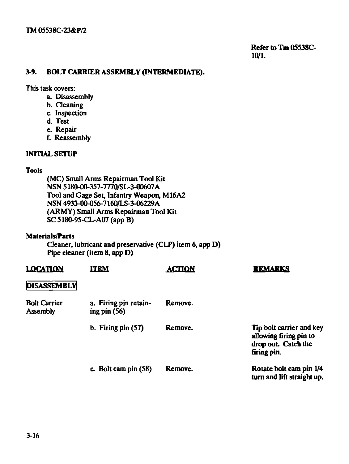
LOCATION HEM. (DISASSEMBLY] Bolt Carrier As- a. Firing pin retain- sembly ingpin(71). —. b. Firing pin (72). 62) I c. Bolt cam pin (73). ACTION REMARKS Remove. Do not spread or close legs of firing pin retain- ing pin Catch firing pin (72) as it drops out. Rotate bolt cam pin (73) 1/4 turn and lift straight ?)UP -Дтз)
2-21
TM 05538C-23&P/2
LOCATION ITEM ACTION REMARKS
d. Bolt assembly (74) and key and bolt car- rier assembly (75). Remove.
[CLEANING]
Bolt Carrier Assembly All items Remove carbon using CLP (item 6, app D).
[INSPECTION]
Bolt Carrier a. Bolt Assembly Check for worn rings by If bolt assembly falls
Assembly b. All items holding the bolt carrier assembly with the bolt as- sembly down. Check ring spacing. Check for serviceability. out of carrier after retaining pin and cam pin are removed, the rings are worn. Evacuate to Inter- mediate Maintenance.
[repair;
Bolt Carrier a. Firing pin retaining Replace if unserviceable. Items are unserviceable
Assembly pin and cam pin b. Bolt assembly See paragraph 2-13. if cracked or mutilated.
c. Firing pin Notify Intermediate Maintenance if unservice- able. CAUTION Firing pin is unservice- able if broken or if tip is mutilated.
Extreme care must be exercised during the following procedure to assure that the striking force is
not directed to the attaching screws and that the tube portion is not enlarged or flared beyond
original requirements as such enlargement would permit loss of gas pressure when the key and gas
tube come together during function.
d. Carrier key Repair small dents
and/or distortions using
fabricated key tools (E-4,
app E) as follows:
2-22
TM 05538C-23&P/2
location HEM
ACTION
REMARKS
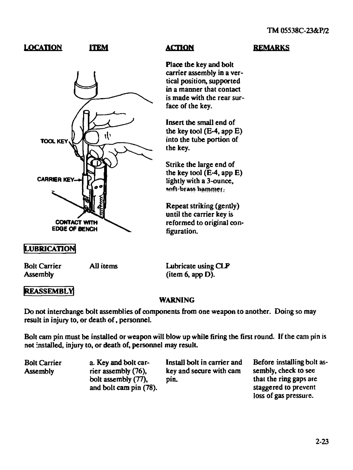
Place the key and bolt
carrier assembly in a ver-
tical position, supported
in a manner that contact
is made with the rear sur-
face of the key.
Insert the small end of
the key tool (E-4, app E)
into the tube portion of
the key.
Strike the large end of
the key tool (E-4, app E)
lightly with a 3-ounce,
«»ft-hraw hammer.
Repeat striking (gently)
until the carrier key is
reformed to original con-
figuration.
Rubrication!
Bolt Carrier All items
Assembly
Reassembly]
Lubricate using CLP
(item 6, app D).
WARNING
Do not interchange bolt assemblies of components from one weapon to another. Doing so may
result in injury to, or death of, personnel.
Bolt cam pin must be installed or weapon will blow up while firing the first round. If the cam pin is
not installed, injury to, or death of, personnel may result.
Bolt Carrier a. Key and bolt car-
Assembly rier assembly (76),
bolt assembly (77),
and bolt cam pin (78).
Install bolt in carrier and Before installing bolt as-
key and secure with cam sembly, check to see
pin. that the ring gaps are
staggered to prevent
loss of gas pressure.
2-23
TM 05538C-23&P/2
location hem action
REMARKS
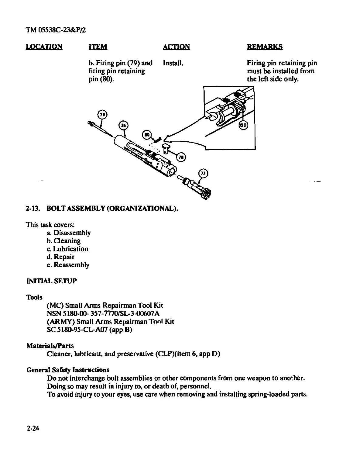
Firing pin retaining pin
must be installed from
the left side only.
b. Firing pin (79) and Install,
firing pin retaining
pin (80).
2-13. BOLT ASSEMBLY (ORGANIZATIONAL).
This task covers:
a. Disassembly
b. Cleaning
c. Lubrication
d. Repair
e. Reassembly
INITIAL SETUP
Tools
(MC) Small Arms Repairman Tool Kit
NSN 5180-00- 357-7770/SL-3-00607A
(ARMY) Small Arms Repairman Toni Kit
SC 5180-95-CVA07 (app B)
Materials/Parts
Cleaner, lubricant, and preservative (CLP)(item 6, app D)
General Safety Instructions
Do not interchange bolt assemblies or other components from one weapon to another.
Doing so may result in injury to, or death of, personnel.
To avoid injury to your eyes, use care when removing and installing spring-loaded parts.
2-24
TM 05538C-23&P/2
LOCATION HEM ACTION EEMARKS
Disassembly] CAUTION
If firing pin is used as a tool to push out extractor pin, use extreme care not to damage its tip.
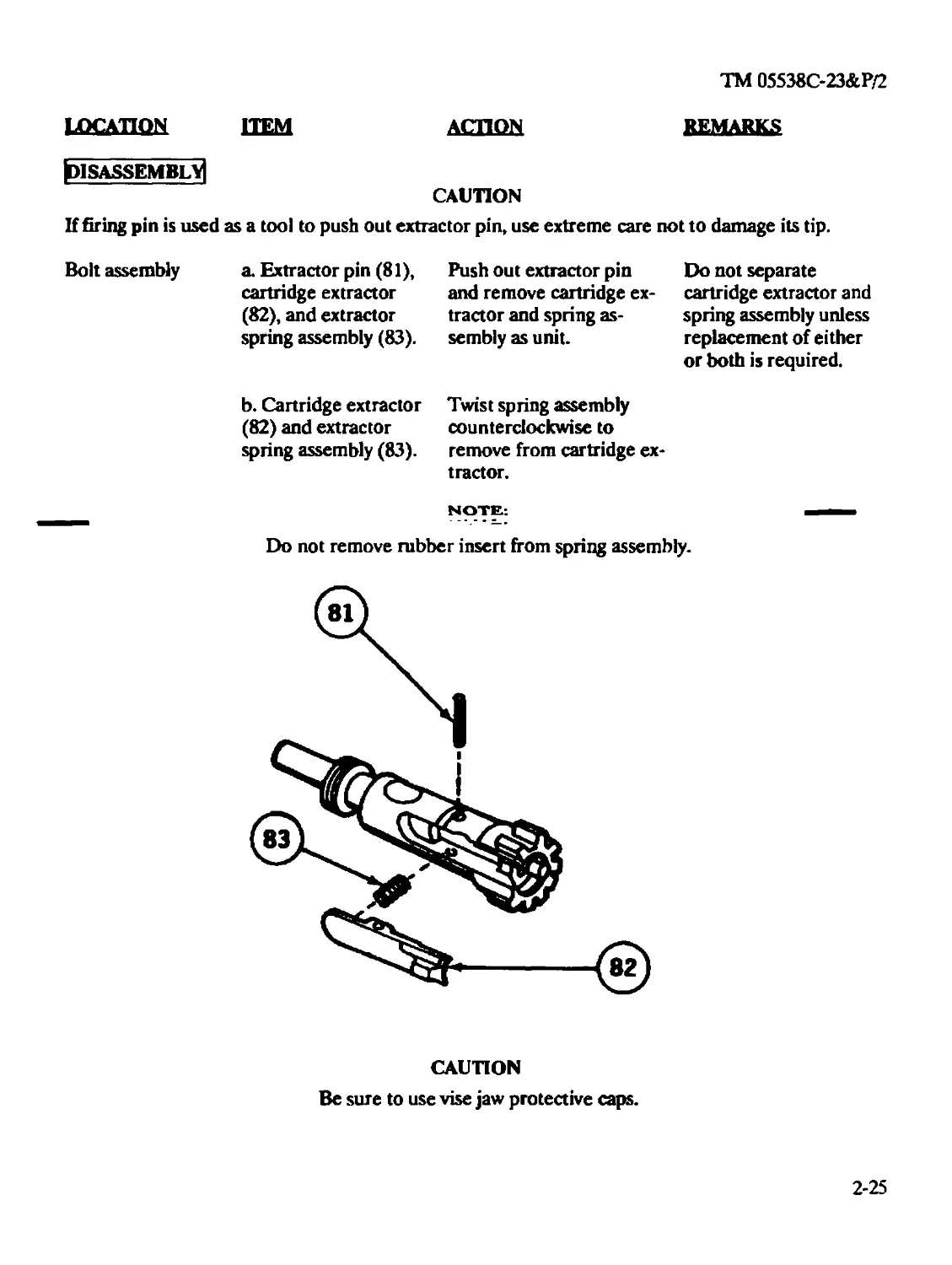
Bolt assembly a. Extractor pin (81), Push out extractor pin Do not separate cartridge extractor and remove cartridge ex- cartridge extractor and (82), and extractor tractor and spring as- spring assembly unless spring assembly (83). sembly as unit. replacement of either or both is required. b. Cartridge extractor Twist spring assembly (82) and extractor counterclockwise to spring assembly (83). remove from cartridge ex- tractor. NOTE: Do not remove rubber insert from spring assembly.
CAUTION
Be sure to use vise jaw protective caps.
2-25
TM 05538C-23&P/2
location
ITEM ACTION REMARKS
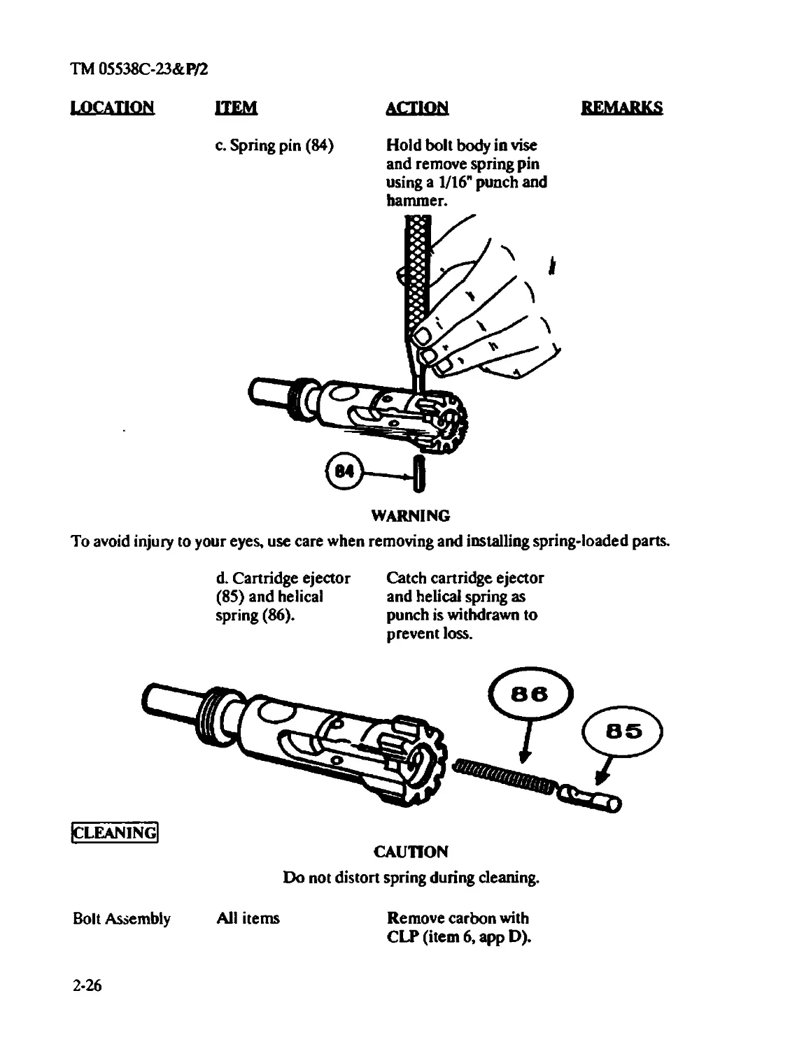
c. Spring pin (84) Hold bolt body in vise
and remove spring pin
using a 1/16" punch and
hammer.
WARNING
To avoid injury to your eyes, use care when removing and installing spring-loaded parts.
d. Cartridge ejector
(85) and helical
spring (86).
Catch cartridge ejector
and helical spring as
punch is withdrawn to
prevent loss.
|CLEAN1NG|
CAUTION
Do not distort spring during cleaning.
Bolt Assembly All items
Remove carbon with
CLP (item 6, app D).
2-26
TM 05538C-23&P/2
LOCATION HEM action remarks
[lubrication]
Bolt Assembly All items Cover with light coat of
CLP (item 6, app D).
[repair]
Bolt Assembly All authorized items Replace if unserviceable.
[REASSEMBLY^
WARNING
Do not interchange bolt assemblies or other components from one weapon to another. Doing so
may result in injury to, or death of personnel.
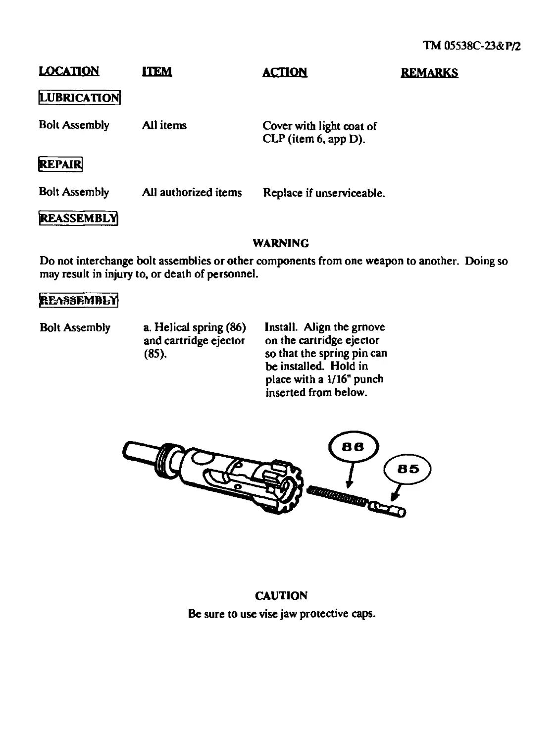
[REASSEMBLY] Bolt Assembly a. Helical spring (86) and cartridge ejector (85). Install. Align the grnove on the cartridge ejector so that the spring pin can be installed. Hold in place with a 1/16" punch inserted from below.
CAUTION
Be sure to use vise jaw protective caps.
LOCATION HEM ACTION
REMARKS
ТМ05538С-23&Р/2
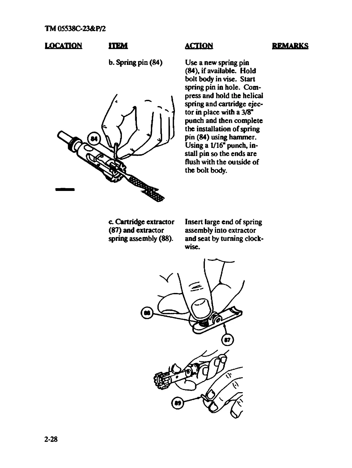
b. Spring pin (84)
Use a new spring pin
(84), if available. Hold
bolt body in vise. Start
spring pin in hole. Com-
press and hold the helical
spring and cartridge ejec-
tor in place with a 3/8*
punch and then complete
the installation of spring
pin (84) using hammer.
Using a 1/16* punch, in-
stall pin so the ends are
flush with the outside of
the bolt body.
a Cartridge extractor
(87) and extractor
spring assembly (88).
Insert large end of spring
assembly into extractor
and seat by turning clock-
wise.
2-28
TM 05538C-23&P/2
LOCATION ITEM
ACTION
REMARKS
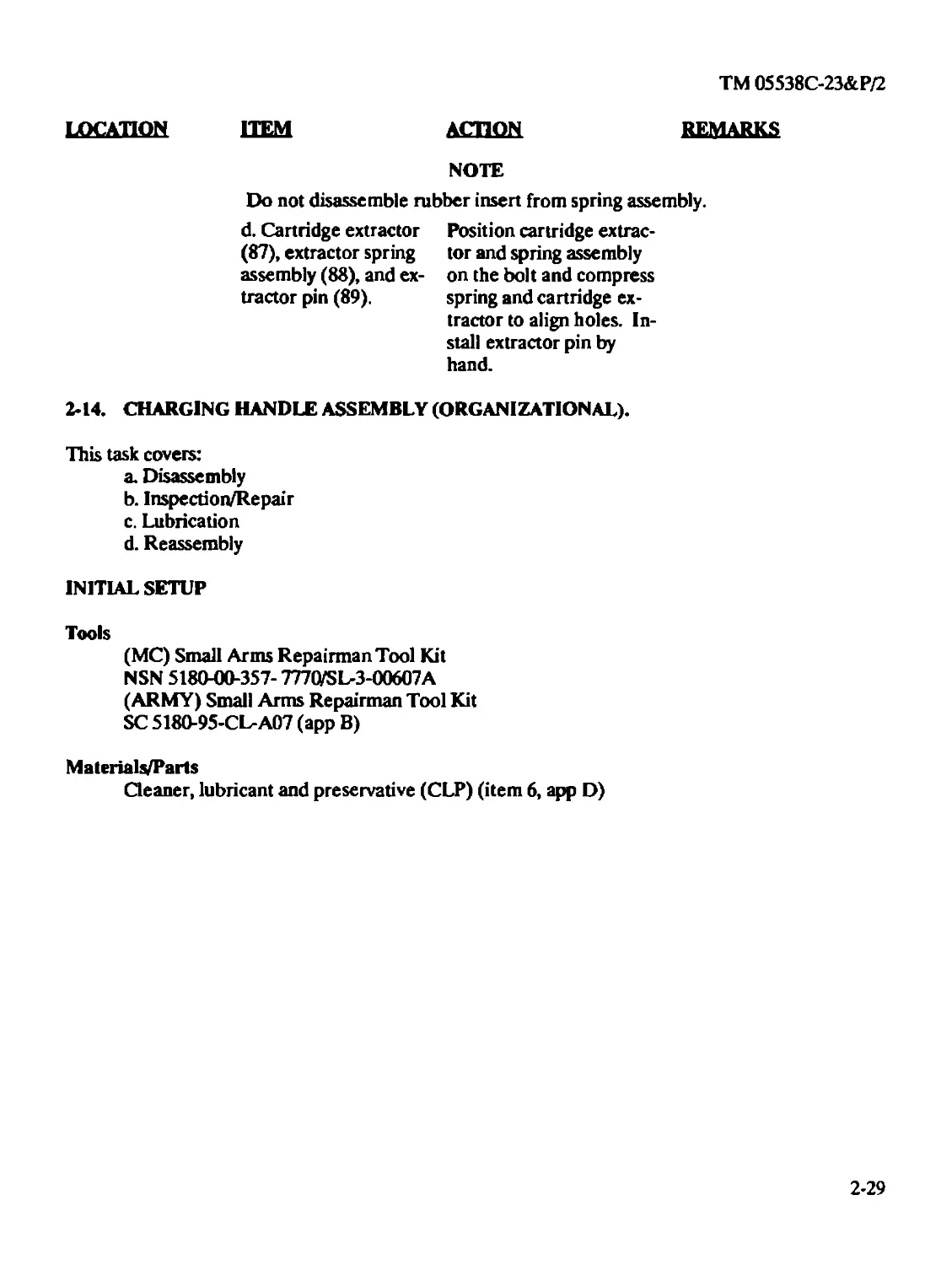
NOTE
Do not disassemble rubber insert from spring assembly.
d. Cartridge extractor
(87), extractor spring
assembly (88), and ex-
tractor pin (89).
Position cartridge extrac-
tor and spring assembly
on the bolt and compress
spring and cartridge ex-
tractor to align holes. In-
stall extractor pin by
hand.
2-14. CHARGING HANDLE ASSEMBLY (ORGANIZATIONAL).
This task covers:
a. Disassembly
b. Inspection/Repair
c. Lubrication
d. Reassembly
INITIAL SETUP
Tools
(MC) Small Arms Repairman Tool Kit
NSN 5180-00-357- 7770/SL-3-00607A
(ARMY) Small Arms Repairman Tool Kit
SC 5180-95-СЬА07 (app B)
Materials/Parts
Cleaner, lubricant and preservative (CLP) (item 6, app D)
2-29
TM 05538C-23&P/2
LOCATION ITEM
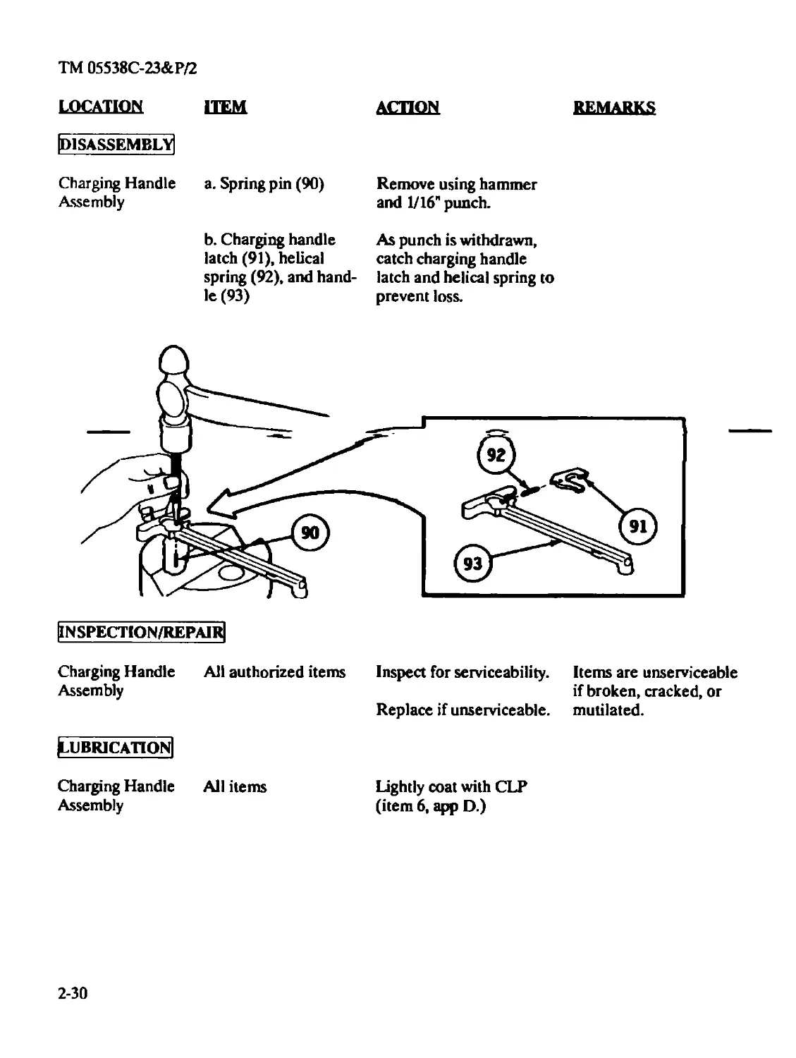
[DISASSEMBLY]
Charging Handle a. Spring pin (90)
Assembly
ACTION
Remove using hammer
and 1/16" punch.
REMARKS
b. Charging handle
latch (91), helical
spring (92), and hand-
le (93)
As punch is withdrawn,
catch charging handle
latch and helical spring to
prevent loss.
Charging Handle All authorized items
Assembly
Inspect for serviceability.
Replace if unserviceable.
Items are unserviceable
if broken, cracked, or
mutilated.
^UBR1CATION|
Charging Handle All items
Assembly
Lightly coat with CLP
(item 6, app D.)
2-30
TM 05538C-23&P/2
location item action
remarks
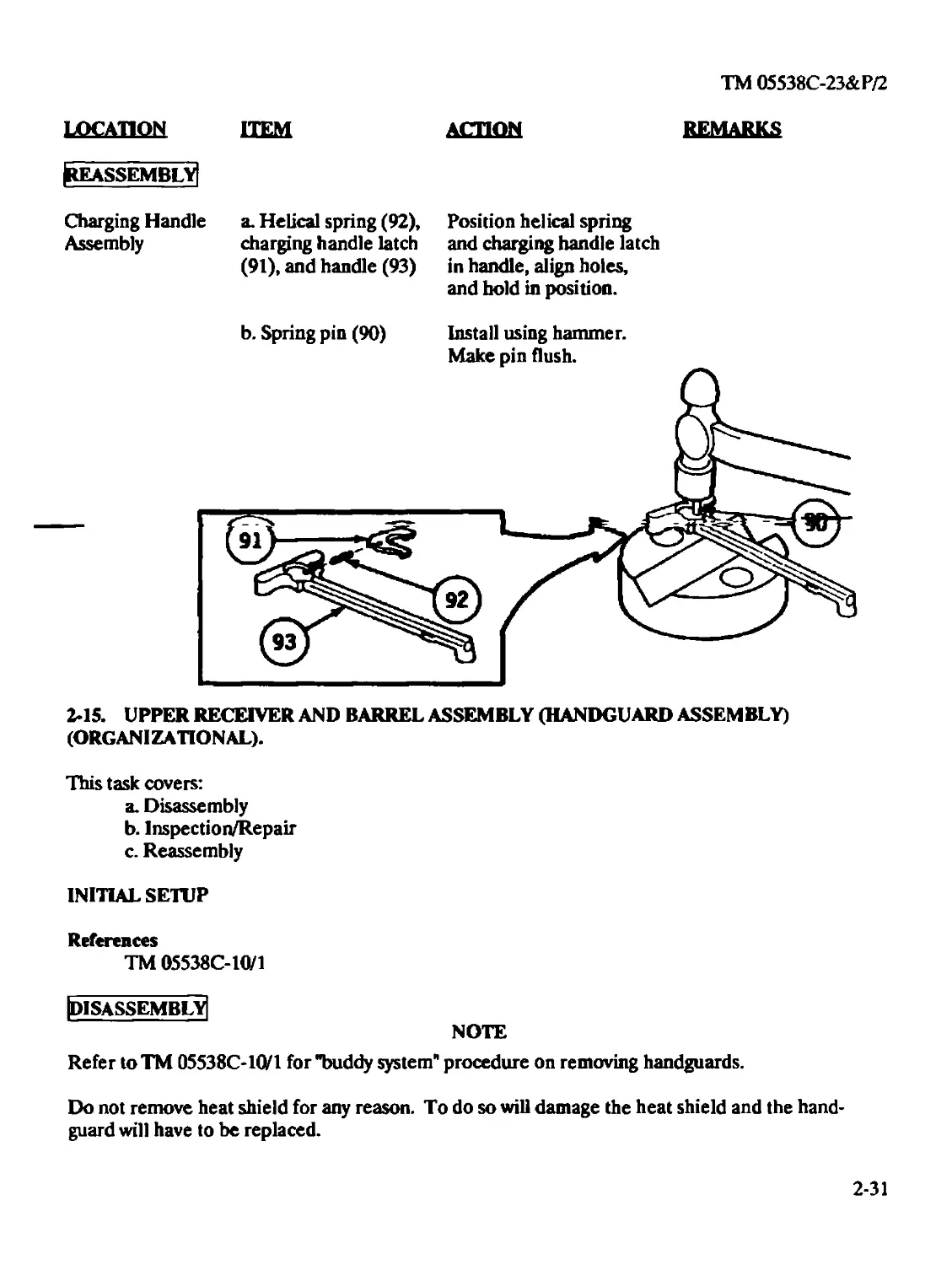
^REASSEMBLY)
Charging Handle
Assembly
a. Helical spring (92),
charging handle latch
(91), and handle (93)
Position helical spring
and charging handle latch
in handle, align holes,
and hold in position.
2-15. UPPER RECEIVER AND BARREL ASSEMBLY (HANDGUARD ASSEMBLY)
(ORGANIZATIONAL).
This task covers:
a. Disassembly
b. Inspection/Repair
c. Reassembly
INITIAL SETUP
References
TM 05538C-10/1
[disassembly!
NOTE
Refer to TM 05538С-10/1 for "buddy system" procedure on removing handguards.
Do not remove heat shield for any reason. To do so will damage the heat shield and the hand-
guard will have to be replaced.
2-31
TM 05538C-23&P/2
LOCATION HEM ACTION
REMARKS
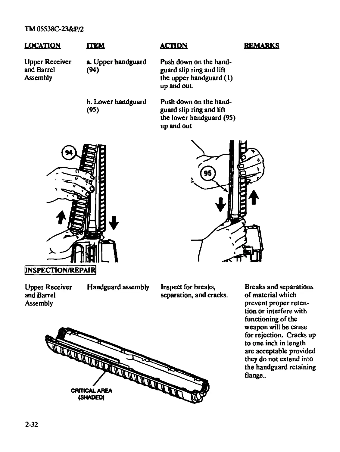
Upper Receiver
and Barrel
Assembly
a. Upper handguard
(94)
Push down on the hand-
guard slip ring and lift
the upper handguard (1)
up and out.
b. Lower handguard
(95)
Push down on the hand-
guard slip ring and lift
the lower handguard (95)
up and out
Upper Receiver Handguard assembly
and Barrel
Assembly
Inspect for breaks,
separation, and cracks.
Breaks and separations
of material which
prevent proper reten-
tion or interfere with
functioning of the
weapon will be cause
for rejection. Cracks up
to one inch in length
are acceptable provided
they do not extend into
the handguard retaining
flange..
2-32
TM 05538C-23&P/2
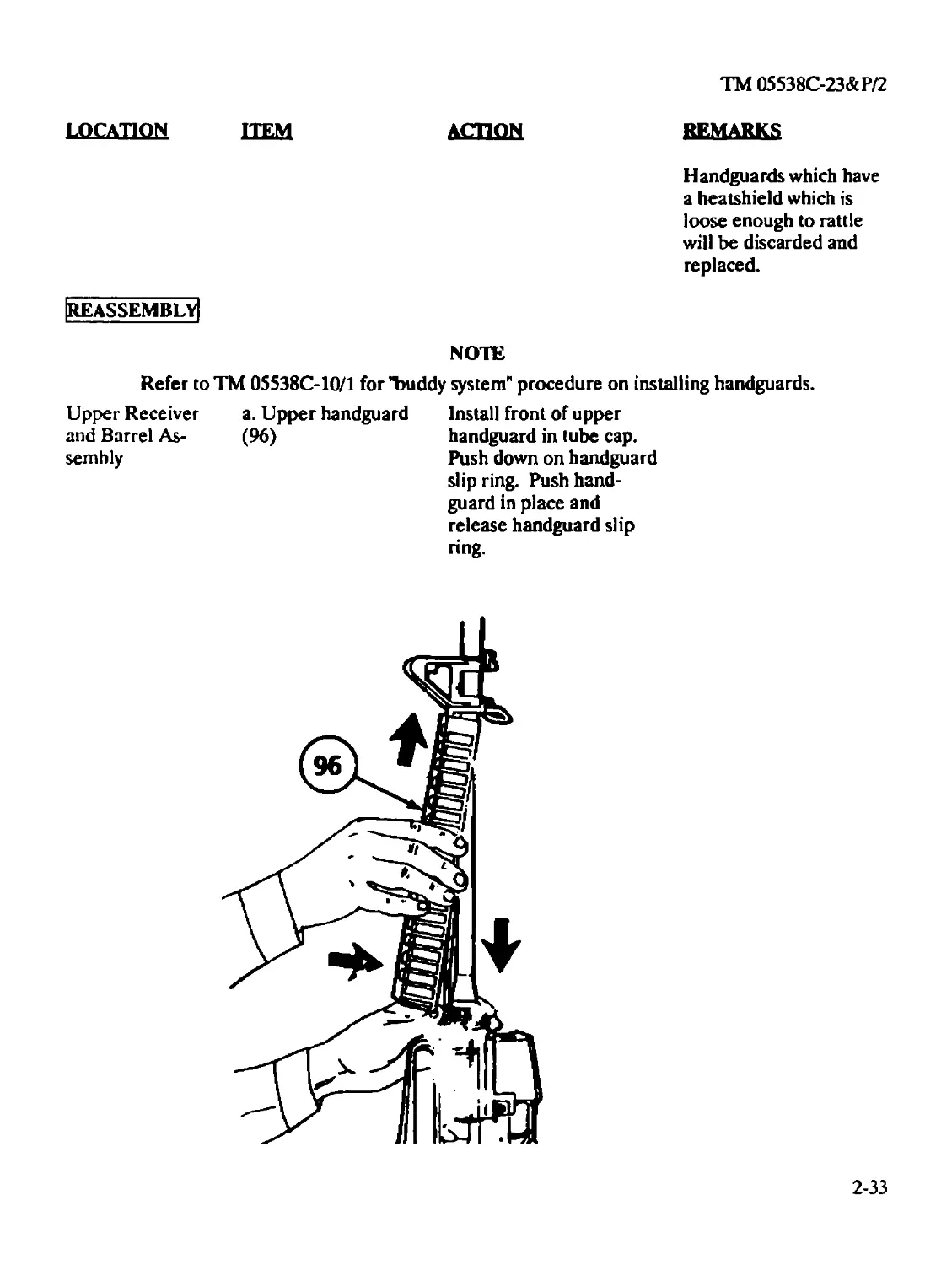
LOCATION ITEM ACTION REMARKS Handguards which have a heatshield which is loose enough to rattle will be discarded and replaced.
|REASSEMBLY| NOTE
Refer toTM 05538C-10/1 for "buddy system" procedure on installing handguards.
Upper Receiver a. Upper handguard and Barrel As- (96) semhly Г 22^ Install front of upper handguard in tube cap. Push down on handguard slip ring. Push hand- guard in place and release handguard slip ring. s 4^r
2-33
TM 05538C-23&P/2
HEM ACTION
remarks
location
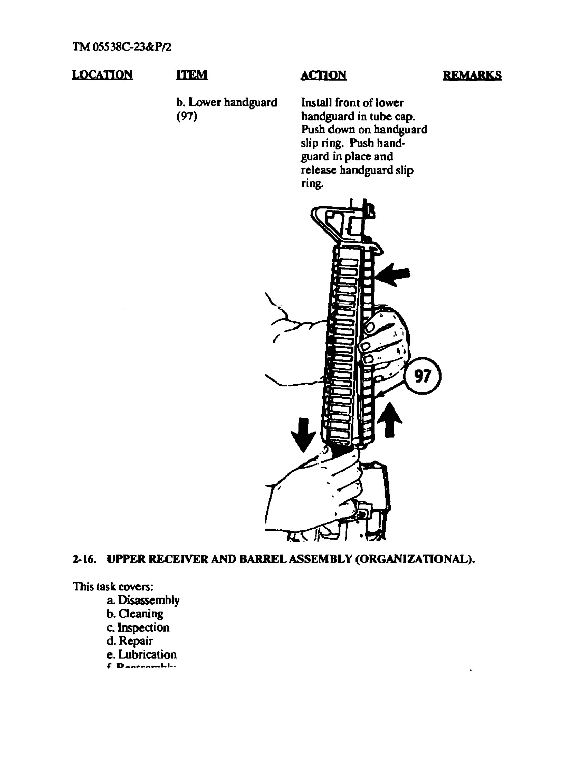
b. Lower handguard
(97)
Install front of lower
handguard in tube cap.
Push down on handguard
slip ring. Push hand-
guard in place and
release handguard slip
2-16. UPPER RECEIVER AND BARREL ASSEMBLY (ORGANIZATIONAL).
This task covers:
a. Disassembly
b. (leaning
c. Inspection
d. Repair
e. Lubrication
TM 05538C-23&P/2
INITIAL SETUP
Tools
(MC) Small Anns Repairman Tool Kit
NSN 5180-00- 357-7770/SL-3-00607A
(ARMY) Small Arms Repairman Tool Kit
SC 5180-95-CL-A07 (app B)
Sight removal tool (E-2, app E)
Front sight detent depressor (E-l, app E)
Materials/Parts
Cleaner, lubricant and preservative (CLPXitem 6, app D)
Equipment Condition
Upper receiver and barrel assembly removed from lower receiver.
General Safety Instructions
To avoid injury to your eyes use care when removing and installing spring-loaded parts.
When using solid film lubricant or dichloromethane, be sure the area is well ventilated.
Do not interchange bolt-assemblies or other components from one weapon to another.
Doing so may result in injury to, or death of, personnel.
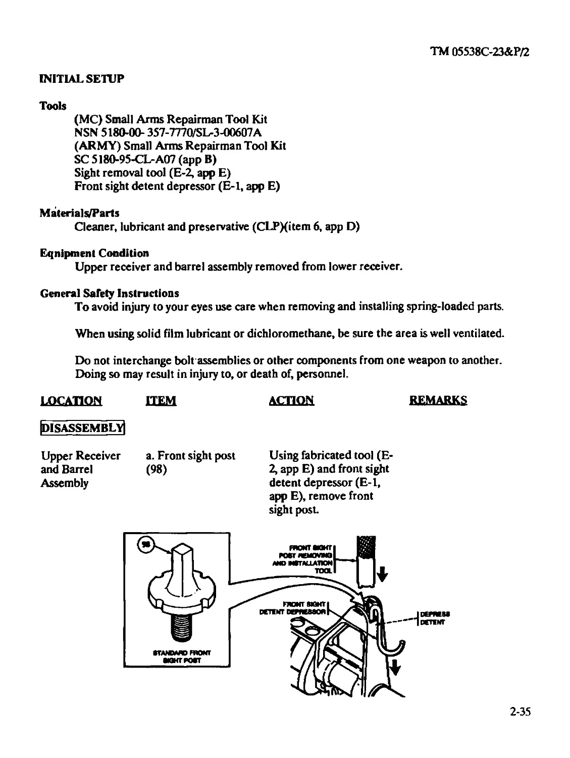
LOCATION ITEM [disassembly! Upper Receiver a. Front sight post and Barrel (98) Assembly tTANOMD FRONT ЮИГКЖТ ACTION REMARKS Using fabricated tool (E- 2, app E) and front sight detent depressor (E-l, app E), remove front sight post нюнтикг) BSn roer лвжмна 1МИ FRONT SIGHT | DCTINT fil JD0VKM * J «TINT
2-35
TM 05538C-23&P/2
АСТИЖ REMARKS
LOCATION ITEM
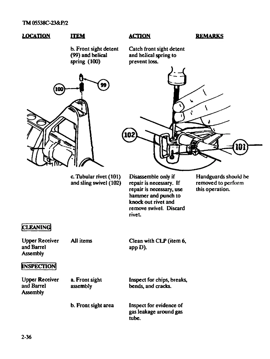
b. Front sight detent
(99) and helical
spring (100)
Catch front sight detent
and helical spring to
prevent loss.
c. Tabular rivet (101)
and sling swivel (102)
Disassemble only if
repair is necessary. If
repair is necessary, use
hammer and punch to
knock out rivet and
remove swivel. Discard
rivet
Handguards should be
removed to perform
this operation.
|CLEAN1NG|
Upper Receiver All items
and Barrel
Assembly
[inspection]
Clean with CLP (item 6,
app D).
Upper Receiver a. Front sight
and Barrel assembly
Assembly
b. Front sight area
Inspect for chips, breaks,
bends, and cracks.
Inspect for evidence of
gas leakage around gas
tube.
2-36
TM 05538C-23&P/2
LOCATION
ITEM А£ШШ REMARKS
c. Barrel Clean and inspect for pits in bore, burrs, broken or worn locking lugs, and surface cracks and defects. Pits no wider than a land or groove and 3/8 inch or less in length are allowable in the bore.
Uniformly fine pits in a densely pitted area of the bore are allowable.
Inspect bore for ringing. Definitely ringed bores or bores ringed suffi- ciently to bulge the out- side surface of the bar- rel are cause for rejec- tion. Lands that appear dark due to coating of gliding metal from projectiles are allowable.
Stripping of lands and grooves shall not be cause for rejection un- less so determined by barrel erosion gage.
Inspect chamber for Fine pits, or fine pits in
pitting. a densely pitted area, are allowable. Pits 1/8 inch in length are cause for rejection.
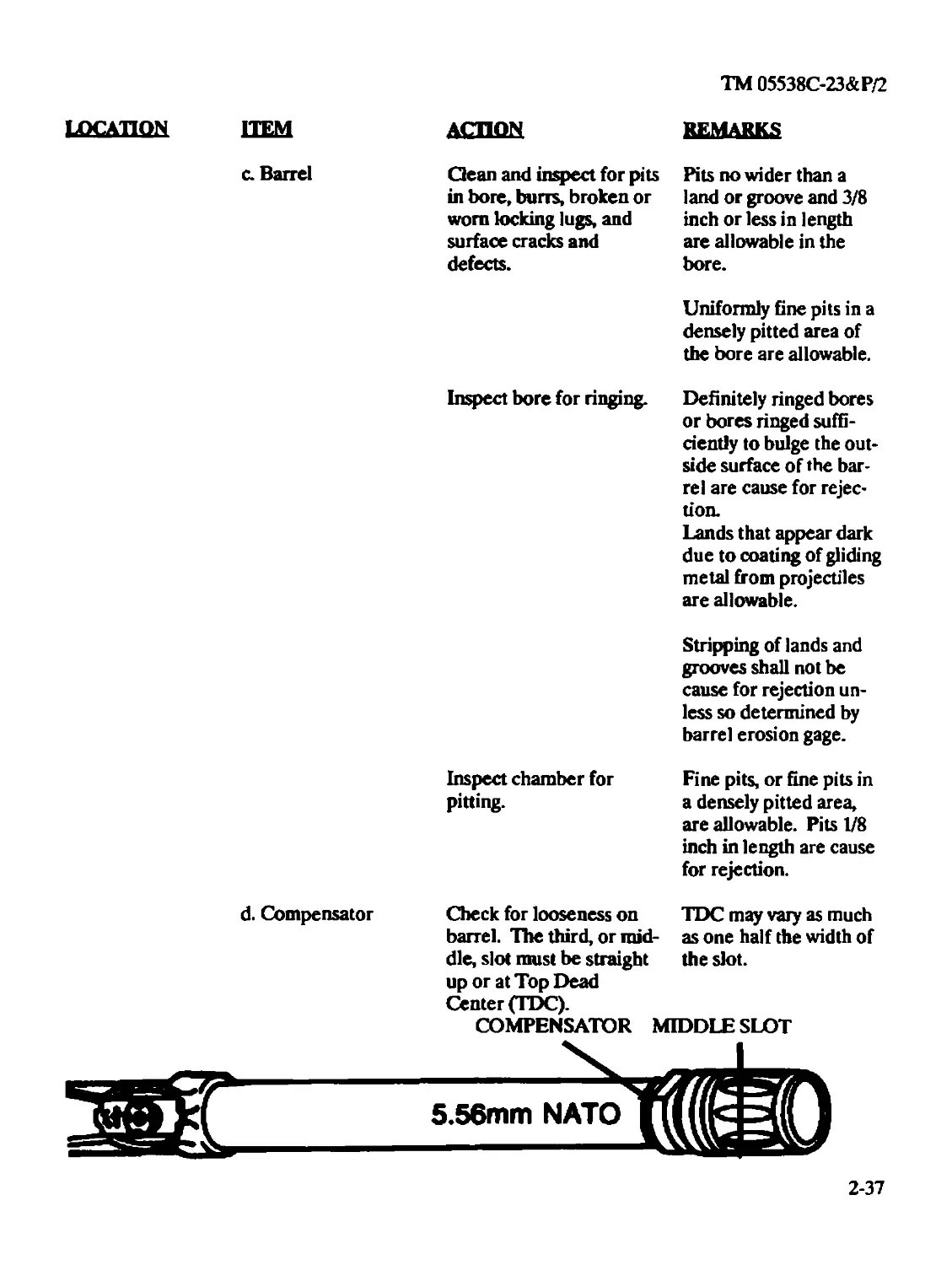
d. Compensator
Check for looseness on
barrel. The third, or mid-
dle, slot must be straight
up or at Top Dead
Center (TDC).
TDC may vary as much
as one half the width of
the slot.
COMPENSATOR MIDDLE SLOT
2-37
TM 05538C-23&P/2
LOCATION
|repair|
Upper Receiver
and Barrel
Assembly
IlubricationI
Upper Receiver
and Barrel As-
sembly
IreassemblyI
Upper Receiver
sembly
HEM ACTION
All authorized items
Replace authorized
unserviceable parts.
All items Cover with a light coat of
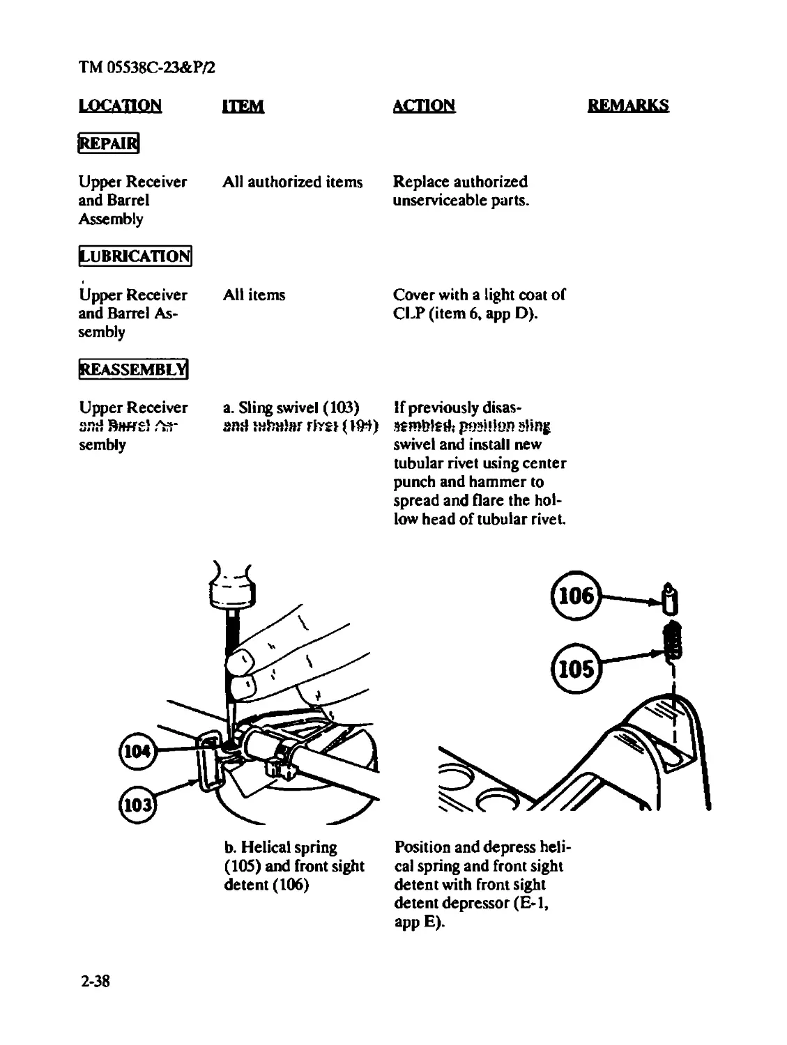
a. Sling swivel (103)
and tnSnlar rtvei (104)
REMARKS
CLP (item 6, app D).
If previously disas-
sembled.- pssilion sling
swivel and install new
tubular rivet using center
punch and hammer to
spread and flare the hol-
low head of tubular rivet.
b. Helical spring
(105) and front sight
detent (106)
Position and depress heli-
cal spring and front sight
detent with front sight
detent depressor (E-l,
app E).
2-38
TM 05538C-23&P/2
LOCATION
ITEM
ACTION
REMARKS
|disassembly|
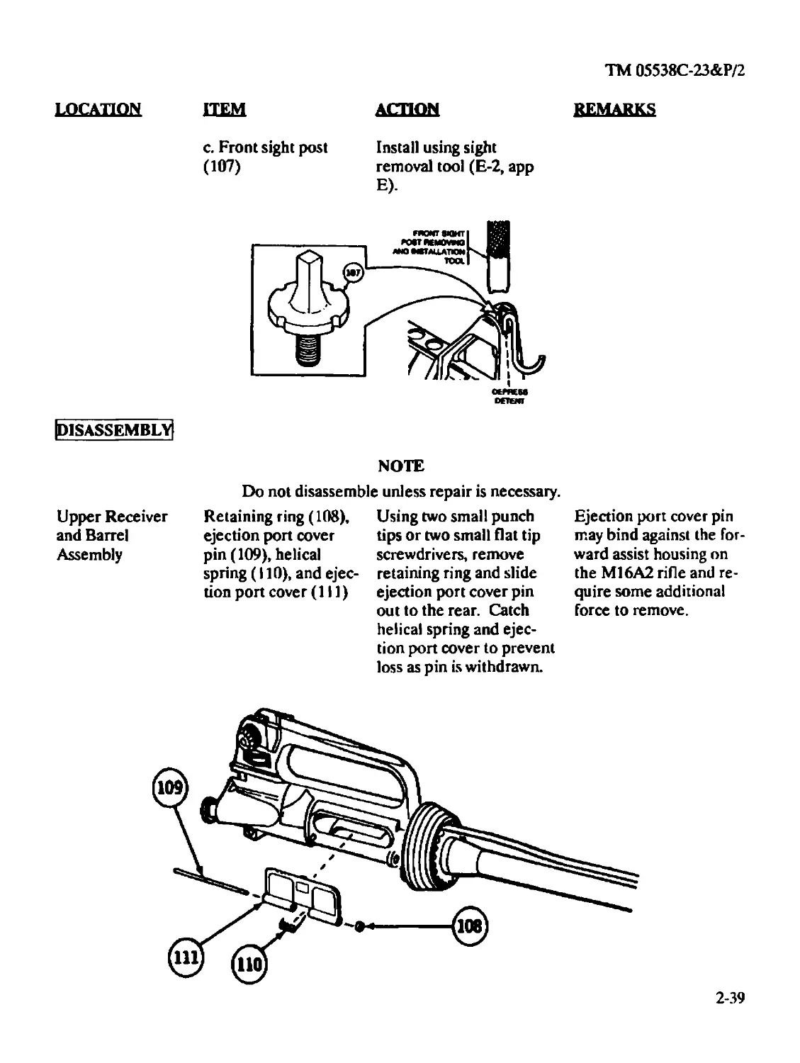
c. Front sight post
(Ю7)
Install using sight
removal tool (E-2, app
E).
NOTE
Do not disassemble unless repair is necessary.
Upper Receiver
and Barrel
Assembly
Retaining ring (108),
ejection port cover
pin (109), helical
spring (110), and ejec-
tion port cover (111)
Using two small punch
tips or two small flat tip
screwdrivers, remove
retaining ring and slide
ejection port cover pin
out to the rear. Catch
helical spring and ejec-
tion port cover to prevent
loss as pin is withdrawn.
Ejection port cover pin
may bind against the for-
ward assist housing on
the M16A2 rifle and re-
quire some additional
force to remove.
2-39
TM 05538C-23&P/2
LOCATION ITEM ACTION remarks
|nspection|
Upper Receiver and Barrel Assembly All items Inspect for serviceability in and tightness of latch assembly on ejection port cover. If items are damaged or nonfunctional, they are unserviceable.
|repair|
Upper Receiver and Barrel Assembly All authorized items Replace if unserviceable.
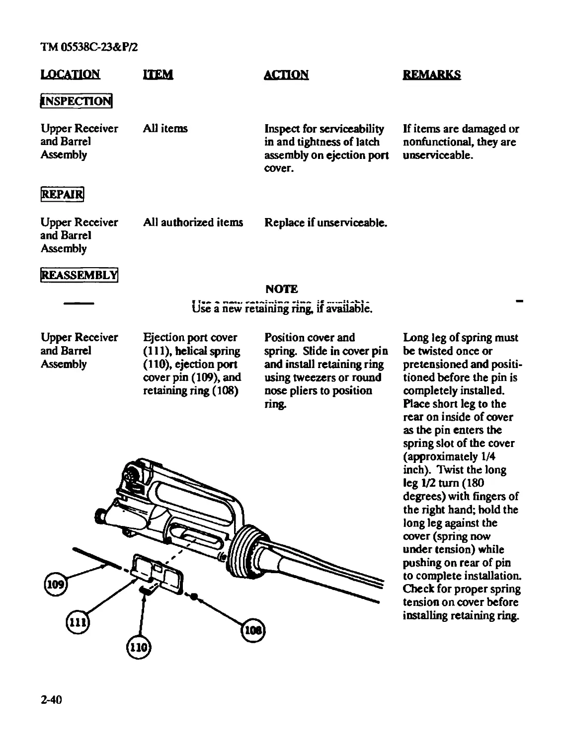
[reassembly! NOTE
Use a new retaining ring, if available.
Upper Receiver
and Barrel
Assembly
Ejection port cover
(111), helical spring
(110), ejection port
cover pin (109), and
retaining ring (108)
Position cover and
spring. Slide in cover pin
and install retaining ring
using tweezers or round
nose pliers to position
ring.
Long leg of spring must
be twisted once or
pretensioned and positi-
tioned before the pin is
completely installed.
Place short leg to the
rear on inside of cover
as the pin enters the
spring slot of the cover
(approximately 1/4
inch). Twist the long
leg 1/2 turn (180
degrees) with fingers of
the right hand; hold the
long leg against the
cover (spring now
under tension) while
pushing on rear of pin
to complete installation.
Check for proper spring
tension on cover before
installing retaining ring.
2-40
TM 05538C-23&P/2
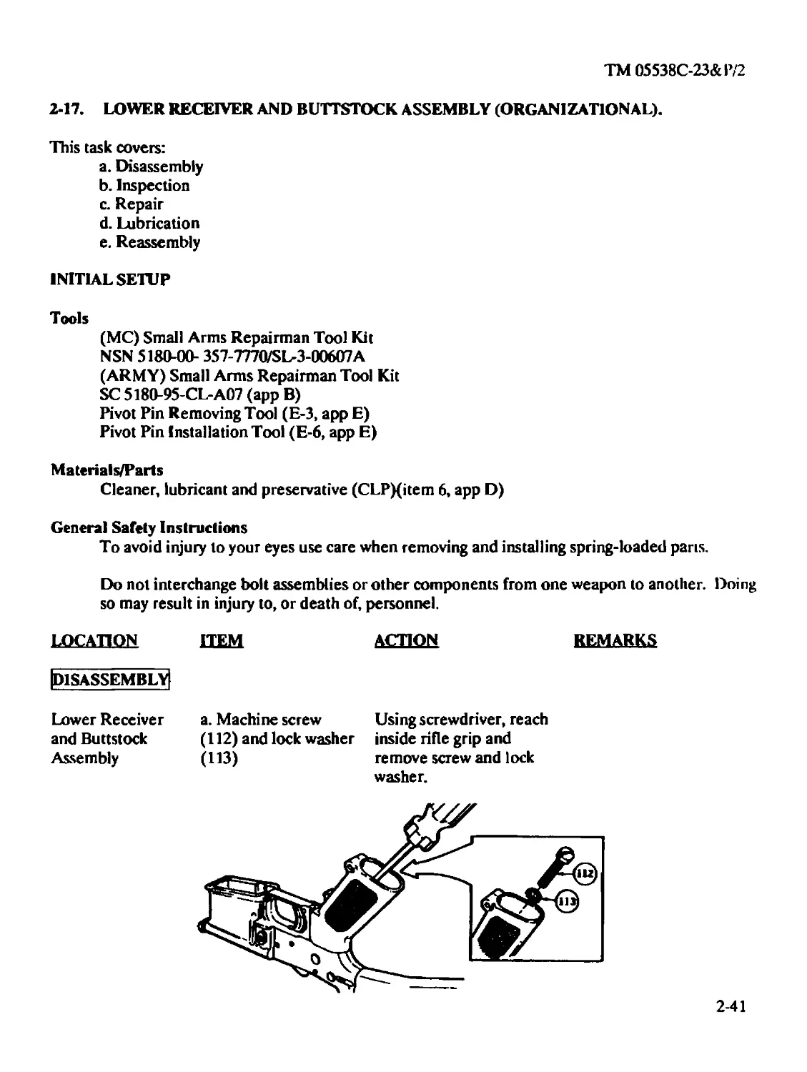
2-17. LOWER RECEIVER AND BUTTSTOCK ASSEMBLY (ORGANIZATIONAL).
This task covers:
a. Disassembly
b. Inspection
c. Repair
d. Lubrication
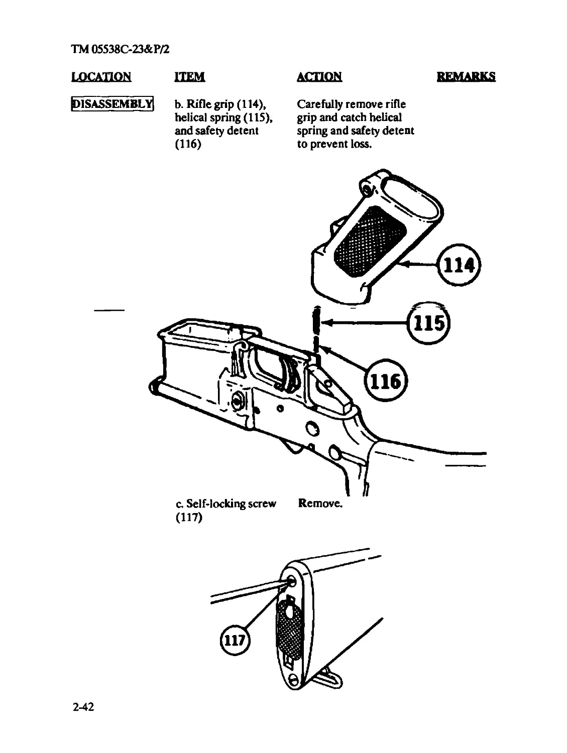
e. Reassembly
INITIAL SETUP
Tools
(MC) Small Arms Repairman Tool Kit
NSN 5180-00- 357-7770/SL-3-00607A
(ARMY) Small Arms Repairman Tool Kit
SC 5180-95-CL-A07 (app B)
Pivot Pin Removing Tool (E-3, app E)
Pivot Pin Installation Tool (E-6, app E)
Materials/Parts
Cleaner, lubricant and preservative (CLPXitem 6, app D)
General Safety Instructions
To avoid injury to your eyes use care when removing and installing spring-loaded pans.
Do not interchange bolt assemblies or other components from one weapon to another. Doing
so may result in injury to, or death of, personnel.
LOCATION ITEM
ACTION
REMARKS
|disassembly|
Lower Receiver
and Buttstock
Assembly
a. Machine screw Using screwdriver, reach
(112) and lock washer inside rifle grip and
(113) remove screw and lock
washer.
2-41
TM 05538C-23&P/2
LOCATION
[disassembly)
ITEM
b. Rifle grip (114),
helical spring (115),
and safety detent
(И6)
action remarks
Carefully remove rifle
grip and catch helical
spring and safety detent
to prevent loss.
c. Self-locking screw Remove.
(И7)
2-42
TM 05538C-23&P/2
LOCATION HEM
AdlQM
REMARKS
d. Buttstock assembly
(118), stepped spacer
(119), helical spring
(120), detent (121),
and takedown pin
(122)
Remove stock carefully
and catch helical spring,
detent, and takedown pin
to prevent loss.
To avoid injury to your eyes, use care when removing and installing spring-loaded parts.
e. Pivot pin (123)
Insert pivot pin removing
tool (E-3, app E) to com-
press detent. Turn pin a
quarter-turn. Remove
tool and pin. Catch
detent and spring as pivot
pin is removed.
2-43
TM 05538C-23&P/2
LOCATION ITEM АСТИЖ
REMARKS
f. Pivot pin detent
(124) and helical
spring (125)
Be sure to hold cupped
hand in front of detent
and helical spring to
prevent loss of detent
and spring.
g. Buffer assembly
(126) and action
spring (127)
Press buffer assembly in.
Using screwdriver,
depress buffer retainer
and release buffer (126)
and action spring (127).
Remove buffer assembly
(126) and action spring
(127) from receiver while
depressing the retainer.
PUSH BUPFER ASSEMBLY
2-44
TM 05538C-23&P/2
LOCATION ITEM ACTION REMARKS
NOTE
Early type buffer assembly must be replaced.
Inspection!
Lower Receiver a. Buffer assembly
and Buttstock
Assembly
The buffer assembly
must not be cracked be-
tween hole and end of
housing.
Some old buffers (128)
have a pin through hole
which protrudes equally
on each side ap-
proximately 1/32 of an
inch.
Some buffers (129)
have a hole in the hous-
ing but no pin. Discard
these.
New buffers (130) do
not have a hole in
buffer body or a pin.
b. Action spring
The free length of the ac-
t'-in spring must be be-
tween 11 3/4 inches min-
mum and 13 1/2 inches
maximum.
U-FREE LENGTH----------4
2-45
TM 05538C-23&P/2
LOCATION ITEM
ACTION
REMARKS
Inspect serial number for
legibility.
c. Lower receiver
(without further
disassembly)
If the serial number is
hard to read, evacuate
to Depot Maintenance.
Inspect for missing or
damaged parts. Inspect
finish of lower receiver
for shiny spots.
Touch up with solid
film lubricant.
|REPA1R|
Lower Receiver
and Buttstock
Assembly
All authorized items
Replace if unserviceable.
Evacuate any damaged
parts to Intermediate
Maintenance.
[Lubrication!
Lower Receiver All metal parts,
and Buttstock
Assembly
Apply a light coat of CLP
(item 6, app D) on all
metal components.
Ireassemblv]
WARNING
To avoid injury to your eyes, use care when removing and installing spring-loaded parts.
Do not interchange bolt assemblies or other components from one weapon to another. Doing so
may result in injury to, or death of, personnel.
2-46
TM 05538C-23&P/2
location ITEM ACTION REMARKS
Lower Receiver and Buttstock Assembly a. Action spring (131) Press in until retainer and buffer assembly snaps up and holds action (132) spring and buffer assembly in place.
b. Helical spring
(133), pivot pin
detent (134), and
pivot pin (135)
Install pivot pin installa-
tion tool (E-6, app E).
Insert spring and detent.
Compress detent in
recess with punch and
rotate tool.
Remove punch. Push out
tool using pivot pin (135)
Rounded end of detent
must be in the groove
of the pivot pin when
assembly is complete.
2-47
TM 05538C-23&P/2
LOCATION ITEM АСТИЖ REMARKS
Lower Receiver c. Takedown pin Install takedown pin with
and Buttstock (136), takedown pin groove to the rear. In-
Assembly detent (137), helical spring (138), stepped spacer (139), buttstock assembly (140), and self- lock- ing screw (141) stall detent and spring from the rear. Install spacer on receiver exten- sion. Begin to install but- tstock assembly. Careful- ly compress the spring with stock and secure the stock in place with the self- locking screw. CAUTION:
Do not kink the detent spring (8) during assembly.
2-48
TM 05538C-23&P/2
LOCATION
ITEM ACTION
remarks
d. Safety detent (142),
helical spring (143),
rifle grip (144),
washer (145), and
machine screw (146)
Install detent, pointed
end first, and spring from
the bottom. Carefully
compress the spring with
the rifle grip and secure
the grip in place with the
lock washer and screw.
The spring is partially
housed in a hole formed
on top of the grip.
2-49
TM 05538C-23&P/2
2-18. BUTTSTOCK ASSEMBLY (ORGANIZATIONAL)
This task covers:
a. Disassembly
b. Inspection
c. Repair
d. Lubrication
e. Reassembly
INITIAL SETUP
Tools
(MC) Small Arms Repairman Tool Kit
NSN 5180-00- 357-7770/SL-3-00607A
(ARMY) Small Arms Repairman Tool Kit
SC 5180-95-CL-A07 (app B)
M ci t crinl^/Pn s
Cleaner, lubricant and preservative (CLPXitem 6, app D)
Equipment Condition
Buttstock assembly removed from lower receiver and buttstock assembly.
1X)CAT1ON HEM ACTION REMARKS
Disassembly]
Buttstock a. Self-locking screw Using screwdriver,
Assembly (147) and small sling remove self-locking
swivel (148) screw, small sling swivel,
and butt plate group.
2-50
TM 05538C-23&P/2
LOCATION
IIEM ACTION REMARKS
b. Butt plate (149)
Push down on plunger
and lift door assembly
out of butt plate
c. Straight pin (150),
hinge (151), and door
assembly (152)
Remove straight pin and
separate hinge and door
assembly.
[inspection]
Buttstock Stock
Assembly
Inspect stock for cracks.
Report cracked stocks
and evacuate to inter-
mediate support.
(MC ONLY)
Evacuate a cracked
stock to Intermediate
Maintenance for repair.
Also submit SF 368.
Quality Deficiency
Report.
Buttstock
Assembly-
All authorized items Replace unserviceable
items.
Unserviceable items are
those items which are
damaged.
2-51
ТМ05538С-23&Р/2
LOCATION
[lubrication]
Buttstock
Assembly
[reassembly]
Buttstock
Assembly
ITEM ACTION remarks
Stock Lubricate all metal com- ponents with CLP (item 6, app D).
a. Door assembly
(152), hinge (151),
and straight pin (150)
Position hinge on door as-
sembly and install
straight pin.
b. Butt plate (153)
Install door assembly into
butt plate and press
plunger to lock.
ОООЯ ASSEMBLY
(UFTOUT)
c. Small sling swivel
(154) and self-locking
screw (155)
Position butt plate group
and rear sling swivel to
the buttstock and secure
with self-locking screw
(155).
See page 2-44 for reas-
sembly of buttstock as-
sembly to lower
receiver.
2-52
TM 05538C-23&P/2
2-19. MAJOR COMPONENTS OF M16A2 RIFLE.
This task covers:
a. Reassembly
b. Organizational Test
c. Organizational Stowage
INITIAL SETUP
References
TM 05538C-10/1
Equipment Condition
Weapon disassembled into major components.
General Safety Instructions
Do not interchange bolt assemblies or components from one weapon to another. Doing so
may result in injury to. or death of. personnel.
Do not keep live ammunition near the work area.
LOCATION ITEM ACTION
remarks
Reassembly]
Weapon
Lower receiver and
buttstock assembly
(156), upper receiver
and barrel assembly
(157), charging hand-
le assembly (158),
bolt carrier assembly
(159), small arms
sling (160), and
cartridge magazine
(161)
Install.
Refer to TM 05538C-
10П.
2-53
TM 05538C-23&P/2
fqcauqn ITEM ACTION remarks
Organizational test! Weapon Function test as follows:
a. Charging handle as- Pull to rear. Check that Do not pull trigger.
sembly chamber is clear. Let bolt and bolt carrier close. Leave hammer in cock- ed position.
b. Selector lever Place in SAFE position and pull trigger. Hammer should not fall.
WARNING
If weapon fails the following tests, continued use of weapon could result in injury or death.
NOTE
: si ss fssssw йгг§Ь8ИТ is Oral s w ю W IBs sis й ?да ““
release.
c. Selector lever Place in SEMI position and pull trigger. Hammer should fall.
Hold trigger to rear, charge weapon and release trigger with a slow, smooth motion, without hesitations or stops, until the trigger is fully forward. Hammer should not fall.
Repeat the SEMI posi- tion test five times, the weapon must not mal- function. If the weapon malfunc- tions during any of these five repetitions, evacuate it to Intermediate- Maintenance for repair.
d. Selector lever Place in Burst position. Cock weapon and squeeze trigger. Hammer should fall.
2-54
TM 05538C-23&P/2
LOCATION
ITEM
ACTION
REMARKS
While holding the trigger
to the rear, pull the charg-
ing handle assembly to
the rear and release it
three times. Release the
trigger.
Hammer should not
fall. The burst discon-
nector should have held
the hammer to the rear
while the trigger was in
the squeezed position.
Squeeze the trigger.
Hammer should fall.
This should be the first
round of a three- round
burst
Section VI. DECONTAMINATION OF RIFLES AND ARMS ROOMS (ARMY ONLY)
2-20. DECONTAMINATION OF SIGHTS ACTIVATED WITH TRITIUM (h 3).
a. Identification. Tritium sights will be marked with the assembly date and the radiation symbol
and stamped H 3,9mc.
b. Damage Determination. Evidence of a break in the glass container for the H 3 will be a lack
of illumination (assuring the expiration date for the sight has not been exceeded). Radiation from
the sight is extremely low and CANNOT be detected with standard issue radiation detectors, i.e.,
AN/PDR-27.
c. Contamination. The tritium isotope used in the low light level sight is in a gaseous state and
will rapidly diffuse into the atmosphere in the event of breakage. Very little residual contamina-
tion should be left on the rifle. All illumlnatiun will cease upon loss of H 3 gas.
WARNING
Dry cleaning solvent is flammable and toxic and should be used in a well ventilated area. The use
of rubber gloves is necessary to protect the skin when washing rifle parts.
d. Decontamination. When a broken sight is found, the sight MUST be removed and turned
in for disposal in accordance with AR 385-11. After removing the sight, the rifle should be
cleaned with dry cleaning solvent (item 13, app D). Wear rubber gloves (item 15, app D) and use a
wash pan to apply solvent. Let dry, then lubricate with cleaner, lubricate and preservative
(CLPXitem 6, app D).
e. Requirements. Because of its small volume of gas and its low energy of emitted radiation,
H 3 does not pose a health hazzard to the user. Current Army regulations, NRC license conditions
and Title 10, Code of Federal regulations. Part 20 require that the above actions be carried out.
2-55
TM 05538C-23&P/2
LOCATION
ITEM
action
REMARKS
2-21. DECONTAMINATION OF SIGHTS ACTIVATED WITH PROMETHIUM (Pm 147).
NOTE
Pin 147 is no longer available for issue. It is being replaced with tritium (H 3).
a. General. When a sight activated with promethium (Pm 147) is found, the sight MUST be
removed and turned in for disposal in accordance with AR 385-11. Contact the local RPO
b. Identification. Promethium sights are marked with the assembly date, the radiation
symbol, and Pm 147, 1 me.
c. Decontamination. If a sight activated with promethium (Pm 147) is found, conduct a
survey under the direction of the local RPO. Decontaminate as required in accordance with local
procedures.
loKGANiZAfioNAL STOWAGE
Weapon
Rifle
Prior to stowing the rifle
in arms room, perform
the following procedures:
Rifles passed into arms
room issue window
should be passed butt
first with the bolt lock-
ed to the rear.
Clear.
Refer to TM 05538C-
10/1.
Place selector in SEML
Point in safe direction.
Hammer should fall.
Squeeze trigger.
Close ejection port (dust)
cover.
Place rifle in rack.
2-56
TM 05538C-23&P/2
CHAPTERS
INTERMEDIATE MAINTENANCE INSTRUCTIONS
CHAPTER OVERVIEW
This chapter provides information and instructions to keep the weapon in good repair and contains
the following sections:
I. Repair Parts and Special Tools
П. Service Upon Receipt
Ш. Intermediate Troubleshooting
IV. Intermediate Maintenance Procedures for the M16A2 Rifle
V. Preparation for Storage or Shipment
VI. Preembarkation Inspection of Material in Units Slated for Overseas Movement
Section I. REPAIR PARTS AND SPECIAL TOOLS
3-1. COMMON TOOLS AND EQUIPMENT. For authorized common tools and equipment, see
SL-3-00607A. Army users refer to TOE/MTOE applicable to your unit.
3-1. SPECIAL TOOLS. Special tools required for intermediate maintenance are listed in appen-
dix C and fabricated tools are listed and illustrated in appendix E.
3-3. REPAIR PARTS. Repair parts are listed and illustrated in appendix C.
NOTE
Bolt assemblies, and/or barrel assemblies may be interchanged, at the Intermediate Maintenance
level, from one rifle to another under the provisions of the note on page C-3. If these parts are in-
terchanged the weapon must be checked/inspected as depicted in paragraphs 3-9, 3-10,3-12.
While performing these checks and inspections, pay special attention to the headspace require-
ments on page 3-46.
Section II. SERVICE UPON RECEIPT
3-4. GENERAL.
a. Check the weapon against the packing slip to see if the shipment is complete. Report all
discrepancies in accordance with MCO P4610.19C.
b. Check to see if all modification instructions have been applied.
(ARMY ONLY)
c. Inspect the weapon for damage incurred during shipment. If the equipment has been
damaged, report the damage on SF 364, Report of Discrepancy (ROD).
d. Check the weapon against the packing slip to see if the shipment is complete. Report all
discrepancies in accordance with the instruction in DA PAM 738-750.
3-1
TM 05538С-23&Р/2
e. Check to see whether the equipment has been modified.
f. Check to see if all MWO’s have been applied.
3*5. INTERMEDIATE SERVICE UPON RECEIPT OF MATERIEL. Perform the action noted in
Table 3-2.
Table 3-2
SERVICE UPON RECEIPT - М1ЙА2 RIFLE
LOCATION
M16A2 Rifle
ITEM
Charging handle
assembly
ACTION
Clear the weapon
REMARKS
Refer to
TM 05538C-10/1.
WARNING
To avoid injury to your eyes, use care when removing and installing spring-loaded parts.
Bolt carrier assembly and bolt assembly Remove. Refer to TM 05538C-10/1.
All components Visually inspected for proper assembly, damage, or missing parts. Refer to TM 05538C-10/1.
Bolt carrier assembly and bolt assembly. Reassemble. Refer to TM Q5538C-10/1.
Hand function to as- sure proper operation.
Cartridge magazine Insert empty magazine and pull the bolt to the rear. Check magazine for positive retention and check functioning of bolt catch by assuring that bolt locks to the rear with empty magazine inserted. Refer toTM05538C- 10/1
3-2
TM 05538C-23&P/2
Section ПЬ INTERMEDIATE MAINTENANCE TROUBLESHOOTING
3-6. GENERAL.
a. This section contains intermediate maintenance troubleshooting information for locating
and correcting most of the operating troubles which may develop in the weapon. Each malfunc-
tion for the individual component, unit, or system is followed by a list of tests or inspections which
will help you to determine the corrective actions to take. You should perform the tests/inspections
and corrective actions noted in Table 3-3 in the order listed in the Test & Inspection column for
each malfunction.
b. This manual cannot list all malfunctions that may occur, nor all tests or inspections and
corrective actions. If a malfunction is not listed or is not corrected by listed corrective actions, see
individual repair sections for maintenance instructions on each major assembly.
3-7. TROUBLESHOOTING PROCEDURES.
Refer to troubleshooting table for malfunctions, tests, and corrective actions. The symptom index
noted in Table 3-1 is provided for a quick reference of the malfunctions covered in table 3-3.
SYMPTOM INDEX
Malfunction
page
Bolt fails to lock to rear after firing last round...............................3-11
Failure of magazine to lock in weapon............................................ 3-8
Failure to chamber................................................................3-8
Failure to cock in either semi or burst mode......................................3-5
Failure to cycle with selector lever set at BURST.................................3-8
Failure to eject..................................................................3-5
Failure to extract................................................................3-5
Failure to feed...................................................................3-8
Failure to fire...................................................................3-4
Failure to lock...................................................................3-9
Failure to unlock.................................................................3-5
Fires two rounds in SEMI selector position (doubling)........................... 3-14
Fires with selector lever on SAFE or when trigger is released with selector lever
on SEMI..........................................................................3-14
Hammer pin "walks”................................................................3-14
Short recoil......................................................................3-9
Weapon cannot be zeroed...........................................................3-12
3-3
TM 05538С-23&Р/2
Table 3-3
INTERMEDIATE TROUBLESHOOTING
MALFUNCTION
1. FAILURE TO FIRE.
TEST OR INSPECTION
Step 1. Broken hammer (1).
Step 2. Weak or broken
hammer spring (2).
Step3. Hammer spring (2)
improperly assembled.
Step 4. Burst cam (3) and/or
clutch spring (4) frozen or
improperly assembled.
Step 5. Selector lever (5)
frozen on SAFE position.
Step 6. Broken firing pin (6)
or firing pin does not meet
gage protrusion requirement
CORRECTIVE ACTION
Replace hammer (1).
Replace spring (2).
Reassemble correctly
(paragraph 3-17).
Disassemble, clean, lubricate,
and reassemble correctly.
Disassemble and clean.
Replace.
3-4
TM 05538C-23&P/2
MALFUNCTION
2. FAILURE TO UNLOCK
TEST OR INSPECTION
Step 1. Burred locking lugs(7)
on bolt assembly.
Step 2. Burred lugs (8) on
barrel extension.
CORRECTIVE ACTION
Remove burrs.
Remove burrs.
Step 3. See short recoil.
3. FAILURE TO EXTRACT. Step 1. Inspect extractor and extractor spring Replace if cracked or broken.
Step 2. Inspect badly pitted Replace rifle barrel assembly if
chamber with reflector tool. chamber is badly pitted.
4. FAILURE TO EJECT. See short recoil.
5. FAILURE TO COCK IN EITHER SEMI OR BURST MODE. Step 1. Worn or broken trigger nose (4) or trigger spring (10). Replace trigger (11) or defective trigger spring (10).
Step 2. Worn or broken hammer trigger notch (12). Replace hammer (13).
Step 3. Worn or broken hammer disconnector hook (14). Replace hammer (13),
3-5
TM 05538C-23&P/2
MALFUNCTION TEST OR INSPECTION CORRECTIVE ACTION
Step 4. Worn or broken ham- Replace the hammer (13)
ner automatic sear hook (15).
Step 5. Worn or broken Replace defective disconnectors
disconnector hooks (16). (17).
Step 6. Weak, broken, or Replace springs (18).
missing disconnector springs
(18).
3-6
TM 05538C-23&P/2
MALFUNCTION
TEST OR INSPECTION
Step 7. Worn, broken, or
missing automatic sear (19).
Step 8. Weak or broken
automatic sear spring (20).
Step 9. Long leg of automatic
sear spring (21) incorrectly
assembled in receiver.
CORRECTIVE ACTION
Replace automatic sear (19).
Replace automatic sear (19).
Remove sear (19) and install
correctly (paragraph 3-15).
Step 10. Burst cam (22) or
clutch spring (23) frozen or
improperly assembled
(paragraph 3-17).
Disassemble, inspect, clean,
lubricate, or replace as required.
3-7
TM 05538С-23&Р/2
MALFUNCTION TEST OR INSPECTION
6. FAILURE OF Step 1. Dirty or corroded
MAGAZINETO LOCK IN magazine catch (24).
WEAPON.
CORRECTIVE ACTION
Disassemble and dean.
Step 2. Defective magazine Replace spring (25). catch spring (25). Step 3. Worn or broken Replace magazine catch (24). magazine catch (24).
7. FAILURE TO FEED. Step 1. Magazine catch spring Replace magazine catch spring (25) weak or broken. (25). Step 2. Short recoil.
8. FAILURE TO CHAMBER. See short recoil.
NOTE
See carrier key tool (E-4, app E) and procedures for its use on page 3-27.
3-8
TM 05538С-23&Р/2
MALFUNCTION
TEST OR INSPECTION CORRECTIVE ACTION
9. FAILURE TO LOCK
Step 1. Damaged bolt carrier
key (26).
Repair or replace bolt carrier
key (26) and check alignment.
Step 2. Loose screws (27) on
bolt carrier key (26).
Disassemble and repair
(paragraph 3-11).
Reassemble using new screws.
Step3. Bent gas tube (28).
Adjust by bending tube in area
of handguards.
Replace gas tube (28) and check
alignment.
10. SHORT RECOIL
Step 4. See short recoil.
Step 1. Improper gap space of
worn, missing, or broken bolt
rings (29).
Replace bolt rings and stagger
gaps.
3-9
TM 05538C-23&P/2
TEST OR INSPECTION
CORRECTIVE ACTION
MALFUNCTION
Step 2. Broken or bent gas
tube (28).
Adjust by bending in area of
handguards or replace gas tube.
Step3. Gas tube spring pin Replace spring pin (30).
(30) missing from front sight
(31).
Step 4. Partially plugged gas Replace gas tube (28).
system because of carbon
build-up in the gas tube (28).
Step 5. Carbon build-up or
foreign matter in the narrow
passage of the bolt carrier key
(26).
Clean with CLP (item 6, app D)
and a pipe cleaner (item 8, app
D).
3-10
TM 05538C-23&P/2
MALFUNCTION
TEST OR INSPECTION CORRECTIVE ACTION
WARNING
When using P-C-l 11, avoid skin contact. If it comes in contact with the skin, wash off thoroughly
with running water. The use of a good lanolin base cream after exposure to compound is helpful.
The use of gloves and protective equipment is required.
Step 6. Carbon build-up in Remove carbon build-up by
barrel gas port (32). soaking n P-C-l 11 (item 5, app
D). Use rubber gloves (item 15,
app D) with P-C-l 11. Use a
small cleaning brush (item 3,
appD).
11. BOLT FAILSTO LOCK Step 1. Broken bolt catch (33). Replace bolt catch (33).
TO REAR AFTER FIRING
LAST ROUND.
Step 2. Weak or broken bolt
catch spring (34).
Step 3. Restricted movement
of bolt catch (33).
Step 4. Weak action on fol-
lower by magazine spring.
Replace bolt catch spring (34).
Disassemble and clean.
Replace magazine (35).
3-11
TM 05538C-23&P/2
MALFUNCTION
12. WEAPON CANNOT BE
ZEROED.
TEST OR INSPECTION
Step 1. Defective or bent rifle
barrel assembly (36).
Step 2. (For windage) barrel
assembly out of alignment
with rear sight on upper
receiver.
Step3. (For elevation)
corroded front (37) or rear
(38) sights.
CORRECTIVE ACTION
Replace rifle barrel assembly
(36).
Align barrel and upper receiver
(paragraph 3-12).
Disassemble, dean, and
lubricate.
3-12
TM 05538C-23&P/2
MALFUNCTION TEST OR INSPECTION CORRECTIVE ACTION
13. FAILURE TO CYCLE WITH SELECTOR LEVER SET AT BURST. Step 1. Broken automatic sear (39) or spring (40). Replace automatic sear (39).
Step 2. Faulty selector lever (41). Replace selector lever (41).
Step 3. Broken tooth on burst cam (42). Replace burst cam (42).
Step 4. Broken cam clutch spring (43). Should be bent and properly formed without any sharp edges or comers. Inspect and replace if required.
Step 5. The bend in the cam clutch spring (43) installed backwards (toward outside). Install properly with the bend to the inside.
NOTE
When hammer is rotated back to cocked position, cam should rotate to allow the burst disconnec-
tor to latch in the next notch.
Step 6. Cam clutch spring
(43) fails to "clutch" and burst
cam (42) fails to rotate back
with hammer.
Replace cam clutch spring (43).
If problem continues, replace
hammer (44) and cam (42).
Step 7. Short recoil.
See malfunction 10.
3-13
TM 05538C-23&P/2
MALFUNCTION TEST OR INSPECTION
14. FIRES WITH SELEC-
TOR LEVER ON SAFE OR
WHEN TRIGGER IS
RF.1.EASED WITH SELEC-
TOR LEVER ON SEMI.
Step 1. Worn or broken
hammer trigger nose (45).
Step 2. Worn or broken
hammer trigger notch (47).
Step 3. Defective selector.
CORRECTIVE ACTION
Replace trigger (46).
Replace firing hammer (48).
Replace selector (49).
15. Fl RES TWO ROUNDS
WITH SELECTOR LEVER
ON SEMI (DOUBLING).
Step 1. Check for worn semi-
automatic disconnector,
hammer, or trigger.
Replace unserviceable parts.
16. HAMMER PIN
"WALKS"
Step 2. Worn trigger or ham-
mer pin hole. Gage trigger
and hammer pin holes.
Hammer pin (50) "walks" or
works loose during firing or
hammer pin is very easy to
push out of receiver when
hammer is installed.
If gage 12006472 enters any of
the four holes (paragraph 3-15),
replace weapon.
Replace hammer assembly
(paragraph 3-15).
3-14
TM 05538C-23&P/2
Section IV. INTERMEDIATE MAINTENANCE PROCEDURES FOR THE M16A2 RIFLE
3-8. MAJOR COMPONENTS OF M16A2 RIFLE.
This task covers disassembly.
INITIAL SETUP
Tools
(MC) Small Arms Repairman Tool Kit
NSN 5180-00-357-7770/51^3-00607A
Tool and Gage Set, Infantry Weapons, M16A2
NSN 4933-00-056-7106/SL-3-06229A
(ARMY) Small Arms Repairman Tool Kit
SC 5180-95-CL-A07 (app B)
References
TM 05538C-10/1
General Safety Instructions
Before starting an inspection, be sure to clear the weapon. Do not pull the trigger until
the rifle has been cleared. Inspect the chamber to ensure that it is empty and no ammunition is in
position to be chambered. Do not keep live ammunition near work area.
LOCATION JTEM ACTION
REMARKS
[disassembly]
Weapon
Cartridge magazine
(51), small arms sling
(52), bolt carrier
assembly (53), charg-
ing handle assembly
(54), upper receiver
and barrel assembly
(65), and lower
receiver and but-
tstock assembly (56).
3-15
TM 05538C-23&P/2
Refer to Tm 05538C-
КУ1.
3-9. BOLT CARRIER ASSEMBLY (INTERMEDIATE).
This task covers:
a. Disassembly
b. Cleaning
c. Inspection
d. Test
e. Repair
f. Reassembly
INITIAL SETUP
Tools
(MC) Small Arms Repairman Tool Kit
NSN 5180-00-357-7770/SL-3-00607A
Tool and Gage Set, Infantry Weapon, M16A2
NSN 4933-00-056-7160/LS-3-06229A
(ARMY) Small Anns Repairman Tool Kit
SC 5180-95-CL-A07 (app B)
Materials/Parts
Cleaner, lubricant and preservative (CLP) item 6, app D)
Pipe cleaner (item 8, app D)
LOCATION ITEM [DISASSEMBLY! Bolt Carrier a. Firing pin retain- Assembly ing pin (56) b. Firing pin (57) c. Bolt cam pin (58) АСПОМ REMARKS Remove. Remove. Tip bolt carrier and key allowing firing pin to dropout. Catch the firing pin. Remove. Rotate bolt cam pin 1/4 turn and lift straight up.
3-16
TM 05538C-23&P/2
LOCATION ITEM
ACTION
REMARKS
|cleaning|
Bolt Carrier
Assembly
Key and bolt carrier
assembly
Clean carrier key and gas
relief ports using CLP
(item 6, app D) and pipe
cleaner (item 8, app D).
Inspection]
Bolt Carrier
Assembly'
a. Key and bolt
carrier assembly
Check carrier and key
screws for tightness and
for proper staking
3-17
TM 05538C-23&P/2
LOCATION
ITEM
b. Firing pin
action remarks
Inspect tip for proper
contour. Inspect for pit-
ting, wear, and burrs.
c. Bolt assembly
UNSERVICEABLE
Inspect for wear, burrs,
and pits
Replace the bolt as-
sembly if it contains a
cluster of pits approx-
imately 1/8 inch in
diameter and if the pits
appear to be more than
0.010 inch deep.
Bolts that contain very
small individual pits in a
scattered pattern shall
not be cause for rejec-
tion.
d. Bolt carrier
assembly and bolt
assembly
Exercise bolt in bolt
carrier assembly.
Prior to reassembly, in-
sert bolt assembly in
bolt carrier assembly
(do not insert cam pin)
and exercise bolt in and
out of bolt carrier as-
sembly. Check for bind-
ing-
Check for proper fit with
cam pin removed. Turn
bolt carrier assembly and
suspend so the bolt as-
sembly is pointed down.
The bolt must not drop
out. Ifweight of bolt as-
sembly allows it to drop
out of carrier assembly,
replace bolt rings.
3-18
TM 05538C-23&P/2
LOCATION HEM ACTION
REMARKS
|TESlj
Test firing pin hole for
Bolt Assembly Bolt assembly
Bolts that have elon-
gated or oversized holes
that permit special no-
go plug gage 12620101
to penetrate fully at any
position on the circum-
ference of the flring pin
hole will be replaced.
Bolt assembly
Using firing pin
protrusion gage 7799735,
check for proper firing
pin protrusion.
Insert firing pin through
bolt assembly.
Large diameter portion
of firing pin should
contact rear of bolt.
3-19
TM 05538C-23&P/2
LOCATION
ITEM
ACTION
REMARKS
Filing pin should touch
the gage on minimum
but should not touch on
maximum.
frEPAIR|
Bolt Carrier
Assembly
jREASSEMBL\j
All authorized items Replace if unserviceable.
Retest all replaced parts.
Bolt Carrier
Assembly
a. Key and bolt car- Install,
rier assembly (60)
and bolt assembly (59)
b. Bolt cam pin (58)
Install and rotate a
quarter turn.
c. Firing pin (57)
Install.
Hold carrier with bolt
assembly down and
drop in firing pin.
d. Firing pin retain- Install.
ing pin (56)
Install from the left
side. To ensure proper
installation of firing pin
retaining pin. Attempt
to shake out firing pin.
3-20
TM 05538C-23&P/2
3-10. BOLT ASSEMBLY (INTERMEDIATE).
This task covers:
a. Disassembly
b. Inspection/Repair
c. Reassembly
INITIAL SETUP
Tools
(MC) small Arms Repairman Tool Kit
NSN 5180-00-357-777(У5ЬЗ-00607А
Tool and Gage Set, Infantry Weapons, M16A2
NSN 4933-OO-O56-71O6/SL-3-O6229A
(ARMY) Small Arms Repairman Tool Kit
SC 5180-95-CL-A07 (app B)
Materials/Parts
Penetrant kit (item 21, app D)
Wiping rag (item 22, app D)
LOCATION ITEM АСПОЙ REMARKS
Disassembly!
note
Do not remove rings unless they require replacement and three new replacement rings are on
hand.
Bolt Assembly Bolt rings and bolt Using a small flat tip Replace defective firing
jeweler’s screwdriver, pin.
remove the three bolt
rings from the bolt
3-21
TM 05538C-23&P/2
LOCATION HEM
|inspection-/repair|
Bolt Assembly a. Bolt rings
ACTION
REMARKS
Visually inspect for
cracks, kinks, and bends.
Replace if defective.
If one or more bolt
rings are damaged,
replace all three rings.
See paragraph 3-9 for
wear check.
b. Bolt locking lugs Inspect for cracks in the
and bolt cam pin hole locking lugs and cam pin
hole area. Use black
light if available; other-
wise use a glass of no
more than 3X magnifica-
tion or use a penetrant
kit (item 21, app D).
Pay close attention to
the area where the lock-
ing lugs meet the body.
Replace bolt assembly
if defective.
NOTE
Replacement of the bolt assembly will require that the headspace be tested.
3-22
TM 05538C-23&P/2
LOCATION ITEM А£ПШ REMARKS
[reassembly]
Bolt Assembly Bolt rings and bolt Install the three bolt
rings one at a time onto
the bolt using care not to
bend or "spring" new bolt
To install a ring, careful-
ly place one end in the
bolt ring groove and
hold in place with the
thumb of one hand.
With the index finger of
the other hand, gently
guide and push the rest
of the ring into the
groove a little bit at a
time until the entire
ring is in place.
NOTE
Make certain ring gap are staggered to prevent loss of gas pressure.
New rings will make installing the bolt in the carrier difficult Lubricate inside
of carrier and use gentle pressure when installing.
3-11. KEY AND BOLT CARRIER ASSEMBLY (INTERMEDIATE).
This task covers:
a. Disassembly
b. Inspection/Repair
c. Reassembly
INITIAL SETUP
Tools
(MC) Small Arms Repairman Tool Kit
NSN 5180-00-357-7770/SL-3-00607A
(ARMY) Small Arms Repairman Tool Kit
SC 5180-95-CL-A07 (app B)
Field Maintenance Basic Less Power Small Arms
Shop Set SC 4933-95-CL-A11 (19204)
Key tool (E-4, app[ E)
3-23
ТМ05538С-23&Р/2
LOCATION ITEM
ACTION
remakes
NOTE
Do not disassemble the key and bolt carrier assembly unless the bolt carrier key or bolt carrier is
defective as determined by inspection procedures described in section III, preceeding.
[disassembly]
Key and Bolt
Carrier Assembly
a. Carrier and key
screws (61)
Using socket wrench
handle and 1/8" socket
head screw socket
wrench attachment,
remove the two socket
head screws.
b. Bolt carrier key Remove.
(62) from bolt carrier
(63)
Use a tight fitting 1/8"
wrench as key screws
are difficult to remove.
The heads and part of
the key may be ground
off in order to remove
key from carrier if
screw cannot be other-
wise removed.
3-24
TM 05538C-23&P/2
LOCATION ITEM ACTION REMARKS
iNSPECTION/REPAIRl Key and Bolt a. Carrier and key Visually inspect the car- Do not retorque carrier
Carrier Assembly screw rier and key screws for and key screws if stak-
looseness and proper staking. ing marks do not indi- cate loosening screws.
STAKING
SURFACE
-------►
a ORIGINAL STAKING
ORIGINAL STAKING
NOTE:
A MAXIMUM OF 0.025 INCH STAKING
MARK PROTRUSION IS PERMISSIBLE.
NOTE:
STAKING SURFACE MUST NOT
INDICATE DISTORTION OR DAMAGE.
FIELD REPLACEMENT STAKING
__10.025 MAX ____________
F"U PLACES У Z
FIELD REPLACEMENT STAKING
NOTE
Staking Surface must not indicate distortion or damage.
A maximum of 0.025 inch staking mark is permissible.
3-25
TM 05538С-23&Р/2
LOCATION ITEM
ACTION
remarks
Repair by replacing
screws and torquing car-
rier and key screws and
restaking. Using the
socket head screw
wrench attachment and
Do not reuse old
screws. Newscrews
must be used at assemb-
ly-
Use a tight-fitting 1/8"
wrench.
an inch/pound torque
wrench, torque the car-
rier and key screws to 35
to 40 inch pounds.
hand hammer to stake units,
the two carrier and key
screws in three places.
-26
TM 05538C-23&P/2
LOCATION HEM
ACTION
REMARKS
CAUTION
Extreme care must be exercised during the following procedure to assure that the striking force is
not directed to the attaching screws and that the tube portion is not enlarged or flared beyond
original requirements. Such enlargement would permit loss of gas pressure when the key and gas
tube come together during functioning.
b. Key luspect for burrs, breaks,
or bends.
c. Bolt carrier
assembly
Repair small dents
and/or distortions using
fabricated key tool (E-4,
app E) as follows:
Place the key and bolt
carrier assembly in a
vertical position, sup-
ported so that contact is
made with the rear sur-
face of the key.
Insert the small end of
the key tool (E-4), app
E) into the tube portion
of the key.
Strike the large end of
the key tool (lightly with
a 3- ounce, soft-grass
hammer.
Repeat striking (gently)
until the carrier key is
reformed to original
configuration.
Inspect for burrs, cracks,
and wear.
3-27
TM 05538C-23&P/2
location ITEM ACTION REMARKS
frEASSEMBLY|
Key and Bolt Carrier Assembly a. Bolt carrier key and bolt carrier Install and position bolt carrier key onto bolt carrier.
b. Carrier and key screws Install the two carrier and key screws. Always use new screws.
Torque and stake. See page 3-25 and below.
STAKING
SURFACE
-------►
Ж ORIGINAL STAKING
ORIGINAL STAKING
NOTE:
A MAXIMUM OF 0.025 INCH STAKING
MARK PROTRUSION IS PERMISSIBLE.
NOTE:
STAKING SURFACE MUST NOT
INDICATE DISTORTION OR DAMAGE.
FIELD REPLACEMENT STAKING
10.025 MAX
FIELD REPLACEMENT STAKING
CAUTION
BLANKS MUST BE USED IF A BFA IS ATTACHED.
NOTE
If the bolt carrier key is replaced, it may be necessary to create a seal between the bolt carrier and
key by firing three through eight rounds. Manual operation of the rifle may be required.
3-28
TM 05538C-23&P/2
3-12. UPPER RECEIVER AND BARREL ASSEMBLY (INTERMEDIATE).
This task covers:
a. Disassembly
b. Inspection/Cleaning
c. Repair
d. Reassembly
e. Test
INITIAL SETUP
Tools
(MC) Small Arms Repairman Tool Kit
NSN 5180 = 00 = 357-7770-SL-3-00607A
Tool and Gage Set, Infantry weapons
NSN 4933-00-056-7106/SL-3-06229A
(ARMY) Small arms Repairman Tool Kit
SC 5180-95-CL-A07 (app B)
Field Maintenance Basic Less Power Small Arms
Shop set SC 4933-95-CL-A11 (19204)
Materials/Parts
Molybdenum disulfide grease (item 16, app D)
Carbon removing compound (P-C-l 11) (item 5, app D)
Abrasive cloth (item 10, app D)
Solid film lubricant (item 18, app D)
Technical dichloromethane (item 12, app D)
Sealing compound (item 23, app D)
Dry cleaning solvent (item 13, app D)
Gloves (item 15, app D)
Brush, cleaning, small (item 3, APP D)
Target (item 25, app D)
References
FM 23-9
TM 05538С-КУ1
General Safety Instructions
To avoid iojury to your eyes use care when removing and installing spring-loaded parts.
When using solid film lubricant or dichloromethane, be sure the area is well ventilated.
When using P-C-l 11, avoid skin, wash thoroughly with running water, Using a good lanolin
base cream after exposure to the compound is helpful. Using gloves and protective equip-
ment is required.
3-29
TM 05538C-23&P/2
LOCATION ITEM ACTION
REMARKS
Disassembly]
WARNING
To avoid injury to your eye, use care when removing and installing spring-loaded parts.
When using solid film lubricant or dichloromethane, be sure the area is well ventilated.
When using P-C-lll, avoid skin contact If P-C-l 11 comes in contact with the skin, wash thorough-
ly with running water. Using a good lanolin base cream after exposure to compound is helpful.
Using gloves and protective equipment is required.
NOTE
Refer to TM 05538С-КУ1 for "buddy system" procedure on removing handguards.
Upper Receiver a. Handguards Remove,
and Barrel
Assembly
b. Spring pin (64)
Remove. Using ballpen
hammer and 5/64 inch-
diameter drive pin
punch, drive spring pin
out of front sight
assembly.
3-30
TM 05538C-23&P/2
location ITEM ACTION remarks
c. Gas tube (66) Remove. Slide gas tube back into receiver to clear front sight assemb- ly. Then lift slightly, pull forward, and remove. Do not disassemble front sight pins (65). If only one pin is missing or loose, replace it. If both pins are loose or missing, replace barrel assembly.
d. Compensator (67) Remove. Using barrel
remover fixture, place
upper receiver and barrel
assembly in vise.
Using combination
wrench and 1/2 inch-
drive handle, remove
compensator.
3-31
TM 05538C-23&P/2
location
ITEM ACTION
e. Peel washer (68) Remove.
REMARKS
Do not lose or bend
thin sections of peel
washer.
Remove upper receiver
and barrel assembly from
barrel remover fixture.
f. Barrel nut
assembly (69)
Place upper receiver and
barrel assembly into bar-
rel remover fixture and
clamp into vise. Using
socket wrench handle
and combination wrench,
loosen barrel nut assemb-
ly (69). Refer to page 3-
27 for disassembly of bar-
rel nut assembly.
Be sure all three drive
pins on combination
wrench are fully
engaged with barrel nut
assembly. Wrench must
be pushed toward upper
receiver to compress
the slip ring spring.
3-32
TM 05538C-23&P/2
LOCATION HEM
g. Upper receiver
assembly (70)
h. Rifle barrel
assembly (71).
ACTION REMARKS
Separate from barrel
assembly (71).
Remove rifle barrel
assembly from remover
fixture.
b. Slip ring spring Remove.
(73) and handguards
slip ring (74).
c. Barrel nut (75)
Do not remove barrel;
nut (75) from the rifle
barrel assembly.
3-33
TM 05538С-23&Р/2
LOCATION ITEM ACTION REMARKS
|INSPECTION/CLEANING|
Upper Receiver and Barrel Assembly a. Gas tube Inspect for cracks.
Replace if defective.
Use P-C-l 11, carbon removing compound (item 5, app D), to remove carbon deposits from interior and ex- terior of gas tube. If a large amount of carbon is found and can- not be removed, replace the gas tube.
NOTE
A small cleaning brush (item 3, app D) may be used to dean interior of front sight
assembly where gas tube is secured.
b. Bore Inspect for burrs, cracks, Pits no wider than a
rust, bulges, and pits. land or groove and no longer than 3/8 inch are allowed in the bore. Lands that appear dark blue due to coating of gilding metal from projectiles are allow- able.
Replace rifle barrel assembly if defective Definitely ringed bores or bores ringed sufG- ciently to bulge the out- side surface of the bar- rel are cause for rejection.
c. Chamber Inspect chamber using reflector tool and flash- light Pits 1/8 inch in length are cause for rejection.
Replace rifle barrel assembly if defective.
3-34
TM 05538C-23&P/2
LOCATION
REMARKS
Chamber may be inspected with or without upper receiver assembled to the barrel assembly.
d. Upper receiver
Inspect for cracks, cor-
rosion, mutilation, wear,
or damage.
Small dents or gouges
that do not affect
functioning will not be
cause for rejection. If
receiver contains cracks
or holes, the receiver
will be replaced.
Inspect springs for
breaks, deformation, and
rust
SHINY SURFACES
(REPARABLE)
Repair corroded surfaces
as follows:
CORRODED
(REPARABLE)
Sand corroded area with
abrasive cloth (item 10,
app D) and make sure all
corrosion has been
removed.
Wash area with technical
dichloromethane (item
12, app D) to remove all
dirt, grease, and foreign
material.
3-35
TM 05538C-23&PZ2
LOCATION нем
ACTION
remarks
CORRODED
(NONREPARABLE)
Apply sealing compound
(item 23, app D), mixed
in accordance with
manufacturer’s direc-
tions, to areas to be filled.
Spread sealing com-
pound as smoothly as
possible into defective
area using a putty knife
or similar tool.
NOTE
Do not feather edges.
Place a sheet of
polyethylene, cut to size,
over filled area. Rub by
band or smooth using
small roller.
After curing, remove
polyethylene sheet in
accordance with instruc-
tions by the manufacturer.
BREAKTHROUGH HOLE
(ACCEPTABLE) WARNING
When using solid film lubricant or dichloromethane, be sure the area is well ventilated.
CAUTION
Solid film lubricant (item 18, app D) is to be used only as an exterior surface protective finish and
touch up. If solid film lubricant comes in contact with recoiling parts or functional surfaces of the
rifle, remove immediately by washing with technical dichloromethane (item 12, app D).
Wash area with technical
dichloromethane (item
12, app D)
(methylenechloride) to
remove all dirt, grease,
and foreign material.
3-36
TM 05538C-23&P/2
LOCAUQn ITEM
e. All parts
АСПОЙ REMARKS
Roughen area to be
refinished with abrasive
and clean surface again.
Do not touch the area
with fingers.
Repair shiny surface. Spray a coat of solid
film lubricant (item 18,
app D) in accordance
with instructions sup-
plied by the manufac-
turer. Dry 24 hours
before handling.
Inspect for damage and
wear. Replace all
defective parts.
fcEPAIR|
Upper Receiver
and Barrel-
Assembly
a. All authorized
items
Replace if unserviceable
b. Front sight guards
Place front sight base
(76) in a vise.
Remove front sight post,
plunger, and spring.
Heat sight guard (77) and
bend with pliers (78).
Use copper or brass
caps (jaw inserts) on
vise to prevent damage
to sight base during
damping.
(See paragraph 2-16).
Remove spring before
heating. (Heat will
damage spring.) The
sight post and plunger
may be reused unless
damaged.
The sight guard (77)
should be put back as
nearly as possible to the
original position.
3-37
TM 05538C-23&P/2
ACTION
REMARKS
LOCATION ITEM
WARNING
Pry cleaning solvent is flammable and toxic and should be used in a well-ventilated area. The use
of rubber gloves is necessary to protect skin when washing rifle parts.
Roughen surface with Allow front sight hous-
abrasive cloth (item 10, ing to air cool.
app D) and clean with
dry cleaning solvent
(item 13, app D). Always
wear rubber gloves (item
15, app D) when using
dry cleaning solvent.
CAUTION
Do not allow solid film lubricant to flow into front sight post threaded well.
Apply solid film lubricant
(item 18, app D) to cover
the damaged finish.
jiti’ assembly]
Bai l el Nut Assembly and Rific Barrel Assembly a. Barrel nut (79) Position barrel nut (79) on barrel. Slide barrel nut to the rear of barrel as far as possible.
b. Handguard slip Slide handguard slip ring
ring (80) over barrel nut
c. Slip ring spring (81) Press in from both sides
and insert slip ring spring
into handguard slip ring.
3-38
TM 05538C-23&P/2
LOCATION HEM
ACTION
REMARKS
d. Retaining ring (82)
Install against slip ring
spring using retaining
ring pliers. Snap retain-
ing ring to barrel nut.
After cleaning, apply molybdenum disulfide grease (item 16, app D) to threads of barrel nut
assembly before installation.
Upper Receiver a. Rifle barrel
and Barrel assembly (83)
Assembly
Position rifle barrel with
alignment pin up. The
alignment pin must not
show any signs of loose-
ness. Using barrel
remover fixture, clamp
barrel in vise.
3-39
TM Q5538C-23&P/2
LOCATION HEM
b. Upper receiver
assembly (84).
ACTION
Align upper receiver as-
sembly using barrel align-
ment pin and the slot in
upper receiver assembly.
Install over end of barrel
REMARKS
The slot should fit the
alignment pin perfectly
with vertical or no rota-
tional play present.
Note the play in a new
barrel and new upper
receiver and use this as
a guide.
NOTE
Wipe upper receiver thread clean and ensure there are no burrs. Apply molybdenum disulfide
grease (item 16, app D) to the threads prior to installation.
nut assembly with upper
receiver assembly.
Using combination
wrench and torque
wrench, torque barrel nut
assembly to 31-35ft-lb.
Torque is measured
when both wrenches are
used together.
3-40
TM 05538C-23&P/2
LOCATION ITEM ACTION REMARKS
Make certain all three
drive pins on combina-
tion wrench are engaged
with barrel nut assembly.
Loosen and repeat
torque operation. Then
loosen the barrel nut
again.
Two time torquing
(three times total) pro-
cedures provide for a
better thread fit and
prevent barrel nuts
from becoming loose.
Do not use the torque
wrench for loosening.
Front sight post must be
installed. Loosen the
vise and align the bore on
a distant vertical target.
Center the target in the
bore from 12 o’clock
through 6 o’clock. The
front sight post should be
on line and vertical with
the target. Tighten vise.
Adjust the rear sight
windage until a proper
sight picture is obtained
on the vertical target.
The rear sight aperture
will be approximately in
the center of the rear
sight base if the barrel is
properly aligned in the
receiver.
VERTICAL
TARGET
LINE
BARREL
REMOVER
FIXTURE
If barrel (usually new)
is not properly aligned
in the receiver (usually
an old part), excessive
windage will be present
and the receiver will re-
quire replacement to
obtain the proper fit be-
tween the alignment pin
and slot.
100 METERS
MMMUM
3-41
ТМ05538С-23&Р/2
LOCATION НЕМ
ACTION
The barrel may be
tightened beyond 35 ft-lb
to align the barrel serra-
tions for proper gas tube
clearance. Never loosen
the barrel nut to align for
gas tube clearance.
Check alignment of bar-
rel nut assembly with
upper receiver assembly.
REMARKS
Do not attempt to hold
the upper receiver with
a pry bar; however, if
the barrel turns in the
holding fixture, a pry
bar may be used
through the front sight
base to help prevent the
barrel from turning in
the holding fixture. Use
care not to distort or
bend front sight or
retaining pins. Use
"buddy system" to hold
pry bar.
The front eight inches
of a gas tube may be
used as an alignment
tool (see illustration).
This is inserted into the
bolt carrier key and
then inserted into the
rear of the receiver. If
the parts of the barrel
nut assembly are
properly aligned, the
tool will pass freely and
lay top dead center
along the top of the bar-
rel. A# 15 twist drill
(.180 inch) may also be
used as an alignment
tool.
If necessary, tighten nut
to next hole to allow
proper alignment
Remove upper receiver
and barrel assembly from
barrel remover fixture.
3-42
TM 05538C-23&P/2
LOCATION
HEM ACTION
c. Peel washer (85) Install on barrel,
and compensator (86)
REMARKS
Peel washer (7) may be
heated with a match to
remove thin sections.
Always place thin sec-
tions to rear.
Torque to 15-20 ft-Ih
using combination
wrench and 1/2" drive
torque wrench. Torque
is measured when both
wrenches are used
together.
Check for Top Dead
Center (TDC) of middle
or third slot.
The third or middle slot
must be straight up al
proper torque level.
Thin sections of peel
washer may be removed
or added as required.
Save unused sections.
Adjust thickness of peel
washer as required.
3-43
TM 05538C-23&P/2
LOCATION HEM action
d. Gas tube (87). Install.
remarks
Slide gas tube (87)
through the barrel nut
assembly and then slide
forward inserting gas
tube into hole in the
front sight assembly.
e. Spring pin(88)
Install. Align the holes in
gas tube and sight Using
ball peen hammer and
5/64-inch diameter drive
pin punch, drive spring
pin into front sight as-
sembly to secure gas tube.
L Front sight pins Replace.
(89)
Replace only if one falls
out. If both fall out,
replace barrel assembly.
3-44
TM 05538C-23&P/2
location HEM action
REMARKS
g. Handguards
Install.
tTESTj
Upper receiver and
barrel assembly
NOTE
1. The following information pertains to the use of breech bore and other gages:
a. All M16A2 barrels and chambers are chromed.
b. Barrel erosion gage P/N 8448496 (normally used on M16A1 fully- chromed barrels) can
be used to gage M16A2 barrels. A second reject mark (for M16A2 barrels) must be applied
5mm to the rear of the original mark.
2. The bore straightness gage, P/N 8448202, is required for use on all barrels. The gage must pass
through the barrel without being forced.
a. Barrel
From chrome barrel, use
barrel erosion gage
8448496 and install bolt
carrier and key assembly
with bolt assembly and
firing pin removed. Hold
rifle vertical with
If the reject mark passes
beyond the rear surface
of the bolt carrier as-
sembly, the barrel is un-
serviceable and shall be
replaced.
receiver up. Insert gage
into rear of key and bolt
carrier assembly. The
reject line must be read
at the rear edge of the
3-45
TM 05538C-23&P/2
LOCATION
ITEM
b. Bore
ACTION REMARKS
Check straightness using
straightness gage
8448202. Put gage in
barrel. Tilt barrel and
allow gage to fall
through. Catch gage as it
falls through.
Gage must pass freely
through barrel. If the
gage does not pass
through the barrel,
clean the bore with a
new bore brush and
repeat the test. If the
barrel is defective, it
must be replaced.
c. Chamber
Assemble charging hand-
le assembly, bolt assemb-
ly. and holt carrier into
upper receiver.
Insert headspace gage
7799734 in chamber.
UPPER RECEIVER
3-46
TM 05538C-23&P/2
LOCATION ITEM
ACTION
REMAKES
Check headspace by
pressing bolt carrier and
bolt assembly and charg-
ing handle forward using
light finger pressure.
Bolt should not rotate
to locked position. Bolt
carrier and bolt assemb-
ly must protrude from
rear of receiver for
proper headspace. If
bolt carrier is flush with
or indented to rear sur-
face, this indicates ex-
cessive headspace. If ex-
cessive headspace, first
replace old bolt assemb-
ly with an unused bolt
assembly and then
recheck. If headspace is
not corrected, replace
barrel assembly; then
recheck with the
original bolt to deter-
mine if the bolt is still
good or if the bolt
should be replaced also.
Remove bolt carrier and
bolt assembly and charg-
ing handle and headspace
gage.
NOTE
Weapons which have been rebarreled must be function-fired with nine rounds of ball ammunition.
After rebarreling, the weapon must be targeted with three rounds of ball ammunition at a
25- meter range using target item 25, app D. Refer to TM 05538C- КУ 1 and FM 23-9.
3-47
TM 05538C-23&P/2
3-13. UPPER RECEIVER ASSEMBLY AND REAR SIGHT ASSEMBLY (INTERMEDIATE).
This task covers:
a. Disassembly
b. Inspection
c. Repair
d. Lubrication
e. Reassembly
INITIAL SETUP
Tools
(MC) Small Arms Repairman Tool Kit
NSN 5180-00-357-777(ySL-3-00607A
(ARMY) Small Arms Repairman Tool Kit
SC 518O-95-CL-AO7 (app B)
Field Maintenance Basic Less Power Small Arms
Shop Set SC4933-95-CL-AU (192(H)
Permanent magnet NSN 5340-01-054-0124
Materials/Parts
Solid film lubricant (item 18, app D)
Cleaner, lubricant and preservative (CLP) (item 6, app D)
General Safety Instructions
To avoid injury to your eyes use care when removing and installing spring-loaded parts.
When using solid film lubricant or dichloromethane, be sure the area is well ventilated.
3-48
TM 05538С-23&Р/2
LOCATION item
ACTION
REMARKS
Disassembly!
caution
Be sure to catch small parts
Upper Receiver
Assembly and
Rear Sight
Assembly
a. Spring pin (90)
Remove using 1/16-inch Use magnet to keep
punch and hammer from losing small pans
(90,92 and 93).
b. Rear sight windage Remove,
knob (91) helical
spring (92), and bear-
ing ball (93).
3-49
TM 05538C-23&P/2
LOCATION ITEM- ACTION
REMARKS
c. Windage screw
(96).
d. Sight aperture (95)
and flat spring (96).
Remove using flat*
bladed screwdriver.
Remove.
e. Spring pin (97)
and helical spring
(98).
Drive out with 3/32 inch
punch.
f. Rear sight base
(99) bearing ball
(100) and helical
spring (101).
g. Elevation index
(102) bearing ball
(103) and helical
spring (104).
h. Index screw (105)
and elevation knob
(106).
i. Spring pin (107)
Rotate elevation index
(102) until sight base
clears the upper receiver.
Push elevation index ont
with thumb using slight
rotation motion.
Use 1/16 inch alien
wrench to remove screw.
Separate elevation index
(102) from elevation
knobby hand.
Remove using 3/32-inch
drive pin punch and hand
hammer.
Catch spring when
punch is withdrawn.
Catch bearing ball and
helical spring as base
clears. Use magnet
Catch bearing ball and
helical spring as base
dears. Use magnet.
Elevation index should
easily separate from
base with screw
removed.
3-50
TM 05538C-23&P/2
LOCATION ITEM. ACTION
REMARKS
j. Forward assist as-
sembly (108), helical
spring (109), and
cartridge receiver
9110).
Remove. If further disas-
sembly is required, see
page 3- 45.
|inspection|
Upper Receiver
assembly and
Rear Sight As-
sembly
a. Rear sight parts
Check for serviceability.
Replace if defective.
Inside of apertures
should be round and dis-
tinct.
b. Rear sight helical
springs (111) bearing
balls (112), and heli-
cal (elevation) spring
(113).
.0
Check for serviceability.
Replace if defective.
Make a visual inspec-
tion. Look for broken,
bent, or missing springs
and bearing balls. Bear-
ing balls should be
smooth and round.
3-51
TM 05538C-23&P/2
LOCATION
ITEM
c. Upper receiver
d. Flat spring (114).
e. Elevation index
(115) and windage
knobs (116).
ACTION
Check for cracks, cor-
rosion, and mutilation.
Repair or replaces if
defective.
Spring shall retain the
sight firmly in either posi-
tion.
Rotate and test for ease
of functioning and
legibility of markings.
f. Elevation knob
zero (117).
Rotate elevation knob
counter clockwise until
the rear sight is all the
way down. If a whole
click is not felt as the
sight stops, the sight has
bottomed-out and will
not pivot freely, position
elevation knob back
slightly to its last whole
click so the rear sight
base is under tension of
the bearing ball and heli-
cal spring (items 111 and
112). Now, rotate the
elevation knob clockwise
three clicks. The 300
meter mark should align
with the mark on the
receiver.
REMARKS
Clear drain hole with a
piece of wire.
Refer to page 3-27.
If sight is not firm,
replace spring.
Underside of elevation
windage knobs should
be checked for cracks.
Detente indexing sur-
faces should be well
formed.
If the 300 meter mark is
not aligned with the
mark on receiver, slip
the range scale in the
following manner. Posi-
tion the 300 meter mark
on the receiver. Insert
a 1/16" Allen wrench
through the
access hole of the rear
sight base and into the
index screw (item 18
page 3-50). Loosen the
index screw three turns
and leave the wrench in
place. Rotate the lower
portion of elevation
knob clockwise three
dicks. Tighten index
screw and remove Allen
wrench. Check for
proper setting as
described in the
ACTION column.
3-52
TM 05538C-23&P/2
LOCATION. ITEM ACTION REMARKS
g. Index screw (118) Check for serviceability Thread should not be damaged and hex recess should not be stripped.
h. Rear sight base (119) Check for serviceability. Clear drain holes for each of the four springs with a piece of wire.
Threaded portion of rear sight base and elevation knob should be well formed.
(repair!
Upper Receiver
Assembly and
Rear Sight
Assembly
a. Rear sight guards
Remove rear sight com-
ponents and place carry-
ing handle (120) in a vise
(121).
Tighten vise (121) to
firmly hold upper
receiver (122).
Using two eight-inch ad-
justable wrenches,
gradually bend guard
(123) to straighten.
After straightening, use a
flat file to remove any
nicks, kinks, or burrs that
remain on the inside of
guards (123).
Apply solid firm
lubricant (item 18), app
D) to brightened area for
final protective coating.
When bending the
guards (123), gradually
bend beyond the
straight point as the
guard will partially
return when bending
pressure is stopped.
3-53
TM 05538С-23&Р/2
LOCATION ITEM
ACTION
REMARKS
Replace rear sight com-
ponents and check that
sight functions properly.
If sight functions check
out, return upper
receiver to service.
RUBRICATION]
Upper Receiver
Assembly and
Hear Sight
Assembly
Lubricate
Apply CLP (item 6, app
D) to springs and bear-
ing balls (three each)
and threaded screw por
tions before installa-
tion. Lubricate springs
and bearing balls
through their respectiv<
drain holes.
jREASSF.MBLM
Upper Receiver
Assembly and
Rear Sight
Assembly
a. Helical spring
(124) and forward as-
sist assembly (125)
Install upper cartridge
receiver (126).
Apply CLP (item 6, app
D) to helical spring,
plunger assembly, paw'
detent, and spring pin.
b. Spring pin (127)
Install using 3/32-inch
drive pin punch and hand
hammer.
3-54
TM 05538C-23&P/2
LOCATION
ITEM
c. Elevation knob
(128) elevation index
(129) and index screw
(130).
d. Bearing ball (131)
and helical spring
(132)
Install with needle-nose
pliers or tweezers. Slide
in elevation knob assemb-
ly-
АСШЖ remarks
Assemble using 1/16-inch Do not overtighten
alien wrench. index screw as scale will
require adjustment.
Depress bearing ball
with a punch inserted
through access hole as
elevation knob is
pushed in from side.
Center elevation knob
in upper receiver.
NOTE
All springs are identical when new. Once disassembled from the rifle, their free length may vary
due to different amounts of compression when installed. If the length of springs varies, use longest
spring as # 134, the next longest as # 141, and the shortest as # 132.
WARNING
To avoid injury to your eyes, use care when removing and installing spring-loaded parts.
3-55
TM 05538C-23&P/2
LOCATION ITEM. ACTION
REMARKS
e. Rear sight base
(133), helical spring
(134), bearing ball
(135), helical spring
(136), and spring pin
(137).
Insert threaded portion
of rear sight base into
receiver and rotate eleva-
tion knob assembly until
threadsengage. Insert
helical spring (134) and
bearing ball (135) in their
hole as base is lowered
into receiver as elevation
knob is further rotated.
Insert helical spring (136)
through underside of
receiver. Install spring
pin (137) while helical
spring is held compressed.
Rotate elevation knob
until sight base is all the
way down. Then come
up 22 clicks before in-
stalling spring pin.
Check spring action of
helical spring (134) on
upper receiver.
As spring pin is in-
stalled, spring must be
held compressed with a
small tip screwdriver.
Pin must pass over
spring, not through its
coils. Rotate elevation
knob until rear sight
base is all the way down.
f. Flat spring (138),
sight aperture (139),
and windage screw
(140).
Install spring and aper-
ture in rear sight base.
Install screw with
screwdriver.
g. Helical spring
(141), bearing ball
detent (142), windage
knob (143), an spring
pin (144).
Insert spring and bearing
ball detent in windage
knob, position windage
knob assembly on shaft
of windage screw. Install
pin.
Tilt receiver toward
windage knob during
positioning to prevent
loss of bearing ball.
[1*1
3-56
TM 05538C-23&P/2
NOTE: Refer to upper receiver & rear sight assembly INSPECTION, item f., to check elevation
knob zero.
3-14. FORWARD ASSIST ASSEMBLY (INTERMEDIATE).
This task covers:
a. Disassembly
b. Inspection
c. Repair
d. Reassembly
INITIAL SETUP
Tools
(MC) Small Arms Repairman Tool Kit
NSN 5180-00-357-7770/SL-3-00607A
(ARMY) Small Arms Repairman Tool Kit
SC 5180-95-CL-A07 (app B)
Field Maintenance Basic Less Power Small Arms
Shop Set SC 4933-95-CL-A11 (19204)
Materials/Parts
CLeaner, lubricant and preservative (CLP) (item 6, app D)
General Safety Instructions
To avoid injury to your eyes use care when removing and installing spring-loaded parts.
LOCATION ITEM [disassembly! Forward Assist a. Spring pin (1450. Assembly b. Forward assist pawl (146), pawl detent (147), helical spring (148), and plunger assembly (149) АСПШ REMARKS Remove using 1/16-inch drive pin punch and hard hammer. Remove. V VUHCHRMCH // ГЛ П
3-57
TM 05538C-23&P/2
LOCATION ITEM ACTION REMAKES
[INSPECTION,
Forward Assist a. Forward assist pawl Inspect for burrs, chips, Minor burrs may may
Assembly and cracks. be removed using fine files or stones, as re- quired. Replace if defective.
b. Pawl detent c. Helical spring Inspect for burrs and cracks. Inspect for kinks, breaks, and wear. Minor burrs may be removed using fine files or stones, as required. Replace if defective. Replace if defective.
[REPAIR, d. Plunger assembly Inspect for wear, burrs, chips, and breaks. Minor burrs may be removed using fine files or stones, as required. Replace if defective.
Forward Assist Assembly a. Forward assist pawl b. Pawl detent c. Plunger assembly Using fine files or stones, as required, smooth burrs but do not deform for- ward assist pawl. Using fine files or stones, as required, smooth burrs bnt do not deform pawl detent. Using fine files or stones, as required, smooth burrs but do not deform plunger assembly.
3-58
TM 05538C-23&P/2
LOCATION ITEM ACTION
REMARKS
Reassembly!
WARNING
To avoid in jury 10 your eyes, use care when removing and installing spring-loaded parts.
Forward Assist
Assembly
Lubricate.
Apply CLP (item 6, app
D) to forward assist
pawl, pawl detent, and
helical spring before in-
stallation.
a. Helical spring Install.
(148), plunger as-
sembly (149), pawl
detent (147), and for-
ward assist pawl (146)
b. Spring pin (1450).
Install using 1/16-inch
drive pin punch and hand
hammer. Pin must be
flush or slightly below
flush after reassembly.
3-59
TM 05538C-23&P/2
3-15. LOWER RECEIVER AND BUTTSTOCK ASSEMBLY (INTERMEDIATE).
This task covers:
a. Disassembly
b. Inspection
c. Repair
d. Test
e. Reassembly
INITIAL SETUP
Tools
(MC) Small Arms Repairman Tool Kit
NSN 5180-00-357-7770/SL-3-00607A
Tool and Gage Set, Infantry Weapons, M16A2
NSN 4933-00-056-7106/PN 8426685/SL-3-06229A
(ARMY) Small Arms Repairman Tool Kit
SC 5280-95-CL-A07 (app B)
Field Maintenance Basic Less Power Small Arms
Shop Set SC 4933-95-CL-A11 (19204)
Pivot pin removing tool (E-3, app E)
Lower receiver gage (E-5, app E)
Modified old trigger "slave" pin (E-7, app E)
Materials/Parts
Solid film lubricant (item 18, app D)
Technical dichloromethane (item 12, app D)
Cleaner, lubricant and preservative (CLP) (item 6, app D)
References
TM 9-1005-301-30
General Safety Instructions
To avoid injury t your eyes use care when removing and installing spring-loaded parts.
When using solid film lubricant or dichloromethane, be sure the area is well ventilated.
3-60
TM 05538C-23&P/2
ITEM
ACTION REMARKS
LOCATION
Disassembly!
Lower receiver
and Buttstock
Assembly
a. Machine screw
(150), and lock
washer (151).
Using screwdriver, reach
inside rifle grip and
remove screw and lock
washer.
b. Rifle grip (152),
helical spring (153),
and safety detent
(154).
Carefully remove rifle
grip and catch helical
spring and safety detent
to prevent loss.
3-61
TM 05538C-23&P/2
LOCATION
ITEM
ACTION
REMARKS
c. Self-locking screw Remove.
d. Buttstock assemb-
ly (156), stepped
spacer (157), helical
spring (158),
takedown pin detent
(159), and takedown
pin (160)
Remove stock carefully
and use magnet to hold
small parts. Catch helical
spring, detent, and
takedown pin to prevent
loss.
3-62
TM 05538C-23&P/2
LOCATION ITEM
ACTION
REMARKS
e. Pivot pin (161)
Insert fabricated tool (E-
3, app E) to compress
detent Turn pin a
quarter turn. Remove
tool and pin.
f. Takedown pin Be sure to hold cupped
detent (162) and heli- hand in front of detent
cal spring (163). and helical spring to
prevent loss of detent
and spring as pivot pin is
removed.
3-63
TM 05538C-23&P/2
LOCATION ITEM ACTION
REMARKS
g. Buffer assembly
(164) and action
spring (165).
Press buffer assembly in.
Using screwdriver,
depress buffer retainer
and release buffer and
action spring.
h. Spring pin (166)
Remove using 3/32-inch
drive pin punch and hand
hammer.
i. Bolt catch (167), Remove,
bolt catch plunger
(168), and helical
spring (169).
3-64
TM 05538C-23&P/2
LOCATION ITEM АСШЖ REMARKS
j. Magazine catch (170). Remove. Using drive pin punch, press in on magazine button (171) and turn magazine catch counterclockwise to un- screw.
k. Magazine button (171) and helical spring (172). Remove.
1. Automatic sear pin
(173).
Remove. Using rounded
tip drive pin punch, push
automatic sear pin out of
receiver.
To remove sear, safety
selector lever must be
positioned to burst (if
installed).
m. Sear (174) and Remove.
selector lever (175).
3-65
ТМ05538С-23&Р/2
LOCATION
ITEM
n. Hammer pin (176)
o. Hammer assembly
(177).
ACTION
Remove. Using drive pin
punch, push pin from
receiver.
Remove. If further disas-
sembly is required see
paragraph 3-17
REMARKS
To remove (hammer
should be forward),
place safety selector
lever (if installed) in
SEMI position.
Hammer pin should
offer resistance as it is
removed. See page 3-
14, step 16.
p. Trigger pin (178).
Remove. Using "slave"
pin (E-7, app E) and
drive pin punch, push out
left side of receiver.
"Slave" pin will allow
removal of these parts
as a unit
q. Semiautomatic dis-
connector (179),
burst disconnector
(180), trigger assemb-
ly (181), and lower
receiver and exten-
Remove. If further disas-
sembly is required, see
paragraph 3-18.
3-66
TM 05538C-23&P/2
LOCATION
ITEM
ACTION
REMARKS
[inspection!
Lower Receiver
and Buttstock
Assembly
a.
All parts
Inspect for cracks, cor-
rosion, and mutilation
which would affect
functioning.
Small dents and gouges
will not be cause for
rejection.
b.
All parts
Inspect for damage
c.
Buffer assembly The buffer assembly
must not be cracked be-
tween hole and end of
housing.
New buffers do not
have hole in housing
and are not likely to
crack.
d. Helical spring
The free length of the
helical spring must be
between 11 3/4 mini-
mum and 13 1/2 maxi-
mum inches.
FREE LENGTH
NOTE
M16A2 Buhstocks, PN9349121, with unauthorized markings, may be used during Direct Support
repair under the following conditions:
a. Buttstocks with unauthorized markings that have been stamped into the surface of the
buttstock will not be used.
b. Unauthorized markings that have been scratched, etched, carved, etc, are acceptable if the
3-67
TM 05538C-23&P/2
LOCATION HEM
ACTION
remakes
marks do not extend into the fiber of the buttstock. Cutting into the fiber of the buttstock may
weaken it.
c. These marks may be at any location on the buttstock. Unauthorized markings are not
desirable, however, they will be allowed during repair due to the cost of the buttstock.
e. Stock assembly
Inspect for breaks and
separation of material
which could prevent
proper functioning of
weapon.
Cracks or breaks in criti-
cal areas will be
repaired or rejected.
For stock repair, see
TM 9-1005-301-30.
Inspect for dents, cracks,
BUTTSTOCK REPARABLE DAMAGED AREAS
BUTTSTOCK - NONREPARABLE DAMAGE
Cracks in other than
critical areas, not ex-
ceeding three inches in
length and 1/16 inch in
width, may be repaired.
Buttstock shall be free
of rough surfaces, sharp
edges, chips, or cracks,
except as follows:
Under the following
conditions, hairline
cracks (no chipped
away material allowed)
originating fi om the but-
tplate end of the
iHittstock are accept-
able without repair.
a. One hairline crack,
not to exceed Г in
length per side of but-
tstock.
b. Two additional hair-
line cracks up to .22” in
length, per side of but-
tstock.
3-68
TM 05538C-23&P/2
(SHADED)
c. A total of three
cracks per side of the
buttstock, originating
from the buttplate end,
are allowable without
repair. Buttstocks with
cracks originating from
the buttplate end of the
buttstock; but not meet-
ing above criteria, may
be repaired if the cracks
are not longer than 2
1/2* in length and if
width of unfilled crack
is not greater than .125*.
No more than two
cracks may be filled on
each side of the but-
tstock. In addition to
these repaired cracks,
two hairline cracks up
to .22* in length are al-
lowed per side of the
buttstock
Cracks in the moldmark
(seam) area at the top
of buttstock, originating
from the buttplate end,
will be included in the
above criteria.
Cracks in the front end
of the buttstock are not
acceptable. Buttstocks
with cracks in this area
must be replaced.
WARNING
When using solid lubricant (item 18, app D) or dichloromethane (item 12, app D), be sure the area
is well ventilated.
Apply solid film
lubricant (item 18, app
D) to shiny surfaces.
3-69
TM 05538C-23&P/2
location hem action
REMARKS
f. Lower receiver and Inspect for corrosion in
buttstock assembly the lower receiver lobes
of the pivot area or hinge
pin area.
If extensive corrosion ap-
pears in these areas, the
receiver will not be
Refer to paragraph 3-12
for repair for repair of
corroded surfaces.
SHINY SURFACES
(REPARABLE)
repaired and rifle will be
turned in for replace-
ment.
SHINY SURFACES CORRODED AND NO HOLES CORRODED
(REPARABLE) (REPARABLE) (REPARABLE)
CORRODED WITH HOLE
(NONREPARABLE)
CORRODED LOBES - WEAKENING
PIVOT PIN AREA
(NONREPARABLE)
3-70
TM 05538C-23&P/2
LOCATION
ITEM
ACTION
REMARKS
SHNY SURFACES
(REPARABLE)
Д8 z»
CORRODED
(REPARABLE)
HOLES AND THIN WALLS
|REPA1R|
Lower Receiver All parts
and Buttstock
Assembly
tTESTl
Repair or replace if
defective.
For stock repair, see
TM 9-1005-301-30.
Weapon
Lower receiver and
buttstock assembly
(MCONLY)
Test lower receiver pivot
pin lug clearance using
fabricated lower receiver
go-no go gage
(E-5, app E).
Do not force gage to fit
between pivot pin lugs.
If lower receiver go-no
go gage E-5, app E)
enters far enough to pass
or cover the entire pivot
hole, the rifle is unser-
viceable and will be
turned in for replace-
ment.
SERVICEABLE
SERVICEABLE
If lower receiver go-no go gage (E-5, —=
appE) does not enter or enters but l»«sehviceabl£
does not pass or cover the entire
pivot pin hole, receiver is still service.
3-71
TM 05538C-23&P/2
LOCATION ITEM.
ACTION
(ARMY ONLY)
Delete this test. Test two
hammer pin holes and
two trigger pin holes
using no-go plug gage
12006472. This test may
be conducted by disas-
sembly of the lower
receiver (paragraph 3-15)
or by pushing the pin far
enough to disengage the
end of the pin from the
side of the receiver which
is being tested.
If the lower receiver is
not disassembled and the
no-go plug gage enters
any hole to first shoulder
(A) the lower receiver
must be disassembled
and all four holes must
be tested again.
Gently insert the no-go
plug gage and rotate it
180 degrees. If the no-go
plug gage passes through
any one of the four pin
holes, the rifle is unser-
viceable and will be
turned in for replace-
ment. The gage must ex-
tend through the wall
thickness to be unservice-
able.
REMARKS
Visually inspect the
lower receiver before
beginning this test. It is
not necessary to disas-
semble the lower
receiver for the sole pur-
pose of this visual in-
spection. If broken or
damaged parts are
found, disassemble and
repair as authorized.
3-72
TM 05538C-23&P/2
LOCATION НЕМ АСПОЙ REMARKS
|reassembly|
WARNING
When using solid film lubricant (item 18, app D) or technical dichloromethane (item 12, app D),
be sure the area is well ventilated.
NOTE
Before reassembling parts, clean them with technical dichloromethane (item 12, app D),
Lower Receiver
and Buttstock
Assembly
a. Lower receiver Install,
and extension assemb-
ly (183), trigger as-
sembly (184), semi-
automatic disconnec-
tor (185), and burst
disconnector (186).
Assemble as a unit
using "slave" pin. Install
in receiver using trigger
pin to push out slave
pin.
b. Trigger pin (187)
Install using drive pin
punch. Push in until
flush.
3-73
TM 05538C-23&PZ2
LOCATION НЕМ ACTION
REMARKS
c. Hammer assembly Install.
(188).
d. Hammer pin (189) Install using drive pin Ends of hammer spring
punch. Push in until to be installed to rear of
flush. hammer pin (189),
resting in the annular
groove on upper surface
of trigger pin.
NOTE
Hammer should be cocked prior to installing the selector lever.
e. Selector lever Install.
(190) and sear (191).
Selector, if installed,
must be positioned to
burst Long leg of
spring must rest on top
of selector.
L Automatic sear pin Install automatic sear pin
(192). into receiver using drive
pinpnnch. Push flush.
3-74
TM 05538C-23&P/2
LOCATION ITEM ACTION REMARKS
g. Helical spring (193) Install.
h. Magazine button Install.
(194)
i. Magazine catch Install. Using drive pin Pin punch should be
(195) punch, push in and turn magazine catch (195) clockwise until end of catch is flush with magazine button head. larger than hole in magazine button.
j. Helical spring Install.
(196), bolt catch
plunger (197), and
bolt catch (198).
k. Spring pin (199)
Install using 3/32-inch
drive pin punch and band
hammer.
3-75
TM 05538C-23&PZ2
location
HEM ACTION
remarks
L Action spring (200) Press in until retainer
and buffer assembly snaps up.
(201).
m. Helical spring
(202) takedown pin
detent (203) and
pivot pin (204)
Install pivot pin installa- Be sure detent is in
tion tool (E-6, app E). In- groove of pivot pin.
sert spring and detent
Compress detent in
recess and rotate tool.
3-76
TM 05538C-23&P/2
LOCATION НЕМ АСПШ
REMARKS
NOTE
Replace the self-locking screw (210) with a new one.
n. Takedown pin
(205) takedown pin
detent (206), helical
spring (207), stepped
spacer (208), but-
tstock assembly (209),
and self-locking screw
(2Ю)
Install takedown pin with
groove to the rear. In-
stall detent and spring
from the rear. Carefully
compress the spring with
stock and secure the
stock in place with the
self-locking screw.
rifle grip (213), lock
washer (214), and
machine screw (215)
spring from the bottom.
Carefully compress the
spring with the rifle grip
and secure the grip in
place with the lock
washer and screw.
3-77
TM 05538C-23&P/2
3-16. BUTTSTOCK ASSEMBLY (INTERMEDIATE).
This task covers:
a. Inspection
b. Repair
INITIAL SETUP
References
TM 9-1005-301-30
LOCATION
ITEM
ACTION
REMARKS
|inspectton|
Buttstock Assemb-
ly
Buttstock
inspect.
See paragraph 3-15.
[repair!
Buttstock Assemb-
ly
Buttstock
Repair
See Tm 9-1005-301-30.
3-17. HAMMER ASSEMBLY (INTERMEDIATE).
This task covers:
a. Disassembly
b. Inspection
c. Reassembly
[DISASSEMBLY]
Hammer Assemb-
ly
Hammer spring
(216), cam clutch
spring (217), burst
cam (218), and ham-
mer assembly (219)
216
217
218
219
3-78
TM 05538C-23&P/2
LOCATION ITEM ACTION remarks
[INSPECTION,
Hammer Assemb- a. Hammer spring Inspect for deformities, Pay special attention to
ly b. Cam clutch spring c. Burst cam breaks, and bends. Inspect for deformities, breaks, and bends. Inspect for deformities, breaks, and bends. large coil. Replace if defective.
Reassembly! d. Firing hammer Inspect for chips and breaks. Install hammer pin into hole in hammer to check spring retention of the hammer pin. Hammer pin should "dick” home under strong ringer pressure Replace if defective.
Hammer Assemb- Hammer assembly Assemble in Sequence. Cam clutch spring
•y (219), burst cam (218), cam clutch spring (217), and ham- mer spring (216) should be assembled with bend to the inside and the large loop of the hammer spring (216) over the burst cam (218).
3-79
TM 05538C-23&P/2
3-18. TRIGGER ASSEMBLY (INTERMEDIATE).
This task covers:
a. Disassembly
b. Inspection
c. Reassembly
INITIAL SETUP
Tools
(MC) Small Arms Repairman Tool Kit
NSN 5180-00-357-777(ySL-3-00607A
(ARMY) Small Arms Repairman Tool Kit
SC 5180-95-CL-A (app B)
Field Maintenance Basic Less Power Small Arms Shop Set SC 4933-95- CL-Al 1
(19204)
General Safety Instructions
To avoid injury to your eyes use care when removing and installing spring-loaded parts.
LOCATION HEM ACTION REMARKS
[disassembly!
Trigger Assembly Trigger spring (220), Remove,
helical springs (221),
and trigger (222).
3-80
TM 05538C-23&P/2
LOCATION ITEM ACTION REMARKS
Inspection!
Trigger Assembly a. Trigger spring Inspect for kinks, deform- ities, and weakness.
Replace if defective.
b. Helical springs Inspect for deformities, bends, breaks, and weak- ness.
Replace if defective.
c. Trigger Inspect for chips and cracks.
Replace if defective.
|REASSEMBLY|
Trigger Assembly a. Trigger (222) and helical springs (221) Install helical springs in trigger. Large end of springs should snap into trigger recesses.
b. Trigger spring (220). Install.
3-81
TM 05538C-23&PZ2
3-19. LOWER RECEIVER AND RECEIVER EXTENSION ASSEMBLY (INTERMEDIATE).
This task covers:
a. Disassembly
b. Inspection
c. Repair/Modify
d. Test
e. Reassembly
INITIAL SETUP
Tools
(MC) Small Arms Repairman Tool Kit
NSN 5180-00-357-777(VSb3-00607A
Tool and Gage Set, infantory weapons, M16A2
NSN 4933-00-056-7106/SL-3-06229A
(ARMY) Small Arms Repairman Tool Kit
SC5180-95-CL-A(app B)
Field Maintenance Basic Less Power Small
Arms Shop Set SC 4933-95-CL-A11 (19204)
Materials/Parts
Abrasive cloth (item 10, app D)
Molybdenum disulfide grease (item 16, app D)
Solid film lubricant (item 18, app D)
General Safety Instructions
To avoid injury to your eyes use care when removing and installing spring-loaded parts.
3-82
TM 05538C-23&P/2
LOCATION ITEM
[DISASSEMBLY]
Lower Receiver a. Spring pin (223)
and Receiver
Extension As-
sembly
ACTION
Remove using V8-inch
drive pin punch and hand
hammer.
remarks
b. Trigger guard (224) Remove.
c. Lower receiver ex-
tension (225)
Remove using vise, vise
jaw caps, combination
wrench, and socket
wrench handle. Clamp
lower receiver in vise and
tighten on solid portion
just tight enough to hold.
NOTE
Use wooden vise jaws in place of brass vise jaw caps.
3-83
ТМ05538С-23&Р/2
LOCATION НЕМ АСПШ remarks
d. Buffer retainer Remove.
(226) and helical
spring (227)
As lower receiver exten-
sion is removed, catch
buffer retainer and
spring.
e. Lower receiver
(228)
Lower receiver is a
serial number control-
led item.
Lower Receiver and Receiver Extension Assembly a. Lower receiver extension (225) Inspect for corrosion, dents, and wear. See paragraph 3-15.
b. Buffer retainer (226) c. Helical spring (227) Repair or replace if defective. Inspect for wear and replace if defective. Inspect for deformities and breaks.
d. Lower receiver (228) Inspect. See paragraph 3-15
e. Trigger guard (224) Inspect for deformities and check plnnger and spring. Replace if defective.
3-84
TM 05538C-23&P/2
Lower Receiver
and Receiver Ex-
tension Assembly
a. Lower receiver ex- Repair. Using abrasive
tension doth (item 10 app D),
remove light corrosion
and use solid film
lubricant (item 18, app
D) to retouch.
b. Lower receiver
Inspect for damage, wear,
and corrosion.
See paragraph 3-15.
Repair or replace
weapon.
Modify (when required)
using 1/16 twist drill and
portable electric drill per
drawing.
This procedure will only
be applied to rifles
whose pivot pin, detent,
or spring cannot be
removed in any other
manner.
CAUTION
EXERCISE EXTREME CARE WHEN DRILLING HOLE THAT PENETRATION IS NOT
MADE IN INNER WALL OF SPRING CAVITY.
3-85
TM 05538C-23&P/2
LOCATION
fTEST|
Lower Receiver
and Receiver Ex-
tension Assembly
ITEM ACTION REMARKS
a. Trigger pin holes Test,
and hammer pin holes
b. Lower receiver Test
pivot pin area spacing.
See paragraph 3-15.
See paragraph 3-15.
|reassembly|
Lower Receiver
and Receiver Ex-
tension Assembly
Lubricate threads of
lower receiver and
receiver extension as-
sembly with molybdebum
disulfide grease (item 16,
app D) before reassemb-
ly-
a. Helical spring Install.
(227), lower receiver
(228), and buffer
retainer (226)
b. Lower receiver ex-
tension (225)
Install while depressing
buffer retainer.
3-86
TM 05538C-23&P/2
ЕОСДЛШ НЕМ
ACTION
Torque using vise, vise
jaw caps, combination
wrench 11010033, and
torque wrench, damping
solid portion of lower
receiver torque to 35 * 39
ft-lb.
REMARKS
Use wooden vise jaws in
vise in place of brass
vise jaw caps, if avail-
able.
TOROUEB HEAD WHEN BOTH
WRENCHES ARE USED TOGETHER.
TORQUE: Зв-ЗВ FT LB
c. Trigger guard (224) Install.
d. Spring pin (229) Install using 1/8-inch
drive pin punch and hand
hammer.
3-87
TM 05538C-23&P/2
3-20. MAJOR COMPONENTS OF M16A2 RIFLE.
This task covers:
a. Reassembly
b. Test
INITIAL SETUP
Tools
(MC) Small Arms Repairman Tool Kit
NSN 5180-00-357-770/SL-3-00607A
Tool and Gage Set, infantry weapon, M16A2
NSN 4944-00-056-7106/SL-3-06229A
(ARMY) Small Arms Repairman Tool Kit
SC 5180-95-CL-A (app B)
References
TM 05538C-10/1
General Safety Instructions
To avoid injury to your eyes, use care when removing and installing spring-loaded parts.
Live ammunition should not be near the work area.
location hem action
remarks
|reassembly|
Weapon
Lower receiver as-
sembly (230), upper
receiver and barrel as-
sembly (231), charg-
ing handle (232), bolt
carrier assembly
(233), small arms
sling (234, and
cartridge magazine
(235).
Install. Refer to TM 05538C-
10/1
3-88
TM 05538C-23&P/2
LOCATION ITEM
ItestI
Weapon Trigger
ACTION REMARKS
Test trigger pull. Using
trigger pull measuring fix-
ture 7274758, add
weights until hammer
trips. Determine weight
applied.
Place weapon in SEMI
position and hold
weapon in vertical posi-
tion.
(3LB]
Hammer should not
trip until 5.5 pounds
have been applied, and
it must trip prior to ap-
plying 9.5 pounds.
If rifle fails trigger pull
test or excessive creep
is present, replace trig-
ger and/or hammer. Al-
ways gage trigger and
hammer pin holes with
no go plug gage
2006472 before replac-
ing parts.
3-89
TM 05538C-23&P/2
3-21. M 1«A2 RIFLE FINAL INSPECTION FOR INTERMEDIATE SUPPORT UNITS.
This task covers:
a. Final inspection
b. Test
c. Functional theory of three-round burst control
INITIAL SETUP
Tools
Tool and Gage Set, infantry weapon, M16A2
NSN 4933-00-056-7106/SL-3-06229A
References
TM 05538C-10/1
General Safety Instructions
Live ammunition should not be near the work area.
LOCATION НЕМ ДСПОЙ REMARKS
frlNAL INSPECTION,
Weapon a. General ap- Weapon should look al- AU metal surfaces are
pearance
to have a dull, rust- or
corrosion-resistant
finish with no burrs or
deep scratches.
most new.
Visually inspect for serv-
iceability
Barrels must be
straight, clean, free of
rust, powder fouling,
and free of bulges and
rings. Fine pitting is al-
lowable.
3-90
TM 05538C-23&P/2
LOCATION HEM
ACTION
Visually inspect for miss*
ing parts, serial numbers,
steel parts, spring pins,
and screws.
b. Bolt Carrier and Functionally inspect key
Gas Tube and bolt carrier assembly
and gas tube alignment
using the following proce*
dures:
Step 1. Disengage the
takedown pin and open
the receiver.
Step 2. Remove bolt car-
rier assembly.
Step 3. Remove bolt as-
sembly from bolt carrier
assembly.
Step 4. Insert key and
bolt carrier assembly into
upper receiver and barrel
assembly.
Step 5. Slide bolt carrier
and key forward to detect
binding between key and
bolt carrier assembly and
gas tube by feel.
REMARKS
All parts must be at-
tached, and all modifica-
tions must be applied.
Serial numbers must be
legible and steel parts
must be rust free.
Spring pins must be
secure and screws must
be tight.
Refer to TM 05538C-
10/1.
Refer to TAM 05538C-
M/l.
Refer to ATM 05538C-
10/1.
Refer to TM 05538C-
10/1.
The bolt assembly must
not be installed while
performing test.
Badly bent gas tube
could cause damage to
both the bolt key and
bolt carrier assembly or
the gas tube. A slightly
bent gas tube will cause
unnecessary wear of the
carrier and key assemb-
ly and gas tube.
3-91
TM 05538C-23&PZ2
LOCATION ITEM ДСПОЙ REMARKS
Step 6. Correct slight
binding by removing
weapon handguards and
by slightly bending gas
tube in the handguard
area while repeating step
5 above until no binding
is detected. Badly bent
gas tubes will be replaced.
Step 7. Remove key and
bolt carrier assembly
from upper receiver and
barrel assembly.
Step 8. Reassemble bolt Refer to TM 05538C-
assembly into key and 10/1.
bolt carrier assembly.
Step 9. Reinstall bolt car-
rier assembly into upper
receiver and barrel as-
sembly.
c. Assembled Rifle Functional Inspection. Make a functional
check of the rifle while
the selector lever is in
SAFE, SEMI, and
BURST positions. Any
portion of this check
may be used alone to
determine the opera-
tional condition of any
specific fire selection.
3-92
TM 05538C-23&P/2
LOCATION HEM ACTION remarks
d. Charging handle Pull to rear. Check to as- sure that chamber is clear. Leave hammer in cock- ed position.
e. Selector lever Place in SAFE position and squeeze trigger. Hammer should not fall.
WARNING
If weapon fails the following tests, continued use of weapon could result in injnry of death,
f. Three-round burst
Place in BURST posi- tion. Cock weapon and squeeze trigger. Hammer should fall.
While holding the trigger to the rear, pull the charg- ing handle assembly to the rear and release it three times. Hammer should not fall. The burst disconnector should have held the hammer to the rear while the trigger was in the squeezed position.
Squeeze the trigger. Hammer should fell. This should be the first round of a three-round burst.
NOTE
A detailed explanation of the three-round burst control can be found in the following pages.
g. Magazine catch Press magazine catch but- button ton. Make sure if functions properly.
h. Bolt catch Press. Make certain it operates smoothly and holds bolt in open posi- tion.
3-93
TM 05538C-23&P/2
LQCAUQM
HEM ACTION
i. Front sight and Inspect,
rear sight
j. Forward assist as- Actuate,
sembly
k. Upper receiver Inspect,
and barrel assembly
REMARKS
Make certain they can
be adjusted properly.
Refer to paragraph 2-16
and paragraph 3-13.
It must work freely.
Barrel assembly should
not rotate within upper
receiver assembly.
[TEST|
a. Headspace Check headspace using headspace gage 7799734. See paragraph 3-12.
b. Firing pin Check firing pin protrusion using firing pin protrusion gage 7799735. See paragraph 3-12.
c. Barrel Check barrel erosion using proper barrel erosion gage. See paragraph 3-12.
d. Compensator Third or middle slot should be straight up (TDC) See paragraph 3-12.
[FUNCTIONAL THEORY OF THREE-ROUND BURST CONTROL)
NOTE
First become familiar with the functioning of the firing mechanism especially when in the SAFE
and SEMI positions. You should also understand the role that the automatic sear plays when
firing in the BURST position. Functioning of the mechanism is explained below in a step by step
manner. This actually will seem to complicate something that is really very simple and happens in
less than one second. The diagrams below and on the following pages do not show the associated
springs for the sake of simplicity. The positioning of the burst cam is shown in detail.
3-94
TM 05538C-23&P/2
Functional check of
three-round burst is as
follows:
Assume the weapon is
fully loaded with a live
round in the chamber
and the selector lever on
BURST:
a. Hammer is cocked,
b. Front hook of burst
disconnector is in stop
notch.
c. Trigger is pulled.
d. Trigger nose drops
and hammer falls firing
the FIRST ROUND,
e. Front hook of burst
disconnector holds burst
cam in place as hammer
falls.
NOTE: Anytime the
hammer falls forward,
the clutch spring
releases the burst cam
and allows the front
hook of the burst dis-
connector to keep it in
place.
STOP NOTCH
3-95
TM 05538C-23&P/2
f. As the bolt carrier as-
sembly moves to the rear,
the hammer is forced to
the rear.
g. The clutch spring of
the burst cam clutches
the cam and causes it to
rotate one notch as the
hammer is forced back.
h. When hammer is fully
to the rear, the automatic
sear catches it.
i. The front hook of the
burst disconnector is now
fully in the second notch.
j. As the bolt carrier as-
sembly travels forward,
the automatic sear
releases the hammer and
the hammer falls.
3-96
TM 05538C-23&P/2
к. When the hammer
fells, the SECOND
ROUND is fired.
1. As the bolt carrier as-
sembly moves to the rear,
the hammer is forced
back to the rear.
m. The clutch spring of
the burst cam clutches
against the cam and
causes it to rotate one
notch as the hammer is
forced back.
n. When the hammer is
felly to the rear, the
automatic sear catches it.
o. The front hook of the
burst disconnector is now
felly in the third notch.
3-97
TM 05538C-23&PZ2
p. As the bolt carrier as-
sembly travels forward,
the automatic sear
releases the hammer and
the hammer falls.
q. When the hammer
falls the THIRD
ROUND is fired.
r. As the bolt carrier
moves to the rear, the
hammer is forced back to
the rear.
s. The clutch spring of
the burst cam clutches
against the cam and
causes it to rotate one
notch as the hammer is
forced back.
L When the hammer is
fully to the rear, it is ini-
tially caught by the
automatic sear.
However, the front hook
3-98
TM 05538C-23&P/2
of the burst disconnector
is now fully in the next
stop notch which is
deeper than the others.
u. Because a stop notch
is deeper than the others,
it allows the front hook
of the burst disconnector
further forward than
before. This allows the
rear hook of the burst dis-
connector to latch on the
rear hammer notch. This
holds the hammer fully to
the rear even though the
trigger is still to the rear.
This happens when the
burst is over and the
firing is stopped.
v. Once the trigger is
released, the trigger nose
comes up and holds the
hammer back.
NOTE
Pulling the trigger to the rear and holding it back again will fire another three-round burst. This
will continue until the magazine is empty. However, the trigger must be released between each
burst.
3-99
TM 05538C-23&PZ2
3-22. М14А2 RIFLE ANNUAL ORGANIZATIONAL AND INTERMEDIATE SUPPORT
LIMITED TECHNICAL INSPECTION (LTI) INSPECTION AND GAGING REQUIREMENTS.
This task covers:
a. LTI inspection
b. Gagging
INITIAL SETUP
Tools
DA Form 2407
(MC) Small Arms Repairman Tool Kit
NSN 5180-00-357-7770/SL-3-00607A
Tool and Gage set, infantry weapon, M16A2
NSN 4933-00-056-7160/SL-3-06229A
(ARMY) Small Arms Repairman Tool Kit
SC 5180-96-CL-A (app B)
Field Maintenance basic Less Power Small Arms Shop Equipment SC 4933-95-CL-A11
(19204)
References
TM 05538C-10/1
TM 4700-15/1
General Safety Instructions
To avoid injury to your eyes, use care when removing and installing spring-loaded parts.
All M16A2 rifles must have an LTI and be gaged at least once annually for safety. In
addition, an LTI will be performed at the time of rifle issue and prior to annual
requalification.
3-100
TM 05538C-23&P/2
LOCATION ITEM ACTION REMARKS
*17 INSPECTION!
Weapon General appearance Overall appearance should indicate a well- maintained weapon. All visual and function- al inspection require- ments must be met
Lower receiver and buttstock assembly Perform final inspection procedures to indude functional inspection of trigger mechanism See paragraph 3-21.
IGAGINGI
Weapon a. Bolt carrier assembly Gage firing pin protrusion using firing pin protrusion gage 7799735. See paragraph 3-9.
Gage firing pin hole using no go plug gage 12620101. See paragraph 3-9.
b. Upper receiver and barrel assembly Inspect chamber using chamber reflector tool 8448201. See paragraph 3-12.
c. Upper receiver and barrel assembly Gage barrel using proper barrel erosion gage, as ap- plicable, and bore straightness gage 8448202. See paragraph 3-12.
d. Upper receiver and extension assemb- ly Check headspace by in- serting headspace gage 7799734 in chamber. See paragraph 3-12.
e. Lower receiver and extension assemb- ly Gage pivot pin lug area clearance using fabri- cated lower receiver go- no go gage. See paragraph 3-15.
3-101
TM 05538C-23&P/2
LOCATION ITEM ACTION REMARKS f. Weapon Gage trigger pull using See paragraph 3-20. trigger pull measuring fix- ture 7274758.
(ARMY ONLY)
Document NAVMC 11003 Document all LTI’s when See TM 4700-15/1. completed. DA FORM 2407 Document Inspection when completed. Section V. PREPARATION FOR STORAGE OR SHIPMENT
3-23. GENERAL. Refer to SB 38-100.
Section VI. PREEMBARKATION INSPECTION OF MATERIAL IN
UNITS SLATED FOR OVERSEAS MOVEMENT.
3.24. GENERAL. Refer to ТВ 9-1000-247-34.
3-102
TM 05538C-23&P/2
CHAPTER4
MAINTENANCE OF AUXILIARY EQUIPMENT
CHAPTER OVERVIEW
This chapter contains information and instructions to keep auxiliary equipment used with your
weapon in good repair. The chapter contains:
I. Organizational Level Auxiliary Equipment Repair
II. Intermediate Support Level Auxiliary Equipment Repair
Section I. ORGANIZATIONAL LEVEL AUXILIARY EQUIPMENT REPAIR
4-1. GENERAL
a. The following items of auxiliary equipment are used with the M16A2 rifle:
(1) Bayonet-Knife M7
(2) Bayonet-Knife Scabbard M8A1 or MIO
(3) 40-mm Grenade Launcher M203
(4) Lock Plate
(5) Top Sling Adapter
(6) Blank Firing Attachment M15A2
b. Refer toTM 9-1010-221-24&P for organizational maintenance for the Grenade
Launcher M203.
c. (ARMY ONLY) Reference TM 9-6920-363-12&P for M261 (Caliber .22 Rimfirc
Adapter) M16, M16A1, and M16A2 Rifles.
d. (ARMY ONLY) Reference TM 9-1005-237-23&P for repair parts on bayonet-knife and
scabbard.
4-2. BAYONET-KNIFE M7.
This task covers:
a. Disassembly
b. Inspection/Repair
c. Reassembly
INITIAL SETUP
General Safety Instructions
Keep tip of blade pointed away from body at all times.
4-1
TM 05538С-23&Р/2
LOCATION ЦЕН
|disassembly|
Bayonet-knife M7 a. Grip screws (1)
b. Lock washers (2)
and grips (3 and 4)
>NSPECTION/REPAIR|
Bayonet-knife M7 a. Grip screws
ACTION REMARKS
Inspect threads and
replace if stripped or
damaged.
b. Grips
Inspect for cracks in both
grips and for stripped
threads in the left grip.
c. Blade assembly
Inspect blade assembly
for nicks, breaks or dents.
Notify intermediate
maintenance if grips are
cracked or if grip screws
have stripped threads.
Blades with blunt points
and nicks will be res-
tored by stoning. The
length of the blade
(measured from the
front face of the guard)
must not be less than 6
1/8 inches after repoint-
ing. Notify inter-
mediate maintenance if
grinding is needed.
4-2
TM 05538C-23&P/2
LOCATION
ITEM
ACTION
REMARKS
Reassembly]
Bayonet-knife M7
Grips (3 and 4), lock
washers (2), and grip
screws (1).
Install grips and secure
with lock washers and
grip screws.
4-3. BAYONET-KNIFE SCABBARD M8A1 OR MIO.
This task covers inspection/repair.
INITIAL SETUP
Materials/Parts
Olive drab enamel (item 14, app D)
Solid film lubricant (item 18, app D)
jlNSPECTION/REPAIR|
Bayonet-knife All parts.
Scabbard M8A1
or MIO
Inspect metal parts.
They must be dark.
Worn metal area will be
repaired by applying
solid film lubricant
(item 18, app D).
Inspect scabbard for
chipped or exposed
fabric and scratched or
marred surface.
Repair by smoothing, as
required, and paint with
olive drab enamel (item
14, app D).
Inspect lace. Clean
and/or replace damaged
lace.
Scabbard is considered
serviceable if lace is
missing.
4-3
TM 05538C-23&PZ2
LOCATION HEM ACTION
4-4. LOCK PLATE.
This task covers:
a. Installation
b. Removal
c.Inspection
INITIAL SETUP
Tools
(MC) Small Arms Repairman Tool Kit
NSN 5180-00-357-7770/SL3-00607A
(ARMY) Small Arms Repairman Tool Kit
SC 5180-95-CL-A (app B)
NSN 5180-00-357-7770/SL-3-00607A
REMARKS
WARNING
The lock plate prevents the selector from being placed in BURST and will be installed at the dis-
cretion of the unit commander. It is recommended for use in civil disturbance (riot control).
Installation^
Lower Receiver a. Screw (5) and lock Using screwdriver, reach
and Buttstock As- washer (6) inside rifle grip and
sembly remove screw and lock
washer.
4-4
TM 05538C-23&P/2
LOCATION
ITEM
b. Rifle grip (7) and
helical spring (8).
ACTION
Carefully remove rifle
grip. Hold helical
spring in place.
REMARKS
c. Lock plate (9)
Install lock plate with
the detent spring pass-
ing through the hole in
the right side, and the
arm on the outside of the
receiver and pointing to
the SAFE position.
d. Rifle grip (7)
Carefully compress the
detent spring install the
rifle grip (7).
4-5
TM 05538C-23&P/2
LOCATION ITEM ACTION REMARKS
e. Lock washer (11) Using screwdriver, install
and screw (10) lock washer and screw.
|removal|
Reverse of installation.
Inspection!
Lower Receiver Lock plate (9) If arm is broken off,
and Buttstock As- Replace lock plate,
sembly
4-5. TOP SUNG ADAPTER.
This task covers:
a. Installation
b. Removal
c Inspection
4-6
TM 05538C-23&P/2
LOCATION дем ACTION
INITIAL SETUP
Materials/Parts
Top Sling Adapter Kit 8448471
Installation)
Rifle M16A2 a. Rifle sling Remove.
b. Top sling strap Install and tie
REMARKS
See TM 9-1005-249-10.
Install.
Remove upper hand-
guard. Use pliers to
force clamp.
4-7
ТМ05538С-23&Р/2
ЕОСАПОЫ
ITEM
d. Sling
ACTION
Attach to adapter strap
and front damp.
Adjust sling.
REMARKS
Reinstall upper hand-
guard.
iREMOVALl
Reverse of Installation.
Inspection!
Rifle M16A2 Top sling adapter Replace if badly worn or
damaged.
4-6. BLANK FIRING ATTACHMENT M15A2.
This task covers:
a. Installation
b. Removal
c. Cleaning
d. Inspection
e. Repainting
f. Replacement
4-8
TM 05538C-23&P/2
LOCATION ITEM
ACTION
remakes
INITIAL SETUP
Materials/Parts
Cleaner, lubricant and preservative (CLP) (item 6, app D)
Fluorescent coating compound (item 11, app D)
General Safety Instructions
Do not keep live ammunition near the work area. Only blank cartridge M200 is to be used
when the blank firing attachment is attached to the rifle.
Installation!
Blank Firing At- a. Slide (12)
tachment M15A2
Unscrew and pull slide
all the way onL
b. Blank firing attach-
ment (13) and com-
pensator (14).
CAUTION
Do not use tools to tighten the blank firing attachment, HANDS
ONLY.
Hook blank firing at-
tachment behind the
first groove of the com-
pensator.
c. Slide (12).
Push slide into compen-
sator and hand tighten.
NOTE
Check and retighten after firing approximately 50 rounds.
4-9
TM 05538C-23&P/2
ACWN REMARKS
LOCATION HEM
‘REMOVAL!
Reverse of installation.
|CLEANING|
Blank Firing At-
tachment M15A2
Inspection!
Blank Firing At-
tachment M15A2
Clean with CLP (item 6,
app D), wipe dry, and
coat with CLP.
Inspect for cracks or dis-
tortion. Be sure the parts
in the slide are clear and
clean.
If blank firing attach-
ment is cracked or dis-
torted, it is unservice-
able.
[repainting!
Blank Firing At-
tachment M15A2
[replacement!
Blank Firing At-
tachment M15A2
Repaint blank firing at-
tachment using fluores-
cent coating compound
(item 11, appD)
Replace if unserviceable.
Painting is the only
repair authorized.
4-10
TM 05538C-23&P/2
Section II. INTERMEDIATE LEVEL AUXILIARY EQUIPMENT REPAIR
4-7. GENERAL
a. The Bayonet-Knife M7 is used in conjunction with the M16A2 rifle.
b. Refer to TM 9-1010-221-24&P for direct support and general support maintenance for
the Grenade Launcher M203.
4-8. BAYONET KNIFE M7.
This task covers:
a. Disassembly
b. Inspection/Repair
c. Reassembly
INITIAL SETUP
Tools
Small Arms Repairman Tool Kit
NSN 5180-00-357-7770/SL-3-00607A
Field Maintenance Basic Less Power
Small Arms Shop Set SC4933-95-CL-A11 (19204)
General Safety Instructioas
Keep tip of blade pointed away from body at all times.
To avoid injury to your eyes, use care when removing and installing spring-loaded parts.
LOCATION HEM
disassembly!
Bayonet-Knife M7 a. Grip screws (1)
b. Lock washers (2),
grip (3) and grip (4).
ACTION REMARKS
4-11
TM 05538C-23&PZ2
ACTION
REMARKS
LOCATION ITEM
NOTE
Prior to disassembly, it is recommended that the right-band release and plate be marked (using
machinist’s scriber) to assist in identification when assembling the left- and right-band releases.
c. Spring pin (15)
d. Release (16) and
spring (17)
e. Spring pin (18)
f. Release (19)
Remove using drive pin
punch and hand hammer.
Remove.
Remove using drive
punch and hand hammer.
Remove.
Spring tension will be
present if releases (16)
was not removed.
g. Blade assembly
(20)
4-12
TM 05538C-23&P/2
REMARKS
LOCATION ITEM ACTION
INSPECTION/REPAIRI
Bayonet-Knife M7 a. Screws Inspect threads and replace if stripped or damaged.
b. Grips laspect for cracks in both grips and stripped threads in the left grip. Replace if defective.
c. Spring pins Replace if worn or damaged.
d. Spring Inspect for kinked, set or broken springs. Replace if defective.
e. Release Inspect release cam- ming area for wear if positive retention is questionable. Replace the release. Inspect release for bends. Repair by straightening or replacing, as re- quired.
f. Blade assembly
Inspect blade assembly for nicks, breaks, or dents. Repair by grinding
and/or stoning. The length of the blade (measures from the front face
of the guard) must not be less then 6 1/8 inches after repointing.
Nicks on the cutting edge not exceeding 3/16 inch in-depth may be
removed by grinding.
.— WORN
аIBEMT
v leaoKEN
4-13
TM 05538C-23&P/2
LOCATION HEM
REMARKS
ACTION
Ground areas shall be
blended into adjacent sur-
faces. Using a sharpen-
ing stone, smooth rough
edges caused by grinding
and hone blade to sharp-
ness. Inspect plates for
looseness. Stake or peen
to tighten. If unable to
tighten, spot or arc weld.
Make certain when
repairing that sufficient
clearance exists after
repairs to permit positive
retention of bayonet to
the rifle.
Inspect for loose guard.
Repair by swaging the
link using a large
diameter drive pin punch
and steel hammer.
4-14
TM 05538C-23&P/2
LOCATION ITEM
EeassemblyI
Bayonet-Knife M7 a. Release (19) and
blade assembly (20)
b. Spring pin (18)
c. Spring (17) and
release (16)
d. Spring pin (15)
ACTION
Install.
lastall using drive pin
punch and hand hammer.
Install.
Install using drive pin
punch and hand hammer.
REMARKS
e. Grip (21), grip Install.
(22) and lockwashers
(23)
f. Screw (24)
Install using flat tip
screwdriver.
4-15
TM 05538C-23&P/2
APPENDIX A
REFERENCES
A-l. TECHNICAL BULLETINS.
ТВ 9-1000-247- Standards for Oversea Shipment or Domestic Issue Small Arms, Aircraft Armament, Towed Howitzers, Mortars, Recoilless Rifles, Rocket Launchers and Associated Fire Control Equipment.
ТВ 43-0196 Inspection and Certification of Gages, Small Arms
A-2. TECHNICAL MANUALS.
TM 05538C-10/1A . U.S Marine Corps Operator’s Manual W/Components List M16A2 Rifle
TM 9-1005-301-30 . Direct Support Maintenance Manual: Repair of Wooden, Fiber Glass/Plastic or Plastic Components of Small Arms Weapons
TM9-1010-221-24&P . Organizational, Direct Support and General Support Maintenance Manual (including Repair Parts and Special Tools List) for Launcher, Grenade: 40-mm M203 W/E (NSN 1010-00-179-6447)
TM 740-90-1 . Administrative Storage of Equipment
TM 750-244-7 . Procedures for Destruction of Equipment to Prevent Enemy Use
TM 4700-15/1 Equipment Record Procedures
TM 9-1005-249-10 Operator’s Manual M16/M16A1 Rifle
A-3. TECHNICAL INSTRUCTIONS.
TI05538A-15/2A Early Warning Indications of Malfunctions
П05538А-35/12А Checking Muzzle and Breech Erosion in Barrel
TM O5538C-23&P/2
APPENDIX A
REFERENCES
АЛ. FIELD MANUALS.
FM 21-11................... First Aid for Soldiers
FM 23-9.................... M16A1 Rifle and Rifle Marksmanship
A-S. RELATED PUBLICATIONS.
FMFM 1-3A..................Field Firing Techniques
FMFM 6-5...................Marine Rifle Squad
MIL-STD-1169...............Packaging, Packing and Marking for Shipment
of Inert Ammunition Components
SI-1300-15/1...............Ammo Data Cards, Marine Corps Ammo
SI-1300-15/2B.............. Procedure for Requesting Disposition for
Class V (W) Materiel
SL-3-06229A................ Components List for Tool and Gage Set
for M16A1 Rifle
A-6. REFERENCES FOR ARMY U SE ONLY.
TM 3-220 .....................Chemical, Biological, and Radiological (CBR)
Decontamination
TM 9-1005-237-23&P............Organizational and Direct Support Maintenance
Manual (Including Repair Parts and Special
Tools List) for Bayonet-Knife M6 and M7 with
Bayonet-Knife Scabbard MIO.
FM 21-40......................NBC (Nuclear, Biological andChemical) Defense
FM 3-87.......................Nuclear, Biological and Chemical (NBC)
Reconnaissance and Decontamination Opera-
tions (How to Fight)
СТА 50-970....................Expendable Items (Except Medical Class V,
Repair Parts and Heraldic Items)
A-2
TM 05538C-23&P/2
APPENDIX
REFERENCES
DA PAM 738-750 ......... The Army Maintenance Management
System (TAMMS)
SB 38-100 ............... Packing Materials Supplies and Equipment
A-3
TM 05538C-23&P/2
APPENDIX В
MAINTENANCE ALLOCATION CHART
Section I. INTRODUCTION
B-l. GENERAL.
a. This section provides a general explanation of all maintenance and repair functions
authorized at various maintenance categories.
b. The Maintenance Allocation Chart (MAC) in section II designates overall authority and
responsibility for the performance of maintenance functions on the identified end item or compon-
ent. The application of the maintenance functions to the end item or component will be consistent
with the capacities and capabilities of the designated maintenance categories.
c. Section III lists the tools and test equipment (both special tools and common tool sets)
required for each maintenance function as referenced from section II.
d. Section IV contains supplemental instructions and explanatory notes for a particular
maintenance function.
B-2. MAINTENANCE FUNCTIONS. Maintenance functionswill be limited to and defined as fol-
lows: (except for ammunition MAC).
a. Inspect. To determine the serviceability of an item by comparing its physical, mechani-
cal, and/or electrical characteristics with established standards through examination (e.g., by sight,
sound, or feel).
b. Test. To verify serviceability by measuring the mechanical, pneumatic, hydraulic, or elec-
trical characteristics of an item and comparing those characteristics with prescribed standards.
c. Service. Operations required periodically to keep an item in proper operating condition,
i.e., to clean (includes decontaminate, when required), to preserve, to drain, to paint, or to
replenish fuel, lubricants, chemical fluids, or gases.
d. Adjust. To maintain or regulate, within prescribed limits, by bringing into proper or
exact position, or by setting the operating characteristics to specified parameters.
e. Align. To adjust specified variable elements of an item to bring about optimum or
desired performance.
f. Calibrate. To determine and cause corrections to be made or to be adjusted on instru-
ments or test, measuring, and diagnostic equipments used in precision measurement. Consists of
B-l
TM 05538C-23&P/2
comparisons of two instruments, one of which is a certified standard of known accuracy, to detect
and adjust any discrepancy in the accuracy of the instrument being compared.
g. Removellnstall. To remove and install the same item when required to perform service
or other maintenance functions. Install may be the act of emplacing, seating, or fixing into positive
a spare, repair part, or module (component or assembly) in a manner to allow the proper function-
ing of an equipment or system.
h. Replace. To remove an unserviceable item and install a serviceable counterpart in its
place. "Replace" is authorized by the MAC and is shown as the 3d position code of the SMR code.
i. Repair. The application of maintenance services1, including fault location/troubleshoot-
ing , removal/installation, and disassembly/assembly 3 procedures, and maintenance actions 4 to
identify troubles and restore serviceability to an item by correcting specific damage, fault, malfunc-
tion, or failure in a part, subassembly, module (component or assembly), end item, or system.
j. Overhaul. That maintenance effort (service/action) prescribed to restore an item to a
completely serviceable/operational condition as required by maintenance standards in appropriate
technical publications (i.e, DMWR). Overhaul is normally the highest degree of maintenance per-
formed by the Army. Overhaul does not normally return an item to like new condition.
k. Rebuild. Consists of those services/actions necessary for the restoration of unserviceable
equipment to a like new condition in accordance with original manufacturing standards. Rebuild
is the highest degree of materiel maintenance applied to Army equipment. The rebuild operation
includes the act of returning to zero those age measurements (hours/miles, etc.) considered in
classifying Army equipment/components.
'Services - inspect, test, service, adjust, align, calibrate, and/or replace.
2F ault locate/troubleshoot - The process of investigating and detecting the cause of equipment mal-
functioning; the act of isolating a fault within a system or unit under test (UUT).
3D isassemble/assemble - encompasses the step-by-step taking apart (or breakdown) of a spare-
/functional group coded item to the level of its least componency identified as maintenance sig-
nificant (i.e., assigned an SMR code) for the category of maintenance under consideration.
4Actions - welding, grinding, riveting, straightening, facing, remachining and/or resurfacing.
B-2
TM 05538C-23&P/2
B-3. EXPLANATION OF COLUMNS IN THE MAC, SECTION II.
a. Column 1, Group Number. Column 1 lists functional group code numbers, the purpose
of which is to identify maintenance significant components, assemblies, subassemblies, and
modules with the next higher assembly. End item group number shall be "00”.
b. Column 2, Component!Assembly. Column 2 contains the names of components, assem-
blies, subassemblies, and modules for which maintenance is authorized.
c. Column 3, Maintenance Function. Column 3 lists the functions to be performed on the
item listed in Column 2. (for detailed explanation of these functions, see paragraph B-2).
d. Column 4, Maintenance Category. Column 4 specifies, by the listing of a work time
figure in the appropriate subcolumn(s), the category of maintenance authorized to perform the
function listed in Column 3. This figure represents the active time required to perform that main-
tenance function at the indicated category of maintenance. If the number or complexity of the
tasks within the listed maintenance function vary at different maintenance categories, appropriate
work time figures will be shown for each category. The work time figure represents the average
time required to restore an item .(assembly, subassembly, component, module,end item, or system)
to a serviceable condition under typical field operating conditions. This time includes preparation
time (including any necessary disassembly/assembly time), troubleshooting/fault location time, and
quality assurance/quality control time in addition to the time required to perform the specific tasks
identified for the maintenance functions authorized in the maintenance allocatipn chan. The sym-
bol designations for the various maintenance categories are as follows:
C.... Operator or Crew
О.... Organizational Maintenance
I.....Intermediate Maintenance
L..... Specialized Repair Activity (SRA)
e. Column 5, Toolsand Equipment. Column 5 specifies, by code, those common tool sets
(not individual tools) and special tools, TMDE, and support equipment required to perform the
designated function.
f. Column 6, Remarks. This column shall, when applicable, contain a letter code, in al-
phabetic order, which shall be keyed to the remarks contained in Section IV.
B-3
TM 05538С-23&Р/2
B-4. EXPLANATION OF COLUMNS IN TOOL AND TEST EQUIPMENT REQUIREMENTS,
SECTION III.
а. Column 1, Reference Code. The tool and test equipment reference code correlates with a
code used in the MAC, Section П, Colnnm 5.
b. Column 2, Maintenance Category. The lowest category of maintenance authorized to use
the tool or test equipment.
c. Column 3, Nomenclature. Name or identification of the tool or test equipment.
d. Column 4, National Stock Number. The National stock number of the tool or test equip-
ment.
e. Column 5, Tool Number. The manufacturer’s part number.
B-5. EXPLANATION OF COLUMNS IN REMARKS, SECTION IV.
a. Column 1, Reference Code. The code recorded in column 6, Section II.
b. Column 2, Remarks. This column lists information pertinent to the maintenance func-
tion being performed as indicated in the MAC, Section П.
B-4
ТМ05538С-23&Р/2
Section II. MAINTENANCE ALLOCATION CHART
(l) GROUP NUMBER (2) COMPONENT^ ASSEMBLY 0) MAINTENANCE FUNCTION (4) MAINTENANCE (5) TOOLS A EQUIP (6) REMARKS
c CATEGORY
О I
00 M16A2 RIFLE, 5 -56MM Inspect 0.1 02 03
Test 0.1 03 4
Service 02 03
Replace 0.1
Repair 0.1 13 A
01 BOLT CARRIER Inspect 0.1 0.1 0.1
Test 0.1 4
Service 0.1 0.1
Install 0.1 0.1 0.1
Replace 0.1
Repair 0.1 02 23
0101 BOLT ASSEMBLY Inspect 0.1 0.1 0.1
Test 0.1 4
Service 0.1 0.1
Install 0.1 0.1 0.1
Replace 0.1
Repair 02 02 23
0102 KEY AND BOLT Inspect 0.1 0.1 O.t
CARRIER ASSEMBLY Service 0.1 0.1
Install 0.1 0.1 0.1
Replace 0.1
Repair 02 23 A
02 HANDLE ASSEMBLY Inspect 0.1 0.1 0.1
Service 0.1
Install 0.1 0.1
Replace 0.1
Repair 0.1 2
03 UPPER RECEIVER Inspect 0.1 02 0.1
AND BARREL Test 02
ASSEMBLY Service 02 02
Install 0.1 0.1 0.1
B-5
TM 05538C-23&P/2
(1) GROUP NUMBER (2) COMPONENT^ ASSEMBLY (3) MAINTENANCE FUNCTION (4) MAINTENANCE (5) TOOLS A EQUIP («I REMARKS
C CATEGORY О I
Replace 02
Repair 0.1 03 2Д4
0301 BARREL ASSEMBLY Inspect 0.1 0.2
Replace 0.5
Repair 02 03 2 B.C
0302 UPPER RECEIVER Inspect 0.1 0.1
ASSEMBLY Install 02
Replace 03
Repair 03 03 23
030201 FORWARD ASSIST Inspect 0.1 0.1 0.1
ASSEMBLY Install 02
Replace 02
Repair 02 23
030202 REAR SIGHT ASSEMBLY Inspect 0.1
Install 02
Replace 03
Repair 03
04 LOWER RECEIVER Inspect 0.1 0.2 02
AND BUTTSTOCK Test 0.1 4
ASSEMBLY Service 0.2 02
Install 0.1 0.1 0.1
Repair 03 03 23.4 D.E,
F
G.H
0401 BUTTSTOCK ASSEMBLY Inspect 0.1 0.1 0.1
Install 0.1 0.1
Replace 0.1
Repair 03 0.3 2 H
0402 HAMMER ASSEMBLY Inspect 0.1 0.1 0.1
Install 0.1
Replace 0.1
Repair 0.1 23
В-6
TM 05538C-23&P/2
(1) GROUP NUMBER (2) COMPONENT^ ASSEMBLY (3) MAINTENANCE FUNCTION (4) MAINTENANCE (5) TOOLS & EQUIP (6) REMARKS
C CATE GORI О r 1
0403 TRIGGER ASSEMBLY Inspect 0.1 0.1 0.1
Install o.t
Replace 0.1
Repair 0.1 23
0404 LOWER RECEIVER Inspect 0.1
Test 0.1 4
Install 0.1
Repair 03 2,3,4
05 BAYONET-KNIFE M7 Inspect 0.1
Sendee 02
Replace 0.1
Repair 02 0.4 23
В-7
TM 05538C-23&P/2
Section ID. TOOL AND TEST EQUIPMENT REQUIREMENTS
FOR
M16A2 RIFLE
(1) (2) (3) (4) (5)
TOOL OR MAINT-
TEST ENANCE NATIONAL
EQUIP CATE- NOMEN- NATO TOOL
- COPE ЗДВХ CLATURE STOCK NO. NO.
1 О Tool Kit, Small Arms Repairman 5180-00-357-7770 SL-3-00607A SC 5180-95-CL-A07
2 F Shop Set, Small Arms: Field Maintenance, Basic Less Pow. 4933-00-754-0664 SC4933-95-CVA11
3 F Tool & Gage Set, DS/GS Maintenance for 5.56-mm Rifle M16 Series &M231 Firing Port Weapon 4933-00-056-7106 8426685 SL-3-06229A
(MCONLY) 4 F Magnet, Permanent 5340-01-054-0124 1809
B-8
TM 05538C-23&PZ2
Section IV. REMARKS
REFERENCE CODE
REMARKS
A Tool, Key
В Tool, Sight Remover
C (MCONLY) Depressor, Front Sight Detent
D Tool, Pivot Pin Removing
E Tool, Pivot Pin Installation
F (MCONLY) Gage, Receiver
G Pin, Modified Old Trigger "Slave'
H TM 9-1005-301-30
B-9
TM 05538С-23&Р/2
APPENDIX C
ORGANIZATIONAL AND INTERMEDIATE
MAINTENANCE REPAIR PARTS AND SPECIAL TOOLS LIST
Section I. INTRODUCTION
C-l. SCOPE. This appendix lists and authorizes spares and repair parts; special tools; special test,
measurement, and diagnostic equipment (TMDE); and other special support equipment required
for performance of organizational and intermediate maintenance of the 536-mm Rifle M16A2. It
authorizes the requisitioning, issue, and disposition of spares, repair parts and special tools as
indicated by the Source, Maintenance and Recoverability (SMR) codes.
C-2. GENERAL. This Repair Parts and Special Tools List (RPSTL) is divided into the following
sections:
a. Section П. Repair Parts List A list of spares and repair parts authorized by this RPSTL for
use in the performance of maintenance. The list also includes parts which must be removed for
replacement of the authorized parts. Parts lists are composed of functional groups in ascending
alphanumeric sequence, with the parts in each group listed in ascending figure and item number
sequence. Bulk materials are listed in NSN sequence.
b. Section III. Special Tools List A list of special tools, special TMDE, and other special
support equipment authorized by this RPSTL for the performance of maintenance.
c. Section IV. National Stock Number and Part Number Index. A list in National item
identification number (NIIN) sequence, of all National stock numbers (NSN) appearing in the
listings, followed by a list in alphanumeric sequence of all part numbers appearing in the listings.
National stock numbers and part numbers are cross-referenced to each illustration figure and item
number appearance.
СЗ. EXPLANATION OF COLUMNS.
a. ILLUSTRATION (Column (1)). This column is divided as follows:
(1) (a) FIG NO. Figure number. Indicates the figure number illustrating an exploded view
of a functional group.
(b) ITEM NO. Indicates the number used to identify items called out in the illustration.
b. SMR CODE (Column (2)). The Source, Maintenance, and Recoverability (SMR) code is a
5-position code which provides requisitioning, maintenance level authority, and maintenance level
disposal authority information and is further described in the following:
C-l
TM 05538C-23&P/2
* Complete Repair: Maintenance capacity, capability, ami authority to petfornt all the corrective
maintenance tasks of the 'Repair" function in a use/user environment in order to restore
serviceability to a failed item.
(1) Source Code. The source code tells you how you get an item needed for maintenance,
repair, or overhaul of an end item/equipinent. Source codes are always the first two positions of
the SMR code. Explanations of source codes follow:
Cfids_______________________________________Explanation
PA
PB PC PD PE PF PG Stocked items; use the applicable NSN Io reqirest/requisition items with these source codes They arc authorized to the category indicated try the cooe entered in the 3d position of the SMR cotie. The complete kit must be requisitioned and applied.
KD KF KB Items with these codes ле not to be reipiested/reqnisitioned individually. They are part of a kit which is authorized to the maintenance category indicated in the 3d position of the SMR code. The complete kit must be requisitioned and applied.
MO-(Made at Org/
AVUM Category)
MF-(Made at JNTMD/
A VIM
MD-(Made at Depot)
AO-(Assembled by
Org/AVUM Category)
Items with these codes are not to ire requested/) eqnisitioned
individually. They must Ik- made from bulk material which is
identified by NSN in tlie Description column and listed in
the Bulk Material group in the repair pans list in this
appendix. If the item is authoi ized to you by the 3d position
code of the SMR code, but the source code indicates it is made
at a higher category, order the item from the higher category of
maintenance.
Items with these codes are not to be reqnested/requisitioned
individually. The parts that make up the assembled item must
C-2
TM 05538C-23&P/2
Code AF-(Assembled by INTMDA/AVIM Category) AD-( Assembled b Depot) Explanation be requisitioned or fabricated and assembled at the category of maintenance indicated by the source code. If the 3rd position code of the SMR code authorizes you to replace the item, but the source code indicates the item is assembled at a higher category, order the item from the higher category of maintenance.
XA Do not requisition an "XA" coded item. Order its next higher assembly. (Also, refer to the NOTE below.)
XB If an "XB" item cannot be obtained from salvage, order it using the FSCM and part number given.
XD Item is not stocked. Order an "XD" coded item through normal supply channels using the FSCM and part number given, if no NSN is available.
NOTE
Cannibalization or controlled exchange, when authorized, may be used as a source of supply for
items with the above source codes, except for those source coded "XA".
(2) Maintenance code. Maintenance codes tell you the category(s) of maintenance
authorized to USE and REPAIR support items. The maintenance codes are entered in the third
and fourth positions of the SMR Codes as follows:
(a) The maintenance code entered in the third position tells you the lowest
maintenance category authorized to remove, replace, and use an item. The maintenance code
entered in the third position will indicate authorization to one of the following categories of
maintenance.
Code c Application/Explanatioo Crew or operator maintenance done within organizational or aviation unit maintenance.
о Organizational or aviation unit category can remove, replace, and use the item.
F Intermediate or aviation intermediate category can remove, replace, and use the item.
L Specialized repair activity can remove replace, and use the item.
C-3
TM 05538C-23&P/2
Cods D Explanation Depot category can remove, replace, and use the item.
(b) The maintenance code entered in the fourth position tells you whether or not the
item is to be repaired and identifies the lowest maintenance category with the capability to do
complete repair (i.e., perform all authorized repair functions). (NOTE: Some limited repair may
be done on the item at a lower category of maintenance, if authorized by the Maintenance
Allocation Chart (MAC) and SMR codes.) This position will contain one of the following
maintenance codes.
О Organizational or aviation unit is the lowest category that can do complete repair of the item.
F Intermediate or aviation intermediate is the lowest category that can do complete repair of the item.
L Specialized repair activity is the lowest category that can do complete repair of the item.
D Depot is the lowest category that can do complete repair of the item.
Z Nonreparable. No repair is authorized.
В No repair is authorized. (No parts or special tools are authorized for the maintenance of a "B" coded item). However, the item may be reconditioned by adjusting, lubricating, etc., at the user level.
(3) Recoverability code. Recoverability codes are assigned to items to indicate the
disposition action on unserviceable items. The Recoverability code is entered in the fifth position
of the SMR Code as follows:
Recoverability Codes Definition
Z Nonreparable item. When unserviceable, condemn and dispose of the item at the category of maintenance shown in 3d position of SMR Code.
О Reparable item. When uneconomical reparable, condemn and dispose of the item at organizational or aviation unit category
C-4
TM 05538C-23&P/2
Recoverability
Codes_________________________________________Definition__________________________________
F Reparable item. When uneconomical reparable, condemn
and dispose of the item at the intermediate or aviation
intermediate category.
D Reparable item. When beyond lower category repair
capability, return to depot. Condemnation and disposal of
item not authorized below depot category.
L Reparable item. Condemnation and disposal not authorized
below specialized repair activity.
A Item requires special handling or condemnation procedures
because of specific reasons (i.e., precious metal content,
high solar value, critical material, or hazardous material).
Refer to appropriate manuals/directives for specific
instructions.
c. NATIONAL STOCKNUMBER (Column (3)). Lists the National stock number (NSN)
assigned to the item. Use the NSN for requests/requisitions.
d. FSCM (Column (4)). The Federal Supply Code for Manufacturer (FSCM) is a 5-digit
numeric code which is used to identify the manufacturer, distributor, or Govemmeot agency, etc.,
that supplies the item.
e. PART NUMBER (Column (5)). Indicates the primary number used by the manufacturer
(individual, company, firm, corporation, or Government activity), which controls the design and
characteristics of the item by means of its engineering drawings, specifications standards, and
inspection requirements to identify an item or range of items.
NOTE
When you use an NSN to requisition an item, the item you receive may have a different part
nnmber from the part ordered, but go ahead and use or furnish it as the replacement part.
f. DESCRIPTION (Column (6)). This column provides the following information:
(1) The Federal Item Name and, when required, a minimum description to identify the
item parts thct make up an assembled item are listed immediately following the assembled item
line entry and are indicated by an asterisk in front of the name.
(2) NSN’s for bulk materials are referenced in the description column in the line item entry
for the item to be manufactured/fabricated.
C-5
TM 05538C-23&P/2
(3) When the part to be used differs between serial numbers of the same model, the
effective serial numbers are shown as the last line of the description.
(4) The USABLE ON CODE, when applicable (see paragraph C- 4, SPECIAL
INFORMATION).
(5) In the Special Tool List Section, the basis of issue (BOI) appears as the last line(s) in the
entry for each special tool, special TMDE, and other special equipment When density of
equipments supported exceeds density spread indicated in the basis of issue, the total
authorization is increased proportionately.
g. U/M (Column (7). The Unit of Measure (UM) indicates the measure (e.g., foot gallon,
pound) or count (e.g., each, dozen, gross) of a listed item. A two-character alpha code (e.g., FT,
GL, :B. EA, DZ, GR) appears in this column to indicate the measure or count. If the U/M code
appearing in this column differs from the Unit of Issue (UH) code listed in the Army Master Data
File (AMDF), request the lowest UH that will satisfy your needs.
h. QTY INCIN UNIT (Column (8)). The Quantity Incorporated in Unit (QTY INCIN UNIT)
indicates the quantity of the item used in the breakout shown on the illustration figure, which is
prepared for a functional group, subfunctional group, or an assembly. A "V” appearing in this
column in lieu of a quantity indicates that no specific quantify is applicable (e.g., shims, spacers).
C-4. SPECIAL INFORMATION
a. The USABLE ON CODE* title appears in the lower right comer of column (6), Description.
Usable on codes are shown in the right-hand margin of the description column. Uncoded items
are applicable to all models. Identification of the usable on codes used in this publication are:
______Gfitk________________________UsstLOCi____________________________
M52 M16A2
538 Bayonet-Knife M7
000 Tool and Gage Set P/N 8426685
b. Detailed assembly instructions for items source coded to be assembled from component
spare/repair parts are found in chapter 3. Items that make up the assembly are listed immediately
following the assembled item entry or appropriate group header.
C-5. HOW TO LOCATE REPAIR PARTS.
a. When National Stock Number or Part Number is not Known:
(1) First. Using the table of contents, determine the functional group or subfunctional
group to which the item belongs. This is necessary since Figures are prepared for functional groups
and subfunctional groups, and listings are divided into the same groups.
C-6
TM 05538C-23&P/2
(2) Second. Find the figure covering the functional group or subfunctional group to which
the item belongs.
(3) Third. Identify the item on the figure and note the item number of the item.
(4) Fourth. Refer to the Repair Parts List for the figure to find the line item entry for the
item number noted on the figure.
b. When National Stock Number or Pan Number is Known:
(1) First. Using the index of National Stock Numbers and Part Numbers, find the pertinent
National Stock Number or part number. The NSN index is in National Item Identification
Number (NUN)* sequence. The part numbers in the Part Number index are listed in ascending
alphanumeric sequence. Both indexes cross- reference you to the illustration figure and item
number of the item you are looking for.
NSN
• The NUN consists of the last 9 digits of the NSN (i.J., 5305-01-674-1467)1
[ NIIN ______[
(2) Second. After finding the figure and item number, verify that the item is the one you’re
looking for, then locate the item number in the repair parts list for the figure.
C-6. FEDERAL SUPPLY CODE FOR MANUFACTURERS.
CODE 13629 MANUFACTURER COLT INDUSTRIES OPERATING CORP. FIREARMS DIVISION 150 HUYSHOPE AVE HARTFORD, Cl'06102
6059 DEVCON CORP 61 ENDICOTT ST DANVERS, MA 01923
19200 ROCK ISLAND ARSENAL ROCK I SI .AND, IL 61299
19204 ROCK ISLAND ARSENAL ROCK ISLAND, IL 61299
C-7
TM 05538C-23&P/2
CODE MANUFACTURER
27412 SANIBAR CORF 9999 MUIRLAND BLVD IRVINE, CA 92714
58536 FEDERAL COMMERCIAL ITEM DESCRIPTION EXECUTED BY GENERAL SERVICE ADMINISTRATION WASHINGTON, DC 20406
64484 SERGEANT-WELCH SCIENTIFIC CO 7300 N. LINDER AVE P.O. BOX 1026 SKOKIE, IL 60077
80205 NATIONAL AEROSPACE STANDARDS COMMITTEE AEROSPACE INDUSTRIES ASSOCIATION OF AMERICA INC. 1725 DE SALES, N.W.W. WASHINGTON, DC
1349 MILITARY SPECIFICATIONS PROMULGATED BY MILITARY DEPARTMENT/AGENCIES UNDER AUTHORITY OF DEFENSE STANDARDIZATION MANUAL 4120 3-M
88044 AERONAUTICAL STANDARDS GROUP DEPARTMENT OF NAVY & AIR FORCE
89855 AMERICAN BRANDS INC. AMERICAN TOBACCO DIVISION 245 PARK AVE NEW YORK, NY 10167
6906 MILITARY STANDARDS PROMULGATED BY MILITARY DEPARTMENTS UNDER AUTHORITY OF DEFENSE STANDARDIZATION MANUAL 4120 3-M
С-8
ТМ05538С-23&Р/2
Figure C-l. 5.56-nn rifle, M16A2 9349000
C-9
TM 05538C-23&P/2
ITEM NO.
Section II. REPAIR PARTS UST
GROUP 00 9.58-MM RFLE. МША?
0348000
ШШ1
TO0tM»B27-30M teeoo «440870 MAGAZINE. CARTRIDGE MS? EA 1
КП6ЧЛЮЮ-ВНЗ leeoo t1«33432 SUNG. SMALL ARMS {MC ONLY) MS EA 1
100801.218 4510 18904 1W4'4I SUNG. SMAll ArtUS |АПМ< ONLY) . ...MS FA 1
iscoe «440001 ROLTCARrtEH ASSEMBLY M92 EA 1
100800-0178548 18904 8348Г80 HAMXE ASSFMEW T MS EA 1
1«O «348080 UPP6T RECEIVER 1 ВАЛПО. ASSEMBLY .... MS? EA l
woo •348100 lOWEn ЛРСРГУЕЯ A 01Л1STOCK АЯЗЕ MS? EA 1
NOTE
(ARMY ONLY)
SMR CODE
PART NUMBER
PACZZ
8446670
C-10
i
Figare C-2 Bolt Carrier Assembly 84485® 1
GROUP Ol BOLT CARRER ASSEMBLY
0448901
3 3 8 3 3
paqzz 1000000901900 нем ombsm
PAQZZ tOOMOOIT-Ma? 10204 0440900
PAQZZ 1000 000901804 10204 >112900
PAOPF <009 00 000 7808 10200 0440900
AFFFF 19000 0110009
RN.RRNGRNRETAMNG .................M92 EA
m.RRNG ...........................M92 EA
BOLT CAM ......................M92 EA
MIT ASSEMBLY......................M92 EA
>gY MO BOLT omen ASaOIOLY.........Mtt EA
NOTE
{ARMY ONLY)
HEM-MO.
.SMftGQCE.
£ABLMUMBEB
2
PAFZZ
«440503
PAFZZ
0448509
C-11
TM 05538C-23&P/2
Figure C-3. Bolt assembly 8448509
ILLUSTRATION
W M NATKMAL
RG. ITEM a« STOCK
33333333
FART USABLE ON MCM
no. no. ft** м*ют_______________________"Г** -МПГП_______________________________________________________mng lmm unit
QROUPOlOl BOLT ASSEMBLY
Bl 18308
1 PAQZZ 100540082-7200 18204 8448513 PM. EXTRACTOR ..........................
2 PAQZZ 100500402-7288 18204 8448612 EXTRACTOR, CARTRDGE ....................
3 PAQZZ 1005007003788 10300 04407S5 SPRING ASSEMBLY ........................
4 PAQZZ M154O-M740M 88008 W4.SPRWG ...............................
6 PAQZZ 1005400027201 10204 8448615 EJECTOR,CARTROGE .......................
8 PAQZZ 5380 tC 888 7203 10304 0440518 BPRNG. HELICAL .........................
7 PAFZZ 100M0002-7287 10204 0440511 fW4G. BOLT..............................
0 XAFZZ 18000 0448510 BOLT ............................. .....
M M S M s
C-12
TM 05538C-23&P/2
Figure C-4. Key and bolt carrier assembly 84485*5
GROUP Otte KEY • BOLT СЛЛПСП ASSEMBLY
644*00$
5 5!
1 PAFZZ КЮ6«>вв2-УЗ*4 18204 8448608
2 PAFZZ Ю0ЮО8в2-Т283 IMOO 8111606
3 PAFZZ lOOS40>3»e2l3 1KCO 8448607
8CFEW.CARRERAW0KY..................MS2 EA 2
iCY.eciTCAmsi......................маг ea i
CARRER.eOL.........................MS2 EA I
C-13
TM 05538C-23&P/2
2
Figure C-5. Handle assembly 8448517
GROUP » HANDLE ASSEMBLY
8448017
MM
C-14
TM 05538C-23&P/2
FiRwrcC 6. Upper receiver and ban el assembly 9349050
П) Р» cm i=) m P) A (4
«лизтнлпсн w m no тем UQ -NO. SMR ЛХХЖ.. NAIICMAI $:c%x МИДОМ г пен ГАНГ MIMirR Г'эсгагчют USA8l€<3N £QOC UM.. O1Y mcin - UMl
C6 1 FAOZZ ICC*»01 1“-t •*« IPX-) O3W0A9 '.| r> 4' 141 en RECEIVER ANO BATWFI гчзземау 93*0050 IUNOGUAIM>0c.9Cb8iH . M52 EA ?
C4 2 CAFZ7 5315 ЛПЯОП •'Slb’-o ICO FW. on»H . .ww ГА 1
ce 3 PAFZ2 ЮИС^МИ» IST'-o m are? MJE.GAS MW EA 1
c* 4 P^77 IP-n 111 HI ’S’” 1091й -3 1 • ruNfns-pm ,.M*7 FA
ce 5 PAfZr 5J»0l 141 Ь9в WK w**%? sibm .... . MS? EA 1
c-e e f*№?2 S3» 1Ю ?S? w> 9»* л МЧ>|»рЛ 1131 IB*?. WIAiANG . ms? FA 1
C4 ce T WZZ PNZZ 1005 00 978 H‘38 1005 *MW,fir 8095 l9?01 IWH «HI**»?» SI’ANG.SJ* RH3. KANrxMURO ЦН-ЕП fCCRUFR 1МЛ, Sir».IWOGUAIMJ M52 M52 EA 1 1
ce 9 АГГГГ 1Н5ГЧ 1 ni*fn l ГСГ AiFn » T4V ..MS? ГА 1
s* * ic Р. » r t • 'V •«». > ..MW FA
C-15
TM 05538C-23&P/2
Figure C-7. Barrel assembly 9349124
GROUP 0X1 ОАЛГР. ASSEMBLY
C-7 1 PAQZZ 100M1-134-MSS IKCO 8048000
C-7 2 PAQZZ «ЮМ»В7В-ЗвХ 18204 8440073
C-7 3 PAQZZ 9ММ0-П»ЭаЭ1 18204 0440074
C-7 4 PAFZZ 100М0070-МИ 10204 0440075
C-7 5 PAQZZ 93еОО1<Ю-7«Эв 18ЯО4 0» 10087
C-7 A PAQZZ 100600017-8543 18204 0440071
POST, FRONT SK3KT .....................MS? EA I
DETENT, FRONT SX3HT ...................MS? EA t
8PRNG, KUCAL...........................MS2 EA 1
PM, FRONT SX3HT .......................MS? EA ?
iwET.meuu>R ...........................мег ea i
SWML SUNG SMALL ........................MM EA I
C-16
TM 05538С-23&Р/2
Figure C-8. Upper receiver assembly 9349062 and rear sight assembly 9349072
C-17
TM 05538C-23&P/2
[») Я Я
LUSTRATION
M M NATIONAL
FKL тем SMR STOCK
NO. NO. CORF NL‘***acP
№ R
PART
wu мууо
OESCRFRON
p) m (4
QTY
USABLE ON MCM
COPE UIM UNIT
GROUP 030? UPPER RECOVER ASSEMBLY
9346062 ANO
GROUP 0300» FOR SIGHT ASSEMBLY
«моста
CA 1 AFFFF 18200 Ю 49073
CA a PAFZZ &3i54XFos8-ee?3 88808 MS189U4O3
CA 3 PAFZZ 100501-134-3827 16000 8346077
C-6 4 PAFZZ 5360-01-148-1751 18200 6346060
CA 5 PAFZZ 3110-01-146-7436 86808 MSieooaoooe
CA A PAFZZ 5305-01-144-1480 18200 6348078
C-B 7 PAFZZ 1006-01 1353687 18200 6346075
CA 8 P4FZZ 830000-078-1027 18300 6448638
CA 0 PAFZZ 100501-134-3631 18200 9348074
CA 10 PAFZZ S31501-027-4750 80205 7MS881510
CA 11 PAFZZ 536001-134-3710 18200 0349070
CA 12 PAFZZ 311001-148-7438 86808 M819081-20003
CA 13 PAFZZ 5360-01-148-1751 18200 6349060
CA 14 PAFZZ 100501434-3822 18200 6348086
CA IS PAFZZ 100501-134-3821 18200 8340068
CA 18 PAFZZ 1005014354872 18200 0348087
C-B V PAOZZ 536505064 2652 86808 MS188321012
C-B 18 PAOZZ 100500078-1023 18304 3446533
CA 18 PAOZZ 5300000751025 18304 8448538
CA 20 PAOZZ 100505073-10» 18204 3448685
CA 21 PAFZZ 5315050556073 86806 MS16M2-1O3
CA 22 AFFFF 18200 9349060
CA 23 PAFZZ 5360-00017-8841 18200 6446540
CA 24 PAFZZ 100801-134-3701 16200 8348083
REAR SIGHT AS9EMO.Y......................МЫ ЁА
• PM, SPRNG.............................MU EA
• KNOB, WINDAGE.........................MM EA
• SPANG, HEUCAL ........................МЫ EA
* BALL, BEARING.........................МЫ EA
• SCREW, WINDAGE........................МЫ EA
• APERTVFC. SIGHT.......................МЫ EA
• STRING, FLAT..........................MU EA
• BASE. FOR SIGHT .....................MS2 EA
PM. 9>RNG ...............................MU EA
SPF»«G. HEUCAL...........................MU EA
BALL. BEARING............................MU EA
9RNG, HEUCAL. .......................... MU EA
300*. INDEX .............................MU EA
MDEX. ELEVATION..........................MU EA
KNOB, ELEVATION .........................MU EA
RMG, FETAINMG ...........................MU EA
PM, EJECTION PORT COVER..................MU EA
SPHNG, FCUCAL . .........................MU EA
ООМЕЯ EJECTION PORT......................МИ EA
PM, SPRMG ...............................MU EA
FORWARD ASSIST ASSEMBLY .................MU EA
SPHNG. HEUCAL. COMPRESSION...............MU EA
RECEIVER. CARTRDGE ......................MU EA
C-18
TM 05538C-23&P/2
Figure C-9. Forward assist assembly 9349084
3 3 3 8 8
PAFZZ S1M&O17-MB UM М11Э
p»zz wcMMiMu» мем мама
PAFZZ KOMOMT-aSM 10804 ими
pafzz вямммом moo ммыг
PAFZZ 100ЫЭТ-144-14М moo whom
РАМА, FORWARD А80ИТ ...............M32 EA
CENT. RAMA. .......................MS2 EA
VfM, HSJCAL, C0MFRE8S0N ...........MOS EA
MIMQSIAMBMBLV ....................MBS EA
C-19
СЛО
TM 05538C-23&P/2
BROUP 04 LOWER RECEIVER AM)
вигпжхж ASSEMBLY
ижт
C-Ю I RAOS BM»41*1474m MOM
С-Ю 2 PROS UIMHZT-NM 00200
ОЮ 9 RAOS TXB4H-1И I— МОЮ
OlO 4 RAOZZ
C-10 S RAOZZ
С-Ю В RAOZZ
C-10 7 PADS
С-Ю В RAOS
C-10 • RAOS
C-W IQ RAOS
C-W 11 RAOS
C-W 1» RAOS
C-W 13 PADS
C-W 14 PROS
c-ю is naps
•C-10 m paps
С-Ю 17 RARS
C-10 1B PARS
0)0 IS PARS
oio a paps
OlO Г PARS
ОЮ 22 PAPS
ОЮ 23 RtfS
ОЮ 24 POPS
C-W 25 POPS
OlO 20 AFFW
OIO 2? PAPS
C-W 30 PAPS
OIO 20 AFFFF
C-W X MAFFA
S30CM91-M2-72K MQO4
1XBXBU0067 10204
Ы0641-147-0Ы6 tO2X
HKMt«10»4073 MSX
soos4i>i4o.7oaa teoo
взоох-овехве мам
1000X008X01 10204
IPX X 088 0X1 10304
1QCM0-017-8B37 10204
100MM974070 102X
0X0 MOW BOX 10204
M1S4&01243I2 88608
1006ЧХМ117-0В4В 18X0
WOM040MS47 18804
OMowox ax mbm
100640480-2201 12204
woMoxa-7302 mbm
BOX X OX 7X1 MBM
1 ОМ X 080 BOX 12204
tow x ox ax маю
10X00 8X BOX 10204
10ХЮ2Х7Х2 10204
10200
WOS-OIMS-TSlO 10200
MOS-01-144-14X 10200
toax
маю
ANB01D4M-10
М8Э8ПМ1
8340127
•442616
1110X1
8340MB
83401 IB
0340MB
04420Ю
•442806
04X001
0448X1
0040816
0040620
MSMoaa-iM
6442BX
044X04
•4408»
•4408»
•4420Ю
011X37
2442SX
044XM
•4420Ю
B34O1C0
06X114
0640110
2642110
8340101
2CRBV, MACMNE .................... M58 EA
WAO№R,LOCX .........................MU EA
GNP.RFLE PLASTIC, BLACK ............MX EA
OPRM, HELICAL, С02ГЯБ08КЖ ..........MU EA
DETENT. SAFETY ....................M58 EA
ECREW. SBF40OW4G...................Mtt EA
L/TTETOCKAMB6ELY ..................MU EA
2RACSR.STE№D.......................M58 EA
3F4W4a, НШСМ.ОСМ'И.ОВЮ» ............MU ea
DETENT. TNOJCWN MN.................M58 EA
RB4. TAISJOWN .....................M58 EA
HN.PW0T............................M58 EA
URFERAMBNLY .......................MU EA
BPfMK heucau соотаюн ...............MU EA
PIN, 0P0W4Q .......................MS2 ea
CATCH, BOLT ........................MU EA
PLUMBER, BOLT CATCH ...............M02 EA
OPROa.HBUCAUOOMPRCOOK» ............MBS EA
CATCH. MMAZINE.....................M58 EA
BUTTON, MA0AZ2C CATCH ..............MU EA
BPfMK HSJCAL, ССМРХ02ЮН ............MU EA
РО4.МЛОМАПС2ЕАН.....................MU EA
BEAR ...............................MU EA
LEVOKBOCTOR ........................MU EA
PO4. HAMMER AK>TRQ0BI...............MU EA
HAMMER ABBBMBLY ....................MU EA
LEVOl LOCKRQEABE ...................MU EA
LEVS', LOCKRBEABE ..................MU EA
TRQ0BIAS8ae.Y ......................MU CA
LOWER RECOVER A fUCENER ЕХТВ48ЮН
ASSEMBLY ...........................MU EA
C-21
TM 05538C-23&P/2
Figure C-ll. Buttstock assembly 9349119
GROUP MOI BUTTSTOCK AS8MLY
111111 §
6X601-144-1404 MBOO 0349120
X860040300M MOM *440869
100601-148-7066 18900 0340IX
9818 00 №3 3891 10904 811848
8340 00 403 3898 19200 8448863
1006004030008 18900 8448868
18900 0349181
SCXW, SELAUOCNNG .....................
MONEL SUNG. ОМАН......................
PLATE. BUTT, SHOULDER GUN STOCK ......
STRAIGHT. HEADLESS................
MNGE. ACCESS DOOR BUTT PLATE .........
DOOR ASSEMBLY, STOWAGE................
BUTTSTOCK ............................
j н и M
C-22
TM 05538C-23&P/2
Figure С-12. Hammer assembly 9349106
14 Я P) Hl Я я Pl я я
ILLUSTRATION DESORPTION
M (4 NATIONAL OTY
FX3. ГТЕЫ 3MA STOCK PART USABLE ON INC IN
NO_____NO.__mDF M1CEB_______________ЕаСЫ___ШМВЕВ____________________________________________________QOQf umt
GROUP 040? HAMMER ASSEMBLY
8348108
Cl? I PAFZZ 5380-01-144-1482 18200 8346107
C 12 2 PAFZZ 53804)1-130-5471 18200 834810»
Cl? 3 PAFZZ Ю1М1-14А-01ТЭ 18200 8348108
C-12 4 PAFZZ 1005-01-134-3830 18200 8348110
SPHNG, HEUCAL .........................MS2 EA
SRNG, HEUCAL .......................MS? EA
CAM. BURST ..........................МЫ EA
HAMMERS HAMMER PIN RETAIN ASSY .....MS? EA
C-23
TM 05538C-23&P/2
Figure C-13. Trigger Assembly 9349115
C-24
TM 05538C-23&P/2
Figure C-14. Lower receiver and receiver extension assembly 9349101
C-14 1 PAFZZ 531540000-0001 00000 MS 14002-100 PM, SPHNO.................................MS2 EA
C-14 2 PAFZZ ЮО&4О4О0-72ОО 10004 0440M7 GUAHD.TRSGER..............................Ы92 EA
C-14 3 PAFZZ WOS4OM0-7207 10200 0440M1 EXTE№ON, LOWER RECOVER....................IM2 EA
с-h 4 pafzz киб-оооба-0091 «0004 тис fetmcr, suffer.............................ы» ea
c-14 0 PAFZZ S30O4MO2-00S2 10200 0440603 SPRMS, HEUCAL COMPRESSION.................M92 EA
c-14 0 XAFDA WOO 0340102 RECEIVER, LOWER...........................MS2 EA
C-25
TM 05538C-23&P/2
Figure C-15. Bayouet-knife M7 11010077
:r и я и
UVbW'ION
(b| NATIONAL
FG ITEM SMR STOCK
NO.___hQ. _ core w MflFfj_________£3C|£
DESCRIPTION
(?) га и
PART
JftJMBEfi.
OTY
USABLE ON INCH
CODE----UM______1Ш
GROUP 05 BAYONET KNIFE M7
11010077
s«: i PAOZZ 530500081 3000 19204 11014078
Ci5 2 PAOZZ 5310-00-579 0079 06808 MS35333-37
C «5 3 PAFZZ 1000-004)51 3607 19204 11010088
c.s 4 PAFZZ 100640-051-3806 19204 11010089
C-15 5 PAFZZ 531540-058-6077 06908 MS 18862 125
С «ь 6 PAFZZ 100540-051 Э8М 19204 11010010
C *: 7 PAFZZ 538040-716-0949 19205 7180949
r. * 8 PAFZZ 140840451-3801 19204 11010011
c - .> 0 XAFDA 19204 11010087
SCREW, MAC HME GRIP ................... 538 EA ?
WASHER. LOCK LOCK NT-TEETW, S.COFLTD.NO-6
SCREW SIZE..............................538 EA 2
GRIP, BAYONET ЮНГЕ LH.
PLASTC. KNURLED BLK 4.400 LCA 1.250 W ..530 EA I
GRIP. BAYONET-KNIFE RH. PLASTIC
ЮАМЕО. BLK. I-250 W, 4.490 LOA......... 530 EA 1
PM. SFRNG S. PHOSCTD,
1/8 ХОД................................ 530 EA 1
LEVER, LOCK-RELEASE BAYONET RH .........530 EA 1
SPRING. HEUCAL, COMPRESSION
8. 0.023 STXCXA, O.I7O FREE OO,
0793 FREE LG. 14 TOTAL COAS ............538 EA 1
LEVER, LOCK RELEASE BAYONET LH .........538 EA I
BLADE ASSEMBLY .........................530 EA 1
C-26
TM 05538C-23&P/2
Section III. SPECIAL TOOLS LIST
Figure C-14. Special tools
C-27
83-Э
¥3 ......................... ПОЕИВО
QNuwOMfw *ш e о дмамунш 'ixovn
a a
UTNOICCH *NOBN11X3 Усташи •
MKNnAOIBMXXvrMMVO .
¥3 ............ NQU.VMMOO УСТвЫМ .
NMjn JOlHVd НОВОЮ *10¥® .
¥3 ............1ШСТШ TXJUW *ВП1Ш •
¥3 МОВЛНЮШМаОМЫЗ'ЗЕЛО .
¥3 юмваяы'жм» •
¥3 ............ пашами* sew® •
¥3 ............НОВОЮ SIZZOH *М¥® »
¥3 новою *вшм *MW® .
¥3 .........юамтло нйллггы Юн® •
¥3 юшммоюси.ышагъаы .
¥3 ЗЕЛ® *®МАЫЫ¥Э *ЭКО •
ж ....................................лммва
н ш ш ш ш
омшомпе ш »чов ммпмикм окш
LMN « ОЫП ЖЫЫ ИЛ *ГШ1 ЛЮТ ММ
30N¥N31NM4 ШОШЛВ «ПО 1П ЗО¥®¥ *1001
«ххи умом «п мпомо
¥МЛ¥ <н-о
Z/dTEZ-OKSSOHL
TM 05538C-23&P/2
Section IV NATIONAL STOCK NUMBER AND PART NUMBER INDEX
STOCK R8URE ПЕМ
NO. NO. NO.
Ы13004174637
Ю084О4174608
1000004174040
3360000174041
»00ММ17-вв41
1000484174840
9318404174847
1000404174040
9318400174068
9818400174682
100840461-3807
1000404814608
83084048148»
1ОО840М1-Э8»
ЮО0404О14»!
1008404884801
вмммвммв
100040490224?
U18004604O44
MIWMOHOn
9310404604061
8318404684878
NIMM6HIN
аж oo oet жа
4833400707*14
4033404707819
48З3404Т00191
боазоостоз!»
10084046740»
823040196-4686
KM80UI WBI
вмиоаиевп
100680 «0 0008
1008404034084
ПЮ80 8ПМ
5316 00 463 3084
поо оо аа Mai
аэюоо-аэт-звм
МЮ404704078
63184889700»
амооотюовю
сю
08
СО
С4
С-7
С-1
С2
С-10
с«
С-8
С-10
С-18
СЮ
сю
С-18
С-10
С-10
С-10
С4
С-10
С-14
С-8
С-8
С4
с-18
С-18
С-18
С-18
С4
СЮ
СЮ
06
С-11
он
он
он
08
С-Ю
018
08
018
STOCK NO. RGUfC NO. псы NO.
8380 00 888 8888 С-Ю 14
Ю0848Ш848М С-10 24
1008 00 8W 888? С-Ю 5
1008 00 868 7МТ 04 2
100840468-7ЭМ С-4 1
1008 00 888 7808 С4 4
Ю084О662-7267 С4 7
1008 00 688 7888 ОО 3
кюоооовг-таоо С4 1
1008 00 886 7361 С4 8
638040466-73» С-10 4
03» 00 6» 73» С-3 0
1008 оо 060 тан С4 3
1000 00 ею 7887 С-14 3
1008 00 068 7388 С-14 2
638040466-7301 С-Ю 21
1006 00 808 7388 с-10 20
8880 00 ОМ 7308 С-13 1
1008 00 806-7308 С-Ю а
3380 00 866 0101 С4 3
loop оо poo оме 08 2
100040466-19» С4 1
эеамн-о«4-б1Ы С-18 4
531041-067-4?» С4 10
403001-0804607 С-16 7
823001-0*34473 С-16 13
6040014040184 с-10 19
838001483-7800 С-7 6
8890414700004 С-Ю 3
100001-081-4836 С-Ю 14
1008414604113 С-1 2
100041*1344831 С4 19
030041-1344023 С4 14
100841-1344868 С-7 1
100041-1344067 СО 3
100841*1303060 С4 1
100041-13038» С-12 4
КП041-13446Э1 СО 0
КП041-1344О» со 4
КП041-13447О1 со 24
100001*1303708 С13 3
С-29
С-30
TM 05538C-23&P/2
2 2 2 2 2
9
s
gS22££££££gg222222
5;
i i I!!!!!!!! 11! {!!!! 1! I (I ’S
ИПИПННИШНШП
TM 05538C-23&P/2
FSCM PART NO. FIGURE NO. ITEM NO.
86044 N49O1DA41B-18 C-10 1
eeeoe MS16082-103 co 2
eeeoe MS16562-103 C-8 21
96000 MS16602-1D6 C-8 2
00906 MS 16062-119 c-w 15
00906 MS 16662-125 G15 5
96906 M310662J29 C-14 1
66906 MSI 0662 96 G3 4
66006 14318626-1137 GO 6
90906 М816632-Ю12 C-8 17
19204 11010068 015 3
19204 11010068 C-15 4
18204 1W10078 G15 1
19200 11626669 C-10 14
19200 11633432 Gi 2
19204 12006359 GlO 7
10204 12006472 Gl6 13
16200 12620101 C 16 3
64464 1806 G18 15
19206 7160940 Gl5 7
16204 7790734 GIO 8
18204 7799733 G16 0
16200 7790782 Gie 12
16200 7799606 GIO 1
18204 8420665 GIO
18204 8448201 C-15 2
18204 0448202 GIO 0
19204 6448490 GIO 4
19200 84485U1 G1 3
18204 8448502 G2 3
18204 6446600 G2 2
18204 8446904 G2 1
19200 0446905 C2 5
18200 8448506 C-4 2
19200 844850? C-4 3
18204 8448506 G4 1
19200 8446600 G2 4
1B200 8446610 G3 8
16204 8446511 G3 7
19204 6448612 C-3 2
18204 6448613 G3 1
19204 6448615 c-3 S
19204 84466Ю Gio 4
FSCM PART NO. FK3URE NO ПЕМ NO.
66906 MS19081-20003 G8 5
66906 M31908I-20000 G8 12
66906 MS35333-37 C-iS 2
66906 MS3633561 C-10 2
60206 NAS561-510 C-8 10
18204 1W100W G15 6
18204 11010011 G15 8
16604 11010032 Gie W
18204 ПОЮОЗЗ Gl8 11
18204 11010067 G15 0
10200 6448615 GIO 13
16004 6448621 C-10 12
16200 6448638 C->0 18
18204 6446628 C-10 14
18204 8448630 C-10 24
18204 0448831 OlO 5
18204 8446633 GW 18
18204 8446634 GW 17
18204 8448636 GlO 20
19204 8448637 GW 21
10204 8148636 С-Ю W
10204 8448692 Gil 22
19200 8448653 C-11 5
19204 8446855 С и 4
16800 6446856 Gil 8
19200 8446670 G* 1
18204 6448677 GW 5
10204 8448807 G7 5
10204 6446712 G8 6
18200 8446755 G3 3
16000 9348050 Ct 9
19200 6346061 C« 4
19200 9046062 CO 9
16200 8046066 07 1
19200 6346059 c« 1
19200 9349062 GO 9
19200 8349063 G8 24
19200 9349085 G8 14
16300 9340088 G8 15
10200 9349067 C-8 18
10200 6349089 G8 4
16000 6349089 G8 13
19200 9046070 G8 tl
С-31
TM 05538C-23&P/2
-а^-ФявЯвЯоЯ-лмчЯ^Ятп^ - г* ° n • « *> •- —
fid ee -_e_^g*ggjj««2®o«f»o-~ ggp«
cz 333o33333d33ddd3d355ud03dddd33
ь IH HI П i ШIH П П i i I i i i i ИI i
8 I || !H ill И И I I ill i п н н H 111
««vmnR22«8vNnbnaNa>vn4V>^S«NwQ^K
2 ЗбЗЗЗЗЗЗЗЗЗЗЗбЗбдбйЗбидбдддддд
h lilHIIIIilllllillllllllinill
§ I I I 11 8 S3 i || П || || i 1 И II И H I II
C-32
TM 05538C-23&P/2
APPENDIX D
EXPENDABLE/DURABLE SUPPLIES AND MATERIALS LIST
Section I. INTRODUCTION
D-l. SCOPE. This appendix lists expendable supplies and materials you will need to operate and
maintain the 5.56-mm Rifle M16A2.
(ARMY ONLY) These items are authorized for your use by СТА 5-970, Expendable Items (Ex-
cept Medical, Class V, Repair Parts, and Heraldic Items).
D-2. EXPLANATION OF COLUMNS.
a. Column I - Item Number. This is the numerical identification of the items on the list.
b. Column 2 - Level. This column identifies the lowest level of maintenance that requires
the listed item.
C - Operator/Crew Maintenance
О - Organizational Maintenance
F - Intermediate Maintenance
с. Column 3 - National Stock Number. This is the National stock number assigned to the
item; use it to request or requisition the item.
d. Column 4 - Description. Indicates the Federal item name and, if required, a description to
identify the item. The last line for each item indicates the Federal Supply Code for Manufacturer
(FSCM) in parentheses followed by the part number.
e. Column 5 - Unit of Measure (U/M). Indicates the measure used in performing the actual
maintenance function. This measure is expressed by a two-character alphabetical abbreviation
(e.g., ea, in.,pr). If the unit of measure differs from the unit of issue, requisition the lowest unit of
issue that will satisfy your requirements.
D-l
TM 05538C-23&P/2
Section II. EXPENDABLE/DURABLE SUPPLIES AND MATERIALS LIST
() m (3) NATIONAL (4) (5)
ITEM STOCK DESCRIPTION U/M
NO. LEVEL NUMBER
1 F 8040-00-944-7292 ADHESIVE KIT (81348) МММ-A-1754 KT
2 О 80204)0-244-0153 BRUSH, ARTISTS: metal ferrule flat, chisel edge, 7/16 w, 11/8 L exposed bristle (81348) H-B-241 EA
3 F 1005-00-716-2702 BRUSH, CLEANING, SMALL: (19205)7162702 EA
4 О 7920-00-205-2401 BRUSH, CLEANING, TOOLS & PARTS: (81349) MILS43871 EA
5 О 6850-00-965-2332 CARBON REMOVING COMPOUND (81348) P-C-lll GL
6 CLEANER, LUBRICANT & PRESERVATIVE: (27412)
О 9150-01-079-6124 CLP-4 4 oz bottUe EA
О 9150-01-054-6453 CLP-5 pt bottle EA
О 9150-01-053-6688 CLP-7 gal bottle EA
7 с 9150-01-102-1473 CLEANER, LUBRICANT & EA
PRESERVATIVE (81349)
MIL-L-63460
1/2 oz bottle
D-2
TM 05538C-23&P/2
(1) ITEM NUMBER (2) LEVEL <3> NATIONAL STOCK NUMBER (4) DESCRIPTION (5) U/M
8 C 9920-00292-9946 CLEANER, TOBACCO PIPE: cotton turf, wire core (89855) DILLSPIPE CLEANER 36 PER PKG EA
9 C 6850-00-224-6656 (ARMY ONLY) CLEANING COMPOUND, RIFLE BORE: small arms bore cleaning solution (RBC) 2-oz (59.t5-ml) bottle (81349) MIL-C-372 oz
10 О 5350-00-221-0872 CLOTH, ABRASIVE: (58536) A-A-1206 SH
11 О 8010-00-181-7859 COATING COMPOUND, FLUORESCENT: paint for blank Oring attach. (81349) MIL-P-21563 1 pt caa EA
12 F 681040-2444290 DICHLOROMETHANE, TECHNICAL: (81349) MIL-D-6998 5 gal pail CN
681040416-9188 600 lb drum DR
13 О 685040-281-1985 DRY CLEANING SOLVENT (81348) A-A-711 Igal caa GL
14 О 801040-2974560 ENAMEL: olive drab GL
Na 3WJ (81348) TT-E-527
1 gal caa
D-3
TM 05538С-23&Р/2
(1) (2) 0) NATIONAL (4) (5)
ITEM STOCK DESCRIPTION U/M
NUMBER LEVEL NUMBER
13 О 8415-00-823-7456 GLOVES, CHEMICAL AND OIL PROTECT- IVE: (81348) ZZ-G-381 PR
16 F 9150-00-754-2595 GREASE, MOLYBDE- NUM DISULFIDE: (81349) MIL-21164 LB
17 • 8010-00-527-2884 LACQUER: Hack lusterleu (81349) MIL-L-19538 GL
18 о 915000-168-2000 LUBRICANT, SOLID FILM: (81349) MIL-L-46147 16 oz spray can OZ
19 c 915000-292-9680 LUBRICATING OIL, WEAPONS: (LAW) for cold weather operation (81349) MTU L-14107 1 qt (0.95-1) can QT
(ARMY ONLY)
20 c LUBRICATING OIL, WEAPONS: OZ
c 9150-00-935-6597 (LSA), semifluid 2-oz(59.15<nl) bottle OZ
9150-00-889-3522 4-oz(11830-ml) bottle (81349) M1L-L-46000
D-4
TM 05538C-23&P/2
(1) (2) (3) NATIONAL W (5)
ITEM STOCK DESCRIPTION U/M
NUMBER LEVEL NUMBER
21 F 6850-00-826-0981 PENETRANT KIT: (81349) М1Ы-25135 KT
22 C 7920-00-205-1711 RAG, WIPING (58536) A-A531 SOJbbdl LB
23 F 8030-00-670-8553 SEALING COMPOUND DEVCONF (16059) KT
24 C 1005-00-912-4248 SWAB, SMALL ARMS: (19204) 11686408 EA
25 C 69204)1-152-2891 TARGET, ZEROING. (19200)9357935 EA
* No longer authorized at organizational or intermediate maintenance level
* * Whenever the term “Cleaner Lubricant and Preservative" (CLP) or the words
“lubricant", "lube", "LSA", or "LAW" are dted in this TM, they are to be interpreted to mean that CLP. LSA or LAW
can be uriKrnd as applicable. Follow constraints noted in paragraph 1-9.
D-5
TM 05538C-23&P/2
APPENDIX E
UST OF LOCALLY MANUFACTURED TOOLS
E-L INTRODUCTION.
a. This appendix contains instructions for making the tools at the organizational or
intermediate maintenance levels.
b. An index references the tool to the figure that describes how to build it.
c. All bulk materials needed to build the tools are listed in the figure.
INDEX
Tool Figure Number
Front sight detent depressor (MC ONLY) E-l
Square front sight post E-2
removing and installation tool
Pivot pin removing tool E-3
Key tool E-4
Lower receiver go-no go gage (MC ONLY) E-5
Pivot pin installation tool E-6
M16A2 rifle
Modified old trigger "slave" pin E-7
E-l
TM 05538C-23&P/2
FABRICATE FROM .0* IN. MUSIC WIRE OR EQUIVALENT.
FINISH: NO. 53.12 OR S 322 OF MIbSTD-17
NOTE: ALL DIMENSIONS ARE IN INCHES.
Figure E-l. Front sight detent depressor. (MCONLY)
FABRICATE FROM 0375 INCH
ROUND METAL BAR, QQ-T-580,
FSCM SI34H, GRADE C, CLASS W2-09,
NSN 95ИМЮ-С40-4407 OR EQUIVALENT.
NOTE: ALL DIMENSIONS ARE IN INCHES
Figure E-2. Square front sight post removing and installation tool.
E-2
TM 05538C-23&P/2
FABRICATE FROM 1/16 IN. SOCKET HEAD SCREW KEY
NSN 120-00-198-5398 OR EQUIVALENT
NOTE: ALL DIMENSIONS ARE IN INCHES.
Figure E-3. Pivot pin removing tool.
FABRICATE FROM 0375 INCH
ROUND METAL BAR, QQ-T-580,
FSCM 81341, GRADE C, CLASS W2-09
NSN 9510-00-640-44)7 OR EQUIVALENT.
NOTE: ALL DIMENSIONS ARE IN INCHES.
Figure E-4. Key loot.
E-3
TM 05538C-23&P/2
FABRICATE FROM 0.750 SQUARE
METAL BAR, QQ-T-5M, GRADE C,
CLASS WM* OR CLASS *2-10
NSN 951040-541-95S OR EQUIVALENT.
NOTE: 1. ALL DIMENSIONS SHALL BE TOLERANCE +/- 0.0005 EXCEPT
CAGING WIDTH (0315) WHICH SHALL BE TOLERANCE -0.0*2
2. ALL DIMENSION ARE IN INCHES
Figure E-5. Lower receiver go-no go gage Ml4A2 rifle. (MC ONLY)
FABRICATE FROM 245 IN. STEEL A1S110*5 OR EQUIVALENT.
HARDEN AND TEMPER TO RC-57-61 FOR LENGTH - A-.
FINISH 53.12 OR 5322 OF MIL-STD-171.
NOTE: ALL DIMENSIONS ARE IN INCHES.
Figure E-0. Pivot pin installation tool.
E-4
TM 05538C-23&P/2
FABRICATE FROM P/N МШ09.
NOTE: ALL DIMENSIONS ARE IN INCHES.
Figure E-7. Modified old trigger 'slave* pin.
E-5
TM 05538C-23&P/2
APPENDIX F
TORQUE LIMITS
F-l. INTRODUCTION. This appendix lists the torque limits for the compensator,
barrel nut, carrier key screws, and lower receiver extension.
ITEM TOROUETO
COMPENSATOR 15 FT LBS TO 20 FT LBS
BARREL NUT 31 FT LBS MIN. DO NOT EXCEED 80 FT LBS TO ALIGN SLOT
CARRIER KEY SCREWS 35 IN. LBS TO 40 IN. LBS
LOWER RECEIVER EXTENSION 35 FT LBS TO 39 FT LBS
F-l