/


Tags: weapons military affairs
Year: 1969
Similar

Text
M-1 GARAND
ТМ 9-1005-222-12
PLUS SUPPLEMENTAL MATERIAL FROM
TM 9-1005-222-35 and FM 23-5
Department of the Army Technical Manual
OPERATOR AND ORGANIZATIONAL
MAINTENANCE MANUAL INCLUDING
REPAIR PARTS AND SPECIAL TOOLS LIST
RIFLE, CALIBER .30 M 1
RIFLE, CALIBER .30 M 1C (Sniper’s)
and
RIFLE, CALIBER .30 M ID (Sniper’s)
M-l GARAND
HEADQUARTERS, DEPARTMENT OF THE ARMY, 17 March, 1969
TECHNICAL MANUAL
No. 9-1OO5-222-12
*TM 9-1005-222-12
HEADQUARTERS, DEPARTMENT OF THE ARMY
Washington, D.C., 17, March 1969
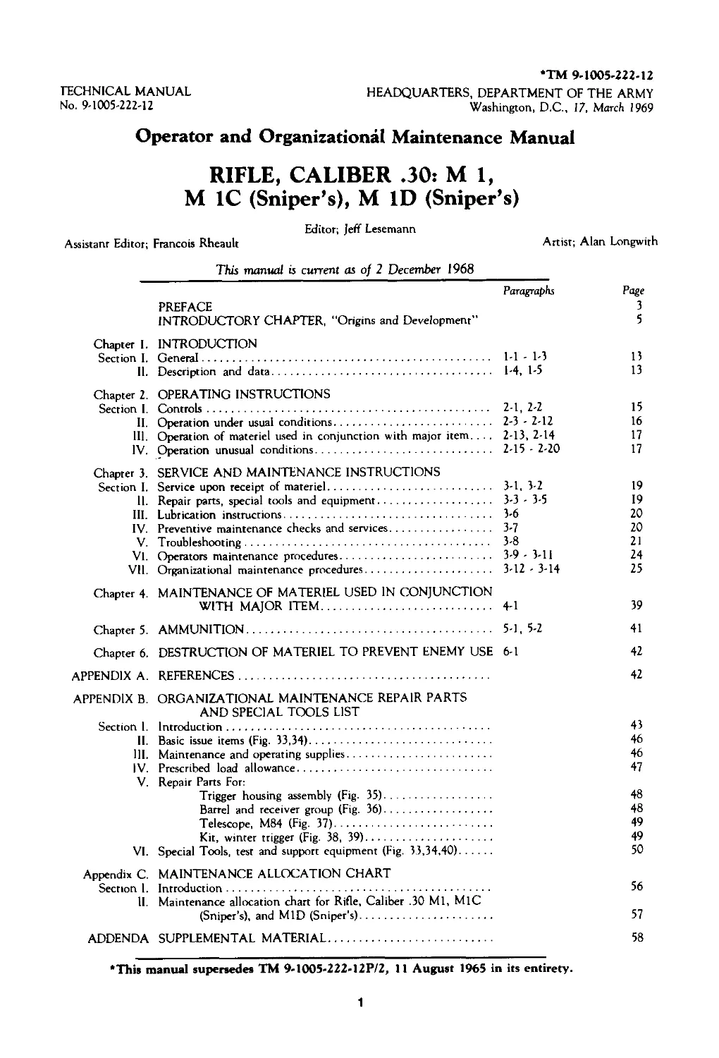
Operator and Organizational Maintenance Manual
RIFLE, CALIBER .30: M 1,
M 1C (Sniper’s), M ID (Sniper’s)
Editor; Jeff Lesemann
Assistant Editor; Francois Rheault Artist; Alan Longwith
This manual is current as of 2 December 1968
Chapter I. PREFACE INTRODUCTORY CHAPTER, “Origins and Development" INTRODUCTION Paragraphs Page 3 5
Section I. General 1-1 - 1-3 13
11. Chapter 2. Description and data OPERATING INSTRUCTIONS 1-4, 1-5 13
Section I. Controls 2-1, 2-2 15
II. Operation under usual conditions 2-3 - 2-12 16
111. Operation of materiel used in conjunction with major item. . .. 2-13, 2-14 17
IV. Chapter 3. Operation unusual conditions SERVICE AND MAINTENANCE INSTRUCTIONS 2-15 - 2-20 17
Section I. Service upon receipt of materiel 3-1, 3-2 19
IL Repair parts, special tools and equipment 3-3 - 3-5 19
III. Lubrication instructions 3-6 20
IV. Preventive maintenance checks and services 3-7 20
V. Troubleshooting 3-8 21
VI. Operators maintenance procedures 3-9-3-11 24
VII. Chapter 4. Organizational maintenance procedures MAINTENANCE OF MATERIEL USED IN CONJUNCTION WITH MAJOR ITEM 3-12-3-14 25 4-1 39
Chapter 5. AMMUNITION 5-1, 5-2 41
Chapter 6. APPENDIX A. APPENDIX B. Section I. II. 111. IV. V. VI. Appendix C. Section I. 11. ADDENDA DESTRUCTION OF MATERIEL TO PREVENT ENEMY USE REFERENCES ORGANIZATIONAL MAINTENANCE REPAIR PARTS AND SPECIAL TOOLS LIST Introduction Basic issue items (Fig. 33,34) Maintenance and operating supplies Prescribed load allowance Repair Parts For: Trigger housing assembly (Fig. 35) Barrel and receiver group (Fig. 36) Telescope, M84 (Fig. 37) Kit, winter trigger (Fig. 38, 39) Special Tools, test and support equipment (Fig. 33,34,40) MAINTENANCE ALLOCATION CHART Introduction Maintenance allocation chart for Rifle, Caliber .30 Ml, M1C (Sniper’s), and MID (Sniper's) SUPPLEMENTAL MATERIAL 6-1 42 42 43 46 46 47 48 48 49 49 50 56 57 58
•This manual supersedes TM 9-1OO5-222-12P/2, 11 August 1965 in its entirety.
1
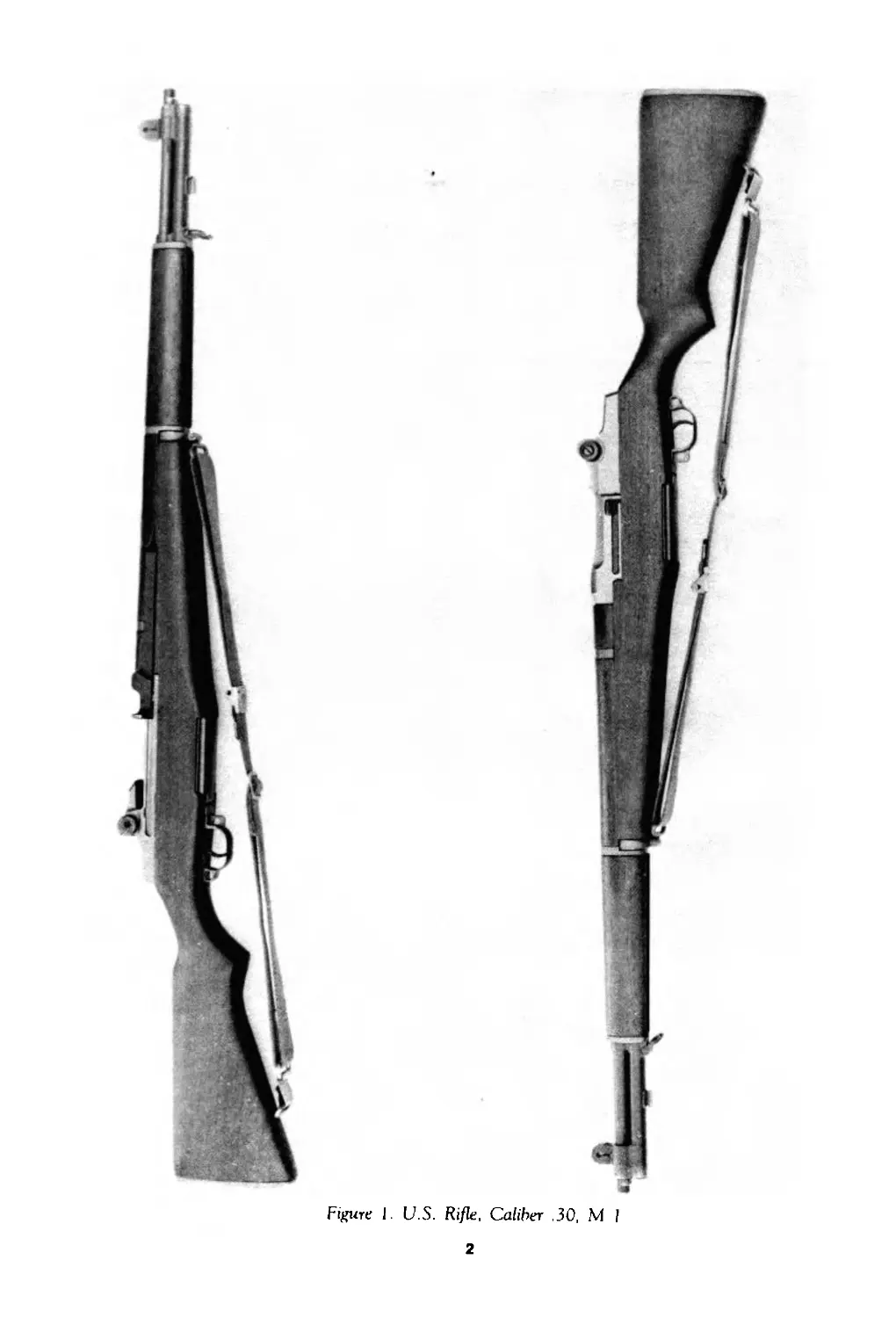
Figure 1. U.S. Rifle, Caliber .30, M 1
2
ТМ9-1005-222-12
Chapter 1
______________________INTRODUCTION_______________________________
Section I. General
1-1. Scope
These instructions are for use by the operator and organizational maintenance personnel. They
apply to Caliber .30 Rifles, Ml, MIC (Sniper’s) and MID (Sniper’s).
1-2. Forms and Records
a. General. Refer to TM 38-750 (Army Equipment Records Procedure) for forms and records
required.
b. Recommendations for Maintenance Manual Improvements. Report of errors,
omissions, and recommendations for improving this publication by the individual user is
encouraged. Reports should be submitted on DA Form 2028 (Recommended Changes to DA
Publications) and forwarded direct to:
Commanding General
U.S. Army Weapons Command
ATTN: AMSWE-SMM-P
Rock Island, Illinois 61201
1-3. Administrative Storage
Refer to TM 740-90-1 for administrative storage.
Section II. DESCRIPTION AND DATA
1-4. Description
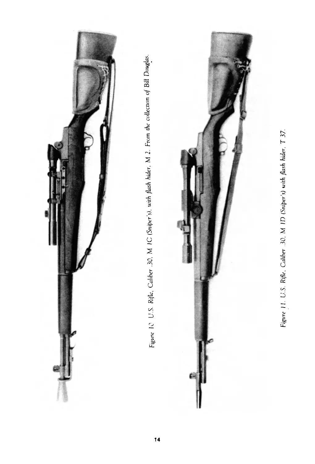
a. General. The Rifles, Ml, MIC (Sniper’s) and MID (Sniper’s) (figs. 1, 10 and 11) are clip-
fed, gas-operated, air-cooled, semiautomatic shoulder weapons.
b. Differences in Models.
(1) The MIC has a telescope mounted to the receiver.
(2) The MID has a telescope mounted to the barrel.
(3) The MIC and MID also require a flash hider and a cheek pad.
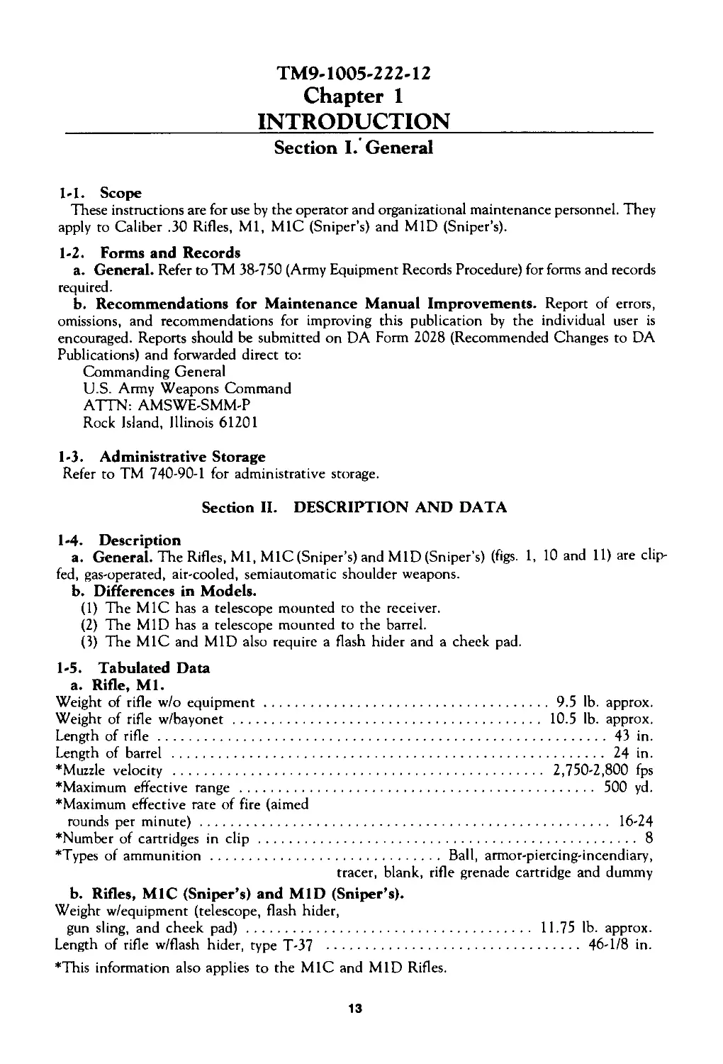
1-5. Tabulated Data
a. Rifle, Ml.
Weight of rifle w/o equipment...........................................9.5 lb. approx.
Weight of rifle w/bayonet.............................................. 10.5 lb. approx.
Length of rifle...................................................................43 in.
Length of barrel ................................................................ 24 in.
*Muzzle velocity ....................................................... 2,750-2,800 fps
‘Maximum effective range ....................................................... 500 yd.
‘Maximum effective rate of fire (aimed
rounds per minute).............................................................. 16-24
‘Number of cartridges in clip......................................................... 8
‘Types of ammunition.................................... Ball, armor-piercing-incendiary,
tracer, blank, rifle grenade cartridge and dummy
b. Rifles, M1C (Sniper’s) and MID (Sniper’s).
Weight w/equipment (telescope, flash hider,
gun sling, and cheek pad)............................................. 11.75 lb. approx.
Length of rifle w/flash hider, type T-37 .................................... 46-1/8 in.
‘This information also applies to the MIC and MID Rifles.
13
Figure 10 U.S. Rifle. Caliber .30, M IC (Sniper’s), with flash hider, M 2. From the collection of Bill Douglas.
Figure 11. U.S. Rifle. Caliber .30, M ID (Sniper’s) with flash hider. T 37.
ТМ9-1005-222-12
Chapter 2
___________OPERATING INSTRUCTIONS____________________________
Section I. Controls
2-1. General
This section describes, locates, illustrates, and furnishes rhe operator with essential informa-
tion pertaining to the various controls provided to properly operate the materiel.
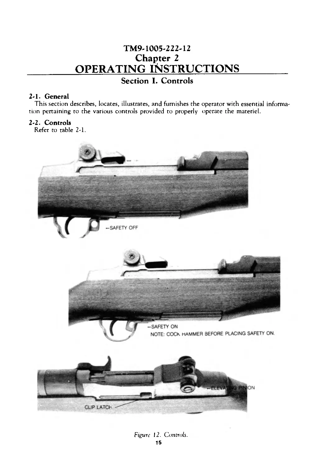
2-2. Controls
Refer to table 2-1.
Figure 12. Controls.
15
Table 2-1. Controls
Item (See fig. 12) Purpose
Safety Trigger Windage knob Elevating pinion Clip latch To preverit accidental firing. To release hammer to effect firing. To adjust lateral movement of rear sight. To adjust elevation of aperture. To hold clip in receiver until last round is fired.
Section II. OPERATION UNDER USUAL CONDITIONS
2-3. General
This section contains instructions for the operation of the rifles under conditions of moderate
temperatures and humidity. Instructions for operation under unusual conditions are covered in
section IV.
2-4. Preparation for Firing
a. Examine bore. Make certain it is free of powder fouling or corrosion.
b. Check gas cylinder lock screw for secure installation.
c. Check ammunition. Make certain it is clean and that it is of the proper type and grade,
d. Cock the rifle and place the safety in safe position (fig. 12).
2-5. Service Before Firing
Perform the before firing operations as indicated in table 3-3.
2-6. Loading
Refer to FM 23-5.
2-7. Zeroing
Refer to FM 23-5.
2-8. Misfire, Hangfire, and Cook-off
Refer to FM 23-5 and paragraph 2-9b, below.
2-9. Procedures for Removing a Round in Case of Failure to Fire
a. General After failure to fire, due to misfire, the following general precautions, as applicable,
will be observed until the round has been removed from the weapon and the cause of failure
determined.
(1) Keep the weapon trained on the target and see that all personnel are clear of the muzzle.
(2) Before retracting the bolt and removing the round, see that personnel, not required
for operation, are cleared from vicinity.
(3) Make certain the round, removed from the weapon, is kept separate from other rounds
until it has been determined whether the round or weapon is at fault. If the weapon is determin-
ed to be at fault, the round may be reloaded.
b. Time Intervals. The definite time intervals for waiting, after failure of weapon to fire, are
prescribed as follows: Always keep the round in the chamber for five seconds from the time
a misfire occurs to insure against an explosion outside of the gun in event a hang-fire develops.
If the barrel is hot and a misfire stops operation of the gun, wait five seconds with the round
locked in the chamber to insure against hangfire dangers (a hangfire will occur within five seconds
after the primer is struck), then extract the round immediately to prevent cook-off. If the round
cannot be extracted within an additional five seconds, it must remain locked in the chamber
for five minutes because of the possibility of a cook-off. Also in the event the barrel is hot and
misfire occurs when attempting to resume firing after an intentional cessation of firing, the round
should remain locked in the chamber for five minutes because of the possibility of a cook-off.
16
2-10. Service During Firing
Perform the during firing operations as described in the operators preventive-maintenance
services (table 3-3).
2-11. Unloading
Refer to FM 23-5.
2-12. Service After Firing
Perform the after firing operations as described in the operator’s preventive-maintenance
services (table 3-3).
Section III. OPERATION OF MATERIEL USED IN CONJUNCTION
WITH MAJOR ITEM
2-13. General
The following materiel is not normally used continually. Therefore, it is necessary to protect
from weather and dampness in storage. Clean and lubricate materiel as required, whether in
use or in storage.
2-14. Equipment
a. Grenade Launcher, M7A3 and Grenade Launcher Sight, M15. Refer to FM 23-30.
b. Bayonet-Knife, M5 and M5A1 and Bayonet-Knife Scabbard, M8A1. Keep bayonet
in scabbard except when removed for training, inspections, cleaning, repair, or for use in
combat or danger zones.
c. Winter Trigger Kit. Use the winter trigger kit only in extreme cold operation and on
authority of unit commander.
Section IV. OPERATION UNDER UNUSUAL CONDITIONS
2-15. General
Report any chronic failure of materiel resulting from subjection to extreme conditions (par 1-2).
2-16. Operation in Extreme Cold
a. In climates consistently below 0°F, it is necessary to prepare the rifle for cold-weather opera-
tion. The rifle should be thoroughly cleaned wiith SD, dry cleaning solvent, and lubricated with
LAW, weapons lubricating oil.
b. Rifles should be free of moisture and excess oil. Moisture or too much oil on the working
parts will cause them to be sluggish in operation, or perhaps to fail completely.
c. Exercise moving parts through their entire range at required intervals. This movement
helps prevent parts from freezing in place and reduces effort required to operate them.
d. Materiel nor in use and stored outside must be protected with proper cover.
Note. Transferring weapon from cold to warm air may cause moisture to collect. If the weapon
is brought into a warm room, allow it to reach room temperature before cleaning and lubricating
as required.
2-17. Operation in Extreme Heat
a. Hot, Dry Climates.
(1) The film of oil necessary for operation and preservation dissipates quickly in hot climates.
Inspect the rifle, paying particular attention to all hidden surfaces such as bolt and lug, operating
rod and recess, cam surfaces and bolt locking recess in receiver, where corrosion might occur
and not be quickly noticed.
(2) Perspiration from the hands contributes to rusting because it contains acids and salts.
After handling materiel, clean, wipe dry, and restore the oil film using PL special, general
purpose lubricating oil.
17
(3) Clean and oil the bore more frequently than usual.
(4) Apply linseed oil to wooden parts to prevent drying.
b. Hot, Damp, and Salty Atmosphere.
(1) See a(l) and (2) above under hot, dry climates.
(2) Inspect materiel frequently because of increased possibility of rust.
(3) When material is active, clean and lubricate the bore and exposed metal surfaces more
frequently than prescribed for normal service.
(4) Moist and salty atmosphere tend to emulsify oils and greases and destroy their rust-
preventive qualities. Inspect all parts frequently for corrosion.
(5) When materiel is inactive, cover metal surfaces with a film of PL special, general
purpose lubricating oil.
(6) Apply linseed oil to wooden parts to keep out moisture.
2-18. Operation in Dusty or Sandy Areas
a. Clean and lubricate the materiel more frequently in sandy or dusty areas. Exercise
particular care to keep sand out of mechanisms when carrying out inspecting and lubricating
operations. Shield parts from flying sand with tarpaulins during disassembly and assembly
operations.
b. Before operating in sandy areas, remove lubricant from bolt, barrel and receiver, operating
rod, and trigger housing assembly, as they will pick up sand and from an abrasive which will
cause rapid wear. Dry surfaces wear less than surfaces coated with lubricants contaminated with
sand. Clean and lubricate all exposed parts after action is over.
2-19. Hand-Carried Fording
a. No special lubricaion is required before fording.
b. Protect from water splashes.
c. If immersion does occur, proceed as directed in paragraph 2-20.
2-20. Maintenance After Immersion
a. General. During hand-carried fording, water seepage into bolt, trigger housing, receiver,
and operating rod assembly will usually occur. It is advisable, therefore, that the service out-
lined below be accomplished on all weapons submerged in water as soon as practical to prevent
damage to the weapon.
b. Procedures.
(1) After submersion in salt water, wash in clear water to remove corrosive salts.
(2) Drain all trapped moisture and wipe dry.
(3) Assemblies which require disassembly for proper lubrication must be disassembled, dried,
and lubricated as soon as possible.
Note. Items not authorized for operator disassembly/assembly must be cleaned by organiza-
tional maintenance personnel.
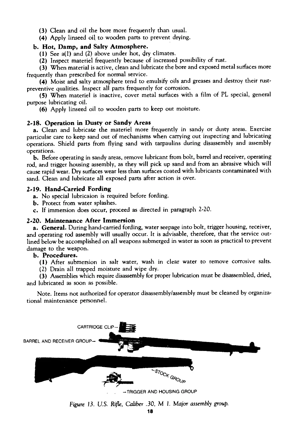
Figure 13. U.S. Rifle, Caliber .30, M 1. Major assembly group.
18
ТМ9-1005-222-12
Chapter 3
SERVICE AND MAINTENANCE INSTRUCTIONS
Section I. Service Upon Receipt of Materiel
3-1. General
a. When a new or reconditioned Rifle, Ml, MIC (Sniper’s) or MID (Sniper’s) is received,
it is the responsibility of the officer in charge to determine whether the materiel has been
properly prepared for service by the supplying organization and to be sure it is in condition to
perform its function.
b. All basic issue items will be checked with the listing in appendix B.
c. A record will be made of all missing parts, tools, and equipment, and of any malfunctions.
Corrective action should be initiated as soon as possible.
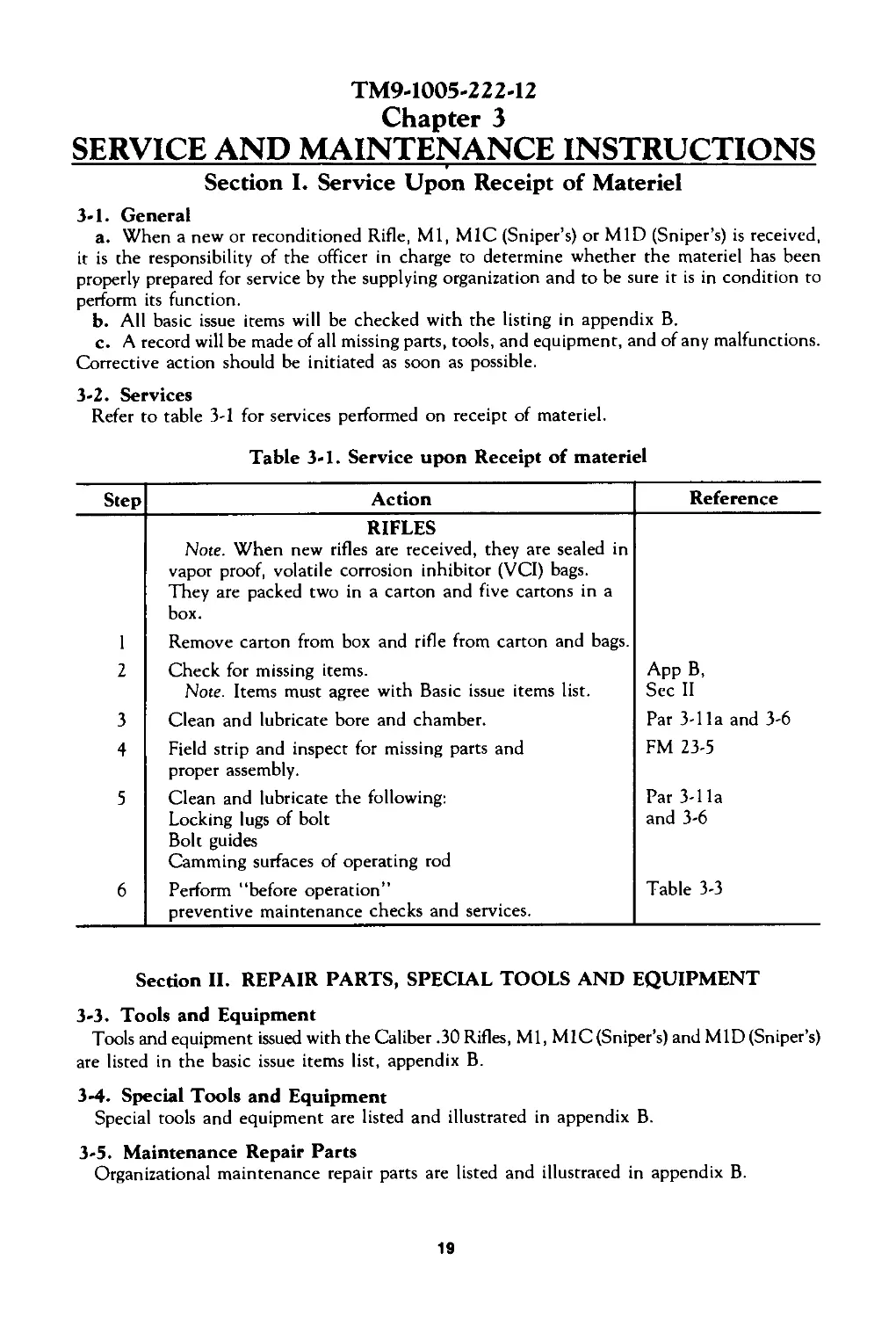
3-2. Services
Refer to table 3-1 for services performed on receipt of materiel.
Table 3-1. Service upon Receipt of materiel
Step Action Reference
RIFLES Note. When new rifles are received, they are sealed in vapor proof, volatile corrosion inhibitor (VCI) bags. They are packed two in a carton and five cartons in a box.
I Remove carton from box and rifle from carton and bags.
2 Check for missing items. Note. Items must agree with Basic issue items list. Арр B, Sec II
3 Clean and lubricate bore and chamber. Par 3-1 la and 3-6
4 Field strip and inspect for missing parts and proper assembly. FM 23-5
5 Clean and lubricate the following: Locking lugs of bolt Bolt guides Camming surfaces of operating rod Par 3-1 la and 3-6
6 Perform “before operation” preventive maintenance checks and services. Table 3-3
Section II. REPAIR PARTS, SPECIAL TOOLS AND EQUIPMENT
3-3. Tools and Equipment
Tools and equipment issued with the Caliber .30 Rifles, Ml, MIC (Sniper’s) and MID (Sniper’s)
are listed in the basic issue items list, appendix B.
3-4. Special Tools and Equipment
Special tools and equipment are listed and illustrated in appendix B.
3-5. Maintenance Repair Parts
Organizational maintenance repair parts are listed and illustrated in appendix B.
19
Section III. LUBRICATION INSTRUCTIONS
3-6. General
a. Make certain all metal parts have been cleaned with SD, dry cleaning, solvent. Dry
thoroughly. Apply a light coat of preservative, PL special, general purpose lubricating oil, for
above 0°F, and LAW, weapons lubricating oil, for below 0°F. Apply a light coat of rifle grease
to the following surfaces:
(1) Locking lugs of bolt, operating lug, and recesses.
(2) Bolt guide.
(3) Cams on trigger and hammer.
b. Refer to table 3-2 for a listing of lubrication and cleaning materiels and stock numbers
for requisitioning purposes.
c. Refer to paragraph 2-16 thru 2-20 for specific lubrication instructions under unusual
conditions.
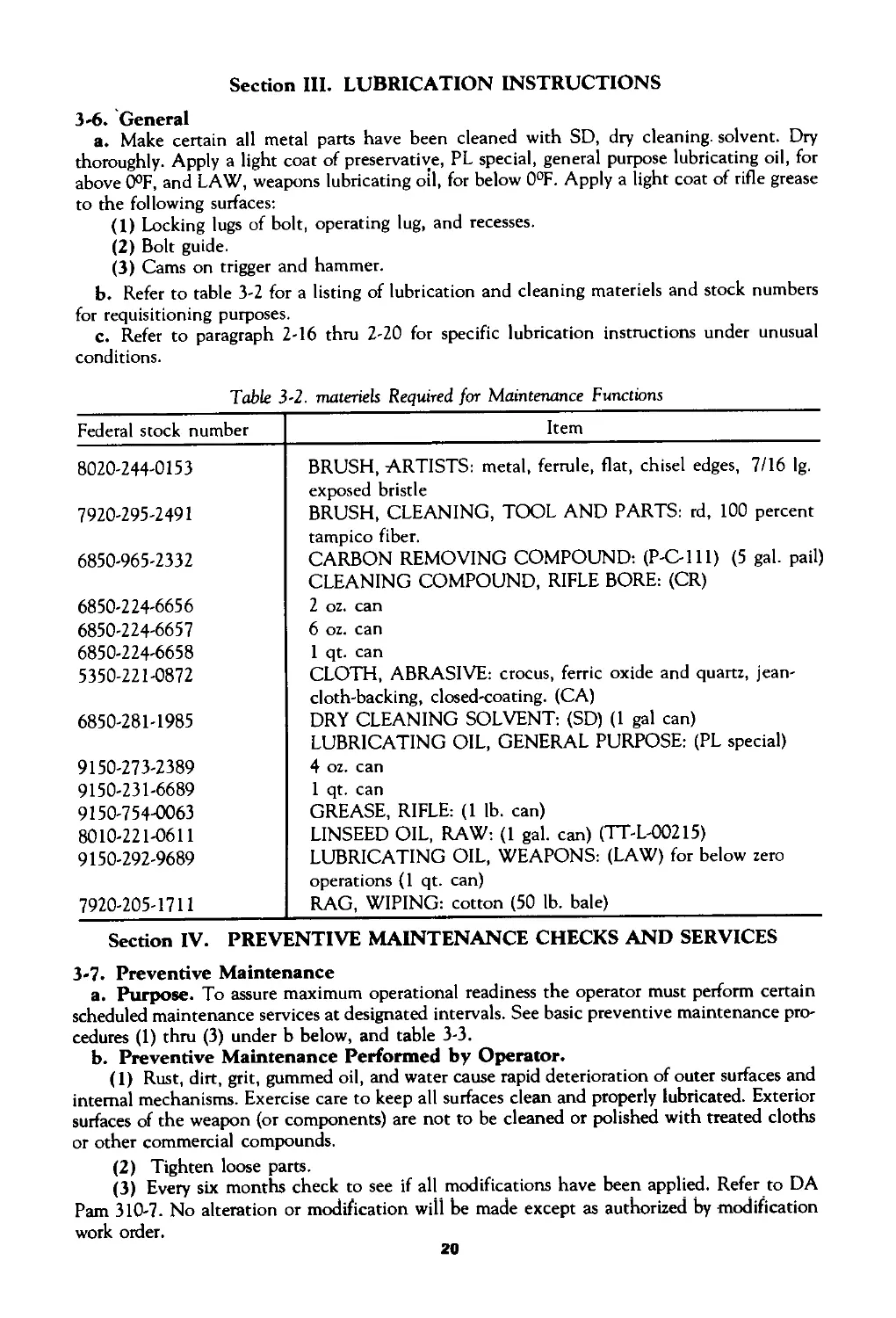
Table 3-2. materiels Required for Maintenance Functions
Federal stock number Item
8020-244-0153 BRUSH, ARTISTS: metal, ferrule, flat, chisel edges, 7/16 ig. exposed bristle
7920-295-2491 BRUSH, CLEANING, TOOL AND PARTS: rd, 100 percent tampico fiber.
6850-965-2332 CARBON REMOVING COMPOUND: (P-C-lll) (5 gal. pail) CLEANING COMPOUND, RIFLE BORE: (CR)
6850-224-6656 2 oz. can
6850-224-6657 6 oz. can
6850-224-6658 1 qt. can
5350-221-0872 CLOTH, ABRASIVE: crocus, ferric oxide and quartz, jean- cloth-backing, closed-coating. (CA)
6850-281-1985 DRY CLEANING SOLVENT: (SD) (1 gal can) LUBRICATING OIL, GENERAL PURPOSE: (PL special)
9150-273-2389 4 oz. can
9150-231-6689 1 qt. can
9150-754-0063 GREASE, RIFLE: (1 lb. can)
8010-221-0611 LINSEED OIL, RAW: (1 gal. can) (TT-L-OO215)
9150-292-9689 LUBRICATING OIL, WEAPONS: (LAW) for below zero operations (1 qt. can)
7920-205-1711 RAG, WIPING: cotton (50 lb. bale)
Section IV. PREVENTIVE MAINTENANCE CHECKS AND SERVICES
3-7. Preventive Maintenance
a. Purpose. To assure maximum operational readiness the operator must perform certain
scheduled maintenance services at designated intervals. See basic preventive maintenance pro-
cedures (1) thru (3) under b below, and table 3-3.
b. Preventive Maintenance Performed by Operator.
(1) Rust, dirt, grit, gummed oil, and water cause rapid deterioration of outer surfaces and
internal mechanisms. Exercise care to keep all surfaces clean and properly lubricated. Exterior
surfaces of the weapon (or components) are not to be cleaned or polished with treated cloths
or other commercial compounds.
(2) Tighten loose parts.
(3) Every six months check to see if all modifications have been applied. Refer to DA
Pam 310-7. No alteration or modification will be made except as authorized by modification
work order.
20
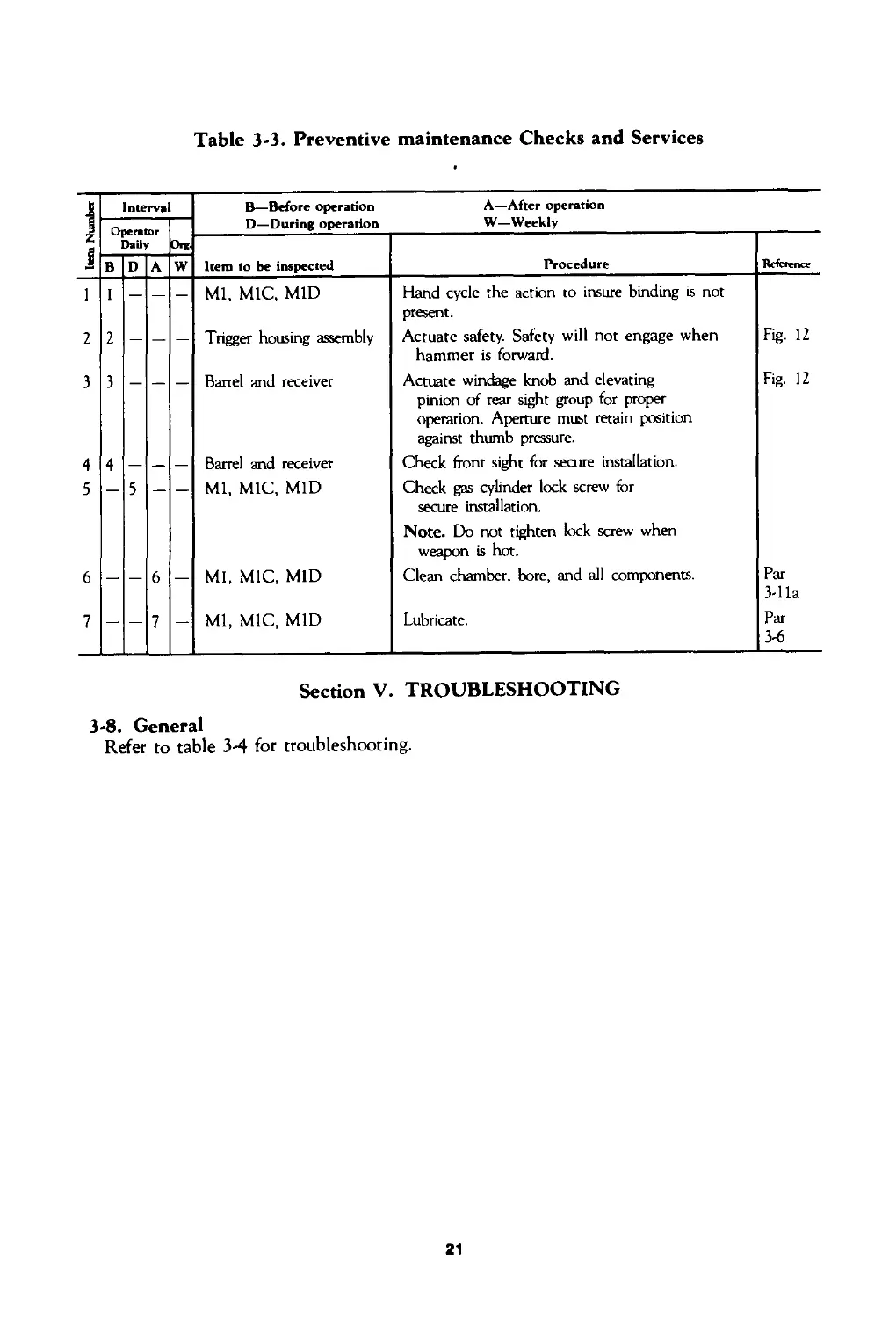
Table 3-3. Preventive maintenance Checks and Services
; Item Number I Interval B— Before operation D—During operation A—After operation W—Weekly
Operator Daily Ont
Item to be inspected Procedure Reference
В D A w
l I — — - Ml, MIC, MID Hand cycle the action to insure binding is not present.
2 2 — — — Trigger housing assembly Actuate safety. Safety will not engage when hammer is forward. Fig- 12
3 3 — — — Barrel and receiver Actuate windage knob and elevating pinion of rear sight group for proper operation. Aperture must retain position against thumb pressure. Fig. 12
4 4 — — — Barrel and receiver Check front sight for secure installation.
5 — 5 — — Ml, MIC, MID Check gas cylinder lock screw for secure installation. Note. Do not tighten lock screw when weapon is hot.
6 — — 6 — MI, MIC, MID Clean chamber, bore, and all components. Par 3-1 la
7 — — 7 — Ml, MIC, MID Lubricate. Par 3-6
Section V. TROUBLESHOOTING
3-8. General
Refer to table 3-4 for troubleshooting.
21
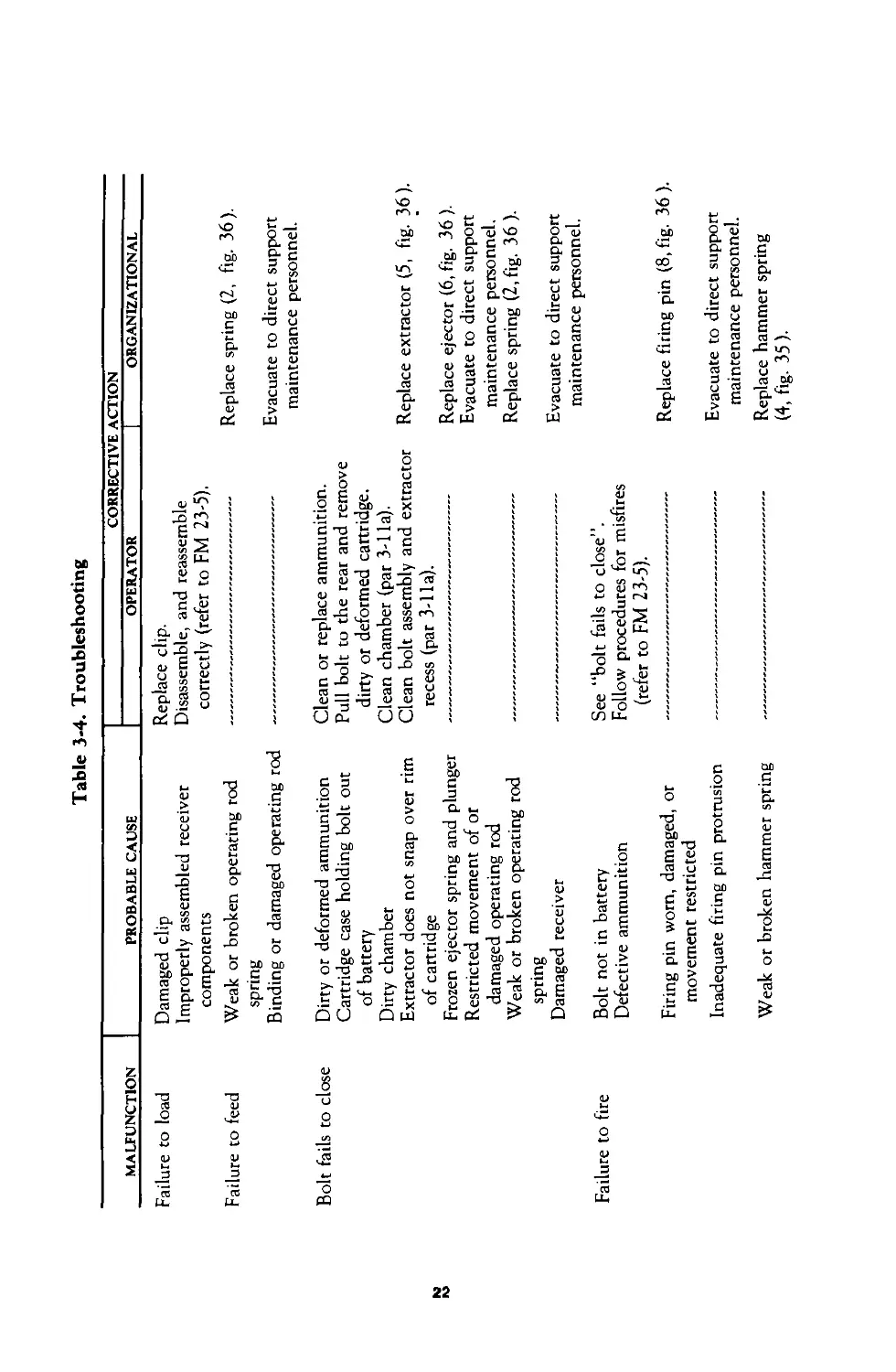
Table 3-4. Troubleshooting
MALFUNCTION PROBABLE CAUSE CORRECTIVE ACTION
OPERATOR | ORGANIZATIONAL
Failure to load Damaged clip Replace clip. Improperly assembled receiver Disassemble, and reassemble components correctly (refer to FM 23-5). Failure to feed Weak or broken operating rod Replace spring (2, fig. 36). spring Binding or damaged operating rod Evacuate to direct support maintenance personnel. Bolt fails to close Dirty or deformed ammunition Clean or replace ammunition. Cartridge case holding bolt out Pull bolt to the rear and remove of battery dirty or deformed cartridge. Dirty chamber Clean chamber (par 3-1 la). Extractor does not snap over rim Clean bolt assembly and extractor Replace extractor (5, fig. 36). of cartridge recess (par 3-1 la). Frozen ejector spring and plunger Replace ejector (6, fig. 36 ). Restricted movement of or Evacuate to direct support damaged operating rod maintenance personnel. Weak or broken operating rod Replace spring (2, fig. 36 ). spring Damaged receiver -— Evacuate to direct support maintenance personnel. Failure to fire Bolt not in battery See “bolt fails to close”. Defective ammunition Follow procedures for misfires (refer to FM 23-5). Firing pin worn, damaged, or Replace firing pin (8, fig. 36 ). movement restricted Inadequate firing pin protrusion -— Evacuate to direct support maintenance personnel. Weak or broken hammer spring Replace hammer spring (4, fig. 35).
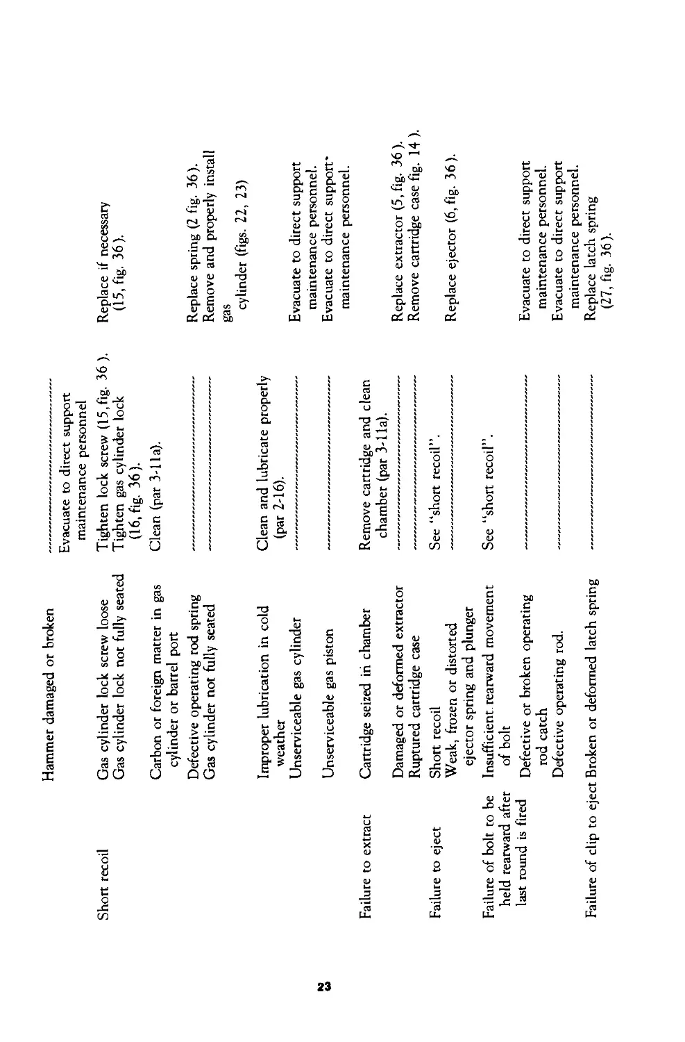
Hammer damaged or broken
Short recoil Gas cylinder lock screw loose Gas cylinder lock not fully seated Carbon or foreign matter in gas cylinder or barrel port Defective operating rod spring Gas cylinder not fully seated
N Ы Improper lubrication in cold weather Unserviceable gas cylinder Unserviceable gas piston
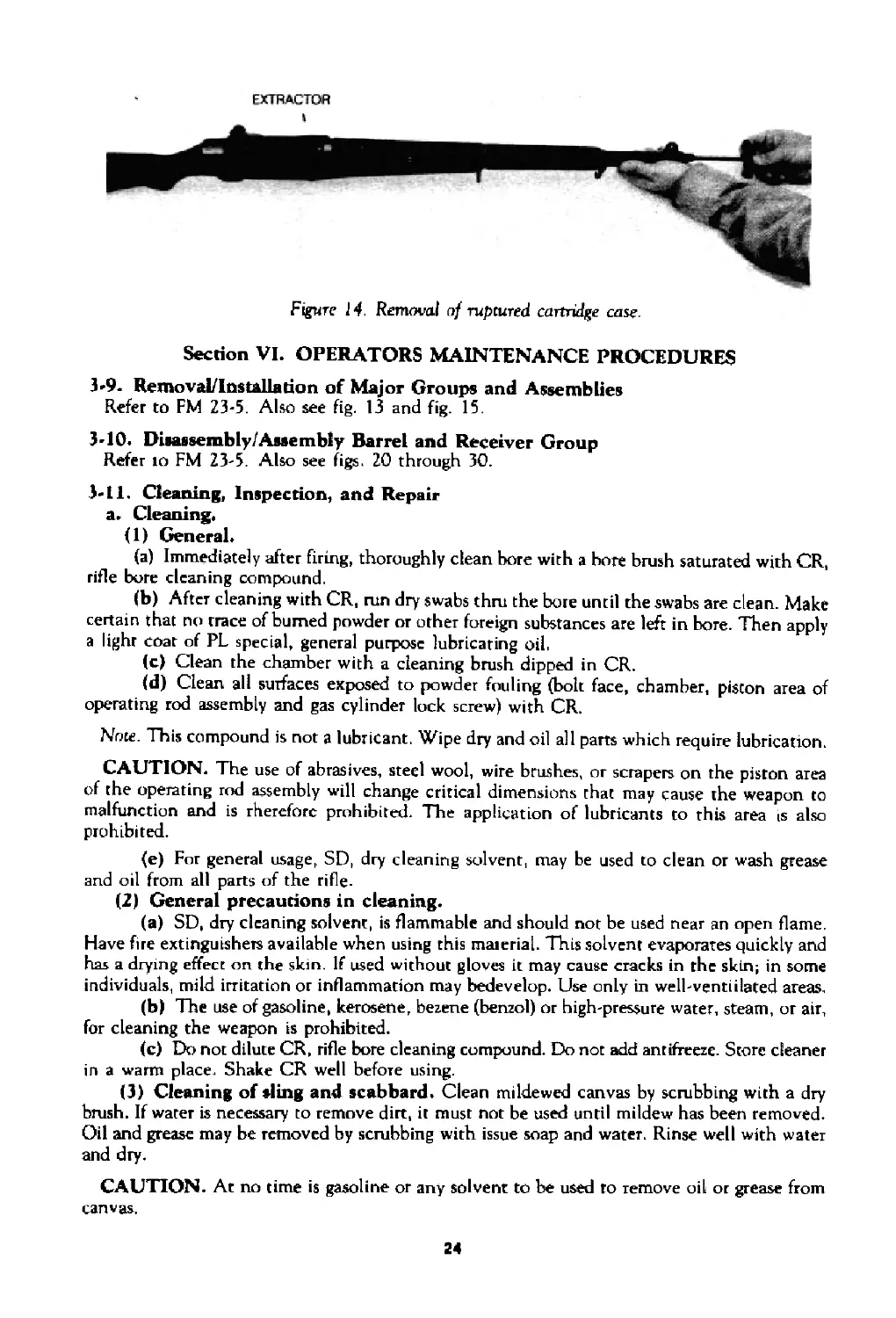
Failure to extract Cartridge seized in chamber
Failure to eject Damaged or deformed extractor Ruptured cartridge case Short recoil
Failure of bolt to be Weak, frozen or distorted ejector spring and plunger Insufficient rearward movement
held rearward after of bolt
last round is fired Defective or broken operating
rod catch Defective operating rod.
Failure of clip to eject Broken or deformed latch spring
Evacuate to direct support
maintenance personnel
Tighten lock screw (15,fig. 36 ). Replace if necessary
Tighten gas cylinder lock (16, fig. 36). Clean (par 3-lla). (15, fig. 36).
---------------------------- Replace spring (2 fig. 36).
---------------------------- Remove and properly install
gas
cylinder (figs. 22, 23)
Clean and lubricate properly
(par 2-16).
---------------------------- Evacuate to direct support
maintenance personnel.
---------------------------- Evacuate to direct support"
maintenance personnel.
Remove cartridge and clean
chamber (par 3-lla).
---------------------------- Replace extractor (5, fig. 36).
---------------------------- Remove cartridge case fig. 14 ).
See “short recoil”.
---------------------------- Replace ejector (6, fig. 36).
See “short recoil”.
maintenance personnel.
maintenance personnel.
(27, fig. 36).
EXTRACTOR
I
Figure J 4 Removal of ruptured cartridge case.
Section VI. OPERATORS MAINTENANCE PROCEDURES
3'9. Removal/Installadon of Major Groups and Assemblies
Refer to FM 23-5. Also see fig. 13 and fig. 15.
3-10. Disassembly/Assembly Barrel and Receiver Group
Refer io FM 23-5. Also see figs. 20 through 30.
3-11. Cleaning, Inspection, and Repair
a. Cleaning.
(1) General.
(a) Immediately after firing, thoroughly clean bore with a bore brush saturated with CR,
rifle bore cleaning compound.
(b) After cleaning with CR, run dry swabs thru the bore until the swabs are clean. Make
certain that no trace of burned powder or other foreign substances are left in bore. Then apply
a light coat of PL special, general purpose lubricating oil,
(c) Clean the chamber with a cleaning brush dipped in CR.
(d) Clean all surfaces exposed to powder fouling (bolt face, chamber, piston area of
operating rod assembly and gas cylinder lock screw) with CR.
Note. This compound is not a lubricant. Wipe dry and oil all parts which require lubrication.
CAUTION. The use of abrasives, steel wool, wire brushes, or scrapers on the piston area
of the operating rod assembly will change critical dimensions that may cause the weapon to
malfunction and is therefore prohibited. The application of lubricants to this area is also
prohibited.
(e) For general usage, SD, dry cleaning solvent, may be used to clean or wash grease
and oil from all parts of the rifle-
(2) General precautions in cleaning.
(a) SD, dry cleaning solvent, is flammable and should not be used near an open flame.
Have fire extinguishers available when using this material. This solvent evaporates quickly and
has a drying effect on the skin. If used without gloves it may cause cracks in the skin; in some
individuals, mild irritation or inflammation may bedevelop. Use only in well-ventiilated areas,
(b> The use of gasoline, kerosene, bezene (benzol) or high-pressure water, steam, or air,
for cleaning the weapon is prohibited.
(c) Do not dilute CR, rifle bore cleaning compound. Do not add antifreeze. Store cleaner
in a warm place. Shake CR well before using.
(3) Cleaning of sling and scabbard. Clean mildewed canvas by scrubbing with a dry
brush. If water is necessary to remove dirt, it must not be used until mildew has been removed.
Oil and grease may be removed by scrubbing with issue soap and water. Rinse well with water
and dry.
CAUTION. At no time is gasoline or any solvent to be used to remove oil or grease from
canvas.
24
To prevent mildew, air canvas items frequently.
(4) Cleaning. Clean with a dry cloth. Periodically rub raw linseed oil on wooden com-
ponents to prevent drying or the absorption of moisture.
CAUTION. Do not apply linseed oil to those surfaces next to the barrel. Application of
oil to these surfaces creates heavy smoking when the barrel is hot. This smoke will obscure the
operator’s vision. Portions which swell due to high moisture content should be dried before ap-
plying the linseed oil. Do not allow linseed oil to contact or remain on metal parts.
b. Inspection. Refer to paragraph 3-7.
c. Repair. Turn rifle into organizational maintenance personnel for any necessary repair.
Section VII. ORGANIZATIONAL MAINTENANCE PROCEDURES
3-12. Removal/Installation of Major Groups and Assemblies
Refer to FM 23-5.
3-13. Disassembly/Assembly of Major Group and Assemblies
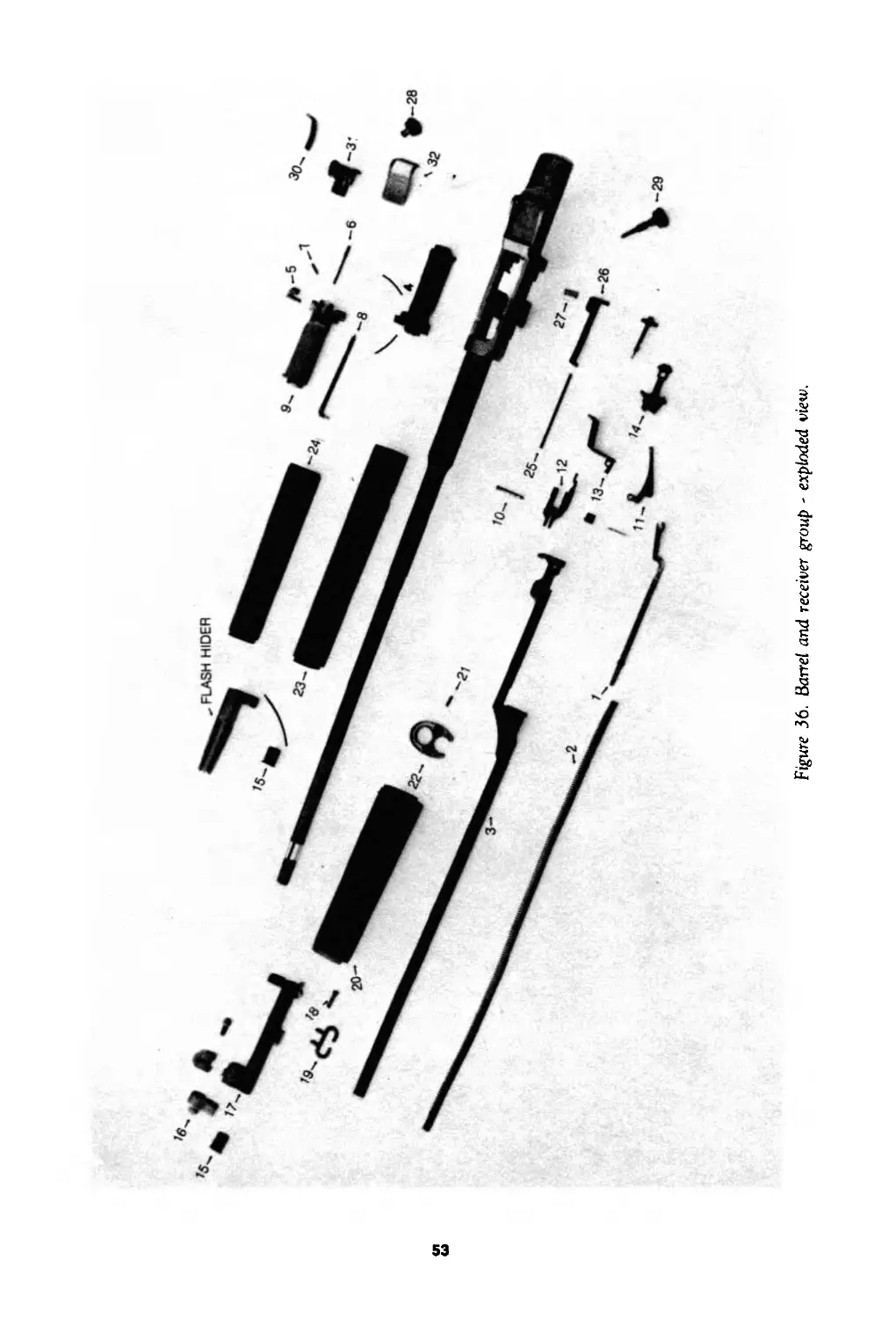
Refer to figures 15 through 30, 35, 36 and 41.
NOTE. White dots indicate disassembly, and black dots indicate assembly.
3-14. Cleaning, Inspection, and Repair
a. Cleaning.
(1) General. Refer to paragraph 3-1 la for general cleaning procedures.
(2) Removing carbon. On component parts which have a hard carbon residue it may be
necessary to clean these parts with P-C-l 11, carbon removing compound. Observe the follow-
ing procedures when using P-C-l 11.
WARNING. Avoid contact of P-C-l 11 with skin. If contact does occur, wash compound
off thoroughly with running water. A good lanolin base cream is helpful if applied after washing
off compound. Recommend use of gloves and protective equipment.
(a)Using a suitable container, fill with fresh compound.
(b) Before soaking a component in compound, remove all grease, dirt and oil as indicated
in paragraph 3-1 la. Place parts to be cleaned in a container and make certain they are
completely immersed.
(c) Soak for 2 to 16 hours as necessary. Remove parts and drain. Rinse with water or
solvent. To effectively remove carbon, brush with a stiff bristle brush (not wire) under running
water.
(d) Wipe parts dry and lubricate (par 3-6).
b. Inspection and Repair.
Refer to table 3-5.
NOTE. For items not authorized at organizational maintenance level, evacuate to direct
support maintenance personnel.
Table 3-5. Organizational Maintenance Functions
Warning: Before starting an inspection, be sure to
clean the weapon. Do not actuate the trigger until
the weapon has been cleared. Inspect the chamber
to insure that it is empty, and check to see that
no ammunition is in position to be introduced.
25
ITEM
INSPECTION AND REPAIR
Trigger housing assembly Inspect for and remove burs. Replace items 1, 2, 4, 6, 8, and 10, Fig. 35, if worn or damaged.
Stock assembly Inspect for cracks, breakage, or damage that would weaken the stock. Evacuate to direct support maintenance personnel. Check for dry, unoiled areas of wood. Oil with raw linseed oil only. Do not oil inside of stock. Make certain that the butt plate assembly is secure to the stock.
Barrel and receiver group Inspect barrel for rust or obstructions in bore and remove. Inspect for and remove burs. Inspect chamber for ruptured cartridge. Remove with the ruptured cartridge case extractor.
Operating rod assembly group Inspect for damage that may restrict movement of operating rod assembly. Replace item 2, fig 36 , if weak, broken, or kinked.
Bolt assembly Inspect for and remove burs. Inspect firing pin. If chips or cracks are present in tip area, or if badly worn, replace. Inspect ejector and spring assembly hole for distortion, burs or rust that would hinder free movement of the ejector assembly. Replace items 5, 6, 7, and 8, fig 36 , if worn or damaged.
Follower group Gas cylinder group Replace item 10, fig 36 , if worn or damaged. Inspect front sight, make sure it is secure. Inspect gas cylinder lock screw. Make sure it is tight, but not “frozen” or cross-threaded in gas cylinder. Replace items 15, 18, and 19 fig 36 , if worn or damaged.
Handguard group Inspect for cracks that would impair serviceability. Replace items 20, 21, and 22, fig 36, if damaged. Note. Evacuate damaged handguards to direct support maintenance personnel for repair. Inspect for damaged parts. Replace item 27, fig 36, if worn or damaged.
Rear sight group Inspect for damaged parts. Inspect windage knob and pinion for binding. Replace items 28, 29, and 30, fig 36, if worn or damaged. Raise the aperture to full height and reduce by four clicks. Grasp the rifle at the small of the stock with the thumb on the aperture. Press down on aperture. Aperture should not move under thumb pressure.
Assembled rifle Hand operate to assure proper functioning.
26
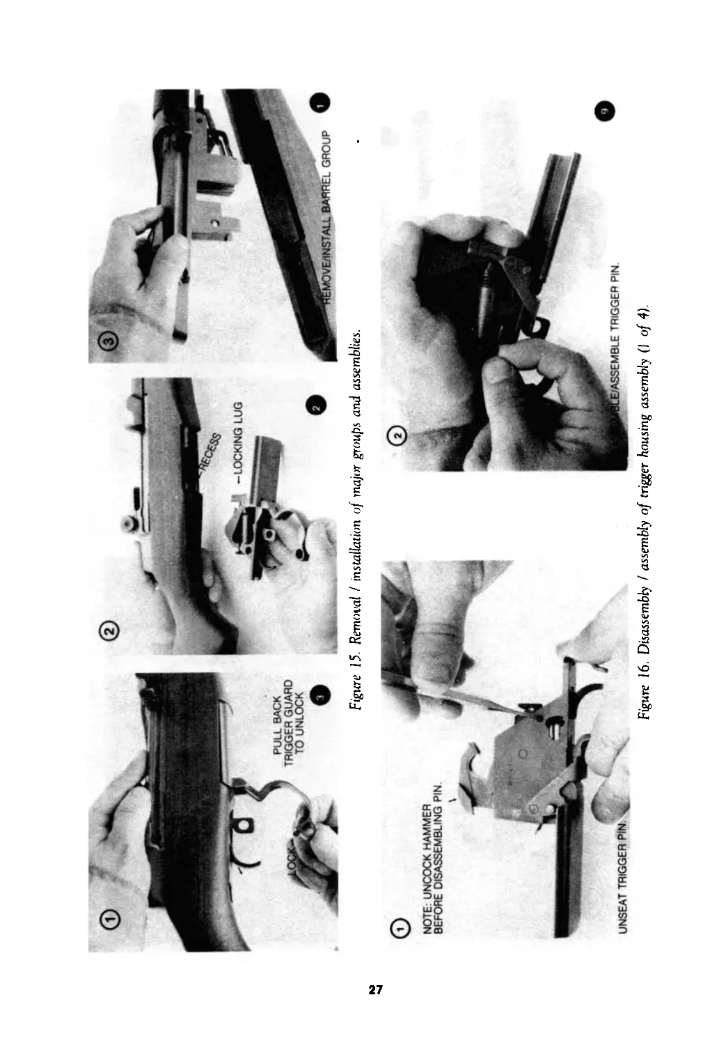
Figure 15. Removal / installation of major groups and assemblies.
Figure 16. Disassembly I assembly of trigger housing assembly (I of 4).
DISASSEMBLE/ASSEMBLE TRIGGER
HOUSING SPRING PLUNGER
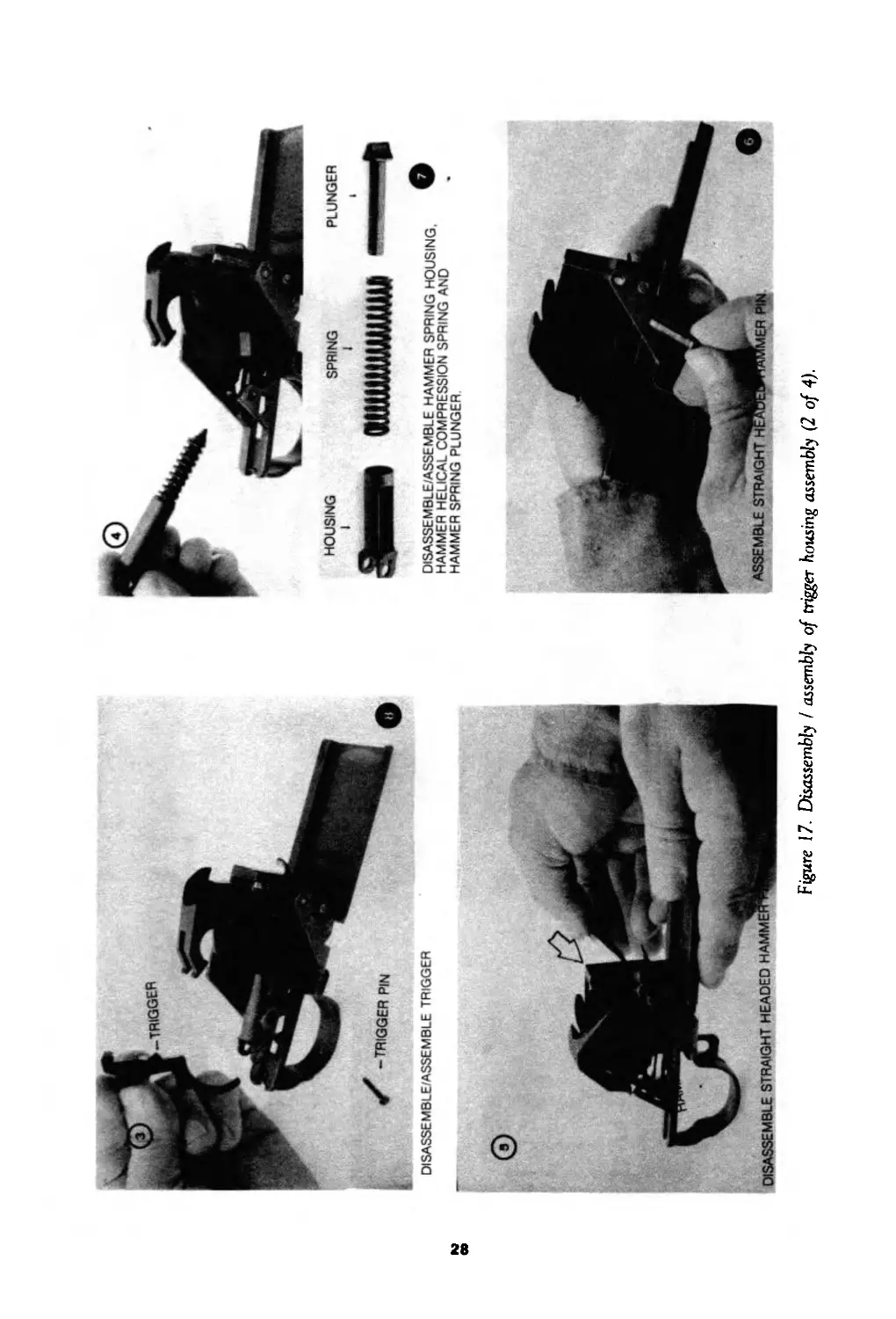
Figure 17. Disassembly I assembly of trigger housing assembly (2 of 4).
DISASSEMBLE/ASSEMBLE HAMMER SPRING HOUSING.
HAMMER HELICAL COMPRESSION SPRING AND
HAMMER SPRING PLUNGER
disassemble/assemble trigger guard
МЯ
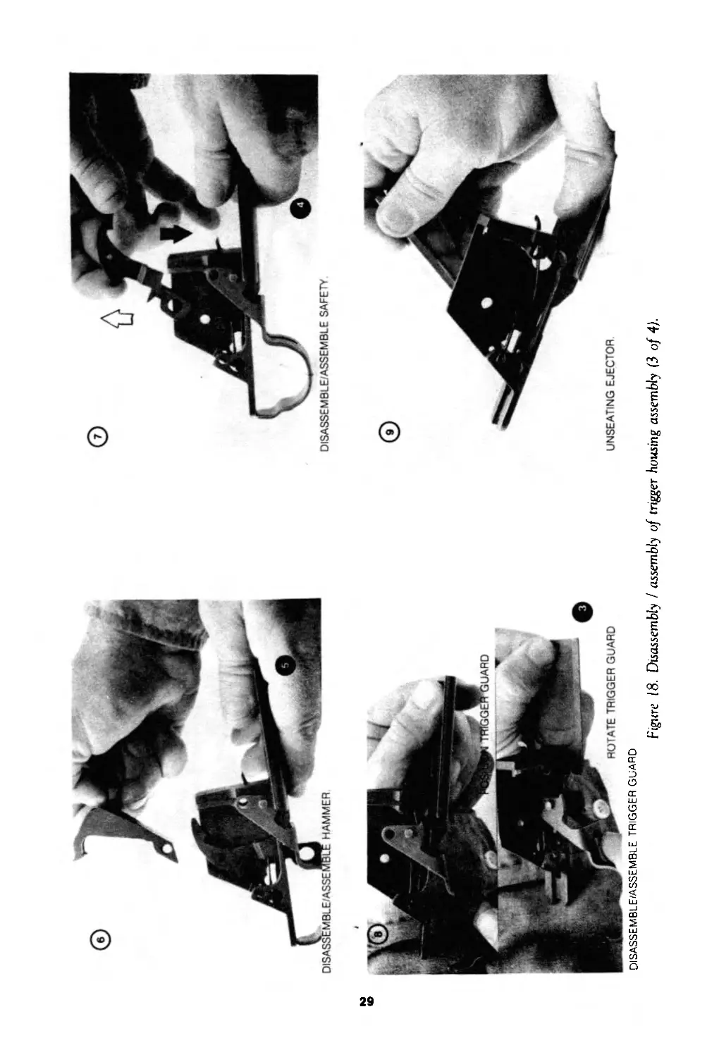
Figure 18. Disassembly I assembly of trigger housing assembly (3 of 4).
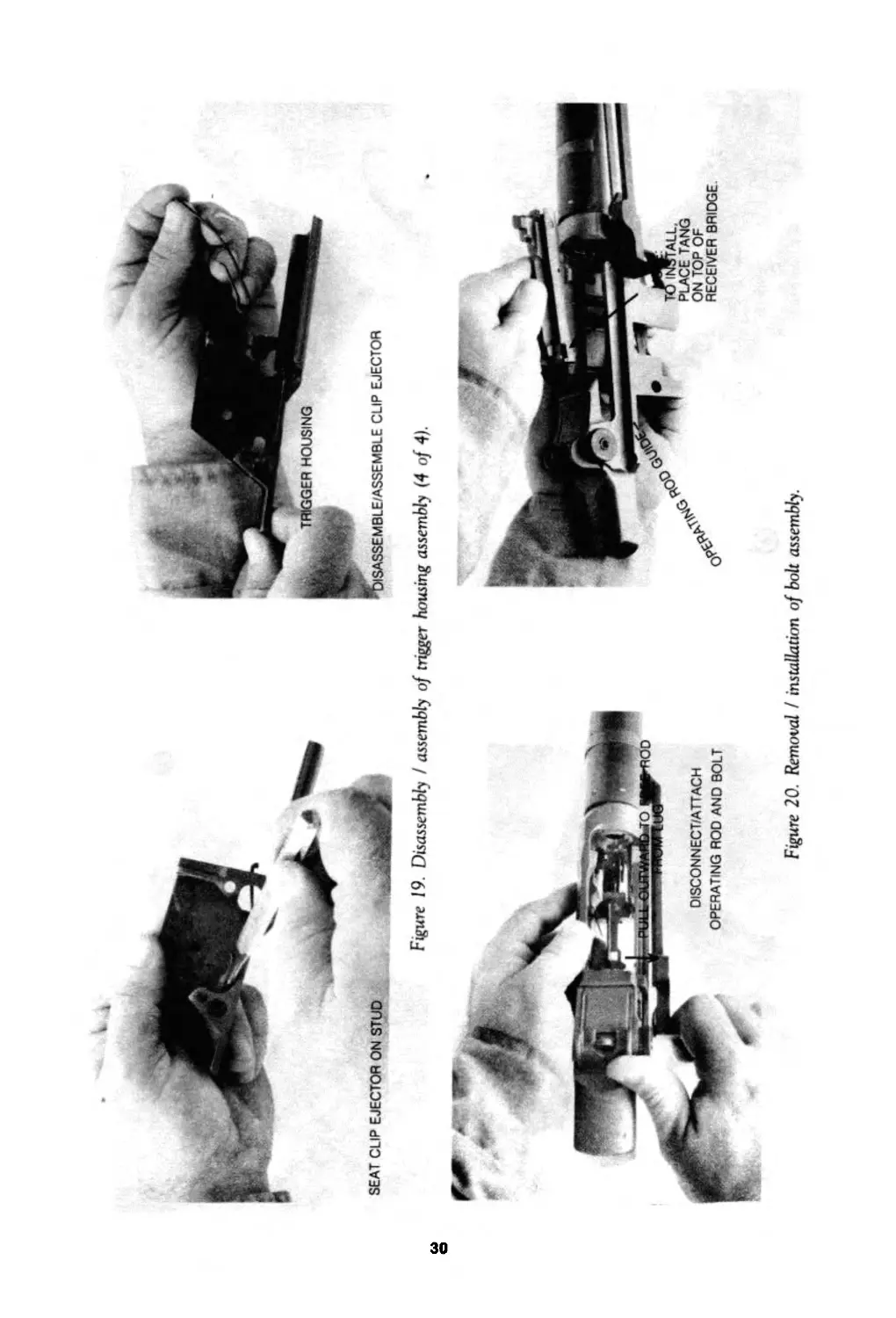
Figure 19. Disassembly I assembly of trigger housing assembly (4 of 4).
CLIP EJECTOR
Figure 20. Removal / installation of bolt assembly
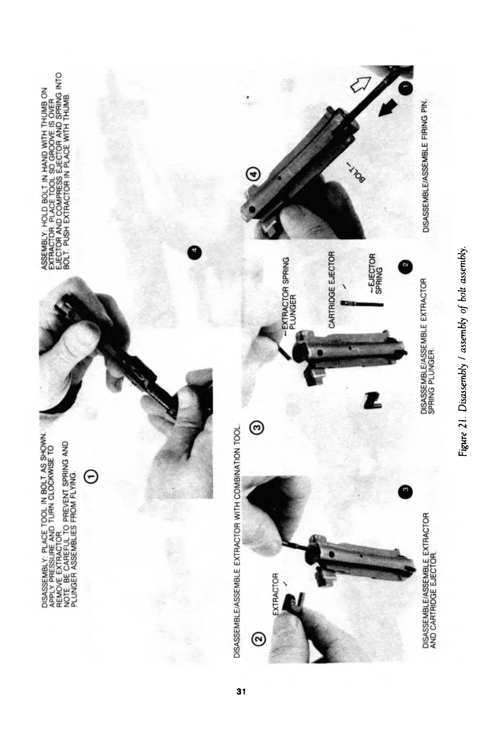
DISASSEMBLY PLACE TOOL IN BOLT AS SHOWN
APPLY PRESSURE AND TURN CLOCKWISE TO
REMOVE EXTRACTOR
NOTE BE CAREFUL TO PREVENT SPRING AND
PLUNGER ASSEMBLIES FROM FLYING.
ASSEMBLY: HOLD BOLT IN HAND WITH THUMB ON
EXTRACTOR PLACE TOOL SO GROOVE IS OVER
EJECTOR AND COMPRESS EJECTOR AND SPRING INTO
BOLT PUSH EXTRACTOR IN PLACE WITH THUMB
DISASSEMBLE/ASSEMBLE EXTRACTOR WITH COMBINATION TOOL
DISASSEMBLE/ASSEMBLE EXTRACTOR
AND CARTRIDGE EJECTOR.
Figure 21. Disassembly I assembly of bolt assembly.
DISASSEMBLE/ASSEMBLE FIRING PIN
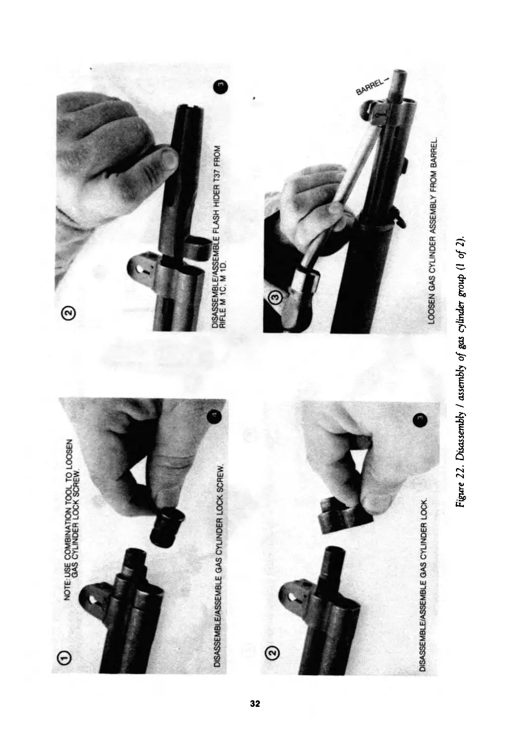
© NOTE USE COMBINATION TOOL TO LOOSEN
GAS CYLINDER LOCK SCREW
DISASSEMBLE/ASSEMBLE GAS CYLINDER LOCK
Figure 22. Disassembly / assembly of gas cylinder group (1 of 2).
LOOSEN GAS CYLINDER ASSEMBLY FROM BARREL
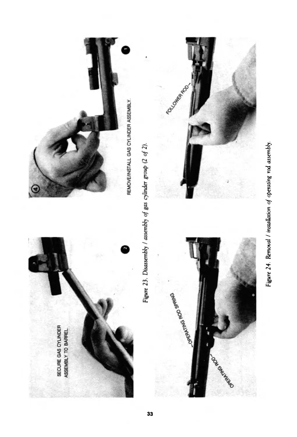
SECURE GAS CYLINDER
ASSEMBLY TO
Figure 23. Disassembly I assembly of gas cylinder group (2 of 2).
Figure 24- Removal I installation of operating rod assembly.
ы
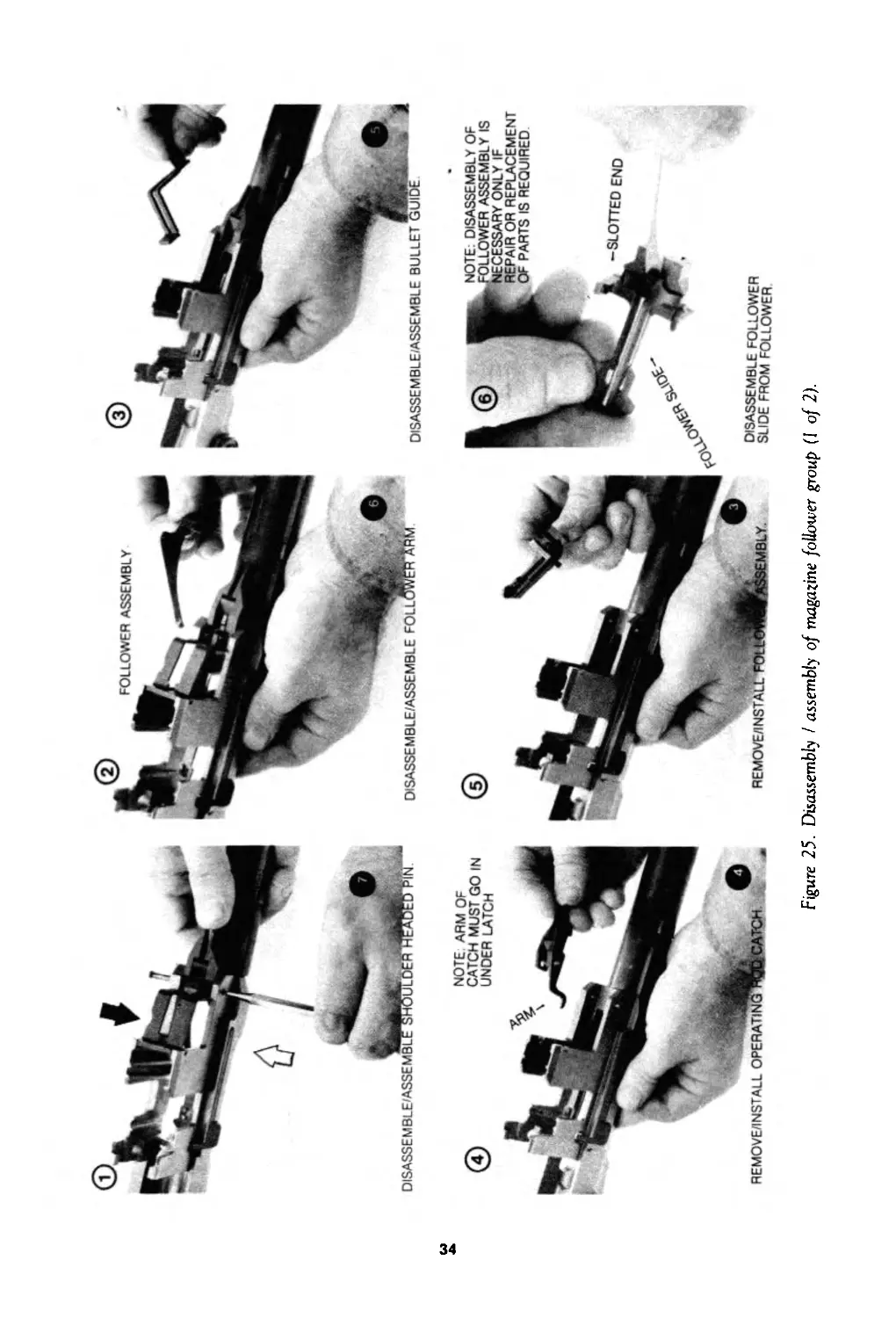
Figure 25. Disassembly / assembly of magazine follower group (I of 2).
•SLOTTED END
NOTE: DISASSEMBLY OF
OLLOWER ASSEMBLY IS
CESSARY ONLY IF
REPAIR OR REPLACEMENT
OF PARTS IS REQUIRED
DISASSEMBLE FOLLOWER
SLIDE FROM FOLLOWER.
w
СП
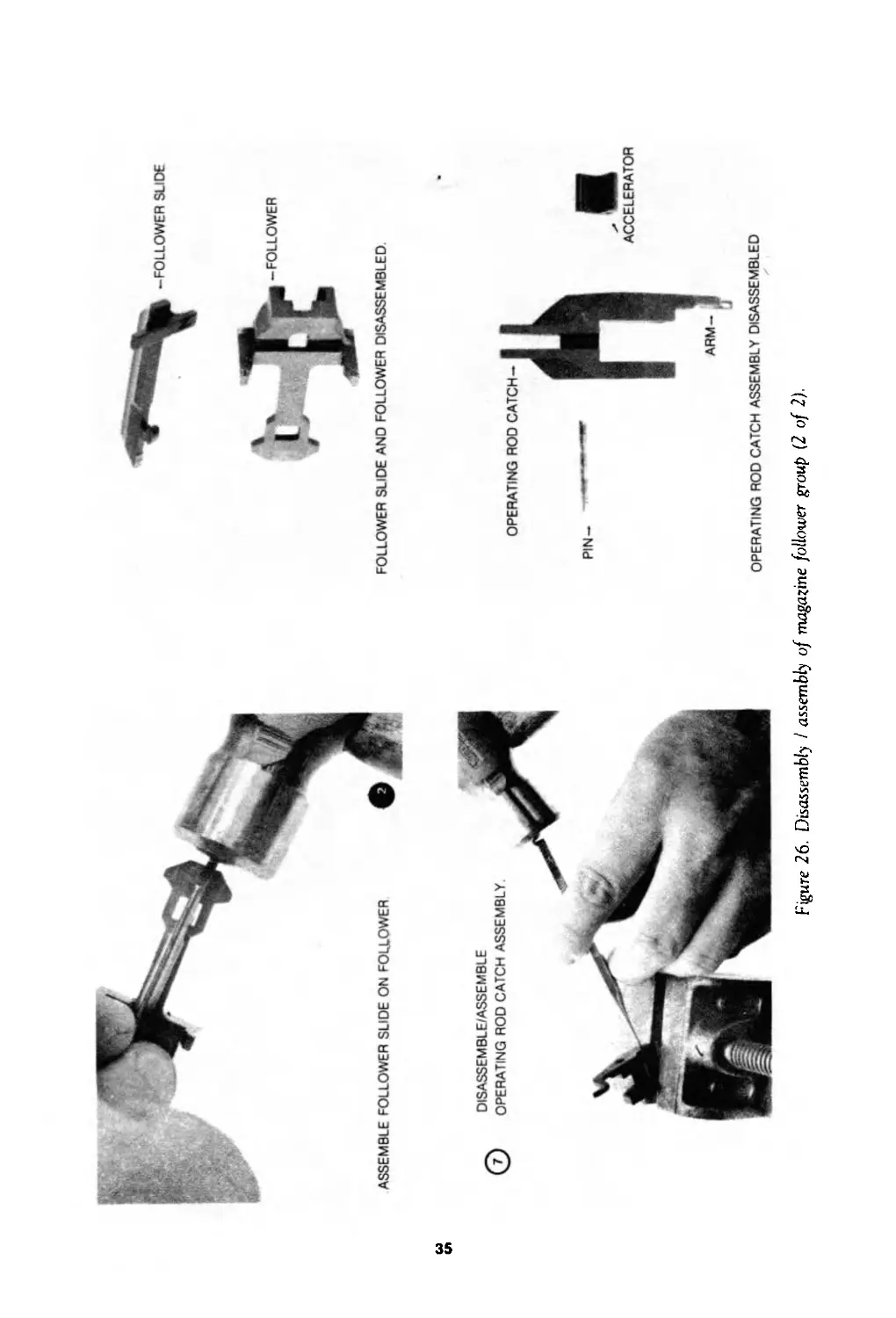
-FOLLOWER SLIDE
FOLLOWER SLIDE AND FOLLOWER DISASSEMBLED
Figure 26. Disassembly I assembly of magazine follower group (2 of 2).
ACCELERATOR
OPERATING ROD CATCH ASSEMBLY DISASSEMBLED
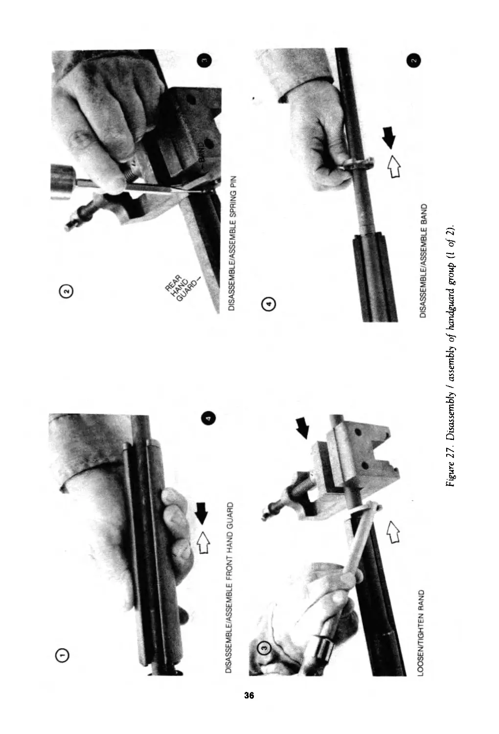
DISASSEMBLE/ASSEMBLE FRONT HAND GUARD
DISASSEMBLE/ASSEMBLE SPRING PIN
LOOSEN/TIGHTEN RAND
DISASSEMBLE/ASSEMBLE BAND
Figure 27. Disassembly I assembly of handguard group (I of 2).
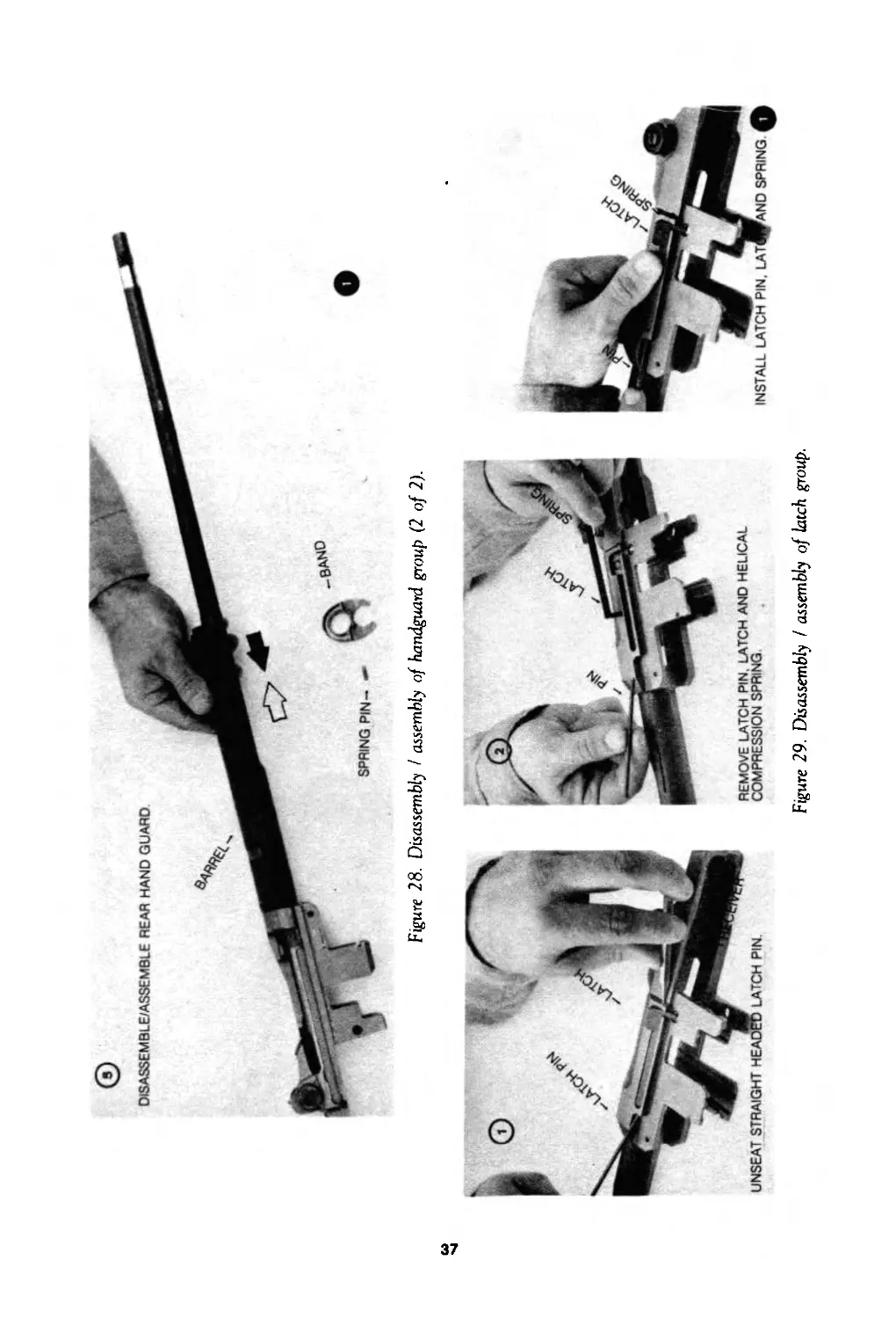
Figure 28. Disassembly I assembly of handguard group (2 of 2).
Figure 29. Disassembly ! assembly of latch group.
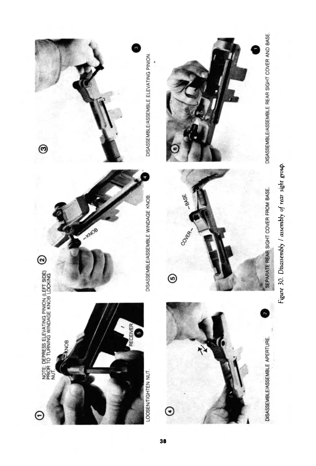
Figure 30. Disassembly I assembly of rear sight group.
ТМ9-1005-222-12
Chapter 4
MAINTENANCE OF MATERIEL USED
IN CONJUNCTION WITH MAJOR ITEM
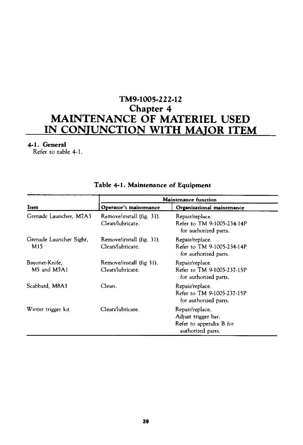
4-1. General
Refer to table 4-1.
Table 4-1. Maintenance of Equipment
Item Maintenance function
Operator’s maintenance ] Organizational maintenance
Grenade Launcher, M7A3 Remove/install (fig. 31). Clean/lubricate. Repair/replace. Refer to TM 9-1005-234-14P for authorized parts.
Grenade Launcher Sight, Ml5 Remove/install (fig. 31). Clean/lubricate. Repair/replace. Refer to TM 9-1005-234-14P for authorized parts.
Bayonet-Knife, M5 and M5A1 Remove/install (fig 31). Clean/lubricate. Repair/replace. Refer to TM 9-1005-237-15P for authorized parts.
Scabbard, M8A1 Clean. Repair/replace. Refer to TM 9-1005-237-15P for authorized pans.
Winter trigger kit Clean/lubricate. Repair/replace. Adjust trigger bar. Refer to appendix В for authorized pans.
39
INSTALUREMOVE GRENADE LAUNCHER
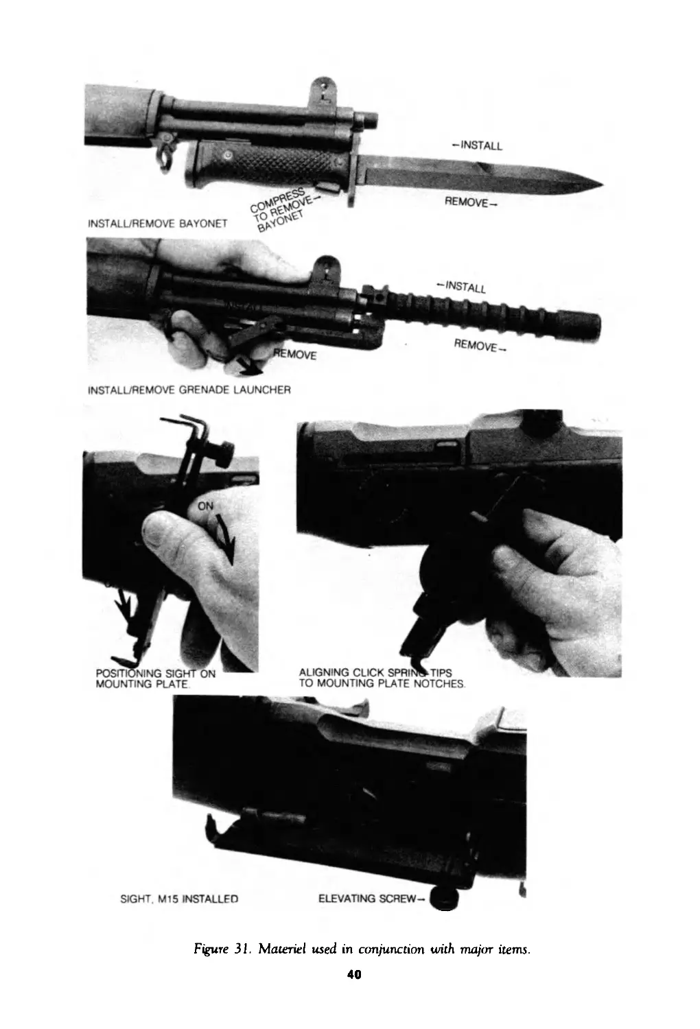
Figure 31. Materiel used in conjunction with major items.
40
ТМ9-1ОО5-222-12
Chapter 5
AMMUNITION
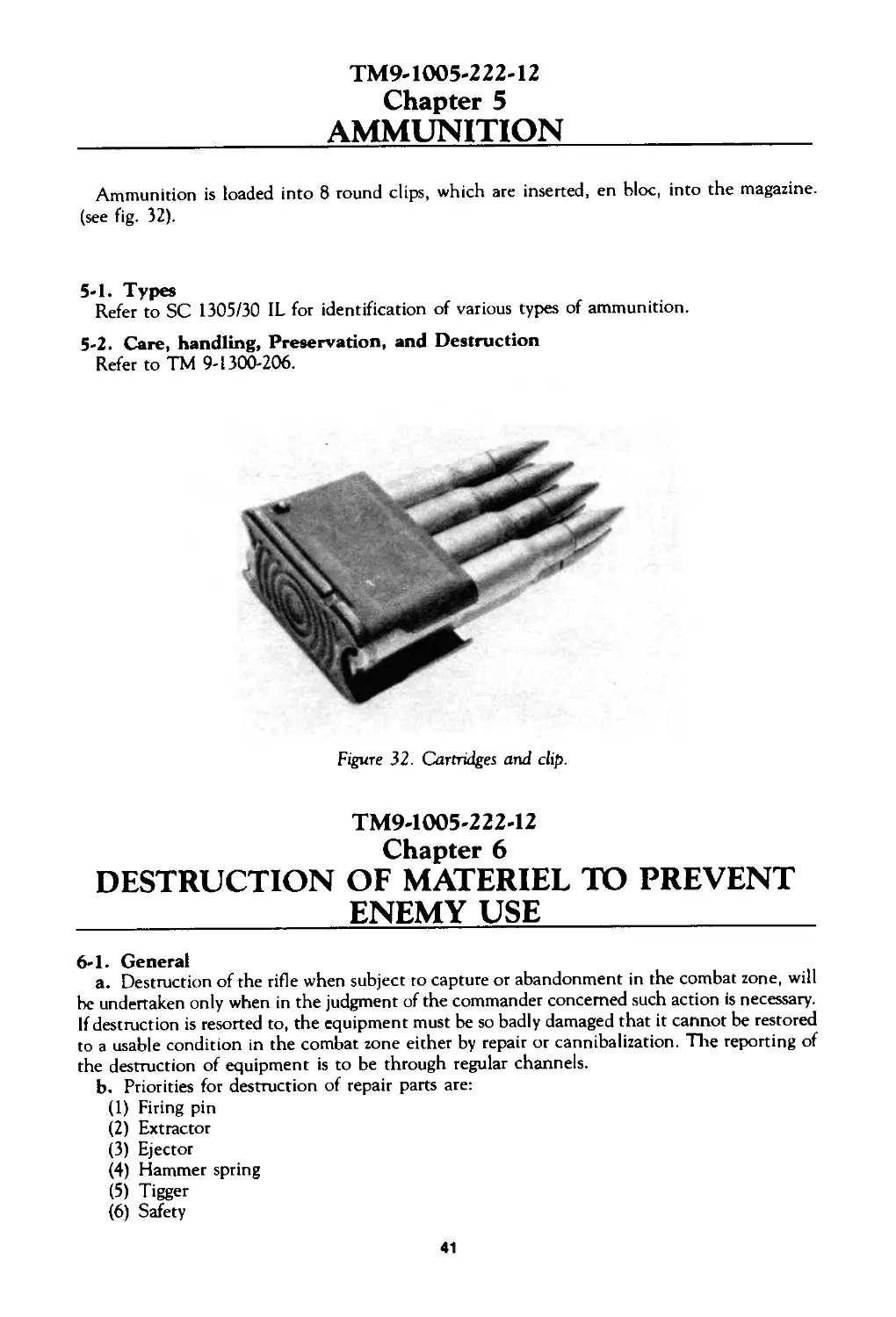
Ammunition is loaded into 8 round clips, which are inserted, en bloc, into the magazine,
(see fig. 32).
5-1. Types
Refer to SC 1305/30 IL for identification of various types of ammunition.
5-2. Care, handling, Preservation, and Destruction
Refer to TM 9-1300-206.
Figure 32. Cartridges and clip.
TM9-1OO5-222-12
DESTRUCTION OF MATERIEL TO PREVENT
ENEMY USE
6-1. General
a. Destruction of the rifle when subject to capture or abandonment in the combat zone, will
be undertaken only when in the judgment of the commander concerned such action is necessary.
If destruction is resorted to, the equipment must be so badly damaged that it cannot be restored
to a usable condition in the combat zone either by repair or cannibalization. The reporting of
the destruction of equipment is to be through regular channels.
b. Priorities for destruction of repair parts are:
(1) Firing pin
(2) Extractor
(3) Ejector
(4) Hammer spring
(5) Tigger
(6) Safety
41
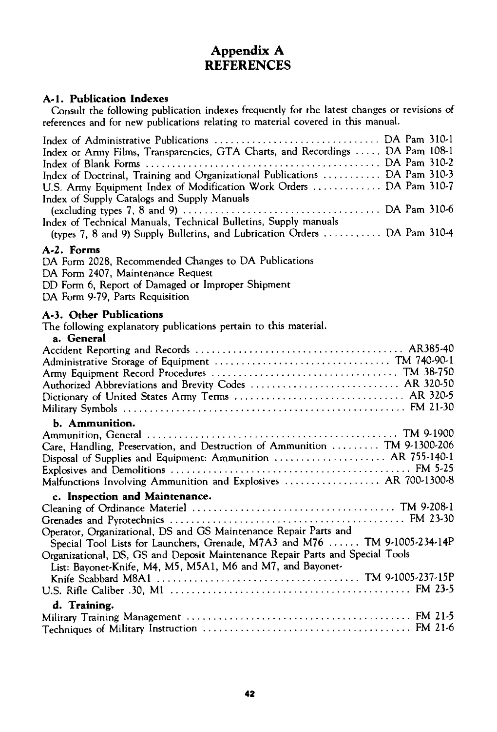
Appendix A
REFERENCES
A-l. Publication Indexes
Consult the following publication indexes frequently for the latest changes or revisions of
references and for new publications relating to material covered in this manual.
Index of Administrative Publications ................................ DA Pam 310-1
Index or Army Films, Transparencies, GTA Charts, and Recordings........DA Pam 108-1
Index of Blank Forms.......................................................DA Pam 310-2
Index of Doctrinal, Training and Organizational Publications...............DA Pam 310-3
U.S. Army Equipment Index of Modification Work Orders........................DA Pam 310-7
Index of Supply Catalogs and Supply Manuals
(excluding types 7, 8 and 9).............................................. DA Pam 310-6
Index of Technical Manuals, Technical Bulletins, Supply manuals
(types 7, 8 and 9) Supply Bulletins, and Lubrication Orders................DA Pam 310-4
A-2. Forms
DA Form 2028, Recommended Changes to DA Publications
DA Form 2407, Maintenance Request
DD Form 6, Report of Damaged or Improper Shipment
DA Form 9-79, Parts Requisition
A-3. Other Publications
The following explanatory publications pertain to this material.
a. General
Accident Reporting and Records............................................. AR385-40
Administrative Storage of Equipment....................................TM 740-90-1
Army Equipment Record Procedures........................................... TM 38-750
Authorized Abbreviations and Brevity Codes.................................AR 320-50
Dictionary of United States Army Terms..................................... AR 320-5
Military Symbols...........................................................FM 21-30
b. Ammunition.
Ammunition, General ....................................................... TM 9-1900
Care, Handling, Preservation, and Destruction of Ammunition............TM 9-1300-206
Disposal of Supplies and Equipment: Ammunition ........................AR 755-140-1
Explosives and Demolitions................................................. FM 5-25
Malfunctions Involving Ammunition and Explosives ......................AR 700-1300-8
c. Inspection and Maintenance.
Cleaning of Ordinance Materiel ............................................TM 9-208-1
Grenades and Pyrotechnics.................................................. FM 23-30
Operator, Organizational, DS and GS Maintenance Repair Parts and
Special Tool Lists for Launchers, Grenade, M7A3 and M76.........TM 9-1005-234-14P
Organizational, DS, GS and Deposit Maintenance Repair Parts and Special Tools
List: Bayonet-Knife, M4, M5, M5A1, M6 and M7, and Bayonet-
Knife Scabbard M8A1 ............................................. TM 9-1005-237-15P
U.S. Rifle Caliber .30, Ml ................................................ FM 23-5
d. Training.
Military Training Management...............................................FM 21-5
Techniques of Military Instruction.........................................FM 21-6
42
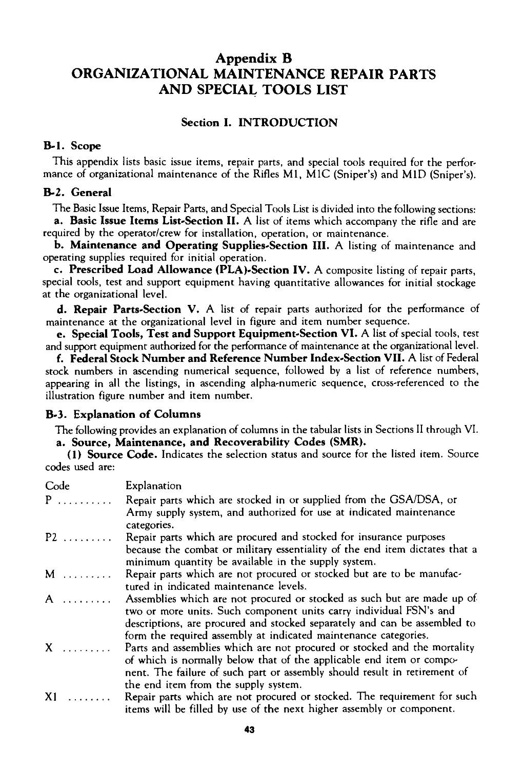
Appendix В
ORGANIZATIONAL MAINTENANCE REPAIR PARTS
AND SPECIAL TOOLS LIST
Section I. INTRODUCTION
B-l. Scope
This appendix lists basic issue items, repair parts, and special tools required for the perfor-
mance of organizational maintenance of the Rifles Ml, MIC (Sniper's) and MID (Sniper’s).
B-2. General
The Basic Issue Items, Repair Parts, and Special Tools List is divided into the following sections:
a. Basic Issue Items List-Section II. A list of items which accompany the rifle and are
required by the operator/crew for installation, operation, or maintenance.
b. Maintenance and Operating Supplies-Section III. A listing of maintenance and
operating supplies required for initial operation.
c. Prescribed Load Allowance (PLA)-Section IV. A composite listing of repair parts,
special tools, test and support equipment having quantitative allowances for initial stockage
at the organizational level.
d. Repair Parts-Section V. A list of repair parts authorized for the performance of
maintenance at the organizational level in figure and item number sequence.
e. Special Tools, Test and Support Equipment-Section VI. A list of special tools, test
and support equipment authorized for the performance of maintenance at the organizational level.
f. Federal Stock Number and Reference Number Index-Section VII. A list of Federal
stock numbers in ascending numerical sequence, followed by a list of reference numbers,
appearing in all the listings, in ascending alpha-numeric sequence, cross-referenced to the
illustration figure number and item number.
B-3. Explanation of Columns
The following provides an explanation of columns in the tabular lists in Sections II through VI.
a. Source, Maintenance, and Recoverability Codes (SMR).
(1) Source Code. Indicates the selection status and source for the listed item. Source
codes used are:
Code Explanation
P ............. Repair parts which are stocked in or supplied from the GSA/DSA, or
Army supply system, and authorized for use at indicated maintenance
categories.
P2 ............ Repair parts which are procured and stocked for insurance purposes
because the combat or military essentiality of the end item dictates that a
minimum quantity be available in the supply system.
M ............. Repair parts which are not procured or stocked but are to be manufac-
tured in indicated maintenance levels.
A .............. Assemblies which are not procured or stocked as such but are made up of
two or more units. Such component units carry individual FSN's and
descriptions, are procured and stocked separately and can be assembled to
form the required assembly at indicated maintenance categories.
X .............. Parts and assemblies which are not procured or stocked and the mortality
of which is normally below that of the applicable end item or compo-
nent. The failure of such part or assembly should result in retirement of
the end item from the supply system.
XI ............ Repair parts which are not procured or stocked. The requirement for such
items will be filled by use of the next higher assembly or component.
43
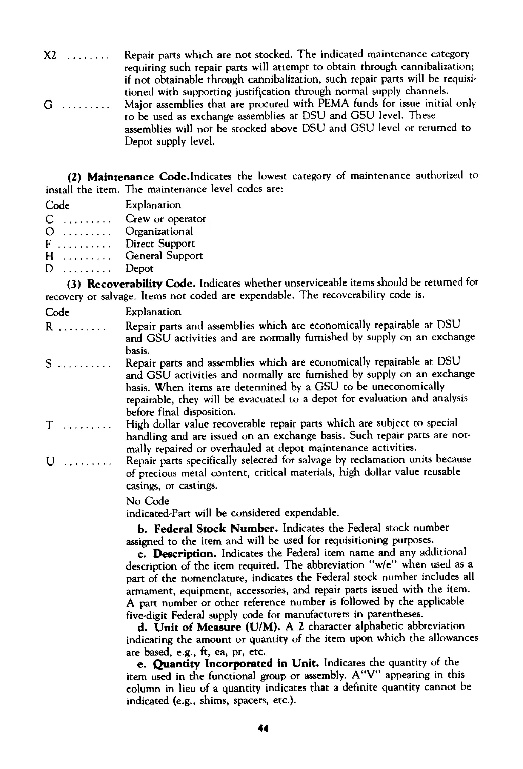
Х2 .......... Repair parts which are not stocked. The indicated maintenance category
requiring such repair parts will attempt to obtain through cannibalization;
if not obtainable through cannibalization, such repair parts will be requisi-
tioned with supporting justification through normal supply channels.
G ........... Major assemblies that are procured with РЕМА funds for issue initial only
to be used as exchange assemblies at DSU and GSU level. These
assemblies will not be stocked above DSU and GSU level or returned to
Depot supply level.
(2) Maintenance Code.Indicates the lowest category of maintenance authorized to
install the item. The maintenance level codes are:
Code Explanation
C ........... Crew or operator
О ........... Organizational
F ........... Direct Support
H ........... General Support
D ........... Depot
(3) Recoverability Code. Indicates whether unserviceable items should be returned for
recovery or salvage. Items not coded are expendable. The recoverability code is.
Code Explanation
R............ Repair parts and assemblies which are economically repairable at DSU
and GSU activities and are normally furnished by supply on an exchange
basis.
S............ Repair parts and assemblies which are economically repairable at DSU
and GSU activities and normally are furnished by supply on an exchange
basis. When items are determined by a GSU to be uneconomically
repairable, they will be evacuated to a depot for evaluation and analysis
before final disposition.
T ........... High dollar value recoverable repair parts which are subject to special
handling and are issued on an exchange basis. Such repair parts are nor-
mally repaired or overhauled at depot maintenance activities.
U ........... Repair parts specifically selected for salvage by reclamation units because
of precious metal content, critical materials, high dollar value reusable
casings, or castings.
No Code
indicated-Part will be considered expendable.
b. Federal Stock Number. Indicates the Federal stock number
assigned to the item and will be used for requisitioning purposes.
c. Description. Indicates the Federal item name and any additional
description of the item required. The abbreviation “w/e” when used as a
part of the nomenclature, indicates the Federal stock number includes all
armament, equipment, accessories, and repair parts issued with the item.
A part number or other reference number is followed by the applicable
five-digit Federal supply code for manufacturers in parentheses.
d. Unit of Measure (U/M). A 2 character alphabetic abbreviation
indicating the amount or quantity of the item upon which the allowances
are based, e.g., ft, ea, pr, etc.
e. Quantity Incorporated in Unit. Indicates the quantity of the
item used in the functional group or assembly. A“V” appearing in this
column in lieu of a quantity indicates that a definite quantity cannot be
indicated (e.g., shims, spacers, etc.).
44
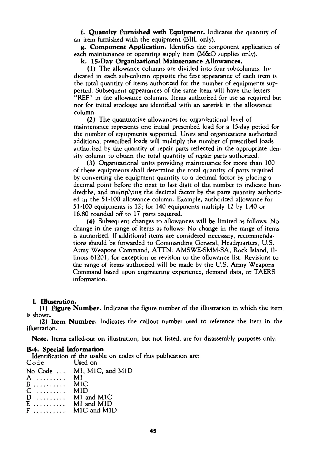
f. Quantity Furnished with Equipment. Indicates the quantity of
an item furnished with the equipment (BIIL only).
g. Component Application. Identifies the component application of
each maintenance or operating supply item (M&O supplies only).
k. 15-Day Organizational Maintenance Allowances.
(1) The allowance columns are divided into four subcolumns. In-
dicated in each sub-column opposite the first appearance of each item is
the total quantity of items authorized for the number of equipments sup-
ported. Subsequent appearances of the same item will have the letters
“REF” in the allowance columns. Items authorized for use as required but
not for initial stockage are identified with an asterisk in the allowance
column.
(2) The quantitative allowances for organizational level of
maintenance represents one initial prescribed load for a 15-day period for
the number of equipments supported. Units and organizations authorized
additional prescribed loads will multiply the number of prescribed loads
authorized by the quantity of repair parts reflected in the appropriate den-
sity column to obtain the total quantity of repair parts authorized.
(3) Organizational units providing maintenance for more than 100
of these equipments shall determine the total quantity of parts required
by converting the equipment quantity to a decimal factor by placing a
decimal point before the next to last digit of the number to indicate hun-
dredths, and multiplying the decimal factor by the parts quantity authoriz-
ed in the 51-100 allowance column. Example, authorized allowance for
51-100 equipments is 12; for 140 equipments multiply 12 by 1.40 or
16.80 rounded off to 17 parts required.
(4) Subsequent changes to allowances will be limited as follows: No
change in the range of items as follows: No change in the range of items
is authorized. If additional items are considered necessary, recommenda-
tions should be forwarded to Commanding General, Headquarters, U.S.
Army Weapons Command, A1 1N: AMSWE-SMM-SA, Rock Island, Il-
linois 61201, for exception or revision to the allowance list. Revisions to
the range of items authorized will be made by the U.S. Army Weapons
Command based upon engineering experience, demand data, or TAERS
information.
< CQ О Q Щ u-
1. Illustration.
(1) Figure Number. Indicates the figure number of the illustration in which the item
is shown.
(2) Item Number. Indicates the callout number used to reference the item in the
illustration.
Note. Items called-out on illustration, but not listed, are for disassembly purposes only.
B-4. Special Information
Identification of the usable on codes of this publication are:
Code Used on
No Code ... Ml, MIC, and MID
.............. Ml
.............. MIC
.............. MID
.............. Ml and MIC
.............. Ml and MID
.............. MIC and MID
45
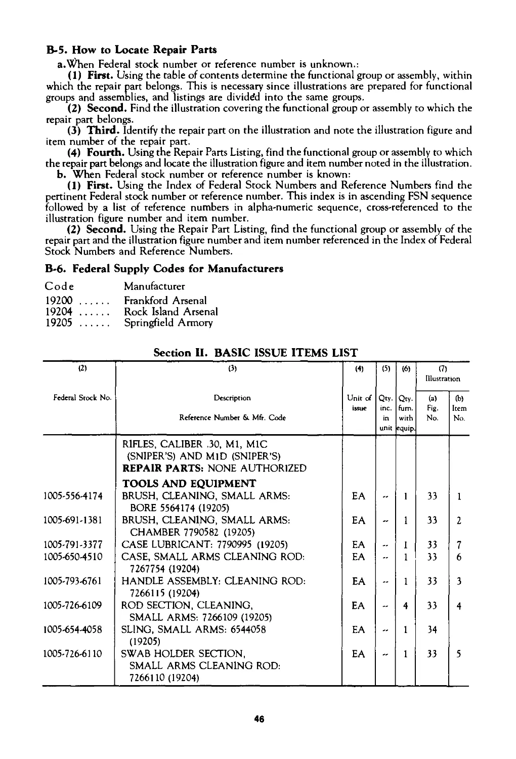
B-5. How to Locate Repair Parts
a.when Federal stock number or reference number is unknown.:
(1) First. Using the table of contents determine the functional group or assembly, within
which the repair part belongs. This is necessary since illustrations are prepared for functional
groups and assemblies, and listings are divided into the same groups.
(2) Second. Find the illustration covering the functional group or assembly to which the
repair part belongs.
(3) Third. Identify the repair part on the illustration and note the illustration figure and
item number of the repair part.
(4) Fourth. Using the Repair Parts Listing, find the functional group or assembly to which
the repair part belongs and locate the illustration figure and item number noted in the illustration,
b. When Federal stock number or reference number is known:
(1) First. Using the Index of Federal Stock Numbers and Reference Numbers find the
pertinent Federal stock number or reference number. This index is in ascending FSN sequence
followed by a list of reference numbers in alpha-numeric sequence, cross-referenced to the
illustration figure number and item number.
(2) Second. Using the Repair Part Listing, find the functional group or assembly of the
repair part and the illustration figure number and item number referenced in the Index of Federal
Stock Numbers and Reference Numbers.
B-6. Federal Supply Codes for Manufacturers
Code Manufacturer
19200 ....... Frankford Arsenal
19204 ....... Rock Island Arsenal
19205 ....... Springfield Armory
Section II. BASIC ISSUE ITEMS LIST
(2) (3) (4) (5) (6) (7) Illustration
Federal Stock No. Description Unit of Qty. Qty- (a) (b)
issue inc. fum. Fig- Item
Reference Number & Mfr. Code in with No. No.
unit equip
RIFLES, CALIBER .30, Ml, MIC (SNIPER'S) AND MID (SNIPER’S) REPAIR PARTS: NONE AUTHORIZED
TOOLS AND EQUIPMENT
1005-556-4174 BRUSH, CLEANING, SMALL ARMS: EA - 1 33 1
BORE 5564174 (19205)
1005-691-1381 BRUSH, CLEANING, SMALL ARMS: EA — 1 33 2
CHAMBER 7790582 (19205)
1005-791-3377 CASE LUBRICANT: 7790995 (19205) EA — 1 33 7
1005-650-4510 CASE, SMALL ARMS CLEANING ROD: EA - 1 33 6
7267754 (19204)
1005-793-6761 HANDLE ASSEMBLY: CLEANING ROD: EA — 1 33 3
7266115 (19204)
1005-726-6109 ROD SECTION, CLEANING, EA — 4 33 4
SMALL ARMS: 7266109 (19205)
1005-654-4058 SLING, SMALL ARMS: 6544058 EA — 1 34
(19205)
1005-726-6110 SWAB HOLDER SECTION, EA — 1 33 5
SMALL ARMS CLEANING ROD: 7266110 (19204)
46
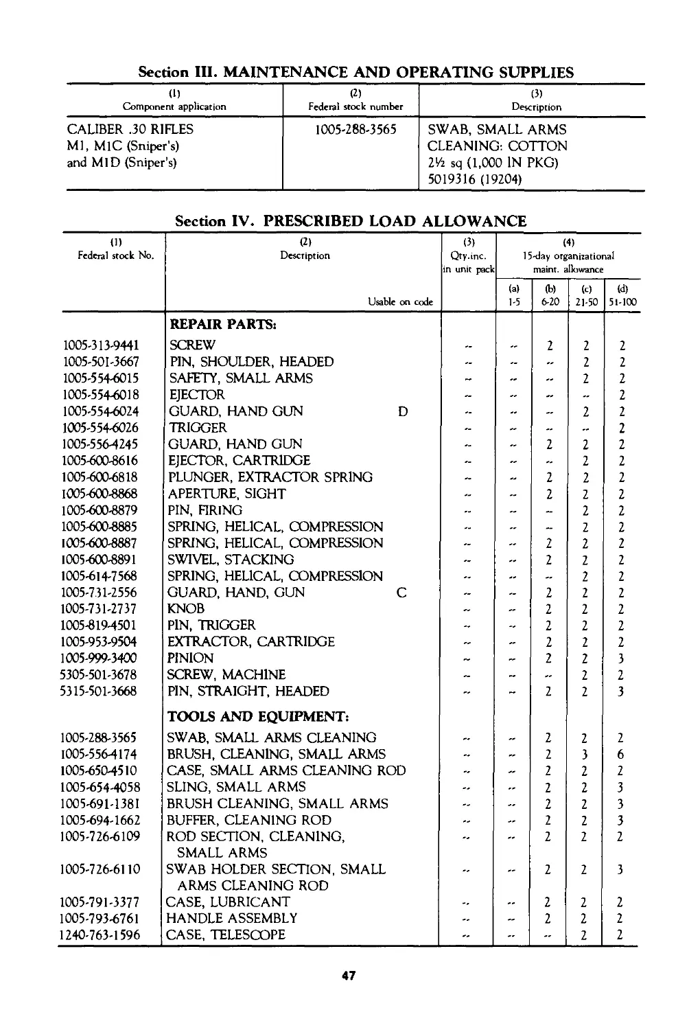
Section III. MAINTENANCE AND OPERATING SUPPLIES
(1) Component application (2) Federal stock number (3) Description
CALIBER .30 RIFLES Ml, M1C (Sniper’s) and MID (Sniper’s) 1005-288-3565 SWAB, SMALL ARMS CLEANING: COTTON 2Vi sq (1,000 IN PKG) 5019316 (19204)
Section IV. PRESCRIBED LOAD ALLOWANCE
(1) Federal stock No. (2) Description (3) Qty.inc. in unit pack (4) 15-day organizational maint. allowance
Usable on code (a) 1-5 (b) 6-20 (c) 21-50 (d) 51-100
1005-313-9441 REPAIR PARTS: SCREW 2 2 2
1005-501-3667 PIN, SHOULDER, HEADED - - - 2 2
1005-554-6015 SAFETY, SMALL ARMS - - - 2 2
1005-554-6018 EJECTOR - - - 2
1005-554-6024 GUARD, HAND GUN D .. - 2 2
1005-554-6026 TRIGGER - 2
1005-556-4245 GUARD, HAND GUN 2 2 2
1005-600-8616 EJECTOR, CARTRIDGE - - 2 2
1005-600-6818 PLUNGER, EXTRACTOR SPRING .. 2 2 2
1005-600-8868 APERTURE, SIGHT - 2 2 2
1005-600-8879 PIN, FIRING - - 2 2
1005-600-8885 SPRING, HELICAL, COMPRESSION - - 2 2
1005-600-8887 SPRING, HELICAL, COMPRESSION - 2 2 2
1005-600-8891 SWIVEL, STACKING - 2 2 2
1005-614-7568 SPRING, HELICAL, COMPRESSION - - 2 2
1005-731-2556 GUARD, HAND, GUN C - - 2 2 2
1005-731-2737 KNOB - 2 2 2
1005-819-4501 PIN, TRIGGER - 2 2 2
1005-953-9504 EXTRACTOR, CARTRIDGE - - 2 2 2
1005-999-3400 PINION - 2 2 3
5305-501-3678 SCREW, MACHINE .. - .. 2 2
5315-501-3668 PIN, STRAIGHT, HEADED - 2 2 3
1005-288-3565 TOOLS AND EQUIPMENT: SWAB, SMALL ARMS CLEANING 2 2 2
1005-556-4174 BRUSH, CLEANING, SMALL ARMS - - 2 3 6
1005-650-4510 CASE, SMALL ARMS CLEANING ROD - - 2 2 2
1005-654-4058 SLING, SMALL ARMS — -- 2 2 3
1005-691-1381 BRUSH CLEANING, SMALL ARMS — — 2 2 3
1005-694-1662 BUFFER, CLEANING ROD - — 2 2 3
1005-726-6109 ROD SECTION, CLEANING, - - 2 2 2
1005-726-6110 SMALL ARMS SWAB HOLDER SECTION, SMALL .. ,, 2 2 3
1005-791-3377 ARMS CLEANING ROD CASE, LUBRICANT .. ,, 2 2 2
1005-793-6761 HANDLE ASSEMBLY - 2 2 2
1240-763-1596 CASE, TELESCOPE - 2 2
47
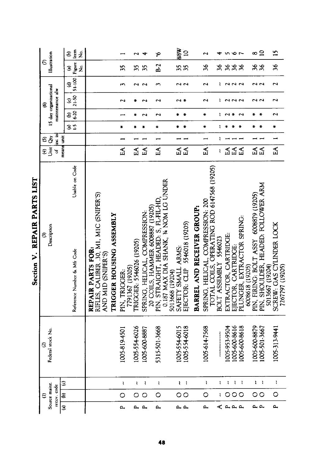
Section V. REPAIR PARTS LIST
(1) Source maint. recov. code (2) Federal stock No. (3) Description (4) Unit of (5) Qty inc in (6) 15 day organizational maintenance alw (7) Illustration
(a) (с) mean:
(a) (b) (c) (d) (a) (b)
Reference Number &. Mfr Code Usable on Code 1-5 6-20 21-50 51-100 Figure Item
No. No.
REPAIR PARTS FOR: RIFLES, CALIBER .30, Ml, MIC (SNIPER’S) AND MID (SNIPER’S) TRIGGER HOUSING ASSEMBLY
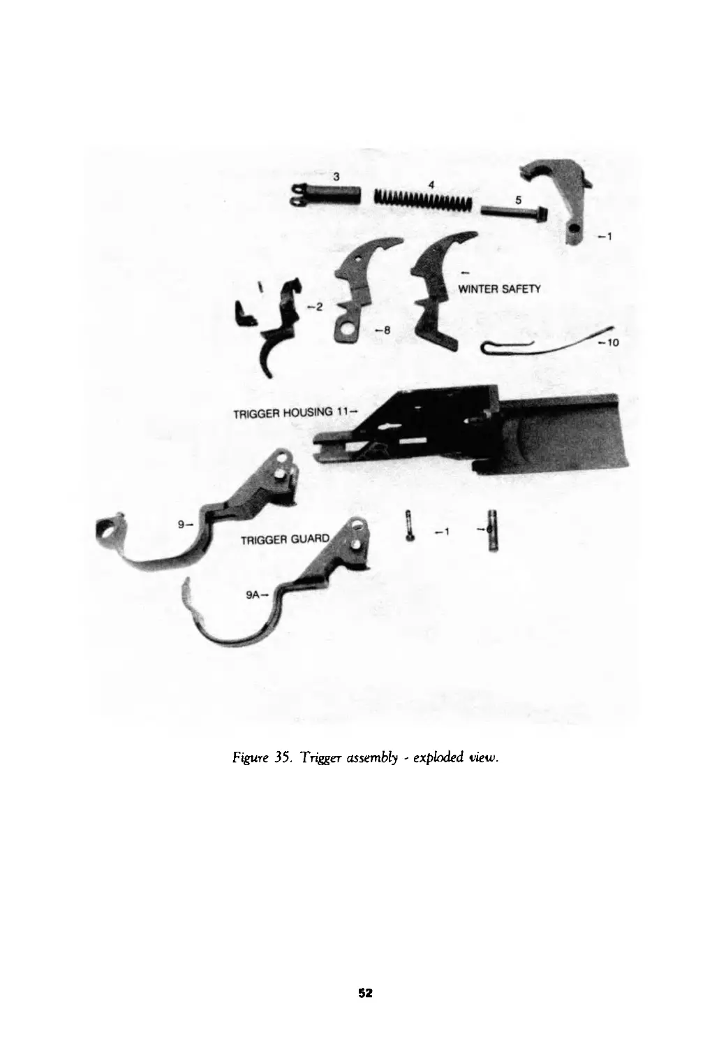
P 0 - 1005-819-4501 PIN, TRIGGER: EA 1 * 1 2 3 35 1
7791367 (19205)
P 0 - 1005-554-6026 TRIGGER: 5546026 (19205) EA 1 * * * 2 35 2
P 0 — 1005-600-8887 SPRING, HELICAL, COMPRESSION: EA 1 * 2 2 2 35 4
20 COILS, HAMMER 6008887 (19205)
P о 5315-501-3668 PIN, STRAIGHT, HEADED: S, FL-F1L-HD, 0.187 MAX DI A SHANK, Уд NOM LG UNDER 5013668 (19204) EA 1 * 2 2 3 B-2 •6
P о -- 1005-554-6015 SAFETY SMALL ARMS: EA 1 * * 2 2 35 &/8W
P 0 - 1005-554-6018 EJECTOR: CLIP 5546018 (19205) EA 1 * * * 2 35 10
BARREL AND RECEIVER GROUP:
P о .. 1005-614-7568 SPRING, HELICAL, COMPRESSION: 200 EA 1 * * 2 2 36 2
TOTAL COILS, OPERATING ROD 6147568 (19205)
A BOLT ASSEMBLY 5546023 36 4
P о 1005-953-9504 EXTRACTOR, CARTRIDGE: EA 1 * 2 2 2 36 5
P о 1005-600-8616 EJECTOR, CARTRIDGE: EA 1 * * 2 2 36 6
P о 1005-600-8618 PLUNGER, EXTRACTOR SPRING: EA 1 * 2 2 2 36 7
6008618 (19205)
P о 1005-600-8879 PIN, FIRING: BOLT ASSY 6008879 (19205) EA 1 * * 2 2 36 8
P о 1005-501-3667 PIN, SHOULDER, HEADED: FOLLOWER ARM EA 1 * * 2 2 36 10
5013667 (19204)
P о — 1005-313-9441 SCREW: GAS CYLINDER LOCK EA 1 * 2 2 2 36 15
7267797 (19205)
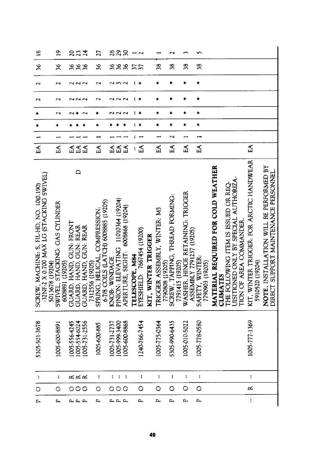
р р р о о о R 5305-501-3678 1005-600-8891 1005-556-4245 SCREW, MACHINE-. S, F1L-HD, NO. 10(0.190) -32NF-2 X 0.700 MAX LG (STACKING SWIVEL) 5013678 (19204) SWIVEL, STACKING: GAS CYLINDER 6008891 (19205) GUARD, HAND, GUN: FRONT EA EA EA 1 1 1 * * * 2 2 2 2 2 2 2 2 36 36 36 18 19 20
р о R 1005-554-6024 GUARD, HAND, GUN: REAR D EA 1 * * 2 2 36 23
р о R 1005-731-2556 GUARD, HAND, GUN: REAR 7312556 (19205) EA 1 * 2 2 2 36 24
р о — 1005-600-885 SPRING, HELICAL, COMPRESSION: 6-7/8 COILS (LATCH) 6008885 (19205) EA 1 * * 2 2 36 27
р о 1005-731-2737 KNOB: WINDAGE EA 1 * 2 2 2 36 28
р о — 1005-999-3400 PINION: ELEVATING 11010364(19204) EA 1 * 2 2 3 36 29
р о - 1005-600-8868 APERTURE, SIGHT: 6008868 (19204) TELESCOPE, M84 EA 1 * 2 2 2 36 37 30 1
р о — 1240-766-7454 EYESHIELD: 7667454 (19200) KIT, WINTER TRIGGER EA 1 * * * * 37 2
р о - 1005-775-0364 TRIGGER ASSEMBLY, WINTER: M5 7790808 (19205) EA 1 * * * * 38 1
р о 5305-990-6435 SCREW, TAPPING, THREAD FORMING: 7791415 (19205) EA 2 * * * * 38 2
р о 1005-010-5022 WASHER, HINGE RETAINING: TRIGGER ASSEMBLY 7791237 (19205) EA 1 * * * * 38 3
р о R - 1005-778-0580 1005-777-1369 SAFETY, WINTER: 7790903 (19205) MATERIAL REQUIRED FOR COLD WEATHER CLIMATES THE FOLLOWING ITEM IS ISSUED OR REQ- UISITIONED ONLY BY SPECIAL AUTHORIZA- TION OF AREA COMMANDER. KIT, WINTER TRIGGER: FOR ARCTIC HANDWEAR 5910520 (19204) NOTE. INSTALLATION WILL BE PERFORMED BY DIRECT SUPPORT MAINTENANCE PERSONNEL. EA EA 1 * * * * 38 5
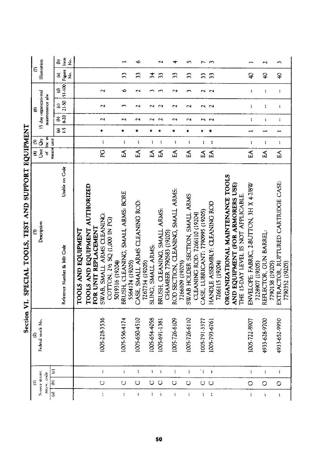
Section VI. SPECIAL TOOLS, TESTANDSUPPORT EQUIPMENT
(I) Source maint. recov, code (2) Federal stock No. (3) Description Reference Number & Mfr Code Usable on Code (4) Unit of mean; (5) Qty inc tn unit (6) 15 day organizational maintenance alw (7) Illustration
(i) (b) (с)
(a) 15 (b) 6-20 (C) 21-50 (d) 51-100 (a) Figure No. (b) Item No.
c 1005-228-3536 TOOLS AND EQUIPMENT TOOLS AND EQUIPMENT AUTHORIZED FOR UNIT REPLACEMENT SWAB, SMALL ARMS CLEANING: COTTON, 2Vz SQ (1,000 IN PG) 5019316 (19204) PG - * 2 2 2
c 1005-556-4174 BRUSH, CLEANING, SMALL ARMS: BORE 5564174 (19205) EA - * 2 3 6 33 1
- c - 1005-650-4510 CASE, SMALL ARMS CLEANING ROD: 7267754 (19205) EA - * 2 2 2 33 6
-- c 1005-654-4058 SLING, SMALL ARMS: EA - * 2 2 3 34
c - 1005-691-1381 BRUSH, CLEANING, SMALL ARMS: CHAMBER 7790583 (19205) EA * 2 2 3 33 2
c - 1005-726-6109 ROD SECTION, CLEANING, SMALL ARMS: 7266109 (19205) EA * 2 2 2 33 4
c 1005-726-6110 SWAB HOLDER SECTION, SMALL ARMS CLEANING ROD: 7266110 (19204) EA * 2 2 3 33 5
c - 1005-791-3377 CASE, LUBRICANT: 7790995 (19205) EA - * 2 2 2 33 7
c 1005-793-6761 HANDLE ASSEMBLY: CLEANING ROD 7266115 (19204) ORGANIZATIONAL MAINTENANCE TOOLS AND EQUIPMENT (FOR ARMORERS USE) THE 15-DAY LEVEL IS NOT APPLICABLE. EA * 2 2 2 33 3
о 1005-722-8907 ENVELOPE: FABRIC, 2-BUTTON, ЗН X 4-7/8W 7228907 (19205) EA 1 40 1
- о -- 4933-628-9700 REFLECTOR, GUN BARREL: 7790138 (19205) EA 1 - - 40 2
о - 4933-652-9950 EXTRACTOR, RUPTURED CARTRIDGE CASE: 7790352 (19205) EA 1 40 3
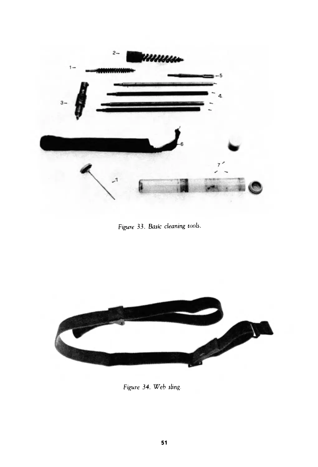
Figure 33. Basic cleaning tools.
Figure 34. Web sling.
51
Figure 35. Trigger assembly - exploded view.
52
I
«о
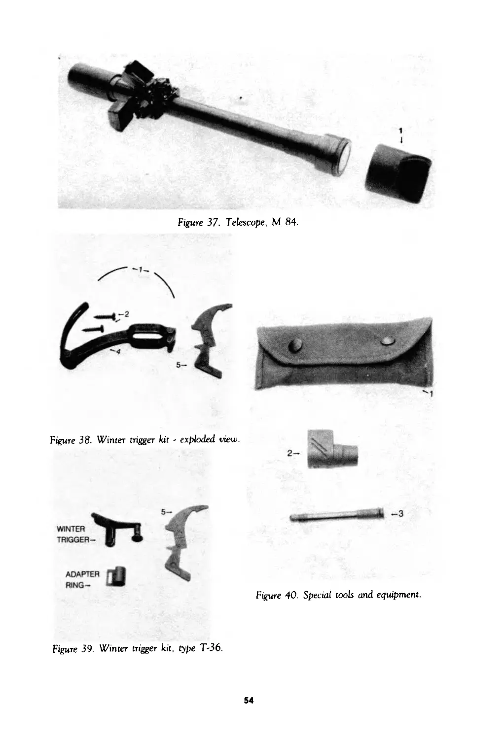
Figure 37' Telescope, M 84
Figure 38. Winter trigger kit - exploded view.
ADAPTER ГЛ
RING-
Figure 40. Special tools and equipment.
Figure 39. Winter trigger kit, type T-36.
54
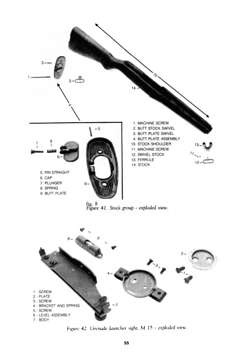
5 . PIN STRAIGHT
6 CAP
7 . PLUNGER
8 SPRING
9 BUTT PLATE
4. BUTT PLATE ASSEMBLY
10 STOCK SHOULDER
11 MACHINE SCREW
12 . SWIVEL STOCK
13 FERRULE
14 STOCK
fig. 8
Figure 41. Stock group - exploded view.
Figure 42. Grenade launcher sight, M 15 - exploded view.
55
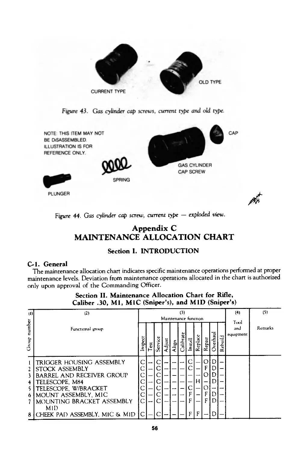
Figure 43. Gas cylinder cap screws, current type and old type.
NOTE THIS ITEM MAY NOT
BE DISASSEMBLED
ILLUSTRATION IS FOR
REFERENCE ONLY
PLUNGER
Figure 44. Gas cylinder cap screw, current type — exploded view.
Appendix C
MAINTENANCE ALLOCATION CHART
CAP SCREW
Section I. INTRODUCTION
C-l. General
The maintenance allocation chart indicates specific maintenance operations performed at proper
maintenance levels. Deviation from maintenance operations allocated in the chart is authorized
only upon approval of the Commanding Officer.
Section II. Maintenance Allocation Chart for Rifle,
Caliber .30, Ml, MIC (Sniper’s), and MID (Sniper’s)
56
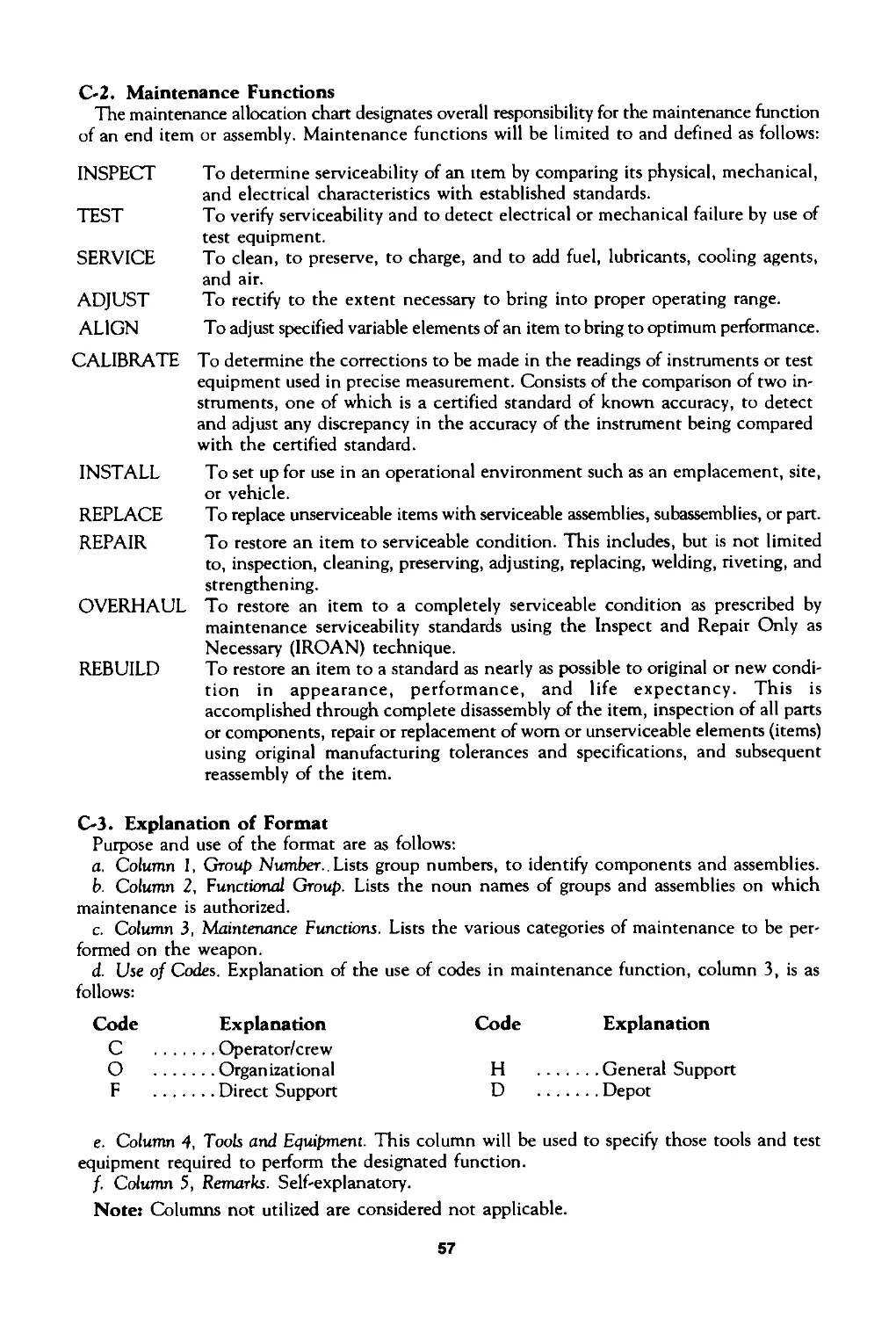
C-2. Maintenance Functions
The maintenance allocation chart designates overall responsibility for the maintenance function
of an end item or assembly. Maintenance functions will be limited to and defined as follows:
INSPECT To determine serviceability of an item by comparing its physical, mechanical, and electrical characteristics with established standards.
TEST To verify serviceability and to detect electrical or mechanical failure by use of test equipment.
SERVICE To clean, to preserve, to charge, and to add fuel, lubricants, cooling agents, and air.
ADJUST ALIGN To rectify to the extent necessary to bring into proper operating range. To adjust specified variable elements of an item to bring to optimum performance.
CALIBRATE To determine the corrections to be made in the readings of instruments or test equipment used in precise measurement. Consists of the comparison of two in- struments, one of which is a certified standard of known accuracy, to detect and adjust any discrepancy in the accuracy of the instrument being compared with the certified standard.
INSTALL To set up for use in an operational environment such as an emplacement, site, or vehicle.
REPLACE REPAIR To replace unserviceable items with serviceable assemblies, subassemblies, or part. To restore an item to serviceable condition. This includes, but is not limited to, inspection, cleaning, preserving, adjusting, replacing, welding, riveting, and strengthening.
OVERHAUL To restore an item to a completely serviceable condition as prescribed by
REBUILD maintenance serviceability standards using the Inspect and Repair Only as Necessary (IROAN) technique. To restore an item to a standard as nearly as possible to original or new condi- tion in appearance, performance, and life expectancy. This is accomplished through complete disassembly of the item, inspection of all parts or components, repair or replacement of worn or unserviceable elements (items) using original manufacturing tolerances and specifications, and subsequent reassembly of the item.
C-3. Explanation of Format
Purpose and use of the format are as follows:
a. Column I, Group Number..Lists group numbers, to identify components and assemblies.
b. Column 2, Functional Group. Lists the noun names of groups and assemblies on which
maintenance is authorized.
c. Column 3, Maintenance Functions. Lists the various categories of maintenance to be per-
formed on the weapon.
d. Use of Codes. Explanation of the use of codes in maintenance function, column 3, is as
follows:
Code Explanation
C ..........Operator/crew
О ..........Organizational
F ..........Direct Support
Code Explanation
H .........General Support
D .........Depot
e. Column 4, Tools and Equipment. This column will be used to specify those tools and test
equipment required to perform the designated function.
f. Column 5, Remarks. Self-explanatory.
Notes Columns not utilized are considered not applicable.
57
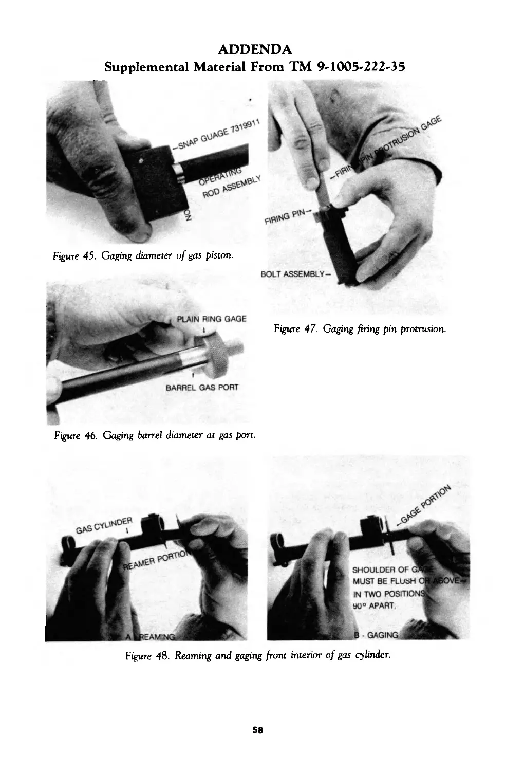
ADDENDA
Supplemental Material From TM 9-1005-222-35
Figure 46. Gaging barrel diameter at gas port.
Figure 48. Reaming and gaging front interior of gas cylinder.
58
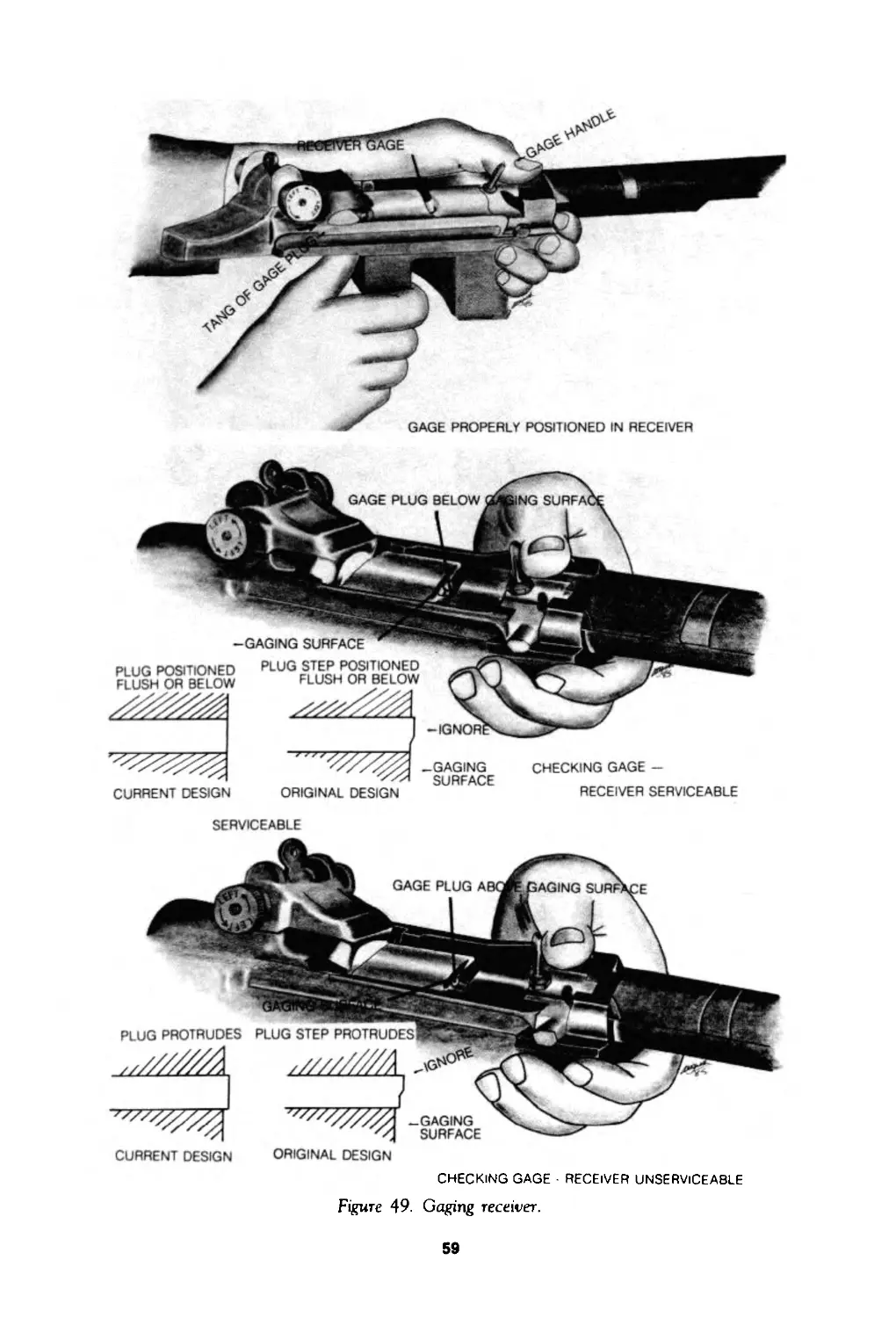
GAGE PROPERLY POSITIONED IN RECEIVER
SERVICEABLE
CURRENT DESIGN ORIGINAL DESIGN
CHECKING GAGE RECEIVER UNSERVICEABLE
Figure 49. Gaging receiver.
59
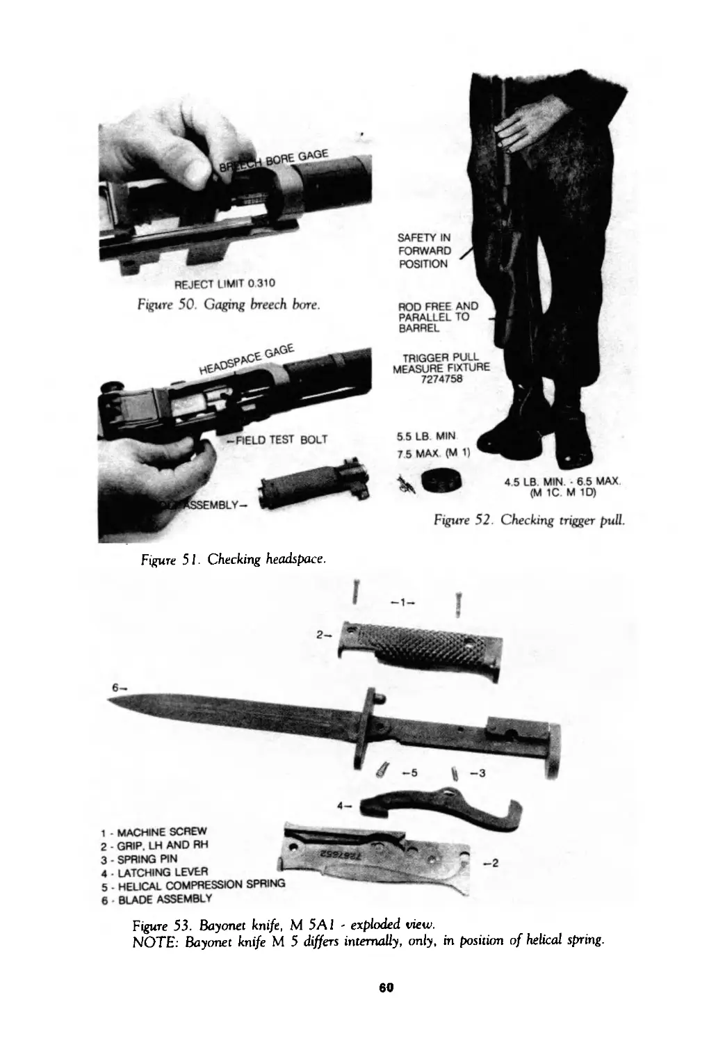
REJECT LIMIT 0 310
Figure 50. Gaging breech bare.
SAFETY IN
FORWARD
POSITION
ROD FREE ANO
PARALLEL TO
BARREL
TRIGGER PULL
MEASURE FIXTURE
7274758
5 5 LB MIN
7 5 MAX (M 1)
4.5 LB MIN 6.5 MAX
(M 1C. M 1D)
Figure 52. Checking trigger pull.
Figure 51. Checking headspace.
1 - MACHINE SCREW
2 GRIP. LH AND RH
3 • SPRING PIN
4 • LATCHING LEVER
5 • HELICAL COMPRESSION SPRING
6 BLADE ASSEMBLY
Figure 53. Bayonet knife, M 5Al - exploded view.
NOTE: Bayonet knife M 5 differs internally, only, in position of helical spring.
60
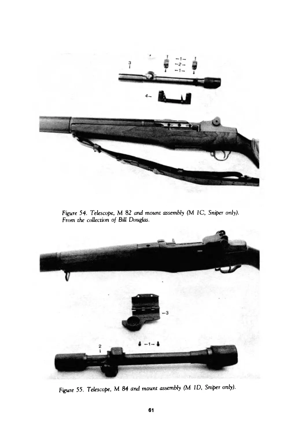
Figure 54. Telescope, M 82 and mount assembly (M 1C, Sniper only).
From the collection of Bill Douglas.
Figure 55. Telescope, M 84 and mount assembly (M ID, Sniper only).
61
DRILLING HOLES IN STOCK ASSEMBLY FOR INSTALLING
WOOD SCREWS
CHEEK BASE
AND PAD-
REMOVE/INSTALL CHEEK PAD.
CHEEK PAD ASSEMBLY - EXPLODED VIEW
(M 1C (Sniper s) and M 1D (Sniper's) only)
Figure 56. Installation/removal of cheek pad assembly, Rifles M 1C and M ID (Sniper’s)
CHEEK PAD WITH LACE INSTALLED ON RIFLE, M 1C
OR M 1D.
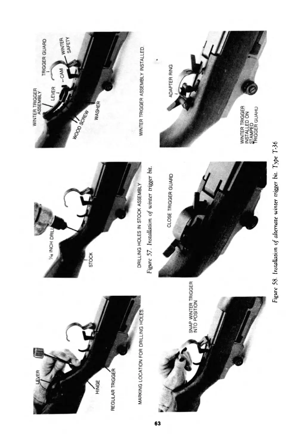
Figure 57 Installation of winter trigger bit.
WINTER TRIGGER ASSEMBLY INSTALLED
Figure 58. Installation of alternate winter trigger bit Type T-36
By Order of the Secretary of the Army:
W.C. WESTMORELAND,
General, United States Army,
Chief of Staff.
Official:
KENNETH G. WICKHAM,
Major General, United States Army,
The Adjutant General.
DISTRIBUTION:
To be distributed in accordance with DA Form 12-40, (qty rqr block no. 128) Organiza-
tional maintenance requirements for Rifles, Caliber .30: Ml, MIC (Sniper’s) and MID (Sniper’s).
64