/


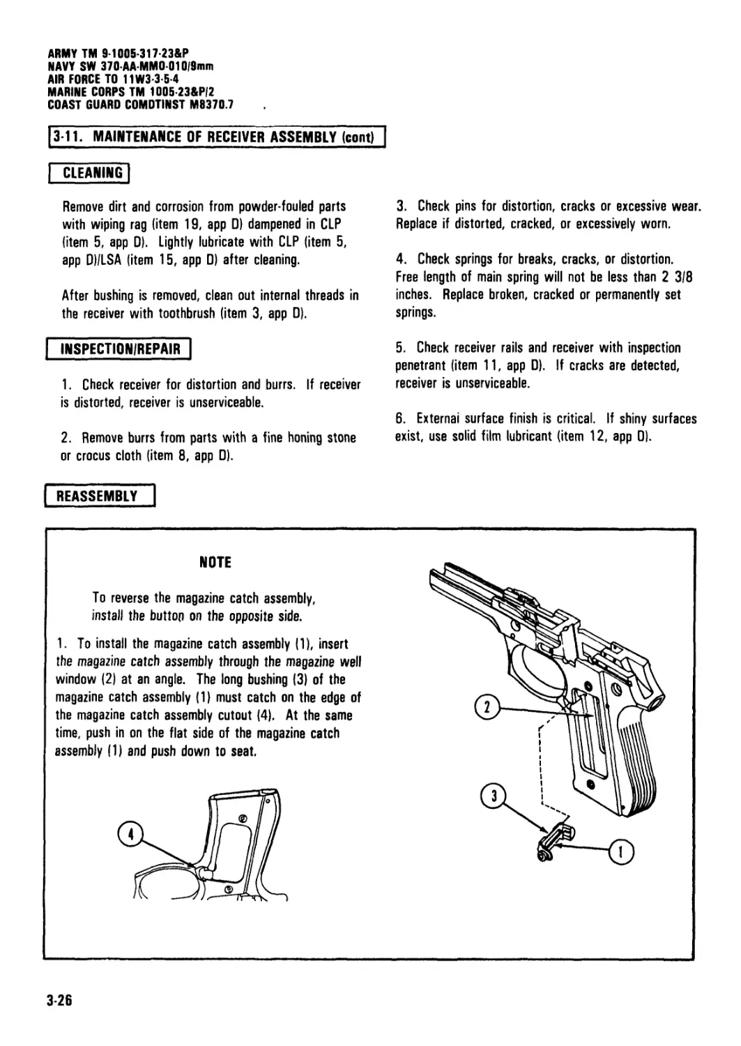
Tags: weapons military affairs
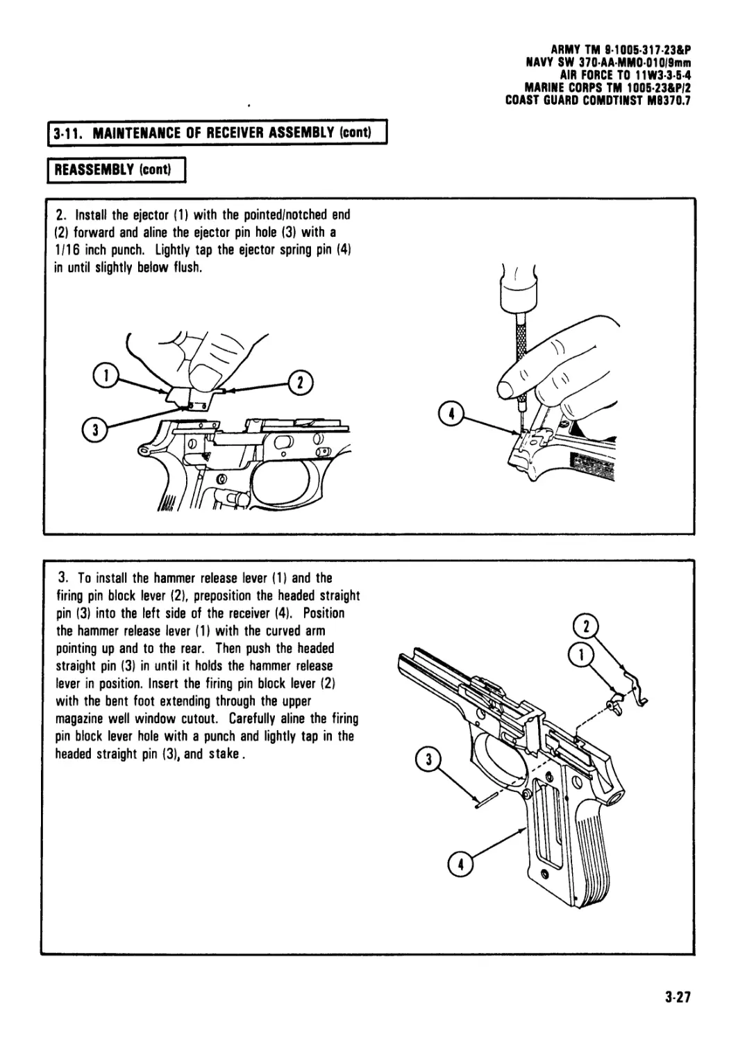
Year: 1986
Similar

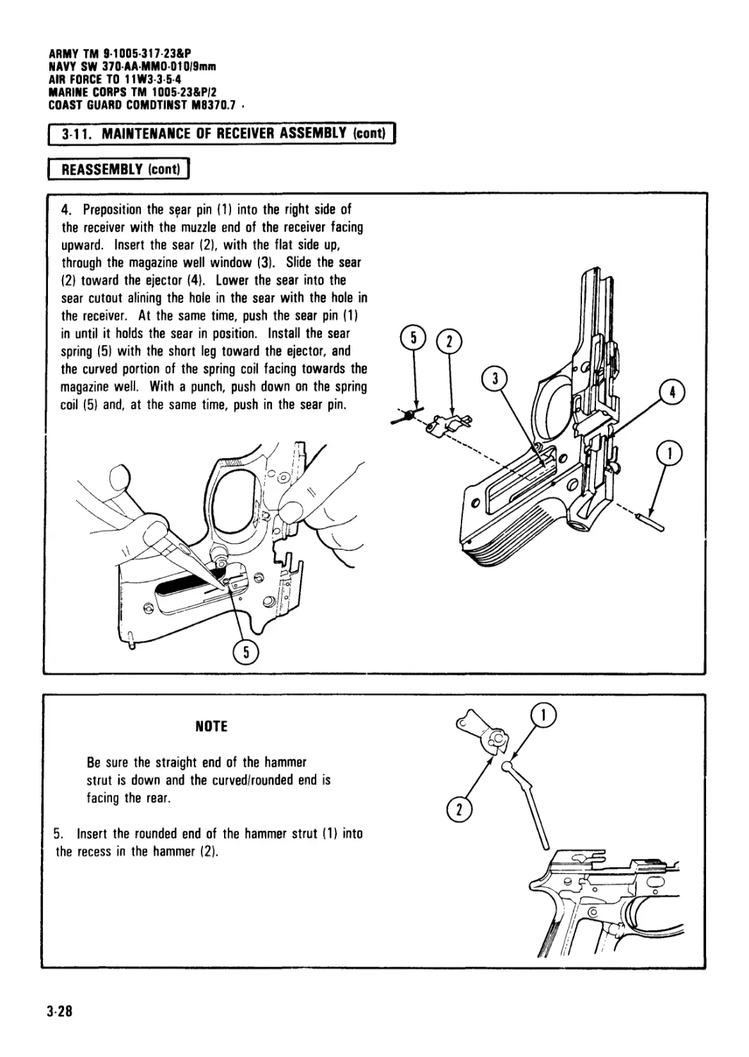
Text
ARMY TM 9-1005-317-23&P
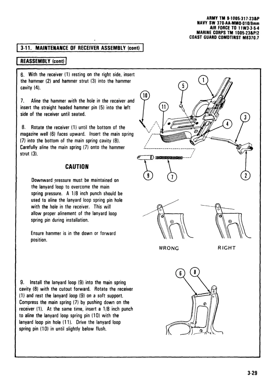
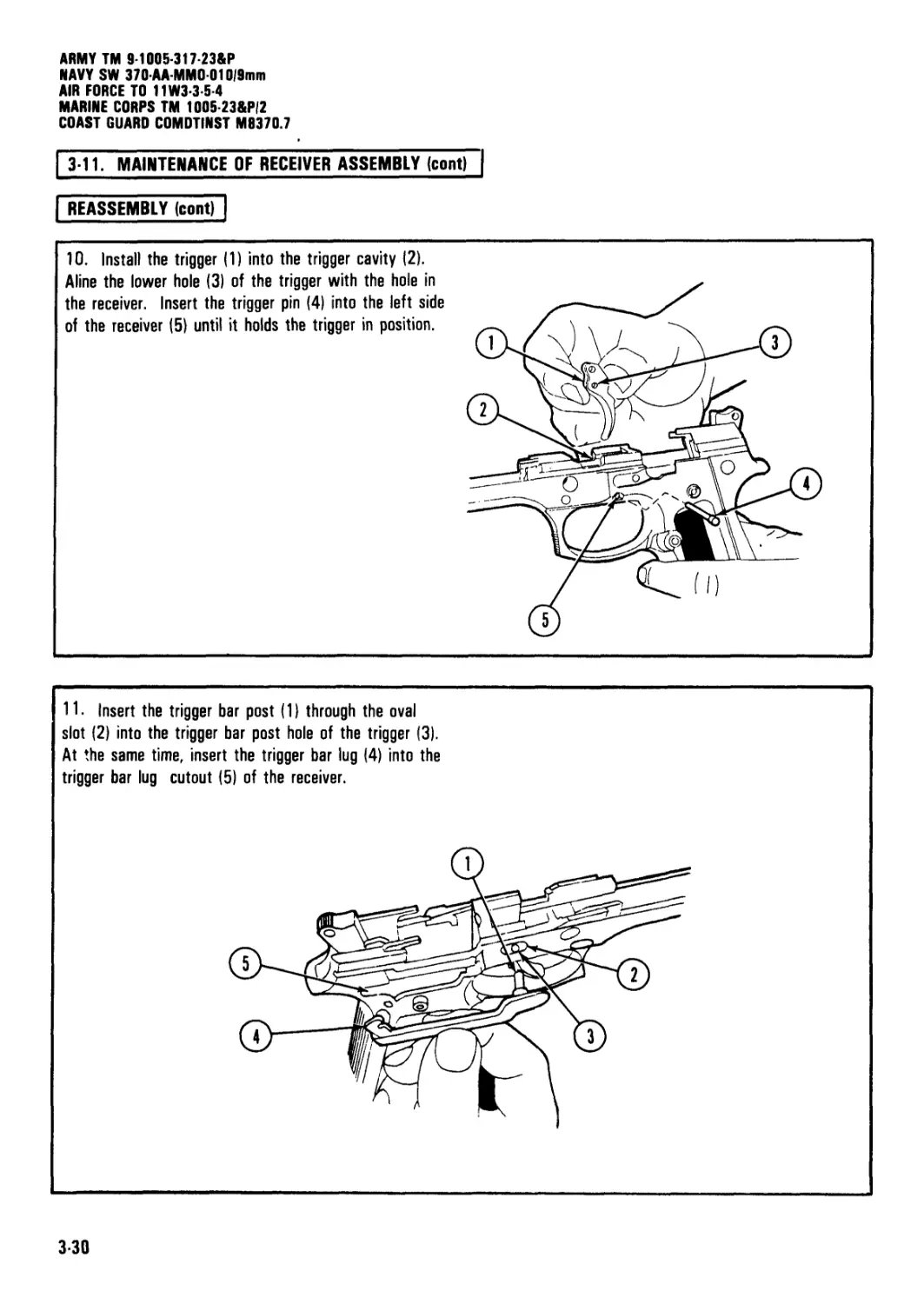
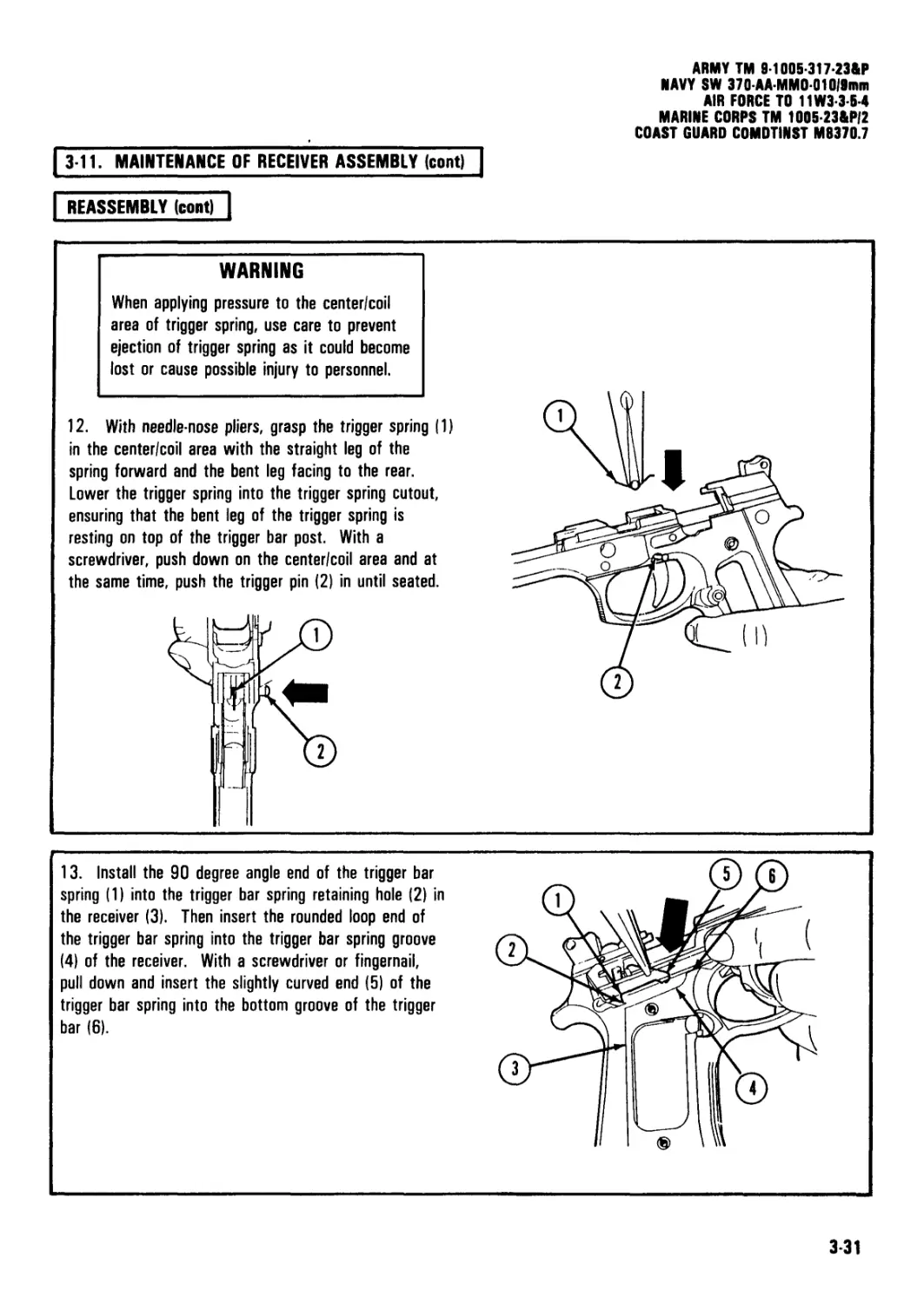
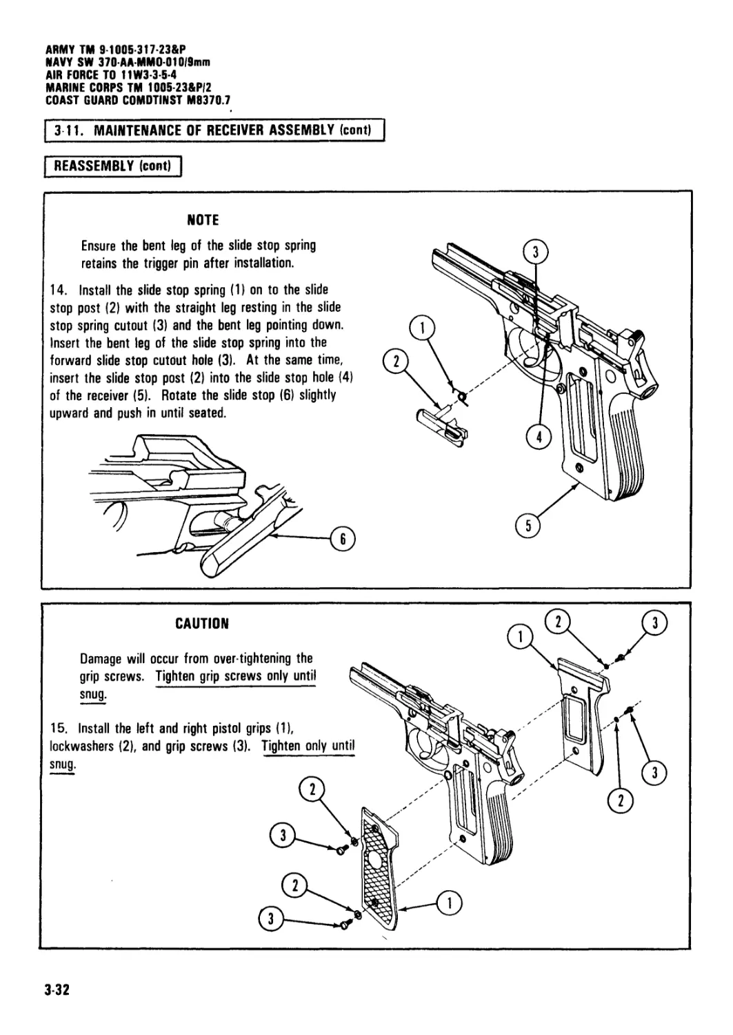
NAVY SW 370-AA-MM0010/9mm
AIR FORCE TO 11W3-3-5-4
MARINE CORPS TM 1005A-23&P/2
COAST GUARD COMDTINST M8370.7
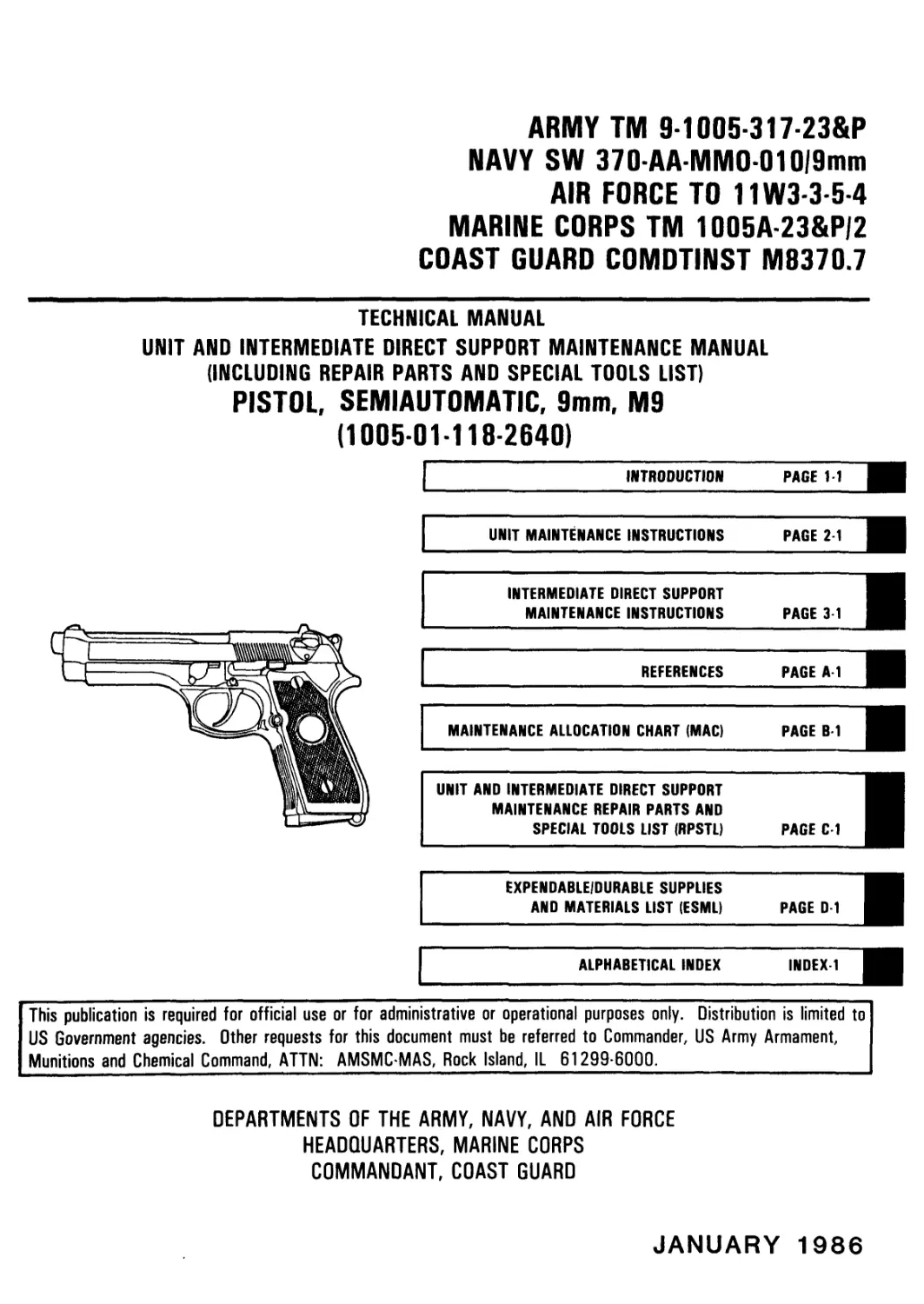
TECHNICAL MANUAL
UNIT AND INTERMEDIATE DIRECT SUPPORT MAINTENANCE MANUAL
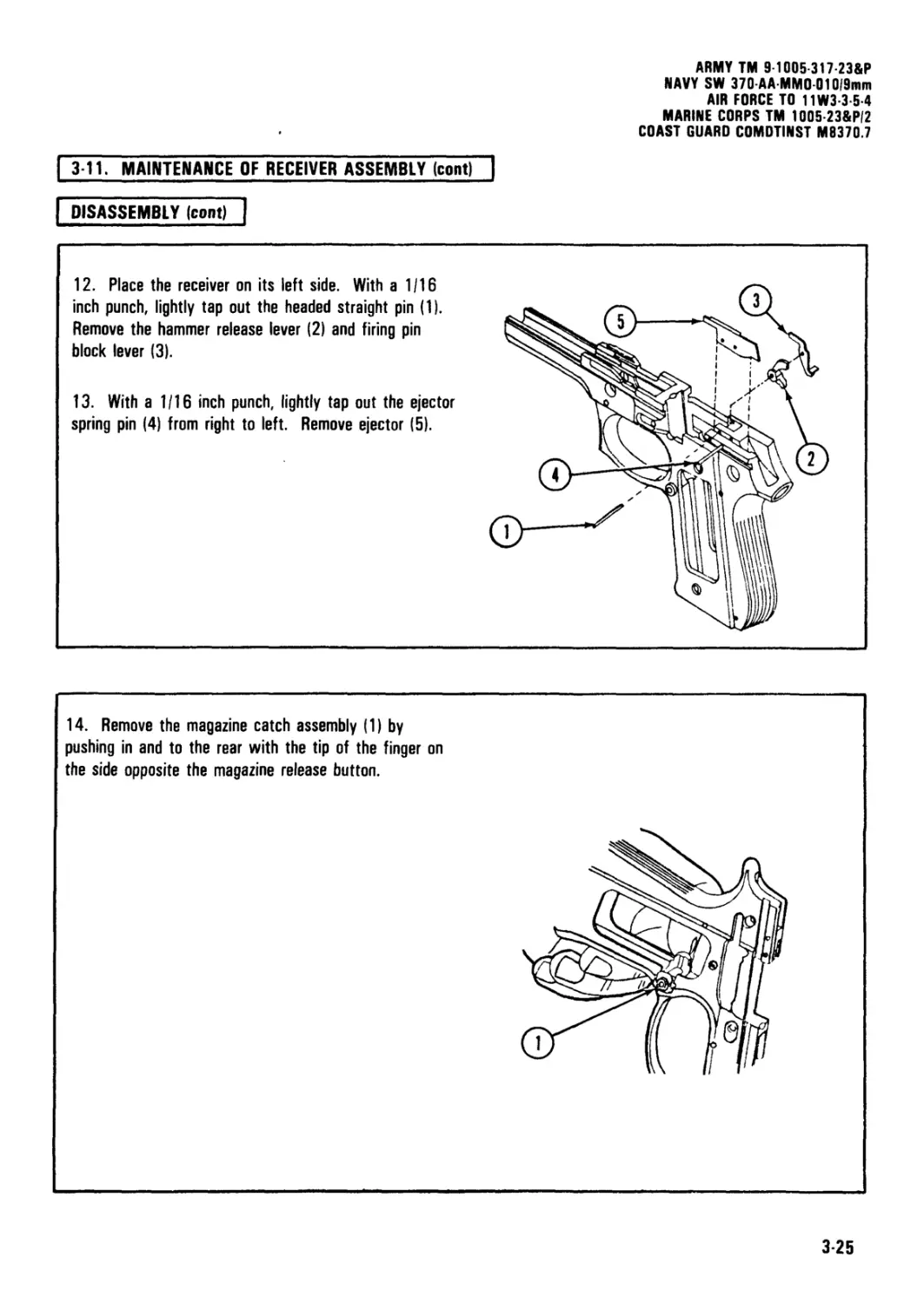
(INCLUDING REPAIR PARTS AND SPECIAL TOOLS LIST)
PISTOL, SEMIAUTOMATIC, 9mm, M9
(1005-01-118-2640)
INTRODUCTION
PAGE 1-1
UNIT MAINTENANCE INSTRUCTIONS PAGE 2 1
INTERMEDIATE DIRECT SUPPORT MAINTENANCE INSTRUCTIONS PAGE 3-1
REFERENCES PAGE A l
MAINTENANCE ALLOCATION CHART (MAC) PAGE
UNIT AND INTERMEDIATE DIRECT SUPPORT
MAINTENANCE REPAIR PARTS AND
SPECIAL TOOLS LIST (RPSTL) PAGE
EXPENDABLEIDURABLE SUPPLIES
AND MATERIALS LIST (ESML)
PAGE D I
ALPHABETICAL INDEX
INDEX 1
This publication is required for official use or for administrative or operational purposes only. Distribution is limited to
US Government agencies. Other requests for this document must be referred to Commander, US Army Armament,
Munitions and Chemical Command, ATTN: AMSMC-MAS, Rock Island, IL 61299-6000.
DEPARTMENTS OF THE ARMY, NAVY, AND AIR FORCE
HEADQUARTERS, MARINE CORPS
COMMANDANT, COAST GUARD
JANUARY 1986
ARMY TM 9 1005 317 23&P
NAVY SW 370-AA-MMO 010/9 mm
AIR FORCE TO 11W3-3-5-4
MARINE CORPS TM 1005 23&P/2 .
COAST GUARD COMDTINST M8370.7
WARNING
Read this manual carefully before performing required maintenance.
Before starting an inspection, and/or performing any maintenance procedures, be sure to clear the pistol. Do not
squeeze trigger until the pistol has been cleared. Inspect the chamber to be sure that it is empty. Check to see that
there are no obstructions in the barrel. Do not keep live ammunition near work/maintenance area.
Safety glasses, hearing protection, and protective clothing should be worn when repairing, firing, or cleaning the
pistol.
Protective gloves should be worn when working with cleaning solvents.
For further information on safety, care, and handling of ammunition: Army users refer to TM 9-1005-317-10; Navy
and Coast Guard users refer to OP 4 or OP 5.
Pistol will fire from the half cock position if the trigger is pulled.
Perform detail disassembly only to the level of maintenance required/authorized to identify and correct deficiencies.
A potential safety hazard exists if the firing pin block is missing or does not return flush with the slide surface after
firing.
During removal of the lanyard loop spring pin, be sure the punch is left in place to prevent injury to personnel or
accidental loss of parts.
Use care when removing recoil spring and spring guide. Because of the amount of compression, assembly will be
released under spring tension and could cause possible injury to personnel, or become damaged or lost.
Cover the top of the trigger cavity to prevent ejection or loss of the trigger spring, or possible injury to personnel
during removal of the trigger pin.
When applying pressure to the center/coil area of trigger spring, use care to prevent ejection of trigger spring as this
could cause possible injury to personnel.
For further information on first aid, refer to FM 21-11.
ARMY TM 9-1005-317 23&P
NAVY SW 370-AA-MM001019mm
AIR FORCE TO 11W3-3-5-4
MARINE CORPS TM 1005 23&P/2
COAST GUARD COMDTINST M0370.7
DEPARTMENTS OF THE ARMY, NAVY,
AND AIR FORCE
HEADQUARTERS, MARINE CORPS
COMMANDANT, COAST GUARD
TECHNICAL MANUAL
ARMY NO. 9-1005-317-23&P
NAVY SW 370-AA-MM0-010/9mm
TECHNICAL ORDER
AIR FORCE NO. 11W3-3-5-4
TECHNICAL MANUAL
MARINE CORPS NO. 1005A-23&P/2
COAST GUARD COMDTINST M8370.7
HEADQUARTERS, DEPARTMENT OF THE ARMY
WASHINGTON, DC, 37 January 1986
UNIT AND INTERMEDIATE DIRECT SUPPORT MAINTENANCE MANUAL
(Including Repair Parts and Special Tools List)
for
PISTOL, SEMIAUTOMATIC, 9mm, M9
(1005-01-118-2640)
Current as of 27 January 1986 for Appendix C
REPORTING ERRORS AND RECOMMENDING IMPROVEMENTS
You can help improve this manual. If you find any mistakes, or if you know of a way to improve the
procedures, please let us know.
Army users mail your letter, DA Form 2028 (Recommended Changes to Equipment Publications and Blank
Forms), or DA Form 2028-2 located in the back of this manual direct to: Commander, U.S. Army
Armament, Munitions and Chemical Command, ATTN: AMSMC-MAS, Rock Island, IL 61299-6000.
Navy users submit Recommended Changes to Publications to: Commanding Officer, Naval Weapons
Support Center, Code 20, Crane, IN 47522-5020.
Air Force users submit AFTO Form 22, Technical Order System Publications Improvement Report and
Reply, to: WR-ALC/MMEDT, Robins AFB, GA 31098-5000.
Marine Corps users submit NAVMC 10772 Form to: Commanding General, Marine Corps Logistics Base
(Code 850), Albany, GA 31704-5000.
Coast Guard users submit Publications Correction/Change Report form CG 4394 to: Commandant, U.S.
Coast Guard (G-ODO-2), Washington, DC 20593.
A reply will be furnished to you.
ARMY TM 9-1005-317-23&P
NAVY SW 370-AA-MM0 010,9mm
AIR FORCE TO 11W3-3-5-4
MARINE CORPS TM 1005-23&P/2
COAST GUARD COMDTINST MS370.7
TABLE OF CONTENTS
CHAPTER 1.
Section 1.
Section II.
Section III.
CHAPTER 2.
Section 1.
Section II.
Section III.
Section IV.
Section V.
Section VI.
CHAPTER 3.
Section 1.
Section II.
Section III.
Section IV.
Section V.
Section VI.
HOW TO USE THIS MANUAL................................................
I INTRODUCTION .......................................................
General Information...................................................
Equipment Description and Data........................................
Principles of Operation...............................................
UNIT MAINTENANCE INSTRUCTIONS I.......................................
Repair Parts, Special Tools, and Support Equipment....................
Service Upon Receipt..................................................
Unit Preventive Maintenance Checks and Services (PMCS)................
Troubleshooting.......................................................
Unit Maintenance Procedures...........................................
Preparation for Storage or Shipment...................................
[INTERMEDIATE DIRECT SUPPORT MAINTENANCE INSTRUCTIONS
Repair Parts, Special Tools, and Support Equipment....................
Service Upon Receipt..................................................
Troubleshooting.......................................................
Intermediate Direct Support Maintenance Procedures ...................
Preparation for Storage or Shipment...................................
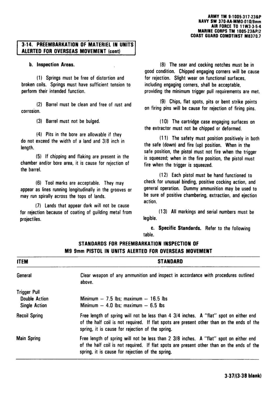
Preembarkation Inspection of Materiel in Units Alerted for Overseas Movement.
Page
iii
1-1
1-2
1-4
Ulus/
Figure
2-1
2-1
2-1
2-4
2-7
2-15
2-21
ГТП
3-1
3-1
3-1
3-8
3-36
3-36
APPENDIX A. [REFERENCES................................................
A-1
APPENDIX B.
Section I.
Section II.
Section III.
APPENDIX C.
Section I.
Section II.
Group 00
Group 01
MAINTENANCE ALLOCATION CHART (MAC).................................
Introduction.......................................................
Maintenance Allocation Chart.......................................
Tool and Test Equipment Requirements for M9 Pistol, 9mm............
B-1
B-1
B-4
B-5
Group 02
Section III.
Section IV.
UNIT AND INTERMEDIATE DIRECT SUPPORT MAINTENANCE REPAIR |
PARTS AND SPECIAL TOOLS LIST I......................................'
Introduction............................................................
Repair Parts List.......................................................
Pistol 9mm, M9..........................................................
Slide and Barrel Assembly...............................................
0101 Barrel Assembly....................................................
0102 Slide Assembly.....................................................
010201 Slide Assembly w/Rear Sight....................................
Receiver Assembly.......................................................
Special Tools List (not applicable)
National Stock Number and Part Number Index.............................
СЕЛ
C-1
C-1-1
C-1-1
C-2-1
C-3-1
C-4-1
C-5-1
C-6-1
1-1
C-1
C-2
C-3
C-4
C-5
C-6
APPENDIX D. lEXPENDABLE/DURABLE SUPPLIES AND MATERIALS LIST |............. |TT
Section I. Introduction....................................................................... D-1
Section II. Expendable/Durable Supplies and Materials List .................................... D-2
[ALPHABETICAL INDEX I................................. [indeiTl
ii
ARMY TM 9-1005-317-23&P
NAVY SW 370-AAMM001019mm
AIR FORCE TO 11W3-3-5-4
MARINE CORPS TM 1005-23&P/2
COAST GUARD COMDTINST M9370.7
HOW TO USE THIS MANUAL
GENERAL
In order to use this manual efficiently, there are several things you need to know.
1. You must familiarize yourself with the entire maintenance procedure before beginning the maintenance task.
2. All references in this manual are either to paragraphs, pages, or to another manual.
3. Whenever the male gender is mentioned in this manual, it also pertains to all joint service personnel.
INDEXES
This manual is organized to help you quickly find the information you need. There are several useful indexes.
1. Front Cover Index. Is a tabbed index of items used often. Keyed to tabbed pages in the manual.
2. Table of Contents. Lists in order all chapters, sections, and appendixes. Gives page references.
3. Nomenclature Cross-Reference List. Gives an alphabetical list of the common names that are substituted
for the official nomenclature in the manual.
4. Chapter Overviews. Summarizes material covered in the chapter.
5. Troubleshooting Symptom Index. Lists in alphabetical order parts of the weapon with possible
malfunctions. References pages of the troubleshooting table.
6. Alphabetical Index. Located at the end of the manual. An extensive subject index for everything in the
manual. It gives page references.
MAINTENANCE PROCEDURES
There are two maintenance chapters:
Army personnel use chapter two for unit maintenance procedures and chapter three for intermediate direct
support maintenance procedures.
Navy personnel use chapter two for organizational maintenance procedures and chapter three for intermediate
maintenance procedures.
Air Force personnel: Only Air Force Specialty Code 753XX Combat Arms Training and Maintenance
Specialists, Technicians, and Gunsmiths are authorized to perform maintenance procedures contained in this manual.
Marine Corps personnel use chapter two for organizational (2d echelon) maintenance procedures and chapter
three for intermediate (3d echelon) maintenance procedures.
Coast Guard personnel refer to COMDTINST 8000.2.
iii
ARMY TM 9-1005-317-23&P
NAVY SW 370-AA-MMO-01019mm
AIR FORCE TO 11W3-3-54
MARINE CORPS TM 1005-23&P/2
COAST GUARD COMDTINST M8370.7
MAINTENANCE PROCEDURES (cont)
Each maintenance chapter has an initial setup containing a list of the following things you will need in order to do
your maintenance task:
1. Tools and Special Tools. For standard and special tools, see appendixes В and C.
2. Materials/Parts. Lists expendable materials and 100 percent replaceable parts. Each material or part is
followed by a part number or appendix reference. If more than one part is needed, the quantity needed precedes the
part number or reference.
3. References. Lists other publications containing necessary information.
4. Equipment Condition. Lists conditions to be met before starting the procedure.
Step-by-step procedures are illustrated procedures for maintenance authorized by the MAC, appendix B.
iv
ARMY TM 91005 317 23&F
NAVY SW 370-AA-MMO-010,9mm
AIR FORCE TO 11W3-3-S4
MARINE CORPS TM 1005-23&FI2
COAST GUARD COMDTINST M8370.7
CHAPTER 1
INTRODUCTION
Chapter Overview
This chapter contains the following: General Information, Equipment Description and Data, and Principles of Operation
for the pistol.
Section I. GENERAL INFORMATION
| 1-1. SCOPE. ~|
a. Type of Manual. Unit and Intermediate Direct
Support Maintenance Manual including Repair Parts and
Special Tools List.
b. Model Number and Equipment Name. M9,
9mm, Semiautomatic Pistol.
c. Purpose of Equipment: Provides personal
defense protection.
12. MAINTENANCE FORMS AND RECORDS.
Department of the Army forms and procedures used for
equipment maintenance will be those prescribed by DA
PAM 738-750, The Army Maintenance Management
System (TAMMS).
Navy and Coast Guard users refer to applicable
Preventive Maintenance System Instructions.
Air Force users refer to TO 11W-1-10 and AFTO Form
105 for documenting weapon maintenance.
Marine Corps personnel refer to TM 4700-15/1 for
equipment forms and record procedures.
13. DESTRUCTION OF MATERIEL TO PREVENT
ENEMY USE.
Only your commanding officer can give the order to
destroy materiel to prevent enemy use. Refer to TM
750-244-7.
1-4. NUCLEAR, BIOLOGICAL AND CHEMICAL (NBC).
General procedures can be found in FM 3-87, FM
21-40, and TM 3-220.
1-5. PREPARATION FOR STORAGE AND
SHIPMENT._____________________________
Requirements for storage and shipment are listed in
paragraph 2-15. Requirements for administrative
storage will be in accordance with OOD 5100.76-M,
Physical Security of Sensitive Conventional Arms,
Ammunition, and Explosives.
1-6. REPORTING EQUIPMENT IMPROVEMENT
RECOMMENDATIONS (EIRs).
If your 9mm pistol needs improvement, let us know.
Send us an EIR. You, the user, are the only one who
can tell us what you don't like about your equipment.
Let us know why you don't like the design or perform-
ance.
Army users submit an SF 368 (Quality Deficiency
Report) and mail it to: Commander, U.S. Army
Armament, Munitions and Chemical Command, ATTN:
AMSMC-QAD, Rock Island, IL 61299-6000.
Navy users submit Quality Deficiency Report to:
Commanding Officer, Naval Weapons Support Center,
Code 20, Crane, IN 47522-5020.
Air Force users submit Material Deficiency Report
(MDR) to: DIR MAT MGT ROBINS AFB GA//MMIRFT//
and Quality Deficiency Report to: DIR MAT MGT
ROBINS AFB GA//QAY//.
Marine Corps users submit QDRs on SF 368 in
accordance with MC0 4855.10 to: Commanding
General, Marine Corps Logistics Base (Code 840),
Albany, GA 31704-5000.
Coast Guard users submit QDRs (SF 368) in accordance
with COMDTINST M4855.1 to: Commandant, U.S.
Coast Guard, (G-0D0-2), Washington, DC 20593.
We'll send you a reply.
1-1
ARMY TM 9-1005-317-23&P
NAVY SW 370 АА-ММ0-01019mm
AIR FORCE TO 11W3 3-5-4
MARINE CORPS TM 1005-23&PI2
COAST 6UAR0 COMDTINST M0370.7
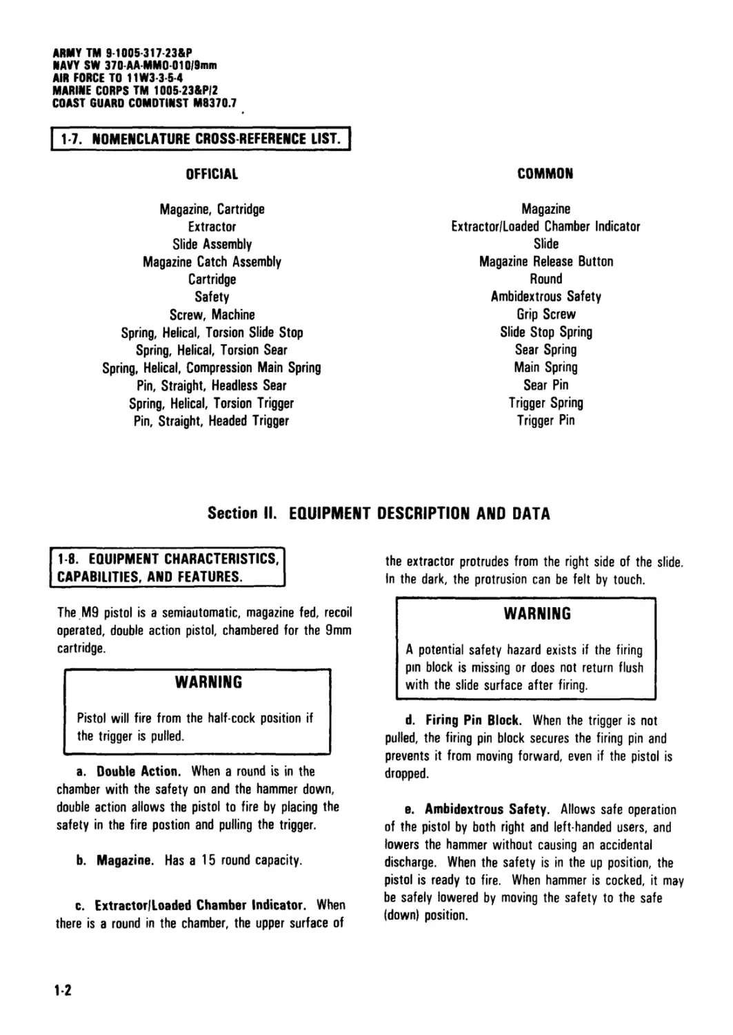
17. NOMENCLATURE CROSS REFERENCE LIST~|
OFFICIAL
Magazine, Cartridge
Extractor
Slide Assembly
Magazine Catch Assembly
Cartridge
Safety
Screw, Machine
Spring, Helical, Torsion Slide Stop
Spring, Helical, Torsion Sear
Spring, Helical, Compression Main Spring
Pin, Straight, Headless Sear
Spring, Helical, Torsion Trigger
Pin, Straight, Headed Trigger
COMMON
Magazine
Extractor/Loaded Chamber Indicator
Slide
Magazine Release Button
Round
Ambidextrous Safety
Grip Screw
Slide Stop Spring
Sear Spring
Main Spring
Sear Pin
Trigger Spring
Trigger Pin
Section II. EQUIPMENT DESCRIPTION AND DATA
18. EQUIPMENT CHARACTERISTICS,
CAPABILITIES, AND FEATURES.
The M9 pistol is a semiautomatic, magazine fed, recoil
operated, double action pistol, chambered for the 9mm
cartridge.
WARNING
Pistol will fire from the half-cock position if
the trigger is pulled.
a. Double Action. When a round is in the
chamber with the safety on and the hammer down,
double action allows the pistol to fire by placing the
safety in the fire postion and pulling the trigger.
b. Magazine. Has a 15 round capacity.
c. ExtractorILoaded Chamber Indicator. When
there is a round in the chamber, the upper surface of
the extractor protrudes from the right side of the slide.
In the dark, the protrusion can be felt by touch.
WARNING
A potential safety hazard exists if the firing
pm block is missing or does not return flush
with the slide surface after firing.
d. Firing Pin Block. When the trigger is not
pulled, the firing pin block secures the firing pin and
prevents it from moving forward, even if the pistol is
dropped.
e. Ambidextrous Safety. Allows safe operation
of the pistol by both right and left handed users, and
lowers the hammer without causing an accidental
discharge. When the safety is in the up position, the
pistol is ready to fire. When hammer is cocked, it may
be safely lowered by moving the safety to the safe
Idown) position.
12
ARMY TM 9-1005-317-23&P
NAVY SW 370-AA MMO-01019mm
AIR FORCE TO 11W3-3-5-4
MARINE CORPS TM 1005-23&PI2
COAST GUARD COMDTINST M0370.7
f. Lanyard Loop. Compatible with standard
lanyards.
g. Receiver. The front and back straps of the
grip are vertically grooved to ensure a firm grip even
with wet hands, or under conditions of rapid combat
fire. The trigger guard is extended, and the concave
forward portion is grooved for a firm grip when using
two hands or gloves.
the weapons serial number control card. Submit all
suspected warranty claims on SF 368 (DDR) to your
appropriate command.
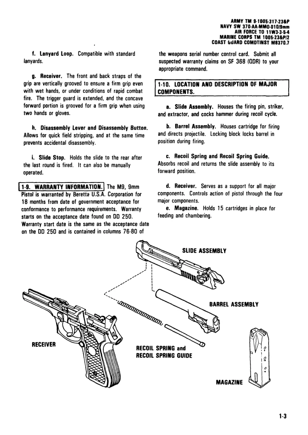
1-10. LOCATION AND DESCRIPTION OF MAJOR
COMPONENTS.
a. Slide Assembly. Houses the firing pin, striker,
and extractor, and cocks hammer during recoil cycle.
h. Disassembly Lever and Disassembly Button.
Allows for quick field stripping, and at the same time
prevents accidental disassembly.
i. Slide Stop. Holds the slide to the rear after
the last round is fired. It can also be manually
operated.
11-9. WARRANTY INFORMATION?] The M9, 9mm
Pistol is warranted by Beretta U.S.A. Corporation for
18 months from date of government acceptance for
conformance to performance requirements. Warranty
starts on the acceptance date found on DD 250.
Warranty start date is the same as the acceptance date
on the DD 250 and is contained in columns 76-80 of
b. Barrel Assembly. Houses cartridge for firing
and directs projectile. Locking block locks barrel in
position during firing.
c. Recoil Spring and Recoil Spring Guide.
Absorbs recoil and returns the slide assembly to its
forward position.
d. Receiver. Serves as a support for all major
components. Controls action of pistol through the four
major components.
e. Magazine. Holds 15 cartridges in place for
feeding and chambering.
1-3
ARMY TM 9-1005-317 23&P
AVY SW 370-AA-MMO01019mm
AM FORCE TO 11W3-3-5-4
MARINE CORPS TM 1005-23&P/2
COAST GUARD COMDTINST M0370.7
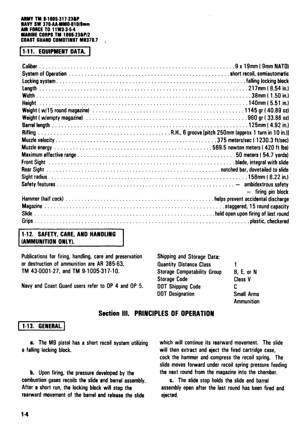
|1 11. EQUIPMENT DATA. |
Caliber.......................................................................................9x19mm (9mm NATO)
System of Operation..........................................................................short recoil, semiautomatic
Locking system.....................................................................................falling locking block
Length..................................................................................................217mm (8.54 in.)
Width....................................................................................................38mm (1.50 in.)
Height..................................................................................................140mm (5.51 in.)
Weight (w/15 round magazine).......................................................................1145 gr (40.89 oz)
Weight (w/empty magazine)..........................................................................960 gr ( 33.86 oz)
Barrel length......................................................................................125mm (4.92 in.)
Rifling...........................................................R.H., 6 groove [pitch 250mm (approx 1 turn in 10 in.)]
Muzzle velocity.........................................................................375 meters/sec (1230.3 ft/sec)
Muzzle energy.........................................................................569.5 newton meters (420 ft lbs)
Maximum effective range.......................................................................50 meters ( 54.7 yards)
Front Sight...................................................................................blade, integral with slide
Rear Sight.................................................................................notched bar, dovetailed to slide
Sight radius.......................................................................................158mm (6.22 in.)
Safety features...............................................................................- ambidextrous safety
- firing pin block
Hammer (half cock)....................................................................helps prevent accidental discharge
Magazine...................................................................................staggered, 15 round capacity
Slide..................................................................................held open upon firing of last round
Grips................................................................................................plastic, checkered
112. SAFETY, CARE, AND HANDLING
(AMMUNITION ONLY).
Publications for firing, handling, care and preservation Shipping and Storage Data:
or destruction of ammunition are AR 385-63, Quantity Distance Class 1
TM 43-0001-27, and TM 9-1005-317-10. Storage Compatability Group Storage Code В, E, or N Class V
Navy and Coast Guard users refer to OP 4 and OP 5. DOT Shipping Code DOT Designation C Small Arms
Ammunition
Section III. PRINCIPLES OF OPERATION
1-13. GENERAL.
a. The M9 pistol has a short recoil system utilizing
a falling locking block.
b. Upon firing, the pressure developed by the
combustion gases recoils the slide and barrel assembly.
After a short run, the locking block will stop the
rearward movement of the barrel and release the slide
which will continue its rearward movement. The slide
will then extract and eject the fired cartridge case,
cock the hammer and compress the recoil spring. The
slide moves forward under recoil spring pressure feeding
the next round from the magazine into the chamber.
c. The slide stop holds the slide and barrel
assembly open after the last round has been fired and
ejected.
1-4
ARMY TM 9-1005-317-23W
NAVY SW 370-AA-MM0 010|9mm
AIR FORCE TO 11W33-54
MARINE CORPS TM 1005-23&P/2
COAST GUARD COMDTINST M8370.7
CHAPTER 2
UNIT MAINTENANCE INSTRUCTIONS
Chapter Overview
This chapter contains information regarding repair parts, special tools, support equipment and instructions for service
upon receipt, Preventive Maintenance Checks and Services (PMCS), troubleshooting, and maintenance to keep the
pistol in good repair.
Section I. REPAIR PARTS, SPECIAL TOOLS, AND SUPPORT EQUIPMENT
21. COMMON TOOLS AND EQUIPMENT.! For
authorized common tools and equipment refer to the
Modified Table of Organization and Equipment (MTOE)
applicable to your unit.
2-3. REPAIR PARTS. Repair parts are listed and
illustrated in appendix C of this manual.
2 2. SPECIAL TOOLS AND SUPPORT EQUIPMENT.
There are no special tools for this item. Tools and
test equipment are listed in appendix В of this manual.
There is no Test, Measurement, and Diagnostic
Equipment (TMDE) for this item.
Section II. SERVICE UPON RECEIPT
| 2-4. GENERAL. | When a pistol is received, it is the
responsibility of the user organization to determine
whether the pistol has been properly prepared for
service by the supplying organization and whether it is
in condition to perform its mission.
I 2 5. SERVICE UPON RECEIPT OF MATERIEL?]
WARNING
Before starting an inspection, and/or
performing any maintenance procedures, be
sure to clear the pistol. Do not squeeze the
trigger until the pistol has been cleared.
Inspect the chamber to be sure that it is
empty. Check to see that there are no
obstructions in the barrel. Do not keep live
ammunition near work/maintenance area.
Unit maintenance personnel may perform limited
maintenance. Inspect and test the pistol in accordance
with the maintenance allocation chart in appendix B.
After the required test/inspections are performed, the
maintenance repairs within their capabilities may be
completed. Unit maintenance may inspect and service
the slide assembly, barrel assembly and receiver
assembly. They may reverse the magazine catch
assembly and replace pistol grips, grip screws and lock
washers. (Coast Guard users are not authorized to
reverse the magazine catch assembly.)
2-1
ARMY TM 9-1005-317-23&P
AVY SW 370 AA MM0 01019mm
AIR FORCE TO 11W3-3-5-4
MARINE CORPS TM 1005 23&PI2
COAST GUARD COMDTINST M8370.7
Table 2-1. Service Upon Receipt
LOCATION ITEM ACTION
REMARKS
1. Container Pistol
Check the container for damage prior to See Operator's manual :
unpacking. Check unpacked equipment. Army TM 9-1005-317-10
Navy SW 370-AA-OPI-010/9mm
a. Inspect the equipment for damage incurred Air Force TO 11W3-3-5-1
during shipment. If the equipment has been Marine Corps TM 1005A-10/1
damaged, report the damage on SF Form 364, Coast Guard COMDTINST
Report of Discrepancy (ROD). M8370.6
b. Check to see whether the equipment has been
modified, if applicable.
c. Check the equipment against the packing slip
to see if the shipment is complete. Report all
discrepancies in accordance with the instructions
of DA PAM 738-750.
Army users submit an SF 368 (Quality Deficiency
Report) to: Commander, U.S. Army Armament,
Munitions and Chemical Command, ATTN:
AMSMC-QAO, Rock Island, IL 61299-6000.
Navy users submit Quality Deficiency Report to:
Commanding Officer, Naval Weapons Support
Center, Code 20, Crane, IN 47522-5020.
Air Force users submit Material Deficiency Report
(MDR) to: DIR MAT MGT ROBINS AFB
GA//MMIRF// and Quality Deficiency Report to:
DIR MAT MGT ROBINS AFB GA//QAY//.
Marine Corps users submit QDRs on SF 368 in
accordance with MC0 4855.10 to: Commanding
General, Marine Corps Logistics Base (Code 840),
Albany, GA 31704-5000.
Coast Guard users submit QDRs (SF 368) in
accordance with COMDTINST M4855.1 to:
Commandant, U.S. Coast Guard (G-ODO-2),
Washington, DC 20593.
22
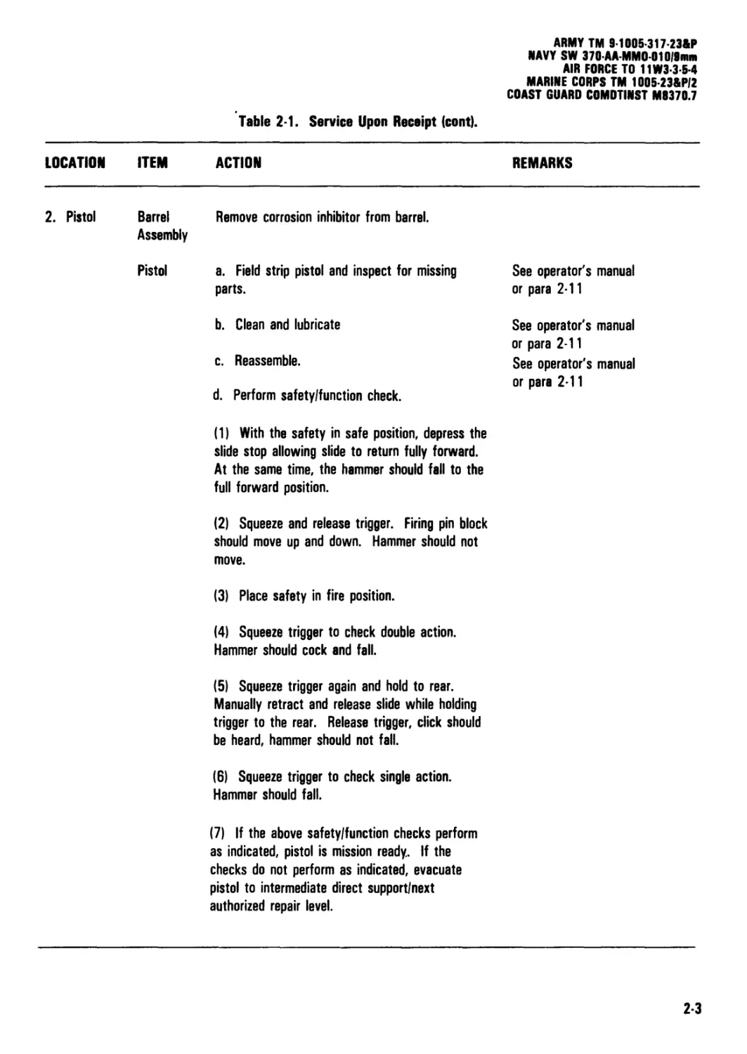
Table 2-1. Service Upon Receipt (cont). ARMY TM 9-1005-317-23&P NAVY SW 370 АА ММ0 010/9МП1 AIR FORCE TO 11W3-3-5-4 MARINE CORPS TM 1005-23&P/2 COAST GUARD COMOTINST M8370.7
LOCATION ITEM ACTION REMARKS
2. Pistol Barrel Remove corrosion inhibitor from barrel. Assembly Pistol a. Field strip pistol and inspect for missing parts. b. Clean and lubricate c. Reassemble. d. Perform safety/function check. (1) With the safety in safe position, depress the slide stop allowing slide to return fully forward. At the same time, the hammer should fall to the full forward position. (2) Squeeze and release trigger. Firing pin block should move up and down. Hammer should not move. (3) Place safety in fire position. (4) Squeeze trigger to check double action. Hammer should cock and fall. See operator's manual or para 2-11 See operator's manual or para 2-11 See operator's manual or para 2-11
(5) Squeeze trigger again and hold to rear.
Manually retract and release slide while holding
trigger to the rear. Release trigger, click should
be heard, hammer should not fall.
(6) Squeeze trigger to check single action.
Hammer should fall.
(7) If the above safety/function checks perform
as indicated, pistol is mission ready. If the
checks do not perform as indicated, evacuate
pistol to intermediate direct support/next
authorized repair level.
2-3
ARMY TM 9-1005-317-23&P
NAVY SW 370-AA-MM0 01019mm
AIR FORCE TO 11W3-3-5-4
MARINE CORPS TM 1005-23&P/2
COAST GUARD COMDTINST M0370.7
Section III. UNIT PREVENTIVE MAINTENANCE CHECKS AND SERVICES (PMCS)
QUARTERLY SCHEDULE
2-6. GENERAL.] If the pistol has not been used for
90 days, perform PMCS in the operator's manual
(ARMY TM 9-1005-317-10, NAVY SW 370-AA-OPI-
010/9mm, AIR FORCE TO 11W3-3-5-1, MARINE
CORPS TM 1005A-10/1, COAST GUARD COMDTINST
M8370.6). If you see rust on a pistol, the PMCS will
be done immediately.
2-7. UNIT PREVENTIVE MAINTENANCE CHECKS
AND SERVICES.
a. General. The PMCS procedures are contained
in table 2-2. They are arranged in logical sequence
requiring a minimum amount of time and effort on the
part of the person(s) performing them. They are
arranged so there will be minimum interference between
person(s) performing checks simultaneously on the same
end item.
b. Item Number Column. Checks and services
are numbered in chronological order regardless of
interval. This column shall be used as a source of item
numbers for the "TM Number" column on DA Form
2404, Equipment Inspection and Maintenance
Worksheet, in recording results on PMCS.
c. Item To Be Inspected Column. The items
listed in this column are divided into groups indicating
the portion of the equipment of which they are a part;
e.g., receiver assembly.
d. Procedures Column. This column contains a
brief description of the procedure by which the check is
to be performed. It contains all the information
required to accomplish the checks and services.
Table 2-2. Unit Preventive Maintenance Checks and Services (PMCS)
Quarterly Schedule.
ITEM
NO. ITEM TO BE INSPECTED
PROCEDURES
WARNING
Before starting an inspection, and/or performing any
maintenance procedures, be sure to clear the weapon. Do not
squeeze the trigger until the pistol has been cleared. Inspect
the chamber to be sure it is empty, and check to see that there
are no obstructions in the barrel. Do not keep live amunition
near work/maintenance area.
GENERAL: Inspect all assemblies for missing, broken, or loose parts.
Inspect parts for cracks, dents, burrs, excessive wear, rust or corrosion.
Make sure all items are cleaned and lubricated (ARMY TM 9-1005-317-10,
NAVY SW 370-AA-0PI-010/9mm, AIR FORCE TO 11W3-3-5-1, MARINE
CORPS TM 1005A-10/1, COAST GUARD COMDTINST M8370.6). Inspect
external surfaces for adequate finish. Repair or replace authorized defective
parts or evacuate to intermediate direct support maintenance/next authorized
repair level.
2-4
ARMY TM 9-1006-317-23&P
NAVY SW 370-AA-MM0-01019mm
AIR FORCE TO 11W3-3-6-4
MARINE CORPS TM 1005-2Э&Р/2
COAST GUARD COMDTINST M0370.7
Table 2-2. Unit Preventive Maintenance Checks and Services (PMCS) (cont).
ITEM
NO. ITEM TO BE INSPECTED
PROCEDURES
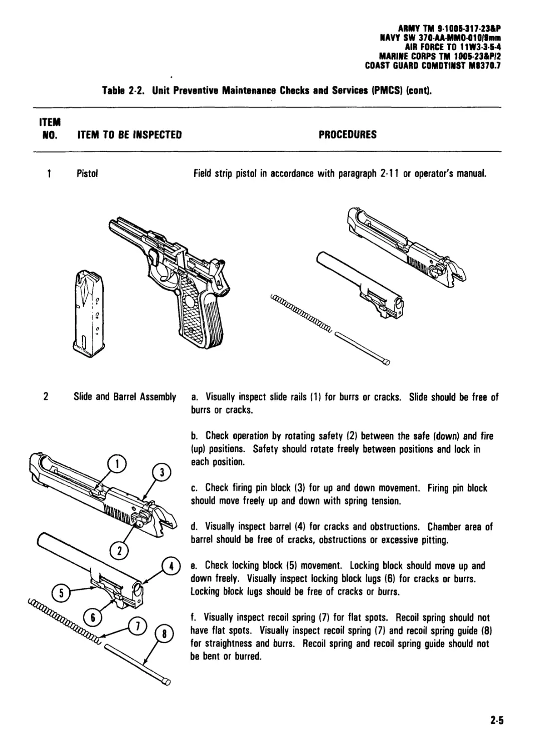
1 Pistol
Field strip pistol in accordance with paragraph 2-11 or operator's manual.
2 Slide and Barrel Assembly
a. Visually inspect slide rails (1) for burrs or cracks. Slide should be free of
burrs or cracks.
b. Check operation by rotating safety (2) between the safe (down) and fire
(up) positions. Safety should rotate freely between positions and lock in
each position.
c. Check firing pin block (3) for up and down movement. Firing pin block
should move freely up and down with spring tension.
d. Visually inspect barrel (4) for cracks and obstructions. Chamber area of
barrel should be free of cracks, obstructions or excessive pitting.
e. Check locking block (5) movement. Locking block should move up and
down freely. Visually inspect locking block lugs (6) for cracks or burrs.
Locking block lugs should be free of cracks or burrs.
f. Visually inspect recoil spring (7) for flat spots. Recoil spring should not
have flat spots. Visually inspect recoil spring (7) and recoil spring guide (8)
for straightness and burrs. Recoil spring and recoil spring guide should not
be bent or burred.
2-5
ARMY TM 9-1005-317 23&P
NAVY SW 370AA-MM0-01019mm
AIR FORCE TO 11W3-3-5-4
MARINE CORPS TM 1005-23&P/2
COAST GUARD COMOTINST M8370.7
Table 2-2. Unit Preventive Maintenance Checks and Services (PMCS) (cont).
ITEM
NO. ITEM TO BE INSPECTED
PROCEDURES
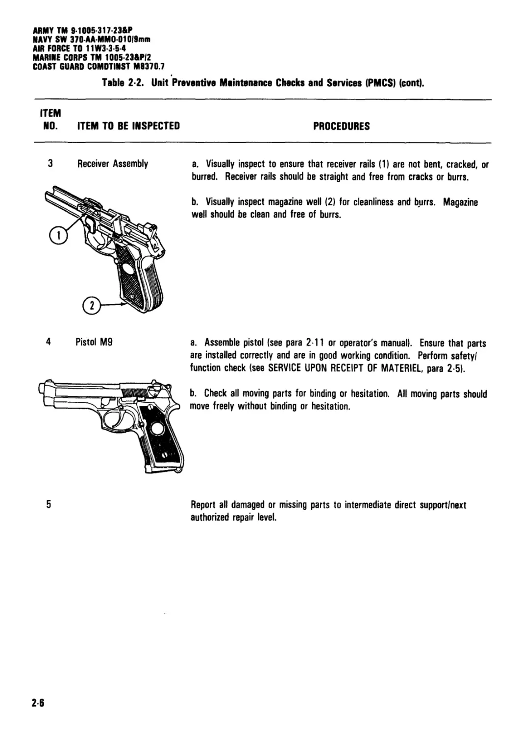
4 Pistol M9
a. Visually inspect to ensure that receiver rails (1) are not bent, cracked, or
burred. Receiver rails should be straight and free from cracks or burrs.
b. Visually inspect magazine well (2) for cleanliness and b,urrs. Magazine
well should be clean and free of burrs.
a. Assemble pistol (see para 2-11 or operator's manual). Ensure that parts
are installed correctly and are in good working condition. Perform safety/
function check (see SERVICE UPON RECEIPT OF MATERIEL, para 2-5).
b. Check all moving parts for binding or hesitation. All moving parts should
move freely without binding or hesitation.
5
Report all damaged or missing parts to intermediate direct support/next
authorized repair level.
26
ARMY TM 9-1005-317-23&P
NAVY SW 370-AA-MM0010l9mm
AIR FORCE TO 11W3-3-5-4
MARINE CORPS TM 1005-23&P/2
COAST GUARD COMDTINST M0370.7
Section IV. TROUBLESHOOTING
2 8. UNIT MAINTENANCE TROUBLESHOOTING.
a. This section contains troubleshooting information
for locating and correcting most of the operating
troubles which may develop in the M9 pistol. Each
malfunction for a part, assembly, or subassembly is
followed by a list of tests or inspections which will
help you to determine corrective actions to take. You
should perform the tests/inspections and corrective
actions in the sequence shown on pages 2-8 through
2-14. The Symptom Index is for page referencing only.
b. This manual cannot list all possible malfunctions
that may occur, nor all tests or inspections and
corrective actions. If a malfunction is not listed (except
when malfunction and cause are obvious) or is not
corrected by listed corrective actions, notify
intermediate direct support/next authorized repair level.
2-9. TROUBLESHOOTING PROCEDURES.! Refer to
table 2-3 for malfunctions, tests or inspections, and
corrective actions.
WARNING
Before performing any of the troubleshooting
procedures, make sure the pistol is
clear/unloaded. Do not keep live ammunition
near work/maintenance area.
NOTE
In this table, evacuate to intermediate direct
support also means evacuate to the next
higher level of maintenance.
SYMPTOM INDEX
Troubleshooting
Procedure
Page
1. Ammunition does not chamber.....................................................................................2-9
2. Cartridge does not extract....................................................................................2-12
3. Failure to eject..............................................................................................2-13
4. Failure to feed................................................................................................2-8
5. Failure to fire................................................................................................2-10
6. Hammer does not cock with safety in the fire position..........................................................2-13
7. Hammer does not decock with safety in the safe position.......................................................2-14
8. Slide does not lock fully forward..............................................................................2-10
9. Slide does not unlock..........................................................................................2-11
10. Pistol fails to fire in double action........................................................................2-14
ARMY TM 9-1005-317-23&P
NAVY SW 370-AA-MMO-010/9mm
AIR FORCE TO 11W3-3-5-4
MARINE CORPS TM 1005-23&P/2
COAST GUARD COMDTINST M9370.7
Table 2-3. Troubleshooting Procedures.
MALFUNCTION
TEST OR INSPECTION
CORRECTIVE ACTION
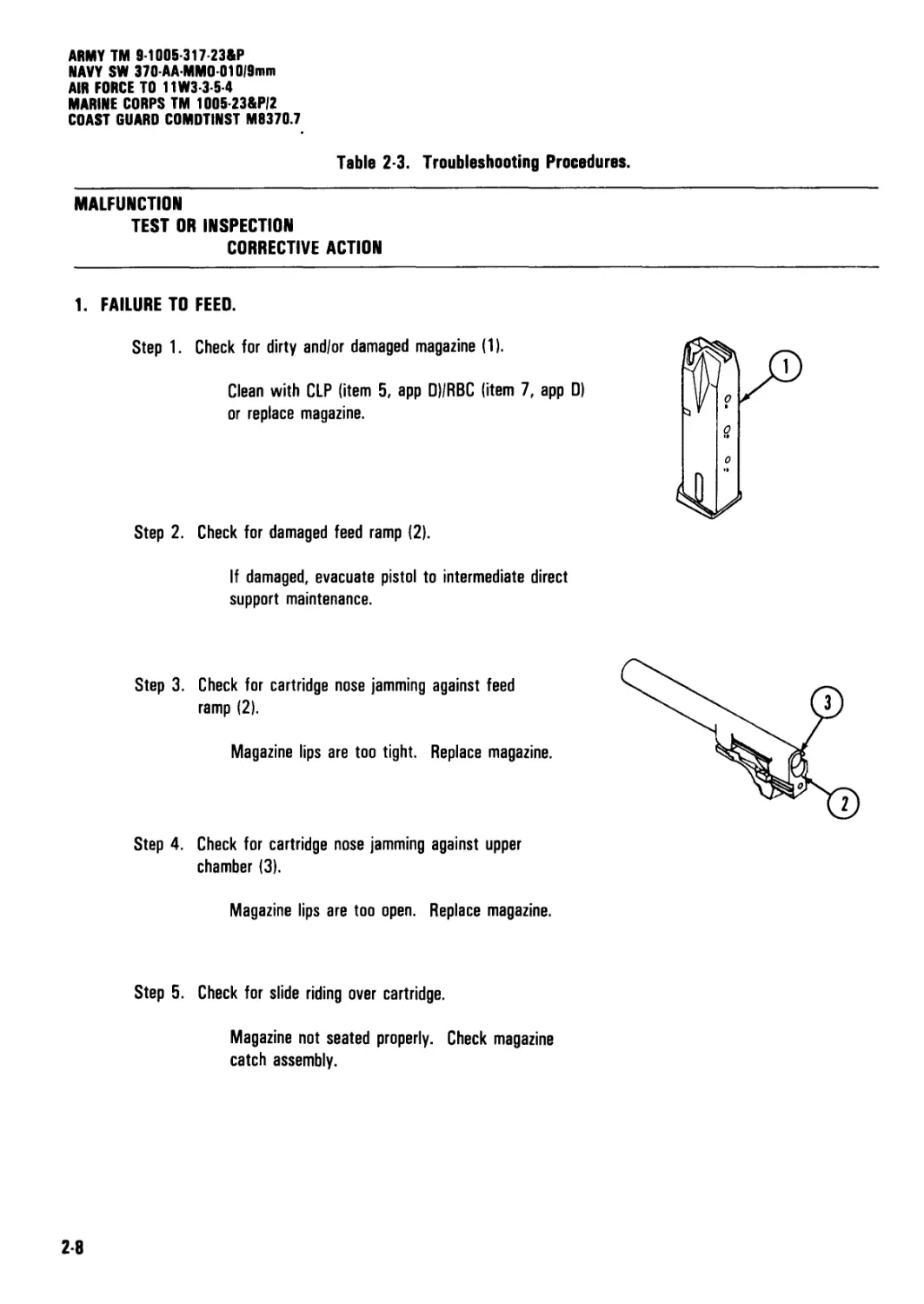
1. FAILURE TO FEED.
Step 1. Check for dirty and/or damaged magazine (1).
Clean with CLP (item 5, app D)/RBC (item 7, app D)
or replace magazine.
Step 2. Check for damaged feed ramp (2).
If damaged, evacuate pistol to intermediate direct
support maintenance.
Step 3. Check for cartridge nose jamming against feed
ramp (2).
Magazine lips are too tight. Replace magazine.
Step 4. Check for cartridge nose jamming against upper
chamber (3).
Magazine lips are too open. Replace magazine.
Step 5. Check for slide riding over cartridge.
Magazine not seated properly. Check magazine
catch assembly.
2-8
ARMY TM 9-1005-317-23AP
NAVY SW 370AA-MMO-010/9im
' Table 2-3. Troubleshooting Procedures (cont).
AIR FORCE TO 11W3-3-54
MARINE CORPS TM 100Б-23АР/2
COAST GUARD COMDTINST M8370.7
MALFUNCTION
TEST OR INSPECTION
CORRECTIVE ACTION
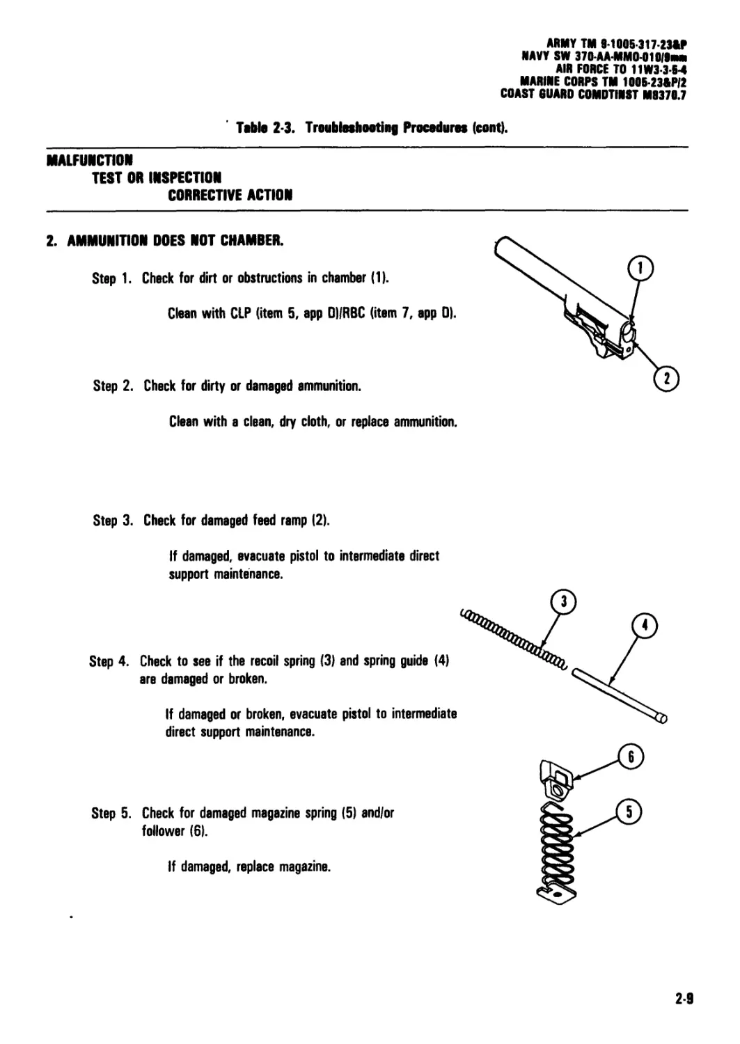
2. AMMUNITION DOES NOT CHAMBER.
Step 1. Check for dirt or obstructions in chamber (1).
Clean with CLP (item 5, app DI/RBC (item 7, app 0).
Step 2. Check for dirty or damaged ammunition.
Clean with a clean, dry cloth, or replace ammunition.
Step 3. Check for damaged feed ramp (2).
If damaged, evacuate pistol to intermediate direct
support maintenance.
Step 4. Check to see if the recoil spring (3) and spring guide (4)
are damaged or broken.
If damaged or broken, evacuate pistol to intermediate
direct support maintenance.
Step 5. Check for damaged magazine spring (5) and/or
follower (6).
If damaged, replace magazine.
2-9
ARMY TM 9-1005-317-23&P
NAVY SW 370-AA-MMO-010/9mm
AIR FORCE TO 11W3-3-5-4
MARINE CORPS TM 1005-23&PI2
COAST GUARD COMDTINST M8370.7
Table 2-3. Troubleshooting Procedures (cont).
MALFUNCTION
TEST OR INSPECTION
CORRECTIVE ACTION
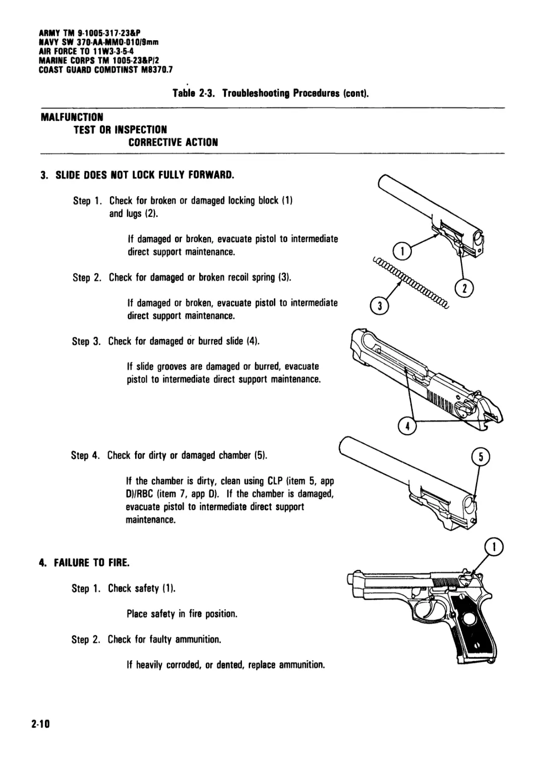
3. SLIDE DOES NOT LOCK FULLY FORWARD.
Step 1. Check for broken or damaged locking block (1)
and lugs (2).
If damaged or broken, evacuate pistol to intermediate
direct support maintenance.
Step 2. Check for damaged or broken recoil spring (3).
If damaged or broken, evacuate pistol to intermediate
direct support maintenance.
Step 3.
Step 4.
Check for damaged or burred slide (4).
If slide grooves are damaged or burred, evacuate
pistol to intermediate direct support maintenance.
Check for dirty or damaged chamber (5).
If the chamber is dirty, clean using CLP (item 5, app
D)/RBC (item 7, app D). If the chamber is damaged,
evacuate pistol to intermediate direct support
maintenance.
4. FAILURE TO FIRE.
Step 1. Check safety (1).
Place safety in fire position.
Step 2. Check for faulty ammunition.
If heavily corroded, or dented, replace ammunition.
2-10
ARMY TM 9-1005-317-23&P
NAVY SW 370-AA-MM0-010|9mm
AIR FORCE TO 11W3-3-5-4
MARINE CORPS TM 1005-23&PI2
COAST GUARD COMDTINST M8370.7
table 2-3. Troubleshooting Procedures (cont).
MALFUNCTION
TEST OR INSPECTION
CORRECTIVE ACTION
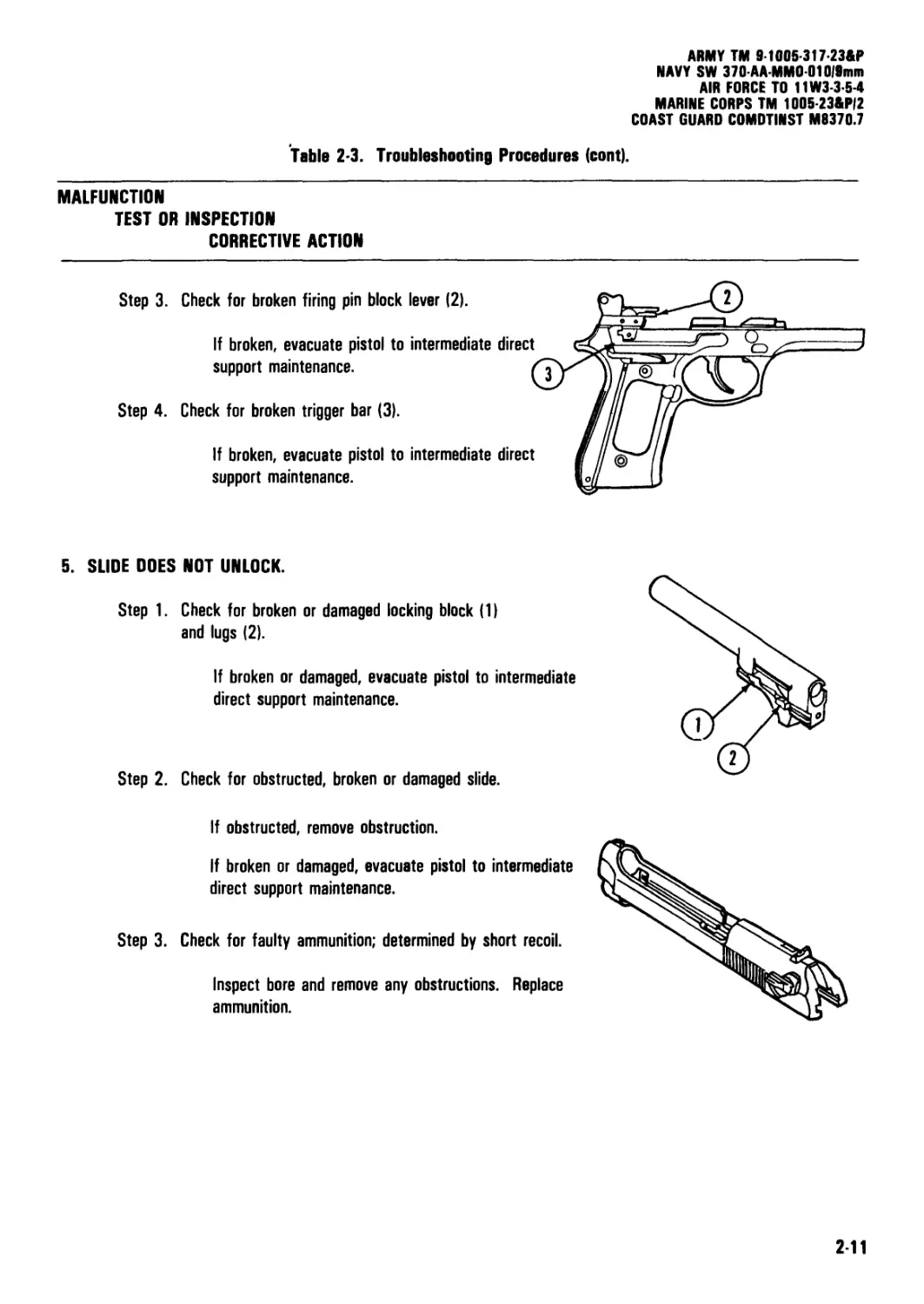
Step 3. Check for broken firing pin block lever (2).
If broken, evacuate pistol to intermediate direct
support maintenance.
Step 4. Check for broken trigger bar (3).
If broken, evacuate pistol to intermediate direct
support maintenance.
5. SLIDE DOES NOT UNLOCK.
Step 1. Check for broken or damaged locking block (1)
and lugs (2).
If broken or damaged, evacuate pistol to intermediate
direct support maintenance.
Step 2. Check for obstructed, broken or damaged slide.
If obstructed, remove obstruction.
If broken or damaged, evacuate pistol to intermediate
direct support maintenance.
Step 3. Check for faulty ammunition; determined by short recoil.
Inspect bore and remove any obstructions. Replace
ammunition.
2-11
ARMY TM 9-1005317-23&P
NAVY SW 370-AAMM0010/9mm
AIR FORCE TO 11W3-3-5-4
MARINE CORPS TM 1005-23&P/2
COAST GUARD COMDTINST M9370.7
fable 2-3. Troubleshooting Procedures (cont).
MALFUNCTION
TEST OR INSPECTION
CORRECTIVE ACTION
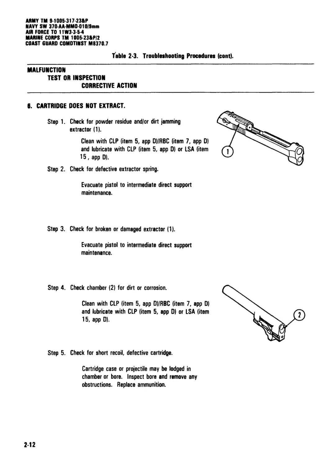
8. CARTRIDGE DOES NOT EXTRACT.
Step 1. Check for powder residue and/or dirt jamming
extractor (1).
Clean with CLP (item 5, app D)/RBC (item 7, app 0)
and lubricate with CLP (item 5, app 0) or LSA (item
15, app D).
Step 2. Check for defective extractor spring.
Evacuate pistol to intermediate direct support
maintenance.
Step 3. Check for broken or damaged extractor (1).
Evacuate pistol to intermediate direct support
maintenance.
Step 4. Check chamber (2) for dirt or corrosion.
Clean with CLP (item 5, app DI/RBC (item 7, app 0)
and lubricate with CLP (item 5, app D) or LSA (item
15, app 0).
Step 5. Check for short recoil, defective cartridge.
Cartridge case or projectile may be lodged in
chamber or bore. Inspect bore and remove any
obstructions. Replace ammunition.
212
ARMY TM 9Ю05-317-23&Р
NAVY SW 370AA-MMD-01019mm
AIR FORCE TO 11W3-3-6-4
MARINE CORPS TM 1005-23&P)2
COAST GUARD COMDTINST M9370.7
Table 2-3. Troubleshooting Procedures (cont).
MALFUNCTION
TEST OR INSPECTION
CORRECTIVE ACTION
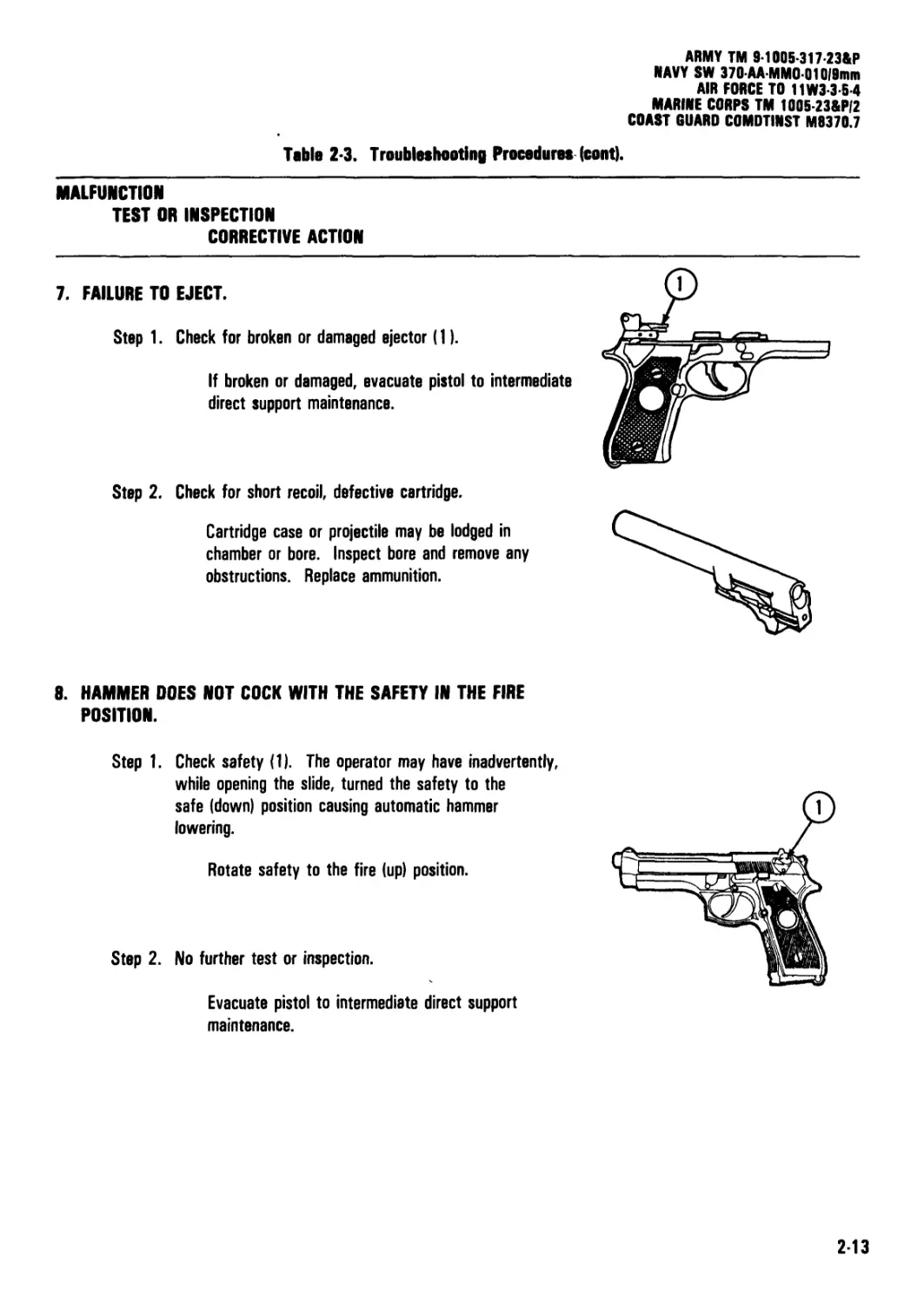
7. FAILURE TO EJECT.
Step 1. Check for broken or damaged ejector (1).
If broken or damaged, evacuate pistol to intermediate
direct support maintenance.
Step 2. Check for short recoil, defective cartridge.
Cartridge case or projectile may be lodged in
chamber or bore. Inspect bore and remove any
obstructions. Replace ammunition.
8. HAMMER DOES NOT COCK WITH THE SAFETY IN THE FIRE
POSITION.
Step 1. Check safety (1). The operator may have inadvertently,
while opening the slide, turned the safety to the
safe (down) position causing automatic hammer
lowering.
Rotate safety to the fire (up) position.
Step 2. No further test or inspection.
Evacuate pistol to intermediate direct support
maintenance.
2-13
ARMY TM 9-1005-317-23&P
NAVY SW 370-AA MM0 010/9min
AIR FORCE TO 11W3-3 5-4
MARINE CORPS TM 1005-23&P/2
COAST GUARD COMDTINST M9370.7
Table 2-3. Troubleshooting Procedures (cont).
MALFUNCTION
TEST OR INSPECTION
CORRECTIVE ACTION
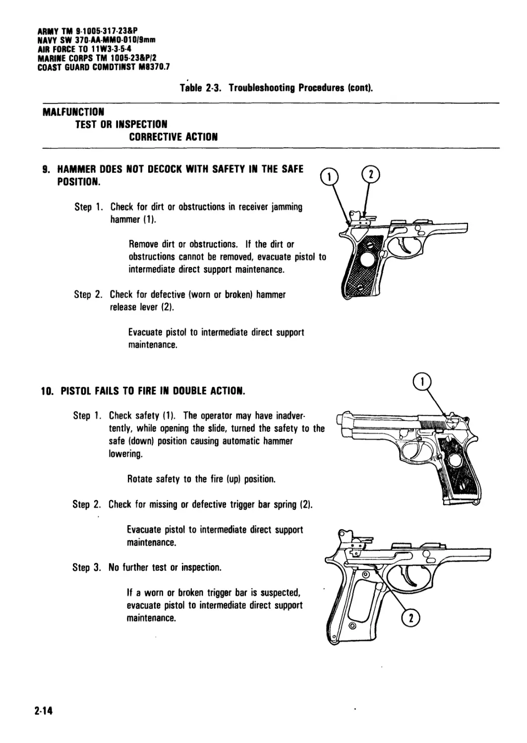
9.
HAMMER DOES NOT DECOCK WITH SAFETY IN THE SAFE
POSITION.
Step 1.
Check for dirt or obstructions in receiver jamming
hammer (1).
Remove dirt or obstructions. If the dirt or
obstructions cannot be removed, evacuate pistol to
intermediate direct support maintenance.
Step 2.
Check for defective (worn or broken) hammer
release lever (2).
Evacuate pistol to intermediate direct support
maintenance.
10. PISTOL FAILS TO FIRE IN DOUBLE ACTION.
Step 1. Check safety (1). The operator may have inadver-
tently, while opening the slide, turned the safety to the
safe (down) position causing automatic hammer
lowering.
Rotate safety to the fire (up) position.
Step 2. Check for missing or defective trigger bar spring (2).
Evacuate pistol to intermediate direct support
maintenance.
Step 3. No further test or inspection.
If a worn or broken trigger bar is suspected,
evacuate pistol to intermediate direct support
maintenance.
2-14
ARMY TM 9-1005-317-23&P
NAVY SW 370-AA-MMO-01019mm
AIR FORCE TO 11W3-3-5-4
MARINE CORPS TM 1005-23&P/2
COAST GUARD COMDTINST M0370.7
Section V. UNIT MAINTENANCE PROCEDURES
(a) Army: Military Occupational Specialty
NOTE
When a pistol is received at unit
maintenance, it must be inspected and if any
deficiences are found, they should be
repaired or noted/tagged for repair at
intermediate direct support maintenance/next
authorized repair level.
| 2 10. GENERAL. |
a. Unit maintenance is limited to replacement of
the pistol grips, minor hardware and reversing the
magazine catch assembly. (Coast Guard users are
not authorized to reverse the magazine catch assembly.)
b. Initial Setup. In order to reduce the space
required for the initial setup portion of the maintenance
procedures, the following data is standard for all initial
setups:
(1) Materials/parts includes only items
applicable to the procedure.
(2) Tools and special tools • includes only the
standard tool set applicable to the procedure.
(3) Personnel required - includes the following
designated joint service descriptions that are applicable
to all unit maintenance procedures:
(MOS) 76Y Supply Clerk/Unit Armorer.
(b) Air Force: Air Force Specialty Code
(AFSC) 753XX Combat Arms Training and Maintenance
Specialists, Technicians and Gunsmiths.
(c) Navy: Gunner's Mate Guns (GMG).
(d) Marine Corps: Military Occupational
Specialty (MOS) 2111 Unit Armorer (Infantry Weapon
Repairer).
(e) Coast Guard: Refer to COMDTINST
8000.2.
(4) References - includes the operator's manual
for joint service use:
(a) ARMY TM 9-1005-317-10.
(b) NAVY SW 370-AA-OPI-010 9mm
(c) AIR FORCE TO 11W3-3-5-1.
(d) MARINE CORPS TM 1005A-10/1.
(e) COAST GUARD COMDTINST M8370.6.
(5) Equipment condition - is listed as applicable
to the procedure.
(6) As General Safety Instructions, make sure
the magazine is removed, the pistol is clear of
ammunition, and the barrel has no obstructions.
2-15
ARMY TM 9-1005-317-23&P
NAVY SW 370-AA-MMO-010|9mm
AIR FORCE TO 11W3-3-5-4
MARINE CORPS TM 1005-23&P/2
COAST GUARD COMDTINST M9370.7
2 11. MAINTENANCE OF 9mm PISTOL
This task covers: a. Disassembly d. Repair b. Cleaning e. Reassembly c. Inspection
INITIAL SETUP Tools and Special Tools Tool Set, Small Arms (SC 5180-95-CL-A07)
Materials/Parts Cleaner, lubricant and preservative (CLP) (item 5, app D) Solid film lubricant (item 12, app D) Solvent, dry cleaning (item 22, app D) WARNING Make certain weapon is clear and there are no obstructions in the barrel or chamber.
DISASSEMBLY
CAUTION
Dry fire the pistol only in conjunction with
the function checks in PMCS and/or during
training.
Do not allow the hammer to fall with full
force by pulling the trigger when the slide is
removed as damage to the receiver can
occur. If necessary, the hammer should be
manually lowered.
1. Clear/unload the pistol.
2. Allow slide to return fully forward.
3. Hold pistol in the right hand with muzzle slightly
elevated. With forefinger, press disassembly lever
release button, and with thumb, rotate disassembly
lever downward until it stops.
216
ARMY TM 9-1005-317-23&P
NAVY SW 370-AAMMO-010|9mm
AIR FORCE TO 11W3-3-5-4
MARINE CORPS TM 1005 23&PI2
COAST GUARD COMDTINST M8370.7
| 211. MAINTENANCE OF 9mm PISTOL (cont)
DISASSEMBLY (cont)
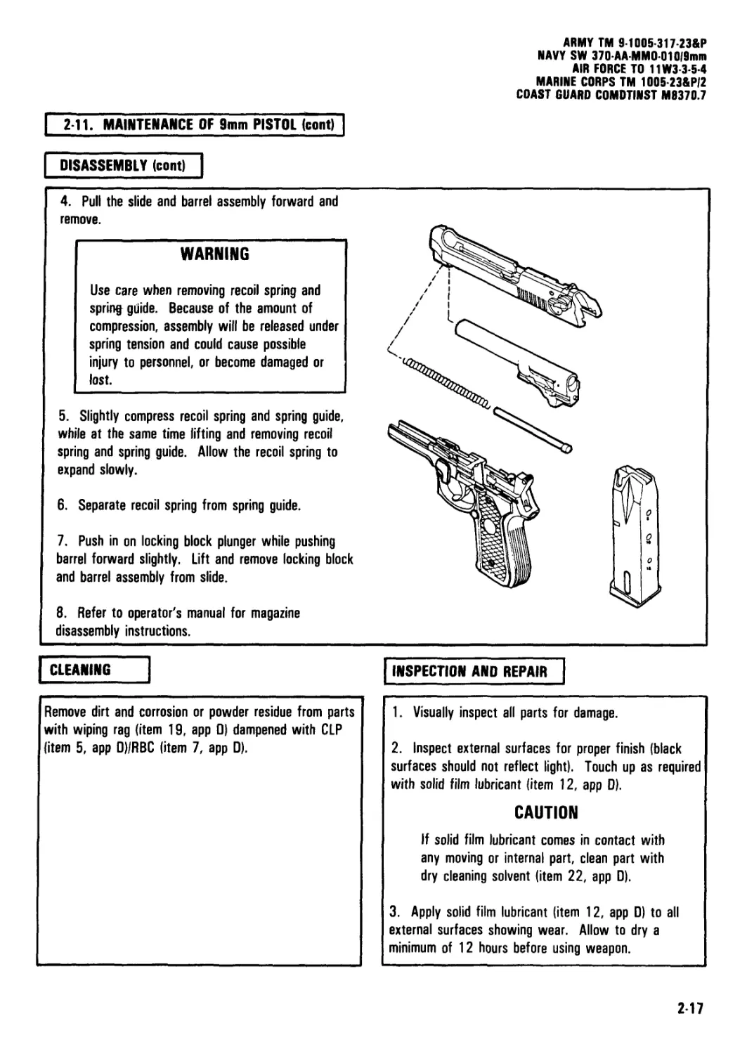
4. Pull the slide and barrel assembly forward and
remove.
WARNING
Use care when removing recoil spring and
spring guide. Because of the amount of
compression, assembly will be released under
spring tension and could cause possible
injury to personnel, or become damaged or
lost.
5. Slightly compress recoil spring and spring guide,
while at the same time lifting and removing recoil
spring and spring guide. Allow the recoil spring to
expand slowly.
6. Separate recoil spring from spring guide.
7. Push in on locking block plunger while pushing
barrel forward slightly. Lift and remove locking block
and barrel assembly from slide.
8. Refer to operator's manual for magazine
disassembly instructions.
| CLEANING
Remove dirt and corrosion or powder residue from parts
with wiping rag (item 19, app 0) dampened with CLP
(item 5, app O)/RBC (item 7, app D).
INSPECTION AND REPAIR
1. Visually inspect all parts for damage.
2. Inspect external surfaces for proper finish (black
surfaces should not reflect light). Touch up as required
with solid film lubricant (item 12, app D).
CAUTION
If solid film lubricant comes in contact with
any moving or internal part, clean part with
dry cleaning solvent (item 22, app D).
3. Apply solid film lubricant (item 12, app 0) to all
external surfaces showing wear. Allow to dry a
minimum of 12 hours before using weapon.
217
ARMY TM 9-100S-317-23&P
NAVY SW 370 AA-MMO-010|9mm
AIR FORCE TO 11W3-3-5-4
MARINE CORPS TM 1005-23&P/2
COAST GUARD COMDTINST M8370.7
I 2-11. MAINTENANCE OF 9mm PISTOL (cont)
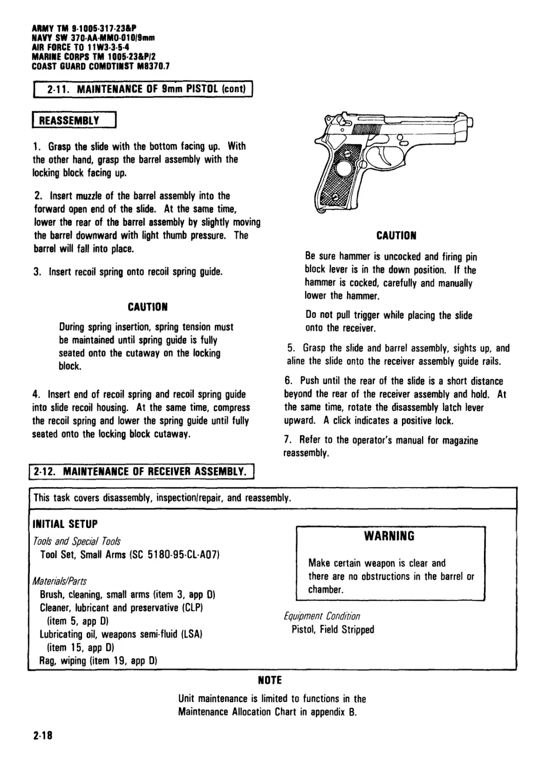
| REASSEMBLY
1. Grasp the slide with the bottom facing up. With
the other hand, grasp the barrel assembly with the
locking block facing up.
2. Insert muzzle of the barrel assembly into the
forward open end of the slide. At the same time,
lower the rear of the barrel assembly by slightly moving
the barrel downward with light thumb pressure. The
barrel will fall into place.
3. Insert recoil spring onto recoil spring guide.
CAUTION
During spring insertion, spring tension must
be maintained until spring guide is fully
seated onto the cutaway on the locking
block.
4. Insert end of recoil spring and recoil spring guide
into slide recoil housing. At the same time, compress
the recoil spring and lower the spring guide until fully
seated onto the locking block cutaway.
CAUTION
Be sure hammer is uncocked and firing pin
block lever is in the down position. If the
hammer is cocked, carefully and manually
lower the hammer.
Do not pull trigger while placing the slide
onto the receiver.
5. Grasp the slide and barrel assembly, sights up, and
aline the slide onto the receiver assembly guide rails.
6. Push until the rear of the slide is a short distance
beyond the rear of the receiver assembly and hold. At
the same time, rotate the disassembly latch lever
upward. A click indicates a positive lock.
7. Refer to the operator's manual for magazine
reassembly.
2-12. MAINTENANCE OF RECEIVER ASSEMBLY.
This task covers disassembly, inspectionfrepair, and reassembly.
INITIAL SETUP
Tools and Special Tools
Tool Set, Small Arms (SC 5180-95-CL-A07)
Materia/s/Parts
Brush, cleaning, small arms (item 3, app D)
Cleaner, lubricant and preservative (CLP)
(item 5, app D)
Lubricating oil, weapons semi-fluid (LSA)
(item 15, app D)
Rag, wiping (item 19, app D)
WARNING
Make certain weapon is clear and
there are no obstructions in the barrel or
chamber.
Equipment Condition
Pistol, Field Stripped
NOTE
Unit maintenance is limited to functions in the
Maintenance Allocation Chart in appendix B.
2-18
ARMY TM 9-1005-317-23&P
NAVY SW 370-AA-MMD-01019mm
AIR FORCE TO 11W3 3-5-4
MARINE CORPS TM 1005-23&P/2
COAST GUARD COMDTINST M8370.7
2-12. MAINTENANCE OF RECEIVER ASSEMBLY (cont)
| DISASSEMBLY
INSPECTION/REPAIR |
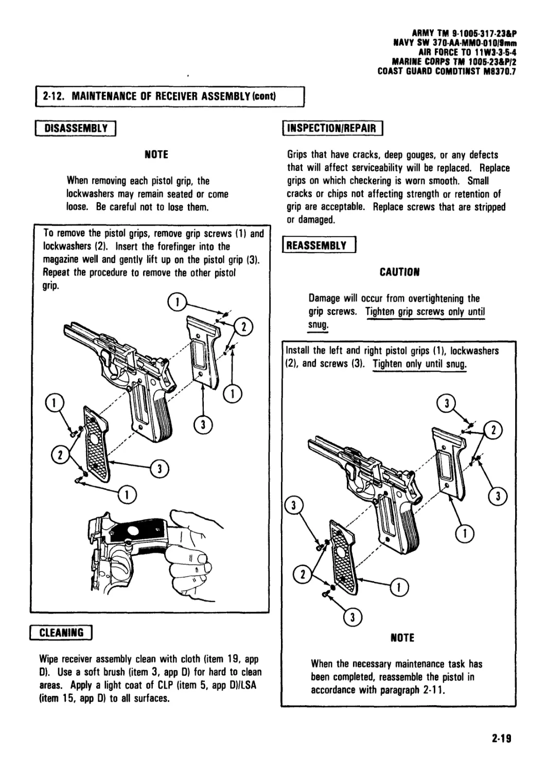
NOTE
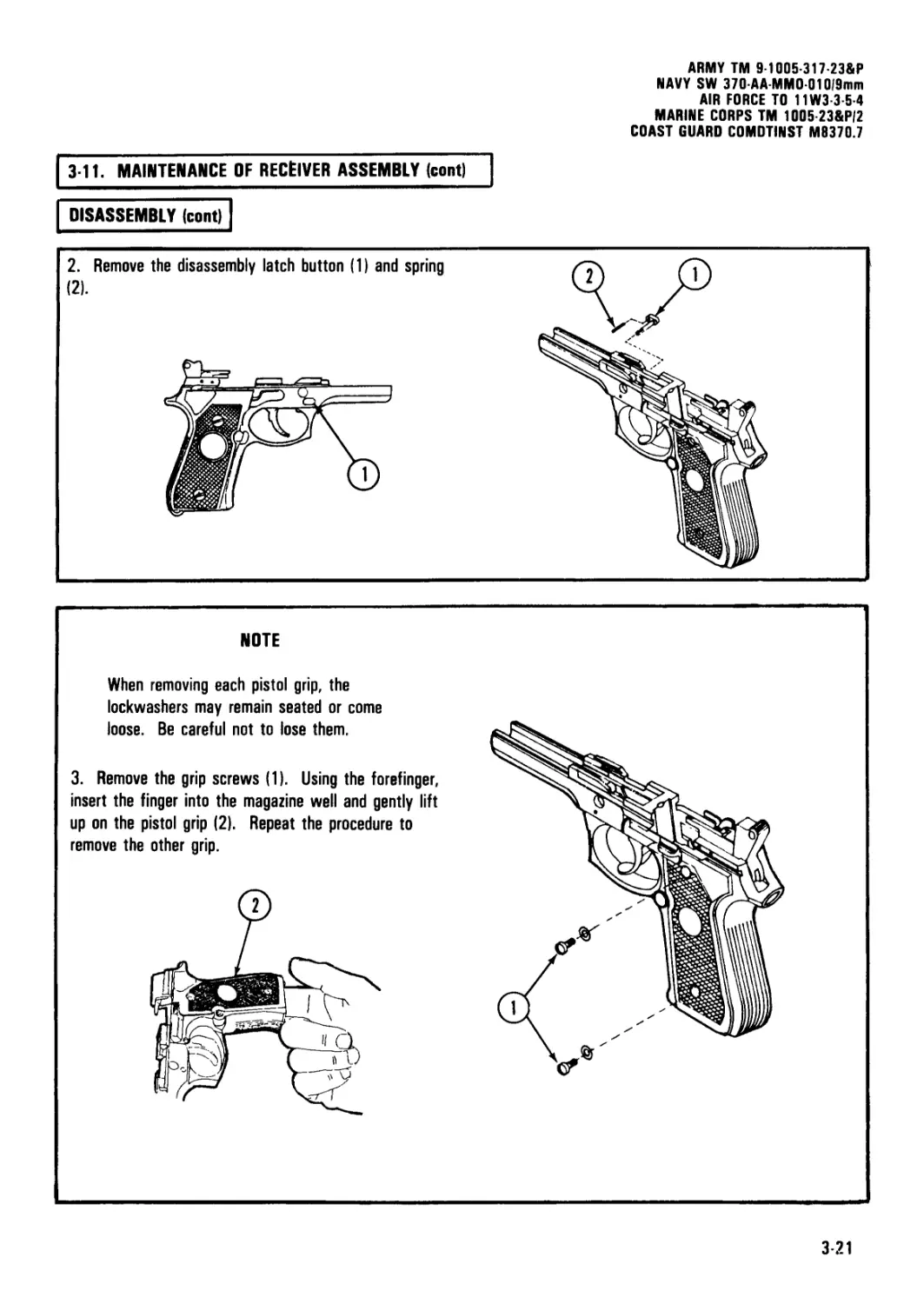
When removing each pistol grip, the
lockwashers may remain seated or come
loose. Be careful not to lose them.
To remove the pistol grips, remove grip screws (1) and
lockwashers (2). Insert the forefinger into the
magazine well and gently lift up on the pistol grip (3).
Repeat the procedure to remove the other pistol
grip.
| CLEANING |
Grips that have cracks, deep gouges, or any defects
that will affect serviceability will be replaced. Replace
grips on which checkering is worn smooth. Small
cracks or chips not affecting strength or retention of
grip are acceptable. Replace screws that are stripped
or damaged.
[reassembly!
CAUTION
Damage will occur from overtightening the
grip screws. Tighten grip screws only until
snug.
Install the left and right pistol grips (1), lockwashers
(2), and screws (3). Tighten only until snug.
NOTE
Wipe receiver assembly clean with cloth (item 19, app
0). Use a soft brush (item 3, app 0) for hard to clean
areas. Apply a light coat of CLP (item 5, app D)/LSA
(item 15, app 0) to all surfaces.
When the necessary maintenance task has
been completed, reassemble the pistol in
accordance with paragraph 2-11.
2-19
ARMY TM 9-1005-317-23&P
NAVY SW 370 AA-MM001019mm
AIR FORCE TO 11W3-3-5-4
MARINE CORPS TM 1005 23&P/2
COAST GUARD COMDTINST M0370.7
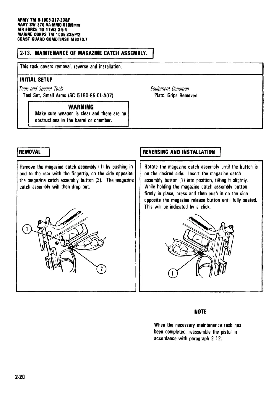
213. MAINTENANCE OF MAGAZINE CATCH ASSEMBLY.
This task covers removal, reverse and installation.
INITIAL SETUP Tools and Special Tools Tool Set, Small Arms (SC 5180-95-CL-A07) Equipment Condition Pistol Grips Removed
WARNING Make sure weapon is clear and there are no obstructions in the barrel or chamber.
REMOVAL Remove the magazine catch assembly (1) by pushing in and to the rear with the fingertip, on the side opposite the magazine catch assembly button (2). The magazine catch assembly will then drop out. REVERSING AND INSTALLATION Rotate the magazine catch assembly until the button is on the desired side. Insert the magazine catch assembly button (1) into position, tilting it slightly. While holding the magazine catch assembly button firmly in place, press and then push in on the side opposite the magazine release button until fully seated. This will be indicated by a click. NOTE When the necessary maintenance task has been completed, reassemble the pistol in accordance with paragraph 2-12.
220
ARMY TM 9-1005-317-23&P
NAVY SW 370-АА-ММ0 010191ШП
AIR FORCE TO 11W3-3-5-4
MARINE CORPS TM 1005-23&P/2
COAST GUARD COMDTINST M9370.7
CHAPTER 3
INTERMEDIATE DIRECT SUPPORT
MAINTENANCE INSTRUCTIONS
Chapter Overview
Section III. TROUBLESHOOTING
This chapter contains information and instructions for
the repairman to help keep the M9 pistol in good repair.
The chapter consists of repair parts, special tools, and
support equipment; service upon receipt;
troubleshooting; and maintenance procedures.
Section I. REPAIR PARTS, SPECIAL TOOLS
AND SUPPORT EQUIPMENT
| 31. COMMON TOOLS AND EQUIPMENT. | For
authorized common tools and equipment, refer to the
Modified Table of Organization and Equipment (MTOE)
applicable to your unit.
[ 3 2. SPECIAL TOOLS AND SUPPORT EQUIPMENT?]
There are no special tools for this item. Tools and test
equipment are listed in appendix B, section III, of this
manual. There is no TMDE for this item.
3-3. REPAIR PARTS.] Repair parts are listed and
illustrated in appendix C of this manual.
Section II. SERVICE UPON RECEIPT
3-4. GENERAL.] Normally intermediate direct support
maintenance does not perform service upon receipt
except to assist unit maintenance as required. Refer to
chapter 2, paragraph 2-5, for service upon receipt.
3-5. INTERMEDIATE DIRECT SUPPORT
TROUBLESHOOTING.
a. This section contains troubleshooting information
for locating and correcting most of the operating
troubles which may develop in the pistols. Each
malfunction for an individual component, unit, or system
is followed by a list of tests or inspections which will
help you to determine the corrective actions to take.
You should perform the tests/inspections and corrective
actions in the sequence shown on pages 3-2 through
3-8. The symptom index is for page referencing only.
b. This manual cannot list all malfunctions that
,ay occur, nor all tests or inspections and corrective
actions. If a malfunction is not listed or is not
corrected by listed corrective actions, see individual
repair sections for maintenance instructions on each
major assembly for remedial action.
| 3 6. TROUBLESHOOTING PROCEDURES.] Refer to
table 3-1 for malfunctions, tests, and corrective
actions. This section should be used in conjunction
with unit troubleshooting procedures (see para 2-9).
WARNING
Before performing any of the troubleshooting
procedures, make sure the pistol is
clear/unloaded. Do not keep live ammunition
near work/maintenance area.
3-1
ARMY TM 9 1005-317 23&P
NAVY SW 370-AA-MMO-010|9mm
AIR FORCE TO 11W3 3-5 4
MARINE CORPS TM 1005 23&P/2
COAST GUARD COMDTINST M8370.7
SYMPTOM INDEX
Troubleshooting
Procedure
Page
1. Ammunition does not chamber.......................................................................3-3
2. Cartridge does not extract.......................................................................3-5
3. Failure to eject..................................................................................3-6
4. Failure to feed...................................................................................3-2
5. Failure to fire...................................................................................3-4
6. Hammer does not cock with safety in the fire position............................................3-6
7. Hammer does not decock with safety in the fire position...........................................3-7
8. Pistol fails to fire in double action.............................................................3-8
9. Slide does not lock fully forward.................................................................3-3
10. Slide does not unlock............................................................................3.5
Table 3-1. Troubleshooting Procedures
MALFUNCTION
TEST OR INSPECTION
CORRECTIVE ACTION
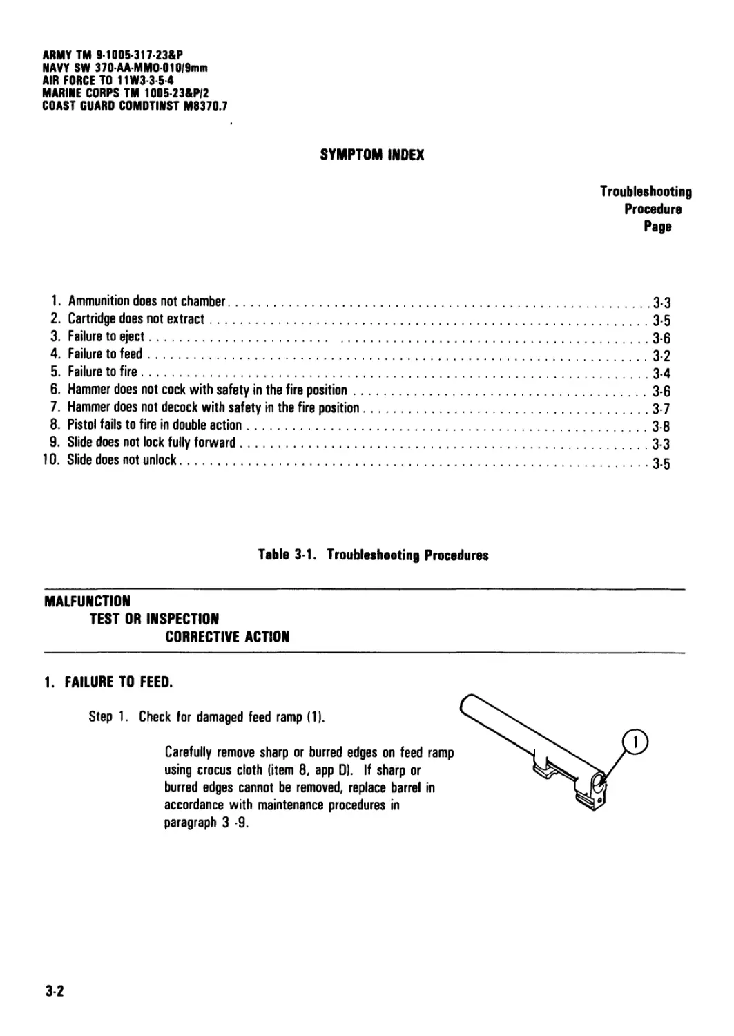
1. FAILURE TO FEED.
Step 1. Check for damaged feed ramp (1).
Carefully remove sharp or burred edges on feed ramp
using crocus cloth (item 8, app 0). If sharp or
burred edges cannot be removed, replace barrel in
accordance with maintenance procedures in
paragraph 3 -9.
3-2
ARMY TM 9-1005-317-23&P
NAVY SW 370-AA-MM0010/9mm
AIR FORCE TO 11W3-3-5-4
MARINE CORPS TM 1005-23&P/2
COAST GUARD COMDTINST M937O.7
Table 3-1. Troubleshooting Procedures (cont)
MALFUNCTION
TEST OR INSPECTION
CORRECTIVE ACTION
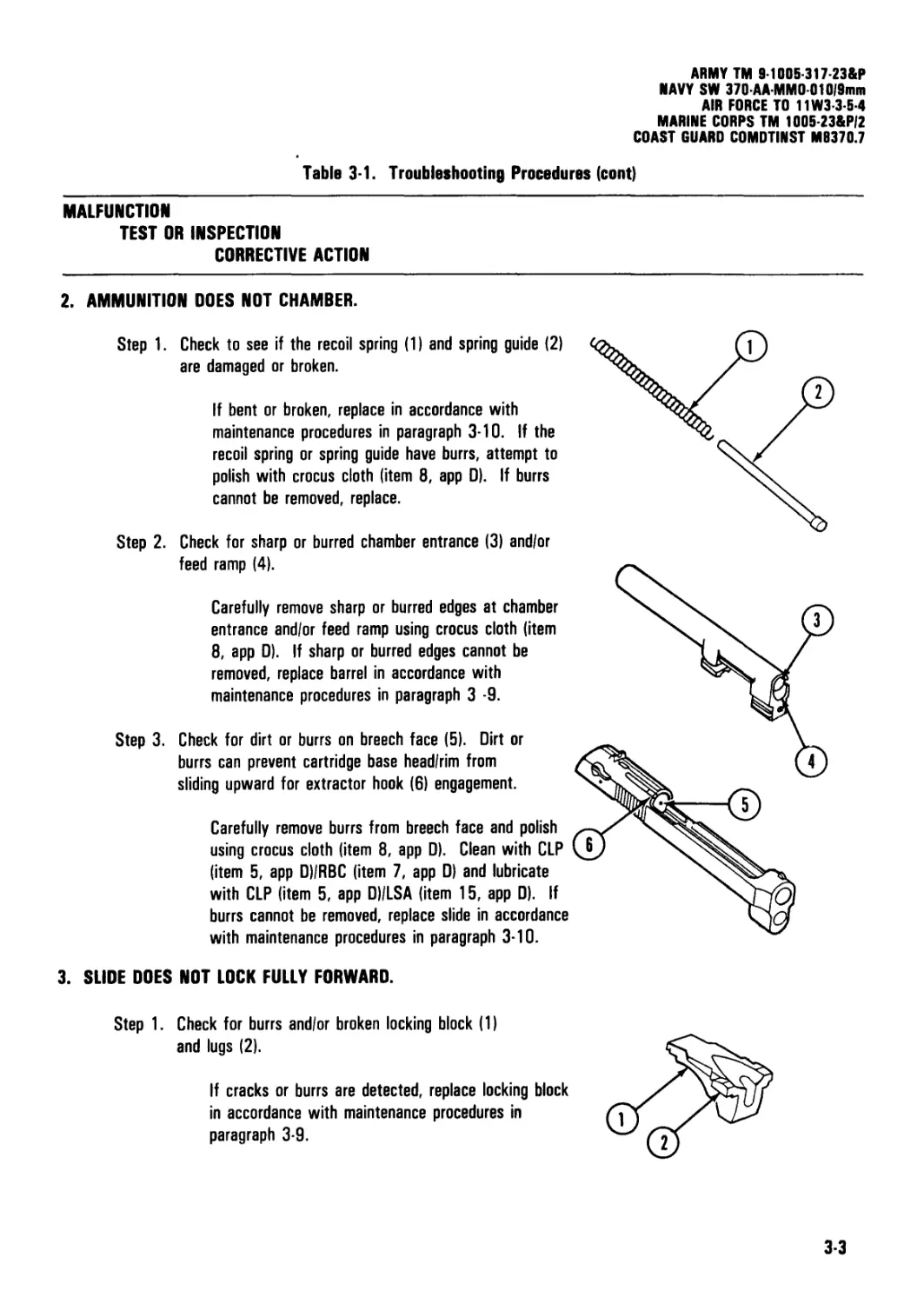
2. AMMUNITION DOES NOT CHAMBER.
Step 1. Check to see if the recoil spring (1) and spring guide (2)
are damaged or broken.
If bent or broken, replace in accordance with
maintenance procedures in paragraph 3-10. If the
recoil spring or spring guide have burrs, attempt to
polish with crocus cloth (item 8, app D). If burrs
cannot be removed, replace.
Step 2. Check for sharp or burred chamber entrance (3) and/or
feed ramp (4).
Carefully remove sharp or burred edges at chamber
entrance and/or feed ramp using crocus cloth (item
8, app D). If sharp or burred edges cannot be
removed, replace barrel in accordance with
maintenance procedures in paragraph 3 -9.
Step 3. Check for dirt or burrs on breech face (5). Dirt or
burrs can prevent cartridge base head/rim from
sliding upward for extractor hook (6) engagement.
Carefully remove burrs from breech face and polish
using crocus cloth (item 8, app D). Clean with CLP
(item 5, app D)/RBC (item 7, app D) and lubricate
with CLP (item 5, app D)/LSA (item 15, app D). If
burrs cannot be removed, replace slide in accordance
with maintenance procedures in paragraph 3-10.
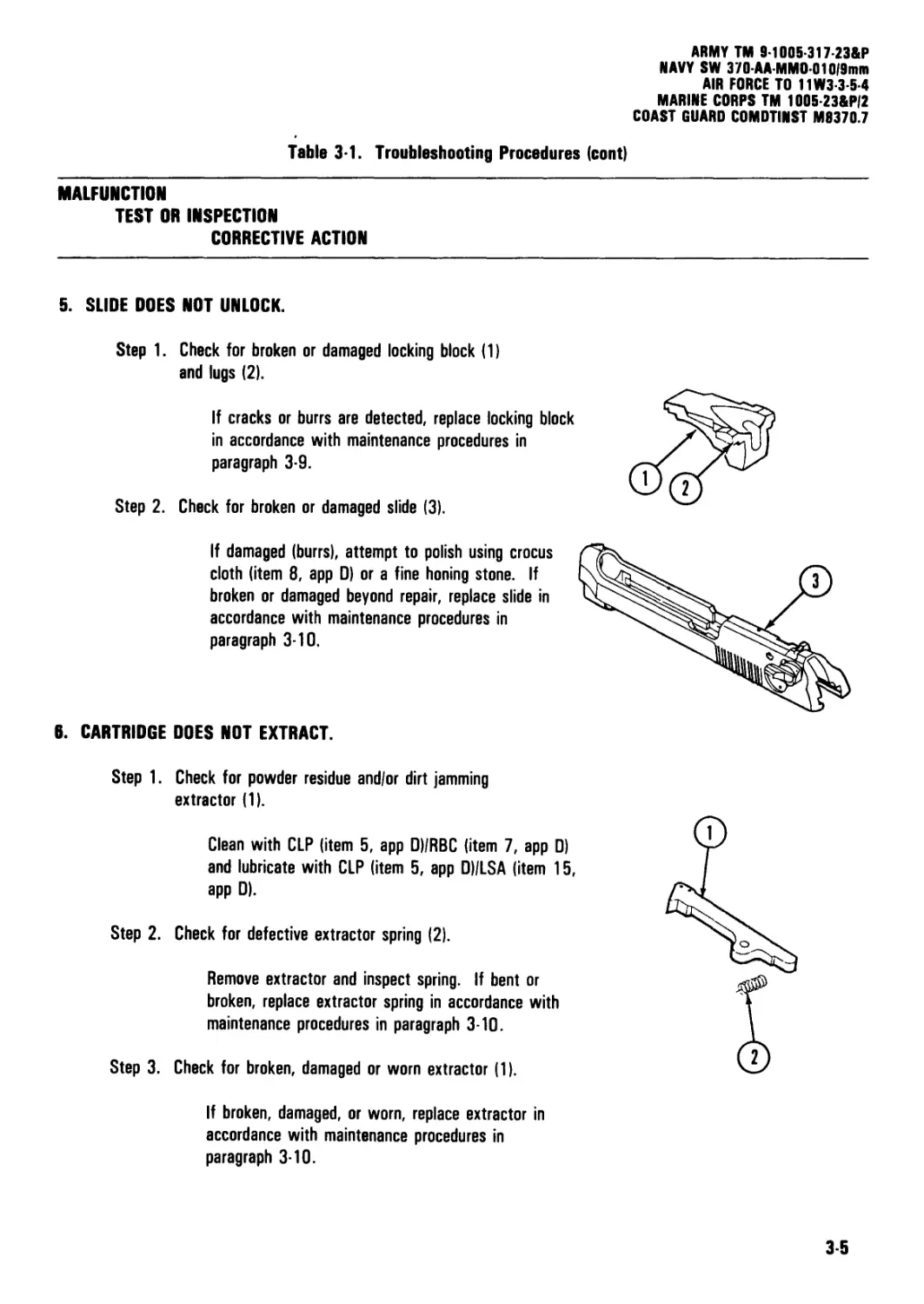
3. SLIDE DOES NOT LOCK FULLY FORWARD.
Step 1. Check for burrs and/or broken locking block (1)
and lugs (2).
If cracks or burrs are detected, replace locking block
in accordance with maintenance procedures in
paragraph 3-9.
3-3
ARMY TM 9-1005-317-23&P
NAVY SW 370-AA-MM0010,9mm
AIR FORCE TO 11W3-3-5-4
MARINE CORPS TM 1005-23&P/2
COAST GUARD COMDTINST M8370.7
Table 3-1. Troubleshooting Procedures (cont).
MALFUNCTION
TEST OR INSPECTION
CORRECTIVE ACTION
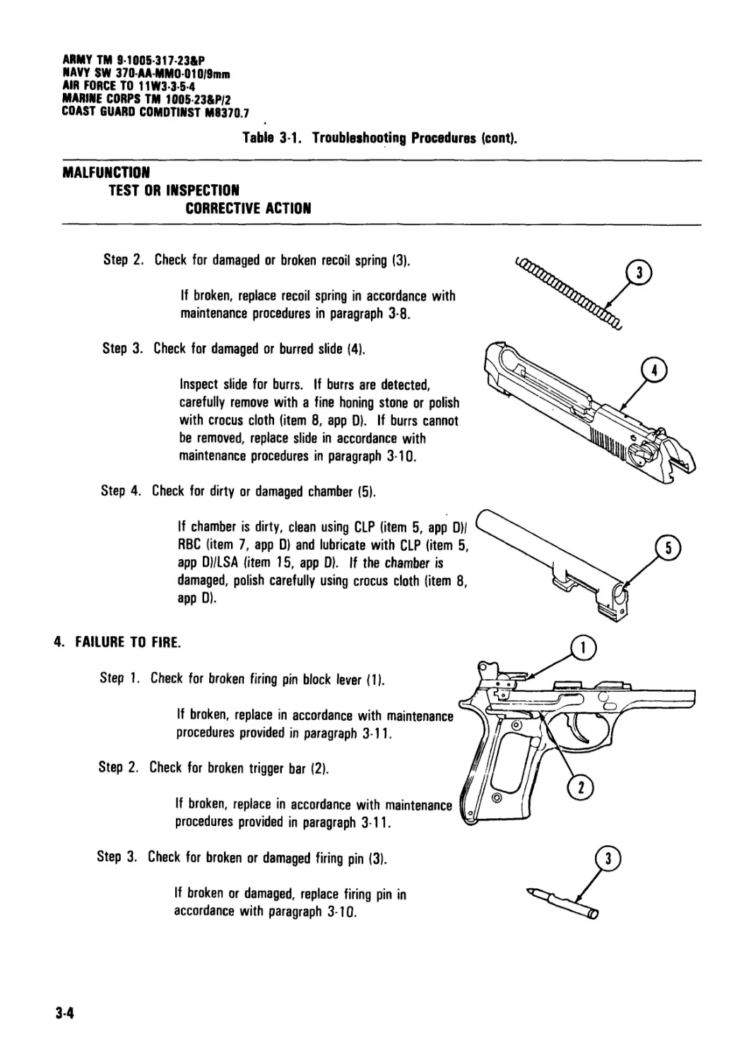
Step 2. Check for damaged or broken recoil spring (3).
If broken, replace recoil spring in accordance with
maintenance procedures in paragraph 3-8.
Step 3. Check for damaged or burred slide (4).
Inspect slide for burrs. If burrs are detected,
carefully remove with a fine honing stone or polish
with crocus cloth (item 8, app 0). If burrs cannot
be removed, replace slide in accordance with
maintenance procedures in paragraph 3-10.
Step 4. Check for dirty or damaged chamber (5).
Step 3. Check for broken or damaged firing pin (3).
If broken or damaged, replace firing pin in
accordance with paragraph 3-10.
3-4
ARMY TM 9-1005-317-23&P
NAVY SW 370-AA-MMO-010|9mm
AIR FORCE TO 11W3-3-5-4
MARINE CORPS TM 1005 23&P/2
COAST GUARD COMDTINST M9370.7
Table 3-1. Troubleshooting Procedures (cont)
MALFUNCTION
TEST OR INSPECTION
CORRECTIVE ACTION
5. SLIDE DOES NOT UNLOCK.
Step 1. Check for broken or damaged locking block (1)
and lugs (2).
If cracks or burrs are detected, replace locking block
in accordance with maintenance procedures in
paragraph 3-9.
Step 2. Check for broken or damaged slide (3).
If damaged (burrs), attempt to polish using crocus
cloth (item 8, app D) or a fine honing stone. If
broken or damaged beyond repair, replace slide in
accordance with maintenance procedures in
paragraph 3-10.
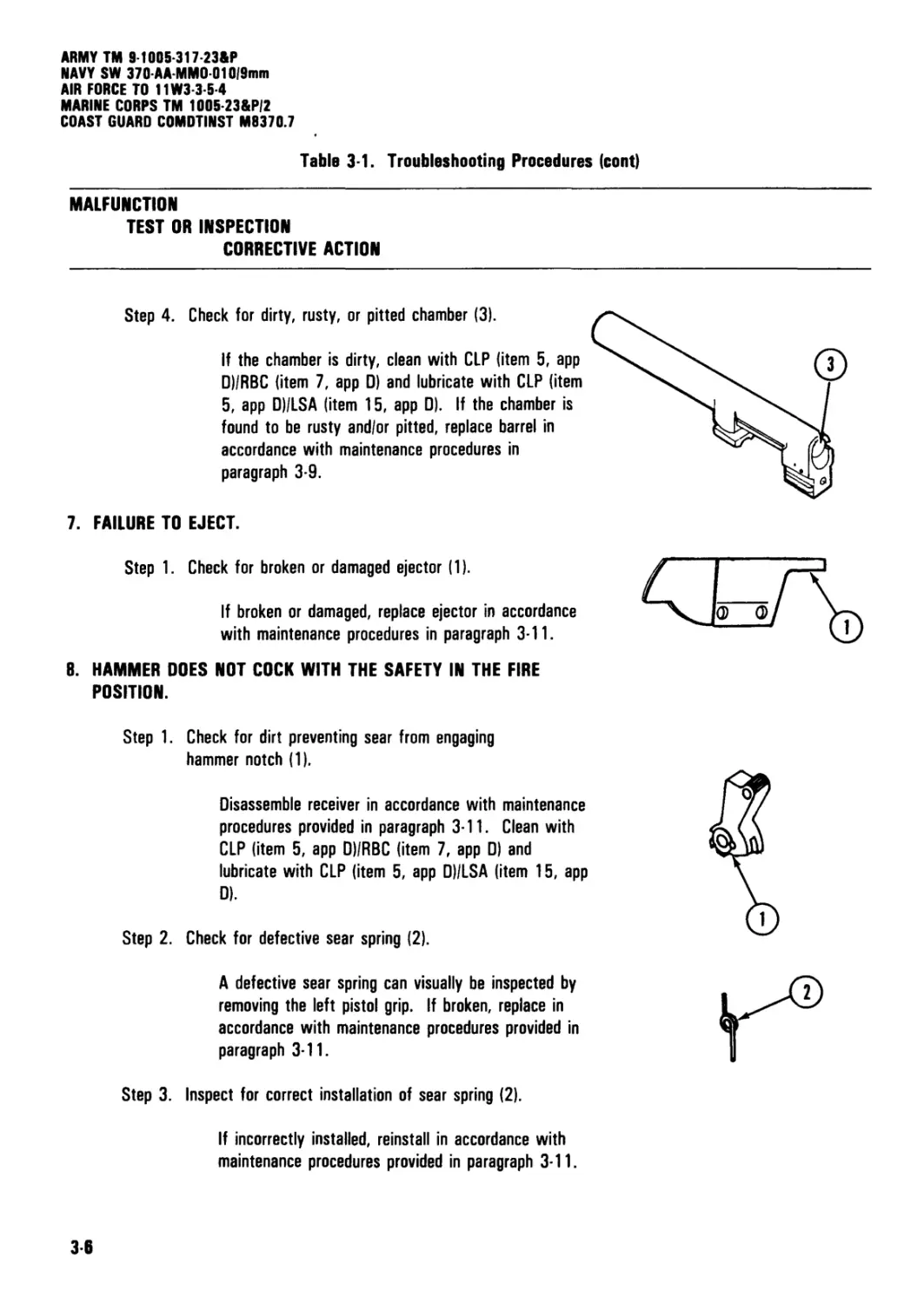
6. CARTRIDGE DOES NOT EXTRACT.
Step 1. Check for powder residue and/or dirt jamming
extractor (1).
Clean with CLP (item 5, app D)/RBC (item 7, app D)
and lubricate with CLP (item 5, app D)/LSA (item 15,
app D).
Step 2. Check for defective extractor spring (2).
Remove extractor and inspect spring. If bent or
broken, replace extractor spring in accordance with
maintenance procedures in paragraph 3-10.
Step 3. Check for broken, damaged or worn extractor (1).
If broken, damaged, or worn, replace extractor in
accordance with maintenance procedures in
paragraph 3-10.
35
ARMY TM 9-1005-317-23&P
NAVY SW 370-AA-MM0010/9mm
AIR FORCE TO 11W3 3-5-4
MARINE CORPS TM 1005 23&P/2
COAST GUARD COMDTINST MS370.7
Table 3-1. Troubleshooting Procedures (cont)
MALFUNCTION
TEST OR INSPECTION
CORRECTIVE ACTION
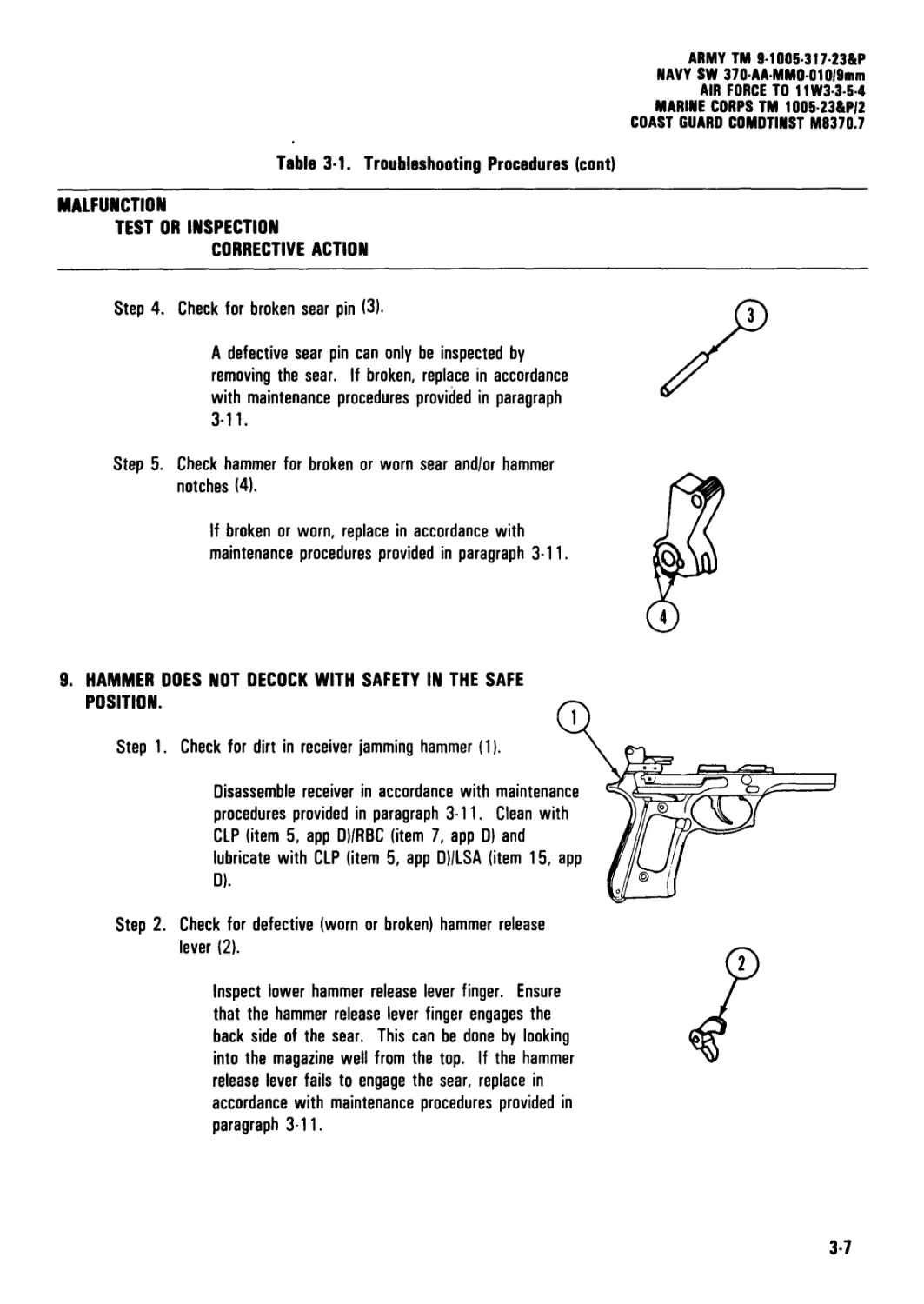
Step 4.
Check for dirty, rusty, or pitted chamber (3).
If the chamber is dirty, clean with CLP (item 5, app
DI/RBC (item 7, app 0) and lubricate with CLP (item
5, app D)/LSA (item 15, app D). If the chamber is
found to be rusty and/or pitted, replace barrel in
accordance with maintenance procedures in
paragraph 3-9.
7. FAILURE TO EJECT.
Step 1. Check for broken or damaged ejector (1).
If broken or damaged, replace ejector in accordance
with maintenance procedures in paragraph 3-11.
8. HAMMER DOES NOT COCK WITH THE SAFETY IN THE FIRE
POSITION.
Step 1. Check for dirt preventing sear from engaging
hammer notch (1).
Disassemble receiver in accordance with maintenance
procedures provided in paragraph 3-11. Clean with
CLP (item 5, app D)/RBC (item 7, app D) and
lubricate with CLP (item 5, app D)/LSA (item 15, app
D).
Step 2. Check for defective sear spring (2).
A defective sear spring can visually be inspected by
removing the left pistol grip. If broken, replace in
accordance with maintenance procedures provided in
paragraph 3-11.
Step 3. Inspect for correct installation of sear spring (2).
If incorrectly installed, reinstall in accordance with
maintenance procedures provided in paragraph 3-11.
36
ARMY TM 9-1005-317-23&P
NAVY SW 370 AA MM0 01019mm
Table 3-1. Troubleshooting Procedures (cont)
AIR FORCE TO 11W3-3-5-4
MARINE CORPS TM 1005-23&P/2
COAST GUARD COMDTINST M8370.7
MALFUNCTION
TEST OR INSPECTION
CORRECTIVE ACTION
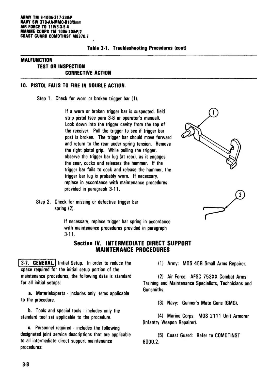
Step 4. Check for broken sear pin (3).
A defective sear pin can only be inspected by
removing the sear. If broken, replace in accordance
with maintenance procedures provided in paragraph
3-11.
Step 5. Check hammer for broken or worn sear and/or hammer
notches (4).
If broken or worn, replace in accordance with
maintenance procedures provided in paragraph 3-11.
9. HAMMER DOES NOT DECOCK WITH SAFETY IN THE SAFE
POSITION.
Step 1. Check for dirt in receiver jamming hammer (1).
Disassemble receiver in accordance with maintenance
procedures provided in paragraph 3-11. Clean with
CLP (item 5, app D)/RBC (item 7, app D) and
lubricate with CLP (item 5, app DI/LSA (item 15, app
Step 2. Check for defective (worn or broken) hammer release
lever (2).
Inspect lower hammer release lever finger. Ensure
that the hammer release lever finger engages the
back side of the sear. This can be done by looking
into the magazine well from the top. If the hammer
release lever fails to engage the sear, replace in
accordance with maintenance procedures provided in
paragraph 3-11.
3-7
ARMY TM 9-1005-317-23&P
NAVY SW 370AAMM0010/9mm
AIR FORCE TO 11W3-3-5-4
MARINE CORPS TM 100S 23&P/2
COAST GUARD COMDTINST M8370.7
Table 3-1. Troubleshooting Procedures (cont)
MALFUNCTION
TEST OR INSPECTION
CORRECTIVE ACTION
10. PISTOL FAILS TO FIRE IN DOUBLE ACTION.
Step 1. Check for worn or broken trigger bar (1).
If a worn or broken trigger bar is suspected, field
strip pistol (see para 3-8 or operator's manual).
Look down into the trigger cavity from the top of
the receiver. Pull the trigger to see if trigger bar
post is broken. The trigger bar should move forward
and return to the rear under spring tension. Remove
the right pistol grip. While pulling the trigger,
observe the trigger bar lug (at rear), as it engages
the sear, cocks and releases the hammer. If the
trigger bar fails to cock and release the hammer, the
trigger bar lug is probably worn. If necessary,
replace in accordance with maintenance procedures
provided in paragraph 3-11.
Step 2. Check for missing or defective trigger bar
spring (2).
If necessary, replace trigger bar spring in accordance
with maintenance procedures provided in paragraph
3-11.
Section IV. INTERMEDIATE DIRECT SUPPORT
MAINTENANCE PROCEDURES
| 3-7. GENERAL Initial Setup. In order to reduce the
space required for the initial setup portion of the
maintenance procedures, the following data is standard
for all initial setups:
a. Materials/parts includes only items applicable
to the procedure.
b. Tools and special tools includes only the
standard tool set applicable to the procedure.
c. Personnel required - includes the following
designated joint service descriptions that are applicable
to all intermediate direct support maintenance
procedures:
(1) Army: MOS 45B Small Arms Repairer.
(2) Air Force: AFSC 753XX Combat Arms
Training and Maintenance Specialists, Technicians and
Gunsmiths.
(3) Navy: Gunner's Mate Guns (GMG).
(4) Marine Corps: MOS 2111 Unit Armorer
(Infantry Weapon Repairer).
(5) Coast Guard: Refer to COMDTINST
8000.2.
3-8
ARMY TM 9-1005-317-23&P
NAVY SW 370AA-MM0010l9min
AIR FORCE TO 11W3-3-5-4
MARINE CORPS TM 1005-23&P/2
COAST GUARD COMDTINST M8370.7
3-7. GENERAL (cont). I
d. References includes the operator's manual for
joint service use:
(1) ARMY TM 9-1005-317-10.
(2) NAVY SW 370-AA 0PI-010/9mm.
(3) AIR FORCE TO 11W3-3-5-1.
(4) MARINE CORPS TM 1005A-10/1.
(5) COAST GUARD COMDTINST M8370.6.
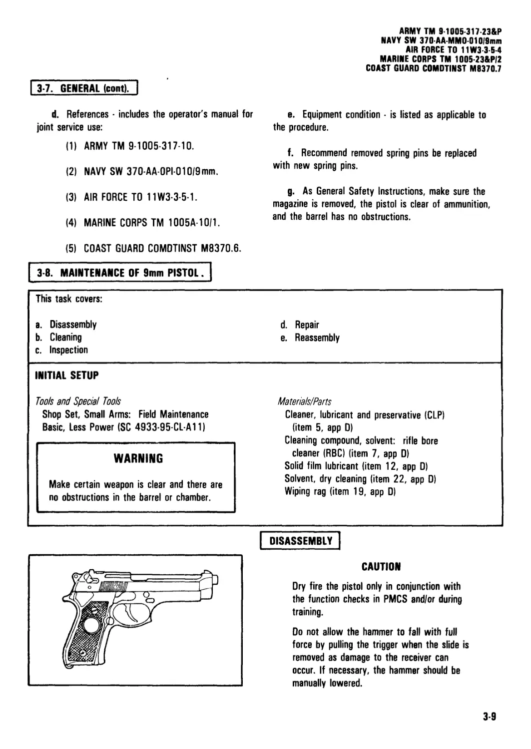
3-8. MAINTENANCE OF 9mm PISTOL.
e. Equipment condition is listed as applicable to
the procedure.
f. Recommend removed spring pins be replaced
with new spring pins.
g. As General Safety Instructions, make sure the
magazine is removed, the pistol is clear of ammunition,
and the barrel has no obstructions.
This task covers:
a. Disassembly d. Repair
b. Cleaning e. Reassembly
c. Inspection
Tools and Special Tools
Shop Set, Small Arms: Field Maintenance
Basic, Less Power (SC 4933-95-CL-A11)
INITIAL SETUP
Materials/Parts
Cleaner, lubricant and preservative (CLP)
(item 5, app D)
Cleaning compound, solvent: rifle bore
cleaner (RBC) (item 7, app D)
Solid film lubricant (item 12, app D)
Solvent, dry cleaning (item 22, app D)
Wiping rag (item 19, app D)
WARNING
Make certain weapon is clear and there are
no obstructions in the barrel or chamber.
DISASSEMBLY
CAUTION
Dry fire the pistol only in conjunction with
the function checks in PMCS and/or during
training.
Do not allow the hammer to fall with full
force by pulling the trigger when the slide is
removed as damage to the receiver can
occur. If necessary, the hammer should be
manually lowered.
3-9
ARMY TM 9-1005-317-23&P
NAVY SW 370-AA-MM0 010/9min
AIR FORCE TO 11W3-3-5-4
MARINE CORPS TM 1005-23&P/2
COAST GUARD COMDTINST M9370.7
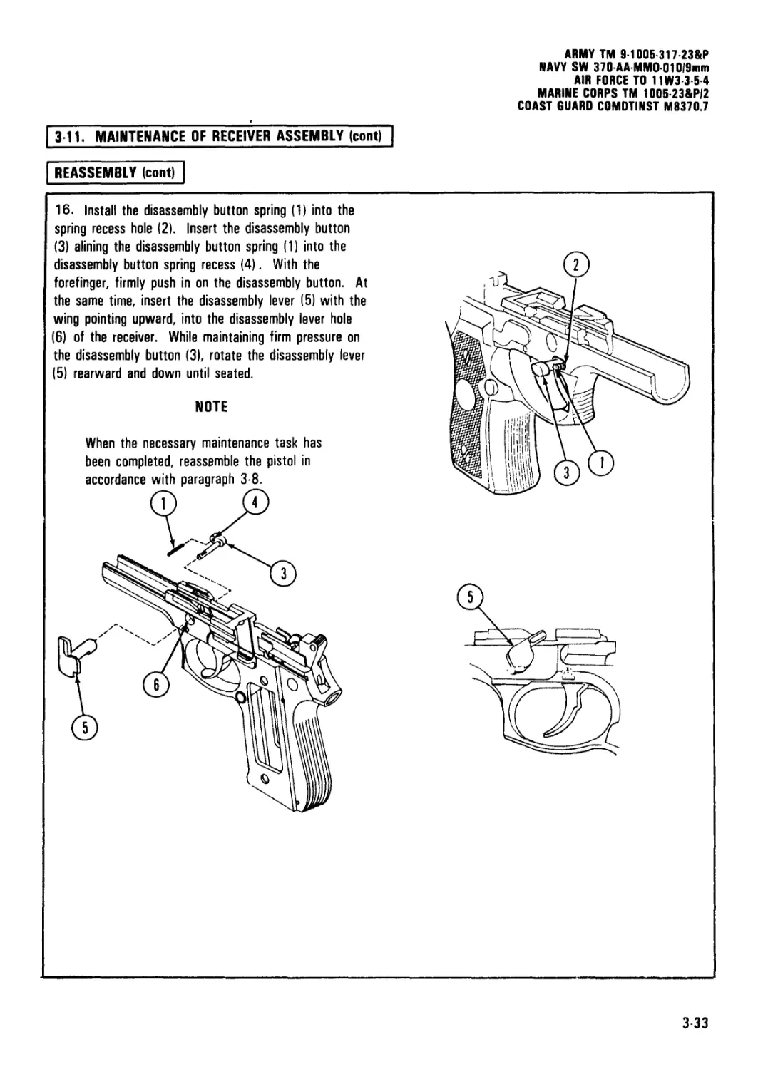
| 3 8. MAINTENANCE OF 9mm PISTOL (cont)'
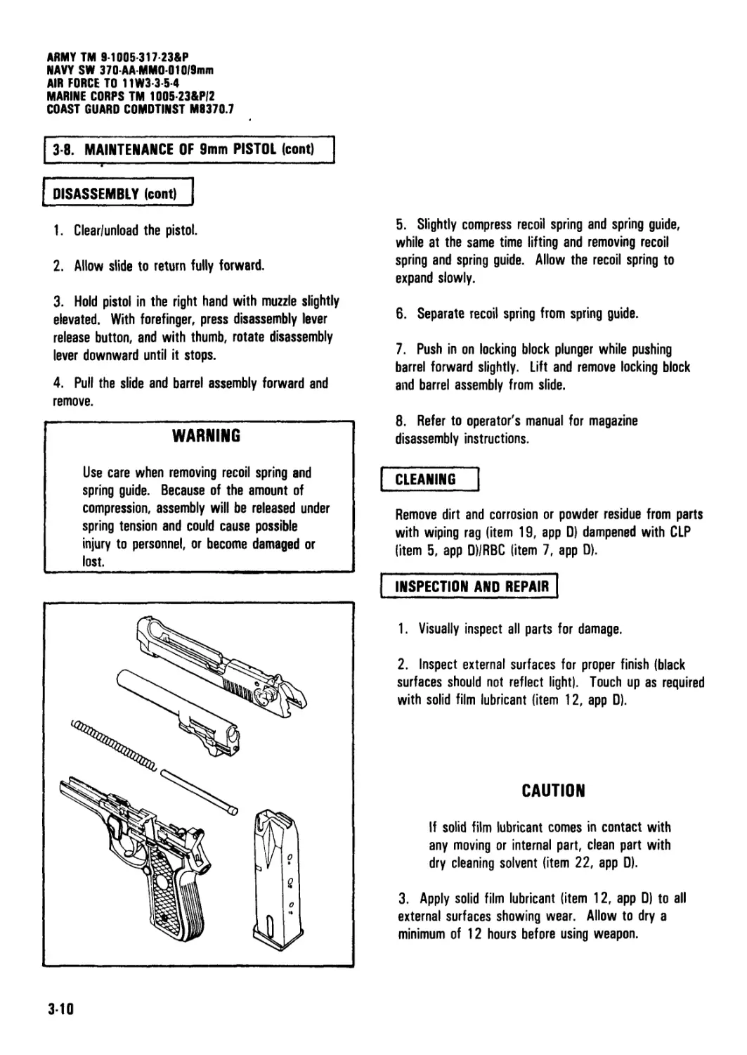
DISASSEMBLY (cont)
1. Clear/unload the pistol.
2. Allow slide to return fully forward.
3. Hold pistol in the right hand with muzzle slightly
elevated. With forefinger, press disassembly lever
release button, and with thumb, rotate disassembly
lever downward until it stops.
4. Pull the slide and barrel assembly forward and
remove.
WARNING
Use care when removing recoil spring and
spring guide. Because of the amount of
compression, assembly will be released under
spring tension and could cause possible
injury to personnel, or become damaged or
lost.
5. Slightly compress recoil spring and spring guide,
while at the same time lifting and removing recoil
spring and spring guide. Allow the recoil spring to
expand slowly.
6. Separate recoil spring from spring guide.
7. Push in on locking block plunger while pushing
barrel forward slightly. Lift and remove locking block
and barrel assembly from slide.
8. Refer to operator's manual for magazine
disassembly instructions.
CLEANING
Remove dirt and corrosion or powder residue from parts
with wiping rag (item 19, app D) dampened with CLP
(item 5, app D)/RBC (item 7, app D).
INSPECTION AND REPAIR
1. Visually inspect all parts for damage.
2. Inspect external surfaces for proper finish (black
surfaces should not reflect light). Touch up as required
with solid film lubricant (item 12, app D).
CAUTION
If solid film lubricant comes in contact with
any moving or internal part, clean part with
dry cleaning solvent (item 22, app D).
3. Apply solid film lubricant (item 12, app D) to all
external surfaces showing wear. Allow to dry a
minimum of 12 hours before using weapon.
3-10
ARMY TM 9-1005-317-23&P
NAVY SW 370-AA-MMO-010|9mm
AIR FORCE TO 11W3-3-5-4
MARINE CORPS TM 1005-23&PI2
COAST GUARD COMDTINST M9370.7
3-8. MAINTENANCE OF 9mm PISTOL (cont)
REASSEMBLY ]
1. Grasp the slide with the bottom facing up. With
the other hand, grasp the barrel assembly with the
locking block facing up.
2. Insert muzzle of the barrel assembly into the
forward open end of the slide. At the same time,
lower the rear of the barrel assembly by slightly moving
the barrel downward with light thumb pressure. The
barrel will fall into place.
3. Insert recoil spring onto recoil spring guide.
CAUTION
During spring insertion, spring tension must
be maintained until spring guide is fully
seated onto the cutaway on the locking
block.
4. Insert end of recoil spring and recoil spring guide
into slide recoil housing. At the same time, compress
the recoil spring and lower the spring guide until fully
seated onto the locking block cutaway.
CAUTION
Be sure hammer is uncocked and firing pin
block lever is in the down position. If the
hammer is cocked, carefully and manually
lower the hammer.
Do not pull trigger while placing the slide
onto the receiver.
5. Grasp the slide and barrel assembly, sights up, and
aline the slide onto the receiver assembly guide rails.
6. Push until the rear of the slide is a short distance
beyond the rear of the receiver assembly and hold. At
the same time, rotate the disassembly latch lever
upward. A click indicates a positive lock.
7. Refer to the operator's manual for magazine
reassembly.
[ 3-9. MAINTENANCE OF BARREL ASSEMBLY?
This task covers:
a. Disassembly c. Inspection/Repair
b. Cleaning d. Reassembly
INITIAL SETUP
Tools and Special Tools
Shop Set, Small Arms: Field Maintenance
Basic, Less Power (SC 4933-95-CL-A11)
Materials/Parts
Brush, cleaning small (item 4, app D)
Cleaner, lubricant and preservative (CLP)
(item 5, app D)
Cleaning compound, solvent, rifle bore cleaner
(RBC) (item 7, app D)
Cloth, abrasive, crocus (item 8, app D)
Lubricating oil, weapons semi fluid (LSA)
(item 15, app D)
Wiping rag (item 19, app D)
Locking block plunger spring pin (9346423)
WARNING
Make certain weapon is clear and there
are no obstructions in the barrel or chamber.
Equipment Condition
Pistol, field stripped
3-11
ARMY TM 9-1005-317 23&P
NAVY SW 370-AA-MMO-010/9mm
AIR FORCE TO 11W3-3 5 4
MARINE CORPS TM 100523&P/2
COAST GUARD COMDTINST M9370.7
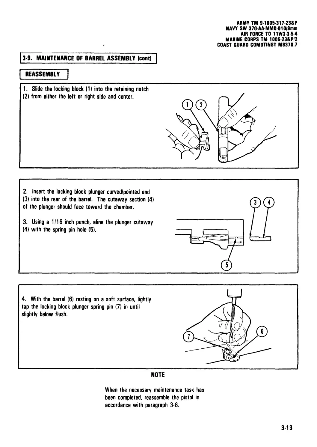
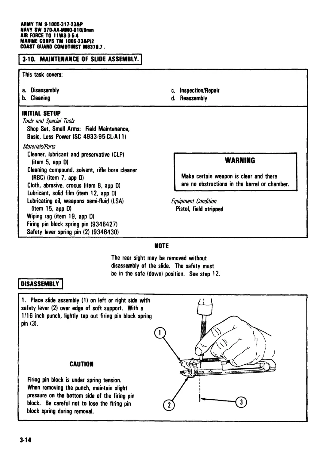
3 9. MAINTENANCE OF BARREL ASSEMBLY (cont).
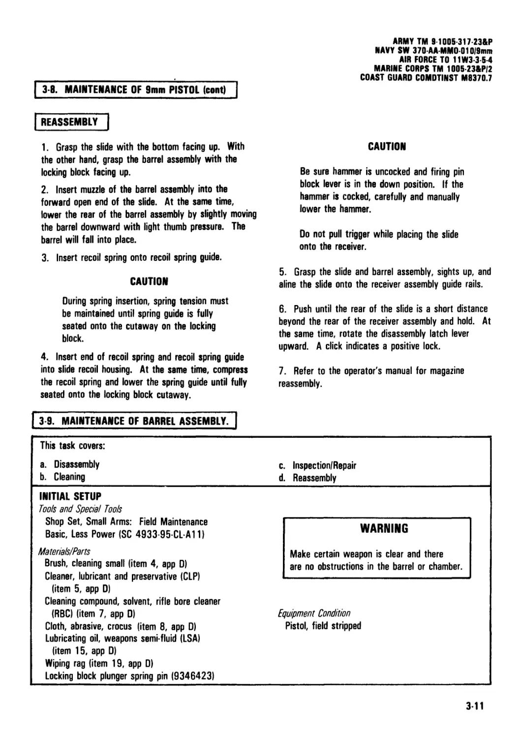
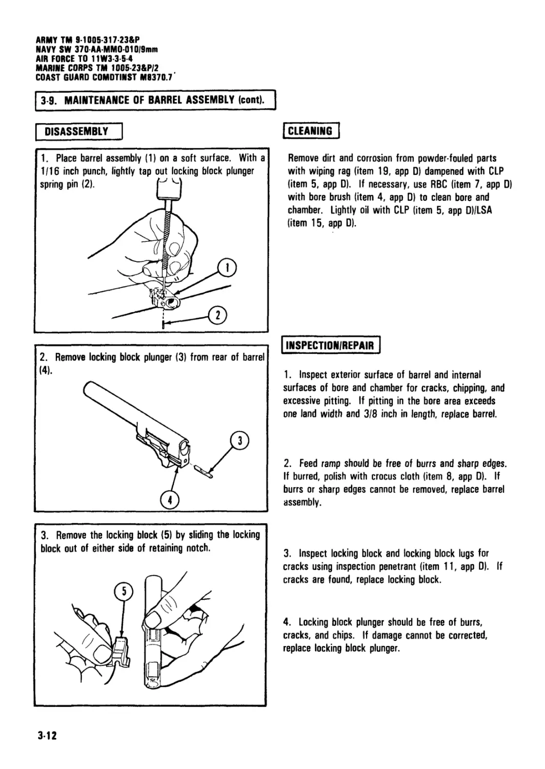
DISASSEMBLY
1. Place barrel assembly (1) on a soft surface. With a
1/16 inch punch, lightly tap out locking block plunger
| CLEANING |
Remove dirt and corrosion from powder-fouled parts
with wiping rag (item 19, app D) dampened with CLP
(item 5, app D). If necessary, use RBC (item 7, app D)
with bore brush (item 4, app D) to clean bore and
chamber. Lightly oil with CLP (item 5, app D)/LSA
(item 15, app D).
2. Remove locking block plunger (3) from rear of barrel
(4).
INSPECTION/REPAIR
1. Inspect exterior surface of barrel and internal
surfaces of bore and chamber for cracks, chipping, and
excessive pitting. If pitting in the bore area exceeds
one land width and 3/8 inch in length, replace barrel.
2. Feed ramp should be free of burrs and sharp edges.
If burred, polish with crocus cloth (item 8, app D). If
burrs or sharp edges cannot be removed, replace barrel
assembly.
3. Remove the locking block (5) by sliding the locking
block out of either side of retaining notch.
3. Inspect locking block and locking block lugs for
cracks using inspection penetrant (item 11, app 0). If
cracks are found, replace locking block.
4. Locking block plunger should be free of burrs,
cracks, and chips. If damage cannot be corrected,
replace locking block plunger.
3-12
ARMY TM 9-100S-317-23&P
NAVY SW 370-AA-MM0-010/9min
AIR FORCE TO 11W3-3-5-4
MARINE CORPS TM 1005-23&P/2
COAST GUARD COMDTINST M9370.7
3-9. MAINTENANCE OF BARREL ASSEMBLY (cont)
REASSEMBLY
1. Slide the locking block (1) into the reteining notch
(2) from either the left or right side and center.
2. Insert the locking block plunger curved/pointed end
(3) into the rear of the barrel. The cutaway section (4)
of the plunger should face toward the chamber.
3. Using a 1/16 inch punch, aline the plunger cutaway
(4) with the spring pin hole (5).
4. With the barrel (6) resting on a soft surface, lightly
tap the locking block plunger spring pin (7) in until
slightly below flush.
NOTE
When the necessary maintenance task has
been completed, reassemble the pistol in
accordance with paragraph 3-8.
3-13
ARMY TM 9-1005-317-23&P
NAVY SW 370 AA-MM0 010f9mm
AM FORCE TO 11W3-3-5-4
MARINE CORPS TM 1005-23&P/2
COAST GUARD COMDTINST M8370.7 .
3-10. MAINTENANCE OF SLIDE ASSEMBLY.
This task covers:
a. Disassembly b. Cleaning c. d. Inspection/Repair Reassembly
INITIAL SETUP Tools and Special Toots Shop Set, Small Arms: Field Maintenance, Basic, Less Power (SC 4933-95-CL-A11) Materials/Parts Cleaner, lubricant and preservative (CLP) (item 5, app D) Cleaning compound, solvent, rifle bore cleaner (RBC) (item 7, app D) Cloth, abrasive, crocus (item 8, app D)
WARNING Make certain weapon is clear and there are no obstructions in the barrel or chamber.
Lubricant, solid film (item 12, app □) Lubricating oil, weapons semi-fluid (LSA) (item 15, app D) Wiping rag (item 19, app D) Firing pin block spring pin (9346427) Safety lever spring pin (2) (9346430) Equipment Condition Pistol, field stripped
NOTE
disassembly"!
The rear sight may be removed without
disassembly of the slide. The safety must
be in the safe (down) position. See step 12.
1. Place slide assembly (1) on left or right side with
safety lever (2) over edge of soft support. With a
1/16 inch punch, lightly tap out firing pin block spring
pin (3).
CAUTION
Firing pin block is under spring tension.
When removing the punch, maintain slight
pressure on the bottom side of the firing pin
block. Be careful not to lose the firing pin
block spring during removal.
314
ARMYTM 9 1005-317-23&P
NAVY SW 370 AA-MMO-01019mm
AIR FORCE TO 11W3-3-5-4
MARINE CORPS TM 1005-23&PI2
COAST GUARD COMDTINST M9370.7
I 3-10. MAINTENANCE OF SLIDE ASSEMBLY (cont) ]
| DISASSEMBLY (cont) |
2. With the forefinger, push in slightly on the bottom
side of the firing pin block. Remove the 1/16 inch
punch from the firing pin block pin hole (1).
4. Place the slide on a soft support with the sights (1)
up. With a 1/16 inch punch, lightly tap out both right
safety lever spring pins (2).
5. Remove the right safety lever wing (3).
3. Slowly releese the pressure on the firing pin block
(1). Remove the firing pin block (1) and firing pin block
spring (2) from cavity.
CAUTION
The trigger bar detent and the left safety
detent are under spring tension. The palms
of both hands should be used when
removing the safety from the slide to
prevent loss of detents and springs.
6. Rotate safety lever (1) to fire (up) position. With a
punch, push in on the rear of the firing pin striker (2)
and rotate safety lever up past fire position until click
is heard and hold. Carefully push in on the right side
of the safety (3) while maintaining control of detents
and springs.
NOTE
In order to remove the spring pins for
removal of the right safety lever wing, the
lever must be in the safe (down) position.
3-15
ARMY TM 9-1005-317-23&P
NAVY SW 370-AA-MM0 010|9mm
AIR FORCE TO 11W3-3-S-4
MARINE CORPS TM 1005-23&P/2
COAST GUARD COMDTINST M9370.7
1310. MAINTENANCE OF SLIDE ASSEMBLY (cont) |
| DISASSEMBLY (cont) |
8. Remove the safety (1) and firing pin striker (2) from
the slide. Remove the firing pin striker (2) from the
safety (1).
9. Place the slide on a soft support with the sights
down. Place the slide in a position so the headed
extractor pin can be tapped out., With a 3/32 inch
punch, lightly tap out the headed extractor pin (1)
downward at a slight angle. With a pair of pliers,
carefully pull the headed extractor pin from the slide
while maintaining slight pressure on the rear of the
extractor.
_______________
CAUTION
When releasing pressure from the rear of the
extractor, ensure the rear of the slide is
covered to prevent ejection of the firing pin
and the firing pin spring.
11. Remove the firing pin (1) and firing pin spring (2)
by elevating the muzzle end of the slide (3).
CAUTION
Rear sight can only be removed/reinstalled
from the left side of slide.
NOTE
Removal of rear sight is authorized only
when replacement is required.
12. Clamp the slide into a soft-jawed vise between the
breech face and the front sight. Support the slide near
the rear sight with a soft support. With a brass punch,
tap the rear sight (1) out of the dovetail on slide.
316
ARMY TM 9-1005-317-23&P
NAVY SW 370-AA-MMO-010f9mm
AIR FORCE TO 11W3-3-5-4
MARINE CORPS TM 1005 23&PI2
COAST GUARD COMDTINST M0370.7
| 3 10. MAINTENANCE OF SLIDE ASSEMBLY (cont) |
| CLEANING |
Remove dirt and corrosion from powder-fouled parts
with wiping rag (item 19, app D) dampened in CLP
(item 5, app D)/RBC (item 7, app D). Lightly lubricate
with CLP (item 5, app D)/LSA (item 15, app D) after
cleaning.
INSPECTION/REPAIR
NOTE
When inserting the firing pin, the firing pin
block cutout in the firing pin must be alined
to the proper angle with the firing pin block
cutout of the slide.
Inspect slide for burrs or chips on contact surfaces.
Polish with crocus cloth (item 8, app D) if necessary.
Inspect slide for cracks using inspection penetrant (item
11, app D). Inspect firing pin for mushrooming, pitting,
or cracks. If necessary, replace. Firing pin spring
should not be bent or broken. If bent or broken,
replace. Check rear sight for looseness upon
reassembly. If loose, try another rear sight. Safety
lever should not be bent or burred. If bent, replace. If
burred, polish with crocus cloth (item 8, app D).
Detents and springs should not be bent or broken. If
bent or broken, replace. Free length of recoil spring will
not be less than 4 3/4 inches. If free length is less
than 4 3/4 inches, replace recoil spring. Extractor
hook should not be burred or broken. If broken,
replace. Breech face should be smooth with no burrs.
If burred, polish with crocus cloth (item 8, app D). All
parts should have a dull black finish (except the firing
pin and springs). External surface finish is critical. If
shiny surfaces exist, use solid film lubricant (item 12,
app D).
| REASSEMBLY
1. Place the slide into a soft-jawed vise. Lightly tap
the rear sight (1), with notch of sight facing to the
rear, into the dovetail on rear of slide.
2. Place the firing pin spring (1) onto the forward
portion of the firing pin (2).
3. Insert the firing pin (2) and the firing pin spring (1)
into the rear of the slide (3) with cutout (4) facing to
the right.
4. With a punch, push in on the firing pin. Insert the
firing pin block (1) upside down into the firing pin block
cutout in the top of the slide. This will ensure that the
cutout of the firing pin is alined with the extractor
retaining pin hole (2).
3-17
ARMY TM 9-1005-317-23&P
NAVY SW 370-AA MMO 010/9 mm
AIR FORCE TO 11W3-3-S-4
MARINE CORPS TM 1005-23&P/2
COAST GUARD COMDTINST M8370.7
3 10. MAINTENANCE OF SLIDE ASSEMBLY (cont)
REASSEMBLY (cont) |
5. Insert the extractor spring (1) into the extractor
spring recess hole (2). Insert the extractor (3) into the
extractor cutout (4).
6. Insert and push the headed extractor pin (5) into
the headed extractor pin hole (6) until it engages and
retains extractor (3), while maintaining pressure on the
7. Lightly tap in the headed extractor pin (1). With a
3/32 inch punch, lightly tap the headed extractor pin in
until seated.
8. Remove firing pin block (2) from the firing pin block
cutout.
The trigger bar detent spring and firing pin
block spring are interchangeable. The safety
detent spring is slightly larger than the
trigger bar detent and firing pin block
springs.
10. Preposition the smaller trigger bar detent (1) and
spring (2) into the trigger bar detent retaining hole.
Also preposition the safety detent (3) and spring (4)
into the safety lever (5).
11. Insert the safety into the slide with the safety
wing slightly above the fire (up) position. Ensure the
rear of the striker is flush with the rear of the safety.
Push the safety in until contacting the trigger bar
detent (1) and spring (2). With a punch, push
downward on the trigger bar detent (1) and spring (2).
While maintaining pressure on the trigger bar detent (1),
push the safety over the top of the detent. With a
punch, push in on the safety detent (3) and spring (4),
at the same time, pushing the safety (5) all the way to
the right until seated. Rotate the safety (5) down to
the safe position.
3-18
ARMY TM 9-1005-317 23&P
NAVY SW 370-AA-MM001019mm
AIR FORCE TO 11W3-3 5-4
MARINE CORPS TM 1005-23&PI2
COAST GUARD COMDTINST M8370.7
I 3-10. MAINTENANCE OF SLIDE ASSEMBLY (c^t[
REASSEMBLY (cont) ~|
12. Insert the right safety wing (1) onto the safety
14. With the forefinger, push in on the firing pin block
(1). Place the slide on its side and with a 3/32 inch
punch, lightly tap the firing pin block spring pin in until
slightly below flush.
NOTE
If safety does not rotate freely between
safe and fire positions, check right safety
lever spring pins for correct installation.
NOTE
When the necessary maintenance task has
been completed, reassemble the pistol in
accordance with paragraph 3-8.
3-19
ARMY TM 9-1005-317-23&P
NAVY SW 370AA-MM0-01019mm
AIR FORCE TO 11W3-3-5-4
MARINE CORPS TM 1005-23&P/2
COAST GUARD COMDTINST M9370.7
| 3-11. MAINTENANCE OF RECEIVER ASSEMBLY.
This task covers:
a. Disassembly b. Cleaning c. Inspection/Repair d. Reassembly
INITIAL SETUP Tools and Special Tools Shop Set, Small Arms: Field Maintenance, Basic, Less Power (SC 4933-95-CL-A11) M9 Staking Tool Materials/Parts (cont) Ejector spring pin (9346468) Lanyard loop spring pin (9346459)
Materials/Parts Brush, cleaning, small arms: toothbrush (item 3, app 0) Cleaner, lubricant and preservative (CLP) (item 5, app D) WARNING Be sure weapon is clear and there are no obstructions in the barrel or chamber.
Cleaning compound, solvent: rifle bore cleaner (RBC) (item 7, app D) Cloth, abrasive, crocus (item 8, app D) Inspection penetrant (item 11, app D) Lubricant, solid film (item 12, app D) Lubricating oil, weapons semi-fluid (LSA) (item 15, app D) Rag, wiping (item 19, app 0) Equipment Condition Pistol, field stripped
DISASSEMBLY
CAUTION
To prevent loss of disassembly button and
spring, be sure to release button pressure
slowly after the removal of the disassembly
latch lever.
1. Push in on the disassembly latch button (1) and
rotate the disassembly latch lever (2) upward until
contacting the slide rail. While maintaining firm
pressure on the disassembly latch button (1), pull out
and rotate upward to remove the disassembly latch
lever (2).
3-20
ARMY TM 9-1005-317-23&P
NAVY SW 370 AA-MM0 010|9mm
AIR FORCE TO 11W3-3-5-4
MARINE CORPS TM 1005-23&P/2
COAST GUARD COMDTINST M8370.7
3-11. MAINTENANCE OF RECEIVER ASSEMBLY (cont)
DISASSEMBLY (cont)
NOTE
When removing each pistol grip, the
lockwashers may remain seated or come
loose. Be careful not to lose them.
3. Remove the grip screws (1). Using the forefinger,
insert the finger into the magazine well and gently lift
up on the pistol grip (2). Repeat the procedure to
remove the other grip.
3-21
ARMY TM 9-100Б-317-23&Р
NAVY SW 370-AA-MM0010/9mm
AIR FORCE TO 11W3-3-S-4
MARINE CORPS TM 1005-23&P/2
COAST GUARD COMDTINST M8370.7
3-11. MAINTENANCE OF RECEIVER ASSEMBLY (cont)
DISASSEMBLY (cont)
4. Place the receiver on the left side. Locate the
trigger bar spring (1) just below the trigger bar (2).
With the tip of fingernail or screwdriver, or the use of
needle-nose pliers, carefully unseat the upper portion of
the trigger bar spring (1) from the trigger bar (2).
Gently lift up and remove the trigger bar spring (1)
from the hole in the receiver.
5. To remove the trigger bar (2), unseat the trigger
bar by inserting the forefinger into the receiver and
pushing outward on the trigger bar. Pull the trigger bar
out from the right side of the receiver (3).
6. Rotate the slide stop (1) slightly upward and pull
out until the slide stop (1) can rotate freely downward.
Remove the slide stop (1) and slide stop spring (2).
3 22
ARMY TM 9-1005-317-23&P
NAVY SW 370-AA-MM0010/9mm
AIR FORCE TO 11W3-3-5-4
MARINE CORPS TM 1005-23&P/2
COAST GUARD COMDTINST M8370.7
3-11. MAINTENANCE OF RECEIVER ASSEMBLY (cont)
DISASSEMBLY (cont)
WARNING
Cover the top of the trigger cavity to
prevent ejection or loss of the trigger spring,
or possible injury to personnel during removal
of the trigger pin.
7. With a 3/32 inch punch, push the headed trigger
pin (1) out from right to left.
8. To remove the trigger (2) and the trigger spring (3),.
push upward on the trigger and pull out.
WARNING
During removal of the lanyard loop spring
pin, be sure the punch is left in place to
prevent accidental loss of parts or injury to
personnel.
10. Using a punch, remove the headed hammer pin (4)
by pushing out from right to left. Lift up and remove
the hammer (5) from the receiver (6). Rotate the
receiver upside down to allow the hammer strut (7) to
fall free.
CAUTION
Ensure hammer is in the down or forward
position.
9. With a 1/8 inch punch, drive out the lanyard loop
spring pin (1) leaving the punch in place. Place the
lanyard loop (2) on a soft support and push down firmly
on the top of the receiver to overcome the main spring(3)
tension . While maintaining downward pressure,
remove the punch and slowly release pressure to
remove the lanyard loop (2) and the main spring (3).
3-23
ARMY TM 9-1005-317-23&P
NAVY SW 370-AAMM0010|9mm
AIR FORCE TO 11W3-3-5-4
MARINE CORPS TM 1005-23&P/2
COAST GUARD COMDTINST M9370.7
| 3-11. MAINTENANCE OF RECEIVER ASSEMBLY (cont) |
DISASSEMBLY (cont) |
CAUTION
During removal of the sear pin, use the
finger to maintain control of the sear spring
to prevent ejection and/or loss.
11. With a 3/32 inch punch, push the sear pin (1) out
of the sear pin hole (2). Rotate the receiver (3) to
allow the sear (4) and the sear spring (5) to fall free.
3-24
ARMY TM 9 1005-317-23&P
NAVY SW 370 AA MMO 01019mm
AIR FORCE TO 11W3-3 54
MARINE CORPS TM 1005-23&P/2
COAST GUARD COMDTINST M8370.7
| 3-11. MAINTENANCE OF RECEIVER ASSEMBLY (cont) |
| DISASSEMBLY (cont) |
12. Place the receiver on its left side. With a 1/16
inch punch, lightly tap out the headed straight pin (1).
Remove the hammer release lever (2) and firing pin
block lever (3).
13. With a 1/16 inch punch, lightly tap out the ejector
spring pin (4) from right to left. Remove ejector (5).
14. Remove the magazine catch assembly (1) by
pushing in and to the rear with the tip of the finger on
the side opposite the magazine release button.
3-25
ARMY TM 9-1005-317 23&P
NAVY SW 370-AA-MM0010,9mm
AIR FORCE TO 11W3-3-5-4
MARINE CORPS TM 1005-23&P/2
COAST GUARD COMDTINST M8370.7
|3-11. MAINTENANCE OF RECEIVER ASSEMBLY]cont)
CLEANING |
Remove dirt and corrosion from powder-fouled parts
with wiping rag (item 19, app D) dampened in CLP
(item 5, app D). Lightly lubricate with CLP (item 5,
app DI/LSA (item 15, app 0) after cleaning.
After bushing is removed, clean out internal threads in
the receiver with toothbrush (item 3, app 0).
INSPECTION/REPAIR
1. Check receiver for distortion and burrs. If receiver
is distorted, receiver is unserviceable.
2. Remove burrs from parts with a fine honing stone
or crocus cloth (item 8, app 0).
3. Check pins for distortion, cracks or excessive wear.
Replace if distorted, cracked, or excessively worn.
4. Check springs for breaks, cracks, or distortion.
Free length of main spring will not be less than 2 3/8
inches. Replace broken, cracked or permanently set
springs.
5. Check receiver rails and receiver with inspection
penetrant (item 11, app 0). If cracks are detected,
receiver is unserviceable.
6. External surface finish is critical. If shiny surfaces
exist, use solid film lubricant (item 12, app □).
REASSEMBLY
NOTE
To reverse the magazine catch assembly,
install the button on the opposite side.
1. To install the magazine catch assembly (1), insert
the magazine catch assembly through the magazine well
window (2) at an angle. The long bushing (3) of the
magazine catch assembly (1) must catch on the edge of
the magazine catch assembly cutout (4). At the same
time, push in on the flat side of the magazine catch
assembly (1) and push down to seat.
3-26
ARMY TM 9-1005-317-23&P
NAVY SW 370 AA-MM0 01019mm
AIR FORCE TO 11W3-3-5-4
MARINE CORPS TM 1005-23&P/2
COAST GUARD COMDTINST M9370.7
311. MAINTENANCE OF RECEIVER ASSEMBLY (cont)
REASSEMBLY (cont)
2. Install the ejector (1) with the pointed/notched end
(2) forward and aline the ejector pin hole (3) with a
1/16 inch punch. Lightly tap the ejector spring pin (4)
in until slightly below flush.
3. To install the hammer release lever (1) and the
firing pin block lever (2), preposition the headed straight
pin (3) into the left side of the receiver (4). Position
the hammer release lever (1) with the curved arm
pointing up and to the rear. Then push the headed
straight pin (3) in until it holds the hammer release
lever in position. Insert the firing pin block lever (2)
with the bent foot extending through the upper
magazine well window cutout. Carefully aline the firing
pin block lever hole with a punch and lightly tap in the
headed straight pin (3), and stake.
3-27
ARMY TM 9-1005-317-23&P
NAVY SW 370AAMM0010/9mm
AIR FORCE TO 11W3-3-5-4
MARINE CORPS TM 1005-23&P/2
COAST GUARD COMDTINST M9370.7 .
3 11. MAINTENANCE OF RECEIVER ASSEMBLY (cont) |
| REASSEMBLY (cont) |
4. Preposition the sear pin (1) into the right side of
the receiver with the muzzle end of the receiver facing
upward. Insert the sear (2), with the flat side up,
through the magazine well window (3). Slide the sear
(2) toward the ejector (4). Lower the sear into the
sear cutout alining the hole in the sear with the hole in
the receiver. At the same time, push the sear pin (1)
in until it holds the sear in position. Install the sear
spring (5) with the short leg toward the ejector, and
the curved portion of the spring coil facing towards the
magazine well. With a punch, push down on the spring
coil (5) and, at the same time, push in the sear pin.
NOTE
Be sure the straight end of the hammer
strut is down and the curved/rounded end is
facing the rear.
5. Insert the rounded end of the hammer strut (1) into
the recess in the hammer (2).
3 28
ARMY TM 9-1005-317-23&P
NAVY SW 370-AAMM0010l9min
AIR FORCE TO 11W3-3-5-4
MARINE CORPS TM 1005-23&P/2
COAST GUARD COMDTINST M8370.7
311. MAINTENANCE OF RECEIVER ASSEMBLY (cont)
| REASSEMBLY (cont) |
6. With the receiver (1) resting on the right side, insert
the hammer (2) and hammer strut (3) into the hammer
cavity (4).
7. Aline the hammer with the hole in the receiver and
insert the straight headed hammer pin (5) into the left
side of the receiver until seated.
8. Rotate the receiver (1) until the bottom of the
magazine well (6) faces upward. Insert the main spring
(7) into the bottom of the main spring cavity (8).
Carefully aline the main spring (7) onto the hammer
strut (3).
CAUTION
Downward pressure must be maintained on
the lanyard loop to overcome the main
spring pressure. A 1/8 inch punch should be
used to aline the lanyard loop spring pin hole
with the hole in the receiver. This will
allow proper alinement of the lanyard loop
spring pin during installation.
Ensure hammer is in the down or forward
position.
9. Install the lanyard loop (9) into the main spring
cavity (8) with the cutout forward. Rotate the receiver
(1) and rest the lanyard loop (9) on a soft support.
Compress the main spring (7) by pushing down on the
receiver (1). At the same time, insert a 1/8 inch punch
to aline the lanyard loop spring pin (10) with the
lanyard loop pin hole (11). Drive the lanyard loop
spring pin (10) in until slightly below flush.
WRONG RIGHT
3-29
ARMY TM 9-1005-317-23&P
NAVY SW 370AA-MM0010/9mm
AIR FORCE TO 11W3-3-5-4
MARINE CORPS TM 1005-23&P/2
COAST GUARD COMDTINST M9370.7
3-11. MAINTENANCE OF RECEIVER ASSEMBLY (cont)
REASSEMBLY (cont)
10. Install the trigger (1) into the trigger cavity (2).
Aline the lower hole (3) of the trigger with the hole in
the receiver. Insert the trigger pin (4) into the left side
of the receiver (5) until it holds the trigger in position.
11- Insert the trigger bar post (1) through the oval
slot (2) into the trigger bar post hole of the trigger (3).
At the same time, insert the trigger bar lug |4) into the
trigger bar lug cutout (5) of the receiver.
3-30
ARMY TM 8-100S-317-23&P
NAVY SW 370-АА-ММО-010|9mm
AIR FORCE TO 11W3-3-B-4
MARINE CORPS TM 1005-23&P/2
COAST GUARD COMDTINST M8370.7
I 311. MAINTENANCE OF RECEIVER ASSEMBLY (cont)
REASSEMBLY (cont) |
WARNING
When applying pressure to the center/coil
area of trigger spring, use care to prevent
ejection of trigger spring as it could become
lost or cause possible injury to personnel.
12. With needle-nose pliers, grasp the trigger spring (1)
in the center/coil area with the straight leg of the
spring forward and the bent leg facing to the rear.
Lower the trigger spring into the trigger spring cutout,
ensuring that the bent leg of the trigger spring is
resting on top of the trigger bar post. With a
screwdriver, push down on the center/coil area and at
the same time, push the trigger pin (2) in until seated.
13. Install the 90 degree angle end of the trigger bar
spring (1) into the trigger bar spring retaining hole (2) in
the receiver (3). Then insert the rounded loop end of
the trigger bar spring into the trigger bar spring groove
(4) of the receiver. With a screwdriver or fingernail,
pull down and insert the slightly curved end (5) of the
trigger bar spring into the bottom groove of the trigger
bar (6).
3-31
ARMY TM 9-1005-317-23&P
NAVY SW 370 AAMMOOIOftmm
AIR FORCE TO 11W3-3-5-4
MARINE CORPS TM 1005-23&PI2
COAST GUARD COMDTINST M8370.7
3 11. MAINTENANCE OF RECEIVER ASSEMBLY (cont)
REASSEMBLY (cont)
NOTE
Ensure the bent leg of the slide stop spring
retains the trigger pin after installation.
14. Install the slide stop spring (1) on to the slide
stop post (2) with the straight leg resting in the slide
stop spring cutout (3) and the bent leg pointing down.
Insert the bent leg of the slide stop spring into the
forward slide stop cutout hole (3). At the same time,
insert the slide stop post (2) into the slide stop hole (4)
of the receiver (5). Rotate the slide stop (6) slightly
upward and push in until seated.
332
ARMY TM 9-1005-317-23&P
NAVY SW 370-AA-MM0 010|9inm
AIR FORCE TO 11W3-3-5-4
MARINE CORPS TM 1005-23&PI2
COAST GUARD COMDTINST M9370.7
3-11. MAINTENANCE OF RECEIVER ASSEMBLY (cont)
REASSEMBLY (cont)
16. Install the disassembly button spring (1) into the
spring recess hole (2). Insert the disassembly button
(3) alining the disassembly button spring (1) into the
disassembly button spring recess (4). With the
forefinger, firmly push in on the disassembly button. At
the same time, insert the disassembly lever (5) with the
wing pointing upward, into the disassembly lever hole
(6) of the receiver. While maintaining firm pressure on
the disassembly button (3), rotate the disassembly lever
(5) rearward and down until seated.
NOTE
When the necessary maintenance task has
been completed, reassemble the pistol in
accordance with paragraph 3-8.
3-33
ARMY TM 91005-317-23&P
NAVY SW 370AA-MM0-010/9mm
AIR FORCE TO 11W3-3-5-4
MARINE CORPS TM 100S-23&P/2
COAST GUARD COMDTINST M8370.7
3-12. FINAL INSPECTION
This task covers: a. General Inspection c. Trigger Pull Test b. Safety/Function Check d. Function-firing Test
INITIAL SETUP Tools and Special Tools Shop Set, Small Arms, Field Maintenance, Basic, Less Power (SC 4933-95-CL-A11) NOTE Final inspection should be done after all maintenance actions. This inspection ensures that pistols are serviceable when returned to user or stock.
WARNING Be sure pistol is clear and there are no obstructions in the barrel or chamber. Equipment Condition Pistol assembled (see para 3-8)
GENERAL INSPECTION 1. Check the overall condition of the pistol and make sure black finish surfaces do not reflect light. 2. Check the tightness of all attaching screws. 3. Check for adequate lubrication. 4. Check for missing parts. 5. Make an overall inspection of the pistol for cleanliness and general appearance. 6. Refer to paragraph 3-14 for preembarkation inspection criteria and specific standards. | SAFETY/FUNCTION CHECK 1. With the safety in safe position, depress the slide stop allowing slide to return fully forward. At the same time, the hammer should fall to the full forward position. 2. Squeeze and release trigger. Firing pin block should move up and down. Hammer should not move. 3. Place safety in fire position. 4. Squeeze trigger to check double action. Hammer should cock and fall. 5. Squeeze trigger again and hold to rear. Manually retract and release slide while holding trigger to the rear. Release trigger, click should be heard, and hammer should not fall. 6. Squeeze trigger to check single action. Hammer should fall. 7. If the above safety/function checks perform as indicated, pistol is mission ready. If the checks do not perform as indicated, refer to intermediate direct support for troubleshooting procedures (see para 3-6).
3-34
ARMY TM 9-1005-317-23&P
NAVY SW 370-АА ММ0-010,9mm
AIR FORCE TO 11W3-3-5-4
MARINE CORPS TM 1005-23&P/2
COAST GUARD COMDTINST M9370.7
| 3-12. FINAL INSPECTION.
| TRIGGER PULL TEST |
1. Place test fixture (1) on bench and add test
weights (2) until minimum load of 4.0 lbs is reached.
2. Single Action: Place the safety (3) in the fire (up)
position-and manually cock hammer (4).
3. Hold the pistol (5) in a vertical position. Place the
end of the test fixture (1) over the trigger (6). Slowly
raise the pistol in a line parallel to the barrel (7) until
the fixture and weights are suspended.
9. Add weights (2) until a maximum load of 16.5 lbs
is reached. Hold the pistol (5) in a vertical position.
Place the end of the test fixture (1) over the trigger
(6). Slowly raise the pistol in a line parallel to the
barrel (7) until the fixture and weights are suspended.
The hammer (4) shall move back slowly to the cocked
position, then release and snap forward quickly. If the
hammer does not meet these requirements, replace the
sear and/or hammer (see para 3-11) and retest.
4. The hammer (4) must not fall. If the hammer falls,
the trigger pull is too light and the sear and/or hammer
must be replaced. Replace the sear and/or hammer in
accordance with the maintenance procedures provided in
paragraph 3-11. If replacement of hammer and/or sear
fails to correct light trigger pull, inspect main spring for
correct free length. Replace if necessary (para 3-11).
5. Add weights until maximum load of 6.5 lbs is
reached. Repeat the above procedures. The hammer
(4) must fall. If the hammer does not fall, replace the
sear and/or hammer (see para 3-11).
NOTE
Ensure that safety is in the fire (up) position.
6. Double Action. The hammer (4) must be forward to
begin test. Do not cock the hammer. Add test
weights (2) until minimum of 7.5 lbs is reached.
7. Hold the pistol (5) in a vertical position. Place the
end of the test fixture (1) over the trigger (6). Slowly
raise the pistol in a line parallel to the barrel (7) until
the fixture and weights are suspended.
8. The hammer (4) must not fall. If the hammer falls,
the trigger pull is too light and the sear and/or hammer
must be replaced. Replace the sear and/or hammer in
accordance with the maintenance procedures provided in
paragraph 3-11. If replacement of hammer and/or sear
fails to correct light trigger pull, inspect main spring for
correct free length. Replace if necessary.
3-35
ARMY TM 9-1005-317 23&P
NAVY SW 370-AA MMO-010/9mm
AIR FORCE TO 11W3-3-5-4
MARINE CORPS TM 1005-23&P/2
COAST GUARD COMDTINST M0370.7
3-12. FINAL INSPECTION (cont) |
| FUNCTION FIRING TEST |
WARNING
Before performing the function-fire test, be
sure to clear the pistol. Do not squeeze the
trigger until the pistol has been cleared.
Inspect the chamber to be sure that it is
empty. Check to see that there are no
obstructions in the barrel.
1. If possible, upon completion of maintenance
procedures, the M9 Pistol should be function-fired to
assure proper operation.
2. Fire three rounds in single action.
3. Fire three rounds in double action.
4. If a test firing facility or live ammunition is not
available, use dummy ammunition to check chambering,
extraction, and ejection.
WARNING
Be sure pistol is clear and there are no
obstructions in the barrel or chamber.
5. Upon completion of function-firing test, clean and
lubricate the pistol in accordance with paragraph 3-8 or
the operator's manual.
Section V. PREPARATION FOR STORAGE OR SHIPMENT
3-13. PREPARATION FOR STORAGE OR SHIPMENT.
Refer to paragraph 2-15 for M9 (9mm) pistol cleaning,
preservation, packaging, packing and marking.
Section VI. PREEMBARKATION INSPECTION OF MATERIEL
IN UNITS ALERTED FOR OVERSEAS MOVEMENT
3 14. PREEMBARKATION INSPECTION OF
MATERIEL IN UNITS ALERTED FOR OVERSEAS
MOVEMENT.
a. Inspection Criteria.
WARNING
Before starting an inspection, be sure to
clear the weapon. Make sure the magazine
is removed, the pistol is clear of ammunition
and the barrel has no obstructions.
(1) Before inspection, the materiel must be
thoroughly cleaned of all grease, dirt, or other foreign
matter that might interfere with its proper function or
the use of gages and tools during inspection.
(2) The pistol must be free of burrs, rust, or
corrosion.
(3) Parts must not be loose, cracked, bent,
distorted, or damaged and must be free of excessive
wear.
(4) Minor defects in metal components do not
normally affect their acceptability. For example, tool
marks are ordinarily of no importance.
(5) Inspect finish of metal surface. Satisfac-
tory metal surfaces for weapons range from black to
light gray. Weapons will be rejected if exterior parts
have a reflective shine. Sights must have a dull gray
or black finish on surfaces that would cause glare.
336
ARMY TM 9-1005-317-23&P
NAVY SW 370-AA-MM0010|9mm
AIR FORCE TO 11W3 3 5 4
MARINE CORPS TM 1005 23&P/2
COAST GUARD COMDTINST M8370.7
3-14. PREEMBARKATION OF MATERIEL IN UNITS
ALERTED FOR OVERSEAS MOVEMENT (cont)
b. Inspection Areas.
(1) Springs must be free of distortion and
broken coils. Springs must have sufficient tension to
perform their intended function.
(2) Barrel must be clean and free of rust and
corrosion.
(3) Barrel must not be bulged.
(4) Pits in the bore are allowable if they
do not exceed the width of a land and 3/8 inch in
length.
(5) If chipping and flaking are present in the
chamber and/or bore area, it is cause for rejection of
the barrel.
(6) Tool marks are acceptable. They may
appear as lines running longitudinally in the grooves or
may run spirally across the tops of lands.
(7) Lands that appear dark will not be cause
for rejection because of coating of guilding metal from
projectiles.
(8) The sear and cocking notches must be in
good condition. Chipped engaging corners will be cause
for rejection. Slight wear on functional surfaces,
including engaging corners, shall be acceptable,
providing the minimum trigger pull requirements are met.
(9) Chips, flat spots, pits or bent strike points
on firing pins will be cause for rejection of firing pins.
(10) The cartridge case engaging surfaces on
the extractor must not be chipped or deformed.
(11) The safety must position positively in both
the safe (down) and fire (up) position. When in the
safe position, the pistol must not fire when the trigger
is squeezed; when in the fire position, the pistol must
fire when the trigger is squeezed.
(12) Each pistol must be hand functioned to
check for unusual binding, positive cocking action, and
general operation. Dummy ammunition may be used to
be sure of positive chambering, extraction, and ejection
action.
(13) All markings and serial numbers must be
legible.
c. Specific Standards. Refer to the following
table.
STANDARDS FOR PREEMBARKATION INSPECTION OF M9 9mm PISTOL IN UNITS ALERTED FOR OVERSEAS MOVEMENT
ITEM STANDARD
General Clear weapon of any ammunition and inspect in accordance with procedures outlined above.
Trigger Pull Double Action Single Action Minimum - 7.5 lbs; maximum - 16.5 lbs Minimum - 4.0 lbs; maximum - 6.5 lbs
Recoil Spring Free length of spring will not be less than 4 3/4 inches. A "flat" spot on either end of the half coil is not required. If flat spots are present other than on the ends of the spring, it is cause for rejection of the spring.
Main Spring Free length of spring will not be less than 2 3/8 inches. A "flat" spot on either end of the half coil is not required. If flat spots are present other than on the ends of the spring, it is cause for rejection of the spring.
3-37/(3-38 blank)