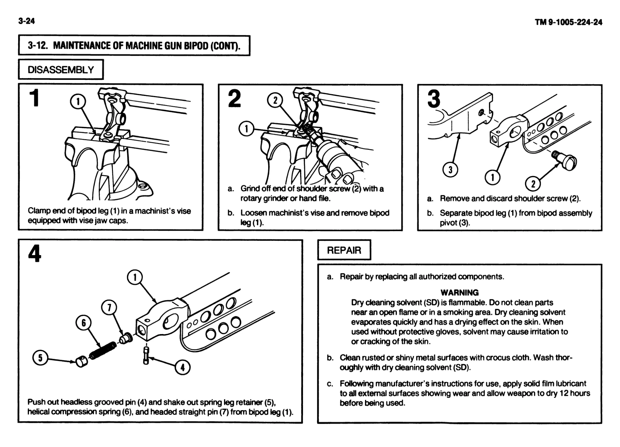
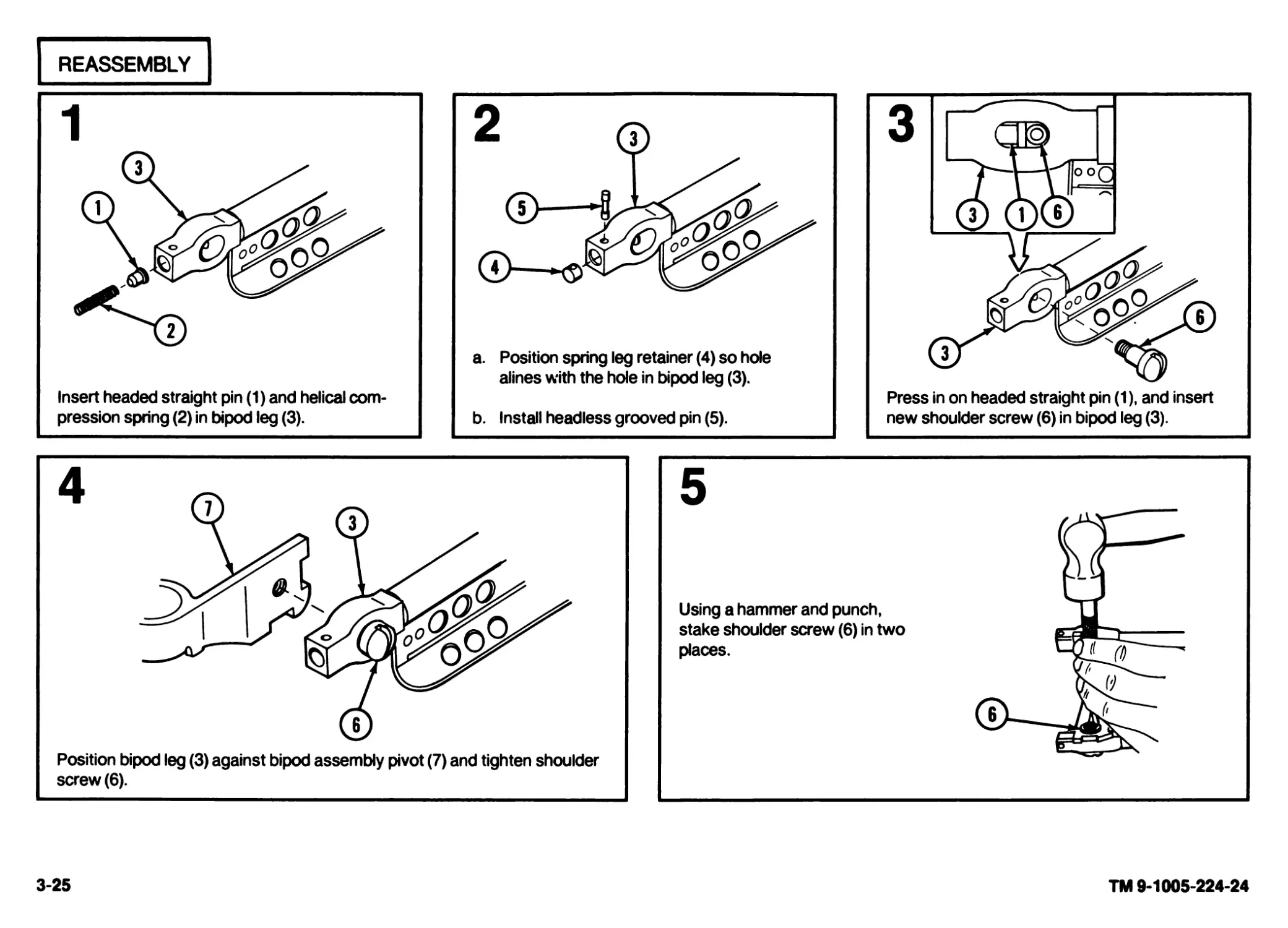
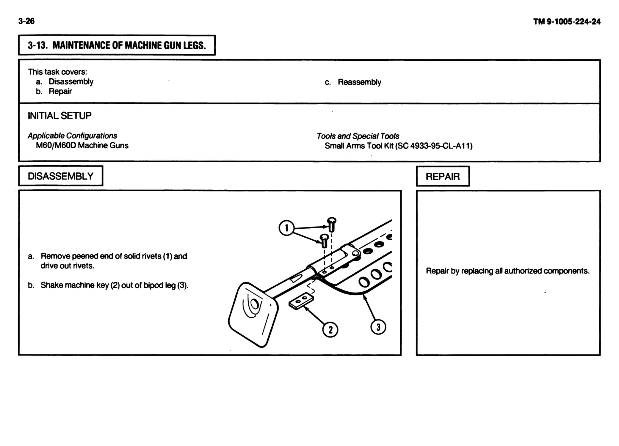
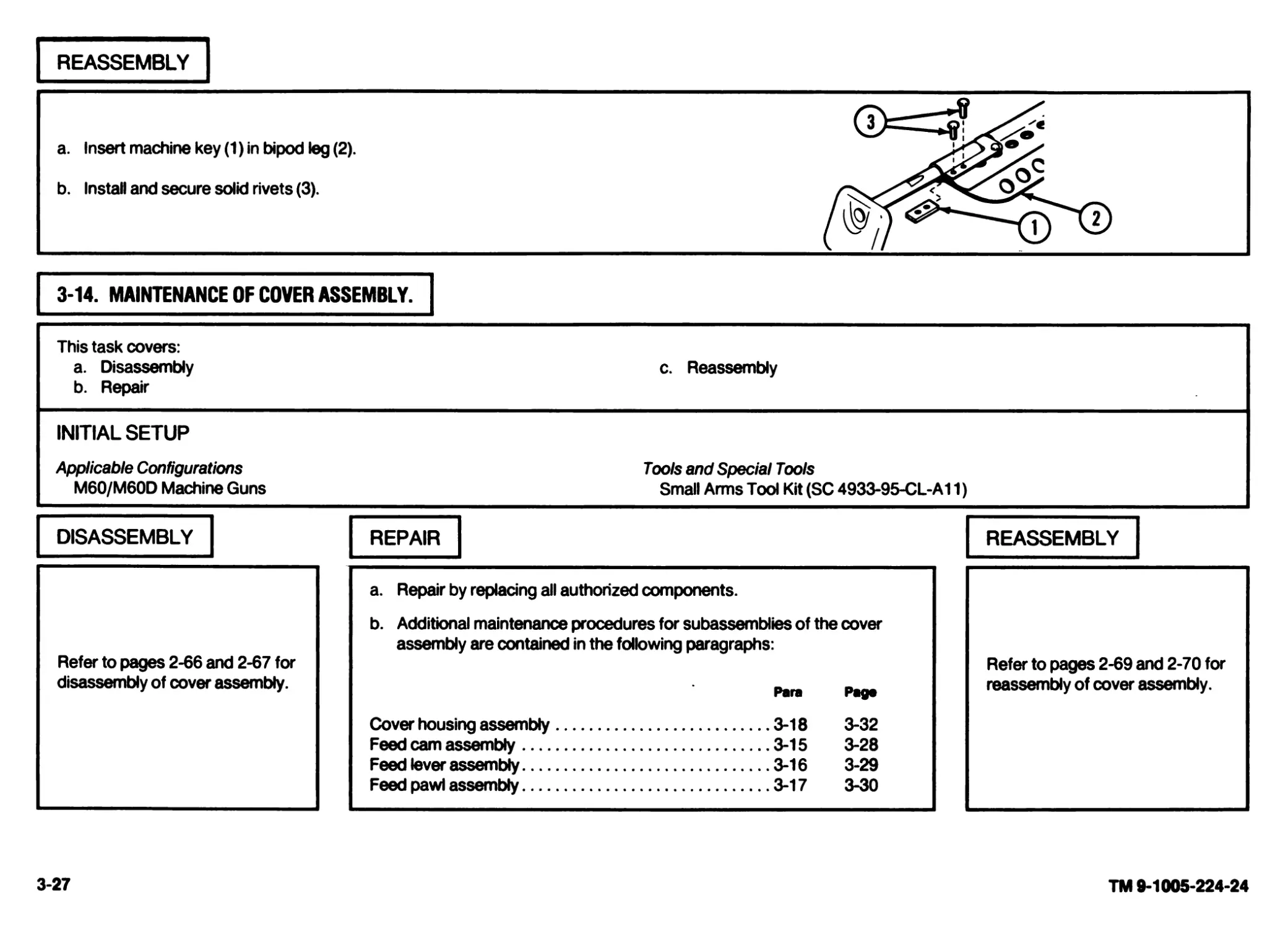
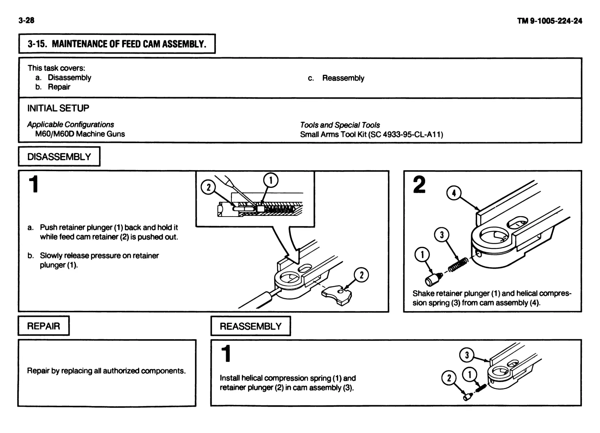
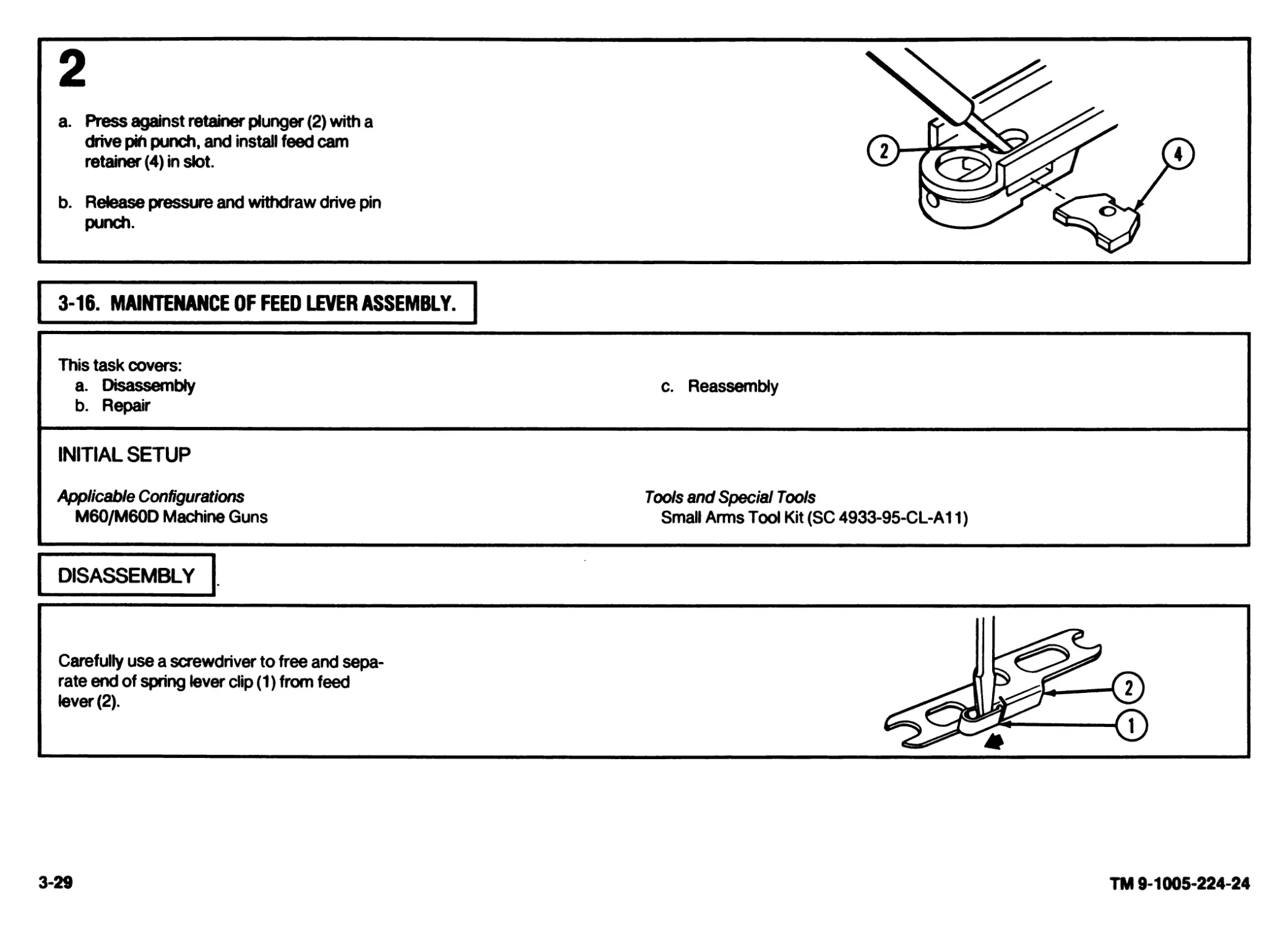
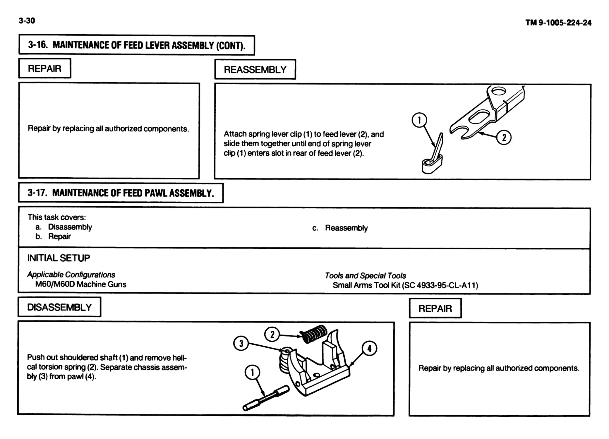
/


Tags: weapons military affairs machine gun
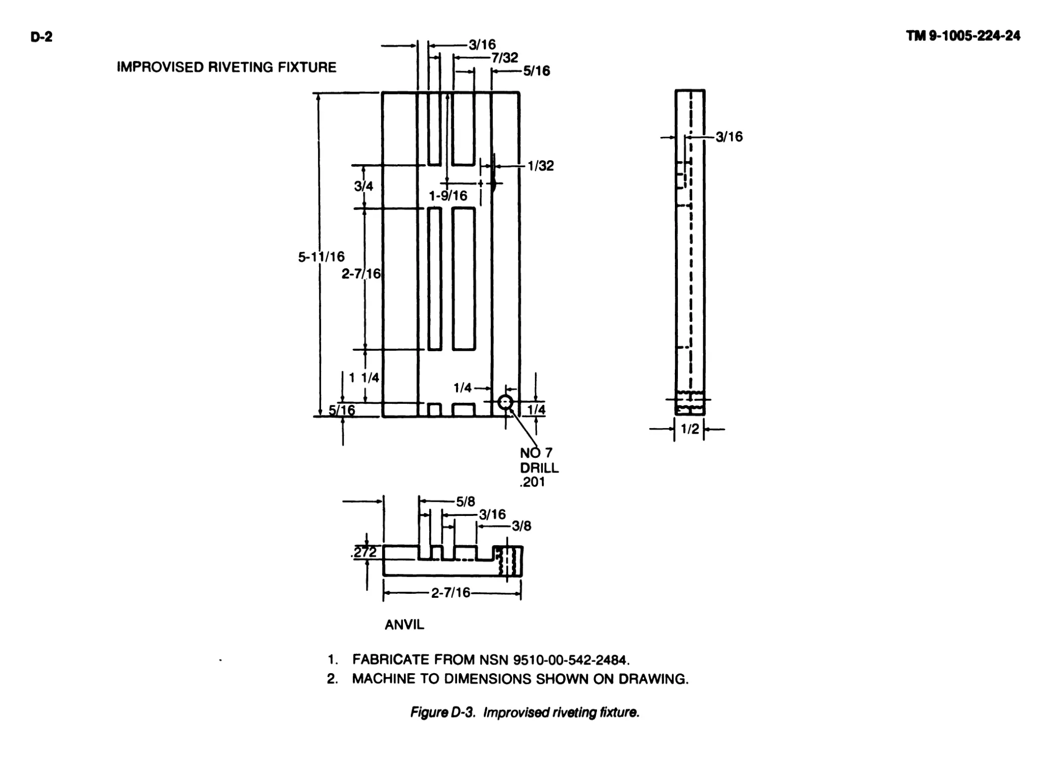
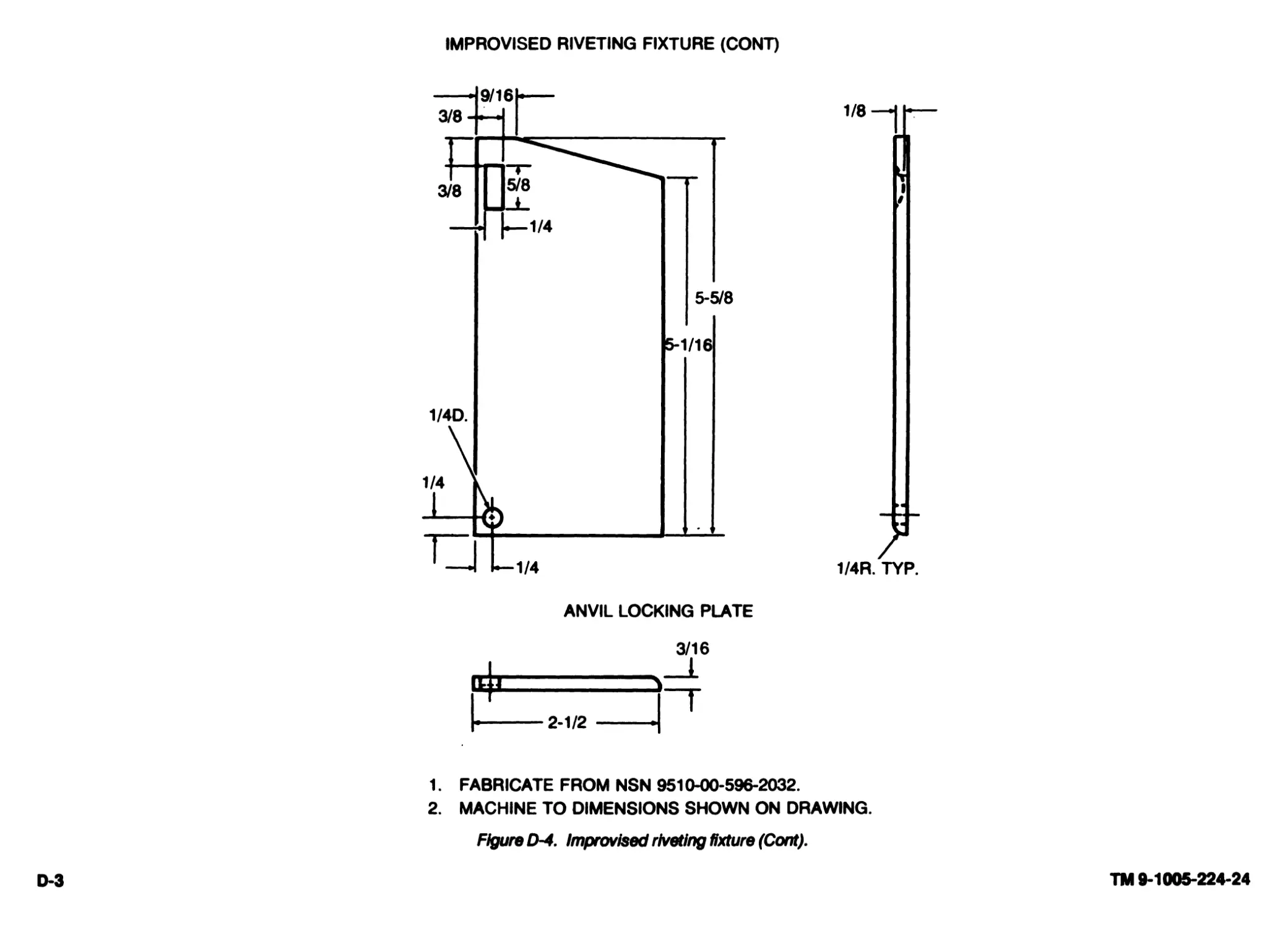
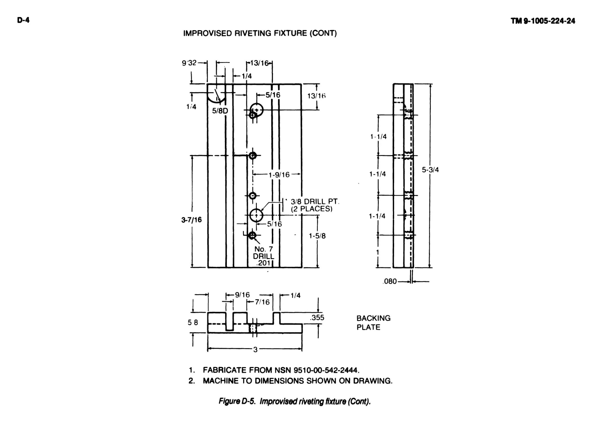
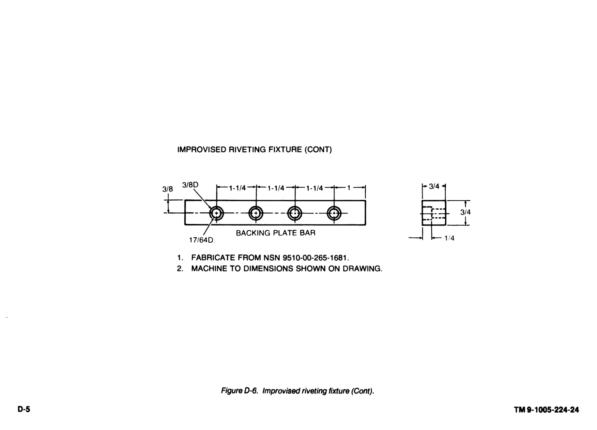
Year: 1987


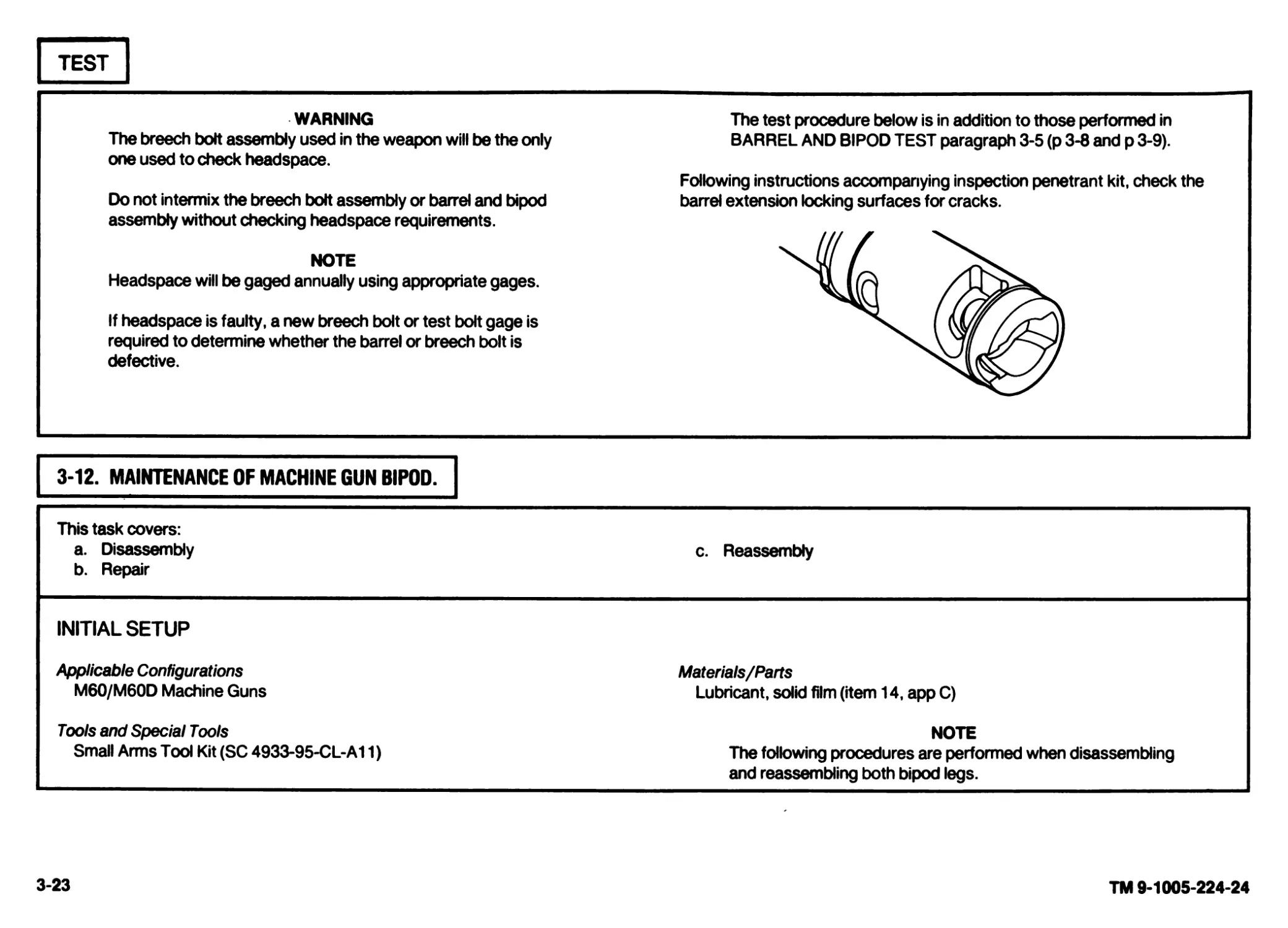
Text
ТМ 9-1005-224-24 v
ol.l/:
Supersedes Copies Dated
17 May 71,29 Aug 73, and 5 May 69
See Page i for details
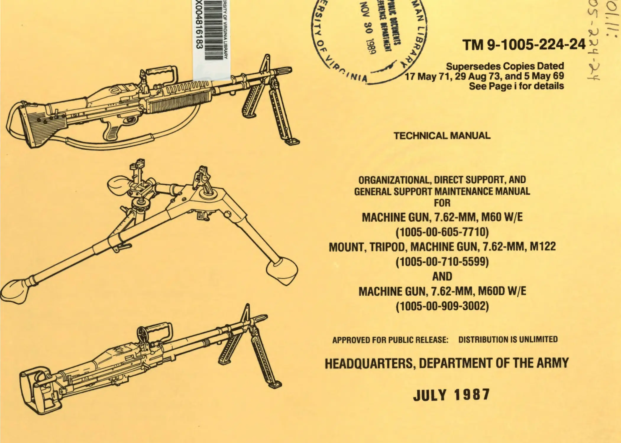
TECHNICAL MANUAL
ORGANIZATIONAL, DIRECT SUPPORT, AND
GENERAL SUPPORT MAINTENANCE MANUAL
FOR
MACHINE GUN, 7.62-MM, M60 W/E
(1005-00-605-7710)
MOUNT, TRIPOD, MACHINE GUN, 7.62-MM, M122
(1005-00-710-5599)
AND
MACHINE GUN, 7.62-MM, M60D W/E
(1005-00-909-3002)
APPROVED FOR PUBLIC RELEASE: DISTRIBUTION IS UNLIMITED
HEADQUARTERS, DEPARTMENT OF THE ARMY
JULY 1987
WARNING
Dry cleaning solvent (SD) is flammable. Do not clean parts near an open flame or in a smoking area. Dry cleaning solvent evaporates quickly and has a
drying effect on the skin. When used without protective gloves, solvent may cause irritation to or cracking of the skin.
Personnel operating vapor degreaser are warned not to breathe the vapor fumes.
Before starting an inspection, be sure to clear the weapon. Do not actuate the trigger before clearing the weapon. Inspect the chamber to make sure it is
empty and free of obstructions. Check to see there are no obstructions in the barrel and no ammunition is in position to be chambered.
Using paint thinners, gasoline, kerosene, benzene (benzol), water, steam, or air for cleaning the weapon is prohibited. Use only authorized cleaning
materials.
Be careful when removing and installing spring-loaded components. Carelessness could cause injury.
*ТМ 9-1005-224-24
Technical Manual ) HEADQUARTERS
I DEPARTMENT OF THE ARMY
No.9-1005-224-24 J Washington, PC, 8 July 1987
Organizational, Direct Support, and
General Support Maintenance Manual
for
MACHINE GUN, 7.S2-MM, M60 W/E
(1005-00-605-7710)
MOUNT, TRIPOD, MACHINE GUN, 7.62-MM, M122
(1005-00-710-5599)
AND
MACHINE GUN, 7.62-MM, M60D W/E
(1005-00-909-3002)
APPROVED FOR PUBLIC RELEASE: DISTRIBUTION IS UNLIMITED
REPORTING ERRORS AND RECOMMENDING IMPROVEMENTS
You can help improve this manual. If you find any mistakes or if you know of a way to improve the procedures, please let us know. Mail your
letter, DA Form 2028 (Recommended Changes to Publications and Blank Forms), or DA Form 2028-2 located in the back of this manual
direct to: Commander, US Army Armament, Munitions and Chemical Command, ATTN: AMSMC-MAS, Rock Island, IL 61299-6000. A
reply will be furnished to you.
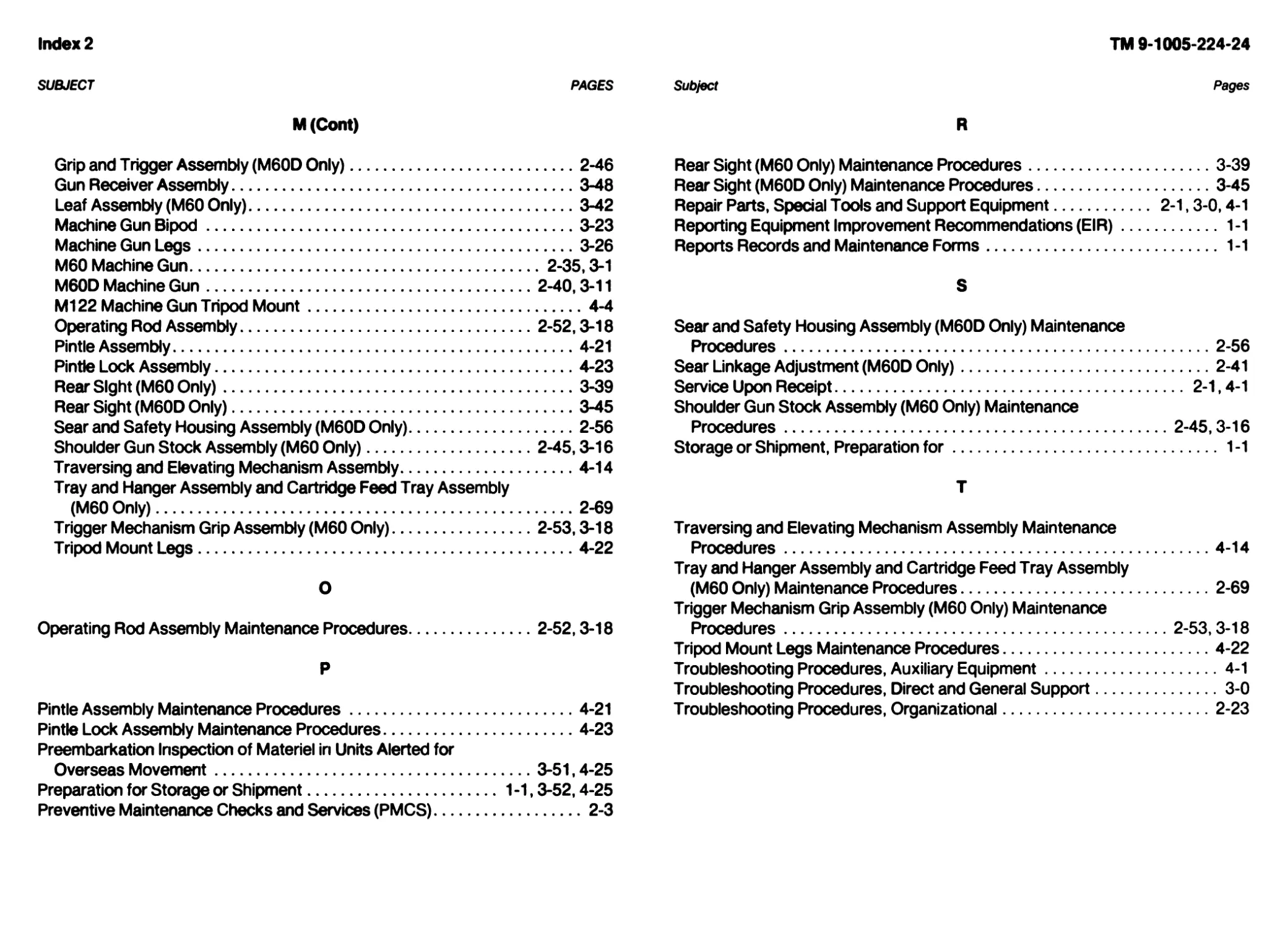
Page
CHAPTER 1 INTRODUCTION
Section I General Information...........................................................................................1-1
Section II Equipment Description and Data................................................................................1-2
CHAPTER 2 ORGANIZATIONAL MAINTENANCE INSTRUCTIONS
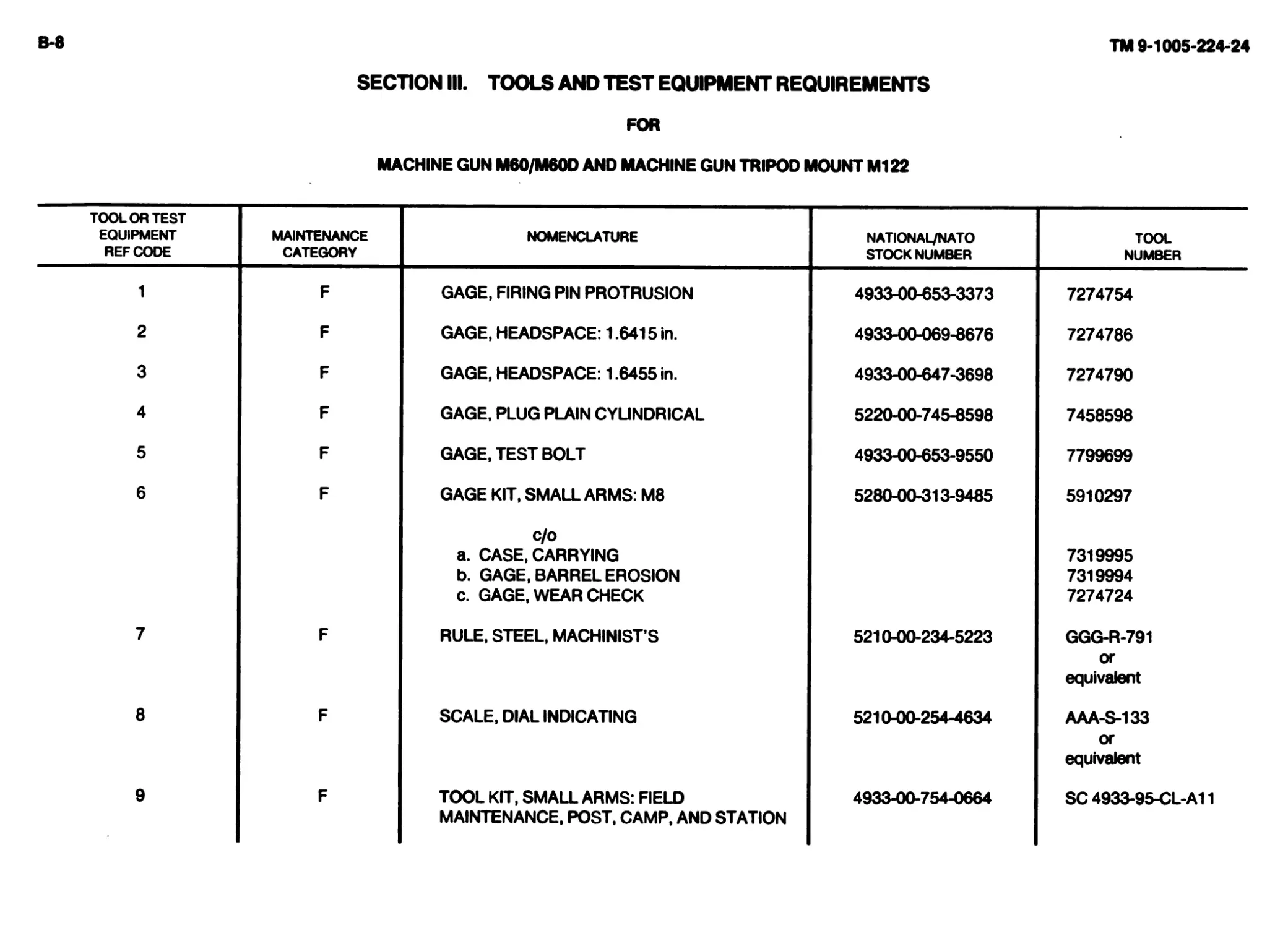
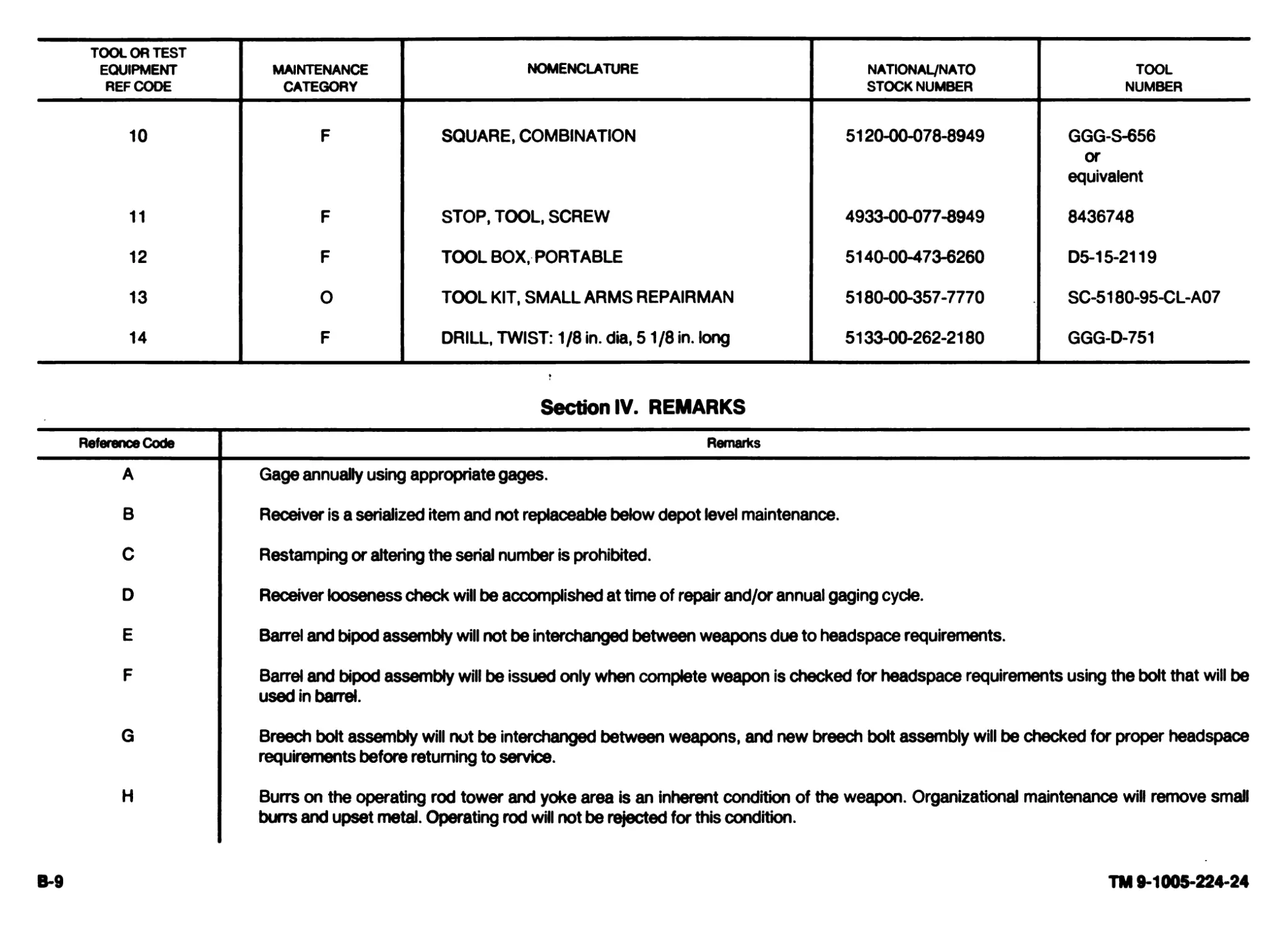
Section I Repair Parts, Special Tools, and Support Equipment.............................................................2-1
Section II Service Upon Receipt..........................................................................................2-1
Section III Preventive Maintenance Checks and Services (PMCS)............................................................. 2-3
Section IV Troubleshooting.............................................................................................. 2-23
Section V Maintenance Procedures...................................................................................... 2-35
Section VI Lubrication Instructions......................................................................................2-75
Section VII Preparation for Storage or Shipment...........................................................................2-75
’This TM supersedes TM 9-1005-224-24, dated 17 May 1971, and in conjunction with TM 9-1005-262-13 supersedes TM 9-1005-262-14 dated 29 August 1973 and
TM 9-1005-262-ESC 5 May 1969, including all changes.
ii TM 9-1005-224-24
Page
CHAPTER 3 DIRECT SUPPORT AND GENERAL SUPPORT MAINTENANCE INSTRUCTIONS
Section I Repair Parts, Special Tods, and Support Equipment....................................................3-0
Section II Troubleshooting....................................................................................3-0
Section III Maintenance Procedures.............................................................................3-0
Section IV Preembarkation Inspection of Materiel in Units Alerted for Overseas Movement.......................3-51
Section V Preparation for Storage or Shipment................................................................3-52
CHAPTER 4 MAINTENANCE OF AUXILIARY EQUIPMENT
Section I Repair Parts, Special Tods, and Support Equipment....................................................4-1
Section II Service Upon Receipt...............................................................................4-1
Section III Troubleshooting....................................................................................4-1
Section IV Maintenance Procedures.............................................................................4-4
Section V Preparation for Storage or Shipment................................................................4-25
Section VI Preembarkation Inspection of Materiel in Units Alerted for Overseas Movement.......................4-25
APPENDIX A REFERENCES...........................................................................................A-0
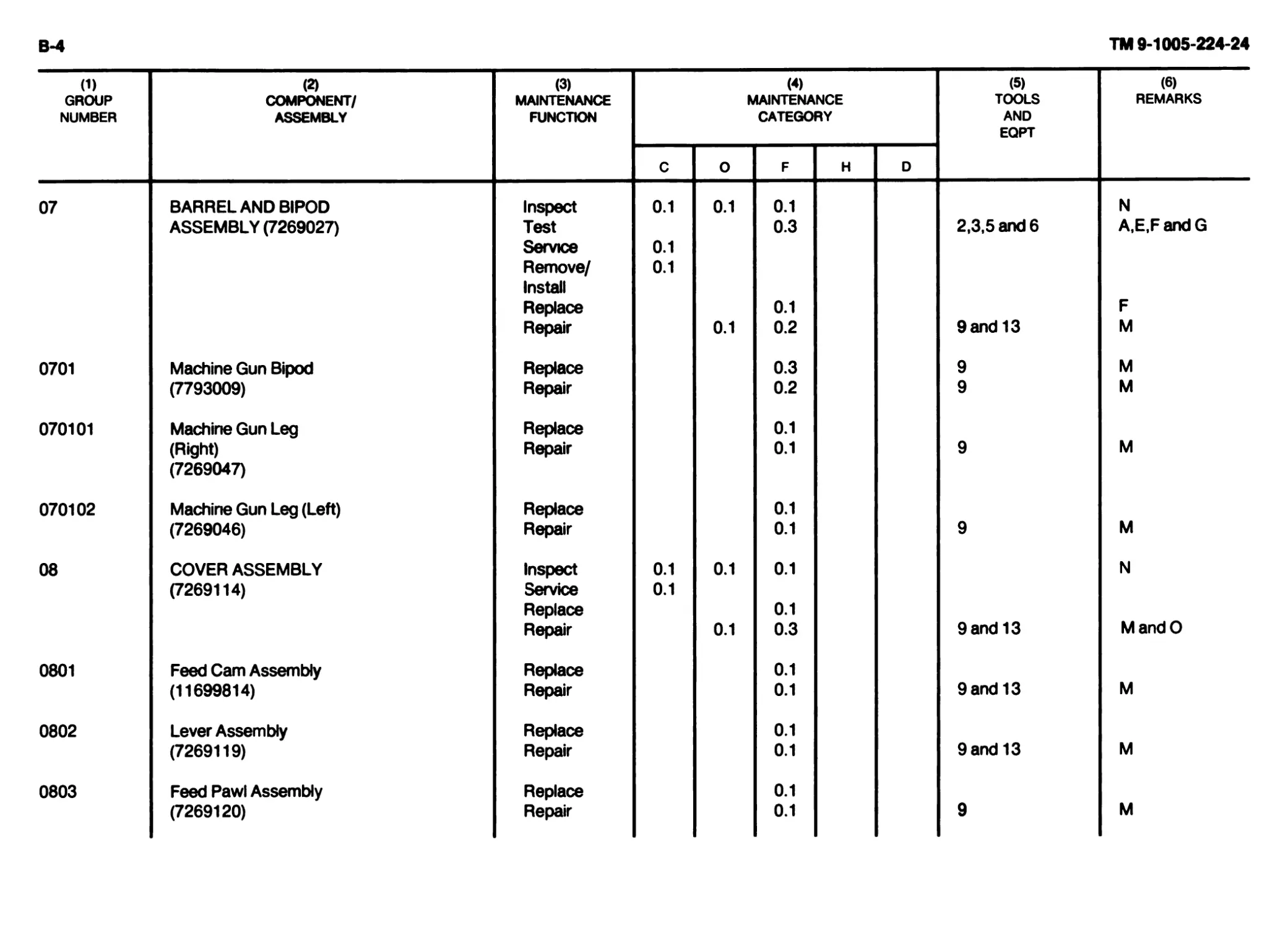
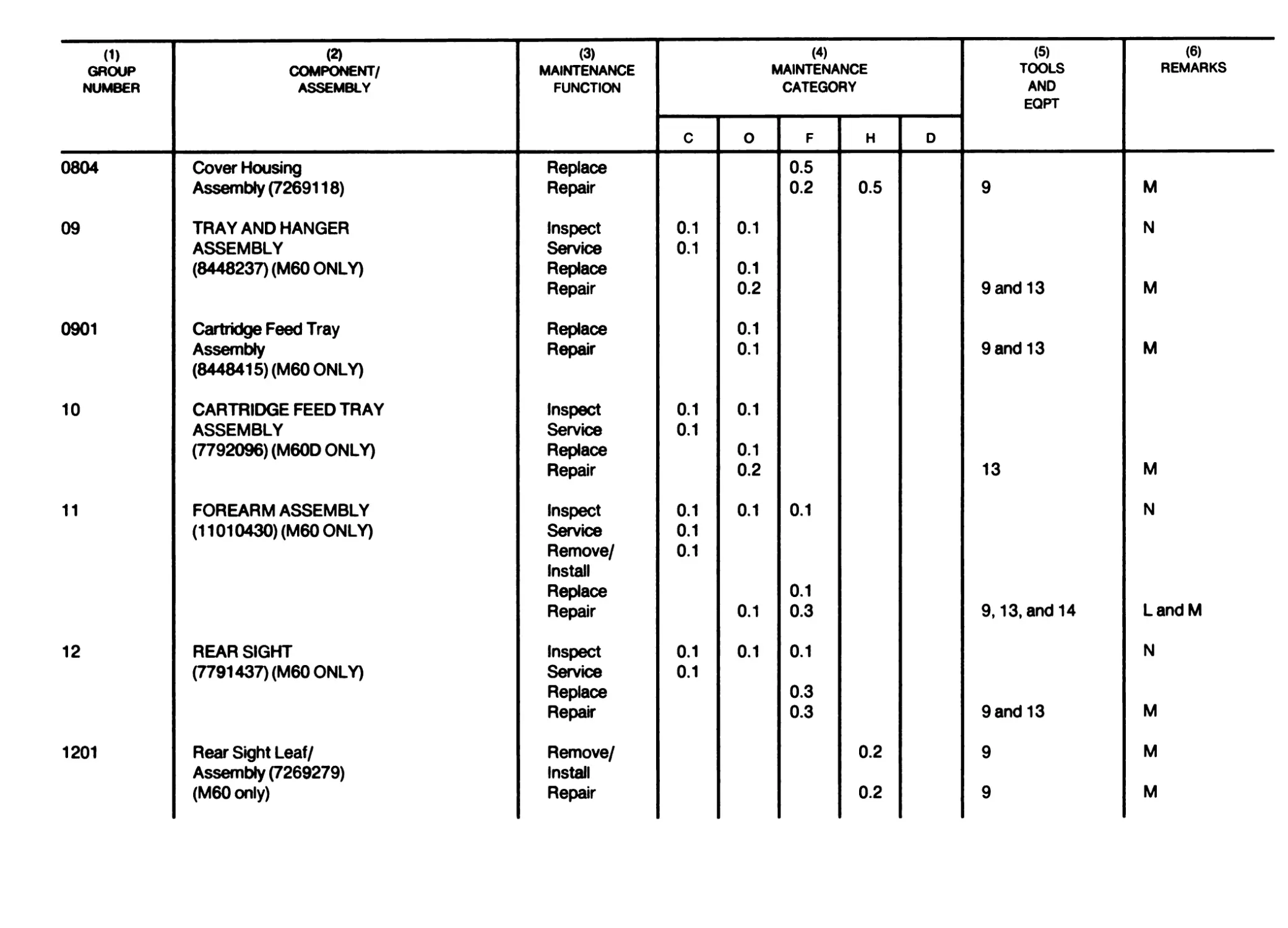
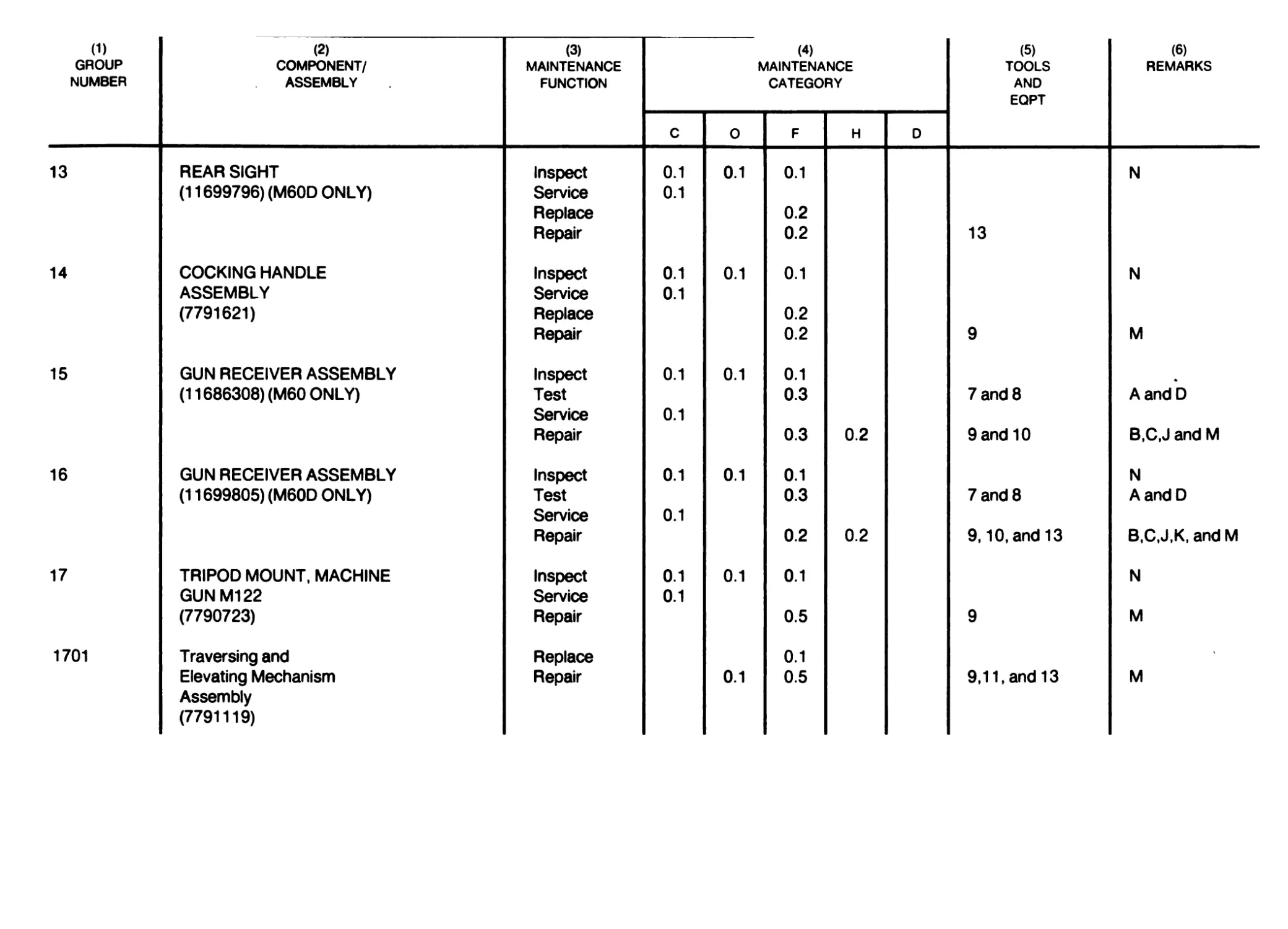
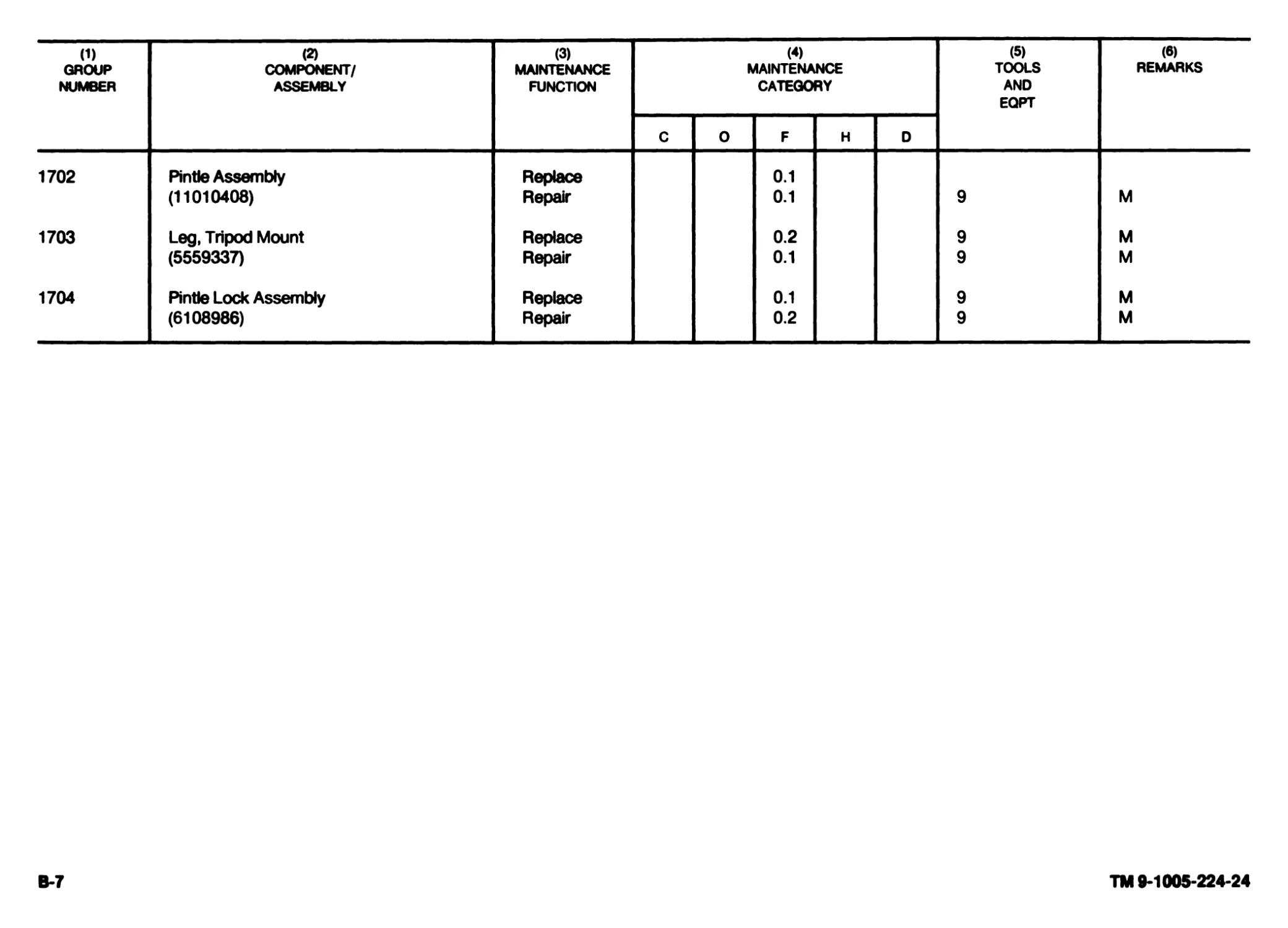
APPENDIX В MAINTENANCE ALLOCATION CHART....................................... .................................B-0
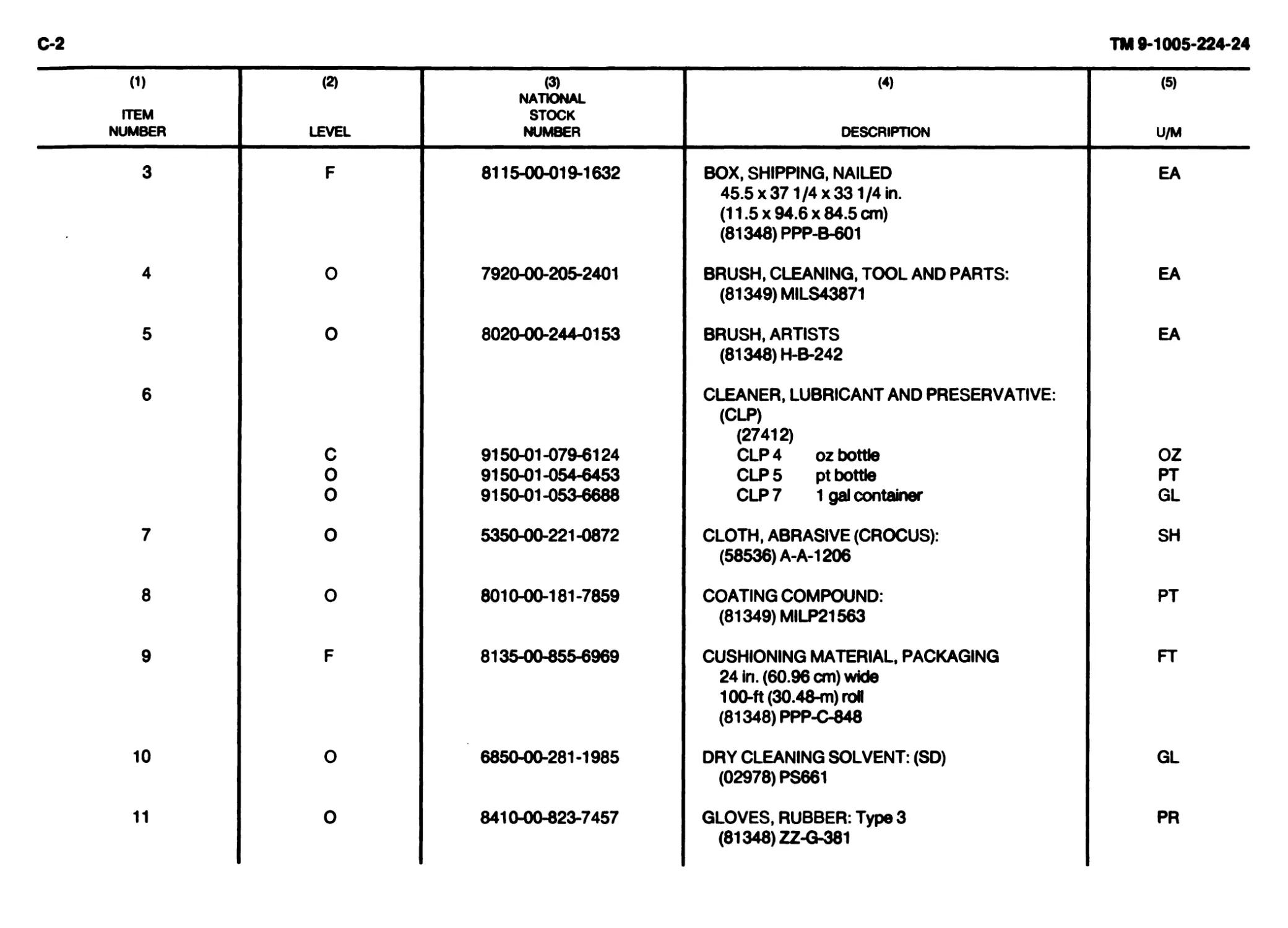
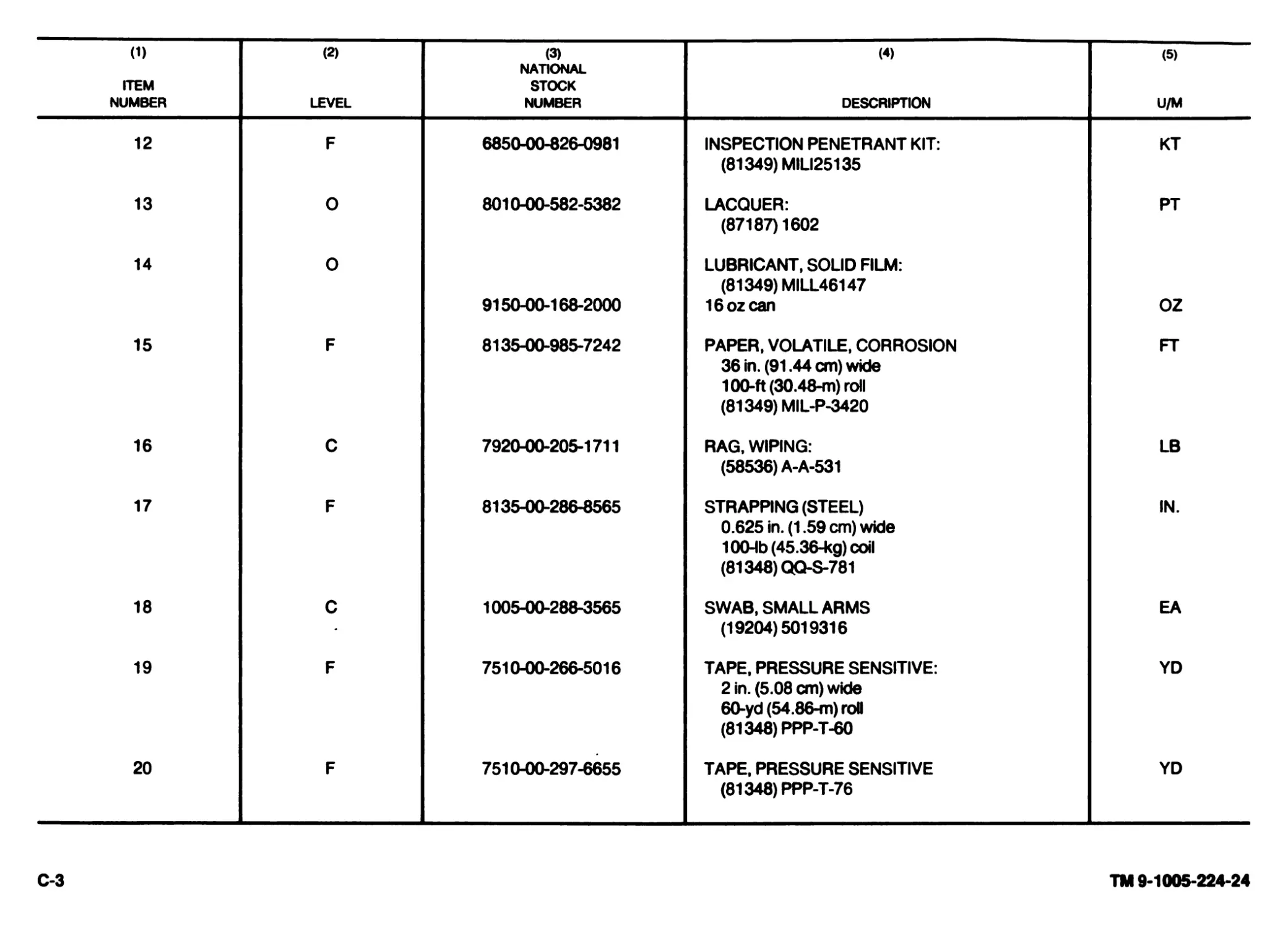
APPENDIX C EXPENDABLE/DURABLE SUPPLIES AND MATERIALS LIST.......................................................C-1
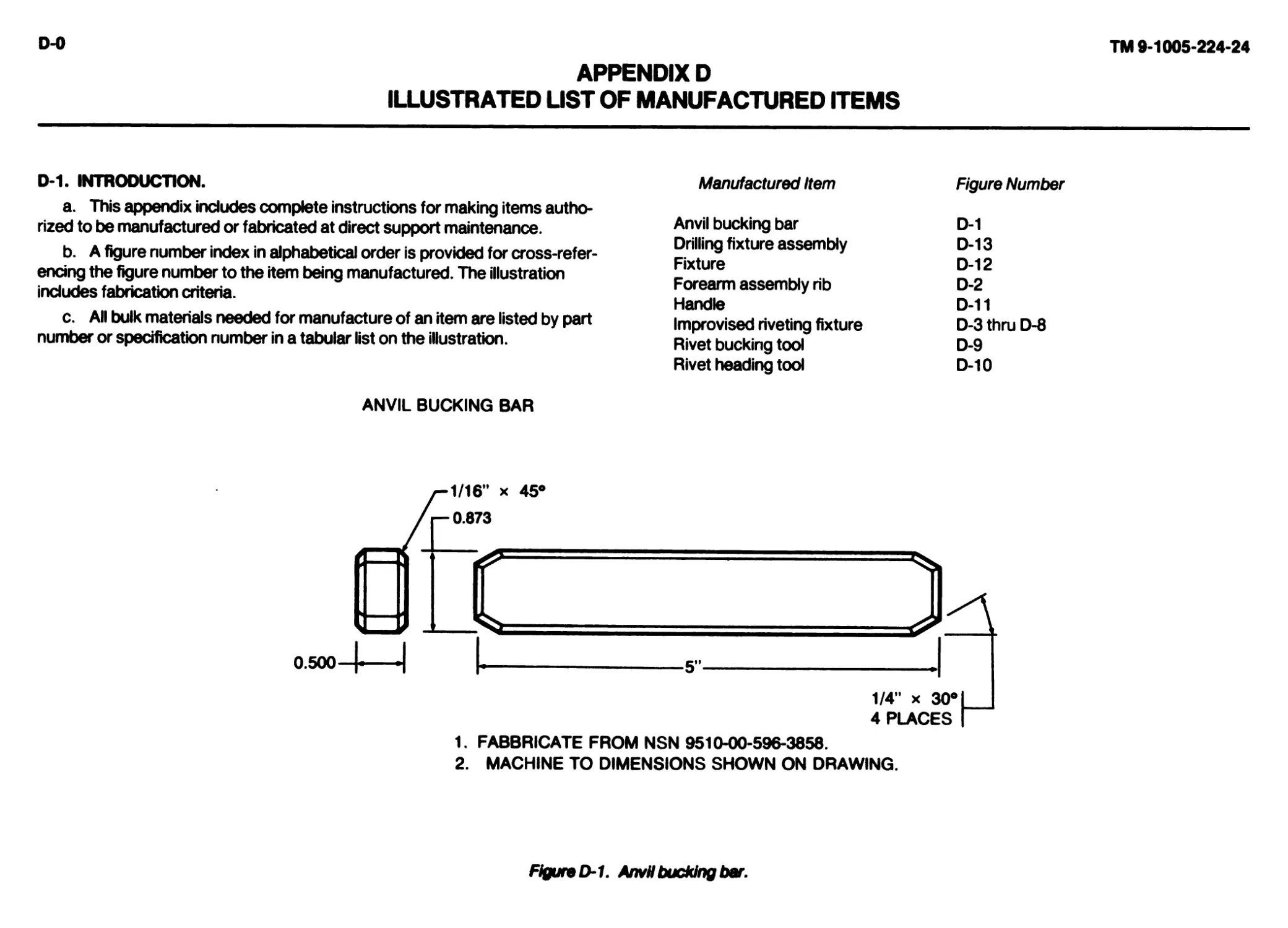
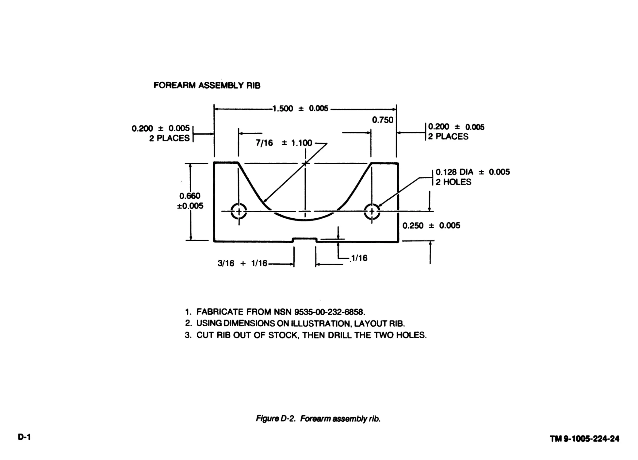
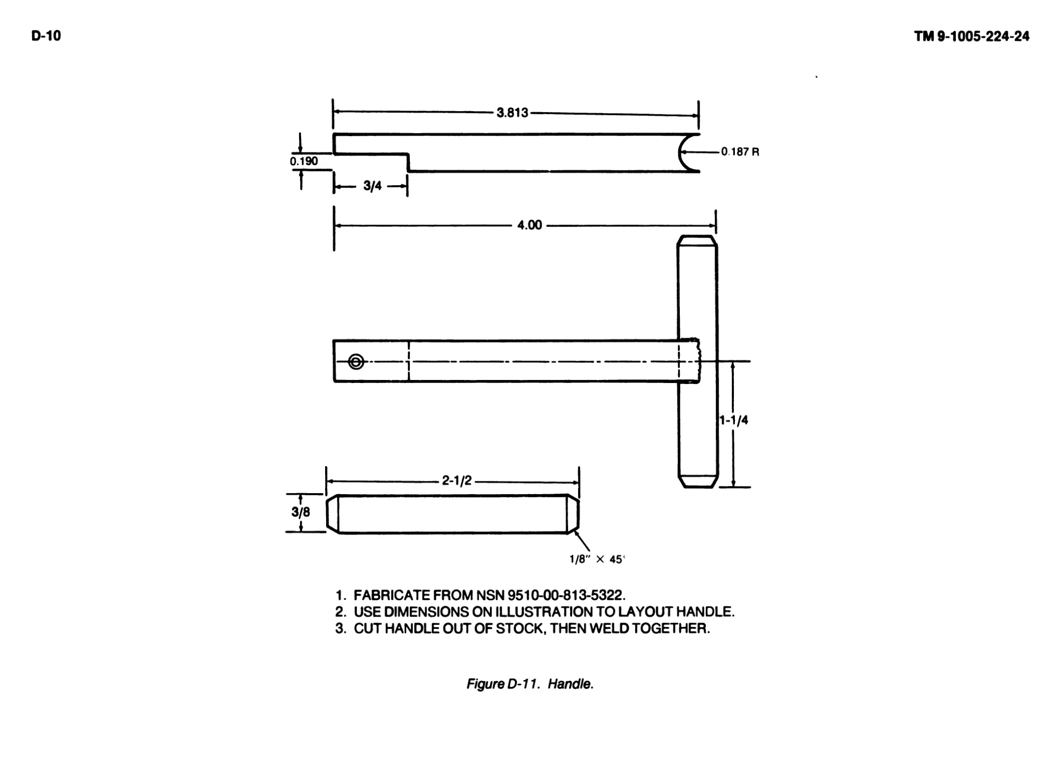
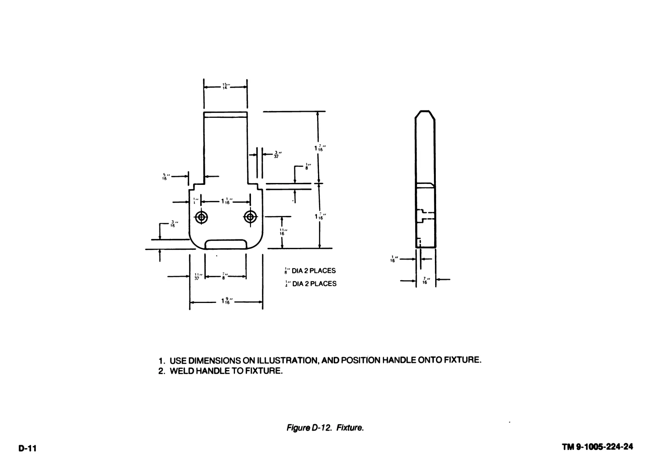
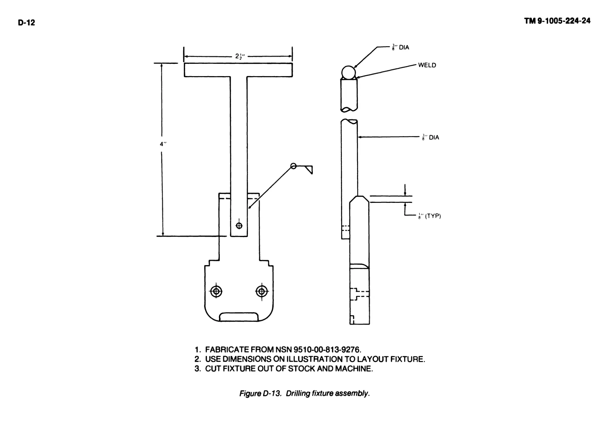
APPENDIX D ILLUSTRATED LIST OF MANUFACTURED ITEMS...............................................................D-0
ALPHABETICAL INDEX...................................................................................Index-1
TM 9-1005-224-24
(iii Blank)/1-0
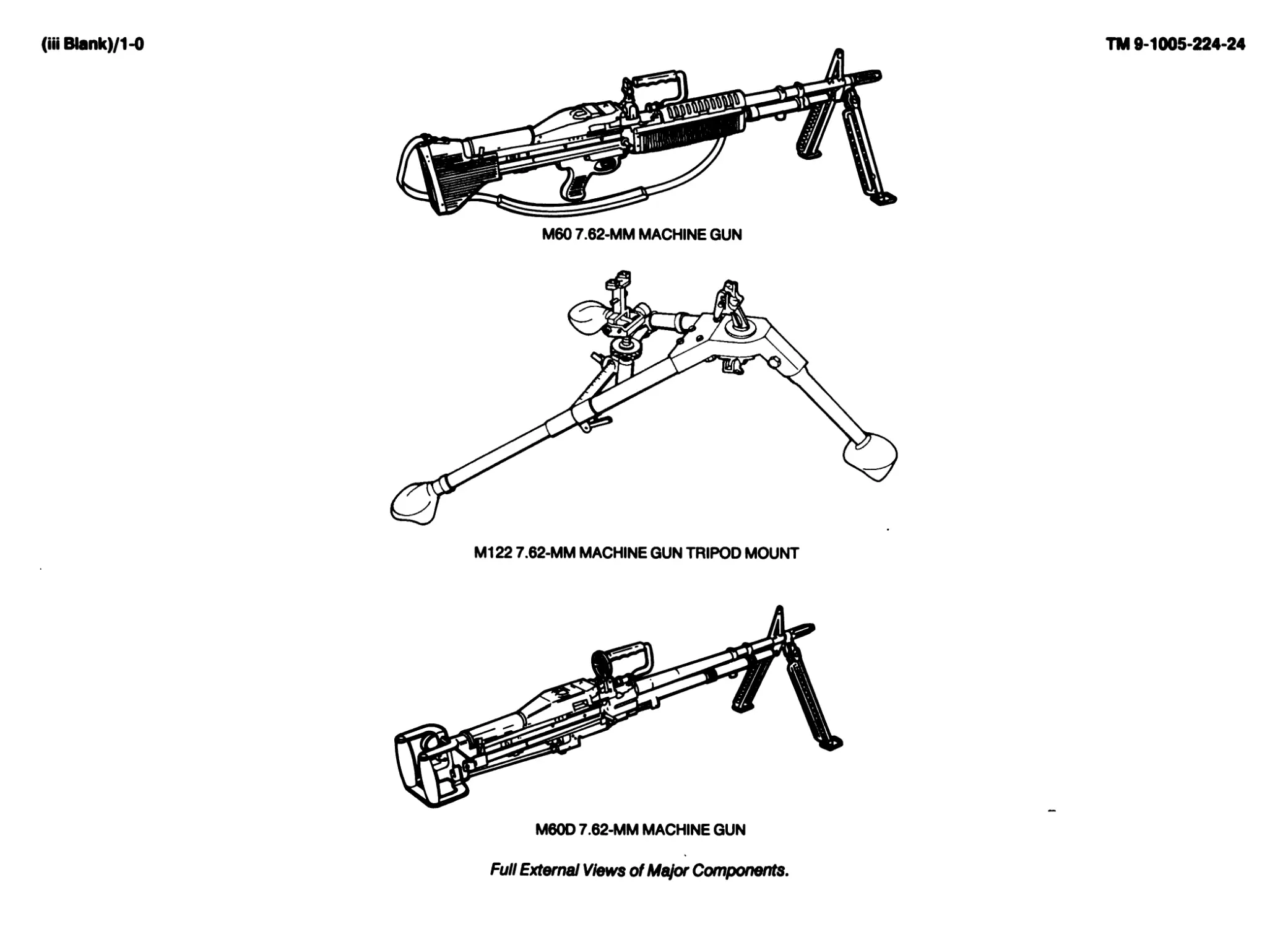
M60 7.62-MM MACHINE GUN
Full External Views of Major Components.
CHAPTER 1
INTRODUCTION
Section!. GENERAL INFORMATION
1-1. SCOPE.
a. Type of Manual: Organizational, Direct Support, and General Support
Maintenance Manual.
b. Model Numbers and Equipment Names:
(1) M60 7.62-mm machine gun
(2) M60D 7.62-mm machine gun
(3) M122 7.62-mm machine gun tripod mount
c. Purpose of Equipment:
(1) The M60 7.62-mm machine gun is a general purpose weapon
capable of being fired from several mounts or while being handheld. The
weapon is mainly used for ground operations.
(2) The M60D 7.62-mm machine gun is a general purpose weapon
capable of being fired from several mounts. The weapon is mainly used is for
support of ground operations. The M60D is an aircraft door-mounted, or vehi-
cle-mounted machine gun.
(3) The M122 machine gun tripod mount is a stable mount used with
the M60 machine gun, allowing quick removal or installation of the gun, as
required.
1-2. MAINTENANCE FORMS, RECORDS, AND REPORTS. Department of
the Army forms and procedures for equipment maintenance will be those pre-
scribed by DA PAM 738-750, The Army Maintenance Management System.
1-3. DESTRUCTION OF ARMY MATERIEL TO PREVENT ENEMY USE. Pro-
cedures and materiels used for the destruction of the machine guns and tripod
mount will be found in TM 750-244-7.
1-4. PREPARATION FOR STORAGE OR SHIPMENT. Requirements for stor-
age or shipment are listed in TM 9-1005-224-10.
1-5. OFFICIAL NOMENCLATURE, NAMES AND DESIGNATIONS.
NOMENCLATURE CROSS-REFERENCE LIST
This listing includes nomenclature cross-references used in this manual:
Common Name Official Nomenclature
Bipod Legs Leg, Machine Gun, RH
Leg, Machine Gun, LH
Leaf Assembly Leaf Assembly, Rear Sight
1-6. REPORTING EQUIPMENT IMPROVEMENT RECOMMENDATIONS
(EIR). If your machine gun or tripod mount needs improvement, let us know.
Send us an EIR. You, the user, are the only one who can tell us what you don’t
like about your equipment. Let us know why you don't like the design. Put it on
an SF 368 Quality Deficiency Report (QDR). Mail it to us at Commander, US
Army Armament, Munitions and Chemical Command, ATTN: AMSMC-QAD,
Rock Island, IL61299-6000. We’ll send you a reply.
1-1
TM 9-1005-224-24
1-2
TM 9-1005-224-24
Section II. EQUIPMENT DESCRIPTION AND DATA
1-7. EQUIPMENT CHARACTERISTICS, CAPABILITIES, AND FEATURES.
a. M60 Machine Gun. The M60 machine gun is an air-cooled, link-belt fed,
gas operated weapon. The operating cycle begins from an open bolt position.
The weapon features fixed headspace, which permits rapid changing of bar-
rels.
b. M122 Tripod Mount. The machine gun tripod mount is durable, stable,
and quick to set up. This permits a high degree of accuracy and control of fire.
c. M60D Machine Gun. The M60D machine gun is an air-cooled, link-belt
fed, gas operated weapon. The operating cycle begins from an open bolt
position. The weapon features fixed headspace, which permits rapid changing
of barrels.
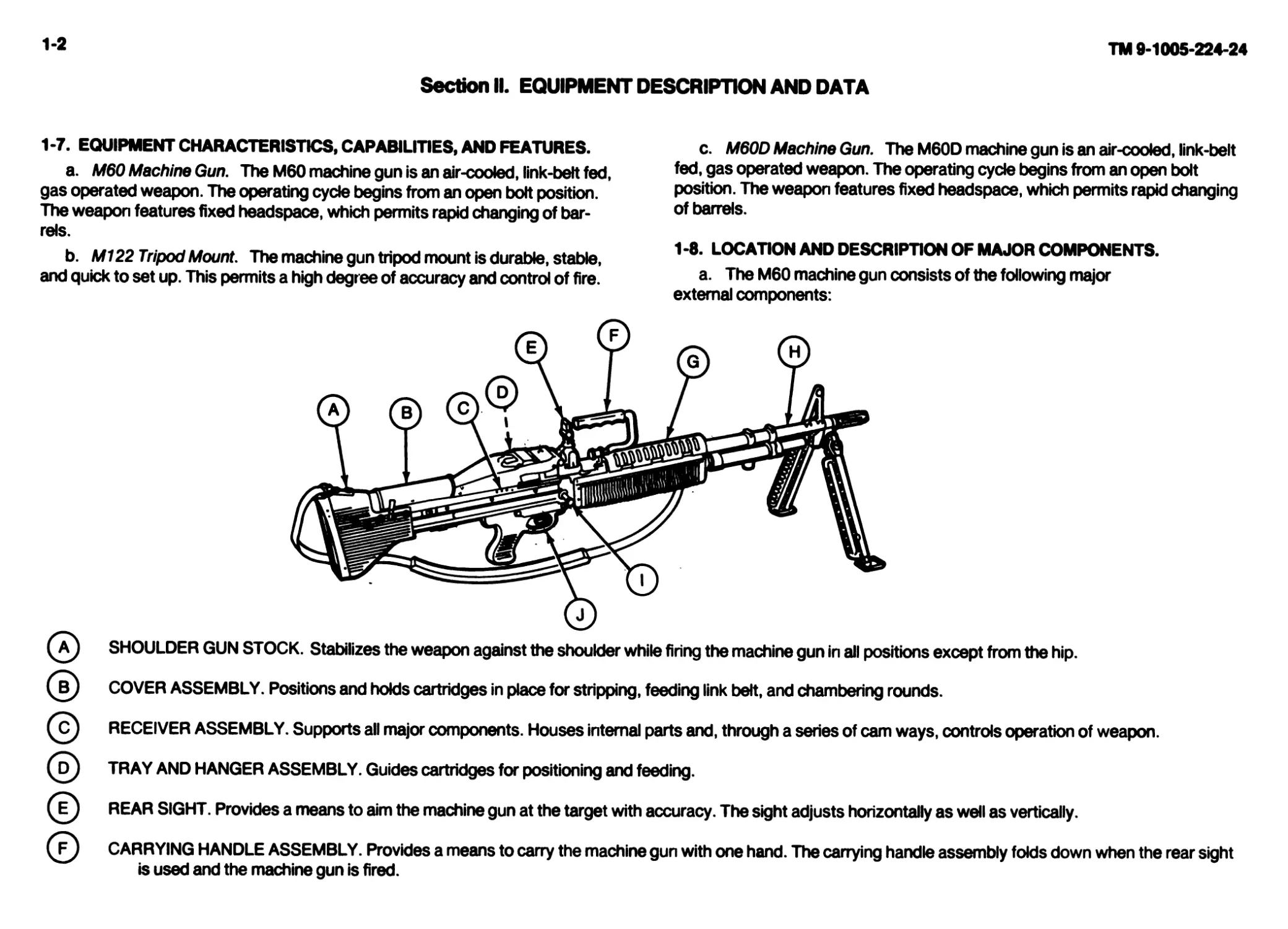
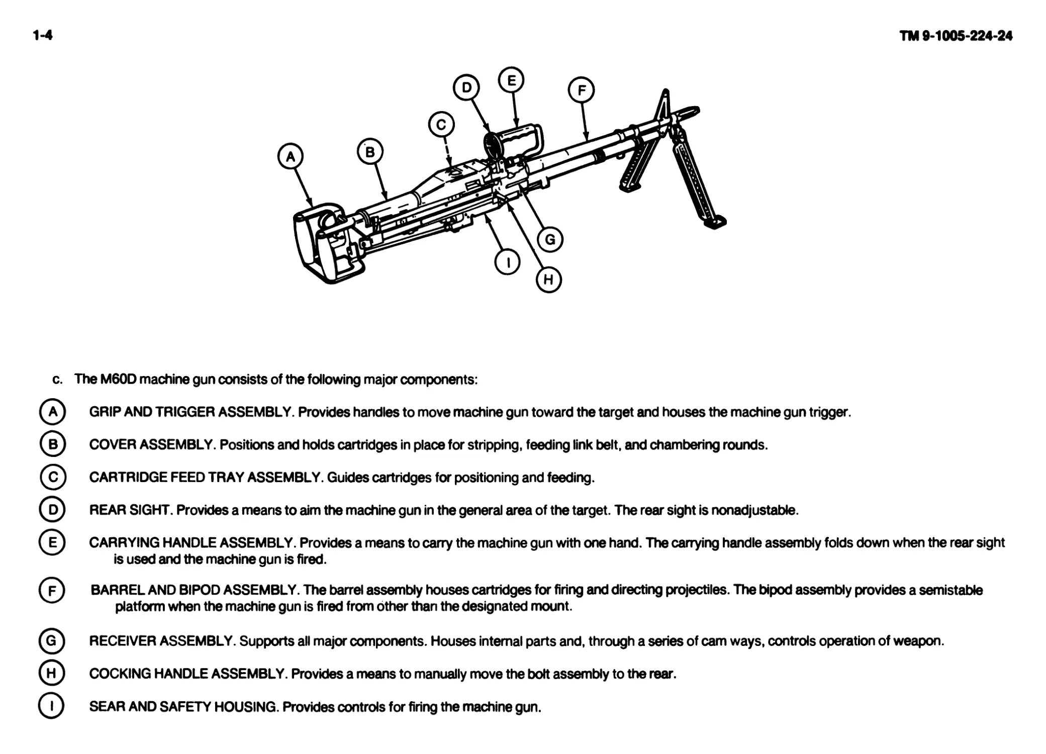
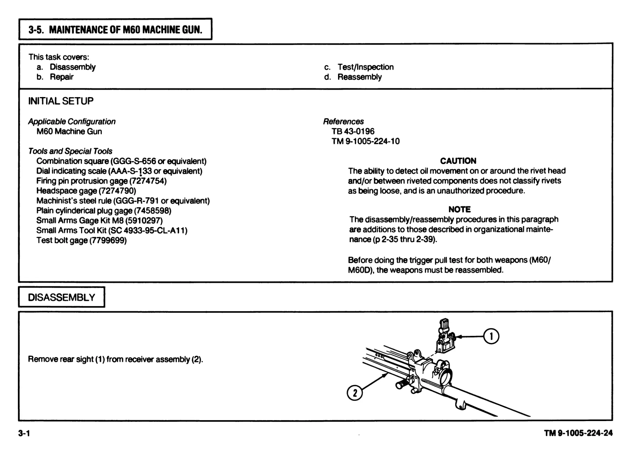
1 -8. LOCATION AND DESCRIPTION OF MAJOR COMPONENTS.
a. The M60 machine gun consists of the following major
external components:
A
SHOULDER GUN STOCK. Stabilizes the weapon against the shoulder while firing the machine gun in all positions except from the hip.
COVER ASSEMBLY. Positions and holds cartridges in place for stripping, feeding link belt, and chambering rounds.
В
RECEIVER ASSEMBLY. Supports all major components. Houses internal parts and, through a series of cam ways, controls operation of weapon.
TRAY AND HANGER ASSEMBLY. Guides cartridges for positioning and feeding.
REAR SIGHT. Provides a means to aim the machine gun at the target with accuracy. The sight adjusts horizontally as well as vertically.
CARRYING HANDLE ASSEMBLY. Provides a means to carry the machine gun with one hand. The carrying handle assembly folds down when the rear sight
is used and the machine gun is fired.
FOREARM ASSEMBLY. Provides a protective cover to hold when firing from the hip or from a standing and/or kneeling position.
BARREL AND BIPOD ASSEMBLY. The barrel assembly houses cartridges for firing and directing projectiles. The bipod assembly provides a semistable
platform when the machine gun is fired from the prone position.
Q COCKING HANDLE ASSEMBLY. Provides a means to manually move the bolt assembly to the rear.
(7) TRIGGER MECHANISM GRIP ASSEMBLY. Provides controls for firing the machine gun.
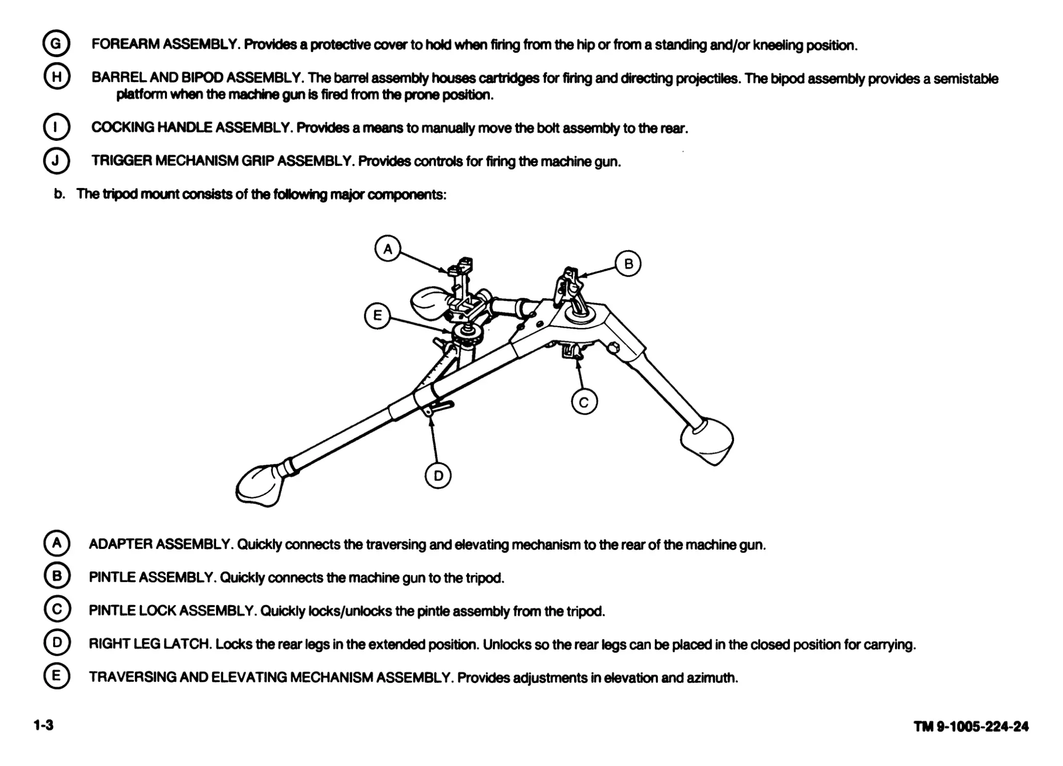
b. The tripod mount consists of the following major components:
(a) ADAPTER ASSEMBLY. Quickly connects the traversing and elevating mechanism to the rear of the machine gun.
PINTLE ASSEMBLY. Quickly connects the machine gun to the tripod.
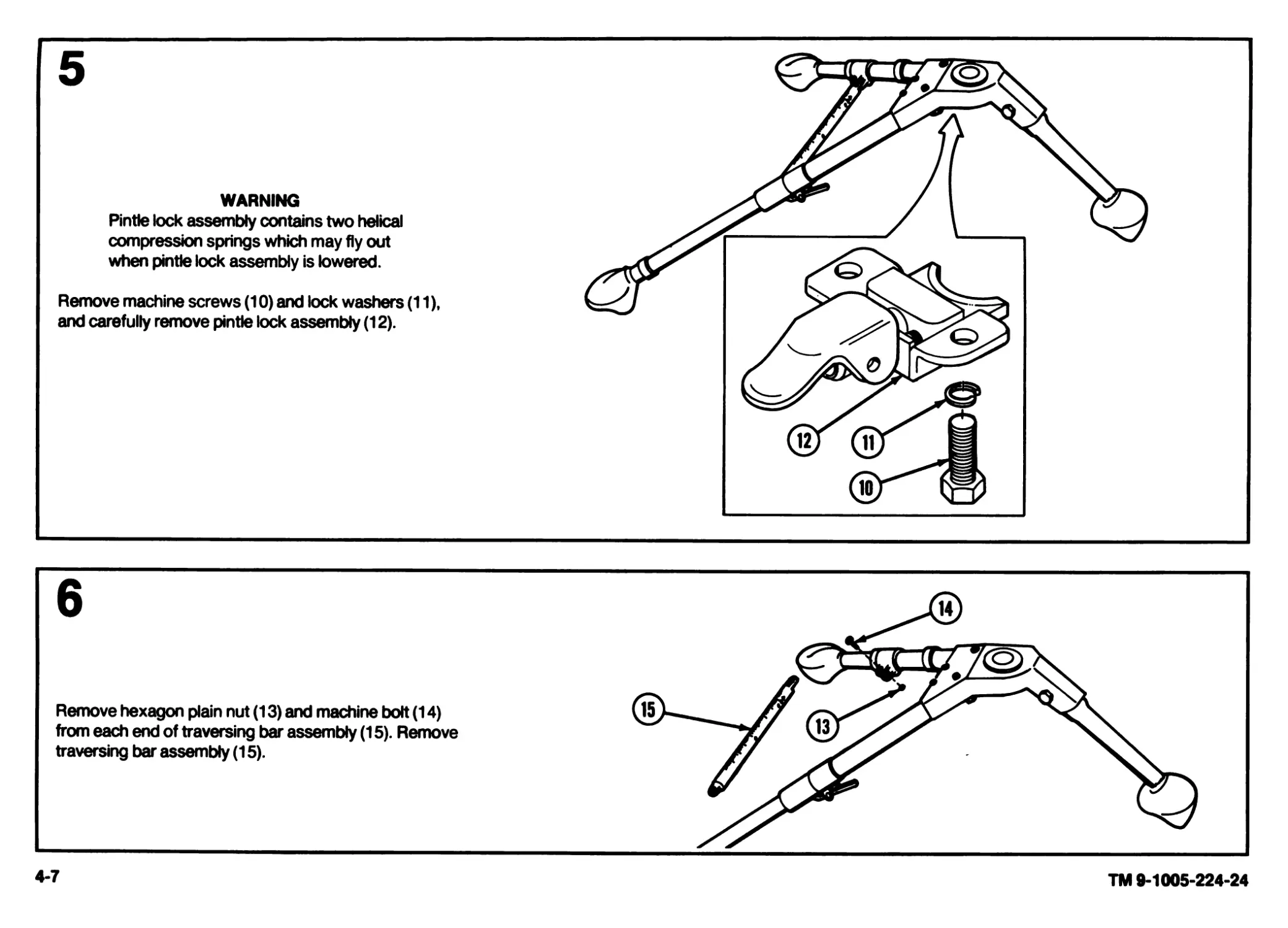
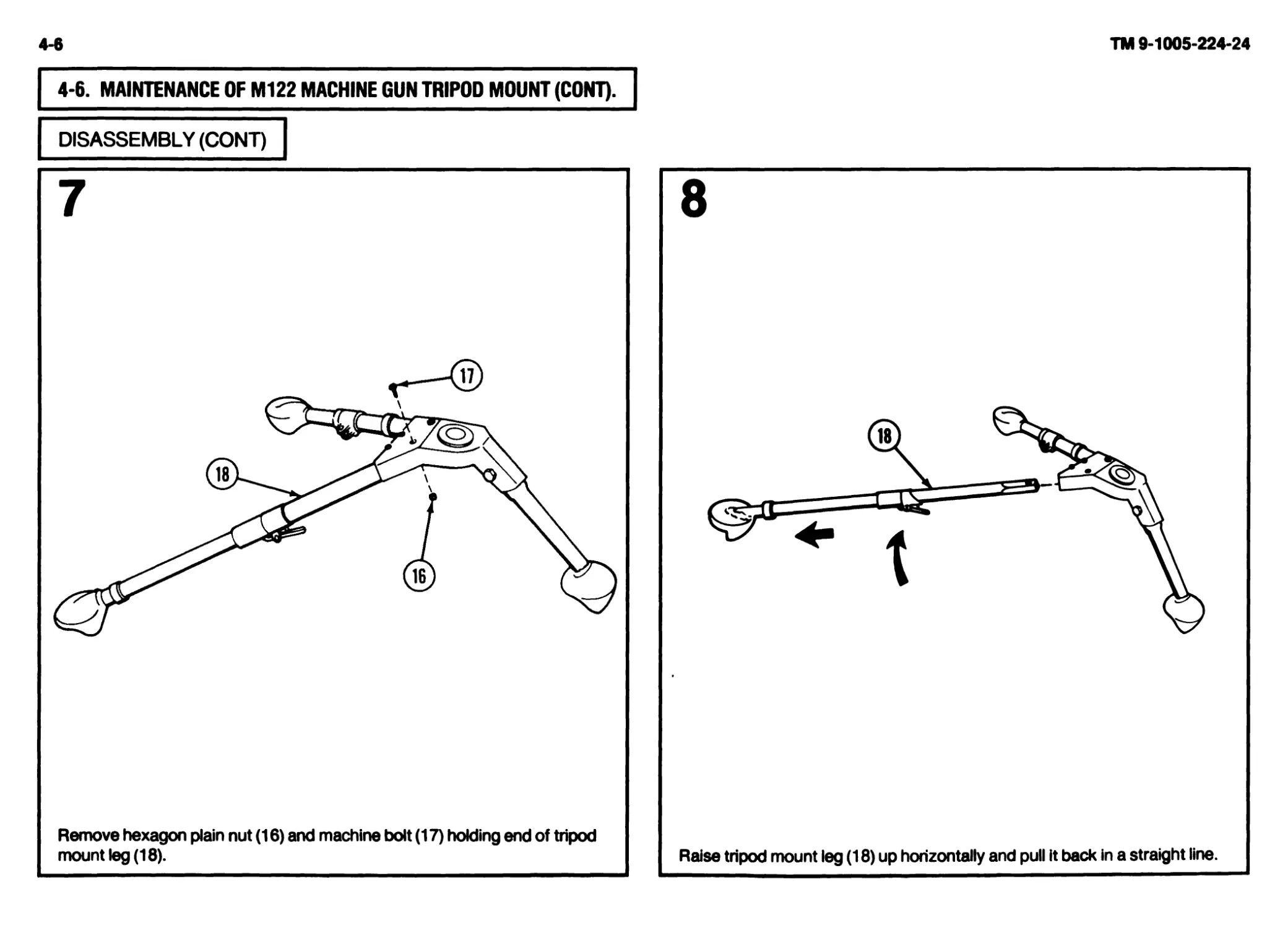
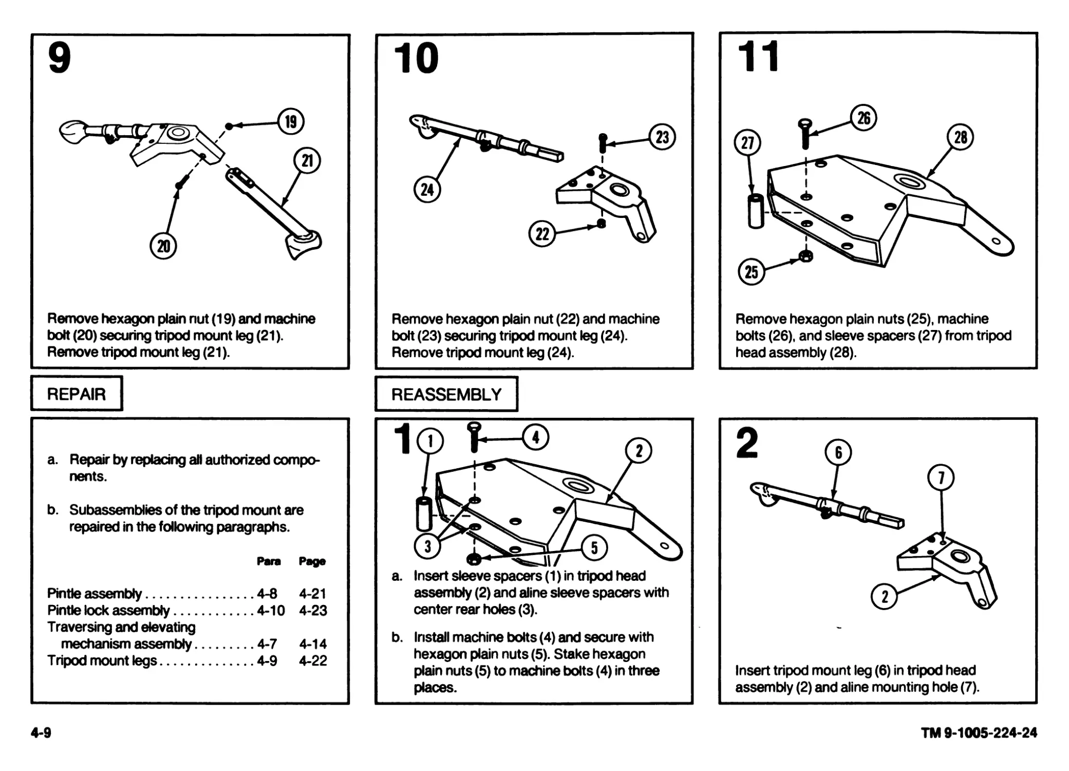
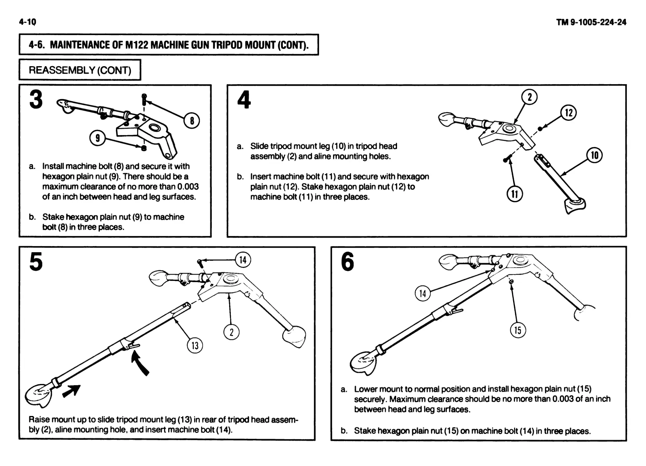
(c) PINTLE LOCK ASSEMBLY. Quickly locks/unlocks the pintle assembly from the tripod.
RIGHT LEG LATCH. Locks the rear legs in the extended position. Unlocks so the rear legs can be placed in the closed position for carrying.
© TRAVERSING AND ELEVATING MECHANISM ASSEMBLY. Provides adjustments in elevation and azimuth.
1-3
TM 9-1005-224-24
1-4
ТМ 9-1005-224-24
о®® ® ®@@®® <
The M60D machine gun consists of the following major components:
GRIP AND TRIGGER ASSEMBLY. Provides handles to move machine gun toward the target and houses the machine gun trigger.
COVER ASSEMBLY. Positions and holds cartridges in place for stripping, feeding link belt, and chambering rounds.
CARTRIDGE FEED TRAY ASSEMBLY. Guides cartridges for positioning and feeding.
REAR SIGHT. Provides a means to aim the machine gun in the general area of the target. The rear sight is nonadjustable.
CARRYING HANDLE ASSEMBLY. Provides a means to carry the machine gun with one hand. The carrying handle assembly folds down when the rear sight
is used and the machine gun is fired.
BARREL AND BIPOD ASSEMBLY. The barrel assembly houses cartridges for firing and directing projectiles. The bipod assembly provides a semistable
platform when the machine gun is fired from other than the designated mount.
RECEIVER ASSEMBLY. Supports all major components. Houses internal parts and, through a series of cam ways, controls operation of weapon.
COCKING HANDLE ASSEMBLY. Provides a means to manually move the bolt assembly to the rear.
SEAR AND SAFETY HOUSING. Provides controls for firing the machine gun.
1-9. DIFFERENCES BETWEEN MODELS. Differences between the M60
and M60D machine gun are listed below.
Assembty/Component
Tray and hanger assembly Cartridge feed tray assembly Dust and moisture seal boot Forearm assembly Grip and trigger assembly Gun adapter Bandoleer hanger assembly Magazine bracket assembly Rear sight (adjustable) Rear sight (nonadjustable) Receiver assembly Receiver assembly Sear and safety housing assembly Sear assembly link and spring Shoulder gun stock assembly Small arms sling Trigger mechanism grip assembly Quick release pin Leaf spring
1-10. EQUIPMENT DATA.
a. M60 Machine Gun.
Weight Length Range Rate of fire (cyclic) Muzzle velocity Capacity of bandoleer ... 23 lb (10.43 kg) ... 43.50 in. overall (1.1 m overall) ... Ref to Ft 7.62-A-2 ... 550 rd per min (approx) ... 2800FPS ... 100rds
1-5
M60 M60D
X X X
X X X
X X
X X
X X X X
X X X X
X X
Rifling:
Number of lands...............
Right hand twist............
Trigger Pull:
Maximum.......................
Minimum.....................
4
One turn in 12 in. (30.54 cm)
11.5 lb (5.2 kg)
6.0 lb (2.7 kg)
TM 9-1005-224-24
1-е
b. М122 Tripod Mount.
Weight.......................
Length:
Extended....................
Folded for transportation....
Spread of rear legs.......
Height.......................
Traversing range:
Using traversing bar......
Free......................
Elevating range:
Free........................
Locked....................
Least increment...........
Elevating handwheel,
graduated.................
15lb(6.8kg)
32.5 in.(82.6 cm)
27 in.(68.6 cm)
30 in.(76.2 cm)
14in.(35.6cm)
50 degrees
360 degrees (6,400 mils)
56 degrees
26 degrees
1 mil
1 mil
TM 9-1005-224-24
c. M60D Machine Gun.
Weight........................
Length........................
Rate of fire (cyclic).........
Muzzle velocity...............
Rifling:
Number of lands.............
Right hand twist............
Trigger pull at sear activator:
Maximum.......................
Minimum.....................
25 lbs(10.42 kg)
43.5 in. overall(1.1 m overall)
550 rd per min (approx)
2800 FPS
4
One turn in 12 in.(30.54 cm)
20lb(9.06kg)
10.5 lb(4.75kg)
CHAPTER 2
ORGANIZATIONAL MAINTENANCE INSTRUCTIONS
Section I. REPAIR PARTS, SPECIAL TOOLS, AND SUPPORT EQUIPMENT
2-1. COMMON TOOLS AND EQUIPMENT. For authorized common tools and
equipment, refer to Modified Table of Organization and Equipment (MTOE)
applicable to your unit.
2-2. SPECIAL TOOLS AND SUPPORT EQUIPMENT. Tools and test equip-
ment are listed in appendix B. Special tools and support equipment are listed
and illustrated in TM 9-1005-224-24P. Fabricated tools are listed and illustrated
in appendix D.
2-3. REPAIR PARTS. Repair parts are listed and illustrated in
TM9-1005-224-24P.
Section II. SERVICE UPON RECEIPT
2-4. GENERAL. When a new or reconditioned weapon is first received, it is
the responsibility of the officer-in-charge to determine whether the weapon has
been properly prepared for service by the supplying organization and whether it
is in condition to perform its mission.
2-5. SERVICE UPON RECEIPT OF MATERIEL.
WARNING
Before starting an inspection, be sure to dear the weapon. Do
not actuate the trigger before clearing the weapon. Inspect the
chamber to make sure it is empty and free of obstructions. Check
to see there are no obstructions in the barrel and no ammunition
is in position to be chambered.
SERVICE UPON RECEIPT
LOCATION ITEM ACTION REMARKS
M60 MACHINE GUN
1. Container a. Machinegun a. Remove machine gun from containers.
b. Inspect the equipment for damage incurred during shipment. If the equipment has been damaged, report the dam- age on SF Form 364, Report of Discrepancy (ROD).
c. Check the equipment against the packing list to see if the shipment is complete. Report all discrepancies in accordance with the instructions of DA PAM 738-750.
b. Basic issue items Check for missing items. TM 9-1005-224-10
2-1 TM 9-1005-224-24
2-2
TM 9-1005-224-24
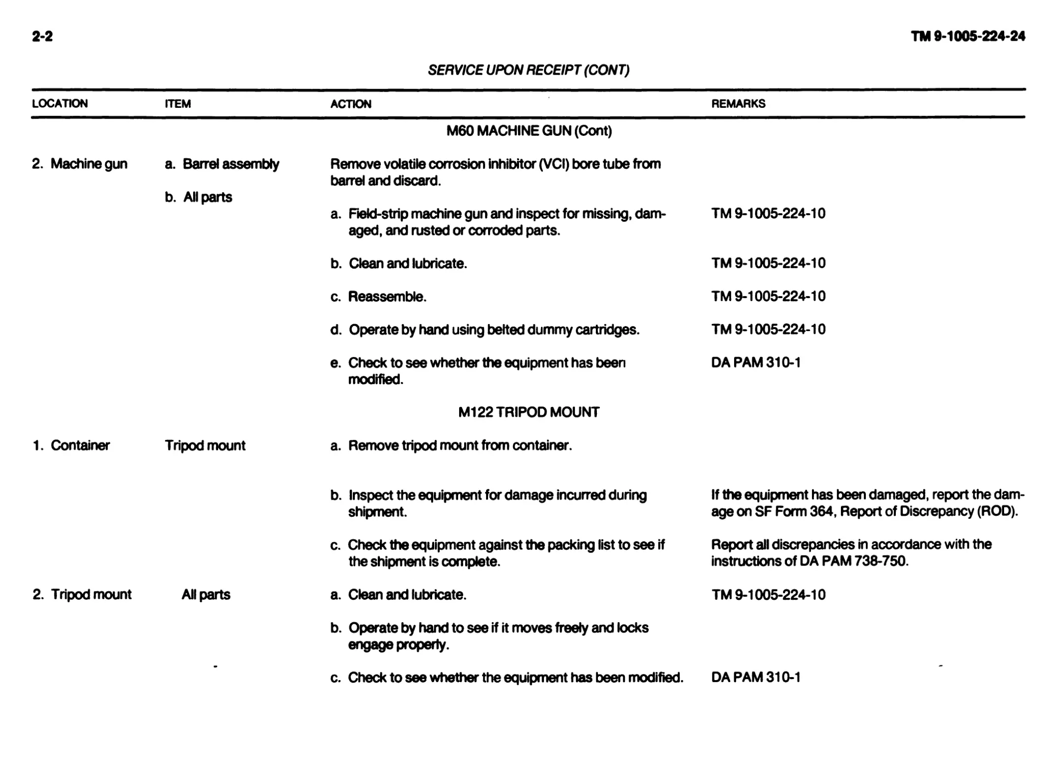
SERVICE UPON RECEIPT (CONT)
LOCATION ITEM ACTION REMARKS
2. Machinegun a. Barrel assembly M60 MACHINE GUN (Cont) Remove volatile corrosion inhibitor (VCI) bore tube from
1. Container b. All parts Tripod mount barrel and discard. a. Field-strip machine gun and inspect for missing, dam- aged, and rusted or corroded parts. b. Clean and lubricate. c. Reassemble. d. Operate by hand using belted dummy cartridges. e. Check to see whether the equipment has been modified. M122 TRIPOD MOUNT a. Remove tripod mount from container. TM 9-1005-224-10 TM 9-1005-224-10 TM 9-1005-224-10 TM 9-1005-224-10 DA PAM 310-1
2. Tripod mount All parts b. Inspect the equipment for damage incurred during shipment. c. Check the equipment against the packing list to see if the shipment is complete. a. Clean and lubricate. If the equipment has been damaged, report the dam- age on SF Form 364, Report of Discrepancy (ROD). Report all discrepancies in accordance with the instructions of DA PAM 738-750. TM 9-1005-224-10
- b. Operate by hand to see if it moves freely and locks engage properly. c. Check to see whether the equipment has been modified. DA PAM 310-1
SERVICE UPON RECEIPT (CONT)
LOCATION ITEM ACTION REMARKS
M60D MACHINE GUN
1. Container a. Machinegun a. Remove machine gun from container.
b. Inspect the equipment for damage incurred during shipment. If the equipment has been damaged, report the dam- age on SF Form 364, Report of Discrepancy (ROD).
c. Check the equipment against the packing list to see if the shipment is complete. Report all discrepancies in accordance with the instructions of DA PAM 738-750.
b. Basic issue items Check for missing items. TM 9-1005-224-10
2. Machinegun a. Barrel assembly Remove volatile corrosion inhibitor (VC!) bore tube from bar- rel and discard.
b. AU parts a. Field-strip machine gun and inspect for missing, dam- aged, and rusted or corroded parts. TM 9-1005-224-10
b. Clean and lubricate. TM 9-1005-224-10
c. Reassemble. TM 9-1005-224-10
d. Operate by hand using belted dummy cartridges. TM 9-1005-224-10
e. Check to see whether the equipment has been modified. DA PAM 310-1
Section III. PREVENTIVE MAINTENANCE CHECKS AND SERVICES (PMCS)
2-6. GENERAL. This section contains the procedures and instructions neces-
sary to perform organizational preventive maintenance checks and services.
These services are to be performed by organizational maintenance personnel
with the assistance, where practical, of the operator/crew who will dean and
lubricate in accordance with TM 9-1005-224-10. All items to be inspected and
procedures for the M60 Machine Gun will apply to the M60D Machine Gun, as
appropriate.
NOTE
Maintenance of some assemblies are not authorized by the
maintenance allocation chart (app B) to organizational mainte-
nance. Insure that no work is being accomplished beyond the
scope authorized to organizational maintenance. Evacuate to
direct and general support maintenance for repairs when
necessary.
2-3
TM 9-1005-224-24
2-4
TM 9-1005-224-24
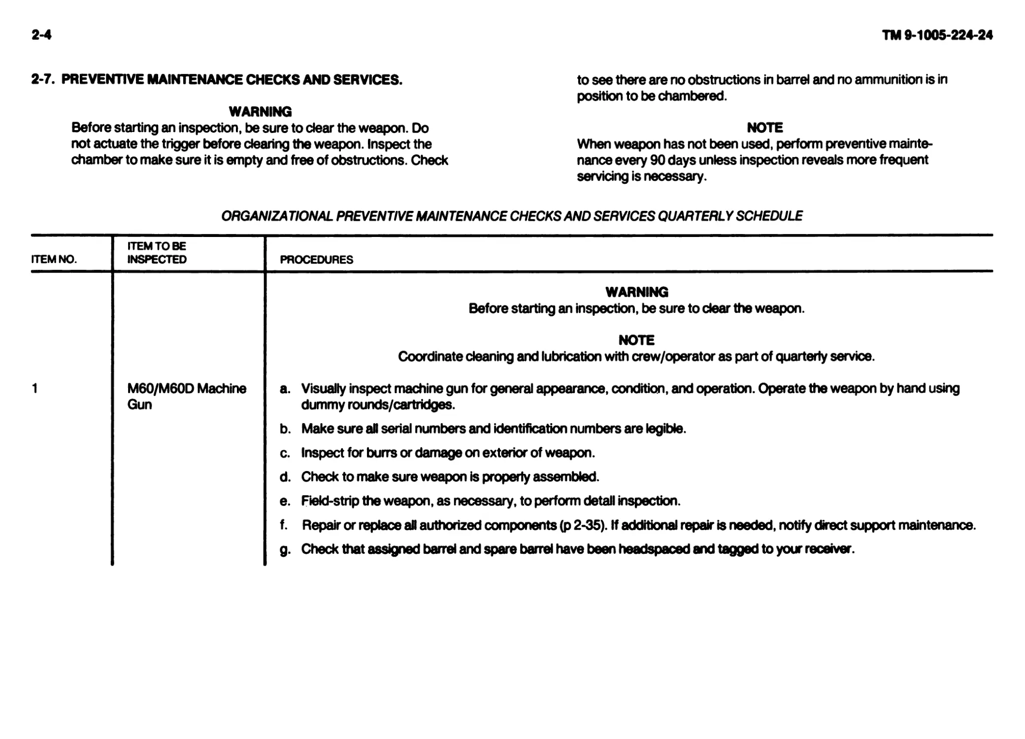
2-7. PREVENTIVE MAINTENANCE CHECKS AND SERVICES.
WARNING
Before starting an inspection, be sure to dear the weapon. Do
not actuate the trigger before clearing the weapon. Inspect the
chamber to make sure it is empty and free of obstructions. Check
to see there are no obstructions in barrel and no ammunition is in
position to be chambered.
NOTE
When weapon has not been used, perform preventive mainte-
nance every 90 days unless inspection reveals more frequent
servidng is necessary.
ORGANIZATIONAL PREVENTIVE MAINTENANCE CHECKSAND SERVICES QUARTERLY SCHEDULE
ITEM NO. ITEM TO BE INSPECTED PROCEDURES
1 M60/M60D Machine Gun WARNING Before starting an inspection, be sure to dear the weapon. NOTE Coordinate cleaning and lubrication with crew/operator as part of quarterly service. a. Visually inspect machine gun for general appearance, condition, and operation. Operate the weapon by hand using dummy rounds/cartridges. b. Make sure all serial numbers and identification numbers are legible. c. Inspect for burrs or damage on exterior of weapon. d. Check to make sure weapon is properly assembled. e. Field-strip the weapon, as necessary, to perform detail inspection. f. Repair or replace aR authorized components (p 2-35). If additional repair is needed, notify direct support maintenance. g. Check that assigned barrel and spare barrel have been headspaced and tagged to your receiver.
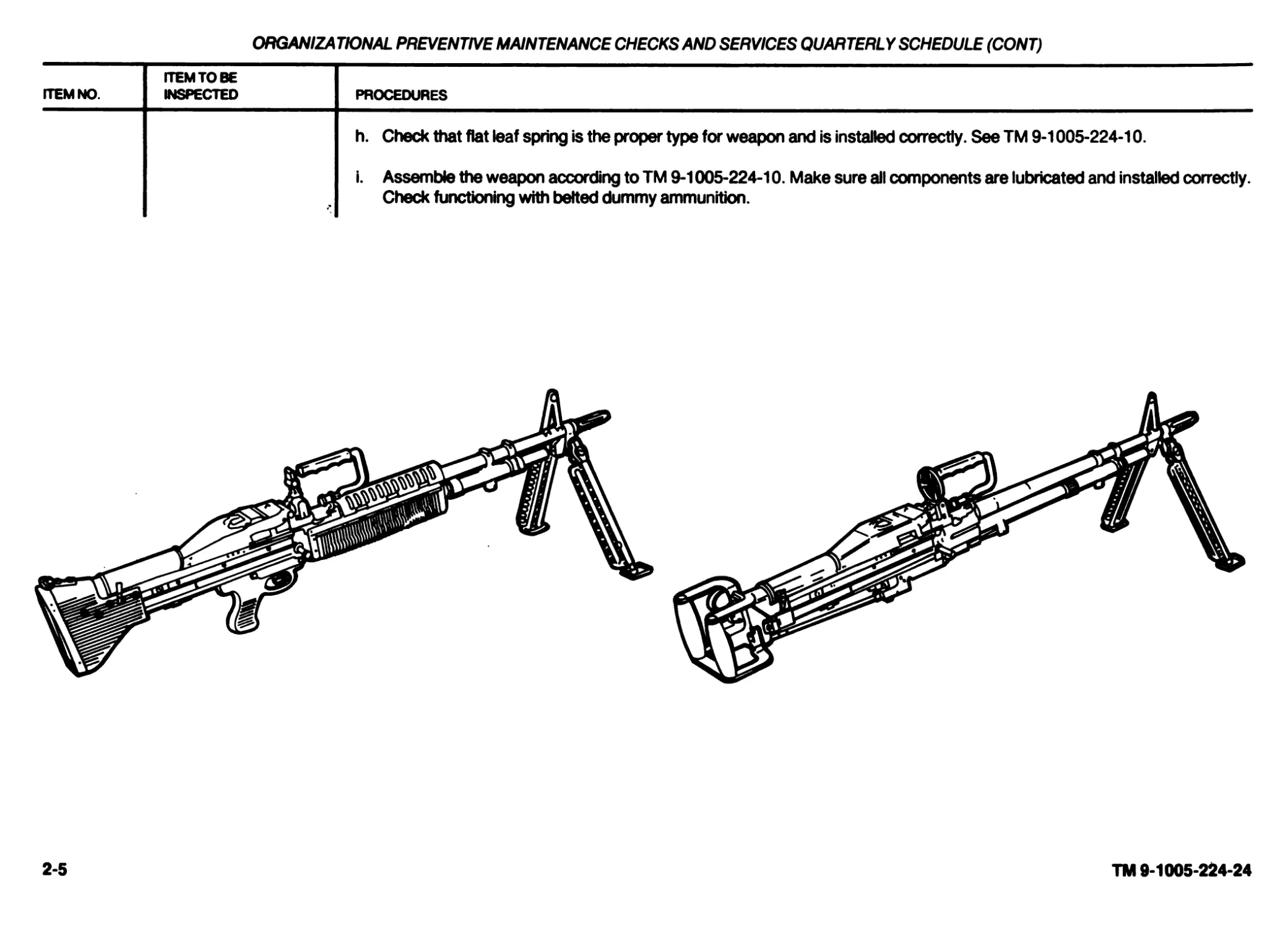
ORGANIZATIONAL PREVENTIVE MAINTENANCE CHECKSAND SERVICES QUARTERLY SCHEDULE (CONT)
ITEM NO. ITEM TO BE INSPECTED PROCEDURES
h. Check that flat leaf spring is the proper type for weapon and is installed correctly. See TM 9-1005-224-10. i. Assemble the weapon according to TM 9-1005-224-10. Make sure all components are lubricated and installed correctly. Check functioning with belted dummy ammunition.
2-5
TM 9-1005-224-24
2-в
TM 9-1005-224-24
ORGANIZATIONAL PREVENTIVE MAINTENANCE CHECKSAND SERVICES QUARTERLY SCHEDULE (CONT)
ITEM NO. ITEM TO BE INSPECTED PROCEDURES
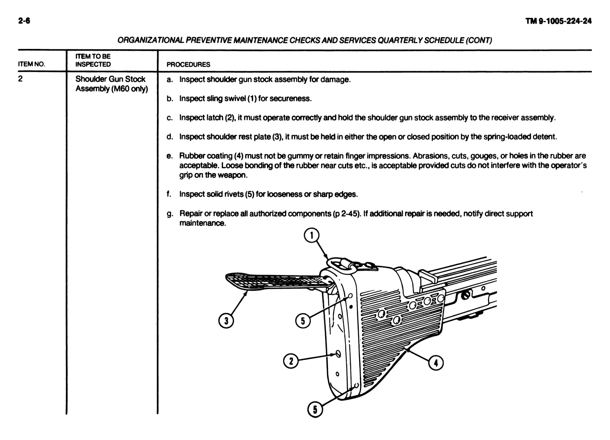
2 Shoulder Gun Stock Assembly (M60 only) a. Inspect shoulder gun stock assembly for damage. b. Inspect sling swivel (1) for secureness. c. Inspect latch (2), it must operate correctly and hold the shoulder gun stock assembly to the receiver assembly. d. Inspect shoulder rest plate (3), it must be held in either the open or closed position by the spring-loaded detent. e. Rubber coating (4) must not be gummy or retain finger impressions. Abrasions, cuts, gouges, or holes in the rubber are acceptable. Loose bonding of the rubber near cuts etc., is acceptable provided cuts do not interfere with the operator s grip on the weapon. f. Inspect solid rivets (5) for looseness or sharp edges. g. Repair or replace all authorized components (p 2-45). If additional repair is needed, notify direct support maintenance. Q ®—I I о к (Sj
ORGANIZATIONAL PREVENTIVE MAINTENANCE CHECKSAND SERVICES QUARTERLY SCHEDULE (CONT)
ITEM NO. ITEM TO BE INSPECTED PROCEDURES
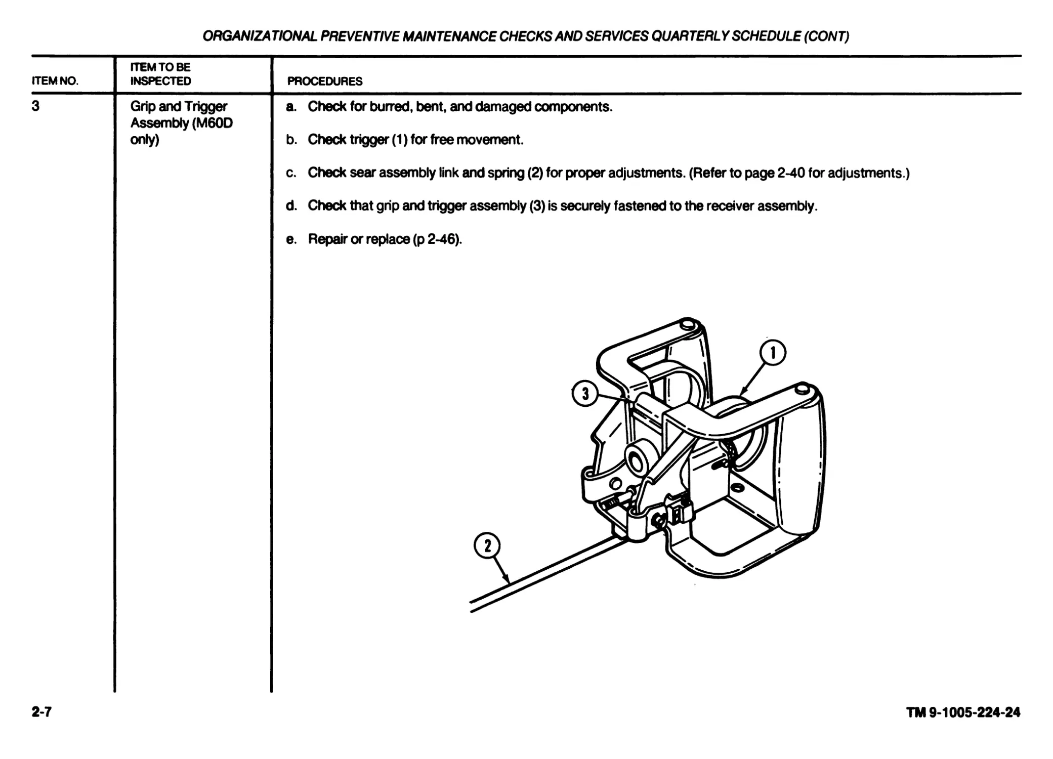
3 Grip and Trigger Assembly (M60D only) a. Check for burred, bent, and damaged components. b. Check trigger (1) for free movement. c. Check sear assembly link and spring (2) for proper adjustments. (Refer to page 2-40 for adjustments.) d. Check that grip and trigger assembly (3) is securely fastened to the receiver assembly. e. Repair or replace (p 2-46).
2-7
TM 9-1005-224-24
2-8
TM 9-1005-224-24
ORGANIZATIONAL PREVENTIVE MAINTENANCE CHECKS AND SERVICES QUARTERLY SCHEDULE (CONT)
ITEM NO. ITEM TO BE INSPECTED PROCEDURES
CAUTION
Do not allow breech bolt to slam closed when the weapon is empty, as this will cause damage to locking surfaces on the breech bolt or barrel socket.
NOTE
Burrs or raised surfaces, may be removed or smoothed using a fine grit sharpening stone. DO NOT change the dimensions of any component by stoning.
Cracks, chips, dents, or gouges on components shall be reported to direct support maintenance for repair or replacement.
Cracks, chips, dents, or gouges on breech bolt locking surfaces can damage the barrel socket. Damage to barrel socket locking surfaces
can damage the breech bolt. If either condition exists, notify direct support maintenance for replacement or repair.
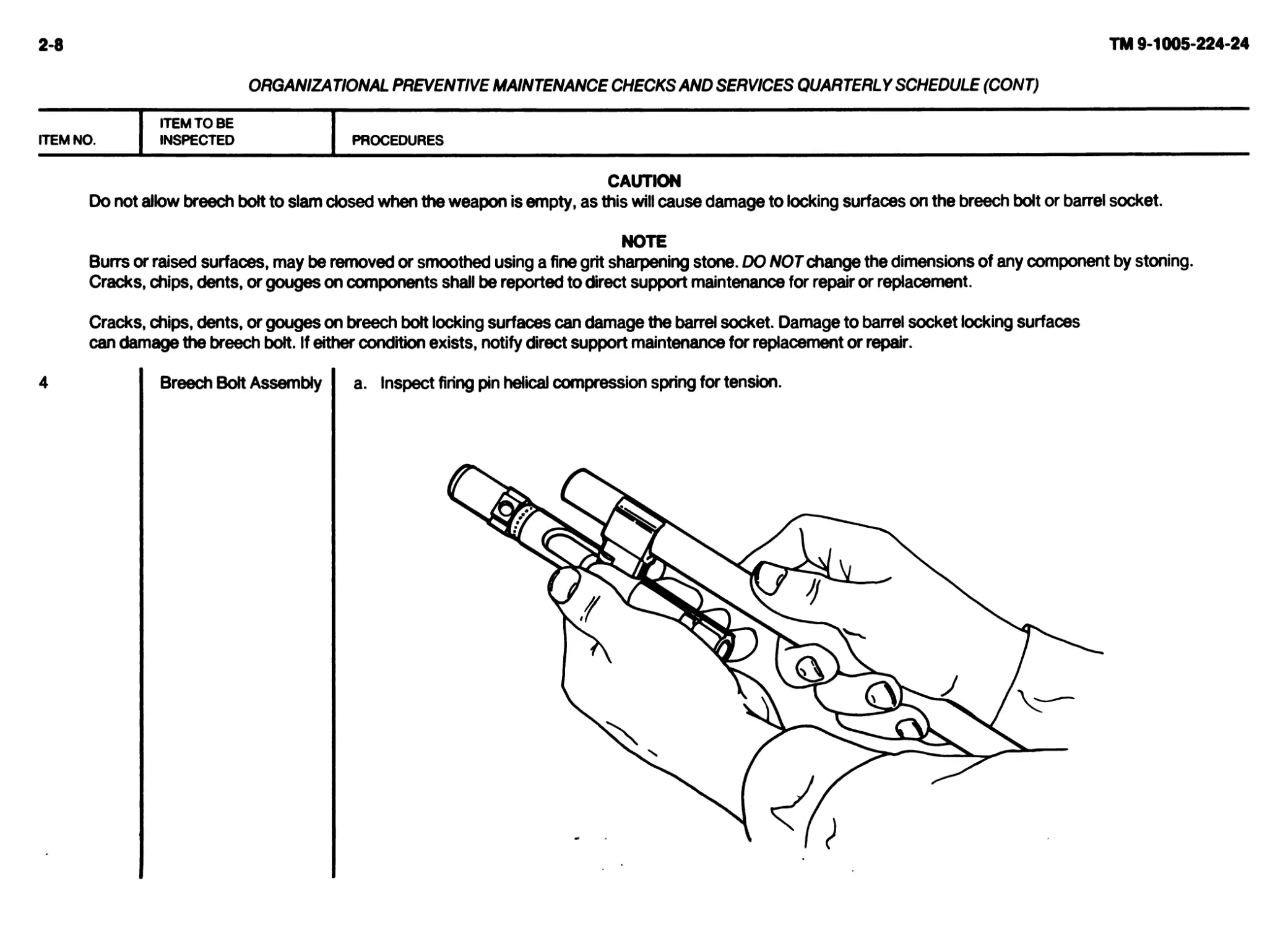
Breech Bolt Assembly a. Inspect firing pin helical compression spring for tension.
ORGANIZA DONAL PREVENTIVE MAINTENANCE CHECKS AND SERVICES QUARTERL Y SCHEDULE (CONT)
ITEM NO.
4
ITEM TO BE
INSPECTED
PROCEDURES
Breech Bolt Assembly
(Cont)
b. Inspect bolt body for burrs or damage in the areas indicated.
d. Inspect firing pin (6) in breech bolt. Firing pin (6) must not be cracked or bent and must have a well-rounded point.
c. Make sure breech bolt operates correctly. Roller (1) on cam actu-
ator assembly (2) should rotate freely, and cam actuator assem-
bly should rotate freely on breech bolt (3). Inspect bolt assembly
for missing headless straight pin (4) securing plug assembly (5).
e. Inspect cartridge ejector (7) for freedom of movement. When cartridge ejector is depressed/released, helical compres-
sion spring must return cartridge ejector to normal position.
f. Inspect cartridge extractor (8) for chipped or damaged hook portion and for freedom of movement. When cartridge
extractor is depressed/released, helical compression spring must return cartridge extractor to normal position.
g. Inspect for pits on breech bolt face. Make sure that firing pin hole
is round and not elongated.
h. Repair or replace all authorized components (p 2-48). If additional
repair is needed, notify direct support maintenance.
2-9
TM 9-1005-224-24
ТМ 9-1005-224-24
' ORGANIZATIONAL PREVENTIVE MAINTENANCE CHECKS AND SERVICES QUARTERLY SCHEDULE (CONT)
ITEM NO. ITEM TO BE INSPECTED PROCEDURES
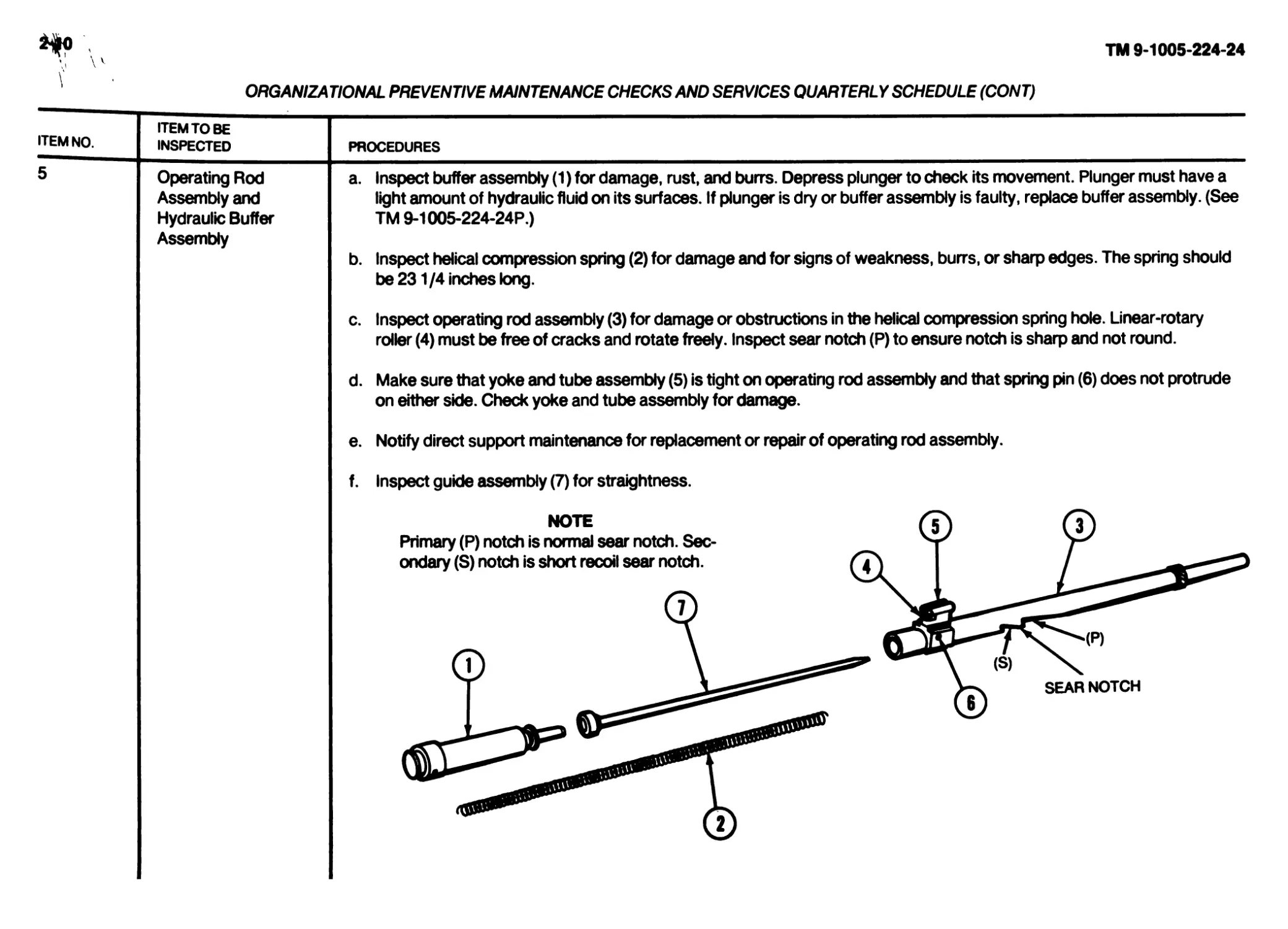
5 Operating Rod Assembly and Hydraulic Buffer Assembly a. Inspect buffer assembly (1) for damage, rust, and burrs. Depress plunger to check its movement. Plunger must have a light amount of hydraulic fluid on its surfaces. If plunger is dry or buffer assembly is faulty, replace buffer assembly. (See TM9-1005-224-24P.) b. Inspect helical compression spring (2) for damage and for signs of weakness, burrs, or sharp edges. The spring should be 231/4 inches long. c. Inspect operating rod assembly (3) for damage or obstructions in the helical compression spring hole. Linear-rotary roller (4) must be free of cracks and rotate freely. Inspect sear notch (P) to ensure notch is sharp and not round. d. Make sure that yoke and tube assembly (5) is tight on operating rod assembly and that spring pin (6) does not protrude on either side. Check yoke and tube assembly for damage. e. Notify direct support maintenance for replacement or repair of operating rod assembly. f. Inspect guide assembly (7) for straightness. №TE (?) (?) Primary (P) notch is normal sear notch. Sec- 4rz Vх ondary(S) notch is short recoil sear notch. (7) I У-x SEAR NOTCH I (?) CD
ORGANIZATIONAL PREVENTIVE MAINTENANCE CHECKS AND SERVICES QUARTERLY SCHEDULE (CONT)
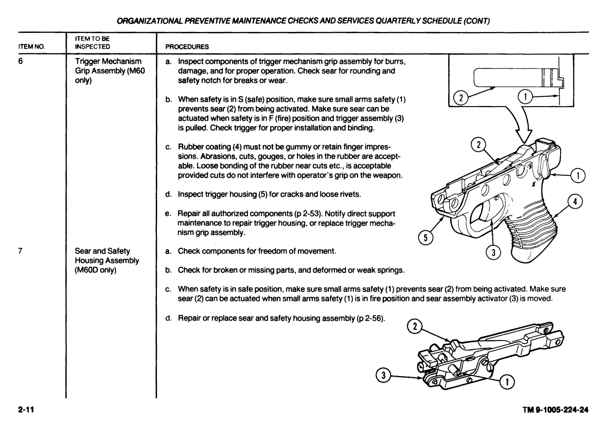
ITEM NO.
6
ITEM TO BE
INSPECTED
Trigger Mechanism
Grip Assembly (M60
only)
PROCEDURES
Sear and Safety
Housing Assembly
(M60D only)
a. Inspect components of trigger mechanism grip assembly for burrs,
damage, and for proper operation. Check sear for rounding and
safety notch for breaks or wear.
b. When safety is in S (safe) position, make sure small arms safety (1)
prevents sear (2) from being activated. Make sure sear can be
actuated when safety is in F (fire) position and trigger assembly (3)
is pulled. Check trigger for proper installation and binding.
c. Rubber coating (4) must not be gummy or retain finger impres-
sions. Abrasions, cuts, gouges, or holes in the rubber are accept-
able. Loose bonding of the rubber near cuts etc., is acceptable
provided cuts do not interfere with operator’s grip on the weapon.
d. Inspect trigger housing (5) for cracks and loose rivets.
e. Repair all authorized components (p 2-53). Notify direct support
maintenance to repair trigger housing, or replace trigger mecha-
nism grip assembly.
a. Check components for freedom of movement.
b. Check for broken or missing parts, and deformed or weak springs.
c. When safety is in safe position, make sure small arms safety (1) prevents sear (2) from being activated. Make sure
sear (2) can be actuated when small arms safety (1) is in fire position and sear assembly activator (3) is moved.
2-11
TM 9-1005-224-24
2-12
TM 9-1005-224-24
ORGANIZATIONAL PREVENTIVE MAINTENANCE CHECKS AND SERVICES QUARTERLY SCHEDULE (CONT)
ITEM NO. ITEM TO BE INSPECTED PROCEDURES
NOTE
Burrs or raised surfaces may be removed or smoothed using a fine grit sharpening stone. DO NOT change the dimensions of any component by stoning.
Components with cracks, chips, dents, or gouges shall be reported to direct support maintenance for repair or replacement.
Cracks, chips, dents, or gouges on breech bolt locking surfaces can damage the barrel socket. Damage to barrel socket locking surfaces
can damage the breech bolt. Notify direct support maintenance for replacement or repair if either condition exists.
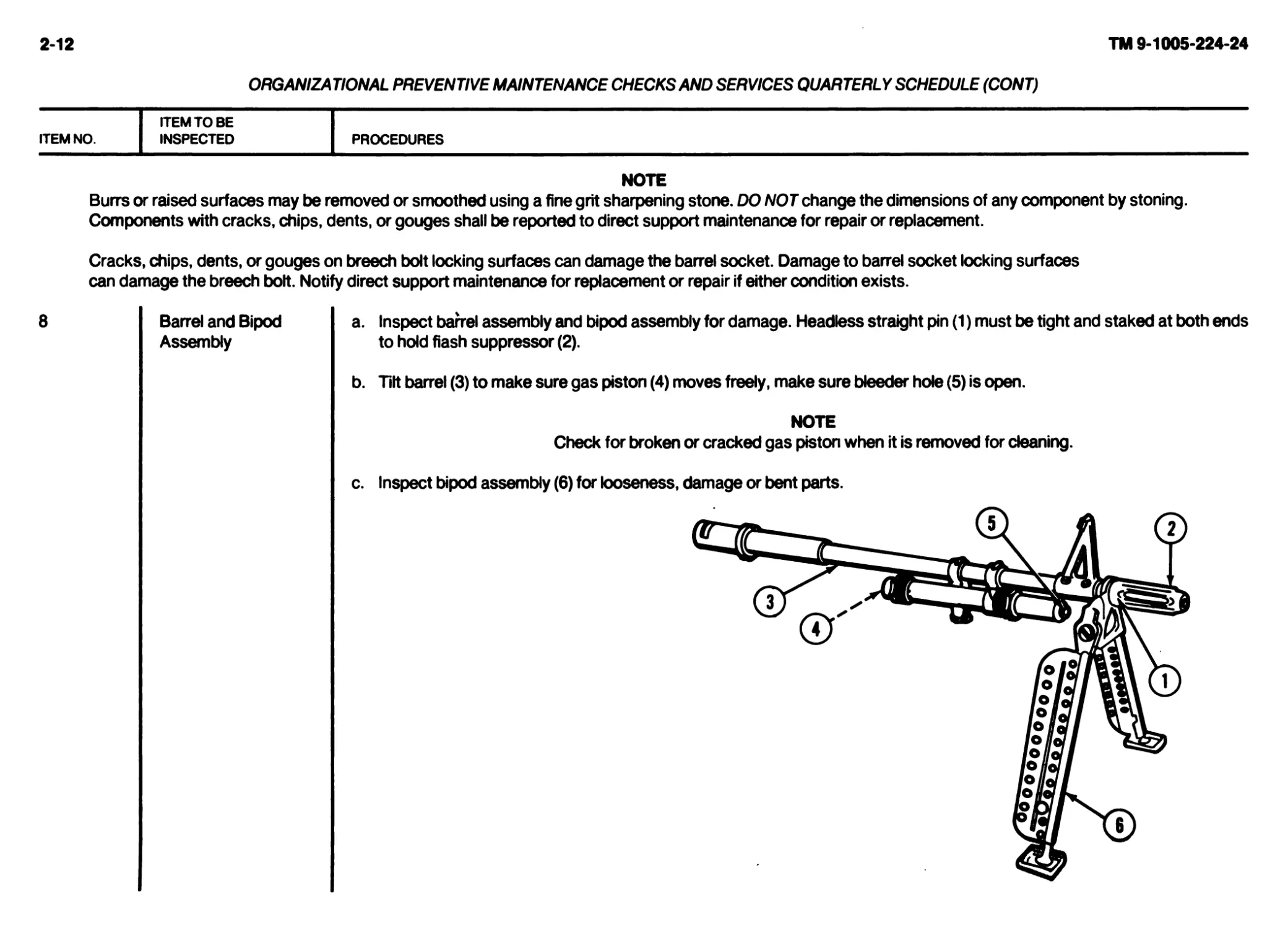
8
Barrel and Bipod
Assembly
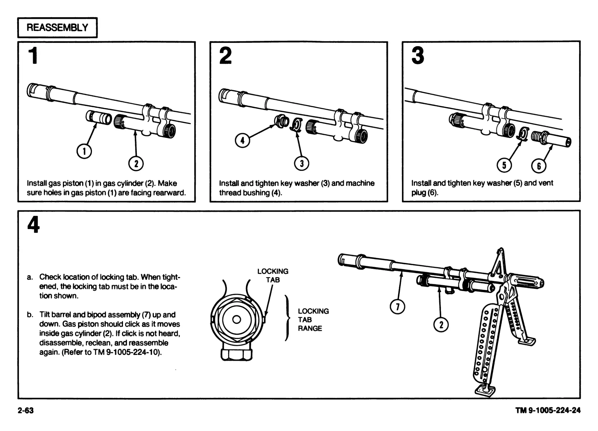
a. Inspect barrel assembly and bipod assembly for damage. Headless straight pin (1) must be tight and staked at both ends
to hold flash suppressor (2).
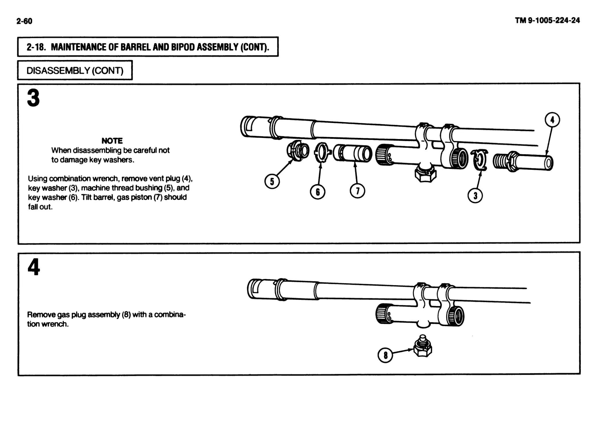
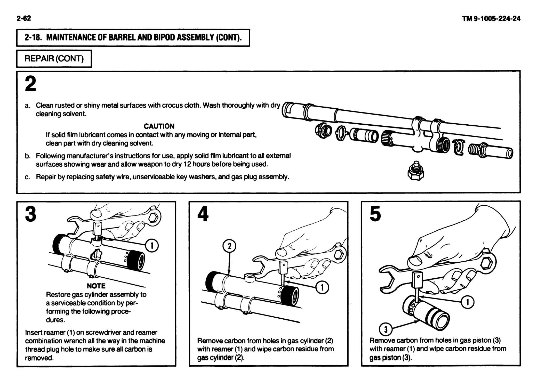
b. Tilt barrel (3) to make sure gas piston (4) moves freely, make sure bleeder hole (5) is open.
NOTE
Check for broken or cracked gas piston when it is removed for cleaning.
c. Inspect bipod assembly (6) for looseness, damage or bent parts.
ORGANIZATIONAL PREVENTIVE MAINTENANCE CHECKS AND SERVICES QUARTERLY SCHEDULE (CONT)
ITEM NO.
ITEM TO BE
INSPECTED
PROCEDURES
Barrel and Bipod
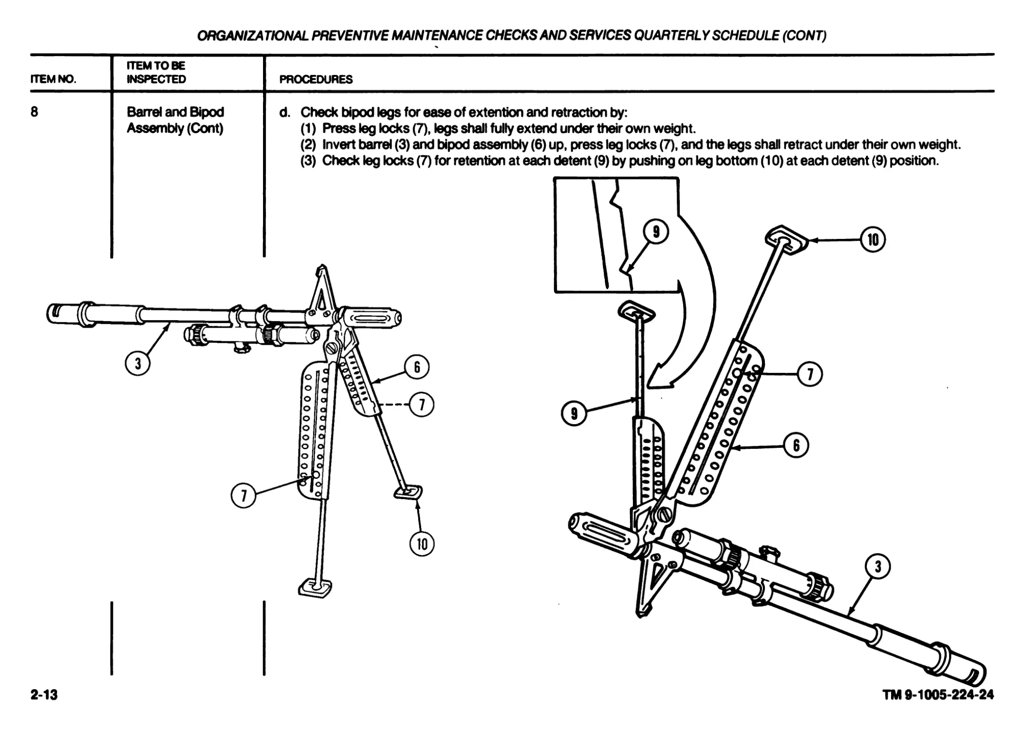
Assembly (Cont)
d. Check bipod legs for ease of extention and retraction by:
(1) Press leg locks (7), legs shall fully extend under their own weight.
(2) Invert barrel (3) and bipod assembly (6) up, press leg locks (7), and the legs shall retract under their own weight.
(3) Check leg locks (7) for retention at each detent (9) by pushing on leg bottom (10) at each detent (9) position.
2-13
TM 9-1005-224-24
2-14
TM 9-1005-224-24
ORGANIZATIONAL PREVENTIVE MAINTENANCE CHECKSAND SERVICES QUARTERLY SCHEDULE (CONT)
ITEM NO. ITEM TO BE INSPECTED PROCEDURES
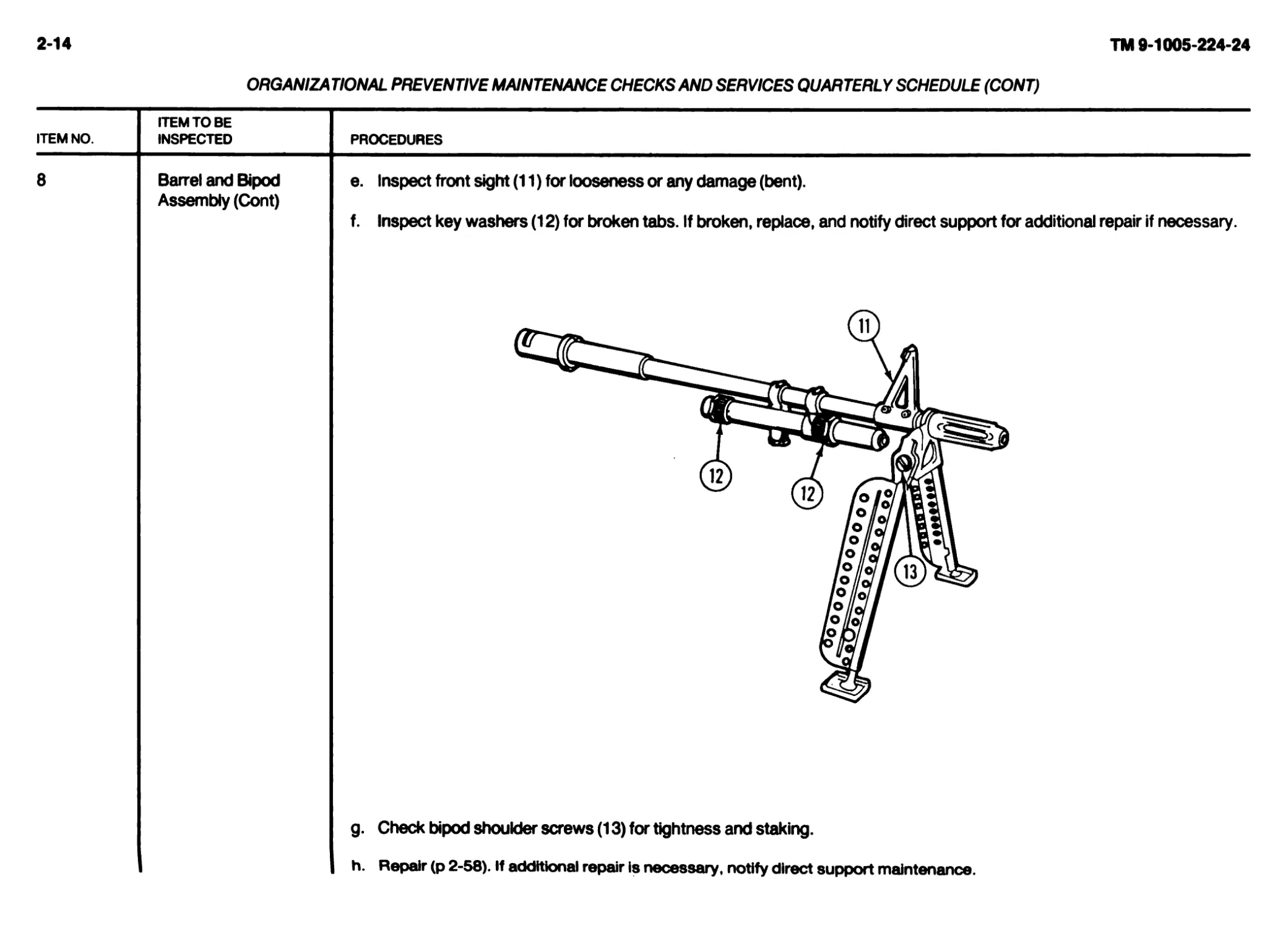
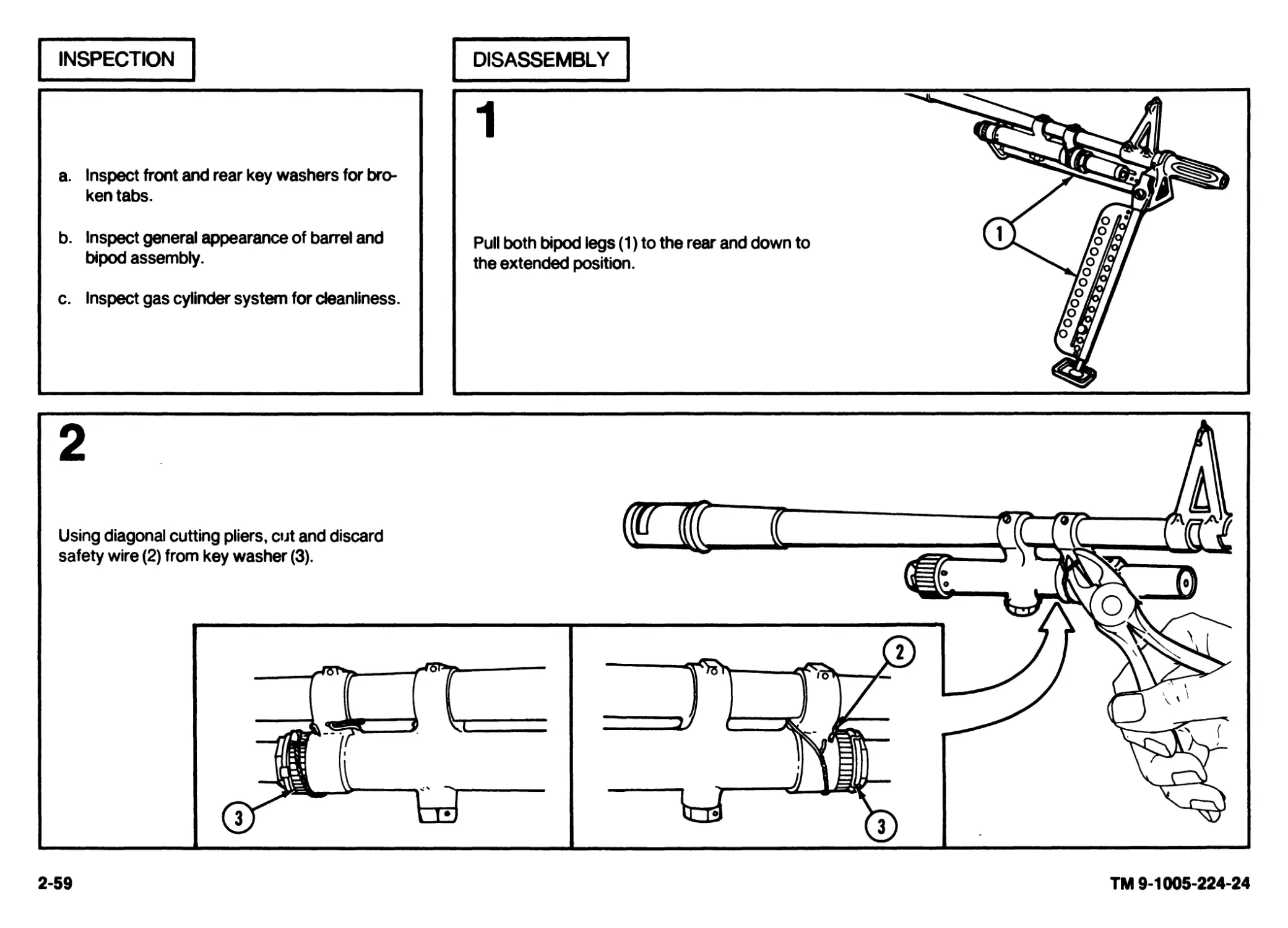
8 Barrel and Bipod Assembly (Cont) e. Inspect front sight (11) for looseness or any damage (bent). f. Inspect key washers (12) for broken tabs. If broken, replace, and notify direct support for additional repair if necessary.
Пгаг r- g. Check bipod shoulder screws (13) for tightness and staking. h. Repair (p 2-58). if additional repair is necessary, notify direct support maintenance.
ORGANIZATIONAL PREVENTIVE MAINTENANCE CHECKS AND SERVICES QUARTERLY SCHEDULE (CONT)
ITEM NO. ITEM TO BE INSPECTED PROCEDURES
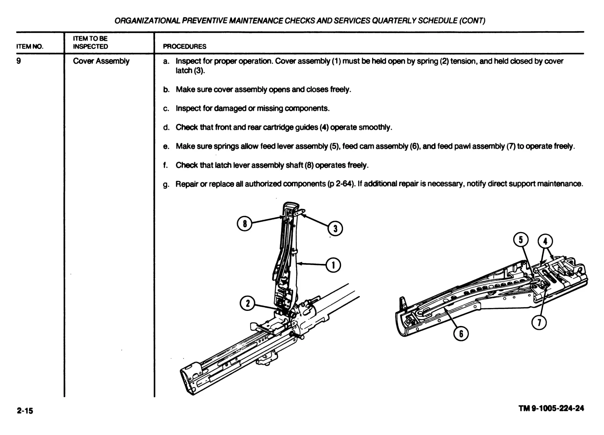
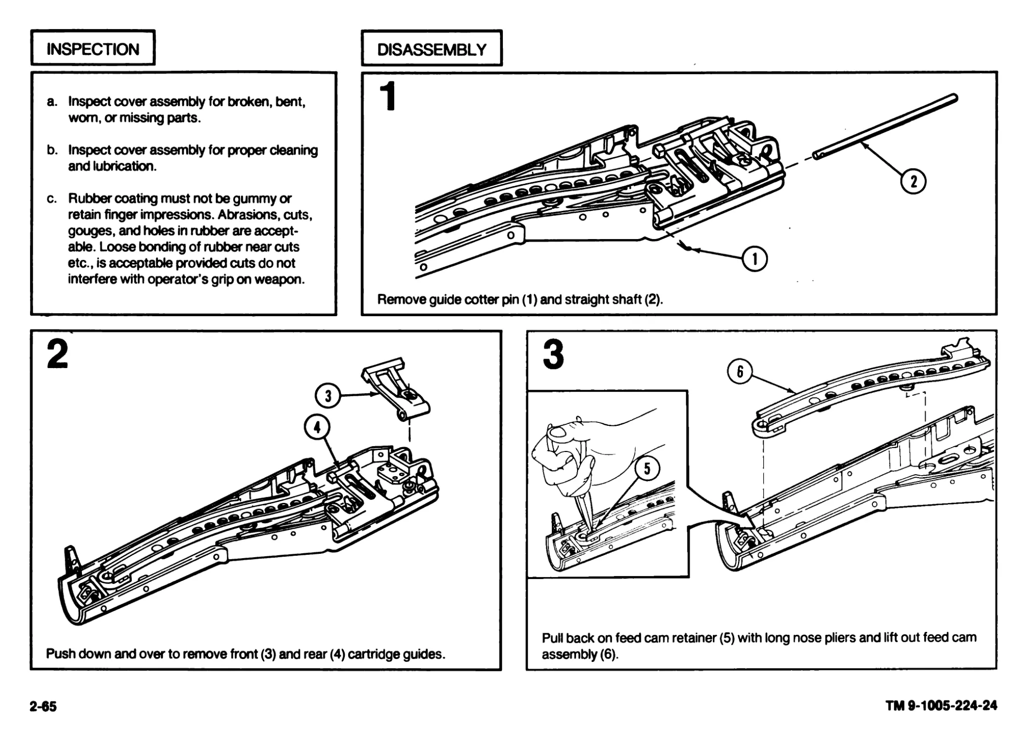
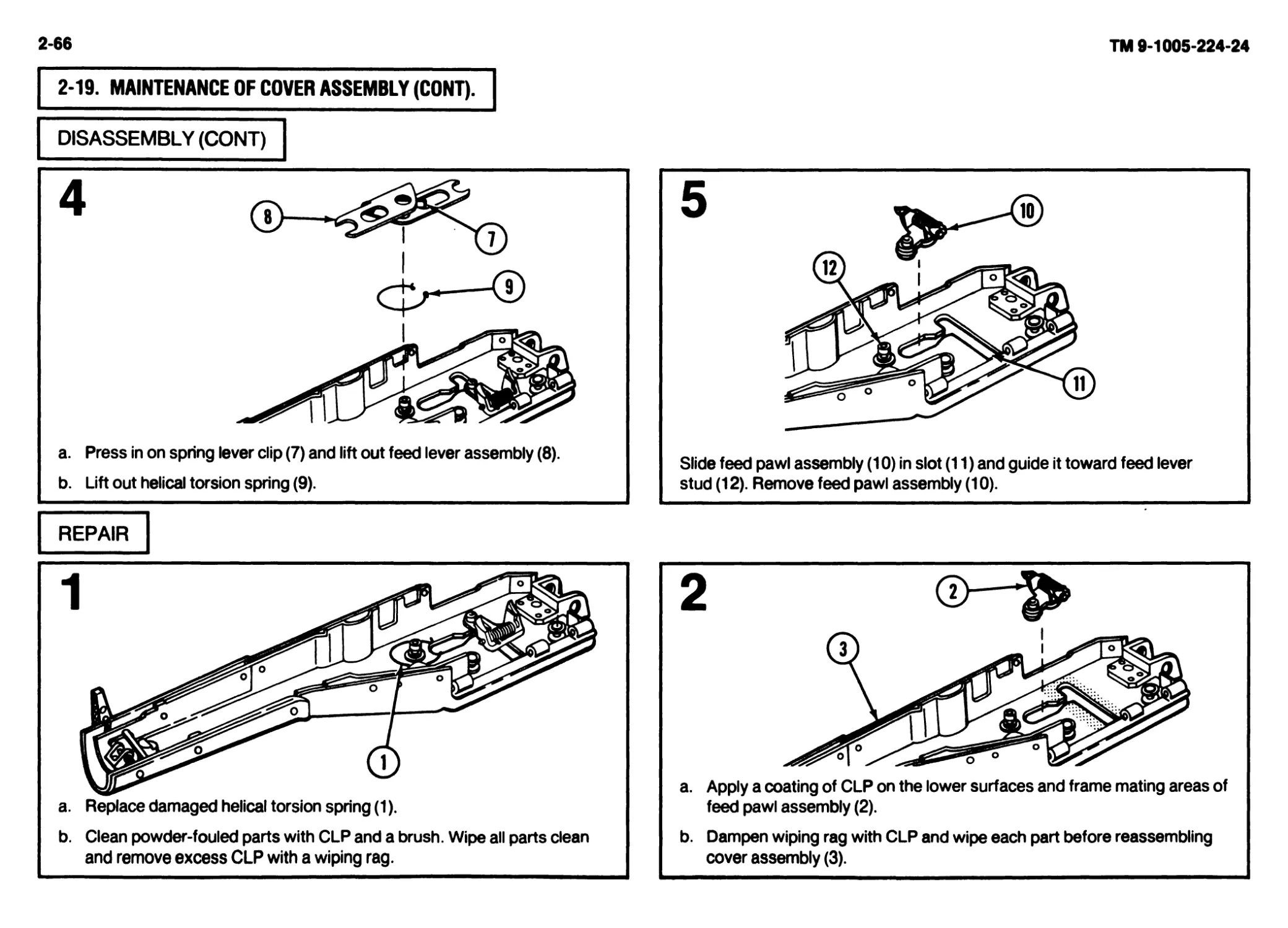
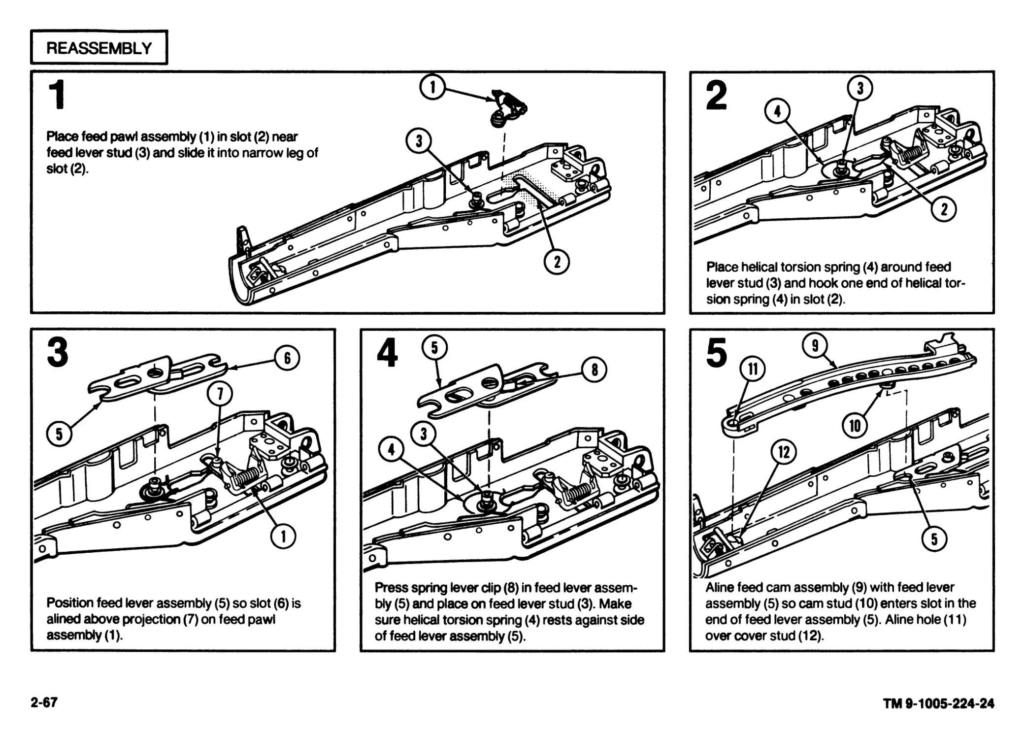
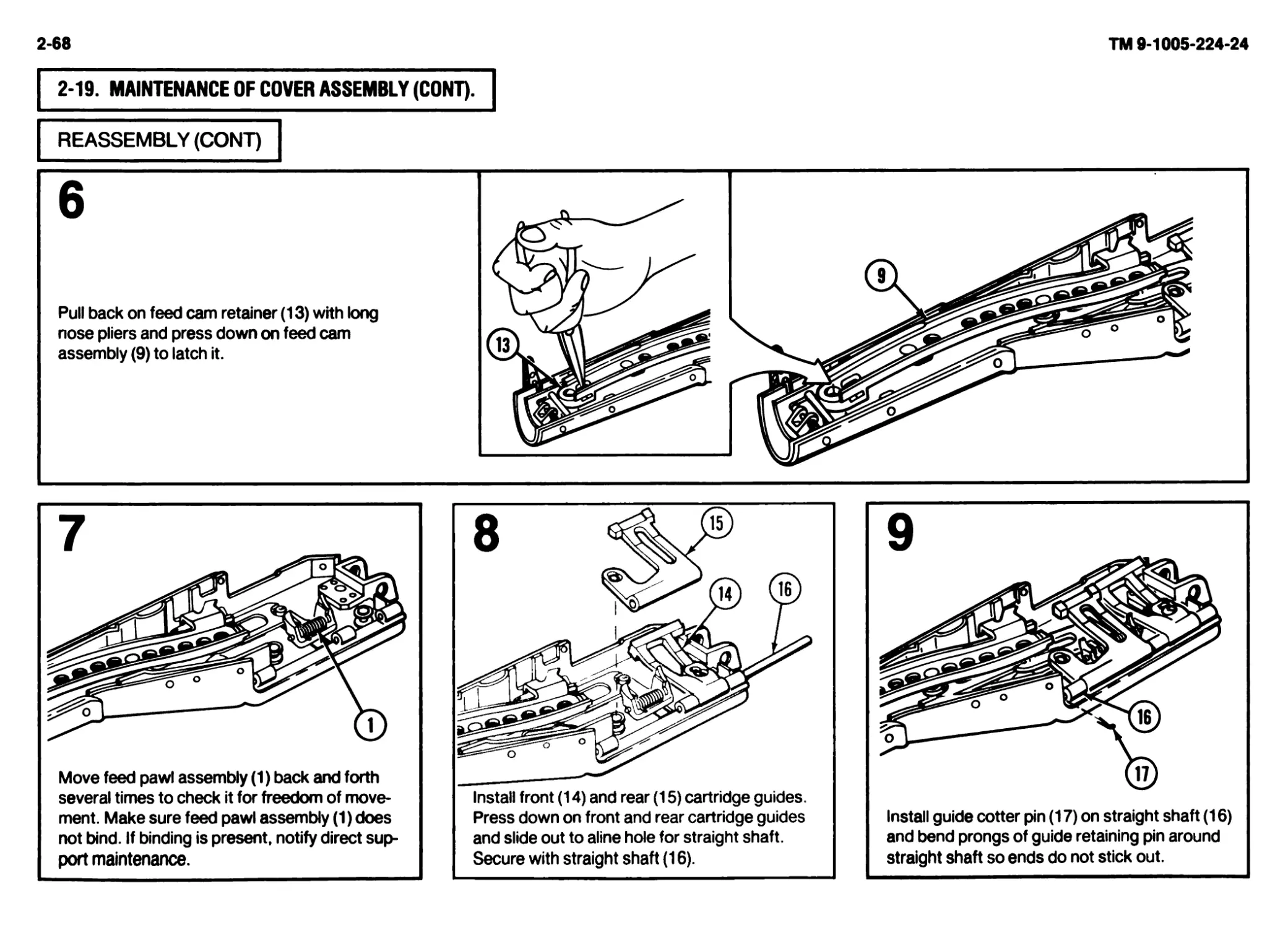
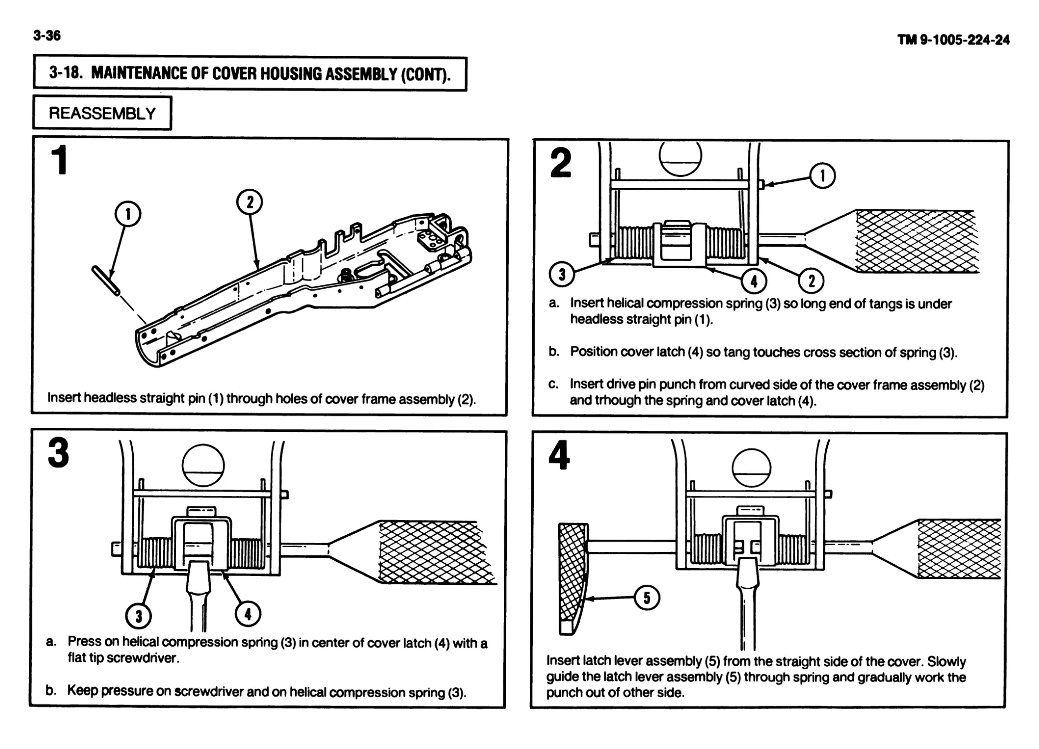
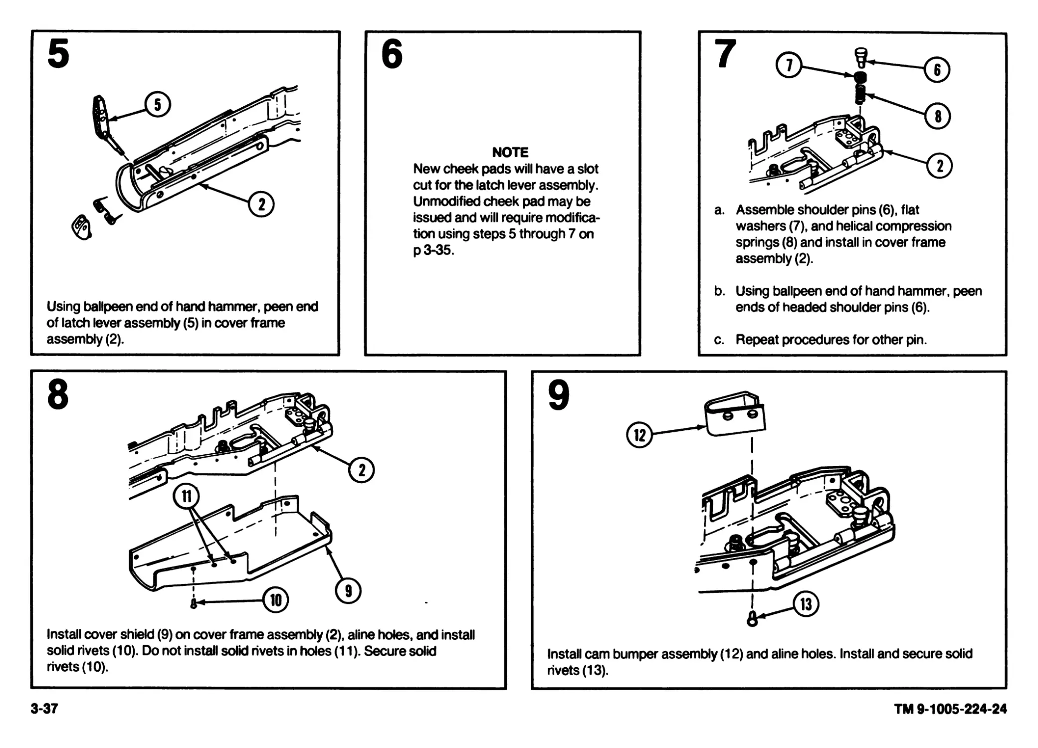
9 Cover Assembly a. Inspect for proper operation. Cover assembly (1) must be held open by spring (2) tension, and held closed by cover latch (3). b. Make sure cover assembly opens and closes freely. c. Inspect for damaged or missing components. d. Check that front and rear cartridge guides (4) operate smoothly. e. Make sure springs allow feed lever assembly (5), feed cam assembly (6), and feed pawl assembly (7) to operate freely. f. Check that latch lever assembly shaft (8) operates freely. g. Repair or replace all authorized components (p 2-64). If additional repair is necessary, notify direct support maintenance. x-ч Illi ® ® (б)
2-15
TM 9-1005-224-24
2-16
TM 9-1005-224-24
ITEM NO.
ITEM TO BE
INSPECTED
ORGANIZATIONAL PREVENTIVE MAINTENANCE CHECKSAND SERVICES QUARTERLY SCHEDULE (CONT)
PROCEDURES
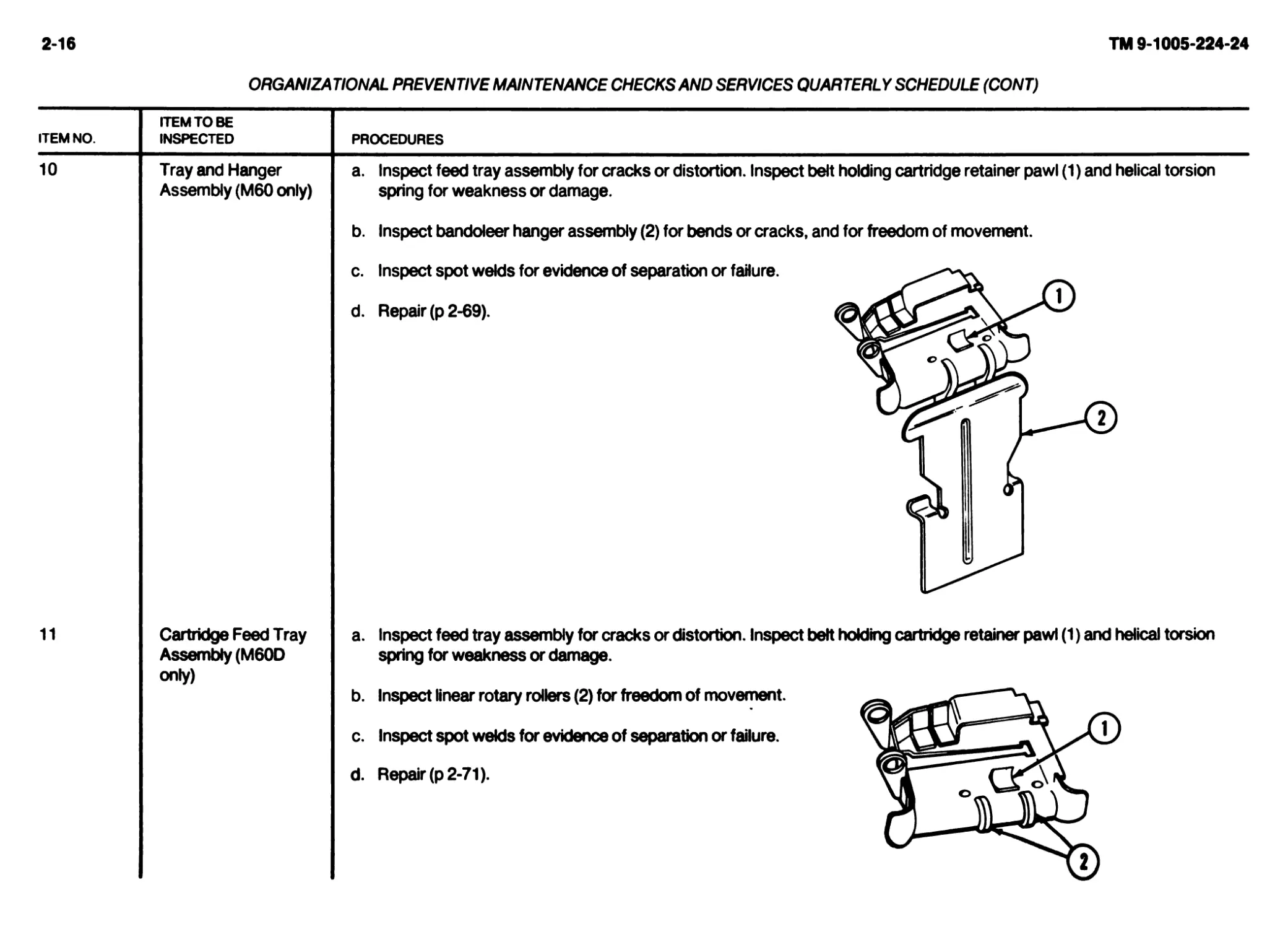
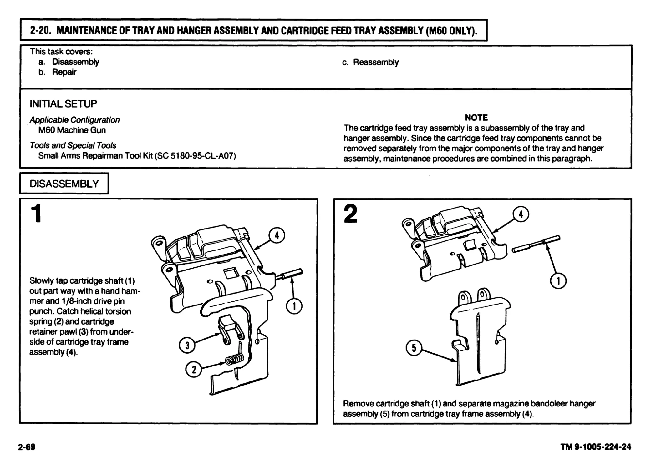
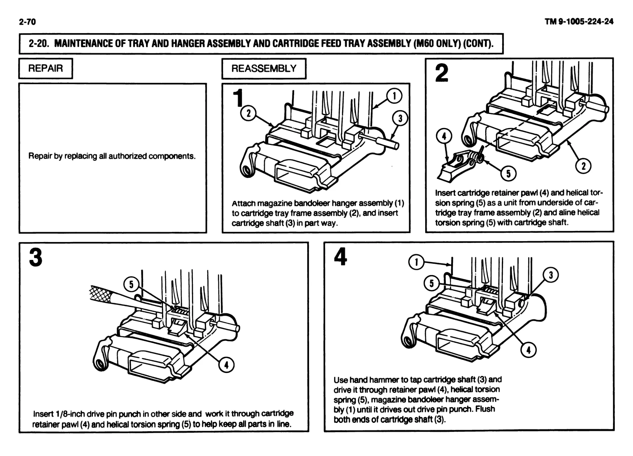
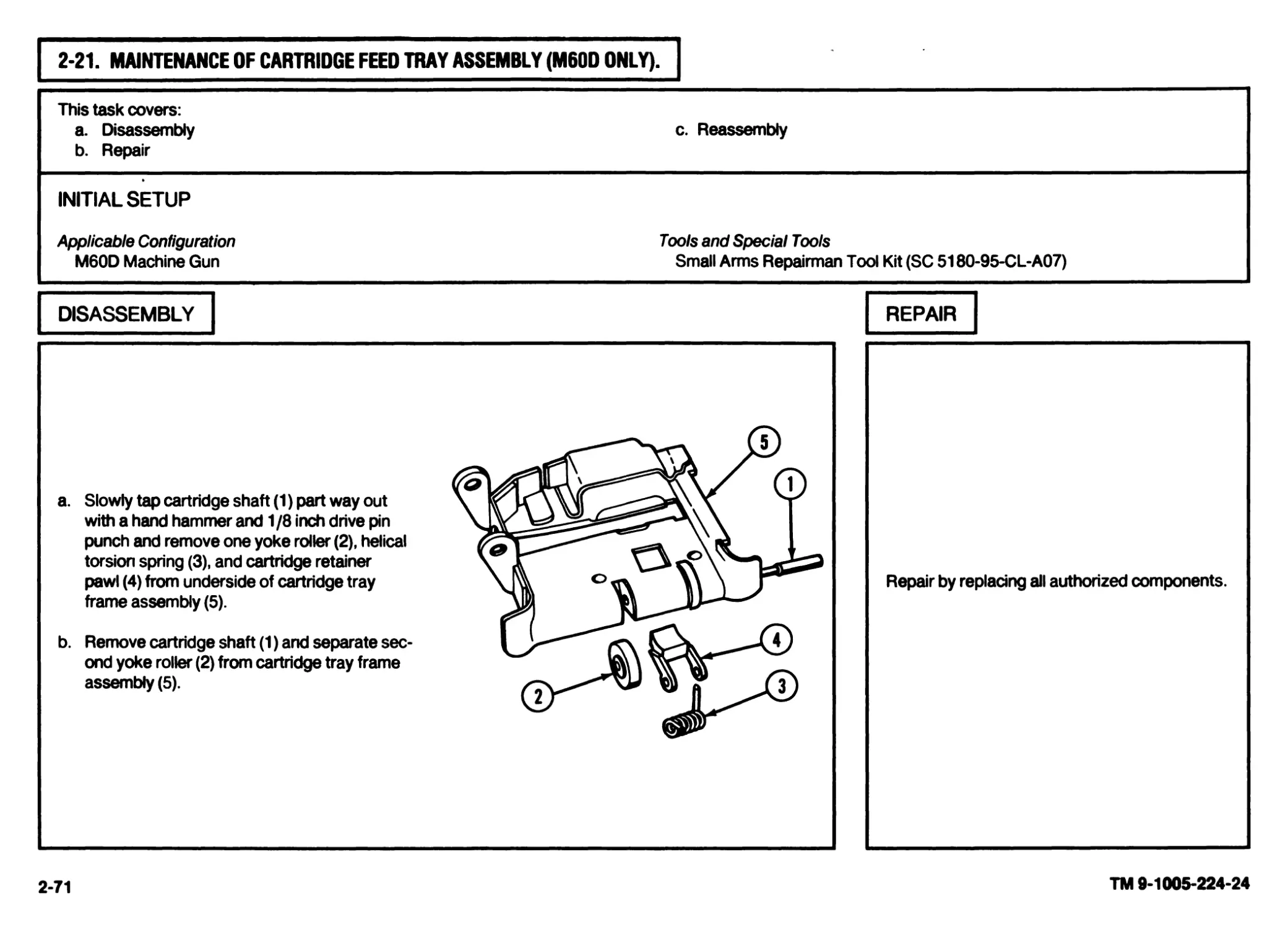
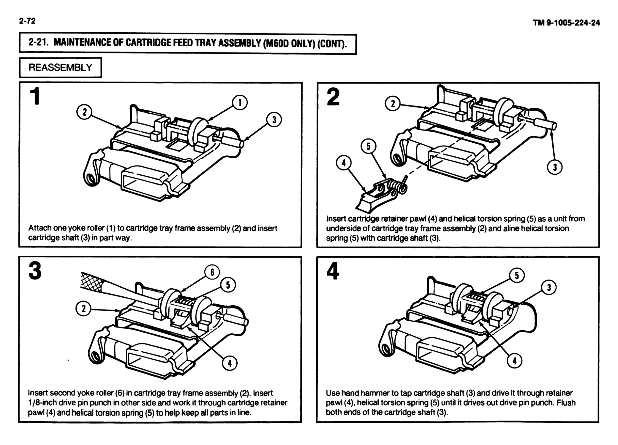
Tray and Hanger a. Inspect feed tray assembly for cracks or distortion. Inspect belt holding cartridge retainer pawl (1) and helical torsion
Assembly (M60 only)
spring for weakness or damage.
b. Inspect bandoleer hanger assembly (2) for bends or cracks, and for freedom of movement.
c. Inspect spot welds for evidence of separation or failure.
d. Repair (p 2-69).
11
Cartridge Feed Tray
Assembly (M60D
only)
a. Inspect feed tray assembly for cracks or distortion. Inspect belt holding cartridge retainer pawl (1) and helical torsion
spring for weakness or damage.
b. Inspect linear rotary rollers (2) for freedom of movement.
c. Inspect spot welds for evidence of separation or failure.
d. Repair (p 2-71).
ORGANIZATIONAL PREVENTIVE MAINTENANCE CHECKS AND SERVICES QUARTERLY SCHEDULE (CONT)
ITEM NO. ITEM TO BE INSPECTED PROCEDURES
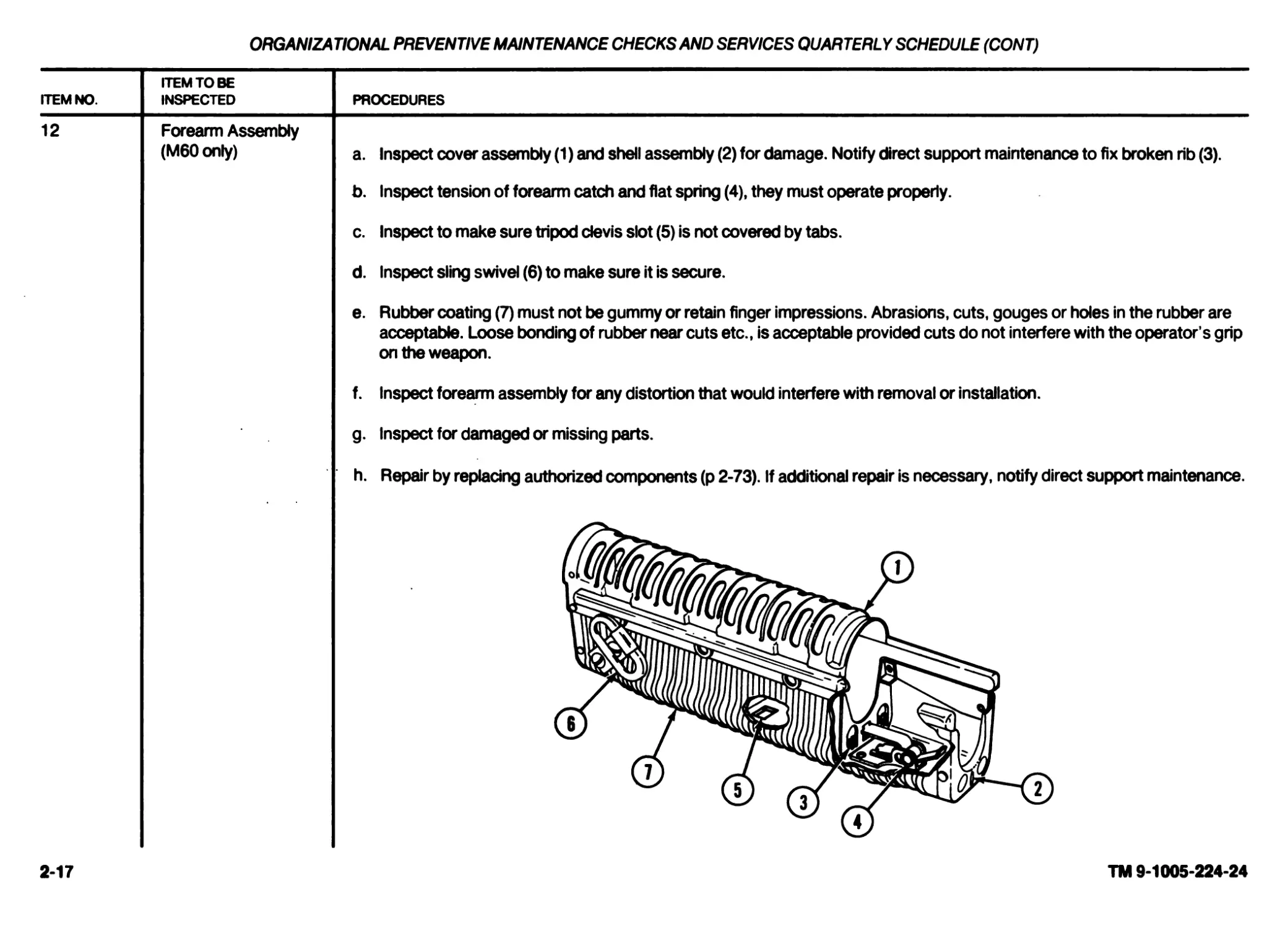
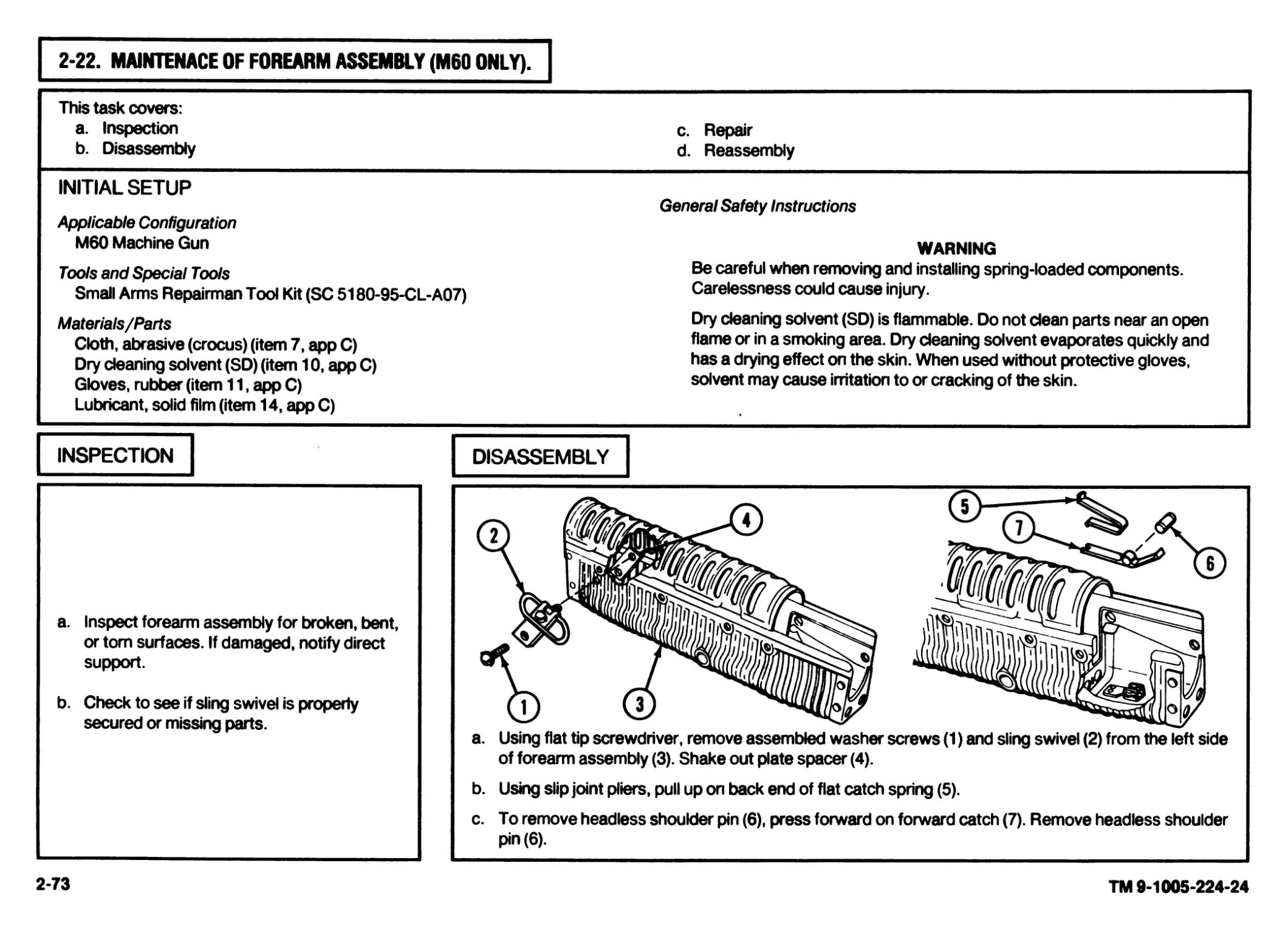
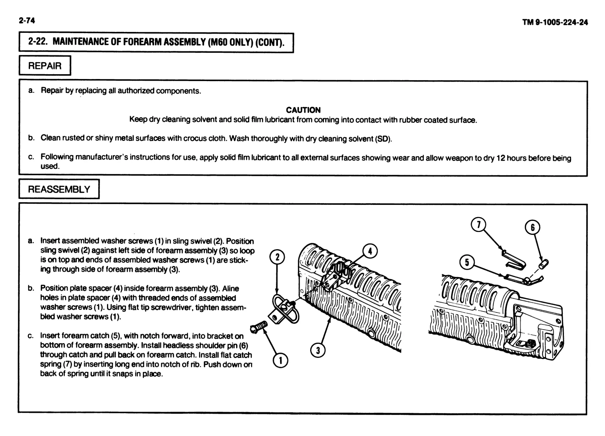
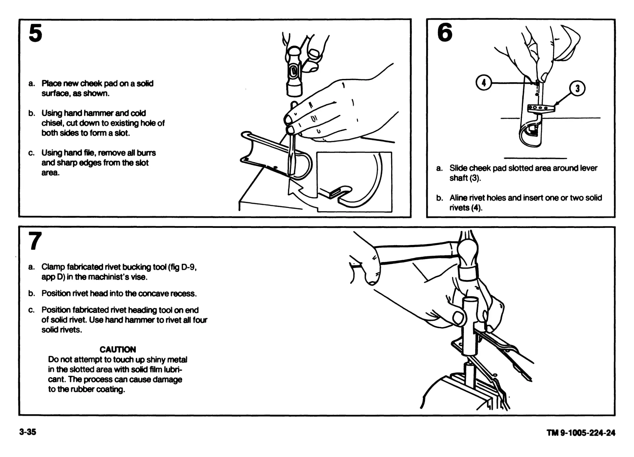
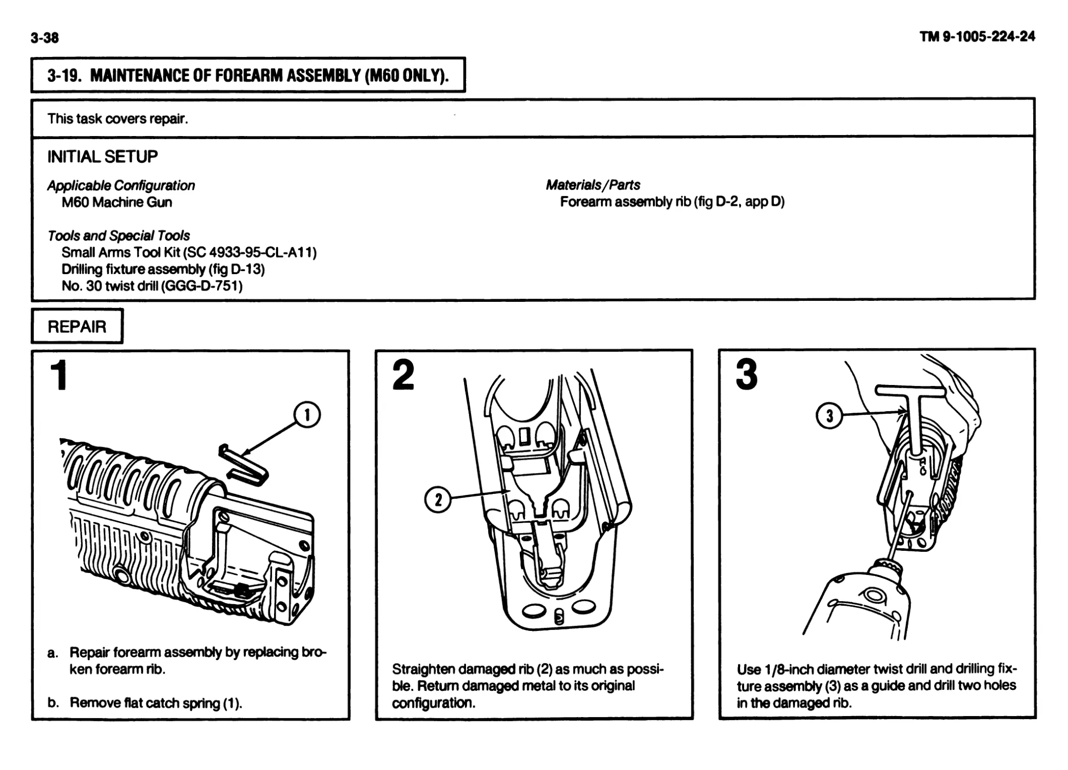
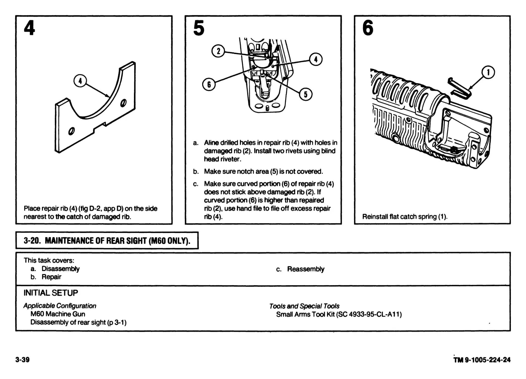
12 Forearm Assembly (M60only) a. Inspect cover assembly (1) and shell assembly (2) for damage. Notify direct support maintenance to fix broken rib (3).
b. Inspect tension of forearm catch and flat spring (4), they must operate properly. c. Inspect to make sure tripod clevis slot (5) is not covered by tabs. d. Inspect sling swivel (6) to make sure it is secure. e. Rubber coating (7) must not be gummy or retain finger impressions. Abrasions, cuts, gouges or holes in the rubber are acceptable. Loose bonding of rubber near cuts etc., is acceptable provided cuts do not interfere with the operator’s grip on the weapon. f. Inspect forearm assembly for any distortion that would interfere with removal or installation. g. Inspect for damaged or missing parts. h. Repair by replacing authorized components (p 2-73). If additional repair is necessary, notify direct support maintenance.
(01) ш ///
2-17
TM 9-1005-224-24
2-18
TM 9-1005-224-24
ITEM NO.
ITEM TO BE
INSPECTED
13
14
ORGANIZATIONAL PREVENTIVE MAINTENANCE CHECKSAND SERVICES QUARTERLY SCHEDULE (CONT)
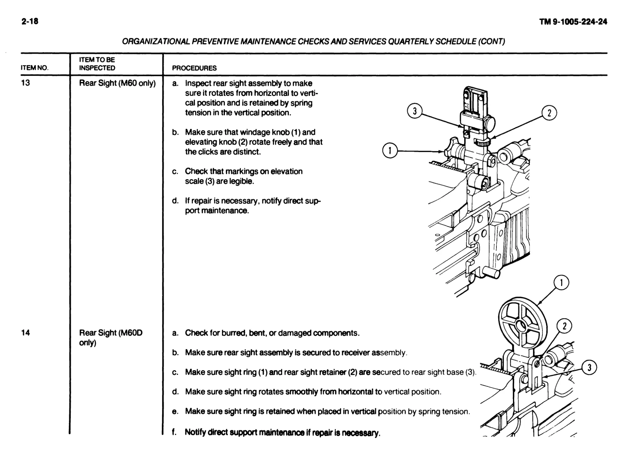
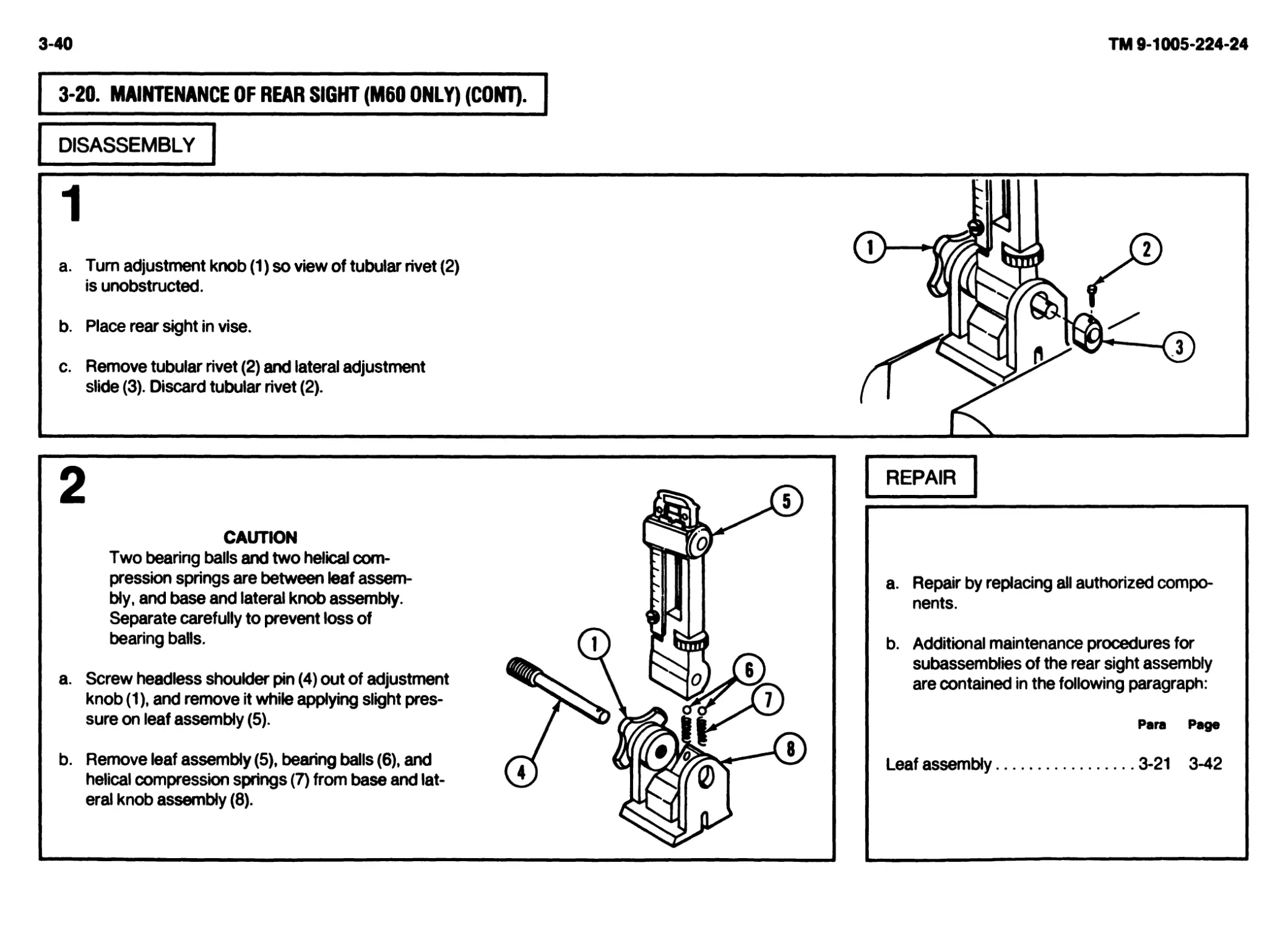
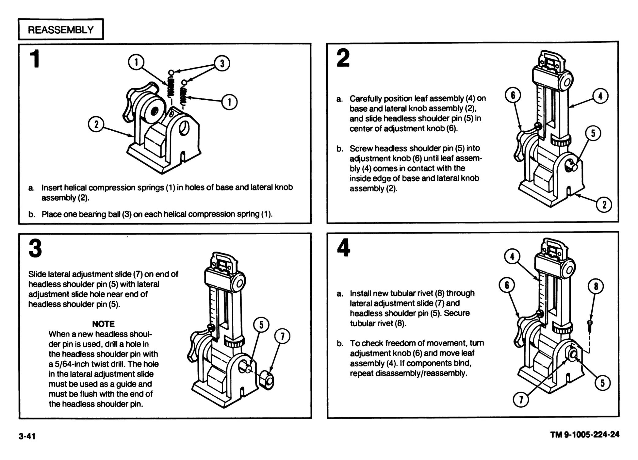
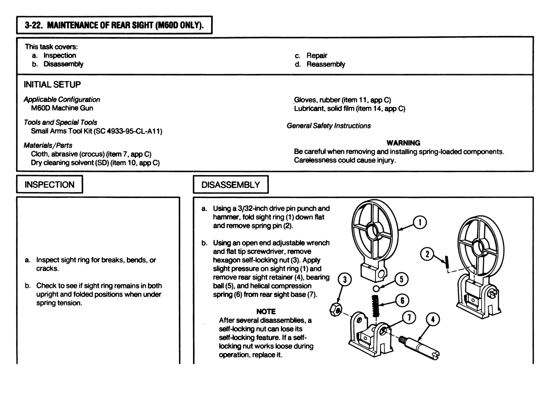
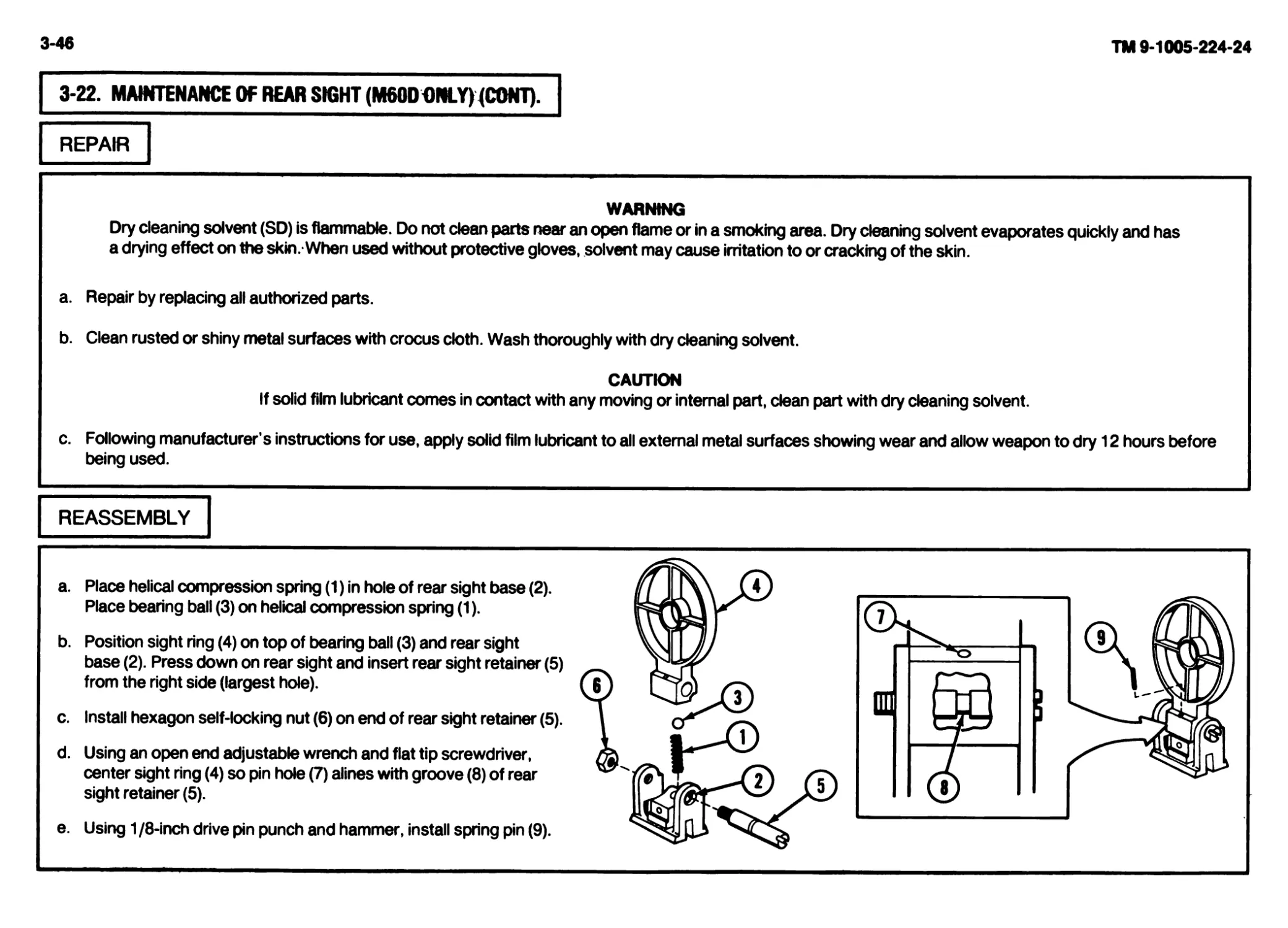
Rear Sight (M60 only)
Rear Sight (M60D
only)
PROCEDURES
a. Inspect rear sight assembly to make
sure it rotates from horizontal to verti-
cal position and is retained by spring
tension in the vertical position.
b. Make sure that windage knob (1) and
elevating knob (2) rotate freely and that
the clicks are distinct.
c. Check that markings on elevation
scale (3) are legible.
d. If repair is necessary, notify direct sup-
port maintenance.
a. Check for burred, bent, or damaged components.
b. Make sure rear sight assembly is secured to receiver assembly.
c. Make sure sight ring (1) and rear sight retainer (2) are secured to rear sight base (3).
d. Make sure sight ring rotates smoothly from horizontal to vertical position.
e. Make sure sight ring is retained when placed in vertical position by spring tension.
f. Notify direct support maintenance if repair is necessary.
ORGANIZATIONAL PREVENTIVE MAINTENANCE CHECKSAND SERVICES QUARTERLY SCHEDULE (CONT)
ITEM NO.
ITEM TO BE
INSPECTED
PROCEDURES
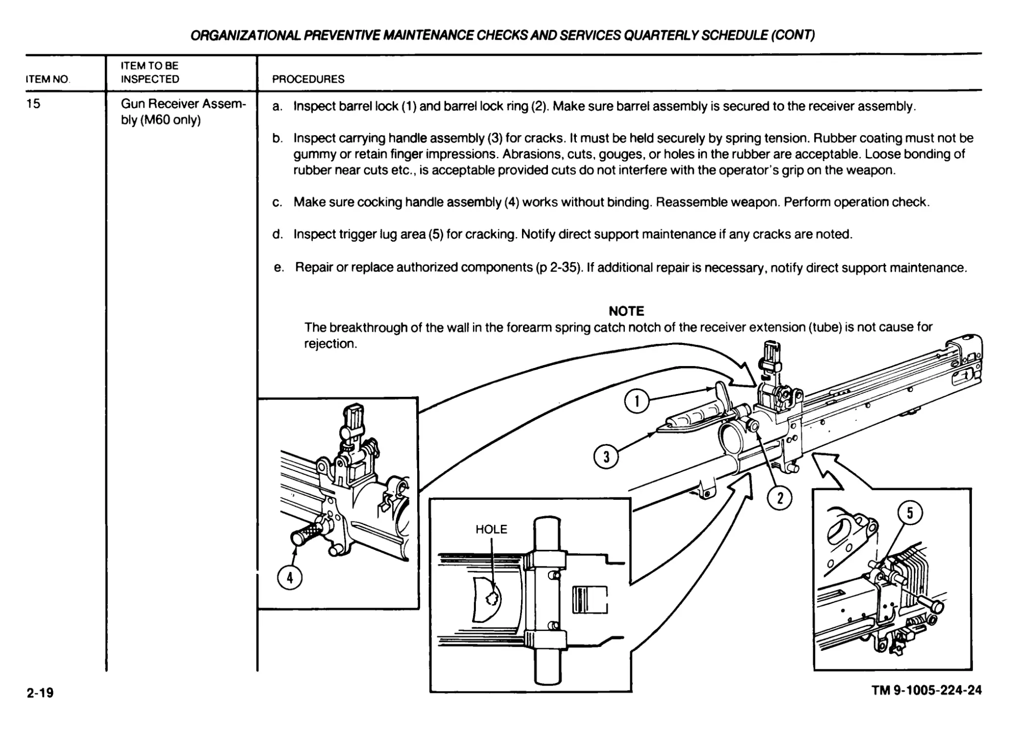
15
Gun Receiver Assem-
bly (M60 only)
a. Inspect barrel lock (1) and barrel lock ring (2). Make sure barrel assembly is secured to the receiver assembly.
b. Inspect carrying handle assembly (3) for cracks. It must be held securely by spring tension. Rubber coating must not be
gummy or retain finger impressions. Abrasions, cuts, gouges, or holes in the rubber are acceptable. Loose bonding of
rubber near cuts etc., is acceptable provided cuts do not interfere with the operator’s grip on the weapon.
c. Make sure cocking handle assembly (4) works without binding. Reassemble weapon. Perform operation check.
d. Inspect trigger lug area (5) for cracking. Notify direct support maintenance if any cracks are noted.
e. Repair or replace authorized components (p 2-35). If additional repair is necessary, notify direct support maintenance.
NOTE
2-19
TM 9-1005-224-24
2-20
TM 9-1005-224-24
ORGANIZATIONAL PREVENTIVE MAINTENANCE CHECKS AND SERVICES QUARTERLY SCHEDULE (CONT)
ITEM NO. ITEM TO BE INSPECTED PROCEDURES
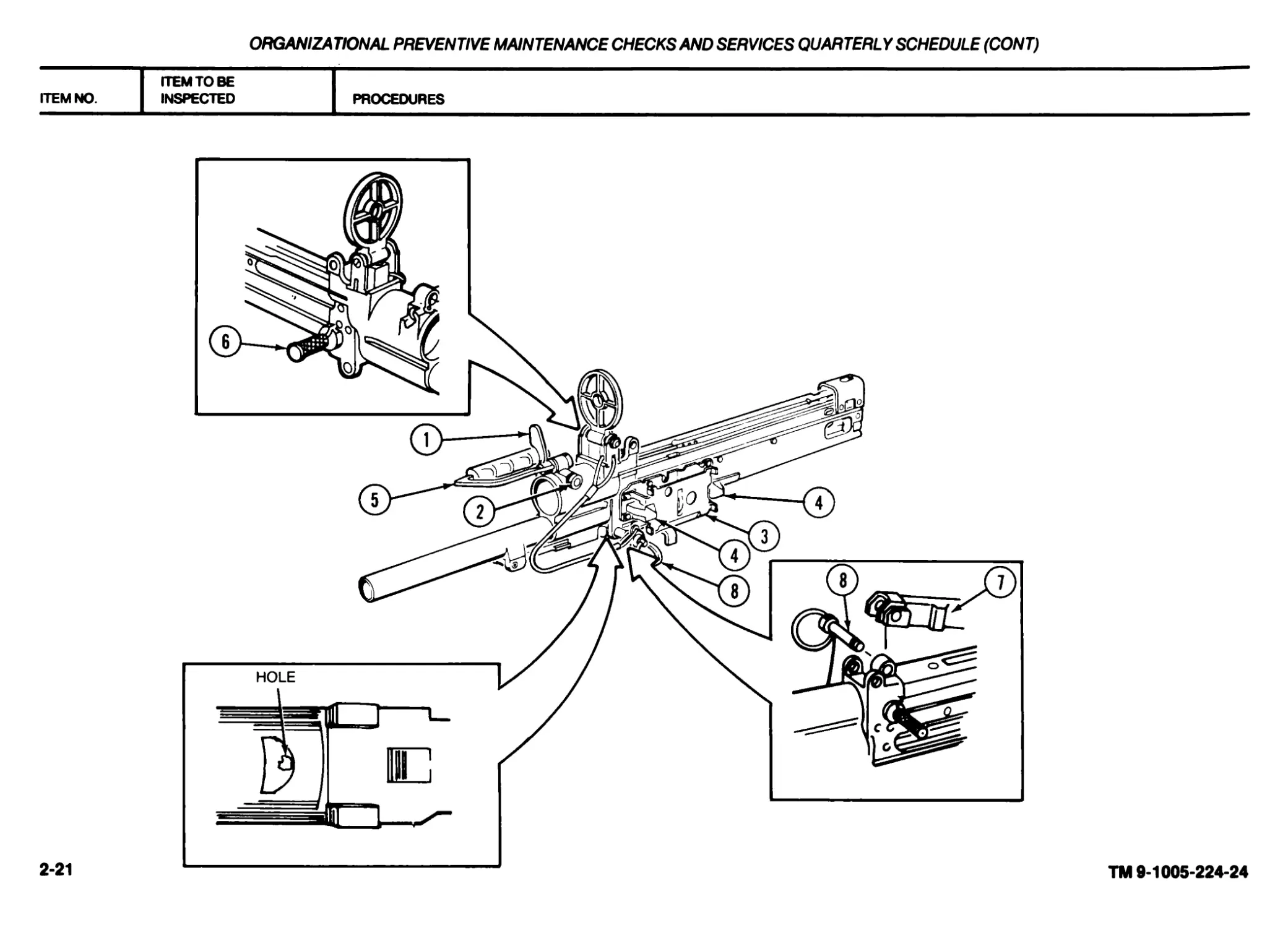
16 Gun Receiver Assem- bly (M60D only) a. Inspect barrel lock (1) and barrel lock ring (2). Make sure barrel assembly is secured to receiver assembly. b. Inspect magazine bracket assembly (3) for damage and positive spring tension of latches (4). c. Inspect carrying handle assembly (5) for cracks. It must be held securely by spring tension. Rubber coating must not be gummy or retain finger impressions. Abrasions, cuts, gouges, or holes in the rubber are acceptable. Loose bonding of rubber near cuts etc., is acceptable provided cuts do not interfere with the operator’s grip on the weapon. d. Make sure cocking handle assembly (6) works without binding. Reassemble weapon and perform operation check. e. Make sure gun adapter (7) moves freely and is held in place by spring pin. f. Inspect quick release pin (8) to make sure that bearing ball works properly, and that wire rope assembly secures quick release pin (8) to rear sight. g. Repair or replace authorized components (p 2-35). If additional repair is necessary, notify direct support maintenance. NOTE Coordinate cleaning and lubrication with crew/operator as part of quarterly services. The breakthrough of the wall in the forearm spring catch notch of the receiver extension (tube) is not cause for rejection.
ORGANIZATIONAL PREVENTIVE MAINTENANCE CHECKSAND SERVICES QUARTERLY SCHEDULE (CONT)
ITEM NO. ITEM TO BE INSPECTED PROCEDURES
2-21
TM 9-1005-224-24
2-22
TM 9-1005-224-24
ORGANIZATIONAL PREVENTIVE MAINTENANCE CHECKS AND SERVICES QUARTERLY SCHEDULE (CONT)
ITEM NO. ITEM TO BE INSPECTED PROCEDURES
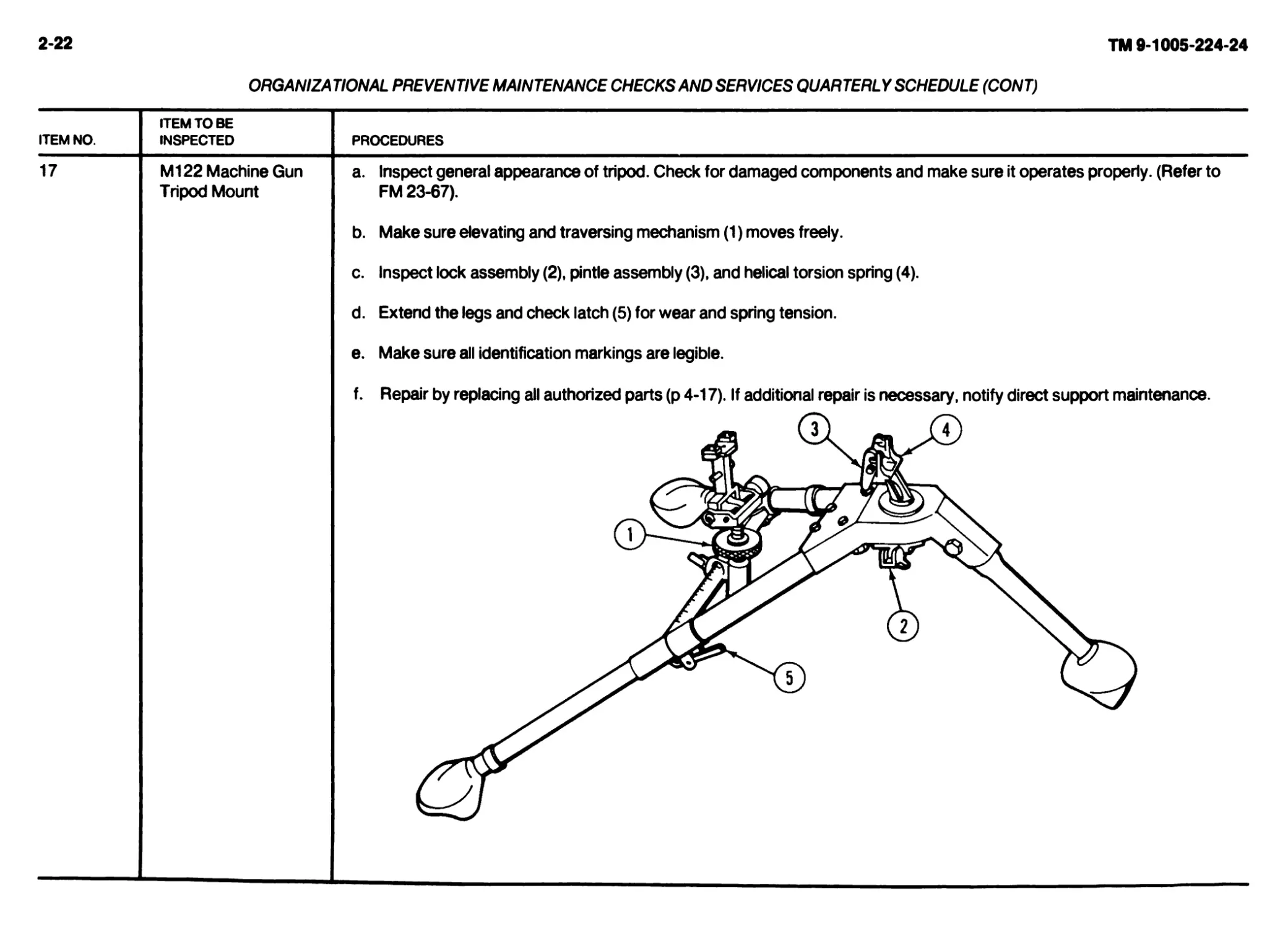
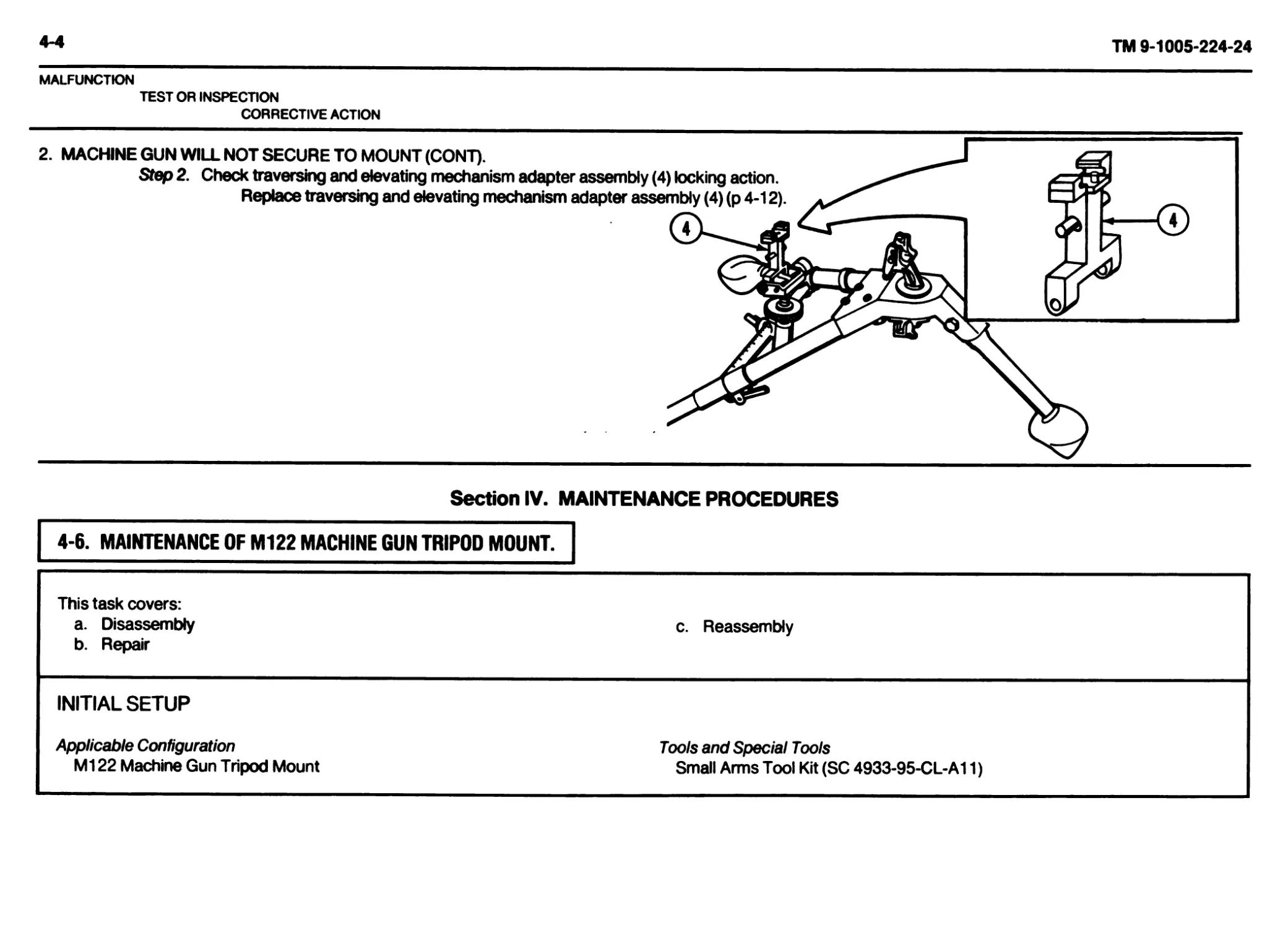
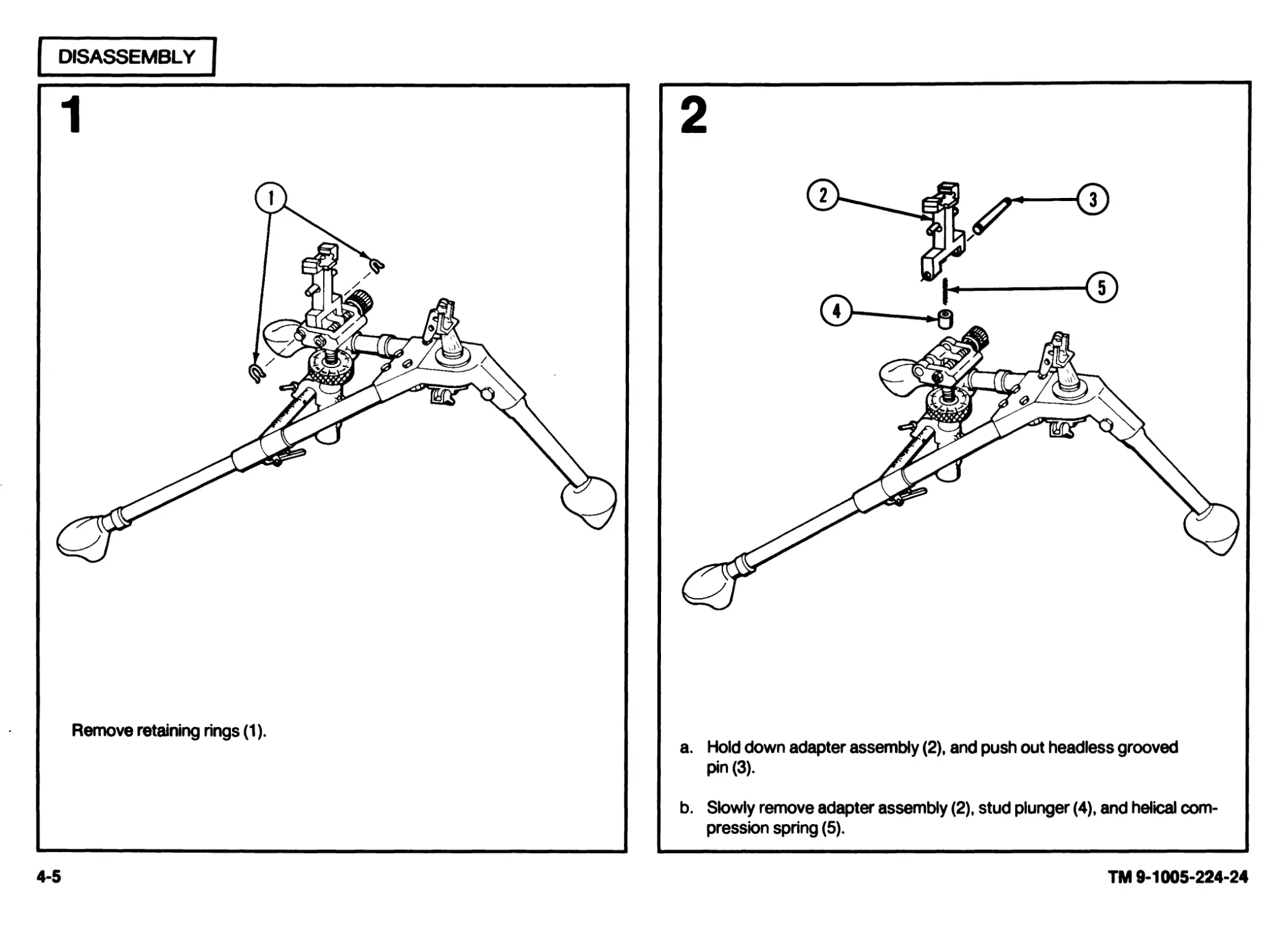
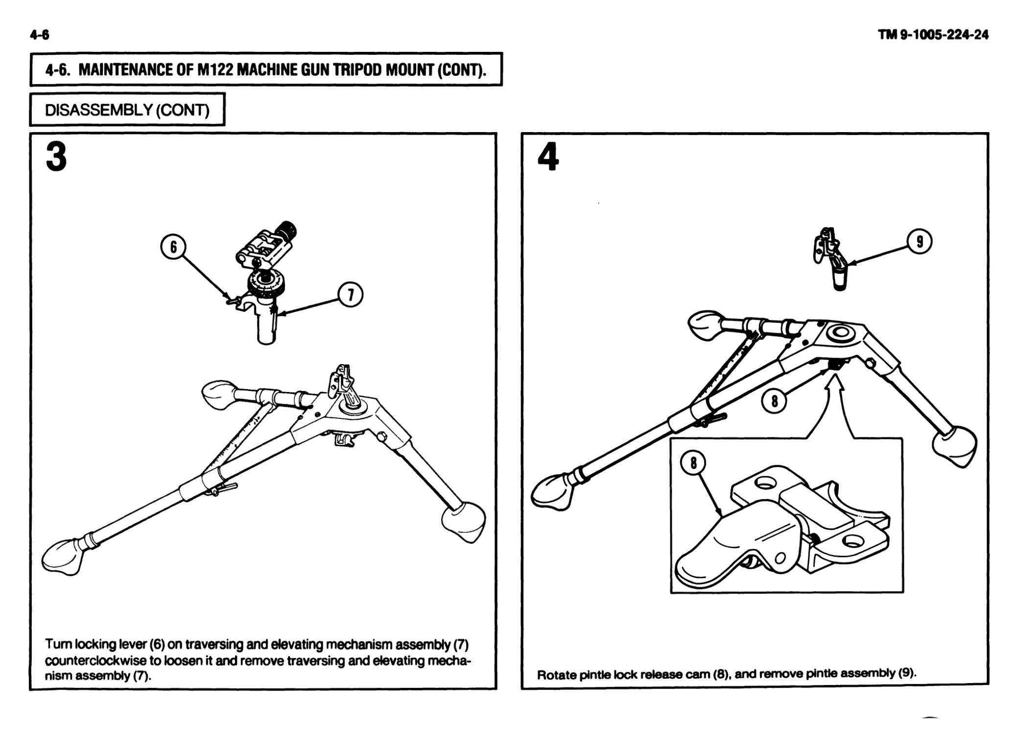
17 M122 Machine Gun Tripod Mount a. Inspect general appearance of tripod. Check for damaged components and make sure it operates properly. (Refer to FM 23-67). b. Make sure elevating and traversing mechanism (1) moves freely. c. Inspect lock assembly (2), pintle assembly (3), and helical torsion spring (4). d. Extend the legs and check latch (5) for wear and spring tension. e. Make sure all identification markings are legible. f. Repair by replacing all authorized parts (p 4-17). If additional repair is necessary, notify direct support maintenance. « (з} Г7)
Section IV. TROUBLESHOOTING
2-8. GENERAL.
a. This section contains troubleshooting information for locating and cor-
recting most of the operating troubles which may develop in your machine gun.
Each malfunction for an individual component, unit, or system is followed by a
list of tests or inspections which will help you to determine corrective actions to
take. You should perform the tests/inspections and corrective actions in the
order listed.
b. This manual cannot list all possible malfunctions that may occur, nor all
tests or inspections and corrective actions. If a malfunction is not listed (except
when malfunction and cause are obvious) or is not corrected by listed correc-
tive actions, notify your supervisor.
2-9. TROUBLESHOOTING PROCEDURES.
SYMPTOM INDEX
Troubleshooting
Procedures
Page
Failure to feed..................................................................................................................................... 2-23
Failure to chamber.................................................................................................................................. 2-26
Failure to lock..................................................................................................................................... 2-27
Failure to fire..................................................................................................................................... 2-28
Failure to unlock................................................................................................................................... 2-29
Failure to extract................................................................................................................................ 2-29
Failure to eject................................................................................................................................... 2-30
Failure to cock..................................................................................................................................... 2-31
Sluggish operation.................................................................................................................................. 2-32
Uncontrolled fire (runaway gun)..................................................................................................................... 2-33
TROUBLESHOOTING
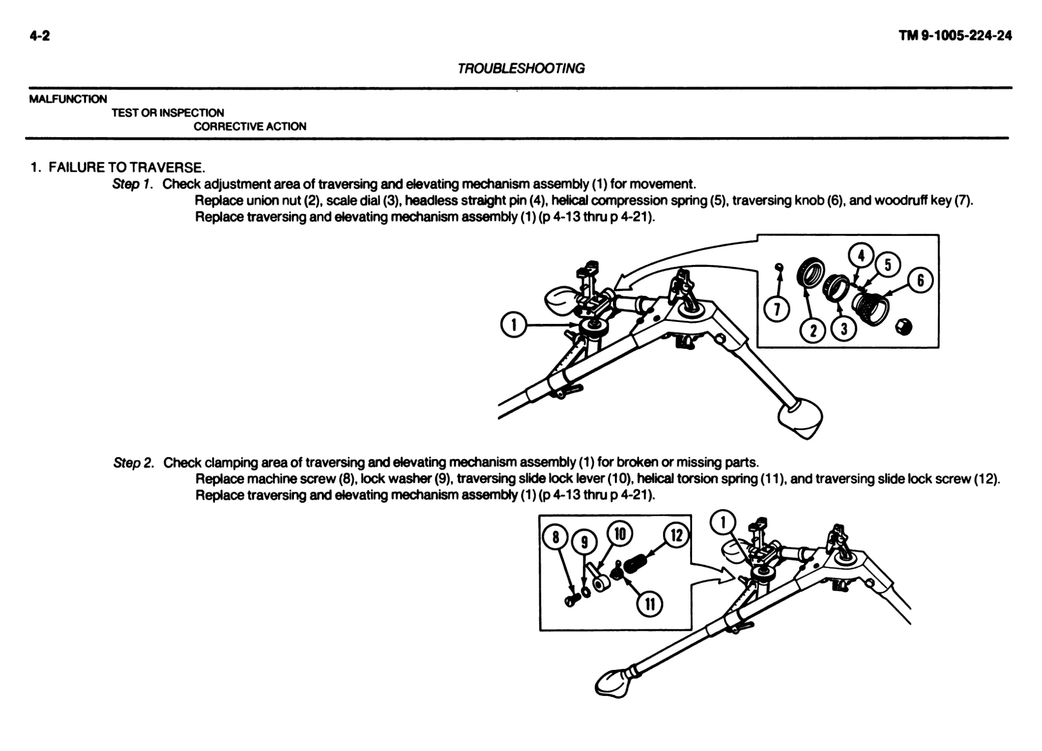
MALFUNCTION
TEST OR INSPECTION
CORRECTIVE ACTION
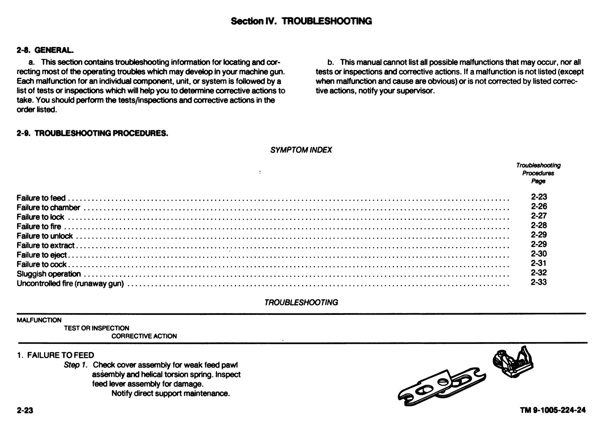
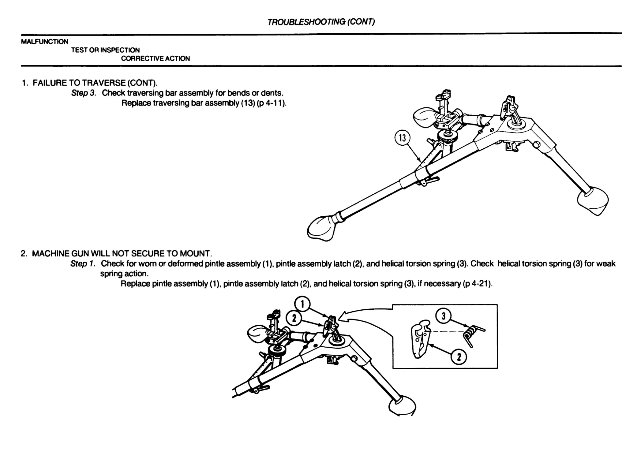
1. FAILURE TO FEED
Step 1. Check cover assembly for weak feed pawl
assembly and helical torsion spring. Inspect
feed lever assembly for damage.
Notify direct support maintenance.
2-23
TM 9-1005-224-24
2-24
TM 9-1005-224-24
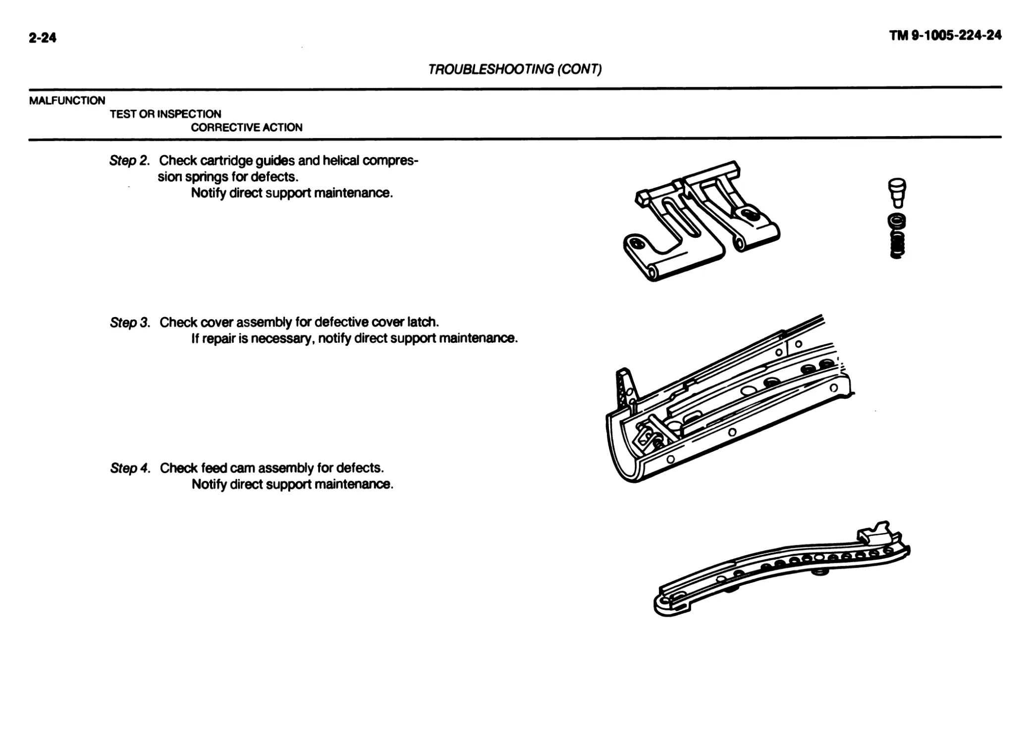
TROUBLESHOOTING (CONT)
MALFUNCTION
TEST OR INSPECTION
CORRECTIVE ACTION
Step 2. Check cartridge guides and helical compres-
sion springs for defects.
Notify direct support maintenance.
Step 3. Check cover assembly for defective cover latch.
If repair is necessary, notify direct support maintenance.
Step 4. Check feed cam assembly for defects.
Notify direct support maintenance.
TROUBLESHOOTING (CONT)
MALFUNCTION
TEST OR INSPECTION
CORRECTIVE ACTION
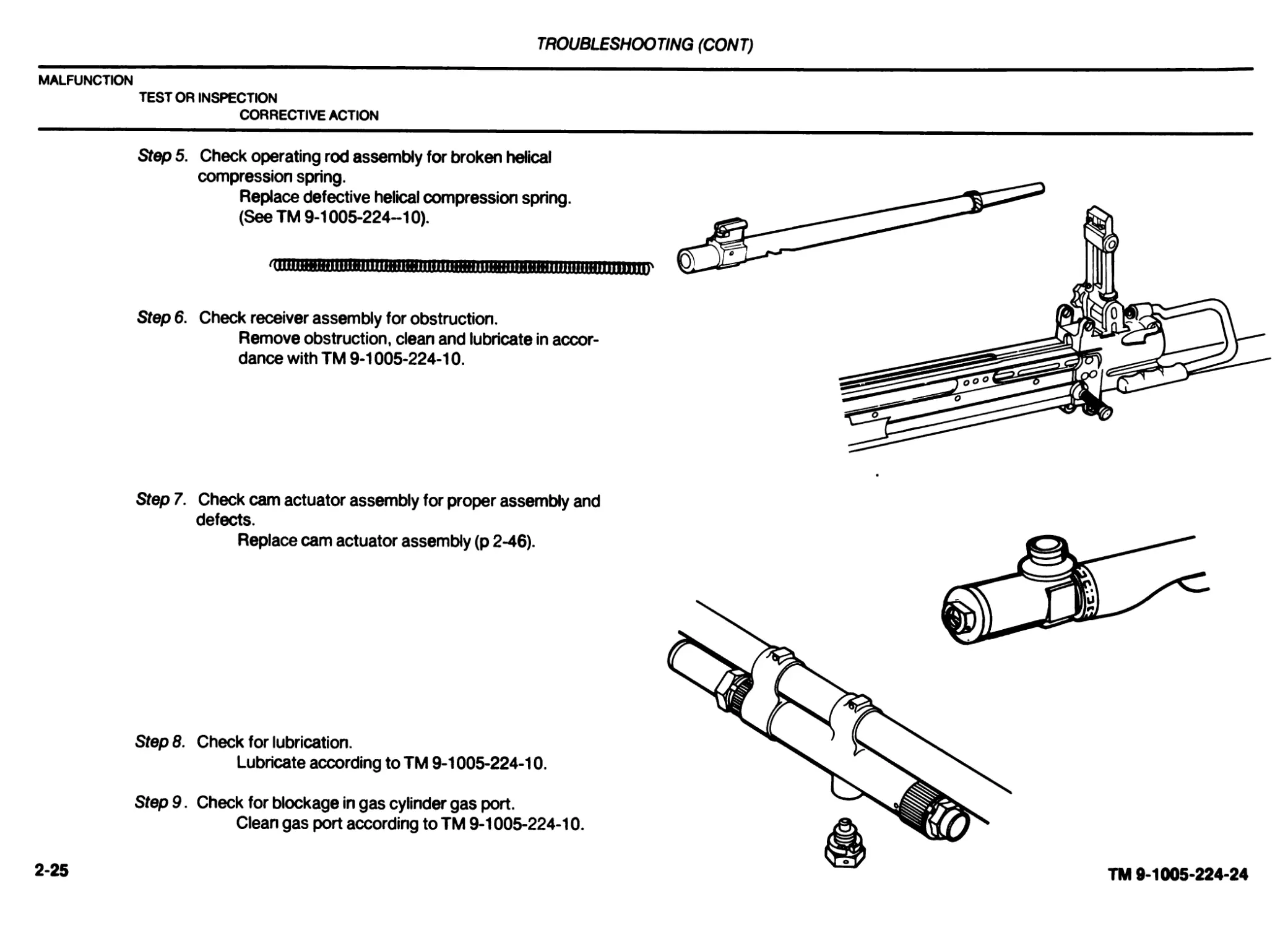
Step 5. Check operating rod assembly for broken helical
compression spring.
Replace defective helical compression spring.
(See TM 9-1005-224-10).
'(||Ц|Ж1Ш1Н1Ш11ПЦН111Н11111111ЖЯ11тнпшнж11П11111Ш11111Н111'
Step 6. Check receiver assembly for obstruction.
Remove obstruction, clean and lubricate in accor-
dance with TM 9-1005-224-10.
Step 7. Check cam actuator assembly for proper assembly and
defects.
Replace cam actuator assembly (p 2-46).
Step 8. Check for lubrication.
Lubricate according to TM 9-1005-224-10.
Step 9. Check for blockage in gas cylinder gas port.
Clean gas port according to TM 9-1005-224-10.
2-25
TM 9-1005-224-24
2-26 TM 9-1005-224-24
TROUBLESHOOTING (CONT)
MALFUNCTION
TEST OR INSPECTION
CORRECTIVE ACTION
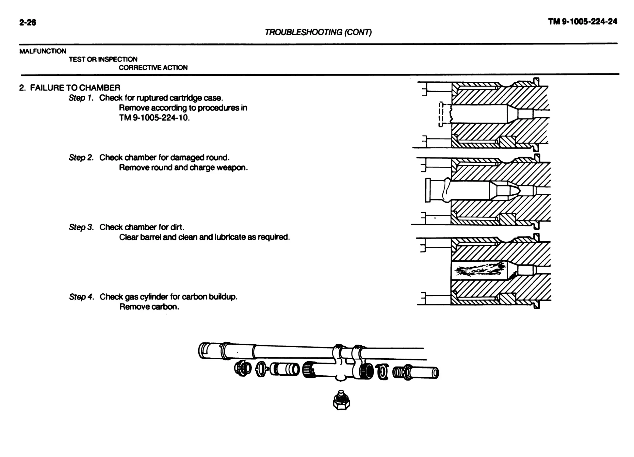
2. FAILURE TO CHAMBER Stepl. Check for ruptured cartridge case. Remove according to procedures in TM 9-1005-224-10. Step 2. Check chamber for damaged round. Remove round and charge weapon. Step3. Check chamber for dirt. Clear barrel and dean and lubricate as required. Step 4. Check gas cylinder for carbon buildup. Remove carbon. ММ В И 11кИ i-~~b
TROUBLESHOOTING (CONT)
MALFUNCTION
TEST OR INSPECTION
CORRECTIVE ACTION
Step 5. Check receiver assembly for carbon buildup.
Remove carbon.
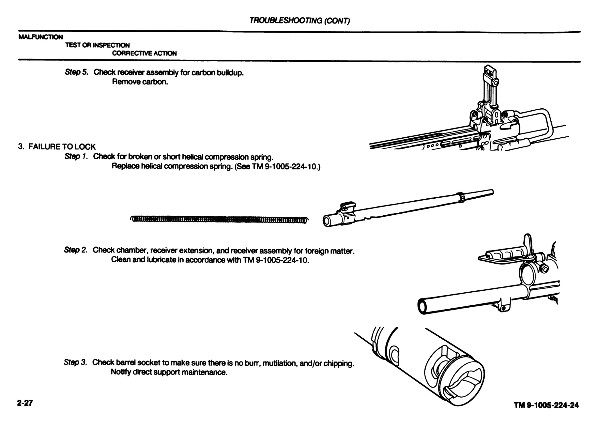
3. FAILURE TO LOCK
Step 1. Check for broken or short helical compression spring.
Replace helical compression spring. (See TM 9-1005-224-10.)
Step 2. Check chamber, receiver extension, and receiver assembly for foreign matter.
Clean and lubricate in accordance with TM 9-1005-224-10.
Step 3. Check barrel socket to make sure there is no burr, mutilation, and/or chipping.
Notify direct support maintenance.
2-27
TM 9-1005-224-24
2-28
TM 9-1005-224-24
TROUBLESHOOTING (CONT)
MALFUNCTION
TEST OR INSPECTION
CORRECTIVE ACTION
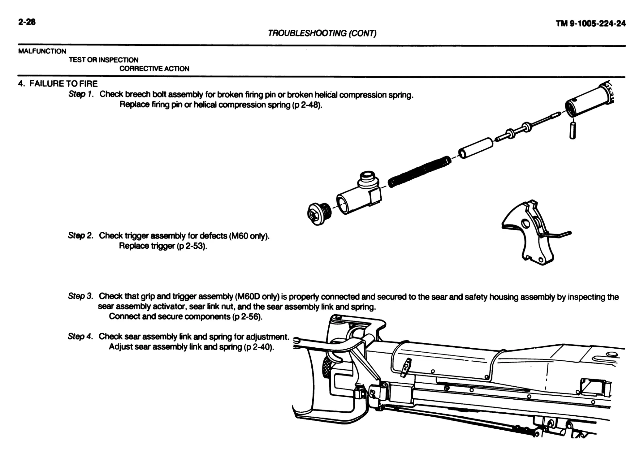
4. FAILURE TO FIRE
Step 1. Check breech bolt assembly for broken firing pin or broken helical compression spring.
Replace firing pin or helical compression spring (p 2-48).
Step 2. Check trigger assembly for defects (M60 only).
Replace trigger (p 2-53).
Step 3. Check that grip and trigger assembly (M60D only) is properly connected and secured to the sear and safety housing assembly by inspecting the
sear assembly activator, sear link nut, and the sear assembly link and spring.
Connect and secure components (p 2-56).
Step 4. Check sear assembly link and spring for adjustment.
Adjust sear assembly link and spring (p 2-40).
TROUBLESHOOTING (CONT)
MALFUNCTION
TEST OR INSPECTION
CORRECTIVE ACTION
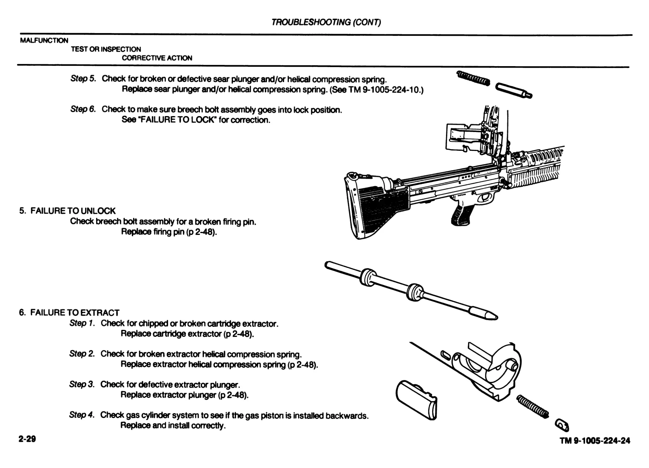
Step 5. Check for broken or defective sear plunger and/or helical compression spring.
Replace sear plunger and/or helical compression spring. (See TM 9-1005-224-10.)
Step 6. Check to make sure breech bolt assembly goes into lock position.
See “FAILURE TO LOCK’ for correction.
5. FAILURE TO UNLOCK
Check breech bolt assembly for a broken firing pin.
Replace firing pin (p 2-48).
6. FAILURE TO EXTRACT
Step 1. Check for chipped or broken cartridge extractor.
Replace cartridge extractor (p 2-48).
Step 2. Check for broken extractor helical compression spring.
Replace extractor helical compression spring (p 2-48).
Step 3. Check for defective extractor plunger.
Replace extractor plunger (p 2-48).
Step 4. Check gas cylinder system to see if the gas piston is installed backwards.
Replace and install correctly.
2-29
TM 9-1005-224-24
2-30
TM 9-1005-224-24
TROUBLESHOOTING (CONT)
MALFUNCTION
TEST OR INSPECTION
CORRECTIVE ACTION
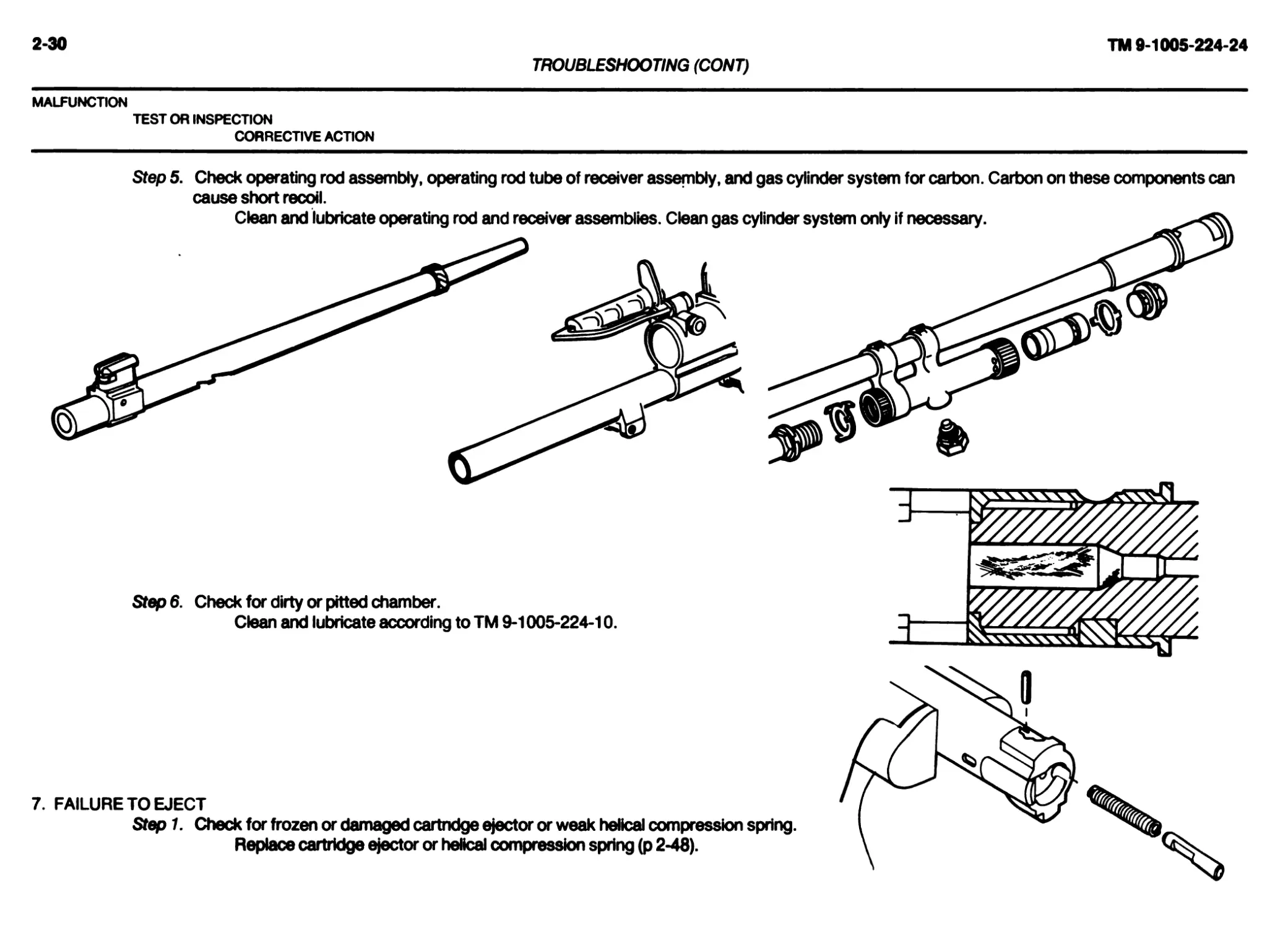
Step 5. Check operating rod assembly, operating rod tube of receiver assembly, and gas cylinder system for carbon. Carbon on these components can
cause short recoil.
Clean and lubricate operating rod and receiver assemblies. Clean gas cylinder system only if necessary.
Step 6. Check for dirty or pitted chamber.
Clean and lubricate according to TM 9-1005-224-10.
7. FAILURE TO EJECT
Step 1. Check for frozen or damaged cartridge ejector or weak helical compression spring.
Replace cartridge ejector or helical compression spring (p 2-48).
TROUBLESHOOTING (CONT)
MALFUNCTION
TEST OR INSPECTION
CORRECTIVE ACTION
Step 2. Check operating rod assembly, operating rod tube of receiver assembly, and gas cylinder system for carbon. Carbon on these components can
cause short recoil.
Clean and lubricate operating rod and receiver assemblies. Clean gas cylinder system only if necessary.
Step 3. Check sear plunger and helical compression spring for breaks or defects.
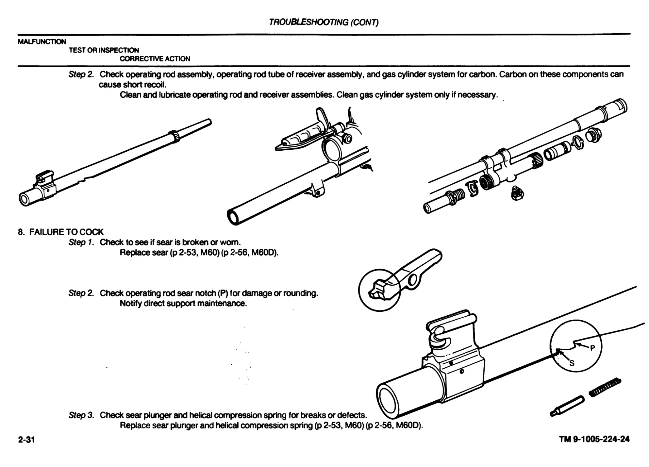
Replace sear plunger and helical compression spring (p 2-53, M60) (p 2-56, M60D).
Step 2. Check operating rod sear notch (P) for damage or rounding.
Notify direct support maintenance.
8. FAILURE TO COCK
Stept Check to see if sear is broken or worn.
Replace sear (p 2-53, M60) (p 2-56, M60D).
2-31
TM 9-1005-224-24
2-32
TM 9-1005-224-24
TROUBLESHOOTING (CONT)
MALFUNCTION
TEST OR INSPECTION
CORRECTIVE ACTION
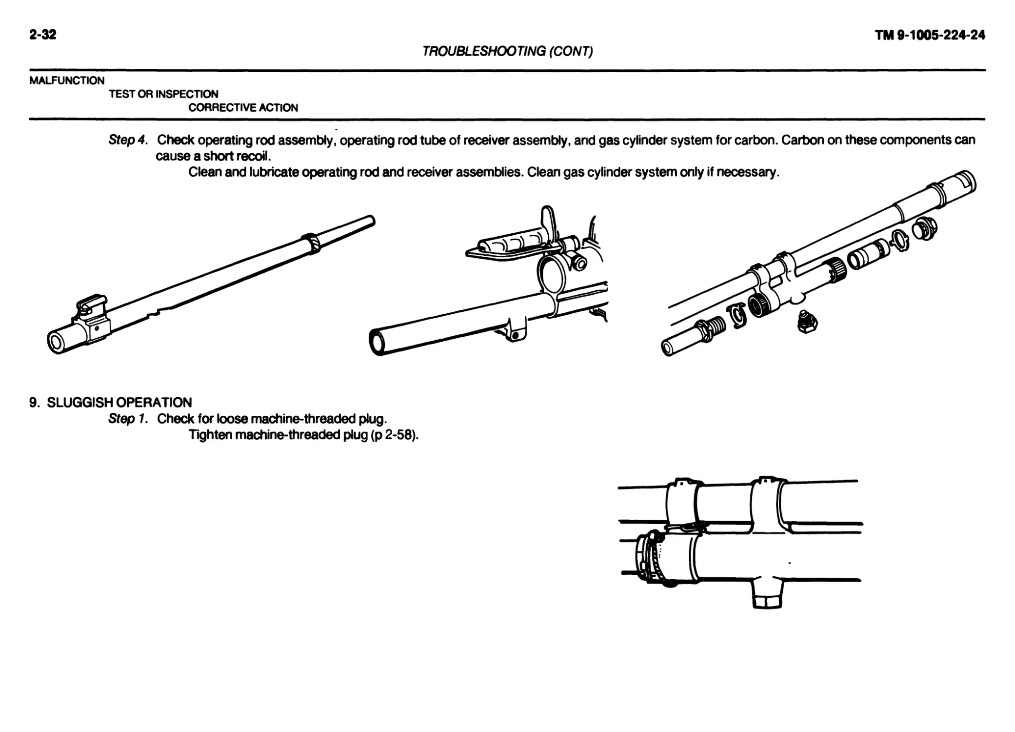
Step 4. Check operating rod assembly, operating rod tube of receiver assembly, and gas cylinder system for carbon. Carbon on these components can
cause a short recoil.
Clean and lubricate operating rod and receiver assemblies. Clean gas cylinder system only if necessary.
9. SLUGGISH OPERATION
Step 1. Check for loose machine-threaded plug.
Tighten machine-threaded plug (p 2-58).
TROUBLESHOOTING (CONT)
MALFUNCTION
TEST OR INSPECTION
CORRECTIVE ACTION
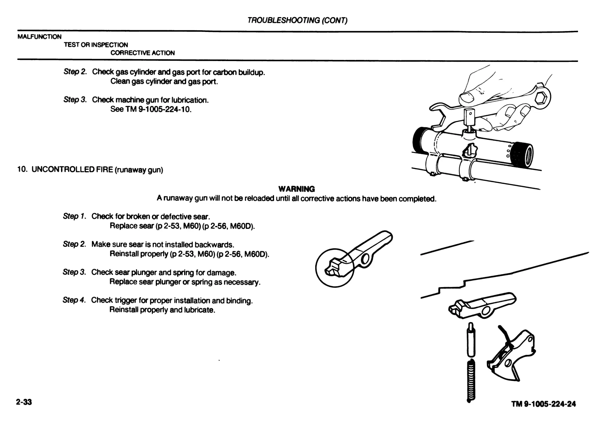
Step 2. Check gas cylinder and gas port for carbon buildup.
Clean gas cylinder and gas port.
Step 3. Check machine gun for lubrication.
See TM 9-1005-224-10.
WARNING
10. UNCONTROLLED FIRE (runaway gun)
A runaway gun will not be reloaded until all corrective actions have been completed.
Step 1. Check for broken or defective sear.
Replace sear (p 2-53, M60) (p 2-56, M60D).
Step 2. Make sure sear is not installed backwards.
Reinstall properly (p 2-53, M60) (p 2-56, M60D).
Sfep3. Check sear plunger and spring for damage.
Replace sear plunger or spring as necessary.
Step 4. Check trigger for proper installation and binding.
Reinstall properly and lubricate.
2-33
TM 9-1005-224-24
2-34
TM 9-1005-224-24
TROUBLESHOOTING (CONT)
MALFUNCTION
TEST OR INSPECTION
CORRECTIVE ACTION
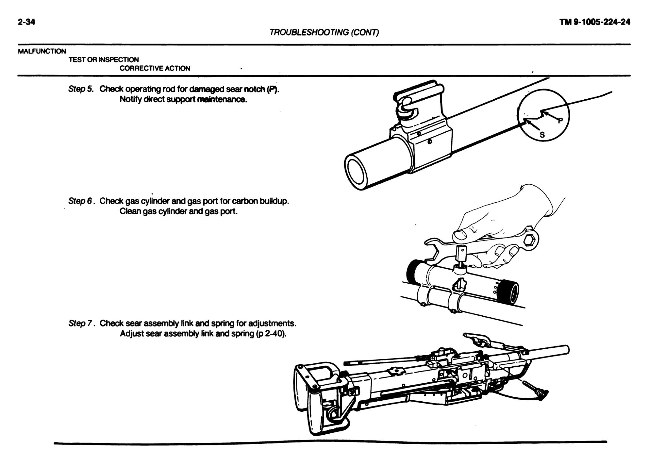
Step 5. Check operating rod for damaged sear notch (₽)•
Notify direct support maintenance.
Step 6. Check gas cylinder and gas port for carbon buildup.
Clean gas cylinder and gas port.
Step 7. Check sear assembly link and spring for adjustments.
______________________________ Section V. MAINTENANCE PROCEDURES
2-10. MAINTENANCE OF M60 MACHINE GUN.
This task covers: a. Inspection b. Disassembly c. Repair d. Reassembly
INITIAL SETUP Applicable Configuration M60 Machine Gun Tools and Special Tools Small Arms Repairman Tool Kit (SC 5180-95-CL-A07) Materials/Parts Cleaner, lubricant and preservative (CLP) (item 6, app C) Cloth, abrasive (crocus) (item 7, app C) Dry cleaning solvent (SD) (item 10, app C) Gloves, rubber (item 11, app C) Lubricant, solid film (item 14, app C) Rag, wiping (item 16, app C) Swab, small arms (item 18, app C) Troubleshooting References See pages 2-23 through 2-34. References TM 9-1005-224-10 General Safety Instructions WARNING Make sure weapon is cleared and there are no obstructions in the barrel or chamber. Be careful when removing and installing spring-loaded com- ponents. Carelessness could cause injury. Dry cleaning solvent (SD) is flammable. Do not dean parts near an open flame or in a smoking area. Dry deaning solvent evaporates quickly and has a drying effect on the skin. When used without protective gloves, solvent may cause irritation to or cracking of the skin. Using paint thinner, gasoline, kerosene, benzene (benzol), water, steam, or air for cleaning the weapon is prohibited. Use only autho- rized cleaning materials. CAUTION Care MUST be exerdsed to avoid getting cleaner, lubricant and preservative (CLP) in the gas cylinder when cleaning the barrel. Position the gas cylinder above the barrel during cleaning. The gas cylinder components will be removed and deaned only when inspection reveals that the piston will no longer move within the cylinder under its own weight when the barrel is tilted end to end. If gas cylinder components are cleaned, wipe interior of cylinder . and piston dry before reassembly. After reassembly, check for movement of gas piston by manually tilting the barrel assembly. Rewire gas cylinder vent plug and machine-thread plug. NOTE Burrs or raised surfaces may be removed or smoothed using a fine grit sharpening stone. DO NOT change the dimensions of any component by stoning. Components with cracks, chips, dents, or gouges shall be reported to direct support maintenance for repair or replacement. Cracks, chips, dents, or gouges on breech bolt locking surfaces can damage the barrel socket. Damage to barrel socket locking surfaces can damage the breech bolt. Notify direct support maintenance for replacement or repair if either condition exists.
2-35
TM 9-1005-224-24
2-36
TM 9-1005-224-24
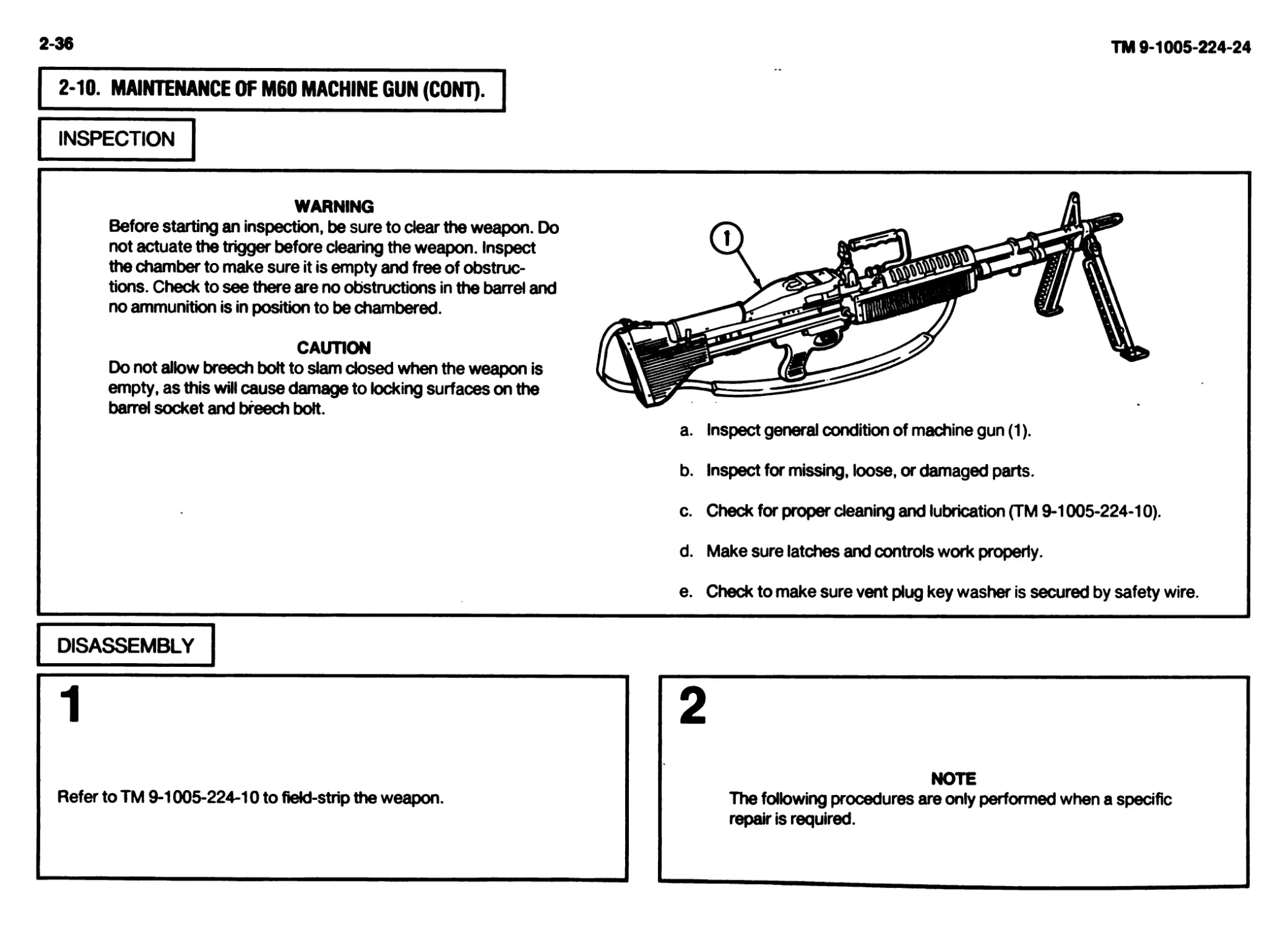
2-10. MAINTENANCE OF M60 MACHINE GUN (CONT).
INSPECTION
WARNING
Before starting an inspection, be sure to clear the weapon. Do
not actuate the trigger before clearing the weapon. Inspect
the chamber to make sure it is empty and free of obstruc-
tions. Check to see there are no obstructions in the barrel and
no ammunition is in position to be chambered.
CAUTION
Do not allow breech bolt to slam closed when the weapon is
empty, as this will cause damage to locking surfaces on the
barrel socket and breech bolt.
a. Inspect general condition of machine gun (1).
b. Inspect for missing, loose, or damaged parts.
c. Check for proper cleaning and lubrication (TM 9-1005-224-10).
d. Make sure latches and controls work properly.
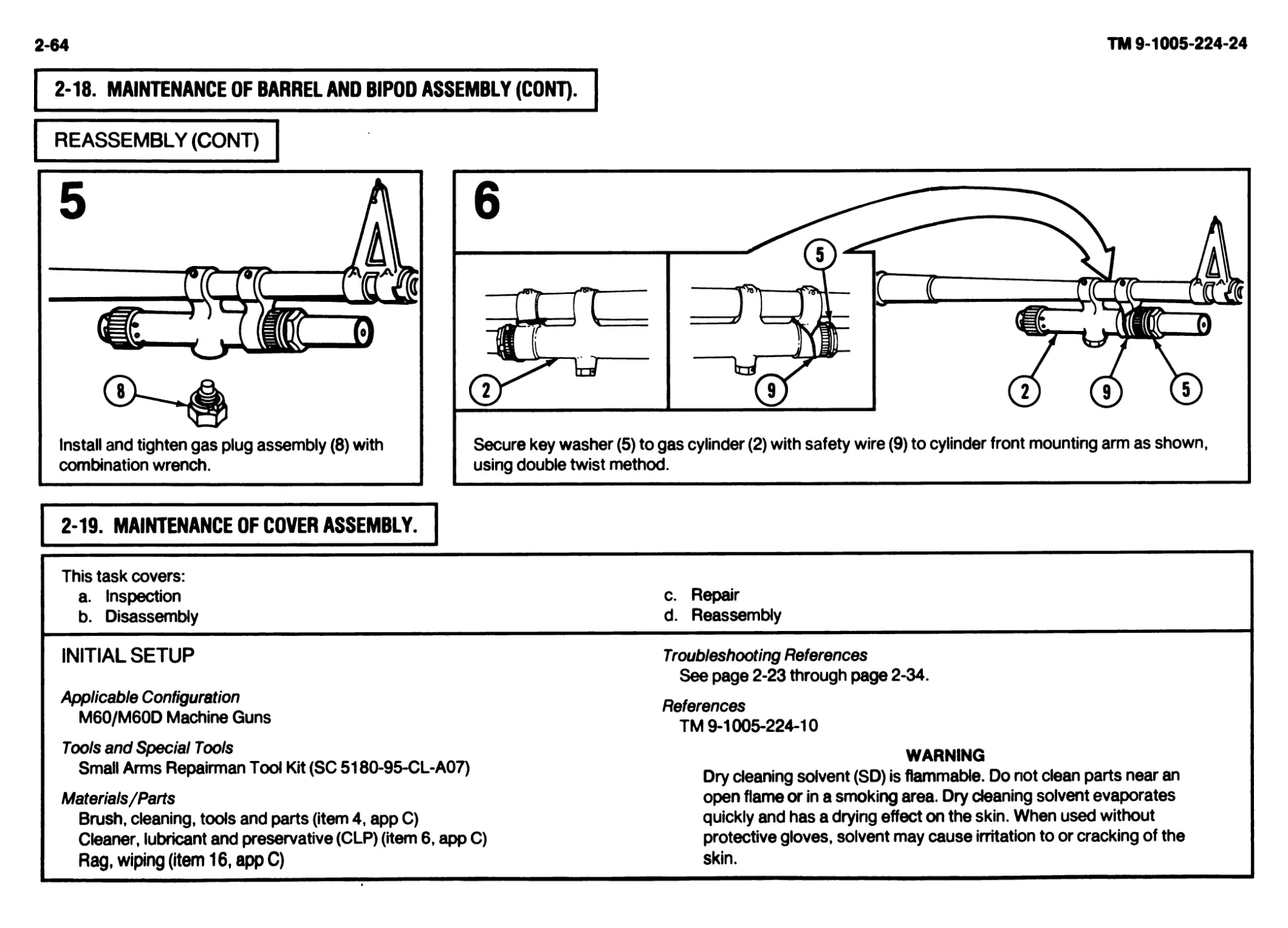
e. Check to make sure vent plug key washer is secured by safety wire.
DISASSEMBLY
2
Refer to TM 9-1005-224-10 to field-strip the weapon.
NOTE
The following procedures are only performed when a specific
repair is required.
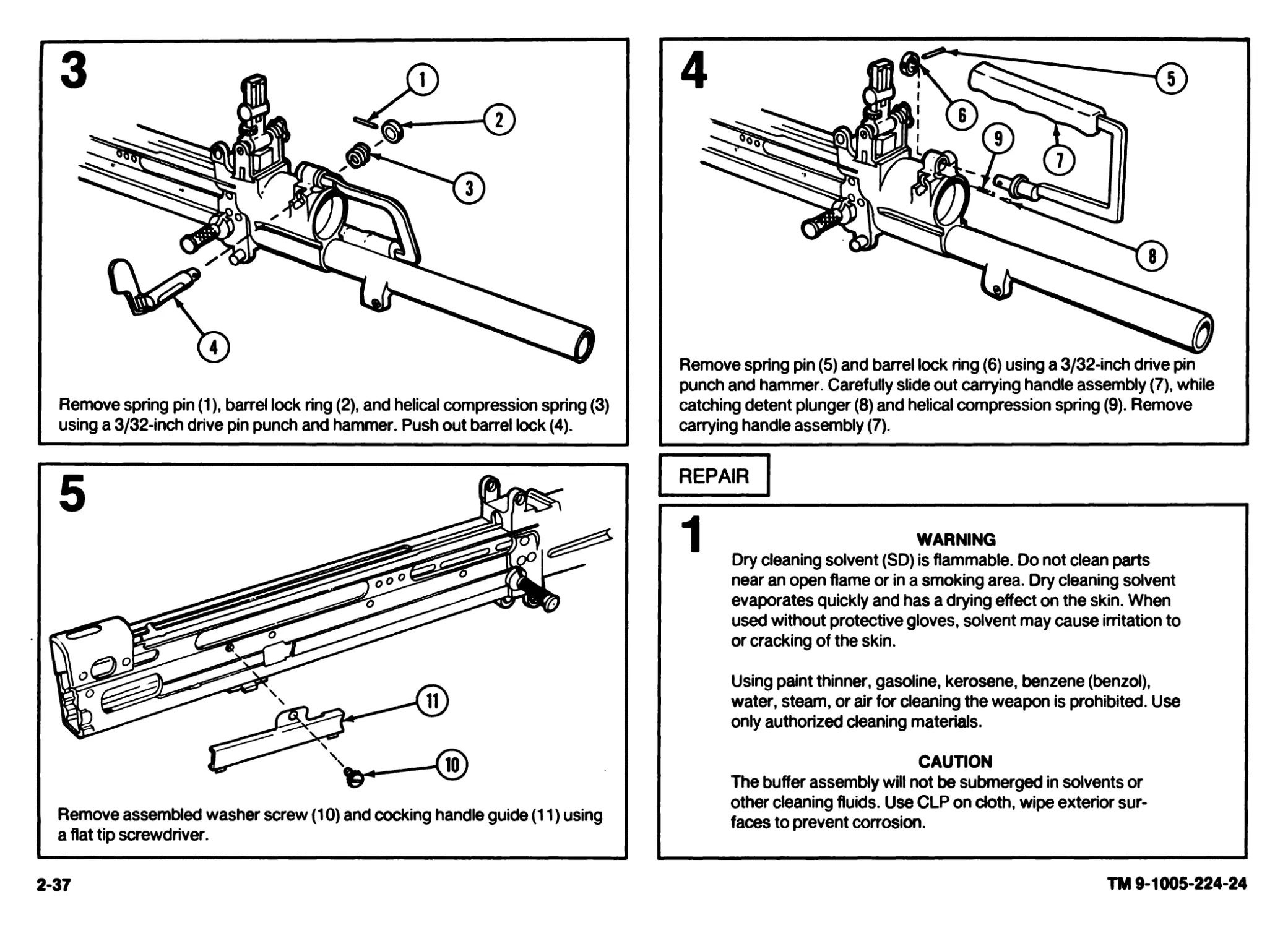
Remove spring pin (1), barrel lock ring (2), and helical compression spring (3)
using a 3/32-inch drive pin punch and hammer. Push out barrel lock (4).
Remove assembled washer screw (10) and cocking handle guide (11) using
a flat tip screwdriver.
2-37
Remove spring pin (5) and barrel lock ring (6) using a 3/32-inch drive pin
punch and hammer. Carefully slide out carrying handle assembly (7), while
catching detent plunger (8) and helical compression spring (9). Remove
carrying handle assembly (7).
REPAIR
WARNING
Dry cleaning solvent (SD) is flammable. Do not clean parts
near an open flame or in a smoking area. Dry cleaning solvent
evaporates quickly and has a drying effect on the skin. When
used without protective gloves, solvent may cause irritation to
or cracking of the skin.
Using paint thinner, gasoline, kerosene, benzene (benzol),
water, steam, or air for cleaning the weapon is prohibited. Use
only authorized cleaning materials.
CAUTION
The buffer assembly will not be submerged in solvents or
other cleaning fluids. Use CLP on doth, wipe exterior sur-
faces to prevent corrosion.
TM 9-1005-224-24
2-38
TM 9-1005-224-24
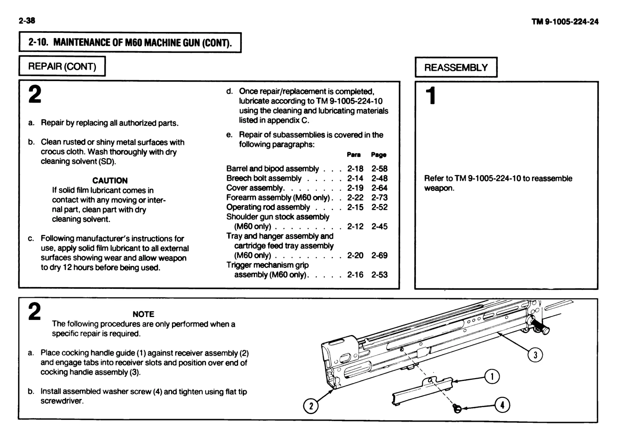
2-10. MAINTENANCE OF M60 MACHINE GUN (CONT).
REPAIR (CONT) REASSEMBLY
О d. Once repair/replacement is completed, м lubricate according to TM 9-1005-224-10 using the cleaning and lubricating materials a. Repair by replacing all authorized parts. listed in appendix C. e. Repair of subassemblies is covered in the b. Clean rusted or shiny metal surfaces with following paragraphs: crocus cloth. Wash thoroughly with dry Para cleaning solvent (SD). Barrel and bipod assembly . . . 2-18 2-58 CAUTION Breech bolt assembly 2-14 2-48 If solid film lubricant comes in Cover assembly 2-19 2-64 contact with any moving or inter- Forearm assembly (M60 only). . 2-22 2-73 nal part, clean part with dry Operating rod assembly .... 2-15 2-52 cleaning solvent. Shoulder gun stock assembly (M60only) 2-12 2-45 c. Following manufacturer's instructions for Tray and hanger assembly and use, apply solid film lubricant to all external cartridge feed tray assembly surfaces showing wear and allow weapon (M60only) . 2-20 2-69 to dry 12 hours before being used. Trigger mechanism grip assembly (M60 only) 2-16 2-53 Refer to TM 9-1005-224-10 to reassemble weapon.
NOTE
The following procedures are only performed when a
specific repair is required.
a. Place cocking handle guide (1) against receiver assembly (2)
and engage tabs into receiver slots and position over end of
cocking handle assembly (3).
b. Install assembled washer screw (4) and tighten using flat tip
screwdriver.
3
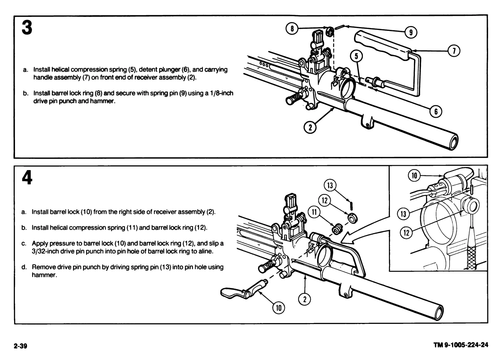
a. Install helical compression spring (5), detent plunger (6), and carrying
handle assembly (7) on front end of receiver assembly (2).
b. Install barrel lock ring (8) and secure with spring pin (9) using a 1 /8-inch
drive pin punch and hammer.
2-39
TM 9-1005-224-24
2-40
TM 9-1005-224-24
2-11. MAINTENANCE OF M60D MACHINE GUN.
This task covers: a. Inspection b. Disassembly c. Repair d. Reassembly
INITIAL SETUP
Applicable Configuration M60D Machine Gun Lubricant, solid film (item 14, app C) Rag, wiping (item 16, app C)
Tools and Special Tools Small Arms Repairman Tool Kit (SC 5180-95-CL-A07) Troubleshooting References See pages 2-23 through 2-34.
Materials/Parts Brush, cleaning, tool and parts (item 4, app C) Cleaner, lubricant and preservative (CLP) (item 6, app C) Cloth, abrasive (crocus) (item 7, app C) Dry cleaning solvent (SD) (item 10, app C) Gloves, rubber (item 11, app C) References TM 9-1005-224-10 General Safety Instructions WARNING Make sure weapon is cleared and there are no obstructions in the barrel or chamber. Be careful when removing and installing spring-loaded components. Carelessness could cause injury.
INSPECTION
WARNING
Before starting an inspection, be sure to clear the weapon. Do not actuate the trigger before clearing the weapon. Inspect the chamber to make sure it is
empty and free of obstructions. Check to see there are no obstructions in the barrel and no ammunition is in position to be chambered.
CAUTION
Do not allow breech bolt to slam closed when the weapon is empty, as this will cause damage to locking surfaces on the barrel socket and breech bolt.
Burrs or raised surfaces may be removed or smoothed using a fine grit sharpening stone. DO NOT change the dimensions of any component by stoning.
Components with cracks, chips, dents, or gouges shall be reported to direct support maintenance for repair or replacement.
a. Inspect general condition of machine gun. d. Make sure latches and controls operate properly.
b. Inspect for missing, loose, or damaged parts. e. Check to make sure gas cylinder machine thread plug, gas extension key
washer, sear link nut, and sear assembly link and spring are secured.
c. Check for proper cleaning and lubrication (TM 9-1005-224-10).
DISASSEMBLY
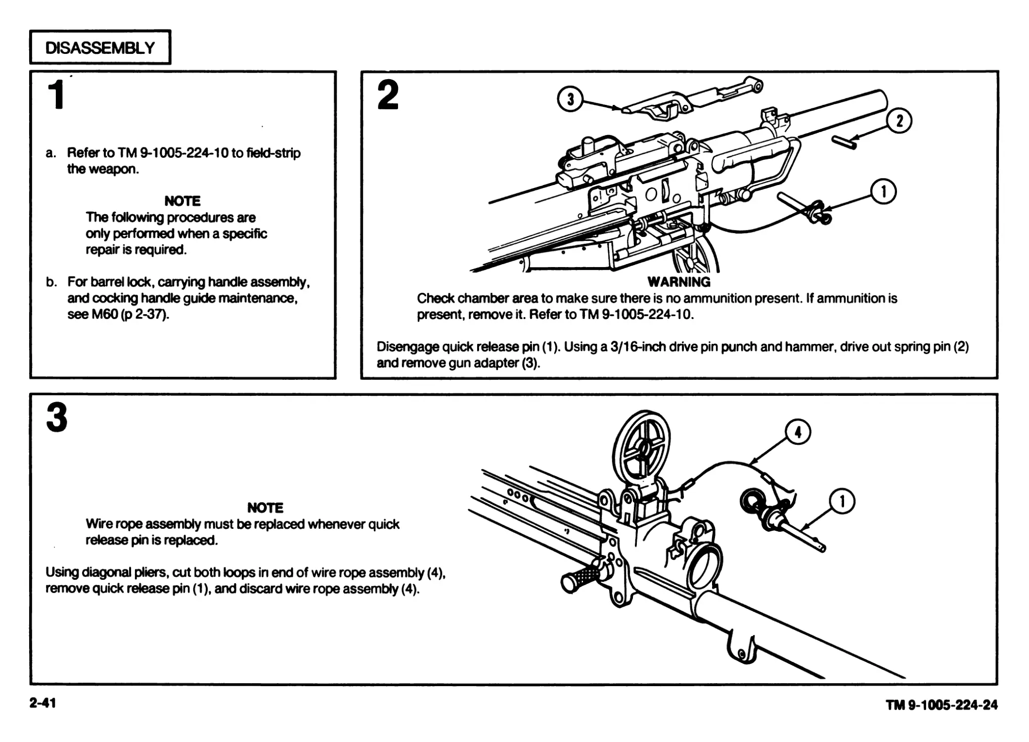
a. Refer to TM 9-1005-224-1Oto field-strip
the weapon.
NOTE
The following procedures are
only performed when a specific
repair is required.
b. For barrel lock, carrying handle assembly,
and cocking handle guide maintenance,
see M60 (p 2-37).
3
NOTE
Wire rope assembly must be replaced whenever quick
release pin is replaced.
Using diagonal pliers, cut both loops in end of wire rope assembly (4),
remove quick release pin (1), and discard wire rope assembly (4).
2-41
TM 9-1005-224-24
2-42
TM 9-1005-224-24
2-11. MAINTENANCE OF M60D MACHINE GUN (CONT).
REPAIR
WARNING
Dry cleaning solvent (SD) is flammable. Do not clean parts near an open flame or in a smoking area. Dry cleaning solvent evaporates quickly and has
a drying effect on the skin. When used without protective gloves, solvent may cause irritation to or cracking of the skin.
Using paint thinners, gasoline, kerosene, benzene (benzol), water, steam, or air for cleaning the weapon is prohibited. Use only authorized cleaning
materials.
CAUTION
The buffer assembly will not be submerged in solvents or other cleaning fluids. Using CLP on a cloth, wipe exterior surfaces to prevent corrosion.
Care MUST be exercised to avoid getting cleaner, lubricant and preservative (CLP) in the gas cylinder when cleaning the barrel. Position the gas
cylinder above the barrel during cleaning. The gas cylinder components will be removed and cleaned only when inspection reveals that the piston
will no longer move within the cylinder under its own weight when the barrel is tilted end to end. If gas cylinder components are cleaned, wipe
interior of cylinder and piston dry before reassembly. After reassembly, check for movement of gas piston by manually tilting the barrel assembly.
Rewire gas cylinder vent plug and machine-thread plug.
У NOTE
Do not dilute CLP. Shake well before using.
a. Repair by replacing all authorized parts.
b. Once repair/replacement is completed, clean and lubricate in accor-
dance with TM 9-1005-224-10.
c. Repair of subassemblies is covered in the following paragraphs:
Para Page
Barrel and bipod assembly........................2-18 2-58
Breech bolt assembly.............................2-14 2-48
Cartridge feed tray assembly (M60D only).........2-21 2-71
Cover assembly...................................2-19 2-64
Grip and trigger assembly (M60D only)............2-13 2-46
Operating rod assembly...........................2-15 2-52
Sear and safety housing assembly (M60D only) ... 2-17 2-56
d. Clean rusted or shiny metal surfaces with crocus cloth. Wash thor-
oughly with dry cleaning solvent.
CAUTION
If solid film lubricant comes in contact with any moving or
internal part, clean part with dry cleaning solvent.
e. Following manufacturer's instructions for use, apply solid film lubricant
to all external surfaces showing wear and allow weapon to dry 12 hours
before being used.
f. On component parts which have a hard carbon residue, it may be
necessary to use CLP to begin repair. Depending on the amount of
carbon residue, coat parts 2 to 16 hours, brush, wipe dry with wiping
rag, and lubricate as necessary using CLP.
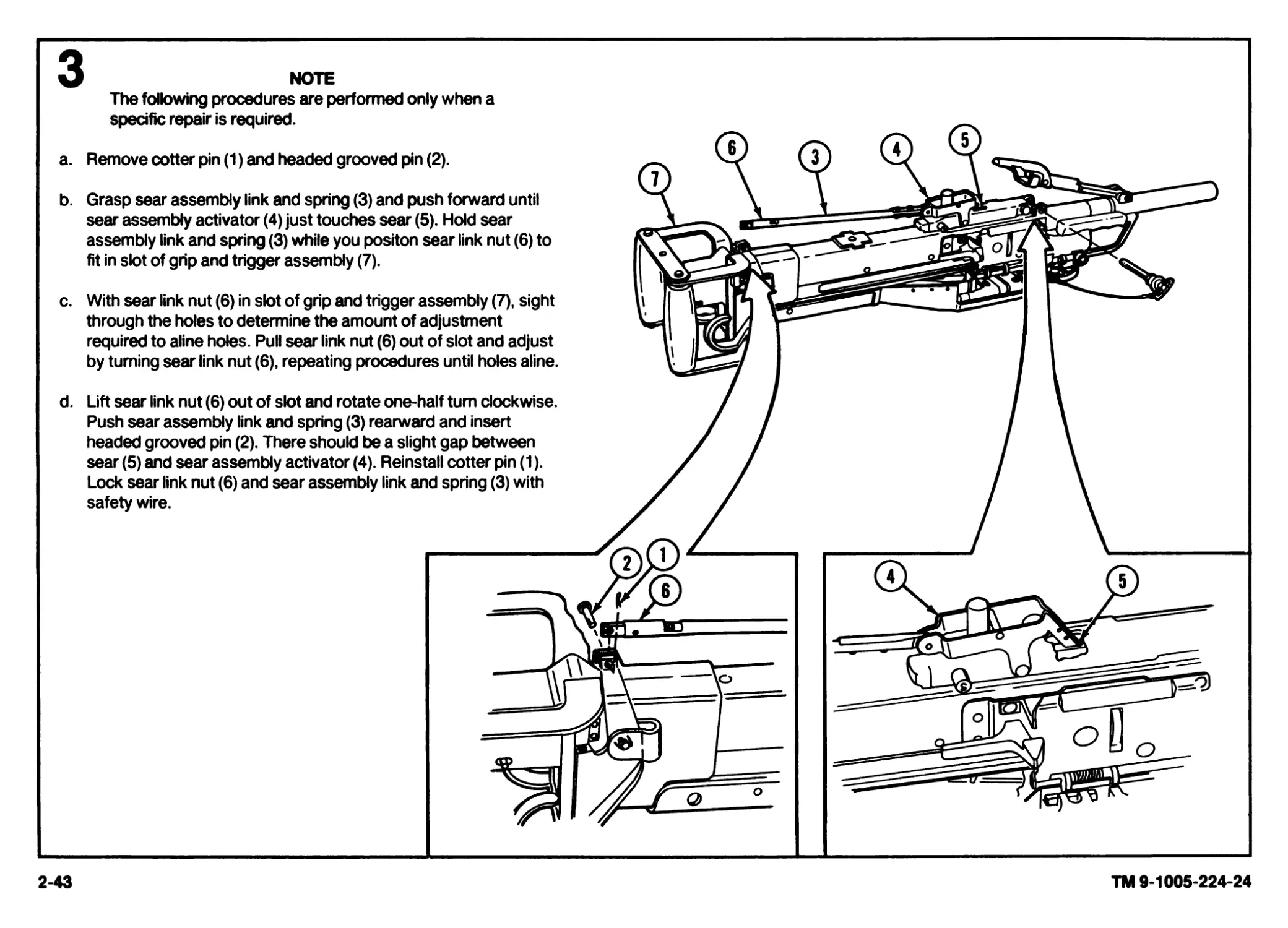
NOTE
The following procedures are performed only when a
specific repair is required.
a.
b.
Remove cotter pin (1) and headed grooved pin (2).
Grasp sear assembly link and spring (3) and push forward until
sear assembly activator (4) just touches sear (5). Hold sear
assembly link and spring (3) while you positon sear link nut (6) to
fit in slot of grip and trigger assembly (7).
c.
With sear link nut (6) in slot of grip and trigger assembly (7), sight
through the holes to determine the amount of adjustment
required to aline holes. Pull sear link nut (6) out of slot and adjust
by turning sear link nut (6), repeating procedures until holes aline.
d.
Lift sear link nut (6) out of slot and rotate one-half turn clockwise.
Push sear assembly link and spring (3) rearward and insert
headed grooved pin (2). There should be a slight gap between
sear (5) and sear assembly activator (4). Reinstall cotter pin (1).
Lock sear link nut (6) and sear assembly link and spring (3) with
safety wire.
2-43
TM 9-1005-224-24
2*44
TM 9-1005-224-24
2-11. MAINTENANCE OF M60D MACHINE GUN (CONT).
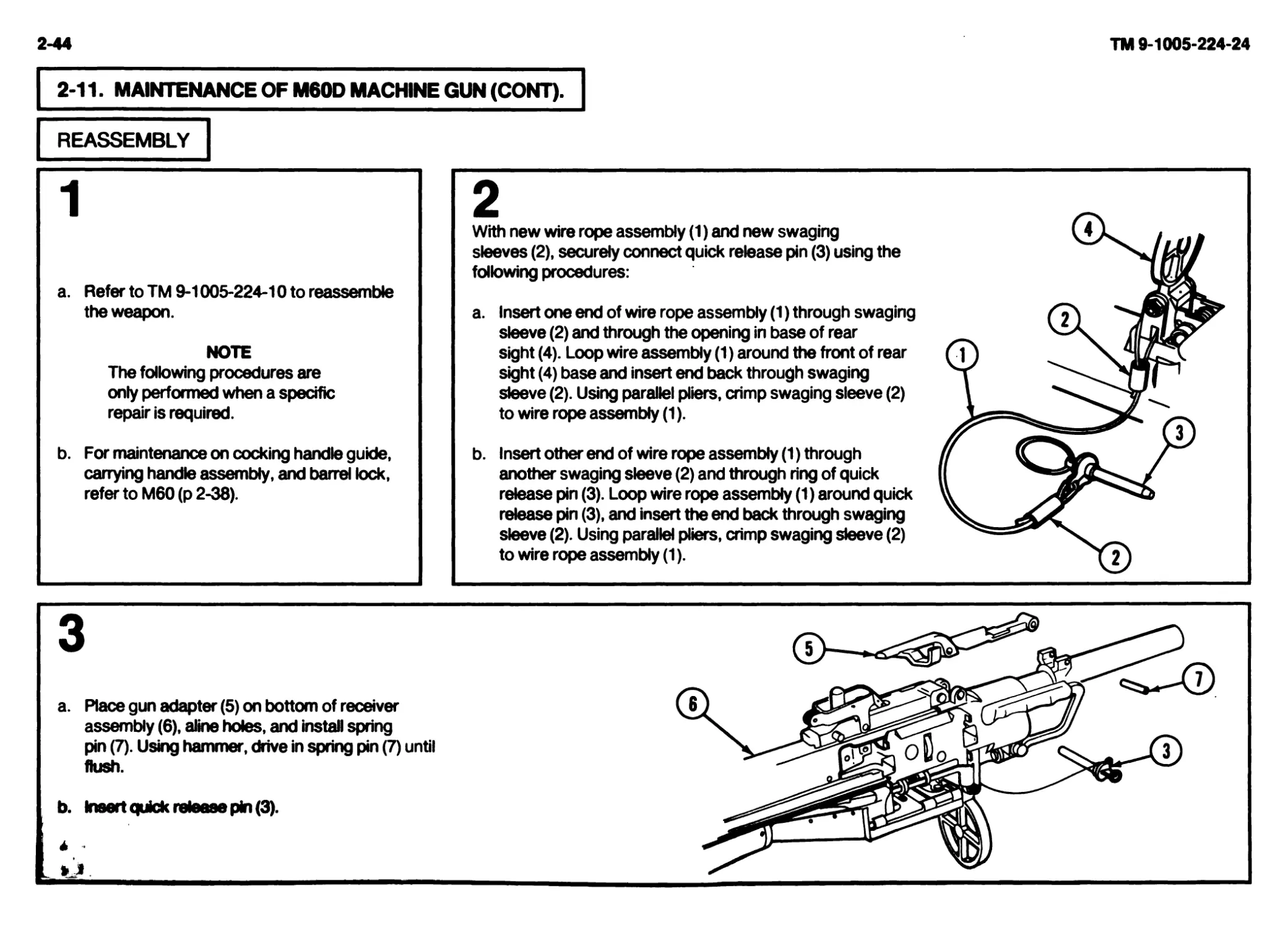
REASSEMBLY
a. Refer to TM 9-1005-224-10 to reassemble
the weapon.
NOTE
The following procedures are
only performed when a specific
repair is required.
b. For maintenance on cocking handle guide,
carrying handle assembly, and barrel lock,
refer to M60 (p 2-38).
2
With new wire rope assembly (1) and new swaging
sleeves (2), securely connect quick release pin (3) using the
following procedures:
a. Insert one end of wire rope assembly (1) through swaging
sleeve (2) and through the opening in base of rear
sight (4). Loop wire assembly (1) around the front of rear
sight (4) base and insert end back through swaging
sleeve (2). Using parallel pliers, crimp swaging sleeve (2)
to wire rope assembly (1).
b. Insert other end of wire rope assembly (1) through
another swaging sleeve (2) and through ring of quick
release pin (3). Loop wire rope assembly (1) around quick
release pin (3), and insert the end back through swaging
sleeve (2). Using parallel pliers, crimp swaging sleeve (2)
to wire rope assembly (1).
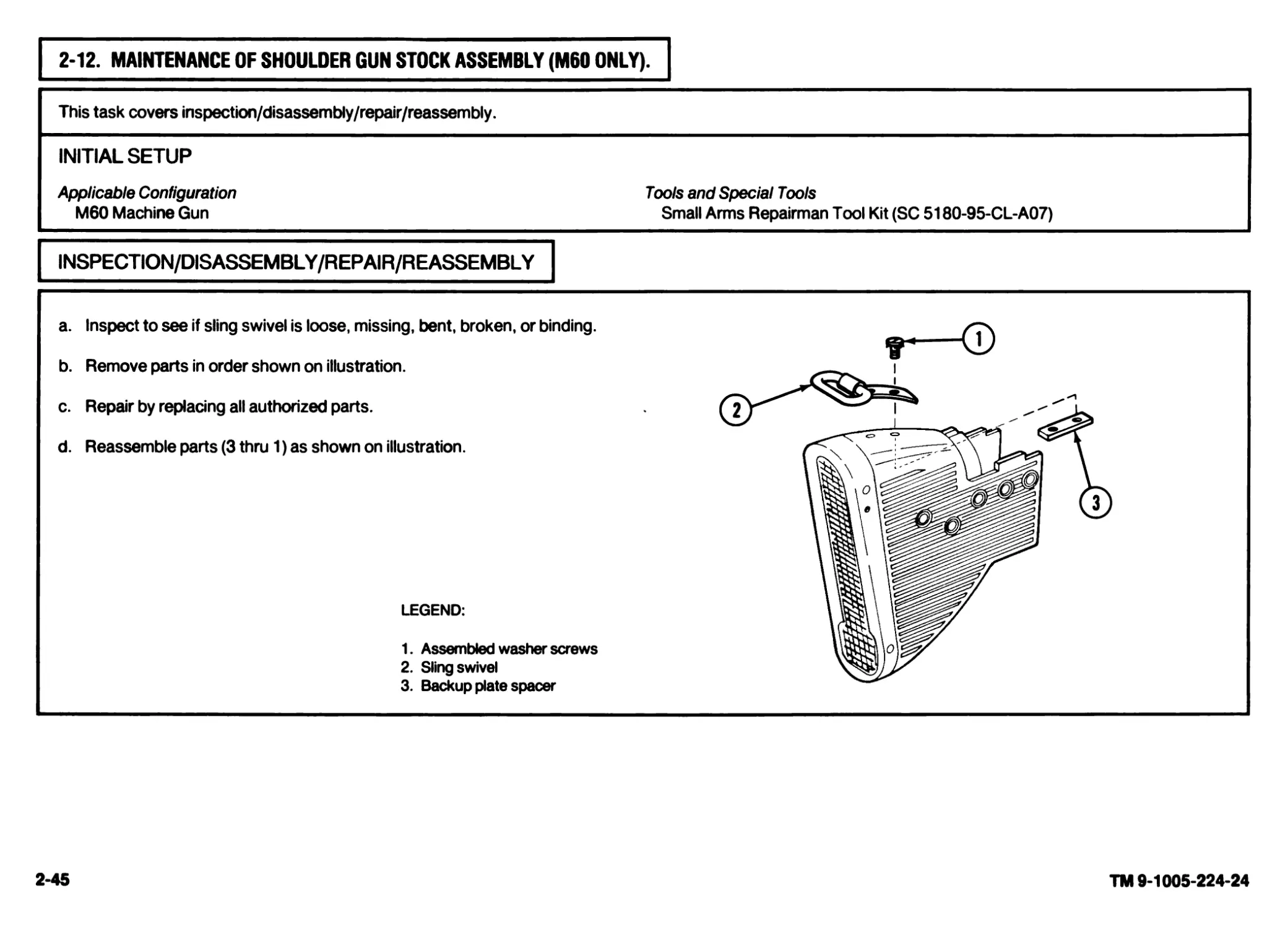
2-12. MAINTENANCE OF SHOULDER GUN STOCK ASSEMBLY (M60 ONLY).
This task covers inspection/disassembly/repair/reassembly.
INITIAL SETUP
Applicable Configuration Tools and Special Tools
M60 Machine Gun Small Arms Repairman Tool Kit (SC 5180-95-CL-A07)
INSPECTION/DISASSEMBLY/REPAIR/REASSEMBLY
a. Inspect to see if sling swivel is loose, missing, bent, broken, or binding.
b. Remove parts in order shown on illustration.
c. Repair by replacing all authorized parts.
d. Reassemble parts (3 thru 1) as shown on illustration.
LEGEND:
1. Assembled washer screws
2. Sling swivel
3. Backup plate spacer
2-45
TM 9-1005-224-24
2-46
TM 9-1005-224-24
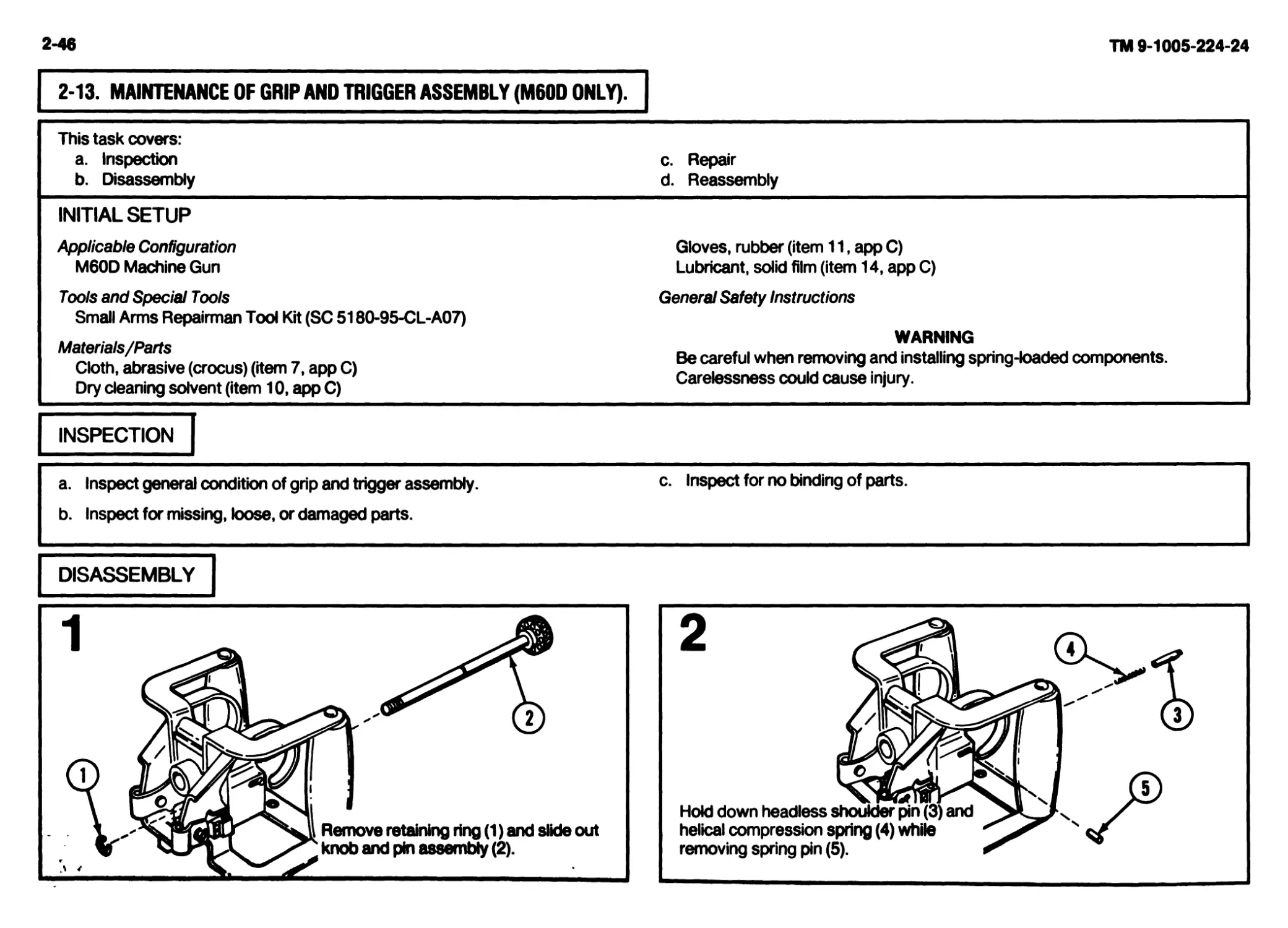
2-13. MAINTENANCE OF GRIP AND TRIGGER ASSEMBLY (M60D ONLY).
This task covers: a. Inspection b. Disassembly c. Repair d. Reassembly
INITIAL SETUP
Applicable Configuration M60D Machine Gun Gloves, rubber (item 11, app C) Lubricant, solid film (item 14, app C)
Tools and Special Tools Small Arms Repairman Tool Kit (SC 5180-95-CL-A07) General Safety Instructions
Materials/Parts Cloth, abrasive (crocus) (item 7, app C) Dry cleaning solvent (item 10, app C) WARNING Be careful when removing and installing spring-loaded components. Carelessness could cause injury.
INSPECTION
a. Inspect general condition of grip and trigger assembly. c- Inspect for no binding of parts.
b. Inspect for missing, loose, or damaged parts.
DISASSEMBLY
Remove cotter pins (6) and push out headed
grooved pins (7).
Raise up grip and trigger assembly (8) and
remove helical compression springs (9).
REPAIR
| WARNING
* Dry cleaning solvent (SD) is
flammable. Do not clean parts near
an open flame or in a smoking area.
Dry cleaning solvent evaporates
quickly and has a drying effect on the
skin. When used without protective
gloves, solvent may cause irritation
to or cracking of the skin.
a. Repair by replacing authorized parts.
b. Clean rusted or shiny metal surfaces with
crocus doth. Wash thoroughly with dry
cleaning solvent (SD).
2
CAUTION
If solid film lubricant comes in
contact with any moving or inter-
nal part, dean part with dry
cleaning solvent.
a. Following manufacturer’s instructions for
use, apply solid film lubricant to all external
surfaces showing wear and allow weapon
to dry 12 hours before being used.
b. Damage not repaired by minor replacement
of parts will cause replacement of entire
assembly.
REASSEMBLY
Raise up grip and trigger assembly (1) and
insert helical compression springs (2) into trig-
ger stop blocks (3).
Aline holes in grip and trigger assembly (1),
install headed grooved pins (4), and secure
with cotter pins (5).
2-47
TM 9-1005-224-24
2-48
TM 9-1005-224-24
2-13. MAINTENANCE OF GRIP AND TRIGGER ASSEMBLY (M60D ONLY) (CONT).
REASSEMBLY (CONT)
3
a. Place helical compression spring (6)
and headless shoulder pin (7) in back
plate (8), and aline holes in headless
shoulder pin (7) with slot (9) in back
plate (8).
b. Press in on headless shoulder pin (7)
and insert spring pin (10) through
slot (9) and into hole of headless
shoulder pin (7). Using a hammer,
drive spring pin (10) into hole.
Install knob and pin assembly (11) through back plate (8) and secure with
retaining ring (12).
2-14. MAINTENANCE OF BREECH BOLT ASSEMBLY.
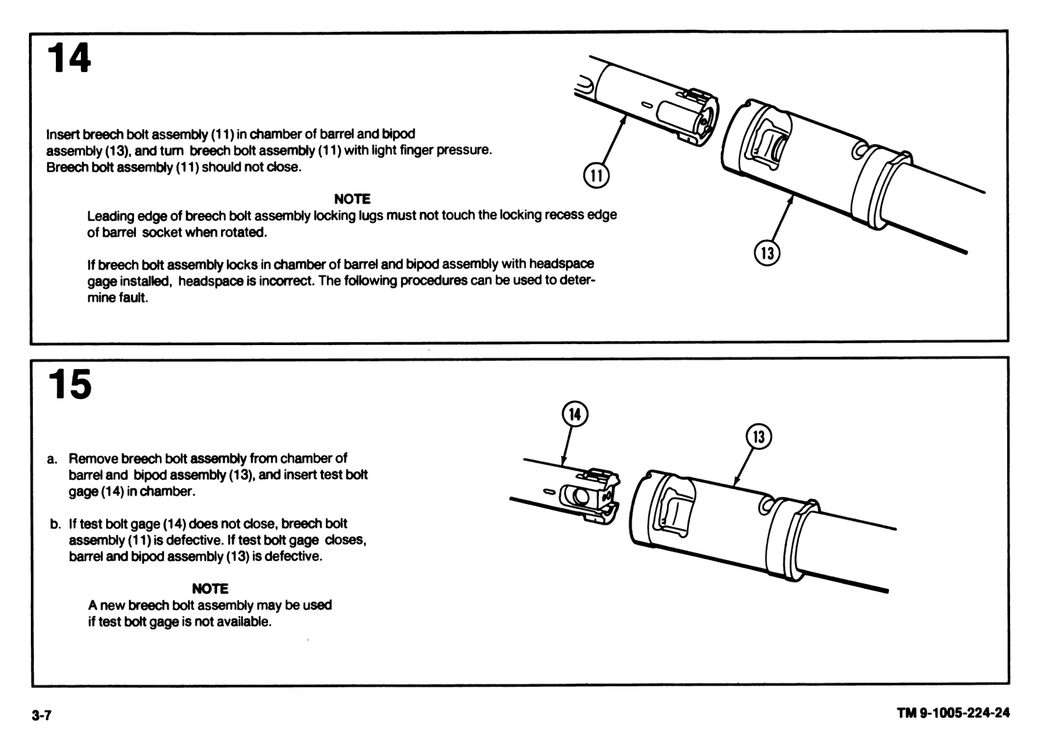
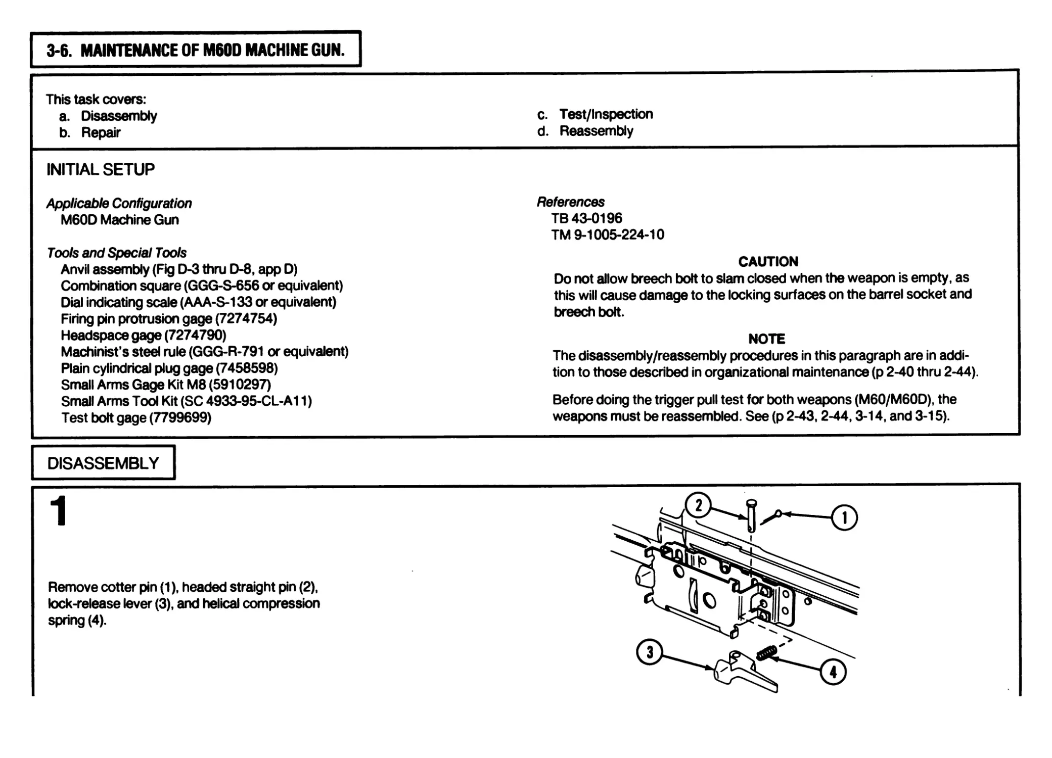
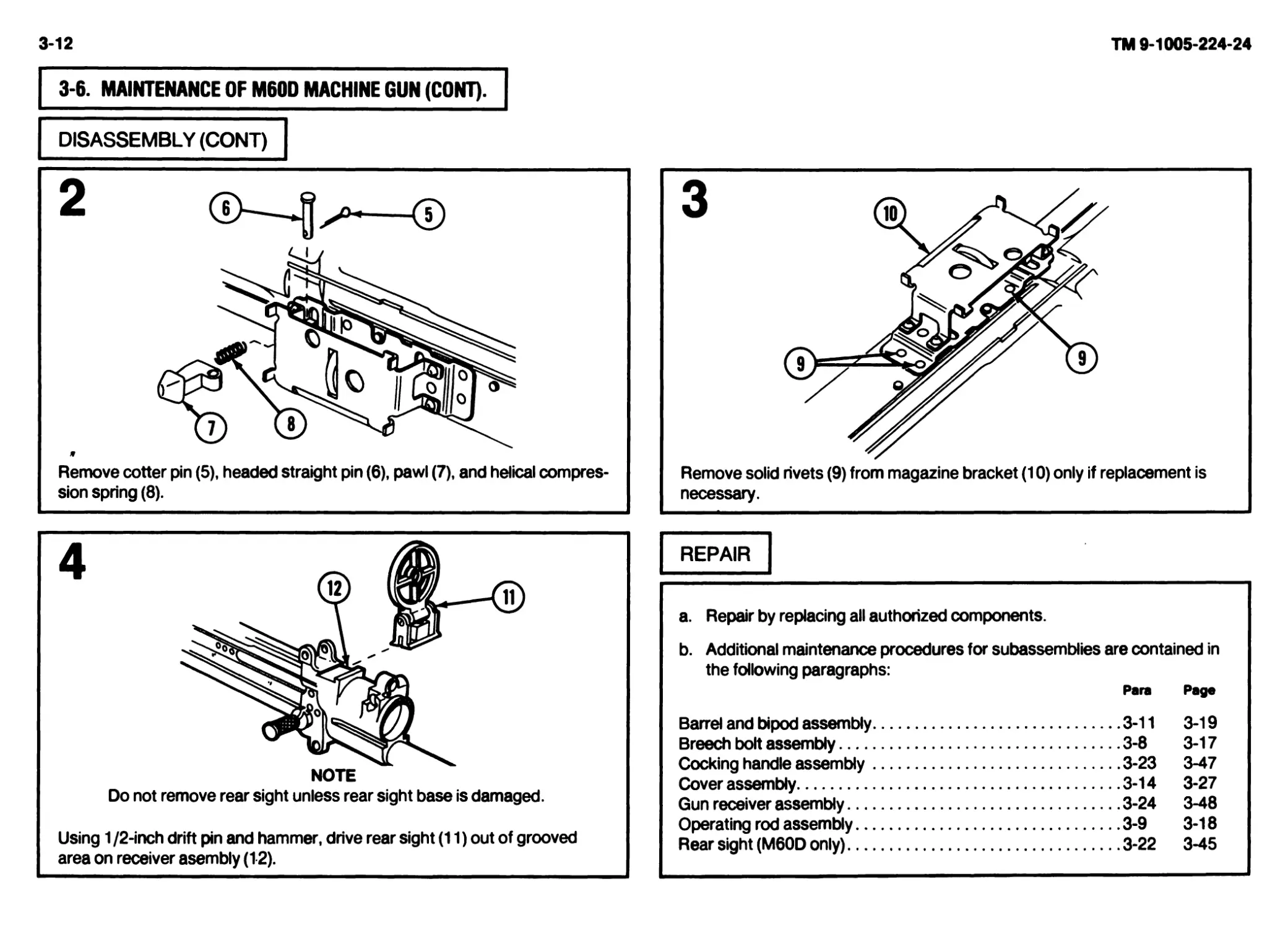
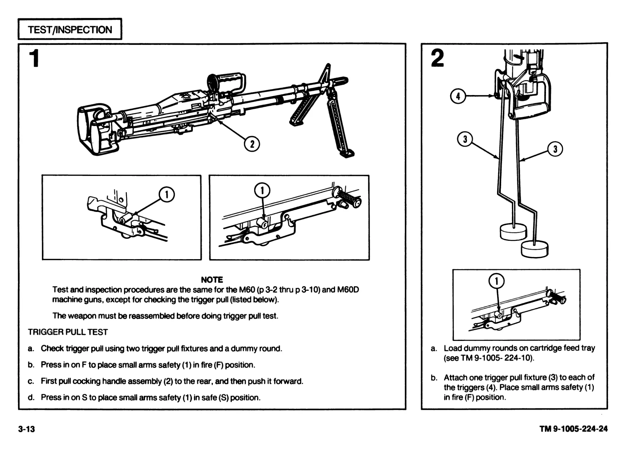
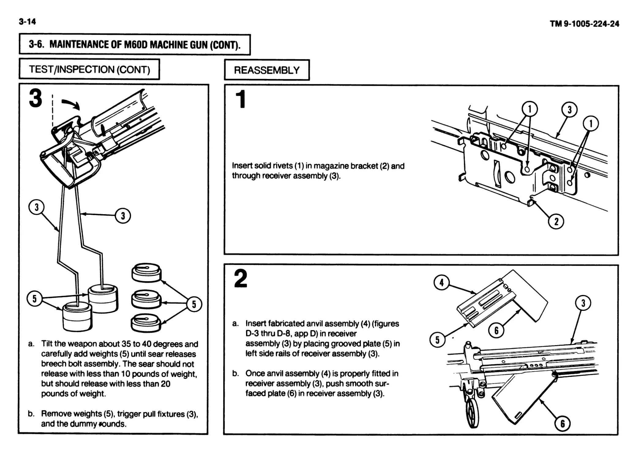
This task covers:
a. Inspection b. Disassembly c. Repair d. Reassembly
INITIAL SETUP General Safety Instructions WARNING
Applicable Configuration M60/M60D Machine Guns Tools and Special Tools Small Arms Repairman Tool Kit (SC 5180-95-CL-A07; Materials /Parts Cleaner, lubricant and preservative (CLP) (item 6, app C) References TM 9-1005-224-10 Be careful when removing and installing spring-loaded components. Carelessness could cause injury. The weapon’s breech bolt assembly will be used to check headspace. Do not intermix the breech bolt assembly or barrel and bipod assembly without checking headspace requirements. CAUTION Do not allow breech bolt to slam closed when the weapon is empty, as this will cause damage to the locking surfaces on the barrel socket and breech bolt. NOTE Headspace will be gaged annually, using appropriate gages, by direct support maintenance personnel. If headspace is faulty, a new breech bolt or test bolt gage is required to determine if the barrel or breech bolt is defective.
INSPECTION
a. Inspect back side of breech bolt assembly
If sharp edges or burrs are present,
notify direct support maintenance
for replacement.
3
a. Inspect left front comer of breech bolt assembly stripping lug (3). A stripping lug showing complete
loss of original radius surface area due to chipping may still be used.
b. Inspect back side of breech bolt assembly stripping lug (3). Burrs may be smoothed by stoning but
cracks, chips, dents, or gouges are not repairable in this area. If cracks, chips, dents, or gouges are
present, notify direct support maintenance.
NOTE
Rounding or mutilation found on breech bolt locking surfaces will cause damage to mating
locking surfaces on the barrel socket. If breech bolt is rounded or mutilated, notify direct
support maintenance.
2-49
TM 9-1005-224-24
2-50
TM 9-1005-224-24
2-14. MAINTENANCE OF BREECH BOLT ASSEMBLY (CONT).
DISASSEMBLY
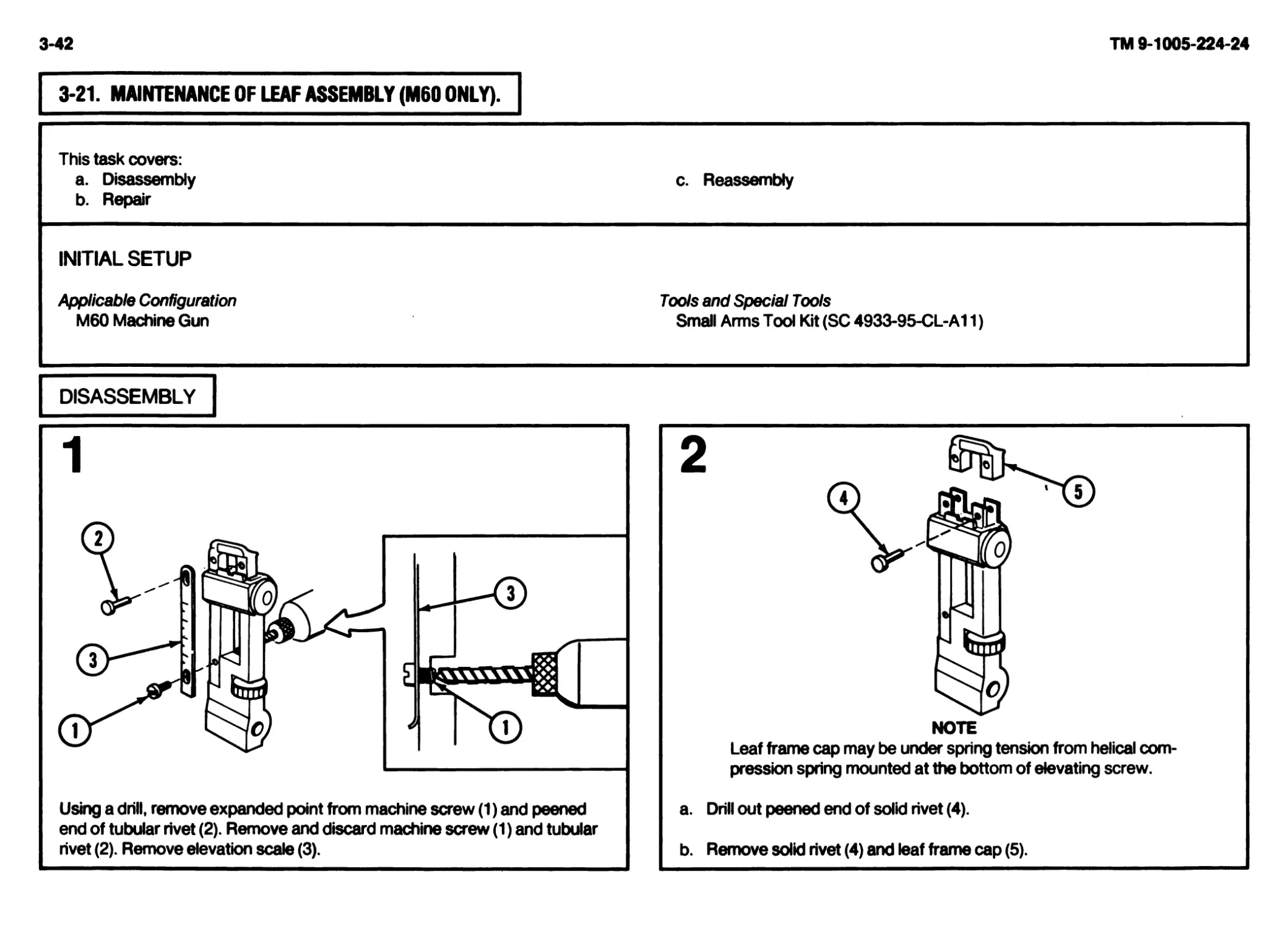
1
a. Refer to TM 9-1005-224-10 to field-strip
the weapon.
NOTE
Procedures shown are in addi-
tion to field-stripping.
b. Place bolt in vise.
Using a 3/32-inch drive pin punch and hammer,
drive out spring pin (1) and remove cartridge
ejector (2) and helical compression spring (3).
Using a 1/16-in ch punch, release spring ten-
sion on cartridge extractor (4). Push punch
rearward and hold it. Move cartridge
extractor (4) rearward and remove it.
REPAIR
Slowly release pressure on punch and remove extractor plunger (5) and
helical compression spring (6) from body of breech bolt (7).
Repair by replacing all authorized components.
NOTE
Burrs or raised surfaces may be removed or smoothed
using a fine grit sharpening stone. DO NOT change the
tolerances of any component by stoning. Components with
cracks, chips, dents, or gouges shall be reported to direct
support maintenance for repair or replacement.
Cracks, chips, dents, or gouges on breech bolt locking
surfaces and rounding/mutilation of the rear locking sur-
face can damage the mating locking surfaces of the barrel
socket. Damage to barrel socket locking surfaces can
damage the breech bolt. Notify direct support maintenance
for replacement or repair if either condition exists.
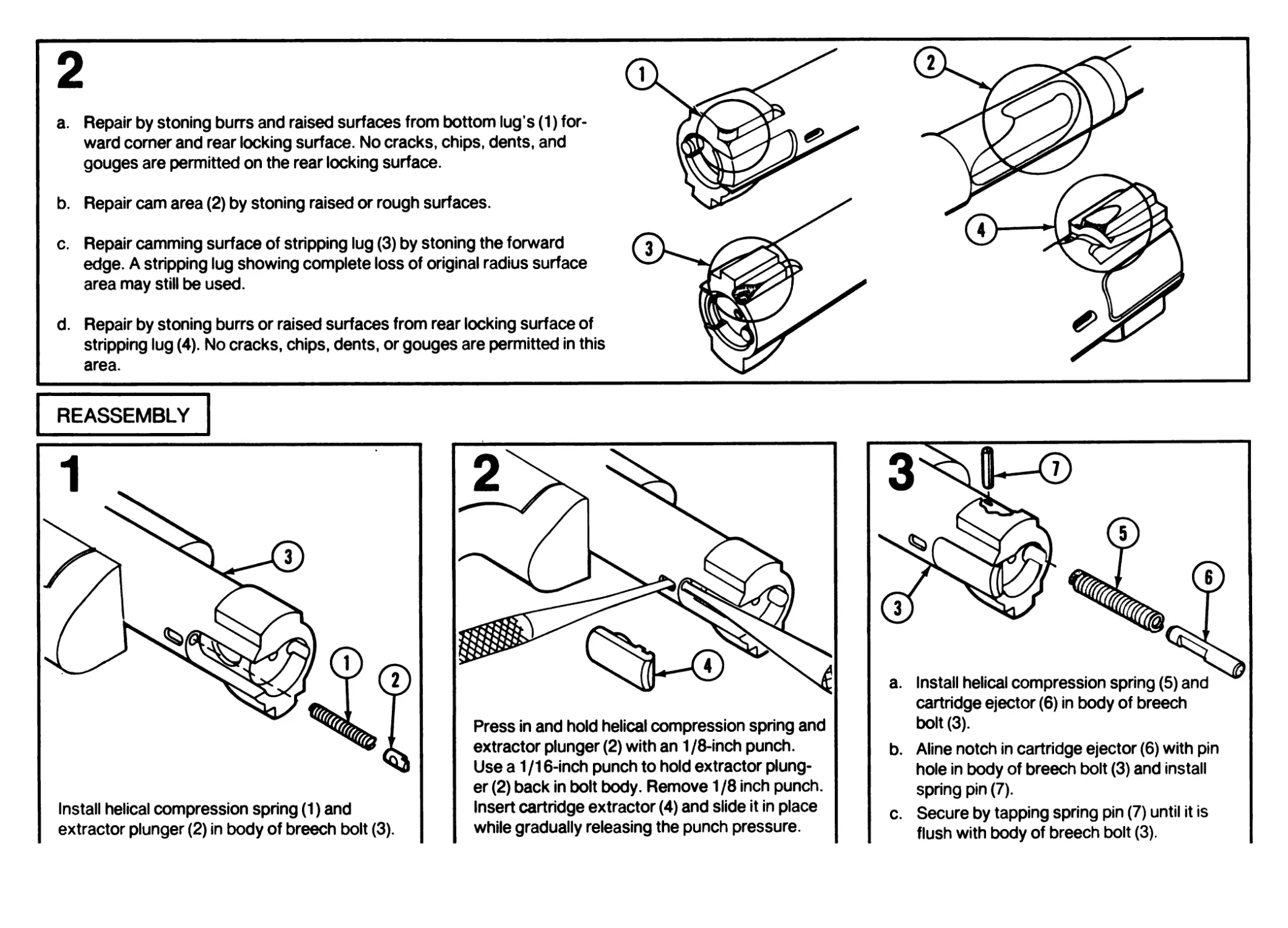
2
a. Repair by stoning burrs and raised surfaces from bottom lug's (1) for-
ward comer and rear locking surface. No cracks, chips, dents, and
gouges are permitted on the rear locking surface.
b. Repair cam area (2) by stoning raised or rough surfaces.
c. Repair camming surface of stripping lug (3) by stoning the forward
edge. A stripping lug showing complete loss of original radius surface
area may still be used.
d. Repair by stoning burrs or raised surfaces from rear locking surface of
stripping lug (4). No cracks, chips, dents, or gouges are permitted in this
area.
REASSEMBLY
Install helical compression spring (1) and
extractor plunger (2) in body of breech bolt (3).
Press in and hold helical compression spring and
extractor plunger (2) with an 1 /8-inch punch.
Use a 1 /16-inch punch to hold extractor plung-
er (2) back in bolt body. Remove 1/8 inch punch.
Insert cartridge extractor (4) and slide it in place
while gradually releasing the punch pressure.
cartridge ejector (6) in body of breech
bolt (3).
b. Aline notch in cartridge ejector (6) with pin
hole in body of breech bolt (3) and install
spring pin (7).
c. Secure by tapping spring pin (7) until it is
flush with body of breech bolt (3).
2-52
TM 9-1005-224-24
2-14. MAINTENANCE OF BREECH BOLT ASSEMBLY (CONT).
REASSEMBLY (CONT)
U Refer to TM 9-1005-224-1 Oto reassemble the weapon.
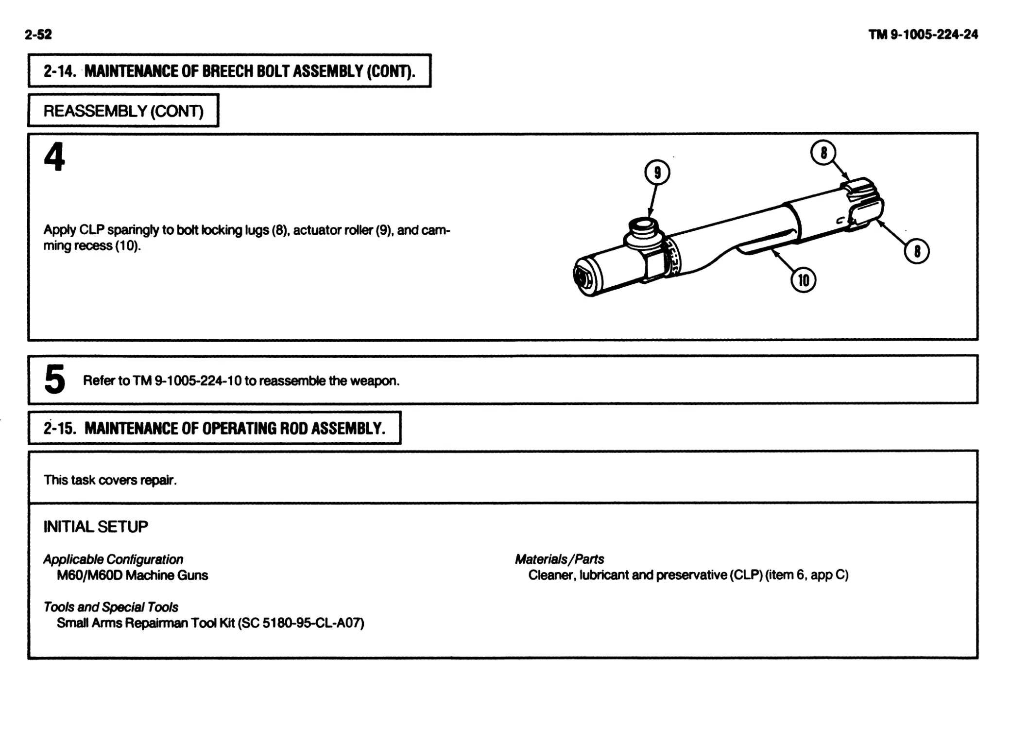
2-15. MAINTENANCE OF OPERATING ROD ASSEMBLY.
This task covers repair.
INITIAL SETUP
Applicable Configuration
M60/M60D Machine Guns
Tools and Special Tools
Small Arms Repairman Tool Kit (SC 5180-95-CL-A07)
Materials/Parts
Cleaner, lubricant and preservative (CLP) (item 6, app C)
REPAIR
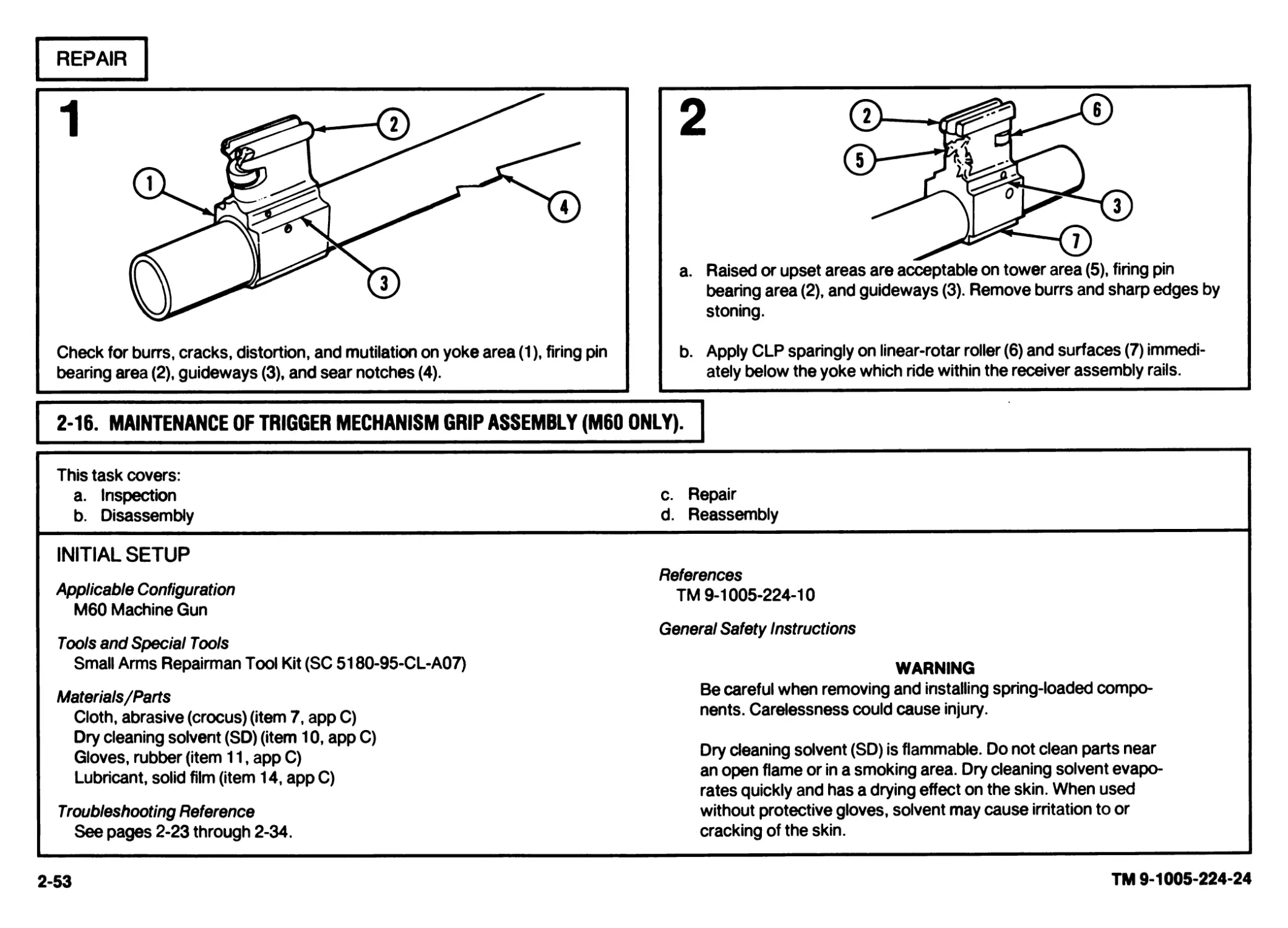
Check for burrs, cracks, distortion, and mutilation on yoke area (1), firing pin
bearing area (2), guideways (3), and sear notches (4).
a. Raised or upset areas are acceptable on tower area (5), firing pin
bearing area (2), and guideways (3). Remove burrs and sharp edges by
stoning.
b. Apply CLP sparingly on linear-rotar roller (6) and surfaces (7) immedi-
ately below the yoke which ride within the receiver assembly rails.
2-16. MAINTENANCE OF TRIGGER MECHANISM GRIP ASSEMBLY (M60 ONLY).
This task covers:
a. Inspection
b. Disassembly
INITIAL SETUP
Applicable Configuration
M60 Machine Gun
Tools and Special Tools
Small Arms Repairman Tool Kit (SC 5180-95-CL-A07)
Materials/Parts
Cloth, abrasive (crocus) (item 7, app C)
Dry cleaning solvent (SD) (item 10, app C)
Gloves, rubber (item 11, app C)
Lubricant, solid film (item 14, app C)
Troubleshooting Reference
See pages 2-23 through 2-34.
c. Repair
d. Reassembly
References
TM 9-1005-224-10
General Safety Instructions
WARNING
Be careful when removing and installing spring-loaded compo-
nents. Carelessness could cause injury.
Dry cleaning solvent (SD) is flammable. Do not clean parts near
an open flame or in a smoking area. Dry cleaning solvent evapo-
rates quickly and has a drying effect on the skin. When used
without protective gloves, solvent may cause irritation to or
cracking of the skin.
2-53
TM 9-1005-224-24
2-54
TM 9-1005-224-24
2-16. MAINTENANCE OF TRIGGER MECHANISM GRIP ASSEMBLY (M60 ONLY) (CONT).
INSPECTION
DISASSEMBLY
a. Inspect sear plunger and helical compression spring for proper operation by checking tension on the
sear.
b. Inspect safety plunger and helical compression spring for proper operation by checking tension on
the small arms safety.
c. Inspect that small arms safety locks sear when rotated to the safe position.
d. Inspect that trigger returns to normal position when depressed and released.
e. Rubber coating must not be gummy or retain finger impressions. Abrasions, cuts, gouges, and holes
in rubber are acceptable. Loose bonding of rubber near cuts, etc., is acceptable providing the cuts
do not interfere with operator's grip on weapon.
2
1
Refer to TM 9-1005-224-10 to field-strip the
weapon.
NOTE
The following procedures are in
addition to field-stripping.
a. Clamp forward section of trigger
housing (1) firmly in vise.
b. Move small arms safety (2) to fire (F)
position.
c. Press down on, and hold, safety plunger (3)
with screwdriver. Remove small arms
safety (2) and slowly release pressure on
safety plunger (3).
Remove safety plunger (3) and helical com-
pression spring (4).
REPAIR
REASSEMBLY
a. Repair by replacing all authorized compo-
nents.
b. Clean rusted or shiny metal surfaces with
crocus doth. Wash thoroughly with dry
cleaning solvent (SD).
CAUTION
If solid film lubricant comes in
contact with any moving or inter-
nal part, dean part with dry
cleaning solvent.
c. Following manufacturer’s instructions for
use, apply solid film lubricant to all external
surfaces showing wear and allow weapon
to dry 12 hours before being used.
2
a. Push down on safety plunger (3) with screwdriver,
hold it, and slowly insert small arms safety (4).
b. After small arms safety (4) is in place, remove
screwdriver.
c. Remove trigger housing (1) from vise.
Refer to TM 9-1005-224-10 to reassemble the
weapon.
2-55
TM 9-1005-224-24
2-56
TM 9-1005-224-24
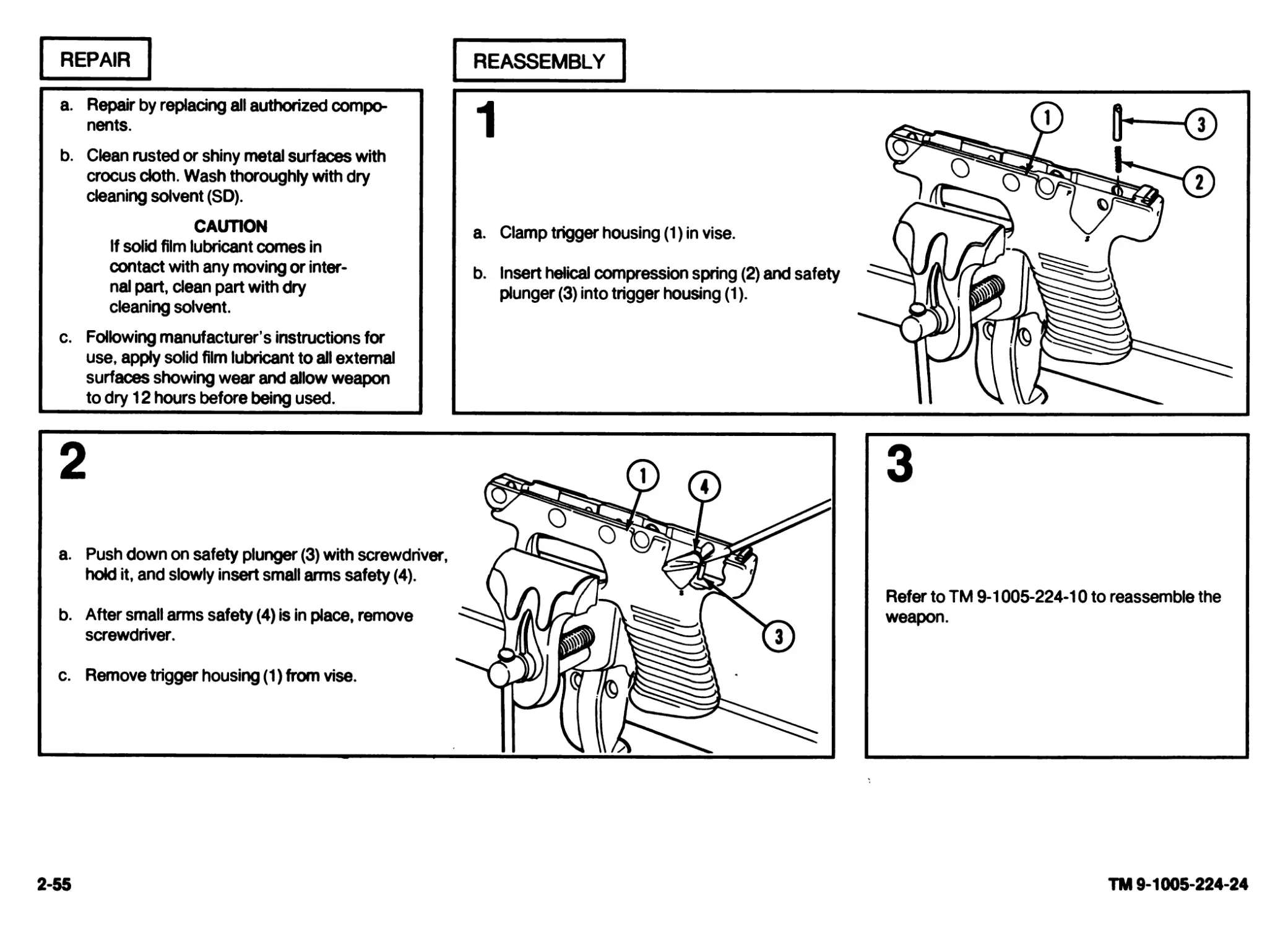
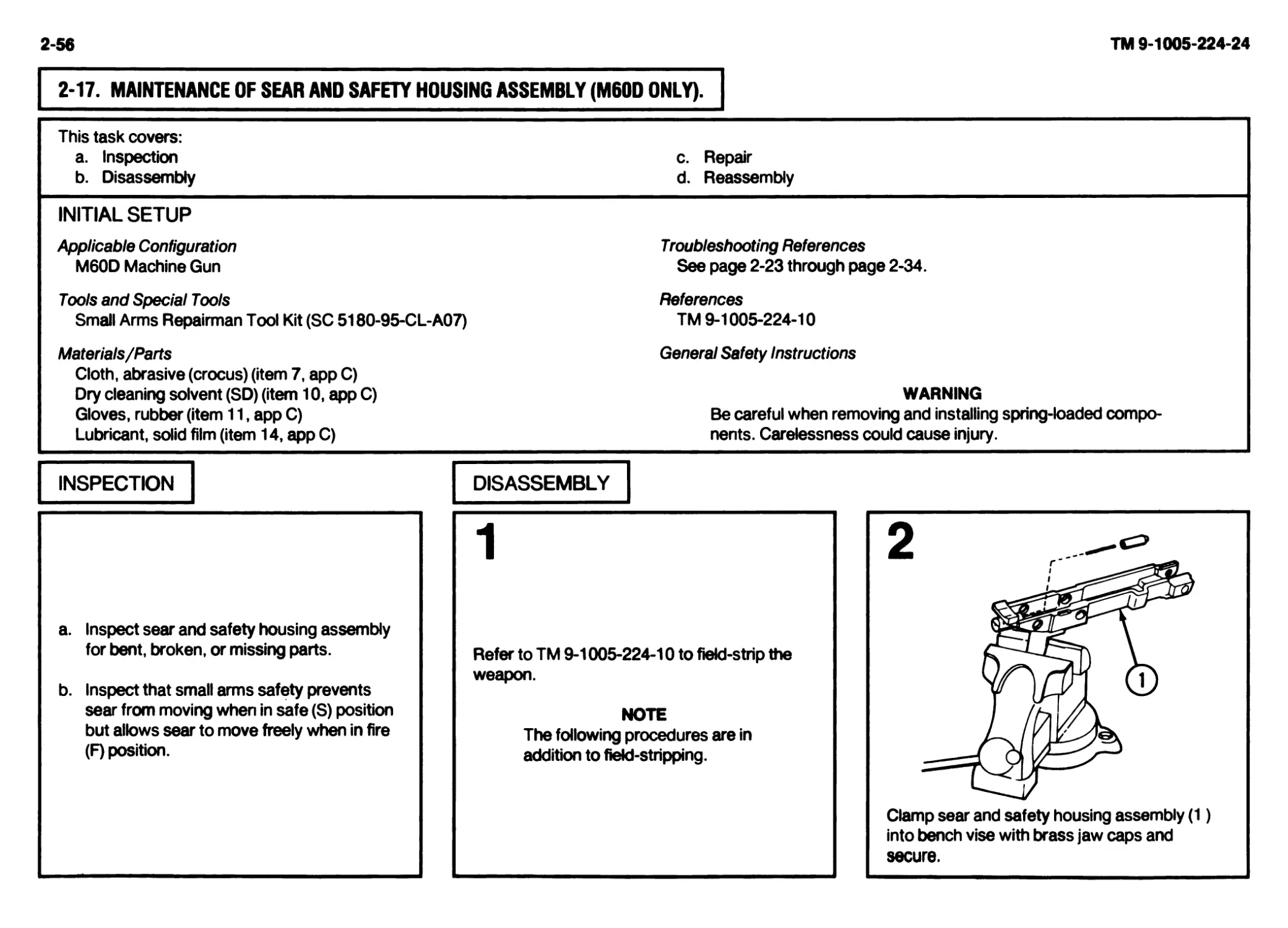
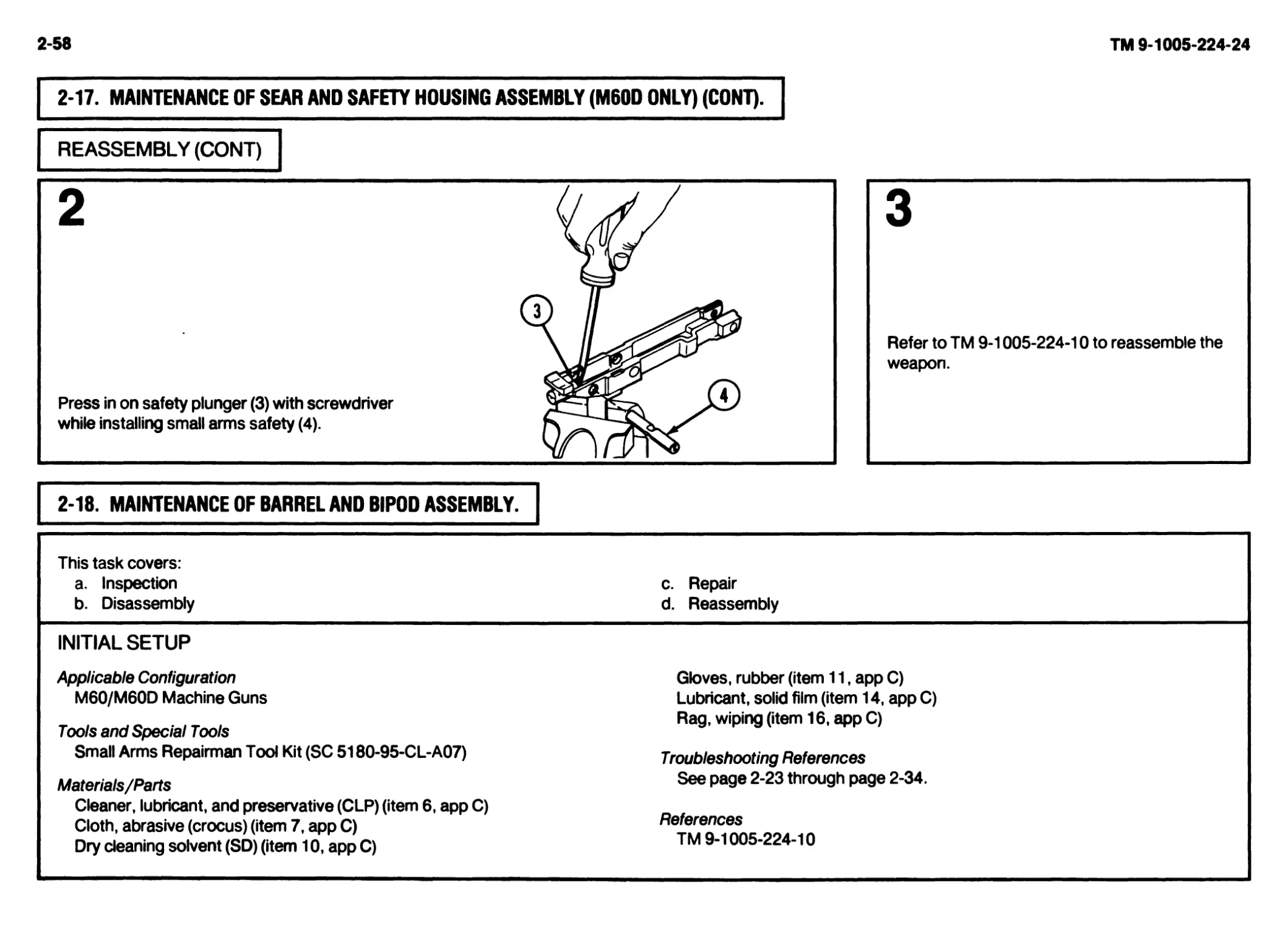
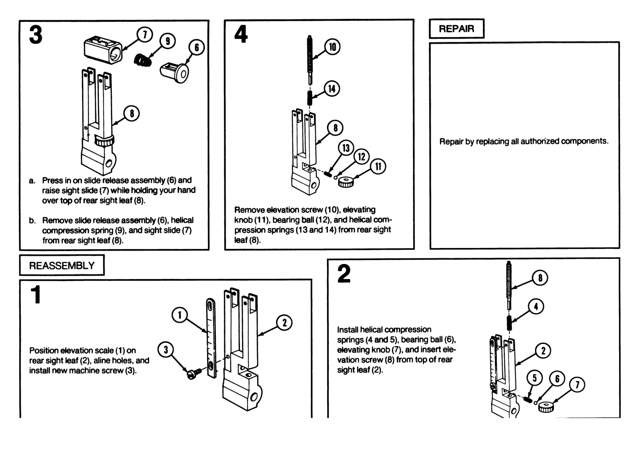
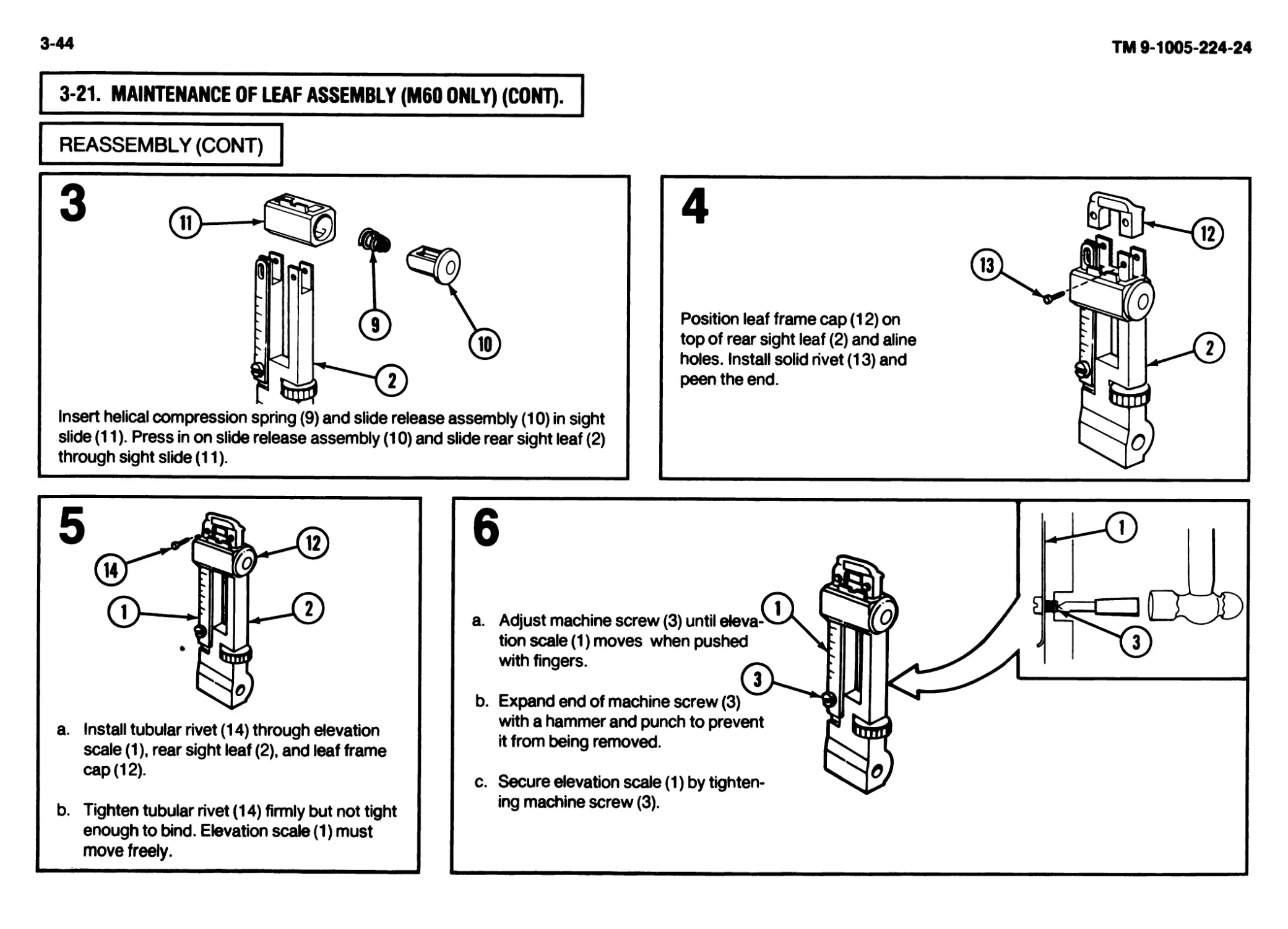
2-17. MAINTENANCE OF SEAR AND SAFETY HOUSING ASSEMBLY (M60D ONLY).
This task covers:
a. Inspection
b. Disassembly
INITIAL SETUP
Applicable Configuration
M60D Machine Gun
Tools and Special Tools
Small Arms Repairman Tool Kit (SC 5180-95-CL-A07)
Materials/Parts
Cloth, abrasive (crocus) (item 7, app C)
Dry cleaning solvent (SD) (item 10, app C)
Gloves, rubber (item 11, app C)
Lubricant, solid film (item 14, app C)
c. Repair
d. Reassembly
Troubleshooting References
See page 2-23 through page 2-34.
References
TM 9-1005-224-10
General Safety Instructions
WARNING
Be careful when removing and installing spring-loaded compo-
nents. Carelessness could cause injury.
INSPECTION
DISASSEMBLY
1
a. Inspect sear and safety housing assembly
for bent, broken, or missing parts.
b. Inspect that small arms safety prevents
sear from moving when in safe (S) position
but allows sear to move freely when in fire
(F) position.
Refer to TM 9-1005-224-10 to field-strip the
weapon.
NOTE
The following procedures are in
addition to field-stripping.
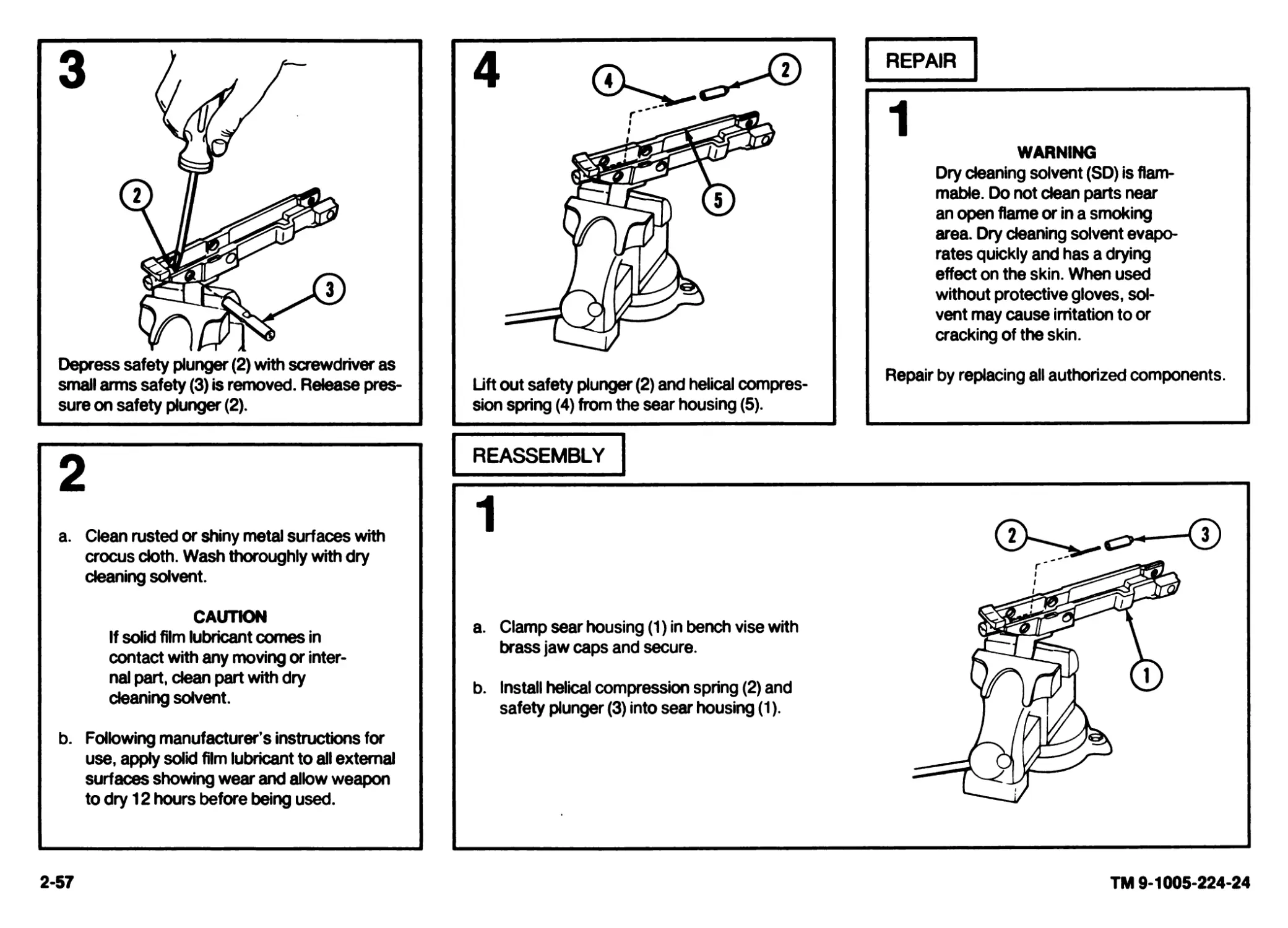
REPAIR
WARNING
Dry cleaning solvent (SD) is flam-
mable. Do not dean parts near
an open flame or in a smoking
area. Dry cleaning solvent evapo-
rates quickly and has a drying
effect on the skin. When used
without protective gloves, sol-
vent may cause irritation to or
cracking of the skin.
Depress safety plunger (2) with screwdriver as
small arms safety (3) is removed. Release pres-
sure on safety plunger (2).
Lift out safety plunger (2) and helical compres-
sion spring (4) from the sear housing (5).
Repair by replacing all authorized components.
2
a. Clean rusted or shiny metal surfaces with
crocus doth. Wash thoroughly with dry
cleaning solvent.
CAUTION
If solid film lubricant comes in
contact with any moving or inter-
nal part, dean part with dry
cleaning solvent.
b. Following manufacturer’s instructions for
use, apply solid film lubricant to all external
surfaces showing wear and allow weapon
to dry 12 hours before being used.
REASSEMBLY
a. Clamp sear housing (1) in bench vise with
brass jaw caps and secure.
b. Install helical compression spring (2) and
safety plunger (3) into sear housing (1).
2-57
TM 9-1005-224-24
2-58
TM 9-1005-224-24
2-17. MAINTENANCE OF SEAR AND SAFETY HOUSING ASSEMBLY (M60D ONLY) (CONT).
REASSEMBLY (CONT)
3
Refer to TM 9-1005-224-10 to reassemble the
weapon.
This task covers: a. Inspection b. Disassembly c. Repair d. Reassembly
INITIAL SETUP
Applicable Configuration M60/M60D Machine Guns Tools and Special Tools Small Arms Repairman Tool Kit (SC 5180-95-CL-A07) Materials/Parts Cleaner, lubricant, and preservative (CLP) (item 6, app C) Cloth, abrasive (crocus) (item 7, app C) Dry cleaning solvent (SD) (item 10, app C) Gloves, rubber (item 11, app C) Lubricant, solid film (item 14, app C) Rag, wiping (item 16, app C) Troubleshooting References See page 2-23 through page 2-34. References TM 9-1005-224-10
INSPECTION
DISASSEMBLY
a. Inspect front and rear key washers for bro-
ken tabs.
b. Inspect general appearance of barrel and
bipod assembly.
c. Inspect gas cylinder system for cleanliness.
2-59
TM 9-1005-224-24
2-60
TM 9-1005-224-24
2-18. MAINTENANCE OF BARREL AND BIPOD ASSEMBLY (CONT).
DISASSEMBLY (CONT)
NOTE
When disassembling be careful not
to damage key washers.
Using combination wrench, remove vent plug (4)
key washer (3), machine thread bushing (5), and
key washer (6). Tilt barrel, gas piston (7) should
fall out.
REPAIR
1
WARNING
Dry cleaning solvent (SD) is flammable. Do not dean parts near an open flame or in a smoking area. Dry cleaning solvent evaporates quickly and has
a drying effect on the skin. When used without protective gloves, solvent may cause irritation to or cracking of the skin.
CAUTION
Care MUST be exercised to avoid getting cleaner, lubricant and preservative (CLP) or oil in the gas cylinder when cleaning the barrel. Position the
gas cylinder above the barrel during cleaning. The gas cylinder components will be removed and cleaned only when inspection reveals that the
piston will no longer move within the cylinder under its own weight when the barrel is tilted end for end. If gas cylinder components are deaned,
wipe interior of cylinder and piston dry before reassembly. After reassembly, check for movement of gas piston by manually tilting the barrel
assembly. Rewire vent plug.
NOTE
Do not dilute CLP. Shake well before using.
Burrs or raised surfaces may be removed or smoothed using a fine grit sharpening stone. DO NOT change the tolerances of any component by
stoning. Cracks, chips, dents, or gouges on components shall be reported to direct support maintenance for repair or replacement.
Cracks, chips, dents, or gouges on breech bolt locking surfaces can damage the barrel socket. Damage to barrel socket locking surfaces can
damage the breech bolt. Notify direct support maintenance for replacement or repair if either condition exists.
2-61
TM 9-1005-224-24
2-62
TM 9-1005-224-24
2-18. MAINTENANCE OF BARREL AND BIPOD ASSEMBLY (CONT).
REPAIR (CONT)
2
a.
Clean rusted or shiny metal surfaces with crocus cloth. Wash thoroughly with dry
cleaning solvent.
b.
c.
CAUTION
If solid film lubricant comes in contact with any moving or internal part,
dean part with dry deaning solvent.
Following manufacturer’s instructions for use, apply solid film lubricant to all external
surfaces showing wear and allow weapon to dry 12 hours before being used.
Repair by repladng safety wire, unserviceable key washers, and gas plug assembly.
Restore gas cylinder assembly to
a serviceable condition by per-
forming the following proce-
dures.
Insert reamer (1) on screwdriver and reamer
combination wrench all the way in the machine
thread plug hole to make sure all carbon is
removed.
Remove carbon from holes in gas cylinder (2)
with reamer (1) and wipe carbon residue from
gas cylinder (2).
REASSEMBLY
1
2
Install gas piston (1) in gas cylinder (2). Make
sure holes in gas piston (1) are facing rearward.
Install and tighten key washer (3) and machine
thread bushing (4).
4
a. Check location of locking tab. When tight-
ened, the locking tab must be in the loca-
tion shown.
b. Tilt barrel and bipod assembly (7) up and
down. Gas piston should click as it moves
inside gas cylinder (2). If click is not heard,
disassemble, reclean, and reassemble
again. (Refer to TM 9-1005-224-10).
2-63
TM 9-1005-224-24
2-64
TM 9-1005-224-24
2-18. MAINTENANCE OF BARREL AND BIPOD ASSEMBLY (CONT).
REASSEMBLY (CONT)
2-19. MAINTENANCE OF COVER ASSEMBLY.
Secure key washer (5) to gas cylinder (2) with safety wire (9) to cylinder front mounting arm as shown,
using double twist method.
This task covers:
a. Inspection
b. Disassembly
c. Repair
d. Reassembly
INITIAL SETUP
Applicable Configuration
M60/M60D Machine Guns
Tools and Special Tools
Small Arms Repairman Tool Kit (SC 5180-95-CL-A07)
Materials/Parts
Brush, cleaning, tools and parts (item 4, app C)
Cleaner, lubricant and preservative (CLP) (item 6, app C)
Rag, wiping (item 16, app C)
Troubleshooting References
See page 2-23 through page 2-34.
References
TM 9-1005-224-10
WARNING
Dry cleaning solvent (SD) is flammable. Do not clean parts near an
open flame or in a smoking area. Dry cleaning solvent evaporates
quickly and has a drying effect on the skin. When used without
protective gloves, solvent may cause irritation to or cracking of the
skin.
INSPECTION
DISASSEMBLY
a. Inspect cover assembly for broken, bent,
worn, or missing parts.
b. Inspect cover assembly for proper cleaning
and lubrication.
c. Rubber coating must not be gummy or
retain finger impressions. Abrasions, cuts,
gouges, and holes in rubber are accept-
able. Loose bonding of rubber near cuts
etc., is acceptable provided cuts do not
interfere with operator’s grip on weapon.
Remove guide cotter pin (1) and straight shaft (2).
Push down and over to remove front (3) and rear (4) cartridge guides.
Pull back on feed cam retainer (5) with long nose pliers and lift out feed cam
assembly (6).
2-65
TM 9-1005-224-24
2-66
2-19. MAINTENANCE OF COVER ASSEMBLY (CONT).
DISASSEMBLY (CONT)
a. Replace damaged helical torsion spring (1).
b. Clean powder-fouled parts with CLP and a brush. Wipe all parts clean
and remove excess CLP with a wiping rag.
TM 9-1005-224-24
Slide feed pawl assembly (10) in slot (11) and guide it toward feed lever
stud (12). Remove feed pawl assembly (10).
a. Apply a coating of CLP on the lower surfaces and frame mating areas of
feed pawl assembly (2).
b. Dampen wiping rag with CLP and wipe each part before reassembling
cover assembly (3).
Place helical torsion spring (4) around feed
lever stud (3) and hook one end of helical tor-
sion spring (4) in slot (2).
Position feed lever assembly (5) so slot (6) is
alined above projection (7) on feed pawl
assembly (1).
Aline feed cam assembly (9) with feed lever
assembly (5) so cam stud (10) enters slot in the
end of feed lever assembly (5). Aline hole (11)
over cover stud (12).
Press spring lever dip (8) in feed lever assem-
bly (5) and place on feed lever stud (3). Make
sure helical torsion spring (4) rests against side
of feed lever assembly (5).
2-67
TM 9-1005-224-24
2-68
TM 9-1005-224-24
2-19. MAINTENANCE OF COVER ASSEMBLY (CONT).
REASSEMBLY (CONT)
Move feed pawl assembly (1) back and forth
several times to check it for freedom of move-
ment. Make sure feed pawl assembly (1) does
not bind. If binding is present, notify direct sup-
port maintenance.
Install front (14) and rear (15) cartridge guides.
Press down on front and rear cartridge guides
and slide out to aline hole for straight shaft.
Secure with straight shaft (16).
Install guide cotter pin (17) on straight shaft (16)
and bend prongs of guide retaining pin around
straight shaft so ends do not stick out.
2-20. MAINTENANCE OF TRAY AND HANGER ASSEMBLY AND CARTRIDGE FEED TRAY ASSEMBLY (M60 ONLY).
This task covers:
a. Disassembly c. Reassembly
b. Repair
INITIAL SETUP
Applicable Configuration NOTE
M60 Machine Gun The cartridge feed tray assembly is a subassembly of the tray and
hanger assembly. Since the cartridge feed tray components cannot be
Tools and Special Tools removed separately from the major components of the tray and hanger
Small Arms Repairman Tool Kit (SC 5180-95-CL-A07) assembly, maintenance procedures are combined in this paragraph.
DISASSEMBLY
Slowly tap cartridge shaft (1) °r\ ' Jt out part way with a hand ham- Л® I mer and 1/8-inch drive pin I fi) punch. Catch helical torsion spring (2) and cartridge fCjk ft J retainer pawl (3) from under- JsT'a II rs side of cartridge tray frame ** ft D ** assembly (4). 'o' JI 1 Ci}—S-иг о. J CM
Remove cartridge shaft (1) and separate magazine bandoleer hanger
assembly (5) from cartridge tray frame assembly (4).
2-69
TM 9-1005-224-24
2-70
TM 9-1005-224-24
2-20. MAINTENANCE OF TRAY AND HANGER ASSEMBLY AND CARTRIDGE FEED TRAY ASSEMBLY (M60 ONLY) (CONT).
REPAIR
REASSEMBLY
Repair by replacing all authorized components.
Attach magazine bandoleer hanger assembly (1)
to cartridge tray frame assembly (2), and insert
cartridge shaft (3) in part way.
Insert cartridge retainer pawl (4) and helical tor-
sion spring (5) as a unit from underside of car-
tridge tray frame assembly (2) and aline helical
torsion spring (5) with carfridge shaft.
Use hand hammer to tap cartridge shaft (3) and
drive it through retainer pawl (4), helical torsion
spring (5), magazine bandoleer hanger assem-
bly (1) until it drives out drive pin punch. Flush
both ends of cartridge shaft (3).
2-21. MAINTENANCE OF CARTRIDGE FEED TRAY ASSEMBLY (M60D ONLY).
This task covers: a. Disassembly b. Repair c. Reassembly
INITIAL SETUP
Applicable Configuration Tools and Special Tools
M60D Machine Gun Small Arms Repairman Tool Kit (SC 5180-95-CL-A07)
DISASSEMBLY ffi (j) a. Slowly tap cartridge shaft (1) part way out \ \ Vj] Y qp with a hand hammer and 1 /8 inch drive pin у Д/ \ I punch and remove one yoke roller (2), helical Л I torsion spring (3), and cartridge retainer \ Г pawl (4) from underside of cartridge tray °^\ \A \ frame assembly (5). A® b. Remove cartridge shaft (1) and separate sec- **k£) ond yoke roller (2) from cartridge tray frame assembly (5). ft REPAIR Repair by replacing all authorized components.
2-71
TM 9-1005-224-24
2-72
TM 9-1005-224-24
2-21. MAINTENANCE OF CARTRIDGE FEED TRAY ASSEMBLY (M60D ONLY) (CONT).
REASSEMBLY
Attach one yoke roller (1) to cartridge tray frame assembly (2) and insert
cartridge shaft (3) in part way.
Insert cartridge retainer pawl (4) and helical torsion spring (5) as a unit from
underside of cartridge tray frame assembly (2) and aline helical torsion
spring (5) with cartridge shaft (3).
Insert second yoke roller (6) in cartridge tray frame assembly (2). Insert
1/8-inch drive pin punch in other side and work it through cartridge retainer
pawl (4) and helical torsion spring (5) to help keep all parts in line.
Use hand hammer to tap cartridge shaft (3) and drive it through retainer
pawl (4), helical torsion spring (5) until it drives out drive pin punch. Flush
both ends of the cartridge shaft (3).
2-22. MAINTENACE OF FOREARM ASSEMBLY (M60 ONLY).
This task covers:
a. Inspection b. Disassembly c. Repair d. Reassembly
INITIAL SETUP General Safety Instructions
Applicable Configuration M60 Machine Gun WARNING
Too/s and Special Tools Small Arms Repairman Tool Kit (SC 5180-95-CL-A07) Materials/Parts Cloth, abrasive (crocus) (item 7, app C) Dry cleaning solvent (SD) (item 10, app C) Gloves, rubber (item 11, app C) Lubricant, solid film (item 14, app C) Be careful when removing and installing spring-loaded components. Carelessness could cause injury. Dry cleaning solvent (SD) is flammable. Do not dean parts near an open flame or in a smoking area. Dry cleaning solvent evaporates quickly and has a drying effect on the skin. When used without protective gloves, solvent may cause irritation to or cracking of the skin.
INSPECTION
DISASSEMBLY
a. Inspect forearm assembly for broken, bent,
or tom surfaces. If damaged, notify direct
support.
b. Check to see if sling swivel is properly
secured or missing parts.
a. Using flat tip screwdriver, remove assembled washer screws (1) and sling swivel (2) from the left side
of forearm assembly (3). Shake out plate spacer (4).
b. Using slip joint pliers, pull up on back end of flat catch spring (5).
c. To remove headless shoulder pin (6), press forward on forward catch (7). Remove headless shoulder
pin (6).
2-73
TM 9-1005-224-24
2-74
TM 9-1005-224-24
2-22. MAINTENANCE OF FOREARM ASSEMBLY (M60 ONLY) (CONT).
REPAIR
a. Repair by replacing all authorized components.
CAUTION
Keep dry cleaning solvent and solid film lubricant from coming into contact with rubber coated surface.
b. Clean rusted or shiny metal surfaces with crocus cloth. Wash thoroughly with dry cleaning solvent (SD).
c. Following manufacturer’s instructions for use, apply solid film lubricant to all external surfaces showing wear and allow weapon to dry 12 hours before being
used.
REASSEMBLY
a. Insert assembled washer screws (1) in sling swivel (2). Position
sling swivel (2) against left side of forearm assembly (3) so loop
is on top and ends of assembled washer screws (1) are stick-
ing through side of forearm assembly (3).
b. Position plate spacer (4) inside forearm assembly (3). Aline
holes in plate spacer (4) with threaded ends of assembled
washer screws (1). Using flat tip screwdriver, tighten assem-
bled washer screws (1).
c. Insert forearm catch (5), with notch forward, into bracket on
bottom of forearm assembly. Install headless shoulder pin (6)
through catch and pull back on forearm catch. Install flat catch
spring (7) by inserting long end into notch of rib. Push down on
back of spring until it snaps in place.
Section VI. LUBRICATION INSTRUCTIONS
2-23. LUBRICATION. Refer to TM 9-1005-224-10 for lubrication instructions.
Section VII. PREPARATION FOR STORAGE OR SHIPMENT
2-24. ADMINISTRATIVE STORAGE. Refer to TM 740-90-1.
2-75
TM 9-1005-224-24
3-0
TM 9-1005-224-24
CHAPTER 3
DIRECT SUPPORT AND GENERAL SUPPORT MAINTENANCE INSTRUCTIONS
Section I. REPAIR PARTS, SPECIAL TOOLS AND SUPPORT EQUIPMENT
3-1. COMMON TOOLS AND EQUIPMENT. For authorized common tools and
equipment refer to Modified Table of Organization and Equipment (MTOE)
applicable to your unit.
3-2. SPECIAL TOOLS AND SUPPORT EQUIPMENT. Tools and Test equip-
ment requirements are listed in appendix B. Special tools and support equip-
ment are listed and illustrated in TM 9-1005-224-24P. Fabricated tools are
listed and illustrated in appendix D.
3-3. REPAIR PARTS. Repair parts are listed and illustrated in
TM 9-1005-224-24P.
Section II. TROUBLESHOOTING
3-4. TROUBLESHOOTING PROCEDURES. Refer to chapter 2 of this manual.
Section III. MAINTENANCE PROCEDURES
NOTE
When a weapon is received by direct support with a maintenance request, all gaging requirements must be checked as a standard maintenance
procedure. In addition, the weapon must be inspected and any other deficiencies found will be repaired, or noted for repair, at the appropriate
maintenance level. As a minimum requirement, the M60/M60D headspace should be verified annually by direct support personnel. This requirement
could be increased to four times a year or after each training cycle depending on usage factors.
Burrs or raised surfaces may be removed or smoothed using a fine grit sharpening stone. DO NOT change the dimensions of any components by stoning.
Cracks, chips, dents, or gouges on components shall be reported to the appropriate maintenance level for repair or replacement.
Cracks, chips, dents, or gouges on breech bolt locking surfaces can damage the barrel socket. Damage to barrel socket locking surfaces can damage
the breech bolt.
3-5. MAINTENANCE OF M60 MACHINE GUN.
This task covers: a. Disassembly b. Repair c. Test/lnspection d. Reassembly
INITIAL SETUP
Applicable Configuration M60 Machine Gun Tools and Special Tools Combination square (GGG-S-656 or equivalent) Dial indicating scale (AAA-S-133 or equivalent) Firing pin protrusion gage (7274754) Headspace gage (7274790) Machinist’s steel rule (GGG-R-791 or equivalent) Rain cylinderical plug gage (7458598) Small Arms Gage Kit M8 (5910297) Small Arms Tool Kit (SC 4933-95-CL-A11) Test bolt gage (7799699) References ТВ 43-0196 TM 9-1005-224-10 CAUTION The ability to detect oil movement on or around the rivet head and/or between riveted components does not classify rivets as being loose, and is an unauthorized procedure. NOTE The disassembly/reassembly procedures in this paragraph are additions to those described in organizational mainte- nance (p 2-35 thru 2-39).
Before doing the trigger pull test for both weapons (М60/ M60D), the weapons must be reassembled.
3-1
TM 9-1005-224-24
3-2
TM 9-1005-224-24
3-5. MAINTENANCE OF M60 MACHINE GUN (CONT).
REPAIR
TEST/INSPECTION
a. Repair by replacing all authorized compo-
nents.
b. Additional maintenance procedures for
subassemblies are contained in the follow-
ing paragraphs:
Para Page
Barrel and bipod assembly.....3-11 3-19
Breech bolt assembly..........3-8 3-17
Cocking handle assembly.......3-23 3-47
Cover assembly................3-14 3-27
Forearm assembly (M60 only).... 3-19 3-38
Operating rod assembly........3-9 3-18
Rear sight (M60 only).........3-20 3-39
Gun receiver assembly.........3-24 3-48
Shoulder gun stock assembly
(M60only).....................3-7 3-16
Trigger mechanism grip assembly
(M60only).....................3-10 3-18
NOTE
Small arms gages will be inspected
and certified annually. The gages will
not be used unless they are accompa-
nied with the appropriate gage record.
Refer to ТВ 43-0196 for requirements.
LOOSE RECEIVER TEST
a. Check for loose receiver. Remove all major
assemblies and internal components (p 2-37 and
p 3-48 thru p 3-50).
b. Clamp receiver assembly (1) securely in machin-
ist’s vise.
2
a. Race combination square (2) against receiver
assembly (1). Combination square (2) should be
parallel to receiver assembly (1) with the edge of its
blade touching the side of receiver assembly (1).
b. Attach dial indicating scale (3) to rear of receiver
assembly (1).
3
NOTE
In the following step, after obtaining 10 pounds of pressure
on dial indicating scale, release pressure and do not move
combination square.
Pull dial indicating scale (3) to 10 pounds of pressure and allow combination
square (2) to move with receiver assembly (1).
3-3
4
a. Attach dial indicating scale (3) on other side of receiver assembly (1) and
pull to 10 pounds of pressure. Butt machinist’s steel rule (4) against
receiver assembly (1) while holding pressure.
b. Read distance between receiver assembly (1) and blade of combination
square (2). Total horizontal movement should not exceed 3/32 (0.094)
of an inch.
c. Remove dial indicating scale (3).
TM 9-1005-224-24
3-4
3-5. MAINTENANCE OF М60 MACHINE GUN (CONT).
TEST/INSPECTION (CONT)
5
a. Move combination square (2) against receiver assembly (1), and attach
dial indicating scale (3) to bottom of receiver assembly (1).
b. Mark receiver assembly (1) at whole number increments for reference
point.
TM 9-1005-224-24
a. Pull dial indicating scale (3) to 10 pounds of pressure and hold it. Mark a
line on the blade of combination square (2), or on the rear of receiver
assembly (1), with pencil.
b. Remove dial indicating scale (3).
a. Attach dial indicating scale (3) to upper side of receiver assembly (1), pull
dial indicating scale (3) to 10 pounds of pressure, and hold it.
b. Measure vertical movement by using scribe line as a reference and
reading against combination square (2). Total vertical movement should
not exceed 3/32 of an inch (0.094).
c. Remove dial indicating scale (3) from receiver assembly (1).
NOTE
Receiver assemblies exceeding the maximum looseness toler-
ance of 3/32 (0.094) of an inch vertically or horizontally will be
judged unserviceable. Receiver assemblies having tolerances
of less than 3/32 (0.094) of an inch in either direction will be
judged serviceable.
Inspect receiver assembly (1) and weld areas (5,6, and 7). Minute or full length cracks in welds are
considered serviceable providing they pass the looseness check of 3/32 of an inch. Cracks in the base
metal of the receiver assembly (1) are a reason to consider it unserviceable.
9
NOTE
Same procedures will be utilized
when checking breech bolt and
barrel for proper preembarkation
headspace.
a. Raise barrel muzzle up to about 30 to 45
degree angle so locking surface can be
seen clearly.
b. Moderate to severe mutilation or chipping
on either surface shall be cause for remov-
ing barrel from service.
3-5
TM 9-1005-224-24
3-6
TM 9-1005-224-24
3-5. MAINTENANCE OF M60 MACHINE GUN (CONT).
TEST/INSPECTION (CONT)
10
a. Lower barrel muzzle to about 30 to 45
degree angle so cam curved surfaces can
be seen clearly.
b. Raised burr on cam cover shall be removed
with a smooth half round file and crocus
cloth.
c. Return barrel to service if headspace check
is within tolerance.
11
BREECH BOLT TEST
a. Disassemble bolt assembly.
b. Using a firing pin protrusion gage and plain cylin-
drical plug gage, test breech bolt assembly.
c. Push forward firing pin (8) and measure the
exposed length with firing pin protrusion gage (9).
Firing pin (8) should protrude a minimum of 0.035
inches to a maximum of 0.043 inches.
Push firing pin (8) rearward using plain cylinder-
ical plug gage (10). The gage shall not enter the
firing pin hole. The body of breech bolt assem-
bly (11) will be replaced if the hole is oversized.
13
WARNING
The breech bolt assembly used with the
weapon will be the only one used when
checking headspace. New breech bolt
assemblies or test bolt gages will not be
used as a standard.
Do not intermix breech bolt assembly or
barrel and bipod assembly without check-
ing headspace requirements.
NOTE
If headspace is faulty, a new breech bolt
or test bolt gage is required to determine
if the barrel or breech bolt is defective.
a. Check breech bolt assembly and barrel and
bipod assembly for proper headspace
using a headspace gage, a test bolt gage,
or a new breech bolt assembly.
b. Insert headspace gage (12) in chamber of
barrel and bipod assembly (13).
14
Insert breech bolt assembly (11) in chamber of barrel and bipod
assembly (13), and turn breech bolt assembly (11) with light finger pressure.
Breech bolt assembly (11) should not dose.
NOTE
Leading edge of breech bolt assembly locking lugs must not touch the locking recess edge
of barrel socket when rotated.
If breech bolt assembly locks in chamber of barrel and bipod assembly with headspace
gage installed, headspace is incorrect. The following procedures can be used to deter-
mine fault.
15
a. Remove breech bolt assembly from chamber of
barrel and bipod assembly (13), and insert test bolt
gage (14) in chamber.
b. If test bolt gage (14) does not dose, breech bolt
assembly (11) is defective. If test bolt gage doses,
barrel and bipod assembly (13) is defective.
NOTE
A new breech bolt assembly may be used
if test bolt gage is not available.
3-7
TM 9-1005-224-24
3-8
TM 9-1005-224-24
3-5. MAINTENANCE OF M60 MACHINE GUN (CONT).
TEST/INSPECTION (CONT)
Remove test bolt gage (14) and headspace gage (12) from barrel and bipod
assembly (13).
BARREL AND BIPOD TEST
Test barrel and bipod assembly for barrel erosion with Small Arms Gage Kit
M8(15).
18
NOTE
Check the small arms gage kit before using it.
a. Check barrel erosion gage (16) by sliding collet (17) on
gage tube (18) to reject line (19).
b. Slide wear check gage (20) on barrel erosion gage (16).
A drag can be felt as barrel erosion gage (16) contacts
wear check gage (20).
c. Remove wear check gage (20) and slide handle of barrel
erosion gage (16) to serviceable range.
20
a. Apply light finger pressure to end of handle
on barrel erosion gage (16) and read scale
against collet (17). Barrel is serviceable until
reject line (19) enters collet (17).
b. Remove and store Small Arms Gage Kit M8.
NOTE
The second mark (20) on barrel
erosion gage (16) is a preem-
barkation mark. It applies to bar-
rels on weapons scheduled for
overseas shipment only.
3-9
TM 9-1005-224-24
3-10
TM 9-1005-224-24
3-5. MAINTENANCE OF M60 MACHINE GUN (CONT).
TEST/INSPECTION (CONT)
21 TRIGGER PULL TEST
CAUTION
Do not allow breech bolt to slam closed when
the weapon is empty, as this will cause damage
to locking surfaces on the breech bolt or barrel.
NOTE
Before doing the trigger pull test for both
weapons (M60/M60D), the weapons must be
reassembled. See step a. below.
a. Reassemble machine gun (p 2-38,2-39, and 3-10).
b. To test trigger pull, load dummy round on cartridge feed
tray (see TM 9-1005-224-10). Place safety in fire (F) posi-
tion and charge weapon.
c. Position the weapon in a vertical position and hook trigger
pull fixture (21) on trigger (22). The sear should not release
with less than 6 pounds of weights attached.
d. Carefully add weights (23), as necessary, until sear
releases. Total weight should not exceed 11.5 pounds.
e. Remove weights (23) and trigger pull fixture (21) after test.
NOTE
REASSEMBLY
a. Slide rear sight (1) on receiver assembly (2)
and center it in groove.
When trigger pull is light, check for worn sear lug (p 2-25), worn sear notch on operating
rod (p 2-25), or a weak sear spring (p 2-25).
When trigger pull is excessive, check for burrs on the sear lug (p 2-25) and on the sear
notch of the operating rod (p 2-25). Check sear spring to see if it is the proper weight or if it
is obstructed.
b. Locate original stake marks (3) on receiver
assembly (2) used to secure rear sight (1).
c. Stake new stake marks (4) in four different
locations.
3-6. MAINTENANCE OF M60D MACHINE GUN.
This task covers:
a. Disassembly
b. Repair
c. Test/lnspection
d. Reassembly
INITIAL SETUP
Applicable Configuration
M60D Machine Gun
Tools and Special Tools
Anvil assembly (Fig D-3 thru D-8, app D)
Combination square (GGG-S-656 or equivalent)
Dial indicating scale (AAA-S-133 or equivalent)
Firing pin protrusion gage (7274754)
Headspace gage (7274790)
Machinist’s steel rule (GGG-R-791 or equivalent)
Plain cylindrical plug gage (7458598)
Small Arms Gage Kit M8 (5910297)
Small Arms Tool Kit (SC 4933-95-CL-A11)
Test bolt gage (7799699)
References
ТВ 43-0196
TM 9-1005-224-10
CAUTION
Do not allow breech bolt to slam closed when the weapon is empty, as
this will cause damage to the locking surfaces on the barrel socket and
breech bolt.
NOTE
The disassembly/reassembly procedures in this paragraph are in addi-
tion to those described in organizational maintenance (p 2-40 thru 2-44).
Before doing the trigger pull test for both weapons (M60/M60D), the
weapons must be reassembled. See (p 2-43,2-44,3-14, and 3-15).
DISASSEMBLY
Remove cotter pin (1), headed straight pin (2),
lock-release lever (3), and helical compression
spring (4).
h
4
3-12
3-6. MAINTENANCE OF M60D MACHINE GUN (CONT).
DISASSEMBLY (CONT)
NOTE
Do not remove rear sight unless rear sight base is damaged.
Using 1 /2-inch drift pin and hammer, drive rear sight (11) out of grooved
area on receiver asembly (12).
TM 9-1005-224-24
Remove solid rivets (9) from magazine bracket (10) only if replacement is
necessary.
REPAIR
a. Repair by replacing all authorized components.
b. Additional maintenance procedures for subassemblies are contained in
the following paragraphs:
Para Page
Barrel and bipod assembly.............................3-11 3-19
Breech bolt assembly..................................3-8 3-17
Cocking handle assembly...............................3-23 3-47
Cover assembly........................................3-14 3-27
Gun receiver assembly.................................3-24 3-48
Operating rod assembly................................3-9 3-18
Rear sight (M60D only)................................3-22 3-45
TEST/1NSPECTI0N
NOTE
Test and inspection procedures are the same for the M60 (p 3-2 thru p 3-10) and M60D
machine guns, except for checking the trigger pull (listed below).
The weapon must be reassembled before doing trigger pull test.
TRIGGER PULL TEST
a. Check trigger pull using two trigger pull fixtures and a dummy round.
b. Press in on F to place small arms safety (1) in fire (F) position.
c. First pull cocking handle assembly (2) to the rear, and then push it forward.
d. Press in on S to place small arms safety (1) in safe (S) position.
a. Load dummy rounds on cartridge feed tray
(see TM 9-1005-224-10).
b. Attach one trigger pull fixture (3) to each of
the triggers (4). Place small arms safety (1)
in fire (F) position.
3-13
TM 9-1005-224-24
3-14
TM 9-1005-224-24
3-6. MAINTENANCE OF M60D MACHINE GUN (CONT).
TEST/INSPECTION (CONT)
REASSEMBLY
a. Tilt the weapon about 35 to 40 degrees and
carefully add weights (5) until sear releases
breech bolt assembly. The sear should not
release with less than 10 pounds of weight,
but should release with less than 20
pounds of weight.
b. Remove weights (5), trigger pull fixtures (3),
and the dummy founds.
2
a. Insert fabricated anvil assembly (4) (figures
D-3 thru D-8, app D) in receiver
assembly (3) by placing grooved plate (5) in
left side rails of receiver assembly (3).
b. Once anvil assembly (4) is properly fitted in
receiver assembly (3), push smooth sur-
faced plate (6) in receiver assembly (3).
a. Position receiver assembly (3) atop back
plate (7). Using a drive pin punch and ham-
mer, tighten solid rivets (1).
b. Pull out smooth surfaced plate (6) and
remove anvil assembly (4).
a. Position helical compression spring (8) and
pawl (9) in magazine bracket (2).
b. Insert headed straight pin (10) and secure
with cotter pin (11).
a. Position helical compression spring (12)
and lock-release lever (13) in magazine
bracket (2).
b. Insert headed straight pin (14) and secure
with cotter pin (15).
Install and center rear sight (16) in grooved
space on receiver assembly (3).
a. Look for old stake marks (17) and restake
new stake marks (18) in a different location.
b. Using a center punch and hammer, stake
receiver assembly to base of rear sight (16)
in four places.
3-15
TM 9-1005-224-24
3-16
TM 9-1005-224-24
3-7. MAINTENANCE OF SHOULDER GUN STOCK ASSEMBLY (M60 ONLY).
This task covers repair.
INITIAL SETUP
Applicable Configuration Materials/Parts
M60 Machine Gun Lubricant, solid film (item 9, app C)
Tools and Special Tools
Small Arms Tool Kit (SC 4933-95-CL-A11)
REPAIR
0
1
2
a. Remove solid rivets (1) from shoulder
gun stock (2) if repair or replacement
is necessary.
a.
NOTE
If shoulder gun stock has
cracks or enlarged holes in
original rivet area, repair
using the following proce-
dures. If cracks are not
present, perform step 1 b.
b.
b. Install and secure solid rivets (1) in
c.
shoulder gun stock (2).
Measure in 1 /2 inch from solid rivet
holes and mark on each side of shoul-
der gun stock. Drill holes (3) as
marked using a drill and a 1 /8-inch
twist drill.
Select a 1 /8-inch diameter, 1 /4 inch-
long, rivet with countersunk head.
Following the instructions furnished
with the riveter, install rivets with a
hand blind riveter.
After blind head rivets are installed,
touch up shiny rivet heads with solid
film lubricant.
3-8. MAINTENANCE OF BREECH BOLT ASSEMBLY.
This task covers: a. Repair b. Test
INITIAL SETUP Applicable Configurations M60/M60D Machine Guns Tools and Special Tools Firing pin protrusion gage (727454) Plain cylindrical plug gage (745898) Small Arms Tool Kit (SC 4933-95-CL-A11) WARNING The breech bolt assembly used in the weapon will be the only one used to check the headspace. Do not intermix the breech bolt assembly or barrel and bipod assembly without checking headspace requirements. CAUTION Do not allow breech bolt to slam closed when the weapon is empty, as this will cause damage to the locking surfaces or the barrel socket and breech bolt.
References ТВ 43-0196 NOTE If headspace is faulty, a new breech bolt or test bolt gage is required to determine whether the barrel or breech bolt is defective.
Disassembly, reassembly, and stoning procedures are covered in chapter 2 (p 2-48 thru p 2-52).
REPAIR Repair by replacing all authorized components or by stoning (p 2-48 and p2-49). NOTE Burrs or raised surfaces may be removed or smoothed using a fine grit sharpening stone. DO NOT change the dimensions of any com- ponents by stoning. Cracks, chips, dents, or gouges on compo- nents shall be reported to the appropriate maintenance level for repair or replacement. Cracks, chips, dents, or gouges on breech bolt locking surfaces can damage the barrel socket. Damage to barrel socket locking surfaces can damage the breech bolt. TEST NOTE Small arms gages will be inspected and certified annually. The gages will not be used unless they are accompanied with the appropriate gage record. Refer to ТВ 43-0196 for require- ments. Perform BREECH BOLT TEST in paragraph 3-5 (p 3-6 thru p 3-9).
3-17
TM 9-1005-224-24
3-18
TM 9-1005-224-24
3-9. MAINTENANCE OF OPERATING ROD ASSEMBLY.
This task covers:
a. Disassembly
b. Repair
c. Reassembly
INITIAL SETUP
Applicable Configurations
M60/M60D Machine Guns
Tools and Special Tools
Small Arms Tool Kit (SC 4933-95-CL-A11)
DISASSEMBLY
REPAIR
REASSEMBLY
Repair by replacing all authorized components.
Remove spring pin (1), headless straight
pin (2), and yoke roller (3) from operating rod
assembly (4).
Insert yoke roller (1) in slot of operating rod (2).
Insert headless straight pin (3) and spring
Pin (4).
3-10. MAINTENANCE OF TRIGGER MECHANISM GRIP ASSEMBLY (M60D ONLY).
This task covers repair.
INITIAL SETUP
Applicable Configuration NOTE
M60 Machine Gun Disassembly and reassembly of trigger mechanism grip
Tools and Special Tools Small Arms Tool Kit (SC 4933-95-CL-A11) assembly are covered on pages 2-53 thru 2-55.
REPAIR
Repair by replacing all authorized components.
3-11. MAINTENANCE OF BARREL AND BIPOD ASSEMBLY.
This task covers: a. Disassembly b. Repair c. Reassembly d. Test
INITIAL SETUP
Applicable Configurations M60/M60D Machine Gun Tools and Special Tools Headspace gage (7274790) Small Arms Gage Kit M8 (5910297) Small Arms Shop Set (SC 4933-95-CL-A11) Test bolt gage (7799699) Materials/Parts Cleaner, lubricant and preservative (CLP) (item 6, app C) Cloth, abrasive (crocus) (item 7, app C) Dry cleaning solvent (item 10, app C) Gloves, rubber (item 11, app C) Inspection penetrant kit (item 12, app C) Lubricant, solid film (item 14, app C) Rag, wiping (item 16, app C) References ТВ 43-0196 TM 9-1005-224-10 WARNING The breech bolt assembly used in the weapon will be the only one used to check headspace. Do not intermix the breech bolt assembly or barrel and bipod assembly without check- ing headspace requirements. NOTE Headspace will be gaged annually using appropriate gages. If headspace is faulty, a new breech bolt or test bolt gage is required to determine whether the barrel or breech bolt is defective.
3-19
TM 9-1005-224-24
3-20
TM 9-1005-224-24
3-11. MAINTENANCE OF BARREL AND BIPOD ASSEMBLY (CONT).
л 1 1 1 ---- —
DISASSEMBLY
Refer to pages 2-58 and 2-59 for disassembly
of the gas cylinder system.
Using a portable electric drill and 7/64-inch twist drill, drill off stake marks
from both sides of flash suppressor (2).
5
a. Unscrew and remove flash suppres-
sor (2) and machine gun bipod (4)
from barrel (5).
b. Remove barrel (5) from machinist's
vise.
У CAUTION
Keep dry cleaning solvent and CLP out of the gas cylinder.
a. Clean rusted or shiny metal surfaces with crocus doth. Wash thor-
oughly with dry deaning solvent (SD).
b. Following manufacturer’s instructions for use, apply solid film lubricant
to all external surfaces showing wear and allow weapon to dry 12 hours
before being used.
c. Clean and lubricate in accordance with TM 9-1005-224-10.
d. Additional maintenance procedures for subassemblies of the barrel and
bipod assembly are listed in the following paragraphs:
Para Page
Machine gun bipod................................3-12 3-23
Machine gun legs.................................3-13 3-26
3-21
REPAIR
Repair by replacing all authorized components.
WARNING
Dry cleaning solvent (SD) is flammable. Do not clean parts
near an open flame or in a smoking area. Dry cleaning solvent
evaporates quickly and has a drying effect on the skin. When
used without protective gloves, solvent may cause irritation to
or cracking of the skin.
REASSEMBLY
NOTE
When a new flash suppres-
sor or barrel is used, it must
be drilled for a headless
straight pin. Redrilling may
be required on originally
installed equipment if toler-
ances changed.
Install machine gun bipod (1) on end of
barrel (2).
TM 9-1005-224-24
3-22
TM 9-1005-224-24
3-11. MAINTENANCE OF BARREL AND BIPOD ASSEMBLY (CONT).
REASSEMBLY (CONT)
2
a. Screw flash suppressor (3) on end of
barrel (2). Tighten and position flash
suppressor (3) so one prong will aline
with gas cylinder.
b. Check that machine gun bipod (1)
swings freely from side to side. Spac-
ing between machine gun bipod (1)
and flash suppressor (3) should not
exceed a maximum of 0.020 inch.
a. Drive headless straight pin (4) in hole (5), and peen to secure both ends of headless
straight pin (4).
b. Loosen machinist’s vise and remove barrel and bipod assembly (6).
c. Clean rusted or shiny metal surfaces with crocus cloth. Wash thoroughly with dry
cleaning solvent (SD).
CAUTION
Make sure solid film lubricant does not enter into the gas cylinder.
d. Following manufacturer’s instructions for use, apply solid film lubricant to all external
surfaces showing wear and allow weapon to dry 12 hours before being used.
e. Refer to page 2-63 for reassembly procedures for the gas cylinder assembly.
NOTE
Bipod legs must be open to work on the gas cylinder assembly.
TEST
WARNING The breech bolt assembly used in the weapon vn one used to check headspace. Do not intermix the breech bolt assembly or ban assembly without checking headspace requires NOTE Headspace will be gaged annually using appropi If headspace is faulty, a new breech bolt or test required to determine whether the barrel or bree defective. The test procedure below is in addition to those performed in rill be the only BARREL AND BIPOD TEST paragraph 3-5 (p 3-8 and p 3-9). Following instructions accompanying inspection penetrant kit, check the 'el and bipod barrel extension locking surfaces for cracks, rents. riate gages. bolt gage is ^x. I vC# ch bolt is jff
3-12. MAINTENANCE OF MACHINE GUN BIPOD.
This task covers: a. Disassembly b. Repair c. Reassembly
INITIAL SETUP Applicable Configurations M60/M60D Machine Guns Tools and Special Tools Small Arms Tool Kit (SC 4933-95-CL-A11) Materials/Parts Lubricant, solid film (item 14, app C) NOTE The following procedures are performed when disassembling and reassembling both bipod legs.
3-23
TM 9-1005-224-24
3-24
TM 9-1005-224-24
3-12. MAINTENANCE OF MACHINE GUN BIPOD (CONT).
DISASSEMBLY
Clamp end of bipod leg (1) in a machinist's vise
equipped with vise jaw caps.
rotary grinder or hand file.
b. Loosen machinist's vise and remove bipod
teg(1).
REPAIR
a. Remove and discard shoulder screw (2).
b. Separate bipod leg (1) from bipod assembly
pivot (3).
Push out headless grooved pin (4) and shake out spring leg retainer (5),
helical compression spring (6), and headed straight pin (7) from bipod leg (1).
a. Repair by replacing all authorized components.
WARNING
Dry cleaning solvent (SD) is flammable. Do not clean parts
near an open flame or in a smoking area. Dry cleaning solvent
evaporates quickly and has a drying effect on the skin. When
used without protective gloves, solvent may cause irritation to
or cracking of the skin.
b. Clean rusted or shiny metal surfaces with crocus cloth. Wash thor-
oughly with dry cleaning solvent (SD).
c. Following manufacturer's instructions for use, apply solid film lubricant
to all external surfaces showing wear and allow weapon to dry 12 hours
before being used.
REASSEMBLY
1
Insert headed straight pin (1) and helical com-
pression spring (2) in bipod leg (3).
a. Position spring leg retainer (4) so hole
alines with the hole in bipod leg (3).
b. Install headless grooved pin (5).
Position bipod leg (3) against bipod assembly pivot (7) and tighten shoulder
screw (6).
3-25
TM 9-1005-224-24
3-26
TM 9-1005-224-24
3-13. MAINTENANCE OF MACHINE GUN LEGS.
This task covers: a. Disassembly b. Repair c. Reassembly
INITIAL SETUP
Applicable Configurations M60/M60D Machine Guns Tools and Special Tools Small Arms Tool Kit (SC 4933-95-CL-A11)
DISASSEMBLY a. Remove peened end of solid rivets (1) and drive out rivets. X z О b. Shake machine key (2) out of bipod leg (3). /^S^^zZ^^Z^* x. // kD ® REPAIR Repair by replacing all authorized components.
This task covers: a. Disassembly b. Repair c. Reassembly
INITIAL SETUP
Applicable Configurations M60/M60D Machine Guns Tools and Special Tools Small Arms Tool Kit (SC 4933-95-CL-A11)
DISASSEMBLY
Refer to pages 2-66 and 2-67 for
disassembly of cover assembly.
REPAIR
a. Repair by replacing all authorized components.
b. Additional maintenance procedures for subassemblies of the cover
assembly are contained in the foltowing paragraphs:
Cover housing assembly
Feed cam assembly ....
Feed lever assembly....
Feed pawl assembly....
Para Pag*
.3-18 3-32
.3-15 3-28
.3-16 3-29
.3-17 3-30
3-27
TM 9-1005-224-24
3*28
TM 9-1005-224-24
3-15. MAINTENANCE OF FEED CAM ASSEMBLY.
This task covers: a. Disassembly b. Repair c. Reassembly
INITIAL SETUP
Applicable Configurations M60/M60D Machine Guns Tools and Special Tools Small Arms Tool Kit (SC 4933-95-CL-A11)
DISASSEMBLY
1 while feed cam retainer (2) is pushed out. \ \ b. Slowly release pressure on retainer Л' plunger (1). x-x Q) 2 Shake retainer plunger (1) and helical compres- sion spring (3) from cam assembly (4).
REPAIR Repair by replacing all authorized components. REASSEMBLY 1 Install helical compression spring (1) and \1\ retainer plunger (2) in cam assembly (3). '
3-16. MAINTENANCE OF FEED LEVER ASSEMBLY.
This task covers: a. Disassembly b. Repair c. Reassembly
INITIAL SETUP
Applicable Configurations M60/M60D Machine Guns Tools and Special Tools Small Arms Tool Kit (SC 4933-95-CL-A11)
3-29
TM 9-1005-224-24
3-30
TM 9-1005-224-24
3-16. MAINTENANCE OF FEED LEVER ASSEMBLY (CONT).
REPAIR
REASSEMBLY
Repair by replacing all authorized components.
Attach spring lever clip (1) to feed lever (2), and
slide them together until end of spring lever
clip (1) enters slot in rear of feed lever (2).
3-17. MAINTENANCE OF FEED PAWL ASSEMBLY.
This task covers: a. Disassembly b. Repair c. Reassembly
INITIAL SETUP
Applicable Configurations M60/M60D Machine Guns Tools and Special Tools Small Arms Tool Kit (SC 4933-95-CL-A11)
REPAIR
Repair by replacing all authorized components.
REASSEMBLY
a. Assemble chassis assembly (1) into center of pawl (2).
b. Insert 1 /16-inch drive pin punch into left side of pawl (2) and through
chassis assembly (1) slightly.
Turn helical compression spring (3) longest tang one half turn so end rests
against chassis assembly.
Install shouldered shaft (4) into right side of chassis assembly (1) and tap it
through to drive drive pin punch out with the shouldered shaft (4).
3-32
TM 9-1005-224*24
3-18. MAINTENANCE OF COVER HOUSING ASSEMBLY.
This task covers: a. Disassembly b. Repair c. Reassembly
INITIAL SETUP Applicable Configurat M60/M60D Machir Tools and Special Toe Small Arms Tool Ki ions Materials/Parts e Guns Rivet bucking tool (fig D-9, app D) Rivet heading tool (fig D-10, app D) )ls t(SC4933-95-CL-A11)
DISASSEMBLY -
Remove solid rivets (' assembly (2). I), and cam bumper -sa-3^
a. Using hand file with file handle, file off
heads of solid rivets (3).
b. Using 1/16 inch drive pin punch and hand
hammer, drive out solid rivets (3) and
remove cover shield (4).
3
a. Using a 1/8 inch twist drill and electric drill,
drive punch end off of headed shoulder
pins (5).
b. Remove and discard headed shoulder
pins (5).
c. Lift out flat washers (6) and helical com-
pression springs (7).
NOTE
If cheek pad is the only item
requiring maintenance, do not
disassemble these items. Go to
repair section below for alternate
repair instructions.
a. Using a 3/16 inch twist drill and an electric
drill, drill end of latch lever assembly (8) to
remove peened area.
Grind off heads of four solid rivets. Using a
1/16 inch punch, drive out solid rivets (11) and
separate cheek pad assembly (12) from cover
frame assembly (13).
b. Remove and discard latch lever
assembly (8). Remove cover latch (9) and
helical torsion spring (10).
3-33
TM 9-1005-224-24
3-34
TM 9-1005-224-24
3*18. MAINTENANCE OF COVER HOUSING ASSEMBLY (CONT).
Using slip joint pliers, bend comer of cheek pad
assembly (1) back past latch lever hole. Break
off comer if possible and discard.
3
Wearing an industrial
faceshield and using a utility
grinding machine, grind off
heads of four solid rivets (2).
5
a. Place new cheek pad on a solid
surface, as shown.
b. Using hand hammer and cold
chisel, cut down to existing hole of
both sides to form a slot.
c. Using hand file, remove all burrs
and sharp edges from the slot
area.
a. Slide cheek pad slotted area around lever
shaft (3).
b. Aline rivet holes and insert one or two solid
rivets (4).
3-35
TM 9-1005-224-24
3-36
3-18. MAINTENANCE OF COVER HOUSING ASSEMBLY (CONT).
REASSEMBLY
Insert headless straight pin (1) through holes of cover frame assembly (2).
a. Press on helical compression spring (3) in center of cover latch (4) with a
flat tip screwdriver.
b. Keep pressure on screwdriver and on helical compression spring (3).
TM 9-1005-224-24
a. Insert helical compression spring (3) so long end of tangs is under
headless straight pin (1).
b. Position cover latch (4) so tang touches cross section of spring (3).
c. Insert drive pin punch from curved side of the cover frame assembly (2)
and trhough the spring and cover latch (4).
Insert latch lever assembly (5) from the straight side of the cover. Slowly
guide the latch lever assembly (5) through spring and gradually work the
punch out of other side.
6
NOTE
New cheek pads will have a slot
cut for the latch lever assembly.
Unmodified cheek pad may be
issued and will require modifica-
tion using steps 5 through 7 on
p3-35.
a. Assemble shoulder pins (6). flat
washers (7), and helical compression
springs (8) and install in cover frame
assembly (2).
b. Using ballpeen end of hand hammer, peen
ends of headed shoulder pins (6).
c. Repeat procedures for other pin.
Install cover shield (9) on cover frame assembly (2), aline holes, and install
solid rivets (10). Do not install solid rivets in holes (11). Secure solid
rivets (10).
3-37
TM 9-1005-224-24
3-38
TM 9-1005-224-24
3-19. MAINTENANCE OF FOREARM ASSEMBLY (M60 ONLY).
This task covers repair.
INITIAL SETUP
Applicable Configuration
M60 Machine Gun
Tools and Special Tools
Small Arms Tool Kit (SC 4933-95-CL-A11)
Drilling fixture assembly (fig D-13)
No. 30 twist drill (GGG-D-751)
Materials/Parts
Forearm assembly rib (fig D-2, app D)
REPAIR
1
a. Repair forearm assembly by replacing bro-
ken forearm rib.
b. Remove flat catch spring (1).
Straighten damaged rib (2) as much as possi-
ble. Return damaged metal to its original
configuration.
Use 1 /8-inch diameter twist drill and drilling fix-
ture assembly (3) as a guide and drill two holes
in the damaged rib.
Place repair rib (4) (fig D-2, app D) on the side
nearest to the catch of damaged rib.
a. Aline drilled holes in repair rib (4) with holes in
damaged rib (2). Install two rivets using blind
head riveter.
b. Make sure notch area (5) is not covered.
c. Make sure curved portion (6) of repair rib (4)
does not stick above damaged rib (2). If
curved portion (6) is higher than repaired
rib (2), use hand file to file off excess repair
rib (4).
3-20. MAINTENANCE OF REAR SIGHT (M60 ONLY).
This task covers:
a. Disassembly
b. Repair
INITIAL SETUP
Applicable Configuration
M60 Machine Gun
Disassembly of rear sight (p 3-1)
c. Reassembly
Tools and Special Tools
Small Arms Tool Kit (SC 4933-95-CL-A11)
3-39
TM 9-1005-224-24
3-40
TM 9-1005-224-24
3-20. MAINTENANCE OF REAR SIGHT (M60 ONLY) (CONT).
2
CAUTION
Two bearing balls and two helical com-
pression springs are between leaf assem-
bly, and base and lateral knob assembly.
Separate carefully to prevent loss of
bearing balls.
a. Screw headless shoulder pin (4) out of adjustment
knob (1), and remove it while applying slight pres-
sure on leaf assembly (5).
b. Remove leaf assembly (5), bearing balls (6), and
helical compression springs (7) from base and lat-
eral knob assembly (8).
REPAIR
a. Repair by replacing all authorized compo-
nents.
b. Additional maintenance procedures for
subassemblies of the rear sight assembly
are contained in the following paragraph:
Para Page
Leaf assembly..................3-21 3-42
REASSEMBLY
a. Insert helical compression springs (1) in holes of base and lateral knob
assembly (2).
b. Place one bearing ball (3) on each helical compression spring (1).
3
Slide lateral adjustment slide (7) on end of
headless shoulder pin (5) with lateral
adjustment slide hole near end of
headless shoulder pin (5).
NOTE
When a new headless shoul-
der pin is used, drill a hole in
the headless shoulder pin with
a 5/64-inch twist drill. The hole
in the lateral adjustment slide
must be used as a guide and
must be flush with the end of
the headless shoulder pin.
3-41
2
a. Carefully position leaf assembly (4) on
base and lateral knob assembly (2),
and slide headless shoulder pin (5) in
center of adjustment knob (6).
b. Screw headless shoulder pin (5) into
adjustment knob (6) until leaf assem-
bly (4) comes in contact with the
inside edge of base and lateral knob
assembly (2).
4
a. Install new tubular rivet (8) through
lateral adjustment slide (7) and
headless shoulder pin (5). Secure
tubular rivet (8).
b. To check freedom of movement, turn
adjustment knob (6) and move leaf
assembly (4). If components bind,
repeat disassembly/reassembly.
TM 9-1005-224-24
3-42
TM 9-1005-224-24
3-21. MAINTENANCE OF LEAF ASSEMBLY (M60 ONLY).
This task covers:
a. Disassembly
b. Repair
INITIAL SETUP
Applicable Configuration
M60 Machine Gun
c. Reassembly
Tbo/s and Special Tools
Small Arms Tool Kit (SC 4933-95-CL-A11)
DISASSEMBLY
Using a drill, remove expanded point from machine screw (1) and peened
end of tubular rivet (2). Remove and discard machine screw (1) and tubular
rivet (2). Remove elevation scale (3).
NOTE
Leaf frame cap may be under spring tension from helical com-
pression spring mounted at the bottom of elevating screw.
a. Drill out peened end of solid rivet (4).
b. Remove solid rivet (4) and leaf frame cap (5).
a. Press in on slide release assembly (6) and
raise sight slide (7) while holding your hand
over top of rear sight leaf (8).
b. Remove slide release assembly (6), helical
compression spring (9), and sight slide (7)
from rear sight leaf (8).
REPAIR
Repair by replacing all authorized components.
Remove elevation screw (10), elevating
knob (11), bearing ball (12), and helical com-
pression springs (13 and 14) from rear sight
leaf (8).
REASSEMBLY
2
Position elevation scale (1) on
rear sight leaf (2), aline holes, and
install new machine screw (3).
Install helical compression
springs (4 and 5), bearing ball (6),
elevating knob (7), and insert ele-
vation screw (8) from top of rear
sight leaf (2).
3-44
TM 9-1005-224-24
3-21. MAINTENANCE OF LEAF ASSEMBLY (M60 ONLY) (CONT).
REASSEMBLY (CONT)
Insert helical compression spring (9) and slide release assembly (10) in sight
slide (11). Press in on slide release assembly (10) and slide rear sight leaf (2)
through sight slide (11).
a.
b.
Position leaf frame cap (12) on
top of rear sight leaf (2) and aline
holes. Install solid rivet (13) and
peen the end.
Adjust machine screw (3) until eleva-
tion scale (1) moves when pushed
with fingers.
a. Install tubular rivet (14) through elevation
scale (1), rear sight leaf (2), and leaf frame
cap (12).
Expand end of machine screw (3)
with a hammer and punch to prevent
it from being removed.
c.
b. Tighten tubular rivet (14) firmly but not tight
enough to bind. Elevation scale (1) must
move freely.
Secure elevation scale (1) by tighten-
ing machine screw (3).
3
3-22. MAINTENANCE OF REAR SIGHT (M60D ONLY).
This task covers: a. Inspection b. Disassembly c. Repair d. Reassembly
INITIAL SETUP
Applicable Configuration Gloves, rubber (item 11, app C)
M60D Machine Gun Lubricant, solid film (item 14, app C)
Tools and Special Tools General Safety Instructions
Small Arms Tool Kit (SC 4933-95-CL-A11)
Materials/Parts WARNING
Cloth, abrasive (crocus) (item 7, app C) Be careful when removing and installing spring-loaded components.
Dry cleaning solvent (SD) (item 10, app C) Carelessness could cause injury.
INSPECTION DISASSEMBLY
a. Using a 3/32-inch drive pin punch and
hammer, fold sight ring (1) down flat
and remove spring pin (2).
a. Inspect sight ring for breaks, bends, or
cracks.
b. Check to see if sight ring remains in both
upright and folded positions when under
spring tension.
b. Using an open end adjustable wrench
and flat tip screwdriver, remove
hexagon self-locking nut (3). Apply
slight pressure on sight ring (1) and
remove rear sight retainer (4), bearing
ball (5), and helical compression
spring (6) from rear sight base (7).
NOTE
After several disassemblies, a
self-locking nut can lose its
self-locking feature. If a self-
locking nut works loose during
operation, replace it.
3-46
TM 9-1005-224-24
3-22. MAINTENANCE OF REAR SIGHT (M60D ONLY) (CONT).
REPAIR
WARNING
Dry cleaning solvent (SD) is flammable. Do not clean parts near an open flame or in a smoking area. Dry cleaning solvent evaporates quickly and has
a drying effect on the skin. When used without protective gloves, solvent may cause irritation to or cracking of the skin.
a. Repair by replacing all authorized parts.
b. Clean rusted or shiny metal surfaces with crocus doth. Wash thoroughly with dry cleaning solvent.
CAUTION
If solid film lubricant comes in contact with any moving or internal part, clean part with dry cleaning solvent.
c. Following manufacturer's instructions for use, apply solid film lubricant to all external metal surfaces showing wear and allow weapon to dry 12 hours before
being used.
REASSEMBLY
a. Place helical compression spring (1) in hole of rear sight base (2).
Place bearing ball (3) on helical compression spring (1).
b. Position sight ring (4) on top of bearing ball (3) and rear sight
base (2). Press down on rear sight and insert rear sight retainer (5'
from the right side (largest hole).
c. Install hexagon self-locking nut (6) on end of rear sight retainer (5)
d. Using an open end adjustable wrench and flat tip screwdriver,
center sight ring (4) so pin hole (7) alines with groove (8) of rear
sight retainer (5).
e. Using 1 /8-inch drive pin punch and hammer, install spring pin (9).
3-23. MAINTENANCE OF COCKING HANDLE ASSEMBLY.
This task covers:
a. Disassembly
b. Repair
INITIAL SETUP
Applicable Configurations
M60/M60D Machine Guns
c. Reassembly
Tools and Special Tools
Small Arms Tool Kit (SC 4933-95-CL-A11)
DISASSEMBLY
REPAIR
REASSEMBLY
Repair by replacing all authorized components.
a. Compress and hold helical compression
spring (1).
b. Remove cocking handle retainer (2) and
helical compression spring (1) from cocking
handle slide assembly (3).
a. Insert helical compression spring (1) in
cocking handle slide assembly (2).
b. Press helical compression spring (1) and
slide cocking handle retainer (3) in cocking
handle slide assembly (2).
c. Release pressure on helical compression
spring (1).
3-47
TM 9-1005-224-24
3-48
TM 9-1005-224-24
3-24. MAINTENANCE OF GUN RECEIVER ASSEMBLY.
This task covers: a. Disassembly b. Repair c. Reassembly d. Test/lnspection
INITIAL SETUP
Applicable Configuration M60/M60D Machine Guns Tools and Special Tools Anvil bucking bar (fig D-1, app D) Combination square (GGG-S-656 or equivalent) Dial indicating scale (AAA-S-133 or equivalent) Machinist’s steel rule (GGG-R-791 or equivalent) Small Arms Tool Kit (SC 4933-95-CL-A11) References ТВ 43-0196
a. Remove staked metal from headed straight
pins (2). Remove and discard headed
straight pins (2).
b. Remove headless straight pin (3).
REPAIR
Repair by replacing all authorized components.
a. Drill out and discard countersunk solid rivets (6).
b. Do not remove bridge (7) from receiver assembly (8).
REASSEMBLY
a. Insert and tighten countersunk solid rivets (1) with a anvil bucking bar (2)
by sliding the anvil bucking bar in rear of receiver assembly (3) near
bridge (4).
b. Make sure countersunk solid rivets do not protrude more than 0.010 of
an inch inside or 0.005 of an inch outside, and peen countersunk solid
rivets.
TM 9-1005-224-24
3-49
3-50
TM 9-1005-224-24
3-24. MAINTENANCE OF GUN RECEIVER ASSEMBLY (CONT).
REASSEMBLY (CONT)
TEST/INSPECTION
NOTE
Small arms gages will be inspected and certified annually. The gages will not be used unless they are accompanied with the appropriate gage
record. Refer to ТВ 43-0196 for requirements.
Perform LOOSE RECEIVER TEST in paragraph 3-5 (p 3-2 thru p 3-6).
Section IV. PREEMBARKATION INSPECTION OF MATERIEL IN UNITS ALERTED FOR OVERSEAS MOVEMENT
3-25. GENERAL. This section provides special instructions for direct and gen-
eral support personnel inspecting materiel in alerted units scheduled for over-
seas duty. Inspection is for:
a. Determining serviceability.
b. Recognizing conditions that would cause failure.
c. Assuring proper maintenance at prescribed level.
d. Determining the ability of a unit to accomplish its maintenance and
supply mission.
3-26. INSPECTION PROCEDURES.
WARNING
Before starting an inspection, be sure to dear the weapon. DO
NOT actuate the trigger until the weapon has been cleared.
Inspect the chamber to make sure that it is empty and that no
ammunition is in position to be introduced.
a. Exercise judgment regarding degree of inspection of integral parts
within assemblies.
b. Refer to ТВ 9-1000-247-34 and specific inspection criteria listed below.
(1) Check headspace using headspace gage 7274786 in place of
headspace gage 7274790 (p 3-6) for procedures.
(2) Check trigger pull (p 3-10) for the M60 machine gun and (p 3-12
and 3-13) for the M60D machine gun.
(3) Check barrel for wear using a barrel erosion gage (p 3-8 and p 3-9).
(4) Check firing pin protrusion using firing pin protrusion gage
7274754 (p 3-6).
(5) Check firing pin hole using plain cylindrical plug gage 7458598
(P3-6).
(6) Measure operating rod helical compression spring. Spring must be
a minimum of 231 /4 inches long.
(7) Check sear cocking surface for roundness. Cocking surface must
not be rounded more than 3/64 of an inch on top rear comer.
(8) Test receiver for looseness using procedures and equipment listed
in paragraph 3-5 (p 3-2 thru p 3- 6).
(9) Make sure that the proper flat leaf spring is available for the proper
model (see PMCS, p 2-4).
3-51
TM 9-1005-224-24
3-52
TM 9-1005-224-24
Section V. PREPARATION FOR STORAGE OR SHIPMENT
3-27. SECURITY. Security of the M60 or M60D machine gun is as defined in
AR 190-11 and AR 190-13. Weapons will be stored in suitable containers to
prevent theft, and as stated by the above security regulations. The storage area
must be covered and as moisture-free as possible.
3-28. CLEANING AND PRESERVATION.
a. Disassemble the M60 or M60D machine gun as necessary to accomplish
cleaning and lubrication.
CAUTION
Avoid contaminating the gas cylinder with CLP (item 6, app C).
b. Clean all metallic surfaces of the M60 and M60D machine gun and BII
items with CLP (item 6, app C) and dry with clean, dry wiping rags (item 16,
app C). Clean nonmetallic surfaces with dean, dry wiping rags.
c. Preserve aH metallic surfaces with general purpose lubrication oil
(item 14, app C).
d. Reassemble weapon except for barrel assembly.
3-29. UNIT PACK.
a. Wrap the barrel assembly, rest of weapon, and BII items with VCI treated
material (item 15, app C) with the treated side next to weapon. Secure wrap with
pressure sensitive tape (item 19, app C).
b. Place wrapped M60 or M60D machine gun and BII items in fiberboard
box (item 1, app C). Use cushioning material (item 9, app C) as required to
immobilize items within container. Serial numbers must be listed on the packing
list. Place packing list in fiberboard box. Secure fiberboard box with tape
(item 20, app C).
3-30. PACKING AND MARKING.
a. Apply the following markings on each fiberboard box:
NATIONAL STOCK NUMBER
FEDERAL ITEM NAME
1 EACH
DATE (MONTH, YEAR)
WEIGHT: CUBE:
b. Place a quantity of packaged M60 or M60D machine guns into a wooden
box (item 2 or 3, app C) according to the weight limitations of either wooden box
used.
c. Use blocking as required to immobilize packaged M60 or M60D machine
guns within wooden box.
d. Nail top to wooden box.
e. Secure wooden box with strapping (item 17, app C).
f. Apply only the following markings by stencil or label to exterior of wooden
box.
ADDRESS OF DESTINATION
WEIGHT AND CUBE
CHAPTER 4
MAINTENANCE OF AUXIUARY EQUIPMENT
Section I. REPAIR PARTS, SPECIAL TOOLS AND SUPPORT EQUIPMENT
4-1. COMMON TOOLS AND EQUIPMENT. For authorized common tools and
equipment refer to Modified Table of Organization and Equipment (MTOE)
applicable to your unit.
4-2. SPECIAL TOOLS AND SUPPORT EQUIPMENT. Tools and test equip-
ment requirements are listed in appendix B. Special tools and support equip-
ment are listed and illustrated in TM 9-1005-224-24P.
4-3. REPAIR PARTS. Repair parts are listed and illustrated in
TM9-1005-224-24P.
Section II. SERVICE UPON RECEIPT
NOTE
Service upon receipt for M122 tripod mount is contained with M60/M60D machine guns in chapter 2.
Section III. TROUBLESHOOTING
4-4. GENERAL.
a. This section contains troubleshooting information for locating and cor-
recting most of the operating troubles which may develop with a tripod mount.
Each malfunction for an individual component, unit, or system is followed by a
list of tests or inspections which will help, to determine what corrective actions
to take. Perform the tests/inspections and corrective actions in the order listed.
b. This manual cannot list all possible malfunctions that may occur, nor all
tests/inspections and corrective actions. If a malfunction is not listed (except
when malfunction and cause are obvious) or is not corrected by listed correc-
tive actions, notify your supervisor.
4-5. TROUBLESHOOTING PROCEDURES.
SYMPTOM INDEX
Troubleshooting
Procedure
Page
Failure to traverse..................................................4-2
Machine gun will not secure to mount.................................4-3
4-1
TM 9-1005-224-24
4-2
TM 9-1005-224-24
TROUBLESHOOTING
MALFUNCTION
TEST OR INSPECTION
CORRECTIVE ACTION
1. FAILURE TO TRAVERSE.
Step 1. Check adjustment area of traversing and elevating mechanism assembly (1) for movement.
Replace union nut (2), scale dial (3), headless straight pin (4), helical compression spring (5), traversing knob (6), and woodruff key (7).
Replace traversing and elevating mechanism assembly (1) (p 4-13 thru p 4-21).
Step 2. Check clamping area of traversing and elevating mechanism assembly (1) for broken or missing parts.
Replace machine screw (8), lock washer (9), traversing slide lock lever (10), helical torsion spring (11), and traversing slide lock screw (12).
Replace traversing and elevating mechanism assembly (1) (p 4-13 thru p 4-21).
TROUBLESHOOTING (CONT)
MALFUNCTION
TEST OR INSPECTION
CORRECTIVE ACTION
1. FAILURE TO TRAVERSE (CONT).
Step 3. Check traversing bar assembly for bends or dents.
Replace traversing bar assembly (13) (p 4-11).
2. MACHINE GUN WILL NOT SECURE TO MOUNT.
Step 1. Check for worn or deformed pintle assembly (1), pintle assembly latch (2), and helical torsion spring (3). Check helical torsion spring (3) for weak
spring action.
Replace pintle assembly (1), pintle assembly latch (2), and helical torsion spring (3), if necessary (p 4-21).
4-4
TM 9-1005-224-24
MALFUNCTION
TEST OR INSPECTION
CORRECTIVE ACTION
2. MACHINE GUN WILL NOT SECURE TO MOUNT (CONT).
Step 2. Check traversing and elevating mechanism adapter assembly (4) locking action.
Replace traversing and elevating mechanism adapter assembly (4) (p 4-12).
Section IV. MAINTENANCE PROCEDURES
4-6. MAINTENANCE OF M122 MACHINE GUN TRIPOD MOUNT.
This task covers: a. Disassembly b. Repair c. Reassembly
INITIAL SETUP
Applicable Configuration M122 Machine Gun Tripod Mount Tools and Special Tools Small Arms Tool Kit (SC 4933-95-CL-A11)
DISASSEMBLY
Remove retaining rings (1).
4-5
2
a. Hold down adapter assembly (2), and push out headless grooved
pin(3).
b. Slowly remove adapter assembly (2), stud plunger (4), and helical com-
pression spring (5).
TM 9-1005-224-24
4-6
4*6. MAINTENANCE OF M122 MACHINE GUN TRIPOD MOUNT (CONT).
DISASSEMBLY (CONT)
Turn locking lever (6) on traversing and elevating mechanism assembly (7)
counterclockwise to loosen it and remove traversing and elevating mecha-
nism assembly (7).
TM 9-1005-224*24
4
Rotate pintle lock release cam (8), and remove pintle assembly (9).
5
WARNING
Pintle lock assembly contains two helical
compression springs which may fly out
when pintle lock assembly is lowered.
Remove machine screws (10) and lock washers (11),
and carefully remove pintle lock assembly (12).
4-7
TM 9-1005-224-24
4-6
4-6. MAINTENANCE OF M122 MACHINE GUN TRIPOD MOUNT (CONT).
TM 9-1005-224-24
8
Raise tripod mount leg (18) up horizontally and pull it back in a straight line.
Remove hexagon plain nuts (25), machine
bolts (26), and sleeve spacers (27) from tripod
head assembly (28).
a. Repair by replacing all authorized compo-
nents.
b. Subassemblies of the tripod mount are
repaired in the following paragraphs.
Para Page
Pintle assembly...............4-8 4-21
Pintle lock assembly..........4-10 4-23
Traversing and elevating
mechanism assembly..........4-7 4-14
Tripod mount legs.............4-9 4-22
4-9
a. Insert sleeve spacers (1) in tripod head
assembly (2) and aline sleeve spacers with
center rear holes (3).
b. Install machine bolts (4) and secure with
hexagon plain nuts (5). Stake hexagon
plain nuts (5) to machine bolts (4) in three
places.
TM 9-1005-224-24
4-1Q
TM 9-1005-224-24
4-6. MAINTENANCE OF M122 MACHINE GUN TRIPOD MOUNT (CONT).
REASSEMBLY (CONT)
a. Install machine bolt (8) and secure it with
hexagon plain nut (9). There should be a
maximum clearance of no more than 0.003
of an inch between head and leg surfaces.
4
a. Slide tripod mount leg (10) in tripod head
assembly (2) and aline mounting holes.
b. Insert machine bolt (11) and secure with hexagon
plain nut (12). Stake hexagon plain nut (12) to
machine bolt (11) in three places.
b. Stake hexagon plain nut (9) to machine
bolt (8) in three places.
Raise mount up to slide tripod mount leg (13) in rear of tripod head assem-
bly (2), aline mounting hole, and insert machine bolt (14).
a. Lower mount to normal position and install hexagon plain nut (15)
securely. Maximum clearance should be no more than 0.003 of an inch
between head and leg surfaces.
b. Stake hexagon plain nut (15) on machine bolt (14) in three places.
a. Position traversing bar assembly (16) with its scale facing toward tripod
mount leg (6) and aline holes in tripod mount leg (6) w’th hole in travers-
ing bar assembly (16).
b. Install machine bolt (17) and secure it with hexagon plain nut (18). Stake
hexagon plain nut (18) on machine bolt (17) in three places.
4-11
a. Move one or both tripod mount legs (6 and 13) to aline hole in traversing
bar assembly (16) with holes in tripod mount leg (13). Adjust traversing
bar so sleeve and stop will be 1 /4 to 3/8 of an inch apart before locking.
Stake adjustment nut in one place.
b. Install machine bolt (19) and secure with hexagon plain nut (20). Stake
hexagon plain nut (20) on machine bolt (19) in three places.
TM 9-1005-224-24
4-12
4-6. MAINTENANCE OF M122 MACHINE GUN TRIPOD MOUNT (CONT).
REASSEMBLY (CONT)
a. Position pintle lock assembly (21) on bottom side of tripod head assem-
bly (2). Make sure pintle lock assembly (21) is properly assembled
before mounting.
b. Secure pintle lock assembly (21) with lock washers (22) and machine
screws (23).
TM 9-1005-224-24
10
a. Rotate pintle lock release cam (24) and insert pintle assembly (25) in
center hole on top of tripod head assembly (2).
b. Reverse pintle lock release cam (24) to secure pintle assembly (25).
a. Position traversing and elevating mechanism assembly (26) on travers-
ing bar assembly (16).
b. Turn locking lever (27) clockwise to secure traversing and elevating
mechanism assembly (26).
4-13
a. Insert helical compression spring (28) and stud plunger (29) in bottom of
adapter assembly (30).
b. Apply pressure to stud plunger (29) and aline adapter assembly (30)
with traversing and elevating mechanism assembly (26). Slide them
together, aline their mounting holes (31), and install headless grooved
pin (32).
TM 9-1005-224-24
4-14
TM 9-1005-224-24
4-6. MAINTENANCE OF M122 MACHINE GUN TRIPOD MOUNT (CONT).
REASSEMBLY (CONT)
This task covers: a. Disassembly b. Repair c. Reassembly
INITIAL SETUP
Applicable Configuration M122 Machine Gun Tripod Mount Tools and Special Tools Small Arms Tool Kit (SC 4933-95-CL-A11) Small Arms Repairman Tool Kit (SC 5180-95-CL-A07) Screw stop tool (8436748)
DISASSEMBLY
Remove hexagon self-locking nuts (1 and 2).
a. Pull out handwheel (3) as a unit. Separate
handwheel only if necessary.
b. To separate handwheel, remove union
nut (4), scale dial (5), headless straight
pin (6), helical compression spring (7), and
traversing knob (8).
washer (10). Push traversing ring (11) out
of yoke (12).
b. Separate traversing screw (13) and
yoke (12) only if necessary. Each may be
removed for maintenance but they are not
authorized replacement parts.
4
a. The traversing screw (13) (step 3 above), upper elevating screw (14), lower elevating
screw (15), and elevating mechanism sleeve (16) are selected, matched items and are not to
be intermixed. The four items make up the elevating screw assembly.
b. Pull out slightly on elevating screw stop (17) and separate upper section (18) of the elevating
screw assembly from lower section (19).
4*16
TM 9-1005-224-24
4-7. MAINTENANCE OF TRAVERSING AND ELEVATING MECHANISM ASSEMBLY (CONT).
DISASSEMBLY (CONT)
Remove upper elevating screw stop (20) from
end of upper elevating screw (21) with screw
stop tool.
a. Remove upper elevating screw (21) with
scale plate (22) attached.
b. Remove scale plate (22) only when replace-
ment is necessary.
Remove externally threaded ring (23). Remove
lower elevating screw (15) and knob (24), as a
unit.
a. Smooth the stake marks on ring (26) and
remove it. Remove dial pointer (27) from
knob (24).
b. Remove headless straight pin (28) and heli-
cal compression spring (29) through the
center hole of knob (24).
NOTE
Do not remove plain solid disk (30) for
normal disassembly. Plain solid disk
may be drilled out for replacement of
helical compression spring (29) or
headless straight pin (28).
Drill out and discard plain solid disk (30) if
replacement is necessary.
a. Drive out spring pin (31).
b. Smooth staked metal on elevating screw
stop (17) and remove it.
a. Remove machine screw (32) and lock
washer (33). Lift slide lock traversing
lever (34) and helical torsion spring (35) off
traversing slide screw (36).
b. Separate helical torsion spring (35) from
slide lock traversing lever (34).
13
Remove traversing slide screw (36) from ele-
vating mechanism sleeve (16).
REPAIR
REASSEMBLY
Repair by replacing all authorized components.
Install traversing slide screw (1) in elevating mech-
anism sleeve (2).
NOTE
Traversing slide screw will need to
be adjusted when traversing slide
lock lever is installed. Traversing
slide lock lever must be alined with
traversing bar assembly.
4-17
TM 9-1005-224-24
4-18
TM 9-1005-224-24
4-7. MAINTENANCE OF TRAVERSING AND ELEVATING MECHANISM ASSEMBLY (CONT).
REASSEMBLY (CONT)
a. Place end of helical torsion spring (3) in
small hole in traversing slide lock lever (4).
b. Push traversing slide lock lever (4) on
traversing slide screw (1). Secure it with
lock washer (5) and machine screw (6).
a. Position elevating screw stop (7) against
elevating mechanism sleeve (2) and stake it
in four places near the bottom.
b. Insert spring pin (8) and stake elevating
mechanism sleeve (2) over spring pin (8) on
both ends.
a. Insert new scale plate (9) in grooved area of
upper elevating screw (10) if removed.
Position as far as possible toward the
upper end of groove.
b. Stake in six locations, top, middle, and bot-
tom of scale plate (9) in the base of thread
area to prevent thread damage.
5
NOTE
If plain solid disk was removed,
the following steps are required
to install helical compression
spring and headless straight pin.
Drill out any portion of plain solid disk (11) in
hole of knob (12) using a 0.125-inch twist drill.
6
a. Install headless straight pin (13), helical
compression spring (14), and plain solid
disk (11) in side hole of knob (12).
b. Stake plain solid disk (11) in knob (12).
NOTE
If plain solid disk was not removed, headless straight pin and helical
compression spring can be inserted through center hole of knob.
a. Install helical compression spring (14) and headless straight pin (13) in center
hole of knob (12).
b. Apply pressure to end of headless straight pin (13) and hold it while inserting
ring (15) from underside of knob. Make sure key of ring (15) is alined with 0
graduation mark on knob*(12).
9
Position lower elevating screw (16) under
ring (15) and rest it on a firm flat surface.
Install dial pointer (17) on ring (15). Make
sure dial pointer alines within 0.030 of 0
graduation, and stake it in four places to
secure.
a. Slide knob (12) on upper elevating
screw (10) until top of dial pointer (17) is
alined with 0 graduation on scale plate (9).
b. Screw tower elevating screw (16) on upper
elevating screw (10) until it’s fully seated in
knob (12). Recheck graduation alinement
to make sure it is correct.
4-19
TM 9-1005-224-24
4-20
TM 9-1005-224-24
4-7. MAINTENANCE OF TRAVERSING AND ELEVATING MECHANISM ASSEMBLY (CONT).
REASSEMBLY (CONT)
b. Tighten externally threaded ring (18) until
it’s flush with bottom of knob (12) and
stake in two places.
11
NOTE
At reassembly threaded hole in knob may
not aline with original hole in flange of
lower elevating screw. In such cases, drill
anew hole in flange.
a. Drill flange hole in lower elevating screw (16) to a
depth of 0.30 of an inch using a 0.078 (5/64) inch
twist drill.
b. Recheck to make sure graduation alinement has
been maintained. Install and tighten setscrew (19).
c. Fully screw upper elevating screw (10) in lower ele-
vating screw (16).
Pull back slightly on elevating screw stop (7)
and screw upper section (21) of elevating
screw assembly in lower section (22).
14
Install yoke (23), traversing ring (24), traversing
screw (25), and flat washer (26).
Assemble union nut (27), scale dial (28),
headless straight pin (29), helical compression
spring (30), and traversing knob (31) to make a
handwheel (32).
a. Install woodruff key (33) and
handwheel (32), and secure with hexagon
self-locking nuts (34 and 35). Tighten
hexagon self-locking nuts (34 and 35).
b. Handwheel (32) should move freely with no
more than 0.001 of an inch backlash.
4-8. MAINTENANCE OF PINTLE ASSEMBLY.
This task covers:
a. Disassembly
b. Repair
c. Reassembly
INITIAL SETUP
Applicable Configuration
M122 Machine Gun Tripod Mount
Tools and Special Tools
Small Arms Tool Kit (SC 4933-95-CL-A11)
4-21
TM 9-1005-224-24
4-22
TM 9-1005-224-24
4-8. MAINTENANCE OF PINTLE ASSEMBLY (CONT).
REASSEMBLY
a. Place helical torsion spring (1) in pintle
assembly latch (2) and position them in
tripod mount pintle (3).
b. Secure with headless grooved pin (4).
This task covers:
a. Disassembly
b. Repair
c. Reassembly
INITIAL SETUP
Applicable Configuration
M122 Machine Gun Tripod Mount
Tools and Special Tools
Small Arms Tool Kit (SC 4933-95-CL-A11)
Materials/Parts
Lubricant, solid film (item 14, app C)
REASSEMBLY
a. Position helical compression spring (1) and
sleeve latch (2) on bottom of leg (3). Install
headless straight pin (4).
b. Peen both ends of headless straight pin (4).
c. Use solid film lubricant to cover shiny metal
surfaces.
This task covers:
a. Disassembly
b. Repair
c. Reassembly
INITIAL SETUP
Applicable Configuration
M122 Machine Gun Tripod Mount
Tools and Special Tods
Small Arms Tool Kit (SC 4933-95-CL-A11)
4-23
TM 9-1005-224-24
4-24
TM 9-1005-224-24
4-10. MAINTENANCE OF PINTLE LOCK ASSEMBLY (CONT).
DISASSEMBLY
REPAIR
Repair by replacing all authorized components.
a. Remove peened metal from solid rivet (1).
b. Remove solid rivet (1), pintle lock release
cam (2), and shaft collar (3).
REASSEMBLY
2
b. Slide housing (3) against
ends of helical compression
springs (1).
a. Clamp body (2) to housing (3)
with a C clamp, so helical com-
pression springs (1) are com-
pressed and end of shaft (4)
projects outward.
b. Place shaft collar (5) on shaft (4)
and aline holes.
NOTE
Refer to TM 740-90-1.
Section VI. PREEMBARKATION INSPECTION OF MATERIEL IN UNITS ALERTED FOR OVERSEAS MOVEMENT
4-11. GENERAL. This section provides special instructions for inspecting the
M122 machine gun tripod mount by direct and general support personnel in
alerted units scheduled for overseas duty. The inspection should:
a. Determine serviceability.
b. Recognize conditions that can cause failures.
c. Assure that prescribed maintenance has been completed at the proper
maintenance level.
d. Determine the capabilities of a unit to accomplish its mission.
4-12. INSPECTION PROCEDURES. The tripod mount should be inspected
for its general condition. Latches and springs should function properly. All
markings should be legible and the legs should retain their position, once the
mount is set up.
a. Traversing Bar Assembly. The traversing bar should be adjusted so
that the sleeve and stop on right leg are 1 /4 to 3/8 inches apart before they
lock. Nuts should be staked snugly to machine bolts.
b. Traversing and Elevating Mechanism Assembly. The handwheel and
elevating scale plate on upper elevating screw should both read 0 graduation
c. Pintle Assembly and Tripod Head. Clearance should be checked to
make sure there is a minimum 0.003 inches clearance.
4-25
TM 9-1005-224-24
А-0
TM 9-1005-224-24
APPENDIX А
REFERENCES
A-1. PUBLICATION INDEXES. Consult the following publication indexes frequently for the latest changes or revisions of references and for new publications relating
to materiel covered in this manual.
A-2. ARMY REGULATIONS.
AR 190-11.......................................
AR 190-13.......................................
A-3. DEPARTMENT OF ARMY PAMPHLETS.
DA PAM 310-1 ...................................
DA PAM 738-750 .................................
A-4. FIELD MANUALS.
Physical Security of Arms, Ammunition and Explosives
The Army Physical Security Program
Consolidated Index of Army Publications and Blank Forms
The Army Maintenance Management System (TAMMS)
FM 21-30.............................................Military Symbols
FM 23-67.............................................Machine Gun, 7.62-MM, M60
A-5. SUPPLY BULLETINS.
SB 708-41/42 ........................................Federal Supply Codes for Manufacturers: United States and Canada
A-6. SUPPLY CATALOGS.
SC 4933-95-CL-A11....................................Tool Kit, Small Arms: Field Maintenance, Post, Camp and Station
SC 5180-95-CL-A07....................................Tool Kit, Small Arms Repairman
A-7. TECHNICAL BULLETINS.
ТВ 9-1000-247-34 .............................................Standards for Overseas Shipment of Small Arms, Aircraft Armament, Towed Howitzers, Mortars,
Recoilless Rifles, Rocket Launchers, and Associated Fire Control Equipment
ТВ 43-0196...................................................Inspection and Certification of Gages - Small Arms
A-8. TECHNICAL MANUALS.
TM 9-1005-224-10......................................Operator’s Manual - M60/M60D Machine Gun and Tripod Mount M122
TM 9-1005-224-24P.....................................Organizational, Direct Support, and General Support Maintenance Repair Parts and Special Tools List
for Machine Gun, 7.62-MM, M60 W/E, Mount, Tripod, Machine Gun, 7.62-MM, M122; and Machine
Gun, 7.62-MM, M60D W/E
TM 9-4933-208-34......................................Kits, Barrel Erosion Gage, M8 and M6A1
TM 740-90-1 ..........................................Administrative Storage of Equipment
TM 750-244-7..........................................Procedures for Destruction of Equipment in Federal Supply Classifications 1000,1005,1010,1015,
1020,1025,1030,1055,1090, and 1095 to Prevent Enemy Use
A-1
TM 9-1005-224-24
B-0 TM 9-1005-224-24
APPENDIX В
MAINTENANCE ALLOCATION CHART
Section I. INTRODUCTION
B-1. GENERAL.
a. This section provides a general explanation of all maintenance and
repair functions authorized at various maintenance categories.
b. The Maintenance Allocation Chart (MAC) in section II designates overall
authority and responsibility for the performance of maintenance functions on
the identified end item or component. The application of the maintenance func-
tions to the end item or component win be consistent with the capacities and
capabilities of the designated maintenance categories.
c. Section III Hsts the tools and test equipment (both special tools and
common tool sets) required for each maintenance function as referenced from
section II.
d. Section IV contains supplemental instructions and explanatory notes for
a particular maintenance function.
B-2. MAINTENANCE FUNCTIONS. Maintenance functions will be limited to
and defined as follows: (except for ammunition MAC1).
a. Inspect. To determine the serviceability of an item by comparing its
physical, mechanical, and/or electrical characteristics with established stan-
dards through examination (e.g., by sight, sound, or feel).
b. Test. To verify serviceability by measuring the mechanical, pneumatic,
hydraulic, or electrical characteristics of an item and comparing those charac-
teristics with prescribed standards.
c. Service. Operations required periodically to keep an item in proper
operating condition, i.e., to clean (includes decontaminate, when required), to
preserve, to drain, to paint, or to replenish fuel, lubricants, chemical fluids, or
gases.
d. Adjust. To maintain or regulate, within prescribed limits, by bringing into
proper or exact position, or by setting the operating characteristics to specified
parameters.
e. Aline. To adjust specified variable elements of an item to bring about
optimum or desired performance.
f. Calibrate. To determine and cause corrections to be made or to be
adjusted on instruments or test, measuring and diagnostic equipments used in
precision measurement. Consists of comparisons of two instruments, one of
which is a certified standard of known accuracy, to detect and adjust any
discrepancy in the accuracy of the instrument being compared.
g. Remove/lnstall. To remove and install the same item when required to
perform service or other maintenance functions. Install may be the act of
emplacing, seating, or fixing into position a spare, repair part, or module (com-
ponent or assembly) in a manner to allow the proper functioning of an equip-
ment or system.
h. Replace. To remove an unserviceable item and install a serviceable
counterpart in its place. "Replace" is authorized by the MAC and is shown as
the 3d position code of the SMR code.
'Exception is authorized for ammunition MAC to permit the redesignation/redeffoition of maintenance function headfogs to more adequately identify ammunition maintenance functions. The heading
designations and definitions w* be included in the appropriate technical manual for each category of ammunition.
i. Repair. The application of maintenance services2, including fault loca-
tion/trouNeshooting3, removal/installation, and disassembly/assembly4 proce-
dures and maintenance actions5 to identify troubles and restore serviceability
to an item by correcting specific damage, fault, malfunction, or failure in a part,
subassembly, module (component or assembly), end item, or system.
j. Overhaul. That maintenance effort (service/action) prescribed to
restore an item to a completely serviceable/operational condition as required
by maintenance standards in appropriate technical publications (i.e., DMWR).
Overhaul is normally the highest degree of maintenance performed by the
Army. Overhaul does not normally return an item to like new condition.
k. Rebuild. Consists of those services/actions necessary for the restora-
tion of unserviceable equipment to a like new condition in accordance with
original manufacturing standards. Rebuild is the highest degree of materiel
maintenance applied to Army equipment. The rebuild operation includes the act
of returning to zero those age measurements (hours/miles, etc.) considered in
classifying Army equipment/components.
B-3. EXPLANATION OF COLUMNS IN THE MAC, SECTION II.
a. Column 1, Group Number. Column 1 lists functional group code num-
bers, the purpose of which is to identify maintenance significant components,
assemblies, subassemblies, and modules with the next higher assembly. End
item group number shall be *00.'
b. Column 2, Component/Assembly. Column 2 contains the names of
components, assemblies, subassemblies, and modules for which maintenance
is authorized.
c. Column 3, Maintenance Function. Column 3 lists the functions to be
performed on the item listed in Column 2. (For detailed explanation of these
functions, see paragraph B-2.)
d. Column 4, Maintenance Category. Column 4 specifies, by the listing of
a work time figure in the appropriate subcolumnfs), the category of mainte-
nance authorized to perform the function listed in Column 3. This figure repre-
sents the active time required to perform that maintenance function at the
indicated category of maintenance. If the number or complexity of the tasks
within the listed maintenance function vary at different maintenance categories,
appropriate work time figures will be shown for each category. The work time
figure represents the average time required to restore an item (assembly,
subassembly, component, module, end item, or system) to a serviceable
condition under typical field operating conditions. This time includes prepara-
tion time (including any necessary disassembly/assembly time), troubleshoot-
ing/fault location time, and quality assurance/quality control time in addition to
the time required to perform the specific tasks identified for the maintenance
functions authorized in the maintenance allocation chart. The symbol designa-
tions for the various maintenance categories are as follows:
C.............Operator or Crew
О.............Organizational Maintenance
F.............Direct Support Maintenance
H.............General Support Maintenance
L.............Specialized Repair Activity (SRA)6
D.............Depot Maintenance
ё. Column 5, Tools and Equipment. Column 5 specifies, by code, those
common tool sets (not individual tools) and special tools, and support equip-
ment required to perform the designated function.
f. Column 6, Remarks. This column shall, when applicable, contain a let-
ter code, in alphabetic order, which shall be keyed to the remarks contained in
Section IV.
‘Services - inspect, test, service, adjust, aline, calibrate, and/or replace.
‘Fault locate/troubleshoot - The process of investigating and detecting the cause of equipment malfunctioning; the act of
isolating a fault within a system or unit under test (UUT).
‘Disassemble/assemble - encompasses the step-by-step taking apart (or breakdown) of a spare/functional group coded item to the level of its least componency identified as maintenance significant
(i.e., assigned an SMR code) for the category of maintenance under
consideration.
‘Actions - welding, grinding, riveting, straightening, facing, remachinery, and/or resurfacing.
®This maintenance category is not included in Section II, column (4) of the Maintenance Allocation Chart. To identify functions to this category of maintenance, enter a work time figure in the “H" column of
Section II, column (4), and use an associated reference code in the Remarks column (6). Key the code to Section IV, Remarks, and explain the SRA complete repair application there.
B-1
TM 9-1005-224-24
В-2
TM 9-1005-224-24
В-4. EXPLANATION OF COLUMNS IN TOOL AND TEST EQUIPMENT
REQUIREMENTS, SECTION III.
a. Column 1, Reference Code. The tool and test equipment reference
code correlates with a code used in the MAC, Section II, Column 5.
b. Column 2, Maintenance Category. The lowest category of maintenance
authorized to use the tool or test equipment.
c. Column 3, Nomenclature. Name or identification of the tool or test
equipment.
d. Column 4, National Stock Number. The National stock number of the
tool or test equipment.
e. Column 5, Tool Number. The manufacturer’s part number.
B-5. EXPLANATION OF COLUMNS IN REMARKS, SECTION IV.
a. Column 1, Reference Code. The code recorded in column 6, Section II.
b. Column 2, Remarks. This column lists information pertinent to the
maintenance function being performed as indicated in the MAC, Section II.
Section II. MAINTENANCE ALLOCATION CHART
FOR
MACHINE GUN, 7.62-MM, M60 AND M60D
(1) GROUP NUMBER (2) COMPONENT/ ASSEMBLY (3) MAINTENANCE FUNCTION (4) MAINTENANCE CATEGORY (5) TOOLS AND EQPT (6) REMARKS
C 0 F H D
00 MACHINE GUN, 7.62-MM, M60 Inspect 0.1 0.2 0.2 CandN
(7269100) AND M60D Test 0.5 1 thru 8,10 A,D,F and G
(11699750) Repair 0.5 0.5 15.0 9 and 13 C,E,F,G,J, and M
01 SHOULDER GUN STOCK Inspect 0.1 0.1 0.1 N
ASSEMBLY (11686711) Service 0.1
(M60ONLY) Remove/ Install 0.1
Replace 0.1
Repair 0.1 0.1 9and13 M
02 GRIP AND TRIGGER Inspect 0.1 0.1 N
ASSEMBLY (11699751) Service 0.1
(M60DONLY) Remove/ Install Replace 0.1 0.1 9 and 13 M
Repair 0.3 9 M
(1) GROUP NUMBER (2) COMPONENT/ ASSEMBLY (3) MAINTENANCE FUNCTION
03 BREECH BOLT ASSEMBLY (11010357) Inspect Test Service Remove/ Install Replace Repair
04 OPERATING ROD ASSEMBLY (9362510) Inspect Service Remove/ Install Replace Repair
05 TRIGGER MECHANISM GRIP ASSEMBLY (7269202) (M60ONLY) Inspect Service Remove/ Install Replace Repair
06 SEAR AND SAFETY HOUSING ASSEMBLY (11699773) (M60DONLY) Inspect Service Remove/ Install Replace Repair
В-3
(4) MAINTENANCE CATEGORY (5) TOOLS ANO EQPT (в) REMARKS
C 0 F H D
0.1 0.1 0.1 0.1 0.1 0.1 1 and 4 N A, F, and G
0.2 0.1 0.2 9and13 landM
0.1 0.1 0.1 0.1 0.1 N
0.1 0.1 0.1 9and 13 HandM
0.1 0.1 0.1 0.1 0.1 N
0.2 0.2 0.2 9 and 13 M
0.1 0.1 0.1 0.1 0.1 N
0.1 0.1 13
TM 9-1005-224-24
В-4
(1) GROUP NUMBER (2) COMPONENT/ ASSEMBLY (3) MAINTENANCE FUNCTION
07 BARREL AND BIPOD ASSEMBLY (7269027) Inspect Test Service Remove/ Install Replace Repair
0701 Machine Gun Bipod (7793009) Replace Repair
070101 Machine Gun Leg (Right) (7269047) Replace Repair
070102 Machine Gun Leg (Left) (7269046) Replace Repair
08 COVER ASSEMBLY (7269114) Inspect Service Replace Repair
0801 Feed Cam Assembly (11699814) Replace Repair
0802 Lever Assembly (7269119) Replace Repair
0803 Feed Pawl Assembly (7269120) Replace Repair
TM 9-1005-224-24
(4) MAINTENANCE CATEGORY (5) TOOLS AND EQPT (6) REMARKS
C 0 F H D
0.1 0.1 0.1 N
0.3 2,3,5 and 6 A,E,FandG
0.1
0.1 0.1 F
0.1 0.2 9 and 13 M
0.3 9 M
0.2 9 M
0.1
0.1 9 M
0.1
0.1 9 M
0.1 0.1 0.1 N
0.1 0.1
0.1 0.3 9 and 13 MandO
0.1
0.1 9 and 13 M
0.1
0.1 9 and 13 M
0.1
0.1 9 M
(1) GROUP NUMBER (2) COMPONENT/ ASSEMBLY (3) MAINTENANCE FUNCTION
0804 Cover Housing Assembly (7269118) Replace Repair
09 TRAY AND HANGER ASSEMBLY (8448237) (M60 ONLY) Inspect Service Replace Repair
0901 Cartridge Feed Tray Assembly (8448415) (M60 ONLY) Replace Repair
10 CARTRIDGE FEED TRAY ASSEMBLY (7792096) (M60D ONLY) Inspect Service Replace Repair
11 FOREARM ASSEMBLY (11010430) (M60 ONLY) Inspect Service Remove/ Install Replace Repair
12 REAR SIGHT (7791437) (M60 ONLY) Inspect Service Replace Repair
1201 Rear Sight Leaf/ Assembly (7269279) (M60 only) Remove/ Install Repair
(4) MAINTENANCE CATEGORY (5) TOOLS AND EQPT (6) REMARKS
C 0 F H D
0.5
0.2 0.5 9 M
0.1 0.1 N
0.1 0.1
0.2 9 and 13 M
0.1
0.1 9 and 13 M
0.1 0.1
0.1 0.1
0.2 13 M
0.1 0.1 0.1 N
0.1
0.1 0.1
0.1 0.3 9,13, and 14 LandM
0.1 0.1 0.1 N
0.1 0.3
0.3 9 and 13 M
0.2 9 M
0.2 9 M
(1) GROUP NUMBER (2) COMPONENT/ ASSEMBLY (3) MAINTENANCE FUNCTION
13 REAR SIGHT (11699796) (M60D ONLY) Inspect Service Replace Repair
14 COCKING HANDLE ASSEMBLY (7791621) Inspect Service Replace Repair
15 GUN RECEIVER ASSEMBLY (11686308) (M60 ONLY) Inspect Test Service Repair
16 GUN RECEIVER ASSEMBLY (11699805) (M60D ONLY) Inspect Test Service Repair
17 TRIPOD MOUNT, MACHINE GUNM122 (7790723) Inspect Service Repair
1701 Traversing and Elevating Mechanism Assembly (7791119) Replace Repair
(4) MAINTENANCE CATEGORY (5) TOOLS AND EQPT (6) REMARKS
C 0 F H D
0.1 0.1 0.1 N
0.1 0.2
0.2 13
0.1 0.1 0.1 N
0.1 0.2
0.2 9 M
0.1 0.1 0.1
0.3 7 and 8 AandD
0.1 0.3 0.2 9 and 10 B.C.J and M
0.1 0.1 0.1 N
0.3 7 and 8 AandD
0.1 0.2 0.2 9,10, and 13 B.C.J.K, and M
0.1 0.1 0.1 N
0.1 0.5 9 M
0.1
0.1 0.5 9,11, and 13 M
(1) GROUP NUMBER (2) COMPONENT/ ASSEMBLY (3) MAINTENANCE FUNCTION
1702 Pintle Assembly (11010408) Replace Repair
1703 Leg, Tripod Mount (5559337) Replace Repair
1704 Pintle Lock Assembly (6108986) Replace Repair
В-7
(4) MAINTENANCE CATEGORY (5) TOOLS AND EQPT (в) REMARKS
C 0 F H D
0.1 0.1 9 M
0.2 0.1 9 9 M M
0.1 0.2 9 9 M M
TM 9-1005-224*24
В-8
TM 9-1005-224-24
SECTION III. TOOLS AND TEST EQUIPMENT REQUIREMENTS
FOR
MACHINE GUN M60/M60D AND MACHINE GUN TRIPOD MOUNT M122
TOOL OR TEST EQUIPMENT REF CODE MAINTENANCE CATEGORY NOMENCLATURE NATIONAL/NATO STOCK NUMBER TOOL NUMBER
1 F GAGE. FIRING PIN PROTRUSION 4933-00-653-3373 7274754
2 F GAGE, HEADSPACE: 1.6415 in. 4933-00-069-8676 7274786
3 F GAGE, HEADSPACE: 1.6455 in. 4933-00-647-3698 7274790
4 F GAGE, PLUG PLAIN CYUNDRICAL 5220-00-745-8598 7458598
5 F GAGE, TEST BOLT 4933-00-653-9550 7799699
6 F GAGE KIT, SMALL ARMS: M8 5280-00-313-9485 5910297
c/o a. CASE, CARRYING b. GAGE, BARREL EROSION c. GAGE, WEAR CHECK 7319995 7319994 7274724
7 F RULE, STEEL, MACHINIST’S 5210-00-234-5223 GGG-R-791 or equivalent
8 F SCALE, DIAL INDICATING 5210-00-254-4634 AAA-S-133 or equivalent
9 F TOOL KIT, SMALL ARMS: FIELD MAINTENANCE, POST, CAMP, AND STATION 4933-00-754-0664 SC 4933-95-CL-A11
TOOL OR TEST EQUIPMENT REF CODE MAINTENANCE CATEGORY NOMENCLATURE NATIONAL/NATO STOCK NUMBER TOOL NUMBER
10 F SQUARE, COMBINATION 5120-00-078-8949 GGG-S-656 or equivalent
11 F STOP, TOOL, SCREW 4933-00-077-8949 8436748
12 F TOOL BOX, PORTABLE 5140-00-473-6260 D5-15-2119
13 0 TOOL KIT, SMALL ARMS REPAIRMAN 5180-00-357-7770 SC-5180-95-CL-A07
14 F DRILL, TWIST: 1/8 in. dia, 51/8 in. long 5133-00-262-2180 GGG-D-751
Section IV. REMARKS
Reference Code Remarks
A Gage annuaty using appropriate gages.
В Receiver is a serialized item and not replaceable below depot level maintenance.
C Restamping or altering the serial number is prohibited.
D Receiver looseness check will be accomplished at time of repair and/or annual gaging cycle.
E Barrel and bipod assembly will not be interchanged between weapons due to headspace requirements.
F Barrel and bipod assembly will be issued only when complete weapon is checked for headspace requirements using the bolt that will be usedin barrel.
G Breech bolt assembly will not be interchanged between weapons, and new breech bolt assembly will be checked for proper headspace requirements before returning to service.
H Burrs on the operating rod tower and yoke area is an inherent condition of the weapon. Organizational maintenance will remove small burrs and upset metal. Operating rod will not be rejected for this condition.
В-9
TM 9-1005-224-24
В-10
TM 9-1005-224-24
Reference Code
Remarks
I
J
К
L
Breech bolt assembly feed lug is prone to chipping and is an inherent condition of the weapon. Organizational maintenance will smooth
surfaces by stoning. Breech bolt will not be rejected for this condition until the bottom camming lug begins to wear.
Fabricated bucking bar anvil will be used to tighten rivets in receiver bridge.
Riveting fixture will be used to tighten rivets in the magazine bracket to receiver surface.
Rivets for repair of forearm rib are supplied with blind head riveter listed in SC 4933-95-CL-A11.
M
The following Supply Catalogs will be substituted for SC 4933-95-CL-A11:
(1) SC 4940-95-CL-A60 (4940-00-209-6236) SHOP EQUIPMENT, SMALL ARMS REPAIR, SHELTER MOUNTED: used in selected
units only (Airborne-Airmobile).
(2) SC 4933-95-CL-A04 (4933-00-348-7396) SHOP SET, SMALL ARMS: FIELD MAINTENANCE, POST, CAMP, AND STATION: used
by TDA units.
N
When a weapon is received by direct support with a maintenance request, all gaging requirements must be checked as a standard
maintenance procedure. In addition, the weapon must be inspected and any other deficiencies found will be repaired, or noted for repair,
at the appropriate maintenance level. As a minimum requirement, the M60/M60D headspace should be verified annually by direct
support personnel. This requirement could be increased to four times a year or after each training cycle depending on usage factors.
О
Riveting fixtures will be used to re-rivet cheek pad of cover.
APPENDIX С
EXPENDABLE/DURABLE SUPPLIES AND MATERIALS UST
Section!. INTRODUCTION
C-1. SCOPE. This appendix lists expendabte/durabte supplies and materials
you will need to operate and maintain the machine gun. This listing is for
informational purposes only and is not authority to requisition the listed items.
These items are authorized to you by СТА 50-970, Expendable/Durable Items
(Except Medical, Class V, Repair Parts, and Heraldic Items), or СТА 8-100,
Army Medical Department Expendable/Durable items.
C-2. EXPLANATION OF COLUMNS.
a. Column 1 - Item Number. This number is assigned to the entry in the
listing and is referenced in the narrative instructions to identify the material
(e.g., “Use CLP, item 6, app C").
b. Column 2 - Level. This column identifies the lowest level of mainte-
nance that requires the listed item.
C - Operator/Crew
О - Organizational Maintenance
F - Direct Support Maintenance
c. Column 3 - National Stock Number. This is the National stock number
assigned to the item; use it to request or requisition the item.
d. Column 4 - Description. Indicates the Federal item name and, if
required, a description to identify the item. The last line for each item indicates
the Federal Supply Code for Manufacturer (FSCM) in parentheses followed by
the part number.
e. Column 5 - Unit of Measure (U/M). Indicates the measure used in
performing the actual maintenance function. This measure is expressed by a
two-character alphabetical abbreviation (e.g., ea, in., pr). If the unit of measure
differs from the unit of issue, requisition the lowest unit of issue that will satisfy
your requirements.
Section II. EXPENDABLE/DURABLE SUPPLIES AND MATERIALS UST
(1) ITEM NUMBER (2) LEVEL (3) NATIONAL STOCK NUMBER (4) DESCRIPTION (5) U/M
1 F 8115-00-190-5020 BOX, SHIPPING, FIBERBOARD 16 X 16 X 16 in. (41 X 41 X 41 cm) (81348) PPP-B-636 EA
2 F 8115-01-023-0301 BOX, SHIPPING, FLAPS 371/4 X 21 1/4 X 151/4 in. (94.6 X 54.0 X 38.8 cm) (81348) PPP-B-601 EA
C-1
TM 9-1005-224-24
С-2
(1) ITEM NUMBER (2) LEVEL (3) NATIONAL STOCK NUMBER
3 F 8115-00-019-1632
4 0 7920-00-205-2401
5 0 8020-00-244-0153
6 c 9150-01-079-6124
0 9150-01-054-6453
0 9150-01-053-6688
7 0 5350-00-221-0872
8 0 8010-00-181-7859
9 F 8135-00-855-6969
10 0 6850-00-281-1985
11 0 8410-00-823-7457
TM 9-1005-224-24
(4) (5)
DESCRIPTION U/M
BOX, SHIPPING, NAILED 45.5x371/4x331/4 in. (11.5 x 94.6 x 84.5 cm) (81348) PPP-B-601 EA
BRUSH, CLEANING, TOOL AND PARTS: (81349) MILS43871 EA
BRUSH, ARTISTS (81348) H-B-242 EA
CLEANER, LUBRICANT AND PRESERVATIVE: (CLP) (27412) CLP 4 oz bottle CLP 5 pt bottle CLP 7 1 gal container OZ PT GL
CLOTH, ABRASIVE (CROCUS): (58536) A-A-1206 SH
COATING COMPOUND: (81349) MILP21563 PT
CUSHIONING MATERIAL, PACKAGING 24 in. (60.96 cm) wide 100-ft(30.48-m)roH (81348) PPP-C-848 FT
DRY CLEANING SOLVENT: (SD) (02978) PS661 GL
GLOVES, RUBBER: ТуреЗ (81348) ZZ-G-381 PR
(1) ITEM NUMBER (2) LEVEL (3) NATIONAL STOCK NUMBER
12 F 6850-00-826-0981
13 0 8010-00-582-5382
14 0 9150-00-168-2000
15 F 8135-00-985-7242
16 C 7920-00-205-1711
17 F 8135-00-286-8565
18 C 1005-00-288-3565
19 F 7510-00-266-5016
20 F 7510-00-297-6655
С-3
(4) (5)
DESCRIPTION U/M
INSPECTION PENETRANT KIT: (81349) MILI25135 KT
LACQUER: (87187)1602 PT
LUBRICANT, SOLID FILM: (81349) MILL46147 16 ozcan oz
PAPER, VOLATILE, CORROSION 36 in. (91.44 cm) wide 100-ft(30.48-m)roll (81349) MIL-P-3420 FT
RAG, WIPING: (58536) A-A-531 LB
STRAPPING (STEEL) 0.625 in. (1.59 cm) wide 1004b (45.36-kg) coil (81348) QQ-S-781 IN.
SWAB, SMALL ARMS (19204)5019316 EA
TAPE, PRESSURE SENSITIVE: 2 in. (5.08 cm) wide 60-yd(54.86-m)roU (81348) PPP-T-60 YD
TAPE, PRESSURE SENSITIVE (81348) PPP-T-76 YD
TM 9-1005-224-24
D-0
TM 9-1005-224-24
APPENDIX D
ILLUSTRATED UST OF MANUFACTURED ITEMS
D-1. INTRODUCTION.
a. This appendix includes complete instructions for making items autho-
rized to be manufactured or fabricated at direct support maintenance.
b. A figure number index in alphabetical order is provided for cross-refer-
encing the figure number to the item being manufactured. The illustration
includes fabrication criteria.
c. AH bulk materials needed for manufacture of an item are listed by part
number or specification number in a tabular list on the iUustration.
Manufactured Item
Anvil bucking bar
Drilling fixture assembly
Fixture
Forearm assembly rib
Handle
Improvised riveting fixture
Rivet bucking tool
Rivet heading tool
Figure Number
D-1
D-13
D-12
D-2
D-11
D-3 thru D-8
D-9
D-10
ANVIL BUCKING BAR
1/16” x 45е
1—0.873
0.500
1/4” x 30е
4 PLACES
1. FABBRICATE FROM NSN 9510-00-596-3858.
2. MACHINE TO DIMENSIONS SHOWN ON DRAWING.
Figure D-1. AnvU bucking bar.
FOREARM ASSEMBLY RIB
0.005
1. FABRICATE FROM NSN 9535-00-232-6858.
2. USING DIMENSIONS ON ILLUSTRATION. LAYOUT RIB.
3. CUT RIB OUT OF STOCK, THEN DRILL THE TWO HOLES.
Figure D-2. Forearm assembly rib.
D-1
TM 9-1005-224-24
TM 9-1005-224-24
1. FABRICATE FROM NSN 9510-00-542-2484.
2. MACHINE TO DIMENSIONS SHOWN ON DRAWING.
Figure D-3. Improvised riveting fixture.
IMPROVISED RIVETING FIXTURE (CONT)
1/4R. TYP.
ANVIL LOCKING PLATE
2-1/2
1. FABRICATE FROM NSN 9510-00-596-2032.
2. MACHINE TO DIMENSIONS SHOWN ON DRAWING.
Figure D-4. Improvised riveting fixture (Cont).
D-3
TM 9-1005-224-24
0-4
TM 9-1005-224-24
IMPROVISED RIVETING FIXTURE (CONT)
BACKING
PLATE
1. FABRICATE FROM NSN 9510-00-542-2444.
2. MACHINE TO DIMENSIONS SHOWN ON DRAWING.
Figure D-5. Improvised riveting fixture (Cont).
D-5
IMPROVISED RIVETING FIXTURE (CONT)
1. FABRICATE FROM NSN 9510-00-265-1681.
2. MACHINE TO DIMENSIONS SHOWN ON DRAWING.
Figure D-6. Improvised riveting fixture (Cont).
I* 3/4-4
TM 9-1005-224-24
D-0
TM 9-1005-224-24
1. POSITION BACKING PLATE BAR ON BACKSIDE OF BACKING PLATE AND ALINE THE FOUR HOLES.
2. USE FOUR OF THE 1 /4-20 x 3/4 SOCKET HEAD SCREWS TO SECURE.
Figure D-7. Improvised riveting fixture (Cont).
1. POSITION ANVIL LOCKING PLATE ON BACKSIDE OF ANVIL AND ALINE THE HOLE.
2. USE ONE 1 /4-2С x 3/4 SOCKET HEAD SCREW TO SECURE.
Figure D-8. Improvised riveting fixture (Cont).
D-7
TM 9*1005-224-24
IM
TM 9-1005-224-24
SECTION A-A
1. MATERIAL: 4140 STEEL (.50 DIA) NSN 9510-00-596-3572.
Figure D-9. Rivet bucking tool.
3/4"
СНА
1. MATERIAL: 4140 STEEL (.750 DIA) NSN 9510-00-596-3554.
Figure D-10. Rivet heading tool.
D-9
TM 9-1005-224-24
D-10
TM 9-1005-224-24
1. FABRICATE FROM NSN 9510-00-813-5322.
2. USE DIMENSIONS ON ILLUSTRATION TO LAYOUT HANDLE.
3. CUT HANDLE OUT OF STOCK, THEN WELD TOGETHER.
Figure D-11. Handle.
1. USE DIMENSIONS ON ILLUSTRATION, AND POSITION HANDLE ONTO FIXTURE.
2. WELD HANDLE TO FIXTURE.
Figure D-12. Fixture.
D-11
TM 9-1005-224-24
D-12
TM 9-1005-224-24
1. FABRICATE FROM NSN 9510-00-813-9276.
2. USE DIMENSIONS ON ILLUSTRATION TO LAYOUT FIXTURE.
3. CUT FIXTURE OUT OF STOCK AND MACHINE.
Figure D-13. Drilling fixture assembly.
ALPHABETICAL INDEX
SUBJECT PAGES
A
Administrative Storage..........................................2-75
Auxiliary Equipment Maintenance Procedures.......................4-4
В
Barrel and Bipod Assembly Maintenance Procedures...........2-58,3-19
Breech Bolt Assembly Maintenance Procedures................2-48,3-17
C
SUBJECT PAGES
Feed Lever Assembly Maintenance Procedures....................3-29
Feed Pawl Assembly Maintenance Procedures.....................3-30
Forearm Assembly Maintenance Procedures (M60 Only).......2-73,3-38
G
General Information................................................ 1-1
Grip and Trigger Assembly (M60D Only) Maintenance Procedures......2-46
Gun Receiver Assembly...............................................3-48
Cartridge Feed Tray Assembly (M60D Only) Maintenance Procedures ... 2-71
Characteristics, Capabilities, and Features of Equipment............1-2
Cocking Handle Assembly Maintenance Procedures.....................3-47
Cover Assembly Maintenance Procedures.........................2-64,3-27
Cover Housing Assembly Maintenance Procedures......................3-32
D
Description and Location of Major Components........................1-2
Destruction of Army Materiel to Prevent Enemy Use...................1-1
Difference Between Models...........................................1-5
E
Equipment Characteristics, Capabilities, and Features...............1-2
Equipment Data......................................................1-5
Equipment Description and Data......................................1-2
Equipment Improvement Recommendations (EIR), Reporting..............1-1
F
Features, Capabilities, and Characteristics of Equipment............1-2
Feed Cam Assembly Maintenance Procedures...........................3-28
Leaf Assembly (M60 Only)............................................3-42
Location and Description of Major Components.........................1-2
Lubrication.........................................................2-75
M
Machine Gun Bipod Maintenance Procedures.......................3-23
Machine Gun Legs...............................................3-26
M60 Machine Gun............................................2-35,3-1
M60D Machine Gun..........................................2-40,3-11
Maintenance Forms, Records, and Reports.........................1-1
Maintenance Procedures:
Auxiliary Equipment...........................................4-4
Barrel and Bipod Assembly...............................2-58,3-19
Breech Bolt Assembly....................................2-48,3-17
Cartridge Feed Tray Assembly (M60D Only).....................2-71
Cocking Handle Assembly......................................3-47
Cover Assembly..........................................2-64,3-27
Cover Housing Assembly.......................................3-32
Feed Cam Assembly............................................3-28
Feed Lever Assembly..........................................3-29
Feed Pawl Assembly...........................................3-30
Forearm Assembly (M60 Only)............................. 2-73 3-38
Index 1
TM 9-1005-224-24
Index 2
SUBJECT PAGES
M(Cont)
Grip and Trigger Assembly (M60D Only)........................2-46
Gun Receiver Assembly........................................3-48
Leaf Assembly (M60 Only).....................................3-42
Machine Gun Bipod............................................3-23
Machine Gun Legs.............................................3-26
M60 Machine Gun..........................................2-35,3-1
M60D Machine Gun........................................2-40,3-11
M122 Machine Gun Tripod Mount.................................4-4
Operating Rod Assembly..................................2-52,3-18
Pintle Assembly..............................................4-21
Pintle Lock Assembly.........................................4-23
Rear Sight (M60 Only)........................................3-39
Rear Sight (M60D Only).......................................3-45
Sear and Safety Housing Assembly (M60D Only).................2-56
Shoulder Gun Stock Assembly (M60 Only)..................2-45,3-16
Traversing and Elevating Mechanism Assembly..................4-14
Tray and Hanger Assembly and Cartridge Feed Tray Assembly
(M60 Only).................................................2-69
Trigger Mechanism Grip Assembly (M60 Only)..............2-53,3-18
Tripod Mount Legs............................................4-22
О
Operating Rod Assembly Maintenance Procedures.............2-52,3-18
P
Pintle Assembly Maintenance Procedures.........................4-21
Pintle Lock Assembly Maintenance Procedures....................4-23
Preembarkation Inspection of Materiel in Units Alerted for
Overseas Movement.......................................3-51,4-25
Preparation for Storage or Shipment....................1 -1,3-52,4-25
Preventive Maintenance Checks and Services (PMCS)...............2-3
TM 9-1005-224*24
Subject Pages
R
Rear Sight (M60 Only) Maintenance Procedures....................3-39
Rear Sight (M60D Only) Maintenance Procedures...................3-45
Repair Parts, Special Tools and Support Equipment........ 2-1,3-0,4-1
Reporting Equipment Improvement Recommendations (EIR)............1-1
Reports Records and Maintenance Forms............................1-1
S
Sear and Safety Housing Assembly (M60D Only) Maintenance
Procedures......................................................2-56
Sear Linkage Adjustment (M60D Only).............................2-41
Service Upon Receipt........................................ 2-1,4-1
Shoulder Gun Stock Assembly (M60 Only) Maintenance
Procedures.................................................2-45,3-16
Storage or Shipment, Preparation for............................ 1-1
T
Traversing and Elevating Mechanism Assembly Maintenance
Procedures......................................................4-14
Tray and Hanger Assembly and Cartridge Feed Tray Assembly
(M60 Only) Maintenance Procedures...............................2-69
Trigger Mechanism Grip Assembly (M60 Only) Maintenance
Procedures.................................................2-53,3-18
Tripod Mount Legs Maintenance Procedures........................4-22
Troubleshooting Procedures, Auxiliary Equipment..................4-1
Troubleshooting Procedures, Direct and General Support...........3-0
Troubleshooting Procedures, Organizational......................2-23
By Order of the Secretary of the Army:
CARL E. VUONO
General, United States Army
Chief of Staff
Official:
R. L DILWORTH
Brigadier Genera!. United States Army
The Adjutant General
DISTRIBUTION:
To be distributed in accordance with DA Form 12-40, Unit and Direct and
General Support Maintenance requirements for Machine Gun, 7.62-MM, M60;
Mount, Tripod, Ml22.
«U.S. GOVERNMENT PRINTING OFFICE: 1969 242.451/05634
RECOMMENDED CHANGES TO EQUIPMENT TECHNICAL PUBLICATIONS
TEAR ALONG DOTTED LINE
F. TOBODGU® WITH THIS PUBLICATION?
1 г • • 1 J \ k. ^7 < Г THEN...JOT DOWN THE г 1 dope ABOUT IT ON THIS FORM. CAREFULLY TEAR f FA1 ] IT OUT. FOLD IT AND DROP 1 I IT IN THE MAIL! . 1 FROM: (PRINT YOUR UNITS COMPLETE ADDRESS)
DATE SENT
PUBLICATION NUMBER TM 9-1005-224-24 PUBLICATION DATE 8 JUL 87 PUBLICATION TITLE M60 & M60D Machine Gun.
BE EXACT...PIN-POINT WHERE IT IS IN THIS SPACE TELL WHAT IS WRONG AND WHAT SHOULD BE DONE ABOUT IT:
PAGE NO. PARA- GRAPH FIGURE NO. TABLE NO.
PRINTED NAME. GRADE OR TITLE. AND TELEPHONE NUMBER SIGN HERE
PREVIOUS EDITIONS
ARE OBSOLETE.
P S. -IF YOUR OUTFIT WANTS TO KNOW ABOUT YOUR
RECOMMENDATION MAKE A CARBON COPY OF THIS
AND GIVE IT TO YOUR HEADQUARTERS.
DA .TB. 2028-2
REVERSE OF DA FORM 2028-2
FILL IN YOUR
UNIT’S ADDRESS
FOLD BACK
DEPARTMENT OF THE ARMY
POSTAGE AND FEES PAID
DEPARTMENT OF THE ARMY
DOD-314
OFFICIAL BUSINESS
PENALTY FOR PRIVATE USE, $300
TEAR ALONG DOTTED LINE
Commander
US Army Armament, Munitions and Chemical Command
ATTN: AMSMC-MAS
Rock Island, IL 61201-9990
the метис system and equivalents
LINEAR MEASURE
1 C*Mim***r “ 10 M«Him»»*»»-0.01 M*t*«> • 0.3937 Inch**
1 M,**»— 100 C*n*in»**»*-1000 Millim»**»» —39.37 Inch**
1 Kilom***»—1000 M***»*-0.621 Mil**
SQUARE MEASURE
1 Sq Centinw**» " 100 Sq Millin'***»*" 0.155 Sq Inch*»
1 Sq M*tc«" 10,000 Sq C*n*im**e»»" 10.76 Sq Fact
1 Sq Kilom***»3 1,000,000 Sq *••<»-0.386 Sq Mil**
WEIGHTS CUBIC MEASURE
1 Grom-0.001 Kilogram»-1000 Mtllig»on>-0.035 Ounc*»
1 Kilogram =1000 G»om* =2.2 Lb
1 M*fric Ten-1000 Ki leg»one -1 Myogram -1.1 Short Ton»
1 Си Centimeter =-1000 Си M dimeters =0.06 Си Inches
I Си Meter =1,000,000 Си Centimeters =35.31 Си Feet
TEMPERATURE
LIQUID MEASURE
1 Milliliter “0.001 Liters* 0.0338 Fluid Ounces
1 Liter" 1000 Milliliters*33.82 Fluid Ounces
5/9 (°F -32) -PC
212** Foh»*nh*il is equivalent *o 100° C*I*I US
90® Fahrenheit is equivalent to 32.2® Celsius
32° Fahrenheit is equivalent to flP Celsius
9/5 C° t32-F®
APPROXIMATE CONVERSION FACTORS
TO CHANGE Inches Feet TO MULTIPLY BY
. Centimeters . Meters . 2.540 . 0.305
Yards . Meters . 0.914
Mlles . Kilometers . 1.609
Square Inches . Square Centimeters . . . 6.451
Square Feet . Square Meters . 0.093
Square Yards . Square Meters . 0.836
Square Miles . Square Kilometers. . . . 2.590
Acres . Square Hectometers . . . 0.405
Cubic Feet . Cubic Meters . 0.028
Cubic Yards . Cubic Meters . 0.765
Fluid Ounces . Milliliters . 29.573
Pints . Liters . 0.473
Quarts . Liters . 0.946
Gallons . Liters . 3.785
Ounces . Grams . 28.349
Pounds . Kilograms . 0.454
Short Tons . Metric Tons . 0.907
Pound-Feet . Newton-Meters . 1.356
Pounds per Square Inch. . Kilopascals . 6.895
Miles per Gallon. . . . . Kilometers per Liter . . 0.425
Miles per Hour . Kilometers per Hour. . . 1.609
TO CHANGE TO
MULTIPLY BY
Centimeters .............
Meters...................
Meters...................
Kilometers...............
Square Centimeter^. . . .
Square Meters ...........
Square Meters ...........
Square Kilometers . . . .
Square Hectometers. . . .
Cubic Meters.............
Cubic Meters.............
Milliliters .............
Liters...................
Liters...................
Liters...................
Grams....................
Kilograms................
Metric Tons .............
Newton-Meters ...........
Kilopascals .............
Kilometers per Liter. . .
Kilometers per Nour . . .
Inches....................0.394
Feet......................3.280
Yards.....................1.094
Miles.....................0.621
Square Inches.............0.1SS
Square Feet..............10.764
Square Yards ............ 1.196
Square Miles ............ 0.386
Acres.....................2.471
Cubic Feet................35.315
Cubic Yards...............1.308
Fluid Ounces..............0.034
Pints.....................2.113
Quarts....................1.057
Gallons...................0.264
Ounces....................0.035
Pounds....................2.205
Short Tons.................1.Ю2
Pound-Feet................0.738
Pounds per Square Inch . 0.145
Mlles per Gallon .... 2.354
Mlles per Hour...........0.621
TA089991