/


Author: Pierre Home-Douglas Francine Lemicux Marc Cassini
Tags: woodworking
ISBN: 0-8094-9543-0
Year: 2005

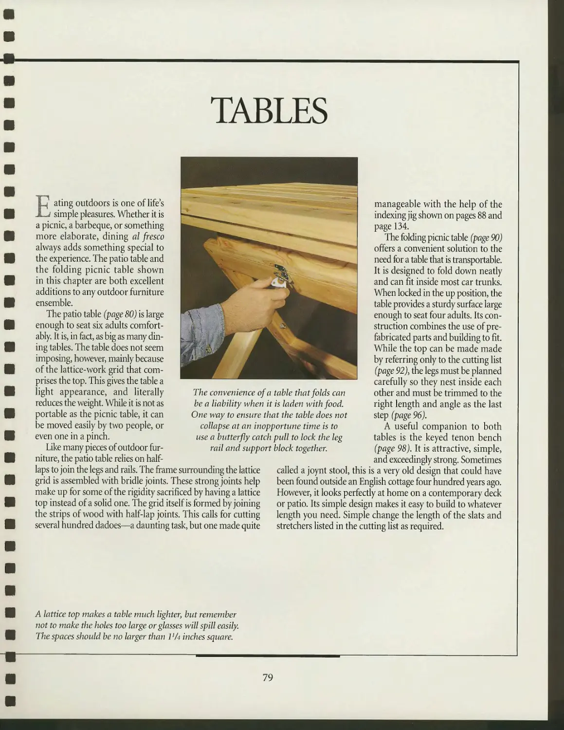
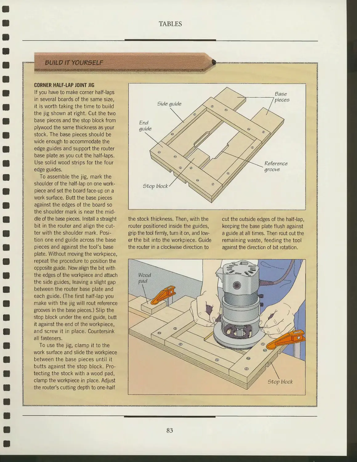
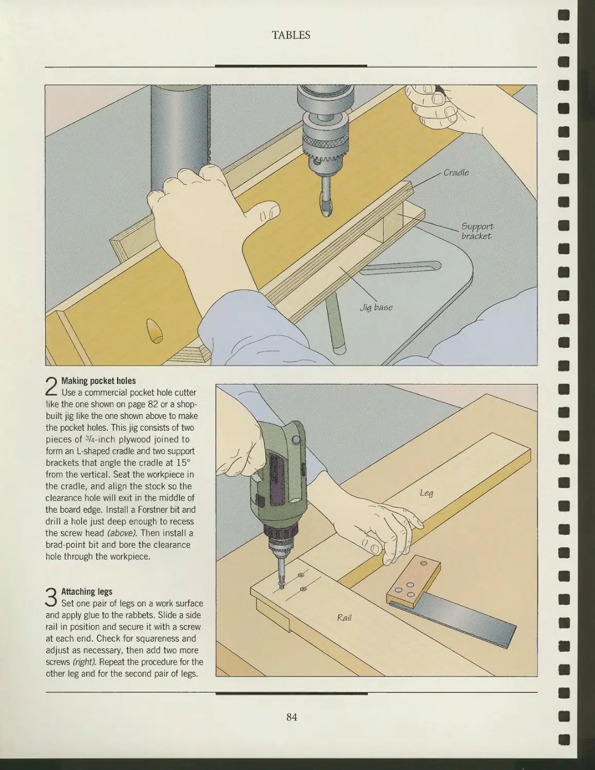
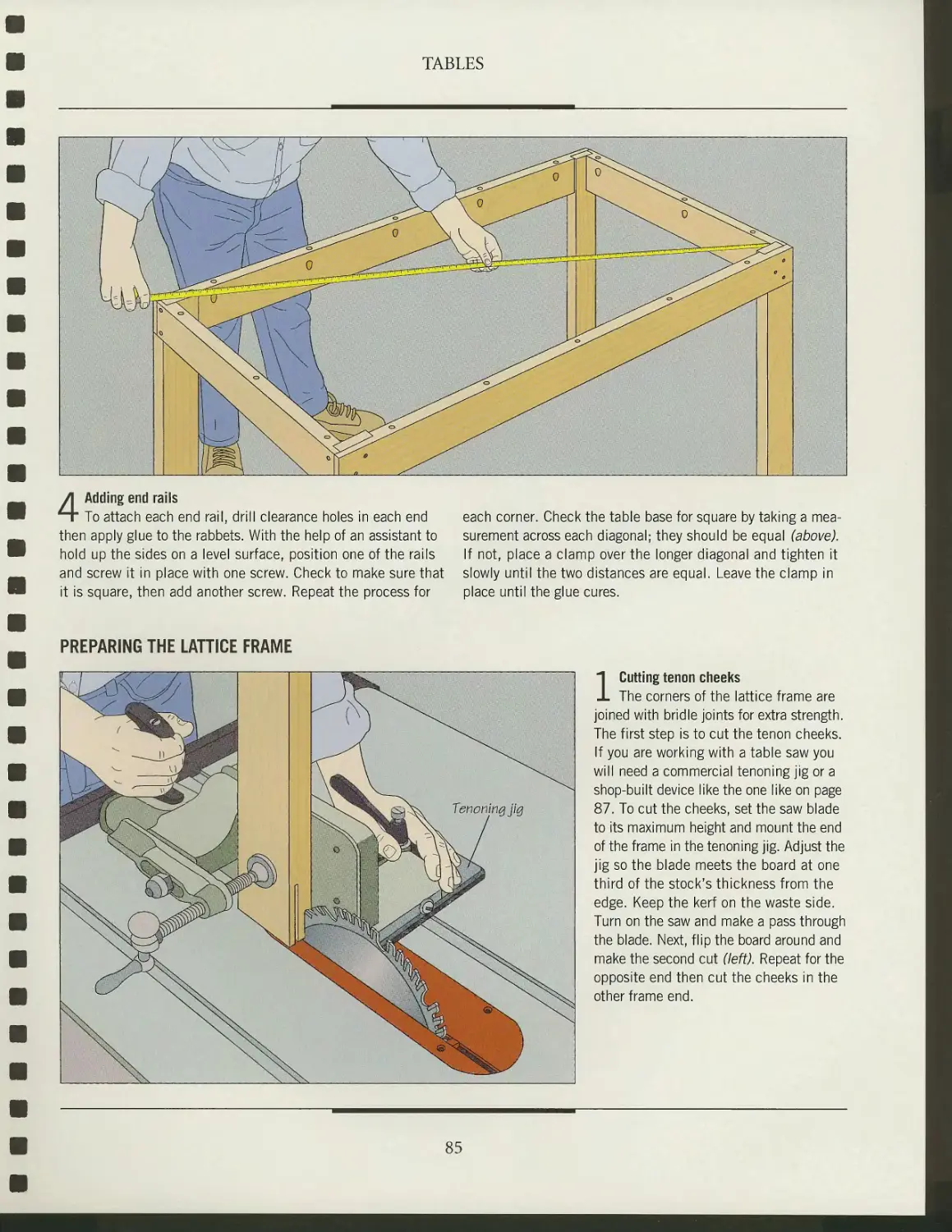
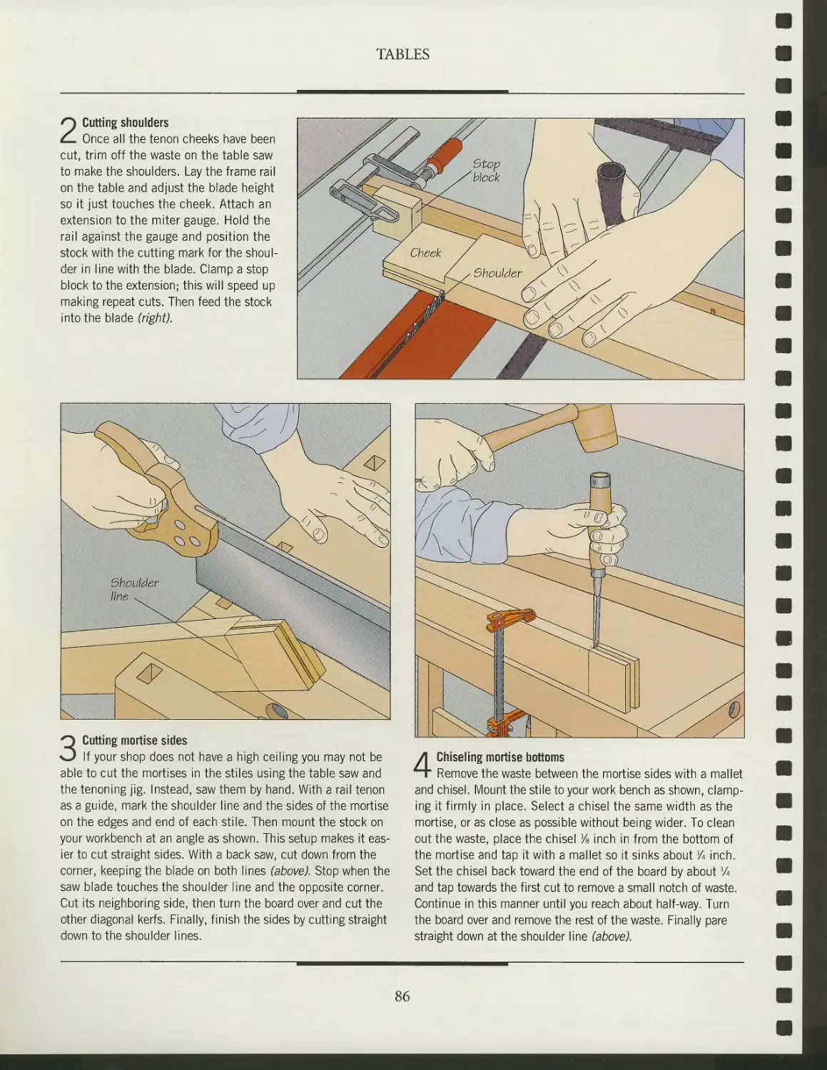
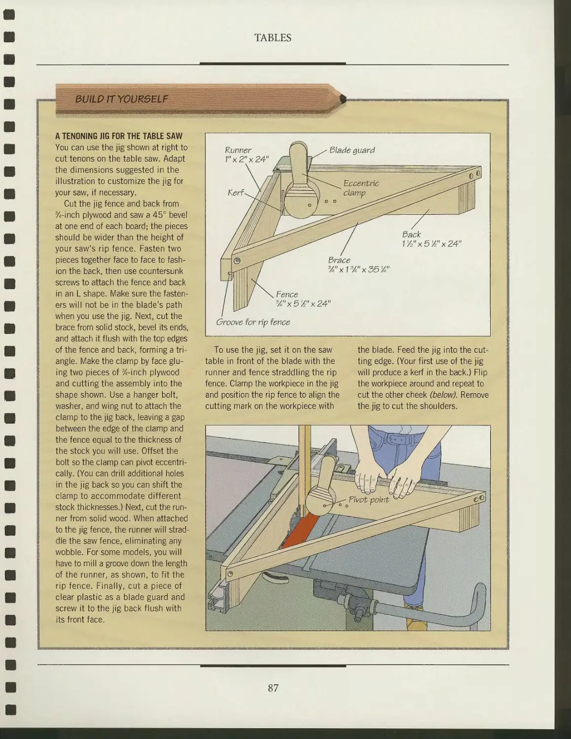
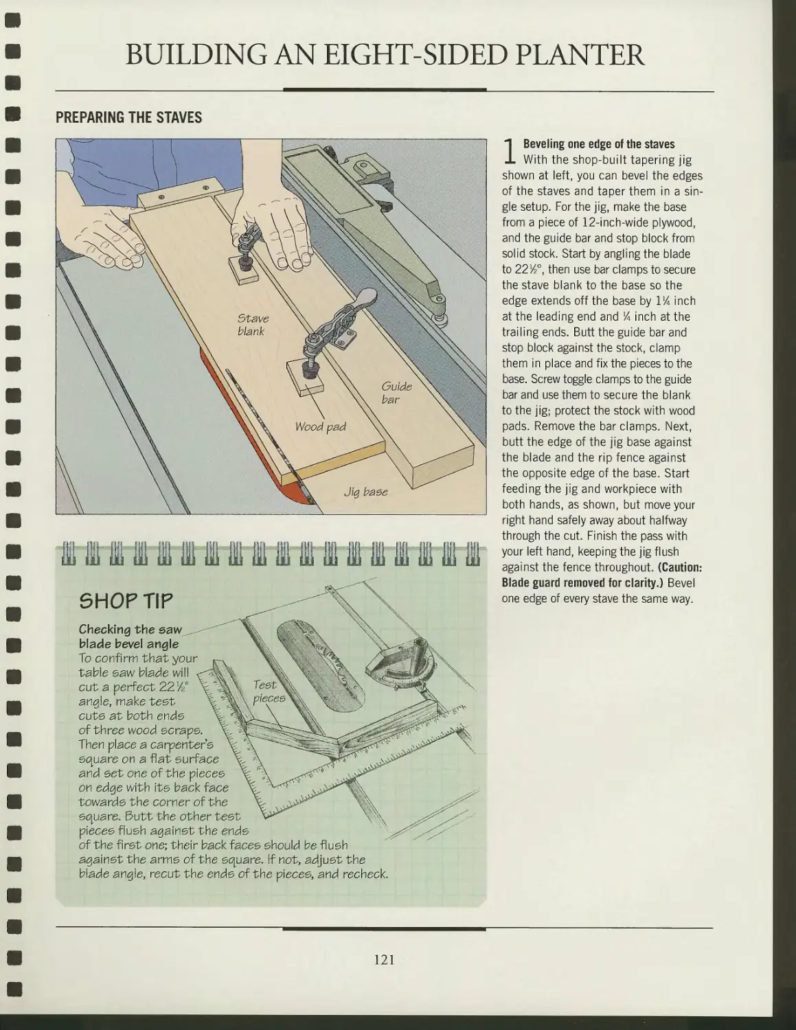
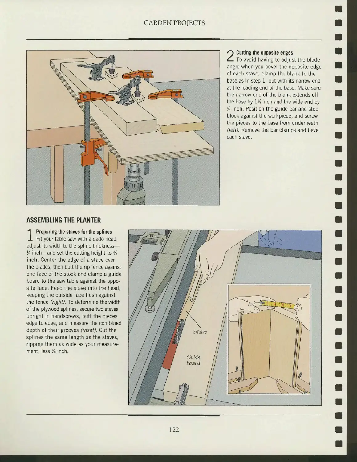
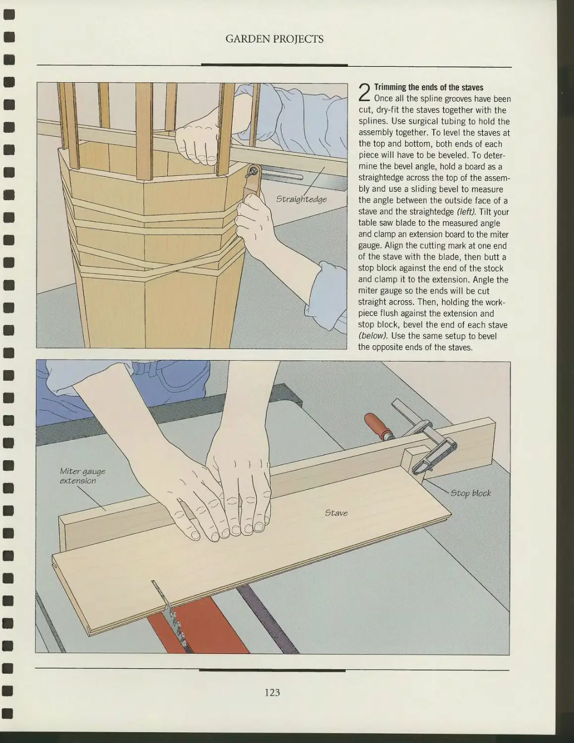
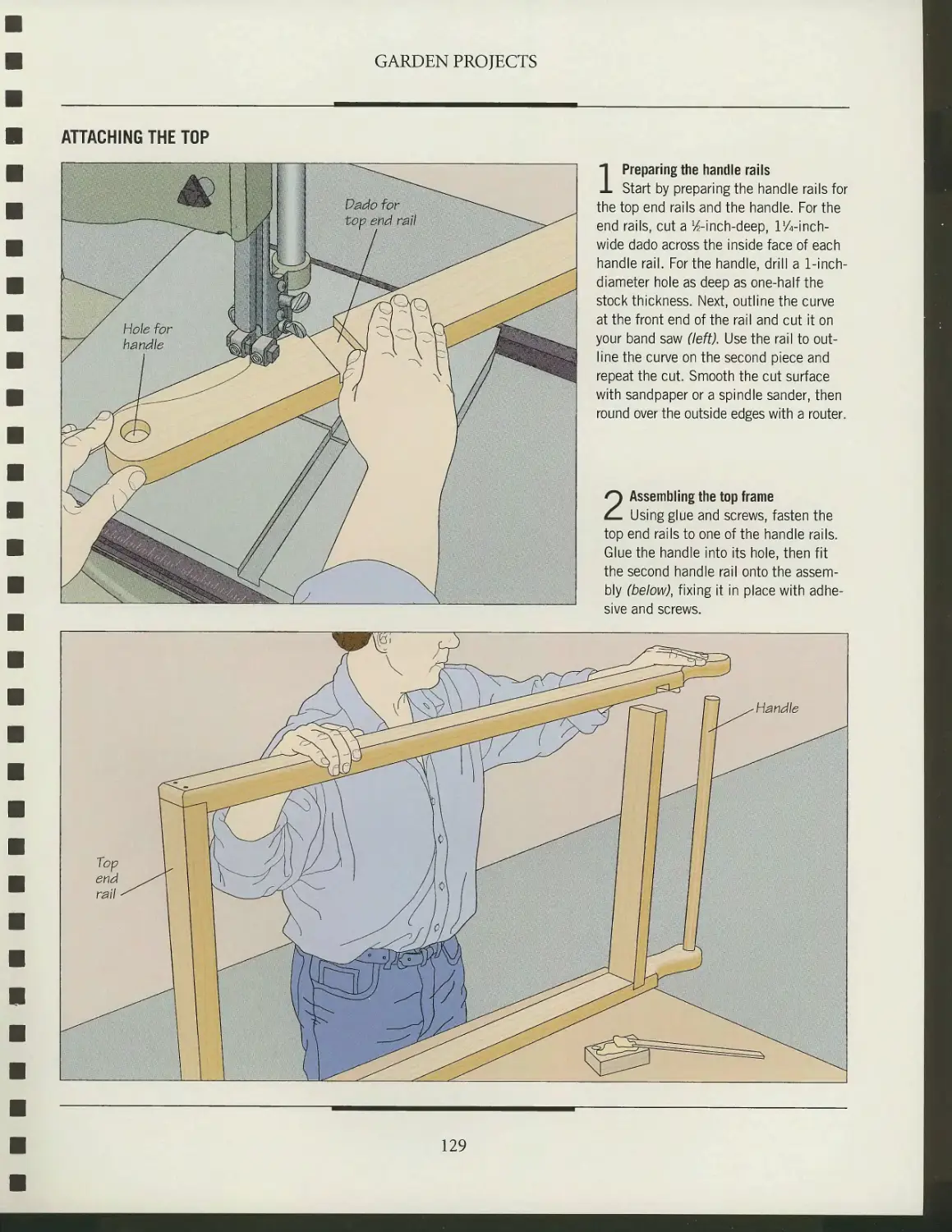
Text
TIME
BOOKS
THE ART OF WOODWORKING
TDOOR
1TURE
3l
/999-2004
A Tuckerdude Scan 2005
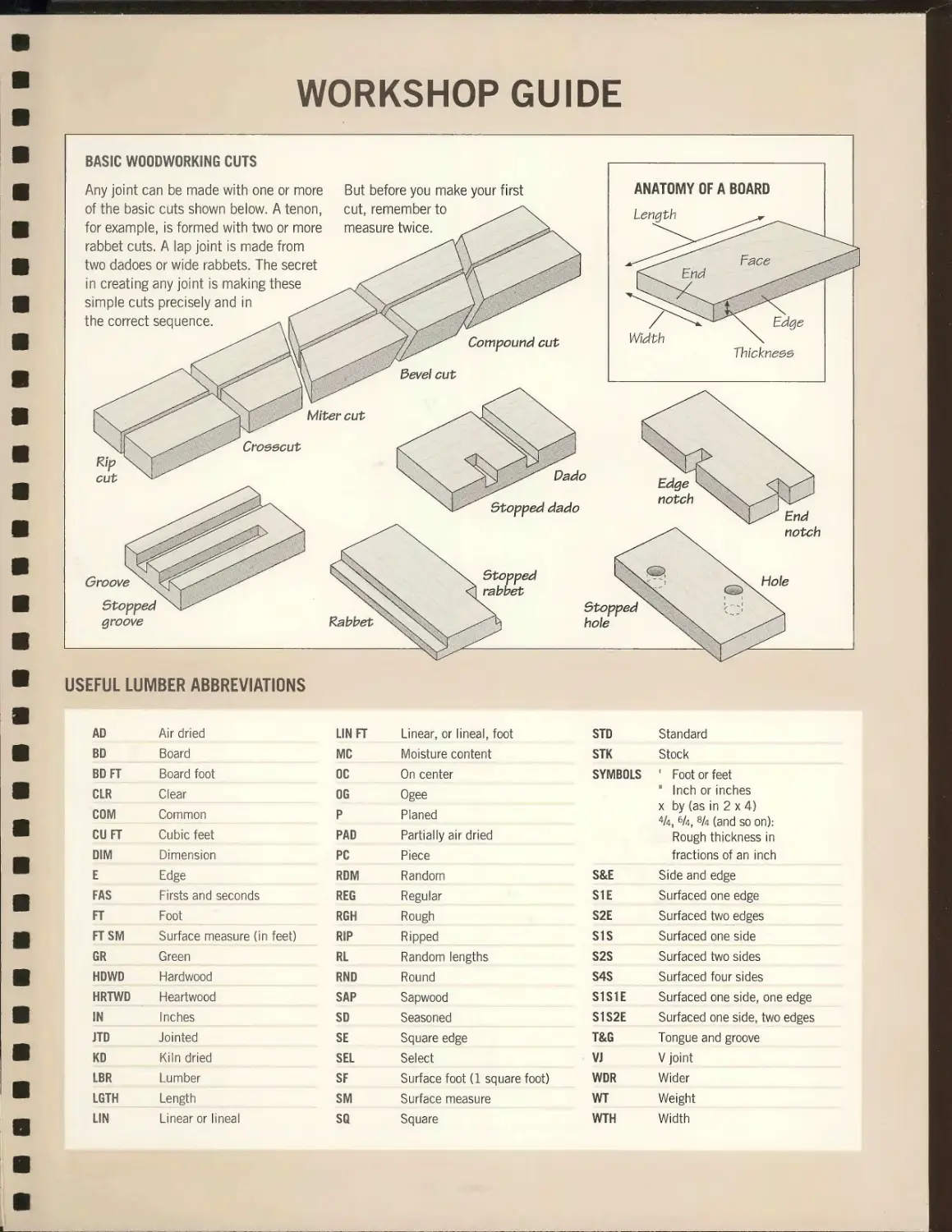
WORKSHOP GUIDE
• Use a safety guard whenever possible.
Before making a bevel cut, confirm that
the guard will be clear of the blade.
• Do not leave the saw running when it is
unattended.
• If you are interrupted, complete the
operation under way before turning off
the saw and looking up.
• Follow the manufacturer's instructions
to change accessories; unplug the saw
first. Make sure that saw blades and
cutters are sharp, clean and undamaged.
• Before cutting a workpiece, remove
any loose knots from it using a hammer.
Inspect salvaged wood for nails and
screws before cutting.
TABLE SAW SAFETY TIPS
• Do not start a cut until the blade is
running at full speed.
• Before using the saw each time, inspect
its safety features. Make sure there is no
binding or misalignment of moving parts.
Do not use the saw until such problems
are corrected.
• Always feed wood into the saw blade
against the direction of blade rotation.
• Make sure the rip fence is locked
in position before ripping.
• Do not use the miter gauge in
combination with the rip fence to make a cut—
except when the blade does not cut
completely through the workpiece, such
as for a dado or a groove.
• Use the rip fence or the miter gauge for
all cutting operations; never attempt to
cut freehand.
• Before ripping a board, ensure that the
edge in contact with the rip fence is smooth
and completely straight and that the
surface against the table is flat.
• Stand to one side of any workpiece
during any cutting operation so you will not
be injured in case of kickback.
• If you have to reach past the blade,
make sure to keep your hands at least
3 inches away from it.
• Use a wooden stick, rather than your
fingers, to clear wood scraps from the
saw table.
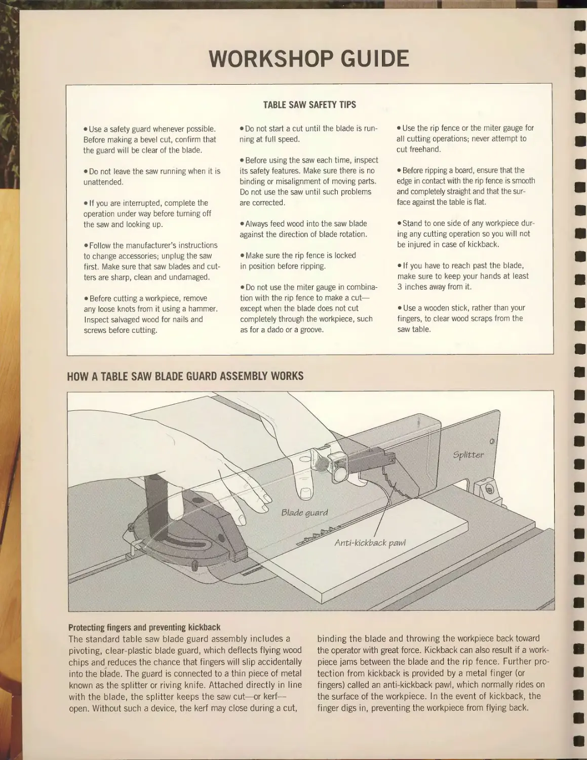
HOW A TABLE SAW BLADE GUARD ASSEMBLY WORKS
Protecting fingers and preventing kickback
The standard table saw blade guard assembly includes a
pivoting, clear-plastic blade guard, which deflects flying wood
chips and reduces the chance that fingers will slip accidentally
into the blade. The guard is connected to a thin piece of metal
known as the splitter or riving knife. Attached directly in line
with the blade, the splitter keeps the saw cut—or kerf—
open. Without such a device, the kerf may close during a cut,
binding the blade and throwing the workpiece back toward
the operator with great force. Kickback can also result if a work-
piece jams between the blade and the rip fence. Further
protection from kickback is provided by a metal finger (or
fingers) called an anti-kickback pawl, which normally rides on
the surface of the workpiece. In the event of kickback, the
finger digs in, preventing the workpiece from flying back.
THE ART OF WOODWORKING
OUTDOOR
FURNITURE
THE ART OF WOODWORKING
OUTDOOR
FURNITURE
TIME-LIFE BOOKS
ALEXANDRIA, VIRGINIA
ST. REMY PRESS
MONTREAL
THE ART OF WOODWORKING was produced by
ST. REMY PRESS
PUBLISHER
PRESIDENT
Series Editor
Series Art Director
Senior Editor
Editor
Art Directors
Designers
Picture Editor
Writers
Contributing Illustrators
Administrator
Production Manager
Coordinator
System Coordinator
Photographer
Indexer
Kenneth Winchester
Pierre Leveille
Pierre Home-Douglas
Francine Lemieux
Marc Cassini
Andrew Jones
Jean-Pierre Bourgeois, Solange Laberge
Helene Dion, Jean-Guy Doiron,
Francois Daxhelet
Christopher Jackson
John Dowling, Adam Van Sertima
Gilles Beauchemin, Michel Blais,
Ronald Durepos, Michael Stockdale,
James Therien
Natalie Watanabe
Michelle Turbide
Dominique Gagne
Eric Beaulieu
Robert Chartier
Christine M. Jacobs
Time-Life Books is a division of Time Life Inc.
TIME LIFE INC.
President and CEO George Artandi
TIME-LIFE BOOKS
Publisher/Managing Editor Neil Kagan
Director of Marketing
Consulting Editor
Director of Editorial Administration
Directors of Book Production
Production Manager
Quality Assurance Manager
Wells P. Spence
John R. Sullivan
Barbara Levitt
Marjann Caldwell, Patricia Pascale
Ken Sabol
James King
THE CONSULTANTS
Craig Gilborn is the former director of the Adirondack
Museum in Blue Mountain Lake, New York. He is also a builder
of outdoor furniture and author of Adirondack And Rustic
Furniture, published by Abrams.
Giles Miller-Mead taught advanced cabinetmaldng at Montreal
technical schools for more than ten years. A native of New
Zealand, he has worked as a restorer of antique furniture.
The Art of woodworking. Outdoor furniture,
p. cm. —
Includes index.
ISBN 0-8094-9543-0
1. Outdoor furniture. 2. Furniture making.
3. Garden ornaments and furniture. I. Time-Life
Books. II. Series: Art of Woodworking.
TT197.5.09A78 1995
684.1'8—dc20 95-35782
CIP
For information about any Time-Life book,
please call 1-800-621-7026, or write:
Reader Information
Time-Life Customer Service
P.O. Box C-32068
Richmond, Virginia
23261-2068
© 1996 Time-Life Books Inc.
All rights reserved.
No part of this book may be reproduced in any form or by
any electronic or mechanical means, including information
storage and retrieval devices or systems, without prior
written permission from the publisher, except that brief passages
may be quoted for reviews.
Second printing 1999. Printed in U.S.A.
Published simultaneously in Canada.
TIME-LIFE is a trademark of Time Warner Inc. U.S.A.
CONTENTS
6
12
14
16
18
20
22
24
26
34
36
44
46
54
56
58
64
70
72
78
80
90
92
98
INTRODUCTION
FACING THE ELEMENTS
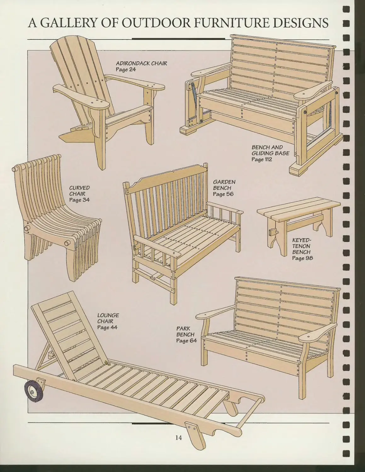
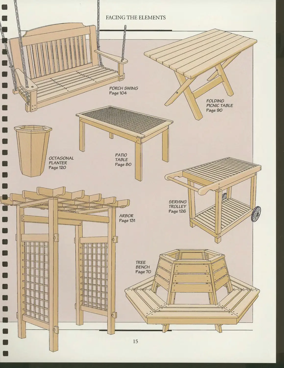
A gallery of outdoor
furniture designs
Selecting wood
Joinery and hardware
Finishing
CHAIRS
Anatomy of an Adirondack chair
Building an Adirondack chair
Anatomy of a curved chair
Fashioning a curved chair
Anatomy of a lounge chair
Making a lounge chair
BENCHES
Anatomy of a garden bench
Building a garden bench
Park bench
Anatomy of a tree bench
Building a tree bench
TABLES
Patio table
Folding picnic table and bench
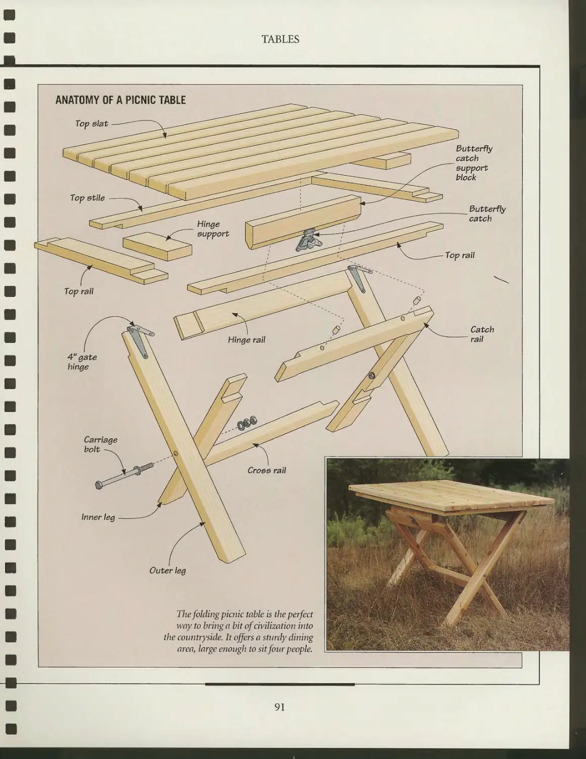
Making a folding picnic table
Keyed tenon bench
102
104
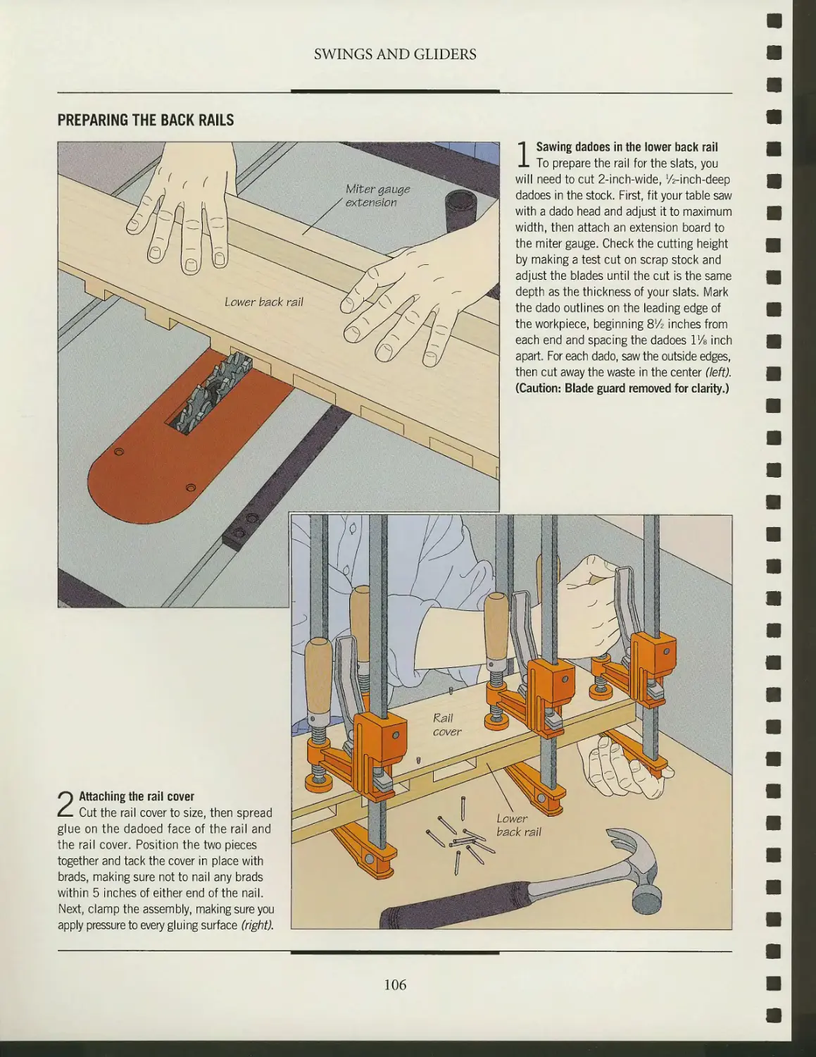
106
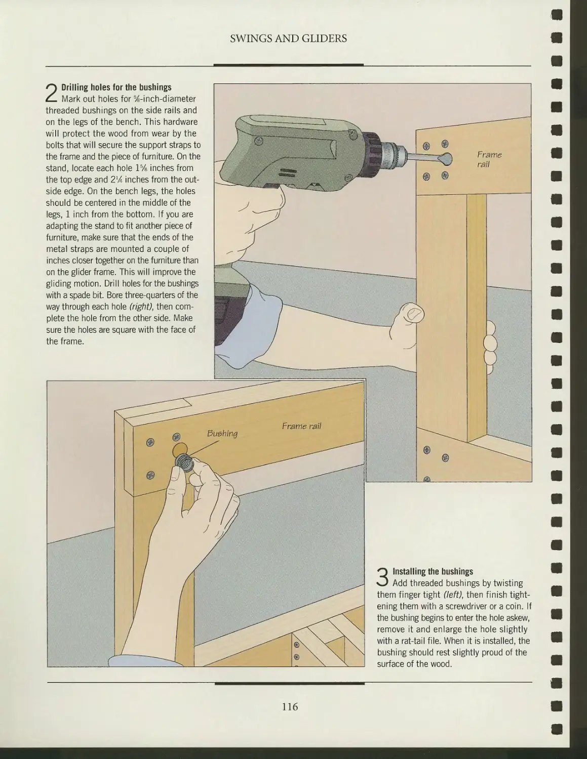
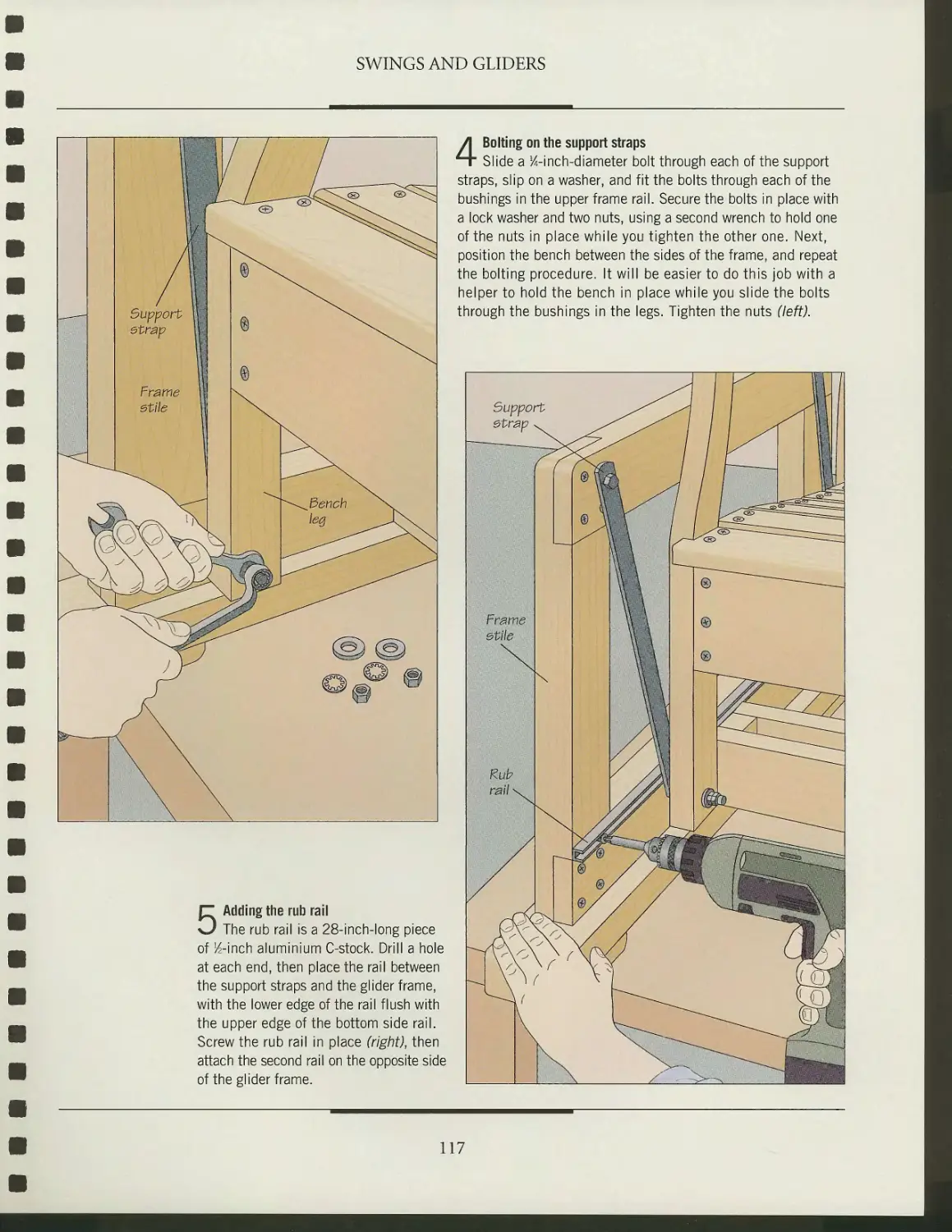
112
114
118
120
121
126
127
131
132
140
142
144
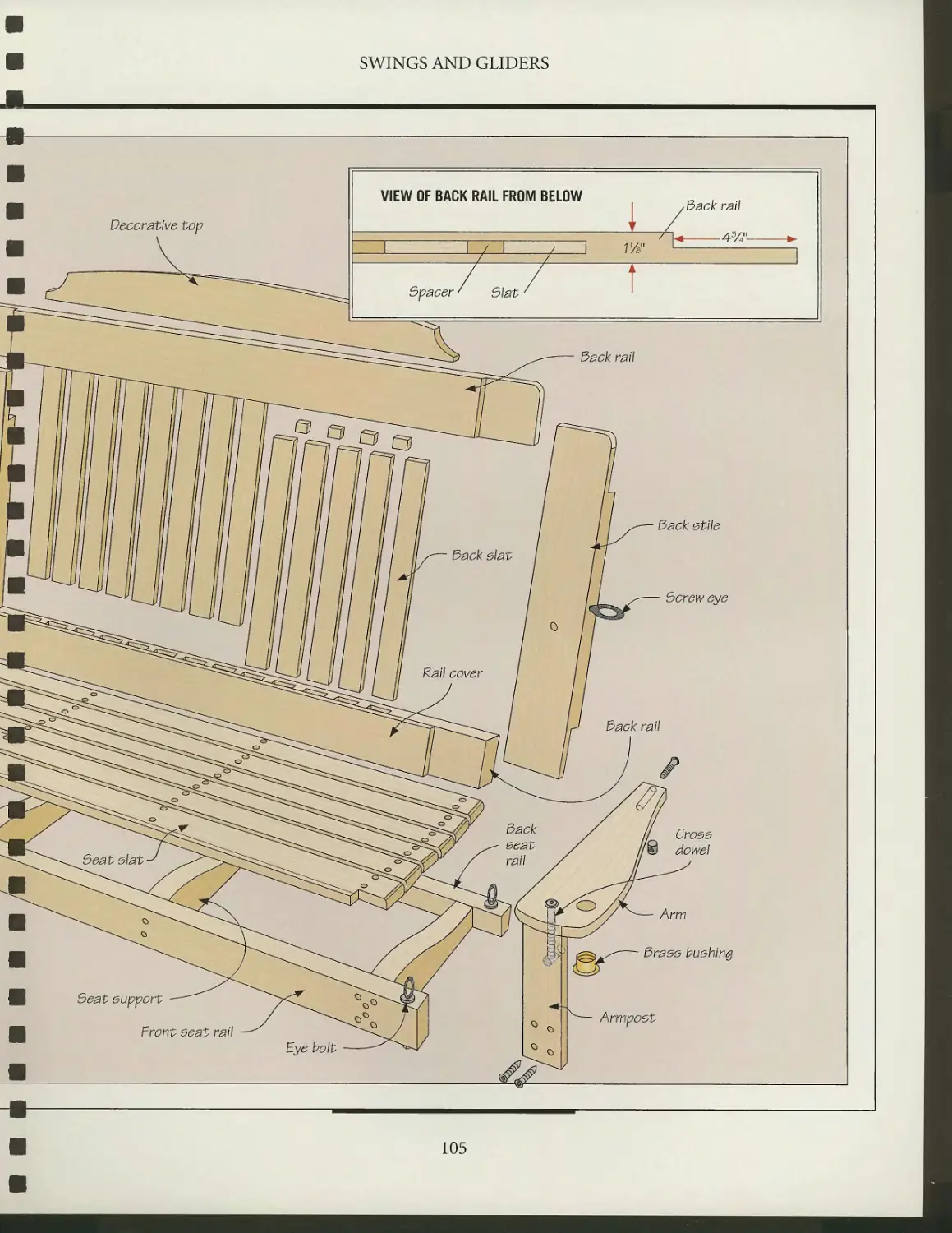
SWINGS AND GLIDERS
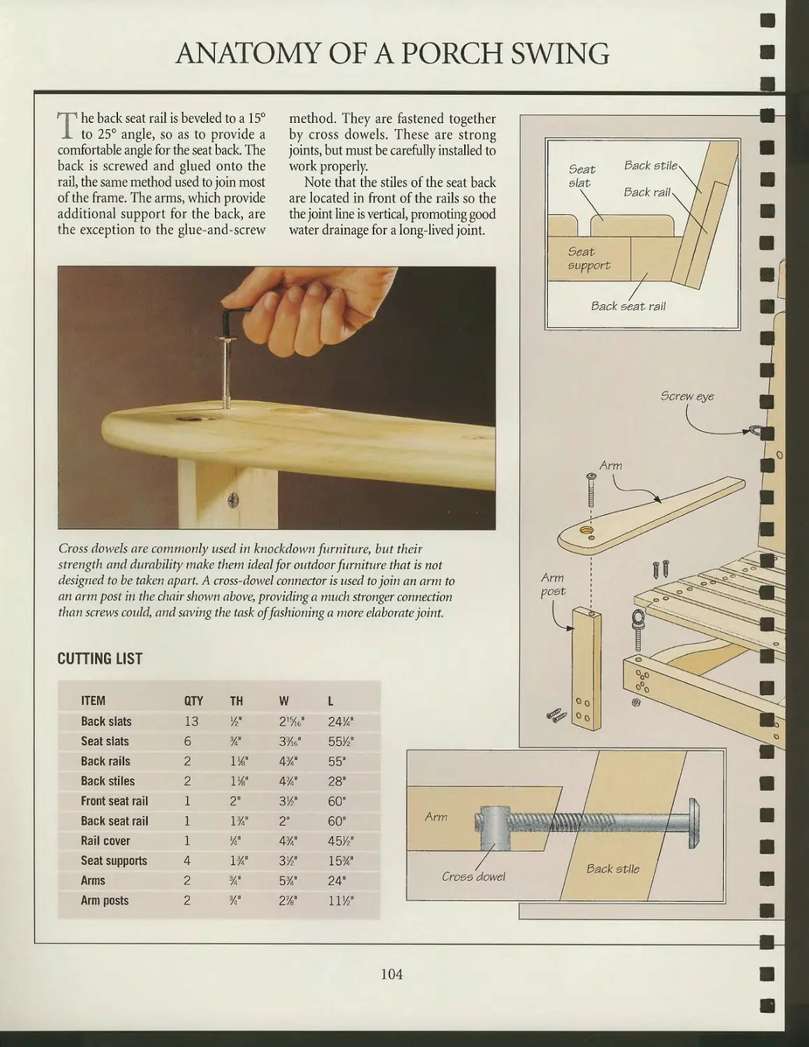
Anatomy of a porch swing
Building a porch swing
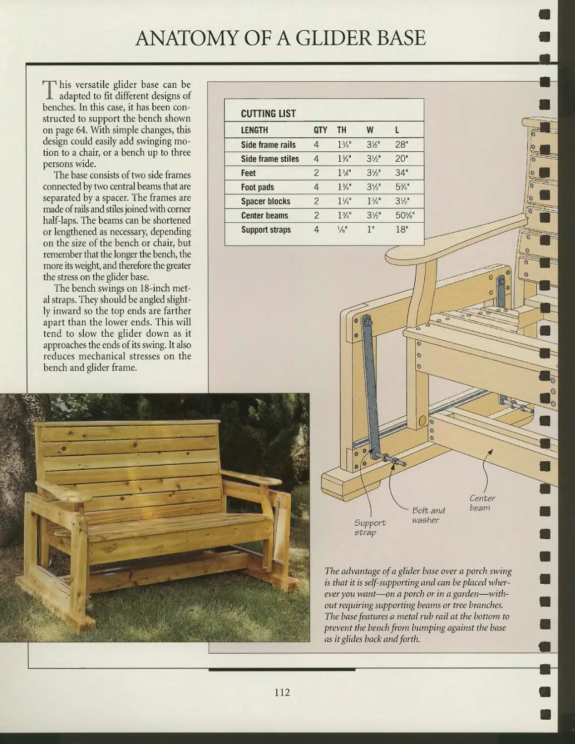
Anatomy of a glider base
Building a glider base
GARDEN PROJECTS
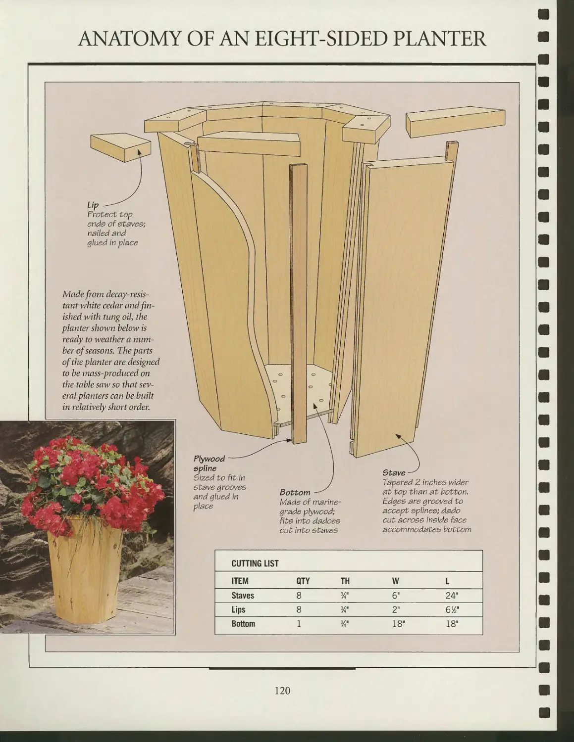
Anatomy of an eight-sided
planter
Building an eight-sided planter
Anatomy of a serving trolley
Fashioning a serving trolley
Anatomy of a garden arbor
Building a garden arbor
GLOSSARY
INDEX
ACKNOWLEDGMENTS
m?-
m^^.-^^^^^^B
f*&ij»*~
1 •'r ;, -i
'"'fc *
;%•=
^
i'i^^l
.J^tl
■*3*fc#fefc<rfc;
A&&&
*^^££.i
l»-.r- ->
■■-**?*;
**;
INTRODUCTION
Jim Tolpin on
LONG-LASTING
FURNITURE
'm going to do what to that lovely chair and table set? Well, I intend to expose it
to the direct heat and ultraviolet rays of the sun. Then I'll let it get soaking wet,
freeze, and then thaw out with blasts of warm, dry air. And f m going to allow this to
happen not just once, but over and over again for the next two to three decades.
Well, of course I am: I'm building a piece of outdoor furniture.
The question is, how can I possibly build wood furniture to endure such
horrific abuse? To find some answers, I looked back to the principles and practices of the
carriage and boat builders of the last century. It was, after all, these tradesmen who
produced some of the most highly stressed and severely exposed—not to mention
beautiful—structures known to man. If these trades could do that, I was betting they
could build one heck of a lawn chair.
What I learned boiled down to this: These craftsmen asked much of every piece
of wood that went into a ship or carriage, but they never asked more that it could
give—and they did all they could to preserve its integrity. They chose woods that
were inherently rot-resistant, being careful not to include sapwood, splits, pitch
pockets, cross-grain, or other defects that might diminish its strength or longevity.
They cut the exposed shoulders of joints at water-shedding angles and applied
bedding compounds like pine tar and Irish felt to the mating surfaces—strategies
that helped prevent moisture from intruding, lingering, and nourishing
wood-eating parasites. They designed channels, drain holes, and dams throughout the
structure to encourage water to flow away from the wood. They avoided flat surfaces,
bowing the tops of horizontal areas like rails and box lids to discourage puddling. And
where fasteners were needed (though they minimized their use as much as possible
by using wood wedges and pins), they chose metals that resisted rust and were not
corrosive to the wood.
While I don't intend to build America while sitting in my lawn furniture (I don't
even intend to be awake), I do want the fruits of my labors to serve my family for many
years. To that end I employ much of what I have learned from these long-gone
tradesmen. And, so far, that chair and table have remained lovely, continuing to do the job
for which they were intended—while living happily outdoors.
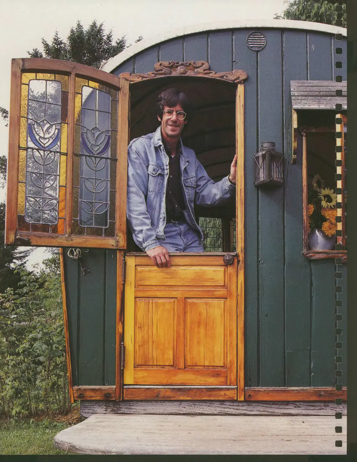
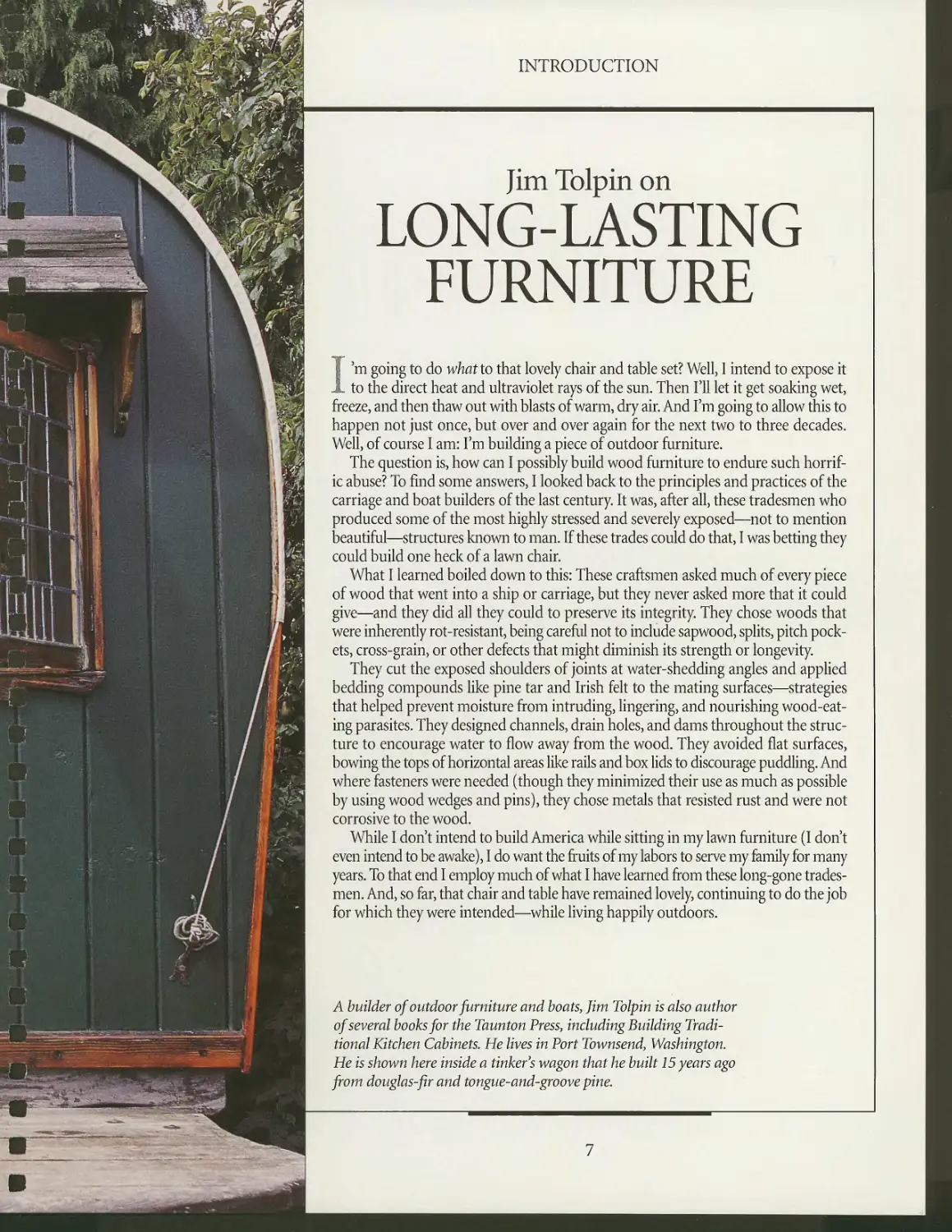
A builder of outdoor furniture and boats, Jim Tolpin is also author
of several books for the Taunton Press, including Building
Traditional Kitchen Cabinets. He lives in Port Townsend, Washington.
He is shown here inside a tinker's wagon that he built 15 years ago
from douglas-fir and tongue-and-groove pine.
I
7
INTRODUCTION
Thomas Phillips describes the
NATURAL
BEAUTY OF WOOD
I was actively involved with repairing all manner of camp furnishings when an
antique dealer friend convinced me to make my first chair. After taking the plunge,
I spent three years researching before I attempted my first piece. That was 11 years
ago, and I still have it: a split post-and-rung model.
Now I build mostly "twig" furniture, the kind with the bark still on. The various
indigenous woods I work with provide me with color, form, and texture, allowing an
artistic freedom of expression virtually unlimited by straight lines. Originally this
work evolved to complement my lifestyle, and it has since become a very rewarding
sideline, providing a business and personal recognition far beyond anything I ever
dreamed of.
Working with wood in its natural state is particularly challenging. Much
preparation and thought goes into every piece I build. A thorough knowledge of the wood
I intend to work with is a must. As an example, if I want to have natural bark on a
project, then I am restricted to harvesting my materials during a few months in the
cold season. Also, tools to work wood in its natural state are not readily available.
More often than not, figuring out how to do something takes longer than actually
doing it. One of my biggest problems is storage: A stash of natural stock for chairs takes
up far more space than milled limber.
There is always some detail that challenges my abilities and ingenuity to execute
it, whether I am working with one of my own designs or something IVe received
from some architectural firm. Often when I am in the forest during my daily
activities I find my eye captured by a special curve some sapling has grown into and a
piece of furniture will take form, piece by piece, in my mind. I can often see the
finished product before I even harvest the unique form that caught my eye. Then, it
may be three weeks, sometimes as much as five years, before the materials are dry
enough to work with. I may consider subsequent designs, but I often go back to the
original one I saw. The actual hands-on work required to make the piece may take
a few hours or weeks, but when it's finished, it always leaves me with a sense of
fulfillment and accomplishment, temporarily drained of the artist's creative spark and
overwhelmed by the natural beauty of wood itself and the warmth it provides.
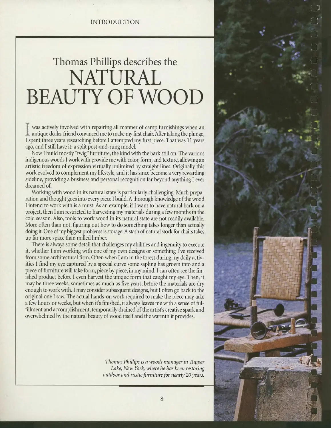
Thomas Phillips is a woods manager in Tapper
Lake, New York, where he has been restoring
outdoor and rustic furniture for nearly 20 years.
1S113I
%^^^-«*
«ii&»^
^t-^*^#«*»*¥'
&****m*mmm
^l^^^f^k^^
-^VWr>*^^m<w*m*
Lz~~" T iT-:'i-.^-"^ »^-^r^ - '-i-, ■-
t*"*- ^r^°=?*^^C^<
INTRODUCTION
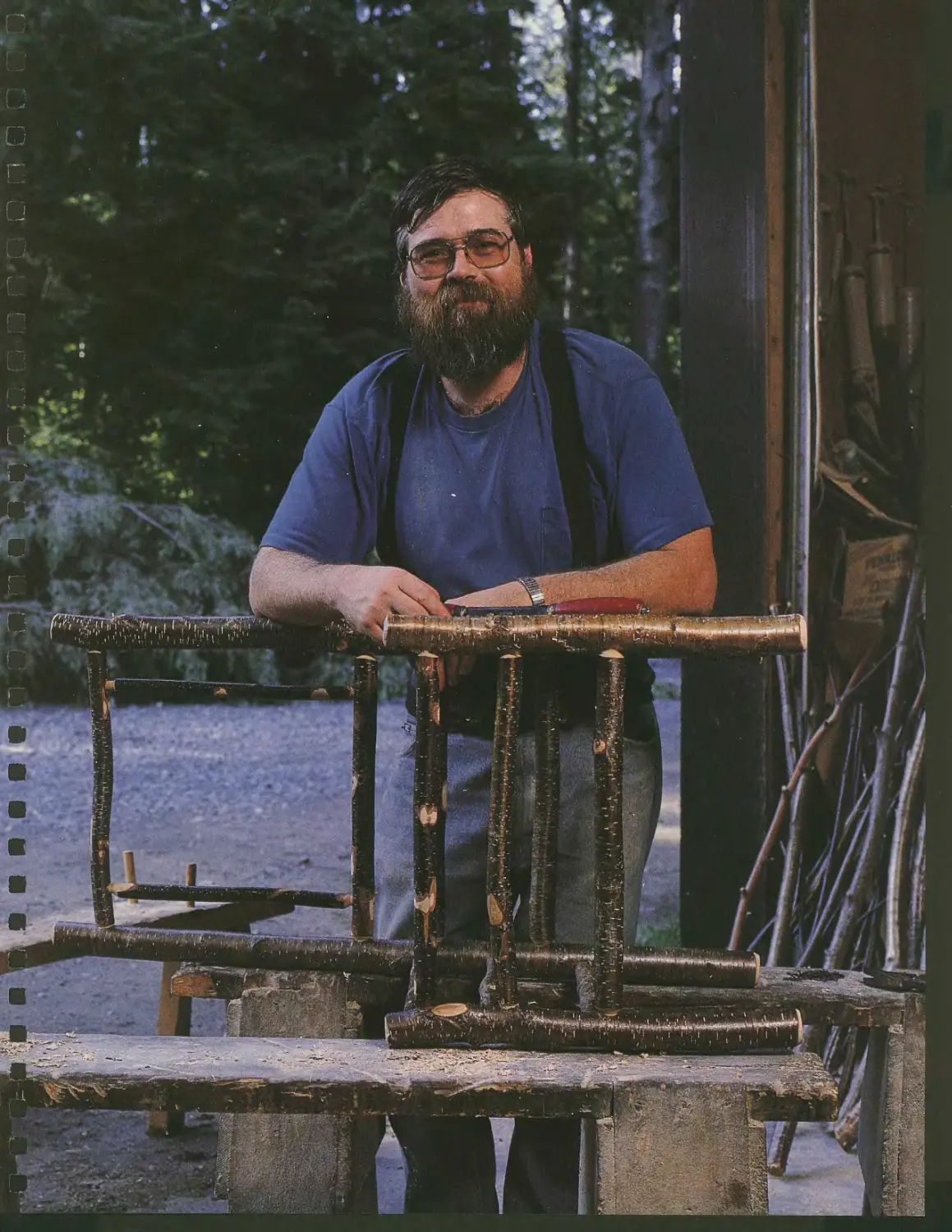
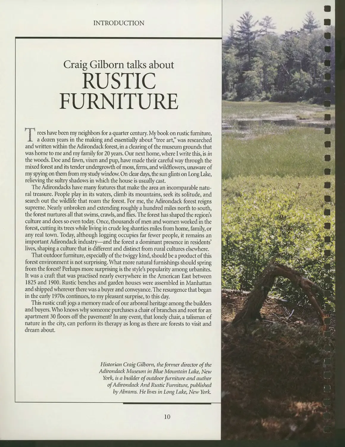
Craig Gilborn talks about
RUSTIC
FURNITURE
Trees have been my neighbors for a quarter century. My book on rustic furniture,
a dozen years in the making and essentially about "tree art," was researched
and written within the Adirondack forest, in a clearing of the museum grounds that
was home to me and my family for 20 years. Our next home, where I write this, is in
the woods. Doe and fawn, vixen and pup, have made their careful way through the
mixed forest and its tender undergrowth of moss, ferns, and wildflowers, unaware of
my spying on them from my study window On clear days, the sun glints on Long Lake,
relieving the sultry shadows in which the house is usually cast.
The Adirondacks have many features that make the area an incomparable
natural treasure. People play in its waters, climb its mountains, seek its solitude, and
search out the wildlife that roam the forest. For me, the Adirondack forest reigns
supreme. Nearly unbroken and extending roughly a hundred miles north to south,
the forest nurtures all that swims, crawls, and flies. The forest has shaped the region s
culture and does so even today. Once, thousands of men and women worked in the
forest, cutting its trees while living in crude log shanties miles from home, family, or
any real town. Today, although logging occupies far fewer people, it remains an
important Adirondack industry—and the forest a dominant presence in residents'
lives, shaping a culture that is different and distinct from rural cultures elsewhere.
That outdoor furniture, especially of the twiggy kind, should be a product of this
forest environment is not surprising. What more natural furnishings should spring
from the forest? Perhaps more surprising is the style's popularity among urbanites.
It was a craft that was practised nearly everywhere in the American East between
1825 and 1900. Rustic benches and garden houses were assembled in Manhattan
and shipped wherever there was a buyer and conveyance. The resurgence that began
in the early 1970s continues, to my pleasant surprise, to this day.
This rustic craft jogs a memory made of our arboreal heritage among the builders
and buyers. Who knows why someone purchases a chair of branches and root for an
apartment 30 floors off the pavement? In any event, that lonely chair, a talisman of
nature in the city, can perform its therapy as long as there are forests to visit and
dream about.
ft* «5*
4&H;>' *' ^"-^
Historian Craig Gilborn, the former director of the
Adirondack Museum in Blue Mountain Lake, New
York, is a builder of outdoor furniture and author
of Adirondack And Rustic Furniture, published
byAbrams. He lives in Long Lake, New York.
10
l-f..'*.^^;^.
*>*»'&
ift&
fc^^£'£ fc,
Alll
<C
, i^tl
v4L .■>
'^1
L*r S'-
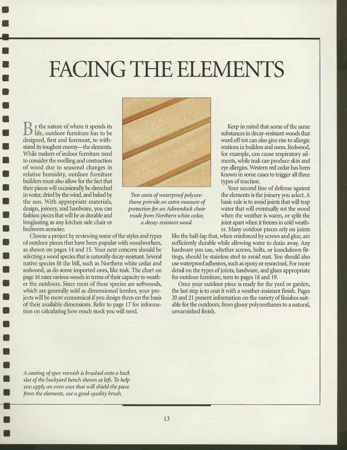
FACING THE ELEMENTS
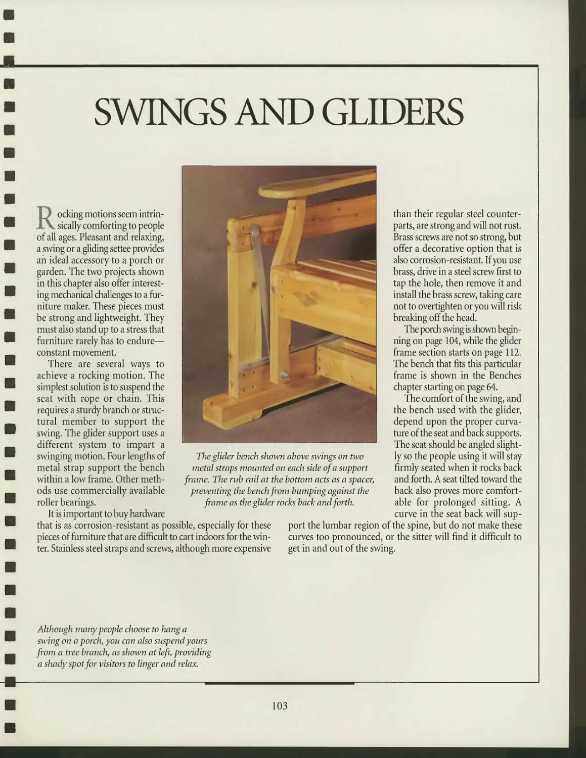
By the nature of where it spends its
life, outdoor furniture has to be
designed, first and foremost, to
withstand its toughest enemy—the elements.
While makers of indoor furniture need
to consider the swelling and contraction
of wood due to seasonal changes in
relative humidity, outdoor furniture
builders must also allow for the fact that
their pieces will occasionally be drenched
in water, dried by the wind, and baked by
the sun. With appropriate materials,
design, joinery, and hardware, you can
fashion pieces that will be as durable and
longlasting as any kitchen side chair or
bedroom armoire.
Choose a project by reviewing some of the styles and types
of outdoor pieces that have been popular with woodworkers,
as shown on pages 14 and 15. Your next concern should be
selecting a wood species that is naturally decay-resistant. Several
native species fit the bill, such as Northern white cedar and
redwood, as do some imported ones, like teak. The chart on
page 16 rates various woods in terms of their capacity to
weather the outdoors. Since most of these species are softwoods,
which are generally sold as dimensioned lumber, your
projects will be more economical if you design them on the basis
of their available dimensions. Refer to page 17 for
information on calculating how much stock you will need.
Two coats of waterproofpolyure-
thane provide an extra measure of
protection for an Adirondack chair
made from Northern white cedar,
a decay-resistant wood.
Keep in mind that some of the same
substances in decay-resistant woods that
ward off rot can also give rise to allergic
reations in builders and users. Redwood,
for example, can cause respiratory
ailments, while teak can produce skin and
eye allergies. Western red cedar has been
known in some cases to trigger all three
types of reaction.
Your second line of defense against
the elements is the joinery you select. A
basic rule is to avoid joints that will trap
water that will eventually rot the wood
when the weather is warm, or split the
joint apart when it freezes in cold
weather. Many outdoor pieces rely on joints
like the half-lap that, when reinforced by screws and glue, are
sufficiently durable while allowing water to drain away. Any
hardware you use, whether screws, bolts, or knockdown
fittings, should be stainless steel to avoid rust. You should also
use waterproof adhesives, such as epoxy or resorcinol. For more
detail on the types of joints, hardware, and glues appropriate
for outdoor furniture, turn to pages 18 and 19.
Once your outdoor piece is ready for the yard or garden,
the last step is to coat it with a weather-resistant finish. Pages
20 and 21 present information on the variety of finishes
suitable for the outdoors, from glossy polyurethanes to a natural,
unvarnished finish.
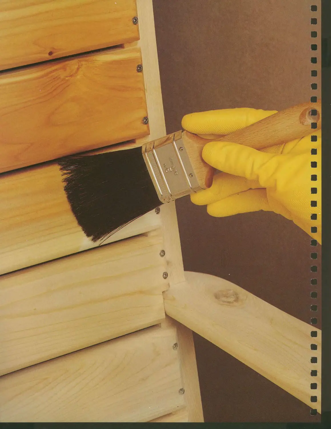
A coating of spar varnish is brushed onto a back
slat of the backyard bench shown at left. To help
you apply an even coat that will shield the piece
from the elements, use a good-quality brush.
13
A GALLERY OF OUTDOOR FURNITURE DESIGNS
SELECTING WOOD
}"] ew decisions are as important to
, building outdoor furniture as the
choice of wood. The chart below rates
several species in terms of resistance to
decay, strength, capacity to withstand
shock, worldng properties (like planing
and sanding or drilling, gluing, and
fastening), and relative cost. There is
probably no one ideal choice. Although a
wood like teak combines strength with
excellent decay resistance, it is very
expensive, and difficult to find and work.
Pine, on the other hand, is readily
available and economical, and is easy to work,
but most species are highly susceptible to
decay and relatively weak. Many
woodworkers consider native species with
superior strength and decay resistance,
such as cedar and white oak, to be an
acceptable compromise.
Keep in mind that the same qualities
that make a wood like teak tough on
blades and cutters will yield sturdy
furniture. Cedar, although it is more
forgiving to blades and tools, has a tendency
to contain a considerable number of
knots, which increase waste and as well
as the risk that the strength of the
furniture will be compromised by a dead
knot that was not cut out. Knots are also
more susceptible to rot.
Whichever species you select, take the
time to choose your boards carefully.
Avoid lumber that is cupped, bowed, or
warped in any way. For maximum
stability, choose air-dried lumber with a
maximum of 20 percent moisture
content. The wood should contain as little
sapwood as possible since the sap will
attract wood-eating bugs.
NOMINAL AND ACTUAL
SOFTWOOD LUMBER SIZES
NOMINAL (inches)
l-by-2
l-by-3
l-by-4
l-by-6
l-by-8
l-by-10
2-by-2
2-by-4
2-by-6
2-by-8
2-by-10
3-by-4
4-by-4
ACTUAL (inches)
Surfaced dry
3/4-by-lV2
3/4-by-2V2
3/4-by-3V2
3/4-by-5V2
3/4-by-7V4
3/4-by-9V4
lV2-by-lV2
lV2-by-3V2
lV2-by-5V2
lV2-by-7V4
lV2-by-9V4
2V2-by-3V2
Ste-by-^
WOOD FOR OUTDOORS
WOOD SPECIES
Ash, white
Beech, American
Birch, yellow
Butternut
Cedar, aromatic
Cedar, Northern white
Cedar, Western red
Cherry, American
Elm, American
Douglas-fir
Maple, hard
Oak, red
Oak, white
Pine, Eastern white
Pine, Southern yellow
Poplar, yellow
Redwood
Spruce, sitka
Teak
Walnut, black
DECAY RESISTANCE
Poor
Fair
Fair
Poor
Excellent
Good
Excellent
Good
Good
Fair
Poor
Fair
Excellent
Fair
Fair
Fair
Excellent
Poor
Excellent
Good
STRENGTH
Fair
Fair
Good
Fair
Fair
Poor
Poor
Fair
Fair
Fair
Excellent
Good
Excellent
Fair
Fair
Fair
Poor
Fair
Excellent
Fair
SHOCK RESISTANCE
Excellent
Fair
Excellent
Fair
Fair
Poor
Poor
Fair
Fair
Fair
Excellent
Fair
Good
Fair
Good
Fair
Poor
Fair
Excellent
Excellent
WORKING PROPERTIES
Average
Good
Good
Good
Average
Fair
Good
Good
Fair
Average
Good
Average
Average
Good
Average
Good
Good
Average
Fair
Good
COST
Low
Low
Average
Average
Average
Average
Average
Average
Low
Low
Low
Average
Low
Low
Low
Low
Average
Average
High
High
16
FACING THE ELEMENTS
CALCULATING BOARD FEET
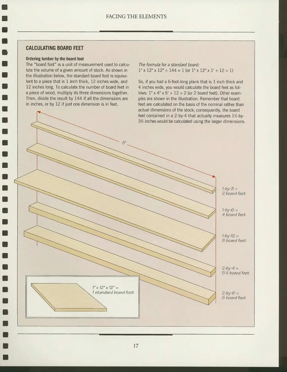
Ordering lumber by the board foot
The "board foot" is a unit of measurement used to
calculate the volume of a given amount of stock. As shown in
the illustration below, the standard board foot is
equivalent to a piece that is 1 inch thick, 12 inches wide, and
12 inches long. To calculate the number of board feet in
a piece of wood, multiply its three dimensions together.
Then, divide the result by 144 if all the dimensions are
in inches, or by 12 if just one dimension is in feet.
The formula for a standard board:
1" x 12" x 12" -r 144 = 1 (or 1" x 12" x 1' - 12 = 1)
So, if you had a 6-foot-long plank that is 1 inch thick and
4 inches wide, you would calculate the board feet as
follows: 1" x 4" x 61 -r 12 = 2 (or 2 board feet). Other
examples are shown in the illustration. Remember that board
feet are calculated on the basis of the nominal rather than
actual dimensions of the stock; consequently, the board
feet contained in a 2-by-4 that actually measures lV^-by-
3/2 inches would be calculated using the larger dimensions.
1"x12"x12" =
1 standard board foot
hby-3 =
2 board feet
1-by-6 =
4 board feet
1-by-12 =
3 board feet
2-by-4 =
5 % board feet
2-by-6 =
3 board feet
17
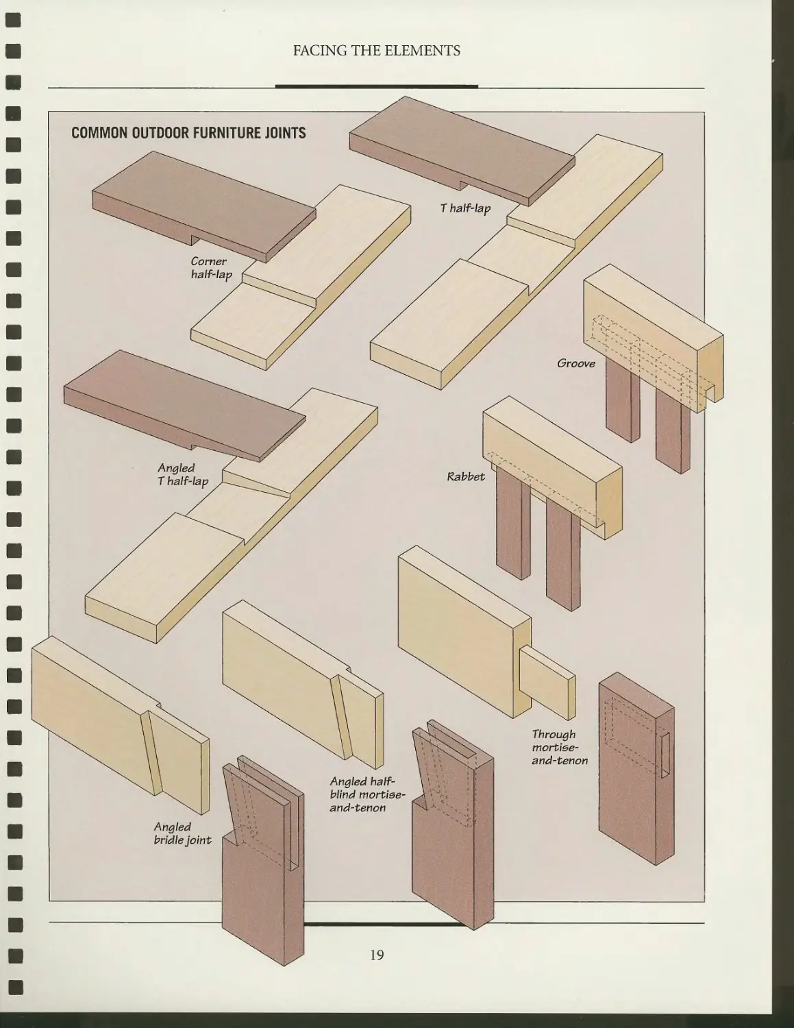
JOINERY AND HARDWARE
Joinery presents unique challenges to
the outdoor furniture maker. Many
of the standard joints used for indoor
furniture are incapable of withstanding
the abuses wrought by weather. The
blind mortise-and-tenon joint, for
example, is normally an excellent choice for
joining chair rails and legs, but it does
not fare well outdoors. Water can
become trapped in the mortise,
causing the joint to swell and leading to
wood decay. A variation on the same
joint, the through mortise-and-tenon
(page 19), solves that problem by
allowing water to drain out. Cutting angled
shoulders helps prevent water from
becoming trapped. Lap joints and
rabbet joints also work well. For extra
protection against water, you can coat the
mating surfaces of joints with a
preservative such as pine tar or an adhesive
caulking compound.
Outdoor furniture makes frequent
use of fasteners to connect components.
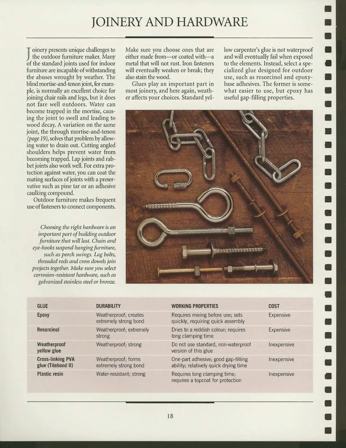
Choosing the right hardware is an
important part of building outdoor
furniture that will last. Chain and
eye-hooks suspend hanging furniture,
such as porch swings. Lag bolts,
threaded rods and cross dowels join
projects together. Make sure you select
corrosion-resistant hardware, such as
galvanized stainless steel or bronze.
Make sure you choose ones that are
either made from—or coated with—a
metal that will not rust. Iron fasteners
will eventually weaken or break; they
also stain the wood.
Glues play an important part in
most joinery, and here again,
weather affects your choices. Standard
yellow carpenter's glue is not waterproof
and will eventually fail when exposed
to the elements. Instead, select a
specialized glue designed for outdoor
use, such as resorcinol and epoxy-
base adhesives. The former is
somewhat easier to use, but epoxy has
useful gap-filling properties.
GLUE
Epoxy
Resorcinol
Weatherproof
yellow glue
Cross-linking PVA
glue (Titebond II)
Plastic resin
DURABILITY
Weatherproof; creates
extremely strong bond
Weatherproof; extremely
strong
Weatherproof; strong
Weatherproof; forms
extremely strong bond
Water-resistant; strong
WORKING PROPERTIES
Requires mixing before use; sets
quickly, requiring quick assembly
Dries to a reddish colour; requires
long clamping time
Do not use standard, non-waterproof
version of this glue
One-part adhesive; good gap-filling
ability; relatively quick drying time
Requires long clamping time;
requires a topcoat for protection
COST
Expensive
Expensive
Inexpensive
Inexpensive
Inexpensive
18
FACING THE ELEMENTS
FINISHING
r P he finish on any project has two pur-
JL poses: to beautify the wood and
protect it. However, if you have built your
furniture from rot-resistant and stable
wood, you may choose to leave the wood
unfinished. This cuts down
substantially on maintenance, because once a finish
is applied, it must be renewed
periodically. Still, for the less decay-resistant
woods, finishing is your best choice to
protect the furniture from the elements
and to keep insects at bay. Also, some
woods with little figure may look better
covered with paint or a stain. A
pigmented topcoat will also conceal any
mismatched grain.
The most common finishing
choices are penetrating oils, varnishes, and
paint. Spar varnish requires that the first
coat be thinned, with undiluted varnish
for the subsequent coats. Other finishes,
especially paints, need a sealer first,
followed by primer, then the finishing coats.
Water is not the only threat to
outdoor furniture. Sunlight can damage
wood by destroying the lignin in the
wood, which fortifies the cell walls. If
you want to shield the wood
completely from the sun, use paint. Generally, the
higher the gloss, the better the
protection, since the gloss will serve to reflect
the sun's rays. Some finishes, such as
spar varnish, contain ultraviolet (UV)
filters, which help shield the furniture
from the sun's harmful radiation. For
maximum UV protection, apply four or
five coats.
Finally, do not expect a finish to
salvage a poor construction. While there
are very expensive finishes available, such
as catalyzed linear polyurethane, that
will protect wood from virtually
anything, including submerging it in water,
the best way to ensure that your piece of
furniture lasts is to start with the right
joinery and glues.
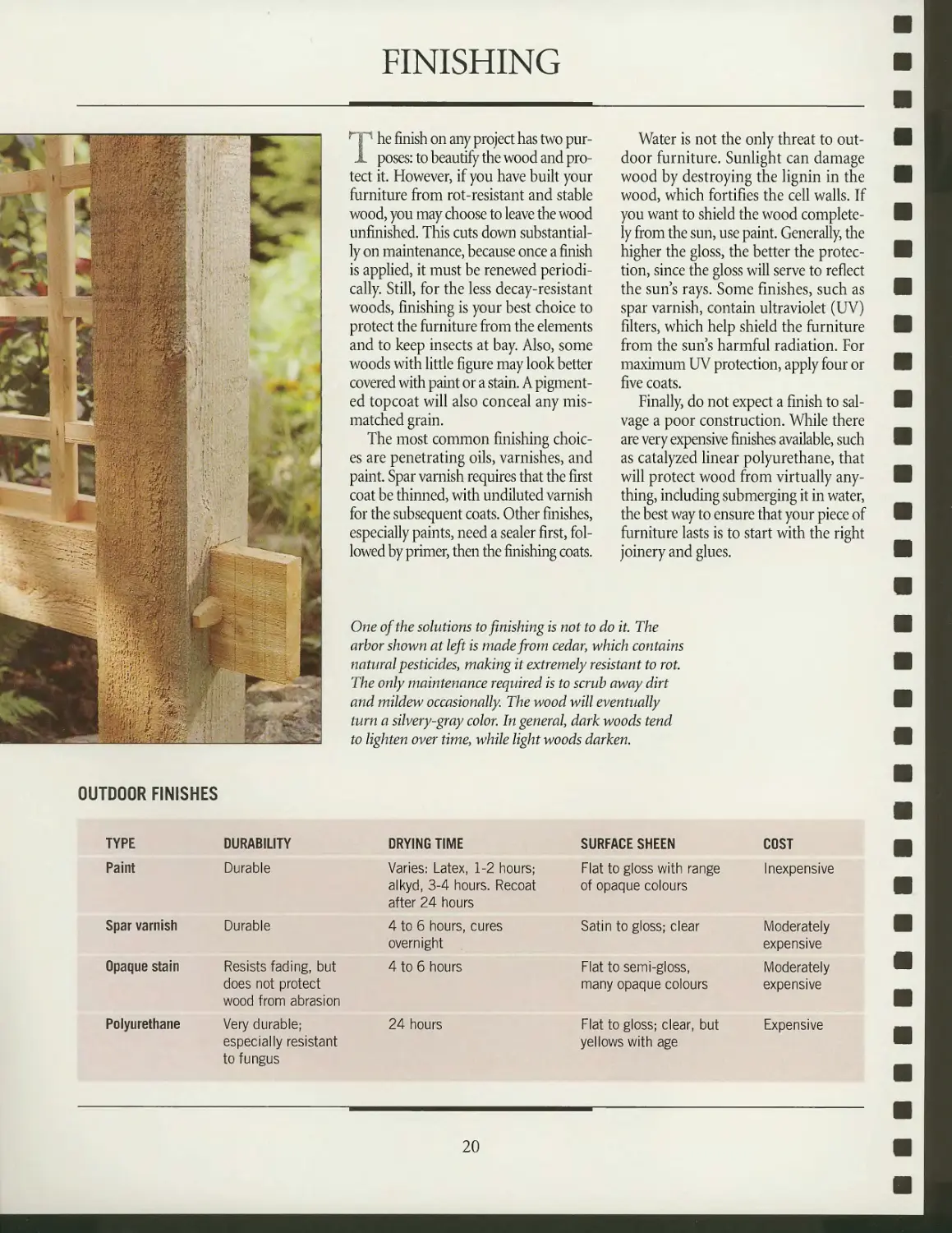
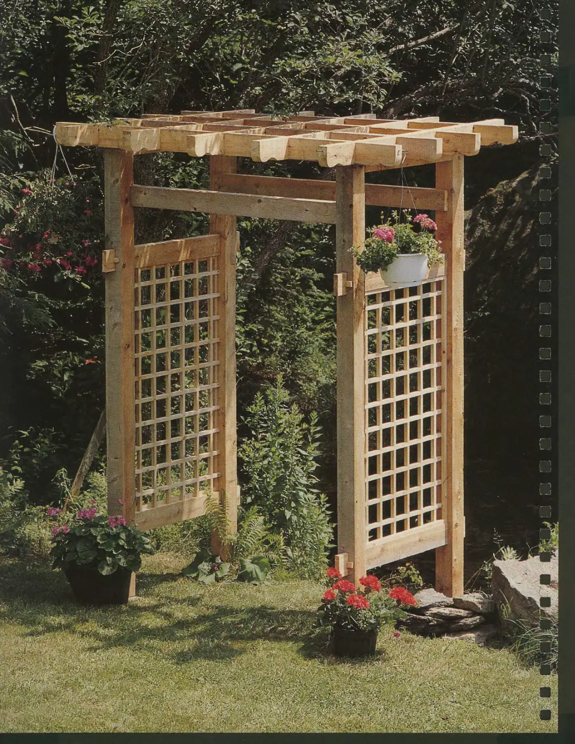
One of the solutions to finishing is not to do it. The
arbor shown at left is made from cedar, which contains
natural pesticides, making it extremely resistant to rot.
The only maintenance required is to scrub away dirt
and mildew occasionally The wood will eventually
turn a silvery-gray color. In general, dark woods tend
to lighten over time, while light woods darken.
OUTDOOR FINISHES
TYPE
Paint
Spar varnish
Opaque stain
Polyurethane
DURABILITY
Durable
Durable
Resists fading, but
does not protect
wood from abrasion
Very durable;
especially resistant
to fungus
DRYING TIME
Varies: Latex, 1-2 hours;
alkyd, 3-4 hours. Recoat
after 24 hours
4 to 6 hours, cures
overnight
4 to 6 hours
24 hours
SURFACE SHEEN
Flat to gloss with range
of opaque colours
Satin to gloss; clear
Flat to semi-gloss,
many opaque colours
Flat to gloss; clear, but
yellows with age
COST
Inexpensive
Moderately
expensive
Moderately
expensive
Expensive
20
FACING THE ELEMENTS
STEPS FOR APPLYING VARNISH OR PAINT
VARNISH
• Sand with 120-grit sandpaper for hardwoods and 220-grit for
softwoods, then clean the surface with a tack cloth.
• Mix varnish by stirring only. Shaking varnish creates bubbles that
may mar the finish.
• Avoid inexpensive varnish brushes. Instead, buy ones made from
china bristle or badger hair. Or, use disposable foam brushes.
• Do not work in direct sunlight or in cool, damp locations.
• Apply at least four coats, preferably five.
• Sand between coats with a sanding block and 280-grit sandpaper,
cleaning the surface afterwards with a tack cloth.
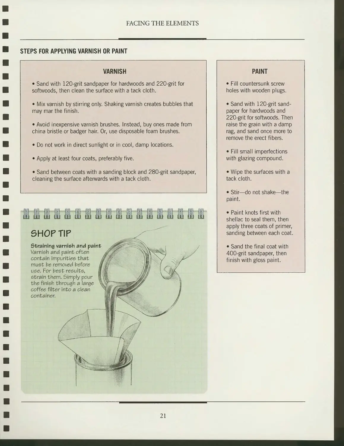
SHOP TIP
Straining varnish and paint
Varnish and paint often $■ ,s-/
contain impurities that £/'v
must be removed before
use. For best results,
strain them. Simply pour
the finish through a large
coffee filter into a clean
container.
PAINT
• Fill countersunk screw
holes with wooden plugs.
• Sand with 120-grit
sandpaper for hardwoods and
220-grit for softwoods. Then
raise the grain with a damp
rag, and sand once more to
remove the erect fibers.
• Fill small imperfections
with glazing compound.
• Wipe the surfaces with a
tack cloth.
• Stir—do not shake—the
paint.
• Paint knots first with
shellac to seal them, then
apply three coats of primer,
sanding between each coat.
• Sand the final coat with
400-grit sandpaper, then
finish with gloss paint.
21
1 i^isnB^i
i I ]
ir 1 •]
JJ
r"l
x^@
:^/V*?
CHAIRS
Outdoor furniture must be
designed to rough it, and the
Adirondack chair, chaise lounge,
and curved chair featured in this
chapter are all up to the task. In
many parts of the country with
harsh winters, the appearance of
outdoor chairs marks the return of
pleasant weather. Carted out of the
garage or basement on the first
sunny day of spring, given a quick
dusting off, and then left exposed to
the elements, they must withstand
rough use, indeed, until they are
returned to shelter after the first
frost. Such treatment places a
particular set of demands on the
joinery. The blind mortise-and-tenon,
for example, which is normally an
excellent choice to join chair parts, does not fare so well with
outdoor furniture, since the mortise serves as a convenient
trap for water. Even with a durable and decay-resistant species,
there is the danger that the wood will eventually rot.
All three chairs in this chapter solve this problem by using
half-lap joints. What it lacks in stoutness, the half-lap makes
up for in versatility. It will not trap water and, when reinforced
with a weatherproof epoxy and screws, it is exceptionally
strong. The joint is also fairly simple to produce. You can
make both parts of the connection on the table saw (page 37).
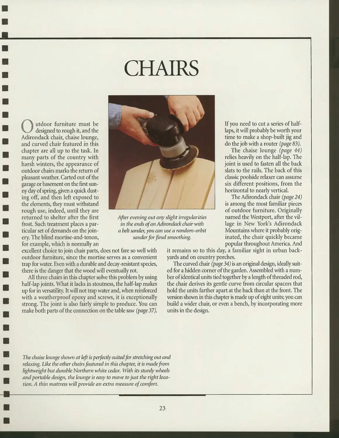
After evening out any slight irregularities
in the ends of an Adirondack chair with
a beltsander, you can use a random-orbit
sander for final smoothing.
If you need to cut a series of half-
laps, it will probably be worth your
time to make a shop-built jig and
do the job with a router (page 83).
The chaise lounge (page 44)
relies heavily on the half-lap. The
joint is used to fasten all the back
slats to the rails. The back of this
classic poolside relaxer can assume
six different positions, from the
horizontal to nearly vertical.
The Adirondack chair (page 24)
is among the most familiar pieces
of outdoor furniture. Originally
named the Westport, after the
village in New York's Adirondack
Mountains where it probably
originated, the chair quickly became
popular throughout America. And
it remains so to this day, a familiar sight in urban
backyards and on country porches.
The curved chair (page 34) is an original design, ideally
suited for a hidden corner of the garden. Assembled with a
number of identical units tied together by a length of threaded rod,
the chair derives its gentle curve from circular spacers that
hold the units farther apart at the back than at the front. The
version shown in this chapter is made up of eight units; you can
build a wider chair, or even a bench, by incorporating more
units in the design.
The chaise lounge shown at left is perfectly suited for stretching out and
relaxing. Like the other chairs featured in this chapter, it is made from
lightweight hut durable Northern white cedar. With its sturdy wheels
and portable design, the lounge is easy to move to just the right
location. A thin mattress will provide an extra measure of comfort.
23
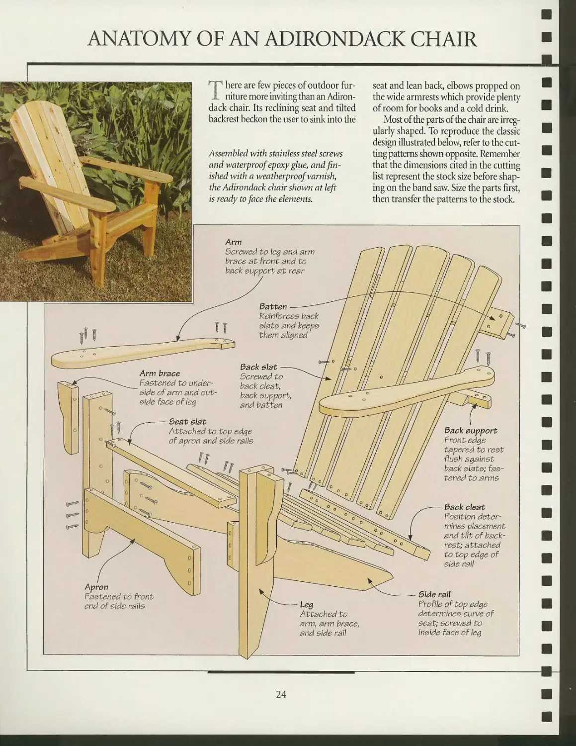
ANATOMY OF AN ADIRONDACK CHAIR
There are few pieces of outdoor
furniture more inviting than an
Adirondack chair. Its reclining seat and tilted
backrest beckon the user to sink into the
Assembled with stainless steel screws
and waterproof epoxy glue, and
finished with a weatherproof varnish
the Adirondack chair shown at left
is ready to face the elements.
seat and lean back, elbows propped on
the wide armrests which provide plenty
of room for books and a cold drink.
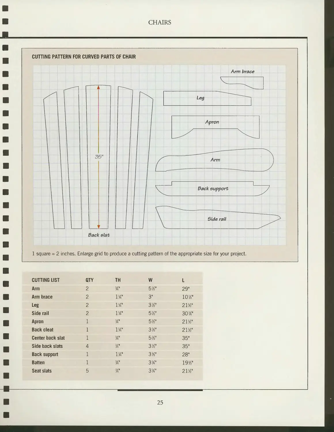
Most of the parts of the chair are
irregularly shaped. To reproduce the classic
design illustrated below, refer to the
cutting patterns shown opposite. Remember
that the dimensions cited in the cutting
list represent the stock size before
shaping on the band saw. Size the parts first,
then transfer the patterns to the stock.
Arm brace
Fastened to
underside of arm and
outside face of leg
Seat e\at
Attached to top edge
of apron and side rails
Arm
Screwed to leg and arm
brace at front and to
back support at rear
batten
Reinforces back
slats and keeps
them aligned
Back e\at
Screwed to
back cleat,
back support,
and batten
Fastened to front
end of side rails
Leg
Attached to
arm, arm brace,
and side rail
Back support
Front edge
tapered to rest
flush against
back slats;
fastened to arms
Back c\eat
Fosltlon
determines placement
and tilt of
backrest; attached
to top edge of
side rail
Side rail
Froflle of top edge
determines curve of
seat; screwed to
Inside face of leg
24
■ CHAIRS
M
CUTTING LIST
Arm
Arm brace
Leg
Side rail
Apron
Back cleat
Center back slat
Side back slats
Back support
Batten
Seat slats
QTY
2
2
2
2
1
1
1
4
1
1
5
TH
Ya"
IK'
IK"
1J4"
%"
IK"
Ya"
Ya"
w
Ya"
Ya"
W
514"
3"
3J4"
51/2"
514"
3J4"
5/2"
3/2"
314"
3lA"
3/4"
L
29"
IO/2"
2I/2"
303/4n
211/2"
21'/a"
35"
35"
28"
1914*
2I/2"
25
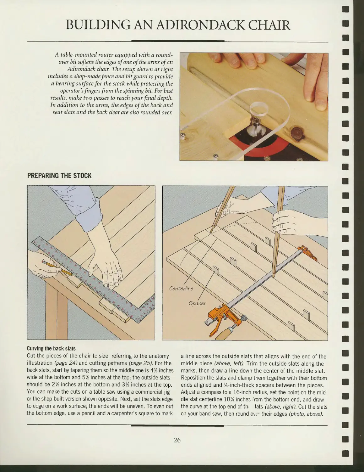
BUILDING AN ADIRONDACK CHAIR
A table-mounted router equipped with a round-
over bit softens the edges of one of the arms of an
Adirondack chair. The setup shown at right
includes a shop-made fence and bit guard to provide
a bearing surface for the stock while protecting the
operator's fingers from the spinning bit. For best
results, make two passes to reach your final depth.
In addition to the arms, the edges of the back and
seat slats and the back cleat are also rounded over.
PREPARING THE STOCK
/^ TV /
Centerlme }Q\
Spacer
<sp
Hr^=^=^^^'
u\^^^%.
«k.
ypy // ^^^y^*\\
^"^ ^^-^
s
Curving the back slats
Cut the pieces of the chair to size, referring to the anatomy
illustration (page 24) and cutting patterns (page 25). For the
back slats, start by tapering them so the middle one is 4% inches
wide at the bottom and blA inches at the top; the outside slats
should be 2lA inches at the bottom and 3lA inches at the top.
You can make the cuts on a table saw using a commercial jig
or the shop-built version shown opposite. Next, set the slats edge
to edge on a work surface; the ends will be uneven. To even out
the bottom edge, use a pencil and a carpenter's square to mark
a line across the outside slats that aligns with the end of the
middle piece (above, left). Trim the outside slats along the
marks, then draw a line down the center of the middle slat.
Reposition the slats and clamp them together with their bottom
ends aligned and ^-inch-thick spacers between the pieces.
Adjust a compass to a 16-inch radius, set the point on the
middle slat centerline 18% inches -rom the bottom end, and draw
the curve at the top end of tn- lats (above, right). Cut the slats
on your band saw, then round ovr their edges (photo, above).
26
CHAIRS
mm
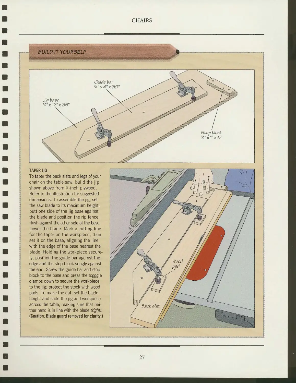
8U1W1TYQUZ5ELF
mmmmmmmmmmwimim
Guide bar
3/4"x4"x30
Jig baee
3/4ux12"x36"
Stop block
3/4"xV'x6"
TAPER JIG
To taper the back slats and legs of your
chair on the table saw, build the jig
shown above from %-inch plywood.
Refer to the illustration for suggested
dimensions. To assemble the jig, set
the saw blade to its maximum height,
butt one side of the jig base against
the blade and position the rip fence
flush against the other side of the base.
Lower the blade. Mark a cutting line
for the taper on the workpiece, then
set it on the base, aligning the line
with the edge of the base nearest the
blade. Holding the workpiece
securely, position the guide bar against the
edge and the stop block snugly against
the end. Screw the guide bar and stop
block to the base and press the togggle
clamps down to secure the workpiece
to the jig; protect the stock with wood
pads. To make the cut, set the blade
height and slide the jig and workpiece
across the table, making sure that
neither hand is in line with the blade (right).
(Caution: Blade guard removed for clarity.)
27
CHAIRS
ASSEMBLING THE CHAIR
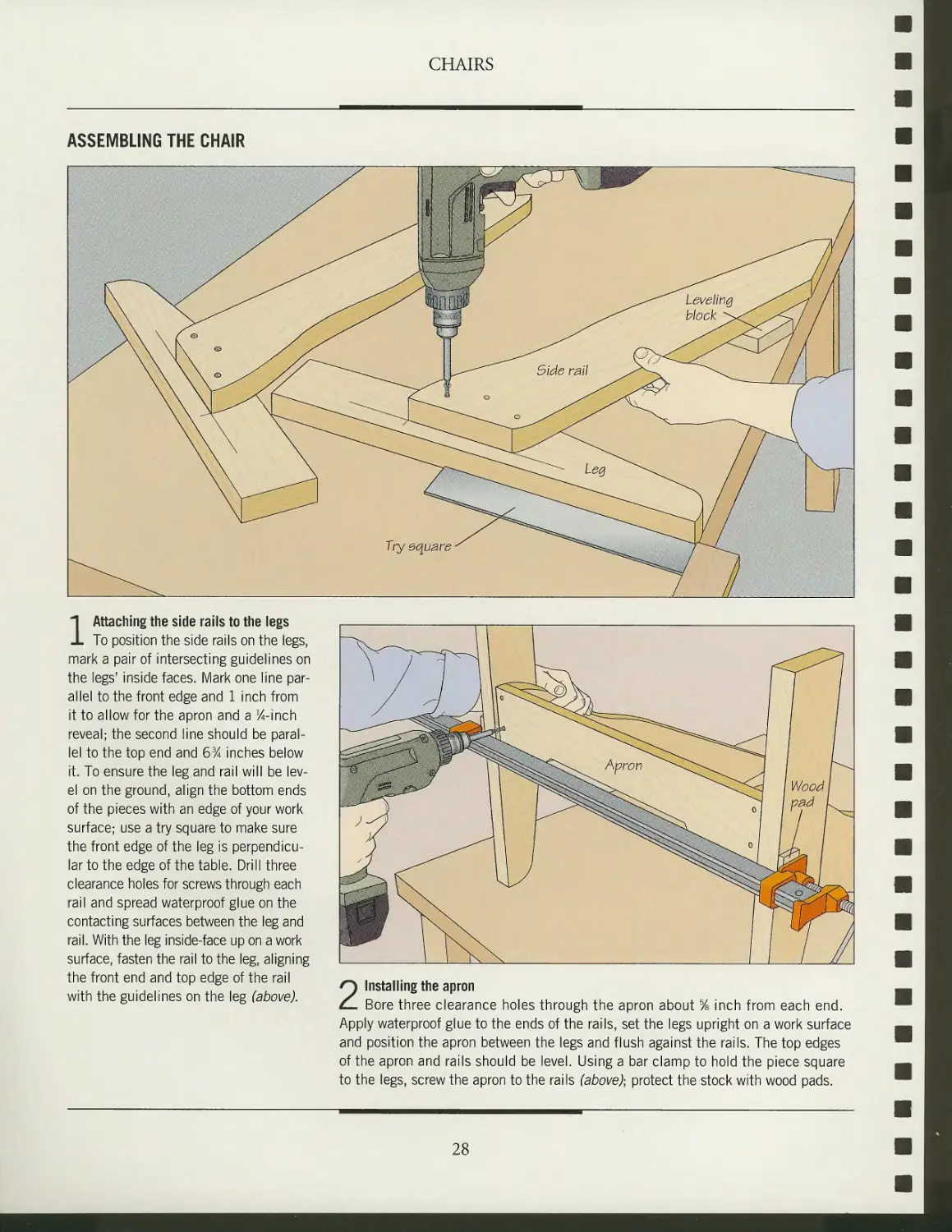
1 Attaching the side rails to the legs
To position the side rails on the legs,
mark a pair of intersecting guidelines on
the legs' inside faces. Mark one line
parallel to the front edge and 1 inch from
it to allow for the apron and a ^-inch
reveal; the second line should be
parallel to the top end and 6% inches below
it. To ensure the leg and rail will be
level on the ground, align the bottom ends
of the pieces with an edge of your work
surface; use a try square to make sure
the front edge of the leg is
perpendicular to the edge of the table. Drill three
clearance holes for screws through each
rail and spread waterproof glue on the
contacting surfaces between the leg and
rail. With the leg inside-face up on a work
surface, fasten the rail to the leg, aligning
the front end and top edge of the rail
with the guidelines on the leg (above).
2 Installing the apron
Bore three clearance holes through the apron about % inch from each end.
Apply waterproof glue to the ends of the rails, set the legs upright on a work surface
and position the apron between the legs and flush against the rails. The top edges
of the apron and rails should be level. Using a bar clamp to hold the piece square
to the legs, screw the apron to the rails (above)] protect the stock with wood pads.
28
CHAIRS
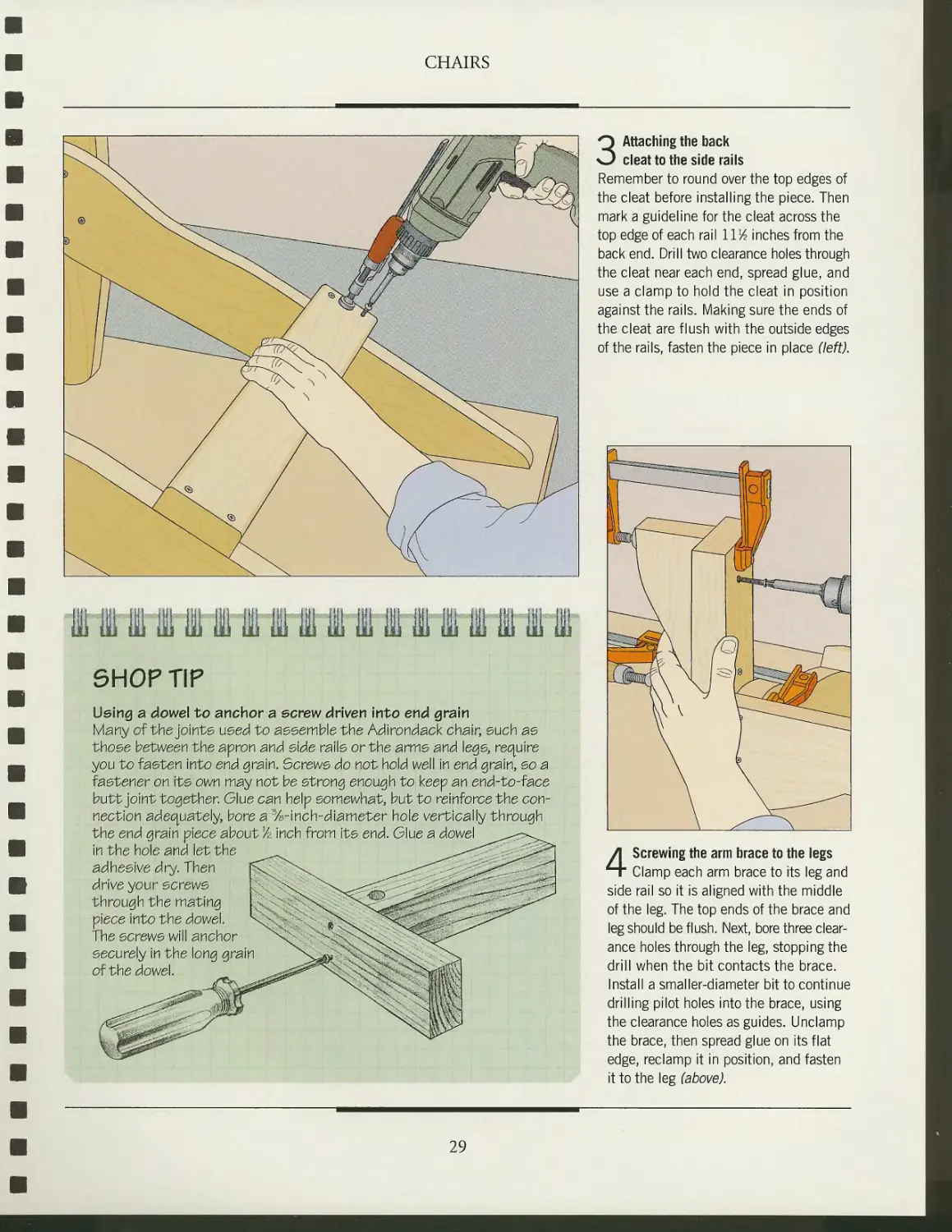
SHOP TIP
Using a dowel to anchor a screw driven Into end grain
Many of the joints used to assemble the Adirondack chair, such as
those between the apron and side rails or the arms and legs, require
you to fasten Into end grain. Screws do not hold well in end grain, so a
fastener on its own may not be strong enough to keep an end-to-face
butt joint together. Glue can help somewhat, but to reinforce the
connection adequately, bore a %-inch-diameter hole vertically through
the end grain piece about Vz Inch from its end. Glue a dowel
In the hole and let the
adhesive dry. Then
drive your screws
through the mating
piece into the dowel.
The screws will anchor
securely in the Ion
of the dowel.
3 Attaching the back
cleat to the side rails
Remember to round over the top edges of
the cleat before installing the piece. Then
mark a guideline for the cleat across the
top edge of each rail l\lA inches from the
back end. Drill two clearance holes through
the cleat near each end, spread glue, and
use a clamp to hold the cleat in position
against the rails. Making sure the ends of
the cleat are flush with the outside edges
of the rails, fasten the piece in place (left).
4 Screwing the arm brace to the legs
Clamp each arm brace to its leg and
side rail so it is aligned with the middle
of the leg. The top ends of the brace and
leg should be flush. Next, bore three
clearance holes through the leg, stopping the
drill when the bit contacts the brace.
Install a smaller-diameter bit to continue
drilling pilot holes into the brace, using
the clearance holes as guides. Unclamp
the brace, then spread glue on its flat
edge, reclamp it in position, and fasten
it to the leg (above).
29
CHAIRS
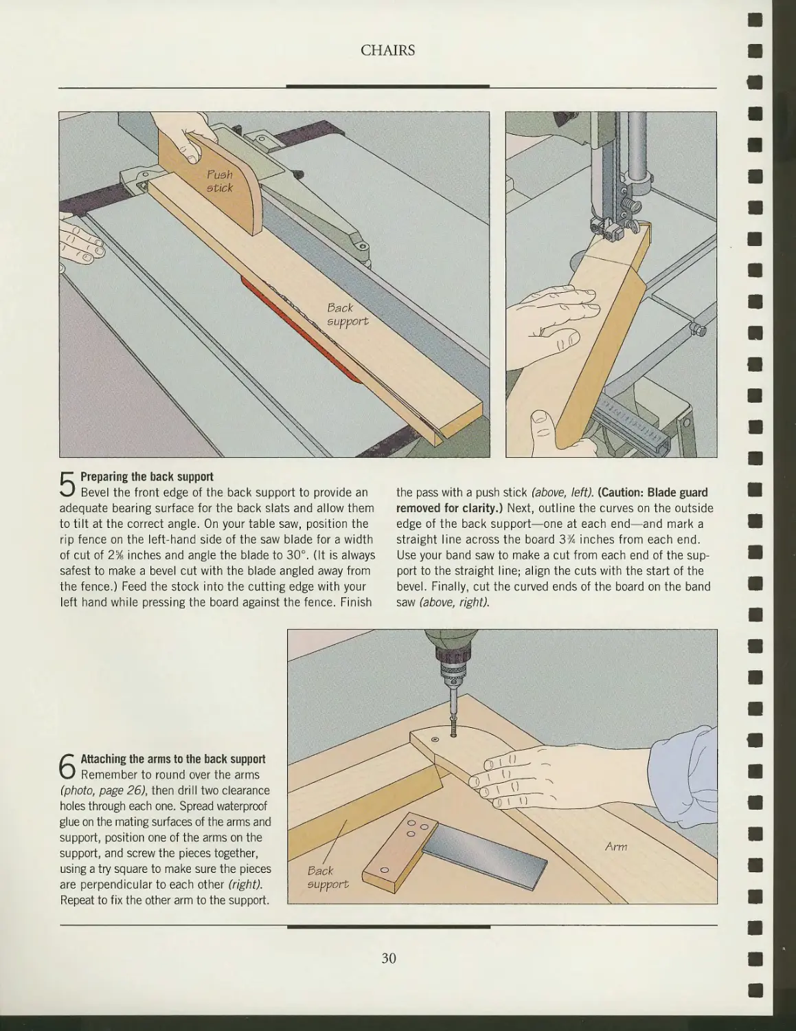
5 Preparing the back support
Bevel the front edge of the back support to provide an
adequate bearing surface for the back slats and allow them
to tilt at the correct angle. On your table saw, position the
rip fence on the left-hand side of the saw blade for a width
of cut of 2% inches and angle the blade to 30°. (It is always
safest to make a bevel cut with the blade angled away from
the fence.) Feed the stock into the cutting edge with your
left hand while pressing the board against the fence. Finish
the pass with a push stick (above, left). (Caution: Blade guard
removed for clarity.) Next, outline the curves on the outside
edge of the back support—one at each end—and mark a
straight line across the board 3% inches from each end.
Use your band saw to make a cut from each end of the
support to the straight line; align the cuts with the start of the
bevel. Finally, cut the curved ends of the board on the band
saw (above, right).
6 Attaching the arms to the back support
Remember to round over the arms
(photo, page 26), then drill two clearance
holes through each one. Spread waterproof
glue on the mating surfaces of the arms and
support, position one of the arms on the
support, and screw the pieces together,
using a try square to make sure the pieces
are perpendicular to each other (right).
Repeat to fix the other arm to the support.
30
CHAIRS
7 Installing the middle back slat
Before you can attach the arms and
back support to the chair, the middle back
slat must be fastened in place. Set the
chair upright on a work surface and clamp
the slat to the center of the back cleat,
aligning the bottom end of the slat with
the bottom face of the cleat; protect the
stock with wood pads. Holding the slat
flush against the cleat, use three screws
to fasten it in place (left). Do not use glue
in case you need to adjust the slat later
when you install the remaining back slats.
8 Fastening the arms and
back support to the chair
Set the arms and back support upside down
on a work surface, then position the leg
assembly on the arms. Center the middle
back slat on the back support and clamp
the pieces together. At the front of the chair,
use a tape measure to ensure that the
inside edges of the arms extend beyond
the legs by the same amount on both sides.
Using the legs and arm supports as guides,
make location marks on the undersides of
the arms once you are satisfied with the
position of the leg assembly (right). Set
the chair upright and drill three clearance
holes through each arm and one through
the middle back slat. Spread glue on the
contacting surfaces of the arms, legs, and
arm supports, then reposition the arms in
place—using the location marks as guides
—and screw the pieces together.
31
CHAIRS
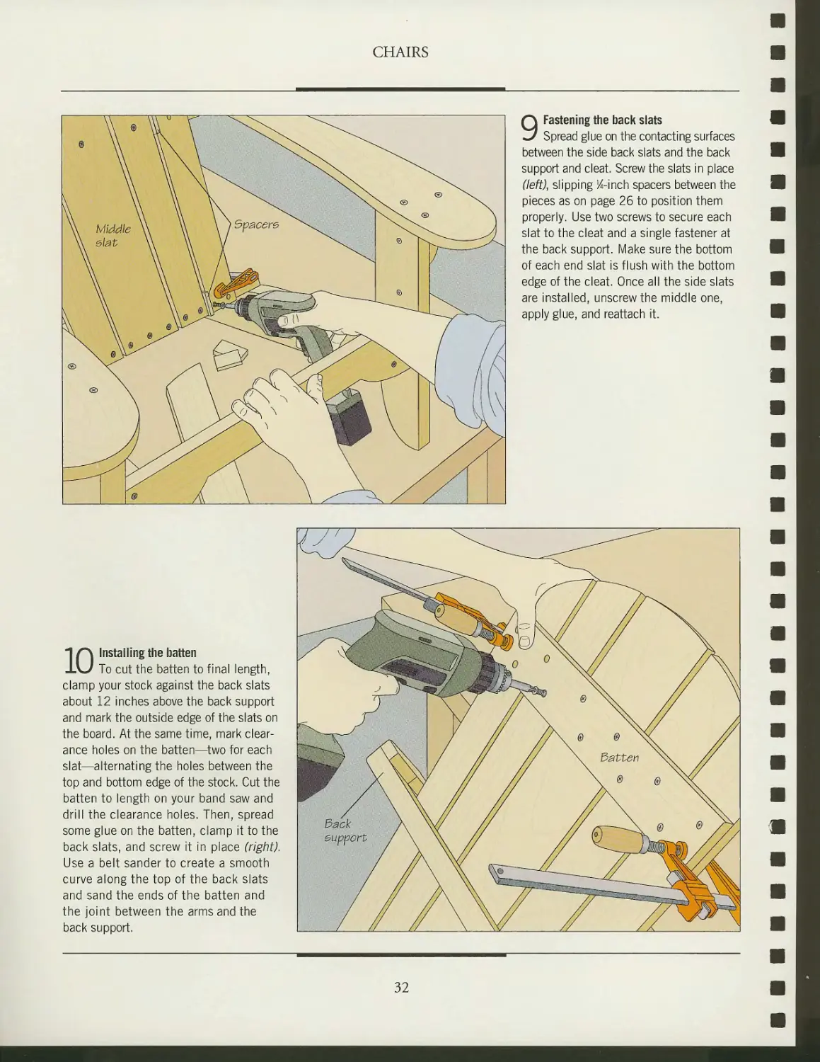
9 Fastening the back slats
Spread glue on the contacting surfaces
between the side back slats and the back
support and cleat. Screw the slats in place
(left), slipping %-inch spacers between the
pieces as on page 26 to position them
properly. Use two screws to secure each
slat to the cleat and a single fastener at
the back support. Make sure the bottom
of each end slat is flush with the bottom
edge of the cleat. Once all the side slats
are installed, unscrew the middle one,
apply glue, and reattach it.
1 r\ Installing the batten
1\J To cut the batten to final length,
clamp your stock against the back slats
about 12 inches above the back support
and mark the outside edge of the slats on
the board. At the same time, mark
clearance holes on the batten—two for each
slat—alternating the holes between the
top and bottom edge of the stock. Cut the
batten to length on your band saw and
drill the clearance holes. Then, spread
some glue on the batten, clamp it to the
back slats, and screw it in place (right).
Use a belt sander to create a smooth
curve along the top of the back slats
and sand the ends of the batten and
the joint between the arms and the
back support.
^y^y
' ^$iM
J I
wjjjjjjjjjMjjM ( V
dack /
eupport /
^i^"- j,
j
v
^^\ r^
W^mZ> °
\\ ^r~ "—^^~~—
® N\
6 ® N
\ 3atter\
\ ®
// (cm ~^t
~^^^^^m3:
® \x"
® ® ///
^Wk
32
CHAIRS
llllilillfI111II11
SHOP TIP
Sealing knots with shellac
Because it is intended to be sturdy and rustic, outdoor furniture
is often built with lower-grade wood. Although this is economical,
many such boards have knots. Loose knots should be cut off, since
they weaken the wood. Although tight knots have no effect on
the strength of stock and can be left intact, they often
ooze pitch, even after a finish is applied to the piece of ~, yyr ,
furniture. This pitch will bleed through paint or varnish, Jw // v^\.
staining the finish and producing a s1
To avoid this problem, brush twc
of shellac over tight knots to st
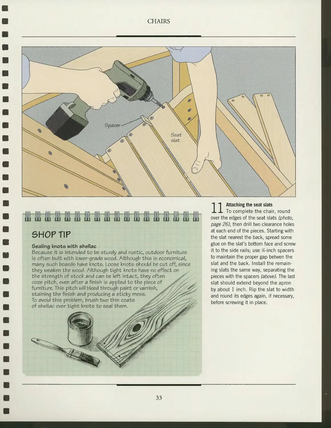
n Attaching the seat slats
To complete the chair, round
over the edges of the seat slats (photo,
page 26), then drill two clearance holes
at each end of the pieces. Starting with
the slat nearest the back, spread some
glue on the slat's bottom face and screw
it to the side rails; use ^-inch spacers
to maintain the proper gap betwen the
slat and the back. Install the
remaining slats the same way, separating the
pieces with the spacers (above). The last
slat should extend beyond the apron
by about 1 inch. Rip the slat to width
and round its edges again, if necessary,
before screwing it in place.
33
ANATOMY OF A CURVED CHAIR
The curved chair featured in this
section is built by joining eight
identical H-shaped units with steel
rods. Each unit is separated from the
adjoining one by three 2-inch-diame-
ter spacers—two at the rear leg and one
at the front. The curve is achieved by
using 1/2-inch-long spacers in back and
%-inch-long spacers in front.
The modular design of the chair is
very versatile. You can use spacers of
uniform length to create a straight
chair or build additional units to make
a bench.
As shown opposite, each seating unit
is joined to its rear and front legs with
half-laps—a T half-lap at the back and
a corner half-lap at the front—and all
the joints are reinforced by screws. Once
the joinery is done, the pieces are
shaped and trimmed with a router and
a template.
The curve of the chair shown at left is made possible by using spacers
at the back that are twice as long as those at the front. This chair was
finished with two coats of primer and one coat of exterior-grade paint.
CHAIRS
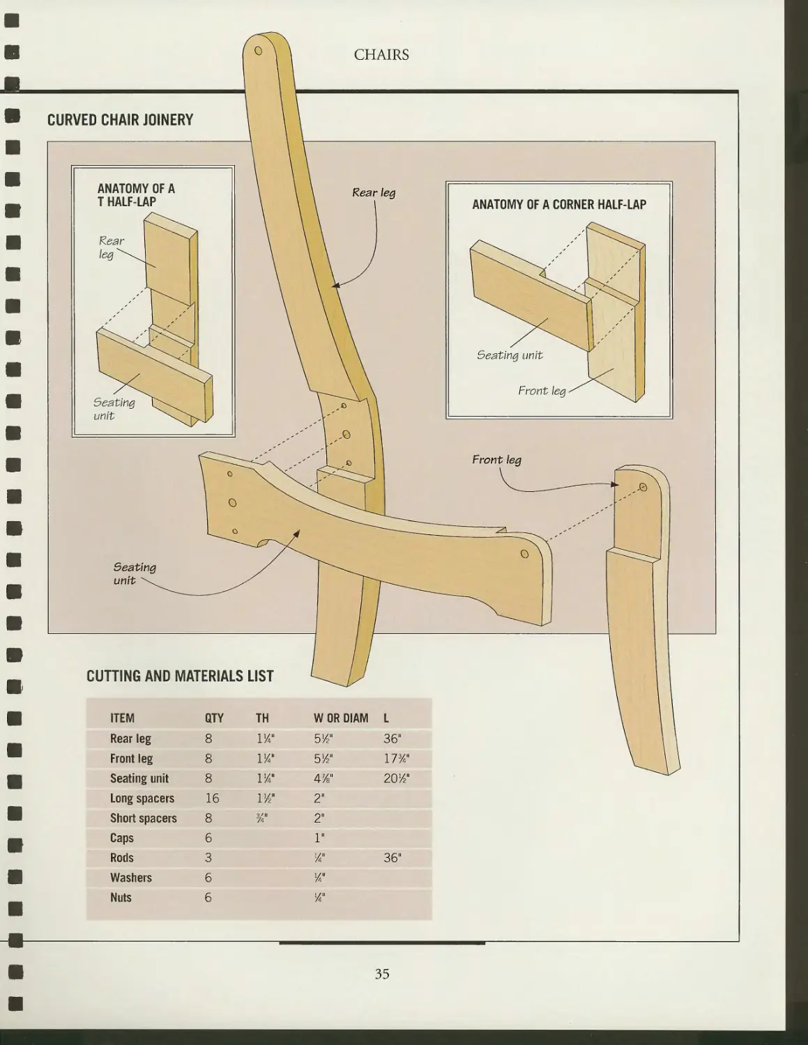
CURVED CHAIR JOINERY
ANATOMY OF A CORNER HALF-LAP
CUTTING AND MATERIALS LIST
ITEM
Rear leg
Front leg
Seating unit
Long spacers
Short spacers
• Caps
Rods
1 Washers
Nuts
QTY
8
8
8
16
8
6
3
6
6
TH
VA"
I//
l1/"
114"
%"
W OR DIAM
5/2"
5W
47/s"
2"
2"
1"
J4"
%"
Va"
I
36"
173/4"
20/2"
36"
35
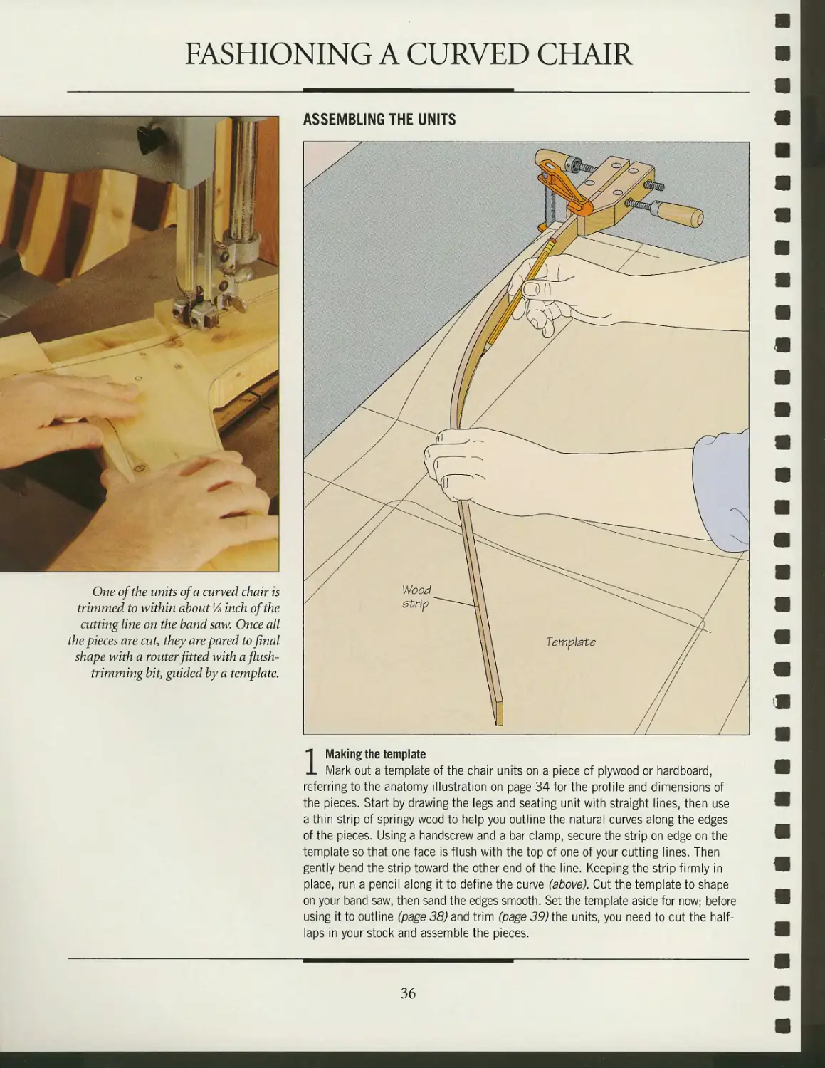
FASHIONING A CURVED CHAIR
1 Making the template
Mark out a template of the chair units on a piece of plywood or hardboard,
referring to the anatomy illustration on page 34 for the profile and dimensions of
the pieces. Start by drawing the legs and seating unit with straight lines, then use
a thin strip of springy wood to help you outline the natural curves along the edges
of the pieces. Using a handscrew and a bar clamp, secure the strip on edge on the
template so that one face is flush with the top of one of your cutting lines. Then
gently bend the strip toward the other end of the line. Keeping the strip firmly in
place, run a pencil along it to define the curve (above). Cut the template to shape
on your band saw, then sand the edges smooth. Set the template aside for now; before
using it to outline (page 38) and trim (page 39) the units, you need to cut the half-
laps in your stock and assemble the pieces.
36
CHAIRS
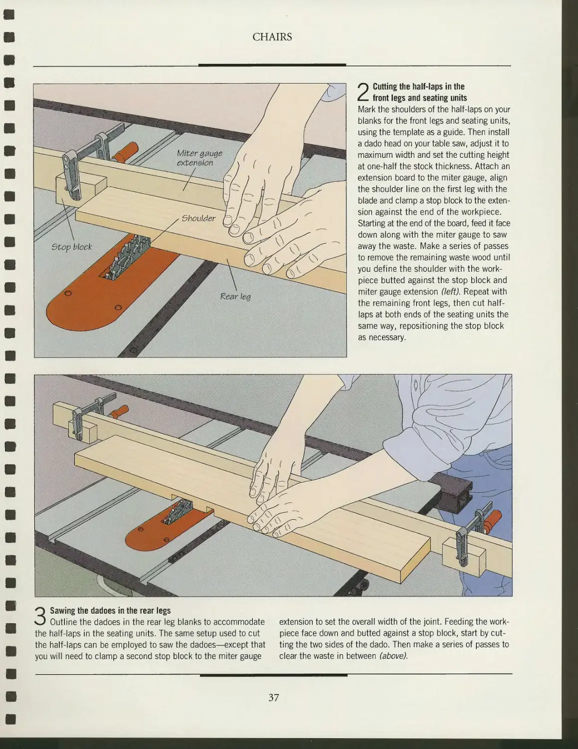
2 Cutting the half-laps in the
front legs and seating units
Mark the shoulders of the half-laps on your
blanks for the front legs and seating units,
using the template as a guide. Then install
a dado head on your table saw, adjust it to
maximum width and set the cutting height
at one-half the stock thickness. Attach an
extension board to the miter gauge, align
the shoulder line on the first leg with the
blade and clamp a stop block to the
extension against the end of the workpiece.
Starting at the end of the board, feed it face
down along with the miter gauge to saw
away the waste. Make a series of passes
to remove the remaining waste wood until
you define the shoulder with the work-
piece butted against the stop block and
miter gauge extension (left). Repeat with
the remaining front legs, then cut half-
laps at both ends of the seating units the
same way, repositioning the stop block
as necessary.
3 Sawing the dadoes in the rear legs
Outline the dadoes in the rear leg blanks to accommodate extension to set the overall width of the joint. Feeding the work-
the half-laps in the seating units. The same setup used to cut piece face down and butted against a stop block, start by cut-
the half-laps can be employed to saw the dadoes—except that ting the two sides of the dado. Then make a series of passes to
you will need to clamp a second stop block to the miter gauge clear the waste in between (above).
37
CHAIRS
Front leg
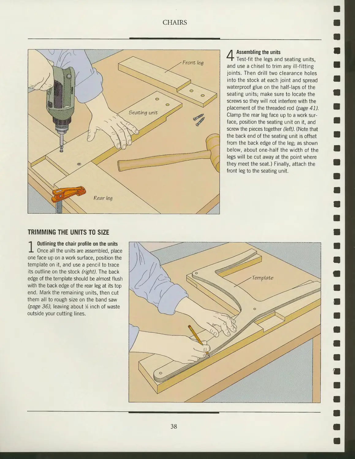
4 Assembling the units
Test-fit the legs and seating units,
and use a chisel to trim any ill-fitting
joints. Then drill two clearance holes
into the stock at each joint and spread
waterproof glue on the half-laps of the
seating units; make sure to locate the
screws so they will not interfere with the
placement of the threaded rod (page 41).
Clamp the rear leg face up to a work
surface, position the seating unit on it, and
screw the pieces together (left). (Note that
the back end of the seating unit is offset
from the back edge of the leg; as shown
below, about one-half the width of the
legs will be cut away at the point where
they meet the seat.) Finally, attach the
front leg to the seating unit.
TRIMMING THE UNITS TO SIZE
1 Outlining the chair profile on the units
Once all the units are assembled, place
one face up on a work surface, position the
template on it, and use a pencil to trace
its outline on the stock (right). The back
edge of the template should be almost flush
with the back edge of the rear leg at its top
end. Mark the remaining units, then cut
them all to rough size on the band saw
(page 36), leaving about lA inch of waste
outside your cutting lines.
38
CHAIRS
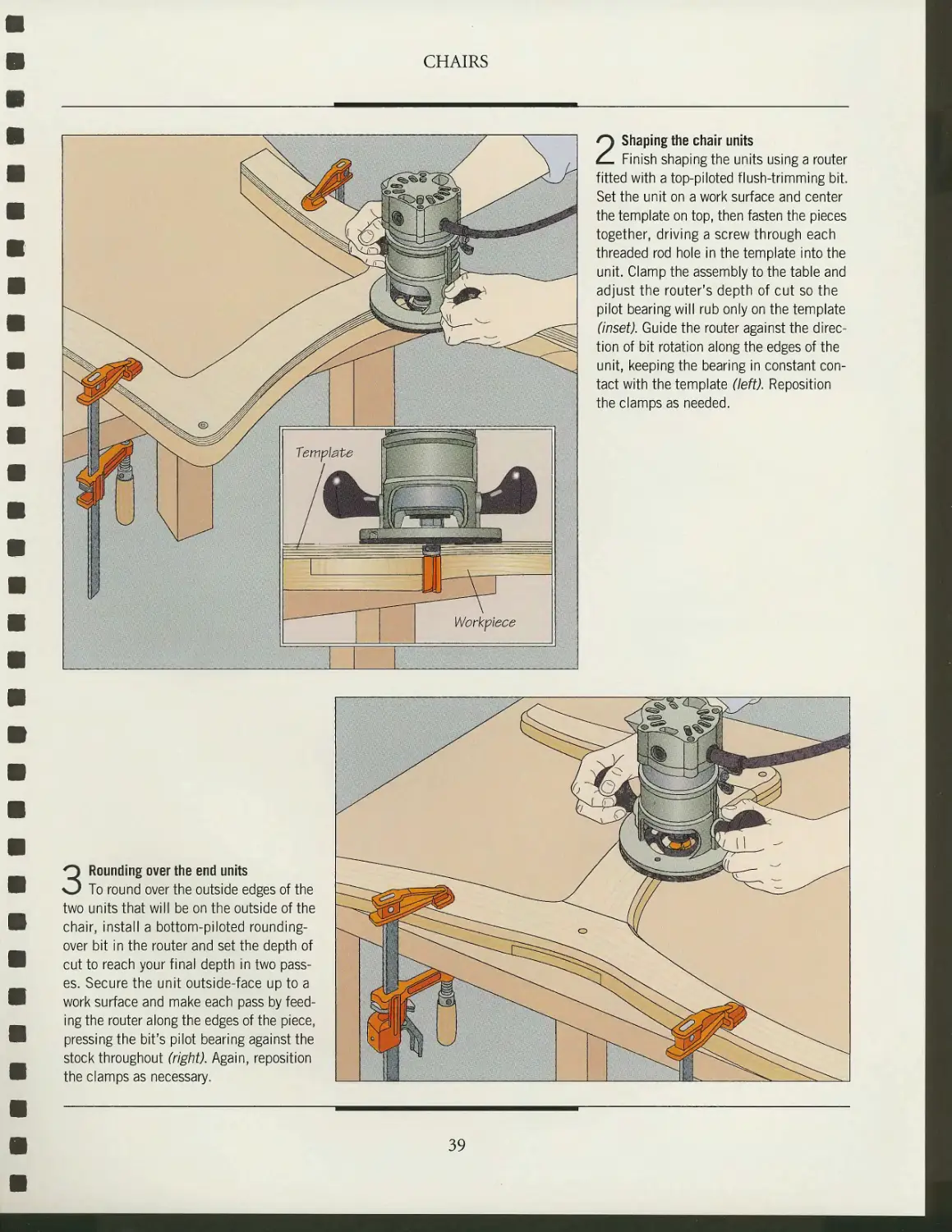
2 Shaping the chair units
Finish shaping the units using a router
fitted with a top-piloted flush-trimming bit.
Set the unit on a work surface and center
the template on top, then fasten the pieces
together, driving a screw through each
threaded rod hole in the template into the
unit. Clamp the assembly to the table and
adjust the router's depth of cut so the
pilot bearing will rub only on the template
(inset). Guide the router against the
direction of bit rotation along the edges of the
unit, keeping the bearing in constant
contact with the template (left). Reposition
the clamps as needed.
3 Rounding over the end units
To round over the outside edges of the
two units that will be on the outside of the
chair, install a bottom-piloted rounding-
over bit in the router and set the depth of
cut to reach your final depth in two
passes. Secure the unit outside-face up to a
work surface and make each pass by
feeding the router along the edges of the piece,
pressing the bit's pilot bearing against the
stock throughout (right). Again, reposition
the clamps as necessary.
39
ASSEMBLING THE CHAIR
CHAIRS
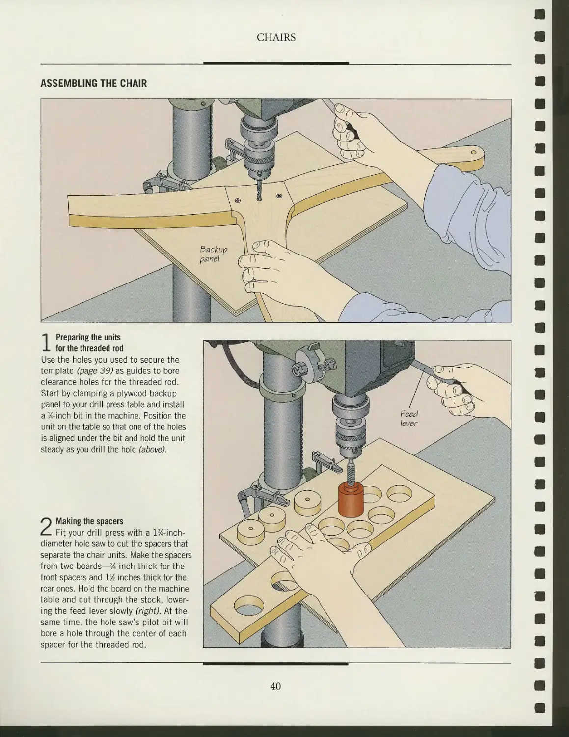
1 Preparing the units
for the threaded rod
Use the holes you used to secure the
template (page 39) as guides to bore
clearance holes for the threaded rod.
Start by clamping a plywood backup
panel to your drill press table and install
a 34-inch bit in the machine. Position the
unit on the table so that one of the holes
is aligned under the bit and hold the unit
steady as you drill the hole (above).
2 Making the spacers
Fit your drill press with a 1%-inch-
diameter hole saw to cut the spacers that
separate the chair units. Make the spacers
from two boards—% inch thick for the
front spacers and \lA inches thick for the
rear ones. Hold the board on the machine
table and cut through the stock,
lowering the feed lever slowly (right). At the
same time, the hole saw's pilot bit will
bore a hole through the center of each
spacer for the threaded rod.
40
CHAIRS
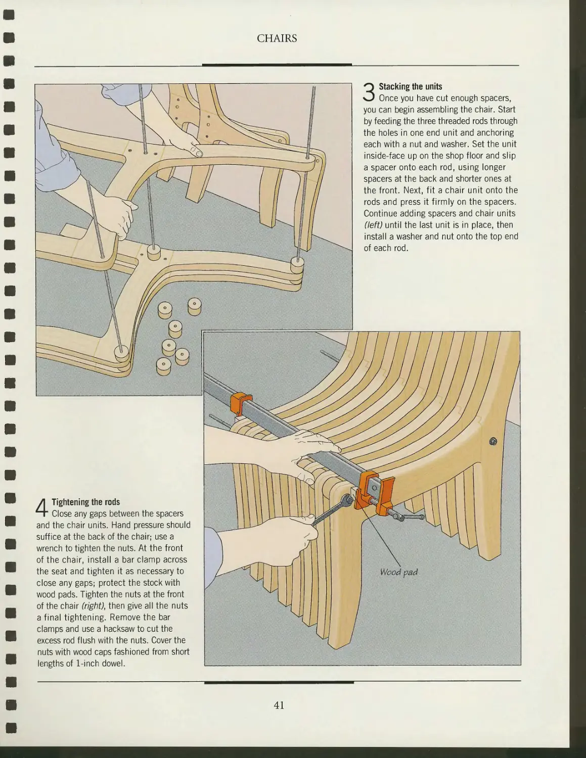
4 Tightening the rods
Close any gaps between the spacers
and the chair units. Hand pressure should
suffice at the back of the chair; use a
wrench to tighten the nuts. At the front
of the chair, install a bar clamp across
the seat and tighten it as necessary to
close any gaps; protect the stock with
wood pads. Tighten the nuts at the front
of the chair (right), then give all the nuts
a final tightening. Remove the bar
clamps and use a hacksaw to cut the
excess rod flush with the nuts. Cover the
nuts with wood caps fashioned from short
lengths of 1-inch dowel.
3 Stacking the units
Once you have cut enough spacers,
you can begin assembling the chair. Start
by feeding the three threaded rods through
the holes in one end unit and anchoring
each with a nut and washer. Set the unit
inside-face up on the shop floor and slip
a spacer onto each rod, using longer
spacers at the back and shorter ones at
the front. Next, fit a chair unit onto the
rods and press it firmly on the spacers.
Continue adding spacers and chair units
(left) until the last unit is in place, then
install a washer and nut onto the top end
of each rod.
41
CHAIRS
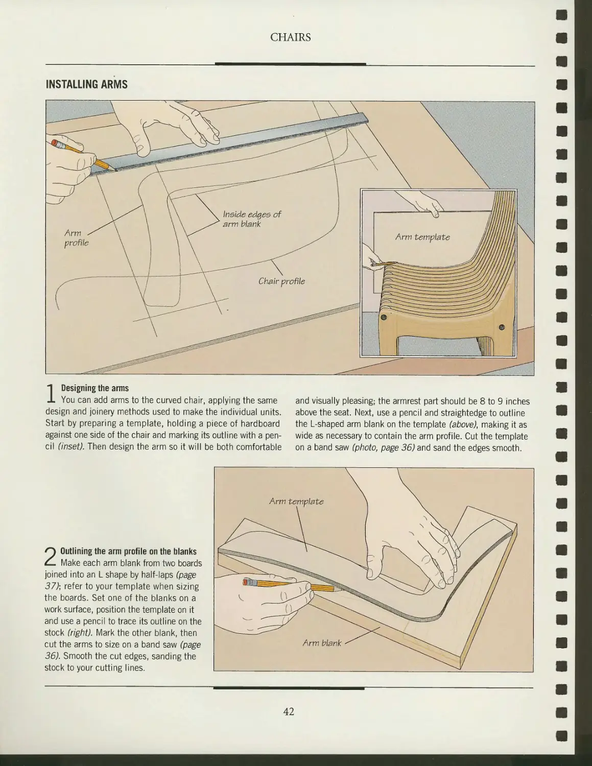
INSTALLING ARMS
1 Designing the arms
You can add arms to the curved chair, applying the same and visually pleasing; the armrest part should be 8 to 9 inches
design and joinery methods used to make the individual units. above the seat. Next, use a pencil and straightedge to outline
Start by preparing a template, holding a piece of hardboard the L-shaped arm blank on the template (above), making it as
against one side of the chair and marking its outline with a pen- wide as necessary to contain the arm profile. Cut the template
cil (inset). Then design the arm so it will be both comfortable on a band saw (photo, page 36) and sand the edges smooth.
2 Outlining the arm profile on the blanks
Make each arm blank from two boards
joined into an L shape by half-laps (page
37); refer to your template when sizing
the boards. Set one of the blanks on a
work surface, position the template on it
and use a pencil to trace its outline on the
stock (right). Mark the other blank, then
cut the arms to size on a band saw (page
36). Smooth the cut edges, sanding the
stock to your cutting lines.
42
CHAIRS
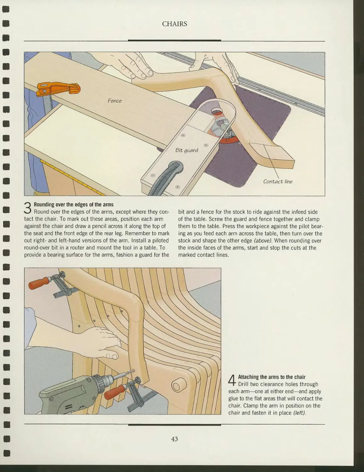
3 Rounding over the edges of the arms
Round over the edges of the arms, except where they
contact the chair. To mark out these areas, position each arm
against the chair and draw a pencil across it along the top of
the seat and the front edge of the rear leg. Remember to mark
out right- and left-hand versions of the arm. Install a piloted
round-over bit in a router and mount the tool in a table. To
provide a bearing surface for the arms, fashion a guard for the
bit and a fence for the stock to ride against the infeed side
of the table. Screw the guard and fence together and clamp
them to the table. Press the workpiece against the pilot
bearing as you feed each arm across the table, then turn over the
stock and shape the other edge (above). When rounding over
the inside faces of the arms, start and stop the cuts at the
marked contact lines.
4 Attaching the arms to the chair
Drill two clearance holes through
each arm—one at either end—and apply
glue to the flat areas that will contact the
chair. Clamp the arm in position on the
chair and fasten it in place (left).
43
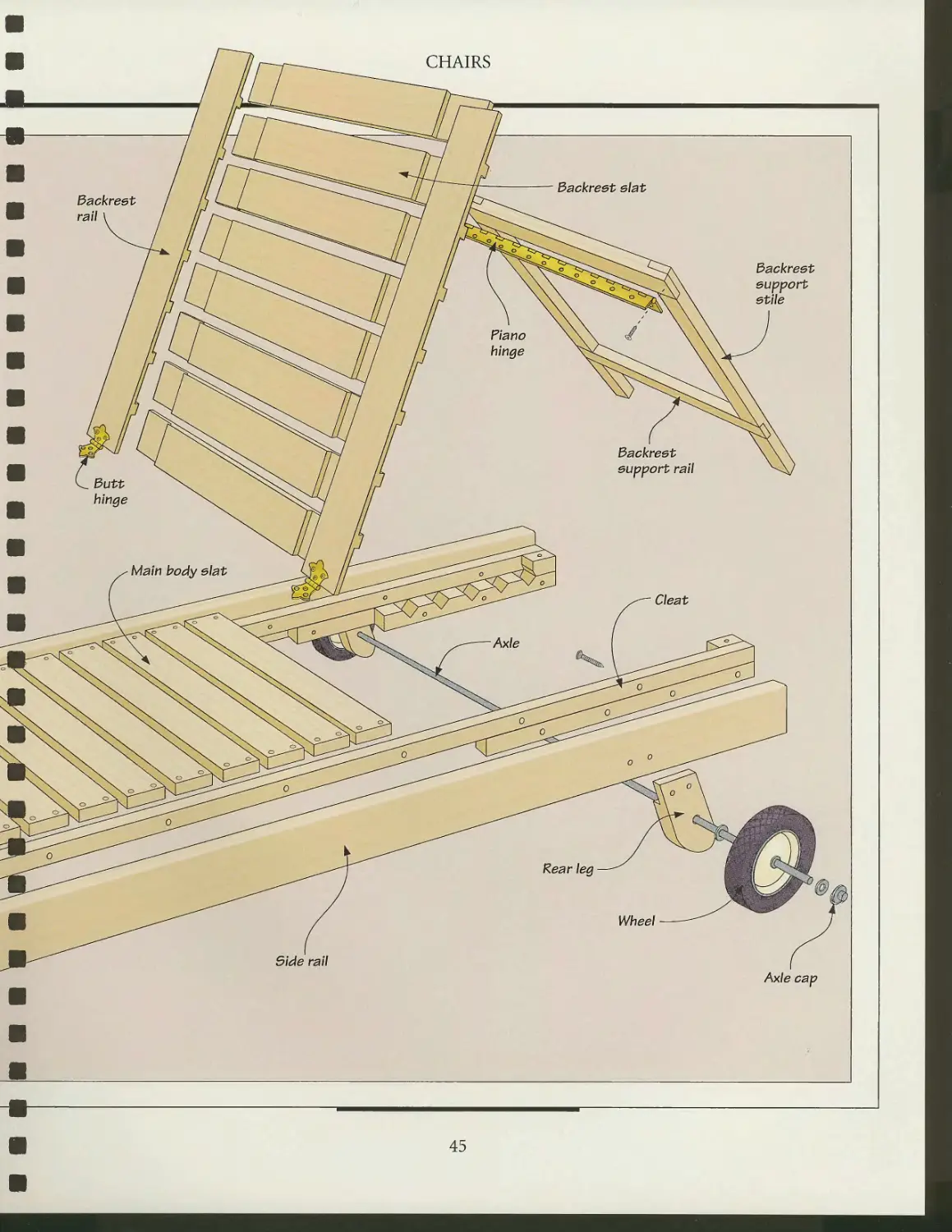
ANATOMY OF A LOUNGE CHAIR
(
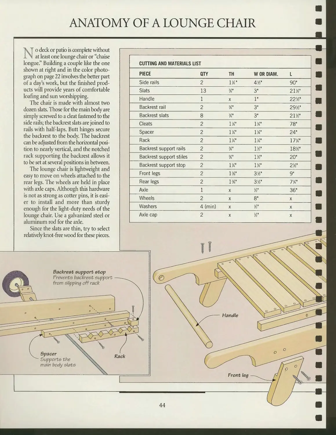
"J o deck or patio is complete without
^ at least one lounge chair or "chaise
longue." Building a couple like the one
shown at right and in the color
photograph on page 22 involves the better part
of a day s work, but the finished
products will provide years of comfortable
loafing and sun worshipping.
The chair is made with almost two
dozen slats. Those for the main body are
simply screwed to a cleat fastened to the
side rails; the backrest slats are joined to
rails with half-laps. Butt hinges secure
the backrest to the body. The backrest
can be adjusted from the horizontal
position to nearly vertical, and the notched
rack supporting the backrest allows it
to be set at several positions in between.
The lounge chair is lightweight and
easy to move on wheels attached to the
rear legs. The wheels are held in place
with axle caps. Although this hardware
is not as strong as cotter pins, it is
easier to install and more than sturdy
enough for the light-duty needs of the
lounge chair. Use a galvanized steel or
aluminum rod for the axle.
Since the slats are thin, try to select
relatively knot-free wood for these pieces.
Backreet eupport etop
Frevente backrest eupport
from clipping off rack
CUTTING AND MATERIALS LIST
PIECE
Side rails
Slats
Handle
Backrest rail
Backrest slats
Cleats
Spacer
Rack
Backrest support rails
Backrest support stiles
Backrest support stop
Front legs
Rear legs
Axle
Wheels
Washers
Axle cap
QTY
2
13
1
2
8
2
2
2
2
2
2
2
2
1
2
4 (min)
2
TH
1/411
3/"
X
%"
%u
P/"
P/4"
P/4"
3/4"
3/4"
P/4"
P/s"
P/s"
X
X
X
X
W OR DIAM.
41/2"
3"
1"
3"
3"
P/411
PA"
P/411
P/2"
P/211
P/4"
31/"
3/2"
1/2"
8"
W
1/2"
L
90"
2 P/2"
22 Vin
291/2"
2 P/211
78"
24"
17*4"
is1/"
20"
21/2"
9"
71/4M
36"
X
X
X
Spacer
Supporte the
mam body elate
o
Handle
Front \eg
AA
CHAIRS
45
MAKING A LOUNGE CHAIR
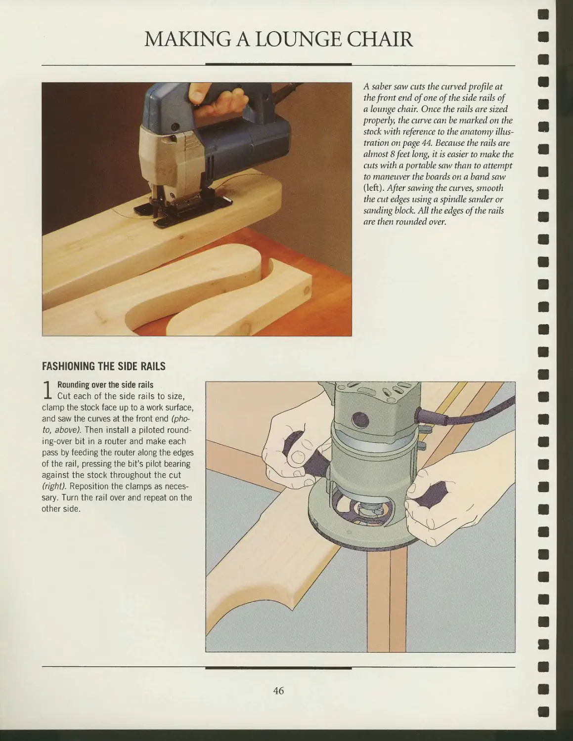
A saber saw aits the curved profile at
the front end of one of the side rails of
a lounge chair. Once the rails are sized
properly, the curve can he marked on the
stock with reference to the anatomy
illustration on page 44. Because the rails are
almost 8 feet long, it is easier to make the
cuts with a portable saw than to attempt
to maneuver the boards on a band saw
(left). After sawing the curves, smooth
the cut edges using a spindle sander or
sanding block. All the edges of the rails
are then rounded over.
FASHIONING THE SIDE RAILS
1 Rounding over the side rails
Cut each of the side rails to size,
clamp the stock face up to a work surface,
and saw the curves at the front end
(photo, above). Then install a piloted round-
ing-over bit in a router and make each
pass by feeding the router along the edges
of the rail, pressing the bit's pilot bearing
against the stock throughout the cut
(right). Reposition the clamps as
necessary. Turn the rail over and repeat on the
other side.
46
CHAIRS
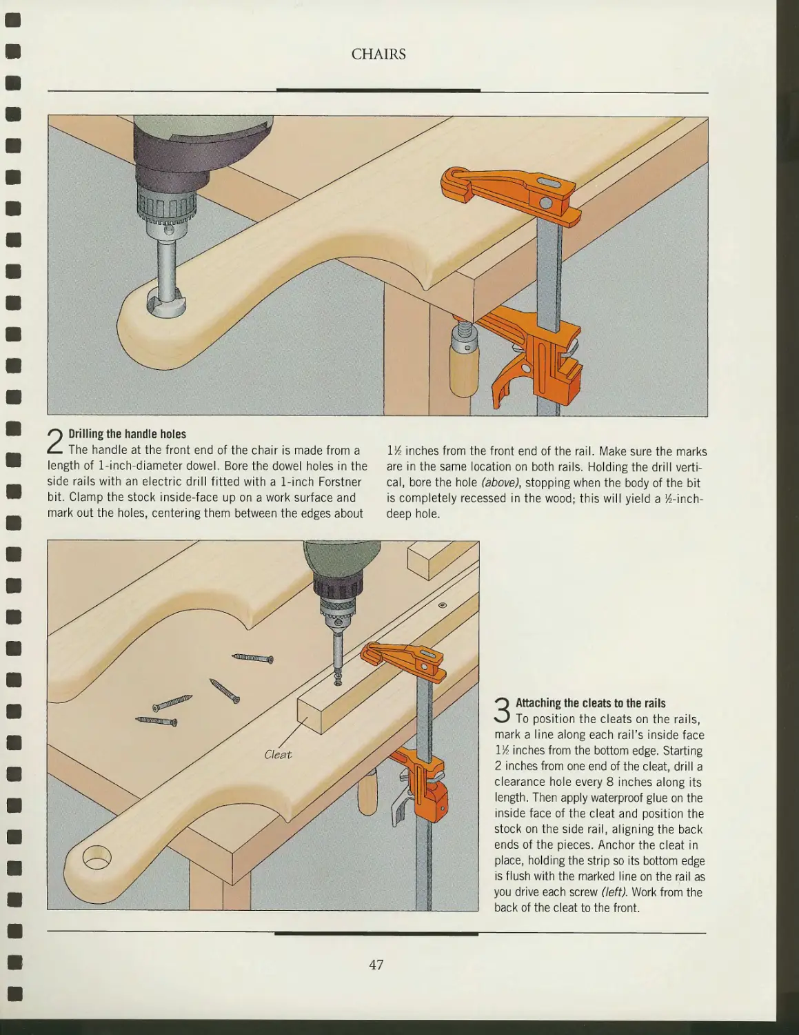
2 Drilling the handle holes
The handle at the front end of the chair is made from a Vk inches from the front end of the rail. Make sure the marks
length of 1-inch-diameter dowel. Bore the dowel holes in the are in the same location on both rails. Holding the drill verti-
side rails with an electric drill fitted with a 1-inch Forstner cal, bore the hole (above), stopping when the body of the bit
bit. Clamp the stock inside-face up on a work surface and is completely recessed in the wood; this will yield a ^-inch-
mark out the holes, centering them between the edges about deep hole.
3 Attaching the cleats to the rails
To position the cleats on the rails,
mark a line along each rail's inside face
Wi inches from the bottom edge. Starting
2 inches from one end of the cleat, drill a
clearance hole every 8 inches along its
length. Then apply waterproof glue on the
inside face of the cleat and position the
stock on the side rail, aligning the back
ends of the pieces. Anchor the cleat in
place, holding the strip so its bottom edge
is flush with the marked line on the rail as
you drive each screw (left). Work from the
back of the cleat to the front.
47
ASSEMBLING THE BODY
CHAIRS
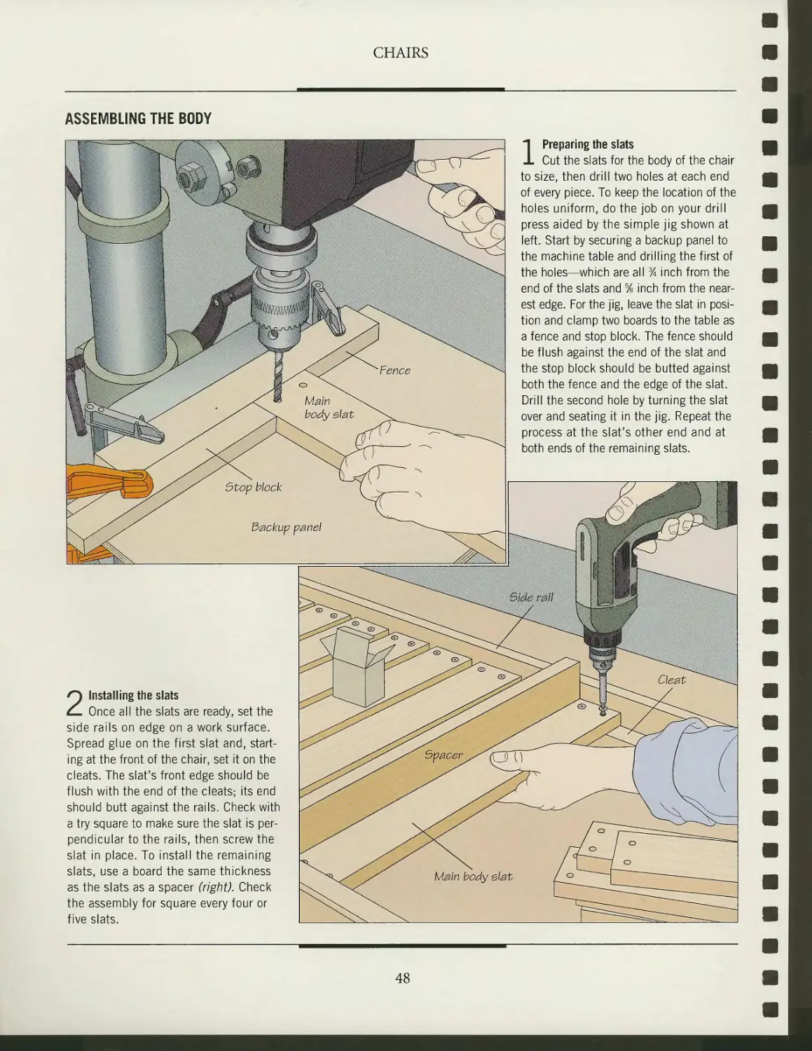
1 Preparing the slats
Cut the slats for the body of the chair
to size, then drill two holes at each end
of every piece. To keep the location of the
holes uniform, do the job on your drill
press aided by the simple jig shown at
left. Start by securing a backup panel to
the machine table and drilling the first of
the holes—which are all % inch from the
end of the slats and % inch from the
nearest edge. For the jig, leave the slat in
position and clamp two boards to the table as
a fence and stop block. The fence should
be flush against the end of the slat and
the stop block should be butted against
both the fence and the edge of the slat.
Drill the second hole by turning the slat
over and seating it in the jig. Repeat the
process at the slat's other end and at
both ends of the remaining slats.
2 Installing the slats
Once all the slats are ready, set the
side rails on edge on a work surface.
Spread glue on the first slat and,
starting at the front of the chair, set it on the
cleats. The slat's front edge should be
flush with the end of the cleats; its end
should butt against the rails. Check with
a try square to make sure the slat is
perpendicular to the rails, then screw the
slat in place. To install the remaining
slats, use a board the same thickness
as the slats as a spacer (right). Check
the assembly for square every four or
five slats.
48
BUILDING THE BACKREST
CHAIRS
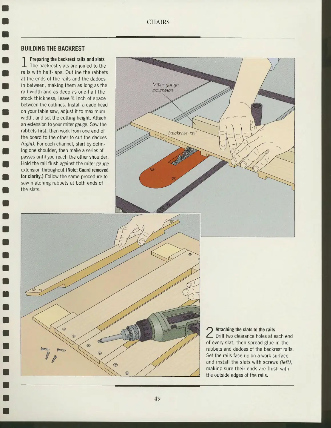
1 Preparing the backrest rails and slats
The backrest slats are joined to the
rails with half-laps. Outline the rabbets
at the ends of the rails and the dadoes
in between, making them as long as the
rail width and as deep as one-half the
stock thickness; leave 3A inch of space
between the outlines. Install a dado head
on your table saw, adjust it to maximum
width, and set the cutting height. Attach
an extension to your miter gauge. Saw the
rabbets first, then work from one end of
the board to the other to cut the dadoes
(right). For each channel, start by
defining one shoulder, then make a series of
passes until you reach the other shoulder.
Hold the rail flush against the miter gauge
extension throughout (Note: Guard removed
for clarity.) Follow the same procedure to
saw matching rabbets at both ends of
the slats.
2 Attaching the slats to the rails
Drill two clearance holes at each end
of every slat, then spread glue in the
rabbets and dadoes of the backrest rails.
Set the rails face up on a work surface
and install the slats with screws (left),
making sure their ends are flush with
the outside edges of the rails.
49
CHAIRS
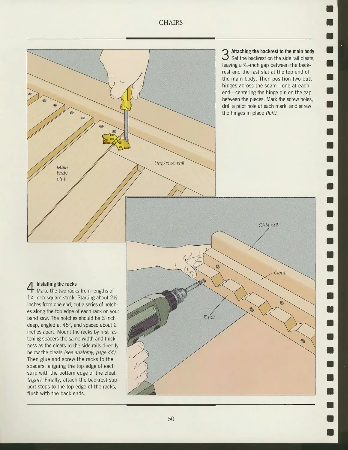
3 Attaching the backrest to the main body
Set the backrest on the side rail cleats,
leaving a 3/ie-inch gap between the
backrest and the last slat at the top end of
the main body. Then position two butt
hinges across the seam—one at each
end—centering the hinge pin on the gap
between the pieces. Mark the screw holes,
drill a pilot hole at each mark, and screw
the hinges in place (left).
4 Installing the racks
Make the two racks from lengths of
l^-inch-square stock. Starting about 2lA
inches from one end, cut a series of
notches along the top edge of each rack on your
band saw. The notches should be % inch
deep, angled at 45°, and spaced about 2
inches apart. Mount the racks by first
fastening spacers the same width and
thickness as the cleats to the side rails directly
below the cleats (see anatomy, page 44).
Then glue and screw the racks to the
spacers, aligning the top edge of each
strip with the bottom edge of the cleat
(right). Finally, attach the backrest
support stops to the top edge of the racks,
flush with the back ends.
50
CHAIRS
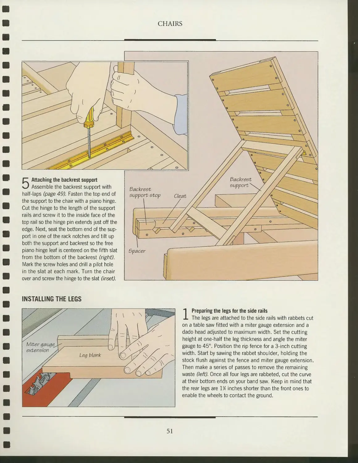
5 Attaching the backrest support
Assemble the backrest support with
half-laps (page 49). Fasten the top end of
the support to the chair with a piano hinge.
Cut the hinge to the length of the support
rails and screw it to the inside face of the
top rail so the hinge pin extends just off the
edge. Next, seat the bottom end of the
support in one of the rack notches and tilt up
both the support and backrest so the free
piano hinge leaf is centered on the fifth slat
from the bottom of the backrest (right).
Mark the screw holes and drill a pilot hole
in the slat at each mark. Turn the chair
over and screw the hinge to the slat (inset).
INSTALLING THE LEGS
1 Preparing the legs for the side rails
The legs are attached to the side rails with rabbets cut
on a table saw fitted with a miter gauge extension and a
dado head adjusted to maximum width. Set the cutting
height at one-half the leg thickness and angle the miter
gauge to 45°. Position the rip fence for a 3-inch cutting
width. Start by sawing the rabbet shoulder, holding the
stock flush against the fence and miter gauge extension.
Then make a series of passes to remove the remaining
waste (left). Once all four legs are rabbeted, cut the curve
at their bottom ends on your band saw. Keep in mind that
the rear legs are 1% inches shorter than the front ones to
enable the wheels to contact the ground.
51
CHAIRS
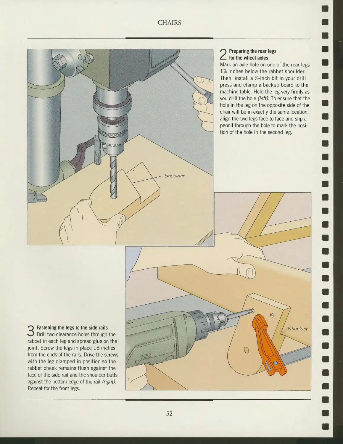
2 Preparing the rear legs
for the wheel axles
Mark an axle hole on one of the rear legs
17s inches below the rabbet shoulder.
Then, install a /2-inch bit in your drill
press and clamp a backup board to the
machine table. Hold the leg very firmly as
you drill the hole (left). To ensure that the
hole in the leg on the opposite side of the
chair will be in exactly the same location,
align the two legs face to face and slip a
pencil through the hole to mark the
position of the hole in the second leg.
3 Fastening the legs to the side rails
Drill two clearance holes through the
rabbet in each leg and spread glue on the
joint. Screw the legs in place 18 inches
from the ends of the rails. Drive the screws
with the leg clamped in position so the
rabbet cheek remains flush against the
face of the side rail and the shoulder butts
against the bottom edge of the rail (right).
Repeat for the front legs.
52
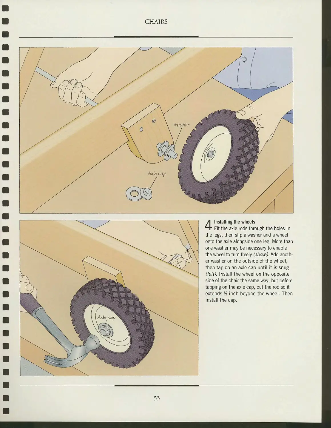
4 Installing the wheels
Fit the axle rods through the holes in
the legs, then slip a washer and a wheel
onto the axle alongside one leg. More than
one washer may be necessary to enable
the wheel to turn freely (above). Add
another washer on the outside of the wheel,
then tap on an axle cap until it is snug
(left). Install the wheel on the opposite
side of the chair the same way, but before
tapping on the axle cap, cut the rod so it
extends lA inch beyond the wheel. Then
install the cap.
MW*$
.<*;,■*"*'.,
«&
-asad
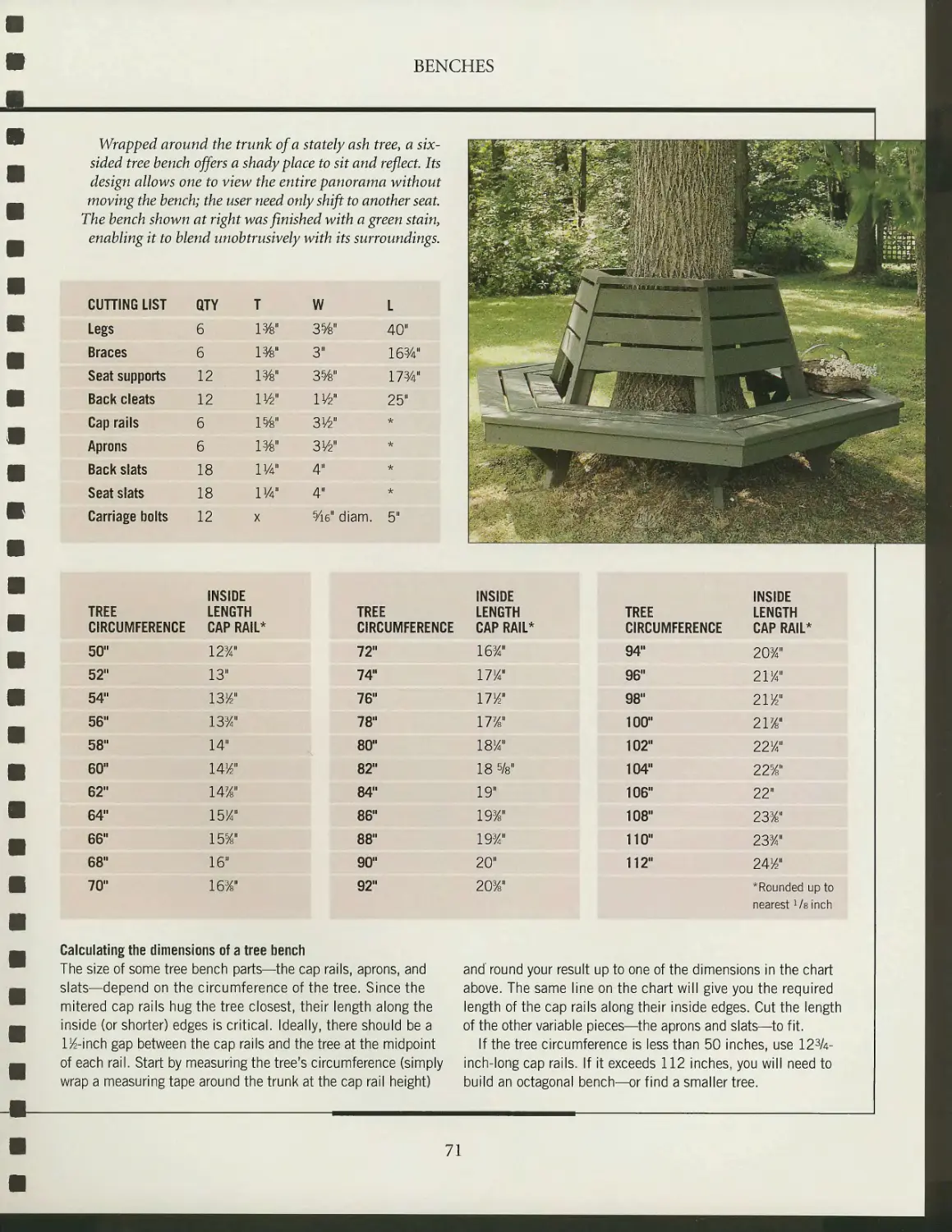
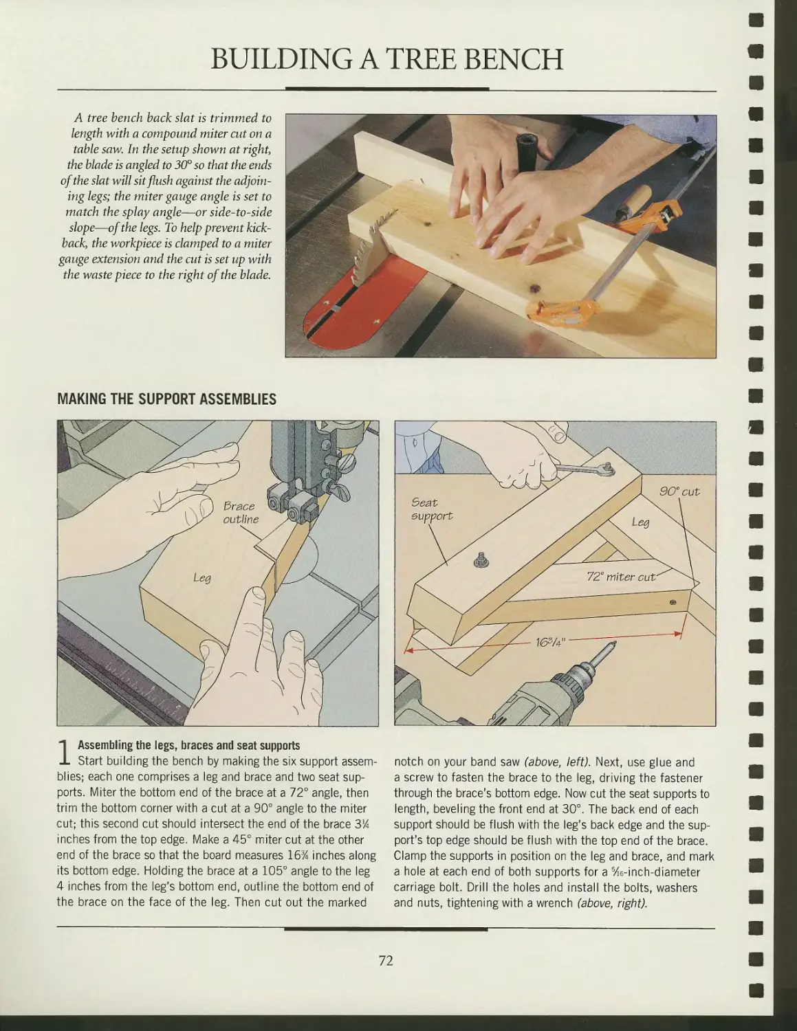
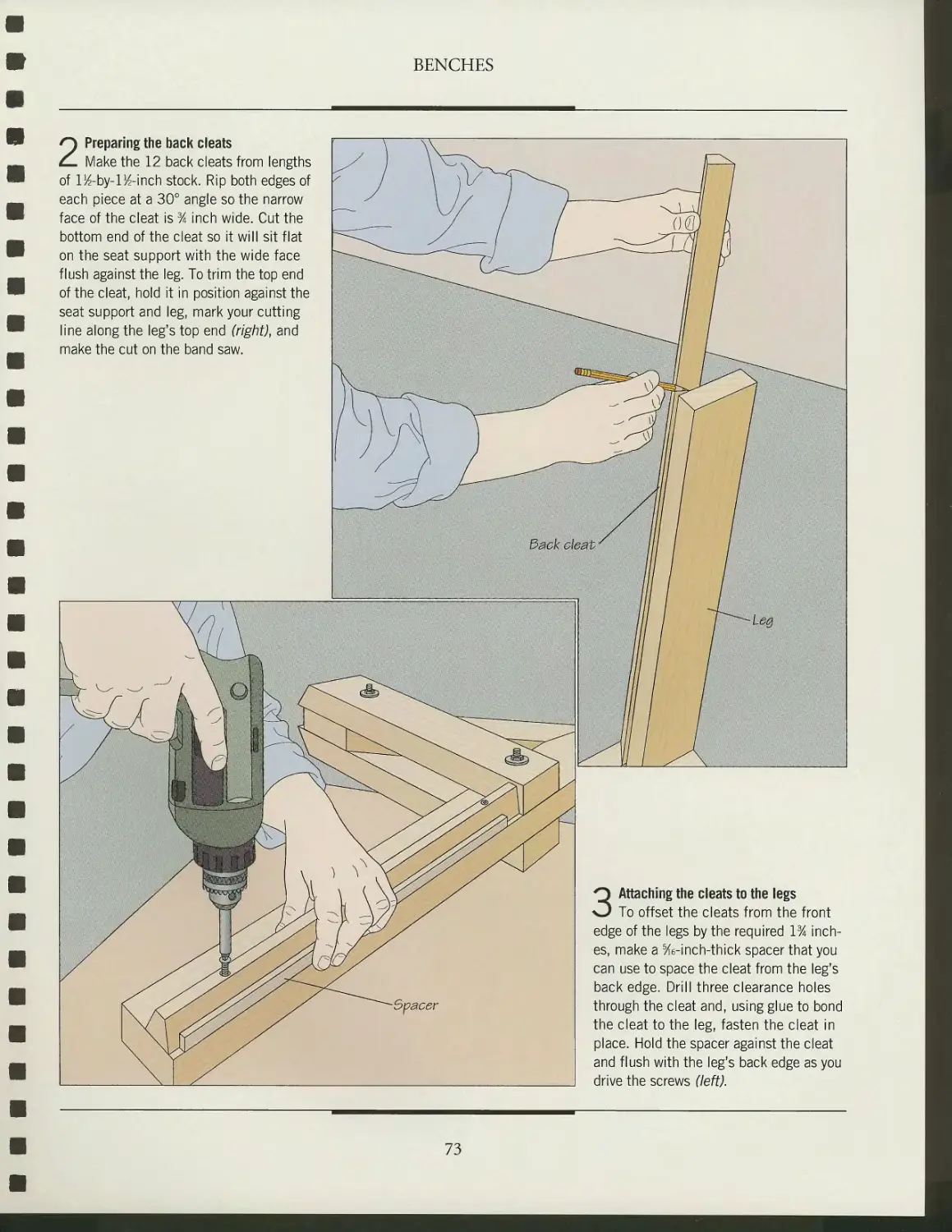
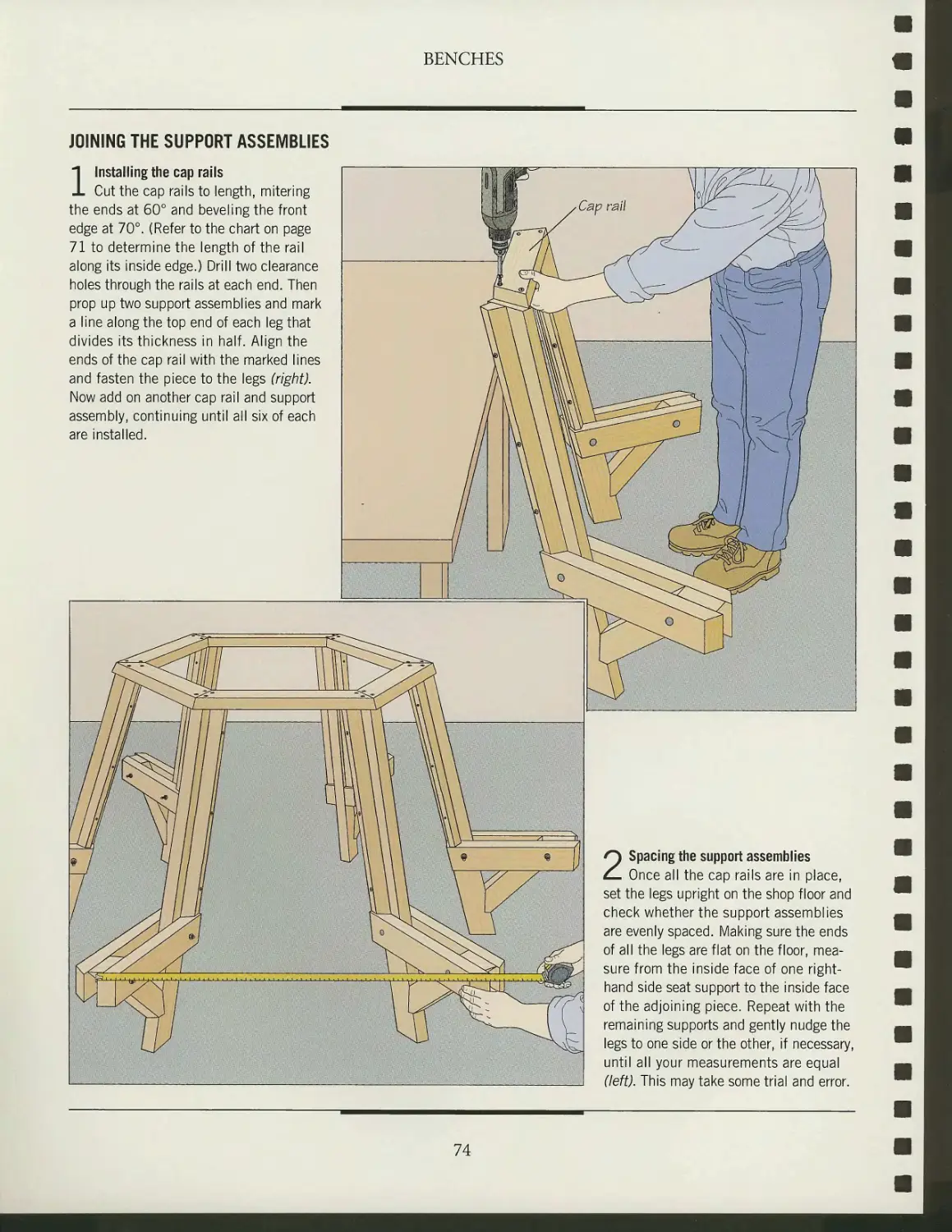
BENCHES
The pleasures of a
backyard or flower garden
are meant to be shared. While
a lone chair may be suited to
solitary reflection, benches
call out for company. More
than anything, a bench is an
invitation, beckoning visitors
to sit and chat or simply
enjoy the surrounding views.
This chapter shows how to
build three different styles of
benches. The garden bench
shown at left and on the
following pages will suit more
formal tastes. Its solid, upright
backrest puts it in character
in a well-ordered garden. But
in the right location, the bench
could also serve as an
interesting counterpoint to a more
informal layout. In either case, try to situate it in front of
tall flowers or shrubs, which will serve as a backdrop to
frame the piece.
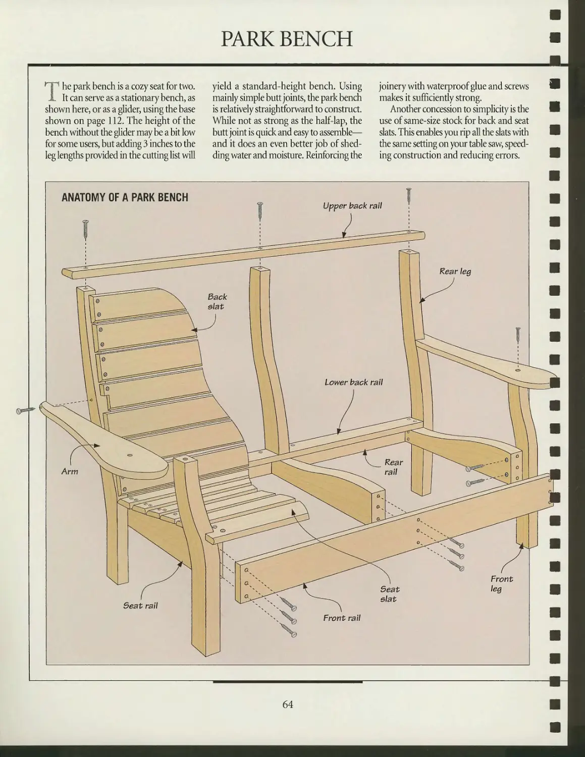
The park bench (page 64) is a versatile piece. The curved
lines of its armrests and legs give it a more casual look than
the garden bench. A simple and attractive bench when used
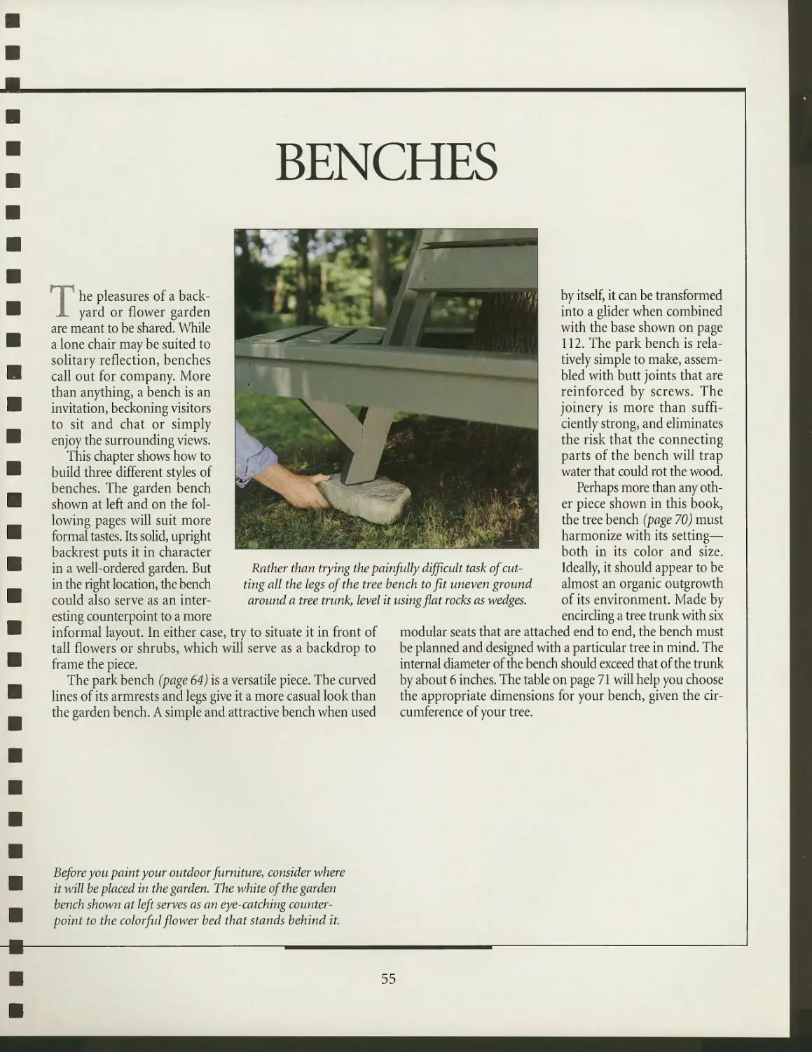
Rather than trying the painfully difficult task of
cutting all the legs of the tree bench to fit uneven ground
around a tree trunk, level it using flat rocks as wedges.
by itself, it can be transformed
into a glider when combined
with the base shown on page
112. The park bench is
relatively simple to make,
assembled with butt joints that are
reinforced by screws. The
joinery is more than
sufficiently strong, and eliminates
the risk that the connecting
parts of the bench will trap
water that could rot the wood.
Perhaps more than any
other piece shown in this book,
the tree bench (page 70) must
harmonize with its setting—
both in its color and size.
Ideally, it should appear to be
almost an organic outgrowth
of its environment. Made by
encircling a tree trunk with six
modular seats that are attached end to end, the bench must
be planned and designed with a particular tree in mind. The
internal diameter of the bench should exceed that of the trunk
by about 6 inches. The table on page 71 will help you choose
the appropriate dimensions for your bench, given the
circumference of your tree.
Before you paint your outdoor furniture, consider where
it will he placed in the garden. The white of the garden
bench shown at left serves as an eye-catching
counterpoint to the colorful flower bed that stands behind it.
55
ANATOMY OF A GARDEN BENCH
rf^ he garden bench is a sophisticated back slats, for example, are housed in that bridge the ends, such as the front
X piece of furniture. Building it demands dadoes that extend right through the seat rail and back rails. Finally, finish the
as much precision and attention to detail rails, allowing any moisture to drain out. seat and back,
as any indoor project. It also incorporates To make the bench, start by assem- To ensure that all the surfaces of the
features that give it the needed strength bling the legs and rails, then add the bench are uniformly smooth when the
and durability to face the elements. The arms and their slats, forming the two time comes to apply a finish, sand the
bottom ends of the arm support and end units. Next, install the longer pieces pieces before fastening them in place.
56
CUTTING LIST
Front legs
Rear legs
End rails
Arms
Arm support slats
Middle stretcher
End stretchers
Front seat rail
Back seat rail
Cleats
Seat supports
Seat slats
Upper back rail
Lower back rail
Lower back rail cap
Back slats
QTY
2
2
2
2
6
1
2
1
1
2
4
7
1
1
1
13
T
W"
VA"
VA"
%"
%"
VA"
VA"
VA"
VA"
1"
VA"
VA"
VA"
1"
%"
%"
W
VA"
FX"
4"
3"
%"
2X
2"
4"
3"
1"
2/4"
3"
43/4"
2/4"
2/4"
2"
L
24"
473/4"*
233/8"
24^"
IVA"
60"
24"
60"
60"
56^"
2 IK"
571/4"
60"
60"
565/s"
2514"
* Final measurement. Stock should be wider to accommodate curve of leg.
FRONT LEG-AND-
RAIL ASSEMBLY
57
BUILDING A GARDEN BENCH
A dado head on a table saw cuts a dado
in the front leg of a garden bench. Each
front leg needs three dadoes—two on the
outside face that match rabbets sawn into
the end and stretcher rails, and one on
the front edge for a rabbet in the front
seat rail. In the setup shown at right, stop
blocks clamped to a miter gauge
extension ensure that the dadoes in the two
legs will be in exactly the same locations.
ASSEMBLING THE END UNITS
b^A
K
_/J \
\ ^^ Rear-leg etock
\. \ ^^ Template
\ nX^ \/\ ^^- Rear-leg outline
VwTcw\
^VjJ/ \ ^s, \
1 Making the rear legs
Referring to the anatomy illustration and cutting list on the
preceding pages, cut the arms, arm support slats, and the end
and stretcher rails. To outline the curved rear legs on the stock,
start by making a plywood or hardboard template; the legs are
vertical from their bottom ends to the seat and then curve
backward at about 10°, an angle that most users will find
comfortable. Once the template is ready, trace its outline on the leg
stock with a pencil. Using a 2-by-6 will enable you to use the
same blank for both legs (above). Cut the legs on your band saw.
2 Cutting the half-lap joints
All of the dadoes and rabbets for the half-laps used to
assemble the end units can be cut on the table saw (photo,
above}—except for those on the back edges of the rear legs for
the back seat rail. These are cut on a band saw because the
cuts are located on the inside of the leg curves, and the
stock cannot rest flat on a table saw table at these points.
Start by making all the table saw cuts, then outline the
remaining dado on each rear leg. Feeding the stock into the blade
with both hands, cut the sides of the dado with two cross-grain
cuts, then make a series of curved (above) and straight cuts to
remove the remaining waste.
58
BENCHES
3 Attaching the end and
stretcher rails to the legs
Set front and rear legs from the same side
of the bench outside face up on a work
surface and apply waterproof glue in the
dadoes. Tap the end and stretcher rails in
position, check the unit for square and drill
pilot holes in the rails, two at each end
of the end rail and one into the stretcher
rail. Screw the pieces together (right).
4 Installing the arms
Screw the arm support slats to the
end rails, making certain that the supports'
bottom ends are flush with the bottom
edges of the rails. Then, holding one leg
assembly upright, set the arm in
position, centering it on the supports and
butting the back end against the rear leg.
Outline the supports on the underside of
the arm and cut a ^-inch-deep mortise
into the arm within each outline. Also
bore two clearance holes through the arm
in line with the front leg and through the
rear leg into the end of the arm. Next,
spread some glue in the arm mortises and
at the points where the arm contacts the
legs, fit the arm in position again (left),
and screw it to the legs.
59
BENCHES
ATTACHING THE SEAT RAILS AND MIDDLE STRETCHER
2 Attaching the middle stretcher the tool level on the rail, feed the bit into the stock and along
Cut a rabbet at each end of the stretcher to mate with the the rail (above); make sure the bit's pilot bearing is pressed
dadoes in the end stretchers. Drill two clearance holes through against the stock throughout. Stop the cut when the router con-
the stretcher at each end of the board, then spread some glue in tacts the opposite front leg, then repeat the pass along the rail's
the rabbets, set the piece in position (above) and screw it down. front face. Increase the cutting depth and make two more passes.
60
BENCHES
INSTALLING THE SEAT
1 Attaching the cleats and seat supports
Secure the cleats to the seat rails with
glue and screws spaced at 8-inch
intervals; position the cleats so that the top edges
of the seat supports and seat rails lie
flush. With the cleats in position, set the
bench on its back and attach the end
seat supports to the cleats, driving the
screws from underneath; the supports
should be flush against the legs and end
rails. Next, fasten the middle seat supports
to the cleats, spacing them evenly and
holding each piece in position as you
drive the screws (right).
2 Installing the seat slats
Round over the top edges of the seat
slats and test-fit them in the bench so that
there is K-inch gap between them; trim the
slats' edges, if necessary. Mark the
locations of the seat supports on each slat and
drill two clearance holes through the slats
at each mark. Starting at the front seat rail,
screw the slats to the supports, using lA-
nch spacers to maintain the gap between
the pieces (left).
61
BENCHES
ASSEMBLING THE BACK
2 Preparing the rail for the back slats
Cut the groove for the slats along the rail on your table saw the position of the dado head when it is hidden by the rail during
equipped with a dado head. Adjust the width of the blades to the the cut, mark two lines on the fence at the point where the blades
slat thickness—% inch—and the cutting height to 1 inch. Center start and stop cutting. Holding the rail against the fence just above
the rail over the blades and butt the rip fence against the stock. the blades and aligning the front end of the piece with the cutting
To help keep the rail pressed against the fence, clamp a feather- mark on the fence, slowly lower it onto the head (above, left). Once
board to the saw table, braced by a support board installed at a 90° the rail is sitting squarely on the table, feed it forward while press-
angle; round over the top edge of the featherboard to facilitate ing it against the fence (above, right). Stop the cut once the back
lowering the workpiece onto the blades. To help you determine end of the rail reaches the back cutting mark.
62
3 Fastening the lower back rail
to the rear legs
Prepare the lower back rail and then install
the back slats in the rail, proceeding as
you would for a porch swing (page 106).
Spread some glue on the contacting
surfaces of the lower rail and rear legs, fit the
assemblies together (above) and drive
two screws into each end of the rail.
4 Attaching the upper back rail
Positioning the upper rail over the slats,
start at one end to push the rail down,
snapping the slats into the groove as you go.
Once the pieces are all in place, glue and
screw the half-laps joining the rail and
rear legs (left). To complete the bench,
glue wood filler strips in the upper rail
groove between the slats. This will keep
the slats from shifting.
PARK BENCH
The park bench is a cozy seat for two.
It can serve as a stationary bench, as
shown here, or as a glider, using the base
shown on page 112. The height of the
bench without the glider may be a bit low
for some users, but adding 3 inches to the
leg lengths provided in the cutting list will
yield a standard-height bench. Using
mainly simple butt joints, the park bench
is relatively straightforward to construct.
Wliile not as strong as the half-lap, the
butt joint is quick and easy to assemble—
and it does an even better job of
shedding water and moisture. Reinforcing tlie
joinery with waterproof glue and screws
makes it sufficiently strong.
Another concession to simplicity is the
use of same-size stock for back and seat
slats. This enables you rip all the slats with
tlie same setting on your table saw,
speeding construction and reducing errors.
ANATOMY OF A PARK BENCH
Rear leg
Lower back rail
Arm
Rear
rail
Seat
elat
Front rail
64
BENCHES
Two coats of spar
varnish applied
on the park bench
shown at right
bring out the rich
natural tones of
the wood—in this
case, Northern
white cedar.
CUTTING
LIST
Front legs
Rear legs
Seat rails
Arms
Front rail
Rear rails
Upper
back rail
Seat slats
Back slats
QTY
2
3
3
2
1
2
1
6
7
TH
VA"
VA"
VA"
%"
3A"
3A"
3A"
3A"
3A"
W
4"
5"
43/4"
6"
4%"
2%"
2"
3"
3"
L
203A"
333/8"
21"
23"
46"
46"
49 %"
47"
47"
65
BENCHES
MAKING THE END UNITS
1 Shaping the legs
Start building the bench by assembling the end units, which cut out the legs on the band saw. Smooth the surfaces of each
consist of the seat and seat rails. Referring to the cutting pat- leg with a sanding block (above), securing the stock to a work
terns shown on page 65, make templates for the front and rear surface and sanding with the grain. Rearrange the leg in the
legs. Then trace the designs onto your leg stock (page 58) and clamps as necessary.
2 Attaching the seat rails to the legs
Cut the seat rails to size, then fasten
one to each leg. Mark layout lines on the
legs to position the rail properly: The rail
should be inset from the outside edges of
the legs by % inch to allow the front and
rear rails to be set flush with the leg's
edges; the bottom edge of the seat rail
should be 5% inches from the bottom of
the rear leg and 6 inches from the bottom
of the front leg. Spread some glue on the
contacting surfaces of the pieces, align the
rail with your layout lines, and use a try
square as you fasten the rails to the legs
to ensure that the bottom edge of the rails
remains perpendicular to the outside edge
of each leg (right).
66
BENCHES
ASSEMBLING THE SEAT
1 Installing the front and rear rails
Cut the front and rear rails to size and
drill clearance holes at the ends of each
piece. Using glue and screws, fasten the
rear rail in place; drive one screw at each
end to start, check for square, then install
the remaining fasteners. Install the front
rail the same way (right), then attach the
third seat rail to the front and rear rails,
centering it between the end units.
2 Installing the seat slats
Cut all the seat and back slats to size
and round over their edges. Drill two
clearance holes through each piece at every
seat rail location. Next, notch the first
seat slat at the front of the bench to fit
around the front legs. To ensure the slat
sits flush against the curved front edge of
the legs, hold it in position on the rails,
outline the leg profile at each end with a
pencil (left) and trim to the line with a
chisel. Screw the slats in place,
separating them with %-inch spacers (page 61).
67
INSTALLING THE ARM
1 Shaping the arm
Outline the appropriate cutting pattern
(page 65) on one arm blank, then cut the
notch at the back end of the blank that
will enable the arm to fit around the rear
leg. To ensure the inside surfaces of the
arm and rear leg will align, hold the blank
in position and mark a line along the top
face of the blank that parallels the leg's
inside face (right). Cut the arm to shape
on your band saw, then use a router to
round over all its edges, except for those
that define the notch. Use the first arm to
outline the opposite one.
2 Installing the arms
Position the arm on the bench so that the inside edge is the arm and drill clearance holes through it. Then apply glue
flush with the rear leg and overhangs the inside face of the to the contacting surfaces of the arm and legs and fasten each
front leg by 1% inches. Mark location lines on the underside of arm in place (above).
BENCHES
68
BENCHES
ASSEMBLING THE BACK
1 Rabbeting the back slats
Cut the rabbets at the ends of the back slats on your
table saw. Install a dado head and adjust its width to
slightly more than lA inch. Then attach an auxiliary fence,
position the fence for a ^-inch cutting width, and raise the blades
into the wooden fence to notch it, making sure that the dado
head is clear of the metal one. Adjust the cutting height to
one-half the slat thickness and screw an extension board to
the miter gauge. Feed the slats rounded-over side up,
holding the stock flush against the fence and miter gauge
extension while you make the cut (above).
2 Attaching back slats and rail
Using glue and two screws at each
end, fasten the back slats to the rear
legs; cut Me-inch spacers to maintain the
proper gap between the bottommost back
slat and the seat, and %-inch spacers for
the remaining rows. Before applying glue
to the fourth slat from the bottom, notch
it at each end to fit around the arms. Once
all the back slats are installed, use two
screws to fasten the bottom end of the
back support piece to the seat slat at
the back of the bench. Complete the
bench by installing the upper back rail.
Apply glue to the contacting surfaces of
the rail and legs, then screw the support
in position (left).
69
ANATOMY OF A TREE BENCH
Once installed, a tree bench can
become an integral part of its
environment, appearing as natural,
necessary, and stable as the tree it
encircles. Indeed, this bench is by
definition a custom-made project. You
cannot complete the cutting list until
you measure the circumference of the
tree around which the bench will fit.
Refer to the chart opposite to help you
size the variable parts of your project.
Although final assembly of the bench
is done on site, you will avoid
frustration if you first test-assemble the six
identical seating units in the shop.
Once you are satisfied with the fit,
disassemble the bench only partially to
move it. Remove the cap rail, seat, slats,
back slats and apron from two
opposite sections, leaving two pairs of seat
sections intact. When you reach your
tree, position the two intact sections
around the trunk, then reattach the
removed sections.
70
BENCHES
Wrapped around the trunk of a stately ash tree, a six-
sided tree bench offers a shady place to sit and reflect. Its
design allows one to view the entire panorama without
moving the bench; the user need only shift to another seat.
The bench shown at right was finished with a green stain,
enabling it to blend unobtrusively with its surroundings.
CUTTING LIST
Legs
Braces
Seat supports
Back cleats
Cap rails
Aprons
Back slats
Seat slats
Carriage bolts
QTY 1
6
6
12
12
6
6
18
18
12 )
L%"
IW
1%"
IW
L%"
L%"
Wa"
Wa"
<
w
3%"
3"
3%"
IV?
3V2"
3V2"
4"
4"
^16" diam.
L
40"
16%"
17%"
25"
*
*
*
*
5"
%m
TREE
CIRCUMFERENCE
50"
52"
54"
56"
58"
60"
62"
64"
66"
68"
70"
INSIDE
LENGTH
CAP RAIL*
123/4"
13"
13/2"
133/4"
14"
I4/2"
147/8"
15%"
155/8"
16"
163/8"
TREE
CIRCUMFERENCE
72"
74"
76"
78"
80"
82"
84"
86"
88"
90"
92"
INSIDE
LENGTH
CAP RAIL*
163/4"
17/4"
UYz"
177/8"
181/"
18 5/8"
19"
193/8"
193/4"
20"
203/8"
TREE
CIRCUMFERENCE
94"
96"
98"
100"
102"
104"
106"
108"
110"
112"
INSIDE
LENGTH
CAP RAIL*
203/4H
21/4"
211/2"
217/8"
221/4"
225/8"
22"
233/8"
233/4H
24/2"
*Rounded up to
nearest lls inch
Calculating the dimensions of a tree bench
The size of some tree bench parts—the cap rails, aprons, and
slats—depend on the circumference of the tree. Since the
mitered cap rails hug the tree closest, their length along the
inside (or shorter) edges is critical. Ideally, there should be a
1^-inch gap between the cap rails and the tree at the midpoint
of each rail. Start by measuring the tree's circumference (simply
wrap a measuring tape around the trunk at the cap rail height)
and' round your result up to one of the dimensions in the chart
above. The same line on the chart will give you the required
length of the cap rails along their inside edges. Cut the length
of the other variable pieces—the aprons and slats—to fit.
If the tree circumference is less than 50 inches, use 123/4-
inch-long cap rails. If it exceeds 112 inches, you will need to
build an octagonal bench—or find a smaller tree.
71
BUILDING A TREE BENCH
A tree bench back slat is trimmed to
length with a compound miter cut on a
table saw. In the setup shown at right,
the blade is angled to 30° so that the ends
of the slat will sit flush against the
adjoining legs; the miter gauge angle is set to
match the splay angle—or side-to-side
slope—of the legs. To help prevent
kickback, the workpiece is clamped to a miter
gauge extension and the cut is set up with
the waste piece to the right of the blade.
MAKING THE SUPPORT ASSEMBLIES
l^#^"
m
■ m
w
y^/ \ [) Brace ^^r\^%/
\\X outline J9W
^ srj
\v / —». J / ^a\/
^V \ / ^ol^ /n\
\N
mr +
1 Assembling the legs, braces and seat supports
Start building the bench by making the six support
assemblies; each one comprises a leg and brace and two seat
supports. Miter the bottom end of the brace at a 72° angle, then
trim the bottom corner with a cut at a 90° angle to the miter
cut; this second cut should intersect the end of the brace 3%
inches from the top edge. Make a 45° miter cut at the other
end of the brace so that the board measures 16% inches along
its bottom edge. Holding the brace at a 105° angle to the leg
4 inches from the leg's bottom end, outline the bottom end of
the brace on the face of the leg. Then cut out the marked
90° cut
notch on your band saw (above, left). Next, use glue and
a screw to fasten the brace to the leg, driving the fastener
through the brace's bottom edge. Now cut the seat supports to
length, beveling the front end at 30°. The back end of each
support should be flush with the leg's back edge and the
support's top edge should be flush with the top end of the brace.
Clamp the supports in position on the leg and brace, and mark
a hole at each end of both supports for a 5/i6-inch-diameter
carriage bolt. Drill the holes and install the bolts, washers
and nuts, tightening with a wrench (above, right).
72
BENCHES
2 Preparing the back cleats
Make the 12 back cleats from lengths
of 1^-by-l^-inch stock. Rip both edges of
each piece at a 30° angle so the narrow
face of the cleat is % inch wide. Cut the
bottom end of the cleat so it will sit flat
on the seat support with the wide face
flush against the leg. To trim the top end
of the cleat, hold it in position against the
seat support and leg, mark your cutting
line along the leg's top end (right), and
make the cut on the band saw.
3 Attaching the cleats to the legs
To offset the cleats from the front
edge of the legs by the required 1%
inches, make a 5/e-inch-thick spacer that you
can use to space the cleat from the leg's
back edge. Drill three clearance holes
through the cleat and, using glue to bond
the cleat to the leg, fasten the cleat in
place. Hold the spacer against the cleat
and flush with the leg's back edge as you
drive the screws (left).
73
JOINING THE SUPPORT ASSEMBLIES
BENCHES
1 Installing the cap rails
Cut the cap rails to length, mitering
the ends at 60° and beveling the front
edge at 70°. (Refer to the chart on page
71 to determine the length of the rail
along its inside edge.) Drill two clearance
holes through the rails at each end. Then
prop up two support assemblies and mark
a line along the top end of each leg that
divides its thickness in half. Align the
ends of the cap rail with the marked lines
and fasten the piece to the legs (right).
Now add on another cap rail and support
assembly, continuing until all six of each
are installed.
2 Spacing the support assemblies
Once all the cap rails are in place,
set the legs upright on the shop floor and
check whether the support assemblies
are evenly spaced. Making sure the ends
of all the legs are flat on the floor,
measure from the inside face of one right-
hand side seat support to the inside face
of the adjoining piece. Repeat with the
remaining supports and gently nudge the
legs to one side or the other, if necessary,
until all your measurements are equal
(left). This may take some trial and error.
74
BENCHES
■
^-^"~ —
Apron x
"^v^sTn
\w y
\L 7
77
\y\^
\ft\
Straightedge
X^ y^i
£*$0^ Brace
3 Sizing the aprons
You will need to mark one apron in position to determine
the final length of the pieces. Start by cutting the aprons
about 36 inches longer than the cap rails. Next, mark lines
along the top ends of two adjoining braces that divide their
thickness in half, and clamp a wood strip as a straightedge
along each marked line. To mark the apron, work with a helper
to hold the board in position at each end; making sure the
apron is flush against the seat supports and butted against the
underside of the straightedges, run a pencil along the wood
strip at each end of the apron (above). Trim the apron, then
use the piece to mark the remaining ones.
\__\_^
\ \\
\°
^l / / Straightedge
&>/(
^\ ?^ix J 1
Apron 1 I J
// //
1
%
(ml
4 Attaching the aprons
Drill a pair of clearance holes at each end of the aprons.
Using straightedges to center the ends of the pieces across the
braces, screw the aprons in place (above). You may need a
helper to hold up the opposite end of each apron as you drive
the first pair of screws.
INSTALLING SEAT AND BACK SLATS
\M
Leg-^\ /ss \J "—-
Seat X \ V
e\at' \ \
etock \
ffi^ \
^V\\^
K
®^~^^
1 Marking the first seat slat
Start sizing the seat slats at the back
of the bench. To determine the exact
angle at which you will need to miter the
ends of the slats, hold the first blank in
position on the seat supports and against
the legs and use a sliding bevel to
measure the angle formed by the slat and
one leg. Adjust the miter gauge on your
table saw to this angle. To locate your
cutting lines on the board, mark lines
along the front edges of the legs that
divide their thickness in half. Then, with
the slat blank in position, draw the
cutting marks Vs inch inside those on the
legs (left). This will leave the required
V4-gap between slats. Trim the slat to
length and use it to size the remaining
ones. Then fasten the slats to the seat
supports with two screws at each end,
leaving a V4-gap between the pieces.
75
BENCHES
2 Attaching the remaining seat slats
The second and third rows of the seat slats are installed in
much the same way as the first. To mark each slat, set it on
the seat supports and butt it edge to edge against the first
slat, placing a ^-inch-thick spacer stick between the slats.
Then use a pencil and a rule to mark lines across the face of
the slat that align with the ends of the first slat (above). Miter
the slat and fasten it to the seat supports, maintaining the %-
inch gap between the ends and a %-inch space between edges.
3 Trimming the back slats to length
The ends of the back slats must be cut at a compound
angle—both mitered and beveled—so they sit flush against
the legs of the tree bench. To mark the slats, set a 6%-inch-
wide spacer on edge on the first seat slat and place the back
slat blank on the spacer. Holding the slat flat against two
adjoining legs, run a pencil along the inside face of the each
leg to mark cutting lines on the face of the slat (above). To cut
the compound angle on your table saw, angle the blade to 60°
and adjust the miter gauge to the angle marked on the slat
(photo, page 72). Use the slat as a guide to trimming the
others in the bottom tier.
4 Installing the back slats
Drill two clearance holes at each end
of every back slat. Using the spacer to
separate the slat from the seat slat below and
a clamp to hold the slat level, fasten each
piece to the back cleats (right). Install the
second and third tiers of back slats the
same way, but use a %-inch-thick spacer to
separate the board edges. Apply your finish
before setting up the bench in its chosen
location outdoors and so avoid splattering
the tree with paint, stain, or varnish. Before
transporting the bench, remove the cap
rail, apron and slats from two opposite
sides of the assembly. This will leave two
pairs of frame sections that, together with
the removed pieces, are easy to move.
Once the two frame sections are positioned
around the tree, you can reinstall the
detached boards (photo, page 77).
76
BENCHES
With two double frame sections
positioned on opposite sides of an ash tree,
a tree bench apron is fastened in place.
Since the bench was built in the shop
and disassembled for easy transport
and positioning, installing the
remaining pieces—the seat and back slats, the
cap rails and the last apron—is a
simple matter. The boards can befitted
into position and the screws driven
into theirpredrilled holes.
SETTING UP A TREE BENCH
Leveling a tree bench
Once all the pieces of your tree bench
have been fastened in place, work with
a helper to lift it and position the
assembly around the tree. The gap between the
trunk and cap rails should be equal around
the tree's circumference. Because the
terrain is unlikely to be as level as your shop
floor, one or more of the legs may not be
in contact with the ground. Rotating the
bench in one direction or the other may
solve the problem. If not, trim a leg (left)
that is resting on higher ground, or prop
up a leg that is not touching the ground
(photo, page 55).
77
u <* m
.M
TABLES
Eating outdoors is one of life's
simple pleasures. Whether it is
a picnic, a barbeque, or something
more elaborate, dining al fresco
always adds something special to
the experience. The patio table and
the folding picnic table shown
in this chapter are both excellent
additions to any outdoor furniture
ensemble.
The patio table (page 80) is large
enough to seat six adults
comfortably. It is, in fact, as big as many
dining tables. The table does not seem
imposing, however, mainly because
of the lattice-work grid that
comprises the top. This gives the table a
light appearance, and literally
reduces the weight. While it is not as
portable as the picnic table, it can
be moved easily by two people, or
even one in a pinch.
Like many pieces of outdoor
furniture, the patio table relies on half-
laps to join the legs and rails. The frame surrounding the lattice
grid is assembled with bridle joints. These strong joints help
make up for some of the rigidity sacrificed by having a lattice
top instead of a solid one. The grid itself is formed by joining
the strips of wood with half-lap joints. This calls for cutting
several hundred dadoes—a daunting task, but one made quite
The convenience of a table that folds can
be a liability when it is laden with food.
One way to ensure that the table does not
collapse at an inopportune time is to
use a butterfly catch pull to lock the leg
rail and support block together.
manageable with the help of the
indexing jig shown on pages 88 and
page 134.
The folding picnic table (page 90)
offers a convenient solution to the
need for a table that is transportable.
It is designed to fold down neatly
and can fit inside most car trunks.
When locked in the up position, the
table provides a sturdy surface large
enough to seat four adults. Its
construction combines the use of
prefabricated parts and building to fit.
While the top can be made made
by referring only to the cutting list
(page 92), the legs must be planned
carefully so they nest inside each
other and must be trimmed to the
right length and angle as the last
step (page 96).
A useful companion to both
tables is the keyed tenon bench
(page 98). It is attractive, simple,
and exceedingly strong. Sometimes
called a joynt stool, this is a very old design that could have
been found outside an English cottage four hundred years ago.
However, it looks perfectly at home on a contemporary deck
or patio. Its simple design makes it easy to build to whatever
length you need. Simple change the length of the slats and
stretchers listed in the cutting list as required.
A lattice top makes a table much lighter, but remember
not to make the holes too large or glasses will spill easily.
The spaces should be no larger than VU inches square.
79
PATIO TABLE
The patio table is a slightly formal,
but welcome addition any deck or
backyard. The lattice grid lends a
lightness to a fairly large table. A clever
design element holds the grid in place
with no need to cut a surrounding
rabbet. The inside length and width of the
frame are VA inches longer than those
of the table base. This creates a % inch
ledge to hold the grid on top of the rails,
within the frame.
The grid itself can be assembled on
the workbench and then installed in
the table. Prepare the strips one inch
longer than cited in the cutting list,
cut the dadoes for the half-laps, then
trim them to fit (page 88).
Though delicate looking, the table is
far from flimsy. But, while it will hold
up to reasonable use, but do not expect
it to withstand the same stress as your
oak dining table.
The base and the lattice grid of the
patio table are easy to separate,
lending itself to this striking finishing
technique. The lattice grid was removed as
a whole unit and finished with tung oil
and spar varnish. The rest of the table
was stained with a dark green opaque
finish, creating a contrast that
highlights the lattice wood's natural color.
The grid of lattice strips lacks the
same strength and rigidity as a solid top.
To increase the top's resistance to
racking, the corners are joined with bridle
joints, which offer twice the gluing
surface of half-laps.
CUTTING LIST
Legs
Side rails
End rails
Frame sides
Frame ends
Short lattice strips
Long lattice strips
QTY
4
2
2
2
2
24
13
T
114"
VA"
VA"
VA"
VA"
%'
%"
W
3!/2"
4V4'
4%"
3"
3"
1%"
VA"
L
29"
55%'
3072"
60"
36"
29%"*
54"*
* prepare strips one
inch longer than
trim to fit after
cutting dados
80
TABLES
TABLES
Pocket holes are an excellent choice
for attaching the table frame to the
rails. They can also be used to join
a rail to a post The commercial jig
shown at left enables you to bore the
holes with a minimum of setup time.
The device clamps the workpiece in
position and features a bushing that
holds the drill bit at the correct angle.
The combination bit shown bores a
clearance hole for the screw shank and
countersinks the hole for the head in
one operation. A stop collar attached
to the bit regulates the drilling depth.
ASSEMBLING LEGS AND STRETCHERS
1 Cutting the half-laps
The rails are joined to the legs with
half-laps. Start with the side rails and the
legs. Install a dado head on your table saw
and set the cutting height to half the
thickness of the stock. Adjust the fence to make
a 3^-inch-long rabbet, then add an
extension board to your miter gauge. Cut the
rabbets in the side rails and the outside
faces of the legs. Next, hold the leg on
edge against the miter gauge extension
and cut the dado in the outside edge to
accommodate the end rail (right). To
prepare the end rails, shift the fence for a
IV2 inch long rabbet, then make the cut
on the inside faces of the end rails. The
final step is to trim 5/8 inch from each end of
the end rails. This will allow the end rails
to sit flush against the legs.
82
TABLES
CORNER HALF-LAP JOINT JIG
If you have to make corner half-laps
in several boards of the same size,
it is worth taking the time to build
the jig shown at right. Cut the two
base pieces and the stop block from
plywood the same thickness as your
stock. The base pieces should be
wide enough to accommodate the
edge guides and support the router
base plate as you cut the half-laps.
Use solid wood strips for the four
edge guides.
To assemble the jig, mark the
shoulder of the half-lap on one work-
piece and set the board face-up on a
work surface. Butt the base pieces
against the edges of the board so
the shoulder mark is near the
middle of the base pieces. Install a straight
bit in the router and align the
cutter with the shoulder mark.
Position one end guide across the base
pieces and against the tool's base
plate. Without moving the workpiece,
repeat the procedure to position the
opposite guide. Now align the bit with
the edges of the workpiece and attach
the side guides, leaving a slight gap
between the router base plate and
each guide. (The first half-lap you
make with the jig will rout reference
grooves in the base pieces.) Slip the
stop block under the end guide, butt
it against the end of the workpiece,
and screw it in place. Countersink
all fasteners.
To use the jig, clamp it to the
work surface and slide the workpiece
between the base pieces until it
butts against the stop block.
Protecting the stock with a wood pad,
clamp the workpiece in place. Adjust
the router's cutting depth to one-half
Side guide
End V
guide / //
\V\ <S> /
Stop block '
sm/s
/ © ^<<
\ ©
v©
^/
©
©\</
/®///
\ e
/<$)/
Baee
/pieces
® /i//
Reference
groove
the stock thickness. Then, with the
router positioned inside the guides,
grip the tool firmly, turn it on, and
lower the bit into the workpiece. Guide
the router in a clockwise direction to
cut the outside edges of the half-lap,
keeping the base plate flush against
a guide at all times. Then rout out the
remaining waste, feeding the tool
against the direction of bit rotation.
83
2 Making pocket holes
Use a commercial pocket hole cutter
like the one shown on page 82 or a shop-
built jig like the one shown above to make
the pocket holes. This jig consists of two
pieces of 3/4-inch plywood joined to
form an L-shaped cradle and two support
brackets that angle the cradle at 15°
from the vertical. Seat the workpiece in
the cradle, and align the stock so the
clearance hole will exit in the middle of
the board edge. Install a Forstner bit and
drill a hole just deep enough to recess
the screw head (above). Then install a
brad-point bit and bore the clearance
hole through the workpiece.
3 Attaching legs
Set one pair of legs on a work surface
and apply glue to the rabbets. Slide a side
rail in position and secure it with a screw
at each end. Check for squareness and
adjust as necessary, then add two more
screws (right). Repeat the procedure for the
other leg and for the second pair of legs.
TABLES
4 Adding end rails
To attach each end rail, drill clearance holes in each end each corner. Check the table base for square by taking a mea-
then apply glue to the rabbets. With the help of an assistant to surement across each diagonal; they should be equal (above).
hold up the sides on a level surface, position one of the rails If not, place a clamp over the longer diagonal and tighten it
and screw it in place with one screw. Check to make sure that slowly until the two distances are equal. Leave the clamp in
it is square, then add another screw. Repeat the process for place until the glue cures.
1 Cutting tenon cheeks
The corners of the lattice frame are
joined with bridle joints for extra strength.
The first step is to cut the tenon cheeks.
If you are working with a table saw you
will need a commercial tenoning jig or a
shop-built device like the one like on page
87. To cut the cheeks, set the saw blade
to its maximum height and mount the end
of the frame in the tenoning jig. Adjust the
jig so the blade meets the board at one
third of the stock's thickness from the
edge. Keep the kerf on the waste side.
Turn on the saw and make a pass through
the blade. Next, flip the board around and
make the second cut (left). Repeat for the
opposite end then cut the cheeks in the
other frame end.
85
PREPARING THE LATTICE FRAME
TABLES
2 Cutting shoulders
Once all the tenon cheeks have been
cut, trim off the waste on the table saw
to make the shoulders. Lay the frame rail
on the table and adjust the blade height
so it just touches the cheek. Attach an
extension to the miter gauge. Hold the
rail against the gauge and position the
stock with the cutting mark for the
shoulder in line with the blade. Clamp a stop
block to the extension; this will speed up
making repeat cuts. Then feed the stock
into the blade (right).
r<=
X \\
Vy—1
Shoulder
line -.
X
/&
^Xy
x^
\iV
/X
X)
M>
1
3 Cutting mortise sides
If your shop does not have a high ceiling you may not be
able to cut the mortises in the stiles using the table saw and
the tenoning jig. Instead, saw them by hand. With a rail tenon
as a guide, mark the shoulder line and the sides of the mortise
on the edges and end of each stile. Then mount the stock on
your workbench at an angle as shown. This setup makes it
easier to cut straight sides. With a back saw, cut down from the
corner, keeping the blade on both lines (above). Stop when the
saw blade touches the shoulder line and the opposite corner.
Cut its neighboring side, then turn the board over and cut the
other diagonal kerfs. Finally, finish the sides by cutting straight
down to the shoulder lines.
4 Chiseling mortise bottoms
Remove the waste between the mortise sides with a mallet
and chisel. Mount the stile to your work bench as shown,
clamping it firmly in place. Select a chisel the same width as the
mortise, or as close as possible without being wider. To clean
out the waste, place the chisel Ys inch in from the bottom of
the mortise and tap it with a mallet so it sinks about lA inch.
Set the chisel back toward the end of the board by about V*
and tap towards the first cut to remove a small notch of waste.
Continue in this manner until you reach about half-way. Turn
the board over and remove the rest of the waste. Finally pare
straight down at the shoulder line (above).
86
TABLES
'^I^SI^M^m^SB.
A TENONING JIG FOR THE TABLE SAW
You can use the jig shown at right to
cut tenons on the table saw. Adapt
the dimensions suggested in the
illustration to customize the jig for
your saw, if necessary.
Cut the jig fence and back from
%-inch plywood and saw a 45° bevel
at one end of each board; the pieces
should be wider than the height of
your saw's rip fence. Fasten two
pieces together face to face to
fashion the back, then use countersunk
screws to attach the fence and back
in an L shape. Make sure the
fasteners will not be in the blade's path
when you use the jig. Next, cut the
brace from solid stock, bevel its ends,
and attach it flush with the top edges
of the fence and back, forming a
triangle. Make the clamp by face
gluing two pieces of %-inch plywood
and cutting the assembly into the
shape shown. Use a hanger bolt,
washer, and wing nut to attach the
clamp to the jig back, leaving a gap
between the edge of the clamp and
the fence equal to the thickness of
the stock you will use. Offset the
bolt so the clamp can pivot
eccentrically. (You can drill additional holes
in the jig back so you can shift the
clamp to accommodate different
stock thicknesses.) Next, cut the
runner from solid wood. When attached
to the jig fence, the runner will
straddle the saw fence, eliminating any
wobble. For some models, you will
have to mill a groove down the length
of the runner, as shown, to fit the
rip fence. Finally, cut a piece of
clear plastic as a blade guard and
screw it to the jig back flush with
its front face.
Runner
Groove for rip fence
To use the jig, set it on the saw
table in front of the blade with the
runner and fence straddling the rip
fence. Clamp the workpiece in the jig
and position the rip fence to align the
cutting mark on the workpiece with
the blade. Feed the jig into the
cutting edge. (Your first use of the jig
will produce a kerf in the back.) Flip
the workpiece around and repeat to
cut the other cheek (below). Remove
the jig to cut the shoulders.
«\'Js &Ji i~»&J*Jii ".'. '^rMk'ft.VJS'SttlLftAIHi.'ifi
wa!a*r«sw*t^aR
87
TABLES
5 Attaching the frame
Once you have cut the bridle joints,
dry assemble the frame and set it on the
table base to ensure that it fits properly.
There should be a % inch ledge all around
the inside edge of the frame, which will
support the lattice grid. Disassemble the
frame and spread some glue on the tenons.
Reassemble the frame, check for
squareness, and clamp each joint with a pair of
clamps. Then round over the outside edges
of the frame. To secure the frame in
position, set it on the rails and arrange it to
create an even % inch ledge. Hold the
frame in place with a clamp in each
corner and secure it with a screw in each
pocket hole (left).
ASSEMBLING THE LATTICE GRID
1 Dadoing the cross strips
The strips that make up the lattice
grid are joined with half-lap joints—more
than 300 in total. Position the dadoes
with a simple indexing jig (see page 134).
Mount a 3/4-inch-wide dado head on your
table saw and adjust the blade height to
half the width of the stock. Fix the jig to
a miter gauge extension to leave llA inch
space between dadoes. Start with stock
one inch longer then the nominal lengths
given in the cutting list. To cut the first
dado in each piece hold it on edge against
the miter gauge with one end butted against
the key. Make a pass through the cutters,
then move the board along the gauge,
fitting the new dado over the key, and make
another pass. Continue in this manner
until you have cut dadoes in all the short
and long strips.
TABLES
2 Sizing the strips
Both the long and short strips must
be trimmed to fit inside the frame. Lay a
short strip across the frame and adjust it
until the distance between the last dado
and the frame is the same on both ends.
Make a mark on the strip (right). To trim
the strip to this mark install a regular blade
in your table saw. Next, reposition the
miter gauge extension so that when the
last dado is fitted over the key, the
trimming mark is lined up with the blade. Trim
the ends of this strip, then trim both ends
of all the short strips the same way. Repeat
this procedure to trim the long strips.
3 Assembling the grid
Assemble the grid, then install it as one unit in the frame. Lay out all the short
strips—dadoed edges up—on a large work surface. Space them out by installing
a long strip at each end. Next, install the rest of the long strips, applying glue first
and working the dadoes together gently (above). Anchor each joint with a 1-inch
galvanized common nail. Once all the long strips are in place, remove the outside
long strips and reinstall them with glue and nail them in place.
4 Installing the grid
Pop the grid in place, then turn the
table upside down. Install angle brackets
to secure the lattice in position. To make
sure the grid rests flat, screw each bracket
to the rails with a lA inch space between
it and the lattice strip. After attaching a
bracket to its rail secure it to the
corresponding lattice (above). The gap will
cause the bracket to be cinched down
on the lattice, holding it tightly.
89
FOLDING PICNIC TABLE AND BENCH
This picnic table is great for
spontaneous afternoons in the country. It
folds down flat to fit into most car trunks
or hatchbacks. The key to its portability
is the U-shaped leg assemblies, which nest
inside each other. To acccomplish this,
make the outer leg assembly first, then cut
the inner one to fit inside it. This
arrangement means, however, that one leg rail
is short, and must rest on a block to
provide the proper table height. The rail is
held to the block with a butterfly catch.
The leg ends are marked and trimmed
after the table is assembled, an easy way
to get exactly the right angle and length.
The perfect complement to the picnic
table is the keyed tenon bench. Also
known as a joynt stool, it is an
adaptation of an old English design that
features an interesting construction
technique. The legs are made in halves, then
joined with dowel joints to ensure
symmetry, while the notches automatically
form the through mortises to hold the
stretchers in place.
CUTTING LIST
PICNIC TABLE
Outer legs
Inner legs
Hinge rail
Catch rail
Cross rail
Top rails
Top stiles
Butterfly catch
support block
Top slats
Hinge supports
BENCH
Leg halves
Upper stretcher
Lower stretcher
Cleats
Seat slats
Tusks
QTY
2
2
1
1
1
2
2
1
7
2
4
1
1
4
3
2
T
VA"
VA"
VA"
l'/2"
VA"
VA"
VA"
VA"
VA"
VA"
VA"
VA"
VA"
VA"
VA"
lA"
w
3VS"
3!/2"
3Vz"
3'/2"
3VS"
4"
4"
A%"
4"
3"
5V2"
3"
3"
VA"
43/4"
1"
36"*
36"*
36"
29"
29"
27"
44"
193/4"
48"
6"
16"
28 W
34"
4%"
36"
4"
*Not final length
TABLES
MAKING A FOLDING PICNIC TABLE
The picnic table's leg assemblies nest inside each
other allowing it to fold as flat as possible.
ASSEMBLING THE TOP
Attaching frame
Cut the top slats to size according to the
cutting list and round over their top edges
and the ends. The top slats are secured to
a rectangular frame which also holds the
leg assemblies. Cut the frame's stiles and
rails to size, then cut rabbets in their ends
for the half-lap joints (page 37). Glue the
frame together and fasten it with screws.
Check for squareness. To assemble the top,
lay out the top slats on a work surface
separated by % inch spacers. Hold them
together with a bar clamp at each end.
Center the frame on the top, checking with
a measuring tape that the borders along
the sides and the ends are even. Secure
the frame with a pair of screws into each
slat (right). Do not use any glue here, so it
will be a simple matter to replace broken
or rotten slats in the future.
<S»
f|^
etile
^m^p
©
^/^
<g>
<g>
<s>
^^^ @
''' s
^tf/
Rail
Spacer
<g> ^^^-Jvf /
-—■
92
TABLES
MAKING LEG ASSEMBLIES
1 Preparing leg pieces
Cut the legs and ajoining rails to size
then cut the rabbets for the half-laps in
the legs and the rails. Next, mark out
a 3/2 inch dado for the cross rail on the
inner legs, starting 21 inches fron the top.
To make the dadoes, make two passes,
cutting out the extremes of the dado,
then remove the rest of the waste (above).
2 Fastening legs and rails
Starting with the outer leg assembly,
lay the legs on a work surface and apply
glue to the rabbets. To attach each rail,
place it in position on the legs and secure
it with one screw at each end. Check that
it is perfectly square, then add the
second screw. Before assembling the inner
legs and rails, double check that the rails
will fit inside the outer assembly, otherwise
the legs will not fold properly. If necessary,
trim the rails and adjust their rabbets to
compensate. Assemble the inner legs as
above, then add the crossrail (left).
93
TABLES
3 Rounding over the legs and rails
Round over the legs and rails after
they have been assembled. Set the depth
of cut to remove the waste in two passes.
Clamp the assembly to a work surface.
Turn on the router and ease the bit into
the wood until the bearing touches, then
work the router around the workpiece,
making sure that you move against the
bit's direction of rotation (left). Reposition
the clamps as necessary. Then round over
the other leg assembly.
4 Fitting carriage bolts
Set the two leg assemblies on a work
surface as shown, with the smaller one
nested inside the larger one, then clamp
them to the table. Mark the holes for the
bolts on both assemblies, 18 inches from
the top of the hinge rail. Fit a drill with a
%6-inch bit, then bore the hole, keeping
the bit perfectly perpendicular to the edge.
It helps to have an assistant sight the bit
to keep it level. Drill as deep as you can,
then finish from the other side. Tap the
carriage bolts through the legs with a
hammer, then slide on a washer. Hand
tighten two nuts, then fit a wrench on both
nuts and hold the inner one in place while
tightening the outer one against it (right).
^ )X^
\ \ Hinge \
\\ rail
^^^\
\ Catch
\\ rail
^^^^^^
)
-7 ^
s / /<=> \. ^^*>
1 <:>' \ ^^"^^^
Carriage n.
bolt x.
^fe^r;' '''ii^
94
TABLES
INSTALLING LEGS
Outer leg
aeeembly
1 Attaching the hinges
Screw the hinge support to the underside of the table-
top where the rails and stiles meet. Then position the outer
leg assembly on the top stile and hold it upright with a
handscrew (left). Arrange the assembly so the hinge will be
3% inches from the outside edge of the stile. Then screw
the hinge to the leg before attaching it to the tabletop.
\<§>^
2 Adding the butterfly catch support block
Cut the block to size according to the cutting
list, ripping one edge at 30 degrees, leaving a 4-
inch-high outside face. Saw the opposite face of
the block at 60 degrees. Apply glue to the table
where the block will touch it and clamp the block
securely. Drill a pilot hole every 4 inches, then
screw the block
in place (below).
95
TABLES
L jf ©
©
© /^-
Dowel
center //
A /\\ / /
Catch
rail /
/ ©
Butterfly
catch
eupport /
block //
© y
3 Installing the dowels
To bolster the union between the
butterfly catch support block and the edge of
the catch rail install a pair of V^-inch
dowels. To fit the dowels, first drill two Vk-inch
holes in the block, perpendicular to the
angled face, to a depth of about 3A inch.
Place dowel centers in the holes and bring
the catch rail into position (left). Push down
on the rail to mark the dowel holes. Drill
1-inch-deep holes in the rail. Spread glue
inside the block holes and tap two IV2
inch long dowels into place. Then screw
the butterfly catch to the rail and support
block. The photograph on page 79 shows
the catch in operation.
FITTING LEGS
1 Marking the legs
The position of the legs makes it
difficult to mark their length so they will sit
perfectly level with the help of only a tape
measure. One trick is to trim a piece of
scrap plywood to a width of 28 inches and
use that as a guide. To mark the inner legs,
clamp a carpenter's square to the guide
to hold it upright and set it against the
leg as shown. Hold a try square against
the board and mark the cutoff length and
angle (right). To mark the outer legs, it is
possible to simply hold the marking board
against the leg edge and trace the line.
With the try square run the lines around
all four sides of each leg.
96
TABLES
2 Trimming the legs
To trim each leg, mount it in a vise and cut it off with a backsaw, keeping
the saw both on the top edge line and the line on the closest face. Once the kerf
extends across the top edge continue cutting straight down (above). Keep
checking both lines to make sure the saw does not wander.
SHOP TIP
Replaceable feet
One of the problems of the legs of
outdoor furniture is that the end
grain naturally acts as a wick to
draw moisture Into the leg,
hastening the decaying process. A
simple solution is to add ^-inch-
thick blocks, whose grain runs
lengthwise. These will be slower
to pick up moisture and can
be easily replaced when they
eventually do rot.
3 Rounding feet
Every time the table is moved, you
risk catching an edge and splintering
the bottom. To prevent this, round over
the bottoms of the legs with a random
orbit sander (above) or a sanding block.
97
KEYED TENON BENCH
The keyed tenon bench, also known
as ajoynt stool is a handy seat that
can be made in almost any length.
It is the perfect complement to the
picnic table but is useful all by itself
MAKING THE LEGS
Scale: 1 $quare=1 inch ~
i
1 Marking leg boards
The leg boards are made in halves, then glued together with
dowel joints. To mark the leg board halves make a template,
referring to the diagram in the inset. Prepare the legs according to
the cutting list. Check that the notched edges are perfectly
straight so they will form a tight glue joint. Set the template on
the leg stock and mark out the curve and the notches.
98
TABLES
2 Cutting the leg boards
Cut out the legs on the band saw.
Start with the curve, simply cutting on or
just outside the marked line. To cut out
the notches, first make a short cross-grain
cut to define the mortise end. Next make
a sweeping cut towards, then along, the
mortise side line until you reach the
other crossgrain mark. Cut this section
free (right). Finally reorient the board
and remove the rest of the waste. Sand
off any machining marks from the curve.
3 Joining leg halves
Join the leg halves with dowel joints.
To prepare the legs for the dowels, drill
two Yz inch diameter holes, 1 inch deep
into one half. Mark the opposite legs with
dowel centers (see page 96). Position the
tops of the legs against a straight edge such
as a rip fence to make sure the notches
will line up. Spread some glue inside the
holes and along the straight edges of the
legs. Push the two halves together (left)
and clamp the leg with a bar clamp
opposite each of the two glued edges (not
opposite the notches).
99
TABLES
ASSEMBLING THE BENCH
1 Cutting tenons in the stretchers
Prepare the stretchers referring to the cutting list, then
rabbet their ends to make the tenons. The top stretcher tenon
should be 1% inches long to end flush with the legs, while the
lower one must be 4 inches long to allow it to hold a tusk pin.
To cut the rabbets, install a dado cutting assembly in your
table saw and attach a miter gauge extension. Adjust the
cutting height to about lA inch and make a cut in both sides of a
piece of scrap stock and test the fit in the open mortise. Fine
tune the height until the test tenon fits snugly. Set the rip fence
to make a lK-inch-long tenon. To cut the tenon, hold the stock
against the miter gauge extension with an end butted against
the fence. Pass the wood over the cutters, then remove the rest
of the waste by moving the workpiece away from the fence in
successive passes. Repeat for the other side and the opposite
end. Next, raise the cutters to lA inch, hold the stretcher on its
lower edge, and cut a notch to allow the stretcher to fit flush
with the top of the legs. Reset the fence to make a 4-inch-long
tenon and make the cut in the lower stretcher (right). Then saw
a lA-inch notch in the top and bottom edges to allow the piece
to fit into the mortise.
2 Installing the stretchers
Install the lower stretcher first. To prepare the tenon for
the tusk pin, bore a 1-inch-diameter hole centered 2% inches
from the tenon end. Then insert the stretcher in the leg (above).
Do not press down on the outside edges of the legs to force
them over the tenon; this is liable to split them. Instead, knock
the leg on both sides of the tenons with the the heel of your
hand. When the stretcher is in place, the tenon should reveal a
/2-inch semicircle to hold the tusk. Whittle and sand the tusk
stock so it fits tightly in the opening. Make it slightly wedge-
shaped so it tightens the joint the further it is inserted. Tap the
tusk in place with a mallet. Finally, apply glue to the upper
mortise and slide the top stretcher in place.
100
TABLES
3 Attaching the seat-support cleats
To avoid having screw holes in the
top of the seat, secure the slats to the
legs with cleats. Trim the cleats so they
fit on either side of the top stretcher. Drill
the pilot holes for attaching the slats off
center to make it easier to tighten the
screws into the seat without knocking
your hands against the legs. Apply glue to
the cleats, then secure them to the legs
with screws so the strips are flush with
the top of the legs (right).
4 Securing the slats
Round over the top edges of the slats,
then lay them out on a work surface,
separated by K-inch spacers. Make sure the
ends are all even, then tighten a bar
clamp across each end to hold the slats
in place. Center the bench base on the
slats and secure it with screws (left).
101
Wlii::l
■J9r
*\$*\
%-a*
w>'m
SWINGS AND GLIDERS
ocking motions seem intrin-
K sically comforting to people
of all ages. Pleasant and relaxing,
a swing or a gliding settee provides
an ideal accessory to a porch or
garden. The two projects shown
in this chapter also offer
interesting mechanical challenges to a
furniture maker. These pieces must
be strong and lightweight. They
must also stand up to a stress that
furniture rarely has to endure—
constant movement.
There are several ways to
achieve a rocking motion. The
simplest solution is to suspend the
seat with rope or chain. This
requires a sturdy branch or
structural member to support the
swing. The glider support uses a
different system to impart a
swinging motion. Four lengths of
metal strap support the bench
within a low frame. Other
methods use commercially available
roller bearings.
It is important to buy hardware
that is as corrosion-resistant as possible, especially for these
pieces of furniture that are difficult to cart indoors for the win-
The glider bench shown above swings on two
metal straps mounted on each side of a support
frame. The rub rail at the bottom acts as a spacer,
preventing the bench from bumping against the
frame as the glider rocks back and forth.
ter. Stainless steel straps and screws, although more expensive get in and out of the swing.
than their regular steel
counterparts, are strong and will not rust.
Brass screws are not so strong, but
offer a decorative option that is
also corrosion-resistant. If you use
brass, drive in a steel screw first to
tap the hole, then remove it and
install the brass screw, taking care
not to overtighten or you will risk
breaking off the head.
The porch swing is shown
beginning on page 104, while the glider
frame section starts on page 112.
The bench that fits this particular
frame is shown in the Benches
chapter starting on page 64.
The comfort of the swing, and
the bench used with the glider,
depend upon the proper
curvature of the seat and back supports.
The seat should be angled
slightly so the people using it will stay
firmly seated when it rocks back
and forth. A seat tilted toward the
back also proves more
comfortable for prolonged sitting. A
curve in the seat back will
support the lumbar region of the spine, but do not make these
curves too pronounced, or the sitter will find it difficult to
Although many people choose to hang a
swing on a porch, you can also suspend yours
from a tree branch, as shown at left, providing
a shady spot for visitors to linger and relax.
103
ANATOMY OF A PORCH SWING
The back seat rail is beveled to a 15°
to 25° angle, so as to provide a
comfortable angle for the seat back. The
back is screwed and glued onto the
rail, the same method used to join most
of the frame. The arms, which provide
additional support for the back, are
the exception to the glue-and-screw
method. They are fastened together
by cross dowels. These are strong
joints, but must be carefully installed to
work properly.
Note that the stiles of the seat back
are located in front of the rails so the
the joint line is vertical, promoting good
water drainage for a long-lived joint.
Cross dowels are commonly used in knockdown furniture, but their
strength and durability make them ideal for outdoor furniture that is not
designed to be taken apart A cross-dowel connector is used to join an arm to
an arm post in the chair shown above, providing a much stronger connection
than screws could, and saving the task of fashioning a more elaborate joint.
CUTTING LIST
ITEM
Back slats
Seat slats
Back rails
Back stiles
Front seat rail
Back seat rail
Rail cover
Seat supports
Arms
Arm posts
QTY
13
6
2
2
1
1
1
4
2
2
TH
1/2"
%"
r/8"
2"
W"
%"
i%"
%"
w
2%'
33/l6"
AW
3/2"
2"
43/4"
3J4"
53/4"
27/8"
L
24/4"
55/2"
55"
28"
60"
60"
45J4"
153/4"
24"
lT/a"
5eat 3ackstl\e\ / /
slat \[ r-J
\ Back raiL r / \
A
P l/Y/
5eat
support
,///
/ ^ 1
dack seat rail
Screw eye
104
SWINGS AND GLIDERS
Decorative top
VIEW OF BACK RAIL FROM BELOW
Seat support
Front seat rail
Eye boit
Arm
drass bushing
Armpost
105
SWINGS AND GLIDERS
PREPARING THE BACK RAILS
1 Sawing dadoes in the lower back rail
To prepare the rail for the slats, you
will need to cut 2-inch-wide, Vnnch-deep
dadoes in the stock. First, fit your table saw
with a dado head and adjust it to maximum
width, then attach an extension board to
the miter gauge. Check the cutting height
by making a test cut on scrap stock and
adjust the blades until the cut is the same
depth as the thickness of your slats. Mark
the dado outlines on the leading edge of
the workpiece, beginning 8V2 inches from
each end and spacing the dadoes lVs inch
apart. For each dado, saw the outside edges,
then cut away the waste in the center (left).
(Caution: Blade guard removed for clarity.)
2 Attaching the rail cover
Cut the rail cover to size, then spread
glue on the dadoed face of the rail and
the rail cover. Position the two pieces
together and tack the cover in place with
brads, making sure not to nail any brads
within 5 inches of either end of the nail.
Next, clamp the assembly, making sure you
apply pressure to every gluing surface (right).
106
SWINGS AND GLIDERS
3 Cutting corner half-laps
The back assembly is composed of stiles joined to the two
rails with half-laps. To cut the joint, use the same setup you made
for sawing dadoes in the lower back rail (step I). This time mark
out the half-laps at the end of each rail and stile. The joint should
be as wide as the stile stock. Butt the stock against the miter
gauge extension, and line up the blades to cut the shoulder of
the half-lap first. Then saw away the remaining waste with
multiple passes (above). Repeat the procedure to cut the joint at the
other end of the stock and in the remaining rail and stiles.
4 Decorating the top rail
Referring to the anatomy illustration on page 104, trace
the shape of the decorative top on the stock and cut it to
shape with a band saw. Then attach it to the upper back
rail with glue and clamp the two pieces together (above).
5 Grooving the top rail
You need to rout a groove in the upper back rail to hold the
back slats. Fit a 14-inch three-wing slotting cutter in a router,
then mount the tool in a table. Mark the points on the face of the
stock where the cut should start and end. Also mark the points
on the fence where the bit starts and stops cutting. Adjust the
height to center the groove in the edge of the rail. Turn on the
router and pivot the rail into the cutter, aligning the front
cutting line on the workpiece with the bit cutting mark on the fence
farthest from you (above). Push the rail along the fence until
the back cutting line aligns with the bit cutting mark closest to
you, then pivot the trailing edge of the workpiece away from the
cutter, steadying the board against the table and fence by
hooking your left hand around the front edge of the table. Use a
chisel to square the ends of the groove, if necessary.
107
SWINGS AND GLIDERS
ASSEMBLING THE BACK
dack elat -
lower back rail
\
Upper back rail
1 Installing the slats
Clamp the lower rail so it stands
right-side up on your work surface. Fit
a slat into each notch (above) and tap the
slats until the ends are flush with the
bottom of the rail. Drive a finishing nail
into each slat through the back of the
rail to secure the piece in place, then fit
the upper back rail onto the slats.
2 Gluing up the back assembly
Lay the partially assembled seat back
on your work surface. Apply adhesive to
the corner lap joints of the rails and stiles
and clamp the assembly together. Then
glue spacers in the groove between the
slats in the upper back rail (right).
108
SWINGS AND GLIDERS
ASSEMBLING THE SEAT
1 Assembling the frame
Cut a 15° to 20° bevel on the rear face of the back seat rail, using
a table saw with the blade tilted to the appropriate angle. Then
prepare four seat supports, copying their shape from the anatomy (page
105). Cut the pieces on a band saw, using the first support as a
template for the others. Smooth the edges on a spindle sander. Glue and
screw the frame together, locating the outside supports 2 inches from
the ends of the rails (above).
2 Attaching the eye bolts
Drill a hole through the protruding
end of each seat rail just large enough
to accommodate a stainless-steel eye
bolt. Slip the eye bolt in place, add a
washer and nut, and tighten the bolt
firmly in place (above). Trim the excess
bolt, if necessary.
3 Attaching the back to the seat frame
Clamp the seat frame beveled-edge
up on a work surface. Spread glue on the
edge and on the front face of the lower
rail of the seat back. Clamp the back to
the seat frame, then drill pilot holes and
screw the two assemblies together (right).
109
SWINGS AND GLIDERS
INSTALLING THE ARMS AND SEAT SLATS
1 Attaching the arm posts
Position the arm post 2 inches from the end of
the front seat rail flush with the bottom of the rail.
Drill 4 pilot holes, then glue the arm post in place and
secure it with screws (above). Repeat the procedure for
the second arm post.
2 Attaching the arm with cross dowels
Cut out the arms on a band saw, referring to the anatomy for
their shape. There is both a right and left arm, so be sure not to
mix them up. Round over the edges of the arms with a router
fitted with a round-over bit. Then use a bevel gauge to transfer the
angle of the chair back to the back edge of the arm and make
the cut on your table saw. This will allow the arm, which is
horizontal, to fit flush against the chair back. Then drill a hole
the same diameter as the cross-dowel bolt through the arm into
the arm post. Make sure you drill straight. Next, bore a hole
into the arm post for the cross-dowel connector about 2 inches
from the top of the post, intercepting the bolt hole at 90°.
Insert the connector in its hole, then slide the bolt into
position and tighten it with a hex wrench (right). Install cross
dowels in the same fashion to connect the back of the seat to the
arm. Repeat the procedure to attach the second arm.
110
SWINGS AND GLIDERS
ASSEMBLING THE CHAIR
3 Adding the seat slats
Round over the front and back edges of the slats. Then
install the front seat slat, notching it to fit around the arm posts.
The front edge of the slat should be flush with the front of the
arm post; the ends of the slats should project beyond the edge
of the end seat supports by lA inch. Mark the position of the
supports and drill pilot holes, then screw the slat in place
(above, left). To install the remaining slats, use spacers V& to lA
inch thick to set the distance between the pieces. Tap the
ends of the slats until they are all aligned (above, right). Then
drill pilot holes and screw the slats in place.
1 \ ^^-^i\ r^"""®
1 l 1 \ ®
-—-
Bushing
® \^
~j J /(ffUJ ®
ti^y
® \
Opening l^
^C chain link 1
5crew 1
~T~ eye V~^^^
1 L, K
<S> ^^
4 Attaching the chains
Install a screw eye in each of the seat
back stiles 2 inches above the arm. Then
mark the point on each arm directly over
the front eye bolt and drill a hole to
accommodate a PA-inch-diameter brass bushing.
Insert the bushing and fasten it in place.
Attach a length of chain with an opening
link to each of the eye bolts in the seat
rails (left). Thread the chain from the front
eye bolts through the bushings; the chain
from the rear eye bolts passes through the
screw eyes in the back stiles. Join the
chains on each side of the chair in pairs
with opening chain links, giving you two
points from which the chair can be hung.
Ill
ANATOMY OF A GLIDER BASE
This versatile glider base can be
adapted to fit different designs of
benches. In this case, it has been
constructed to support the bench shown
on page 64. With simple changes, this
design could easily add swinging
motion to a chair, or a bench up to three
persons wide.
The base consists of two side frames
connected by two central beams that are
separated by a spacer. The frames are
made of rails and stiles joined with corner
half-laps. The beams can be shortened
or lengthened as necessary, depending
on the size of the bench or chair, but
remember that the longer the bench, the
more its weight, and therefore the greater
the stress on the glider base.
The bench swings on 18-inch
metal straps. They should be angled
slightly inward so the top ends are farther
apart than the lower ends. This will
tend to slow the glider down as it
approaches the ends of its swing. It also
reduces mechanical stresses on the
bench and glider frame.
CUTTING LIST
LENGTH
Side frame rails
Side frame stiles
Feet
Foot pads
Spacer blocks
Center beams
Support straps
QTY
4
4
2
4
2
2
4
TH
P/41'
P/4"
P/"
P/4"
P/4"
P/"
%"
W
3/2"
3/2"
3/2"
3V4"
P/4"
3/2"
1"
L
28"
20"
34"
53/4"
3/2"
50%"
18"
Support
etrap
^ 'dolt and
waeher
Center
beam
The advantage of a glider base over a porch swing
is that it is self-supporting and can be placed
wherever you want—on a porch or in a
garden—without requiring supporting beams or tree branches.
The base features a metal rub rail at the bottom to
prevent the bench from bumping against the base
as it glides back and forth.
Ill
SWINGS AND GLIDERS
MAKING THE BASE
SWINGS AND GLIDERS
~^~^^\_ K
J\_____ _____ X
l~~
\L^^
^IH
rfl^^^^^^^^^^klK -Viffi^&Hfflk
^ ^\^\ ^"^^ ^^8
Eg™
/\ -. .A
1 Making the feet
Round over the back edge of each
foot pad on a disk sander. Glue and
screw the pads in place, with the front
edge flush with the front of the foot.
Then round over the front edges of each
pad and foot (above).
2 Assembling the sides
Cut half-lap joints in the side rails
and stiles (page 107). Assemble each joint
with four screws and glue, then center the
feet on the bottom of each side and drill a
pilot hole 5% inches from each end into
the lower side rails for a S^-inch-long,
%-inch-diameter lag bolt. Add a washer,
then insert the bolt in the hole and tighten
it with a wrench (right).
114
SWINGS AND GLIDERS
3 Attaching the center beams to the sides
Glue and screw a spacer block to the center of the inside attach the beams to the other spacer block, checking with a
face of each side rail. Then glue and screw the center square on both lower side rails to make sure the assembly
beams on either side of each spacer block (above), then is perfectly square.
1 Drilling the holes in the support straps
Strike the strap with a center punch
1 inch from each end. This will dimple
the surface, providing a starting point for
your drill. Next, fit a 3/8-inch bit into your
drill press. Clamp a piece of scrap wood
to the machine table as a backup board,
then position the strap with the mark you
just made centered under the bit. Place
a second piece of wood on top of the
strap to prevent the drill bit from lifting
the strap as the bit is retracted from the
hole. Bore the hole (left). Repeat at the
other end and for the three other straps.
115
INSTALLING THE GLIDERS
SWINGS AND GLIDERS
2 Drilling holes for the bushings
Mark out holes for %-inch-diameter
threaded bushings on the side rails and
on the legs of the bench. This hardware
will protect the wood from wear by the
bolts that will secure the support straps to
the frame and the piece of furniture. On the
stand, locate each hole l5/s inches from
the top edge and 2lA inches from the
outside edge. On the bench legs, the holes
should be centered in the middle of the
legs, 1 inch from the bottom. If you are
adapting the stand to fit another piece of
furniture, make sure that the ends of the
metal straps are mounted a couple of
inches closer together on the furniture than
on the glider frame. This will improve the
gliding motion. Drill holes for the bushings
with a spade bit. Bore three-quarters of the
way through each hole (right), then
complete the hole from the other side. Make
sure the holes are square with the face of
the frame.
3 Installing the bushings
Add threaded bushings by twisting
them finger tight (left), then finish
tightening them with a screwdriver or a coin. If
the bushing begins to enter the hole askew,
remove it and enlarge the hole slightly
with a rat-tail file. When it is installed, the
bushing should rest slightly proud of the
surface of the wood.
116
SWINGS AND GLIDERS
4 Bolting on the support straps
Slide a K-inch-diameter bolt through each of the support
straps, slip on a washer, and fit the bolts through each of the
bushings in the upper frame rail. Secure the bolts in place with
a lock washer and two nuts, using a second wrench to hold one
of the nuts in place while you tighten the other one. Next,
position the bench between the sides of the frame, and repeat
the bolting procedure. It will be easier to do this job with a
helper to hold the bench in place while you slide the bolts
through the bushings in the legs. Tighten the nuts (left).
5 Adding the rub rail
The rub rail is a 28-inch-long piece
of ^-inch aluminium C-stock. Drill a hole
at each end, then place the rail between
the support straps and the glider frame,
with the lower edge of the rail flush with
the upper edge of the bottom side rail.
Screw the rub rail in place (right), then
attach the second rail on the opposite side
of the glider frame.
117
w _r: ^-^ ^*
^:*J*b
4#f
m^&$*U
m
WM
"^sr-""" .^a^
GARDEN PROJECTS
The arbor, planter, and
serving trolley presented in
this chapter complement the
furniture designs featured in
previous chapters. The arbor
creates a base for climbing
plants and a decorative focal
point for outdoor recreation
or relaxation. Planters can be
used to establish flowers or
other plantings in any part of a
garden. And with its capacity
to transport both victuals and
kitchen items like plates,
dishes, and cutlery, the serving
trolley is a welcome convenience for
backyard entertaining.
The planter (page 120) is
built from white cedar formed
Tung oil is applied to the surface of a serving trolley.
Using a squirt bottle as shown above is a quick and
easy way to spread this finish. After being allowed
to penetrate the wood for about 15 minutes, the
excess oil is wiped from the surface with a rag.
into staves. A VAnch piece of marine-grade plywood forms the
bottom, and the staves are joined with spline-and-groove joints.
A lip around the top edge protects the ends of the staves and
adds a decorative element. For an eight-sided planter, the edges
of the staves must be beveled at 22/4°. The table-saw jig shown on
page 121 will enable you to cut the bevels and taper the staves
at die same time so they are wider at the top than at the bottom.
The serving trolley featured on page 126 is built around a
frame joined with half-laps and reinforced by glue and screws.
The slats on the bottom rest on cleats running along the inside
faces of the lower side rails. The top consists of four rails that
slip over the frame assembly,
and are screwed to the top of
the frame. The trolley rolls on
two wheels of the type designed
for gas barbecues. Indeed, the
trolley could be used to replace
the often flimsy metal bases
provided with many barbecues.
The arbor is built from
rough-sawn cedar (page 131).
Left without a finish, the wood
will turn an attractive silver
hue as it weathers. Meanwhile,
the natural decay-resistance of
cedar will protect the piece
from the elements. One
practical advantage of leaving the
wood bare is that the arbor will
never require refmishing—a
plus once climbing plants weave themselves into the trellis and
around the posts.
The sides of the arbor are built with tusk tenons and joined
with half-laps, and the trellises are held in place by cleats.
Although the top of the piece is simply nailed to the sides, the
project does not skimp on traditional joinery techniques—
the arbor shown in the photo at left relies on no fewer than
148 half-lap joints.
Although white cedar was chosen for these projects, other
decay-resistant, attractive woods such as redwood and red
cedar will work equally well.
Festooned with flowers, the rustic-style arbor shown at left
frames a pathway from a backyard garden to a pond.
The arbor is made from lattices of rough-sawn %-inch
northern white cedar assembled with half-lap joinery.
119
ANATOMY OF AN EIGHT-SIDED PLANTER
Up
Frotect top
ends of staves,
nailed and
glued in place
Made from
decay-resistant white cedar and
finished with tung oil the
planter shown, below is
ready to weather a
number of seasons. The parts
of the planter are designed
to be mass-produced on
the table saw so that
several planters can be built
in relatively short order.
Plywood
epline
Sized to fit in
stave grooves
and glued in
place
Bottom
Made of marine-
grade plywood;
fits into dadoes
cut into staves
Tapered 2 inches wider
at top than at botton.
Edges are grooved to
accept splines; dado
cut across inside face
accommodates bottom
CUTTING LIST
ITEM
Staves
Lips
Bottom
QTY
8
8
1
TH
%"
%"
%"
W
6"
2"
18"
L
24"
6%'
18"
120
BUILDING AN EIGHT-SIDED PLANTER
PREPARING THE STAVES
SHOP TIP
Checking the saw _ -
blade bevel angle
To confirm that your
table saw blade will
cut a perfect 22 V20
angle, make test
cuts at both ends
of three wood scraps.
Then place a carpenter's
square on a flat surface
and set one of the pieces
on edge with its back face
towarde the corner of the
square. Butt the other test
pieces flush against the ends
of the first one; their back faces should be flush
against the arms of the square. If not, adjust the
blade angle, recut the ends of the pieces, and recheck.
1 Beveling one edge of the staves
With the shop-built tapering jig
shown at left, you can bevel the edges
of the staves and taper them in a
single setup. For the jig, make the base
from a piece of 12-inch-wide plywood,
and the guide bar and stop block from
solid stock. Start by angling the blade
to 22lA°, then use bar clamps to secure
the stave blank to the base so the
edge extends off the base by llA inch
at the leading end and lA inch at the
trailing ends. Butt the guide bar and
stop block against the stock, clamp
them in place and fix the pieces to the
base. Screw toggle clamps to the guide
bar and use them to secure the blank
to the jig; protect the stock with wood
pads. Remove the bar clamps. Next,
butt the edge of the jig base against
the blade and the rip fence against
the opposite edge of the base. Start
feeding the jig and workpiece with
both hands, as shown, but move your
right hand safely away about halfway
through the cut. Finish the pass with
your left hand, keeping the jig flush
against the fence throughout. (Caution:
Blade guard removed for clarity.) Bevel
one edge of every stave the same way.
121
GARDEN PROJECTS
2 Cutting the opposite edges
To avoid having to adjust the blade
angle when you bevel the opposite edge
of each stave, clamp the blank to the
base as in step 1, but with its narrow end
at the leading end of the base. Make sure
the narrow end of the blank extends off
the base by VA inch and the wide end by
lA inch. Position the guide bar and stop
block against the workpiece, and screw
the pieces to the base from underneath
(left). Remove the bar clamps and bevel
each stave.
ASSEMBLING THE PLANTER
1 Preparing the staves for the splines
Fit your table saw with a dado head,
adjust its width to the spline thickness—
lA inch—and set the cutting height to 3/8
inch. Center the edge of a stave over
the blades, then butt the rip fence against
one face of the stock and clamp a guide
board to the saw table against the
opposite face. Feed the stave into the head,
keeping the outside face flush against
the fence (right). To determine the width
of the plywood splines, secure two staves
upright in handscrews, butt the pieces
edge to edge, and measure the combined
depth of their grooves (inset). Cut the
splines the same length as the staves,
ripping them as wide as your
measurement, less Vs inch.
122
GARDEN PROJECTS
2 Trimming the ends of the staves
Once all the spline grooves have been
cut, dry-fit the staves together with the
splines. Use surgical tubing to hold the
assembly together. To level the staves at
the top and bottom, both ends of each
piece will have to be beveled. To
determine the bevel angle, hold a board as a
straightedge across the top of the
assembly and use a sliding bevel to measure
the angle between the outside face of a
stave and the straightedge (left). Tilt your
table saw blade to the measured angle
and clamp an extension board to the miter
gauge. Align the cutting mark at one end
of the stave with the blade, then butt a
stop block against the end of the stock
and clamp it to the extension. Angle the
miter gauge so the ends will be cut
straight across. Then, holding the work-
piece flush against the extension and
stop block, bevel the end of each stave
(below). Use the same setup to bevel
the opposite ends of the staves.
123
GARDEN PROJECTS
3 Preparing the staves for the bottom
Cut dadoes across the inside faces
of the staves for the bottom with a
similar setup you used for crosscutting the
staves. Adjust the width of the dado head
to % inch and tilt the blades to the same
angle you measured in step 2. Set the
cutting height to 3/8 inch. Clamp the stop
block to the miter gauge extension to
locate the dado 3A inch from the bottom
of the staves. Angle the miter gauge as you
did in the previous step to compensate
for the tapered sides of the staves. Hold
the workpiece flush against the extension
and the stop block as you feed it across
the saw table (above).
4 Cutting the bottom of the planter
Dry-fit the staves and splines together
(page 123). Center the assembly on a piece
of 3/4-inch marine-grade plywood and
outline the outside of the planter on the work-
piece. Then mark a second outline within
the first, offset from it by lA inch to
compensate for the dadoes in the staves. Use
the second outline as your cutting pattern
as you saw out the bottom on your band
saw (right). Once the bottom is cut out,
drill a few drainage holes through it.
124
GARDEN PROJECTS
5 Assembling the planter
Test-fit all the pieces together, making sure the splines fit
snugly in their grooves and the bottom fits into its dadoes. Use
a chisel to fine-tune any ill-fitting joints. Spread glue in the
spline grooves, then fit the staves around the bottom, slipping
the splines in place as you go (above, left). Push the splines
down until their ends are flush with the bottom piece. Once all
the pieces are in place, secure the assembly with two
lengths of surgical tubing, bicycle inner tube, or band clamps
wrapped around the staves—one near the top and one near the
bottom. Also install two bar clamps at each end of the planter
on opposite sides of the staves (above, right). Trim the splines
flush with the top end of the staves using a flush-cutting saw.
6 Installing the lip
Trim the lip pieces to length by miter-
ing each end at 221/2°. Apply glue to the
contacting surfaces of the staves and lip
pieces, and position each piece so its
ends align with the seams between the
staves. Use two nails to fix each lip piece
to its stave (left).
125
ANATOMY OF A SERVING TROLLEY
Upper eide rail
Lower end rail
Lower eide rail
Wt''^^-
BI'E?
Kb
gfejfe^ ,
pSf/-^
f •
liit
'a^Wi^raE
^ -"y'/s/ "\^^
J^ftl* ?
^■41pl---
J.
liiJ.M
^
~-i _f - ""^lir 1
r^r ^
-«ASSB8" .- 1
The serving trolley shown above rolls on wheels
designed as replacements for gas barbecues. With
its convenient handle, the trolley is easy to move
around, and its stout legs and rails, joined with
half-lap joinery, make the piece sturdy and durable.
CUTTING LIST
ITEM
Top end rails
Handle rails
Upper slats
Upper side rails
Upper end rails
Front legs
Rear legs
Lower end rails
Lower side rails
Lower slats
Handle
Cleats
QTY
2
2
18
2
2
2
2
2
2
15
1
2
TH
IK"
lto1
%'
1V4"
ito"
ifc"
ifc-
lvv
1V411
3/4"
1V4"
W OR DIAM
2fc"
21/2"
l3/4"
4"
4"
21/2"
2V2"
2y4"
2y4"
l3/4"
1"
IV4"
L
211/8"
47"
201/b"
32"
20"
27"
30"
20"
32"
nw
211/2"
305/8"
126
FASHIONING A SERVING TROLLEY
MAKING THE FRAME
2 Fastening the side rails and legs together
Once all the joinery cuts are made, spread glue on the
contacting surfaces of the legs and side rails, and fit the rails and
one pair of front and rear legs together. Use two screws to
reinforce each joint, driving the fasteners through the rails and into
the legs. To check whether the assembly is square, measure
1 Preparing the stock
Consisting of the side and end rails, and the legs, the frame
of the serving trolley is assembled with half-lap joinery. On your
table saw, install a dado head and adjust it to maximum width.
Refer to the anatomy illustration opposite for the location and
size of the rabbets and dadoes required. At the bottom end of
the rear legs, for example, start by cutting a rabbet along the
outside face to accept the lower side rail. The length of the
rabbet should equal the width of the side rail and its depth should
be one-half the stock thickness. Next, cut a rabbet along the
outside edge of the leg to accommodate the lower end rail.
Position the rip fence so you can feed the stock along the fence
as you define the rabbet shoulder, then make a series of passes
to remove the remaining waste (left). Guide the workpiece with
the miter gauge for each of these passes.
the diagonals between opposite corners immediately after
tightening the screws (above). The two results should be the same.
If not, install a bar clamp across the longer diagonal. Tighten
the clamp a little at a time, measuring as you go until the two
diagonals are equal.
127
GARDEN PROJECTS
3 Installing the end rails
Once both sides of the frame are
assembled, add the four end rails. Use
glue and screws to fasten the upper end
rails to the legs, then set the assembly
upside down and fix the lower end rails
in position (above).
4 Installing the lower slats
Using glue and screws, attach a cleat
along the inside face of each lower side
rail so the top edges of the cleats are 5/s
inch below the top edges of the rails; apply
only a few drops of adhesive along the
length of the cleat, rather than covering
its entire surface to avoid trapping water
between the rails and cleats. Start installing
the slats at one end rail. Notch the ends
of the first and last slats to accommodate
the legs, and fix each piece in place with
two nails at each end. Use Vi-inch
spacers to separate the slats (right).
128
GARDEN PROJECTS
ATTACHING THE TOP
1 Preparing the handle rails
Start by preparing the handle rails for
the top end rails and the handle. For the
end rails, cut a ^-inch-deep, PA-inch-
wide dado across the inside face of each
handle rail. For the handle, drill a 1-inch-
diameter hole as deep as one-half the
stock thickness. Next, outline the curve
at the front end of the rail and cut it on
your band saw (left). Use the rail to
outline the curve on the second piece and
repeat the cut. Smooth the cut surface
with sandpaper or a spindle sander, then
round over the outside edges with a router.
2 Assembling the top frame
Using glue and screws, fasten the
top end rails to one of the handle rails.
Glue the handle into its hole, then fit
the second handle rail onto the
assembly (below), fixing it in place with
adhesive and screws.
x^^r^^
\ 1 I
end ^^\
rail ^
^^-^^^ABg-
r~v
^y.
\J^z
fW' c_)
V JO
\ \\^X^^^ M ^-Handle
i / ^^ " ,j
A\)
^m IU
J
^L^S^\
129
GARDEN PROJECTS
■ Support block
Handle
rail
3 Attaching the support blocks
Cut four 1-inch-square blocks and drill a ^-inch-diameter
hole through each one. Glued and screwed to the handle rails,
the blocks will support the slats at the front and back ends of
the top. Clamp the top assembly on edge to a work surface
and attach a block to each corner formed by the handle rails
and top end rails (above); position the blocks % inch below
the top edge of the rails.
4 Attaching the top to the upper rails
Lower the top over the upper rails; it should fit snugly
around the outside of the frame. Holding the top so that the top
edges of the support blocks and upper rails are flush, fasten the
rails together (above). Glue and fasten the top slats in place, as
shown on page 128. Use the support blocks and the top of the
frame to support the slats in place of the long cleats used in the
bottom of the frame. Install the upper slats as you did the lower
ones, nailing them to the upper rails and support blocks.
5 Installing the wheels
Set the trolley upside down on a work
surface and drill a %-inch-diameter hole
through each lower rail 3 inches from its
end. Make sure the holes are aligned. Slide
a V^-inch-diameter axle rod through the
holes and slip a washer on each end of
the rod. Fit a wheel onto each end of the
axle (right), then lock it in place with a
second washer and a pressure nut. Tap the
nut in place with a hammer, while
holding a block of wood against the opposite
end of the axle.
R^t
o /
V-\ (
' -T^MMPaSHr ~* "*~-^> ""^
^K-^ (SlSl)^
L ^^^^^^L
^^::::^<JX
° / / /
O / / /
^/y* 1 f ^
/ //M/ S ^
Freeeure nut
Kssr
130
ANATOMY OF A GARDEN ARBOR
Vertical lattice strips
Horizontal lattice strips
20
30"
3/4"
%"
Cap rails
38"
4"
Short top rails
60"
4"
2"
Long top rails
82"
2"
Vertical cleats
49/211
%"
Horizontal cleats
30"
3AU
Front/Back rails 2
*Note: Length includes tenon length.
58
A tusk tenon joint fixes the side
rails of the arbor to the posts.
The end of the side rail is fitted
through a mortise on the post,
and a tenon wedge is driven
through a hole in the rail, locking
the joint. This traditional joinery
method complements the rustic
look of this unfinished piece, built
from northern white cedar.
131
BUILDING A GARDEN ARBOR
MAKING TUSK TENONS
2 Roughing out the mortises in the posts
You can cut the post mortises by hand,
or use a mortiser or a drill press, fitted with
either a mortising attachment or a 1-inch-
diameter spade bit, as shown at right. The
mortises should start 18 inches from the
bottom and 24 inches from the top of the
posts. Use the finished tenons to lay out
the length and width of the mortises,
making sure the outlines are centered on the
inside faces of the posts. Then clamp a
backup panel to your drill press table and
set the post on the panel, centering the
outline under the bit. Drill a hole through
the post at each end of the outline (right),
then bore a series of overlapping holes to
complete the mortise.
1 Roughing the side rails
Start building the arbor by cutting
the tusk tenons that join the side rails
to the post. To cut the tenons at the ends
of the rails on your table saw, install a
dado head and adjust it to its maximum
width, and attach an extension board to
the miter gauge. Set the cutting height
at Vz inch and position the rip fence for
a 12-inch-wide cut. Feed the rail face
down with one end riding along the fence
to define the tenon shoulder. Make a
series of passes to complete the tenon
cheek, then turn the rail over and repeat
the process on the other side. Cut tenons
at the other end of the rail and at both
ends of the remaining rails. Hold the
edge of the rail flush against the miter
gauge extension for every pass.
132
GARDEN PROJECTS
3 Cleaning up the mortises
Square the walls of the mortises using
a chisel as wide as the mortises. Holding
the chisel vertically, bevel facing the waste,
align the tip with one of your cutting lines
and tap the tool with a wooden mallet
(right). Continue around the perimeter of
the mortise until all the waste is cleared
away. Test-fit each tenon in its mortise and
widen or lengthen the cavity as needed.
4 Assembling the posts and rails
Fit the posts and rails together and
mark a line along the top of each cheek
where the tenon emerges from the
mortise. Disassemble the joint and drill a
1-inch-diameter hole through the tenon
centered on the line. Cut a /2-by-l-inch
hardwood piece into the bullet shape
shown at left; make the length of the
tenon wedge about equal to the post
thickness. Slide the tenon into the mortise and
strike the wedge firmly with a hammer
until the joint is tight.
133
GARDEN PROJECTS
INSTALLING THE TRELLIS
1 Installing the cleats
Cut the cleats that frame the inside edges of the posts and
side rails, mitering both ends of each piece at 45°. Start with
the cleats along the rails, nailing the pieces in place, then
install the one along the posts. For each cleat, drive the first
nail about 2 inches from one end, continuing at about 8-inch
intervals. Use a tape measure periodically to check that the
cleats are offset by about Vs inch from the outside edges of
the posts and rails (right).
2 Preparing the lattice strips
The dadoes for the half-laps joining the lattice strips
together can be cut one after another on the table saw using
a dado head and a simple jig made from an extension board
clamped to the miter gauge. Feed the extension into the
blades to cut a dado, then slide the extension along the miter
gauge so the space between the dado and the blades equals
4 inches. Screw the extension to the gauge and cut a second
dado. Then, insert a tight-fitting wooden key in the first dado
so it projects at least 2 inches from the extension. For each
lattice strip, butt the edge of the board against the key and
hold an edge flush against the extension. Feed the strip into
the blades to cut a first dado, then fit the notch you just cut
over the key and make a second cut. Continue cutting dadoes
in this manner (below) until you reach the opposite end of
the strip. Hook your thumbs around the extension to steady
the strip during each pass.
134
GARDEN PROJECTS
) Cutting the lattice strips to length
) Once all the joinery cuts have been
the lattice strips, use the same setup
cut the pieces to length. Replace the
do head with a combination blade. For
ch strip, slip the last dado you cut
er the key and feed the piece into the
ade (left).
4 Assembling and installing the lattice
Lay out the horizontal lattice strips
on a work surface, spread some glue into
all the dadoes and fit the vertical strips
in position (below). Use a wooden
mallet to close the joints snugly, then
reinforce every second joint with a nail. To
install the lattice, hold the panel against
the inside face of the cleats and fasten
the strips to the cleats, driving a screw
into each corner and into the center of
each side (inset).
135
GARDEN PROJECTS
1 Outlining the half-laps on the top rails
The top rails comprising the top of the arbor are joined with inches from one end of the boards, begin marking the dado
half-lap joints. To mark out the dadoes in all the pieces in a shoulders. To extend the lines accurately across the rails, use
single setup—and ensure that they align—clamp the five short a carpenter's square, butting one arm against the outside edge
top rails and then the four long top rails together face to face. of the stock (above). Each dado should be 2 inches wide. Mark
Make sure the ends of the pieces in each set align. Starting 14 the dado depth—2 inches—on each rail.
136
GARDEN PROJECTS
2 Sawing the dado shoulders
Because the top rails are unwieldy
to cut on the table saw, you should
make the dadoes by hand. Clamp the
workpiece bottom-face up to a work
surface and use a crosscut saw to cut
along the shoulder lines (above). Stop
each kerf at the depth line.
3 Chiseling out the waste
Once all the dado shoulders have been
cut, turn the workpiece on one side and use
a chisel as wide as the dadoes to remove
the waste. Starting just below the bottom
edge of the stock, hold the chisel
vertically, with the bevel facing the bottom edge,
and tap the tool with a mallet to sever a
piece of waste wood (left). Continue in this
fashion until you make a final cut with the
chisel tip aligned with the depth line.
137
GARDEN PROJECTS
4 Shaping the ends of the top rails
Referring to the anatomy illustration
(page 131), draw the decorative curve
at the ends of the top rails on a piece of
%-inch plywood and cut out the profile on
your band saw. Using the plywood piece
as a template, transfer the curve onto each
rail. Clamp the rail to a work surface with
the end to be cut extending off the table,
and cut the curve with a saber saw (left).
Once all the rails have been shaped, sand
the cut ends smooth and assemble the
pieces with glue and screws as you did
the lattice (page 134).
INSTALLING THE ARBOR
1 Burying the anchors
The posts of the arbor can be set in
concrete or—more easily—metal anchors that
are driven into the ground. Place the arbor
where it will go and mark the location of the
posts. Fit a length of post stock into each
anchor and use a sledgehammer to drive
the stock and anchor into the ground (right).
Continue until the top end of each anchor is
near the ground. Make sure the tops of the
four anchors are all level. Remove the post
stock from the anchors and insert the posts.
138
GARDEN PROJECTS
2 Attaching the front and back rails
Cut a 1-inch-deep and 3-inch-
long rabbet at each end of the front
and back rails. Then fit the rails in
place and secure them with two
screws at each end (left).
3 Installing the top
To complete building the arbor, work
with a helper to lift the top into position
(below). If you are using stepladders,
make sure they are placed securely on
solid ground. Nail the top rails of the
arbor to the cap rails.
139
GLOSSARY
A-B-C-D
Auxiliary fence: A wooden attachment
to a tool's rip fence that serves to hold
accessories or prevent damage to the
blade by the metal fence.
Axle cap: A stamped, unthreaded
cap driven onto an axle rod to hold
a wheel in place.
Backing board: A board attached to
a drill pass to give the work a larger
bearing surface and to prevent tearout.
Batten: A board stretched across a
number of slats or across the grain of
a flat surface to increase rigidity and
minimize warping.
Bevel cut: A cut at an angle from face
to face along the length or width of a
workpiece. See miter cut
Blank: A piece of solid or glued-up
wood used to create a furniture part.
Board foot: A unit of wood volume
measurement equivalent to a piece of
wood 1 inch thick and 12 inches square.
Bridle joint: A type of open mortise-
and-tenon joint in which the tenon is
as long as the width of the mortise
piece and the mortise extends across
the entire width of the board.
Butterfly catch: A special latch with a
winged knob designed to secure together
two parts of a piece of furniture.
Chamfer: A bevel cut along the edge
of a workpiece.
Cheek: The face of the projecting
tenon in a mortise-and-tenon joint.
Clearance hole: A hole bored in a
workpiece to accommodate the shank
of a screw.
Cleat: A strip of wood fastened to one
furniture part to support another.
Counterbore: Drilling a hole that
permits the head of a screw or bolt to
sit below a wood surface so it can be
concealed by a wood plug.
Countersink: Drilling a hole so the
head of a screw lies flush with or
slightly below the surface of the workpiece.
Cross-dowel: A metal cylinder
threaded across its axis to accommodate a
screw or knockdown fastener; usually
used to provide long-grain strength
when screwing into end grain.
Crosscut: Any cut made perpendicular
to the wood grain.
Dado: A rectangular channel cut into
a workpiece perpendicular to the grain.
See groove.
Dowel center: A metal cylinder that is
inserted into a dowel hole to pinpoint
a matching hole in a mating workpiece.
Dowel joint: An edge-to-edge glue joint
aligned and reinforced with dowels.
Er-F-G-H-I-J
Edge guide: A straightedge or long
piece of square stock used to guide a
tool during a cut.
End grain: The arrangement and
direction of the wood fibers running
across the ends of a board.
Eye bolt: A metal fastener with a
threaded shaft and a ring at one end;
used with a length of chain to hang
porch swings.
Featherboard: A piece of wood with
thin fingers or "feathers" along one end
to hold a workpiece securely against the
fence or table of a power tool.
Fence: An adjustable guide to keep the
edge of a workpiece a set distance from
the cutting edge of a tool.
Flush trimming bit: A piloted straight
router bit used to cut wood flush with
a template.
Four square: Lumber that has been
jointed, ripped and planed so the edges
are square to the faces.
Groove: A rectangular channel cut
into a workpiece parallel to the grain.
See dado.
Half-lap: A lap joint in which the
dadoes are half the thickness of the
stock; see lap joint
Jig: A device for guiding a tool or
holding workpiece in position.
Kerf: A cut made in wood by the width
of a saw blade.
Knockdown fitting: A fastener that
allows the quick assembly and
disassembly of a piece of furniture.
Lattice: An assembly of narrow or thin
wood stock joined together to form a
grid-like pattern.
Lap joint: A joint in which one or both
of the mating boards are dadoed to
increase gluing area and allow the
surfaces of the pieces to lie flush with one
another when the joint is assembled.
140
K-L-M-N-O-P-Q
Kickback: The tendency of a work-
piece to be thrown back toward the
operator of a woodworking machine.
Miter cut: A cut that angles across the
face of a workpiece; see bevel cut
Nominal size: The dimensions to
which lumber is sawn before it is
planed; wood is sold according to
nominal size.
Miter gauge: A device that slides in a
slot parallel to the fence on a saw or
router table, providing support for
the stock as it moves past the blade or
bit; can be adjusted to different angles
for miter cuts.
Mortise: A socket cut into a piece of
wood to receive a tenon.
Mortise-and-tenon joint: A joinery
technique in which a projecting tenon
cut in one board fits into a matching
hole, or mortise, in another.
Open mortise: In a through mortise-
and-tenon joint, a mortise that extends
through the mortise workpiece.
Pattern routing: Using a template and
flush-trimming bit to make identical
copies of a furniture piece.
Pilot bearing: A free-spinning metal
collar above or below the cutting edge
of a piloted router bit that guides the
bit along the edge of a workpiece or
template during a cut.
Pilot hole: A hole drilled into a work-
piece to prevent splitting when a
screw is driven; usually made slightly
smaller than the threaded section of
the screw.
Post: A vertical member in a frame
assembly, such as an arbor.
Push block or stick: A device used to
feed a workpiece into the blade or
cutter of a tool to protect the
operator's fingers.
R~S
Rabbet: A step-like cut in the edge or
end of a of a board; usually forms part
of a joint.
Rail: A board running along the
bottom edge of a tabletop to which the
legs can be attached; in a chair, the
horizontal members of the seat frame
which are joined to the legs. Also the
horizontal member of a frame-and-
panel assembly. See stile.
Reveal: A decorative feature where the
face of a rail is positioned so the stile
to which it is attached protrudes
slightly; frequently used in table frames.
Rip cut: A cut following the grain of
a workpiece—usually made along the
length of the stock.
Rough sawn: Lumber in need of
jointing and planing to render straight
and square.
Seasoning: The process or technique
of removing moisture from green
wood to improve its stability.
Shoulder: In a mortise-and-tenon
joint, the part of the tenon that is
perpendicular to the cheek.
Slat: Thin, narrow strips of wood used
in seats and backs of outdoor furniture.
Stave: A tapered, beveled piece of wood.
Stile: The vertical member of a frame-
and-panel assembly. See rail.
Stop block: A block of wood clamped
to the fence or miter gauge of a
stationary tool to enable a workpiece to
be positioned properly for repeat cuts.
Stopped groove: A groove that does
not run the full length of a workpiece.
T-U-V-W-X-Y-Z
T half-lap: A half-lap joint that
intersects the middle of one board.
Taper cut: An angled cut along the
edge of a workpiece that reduces its
width or thickness at one end.
Tearout: The tendency of a blade or
cutter to tear wood fibers.
Template: A pattern, typically made
of plywood or hardboard, used to
guide a tool in reproducing identical
copies of a piece.
Tenon: A protrusion from the end of
a workpiece that fits into a mortise.
Through tenon: A tenon extending
completely through an open mortise.
Tusk tenon joint: A type of through
mortise-and-tenon joint in which the
tenon is fixed not by glue, but by a
tusk-like wedge.
Wood movement: The shrinking or
swelling of wood in reaction to changes
in relative humidity.
Zinc plating: A procedure in which
metal is electroplated with a thin
coating of zinc; used in some fasteners.
141
INDEX
Page references in italics indicate an
illustration of subject matter. Page
references in bold indicate a Build It
Yourself project.
A-B-C
Adhesives, 13,18
Adirondack chairs, 14, 23, 24
Assembly, 28-33
using dowels to anchor screws
driven into end grain (Shop
Tip), 29
Back slats, 26-27
Cutting lists, 25
Cutting patterns, 25
Seats, 33
Allergic reactions, 13
Arbors, 15, 118, 119,131
Cap rails, 136
Cutting lists, 131
Installation, 138-139
Tops, 136-138
Trellises, 134-135
Tusk tenon joints, 131, 132-133
Benches. See Garden benches;
Glider bases; Keyed tenon
benches; Park benches;
Porch swings; Tree benches
Bevel angles
Checking saw blade bevel angles
(Shop Tip), 121
Board feet, 17
Build It Yourself
Corner half-lap joint jigs, 83
Taper jigs, 27
Tenoning jigs for the table saw, 87
Chairs. See Adirondack chairs;
Benches; Curved chairs;
Lounge chairs; Porch swings
Chaise longues. See Lounge chairs
Curved chairs, 14, 23, 34
Arms, 42-43
Assembly, 40-41
Cutting lists, 35
Joinery, 35, 37-38
Shaping, 38-39
Templates, 36, 38
Cutting lists
Adirondack chairs, 25
Arbors, 131
Curved chairs, 35
Garden benches, 57
Glider bases, 112
Keyed tenon benches, 90
Lounge chairs, 44
Park benches, 65
Patio tables, 80
Picnic tables, 90
Planters, 120
Porch swings, 104
Tree benches, 71
Trolleys, 126
Cutting patterns
Adirondack chairs, 25
Garden benches, 57
Park benches, 65
D-E-F-G
Decay resistance, 13,16
Finishes, 20-2i
Knots in wood, 21
sealing knots with shellac
(Shop Tip), 33
Lattice-top tables, 80
Paint, 20, 21
Polyurethane, 20
Spar varnish, 12, 20, 21
Stains, 20
Straining varnish and paint
(Shop Tip),2i
Folding picnic tables. See Picnic
tables
Garden benches, 14, 54, 55, 56
Backs, 62-63
Cutting lists, 57
Cutting patterns, 57
End units, 58-59
Leg-and-rail assemblies, 57
Seats, 60-61
Gilborn, Craig, 10-11
Glider bases, 14, 103, 112-113,
114-115
Cutting lists, 112
Gliders, 115-117
Glues. See Adhesives
Half-lap joints, 23, 35, 37-38
Corner half-lap joint jigs, 83
H-I-J
Hardware, 13, 18
Jigs
Corner half-lap joint jigs, 83
Pocket hole jigs, 82
Taper jigs, 27
Tenoning jigs for the table saw, 87
Joinery, 13,18, 19
Cross dowels, 104, 110
Garden benches, 57
Half-lap joints, 23, 35, 37-38
corner half-lap joint jigs, 83
Tusk tenon joints, 100, 131,
132-133
Using dowels to anchor screws
driven into end grain (Shop
Tip), 29
Joynt stools. See Keyed tenon
benches
142
K-L-M-N-O
Keyed tenon benches, 14, 79, 90, 98
Cutting lists, 90
Leg boards, 98-99
Seats, 101
Stretchers, 100
Lounge chairs, 14, 22-23, 44-45
Assembly, 48
Backrests, 49-51
Cutting lists, 44
Legs, 51-53
Side rails, 46-47
Wheels, 53
Lumber
Abbreviations, front endpaper
Board feet, 17
Grades, front endpaper
Sizes, 16
See also Wood
Octagonal planters. See Planters
P-Q-R
Paint, 20, 21
Straining varnish and paint
(Shop Tip), 21
Park benches, 14, 55, 64, 65
Backs, 69
Cutting lists, 65
Cutting patterns, 65
End units, 66
Seats, 67
Patio tables, 15,79,80-81
Cutting lists, 80
Lattice tops, 78, 79, 80
frames, 85-88
grids, 88-89
Legs and stretchers, 82-85
Pocket holes, 82, 84
Phillips, Thomas, 8-9
Picnic tables, 15, 79, 90, 91-92
Butterfly catches, 79
Cutting lists, 90
Folding leg assemblies, 92, 95-97
Replaceable feet (Shop Tip), 97
Tops, 92
Planters, 15, 119,120
Assembly, 122-125
Cutting lists, 120
Staves, 121-122
Pocket holes, 82, 84
Polyurethane, 20
Porch swings, 15, 102, 103, 104-105
Assembly, 111
Backs, 106-108
Cutting lists, 104
Seats, 109-110
Routers
Corner half-lap joint jigs, 83
S-T-U-V
Safety precautions
Table saws, back endpaper
Sanding, 23
Serving trolleys. See Trolleys
Shop Tips, 21, 29, 97
Finishes, 21, 33
Spar varnish, 12, 20, 21
Straining varnish and paint
(Shop Tip), 21
Stains (finishes), 20
Swings. See Porch swings
Tables. See Patio tables; Picnic
tables; Trolleys
Table saws
Blade guard assemblies, back
endpaper
Checking saw blade bevel angles
(Shop Tip), 121
Safety precautions, back endpaper
Tenoning jigs for the table saw, 87
Taper jigs, 27
Tolpin, Jim, 6-7
Tree benches, 15, 55, 70, 71
Cutting lists, 71
Dimensions, 71
Installation, 77
Seats, 75-76
Support assemblies, 72-75
Trolleys, 15, 119, 126
Cutting lists, 126
Frames, 127-128
Lower slats, 128
Toys, 129-130
Wheels, 130
Tusk tenon joints, 100, 131, 132-133
W-X-Y-Z
Varnish, 12, 20, 21
Straining varnish and paint
(Shop Tip), 21
Weatherproofing, 13, 20
Joints, 18
Wheels
Lounge chairs, 53
Trolleys, 130
Wood
Allergic reactions, 13
Board feet, 17
Decay resistance, 13,16
Lumber sizes, 16
Painting knots, 21
sealing knots with shellac
(Shop Tip), 33
Selection, 16
143
ACKNOWLEDGMENTS
The editors wish to thank the following:
CHAIRS
Adjustable Clamp Co., Chicago, IL; Black & Decker/Elu Power Tools, Towson, MD;
CMT Tools, Oldsmar, FL; Delta International Machinery/Porter-Cable, Guelph, Ont.;
Ryobi America Corp., Anderson, SC; Sears, Roebuck and Co., Chicago, IL;
Stanley Tools, Division of the Stanley Works, New Britain, CT; The Woodworker's Store, Rogers, MN;
Tool Trend Ltd., Concord, Ont.; Wainbee Ltd., Pointe Claire, Que./DE-STA-CO, Troy, MI
BENCHES
Adjustable Clamp Co., Chicago, IL; CMT Tools, Oldsmar, FL;
Delta International Machinery/Porter-Cable, Guelph, Ont.; Dynbort & Martineault, Montreal, Que.;
Milwaukee Electric Tool Corp., Brookfield, WI; Sandvik Saws and Tools Co., Scranton, PA;
Sears, Roebuck and Co., Chicago, IL; Stanley Tools, Division of the Stanley Works, New Britain, CT
TABLES
Adjustable Clamp Co., Chicago, IL; Delta International Machinery/Porter-Cable, Guelph, Ont.;
Black & Decker/Elu Power Tools, Towson, MD; Freud Westmore Tools, Ltd., Mississauga, Ont.;
Great Neck Saw Mfrs. Inc. (Buck Bros. Division), Millbury, MA;
Milwaukee Electric Tool Corp., Brookfield, WI; Sears, Roebuck and Co., Chicago, IL;
M.E. Wyant Distributing Inc., Nottawa, Ont.
SWINGS & GLIDERS
Adjustable Clamp Co., Chicago, IL; American Tool Cos., Lincoln, NE; CMT Tools, Oldsmar, FL;
Delta International Machinery/Porter-Cable, Guelph, Ont.; Sears, Roebuck and Co., Chicago, IL;
Stanley Tools, Division of the Stanley Works, New Britain, CT; Tool Trend Ltd., Concord, Ont.
GARDEN PROJECTS
Adjustable Clamp Co., Chicago, IL; American Tool Cos., Lincoln, NE;
Delta International Machinery/Porter-Cable, Guelph, Ont.; Sears, Roebuck and Co., Chicago, IL.;
Stanley Tools, Division of the Stanley Works, New Britain, CT;
The following persons also assisted in the preparation of this book:
Normand Boudreault, Ingrid Chartrand, Lorraine Dore, Isabel Gales
PICTURE CREDITS
Cover Robert Chartier
6,7 Raymond Gendreau
8,9 Ed Homonylo/Mammoth
10,11 Ed Homonylo/Mammoth
144
WORKSHOP GUIDE
BASIC WOODWORKING CUTS
Any joint can be made with one or more
of the basic cuts shown below. A tenon,
for example, is formed with two or more
rabbet cuts. A lap joint is made from
two dadoes or wide rabbets. The secret
in creating any joint is making these
simple cuts precisely and in
the correct sequence.
But before you make your first
cut, remember to
measure twice.
ANATOMY OF A BOARD
Length
USEFUL LUMBER ABBREVIATIONS
AD
BD
BDFT
CLR
COM
CUFT
DIM
E
FAS
FT
FTSM
GR
HDWD
HRTWD
IN
JTD
KD
LBR
LGTH
LIN
Air dried
Board
Board foot
Clear
Common
Cubic feet
Dimension
Edge
Firsts and seconds
Foot
Surface measure (in feet)
Green
Hardwood
Heartwood
Inches
Jointed
Kiln dried
Lumber
Length
Linear or lineal
LIN FT
MC
OC
OG
P
PAD
PC
RDM
REG
RGH
RIP
RL
RND
SAP
SD
SE
SEL
SF
SM
SQ
Linear, or lineal, foot
Moisture content
On center
Ogee
Planed
Partially air dried
Piece
Random
Regular
Rough
Ripped
Random lengths
Round
Sapwood
Seasoned
Square edge
Select
Surface foot A square foot)
Surface measure
Square
STD
STK
SYMBOLS
S&E
S1E
S2E
S1S
S2S
S4S
S1S1E
S1S2E
T&G
VJ
WDR
WT
WTH
Standard
Stock
1 Foot or feet
" Inch or inches
x by (as in 2 x 4)
4/4, 6/4, 8/4 (and so on):
Rough thickness in
fractions of an inch
Side and edge
Surfaced one edge
Surfaced two edges
Surfaced one side
Surfaced two sides
Surfaced four sides
Surfaced one side, one edge
Surfaced one side, two edges
Tongue and groove
V joint
Wider
Weight
Width