/


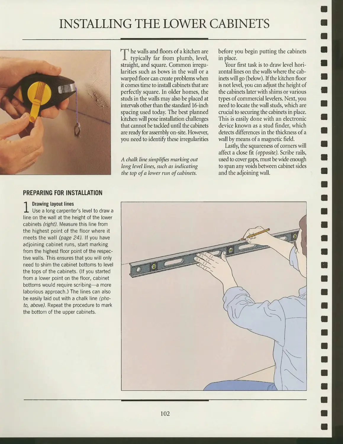
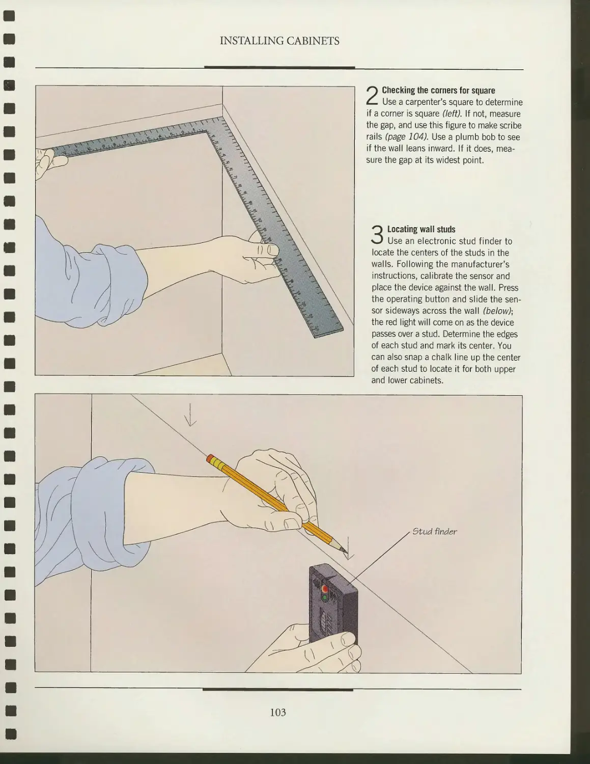
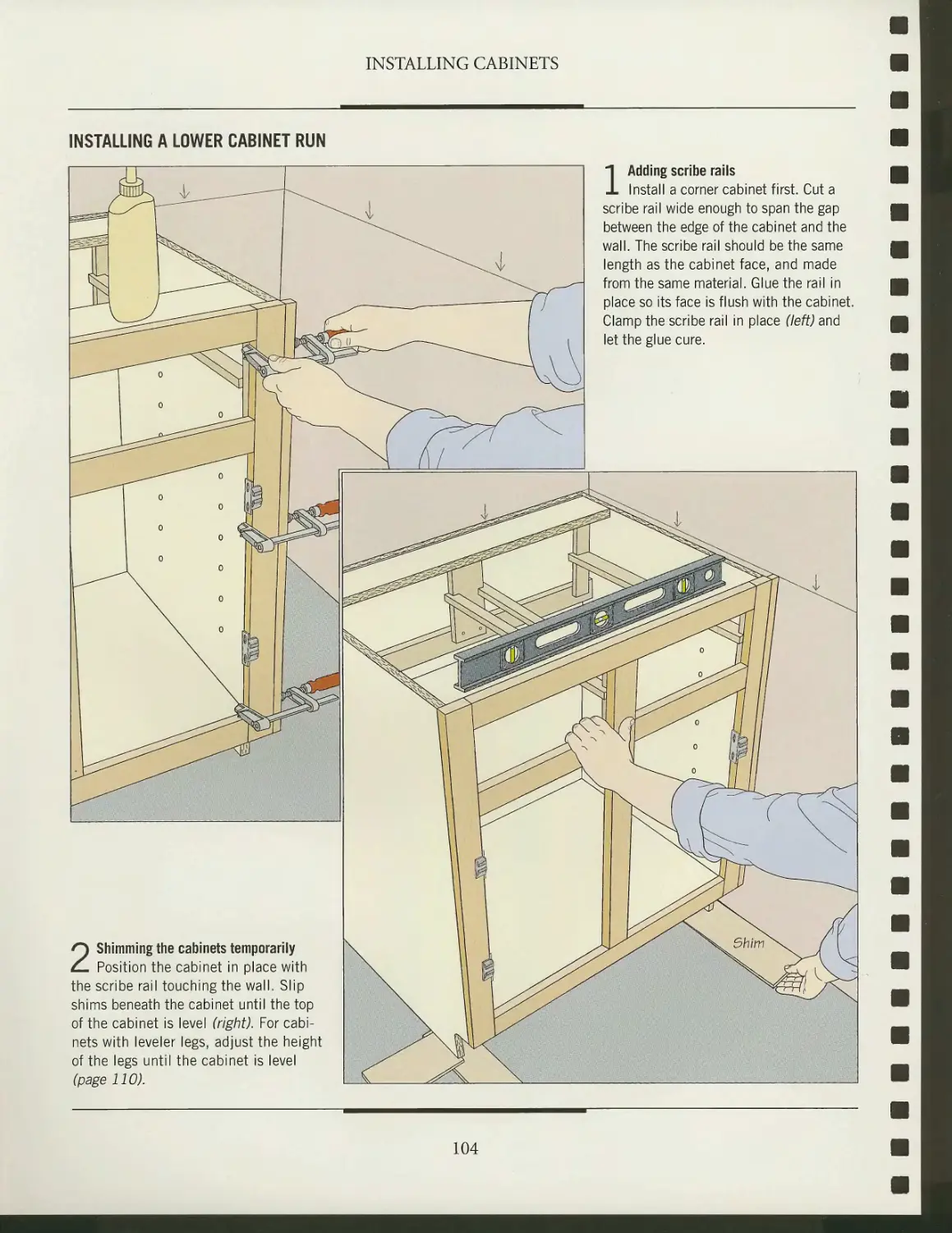
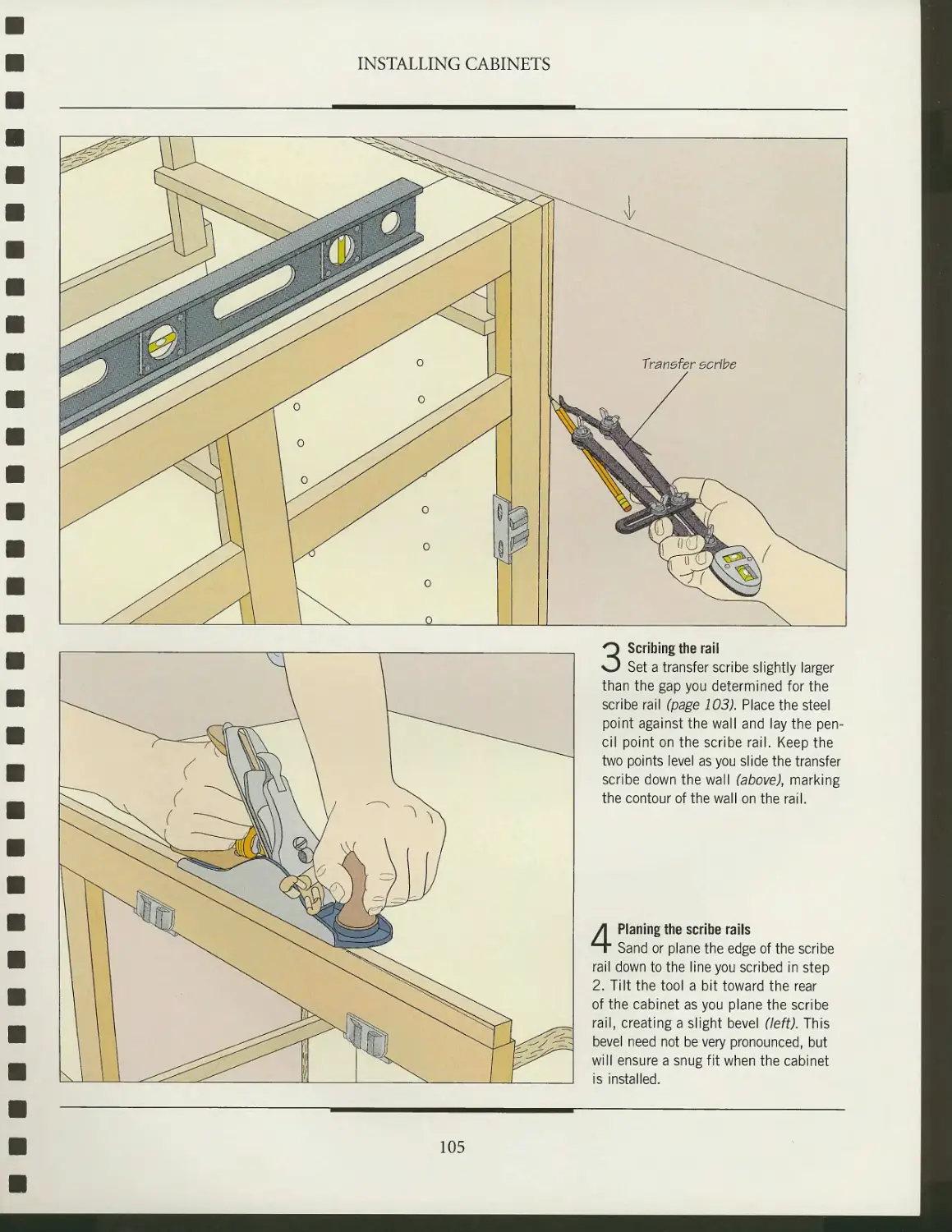
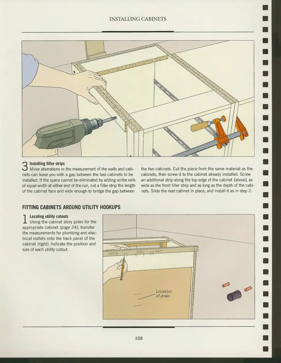

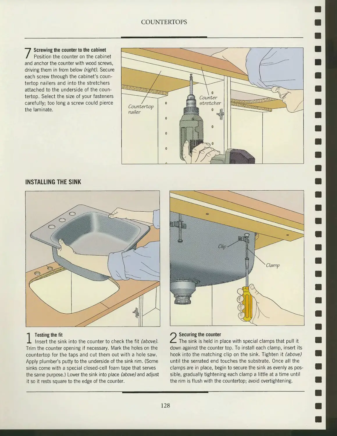
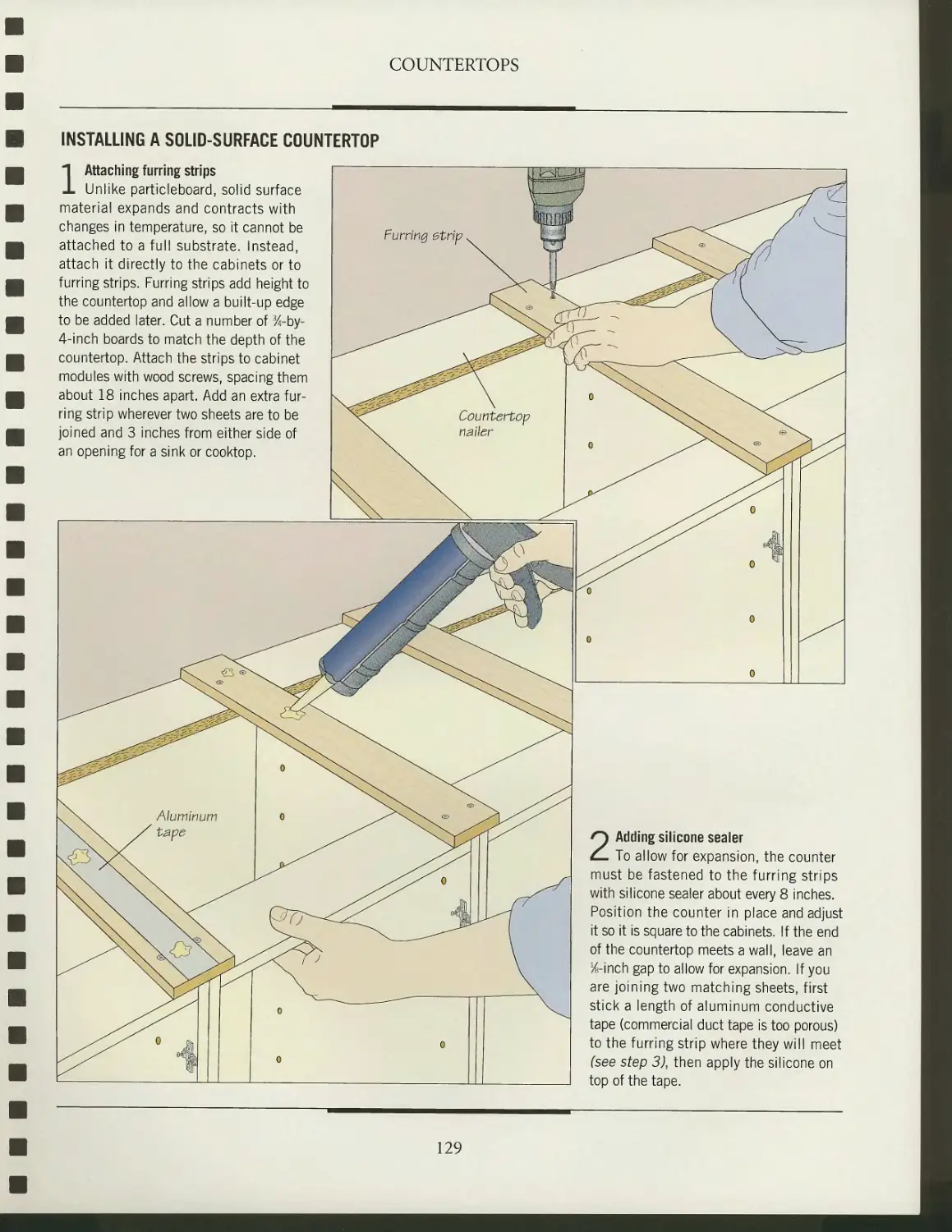
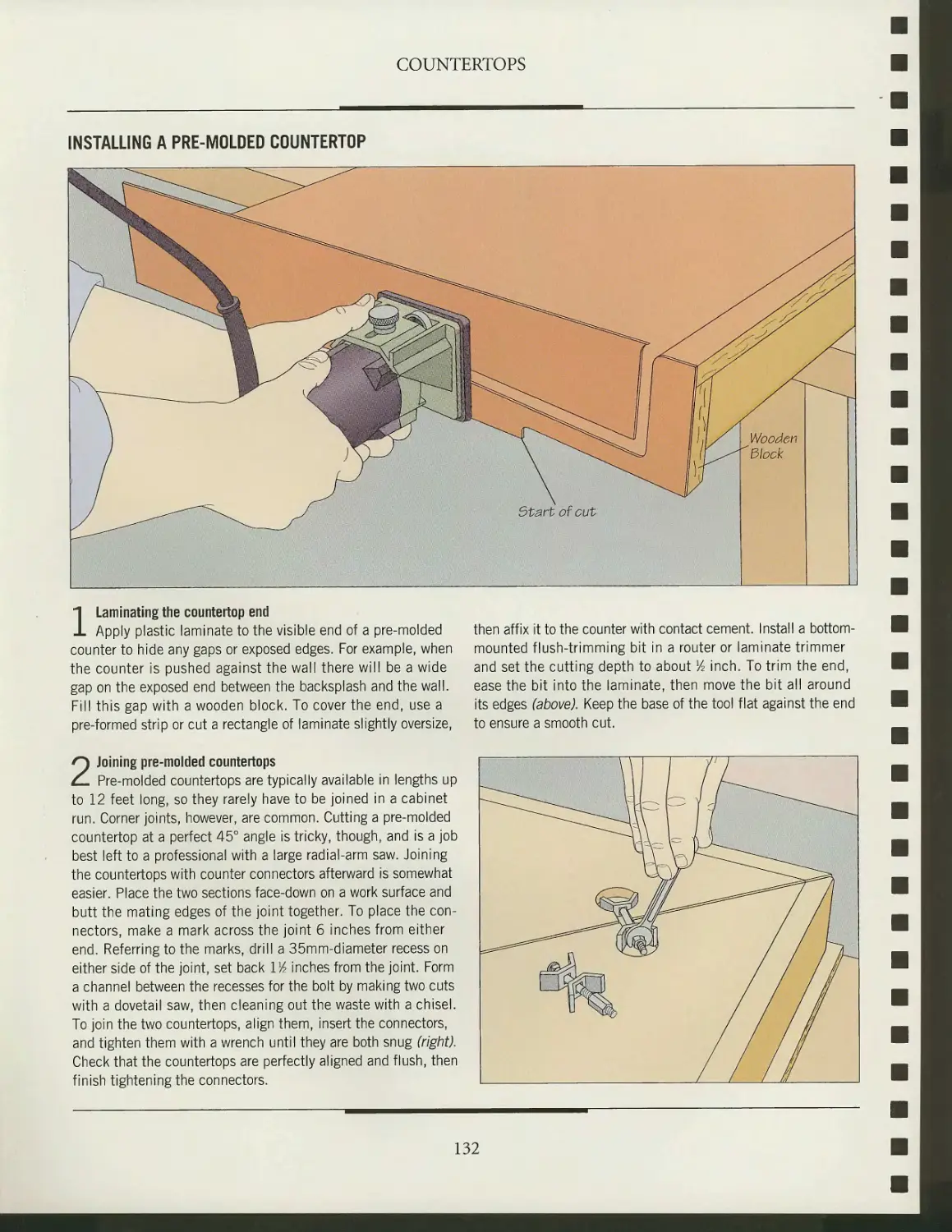
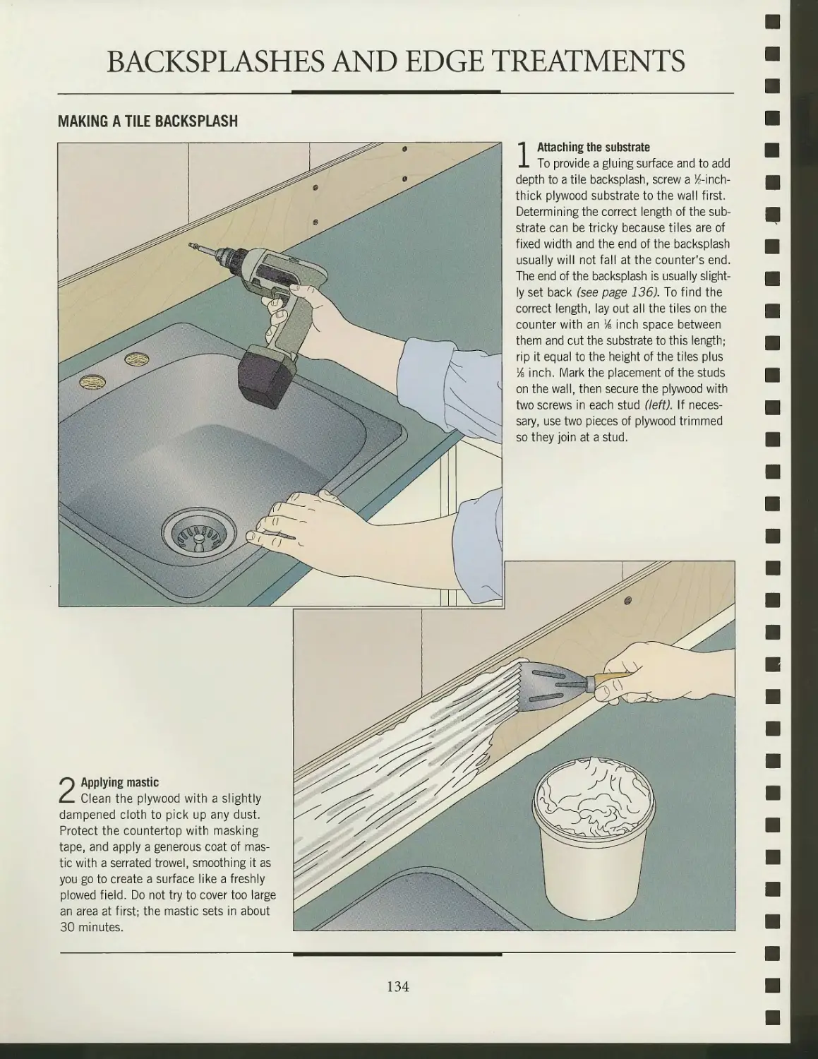


Text
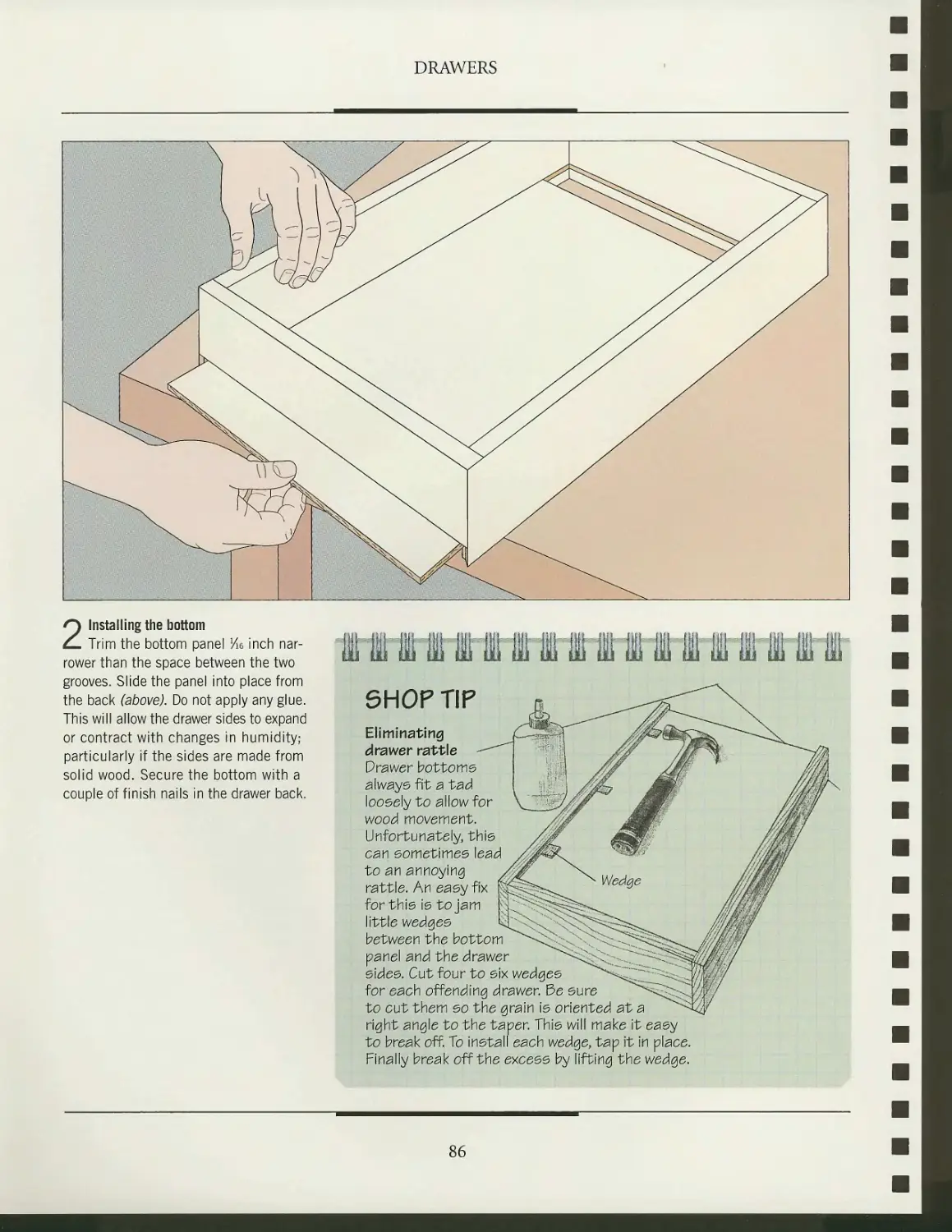
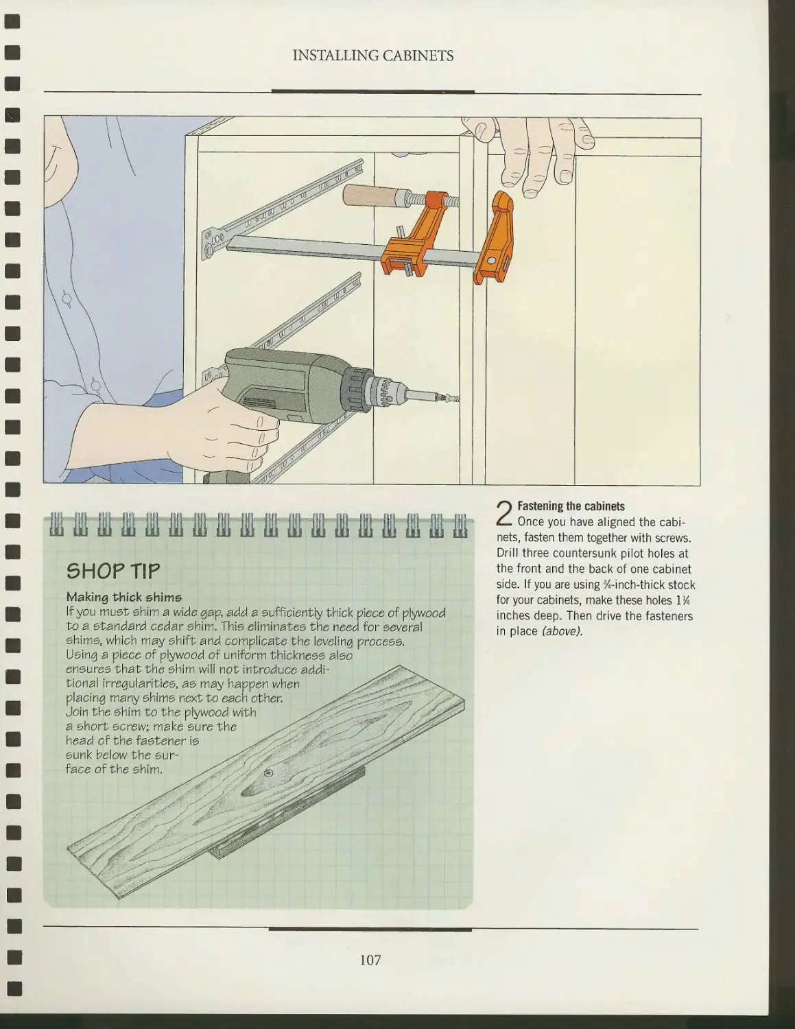
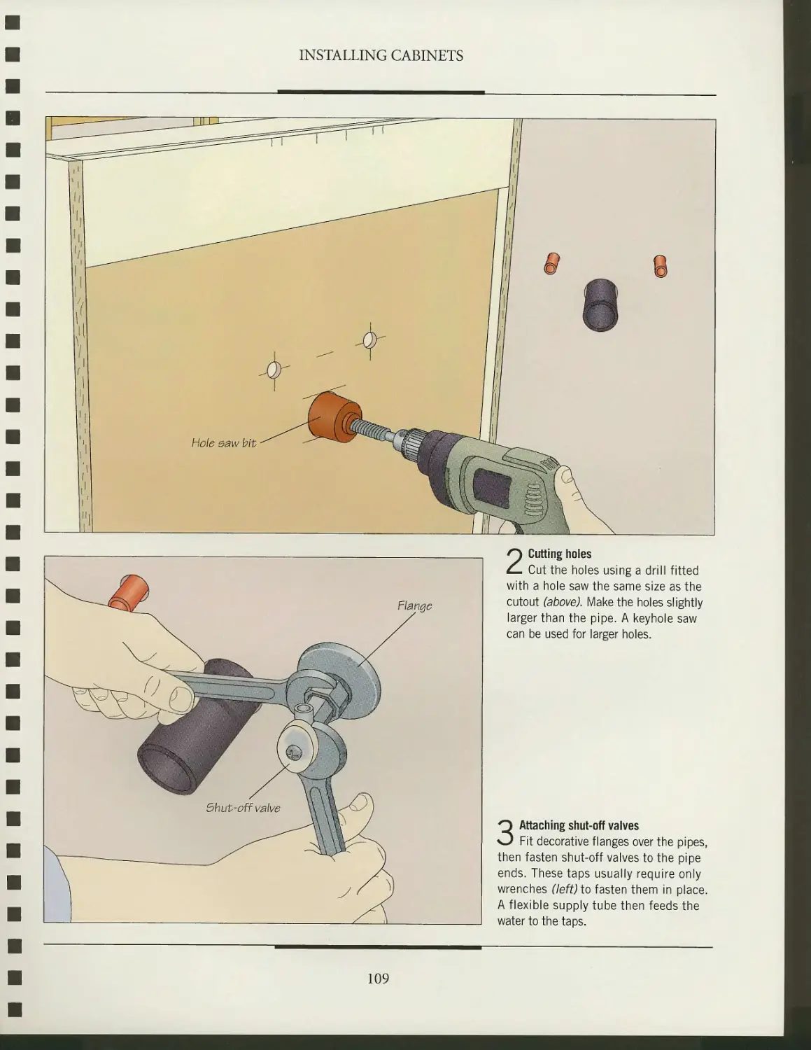
TIME
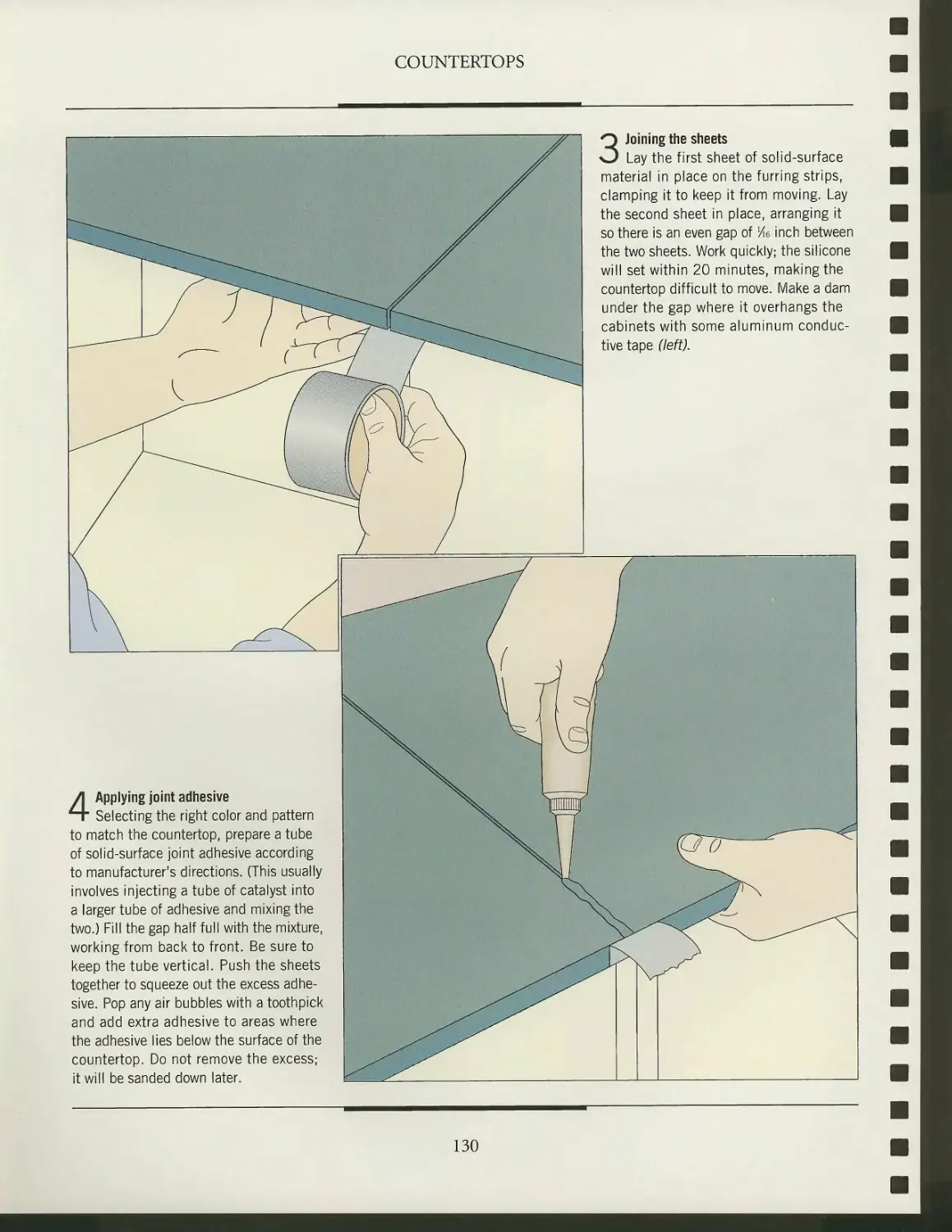
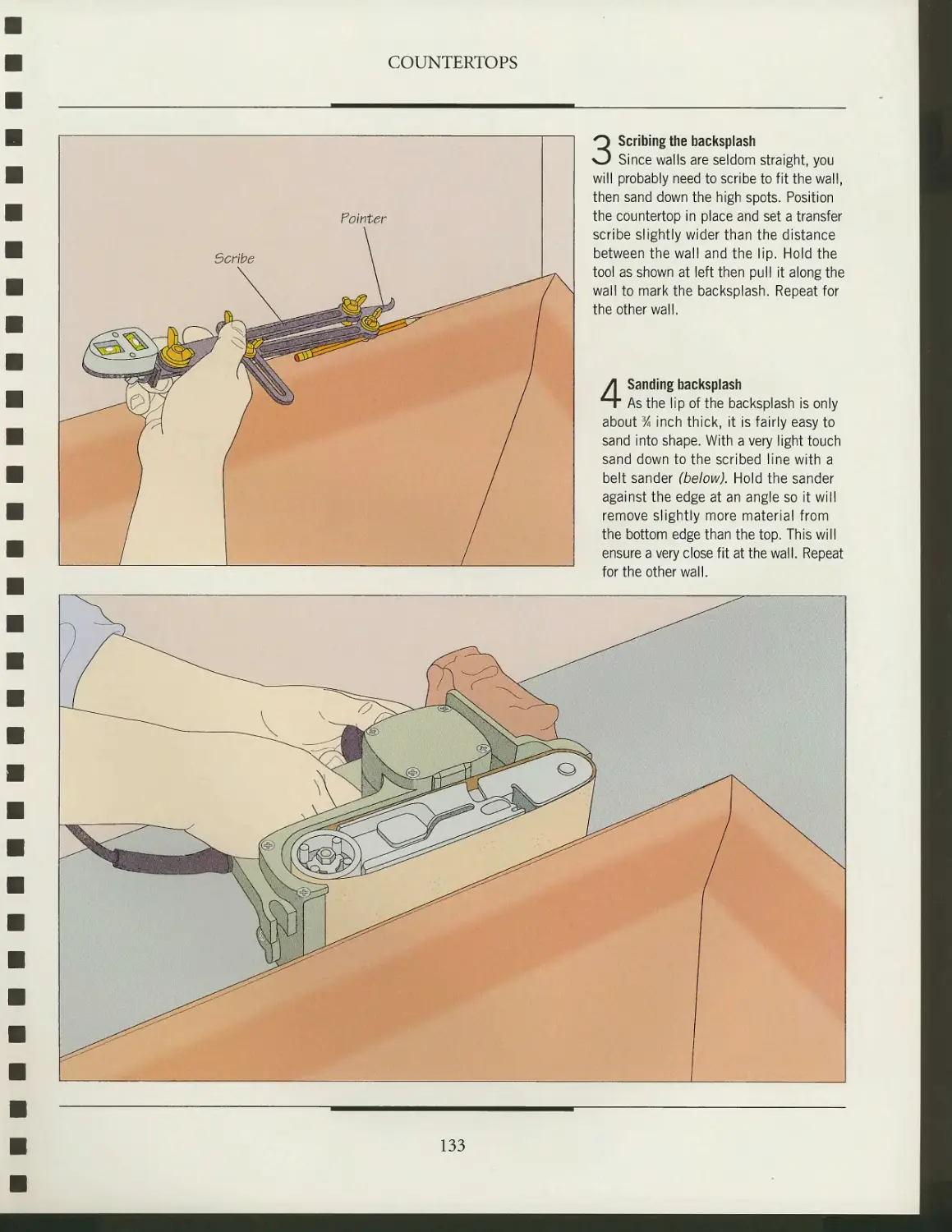
BOOKS
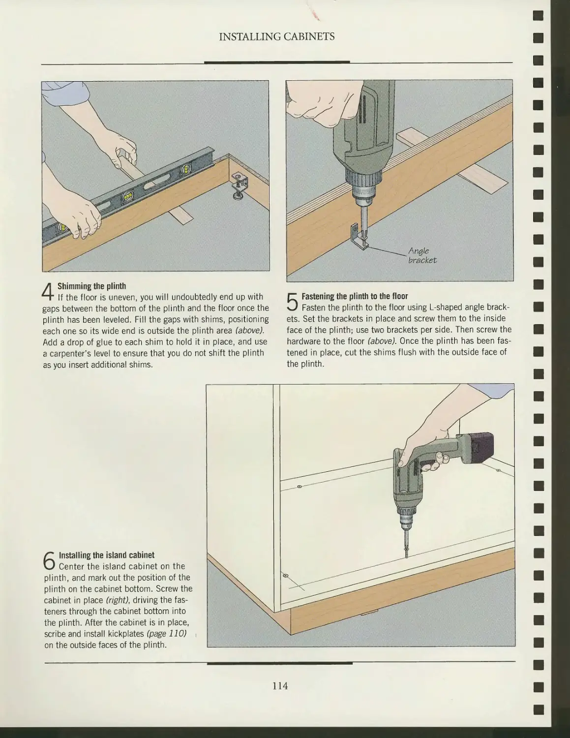
, THE ART OF WOODWORKING
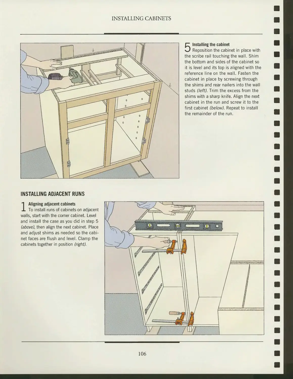
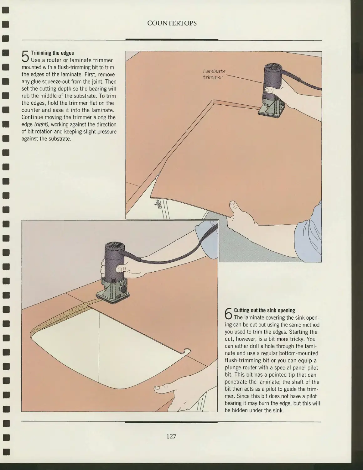
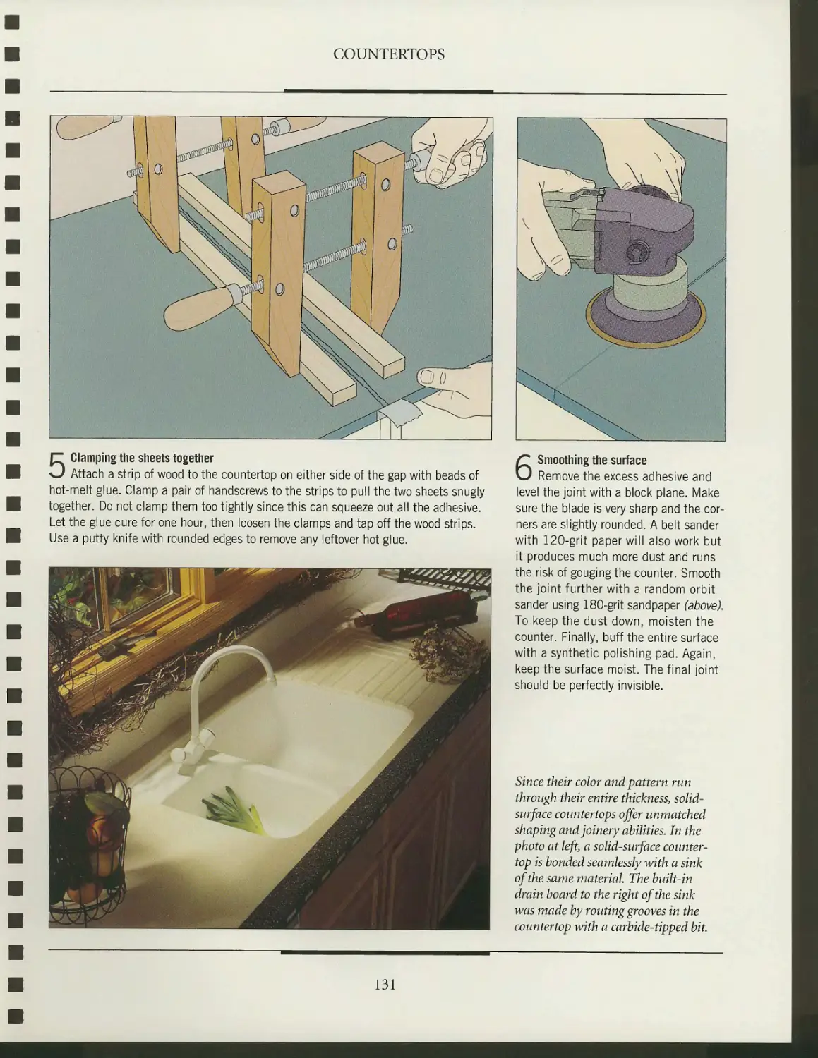
KITCHEN
CABINETS
i-5^
■^fcr
.«*<•
3l
/999-2004
A Tuckerdude Scan 2005
ENs
WORKSHOP GUIDE
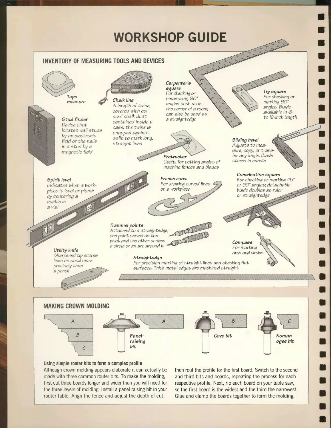
INVENTORY OF MEASURING TOOLS AND DEVICES
Tape
measure
Stud finder
Device that
locatee wall etude
by an electronic
field or the nalle
In a etud by a
magnetic field
Spirit level
Indlcatee when a work-
piece ie level or plumb
by centering a
bubble In
a vial
Chalk line
A length of twine,
covered with
colored chalk duet
contained Inelde a
caee; the twine ie
enapped agalnet
walle to mark long,
etralght llnee
Carpenter'e
e<\uare
For checking or
meaeurlng 90°
anglee euch ae In
the corner of a room;
can aleo be ueed ae
a etralghtedge
Protractor
Ueeful for eettlng anglee of
machine fencee and bladee
French curve
For drawing curved llnee
on a workplece
Utility knife
Sharpened tip ecoree
llnee on wood more
precleely than
a pencil
Trammel pointe
Attached to a etralghtedge;
one point eervee ae the
pivot and the other ecrlbee
a circle or an arc around It
Sliding bevel
Adjuete to mea-
eure, copy, or trane-
fer any angle. 3lade
etoree In handle
Combination equare
For checking or marking 45°
or 90° anglee; detachable
blade doublee ae ruler
or etralghtedge
Compaee
For marking
arce and clrclee
Straightedge
For preclelon marking of etralght llnee and checking flat
eurracee. Thick metal edgee are machined etralght
^
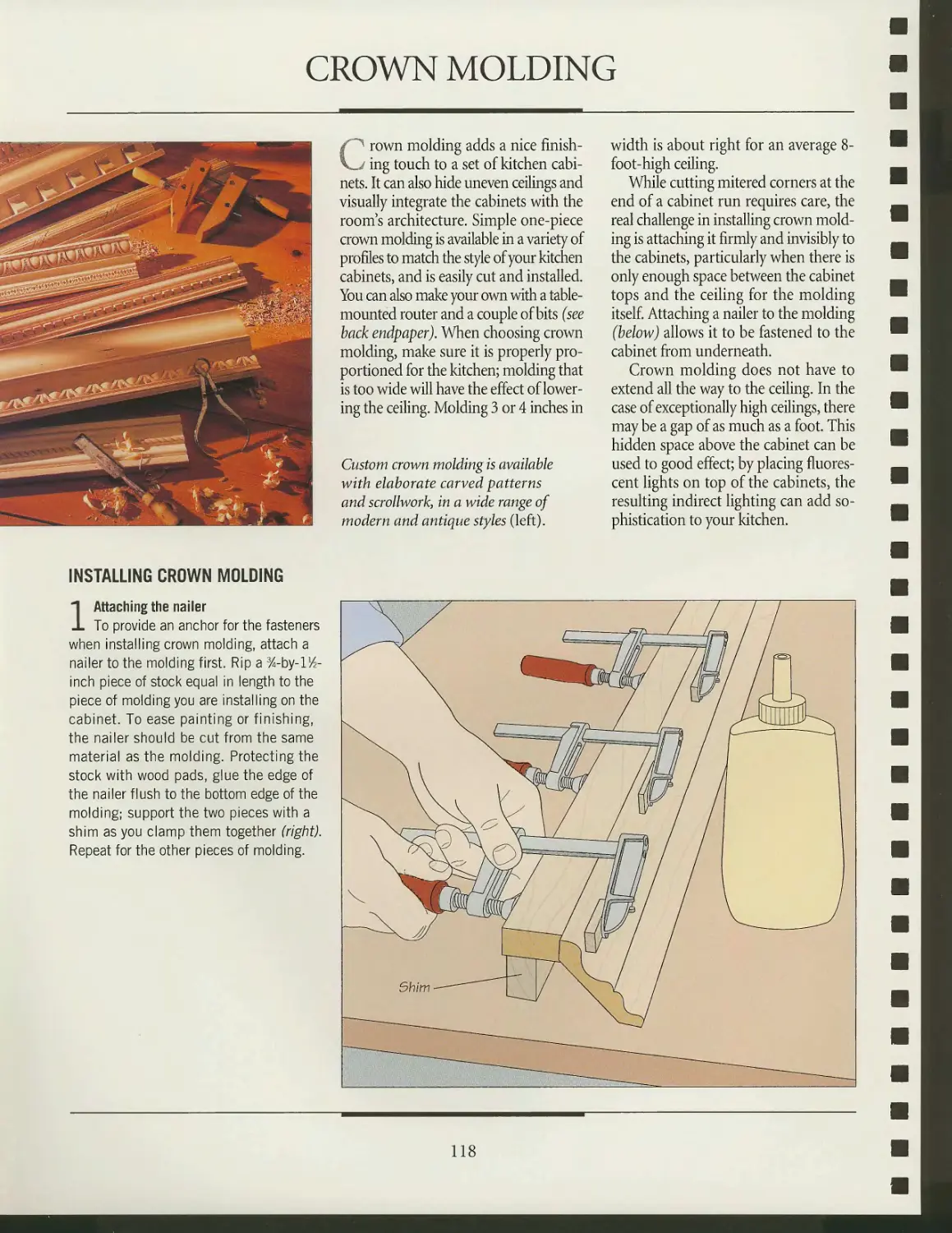
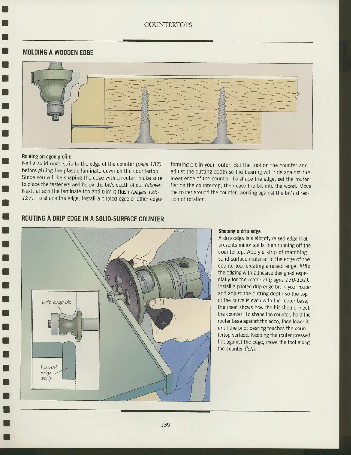
MAKING CROWN MOLDING
3
Panel-
raising
bit
Using simple router bits to form a complex profile
Although crown molding appears elaborate it can actually be
made with three common router bits. To make the molding,
first cut three boards longer and wider than you will need for
the three layers of molding. Install a panel raising bit in your
router table. Align the fence and adjust the depth of cut,
Roman
ogee bit
then rout the profile for the first board. Switch to the second
and third bits and boards, repeating the process for each
respective profile. Next, rip each board on your table saw,
so the first board is the widest and the third the narrowest.
Glue and clamp the boards together to form the molding.
TH E ART OF WOODWORKING
KITCHEN
CABINETS
THE ART OF WOODWORKING
KITCHEN
CABINETS
TIME-LIFE BOOKS
ALEXANDRIA, VIRGINIA
ST. REMY PRESS
MONTREAL
THE ART OF WOODWORKING was produced by
ST. REMY PRESS
PUBLISHER
PRESIDENT
Series Editor
Series Art Director
Editor
Art Directors
Designers
Picture Editor
Writers
Contribu ting Illustra to rs
Administrator
Production Manager
Coordinator
System Coordinator
Photographer
Proofreader
Indexer
Kenneth Winchester
Pierre Leveille
Pierre Home-Douglas
Francine Lemieux
Andrew Jones
Jean-Pierre Bourgeois,
Normand Boudreau
Francois Daxhelet,
Jean-Guy Doiron
Genevieve Monette
John Dowling, Adam Van Sertima
Gilles Beauchemin, Michel Blais,
Ronald Durepos, Jacques Perrault,
Michael Stockdale, James Therien
Natalie Watanabe
Michelle Turbide
Dominique Gagne
Eric Beaulieu
Robert Chartier
Judy Yelon
Christine M. Jacobs
Time-Life Books is a division of Time Life Inc.,
a wholly owned subsidiary of
THE TIME INC. BOOK COMPANY
TIME-LIFE INC.
President and CEO John M. Fahey
TIME-LIFE BOOKS
President
Managing Editor
Director of Design
Director of Editorial Operations
Consulting Editor
Vice-President, Book Production
Production Manager
Quality Assurance Manager
John D. Hall
Roberta Conlan
Michael Hentges
Ellen Robling
John R. Sullivan
Marjann Caldwell
Marlene Zack
James King
THE CONSULTANTS
Jon Eakes has been a cabinetmaker and custom renovator in
Montreal for more than 20 years. He is known primarily for his
teaching through books, videos, radio, and the TV show
Renovation Zone.
Giles Miller-Mead taught advanced cabinctmaking at Montreal
technical schools for more than ten years. A native of New
Zealand, he has worked as a restorer of antique furniture.
Kitchen cabinets.
p. cm. — (The Art of woodworking)
Includes index.
ISBN 0-8094-9545-7
1. Kitchen-cabinets. 2. Cabinetwork.
I. Time-Life Books. II. Series.
TT197.5.K57 1996
684.1'6—dc20
95-46501
CIP
For information about any Time-Life book,
please call 1-800-621-7026, or write:
Reader Information
Time-Life Customer Service
P.O. Box C-32068
Richmond, Virginia
23261-2068
© 1996 Time-Life Books Inc.
All rights reserved.
No part of this book may be reproduced in any form or by
any electronic or mechanical means, including information
storage and retrieval devices or systems, without prior
written permission from the publisher, except that brief passages
may be quoted for reviews.
First printing. Printed in U.S.A.
Published simultaneously in Canada.
TIME-LIFE is a trademark of Time Warner Inc. U.S.A.
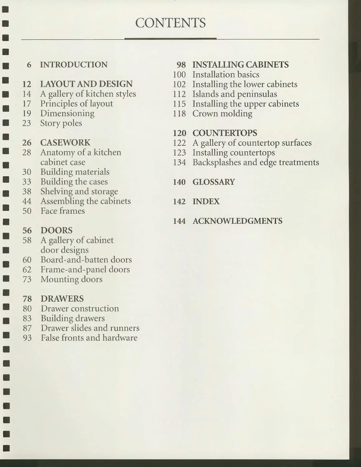
CONTENTS
6
12
14
17
19
23
26
28
30
33
38
44
50
56
58
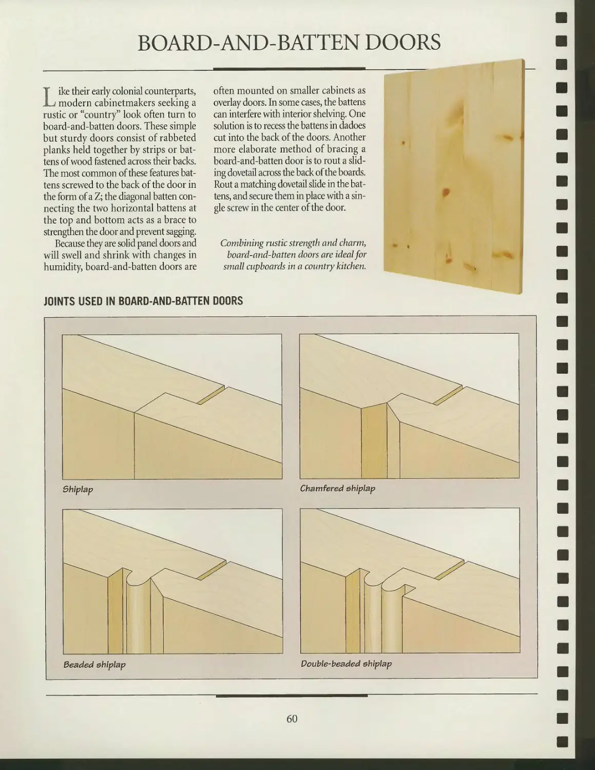
60
62
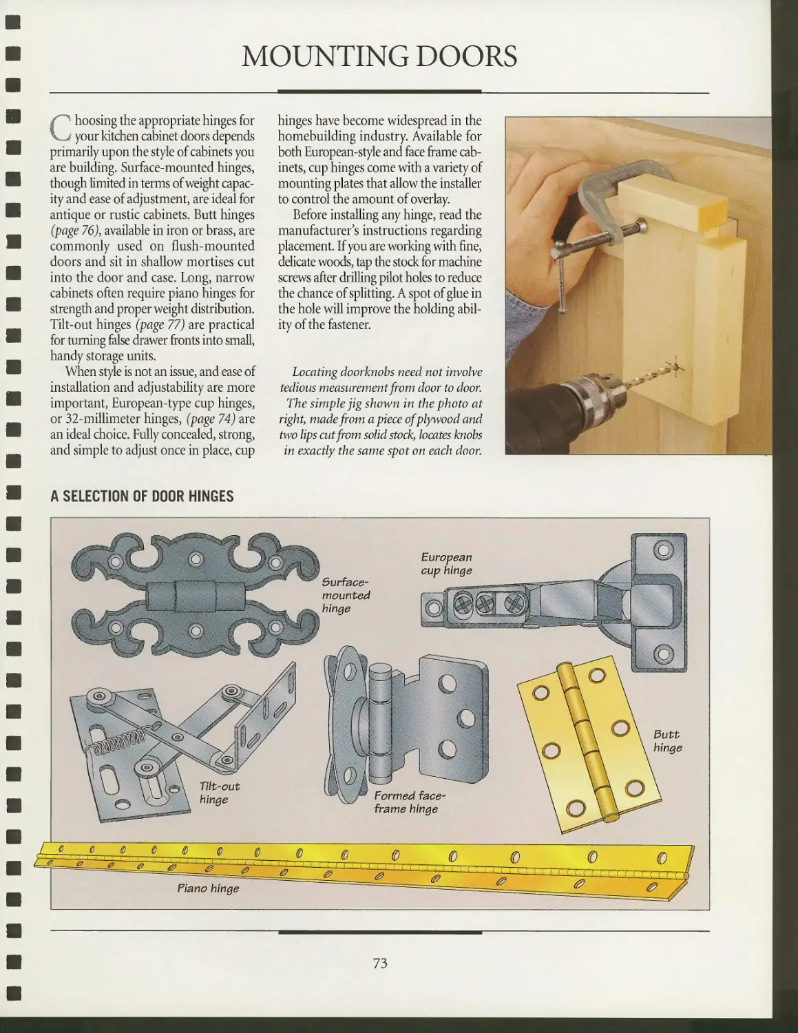
73
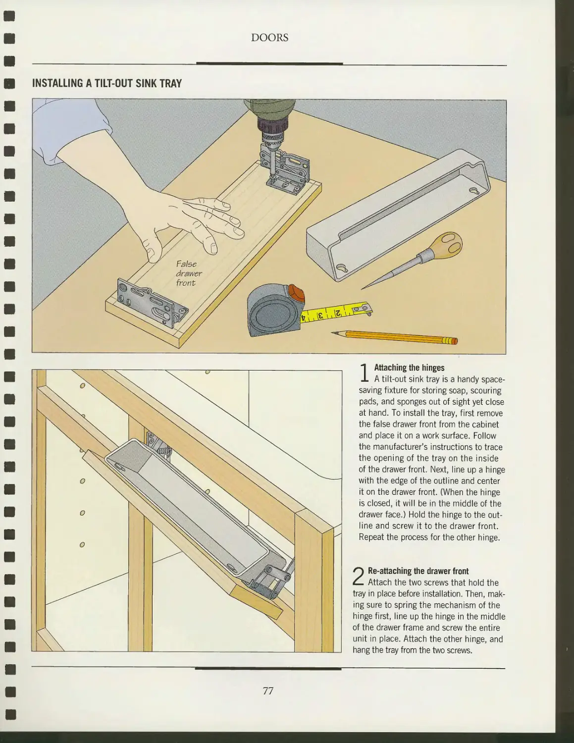
78
80
83
87
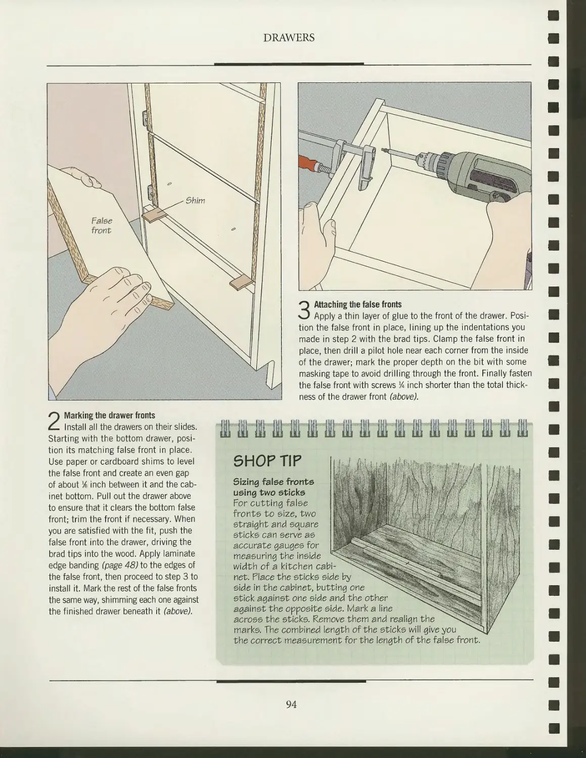
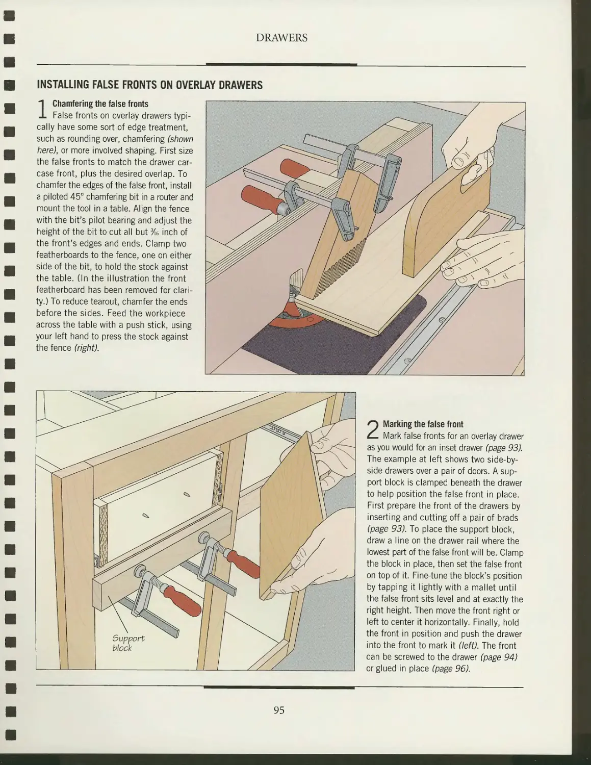
93
INTRODUCTION
LAYOUT AND DESIGN
A gallery of kitchen styles
Principles of layout
Dimensioning
Story poles
CASEWORK
Anatomy of a kitchen
cabinet case
Building materials
Building the cases
Shelving and storage
Assembling the cabinets
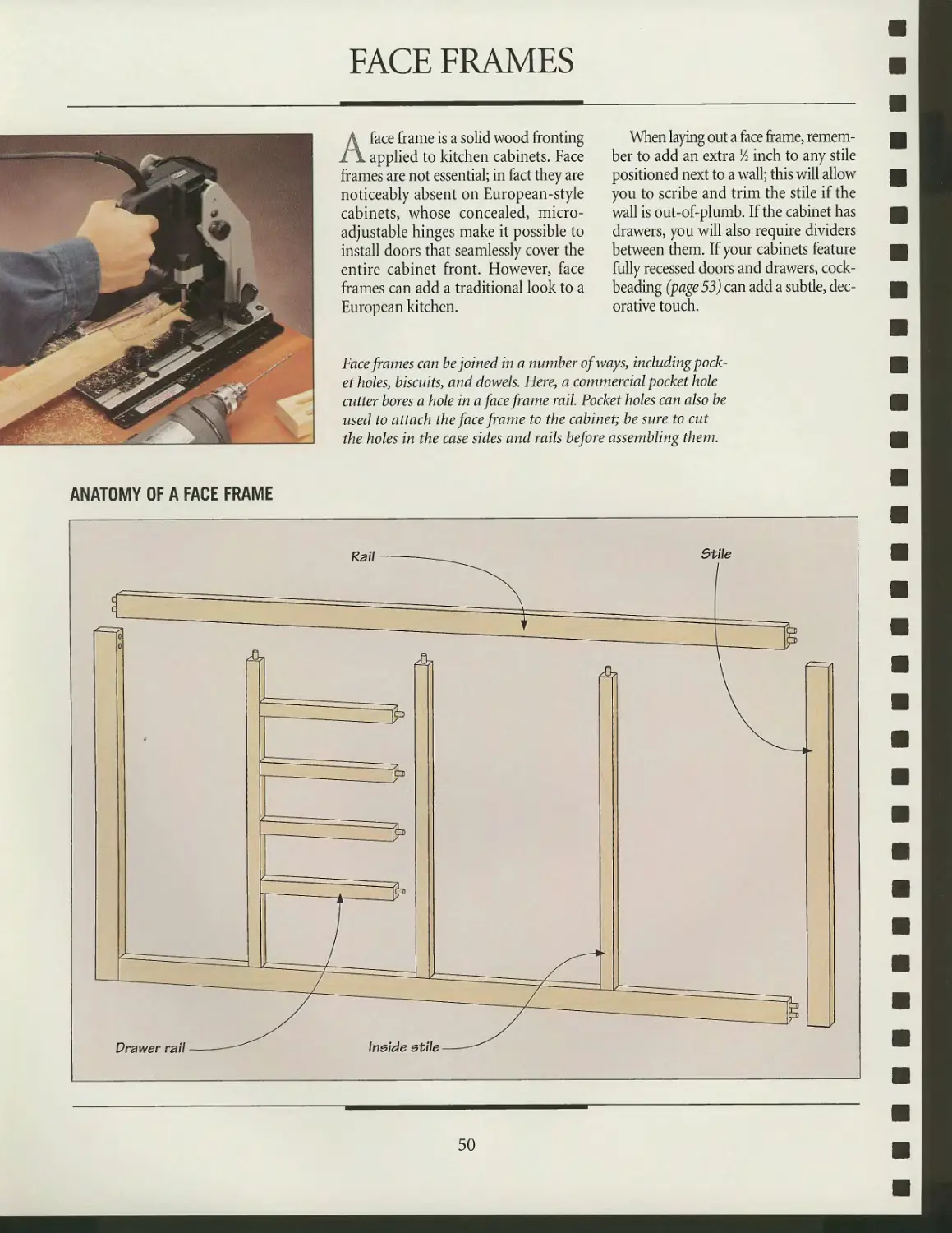
Face frames
DOORS
A gallery of cabinet
door designs
Board-and-batten doors
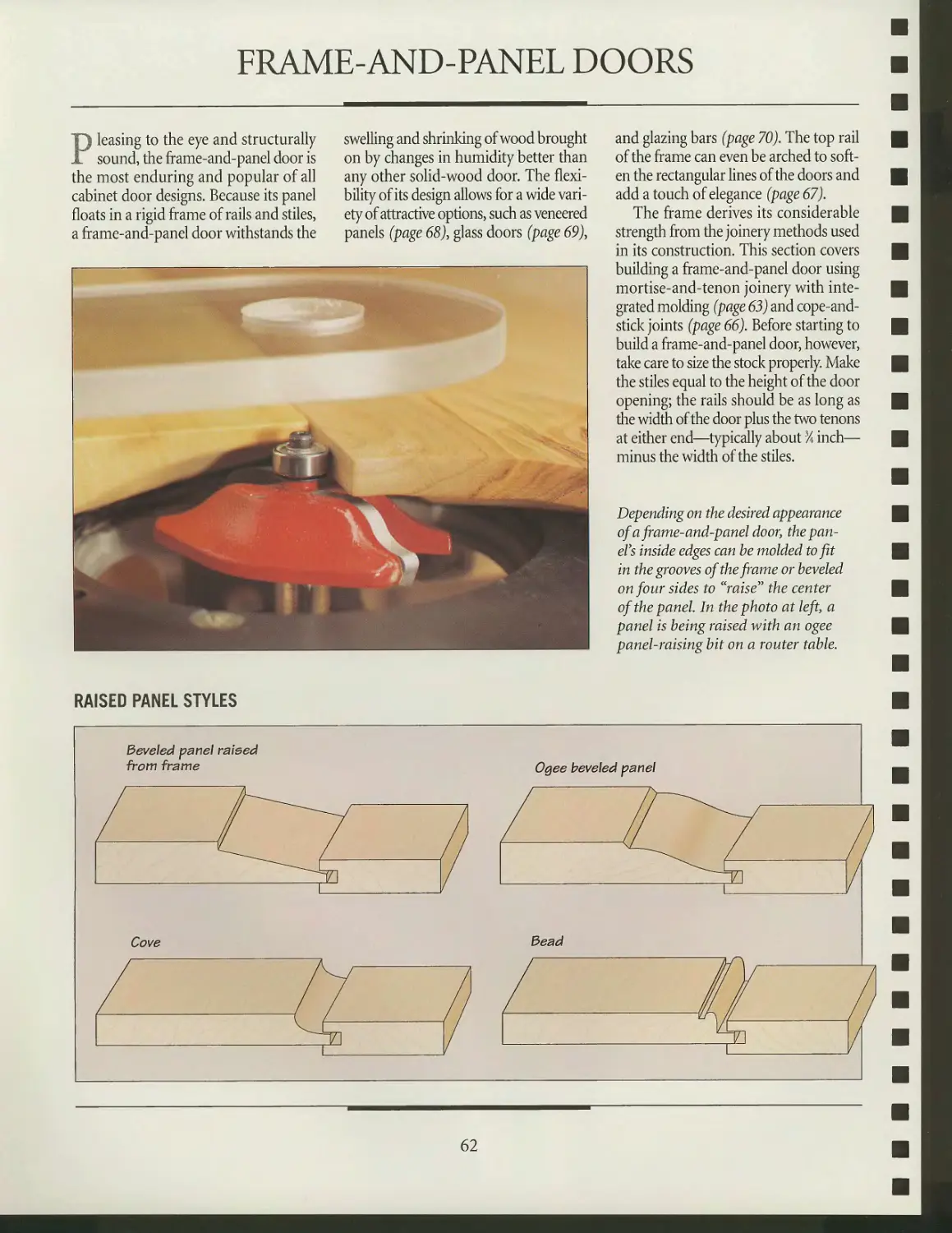
Frame-and-panel doors
Mounting doors
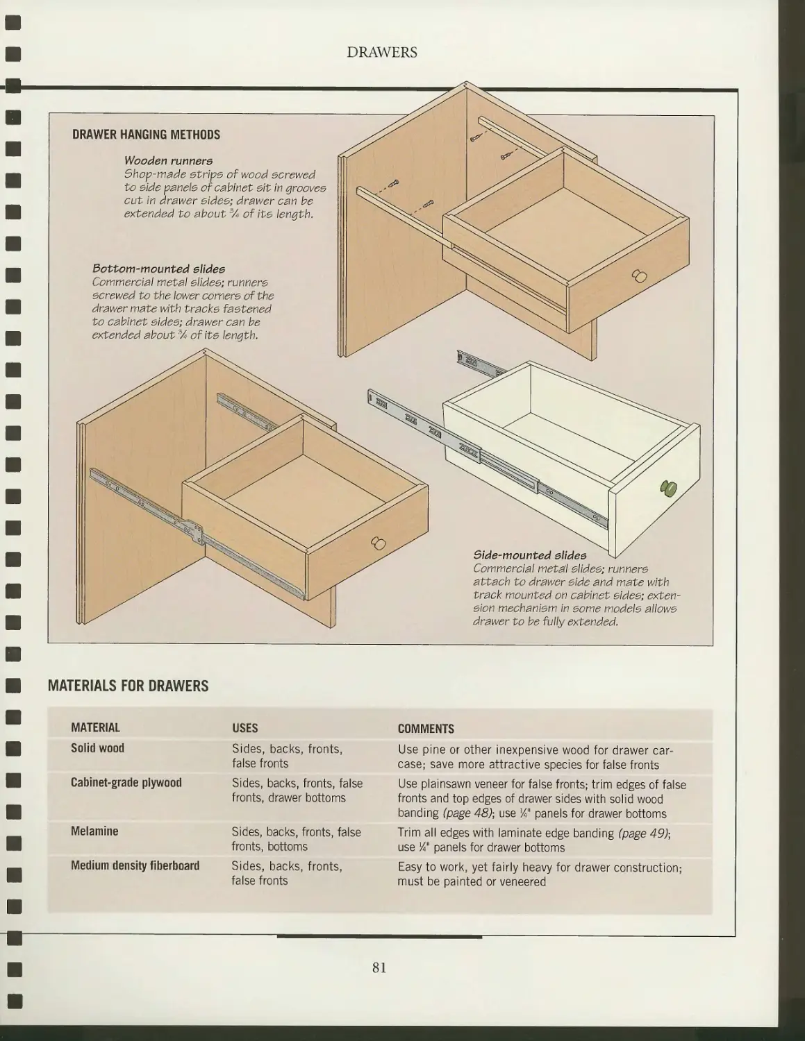
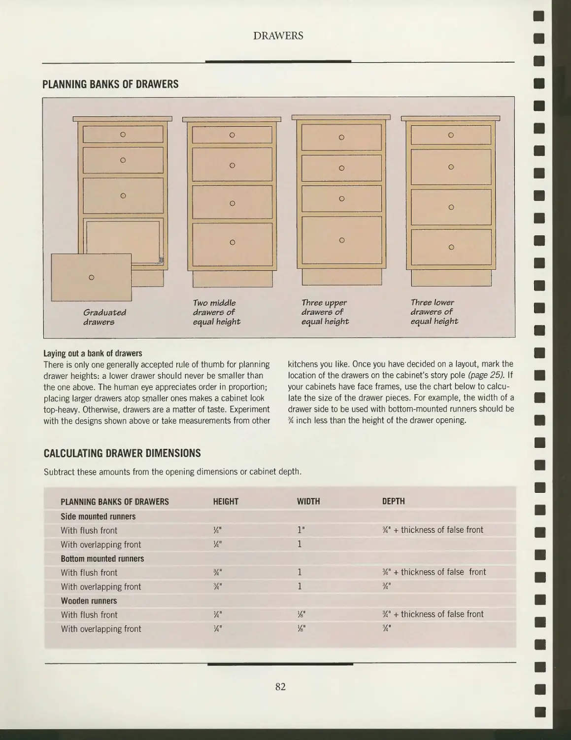
DRAWERS
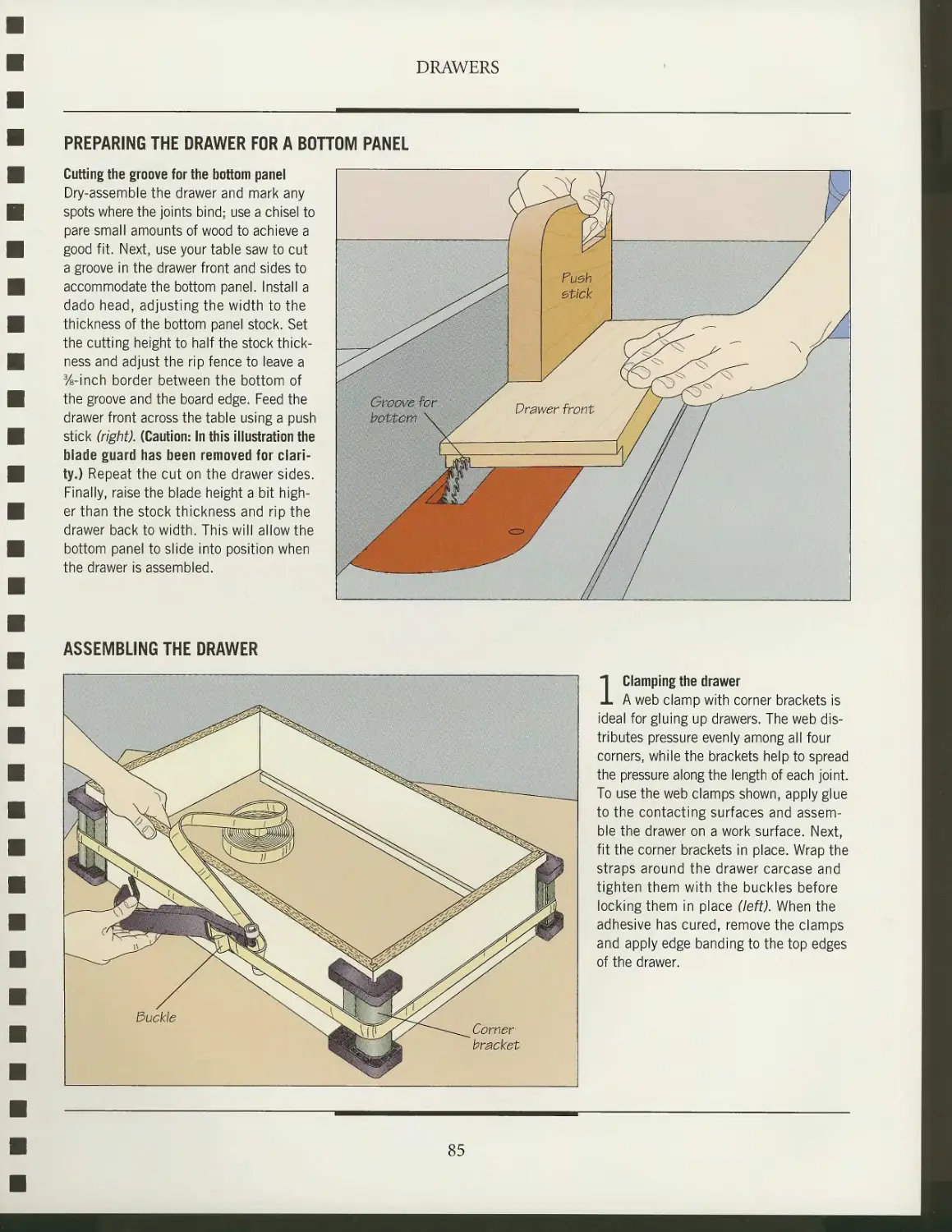
Drawer construction
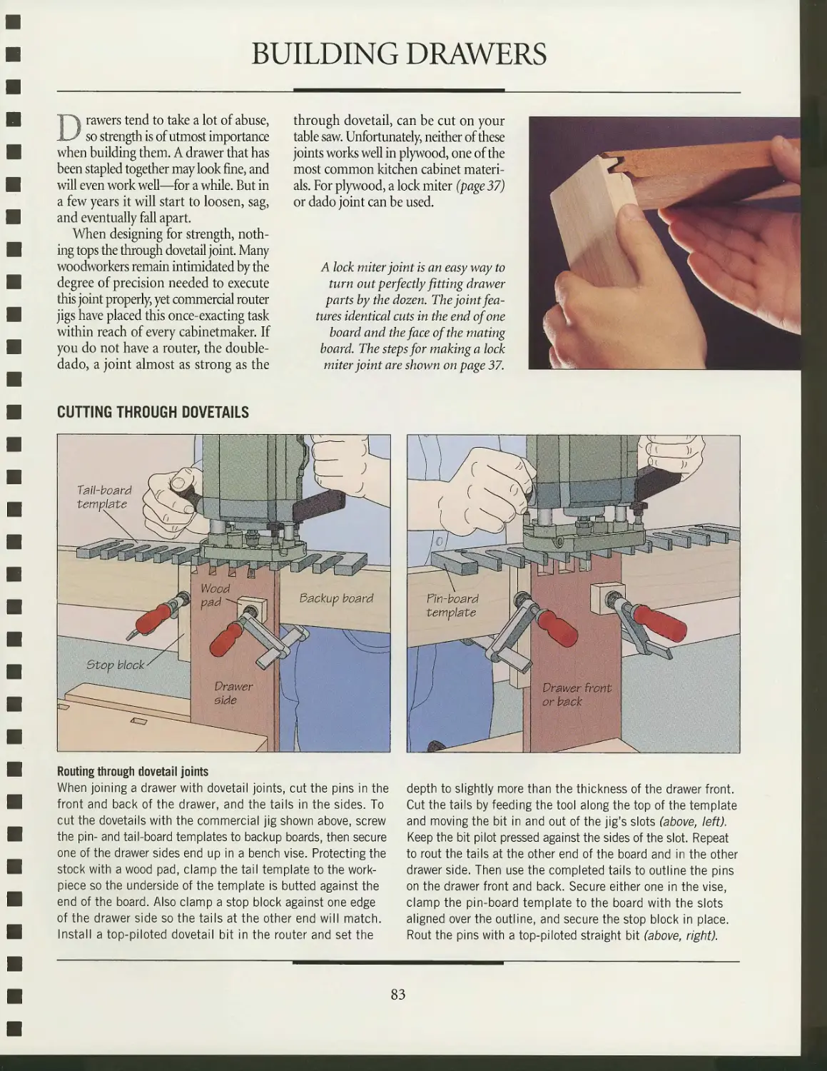
Building drawers
Drawer slides and runners
False fronts and hardware
98
100
102
112
115
118
120
122
123
134
140
142
144
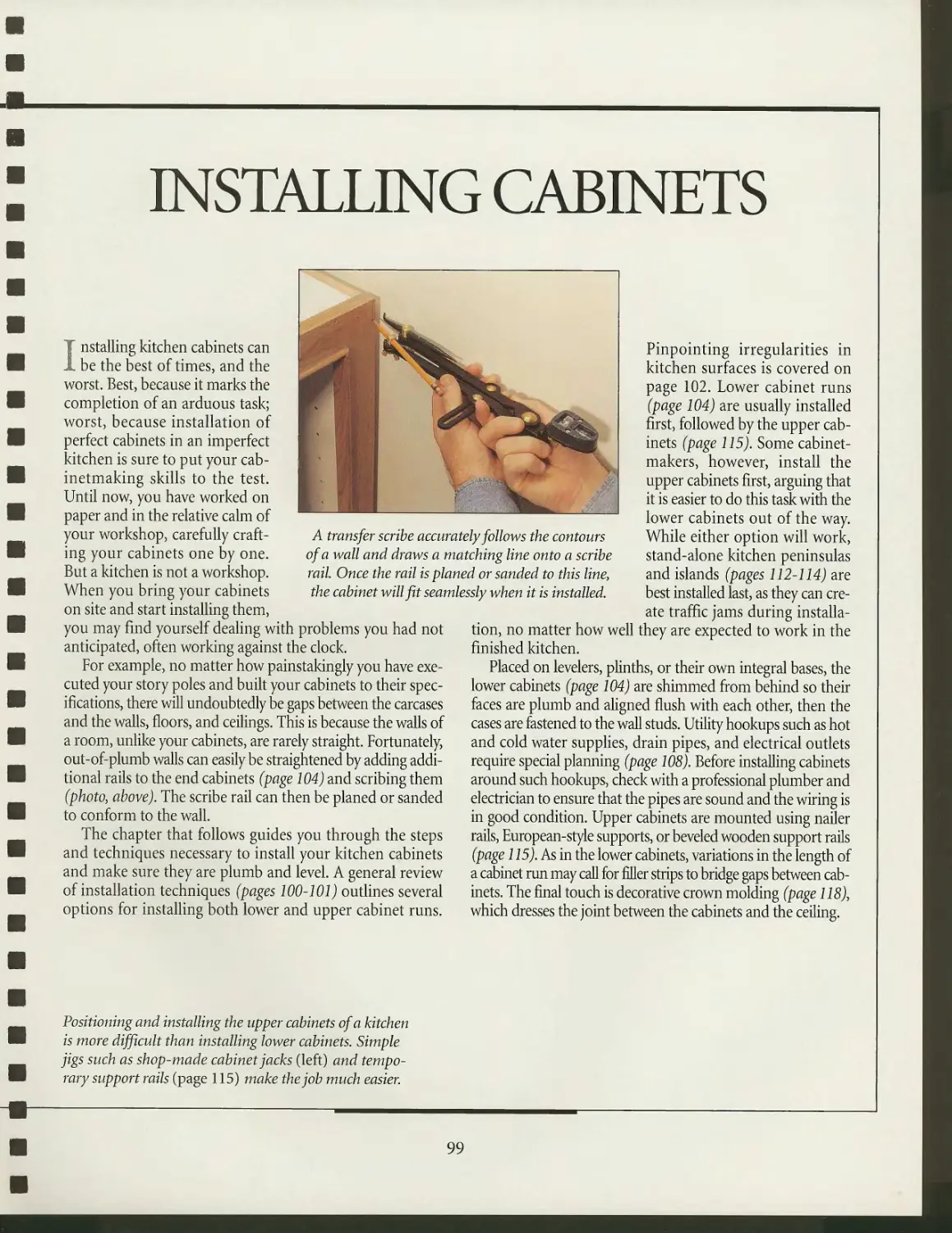
INSTALLING CABINETS
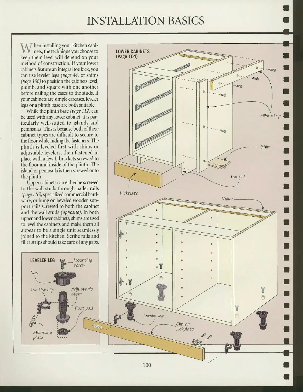
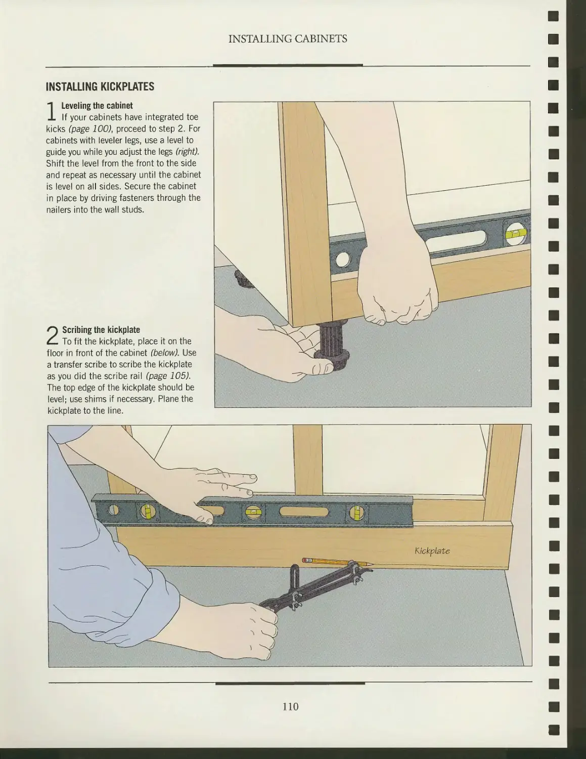
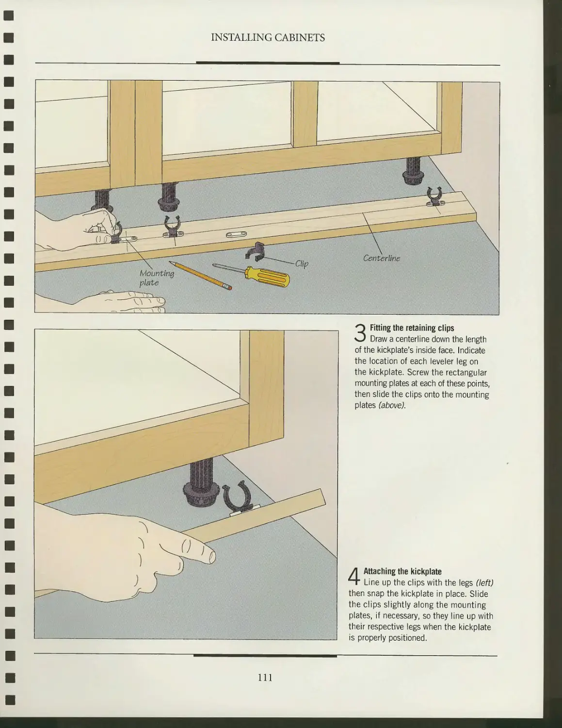
Installation basics
Installing the lower cabinets
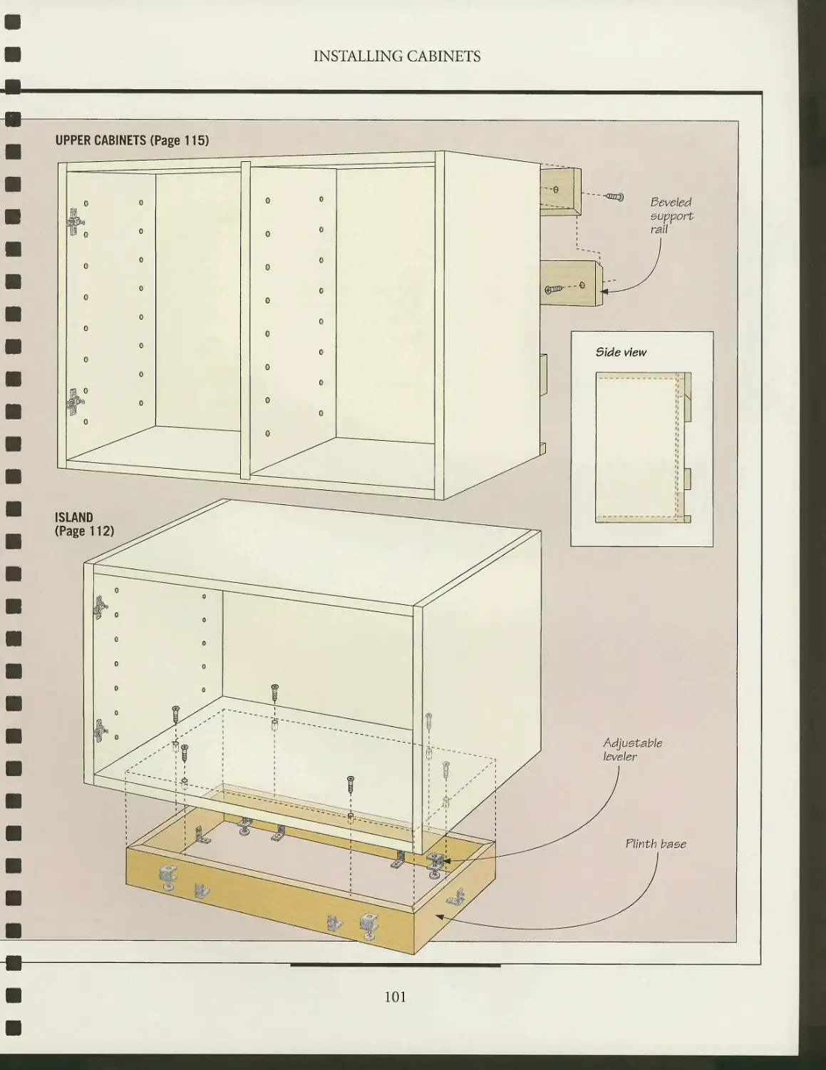
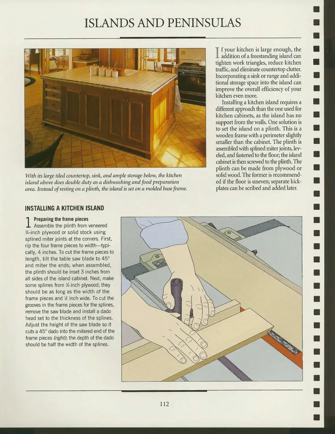
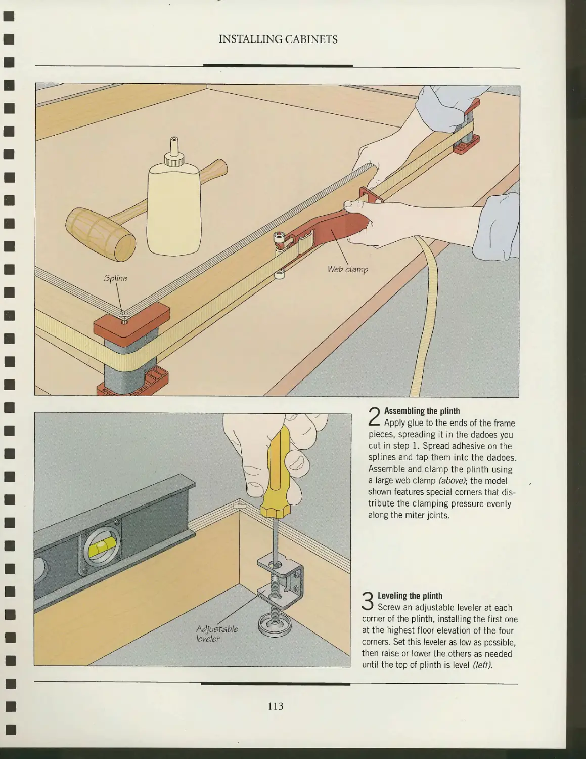
Islands and peninsulas
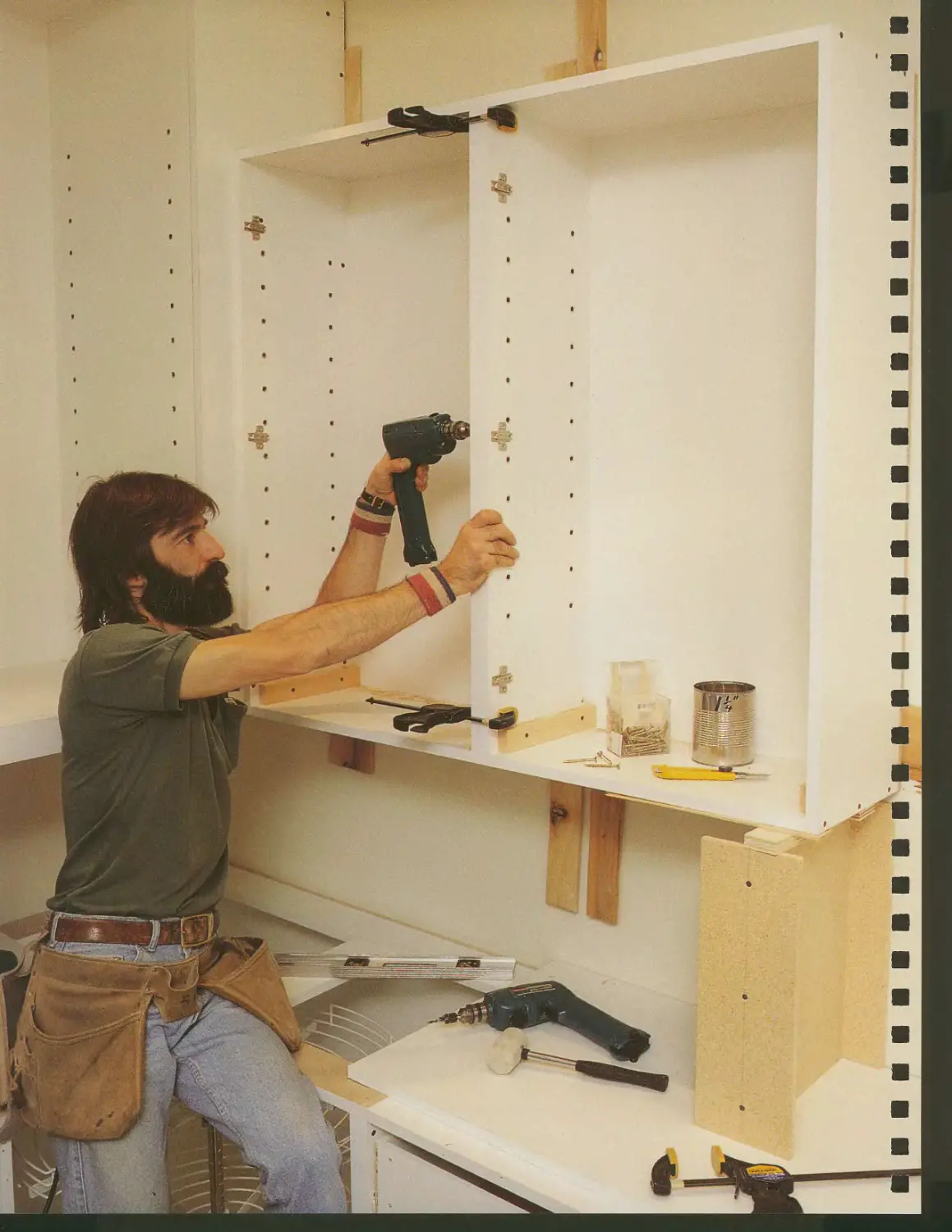
Installing the upper cabinets
Crown molding
COUNTERTOPS
A gallery of countertop surfaces
Installing countertops
Backsplashes and edge treatments
GLOSSARY
INDEX
ACKNOWLEDGMENTS
INTRODUCTION
Tom Santarsiero on
CHOOSING
CABINET STYLES
Despite the tremendous variety of kitchen cabinets, they all come down to two
basic types: face frame and frameless. Each has characteristics that greatly affect
how the heart of the modern home will appear and function. For the designer,
cabinetmaker, and installer, they also determine how the cabinets will be created.
Face frame cabinets are the most popular type of kitchen cabinet in North
America. This time-honored method of construction involves attaching a framework
of solid lumber to the front of a carcase. Doors and drawers can be mounted in
one of three ways: inset, lipped, or overlay. Inset, the most elegant in appearance, is
a true test of a craftsman's skill in construction and installation. Tight tolerances
are required to accommodate seasonal wood movement and yield a pleasing
margin between frame and door. During installation, cabinets must be set perfectly level
and plumb to maintain that margin. My clients who choose framed cabinets are
very interested in forging a link with the past. They appreciate the classic look of well-
fitted doors and drawers that open with ease and close with a gentle puff of air as
they nest within the frame.
Frameless cabinetry was born in Europe after World War II. It addressed some
of the challenges of the time, such as the shortage of lumber and the need to rebuild
housing rapidly. The simplicity of the frameless, or European, kitchen cabinet greatly
reduced material, needs, and production time. Doors would align tightly together,
creating a clean, flowing line of casework. This reflected a modernist view of a changed
world where time was short and production and efficiency reigned supreme. This
construction method yielded other benefits. Drawers could be wider and deeper
because they didn't need to clear a face frame. And storage and removal of items
along with cleaning the cabinet interior became easier and more efficient.
Today, the line between face frame and frameless casework has blurred slightly.
Frameless cabinets are no longer limited to flush-laminate doors; most of the
frameless kitchens I build feature traditional raised panel doors, multi-part cornice moldings,
and other accoutrements endowing each kitchen with warmth and comfort. For
building, installing, maximizing storage, and ease of use, frameless cabinets can't be
surpassed. If, on the other hand, you'd prefer a touch of timeless tradition in your
kitchen, your cabinets are only a face frame away.
Tom Santarsiero is President
of the Kitchen Design Center
in Montclair, New Jersey.
6
C iV
$s§s^
^^>5^^S
INTRODUCTION
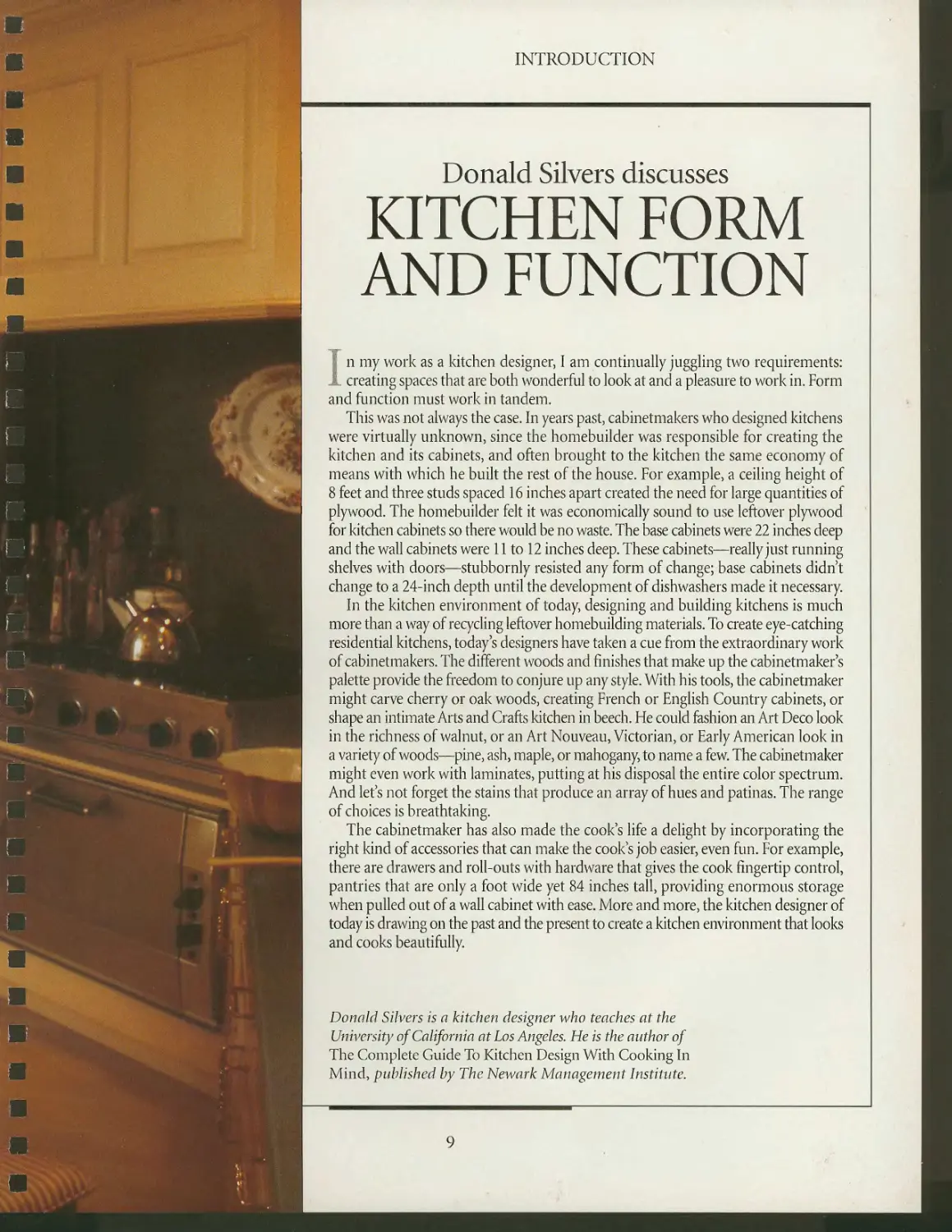
Donald Silvers discusses
KITCHEN FORM
AND FUNCTION
I n my work as a kitchen designer, I am continually juggling two requirements:
I creating spaces that are both wonderful to look at and a pleasure to work in. Form
and function must work in tandem.
This was not always the case. In years past, cabinetmakers who designed kitchens
were virtually unknown, since the homebuilder was responsible for creating the
kitchen and its cabinets, and often brought to the kitchen the same economy of
means with which he built the rest of the house. For example, a ceiling height of
8 feet and three studs spaced 16 inches apart created the need for large quantities of
plywood. The homebuilder felt it was economically sound to use leftover plywood
for kitchen cabinets so there would be no waste. The base cabinets were 22 inches deep
and the wall cabinets were 11 to 12 inches deep. These cabinets—really just running
shelves with doors—stubbornly resisted any form of change; base cabinets didn't
change to a 24-inch depth until the development of dishwashers made it necessary
In the kitchen environment of today, designing and building kitchens is much
more than a way of recycling leftover homebuilding materials. To create eye-catching
residential kitchens, today's designers have taken a cue from the extraordinary work
of cabinetmakers. The different woods and finishes that make up the cabinetmaker's
palette provide the freedom to conjure up any style. With his tools, the cabinetmaker
might carve cherry or oak woods, creating French or English Country cabinets, or
shape an intimate Arts and Crafts kitchen in beech. He could fashion an Art Deco look
in the richness of walnut, or an Art Nouveau, Victorian, or Early American look in
a variety of woods—pine, ash, maple, or mahogany, to name a few. The cabinetmaker
might even work with laminates, putting at his disposal the entire color spectrum.
And let's not forget the stains that produce an array of hues and patinas. The range
of choices is breathtaking.
The cabinetmaker has also made the cook's life a delight by incorporating the
right kind of accessories that can make the cook's job easier, even fun. For example,
there are drawers and roll-outs with hardware that gives the cook fingertip control,
pantries that are only a foot wide yet 84 inches tall, providing enormous storage
when pulled out of a wall cabinet with ease. More and more, the kitchen designer of
today is drawing on the past and the present to create a kitchen environment that looks
and cooks beautifully.
Donald Silvers is a kitchen designer who teaches at the
University of California at Los Angeles. He is the author of
The Complete Guide To Kitchen Design With Cooking In
Mind, published by The Newark Management Institute.
9
INTRODUCTION
Sven Hanson talks about
A SMOOTH
INSTALLATION
Kitchen cabinets need top-quality installation to look good and function well.
Unlike fine furniture that can look good in a dusty corner of the shop, cabinets
don't come to life until after they have been installed. Unfortunately, we tend to put
off considering the problems of installation because it happens in an unfamiliar
environment and requires skills different from those needed to build the cabinets.
To avoid these problems, start with and stick to a detailed installation plan, drawn
up well before the cabinets are finished. Don't be tempted to change it because you
suddenly like a 42-inch drop-in cooktop instead of the 36-inch one you originally
planned for. This will force you to modify the range base, both adjacent cabinets,
and their drawers. It's far more efficient to bring all parties to the negotiating table
and make that kind of decision before you build the cabinets.
You will get to practice your psychological skills when you announce to the rest
of the household that the kitchen will be closed for a few days while the new cabinets
go in. Try to keep the blockade short and timed conveniently for everyone. Above all,
do not fall into the snake pit of trying to have your new kitchen ready just before
Thanksgiving or Christmas, investing in one of those "if everything goes to plan"
schedules. However, if you plan to get rid of your in-laws while convincing them
you are the complete idiot they thought, success beckons.
There is no right or wrong way to install cabinets. I like to install and level the
plinths for the lower cabinets the afternoon before the installation begins. For sheer
exhaustion, crawling around the floor to set all the bases level to the highest point of
the floor stands apart from most woodworking chores. The following morning, I
install the upper cabinets first, then the lower cabinets. As I screw the cabinets in
place, I always double-check for levelness. Nothing says "idiot" louder than a tilting
sink or cooktop. During installation, a dust curtain made of 4-mil plastic sheeting can
repel would-be snackers while keeping most dust and some noise contained. To
further reduce dust, you should block any air ducts and open the kitchen window a crack.
Finally, I've observed many first-time installers who use surprisingly few tools.
I rely on many more and lay them out on a temporary workbench set at the edge
of the room. If your shop is apart from the job site, start making a list of the
installation tools while you're still constructing the cabinets. Visualizing the installation helps
to fabricate a cabinet that is truly ready to install and helps organize your tools (and
mindset) to finish the job properly. In 25 years I've never heard a single woodworker
say, "I wish I hadn't wasted so much time preparing for that job."
Sven Hanson is a cabinetmaker
in Albuquerque, New Mexico.
10
/
Jk
*0H,EI
fycx
-\^rtv
LAYOUT AND DESIGN
v ' ince colonial days, the American
\ > kitchen has been thought of as the
heart of the home. It is the first room a
family shares each day; it is not only the
place where meals are prepared, but also
where they are often eaten. The kitchen
is where children and adults do their
homework, and where they linger for
conversation. Yet, although the role of
the kitchen has not changed in three
centuries, its appearance has. Once,
cooking was done by the central
fireplace, and the larder was stored against
the cold, north-facing wall. Today, a
kitchen must be carefully planned to
meet the demands of a busy household,
and to accommodate a battery of labor-
saving devices. This chapter focuses on
the work of today's
kitchen—especially its cabinetry—introduces popular designs, and outlines
some basic principles that will help you create a kitchen that
meets your needs.
A kitchen design often starts as a natural extension of the
architectural style of a house. Just as trim, molding, and
furnishings can distinguish a home as being Victorian or Colonial,
cabinet doors, molding, and hardware can define the style of a
kitchen. For example, Victorian is an opulent style marked by
complex egg-and-dart molding, porcelain pulls, and exposed
hinges, while Shaker style is a model of austerity, relying on
simple, recessed frame-and-panel doors, an absence of
molding, and the muted colors of milk paint. A gallery of kitchen
styles from traditional to modern is shown starting on page 14.
Whether you choose a traditional architectural style for your
kitchen or a blend of several styles, adequate room must be
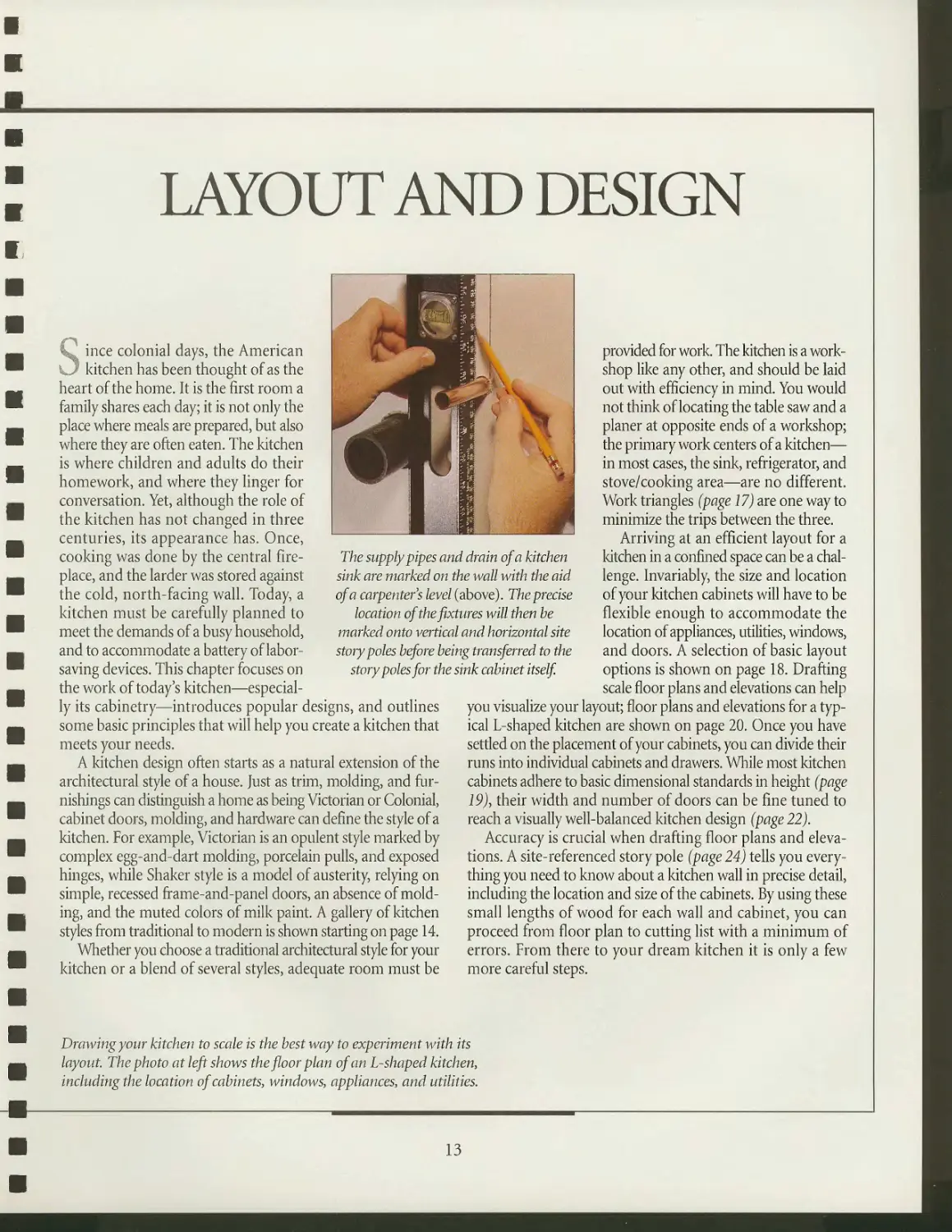
The supply pipes and drain of a kitchen
sink are marked on the wall with the aid
of a carpenters level (above). The precise
location of the fixtures will then he
marked onto vertical and horizontal site
story poles before being transferred to the
story poles for the sink cabinet itself
provided for work. The kitchen is a
workshop like any other, and should be laid
out with efficiency in mind. You would
not think of locating the table saw and a
planer at opposite ends of a workshop;
the primary work centers of a kitchen—
in most cases, the sink, refrigerator, and
stove/cooking area—are no different.
Work triangles (page 17) are one way to
minimize the trips between the three.
Arriving at an efficient layout for a
kitchen in a confined space can be a
challenge. Invariably, the size and location
of your kitchen cabinets will have to be
flexible enough to accommodate the
location of appliances, utilities, windows,
and doors. A selection of basic layout
options is shown on page 18. Drafting
scale floor plans and elevations can help
you visualize your layout; floor plans and elevations for a
typical L-shaped kitchen are shown on page 20. Once you have
settled on the placement of your cabinets, you can divide their
runs into individual cabinets and drawers. While most kitchen
cabinets adhere to basic dimensional standards in height (page
19), their width and number of doors can be fine tuned to
reach a visually well-balanced kitchen design (page 22).
Accuracy is crucial when drafting floor plans and
elevations. A site-referenced story pole (page 24) tells you
everything you need to know about a kitchen wall in precise detail,
including the location and size of the cabinets. By using these
small lengths of wood for each wall and cabinet, you can
proceed from floor plan to cutting list with a minimum of
errors. From there to your dream kitchen it is only a few
more careful steps.
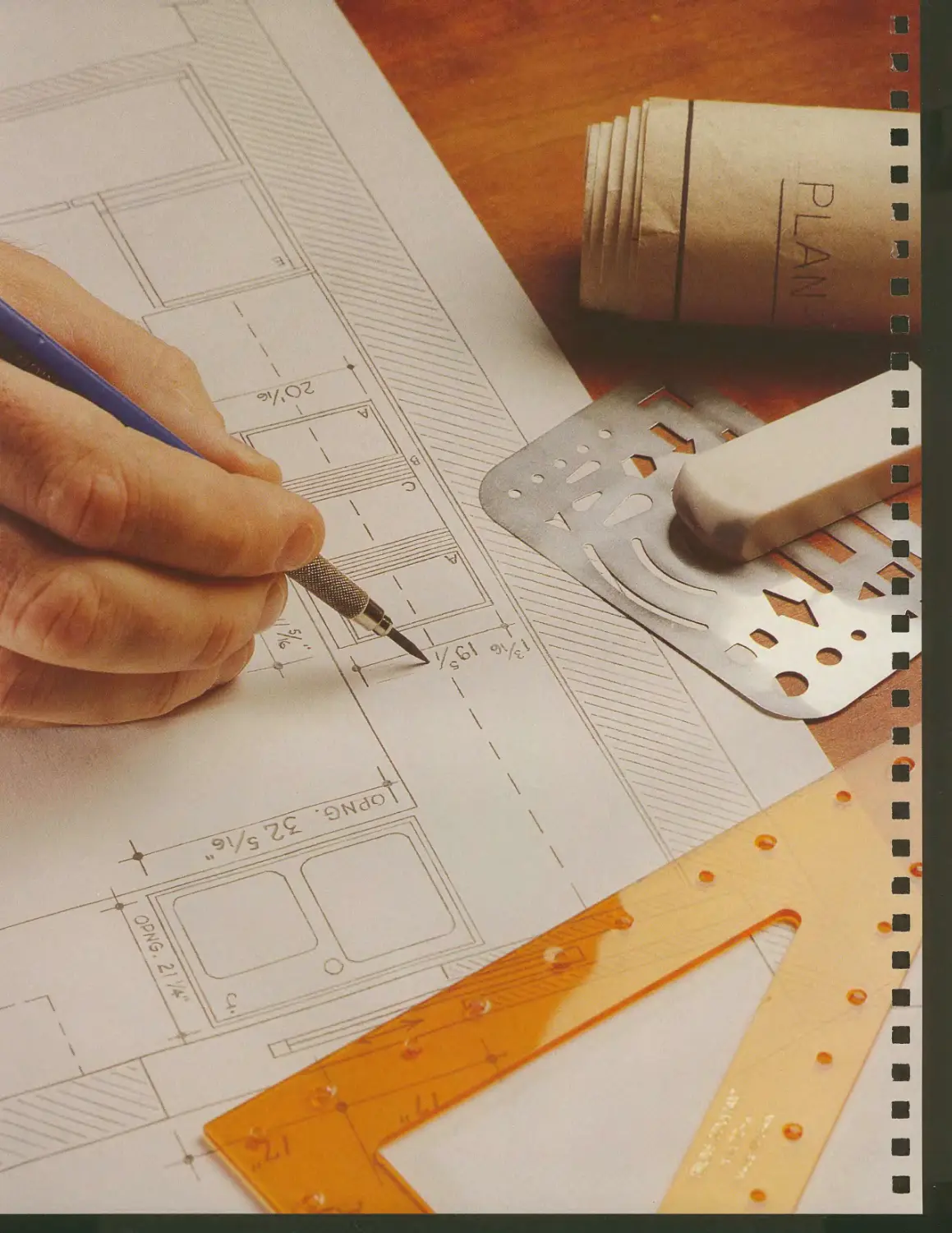
Drawing your kitchen to scale is the best way to experiment with its
layout. The photo at left shows the floor plan of an L-shaped kitchen,
including the location of cabinets, windows, appliances, and utilities.
13
A GALLERY OF KITCHEN STYLES
While a kitchen should reflect your
personal culinary needs and
tastes, its design should not be chosen
without first addressing a few
important questions. Will the style
complement or clash with the rest of the house
architecturally? A Victorian kitchen
would look out of place in a modern
house decorated with Mission furniture.
Budget is another important
consideration. The lumber costs alone for an
Arts and Crafts-style kitchen with
cherry cabinets and frame-and-panel doors
are beyond the reach of many. Popular,
less expensive options include the
European-style kitchen, which uses
standardized melamine cabinets, or the
Country-style kitchen, in which rustic
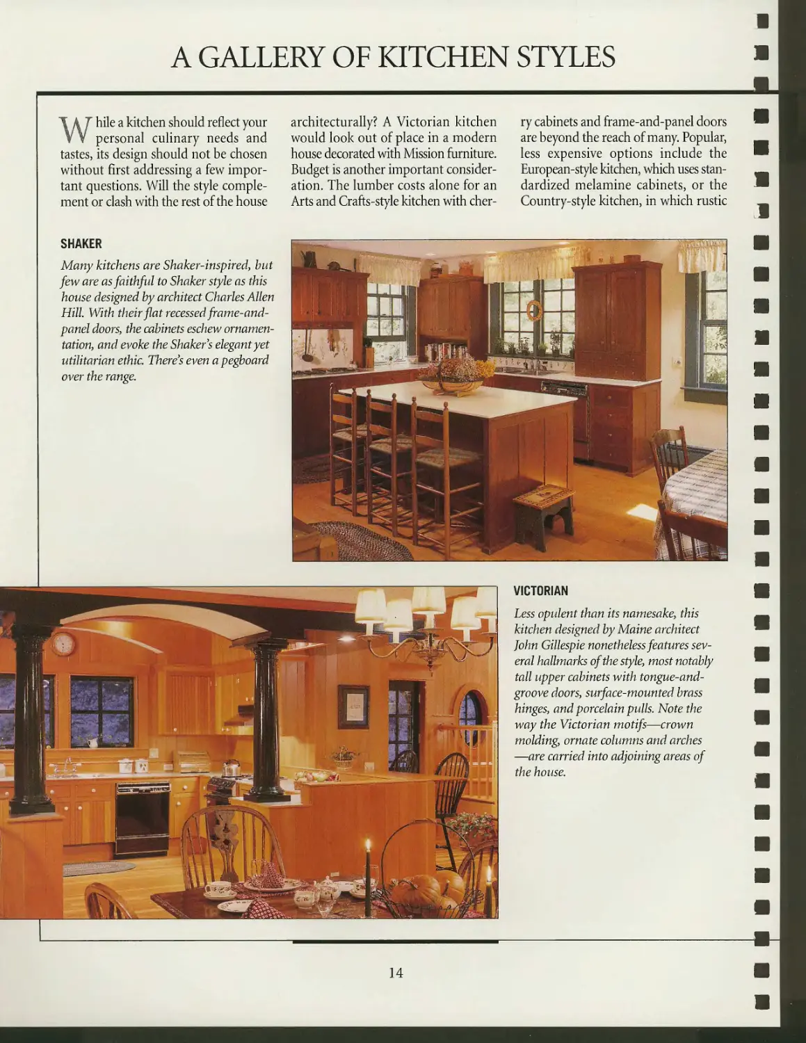
SHAKER
Many kitchens are Shaker-inspired, but
few are as faithful to Shaker style as this
house designed by architect Charles Allen
Hill. With their flat recessed frame-and-
panel doors, the cabinets eschew
ornamentation, and evoke the Shaker's elegant yet
utilitarian ethic. There's even apegboard
over the range.
VICTORIAN
Less opulent than its namesake, this
kitchen designed by Maine architect
John Gillespie nonetheless features
several hallmarks of the style, most notably
tall upper cabinets with tongue-and-
groove doors, surface-mounted brass
hinges, and porcelain pulls. Note the
way the Victorian motifs—crown
molding, ornate columns and arches
—are carried into adjoining areas of
the house.
14
LAYOUT AND DESIGN
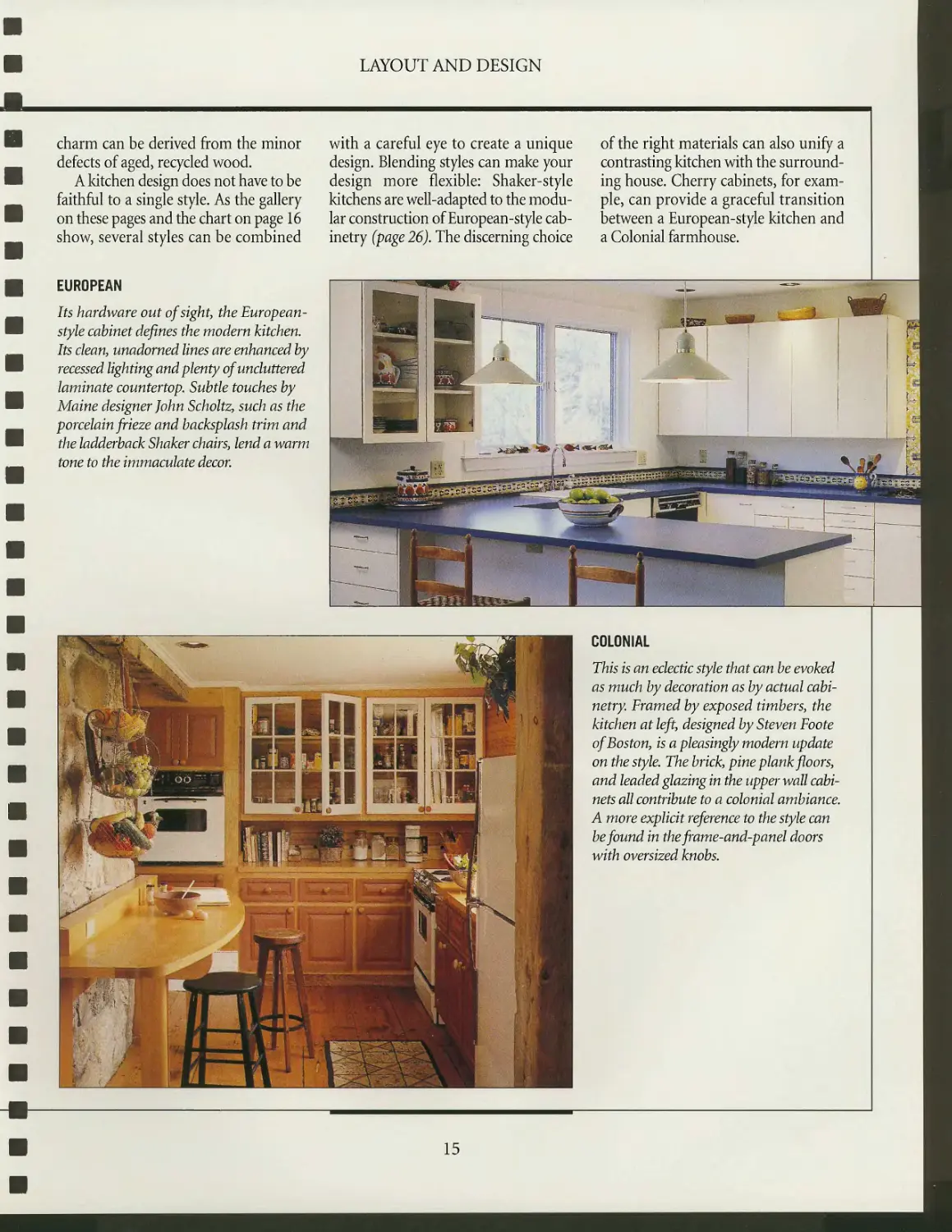
charm can be derived from the minor
defects of aged, recycled wood.
A kitchen design does not have to be
faithful to a single style. As the gallery
on these pages and the chart on page 16
show, several styles can be combined
EUROPEAN
Its hardware out of sight, the European-
style cabinet defines the modern kitchen.
Its cleany unadorned lines are enhanced by
recessed lighting and plenty of uncluttered
laminate countertop. Subtle touches by
Maine designer John Scholtz, such as the
porcelain frieze and backsplash trim and
the ladderback Shaker chairs, lend a warm
tone to the immaculate decor.
with a careful eye to create a unique
design. Blending styles can make your
design more flexible: Shaker-style
kitchens are well-adapted to the
modular construction of European-style
cabinetry (page 26). The discerning choice
of the right materials can also unify a
contrasting kitchen with the
surrounding house. Cherry cabinets, for
example, can provide a graceful transition
between a European-style kitchen and
a Colonial farmhouse.
MIT
1
■i*s^^&&s&§j0 tn&&ggg&
COLONIAL
This is an eclectic style that can be evoked
as much by decoration as by actual
cabinetry. Framed by exposed timbers, the
kitchen at left, designed by Steven Foote
of Boston, is a pleasingly modern update
on the style. The brick, pine plank floors,
and leaded glazing in the upper wall
cabinets all contribute to a colonial ambiance.
A more explicit reference to the style can
be found in thefiume-and-panel doors
with oversized knobs.
15
LAYOUT AND DESIGN
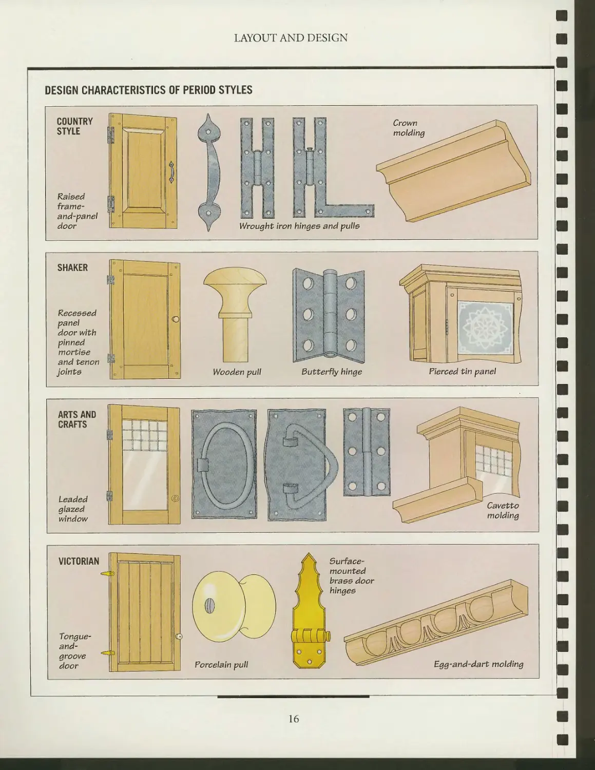
DESIGN CHARACTERISTICS OF PERIOD STYLES
COUNTRY
STYLE
Raised
frame-
and-panel
door
OttO
OxULCj
Wrought iron hinges and pulle
SHAKER
Receeeed
panel
door with
pinned
mortise
and tenon
joints
[op
\9--
[a.
>.-.
i
Tf
,-Q,
Q
Wooden pull
Butterfly hinge
Pierced tin panel
ARTS AND
CRAFTS
Leaded
glazed
window
o
t _ 1
Pol
-Id
o
molding
VICTORIAN
<zp
Tongue-
and-
groove
door
<=zp
Surface-
mounted
brass door
hinges
Porcelain pull
KJU?
Egg-and-dart molding
16
PRINCIPLES OF LAYOUT
A successful kitchen depends on
three things: sufficient space to
work, adequate lighting over the sink
and cooking areas, and cabinets arranged
so that everything from the cutlery to
the breadbox is at hand. Sometimes the
area destined for the kitchen is
woefully inadequate in the first of these three
needs. Still, with a little creative
planning, a functional kitchen can be laid
out in the tightest of spaces.
The cornerstone of kitchen layout is
positioning the stove, refrigerator, and
sink so they form a triangle (below). The
smaller the triangle, the more efficient
the use of space. As the illustrations on
page 18 show, there are several layout
options for a kitchen. The most
popular of these, the U- and L-shaped
designs, allow for efficient work
triangles. A large kitchen can benefit from
the addition of an island, which tightens
the work triangle while freeing up
counter space. Conversely, a single wall
or corridor-style layout makes the best
use of a small space.
All appliances and fixtures come with
dimensional requirements of their own
that should be taken into consideration
before their positions are fixed. For
example, a sink should have counter
space of about 30 inches on each side
for washing dishes; a stove should have
20 to 24 inches of space on both sides
for uncluttered and safe cooking. The
doors of refrigerators, dishwashers, and
ovens create further demand for space;
these appliances should be positioned
fully open.
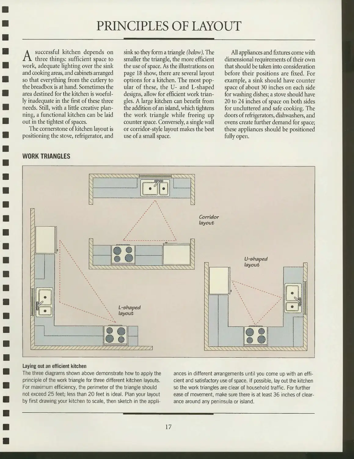
WORK TRIANGLES
\\\\\N
Corridor
layout
N
L-ehaped
layout
V7y7\
U-ehaped
layout
Laying out an efficient kitchen
The three diagrams shown above demonstrate how to apply the
principle of the work triangle for three different kitchen layouts.
For maximum efficiency, the perimeter of the triangle should
not exceed 25 feet; less than 20 feet is ideal. Plan your layout
by first drawing your kitchen to scale, then sketch in the
appliances in different arrangements until you come up with an
efficient and satisfactory use of space. If possible, lay out the kitchen
so the work triangles are clear of household traffic. For further
ease of movement, make sure there is at least 36 inches of
clearance around any peninsula or island.
17
LAYOUT AND DESIGN
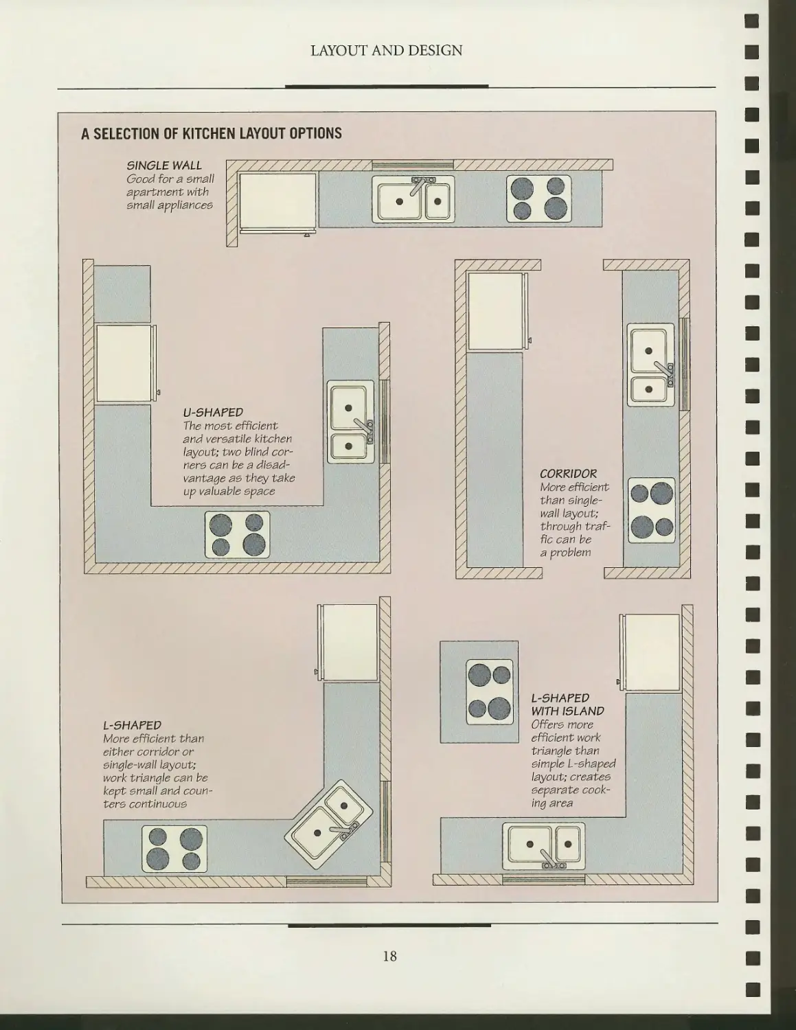
A SELECTION OF KITCHEN LAYOUT OPTIONS
5INGLE WALL
Good for a email
apartment with
email appllancee
V\
U-5HAFEP
The moet efficient
and vereatile kitchen
layout; two blind
corner e can be a dlead-
vantage ae they take
up valuable epace
CORRIDOR
More efficient
than eingle-
wall layout;
through
traffic can be
a problem
I//////
L-5HAFED
More efficient than
either corridor or
eingle-wall layout;
work triangle can be
kept email and coun-
tere continuoue
L-5HAFED
WITH 15LAND
Off ere more
efficient work
triangle than
eimple L-ehaped
layout; createe
eeparate
cooking area
nn
IN
N
N
N
N
I
18
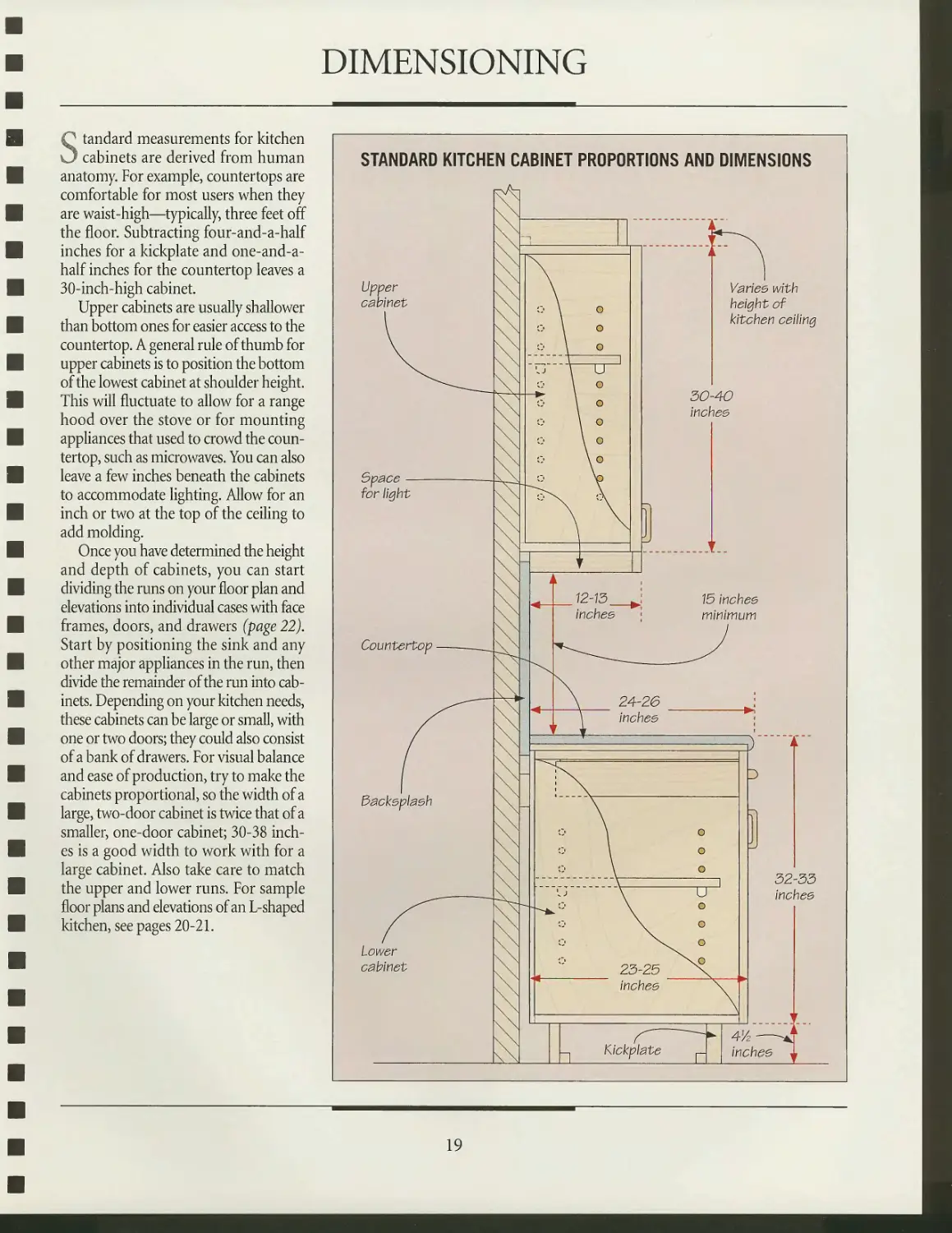
DIMENSIONING
Standard measurements for kitchen
cabinets are derived from human
anatomy. For example, countertops are
comfortable for most users when they
are waist-high—typically, three feet off
the floor. Subtracting four-and-a-half
inches for a kickplate and one-and-a-
half inches for the countertop leaves a
30-inch-high cabinet.
Upper cabinets are usually shallower
than bottom ones for easier access to the
countertop. A general rule of thumb for
upper cabinets is to position the bottom
of the lowest cabinet at shoulder height.
This will fluctuate to allow for a range
hood over the stove or for mounting
appliances that used to crowd the
countertop, such as microwaves. You can also
leave a few inches beneath the cabinets
to accommodate lighting. Allow for an
inch or two at the top of the ceiling to
add molding.
Once you have determined the height
and depth of cabinets, you can start
dividing the runs on your floor plan and
elevations into individual cases with face
frames, doors, and drawers (page 22).
Start by positioning the sink and any
other major appliances in the run, then
divide the remainder of the run into
cabinets. Depending on your kitchen needs,
these cabinets can be large or small, with
one or two doors; they could also consist
of a bank of drawers. For visual balance
and ease of production, try to make the
cabinets proportional, so the width of a
large, two-door cabinet is twice that of a
smaller, one-door cabinet; 30-38
inches is a good width to work with for a
large cabinet. Also take care to match
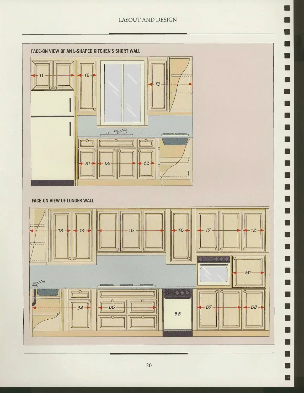
the upper and lower runs. For sample
floor plans and elevations of an L-shaped
kitchen, see pages 20-21.
STANDARD KITCHEN CABINET PROPORTIONS AND DIMENSIONS
Upper
cabinet
Space —
for light
Countertop -
dacksplash
Lower
cabinet
Varies with
height of
kitchen ceiling
Kickplate
32-33
inches
4Vz
inches
19
LAYOUT AND DESIGN
FACE-ON VIEW OF AN L-SHAPED KITCHEN'S SHORT WALL
FACE-ON VIEW OF LONGER WALL
T3
T4-W\
k>
K 71
urf
4f- T5
K —71
&
_EEZ52J3ZESL_
_E3E22S55S3_
M
34-
V J^J
£5-
T6-*H
to
36
T7-
o o ^ a
-re-
i?Q
■37-
i^ _^i
v ^
pe-
20
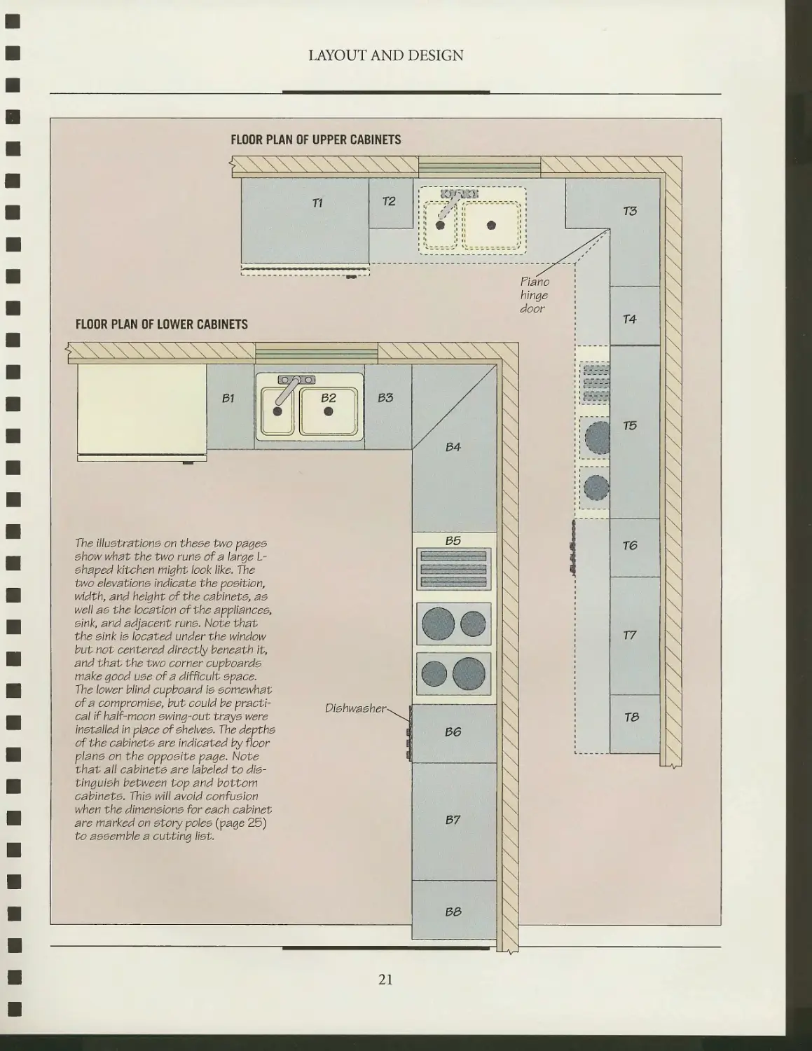
LAYOUT AND DESIGN
FLOOR PLAN OF UPPER CABINETS
The illuetratione on theee two payee
ehow what the two rune of a large L-
ehaped kitchen might look like. The
two elevatlone Indicate the poeltlon,
width, and height of the cablnete, ae
well ae the location of the appllancee,
eink, and adjacent rune. Note that
the eink ie located under the window
but not centered directly beneath it,
and that the two corner cupboarde
make good uee of a difficult epace.
The lower blind cupboard ie eomewhat
of a compromiee, but could be
practical If half-moon ewing-out traye were
inetalled In place of ehelvee. The depthe
of the cablnete are indicated by floor
plane on the oppoeite page. Note
that all cablnete are labeled to die-
tinguieh between top and bottom
cablnete. Thie will avoid confueion
when the dimeneione for each cabinet
are marked on etory polee (page 25)
to aeeemble a cutting Hat.
Diehwaeher-
37
33
21
LAYOUT AND DESIGN
DIVIDING A RUN
2-inch
space
The illustration below
ehowe how to divide a
lower and upper run of' cabl-
nete. In the lower run, the
dlehwaeher and elnk are
poeltloned, then the reet
of the run le divided Into
ec\ual caeee. Next, the
caeee are divided Into
draw ere and doore. In
thle example, the upper
cabinet run le aleo divided
to match the lower run.
For different matching
effecte, eee the llluetra-
tlon at the bottom of
the page.
Adjacent
run
24 inchee
4-3 inchee wider
than eink
rT^f
Double caee
13-19 \
inchee wide
Single
caee 10
inchee
wide
Double qaee
13-19 :
inchee vyide
^H
Tilt-out
eink
tray
MATCHING UPPER AND LOWER CABINETS
o op
op o
op p
op p
op p
op p
Matching top run to bottom
Matching bottom run to top
Staggered run
22
STORY POLES
Story poles are a method of
measuring kitchen cabinets accurately for a
master cutting list without relying on a
tape measure or ruler. Carpenters have
been laying out entire homes on these
long, narrow sticks of wood for
centuries, and this tried-and-true method
offers several advantages over standard
measuring techniques. For one, all
measurements are marked out full-size,
making an error-free cutting list easier to
calculate than from scale drawings.
Story poles also allow you to visualize
construction details more easily. By
marking the measurements for each
cabinet on the sticks you have an exact
picture of each cabinet; lengths, widths, and
positions of joints can all be marked
later on the stock directly, without a tape
measure introducing error. For ease of
handling, make your story poles from
wood lk inch to 3U inch thick and about
1 xh inches wide. To see the pencil marks
better, use light-colored wood.
When laying out a kitchen, site story
poles are first completed for each wall
of the kitchen (page 24). On the
horizontal story pole, the location of
everything along that wall is marked: the
appliances and cabinets in the run,
doors, windows, and any electrical or
plumbing fixtures such as outlets or sink
pipes (see photo, page 13). The vertical
story pole shows the height of the kick-
plate, lower cabinet, countertop, back-
splash, upper cabinet, and ceiling
molding, as well as any windows and
electrical or plumbing fixtures. A depth
story pole provides the depth of kick-
plate, cabinet, and countertop overhang.
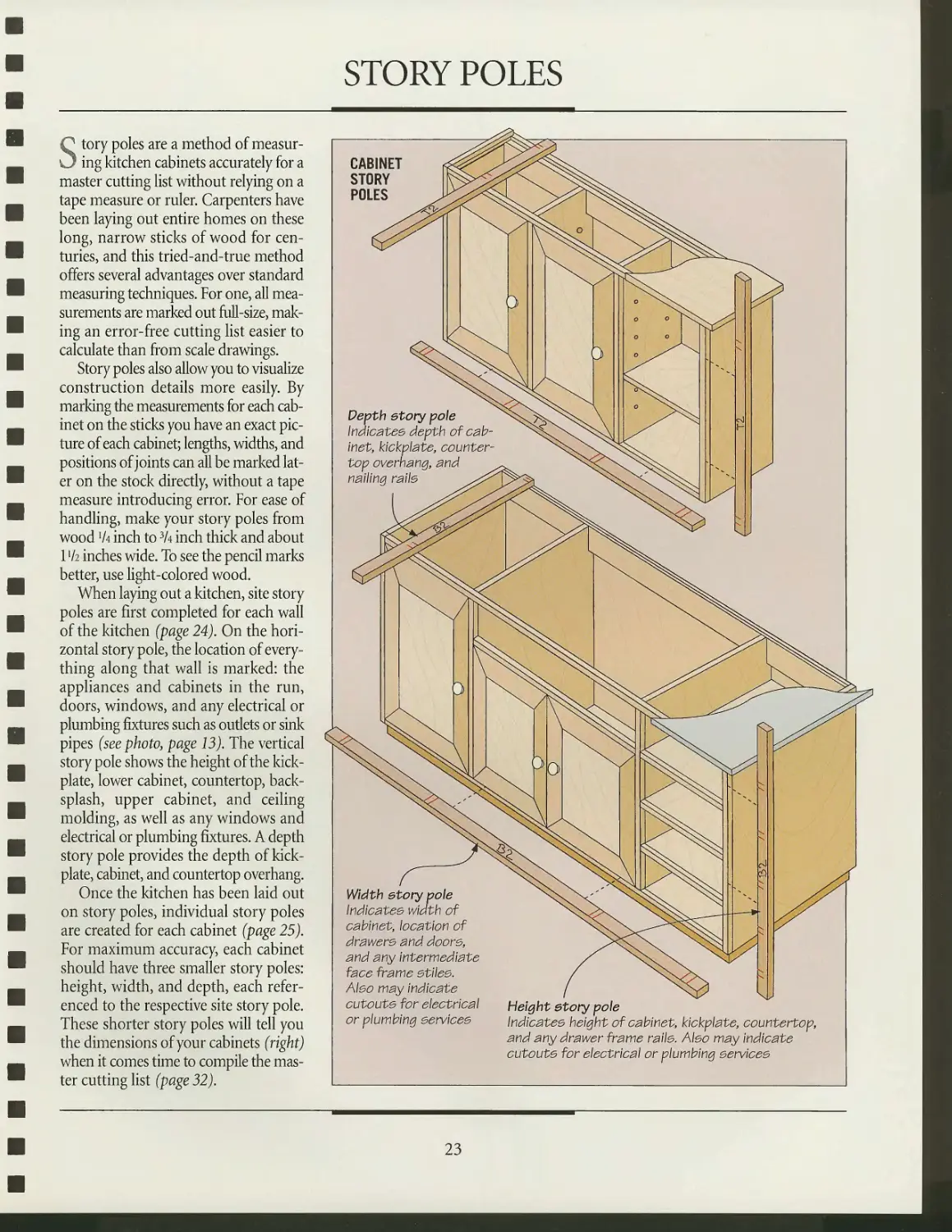
Once the kitchen has been laid out
on story poles, individual story poles
are created for each cabinet (page 25).
For maximum accuracy, each cabinet
should have three smaller story poles:
height, width, and depth, each
referenced to the respective site story pole.
These shorter story poles will tell you
the dimensions of your cabinets (right)
when it comes time to compile the
master cutting list (page 32).
Width story pole
Indicates width of
cabinet, location of
drawere and doore,
and any Intermediate
face frame etliee.
Aleo may indicate
cutoute for electrical
or plumbing eervlcee
Height story pole
Indlcatee height of cabinet, klckpiate, countertop,
and any drawer frame ralie. Aleo may indicate
cutoute for electrical or plumbing eervlcee
23
LAYOUT AND DESIGN
LAYING OUT A KITCHEN WITH STORY POLES
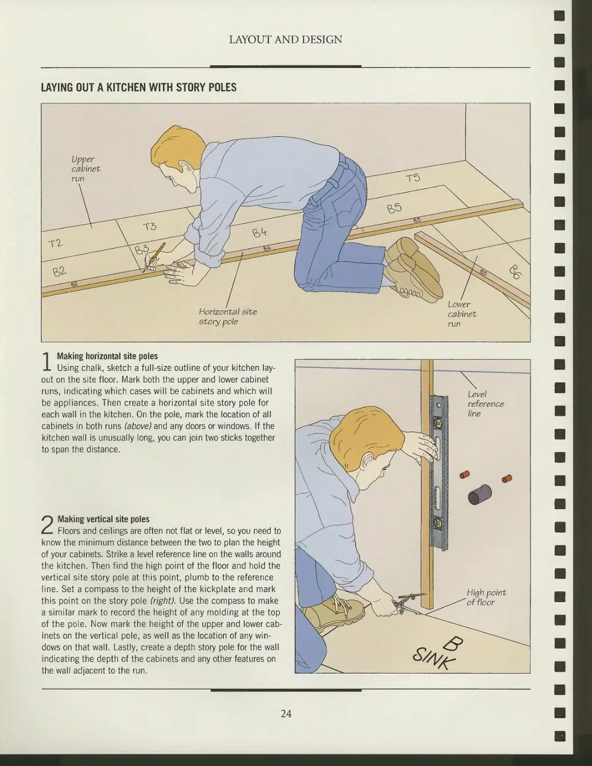
1 Making horizontal site poles
Using chalk, sketch a full-size outline of your kitchen
layout on the site floor. Mark both the upper and lower cabinet
runs, indicating which cases will be cabinets and which will
be appliances. Then create a horizontal site story pole for
each wall in the kitchen. On the pole, mark the location of all
cabinets in both runs (above) and any doors or windows. If the
kitchen wall is unusually long, you can join two sticks together
to span the distance.
2 Making vertical site poles
Floors and ceilings are often not flat or level, so you need to
know the minimum distance between the two to plan the height
of your cabinets. Strike a level reference line on the walls around
the kitchen. Then find the high point of the floor and hold the
vertical site story pole at this point, plumb to the reference
line. Set a compass to the height of the kickplate and mark
this point on the story pole (right). Use the compass to make
a similar mark to record the height of any molding at the top
of the pole. Now mark the height of the upper and lower
cabinets on the vertical pole, as well as the location of any
windows on that wall. Lastly, create a depth story pole for the wall
indicating the depth of the cabinets and any other features on
the wall adjacent to the run.
24
LAYOUT AND DESIGN
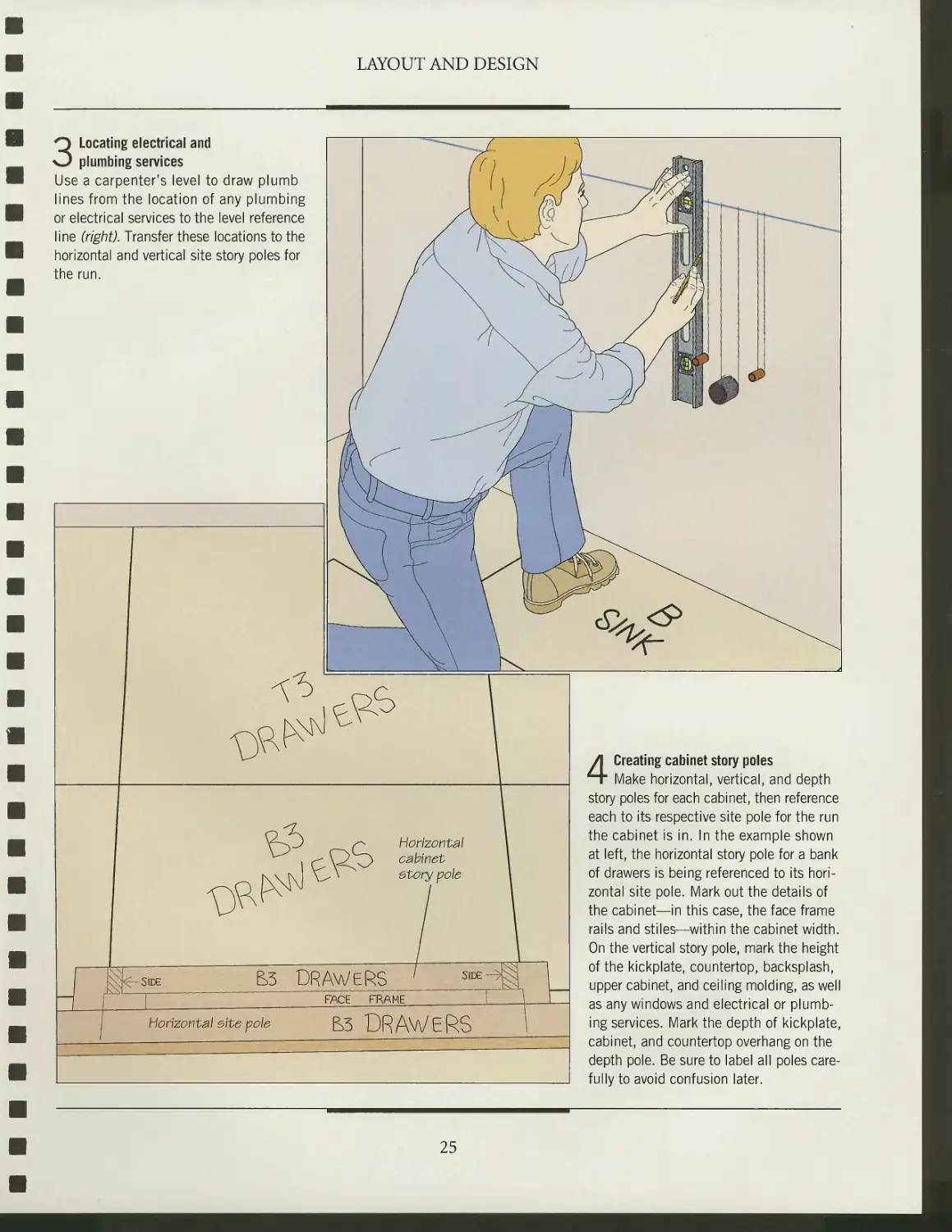
3 Locating electrical and
plumbing services
Use a carpenter's level to draw plumb
lines from the location of any plumbing
or electrical services to the level reference
line (right). Transfer these locations to the
horizontal and vertical site story poles for
the run.
Horizontal
cabinet
etory pole
m
-SIDE
&3 DRAWERS
FACE FRAME
Horizontal elte pole
&3 DRAWERS
4 Creating cabinet story poles
Make horizontal, vertical, and depth
story poles for each cabinet, then reference
each to its respective site pole for the run
the cabinet is in. In the example shown
at left, the horizontal story pole for a bank
of drawers is being referenced to its
horizontal site pole. Mark out the details of
the cabinet—in this case, the face frame
rails and stiles—within the cabinet width.
On the vertical story pole, mark the height
of the kickplate, countertop, backsplash,
upper cabinet, and ceiling molding, as well
as any windows and electrical or
plumbing services. Mark the depth of kickplate,
cabinet, and countertop overhang on the
depth pole. Be sure to label all poles
carefully to avoid confusion later.
25
4^
■.<**..
$^i
\
V
^
m
CASEWORK
Built-in kitchen cabinets are
relatively recent arrivals in domestic
kitchens. Traditionally, kitchen
cupboards were freestanding units with
frame-and-panel construction and face
frames, much like the china cabinet in
the parlor. Yet by the turn of the
century, the switch to built-ins had already
begun. It accelerated during the post-
WWII housing boom in Europe, when
the construction of millions of new
homes prompted the development of
new wood products, tools, and
techniques that saved labor and materials.
No room in the house benefitted from
these advances more than the kitchen.
The development of plywood, parti-
cleboard, fiberboard, and other
manufactured sheet goods made assembly-line
production of large and rigid cabinets
possible. The European 32-millimeter system—so called
because all the holes for drawer slides, dowels, shelf supports,
and hinges are spaced 32 millimeters apart—was
revolutionary in design. Its modular, predrilled melamine cabinets offered
unparalleled flexibility. It also made the modern kitchen
affordable: Even the most modest home could now be outfitted with
a fall complement of sleek kitchen cabinets.
Building these cases is mainly a matter of cutting the stock
to size and then joining it using one of the techniques shown
on pages 33 to 37; the chart on page 31 will help you choose
from available materials. Face frames, doors, drawer fronts,
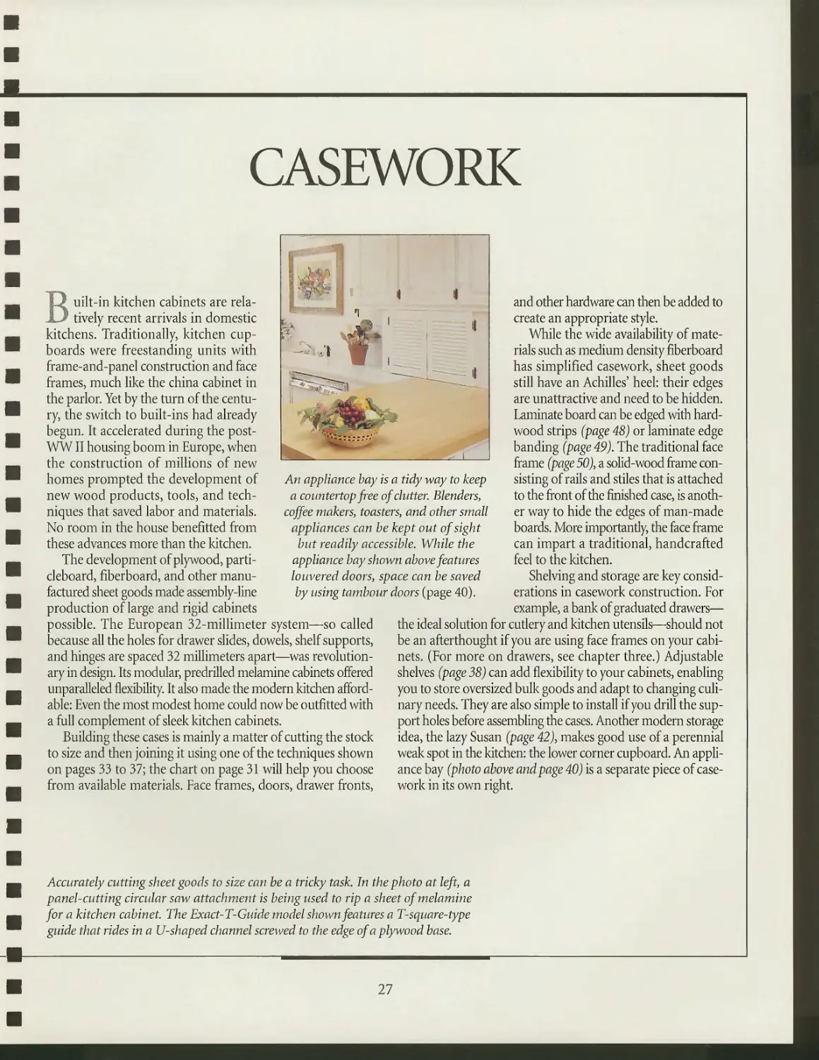
An appliance bay is a tidy way to keep
a countertop free of clutter. Blenders,
coffee makers, toasters, and other small
appliances can be kept out of sight
but readily accessible. While the
appliance bay shown above features
louvered doors, space can be saved
by using tambour doors (page 40).
and other hardware can then be added to
create an appropriate style.
While the wide availability of
materials such as medium density fiberboard
has simplified casework, sheet goods
still have an Achilles' heel: their edges
are unattractive and need to be hidden.
Laminate board can be edged with
hardwood strips (page 48) or laminate edge
banding (page 49). The traditional face
frame (page 50), a solid-wood frame
consisting of rails and stiles that is attached
to the front of the finished case, is
another way to hide the edges of man-made
boards. More importantly, the face frame
can impart a traditional, handcrafted
feel to the kitchen.
Shelving and storage are key
considerations in casework construction. For
example, a bank of graduated drawers—
the ideal solution for cutlery and kitchen utensils—should not
be an afterthought if you are using face frames on your
cabinets. (For more on drawers, see chapter three.) Adjustable
shelves (page 38) can add flexibility to your cabinets, enabling
you to store oversized bulk goods and adapt to changing
culinary needs. They are also simple to install if you drill the
support holes before assembling the cases. Another modern storage
idea, the lazy Susan (page 42), makes good use of a perennial
weak spot in the kitchen: the lower corner cupboard. An
appliance bay (photo above and page 40) is a separate piece of
casework in its own right.
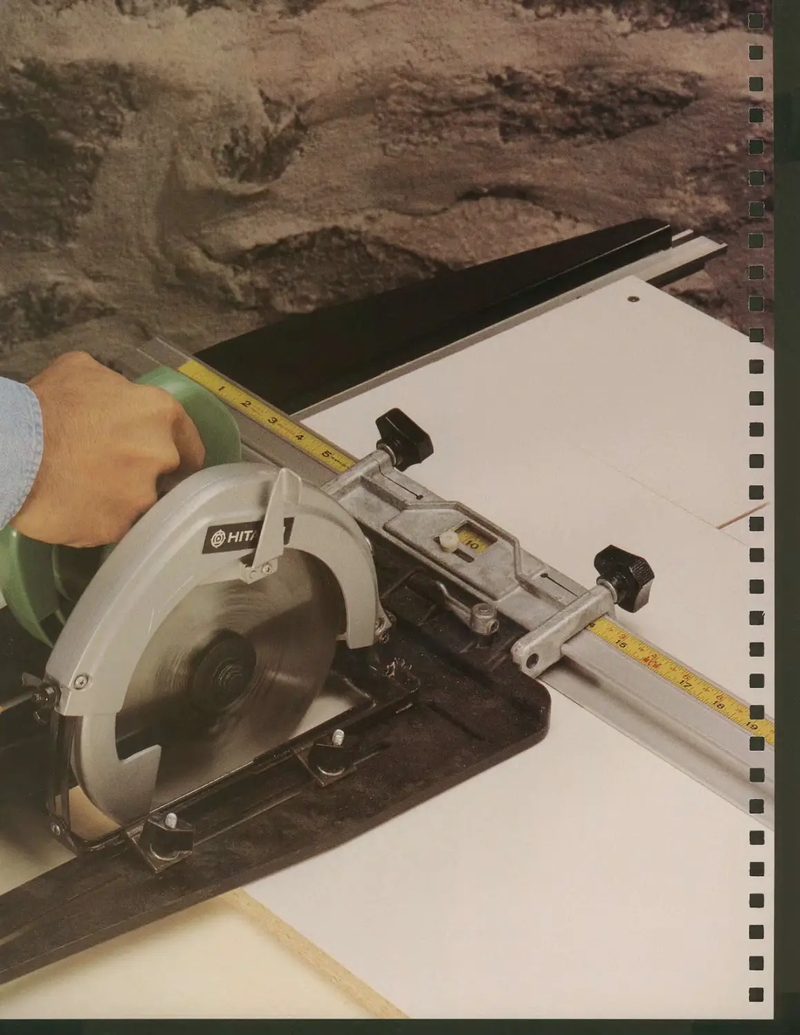
Accurately cutting sheet goods to size can be a tricky task. In the photo at left, a
panel-cutting circular saw attachment is being used to rip a sheet of melamine
for a kitchen cabinet. The Exact-T-Guide model shown features a T-square-type
guide that rides in a U-shaped channel screwed to the edge of a plywood base.
27
ANATOMY OF A KITCHEN CABINET CASE
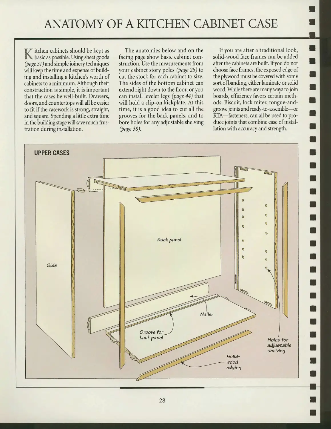
Kitchen cabinets should be kept as
basic as possible. Using sheet goods
(page 31) and simple joinery techniques
will keep the time and expense of
building and installing a kitchen's worth of
cabinets to a minimum. Although their
construction is simple, it is important
that the cases be well-built. Drawers,
doors, and countertops will all be easier
to fit if the casework is strong, straight,
and square. Spending a little extra time
in the building stage will save much
frustration during installation.
The anatomies below and on the
facing page show basic cabinet
construction. Use the measurements from
your cabinet story poles (page 25) to
cut the stock for each cabinet to size.
The sides of the bottom cabinet can
extend right down to the floor, or you
can install leveler legs (page 44) that
will hold a clip-on kickplate. At this
time, it is a good idea to cut all the
grooves for the back panels, and to
bore holes for any adjustable shelving
(page 38).
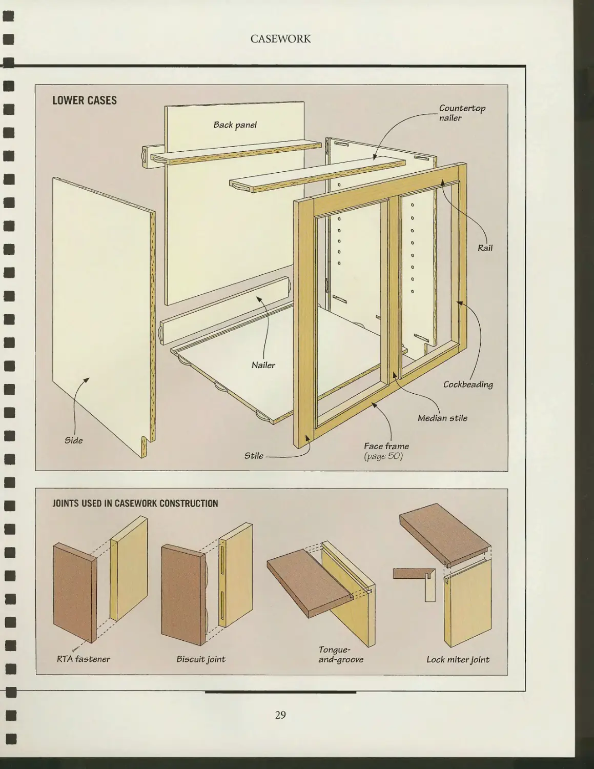
If you are after a traditional look,
solid-wood face frames can be added
after the cabinets are built. If you do not
choose face frames, the exposed edge of
the plywood must be covered with some
sort of banding, either laminate or solid
wood. While there are many ways to join
boards, efficiency favors certain
methods. Biscuit, lock miter, tongue-and-
groove joints and ready-to-assemble—or
RTA—fasteners, can all be used to
produce joints that combine ease of
installation with accuracy and strength.
UPPER CASES
A
Solid-
wood
edging
\J
Holee for
adjustable
shelving
28
CASEWORK
LOWER CASES
Back panel
Countertop
nailer
Rail
Cockbeading
Median etile
Face frame
(page 50)
JOINTS USED IN CASEWORK CONSTRUCTION
S
RTA faetener
Biscuit joint
Tongue-
and-groove
Lock miter joint
29
BUILDING MATERIALS
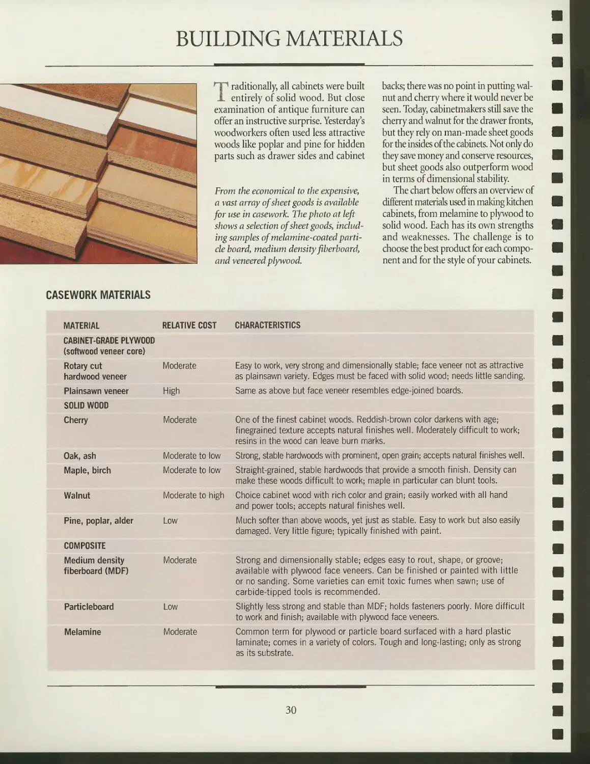
Traditionally, all cabinets were built
entirely of solid wood. But close
examination of antique furniture can
offer an instructive surprise. Yesterday s
woodworkers often used less attractive
woods like poplar and pine for hidden
parts such as drawer sides and cabinet
From the economical to the expensive,
a vast array ojsheet goods is available
for use in casework. The photo at left
shows a selection of sheet goods,
including samples of melamine-coated
particle board, medium density fiberboard,
and veneered plywood.
backs; there was no point in putting
walnut and cherry where it would never be
seen. Today, cabinetmakers still save the
cherry and walnut for the drawer fronts,
but they rely on man-made sheet goods
for the insides of the cabinets. Not only do
they save money and conserve resources,
but sheet goods also outperform wood
in terms of dimensional stability
The chart below offers an overview of
different materials used in making kitchen
cabinets, from melamine to plywood to
solid wood. Each has its own strengths
and weaknesses. The challenge is to
choose the best product for each
component and for the style of your cabinets.
CASEWORK MATERIALS
MATERIAL
CABINET-GRADE PLYWOOD
(softwood veneer core)
Rotary cut
hardwood veneer
Plainsawn veneer
SOLID WOOD
Cherry
Oak, ash
Maple, birch
Walnut
Pine, poplar, alder
COMPOSITE
Medium density
fiberboard (MDF)
Particleboard
Melamine
RELATIVE COST CHARACTERISTICS
Moderate Easy to work, very strong and dimensionally stable; face veneer not as attractive
as plainsawn variety. Edges must be faced with solid wood; needs little sanding.
High Same as above but face veneer resembles edge-joined boards.
Moderate One of the finest cabinet woods. Reddish-brown color darkens with age;
finegrained texture accepts natural finishes well. Moderately difficult to work;
resins in the wood can leave burn marks.
Moderate to low Strong, stable hardwoods with prominent, open grain; accepts natural finishes well.
Moderate to low Straight-grained, stable hardwoods that provide a smooth finish. Density can
make these woods difficult to work; maple in particular can blunt tools.
Moderate to high Choice cabinet wood with rich color and grain; easily worked with all hand
and power tools; accepts natural finishes well.
Low Much softer than above woods, yet just as stable. Easy to work but also easily
damaged. Very little figure; typically finished with paint.
Moderate Strong and dimensionally stable; edges easy to rout, shape, or groove;
available with plywood face veneers. Can be finished or painted with little
or no sanding. Some varieties can emit toxic fumes when sawn; use of
carbide-tipped tools is recommended.
Low Slightly less strong and stable than MDF; holds fasteners poorly. More difficult
to work and finish; available with plywood face veneers.
Moderate Common term for plywood or particle board surfaced with a hard plastic
laminate; comes in a variety of colors. Tough and long-lasting; only as strong
as its substrate.
30
CASEWORK
TYPES OF PLYWOOD
VENEER
CORE
face veneer
Croeebande
LUMBER
CORE
Face veneer
Croeebande
Veneer core
3ack veneer
Lumber core
3ack
veneer
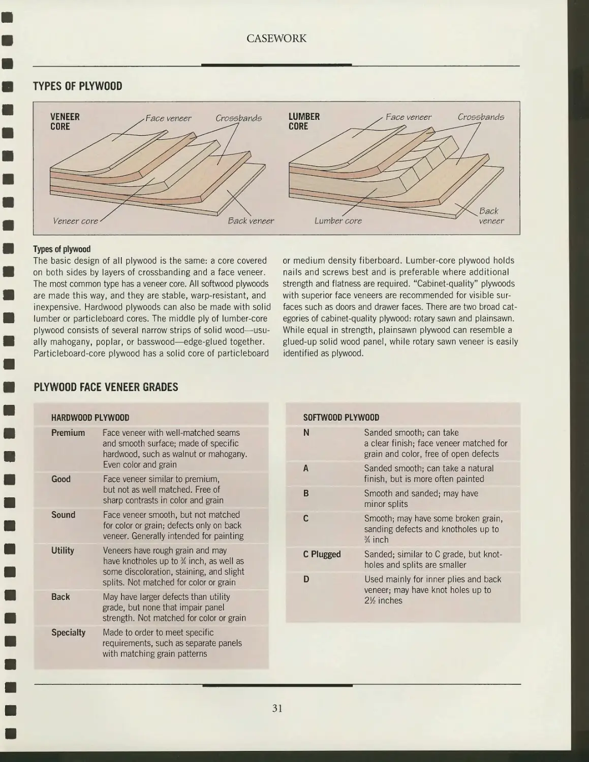
Types of plywood
The basic design of all plywood is the same: a core covered
on both sides by layers of crossbanding and a face veneer.
The most common type has a veneer core. All softwood plywoods
are made this way, and they are stable, warp-resistant, and
inexpensive. Hardwood plywoods can also be made with solid
lumber or particleboard cores. The middle ply of lumber-core
plywood consists of several narrow strips of solid
wood—usually mahogany, poplar, or basswood—edge-glued together.
Particleboard-core plywood has a solid core of particleboard
or medium density fiberboard. Lumber-core plywood holds
nails and screws best and is preferable where additional
strength and flatness are required. "Cabinet-quality" plywoods
with superior face veneers are recommended for visible
surfaces such as doors and drawer faces. There are two broad
categories of cabinet-quality plywood: rotary sawn and plainsawn.
While equal in strength, plainsawn plywood can resemble a
glued-up solid wood panel, while rotary sawn veneer is easily
identified as plywood.
PLYWOOD FACE VENEER GRADES
HARDWOOD PLYWOOD
Premium Face veneer with well-matched seams
and smooth surface; made of specific
hardwood, such as walnut or mahogany.
Even color and grain
Good Face veneer similar to premium,
but not as well matched. Free of
sharp contrasts in color and grain
Sound Face veneer smooth, but not matched
for color or grain; defects only on back
veneer. Generally intended for painting
Utility Veneers have rough grain and may
have knotholes up to % inch, as well as
some discoloration, staining, and slight
splits. Not matched for color or grain
Back May have larger defects than utility
grade, but none that impair panel
strength. Not matched for color or grain
Specialty Made to order to meet specific
requirements, such as separate panels
with matching grain patterns
SOFTWOOD PLYWOOD
N
C Plugged
Sanded smooth; can take
a clear finish; face veneer matched for
grain and color, free of open defects
Sanded smooth; can take a natural
finish, but is more often painted
Smooth and sanded; may have
minor splits
Smooth; may have some broken grain,
sanding defects and knotholes up to
% inch
Sanded; similar to C grade, but
knotholes and splits are smaller
Used mainly for inner plies and back
veneer; may have knot holes up to
2Yz inches
31
CASEWORK
CASE
22%"
FACE FRAME
Bottom:
23%"X22"X%"
SO'A"-
3VA"
2TA"
Nailer: 4@
'23%"X4"X%"
Back panel:
~305A"X29%"X%"
Bide: 2@
~3?A"X22"X%"
Stile: 2@
'3VAUX2"X%"
Median rail:
'2?A"X2"X%"
Rail: 2@
'26%"X2"X%"
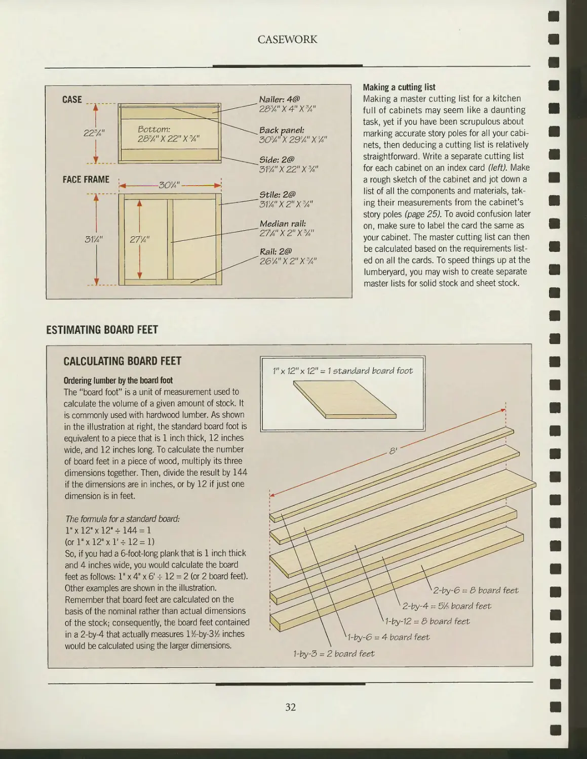
Making a cutting list
Making a master cutting list for a kitchen
full of cabinets may seem like a daunting
task, yet if you have been scrupulous about
marking accurate story poles for all your
cabinets, then deducing a cutting list is relatively
straightforward. Write a separate cutting list
for each cabinet on an index card (left). Make
a rough sketch of the cabinet and jot down a
list of all the components and materials,
taking their measurements from the cabinet's
story poles (page 25). To avoid confusion later
on, make sure to label the card the same as
your cabinet. The master cutting list can then
be calculated based on the requirements
listed on all the cards. To speed things up at the
lumberyard, you may wish to create separate
master lists for solid stock and sheet stock.
ESTIMATING BOARD FEET
CALCULATING BOARD FEET
Ordering lumber by the board foot
The "board foot" is a unit of measurement used to
calculate the volume of a given amount of stock. It
is commonly used with hardwood lumber. As shown
in the illustration at right, the standard board foot is
equivalent to a piece that is 1 inch thick, 12 inches
wide, and 12 inches long. To calculate the number
of board feet in a piece of wood, multiply its three
dimensions together. Then, divide the result by 144
if the dimensions are in inches, or by 12 if just one
dimension is in feet.
The formula for a standard board:
1hx12"x12"-t144=1
(orl>xl2"xr-rl2 = l)
So, if you had a 6-foot-long plank that is 1 inch thick
and 4 inches wide, you would calculate the board
feet as follows: 1" x 4" x 6' -r 12 = 2 (or 2 board feet).
Other examples are shown in the illustration.
Remember that board feet are calculated on the
basis of the nominal rather than actual dimensions
of the stock; consequently, the board feet contained
in a 2-by-4 that actually measures l^-by-3/4 inches
would be calculated using the larger dimensions.
K2-by-6 = 3 board feet
k 2-by-4 = 5]/3 board feet
K hby-12 = 3 board feet
K1-by-6 = 4 board feet
hby-3 = 2 board feet
32
BUILDING THE CASES
After you have calculated a master
cutting list for your cabinets, you
are finally ready to start building them.
As you cut the materials to size,
carefully mark each piece to indicate which
cabinet it belongs to. Then cut the grooves
for the back panels and bore the holes
for any adjustable shelving (page 38).
With this groundwork done,
assembly is largely a matter of choosing a
joinery method. If you are comfortable with
your table saw, tongue-and-groove
joints (page 35) are a good choice. Those
well-versed in using a plate jointer may
want to join their cases with biscuits
(below), a joint equal in strength to the
tongue-and-groove. If you have a shaper
or a very solid router table and a heavy-
duty router, lock miter joints (page 36)
are solid, durable, and easy to cut. If
space in your workshop is at a
premium or if you need to disassemble and
move your cabinets, ready-to-assemble
—or RTA—fasteners (page 37) may be
the best choice.
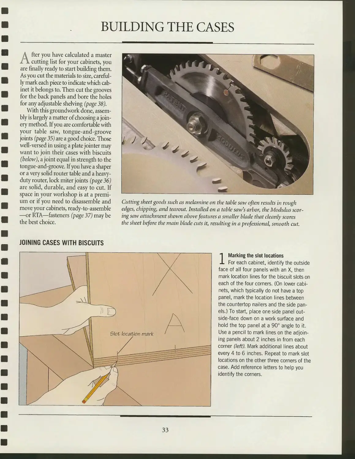
Cutting sheet goods such as melamine on the table saw often results in rough
edges, chipping, and tearout. Installed on a table saw's arbor, the Modulus
scoring saw attachment shown above features a smaller blade that cleanly scores
the sheet before the main blade cuts it, resulting in a professional, smooth cut.
JOINING CASES WITH BISCUITS
1 Marking the slot locations
For each cabinet, identify the outside
face of all four panels with an X, then
mark location lines for the biscuit slots on
each of the four corners. (On lower
cabinets, which typically do not have a top
panel, mark the location lines between
the countertop nailers and the side
panels.) To start, place one side panel out-
side-face down on a work surface and
hold the top panel at a 90° angle to it.
Use a pencil to mark lines on the
adjoining panels about 2 inches in from each
corner (left). Mark additional lines about
every 4 to 6 inches. Repeat to mark slot
locations on the other three corners of the
case. Add reference letters to help you
identify the corners.
33
CASEWORK
faceplate -
Top panel
^
wJw
/jr^U
"^nOflre
L^wi] l|v
^ 5\dt
X /^ y
l'n / f
m / , /
■§' / >ji //
If/ ^Mr /
■ sSSSbsM^^B^'j
////~*^^ ^^^^^^iX^^/lv-'
Support board / /
? panel / /
/
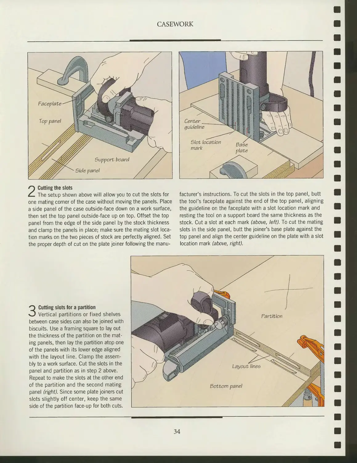
2 Cutting the slots
The setup shown above will allow you to cut the slots for
one mating corner of the case without moving the panels. Place
a side panel of the case outside-face down on a work surface,
then set the top panel outside-face up on top. Offset the top
panel from the edge of the side panel by the stock thickness
and clamp the panels in place; make sure the mating slot
location marks on the two pieces of stock are perfectly aligned. Set
the proper depth of cut on the plate joiner following the
manufacturer's instructions. To cut the slots in the top panel, butt
the tool's faceplate against the end of the top panel, aligning
the guideline on the faceplate with a slot location mark and
resting the tool on a support board the same thickness as the
stock. Cut a slot at each mark (above, left). To cut the mating
slots in the side panel, butt the joiner's base plate against the
top panel and align the center guideline on the plate with a slot
location mark (above, right).
3 Cutting slots for a partition
Vertical partitions or fixed shelves
between case sides can also be joined with
biscuits. Use a framing square to lay out
the thickness of the partition on the
mating panels, then lay the partition atop one
of the panels with its lower edge aligned
with the layout line. Clamp the
assembly to a work surface. Cut the slots in the
panel and partition as in step 2 above.
Repeat to make the slots at the other end
of the partition and the second mating
panel (right). Since some plate joiners cut
slots slightly off center, keep the same
side of the partition face-up for both cuts.
34
CASEWORK
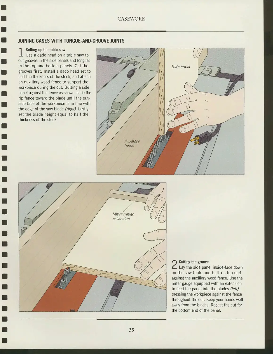
JOINING CASES WITH TONGUE-AND-GROOVE JOINTS
1 Setting up the table saw
Use a dado head on a table saw to
cut grooves in the side panels and tongues
in the top and bottom panels. Cut the
grooves first. Install a dado head set to
half the thickness of the stock, and attach
an auxiliary wood fence to support the
workpiece during the cut. Butting a side
panel against the fence as shown, slide the
rip fence toward the blade until the
outside face of the workpiece is in line with
the edge of the saw blade (right). Lastly,
set the blade height equal to half the
thickness of the stock.
2 Cutting the groove
Lay the side panel inside-face down
on the saw table and butt its top end
against the auxiliary wood fence. Use the
miter gauge equipped with an extension
to feed the panel into the blades (left),
pressing the workpiece against the fence
throughout the cut. Keep your hands well
away from the blades. Repeat the cut for
the bottom end of the panel.
35
CASEWORK
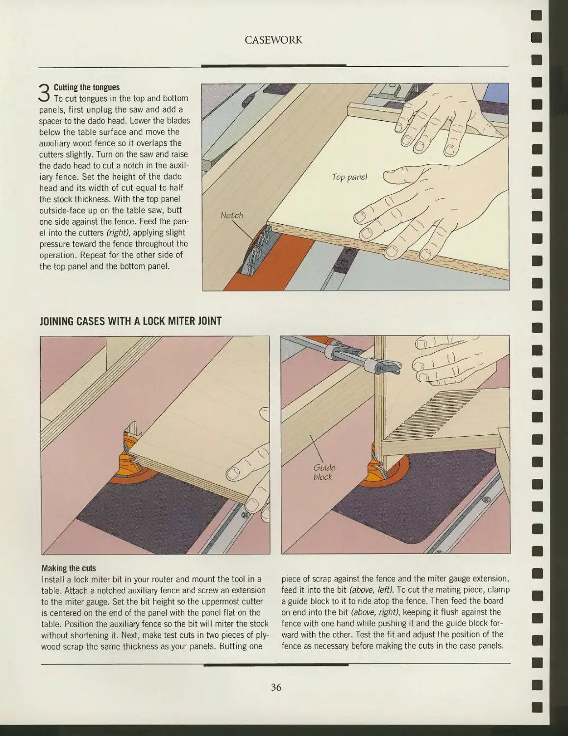
3 Cutting the tongues
To cut tongues in the top and bottom
panels, first unplug the saw and add a
spacer to the dado head. Lower the blades
below the table surface and move the
auxiliary wood fence so it overlaps the
cutters slightly. Turn on the saw and raise
the dado head to cut a notch in the
auxiliary fence. Set the height of the dado
head and its width of cut equal to half
the stock thickness. With the top panel
outside-face up on the table saw, butt
one side against the fence. Feed the
panel into the cutters (right), applying slight
pressure toward the fence throughout the
operation. Repeat for the other side of
the top panel and the bottom panel.
JOINING CASES WITH A LOCK MITER JOINT
Making the cuts
Install a lock miter bit in your router and mount the tool in a
table. Attach a notched auxiliary fence and screw an extension
to the miter gauge. Set the bit height so the uppermost cutter
is centered on the end of the panel with the panel flat on the
table. Position the auxiliary fence so the bit will miter the stock
without shortening it. Next, make test cuts in two pieces of
plywood scrap the same thickness as your panels. Butting one
piece of scrap against the fence and the miter gauge extension,
feed it into the bit (above, left). To cut the mating piece, clamp
a guide block to it to ride atop the fence. Then feed the board
on end into the bit (above, right), keeping it flush against the
fence with one hand while pushing it and the guide block
forward with the other. Test the fit and adjust the position of the
fence as necessary before making the cuts in the case panels.
36
CASEWORK
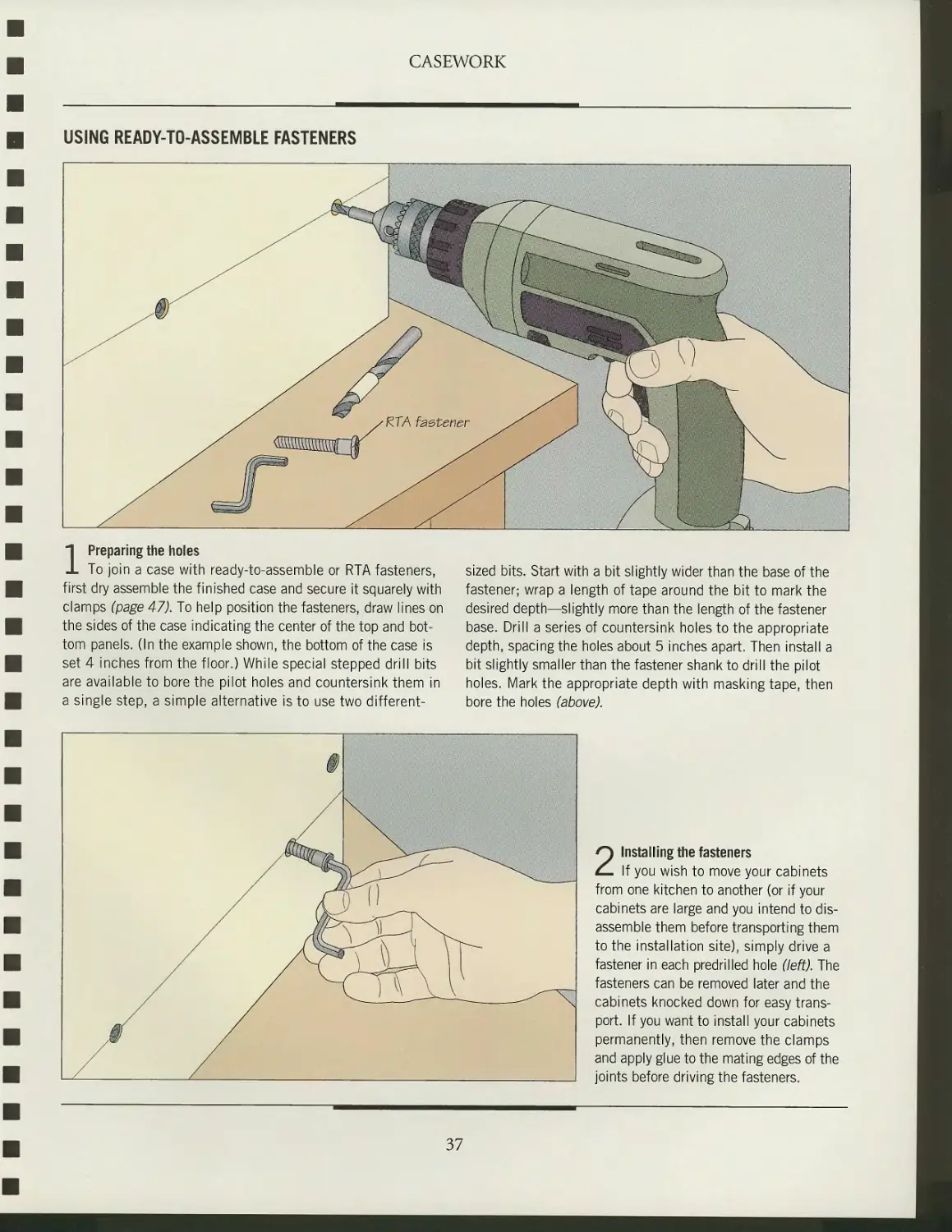
USING READY-TO-ASSEMBLE FASTENERS
1 Preparing the holes
To join a case with ready-to-assemble or RTA fasteners,
first dry assemble the finished case and secure it squarely with
clamps (page 47). To help position the fasteners, draw lines on
the sides of the case indicating the center of the top and
bottom panels. (In the example shown, the bottom of the case is
set 4 inches from the floor.) While special stepped drill bits
are available to bore the pilot holes and countersink them in
a single step, a simple alternative is to use two different-
sized bits. Start with a bit slightly wider than the base of the
fastener; wrap a length of tape around the bit to mark the
desired depth—slightly more than the length of the fastener
base. Drill a series of countersink holes to the appropriate
depth, spacing the holes about 5 inches apart. Then install a
bit slightly smaller than the fastener shank to drill the pilot
holes. Mark the appropriate depth with masking tape, then
bore the holes (above).
2 Installing the fasteners
If you wish to move your cabinets
from one kitchen to another (or if your
cabinets are large and you intend to
disassemble them before transporting them
to the installation site), simply drive a
fastener in each predrilled hole (left). The
fasteners can be removed later and the
cabinets knocked down for easy
transport. If you want to install your cabinets
permanently, then remove the clamps
and apply glue to the mating edges of the
joints before driving the fasteners.
37
SHELVING AND STORAGE
f~^ ooks seldom complain about hav-
\^j ing too much storage space in their
kitchens. Appliances, pots, cans, spice
racks, cookbooks, and dishes all seem to
conspire to fill every nook and cranny of
available space. Efficient shelving and
storage devices can create a surprising
amount of space simply by keeping
things organized. For example, the
height of adjustable shelves (below) can
From towel racks to slide-out garbage
bins, there are many commercial
storage devices on the market designed to
reduce time spent rummaging in lower
cabinets. The photo at left shows slide-
out shelving mounted on drawer slides.
be changed to accommodate different-
sized dry goods or dishes. Corner
cabinets are particularly prone to wasting
valuable space; items at the very back of
such cabinets tend to be forgotten. A lazy
Susan (page 42) is an elegant solution to
this problem: Its two round shelves
rotate around a central shaft, making all
the contents readily accessible.
Appliance clutter is another common
kitchen complaint. Certain appliances
that see frequent use, such as toasters,
coffee makers, and blenders, often crowd
the countertop. An appliance bay with
a sliding tambour door (page 40)
provides a tidy place to keep these kitchen
conveniences plugged in and out of sight,
yet easily accessible.
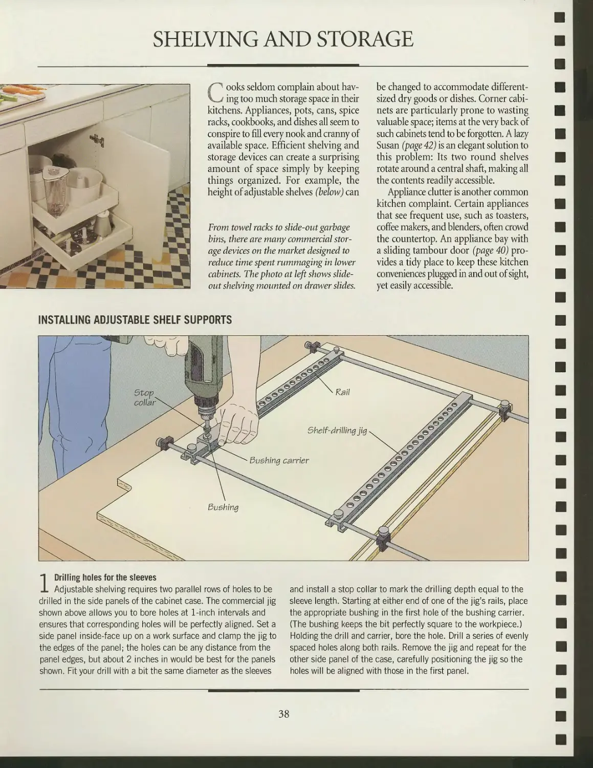
INSTALLING ADJUSTABLE SHELF SUPPORTS
1 Drilling holes for the sleeves
Adjustable shelving requires two parallel rows of holes to be
drilled in the side panels of the cabinet case. The commercial jig
shown above allows you to bore holes at 1-inch intervals and
ensures that corresponding holes will be perfectly aligned. Set a
side panel inside-face up on a work surface and clamp the jig to
the edges of the panel; the holes can be any distance from the
panel edges, but about 2 inches in would be best for the panels
shown. Fit your drill with a bit the same diameter as the sleeves
and install a stop collar to mark the drilling depth equal to the
sleeve length. Starting at either end of one of the jig's rails, place
the appropriate bushing in the first hole of the bushing carrier.
(The bushing keeps the bit perfectly square to the workpiece.)
Holding the drill and carrier, bore the hole. Drill a series of evenly
spaced holes along both rails. Remove the jig and repeat for the
other side panel of the case, carefully positioning the jig so the
holes will be aligned with those in the first panel.
38
CASEWORK
SHOP TIP
A shop-made shelf
drilling jig
The T-shaped
jig shown at
right will allow
you to bore a row
of evenly spaced
holes as accuratt ^
a commercial'^. Make
the jig from 1-by-3 stock,
being careful to ecrew the
fence and arm together at a
perfect 90° angle. Mark a line down
the center of the arm and bore holes
along it at 2-inch intervals with the
same bit you would use for
threaded sleeves. To use the jig, clamp it to a
side panel with the fence butted against
either end of the panel and the marked
centerline 2 inches in from its edge.
Fit your drill bit with a stop collar, bore the
holes, and reposition the jig for each new row.
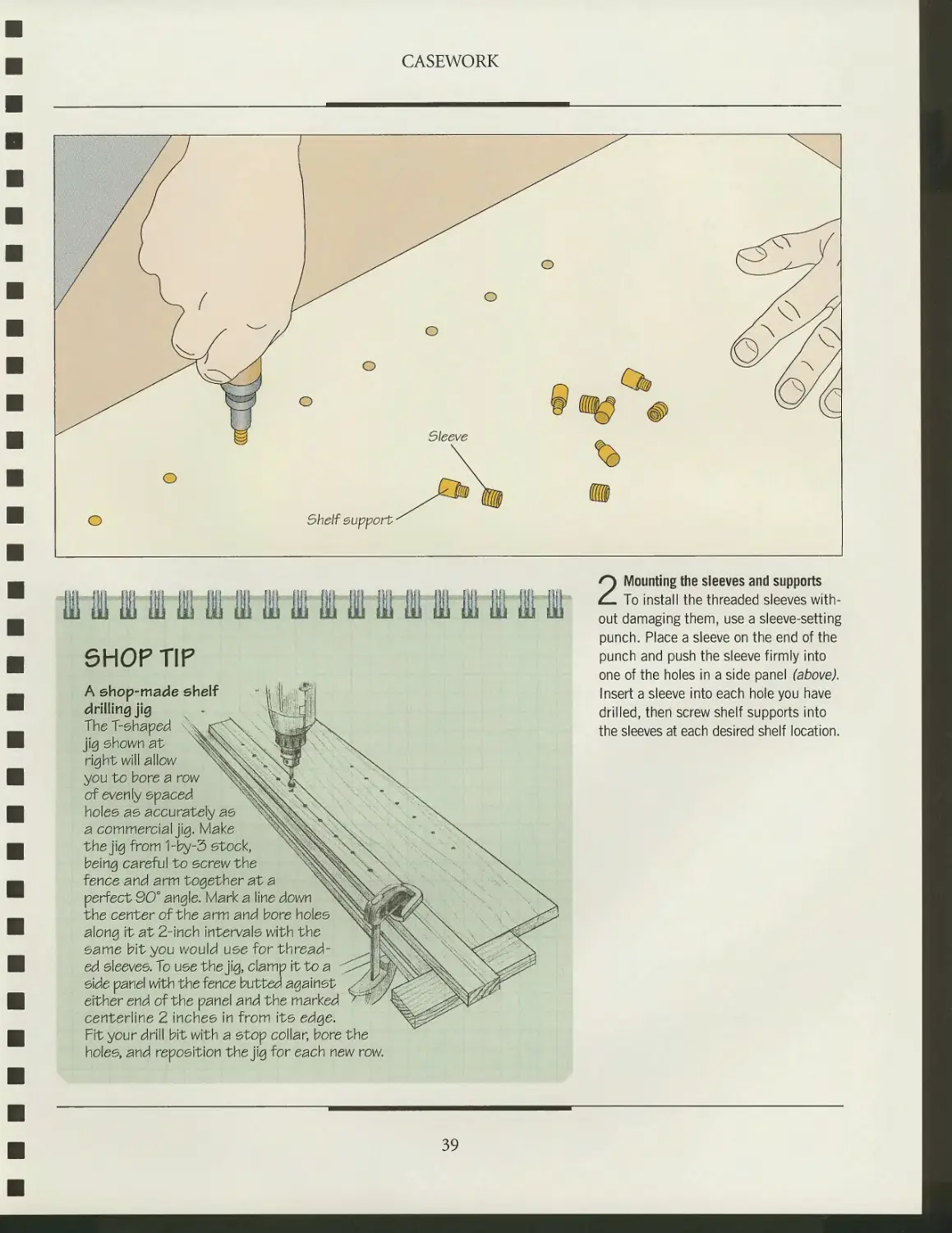
2 Mounting the sleeves and supports
To install the threaded sleeves
without damaging them, use a sleeve-setting
punch. Place a sleeve on the end of the
punch and push the sleeve firmly into
one of the holes in a side panel (above).
Insert a sleeve into each hole you have
drilled, then screw shelf supports into
the sleeves at each desired shelf location.
39
CASEWORK
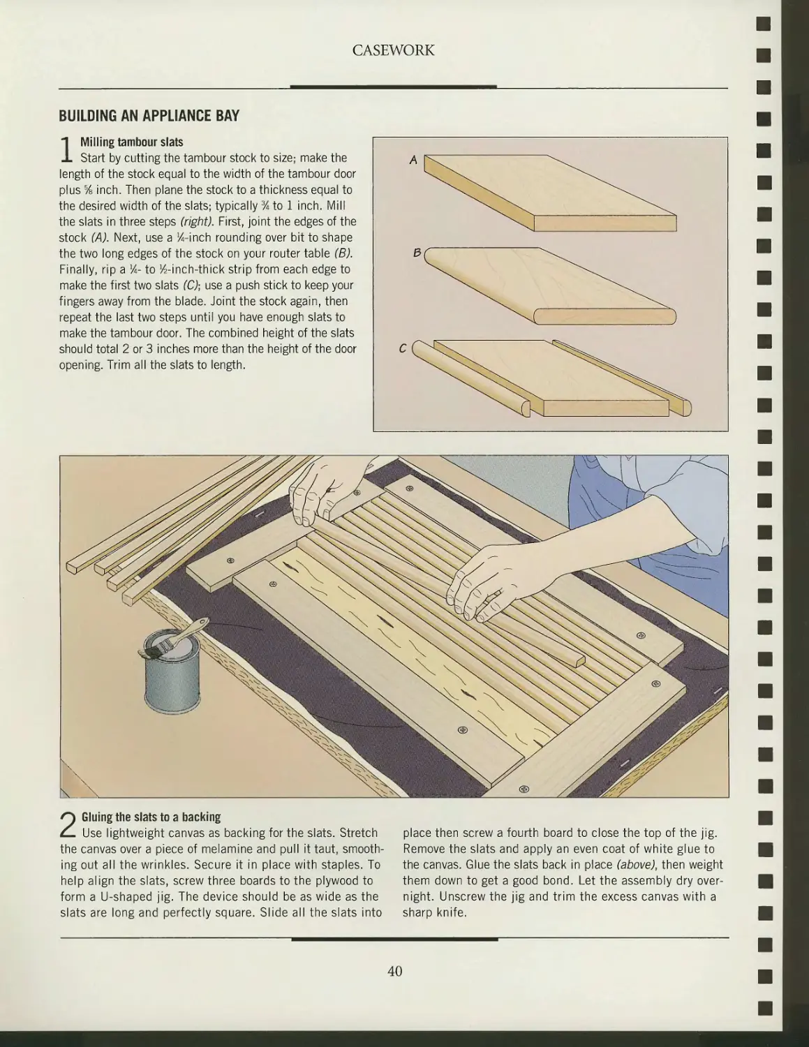
BUILDING AN APPLIANCE BAY
1 Milling tambour slats
Start by cutting the tambour stock to size; make the
length of the stock equal to the width of the tambour door
plus % inch. Then plane the stock to a thickness equal to
the desired width of the slats; typically % to 1 inch. Mill
the slats in three steps (right). First, joint the edges of the
stock (A). Next, use a %-inch rounding over bit to shape
the two long edges of the stock on your router table (B).
Finally, rip a lA- to ^-inch-thick strip from each edge to
make the first two slats (C); use a push stick to keep your
fingers away from the blade. Joint the stock again, then
repeat the last two steps until you have enough slats to
make the tambour door. The combined height of the slats
should total 2 or 3 inches more than the height of the door
opening. Trim all the slats to length.
2 Gluing the slats to a backing
Use lightweight canvas as backing for the slats. Stretch place then screw a fourth board to close the top of the jig.
the canvas over a piece of melamine and pull it taut, smooth- Remove the slats and apply an even coat of white glue to
ing out all the wrinkles. Secure it in place with staples. To the canvas. Glue the slats back in place (above), then weight
help align the slats, screw three boards to the plywood to them down to get a good bond. Let the assembly dry over-
form a U-shaped jig. The device should be as wide as the night. Unscrew the jig and trim the excess canvas with a
slats are long and perfectly square. Slide all the slats into sharp knife.
40
CASEWORK
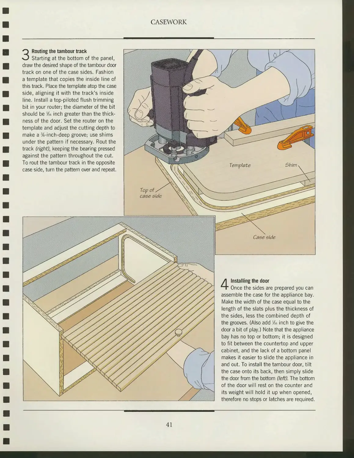
3 Routing the tambour track
Starting at the bottom of the panel,
draw the desired shape of the tambour door
track on one of the case sides. Fashion
a template that copies the inside line of
this track. Place the template atop the case
side, aligning it with the track's inside
line. Install a top-piloted flush trimming
bit in your router; the diameter of the bit
should be Me inch greater than the
thickness of the door. Set the router on the
template and adjust the cutting depth to
make a 3/s-inch-deep groove; use shims
under the pattern if necessary. Rout the
track (right), keeping the bearing pressed
against the pattern throughout the cut.
To rout the tambour track in the opposite
case side, turn the pattern over and repeat.
4 Installing the door
Once the sides are prepared you can
assemble the case for the appliance bay.
Make the width of the case equal to the
length of the slats plus the thickness of
the sides, less the combined depth of
the grooves. (Also add Me inch to give the
door a bit of play.) Note that the appliance
bay has no top or bottom; it is designed
to fit between the countertop and upper
cabinet, and the lack of a bottom panel
makes it easier to slide the appliance in
and out. To install the tambour door, tilt
the case onto its back, then simply slide
the door from the bottom (left). The bottom
of the door will rest on the counter and
its weight will hold it up when opened,
therefore no stops or latches are required.
41
CASEWORK
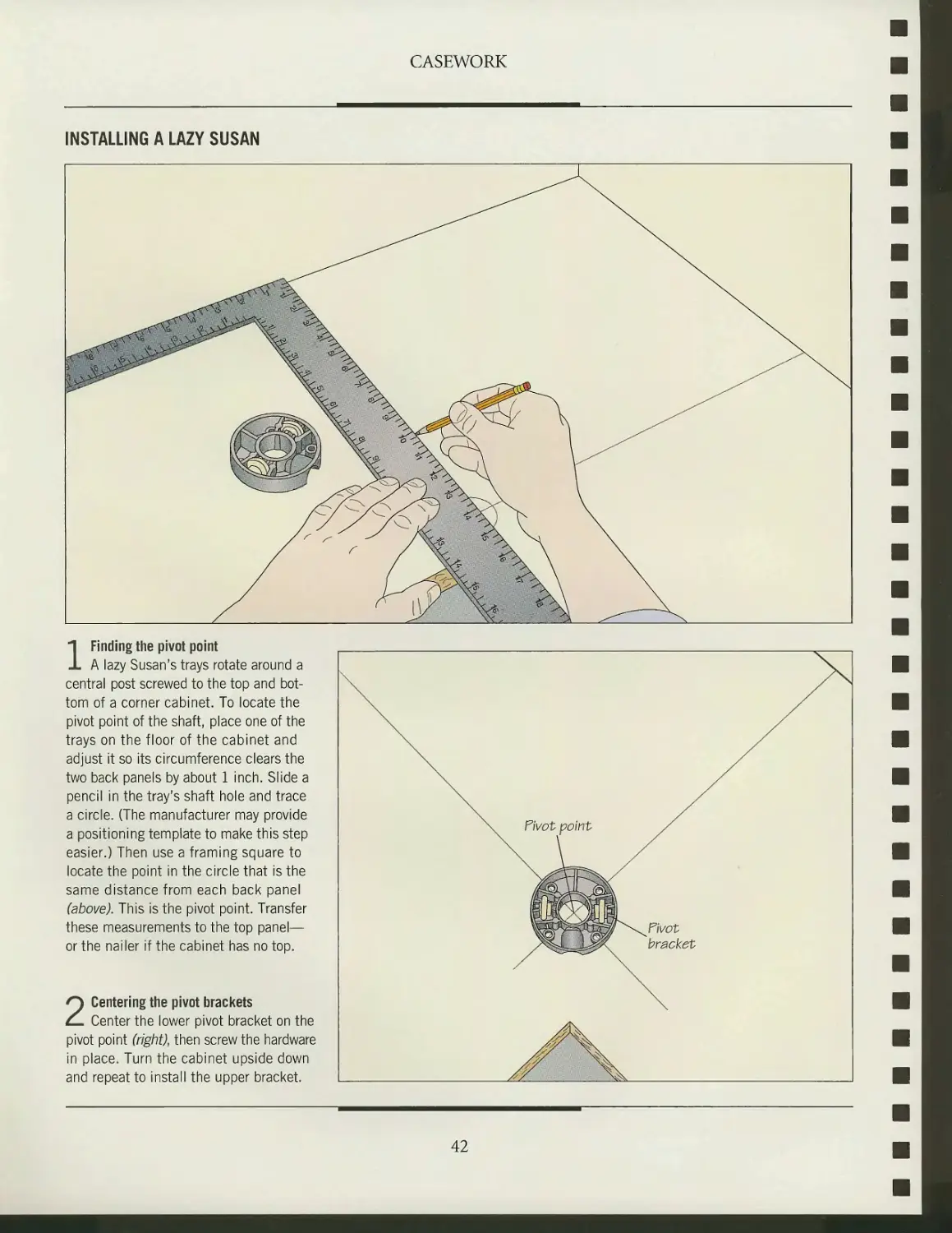
INSTALLING A LAZY SUSAN
1 Finding the pivot point
A lazy Susan's trays rotate around a
central post screwed to the top and
bottom of a corner cabinet. To locate the
pivot point of the shaft, place one of the
trays on the floor of the cabinet and
adjust it so its circumference clears the
two back panels by about 1 inch. Slide a
pencil in the tray's shaft hole and trace
a circle. (The manufacturer may provide
a positioning template to make this step
easier.) Then use a framing square to
locate the point in the circle that is the
same distance from each back panel
(above). This is the pivot point. Transfer
these measurements to the top panel—
or the nailer if the cabinet has no top.
2 Centering the pivot brackets
Center the lower pivot bracket on the
pivot point (right), then screw the hardware
in place. Turn the cabinet upside down
and repeat to install the upper bracket.
42
CASEWORK
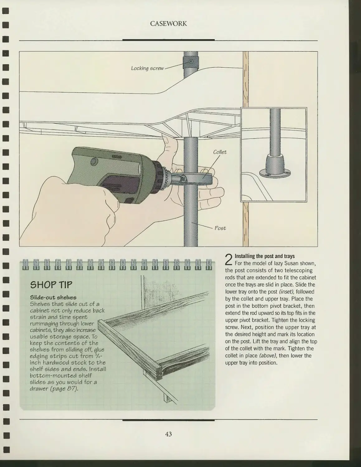
5H0PTIP
Slide-out shelves
Shelves that slide out of a
cabinet not only reduce back
strain and time spent
rummaging through lower ]
cabinets, they also increase
usable storage space. To
keep the contents of the
shelves from sliding off, glue
edging strips cut from %-
Inch hardwood stock to the
shelf sides and ends. Insta
bottom-mounted shelf
slides as you would for a
drawer (page 37).
2 Installing the post and trays
For the model of lazy Susan shown,
the post consists of two telescoping
rods that are extended to fit the cabinet
once the trays are slid in place. Slide the
lower tray onto the post (inset), followed
by the collet and upper tray. Place the
post in the bottom pivot bracket, then
extend the rod upward so its top fits in the
upper pivot bracket. Tighten the locking
screw. Next, position the upper tray at
the desired height and mark its location
on the post. Lift the tray and align the top
of the collet with the mark. Tighten the
collet in place (above), then lower the
upper tray into position.
43
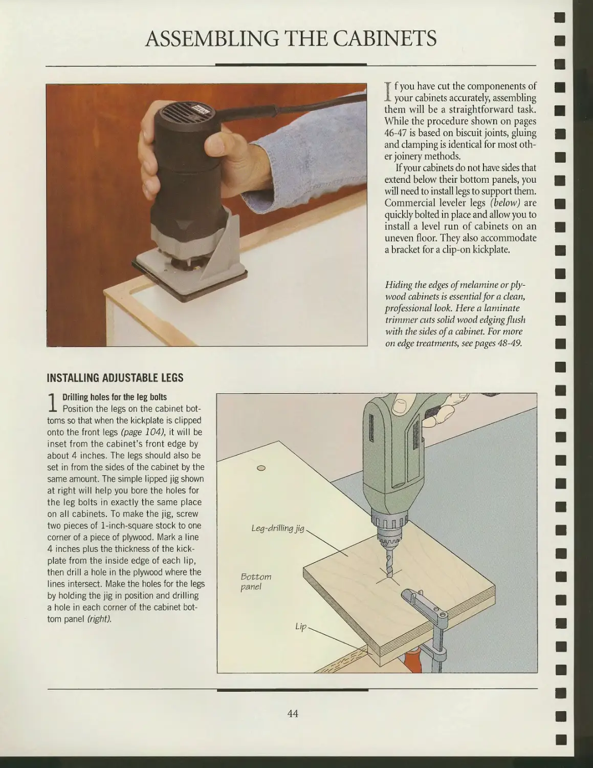
ASSEMBLING THE CABINETS
If you have cut the componenents of
your cabinets accurately, assembling
them will be a straightforward task.
While the procedure shown on pages
46-47 is based on biscuit joints, gluing
and clamping is identical for most
other joinery methods.
If your cabinets do not have sides that
extend below their bottom panels, you
will need to install legs to support them.
Commercial leveler legs (below) are
quickly bolted in place and allow you to
install a level run of cabinets on an
uneven floor. They also accommodate
a bracket for a clip-on kickplate.
Hiding the edges ofmelamine or
plywood cabinets is essential for a clean,
professional look. Here a laminate
trimmer cuts solid wood edging flush
with the sides of a cabinet. For more
on edge treatments, seepages 48-49.
INSTALLING ADJUSTABLE LEGS
1 Drilling holes for the leg bolts
Position the legs on the cabinet
bottoms so that when the kickplate is clipped
onto the front legs (page 104), it will be
inset from the cabinet's front edge by
about 4 inches. The legs should also be
set in from the sides of the cabinet by the
same amount. The simple lipped jig shown
at right will help you bore the holes for
the leg bolts in exactly the same place
on all cabinets. To make the jig, screw
two pieces of 1-inch-square stock to one
corner of a piece of plywood. Mark a line
4 inches plus the thickness of the
kickplate from the inside edge of each lip,
then drill a hole in the plywood where the
lines intersect. Make the holes for the legs
by holding the jig in position and drilling
a hole in each corner of the cabinet
bottom panel (right).
Dottom
panel
44
CASEWORK
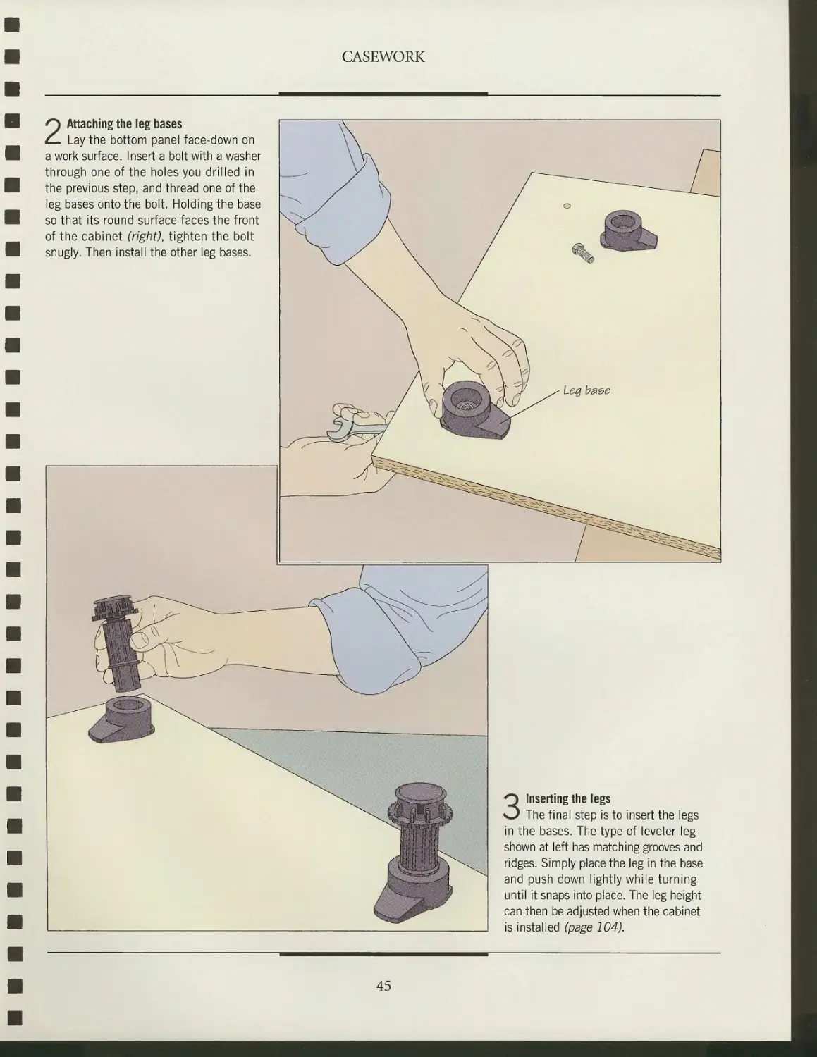
2 Attaching the leg bases
Lay the bottom panel face-down on
a work surface. Insert a bolt with a washer
through one of the holes you drilled in
the previous step, and thread one of the
leg bases onto the bolt. Holding the base
so that its round surface faces the front
of the cabinet (right), tighten the bolt
snugly. Then install the other leg bases.
3 Inserting the legs
The final step is to insert the legs
in the bases. The type of leveler leg
shown at left has matching grooves and
ridges. Simply place the leg in the base
and push down lightly while turning
until it snaps into place. The leg height
can then be adjusted when the cabinet
is installed (page 104).
45
CASEWORK
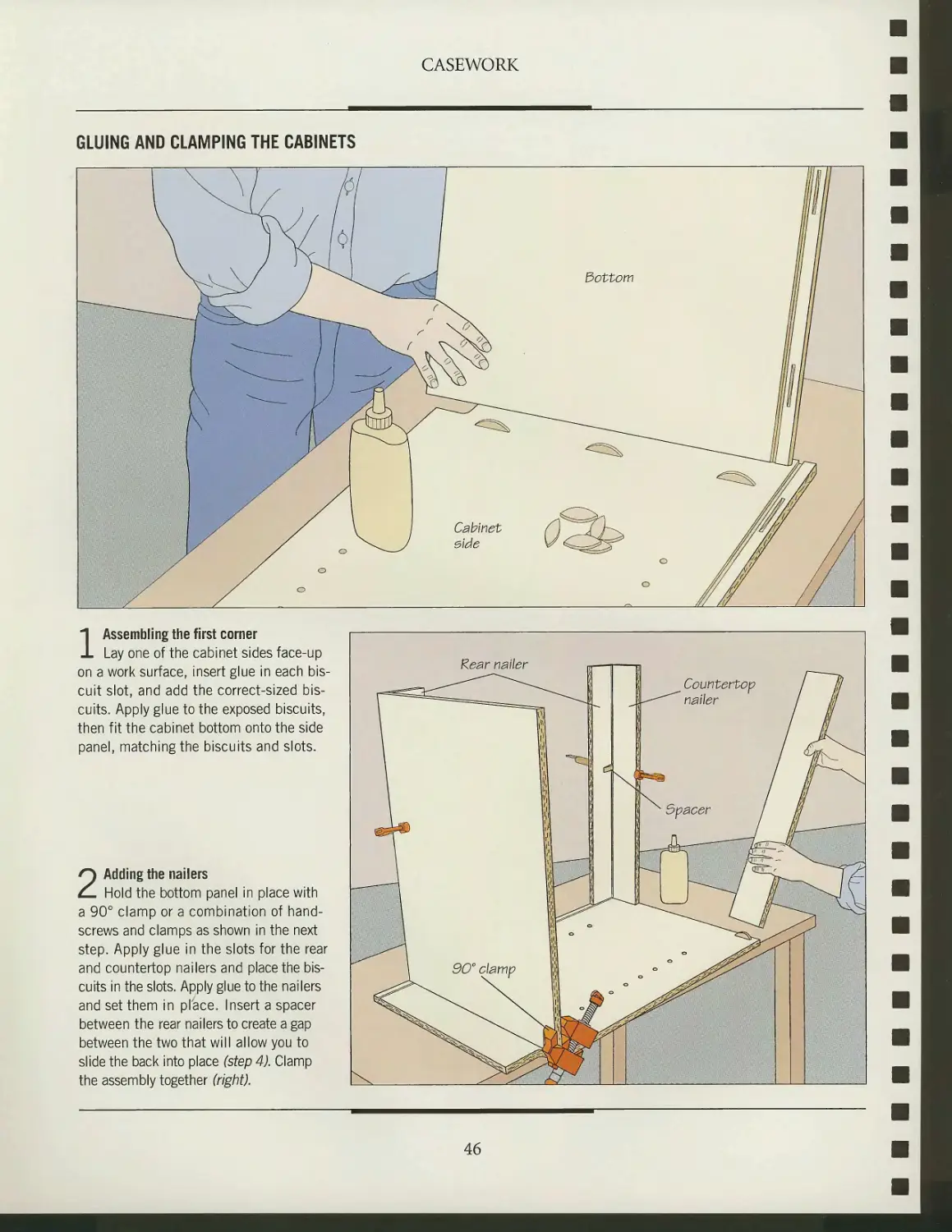
GLUING AND CLAMPING THE CABINETS
b\
'o
Bottom
Cabinet
elde
1 Assembling the first corner
Lay one of the cabinet sides face-up
on a work surface, insert glue in each
biscuit slot, and add the correct-sized
biscuits. Apply glue to the exposed biscuits,
then fit the cabinet bottom onto the side
panel, matching the biscuits and slots.
2 Adding the nailers
Hold the bottom panel in place with
a 90° clamp or a combination of hand-
screws and clamps as shown in the next
step. Apply glue in the slots for the rear
and countertop nailers and place the
biscuits in the slots. Apply glue to the nailers
and set them in place. Insert a spacer
between the rear nailers to create a gap
between the two that will allow you to
slide the back into place (step 4). Clamp
the assembly together (right).
Rear nailer
46
CASEWORK
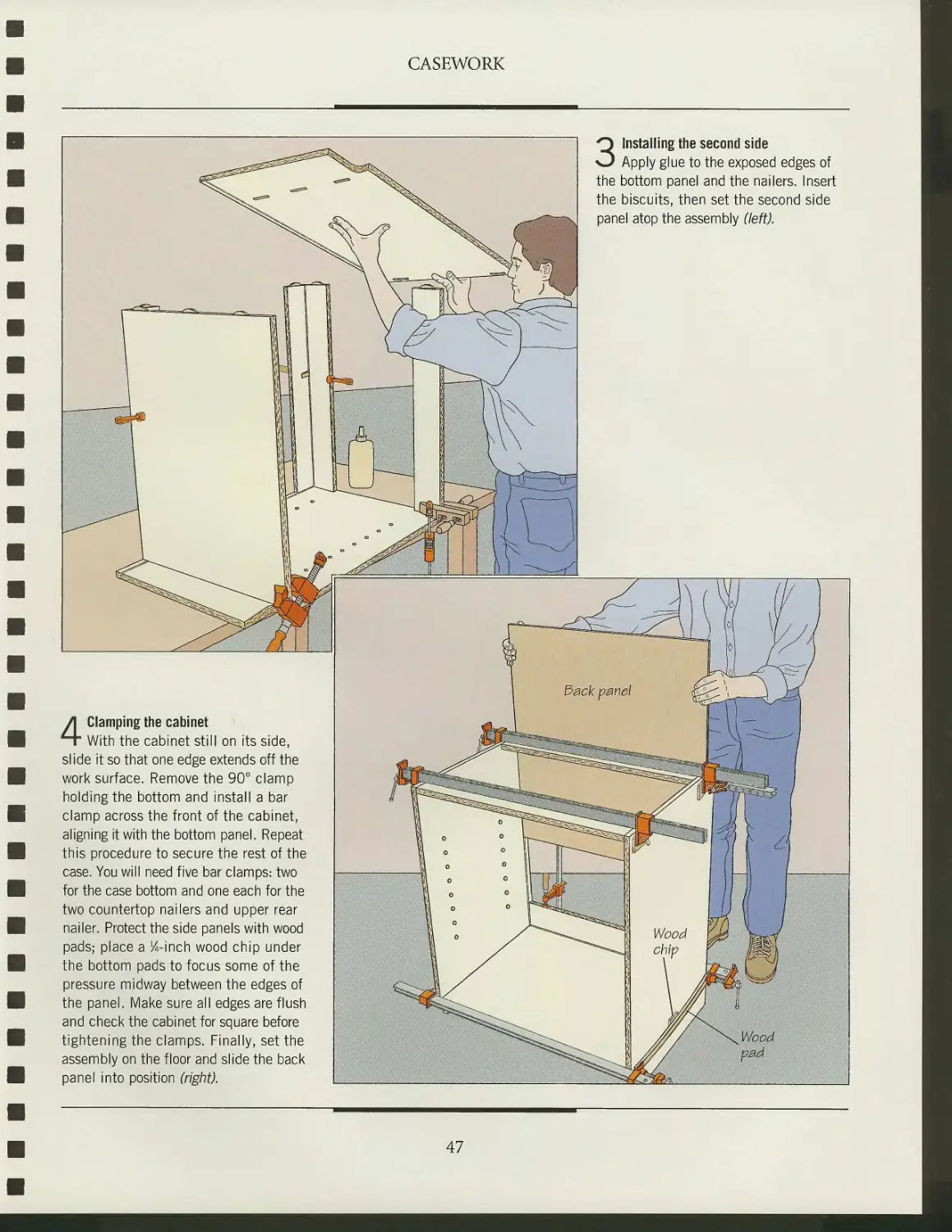
3 Installing the second side
Apply glue to the exposed edges of
the bottom panel and the nailers. Insert
the biscuits, then set the second side
panel atop the assembly (left).
4 Clamping the cabinet
With the cabinet still on its side,
slide it so that one edge extends off the
work surface. Remove the 90° clamp
holding the bottom and install a bar
clamp across the front of the cabinet,
aligning it with the bottom panel. Repeat
this procedure to secure the rest of the
case. You will need five bar clamps: two
for the case bottom and one each for the
two countertop nailers and upper rear
nailer. Protect the side panels with wood
pads; place a K-inch wood chip under
the bottom pads to focus some of the
pressure midway between the edges of
the panel. Make sure all edges are flush
and check the cabinet for square before
tightening the clamps. Finally, set the
assembly on the floor and slide the back
panel into position (right).
47
CASEWORK
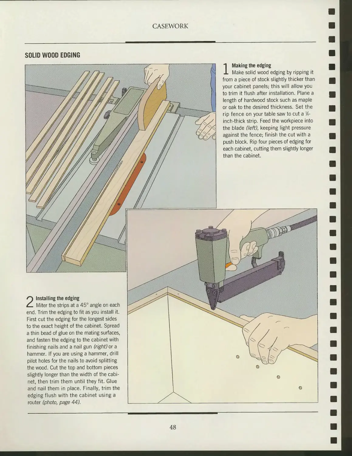
SOLID WOOD EDGING
2 Installing the edging
Miter the strips at a 45° angle on each
end. Trim the edging to fit as you install it.
First cut the edging for the longest sides
to the exact height of the cabinet. Spread
a thin bead of glue on the mating surfaces,
and fasten the edging to the cabinet with
finishing nails and a nail gun (right) or a
hammer. If you are using a hammer, drill
pilot holes for the nails to avoid splitting
the wood. Cut the top and bottom pieces
slightly longer than the width of the
cabinet, then trim them until they fit. Glue
and nail them in place. Finally, trim the
edging flush with the cabinet using a
router (photo, page 44).
1 Making the edging
Make solid wood edging by ripping it
from a piece of stock slightly thicker than
your cabinet panels; this will allow you
to trim it flush after installation. Plane a
length of hardwood stock such as maple
or oak to the desired thickness. Set the
rip fence on your table saw to cut a lA-
inch-thick strip. Feed the workpiece into
the blade (left), keeping light pressure
against the fence; finish the cut with a
push block. Rip four pieces of edging for
each cabinet, cutting them slightly longer
than the cabinet.
48
CASEWORK
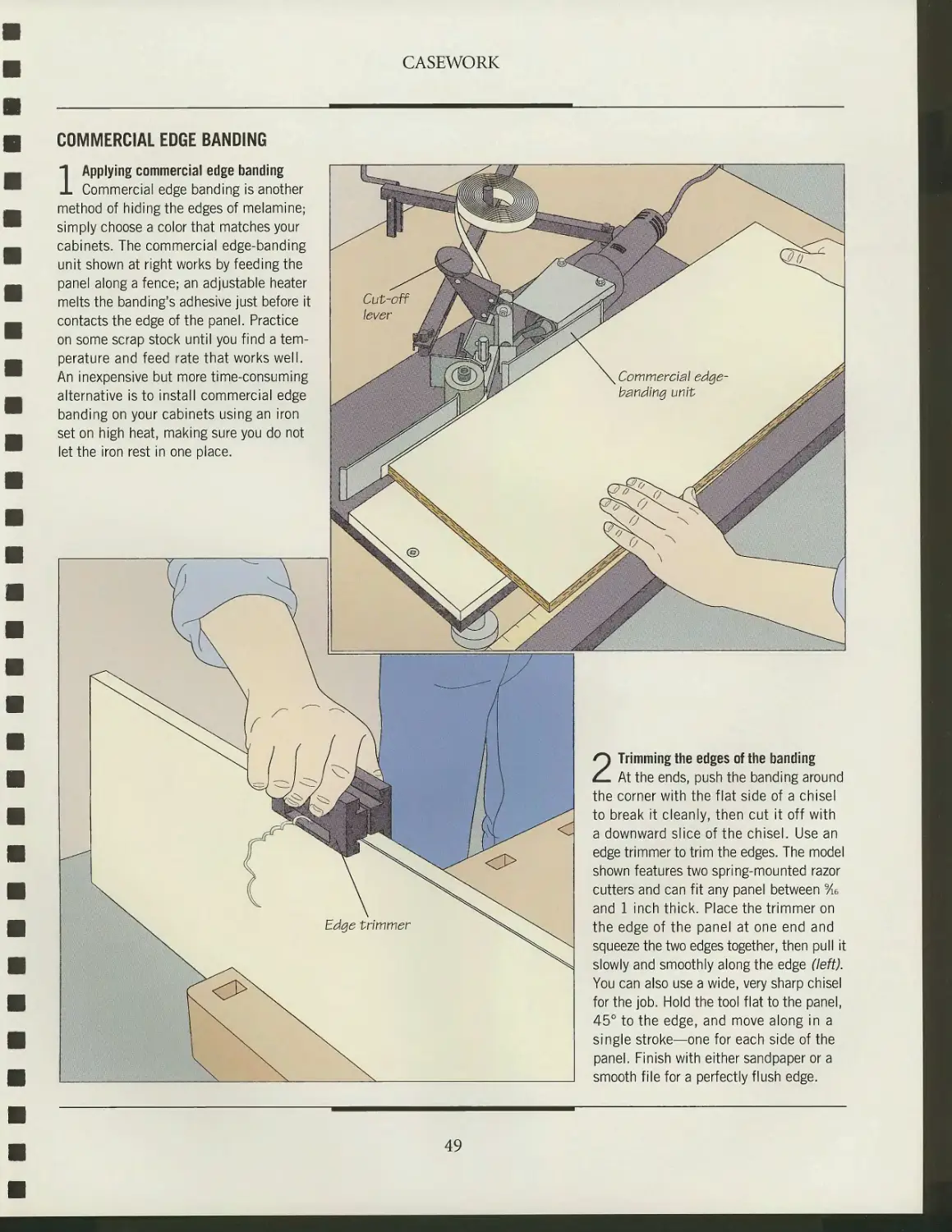
COMMERCIAL EDGE BANDING
1 Applying commercial edge banding
Commercial edge banding is another
method of hiding the edges of melamine;
simply choose a color that matches your
cabinets. The commercial edge-banding
unit shown at right works by feeding the
panel along a fence; an adjustable heater
melts the banding's adhesive just before it
contacts the edge of the panel. Practice
on some scrap stock until you find a
temperature and feed rate that works well.
An inexpensive but more time-consuming
alternative is to install commercial edge
banding on your cabinets using an iron
set on high heat, making sure you do not
let the iron rest in one place.
2 Trimming the edges of the banding
At the ends, push the banding around
the corner with the flat side of a chisel
to break it cleanly, then cut it off with
a downward slice of the chisel. Use an
edge trimmer to trim the edges. The model
shown features two spring-mounted razor
cutters and can fit any panel between 9/ie
and 1 inch thick. Place the trimmer on
the edge of the panel at one end and
squeeze the two edges together, then pull it
slowly and smoothly along the edge (left).
You can also use a wide, very sharp chisel
for the job. Hold the tool flat to the panel,
45° to the edge, and move along in a
single stroke—one for each side of the
panel. Finish with either sandpaper or a
smooth file for a perfectly flush edge.
49
FACE FRAMES
A face frame is a solid wood fronting
applied to kitchen cabinets. Face
frames are not essential; in fact they are
noticeably absent on European-style
cabinets, whose concealed, micro-
adjustable hinges make it possible to
install doors that seamlessly cover the
entire cabinet front. However, face
frames can add a traditional look to a
European kitchen.
When laying out a face frame,
remember to add an extra lA inch to any stile
positioned next to a wall; this will allow
you to scribe and trim the stile if the
wall is out-of-plumb. If the cabinet has
drawers, you will also require dividers
between them. If your cabinets feature
fully recessed doors and drawers, cock-
beading (page 53) can add a subtle,
decorative touch.
Face frames can be joined in a number of ways, including
pocket holes, biscuits, and dowels. Here, a commercial pocket hole
cutter bores a hole in a face frame rail Pocket holes can also be
used to attach the face frame to the cabinet; be sure to cut
the holes in the case sides and rails before assembling them.
ANATOMY OF A FACE FRAME
Drawer rail
\r\e\de et\\e
50
CASEWORK
JOINING FACE FRAMES WITH DOWELS
1 Drilling holes
Use a doweling jig to drill holes for
dowels in the face frame members. The
model shown at right not only aligns the
holes in both rails and stiles, but also holds
the bit exactly perpendicular to the wood
surface. Follow the manufacturer's
instructions to set up the jig for the thickness of
the face frame stock, then adjust the jig to
drill two holes about 54 inch in from either
end of one of the stiles. Insert the bushing
that matches the dowel diameter into the
bushing carrier of the jig, and attach a
collet to the drill bit and adjust it to bore
a hole Vie inch deeper than half the length
of the dowels. (Allow for the thickness of
the jig and bushing when making this
measurement.) Clamp a stile in your workbench
and place the jig on the stile, aligning it
with one end of the workpiece. Set the
bushing carrier in the appropriate hole in
the doweling jig. Holding the jig steady,
drill the hole. Repeat to drill the second
hole, then bore the holes at the opposite
end of the stile, in both ends of all rails
(right), and in any inside stiles that also
require dowel holes.
2 Inserting the dowels
Insert dowels in the drawer rails and
inside stiles first, then in the outer stiles.
To insert the dowels, clamp the appropriate
frame member to your bench, spread glue
on one end of the dowel, then tap it home
with a mallet (left). Assemble the frame
(page 53).
51
CASEWORK
-3UIL&ITY0UZ6ELF
>
Auxiliary table
7"x12"
Barrel support
1"x3Y2"x6"
PLATE JOINER STAND
To reduce the setup time needed
to cut slots for biscuit-jointed face
frames, mount your plate joiner in a
shop-made stand like the one shown
at left. Build the jig from 3/4-inch
plywood, except for the barrel
support, which should be solid wood.
Refer to the illustration for
suggested dimensions.
Screw the handle support to the
base, then attach the handle
brackets, spacing them to fit your tool.
With the plate joiner resting upside
down on the handle support, butt
the barrel support against the motor
housing and trace the outline of the
barrel on the stock. Cut or bore a
hole for the barrel, then saw the
support in two across its width, through
the center of the hole. Screw the
bottom part to the base and fit the
other half on top. Bore holes for
hanger bolts through the top on each
side of the opening, then drive the
hanger bolts into the bottom of the
support. For quick installation and
removal of the tool, use wing nuts
to hold the two halves together.
Screw the auxiliary table to the
fixed-angle fence of the joiner. (It
may be necessary to drill holes in
the fence to accept the screws.)
To use the stand, secure the joiner
in it, then clamp the base to a work
surface. Set the fence at the correct
height and, for repeat cuts, clamp stop
blocks to the auxiliary table to center
the workpiece on the cutter wheel. To
cut a slot, put the workpiece flat
on the table and butted against the
joiner's faceplate, then turn on the
tool and push the stock and the table
toward the cutter (left, below).
52
CASEWORK
ASSEMBLING THE FACE FRAME
Clamping up the frame
Assemble the frame working from the
middle outward, gluing up any drawer
rails and inside stiles first. In the frame
shown at right, start by gluing the inside
stile to the two face frame rails. Apply
glue to the exposed dowels then push
the rails into place. Tighten the
assembly with a bar clamp. Next, spread some
glue on the dowels in the rails and install
the other stiles; tighten them in place with
two more bar clamps. Check the assembly
for square by measuring across the two
diagonals (right). They should be equal.
If not, place a bar clamp across the longer
diagonal and tighten it until the frame
is square.
^\^
Face ys
frame '
rail
'Mil
;t?ia'
^Inside
etile
y&O
rfl
^fSf^
gPffii
Face
frame
etlle
raJM
INSTALLING COCKBEADING
x ife_ ^ip^
%«w^jpf
^\ i$^§5s-^ y^yyy
^^^^^V^^^W
Canoe -^fgEi__
bead bit ^^^^^^^^^^^^^
1/C
//€1
W // 1
^9
T"
^ - i
fv / J ^ /
my
\\^ ~
'C—- ■"
Featherboard r^~^
\^E&\\$p$
1! 7*
^
".J
1 Making cockbeading
Make cockbeading as you made solid
wood edging (page 48), ripping % inch-
thick strips from a piece of hardwood
stock lA inch thicker than the thickness
of the face frame. To round over the
outside edge of the cockbeading, install a 14-
inch canoe bead bit in a router and install
the tool in a table. Raise the height of
the bit so it is centered on the stock, and
adjust the position of the fence to just
behind the cutter. Attach a featherboard
to the table to hold the stock against the
fence, and clamp two more featherboards
to the fence on either side of the bit to
prevent the stock from lifting up. (In the
illustration, the front featherboard has
been removed for clarity.) With the work-
piece lying flat on the table, feed it into
the bit (left), finishing the cut with a
push stick. Rip the cockbeading to width
and then cut it to length, mitering the
ends at 45°.
53
CASEWORK
2 Installing the cockbeading
Dry fit the cockbeading strips; pare
any ill-fitting joints with a chisel. Lay the
frame on a flat surface. Spread some
glue on the outside face of a strip of
cockbeading and position it on the frame,
aligning the back edges of the two. Drive
in finishing nails with a hammer or an air
nailer (left).
INSTALLING THE FACE FRAME
Attaching the face frame to the casework
Apply some glue to the edges of the
cabinet. Place the face frame in position and
align it with the top, bottom, and sides of
the cabinet. In the illustration at right, the
right side of the frame overhangs the
cabinet; this is to allow the stile of the face
frame to be trimmed to fit the profile of the
wall (page 104). Fasten the face frame in
place with a finishing nail every 4-6 inches.
54
CASEWORK
iiiiiiiiiiiiiiiii
SHOP TIP
Making
wood plugs
Save time making
wood plugs by using a
piece of tape to remove
them from their holes. Use a
plug cutter on the drill press to
bore a row of plugs to the depth you
require. Cover the row with a strip of
masking tape, then rip the plugs to
length on the band saw. Simply peel off
the tape to remove the row of plugs.
Using screws and wood plugs
If you are installing your face frames
with screws, counterbore the fasteners
and cover their heads with wood plugs.
Position the frame in place as you would
for face-nailing (page 54), drill and
counterbore screw holes, then drive the
screws in place. To make the plugs,
install a plug cutter the same diameter
as the counterbored holes in your drill
press. Choosing some wood that
matches the frame stock for grain and color,
bore as many plugs as you need in the
stock (above, left). Pry the plugs free
with a screwdriver or narrow chisel. (See
the Shop Tip at left for an alternate
procedure.) To install the plugs, apply glue
in the hole, then tap the plug in place.
Trim the excess with a chisel. Holding
the chisel bevel-side up on the frame,
remove the waste in fine shavings (above,
right) until the plug is perfectly flush.
This will produce a much cleaner
surface than if the plug were sanded flush.
55
I
\\ I
V
%
"'. \ }■'
1-1
1- :
:-r-^
^V ;^.
V«*;'-V-
^.r^&sessfe
M-^
*y. \.v^>v.;7^,iti
fr>V
:•&
«fe*
■4-7-r^ «
M*
»'r.
*.
•-..a..?**;
DOORS
Cabinet doors are arguably the most
important single decorative feature
of a kitchen. They are the first item to
greet the eye and, because they are
usually so numerous, can also be the most
impressive. The style, finish, and
construction deserve careful attention.
Once, cabinetmakers were concerned
primarily with building simple, sturdy
doors that would stand up to the
punishment meted out to them in daily use.
Form certainly followed function by a
wide margin; kitchen cabinets, and
especially their doors, were the most
utilitarian of furniture. But gone are the days
of one-style-fits-all kitchens. Today,
homeowners carefully consider the
period and style of their dwellings before determining the decor of
their kitchens. Some of the possibilities are shown in the Layout
And Design chapter (page 16).
Once the basic choice is made, door style can be arrived at.
Perhaps it is a basic board-and-batten door (page 60) for a
country cottage. An Arts and Crafts bungalow might demand
finer work, with doors featuring glass panes set in glazing bars
(page 70). Most homeowners will probably prefer traditional
frame-and-panel doors (page 62). But even here there are
variations, such as arched panel (page 67), veneered panel (page
68), and glass panel doors (page 69). This chapter introduces
five door styles and the steps to building each, so you can
produce doors that will lend character to your kitchen.
A brad driver secures a strip of molding
to the frame of a kitchen cabinet door,
sandwiching a central pane of glass
between the molding and a rabbet cut
into the inside edge of the frame. For
more on building glass doors, seepage 69.
Considerations of style should not
cloud the need for durability. Kitchen
doors work hard and, since wood is
prone to swelling and warping, solid
doors such as board-and-batten doors
should only be installed on small
cabinets. Frame-and-panel, veneered-panel,
and glass doors are better able to
accommodate wood movement caused by
fluctuations in heat and humidity. Also,
different doors require different degrees
of precision when building them. A
flush-mounted door, for example, is cut
to close tolerances; an error as slight as
V\e inch can spoil the look of an
otherwise finely executed cabinet. Overlay
doors, on the other hand, do not require
the same precision as they exceed the size of their openings.
Advances in the manufacturing of door hardware,
particularly hinges, have greatly improved both the appearance of
cabinet doors and the ease of mounting them (page 73). Classic or
antique-style doors may still be hung from such decorative and
attractive fasteners as surface-mounted hinges that come in
polished iron or brass finishes. Other hinge options include
the simple but efficient butt hinge (page 76) for
flush-mounted doors, and the piano hinge for corner cabinet doors.
European-style cup hinges (page 74) have virtually become
the standard hardware for melamine kitchen cabinets. Not
only are these versatile hinges fully concealed; they are also
simple to install and easily adjustable.
The versatile European cup hinge can be used to hang a
variety of kitchen cabinet doors. In the photo at left, a full overlay
frame-and-panel door is being mounted on a face frame
cabinet. The door can be adjusted or removed with ease.
57
A GALLERY OF CABINET DOOR DESIGNS
Of the four door types shown below
and on the following page, all but
the board-and-batten door are built
using frame-and-panel techniques. The
board-and-batten door (page 60) is a
solid panel door featuring a series of
planks with rabbeted edges held
together by battens screwed across the back of
the door. Frame-and-panel doors (page
62) feature a panel that floats within a
frame composed of rails and stiles
assembled with mortise-and-tenon or
cope-and-stick joints. The floating
panel in the center of the door can be raised
or shaped for decorative effect. The rails
and stiles have an integrated molding
cut into them; for added embellishment
you can also cut an arch or curve into
the upper rail and panel.
Veneered-panel doors (page 68)
feature a panel made from veneered sheet
stock that is glued to the frame. To
conceal the plate joints between the
panel and the frame, rabbets are cut
into the inside edges of the frame at
the back. Glass-panel doors (page 69)
are essentially a frame-and-panel door
with a pane of glass replacing a
floating panel. The piece of glass sits in
rabbets cut along the edges of the
frame. It is held in place by strips of
molding. A variation of the glass panel
door features glazing bars that hold
smaller panes in place (page 70). Joined
by mitered half-laps, the glazing bars
have rabbets cut along their back edges
to accommodate the glass and glass-
stop molding.
Although a door is always made to fit
its cabinet, it does not always have to be
sized exactly to fit its opening, as shown
in the illustration on the opposite page.
Flush-mounted and full-recess doors
can be time-consuming to construct
because of the fine tolerances required
to fit and hang them properly. They are
particularly unsuitable for board-and-
batten doors, as these doors tend to
BOARD-AND-BATTEN DOOR
FRAME-AND-PANEL DOOR
5tile
Batten
58
DOORS
expand and contract with changes in
humidity. Full-overlay or lip-rabbeted
doors are easier to make. A full-overlay
door covers the entire width of the
cabinet, while a lip-rabbeted door has
rabbets cut around its outside edges at the
back so that only a part of its thickness
is exposed.
One of the most commonly used doors
is the one typically used for European-
style cabinets—a piece of laminated par-
ticleboard such as melamine simply cut
to size. While inexpensive and easier to
maintain, melamine doors need edge
banding (pages 48-49) to conceal their
non-laminated edges.
DOOR MOUNTING METHODS
Flush-mounted
Full receee
Up-rabbeted
59
BOARD-AND-BATTEN DOORS
Like their early colonial counterparts,
modern cabinetmakers seeking a
rustic or "country" look often turn to
board-and-batten doors. These simple
but sturdy doors consist of rabbeted
planks held together by strips or
battens of wood fastened across their backs.
The most common of these features
battens screwed to the back of the door in
the form of a Z; the diagonal batten
connecting the two horizontal battens at
the top and bottom acts as a brace to
strengthen the door and prevent sagging.
Because they are solid panel doors and
will swell and shrink with changes in
humidity, board-and-batten doors are
often mounted on smaller cabinets as
overlay doors. In some cases, the battens
can interfere with interior shelving. One
solution is to recess the battens in dadoes
cut into the back of the doors. Another
more elaborate method of bracing a
board-and-batten door is to rout a
sliding dovetail across the back of the boards.
Rout a matching dovetail slide in the
battens, and secure them in place with a
single screw in the center of the door.
Combining rustic strength and charm,
board-and-batten doors are ideal for
small cupboards in a country kitchen.
JOINTS USED IN BOARD-AND-BATTEN DOORS
Shlplap
Chamfered shlplap
Beaded ehiplap
Double-beaded ehiplap
60
DOORS
MAKING A BOARD-AND-BATTEN DOOR
2 Assembling the door
Clamp the door together and place it inside-face up on a places where the screw will join the batten to an outside door
work surface. Then cut two battens slightly shorter than the board. Then, holding the batten square to the edge of the door,
width of the door and narrower than the door boards. Position drive in each screw (above, left). Cut a third batten to fit diago-
the two pieces of wood across the top and bottom of the assem- nally between the two already in place and screw it into posi-
bly as shown. Then fit an electric drill with a combination bit tion. To conceal the screws, apply a dab of glue to their heads,
and counterbore holes for screws and wood plugs at 2-inch then insert plugs in the holes. Tap the plugs in place with a
intervals along the battens, alternating between the top and wooden mallet (above, right), then use a chisel to trim the pro-
bottom of each board. Make clearance holes except in the jecting stubs flush with the door surface.
61
FRAME-AND-PANEL DOORS
Pleasing to the eye and structurally
sound, the frame-and-panel door is
the most enduring and popular of all
cabinet door designs. Because its panel
floats in a rigid frame of rails and stiles,
a frame-and-panel door withstands the
swelling and shrinking of wood brought
on by changes in humidity better than
any other solid-wood door. The
flexibility of its design allows for a wide
variety of attractive options, such as veneered
panels (page 68), glass doors (page 69),
~^mg§p99K*f
and glazing bars (page 70). The top rail
of the frame can even be arched to
soften the rectangular lines of the doors and
add a touch of elegance (page 67).
The frame derives its considerable
strength from the joinery methods used
in its construction. This section covers
building a frame-and-panel door using
mortise-and-tenon joinery with
integrated molding (page 63) and cope-and-
stick joints (page 66). Before starting to
build a frame-and-panel door, however,
take care to size the stock properly. Make
the stiles equal to the height of the door
opening; the rails should be as long as
the width of the door plus the two tenons
at either end—typically about % inch—
minus the width of the stiles.
Depending on the desired appearance
of a frame-and-panel door, the
panel's inside edges can be molded to fit
in the grooves of the frame or beveled
on four sides to "raise" the center
of the panel. In the photo at left, a
panel is being raised with an ogee
panel-raising bit on a router table.
RAISED PANEL STYLES
Beveled panel raised
from frame
Ogee beveled panel
Cove
62
DOORS
MAKING A FRAME-AND-PANEL DOOR
1 Cutting the tenon cheeks
Install a dado head slightly wider than
the tenon length on your table saw. Attach
and notch an auxiliary fence, then set the
width of cut equal to the length of the
tenon to saw the tenon cheeks; adjust the
cutting height to about one-third the
thickness of the stock. Butting the rail against
the fence and the miter gauge, feed the
stock face down into the blades. Turn the
rail over and repeat the cut on the other
side of the tenon. Then repeat the process
at the opposite end of the rail (left) and
with the second rail.
2 Cutting the tenon shoulders
To cut the tenon shoulders, set the
height of the dado head at about Vz inch.
Standing the rail on edge flush against
the fence and miter gauge, feed the
workpiece into the blades. Turn the rail
over and repeat on the other side of the
tenon. Cut the tenon shoulders at the
opposite end of the rail the same way
(right). Repeat the process with the
second rail. To add integrated molding, fit a
router with the appropriate bit, mount
the tool in a router table and cut along
the inside edges of the rails and stiles.
Integrated
molding
3 Preparing the rails for glue up
Remove the auxiliary fence and dado
head. Install a combination blade and
adjust its angle to 45°. To set the width
of cut, mark a line on the molded edge of
a rail the same distance from the tenon
shoulder as the molding width. Align the
mark with the blade where it exits the table
opening, then butt the fence against the
rail. Adjust the blade height until one tooth
protrudes just beyond the tenon shoulder.
To make the cuts, butt the rail against the
fence and hold it flush against the miter
gauge to feed it molded-edge down into the
blade. Repeat to cut the other end of the
rail (left) and both ends of the second rail.
63
DOORS
4 Preparing the stiles
Mark a line on the molded edge of
each stile the width of a rail away from
the end of the board. With the table saw
blade angled at 45°, align the cutting
edge with the mark and cut into the
molded edge; adjust the cutting height so the
cut finishes at the point where the
molding ends and the face of the stile begins.
Next, slice off the strip of molding between
the 45° cut and the end of the stile with
a band saw (right).
5 Smoothing the cut edge
On the table saw, adjust the rip fence
so the blade lines up with the beginning
of the cut you made in step 1 when the
stile is butted against the fence. Hold the
stile flush against the miter gauge. Slide
the stock back and forth along the miter
gauge to smooth the cut edge (left).
6 Cutting the mortises
Cut the mortises in the stiles on a drill
press using a commercial mortising
attachment. Align a rail with each stile and mark
the outline of the mortises. Install a
mortising attachment on your drill press and
clamp the stile to the fence, centering the
mortise outline under the chisel and bit.
Set the drilling depth slightly deeper than
the tenon length, then make a cut at each
end of the mortise before boring out the
waste in between (right).
64
DOORS
Three-wing
slotting cutter
7 Cutting grooves for the panel
Assemble the rails and stiles. Then,
protecting the stock with wood pads, use
two bar clamps to hold the frame together
securely. Fit a router with a %-inch three-
wing slotting cutter and mount the tool in
a router table. Remove the fence and set
the frame on the table. Adjust the cutter
height to place the groove midway between
the bottom of the frame and the edge of
the molding. Gripping the bar clamps
firmly, butt the inside edge of the frame
against the bit near one corner, then
rotate it against the direction of bit
rotation to cut the groove along the rails and
stiles (left). Keep the frame flat on the
table as you feed it into the bit. Raise a
panel to fit the frame (photo, page 62),
then disassemble the frame.
"^A
h (
\ ^
|W
V
A
X '\
^n^z^
W^S5 Ufvx
\fj|
m%Ti kLL
pL^x,/
Notched |
wood block
S^xp
^?%§^^ ^^\
Raized ^^^g^.
panel ^^x^
^\N^X\ /i ^r
X^\^Vw\ l\ s^ ^r^
^^-^-^ f^s^O ;/&
^^\X^i mIw " -sS
8 Gluing up the door
Glue up a panel from ^-inch-thick solid stock and cut it to
size; adding lA inch to each side to allow the panel to fit the
groove in the frame. Then rout the edges of the panel to
produce the raised center, as shown in the photo on page 62.
Make successive passes until the edge of the panel fits into the
groove in the frame. To reduce tearout, rout the top and bottom
edges before routing the sides. Squeeze some glue into the
mortises in the stiles and on the tenon cheeks and shoulders at
the ends of the rails; also apply some adhesive on the
contacting surfaces of the miter cuts in the rails and stiles. Do not add
any glue to the panel grooves. Then, assemble the door and set
on two bar clamps on a work surface, aligning the rails with the
bars of the clamps. To keep the clamps from falling over, prop
each one on a notched wood block. Protecting the frame with
wood pads, tighten the clamps just enough to fully close the
joints (above), then use a square to check whether the corners
of the door are at right angles. Finish tightening the clamps
until the glue squeezes out of the joints, checking occasionally
that the corners remain square. Once the glue has dried, use a
cabinet scraper to remove any remaining adhesive.
65
DOORS
COPE-AND-STICK JOINERY
1 Cutting tongues in the rails
The cope-and-stick joint provides a
method of joining stiles and rails in frame-
and-panel construction. Tongues in the
rails mesh with grooves in the stiles; the
router bit that cuts the grooves for the
panel also carves a decorative molding in
the inside edges of the frame. To cut the
tongues, install a piloted coping bit—the
rail cutter—in your router and mount
the tool in a table. Butt the end of a
rail against the bit and adjust the depth
of cut so that the top of the uppermost
cutter is slightly above the workpiece.
Position the fence parallel to the miter
gauge slot in line with the edge of the bit
pilot. Fit the miter gauge with an
extension and lay the outside face of the stock
flat on the table; keep the ends of the
workpiece and extension butted against
the fence throughout each cut (left).
2 Cutting the grooves
Unplug the router and replace the
coping bit with a piloted sticking bit-
also known as a stile cutter. To set the
cutting depth, butt the end of a
completed rail against the stile cutter; adjust the
height of the bit until one of its cutters is
level with the rail tongue (inset). Align the
fence with the edge of the pilot bearing.
Use two featherboards to secure the work-
piece during the cut: Clamp one to the
router table opposite the bit and secure
the other on the infeed side of the fence.
Make each cut with the stock outside-face
down, pressing the inside edge of the work-
piece against the fence (right). Use a push
stick to complete the pass. Repeat on the
inside edges of all rails and stiles.
66
DOORS
RAISING AN ARCHED PANEL
1 Raising the arch
Bandsaw the panel to size, adding
lA inch on each side to allow the panel to
fit the groove in the frame. Install a panel-
raising bit in your router and mount the
tool in a table, setting it for a shallow cut.
Clamp a free-standing bit guard to the
table, and a guide extending from the
infeed end of the table to the bit's pilot
bearing. (Do not use a fence for this
operation, as you will need to pivot the panel
beyond the bit.) Using the guide as a pivot
point (right), pivot one end of the arch
into the bit and start routing the arch,
keeping the panel flush with the pilot
bearing throughout the cut. Make several
passes on the arch, raising the bit Vs inch
at a time until the panel fits the groove
in the frame.
2 Raising the sides
To raise the sides and end of the
panel, use the same setup or remove the
guide and bit guard and install a fence on
your router table. Lower the bit to a shallow
cutting depth. Then, holding the panel
flat on the table, feed it into the bit with
your right hand and press it flat against
the guide with your left (left). Repeat for
the other side and the end of the panel.
Make as many passes as necessary for
the panel to fit in the grooves in the frame,
raising the bit lk inch at a time and
testing between passes. Then glue up the
door as you would a regular frame-and-
panel assembly (page 65, step 8).
67
DOORS
VEENERED-PANEL DOOR
1 Preparing the frame pieces
Rip the four frame pieces to width, then crosscut them slightly
longer than their finished length. Fit a router with a decorative
molding bit, install the tool in a router table, and rout the
outside edge of each frame piece. Next, cut a rabbet in the back
face of each of frame piece. Set the cutting height to equal the
thickness of the panel; the width should be one-half the stock
thickness. Clamp featherboards to the saw table to support the
workpiece. Insert a shim between the vertical featherboard and
the fence to keep the pressure off the rabbeted part of the stock.
Feed the workpiece face up into the dado head (right). Cut the
frame pieces to size, making 45° miter cuts at each end. Dry-
assemble the frame, then cut the panel to fit it. Mark the panel
edges and their mating frame pieces to help you correctly
assemble the door at the time of glue up.
2 Cutting biscuit slots in the frames
Cut the panel to size and mark a line across the panel and
frame pieces about 4 inches from each edge and at 6-inch
intervals in between. Disassemble the door and clamp one
frame piece to a work surface, protecting the stock with wood
pads. Set the proper depth of a cut on a plate joiner, then set
the tool's base plate on the bottom of the rabbet in the frame
piece. Set the cutting height so the slots will be made in the
middle of the rabbeted portion of the frame, as shown by the
red dotted line in the illustration. With a support board under
the joiner to keep it level, align the guideline on the tool
with a slot location mark. Holding the joiner with both hands,
cut a groove at each mark (above). Repeat for the other frame
pieces, then cut the mating slots in the panel the same way.
3 Assembling the door
Once all the slots have been cut, glue up the door. Set the
frame pieces and the panel face-down on a clean work surface
and squeeze glue into each slot, inserting biscuits as you go.
To prevent the biscuits from expanding before everything is put
together, assemble the doors as quickly as possible, fitting the
frame pieces to the panel (above). Set the door on two bar clamps
on a work surface. With wood pads protecting the frame,
tighten the clamps just enough to close the joints. Install two more
clamps, across the top of the door, placing them perpendicular
to the first two. Finish tightening until glue squeezes out of
the joints. Once the adhesive has dried, remove any excess
with a cabinet scraper.
DOORS
GLASS-PANEL DOOR
1 Cutting a rabbet around the
inside of a door frame
Make and glue up a frame as you would for
a frame-and-panel door (page 63). Using
a wood pad for protection, clamp the frame
to a work surface. Then install a %-inch
rabbeting bit in a router and set the depth
of cut to the combined depth of the
molding and the pane of glass you intend to
install in the frame. Hold the tool firmly
with both hands while resting the
baseplate on the frame near one corner, then
turn on the router and guide the bit into
the inside edge of the door. Move the router
clockwise along the edges (right) until the
cut is completed. Square the corners with
a wooden mallet and a wood chisel (below).
Make the cuts against the grain first to
avoid splitting the frame.
2 Fitting the glass
To hold the glass in the frame, make
glass-stop molding by routing a decorative
edge in either side of a long piece of
solid stock. Rip the molding to width, then
miter four pieces to fit the frame. Set the
frame and the glass on a work surface, then
place the molding in position. Bore a pilot
hole every 2 inches using an electric drill
fitted with a small finishing nail with the
head snipped off. Drive the brads in place
using either a hammer or a brad driver
(photo, page 57). When using a hammer,
hold the molding flush against the frame
of the door; slide the hammer along the
surface of a piece of cardboard to avoid
breaking the glass (left).
69
DOORS
If you prefer the look of smaller panes of glass rather
than one larger single pane in your door you can choose
to make glazing bars. The molded strips are joined with
mitered half-laps. Rabbets are cut along the back edges of
the bars to accommodate panes of glass and glass-stop
molding The ends of the bars can be joined to the outer
rails and stiles with dowels or cope-and-stick joints.
MAKING A GLAZING BAR DOOR
1 Molding the glazing bars
The joint is made in three stages: Start by cutting the
proper profile in the glazing bars, as shown above; next, cut
rabbets into the opposite sides of the bars to hold the glass and
molding strips (step 2); finally, produce the mitered half-lap
(steps 3 to 5). For the first stage, install a piloted roundover bit
in a router, mount the tool in a table, and align the fence with
the bit's pilot bearing. The stock should be wide enough so that
making a pass on each side of the bar will leave a %-inch-wide
lip between the cuts. Support the workpiece during the
operation with three featherboards: Clamp one to the table opposite
the bit and two to the fence on each side of the cutter. (In the
illustration, the featherboard on the outfeed side of the fence
has been removed for clarity). Feed the bar into the bit until
your fingers approach the cutter, then use the next piece as a
push stick or move to the other side of the table and pull the
workpiece through the cut. Repeat the pass on the other side
of the bar (above). Prepare an extra bar to help set up the cut
in step 3.
70
DOORS
=^^^^^^^~^7^^H
illiit
|^*V?^i^—/i
yyyKabbet 1 M
vy/ depth /TJ^^A
// line /£! ^jSk
Auxiliary mMm
fence >^n|^^tfK
rj7_/jQ m'^V
vt$3r$£////
w£aj ffl /
fongue^-
f / ~"~i /
/^^y
)A
2 Cutting rabbets for the glass panes
Install a dado head on your table saw slightly wider than the
desired rabbets. The tongue remaining after the rabbets are cut
should measure % inch wide. Install a wooden auxiliary fence
and mark the rabbet depth on it—the combined thickness of
the glass and the molding strip. Position the auxiliary fence over
the dado head and raise the blades to notch the fence to the
height of the marked line. Turn off the saw and mark the width
of the rabbets on the leading end of the glazing bar. Butt one
of the marks against the outer blade of the dado head, then
position the fence flush against the bar. Use three featherboards
to support the piece as in step 1, adding a support board to
provide extra pressure to the featherboard clamped to the table.
(Again in this illustration, the featherboard on the outfeed side
of the table has been removed for clarity.) Feed the bars by hand
(left) until your fingers approach the featherboards, then use the
next workpiece to finish the pass. Complete the cut on the final
workpiece by pulling it from the outfeed side of the table.
Miter gauge
extension
3 Making the miter cuts
Remove the dado head and install a crosscut blade. Adjust
the blade angle to 45° and attach a miter gauge extension. To
set the blade height, hold the extra glazing bar on the saw
table so the tongue you cut in step 2 is flush against the
extension. The top of the blade should be level with the lower side
of the lip (inset). Then mark the miter cuts on both sides of
the bars; at their widest points, the Vs should be the same
width as the stock. To make the cut, hold the tongue of the
bar flat against the miter extension and align one of the
marks with the blade. Butt a stop block against the end of
the stock and clamp it to the extension for subsequent cuts.
Clamp the workpiece to the extension and feed the glazing
bar into the blade while holding it firmly in place. Rotate
the piece and make the same cut on the other side of the V.
Repeat the process to cut the V on the opposite side of the
bar (above).
71
DOORS
4 Cleaning the V-cuts
Once all the miter cuts have been
made, use a narrow chisel to pare away
the waste. The width of the channel at
the bottom of the V should equal the
width of the lip. Holding the chisel bevel-
side up, pare away the waste (right) until
the bottom of the V is smooth and flat.
Work carefully to avoid tearout.
5 Cutting the half-laps
Reinstall the dado head in your table saw and adjust it bar flush against the miter gauge extension. Keep the work-
to the width of the bar's lip. Set the cutting depth to one- piece flat on the saw table and flush against the extension
half the stock thickness. You will need to saw a half-lap in as you cut the half-laps (above). Use dowels or coping cuts
the bottom of one glazing bar, then make an identical cut in (page 66) to secure the glazing bars to a frame-and-panel
the top of the mating piece. Set up the cut by aligning the door, then install glass panes as you would for a glass-panel
middle of the V-cut with the dado head, while holding the door (page 69).
72
MOUNTING DOORS
Choosing the appropriate hinges for
your kitchen cabinet doors depends
primarily upon the style of cabinets you
are building. Surface-mounted hinges,
though limited in terms of weight
capacity and ease of adjustment, are ideal for
antique or rustic cabinets. Butt hinges
(page 76), available in iron or brass, are
commonly used on flush-mounted
doors and sit in shallow mortises cut
into the door and case. Long, narrow
cabinets often require piano hinges for
strength and proper weight distribution.
Tilt-out hinges (page 77) are practical
for turning false drawer fronts into small,
handy storage units.
When style is not an issue, and ease of
installation and adjustability are more
important, European-type cup hinges,
or 32-millimeter hinges, (page 74) are
an ideal choice. Fully concealed, strong,
and simple to adjust once in place, cup
hinges have become widespread in the
homebuilding industry. Available for
both European-style and face frame
cabinets, cup hinges come with a variety of
mounting plates that allow the installer
to control the amount of overlay.
Before installing any hinge, read the
manufacturer's instructions regarding
placement. If you are working with fine,
delicate woods, tap the stock for machine
screws after drilling pilot holes to reduce
the chance of splitting. A spot of glue in
the hole will improve the holding
ability of the fastener.
Locating doorknobs need not involve
tedious measurement from door to door.
The simple jig shown in the photo at
right, made from apiece of plywood and
two lips cut from solid stock, locates knobs
in exactly the same spot on each door.
A SELECTION OF DOOR HINGES
73
DOORS
MOUNTING AN OVERLAY DOOR
1 Drilling holes for hinges
Drill the holes for European cup hinges
with a commercial drilling jig and guide, or
make your own jig by installing a plywood
fence and backup board on your drill press.
Fit the drill with a 35-millimeter Forstner
bit, and screw the fence and backup board
together as shown. Follow the hinge
manufacturer's instructions regarding
recommended boring depth and distance from
the edge of the door; use a piece of scrap
wood to properly position the jig. Clamp
the jig to the drill press table, and mark
the centerline of the hole on the fence.
Next, mark the location of the hinges on
the doors; depending on the size of the
door you are working with, hinges can be
installed anywhere from 3 to 6 inches
from either end of the door; mark a similar
centerline on the fence. Lay the door face
down on the drill press table and butt it
against the fence, aligning a hinge mark
with the centerline. Hold the door steady
and drill the hole (left). Slide the door
along, line up the second hinge mark with
the centerline, and drill the second hole.
2 Installing the hinges
To work comfortably, place the door
face down on a work surface. With the
mounting plate attached to the hinge arm,
fit the body of the hinge in the hole you
drilled in step 1. Then, making sure that
the hinge arm is perfectly perpendicular
to the edge of the door, fasten the hinge
in place with the screws provided by the
manufacturer (right).
74
DOORS
/k^^ h^^^—' ^4: J 1
0 /§^/y
Adjustment /// /i
ecrewe /// /
3 Installing the mounting plate
With the mounting plate still attached to the hinge, align
the door with the cabinet as shown, and extend the hinge arms to
butt the mounting plate against the panel. Making sure that
the adjustment screws on the mounting plate are in mid-position,
mark a reference line, unscrew the mounting plate from the
hinge arms, and fasten it to the cabinet side (above). This need
not be overly precise; the hinge can easily be adjusted after
installation (step 4).
4 Hanging the door
Slide the hinge arms onto the mounting plate until they
click into position (above), then screw them together. Close the
door and check its position. Adjust the height, depth, or lateral
position of the door by loosening or tightening the appropriate
adjustment screws on the hinge arms and mounting plate.
INSTALLING EUROPEAN-STYLE FACE FRAME HINGES
Installing the hinge
European-style hinges are also available
for face frame cabinets, the predominant
cabinet style in North American kitchens.
Install the hinges to the doors in the same
manner you would an overlay door, but
fasten the mounting plate to the inside
edge of the face frame (left).
75
INSTALLING A FLUSH-MOUNTED DOOR
1 Routing hinge mortises
To rout the mortises for butt hinges on
a flush-mounted door, first make a hinge
mortising jig (inset). Draw a centerline
across the width of a piece of %-inch
plywood and center a hinge leaf on the
board's edge. Trace the profile of the
hardware on the template. Next, install a
straight-cutting bit in a router and rest the
bit on the left edge of the hinge outline.
Make a mark at the left side of the router
base plate. Repeat the procedure at the
right and inside edges of the outline. Use
a square to complete the template profile
and cut it out on a band saw. Now position
the hinge on the cabinet side and measure
the distance from the bottom of the
cabinet to the midpoint of the hinge. Measure
the same distance from the centerline
of the template to either end of the jig
and trim it to length. Finally, cut two
small blocks for lips and nail them to the
front of your template. To use the jig,
place the cabinet on its side on a work
surface, then set the router's depth of cut
to the thickness of the hinge leaf. Butt
the template against the bottom of the
cabinet and clamp both in place. Using
the template as a guide, rout the
mortise (above, right). Butt the template
against the top of the cabinet and repeat
the cut. Use a chisel to square the corners.
2 Hanging the door
To cut mating mortises in the edge of
the door, secure the workpiece edge-up in
a vise. Mark the hinge outlines on the edge
of the door transferring their location from
the cabinet side; make sure the hinge pin
projects over the edge. Clamp an edge guide
to the face of the door to provide a wider
bearing surface for the router, then rout the
mortises. Next, shim the door with a piece
of wood so the door is level with the
cabinet. Set the hinge leaves in the mortises cut
in the cabinet sides, and screw the hardware
in place (right).
DOORS
INSTALLING A TILT-OUT SINK TRAY
1 Attaching the hinges
A tilt-out sink tray is a handy space-
saving fixture for storing soap, scouring
pads, and sponges out of sight yet close
at hand. To install the tray, first remove
the false drawer front from the cabinet
and place it on a work surface. Follow
the manufacturer's instructions to trace
the opening of the tray on the inside
of the drawer front. Next, line up a hinge
with the edge of the outline and center
it on the drawer front. (When the hinge
is closed, it will be in the middle of the
drawer face.) Hold the hinge to the
outline and screw it to the drawer front.
Repeat the process for the other hinge.
2 Re-attaching the drawer front
Attach the two screws that hold the
tray in place before installation. Then,
making sure to spring the mechanism of the
hinge first, line up the hinge in the middle
of the drawer frame and screw the entire
unit in place. Attach the other hinge, and
hang the tray from the two screws.
77
/
w
DRAWERS
Properly proportioned and well-built
drawers are an indispensable part of
any kitchen. Like cabinet doors, well-
styled drawer fronts can contribute
handsomely to the overall look of a
kitchen. Yet their appealing faces hide
the kitchens most abused elements: the
drawers themselves. Their organization
and construction are of paramount
importance, for a visually striking kitchen can
be a frustrating place to work if its
drawers are haphazardly located or jam every
time they are opened.
Kitchen drawers must be built to last.
They are yanked open and slammed shut
countless times a day. Worse, drawers in
the kitchen are often weighed down with
appliances and crammed full of cutlery
and utensils, so any shortcut made in
their construction will eventually
compromise their strength and utility.
This chapter details the techniques involved in building
strong, attractive, smoothly functioning drawers. The
construction guides on pages 80 and 81 offer an overview of your
options for drawer faces, joinery, mounting, and materials.
Your eventual choice will depend on your experience, shop
setup, and timetable. When it comes to joinery, there is little
question that the strongest joint is the through dovetail (page
Drawers can influence look and feel of a
kitchen. With their molded edges and
round pulls, the bank of overlay drawers
in the kitchen shown above speaks of a
very traditional, almost Victorian, style.
83). Other options, like the lock miter
(page 37), dado (page 35), and the
double dado are suitable alternatives.
Kitchen drawers place tough demands
on the mounting method used to secure
them to the casework. Side-mounted full
extension slides (page 89) are designed to
withstand very rigorous use, and are the
best choice if your budget permits.
Bottom-mounted slides (page 87) are
not quite as strong, but are less expensive
and easier to install.
When it comes to the appearance of
a kitchen, the front is the most important
part of a drawer. The design of your
drawer fronts will help set the tone for
the kitchens style. How well the drawers
are installed will also prove to be a
lasting testimonial to your craftsmanship.
It can be a time-consuming task to hang
a drawer so it rests perfectly straight and
level, let alone several banks of drawers in a cabinet run.
Applying a false front to the drawer (page 93) can reduce the
time spent fussing with levels and drawer slides. With minimal
experience, you can quickly and accurately install false fronts
on both inset and overlay drawers. Even if the mounted
drawers themselves are slightly uneven, they will appear to be hung
with the precise eye of a master cabinetmaker.
A bank of inset drawers in aframeless cabinet like the one
shown at left allows little room for error. By installing
false fronts, the drawers need not be hung perfectly; the false
fronts can then be positioned straight and level to the case.
79
DRAWER CONSTRUCTION
INSET DRAWER
Also known as a flush-front drawer, an inset
drawer fits entirely within its cabinet. To hide
the end grain of the drawer sides, a rabbet can
be cut into the back face of the drawer front as
shown above, or a false front can be added.
OVERLAY DRAWER
An overlay drawer features a separate false
front screwed to the drawer front. A false front
is typically larger than its drawer counterpart
so that it overlays the face frame of the cabinet.
DRAWER JOINTS
Dado
Commonly used to join drawer
backs to aides; suitable for solid
wood, plywood, or melamine.
Through dovetail
Very strong,
decorative joint suitable
for any drawer
corner; end grain of
drawer sides can be
concealed with false
front. Used only
with solid wood.
Lock miter joint
Also known as a drawer lock joint,
cut with a special shaper cutter
or router bit. Suitable for solid
wood, plywood, and melamine.
Double dado
Can be used
for all corners
of a drawer;
conceals end
grain of sides.
Suitable only
for solid wood.
80
DRAWERS
DRAWER HANGING METHODS
Wooden runners
Shop-made strips of wood screwed
to aide panels of cabinet sit in grooves
cut in drawer sides; drawer can be
extended to about % of Its length.
Bottom-mounted slides
Commercial metal slides; runners
screwed to the lower corners of the
drawer mate with tracks fastened
to cabinet sides; drawer can be
extended about % of Its length.
Side-mounted slides
Commercial metal slides; runners
attach to drawer side and mate with
track mounted on cabinet sides;
extension mechanism In some models allows
drawer to be fully extended.
MATERIALS FOR DRAWERS
MATERIAL
Solid wood
Cabinet-grade plywood
Melamine
Medium density fiberboard
USES
Sides, backs, fronts,
false fronts
Sides, backs, fronts, false
fronts, drawer bottoms
Sides, backs, fronts, false
fronts, bottoms
Sides, backs, fronts,
false fronts
COMMENTS
Use pine or other inexpensive wood for drawer
carcase; save more attractive species for false fronts
Use plainsawn veneer for false fronts; trim edges of false
fronts and top edges of drawer sides with solid wood
banding (page 48); use ]in panels for drawer bottoms
Trim all edges with laminate edge banding (page 49);
use %n panels for drawer bottoms
Easy to work, yet fairly heavy for drawer construction;
must be painted or veneered
DRAWERS
PLANNING BANKS OF DRAWERS
o
o
o
o
J
] C
o
o
o
Graduated
drawers
Two middle
drawers of
equal height
3 C
O
O
O
Three upper
drawers of
equal height
3 C
O
Three lower
drawers of
equal height
Laying out a bank of drawers
There is only one generally accepted rule of thumb for planning
drawer heights: a lower drawer should never be smaller than
the one above. The human eye appreciates order in proportion;
placing larger drawers atop smaller ones makes a cabinet look
top-heavy. Otherwise, drawers are a matter of taste. Experiment
with the designs shown above or take measurements from other
kitchens you like. Once you have decided on a layout, mark the
location of the drawers on the cabinet's story pole (page 25). If
your cabinets have face frames, use the chart below to
calculate the size of the drawer pieces. For example, the width of a
drawer side to be used with bottom-mounted runners should be
% inch less than the height of the drawer opening.
CALCULATING DRAWER DIMENSIONS
Subtract these amounts from the opening dimensions or cabinet depth.
PLANNING BANKS OF DRAWERS
Side mounted runners
With flush front
With overlapping front
Bottom mounted runners
With flush front
With overlapping front
Wooden runners
With flush front
With overlapping front
HEIGHT
1/4"
3/4"
%H
WIDTH
1"
1
1
1
Vsu
DEPTH
%n + thickness of false front
%" + thickness of false front
%n + thickness of false front
82
BUILDING DRAWERS
Drawers tend to take a lot of abuse,
so strength is of utmost importance
when building them. A drawer that has
been stapled together may look fine, and
will even work well—for a while. But in
a few years it will start to loosen, sag,
and eventually fall apart.
When designing for strength,
nothing tops the through dovetail joint. Many
woodworkers remain intimidated by the
degree of precision needed to execute
this joint properly, yet commercial router
jigs have placed this once-exacting task
within reach of every cabinetmaker. If
you do not have a router, the double-
dado, a joint almost as strong as the
through dovetail, can be cut on your
table saw Unfortunately, neither of these
joints works well in plywood, one of the
most common kitchen cabinet
materials. For plywood, a lock miter (page 37)
or dado joint can be used.
A lock miter joint is an easy way to
turn out perfectly fitting drawer
parts by the dozen. The joint
features identical cuts in the end of one
board and the face of the mating
board. The steps for making a lock
miter joint are shown on page 37.
CUTTING THROUGH DOVETAILS
Ta\\-board
template
Routing through dovetail joints
When joining a drawer with dovetail joints, cut the pins in the
front and back of the drawer, and the tails in the sides. To
cut the dovetails with the commercial jig shown above, screw
the pin- and tail-board templates to backup boards, then secure
one of the drawer sides end up in a bench vise. Protecting the
stock with a wood pad, clamp the tail template to the work-
piece so the underside of the template is butted against the
end of the board. Also clamp a stop block against one edge
of the drawer side so the tails at the other end will match.
Install a top-piloted dovetail bit in the router and set the
depth to slightly more than the thickness of the drawer front.
Cut the tails by feeding the tool along the top of the template
and moving the bit in and out of the jig's slots (above, left).
Keep the bit pilot pressed against the sides of the slot. Repeat
to rout the tails at the other end of the board and in the other
drawer side. Then use the completed tails to outline the pins
on the drawer front and back. Secure either one in the vise,
clamp the pin-board template to the board with the slots
aligned over the outline, and secure the stop block in place.
Rout the pins with a top-piloted straight bit (above, right).
83
DRAWERS
DOUBLE DADO JOINTS
1 Cutting dadoes in the drawer front
Mark one end of the drawer front,
dividing its thickness into thirds. Then,
install a dado head on your table saw,
adjusting its width to one-third the
thickness of the drawer front. Set the cutting
height equal to the thickness of the drawer
sides. Next, install a tenoning jig; the
model shown slides in the miter slot.
Protecting the stock with a wood pad,
clamp the drawer front to the jig; mark
the outside face with an X. Move the jig
sideways to align the blade with the
middle third of the board. Turn on the saw
and slide the jig along the miter slot to
cut the dado. Turn the drawer front over
and clamp it to the jig to cut the dado
at the other end (right).
Drawer front
2 Trimming the tongues
Install a wood auxiliary fence on the rip fence. Mark a
cutting line on the edge of the drawer front that divides the
tongue on its inside face in half. With the stock flush against
the miter gauge, inside-face down, align the mark with the blade.
Butt the fence against the stock and raise the blades to cut
a relief notch in the fence. Set the cutting height to trim the
half-tongue. Holding the drawer front firmly against the gauge,
feed it into the cutters (above). Turn the board around and
repeat the procedure at the other end.
/^_zy> <k\ yp[
/j^r
y^x^L
/X/^Jen
1\]
r
w^m
\\ .^ift
{, <( m
[ \ YjmLJ
3 Cutting matching dadoes in the drawer sides
To join the drawer sides to the front, cut a dado near the
front end of each side. The dado must mate with the half-
tongue on the front. Set the cutting height to the length of the
half-tongue and screw a wooden extension board to the miter
gauge. To set the width of cut, butt the drawer side against
the front and use a pencil to outline the half-tongue on the
drawer side. Hold the side against the extension and align the
marks with the dado head. Clamp a stop block flush against
the end of the stock and feed the board to cut the dado (above).
Repeat the cut on the other side.
84
DRAWERS
PREPARING THE DRAWER FOR A BOTTOM PANEL
Cutting the groove for the bottom panel
Dry-assemble the drawer and mark any
spots where the joints bind; use a chisel to
pare small amounts of wood to achieve a
good fit. Next, use your table saw to cut
a groove in the drawer front and sides to
accommodate the bottom panel. Install a
dado head, adjusting the width to the
thickness of the bottom panel stock. Set
the cutting height to half the stock
thickness and adjust the rip fence to leave a
3/s-inch border between the bottom of
the groove and the board edge. Feed the
drawer front across the table using a push
stick (right). (Caution: In this illustration the
blade guard has been removed for
clarity.) Repeat the cut on the drawer sides.
Finally, raise the blade height a bit
higher than the stock thickness and rip the
drawer back to width. This will allow the
bottom panel to slide into position when
the drawer is assembled.
ASSEMBLING THE DRAWER
1 Clamping the drawer
A web clamp with corner brackets is
ideal for gluing up drawers. The web
distributes pressure evenly among all four
corners, while the brackets help to spread
the pressure along the length of each joint.
To use the web clamps shown, apply glue
to the contacting surfaces and
assemble the drawer on a work surface. Next,
fit the corner brackets in place. Wrap the
straps around the drawer carcase and
tighten them with the buckles before
locking them in place (left). When the
adhesive has cured, remove the clamps
and apply edge banding to the top edges
of the drawer.
85
DRAWERS
2 Installing the bottom
Trim the bottom panel Vie inch
narrower than the space between the two
grooves. Slide the panel into place from
the back (above). Do not apply any glue.
This will allow the drawer sides to expand
or contract with changes in humidity;
particularly if the sides are made from
solid wood. Secure the bottom with a
couple of finish nails in the drawer back.
iiiiiiiiiiiiiiiiii
86
DRAWER SLIDES AND RUNNERS
Commercial slides have simplifed the
installation of drawers to the point
where that they have virtually
supplanted all other drawer-hanging hardware,
and for good reason. The slides are
simple to install and can be secured with
only three or four screws. Some
commercial slides even allow for fine tuning
and can be adjusted vertically after the
screws have been installed.
For the kitchen user, commercial
drawer slides also offer unmatched
durability. Good quality side-mounted
slides (page 89) are rigorously tested;
they must open and close flawlessly at
least 100,000 times and support a load
of 150 pounds when fully extended.
Bottom-mounted slides (below) cannot
bear nearly as much weight, but are
considerably less expensive. Wooden slides
(page 91) still have a place. Inexpensive
to make, they are perfectly suitable for
light-duty situations.
Some bottom-mounted drawer slides can extend
a drawer its full length to display the contents inside.
INSTALLING BOTTOM-MOUNTED SLIDES
1 Attaching the runner to the drawer
Bottom-mounted slides consist of two
parts: a runner that attaches to the
bottom of the drawer slide and a track that
is secured to the cabinet sides. Before
installing the first drawer, place it in front
of the case and lay out the slide parts
beside it. Make sure you understand
where each piece goes and its orientation.
To position the runner, set the drawer
on its side and butt the runner against
the bottom of the drawer side as shown.
Inset the hardware Me inch back from the
drawer front so it will not interfere with
the false front (page 93). The runner
can be secured from below or from the
side. If you are using solid wood or
plywood, attach it from the side. If you have
chosen melamine, attach the runner from
below (left). In both cases, drill pilot holes
first to avoid splitting the material.
87
DRAWERS
2 Positioning the tracks
Once you have determined the spacing of the drawers
(page 82), position the tracks for bottom-mounted slides on the
sides of the cabinet. Place a track on the cabinet side, using a
framing square to hold it at a right angle to the cabinet front.
For face frame cabinets, place the track almost flush with the
front edge of the cabinet; for frameless cabinets like the one
shown above, inset the drawer by the thickness of the false
front stock; typically about % inch. Measure out the appropriate
drawer height from the cabinet story pole (page 25) then move
the square and track together to align the bottom of the track
with this distance (above). Given the combined thickness of the
runner and track, this means the bottom of the drawer sides
will be actually about 3/32-inch higher than on the story pole.
This bit of extra clearance over the drawer below will not be
noticeable since the false fronts will cover the gap. Finally,
mark the predrilled holes in the track onto the cabinet side.
3 Fastening the tracks
Drill a pilot hole at each of the marks
you made in step 1, wrapping a piece of
tape around the drill bit to ensure that
the screws do not pass through the side
of the cabinet. Then fasten the track in
place with a screw in each hole (right).
If you have more than one drawer to install
at a certain height, cut a plywood spacer
to fit between the track and the cabinet
bottom. You can use this to place all the
tracks at exactly the same height without
measuring. Repeat steps 1 and 2 for the
other drawers in the cabinet.
88
DRAWERS
INSTALLING SIDE-MOUNTED SLIDES
1 Attaching the drawer runners
Unlike bottom-mounted slides, the
runners of a side-mounted drawer slide
can be attached to the side of a drawer at
any height. To make installation easier,
always offset the runner the same distance
from the bottom edge of the drawer side.
The runner in the illustration was placed
3/8 inches from the edge, measuring to
the center of the runner. Make a simple
jig to position all the runners at exactly
the same spot on each drawer. Fasten
some one-inch-square stock as a lip to a
12-inch length of plywood, then trim the
jig to width to hold the runner at the right
position as shown. To attach each runner,
first separate the runner from the track.
Then clamp the jig to the drawer side and
hold the runner against it, making sure it
is flush with the drawer front. Secure the
runner with screws (right).
2 Fastening the tracks
Position the tracks on the sides of the
cabinet according to the desired spacing
(page 82). For the lowest track, simply
measure the offset of the drawer runner
(above) from the cabinet bottom, adding
lA inch for clearance. Draw a line at this
height. Hold the track against the cabinet
side and center the predrilled screw holes
over the line. For face frame cabinets,
position the track so it is nearly flush with
the front of the cabinet; for frameless
cabinets, inset the track by the thickness
of the false front stock. Fasten the track
with screws (left). The higher tracks
can be positioned by adding the drawer
height specified on the cabinet story pole
(page 25) to the runner offset. Remember
to measure to the center of the track.
Repeat steps 1 and 2 for the other drawers.
89
DRAWERS
3 Installing the drawer
If you have carefully positioned and
installed the runners and tracks, the
drawers can be hung by simply slipping
their runners into the slides mounted on
the cabinet sides. To remove the drawer,
extend it fully then trip the lever releases
on both slides (above).
SHOP TIP
building up face frame cabinets
Since most commercial drawer
slides are designed to be screwed
directly to the sides of a cabinet,
they cannot be used or\ face
frame cabinets without certain
adjustments. Manufacturers
make special brackets
to bridge this gap but a
much sturdier, shop-made
alternative is to build up the
net sides. Rip some 1/2-inch-t
solid stock equal in width tc
distance between the edge oi
frame ar\d the sides of the ct
will need three upright pieces that stretch
between the bottom ar\d top of the cabinet. Drill pilot holes in the
uprights every four to six inches. Locate each of the uprights so
it is opposite a pre-drilled screw hole in the slide, then fasten the
spacers to the cabinet side with wood ecrewe. Now the slide can
be securely installed in line with the inside edge of the face frame.
90
DRAWERS
Long before the advent of
commercial drawer slides, cabinetmakers
were making simple yet efficient
drawer runners from wood. The
drawer in the face frame cabinet
shown at right has dadoes cut into
its sides that slide over wooden
runners mounted to the inside of
the cabinet. Four notched blocks
screwed to the face frame and
cabinet back support each runner. To
install wooden runners in a frame-
less cabinet, see the steps below.
HANGING DRAWERS WITH SHOP-MADE RUNNERS
1 Cutting grooves in the drawer sides
Before assembling the drawer, cut a
groove for the runner in the outside face
of each drawer side. To make installation
easier, offset each groove the same
distance from the bottom edge of the drawer
side. There are no rigid rules for the width
of the groove, but it should accommodate
slides that are thick enough to support
the drawer. On your table saw install a
dado head the same width as the groove.
Draw cutting lines for the groove in the
middle of the leading end of one drawer
side. Also mark the depth of the groove;
it should be no more than one-half the
stock thickness. Butt the lines for the
groove against the dado head, then crank
the blades up to the depth line. Butt the
rip fence flush against the stock and make
the cut. Repeat for each drawer side.
91
DRAWERS
2 Installing the slides
Mill the slide stock so its thickness
and width are about xki inch less than the
dimensions of the groove in the drawer
sides. Trim the slides a few inches shorter
than the cabinet sides, then drill three
counterbored clearance holes in each.
Position the wooden slides as you would
commercial side-mounted slides (page 89).
Hold a slide so it is inset from the front
edge of the cabinet by the thickness
of the false front stock, then screw it in
place (right). Test-fit the drawer. If it is
too loose, add shims under the slides;
if too tight, remove it and plane or sand
it slightly thinner.
3 Fine-tuning drawer fit
Slide the drawer onto its runners. If the sides bind, remove
the drawer and mark any shiny areas on the sides—high spots
that can be shaved off with a hand plane. To secure the drawer
for planing, clamp a wide board to a workbench with one edge
extending over the side as shown. Remove the bottom of the
drawer and hang the drawer on the board so the binding side
is facing up. Then clamp another board to the workbench,
butting it against the drawer; use a bench dog to keep the
second board from moving. Gripping the plane with both hands,
shave off the marked spots with smooth, even strokes (above).
Test-fit the drawer and repeat until it slides smoothly. Replace
the bottom panel.
92
FALSE FRONTS AND FIARDWARE
False fronts solve the problem of
hanging drawers so they are perfectly
straight and level. With the false front
system, all the drawers in a cabinet are
mounted as close to level as possible,
then the fronts are positioned
individually so they are plumb and level with
the case or face frame. Shims are used
to fine-tune the fit. The location of the
false fronts are marked with nail tips set
in the drawers, then the drawers are
removed and the false fronts are fastened
in place.
False fronts can be used with either
frameless or face frame cabinets. The
former always uses inset drawers (below),
while the latter can have either inset or
overlay drawers (page 80).
Installing knobs or pulls is not
tricky, but take the time to do it right.
The key is to center the hardware on
the drawer front. Techniques for
installing the two different types of
hardware are shown on page 97.
One of the final touches in making a
drawer is adding the appropriate
handle or knob. Here a drawer knob is
attached to a frame-and-panel false front.
;*&,
m
v£-
INSTALLING FALSE FRONTS ON INSET DRAWERS
1 Preparing the drawer
Once the drawer slides have been
properly mounted (pages 87-92), set the
drawer face-up on a work surface and drive
two brads into the drawer front, leaving
their head protruding. Make sure the brads
are not located where the drawer pull will
be installed. Then snip off the heads,
leaving about Ya inch exposed.
93
DRAWERS
11 n
1 (ski
1 1 |'( ^s^v
^^c^*^ 11 H
m \ IrH^
\V\\ front \ \,
/ y
^ S/i/m
&
HI
M
\ M
\NJS\
\\ \
w
I
2 Marking the drawer fronts
Install all the drawers on their slides.
Starting with the bottom drawer,
position its matching false front in place.
Use paper or cardboard shims to level
the false front and create an even gap
of about % inch between it and the
cabinet bottom. Pull out the drawer above
to ensure that it clears the bottom false
front; trim the front if necessary. When
you are satisfied with the fit, push the
false front into the drawer, driving the
brad tips into the wood. Apply laminate
edge banding (page 48) to the edges of
the false front, then proceed to step 3 to
install it. Mark the rest of the false fronts
the same way, shimming each one against
the finished drawer beneath it (above).
3 Attaching the false fronts
Apply a thin layer of glue to the front of the drawer.
Position the false front in place, lining up the indentations you
made in step 2 with the brad tips. Clamp the false front in
place, then drill a pilot hole near each corner from the inside
of the drawer; mark the proper depth on the bit with some
masking tape to avoid drilling through the front. Finally fasten
the false front with screws lA inch shorter than the total
thickness of the drawer front (above).
liiiiiiiiiiiiiiiii
SHOP TIP
Sizing false fronts
using two sticks
For cutting false
fronts to size, two
straight and square
sticks can serve as
accurate gauges for
measuring the inside
width of a kitchen
cabinet. Place the sticks side by
side in the cabinet, butting one
stick against one side and the other
against the opposite side. Mark a line
across the sticks. Remove them and realign the
marks. The combined length of the sticks will give you
the correct measurement for the length of the false front.
94
DRAWERS
INSTALLING FALSE FRONTS ON OVERLAY DRAWERS
1 Chamfering the false fronts
False fronts on overlay drawers
typically have some sort of edge treatment,
such as rounding over, chamfering (shown
here), or more involved shaping. First size
the false fronts to match the drawer
carcase front, plus the desired overlap. To
chamfer the edges of the false front, install
a piloted 45° chamfering bit in a router and
mount the tool in a table. Align the fence
with the bit's pilot bearing and adjust the
height of the bit to cut all but 3Ae inch of
the front's edges and ends. Clamp two
featherboards to the fence, one on either
side of the bit, to hold the stock against
the table. (In the illustration the front
featherboard has been removed for
clarity.) To reduce tearout, chamfer the ends
before the sides. Feed the workpiece
across the table with a push stick, using
your left hand to press the stock against
the fence (right).
2 Marking the false front
Mark false fronts for an overlay drawer
as you would for an inset drawer (page 93).
The example at left shows two side-by-
side drawers over a pair of doors. A
support block is clamped beneath the drawer
to help position the false front in place.
First prepare the front of the drawers by
inserting and cutting off a pair of brads
(page 93). To place the support block,
draw a line on the drawer rail where the
lowest part of the false front will be. Clamp
the block in place, then set the false front
on top of it. Fine-tune the block's position
by tapping it lightly with a mallet until
the false front sits level and at exactly the
right height. Then move the front right or
left to center it horizontally. Finally, hold
the front in position and push the drawer
into the front to mark it (left). The front
can be screwed to the drawer (page 94)
or glued in place (page 96).
95
DRAWERS
3 Gluing on false fronts
Remove the drawer a'nd spread a
thin layer of glue on the back of the false
front. Place the front in position, with the
two brads in their impressions. Hold the
assembly together, using quick-action bar
clamps along the edge of the front and
deep-throated C clamps along the bottom
edge; protect the stock with wood pads
where necessary. Tighten the clamps
evenly until there are no gaps between
the false front and the drawer (above).
Iliillililiililili
SHOP TIP
Securing false fronts
with double-faced tape
Double-faced tape is
a quick and easy
way to position
ar\d hold false
fronts in place
while installing
them. Stick a strip
of double-faced tape
to the front of the
drawer carcaee. For face frame
cabinets (shown here), hold the false front
in place with a support board. For
frameless cabinets, shim the front
with paper or cardboard shims. Then
push the front against the drawer so
it sticks to the tape. Finally, install
the false front with screws.
96
DRAWERS
HANDLES AND PULLS
1 Installing knobs
Drawers with single knobs should have
the knob centered in the middle of the
drawer front. To find the center, draw
diagonals connecting opposite corners,
marking just near the middle of the drawer
(right)] do not make the lines too dark or
they will be difficult to erase later. Drill
a clearance hole for the knob; the hole
should be just a shade larger than the bolt
so the knob base will have something to
bear against. Install the knob after
applying a finish to the front.
2 Installing drawer pulls
The holes for drawer pulls are a little
more time-consuming to mark. Most fronts
are laid out so the pull is level and
centered both horizontally and vertically; some
taller drawers may have pulls placed a bit
below the halfway mark. For a single
centered pull, begin by drawing a line that
divides the front in half lengthwise. Use
a framing square to lay out the line, then
double check with a ruler to make sure
that it is even at both ends. Measure out
the exact midpoint of this line and make
a mark. Measure the distance from center
to center of the two ends of the pull and
divide this number in two. Mark out this
distance on the centerline, measuring
from both sides of the midpoint. Drill
clearance holes through the front at these
two points. Install the pull after applying
a finish to the front.
97
s
*&
3?
J
y^fc;
m>s
pj
«&:
*
INSTALLING CABINETS
T nstalling kitchen cabinets can
JL be the best of times, and the
worst. Best, because it marks the
completion of an arduous task;
worst, because installation of
perfect cabinets in an imperfect
kitchen is sure to put your cab-
inetmaking skills to the test.
Until now, you have worked on
paper and in the relative calm of
your workshop, carefully
crafting your cabinets one by one.
But a kitchen is not a workshop.
When you bring your cabinets
on site and start installing them,
you may find yourself dealing with problems you had not
anticipated, often working against the clock.
For example, no matter how painstakingly you have
executed your story poles and built your cabinets to their
specifications, there will undoubtedly be gaps between the carcases
and the walls, floors, and ceilings. This is because the walls of
a room, unlike your cabinets, are rarely straight. Fortunately,
out-of-plumb walls can easily be straightened by adding
additional rails to the end cabinets (page 104) and scribing them
(photo, above). The scribe rail can then be planed or sanded
to conform to the wall.
The chapter that follows guides you through the steps
and techniques necessary to install your kitchen cabinets
and make sure they are plumb and level. A general review
of installation techniques (pages 100-101) outlines several
options for installing both lower and upper cabinet runs.
A transfer scribe accurately follows the contours
of a wall and draws a matching line onto a scribe
rail Once the rail is planed or sanded to this line,
the cabinet will fit seamlessly when it is installed.
Pinpointing irregularities in
kitchen surfaces is covered on
page 102. Lower cabinet runs
(page 104) are usually installed
first, followed by the upper
cabinets (page 115). Some
cabinetmakers, however, install the
upper cabinets first, arguing that
it is easier to do this task with the
lower cabinets out of the way.
While either option will work,
stand-alone kitchen peninsulas
and islands (pages 112-114) are
best installed last, as they can
create traffic jams during
installation, no matter how well they are expected to work in the
finished kitchen.
Placed on levelers, plinths, or their own integral bases, the
lower cabinets (page 104) are shimmed from behind so their
faces are plumb and aligned flush with each other, then the
cases are fastened to the wall studs. Utility hookups such as hot
and cold water supplies, drain pipes, and electrical outlets
require special planning (page 108). Before installing cabinets
around such hookups, check with a professional plumber and
electrician to ensure that the pipes are sound and the wiring is
in good condition. Upper cabinets are mounted using nailer
rails, European-style supports, or beveled wooden support rails
(page 115). As in the lower cabinets, variations in the length of
a cabinet run may call for filler strips to bridge gaps between
cabinets. The final touch is decorative crown molding (page 118),
which dresses the joint between the cabinets and the ceiling.
Positioning and installing the upper cabinets of a kitchen
is more difficult than installing lower cabinets. Simple
jigs such as shop-made cabinet jacks (left) and
temporary support rails (page 115) make the job much easier.
99
INSTALLATION BASICS
Wr hen installing your kitchen
cabinets, the technique you choose to
keep them level will depend on your
method of construction. If your lower
cabinets feature an integral toe kick, you
can use leveler legs (page 44) or shims
(page 106) to position the cabinets level,
plumb, and square with one another
before nailing the cases to the studs. If
your cabinets are simple carcases, leveler
legs or a plinth base are both suitable.
While the plinth base (page 112) can
be used with any lower cabinet, it is
particularly well-suited to islands and
peninsulas. This is because both of these
cabinet types are difficult to secure to
the floor while hiding the fasteners. The
plinth is leveled first with shims or
adjustable levelers, then fastened in
place with a few L-brackets screwed to
the floor and inside of the plinth. The
island or peninsula is then screwed onto
the plinth.
Upper cabinets can either be screwed
to the wall studs through nailer rails
(page 116), specialized commercial
hardware, or hung on beveled wooden
support rails screwed to both the cabinet
and the wall studs (opposite). In both
upper and lower cabinets, shims are used
to level the cabinets and make them all
appear to be a single unit seamlessly
joined to the kitchen. Scribe rails and
filler strips should take care of any gaps.
Mounting
screw
Adjustable
etem
Foot pad
Mounting
plate
LOWER CABINETS
(Page 104)
Filler etrip
INSTALLING CABINETS
INSTALLING THE LOWER CABINETS
The walls and floors of a kitchen are
typically far from plumb, level,
straight, and square. Common
irregularities such as bows in the wall or a
warped floor can create problems when
it comes time to install cabinets that are
perfectly square. In older homes, the
studs in the walls may also be placed at
intervals other than the standard 16-inch
spacing used today. The best planned
kitchen will pose installation challenges
that cannot be tackled until the cabinets
are ready for assembly on-site. However,
you need to identify these irregularities
A chalk line simplifies marking out
long level lines, such as indicating
the top of a lower run of cabinets.
before you begin putting the cabinets
in place.
Your first task is to draw level
horizontal lines on the walls where the
cabinets will go (below). If the kitchen floor
is not level, you can adjust the height of
the cabinets later with shims or various
types of commercial levelers. Next, you
need to locate the wall studs, which are
crucial to securing the cabinets in place.
This is easily done with an electronic
device known as a stud finder, which
detects differences in the thickness of a
wall by means of a magnetic field.
Lastly, the squareness of corners will
affect a close fit (opposite). Scribe rails,
used to cover gaps, must be wide enough
to span any voids between cabinet sides
and the adjoining wall.
PREPARING FOR INSTALLATION
1 Drawing layout lines
Use a long carpenter's level to draw a
line on the wall at the height of the lower
cabinets (right). Measure this line from
the highest point of the floor where it
meets the wall (page 24). If you have
adjoining cabinet runs, start marking
from the highest floor point of the
respective walls. This ensures that you will only
need to shim the cabinet bottoms to level
the tops of the cabinets. (If you started
from a lower point on the floor, cabinet
bottoms would require scribing—a more
laborious approach.) The lines can also
be easily laid out with a chalk line
(photo, above). Repeat the procedure to mark
the bottom of the upper cabinets.
102
INSTALLING CABINETS
2 Checking the corners for square
Use a carpenter's square to determine
if a corner is square (left). If not, measure
the gap, and use this figure to make scribe
rails (page 104). Use a plumb bob to see
if the wall leans inward. If it does,
measure the gap at its widest point.
3 Locating wall studs
Use an electronic stud finder to
locate the centers of the studs in the
walls. Following the manufacturer's
instructions, calibrate the sensor and
place the device against the wall. Press
the operating button and slide the
sensor sideways across the wall (below);
the red light will come on as the device
passes over a stud. Determine the edges
of each stud and mark its center. You
can also snap a chalk line up the center
of each stud to locate it for both upper
and lower cabinets.
103
INSTALLING CABINETS
INSTALLING A LOWER CABINET RUN
1 Adding scribe rails
Install a corner cabinet first. Cut a
scribe rail wide enough to span the gap
between the edge of the cabinet and the
wall. The scribe rail should be the same
length as the cabinet face, and made
from the same material. Glue the rail in
place so its face is flush with the cabinet.
Clamp the scribe rail in place (left) and
let the glue cure.
2 Shimming the cabinets temporarily
Position the cabinet in place with
the scribe rail touching the wall. Slip
shims beneath the cabinet until the top
of the cabinet is level (right). For
cabinets with leveler legs, adjust the height
of the legs until the cabinet is level
(page 110).
104
INSTALLING CABINETS
k \ \
■ — v v. \
%
1
^ M
isiSP
p
fck^
i L ^^^
3 Scribing the rail
Set a transfer scribe slightly larger
than the gap you determined for the
scribe rail {page 103). Place the steel
point against the wall and lay the
pencil point on the scribe rail. Keep the
two points level as you slide the transfer
scribe down the wall (above), marking
the contour of the wall on the rail.
4 Planing the scribe rails
Sand or plane the edge of the scribe
rail down to the line you scribed in step
2. Tilt the tool a bit toward the rear
of the cabinet as you plane the scribe
rail, creating a slight bevel (left). This
bevel need not be very pronounced, but
will ensure a snug fit when the cabinet
is installed.
105
INSTALLING CABINETS
5 Installing the cabinet
Reposition the cabinet in place with
the scribe rail touching the wall. Shim
the bottom and sides of the cabinet so
it is level and its top is aligned with the
reference line on the wall. Fasten the
cabinet in place by screwing through
the shims and rear nailers into the wall
studs (left). Trim the excess from the
shims with a sharp knife. Align the next
cabinet in the run and screw it to the
first cabinet (below). Repeat to install
the remainder of the run.
INSTALLING ADJACENT RUNS
1 Aligning adjacent cabinets
To install runs of cabinets on adjacent
walls, start with the corner cabinet. Level
and install the case as you did in step 5
(above), then align the next cabinet. Place
and adjust shims as needed so the
cabinet faces are flush and level. Clamp the
cabinets together in position (right).
106
INSTALLING CABINETS
SHOP TIP
Making thick ehlme
If you must shim a wide gap, add a sufficiently thick piece of plywood
to a standard cedar shim. This eliminates the need for several
shims, which may shift ar\d complicate the leveling process.
Using a piece of plywood of uniform thickness also
ensures that the shim will not Introduce «
tional irregularities, as may happen when
placing many ehlme next to each other.
Join the shim to the plywood with
a short screw; make sure the
head of the fastener is
sunk below the sur- Jss*r/' / ^
face of:1
2 Fastening the cabinets
Once you have aligned the
cabinets, fasten them together with screws.
Drill three countersunk pilot holes at
the front and the back of one cabinet
side. If you are using %-inch-thick stock
for your cabinets, make these holes VA
inches deep. Then drive the fasteners
in place (above).
107
INSTALLING CABINETS
3 Installing filler strips
Minor aberrations in the measurement of the walls and
cabinets can leave you with a gap between the last cabinets to be
installed. If the space cannot be eliminated by adding scribe rails
of equal width at either end of the run, cut a filler strip the length
of the cabinet face and wide enough to bridge the gap between
the two cabinets. Cut the piece from the same material as the
cabinets, then screw it to the cabinet already installed. Screw
an additional strip along the top edge of the cabinet (above), as
wide as the front filler strip and as long as the depth of the
cabinets. Slide the next cabinet in place, and install it as in step 2.
FITTING CABINETS AROUND UTILITY HOOKUPS
1 Locating utility cutouts
Using the cabinet story poles for the
appropriate cabinet (page 24), transfer
the measurements for plumbing and
electrical outlets onto the back panel of the
cabinet (right). Indicate the position and
size of each utility cutout.
*7£>^X~
cold____n___r
jl2£_, n_Jl£I
>/v\ vj// \
Location r
""""^^^ of dram .','
r
11A
/
1
108
INSTALLING CABINETS
\Y~
Shut-off valve
€>j)
\ Vfi\ ^
F/a/1gi5
^
y
2 Cutting holes
Cut the holes using a drill fitted
with a hole saw the same size as the
cutout (above). Make the holes slightly
larger than the pipe. A keyhole saw
can be used for larger holes.
3 Attaching shut-off valves
Fit decorative flanges over the pipes,
then fasten shut-off valves to the pipe
ends. These taps usually require only
wrenches (left) to fasten them in place.
A flexible supply tube then feeds the
water to the taps.
109
INSTALLING CABINETS
INSTALLING KICKPLATES
1 Leveling the cabinet
If your cabinets have integrated toe
kicks (page 100), proceed to step 2. For
cabinets with leveler legs, use a level to
guide you while you adjust the legs (right).
Shift the level from the front to the side
and repeat as necessary until the cabinet
is level on all sides. Secure the cabinet
in place by driving fasteners through the
nailers into the wall studs.
2 Scribing the kickpiate
To fit the kickpiate, place it on the
floor in front of the cabinet (beiow). Use
a transfer scribe to scribe the kickpiate
as you did the scribe rail (page 105).
The top edge of the kickpiate should be
level; use shims if necessary. Plane the
kickpiate to the line.
110
INSTALLING CABINETS
3 Fitting the retaining clips
Draw a centerline down the length
of the kickplate's inside face. Indicate
the location of each leveler leg on
the kickplate. Screw the rectangular
mounting plates at each of these points,
then slide the clips onto the mounting
plates (above).
4 Attaching the kickplate
Line up the clips with the legs (left)
then snap the kickplate in place. Slide
the clips slightly along the mounting
plates, if necessary, so they line up with
their respective legs when the kickplate
is properly positioned.
Ill
ISLANDS AND PENINSULAS
With its large tiled countertop, sink, and ample storage below, the kitchen
island above does double duty as a dishwashing and food preparation
area. Instead of resting on a plinth, the island is set on a molded base frame.
If your kitchen is large enough, the
addition of a freestanding island can
tighten work triangles, reduce kitchen
traffic, and eliminate countertop clutter.
Incorporating a sink or range and
additional storage space into the island can
improve the overall efficiency of your
kitchen even more.
Installing a kitchen island requires a
different approach than the one used for
kitchen cabinets, as the island has no
support from the walls. One solution is
to set the island on a plinth. This is a
wooden frame with a perimeter slightly
smaller than the cabinet. The plinth is
assembled with splined miter joints,
leveled, and fastened to the floor; the island
cabinet is then screwed to the plinth. The
plinth can be made from plywood or
solid wood. The former is
recommended if the floor is uneven; separate kick-
plates can be scribed and added later.
INSTALLING A KITCHEN ISLAND
1 Preparing the frame pieces
Assemble the plinth from veneered
%-inch plywood or solid stock using
splined miter joints at the corners. First,
rip the four frame pieces to
width—typically, 4 inches. To cut the frame pieces to
length, tilt the table saw blade to 45°
and miter the ends; when assembled,
the plinth should be inset 3 inches from
all sides of the island cabinet. Next, make
some splines from %-inch plywood; they
should be as long as the width of the
frame pieces and lA inch wide. To cut the
grooves in the frame pieces for the splines,
remove the saw blade and install a dado
head set to the thickness of the splines.
Adjust the height of the saw blade so it
cuts a 45° dado into the mitered end of the
frame pieces (right); the depth of the dado
should be half the width of the splines.
112
INSTALLING CABINETS
2 Assembling the plinth
Apply glue to the ends of the frame
pieces, spreading it in the dadoes you
cut in step 1. Spread adhesive on the
splines and tap them into the dadoes.
Assemble and clamp the plinth using
a large web clamp (above); the model
shown features special corners that
distribute the clamping pressure evenly
along the miter joints.
3 Leveling the plinth
Screw an adjustable leveler at each
corner of the plinth, installing the first one
at the highest floor elevation of the four
corners. Set this leveler as low as possible,
then raise or lower the others as needed
until the top of plinth is level (left).
113
INSTALLING CABINETS
4 Shimming the plinth
If the floor is uneven, you will undoubtedly end up with
gaps between the bottom of the plinth and the floor once the
plinth has been leveled. Fill the gaps with shims, positioning
each one so its wide end is outside the plinth area (above).
Add a drop of glue to each shim to hold it in place, and use
a carpenter's level to ensure that you do not shift the plinth
as you insert additional shims.
5 Fastening the plinth to the floor
Fasten the plinth to the floor using L-shaped angle
brackets. Set the brackets in place and screw them to the inside
face of the plinth; use two brackets per side. Then screw the
hardware to the floor (above). Once the plinth has been
fastened in place, cut the shims flush with the outside face of
the plinth.
6 Installing the island cabinet
Center the island cabinet on the
plinth, and mark out the position of the
plinth on the cabinet bottom. Screw the
cabinet in place (right), driving the
fasteners through the cabinet bottom into
the plinth. After the cabinet is in place,
scribe and install kickplates (page 110)
on the outside faces of the plinth.
114
INSTALLING THE UPPER CABINETS
Upper cabinets can be fastened to
the walls in one of three ways. The
easiest method is simply to screw the
cabinets to the wall studs through nailers
(below). If you want a less permanent
solution, you can hang the cabinets from
shop-made interlocking rails (page 116).
One rail is screwed to the back of the
cabinet, the other to the wall. Cabinets can
also be hung using commercially
available adjustable rails and cabinet supports
(photo, right). Whatever method you
choose, the cabinets need to be leveled
before final installation.
The European-style cabinet support shown in the cutaway cabinet
at right provides stronger support for mounting upper cabinets than
screws driven into the wall. Screwed to the inside corner of a cabinet,
the hardware features a metal hook that protrudes through the back and
clips onto a rail fastened to the wall behind the cabinet. Adjustment
screws allow the cabinet to be leveled and tightened against the rail.
INSTALLING UPPER CABINETS
1 Installing a temporary support rail
Attaching a temporary support rail will help you hold the upper cabinets
in position as you install them. Screw a straight piece of l-by-2 stock to the
wall (above), aligning its top with the layout line indicating the bottom of
the upper cabinet run. Make sure to drive the fasteners into the wall studs.
115
INSTALLING CABINETS
2 Installing the first cabinet
Position the first cabinet in the upper
run in its corner, setting it on the support
rail. If necessary, add a scribe rail (page
105), then reposition the cabinet and
screw it to the wall studs with two screws
driven through the back of the cabinet
near the top. Do not drive the fasteners all
the way; leave some slack so you can shim
the cabinet. Clamp a level to the side
of the cabinet and slip shims behind the
case until it is plumb (left), then tighten
the screws. Drive a second pair of screws
into the wall studs through the back of
the cabinet at the bottom.
3 Installing additional cabinets
Position the second cabinet in the run
next to the first and clamp them together
so the faces are flush. Drive two screws in
the second cabinet (right), leaving them
slack so you can shim the cabinet as in
the previous step. Shim the second
cabinet until it is level, then screw it to the
first cabinet. Tighten the screws joining
the second cabinet to the wall. Screw the
cabinets together. Repeat to install the
other cabinets in the run.
116
INSTALLING CABINETS
USING BEVELED NAILERS
3eveled nailer
SHOP TIP
5hop-made cabinet jacks
Cabinet jacks serve as an extra pair of
hands, holding a caee in place while you
install it. You can easily make your own
shop-built jacks. Simply screw three pieces
of plywood or melamine together into the
l-shape shown at right. Make the pieces
as long as the distance between the upper
cabinets and the countertop. The center
piece should be wide enough to support
a cabinet unit.
Wall
Bide view
Batten
Cabinet
Filler atrip
Hanging the cabinets
If you are using beveled nailers to install
your cabinets, first screw a length of
l-by-6 to the back of an upper cabinet.
Position the case on the wall so the
bottom of the case is aligned with the line
on the wall indicating the bottom of the
upper cabinets, then mark the location
of the l-by-6 on the wall. Remove the
strip of wood and cut a 45° bevel down
its middle. Crosscut the pieces to the
desired length. Screw one of the strips
to the wall studs as a batten, its bevel
pointing up and facing the wall. Screw
the other piece to the back of the
cabinet as shown. Attach a second rail an
equal distance from the bottom of the
cabinet to act as a shim. Screw a filler
strip to the back of the cabinet flush
with the bottom, then hang the case in
place (top, left).
117
CROWN MOLDING
Crown molding adds a nice
finishing touch to a set of kitchen
cabinets. It can also hide uneven ceilings and
visually integrate the cabinets with the
room's architecture. Simple one-piece
crown molding is available in a variety of
profiles to match the style of your kitchen
cabinets, and is easily cut and installed.
You can also make your own with a table-
mounted router and a couple of bits (see
back endpaper). When choosing crown
molding, make sure it is properly
proportioned for the kitchen; molding that
is too wide will have the effect of
lowering the ceiling. Molding 3 or 4 inches in
Custom crown molding is available
with elaborate carved patterns
and scrollwork, in a wide range of
modern and antique styles (left).
width is about right for an average 8-
foot-high ceiling.
While cutting mitered corners at the
end of a cabinet run requires care, the
real challenge in installing crown
molding is attaching it firmly and invisibly to
the cabinets, particularly when there is
only enough space between the cabinet
tops and the ceiling for the molding
itself. Attaching a nailer to the molding
(below) allows it to be fastened to the
cabinet from underneath.
Crown molding does not have to
extend all the way to the ceiling. In the
case of exceptionally high ceilings, there
may be a gap of as much as a foot. This
hidden space above the cabinet can be
used to good effect; by placing
fluorescent lights on top of the cabinets, the
resulting indirect lighting can add
sophistication to your kitchen.
INSTALLING CROWN MOLDING
1 Attaching the nailer
To provide an anchor for the fasteners
when installing crown molding, attach a
nailer to the molding first. Rip a %-by-l1^-
inch piece of stock equal in length to the
piece of molding you are installing on the
cabinet. To ease painting or finishing,
the nailer should be cut from the same
material as the molding. Protecting the
stock with wood pads, glue the edge of
the nailer flush to the bottom edge of the
molding; support the two pieces with a
shim as you clamp them together (right).
Repeat for the other pieces of molding.
118
INSTALLING CABINETS
2 Cutting the molding to length
Mark the length of the top of the cabinet run on the upper aligned with the blade. Secure the molding in place with the
face of the nailer. Set your miter saw to cut a 45° angle and saw's vise knob; use a scrap piece of wood if necessary. Make
position the molding right-side up on the saw so the mark is the cut, keeping your hand well clear of the blade (above).
3 Installing the molding
Position the crown molding on top of
the cabinet run, aligning the heel of the
miter you cut in step 2 with the corner of
the cabinet. The nailer should extend out
over the exterior of the cabinet front by
the thickness of the doors. If there is
sufficient space, screw the crown molding to
the top of the cabinets through the nailers,
spacing the fasteners every 6 to 8 inches.
Otherwise, drive the fasteners from
underneath. Miter the piece of crown molding
for the end of the cabinet, then screw it
in place (left).
119
<
v>-^5^^cs^- ^^g*>-<j
"r-
-^^^&*^
COUNTERTOPS
As indispensable to the
kitchen as a workbench
is to the shop, the countertop
bears the brunt of the kitchen's
workload. In addition to
supporting the preparation and
cooking of meals, the counter
is also an all-purpose work
surface used for scores of other
daily household tasks, from
brewing coffee to writing
letters, from fixing appliances to
sundry arts and crafts activities.
It must be solid enough to stand
on, easily cleaned with a damp
cloth, and durable enough to
look as good after 10 years as
the day it was installed.
Fortunately, the technical
innovations that transformed
kitchen cabinetmaking in the post-war era have made this kind
of performance commonplace. In particular, the perfection of
plastic laminate has put attractive and resilient countertops
within the reach of even the tightest of homebuilding budgets.
Solid-surface materials sold under such brand names as Corian
and Avonite offer even better performance—but at a price. And
there still is a place in the kitchen for natural materials like
wood and stone. The guide on page 122 will help you choose
the best counter surface for your kitchen; the pages that follow
outline the procedures and techniques necessary to install it.
While installation methods differ somewhat among
countertop materials, there are many similarities. The procedure
for installing a sink in a countertop with a plastic laminate
surface (page 125), for example, can be easily adapted to
other countertops. One of the appeals of plastic laminate is its
A tile backsplash can elevate an ordinary kitchen into a
work of art. In the kitchen shown above, a backsplash of
decorative ceramic tiles is carried over into an elaborate
mural in the open space above the range, providing a
traditional contrast to the clean, modern lines of the cabinets.
ease of application (page 126).
The original fitting need not
be painstakingly exact; once
the laminate is glued in place,
it can be trimmed perfectly
flush with the substrate using a
laminate trimmer. This
custom-fitting ability is
particularly useful when melding the
top sheet of laminate with a
contrasting edge treatment
(page 137). Plastic laminate is
the material used to make
inexpensive, popular pre-molded
counter tops (page 132). These
countertops have the top, edge
treatment, and backsplash
combined in one unit, and take
much of the work out of
installing a countertop. Solid-
surface countertops (page 129) are more difficult to install but
the results are rewarding. The ability to mold edges and
execute invisible joints and repairs has made solid-surface
countertops second only to plastic laminate in popularity, despite
their higher cost.
Getting all the details right is the mark of true
craftsmanship, and installing a backsplash (pages 134-136) is an excellent
way to add an individual touch to your kitchen. Since a
backsplash does not bear as much abuse as a countertop, you have
considerably more leeway when choosing the material. Wood
and tile, which can be problematic as countertop surfaces, are
excellent choices for backsplashes. Selecting the perfect piece
of hardwood or using ceramic tiles with an antique hand-
painted pattern as a backsplash could be the difference that
makes your kitchen unique.
Solid-surface countertop materials offer superior joint-cutting and shaping abilities.
The kitchen at left features countertops made from Corian, a popular solid-surface
material. Note the molded corners and seamless transition from countertop to sink.
121
A GALLERY OF COUNTERTOP SURFACES
The ideal countertop is not only
attractive, durable, heat-resistant
and waterproof, but easy to form,
install, and repair, and inexpensive.
Alas, this wonder has yet to be invented.
Fortunately, there are several products,
both man-made and natural, that
come close.
Plastic laminate is the most common
countertop facing material. First created
in 1913, this material is formed by
bonding paper, phenolic resins, and melamine
plastic under heat and pressure. Plastic
laminate has since become the standard,
covering millions of tables and counters
around the world.
Made of cast acrylic and polyester,
solid-surface countertops were invented
in the late 1960s, and are the closest to an
ideal counter surface, but for their
expense. If your budget permits, you can
opt for the opulence of stone, such as
granite or marble. Wood can be a very
attractive counter, but many people shy
away from using it near the sink where
it will become wet.
Some of the best-designed kitchens
make use of several contrasting
materials, taking advantage of their
different strengths. For example, a counter
might be mostly wood or tile but
switch to stainless steel around the
sink. Another option is a plastic
laminate or solid-surface countertop with
an inset cutting board of wood. Lastly,
do not forget the decorative
possibilities of the backsplash, where the use of
either wood or tiles can add a
handcrafted touch.
Plastic laminate is tough, inexpensive,
and relatively easy to apply. Because
it is paper thin, however, it cannot be
shaped and is very difficult to repair.
Solid-surface material, such as Corian
or Avonite, is expensive, but can be
worked much like wood, since the
pattern and color is consistent through its
entire thickness. It can also be joined
or repaired with invisible results.
wEn! rxisS< <■. ''Tab*. _!,?*- . »•»- fii/'Se"- =.jv ^-^^-.^
^
Granite is the most prestigious—and
expensive—material for countertops:
extremely hard, smooth, and ideal for
rolling pastry dough. It is also heavy
and difficult to install.
Tile is heat- and water-resistant and
available in a variety of patterns, colors,
and finishes. The grout between the tiles
can become stained and mildewed unless
a high-quality epoxy grout is used.
Marble is very expensive but is
not as tough as granite. And like
granite, it needs to be cut and
polished professionally.
Wooden countertops are warm and
pleasant—well suited for country-style
kitchens, but the least durable of the lot.
They are best used for part of a counter,
such as a chopping block insert.
122
INSTALLING COUNTERTOPS
Wooden and plastic laminate coun-
tertops are installed by simply
screwing them to the supporting cabinets.
In the photo at left, a wooden
counter top with mitered solid wood edging
is being secured to a corner cabinet
that features a lazy Susan; the
fasteners are driven through the cabinet s
countertop nailers into stretchers
attached to the underside of the top.
BUILDING UP THE COUNTER
Attaching stretching and cleats
Counter substrates are usually made of %-inch medium-den- of 4-inch-wide stretchers and cleats of the same material as
sity fiberboard, chosen for its dimensional stability. To double the substrate. Screw the stretchers along the edges of the
the perceived thickness of the countertop and increase its substrate, then attach cleats between the stretchers, spacing
strength, build up the substrate with stretchers and cleats. them every 18 to 20 inches. If you are joining two sheets of
First cut the substrate to size, making sure to include the substrate into an L-shaped countertop (above), make sure to
amount of overhang; typically % inch. Then prepare a number secure a cleat on the joint.
123
COUNTERTOPS
CUTTING A HOLE FOR THE SINK
^ ')\^^^^-^
^C^--^r^v^^-^l
^/^^^^ J
/ ^J~—^ "~~~""~---^. / Kr ^ *'^ * ^ * ^
^tti I / ~^~^—. / vr*- , > ■ \, \, V
— >—^-^^ / Template / F" ~A
~^~~p ^^**^J^ / r n
f^J
1 Marking the substrate
Most new sinks come with a template
that will help you position and mark the
opening on the substrate. If you do not
have a template, you can make one from
cardboard. Place the sink face down on
the cardboard and trace its outline. Next
draw a second line Vi inch inside the first
one then cut out the template along this
inner line. Draw a pair of lines dividing the
template in half both vertically and
horizontally. Center the sink on the substrate
atop its lower cabinet, marking
intersecting lines on the substrate. Place the
template in position and align the two pairs of
lines. Trace the outline with a pencil (left).
2 Cutting the opening
Once you have marked out the
position of the sink, check that the line does
not cross any of the screws holding the
stretchers and cleats. Next, drill a /2-inch
access hole through the substrate just
inside the perimeter. Install a
combination blade in a saber saw and lower the
blade through the hole. Holding the tool
firmly, turn it on and start cutting along
the line (right). Try to cut as close to the
line as possible. This need not be exact,
as the edge will be hidden by the lip of
the sink. To keep the waste piece from
breaking off as you near the end of the
cut, support it with your free hand. Solid-
surface tops should never be cut with
a saber saw; instead, use a router with a
straight bit and a plywood template.
124
COUNTERTOPS
INSTALLING A LAMINATE COUNTERTOP
1 Trimming laminate
A sheet of plastic laminate can be ripped to width on your
table saw, but it is easier to crosscut it with the jig shown here.
To set up the jig, first joint two boards so they each have one
straight edge. With a framing square, draw a line across the
laminate at the desired length. Next, sandwich the laminate
between the boards as shown. Align the line with the edges of
the boards and clamp the whole assembly to the work surface.
Install a flush-trimming bit in your router and set the cutting
depth so the pilot bearing will rub against the jig. Place the
router flat on the jig and ease the bit into the laminate, making
sure the bearing rubs against the jig throughout the cut (left).
If a sheet is damaged at both ends, first trim one end to get a
clean edge, then mark off the desired length and trim the other
end. Cut the laminate at least an inch longer and wider than
necessary; it can be trimmed flush later.
Fluah-trimming bit
^A
y
Outer eheet
nS^
2 Trimming matched pieces
Whenever two pieces of plastic laminate meet it is important
that they match perfectly. Any gaps will be very noticeable and
unattractive. Trimming the two sheets before installation in the
jig shown here however will result in precisely matched edges
every time. The procedure is similar to trimming a single sheet
(step I). To set up the jig, secure both sheets between the boards,
overlapping them by 4 to 5 inches, and clamp the assembly
in place. To support the outer sheet, clamp it to the table in
a second jig about 6 inches from the first (inset). To trim the
sheets, set the router on the jig with the pilot bearing against
the edge, then pull it through the sheets (above). Keep a slight
pressure against the jig throughout the cut.
125
COUNTERTOPS
3 Positioning the laminate
Attach the laminate sheet to the
substrate with contact cement. First finish
the edges of the substrate (page 138)\
otherwise the edge of the laminate will
show. Trim the sheet to approximate size,
and joint any mating edges (step 2). The
sheet shown at left is for an L-shaped
counter; the inside corner can be trimmed
after gluing. Apply an even coat of
contact cement to the substrate and let it
dry. Then apply a thin coat to both
surfaces and let dry until it is tacky. As
contact cement bonds instantly, set V^-inch
dowels on the substrate about 12 inches
apart. Lay the laminate sheet on the
dowels without letting it touch the
substrate (left).
4Gluing down the laminate
Slide the laminate sheet over the
dowels to position it properly; since the sheet
is slightly oversized, you have some
margin for error. Starting at one end, remove
the first dowel and press the laminate
against the substrate. Work toward the
other end, removing dowels and pressing
the laminate down as you go (right). Press
the laminate sheet against the substrate
with a roller (inset). If you are dealing
with two matching sheets, draw a line
across the substrate where the two sheets
are to meet. When installing the first
sheet, begin by laying down the edge
starting at this line. To install the second
sheet, begin by carefully butting its edge
against the first piece.
126
COUNTERTOPS
5 Trimming the edges
Use a router or laminate trimmer
mounted with a flush-trimming bit to trim
the edges of the laminate. First, remove
any glue squeeze-out from the joint. Then
set the cutting depth so the bearing will
rub the middle of the substrate. To trim
the edges, hold the trimmer flat on the
counter and ease it into the laminate.
Continue moving the trimmer along the
edge (right), working against the direction
of bit rotation and keeping slight pressure
against the substrate.
6 Cutting out the sink opening
The laminate covering the sink
opening can be cut out using the same method
you used to trim the edges. Starting the
cut, however, is a bit more tricky. You
can either drill a hole through the
laminate and use a regular bottom-mounted
flush-trimming bit or you can equip a
plunge router with a special panel pilot
bit. This bit has a pointed tip that can
penetrate the laminate; the shaft of the
bit then acts as a pilot to guide the
trimmer. Since this bit does not have a pilot
bearing it may burn the edge, but this wil
be hidden under the sink.
127
COUNTERTOPS
7 Screwing the counter to the cabinet
Position the counter on the cabinet
and anchor the counter with wood screws,
driving them in from below (right). Secure
each screw through the cabinet's coun-
tertop nailers and into the stretchers
attached to the underside of the coun-
tertop. Select the size of your fasteners
carefully; too long a screw could pierce
the laminate.
INSTALLING THE SINK
1 Testing the fit
Insert the sink into the counter to check the fit (above).
Trim the counter opening if necessary. Mark the holes on the
countertop for the taps and cut them out with a hole saw.
Apply plumber's putty to the underside of the sink rim. (Some
sinks come with a special closed-cell foam tape that serves
the same purpose.) Lower the sink into place (above) and adjust
it so it rests square to the edge of the counter.
"^^^^
srapP^^---^^
J
fstt^f
Clip^ |
W$&MMi^><!,;1^ y
»^^^^p^SwIi&' ■>/'--'
%'"" w
IPiS?
AMP**!
€30
(f)
^lr~~~~~--~--^ * j^
/ Clamp
/
2 Securing the counter
The sink is held in place with special clamps that pull it
down against the counter top. To install each clamp, insert its
hook into the matching clip on the sink. Tighten it (above)
until the serrated end touches the substrate. Once all the
clamps are in place, begin to secure the sink as evenly as
possible, gradually tightening each clamp a little at a time until
the rim is flush with the countertop; avoid overtightening.
128
COUNTERTOPS
INSTALLING A SOLID-SURFACE COUNTERTOP
1 Attaching furring strips
Unlike particleboard, solid surface
material expands and contracts with
changes in temperature, so it cannot be
attached to a full substrate. Instead,
attach it directly to the cabinets or to
furring strips. Furring strips add height to
the countertop and allow a built-up edge
to be added later. Cut a number of %-by-
4-inch boards to match the depth of the
countertop. Attach the strips to cabinet
modules with wood screws, spacing them
about 18 inches apart. Add an extra
furring strip wherever two sheets are to be
joined and 3 inches from either side of
an opening for a sink or cooktop.
Furring etrip
2 Adding silicone sealer
To allow for expansion, the counter
must be fastened to the furring strips
with silicone sealer about every 8 inches.
Position the counter in place and adjust
it so it is square to the cabinets. If the end
of the countertop meets a wall, leave an
-inch gap to allow for expansion. If you
are joining two matching sheets, first
stick a length of aluminum conductive
tape (commercial duct tape is too porous)
to the furring strip where they will meet
(see step 3), then apply the silicone on
top of the tape.
129
COUNTERTOPS
3 Joining the sheets
Lay the first sheet of solid-surface
material in place on the furring strips,
clamping it to keep it from moving. Lay
the second sheet in place, arranging it
so there is an even gap of Me inch between
the two sheets. Work quickly; the silicone
will set within 20 minutes, making the
countertop difficult to move. Make a dam
under the gap where it overhangs the
cabinets with some aluminum
conductive tape (left).
4 Applying joint adhesive
Selecting the right color and pattern
to match the countertop, prepare a tube
of solid-surface joint adhesive according
to manufacturer's directions. (This usually
involves injecting a tube of catalyst into
a larger tube of adhesive and mixing the
two.) Fill the gap half full with the mixture,
working from back to front. Be sure to
keep the tube vertical. Push the sheets
together to squeeze out the excess
adhesive. Pop any air bubbles with a toothpick
and add extra adhesive to areas where
the adhesive lies below the surface of the
countertop. Do not remove the excess;
it will be sanded down later.
130
COUNTERTOPS
5 Clamping the sheets together
Attach a strip of wood to the countertop on either side of the gap with beads of
hot-melt glue. Clamp a pair of handscrews to the strips to pull the two sheets snugly
together. Do not clamp them too tightly since this can squeeze out all the adhesive.
Let the glue cure for one hour, then loosen the clamps and tap off the wood strips.
Use a putty knife with rounded edges to remove any leftover hot glue.
6 Smoothing the surface
Remove the excess adhesive and
level the joint with a block plane. Make
sure the blade is very sharp and the
corners are slightly rounded. A belt sander
with 120-grit paper will also work but
it produces much more dust and runs
the risk of gouging the counter. Smooth
the joint further with a random orbit
sander using 180-grit sandpaper (above).
To keep the dust down, moisten the
counter. Finally, buff the entire surface
with a synthetic polishing pad. Again,
keep the surface moist. The final joint
should be perfectly invisible.
Since their color and pattern run
through their entire thickness, solid-
surface countertops offer unmatched
shaping and joinery abilities. In the
photo at left, a solid-surface counter-
top is bonded seamlessly with a sink
of the same material. The built-in
drain board to the right of the sink
was made by routing grooves in the
countertop with a carbide-tipped bit.
131
COUNTERTOPS
INSTALLING A PRE-MOLDED COUNTERTOP
■ /^swl$ ^!^C^/i
pyp
l^>^ vu
Start of cut
/s
<^^
Wooden
"block
1 Laminating the countertop end
Apply plastic laminate to the visible end of a pre-molded
counter to hide any gaps or exposed edges. For example, when
the counter is pushed against the wall there will be a wide
gap on the exposed end between the backsplash and the wall.
Fill this gap with a wooden block. To cover the end, use a
pre-formed strip or cut a rectangle of laminate slightly oversize,
then affix it to the counter with contact cement. Install a bottom-
mounted flush-trimming bit in a router or laminate trimmer
and set the cutting depth to about lA inch. To trim the end,
ease the bit into the laminate, then move the bit all around
its edges (above). Keep the base of the tool flat against the end
to ensure a smooth cut.
2 Joining pre-molded countertops
Pre-molded countertops are typically available in lengths up
to 12 feet long, so they rarely have to be joined in a cabinet
run. Corner joints, however, are common. Cutting a pre-molded
countertop at a perfect 45° angle is tricky, though, and is a job
best left to a professional with a large radial-arm saw. Joining
the countertops with counter connectors afterward is somewhat
easier. Place the two sections face-down on a work surface and
butt the mating edges of the joint together. To place the
connectors, make a mark across the joint 6 inches from either
end. Referring to the marks, drill a 35mm-diameter recess on
either side of the joint, set back VA inches from the joint. Form
a channel between the recesses for the bolt by making two cuts
with a dovetail saw, then cleaning out the waste with a chisel.
To join the two countertops, align them, insert the connectors,
and tighten them with a wrench until they are both snug (right).
Check that the countertops are perfectly aligned and flush, then
finish tightening the connectors.
132
COUNTERTOPS
3 Scribing the backsplash
Since walls are seldom straight, you
will probably need to scribe to fit the wall,
then sand down the high spots. Position
the countertop in place and set a transfer
scribe slightly wider than the distance
between the wall and the lip. Hold the
tool as shown at left then pull it along the
wall to mark the backsplash. Repeat for
the other wall.
4 Sanding backsplash
As the lip of the backsplash is only
about % inch thick, it is fairly easy to
sand into shape. With a very light touch
sand down to the scribed line with a
belt sander (below). Hold the sander
against the edge at an angle so it will
remove slightly more material from
the bottom edge than the top. This will
ensure a very close fit at the wall. Repeat
for the other wall.
133
BACKSPLASHES AND EDGE TREATMENTS
MAKING A TILE BACKSPLASH
2 Applying mastic
Clean the plywood with a slightly
dampened cloth to pick up any dust.
Protect the countertop with masking
tape, and apply a generous coat of
mastic with a serrated trowel, smoothing it as
you go to create a surface like a freshly
plowed field. Do not try to cover too large
an area at first; the mastic sets in about
30 minutes.
1 Attaching the substrate
To provide a gluing surface and to add
depth to a tile backsplash, screw a ^-inch-
thick plywood substrate to the wall first.
Determining the correct length of the
substrate can be tricky because tiles are of
fixed width and the end of the backsplash
usually will not fall at the counter's end.
The end of the backsplash is usually
slightly set back (see page 136). To find the
correct length, lay out all the tiles on the
counter with an lA inch space between
them and cut the substrate to this length;
rip it equal to the height of the tiles plus
Vs inch. Mark the placement of the studs
on the wall, then secure the plywood with
two screws in each stud (left). If
necessary, use two pieces of plywood trimmed
so they join at a stud.
134
COUNTERTOPS
3 Mounting the tiles
Cut ^-inch-thick spacers to separate
the tiles. Make sure the tiles are all clean
and dust free. Starting in one corner, place
two spacers on the counter in front of the
wall where the first tile will go. Set the
tile on the spacers and pivot it into place,
separating it from the wall corner with
another spacer. Press the tile against the
substrate, giving it a slight twist to ensure
a tight fit. Then install the rest of the
tiles, separating them with spacers (right).
4 Attaching molding
Add molding to the top of the back-
splash after the tile mastic has cured. The
width of the molding should be equal to
the combined thickness of the substrate
and the tiles. Miter the end of the
molding, then trim it to length. Apply a bead of
glue to the plywood substrate then place
the molding in position. Fasten it to the
substrate with a finishing nail every 5 to
6 inches. Remove the masking tape and
seal the tiles by filling all the gaps with
epoxy grout, and applying a joint of
silicone between the tiles and countertop.
135
COUNTERTOPS
INSTALLING A WOODEN BACKSPLASH
2 Installing a return
Where the backsplash ends, make a
return molding from some scrap leftover
from the backsplash. Miter the return so
it fills the gap between the backsplash
and the wall, forming a square end and
continuing the molded profile. Since this
piece will not be subjected to a lot of
stress it can be simply glued in place
and then held with some masking tape
until the glue cures.
1 Attaching the backsplash
To make a wooden backsplash with
molded top and side edges, install a
square-edged board, then add a molding
(page 135) or shape the edge of a wider
board with a router or shaper and install
the backsplash in one piece. In either case,
select a length of attractive hardwood for
your backsplash and plane it to a
thickness of % to % inch. Cut it to size, making
it slightly shorter than the countertop to
create a setback at the end. Miter the ends
as shown. Indicate the placement of each
stud with a light mark on the wall, then
nail the board in place (left).
136
COUNTERTOPS
A chamfering bit reveals a walnut
divider between plastic laminate top
and edge surfaces. This effect was
created by applying a solid wood
edge to the counter substrate, then
adding laminate to the top and edge.
Not only is this an attractive way to
ease the counter front but it also dis-
gidses the dark edges of the laminate.
INSTALLING A DECORATIVE EDGING
1 Applying wooden edging
Apply solid wood edging to the countertop before you glue Spread a film of glue on the wood, then fasten the piece in
down the plastic laminate top (page 126). (This will ensure there place with finishing nails every 4 to 6 inches. If the edge will
are no cracks between the upper laminate and the edging.) Mill be chamfered (step 3), place the nails at least lA inch below the
the edge stock to a thickness of xh inch and the desired width. top edge; this will protect the router bit from being damaged.
137
COUNTERTOPS
2 Applying laminate
Trim a length of plastic laminate a bit
wider than the thickness of the counter.
Fasten it to the counter edge with contact
cement (left) and press it down firmly
with a roller. When the adhesive has cured,
trim the laminate flush with a router or
laminate trimmer. Use a chisel to square
up any inside corners, then remove any
excess contact cement with a scraper.
Once this is done, apply laminate to the
countertop (pages 125-127).
3 Chamfering the edge
By chamfering the corners of the
built-up edging, you will expose the wood
edge you added in the first step. Install a
piloted chamfering bit in your router and
set the cutting depth to 3/8 inch. Holding
the tool with its base flat on the counter-
top, ease the bit into the laminate until the
bearing touches the counter edge. Move
the tool around the counter, working it
against the direction of bit rotation. The bit
cannot cut right into the apex of an inside
corner, but the resulting lamb's tongue
pattern is an attractive effect.
138
COUNTERTOPS
MOLDING A WOODEN EDGE
Routing an ogee profile
Nail a solid wood strip to the edge of the counter (page 137)
before gluing the plastic laminate down on the countertop.
Since you will be shaping the edge with a router, make sure
to place the fasteners well below the bit's depth of cut (above).
Next, attach the laminate top and trim it flush (pages 126-
127). To shape the edge, install a piloted ogee or other edge-
forming bit in your router. Set the tool on the counter and
adjust the cutting depth so the bearing will ride against the
lower edge of the counter. To shape the edge, set the router
flat on the countertop, then ease the bit into the wood. Move
the router around the counter, working against the bit's
direction of rotation.
ROUTING A DRIP EDGE IN A SOLID-SURFACE COUNTER
Shaping a drip edge
A drip edge is a slightly raised edge that
prevents minor spills from running off the
countertop. Apply a strip of matching
solid-surface material to the edge of the
countertop, creating a raised edge. Affix
the edging with adhesive designed
especially for the material (pages 130-131).
Install a piloted drip edge bit in your router
and adjust the cutting depth so the top
of the curve is even with the router base,-
the inset shows how the bit should meet
the counter. To shape the counter, hold the
router base against the edge, then lower it
until the pilot bearing touches the
countertop surface. Keeping the router pressed
flat against the edge, move the tool along
the counter (left).
139
GLOSSARY
A-B-C-D
Adjustable leveller: Any commercial
foot or leg attached to lower kitchen
cabinets to level and support them.
Auxiliary fence: A wooden attachment
to a tool's rip fence that serves to attach
accessories and prevent accidental
damage to the fence.
Backsplash: A continuation of the
countertop along the back wall; can be
part of the countertop itself or made
from tile or wood.
Biscuit: A thin oval wafer of
compressed wood that fits into a
semicircular slot cut by a plate joiner.
Blank: A piece of solid or glued-up
wood used to create a furniture part.
Board-and-batten door: A door
made of boards fastened together
with lap joints and held together
by a diagonal batten.
Board foot: A unit of wood volume
measurement equivalent to a piece of
wood one inch thick, 12 inches long,
and 12 inches wide.
Caul: In veneering or gluing up a
carcase, a board placed between
the clamps and the workpiece to
distribute clamping pressure.
Chalk line: A length of twine loaded
with chalk dust used to mark long lines
that are normally either level or plumb.
Chamfer: A decorative bevel cut along
the edge of a workpiece.
Cheek: The face of the projecting
tenon in a mortise-and-tenon joint.
Cockbeading: A narrow decorative
molding applied to the inside edges
of a face frame or drawer opening.
Cope-and-stick joint: A method of
joining stiles and rails in frame-and-
panel construction. Tongues in the
rails mesh with grooves in the stiles;
a decorative molding is cut along the
inside edge of the frame.
Counterbore: To drill a hole that
permits the head of a screw to sit below
the wood surface and be concealed
with a wood plug.
Countersink: To drill a hole that
permits the head of a screw to lie flush
with or slightly below a wood surface.
Dado: A rectangular channel cut
in a workpiece.
Dado head: A combination of blades
and cutters used to form dadoes and
grooves in wood. The assembly is
mounted on a table saw with two
blades separated by one to five cutters
to achieve the right width.
Drip edge: A raised profile at the edge
of a countertop that prevents spills.
E-F-G-H-I-J
Edge banding: Strips of material used
to cover the edges of plywood and
composite boards; can be solid wood
or plastic laminate.
End grain: The arrangement and
direction of the wood fibers running
across the the ends of a board.
Face frame: A decorative wooden
frame fixed around the front of a
cabinet, providing extra rigidity to
the cabinet.
False front: A piece of wood installed
over a drawer front, usually to conceal
the end grain of the sides or to create
a lipped front.
Featherboard: A piece of wood with
thin fingers or "feathers" along one end
to hold a workpiece securely against the
fence or table of a power tool.
Fence: An adjustable guide used to
keep the edge of a workpiece a set
distance from the cutting edge of a tool.
Filler strip: A thin strip of either
wood or laminate-covered material
used to conceal gaps between cabinets.
Furring strip: A narrow length
of wood installed atop a lower
cabinet to support the counter and
raise its height.
Glass-stop molding: Decorative strips
of wood used to hold panes of glass in
a cabinet door.
Glazing bars: Molded strips of wood
joined by half-laps to hold several
panes of glass in a single cabinet door.
Inset drawer: A drawer that fits flush
within a frameless cabinet.
Island: A freestanding cabinet or
cabinet run isolated from the walls
of a kitchen.
Jig: A device for guiding a tool
or holding workpiece in position.
K-Wvi-N-Q-P-Q
Kickback: The tendency of a
workpiece to be thrown back in
the direction of the operator of a
woodworking machine.
Kickplate: The board that covers the
toe kick of a lower kitchen cabinet or
the exposed faces of a plinth.
Laminate trimmer: A lightweight
router used to trim plastic laminate
and solid wood edging flush with
its substrate.
140
Lock miter joint: A joint cut with a
special router bit that produces
an interlocking connection with
a mitered outside corner.
Melamine: A popular brand of
plastic laminate made from bonded
plastic, paper, and phenolic resin;
available in sheets or bonded to
plywood or particleboard.
Miter gauge: A device that slides in a
slot on a saw or router table, providing
support for the stock as it moves past
the blade or bit; can be adjusted to
different angles for miter cuts.
Mortise-and-tenon joint: A joinery
technique in which a projecting tenon
cut in one board fits into a matching
hole, or mortise, in another.
Mortise: A hole cut into a piece of
wood to receive a tenon.
Nailer rails: Wooden rails attached
to the backs of cabinets that support
the cabinets when screwed to the
wall studs.
Overlay drawer: A drawer that
partially or fully overlays the frame of a
face frame cabinet.
Panel saw: A track-mounted circular
saw used for accurate cuts of large
sheet goods such as plywood.
Plainsawn veneer: Veneer that
has been cut from the log in a flat
sheet; hardwood plywood with
plainsawn face veneer closely
resembles solid wood.
Plinth: A mitered wooden frame
that acts as a base for lower cabinets
or islands.
Push block or stick: A device used to
feed a workpiece into a blade or cutter
to protect the operator's fingers.
R~S
Rabbet: A step-like cut in the edge
or end of a board; usually forms part
of a joint.
Rail: The horizontal member of a
frame-and-panel assembly. See stile.
Ready-to-assemble (RTA) fastener:
A type of threaded fastener with a
stout shaft and a narrow head; used
for fast assembly of cabinets.
Scribing: Marking a line with a
compass or scribing tool to copy the
irregularity of a wall onto a cabinet or
counter where it butts against a wall.
Once the wood is planed or sanded
to this line, the cabinet or counter
will fit seamlessly against the wall
Shim: A thin, wedge-shaped piece of
material used to level cabinets and fill
minor irregularities.
Shoulder: In a mortise-and-tenon
joint, the part of the tenon that is
perpendicular to the cheek.
Solid-surface material: A composite
board made of cast acrylic and
polyester used for kitchen countertops;
sold under such names as Corian
and Avonite.
Stile: The vertical member of a frame-
and-panel assembly. See rail.
Story pole: A long, thin piece of wood
with the measurements for a project
indicated on its length.
Stud finder: A device that
electronically pinpoints the location of wall studs.
T-U-V-W-X-Y-Z
Tambour door: A type of door made
from narrow slats attached to a flexible
canvas backing that slides in tracks
routed in the sides of the carcase.
Tearout: The tendency of a blade or
cutter to tear wood fibers.
Template: A pattern used to guide a
tool in reproducing identical copies
of a piece.
Tenon: A protrusion from the end of
a workpiece that fits into a mortise.
Three-wing slotting cutter: A piloted,
groove-cutting router bit.
Toe kick: The recess running along
the bottom of a lower cabinet that
allows space for the feet of a person
standing before the cabinet.
Tongue-and-groove joint: A joint in
which a tongue cut in the edge or end
of one piece fits into a groove in the
mating piece.
Transfer scribe: A compass-like device
that transfers the profile of one surface
onto another.
Utility hookup: The point where
utilities such as water, sewage, and
electricity are connected.
Wood movement: The shrinking
or swelling of wood in reaction to
changes in relative humidity.
Work triangle: An ergonomic
principle measuring the efficiency of a
workspace that connects the three
most common places of work in
that space; in a kitchen, typically the
refrigerator, stove, and sink.
141
INDEX
A-B-C
Adjustable shelving
Shelf supports, 38-39
Shop-made shelf drilling jigs
(Shop Tip), 39
Appliance bays, 27, 38, 40-41
Arts and crafts style, 16
Backsplashes
Tile, 121, 134-135
Wooden, 136
Biscuit joints, 29, 33-34, 46-47
Plate joiner stands, 52
Board-and-batten doors, 58, 60-61
Board feet, 32
Build It Yourself
Plate joiner stands, 52
Cabinet jacks, 98
Cabinets
Dimensions, 19, 20-22
See also Casework; Doors;
Hardware; Layout; Lower
cabinets; Upper cabinets
Casework, 27, 28
Gluing up, 46-47
Lower cases, 29
Upper cases, 28
See also Joinery; Lower cabinets;
Upper cabinets
Cockbeading, 53-54
Colonial style, 15
Countertops, 121
Backsplashes
tile, 121,134-135
wooden, 136
Decorative edgings, 137-139
Installation, 123
plastic laminate countertops,
125-128,137-139
pre-molded countertops,
132-133
sinks, 124, 127, 128
solid surface countertops,
129-131, 139
Plastic laminate, 121, 122,
125-128,132-133
edgings, 137-139
Solid-surface, 120, 121,122,
129-131
drip edges, 139
Wooden, 122,123
Country style, 16
Crown molding, 16,118-119
Making crown molding,
back endpaper
Cutting lists, 32
D-E-F
Dado joints, 80
Double dado joints, 80, 84
Design, 13
Arts and crafts style, 16
Colonial style, 15
Country style, 16
European style, 15
Shaker style, 14,16
Victorian style, 14,16
Doors, 57
Board-and-batten, 58, 60-61
Frame-and-panel, 58, 62-65
arched panels, 67
cope-and-stick joints, 66
raised panels, 62
Glass panel, 57, 58, 59, 69
glazing bars, 70-72
Hinges, 73-76
Mounting techniques, 59, 73
flush-mounted doors, 76
overlay doors, 74-75
Veneered-panel, 58, 59, 68
Double dado joints, 80, 84
Drawers, 79
Assembly, 85-86
Bottom panels, 85, 86
Dimensions, 82
Eliminating drawer rattle
(Shop Tip), 86
False fronts, 78, 79, 93-96
securing false fronts with
double-faced tape
(Shop Tip), 96
sizing false fronts
(Shop Tip), 94
Inset, 78, 80, 93-94
Joinery, 80
double dado joints, 80, 84
lock miter joints, 80, 83
through dovetail joints, 80, 83
Knobs and pulls, 93, 97
Layout, 82
Materials, 81
Mounting, 79, 87
bottom-mounted slides,
81, 87-88
building up face frame cabinets
(Shop Tip), 90
side-mounted slides, 81, 89-90
wooden runners, 81, 91-92
Overlay, 79, 80, 95-96
Drawer slides, 38, 81
Drip edges, 139
Edge treatments, 44
Commercial edge banding, 49
Countertops
decorative edgings, 137-139
drip edges, 139
Solid wood, 44, 48
European cup hinges, 56, 74-75
European style, 15
Face frames, 28, 50-51, 53-55
Building up face frame cabinets
for mounting drawers
(Shop Tip), 90
Making wood plugs (Shop Tip), 55
Fasteners
Concealment
making wood plugs
(Shop Tip), 55
Knockdown fasteners,
front endpaper
Ready-to-assemble (RTA), 37
Floor plans, 12
Flush-front drawers.
See Inset drawers
Frame-and-panel doors, 58, 62-65
Arched panels, 67
Cope-and-stick joints, 66
Raised panels, 62
G-H-I
Glass panel doors, 57, 58, 59, 69
Glazing bars, 70-72
Glazing bars, 70-72
Handles, 16
Drawers, 93, 97
Hansen, Sven, 10-11
Hardware
Doors, 57
Drawer slides, 38
bottom-mounted slides,
81, 87-88
side-mounted slides, 81, 89-90
142
Knobs and pulls, 16, 93, 97
Shelf supports, 38-39
See also Hinges
Hinges, 16, 73
European cup hinges, 56, 74-75
European face frame hinges, 75
Inset drawers, 78, 80, 93-94
J-K-L
Jigs
Cabinet jacks, 98,117
Circular saws
panel-cutting attachments, 26
scoring saw attachments, 33
Drills
shop-made shelf drilling jigs
(Shop Tip), 39
Plate joiners
plate joiner stands, 52
Temporary support rails, 115
Joinery, 29
Biscuit joints, 33-34, 46-47
plate joiner stands, 52
Board-and-batten doors, 60
Cope-and-stick joints, 66
Dado joints, 80
Double dado joints, 80, 84
Lock miter joints, 29, 36, 80, 83
Through dovetail joints, 80, 83
Tongue-and-groove joints, 35-36
Kickplates, 110-111
Kitchen islands, 112
Plinths, 100, 101, 112-114
Knobs, 16
Drawers, 93, 97
Layout, 13,18
Drawers, 82
Proportions and dimensions,
19, 20-22
Work triangles, 17
Lazy Susans, 38, 42-43
Legs
Leveler legs, 44-45, 100
Levelling techniques, 100,102
Lock miter joints, 29, 36, 80, 83
Lower cabinets
Casework, 29
Installation, 99,100, 104-106
adjacent walls, 106-108
levelling techniques, 100,
102-103
making thick shims
(Shop Tip), 107
utility hookups, 108-109
wall studs, 103
Kickplates, 110- 111
Layout, 19, 20-22, 24-25
Lumber
Board feet, 32
Cutting lists, 32
Drawers, 81
Plywood, 30, 31, 81
M-N-O-P-Q-R-S
Moldings, 16
See also Crown molding
Overlay drawers, 79, 80, 95-96
Panels
Arched panels, 67
Raised panels, 62
Peninsulas. See Kitchen islands
Plastic laminate countertops,
121, 122, 125-128, 132-133
Edgings, 137-139
Plate joiner stands, 52
Plate joints. See Biscuit joints
Plumbing, 13
Sinks, 124,127,128
Utility hookups, 108-109
Plywood, 30, 31, 81
Santarsiero, Tom, 6- 7
Shaker style, 14,16
Sheet goods, 30
Plywood, 30, 31, 81
Reducing tearout, 33
See also Plastic laminate
countertops
Shelf supports, 38-39
Shelves
Adjustable shelving supports,
38-39
Slide-out shelves
(Shop Tip), 43
Shims
Making thick shims
(Shop Tip), 107
Shop Tips
Cabinet installation, 107,117
Casework, 39, 43, 55
Drawers, 86, 90, 94, 96
Silvers, Don, 8-9
Sinks, 124,127,128
Sink trays, 77
Solid-surface countertops,
120, 121,122, 129-131
Drip edges, 139
Story poles, 13, 23-25
T-U-V
Tambour slats, 40-41
Through dovetail joints, 80, 83
Tiles
Backsplashes, 121,134-135
Countertops, 122
Tilt-out sink trays, 77
Tongue-and-groove joints, 29, 35-36
Tools
Circular saws
panel-cutting attachments, 26
scoring saw attachments, 33
Drills
shop-made shelf drilling jigs
(Shop Tip), 39
Laminate trimmers, 44
Measuring tools, back endpaper
Plate joiner stands, 52
Routers
bits, back endpaper
Table saws
blades, front endpaper
Transfer scribes, 99
Upper cabinets
Casework, 28
Installation, 98, 99,
100, 101, 115-116
beveled nailers, 117
commercial cabinet supports,
115
crown molding, 118-119
making thick shims
(Shop Tip), 107
shop-made cabinet jacks
(Shop Tip), 117
Layout, 19, 20-22, 24-25
Utility hookups, 108-109
Veneered-panel doors, 58, 59, 68
Victorian style, 14,16
W-X-Y-Z
Wood, 30
See also Lumber; Sheet goods
Wood plugs (Shop Tip), 55
Work triangles, 17
143
ACKNOWLEDGMENTS
The editors wish, to thank the following:
LAYOUT AND DESIGN
Lee Valley Tools, Ltd., Ottawa, Ont.; Stanley Tools, Division of the Stanley Works,
New Britain, CT; Tritech Industries, St-Lambert, Que.
CASEWORK
Adjustable Clamp Co., Chicago, IL; American Clamping (Canada) Inc., Cambridge, Ont.;
Black & Decker/Elu Power Tools, Towson, MD; Bradbury Industries, Toronto, Ont.;
Canadian Industrial Distributors, Inc., Montreal, Que.; CMT Tools, Oldsmar, FL;
Delta International Machinery/Porter-Cable, Guelph, Ont.; Freud Westmore Tools, Ltd.,
Mississauga, Ont.; Hitachi Power Tools U.S.A. Ltd., Norcross, GA;
Julius Blum Inc., Stanley, NC; Lee Valley Tools, Ltd., Ottawa, Ont.; Modulus, St-Hubert, Que.;
Les Realisations Loeven-Morcel, Montreal, Que.; Sears, Roebuck and Co., Chicago, IL;
Senco Products, Inc., Cincinnati, OH; Steiner-Lamello A.G.
Switzerland/Colonial Saw Co., Kingston, MA; Tool Trend Ltd., Concord, Ont.
DOORS
Adjustable Clamp Co., Chicago, IL; American Tool Cos., Lincoln, NE; CMT Tools, Oldsmar, FL;
Delta International Machinery/Porter-Cable, Guelph, Ont.; Great Neck SawMfrs. Inc. (Buck Bros.
Division), Millbury, MA; Julius Blum Inc., Stanley, NC; Sears, Roebuck and Co., Chicago, IL;
Steiner-Lamello A.G. Switzerland/Colonial Saw Co., Kingston, MA; Tool Trend Ltd., Concord, Ont.
DRAWERS
Adjustable Clamp Co., Chicago, IL; Delta International Machinery/Porter-Cable, Guelph, Ont.;
David Keller, Petaluma, CA; Julius Blum Inc., Stanley, NC; Sears, Roebuck and Co., Chicago, IL;
Stanley Tools, Division of the Stanley Works, New Britain, CT; Steiner-Lamello A.G.
Switzerland/Colonial Saw Co., Kingston, MA; Tool Trend Ltd., Concord, Ont.
INSTALLING CABINETS
Adjustable Clamp Co., Chicago, IL; Delta International Machinery/Porter-Cable, Guelph, Ont.;
Hitachi Power Tools U.S.A. Ltd., Norcross, GA; Julius Blum Inc., Stanley, NC;
Lee Valley Tools, Ltd., Ottawa, Ont.; Ornamental Mouldings, High Point, NC; Sears,
Roebuck and Co., Chicago, IL; Stanley Tools, Division of the Stanley Works, New Britain, CT;
Steiner-Lamello A.G. Switzerland/Colonial Saw Co., Kingston, MA; Tritech Industries, St-Lambert, Que.
COUNTERTOPS
Adjustable Clamp Co., Chicago, IL; Avonite, Inc., Sylmar, CA; Black & Decker/Elu Power Tools,
Towson, MD; CMT Tools, Oldsmar, FL; Delta International Machinery/Porter-Cable, Guelph, Ont.;
Lee Valley Tools, Ltd., Ottawa, Ont.; Sears, Roebuck and Co., Chicago, IL;
Senco Products, Inc., Cincinnati, OH
The following persons also assisted in the preparation of this book:
Lorraine Dore, Kerry & Victoria McCluggage, Scott Yetman
PICTURE CREDITS
Cover Robert Chartier
6,7 Carolyn Jones
8,9 Gary Moss
10,11 Michael Tincher
14,15,27,38,79 Brian Vanden Brink
87 Courtesy Julius Blum, Inc.
112 Brian Vanden Brink
118 Courtesy Ornamental Mouldings
120,121 Brian Vanden Brink
131 Courtesy Avonite, Inc.
144
WORKSHOP GUIDE
TABLE SAW BLADES FOR KITCHEN CABINETS
Combination blade
All-purpoee eaw
blade; can rip and
croeecut lumber
Mela mine blade
5 peel a Heed blade ueed
for cutting lamlnatee
euch ae melamlne-
covered partlcleboard
t*5<5t/i that m^/c<5 ^
emooth, epllnter-
free cut In plywood
JW
Dado blade
Two bladee are fitted
on either elde of chipper
bladee, which are added
ae neceeeary to vary
the width of the cut