/


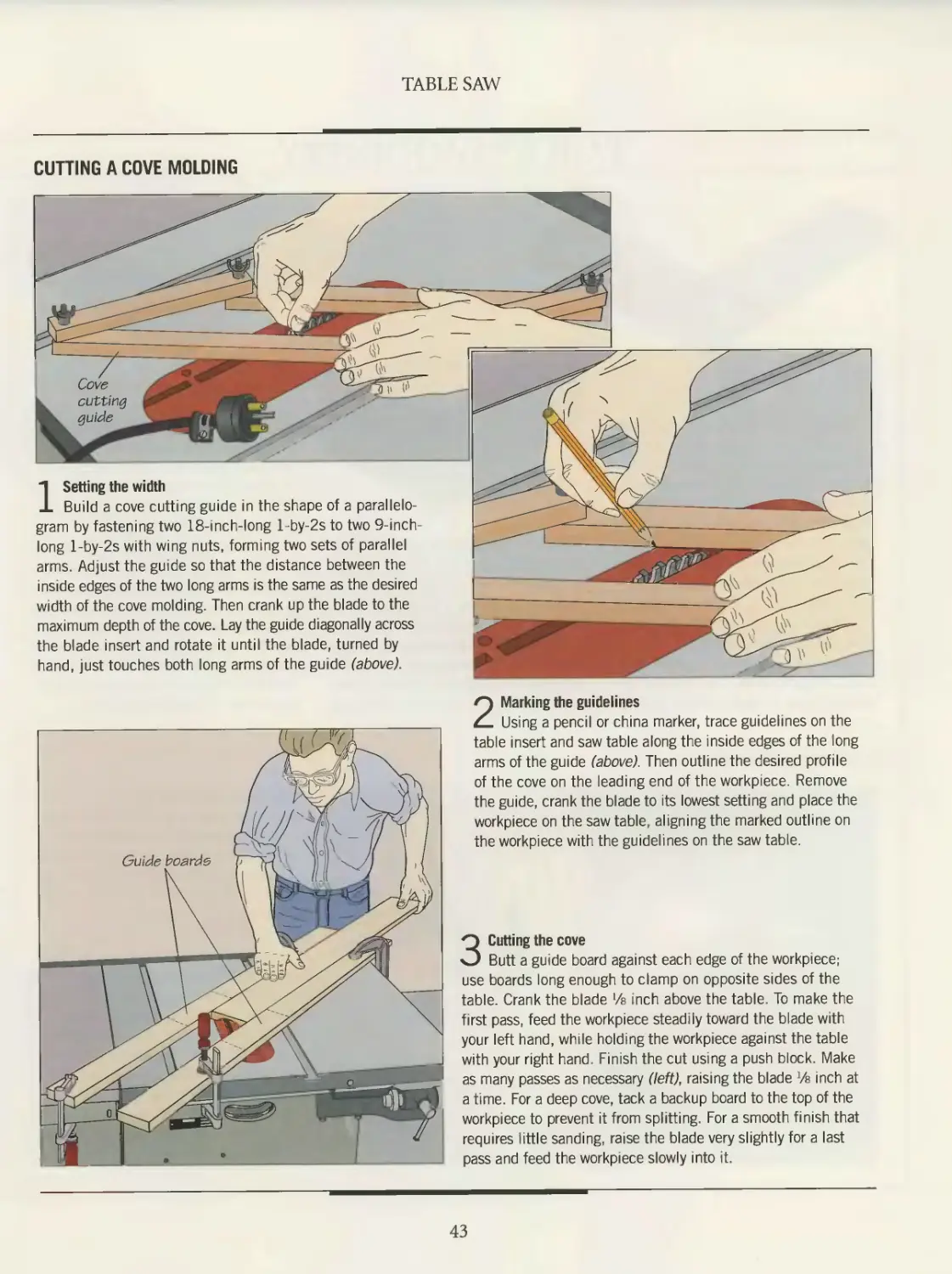
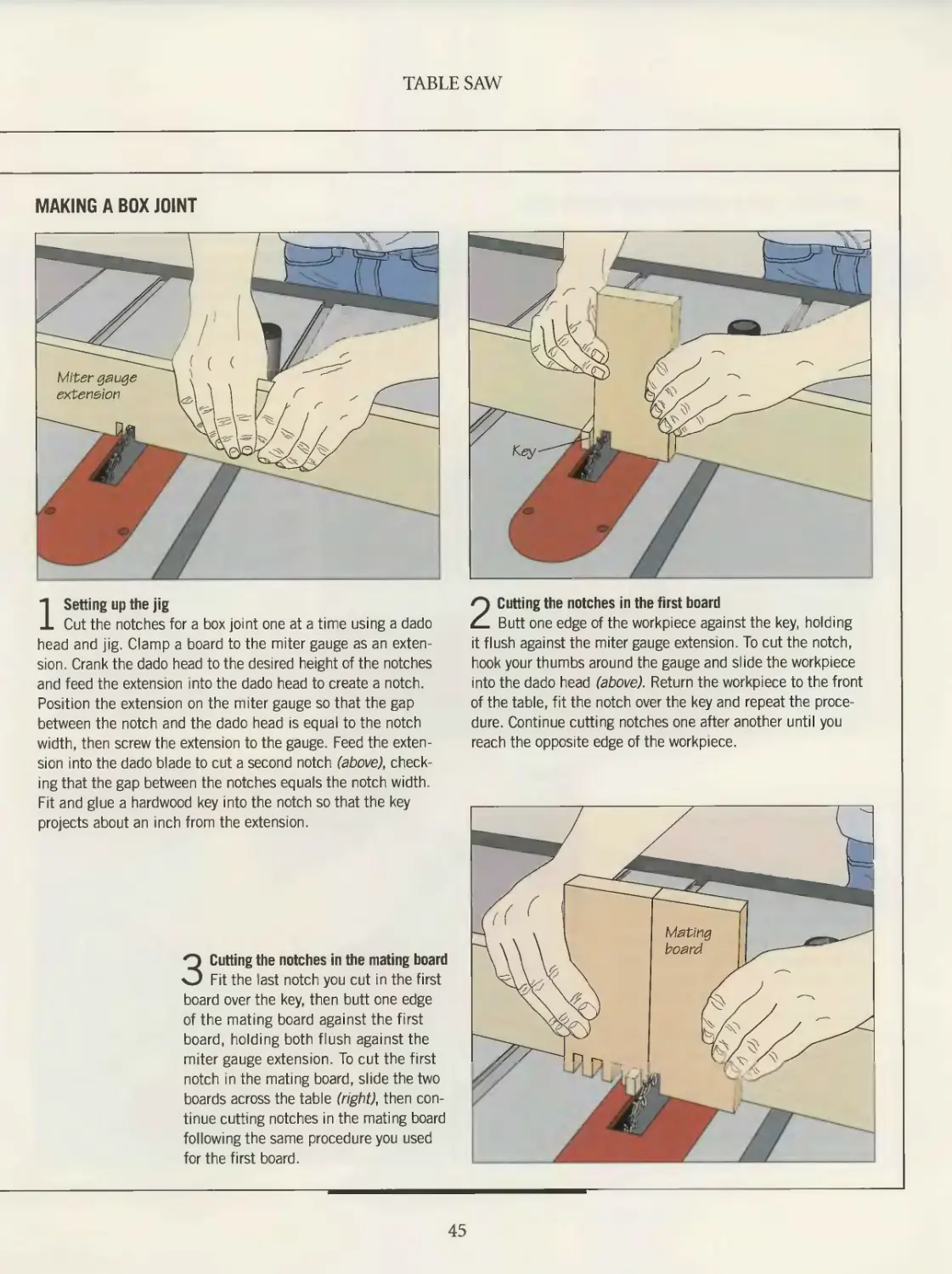
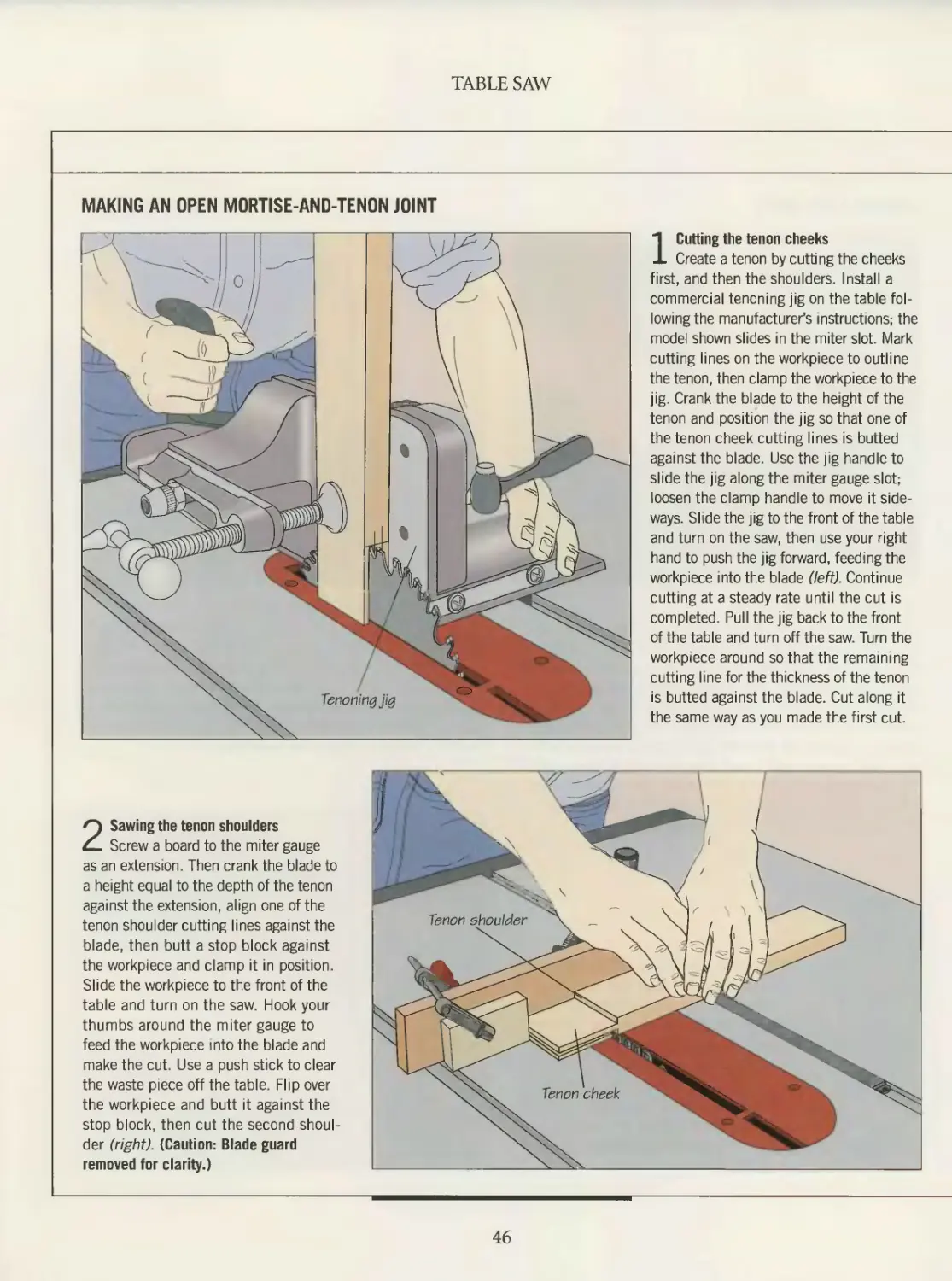


Text
TIME
BOOKS
THE ART OF WOODWORKING
WOODWORKING
MACHINES
A Tuckerdude Scan 2004
WORKSHOP GUIDE
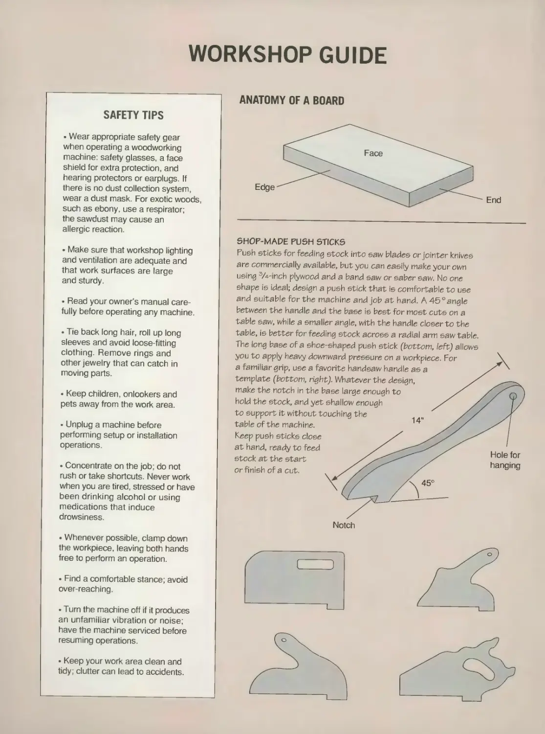
ANATOMY OF A BOARD
SAFETY TIPS
• Wear appropriate safety gear
when operating a woodworking
machine: safety glasses, a face
shield for extra protection, and
hearing protectors or earplugs. If
there is no dust collection system,
wear a dust mask. For exotic woods,
such as ebony, use a respirator;
the sawdust may cause an
allergic reaction.
• Make sure that workshop lighting
and ventilation are adequate and
that work surfaces are large
and sturdy.
• Read your owner’s manual care-
fully before operating any machine.
• Tie back long hair, roll up long
sleeves and avoid loose-fitting
clothing. Remove rings and
other jewelry that can catch in
moving parts.
• Keep children, onlookers and
pets away from the work area.
• Unplug a machine before
performing setup or installation
operations.
♦ Concentrate on the job; do not
rush or take shortcuts. Never work
when you are tired, stressed or have
been drinking alcohol or using
medications that induce
drowsiness.
• Whenever possible, clamp down
the workpiece, leaving both hands
free to perform an operation.
• Find a comfortable stance; avoid
over-reaching.
• Turn the machine off if it produces
an unfamiliar vibration or noise;
have the machine serviced before
resuming operations.
• Keep your work area clean and
tidy ; clutter can lead to accidents.
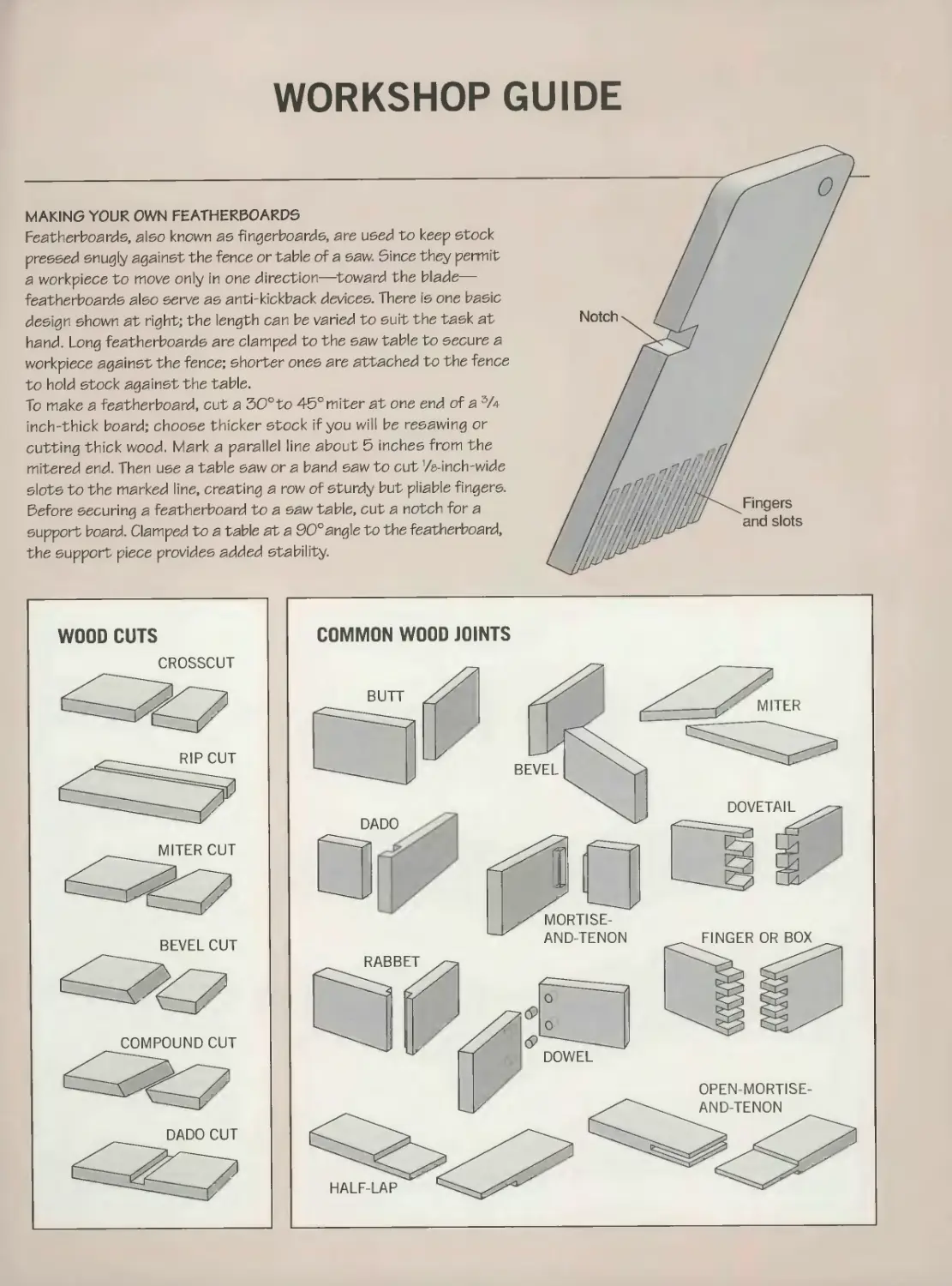
SHOP-MADE PUSH STICKS
Push sticks for feeding stock into saw blades or jointer knives
are commercially available, but you can easily make your own
using 3/4-inch plywood and a band saw or saber saw. No one
shape is ideal; design a push stick that is comfortable to use
and suitable for the machine and job at hand. A 45°angle
between the handle and the base is best for most cuts on a
table saw, while a smaller angle, with the handle closer to the
table, is better for feeding stock across a radial arm saw table.
The long base of a shoe-shaped push stick (bottom, teftj allows
you to apply heavy downward pressure on a workpiece. For
a familiar grip, use a favorite handsaw handle as a
template (bottom, right}. Whatever the design,
make the notch in the base large enough to
hold the stock, and yet shallow enough
to support it without touching the
table of the machine.
Keep push sticks close
at hand, ready to feed
stock at the start
or finish of a cut.
Notch
Hole for
hanging
1
THE ART OF WOODWORKING
WOODWORKING
MACHINES
THE ART OF WOODWORKING
WOODWORKING
MACHINES
TIME-LIFE BOOKS
ALEXANDRIA, VIRGINIA
ST. REMY PRESS
MONTREAL* NEW YORK
THE ART OF WOODWORKING was produced by
ST. REMY MULTIMEDIA INC.
PRESIDENT Pierre Leveille
Series Editor
Series Art Director
Senior Editors
Art Directors
Designer
Research Editor
Picture Editor
Contributing Illustrators
Administrator
Production Manager
System Coordinator
Photographer
Pierre Home-Douglas
Francine Lemieux
Marc Cassini (Text)
Heather Mills (Research)
Normand Boudreault, Solange Laberge
Luc Germain
Jim McRae
Christopher Jackson
Ronald Durepos, Christiane L’ltalien,
Robert Paquet, Studio La Perluete inc.
Natalie Watanabe
Michelle Turbide
lean-Luc Roy
Robert Chartier
TIME®
LIFE
THE CONSULTANTS
Mark Duginske, a cabinetmaker who lives
in Wausau, Wisconsin, is a contributing
editor to Fine Woodworking magazine
and the author of several books on woodwork-
ing power tools.
Leonard Lee is the president of Veritas Tools
and Lee Valley Tools, manufacturers and retail-
ers of fine woodworking hand tools. He is also
the publisher and executive editor of Woodcuts,
a magazine that focuses on the history and
techniques of woodworking.
Giles Miller-Mead has taught advanced cabi-
netmaking at Montreal technical schools for
more than ten years. A native of New Zealand,
he previously worked as a restorer of antique
furniture.
Joseph Truini is Senior Editor of Home
Mechanix magazine. A former Shop and Tools
Editor of Popular Mechanics, he has worked as
a cabinetmaker, home improvement contractor
and carpenter.
BOOKS
Time-Life Books is a division of Time Life Inc.
TIME LIFE INC.
PRESIDENT and CEO: George Artandi
TIME-LIFE BOOKS
PRESIDENT: John D. Hall
PUBLISHER/MANAGING EDITOR: Neil Kagan
DEDICATION
The editors of Time-Life Books
and St. Remy Multimedia Inc. dedicate
Woodworking Machines to the
memory of Giles Miller-Mead (page 6-7).
Mr. Giles Miller-Mead, the overall consultant
for THE ART OF WOODWORKING,
was a superb practitioner and popular teacher
of this craft, as well as a mentor to
many talented cabinetmakers.
Woodworking machines.
p. cm.—(The Art of Woodworking)
Includes index.
ISBN 0-8094-9900-2.
ISBN 0-8094-9901-0 (lib. bdg).
1. Woodworking tools. 2. Woodworking
machinery. 3. Saws.
I. Time- Life Books. II Series
TT186.W658 1992
684’ .083—dc20
For information about any Time-Life book,
please call 1 -800-621 -7026, or write:
Reader Information
Time-Life Customer Service
P.O. Box C-32068
Richmond, Virginia
23261-2068
© 1992 Time-Life Books Inc.
All rights reserved.
No part of this book may be reproduced in
any form or by any electronic or mechanical
means, including information storage and
retrieval devices or systems, without prior
written permission from the publisher, except
that brief passages may be quoted for reviews.
First printing. Printed in U.S.A.
Published simultaneously in Canada.
TIME-LIFE is a trademark of Time Warner
Inc. U.S.A.
CONTENTS
6
12
14
16
18
20
24
30
35
36
40
44
48
50
52
58
60
62
63
66
69
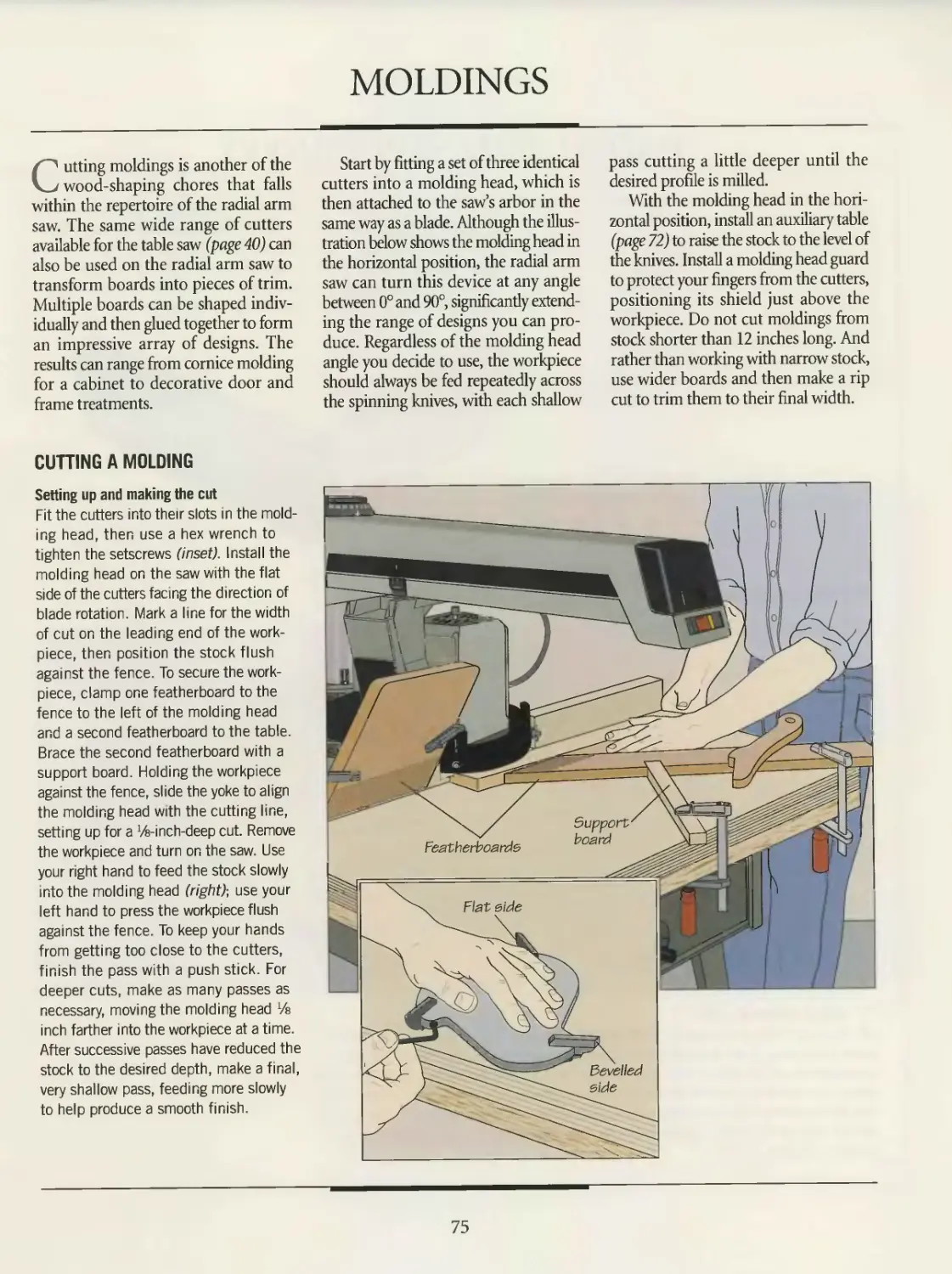
75
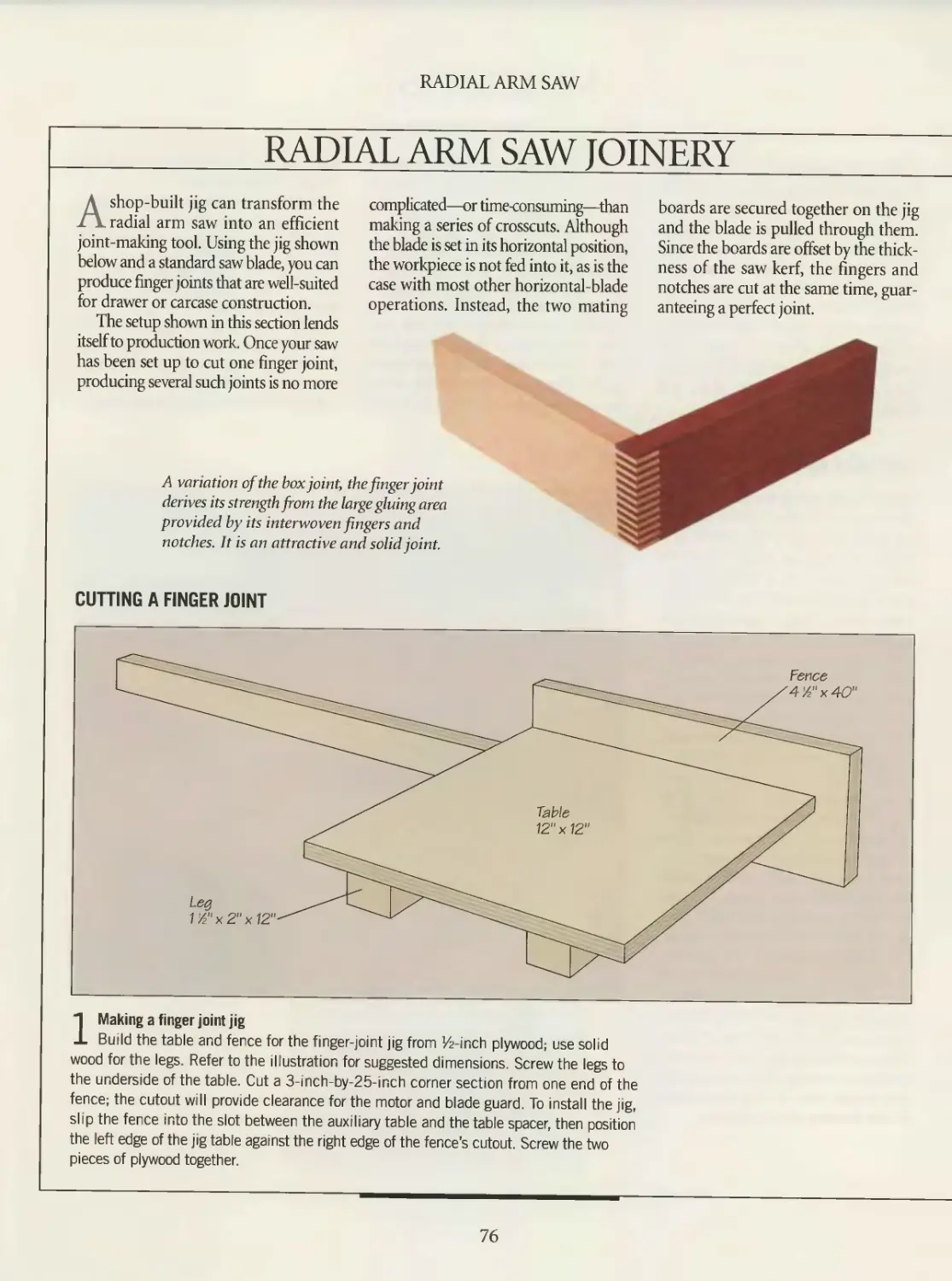
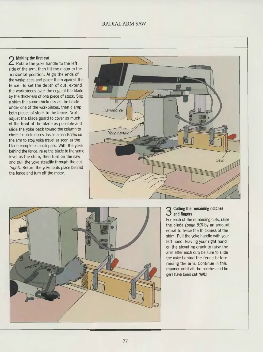
76
78
80
82
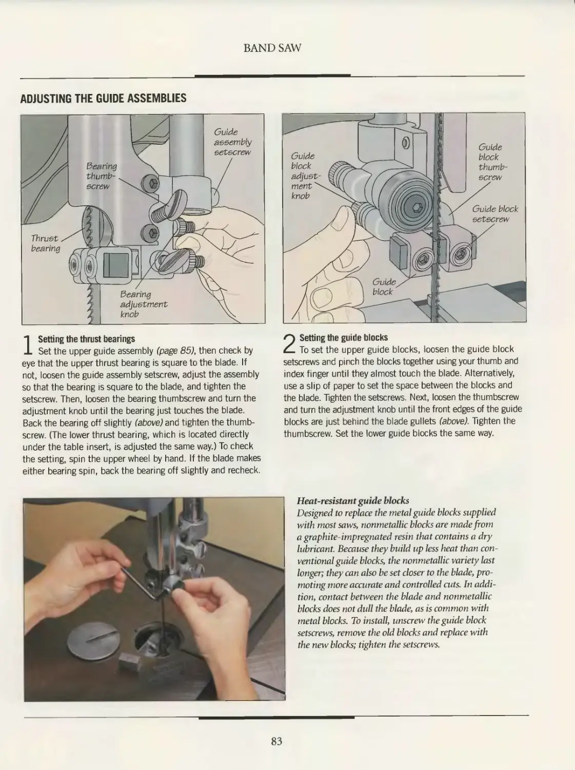
85
86
89
94
98
100
101
INTRODUCTION
TABLE SAW
Anatomy of a table saw
Setting up
Safety
Table saw blades
Ripping
Crosscutting
Angle cuts
Dado cuts
Moldings
Table saw joinery
RADIAL ARM SAW
Anatomy of a radial arm saw
Setting up
Radial arm saw blades
and accessories
Safety
Crosscutting
Angle cuts
Ripping
Dado cuts
Moldings
Radial arm saw joinery
BANDSAW
Anatomy of a band saw
Setting up
Safety
Band saw blades
Cutting curves
Straight cuts
Angle and taper cuts
Cutting duplicate pieces
Band saw joinery
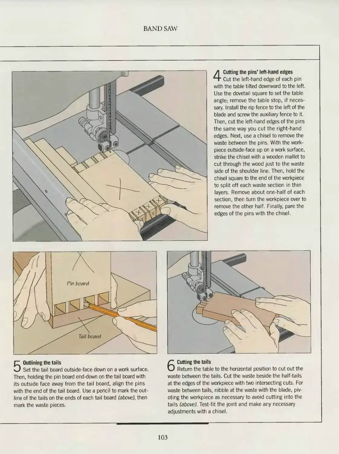
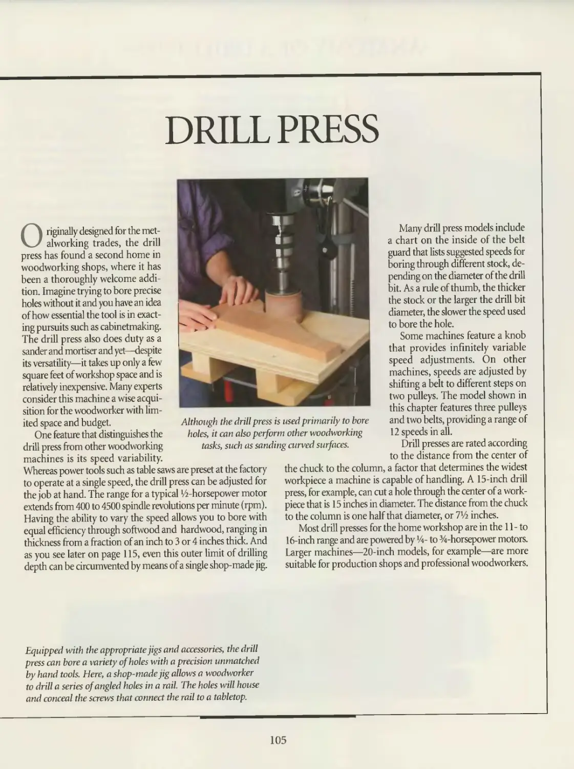
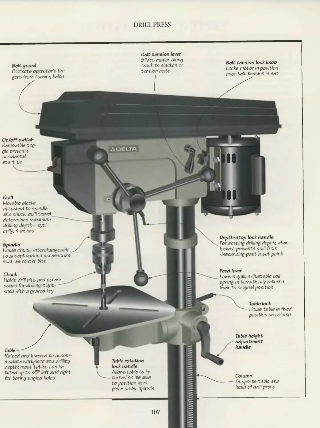
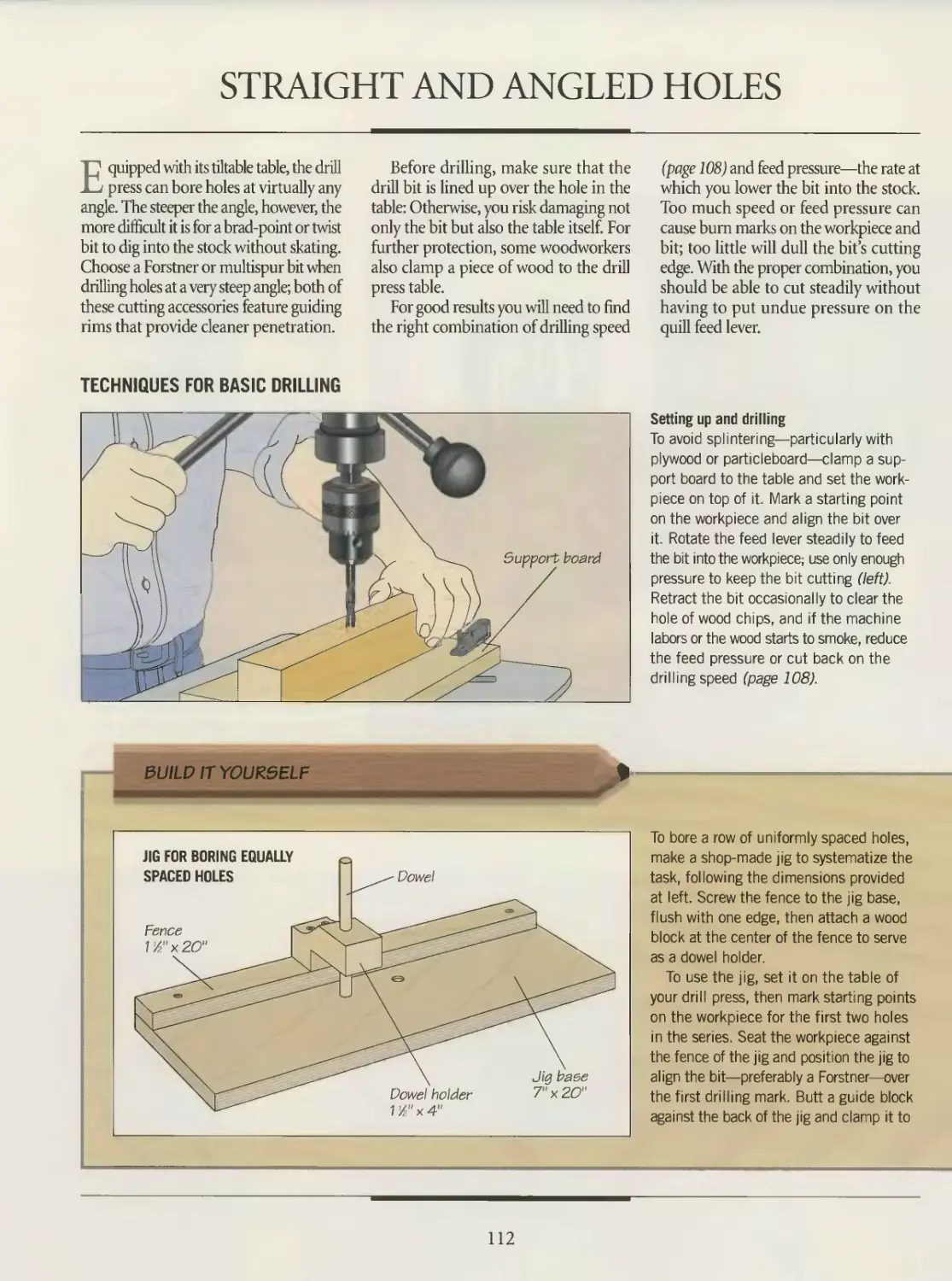
104 DRILL PRESS
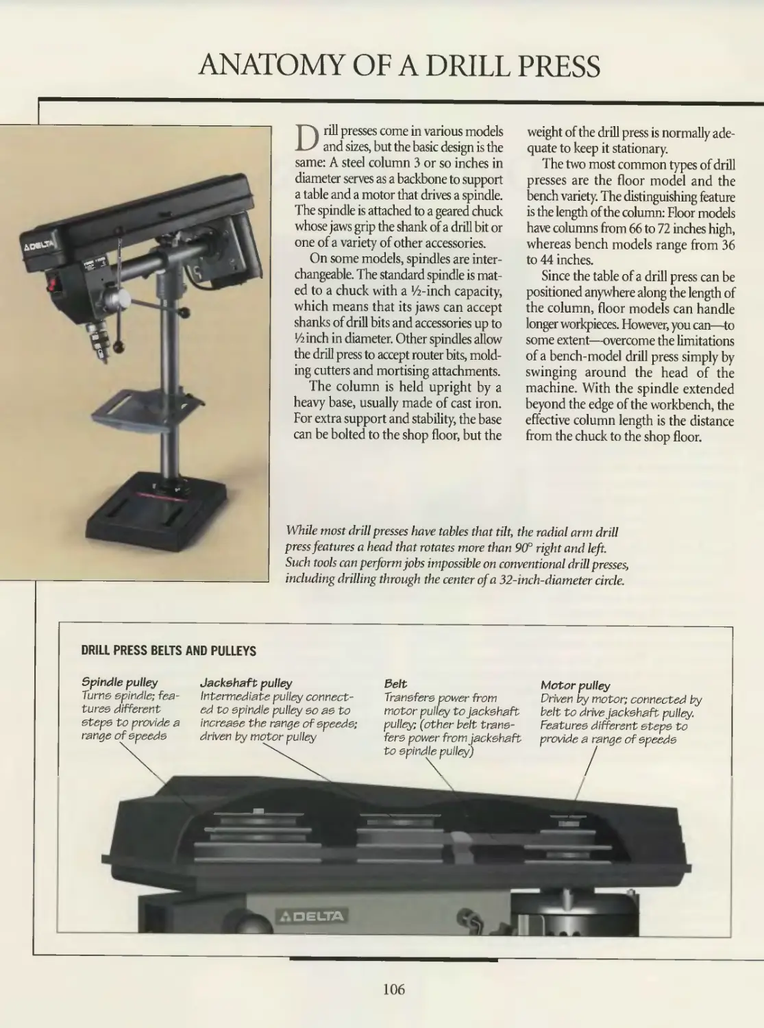
106 Anatomy of a drill press
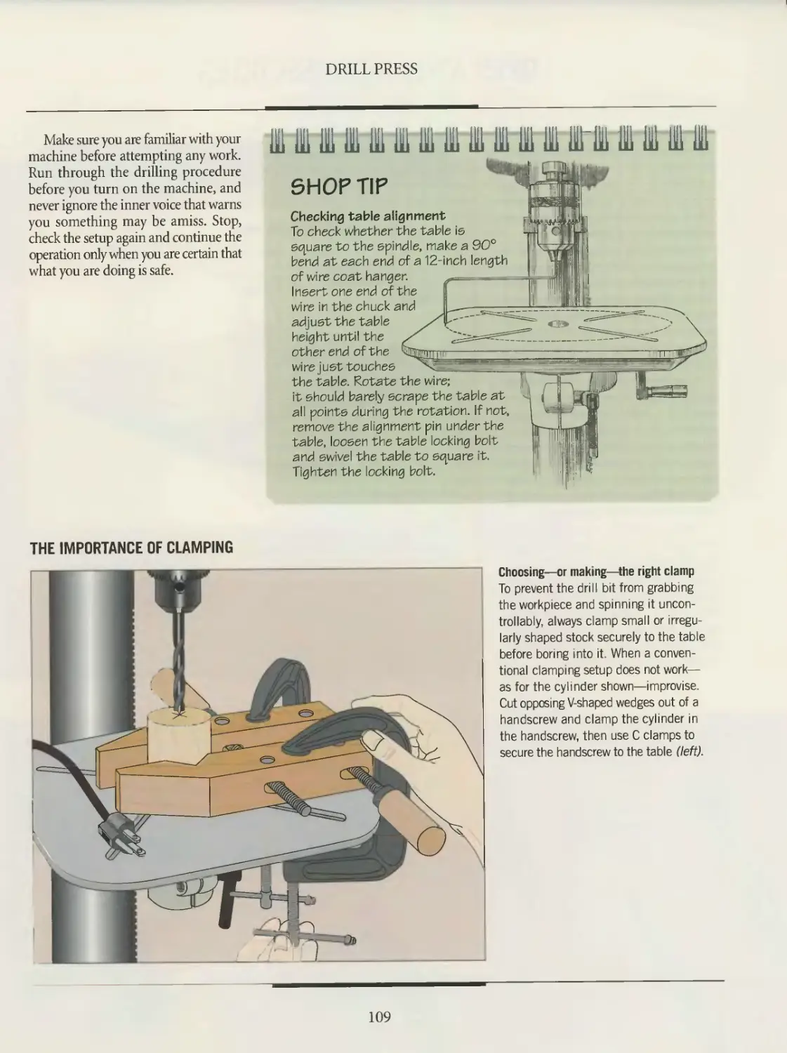
108 Setting up and safety
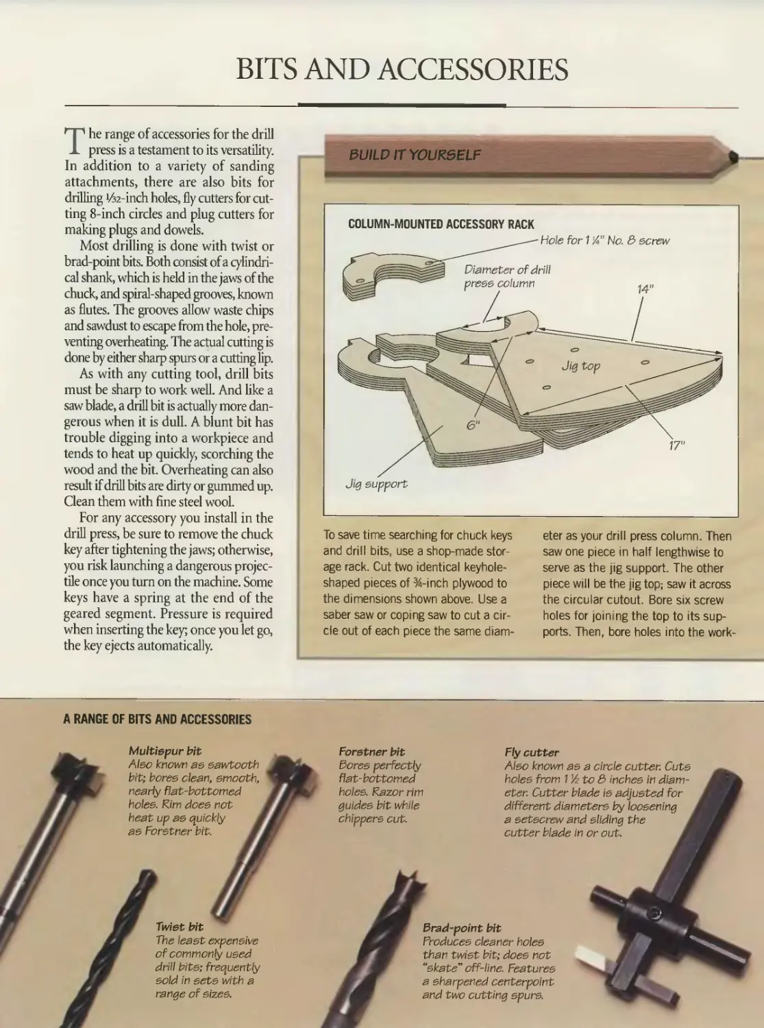
110 Bits and accessories
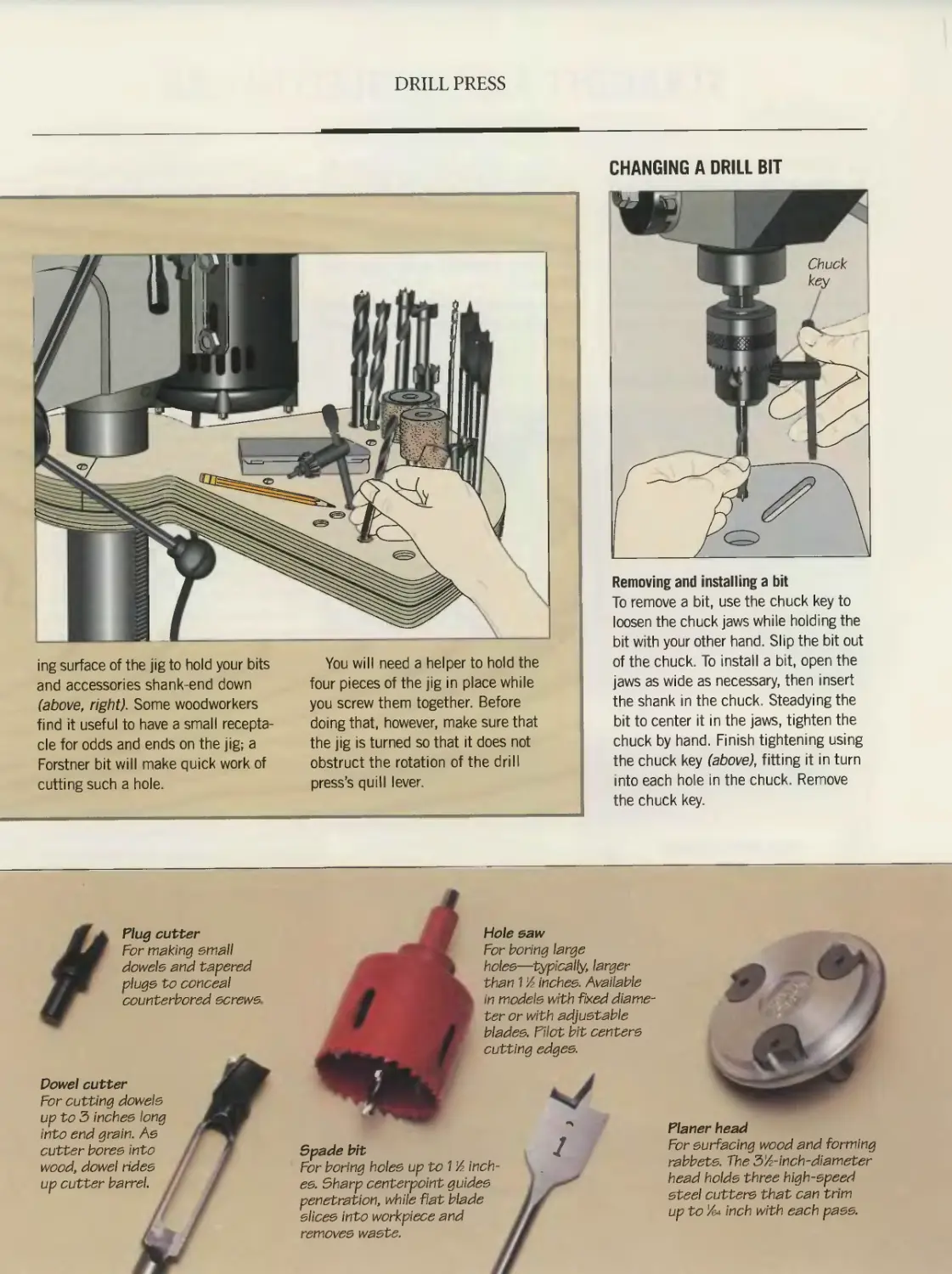
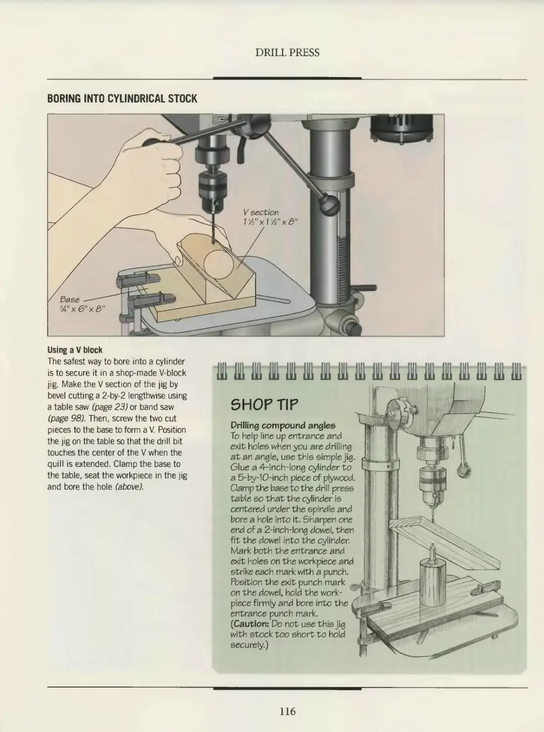
112 Straight and angled holes
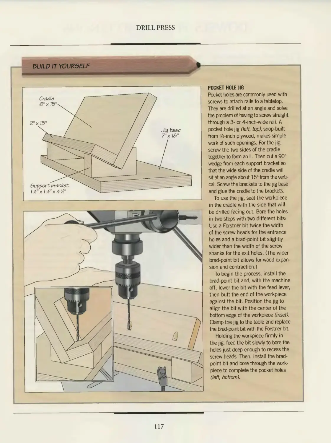
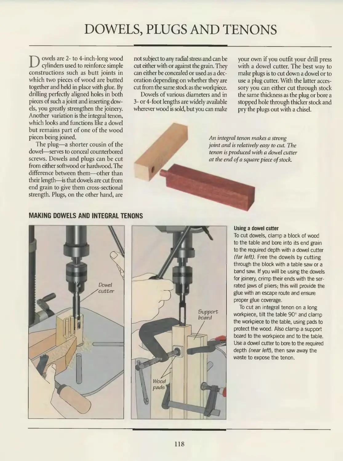
118 Dowels, plugs and tenons
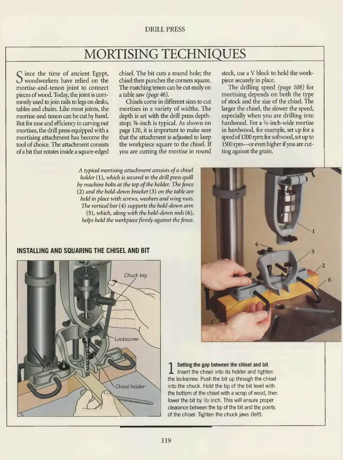
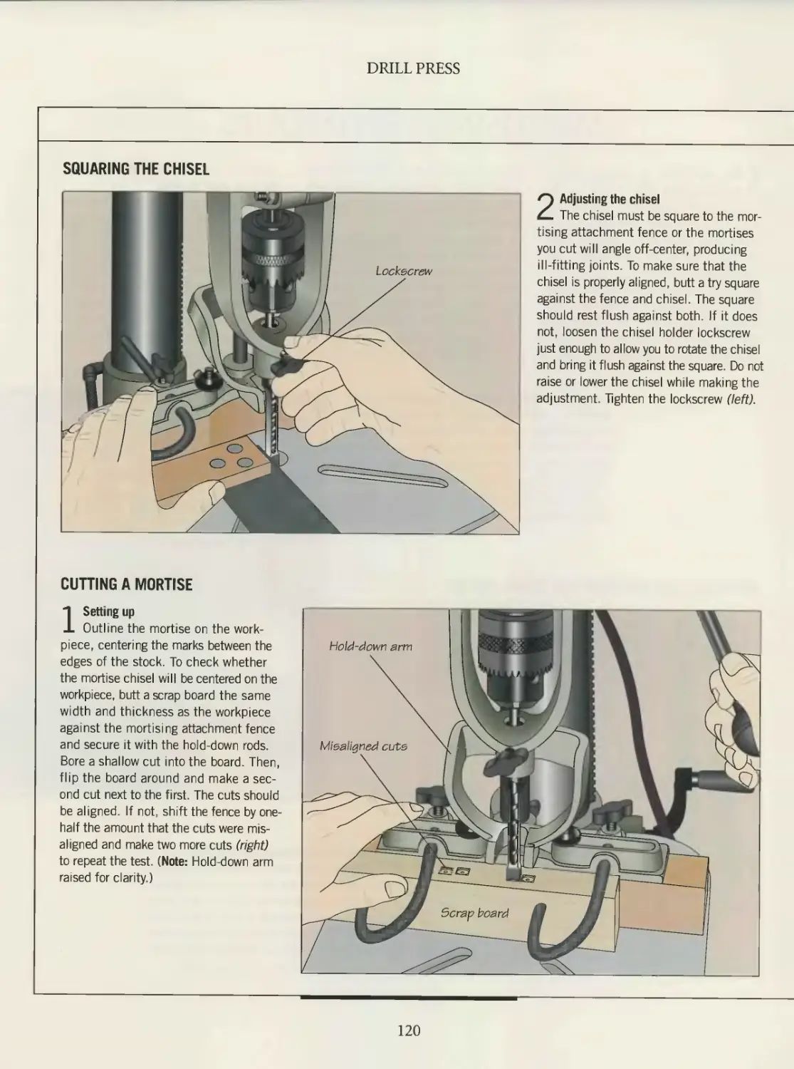
119 Mortising techniques
122 The drill press as sander
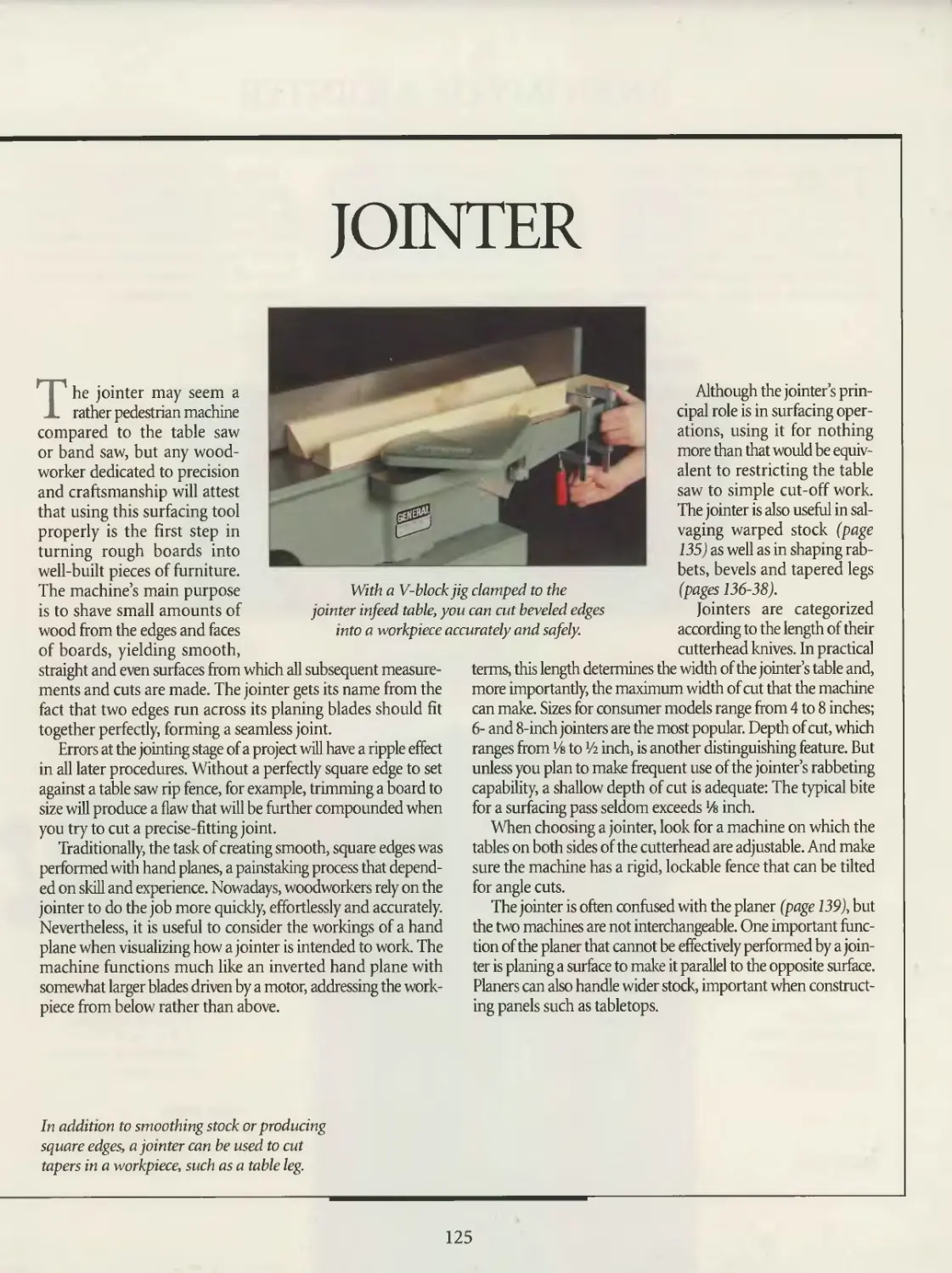
124 JOINTER
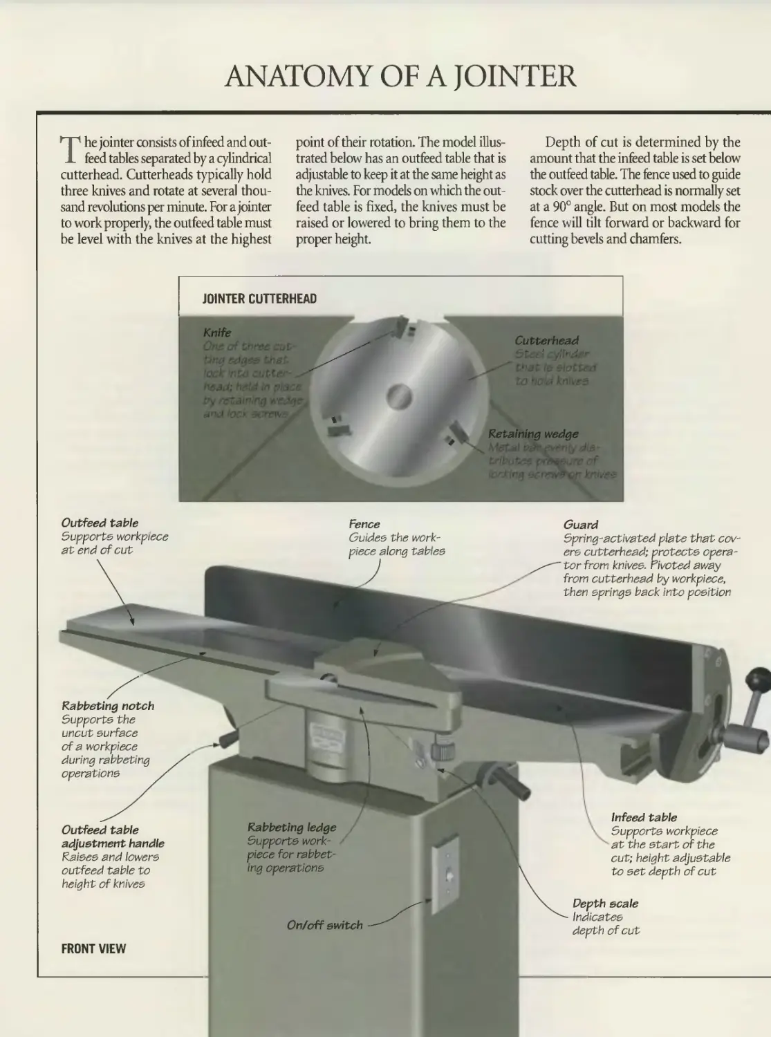
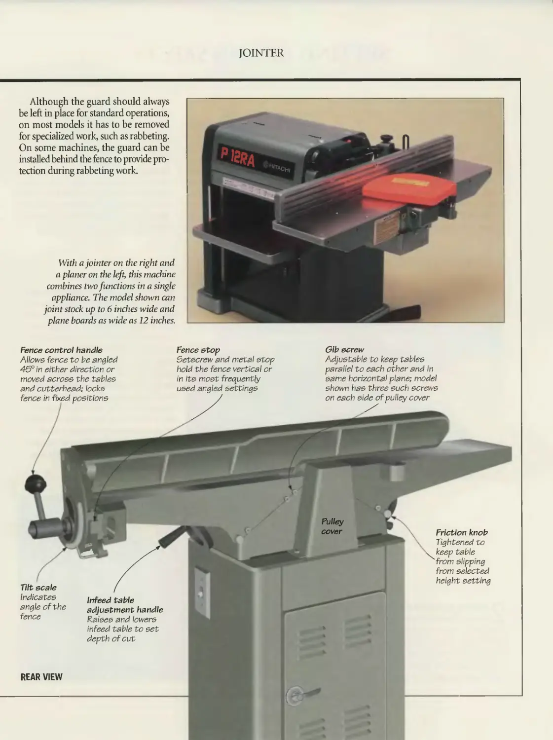
126 Anatomy of a jointer
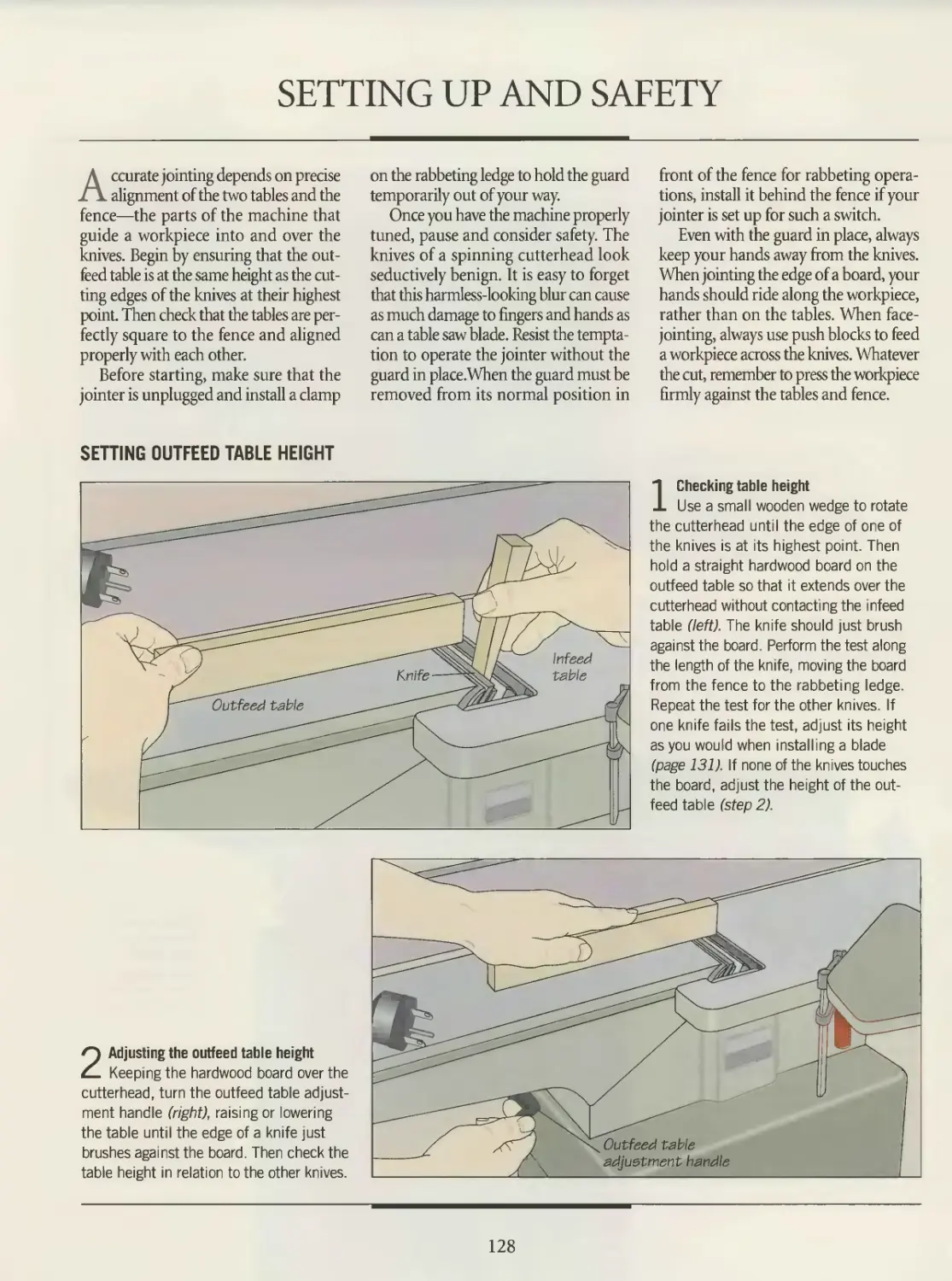
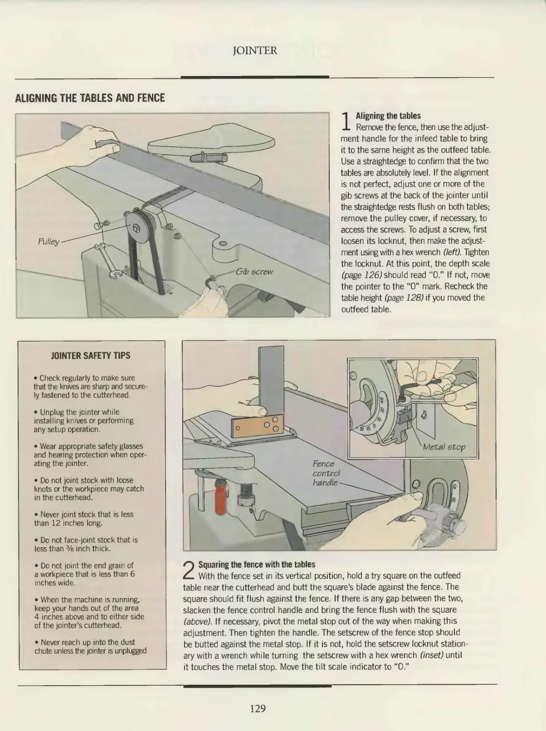
128 Setting up and safety
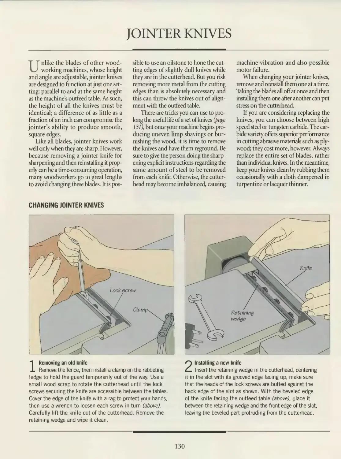
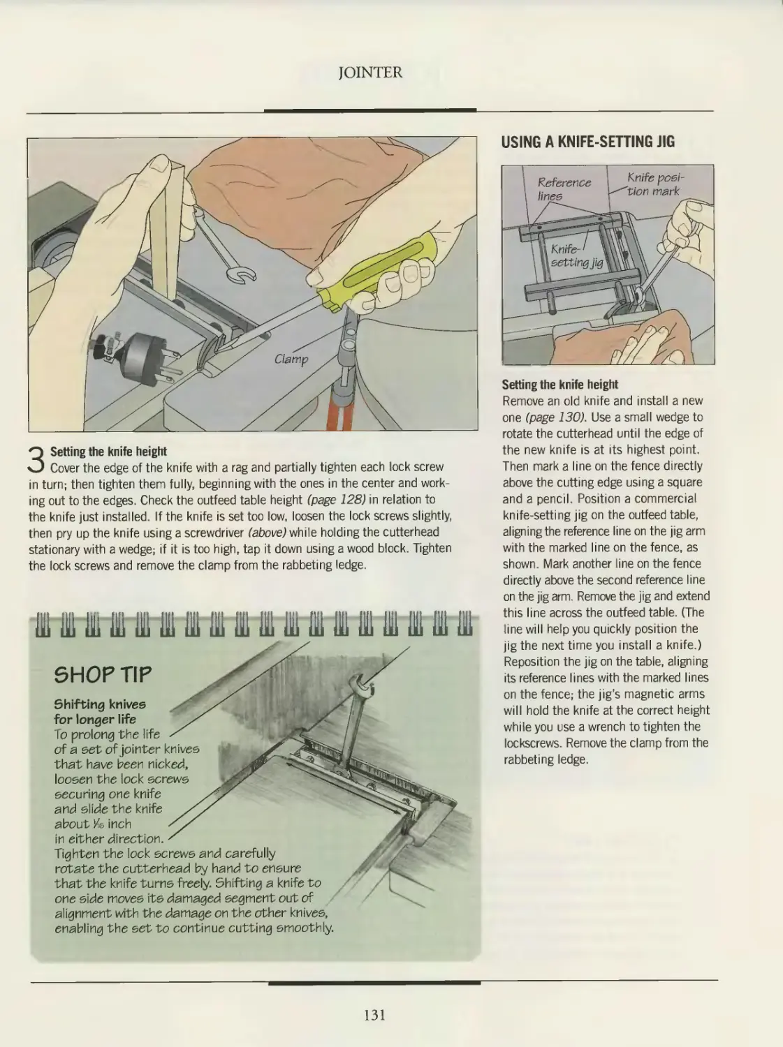
130 Jointer knives
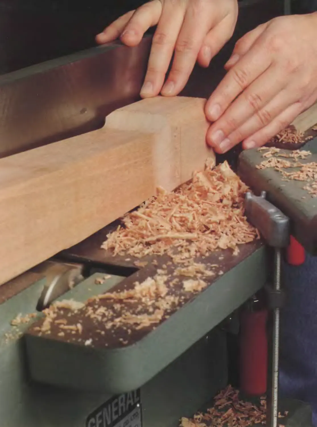
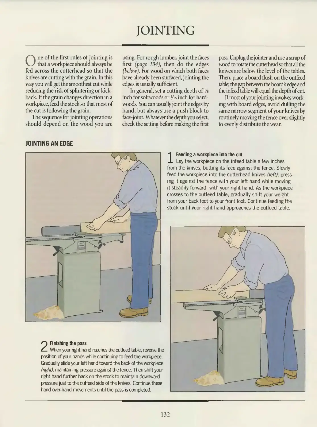
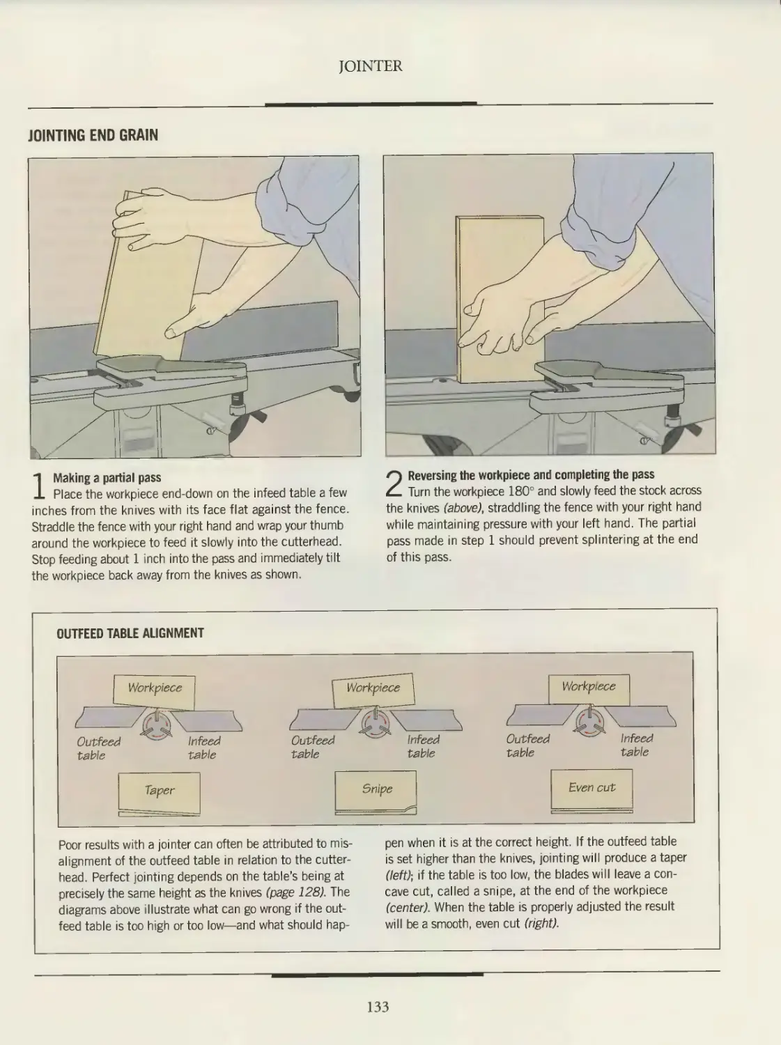
132 Jointing
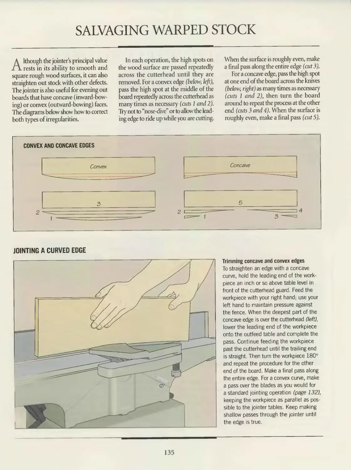
135 Salvaging warped stock
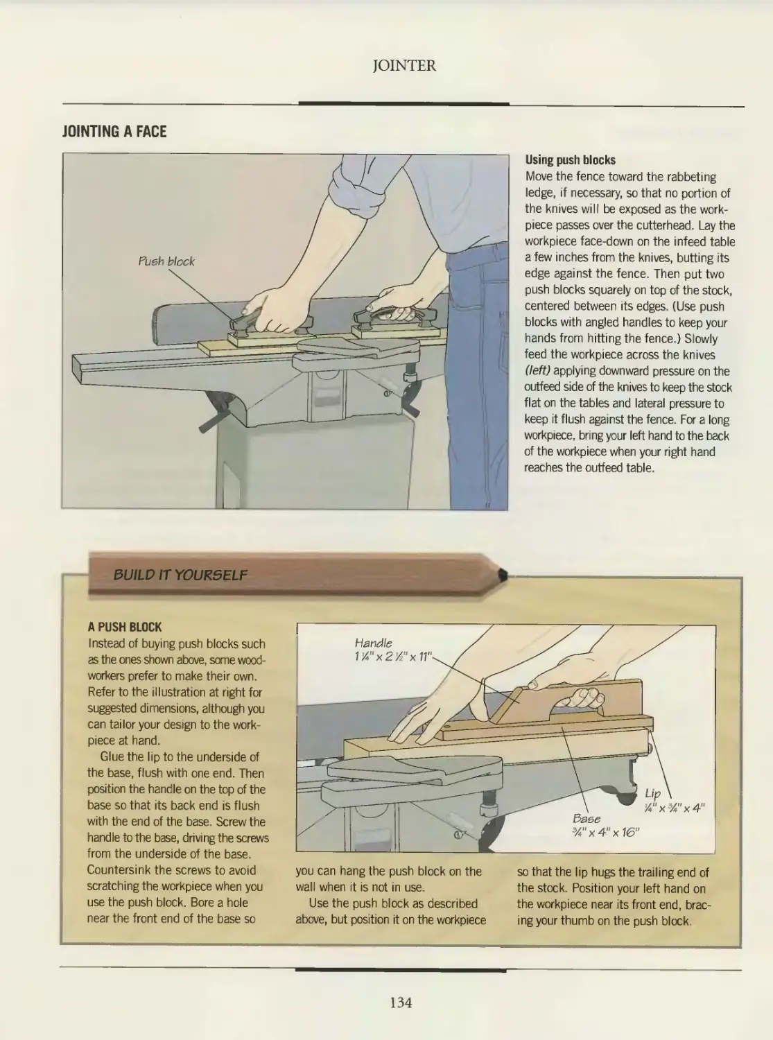
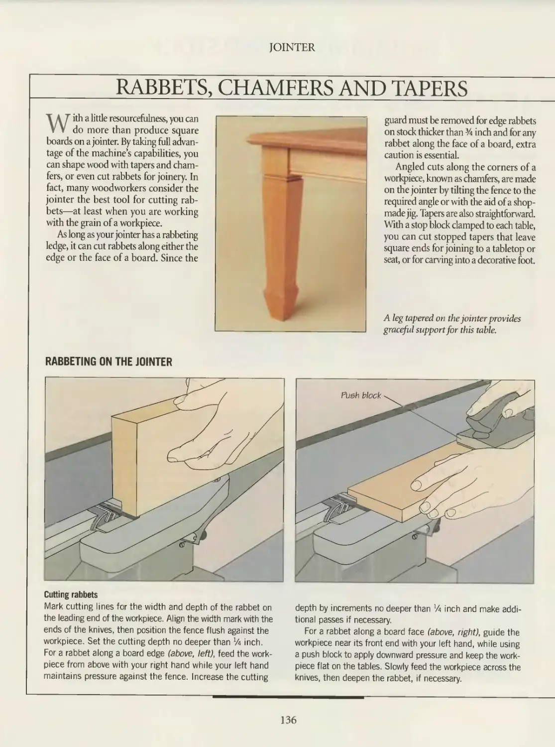
136 Rabbets, chamfers and tapers
139 Planer
140 GLOSSARY
142 INDEX
144 ACKNOWLEDGMENTS
INTRODUCTION
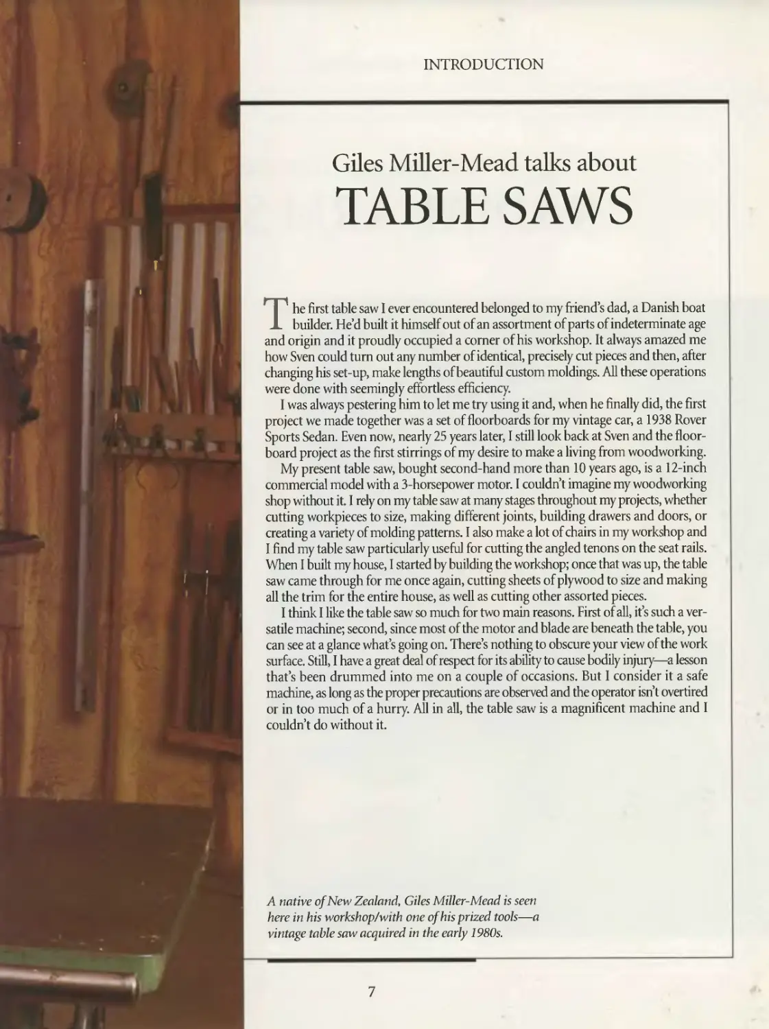
Giles Miller-Mead talks about
TABLE SAWS
The first table saw I ever encountered belonged to my friend’s dad, a Danish boat
builder. He’d built it himself out of an assortment of parts of indeterminate age
and origin and it proudly occupied a corner of his workshop. It always amazed me
how Sven could turn out any number of identical, precisely cut pieces and then, after
changing his set-up, make lengths of beautiful custom moldings. All these operations
were done with seemingly effortless efficiency.
I was always pestering him to let me try using it and, when he finally did, the first
project we made together was a set of floorboards for my vintage car, a 1938 Rover
Sports Sedan. Even now, nearly 25 years later, I still look back at Sven and the floor-
board project as the first stirrings of my desire to make a living from woodworking.
My present table saw, bought second-hand more than 10 years ago, is a 12-inch
commercial model with a 3-horsepower motor. I couldn’t imagine my woodworking
shop without it. I rely on my table saw at many stages throughout my projects, whether
cutting workpieces to size, making different joints, building drawers and doors, or
creating a variety of molding patterns. I also make a lot of chairs in my workshop and
I find my table saw particularly useful for cutting the angled tenons on the seat rails.
When I built my house, I started by building the workshop; once that was up, the table
saw came through for me once again, cutting sheets of plywood to size and making
all the trim for the entire house, as well as cutting other assorted pieces.
I think 1 like the table saw so much for two main reasons. First of all, it’s such a ver-
satile machine; second, since most of the motor and blade are beneath the table, you
can see at a glance what’s going on. There’s nothing to obscure your view of the work
surface. Still, 1 have a great deal of respect for its ability to cause bodily injury—a lesson
that’s been drummed into me on a couple of occasions. But I consider it a safe
machine, as long as the proper precautions are observed and the operator isn’t overtired
or in too much of a hurry. All in all, the table saw is a magnificent machine and I
couldn’t do without it.
A native of New Zealand, Giles Miller-Mead is seen
here in his workshop/with one of his prized tools—a
vintage table saw acquired in the early 1980s.
7
INTRODUCTION
Frank Klausz discusses
RADIAL ARM SAWS
Until he was about 14 years old, my
son was content to spend his sum-
mers in my shop doing sanding jobs.
Then he decided to make something
himself. I suggested he design a jewelry
box, which I helped him construct. The
next summer, he wanted to build some-
thing without my help—which meant
working on my big machines.
Being safety-conscious, I got a bit ner-
vous. Still, I took him to the radial arm
saw and explained the basics. Then I
painted two red lines on the saw table,
each a few inches away from the blade,
and filled in the space in between. “Safety
with this machine is simple,” I told him.
“Keep your hands away from the red
zone.” In no time at all, he was working
at the saw without supervision. He cut
ke-inch rabbets into the edges of his jew-
elry box top and added a black ebony
inlay. I would have used a router, but he
did fine with the saw.
Because you pull the blade into a sta-
tionary workpiece, the radial arm saw is
a very safe machine—provided you set up
properly, use only sharp blades, follow
the manufacturer’s safety instructions
and, if you wish, add your own red zone.
I use the radial arm saw for a variety
of tasks: crosscutting rough lumber,
cutting miters and dadoes, and ripping.
If you rip, remember to feed evenly
and from the correct side of the table to
avoid kickback.
Frank Klausz owns a workshop in
Pluckemin, New Jersey, that specializes
in making and restoring fine furniture.
8
INTRODUCTION
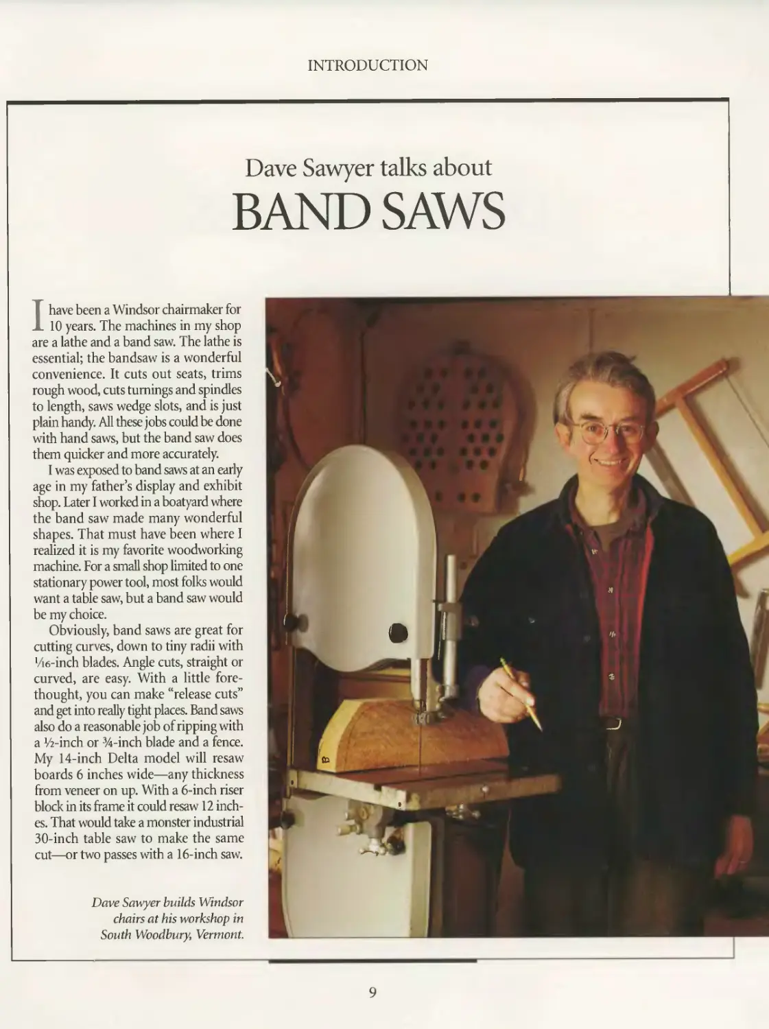
Dave Sawyer talks about
BAND SAWS
I have been a Windsor chairmaker for
10 years. The machines in my shop
are a lathe and a band saw. The lathe is
essential; the bandsaw is a wonderful
convenience. It cuts out seats, trims
rough wood, cuts turnings and spindles
to length, saws wedge slots, and is just
plain handy. All these jobs could be done
with hand saws, but the band saw does
them quicker and more accurately.
I was exposed to band saws at an early
age in my father’s display and exhibit
shop. Later I worked in a boatyard where
the band saw made many wonderful
shapes. That must have been where I
realized it is my favorite woodworking
machine. For a small shop limited to one
stationary power tool, most folks would
want a table saw, but a band saw would
be my choice.
Obviously, band saws are great for
cutting curves, down to tiny radii with
Vie-inch blades. Angle cuts, straight or
curved, are easy. With a little fore-
thought, you can make “release cuts”
and get into really tight places. Band saws
also do a reasonable job of ripping with
a Уг-inch or %-inch blade and a fence.
My 14-inch Delta model will resaw
boards 6 inches wide—any thickness
from veneer on up. With a 6-inch riser
block in its frame it could resaw 12 inch-
es. That would take a monster industrial
30-inch table saw to make the same
cut—or two passes with a 16-inch saw.
Dave Sawyer builds Windsor
chairs at his workshop in
South Woodbury, Vermont.
9
INTRODUCTION
Judith Ames on
DRILL PRESSES
Of all the tools in my shop, the drill
press may not see as many hours
of use as some others, but for certain
tasks it is indispensable. The machine I
use is a Sears Craftsman, manufactured
in the mid-1950s. It came into our shop
about four years ago. What I like about
this drill press is its old-tool charm, the
weight of it. It’s solid. It was built to last.
Prior to getting into furniture-mak-
ing, I experimented with carpentry and
cabinetmaking. I studied woodworking
in Colorado, taking classes with such
highly respected furniture makers as Art
Carpenter. Furniture-making is what I’ve
been doing for the last seven years. I find
it very satisfying. I’m constantly learning
new techniques and trying new designs.
I produce a line of furniture as well as
custom design pieces. I make a rocking
chair for children with a design that
includes bear paws on the arms and
dowels set into a curved frame that pro-
vides back support. I depend on the drill
press to bore precise holes for the dowels.
On a rocking chair I make for adults,
the legs are square at the middle where
they meet the seat, and have tenons
at either end that fit into the rockers
at the bottom and the arms at the top.
To make the transition between the leg’s
square middle and round tenons, I sculpt
the legs with a router and a spokeshave.
The drill press reams the holes in the
rockers and the arms for the tenons.
Judith Ames is a furniture-
maker in Seattle, Washington.
10
INTRODUCTION
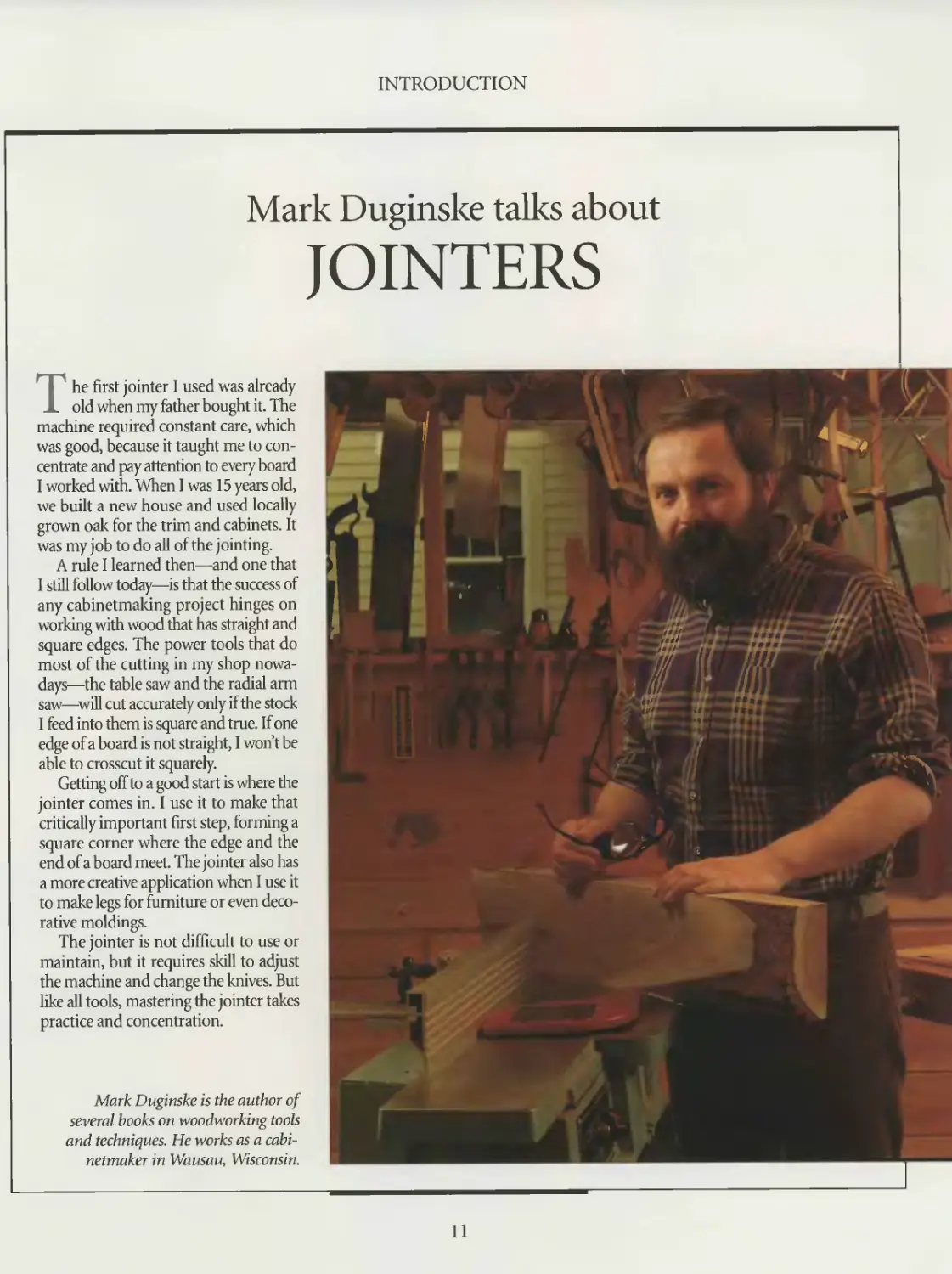
Mark Duginske talks about
JOINTERS
The first jointer 1 used was already
old when my father bought it. The
machine required constant care, which
was good, because it taught me to con-
centrate and pay attention to every board
I worked with. When I was 15 years old,
we built a new house and used locally
grown oak for the trim and cabinets. It
was my job to do all of the jointing.
A rule I learned then—and one that
I still follow today—is that the success of
any cabinetmaking project hinges on
working with wood that has straight and
square edges. The power tools that do
most of the cutting in my shop nowa-
days—the table saw and the radial arm
saw—Mil cut accurately only if the stock
1 feed into them is square and true. If one
edge of a board is not straight, I won’t be
able to crosscut it squarely.
Getting off to a good start is where the
jointer comes in. I use it to make that
critically important first step, forming a
square corner where the edge and the
end of a board meet. The jointer also has
a more creative application when I use it
to make legs for furniture or even deco-
rative moldings.
The jointer is not difficult to use or
maintain, but it requires skill to adjust
the machine and change the knives. But
like all tools, mastering the jointer takes
practice and concentration.
Mark Duginske is the author of
several books on woodworking tools
and techniques. He works as a cabi-
netmaker in Wausau, Wisconsin.
11
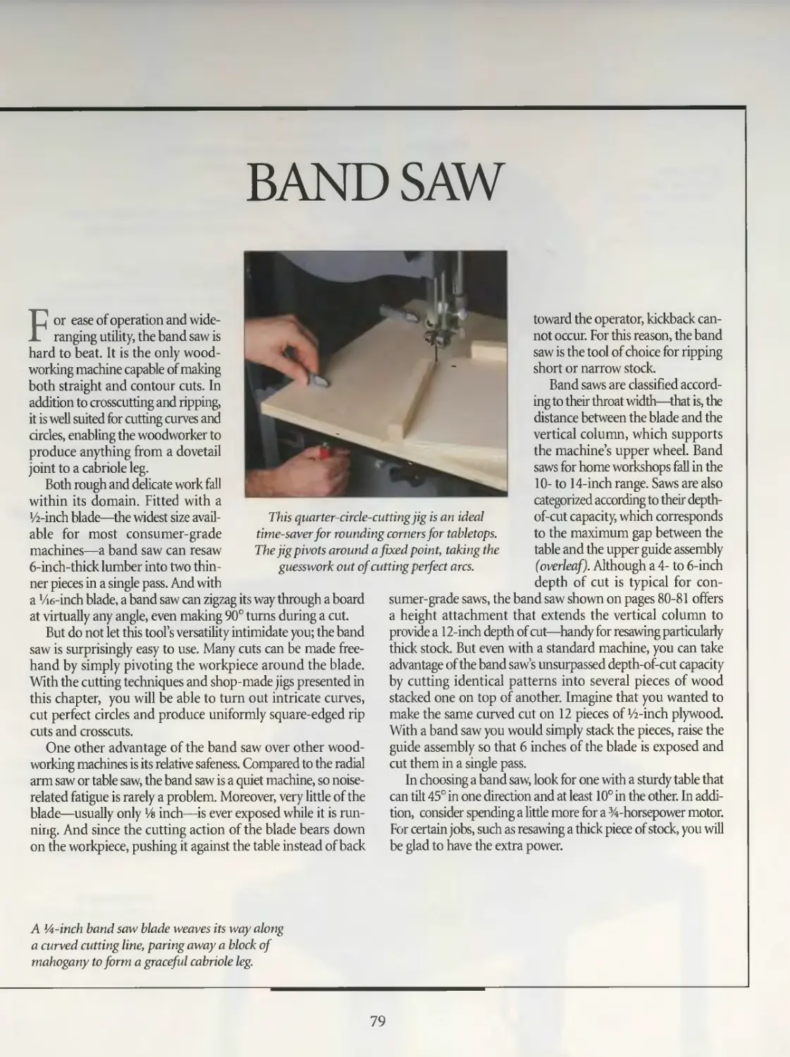
TABLE SAW
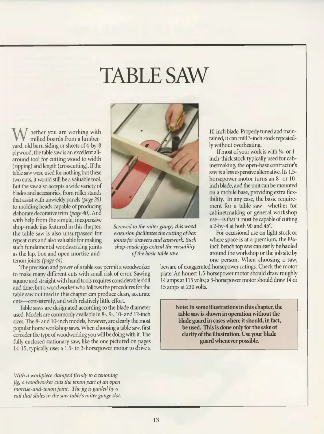
Screwed to the miter gauge, this wood
extension facilitates the cutting of box
joints for drawers and casework. Such
shop-made jigs extend the versatility
of the basic table saw.
Whether you are working with
milled boards from a lumber-
yard, old barn siding or sheets of 4-by-8
plywood, the table saw is an excellent all-
around tool for cutting wood to width
(ripping) and length (crosscutting). If the
table saw were used for nothing but these
two cuts, it would still be a valuable tool.
But the saw also accepts a wide variety of
blades and accessories, from roller stands
that assist with unwieldy panels (page 26)
to molding heads capable of producing
elaborate decorative trim (page 40). And
with help from the simple, inexpensive
shop-made jigs featured in this chapter,
the table saw is also unsurpassed for
repeat cuts and also valuable for making
such fundamental woodworking joints
as the lap, box and open mortise-and-
tenon joints (page 44).
The precision and power of a table saw permit a woodworker
to make many different cuts with small risk of error. Sawing
square and straight with hand tools requires considerable skill
and time; but a woodworker who follows the procedures for the
table saw outlined in this chapter can produce clean, accurate
cuts—consistently, and with relatively little effort.
Table saws are designated according to the blade diameter
used. Models are commonly available in 8-, 9-, 10- and 12-inch
sizes. The 8- and 10-inch models, however, are clearly the most
popular home workshop saws. When choosing a table saw, first
consider the type of woodworking you will be doing with it. The
fully enclosed stationary saw, like the one pictured on pages
14-15, typically uses a 1.5- to 3-horsepower motor to drive a
10-inch blade. Properly tuned and main-
tained, it can mill 3-inch stock repeated-
ly without overheating.
If most of your work is with %- or 1 -
inch-thick stock typically used for cab-
metmaking, the open-base contractor’s
saw is a less expensive alternative. Its 1.5-
horsepower motor turns an 8- or 10-
inch blade, and the unit can be mounted
on a mobile base, providing extra flex-
ibility. In any case, the basic require-
ment for a table saw—whether for
cabinetmaking or general workshop
use—is that it must be capable of cutting
a 2-by-4 at both 90 and 45°.
For occasional use on light stock or
where space is at a premium, the Sc-
inch bench top saw can easily be hauled
around the workshop or the job site by
one person. When choosing a saw,
beware of exaggerated horsepower ratings. Check the motor
plate: An honest 1.5-horsepower motor should draw roughly
14 amps at 115 volts; a 3-horsepower motor should draw 14 or
15 amps at 230 volts.
Note: In some illustrations in this chapter, the
table saw is shown in operation without the
blade guard in cases where it should, in fact,
be used. This is done only for the sake of
clarity of the illustration. Use your blade
guard whenever possible.
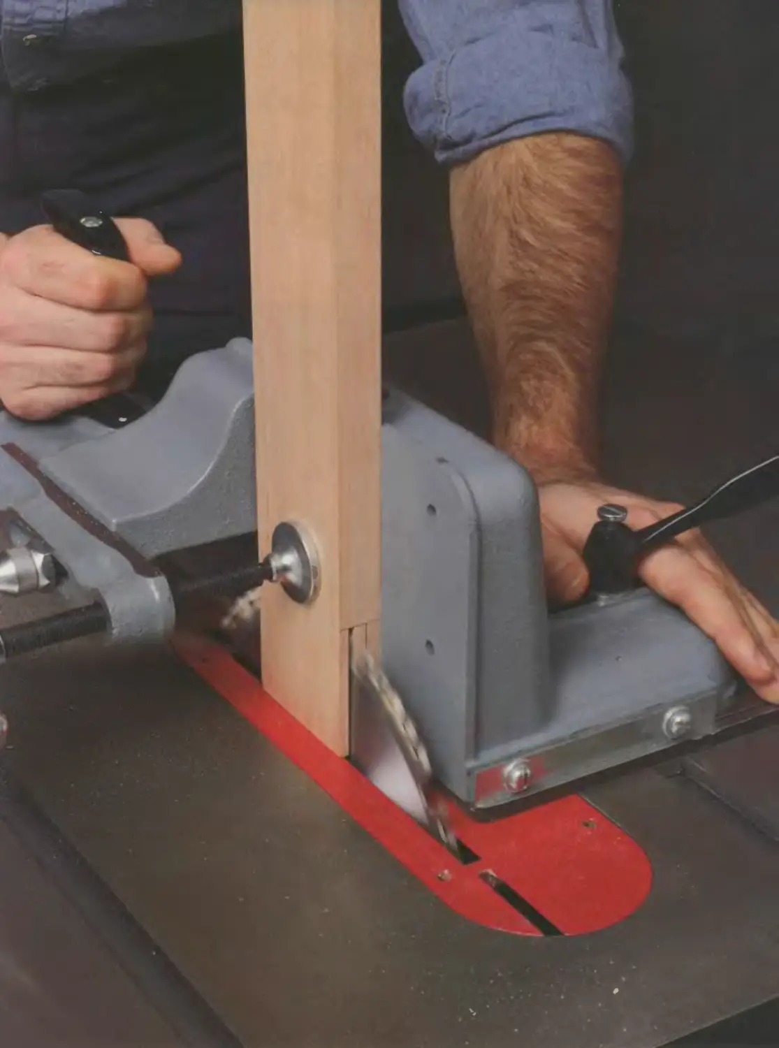
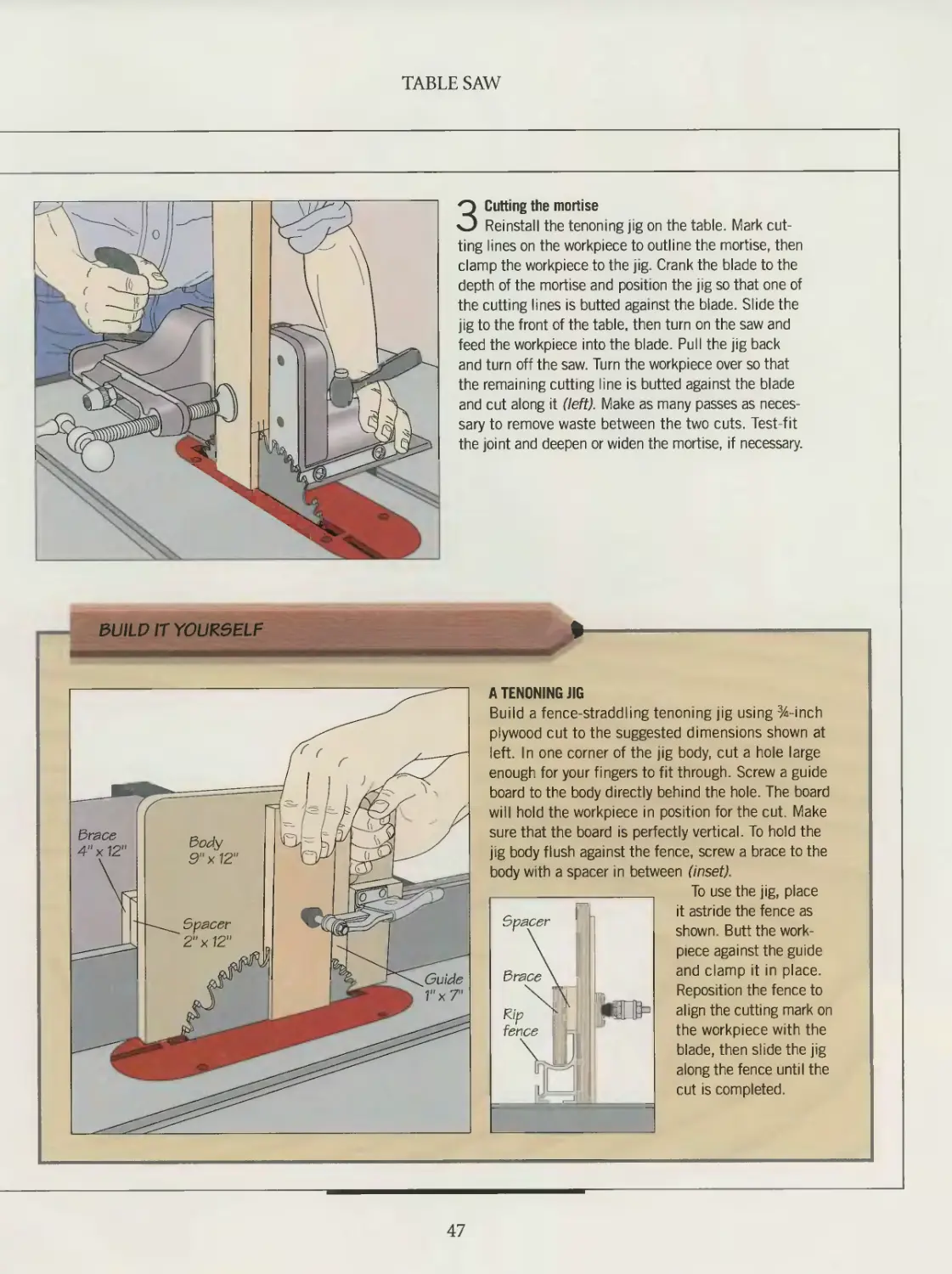
With a workpiece clamped firmly to a tenoning
jig, a woodworker cuts the tenon part of an open
mortise-and-tenon joint. The jig is guided by a
rail that slides in the saw table's miter gauge slot.
13
ANATOMY OF A TABLE SAW
Blade
angle
scale
Vacuum
attachment
For dust col-
lection system
Lock knob
Holds crank
at fixed set-
ting; tight-
ened firmly
before saw
is operated
On/off switch
Magnetic
switch turns
ff saw if
machine is
unplugged
Auxiliary table inserts
Keep wood pieces from
falling into table; wider
slots for dado or mold-
ing heads
Rip fence
Guides workpiece
across table \
for rippmg
Blade guard
Clear shield that
protects operator
from blade; bolted
to splitter and
anti-kickback device
Blade height
adjustment
crank |
Standard
table insert
Keeps wood
pieces from
falling into table
Mobile base
Facilitates moving the
saw aside in small
shops; wheels can be
locked in position
Blade angle
adjustment
crank
Roller stand
Supports long work- .
pieces during cutting
operations
Miter gauge
Guides workpiece across table for cross-
cutting; wooden extension can be screwed
to gauge to support wide pieces
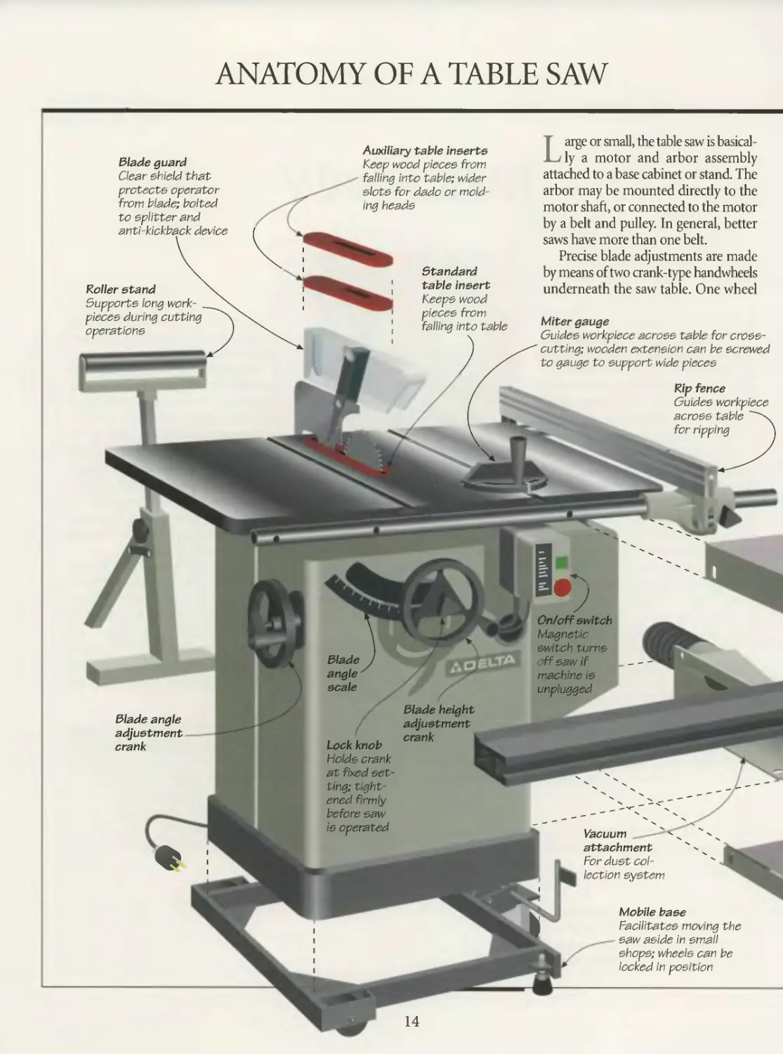
Large or small, the table saw is basical-
ly a motor and arbor assembly
attached to a base cabinet or stand. The
arbor may be mounted directly to the
motor shaft, or connected to the motor
by a belt and pulley. In general, better
saws have more than one belt.
Precise blade adjustments are made
by means of two crank-type handwheels
underneath the saw table. One wheel
TABLE SAW
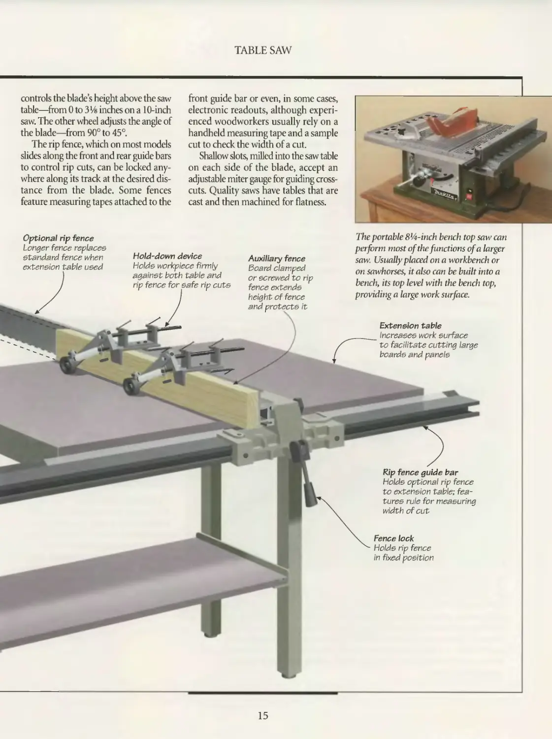
controls the blade s height above the saw
table—from 0 to 3l/s inches on a 10-inch
saw. The other wheel adjusts the angle of
the blade—from 90° to 45°.
The rip fence, which on most models
slides along the front and rear guide bars
to control rip cuts, can be locked any-
where along its track at the desired dis-
tance from the blade. Some fences
feature measuring tapes attached to the
Optional rip fence
Longer fence replaces
standard fence when
extension table used
Hold-down device
Holds workpiece firmly
against both table and
rip fence for safe rip cuts
Extension table
Increases work surface
to facilitate cutting large
boards and panels
Fence lock
Holds rip fence
in fixed position
fZip fence guide bar
Holds optional rip fence
to extension table; fea-
tures rule for measuring
width of cut
front guide bar or even, in some cases,
electronic readouts, although experi-
enced woodworkers usually rely on a
handheld measuring tape and a sample
cut to check the width of a cut.
Shallow slots, milled into the saw table
on each side of the blade, accept an
adjustable miter gauge for guiding cross-
cuts. Quality saws have tables that are
cast and then machined for flatness.
Auxiliary fence
Board clamped
or screwed to rip
fence extends
height of fence
it
The portable Sl^-inch bench top saw can
perform most of the functions of a large
saw. Usually placed on a workbench or
on sawhorses, it also can be built into a
bench, its top level with the bench top,
providing a large work surface.
r
15
SETTING UP
Whether your table saw sits poised
to make its first cut, or is a sea-
soned machine with a home full of fur-
niture to its credit, it cannot cut with
precision unless its adjustable parts are
in proper alignment. A table saw with
misaligned parts can result in any one of
several frustrating problems, including
excessive vibration, increased risk of
kickback, blade damage, burn marks on
workpieces as well as inaccurate cuts.
Even errors as little as 1/ы inch can com-
promise the quality and strength of a
piece of furniture.
The components of your table saw
requiring the most attention are those
that contact and guide the workpiece
during cutting operations: the saw table,
the blade, the miter gauge and the rip
fence. Before putting a table saw through
its paces on the cutting techniques
described in this chapter, first set up the
machine properly by checking and, if
necessary, adjusting the alignment of its
parts. For best results, unplug the saw,
adjust the table insert setscrews to make
the insert perfectly flush with the saw
table, and crank the blade to its highest
setting. Then follow the steps shown
below in the sequence that they appear.
There is little point in aligning the miter
gauge with the saw blade, for example, if
the blade itself has not been squared with
the table.
To confirm that your table saw is
properly tuned, make a few test cuts. A
good way to ensure that your saw is cut-
ting in precise, straight lines is to cut a
squared board in two and flip one of the
pieces over. Butt the two cut ends togeth-
er. They should fit together without any
gaps as perfectly as they did before the
board was flipped.
Because the normal vibration from
cutting can upset proper alignment, tune
your table saw periodically; many wood-
workers take the time to adjust their saws
before starting each project.
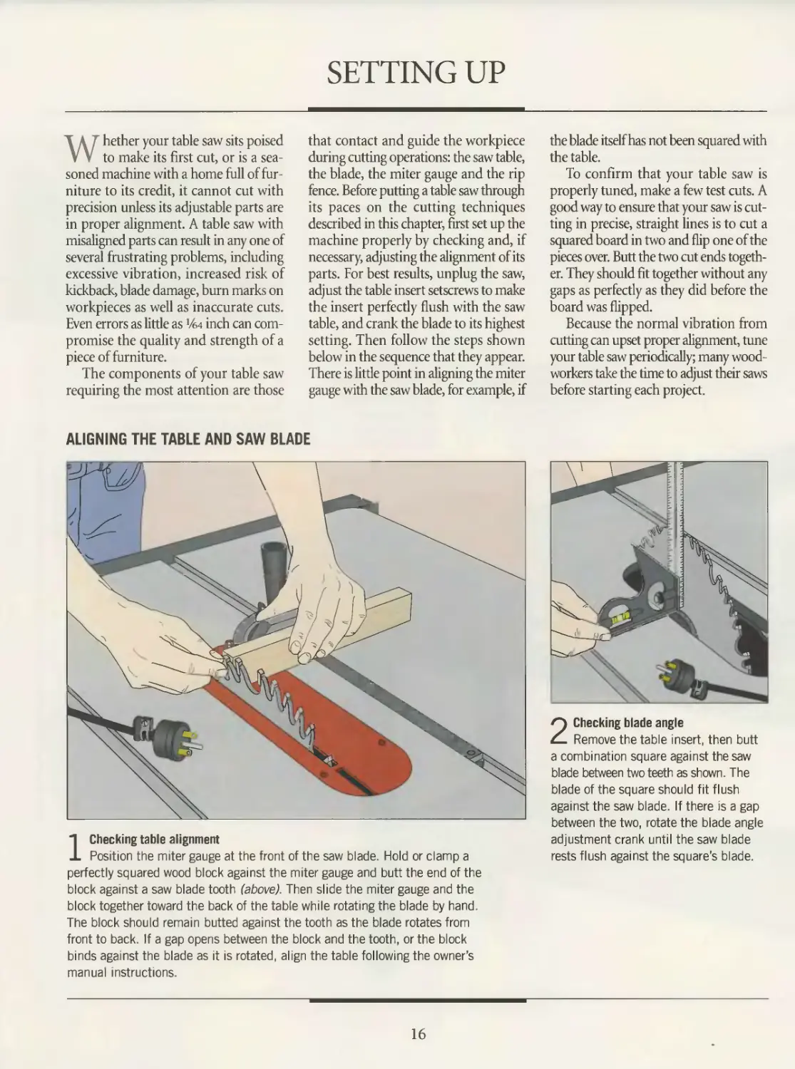
ALIGNING THE TABLE AND SAW BLADE
1 Checking table alignment
Position the miter gauge at the front of the saw blade. Hold or clamp a
perfectly squared wood block against the miter gauge and butt the end of the
block against a saw blade tooth (above). Then slide the miter gauge and the
block together toward the back of the table while rotating the blade by hand.
The block should remain butted against the tooth as the blade rotates from
front to back. If a gap opens between the block and the tooth, or the block
binds against the blade as it is rotated, align the table following the owner’s
manual instructions.
2 Checking blade angle
Remove the table insert, then butt
a combination square against the saw
blade between two teeth as shown. The
blade of the square should fit flush
against the saw blade. If there is a gap
between the two, rotate the blade angle
adjustment crank until the saw blade
rests flush against the square's blade.
16
TABLE SAW
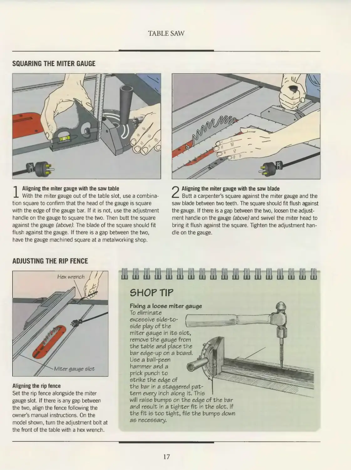
SQUARING THE MITER GAUGE
1 Aligning the miter gauge with the saw table
With the miter gauge out of the table slot, use a combina-
tion square to confirm that the head of the gauge is square
with the edge of the gauge bar. If it is not, use the adjustment
handle on the gauge to square the two. Then butt the square
against the gauge (above). The blade of the square should fit
flush against the gauge. If there is a gap between the two,
have the gauge machined square at a metalworking shop.
2 Aligning the miter gauge with the saw blade
Butt a carpenter’s square against the miter gauge and the
saw blade between two teeth. The square should fit flush against
the gauge. If there is a gap between the two, loosen the adjust-
ment handle on the gauge (above) and swivel the miter head to
bring it flush against the square. Tighten the adjustment han-
dle on the gauge.
ADJUSTING THE RIP FENCE
Ш hi in in щ in m in ш Ш in in m ш ш in m in
SHOP TIP
Fixing a loose miter gauge
To eliminate
excessive side-to- f
side play of the
miter gauge in its slot,
remove the gauge from
the table and place the
bar edge-up on a board.
Use a ball-peen
hammer and a
prick punch to
strike the edge of
the bar in a staggered pat-
tern every inch along it. This
Aligning the rip fence
Set the rip fence alongside the miter
gauge slot. If there is any gap between
the two, align the fence following the
owner’s manual instructions. On the
model shown, turn the adjustment bolt at
the front of the table with a hex wrench.
will raise bumps on the edge of the bar
and result in a tighter fit in the slot. If
the fit is too tight, file the bumps down
as necessary.
17
SAFETY
Safety is as much a matter of attitude
and common sense as correct tech-
nique. The table saw is a powerful
machine; all the safety devices in the
world will not make up for a cavalier atti-
tude or sloppy work practices. On the
other hand, a woodworker should not
approach a table saw with trepidation; a
timid operator, someone reluctant to
hold a workpiece firmly while cutting it,
faces as many risks as a careless worker.
Caution mixed with confidence stem-
ming from an understanding of the
machine and the task at hand should be
the woodworker’s guide.
Read the owner’s manual supplied
with your saw. Before starting a job,
make sure you know how to use the safe-
ty accessories that are designed to protect
you from specific injuries while operat-
ing the machine. Use devices like push
sticks and featherboards, as shown
throughout this chapter, to protect your
fingers from the blade. A hold-down
device, such as the one illustrated on
page 25, is also a worthwhile investment.
And remember that not only your fin-
gers and hands are at risk: A safe work-
shop also includes hearing protectors,
safety glasses and dust masks.
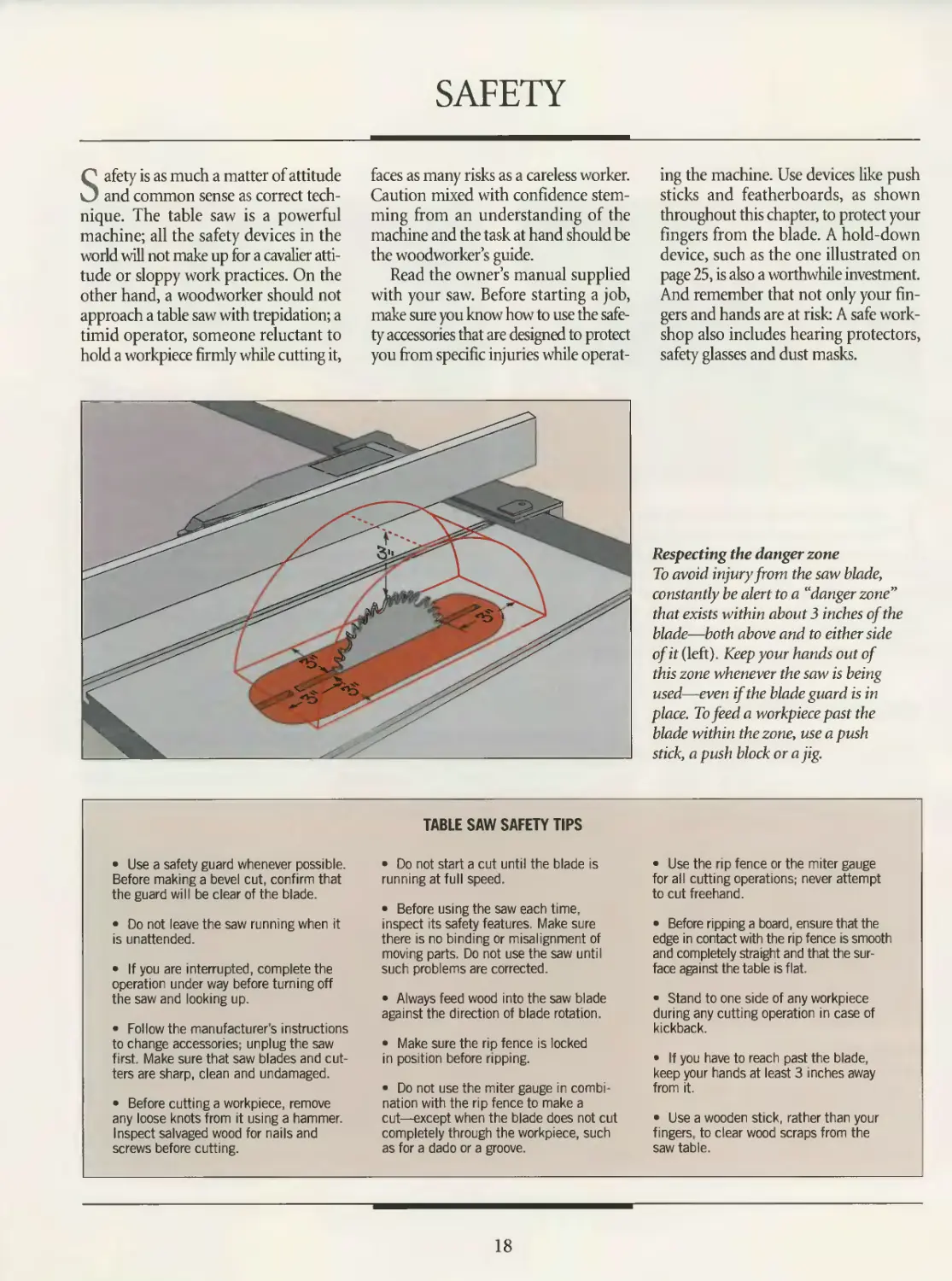
Respecting the danger zone
To avoid injury from the saw blade,
constantly be alert to a “danger zone”
that exists within about 3 inches of the
blade—both above and to either side
of it (left). Keep your hands out of
this zone whenever the saw is being
used—even if the blade guard is in
place. To feed a workpiece past the
blade within the zone, use a push
stick, a push block or a jig.
• Use a safety guard whenever possible.
Before making a bevel cut, confirm that
the guard will be clear of the blade.
• Do not leave the saw running when it
is unattended.
• If you are interrupted, complete the
operation under way before turning off
the saw and looking up.
• Follow the manufacturer's instructions
to change accessories; unplug the saw
first. Make sure that saw blades and cut-
ters are sharp, clean and undamaged.
• Before cutting a workpiece, remove
any loose knots from it using a hammer.
Inspect salvaged wood for nails and
screws before cutting.
TABLE SAW SAFETY TIPS
• Do not start a cut until the blade is
running at full speed.
• Before using the saw each time,
inspect its safety features. Make sure
there is no binding or misalignment of
moving parts. Do not use the saw until
such problems are corrected.
• Always feed wood into the saw blade
against the direction of blade rotation.
• Make sure the rip fence is locked
in position before ripping.
• Do not use the miter gauge in combi-
nation with the rip fence to make a
cut—except when the blade does not cut
completely through the workpiece, such
as for a dado or a groove.
• Use the rip fence or the miter gauge
for all cutting operations; never attempt
to cut freehand.
• Before ripping a board, ensure that the
edge in contact with the rip fence is smooth
and completely straight and that the sur-
face against the table is flat.
• Stand to one side of any workpiece
during any cutting operation in case of
kickback.
• If you have to reach past the blade,
keep your hands at least 3 inches away
from it.
• Use a wooden stick, rather than your
fingers, to clear wood scraps from the
saw table.
18
TABLE SAW
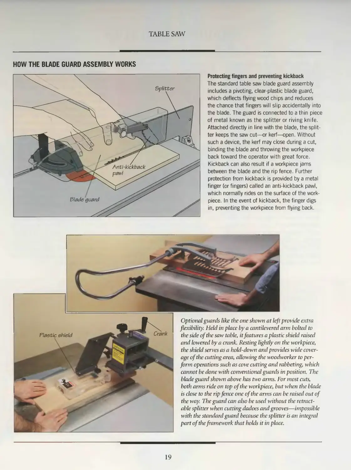
HOW THE BLADE GUARD ASSEMBLY WORKS
Protecting fingers and preventing kickback
The standard table saw blade guard assembly
includes a pivoting, clear-plastic blade guard,
which deflects flying wood chips and reduces
the chance that fingers will slip accidentally into
the blade. The guard is connected to a thin piece
of metal known as the splitter or riving knife.
Attached directly in line with the blade, the split-
ter keeps the saw cut—or kerf—open. Without
such a device, the kerf may close during a cut,
binding the blade and throwing the workpiece
back toward the operator with great force.
Kickback can also result if a workpiece jams
between the blade and the rip fence. Further
protection from kickback is provided by a metal
finger (or fingers) called an anti-kickback pawl,
which normally rides on the surface of the work-
piece. In the event of kickback, the finger digs
in, preventing the workpiece from flying back.
Optional guards like the one shown at left provide extra
flexibility. Held in place by a cantilevered arm bolted to
the side of the saw table, it features a plastic shield raised
and lowered by a crank. Resting lightly on the workpiece,
the shield serves as a hold-down and provides wide cover-
age of the cutting area, allowing the woodworker to per-
form operations such as cove cutting and rabbeting, which
cannot be done with conventional guards in position. The
blade guard shown above has two arms. For most cuts,
both arms ride on top of the workpiece, but when the blade
is close to the rip fence one of the arms can be raised out of
the way. The guard can also be used without the retract-
able splitter when cutting dadoes and grooves—impossible
with the standard guard because the splitter is an integral
part of the framework that holds it in place.
19
TABLE SAW BLADES
A table saw is only as good as the saw
blade it turns. A dull or chipped
blade can transform even the best of
table saws into a poor or even dangerous
tool. To protect blades from damage,
avoid stacking them directly atop each
other. Hang them individually on hooks
or place cardboard between them.
Replace a blade that is dull or cracked or
has chipped teeth; more accidents are
caused by dull blades than sharp ones.
Keep your saw blades clean. Wood resins
can gum up a blade and hamper its ability
to make a smooth cut To clean sticky wood
resin and pitch off a blade, soak it in turpen-
tine, then scrub it with steel wool. Spray-on
oven cleaner can be used to dissolve stub-
born deposits.
Proper blade performance is as much
a mattei of using the right blade for the
job as keeping it clean and in good con-
dition. Whereas in the past there were
relatively few saw blades to choose from,
today’s woodworker faces a wide array of
options. As illustrated below, there are
blades designed specifically for crosscut-
ting or ripping, others to minimize kick-
back or produce thin kerfs, and blades
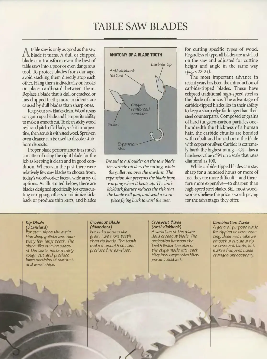
Brazed to a shoulder on the saw blade,
the carbide tip does the cutting, while
the gullet removes the sawdust. The
expansion slot prevents the blade from
warping when it heats up. The anti-
kickbackfeature reduces the risk that
the blade will jam, and send a work-
pieceflying back toward the user.
for cutting specific types of wood.
Regardless of type, all blades are installed
on the saw and adjusted for cutting
height and angle in the same way
(pages 22-23).
The most important advance in
recent years has been the introduction of
carbide-tipped blades. These have
eclipsed traditional high-speed steel as
the blade of choice. The advantage of
carbide-tipped blades lies in their ability
to keep a sharp edge far longer than their
steel counterparts. Composed of grains
of hard tungsten-carbon particles one-
hundredth the thickness of a human
hair, the carbide chunks are bonded
with cobalt and brazed onto the blade
with copper or silver. Carbide is extreme-
ly hard; the highest rating—C4—has a
hardness value of 94 on a scale that rates
diamond as 100.
While carbide-tipped blades can stay
sharp for a hundred hours or more of
use, they are more difficult—and there-
fore more expensive—to sharpen than
high-speed steel blades. Still, most wood-
workers believe the price is worth paying
for the advantages they offer.
Rip blade
(Standard)
For cuts along the grain.
Has deep gullets and rela-
tively few, large teeth. The
chisel-like cutting edges
of the teeth make a fairly
rough cut and produce
large particles of sawdust
and wood chips.
Crosscut Slade
(Standard)
For cuts across the
grain. Has more teeth
than rip blade. The teeth
make a smooth cut and
produce fine sawdust.
Crosscut Slade
(Anti-Kickback)
A variation of the stan-
dard crosscut blade. The
projection between the
teeth limits the size of
the chips made with each
bite; less aggressive bites
prevent kickback.
Combination Slade
A general-purpose blade
for ripping or crosscut-
ting; does not make as
smooth a out as a rip
or crosscut blade, but
makes frequent blade
changes unnecessary.
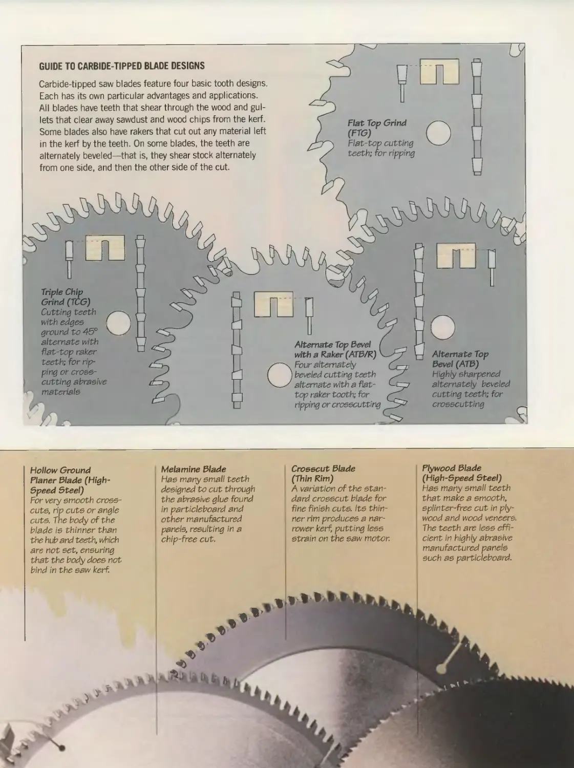
GUIDE TO CARBIDE-TIPPED BLADE DESIGNS
Carbide-tipped saw blades feature four basic tooth designs.
Each has its own particular advantages and applications.
All blades have teeth that shear through the wood and gul-
lets that clear away sawdust and wood chips from the kerf.
Some blades also have rakers that cut out any material left
in the kerf by the teeth. On some blades, the teeth are
alternately beveled—that is, they shear stock alternately
from one side, and then the other side of the cut.
Flat Top Grind
(FTG)
Flat-top cutting
teeth; for ripp:ng
Triple Chip
Grind (TCG)
Cutting teeth
with edges 1
ground to 45°
alternate with
flat-top raker
teeth; for rip-
ping or cross-
cutting abrasive
materials
Alternate Top Bevel /
with a Raker (ATB/R) '
Four alternately
beveled cutting teeth
alternate with a flat-
top raker tooth; for
ripping or crosscutting
Highly sharpened
alternately beveled
cutting teeth; for
crosscutting
Hollow Ground
Planer Blade (High-
Speed Steel)
For very smooth cross-
cuts, rip cuts or angle
cuts. The body of the
blade is thinner than
the hub and teeth, which
are not set, ensuring
that the body does not
bind in the saw kerf.
Melamine Blade
Has many small teeth
designed to cut through
the abrasive glue found
in particleboard and
other manufactured
panels, resulting in a
chip-free cut.
Crosscut Blade
(Thin Rim)
A variation of the stan-
dard crosscut blade for
fine finish cute, its thin-
ner rim produces a nar-
rower kerf, putting less
strain on the saw motor.
Plywood Blade
(High-Speed Bteel)
Has many small teeth
that make a smooth,
splinter-free cut in ply-
wood and wood veneers.
The teeth are less effi-
cient in highly abrasive
manufactured panels
such as particleboard.
TABLE SAW
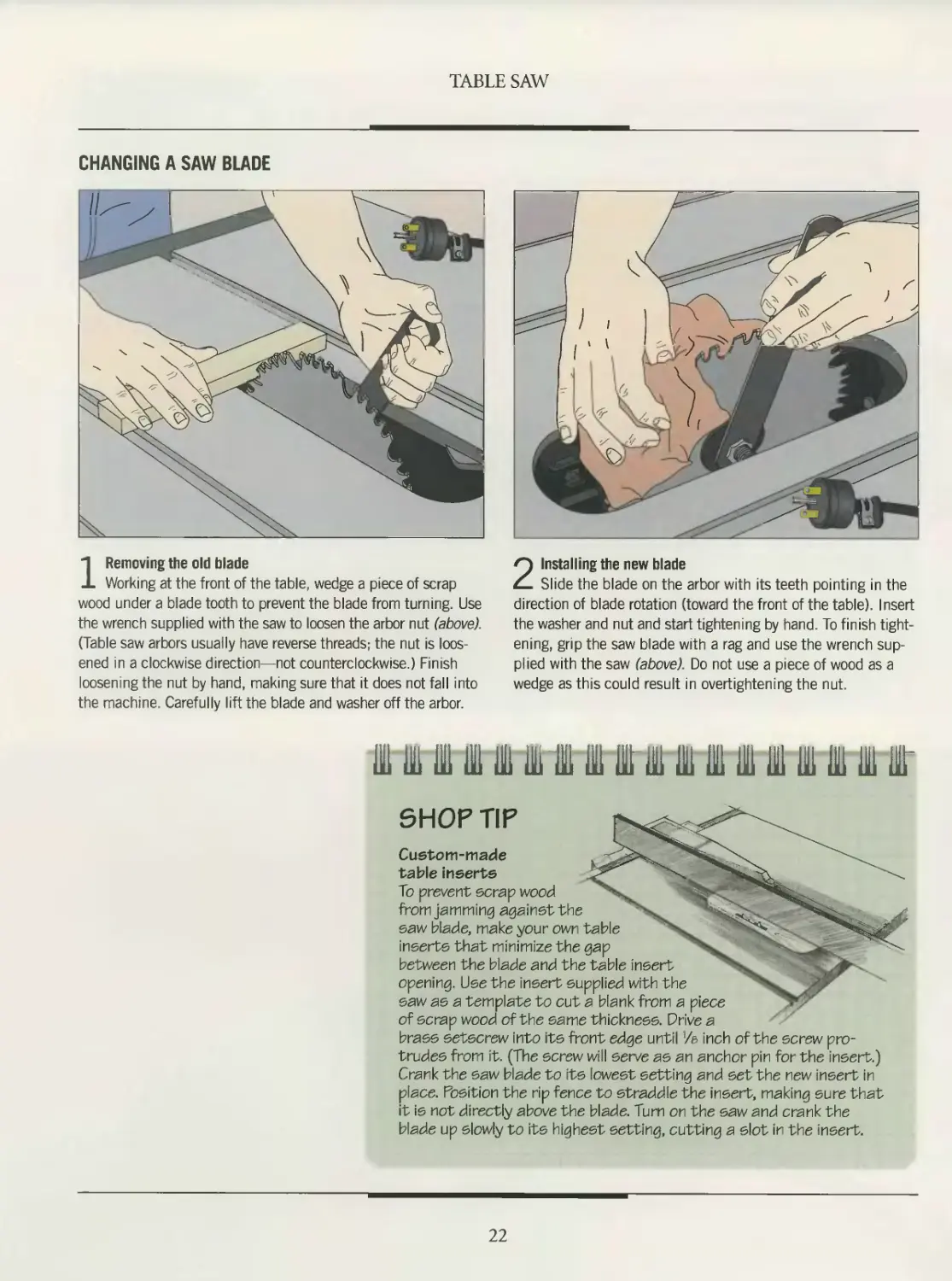
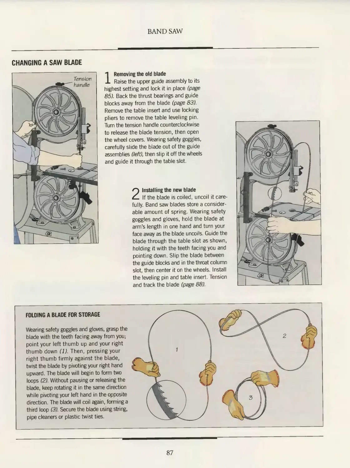
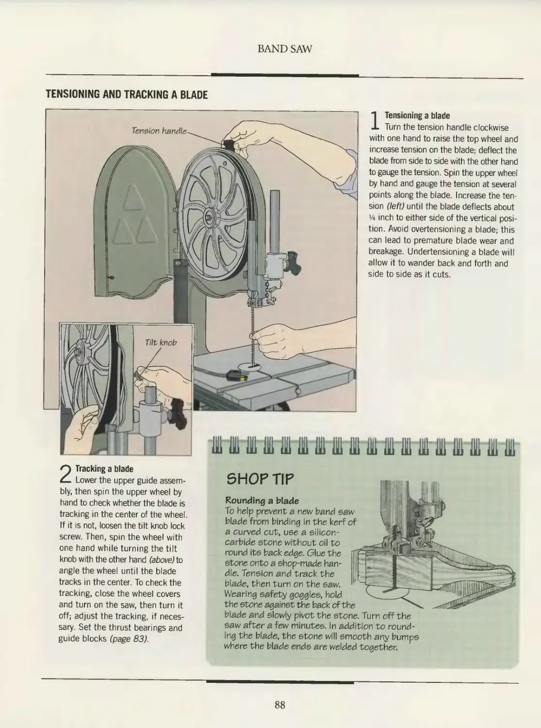
CHANGING A SAW BLADE
1 Removing the old blade
Working at the front of the table, wedge a piece of scrap
wood under a blade tooth to prevent the blade from turning. Use
the wrench supplied with the saw to loosen the arbor nut (above).
(Table saw arbors usually have reverse threads; the nut is loos-
ened in a clockwise direction—not counterclockwise.) Finish
loosening the nut by hand, making sure that it does not fall into
the machine. Carefully lift the blade and washer off the arbor.
2 Installing the new blade
Slide the blade on the arbor with its teeth pointing in the
direction of blade rotation (toward the front of the table). Insert
the washer and nut and start tightening by hand. To finish tight-
ening, grip the saw blade with a rag and use the wrench sup-
plied with the saw (above). Do not use a piece of wood as a
wedge as this could result in overtightening the nut.
Ill 111 ill to ill to 1 111 Hi ill 1111 Hi 111 111 HI ilrt
SHOP TIP
Custom-made
table inserts
To prevent scrap wood
from jamming againstthe
saw blade, make your own table
inserts that minimize the gap
between the blade and the table insert
opening. Use the insert supplied with the
saw as a template to cut a blank from a piece
of scrap wood of the same thickness. Drive a
brass setscrew into its front edge until '/e inch of the screw pro-
trudes from it. (The screw will serve as an anchor pin for the insert.)
Crank the saw blade to its lowest setting and set the new insert in
place. Position the rip fence to straddle the insert, making sure that
it is not directly above the blade. Turn on the saw and crank the
blade up slowly to its highest setting, cutting a slot in the insert.
22
TABLE SAW
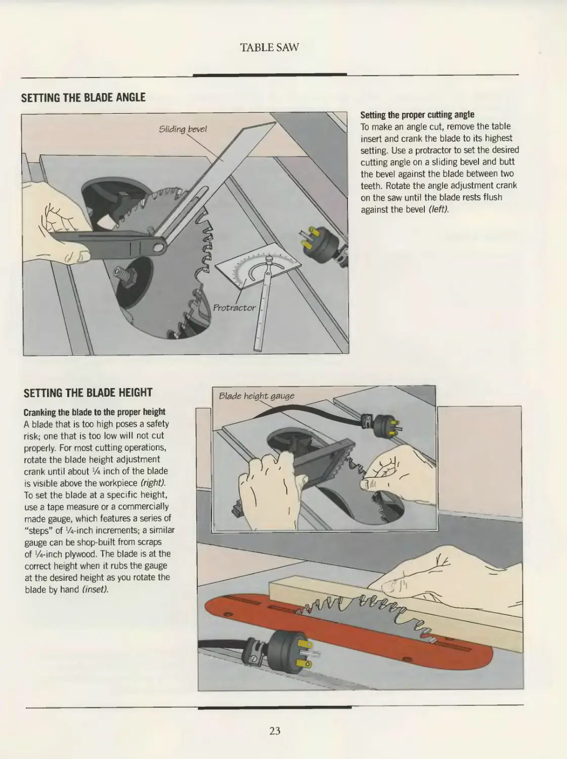
SETTING THE BLADE ANGLE
Setting the proper cutting angle
To make an angle cut, remove the table
insert and crank the blade to its highest
setting. Use a protractor to set the desired
cutting angle on a sliding bevel and butt
the bevel against the blade between two
teeth. Rotate the angle adjustment crank
on the saw until the blade rests flush
against the bevel (left).
SETTING THE BLADE HEIGHT
Cranking the blade to the proper height
A blade that is too high poses a safety
risk, one that is too low will not cut
properly. For most cutting operations,
rotate the blade height adjustment
crank until about A inch of the blade
is visible above the workpiece (right)
To set the blade at a specific height,
use a tape measure or a commercially
made gauge, which features a series of
“steps" of Winch increments; a similar
gauge can be shop-built from scraps
of Winch plywood. The blade is at the
correct height when it rubs the gauge
at the desired height as you rotate the
blade by hand (inset).
23
RIPPING
Ripping has traditionally been
defined as “cutting with the grain.”
But considering that some woods
today—plywood and particleboard, for
example—have no overall grain pattern,
the definition needs some amending. A
more appropriate description focuses on
the table saw accessory used to make a
rip cut. Whereas crosscutting is done
using the miter gauge, ripping involves
the rip fence. (Except for certain cuts that
do not pass completely through the
workpiece, such as a dado cut, the rip
fence and miter gauge should never be
used at the same time, or jamming and
kickback can occur.)
Before ripping a workpiece, set the
height of the saw blade (page 23), then
lock the rip fence in position for the
width of cut. The most crucial safety
concern when ripping is keeping your
hands out of the blade s path. For protec-
tion, use accessories such as push sticks,
featherboards and hold-down devices.
To use a hold-down device, it may
first be necessary to screw a wood aux-
iliary fence to the rip fence. Auxiliary
fences are ideal surfaces for clamping;
many woodworkers make them a per-
manent fixture on their saws.
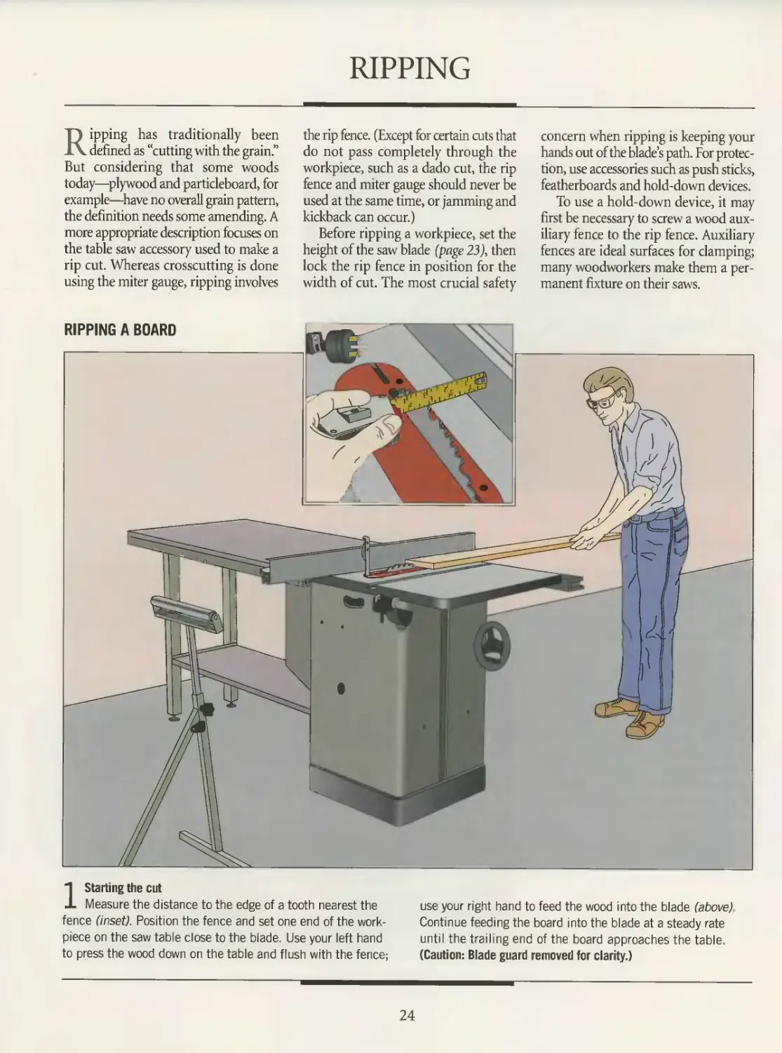
1 Starting the cut
Measure the distance to the edge of a tooth nearest the
fence (inset). Position the fence and set one end of the work-
piece on the saw table close to the blade. Use your left hand
to press the wood down on the table and flush with the fence;
use your right hand to feed the wood into the blade (above)
Continue feeding the board into the blade at a steady rate
until the trailing end of the board approaches the table.
(Caution: Blade guard removed for clarity.)
24
TABLE SAW
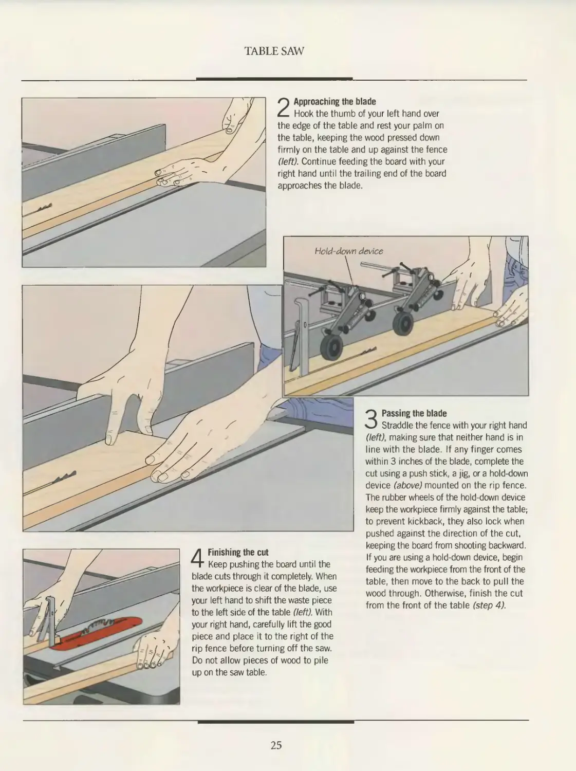
2 Approaching the blade
Hook the thumb of your left hand over
the edge of the table and rest your palm on
the table, keeping the wood pressed down
firmly on the table and up against the fence
(left). Continue feeding the board with your
right hand until the trailing end of the board
approaches the blade.
3 Passing the blade
Straddle the fence with your right hand
(left), making sure that neither hand is in
line with the blade. If any finger comes
within 3 inches of the blade, complete the
cut using a push stick, a jig, or a hold-down
device (above) mounted on the rip fence.
The rubber wheels of the hold-down device
keep the workpiece firmly against the table;
to prevent kickback, they also lock when
pushed against the direction of the cut,
4 Finishing the cut
Keep pushing the board until the
blade cuts through it completely. When
the workpiece is clear of the blade, use
your left hand to shift the waste piece
to the left side of the table (left). With
your right hand, carefully lift the good
piece and place it to the right of the
rip fence before turning off the saw.
Do not allow pieces of wood to pile
up on the saw table.
keeping the board from shooting backward.
If you are using a hold-down device, begin
feeding the workpiece from the front of the
table, then move to the back to pull the
wood through. Otherwise, finish the cut
from the front of the table (step 4).
25
TABLE SAW
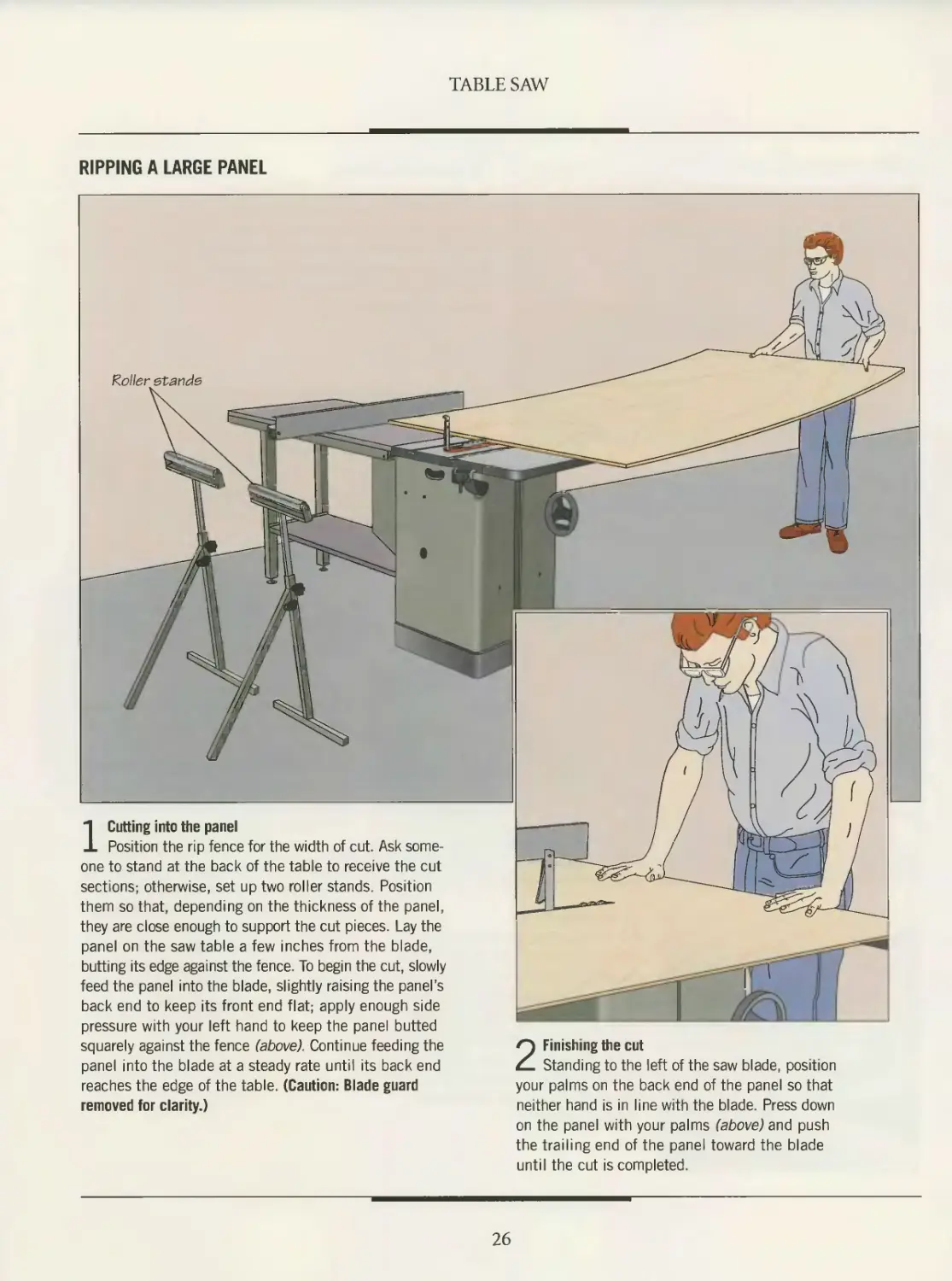
RIPPING A LARGE PANEL
Roller stands
1 Cutting into the panel
Position the rip fence for the width of cut. Ask some-
one to stand at the back of the table to receive the cut
sections; otherwise, set up two roller stands. Position
them so that, depending on the thickness of the panel,
they are close enough to support the cut pieces. Lay the
panel on the saw table a few inches from the blade,
butting its edge against the fence. To begin the cut, slowly
feed the panel into the blade, slightly raising the panel’s
back end to keep its front end flat; apply enough side
pressure with your left hand to keep the panel butted
squarely against the fence (above). Continue feeding the
panel into the blade at a steady rate until its back end
reaches the edge of the table. (Caution: Blade guard
2 Finishing the cut
Standing to the left of the saw blade, position
your palms on the back end of the panel so that
removed for clarity.)
neither hand is in line with the blade. Press down
on the panel with your palms (above) and push
the trailing end of the panel toward the blade
until the cut is completed.
26
TABLE SAW
RIPPING A NARROW STRIP
Using a featherboard and push stick
Position the rip fence for the width of
cut. Then butt the workpiece against the
fence. To keep your hands away from
the blade as it cuts the workpiece, use
two accessories—a featherboard and a
push stick. Clamp a featherboard to the
saw table—the model shown is installed
in the miter slot—so that its fingers hold
the workpiece snugly against the fence.
Use a push stick as shown to feed
the workpiece into the blade. Continue
cutting steadily until the blade nears
the end of the cut. Support the waste
piece with your left hand; to prevent
your hand from being pulled back into
the blade in case of kickback, curl your
fingers around the edge of the table (left).
(Caution: Blade guard removed for clarity.)
BUILD IT YOURSELF
A JIG FOR MAKING REPEAT NARROW CUTS
To rip several narrow strips to the same width, use the
shopmade jig shown at left. For the jig, cut a board with
a lip at one end. Screw a hold-down block to the jig, then
butt the jig flush against the rip fence. Mark a cutting line
on the workpiece, then seat it against the jig, flush with the
lip. Position the rip fence so that the cutting line on the
workpiece is aligned with the saw blade.
To make each cut, slide the jig and the workpiece as a
unit across the table, feeding the workpiece into the blade
(left). (The first cut will trim the lip to the width of the cut.)
Use your left hand to keep the workpiece flush against the
jig. Remove the cut strip, reposition the workpiece in the
j:g, and repeat for identical strips. (Caution: Blade guard
removed for clarity.)
27
TABLE SAW
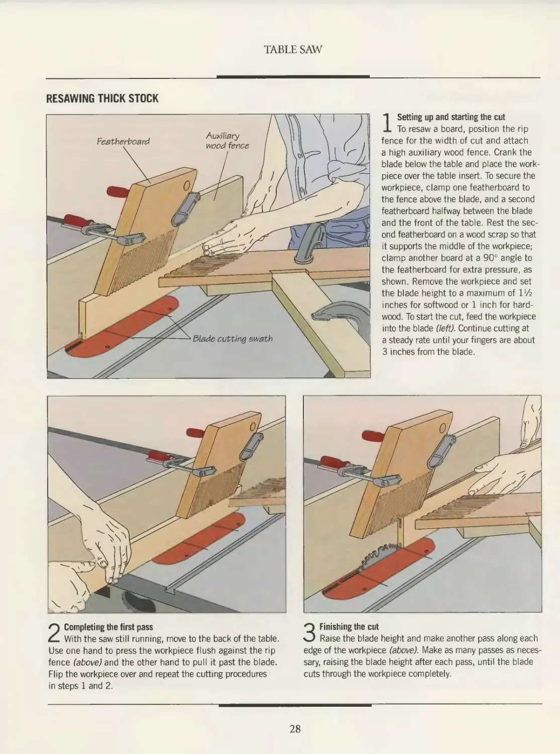
RESAWING THICK STOCK
1 Setting up and starting the cut
To resaw a board, position the rip
fence for the width of cut and attach
a high auxiliary wood fence. Crank the
blade below the table and place the work-
piece over the table insert. To secure the
workpiece, clamp one featherboard to
the fence above the blade, and a second
featherboard halfway between the blade
and the front of the table. Rest the sec-
ond featherboard on a wood scrap so that
it supports the middle of the workpiece;
clamp another board at a 90° angle to
the featherboard for extra pressure, as
shown. Remove the workpiece and set
the blade height to a maximum of I1/?
inches for softwood or 1 inch for hard-
wood. To start the cut, feed the workpiece
into the blade (left). Continue cutting at
a steady rate until your fingers are about
3 inches from the blade.
2 Completing the first pass
With the saw still running, move to the back of the table.
Use one hand to press the workpiece flush against the rip
fence (above) and the other hand to pull it past the blade.
Flip the workpiece over and repeat the cutting procedures
in steps 1 and 2.
3 Finishing the cut
Raise the blade height and make another pass along each
edge of the workpiece (above). Make as many passes as neces-
sary, raising the blade height after each pass, until the blade
cuts through the workpiece completely.
28
TABLE SAW
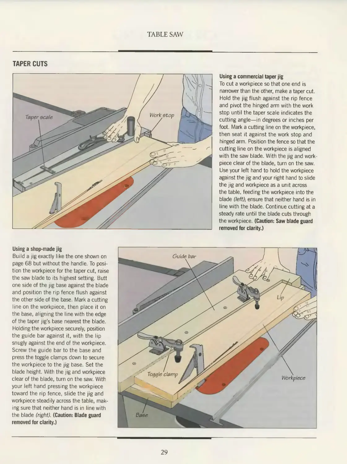
TAPER CUTS
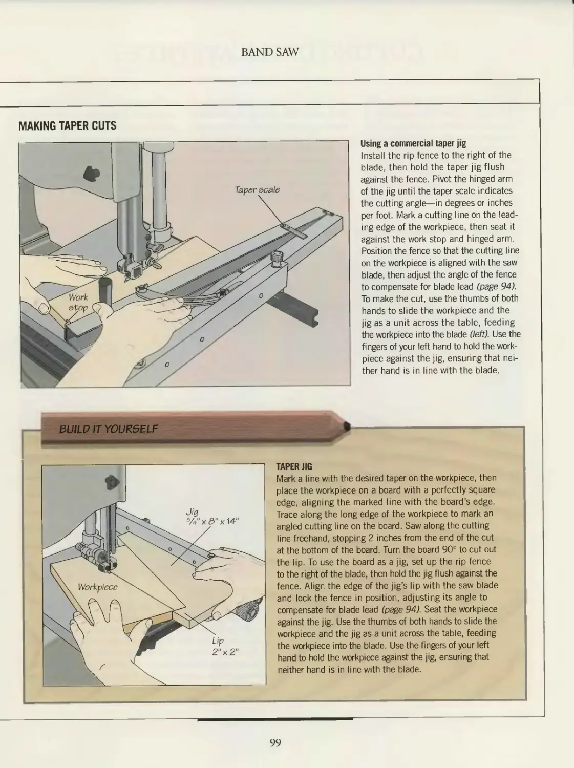
Using a commercial taper jig
To cut a workpiece so that one end is
narrower than the other, make a taper cut.
Hold the jig flush against the rip fence
and pivot the hinged arm with the work
stop until the taper scale indicates the
cutting angle—in degrees or inches per
foot. Mark a cutting line on the workpiece,
then seat it against the work stop and
hinged arm Position the fence so that the
cutting line on the workpiece is aligned
with the saw blade. With the jig and work-
piece clear of the blade, turn on the saw.
Use your left hand to hold the workpiece
against the jig and your right hand to slide
the jig and workpiece as a unit across
the table, feeding the workpiece into the
blade (left); ensure that neither hand is in
line with the blade. Continue cutting at a
steady rate until the blade cuts through
the workpiece. (Caution: Saw blade guard
removed for clarity.)
Using a shop-made jig
Build a jig exactly like the one shown on
page 68 but without the handle. To posi-
tion the workpiece for the taper cut, raise
the saw blade to its highest setting. Butt
one side of the jig base against the blade
and position the rip fence flush against
the other side of the base. Mark a cutting
line on the workpiece, then place it on
the base, aligning the line with the edge
of the taper jigs base nearest the blade.
Holding the workpiece securely, position
the guide bar against it, with the lip
snugly against the end of the workpiece.
Screw the guide bar to the base and
press the toggle clamps down to secure
the workpiece to the jig base. Set the
blade height. With the jig and workpiece
clear of the blade, turn on the saw. With
your left hand pressing the workpiece
toward the rip fence, slide the jig and
workpiece steadily across the table, mak-
ing sure that neither hand is in line with
the blade (right). (Caution: Blade guard
removed for clarity.)
29
CROSSCUTTING
As cutting with the grain is synony-
mous with the use of the rip fence,
so crosscutting is defined by the device
used to make the cut: the miter gauge.
The general technique for making a
crosscut, as shown below, begins with
correct hand placement to keep the
workpiece both flush on the table and
firmly against the miter gauge. The
workpiece is fed into the blade at a steady
rate. As with ripping, make sure that
scrap pieces do not pile up on the table,
and keep both hands out of line with the
blade. Also, keep the rip fence well back
from the blade to prevent any cut-off
part of the workpiece from becoming
trapped between the blade and fence and
kicking back.
To reduce the amount of sanding you
will need to do later, remember that the
slower the feed, the smoother the cut,
especially when the blade breaks through
the workpiece at the end of the cut.
Although a combination blade can be
used for crosscutting, a crosscut blade
will produce a finer cut.
When a longer workpiece is being cut,
it is a good idea to attach an extension to
the miter gauge to provide a more secure
base. Miter gauges commonly have
two screw holes for just such an addi-
tion—normally, a piece of hardwood
3 to 4 inches wide and about 2 feet long.
Use the miter gauge extension in con-
junction with a stop block to make
repeat cuts (page 32).
For wide panels or long boards, a
shop-made crosscutting jig (page 33) is
particularly helpful, and will ensure very
accurate cuts. The jig can also be used for
smaller pieces and provides a safe, con-
venient way to perform most crosscuts.
Many experienced woodworkers consid-
er it the single most indispensable acces-
sory for crosscutting.
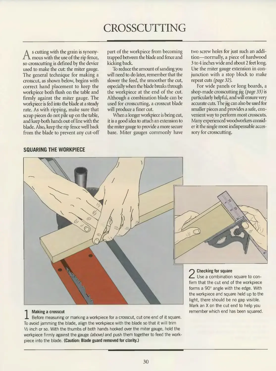
SQUARING THE WORKPIECE
2 Checking for square
Use a combination square to con-
firm that the cut end of the workpiece
forms a 90° angle with the edge. With
the workpiece and square held up to the
light, there should be no gap visible.
Mark an X on the cut end to help you
1 Making a crosscut
Before measuring or marking a workpiece for a crosscut, cut one end of it square.
To avoid jamming the blade, align the workpiece with the blade so that it will trim
*/2 inch or so. With the thumbs of both hands hooked over the miter gauge, hold the
workpiece firmly against the gauge (above) and push them together to feed the work-
piece into the blade. (Caution: Blade guard removed for clarity.)
remember which end has been squared.
30
TABLE SAW
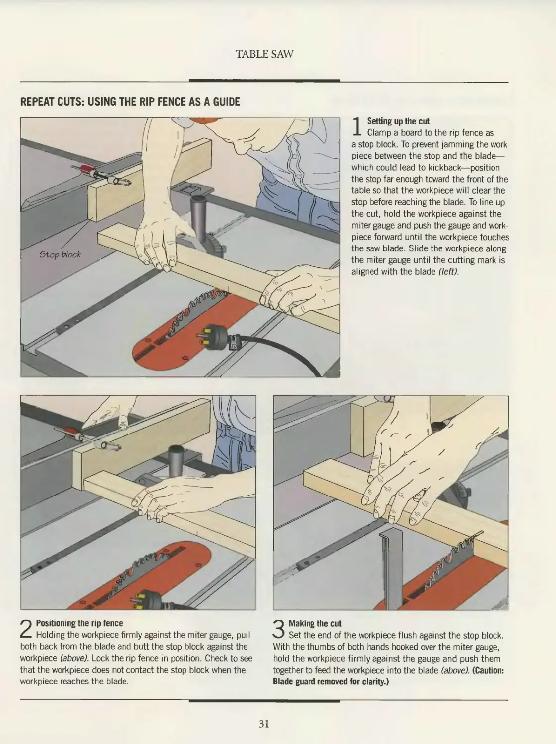
REPEAT CUTS: USING THE RIP FENCE AS A GUIDE
1 Setting up the cut
Clamp a board to the rip fence as
a stop block. To prevent jamming the work-
piece between the stop and the blade—
which could lead to kickback—position
the stop far enough toward the front of the
table so that the workpiece will clear the
stop before reaching the blade. To line up
the cut, hold the workpiece against the
miter gauge and push the gauge and work-
piece forward until the workpiece touches
the saw blade. Slide the workpiece along
the miter gauge until the cutting mark is
aligned with the blade (left).
2 Positioning the rip fence
Holding the workpiece firmly against the miter gauge, pull
both back from the blade and butt the stop block against the
workpiece (above). Lock the rip fence in position. Check to see
that the workpiece does not contact the stop block when the
workpiece reaches the blade.
3 Making the cut
Set the end of the workpiece flush against the stop block.
With the thumbs of both hands hooked over the miter gauge,
hold the workpiece firmly against the gauge and push them
together to feed the workpiece into the blade (above). (Caution:
Blade guard removed for clarity.)
31
TABLE SAW
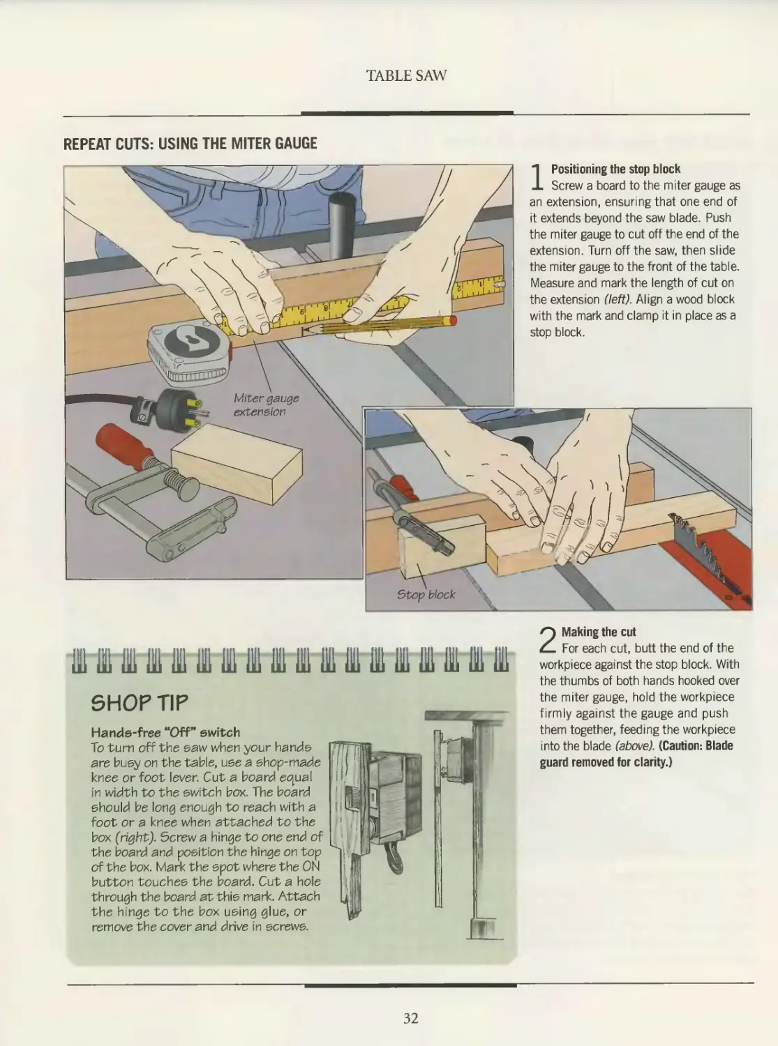
REPEAT CUTS: USING THE MITER GAUGE
1 Positioning the stop block
Screw a board to the miter gauge as
an extension, ensuring that one end of
it extends beyond the saw blade. Push
the miter gauge to cut off the end of the
extension. Turn off the saw, then slide
the miter gauge to the front of the table.
Measure and mark the length of cut on
the extension (left). Align a wood block
with the mark and clamp it in place as a
stop block.
lU Hi 1 111 III Hl 111 1 III 111 HI HI ill 111 111 III III 111
SHOP TIP
Hands-free “Off” switch
To turn off the saw when your hands
are busy on the table, use a shop-made
knee or foot lever. Cut a board equal
in width to the switch box. The board
should be long enough to reach with a
foot or a knee when attached to the
box (right). Screw a hinge to one end of
the board and position the hinge on top
of the box. Mark the spot where the ON
button touches the board. Cut a hole
through the board at this mark. Attach
the hinge to the box using glue, or
remove the cover and drive in screws.
2 Making the cut
For each cut, butt the end of the
workpiece against the stop block. With
the thumbs of both hands hooked over
the miter gauge, hold the workpiece
firmly against the gauge and push
them together, feeding the workpiece
into the blade (above). (Caution: Blade
guard removed for clarity.)
32
TABLE SAW
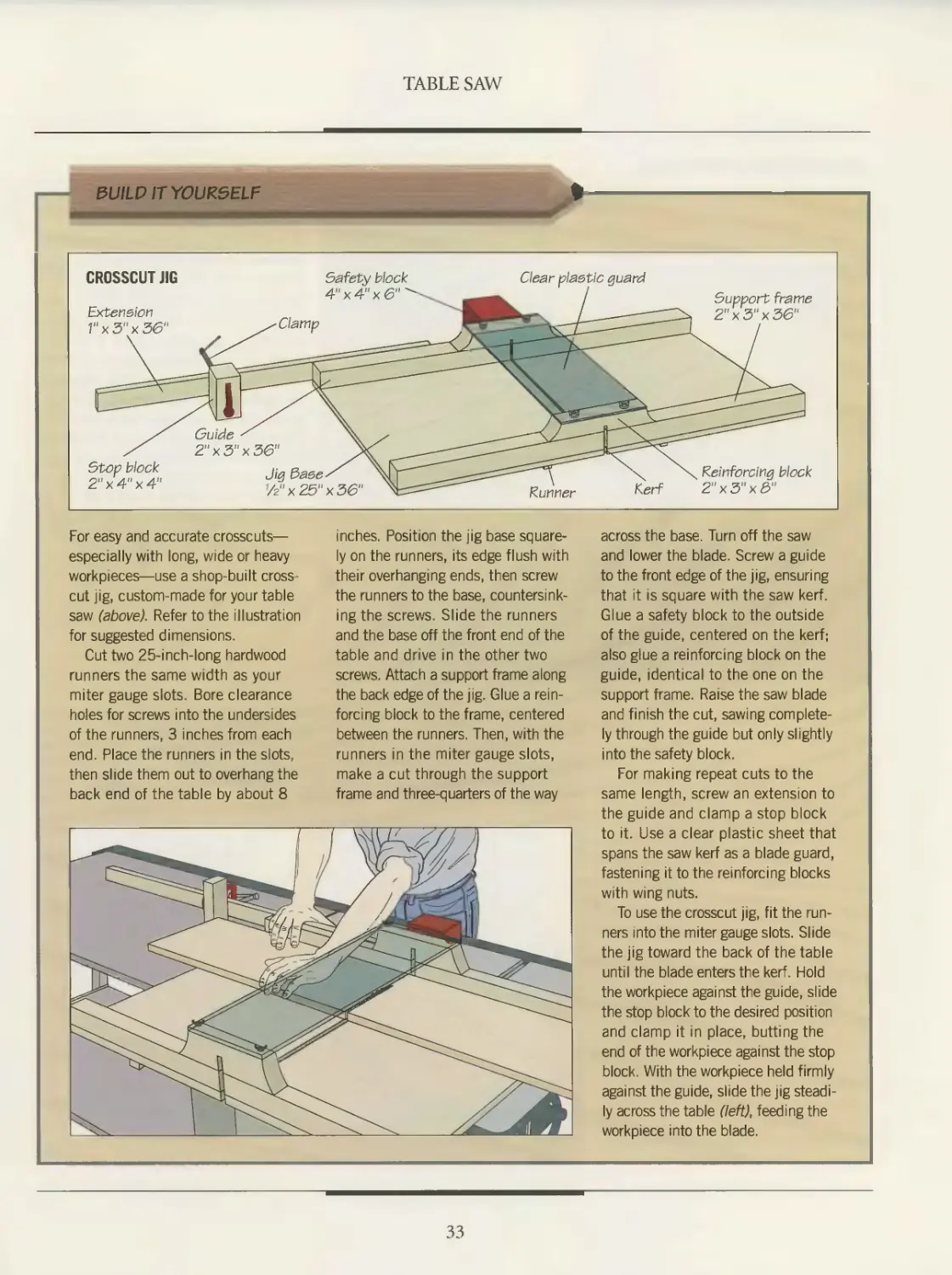
BUILD IT YOU R5 ELF
CROSSCUT JIG
Clear plastic guard
Clamp
Extension
I"x3"x3&
Safety block
4"x4"x6
Support frame
2"x3"x36
Runner
Stop block
2"x4"x4"
Guide
2"x3"x36‘
Jig Заве
7z"x25"x36‘
Reinforcing block
Kerf 2"x3"x3"
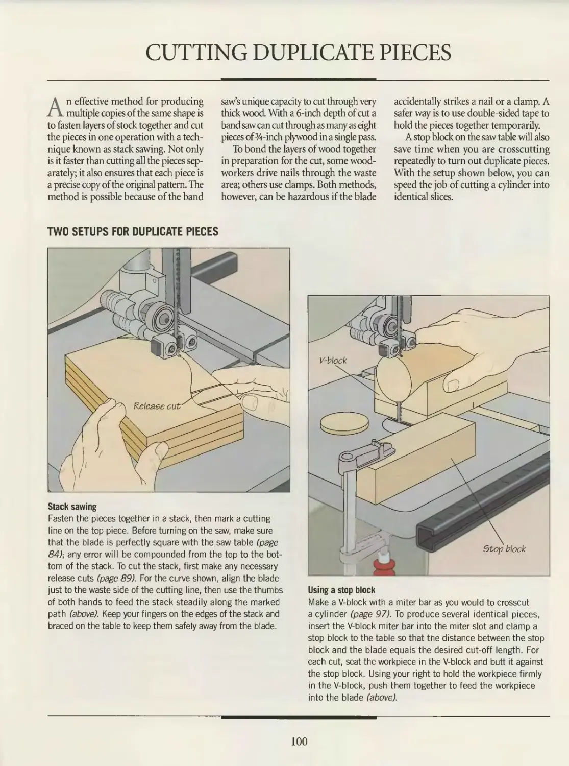
For easy and accurate crosscuts—
especially with long, wide or heavy
workpieces—use a shop-built cross-
cut jig, custom-made for your table
saw (above). Refer to the illustration
for suggested dimensions.
Cut two 25-inch-long hardwood
runners the same width as your
miter gauge slots. Bore clearance
holes for screws into the undersides
of the runners, 3 inches from each
end. Place the runners in the slots,
then slide them out to overhang the
back end of the table by about 8
inches. Position the jig base square-
ly on the runners, its edge flush with
their overhanging ends, then screw
the runners to the base, countersink-
ing the screws. Slide the runners
and the base off the front end of the
table and drive in the other two
screws. Attach a support frame along
the back edge of the jig. Glue a rein-
forcing block to the frame, centered
between the runners. Then, with the
runners in the miter gauge slots,
make a cut through the support
frame and three-quarters of the way
across the base. Turn off the saw
and lower the blade. Screw a guide
to the front edge of the jig, ensuring
that it is square with the saw kerf.
Glue a safety block to the outside
of the guide, centered on the kerf;
also glue a reinforcing block on the
guide, identical to the one on the
support frame. Raise the saw blade
and finish the cut, sawing complete-
ly through the guide but only slightly
into the safety block.
For making repeat cuts to the
same length, screw an extension to
the guide and clamp a stop block
to it. Use a clear plastic sheet that
spans the saw kerf as a blade guard,
fastening it to the reinforcing blocks
with wing nuts.
To use the crosscut jig, fit the run-
ners into the miter gauge slots. Slide
the jig toward the back of the table
until the blade enters the kerf. Hold
the workpiece against the guide, slide
the stop block to the desired position
and clamp it in place, butting the
end of the workpiece against the stop
block. With the workpiece held firmly
against the guide, slide the jig steadi-
ly across the table (left), feeding the
workpiece into the blade.
33
TABLE SAW
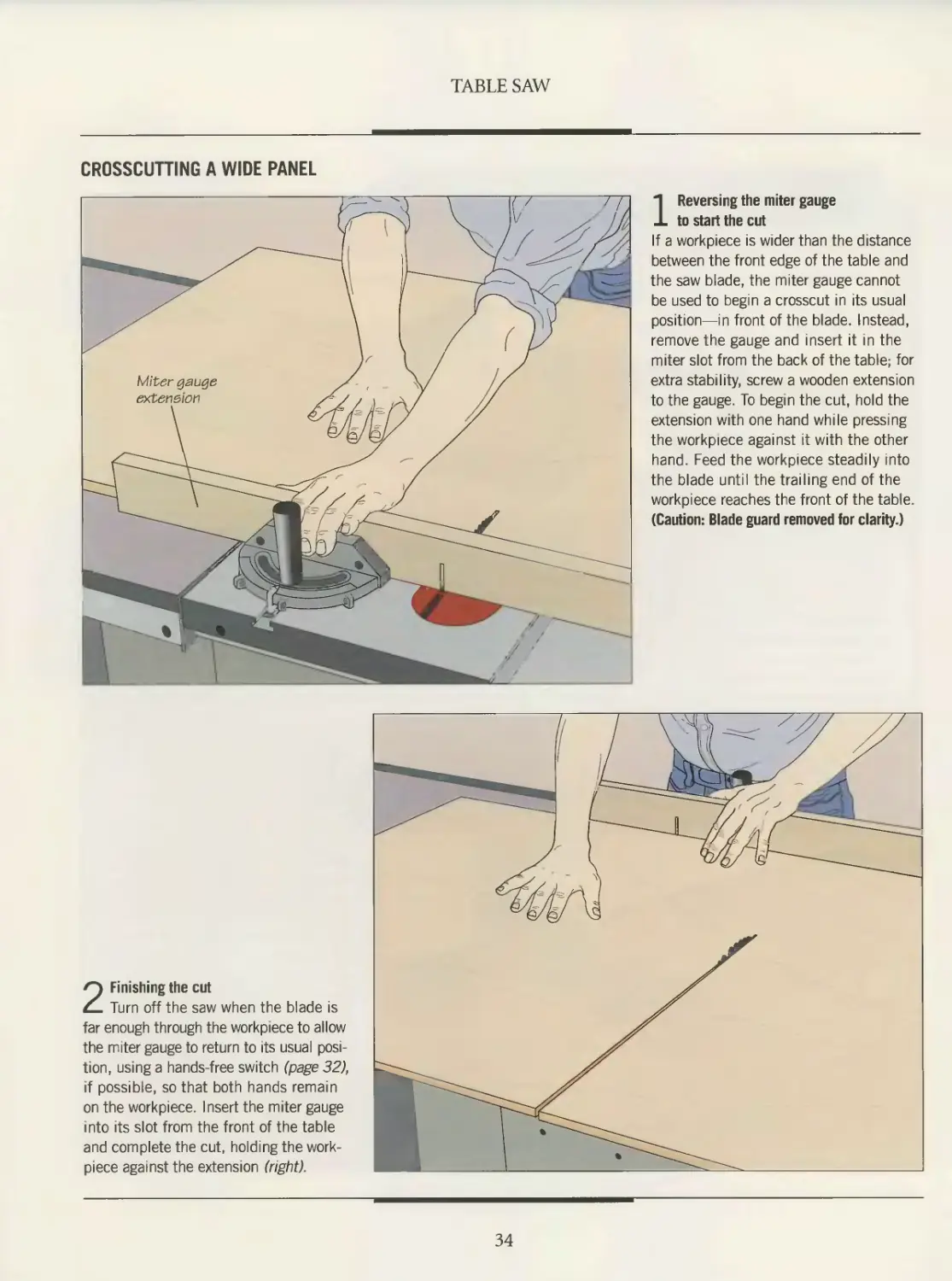
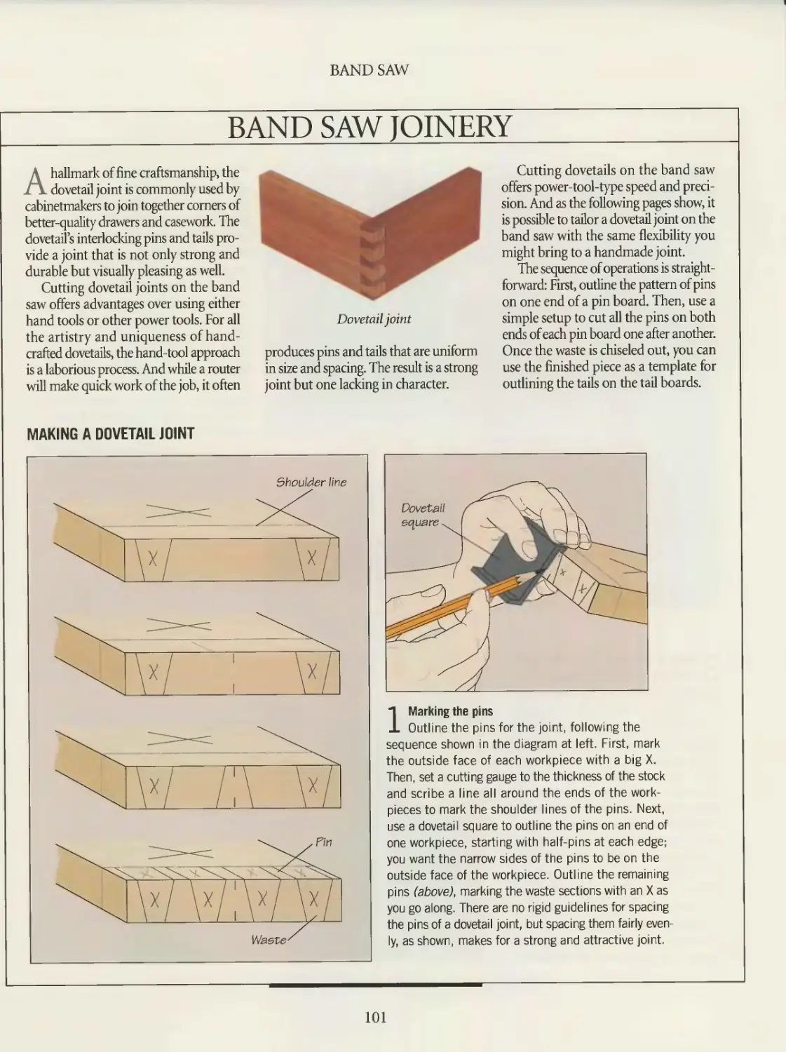
CROSSCUTTING A WIDE PANEL
1 Reversing the miter gauge
to start the cut
If a workpiece is wider than the distance
between the front edge of the table and
the saw blade, the miter gauge cannot
be used to begin a crosscut in its usual
position—in front of the blade. Instead,
remove the gauge and insert it in the
miter slot from the back of the table; for
extra stability, screw a wooden extension
to the gauge. To begin the cut, hold the
extension with one hand while pressing
the workpiece against it with the other
hand. Feed the workpiece steadily into
the blade until the trailing end of the
workpiece reaches the front of the table.
(Caution: Blade guard removed for clarity.)
2 Finishing the cut
Turn off the saw when the blade is
far enough through the workpiece to allow
the miter gauge to return to its usual posi-
tion, using a hands-free switch (page 32),
if possible, so that both hands remain
on the workpiece. Insert the miter gauge
into its slot from the front of the table
and complete the cut, holding the work-
piece against the extension (right).
34
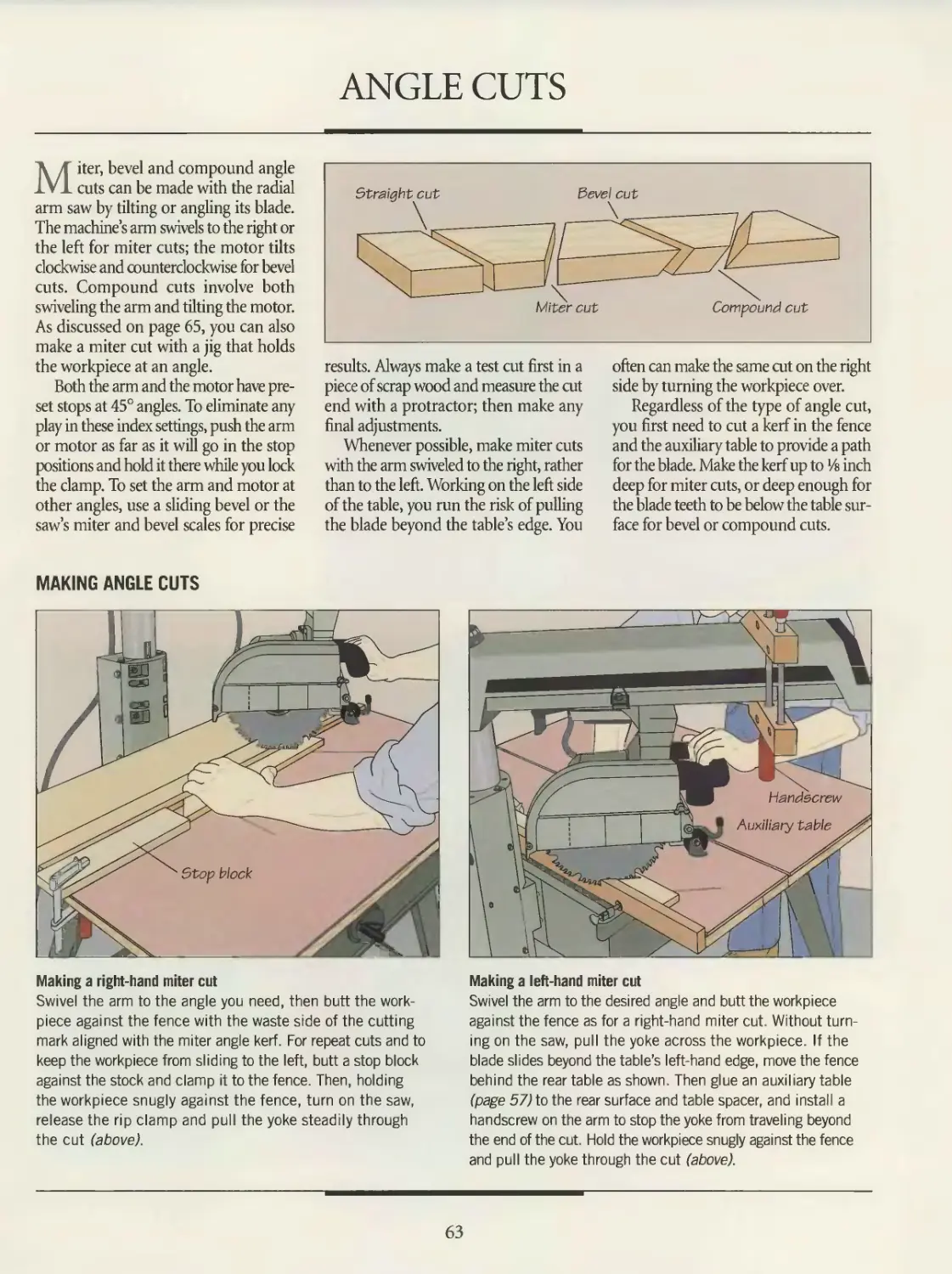
ANGLE CUTS
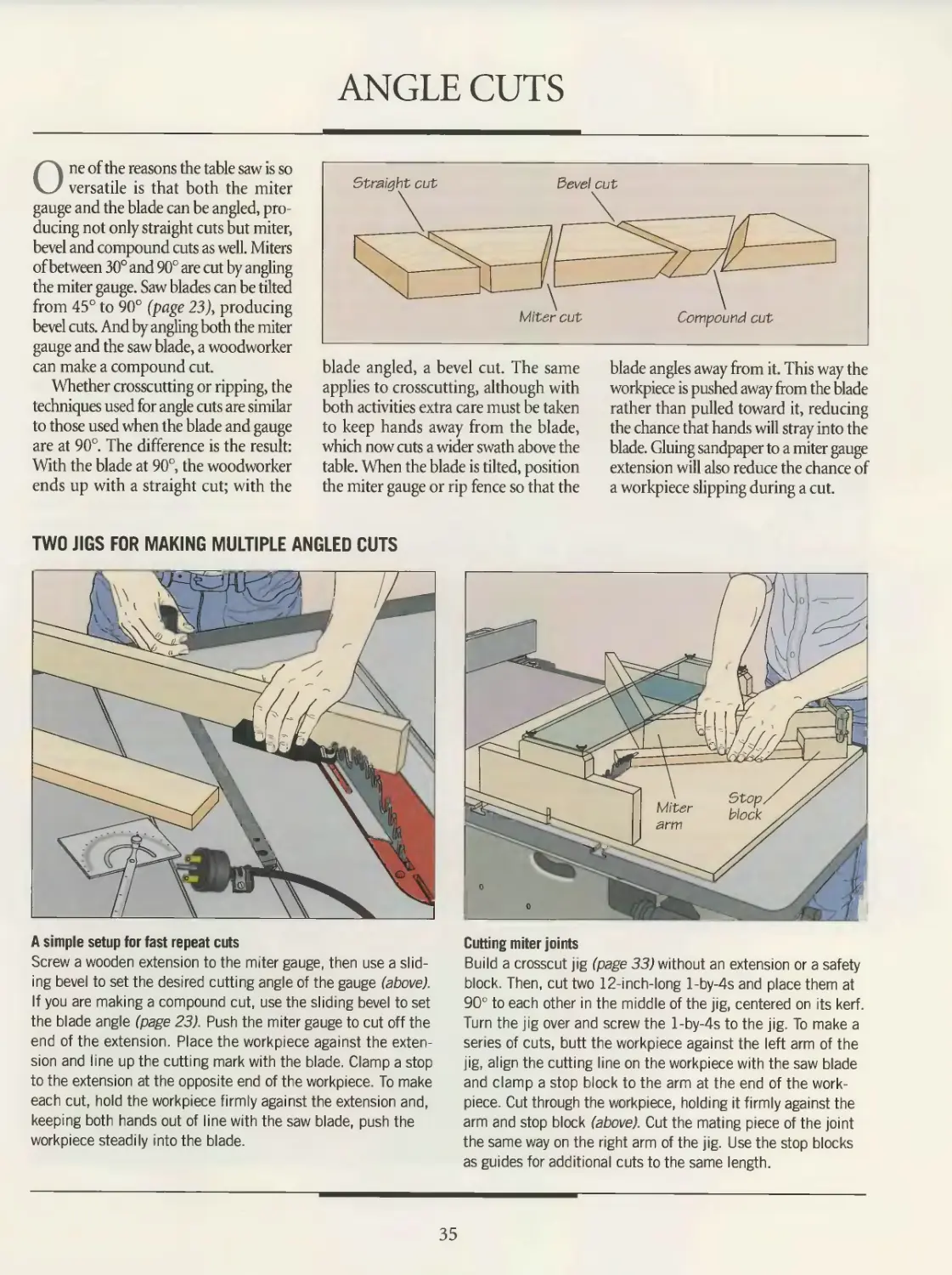
One of the reasons the table saw is so
versatile is that both the miter
gauge and the blade can be angled, pro
ducing not only straight cuts but miter,
bevel and compound cuts as well. Miters
of between 30° and 90° are cut by angling
the miter gauge. Saw blades can be tilted
from 45° to 90° (page 23), producing
bevel cuts. And by angling both the miter
gauge and the saw blade, a woodworker
can make a compound cut.
Whether crosscutting or ripping, the
techniques used for angle cuts are similar
to those used when the blade and gauge
are at 90°. The difference is the result:
With the blade at 90°, the woodworker
ends up with a straight cut; with the
blade angled, a bevel cut. The same
applies to crosscutting, although with
both activities extra care must be taken
to keep hands away from the blade,
which now cuts a wider swath above the
table. When the blade is tilted, position
the miter gauge or rip fence so that the
blade angles away from it. This way the
workpiece is pushed away from the blade
rather than pulled toward it, reducing
the chance that hands will stray into the
blade. Gluing sandpaper to a miter gauge
extension will also reduce the chance of
a workpiece slipping during a cut.
TWO JIGS FOR MAKING MULTIPLE ANGLED CUTS
A simple setup for fast repeat cuts
Screw a wooden extension to the miter gauge, then use a slid-
ing bevel to set the desired cutting angle of the gauge (above).
If you are making a compound cut, use the sliding bevel to set
the blade angle (page 23). Push the miter gauge to cut off the
end of the extension. Place the workpiece against the exten-
sion and line up the cutting mark with the blade. Clamp a stop
to the extension at the opposite end of the workpiece. To make
each cut, hold the workpiece firmly against the extension and,
keeping both hands out of line with the saw blade, push the
workpiece steadily into the blade.
Cutting miter joints
Build a crosscut jig (page 33) without an extension or a safety
block. Then, cut two 12-inch-long l-by-4s and place them at
90° to each other in the middle of the jig, centered on its kerf.
Turn the jig over and screw the l-by-4s to the jig. To make a
series of cuts, butt the workpiece against the left arm of the
jig, align the cutting line on the workpiece with the saw blade
and clamp a stop block to the arm at the end of the work-
piece. Cut through the workpiece, holding it firmly against the
arm and stop block (above). Cut the mating piece of the joint
the same way on the right arm of the jig. Use the stop blocks
as guides for additional cuts to the same length.
35
DADO CUTS
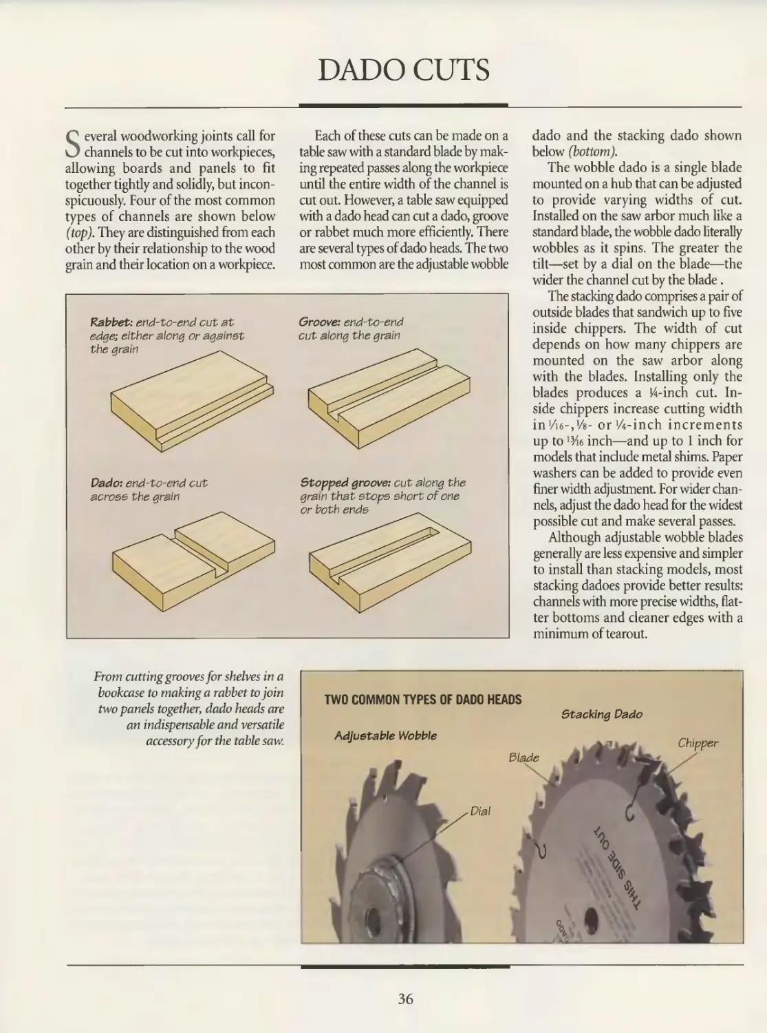
Several woodworking joints call for
channels to be cut into workpieces,
allowing boards and panels to fit
together tightly and solidly, but incon-
spicuously. Four of the most common
types of channels are shown below
(top). They are distinguished from each
other by their relationship to the wood
grain and their location on a workpiece.
Rabbet: end-to-end cut at
edge; either along or against
Dado: end-to-end cut
across the grain
Each of these cuts can be made on a
table saw with a standard blade by mak-
ing repeated passes along the workpiece
until the entire width of the channel is
cut out. However, a table saw equipped
with a dado head can cut a dado, groove
or rabbet much more efficiently. There
are several types of dado heads. The two
most common are the adjustable wobble
Groove: end-to-end
cut along the grain
Stopped groove: cut along the
grain that stops short of one
dado and the stacking dado shown
below (bottom).
The wobble dado is a single blade
mounted on a hub that can be adjusted
to provide varying widths of cut.
Installed on the saw arbor much like a
standard blade, the wobble dado literally
wobbles as it spins. The greater the
tilt—set by a dial on the blade—the
wider the channel cut by the blade.
The stacking dado comprises a pair of
outside blades that sandwich up to five
inside chippers. The width of cut
depends on how many chippers are
mounted on the saw arbor along
with the blades. Installing only the
blades produces a И-inch cut. In-
side chippers increase cutting width
in'/ie-jks- or'Zi-inch increments
up to 13/i6 inch—and up to 1 inch for
models that include metal shims. Paper
washers can be added to provide even
finer width adjustment. For wider chan-
nels, adjust the dado head for the widest
possible cut and make several passes.
Although adjustable wobble blades
generally are less expensive and simpler
to install than stacking models, most
stacking dadoes provide better results:
channels with more precise widths, flat-
ter bottoms and cleaner edges with a
minimum of tearout.
From cutting grooves for shelves in а
bookcase to making a rabbet to join
two panels together, dado heads are
an indispensable and versatile
accessory for the table saw.
TWO COMMON TYPES OF DADO HEADS
Stacking Dado
36
TABLE SAW
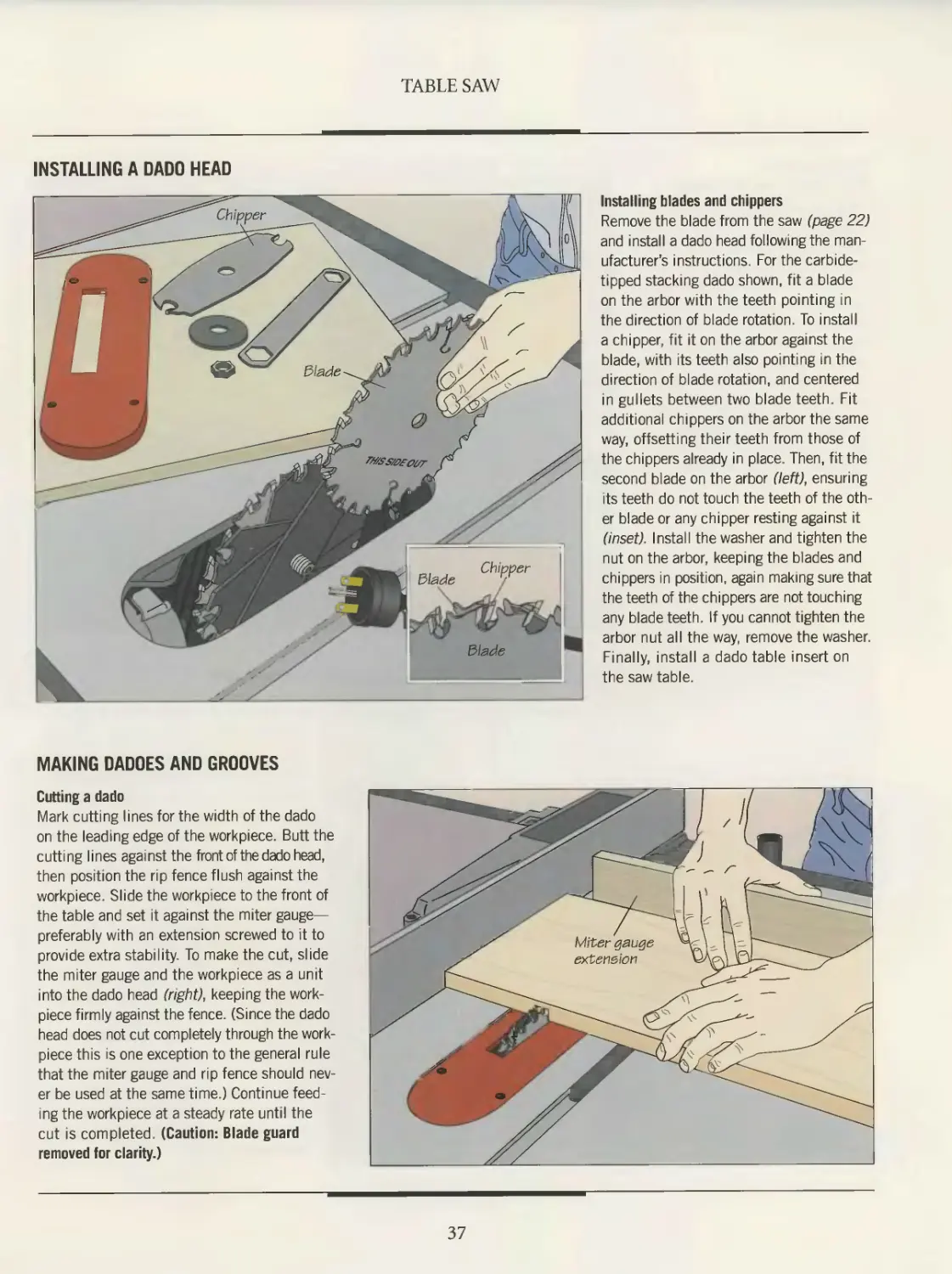
INSTALLING A DADO HEAD
Installing blades and chippers
Remove the blade from the saw (page 22)
and install a dado head following the man-
ufacturer’s instructions. For the carbide-
tipped stacking dado shown, fit a blade
on the arbor with the teeth pointing in
the direction of blade rotation. To install
a chipper, fit it on the arbor against the
blade, with its teeth also pointing in the
direction of blade rotation, and centered
in gullets between two blade teeth. Fit
additional chippers on the arbor the same
way, offsetting their teeth from those of
the chippers already in place. Then, fit the
second blade on the arbor (7eft), ensuring
its teeth do not touch the teeth of the oth-
er blade or any chipper resting against it
(inset). Install the washer and tighten the
nut on the arbor, keeping the blades and
chippers in position, again making sure that
the teeth of the chippers are not touching
any blade teeth. If you cannot tighten the
arbor nut all the way, remove the washer.
Finally, install a dado table insert on
the saw table.
MAKING DADOES AND GROOVES
Cutting a dado
Mark cutting lines for the width of the dado
on the leading edge of the workpiece. Butt the
cutting lines against the front of the dado head,
then position the rip fence flush against the
workpiece. Slide the workpiece to the front of
the table and set it against the miter gauge—
preferably with an extension screwed to it to
provide extra stability. To make the cut, slide
the miter gauge and the workpiece as a unit
into the dado head (right), keeping the work-
piece firmly against the fence. (Since the dado
head does not cut completely through the work-
piece this is one exception to the general rule
that the miter gauge and rip fence should nev
er be used at the same time.) Continue feed-
ing the workpiece at a steady rate until the
cut is completed. (Caution: Blade guard
removed for clarity.)
37
TABLE SAW
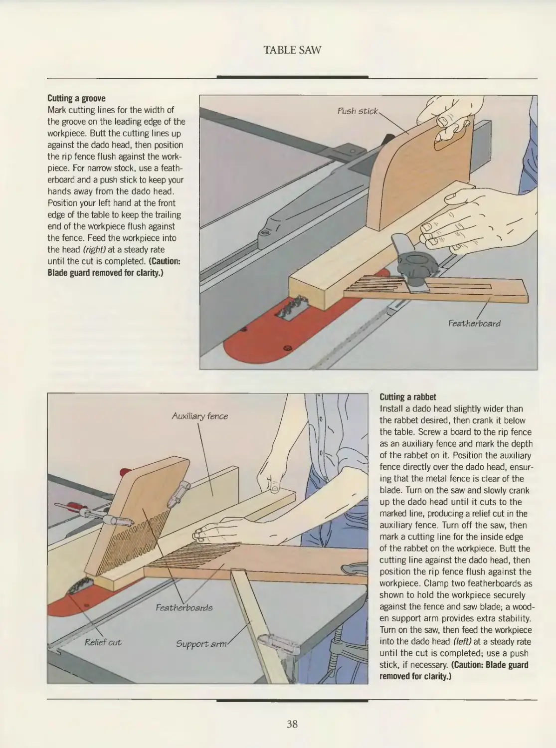
Cutting a groove
Mark cutting lines for the width of
the groove on the leading edge of the
workpiece. Butt the cutting lines up
against the dado head, then position
the rip fence flush against the work-
piece. For narrow stock, use a feath-
erboard and a push stick to keep your
hands away from the dado head.
Position your left hand at the front
edge of the table to keep the trailing
end of the workpiece flush against
the fence. Feed the workpiece into
the head (right) at a steady rate
until the cut is completed. (Caution:
Blade guard removed for clarity.)
Cutting a rabbet
Install a dado head slightly wider than
the rabbet desired, then crank it below
the table. Screw a board to the rip fence
as an auxiliary fence and mark the depth
of the rabbet on it. Position the auxiliary
fence directly over the dado head, ensur-
ing that the metal fence is clear of the
blade. Turn on the saw and slowly crank
up the dado head until it cuts to the
marked line, producing a relief cut in the
auxiliary fence. Turn off the saw, then
mark a cutting line for the inside edge
of the rabbet on the workpiece. Butt the
cutting line against the dado head, then
position the rip fence flush against the
workpiece. Clamp two featherboards as
shown to hold the workpiece securely
against the fence and saw blade; a wood-
en support arm provides extra stability.
Turn on the saw, then feed the workpiece
into the dado head (left) at a steady rate
until the cut is completed; use a push
stick, if necessary. (Caution: Blade guard
removed for clarity.)
38
TABLE SAW
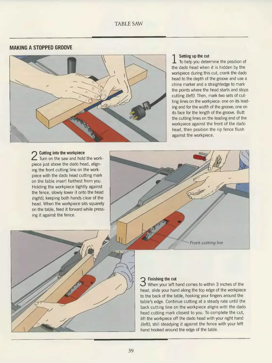
MAKING A STOPPED GROOVE
1 Setting up the cut
To help you determine the position of
the dado head when it is hidden by the
workpiece during this cut, crank the dado
head to the depth of the groove and use a
china marker and a straightedge to mark
the points where the head starts and stops
cutting (left). Then, mark two sets of cut-
ting lines on the workpiece: one on its lead-
ing end for the width of the groove; one on
its face for the length of the groove. Butt
the cutting lines on the leading end of the
workpiece against the front of the dado
head, then position the rip fence flush
against the workpiece
2 Cutting into the workpiece
Turn on the saw and hold the work-
piece just above the dado head, align-
ing the front cutting line on the work-
piece with the dado head cutting mark
on the table insert farthest from you.
Holding the workpiece tightly against
the fence, slowly lower it onto the head
(right), keeping both hands clear of the
head. When the workpiece sits squarely
on the table, feed it forward while press-
ing it against the fence.
3 Finishing the cut
When your left hand comes to within 3 inches of the
head slide your hand along the top edge of the workpiece
to the back of the table, hooking your fingers around the
table’s edge. Continue cutting at a steady rate until the
back cutting line on the workpiece aligns with the dado
head cutting mark closest to you. To complete the cut,
lift the workpiece off the dado head with your right hand
(left), still steadying it against the fence with your left
hand hooked around the edge of the table.
39
MOLDINGS
A table saw is more than just a machine
to cut wood. With the proper setup,
a saw blade can serve as a milling device
to cut cove moldings (page 43). And by
replacing the saw blade with a molding
head and different sets of cutters, a plain
board can become an elaborate molding.
Pieces of wood can be shaped separately
and then glued together to form an
impressive array of designs. The results
range from crown moldings for a cabinet
to decorative door and frame mold-
ings—made at a fraction of the cost of
their store-bought counterparts.
Molding cutters are sold in sets of
three, which are installed in a molding
head and then fastened onto the arbor.
By passing the wood over the cutters
repeatedly and raising the molding head
slightly each time, a pattern is cut into
the wood. The more passes, the deeper
the inscription.
Like a dado head, a molding head
requires its own table insert with a wide
opening to accommodate the width of
the cutters. A woodworker can make an
insert for each set of cutters by placing a
blank piece of wood in the table insert
slot and slowly cranking up the molding
head—much like making special inserts
for saw blades (page 22).
Molding heads have a reputation for
being dangerous and while there are
always hazards involved when using a
table saw, there is little risk when mold-
ing heads are used with proper care. A
few points to keep in mind: Do not cut
moldings on short lengths of wood; a
piece should be at least 12 inches long.
Also, do not cut moldings on narrow
strips; cut the moldings on pieces at least
4 inches wide and then rip to width.
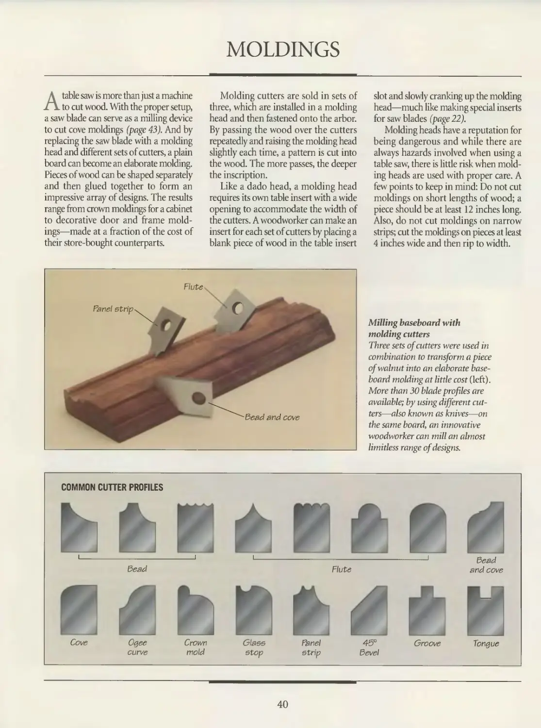
Milling baseboard with
molding cutters
Three sets of cutters were used in
combination to transform a piece
of walnut into an elaborate base-
board molding at little cost (left).
More than 30 blade profiles are
available; by using different cut-
ters—also known as knives—on
the same board, an innovative
woodworker can mill an almost
limitless range of designs.
COMMON CUTTER PROFILES
40
TABLE SAW
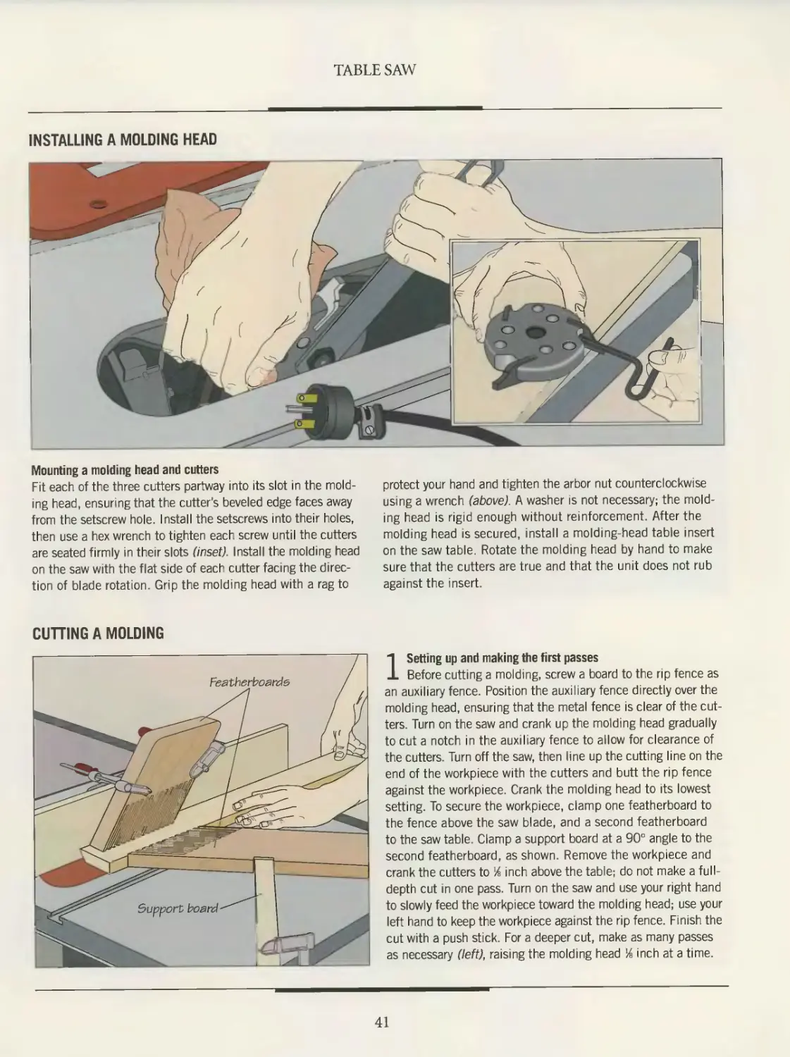
INSTALLING A MOLDING HEAD
Mounting a molding head and cutters
Fit each of the three cutters partway into its slot in the mold-
ing head, ensuring that the cutter's beveled edge faces away
from the setscrew hole. Install the setscrews into their holes,
then use a hex wrench to tighten each screw until the cutters
are seated firmly in their slots (inset). Install the molding head
on the saw with the flat side of each cutter facing the direc-
tion of blade rotation. Grip the molding head with a rag to
protect your hand and tighten the arbor nut counterclockwise
using a wrench (above). A washer is not necessary; the mold-
ing head is rigid enough without reinforcement. After the
molding head is secured, install a molding-head table insert
on the saw table. Rotate the molding head by hand to make
sure that the cutters are true and that the unit does not rub
against the insert.
CUTTING A MOLDING
1 Setting up and making the first passes
Before cutting a molding, screw a board to the rip fence as
an auxiliary fence. Position the auxiliary fence directly over the
molding head, ensuring that the metal fence is clear of the cut-
ters. Turn on the saw and crank up the molding head gradually
to cut a notch in the auxiliary fence to allow for clearance of
the cutters. Turn off the saw, then line up the cutting line on the
end of the workpiece with the cutters and butt the rip fence
against the workpiece. Crank the molding head to its lowest
setting. To secure the workpiece, clamp one featherboard to
the fence above the saw blade, and a second featherboard
to the saw table. Clamp a support board at a 90° angle to the
second featherboard, as shown. Remove the workpiece and
crank the cutters to % inch above the table; do not make a full-
depth cut in one pass. Turn on the saw and use your right hand
to slowly feed the workpiece toward the molding head; use your
left hand to keep the workpiece against the rip fence. Finish the
cut with a push stick. For a deeper cut, make as many passes
as necessary (left), raising the molding head % inch at a time.
41
TABLE SAW
3 Separating the molding from the board
After the proper profile has been cut,
separate the molding from the workpiece.
Remove the molding head from the arbor
and install a rip or combination blade.
Feed the board through the blade, using
a push stick to keep the workpiece firmly
on the table (right); use your left hand or
a featherboard to press it flush against
the rip fence.
2 Making the final pass
After successive passes have pro-
duced the depth of cut desired, crank
the molding head up very slightly and
pass the workpiece through a final time
at half the speed of previous passes
(left). By feeding the workpiece slowly,
the final cut produces a smooth finish
that requires minimal sanding.
42
TABLE SAW
CUTTING A COVE MOLDING
1 Setting the width
Build a cove cutting guide in the shape of a parallelo-
gram by fastening two 18-inch-long l-by-2s to two 9-inch-
long l-by-2s with wing nuts, forming two sets of parallel
arms. Adjust the guide so that the distance between the
inside edges of the two long arms is the same as the desired
width of the cove molding. Then crank up the blade to the
maximum depth of the cove. Lay the guide diagonally across
the blade insert and rotate it until the blade, turned by
hand, just touches both long arms of the guide (above).
2 Marking the guidelines
Using a pencil or china marker, trace guidelines on the
table insert and saw table along the inside edges of the long
arms of the guide (above) Then outline the desired profile
of the cove on the leading end of the workpiece. Remove
the guide, crank the blade to its lowest setting and place the
workpiece on the saw table, aligning the marked outline on
the workpiece with the guidelines on the saw table.
3 Cutting the cove
Butt a guide board against each edge of the workpiece;
use boards long enough to clamp on opposite sides of the
table. Crank the blade Vb inch above the table. To make the
first pass, feed the workpiece steadily toward the blade with
your left hand, while holding the workpiece against the table
with your right hand. Finish the cut using a push block Make
as many passes as necessary (left), raising the blade Vb inch at
a time. For a deep cove, tack a backup board to the top of the
workpiece to prevent it from splitting. For a smooth finish that
requires little sanding, raise the blade very slightly for a last
pass and feed the workpiece slowly into it.
43
TABLE SAW JOINERY
Box Joint
Lap joint
Open mortise-and-tenon joint
The speed and precision of a table saw
make it an obvious choice for cut-
tingjoints, particularly repeat cuts. Once
a saw is adjusted to cut one box joint or
open mortise-and-tenon joint, for exam-
ple, five or ten more can be cut in short
order. The most time-consuming part is
the setup; and much depends upon the
care taken at this point. A few extra min-
utes spent at the beginning will result in
a strong, long-lasting joint. As always,
measure twice and cut once.
Every joint has its own specific qual-
ities and applications. Lap joints are fre-
quently used to make picture frames.
Made from two pieces of wood that have
half their thickness cut away, a lap joint
is simple to make. When glued and
clamped, it creates a strong joint that
does not require reinforcement.
A box joint, also known as a finger
joint, is ideal for carcase work—for mak-
ing drawers or boxes. It consists of inter-
locking pins and notches, which are
generally one-half or one-quarter the
stock’s thickness. Once used for mass-
produced products such as packing box-
es, the box joint creates a strong joint by
virtue of the size of the large glue area
created by the pins and notches.
The mortise-and-tenon joint is often
found in chairs and desks. Sometimes
called a bridle joint, it consists of a pro-
jection—or tenon—from one board that
slides into a slot—or open mortise—in
another board. Like the box joint, it
requires a jig, which can be shop-built.
The following section describes how to
make each of these useful joints.
MAKING A LAP JOINT
Cutting laps with a dado head
Mark cutting lines for the width of each lap
on the leading edge of the workpiece. Butt
one cutting line against the outside blade at
the front of the dado head, then position the
rip fence flush against the workpiece. Slide
the workpiece to the front of the table and
press it firmly against the fence and the
miter gauge. To make the cut, slide the
gauge and the workpiece as a unit into
the dado head, keeping the workpiece flush
against the fence. (This is another exception
to the general rule that the miter gauge and
rip fence should not be used at the same
time.) Continue feeding the workpiece at a
steady rate until the cut is made. Make suc-
cessive passes (left), cutting away the waste
until the lap is completed. (Caution: Blade
guard removed for clarity.)
44
TABLE SAW
MAKING A BOX JOINT
1 Setting up the jig
Cut the notches for a box joint one at a time using a dado
head and jig. Clamp a board to the miter gauge as an exten-
sion. Crank the dado head to the desired height of the notches
and feed the extension into the dado head to create a notch.
Position the extension on the miter gauge so that the gap
between the notch and the dado head is equal to the notch
width, then screw the extension to the gauge. Feed the exten-
sion into the dado blade to cut a second notch (above), check-
ing that the gap between the notches equals the notch width.
Fit and glue a hardwood key into the notch so that the key
projects about an inch from the extension.
3 Cutting the notches in the mating board
Fit the last notch you cut in the first
board over the key, then butt one edge
of the mating board against the first
board, holding both flush against the
miter gauge extension. To cut the first
notch in the mating board, slide the two
boards across the table (right), then con-
tinue cutting notches in the mating board
following the same procedure you used
for the first board.
2 Cutting the notches in the first board
Butt one edge of the workpiece against the key, holding
it flush against the miter gauge extension. To cut the notch,
hook your thumbs around the gauge and slide the workpiece
into the dado head (above). Return the workpiece to the front
of the table, fit the notch over the key and repeat the proce-
dure. Continue cutting notches one after another until you
reach the opposite edge of the workpiece.
45
TABLE SAW
MAKING AN OPEN MORTISE-AND-TENON JOINT
1 Cutting the tenon cheeks
Create a tenon by cutting the cheeks
first, and then the shoulders. Install a
commercial tenoning jig on the table fol-
lowing the manufacturer’s instructions; the
model shown slides in the miter slot. Mark
cutting lines on the workpiece to outline
the tenon, then clamp the workpiece to the
jig. Crank the blade to the height of the
tenon and position the jig so that one of
the tenon cheek cutting lines is butted
against the blade. Use the jig handle to
slide the jig along the miter gauge slot;
loosen the clamp handle to move it side-
ways. Slide the jig to the front of the table
and turn on the saw, then use your right
hand to push the jig forward, feeding the
workpiece into the blade (left). Continue
cutting at a steady rate until the cut is
completed. Pull the jig back to the front
of the table and turn off the saw. Turn the
workpiece around so that the remaining
cutting line for the thickness of the tenon
is butted against the blade. Cut along it
the same way as you made the first cut.
2 Sawing the tenon shoulders
Screw a board to the miter gauge
as an extension. Then crank the blade to
a height equal to the depth of the tenon
against the extension, align one of the
tenon shoulder cutting lines against the
blade, then butt a stop block against
the workpiece and clamp it in position.
Slide the workpiece to the front of the
table and turn on the saw. Hook your
thumbs around the miter gauge to
feed the workpiece into the blade and
make the cut. Use a push stick to clear
the waste piece off the table. Flip over
the workpiece and butt it against the
stop block, then cut the second shoul-
der (right). (Caution: Blade guard
removed for clarity.)
46
TABLE SAW
Cutting the mortise
Reinstall the tenoning jig on the table. Mark cut-
ting lines on the workpiece to outline the mortise, then
clamp the workpiece to the jig. Crank the blade to the
depth of the mortise and position the jig so that one of
the cutting lines is butted against the blade. Slide the
jig to the front of the table, then turn on the saw and
feed the workpiece into the blade. Pull the jig back
and turn off the saw. Turn the workpiece over so that
the remaining cutting line is butted against the blade
and cut along it (left). Make as many passes as neces-
sary to remove waste between the two cuts. Test-fit
the joint and deepen or widen the mortise, if necessary.
PU/LP IT YOURSELF
A TENONING JIG
Build a fence-straddling tenoning jig using %-inch
plywood cut to the suggested dimensions shown at
left. In one corner of the jig body, cut a hole large
enough for your fingers to fit through. Screw a guide
board to the body directly behind the hole. The board
will hold the workpiece in position for the cut. Make
sure that the board is perfectly vertical. To hold the
jig body flush against the fence, screw a brace to the
body with a spacer in between (inset).
To use the jig, place
it astride the fence as
shown. Butt the work-
piece against the guide
and clamp it in place.
Reposition the fence to
align the cutting mark on
the workpiece with the
blade, then slide the jig
along the fence until the
cut is completed.
47
RADIAL ARM SAW
Augmented by a raised auxiliary table,
the radial arm saw—its blade turned horizon-
tally—cuts the notches for a finger joint.
Many woodworkers look on the
radial arm saw as the table
saw’s poor cousin, suitable only for
rough crosscuts and other carpen-
try-related chores. There are several
reasons for this perception. One is
that more woodworkers learn and
fine-tune their craft on table saws
than on radial arm saws. Table saws
also have fewer moving parts and
are easier to set up. Consequently,
many woodworkers base their first
impressions as a result of working
on ill-adjusted machines.
There is no denying that the table
saw is an excellent choice for the often
repetitive chores of furniture making.
Nevertheless, it is not the ideal stationary cutting tool for every-
one. For repeat cuts, table saws usually require a jig to feed stock
into the blade with uniform results. And some jigs are time-con-
suming to build or costly to buy. Table saws also need a fair
amount of room to allow unhindered operation. Such space is
at a premium in many home workshops.
With the exception of crosscutting very wide boards, radial
arm saws can duplicate just about any job a table saw can per-
form. Even the crosscutting limitations are not severely restric-
tive. Most radial arm saws can rip up to a width of 25 inches,
allowing you to cut a 4-foot-wide panel in half lengthwise.
Moreover, the radial arm saw requires relatively little workshop
space. Since stock either remains
stationary on the saw table or
passes laterally across the table, the
machine can be stationed perma-
nently against a wall.
A key advantage of the radial
arm saw is that its blade remains
visible as it cuts—a boon to safety.
Another benefit is that most cuts
can be made without having to shift
the workpiece. Instead, the machine
itself moves, with the arm pivoting
on the column and the motor
swiveling and rotating on its yoke.
This allows the blade to be pulled
through a workpiece at almost any
angle. It also makes simple work of
setting up the machine for custom work. But to take full advan-
tage of the saw’s capacity for cutting accurately, you must take
the time to adjust the machine and keep it finely tuned.
On a poorly adjusted machine, the radial arm saw’s flexi-
bility can be its Achilles’ heel. All of its sliding and pivoting
movements must be highly controlled, and its movable parts
must remain fixed when locked in position. Otherwise, the
saw is condemned to a life of imprecise cuts. This holds true
for any size machine. Radial arm saws typically range from
1 to 7 horsepower; the average home workshop model is rated
at 1.5 horsepower. Blade size typically ranges from 8 to 24
inches; the standard home model has a 10-inch blade.
This jig will allow you to make miter cuts on the
radial arm saw with the blade in the standard cross-
cuttingposition—90° to the table. The jig ensures
that mating boards will form a perfectly square joint.
49
ANATOMY OF A RADIAL ARM SAW
The radial arm saw is essentially
a circular saw suspended above a
work table. For most operations, the
blade cuts through the workpiece and
runs along a kerf in a piece of hardboard
or plywood that is glued to the saw table.
The machine’s many pivoting and
sliding parts enable it to carry the blade
into a workpiece from a variety of dif-
ferent angles and directions. Sliding the
yoke along the arm pulls the blade across
the table for a crosscut. Swiveling the
arm on the column allows for miter cuts;
the maximum range of the model illus-
trated below is nearly 90° to the right and
50° to the left. Tilting the motor and
blade makes a bevel cut possible, while
rotating the yoke to bring the blade par-
allel to the fence sets up the machine for
a rip cut.
Depending on the width of the stock
you need to cut, two types of rip cuts are
feasible: an in-rip, with the blade turned
closest to the column, and an out-rip,
Arm
Supports
yoke, motor
and blade
Yoke clamp handle
Locks yoke in fixed
position on arm;
released to rotate
yoke for ripping
Stand
Supports saw;
screws on feet are
adjustable to level
saw table
Column
Supports arm; four
setscrews on front of col-
umn base and four bolts
on rear of base tightened
to prevent rotation
Blade guard
Protects operator
from upper part of blade;
nose tilts to cover lead-
ing edge of blade for rip-
ping. Lower blade guard
used for crosscutting
Miter clamp handle
Locks arm in fixed position
on column; released to swiv-
el arm and set miter angle.
Locks automatically at pre-
set angles, including 0° and
45° to the right and left
On/off switch
Removable toggle
prevents acciden-
Yoke
Holds motor and
blade; attached to
the arm by a car-
riage unit with roller
bearings that slide
along a track under-
neath the arm
Yoke handle
Used to slide
yoke along arm
for crosscutting
Bevel clamp handle
Locks motor in fixed
position on yoke; released
to set bevel angle or to
move blade to horizon-
tal position. Locks auto-
matically at preset
angles, including 0° and
45°, and 90° to the
right and left
Blade guard
clamp screw
Holds guard in
fixed position;
loosened to
move guard
Splitter
Keeps wood kerf from binding
during a cut; anti-kickback fin-
gers on each side of splitter
prevent workpiece from lifting
Elevating crank
Raises and lowers am on
column to set depth of cut
with the blade swiveled farthest away
from the column.
Although the blade is kept vertical to
the table for most operations, it can also
be tilted to operate horizontally. Such
a position is particularly useful for
tasks such as cutting grooves, finger
joints and moldings.
Light and compact enough to move
around the shop or travel to construc-
tion sites, this portable 814-inch radial
arm saw can usurp the many roles of a
table saw. Fitted with a special bit and
equipped with an accessory motor shaft
that turns at 18,500 rpm, this model
will double as an overhead router.
Dust spout
For dust collection
system; adjustable
nozzle directs dust
Arm cover
Keeps dust from
entering rear
part of arm
Rip clamp handle
Locks yoke in position on arm
for ripping and for some cuts
with blade in horizontal posi-
tion; released for crosscutting
Column
base cover
0 •
Rear table
Motor
One end holds blade; oppo-
site end serves as acces-
sory shaft for attaching a
variety of accessories
Fence
Prevents workpiece from
moving during cross-
cutting; guides work-
piece across table for
ripping. Owner-installed
Usually set between
front and rear tables
as shown; positioned
behind rear table when
cutting wide stock
Auxiliary table
Replaceable hardboard
or plywood panel glued
to front saw table; blade
runs in kerfs cut in aux-
iliary table
Table spacer
Removable to allow
installation of a
wider fence
Miter clamp
adjustment screw
Turned to adjust ten-
sion on miter clamp;
hole in arm cover pro-
vides access
Column adjust-
ment bolts
Four bolts control
amount of play
between column
and column base
Table clamp
Presses rear gaiv
table and spacer
flush against
fence and front
saw table
SETTING UP
The setup procedures described on
these pages may seem long and
involved, but do not neglect them.
Without careful maintenance, your
machine will not cut with precision.
A problem with many radial arm saws
is that adjustments are left too loose,
allowing excessive play in moving parts
and resulting in sloppy cuts. Ideally,
clamps should lock tight and sliding
mechanisms should be neither too loose
nor too snug.
Adjust the table (right), the clamps
(below) and the sliding mechanisms
(page 54) before every new project. Each
time you use the saw, clear the sawdust
from the gap between the table and the
fence, and clear the track underneath the
arm. Periodically, touch up the moving
parts with a silicone-based lubricant. It is
also important to square the blade (page
55) and check for heeling (page 56).
Before using your saw for the first
time, you will need to install a fence
and an auxiliary table (page 57). To test
your adjustments, crosscut a 12-inch-
wide board and a l-by-3 standing on
edge, then check the cut ends with a
carpenter’s square.
ADJUSTING THE TABLE
Leveling the table with the arm
Tilt the motor until the arbor points down, its end slightly above table level.
Then swivel the arm to position the arbor over the rail nuts on both sides
of the table; in each position measure the gap between the arbor and the table.
If the measurements are not equal, raise the low end of the table by turning the
rail nut in a clockwise direction, using the head of an adjustable wrench to lever
up the table surface (above). Then make the same adjustment on the other side
of the table. Repeat the measurements to ensure that the table is level.
ADJUSTING THE CLAMPS
1 Adjusting the miter clamp
Swivel the arm to the right to a
position between 0° and 45°. Lock
the clamp and try to push the end
of the arm toward the 0° position
(left). If there is any play in the arm,
adjust the clamp that holds it in place.
For the model shown, you will need
to use a hex wrench to tighten the
miter clamp adjustment screw,
located inside an access hole in the
arm cover.
52
RADIAL ARM SAW
2 Fine-tuning the yoke clamp
Rotate the yoke to a position between the ones used
for crosscutting and ripping. Lock the clamp, then use
both hands to try to push the motor to the crosscutting posi-
tion (right). The motor should not budge; if it does, adjust
the clamp that locks it in position. For the model shown, un-
screw the knob from the yoke clamp handle and remove
the wrench-like lower part of this device. Use the wrench
to tighten the adjustment nut located under the arm by hold-
ing the upper part of the handle and pulling the wrench
toward it (inset) until the two are aligned. Lock the clamp
and check again for play. If necessary, tighten the nut fur-
ther; otherwise, screw the knob back in place. This adjust-
ment may vary on some models; check your owner’s manual.
3 Adjusting the bevel clamp
Tilt the motor to a position between
0° and 45°. Lock the bevel clamp, then
use both hands to try to move the
motor (left). If there is any looseness,
adjust the clamp. For the model shown,
use a socket wrench to tighten the motor
support nut, then release the clamp and
try tilting the motor to each of the preset
angles; if you cannot move the motor,
loosen the support nut slightly. Other-
wise, lock the clamp again and check
once more for play in the motor.
53
RADIAL ARM SAW
4 Checking the rip clamp
Lock the rip clamp, then use
both hands to try to slide the yoke
along the arm (left). The yoke should
not move; if it does, adjust the rip
clamp. For the model shown, release
the clamp, then use a wrench to tight-
en the nut at the end of the rip clamp
bolt. Try sliding the yoke along the
arm; if it binds, loosen the lock nut
slightly. Otherwise, recheck the clamp
and tighten the nut further if needed.
CARING FOR THE SLIDING MECHANISMS
1 Adjusting the carriage roller bearings
Use a silicone-based lubricant to clean
the track under the arm and the roller
bearings to the front and rear of the car-
riage unit that attaches the yoke to the
arm To check the bearings, press your
thumb against each one in turn while
sliding the carriage away from your hand.
The bearings should turn as the carriage
slides along the arm If your thumb keeps
one of them from turning, you will need to
tighten the bearing; if the carriage binds
on the arm, a bearing will need to be loos-
ened. In either case, loosen the bearing
nut while holding the bolt stationary with
a second wrench (right). Tighten or loosen
the bolt, as necessary, then retighten the nut.
Adjust the other bolt by the same amount,
then check the bearings once again.
54
RADIAL ARM SAW
2 Adjusting column-to-base tension
Wipe the column clean, then loosen the four setscrews on
the front of the column base using a hex wrench To check
column-to-base tension, use both hands to try to lift the end
of the arm (above, left)-, there should be little or no give to
the column. Turn the elevating crank in both directions; the
arm should slide smoothly up and down. If there is excessive
movement at the column-to-base joint or if the arm jumps or
vibrates as it rises and lowers, adjust the four bolts located
m the access holes on the cover of the base. Repeat the
tests and, if necessary, make additional adjustments. Then
try pushing the arm sideways (above, right)- if there is any
rotation of the column, tighten the setscrews just enough
to prevent movement. Run through the tests a final time,
fine-tuning the adjustments.
SQUARING THE BLADE
1 Squaring the blade with the table
Set the yoke in the crosscutting posi-
tion and install a blade (page 59). Release
the bevel clamp and tilt the motor counter-
clockwise as far as it will go in the 0° posi-
tion. Then relock the clamp. To check the
blade position, butt a carpenter's square
between two teeth (left). The square should
fit flush against the side of the blade. If
any gap shows between them, release the
bevel clamp. Then, loosen the bevel clamp
setscrews and tilt the motor to bring the
blade flush against the square. Holding the
motor in this position, have a helper lock
the bevel clamp and tighten the setscrews.
Tilt the motor to the 45° bevel position, then
return it to the 0° position and check the
blade once again.
55
RADIAL ARM SAW
2 Setting the arm perpendicular to the fence
Release the miter clamp and swivel the
arm to the right as far as it will go in the 0°
position, then relock the clamp. Release the
rip clamp and butt the two sides of a carpen-
ter’s square against the fence and the blade
tooth nearest to the table. Holding the blade
steady, slide the yoke along the arm (left);
pull slowly to avoid dulling the tooth. The blade
should make a constant rubbing sound as it
moves along the edge of the square. If a gap
opens up between the blade and the square,
or if the blade binds against the square as it
moves, loosen the setscrews on the column base.
To close a gap between the blade and the
square, tighten the top right screw; to elimi-
nate binding, tighten the top left screw. Once
the arm is square to the fence, tighten the low-
er screws, alternating from left to right
CORRECTING BLADE HEEL
1 Fine-tuning horizontal rotation
Install a blade (page 59) and set the
motor in its horizontal position; tilt the motor
counterclockwise as far as it will go, then
lock the bevel clamp. To test for heel-
ing—blade rotation that is not parallel to
the table—build an L-shaped sounding
jig and bore two holes in it. Sharpen the
ends of two dowels and fit them into
the jig as shown. Then position the jig to
align a blade tooth near the back of the
table directly over the vertical dowel.
Lower the blade until the tooth rests
lightly on the dowel; clamp the jig in
place. Wearing a work glove, spin the
blade backward and listen (right). Next,
slide the yoke along the arm to align a
tooth near the front of the table over the
dowel and repeat the test. The sound
should be the same in both positions.
If it is not, release the bevel clamp and
loosen the two screws on either side of
the motor support nut. Repeat the tests
until the sound stays the same, then lock
the bevel clamp and tighten the screws
56
RADIAL ARM SAW
2 Eliminating vertical heeling
Tilt the motor counterclockwise as far as it will go in the
vertical position, then lock the bevel clamp. To test for vertical
heeling, position the sounding jig so that the tip of the horizon-
tal dowel aligns with a blade tooth near the back of the table.
Lower the blade and send it spinning backward so you can sam-
ple the sound as in step 1 (above, left). Slide the yoke along the
arm and repeat the process, once again listening for changes in
tone. If there is a discrepancy, release the yoke clamp and loosen
the four screws under the yoke using a hex wrench (above,
right). Rotate the motor as necessary and retest until each test
produces a similar tone. Then, lock the yoke clamp and tighten the
screws. To check your adjustments, crosscut a 12-inch-wide
board and then a l-by-3 standing on edge. Check the cut
ends using a carpenter’s square.
INSTALLING A FENCE AND AUXILIARY TABLE
Cutting a kerf in the fence and auxiliary table
Install a fence of ^-inch-thick, knot-free wood
between the table spacer and the front table;
make the fence slightly higher than the thick-
ness of the workpiece. For an auxiliary table,
cut a piece of И-inch hardboard or plywood
the same size as the front table and use con-
tact cement to glue it down leaving a slight
gap between it and the fence to prevent saw-
dust from jamming between the two. Before
crosscutting or making miter cuts, slice through
the fence and We to Vb inch deep into the aux-
iliary table in the 90° and 45° paths of the
blade. Then, rotate the motor to the in-rip
position (page 66) and pull the yoke along
the arm to furrow out a shallow rip trough in
the auxiliary table (left)
57
RADIAL ARM SAW BLADES AND ACCESSORIES
Like its shop cousin the table saw, the
radial arm saw is only as good as the
blade on its arbor. To get the best perfor-
mance from your machine, keep its
blades clean and in good repair. Inspect
the arbor washers and blade collars, and
replace any damaged parts. Use a rag to
wipe sawdust or loose dirt from a blade;
remove resin or pitch with steel wool and
turpentine. Spray-on oven cleaner is also
useful for dissolving stubborn deposits.
To protect blades from damage, hang
them individually on hooks or, if you
stack them, place cardboard between
them. Replace blades whenever they
become cracked or chipped; sharpen
non-carbide tipped blades regularly. A
dull or damaged blade is more likely to
contribute to accidents than a sharp
blade in good condition.
In general, the radial arm saw uses the
same types of blades as a table saw (page
20). Combination blades are suitable for
90 percent of the jobs you will be doing.
Blades for specific jobs, such as cross-
cutting or ripping, are also available. In
Formed by the intersection of one
line drawn from the tip of a tooth
to the center of the arbor hole and one
drawn parallel to the tooth’s face,
blade hook angle determines
how much bite a blade will have.
any case, it is important to consider the
hook angle of a blade (left). The larger
the angle, the bigger the bite—and the
greater the risk of a blade running across
a workpiece when crosscutting or lifting
stock when ripping. In both cases, feed
the blade through the workpiece slowly
and firmly. While a hook angle of 30°
would be suitable for a table saw, the
same blade on the radial arm saw could
prove unsafe. The ideal hook angle for a
radial arm saw is 15° or less.
Carbide-tipped blades are the choice
of most woodworkers today. Although
they cost more than the traditional high-
speed steel blades and are more expen-
sive to have sharpened, they hold their
edge considerably longer and are capable
of more precise cuts.
In addition to saw blades, the radial
arm saw also accepts various accessories,
which are attached to either the arbor or
an accessory shaft at the opposite end of
the motor. On some models, the shaft
can spin at more than 20,000 rpm, mak-
ing it ideal for powering router bits.
ACCESSORIES
Sanding drum
Attached to the saw’s accessory
shaft; can be used in vertical, hor-
izontal, or bevel positions. In verti-
cal applications, drum is lowered
into a cutout in an auxiliary table.
Drilling chuck
Attached to accessory
shaft; can be used in
horizontal or vertical
positions with an auxil-
iary table that elevates
the workpiece or with a
jig that holds the stock
in position.
Molding head
Used in horizontal
position with a molding
head guard and an
auxiliary table that
elevates the workpiece.
Wide variety of cutters
available for different
molding styles.
Sanding disc
Commonly used in
vertical position with
an auxiliary table to
elevate the workpiece.
Rotary surface planer
Used in horizontal
position; can be angled
to form raised panels.
Features three knives
removable for sharpening.
58
RADIAL ARM SAW
CHANGING A SAW BLADE
Removing and installing blades
Unplug the saw, lock the clamps and
remove the blade guard. Then, fit one of
the wrenches supplied with the saw
on the arbor between the blade and the
motor. Holding the arbor steady with this
tool, use the other wrench to loosen the
arbor nut. (Radial arm saw arbors usually
have reverse threads; the nut is loosened
in a clockwise direction.) Remove the nut
and the outer blade collar, then slide the
blade from the arbor. To install a blade,
place it on the arbor with its teeth point-
ing in the direction of blade rotation.
Install the collar and start the nut by hand.
With one wrench on the arbor propped
against the table, finish tightening the
nut (left), but avoid overtightening.
Install the blade guard.
SETTING THE BLADE HEIGHT
Preparing to make a cut
For a standard vertical cut, lower the blade
into one of the precut kerfs in the auxiliary table
(page 57) For a cut partway through a work-
piece, such as a dado cut, mark a line on the
workpiece for the depth of cut, then set the
stock on the auxiliary table and lower the
blade to the line. For most saws, one turn of
the elevating crank raises or lowers the blade
% or Me inch. To gauge the crank on your saw,
lower the blade to within inch of the auxil-
iary table, then crank in the opposite direc-
tion until the blade begins to move up Hold
a piece of scrap wood that is at least 1 inch
thick against the fence and cut into it at one
end. Turn off the saw and raise the blade by
exactly one turn of the elevating crank. Slide
the workpiece about inch to one side and
make another cut (right). The difference in
depth between the two cuts will show the
amount the blade raises or lowers with one
turn of the crank.
59
SAFETY
Although the many moving parts of
a radial arm saw make it one of the
most flexible machines in the workshop,
they also make it one of the most dan-
gerous. Crosscutting—the most basic use
of the saw—requires you to pull the
blade toward your body. And depending
on the setting of the arm, yoke and
motor, the blade can make its approach
from several directions and angles. With
every cut, you have to anticipate exactly
where the blade will end up.
When you rip boards on a radial arm
saw, you feed the workpiece into the
blade, and this demands even greater
care and concentration. The chances of
kickback are high enough that the safety
devices illustrated below and at right are
absolutely essential.
Armed with a thorough knowledge of
the machine’s operation, you can ap-
proach it with a healthy mixture of cau-
tion and confidence—as you would with
any other power tool in your workshop.
Make certain that all the clamps for
holding the arm, yoke, carriage and
motor in position are locked whenever
you turn on the saw. Also be sure to
familiarize yourself with the owner’s
manual for your machine, and take the
time to set up the many safety accessories
and blade guards that are available.
Remember, however, that no accessory or
guard can compensate for a lack of care-
ful attention and common sense.
For any cut, keep your fingers at least
6 inches away from the blade; use push
sticks or featherboards where possible to
feed or hold the workpiece. Wear safety
glasses at all times, and a mask or respi-
rator and hearing protection for extended
use of the saw.
RIPPING SAFELY
Setting up for the cut
Unplug the saw, then set the workpiece on the table so that you will be
feeding against the direction of the blade's rotation. (Most blade guards
have an arrow indicating which way the blade spins.) Follow the owner's
manual instructions for setting the height of the anti-kickback device
and for positioning the nose of the blade guard so that it just clears the
workpiece. For added protection against kickback, install a wheeled hold-
down device (pages 61 and 66) or spring-type hold-down fingers (page
61). Feed the workpiece steadily (above), making sure that neither hand
is in line with the blade.
RADIAL ARM SAW SAFETY TIPS
• Never install blades or other
devices on both the arbor and the
accessory shaft at the same time.
Keep a safety screw cap or guard
over the accessory shaft when it is
not in use to prevent it from snag-
ging hair or clothing.
• Never operate the saw without a
blade guard. Use specialty guards
for crosscuts and for molding or dado
cuts with the motor and blade in the
horizontal position. When making a
rip cut, adjust the height of the anti-
kickback device for the workpiece.
• Before starting a cut make sure that
the motor is at full operating speed.
• Do not rip a workpiece that is
shorter than 12 inches. When making
a crosscut on stock shorter than
7 inches, use a hold-down device,
rather than a hand, to secure the
workpiece to the table or the fence.
• When ripping, ensure that the edge
of the workpiece in contact with the
fence is smooth and straight; feed
from the side of the table opposite
the splitter and anti-kickback device.
• To avoid kickback, always hold the
workpiece securely against the table
and fence when crosscutting.
• After making a crosscut, lock the rip
clamp as soon as the blade is back
behind the fence.
60
RADIAL ARM SAW
ANTI-KICKBACK DEVICES AND SPECIALTY GUARD
The hold-down device shown at left fea-
tures rubber wheels that ride along the
top of the workpiece, pressing it down
against the table. The mechanism is
installed at a slight angle so that the
wheels also push the workpiece against
the fence. The wheels and collar can
be adjusted to accommodate work-
pieces of virtually any thickness. To help
prevent kickback, the wheels are
designed to rotate in one direction only.
When the yoke is rotated to the out-rip
position (page 67) and the workpiece
is fed from the other side of the table, the
wheels are swung around to turn in the
opposite direction.
Another safety accessory for use in ripping and
molding operations is the set of metal hold-
down fingers shown at right. Clamped to
L-shaped rods that extend over the fence on
either side of the blade, the fingers push the
workpiece down on the table. The rods can
be adjusted to accommodate various sizes
ofstock.With the motor tilted to its horizontal
position, a special guard covers the portion
of the blade facing the front of the table. To
use the guard, you must first make a cutout
in the fence to allow the device’s shield to be
lowered onto the workpiece. Before turning
on the saw, spin the blade by hand to ensure
that the guard does not obstruct it.
61
CROSSCUTTING
The radial arm saw is best known for
its convenience in crosscutting. The
technique is straightforward: Hold the
workpiece firmly against the fence and
pull the yoke and the blade through the
stock. Since the thrust of the blade is
downward and toward the back of the
table, the cutting action helps to keep the
workpiece pressed against the table and
the fence. However, several factors can
cause the blade to climb up on the work-
piece and jump toward you. These
include a dull blade or one with teeth too
large for the job at hand, poor quality
wood, or loose roller bearings. But even
with equipment in proper repair, it is still
essential to remain in control of the blade
at all times.
As a rule of thumb, hold the work-
piece against the fence with your left
hand, keeping it at least 6 inches from
the blade; use a clamp to secure short
stock (page 64). With your right hand,
pull the yoke, gripping it firmly to con-
trol the rate of cut. The slower the feed,
the smoother will be the results. To cut
several workpieces to the same length or
to saw a thick workpiece in more than
one pass, clamp a stop block to the fence,
as shown below.
MAKING A CROSSCUT
Crosscutting a board
Butt the workpiece against the fence with the 90° kerf in the fence lined up
with the waste side of the cutting mark. Support long stock with roller stands
or a table. Holding the workpiece snugly against the fence, turn on the saw,
release the rip clamp and pull the yoke steadily through the cut (above) with-
out forcing the blade. Once the blade cuts through the workpiece, push the
yoke back, returning it to its place behind the fence. Lock the rip clamp.
MAKING REPEAT CUTS
Using a stop block
Cut a small notch from one corner of the stop block, as
shown, to prevent sawdust from accumulating between
it and the workpiece. Measure along the fence to the
left of the kerf the length of the piece you need to cut;
clamp the block at that point. Butt the workpiece against
the block and the fence, then make the cut (left). To cut
a thick workpiece in two passes, clamp the stop block to
the fence and cut halfway through the stock, then flip
the workpiece over and finish the cut.
62
ANGLE CUTS
Miter, bevel and compound angle
cuts can be made with the radial
arm saw by tilting or angling its blade.
The machine’s arm swivels to the right or
the left for miter cuts; the motor tilts
clockwise and counterclockwise for bevel
cuts. Compound cuts involve both
swiveling the arm and tilting the motor.
As discussed on page 65, you can also
make a miter cut with a jig that holds
the workpiece at an angle.
Both the arm and the motor have pre-
set stops at 45° angles. To eliminate any
play in these index settings, push the arm
or motor as far as it will go in the stop
positions and hold it there while you lock
the clamp. To set the arm and motor at
other angles, use a sliding bevel or the
saw’s miter and bevel scales for precise
results. Always make a test cut first in a
piece of scrap wood and measure the cut
end with a protractor; then make any
final adjustments.
Whenever possible, make miter cuts
with the arm swiveled to the right, rather
than to the left. Working on the left side
of the table, you run the risk of pulling
the blade beyond the table’s edge. You
often can make the same cut on the right
side by turning the workpiece over.
Regardless of the type of angle cut,
you first need to cut a kerf in the fence
and the auxiliary table to provide a path
for the blade. Make the kerf up to Vs inch
deep for miter cuts, or deep enough for
the blade teeth to be below the table sur-
face for bevel or compound cuts.
MAKING ANGLE CUTS
Making a right-hand miter cut
Swivel the arm to the angle you need, then butt the work-
piece against the fence with the waste side of the cutting
mark aligned with the miter angle kerf. For repeat cuts and to
keep the workpiece from sliding to the left, butt a stop block
against the stock and clamp it to the fence. Then, holding
the workpiece snugly against the fence, turn on the saw,
release the rip clamp and pull the yoke steadily through
the cut (above).
Making a left-hand miter cut
Swivel the arm to the desired angle and butt the workpiece
against the fence as for a right-hand miter cut. Without turn-
ing on the saw, pull the yoke across the workpiece. If the
blade slides beyond the table’s left-hand edge, move the fence
behind the rear table as shown. Then glue an auxiliary table
(page 57) to the rear surface and table spacer, and install a
handscrew on the arm to stop the yoke from traveling beyond
the end of the cut. Hold the workpiece snugly against the fence
and pull the yoke through the cut (above).
63
RADIAL ARM SAW
Making a bevel cut
Tilt the motor to the angle you need,
raising the arm high enough to keep the
blade from striking the table as it turns.
Butt the workpiece against the fence
with the waste side of the cutting mark
aligned with the bevel angle kerf in
the fence,- if there is no such kerf on
your machine, you will need to make
one. Then, holding the workpiece snugly
against the fence, pull the yoke steadily
through the cut (left). To make a bevel
cut along the length of a workpiece, tilt
the motor to the desired angle, then
rotate the yoke to the in-rip position
and make the cut (page 66).
SHOP TIP
Cutting a short workpiece
To cut a workpiece that is too short to hold safely by hand, secure
it to the table with a toggle clamp. Screw the clamp to an auxiliary
fence, then install the fence between the front table and the table
spacer, making certain that the clamp will not be in the way of the
blade. When you tighten the clamp, protect the workpiece with a
wood block. To avoid
64
RADIAL ARM SAW
EUILD IT YOURSELF
MITER JIG
To make 45° miter cuts without
having to swivel the arm on the saw,
use the shop-built jig shown at right.
The jig holds the workpiece at an
angle, so that the blade can remain
in the 90° crosscutting position.
Refer to the illustration for sug-
gested dimensions.
Before building the jig, make 45°
miter cuts in the ends of two pieces
of 3/4-plywood that will serve as
guides. Then cut the base and the
fence and screw the two boards
together, leaving enough of the
fence protruding below the base to
fit into the slot between the front
auxiliary table and the spacer.
Remove the standard fence and
set the base on the table, sand-
wiching the jig's fence between
the front surface and table spacer.
With the blade in the 90° crosscut-
ting position, slice through the jig
fence and % inch deep into the base,
pulling the yoke forward as far as
it will go. Turn off the saw.
Screw one of the guides to the
base so that its mitered end is
flush against the fence with its
point touching the kerf in the
base. Position the mitered end of
the second guide flush with the
front of the table as shown. Use a
carpenter’s square to set the sec-
ond guide at a 90° angle to the
first one. Then, screw the second
piece to the base, leaving enough
space between the two guides
for the stock you will be cutting
to fit between them. Turn on the
saw and pull the yoke across
the kerf to trim off the corner of the
second guide.
To use the jig, hold the workpiece
flush against the right-hand guide,
butting the end of the stock against
the fence, and pull the yoke
through the cut (left). Next, hold the
edge of the mating piece flush
against the left-hand guide, with its
end butted against the other
guide. Pull the yoke through the
cut. The resulting 45° ends should
form a perfectly square joint.
65
RIPPING
Whether you are cutting with the
grain of a piece of hardwood or
softwood, or sawing along the length of
a plywood panel with no defined grain
pattern, ripping on a radial arm saw
bears little resemblance to crosscutting.
Rather than pulling the blade across a
stationary piece of stock, you will be
locking the yoke in a position that holds
the cutting edge parallel to the fence
and feeding the workpiece into the cut.
Depending on the width of the stock
to be cut, the yoke can be rotated in two
directions. For a narrow cut, typically
up to 14 inches, the yoke is rotated to
position the blade close to the fence.
This is called the in-rip position. For
wider stock, the yoke is rotated in the
opposite direction, leaving the blade far-
ther from the fence in the out-rip posi-
tion. For the maximum width of cut,
relocate the fence behind the rear table
and use the out-rip configuration.
Because of the risk of kickback and
the fact that you will be feeding the
workpiece with your hands, ripping
demands great care. Try to stand to one
side of the stock as you feed it to the
blade and keep your hands at least 6
inches from the cutting edge. Use a
push stick to feed narrow stock or to
complete a cut on a wide workpiece.
Where possible, use featherboards to
hold stock firmly against the fence.
As illustrated below, a good hold-
down device will provide an additional
measure of safety. Plan your cuts safely
(page 60), always feeding the workpiece
against the direction of blade rotation:
from the right-hand side of the table for
an in-rip and from the left-hand side
for an out-rip. Use the blade guard
when ripping, and it is a good idea to
install a new fence to keep the work-
piece from catching in old kerfs.
RIPPING A BOARD (IN-RIP)
1 Installing a hold-down device
Unplug the saw, release the yoke clamp and rotate the
yoke to the in-rip position; lock the yoke clamp. To position
the blade for the width of cut you need, release the rip
clamp, slide the yoke to the appropriate distance from the
fence, and relock the clamp.
To install a wheeled hold-down device, replace the standard
fence with an auxiliary fence about 1 inch thick and slightly
higher than the thickness of the workpiece. Use the template
supplied with the device to bore three sets of holes along the top
edge of the fence; one set should be directly in line with the
blade and the others to either side of the first. Fit the pins on
the bottom of the hold-down device into one set of holes and
tighten the thumbscrew using a wood block to distribute the
pressure evenly along the fence.
66
RADIAL ARM SAW
2 Making the cut
Set the workpiece up against the
right-hand side of the table. Standing to
one side of the stock, slip its leading edge
under the wheels of the hold-down device
and feed it into the blade, applying pres-
sure between the fence and the cutting
edge. Make sure that neither of your hands
is in line with the blade. When your fin-
gers come within 6 inches of the blade,
continue feeding with a push stick (right).
If you are using a hold-down device, move
to the outfeed side of the table and pull the
workpiece through; otherwise, finish
the cut from the infeed side of the table.
Retract the push stick carefully to prevent
it from getting caught in the blade.
USING THE OUT-RIP CONFIGURATION
Cutting a panel to width
Unplug the saw, release the clamp and
rotate the yoke to the out-rip position, with
the blade away from the fence, as shown.
Lock the yoke clamp. Position the blade for
the width of cut as in step 1, opposite.
Move the fence behind the rear table, if
necessary. Install a hold-down device, fol-
lowing the manufacturer’s instructions to
reverse the wheel-locking mechanism.
Set up roller stands or a table to support
the workpiece as it comes off the table.
To make the cut, lay the panel on the
left-hand side of the table to allow you to
feed against the direction of blade rotation
Butting the edge of the stock against the
fence, slowly feed it into the blade. Apply
enough lateral pressure to keep the panel
flush against the fence (left).
67
RADIAL ARM SAW
&UILD IT YOURSELF
TAPER JIG
For accurate taper cuts, build the
jig shown at right (top,) from %-inch
plywood. Refer to the illustration for
suggested dimensions.
To prepare for a taper cut, install
a hold-down device on the saw
(page 66), then rotate the yoke to
the in-rip position and set the width
of cut for the width of the jig base.
Draw a cutting line for the taper on
the workpiece, then set it on the jig,
aligning the mark with the edge of
the base. Holding the workpiece in
place, butt the guide bar against it,
with the lip seated against the end
of the stock Screw the guide bar to
the base, then attach the toggle
clamps to the guide bar. Push the
jig past the blade to make sure that
the clamps do not interfere with the
blade or guard. Then use screws to
afix a handle to the base at least
6 inches away from the side that will
pass by the blade.
f Уг" х! 7г'
Jig base
12"x3&
Handle
Guide bar
2"x13"
To use the jig, lower the blade so
that the full length of one tooth is
below the top of the base (above).
Press the toggle clamps down to
secure the workpiece to the jig and
turn on the saw. Use the jig handle
to slide the jig and workpiece as a
unit across the table (right, bottom).
Continue cutting at a steady rate until
the blade clears the workpiece.
68
DADO CUTS
The same range of dado cuts that can
be made on the table saw (page
36)—the cross-grain dado, the groove,
the stopped groove and the rabbet—are
also possible on a radial arm saw. As you
will discover in the pages that follow, the
ability of the radial arm saw to function
in either vertical or horizontal planes
means that there is often more than one
way to make the same cut. Generally,
most woodworkers find it easiest to keep
the blade in the 90° crosscutting position
when making cross-grain dadoes, rabbets
along the ends of stock and grooves in
wide boards. Moving the blade to the
horizontal position works best for a rab-
bet along the edge of a workpiece or for
a groove in a narrow board.
There is a way of cutting grooves
without a dado head. With a standard
saw blade you can make cuts on both
edges of the groove and then saw out the
waste between them in as many passes as
is necessary. But the job can be done
more quickly and precisely with a dado
head mounted on the arbor. The radial
arm saw accepts either the adjustable
wobble dado head or the stacking dado
(page 36). Although the stacking dado
head is generally more expensive and
takes longer to install, it produces cuts
with flatter bottoms and smoother edges.
The wider swath cut by the dado chip-
pers and blades, compared to the relative-
ly narrow width of a standard saw blade,
means that you will have to feed the stock
more slowly. For safety’s sake, keep track
of the dado head during a cut, noting its
location on the table when the workpiece
hides it from view. Install a standard
guard or a dado head blade guard when
the blades are turned horizontally.
INSTALLING A DADO HEAD
Chipper
Blade Chipper
Adding blades and chippers
Remove the blade from the arbor (page
59) and install a dado head following
the manufacturer’s instructions. For the
stacking dado shown, fit a blade on
the arbor with the teeth pointing in the
direction of blade rotation. Then install
a chipper with its teeth centered in the
gullets between two blade teeth. Fit on
additional chippers, off-setting their teeth
from those already in place. Put the sec-
ond blade on the arbor (left), making
sure that its teeth do not touch those
of the chipper resting against it (inset).
Install the blade collar and nut, keeping
the blades and chippers carefully arranged
as you do so. If you cannot tighten the
nut all the way down, remove the collar.
Install a standard guard or a dado
head guard.
69
RADIAL ARM SAW
CUTTING DADOES WITH THE BLADES POSITIONED VERTICALLY
Making the cut
With the dado head in the 90° cross-
cutting position, cut a kerf through the
fence as deep as the dado you are plan-
ning to make. Mark two sets of cutting
lines on the workpiece: one on its face to
show the width of the dado, and one on
its leading edge to show the depth. Butt
the marks on the edge of the stock
against the dado head and lower the
blades and chippers to the appropriate
depth. Slide the yoke behind the fence.
Align the cutting lines on the face
of the workpiece with the kerf in the
fence. Then, holding the workpiece
snugly against the fence, pull the yoke
steadily through the cut (above).
mtm rimi гиги ш ш
SHOP TIP
Cutting repeat dadoes
To cut a series of equally spaced dadoes, use the simple setup
shown below. Make a kerf in the fence and cut the first dado,
then slide the workpiece along the fence, measuring to position
the second dado the desired distance from the first. Before
making the cut, drive a screw into the fence, with the head of
the screw butted against the left
edge of the first dado. Then cut the
second dado and slide the work-
piece along until the left edge of
the second dado butts against
the screw head. Continue in this
manner until all the dadoes are cut.
70
RADIAL ARM SAW
Cutting a groove
With the dado head in the in-rip position,
install a hold-down device (page 66) and
rotate the nose of the blade guard so that it
just clears the workpiece. Then, mark two
sets of cutting lines on the workpiece: one
to show the width of the groove and
one to show its depth. Butt the depth
line against the dado head and lower the
blades and chippers to the appropriate
height. Slide the yoke forward or backward
to align the dado head with the cutting
lines on the face of the workpiece. Then,
standing to the right side of the table, use
a push stick lined up between the fence
and the dado head to feed the workpiece
steadily into the blades and chippers (left).
Cutting an edge rabbet
Install a dado head that is slightly wider
than the rabbet you wish to cut. With
the dado head in the in-rip position,
rotate the blade guard until its nose just
clears the workpiece. Mark the depth of
the rabbet on the fence, then position the
dado head so that about one-third of its
width is over the fence. Turn on the saw
and lower the dado head until it cuts to
the marked line, producing a relief cut
in the fence to allow for clearance of the
blades and chippers. Turn off the saw,
then mark a cutting line for the inside
edge of the rabbet on the workpiece.
Move the yoke to align the dado head
with the mark. Clamp a featherboard and
a support board to the table as shown to
keep the workpiece flush against the
fence. Then, standing on the right side
of the table, use a push stick to feed
the workpiece steadily into the blades
and chippers (right).
71
RADIAL ARM SAW
BUILD ITYOURBELF
AUXILIARY FENCE AND TABLE FOR
HORIZONTAL DADO OR MOLDING CUTS
To cut dadoes or moldings (page 75)
with the motor in its horizontal posi-
tion, use the shop-built auxiliary
fence shown at right. S.nce the
arbor prevents the blades from being
lowered to table level, you may also
have to build an auxiliary table, such
as the one shown below. For both jigs,
refer to the illustrations for suggested
dimensions.
Cut %-inch plywood for the fence,
using a piece that is slightly wider
than the height of the workpiece;
use 1 -inch-thick stock for the fence
if you you are planning to install a
hold-down device (page 66). For the
fence cutout, saw an opening that is
large enough to accommodate the
dado or molding head and guard,
leaving a lip of at least Tj inch at
the bottom of the cutout protruding
above the table when the fence is in
position. Without this lip, the work-
piece will not be supported properly
as it rides along the fence during a
cut—and it may be drawn into the
blade. Install the fence between
the front table and the spacer as you
would a standard fence.
For the auxiliary table and fence,
cut two pieces of %-inch plywood to
the same dimensions as the front
saw table, then screw the pieces
together, making sure that the screws
will be well clear of the blade.
Offset the top piece slightly to cre-
ate a gap along the fence that will
prevent sawdust from accumulating
between the base of the auxiliary
table and the fence when the table
is in position. Screw the auxiliary table
to a fence 1 inch wider than the auxil-
iary fence shown above.
To install the auxiliary table, slip its
fence between the front table of the
saw and the table spacer, then tight-
en the table clamps (page 51) to
secure the jig table in position.
72
RADIAL ARM SAW
CUTTING A GROOVE WITH HORIZONTAL BLADES AND CHIPPERS
1 Setting up the cut
With the dado head in the horizontal
position, slide the yoke to the back of
the table as far as it will go; lock all the
clamps on the saw. Install an auxiliary
fence or table (page 72), then mark cut-
ting lines on the workpiece to show the
width and depth of the cut. Holding
the workpiece against the fence, slide the
yoke to align the dado head with the depth
mark on the face of the stock (left). To
help keep track of the dado head’s loca-
tion when it is hidden by the workpiece,
mark two lines on the table to delin-
eate the cutting swath. Install a dado
head guard, lowering its shield onto the
workpiece. Spin the dado head by hand
to make sure that it rotates freely. Slide
the yoke behind the fence.
2 Cutting the groove
Butt the workpiece against the fence,
then clamp a featherboard to the table
to hold the stock in alignment; clamp a
support board at а 90е angle to the feath-
erboard for extra pressure. Then, slide the
workpiece back until you can lower
the dado head to align its blades and chip-
pers with the width marks on the end of
the stock. Turn on the saw and use the
thumbs of both hands to feed the work-
piece steadily into the blades (right),
straddle the fence with the fingers of your
right hand to help maintain control. To
keep your hands from getting too close
to the dado head, use a push stick to
complete the cut.
73
RADIAL ARM SAW
MAKING A STOPPED GROOVE
1 Setting up and starting the cut
Set up the cut as on the preceding
page, but add one more set of cutting lines
on the face of the workpiece to show the
beginning and end of the groove. Standing
on the right-hand side of the table, pivot
the leading end of the workpiece away
from the fence. Turn on the saw and align
the cutting line for the beginning of the
groove with the blade mark on the table
surface (right). Keeping both hands well
clear of the dado head, hold the trailing
end of the workpiece against the fence
while pivoting the other end into the
blades and chippers until the whole
edge is flush with the fence.
2 Cutting the groove
With your right hand gripping the trailing
end of the workpiece, push the stock steadily
forward. Use your left hand to keep the work-
piece flush against the fence. Making sure
that both hands stay well clear of the dado
head, continue feeding until the cutting line
for the end of the groove is aligned with the
blade mark nearest you.
3 Finishing the cut
Slide your left hand care-
fully along the workpiece toward
its leading edge, pressing the
workpiece against the fence.
Keeping both hands clear of the
dado head, use your right hand
to pivot the trailing end of the
stock away from the fence (right).
74
MOLDINGS
Cutting moldings is another of the
wood-shaping chores that falls
within the repertoire of the radial arm
saw. The same wide range of cutters
available for the table saw (page 40) can
also be used on the radial arm saw to
transform boards into pieces of trim.
Multiple boards can be shaped indiv-
idually and then glued together to form
an impressive array of designs. The
results can range from cornice molding
for a cabinet to decorative door and
frame treatments.
Start by fitting a set of three identical
cutters into a molding head, which is
then attached to the saw’s arbor in the
same way as a blade. Although the illus-
tration below shows the molding head in
the horizontal position, the radial arm
saw can turn this device at any angle
between 0° and 90°, significantly extend-
ing the range of designs you can pro-
duce. Regardless of the molding head
angle you decide to use, the workpiece
should always be fed repeatedly across
the spinning knives, with each shallow
pass cutting a little deeper until the
desired profile is milled.
With the molding head in the hori-
zontal position, install an auxiliary table
(page 72) to raise the stock to the level of
the knives. Install a molding head guard
to protect your fingers from the cutters,
positioning its shield just above the
workpiece. Do not cut moldings from
stock shorter than 12 inches long. And
rather than working with narrow stock,
use wider boards and then make a rip
cut to trim them to their final width.
CUTTING A MOLDING
Setting up and making the cut
Fit the cutters into their slots in the mold-
ing head, then use a hex wrench to
tighten the setscrews (inset). Install the
molding head on the saw with the flat
side of the cutters facing the direction of
blade rotation. Mark a line for the width
of cut on the leading end of the work-
piece, then position the stock flush
against the fence. To secure the work-
piece, clamp one featherboard to the
fence to the left of the molding head
and a second featherboard to the table.
Brace the second featherboard with a
support board. Holding the workpiece
against the fence, slide the yoke to align
the molding head with the cutting line,
setting up for a ^-inch-deep cut. Remove
the workpiece and turn on the saw. Use
your right hand to feed the stock slowly
into the molding head (right)-, use your
left hand to press the workpiece flush
against the fence. To keep your hands
from getting too close to the cutters,
finish the pass with a push stick. For
deeper cuts, make as many passes as
necessary, moving the molding head Vb
inch farther into the workpiece at a time.
After successive passes have reduced the
stock to the desired depth, make a final,
very shallow pass, feeding more slowly
to help produce a smooth finish.
75
RADIAL ARM SAW
RADIAL ARM SAW JOINERY
Ashop-built jig can transform the
radial arm saw into an efficient
joint-making tool. Using the jig shown
below and a standard saw blade, you can
produce finger joints that are well-suited
for drawer or carcase construction.
The setup shown in this section lends
itself to production work. Once your saw
has been set up to cut one finger joint,
producing several such joints is no more
complicated—or time-consuming—than
making a series of crosscuts. Although
the blade is set in its horizontal position,
the workpiece is not fed into it, as is the
case with most other horizontal-blade
operations. Instead, the two mating
boards are secured together on the jig
and the blade is pulled through them.
Since the boards are offset by the thick-
ness of the saw kerf, the fingers and
notches are cut at the same time, guar-
anteeing a perfect joint.
A variation of the box joint, the finger joint
derives its strength from the large gluing area
provided by its interwoven fingers and
notches. It is an attractive and solid joint.
CUTTING A FINGER JOINT
1 Making a finger joint jig
Build the table and fence for the finger-joint jig from кг-inch plywood; use sobd
wood for the legs. Refer to the illustration for suggested dimensions. Screw the legs to
the underside of the table. Cut a 3-inch-by-25-inch corner section from one end of the
fence; the cutout will provide clearance for the motor and blade guard. To install the jig,
slip the fence into the slot between the auxiliary table and the table spacer, then position
the left edge of the jig table against the right edge of the fence's cutout. Screw the two
pieces of plywood together.
76
RADIAL ARM SAW
2 Making the first cut
Rotate the yoke handle to the left
side of the arm, then tilt the motor to the
horizontal position. Align the ends of
the workpieces and place them against the
fence. To set the depth of cut, extend
the workpieces over the edge of the blade
by the thickness of one piece of stock. Slip
a shim the same thickness as the blade
under one of the workpieces, then clamp
both pieces of stock to the fence. Next,
adjust the blade guard to cover as much
of the front of the blade as possible and
slide the yoke back toward the column to
check for obstructions. Install a handscrew on
the arm to stop yoke travel as soon as the
blade completes each pass. With the yoke
behind the fence, raise the blade to the same
level as the shim, then turn on the saw
and pull the yoke steadily through the cut
(right). Return the yoke to its place behind
the fence and turn off the motor.
3 Cutting the remaining notches
and fingers
For each of the remaining cuts, raise
the blade (page 59) by an amount
equal to twice the thickness of the
shim. Pull the yoke handle with your
left hand, leaving your right hand
on the elevating crank to raise the
arm after each cut; be sure to slide
the yoke behind the fence before
raising the arm. Continue in this
manner until all the notches and fin-
gers have been cut (left).
77
BANDSAW
This quarter-circle-cutting jig is an ideal
time-saver for rounding corners for tabletops.
The jig pivots around a fixed point, taking the
guesswork out of cutting perfect arcs.
For ease of operation and wide-
ranging utility, the band saw is
hard to beat. It is the only wood-
working machine capable of making
both straight and contour cuts. In
addition to crosscutting and ripping,
it is well suited for cutting curves and
circles, enabling the woodworker to
produce anything from a dovetail
joint to a cabriole leg.
Both rough and delicate work fall
within its domain. Fitted with a
Уг-тсЬ blade—the widest size avail-
able for most consumer-grade
machines—a band saw can resaw
6-inch-thick lumber into two thin-
ner pieces in a single pass. And with
a Vie-inch blade, a band saw can zigzag its way through a board
at virtually any angle, even making 90° turns during a cut.
But do not let this tool’s versatility intimidate you; the band
saw is surprisingly easy to use. Many cuts can be made free-
hand by simply pivoting the workpiece around the blade.
With the cutting techniques and shop-made jigs presented in
this chapter, you will be able to turn out intricate curves,
cut perfect circles and produce uniformly square-edged rip
cuts and crosscuts.
One other advantage of the band saw over other wood-
working machines is its relative safeness. Compared to the radial
arm saw or table saw, the band saw is a quiet machine, so noise-
related fatigue is rarely a problem. Moreover, very little of the
blade—usually only Ve inch—is ever exposed while it is run-
ning. And since the cutting action of the blade bears down
on the workpiece, pushing it against the table instead of back
toward the operator, kickback can-
not occur. For this reason, the band
saw is the tool of choice for ripping
short or narrow stock.
Band saws are classified accord-
ing to their throat width—that is, the
distance between the blade and the
vertical column, which supports
the machine’s upper wheel. Band
saws for home workshops fall in the
10- to 14-inch range. Saws are also
categorized according to their depth-
of-cut capacity, which corresponds
to the maximum gap between the
table and the upper guide assembly
(overleaf). Although a 4- to 6-inch
depth of cut is typical for con-
sumer-grade saws, the band saw shown on pages 80-81 offers
a height attachment that extends the vertical column to
provide a 12-inch depth of cut—handy for resawing particularly
thick stock. But even with a standard machine, you can take
advantage of the band saw’s unsurpassed depth-of-cut capacity
by cutting identical patterns into several pieces of wood
stacked one on top of another. Imagine that you wanted to
make the same curved cut on 12 pieces of W-inch plywood.
With a band saw you would simply stack the pieces, raise the
guide assembly so that 6 inches of the blade is exposed and
cut them in a single pass.
In choosing a band saw, look for one with a sturdy table that
can tilt 45° in one direction and at least 10° in the other. In addi-
tion, consider spending a little more for a %-horsepower motor.
For certain jobs, such as resawing a thick piece of stock, you will
be glad to have the extra power.
A Vi-inch band saw blade weaves its way along
a curved cutting line, paring away a block of
mahogany to form a graceful cabriole leg.
79
Tension handle
Wheel cover
Protects operator
from wheel and blade;
may be removable or
hinged to provide
access to wheel —x
Raises and lowers upper wheel
to adjust blade tension
Blade guard
Protects operator from biade; moved
up and down with guide assembly
Wheel
Rimmed by a
rubber tire that
cushions the
blade and keeps
it from slipping -
Upper guide assembly
Raised and lowered depending on
thickness of workpiece; includes blade
guard, thrust bearing and guide blocks.
Setscrews release guide blocks for
lateral adjustment; thumbscrews
release bearing and blocks for front-to-
back adjustment by means of adjust-
ing knobs. (A fixed guide assembly with
thrust bearing and guide blocks locat-
ed under table insert.)
Throat column
Supports blade
between wheels
and protects oper-
ator from blade —
Rip fence
Guides workpiece
across table for i
cuts, crosscuts
and resawing
Miter gauge
Guides workpiece
across table for
crosscuts or
miter cuts
Table lock knob
Allows table to be
tilted for bevel or
compound cuts;
a second knob is
located on oppo-
site side of table
Table leveling pin
Adjustable to keep miter
gauge slot properly aligned
Table insert
Prevents wood pieces from
falling into table and supports
workpiece when close to blade;
usually made of aluminum
Dust spout
For dust collection system
On/Off switch
Can be padlocked in Off
position for safety
ANATOMY OF A BAND SAW
As the name suggests, a band saw
blade is a continuous steel band.
Varying in length from roughly 72 inches
to 104 inches depending on the size of
the machine, the blade runs around rub-
ber-rimmed wheels and passes through
an opening in the saw table. One of the
wheels—typically the lower one—is the
drive wheel, which is turned by a motor.
The blade is not fastened to the wheels
but is held in place by tension and turns
through its elliptical path at roughly
3,000 feet per minute—the average cut-
ting speed for a 14-inch saw.
The blade is kept taut by means of
a tension handle, which raises and lowers
the upper wheel. A tilt knob that cants
the upper wheel is used to keep the blade
centered on the wheels. The blade is kept
steady on its path by thrust bearings
located behind the blade above and
below the table, and by guide blocks,
which prevent lateral movement.
Although some cuts can be made free-
hand, a rip fence and miter gauge are
available with many models to guide
workpieces across the table.
GUIDE ASSEMBLY
Guide assem-
bly lock knob
Holds guide
assembly at
desired height
Thrust bearing
adjusting knob
Thrust bearing
thumbscrew
Guide block
adjusting knob
Thrust
bearing
Setscrew
Guide block
Guide block
thumbscrew
UPPER
WHEEL
Tilt knob
Adjusts angle
of top wheel to
track blade in
center of wheels
The three-wheel hand saw’s wide throat
capacity — typically 20 inches, rather than
the 10 to 14 inches available on most two-
wheel models—makes it more convenient for
working with particularly large workpieces.
81
SETTING UP
The band saw has a reputation
among some woodworkers as a rel-
atively imprecise cutting tool. And yet
band saws are routinely used in industry
to cut very hard materials such as metal
to very close tolerances. The fact
remains, however, that the tool can only
be made to cut straight edges and pre-
cise curves if it is kept finely tuned.
The ideal is for the blade to cut
squarely into the workpiece, producing
a smooth, accurate result. But the pecu-
liarities of band saw geometry can make
this ideal difficult to achieve. After bend-
ing around the machine’s wheels at 35
miles per hour, a section of the blade
must straighten out by the time it reach-
es the saw table a split second later.
For this to happen, the adjustable
parts of the saw must be kept in proper
alignment so that the blade runs
smoothly and square to the table.
Particular attention should be paid to the
wheels, the guide assembly and the saw
table itself.
To tune your band saw, unplug it,
install and tension the blade you plan to
use (page 87) then follow the set-up steps
detailed on the following pages. Take the
time to do it right. Adjusting the band
saw may be more time-consuming than
learning how to operate the tool. But the
advantages of a well-tuned machine will
be noticeable not only in the quality of
the results but in the longevity of your
blades and of the band saw itself.
Misaligned wheels or poorly adjusted
guide blocks can lead to premature blade
wear or breakage.
Installing nonmetallic guide blocks on
a band saw can reduce wear and tear
appreciably (page 83), but there is no
substitute for getting around the need to
check thrust bearings, guide blocks and
wheels for proper alignment.
ALIGNING THE WHEELS
1 Checking wheel alignment
To make certain that the wheels are parallel
to each other and in the same vertical plane, loosen
the table lock knobs and tilt the table out of the way.
Open both wheel covers and hold a long straightedge
against the wheel rims as shown. The straightedge
should rest flush against the top and bottom of
each wheel. If the wheels are out of alignment, try
to bring the top wheel to a vertical position by
means of the tilt knob. If the straightedge still will
not rest flush, you will have to adjust the position
of the upper wheel (step 2).
- --да - _ ji
2 Shifting the upper wheel
Move the upper wheel in or out on its
axle following the instructions in your
owner's manual. On the model shown, you
must first remove the blade (page 87)
and the wheel. Then shift the wheel by
either adding or removing one or more
washers (left). Reinstall the wheel and
tighten the axle nut. Install the blade
and recheck wheel alignment.
82
BAND SAW
ADJUSTING THE GUIDE ASSEMBLIES
1 Setting the thrust bearings
Set the upper guide assembly (page 85), then check by
eye that the upper thrust bearing is square to the blade. If
not, loosen the guide assembly setscrew, adjust the assembly
so that the bearing is square to the blade, and tighten the
setscrew. Then, loosen the bearing thumbscrew and turn the
adjustment knob until the bearing just touches the blade.
Back the bearing off slightly (above) and tighten the thumb-
screw. (The lower thrust bearing, which is located directly
under the table insert, is adjusted the same way.) To check
the setting, spin the upper wheel by hand. If the blade makes
either bearing spin, back the bearing off slightly and recheck.
2 Setting the guide blocks
To set the upper guide blocks, loosen the guide block
setscrews and pinch the blocks together using your thumb and
index finger until they almost touch the blade. Alternatively,
use a slip of paper to set the space between the blocks and
the blade. Tighten the setscrews. Next, loosen the thumbscrew
and turn the adjustment knob until the front edges of the guide
blocks are just behind the blade gullets (above). Tighten the
thumbscrew. Set the lower guide blocks the same way.
Heat-resistant guide blocks
Designed to replace the metal guide blocks supplied
with most saws, nonmetallic blocks are made from
a graphite-impregnated resin that contains a dry
lubricant. Because they build up less heat than con-
ventional guide blocks, the nonmetallic variety last
longer; they can also be set closer to the blade, pro-
moting more accurate and controlled cuts. In addi-
tion, contact between the blade and nonmetallic
blocks does not dull the blade, as is common with
metal blocks. To install, unscrew the guide block
setscrews, remove the old blocks and replace with
the new blocks; tighten the setscrews.
83
BAND SAW
SQUARING THE TABLE AND BLADE
1 Aligning the table
To ensure that the miter gauge slot
is properly aligned on both sides of the
table slot, set the miter gauge in its slot
and slide the gauge back and forth across
the table. The gauge should slide freely
with only moderate pressure. If the gauge
binds, use locking pliers to remove the
leveling pin. Then, insert the pin into its
hole and use a ball-peen hammer to tap
the pin deeper (left) until the miter
gauge slides freely.
2 Checking the table angle
With the table in the horizontal position, remove the
table insert, then butt a combination square against the
saw blade as shown. The square should fit flush against
the saw blade. If there is a gap between the two, loosen
the two table lock knobs and make sure the table is seated
properly on the table stop under the table. Tighten the lock
knobs. If the gap remains, adjust the table stop (step 3).
3 Adjusting the table stop
Tilt the table out of the way, then use two wrenches as
shown to adjust the table stop. Use the lower wrench to hold
the nut stationary and the upper wrench to turn the table
stop: clockwise to lower it; counterclockwise to raise it.
Recheck the table angle.
84
SAFETY
Compared to the table saw or radial
arm saw, the band saw seems like a
relatively safe machine. There is no
aggressive whine of a IV2- or 3-horse-
power motor turning a 10-inch saw
blade; instead, the band saw produces a
quiet hum that some woodworkers liken
to the sound of a sewing machine. And
with its blade guard properly set, no
more than Vs inch of the blade is exposed
above the table.
Still, it is impossible to be too careful
with any woodworking machine and the
band saw is no exception, Band saw
blades occasionally break, and when
they do they tend to fly to the right of
where the operator normally stands.
Therefore, it is wise to stand slightly to
the throat column side of the blade
whenever possible. If a blade snaps, turn
off the saw and do not open the wheel
covers to install a new blade until the
wheels have stopped completely.
Although the blade guard adequately
covers the blade above the table, there
is no guard at the level of the table
or underneath it. As a result, you need
to keep your hands out of the hole cov-
ered by the table insert and refrain
from reaching under the table to clear
debris from the blade before the blade
has come to a stop.
Most of the accidents that occur with
the band saw are a result of excessive feed
pressure and poor hand position. Feed a
workpiece steadily into the blade, but
with a minimal amount of pressure, oth-
erwise the blade may jam and break. For
most cuts, feed the workpiece with one
hand, using the other hand to guide it.
Keep your fingers out of line with the
blade. Hook the fingers of the feed hand
around an edge of the workpiece to pre-
vent them from slipping into the blade
as your hand nears the cutting area.
CUTTING SAFELY WITH THE BAND SAW
Setting the upper guide assembly and blade guard
Before turning on the saw to begin a cut, set the upper guide assembly Ve inch
above the workpiece. Use one hand to hold the guide assembly in position and
the other hand to tighten the guide assembly lock knob (above). Alternatively,
use the workpiece to lever the guide assembly up slightly, then tighten the lock
knob. Setting the guide assembly as close to the workpiece as possible not only
protects you from the blade when the saw is running; it also supports the blade
as it cuts, minimizing excessive blade deflection.
BAND SAW SAFETY TIPS
• Except when changing a blade,
always keep the wheel covers closed.
• Make sure that saw blades are sharp,
clean and undamaged. Disconnect
the saw before changing a blade.
• Stand slightly to the left of the
blade when cutting at the front of the
band saw table. Do not stand, or allow
anyone else to stand, to the right of
the blade. This is the direction in
which the blade will fly if it breaks.
• Do not cut until the blade is turning
at full speed.
• Keep your hands away from the
blade when the saw is on. Use a push
stick or a jig to cut small or narrow
pieces.
• Avoid making turns that are too tight
for the blade you are using. This can
break the blade.
• Cut with the blade guard no more
than Ve inch above the workpiece.
• Before backing out of a cut, turn
off the saw.
85
BAND SAW BLADES
Lumber mill band saws regularly use
blades as wide as 12 inches to cut
logs into boards. Blades for consumer-
grade saws are much smaller—generally
ranging from '/i6 to !Л inch wide. But
even within this relatively narrow spec-
trum, choosing the best blade for the job
is not always straightforward. There is no
single all-purpose combination blade in
band sawing, nor any blade specifically
designed for ripping or crosscutting.
However, a woodworker should keep
three basic variables in mind: tooth
design, blade width and blade set.
As illustrated at right, band saw blades
for cutting wood are available in three
basic tooth designs; each design does
something better than the others. The
chart below shows the importance of
selecting a blade of appropriate width for
cutting curves. In general, narrow blades
are used for cuts with intricate curves,
while wide blades are ideal for resawing
thick stock.
Blade set refers to how much the
blade teeth are angled to the side, making
a saw cut—or kerf—that is wider than
the blade. This reduces the chance of the
blade binding in a cut. A blade with min-
imal set, called a light set blade, produces
a smooth cut and a narrow kerf, but is
also more prone to binding, which limits
its ability to cut a tight curve. A heavy set
blade—one with greater set—cuts faster
than a light set blade, and is less likely to
bind due to its wider kerf. However, a
heavy set blade leaves more visible cor-
rugated marks in the cut edge of a work-
piece, an effect called “washboarding.”
There are enough stresses on a band
saw blade under the best of circum-
stances without adding to them by
improper operation of the machine.
Some of the many avoidable causes of
blade breakage include forcing a blade
around a curve that is too tight for its
width, improper adjustment of the blade
guides, excessive feed speed or pressure,
dull blade teeth, excessive blade tension,
insufficient tooth set and running the
blade for extended periods without cut-
ting. Tension and track a blade (pnge 88)
immediately after you install it. Incorrect
tension can shorten the life of a blade.
The typical band saw blade has a loop
length of several feet. To reduce the
amount of storage space, fold the blade
into three loops as shown on page 87.
Clean a band saw blade regularly to keep
it from gumming up with resins and
pitch. Use a wire or stiff-bristled brush
dipped in solvent such as turpentine,
oven cleaner or an ammonia-based
cleaner. Before storing a blade or for
removing rust, wipe the blade with an
oily rag. For rust, use steel wool.
BLADE TYPES
Btandard Blade
For straight cuts across the
grain or diagonal to the grain.
Ideal for intricate curves or
cuts when the orientation of
the blade to the grain changes
during the cut.
Skip-tooth Blade
So called because every other
tooth is missing. For long,
gentle curves with the grain.
Cuts faster, but more roughly,
than a standard blade. A 1A-
inch skip-tooth blade with 4
to & teeth per inch is a good
all-purpose blade.
Hook-tooth Blade
For straight cuts and curves
with the grain; the best blade
for ripping or resawing.
When choosing a band saw blade for a
contour cut, consider the tightest curve
that the blade will turn. Use the chart
at left as a rough guide. In general, the
narrower the blade, the tighter the curve,
given the same blade set. But because
wider blades resist unwanted deflection,
a narrow blade is not always the best
choice for a curved cut. A good rule of
thumb is to use the widest blade for the
tightest curve required. The limitations
on a blade’s turning capacity cannot be
ignored. Forcing a blade around a corner
that is too tight will cause it to bind in
the kerf, twist and, ultimately, snap.
86
BAND SAW
CHANGING A SAW BLADE
1 Removing the old blade
Raise the upper guide assembly to its
highest setting and lock it in place (page
85). Back the thrust bearings and guide
blocks away from the blade (page 83).
Remove the table insert and use locking
pliers to remove the table leveling pin.
Turn the tension handle counterclockwise
to release the blade tension, then open
the wheel covers. Wearing safety goggles,
carefully slide the blade out of the guide
assemblies (left), then slip it off the wheels
and guide it through the table slot.
2 Installing the new blade
If the blade is coiled, uncoil it care-
fully. Band saw blades store a consider-
able amount of spring. Wearing safety
goggles and gloves, hold the blade at
arm's length in one hand and turn your
face away as the blade uncoils. Guide the
blade through the table slot as shown,
holding it with the teeth facing you and
pointing down. Slip the blade between
the guide blocks and in the throat column
slot, then center it on the wheels. Install
the leveling pin and table insert Tension
and track the blade (page 88).
FOLDING A BLADE FOR STORAGE
Wearing safety goggles and gloves, grasp the
blade with the teeth facing away from you;
point your left thumb up and your right
thumb down (1). Then, pressing your
right thumb firmly against the blade,
twist the blade by pivoting your right hand
upward. The blade will begin to form two
loops (2). Without pausing or releasing the
blade, keep rotating it in the same direction
while pivoting your left hand in the opposite
direction. The blade will coil again, forming a
third loop (3). Secure the blade using string,
pipe cleaners or plastic twist ties.
87
BAND SAW
TENSIONING AND TRACKING A BLADE
Tension handle
SHOP TIP
2 Tracking a blade
Lower the upper guide assem-
bly, then spin the upper wheel by
hand to check whether the blade is
tracking in the center of the wheel.
If it is not, loosen the tilt knob lock
screw. Then, spin the wheel with
one hand while turning the tilt
knob with the other hand (above) to
angle the wheel until the blade
tracks in the center. To check the
tracking, close the wheel covers
and turn on the saw, then turn it
off; adjust the tracking, if neces-
sary. Set the thrust bearings and
guide blocks (page 83).
1 Tensioning a blade
Turn the tension handle clockwise
with one hand to raise the top wheel and
increase tension on the blade; deflect the
blade from side to side with the other hand
to gauge the tension. Spin the upper wheel
by hand and gauge the tension at several
points along the blade. Increase the ten-
sion (left) until the blade deflects about
Vt inch to either side of the vertical posi-
tion. Avoid overtensioning a blade; this
can lead to premature blade wear and
breakage. Undertensioning a blade will
allow it to wander back and forth and
side to side as it cuts.
Rounding a blade
To help prevent a new band saw
blade from binding in the kerf of
a curved cut, use a silicon-
carbide stone without oil to
round its back edge. Glue the
stone onto a shop-made han-
dle. Tension and track the
blade, then turn on the saw.
Wearing safety goggles, hold
the stone against the back of the
blade and slowly pivot the stone. Turn off the
saw after a few minutes. In addition to round-
ing the blade, the stone will smooth any bumps
where the blade ends are welded together.
88
CUTTING CURVES
Much of the curved wood that
graces well-made furniture is cut
on the band saw, which can produce vir-
tually any contour. As shown in the
pages that follow, you cut curves in a
variety of ways: by sawing freehand along
a cutting line, by making use of a pattern
(page 90) or by relying on shop-built jigs.
Whatever the shape of the curve, the
biggest challenge in contour-cutting is
avoiding dead ends, where the workpiece
hits the throat column before the end of
a cut. When this occurs, you have to veer
off the cutting line and saw to the edge
of the workpiece, or turn off the saw and
back the blade out of the cut. In either
case, you must choose a new starting
point for the cut. The key to avoiding
such pitfalls is to visualize the cut before
you make it so you can select the best
starting point. If a dead end seems
unavoidable, mark cutting lines on both
sides of the workpiece. Occasionally,
starting a cut on one side of a workpiece
and finishing it on the other is the only
way to make a cut.
On many contour cuts, making a
series of straight “release” cuts through
waste areas as illustrated below will great-
ly facilitate the procedure. If backtracking
out of a cut is unavoidable, try to start
with shorter cuts and back out of these,
rather than beginning with the longer
cuts. For particularly tight curves, drill a
hole at the tightest curves and then cut
to the hole along the marked cutting line.
One of the peculiarities of the band
saw is that its blade will readily follow a
Using a band saw and a
shop-made circle-cutting
jig like the one shown on
page 93, a woodworker
cut the top of this
Shaker-style
table. The table’s
legs were also produced
on the band saw.
marked line when cutting across the
grain, but will tend to veer off when fol-
lowing the grain.
For greater control and accuracy,
start a curve with a cut that runs across
the grain rather than with it. When
entering a curve from a straight cut,
remember to reduce feed speed slightly
to help ensure precision.
CUTTING A CURVE FREEHAND
1 Making release cuts and starting the curved cut
To keep the blade from binding in the kerf of a curved
cut, make a series of straight release cuts from the edge of
the workpiece to the cutting line. The exact location of the
cuts is arbitrary, but try to make them to the tightest parts of
the curve, as shown. To start the curved cut, align the blade
just to the waste side of the cutting line. Feed the workpiece
steadily into the blade using your right hand, while guiding it
with your left hand (above) Make sure that neither hand is
in line with the blade.
2 Finishing the cut
To cut the tightest parts of the curve, pivot the workpiece
on the table, shifting your hand position as necessary. For the
cut shown, saw to the end of the curved portion of the cutting
line, feeding with your left hand. Pivot the workpiece with your
right hand to avoid twisting the blade; veer off the cutting line
and saw to a release cut, if necessary. Keep two fingers of your
right hand braced against the table to maintain control of the
cut (above). Turn the workpiece around and cut along the
straight portion of the cutting line.
89
BAND SAW
MAKING MULTIPLE CURVED CUTS
1 Setting up the fence and starting the cut
To produce multiple curved pieces with the same width from a single work-
piece, cut the first curve freehand (page 89). Then, make a T-shaped single-point
fence with a rounded nose at the base of the T. Cut a notch in the base so that the
guide assembly can be lowered to the workpiece. (Note: In this illustration, the guide
assembly is raised for clarity.) Install the rip fence and screw the single-point fence
to it with the tip of the base parallel to the blade. Position the rip fence for the width
of cut. To start each cut, butt the workpiece against the tip of the single-point fence
and feed it into the blade using both hands (above). Keep the workpiece square to
the tip of the single-point fence and ensure that neither hand is in line with the blade.
2 Finishing the cut
As the trailing end of the workpiece
nears the tip of the single-point fence,
shift your left hand to the back of
the table to support the cut piece.
Brace your left arm on the fence and
hook two fingers over the edge of the
table to keep your arm clear of the blade
(above). Continue feeding with your
right hand until the cut is completed.
PATTERN SAWING
1 Setting up a double-point fence
To cut the same curved pattern from
different workpieces, cut the first piece
freehand (page 89); then, use it as a tem-
plate to cut the other pieces. Prepare a
double-point fence with a shallow notch
at the end for the blade and a deeper
notch below for the workpiece to slide
under it. Screw the fence to an L-shaped
support board that hugs the side of the
table, then clamp the support board
to the table, making sure the blade fits
into the end notch of the fence. Use strips
of double-sided tape as shown to fasten
each workpiece to the template, ensuring
that the straight edges of the boards are
aligned. Trim the workpiece if necessary
to prevent it from hitting the fence when
you make the cut.
90
BAND SAW
2 Lining up and starting the cut
Align the template and workpiece so
that the edge of the template is parallel to
the blade (right). To begin the cut, use
your left hand to feed the workpiece into
the blade. Once the blade begins cutting,
apply slight pressure with your right hand
to press the template squarely against the
end of the double-point fence. Keep the
template in contact with both points of
the fence throughout the cut.
3 Completing the cut
Continue feeding with your left hand
while using your right hand to keep the
template flush against both points of
the fence (left); the template should
ride along the fence as the blade cuts
through the workpiece. Once you have
finished the cut, pry the workpiece
and template apart.
91
BAND SAW
ROUNDING CORNERS
1 Setting up a quarter-circle-cutting jig
Cut a sheet of 2 3/4-inch plywood slight-
ly larger than the saw table, then feed it
into the blade to cut a kerf from the mid-
dle of one side to the center. Clamp the
sheet in position as an auxiliary table.
Align a carpenter’s square with the back
of the blade gullets and mark a line on the
auxiliary table that is perpendicular to
the kerf. Then, mark a pivot point on the
table the same distance from the blade
as the radius of the rounded corners you
plan to cut (right). Cut another plywood
sheet as a jig base and mark a square at
one corner, with sides the same length as
the radius of the rounded corners. Bore a
hole for a screw at the marked corner (the
spot marked “pivot point” on the inset
illustration). Screw guides to adjacent
edges of the jig base, then screw the jig
base to the auxiliary table, centering the
screw hole over the pivot point. Leave
the screw loose enough to pivot the jig
on the table. Round the marked corner of
the jig by pivoting it into the blade (inset).
2 Rounding a corner
To round the corner of a workpiece,
turn off the saw and seat the workpiece
against the guides of the jig. Turn on
the saw, then use your right hand to
pivot the jig, feeding the workpiece
into the blade; your left hand should
hold the workpiece snugly against the
guides. Round each corner of a work-
piece the same way (left).
92
BAND SAW
CIRCLE-CUTTING JIG
For cutting perfect circles, use a shop-
built circle-cutting jig custom-made for
your band saw. Refer to the illustration
at right for suggested dimensions.
Rout a 3/e-inch-deep dovetail
channel in the middle of the jig
base, then use a table saw to rip
a thin board with a bevel along two
edges to produce a bar that slides
smoothly in the channel. (Set the
saw blade bevel angle by measuring
the angle of the channel edges.) Cut
out the notch on the band saw, then
screw the support arms to the under-
side of the jig base, spacing them
far enough apart to hug the sides of
the band saw table when the jig is
placed on it. Bore two screw holes
through the bottom of the dovetail
channel in the jig base 1 inch and 3
inches from the unnotched end; also
bore two holes into the bar as shown.
To prepare a workpiece for circle-
cutting, mark the circumference and
center of the circle you plan to cut
on its underside (far right). Then,
use the band saw to cut off the four
corners of the workpiece to keep it
from hitting the clamps that secure
the jig to the table as the workpiece
pivots. Make a release cut from the
edge of the workpiece to the marked
circumference, then veer off to the
edge. Turn the workpiece over and
mark the contact point where the
blade touched the circumference.
Screw the narrow side of the
bar to the center of the workpiece
through one of the bar’s holes. Do
not tighten the screw; leave it loose
enough to pivot the workpiece. Then,
slide the bar into the channel and
pivot the workpiece until the marked
contact point is butted against
the blade. Screw through one of the
holes in the jig base to secure
the pivot bar to the base.
To use the jig, pivot the workpiece
into the blade (left), feeding with your
right hand and guiding with your left
hand until the cut is completed.
93
STRAIGHT CUTS
With a depth of cut that can be
extended to 12 inches on some
machines, the band saw is the ideal shop
tool for resawing. Whereas a 10-inch
table saw would take two passes to resaw
a 6-inch-wide board, a standard 14-inch
band saw can make the same cut in a
single pass.
Because the band saw blade is relatively
thin, it produces a narrower kerf—and less
waste—than is possible with a table or
radial arm saw. Resawing can be done free-
hand, but for more precision, use a pivot
block and a featherboard (page 96). The
band saw is also an excellent choice for rip-
ping narrow or round stock (page 95).
Because the thin, flexible band saw
blade has a natural tendency to pulse
back and forth and sway from side to
side imperceptibly as it cuts, you will
need to keep your machine carefully
tuned to get smooth and accurate cuts.
Without such fastidious maintenance,
crosscutting and ripping will be imprecise.
Band saw blades also have a tendency
to “lead,” or veer away from a straight
line during a cut. This effect can be min-
imized by reducing feed speed and using
sharp blades that are properly tensioned
and tracked (page 88).
Although more pronounced with
narrower blades, some blade lead is gen-
erally unavoidable. However, the lead of
a particular blade is usually constant and
predictable, so you can usually angle
your rip fence to compensate for it.
Crosscutting is a safe procedure on
the band saw. But remember, one of the
shortcomings of this machine is that
crosscutting is limited by the width of the
throat: typically 10 to 11 inches on a two-
wheel consumer-grade tool.
SHOP TIP
Compensating
for blade lead
To set the angle of
the rip fence and ensure
accurate, straight cuts
when using the rip fence as
a guide, adjust the position
of the fence on the saw table
for each blade in the shop. Mark
a cutting line on a board that is
parallel to its edge. Then, cut halfway
along the line freehand. You may
have to angle the board slight'y to
keep the blade on the line; this is the
result of blade lead. Mark a line on the table along
the edge of the board. Align the rip fence parallel
with this line whenever using the same blade.
RIPPING
Ripping a board
Position the rip fence for the width of cut, adjusting its angle to compensate for
blade lead. Butt the workpiece against the fence and feed it steadily into the blade
with the thumbs of both hands (above). To maintain proper control of the cut, strad-
dle the fence with the fingers of your left hand and keep three fingers of your right
hand braced on the table. Make sure that neither hand is in line with the blade.
94
BAND SAW
A SHOP-MADE RIP FENCE
Like a commercial fence, the rip fence
shown at left can be adjusted to com-
pensate for blade lead. First, fasten a
wooden fence to a support board with
a bolt and wing nut. The board should
rest flush against the front edge of the
saw table. Ensure that the fence will
pivot when the wing nut is loosened.
To use the fence, first mark a line
on the table for the blade lead (page
94). Hold the support board in posi-
tion, then loosen the wing nut to pivot
the fence and align its edge with the
marked line. Tighten the wing nut,
then clamp the fence in place. Feed
short or narrow stock, as shown, using
a push stick.
Ripping a cylinder
Rip a cylinder using a shop-made V-block
jig. First, make the V section of the jig
by bevel cutting (page 98) a 2-by-2 diago-
nally. Then, screw the two cut pieces side-
by-side to a base of solid wood or %-inch
plywood to form a V. To provide clearance
for the blade when using the jig, make
a cut halfway across the center of the V
and the base.
To make the rip cut, slip the blade through
the clearance cut, then clamp the jig
to the table. Feed the cylinder into the
blade using the thumbs of both hands
(left). Keep your fingers away from the
blade. For a cylinder that is too narrow to
be cut through from the front of the table
without endangering your thumbs, stop
feeding midway through the cut. Then,
move to the back of the table to pull the
cylinder past the blade.
95
BAND SAW
RESAWING
1 Using a pivot block and featherboard
To resaw a board, make a pivot block
from two pieces of wood joined perpen-
dicularly, with the shorter piece trimmed
to form a rounded nose. Install the rip
fence and screw the pivot block to it so
that the rounded tip is aligned with the
blade (inset). Position the rip fence for
the width of cut and adjust its angle to
compensate for blade lead (page 94).
To start the cut, feed the workpiece into
the blade using the thumbs of both hands;
use your fingers to keep the workpiece
flush against the tip of the pivot block.
A few inches into the cut, stop feeding
and turn off the saw. Clamp a feather-
board to the table, propping it on a wood
scrap to support the middle of the work-
piece. Turn on the saw and continue the
cut (left) until your fingers reach the
featherboard.
2 Completing the cut
With the saw still running, move
to the back of the table to finish the
cut. Use one hand to keep the work-
piece square against the pivot block
while pulling it past the blade with the
other hand (right).
96
BAND SAW
CROSSCUTTING
Using the miter gauge as a guide
Use a carpenter’s square to ensure that the
miter gauge is perpendicular to the blade.
Mark a cutting line on the leading edge of
the workpiece. Holding the workpiece flush
against the gauge, align the cutting line with
the blade. With the thumb of your right hand
hooked over the miter gauge, hold the work-
piece firmly against the gauge and the saw
table; use your left hand to push them togeth-
er to feed the workpiece into the blade (right).
(Note: Do not try to compensate for blade lead
when using the miter gauge for crosscutting.)
Using the rip fence as a guide
Position the rip fence for the length of
cut, adjusting its angle to compensate
for blade lead (page 94). Butt the edge
of the workpiece against the fence and
feed it into the blade with the thumbs
of both hands (left). To maintain con-
trol of the cut, straddle the fence with
the fingers of your left hand while keep-
ing the fingers of your right hand braced
on the face of the workpiece. Be sure
that neither hand is in line with the blade.
Crosscutting a cylinder
To crosscut a cylinder, make a V-block as described on page
95 but omitting the clearance cut. Butt the V-block against
the blade and mark the center of the miter slot on the base
of the V-block. Screw a narrow strip of wood to the bottom of
the V-block to serve as a miter bar, aligning the screws with the
center mark; countersink the screws to keep them from scratch-
ing the saw table when using the V-block. Glue a sandpaper
strip to the inside edges of the V-block to keep the workpiece
from slipping during the cut. Insert the miter bar into the miter
slot and seat the workpiece in the V-block so that it overhangs
the edge of the V-block by an amount equal to the width of cut.
Using your right hand to hold the workpiece firmly in the
V-block, push it into the blade (left).
97
ANGLE AND TAPER CUTS
By setting the band saw’s miter gauge
at an angle or tilting the saw table
you can make precise angle cuts, such as
miters, bevels and tapers. For a miter cut,
use a sliding bevel to set the miter gauge
to the desired angle—the gauge can
be turned up to 90°—and then make the
cut as you would a standard crosscut
(page 97). For best results, make a test
cut, check the angle of the cut edge
with a square and adjust the miter gauge
setting, if necessary.
For a bevel cut, tilt the table to the
desired angle—band saw tables tilt up to
45° to the right and 10° to the left—and,
for a cut along the grain, install the rip
fence on the right-hand side of the blade.
This will position the workpiece on the
“downhill” side of the blade, keeping
the workpiece—and your hands—from
slipping toward the blade for a safer cut.
For more accurate cuts, adjust the angle
of the rip fence to compensate for blade
lead (page 94). Then, cut the bevel as you
would a standard rip cut. The simple
setups shown below can be useful for
making multiple miter and bevel cuts.
Taper cuts can be made freehand, but
for several identical pieces, using a jig
(page 99) guarantees uniform results.
MAKING REPEAT ANGLE CUTS
Mitering both ends of a board
Loosen the handle of the miter gauge and set the gauge to the
desired angle. Then, screw a board to the gauge as an exten-
sion and cut off the end to the left of the saw blade. Glue a
sandpaper strip to the extension to minimize the chance of
the workpiece’s slipping during a cut. Use the extension as a
guide to cut the first miter, then make the miter cut on one
end of a stop block. To cut the second miter, mark a cutting
line on the leading edge of the workpiece. Holding the work-
piece flush against the miter gauge, align the cutting line with
the blade and butt the stop block against the end of the work-
piece. Clamp the stop block and workpiece to the extension,
then hook the thumb of your right hand over the miter gauge
to hold the workpiece firmly against the gauge and the table.
Use your left hand to feed the workpiece into the blade (above)
Cutting bevels
Loosen the table lock knobs and set the saw table to the
desired angle. Screw a board to the miter gauge as an exten-
sion and cut off the end of it. Use the extension as a guide
to cut the first bevel. To cut the second bevel, mark a cutting
line on the leading edge of the workpiece. Then, holding the
workpiece flush against the miter gauge, align the cutting
line with the blade and butt a stop block against the end of
the workpiece. Clamp the stop block to the extension, then
hook the thumb of your right hand over the miter gauge to
hold the workpiece firmly against the gauge and the table.
Use your left hand to push the miter gauge and workpiece
together through the cut (above).
98
BAND SAW
Using a commercial taper jig
Install the rip fence to the right of the
blade, then hold the taper jig flush
against the fence. Pivot the hinged arm
of the jig until the taper scale indicates
the cutting angle—in degrees or inches
per foot. Mark a cutting line on the lead-
ing edge of the workpiece, then seat it
against the work stop and hinged arm.
Position the fence so that the cutting line
on the workpiece is aligned with the saw
blade, then adjust the angle of the fence
to compensate for blade lead (page 94).
To make the cut, use the thumbs of both
hands to slide the workpiece and the
jig as a unit across the table, feeding
the workpiece into the blade (left). Use the
fingers of your left hand to hold the work-
piece against the jig, ensuring that nei-
ther hand is in line with the blade.
SUILPIT YOURSELF
TAPER JIG
Mark a line with the desired taper on the workpiece, then
place the workpiece on a board with a perfectly square
edge, aligning the marked line with the board’s edge.
Trace along the long edge of the workpiece to mark an
angled cutting line on the board. Saw along the cutting
line freehand, stopping 2 inches from the end of the cut
at the bottom of the board. Turn the board 90° to cut out
the lip. To use the board as a jig, set up the rip fence
to the nght of the blade, then hold the jig flush against the
fence. Align the edge of the jig’s lip with the saw blade
and lock the fence in position, adjusting its angle to
compensate for blade lead (page 94). Seat the workpiece
against the jig. Use the thumbs of both hands to slide the
workpiece and the jig as a unit across the table, feeding
the workpiece into the blade. Use the fingers of your left
hand to hold the workpiece against the jig, ensuring that
neither hand is in line with the blade.
99
CUTTING DUPLICATE PIECES
An effective method for producing
multiple copies of the same shape is
to fasten layers of stock together and cut
the pieces in one operation with a tech-
nique known as stack sawing. Not only
is it faster than cutting all the pieces sep-
arately; it also ensures that each piece is
a precise copy of the original pattern. The
method is possible because of the band
saw’s unique capacity to cut through very
thick wood. With a 6-inch depth of cut a
band saw can cut through as many as eight
pieces of %-inch plywood in a single pass.
To bond the layers of wood together
in preparation for the cut, some wood-
workers drive nails through the waste
area; others use clamps. Both methods,
however, can be hazardous if the blade
accidentally strikes a nail or a clamp. A
safer way is to use double-sided tape to
hold the pieces together temporarily.
A stop block on the saw table will also
save time when you are crosscutting
repeatedly to turn out duplicate pieces.
With the setup shown below, you can
speed the job of cutting a cylinder into
identical slices.
TWO SETUPS FOR DUPLICATE PIECES
Stack sawing
Fasten the pieces together in a stack, then mark a cutting
line on the top piece. Before turning on the saw, make sure
that the blade is perfectly square with the saw table (page
84); any error will be compounded from the top to the bot-
tom of the stack. To cut the stack, first make any necessary
release cuts (page 89). For the curve shown, align the blade
just to the waste side of the cutting line, then use the thumbs
of both hands to feed the stack steadily along the marked
path (above). Keep your fingers on the edges of the stack and
braced on the table to keep them safely away from the blade.
Using a stop block
Make a V-block with a miter bar as you would to crosscut
a cylinder (page 97). To produce several identical pieces,
insert the V-block miter bar into the miter slot and clamp a
stop block to the table so that the distance between the stop
block and the blade equals the desired cut-off length. For
each cut, seat the workpiece in the V-block and butt it against
the stop block. Using your right to hold the workpiece firmly
in the V-block, push them together to feed the workpiece
into the blade (above).
100
BAND SAW
BAND SAW JOINERY
A hallmark of fine craftsmanship, the
dovetail joint is commonly used by
cabinetmakers to join together corners of
better-quality' drawers and casework. The
dovetail’s interlocking pins and tails pro-
vide a joint that is not only strong and
durable but visually pleasing as well.
Cutting dovetail joints on the band
saw offers advantages over using either
hand tools or other power tools. For all
the artistry and uniqueness of hand-
crafted dovetails, the hand-tool approach
is a laborious process. And while a router
will make quick work of the job, it often
Dovetail joint
produces pins and tails that are uniform
in size and spacing. The result is a strong
joint but one lacking in character.
Cutting dovetails on the band saw
offers power-tool-type speed and preci-
sion. And as the following pages show, it
is possible to tailor a dovetail joint on the
band saw with the same flexibility you
might bring to a handmade joint.
The sequence of operations is straight-
forward: First, outline the pattern of pins
on one end of a pin board. Then, use a
simple setup to cut all the pins on both
ends of each pin board one after another.
Once the waste is chiseled out, you can
use the finished piece as a template for
outlining the tails on the tail boards.
1 Marking the pins
Outline the pins for the joint, following the
sequence shown in the diagram at left. First, mark
the outside face of each workpiece with a big X.
Then, set a cutting gauge to the thickness of the stock
and scribe a line all around the ends of the work-
pieces to mark the shoulder lines of the pins. Next,
use a dovetail square to outline the pins on an end of
one workpiece, starting with half-pins at each edge;
you want the narrow sides of the pins to be on the
outside face of the workpiece. Outline the remaining
pins (above), marking the waste sections with an X as
you go along. There are no rigid guidelines for spacing
the pins of a dovetail joint, but spacing them fairly even-
ly, as shown, makes for a strong and attractive joint.
101
BAND SAW
Stop block
3 Using a stop block for repeat cuts
With the blade butted against the
shoulder line, hold a stop block against
the workpiece and screw it to the auxil-
iary fence (right). To cut the right-hand
edge of the first half-pin at the other end
of the workpiece, rotate the workpiece
180° and hold it flush against the auxil-
iary fence. Then, make the cut the same
way you cut the first half-pin, stopping
when the workpiece touches the stop
block. Rotate the workpiece 180° again,
align the blade with the marked line for
the right-hand edge of the next pin,
butt the auxiliary fence against the work-
piece and cut to the stop block. Continue,
shifting the position of the rip fence as nec-
essary and cutting the right-hand edge of
each pin on both ends of the workpiece.
2 Setting up the table and
making the first cut
Cut one edge of each pin with the saw
table tilted downward to the right. To set
up the table, loosen the lock knobs and
set the table angle to match the edge of
the dovetail square (inset), then tighten the
lock knobs. Set up the rip fence and
screw a wooden L-shaped auxiliary fence
to it. Then, with the workpiece on the saw
table outside-face up, align the marked
line for the right-hand edge of the first
half-pin with the saw blade. Butt the
auxiliary fence against the workpiece. To
make the cut, feed the workpiece into
the blade using the thumbs of both
hands (left); press the workpiece flush
against the auxiliary fence with your left
hand and straddle the fence with your
right hand. Stop the cut and turn off the
saw when the blade reaches the shoulder
line on the face of the workpiece.
102
BAND SAW
4 Cutting the pins’ left-hand edges
Cut the left-hand edge of each pin
with the table tilted downward to the left.
Use the dovetail square to set the table
angle; remove the table stop, if neces-
sary. Install the rip fence to the left of the
blade and screw the auxiliary fence to it.
Then, cut the left-hand edges of the pins
the same way you cut the right-hand
edges. Next, use a chisel to remove the
waste between the pins. With the work-
piece outside-face up on a work surface,
strike the chisel with a wooden mallet to
cut through the wood just to the waste
side of the shoulder line. Then, hold the
chisel square to the end of the workpiece
to split off each waste section in thin
layers. Remove about one-half of each
section, then turn the workpiece over to
remove the other half. Finally, pare the
edges of the pins with the chisel.
5 Outlining the tails
Set the tail board outside-face down on a work surface.
Then, holding the pin board end-down on the tail board with
its outside face away from the tail board, align the pins
with the end of the tail board. Use a pencil to mark the out-
line of the tails on the ends of each tail board (above), then
mark the waste pieces.
6 Cutting the tails
Return the table to the horizontal position to cut out the
waste between the tails. Cut the waste beside the half-tails
at the edges of the workpiece with two intersecting cuts. For
waste between tails, nibble at the waste with the blade, piv-
oting the workpiece as necessary to avoid cutting into the
tails (above). Test-fit the joint and make any necessary
adjustments with a chisel.
103
DRILL PRESS
Originally designed for the met-
alworking trades, the drill
press has found a second home in
woodworking shops, where it has
been a thoroughly welcome addi-
tion. Imagine trying to bore precise
holes without it and you have an idea
of how essential the tool is in exact-
ing pursuits such as cabinetmaking.
The drill press also does duty as a
sander and mortiser and yet—despite
its versatility—it takes up only a few
square feet of workshop space and is
relatively inexpensive. Many experts
consider this machine a wise acqui-
sition for the woodworker with lim-
ited space and budget.
One feature that distinguishes the
drill press from other woodworking
machines is its speed variability.
Whereas power tools such as table saws are preset at the factory
to operate at a single speed, the drill press can be adjusted for
the job at hand. The range for a typical ^-horsepower motor
extends from 400 to 4500 spindle revolutions per minute (rpm).
Having the ability to vary the speed allows you to bore with
equal efficiency through softwood and hardwood, ranging in
thickness from a fraction of an inch to 3 or 4 inches thick. And
as you see later on page 115, even this outer limit of drilling
depth can be circumvented by means of a single shop-made jig.
Although the drill press is used primarily to bore
holes, it can also perform other woodworking
tasks, such as sanding curved surfaces.
Many drill press models include
a chart on the inside of the belt
guard that lists suggested speeds for
boring through different stock, de-
pending on the diameter of the drill
bit. As a rule of thumb, the thicker
the stock or the larger the drill bit
diameter, the slower the speed used
to bore the hole.
Some machines feature a knob
that provides infinitely variable
speed adjustments. On other
machines, speeds are adjusted by
shifting a belt to different steps on
two pulleys. The model shown in
this chapter features three pulleys
and two belts, providing a range of
12 speeds in all.
Drill presses are rated according
to the distance from the center of
the chuck to the column, a factor that determines the widest
workpiece a machine is capable of handling. A 15-inch drill
press, for example, can cut a hole through the center of a work-
piece that is 15 inches in diameter. The distance from the chuck
to the column is one half that diameter, or 71/? inches.
Most drill presses for the home workshop are in the 11- to
16-inch range and are powered by 14- to 44-horsepower motors.
Larger machines—20-inch models, for example—are more
suitable for production shops and professional woodworkers.
Equipped with the appropriate jigs and accessories, the drill
press can bore a variety of holes with a precision unmatched
by hand tools. Here, a shop-made jig allows a woodworker
to drill a series of angled holes in a rail. The holes will house
and conceal the screws that connect the rail to a tabletop.
105
ANATOMY OF A DRILL PRESS
Drill presses come in various models
and sizes, but the basic design is the
same: A steel column 3 or so inches in
diameter serves as a backbone to support
a table and a motor that drives a spindle.
The spindle is attached to a geared chuck
whose jaws grip the shank of a drill bit or
one of a variety of other accessories.
On some models, spindles are inter-
changeable. The standard spindle is mat-
ed to a chuck with a l/2-inch capacity,
which means that its jaws can accept
shanks of drill bits and accessories up to
Y inch in diameter. Other spindles allow
the drill press to accept router bits, mold-
ing cutters and mortising attachments.
The column is held upright by a
heavy base, usually made of cast iron.
For extra support and stability, the base
can be bolted to the shop floor, but the
weight of the drill press is normally ade-
quate to keep it stationary.
The two most common types of drill
presses are the floor model and the
bench variety. The distinguishing feature
is the length of the column: Floor models
have columns from 66 to 72 inches high,
whereas bench models range from 36
to 44 inches.
Since the table of a drill press can be
positioned anywhere along the length of
the column, floor models can handle
longer workpieces. However, you can—to
some extent—overcome the limitations
of a bench-model drill press simply by
swinging around the head of the
machine. With the spindle extended
beyond the edge of the workbench, the
effective column length is the distance
from the chuck to the shop floor.
While most drill presses have tables that tilt, the radial arm drill
press features a head that rotates more than 9CP right and left.
Such tools can perform jobs impossible on conventional drill presses,
including drilling through the center of a 32-inch-diameter circle.
DRILL PRESS BELTS AND PULLEYS
Spindle pulley
Turns spindle; fea-
tures different
steps to provide a
range of speeds
Jackshaft pulley
Intermediate pulley connect-
ed to spindle pulley so as to
increase the range of speeds;
driven by motor pulley
Belt
Transfers power from
motor pulley to jackshaft
pulley; (other belt trans-
fers power from jackshaft
to spindle pulley)
Motor pulley
Driven by motor; connected by
belt to drive jackshaft pulley.
Features different steps to
provide a range of speeds
Л DELTA
106
DRILL PRESS
Belt tension lever
Belt guard
Protects operators fin-
gers from turning belts
Slides motor along
track to slacken or
tension belts
On/off switch
Removable tog-
gle prevents
accidental
start-up
Belt tension lock knob
Locks motor in position
once belt tension is set
Spindle
Holds chuck; interchangeable
to accept various accessories
such as router bits
Chuck
Holds drill bits and acces-
sories for drilling; tight-
ened with a geared key
Depth-stop lock handle
For setting drilling depth; when
locked, prevents quill from
descending past a set point
Feed lever
Lowers quill; adjustable coil
spring automatically returns
lever to original position
Table lock
Holds table in fixed
position on column
Table height
adjustment
handle
Quill
Movable sleeve
attached to spindle
and chuck; quill travel
determines maximum
drilling depth—typi-
cally, 4 inches
Table
Raised and lowered to accom-
modate workpiece and drilling
depth; most tables can be
tilted up to 45° left and right
for boring angled holes
Table rotation
lock handle
Allows table to be
turned on its axis
to position work-
piece under spindle
Column
Supports table and
head of drill press
SETTING UP AND SAFETY
Like any stationary power tool, the
drill press has to be kept in adjust-
ment to perform well. Before switching
a machine on, check it carefully. Make
sure all nuts and lock knobs are tight-
ened. Even if you bought your machine
new, there is no guarantee that it is per-
fectly ready to run. Check regularly that
the table is square to the spindle.
There are also adjustments that have to
be made depending on the particular job
at hand, beginning with setting the drilling
speed. The speed is changed either by
turning a knob or by shifting the position
of the belt—or belts—that connect the
motor pulley to the spindle pulley.
The drill press has a reputation as a
“safe” machine, and there is no denying
that machines such as the table saw and
jointer account for a greater number of
serious accidents. Nevertheless, it is pos-
sible for even seasoned woodworkers to
have accidents on the drill press. Unlike
the table saw, a drill press will not kick
back, but it can grip a small workpiece
and send it spinning out of control if the
stock is not clamped properly.
SETTING THE DRILLING SPEED
Changing belt position and setting belt tension
Loosen the belt tension lock knob and turn the belt tension
lever counterclockwise to shift the motor toward the spindle pul-
ley and slacken the belts. To set the desired rpm, position each
belt on the correct steps of the pulleys, taking care not to pinch
your fingers. (If your drill press has a drilling speed chart on the
inside of the belt guard, refer to it in selecting the correct speed
for the drill bit diameter you will be using and for the type and
thickness of stock.) To set the belt tension, turn the tension
lever clockwise while pressing the belt connected to the motor
pulley until it flexes about 1 inch out of line (left). Tighten the
belt tension lock knob Do not overtension the belt this can
reduce belt and pulley life. Undertensioned belts may slip.
SQUARING THE TABLE
Aligning the table
Install an 8-inch-long steel rod in the
chuck as you would a drill bit (page 111),
then raise the table until it almost touch-
es the rod. Butt a try square against the
rod as shown; the blade should rest flush
against the rod (right). If there is a gap,
remove the alignment pin under the table
using a wrench (inset). Loosen the table
locking bolt. Swivei the table to bring the
rod flush against the square, then tighten
the locking bolt. (Since the holes for the
alignment pin will now be offset, do not
reinstall the pin. The locking bolt is suffi-
cient to hold the table securely in place.)
108
DRILL PRESS
Make sure you are familiar with your
machine before attempting any work.
Run through the drilling procedure
before you turn on the machine, and
never ignore the inner voice that warns
you something may be amiss. Stop,
check the setup again and continue the
operation only when you are certain that
what you are doing is safe.
SHOP TIP
Checking table alignment
To check whether the table is
square to the spindle, make a 90°
bend at each end of a 12-inch length
of wire coat hanger.
Insert one end of the
wire in the chuck and
adjust the table
height until the
other end of the
wire just touches
the table. Rotate the wire;
it should barely scrape the table at
all points during the rotation. If not,
remove the alignment pin under the
table, loosen the table locking bolt
and swivel the table to square it.
Tighten the locking bolt.
THE IMPORTANCE OF CLAMPING
Choosing—or making—the right clamp
To prevent the drill bit from grabbing
the workpiece and spinning it uncon-
trollably, always clamp small or irregu-
larly shaped stock securely to the table
before boring into it. When a conven-
tional clamping setup does not work—
as for the cylinder shown—improvise.
Cut opposing V-shaped wedges out of a
handscrew and clamp the cylinder in
the handscrew, then use C clamps to
secure the handscrew to the table (left).
109
BITS AND ACCESSORIES
The range of accessories for the drill
press is a testament to its versatility.
In addition to a variety of sanding
attachments, there are also bits for
drilling 162-inch holes, fly cutters for cut-
ting 8-inch circles and plug cutters for
making plugs and dowels.
Most drilling is done with twist or
brad-point bits. Both consist of a cylindri-
cal shank, which is held in the jaws of the
chuck, and spiral-shaped grooves, known
as flutes. The grooves allow waste chips
and sawdust to escape from the hole, pre-
venting overheating. The actual cutting is
done by either sharp spurs or a cutting lip.
As with any cutting tool, drill bits
must be sharp to work well. And like a
saw blade, a drill bit is actually more dan-
gerous when it is dull. A blunt bit has
trouble digging into a workpiece and
tends to heat up quickly, scorching the
wood and the bit. Overheating can also
result if drill bits are dirty or gummed up.
Clean them with fine steel wool.
For any accessory you install in the
drill press, be sure to remove the chuck
key after tightening the jaws; otherwise,
you risk launching a dangerous projec-
tile once you turn on the machine. Some
keys have a spring at the end of the
geared segment. Pressure is required
when inserting the key; once you let go,
the key ejects automatically.
BUILD IT YOURSELF
COLUMN-MOUNTED ACCESSORY RACK
Jig support
To save time searching for chuck keys
and drill bits, use a shop-made stor-
age rack. Cut two identical keyhole-
shaped pieces of %-mch plywood to
the dimensions shown above. Use a
saber saw or coping saw to cut a cir-
cle out of each piece the same diam-
eter as your drill press column. Then
saw one piece in half lengthwise to
serve as the jig support. The other
piece will be the jig top; saw it across
the circular cutout. Bore six screw
holes for joining the top to its sup-
ports. Then, bore holes into the work-
A RANGE OF BITS AND ACCESSORIES
Multispur bit
Also known as sawtooth
bit; bores clean, smooth,
nearly flat-bottomed
holes. Rim does not
heat up as quickly
as Forstner bit.
Twist bit
The least expensive
of commonly used
drill bits; frequently
sold in sets with a
range of sizes.
Forstner bit
Pores perfectly
flat-bottomed
holes. Razor rim
guides bit while
chippers cut.
Fly cutter
Also known as a circle cutter. Cuts
holes from 1 '/2. to 3 inches in diam-
eter. Cutter blade is adjusted for
different diameters by loosening
a setscrew and sliding the
cutter blade in or out.
Brad-point bit
Produces cleaner holes
than twist bit; does not
“skate” off-line. Features
a sharpened centerpoint
and two cutting spurs.
DRILL PRESS
CHANGING A DRILL BIT
ing surface of the jig to hold your bits
and accessories shank-end down
(above, right). Some woodworkers
find it useful to have a small recepta-
cle for odds and ends on the jig; a
Forstner bit will make quick work of
cutting such a hole
You will need a helper to hold the
four pieces of the jig in place while
you screw them together. Before
doing that, however, make sure that
the jig is turned so that it does not
obstruct the rotation of the drill
press’s quill lever.
Removing and installing a bit
To remove a bit, use the chuck key to
loosen the chuck jaws while holding the
bit with your other hand. Slip the bit out
of the chuck. To install a bit, open the
jaws as wide as necessary, then insert
the shank in the chuck. Steadying the
bit to center it in the jaws, tighten the
chuck by hand. Finish tightening using
the chuck key (above), fitting it in turn
into each hole in the chuck Remove
the chuck key.
J' Plug cutter
For making small
dowels and tapered
LjT plugs to conceal
counterbored screws
Dowel cutter
For cutting dowels
up to 5 inches 'ong
into end grain. As
cutter bores into
wood, dowel rides
up cutter barrel.
Hole saw
For boring large
holes—typically, larger
than 1 ’/г inches. Available
in models with fixed diame-
ter or with adjustable
blades. Pilot bit centers
cutting edges.
Spade bit
For boring holes up to 1 ’/2 inch-
es. Sharp centerpoint guides
penetration, while flat blade
slices into workpiece and
removes waste.
Planer head
For surfacing wood and forming
rabbets. The З'/г-inch-diameter
head holds three high-speed
steel cutters that can trim
up to '/&> inch with each pass.
STRAIGHT AND ANGLED HOLES
Equipped with its tiltable table, the drill
press can bore holes at virtually any
angle. The steeper the angle, however, the
more difficult it is for a brad-point or twist
bit to dig into the stock without skating.
Choose a Forstner or multispur bit when
drilling holes at a very steep angle; both of
these cutting accessories feature guiding
rims that provide cleaner penetration.
Before drilling, make sure that the
drill bit is lined up over the hole in the
table: Otherwise, you risk damaging not
only the bit but also the table itself. For
further protection, some woodworkers
also clamp a piece of wood to the drill
press table.
For good results you will need to find
the right combination of drilling speed
(page 108) and feed pressure—the rate at
which you lower the bit into the stock.
Too much speed or feed pressure can
cause burn marks on the workpiece and
bit; too little will dull the bit’s cutting
edge. With the proper combination, you
should be able to cut steadily without
having to put undue pressure on the
quill feed lever.
TECHNIQUES FOR BASIC DRILLING
Setting up and drilling
To avoid splintering—particularly with
plywood or particleboard—clamp a sup-
port board to the table and set the work-
piece on top of it. Mark a starting point
on the workpiece and align the bit over
it. Rotate the feed lever steadily to feed
the bit into the workpiece; use only enough
pressure to keep the bit cutting (left).
Retract the bit occasionally to clear the
hole of wood chips, and if the machine
labors or the wood starts to smoke, reduce
the feed pressure or cut back on the
drilling speed (page 108).
BUILD IT YOURSELF
JIG FOR BORING EQUALLY
SPACED HOLES
To bore a row of uniformly spaced holes,
make a shop-made jig to systematize the
task, following the dimensions provided
at left. Screw the fence to the jig base,
flush with one edge, then attach a wood
block at the center of the fence to serve
as a dowel holder.
To use the jig, set it on the table of
your drill press, then mark starting points
on the workpiece for the first two holes
in the series. Seat the workpiece against
the fence of the jig and position the jig to
align the bit—preferably a Forstner—over
the first drilling mark. Butt a guide block
against the back of the jig and clamp it to
112
DRILL PRESS
BORING STOPPED HOLES
Setting the drilling depth
For a stopped or blind hole—one that
does not pass completely through a
workpiece—mark a line at the desired
depth of the hole on the edge of the
stock. Then, lower the quill until the tip
of the drill bit reaches the marked line.
Hold the quill steady with one hand
and, for the model shown, unscrew the
depth-stop lock handle with the other
hand and turn it counterclockwise as far
as it will go (left). Tighten the handle.
This will keep the drill press from drilling
any deeper than the depth mark.
the table. If you are boring stopped holes,
set the drilling depth (above). Bore the
first hole, then slide the jig along the
guide block and bore a ho'e through the
dowel holder. Fit a dowel through the
hole in the holder and into the hole in the
workpiece. Slide the jig along the guide
block until the second mark on the work-
piece is aligned under the bit. Clamp the
jig to the table and bore the hole.
To bore each of the remaining holes,
retract the dowel and slide the work-
piece along the jig’s fence until the
dowel drops into the last hole you made
(right), then bore another hole.
113
DRILL PRESS
BORING ANGLED HOLES
Setting the table angle
Install a straight 8-inch-long steel rod in the
chuck as you would a drill bit, then use a pro-
tractor to set the drilling angle you need on a
sliding bevel. Loosen the table as you would
to square it (page 108). Then butt the bevel
against the steel rod and swivel the table until
the table rests flush against the handle of the
bevel (left). Remove the rod from the chuck
and tighten the locking bolt. After installing
the drill bit, set the drilling depth (page 113)
to prevent the bit from reaching the table.
For added protection, clamp a piece of wood
to the table.
BUILD IT YOURSELF t
TILTING TABLE JIG
Hinges /
Jig base
11"x13"
Support
bracket -
V/J'xlO"
To bore angled holes without tilting
the table, use a tilting jig, shop-
built from 3A-inch plywood. Refer to
the illustration above for suggested
dimensions. Connect the jig top to
the base using two sturdy butt
hinges. Cut a ^-inch-wide slot in
the support brackets, then screw
each one to the top; secure the
brackets to the base with wing nuts
and hanger bolts.
To use the jig, center it under the
spindle. Clamp the base to the table.
Loosen the wing nuts and set the
angle of the jig as you would the
table (step above), but without
removing the alignment pin or
loosening the table locking bolt.
Tighten the wing nuts, clamp the
workpiece to the jig and bore the
hole (above, right).
114
DRILL PRESS
BORING DEEP HOLES
Exceeding the quill stroke
The maximum length that the quill
can be extended—known as the quill
stroke—limits most drill presses to
boring no more than 4 inches deep
at a time. To drill a deeper hole, use
an extension bit or, if the hole is less
than twice the quill stroke, perform
the operation in two stages, as shown
above. First, clamp a scrap board to
the drill press table and bore a guide
hole into it. Then, clamp the workpiece
to the board and bore into it as deeply
as the quill stroke will allow. Remove
the workpiece and fit a dowel into the
guide hole in the scrap board. Fit the
hole in the workpiece over the dowel
and bore into the workpiece from the
other side. The dowel will ensure that
the two holes in the workpiece are
perfectly aligned.
SHOP TIP
A simple center finder
Cut a 90° wedge out of
a 7-by-12-inch piece of
%-inch plywood. Screw
a 12-inch-long 1-by-2
to the piece so that
one long edge of the
1-by-2 bisects the
wedge at 45°. To use
the center finder, seat the
workpiece in the wedge and use the 1-by-2 as a guide to
draw a line across the diameter of the workpiece. Rotate
the workpiece 90°and draw a second line across it. The
two lines will intersect at the center of the workpiece.
115
DRILL PRESS
BORING INTO CYLINDRICAL STOCK
Using a V block
The safest way to bore into a cylinder
is to secure it in a shop-made V-block
jig. Make the V section of the jig by
bevel cutting a 2-by-2 lengthwise using
a table saw (page 23) or band saw
(page 98). Then, screw the two cut
pieces to the base to form a V. Position
the jig on the table so that the drill bit
touches the center of the V when the
quill is extended. Clamp the base to
the table, seat the workpiece in the jig
and bore the hole (above).
Ш ш mi HI III 111 III III III Hl di in III Ш Hl Hi Hi ill
SHOP TIP
Prilling compound angles
To help line up entrance and
exit holes when you are drilling
at an angle, use this simple jig.
Glue a 4-inch-long cylinder to
a 5-by-10-inch piece of plywood.
Clamp the base to the drill press
table so that the cylinder is
centered under the spindle and
bore a hole into it. Sharpen one
end of a 2-inch-long dowel, then
fit the dowel into the cylinder.
Mark both the entrance and
exit holes on the workpiece and
strike each mark with a punch.
Position the exit punch mark
on the dowel, hold the work-
piece firmly and bore into the
entrance punch mark.
(Caution: Do not use this jig
with stock too short to hold
securely.)
116
DRILL PRESS
SUILD IT YOURSELF
POCKET HOLE JIG
Pocket holes are commonly used with
screws to attach rails to a tabletop.
They are drilled at an angle and solve
the problem of having to screw straight
through a 3- or 4-inch-wide ran. A
pocket hole jig (left, top), shop-built
from %-inch plywood, makes simple
work of such openings. For the jig,
screw the two sides of the cradle
together to form an L. Then cut a 90'
wedge from each support bracket so
that the wide side of the cradle will
sit at an angle about 15° from the verti-
cal. Screw the brackets to the jig base
and glue the cradle to the brackets.
To use the jig, seat the workpiece
in the cradle with the side that will
be drilled facing out. Bore the holes
in two steps with two different bits:
Use a Forstner bit twice the width
of the screw heads for the entrance
holes and a brad-point bit slightly
wider than the width of the screw
shanks for the exit holes. (The wider
brad-point bit allows for wood expan-
sion and contraction.)
To begin the process, install the
brad-point bit and, with the machine
off, lower the bit with the feed lever,
then butt the end of the workpiece
against the bit. Position the jig to
align the bit with the center of the
bottom edge of the workpiece (inset).
Clamp the jig to the table and replace
the brad-point bit with the Forstner bit.
Holding the workpiece firmly in
the jig, feed the bit slowly to bore the
holes just deep enough to recess the
screw heads. Then, install the brad-
point bit and bore through the work-
piece to complete the pocket holes
(left, bottom).
117
DOWELS, PLUGS AND TENONS
Dowels are 2- to 4-inch-long wood
cylinders used to reinforce simple
constructions such as butt joints in
which two pieces of wood are butted
together and held in place with glue. By
drilling perfectly aligned holes in both
pieces of such a joint and inserting dow-
els, you greatly strengthen the joinery.
Another variation is the integral tenon,
which looks and functions like a dowel
but remains part of one of the wood
pieces being joined.
The plug—a shorter cousin of the
dowel—serves to conceal counterbored
screws. Dowels and plugs can be cut
from either softwood or hardwood. The
difference between them—other than
their length—is that dowels are cut from
end grain to give them cross-sectional
strength. Plugs, on the other hand, are
not subject to any radial stress and can be
cut either with or against the grain. They
can either be concealed or used as a dec-
oration depending on whether they are
cut from the same stock as the workpiece.
Dowels of various diameters and in
3- or 4-foot lengths are widely available
wherever wood is sold, but you can make
An integral tenon makes a strong
joint and is relatively easy to cut. The
tenon is produced with a dowel cutter
at the end of a square piece of stock.
your own if you outfit your drill press
with a dowel cutter. The best way to
make plugs is to cut down a dowel or to
use a plug cutter. With the latter acces-
sory you can either cut through stock
the same thickness as the plug or bore a
stopped hole through thicker stock and
pry the plugs out with a chisel.
MAKING DOWELS AND INTEGRAL TENONS
Using a dowel cutter
To cut dowels, clamp a block of wood
to the table and bore into its end grain
to the required depth with a dowel cutter
(far left). Free the dowels by cutting
through the block with a table saw or a
band saw. If you will be using the dowels
for joinery, crimp their ends with the ser-
rated jaws of pliers; this will provide the
glue with an escape route and ensure
proper glue coverage.
To cut an integral tenon on a long
workpiece, tilt the table 90r and clamp
the workpiece to the table, using pads to
protect the wood. Also clamp a support
board to the workpiece and to the table.
Use a dowel cutter to bore to the required
depth (near left), then saw away the
waste to expose the tenon
118
DRILL PRESS
MORTISING TECHNIQUES
Since the time of ancient Egypt,
woodworkers have relied on the
mortise-and-tenon joint to connect
pieces of wood. Today, the joint is com-
monly used to join rails to legs on desks,
tables and chairs. Like most joints, the
mortise-and-tenon can be cut by hand.
But for ease and efficiency in carving out
mortises, the drill press equipped with a
mortising attachment has become the
tool of choice. The attachment consists
of a bit that rotates inside a square-edged
chisel. The bit cuts a round hole; the
chisel then punches the corners square.
The matching tenon can be cut easily on
a table saw (page 46).
Chisels come in different sizes to cut
mortises in a variety of widths. The
depth is set with the drill press depth-
stop; %-inch is typical. As shown on
page 120, it is important to make sure
that the attachment is adjusted to keep
the workpiece square to the chisel. If
you are cutting the mortise in round
stock, use a V block to hold the work-
piece securely in place.
The drilling speed (page 108) for
mortising depends on both the type
of stock and the size of the chisel. The
larger the chisel, the slower the speed,
especially when you are drilling into
hardwood. For a ^-inch-wide mortise
in hardwood, for example, set up for a
speed of 1200 rpm; for softwood, set up to
1500 rpm—or even higher if you are cut-
ting against the grain.
A typical mortising attachment consists of a chisel
holder (1), which is secured to the drill press quill
by machine bolts at the top of the holder. The fence
(2) and the hold-down bracket (3) on the table are
held in place with screws, washers and wing nuts.
The vertical bar (4) supports the hold-down arm
(5), which, along with the hold-down rods (6),
helps hold the workpiece firmly against the fence.
INSTALLING AND SQUARING THE CHISEL AND BIT
1 Setting the gap between the chisel and bit
Insert the chisel into its holder and tighten
the lockscrew. Push the bit up through the chisel
into the chuck. Hold the tip of the bit level with
the bottom of the chisel with a scrap of wood, then
lower the bit by ^2 inch. This will ensure proper
clearance between the tip of the bit and the points
of the chisel. Tighten the chuck jaws (lefty
119
DRILL PRESS
SQUARING THE CHISEL
2 Adjusting the chisel
The chisel must be square to the mor-
tising attachment fence or the mortises
you cut will angle off-center, producing
ill-fitting joints. To make sure that the
chisel is properly aligned, butt a try square
against the fence and chisel. The square
should rest flush against both. If it does
not, loosen the chisel holder lockscrew
just enough to allow you to rotate the chisel
and bring it flush against the square. Do not
raise or lower the chisel while making the
adjustment. Tighten the lockscrew (left).
CUTTING A MORTISE
1 Setting up
Outline the mortise on the work-
piece, centering the marks between the
edges of the stock To check whether
the mortise chisel will be centered on the
workpiece, butt a scrap board the same
width and thickness as the workpiece
against the mortising attachment fence
and secure it with the hold-down rods.
Bore a shallow cut into the board. Then,
flip the board around and make a sec-
ond cut next to the first. The cuts should
be aligned. If not shift the fence by one-
half the amount that the cuts were mis-
aligned and make two more cuts (right)
to repeat the test. (Note: Hold-down arm
raised for clarity.)
120
DRILL PRESS
OF CUTS
2 Boring the ends of the mortise
Adjust the hold-down arm and rods to secure
the workpiece while allowing it to slide freely along the
fence. If you are boring a stopped mortise—one that
does not pass completely through the workpiece—set
the drilling depth (page 113). Make a cut at each end
of the planned mortise (above), feeding the chisel and
bit with enough pressure to allow them to dig into the
wood without laboring. Retract the chisel often to clear
away waste chips and prevent overheating.
3 Completing the mortise
Make a series of staggered cuts to
complete the mortise. Follow the sequence
shown in the inset, making a single row
of cuts if you are using a chisel equal in
width to the mortise, or two parallel rows
if the mortise is too wide to be cut in a
single pass. In the latter case, use a chis-
el slightly wider than one-half the width
of the mortise.
121
THE DRILL PRESS AS SANDER
Drill presses make excellent sanders.
The machine’s table provides good
support for the workpiece, holding it at
90° to the sanding drum to produce
sanded edges that are square to adjacent
surfaces. And with help from some sim-
ple jigs, the drill press can sand not only
straight surfaces but curved ones as well.
Sanding drums come in diameters
ranging from У2 to 3 inches. The shaft of
a drum is inserted into the jaws of the
chuck and secured in the same way that
drill bits are installed. Sanding sleeves to
cover the drum are available in a variety
of grits—from a coarse 40 grit to a fine
220 grit. In most cases, sleeves are
changed by loosening a nut at either the
top or the bottom of the drum, which
reduces the pressure and releases the
sandpaper. Remove the old sleeve and
slip on the new. Tightening the nut will
cause the drum to expand and grip the
sleeve securely.
As with standard drilling operations,
sanding requires a variety of speeds
depending on the job. The higher the
rpm, the smoother the finish, but high
speeds will also wear out your sleeves
more quickly. Most sanding is done
between 1200 and 1500 rpm. Sanding
produces fine dust so remember to wear
a dust mask.
In addition to sanding, the drill press
can double as a router, although its rel-
atively slow spindle speed keeps it from
performing as well as its portable coun-
terpart. While a drill press generates
roughly 3500 to 4500 rpm, a router turns
at more than 20,000 rpm, producing
much smoother results.
To use your drill press as a router,
you will need to buy a special spindle
to attach router bits to the machine.
Feeding the stock slowly will help com-
pensate for the machine’s slower speed.
SUILP IT YOURSELF
AUXILIARY SANDING TABLE AND
PATTERN SANDING INSERT
Sanding drums larger than
%-inch in diameter are too wide to
fit through the hole in most drill
press tables. To make full use of
the sanding surface of wider drums
you will need to make a sanding
table (near right, top).
Use a coping saw or saber saw
to cut a hole in the plywood top,
centering the opening 3 inches
from the back of the table.
Assemble the L-shaped jig base
from l-by-4 and 2-by-2 stock,
then glue it to the table.
To use the jig, clamp the base
to the drill press table with the cir-
cular hole directly underneath the
drum. Adjust the table height to
bring the bottom of the drum
level with the jig.
Holding the workpiece firmly,
feed it at a uniform speed in a
direction opposite the rotation of
the sanding drum (near right, bot-
tom). To avoid burning or gouging
122
DRILL PRESS
Hl Ш И « H Г1О 111 11 111 H
SHOP TIP
Shop-made sanding drums
If you need a special off-size sanding
drum, you can make your own from a dowel.
Find the right size of dowel, then cut a
strip of sandpaper as wide as the dowel’s
circumference. Apply a thin coat of white
glue to the dowel and fasten the paper
to it (top). For a flexible sander that can
sand irregularly shaped workpieces or
enlarge holes, cut a slot in a dowel, then fit
a strip of abrasive paper into it (bottom).
the workpiece, feed the stock with one
smooth, continuous motion. As seg-
ments of the sanding sleeve wear out,
raise the drill press table to bring fresh
surfaces to bear.
Used in conjunction with the auxil
lary sanding table, a shop-made pat-
tern sanding jig (right, top) will allow
you to sand parallel curves. To make the
jig, cut a U-shaped wedge out of the
plywood table the same size as the hole
in the sanding table jig. Then, use a */-
inch Forstner bit to bore a hole the same
distance from the bottom of the U as the
width of the stock that will be sanded.
Insert a dowel into the hole to serve as
a guide post.
To use the jig, clamp it to the auxil-
iary sanding table so that opposite edges
of the workpiece rest against the dow-
el and the sanding drum Remove the
workpiece, then switch on the drill
press. Feed the workpiece slowly but
continuously against the direction of
sanding drum rotation with your left
hand while guiding it with your right
hand (right, bottom).
123
JOINTER
With a V-blockjig clamped to the
jointer infeed table, you can cut beveled edges
into a workpiece accurately and safely.
The jointer may seem a
rather pedestrian machine
compared to the table saw
or band saw, but any wood-
worker dedicated to precision
and craftsmanship will attest
that using this surfacing tool
properly is the first step in
turning rough boards into
well-built pieces of furniture.
The machine’s main purpose
is to shave small amounts of
wood from the edges and faces
of boards, yielding smooth,
straight and even surfaces from which all subsequent measure-
ments and cuts are made. The jointer gets its name from the
fact that two edges run across its planing blades should fit
together perfectly, forming a seamless joint.
Errors at the jointing stage of a project will have a ripple effect
in all later procedures. Without a perfectly square edge to set
against a table saw rip fence, for example, trimming a board to
size will produce a flaw that will be further compounded when
you try to cut a precise-fitting joint.
Traditionally, the task of creating smooth, square edges was
performed with hand planes, a painstaking process that depend-
ed on skill and experience. Nowadays, woodworkers rely on the
jointer to do the job more quickly, effortlessly and accurately.
Nevertheless, it is useful to consider the workings of a hand
plane when visualizing how a jointer is intended to work. The
machine functions much like an inverted hand plane with
somewhat larger blades driven by a motor, addressing the work-
piece from below rather than above.
Although the jointer’s prin-
cipal role is in surfacing oper-
ations, using it for nothing
more than that would be equiv-
alent to restricting the table
saw to simple cut-off work.
The jointer is also useful in sal-
vaging warped stock (page
135) as well as in shaping rab-
bets, bevels and tapered legs
(pages 136-38).
Jointers are categorized
according to the length of their
cutterhead knives. In practical
terms, this length determines the width of the jointer’s table and,
more importantly, the maximum width of cut that the machine
can make. Sizes for consumer models range from 4 to 8 inches;
6- and 8-inch jointers are the most popular. Depth of cut, which
ranges from L/e to ¥2 inch, is another distinguishing feature. But
unless you plan to make frequent use of the jointer’s rabbeting
capability, a shallow depth of cut is adequate: The typical bite
for a surfacing pass seldom exceeds Vs inch.
When choosing a jointer, look for a machine on which the
tables on both sides of the cutterhead are adjustable. And make
sure the machine has a rigid, lockable fence that can be tilted
for angle cuts.
The jointer is often confused with the planer (page 139), but
the two machines are not interchangeable. One important func-
tion of the planer that cannot be effectively performed by a join-
ter is planing a surface to make it parallel to the opposite surface.
Planers can also handle wider stock, important when construct-
ing panels such as tabletops.
In addition to smoothing stock or producing
square edges, a jointer can be used to cut
tapers in a workpiece, such as a table leg.
125
ANATOMY OF A JOINTER
The jointer consists of infeed and out-
feed tables separated by a cylindrical
cutterhead. Cutterheads typically hold
three knives and rotate at several thou-
sand revolutions per minute. For a jointer
to work properly, the outfeed table must
be level with tbe knives at the highest
point of their rotation. The model illus-
trated below has an outfeed table that is
adjustable to keep it at the same height as
the knives. For models on which the out-
feed table is fixed, the knives must be
raised or lowered to bring them to the
proper height.
Depth of cut is determined by the
amount that the infeed table is set below
the outfeed table. The fence used to guide
stock over the cutterhead is normally set
at a 90° angle. But on most models the
fence will tilt forward or backward for
cutting bevels and chamfers.
Guard
Spring-activated plate that cov-
ers cutterhead; protects opera-
tor from knives. Pivoted away
from cutterhead by workpiece,
then springs back into position
Outfeed table
Supports workpiece
at end of cut
Fence
Guides the work-
piece along tables
On/off switch
Rabbeting ledge
Supports work
piece for rabbet-
ing operations
Depth scale
Indicates
depth of cut
Outfeed table
adjustment handle
Raises and lowers
outfeed table to
height of knives
Infeed table
Supports workpiece
at the start of the
cut; height adjustable
to set depth of cut
FRONT VIEW
Rabbeting notch
Supports the
uncut surface
of a workpiece
during rabbeting
operations
JOINTER
Although the guard should always
be left in place for standard operations,
on most models it has to be removed
for specialized work, such as rabbeting.
On some machines, the guard can be
installed behind the fence to provide pro-
tection during rabbeting work.
With a jointer on the right and
a planer on the left, this machine
combines two functions in a single
appliance. The model shown can
joint stock up to 6 inches wide and
plane boards as wide as 12 inches.
Fence control handle
Allows fence to be angled
45° in either direction or
moved across the tables
and cutterhead; locks
Fence stop
Setscrew and metai stop
hold the fence vertical or
in its most frequently
used angled settings
Gib screw
Adjustable to keep tables
parallel to each other and in
same horizontal plane; model
shown has three such screws
fence in fixed
on each side of pulley cover
REAR VIEW
Tilt scale
Indicates
angle of the
fence
Infeed table
adjustment handle
Raises and lowers
infeed table to set
depth of cut
Friction knob
Tightened to
keep table
from slipping
from selected
height setting
-
SETTING UP AND SAFETY
Accurate jointing depends on precise
alignment of the two tables and the
fence—the parts of the machine that
guide a workpiece into and over the
knives. Begin by ensuring that the out-
feed table is at the same height as the cut-
ting edges of the knives at their highest
point. Then check that the tables are per-
fectly square to the fence and aligned
properly with each other.
Before starting, make sure that the
jointer is unplugged and install a clamp
on the rabbeting ledge to hold the guard
temporarily out of your way.
Once you have the machine properly
tuned, pause and consider safety. The
knives of a spinning cutterhead look
seductively benign. It is easy to forget
that this harmless-looking blur can cause
as much damage to fingers and hands as
can a table saw blade. Resist the tempta-
tion to operate the jointer without the
guard in place.When the guard must be
removed from its normal position in
front of the fence for rabbeting opera-
tions, install it behind the fence if your
jointer is set up for such a switch.
Even with the guard in place, always
keep your hands away from the knives.
When jointing the edge of a board, your
hands should ride along the workpiece,
rather than on the tables. When face-
jointing, always use push blocks to feed
a workpiece across the knives. Whatever
the cut, remember to press the workpiece
firmly against the tables and fence.
SETTING OUTFEED TABLE HEIGHT
1 Checking table height
Use a small wooden wedge to rotate
the cutterhead until the edge of one of
the knives is at its highest point. Then
hold a straight hardwood board on the
outfeed table so that it extends over the
cutterhead without contacting the infeed
table (left). The knife should just brush
against the board. Perform the test along
the length of the knife, moving the board
from the fence to the rabbeting ledge.
Repeat the test for the other knives. If
one knife fails the test, adjust its height
as you would when installing a blade
(page 131). If none of the knives touches
the board, adjust the height of the out-
feed table (step 2).
2 Adjusting the outfeed table height
Keeping the hardwood board over the
cutterhead, turn the outfeed table adjust-
ment handle (right), raising or lowering
the table until the edge of a knife just
brushes against the board. Then check the
table height in relation to the other knives.
128
JOINTER
ALIGNING THE TABLES AND FENCE
1 Aligning the tables
Remove the fence, then use the adjust-
ment handle for the infeed table to bring
it to the same height as the outfeed table.
Use a straightedge to confirm that the two
tables are absolutely level. If the alignment
is not perfect, adjust one or more of the
gib screws at the back of the jointer until
the straightedge rests flush on both tables;
remove the pulley cover, if necessary, to
access the screws. To adjust a screw, first
loosen its locknut, then make the adjust-
ment using with a hex wrench (left). Tighten
the locknut. At this point, the depth scale
(page 126) should read “0.” If not, move
the pointer to the “0" mark. Recheck the
table height (page 128) if you moved the
outfeed table.
JOINTER SAFETY TIPS
• Check regularly to make sure
that the knives are sharp and secure-
ly fastened to the cutterhead.
• Unplug the jointer while
installing knives or performing
any setup operation.
• Wear appropriate safety glasses
and hearing protection when oper-
ating the jointer.
• Do not joint stock with loose
knots or the workpiece may catch
in the cutterhead.
• Never joint stock that is less
than 12 inches long.
• Do not face-joint stock that is
less than % inch thick.
• Do not joint the end grain of
a workpiece that is less than 6
inches wide.
• When the machine is running,
keep your hands out of the area
4 inches above and to either side
of the jointer’s cutterhead.
• Never reach up into the dust
chute unless the jointer is unplugged
2 Squaring the fence with the tables
With the fence set in its vertical position, hold a try square on the outfeed
table near the cutterhead and butt the square's blade against the fence. The
square should fit flush against the fence. If there is any gap between the two,
slacken the fence control handle and bring the fence flush with the square
(above). If necessary, pivot the metal stop out of the way when making this
adjustment. Then tighten the handle. The setscrew of the fence stop should
be butted against the metal stop. If it is not, hold the setscrew locknut station-
ary with a wrench while turning the setscrew with a hex wrench (inset) until
it touches the metal stop. Move the tilt scale indicator to “0."
129
JOINTER KNIVES
Unlike the blades of other wood-
working machines, whose height
and angle are adjustable, jointer knives
are designed to function at just one set-
ting: parallel to and at the same height
as the machine’s outfeed table. As such,
the height of all the knives must be
identical; a difference of as little as a
fraction of an inch can compromise the
jointer’s ability to produce smooth,
square edges.
Like all blades, jointer knives work
well only when they are sharp. However,
because removing a jointer knife for
sharpening and then reinstalling it prop-
erly can be a time-consuming operation,
many woodworkers go to great lengths
to avoid changing these blades. It is pos-
sible to use an oilstone to hone the cut-
ting edges of slightly dull knives while
they are in the cutterhead. But you risk
removing more metal from the cutting
edges than is absolutely necessary and
this can throw the knives out of align-
ment with the outfeed table.
There are tricks you can use to pro-
long the useful life of a set of knives (page
131), but once your machine begins pro-
ducing uneven limp shavings or bur-
nishing the wood, it is time to remove
the knives and have them reground. Be
sure to give the person doing the sharp-
ening explicit instructions regarding the
same amount of steel to be removed
from each knife. Otherwise, the cutter-
head may become imbalanced, causing
machine vibration and also possible
motor failure.
When changing your jointer knives,
remove and reinstall them one at a time.
Taking the blades all off at once and then
installing them one after another can put
stress on the cutterhead.
If you are considering replacing the
knives, you can choose between high
speed steel or tungsten carbide. The car-
bide variety offers superior performance
in cutting abrasive materials such as ply-
wood; they cost more, however. Always
replace the entire set of blades, rather
than individual knives. In the meantime,
keep your knives clean by rubbing them
occasionally with a cloth dampened in
turpentine or lacquer thinner.
1 Removing an old knife
Remove the fence, then install a clamp on the rabbeting
ledge to hold the guard temporarily out of the way. Use a
small wood scrap to rotate the cutterhead until the lock
screws securing the knife are accessible between the tables.
Cover the edge of the knife with a rag to protect your hands,
then use a wrench to loosen each screw in turn (above).
Carefully lift the knife out of the cutterhead. Remove the
retaining wedge and wipe it clean.
2 Installing a new knife
Insert the retaining wedge in the cutterhead, centering
it in the slot with its grooved edge facing up; make sure
that the heads of the lock screws are butted against the
back edge of the slot as shown. With the beveled edge
of the knife facing the outfeed table (above), place it
between the retaining wedge and the front edge of the slot,
leaving the beveled part protruding from the cutterhead.
130
JOINTER
3 Setting the knife height
Cover the edge of the knife with a rag and partially tighten each lock screw
in turn; then tighten them fully, beginning with the ones in the center and work-
ing out to the edges. Check the outfeed table height (page 128) in relation to
the knife just installed. If the knife is set too low, loosen the lock screws slightly,
then pry up the knife using a screwdriver (above) while holding the cutterhead
stationary with a wedge; if it is too high, tap it down using a wood block Tighten
the lock screws and remove the clamp from the rabbeting ledge.
Ill 111 Hi 111 IB 111 in III IB in IBIB 111 IB in IB III IB
SHOP TIP
Shifting knives /
for longer life /
To prolong the life /
of a set of jointer knives
that have been nicked,
loosen the lock screws
securing one knife
and slide the knife
about Ks inch
in either direction.
Tighten the lock screws and carefully
rotate the cutterhead by hand to ensure
that the knife turns freely. Shifting a knife to
one side moves its damaged segment out of
alignment with the damage on the other knives,
enabling the set to continue cutting smoothly.
USING A KNIFE-SETTING JIG
Setting the knife height
Remove an old knife and install a new
one (page 130). Use a small wedge to
rotate the cutterhead until the edge of
the new knife is at its highest point.
Then mark a line on the fence directly
above the cutting edge using a square
and a pencil. Position a commercial
knife-setting jig on the outfeed table,
aligning the reference line on the jig arm
with the marked line on the fence, as
shown. Mark another line on the fence
directly above the second reference line
on the jig arm. Remove the jig and extend
this line across the outfeed table. (The
line will help you quickly position the
jig the next time you install a knife.)
Reposition the jig on the table, aligning
its reference lines with the marked lines
on the fence; the jig's magnetic arms
will hold the knife at the correct height
while you use a wrench to tighten the
lockscrews. Remove the clamp from the
rabbeting ledge.
131
JOINTING
One of the first rules of jointing is
that a workpiece should always be
fed across the cutterhead so that the
knives are cutting with the grain. In this
way you will get the smoothest cut while
reducing the risk of splintering or kick-
back. If the grain changes direction in a
workpiece, feed the stock so that most of
the cut is following the grain.
The sequence for jointing operations
should depend on the wood you are
using. For rough lumber, joint the faces
first (page 134), then do the edges
(below). For wood on which both faces
have already been surfaced, jointing the
edges is usually sufficient.
In general, set a cutting depth of Vs
inch for softwoods or ’/re inch for hard-
woods. You can usually joint the edges by
hand, but always use a push block to
face-joint. Whatever the depth you select,
check the setting before making the first
pass. Unplug the jointer and use a scrap of
wood to rotate the cutterhead so that all the
knives are below the level of the tables.
Then, place a board flush on the outfeed
table; the gap between the board s edge and
the infeed table will equal the depth of cut.
If most of your jointing involves work-
ing with board edges, avoid dulling the
same narrow segment of your knives by
routinely moving the fence over slightly
to evenly distribute the wear.
JOINTING AN EDGE
2 Finishing the pass
When your right hand reaches the outfeed table, reverse the
position of your hands while continuing to feed the workpiece.
Gradually slide your left hand toward the back of the workpiece
(right), maintaining pressure against the fence. Then shift your
right hand further back on the stock to maintain downward
pressure just to the outfeed side of the knives. Continue these
hand-over-hand movements until the pass is completed.
1 Feeding a workpiece into the cut
Lay the workpiece on the infeed table a few inches
from the knives, butting its face against the fence. Slowly
feed the workpiece into the cutterhead knives (left), press-
ing it against the fence with your left hand while moving
it steadily forward with your right hand. As the workpiece
crosses to the outfeed table, gradually shift your weight
from your back foot to your front foot. Continue feeding the
stock until your right hand approaches the outfeed table.
132
JOINTER
JOINTING END GRAIN
1 Making a partial pass
Place the workpiece end-down on the infeed table a few
inches from the knives with its face flat against the fence.
Straddle the fence with your right hand and wrap your thumb
around the workpiece to feed it slowly into the cutterhead.
Stop feeding about 1 inch into the pass and immediately tilt
the workpiece back away from the knives as shown.
Reversing the workpiece and completing the pass
Turn the workpiece 180° and slowly feed the stock across
the knives (above), straddling the fence with your right hand
while maintaining pressure with your left hand. The partial
pass made in step 1 should prevent splintering at the end
of this pass.
OUTFEED TABLE ALIGNMENT
Poor results with a jointer can often be attributed to mis-
alignment of the outfeed table in relation to the cutter-
head. Perfect jointing depends on the table’s being at
precisely the same height as the knives (page 128). The
diagrams above illustrate what can go wrong if the out-
feed table is too high or too low—and what should hap-
pen when it is at the correct height. If the outfeed table
is set higher than the knives, jointing will produce a taper
(left); if the table is too low, the blades will leave a con-
cave cut, called a snipe, at the end of the workpiece
(center). When the table is properly adjusted the result
will be a smooth, even cut (right).
133
JOINTER
JOINTING A FACE
Using push blocks
Move the fence toward the rabbeting
ledge, if necessary, so that no portion of
the knives will be exposed as the work-
piece passes over the cutterhead. Lay the
workpiece face-down on the infeed table
a few inches from the knives, butting its
edge against the fence Then put two
push blocks squarely on top of the stock,
centered between its edges. (Use push
blocks with angled handles to keep your
hands from hitting the fence.) Slowly
feed the workpiece across the knives
(left) applying downward pressure on the
outfeed side of the knives to keep the stock
flat on the tables and lateral pressure to
keep it flush against the fence. For a long
workpiece, bring your left hand to the back
of the workpiece when your right hand
reaches the outfeed table.
BUILD IT YOURSELF
A PUSH BLOCK
Instead of buying push blocks such
as the ones shown above, some wood-
workers prefer to make their own.
Refer to the illustration at right for
suggested dimensions, although you
can tailor your design to the work-
piece at hand.
Glue the lip to the underside of
the base, flush with one end Then
position the handle on the top of the
base so that its back end is flush
with the end of the base. Screw the
handle to the base, driving the screws
from the underside of the base.
Countersink the screws to avoid
scratching the workpiece when you
use the push block. Bore a hole
near the front end of the base so
you can hang the push block on the
wall when it is not in use.
Use the push block as described
above, but position it on the workpiece
so that the lip hugs the trailing end of
the stock. Position your left hand on
the workpiece near its front end, brac-
ing your thumb on the push block
134
SALVAGING WARPED STOCK
Although the jointer’s principal value
rests in its ability to smooth and
square rough wood surfaces, it can also
straighten out stock with other defects.
The jointer is also useful for evening out
boards that have concave (inward-bow-
ing) or convex (outward-bowing) faces.
The diagrams below show how to correct
both types of irregularities.
In each operation, the high spots on
the wood surface are passed repeatedly
across the cutterhead until they are
removed. For a convex edge (below, left),
pass the high spot at the middle of the
board repeatedly across the cutterhead as
many times as necessary (cuts 1 and 2).
Try not to “nose-dive” or to allow the lead-
ing edge to ride up while you are cutting.
When the surface is roughly even, make
a final pass along the entire edge (cut 3).
For a concave edge, pass the high spot
at one end of the board across the knives
(below, right) as many times as necessary
(cuts 1 and 2), then turn the board
around to repeat the process at the other
end (cuts 3 and 4). When the surface is
roughly even, make a final pass (cut 5).
JOINTING A CURVED EDGE
Trimming concave and convex edges
To straighten an edge with a concave
curve, hold the leading end of the work-
piece an inch or so above table level in
front of the cutterhead guard. Feed the
workpiece with your right hand; use your
left hand to maintain pressure against
the fence. When the deepest part of the
concave edge is over the cutterhead (left),
lower the leading end of the workpiece
onto the outfeed table and complete the
pass. Continue feeding the workpiece
past the cutterhead until the trailing end
is straight. Then turn the workpiece 180°
and repeat the procedure for the other
end of the board. Make a final pass along
the entire edge. For a convex curve, make
a pass over the blades as you would for
a standard jointing operation (page 132),
keeping the workpiece as parallel as pos-
sible to the jointer tables. Keep making
shallow passes through the jointer until
the edge is true.
135
JOINTER
RABBETS, CHAMFERS AND TAPERS
With a little resourcefulness, you can
do more than produce square
boards on a jointer. By taking full advan-
tage of the machine’s capabilities, you
can shape wood with tapers and cham-
fers, or even cut rabbets for joinery. In
fact, many woodworkers consider the
jointer the best tool for cutting rab-
bets—at least when you are working
with the grain of a workpiece.
As long as your jointer has a rabbeting
ledge, it can cut rabbets along either the
edge or the face of a board. Since the
guard must be removed for edge rabbets
on stock thicker than % inch and for any
rabbet along the face of a board, extra
caution is essential.
Angled cuts along the corners of a
workpiece, known as chamfers, are made
on the jointer by tilting the fence to the
required angle or with the aid of a shop-
made jig. Tapers are also straightforward.
With a stop block clamped to each table,
you can cut stopped tapers that leave
square ends for joining to a tabletop or
seat, or for carving into a decorative foot.
A leg tapered on the jointer provides
graceful support for this table.
RABBETING ON THE JOINTER
Cutting rabbets
Mark cutting lines for the width and depth of the rabbet on
the leading end of the workpiece. Align the width mark with the
ends of the knives, then position the fence flush against the
workpiece. Set the cutting depth no deeper than % inch.
For a rabbet along a board edge (above, left), feed the work-
piece from above with your right hand while your left hand
maintains pressure against the fence. Increase the cutting
depth by increments no deeper than lA inch and make addi-
tional passes if necessary.
For a rabbet along a board face (above, right), guide the
workpiece near its front end with your left hand, while using
a push block to apply downward pressure and keep the work-
piece flat on the tables. Slowly feed the workpiece across the
knives, then deepen the rabbet, if necessary.
136
JOINTER
SUILP IT YOURSELF
AV-BLOCK JIG
To cut a series of chamfers on the jointer, use this simple
shop-made jig. Refer to the illustration shown at left for
suggested dimensions.
Begin the V section of the jig by bevel cutting 2-by-2s
Position the two cut pieces so that they extend beyond
one end of the base by about 6 inches, and have а У2-
inch gap between them. Attach the two pieces through
the base with countersunk screws to avoid scratching the
jointer table when the jig is clamped in place.
To use the jig, clamp it in place with one end of the
base aligned with the cutterhead-end of the infeed table.
Lower the infeed table to the maximum depth of cut,
typically ‘/2 inch. Seat the workpiece in the gap of the
jig, then feed it across the knives with your right hand,
while holding it firmly in the V with your left hand.
1 Setting up and starting the cut
Use a marking gauge to outline the
taper on the workpiece (inset); then mark
lines on the four faces of the stock to
indicate where the taper will begin. Install
a clamp on the rabbeting ledge to hold
the guard out of the way. Set a Va-inch
depth of cut and, holding the workpiece
against the fence, align the taper start
line with the front of the outfeed table.
Butt a stop block against the other end
of the workpiece and clamp it to the
infeed table. To start each pass, carefully
lower the workpiece onto the knives while
holding the workpiece firmly against the
fence and making sure that your hands
are on the infeed side of the knives (left).
Straddle the fence with your right hand,
using your thumb to keep the workpiece
flush against the stop block.
137
JOINTER
2 Cutting the taper
Use a push stick to feed the workpiece
across the cutterhead. With your right hand,
apply downward pressure on the trailing
end of the workpiece; use your left hand to
keep the workpiece flush against the fence
(right). Make as many passes across the
knives as necessary to complete the taper
on the first face of the workpiece. To cut the
remaining faces, rotate the workpiece clock-
wise 90° and make repeated passes over the
cutterhead until you have trimmed the stock
down to the taper marks.
Cutting with twin stop blocks
Mark lines on all faces of the workpiece to indicate where the
tapering will begin and end. Install a clamp on the rabbeting
ledge to hold the guard out of the way. Set a Vfe-inch depth of
cut, then butt the workpiece against the fence with the taper
start line % inch behind the front of the outfeed table. (The
extra % inch will compensate for the fact that, when the infeed
table is lowered later, it will also slide back slightly.) Butt a
stop block against the end of the workpiece and clamp it to the
infeed table. Next align the taper end line with the back end
of the infeed table. Butt a second stop block against the other
end of the workpiece and clamp in place. To make the first
pass, lower the workpiece onto the knives, keeping it flush
against the fence and the stop block on the infeed table. Feed
the workpiece using the thumb of your right hand (above), fin-
gers straddling the fence; use your left hand to press the work-
piece against the fence and down on the knives. Keep both
hands well above the cutterhead. Make one pass on each face,
then lower the infeed table Ve inch and repeat the process on
all four sides. Continue, increasing the cutting depth until the
taper is completed.
138
PLANER
For smoothing rough stock, planing a
glued-up panel or reducing the
thickness of a board uniformly, the plan-
er is the ideal woodworking machine. Its
main function is to plane wood from a
board, producing a smooth surface that
is parallel with the opposite face.
Planers are easy to use, but keep the
following points in mind to get the best
results. Always feed stock into the knives
following the direction of grain. Al-
though the maximum depth of cut for
most planers is Vs inch, limit each pass to
Vie inch and make multiple passes.
Some of the tasks you perform on
the jointer cannot be duplicated on
the planer. You cannot, for example,
straighten out a warped board. Since the
planer produces parallel surfaces, warped
stock will emerge thinner from the
machine, but just as warped.
HOW A PLANER
WORKS
Infeed roller
Grabs workpiece
and feeds it into
cutterhead
Chipbreaker
Presses workpiece
against table before
it reaches knives
Knife
Cutterhead
Pressure bar
Presses workpiece down
after it is shaved, keep-
ing it flat
Outfeed roller
----Pushes workpiece
clear of machine
Table
Table roller
Helps reduce fric-
tion between work-
piece and table —
PLANING A BOARD
Using the planer
To set the cutting depth, lay the workpiece
on the table and align its end with the
depth guide. Fora typical be-inch depth
of cut, turn the table adjustment handle
until the top of the board just clears the
bottom of the guide (inset). To make a
pass through the planer, stand to one side
of the workpiece and use both hands to
feed it slowly into the infeed roller, keep-
ing its edges parallel to the table edges.
Once the infeed roller grips the workpiece
and begins pulling it past the cutterhead,
support the trailing end of the stock to
keep it flat on the table (left), As the trail-
ing end of the workpiece reaches the plan-
er’s table, move to the outfeed side of the
machine Support the workpiece with both
hands until it clears the outfeed roller. To
prevent stock from warping, plane from
both sides of a workpiece rather than
removing thickness from one side only.
139
GLOSSARY
A-В
Arbor: A round shaft projecting from
the saw motor to turn revolving saw
blades or other cutting implements.
Bead: A rounded, convex shape cut
in wood.
Bevel cut: Sawing at an angle from
face to face through the thickness or
along the length of a workpiece.
Blade lead: The tendency of a band
saw blade to drift off the intended
line of a cut.
Blade set: The amount that saw teeth
are offset alternately to the left and
to the right, allowing a blade to cut a
kerf slightly wider than its own thick-
ness to help prevent binding.
Box joint: Identical interlocking fin-
gers that mesh together to form a
corner joint.
C
Carbide-tipped blade: A saw’s cut-
ting edge on which the teeth are made
of a compound of carbon and steel;
such blade edges are stronger and
stay sharper longer than convention-
al high-speed steel.
Carcase: The box-like frame of a
piece of furniture, such as a chest
or bookcase.
Chamfer: A decorative bevel cut
along the edge of a workpiece.
Cheek: The face of the projecting
tenon in a mortise-and-tenon joint.
Chippers: Auxiliary cutters that
clean out the waste wood between
the cuts made by the two saw blades
of a stacking dado head.
Chuck: Adjustable jaws on a drill for
holding bits or other cutting or sand-
ing accessories.
Compound cut: Sawing through a
board with the blade presented at
angles other than 90° relative to the
face and edge of the stock.
Concave: A rounded inward shape,
like the inside of a bowl.
Contour cut: Sawing along a curved
line; usually with a band saw.
Convex: A rounded outward shape,
like the outside of a bowl.
Countersink: To drill a hole that per-
mits the head of a screw or bolt to lie
flush or slightly below a wood surface.
Cove: A hollow concave form cut
into wood.
Crosscut: Sawing across the grain of
a workpiece.
D-E
Dado: A rectangular channel cut into
a workpiece.
Dado head: A blade—or combina-
tion of blades and cutters—used
to shape dadoes in wood. The two
main types are wobblers, one or two
blades that wobble back and forth
on adjustable hubs, and stacking
dado heads, which are pairs of blades
sandwiched around one to five inte-
rior chippers.
Dovetail joint: A method of joining
wood at corners by means of inter-
locking pins and tails; the name
derives from the distinctive shape cut
into the ends of the joining boards.
Dowel: Wood pins used to reinforce
certain types of joints.
Edges: The narrower surfaces of a
piece of wood.
Edge jointing: Using a jointer to cut
thin shavings from the edge of a
workpiece until it is flat and square
to the face.
F
Faces: The wider surfaces of a piece
of wood.
Face jointing: Using a jointer to cut
thin shavings from the face of a
workpiece until it is flat and square
to the edge.
Featherboard: A piece of wood cut
with fingers or “feathers” at one end;
used in conjunction with clamps to
hold workpieces against a saw table
or fence.
Feed pressure: Rate at which a work-
piece is pushed into the blade or cut-
ters of a woodworking machine.
Fence: An adjustable guide to keep
the edge of a workpiece a set distance
from the cutting edge of a tool.
Finger joint: Similar to a box joint
but with narrower intermeshing fin-
gers, typically less than Vs inch wide.
Flute: A rounded concave groove cut
with a molding head.
Fly cutter: A drill press accessory
with a shaft and a sliding cutter blade
that can be adjusted to make holes of
various diameters.
Freehand: To cut a workpiece on a
band saw without using either the
miter gauge or the fence; freehand
cutting should never be attempted
on the table saw and radial arm saw.
G-H-I
Grain: The arrangement and direc-
tion of the fibers that make up wood;
grain will look different in different
trees and as a result of the sawing
technique used to harvest lumber
from the log.
Gullet: The gap between teeth on a
saw blade.
Hardwood: Wood cut from decidu-
ous (leaf-shedding) trees; some types
may actually be soft and easy to cut.
140
Hook angle: Angle of the face of a
saw blade’s tooth in relation to a line
from the tip of the tooth to the cen-
ter of the blade.
Infeed: The part of a machine’s table
that is in front of the blade or cutter
during a cutting operation.
In-rip: The position a radial arm
saw blade must be in to rip a narrow
board; the motor is rotated to situate
the blade near the fence.
J-K-L
Jig: Device for guiding a tool or
holding a workpiece in position.
Kerf: A cut made in wood by the
width of a saw blade.
Kickback: The tendency of a work-
piece to be thrown back in the
direction of the operator of a wood-
working machine.
M-N
Miter cut: A cut that angles across
the face of a workpiece.
Miter gauge: A device that slides in a
slot on the saw table, providing sup-
port for the stock as it moves past the
blade for crosscuts; can be adjusted
to different angles for miter cuts.
Molding head: A solid metal wheel
that attaches to the arbor and holds
sets of identical knives for carving
moldings; used on table saws and
radial arm saws.
Mortise: A rectangular hole cut into
a piece of wood.
Mortise-and-tenon joint: A joinery
technique in which a projecting
tenon on one board is made to fit
into a mortise on another; in an
open mortise-and-tenon joint, the
mortise is not stopped, but passes
completely through the workpiece.
O-P
Ogee: A decorative molding with an
S-shaped profile.
Outfeed: The part of a machine’s
table that is behind the blade during
a cutting operation.
Out-rip: The position a radial arm
saw blade must be in to rip a wide
board; the motor is rotated to posi-
tion it between the blade and fence.
Pawls: Pivoting levers with sharp
ends designed to grip a workpiece
and prevent it from being kicked
back toward the operator.
Push stick: A device used to push a
workpiece into a blade or cutter so
as to protect the operator’s fingers.
Q-R
Quill: A sleeve surrounding the spin-
dle of a drill press; the amount that
the quill can be raised and lowered
determines the depth of hole a drill
press can bore.
Rabbet: A step-like cut in the edge or
end of a board; usually forms part of
a joint.
Raker: A tooth in a saw blade that
clears away sawdust and wood chips
from the kerf.
Release cut: A preliminary incision
from the edge of a workpiece to a
line about to be cut; such prepara-
tions enable a band saw to cut along
tighter turns by facilitating the
removal of waste wood.
Relief cut: Sawing into an auxiliary
fence to provide clearance for a table
saw or radial arm saw blade or cutter.
Resaw: To reduce the thickness of a
board by cutting it into two or more
thinner pieces.
Reverse thread: Machine threads cut
so that a nut turns counterclockwise
to tighten; commonly found on saw
arbors to prevent blade fasteners
from working loose.
Rip cut: A cut that follows the grain
of a workpiece—usually made along
its length.
S-T-U
Shoulder: In a mortise-and-tenon
joint, the part of the tenon perpen-
dicular to the cheek.
Softwood: Wood cut from logs of
cone-bearing (coniferous) trees.
Spindle: The vertical rotating shaft
of a drill press; holds the chuck that
grips the bit.
Stopped groove: A groove that does
not run the full length or width of
a workpiece.
Stopped hole: A hole that does not
pass all the way through a workpiece;
also known as a blind hole.
Taper cut: An angled cut along the
length of a workpiece that reduces
its width at one end.
Tearout: The tendency of a blade or
cutter to tear the fibers of the wood
it is cutting, leaving ragged edges on
the workpiece; a problem especially
when crosscutting.
Tenon: A protrusion from the end of
a board that fits into a mortise.
V-W-X-Y-Z
Veneer: A thin layer of decorative
wood laid into or over a more com-
mon wood.
141
INDEX
Page references in italics indicate
an illustration of subject matter.
Page references in bold indicate
a Build It Yourself project.
A
Ames, Judith, 10
Angle cuts, back endpaper
Band saws, 98
Jointers, 136-138, 137
Radial arm saws, 63-64
miter cuts, 48-49, 63, 65
Table saws, 35
Angled holes:
Drill presses, 104, 112,114, 114,117
compound angles (Shop Tip), 116
jigs, 114,117
Band saws, 9, 78-79, 80-81
Alignment, 82-84
Angle cuts, 98
Blade guards, 80, 85
Blades, 79, 81, 85, 86-88
blade lead (Shop Tip), 94, 97
installation, 87
rounding of back edge (Shop Tip), 88
Crosscutting, 94, 97
Curved cuts, 78-79, 89-92
blades, 86
circle-cutting jigs, 93
quarter-circle-cutting jigs, 79, 92
rounding corners, 92
Dovetail joints, 101-103
Guide assemblies, 80, 81, 83, 85
Guide blocks, 82, 83
Multiple duplicate pieces, 90, 100
Pattern sawing, 90-91
Pivot blocks, 96
Rip fences, 80, 94, 95, 97
Ripping, 94, 95, 96
Safety precautions, 79, 85
Shop Tips, 88, 94
Stop blocks, 100, 102
Taper cuts, 98, 99, 99
Three-wheel band saws, 81
Bench top table saws, 13, 15
Bevel clamps, 50, 53
Bevel cuts, 64, 98
see also Angle cuts
Bits:
Drill presses, 110-111
Blade guards, 50, 60, 61
Band saws, 80
Radial arm saws, 50, 60, 61
Blades. See Band saws; Radial arm saws;
Table saws
Box joints, 44, 45
Finger joints, 49, 76-77
Jigs, 13, 76
Build It Yourself:
Band saws
circle-cutting jigs, 93
rip fences, 95
taper jigs, 99
Drill presses
accessory rack, 110-111
jigs for equally spaced holes, 112-113
pocket hole jigs, 117
sanding table and pattern sanding
insert, 122-123
tilting table jigs, 114
Jointers
push blocks, 134
V-block jigs, 137
Radial arm saws
fence and table for dado and
molding cuts, 72
miter jigs, 65
taper jigs, 68
Table saws
crosscut jigs, 33
jigs for repeat narrow cuts, 27
tenoning jigs, 47
c
Carbide-tipped blades:
Radial arm saws, 58
Table saws, 20-21
Chamfers, 136,137
Circles:
Center finders (Shop Tip), 115
Circle-cutting jigs, 93
Quarter-circle-cutting jigs, 79, 92
Clamping:
Drill presses, 109
Contractor’s saws, 13
Cove cutting, 43
Crosscutting:
Band saws, 94, 97
Radial arm saws, 60, 62
Table saws, 30-33
blades, 20, 21
jigs, 30, 33
wide panels, 34
Curved cuts. See Band saws: Curved cuts
Cutterheads, 126, 130-131, 133
D
Dado cuts. See Dadoes; Grooves; Rabbets
Dadoes:
Radial arm saws, 69-70
repeat cuts (Shop Tip), 70
Table saws, 36-37
Dado heads, 36-37, 69-70
Dovetail joints, 101-103
Dowels, 111, 118
Drilling, 112-118
Angledholes, /04-105, 112, 114,
114, 117
compound angles (Shop Tip), 116
jigs, 114, 117
Center finders (Shop Tip), 115
Equally spaced holes, 112-113
Drill presses, 10, 104-105, 106-107
Accessories, 110-111
dowel cutters, 111, 118
mortising attachments, 119-121
plug cutters, 111, 118
racks, 110-111
sanding drums, 105, 122-123
sanding drums, off-size (Shop
Tip), 123
Alignment, 108-109
checking (Shop Tip), 109
Bits, 110-111
Clamping, 109
Integral tenons, 118
Radial arm drill press, 106
Safety precautions, 108, 109
Sanding table and pattern sanding
insert, 122-123
Shop Tips, 109, 115,116, 123
Speeds, 108, 122
See also Drilling
Duginske, Mark, 11
F-G-H
Featherboards, back endpaper
Finger joints, 49, 76-77
Grooves:
Radial arm saws, 71, 72, 73-74
Table saws, 36, 38, 39
Hold-down devices:
Radial arm saws, 60, 61, 66
Table saws, 15,18, 24, 25
Holes. See Drilling
II
Integral tenons, 118
Jigs:
Band saws
circle-cutting jigs, 93
quarter-circle-cutting jigs, 79, 92
V-block jigs, 95, 97
Drill presses
jigs for equally spaced holes,
112-113
pocket hole jigs, 104,117
tilting table jigs, 114
V-block jigs, 116
Jointers
knife-setting jigs, 131
V-block jigs, 137
Radial arm saws
auxiliary fence and table, 72
finger joint jigs, 76
miter jigs, 48-49, 65
taper jigs, 68
Table saws
box joints, 13, 45
crosscuts, 30, 33
multiple angled cuts, 35
repeat narrow cuts, 27
taper cuts, 29
tenoning jigs, 12-13, 46,47
Joinery, back endpaper
Bandsaws, 101-103
Drill presses, 118-121
Radial arm saws, 49, 76-77
Table saws, 12-13, 13, 44-47
Jointers, 11, 124-125, 126-127
142
Alignment, 128-129, 133
Guards, 126, 127, 128, 136
Knives, 126, 130-131
prolonging use (Shop Tip), 131
Push blocks, 134
Jointing, 132-134
Chamfers, 136, 137
Rabbets, 136
taper cuts, 124-125, 136, 137-138
Warped boards, 135
See also Jointers
K-L-M
Klausz, Frank, 8
Lap joints, 44
Melamine blades, 21
Miller-Mead, Giles, 6-7
Miter clamps, 50, 51, 52
Miter cuts, 48-49, 63, 65, 98
see also Angle cuts
Miter gauges:
Band saws, 80, 81, 84, 97, 98
Table saws, 13, 14, 15, 17, 30, 32
fixing a loose (Shop Tip), 17
rip fences with, 18, 24, 30, 31
wide panels, 34
Miter jigs, 48-49, 65
Moldings:
Radial arm saws, 72, 75
Table saws, 40-43
Mortise-and-tenon joints:
Drill presses, 119-121
Table saws, 12-13, 44, 46-47
P-Q-R
Panels:
Radial arm saws, 67
Table saws, 26, 34
Planers, 125, 127, 139
Drill presses, 111
Radial arm saws, 58
Plugs, 111, 118
Plywood blades, 21
Pocket hole jigs, 104, 117
Push blocks, 134
Push sticks, front endpaper
Quarter-circle-cutting jigs, 79, 92
Rabbets:
Jointers, 136
Radial arm saws, 71
Table saws, 36, 38
Radial arm drill presses, 106
Radial arm saws, 8, 48-49, 50-51
Accessories, 58, 75
hold-down devices, 60, 61, 66
router bits, 51
specialized blade guards, 60, 61, 75
Adjustment, 49, 52-57
Angle cuts, 48-49, 63-64, 65
Auxiliary tables, 51, 57, 72
finger joints, 49, 76
Blade guards, 50, 60, 61,75
Blades, 49, 58, 59, 62
alignment, 55-57
dado heads, 69-70
installation, 59, 69
molding cutters, 75
Crosscutting, 62
Dado cuts, 69-74
auxiliary fence and table, 72
repeat dadoes (Shop Tip), 70
Fences, 51, 57, 72
Joinery, 49, 76-77
Moldings, 72, 75
Panels, 67
Portable, 51
Repeat cuts, 62, 70
Shop Tips, 64, 70
Short workpieces (Shop Tip), 64
See also subheading Radial arm
saws under Jigs; Ripping; Safety
precautions
Resawing, 28, 96
Rip clamps, 51, 54
Rip fences:
Band saws, 80, 94, 95, 97
Table saws, 14, 15, 17, 18, 24
crosscutting guide, 31
miter gauges with, 18, 24, 30, 31
Ripping:
Band saws, 94, 95, 96
cylinders, 95
Radial arm saws, 60-61, 66-67
taper cuts, 68
Table saws, 20, 24-25
angle cuts, 35
narrow strips, 27, 27
resawing, 28
taper cuts, 29
wide panels, 26
Roller stands, 14, 26
Routers:
Drill presses, 122
Radial arm saws, 51
Safety precautions, front endpaper
Band saws, 79, 85
Drill presses, 108, 109
Jointers, 126, 127, 128,129, 136
guards, 126, 127, 128, 136
Radial arm saws, 58, 60, 62, 67
blade guards, 50, 60, 61, 75
hold-down devices, 60, 61, 66
kickback, 58, 60, 61, 66
Table saws, 13, 18, 30
blade guards, 13, 14, 18, 19
hands-free “Off switch (Shop
Tip), 32
hold-down devices, 15, 18, 24, 25
kickback, 18, 19, 20, 24, 25
molding cutters, 40
table inserts (Shop Tip), 22
Sanding:
Drill presses, 122-123
sanding table and pattern sanding
insert, 122-123
Sanding drums:
Drill presses, 105, 122-123
off-size drums (Shop Tips), 123
Radial arm saws, 58
Sawyer, Dave, 9
Shop Tips:
Band saws, 88, 94
Drill presses, 109, 115, 116, 123
Jointers, 131
Radial arm saws, 64, 70
Table saws, 17, 22, 32
Stationary saws, 13, 14
Stopped grooves, 36, 39, 74
Stopped holes, 113
Stopped tapers, 138
T
Table saws, 6-7, 12, 13, 14-15,49
Accessories, 13
hold-down devices, 15, 18, 24, 25
molding cutters, 13, 40-41
roller stands, 14, 26
specialized blade guards, 19
Alignment, 16-17
Angle cuts, 35
Blade guards, 13, 14, 18, 19
Blades, 20-21, 23
dado heads, 36-37
installation, 22, 37
Dado cuts, 36-39
Hands-free “Off switch (Shop
Tip), 32
Moldings, 40-43
Portable, 13, 15
Repeat cuts, 27, 32
Shop Tips, 17, 22, 32
Table inserts (Shop Tip), 22
See also subheading Table saws under
Crosscutting; Jigs; Miter gauges;
Rip fences; Ripping;
Safety precautions
Taper cuts:
Band saws, 98, 99, 99
Jointers, 124-125, 136, 137-138
Radial arm saws, 68
Table saws, 29
Taper jigs:
Band saws, 99
Radial arm saws, 68
Table saws, 29
Tenoning jigs, 12-13, 46, 47
Tenons:
Integral tenons, 118
See also Mortise-and-tenon joints
Three-wheel band saws, 81
Tilting table jigs, 114
U-V-W-X-Y-Z
V-block jigs, 95, 97, 116,137
Warped boards, 135, 139
Yoke clamps, 50, 53
143
ACKNOWLEDGMENTS
The editors wish to thank the following:
TABLE SAW
Delta International Machinery, Guelph, Ont.; Freud Westmore
Tools, Ltd., Mississauga, Ont.; Lee Valley Tools Ltd., Ottawa,
Ont.; Leichtung Workshops, Cleveland, OH; Makita Canada
Ltd., Whitby, Ont.; HTC Products, Inc., Royal Oak, MI;
Richards Engineering Co., Ltd., Vancouver, BC; Sears, Roebuck
and Co., Chicago, IL; Shopsmith, Inc., Montreal, Que.;
Vermont American Corp., Lincolnton, NC and Louisville, KY
RADIAL ARM SAW
Adjustable Clamp Co., Chicago, IL; Fisher Hill Products, Inc.,
Fitzwilliam, NH; Freud Westmore Tools, Ltd., Mississauga,
Ont.; G & W Tool, Inc., Tulsa, OK; Jon Eakes, Montreal, Que.;
Richards Engineering Co. Ltd., Vancouver, BC; Ryobi America
Corp., Anderson, SC; Sears, Roebuck and Co., Chicago, IL;
Shopsmith, Inc., Montreal, Que.; Vermont American Corp.,
Lincolnton, NC and Louisville, KY
BAND SAW
Delta International Machinery, Guelph, Ont.; Garrett Wade
Co., Inc., New York, NY; Lee Valley Tools Ltd., Ottawa, Ont.;
Mohawk Finishing Products of Canada, Montreal, Que.;
Shopsmith, Inc., Montreal, Que.; Vermont American Corp.,
Lincolnton, NC and Louisville, KY
DRILL PRESS
Adjustable Clamp Co., Chicago, IL; Delta International
Machinery, Guelph, Ont.; G & W Tool, Inc., Tulsa, OK;
Lee Valley Tools Ltd., Ottawa, Ont.
JOINTER/PLANER
Adjustable Clamp Co., Chicago, IL; Hitachi Power Tools U.S.A.
Ltd., Norcross, GA; Lee Valley Tools Ltd., Ottawa, Ont.;
Communication Masters, Norcross, GA; Shopsmith, Inc.,
Montreal, Que.; Uniquest Corp., Murray, UT
The following persons also assisted in the preparation
of this book:
Nyla Ahmad, Renaud Boisjoly, Maryse Doray, Lorraine Dore,
Naomi Fukuyama, Graphor Consultation, Josee Laperriere,
Gerard Mariscalchi, Jennifer Meltzer, Nicolas Moumouris,
Maryo Proulx, Shirley Sylvain, James Therrien
PICTURE CREDITS
Cover Paul McCarthy/Au Puits de Lumiere
6,7 Robert Chartier
8 Patrick Harbron/Outline
9 Carl Valiquet Photographe
10 Raymond Gendreau
11 Glen Hartjes /Image Studios
144
WORKSHOP GUIDE
MAKING YOUR OWN FEATHERBOARDS
Featherboards, also known as fingerboards, are used to keep stock
pressed snugly against the fence or table of a saw. Since they permit
a workpiece to move only in one direction—toward the blade—
featherboards also serve as anti-kickback devices. There is one basic
design shown at right; the length can be varied to suit the task at
hand. Long featherboards are clamped to the saw table to secure a
workpiece against the fence; shorter ones are attached to the fence
to hold stock against the table.
To make a featherboard, cut a 30°to 45°miter at one end of а ЭД
inch-thick board; choose thicker stock if you will be resawing or
cutting thick wood. Mark a parallel line about 5 inches from the
mitered end. Then use a table saw or a band saw to cut ’/e-inch-wide
slots to the marked line, creating a row of sturdy but pliable fingers.
Before securing a featherboard to a saw table, cut a notch for a
support board. Clamped to a table at a 90°angle to the featherboard,
the support piece provides added stability.
ISBN 0-8094-9900-2