/


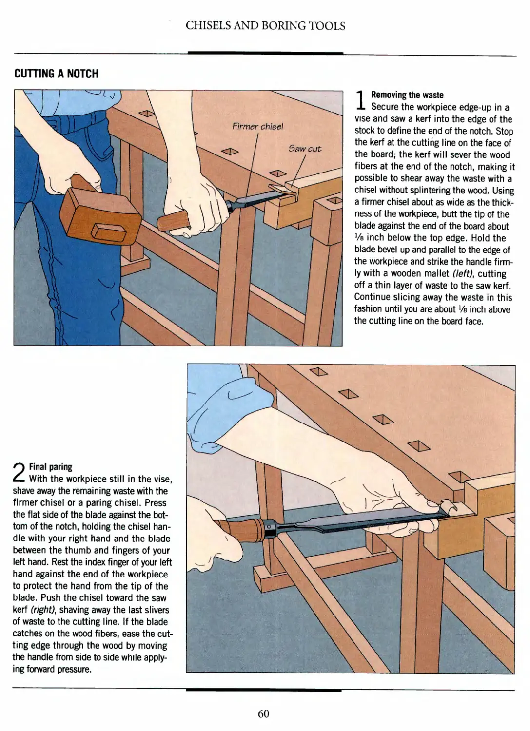


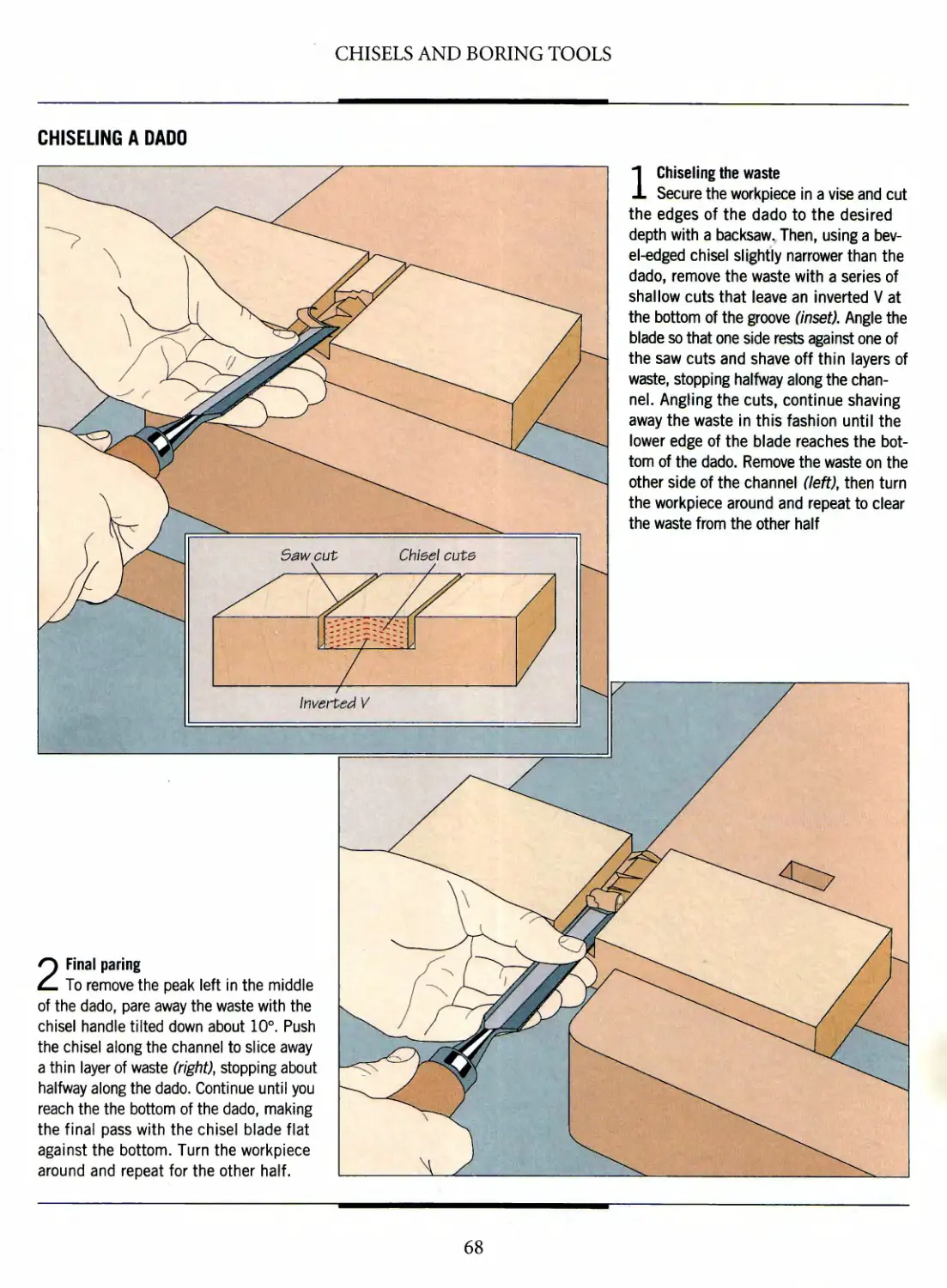


Author: Flaherty T. H.
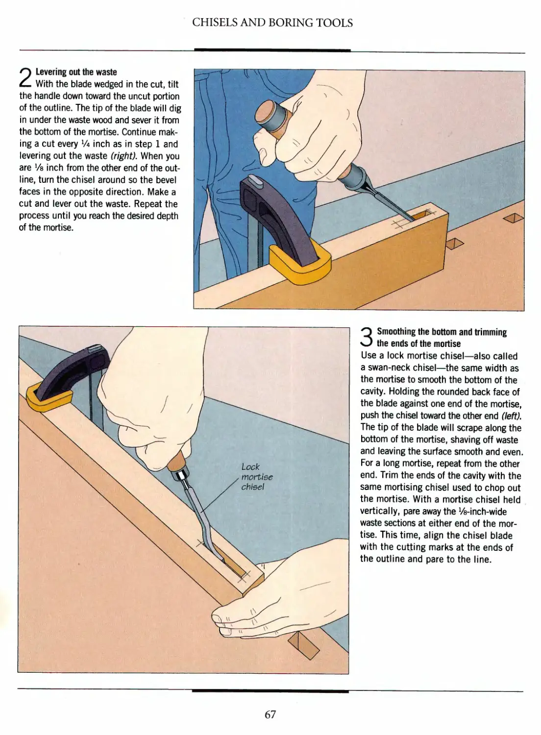
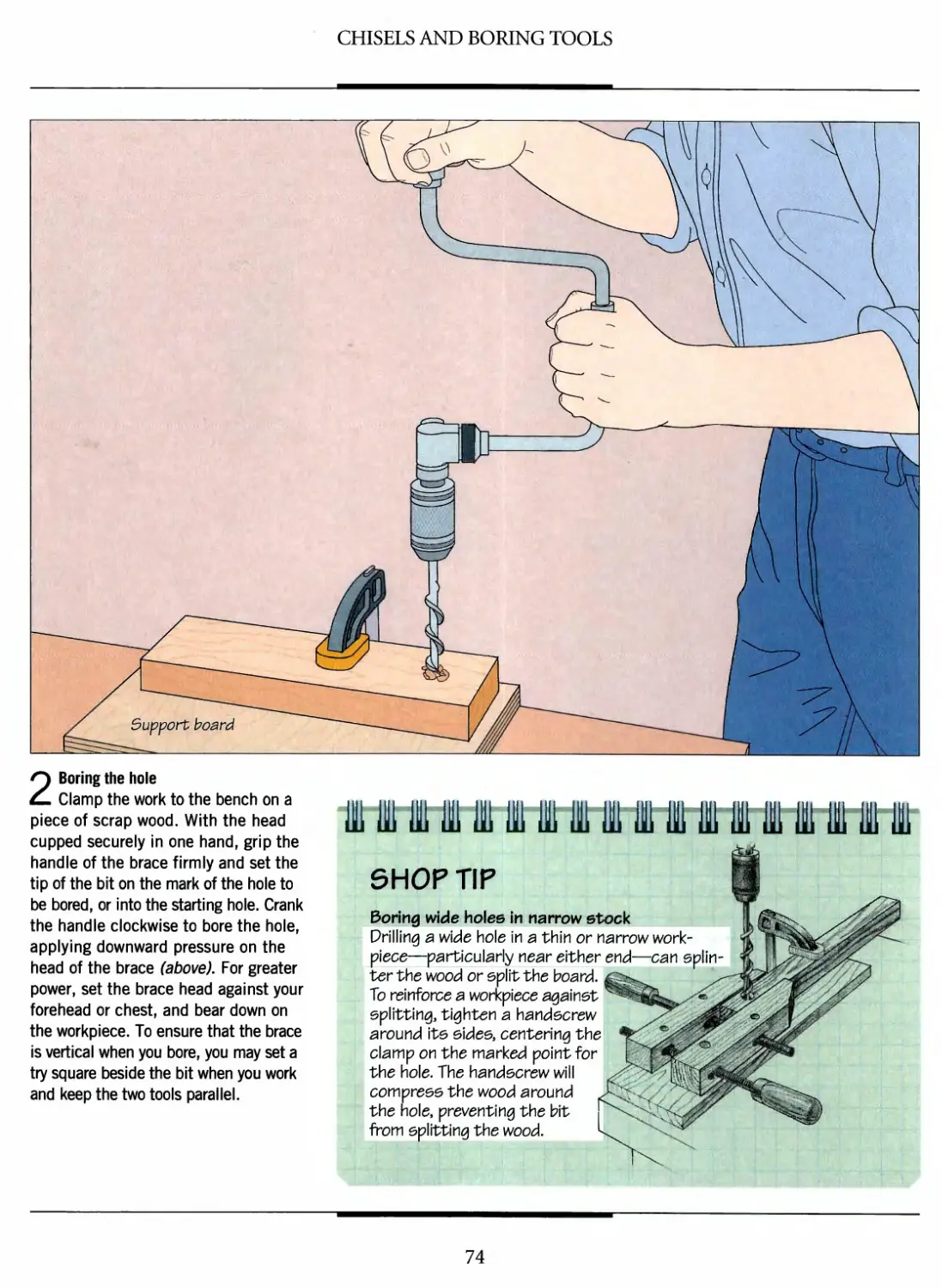
Tags: woodworking the art of woodworking hand tools. woodworking tools workshop guide
ISBN: 0-8094-9925-8
Year: 1993

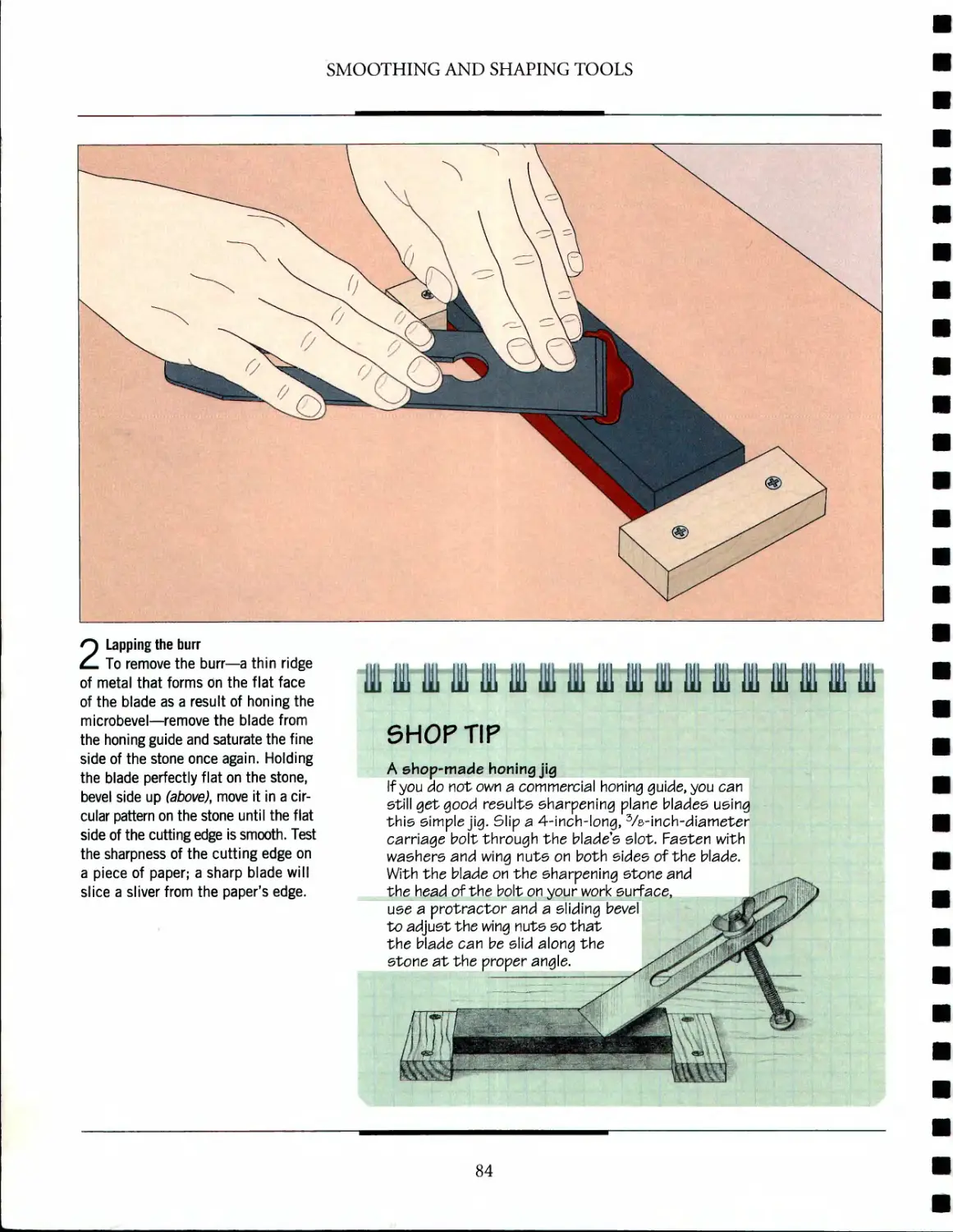
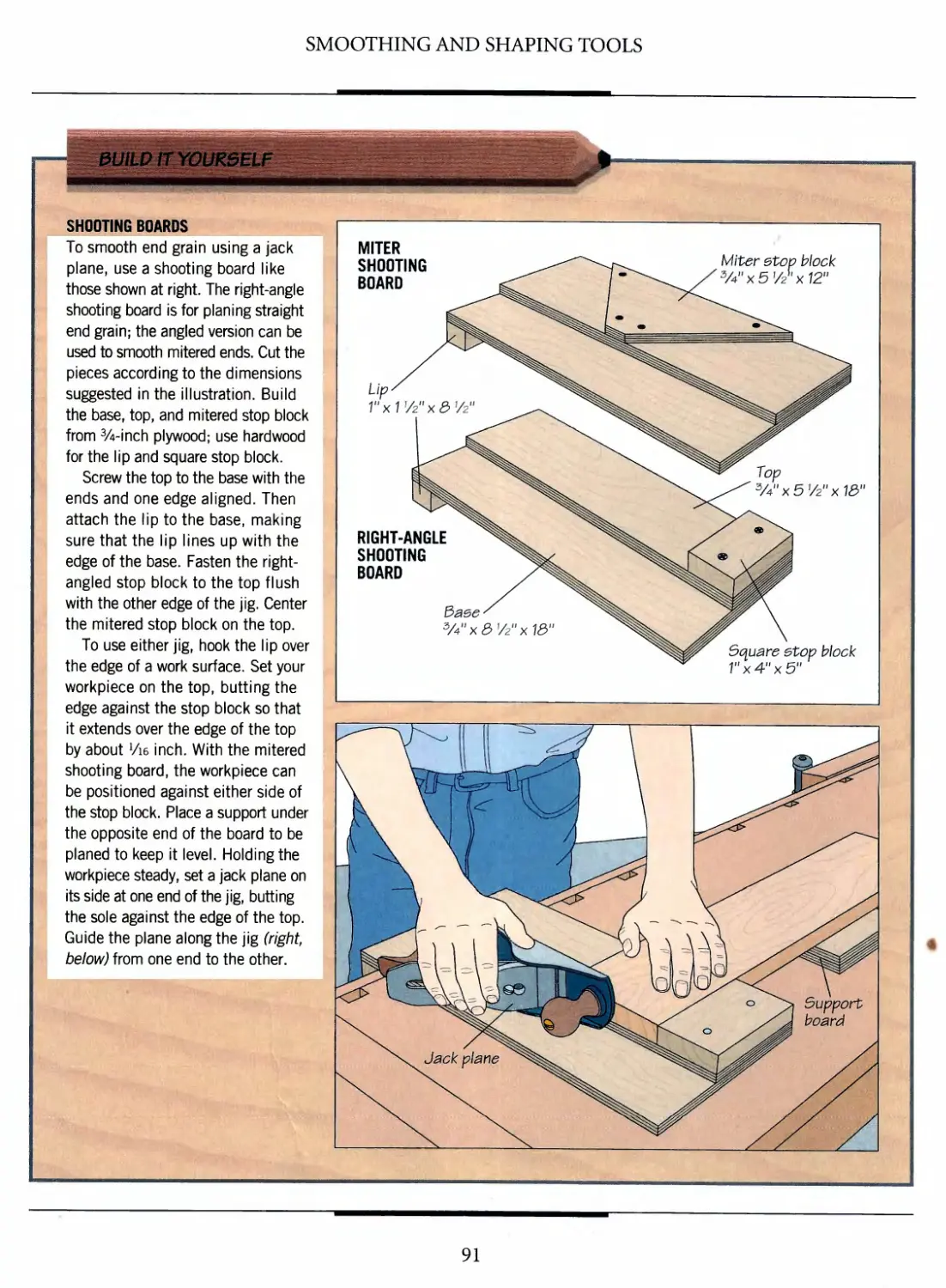
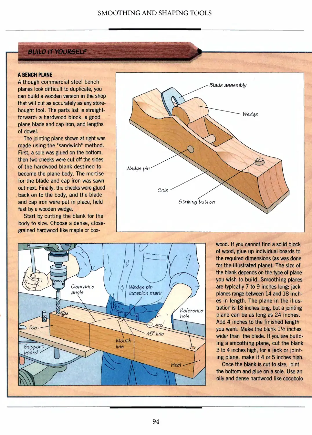
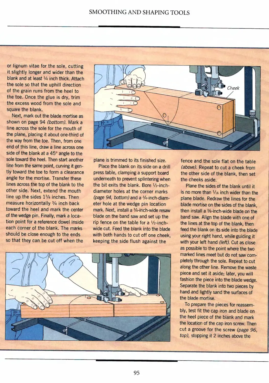
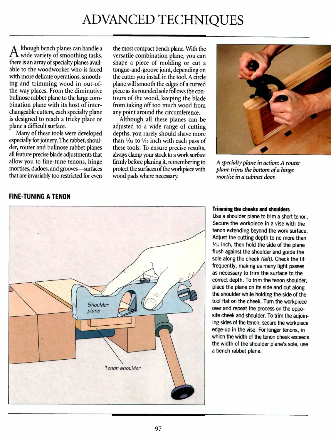
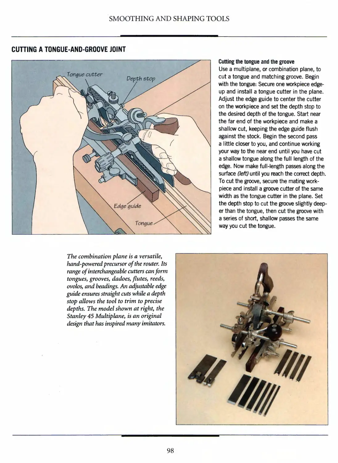
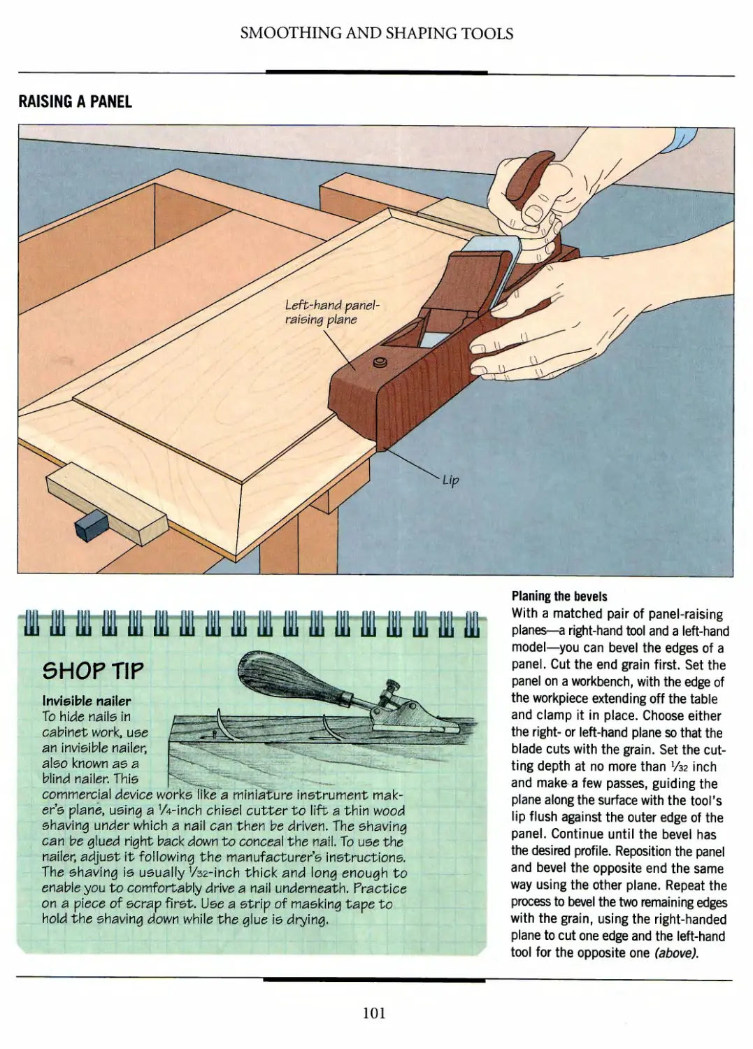
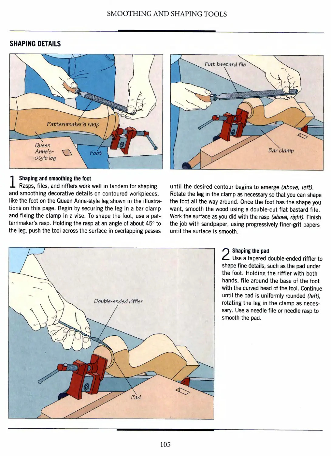
Text
TIME
BOOKS
THE ART OF WOODWORKING
HAND TOOLS
*fe~
WORKSHOP GUIDE
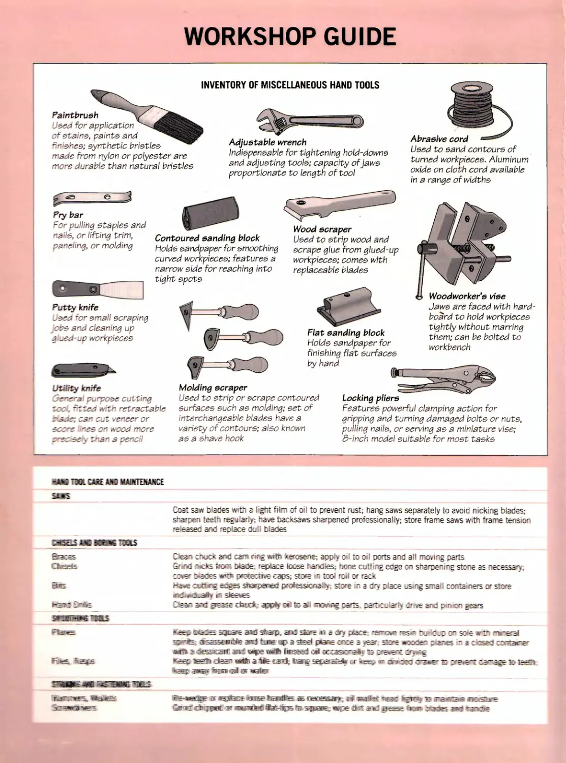
INVENTORY OF MISCELLANEOUS HAND TOOLS
Paintbrush
^sez for application
:* ezaine, vainte and
---'shee; synthetic brietlee
-^aie from nylon or polyester are
~S"S curable than natural brietlee
Adjustable wrench
Indiepeneable for tightening hold-downe
and adjueting toole; capacity ofjawe
proportionate to length of tool
P
e
Pry bar
~c culling etaplee and
-*s \e, or lifting trim,
cameling, or molding
Contoured sanding block
Holds eandpaper for smoothing
curved workpiecee; features a
narrow eide for reaching into
tight epote
Wood scraper
Deed to etrip wood and
ecrape glue from glued-up
workpiecee; comee with
replaceable bladee
Putty knife
^,365 'c srrali ecraping
zraa^z cleaning up
j -€i-^v vorKpleces
Utility knife
r:: . ~z~?j .•. 7-" -ez"actable
f=CO
Abrasive cord
Deed to eand contoure of
turned workpiecee. Aluminum
oxide on cloth cord available
in a range of widthe
Flat sanding block
Holde eandpaper for
finishing flat eurfacee
by hand
m
Woodworker's vise
Jawe are faced with hard-
board to hold workpiecee
tightly without marring
them; can be bolted to
workbench
Molding scraper
Used to etrip or ecrape contoured
eurfacee euch ae molding; eet of
interchangeable bladee have a
varievy of cor.toure; aieo known
ae a srave hook
Locking pliers
Featuree powerful clamping action for
gripping and turning damaged bolte or nuts,
pulling nails, or eerving ae a miniature viee;
3-inch model euitable for moet taeke
mm t c?x cm w*o MAittimycE
ssjis
ZftSES- km 3GS36 TOOLS
Pisces
■IFiiiiie^,, ilijEEps
mwmjm -fflsna—t mas
-itiiliiiFiiisniai^, Wwest
jiEirawSiiiiiEEal'
:oa: saw Varies mi? a «>^t fid™ of oc; to prevent rest; hang saws separately to avoid nicking bJaties;
r7€i ies:rj "egj.arvy; r.ave sacKsaws sharpened professionally; store frame saws with frame tension
5 lessee ar.c 'ezs'sca iui- DQes
~iea~ coc*: *nc osrr* rvg w"tin» fc^esere; app.y ■:"" id of? peris and ail moving pars
3'>.a '«c*s f?€€- 3180=: -epflece iccse Tisr-cies; dots c-tr-g acge en s-a^pe^rg st3r-e as ~ece
7^*er imsOES j*fltT» DOLeCflihfe CSipS; 5tG*£ ~ ICO r7 I 3f r2CK
r*3*e aso^g sugrs snarpeBTecE prafessicr»5lly st;-£ ~ a cry :■ ace ^irg s^ra I 3C~:a^afs c-r s:c
^jdiMidiLailKi r- steies
2''-=3"- 5ndr .3tsse idhodfej ^ppllf €il fe ailll TOtrspe zzns. 7a*37- a^ :r-.v£ 2-3 :«rc~ sears
it-ceiii.iEvaots sqiiKii'iE aiiffll stoarp* sund) store m a •irj pace -s^c^e *5s.f "j 7-
sp^il^: disasssEriPite aid town* up 51 -steal peine or de a _»eac saore #jec-rr z e
ftiiHii i 'isssraiiiit iiifrailiiipeiiii fiiisssidl ©nil a&rasio^ialk fc G~eve<rr ir.>-rg
ifeiOBipi felto cfei liiiliiii i2ii- iilfiiillfe' '.^jMifldlf^ llliiioffliini^ ^spTSiiistelliw or ^ieo anr owoej i?f5*?r
"iisiif. SMS? fciiiiniinlli m wata
: 7" soe w7i -ureal
-es rs: '-zee:? rcoraorf
iiifeiiiWdiiijilflE11 IF llllgpibDf llHlHiH"' llteroillllte.. ^il&. illlSiettESSSilfllf',,„ liill iililijililfirt
Qmniii1 idhrjpp ni!»niiiiiBiitai liitHiipKi'iiii.afpiiaK;.;: nnpiE '#irit smi jps
WORKSHOP GUIDE
INVENTORY OF MISCELLANEOUS HAND TOOLS
Paintbrush
Ueed for application
ofstaine, painte and
finiehee; eynthetic brietlee
made from nylon or polyeeter are
more durable than natural brietlee
Adjustable wrench
Indiepeneable for tightening hold-downe
and adjueting toole; capacity ofjawe
proportionate to length of tool
Pry bar
For pulling etaplee and
naile, or lifting trim,
paneling, or molding
Putty knife
Ueed for email ecraping
jobe and cleaning up
glued-up workpiecee
Utility knife
General purpoee cutting
u>c% fitted with retractable
ir&ae; can cut veneer or
ecc~e \'nes on wood more
zr-e&aety than a pencil
Contoured sanding block
Holde eandvaper for emoothing
curved workpiecee; featuree a
narrow eide for reaching into
tight epote
Wood scraper
Ueed to etrip wood and
ecrape glue from glued-up
workpiecee; comee with
replaceable bladee
t=r
Flat sanding block
Holde eandpaper for
finiehing flat eurfacee
by hand
Molding scraper
Ueed to etrip or ecrape contoured
eurfacee euch ae molding; eet of
interchangeable bladee have a
variety of contoure; aleo known
ae a ehave hook
Abrasive cord
Ueed to eand contoure of
turned workpiecee. Aluminum
oxide on cloth cord available
in a range of widthe
Woodworker's vise
Jawe are faced with hard-
board to hold workpiecee
tightly without marring
them; can be bolted to
workbench
Locking pliers
Featuree powerful clamping action for
gripping and turning damaged bolte or nute,
pulling naile, or eerving ae a miniature viee;
3-inch model euitable for moet taeke
sums
m
Coat saw biades with a light film of oil to prevent rust; hang saws separately to avoid nicking blades;
sharpen teeth regularly; have hacksaws sharpened professionally; store frame saws with frame tension
released and replace dull blades
Dear* duck and cam ring with kerosene, apply oil to oil ports and ail moving parts
Grind racks mm biacSe; replace loose handles? hone 'Cuffing edge on sharpening stone as necessary;
eerier biades with poiraiie ops- sfve w tool roll or rack
l^iieailfeied^siiaipffl professionally; store in a dry place using small containers or store
jiiii^li*Scffii£aiili^ ii stoewes
Gleam amd ;p=as£ tibodk; .ajpplf di Is ill «w«g parts, psrteojiariy dirove and pinion gears
jftafes spwe ami ^liiatpln aid share Ira a cty place; 'resist resm hrnl&jo on so*e wi£b nm&M
jflBBtjBfiaHiiiiftfe annul Hums up a stadl jploBs ones 3 yzz*- store wnEMfew sfesraes in & ctesd- €Sifeiii®r
' anmlO wpewlli linesraraflft oil1 msammO^ te pFe^^i eftying
iCbimiiiiiiih .ai ffljllllte' (csairfll; Iteiiiigs^pHiiiiiillf 'or keep m tim&ssi chaser a^ pmest t^m<M^ w
lillir Motor
ilHni—v ll^irllllfe;..lais;. iiiiiiiiffiaiiit|i^ .imp nmdlM WifsaB|ii llljgpi]l|
liillliuibililflS'
WORKSHOP GUIDE
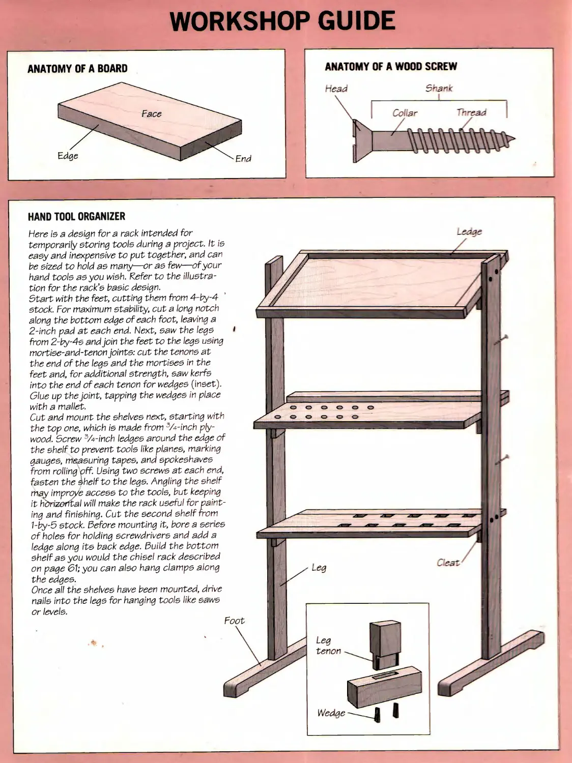
ANATOMY OF A BOARD
L^/^^^^^ Face
/ ^Hj/Nv ^^
l Edge ^"^^J^^
^^End
ANATOMY OF A WOOD SCREW
^eaa
~ar<
,o\ar
'324
V—
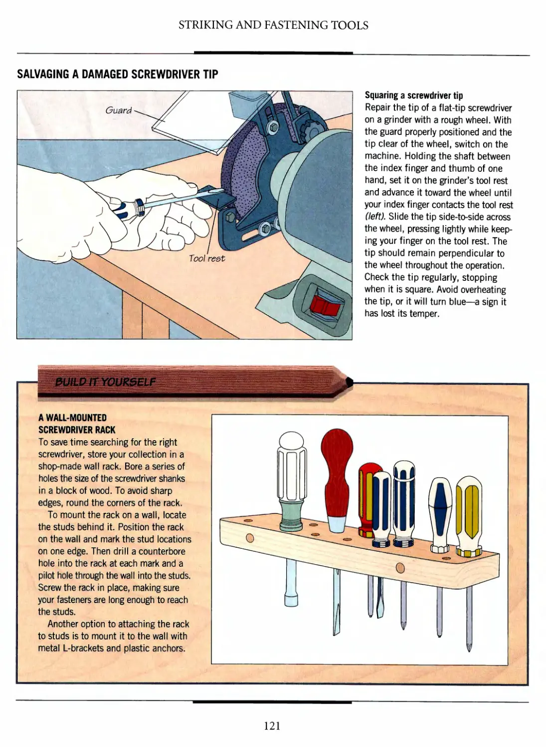
HAND TOOL ORGANIZER
Here is a design for a rack intended for
temporarily storing tools during a project. It ie
easy and inexpensive to put together, and can
be sized to hold ae many—or ae few—of your
hand tools as you wish. Refer to the
illustration for the rack's basic design.
Start with the feet, cutting them from 4-by-4
stock. For maximum stability, cut a long notch
along the bottom edge of each foot, leaving a
2-inch pad at each end. Next, saw the legs
from 2-by-As and join the feet to the lege using
mortise-and-tenon joints: cut the tenons at
the end of the legs and the mortises in the
feet and, for additional strength, saw kerfs
into the end of each tenon for wedges (Inset).
Glue up the joint, tapping the wedges in place
with a mallet.
Cut and mount the shelves next, starting with
the top one, which is made from 3A-inch
plywood. Screw 3A-inch ledges around the edge of
the shelf to prevent tools like planes, marking
gauges, measuring tapes, and spokeshaves
from rolling"off. Using two screws at each end,
fasten the shelf to the legs. Angling the shelf
may improye access to the tools, but keeping
it horizontal will make the rack useful for
painting and finishing. Cut the second shelf from
1-by-5 stock. Before mounting it, bore a series
of holes for holding screwdrivers and add a
ledge along its back edge. 3uild the bottom
shelf as you would the chisel rack described
on page 61; you can also hang clamps along
the edges.
Once all the shelves have been mounted, drive
nails into the legs for hanging tools like saws
or levels.
^33€
THE ART OF WOODWORKING
HAND TOOLS
TIME-LIFE BOOKS
ALEXANDRIA, VIRGINIA
ST. REMY PRESS
MONTREAL-NEW YORK
THE ART OF WOODWORKING was produced by
ST. REMY PRESS
PUBLISHER
PRESIDENT
Series Editor
Series Art Director
Senior Editors
Art Directors
Designers
Research Editor
Picture Editor
Writers
Contributing Illustrators
Administrator
Production Manager
System Coordinator
Photographer
Kenneth Winchester
Pierre Leveille
Pierre Home-Douglas
Francine Lemieux
Marc Cassini (Text)
Heather Mills (Research)
Normand Boudreault, Luc Germain
Solange Laberge
Jean-Guy Doiron, Michel Giguere
Jim McRae
Christopher Jackson
Andrew Jones, Rob Lutes
Ronald Durepos, Jean-Pierre
Bourgeois, Michel Blais, Jacques
Perrault, Alain Longpre, Jocelyn
Veillette, Robert Paquet
Natalie Watanabe
Michelle Turbide
Jean-Luc Roy
Robert Chartier
Time-Life Books is a division of Time-Life Inc.,
a wholly owned subsidiary of
THE TIME INC. BOOK COMPANY
TIME-LIFE BOOKS
President
Vice President
Editor-in-Chief
Director of Editorial Resources
John D Hall
Nancy K. Jones
Thomas H. Flaherty
Elise D. Ritter-Clough
Marketing Director ReginaHall
Editorial Director Lee Hassig
Consulting Editor John R. Sullivan
Production Manager Marlene Zack
THE CONSULTANTS
Bob Jardinico manages woodworking sales
for Colonial Saw Co., a machinery sales and
service company based in Kingston,
Massachusetts. He also restores antique furniture
in his home workshop in Plymouth, Mass.
Giles Miller-Mead taught advanced cabinet-
making at Montreal technical schools for more
than ten years. A native of New Zealand, he has
worked as a restorer of antique furniture.
Joseph Truini is Senior Editor of Home
Mechanix magazine. A former Shop and Tools
Editor of Popular Mechanics, he has worked as
a cabinetmaker, home improvement contractor
and carpenter.
Hand tools
p. cm.—(The Art of Woodworking)
Includes index.
ISBN 0-8094-9925-8
1. Woodworking tools
I. Time-Life Books. II. Series
TT186.H36 1993
684' .082—dc20 92-46416
CIP
For information about any Time-Life book,
please call 1-800-621-7026, or write:
Reader Information
Time-Life Customer Service
P.O.BoxC-32068
Richmond, Virginia
23261-2068
© 1993 Time-Life Books Inc.
All rights reserved.
No part of this book may be reproduced in
any form or by any electronic or mechanical
means, including information storage and
retrieval devices or systems, without prior
written permission from the publisher, except
that brief passages may be quoted for reviews.
First printing. Printed in U.S.A.
Published simultaneously in Canada.
TIME-LIFE is a trademark of Time Warner
Inc. U.S.A.
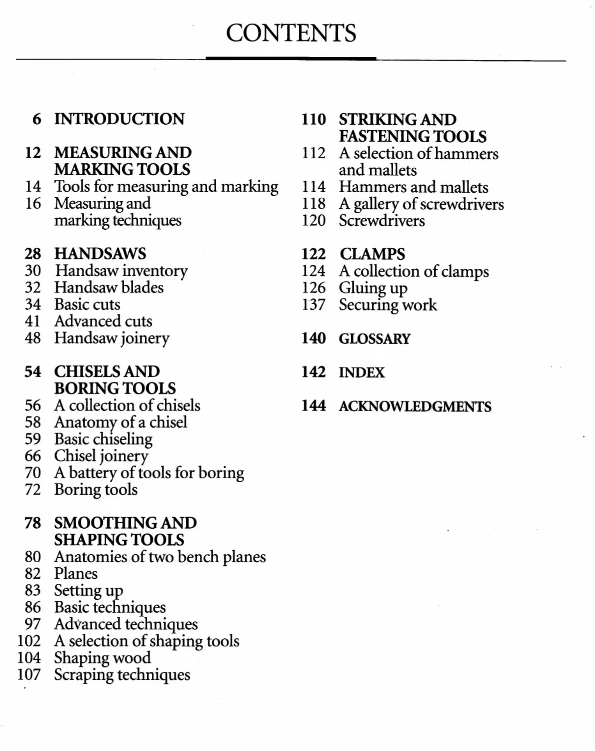
6 INTRODUCTION
12 MEASURING AND
MARKING TOOLS
14 Tools for measuring and marking
16 Measuring and
marking techniques
28 HANDSAWS
30 Handsaw inventory
32 Handsaw blades
34 Basic cuts
41 Advanced cuts
48 Handsaw joinery
54 CHISELS AND
BORING TOOLS
56 A collection of chisels
58 Anatomy of a chisel
59 Basic chiseling
66 Chisel joinery
70 A battery of tools for boring
72 Boring tools
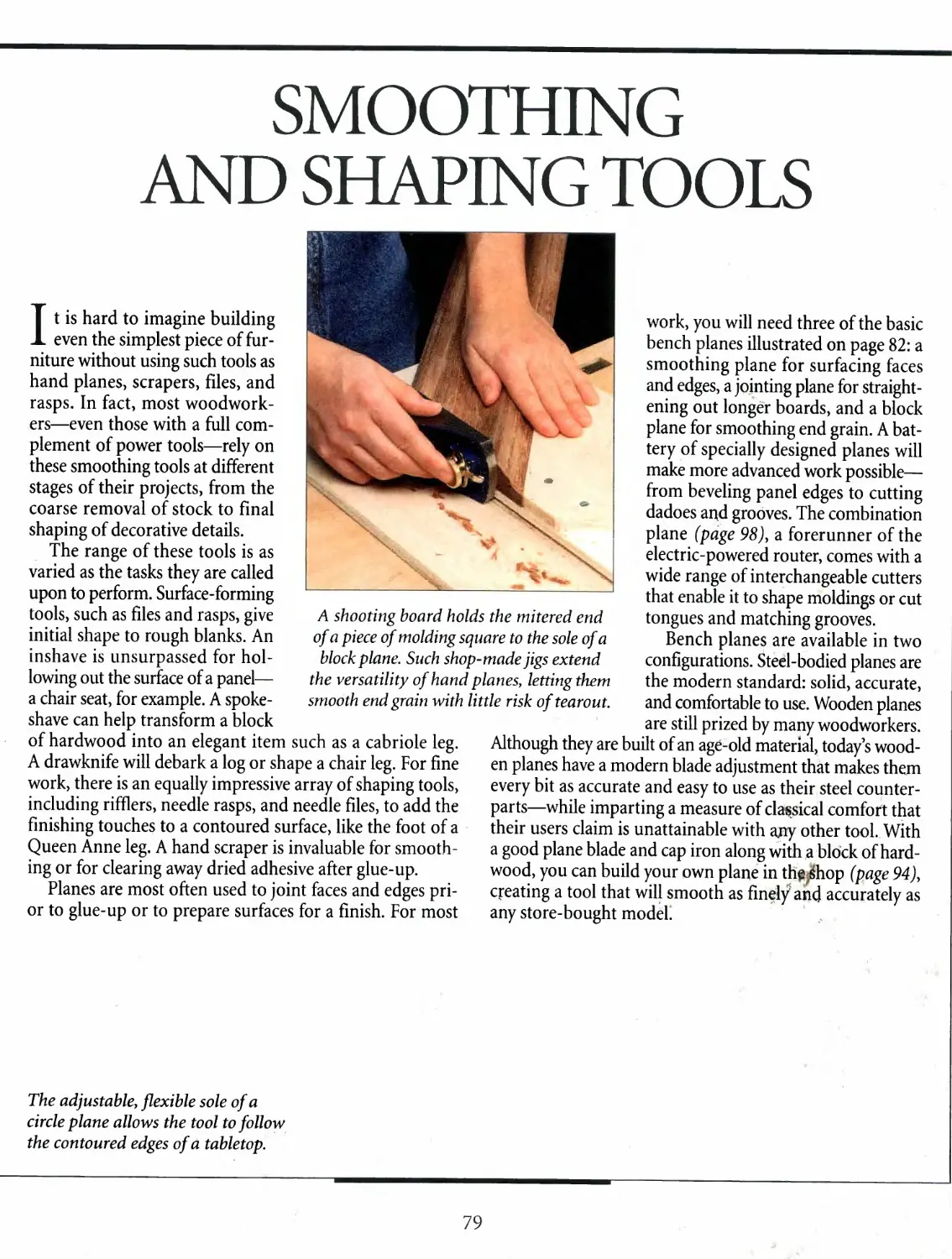
78 SMOOTHING AND
SHAPING TOOLS
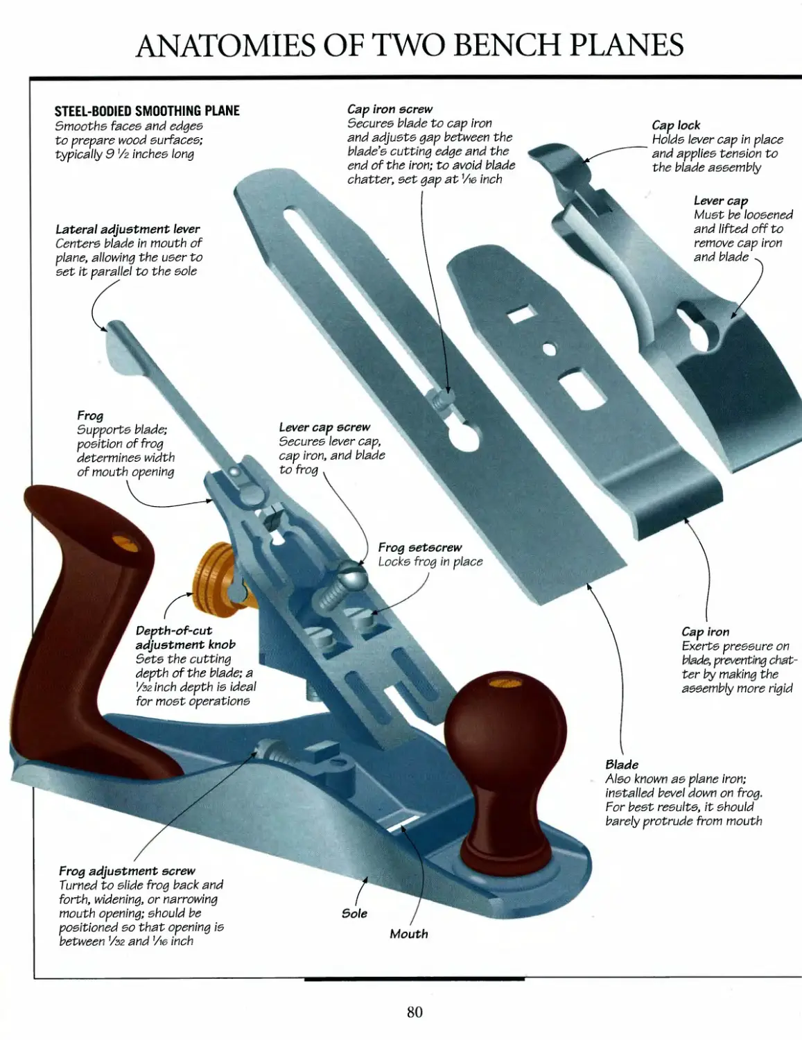
80 Anatomies of two bench planes
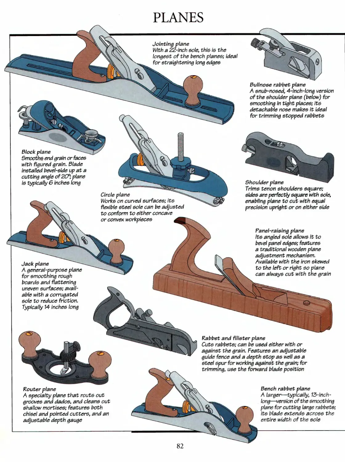
82 Planes
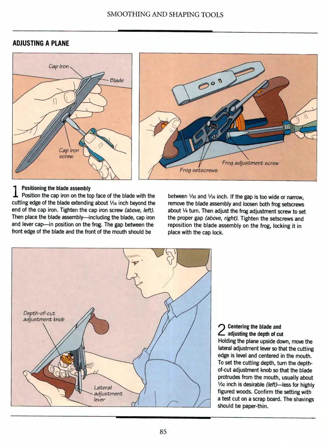
83 Setting up
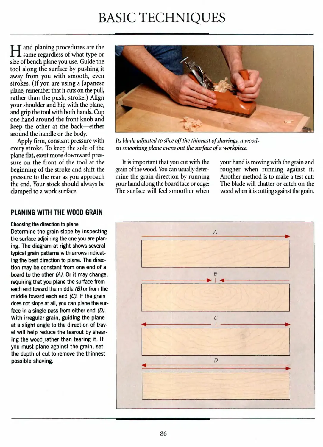
86 Basic techniques
97 Advanced techniques
102 A selection of shaping tools
104 Shaping wood
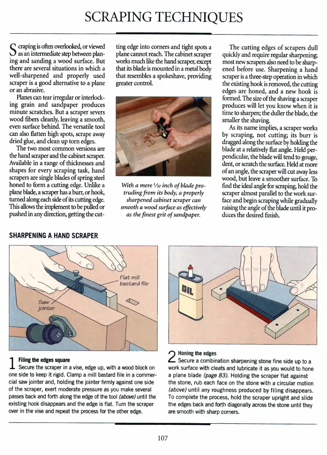
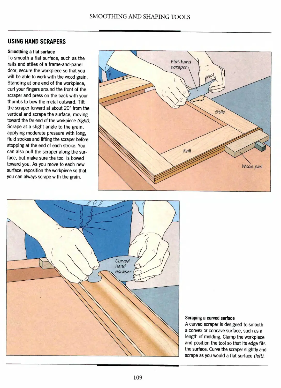
107 Scraping techniques
110
112
114
118
120
122
124
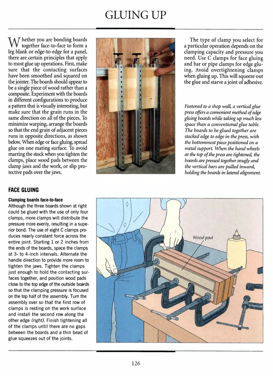
126
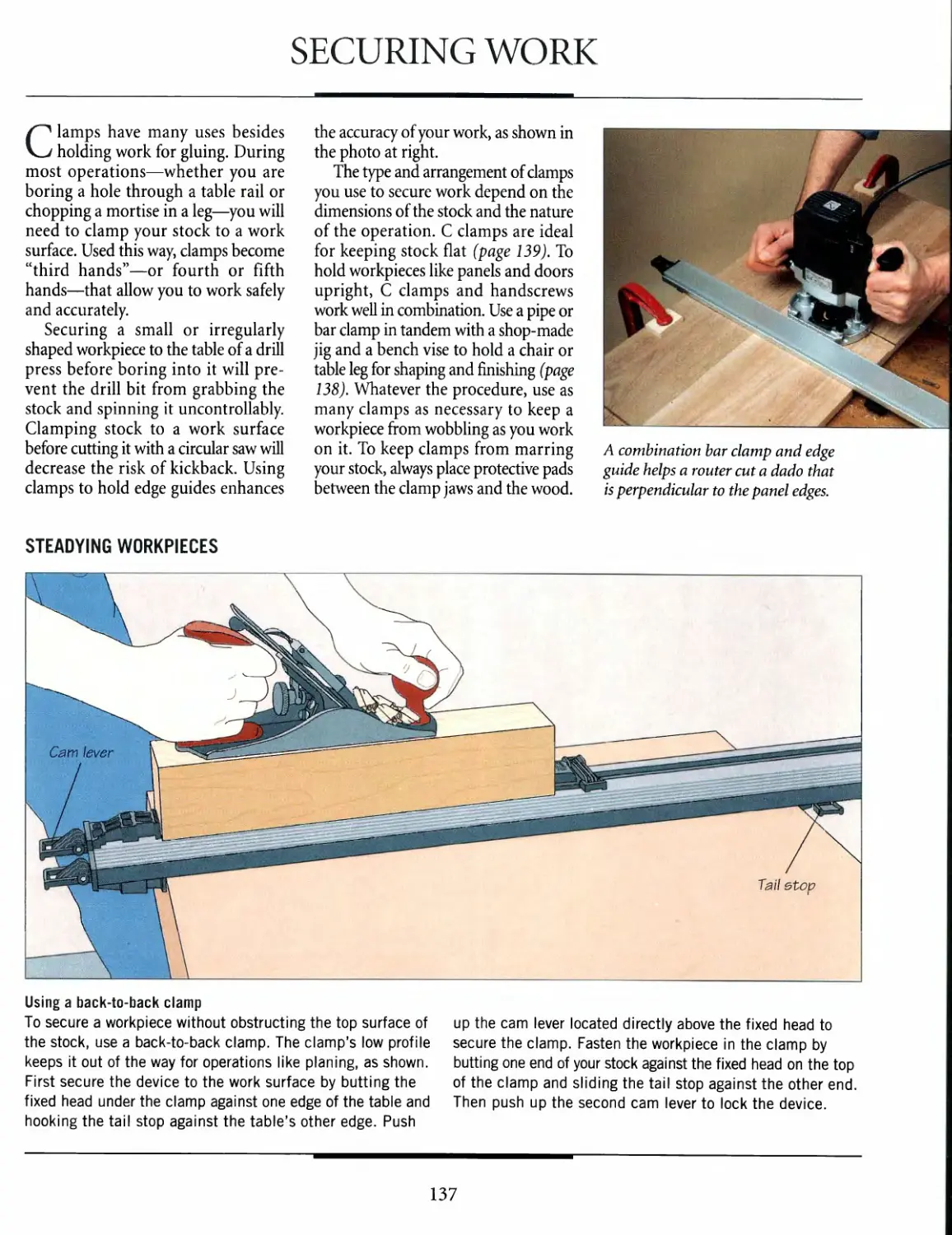
137
140
142
STRIKING AND
FASTENING TOOLS
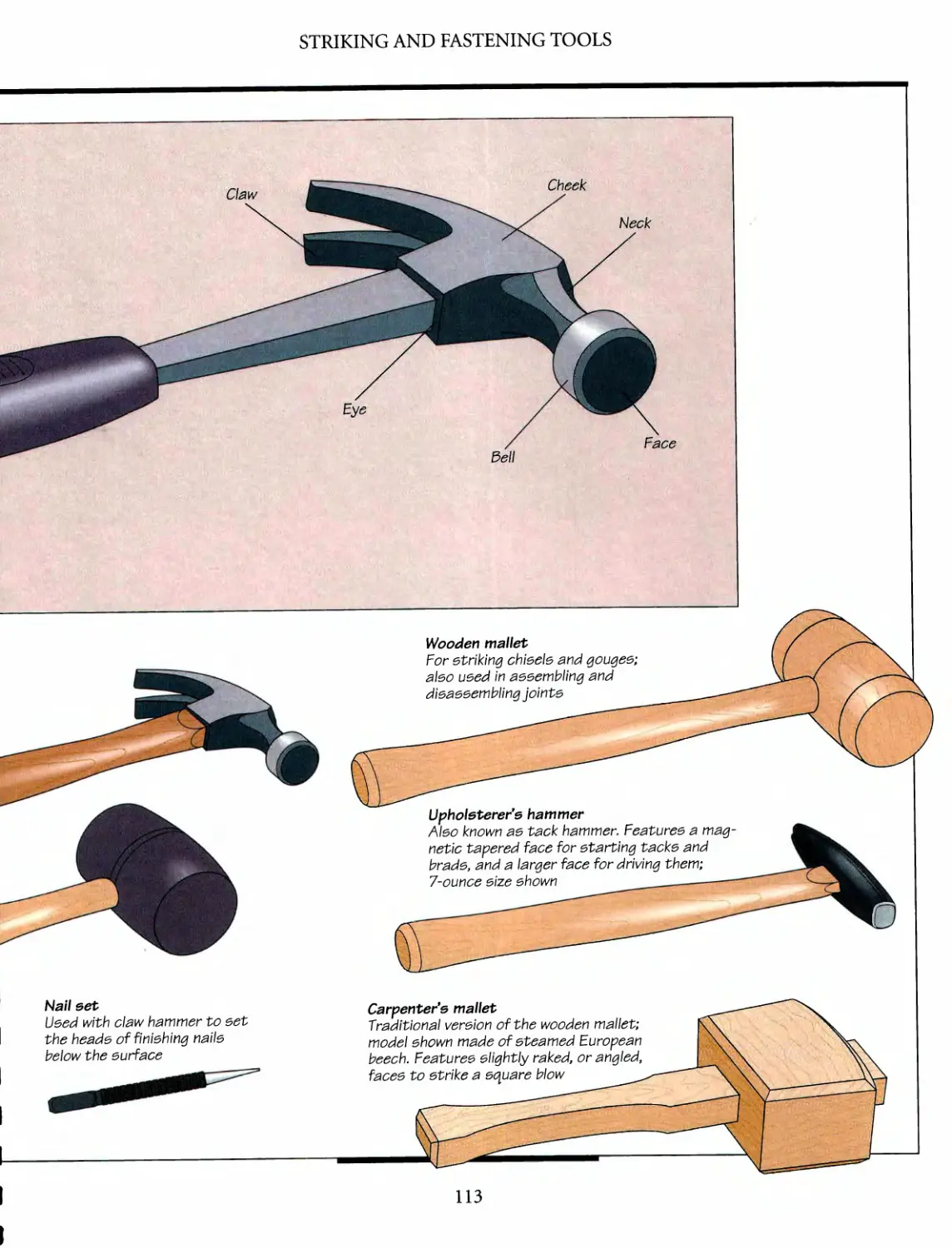
A selection of hammers
and mallets
Hammers and mallets
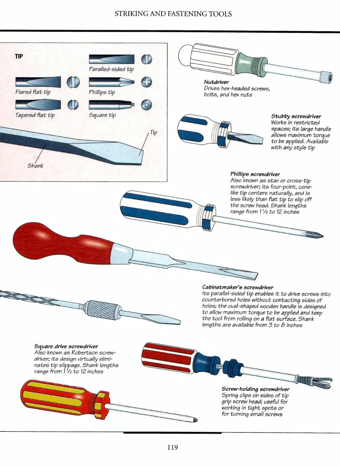
A gallery of screwdrivers
Screwdrivers
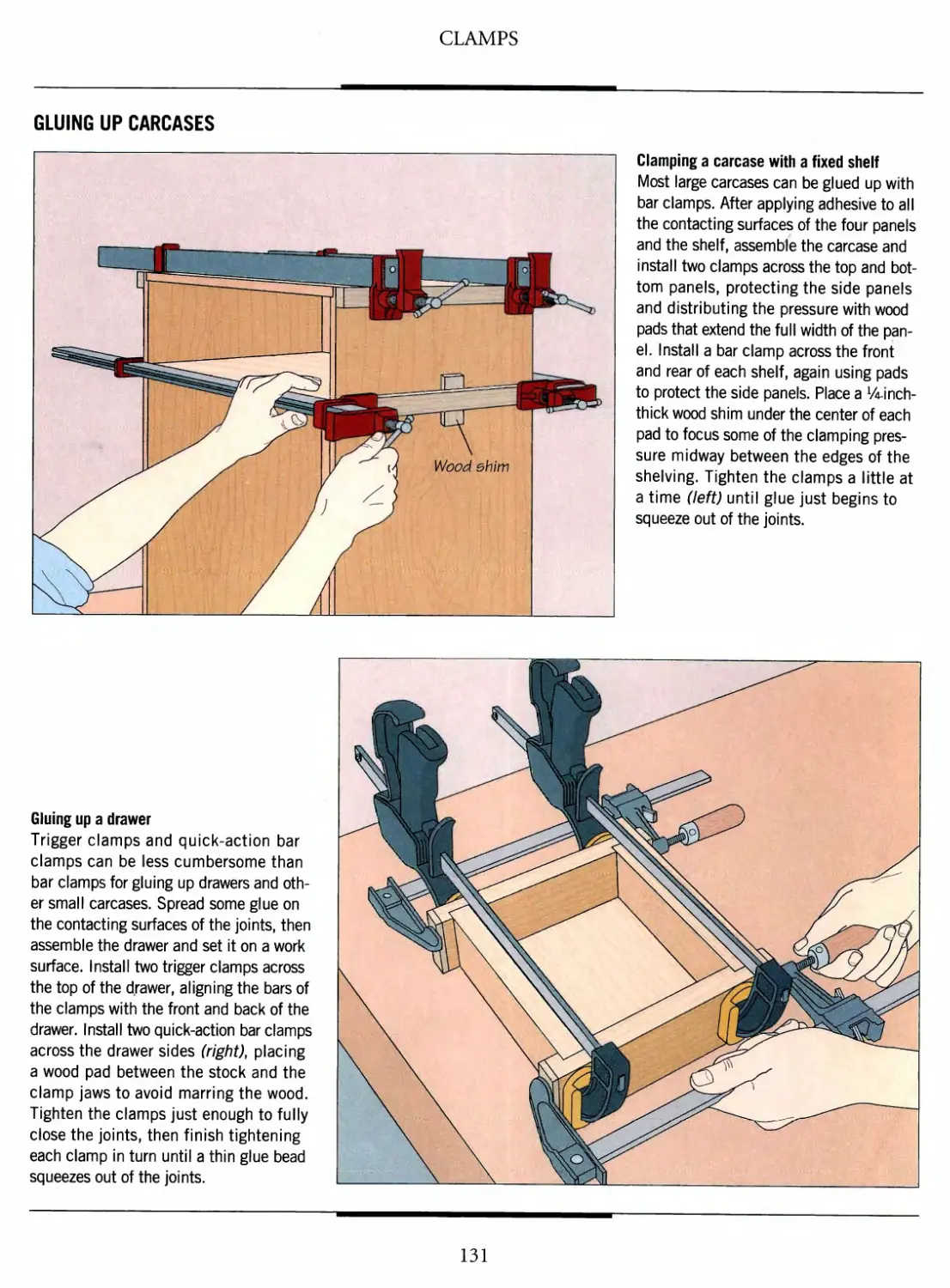
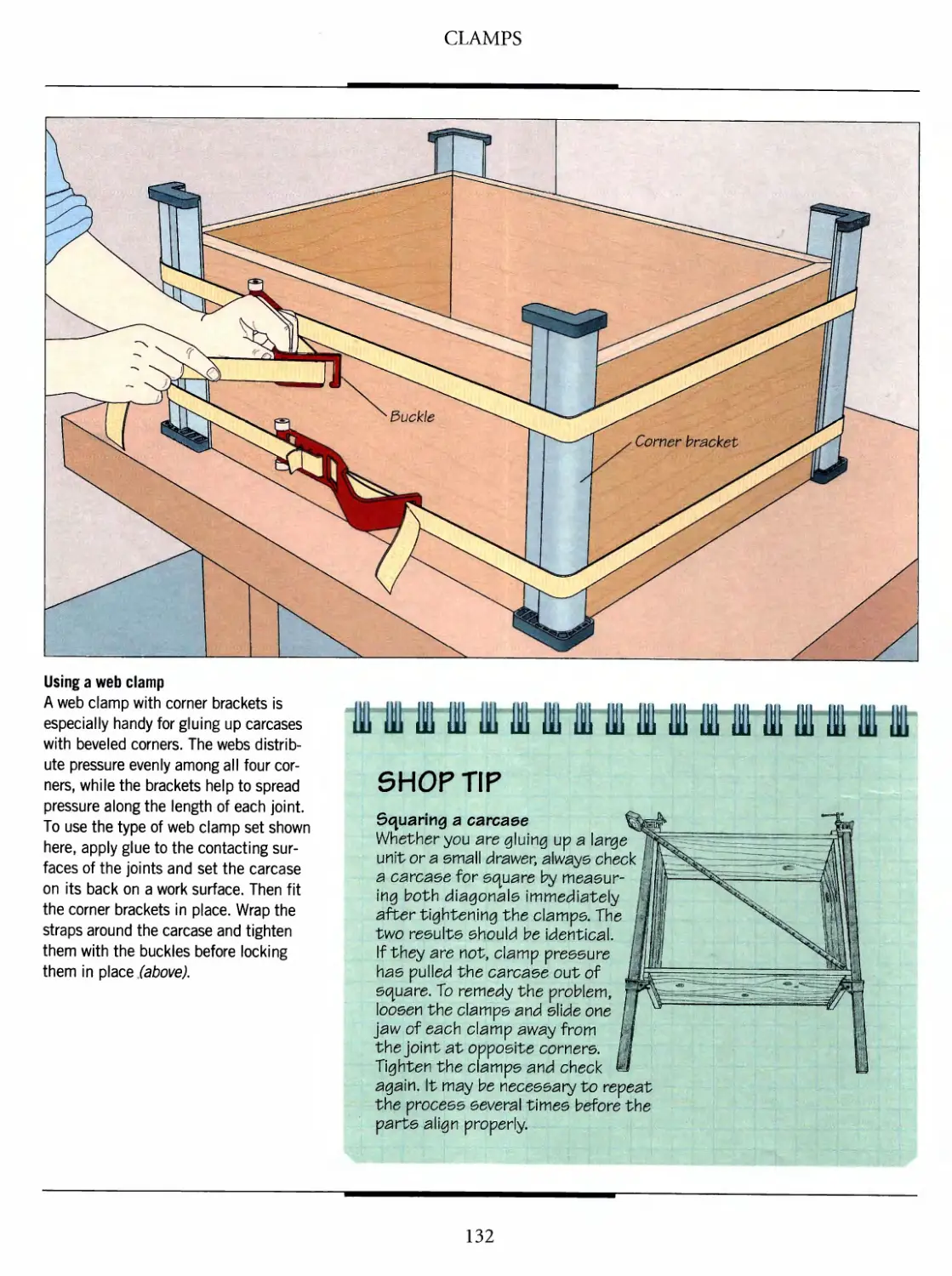
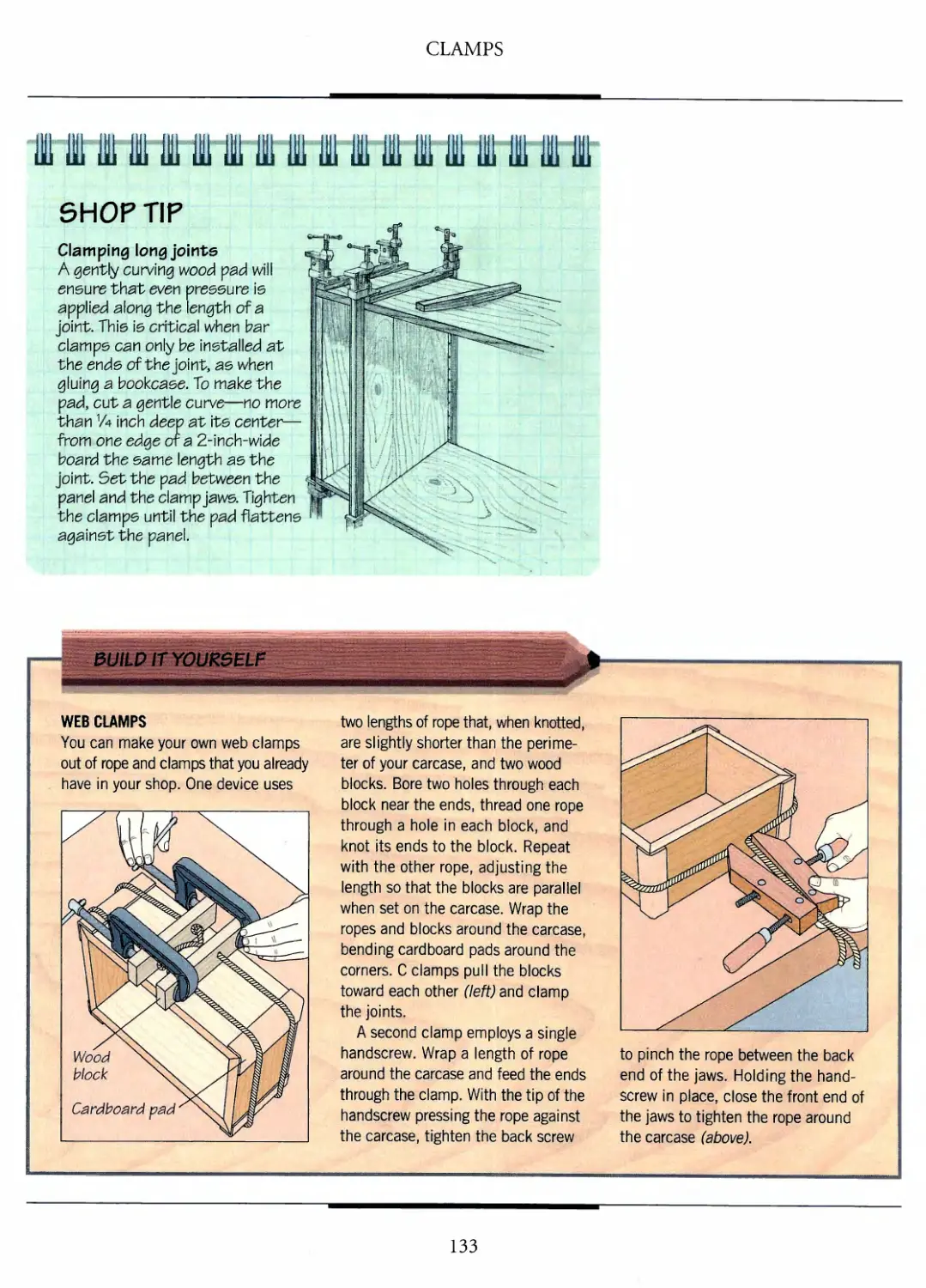
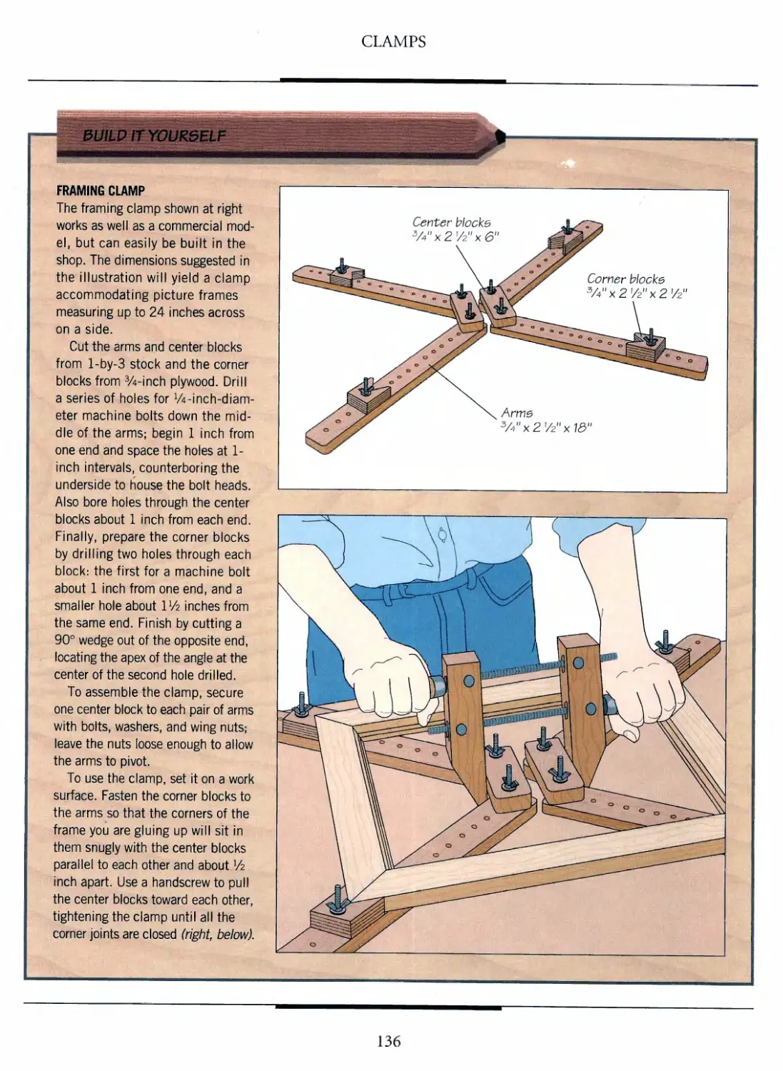
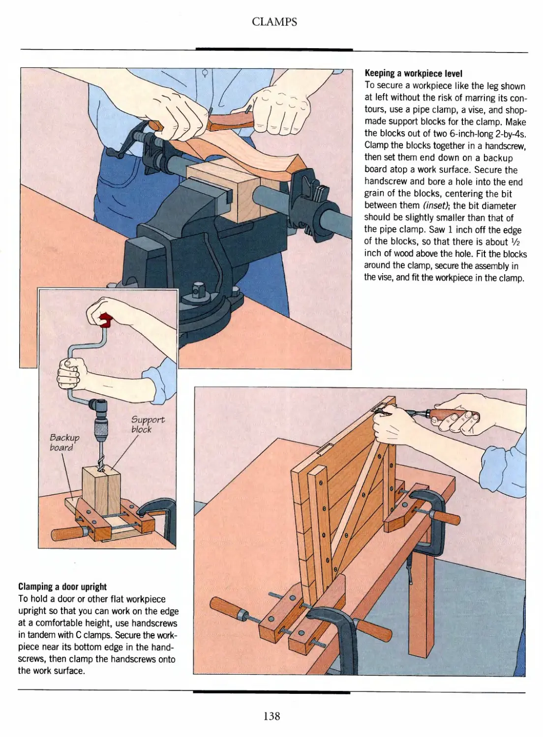
CLAMPS
A collection of clamps
Gluing up
Securing work
GLOSSARY
INDEX
144 ACKNOWLEDGMENTS
'I
#v
III
^
'-"*-• -I
*-*
' ,-*i
INTRODUCTION
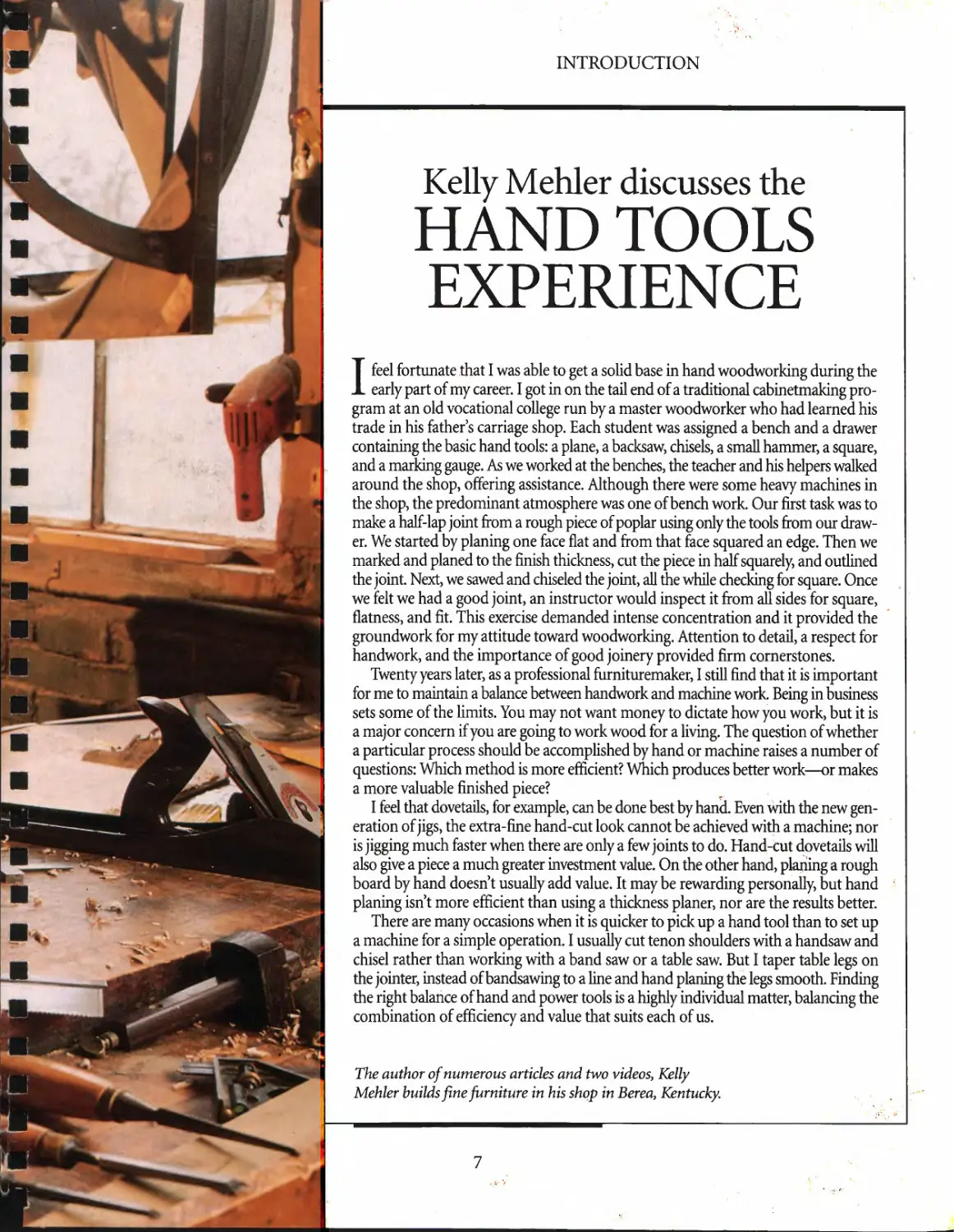
Kelly Mehler discusses the
HAND TOOLS
EXPERIENCE
I feel fortunate that I was able to get a solid base in hand woodworking during the
early part of my career. I got in on the tail end of a traditional cabinetmaking
program at an old vocational college run by a master woodworker who had learned his
trade in his father's carriage shop. Each student was assigned a bench and a drawer
containing the basic hand tools: a plane, a backsaw, chisels, a small hammer, a square,
and a marking gauge. As we worked at the benches, the teacher and his helpers walked
around the shop, offering assistance. Although there were some heavy machines in
the shop, the predominant atmosphere was one of bench work. Our first task was to
make a half-lap joint from a rough piece of poplar using only the tools from our
drawer. We started by planing one face flat and from that face squared an edge. Then we
marked and planed to the finish thickness, cut the piece in half squarely, and outlined
the joint. Next, we sawed and chiseled the joint, all the while checking for square. Once
we felt we had a good joint, an instructor would inspect it from all sides for square,
flatness, and fit. This exercise demanded intense concentration and it provided the
groundwork for my attitude toward woodworking. Attention to detail, a respect for
handwork, and the importance of good joinery provided firm cornerstones.
Twenty years later, as a professional fiirnituremaker, I still find that it is important
for me to maintain a balance between handwork and machine work Being in business
sets some of the limits. You may not want money to dictate how you work, but it is
a major concern if you are going to work wood for a living. The question of whether
a particular process should be accomplished by hand or machine raises a number of
questions: Which method is more efficient? Which produces better work—or makes
a more valuable finished piece?
I feel that dovetails, for example, can be done best by hand. Even with the new
generation of jigs, the extra-fine hand-cut look cannot be achieved with a machine; nor
is jigging much faster when there are only a few joints to do. Hand-cut dovetails will
also give a piece a much greater investment value. On the other hand, planing a rough
board by hand doesn't usually add value. It may be rewarding personally, but hand
planing isn't more efficient than using a thickness planer, nor are the results better.
There are many occasions when it is quicker to pick up a hand tool than to set up
a machine for a simple operation. I usually cut tenon shoulders with a handsaw and
chisel rather than working with a band saw or a table saw. But I taper table legs on
the jointer, instead of bandsawing to a line and hand planing the legs smooth. Finding
the right balance of hand and power tools is a highly individual matter, balancing the
combination of efficiency and value that suits each of us.
The author of numerous articles and two videos, Kelly
Mehler builds fine furniture in his shop in Berea, Kentucky.
7
INTRODUCTION
Curtis Erpelding on
MAKING
HAND TOOLS
IVe been making my own hand tools for almost as long as IVe been woodworking.
A friend once asked me, "Why bother when you can buy factory-made hand tools
ready to use?" Why indeed? There is no easy answer.
I could say that making my own tools lets me customize them for special jobs. For
example, I've made several wooden planes with the pitch of the blade greater than
the standard 45 degrees—the angle at which the front of the edge contacts the
wood—in order to work difficult grain without tearout. IVe also made molding planes
with cutting profiles that are simply not available in a store-bought plane or routpr
bit. Another reason that I make my own tools is for the fit. Anyone who has made a
wooden-bodied plane knows that in use it has a different feel from a cast iron or steel
plane; this is sometimes a benefit. A handle or plane body can be shaped to conform
to the hand, and feel comfortable.
Hand-made tools can be superior to manufactured tools, but many of the planes,
chisels, and knives I have made are functionally no different from their mass-produced
counterparts. For me, function alone is not enough to explain the extra time and effort
involved. Some would say then that making hand tools indicates a romantic nature,
an attempt to recapture an earlier era, to mimic a purer form of craftsmanship. While
I won't deny a certain romantic bent, what little research I have done into the history
of the woodworker s craft has convinced me that few workmen ever made their own
tools if they could afford not to. Toolmaking as a separate craft predates the Industrial
Revolution. Only for the most off-beat job or only if he plied his trade in some isolated
corner would the woodworker presume to duplicate or improve on the product of
fellow artisans skilled in the specialized manufacture of tools.
No, in the final an%sis I guess that I make my own tools simply because I enjoy
making tools. Toolmaking, like furniture making, boat building, or instrument
making, is a discipline unto itself. The main difference I suppose is that when I complete
a piece of furniture, I send it into the world and it is no longer part of my life. But when
I make a tool, it joins my family of other tools. And, after I deliver that piece of furniture
I stand back and think with satisfaction, "I made that—and I made it with the tools
that I also made."
Curtis Erpelding builds custom furniture
in his shop in Port Orchard, Washington.
8
JT5M*- -~V'SPi":
*r«, „•
:••
*«**
w«
4
V
^)
s
cv
A
mK'
£.<#
INTRODUCTION
Toshio Odate expresses
RESPECT FOR
HAND TOOLS
T apanese craftsmen have a very special relationship with their took We believe each
J of our tools possesses a soul For example, when we need to get around in our shops,
we don't step over our tools; we prefer to walk around them instead.
I learned these lessons as a young apprentice in Japan, when I carried my master's
toolbox for the first time. The box was made of pine, and measured about three feet
long, one foot wide, and eight inches deep. Packed with steel tools, hardwood blocks,
and several sharpening stones, the box was heavy enough to crush my shoulder,
especially with our destination—a customer's house—still miles away When we arrived,
after struggling to keep up with my fast-walking master, I looked for a spot to put the
toolbox down. Our customer, sensing the pain in my shoulder, indicated the veranda.
I set the box down carelessly—and noisily. I didn't think much of it; there was nothing
breakable in the box. But my master turned and yelled at me. When I looked up, I
could see that he was furious. Had our customer not been there, my master probably
would have struck me.
Such a scene reveals the intense experience of apprenticeships in Japan, and the
setting in which I learned to respect my tools. For a shokunin—Si craftsman with skill,
speed, and professional responsibility—tools are not just things. They have a soul.
They can be an extension of the craftsman's body Japanese craftsmen form a bond
with their tools, one that more closely resembles a personal relationship than one
between a person and an inanimate object.
In contrast with modern methods of mechanized furniture production, working
with hand tools allows you to take a personal approach to your work. When you put
your mind into your work fully—as hand tools permit you to do—you give your work
a human touch. Qualities like love, pride, concern, and simplicity will show in the
finished work itself as by-products of the woodworking process.
There is something missing from modern furniture making. Much of it lacks
warmth; it isn't personal. Fitting hundreds of inlays on a tabletop by means of a
computer program may be quick, and it may be the "reasonable" way to get the job done.
However, it shows nothing of the kind of feeling you impart with the keen cutting edge
of a plane blade. I respect modern technology, but there has never been a greater need
for hand tools as a key to express the nuances of human values.
Toshio Odate builds fine furniture in his workshop
in Woodbury, Connecticut He also teaches
woodworking at the Pratt Institute in Brooklyn, New York
11
*
V
ESB?;. .■■>.■■**'
J^-^.V^
;yr r
MEASURING
AND MARKING TOOLS
Every woodworking project begins
with a single mark—a line
describing the size and shape of the work's first
piece. Inscribed accurately and followed
skillfully, this measurement and others
that follow will guide the woodcrafter
unerringly toward successful
completion of an object of beauty. But much is
at stake: Inaccurate or erratic
measurements can doom a noble design to the
kindling box.
Fortunately, something close to
perfection is attainable; centuries of
experience have produced tools and techniques
that produce reliable, accurate
measurements. This chapter is a guide to
those instruments and methods.
On the pages that follow you will find
a wide array of instruments described;
gauges of several kinds, protractors,
knives, compasses, squares, lines, tapes, and rules. Although
it is possible to work well with nothing more than a pencil and
ruler, each specialized tool has a job that it does better than
any substitute. Some are considered indispensable. The
majority of woodworkers would probably include among these a
carpenter's square, a try square, a combination square, a tape
measure, and a cutting gauge.
A miter square confirms that a
bevel cut on the end of a board forms
a 45° angle with the face. With the
workpiece and square held up to the
light, there should be no gap visible.
As you accumulate your tools, do
not compromise on quality. Although
there are genuine bargains to be found—
high-quality tools at low prices—beware
of cheap goods: Nothing robs the
pleasure from a project more quickly than
rough edges, loose joints, and hard-to-
' read markings.
Take the'time to master the
techniques of precise layout, for they—as
well as the proper tools—will assure
accuracy. Some details may seem
inconsequential, but they are not. As explained
on page 26, the position of the bevel on
the tiny blade of a cutting gauge can spell
the difference between cutting a groove
effortlessly, and laboring endlessly to
square its sides.
Even using the best measuring and
marking tools and the most skilled
craftsmanship will not guarantee that you will always measure
correcdy. Eventually—and probably inevitably—you may
misread your plans or miscalculate a dimension. For this reason
most woodworkers take out a basic layout insurance policy:
"Measure twice and cut once" Double-checking each and every
mark and measurement helps ensure that you will catch your
mistakes before the irreversible first cut. ;
A trio of marking tools works together to outline the pins for
a dovetail joint. After a cutting gauge scribes a shoulder line
around the end of the boardy a dovetail square sets the angle
for the pins on the board end. A combination square then
extends the pin marks to the shoulder lines on both faces.
13
TOOLS FOR MEASURING AND MARKING
Dovetail square
Outlinee dovetail joints. Model
with angle of 1:3 intended for
hardwood; 1:6 model is
for softwood
Pounce wheel
Tracee designs from paper patterns
onto wood surfaces; teeth perfo
rate paper and score
imprint on wood
Awl
Scribes linee on wood with more
precision than a pencil;
aleo ueed to etart
holes for nails
or screws
Steel protractor
Checks and marke angles
up to 130°; can be ueed
to eet tool angle
Tape measure
Meaeuree straight
linee and circumfer-
encee. Models with
16-foot-long and %-
inch-wide lockable
tape recommended
Compass
Drawe circlee and arce;
available with 6- to
16-inch epane
Chalk line
Reel diepeneee chalk-covered
string for marking long etraight
linee; etring ie held taut on
eurface and enapped
Mortise gauge
Outlinee mortieee and tenone; hae
one fixed pin and one adjuetable
pin to eet width of outline. Some
modele feature a threaded rod
and ecrew for fine adjuetment
Cutting gauge
Ueed like a marking gauge
for scribing linee acroee
wood grain; features a eteel
blade rather than a pin
Center punch
Marke etarting holee for nails
or screws; type shown hae epring-
loaded tip, eliminating the need
to etrike it with a hammer
Marking gauge
Uses a sharp cutter to
scribe linee with the wood
grain; thumbscrew on body
is loosened to 5<?t depth
Marking knife
Scribes linee on wood
with more precieion
than a pencil or an awl
14
MEASURING AND MARKING TOOLS
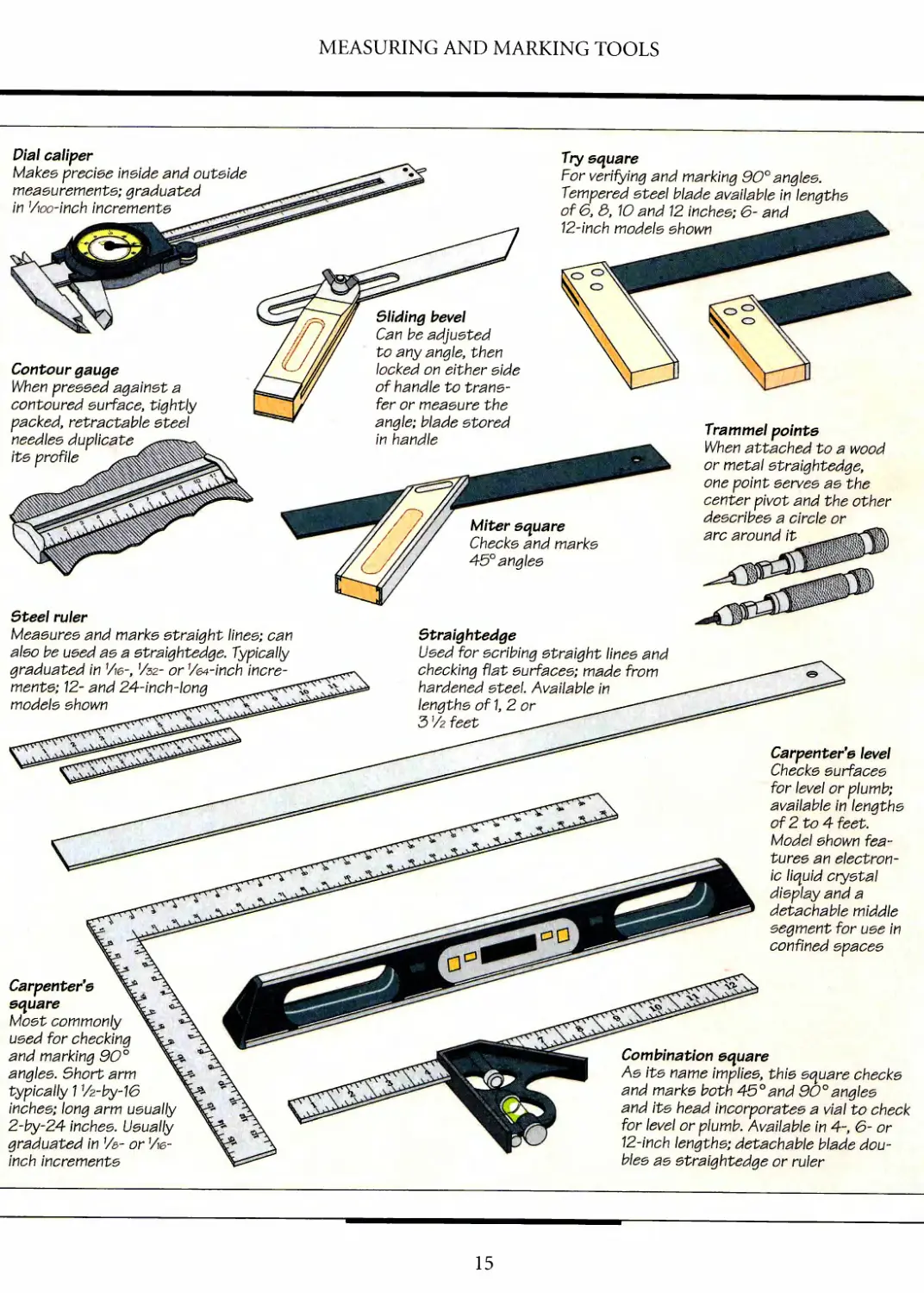
Dial caliper
Makes precise inside and outside
measurements; graduated
in Vioo-'mch increments
Try square
For verifying and marking 90° angles.
Tempered steel blade available in lengths
of 6, &, 10 and 12 inches; 6- and
12-inch models shown
Contour gauge
When pressed against a
contoured surface, tightly
packed, retractable steel
needles duplicate
its profile
Sliding bevel
Can be adjusted
to any angle, then
locked on either side
of handle to
transfer or measure the
angle; blade stored
in handle
Steel ruler
Measures and marks straight lines; can
also be used as a straightedge. Typically
graduated in Vie-, V32- or Vet-inch
increments; 12- and 24-inch-long
models shown
Miter square
Checks and marks
45° angles
Straightedge
Used for scribing straight lines and
checking flat surfaces; made from
hardened steel Available in
lengths of 1, 2 or
3 Vz feet
Trammel points
When attached to a wood
or metal straightedge,
one point serves as the
center pivot and the other
describes a circle or
arc around it
Carpenter's level
Checks surfaces
for level or plumb;
available in lengths
of 2 to 4 feet.
Model shown
features an
electronic liquid crystal
display and a
detachable middle
segment for use in
confined spaces
Carpenter's
square
Most commonly
used for checking
and marking 90°
angles. Short arm
typically 1 Vz-by-16
inches; long arm usually
2-by-24 inches. Usually
graduated in V&- or Ve-
inch increments
Combination square
As its name implies, this square checks
and marks both 45°and 90°angles
and its head incorporates a vial to check
for level or plumb. Available in 4-, 6- or
12-inch lengths; detachable blade
doubles as straightedge or ruler
15
MEASURING AND MARKING TECHNIQUES
Craftsmanship begins with proper
measuring and marking. The
accuracy of every line you make is only as
good as the previous one. Lines that are
not quite straight or angles that veer off
the mark invariably result in out-of-
square cuts and poorly fitting joints.
The tools shown on pages 14 and 15
are essential at many stages of a
woodworking project, from initial setup to the
periodic checking that you should do to
confirm the progress of your work. The
balance of this chapter describes some
basic operations and offers a few tips and
shortcuts for taking precise
measurements and setting up your tools in
awkward and uncommon situations.
Although useful shortcuts do exist,
take nothing for granted. Experience has
taught that there is even a best tool and
One of the simplest marking gauges is
your own hand. With a pencil held
between your thumb and index finger,
run your middle finger along an edge
of a board to mark a straight line.
technique for drawing a straight line.
Sharp, medium-hard pencils, such as
2H, or a fine-point mechanical pencil,
are best for thin and clean lines; softer-
tipped pencils like HB produce wider
lines that can introduce inaccuracy.
Hold a pencil at a slight angle to the
surface being marked so that the point
rides along the edge of your ruler.
The best markers have beveled edges,
so that the graduation mark is close to
the work surface. If you are working
with a square-sided ruler, hold it on edge
to avoid any distortion. If you are
laying out a precision joint, a marking knife
will produce a finer line than a pencil.
A safety reminder: If your
measuring or marking involves a power tool,
make sure the machine is unplugged
while you set it up.
LINES AND ANGLES
Scribing a line
To mark a line across the end of a board, use a cutting gauge. Loosen the thumbscrew on the
gauge and use a ruler to set the distance between the blade and the tool's stock. Tighten the
thumbscrew (above, left). You can tap the stock with a finger to move it slightly. Then, holding
the board flat on a work surface, butt the stock against its end and guide the blade across the
surface (above, right). Holding the gauge on an angle will make a clean, straight cut.
16
MEASURING AND MARKING TOOLS
Taking an inside measurement
The length of a tape measure case as
marked on its side or bottom is not
always accurate, so you should not rely
on the tool alone to make an inside
measurement. A better method is to use a
tape measure in conjunction with a ruler.
To determine the distance between the
side panels of a carcase, butt the ruler
against one panel and the end of the
tape against the other panel; butt the
tape measure up against the ruler to
ensure that both tools are measuring
along the same line (above). To calculate
the distance, read the tape marking just
where the tape contacts the ruler, then
add it to the length of the ruler.
SHOP TIP
Inside measurement
using two sticks
Two straight and
square sticks can
serve as accurate
gauges for measuring
inside distances.
Place the sticks side
by side in the
enclosed space,
butting one stick against
one edge and the other against
the opposite edge. Mark a line
across the sticks, then remove them and
realign the marks. The combined length of the
sticks will give you the inside measurement.
17
MEASURING AND MARKING TOOLS
Marking a line perpendicular
to an existing line
If your workpiece is too wide or long
for a try square or combination square,
use a carpenter's square. Align the
outer edge of the square's long arm
with the existing line, then draw a
pencil line along the short arm (left).
Marking a line at an angle to an edge
Set the angle you need on a metal
protractor, then unscrew the wing nut of a
sliding bevel to loosen the blade. Holding
the inner edge of the blade against the
base of the protractor, align the bevel's
handle with the protractor dial, then
tighten the wing nut (right). To transfer the
angle, hold the bevel's handle against the
edge of the workpiece and draw a pencil
line along the blade (inset).
18
MEASURING AND MARKING TOOLS
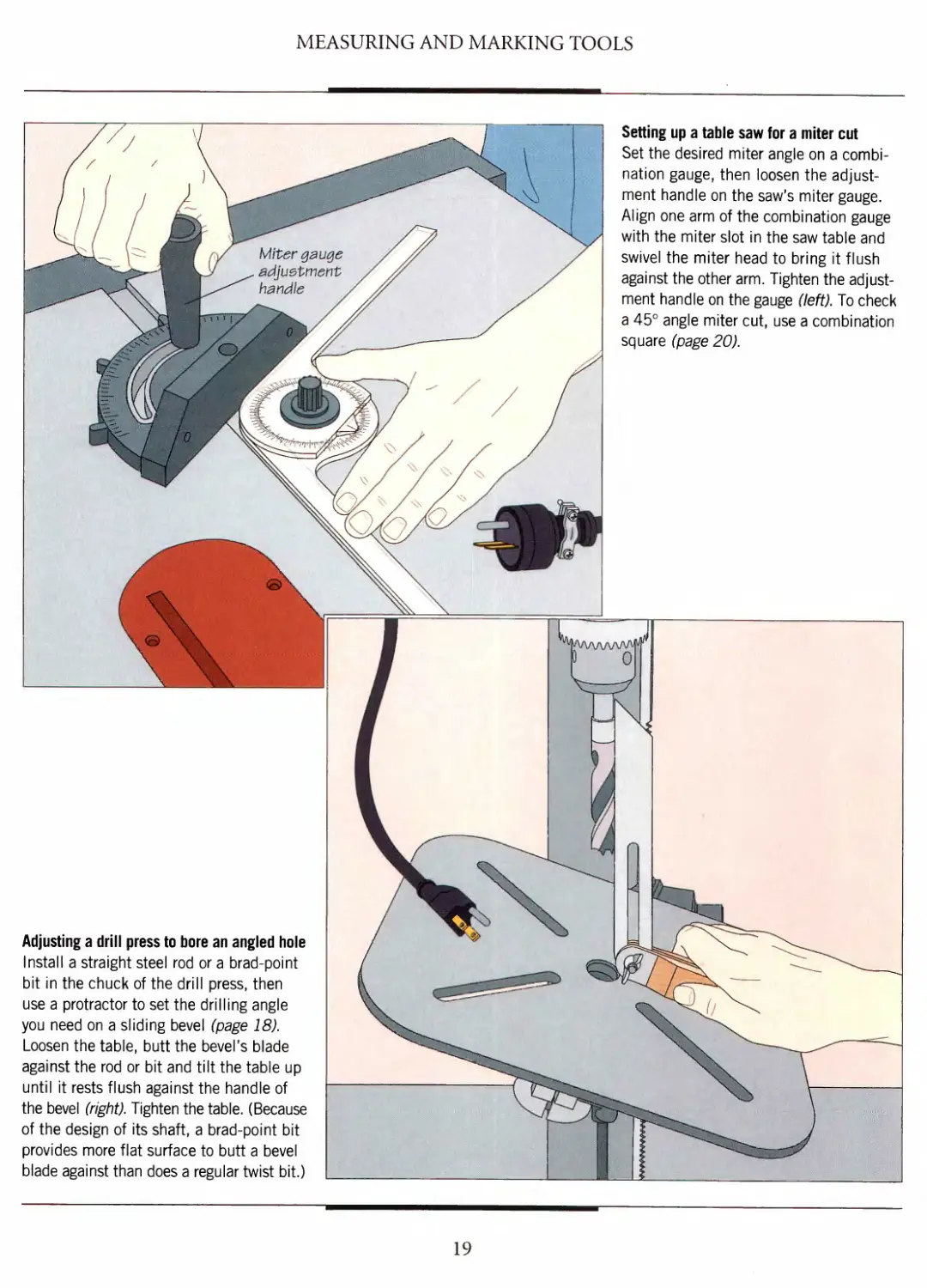
Setting up a table saw for a miter cut
Set the desired miter angle on a
combination gauge, then loosen the
adjustment handle on the saw's miter gauge.
Align one arm of the combination gauge
with the miter slot in the saw table and
swivel the miter head to bring it flush
against the other arm. Tighten the
adjustment handle on the gauge (left). To check
a 45° angle miter cut, use a combination
square (page 20).
Adjusting a drill press to bore an angled hole
Install a straight steel rod or a brad-point
bit in the chuck of the drill press, then
use a protractor to set the drilling angle
you need on a sliding bevel (page 18).
Loosen the table, butt the bevel's blade
against the rod or bit and tilt the table up
until it rests flush against the handle of
the bevel (right). Tighten the table. (Because
of the design of its shaft, a brad-point bit
provides more flat surface to butt a bevel
blade against than does a regular twist bit.)
19
MEASURING AND MARKING TOOLS
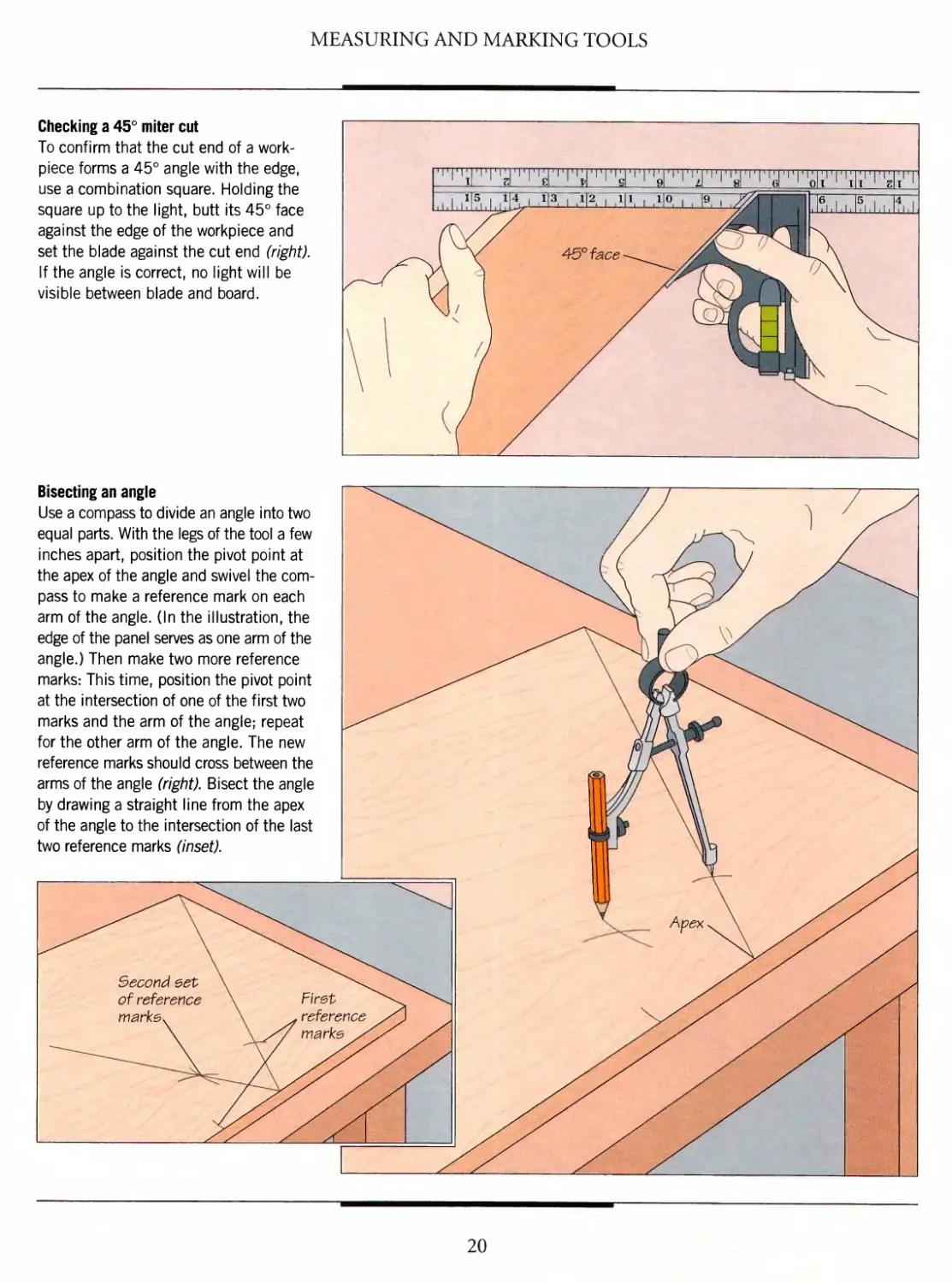
Checking a 45° miter cut
To confirm that the cut end of a work-
piece forms a 45° angle with the edge,
use a combination square. Holding the
square up to the light, butt its 45° face
against the edge of the workpiece and
set the blade against the cut end (right).
If the angle is correct, no light will be
visible between blade and board.
Bisecting an angle
Use a compass to divide an angle into two
equal parts. With the legs of the tool a few
inches apart, position the pivot point at
the apex of the angle and swivel the
compass to make a reference mark on each
arm of the angle. (In the illustration, the
edge of the panel serves as one arm of the
angle.) Then make two more reference
marks: This time, position the pivot point
at the intersection of one of the first two
marks and the arm of the angle; repeat
for the other arm of the angle. The new
reference marks should cross between the
arms of the angle (right). Bisect the angle
by drawing a straight line from the apex
of the angle to the intersection of the last
two reference marks (inset).
20
MEASURING AND MARKING TOOLS
isv
v^-' (i
^-^'""A /
\r ^1
^^?r //
1 / /'/}
\ / (^: / / -J
1111111111 m 11 in i 11 m
SHOP TIP
Checking a try square
To confirm whether a try square is true, hold the
handle against the edge of a straight board and
draw a pencil along the blade.
Then turn over the square.
The edge of the blade
should lie right on top
of the marked line.
Any difference
between the
two represents
twice the error
of the square.
You can a\eo
use this technique
to check a
carpenters square.
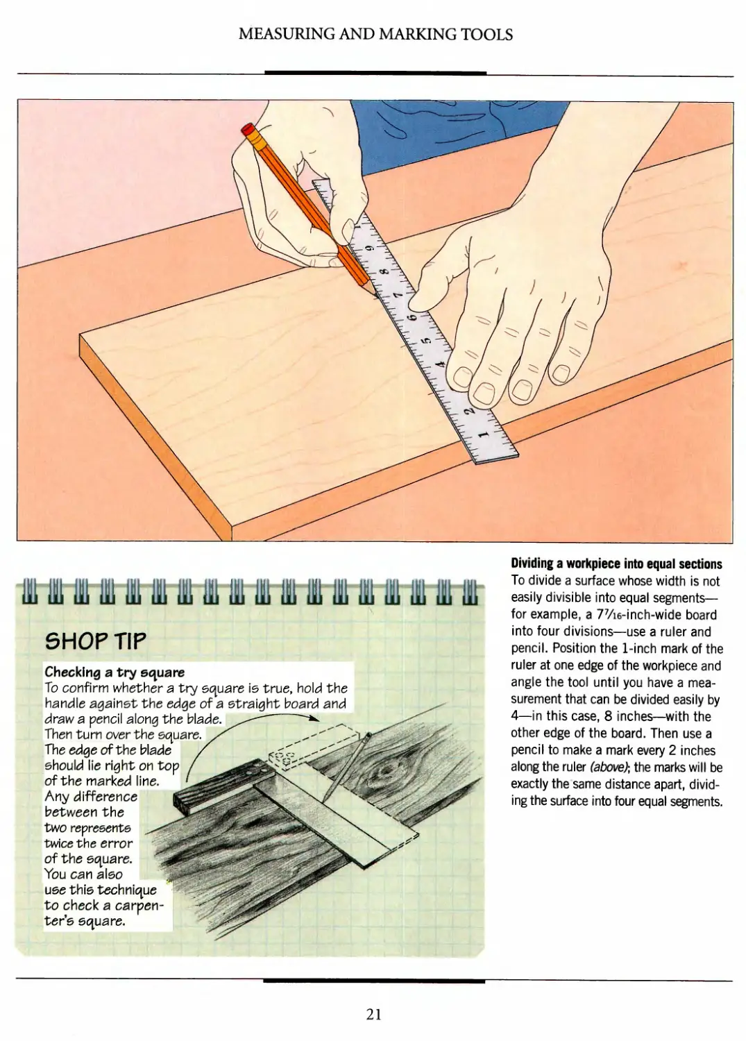
Dividing a workpiece into equal sections
To divide a surface whose width is not
easily divisible into equal segments—
for example, a 77/i6-inch-wide board
into four divisions—use a ruler and
pencil. Position the 1-inch mark of the
ruler at one edge of the workpiece and
angle the tool until you have a
measurement that can be divided easily by
4—in this case, 8 inches—with the
other edge of the board. Then use a
pencil to make a mark every 2 inches
along the ruler (above); the marks will be
exactly the same distance apart,
dividing the surface into four equal segments.
21
MEASURING AND MARKING TOOLS
CIRCLES AND CURVES
Marking a circle
To scribe a circle with a radius greater
than the span of a compass or dividers,
use a set of trammel points. Install
a sharpened pencil lead in one of the
points and use a ruler to set the gap
between the points equal to the radius
of the circle you need to draw. On the
type shown, slide the trammel points to
the appropriate position along the ruler,
and tighten the thumbscrews. Then hold
the pivot point steady at the center of
the circle and slowly rotate the pencil
point around it (left).
A SHOP-MADE COMPASS
The shop-made compass shown at
right, consisting of an arm, an awl,
and a pencil, will allow you to scribe
a circle of virtually any radius. For
the arm, cut a strip of V2-inch stock
2 inches wide and at least 2 inches
longer than the radius of the circle
you wish to draw. Bore a hole about
1 inch from the end of the arm, large
enough to hold the shaft of the awl.
Bore a second hole, wide enough to
accommodate the pencil, making
the distance between the holes equal
to the radius of the circle. Fit the
awl into one hole and a sharpened
pencil into the other, making sure
the two extend from the bottom of
the arm by the same amount.
Use the compass as you would
trammel points, holding the tip of
the awl at the center of the circle
and rotating the pencil around it
to scribe the circle.
22
MEASURING AND MARKING TOOLS
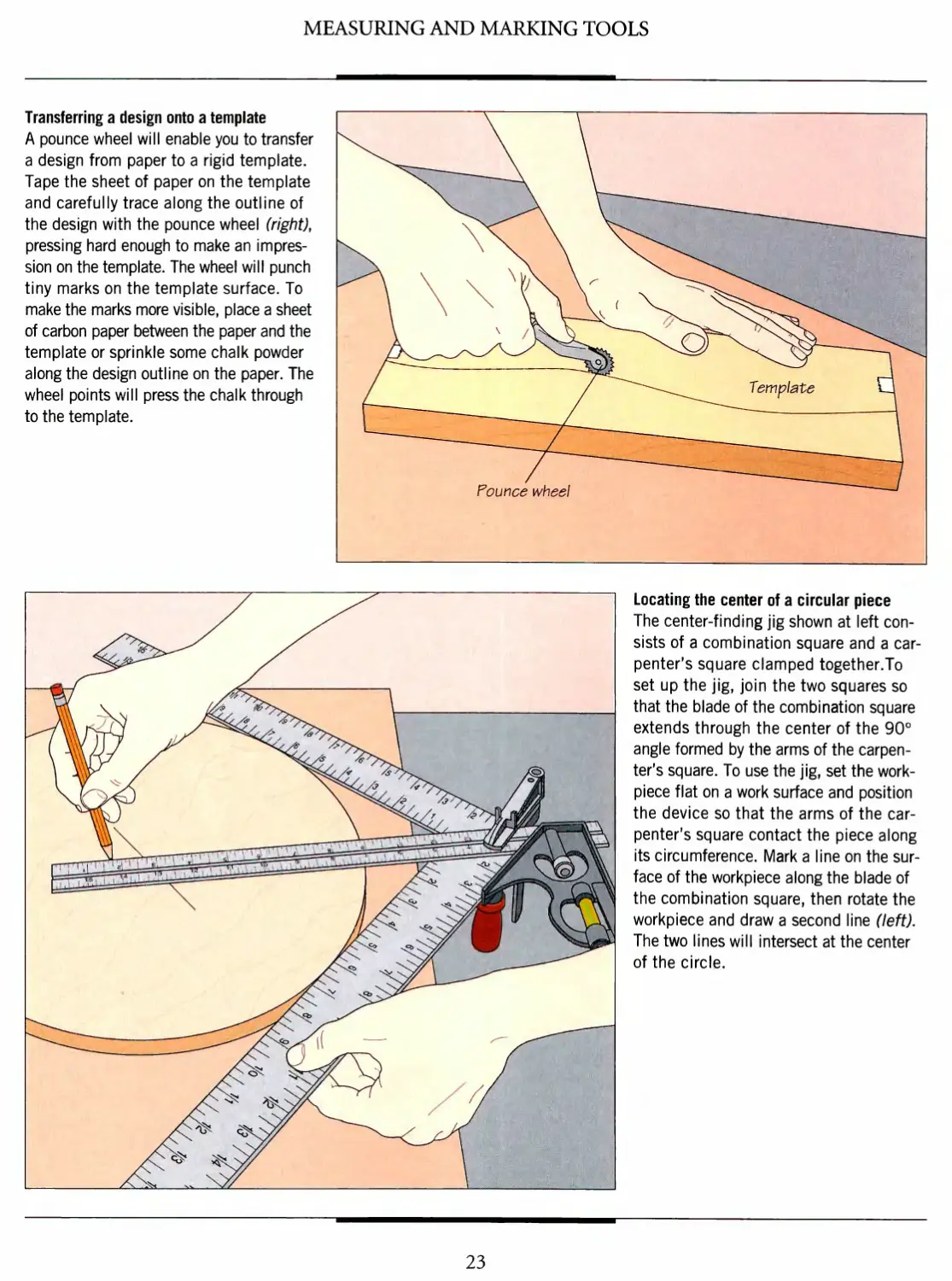
Transferring a design onto a template
A pounce wheel will enable you to transfer
a design from paper to a rigid template.
Tape the sheet of paper on the template
and carefully trace along the outline of
the design with the pounce wheel (right),
pressing hard enough to make an
impression on the template. The wheel will punch
tiny marks on the template surface. To
make the marks more visible, place a sheet
of carbon paper between the paper and the
template or sprinkle some chalk powder
along the design outline on the paper. The
wheel points will press the chalk through
to the template.
X ^\\ ^
\ \x YW'
\ x rv v> ——
Pounce wheel
v^^
\oi"
Template Q
Locating the center of a circular piece
The center-finding jig shown at left
consists of a combination square and a
carpenter's square clamped together.To
set up the jig, join the two squares so
that the blade of the combination square
extends through the center of the 90°
angle formed by the arms of the
carpenter's square. To use the jig, set the work-
piece flat on a work surface and position
the device so that the arms of the
carpenter's square contact the piece along
its circumference. Mark a line on the
surface of the workpiece along the blade of
the combination square, then rotate the
workpiece and draw a second line (left).
The two lines will intersect at the center
of the circle.
23
MEASURING AND MARKING TOOLS
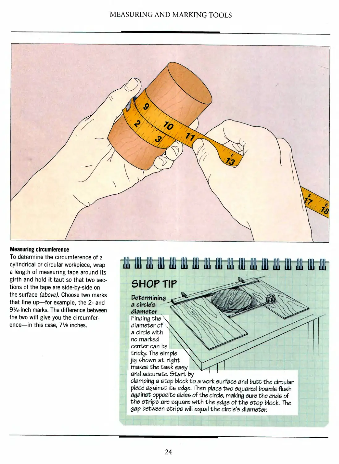
Measuring circumference
To determine the circumference of a
cylindrical or circular workpiece, wrap
a length of measuring tape around its
girth and hold it taut so that two
sections of the tape are side-by-side on
the surface (above). Choose two marks
that line up—for example, the 2- and
Ws-inch marks. The difference between
the two will give you the
circumference—in this case, 7Vs inches.
im 1111 u 11 iinmt ii
SHOP TIP
Determining
a circle's
diameter
Finding thev
diameter of
a circle with
y\o marked
center car\ be
tricky. The simple
jig shown at r\g\
makes the task
and accurate. Start by
clamping a stop block to a work surface ar\d butt the circular
piece against its edge. Then place two squared boards flush
against opposite sides of the circle, making sure the ends of
the strips are square with the edge of the stop block. The
gap between strips will equal the circle's diameter.
24
MEASURING AND MARKING TOOLS
MARKING JOINTS
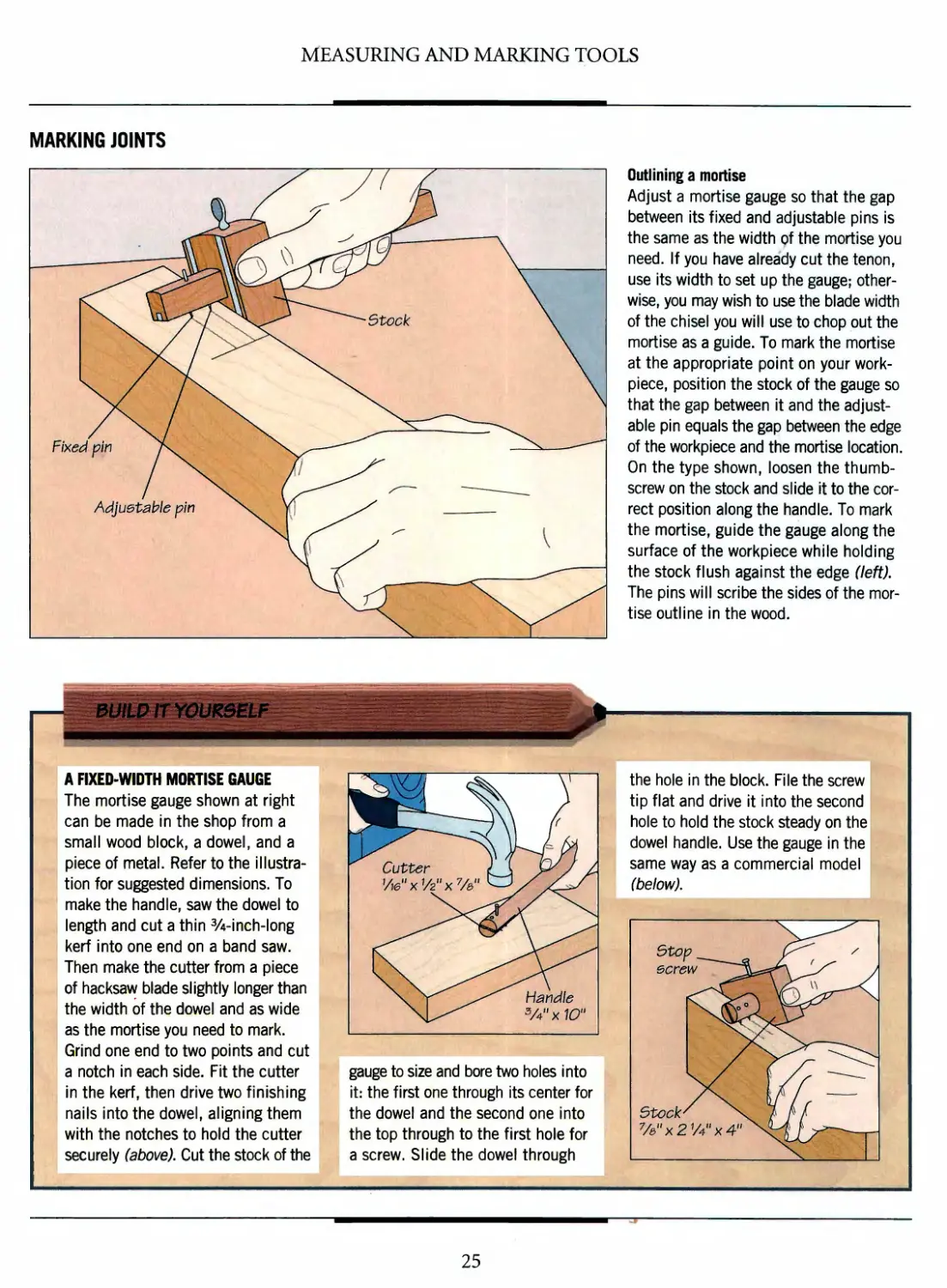
Outlining a mortise
Adjust a mortise gauge so that the gap
between its fixed and adjustable pins is
the same as the width of the mortise you
need. If you have already cut the tenon,
use its width to set up the gauge;
otherwise, you may wish to use the blade width
of the chisel you will use to chop out the
mortise as a guide. To mark the mortise
at the appropriate point on your work-
piece, position the stock of the gauge so
that the gap between it and the
adjustable pin equals the gap between the edge
of the workpiece and the mortise location.
On the type shown, loosen the
thumbscrew on the stock and slide it to the
correct position along the handle. To mark
the mortise, guide the gauge along the
surface of the workpiece while holding
the stock flush against the edge (left).
The pins will scribe the sides of the
mortise outline in the wood.
A FIXED-WIDTH MORTISE GAUGE
The mortise gauge shown at right
can be made in the shop from a
small wood block, a dowel, and a
piece of metal. Refer to the
illustration for suggested dimensions. To
make the handle, saw the dowel to
length and cut a thin 3/4-inch-long
kerf into one end on a band saw.
Then make the cutter from a piece
of hacksaw blade slightly longer than
the width of the dowel and as wide
as the mortise you need to mark.
Grind one end to two points and cut
a notch in each side. Fit the cutter
in the kerf, then drive two finishing
nails into the dowel, aligning them
I with the notches to hold the cutter
j securely (above). Cut the stock of the
HHBHI^^^^^^^H^^
Cutter i\ ?^/ /■
Vie" x v2" x %" ax^y
\ y ^^ Handle
\U*-^ 3/4nx10"
gauge to size and bore two holes into
it: the first one through its center for
the dowel and the second one into
the top through to the first hole for
a screw. Slide the dowel through
the hole in the block. File the screw
tip flat and drive it into the second
hole to hold the stock steady on the
dowel handle. Use the gauge in the
same way as a commercial model
(below).
Sto\
ecre
Stock'
%"x2
y4" x 4» \£J^
25
MEASURING AND MARKING TOOLS
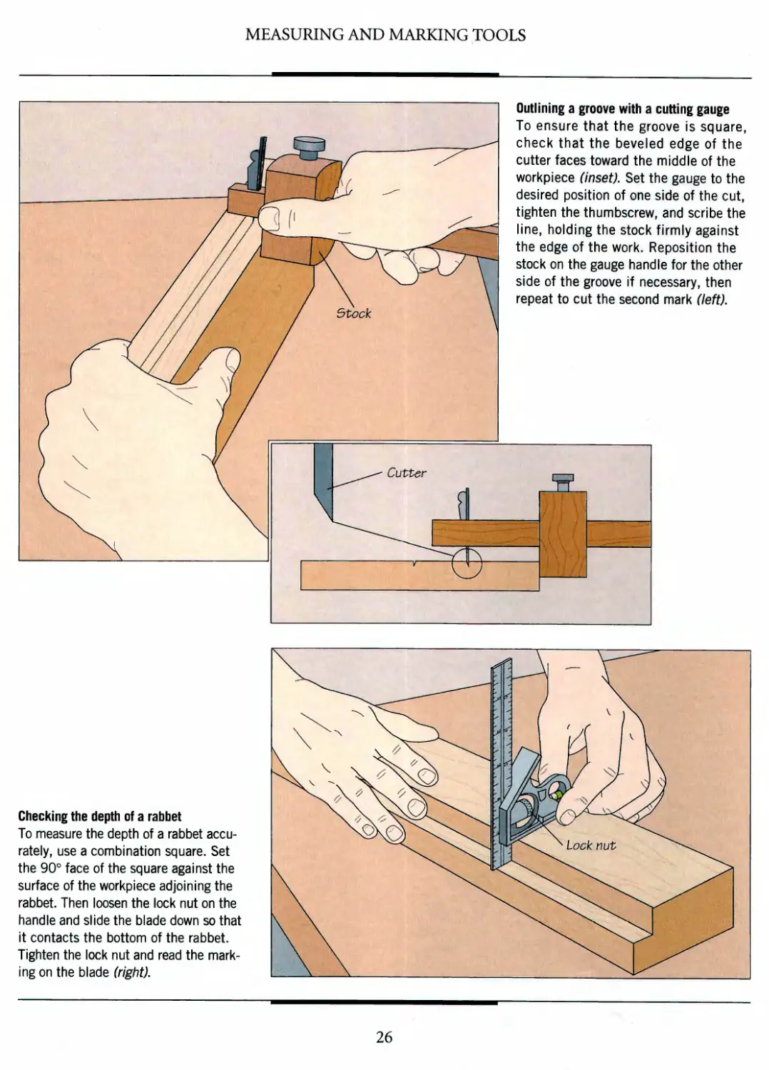
Outlining a groove with a cutting gauge
To ensure that the groove Is square,
check that the beveled edge of the
cutter faces toward the middle of the
workpiece (inset). Set the gauge to the
desired position of one side of the cut,
tighten the thumbscrew, and scribe the
line, holding the stock firmly against
the edge of the work. Reposition the
stock on the gauge handle for the other
side of the groove if necessary, then
repeat to cut the second mark (left).
Checking the depth of a rabbet
To measure the depth of a rabbet
accurately, use a combination square. Set
the 90° face of the square against the
surface of the workpiece adjoining the
rabbet. Then loosen the lock nut on the
handle and slide the blade down so that
it contacts the bottom of the rabbet.
Tighten the lock nut and read the
marking on the blade (right).
26
MEASURING AND MARKING TOOLS
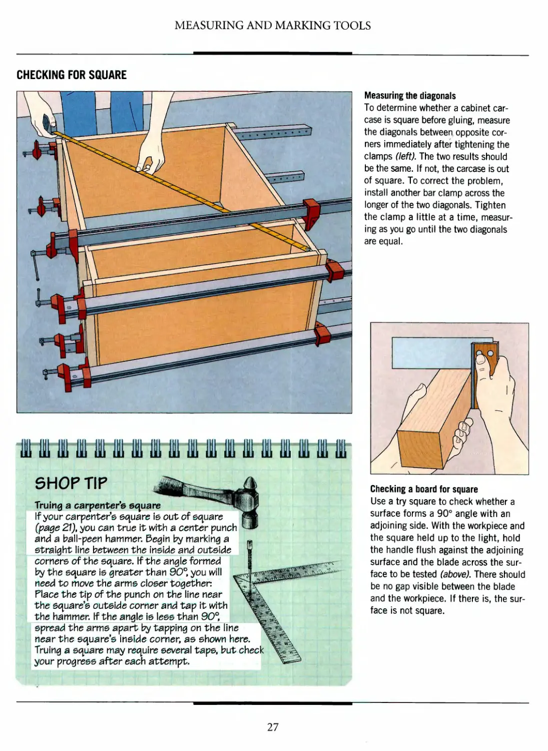
CHECKING FOR SQUARE
SHOP TIP
Truing a carpenter's square
If your carpenter's square is out of square
(page 21), you can true it with a center punch
and a ball-peen hammer. Begin by marking a
straight line between the inside and outside
corners of the square. If the angle formed
by the square is greater than 90°, you will
need to move the arms closer together.
Place the tip of the punch on the line near
the square's outside corner and tap it with
the hammer. If the angle is less than 90°,
spread the arms apart by tapping on the line
near the square's inside corner, as shown here,
Truing a square may require several tape, but check
your progress after each attempt.
Measuring the diagonals
To determine whether a cabinet
carcase is square before gluing, measure
the diagonals between opposite
corners immediately after tightening the
clamps (left)- The two results should
be the same. If not, the carcase is out
of square. To correct the problem,
install another bar clamp across the
longer of the two diagonals. Tighten
the clamp a little at a time,
measuring as you go until the two diagonals
are equal.
Checking a board for square
Use a try square to check whether a
surface forms a 90° angle with an
adjoining side. With the workpiece and
the square held up to the light, hold
the handle flush against the adjoining
surface and the blade across the
surface to be tested (above). There should
be no gap visible between the blade
and the workpiece. If there is, the
surface is not square.
27
HANDSAWS
The handsaw has a rich history that
began at least 4,000 years ago, when
the Egyptians fashioned saw blades from
copper and joined them to pistol-grip
handles. Later, the Greeks and Romans
devised frames that held blades tautly in
place. They also discovered the
importance of setting saw teeth—bending them
alternately to the right and left—so the
saw cuts a kerf slightly wider than the
blade. The design is still used today to
prevent a blade from binding in the cut.
Medieval craftsmen tinkered with the
design of the frame, but it was not until
the 17th Century that handsaws assumed
their modern guise when English saw
manufacturers attached a wooden
handle with an oval hand hole to a steel
blade. Tool design flourished and
within 100 years, cabinetmakers devised tenon
and dovetail saws by adding a heavy steel
or brass spine to a shorter, finer,
smaller-toothed blade. Today, there is a
handsaw for just about any cutting task.
Although all handsaws cut wood in
the same way, there are important
differences between them. As discussed on page 32, the number
of teeth on a blade, their shape and the spacing between them,
all affect a saw's performance. The finely spaced teeth of a
dovetail saw, for example, allow it to cut wood cleanly and its
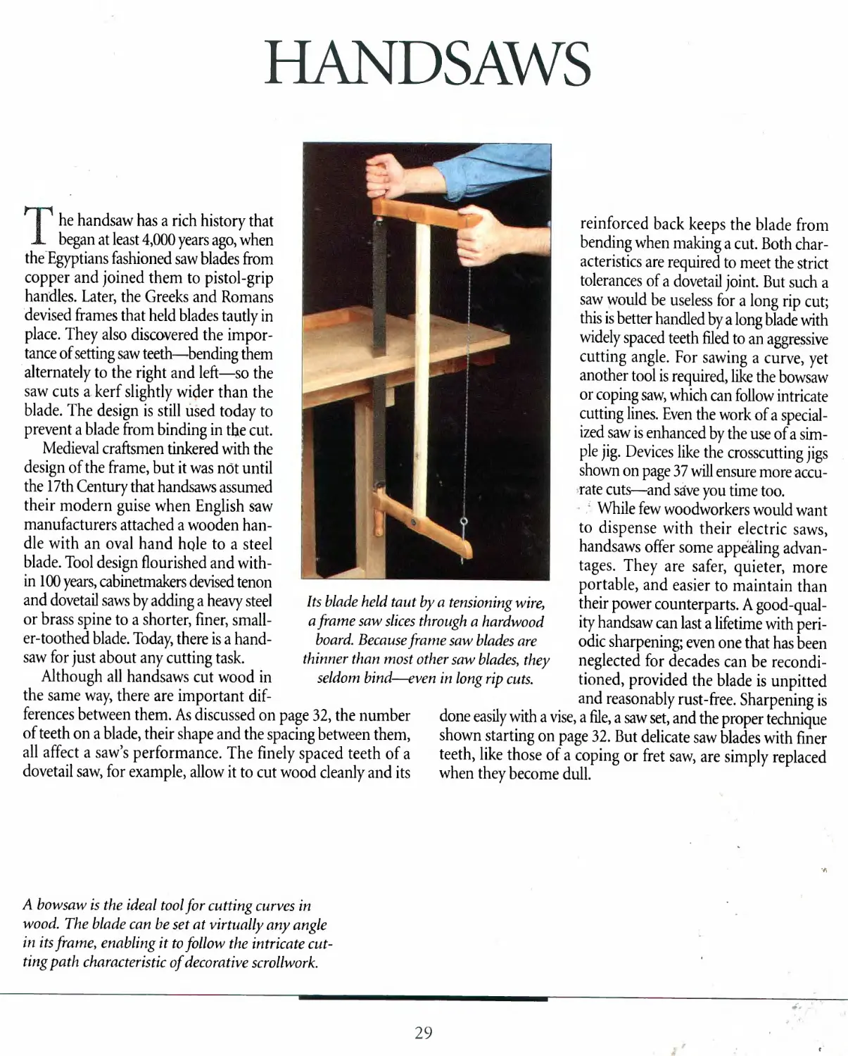
Its blade held taut by a tensioning wire,
a frame saw slices through a hardwood
board. Because frame saw blades are
thinner than most other saw blades, they
seldom bind—even in long rip cuts.
reinforced back keeps the blade from
bending when making a cut. Both
characteristics are required to meet the strict
tolerances of a dovetail joint. But such a
saw would be useless for a long rip cut;
this is better handled by a long blade with
widely spaced teeth filed to an aggressive
cutting angle. For sawing a curve, yet
another tool is required, like the bowsaw
or coping saw, which can follow intricate
cutting lines. Even the work of a
specialized saw is enhanced by the use of a
simple jig. Devices like the crosscutting jigs
shown on page 37 will ensure more
accurate cuts—and save you time too.
/ While few woodworkers would want
to dispense with their electric saws,
handsaws offer some appealing
advantages. They are safer, quieter, more
portable, and easier to maintain than
their power counterparts. A
good-quality handsaw can last a lifetime with
periodic sharpening; even one that has been
neglected for decades can be
reconditioned, provided the blade is unpitted
and reasonably rust-free. Sharpening is
done easily with a vise, a file, a saw set, and the proper technique
shown starting on page 32. But delicate saw blades with finer
teeth, like those of a coping or fret saw, are simply replaced
when they become dull.
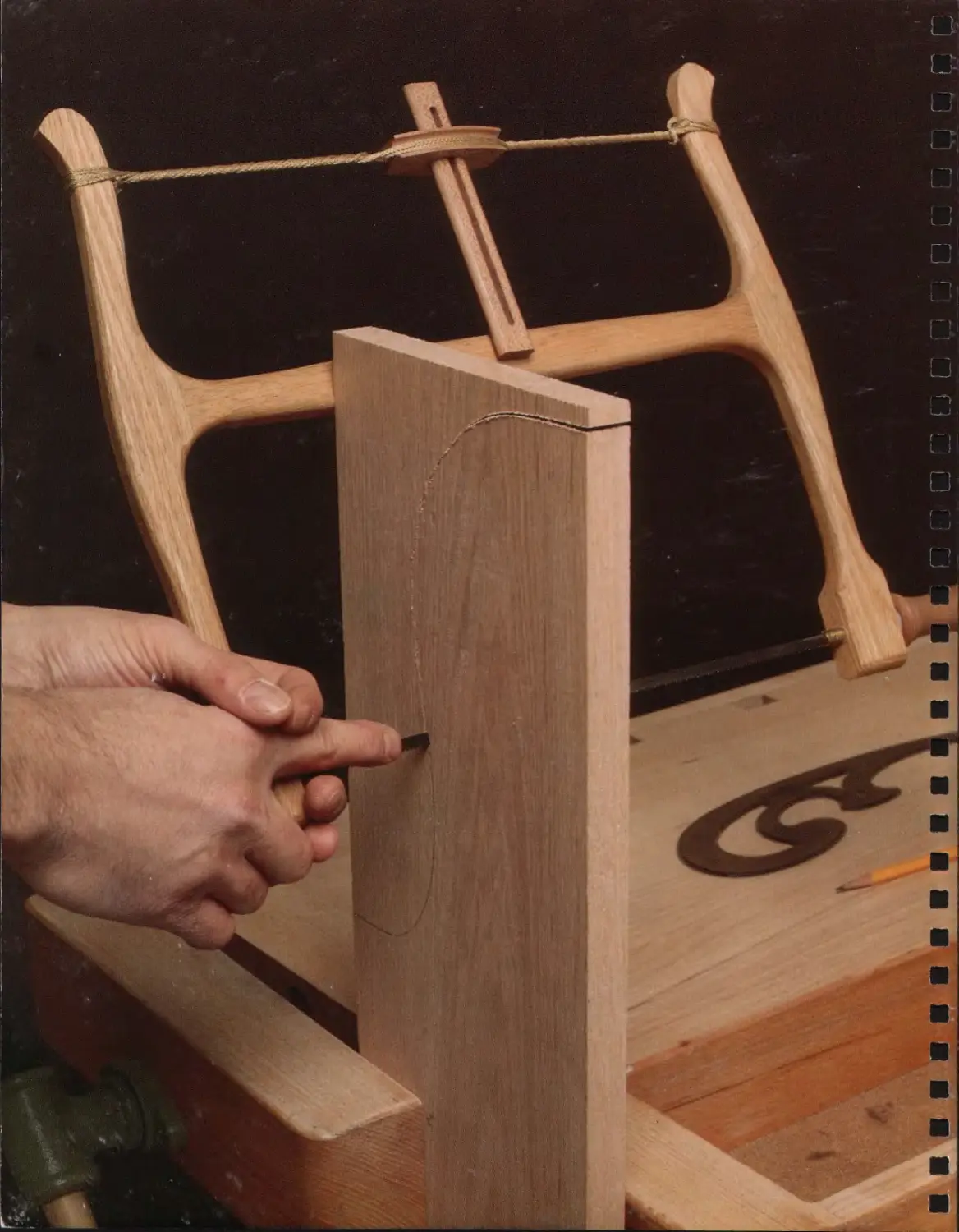
A bowsaw is the ideal tool for cutting curves in
wood. The blade can be set at virtually any angle
in its frame, enabling it to follow the intricate
cutting path characteristic of decorative scrollwork.
29
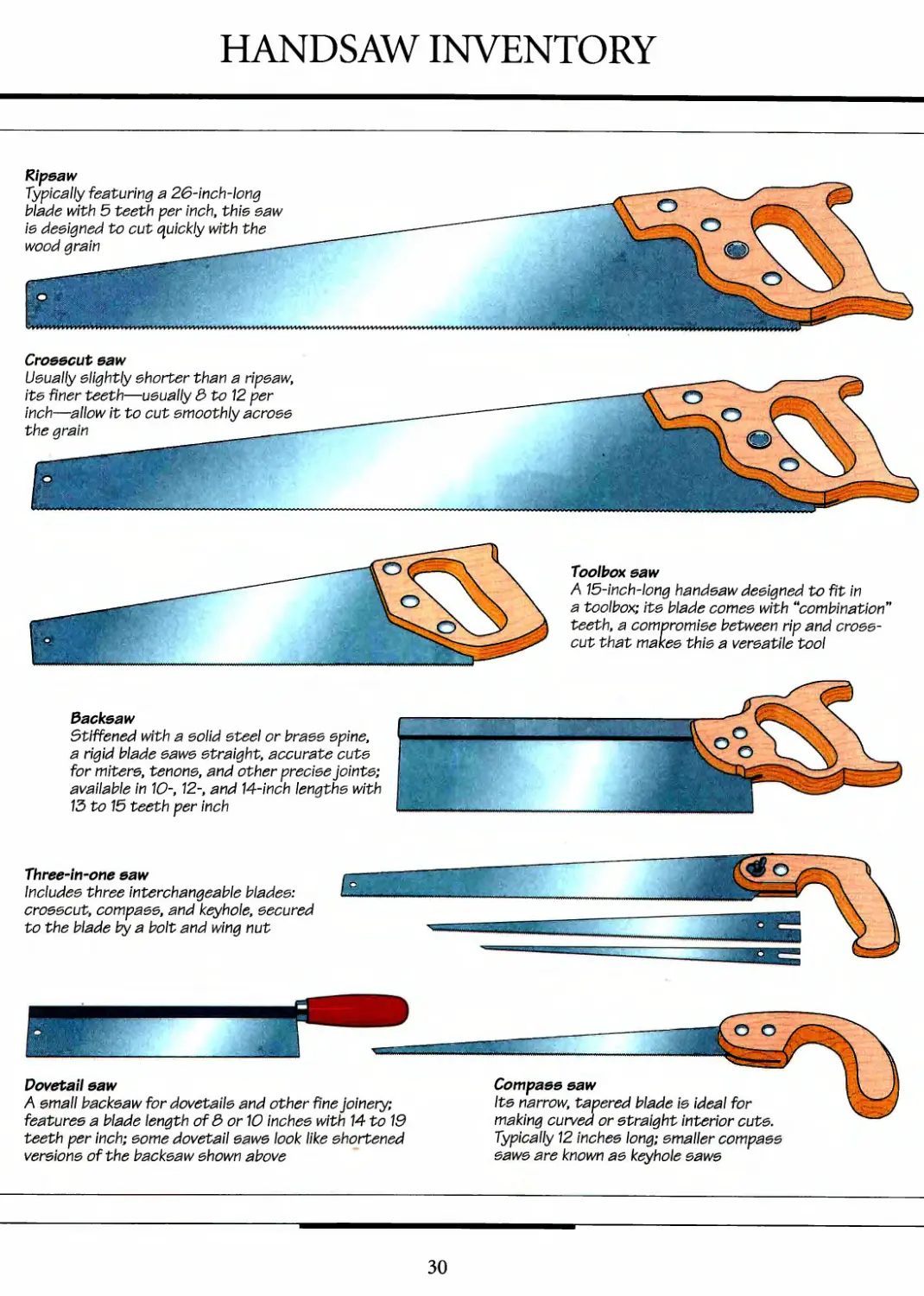
HANDSAW INVENTORY
Ripsaw
Typically featuring a 26-inch-long
blade with 5 teeth per inch, this saw
is designed to cut quickly with the
wood grain
Crosscut saw
Usually slightly shorter than a ripsaw,
its finer teeth—usually 3 to 12 per
inch—allow it to cut smoothly across
the grain
Toolbox saw
A 15-inch-long handsaw designed to fit in
a toolbox; its blade comes with "combination"
teetht a compromise between rip and
crosscut that makes this a versatile tool
Backsaw
Stiffened with a solid steel or brass spine,
a rigid blade saws straight, accurate cuts
for miters, tenons, and other precise joints;
available in 10-, 12-, and 14-inch lengths with
13 to 15 teeth per inch
Three-in-one saw
Includes three interchangeable blades:
crosscut, compass, and keyhole, secured
to the blade by a bolt and wing nut
Dovetail saw
A small backsaw for dovetails and other fine joinery;
features a blade length of 3 or 10 inches with 14 to 19
teeth per inch; some dovetail saws look like shortened
versions of the backsaw shown above
Compass saw
Its narrow, tapered blade is ideal for
making curved or straight interior cuts.
Typically 12 inches long; smaller compass
saws are known as keyhole saws
30
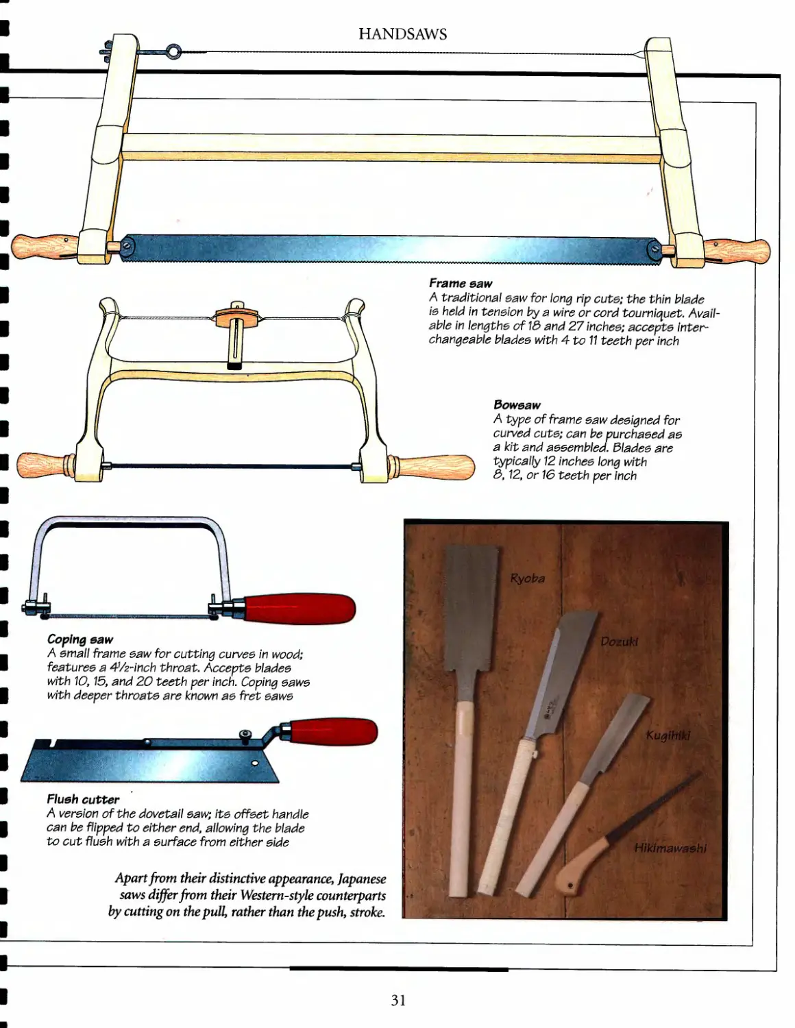
HANDSAWS
Frame saw
A traditional eaw for long rip cute; the thin blade
ie held in teneion by a wire or cord tourniquet.
Available in lengths of 13 and 27 inchee; accepte
interchangeable bladee with 4 to 11 teeth per inch
3oweaw
A type of frame eaw deeigned for
curved cute; can be purchaeed ae
a kit and aeeembled. dladee are
typically 12 inchee long with
3,12, or 16 teeth per inch
Coping eaw
A email frame eaw for cutting curves in wood;
featuree a 4Vz-inch throat. Accepte bladee
with 10,15, and 20 teeth per inch. Coping eawe
with deeper throate are known ae fret eawe
Flush cutter
A vereion of the dovetail eaw; ite offeet handle
can be flipped to either end, allowing the blade
to cut flueh with a eurface from either side
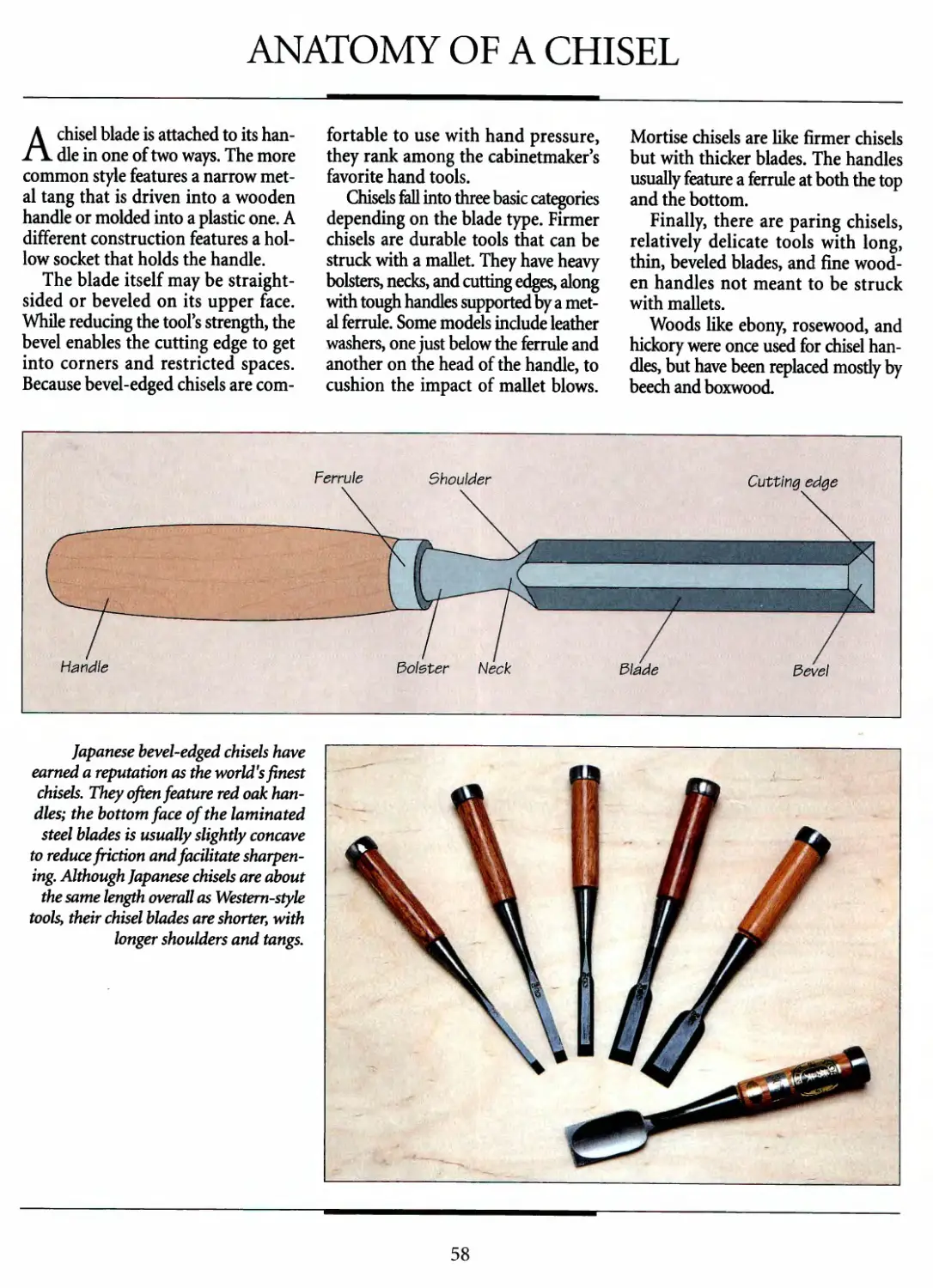
Apart from their distinctive appearance, Japanese
saws differ from their Western-style counterparts
by cutting on the pull rather than the push, stroke.
31
HANDSAW BLADES
All saw blades are essentially alike,
consisting of a row of sharp teeth
that sever wood fibers and clear the
resulting debris out of the cut, or kerf.
But blades intended for different uses
deviate markedly in their details.
A ripsaw blade has widely spaced
teeth—five to seven teeth per inch
(TPI)—designed to tear rapidly along
the grain. To speed the work and prevent
binding, rip teeth have a pronounced
"set," that is, they are bent alternately to
each side of the blades center line. The
resulting edge, although relatively rough,
can easily be planed smooth.
A crosscut saw, on the other hand,
must make precise cuts, usually only a
few inches long. Its teeth are closely
spaced—eight to 12 TPI—and possess
barely any set; although they cut slowly,
little cleanup is necessary.
Of course, no saw cuts well if its teeth
are not sharpened and set properly. For
the most part, these tasks can be done in
the shop (see below), although saws with
very fine teeth, like dovetails and tenon
saws, are best left to professionals.
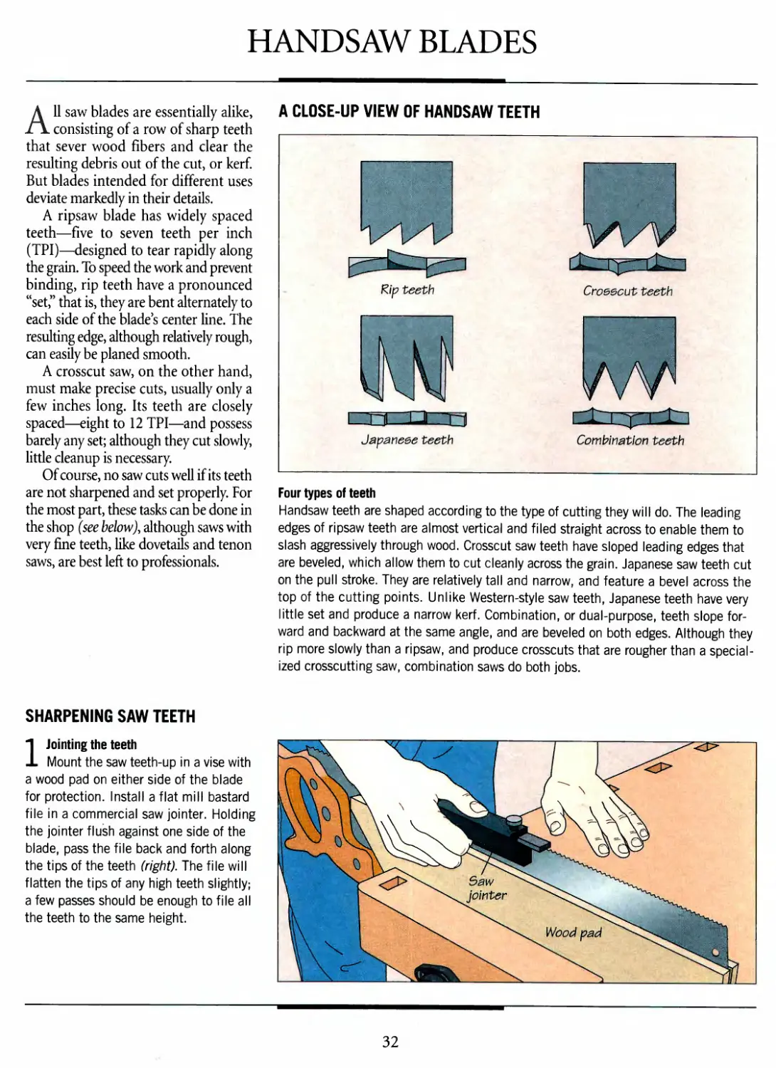
A CLOSE-UP VIEW OF HANDSAW TEETH
Rip teeth
Croeecut teeth
Japaneee teeth
Combination teeth
Four types of teeth
Handsaw teeth are shaped according to the type of cutting they will do. The leading
edges of ripsaw teeth are almost vertical and filed straight across to enable them to
slash aggressively through wood. Crosscut saw teeth have sloped leading edges that
are beveled, which allow them to cut cleanly across the grain. Japanese saw teeth cut
on the pull stroke. They are relatively tall and narrow, and feature a bevel across the
top of the cutting points. Unlike Western-style saw teeth, Japanese teeth have very
little set and produce a narrow kerf. Combination, or dual-purpose, teeth slope
forward and backward at the same angle, and are beveled on both edges. Although they
rip more slowly than a ripsaw, and produce crosscuts that are rougher than a
specialized crosscutting saw, combination saws do both jobs.
SHARPENING SAW TEETH
1 Jointing the teeth
Mount the saw teeth-up in a vise with
a wood pad on either side of the blade
for protection. Install a flat mill bastard
file in a commercial saw jointer. Holding
the jointer flush against one side of the
blade, pass the file back and forth along
the tips of the teeth (right). The file will
flatten the tips of any high teeth slightly;
a few passes should be enough to file all
the teeth to the same height.
32
HANDSAWS
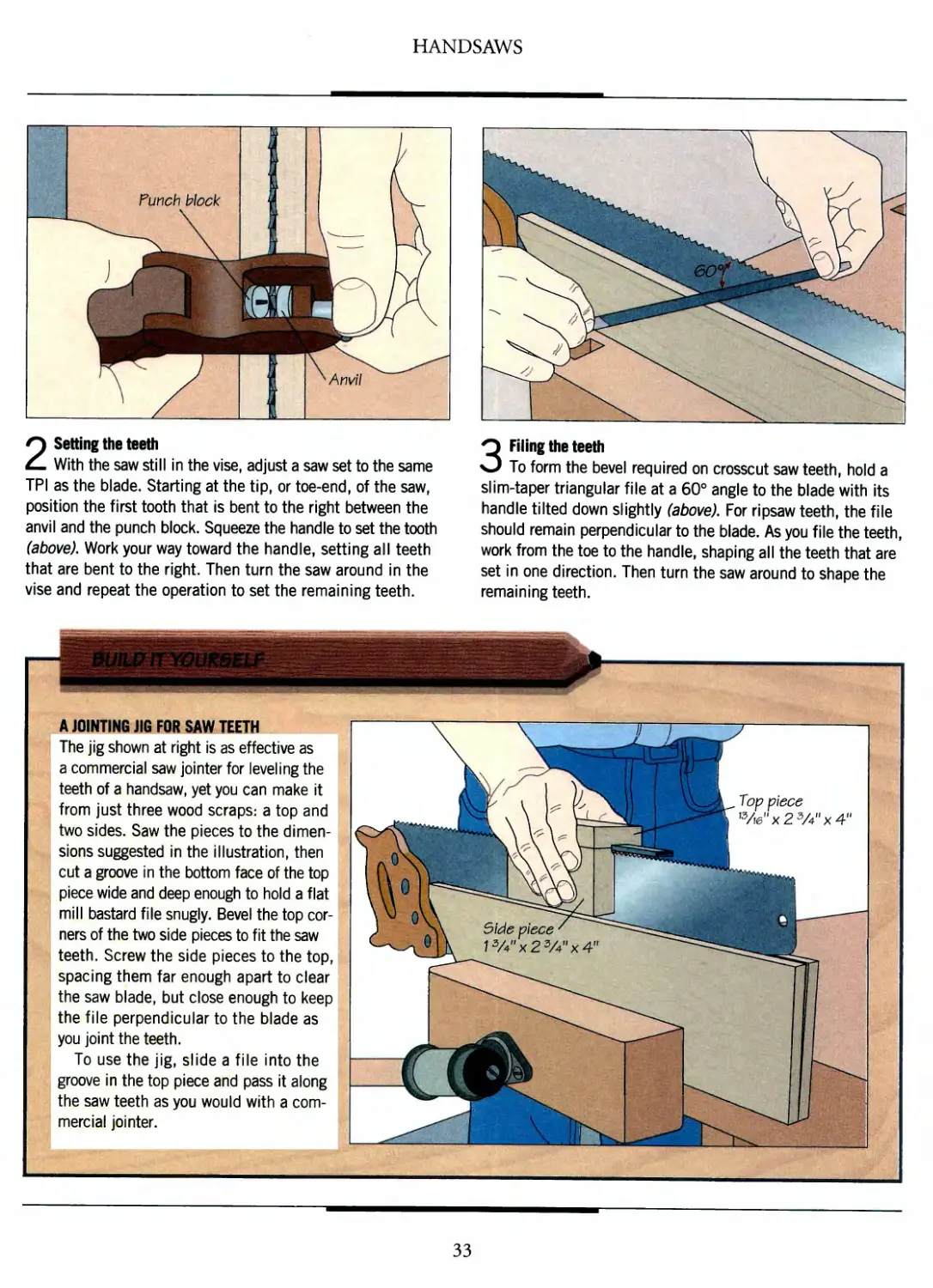
? !J
Funch block
[(■fj
^ Anvil
1/ .
2 Setting the teeth
With the saw still in the vise, adjust a saw set to the same
TPI as the blade. Starting at the tip, or toe-end, of the saw,
position the first tooth that is bent to the right between the
anvil and the punch block. Squeeze the handle to set the tooth
(above). Work your way toward the handle, setting all teeth
that are bent to the right. Then turn the saw around in the
vise and repeat the operation to set the remaining teeth.
iu ^i§
"\
/
/
*\ ^^^^2
'^^^^^
\^\
fe*. ^^x \> /
^
3 Filing the teeth
To form the bevel required on crosscut saw teeth, hold a
slim-taper triangular file at a 60° angle to the blade with its
handle tilted down slightly (above). For ripsaw teeth, the file
should remain perpendicular to the blade. As you file the teeth,
work from the toe to the handle, shaping all the teeth that are
set in one direction. Then turn the saw around to shape the
remaining teeth.
A JOINTING JIG FOR SAW TEETH
The jig shown at right is as effective as
a commercial saw jointer for leveling the
teeth of a handsaw, yet you can make it
from just three wood scraps: a top and
two sides. Saw the pieces to the
dimensions suggested in the illustration, then
cut a groove in the bottom face of the top
piece wide and deep enough to hold a flat
mill bastard file snugly. Bevel the top
corners of the two side pieces to fit the saw
teeth. Screw the side pieces to the top,
spacing them far enough apart to clear
the saw blade, but close enough to keep
the file perpendicular to the blade as
you joint the teeth.
To use the jig, slide a file into the
groove in the top piece and pass it along
the saw teeth as you would with a
commercial jointer.
33
BASIC CUTS
Sawing wood quickly and accurately
by hand depends on the proper
setup, posture, and sawing angle. Always
support a workpiece adequately, either
on sawhorses or some other stable
surface, and keep it in place with clamps or
a vise. Never attempt to steady a work-
piece with your free hand.
Set up your work at a comfortable
height that allows you to maintain your
balance while sawing. Hold the saw blade
in line with your arm and shoulder. As
shown below, the correct sawing angle
varies with the type of cut. The saw is
held closest to the vertical for rip cuts,
and somewhat lower for crosscutting.
An even lower angle will yield the finest
cut. As illustrated in the photo at right,
to finish off an interior cut, you have to
hold the saw with the blade at a 90° angle
to the surface.
SAWING ANGLES
Choosing the right angle
Although holding a saw at a 90° angle to the workpiece, as shown in the photo above,
is the quickest way to shear through wood, the resulting cut edges are invariably
rough and splintered. For finer cuts, lower the angle of the saw. Start the operation
with as low an angle as possible, then raise the angle, to about 60° for rip cuts and
to about 45° for crosscuts. To completely eliminate rough edges and splintering,
keep the saw at an angle of about 20° to the workpiece.
If, in spite of your preparations, the
saw drifts off the cutting line, twist the
blade slightly on the push stroke to
straighten it out. If the blade sticks
during the cut, you may need to reset or file
the teeth (page 32). As a short-term
measure, you can rub a little paste wax or
paraffin on the blade (not the teeth)
or use a kerf splitter to keep the blade
from sticking (page 35). Remove any
wax buildup with steel wool and
mineral spirits.
When you measure and mark a cut,
remember that the kerf will be up to Vi
inch wide. Be sure to make your cut on
the waste side of the cutting line.
Holding a saw vertically at the
end of an interior cut enables
the teeth to end the cut square.
34
HANDSAWS
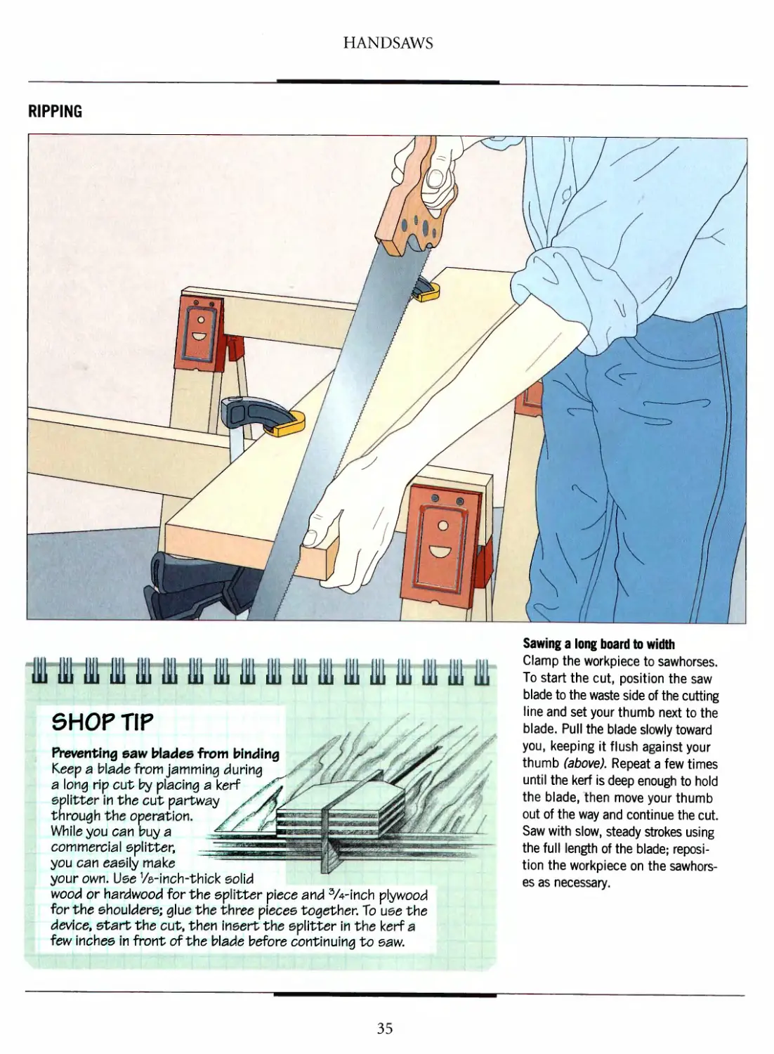
RIPPING
1111 i i i i i i 111 i 1111
SHOP TIP
Preventing saw blades from binding
Keep a blade from jamming during
a long rip cut by placing a kerf ^^
splitter in the cut partway /O^L
through the operation. /*/
While you can buy a
commercial splitter,
you can easily make
your own. Use VHnch-thick solid
wood or hardwood for the splitter piece ar\d 3A-inch plywood
for the shoulders; glue the three pieces together. To use the
device, start the cut, then insert the splitter in the kerf a
few inches in front of the blade before continuing to saw.
Sawing a long board to width
Clamp the workpiece to sawhorses.
To start the cut, position the saw
blade to the waste side of the cutting
line and set your thumb next to the
blade. Pull the blade slowly toward
you, keeping it flush against your
thumb (above). Repeat a few times
until the kerf is deep enough to hold
the blade, then move your thumb
out of the way and continue the cut.
Saw with slow, steady strokes using
the full length of the blade;
reposition the workpiece on the
sawhorses as necessary.
35
HANDSAWS
■■1
4
1 ]V. \ —-^^2.
TV)
v ° jL
Ripping a short board
Secure the workpiece vertically in a vise
with the cutting line extending from the
vise; this will keep the workpiece from
rattling and the saw blade from binding.
Start the cut normally, using your free
hand to steady the piece once the blade
is completely in the kerf. To minimize
tearout, straighten the blade until it is
nearly perpendicular to the face as you
near the end of the cut.
CROSSCUTTING
Cutting a board to length
Clamp the workpiece to sawhorses. Start the operation as
you would a rip cut (page 35), then lower the saw to an angle
of about 45° once the kerf is deep enough. Saw slowly and
steadily with the full length of the blade. To prevent the waste
piece from tearing the wood as you complete the cut, support
the waste with your free hand while raising the angle of the
blade until it is almost vertical.
^/\ ^_y u On
\\v^ x^$v
\\\\ \D/ x i
v?3^<\
^o^^\ \
Edge \, v^\
guide \. X \
Clamp
x A n. \r^ \ jo
Crosscutting a wide panel
Set the panel on a work surface with the cutting line extending
off the table. To help you keep the saw blade vertical and
prevent it from veering off-line during the cut, clamp a board as a
edge guide to the workpiece on the good side of the cutting line.
The guide should be longer than the width of the panel and
square with its edges. Set up the clamps so that they will not
interfere with the saw as you make the cut. Saw through the
panel as you would a standard crosscut, keeping the blade
flush against the guide throughout the operation (above).
36
HANDSAWS
TWO CROSSCUTTING JIGS
The shop-built jigs shown at right and
below will ensure that your crosscuts
are square; each is designed for use
with a different work surface—a
workbench or saw horses.
For the bench hook jig (right), use
Vfe-inch plywood for the edge guide
and strips of 2-by-2 stock for the lips.
Make the edge guide at least as long
as the width of your workpiece and
wide enough to support it. Screw the
lips to the guide, attaching one to
each face. Take care to align the lips
flush with opposite ends of the guide.
To use the jig, butt one lip against
the edge of your bench and press the
workpiece firmly against the other lip.
Align the cutting line with the edge of
the guide and make the cut, keeping
the blade against the guide and
steadying the jig with your free hand.
Another type of crosscutting guide
(left), for use with a sawhorse, is built
with 3/4-inch plywood. Cut the base
and fence longer than the width of
your workpiece. Screw the fence and
lip to the base, then clamp the jig to
the stock, butting the lip against the
edge of the workpiece and aligning
the fence with the cutting line. Keep
the blade flush against the fence as
you make the cut.
37
HANDSAWS
A SIZING BOARD FOR CROSSCUTS
To crosscut several workpieces
to the same length, use a shop-
built sizing board like the one
shown at right. The jig features an
adjustable stop block that can be
positioned at any distance from a
kerf in the fence.
Cut the base and fence to the
dimensions suggested in the
illustration from V2- or 3A-inch plywood.
Use hardwood for the stop block and
lip. Screw the lip to the underside
of the base, taking care to align
the edges of the two pieces. Saw
the fence into two segments about
7 inches from one end, then use
a router to cut grooves through
both pieces about 1 inch from their
top edges; stop the grooves about
2 -inches from the ends of each piece.
Make the width of the grooves equal
to the diameter of a lV^-inch-long,
lA-inch-diameter carriage bolt.
Screw the two fence sections to
the base, ensuring that the gap
between the two pieces is wide
enough to accommodate your saw
blade. Saw a kerf across the
surface of the base in line with the
kerf in the fence.
To prepare the stop block, cut
a 3-inch-long rabbet on one face
and bore a clearance hole through
its center for the carriage bolt.
Fasten the block to the fence with
the bolt, washer, and wing nut.
To use the sizing board, butt
the lip against the edge of a
workbench. Then loosen the wing nut
and slide the stop block along the
fence to the proper distance from
the kerf between the two fences.
Tighten the wing nut and butt the
SIZING BOARD
5top block
l'/2,,x2,/2,,x4V f
Kerf ^_
5 &
x'
fx
y^S &aee
' 1/2"x9"x21"
Fence
Up
end of the workpiece against the
stop block. Hold the stock firmly
against the fence as you saw, using
the kerf as a guide (below).
38
HANDSAWS
ANGLE CUTS
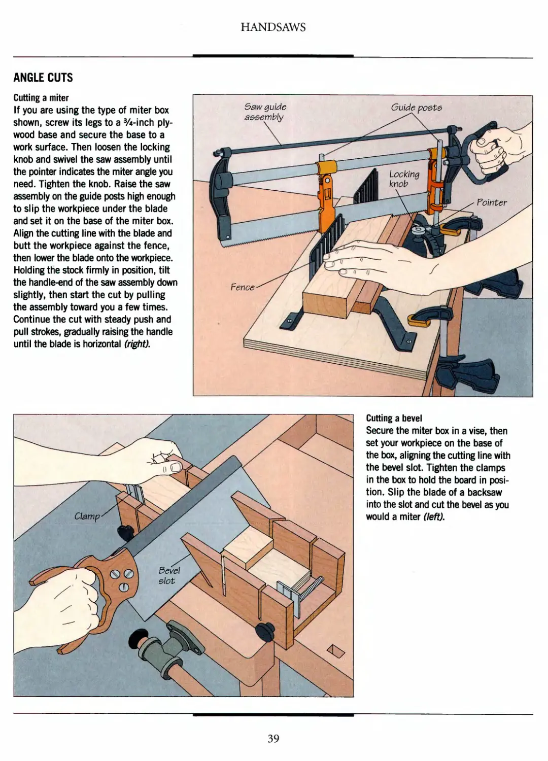
Cutting a miter
If you are using the type of miter box
shown, screw its legs to a 3/4-inch
plywood base and secure the base to a
work surface. Then loosen the locking
knob and swivel the saw assembly until
the pointer indicates the miter angle you
need. Tighten the knob. Raise the saw
assembly on the guide posts high enough
to slip the workpiece under the blade
and set it on the base of the miter box.
Align the cutting line with the blade and
butt the workpiece against the fence,
then lower the blade onto the workpiece.
Holding the stock firmly in position, tilt
the handle-end of the saw assembly down
slightly, then start the cut by pulling
the assembly toward you a few times.
Continue the cut with steady push and
pull strokes, gradually raising the handle
until the blade is horizontal (right).
Saw guide
aeeembiy
Fence ^ /
a i) -
Guide poete
_____ \\ \
locking j§ U^^^^
knob wttm ^^^^
"\ laLPP ^- Pointer J
~- ~~~ f ^|
T ■ i
Cutting a bevel
Secure the miter box in a vise, then
set your workpiece on the base of
the box, aligning the cutting line with
the bevel slot. Tighten the clamps
in the box to hold the board in
position. Slip the blade of a backsaw
into the slot and cut the bevel as you
would a miter (left).
39
HANDSAWS
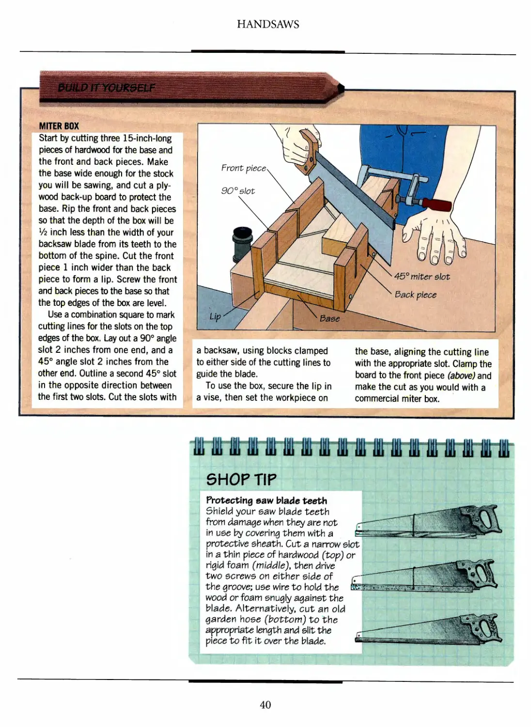
MITER BOX
Start by cutting three 15-inch-long
pieces of hardwood for the base and
the front and back pieces. Make
the base wide enough for the stock
you will be sawing, and cut a
plywood back-up board to protect the
base. Rip the front and back pieces
so that the depth of the box will be
x/z inch less than the width of your
backsaw blade from its teeth to the
bottom of the spine. Cut the front
piece 1 inch wider than the back
piece to form a lip. Screw the front
and back pieces to the base so that
the top edges of the box are level.
Use a combination square to mark
cutting lines for the slots on the top
edges of the box. Lay out a 90° angle
slot 2 inches from one end, and a
45° angle slot 2 inches from the
other end. Outline a second 45° slot
in the opposite direction between
the first two slots. Cut the slots with
a backsaw, using blocks clamped
to either side of the cutting lines to
guide the blade.
To use the box, secure the lip in
a vise, then set the workpiece on
the base, aligning the cutting line
with the appropriate slot. Clamp the
board to the front piece (above) and
make the cut as you would with a
commercial miter box.
tttttttttttttttttt
SHOP TIP
Protecting eaw blade teeth
Shield your eaw blade teeth
from damage tvhen they are not
in use by covering them with a
protective sheath. Cut a narrow slot
in a thin piece of hardwood (top) or
rigid foam (middle), then drive
two ecrewe on either elde of
the groove; use wire to hold the
wood or foam snugly against the
blade. Alternatively, cut ar\ old
garden hose (bottom) to the
appropriate length and slit the
piece to fit it over the blade.
40
ADVANCED CUTS
Some sawing tasks cannot be done
with standard handsaws. Cutting an
intricate curve or trimming a workpiece
flush with an adjoining surface, for
example, demands specialty saws like
those shown on the following pages.
Gentle curves and rectangular
interior cuts can be made with a compass
saw. Tighter contours, however, require
a saw with the thinnest of blades, held
under tension to prevent it from
bending and breaking.
Bowsaws and coping saws are types
of frame saws capable of cutting
complicated curves while leaving a narrow
kerf. Both feature blades that can be
rotated in the frame for cuts that are
deeper than the throat of the saw. They
can also be used on either the push or
pull stroke. If you are cutting a work-
piece that is face down, mount the blade
with the teeth facing the handle and cut
The detachable blade of a
coping saw is thin enough to
follow the most intricate curve.
on the pull stroke. If the workpiece is
clamped end-up, install the blade with
the teeth facing away from the handle
and cut on the push stroke.
Japanese saws are particularly well
suited to many kincls of intricate cuts.
The main benefit of the double-edged
ryoba saw for cutting a notch, for
example, is that the same tool can be used to
make the crosscut and the rip cut (page
47). Because they cut on the pull stroke,
Japanese saw blades can be
exceptionally thin and light, so they slice through
wood very quiddy. Many Western
woodworkers keep one or more in their
tool chests because the Oriental tools
sometimes are convenient to use in
situations where a Western-style saw
might prove clumsy.
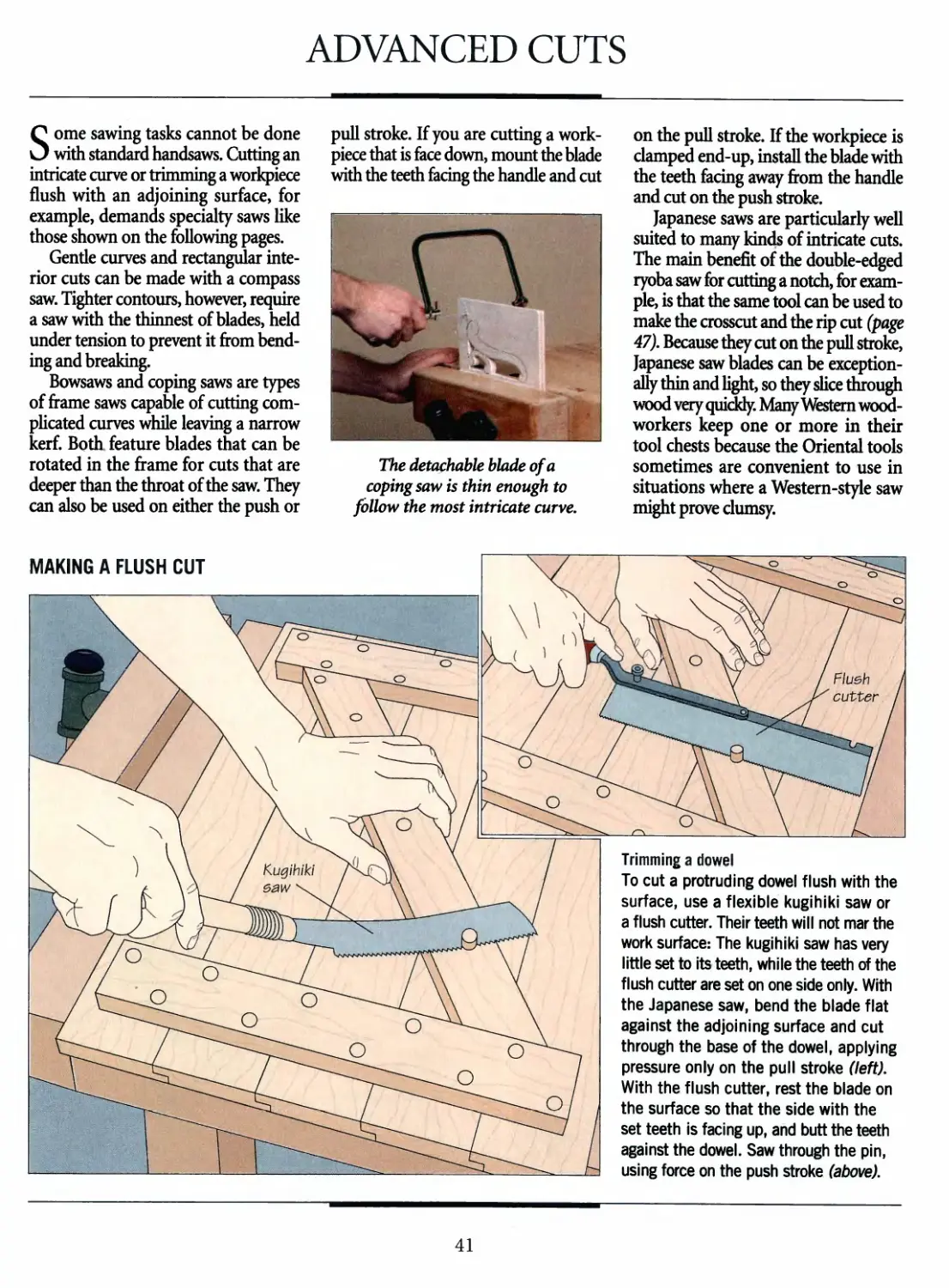
MAKING A FLUSH CUT
Trimming a dowel
To cut a protruding dowel flush with the
surface, use a flexible kugihiki saw or
a flush cutter. Their teeth will not mar the
work surface: The kugihiki saw has very
little set to its teeth, while the teeth of the
flush cutter are set on one side only. With
the Japanese saw, bend the blade flat
against the adjoining surface and cut
through the base of the dowel, applying
pressure only on the pull stroke (left).
With the flush cutter, rest the blade on
the surface so that the side with the
set teeth is facing up, and butt the teeth
against the dowel. Saw through the pin,
using force on the push stroke (above).
41
HANDSAWS
MAKING INTERIOR CUTS
\^^ ^^"^^\^^ 3\ade
Vi^/&k
aiL
v(
\f7L\
^^^^:A
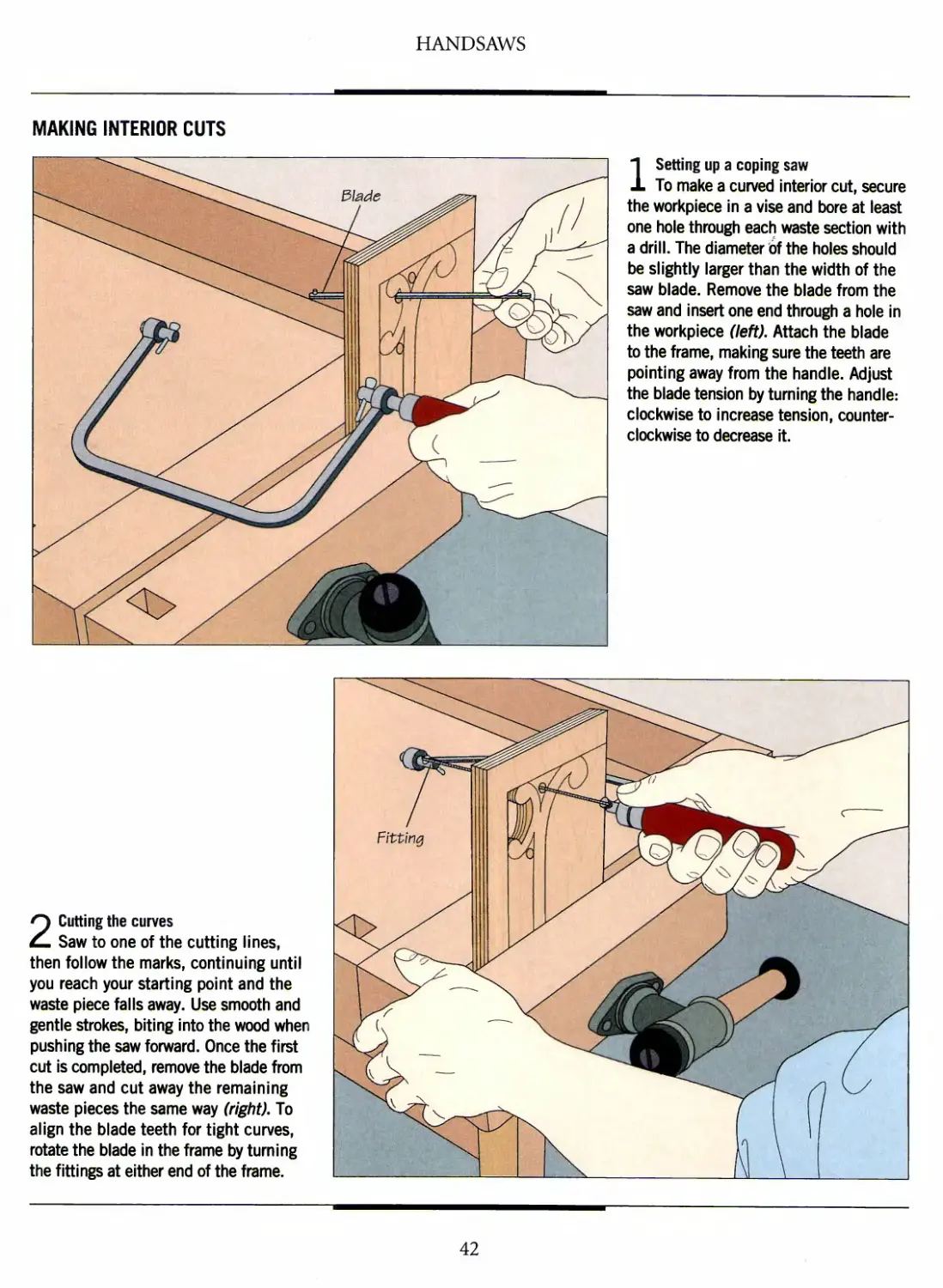
1 Setting up a coping saw
To make a curved interior cut, secure
the workpiece in a vise and bore at least
one hole through each waste section with
a drill. The diameter of the holes should
be slightly larger than the width of the
saw blade. Remove the blade from the
saw and insert one end through a hole in
the workpiece (left). Attach the blade
to the frame, making sure the teeth are
pointing away from the handle. Adjust
the blade tension by turning the handle:
clockwise to increase tension,
counterclockwise to decrease it.
2 Cutting the curves
Saw to one of the cutting lines,
then follow the marks, continuing until
you reach your starting point and the
waste piece falls away. Use smooth and
gentle strokes, biting into the wood when
pushing the saw forward. Once the first
cut is completed, remove the blade from
the saw and cut away the remaining
waste pieces the same way (right). To
align the blade teeth for tight curves,
rotate the blade in the frame by turning
the fittings at either end of the frame.
42
HANDSAWS
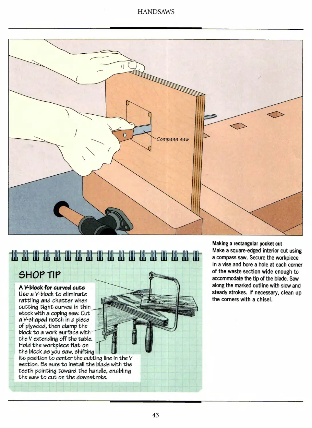
Making a rectangular pocket cut
Make a square-edged interior cut using
a compass saw. Secure the workpiece
in a vise and bore a hole at each corner
of the waste section wide enough to
accommodate the tip of the blade. Saw
along the marked outline with slow and
steady strokes. If necessary, clean up
the corners with a chisel.
«-!#■
SHOP TIP
A V-block for curved cute
Use a V-block to eliminate
rattling and chatter when
cutting tight curves in thin
stock with a coping eaw. Cut
a V-shaped notch in a piece
of plywood, then clamp the
block to a work surface with ■"
the V extending off the table.
Hold the workpiece flat on
the block as you saw, shifting
its position to center the cutting line in the V
section. Be sure to install the blade with the
teeth pointing toward the handle, enabling
the saw to cut on the downstroke.
43
HANDSAWS
CUTTING CURVES IN THICK STOCK
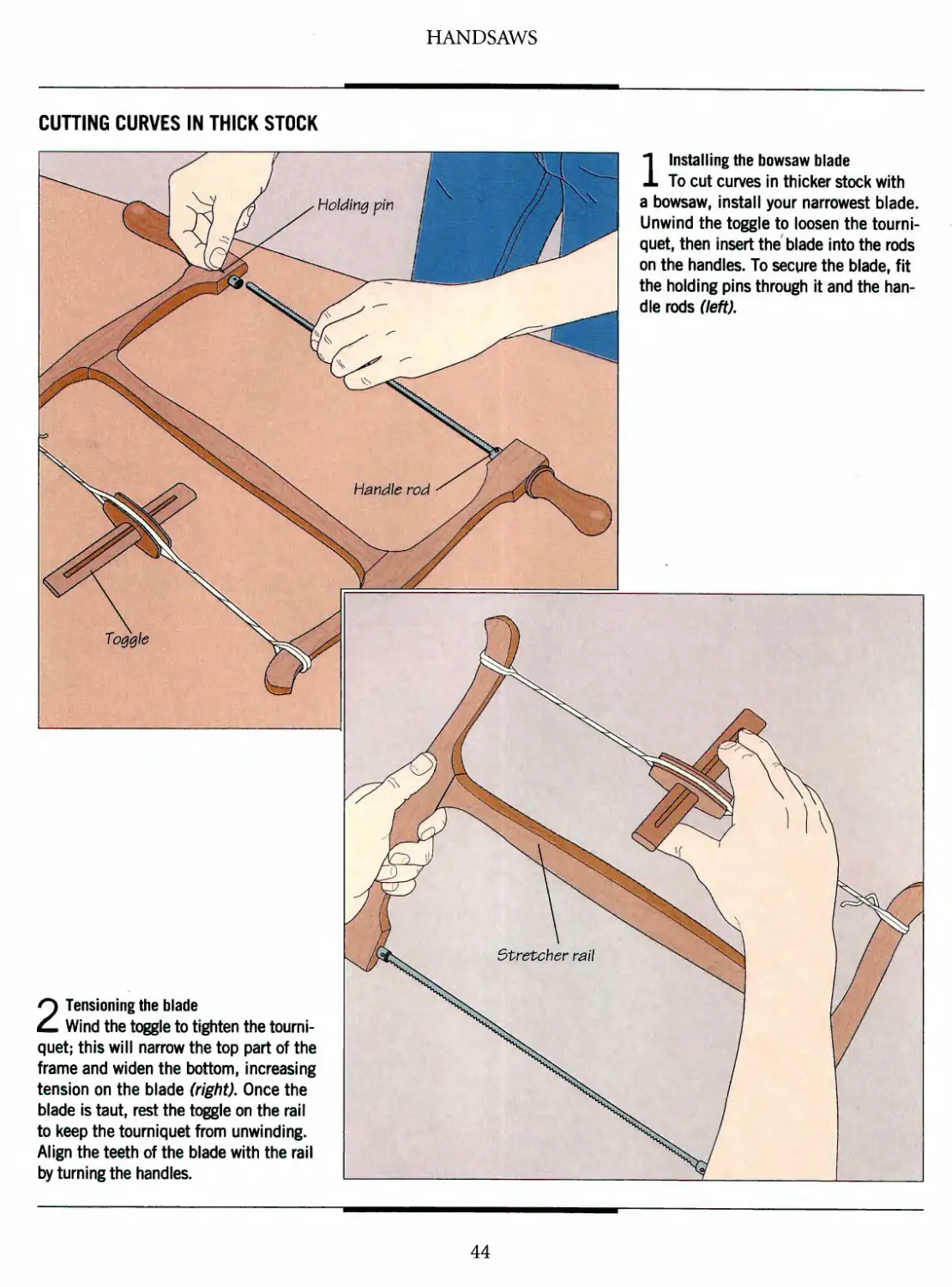
1 Installing the bowsaw blade
To cut curves in thicker stock with
a bowsaw, install your narrowest blade.
Unwind the toggle to loosen the
tourniquet, then insert the blade into the rods
on the handles. To secure the blade, fit
the holding pins through it and the
handle rods (left).
2 Tensioning the blade
Wind the toggle to tighten the
tourniquet; this will narrow the top part of the
frame and widen the bottom, increasing
tension on the blade (right). Once the
blade is taut, rest the toggle on the rail
to keep the tourniquet from unwinding.
Align the teeth of the blade with the rail
by turning the handles.
44
HANDSAWS
A%m*:.
<3>
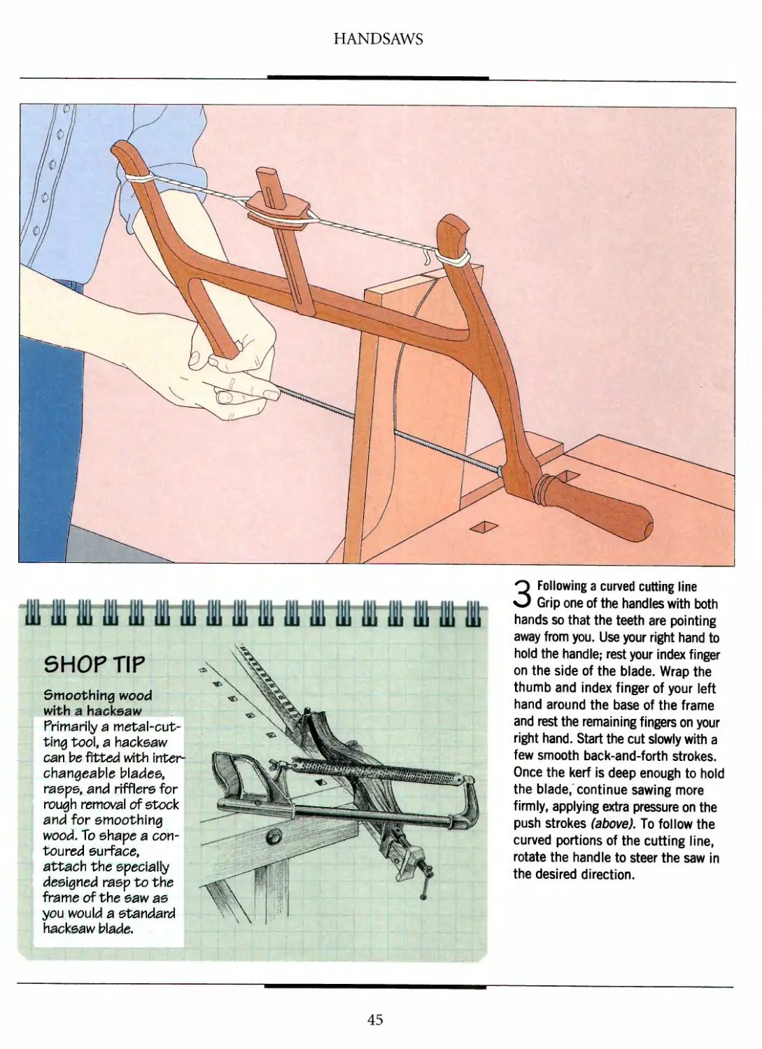
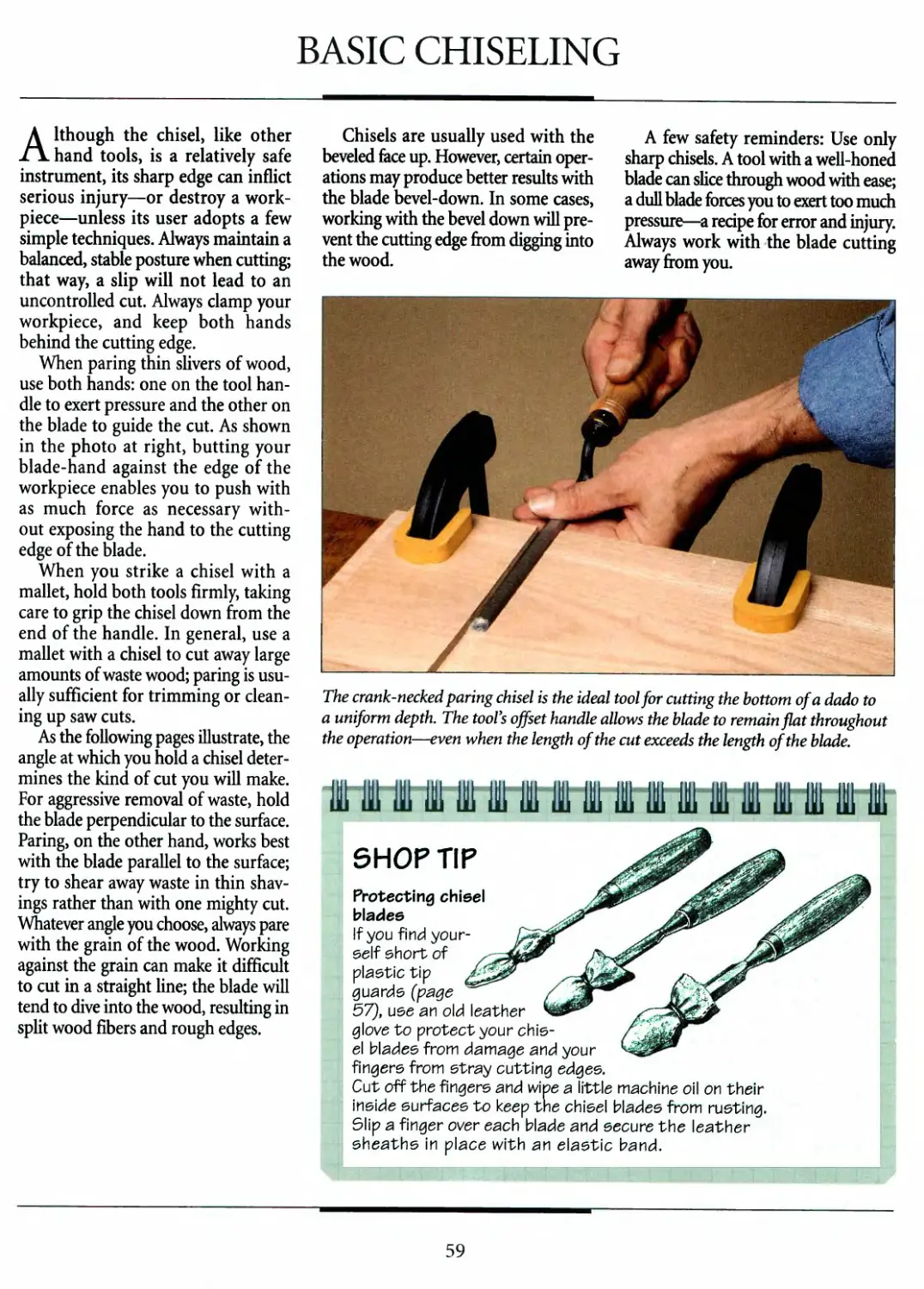
shop r\p
Smoothing wood
with a hackeaw
Primarily a
metal-cutting tool, a hackeaw
can be fitted with inter
changeable blades,
rasps, and rifflers for
rough removal of stock
and for smoothing
wood. To shape a
contoured surface,
attach the specially
designed rasp to the
frame of the saw as
you would a standard
hackeaw blade.
3 Following a curved cutting line
Grip one of the handles with both
hands so that the teeth are pointing
away from you. Use your right hand to
hold the handle; rest your index finger
on the side of the blade. Wrap the
thumb and index finger of your left
hand around the base of the frame
and rest the remaining fingers on your
right hand. Start the cut slowly with a
few smooth back-and-forth strokes.
Once the kerf is deep enough to hold
the blade/continue sawing more
firmly, applying extra pressure on the
push strokes (above). To follow the
curved portions of the cutting line,
rotate the handle to steer the saw in
the desired direction.
45
HANDSAWS
MAKING A COPED CUT
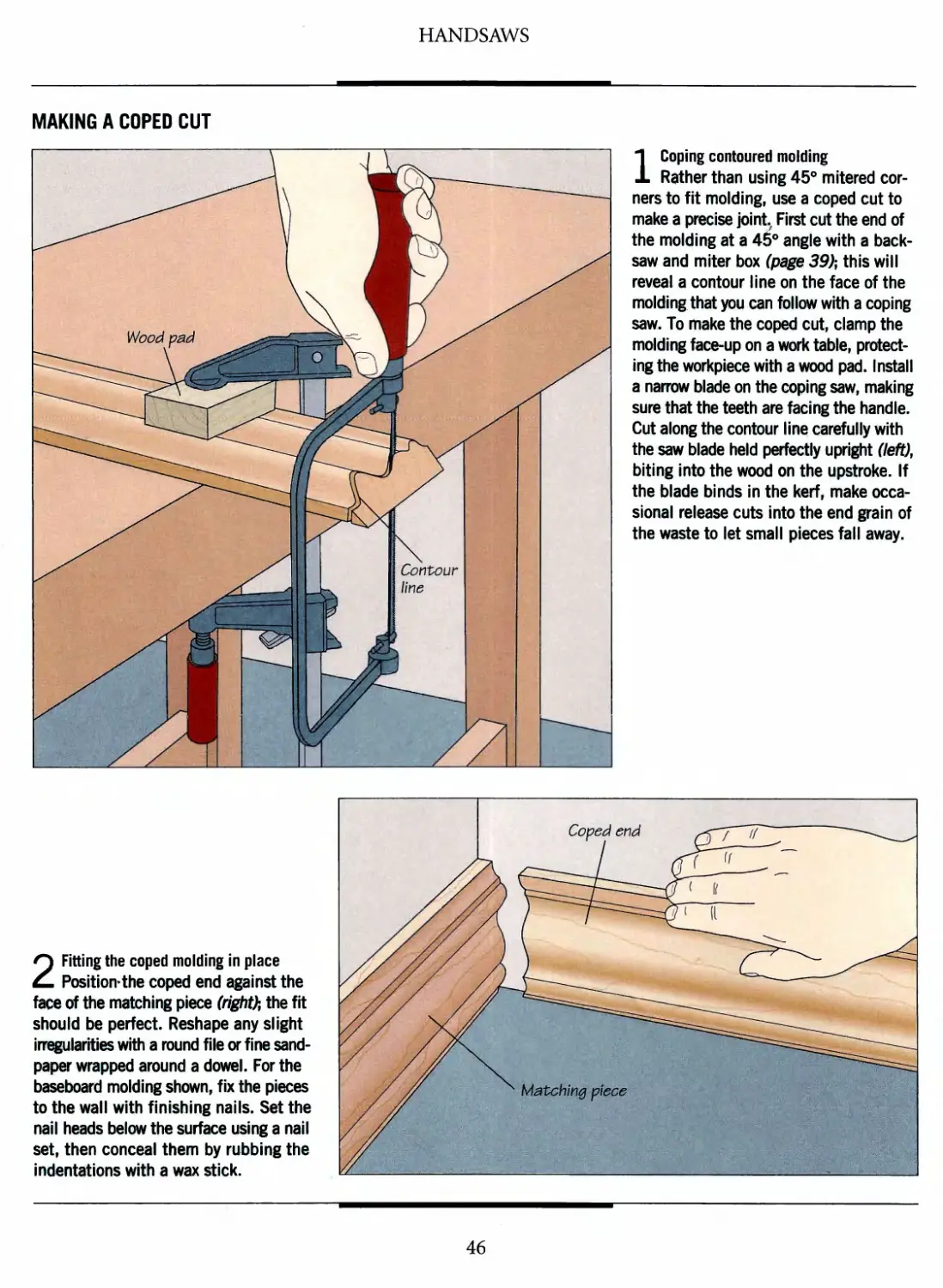
1 Coping contoured molding
Rather than using 45° mitered
corners to fit molding, use a coped cut to
make a precise joint, First cut the end of
the molding at a 45° angle with a back-
saw and miter box (page 39); this will
reveal a contour line on the face of the
molding that you can follow with a coping
saw. To make the coped cut, clamp the
molding face-up on a work table,
protecting the workpiece with a wood pad. Install
a narrow blade on the coping saw, making
sure that the teeth are facing the handle.
Cut along the contour line carefully with
the saw blade held perfectly upright (left),
biting into the wood on the upstroke. If
the blade binds in the kerf, make
occasional release cuts into the end grain of
the waste to let small pieces fall away.
2 Fitting the coped molding in place
Position*the coped end against the
face of the matching piece (right); the fit
should be perfect. Reshape any slight
irregularities with a round file or fine
sandpaper wrapped around a dowel. For the
baseboard molding shown, fix the pieces
to the wall with finishing nails. Set the
nail heads below the surface using a nail
set, then conceal them by rubbing the
indentations with a wax stick.
46
HANDSAWS
USING A JAPANESE COMBINATION SAW
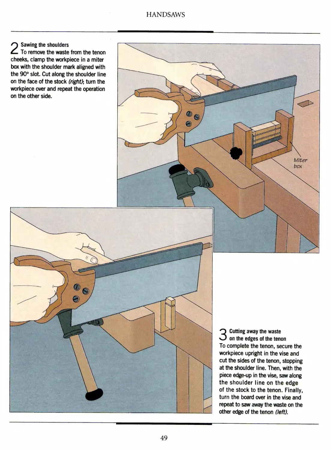
1 Making a crosscut
A combination saw such as a ryoba
can both rip and crosscut—ideal if you
are performing a task such as cutting a
notch. To make the cut, secure your
workpiece edge-up in a vise and butt the
saw's crosscut teeth against the cutting
line. Saw slowly at first, then continue
with firmer strokes using the full length
of the saw (right). Exert more pressure
on the pull stroke and keep the blade
upright throughout the operation. Do not
allow the rip teeth on the other side of
the blade to enter the kerf; their wider
set would cause the blade to bind. If
the cut is deeper than the width of the
saw, make an occasional rip cut to
remove the waste piece before
continuing with the crosscut.
llfek
1
u ^
gLwV
TS&
ft15*/
X
<&
•*
/^ 1
/4? /
yS *& Croeecut teeth
V @(
^°-'\~
Hw -''■ BBH
n
W^7
V^l \
WK^^^KEB^-'y^
/^ /'mm
/<& 1
^^ Rip teeth
2 Making a rip cut
Reposition the workpiece end-up
in the vise. Cut along your marked line
the same way you made the crosscut,
but this time use the saw's rip teeth.
47
HANDSAW JOINERY
Five joints cut with handsaws:
(clockwise from bottom left) a
miter-and-spline, a dado, a through
dovetail a four-shouldered mortise-
and-tenon, and a rabbet
Many woodworkers instinctively
turn to power tools to cut most
of their joints. And while it is true that,
equipped with the proper jig, a router
or a table saw can churn out joints
by the dozen with unrivaled efficiency,
hand tools oflfer their own advantages.
Sometimes the set-up time required by
a power tool is excessive. For example,
the dovetails for a single drawer can
probably be cut more quickly with a
handsaw and chisel than a router and a
dovetail jig.
Cutting joints by hand offers
another reward—the satisfaction of working
closely with wood. The whir of an
electric motor and a spinning blade or bit
can distance you from your work. At
worst, you may notice an error only after
a tool has destroyed a workpiece. With
a handsaw, you can cut out a joint at
your own pace, controlling the blade's
path with a precision equal to what any
power tool can provide.
CUTTING A TENON
1 Cutting the cheeks
Make a tenon by cutting the cheeks first, and then the
shoulders. Secure your workpiece in a vise with the end tilted
forward. Cut along the lines on the end of the board with a back-
saw until you reach the shoulder line of the tenon (above, left);
reposition the workpiece in the vise, with the end tilted toward
you, and repeat. Then, with the workpiece upright in the vise,
cut down to the shoulder line, keeping the saw level
throughout the operation (above, right).
48
HANDSAWS
2 Sawing the shoulders
To remove the waste from the tenon
cheeks, clamp the workpiece in a miter
box with the shoulder mark aligned with
the 90° slot. Cut along the shoulder line
on the face of the stock (right); turn the
workpiece over and repeat the operation
on the other side.
3 Cutting away the waste
on the edges of the tenon
To complete the tenon, secure the
workpiece upright in the vise and
cut the sides of the tenon, stopping
at the shoulder line. Then, with the
piece edge-up in the vise, saw along
the shoulder line on the edge
of the stock to the tenon. Finally,
turn the board over in the vise and
repeat to saw away the waste on the
other edge of the tenon (left).
49
HANDSAWS
CUTTING A THROUGH DOVETAIL
1 Marking the pins
Outline the pins for the joint, as
shown in the diagram below. Mark the
outside face of each workpiece with a
big X, then set a cutting gauge to the
thickness of the stock and scribe a line
along the ends of both boards to mark the
shoulder of the pins and tails. Next use a
dovetail square to outline the pins on the
end of one board. Start with half-pins at
each edge, making sure that the narrow
ends of the pins are on the outside face of
the board. Mark the waste sections
adjacent to the half-pins, then draw the center
of the board end. Outline a pin at the
center line, then mark the remainder of the
pins in between (right), spacing them
evenly. Use a combination square to extend the
pin marks to the shoulder lines.
2 Cutting the pins
Secure the pin board in a vise with its
outside face toward you. Use a dovetail
saw to cut along the edges of the pins,
working from one side of the board to the
other. (Some woodworkers cut the left-
hand edges first, then move on to the
right-hand edges.) For each cut, align
the saw blade just to the waste side of
the cutting line. Use smooth, even strokes,
allowing the saw to cut on the push stroke
(right). Continue sawing to the shoulder
line, making sure that the blade is
perpendicular to the line.
Dovetail eaw
50
HANDSAWS
3 Removing the waste
Use a coping saw to cut away the
waste wood between the pins. Slide the
saw's blade into the kerf at the side of
each pin and rotate the frame until it is
almost level with the end of the board.
Cut out as much of the waste as you
can while keeping the blade about Vie
inch above the shoulder line (right).
Pare away the remaining waste with a
chisel (page 69).
4 Marking and cutting the tails
Set the tail board outside-face down
on the work surface. Then, hold the pin
board end-down on the tail board with its
outside face away from the tail board.
Align the pins with the end of the tail
board. Use a marking knife to outline the
tails and a combination square to extend
the lines onto the end of the board. Cut
the tails with a dovetail saw the same way
you cut the pins. Some woodworkers prefer
angling the board (left), rather than the
saw, so that the cuts are vertical. In either
case, saw smoothly and evenly, stopping
just a fraction of an inch before you reach
the shoulder line. Remove the bulk of the
waste with a coping saw, then pare away
the final bits of waste with a chisel.
51
HANDSAWS
CUTTING A MITER-AND-SPLINE JOINT
1 Cutting the grooves
Cut bevels at the ends of the boards
to be joined and glue up the corner, then
secure the workpiece in a vise as shown.
Scribe a line along the outside faces of
both boards with a cutting gauge to mark
the depth of the splines, which should be
slightly less than the thickness of the
joint. Use a dozuki saw to cut grooves into
the joint for the splines, spacing the cuts
about 1 inch apart. (A backsaw will also
work well, but its wider kerf means that
you will have to cut thicker splines.) Saw
smoothly and evenly, allowing the blade to
cut on the pull stroke. Continue to the
spline depth line, making sure that the
blade is perpendicular (left).
2 Fitting in the splines
Cut triangular-shaped splines from
veneer to fit-in the grooves. For
maximum strength, make sure that the grain
of the splines runs along their long edge.
Spread a little glue in the grooves and
insert the splines long-edge down into
the cuts (right). The wooden wafers will
absorb some of the adhesive and swell,
making a solid joint. Once the glue has
dried, cut and sand the projections flush
with the boards.
52
HANDSAWS
CUTTING DADOES
N>_
^f
III V -. .. j J
^j8F1 ^^33L_
W9^;' :■ 'S^.',*"^*"'^■~i?$, 'f^&ffi
Depth etop
r
Cutting kerfs inside the dado outline
Mark the width of the dado on the face of the
stock, then set the board on a bench hook
(page 37). To ensure that all the kerfs are cut to
the correct depth, clamp a depth stop on one
side of a backsaw blade. The depth stop should
be as wide as the blade from the teeth to the
bottom of the spine, less the desired depth of
the dado. Saw into the workpiece at one of the
width marks to cut an edge of the dado, stopping
when the depth stop is flush against the face of
the stock. Repeat to cut the channel's other
edge (left). To remove as much waste as possible,
saw a number of kerfs between the two cuts,
working at roughly Vs-inch intervals. Remove
the remaining waste with a chisel.
SAWING RABBETS
Cutting an end rabbet
Outline the rabbet on the end of the workpiece, then use a
backsaw to cut it. Clamp the stock face-up on a work surface,
protecting the workpiece with a wood pad. Align the pad with
the cutting line to guide the saw and make a crosscut for the
depth of the rabbet (above). Keep the saw perpendicular to
the board face, taking care to stop when the blade reaches
the rabbet width line. You can also clamp a depth stop to the
blade to control the depth of the cut (step above). To complete
the rabbet, secure the workpiece end-up in a vise and cut off
the waste (right).
53
•j&
»^
\
i3'^^^^
#'
CHISELS
AND BORING TOOLS
The wood chisel is one of
woodworking's indispensable tools. This
is no wonder: Although saws, drills,
planes, and other tools have been
motorized successfully, no suitable
substitute has been found for the simple—
and versatile—wood chisel. Strong
enough to withstand the forceful blows
of a mallet and hog out great quantities
of waste wood, the ordinary chisel is
also light and well-balanced, so that
sensitive hands can use it to impart the
most precise shapes.
When the table saw is turned off and
the whine of router and drill ceases,
the chisel is put to work squaring
corners, trimming tenons, smoothing
curves, and trueing dovetails. The
varieties of chisels and some of the
techniques for using them for a number of
woodworking tasks are explained in
the following pages.
The results you obtain at the
workbench will be strongly influenced by the
quality of your chisels and the keenness of their blades. Time
invested in learning and using sharpening skills (page 65) will
help produce superior work. Invest also in good-quality tools.
Naturally, strength is one requirement. The steel must also
Mounted in a brace, an auger bit bores
a hole through a block of hardwood.
Aligning the bit over the gap between
the workbench and the vise permits
the hole to be drilled without
marring the bench top.
hard use; the entire tool must be well
balanced—easy to hold and easy to
guide. When shopping for a chisel,
discuss your needs with dealers and other
woodworkers. Look for high-quality
steel, a well-fitted handle, and a blade
that is finely finished top and bottom.
Also check that the back of the chisel
blade is perfectly flat, particularly just
behind the cutting edge. A flat back is
essential when you are using the chisel
for paring, as it provides an even bearing
surface that increases accuracy. An old
chisel may be pitted with rust, but it can
still give adequate service once it has
been reground.
Electric motors now power the drills
and other boring devices in most
workshops. Nevertheless, most
woodworkers still keep a brace, hand drill, and
push drill handy, for these hand tools
have unique abilities not readily
duplicated by power tools, especially
working in tight quarters or when precise
control of a hole's depth is required. Some of the tools and
their uses are detailed starting on page 70.
Although new hand tools sometimes cost as much as their
electric counterparts, good used hand tools are more afford-
take and maintain a sharp edge; the handle must withstand able. They deserve a place in every well-equipped tool chest.
A paring chisel shaves away a sliver of waste from
one side of a dovetail The skew chisels on the
workbench are used to trim waste to the shoulder line.
55
A COLLECTION OF CHISELS
Firmer chieel
Aieo known ae a framing chieel Featuree
square-edged eidee and a beveled tip for heavy-duty
etock removal; metal ferrule and leather waeher at
the baee of the handle allow the tool to be etruck
with a mallet. Widths from Va to 2 inches
Faring chisel
Ite long, thin, bevel-sided
blade ie ueed with hand
preeeure to pare long cute;
widthe from Va to 2 inchee
Lock mortise chisel
Aleo known ae a ewan-neck mortiee
chieel; ite curved blade provides the
neceeeary clearance and leverage for
smoothing the bottom of mortieee.
Widthe from % to % inchee
Corner chisel
Struck with a mallet to square mortise corners
cut by a router or other power tool; features two
perpendicular cutting edges that form a corner-
ehaped blade. Widths starting at % inch
Mortise chisel
A firmer chisel featuring a thick, extra-
strong blade with a higher bevel angle;
struck with a mallet to cut mortises.
Widths from Va to 2 inches
Skew chisel
The 60° angle of its blade is intended for shearing end grain
and paring wood in corners; right- and left-angled chisels usually
used in tandem to reach both sides of a joint or corner. Indispensable
for trimming blind or half-blind dovetails; widthe from V2 to 1 inch
56
CHISELS AND BORING TOOLS
butt chisel
Ite ehort blade with equare- or
bevel-edged eidee cute hinge mor-
tieee; widthe from % to 2 inchee
Bevel-edged chisel
Aleo known ae a bevel-edged firmer
chieel or cabinetmaker e chieel. Ite blade
featuree beveled eidee for fine cutting of wood;
normally ueed with hand preeeure, but can be tapped
lightly with a mallet. Widthe from V& to 2 inchee
Drawer lock chisel
An all-eteel tool with two bladee at right
anglee to one another. Struck with a hammer
to cut ehallow mortieee for locke and hingee
in tight epote; widthe 3/a to 5/a inchee
Cranked-neck paring chisel
Ite handle ie orfeet from the
blade, allowing the cutting edge
to remain flat through long cute;
widthe from V* to 2 inchee
STORING CHISELS
^^^^ c-TP^
f 7/ M
s\
»* *
\" ' \
A\\V; X
\J
Protecting chisels from damage
The cutting edges of chisels can be
nicked if they are stored loosely in a
toolbox or on a workbench. Protect
your chisels with plastic guards or a
tool roll. Chisel guards are available
in a variety of widths to fit any tip
size, and can usually be bought either
individually or in sets of five or ten.
Tool rolls are generally made from
leather or heavy-duty canvas or cloth,
with anywhere from six to 12 slots for
chisel blades and a flap that folds
over the handles.
57
ANATOMY OF A CHISEL
A chisel blade is attached to its
handle in one of two ways. The more
common style features a narrow
metal tang that is driven into a wooden
handle or molded into a plastic one. A
different construction features a
hollow socket that holds the handle.
The blade itself may be straight-
sided or beveled on its upper face.
While reducing the tool's strength, the
bevel enables the cutting edge to get
into corners and restricted spaces.
Because bevel-edged chisels are
comfortable to use with hand pressure,
they rank among the cabinetmaker's
favorite hand tools.
Chisels fall into three basic categories
depending on the blade type. Firmer
chisels are durable tools that can be
struck with a mallet. They have heavy
bolsters, necks, and cutting edges, along
with tough handles supported by a
metal ferrule. Some models include leather
washers, one just below the ferrule and
another on the head of the handle, to
cushion the impact of mallet blows.
Mortise chisels are like firmer chisels
but with thicker blades. The handles
usually feature a ferrule at both the top
and the bottom.
Finally, there are paring chisels,
relatively delicate tools with long,
thin, beveled blades, and fine
wooden handles not meant to be struck
with mallets.
Woods like ebony, rosewood, and
hickory were once used for chisel
handles, but have been replaced mostly by
beech and boxwood.
Handle
Ferrule
Shoulder
Cutting edge
Bolster Neck
Blade
Bevel
Japanese bevel-edged chisels have
earned a reputation as the world's finest
chisels. They often feature red oak han-
dies; the bottom face of the laminated
steel blades is usually slightly concave
to reduce friction and facilitate
sharpening. Although Japanese chisels are about
the same length overall as Western-style
toohy their chisel blades are shorter, with
longer shoulders and tangs.
58
BASIC CHISELING
Although the chisel, like other
hand tools, is a relatively safe
instrument, its sharp edge can inflict
serious injury—or destroy a work-
piece—unless its user adopts a few
simple techniques. Always maintain a
balanced, stable posture when cutting;
that way, a slip will not lead to an
uncontrolled cut. Always clamp your
workpiece, and keep both hands
behind the cutting edge.
When paring thin slivers of wood,
use both hands: one on the tool
handle to exert pressure and the other on
the blade to guide the cut. As shown
in the photo at right, butting your
blade-hand against the edge of the
workpiece enables you to push with
as much force as necessary
without exposing the hand to the cutting
edge of the blade.
When you strike a chisel with a
mallet, hold both tools firmly, taking
care to grip the chisel down from the
end of the handle. In general, use a
mallet with a chisel to cut away large
amounts of waste wood; paring is
usually sufficient for trimming or
cleaning up saw cuts.
As the following pages illustrate, the
angle at which you hold a chisel
determines the kind of cut you will make.
For aggressive removal of waste, hold
the blade perpendicular to the surface.
Paring, on the other hand, works best
with the blade parallel to the surface;
try to shear away waste in thin
shavings rather than with one mighty cut.
Whatever angle you choose, always pare
with the grain of the wood. Working
against the grain can make it difficult
to cut in a straight line; the blade will
tend to dive into the wood, resulting in
split wood fibers and rough edges.
Chisels are usually used with the
beveled face up. However, certain
operations may produce better results with
the blade bevel-down. In some cases,
working with the bevel down will
prevent the cutting edge from digging into
the wood.
A few safety reminders: Use only
sharp chisels. A tool with a well-honed
blade can slice through wood with ease;
a dull blade forces you to exert too much
pressure—a recipe for error and injury.
Always work with the blade cutting
away from you.
The crank-necked paring chisel is the ideal tool for cutting the bottom of a dado to
a uniform depth. The tooVs offset handle allows the blade to remain flat throughout
the operation—even when the length of the cut exceeds the length of the blade.
i If 1111II UMm*lHrtt
SHOP TIP
Protecting chisel
blades
If you find
yourself short of
plastic tip
guards {page
57), use an o\d leather
glove to protect your
chisel blades from damage and ;
fingers from stray cutting edges.
Cut off the fingers and wipe a little machine oil on their
inside surfaces to keep trie chisel blades from rusting.
Slip a finger over each \Aade and eecure the leather
eheathe in place with an elastic band.
I you
59
CHISELS AND BORING TOOLS
CUTTING A NOTCH
1 Removing the waste
Secure the workpiece edge-up in a
vise and saw a kerf into the edge of the
stock to define the end of the notch. Stop
the kerf at the cutting line on the face of
the board; the kerf will sever the wood
fibers at the end of the notch, making it
possible to shear away the waste with a
chisel without splintering the wood. Using
a firmer chisel about as wide as the
thickness of the workpiece, butt the tip of the
blade against the end of the board about
Ve inch below the top edge. Hold the
blade bevel-up and parallel to the edge of
the workpiece and strike the handle
firmly with a wooden mallet (left), cutting
off a thin layer of waste to the saw kerf.
Continue slicing away the waste in this
fashion until you are about Vb inch above
the cutting line on the board face.
2 Final paring
With the workpiece still in the vise,
shave away the remaining waste with the
firmer chisel or a paring chisel. Press
the flat side of the blade against the
bottom of the notch, holding the chisel
handle with your right hand and the blade
between the thumb and fingers of your
left hand. Rest the index finger of your left
hand against the end of the workpiece
to protect the hand from the tip of the
blade. Push the chisel toward the saw
kerf (right), shaving away the last slivers
of waste to the cutting line. If the blade
catches on the wood fibers, ease the
cutting edge through the wood by moving
the handle from side to side while
applying forward pressure.
Y/^
\i y
^S^S&b
^^SlisM^ \ '
\^N
_3^J>^
S^^ai^^B^^B^^^^^^^
\ 1 I •-\.
•\ \ \ - ' - '
' -?\ \ \
>"• V\\\
* ...- - -*< 1' \ \ \ 1-1
^\~
\^
v \_E
\ \
A
!"'-'.'■
' - *• 1
hi
F>*
60
CHISELS AND BORING TOOLS
3evel-edged chieel -^ \
Kir /
BIT 4
^<^\
Vertical paring
To shave away waste from a vertical
surface, such as the shoulders of a tenon,
clamp the workpiece to a work surface.
Holding the handle of a bevel-edged chisel
with your right hand, use the thumb of
your left hand to butt the flat side of the
blade against the tenon shoulder. Rest
the fingers of your left hand on the face of
the board. Leaning over the workpiece
and keeping your arms locked in position,
slice away thin slivers of waste at a time
(left), exerting pressure by moving your
upper body rather than your arms or hands.
Once you reach the cutting line, turn
the workpiece over and repeat on the
other side of the tenon.
A WALL-MOUNTED CHISEL RACK
Keep your chisels organized and in
full view in a shop-made wall rack.
Build the rack from three strips.- the
back piece should be longer than the
others so its ends can be screwed
to the wall; make the middle piece
twice as wide as the outside pieces.
Cut slots for your chisels along the
edges of the middle piece. The slots
should be about Vi inch deep and
slightly wider than your chisel blades.
Glue the three pieces together and
mount the rack on a wall as you would
a screwdriver rack (page 121).
61
CHISELS AND BORING TOOLS
Paring a groove
Secure the workpiece in a vise. The
illustration shows a piece for a miter-and-
spline joint, with saw cuts already made
defining the groove. With the mitered
end up, angle the board to position
the groove level with the work surface.
Using a bevel-edged chisel slightly
narrower than the groove, work with the
grain, shaving away waste in thin layers
as you would in paring a notch (page
60). Clean out the groove periodically
so the shavings will not cover the blade
and obscure the cutting edge.
Shaping a circular edge
To smooth a curved cut, clamp the work-
piece face up to a work surface. To
protect the bench, clamp a support board
between the stock and the work surface.
Using a bevel-edged chisel, grip the tool
as you would for vertical paring (page 61),
slicing away thin layers of waste along
the edges of the cut (right). Push the tool
using a side-to-side rocking motion.
62
CHISELS AND BORING TOOLS
CUTTING A DOOR HINGE MORTISE
1 Scoring the hinge outline
Secure the door in a vise with the
pencilled outline of the mortise facing up. Using
a bevel-edged chisel about the same width as
the mortise, position the blade at one end
just inside the cutting line. The bevel should
face the waste. Strike the tool lightly with a
mallet, cutting to the full depth of the
mortise. Continue scoring around the hinge
outline, then pare away the waste (step 2).
You may be able to cut a shallow mortise
using hand pressure only, without the mallet.
2 Cleaning out the waste
Once the mortise outline has been
scored, use the chisel as you did in step
1 to make a series of cuts every Vi inch
from one end of the outline to the other.
Then cut the waste away, keeping the
flat side of the blade flat against the
bottom of the mortise (above).
63
CHISELS AND BORING TOOLS
TRIMMING IN RESTRICTED SPACES
f:
1—^\_i--^"""^
kx
\ y » '
I ' * •
I ' ' ■** 1 '
,-' 1 ---,-.. «'? -
S^^"^ -s^
^ V^-"""'
tti^^^^^^m
J,lj^^^^^^tm
r
'^>s)
y'
^ ' .
s~~\
\w >^ y/7 // f\
V r / s /' ' - •7^Ssv ^v
i / / >w N.
Cleaning up a corner
Use a skew chisel to trim a surface in a
tight spot that a standard chisel is unable
to reach, such as the inside corner of a
drawer. Secure the drawer in a vise and
hold the chisel in the drawer bevel up,
pressing the blade flat and guiding it
with your left hand. Push the chisel
toward the corner lightly to trim the
surface (above).
f-tttlllrirttim-ttt*^
SHOP TIP
A makeshift router plane
If you need to smootn the .,
bottom of a dado, but do \y
not own a router plane, you
can improvise a tool that
does the same job. Mount
a firmer chisel bevel down in
a sharpening guide, with the
microbevel (page 65) flat on the
bottom of the dado. Butt a
support board the same thickness
your workpiece against the dado
keep your makeshift plane level ""
advance the chisel along the channel.
Pushing it slowly will prevent the
cutting edge from gouging the bottom
of the dado.
64
CHISELS AND BORING TOOLS
SHARPENING A CHISEL
1 Honing the cutting edge
Sharpening a chisel blade involves
two steps: honing a secondary bevel on
ihe forward edge of the existing bevel-
called a microbevel—then removing the
resulting burr. To form the microbevel, lay
a combination stone coarse side up and
nail cleats to the work surface to keep
the stone from moving. Saturate the stone
with the appropriate lubricant—either
water or a light oil—until it pools on the
surface. Start by holding the blade with
the existing bevel flat on the stone; then
raise it about 5° and slide the cutting edge
on the stone with long, elliptical passes
(left). Apply moderate pressure until a
microbevel forms (inset). Turn the stone
over to make a few passes on the fine side.
2 Lapping the burr
To remove the burr that forms on the
flat side of the blade—a process
woodworkers call "lapping" the burr—saturate
the stone once again. Holding the chisel
blade flat on the fine side of the stone,
bevel side up, move it in a circular
pattern (right) until the flat side of the
cutting edge is smooth to the touch. A few
strokes should suffice.
65
CHISEL JOINERY
Although modern machinery may
have relegated the chisel to a
backup role in many joint-making
operations, this particular hand tool remains
indispensable for cutting the finishing
touches on joints. Two everyday
examples are cleaning out the corners of a
router-cut blind dado and shaving
away the last slivers of waste from
dovetails cut by a saw.
A chisel is also a good choice for
chopping out mortises, particularly
when only a few joints are involved.
For small jobs, the speed of power
tools is usually offset by setup time. It
is faster to hand-cut the mortises for
one table, for example, than to set up
a mortising attachment on a drill press.
There is no single correct sequence
in chiseling a mortise. Some wood-
With its 90° angled cutting edge,
a corner chisel squares the corners
of a mortise cut by a router.
workers prefer to start their cuts in the
middle of the mortise outline and work
toward the ends. You can just as easily
start at one end and proceed to the
other, as shown below.
One requirement that does not vary,
however, is using the correct tool for
each stage of the operation. A mortise
chisel will cut a cavity with cleaner edges
than either a firmer or ordinary bevel-
edged chisel, and a swan-neck chisel
simplifies clean-up of the cavity. A corner
chisel is useful for squaring mortise
corners cut by a router.
The dado is another joint that can be
chiseled effectively. The technique shown
on page 68—shaving off the waste wood
in a series of thin layers—may seem
relatively time-consuming, but the
resulting channel will be square and clean.
HAND-CUTTING A MORTISE
1 Chopping the mortise
Clamp your stock to a work surface.
Then, starting about Vs inch inside the
cutting line at one end of the outline, hold
a mortise chisel vertically and strike it
with a wooden mallet, making a cut that
is about lA inch deep. Use a chisel the
same width as the mortise and be sure
that the beveled face of the blade is
facing the waste. Then make another cut V*
inch from the first (right) and lever out the
waste (step 2).
^^—-^
/1
V ^^
i' .JS^
—L^ ^
-<=\
/A
Mortieitig
'chieel
^^
-<<P>
66
CHISELS AND BORING TOOLS
2 Levering out the waste
With the blade wedged in the cut, tilt
the handle down toward the uncut portion
of the outline. The tip of the blade will dig
in under the waste wood and sever it from
the bottom of the mortise. Continue
making a cut every Vi inch as in step 1 and
levering out the waste (right). When you
are Vs inch from the other end of the
outline, turn the chisel around so the bevel
faces in the opposite direction. Make a
cut and lever out the waste. Repeat the
process until you reach the desired depth
of the mortise.
15SS^BEBBbKL^>/
jumbl
r-7 \iiH^3S0E9r^^^^^^l
fa ViitoBWB Bo\
M \THBf In \
Iv ^*^^ ^^"
W^
} / i
cy / J
^^<S>,
^0f
^\. >sWw^J \
J
1
Nv v
/ /
\>
(
P\ u
VS-
Lock
s mort'iee
chieel
u ^^~~~~~fr^~-~~7
^y J
3 Smoothing the bottom and trimming
the ends of the mortise
Use a lock mortise chisel—also called
a swan-neck chisel—the same width as
the mortise to smooth the bottom of the
cavity. Holding the rounded back face of
the blade against one end of the mortise,
push the chisel toward the other end (left).
The tip of the blade will scrape along the
bottom of the mortise, shaving off waste
and leaving the surface smooth and even.
For a long mortise, repeat from the other
end. Trim the ends of the cavity with the
same mortising chisel used to chop out
the mortise. With a mortise chisel held
vertically, pare away the Vs-inch-wide
waste sections at either end of the
mortise. This time, align the chisel blade
with the cutting marks at the ends of
the outline and pare to the line.
67
CHISELS AND BORING TOOLS
CHISELING A DADO
Inverted V
1 Chiseling the waste
Secure the workpiece in a vise and cut
the edges of the dado to the desired
depth with a backsaw. Then, using a
bevel-edged chisel slightly narrower than the
dado, remove the waste with a series of
shallow cuts that leave an inverted V at
the bottom of the groove (inset). Angle the
blade so that one side rests against one of
the saw cuts and shave off thin layers of
waste, stopping halfway along the
channel. Angling the cuts, continue shaving
away the waste in this fashion until the
lower edge of the blade reaches the
bottom of the dado. Remove the waste on the
other side of the channel (left), then turn
the workpiece around and repeat to clear
the waste from the other half
2 Final paring
To remove the peak left in the middle
of the dado, pare away the waste with the
chisel handle tilted down about 10°. Push
the chisel along the channel to slice away
a thin layer of waste (right), stopping about
halfway along the dado. Continue until you
reach the the bottom of the dado, making
the final pass with the chisel blade flat
against the bottom. Turn the workpiece
around and repeat for the other half.
68
CHISELS AND BORING TOOLS
FINE-TUNING A DOVETAIL JOINT
Trimming to the shoulder line
To remove the waste from dovetails cut with a
handsaw, use a bevel-edged chisel slightly
narrower than the space between the tails at the
shoulder line. Set the tail board face down and
align the tip of the chisel with the shoulder line.
Using your thumb to hold the blade vertical,
push the chisel straight down to pare away the
final sliver of waste (right). Repeat the process
between the other tails until there is no waste •
beyond the shoulder line. To trim to the cutting
lines on the sides of the tails, secure the work-
piece end-out in a vise and use the bevel-edged
chisel horizontally to pare away any waste. Then,
with the workpiece clamped end-up, remove
waste wood in the corners between the tails and
the shoulder with a skew chisel. Holding the flat
face of the blade flush against the shoulder, guide
the tip of the blade to the base of the tail to clean
up the corner (below). Use the same tools and
techniques on the pin board.
0s
so;
69
A BATTERY OF TOOLS FOR BORING
Hand drill
An "egg beater'-etyle
drill that boree holee up
to 3/a inch in diameter;
comee with a three-jaw
chuck and handlee on ite
aide and top for
horizontal or vertical drilling
Handle
Ratcheting hand brace
Deed mainly with auger or
expanelve bit to bore holee
from % to 3 Inchee In
diameter. Featuree revereible
ratcheting action and a two-jaw
chuck; available with a 5-to
14-lnch-diameter ewlng I
Fueh drill
A ratcheting tool
for boring email
holee; puehlng down
on the handle turne
the ehaft and drlvee
the bit. Ueually
comee with notched
drill pointe that fit
into ite epecially
deeigned chuck
Crank handle
Screw Starter
An awl-llke tool
with a threaded tip
for boring etartlng
holee for ecrewe
Hand countersink
Boree countereink
holee; featuree a
countereink bit mounted In
a wooden handle
70
CHISELS AND BORING TOOLS
A RANGE OF BRACE AND DRILL BITS
Double-twist auger bit
Aleo known ae a Jennings pattern auger bit; boree holee from % to 1 Vz
inchee in diameter. Featuree two epure and a lead ecrew; the epiral
throat allowe waete and eawduet to paee quickly from the hole
Countersink bit
Deed with hand brace
or drill to bore
countersink holee V2, % and 3A
inch in diameter
Solid-center auger bit
A general-purpoee brace bit for boring holee from V* to
1 inch in diameter; featuree a lead ecrew and two eharpened
cutting epure. Available in a wide range of ehank lengthe
Expansive bit
An adjuetable bit with two
interchangeable cuttere; ueed
with a brace to bore holee from
5/& to 3 inchee in diameter
Drill point
A fluted bit ueed in a pueh or
hand drill to bore holee from
Vie to u/64 inch in diameter
Spoon bit
A traditional gouge-ehaped
bit ueed in a brace to bore
3/a- to 3A-inch holee for chair
lege and dowele; aleo available
in tapered form for reaming
4
Screwdriver bit
A flat-tip bit ueed with a
brace to drive elot-head
ecrewe; ueually available in
3/a- to 3A-inch blade widthe
3rad-point wood bit
3oree holee from Va to 11nch in diameter; hae a
ehort brad lead and epure. Available with etraight
or tapered ehank to fit in hand drill or brace
Braces come in many shapes and sizes depending on the job
they are designed to perform. The close-quarter or joist brace
(far right) can bore holes in tight spots that would be cramped
for a conventional brace. Its lever is set at a 90° angle to the
bit, enabling the tool to be cranked while the head is held
directly over the hole. The short-throw brace (near right) is
essentially a standard brace with a shorter swing radius—a
useful feature for restricted spaces that cannot accommodate
the 12-inch swing of the typical standard brace handle.
Center bit
Fite into a brace to bore
ehallow holee from 3/m and
2 ]A inchee in diameter
Twist drill
An all-purpoee drill with a etraight ehank
that only fite in three-jaw drill chucke;
boree holee from Ve to V2 Inch in diameter
w£$®
BORING TOOLS
B.
Fitted with a countersink bit, a
hand drill widens the mouth of a
pilot hole to allow the screw head
to be set flush with the surface.
efore the electric drill and the drill
press, craftsmen used braces and
hand drills to bore holes in wood.
Like their electric counterparts, these
traditional hand tools accept a
variety of bits to drill holes of different
type and diameter.
Bits for braces and hand drills are
not interchangeable. As shown on the
previous page, brace bits feature
square, tapered tangs that mate with
the two-jaw chuck of a brace. The
three-jaw chuck of a hand drill accepts
only straight-shaft bits. Hand drills
frequently come with a set of drill
points, which are stored in the handle.
Push drills, a type of hand drill used
to bore very small holes, can only use
notched drill points held in the chuck
by a ball-bearing mechanism.
To bore a full range of holes you
need both types of tools. As a rule of
thumb, drill holes up to Va inch in
diameter with either a push drill and
drill point, or a hand drill fitted with
a twist bit, drill point, or brad-point
bit. The hand drill can be fitted with
bits up to Vi inch in diameter. For
larger holes, from l/i to 3 inches in
diameter, use a brace fitted with an auger bit,
expansive bit, or a center bit. Auger bits
are your best choice for boring deep
holes as they are easy to keep centered.
The solid-center bit is the stronger of
the two auger styles and is the preferred
type for longer bits. Brace bits
frequently have lead screws, which makes
them self-starting. If you are using a
bit with no lead screw, bore a small
starting hole with a gimlet or a screw-
starter to keep the bit from slipping.
You can use either a hand drill or
brace to bore holes for screws,
depending on the gauge of the screw. A
common sequence is to start with a
counterbore hole drilled with a brad
point bit, then continue with a hand
drill and drill point to bore clearance
holes. The pilot hole is bored next, and
a brace and screwdriver bit can then be
used to drive the screw. Countersink
holes can be drilled using a brace or
hand drill fitted with a countersink bit,
or with a hand countersink.
MAKING STARTING HOLES
Using a gimlet
Hold the workpiece steady on a flat
surface and set the tip of a gimlet on the
marked point for the hole. Press the
gimlet into the wood and rotate it to bore a
small starting hole (right). Be sure to keep
the tool vertical throughout the operation.
To bore your hole, set the tip of a drill or
brace bit in the starting hole.
72
CHISELS AND BORING TOOLS
BORING HOLES WITH A BRACE AND BIT
1 Installing a bit
Set the cam ring to the
non-ratcheting position. Then, holding the chuck
with one hand, crank the handle to open
the jaws of the tool as wide as necessary.
Insert the bit shank in the chuck,
making sure that the tangs fit into the V
grooves of the jaws. Crank the handle in
the opposite direction; to finish
tightening, steady the head of the brace against
your hip and crank the handle while
holding the chuck (left). Adjust the cam ring
to the ratcheting position and turn the
chuck by hand to make sure it is tight.
SHOP TIP
Eliminating bit splintering
Boring through an unsupported
workplace often results in splintering on the
opposite face. One solution is to stop
boring just as the tip of the bit's lead
screw emerges. Then turn the workpiece
over, set.the bit in the small opening
pierced by the lead screw and finish
drilling the hole. A back-up block
clamped to the bottom
of the piece will also
reduce the chance of
splintering.
73
CHISELS AND BORING TOOLS
2 Boring the hole
Clamp the work to the bench on a
piece of scrap wood. With the head
cupped securely in one hand, grip the
handle of the brace firmly and set the
tip of the bit on the mark of the hole to
be bored, or into the starting hole. Crank
the handle clockwise to bore the hole,
applying downward pressure on the
head of the brace (above). For greater
power, set the brace head against your
forehead or chest, and bear down on
the workpiece. To ensure that the brace
is vertical when you bore, you may set a
try square beside the bit when you work
and keep the two tools parallel.
shop r\p
Boring wide holes in narrow stock
Drilling a wide hole in a thin or narrow work-
piece—particularly near either end—can splin
ter tha wood or split tha board.
To reinforce a workpiaca against
splitting, tighten a handecrew
around its sidas, centering tha
clamp on tha marked point for
tha hola. Tha handecrew will
compress tha wood around
tha hola, preventing tha bit
from splitting tha wood.
74
CHISELS AND BORING TOOLS
BORING WIDE HOLES
1 Setting up an expansive bit
To adjust the bit to bore a hole of
the appropriate diameter, loosen the
setscrew on the back of the bit and turn
the dial on the front until the correct
increment on the cutter's ruler lines up
with the gauge line. To check the
adjustment, use a ruler; the distance between
the spur on the cutter and the center of
the bit's lead screw will equal the radius
of the hole (right). Tighten the setscrew
and recheck the adjustment.
2 Boring the hole
Clamp your stock to a work surface
along with a support board to prevent
splintering. Set the brace to the
ratcheting position; it takes a fair amount of
force to bore a hole with the expansive
bit. Hold the brace as you would when
drilling a standard hole. To start the hole,
crank the handle with a few short strokes
until the cutting spur scores the outline
of the hole (left). You will need to apply a
considerable amount of pressure on the
head of the brace to keep the bit from
wobbling or moving out of alignment as
you complete the hole.
75
CHISELS AND BORING TOOLS
HOLES FOR SCREWS AND PLUGS
Boring holes for screws
Before driving a screw into dense wood, first
drill a hole into the workpieces. You may
need up to three holes of different
diameters, one inside the next. If you want the
screw head to sit on the surface of the
wood, drill a pilot hole for the threads and
a clearance hole for the shank. The pilot
hole should be slightly smaller than the
screw threads. To set the head flush with
the surface, bore a countersink hole (far
right). Make it a counterbore hole (near
right) if you need to conceal the screw
with a plug. There is no prescribed sequence
for boring these holes, but for a
countersink hole, the order shown below and on the
facing page is preferred by many
woodworkers. If you are drilling a counterbore hole,
begin with the counterbore, then drill the
clearance and pilot holes.
Counterbore hole
for ecrew and plug
Countersink
hole for screw
•^ Pilot hole
DRIVING SCREWS
^J!^^/ ~~W ^
^^-~-g^sc \—-
f
F
V
s=»--^N
TT
Wi
-
j^^I^zrr--^
1 Boring a clearance hole
Clamp the workpiece to a work surface, setting a support
board under it to prevent splintering. Fit a hand drill with a
fluted bit slightly smaller than the screw shank. Press down on the
drill's top handle with your thumb and turn the crank handle to
bore the hole (above). This depth should equal the length of
the screw collar. Be sure to keep the drill perfectly square to
the workpiece throughout the operation.
2 Adding a countersink hole
Once all the clearance holes have been drilled, bore the
countersinks. Holding a hand countersink firmly, set the tip in
a clearance hole (above) and twist it to widen the mouth of the
hole. The countersink must be the same diameter as the screw
head and its depth should equal the thickness of the head; test
for fit with the screw head.
76
CHISELS AND BORING TOOLS
3 Drilling a pilot hole
Remove the clamps, put the support board aside, align the
workpieces to be fastened together and clamp them. (In the
illustration, a drawer front is being attached to a false front.) Fit
a push drill with a fluted bit of a diameter slightly smaller than
the screw threads and bore the pilot hole to about the length
of the threads (above).
4 Driving the screw
Set the screw in the hole by hand, then install a
screwdriver bit in the brace. Fit the bit into the screw head and, holding
the brace as you would to bore a hole, crank the handle to drive
the screw (above).
shop r\P
Protecting wood surfaces
Screwdriver bite being turned by
a brace can slip off a ecrew head.
To avoid damaging a work-
piece, cut a email piece,
of perforated hard-
board and use a bit to
enlarge one of ite holes
so that it is larger than a
ecrew head. Then, before
tightening the screw with the
brace, slip the hardboard over
the head. If the bit slips off, it will
strike the hardboard rather than
the workpiece.
77
?tr
SMOOTHING
AND SHAPING TOOLS
It is hard to imagine building
even the simplest piece of
furniture without using such tools as
hand planes, scrapers, files, and
rasps. In fact, most
woodworkers—even those with a full
complement of power tools—rely on
these smoothing tools at different
stages of their projects, from the
coarse removal of stock to final
shaping of decorative details.
The range of these tools is as
varied as the tasks they are called
upon to perform. Surface-forming
tools, such as files and rasps, give
initial shape to rough blanks. An
inshave is unsurpassed for
hollowing out the surface of a panel—
a chair seat, for example. A spoke-
shave can help transform a block
of hardwood into an elegant item such as a cabriole leg.
A drawknife will debark a log or shape a chair leg. For fine
work, there is an equally impressive array of shaping tools,
including rifflers, needle rasps, and needle files, to add the
finishing touches to a contoured surface, like the foot of a
Queen Anne leg. A hand scraper is invaluable for
smoothing or for clearing away dried adhesive after glue-up.
Planes are most often used to joint faces and edges pri-
A shooting board holds the mitered end
of a piece of molding square to the sole of a
block plane. Such shop-made jigs extend
the versatility of hand planes, letting them
smooth end grain with little risk oftearout.
or to glue-up or to prepare surfaces for a finish. For most any store-bought model.
work, you will need three of the basic
bench planes illustrated on page 82: a
smoothing plane for surfacing faces
and edges, a jointing plane for
straightening out longer boards, and a block
plane for smoothing end grain. A
battery of specially designed planes will
make more advanced work possible—
from beveling panel edges to cutting
dadoes and grooves. The combination
plane (page 98), a forerunner of the
electric-powered router, comes with a
wide range of interchangeable cutters
that enable it to shape moldings or cut
tongues and matching grooves.
Bench planes are available in two
configurations. Steel-bodied planes are
the modern standard: solid, accurate,
and comfortable to use. Wooden planes
are still prized by many woodworkers.
Although they are built of an age-old material, today's
wooden planes have a modern blade adjustment that makes them
every bit as accurate and easy to use as their steel
counterparts—while imparting a measure of classical comfort that
their users claim is unattainable with ajiy other tool. With
a good plane blade and cap iron along with a block of
hardwood, you can build your own plane in the?shop (page 94),
cheating a tool that will smooth as finely ancj accurately as
The adjustable, flexible sole of a
circle plane allows the tool to follow
the contoured edges of a tabletop.
79
ANATOMIES OF TWO BENCH PLANES
STEEL-BODIED SMOOTHING PLANE
Smooths faces and edges
to prepare wood surfaces;
typically 9 Vz inches long
lateral adjustment lever
Centers blade in mouth of
plane, allowing the user to
eet it parallel to the sole
Cap iron screw
Secures blade to cap iron
and adjusts gap between the
blade's cutting edge and the
end of the iron; to avoid blade
chatter, s^t gap at Vie inch
Cap lock
Holds lever cap in place
and applies tension to
the blade assembly
lever cap
Must be loosened
and lifted off to
Cap iron
Exerts pressure on
blade, preventing
chatter by making the
assembly more rigid
Blade
Also known as plane iron;
installed bevel down on frog.
For best results, it should
barely protrude from mouth
Frog adjustment screw
Turned to slide frog back and
forth, widening, or narrowing
mouth opening; should be
positioned so that opening is
between V32 and Vw inch
Mouth
80
SMOOTHING AND SHAPING TOOLS
WOODEN SMOOTHING PLANE
Features a finer blade adjustment than \te
steel-bodied counterpart; hae a
self-lubricating lignum vitae sole that reducee friction
lateral
adjustment lever
Lateral adjustment
locking screw
Holds lateral
adjustment lever in place
Traditional wooden planes incorporate a simple
but effective way of adjusting the blade's depth of
cut. To increase the depth of cut slightly, tap the
wedge; for greater depth, hit the blade. Tapping
the striking button on top of the plane will
decrease the depth of cut
Cutting depth
adjustment screw
Cap iron
Coil spring
Exerts pressure on
crossbar and blade
assembly to
prevent chatter
r
Blade
81
PLANES
Jointing plane
With a 22-inch eole, thie ie the
longeet of the bench planee; ideal
for straightening long edgee
Bullnoee rabbet plane
A snub-nosed, 4-inch-long vereion
of the shoulder plane (below) for
emoothing in tight places; ite
detachable nose makes it ideal
for trimming stopped rabbets
Block plane
Smootha end grain or faces
with figured grain. 3lade
installed bevel-side up at a
cutting angle of2CP; plane
is typically 6 inches long
Circle plane
Works on curved surfaces; ite
flexible steel sole can be adjusted
to conform to either concave
or convex workpieces
Jack plane
A general-Durpo&e plane
for emootning rough
boarde and flattening
uneven surfaces;
available with a corrugated
sole to reduce friction.
Typically 14 inches long
Shoulder plane
Trims tenon shoulders square;
eidee are perfectly square with sole,
enabling plane to cut with equal
precision upright or on either side
Panel-raising plane
Its angled sole allows it to
bevel panel edges; features
a traditional wooden plane
adjustment mechanism.
Available with the iron skewed
to the left or right eo plane
can always cut with the grain
Rabbet and filister plane
Cute rabbets; can be used either with or
against the grain. Features an adjustable
guide fence and a depth etop as well ae a
steel epur for working against the grain; for
trimming, use the forward blade position
Router plane
A specialty plane that route out
grooves ana dadoe, and cleans out
shallow mortises; features both
chisel and pointed cuttere, and an
adjustable depth gauge
Bench rabbet plane
A larger—typically, 13-inch-
long—vereion of the emoothing
plane for cutting large rabbets;
ite blade extende acroee the
entire width of the sole
SETTING UP
A plane must be sharp and properly
adjusted to shear off shavings of
wood—often as thin as paper—with no
tearout. Before using a new plane you
will have to sharpen the blade and adjust
the tool for top performance. The
procedure involves two steps: creating a
bevel on the blade s cutting edge and honing
another bevel on part of the first one,
called a microbevel; then removing, or
"lapping," the burr that results from the
honing process.
If the cutting edge is damaged in any
way, or if you are trying to restore an old
blade, you first need to square its end.
As shown in the photo at right, a grinder
is the best tool to use for this purpose.
Whether you work with steel-bodied
or wooden planes, setting them up
requires very little in the way of
specialized equipment. Honing can be
accomplished with a combination sharpening
stone and a commercial honing guide.
Adjusting a plane's depth of cut requires
only a screwdriver. The sole of a
wooden plane becomes naturally slick with
use; however, rubbing a little paste wax
on the bottom of a steel-bodied plane
will reduce friction.
Hone your blades frequently to
maintain a keen edge and always retract
them into the plane after use. Store the
plane upright to prevent the sole from
being harmed by other tools.
A nicked or out-of-square plane blade
can be salvaged by squaring its end on a
grinder. The guide helps keep the blade
perpendicular to the grinding wheel.
HONING A PLANE BLADE
1 Creating a bevel and
honing a microbevel
Place a combination sharpening stone
coarse side up on a work surface. Nail
cleats to the table against the stone to
keep it from moving. Clamp the blade
top face up in a commercial honing guide
set for a 30° bevel. Saturate the stone
with the appropriate lubricant—either
water or a light oil—until it pools on the
surface. Then, holding the honing guide,
slide the blade back and forth from end
to end along the stone (left), grinding
the bevel. To hone the microbevel,
reposition the blade in the guide, raise the
angle by 5°, and turn the stone over.
Saturate the stone again and repeat the
process, applying moderate pressure
until a microbevel forms (inset).
83
SMOOTHING AND SHAPING TOOLS
2 Lapping the burr
To remove the burr—a thin ridge
of metal that forms on the flat face
of the blade as a result of honing the
microbevel—remove the blade from
the honing guide and saturate the fine
side of the stone once again. Holding
the blade perfectly flat on the stone,
bevel side up (above), move it in a
circular pattern on the stone until the flat
side of the cutting edge is smooth. Test
the sharpness of the cutting edge on
a piece of paper; a sharp blade will
slice a sliver from the paper's edge.
Ill i HI 1 i i 111 HI 1 i 111 11 111 i i 11
SHOP TIP
84
SMOOTHING AND SHAPING TOOLS
ADJUSTING A PLANE
1 Positioning the blade assembly
Position the cap iron on the top face of the blade with the
cutting edge of the blade extending about Vie inch beyond the
end of the cap iron. Tighten the cap iron screw (above, left).
Then place the blade assembly—including the blade, cap iron
and lever cap—in position on the frog. The gap between the
front edge of the blade and the front of the mouth should be
between V32 and Vie inch. If the gap is too wide or narrow,
remove the blade assembly and loosen both frog setscrews
about VI turn. Then adjust the frog adjustment screw to set
the proper gap (above, right). Tighten the setscrews and
reposition the blade assembly on the frog, locking it in
place with the cap lock.
Depth-of-cut
adjustment knob
<^fsM
\ ^^™
Hit y\ \ —-—^
SlwK^'
f(t] Lateral ^^
^^-^ adjustment
.^^ lever
*
)V
V
<s
J
^
V
L ■. i? -jj
L
2 Centering the blade and
adjusting the depth of cut
Holding the plane upside down, move the
lateral adjustment lever so that the cutting
edge is level and centered in the mouth.
To set the cutting depth, turn the depth-
of-cut adjustment knob so that the blade
protrudes from the mouth, usually about
V&2 inch is desirable (left)—less for highly
figured woods. Confirm the setting with
a test cut on a scrap board. The shavings
should be paper-thin.
85
BASIC TECHNIQUES
Hand planing procedures are the
same regardless of what type or
size of bench plane you use. Guide the
tool along the surface by pushing it
away from you with smooth, even
strokes. (If you are using a Japanese
plane, remember that it cuts on the pull,
rather than the push, stroke.) Align
your shoulder and hip with the plane,
and grip the tool with both hands. Cup
one hand around the front knob and
keep the other at the back—either
around the handle or the body.
Apply firm, constant pressure with
every stroke. To keep the sole of the
plane flat, exert more downward
pressure on the front of the tool at the
beginning of the stroke and shift the
pressure to the rear as you approach
the end. Your stock should always be
clamped to a work surface.
Its blade adjusted to slice off the thinnest of shavings, a
wooden smoothing plane evens out the surface of a workpiece.
It is important that you cut with the
grain of the wood. You can usually
determine the grain direction by running
your hand along the board face or edge:
The surface will feel smoother when
your hand is moving with the grain and
rougher when running against it.
Another method is to make a test cut:
The blade will chatter or catch on the
wood when it is cutting against the grain.
PLANING WITH THE WOOD GRAIN
Choosing the direction to plane
Determine the grain slope by inspecting
the surface adjoining the one you are
planing. The diagram at right shows several
typical grain patterns with arrows
indicating the best direction to plane. The
direction may be constant from one end of a
board to the other (A). Or it may change,
requiring that you plane the surface from
each end toward the middle (B) or from the
middle toward each end (C). If the grain
does not slope at all, you can plane the
surface in a single pass from either end (D).
With irregular grain, guiding the plane
at a slight angle to the direction of
travel will help reduce the tearout by
shearing the woodrather than tearing it. If
you must plane against the grain, set
the depth of cut to remove the thinnest
possible shaving.
A
w
3
^ 1 ^
W 1 ^
c
^ 1 ^
^ W
D
^ *
w
86
PLANING A FACE
SMOOTHING AND SHAPING TOOLS
SHOP TIP
Checking for flatness with a bench plane
If the sides of your plane are perfectly square to the sole, you can
use it instead of a straightedge to determine whether a surface is
flat. Simply tip the tool or\ edge and hold it on the surface at
several points. If the plane rests flush along its entire length, the
surface is flat.
Using a jack plane
Secure your stock face up on a work
surface. Once you have oriented the
plane with the wood grain, set the sole
on the board with the blade just clear
of one end. To remove stock quickly,
plane with smooth, even strokes,
angling the tool slightly to the grain
(above, top). To smooth the surface,
keep the plane parallel to the grain,
using a series of straight passes that
slightly overlap. Examine the
shavings as you work and adjust the
cutting depth if you want a finer cut. Keep
planing until the surface is smooth
and shiny. To check whether the
surface is flat, hold a straightedge across
the face at several points (above,
bottom). The straightedge should rest flush
against the surface. If there is a gap,
plane the high spots and recheck.
87
SMOOTHING AND SHAPING TOOLS
SMOOTHING EDGES
Planing edges square
Secure the workpiece edge up in a vise.
Guide a jack plane along the edge from
one end of the board to the other,
keeping the sole straight and flat on the
surface (above, top). To help steady the
plane, you can press down on the toe
with the thumb of your forward hand and
curl your fingers around the face of the
workpiece as you make the pass. If you
need to plane the edges of several work-
pieces, secure them face to face in the
vise, aligning ttieir ends and edges. Then
smooth their surfaces together (above,
bottom) as you would a single board.
SHOP TIP
A fence for planing edqee
To plane the edge of
a workpiece square,
attach a shop-made
fence to the plane.
Make the fence from
Winch-thick
hardwood, cutting it to
the same length ae
the sole of the plane.
Then drill two holes for No. & ecrewe through the sole near one
edge and fasten the fence to the plane so that it overlaps
the blade by about 1A inch. Putt the fence against the face
of a workpiece to keep the sole of the plane square on the
edge as you make your pass.
88
SMOOTHING AND SHAPING TOOLS
Straightening out a long edge
To plane the edge of a long workpiece, use a jointing plane. Its sary to keep the board steady. Starting at one end, guide the
long sole makes it less likely than a jack plane to follow the plane along the edge (above), walking next to the workpiece
contours that you want to remove. Secure the workpiece with until you reach the other end. Make as many passes as neces-
the edge facing up; clamp one end to the workbench if neces- sary until the plane slices off one long shaving from end to end.
A BENCH STOP FOR PLANING
To secure a board to a work surface
for planing without a vise or clamps,
use the bench stop shown at left.
Cut the stop from 3A-inch plywood
to the dimensions suggested in the
illustration, then saw a triangular
wedge out of one end.
To use the stop, screw it to the
work surface, then position your
workpiece in the cut-out section,
butting it against the straight side
of the notch. Slide the wedge against
the workpiece, tapping it with a
wooden mallet to hold it snugly in place.
89
SMOOTHING AND SHAPING TOOLS
PLANING END GRAIN
Smoothing end grain
Use a block plane to smooth the ends of a workpiece. There are
three ways to do the job without causing tearout at the end of
each cut. Two are shown above; a third method is shown below.
Start by securing the workpiece end-up in a vise. For the first
method, work toward the center, beginning at one edge of the
board with the plane held at an angle to the sides. Guide the
tool along the surface until the blade is about halfway across
the end (above, left), then repeat the process from the opposite
edge. For the second method, cut a chamfer: Hold the plane at
an angle to flatten the corner (above, right). Then make a pass
along the entire end, beginning the stroke at the other edge.
Using a support block
A third method of smoothing end grain
allows you to.make each pass with a
single stroke. Secure the workpiece end up
with support blocks clamped to both edges
as shown. The blocks should be the same
thickness as the workpiece; the one at the
end of the pass should be level with the
end to be planed. Guide the plane along
the surface from one edge to the other,
holding the tool at a slight angle to the
sides of the board (right).
Support bloc
^^^t^^^M
* jJ^M^Z)^
^^^^^^^^^^ f^^^^^^^^^s^T ^^<^^^"^ \ ^J
i^^^^ ^^LJVTS^agf^^l^^y"
^^--^^^J^j^^J
r^-^^'''"^^
j|[
90
SMOOTHING AND SHAPING TOOLS
SHOOTING BOARDS
To smooth end grain using a jack
plane, use a shooting board like
those shown at right. The right-angle
shooting board is for planing straight
end grain; the angled version can be
used to smooth mitered ends. Cut the
pieces according to the dimensions
suggested in the illustration. Build
the base, top, and mitered stop block
from 3/Hnch plywood; use hardwood
for the lip and square stop block.
Screw the top to the base with the
ends and one edge aligned. Then
attach the lip to the base, making
sure that the lip lines up with the
edge of the base. Fasten the right-
angled stop block to the top flush
with the other edge of the jig. Center
the mitered stop block on the top.
To use either jig, hook the lip over
the edge of a work surface. Set your
workpiece on the top, butting the
edge against the stop block so that
it extends over the edge of the top
by about Vie inch. With the mitered
shooting board, the workpiece can
be positioned against either side of
the stop block. Place a support under
the opposite end of the board to be
planed to keep it level. Holding the
workpiece steady, set a jack plane on
its side at one end of the jig, butting
the sole against the edge of the top.
Guide the plane along the jig (right,
below) from one end to the other.
MITER
SHOOTING
BOARD
Miter etop block
Wx5VzStx12"
3A"x5Vz"x13"
RIGHT-ANGLE
SHOOTING
BOARD
3aee
5/4"x<3'/2"x7<9'
Square etop block
1"x4"x5"
91
SMOOTHING AND SHAPING TOOLS
SALVAGING A BOWED BOARD
r—
L—
^\\ \ r \ \\\
j /t-^^-y^
Concave side High epot--^^
MM iT^Hg^
_-—-J
^miiiiiiiiiHiik^-M
~v^3^^^f^^^
Convex sfcte
~ La * "L ^ - -^
\. \
Planing a bowed board flat
Salvage a bowed board in two steps using a jack plane. First, secure the workpiece with its
concave face up and shave away the high spots near the ends of the board (inset, top). Guide the
plane at a 45° angle to the grain, alternating the direction of your strokes by 90°, as shown by
the red arrows (above, top). Once the surface is flat, turn the workpiece over and repeat the
process (above, bottom). This time, you will be removing a single high spot in the middle of
the board (inset, bottom).
92
SMOOTHING AND SHAPING TOOLS
TROUBLESHOOTING PLANING PROBLEMS
Round ridges
A eeriee of corrugations results from using a
plane with a rounded or improperly ground cutting
edge. To eliminate the ridges, square the end of
the blade with a grinder (page 83). (Rounding a
blade and using it to remove stock rapidly from a
rough surface is occasionally done deliberately;
this technique is known as "hogging")
Snicking
Triangular ridges are caused by planing with
a nicked or chipped cutting edge. Correct the
problem by squaring the blade end with a
grinder (page 83) and resharpening.
Depressions
Stepped ridges are made by a cutting edge that
is on-center in the mouth of the tool, making the
blade protrude more from one side of the mouth
than the other. If you observe these defects In
your work, use the lateral adjustment lever to
center the blade in the mouth of the plane.
Torn fibers
Uneven patches of torn wood caused by planing
faces or edges against or across the grain. Prevent
tearout by cutting with the grain (page 86).
93
SMOOTHING AND SHAPING TOOLS
A BENCH PLANE
Although commercial steel bench
planes look difficult to duplicate, you
can build a wooden version in the shop
that will cut as accurately as any store-
bought tool. The parts list is
straightforward: a hardwood block, a good
plane blade and cap iron, and lengths
of dowel.
The jointing plane shown at right was
made using the "sandwich" method.
First, a sole was glued on the bottom,
then two cheeks were cut off the sides
of the hardwood blank destined to
become the plane body. The mortise
for the blade and cap iron was sawn
out next. Finally, the cheeks were glued
, back on to the body, and the blade
and cap iron were put in place, held
fast by a wooden wedge.
Start by cutting the blank for the
body to size. Choose a dense, close-
grained hardwood like maple or box-
Dlade aesembiy
\Nedqe pin
Striking button
wood. If you cannot find a solid block
of wood, glue up individual boards to
the required dimensions (as was done
for the illustrated plane). The size of
the blank depends on the type of plane
you wish to build. Smoothing planes
are typically 7 to 9 inches long; jack
planes range between 14 and 18
inches in length. The plane in the
illustration is 18 inches long, but a jointing
plane can be as long as 24 inches.
Add 4 inches to the finished length
you want. Make the blank \lh inches
wider than the blade. If you are
building a smoothing plane, cut the blank
3 to 4 inches high; for a jack or
jointing plane, make it 4 or 5 inches high.
Once the blank is cut to size, joint
the bottom and glue on a sole. Use an
oily and dense hardwood like cocobolo
94
SMOOTHING AND SHAPING TOOLS
or lignum vitae for the sole, cutting
it slightly longer and wider than the
blank and at least Vi inch thick. Attach
the sole so that the uphill direction
of the grain runs from the heel to
the toe. Once the glue is dry, trim
the excess wood from the sole and
square the blank.
Next, mark out the blade mortise as
shown on page 94 (bottom). Mark a
line across the sole for the mouth of
the plane, placing it about one-third of
the way from the toe. Then, from one
end of this line, draw a line across one
side of the blank at a 45° angle to the
sole toward the heel. Then start another
line from the same point, curving it
gently toward the toe to form a clearance
angle for the mortise. Transfer these
lines across the top of the blank to the
other side. Next, extend the mouth
line up the sides PA inches. Then
measure horizontally % inch back
toward the heel and mark the center
of the wedge pin. Finally, mark a
location point for a reference dowel inside
each corner of the blank. The marks
should be close enough to the ends
so that they can be cut off when the
plane is trimmed to its finished size.
Place the blank on its side on a drill
press table, clamping a support board
underneath to prevent splintering when
the bit exits the blank. Bore Vfe-inch-
diameter holes at the corner marks
(page 94, bottom) and a 3/4-inch-diam-
eter hole at the wedge pin location
mark. Next, install a 3/4-inch-wide resaw
blade on the band saw and set up the
rip fence on the table for a ^-inch-
wide cut. Feed the blank into the blade
with both hands to cut off one cheek,
keeping the side flush against the
fence and the sole flat on the table
(above). Repeat to cut a cheek from
the other side of the blank, then set
the cheeks aside.
Plane the sides of the blank until it
is no more than Vie inch wider than the
plane blade. Redraw the lines for the
blade mortise on the sides of the blank,
then install a %-inch-wide blade on the
band saw. Align the blade with one of
the lines at the top of the blank, then
feed the blank on its side into the blade
using your right hand, while guiding it
with your left hand (left). Cut as close
as possible to the point where the two
marked lines meet but do not saw
completely through the sole. Repeat to cut
along the other line. Remove the waste
piece and set it aside; later, you will
fashion the piece into the blade wedge.
Separate the blank into two pieces by
hand and lightly sand the surfaces of
the blade mortise.
To prepare the pieces for
reassembly, test fit the cap iron and blade on
the heel piece of the blank and mark
the location of the cap iron screw. Then
cut a groove for the screw (page 96,
top), stopping it 2 inches above the
95
SMOOTHING AND SHAPING TOOLS
mouth of the plane. Glue the cheeks
back onto the blank, inserting
lengths of V^-inch-diameter dowel into
the reference holes in the sides of the
cheeks to help align the pieces
accurately (right). Clamp the
assembly together securely. Once
the glue is dry, remove the clamps
and cut off the doweled ends of
the blank.
Next, prepare the wedge and wedge
pin. Cut the wedge from the waste
piece you sawed out of the blank. The
bottom of the wedge should taper to
a point, the surface that rests against
the blade and cap iron should be flat,
and the top should be rounded. For
the wedge pin, cut a 3/4-inch dowel to
the same length as the width of the
plane body. File a flat surface on one
side of the pin large enough to
accommodate the wedge.
Use the jointer to fine-tune the
mouth opening of your plane. Set up
the machine for a Vfe-inch depth of
cut and make one pass. Then install
the blade, cap iron, wedge, and
wedge pin in the body and measure
the distance from the cutting edge to
Heel piece
Cap iron groove
Locating dowele
i
( 0
( 0
Clearance
angle block
Striking
button \
1 \J
y^o
^ r^
lj^~ <2^^
^\A
the bottom of the sole. Your goal is a
Vie-inch space, and several passes
through the jointer—plane blade and
wedge removed—may be necessary.
Once the space is right, use a chisel
to widen the mouth, shaving the front
edge of the opening so that the blade
just slips through it (left). Check the
mouth opening by installing the blade
and wedge, and making a pass with
the plane on a scrap board. If the
shavings jam against the blade, rather
than curling up over it, widen the
mouth with the chisel.
Once the mouth is perfectly
adjusted, you can modify the shape of the
plane body to suit your hands. Finally,
glue a striking button onto the top of
the body near the toe. To loosen the
wedge and remove the blade and cap
iron from the tool, tap the striking
button with a wooden mallet (left)- To
use the plane, set the blade and cap
iron in position at the appropriate
cutting depth, and install the wedge
and its pin. Tap the wedge with a
mallet, making sure it is holding the
blade snugly in place.
96
ADVANCED TECHNIQUES
Although bench planes can handle a
wide variety of smoothing tasks,
there is an array of specialty planes
available to the woodworker who is faced
with more delicate operations,
smoothing and trimming wood in out-of-
the-way places. From the diminutive
bullnose rabbet plane to the large
combination plane with its host of
interchangeable cutters, each specialty plane
is designed to reach a tricky place or
plane a difficult surface.
Many of these tools were developed
especially for joinery. The rabbet,
shoulder, router and bullnose rabbet planes
all feature precise blade adjustments that
allow you to fine-tune tenons, hinge
mortises, dadoes, and grooves—surfaces
that are invariably too restricted for even
the most compact bench plane. With the
versatile combination plane, you can
shape a piece of molding or cut a
tongue-and-groove joint, depending on
the cutter you install in the tool. A circle
plane will smooth the edges of a curved
piece as its rounded sole follows the
contours of the wood, keeping the blade
from taking off too much wood from
any point around the circumference.
Although all these planes can be
adjusted to a wide range of cutting
depths, you rarely should shave more
than V32 to Vi6 inch with each pass of
these tools. To ensure precise results,
always clamp your stock to a work surface
firmly before planing it, remembering to
protect the surfaces of the workpiece with
wood pads where necessary.
A specialty plane in action: A router
plane trims the bottom of a hinge
mortise in a cabinet door.
FINE-TUNING A TENON
Trimming the cheeks and shoulders
Use a shoulder plane to trim a short tenon.
Secure the workpiece in a vise with the
tenon extending beyond the work surface.
Adjust the cutting depth to no more than
V32 inch, then hold the side of the plane
flush against the shoulder and guide the
sole along the cheek (left). Check the fit
frequently, making as many light passes
as necessary to trim the surface to the
correct depth. To trim the tenon shoulder,
place the plane on its side and cut along
the shoulder while holding the side of the
tool flat on the cheek. Turn the workpiece
over and repeat the process on the
opposite cheek and shoulder. To trim the
adjoining sides of the tenon, secure the workpiece
edge-up in the vise. For longer tenons, in
which the width of the tenon cheek exceeds
the width of the shoulder plane's sole, use
a bench rabbet plane.
97
SMOOTHING AND SHAPING TOOLS
CUTTING A TONGUE-AND-GROOVE JOINT
^^ Tongue cutter ^
ft^\\\ \ Depth etop
/
j
\ \ \Edge guide \.
\ \ \ Tongue^
f N
Cutting the tongue and the groove
Use a multiplane, or combination plane, to
cut a tongue and matching groove. Begin
with the tongue: Secure one workpiece edge-
up and install a tongue cutter in the plane.
Adjust the edge guide to center the cutter
on the workpiece and set the depth stop to
the desired depth of the tongue. Start near
the far end of the workpiece and make a
shallow cut, keeping the edge guide flush
against the stock. Begin the second pass
a little closer to you, and continue working
your way to the near end until you have cut
a shallow tongue along the full length of the
edge. Now make full-length passes along the
surface (left) until you reach the correct depth.
To cut the groove, secure the mating work-
piece and install a groove cutter of the same
width as the tongue cutter in the plane. Set
the depth stop to cut the groove slightly
deeper than the tongue, then cut the groove with
a series of short, shallow passes the same
way you cut the tongue.
The combination plane is a versatile,
hand-powered precursor of the router. Its
range of interchangeable cutters can form
tongues, grooves, dadoes, flutes, reeds,
ovolos, and headings. An adjustable edge
guide ensures straight cuts while a depth
stop allows the tool to trim to precise
depths. The model shown at right, the
Stanley 45 Multiplane, is an original
design that has inspired many imitators.
98
SMOOTHING AND SHAPING TOOLS
CUTTING A RABBET
Using a rabbet and fillister plane
Secure your workpiece to a work surface,
protecting the stock with wood pads.
Adjust the plane's edge guide for the
desired width of the rabbet and set the
depth stop located behind the fence for
the depth. Cut the rabbet as you would
a tongue or groove with the combination
plane: Start with short strokes near the
far end of the workpiece and gradually
work your way to the near end until you
have plowed a shallow rabbet. Then make
a series of passes along the entire length
of the surface (right) until the depth stop
prevents the blade from cutting further. If
you need to plane both across and with
the grain, work across the grain first,
clamping a support block to the work-
piece when planing across the grain to
prevent tearout (page 90).
Rabbet and
fillieter plane
Using a bench rabbet plane
Since the bench rabbet plane has no
built-in edge guide or depth stop, you will
need to mark one line on the face of the
workpiece for the width of the rabbet and
another on the edge for the rabbet's
depth. Secure the workpiece and clamp
an edge guide to the face of the stock so
that it aligns with the rabbet width line.
Starting at the near end of the workpiece,
make a full-length pass, keeping the side
of the plane flush against the edge guide.
Continue in this manner until the rabbet
is deep enough for its shoulder to guide
the plane. Remove the edge guide and
continue planing (left) until you have
cut to the depth line.
99
SMOOTHING AND SHAPING TOOLS
TRIMMING A STOPPED RABBET
Leveling the rabbet
A bullnose rabbet plane Is designed to
trim a stopped rabbet or other enclosed
spaces. Secure the workpiece, then
unscrew the nose from the front of the
plane and set the depth of cut at no more
than V32 inch. Starting at the end of the
workpiece, guide the plane along the
surface to the other end of the rabbet (left),
keeping the side of plane flush against
the rabbet shoulder. Make as many passes
as necessary to trim the rabbet to the
appropriate depth.
CUTTING A DADO
Making the cut
Cut a dado using a router plane. Clamp
the workpiece face-up, then mark two
sets of cutting lines: one on the face
for the width of the dado and another
on the edge for the dado depth. Saw a
kerf along each of the dado width lines,
stopping the cuts at the depth line. Then
install a chisel cutter on the plane. Loosen
the depth adjustment knob and set the
cutting depth to about Vie inch; tighten
the knob. Begin each pass with the plane
at the far edge of the workpiece and pull
the tool toward you (right). Keep the cutter
flat on the surface and aligned between
the saw kerfs. Increase the cutting depth
of the plane after each pass,
continuing until you reach the depth mark.
^X / / /
Z*/?7*}
/ ^.-^B
\ \\ Depth mark/ \
7 /
/ Depth
/ adjustment knob
~~^^^ / Chisel cutter
^^^V - /
^^C^-^ ^^>->^^ \ x. /
Ttv
tr
100
SMOOTHING AND SHAPING TOOLS
RAISING A PANEL
Planing the bevels
With a matched pair of panel-raising
planes—a right-hand tool and a left-hand
model—you can bevel the edges of a
panel. Cut the end grain first. Set the
panel on a workbench, with the edge of
the workpiece extending off the table
and clamp it in place. Choose either
the right- or left-hand plane so that the
blade cuts with the grain. Set the
cutting depth at no more than V32 inch
and make a few passes, guiding the
plane along the surface with the tool's
lip flush against the outer edge of the
panel. Continue until the bevel has
the desired profile. Reposition the panel
and bevel the opposite end the same
way using the other plane. Repeat the
process to bevel the two remaining edges
with the grain, using the right-handed
plane to cut one edge and the left-hand
tool for the opposite one (above).
101
SHOP TIP
Invisible nailer
To hide nalle in
cabinet work, uee
an invisible nailer,
also known ae a
blind nailer. This
commercial device works like a miniature instrument
maker's plane, using a W-inch chisel cutter to lift a thin wood
shaving under which a nail can then be driven. The shaving
can be glued right back down to conceal the nail. To use the
nailer, adjust it following the manufacturers instructions.
The shaving is usually 1/32-inch thick and long enough to
enable you to comfortably drive a nail underneath. Practice
on a piece of scrap first. Use a strip of masking tape to
hold the shaving down while the glue is drying.
A SELECTION OF SHAPING TOOLS
Flat file
A coaree, double-cut general-purpoee
file ueed after a raep to emooth wood;
aleo eharpene ecrapere and tool bladee
Cabinet scraper
5moothe wood eurfacee, typically after
planing; well euited for leveling knote and
ecraping away dried glue. Blade cute a
paper-thin ehaving of wood; ite twin
handlee offer greater control than a
hand ecraper
Half-round file
Featuree one rounded face for ehaping
concave eurfacee; often double-cut with
two rowe of diagonally croeeed teeth
for faet etock removal
Triangular file
Filee groovee, anglee, cornere,
and notchee; finer double-cut
modele aleo ueed for tool
eharpening
Spokeehave
Flat-face model emoothe and ehapee flat
or convex edgee; round-face model worke
well on concave edgee. Fuehed or pulled
with both hande along eurface
Round file
Enlargee holee and ehapee
tight ineide curvee; tapere
to a blunt point
Shaver
5hapee and emoothe
curved edgee; ueed
with one hand
Pocket plane
A email hand-held vereion of the ehaping
plane (below); ehapee and emoothe wood
faeter than a raep and will not clog
File card
Cleane filee and raepe;
modele with fine eteel wiree are
beet for general-purpoee work
Scorp
A email inehave that hollowe out
emaller piecee euch ae bowle and
epoone; ueed with one hand
Shaping plane
A combination file and plane ueed
for preliminary ehaping of wood;
featuree a replaceable blade
perforated with raep-like teeth
102
I
SMOOTHING AND SHAPING TOOLS
Riffler
A double-ended file or rasp with two
tapered heads used to smooth
contours in wood; usually sold in s<?t^
Patternmaker's raep
Used for preliminary shaping of stock; its
irregularly placed teeth produce a smoother cut and
offer better control than a standard rasp
Needle raep
A tiny smooth-cut rasp with a variety
of shapes used for detailed shaping
and carving; usually sold in 5<?t5
Hand ecrapere
Steel blade may be
ground to shape for
smoothing curved
or flat surfaces
Planer raep
A rasp with a perforated
blade that removes stock
quickly without clogging
Concave raep
A large, curved
patternmakers rasp for
smoothing concave
surfaces
Bumieher
Forms a fine burn or hookt on
the cutting edge of a scraper
after honing. Round models
are usually used for curved
scrapers and triangular
models for rectangular scrapers;
tri-burnisher combines round,
rectangular, and oval
burnishers in one tool
tnehave
A small version of the
drawknife (below) with
a tightly curved blade
typically used to hollow
out chair seats
Variable burnieher
A highly accurate, adjustable
burnisher with a dial permitting
selection of any hook angle
between 0°and 15°
SHAPING WOOD
Between the drawknife, with its
capacity to take large bites of wood, and
the precision contouring tools known
as rifflers, lie files and rasps, two
common and frequently used shaping tools
in the woodworker's toolbox.
Files and rasps are classified
according to their shape, cut, and coarseness.
There are flat files to smooth flat
surfaces, round and half-round files for con-
An inshave slices thin shavings from
aflaty oval panel, transforming the
surface into a chair seat.
toured surfaces, and triangular files for
reaching into restricted spaces like
corners and keyholes.
The cut of a file refers to the
arrangement of its teeth. Single-cut files have
one set of continuous, parallel teeth
running across the face of the blade. These
are often used for sharpening tool blades
and scrapers. Double-cut files have a
second set of teeth running across the first,
forming a series of points, which makes
for a rougher cut.
Although a double-cut file will cut
wood quickly, the job is usually left to
the rasp, which has large, individual teeth
rather than a lined pattern of cutting
edges. Rasp teeth shear slivers of wood
with relative ease, but they leave a rough
surface which must usually be smoothed
with a file or sandpaper.
The coarseness of a file or a rasp
depends on the depth of the teeth and
the spacing between them. In order of
increasing fineness, files are graded
bastard, second, and smooth cuts. Smooth
files have closely packed, shallow teeth.
Rasps are available as bastard and
second cuts. In general, the longer a rasp
or file, the coarser its teeth will be. While
any file can be used on wood, finer cuts
clog quickly with shavings, making
sandpaper a better choice for final smoothing
of a work. A double-cut bastard file is
your best bet for shaping tasks.
Grip the tool with both hands and
work diagonally across the grain,
applying even pressure. Since file teeth
face away from the handle, they cut
only on the push stroke. For that
reason, you should avoid moving a file
back and forth like a saw; this will dull
the teeth. Instead, raise the teeth clear
of the surface on the return stroke. For
an extra-smooth result, hold the file
with both hands perpendicular to
the grain of the workpiece and draw
the blade gently along the grain,
guiding it back and forth.
Whenever you are filing, clamp the
workpiece securely. If the file or rasp has
no handle, fit it with one first; an
exposed tang can be hazardous. Almost
anything that suits you will do: Some
woodworkers use old golf balls as
makeshift handles. To help reduce
clogging, sprinkle file or rasp teeth lightly
with chalk. Oiling is not recommended
as it attracts sawdust.
SHOP TIP
Cleaning a file or rasp
The fine wood shavings
produced by
filing tend to
stick to the
tool and c\oq
its teeth. This
both reduces the blade's cutting efficiency and
causes uneven scoring of the workpiece. To loosen dust
and shavings from a file or rasp, use a file card. Start by
lightly tapping the file on your bench to releaee some of the
sawdust, then draw the carde wire bristles across the blade,
scrubbing parallel to the rows eft teeth. For finer rasps or files,
use a card with a brush. Pick out stubborn particles with a nail.
104
SMOOTHING AND SHAPING TOOLS
SHAPING DETAILS
N. V^^^fifcS
I
j
fV^v
HfjK
^^^
"^^fv^^^SSS^^i^
x^^^^^Pf
3r—f3!EHBHra
/ Patternmaker's raep J
Queen
Anne'e-
etyle \eq
M?"W^Sw^rl
\
^^^/
llf \
1 Shaping and smoothing the foot
Rasps, files, and rifflers work well in tandem for shaping
and smoothing decorative details on contoured workpieces,
like the foot on the Queen Anne-style leg shown in the
illustrations on this page. Begin by securing the leg in a bar clamp
and fixing the clamp in a vise. To shape the foot, use a
patternmaker's rasp. Holding the rasp at an angle of about 45° to
the leg, push the tool across the surface in overlapping passes
until the desired contour begins to emerge (above, left).
Rotate the leg in the clamp as necessary so that you can shape
the foot all the way around. Once the foot has the shape you
want, smooth the wood using a double-cut flat bastard file.
Work the surface as you did with the rasp (above, right). Finish
the job with sandpaper, using progressively finer-grit papers
until the surface is smooth.
2 Shaping the pad
Use a tapered double-ended riffler to
shape fine details, such as the pad under
the foot. Holding the riffler with both
hands, file around the base of the foot
with the curved head of the tool. Continue
until the pad is uniformly rounded (left),
rotating the leg in the clamp as
necessary. Use a needle file or needle rasp to
smooth the pad.
105
SMOOTHING AND SHAPING TOOLS
SMOOTHING EDGES
Smoothing a saw cut
A planer rasp will give the final contour
to a curved saw cut. Secure the workpiece
in a vise. Holding the rasp with both hands
so that its teeth are facing down, push
the blade diagonally across the grain
(left). Use moderate pressure, working
from one end of the surface to the
other. Finish smoothing the wood with a
round wood file.
Shaping and smoothing
a contoured surface
To give a contoured workpiece such as
a cabriole leg its finished shape, and
smooth its surface, use a spokeshave.
Secure the leg as shown on page 105.
Pull the spokeshave slowly toward you
with both hands, cutting a thin shaving
that follows the grain (right). Exert
moderate pressure and keep your arms rigid.
Continue until the contour you want
begins to take shape and the surface is
smooth, adjusting the angle of the tool
after each stroke to follow the curved
surface. If the grain direction changes
partway through the stroke, causing the blade
to chatter or skip, reverse your direction
and push the spokeshave rather than pull
it. Rotate the leg in the bar clamp to
shape and smooth the other edges.
106
SCRAPING TECHNIQUES
Scraping is often overlooked, or viewed
as an intermediate step between
planing and sanding a wood surface. But
there are several situations in which a
well-sharpened and properly used
scraper is a good alternative to a plane
or an abrasive.
Planes can tear irregular or
interlocking grain and sandpaper produces
minute scratches. But a scraper severs
wood fibers cleanly, leaving a smooth,
even surface behind. The versatile tool
can also flatten high spots, scrape away
dried glue, and clean up torn edges.
The two most common versions are
the hand scraper and the cabinet scraper.
Available in a range of thicknesses and
shapes for every scraping task, hand
scrapers are single blades of spring steel
honed to form a cutting edge. Unlike a
plane blade, a saaper has a burr, or hook,
turned along each side of its cutting edge.
This allows die implement to be pulled or
pushed in any direction, getting the
cutting edge into corners and tight spots a
plane cannot reach. The cabinet scraper
works much like the hand saaper, except
that its blade is mounted in a metal body
that resembles a spokeshave, providing
greater control.
With a mere l/n inch of blade
protruding from its body, a properly
sharpened cabinet scraper can
smooth a wood surface as effectively
as the finest grit of sandpaper.
The cutting edges of scrapers dull
quickly and require regular sharpening;
most new scrapers also need to be
sharpened before use. Sharpening a hand
scraper is a three-step operation in which
the existing hook is removed, the cutting
edges are honed, and a new hook is
formed. The size of the shaving a scraper
produces will let you know when it is
time to sharpen; the duller the blade, the
smaller the shaving.
As its name implies, a scraper works
by scraping, not cutting; its burr is
dragged along the surface by holding the
blade at a relatively flat angle. Held
perpendicular, the blade will tend to gouge,
dent, or saatch the surface. Held at more
of an angle, the scraper will cut away less
wood, but leave a smoother surface. To
find the ideal angle for scraping, hold the
scraper almost parallel to the work
surface and begin scraping while gradually
raising the angle of the blade until it
produces the desired finish.
SHARPENING A HAND SCRAPER
\ \
^^Hk^
Saw /\^^
jointer ^-
^■■Aik
\\^\
"^§\^
JgJK. Flat mill
|B^r^>><r^~~^ baetard file
^>
1 Filing the edges square
Secure the scraper In a vise, edge up, with a wood block on
one side to keep it rigid. Clamp a mill bastard file in a
commercial saw jointer and, holding the jointer firmly against one side
of the scraper, exert moderate pressure as you make several
passes back and forth along the edge of the tool (above) until the
existing hook disappears and the edge is flat. Turn the scraper
over in the vise and repeat the process for the other edge.
2 Honing the edges
Secure a combination sharpening stone fine side up to a
work surface with cleats and lubricate it as you would to hone
a plane blade (page 83). Holding the scraper flat against
the stone, rub each face on the stone with a circular motion
(above) until any roughness produced by filing disappears.
To complete the process, hold the scraper upright and slide
the edges back and forth diagonally across the stone until they
are smooth with sharp corners.
107
SMOOTHING AND SHAPING TOOLS
3 Burnishing the edges
Wipe a tiny amount of oil onto the
edge of the scraper. Form a hook on
each cutting edge of the scraper by
laying the scraper flat on a work surface
with an edge extending off the table,
then run the burnisher back and forth
along the edge (left), exerting strong
downward pressure. Burnish the other
cutting edge the same way, then turn
the scraper over and burnish the edges
on the other face.
4 Completing the hook
Secure the scraper edge-up in the
vise and wipe a little more oil onto its
edge. Holding the burnisher level, make
a few passes along the edge in one
direction until the edge swells slightly. Apply
moderate pressure to turn the edge
outward on one side (right). Then hold the
burnisher so that the handle is 10° to
15° above the horizontal and continue
burnishing until the edge turns over. To
form a hook on the other side of the edge
(inset), repeat the process with the han
die in your other hand. The greater the
pressure you apply, the bigger the hook
Turn the scraper over in the vise and
complete the'hooks on the other edge.
108
SMOOTHING AND SHAPING TOOLS
USING HAND SCRAPERS
Smoothing a flat surface
To smooth a flat surface, such as the
rails and stiles of a frame-and-panel
door, secure the workpiece so that you
will be able to work with the wood grain.
Standing at one end of the workpiece,
curl your fingers around the front of the
scraper and press on the back with your
thumbs to bow the metal outward. Tilt
the scraper forward at about 20° from the
vertical and scrape the surface, moving
toward the far end of the workpiece (right).
Scrape at a slight angle to the grain,
applying moderate pressure with long,
fluid strokes and lifting the scraper before
stopping at the end of each stroke. You
can also pull the scraper along the
surface, but make sure the tool is bowed
toward you. As you move to each new
surface, reposition the workpiece so that
you can always scrape with the grain.
/ ^-^^^ Flat hand N
Sk /^fc^ ^^\ scraperv *
\N^K ^\^^ Kail
\\. Stile
Wood pad
Scraping a curved surface
A curved scraper is designed to smooth
a convex or concave surface, such as a
length of molding. Clamp the workpiece
and position the tool so that its edge fits
the surface. Curve the scraper slightly and
scrape as you would a flat surface (left).
109
jtt*'.;,V
STRIKING AND
FASTENING TOOLS
The history of striking and
fastening tools is as old as
woodworking itself. The earliest
hammers and mallets were little
more than simple stone
implements and heavy blocks of wood
used to drive home nails, fit
joints together, and disassemble
furniture. Later, true hammers
emerged, forged by hand by
blacksmiths. The screwdriver,
known as a turnscrew until the
early 19th Century, was
originally nothing more than a simple
flat-tipped instrument limited to
turning slotted-head screws. But
as the following pages show, both tools have been refined over
the years so that today there is a specific striking or fastening
tool for every task.
Nevertheless, hammers and screwdrivers are among the
most abused tools in the workshop. Craftsmen who would not '
dream of ripping a board and cutting dovetails with the same
saw, or smoothing end grain and flat surfaces with a single
plane, laboriously use the same claw hammer to drive brads,
finishing nails and larger nails, and tap joints in place.
Screwdrivers, too, suffer from the tendency of otherwise well-
equipped cabinetmakers to "make do" with one or two sizes,
which may be called upon to do the work of pry bars and
chisels. In every case, the tool and its user end up doing many jobs
poorly and few tasks well.
The non-tapered tip of a
driver enables it to drive a
hole without marring
Each of the striking and
fastening tools shown in this
chapter has a specific application. The
cabinetmakers hammer, for
example, has two faces: One is
specially designed to start brads and
small finishing nails, while the
other drives them home (page
112). Dead-blow hammers are
ideal for assembling and
disassembling joints, while wooden
mallets are the best tools for
striking chisels and gouges. And
no woodworking shop is
complete without a proper
assortment of screwdrivers.
The right tool should be of good quality. Look for cross-
ground screwdriver tips, or tips that have been ground
horizontally, rather than vertically This feature makes the sides of
the tips more abrasive and less glossy, giving them a better grip
on screw heads. Some are even available with horizontal grooves
running across the tips for an improved hold on screws.
Technology has improved even the simplest tools. The claw
hammer has undergone subtle but significant modification.
Better steel and forging processes have created tough, hard
heads. High-tech plastic, reinforced with carbon and glass
fibers, makes nearly indestructible handles. Few such changes
have affected the wooden mallet, however. Lignum vitae is
probably the best choice for a mallet, but there are many
worthy substitutes, including European beech, maple, and oak..
cabinetmaker's screw-
screw into a counterbore
the sides of the hole.
A wooden carpenter's mallet taps a pair of
dowels into a tapered leg, which will then
be attached to a rail with matching holes.
Ill
A SELECTION OF HAMMERS AND MALLETS
Brad driver
A pliere-llke tool for driving email nalle
and brade In tight spots; typically
ueed to faeten molding to door
and picture framee
Cabinetmaker'e hammer
Features a tapered tip for starting email
nalle and braae, and a flat face for driving
faetenere. Available In welghte from
3 V2 to 12 ouncee; 10-ounce
hammer ehown
Dead-blow hammer
A plaetic mallet with a soft-faced,
hollow head filled with metal ehot
dellvere a firm but bounce-free blow.
Available In 14- to 43-ounce welghte;
14- and 42-ounce elzee ehown
ANATOMY OF A CLAW HAMMER
Graphite-handled claw hammer
Space-age materials exceed the strength of the
traditional wooden handle while emulating wood's
shock-absorbing comfort. The claw is moderately
curved for pulling nails and the face is slightly
domed for driving nails true; the hammer is
available in 13- to 22-ounce welghte
5utt
Handle
Wood-handled claw hammer
The traditional hammer con-
tin uee to eet the standard
for balance and comfort;
curved-claw type commonly
available in welghte from
12 to 20 ouncee
Plaetic-tipped mallet
A lightweight tool with replaceable
tips for tapping jointe together and
dieaeeembling them, particularly
In tight epote
Rubber mallet
A rubber-headed mallet with a wooden handle
for tapping pints together and knocking them
apart; 16-ounce mallet ehown. White-rubber
mallete do not leave black marks on wood
112
STRIKING AND FASTENING TOOLS
Cheek
dell
Face
Wooden mallet
For striking chieele and gougee;
aleo ueed in aeeembling and
disassembling jointe
Upholsterer's hammer
Aleo known ae tack hammer. Featuree a
magnetic tapered face for starting tacke and
brade, and a larger face for driving them;
7-ounce elze ehown
Nail eet
Ueed with claw hammer to eet
the heade of finiehing naile
below the eurface
Carpenter's mallet
Traditional verelon of the wooden mallet;
model ehown made of eteamed European
beech. Featuree ellghtfy raked, or angled,
facee to strike a square blow
113
HAMMERS AND MALLETS
Hammers are simple tools that make
driving nails seem the easiest of
tasks. And while it is true that
pounding nails into a board scarcely seems to
require instruction, even this most basic
activity can benefit from the use of
proper technique and a few tricks of the trade.
Acquired skill and extra care will enable
you to sink a row of finishing nails into a
fine cabinet without marring the surface.
For best results, use a well-balanced
hammer with a forged head; the cast
heads used on low-cost models tend to
mushroom and shatter with use. The
best hammers feature a slightly convex
face, allowing nails to be driven flush
without leaving hammer marks on the
surface. Placing a piece of perforated
hardboard between the hammer head
and the wood and then using a nail set
to sink nail heads below the surface offers
an additional measure of protection.
Consider the force you use. A short
swing from the wrist is sufficient to
drive finishing nails, but a fuller swing,
involving elbow and shoulder action,
should be used with larger nails.
Nails that bend or go askew as you
drive them should be removed, not
straightened in place. To pull a nail, place
a small wood block under the hammer
head to provide extra leverage and to
protect the surface. Before nailing into
dense hardwoods or an obstruction like
a knot, bore a pilot hole.
Some safety reminders: Wear safety
glasses and do not use a damaged
hammer or one with a loose handle. Never
strike one hammer head against
another; the heads may shatter. Use the face
of the hammer to strike a nail, rather
than the cheek. Keep hammer and
mallet faces free of oil and dirt.
A dead-blow hammer strikes a chair leg to separate it
from the leg rails. The metal shot in the head absorbs
the blow, focusing the impact on the leg and
preventing the hammer from rebounding
SHOP TIP
Choosing a durable hammer
Despite the availability of a
variety of man-made
compounds such as graphite and
fiberglass, wooden-handled
hammers remain a popular
choice among craftsmen.
They are light yet strong and
feature a well-balanced feel
The strength of wooden
handles varies greatly, however,
depending on the orientation
of their wood grain to the
hammer head. Choose a
hammer with a handle that has
the grain running perpendicular
to the face; handles with grain
parallel to the face tend to
Weak more easily.
Stronger
114
STRIKING AND FASTENING TOOLS
DRIVING NAILS
\ 1 7 Na/7 5£t \
1 /I
Mxf
Using a claw hammer
To protect the workpiece, slip a piece of perforated hardboard over the nail head once the nail has been
started. Holding the hammer near the butt of the handle, drive the nail with short strokes (above, left).
To set the nail head flush with or slightly below the surface, use a nail set with a tip the same size as the
nail head. Place the nail set on the center of the nail head and tap it sharply with the hammer (above,
right). To conceal a nail head you have driven below the surface, cover it by rubbing with a wax stick.
Using a cabinetmaker's hammer
Use a cabinetmaker's hammer to drive
small nails and tacks. To start a nail,
hold it between your thumb and index
finger, and tap it lightly with the tapered
end of the hammer (left). Alternatively,
you can start a very small nail by holding
it upright in a piece of cardboard with a
slot cut into it. Once the nail has been
started, drive it home as you would with
a claw hammer.
115
STRIKING AND FASTENING TOOLS
REPLACING A HAMMER HANDLE
1 Removing the old handle and preparing the new one
A split, splintered or broken wooden hammer handle
can easily be replaced, making a timeworn tool as good
as new. To remove the old handle, saw it off just below
the head and tap out the wood remaining in the head with
a chisel or a punch. If the wood is difficult to remove, bore
a few holes through it. To prepare the replacement handle,
secure it in a vise and pare it to fit into the head using a
chisel (left). For best results, use a slicing motion toward
the top of the handle; periodically test-fit the head until
it slides on snugly. Then clamp the handle upright in the
vise and saw a kerf into it as deep as the length of the
wedge you will use in step 3. Make the kerf perpendicular
to the orientation of the head.
2 Attaching the head
Fit the head on the new handle
and tap the butt on a work surface
to allow the weight of the head to
settle it on the handle (near right).
To finish fastening the head, hold
the hammer head-down with one
hand and strike the butt repeatedly
with a wooden mallet (far right). If
the handle emerges from the top of
the head, saw it off flush.
116
STRIKING AND FASTENING TOOLS
3 Inserting a wedge
Insert a commercial metal
hammer-wedge into the kerf you cut in
step 1 and tap it into the handle until
the wedge is flush with the top. Make
sure the wedge goes in straight; tap it
occasionally on the side to straighten
it out, if necessary.
A WOODEN MALLET
Shop-building your own wooden
mallet from laminated pieces of
hardwood is an inexpensive way to stock
your shop with a selection of these
useful, durable tools. Although the
illustration includes suggested
dimensions, you can size the mallet to suit
your needs.
Cut the three head blanks and
the handle from a wood like oak or
maple. To fashion the handle, taper
the sides slightly from both ends to
the middle on the band saw. Then
saw a kerf into one end of the
handle. Copy the handle's shape onto
the middle head blank and saw it
out. Then glue up the mallet,
alternating the grain direction of the
head pieces to provide the
maximum strength.
Allow the glue to dry overnight;
once it has cured, insert a shop-
Head blank
Wooden
wedqe
made wooden wedge in the kerf and
tap it in place, then shape the head
to your liking on the band saw.
Mallet heads are typically rounded
on the top with slight angles on each
face to ensure square striking.
Chamfer the edges of the head
to prevent it from splitting and
cut a bevel along the edges of
the handle for a comfortable grip.
117
A GALLERY OF SCREWDRIVERS
Screwdrivers are frequently sold in sets
with a variety of tip sizes and shank
lengths. Flat-tip screwdrivers are
available in an infinite number of tip sizes,
while Phillips and square drive (or
Robertson) models are limited to four.
Shank lengths vary from stubby to extra-
long. Many handle styles are also
available, but the most common is fluted
plastic molded directly onto the shaft.
Screwdrivers often feature flat, square,
or hex-shaped shanks that enable a
wrench to be used when additional
torque is required.
Offeet ecrewdriver
Aleo known ae cranked
ecrewdriven turne ecrewe in
reetricted epacee. Available with flat or
Fhillipe tipe, or one of each, in varioue eizee
Offeet ratchet ecrewdriver
Offeet ecrewdriver with
revereible ratchet mechaniem
Jeweier'e ecrewdriver
Deed for turning tiny ecrewe, eepe-
ciaily in reetricted epacee; typically
available in eete which include flat,
Fhillipe, and awl-ehaped tipe
Spiral ratchet ecrewdriver
Similar to ratchet ecrewdriven tip turne when handle
ie puehed in. Depending on eetting, drivee or removee
ecrewe, or worke ae a etandard or ratchet driver
Magnetizer/
demagnetizer
Magnetizee the tipe
of ecrewdrivere to
hold eteel ecrewe
Ratchet ecrewdriver
The handle e ratchet mechaniem
permite faet turning of ecrewe; typically
available with Interchangeable flat, Fhiilipe, and
Roberteon tipe that can be etored in the handle
118
STRIKING AND FASTENING TOOLS
TIP
flH^^^^3^^l
Flared flat tip
Tapered flat tip
Shank
€L
D
M-W'
1 €P
—-M
Far ailed-sided tip
Fhiilips tip
1 ,,,..., i—3P
Square tip
®
Drivee hex-headed screws,
bolts, and hex nute
Stubby screwdriver
Works in reetricted
spaces; ite large handle
allowe maximum torque
to be applied. Available
with any etyle tip
Phillipe screwdriver
Aieo known ae etar or oroee-tip
screwdriver; ite four-point,
conelike tip centere naturally, and ie
leee likely than flat tip to ellp off
the ecrew head. Shank lengths
range from 1 V2 to 12 Inchee
Cabinetmaker's screwdriver
Ite parallel-elded tip enables It to drive screws into
counterbored holee without contacting sides of
holes; the oval-shaped wooden handle is designed
to allow maximum torque to be applied and keep
the tool from rolling on a flat surface. Shank
lengths are available from 3 to & Inches
Square drive screwdriver
Also known as Robertson
screwdriver; Its design virtually
eliminates tip slippage. Shank lengths
range from 1 Vz to 12 Inches
Screw-holding screwdriver
Spring clips on sides of tip
grip screw head; useful for
working In tight spots or
for turning small screws
119
SCREWDRIVERS
Try to match the screwdriver tip as
closely as possible to the size of the
screw head. This will reduce the chances
of slippage which can mar a workpiece
or cause a screwdriver tip to break. Avoid
the temptation to use a damaged
screwdriver. A flat-tip driver with a rounded or
chipped tip, for example, is likely to slip
off. In many cases, a damaged tip can be
squared easily with a grinder (page 121).
A long-handled screwdriver or one
with a thicker handle will provide extra
twisting power. To apply maximum
torque, select a ratchet driver.
Before driving a screw into any dense
wood you should predrill a hole to
prevent the screw head from breaking off
or the workpiece from splitting.
Depending on how deep you wish to drive the
screw, you may have to bore up to three
overlapping holes of different diameters,
one inside the next. Begin by marking
Using a screw-holding screwdriver
Slide the collar on the shaft of the
screwdriver toward the tip to open the screw-
holding clips. Fit the tip into the screw
head slot and release the collar; the clips
will close and grip the screw. Start the
screw in the hole, then open the clips and
drive the screw as you would with a
standard tool (right). To magnetize the shank
of a standard screwdriver, use a
commercial magnetizer/demagnetizer. Push the
driver tip into the hole in the device and
slide the magnetizer up and down on the
shank a few times (inset). The tip will be
able to hold a steel screw. To
demagnetize the screwdriver shank, slide it in the
slot on the side of the device.
A ratchet screwdriver is ideal for
turning screws where space is limited, such
as inside the door opening of a cabinet.
the screw's location with an awl. To set
the screw head on the surface of the
wood, bore a pilot hole for the threads
and a clearance hole for the shank. For
maximum grip, the pilot hole should be
slightly smaller than the screw threads; its
depth should be about one-half the
screw length in softwood, and about as
deep as the screw length in hardwood.
If you want the screw head to sit flush
with the surface, bore a countersinking
hole; to conceal the screw under a wood
plug, bore a counterbore hole. You can
bore these holes with a brace and bit or
hand drill and a hand countersinker
[page 76) or with an electric drill.
Where there is enough room for you
to work with both hands, hold a screw
steady in its hole while you start it. In
tight spots, use a screw-holding
screwdriver or magnetize the driver tip, as
shown below.
DRIVING SCREWS IN RESTRICTED SPACES
SPACES
Collar
Magnetizer/
demagnetlzer
120
STRIKING AND FASTENING TOOLS
SALVAGING A DAMAGED SCREWDRIVER TIP
Squaring a screwdriver tip
Repair the tip of a flat-tip screwdriver
on a grinder with a rough wheel. With
the guard properly positioned and the
tip clear of the wheel, switch on the
machine. Holding the shaft between
the index finger and thumb of one
hand, set it on the grinder's tool rest
and advance it toward the wheel until
your index finger contacts the tool rest
(left). Slide the tip side-to-side across
the wheel, pressing lightly while
keeping your finger on the tool rest. The
tip should remain perpendicular to
the wheel throughout the operation.
Check the tip regularly, stopping
when it is square. Avoid overheating
the tip, or it will turn blue—a sign it
has lost its temper.
A WALL-MOUNTED
SCREWDRIVER RACK
To save time searching for the right
screwdriver, store your collection in a
shop-made wall rack. Bore a series of
holes the size of the screwdriver shanks
in a block of wood. To avoid sharp
edges, round the corners of the rack.
To mount the rack on a wall, locate
the studs behind it. Position the rack
on the wall and mark the stud locations
on one edge. Then drill a counterbore
hole into the rack at each mark and a
pilot hole through the wall into the studs.
Screw the rack in place, making sure
your fasteners are long enough to reach
the studs.
Another option to attaching the rack
to studs is to mount it to the wall with
metal L-brackets and plastic anchors.
121
■*&•■■*
'>.-
-^^••^;
<f *?*• -\
^»*.
^^
-**»
->.c.^:
^^-^v^^w £ :t*
-* .*
•* '«^
i
CLAMPS
Clamps may be the busiest tools
in the woodworking shop. They
are certainly the most numerous; some
craftsmen line their shop walls with as
many as three dozen clamps. And no
wonder, because clamps are employed
at almost every step of every project,
from rough-out to final glue up.
There are clamps for every occasion,
large and small, simple and versatile—
like the ubiquitous C clamp—and
complex and specialized, like the
precision corner clamp. Many
woodworkers adhere to the belief that
they can never own enough clamps.
Experience has proven them right
more often than not. Hence, experts
advise that an adequate startup set
include what appears to a novice to be an astonishing number
of clamps: several 4- and 6-inch C clamps, a pair of 8-inch
wooden handscrews, several spring clamps, a half-dozen
4-foot pipe or bar clamps, and a web clamp.
Although you can buy all the clamps you need, you can
make a surprising number of equally capable substitutes in
your own shop, using such common materials as scrap
wood, bicycle inner tubes, and rope. This chapter discusses
the use of most types of clamps, and shows you how to
make many devices yourself.
The two types of clamps that most woodworkers
inevitably wish they had more of are trigger clamps and bar
With its two outside screws gripping
the opposite faces of a workpiece} the
center screw of a three-way C clamp
presses a length of edge banding
in place during glue up.
clamps. Trigger clamps are highly
prized because they can handle a
wide range of small- to medium-
sized tasks. They are very powerful,
have a relatively deep throat, and
work one-handed.
Long-reaching bar and pipe clamps
are indispensable for building large
cabinets, assembling table frames and
edge gluing boards into panels. They
also provide a convenient way to dry-
assemble cabinets prior to final glue
up, which allows you to confirm that all
the joints fit together snugly.
You can buy threaded couplings
that allow you to join lengths of pipe
together to create clamps of
virtually any length.
A number of specialty clamps are available for tackling
specific tasks. One of the most popular is the corner clamp.
Designed to hold two workpieces together at an angle of
90°, this clamp is invaluable for gluing up drawers and
other small carcases, especially those assembled with bevel
joints. Other popular specialty clamps include picture frame
clamps and three-way C clamps, which are used mainly to
hold edge banding to shelving.
Like all other tools, clamps work best when guided by good
technique. Often, all that is needed is the placement of blocks or
strips of wood to protect surfaces and distribute their pressure.
Most common techniques are described in the following pages.
A corner clamp holds the adjoining pieces of a miter joint
at 90°. Applied on each of the corners of a picture frame}
these clamps will produce a perfectly square frame.
123
A COLLECTION OF CLAMPS
Clamp heads
Jaw piece is
screwed to edge
of a 2-by-4and
sliding tail stop locks in
place to form an easily
adjustable bar clamp
Trigger clamp
Available in varying spans
ranging from 6 to 36 inches
with a 3 VA-inch reach
designed to be operated with
one hand, features
padded \aws to
protect stock
Hold-down clamp
Usually bolted to a
work surface: for
securing stock away
from the edges of
the work surface
C clamp
Available in sizes up to
13 inches; some have
deep throats for extended
clamping reach
3ack-to-back clamp
Also known as double-
sided clamp; one side is
clamped to the work surface
while the other secures the
stock. Clamping capacity of
up to 50 inches
Bar clamp
Steel or aluminum
clamp up to 3 feet
in length; most common
sizes are 24, 36 and
43 inches. Typically
features a reach of 2 inches
Pipe clamp
Jaws attach to
V*-, V2-, or ?A-inch
diameter steel pipe;
pipe length can be
customized for a
particular span
Quick-action bar clamp
Also known as short bar
clamp or cabinetmakers
clamp; features one fixed
jaw and one sliding jaw with
an adjustable screw. Sizes range
from 4- to 36-inch clamping
capacity with a maximum 5-inch reach
Three-way clamp
A C clamp with a third
screw sat at a 90°angle
to the other two; for
securing banding to
narrow edges. Available I
with a clamping capacity
and reach of 2 Vz inches
band clamp
A 2-inch-wide, pre-stretched canvas
band applies even pressure around
large round and irregularly shaped
work; available with bands from
10 to 30 feet in length
Web clamp
Also known as strap '
clamp; used to apply
pressure in more than one direction,
such as when clamping four chair legs at
once. Typically features a 1-inch-wide,
15-foot-long nylon band with a ratcheting I
buckle, four corner brackets, and a wrench
Picture frame clamp
Four-corner clamp
used to assemble
picture frames and
other rectangular work;
2- to 43-inch
clamping capacity
CLAMPS
Toggle clamp
Quick-acting clamp
that is ecrewed to
a work surface or
jig to hold etock
down in place
Spring Clamp
A pincer-like tool
available in a range
of sizes with a
capacity and reach of up to
4 inchee; eome modele
feature plaetic tipe to
protect etock
Pinch dog
Aleo known ae joint clamp
or joiner e dog; the two
tapered pointe are driven
into the end grain of two
adjoining boards, pulling
their contacting eurfacee
together tightly. Available
in eizee of 1 to 3 Vz inchee
Corner clamp
Clampe miter and butt
jointe up to 3 inchee
wide eo that adjoining
piecee are at 90° to
each other
Handecrew
Aleo known ae ecrew clamp; comee
in varioue eizee with jaws that
can open up to 17 inchee wide
with a 12-inch reach.
Ideal for clamping
angled work
Hinged bar damps resemble quick-
action clamps with a pivoting head
instead of a fixed jaw at one end.
Fastened to the underside of a work
surface, the pivoting head keeps the
clamp out of the way when it is not
in use, but allows it to swing up into
position to secure work to top of
the table. The clamps can also be
attached to a track fixed under a
table so that they can be slid to any
position along the table's length.
CLAMPING ACCESSORIES
Rubber pads
Slip on jawe of bar,
pipe, and C clampe to
prevent marring etock
Center pipe clamp fixture
Fite on pipe eection of
pipe clamp to apply
downward preeeure
Pipe saddles
Brackets are ecrewed
to a work eurface and
ueed to hold pipe clampe
level and prevent them
from falling over
Edge clamp fixture
Fitted onto the bar
of a trigger clamp
to apply clamping
preeeure at a 90°
angle to thejawe
125
GLUING UP
Whether you are bonding boards
together face-to-face to form a
leg blank or edge-to-edge for a panel,
there are certain principles that apply
to most glue up operations. First, make
sure that the contacting surfaces
have been smoothed and squared on
the jointer. The boards should appear to
be a single piece of wood rather than a
composite. Experiment with the boards
in different configurations to produce
a pattern that is visually interesting, but
make sure that the grain runs in the
same direction on all of the pieces. To
minimize warping, arrange the boards
so that the end grain of adjacent pieces
runs in opposite directions, as shown
below. When edge or face gluing, spread
glue on one mating surface. To avoid
marring the stock when you tighten the
clamps, place wood pads between the
clamp jaws and the work, or slip
protective pads over the jaws.
The type of clamp you select for
a particular operation depends on the
clamping capacity and pressure you
need. Use C clamps for face gluing
and bar or pipe clamps for edge
gluing. Avoid overtightening clamps
when gluing up. This will squeeze out
the glue and starve a joint of adhesive.
Fastened to a shop wall, a vertical glue
press offers a convenient method of edge
gluing boards while taking up much less
space than a conventional glue table.
The boards to be glued together are
stacked edge to edge in the press, with
the bottommost piece positioned on a
metal support. When the hand wheels
at the top of the press are tightened, the
boards are pressed together snugly and
the vertical bars are pulled inward,
holding the boards in lateral alignment.
FACE GLUING
Clamping boards face-to-face
Although the three boards shown at right
could be glued with the use of only four
clamps, more clamps will distribute the
pressure more evenly, resulting in a
superior bond. The use of eight C clamps
produces nearly constant force across the
entire joint. Starting 1 or 2 inches from
the ends of the boards, space the clamps
at 3- to 4-inch intervals. Alternate the
handle direction to provide more room to
tighten the jaws. Tighten the clamps
just enough to hold the contacting
surfaces together, and position wood pads
close to the top edge of the outside boards
so that the clamping pressure is focused
on the top half of the assembly. Turn the
assembly over so that the first row of
clamps is resting on the work surface
and install the second row along the
other edge (right). Finish tightening all
of the clamps until there are no gaps
between the boards and a thin bead of
glue squeezes out of the joints.
126
CLAMPS
GLUING DOWN TRIM
Using a C clamp
To increase the reach of a C clamp when you need to apply clamping
pressure away from the edges of a work surface, use a wood strip as a
clamp extension. Once the trim has been positioned, place a wood block
of the same thickness as the trim near the edge of the surface and a
wood strip long enough to reach from the block to the point on the trim
where pressure is required. Install the C clamp on the strip just ahead
of the wood block and tighten the clamp (above) until the far end of
the strip is securely holding the piece of trim.
HI 1 ft 11111 i 111 11 till
SHOP TIP
Shop-made
spring clamps
Rough but
effective spring clamps
can be fashioned
from pliers and a length
of bicycle inner tube. Tie a strip of the rubber
around the handles tight enough to keep the jaws
closed. Then open the jaws ar\d slip the work to be
clamped between them, making sure to position
protective pads between the stock and the jaws. When you release
the pliers, the inner tube strip will squeeze the jaws together
with enough clamping pressure for most jobs.
Using spring clamps
Spring clamps are intended to apply
clamping pressure close to the edge of a
work surface quickly and easily. Set the
trim in place, then install the clamps so
that the jaws sit squarely on the wood
(above)\ cover the jaws with protective
rubber or plastic pads, if necessary. Use
as many clamps as necessary to apply
even pressure along the full length of
the trim.
127
CLAMPS
EDGE GLUING
iilM-#«If i if f 11111 f
SHOP TIP
Protective pads
for C damps
Instead of buying protective
pads for your clamps, you can
make your own inexpensively.
Film canister caps (near
right) will fit the jaws of most
C clamps. You can also use
felt (middle right) or a piece of
ecrap wood (far right) cut to the prop
er size. In either case, damping
pressure will hold the pads in place. ,___
Using bar clamps
Set as many bar clamps on a work
surface as necessary to support the boards
to be glued at 24- to 36-inch intervals.
To keep the bars from moving, place
them in notched wood blocks (inset).
Cut two pieces of scrap wood at least
as long as the boards and use them
as pads. With the boards set on edge
on the clamps, apply adhesive to their
contacting surfaces. Then set the boards
face down and line up their ends. Tighten
the clamps only enough to butt the
boards. Overtightening will make them
buckle up at the joints. Place
additional clamps across the top of the
boards, centering them between each
pair below. Tighten the clamps after
they are all in place (above).
128
CLAMPS
CROSSBARS FOR EDGE GLUING
To keep panels from bowing when
clamping pressure is applied during
glue up, place a pair of shop-made
crossbars between each pair of bar
clamps. Make each crossbar from two
short wood spacers and two strips of
1-by-l stock a few inches longer than
the panel's width. The spacers should
be slightly thicker than the diameter
of the bolts used to hold the
crossbars to the panel. Glue the spacers
between the ends of the strips. Install
the crossbars in pairs after all the bar
clamps have been tightened,
centering them between the clamps
already in place. Use machine bolts
with washers and wing nuts to hold
the crossbars snug against the panel
(right). Wax the bars to prevent excess
glue from adhering.
\~a
Spacer ^^^^^^^^i
Croeebar «gv JH^kX
y^XK^ Machine bolt -—X^s~_^v
A
i / '
L__^
\<fr3 ^^H
SHOP TIP
Edge gluing
thin stock
The edge gluing method
shown here was developed by
guitar makers to overcome a
particular problem: Edge gluing thin stock
with bar clamps risks buckling the boards
when the clamps are tightened. Place the boards
to be joined on wooden bare that are a few inches longer than the
width of the panel. Spread glue on the contacting surfaces, then tie a
loop at one end of a length of rope and fit it around the end of one of
the strips. Weave the rope over the boards and under the bars before
making it fast with a knot. Repeat the process with the other wood
strip and tighten the ropes by driving wooden wedges between them
and the top of the panel. Wax the bearing surfaces of the wedges and
bare to prevent them from being glued to the panel.
129
CLAMPS
GLUING UP EXTRA-WIDE PANELS
Using pipe clamps in pairs
If you lack enough long pipe clamps
to glue an extra-wide panel, double
up two shorter clamps to function as
a single long one. Set up the boards to
be joined as you would for a panel of
standard width. To fashion a long clamp,
position two shorter clamps across the
panel so that the handle-end jaws rest
against opposite edges and the tail
stops of the clamps overlap. Tighten one
of the clamps until the tail stops make
contact (left). As you continue to
tighten the clamp, it will pull the boards
together in the same manner as a
single long clamp. Use string to tie the
clamps together and keep them from
slipping apart.
PIPE CLAMP EXTENDER
The shop-built jig shown at right will
extend the capacity of your pipe
clamps. Cut the main body of the
extender from l-by-6 stock and
the cleat from a 2-by-2. Saw a D-
shaped cutout near one end of the
body to accommodate the pipe clamp
tail stop, then screw the cleat to
the body (inset).
To use the jig, set the cleat against
one edge of the workpiece to be
glued up and fit the pipe clamp tail
stop into the cutout. Then tighten
the clamp so that the handle-end
jaw is pressing against the opposite
edge of the workpiece.
130
CLAMPS
GLUING UP CARCASES
Clamping a carcase with a fixed shelf
Most large carcases can be glued up with
bar clamps. After applying adhesive to all
the contacting surfaces of the four panels
and the shelf, assemble the carcase and
install two clamps across the top and
bottom panels, protecting the side panels
and distributing the pressure with wood
pads that extend the full width of the
panel. Install a bar clamp across the front
and rear of each shelf, again using pads
to protect the side panels. Place a ^inch-
thick wood shim under the center of each
pad to focus some of the clamping
pressure midway between the edges of the
shelving. Tighten the clamps a little at
a time (left) until glue just begins to
squeeze out of the joints.
Gluing up a drawer
Trigger clamps and quick-action bar
clamps can be less cumbersome than
bar clamps for gluing up drawers and
other small carcases. Spread some glue on
the contacting surfaces of the joints, then
assemble the drawer and set it on a work
surface. Install two trigger clamps across
the top of the drawer, aligning the bars of
the clamps with the front and back of the
drawer. Install two quick-action bar clamps
across the drawer sides (right), placing
a wood pad between the stock and the
clamp jaws to avoid marring the wood.
Tighten the clamps just enough to fully
close the joints, then finish tightening
each clamp in turn until a thin glue bead
squeezes out of the joints.
131
CLAMPS
~N >
^ f^
"^ \ J\
>Vsll
v. " ^%
f—
a ^ Buckle
A
y Comer bracket ^^((\
Using a web clamp
A web clamp with corner brackets is
especially handy for gluing up carcases
with beveled corners. The webs
distribute pressure evenly among all four
corners, while the brackets help to spread
pressure along the length of each joint.
To use the type of web clamp set shown
here, apply glue to the contacting
surfaces of the joints and set the carcase
on its back on a work surface. Then fit
the corner brackets in place. Wrap the
straps around the carcase and tighten
them with the buckles before locking
them in place (above).
SHOP TIP
Squaring a carcaee
Whether you are gluing up a large
unit or a small drawer, alwaye check
a carcaee for square by
measuring both diagonals immediately
after tightening the clamps. The
two results should be Identical
If they are not, clamp pressure
has pulled the carcaee out of
ec\uare. To remedy the problem,
loosen the clamps ar\d slide or\e
jaw of each damp away from
the joint at opposite cornere.
Tighten the clamps and check
aqa\r\. It may be necessary to repeat
the process several times before the
parts align properly.
132
CLAMPS
SHOP TIP
Clamping long joints
A gently curving wood pad will
ensure that even pressure is
applied along the length of a
joint. This is critical when bar
clamps can only be installed at
the ends of the joint, as when
gluing a bookcase. To make the
pad, cut a gentle curve—r\o more
than 1A inch deep at its center—
from or\e edge of a 2-inch-wide
board the same length as the
joint. Set the pad between the
panel av\d the clamp jaws. Tighten
the clamps until the pad flattens
against the panel.
WEB CLAMPS
You can make your own web clamps
out of rope and clamps that you already
have in your shop. One device uses
X ( | I J? ^v
U \/\S^
Wood NV ^\F|
Woc/c \\ yjfi J
Cardboard pad ''\\J / Mf
two lengths of rope that, when knotted,
are slightly shorter than the
perimeter of your carcase, and two wood
blocks. Bore two holes through each
block near the ends, thread one rope
through a hole in each block, and
knot its ends to the block. Repeat
with the other rope, adjusting the
length so that the blocks are parallel
when set on the carcase. Wrap the
ropes and blocks around the carcase,
bending cardboard pads around the
corners. C clamps pull the blocks
toward each other (left) and clamp
the joints.
A second clamp employs a single
handscrew. Wrap a length of rope
around the carcase and feed the ends
through the clamp. With the tip of the
handscrew pressing the rope against
the carcase, tighten the back screw
to pinch the rope between the back
end of the jaws. Holding the hand-
screw in place, close the front end of
the jaws to tighten the rope around
the carcase (above). I
133
CLAMPS
GLUING UP LEGS AND RAILS
\
t
3ack rail
^C3l ^\
/\
^pPC'^^. y Side rail
^v^S,^-^^
^jj^^KL/\\ Front rail
1 L^^^^^^ y
Wood pad
^^EL^^A
Clamping table legs and rails
Spread glue on the contacting surfaces
of the legs and the front and back rails,
then fit them together. Protecting the
stock with wood pads the same size
as the end of the rails, hold the joints
together with bar clamps. Carefully
straighten the clamps by aligning the
bars with the furniture rails, then
tighten them until a bead of glue begins to
squeeze out of the joints. Once the
adhesive has cured, repeat the procedure to
fasten the legs to the side rails (left).
Assembling chair legs and rails
Clamp the chair seat face-down to
a work surface, and spread glue on all
the mating surfaces of the legs and
rails. Fit the ends of the rails into the
sockets in the legs and wrap the strap
of a web clamp around the legs near
the bottom of the chair; place corner
brackets between the strap and the legs
to keep the strap from slipping down the
legs. Pull the strap though the buckle
until it is snug around the legs. To finish
tightening the clamp, turn the ratchet
bolt on the buckle with a wrench (right).
■ Corner bracket
134
CLAMPS
GLUING UP MITER JOINTS
Clamping a picture frame
Glue up a picture frame either with
a framing clamp or individual corner
clamps. With the framing clamp, set
the clamp on a work surface with the
corner brackets spread as far apart as
possible. Apply adhesive on the
contacting surfaces of the corner joints and
set the picture frame flat inside the
clamp. Slide the corner brackets until
they all sit flush against the corners of
the frame. Tighten the nuts of each
bracket a little at a time until all the
joints are closed (above). Separate corner
clamps are used to secure each corner
of the frame (inset). Fit adjoining
pieces of the frame in the clamps and,
once the four corners are secured,
tighten the two screws of each clamp
alternately until the joints are tight.
135
SHOP TIP
An inner tube web damp
You can fabricate a web
damp for gluing up chair
lege with a length of
bicycle inner tube and a wood
strip. Wrap the inner tube
around the legs, making a
loop around one leg to
prevent slippage. Form another
loop midway between two
legs. Slip the wood atrip
through the loop, twist it
until the inner tube is tight,
and keep the assembly in
place with a spring clamp.
CLAMPS
FRAMING CLAMP
The framing clamp shown at right
works as well as a commercial
model, but can easily be built in the
shop. The dimensions suggested in
the illustration will yield a clamp
accommodating picture frames
measuring up to 24 inches across
on a side.
Cut the arms and center blocks
from l-by-3 stock and the corner
blocks from 3/4-inch plywood. Drill
a series of holes for
Winch-diameter machine bolts down the
middle of the arms; begin 1 inch from
one end and space the holes at 1-
inch intervals, counterboring the
underside to house the bolt heads.
Also bore holes through the center
blocks about 1 inch from each end.
Finally, prepare the corner blocks
by drilling two holes through each
block: the first for a machine bolt
about 1 inch from one end, and a
smaller hole about Vh inches from
the same end. Finish by cutting a
90° wedge out of the opposite end,
locating the apex of the angle at the
center of the second hole drilled.
To assemble the clamp, secure
one center block to each pair of arms
with bolts, washers, and wing nuts;
leave the nuts loose enough to allow
the arms to pivot.
To use the clamp, set it on a work
surface. Fasten the corner blocks to
the arms so that the corners of the
frame you are gluing up will sit in
them snugly with the center blocks
parallel to each other and about lh
inch apart. Use a handscrew to pull
the center blocks toward each other,
tightening the clamp until all the
corner joints are closed (right, belowl
Center blocke
V4"x2/2ux6'
Corner blocke
3/4"x2V2nx2V2"
Arme
3A"x2V2"x13"
\
~\ ^
kskL'"
?^~=—\=J._[<=!i^'
5 ISlJ?
fia
J*Jmm
rap^l
nA \ ' "'
O \ i ' \
jS o
T
ki^L
-A \ / ■
' 1
apKv&'X
136
SECURING WORK
Clamps have many uses besides
holding work for gluing. During
most operations—whether you are
boring a hole through a table rail or
chopping a mortise in a leg—you will
need to clamp your stock to a work
surface. Used this way, clamps become
"third hands"—or fourth or fifth
hands—that allow you to work safely
and accurately.
Securing a small or irregularly
shaped workpiece to the table of a drill
press before boring into it will
prevent the drill bit from grabbing the
stock and spinning it uncontrollably.
Clamping stock to a work surface
before cutting it with a circular saw will
decrease the risk of kickback. Using
clamps to hold edge guides enhances
the accuracy of your work, as shown in
the photo at right.
The type and arrangement of clamps
you use to secure work depend on the
dimensions of the stock and the nature
of the operation. C clamps are ideal
for keeping stock flat (page 139). To
hold workpieces like panels and doors
upright, C clamps and handscrews
work well in combination. Use a pipe or
bar clamp in tandem with a shop-made
jig and a bench vise to hold a chair or
table leg for shaping and finishing (page
138). Whatever the procedure, use as
many clamps as necessary to keep a
workpiece from wobbling as you work
on it. To keep clamps from marring
your stock, always place protective pads
between the clamp jaws and the wood.
A combination bar clamp and edge
guide helps a router cut a dado that
is perpendicular to the panel edges.
STEADYING WORKPIECES
Using a back-to-back clamp
To secure a workpiece without obstructing the top surface of
the stock, use a back-to-back clamp. The clamp's low profile
keeps it out of the way for operations like planing, as shown.
First secure the device to the work surface by butting the
fixed head under the clamp against one edge of the table and
hooking the tail stop against the table's other edge. Push
up the cam lever located directly above the fixed head to
secure the clamp. Fasten the workpiece in the clamp by
butting one end of your stock against the fixed head on the top
of the clamp and sliding the tail stop against the other end.
Then push up the second cam lever to lock the device.
137
CLAMPS
Keeping a workpiece level
To secure a workpiece like the leg shown
at left without the risk of marring its
contours, use a pipe clamp, a vise, and shop-
made support blocks for the clamp. Make
the blocks out of two 6-inch-long 2-by-4s.
Clamp the blocks together in a handscrew,
then set them end down on a backup
board atop a work surface. Secure the
handscrew and bore a hole into the end
grain of the blocks, centering the bit
between them (inset); the bit diameter
should be slightly smaller than that of
the pipe clamp. Saw 1 inch off the edge
of the blocks, so that there is about V2
inch of wood above the hole. Fit the blocks
around the clamp, secure the assembly in
the vise, and fit the workpiece in the clamp.
Clamping a door upright
To hold a door or other flat workpiece
upright so that you can work on the edge
at a comfortable height, use handscrews
in tandem with C clamps. Secure the work-
piece near its bottom edge in the hand-
screws, then clamp the handscrews onto
the work surface.
138
CLAMPS
SHOP TIP
Holding large panels edge up
For some operations, it may be
most convenient to secure a panel
upright on edge. For a panel that
is too unwieldy to be set on a
work table with handscrews and
C clamps, use two pipe clamps set
on the shop floor. Align the jaws, but
face the clamps in opposite
directions. The wide stance of the
extended pipes should support
most workpieces adequately.
Steadying stock on a work surface
To prevent a workpiece from moving
while you cut or drill it, secure it to
a work surface. As in the example
shown—cutting slots into the end grain
of a board with a plate joiner—you will
be able to keep both hands on the tool.
Set the workpiece on the table, then
use C clamps to hold it in position;
protect the stock with wood pads. Do not
try to make do with just one clamp: The
workpiece will have a tendency to pivot
when the plate joiner is pushed against
the board to make its cut.
139
GLOSSARY
A-B-C
Bastard file: A file with relatively
deep and widely spaced teeth,
providing a coarser cut than second-
or smooth-grade files.
Bearing angle: The angle at which
a file is held in sharpening the teeth
of a handsaw.
Bench stop: A jig fastened or
clamped to a work surface to hold
a workpiece steady for crosscutting.
Bevel cut: A cut at an angle from
face to face along the length or
width of a workpiece. See miter cut
Blade set: The amount that saw
teeth are offset alternately to the left
and to the right, allowing a blade to
cut a kerf slightly wider than its own
thickness to prevent binding.
Bolster: The enlarged portion of
a chisel blade next to the handle.
Bow: A lumber defect characterized
by an end-to-end curve along the
face of stock.
Burnisher: A rod-like steel tool used
in the sharpening process for scrapers.
Burr: A small ridge formed on the
flat face of chisel and plane blades
as a result of the honing process.
Cap iron: A metal plate screwed to a
plane blade, providing a chip
breaker and preventing chatter.
Carcase: The box-like frame of a
piece of furniture, such as a chest,
cabinet, or bookcase.
Chamfer: A bevel cut along the edge
of a workpiece.
Cheek: The face of the projecting
tenon in a mortise-and-tenon joint.
Chuck: Adjustable jaws that hold
drill bits, drivers, and other
accessories in a brace or hand drill.
Clamping capacity: The widest
span of a clamp's jaws.
Clearance hole: A hole bored in a
workpiece to accommodate the
shank of a screw.
Compound cut: A saw cut through
a workpiece with the blade
presented at angles other than 90° relative
to the face and edge of the stock.
Concave: A rounded inward shape,
like the inside of a bowl.
Contour cut: A cut made along a
curved line, usually with a bowsaw
or a coping saw.
Convex: A rounded outward shape,
like the outside of a bowl.
Counterbore: To drill a hole that
permits the head of a screw to sit
deep enough below a wood surface
to be concealed by a wood plug.
Countersink: Drilling a hole that
allows a screw head to lie flush with
or slightly below the surface.
Crosscut: A saw cut across the grain
of a workpiece.
Cutting gauge: A marking tool
featuring a handle, a fence, and a sharp
cutting edge for scribing a line on
a workpiece.
D-E-F
Dado: A rectangular channel cut
into a workpiece.
Dovetail joinery: A method of
joining wood at corners by means of
interlocking pins and tails; the name
derives from the distinctive shape cut
into the ends of the joining boards.
Edge gluing: Bonding several boards
together edge-to-edge to form a
solid panel.
End grain: The arrangement and
direction of the wood fibers running
across the width of a workpiece
when viewed from the ends.
Face gluing: Similar to edge gluing,
except that the boards are joined
together face-to-face to form a
thicker workpiece.
Fence: An adjustable guide to keep
the edge of a workpiece a set distance
from the cutting edge of a tool.
Firmer chisel: A heavy-duty chisel
usually featuring a rectangular
blade, typically used with a mallet
to cut away large amounts of
waste wood.
Frame saw: Any saw with
interchangeable blades held taut in a
frame; includes the bowsaw, coping
saw, and fret saw.
Frog: The surface of a hand plane
that supports the blade; in some
models, the frog can be moved
back and forth to adjust the mouth
opening.
G-H-I-J-K-L
Grain: The arrangement and
direction of the fibers of wood.
Grit: The density and size of abrasive
particles on a piece of sandpaper.
Hogging: A planing operation
that removes large quantities of
stock quickly.
Honing: The process of converting a
rough-ground edge to a smooth,
uniform cutting edge.
Hook: A uniform burr turned on
the cutting edges of a hand scraper.
140
GLOSSARY
Inlay: A decorative strip of metal,
wood, or marquetry that is glued in a
groove cut into a workpiece.
Jointing: Filing the teeth of a
handsaw to the same height; jointing is
the first step in sharpening saw
teeth. Also, straightening the edge of
a workpiece with a jointing plane.
Kerf: A cut made in wood by the
width of a saw blade.
Lapping: Rubbing the face of a plane
or chisel blade across a sharpening
stone to remove the burr that results
from honing the blade.
M-N-O
Microbevel: A secondary bevel honed
on the front part of the cutting edge
of a plane or chisel blade.
Miter cut: A cut that angles across
the face of a workpiece; see bevel cut.
Mortise: A rectangular, round or
oval hole cut into a piece of wood.
Mortise-and-tenon: A joint in
which a projecting tenon of one
board fits into a mortise on another.
Nail set: A cylindrical, steel tool used
to drive the head of a nail below the
surface of the work so it can be
concealed with filler material.
P-Q-R-S
Paring: Slicing thin wood shavings
from a surface with a chisel.
Pilot hole: A hole bored into a work-
piece to accommodate the threaded
part of a screw; usually slightly
smaller than the threaded section of a
screw. The hole guides the screw and
prevents splitting while giving a firm
grip to the threads.
Pin board: The board containing
the pins of a dovetail joint; mates
with tail board.
Points per inch (PPI): See teeth
per inch.
Rabbet: A step-like cut in the edge
or end of a board; usually forms part
of a joint.
Radius: The distance from the
center of a circle to its outside edge;
equal to one half the diameter.
Reach: The greatest distance that a
clamp s jaws are able to extend onto
a workpiece.
Rip cut: A cut that follows the grain
of a workpiece—usually made along
its length.
Screw collar: The unthreaded
portion of a screw's shank.
Shooting board: A jig for holding
the end grain of a workpiece square
to the sole of a hand plane.
Shoulder: The flat portion adjacent
to the tenon in a mortise-and-tenon
joint; in a dovetail joint, the flat
sections between the pins and tails.
Snicking: Vertical ridges on the
surface of a workpiece resulting from
using a hand plane with a nicked or
damaged blade.
Spokeshave: A hand tool with an
adjustable cutter for shaping
curved surfaces.
Spring steel: A type of steel that is
both flexible and strong.
Square: Adjoining surfaces that meet
at an angle of 90°.
Squeeze out: The excess glue that is
forced from a joint when clamping
pressure is applied.
Starting hole: A small hole drilled
into the surface of a workpiece to
facilitate drilling with a brace or
hand drill bit.
Stopped groove: A groove that does
not run the full length or width of
a workpiece.
Stopped rabbet: A rabbet that does
not run the full length or width of
the workpiece.
T-U-V-W-X-Y-Z
Tail board: In a dovetail joint, the
board containing the tails; mates
with pin board.
Tail stop: The movable jaw of a bar
or pipe clamp.
Tang: The pointed end of a file or
rasp; typically inserted in a handle.
Tearout: The tendency of a blade
to tear the fibers of the wood it is
cutting, leaving ragged edges on
the workpiece.
Teeth per inch (TPI): The number
of saw teeth per inch; a measure of
a blade's fineness or coarseness in
which the lower number indicates
a blade that will cut rapidly but
roughly. Points per inch is a related
measure, always one number less
than teeth per inch.
Tenon: A protrusion from the end
of a board that fits into a mortise.
Tongue: In a tongue-and-groove
joint, a protrusion from the edge
or end of one board that fits into
the groove of another.
141
INDEX
Page references in italics indicate
an illustration of subject matter.
Page references in bold indicate
a Build It Yourself project.
ABC
Angle cuts, 13, 18-20
Handsaws, 39, 40
Angled holes:
Drill presses, 19
Backsaws, 30, 48-49, 52, 53
Back-to-back clamps, 124, 137
Bar clamps, 123, 124, 128, 131, 134
Bench planes, 80-82, 94-96
Bench rabbet planes, 82, 99
Bench stops, 89
Bevel-edged chisels, 57, 58, 62, 63, 68, 69
Bits, 55, 71, 72
Blades:
See Chisels; Handsaws; Planes;
Scrapers
Blind nailers:
Shop Tip, 101
Block planes, 82, 90
Boring tools, 55, 70- 71
Bits, 71, 72
Gimlets, 70, 72
See also Drilling; Hand drills
Bowsaws, 28, 31, 44-45
Braces (boring tools), 55, 70, 71
Bits, 71, 72
See also Boring tools; Drilling
Build It Yourself:
Chisels
wall-mounted chisel racks, 61
Clamps
crossbars for edge gluing, 129
framing clamps, 136
pipe clamp extenders, 130
web clamps, 133
Handsaws
crosscutting jigs, 37
jointing jigs for saw teeth, 33
miter boxes, 40
sizing boards for crosscuts, 38
Measuring and marking tools
compasses, 22
fixed-width mortise gauges, 25
Planes
bench planes, 94-96
bench stops for planing, 89
shooting boards, 91
Screwdrivers
wall-mounted racks,
121
Wooden mallets, 117
Bullnose rabbet planes, 82, 100
C
Cabinetmaker's hammers, 111, 112, 115
Carcases:
Gluing, 131, 132
curved wood pads for long joints
(Shop Tip), 133
Squaring a carcase (Shop Tip), 132
C clamps, 123, 124, 137-139
Protective pads for C clamps
(Shop Tip), 128
Chairs:
Clamping, 134, 135
Chiseling, 59, 61, 62, 64
Dadoes, 66, 68
makeshift router planes
(Shop Tip), 64
Dovetail joints, 69
Mortises, 66-67
door-hinge mortises, 63
Notches, 60
Chisels, 54, 55, 56-57, 58
Japanese, 58
Sharpening, 65
Storing, 57, 61
protecting chisel blades
(Shop Tip), 59
Circle planes, 79, 82
Clamping:
Carcases, 131, 132
curved wood pads for long joints
(Shop Tip), /33
squaring a carcase (Shop Tip), 132
Drawers, 131
Edge-glued boards, 129
edge-gluing thin stock
(Shop Tip), 129
glue presses, 126
Face gluing, 126
Legs and rails, 134
inner tube web clamps
(Shop Tip), 135
Miter joints, 135
Securing workpieces, 137-139
holding large panels edge up
(Shop Tip), 139
Trim, 127
Clamps, 122, 123,124-125
Combination gauges, 14, 19
Combination planes, 98
Compasses, 14, 20, 22
Compass saws, 30, 43
Coping saws, 31,41,42,46
V-blocks for curved cuts
(Shop Tip), 43
Corner clamps, 122, 125
Crosscutting:
Handsaws, 34, 36, 37, 38, 47
Curved cuts, 29
Bowsaws, 44
Chiseling, 62
Coping saws, 41,42
V-blocks for curved cuts
(Shop Tip), 43
Cutting gauges, 12, 13, 14, 16, 26
D-E-F
Dadoes, 142
Chiseling, 59, 66, 68
makeshift router planes
(Shop Tip), 64
Handsaws, 48, 53
Dovetail joints, 50-51
Chiseling, 69
Dovetail saws, 30, 50-51
Dowels:
Flush cuts, 41
Drawers:
Clamping, 131
Drilling:
Hand tools, 73-77
boring wide holes in narrow stock
(Shop Tip), 74
driving screws, 76-77
eliminating bit splintering
(Shop Tip), 73
protecting wood surfaces from
screwdriver bits (Shop Tip), 77
Drills. See Hand drills
Erpelding, Curtis, 8-9
Face gluing, 126
Files, 79, 102, 104-105
Cleaning a file or rasp (Shop Tip), 104
Firmer chisels, 56, 57, 60-61
Flush cutters, 31,41
Frame saws, 29, 31
Bowsaws, 28,31, 44-45
Framing clamps, 124, 135, 136
G-H-I-J
Gauges, 14-15
Combination gauges, 14, 19
Cutting gauges, 12, 13, 14, 16, 26
Mortise gauges, 25, 25
Gimlets, 70, 72
Gluing:
Carcases, 131, 132
curved wood pads for long joints
(Shop Tip), 133
squaring a carcase (Shop Tip), 132
Drawers, 131
Edge-glued boards, 129
edge-gluing thin stock
(Shop Tip), 129
glue presses, 126
Face gluing, 126
Legs and rails, 134
Miter joints, 135
Grooves:
Chiseling, 62
Hacksaws:
Smoothing wood with a hacksaw
(Shop Tip), 45
Hammers, 110, 111, 112-113
Choosing a durable hammer
(Shop Tip), 114
Driving nails, 114, 115
Handles, 116-117
Wooden mallets, 110, 111, 113,117
Hand drills, 55, 70-71
Bits, 71, 72
See also Boring tools; Drilling
Handsaws, 29, 30-31
Angle cuts, 39, 40
Blades, 29, 32-33
protecting saw blade teeth
(Shop Tip), 40
sharpening, 32-33, 33
Crosscutting, 34, 36, 37, 38, 47
Curved cuts, 42, 44-45
V-blocks for curved cuts
(Shop Tip), 43
Flush cuts, 41
Interior cuts, 42-43
Japanese tools, 31,32,41, 47, 52
Moldings, 46
Ripping, 34, 35-36, 47
preventing saw blades from
binding (Shop Tip), 35
142
Hand tools, front endpaper, 7, 11
Maintenance, front endpaper
Inshaves, 103,104
Jack planes, 82, 87-89, 92
Japanese tools, 11
Chisels, 58
Handsaws, 31, 32, 41, 47, 52
Planer-rasps, 103
Jigs:
Chisels
makeshift router planes
(Shop Tip), 64
Clamps
crossbars for edge gluing, 129
curved wood pads for long joints
(Shop Tip), 133
framing clamps, 136
inner tube web clamps
(Shop Tip), 135
pipe clamp extenders, 130
web clamps, 133
Handsaws
bench hook jigs, 37
crosscutting guides, 37
jointing jigs for saw teeth, 33
kerf splitters (Shop Tip), 35
sizing boards for crosscuts, 38
V-blocks for curved cuts
(Shop Tip), 43
Measuring and marking tools
center-finding jigs, 23
compasses, 22
determining a circle's diameter, 24
fixed-width mortise gauges, 25
Planes
bench stops, 89
fences for planing edges
(Shop Tip), 88
honing jigs (Shop Tip), 84
shooting boards, 91
Joinery:
Chisels, 66-69
Handsaws, 48-53
Marking techniques, 25,25, 26
Planes, 97-100
See also Clamping
K-L-M-N
Lock mortise chisels, 56, 67
Mallets, 110, 111, 112-113
Wooden mallets, 110, 111, 113, 117
Marking techniques, 12, 13, 14-15
Circles, 22
shop-made compasses, 22
Curved lines, 23
Joints, 25-26
fixed-width mortise gauges, 25
Straight lines, 16,18
Measuring techniques:
Angles, 13, 18-20
checking for square, 27
Circles, 23-24
determining a circle's diameter
(Shop Tip), 24
Dividing a workpiece into equal
sections, 21
Inside measurements, 17
using two sticks (Shop Tip), 17
Measuring tools, 13, 14-15
Checking a try square (Shop Tip), 21
Truing a carpenter's square
(Shop Tip), 27
Mehler, Kelly, 6-1
Miter-and-spline joints, 48, 52
Miter boxes, 40
Miter cuts, 19, 20
Miter joints, 122,135
Moldings:
Coping, 46
Mortise-and-tenon joints, 48-49, 66-67
Mortise chisels, 56, 58, 66-67
Mortise gauges, 25
Fixed-width mortise gauges, 25
Mortises:
Door hinge, 63
See also Mortise-and-tenon joints
Multiplanes, 98
Nails:
Concealment
invisible nailers (Shop Tip), 101
Hammering, 114, 115
O-P-Q
Odate, Toshio, 10-11
Panel-raising planes, 82, 101
Panels:
Holding large panels edge up
(Shop Tip), 139
Raised panels, 101
Paring chisels, 55, 56, 58
Picture frames:
Clamping, 135,136
Pipe clamps, 123, 124, 130
Extenders, 130
Planes, 78, 79, 80-82, 85
Bench planes, 80-82, 94-96
Combination planes, 98
Makeshift router planes
(Shop Tip), 64
Sharpening, 83-84
shop-made honing jigs
(Shop Tip), 84
Planing, 86-101
Bench stops, 89
Bowed boards, 92
Checking for flatness with a bench
plane (Shop Tip), 87
Fences for planing edges
(Shop Tip), 88
Raised panels, 101
Shooting boards, 79,91
Tenons, 97
Pounce wheels, 14, 23
R-S-T-U
Rabbet and fillster planes, 82, 99
Rabbet joints, 48, 53, 99-100
Handsaws, 53
Rasps, 79, 102, 104, 105, 106
Cleaning a file or rasp (Shop Tip), 104
Ratchet screwdrivers, 118, 120
Rifflers, 103, 105
Ripping:
Handsaws, 34, 35-36, 47
preventing saw blades from binding
(Shop Tip), 35
Router planes, 82, 97,100
Makeshift router planes
(Shop Tip), 64
Sawing. See Crosscutting; Handsaws;
Ripping
Saws. See Handsaws
Scrapers, 102-103,107-109
Screwdrivers, 111, 118-119,120
Damaged tips, 121
Storing, 121
Screws, back endpaper
Driving
protecting wood surfaces from
screwdriver bits (Shop Tip), 77
with hand drills, 76-77
with screwdrivers, 120
Holes, 76,120
Shaping tools, 102-106
Shooting boards, 79,91
Shop Tips:
Boring tools, 73, 74, 77
Chisels, 59, 64
Clamps, 127, 128, 129, 132, 133,
135, 139
Files and rasps, 104
Hammers, 114
Handsaws, 35, 40, 43, 45
Invisible nailers, 101
Measuring and marking tools, 17,
21, 24, 27
Planes, 84, 87, 88
Shoulder planes, 82, 97
Skew chisels, 55, 56, 64
Smoothing tools:
Scrapers, 102-03, 107-109
Shaping tools, 102-106
Smoothing wood with a hacksaw
(Shop Tip), 45
See also Planes
Spokeshaves, 102, 106
Spring clamps, 127
Square:
Carcases, 27
squaring a carcase (Shop Tip), 132
Checking for square, 27
Squares (tools), 12, 13, 14, 15, 26, 27
Checking a try square (Shop Tip), 21
Truing a carpenter's square
(Shop Tip), 27
V-W-X-Y-Z
Tables:
Clamping, 134
Tenons:
Handsaws, 48-49
Planing, 97
See also Mortise-and tenon joints
Through dovetail joints, 48, 50-51
Tongue-and-groove joints, 98
Tool racks, back endpaper
Trammel points, 15, 22
Trigger clamps, 123, 124y 131
Trim:
Clamping, 127
Warped boards, 92
Web clamps, 124,132,133,134
Inner tube web clamps
(Shop Tip), 135
143
ACKNOWLEDGMENTS
The editors wish to thank the following:
MEASURING AND MARKING TOOLS
Adjustable Clamp Co., Chicago, IL; Delta International Machinery, Guelph, Ont;
General Tools Manufacturing Co., Inc., New York, NY; Lee Valley Tools Ltd.,
Ottawa, Ont.; Robert Larson Company, Inc., San Francisco, CA; Stanley Tools,
Division of the Stanley Works, New Britain, CT; Wedge Innovations, San Jose, CA
HANDSAWS
Adjustable Clamp Co., Chicago, IL; American Tool Cos., Lincoln, NE; General
Tools Manufacturing Co., Inc., New York, NY; Hempe Manufacturing Co., Inc.,
New Berlin, WI; Lee Valley Tools Ltd., Ottawa, Ont.; Sandvik Saws and Tools Co.,
Scranton, PA; Stanley Tools, Division of the Stanley Works, New Britain, CT;
Veritas Tools Inc., Ottawa, Ont./Ogdensburg, NY; Vermont American Corp.,
Lincolnton, NC and Louisville, KY
CHISELS AND BORING TOOLS
Adjustable Clamp Co., Chicago, IL; American Tool Cos., Lincoln, NE;
General Tools Manufacturing Co., Inc., New York, NY; Great Neck Saw Mfrs. Inc.
(Buck Bros. Division), Millbury, MA; The Irwin Company, Wilmington, OH;
Lee Valley Tools Ltd., Ottawa, Ont.; Robert Sorby Ltd., Sheffield, U.K./Busy Bee
Machine Tools, Concord, Ont.; Stanley Tools, Division of the Stanley Works,
New Britain, CT; Vermont American Corp., Lincolnton, NC and Louisville, KY;
Woodcraft Supply Corp., Parkersburg, WV
SMOOTHING AND SHAPING TOOLS
Adjustable Clamp Co., Chicago, IL; Anglo-American Enterprises Corp., Somerdale, NJ;
Delta International Machinery, Guelph, Ont.; Great Neck Saw Mfrs., Inc., Mineola,
MA; Lee Valley Tools Ltd., Ottawa, Ont.; Record Tools Inc., Pickering, Ont.;
Robert Larson Company, Inc., San Francisco, CA; Veritas Tools Inc., Ottawa,
Ont./Ogdensburg, NY; Vermont American Corp., Lincolnton, NC and Louisville, KY
STRIKING AND FASTENING TOOLS
Adjustable Clamp Co., Chicago, IL; Delta International Machinery, Guelph, Ont.;
Great Neck Saw Mfrs. Inc. (Buck Bros. Division), Millbury, MA; Stanley Tools,
Division of the Stanley Works, New Britain, CT; Vermont American Corp.,
Lincolnton, NC and Louisville, KY
CLAMPS
Adjustable Clamp Co., Chicago, IL; Advanced Machinery Imports Ltd.,
New Castle, DE; American Tool Cos., Lincoln, NE; Griset Industries, Inc.,
Santa Ana, CA; Hitachi Power Tools U.S.A. Ltd.; Record Tools Inc., Pickering, Ont.;
Steiner-Lamello A.G. Switzerland/Colonial Saw, Kingston, MA;
Vermont American Corp., Lincolnton, NC and Louisville, KY
The following persons also assisted in the preparation of this book:
Donna Curtis, Lorraine Dore, Graphor Consultation, Leonard Lee
PICTURE CREDITS
Cover Robert Chartier
6,7 Mark Tucker
8,9 Raymond Gendreau
10, lllanGittler
144