/


Text
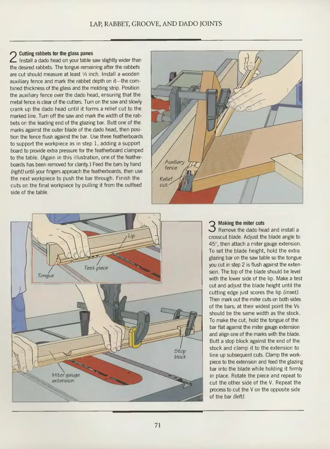
TIME
LIFE
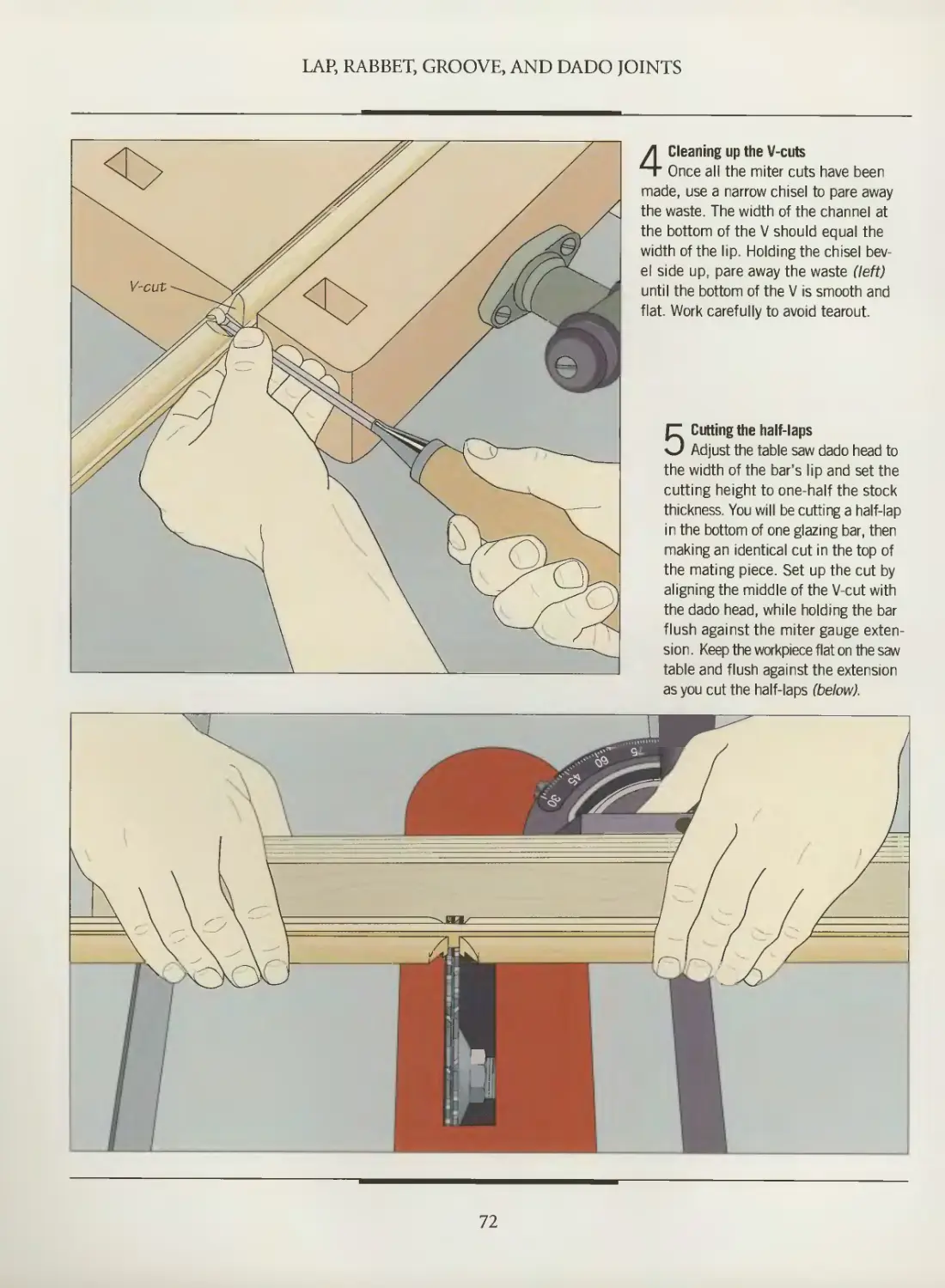
BOOKS
THE ART OF WOODWORKING
4 DBOOK
OF JOINERY
" s
-v «.
v
Vv
V
\
\
djvu AH09
Jw ^Lppfag/ c/fi&tt0%
/999-&O04
WORKSHOP GUIDE
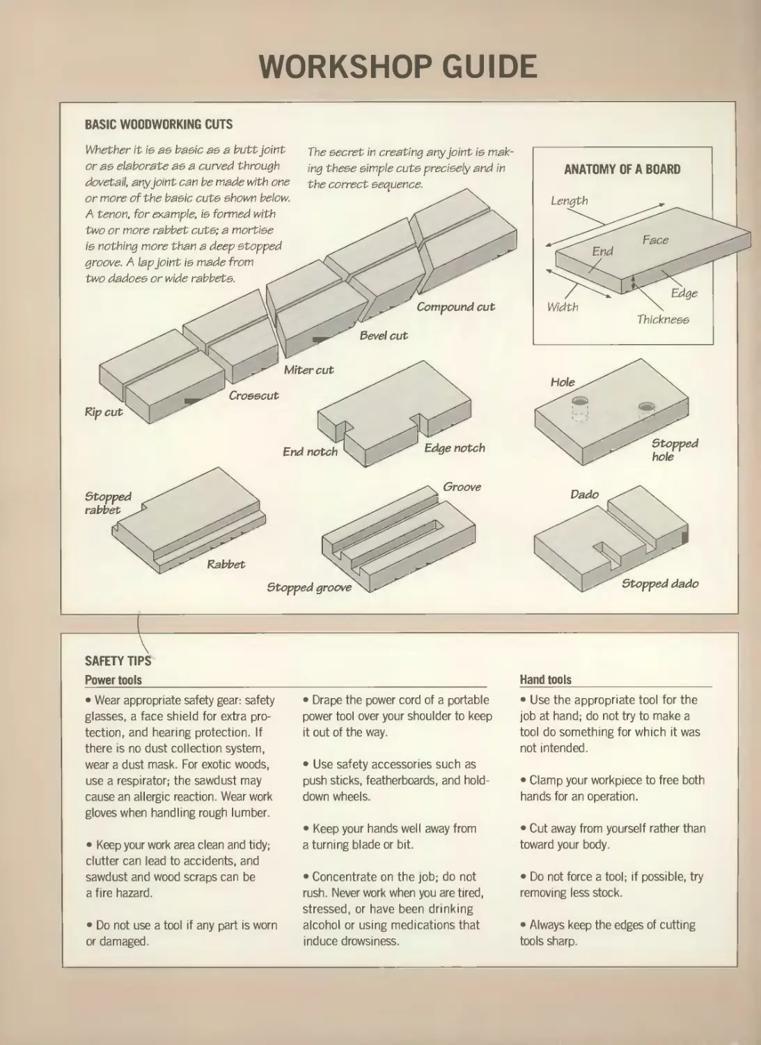
BASIC WOODWORKING CUTS
Whether it is as basic as a butt joint
or as elaborate as a curved through
dovetail, any joint can be made with one
or more of the basic cuts shown below.
A tenon, for example, is formed with
two or more rabbet cuts; a mortise
is nothing more than a deep stopped
groove. A lap joint is made from
two dadoes or wide rabbets.
Jhe secret in creating any joint is
making these simple cuts precisely and in
the correct sequence.
ANATOMY OF A BOARD
Length
SAFETY TIPS
Power tools
Hand tools
• Wear appropriate safety gear: safety
glasses, a face shield for extra
protection, and hearing protection. If
there is no dust collection system,
wear a dust mask. For exotic woods,
use a respirator; the sawdust may
cause an allergic reaction. Wear work
gloves when handling rough lumber.
• Keep your work area clean and tidy;
clutter can lead to accidents, and
sawdust and wood scraps can be
a fire hazard.
• Do not use a tool if any part is worn
or damaged.
• Drape the power cord of a portable
power tool over your shoulder to keep
it out of the way.
• Use safety accessories such as
push sticks, featherboards, and hold-
down wheels.
• Keep your hands well away from
a turning blade or bit.
• Concentrate on the job; do not
rush. Never work when you are tired,
stressed, or have been drinking
alcohol or using medications that
induce drowsiness.
• Use the appropriate tool for the
job at hand; do not try to make a
tool do something for which it was
not intended.
• Clamp your workpiece to free both
hands for an operation.
• Cut away from yourself rather than
toward your body.
• Do not force a tool; if possible, try
removing less stock.
• Always keep the edges of cutting
tools sharp.
THE ART OF WOODWORKING
HANDBOOK
OF JOINERY
THE ART OF WOODWORKING
HANDBOOK
OF JOINERY
TIME-LIFE BOOKS
ALEXANDRIA, VIRGINIA
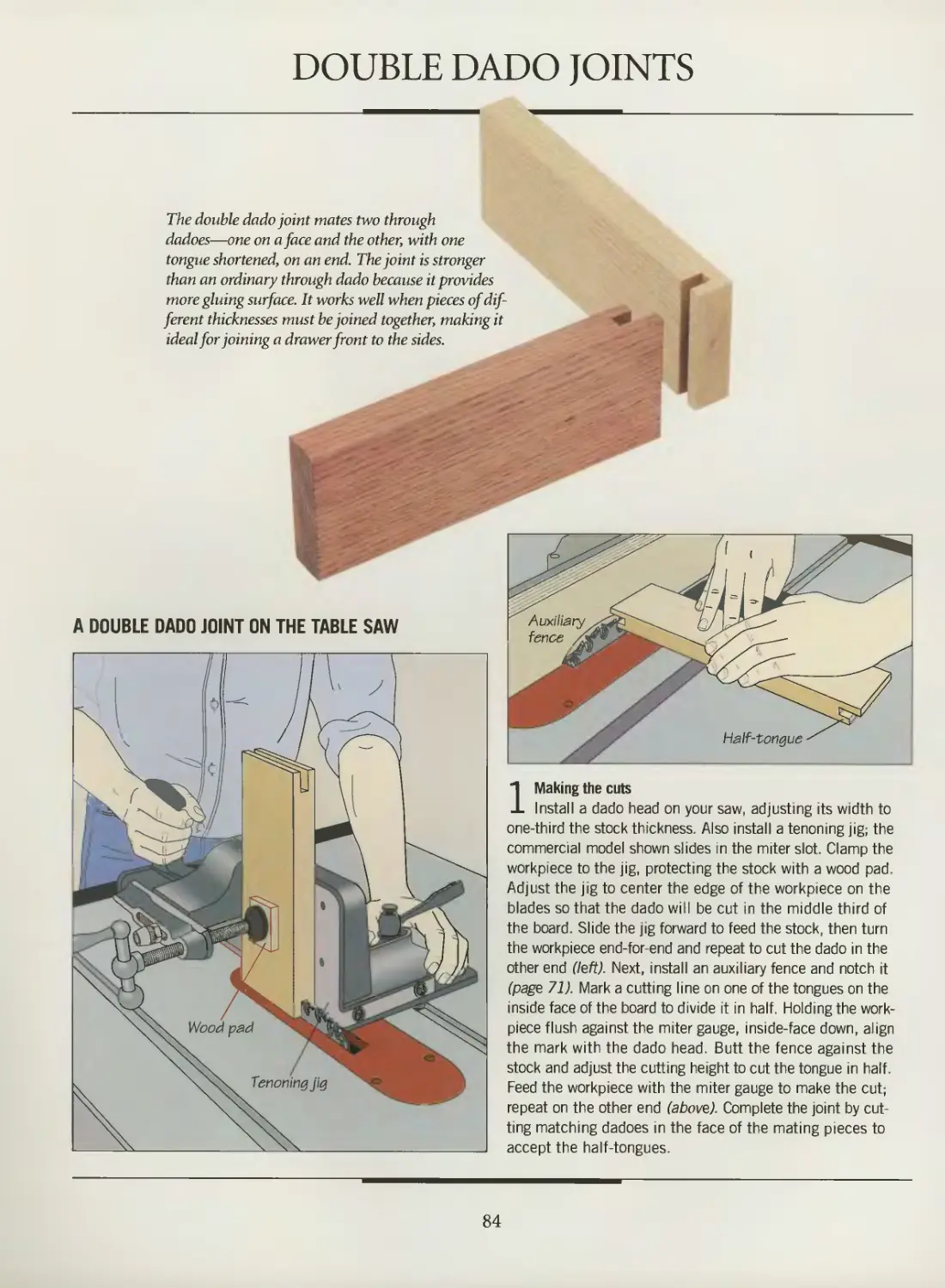
ST. REMY PRESS
MONTREAL- NEW YORK
THE ART OF WOODWORKING was produced by
ST. REMY PRESS
PUBLISHER
PRESIDENT
Series Editor
Series Art Director
Senior Editors
Art Directors
Designers
Research Editor
Picture Editor
Writers
Research Assistant
Contributing Illustrators
Administrator
Production Manager
System Coordinator
Photographer
Proofreader
Indexer
Kenneth Winchester
Pierre Leveille
Pierre Home-Douglas
Francine Lemieux
Marc Cassini (Text)
Heather Mills (Research)
Normand Boudreault, Luc Germain,
Solange Laberge
Jean-Guy Doiron, Michel Giguere,
Helene Dion
Jim McRae
Christopher Jackson
Andrew Jones, Rob Lutes
Bryan Quinn
Gilles Beauchemin, Rolland Bergera,
Jean-Pierre Bourgeois, Michel Blais,
Ronald Durepos, Robert Paquet,
James Therien
Natalie Watanabe
Michelle Turbide
Jean-Luc Roy
Robert Chartier
Judith Yelon
Christine M. Jacobs
Time-Life Books is a division of Time-Life Inc.,
a wholly owned subsidiary of
THE TIME INC. BOOK COMPANY
TIME-LIFE BOOKS
President
Vice-President
Editor-in-Chief
Director of Editorial Resources
John D. Hall
Nancy K. Jones
Thomas H. Flaherty
Elise D. Ritter-CIough
Marketing Director Regina Hall
Editorial Director Lee Hassig
Consulting Editor John R. Sullivan
Production Manager Marlene Zack
THE CONSULTANTS
Jon Arno is a consultant, cabinetmaker and
freelance writer who lives in Troy, Michigan. He
also conducts seminars on wood identification
and early American furniture design.
Giles Miller-Mead taught advanced cabinet-
making at Montreal technical schools for more
than ten years. A native of New Zealand, he has
worked as a restorer of antique furniture.
Joseph Truini is Senior Editor of Home
Mechanix magazine. A former Shop and Tools
Editor of Popular Mechanics, he has worked as
a cabinetmaker, home improvement contractor
and carpenter.
Handbook of Joinery
p. cm.—(The Art of Woodworking)
Includes index.
ISBN 0-8094-9941-X (trade)
ISBN 0-8094-9942-8 (lib)
1.Joinery
I. Time-Life Books. II. Series
TH5663.H36 1993
694'.6—dc20 93-24638
CIP
For information about any Time-Life book,
please call 1-800-621-7026, or write:
Reader Information
Time-Life Customer Service
P.O. Box C-32068
Richmond, Virginia
23261-2068
© 1993 Time-Life Books Inc.
All rights reserved.
No part of this book may be reproduced in
any form or by any electronic or mechanical
means, including information storage and
retrieval devices or systems, without prior
written permission from the publisher, except
that brief passages may be quoted for reviews.
First printing. Printed in U.S.A.
Published simultaneously in Canada.
TIME-LIFE is a trademark of Time Warner
Inc. U.S.A.
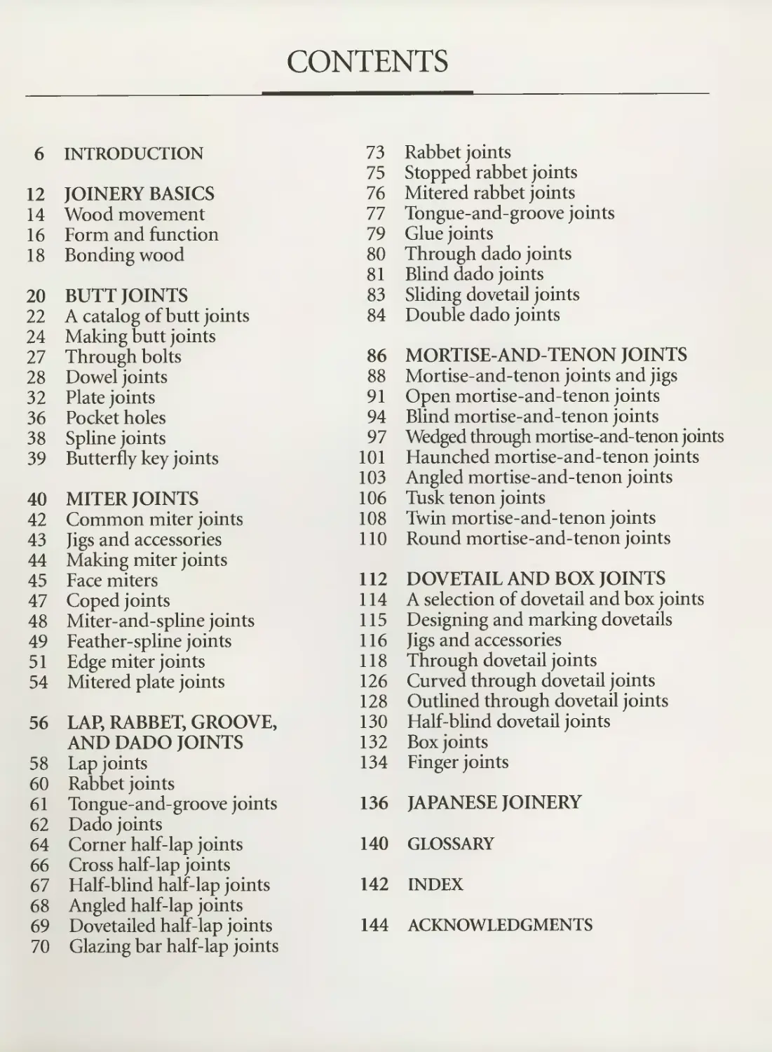
CONTENTS
6
12
14
16
18
20
22
24
27
28
32
36
38
39
40
42
43
44
45
47
48
49
51
54
56
58
60
61
62
64
66
67
68
69
70
INTRODUCTION
JOINERY BASICS
Wood movement
Form and function
Bonding wood
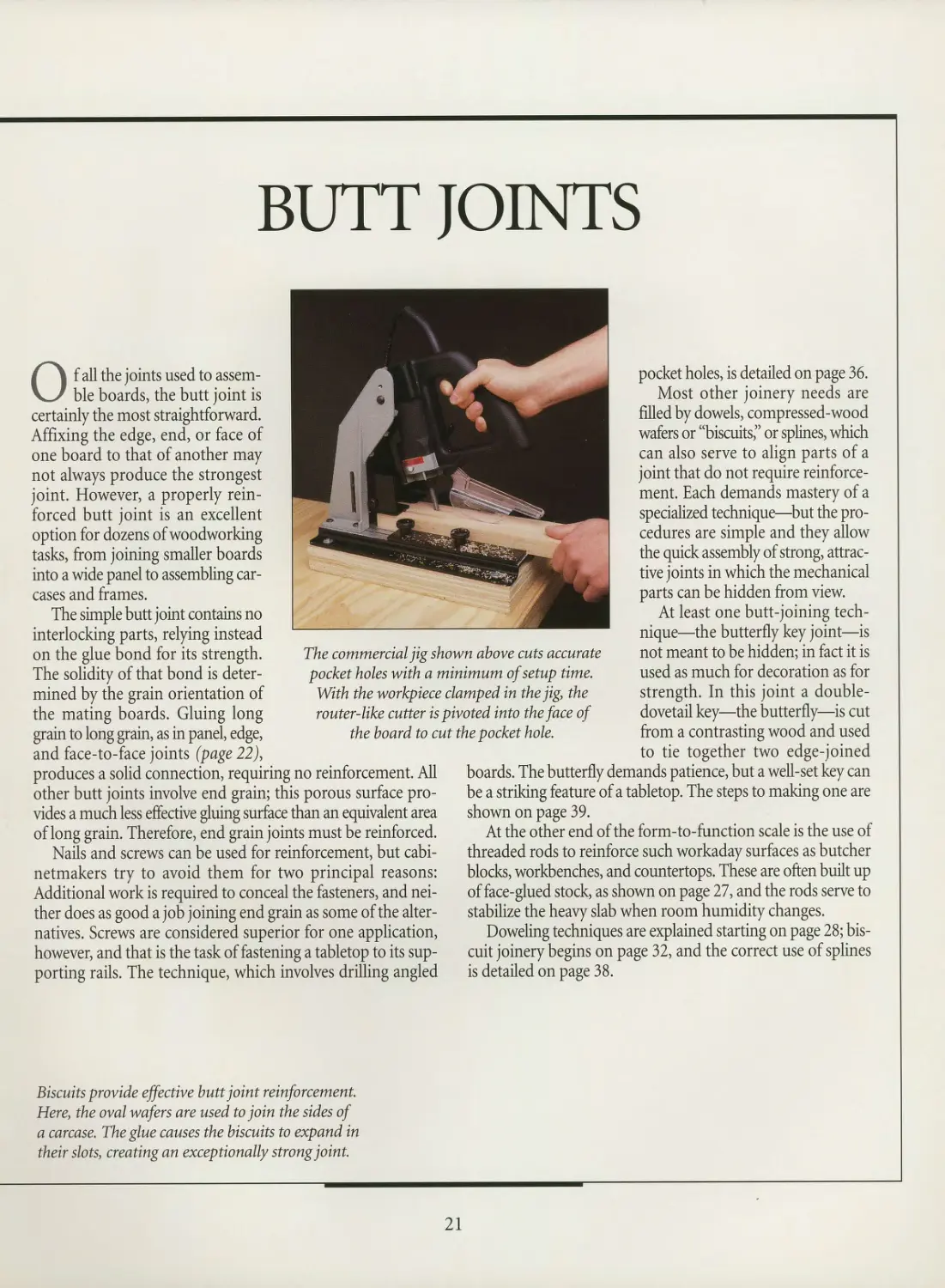
BUTT JOINTS
A catalog of butt joints
Making butt joints
Through bolts
Dowel joints
Plate joints
Pocket holes
Spline joints
Butterfly key joints
MITER JOINTS
Common miter joints
Jigs and accessories
Making miter joints
Face miters
Coped joints
Miter-and-spline joints
Feather-spline joints
Edge miter joints
Mitered plate joints
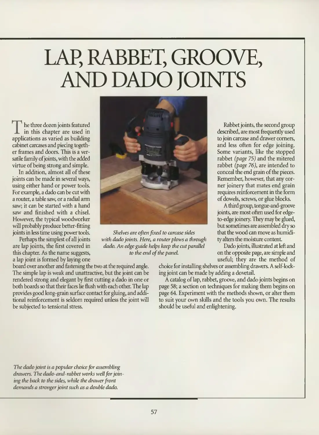
LAP, RABBET, GROOVE,
AND DADO JOINTS
Lap joints
Rabbet joints
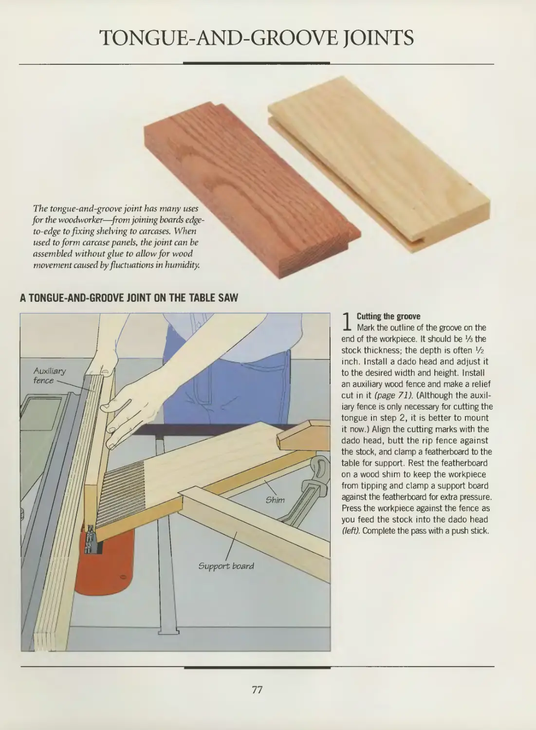
Tongue-and-groove joints
Dado joints
Corner half-lap joints
Cross half-lap joints
Half-blind half-lap joints
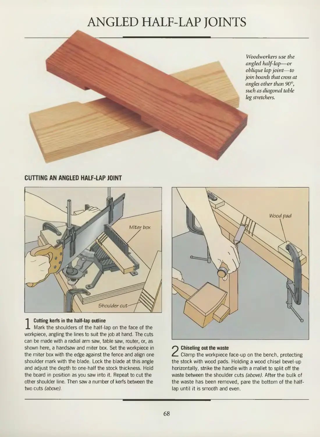
Angled half-lap joints
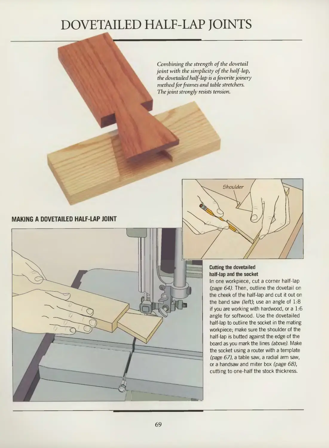
Dovetailed half-lap joints
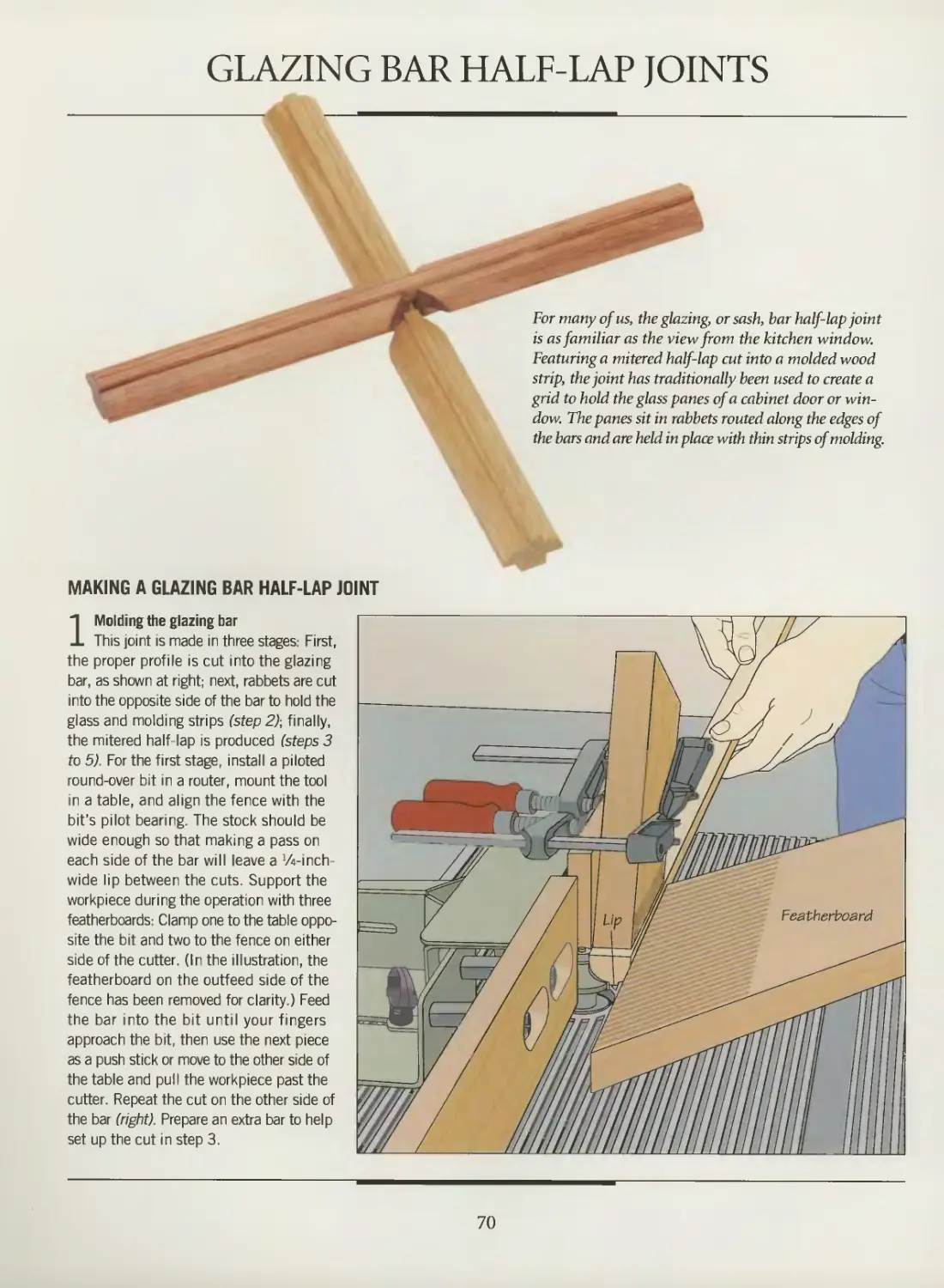
Glazing bar half-lap joints
73
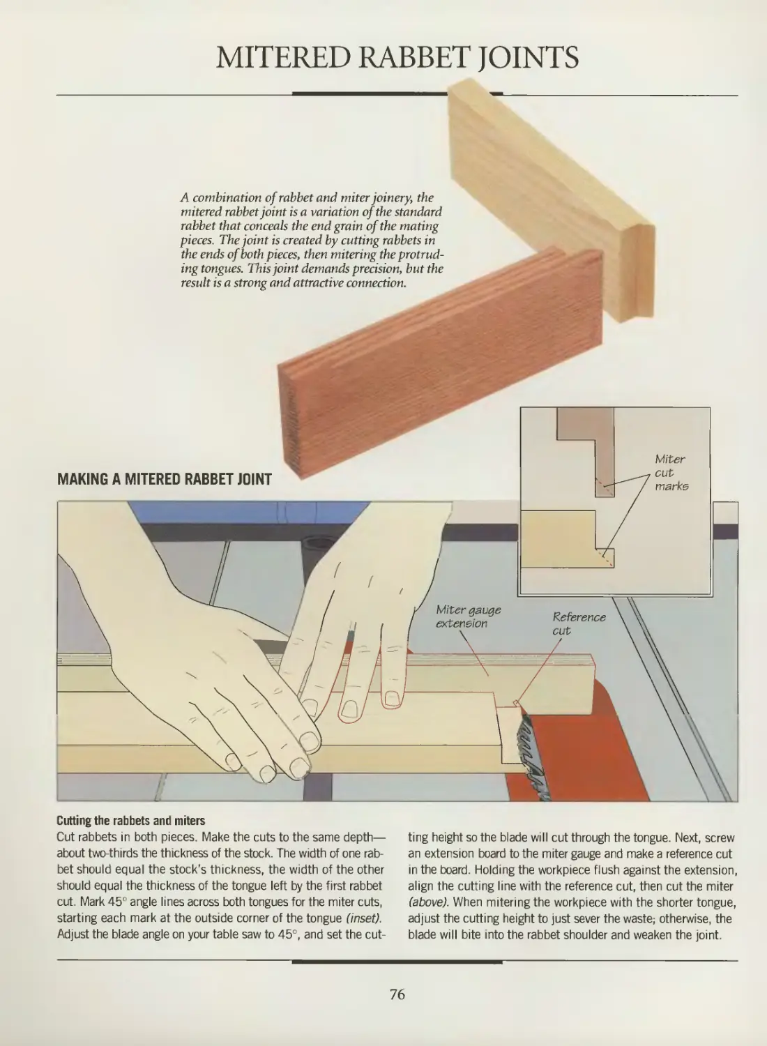
75
76
77
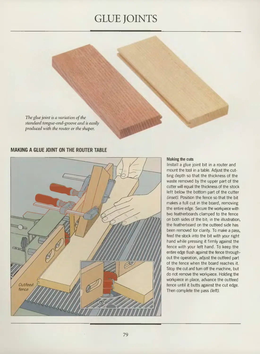
79
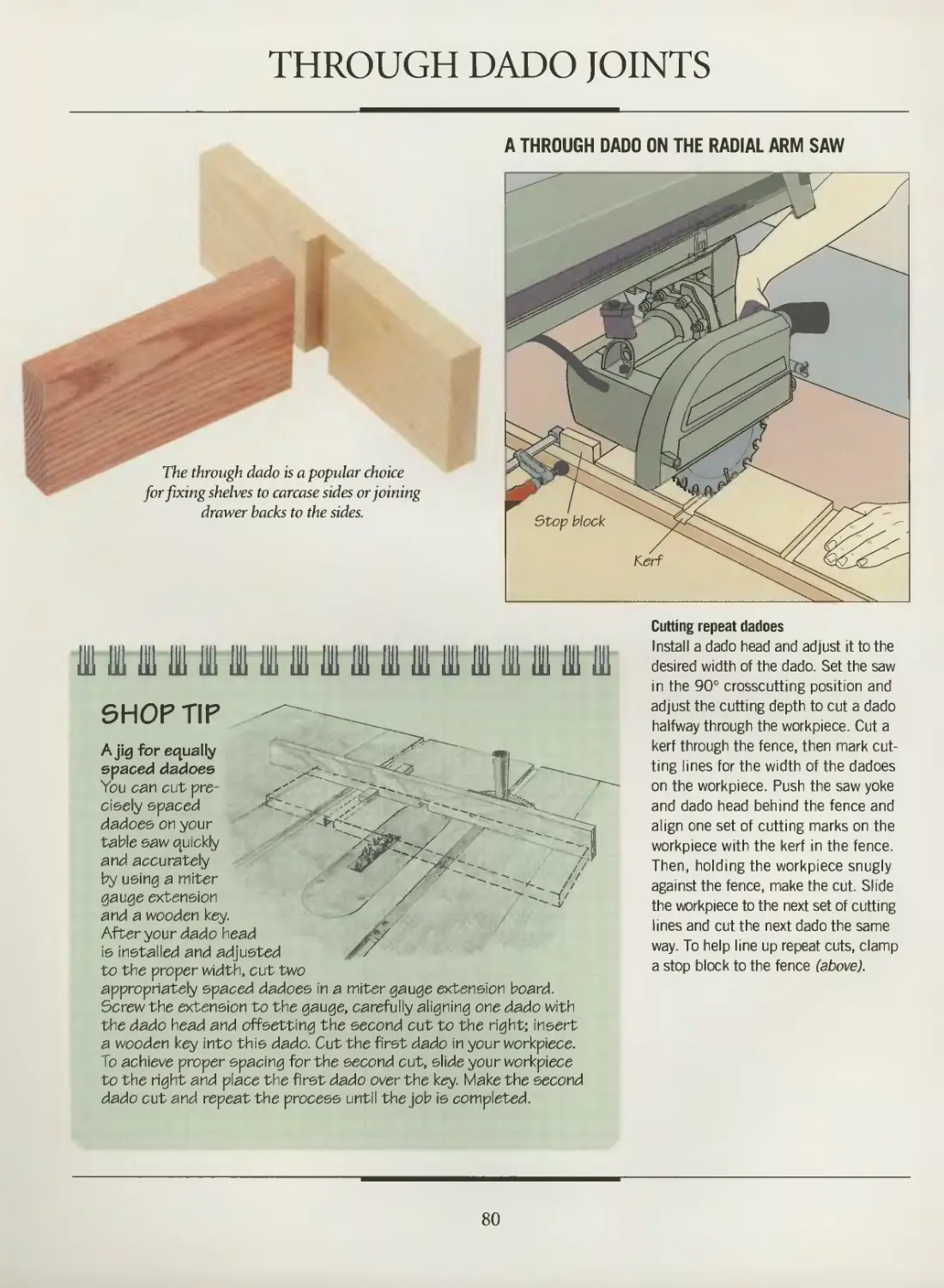
80
81
83
84
86
88
91
94
97
101
103
106
108
110
112
114
115
116
118
126
128
130
132
134
136
140
142
144
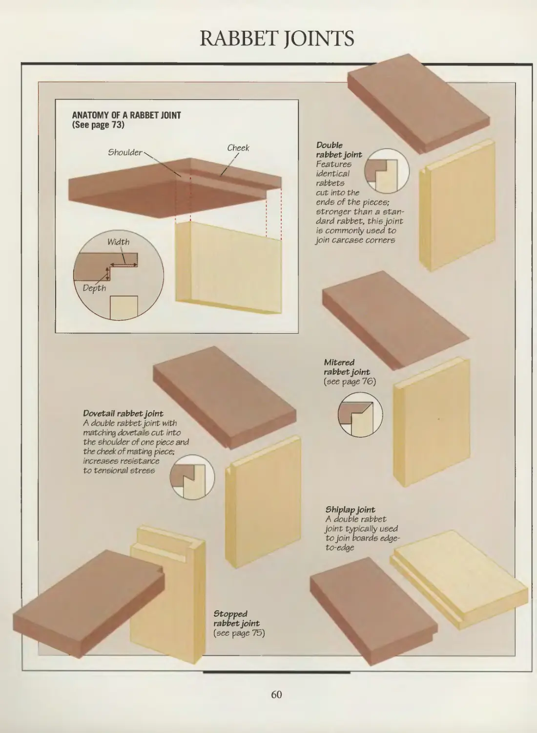
Rabbet joints
Stopped rabbet joints
Mitered rabbet joints
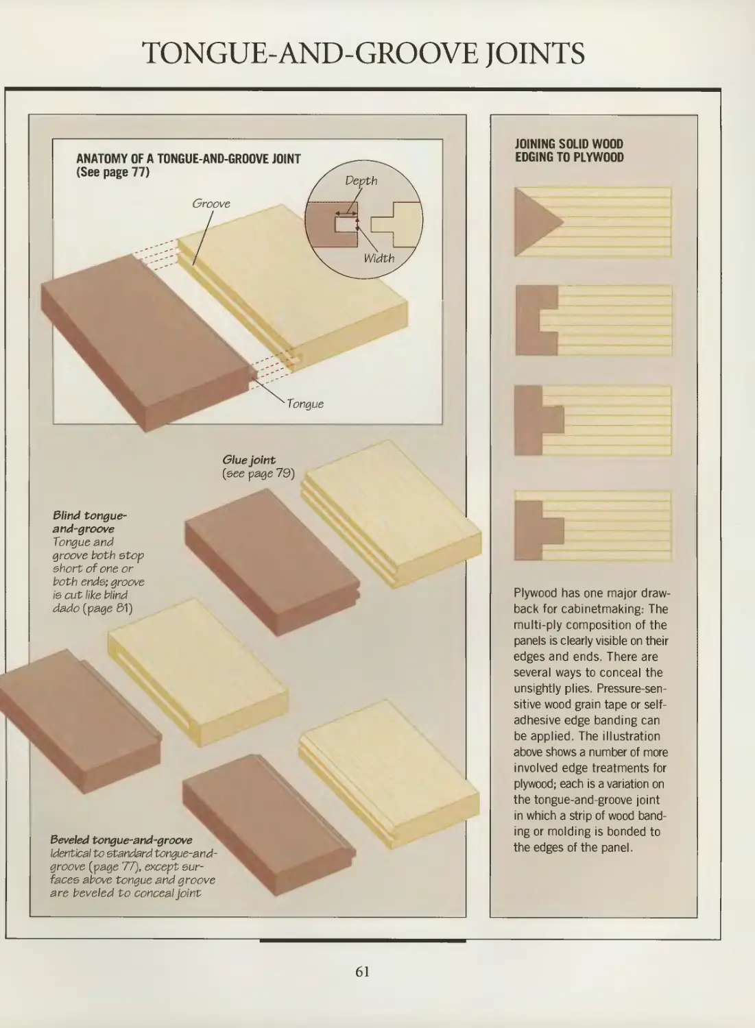
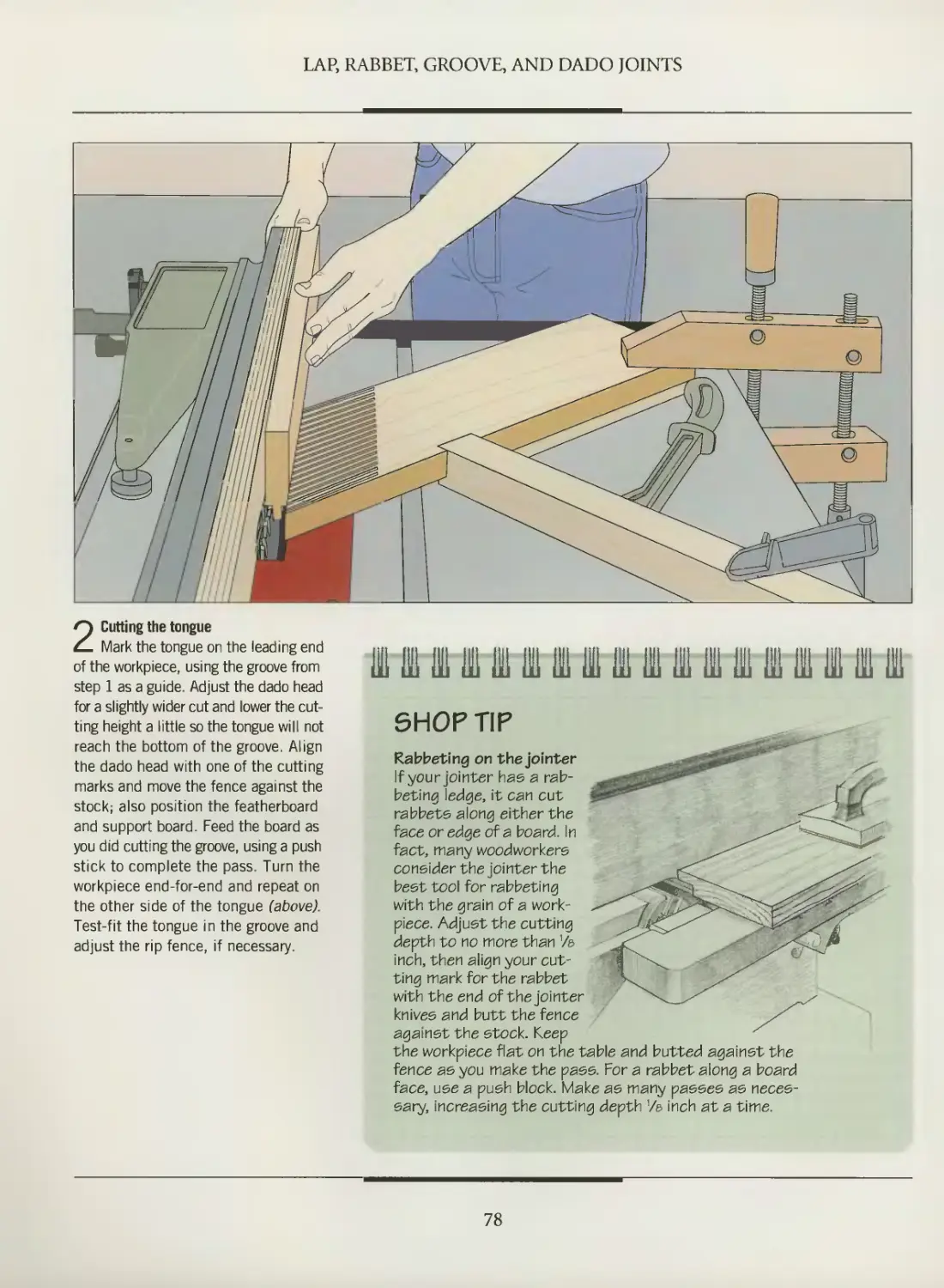
Tongue-and-groove joints
Glue joints
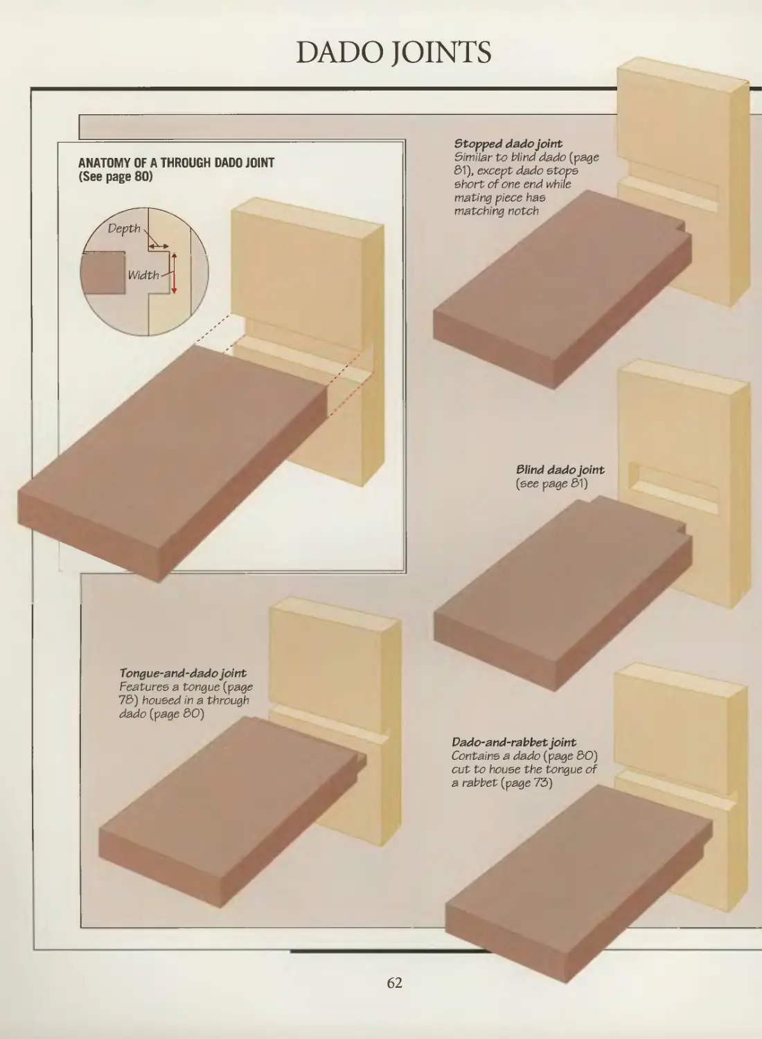
Through dado joints
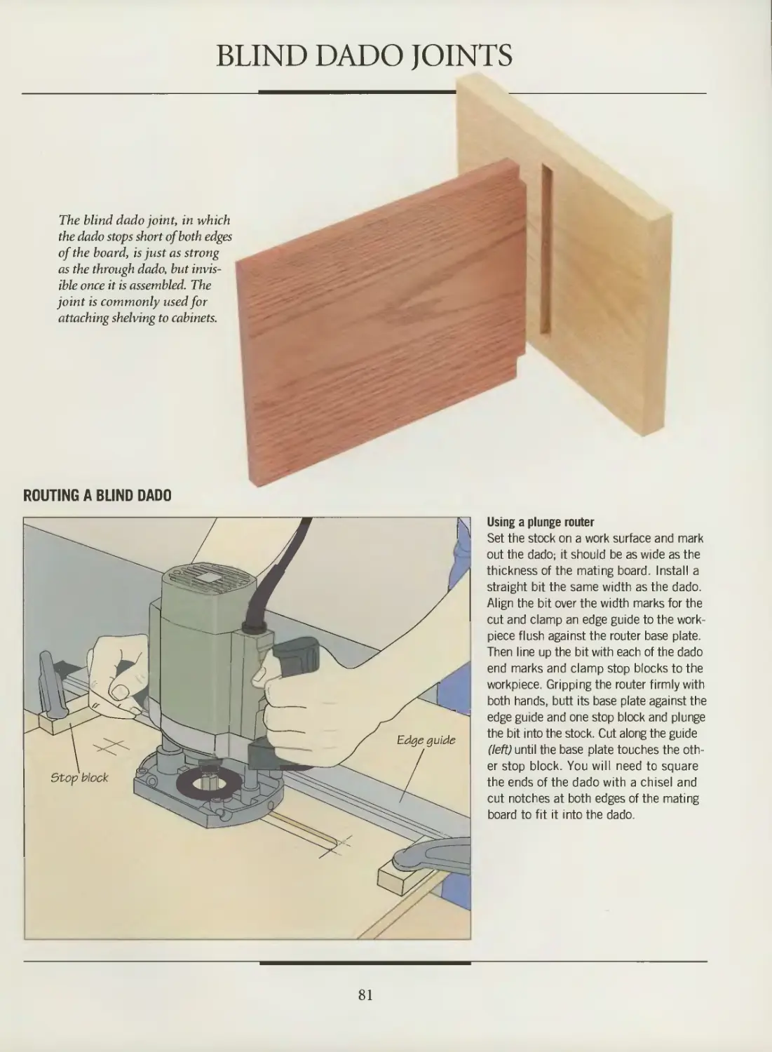
Blind dado joints
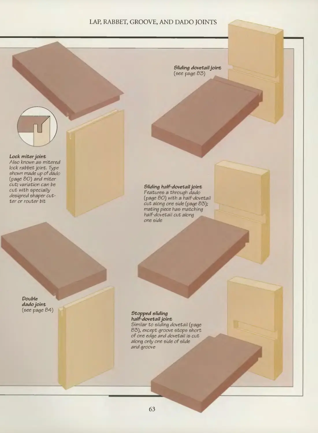
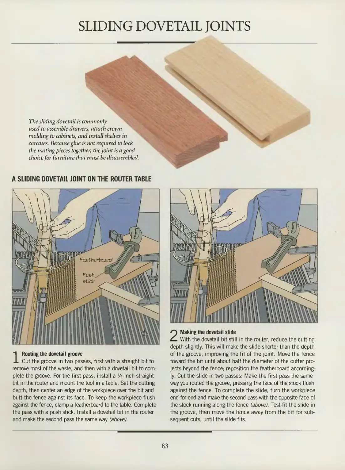
Sliding dovetail joints
Double dado joints
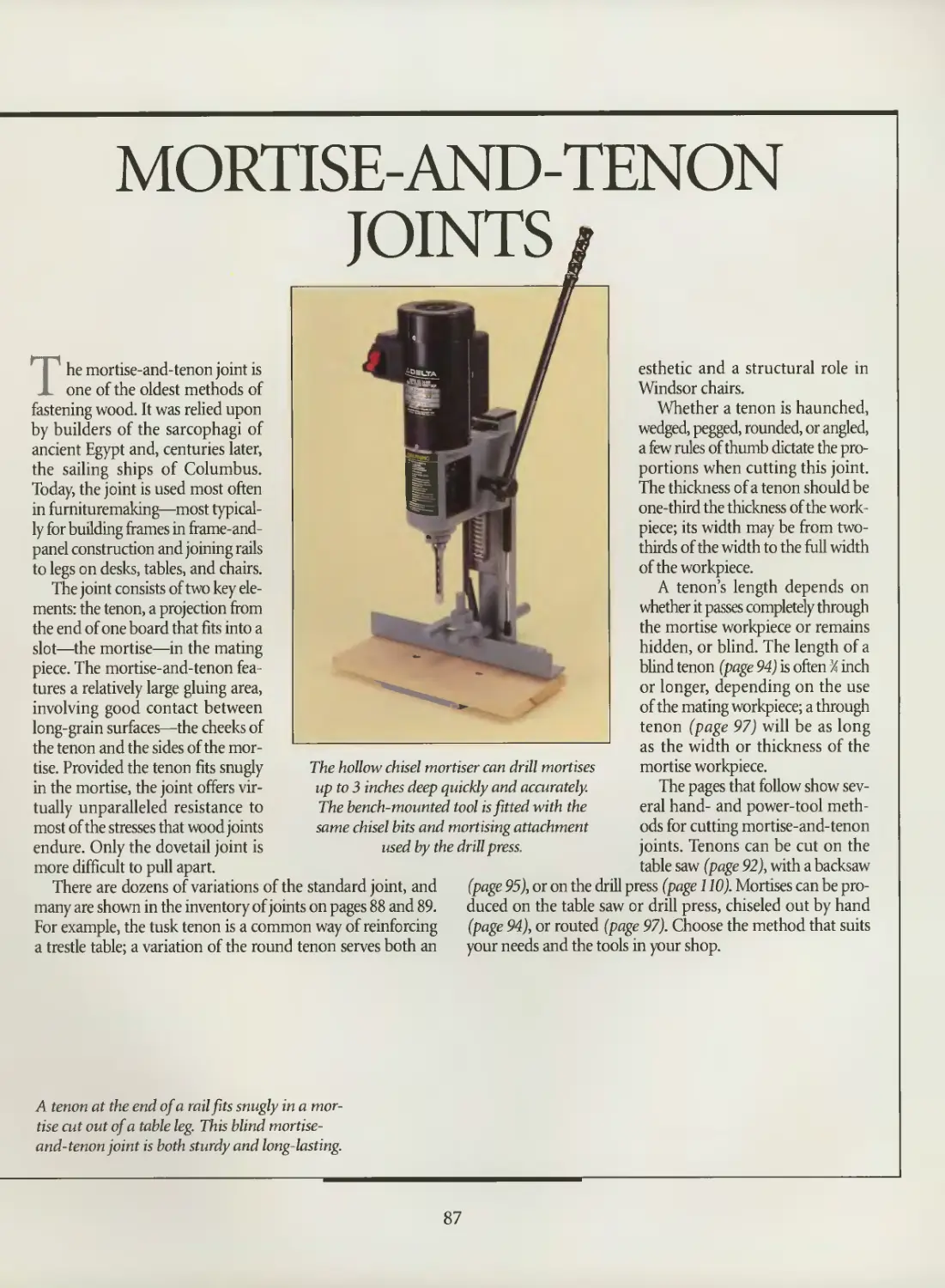
MORTISE-AND-TENON JOINTS
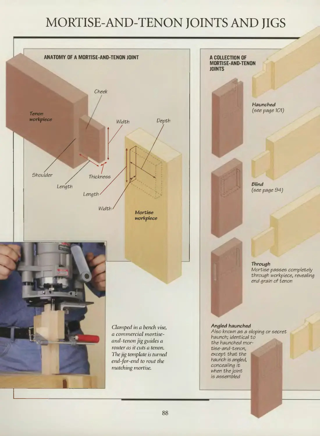
Mortise-and-tenon joints and jigs
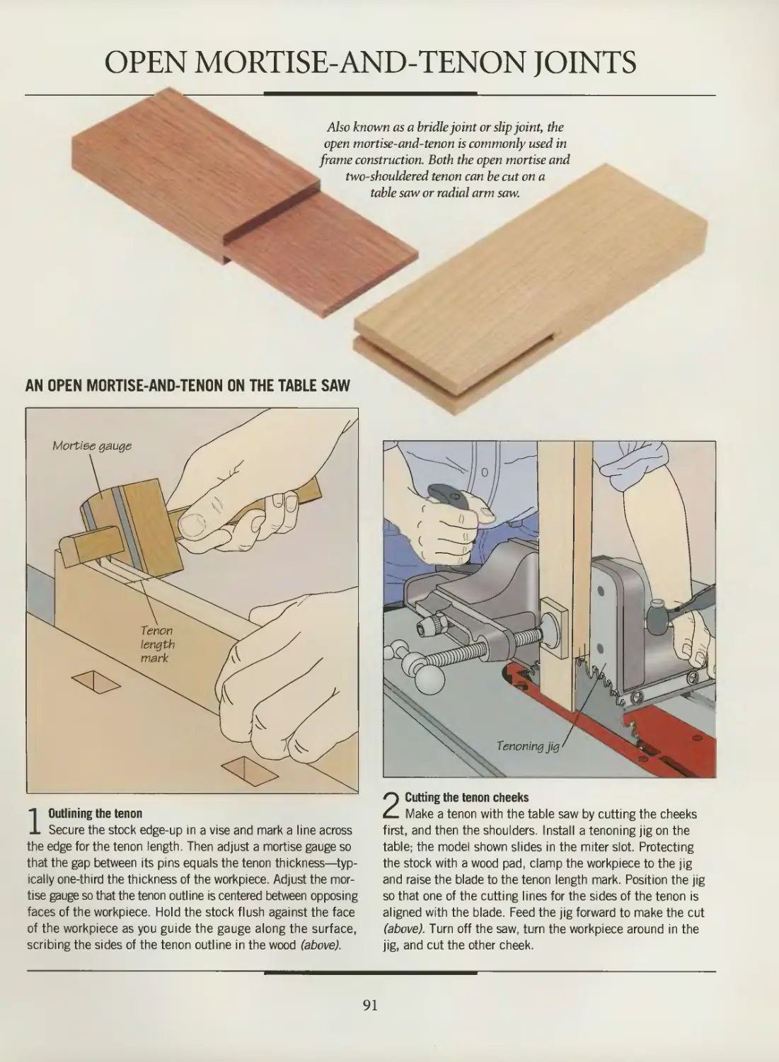
Open mortise-and-tenon joints
Blind mortise-and-tenon joints
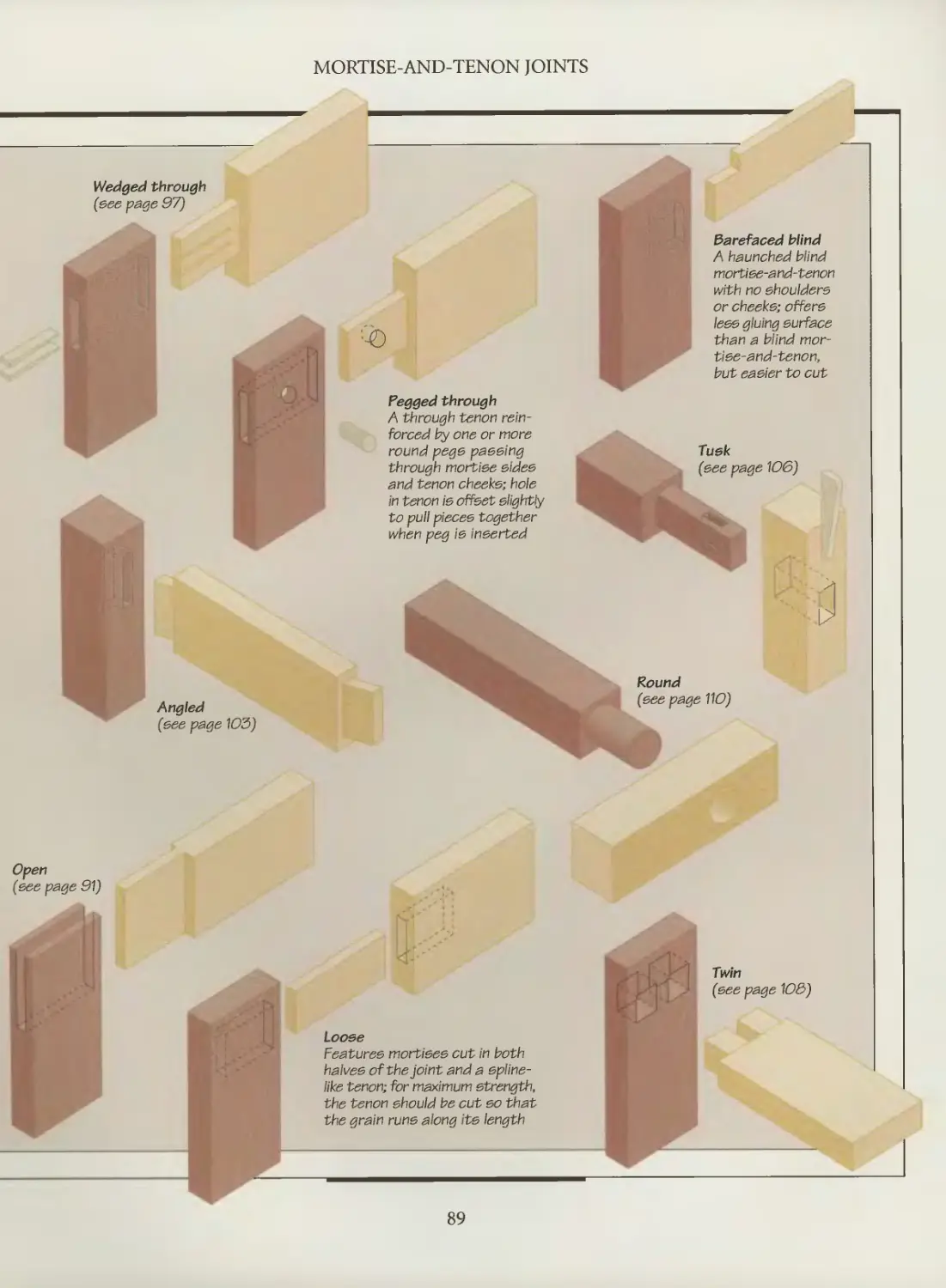
Wedged through mortise-and-tenon joints
Haunched mortise-and-tenon joints
Angled mortise-and-tenon joints
Tusk tenon joints
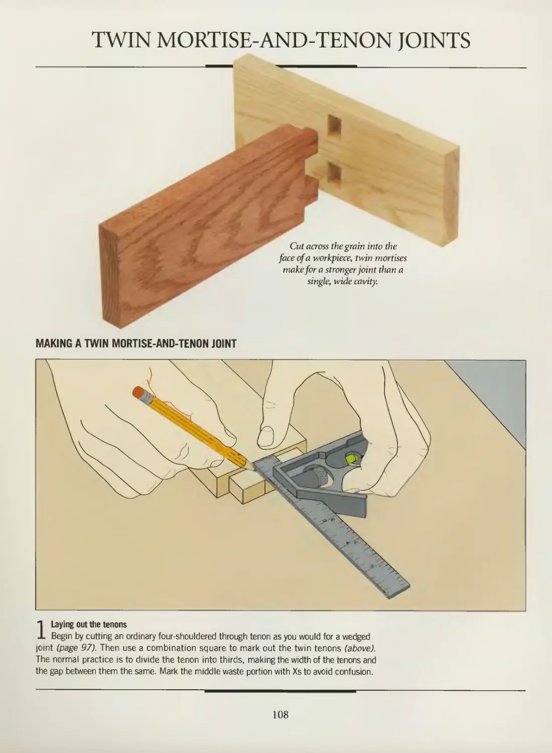
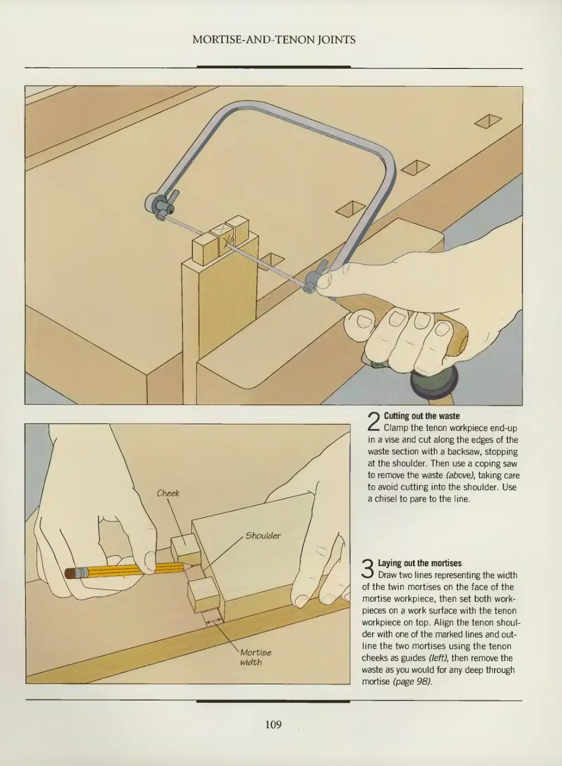
Twin mortise-and-tenon joints
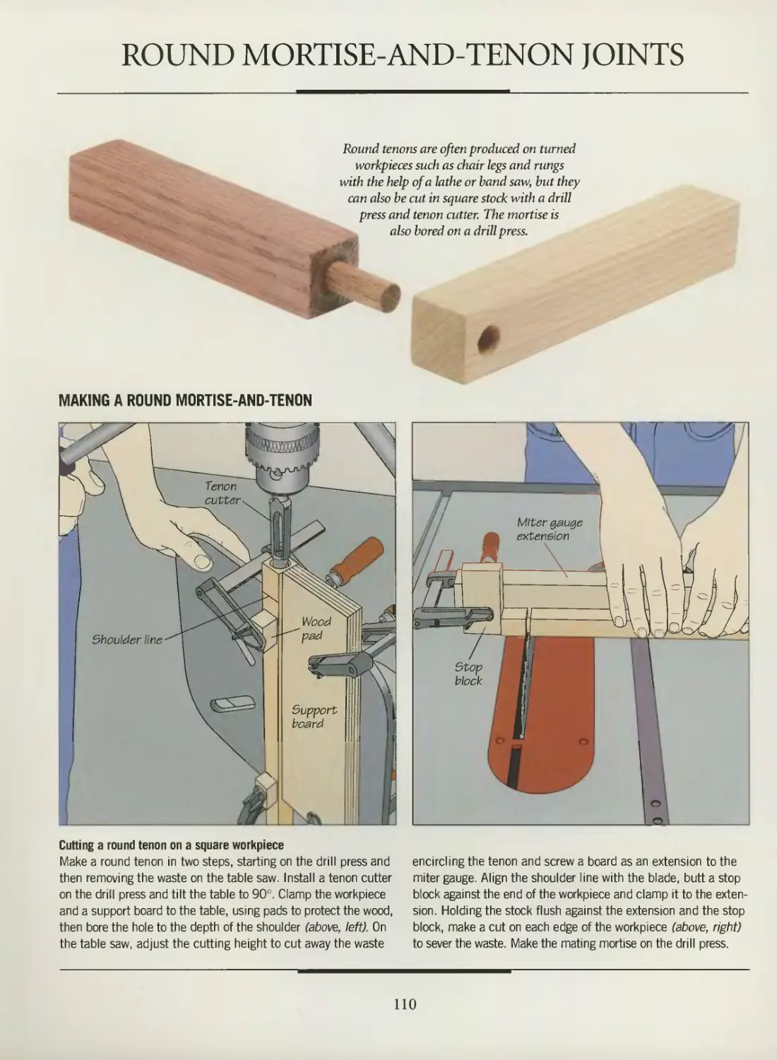
Round mortise-and-tenon joints
DOVETAIL AND BOX JOINTS
A selection of dovetail and box joints
Designing and marking dovetails
Jigs and accessories
Through dovetail joints
Curved through dovetail joints
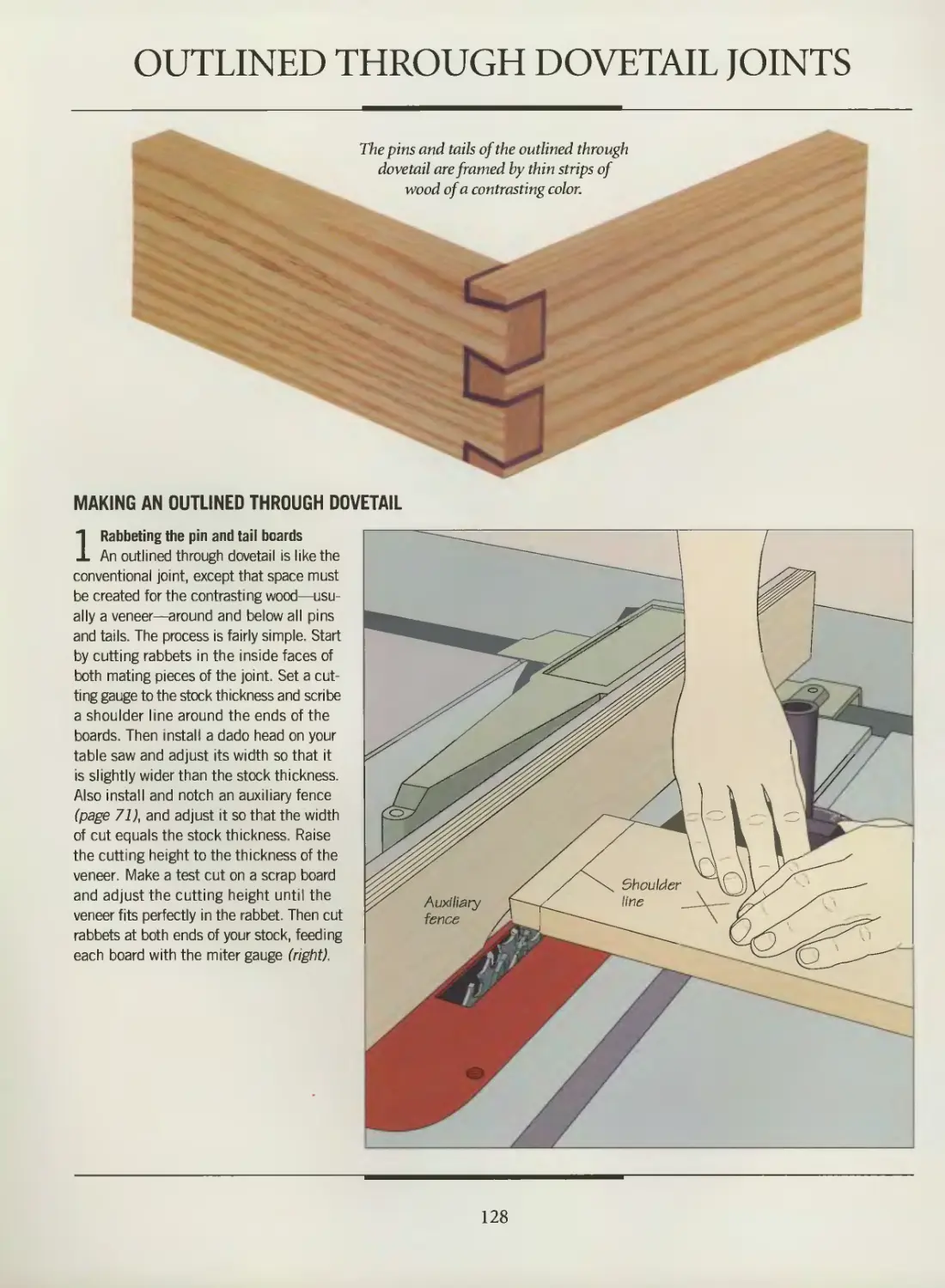
Outlined through dovetail joints
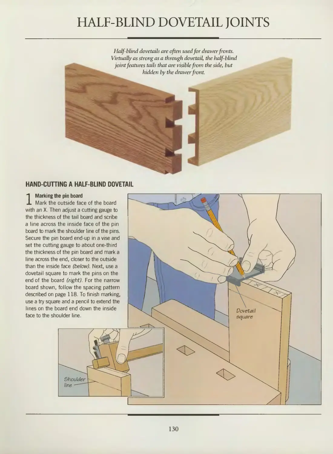
Half-blind dovetail joints
Box joints
Finger joints
JAPANESE JOINERY
GLOSSARY
INDEX
ACKNOWLEDGMENTS
< "
4-
fV
*
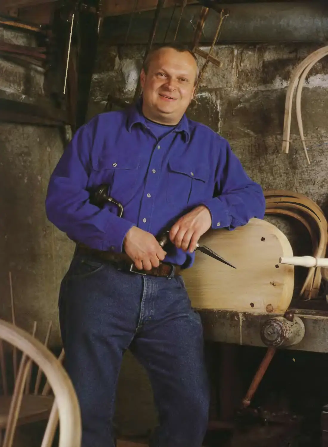
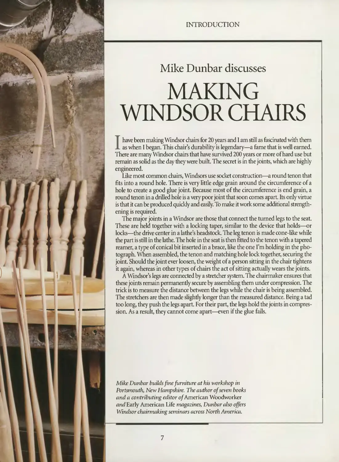
INTRODUCTION
Mike Dunbar discusses
MAKING
WINDSOR CHAIRS
I have been making Windsor chairs for 20 years and 1 am still as fascinated with them
as when I began. This chair's durability is legendary—a fame that is well earned.
There are many Windsor chairs that have survived 200 years or more of hard use but
remain as solid as the day they were built. The secret is in the joints, which are highly
engineered.
Like most common chairs, Windsors use socket construction—a round tenon that
fits into a round hole. There is very little edge grain around the circumference of a
hole to create a good glue joint. Because most of the circumference is end grain, a
round tenon in a drilled hole is a very poor joint that soon comes apart. Its only virtue
is that it can be produced quickly and easily. To make it work some additional
strengthening is required.
The major joints in a Windsor are those that connect the turned legs to the seat.
These are held together with a locking taper, similar to the device that holds—or
locks—the drive center in a lathe's headstock. The leg tenon is made cone-like while
the part is still in the lathe. The hole in the seat is then fitted to the tenon with a tapered
reamer, a type of conical bit inserted in a brace, like the one I'm holding in the
photograph. When assembled, the tenon and matching hole lock together, securing the
joint. Should the joint ever loosen, the weight of a person sitting in the chair tightens
it again, whereas in other types of chairs the act of sitting actually wears the joints.
A Windsor's legs are connected by a stretcher system. The chairmaker ensures that
these joints remain permanently secure by assembling them under compression. The
trick is to measure the distance between the legs while the chair is being assembled.
The stretchers are then made slightly longer than the measured distance. Being a tad
too long, they push the legs apart. For their part, the legs hold the joints in
compression. As a result, they cannot come apart—even if the glue fails.
Mike Dunbar builds fine furniture at his workshop in
Portsmouth, New Hampshire. The author of seven books
and a contributing editor of American Woodworker
and Early American Life magazines, Dunbar also offers
Windsor chairmaking seminars across North America.
7
INTRODUCTION
^
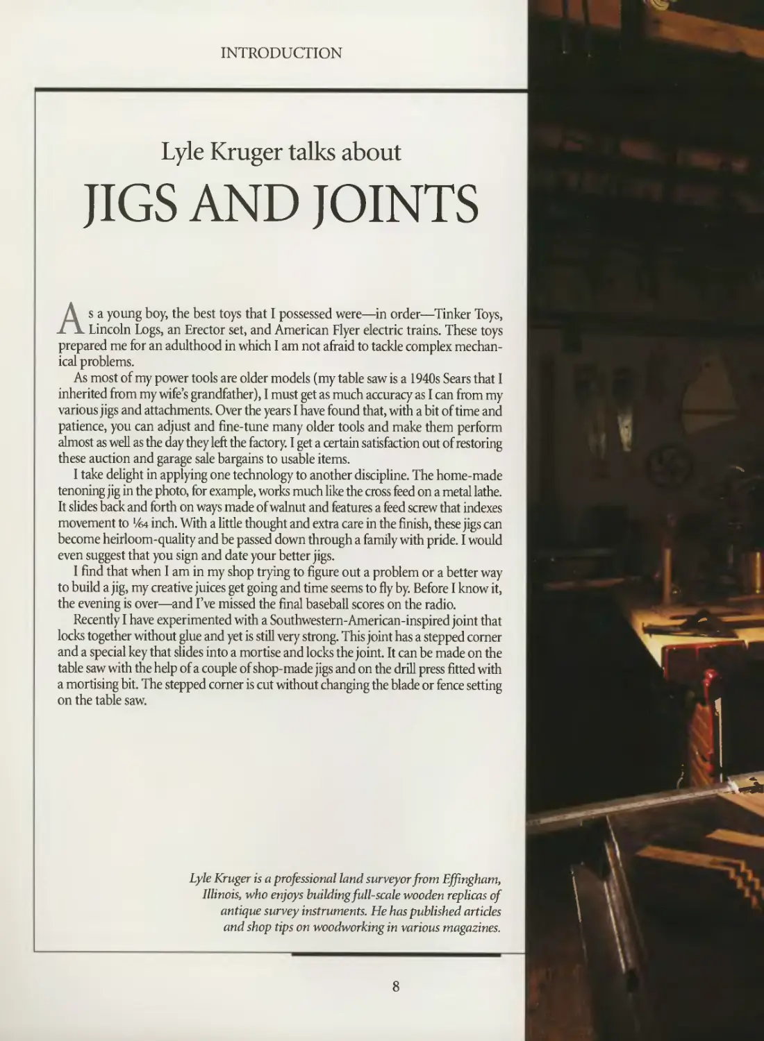
Lyle Kruger talks about
JIGS AND JOINTS
As a young boy, the best toys that I possessed were—in order—Tinker Toys,
Lincoln Logs, an Erector set, and American Flyer electric trains. These toys
prepared me for an adulthood in which I am not afraid to tackle complex
mechanical problems.
As most of my power tools are older models (my table saw is a 1940s Sears that I
inherited from my wife's grandfather), I must get as much accuracy as I can from my
various jigs and attachments. Over the years I have found that, with a bit of time and
patience, you can adjust and fine-tune many older tools and make them perform
almost as well as the day they left the factory. I get a certain satisfaction out of restoring
these auction and garage sale bargains to usable items.
I take delight in applying one technology to another discipline. The home-made
tenoning jig in the photo, for example, works much like the cross feed on a metal lathe.
It slides back and forth on ways made of walnut and features a feed screw that indexes
movement to Vea inch. With a little thought and extra care in the finish, these jigs can
become heirloom-quality and be passed down through a family with pride. I would
even suggest that you sign and date your better jigs.
I find that when I am in my shop trying to figure out a problem or a better way
to build a jig, my creative juices get going and time seems to fly by. Before I know it,
the evening is over—and I've missed the final baseball scores on the radio.
Recently I have experimented with a Southwestern-American-inspired joint that
locks together without glue and yet is still very strong. This joint has a stepped corner
and a special key that slides into a mortise and locks the joint. It can be made on the
table saw with the help of a couple of shop-made jigs and on the drill press fitted with
a mortising bit. The stepped corner is cut without changing the blade or fence setting
on the table saw.
Lyle Kruger is a professional land surveyor from Effingham,
Illinois, who enjoys building full-scale wooden replicas of
antique survey instruments. He has published articles
and shop tips on woodworking in various magazines.
\
8
i
/
^
\
\
»V
INTRODUCTION
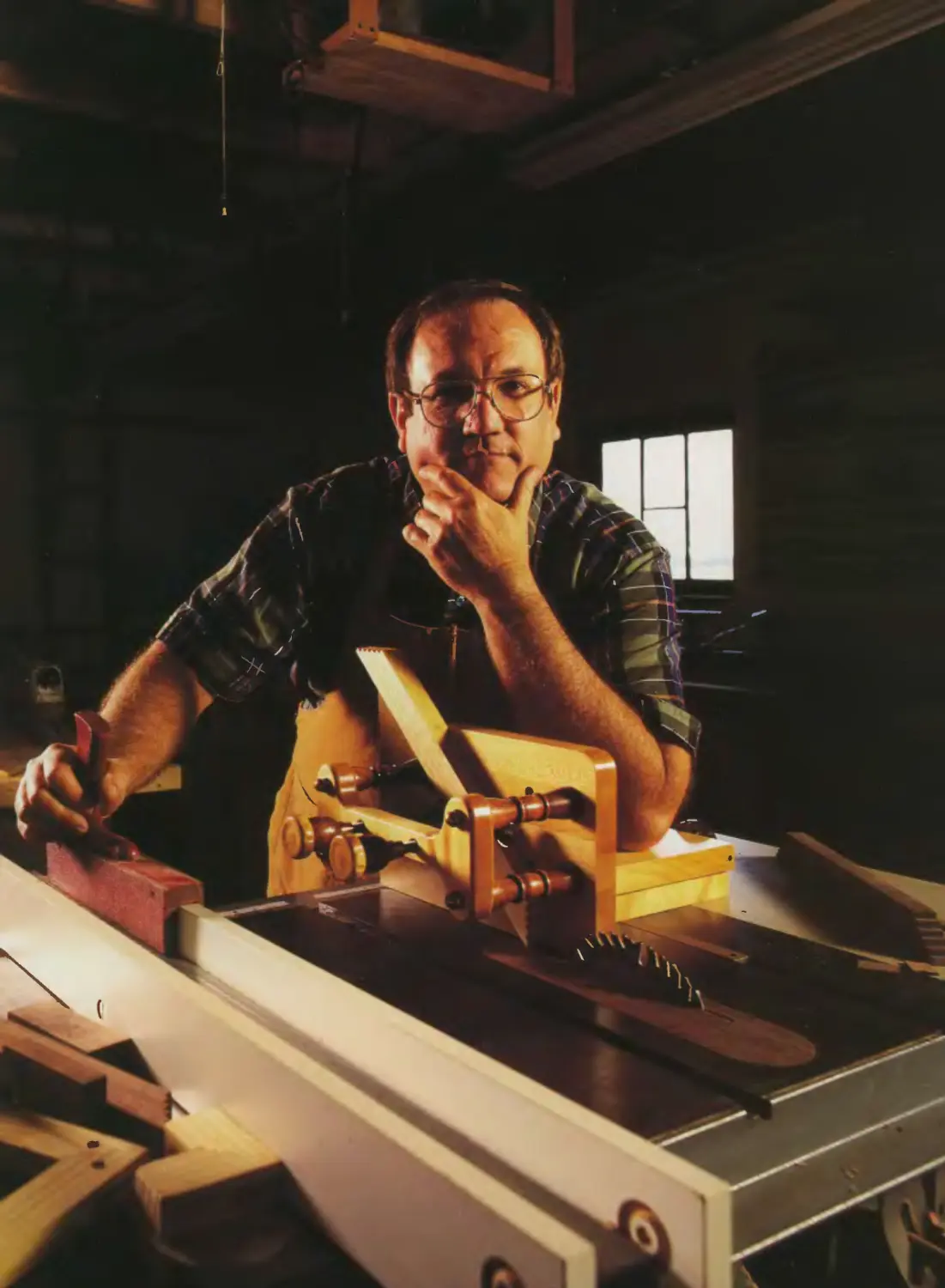
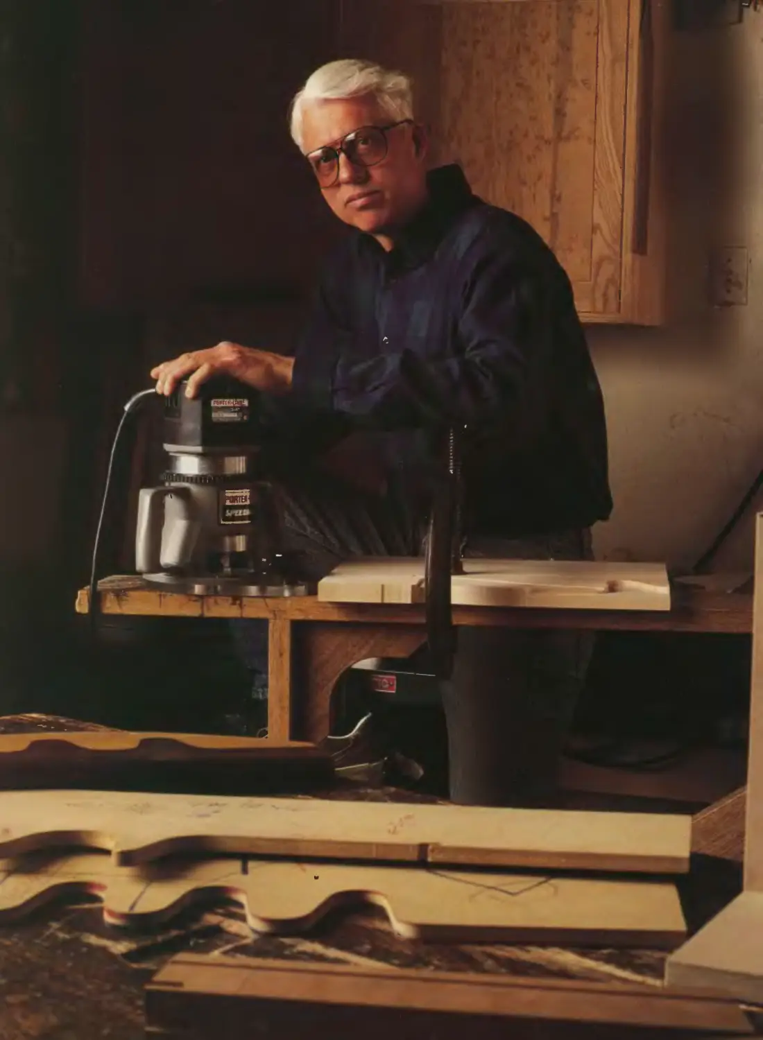
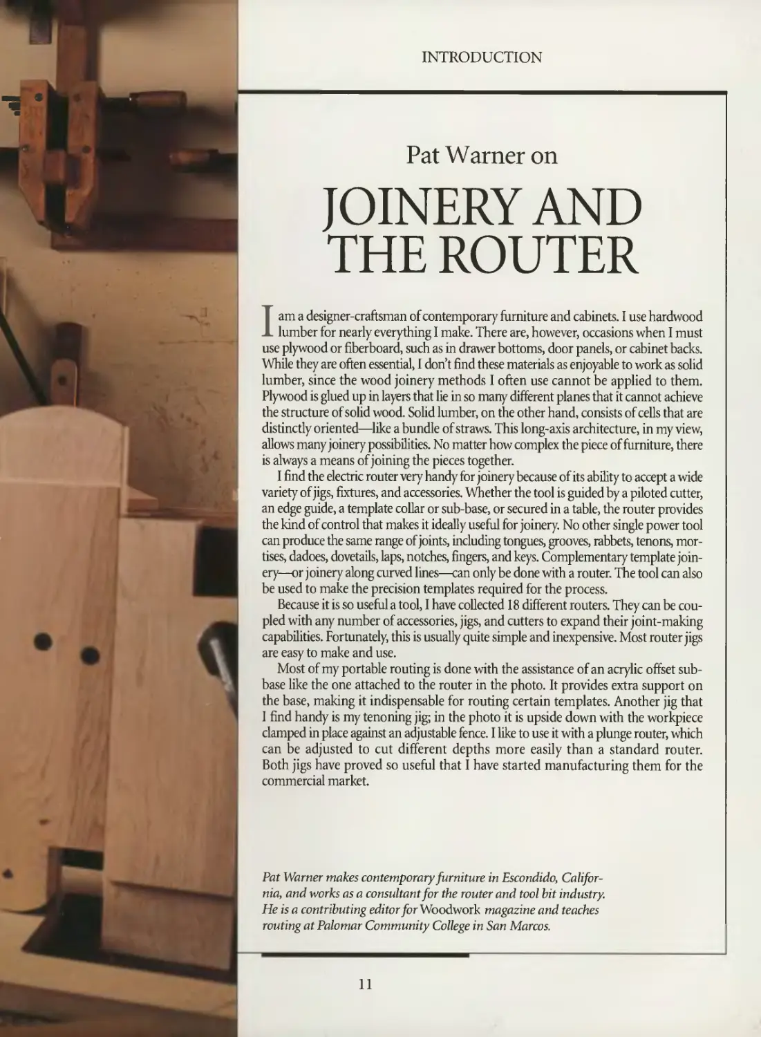
Pat Warner on
JOINERY AND
THE ROUTER
I am a designer-craftsman of contemporary furniture and cabinets. I use hardwood
lumber for nearly everything I make. There are, however, occasions when I must
use plywood or fiberboard, such as in drawer bottoms, door panels, or cabinet backs.
While they are often essential, I don't find these materials as enjoyable to work as solid
lumber, since the wood joinery methods I often use cannot be applied to them.
Plywood is glued up in layers that lie in so many different planes that it cannot achieve
the structure of solid wood. Solid lumber, on the other hand, consists of cells that are
distinctly oriented—like a bundle of straws. This long-axis architecture, in my view,
allows many joinery possibilities. No matter how complex the piece of furniture, there
is always a means of joining the pieces together.
I find the electric router very handy for joinery because of its ability to accept a wide
1 variety of jigs, fixtures, and accessories. Whether the tool is guided by a piloted cutter,
an edge guide, a template collar or sub-base, or secured in a table, the router provides
the kind of control that makes it ideally useful for joinery. No other single power tool
can produce the same range of joints, including tongues, grooves, rabbets, tenons,
mortises, dadoes, dovetails, laps, notches, fingers, and keys. Complementary template
joinery—or joinery along curved lines—can only be done with a router. The tool can also
be used to make the precision templates required for the process.
Because it is so useful a tool, I have collected 18 different routers. They can be
coupled with any number of accessories, jigs, and cutters to expand their joint-making
capabilities. Fortunately, this is usually quite simple and inexpensive. Most router jigs
are easy to make and use.
Most of my portable routing is done with the assistance of an acrylic offset sub-
base like the one attached to the router in the photo. It provides extra support on
the base, making it indispensable for routing certain templates. Another jig that
I find handy is my tenoning jig; in the photo it is upside down with the workpiece
clamped in place against an adjustable fence. I like to use it with a plunge router, which
can be adjusted to cut different depths more easily than a standard router.
Both jigs have proved so useful that I have started manufacturing them for the
commercial market.
Pat Warner makes contemporary furniture in Escondido,
California, and works as a consultant for the router and tool bit industry.
He is a contributing editor forWoodwork magazine and teaches
routing at Palomar Community College in San Marcos.
11
JOINERY BASICS
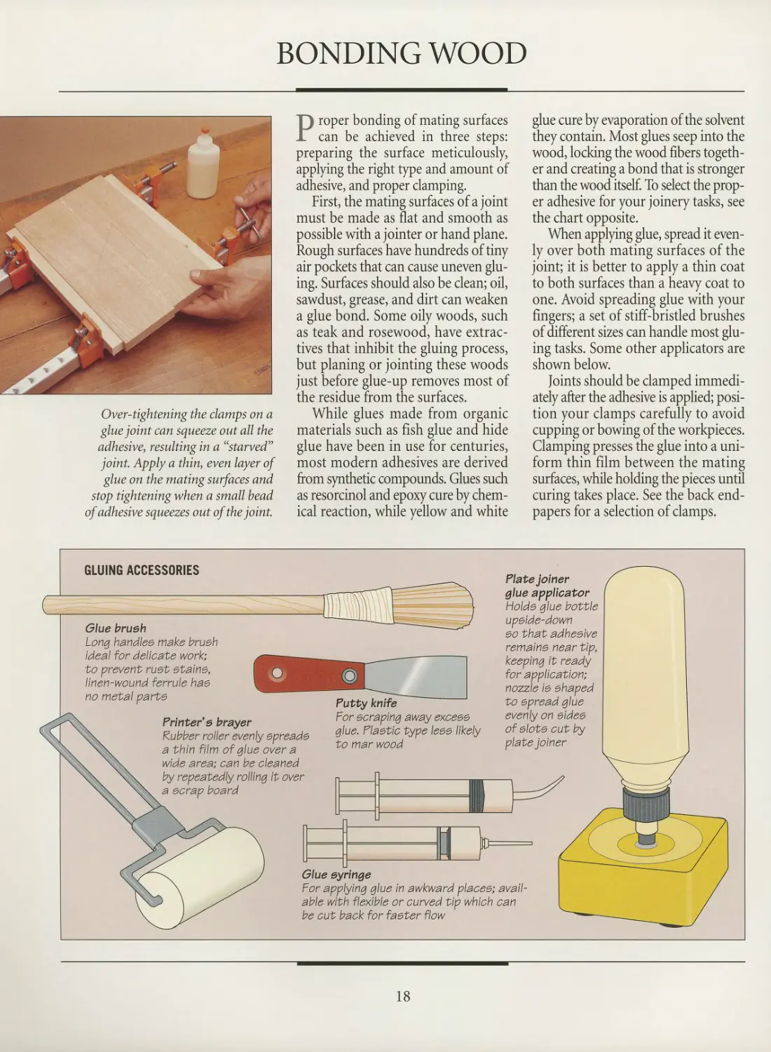
Joinery, the foundation of
woodworking, is a subtle blend of art and
engineering. Whether the product is a
simple tabletop or an ornate chest, its
joinery will establish its worth: Strong
joints will give it longevity, and their
design and craftsmanship will enhance
its beauty.
The need for jointmaking derives
from the fact that woodworkers make
demands on their material that nature
never intended. Interlocking curves of
fiber link a branch to the tree trunk,
while a leg is attached to a table at an
abrupt 90° intersection. Thus, although
a properly glued joint is stronger than
wood fiber, that bond alone is seldom
able to withstand the forces exerted on
tables, chairs, cabinets, and doors
during normal use.
Most joints need some sort of
mechanical aid—a reinforcement designed
to meet the stresses head-on. From that
need springs the craft of joinery.
The simplest supports are nails,
screws, splines, biscuits, and dowels.
These require simply cutting a hole and
adding wood or metal to the
intersection of the pieces. Often, this is enough
to satisfy structural and esthetic needs.
Sometimes—most often when
furniture is involved—greater strength and
beauty are called for. The solution then
is to cut the intersecting pieces so that
the gluing area is increased or they form
an interlocking bond.
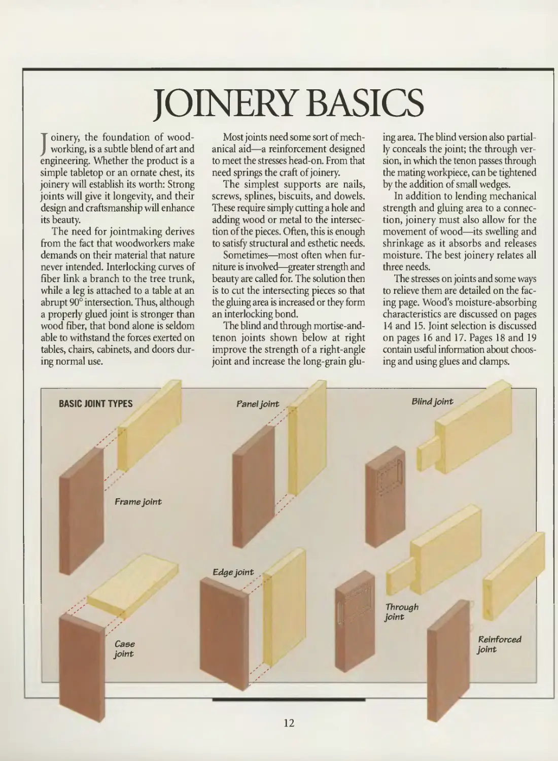
The blind and through mortise-and-
tenon joints shown below at right
improve the strength of a right-angle
joint and increase the long-grain
gluing area. The blind version also
partially conceals the joint; the through
version, in which the tenon passes through
the mating workpiece, can be tightened
by the addition of small wedges.
In addition to lending mechanical
strength and gluing area to a
connection, joinery must also allow for the
movement of wood—its swelling and
shrinkage as it absorbs and releases
moisture. The best joinery relates all
three needs.
The stresses on joints and some ways
to relieve them are detailed on the
facing page. Wood's moisture-absorbing
characteristics are discussed on pages
14 and 15. Joint selection is discussed
on pages 16 and 17. Pages 18 and 19
contain useful information about
choosing and using glues and clamps.
BASIC JOINT TYPES
Frame joint
Panel joint
Edge joint
Blind joint
Through
joint
Case
joint
Reinforced
joint
12
JOINERY BASICS
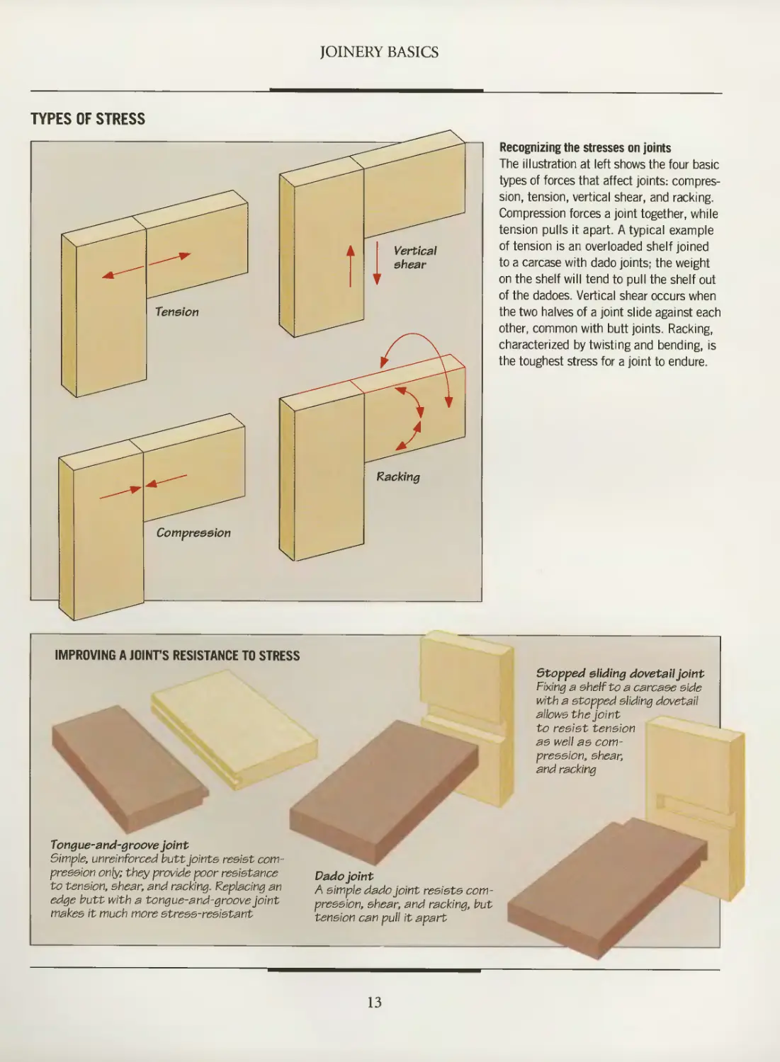
TYPES OF STRESS
Recognizing the stresses on joints
The illustration at left shows the four basic
types of forces that affect joints:
compression, tension, vertical shear, and racking.
Compression forces a joint together, while
tension pulls it apart. A typical example
of tension is an overloaded shelf joined
to a carcase with dado joints; the weight
on the shelf will tend to pull the shelf out
of the dadoes. Vertical shear occurs when
the two halves of a joint slide against each
other, common with butt joints. Racking,
characterized by twisting and bending, is
the toughest stress for a joint to endure.
IMPROVING A JOINT'S RESISTANCE TO STRESS
Tongue-and-groove joint
Simple, unreinforced butt joints resist
compression only; they provide poor resistance
to tension, shear, and racking. Replacing an
edge butt with a tongue-and-groove joint
makes it much more stress-resistant
Stopped sliding dovetail joint
Fixing a shelf to a carcase side
with a stopped sliding dovetail
allows the joint
to resist tension
as well as
compression, shear,
and racking
Dado joint
A simple dado joint resists
compression, shear, and racking, but
tension can pull it apart
13
WOOD MOVEMENT
an6e%i ^
Scientists describe wood as a
hygroscopic material—that is, it absorbs
moisture. Long after a tree has been
felled and its wood milled and made into
furniture, the fibrous cells absorb and
release moisture, mirroring the
humidity of the surrounding air.
The consequences for the
woodworker can be serious: Wood swells as
it absorbs moisture and shrinks as it
expels it, causing motion that accounts
for most failed joints, wobbly chairs,
sticking doors, and split picture frames.
Although wood movement is
unavoidable, such consequences are not:
An understanding of wood's
characteristics will enable you to
accommodate this swelling and contraction and
produce joinery that is both durable
and stable.
The wood of most species is
characterized by growth rings, which are
concentric bands perpendicular to the axis
of the trunk. The manner in which the
rings are exposed on a wood surface can
help you anticipate how the piece will
react to humidity changes. As the
illustration below shows, there is more
swelling and shrinkage along the growth
rings than across them. The way
lumber is cut from a log has a crucial effect
on how much the wood will shrink and
which dimension—length, width, or
thickness—will be most affected.
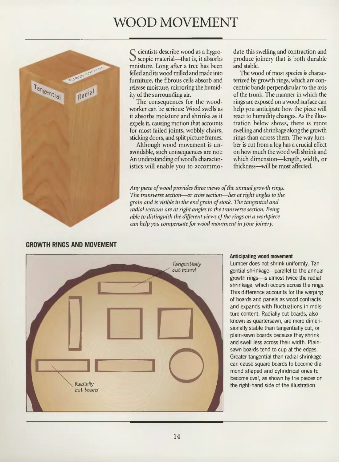
Any piece of wood provides three views of the annual growth rings.
The transverse section—or cross section—lies at right angles to the
grain and is visible in the end grain of stock. The tangential and
radial sections are at right angles to the transverse section. Being
able to distinguish the different views of the rings on a workpiece
can help you compensate for wood movement in your joinery.
GROWTH RINGS AND MOVEMENT
^
][
Radially
cut board
TanqentiaHy
cut board
nn
■O
Anticipating wood movement
Lumber does not shrink uniformly.
Tangential shrinkage—parallel to the annual
growth rings—is almost twice the radial
shrinkage, which occurs across the rings.
This difference accounts for the warping
of boards and panels as wood contracts
and expands with fluctuations in
moisture content. Radially cut boards, also
known as quartersawn, are more dimen-
sionally stable than tangentially cut, or
plain-sawn boards because they shrink
and swell less across their width. Plain-
sawn boards tend to cup at the edges.
Greater tangential than radial shrinkage
can cause square boards to become
diamond shaped and cylindrical ones to
become oval, as shown by the pieces on
the right-hand side of the illustration.
14
JOINERY BASICS
Logs are sawn in two basic ways, with
many variations. The most common
system, called plain-sawing, slices the log
tangent to the growth rings. The other
method, less commonly used, is called
quartersawing or edge-grain sawing. It
takes slices at right angles to the growth
rings. Although the techniques used in
each system are very different, each will
produce some boards with
characteristics of the other. For example,
plain-sawing through the center of a log produces
a piece of stock that looks much like a
quarter-sawn board.
Quartersawn boards have their
annual growth rings perpendicular to the face.
This orientation of the growth rings
accounts for the superior dimensional
stability of quartersawn boards. Wood
shrinks and expands roughly twice as
much tangentially to the rings as its does
radially. When quartersawn boards swell
or shrink they do so mostly in thickness,
which is minimal, whereas a plain-sawn
board changes across its width. A table
made from plain-sawn pine boards, for
example, can change as much as 1 inch
in width; a similar table made from
quartersawn boards would only swell or
shrink by one-quarter as much or less,
depending on the species.
Although you may not be able to
control the environment where your
furniture will be used, you can make your
joinery choices to compensate for wood
movement. Orient the growth rings in
the mating pieces of a joint so that they
move together. For example, the rings
of the two parts of a corner joint should
be parallel to each other so that they
shrink or swell in tandem. When the
rings of the pieces meet at right angles,
as in a mortise-and-tenon joint, make
sure their tangential surfaces are aligned.
Workpieces that feature irregular
grain require particular attention. A
square chair leg with growth rings that
run diagonally through it when viewed
in cross section, for example, will
eventually lose its square shape and become
a diamond shape, pulling the chair frame
out of square with it.
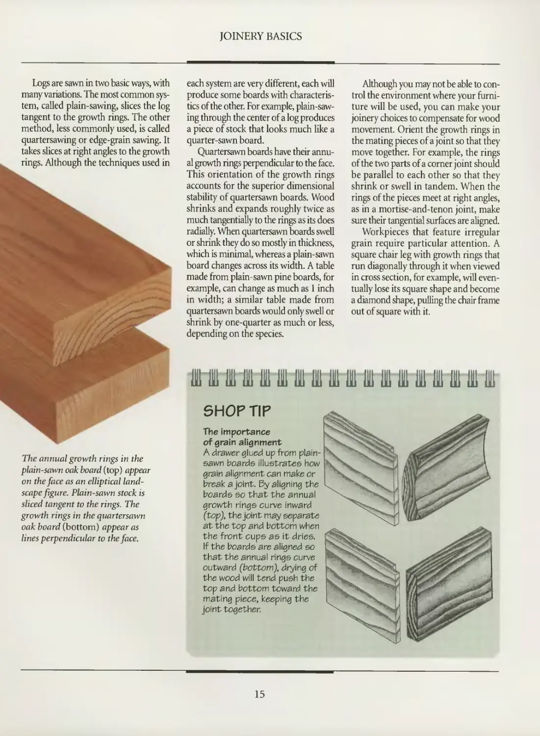
The annual growth rings in the
plain-sawn oak board (top) appear
on the face as an elliptical
landscape figure. Plain-sawn stock is
sliced tangent to the rings. The
growth rings in the quartersawn
oak board (bottom) appear as
lines perpendicular to the face.
SHOP TIP
The Importance
of grain alignment
A drawer glued up from plain-
sawn boards illustrates how
grain alignment can make or
break a joint. By aligning the
boards so that the annual
growth rings curve inward
(top), the joint may separate
at the top and bottom when
the front cups as it dries.
If the boards are aligned so
that the annual rings curve
outward (bottom), drying of
the wood will tend push the
top and bottom toward the
mating piece, keeping the
joint together.
15
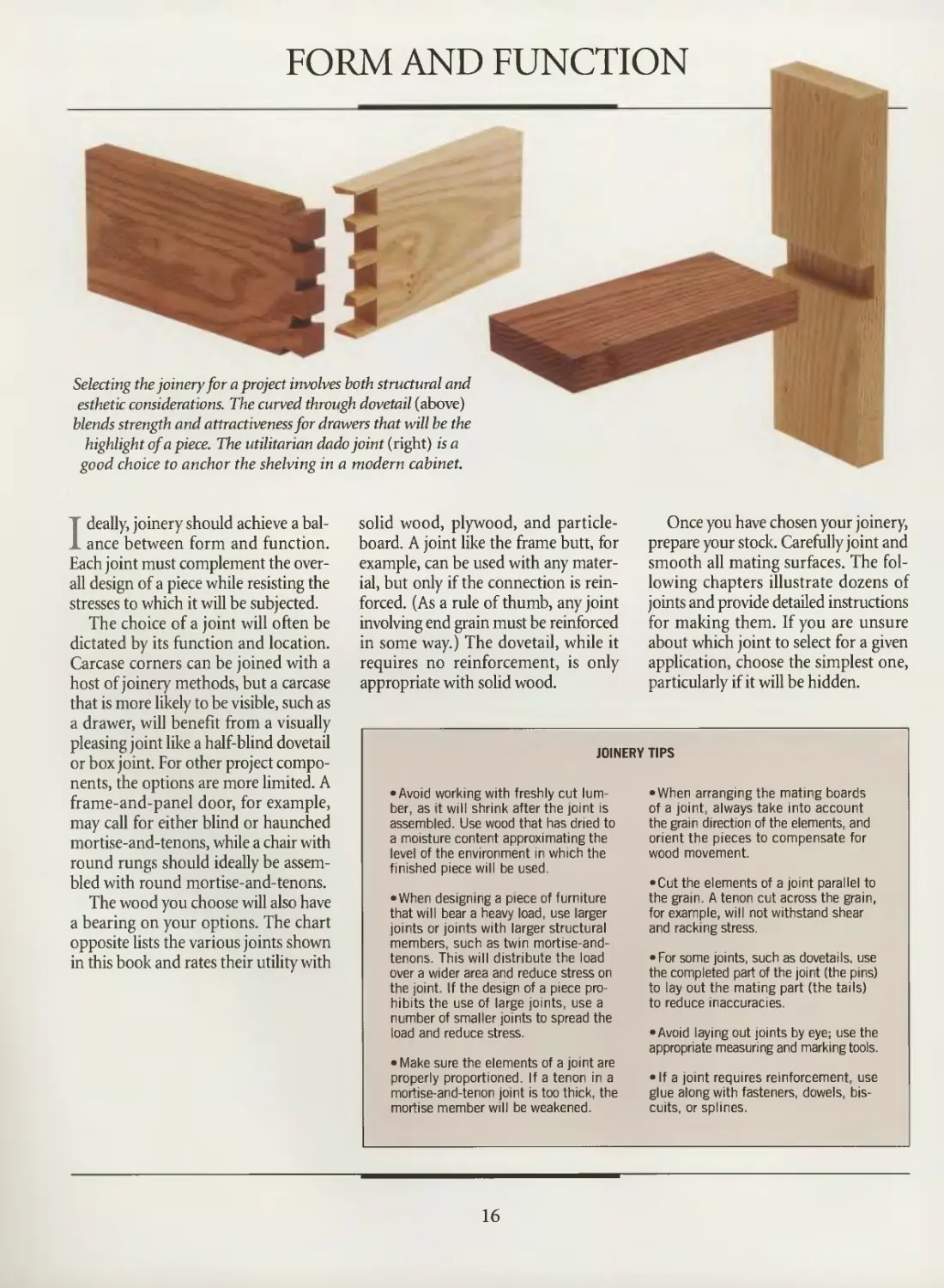
FORM AND FUNCTION
Selecting the joinery for a project involves both structural and
esthetic considerations. The curved through dovetail (above)
blends strength and attractiveness for drawers that will be the
highlight of a piece. The utilitarian dado joint (right) is a
good choice to anchor the shelving in a modern cabinet.
Ideally, joinery should achieve a
balance between form and function.
Each joint must complement the
overall design of a piece while resisting the
stresses to which it will be subjected.
The choice of a joint will often be
dictated by its function and location.
Carcase corners can be joined with a
host of joinery methods, but a carcase
that is more likely to be visible, such as
a drawer, will benefit from a visually
pleasing joint like a half-blind dovetail
or box joint. For other project
components, the options are more limited. A
frame-and-panel door, for example,
may call for either blind or haunched
mortise-and-tenons, while a chair with
round rungs should ideally be
assembled with round mortise-and-tenons.
The wood you choose will also have
a bearing on your options. The chart
opposite lists the various joints shown
in this book and rates their utility with
solid wood, plywood, and particle-
board. A joint like the frame butt, for
example, can be used with any
material, but only if the connection is
reinforced. (As a rule of thumb, any joint
involving end grain must be reinforced
in some way.) The dovetail, while it
requires no reinforcement, is only
appropriate with solid wood.
Once you have chosen your joinery,
prepare your stock. Carefully joint and
smooth all mating surfaces. The
following chapters illustrate dozens of
joints and provide detailed instructions
for making them. If you are unsure
about which joint to select for a given
application, choose the simplest one,
particularly if it will be hidden.
JOINERY TIPS
• Avoid working with freshly cut
lumber, as it will shrink after the joint is
assembled. Use wood that has dried to
a moisture content approximating the
level of the environment in which the
finished piece will be used.
• When designing a piece of furniture
that will bear a heavy load, use larger
joints or joints with larger structural
members, such as twin mortise-and-
tenons. This will distribute the load
over a wider area and reduce stress on
the joint. If the design of a piece
prohibits the use of large joints, use a
number of smaller joints to spread the
load and reduce stress.
• Make sure the elements of a joint are
properly proportioned. If a tenon in a
mortise-and-tenon joint is too thick, the
mortise member will be weakened.
•When arranging the mating boards
of a joint, always take into account
the grain direction of the elements, and
orient the pieces to compensate for
wood movement.
•Cut the elements of a joint parallel to
the grain. A tenon cut across the grain,
for example, will not withstand shear
and racking stress.
• For some joints, such as dovetails, use
the completed part of the joint (the pins)
to lay out the mating part (the tails)
to reduce inaccuracies.
•Avoid laying out joints by eye; use the
appropriate measuring and marking tools.
• If a joint requires reinforcement, use
glue along with fasteners, dowels,
biscuits, or splines.
16
JOINERY BASICS
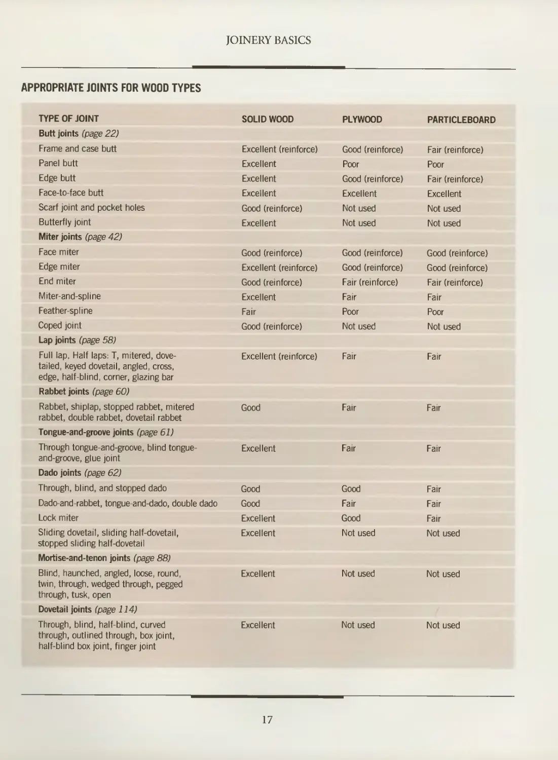
APPROPRIATE JOINTS FOR WOOD TYPES
TYPE OF JOINT
Butt joints (page 22)
Frame and case butt
Panel butt
Edge butt
Face-to-face butt
Scarf joint and pocket holes
Butterfly joint
Miter joints (page 42)
Face miter
Edge miter
End miter
Miter-and-spline
Feather-spline
Coped joint
Lap joints (page 58)
Full lap, Half laps: T, mitered,
dovetailed, keyed dovetail, angled, cross,
edge, half-blind, corner, glazing bar
Rabbet joints (page 60)
Rabbet, shiplap, stopped rabbet, mitered
rabbet, double rabbet, dovetail rabbet
Tongue-and-groove joints (page 61)
Through tongue-and-groove, blind tongue-
and-groove, glue joint
Dado joints (page 62)
Through, blind, and stopped dado
Dado-and-rabbet, tongue-and-dado, double dado
Lock miter
Sliding dovetail, sliding half-dovetail,
stopped sliding half-dovetail
Mortise-and-tenon joints (page 88)
Blind, haunched, angled, loose, round,
twin, through, wedged through, pegged
through, tusk, open
Dovetail joints (page 114)
Through, blind, half-blind, curved
through, outlined through, box joint,
half-blind box joint, finger joint
SOLID WOOD
Excellent (reinforce)
Excellent
Excellent
Excellent
Good (reinforce)
Excellent
Good (reinforce)
Excellent (reinforce)
Good (reinforce)
Excellent
Fair
Good (reinforce)
Excellent (reinforce)
Good
Excellent
Excellent
Excellent
PLYWOOD
Good (reinforce)
Poor
Good (reinforce)
Excellent
Not used
Not used
Good (reinforce)
Good (reinforce)
Fair (reinforce)
Fair
Poor
Not used
Fair
Fair
Fair
Not used
Not used
PARTICLEBOARD
Fair (reinforce)
Poor
Fair (reinforce)
Excellent
Not used
Not used
Good (reinforce)
Good (reinforce)
Fair (reinforce)
Fair
Poor
Not used
Fair
Fair
Fair
Good
Good
Excellent
Excellent
Good
Fair
Good
Not used
Fair
Fair
Fair
Not used
Not used
Not used
17
JOINERY BASICS
JOINERY ADHESIVES
TYPE CHARACTERISTICS
White Polyvinyl-acetate based; not toxic or flammable • Strong bonding; working time 3 to 5
glue minutes • Setting time about 30 to 45 minutes; cures fully in 24 to 72 hours • Dries
clear and colorless • Does not sand as well as yellow glue
Yellow Aliphatic-resin based; not toxic or flammable • Better immediate adhesion for faster
glue grab than white glue; working time 3 to 5 minutes • Setting time about 30 to 40 minutes;
cures fully in 24 to 72 hours • Dries opaque (faded yellow); more heat-resistant for better
sanding properties than white glue
Epoxy Resin and hardener must be mixed prior to use; not flammable but may be
glue toxic • Strong, waterproof bonding; working time 5 minutes to 2 hours (depending on
type) • Setting time 5 minutes to 2 hours (depending on type); cures fully in 24 hours
Fish glue Protein-based; not toxic or flammable • Average bonding; working time 60 to 90
minutes • Setting and curing time 12 hours • Sandable, dries an opaque color, resists
solvents • Not water-resistant: Glue bond can be softened with water for disassembly
Hide glue Protein-based; available in granular or liquid form; not toxic or flammable • Strong
bonding, working time 3-5 minutes • Setting time 1 hour; cures fully in 24 hours • Sandable,
dries a dark color • Not water-resistant, glue bond can be softened with water for disassembly
Casein Milk-based, comes in powdered form; not toxic or flammable • Average bonding; working
glue time 15 to 20 minutes • Setting time 15 to 20 minutes, cures fully in 8 to 12 hours
• High resistance to water, dries an opaque color, sands cleanly, stains acidic woods
Plastic Urea-formaldehyde-based, available in powdered form; not flammable but toxic
resin • Strong bonding, working time 20 minutes • Setting time 4 to 6 hours; cures fully
in 3 days • Water resistance higher than that of aliphatic glues, does not stain acidic
woods, sands cleanly
USES
General woodworking
General woodworking
Bonding acidic woods such as
oak; use on exotic woods that
bond poorly with other glues
Furniture construction, luthier
work, antique restoration and tasks
that require a long working time
Cabinet construction, antique
restoration, veneering, and fine
woodworking
Oily woods that bond poorly
with other glues, such as teak,
yew, and lemonwood; laminating
Veneering, laminating, and
edge-gluing hardwood
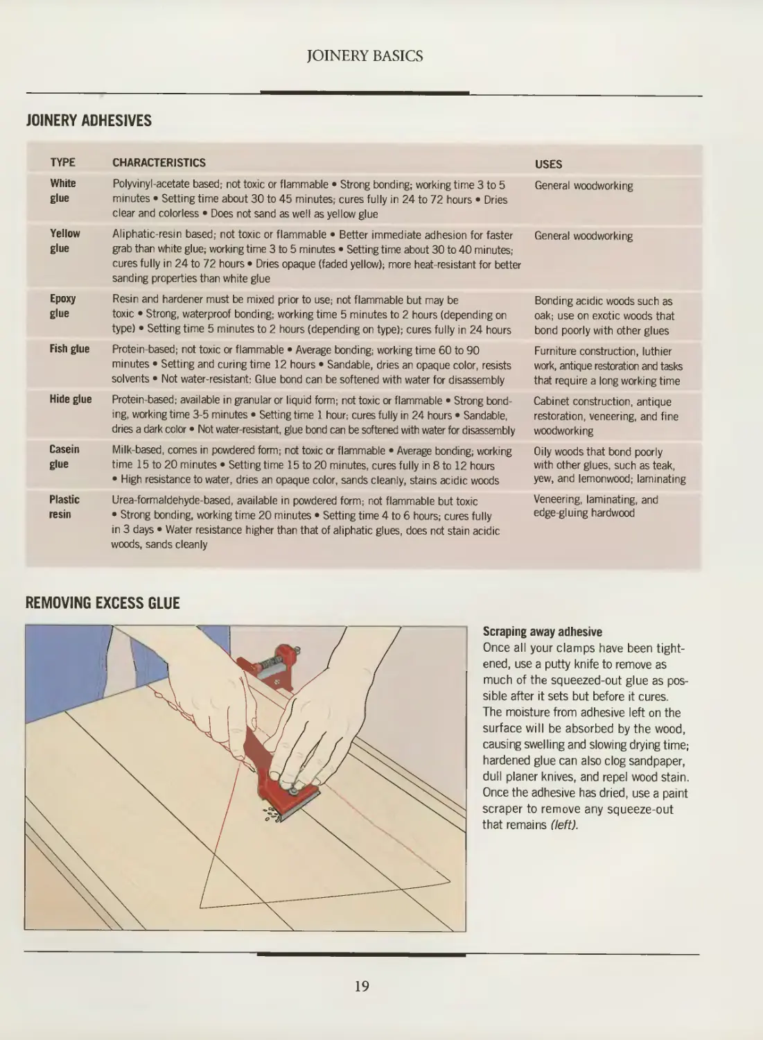
REMOVING EXCESS GLUE
Scraping away adhesive
Once all your clamps have been
tightened, use a putty knife to remove as
much of the squeezed-out glue as
possible after it sets but before it cures.
The moisture from adhesive left on the
surface will be absorbed by the wood,
causing swelling and slowing drying time;
hardened glue can also clog sandpaper,
dull planer knives, and repel wood stain.
Once the adhesive has dried, use a paint
scraper to remove any squeeze-out
that remains (left).
19
-I
' *!
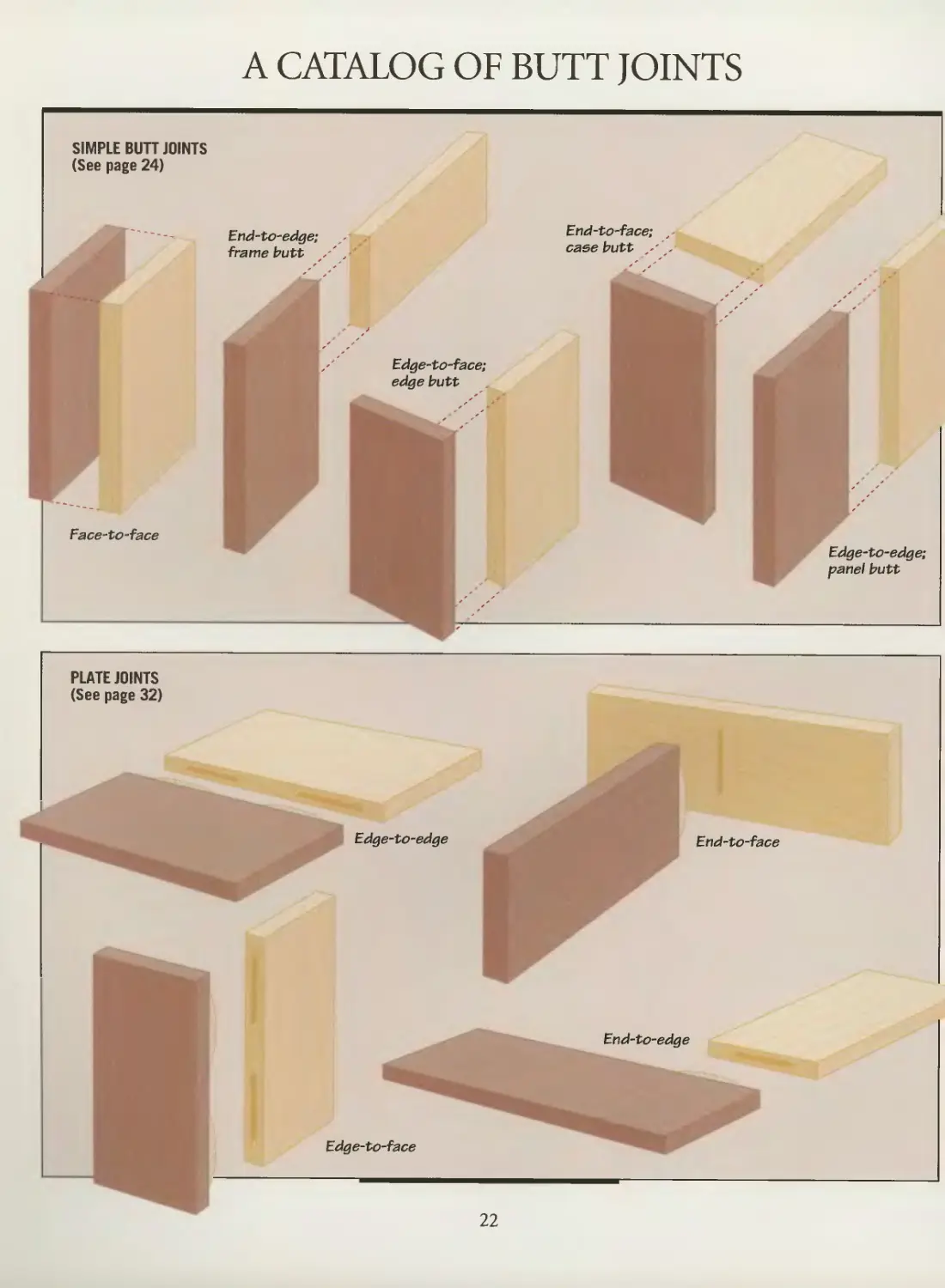
A CATALOG OF BUTT JOINTS
SIMPLE BUTT JOINTS
(See page 24)
End-to-edge;
frame butt /' .
Edge-to-face;
edge butt
Face-to-face
PLATE JOINTS
(See page 32)
Edge-to-edge End-to-face
End-to-edge
Edge-to-face
End-to-face;
case butt .■
Edge-to-edge;
panel butt
22
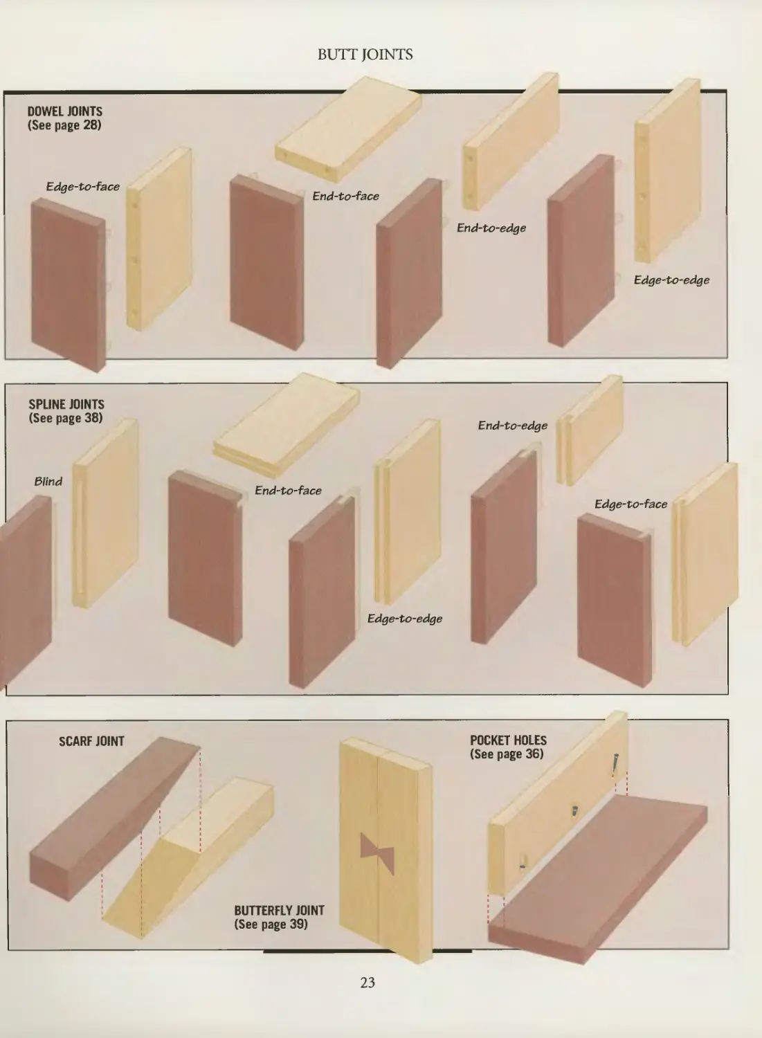
DOWEL JOINTS
(See page 28)
Edge-to-face
BUTT JOINTS
End-to-face
End-to-edge
Edge-to-edge
SPLINE JOINTS
(See page 38)
Blind
End-to-face
End-to-edge
Edge-to-face
Edge-to-edge
SCARF JOINT
;
s
1
BUTTERFLY JOINT
(See page 39)
POCKET HOLES
(See page 36)
: :
;
23
MAKING BUTT JOINTS
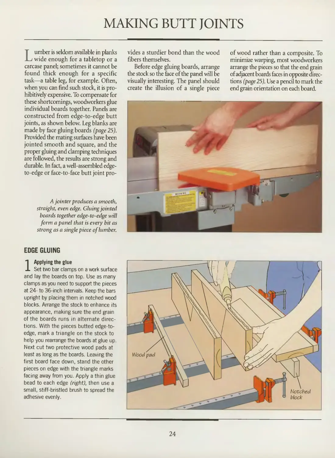
Lumber is seldom available in planks
wide enough for a tabletop or a
carcase panel; sometimes it cannot be
found thick enough for a specific
task—a table leg, for example. Often,
when you can find such stock, it is
prohibitively expensive. To compensate for
these shortcomings, woodworkers glue
individual boards together. Panels are
constructed from edge-to-edge butt
joints, as shown below. Leg blanks are
made by face gluing boards (page 25).
Provided the mating surfaces have been
jointed smooth and square, and the
proper gluing and clamping techniques
are followed, the results are strong and
durable. In fact, a well-assembled edge-
to-edge or face-to-face butt joint pro-
A jointer produces a smooth,
straight, even edge. Gluing jointed
boards together edge-to-edge will
form a panel that is every bit as
strong as a single piece of lumber.
EDGE GLUING
1 Applying the glue
Set two bar clamps on a work surface
and lay the boards on top. Use as many
clamps as you need to support the pieces
at 24- to 36-inch intervals. Keep the bars
upright by placing them in notched wood
blocks. Arrange the stock to enhance its
appearance, making sure the end grain
of the boards runs in alternate
directions. With the pieces butted edge-to-
edge, mark a triangle on the stock to
help you rearrange the boards at glue up.
Next cut two protective wood pads at
least as long as the boards. Leaving the
first board face down, stand the other
pieces on edge with the triangle marks
facing away from you. Apply a thin glue
bead to each edge (right), then use a
small, stiff-bristled brush to spread the
adhesive evenly.
vides a sturdier bond than the wood
fibers themselves.
Before edge gluing boards, arrange
the stock so the face ofthe panel will be
visually interesting. The panel should
create the illusion of a single piece
of wood rather than a composite. To
minimize warping, most woodworkers
arrange the pieces so that the end grain
of adjacent boards faces in opposite
directions (page 25). Use a pencil to mark the
end grain orientation on each board.
«i«»lli— _*
Notched
block
24
BUTT JOINTS
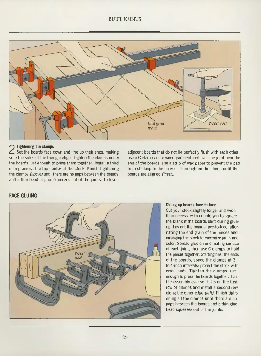
2 Tightening the clamps
Set the boards face down and line up their ends, making adjacent boards that do not lie perfectly flush with each other,
sure the sides of the triangle align. Tighten the clamps under use a C clamp and a wood pad centered over the joint near the
the boards just enough to press them together. Install a third end of the boards; use a strip of wax paper to prevent the pad
clamp across the top center of the stock. Finish tightening from sticking to the boards. Then tighten the clamp until the
the clamps (above) until there are no gaps between the boards boards are aligned (inset).
and a thin bead of glue squeezes out of the joints. To level
Gluing up boards face-to-face
Cut your stock slightly longer and wider
than necessary to enable you to square
the blank if the boards shift during glue-
up. Lay out the boards face-to-face,
alternating the end grain of the pieces and
arranging the stock to maximize grain and
color. Spread glue on one mating surface
of each joint, then use C clamps to hold
the pieces together. Starting near the ends
of the boards, space the clamps at 3-
to 4-inch intervals; protect the stock with
wood pads. Tighten the clamps just
enough to press the boards together. Turn
the assembly over so it sits on the first
row of clamps and install a second row
along the other edge (left). Finish
tightening all the clamps until there are no
gaps between the boards and a thin glue
bead squeezes out of the joints.
FACE GLUING
25
BUTT JOINTS
CLAMPING TECHNIQUES FOR THREE BUTT JOINTS
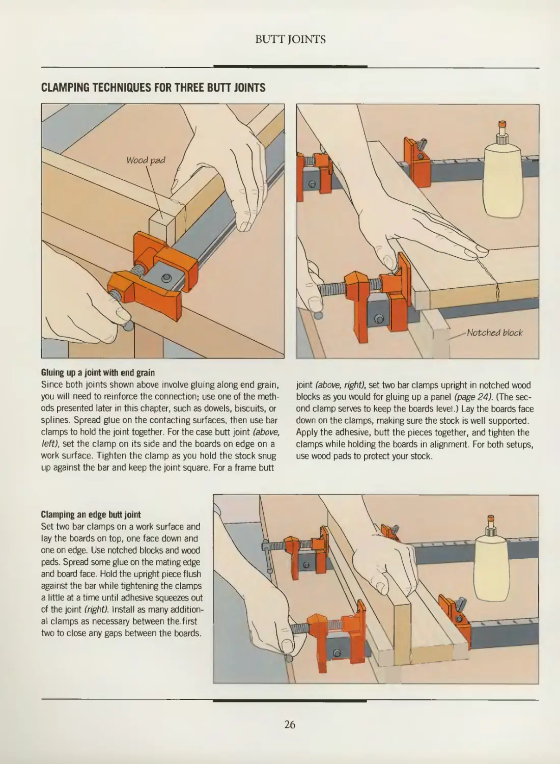
Gluing up a joint with end grain
Since both joints shown above involve gluing along end grain,
you will need to reinforce the connection; use one of the
methods presented later in this chapter, such as dowels, biscuits, or
splines. Spread glue on the contacting surfaces, then use bar
clamps to hold the joint together. For the case butt joint (above,
left), set the clamp on its side and the boards on edge on a
work surface. Tighten the clamp as you hold the stock snug
up against the bar and keep the joint square. For a frame butt
Notched block
joint (above, right), set two bar clamps upright in notched wood
blocks as you would for gluing up a panel (page 24). (The
second clamp serves to keep the boards level.) Lay the boards face
down on the clamps, making sure the stock is well supported.
Apply the adhesive, butt the pieces together, and tighten the
clamps while holding the boards in alignment. For both setups,
use wood pads to protect your stock.
Clamping an edge butt joint
Set two bar clamps on a work surface and
lay the boards on top, one face down and
one on edge. Use notched blocks and wood
pads. Spread some glue on the mating edge
and board face. Hold the upright piece flush
against the bar while tightening the clamps
a little at a time until adhesive squeezes out
of the joint (right). Install as many
additional clamps as necessary between the.first
two to close any gaps between the boards.
26
BUTT JOINTS
THROUGH BOLTS
1
\
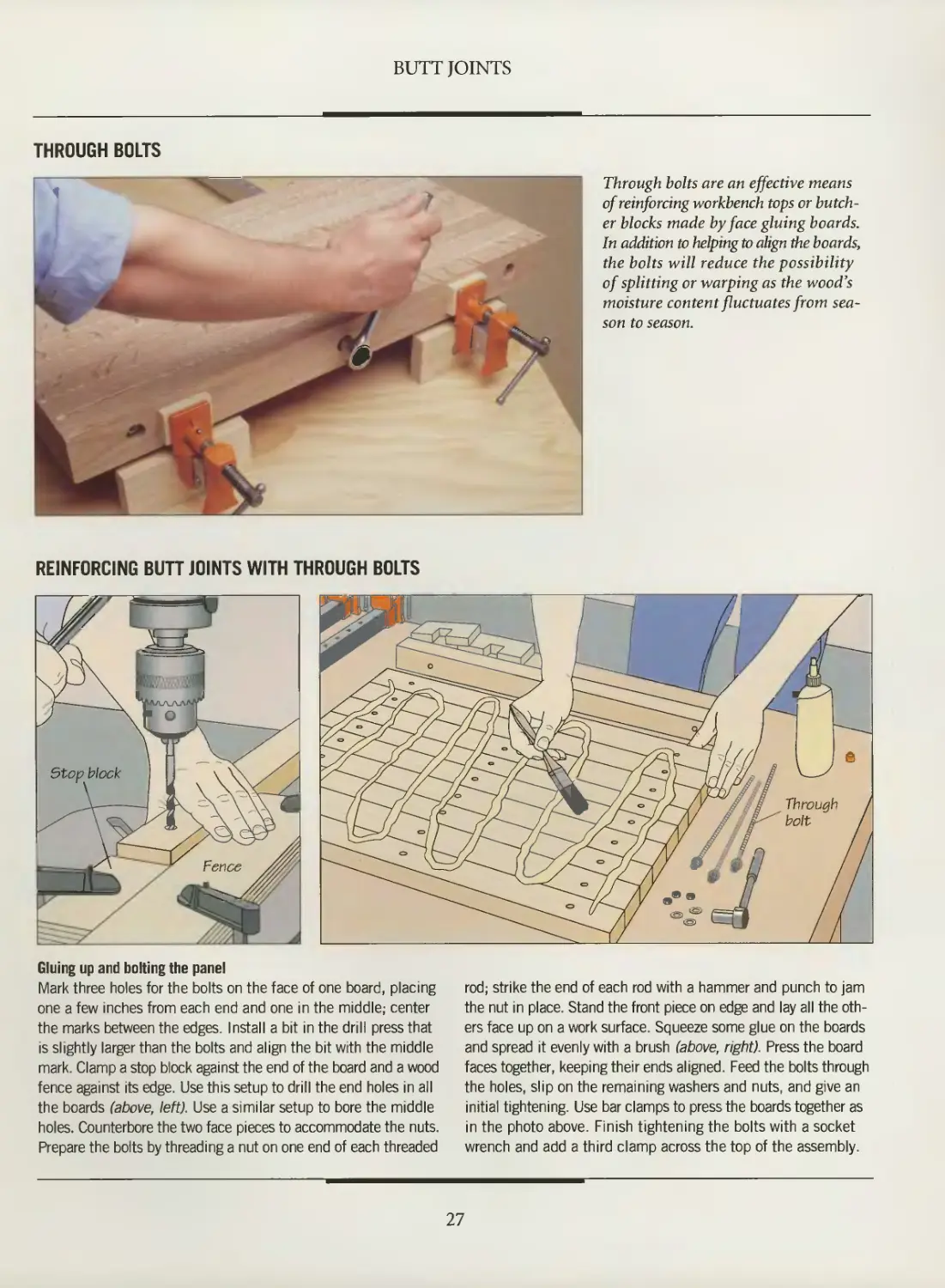
Through bolts are an effective means
of reinforcing workbench tops or
butcher blocks made by face gluing boards.
In addition to helping to align the boards,
the bolts will reduce the possibility
of splitting or warping as the wood's
moisture content fluctuates from
season to season.
REINFORCING BUTT JOINTS WITH THROUGH BOLTS
Through
f^ bolt
Gluing up and bolting the panel
Mark three holes for the bolts on the face of one board, placing
one a few inches from each end and one in the middle; center
the marks between the edges. Install a bit in the drill press that
is slightly larger than the bolts and align the bit with the middle
mark. Clamp a stop block against the end of the board and a wood
fence against its edge. Use this setup to drill the end holes in all
the boards (above, left). Use a similar setup to bore the middle
holes. Counterbore the two face pieces to accommodate the nuts.
Prepare the bolts by threading a nut on one end of each threaded
rod; strike the end of each rod with a hammer and punch to jam
the nut in place. Stand the front piece on edge and lay all the
others face up on a work surface. Squeeze some glue on the boards
and spread it evenly with a brush (above, right). Press the board
faces together, keeping their ends aligned. Feed the bolts through
the holes, slip on the remaining washers and nuts, and give an
initial tightening. Use bar clamps to press the boards together as
in the photo above. Finish tightening the bolts with a socket
wrench and add a third clamp across the top of the assembly.
27
DOWEL JOINTS
*
*
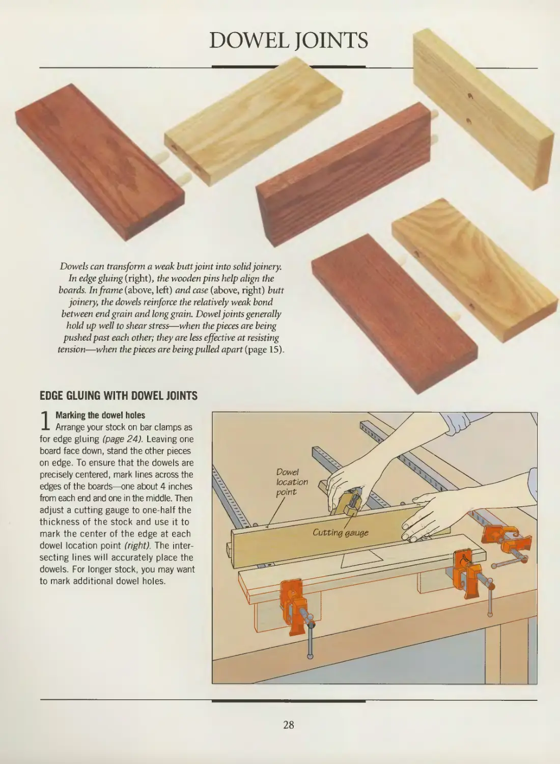
Dowels can transform a weak butt joint into solid joinery.
In edge gluing (right), the wooden pins help align the
boards. In frame (above, left) and case (above, right) butt
joinery, the dowels reinforce the relatively weak bond
between end grain and long grain. Dowel joints generally
hold up well to shear stress—when the pieces are being
pushed past each other; they are less effective at resisting
tension—when the pieces are being pulled apart (page 15).
EDGE GLUING WITH DOWEL JOINTS
1 Marking the dowel holes
Arrange your stock on bar clamps as
for edge gluing (page 24). Leaving one
board face down, stand the other pieces
on edge. To ensure that the dowels are
precisely centered, mark lines across the
edges of the boards—one about 4 inches
from each end and one in the middle. Then
adjust a cutting gauge to one-half the
thickness of the stock and use it to
mark the center of the edge at each
dowel location point (right). The
intersecting lines will accurately place the
dowels. For longer stock, you may want
to mark additional dowel holes.
28
BUTT JOINTS
SHOP TIP
Doweling jig
The commercial doweling
jig shown here
automatically centers
dowel holes on
the stock and
spaces them
at intervals
you choose. Clamp the workpiece
in handscrews, then secure the
board to a work surface. Clamp the jig
onto the edge of the stock. Fit your drill
with a bit the same diameter as the dowels,
then install a stop collar to control the
drilling depth. Slide the rectangular bushing
carrier along the jig, and insert the
appropriate bushing to keep the bit square to the
board. Holding the drill firmly, bore the hole.
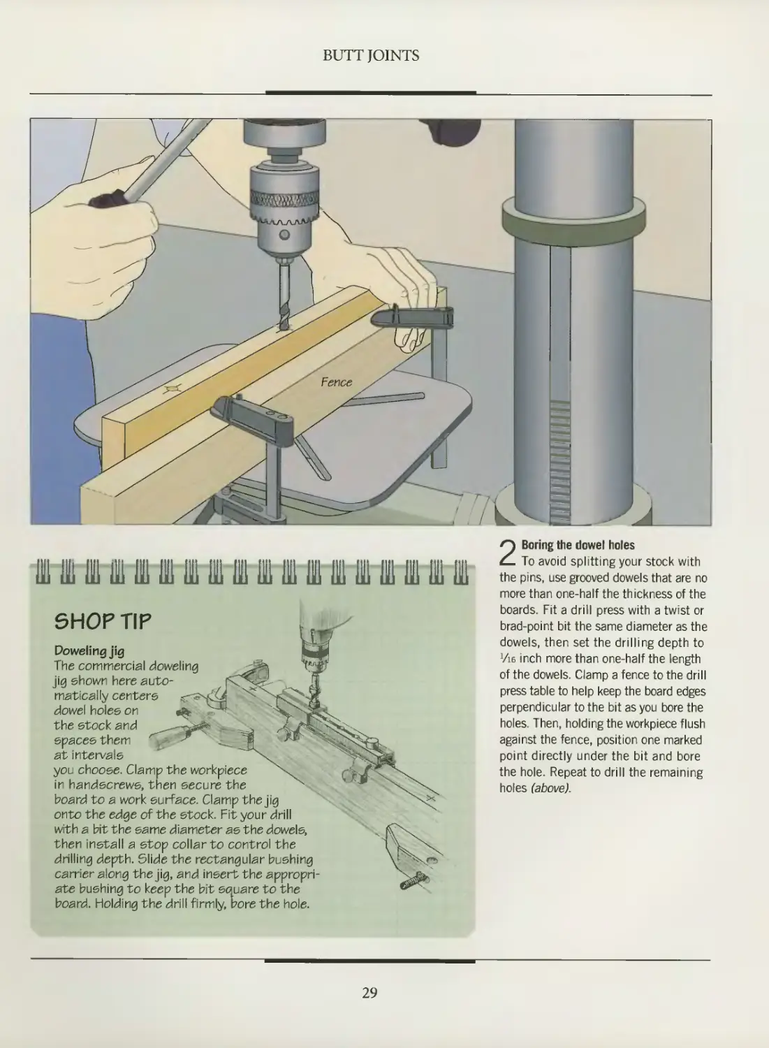
2 Boring the dowel holes
To avoid splitting your stock with
the pins, use grooved dowels that are no
more than one-half the thickness of the
boards. Fit a drill press with a twist or
brad-point bit the same diameter as the
dowels, then set the drilling depth to
Vie inch more than one-half the length
of the dowels. Clamp a fence to the drill
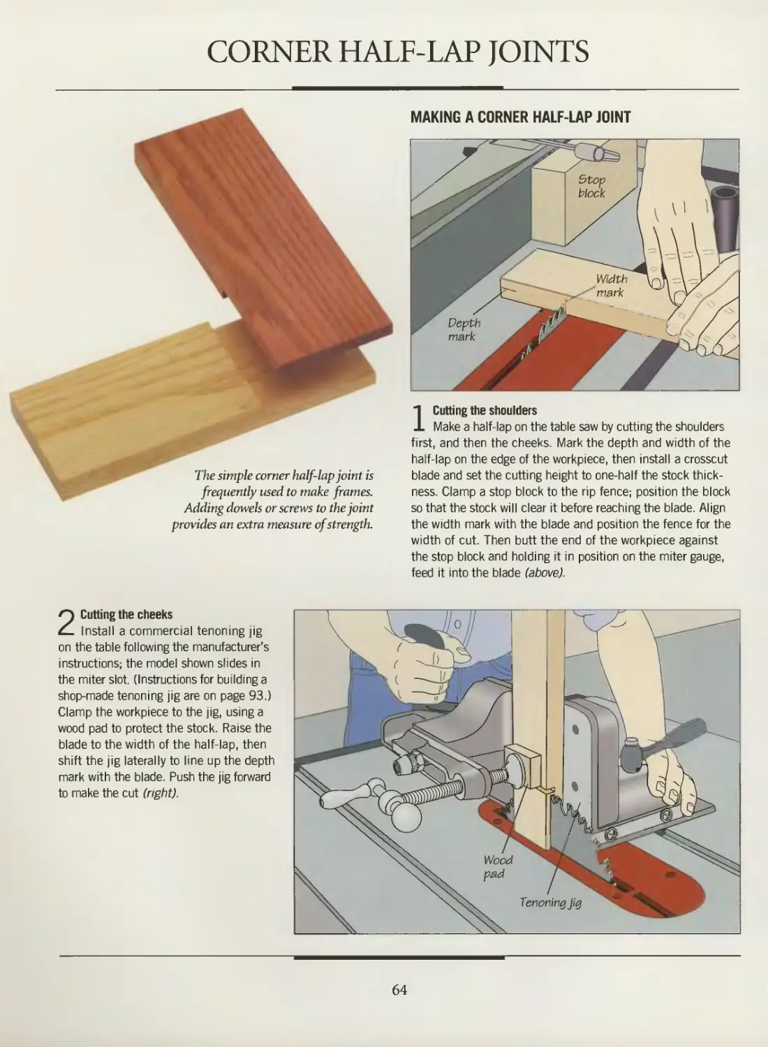
press table to help keep the board edges
perpendicular to the bit as you bore the
holes. Then, holding the workpiece flush
against the fence, position one marked
point directly under the bit and bore
the hole. Repeat to drill the remaining
holes (above).
29
BUTT JOINTS
BUILD IT YOURSELF
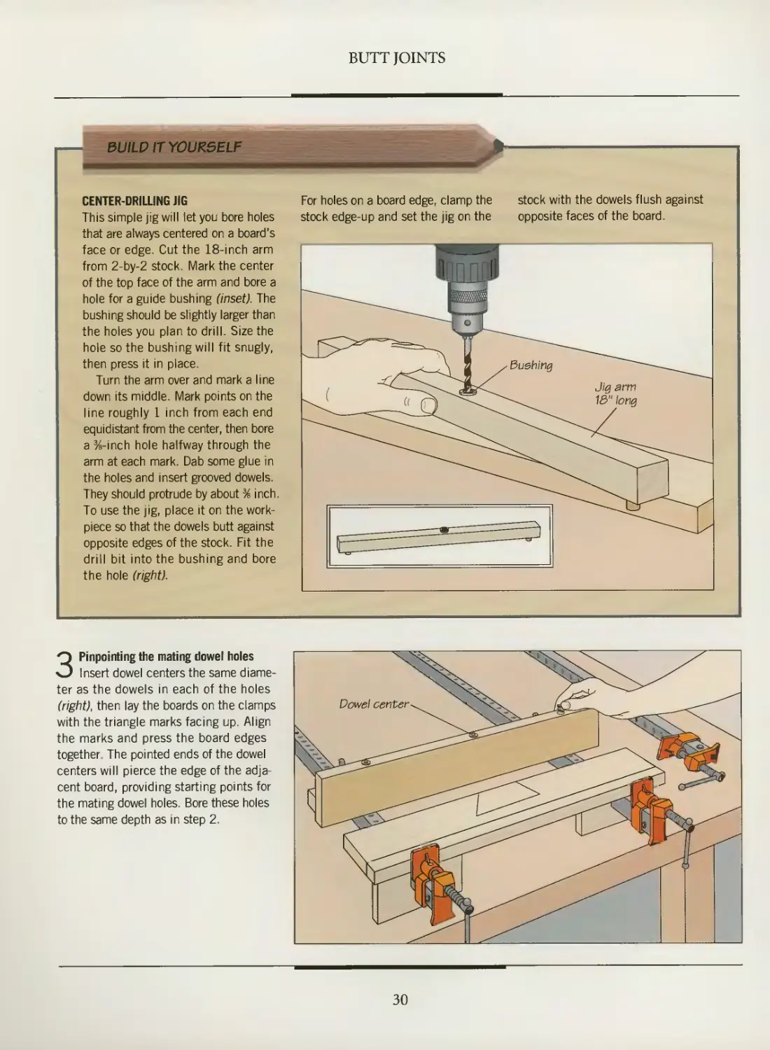
CENTER-DRILLING JIG
This simple jig will let you bore holes
that are always centered on a board's
face or edge. Cut the 18-inch arm
from 2-by-2 stock. Mark the center
of the top face of the arm and bore a
hole for a guide bushing (inset). The
bushing should be slightly larger than
the holes you plan to drill. Size the
hole so the bushing will fit snugly,
then press it in place.
Turn the arm over and mark a line
down its middle. Mark points on the
line roughly 1 inch from each end
equidistant from the center, then bore
a %-inch hole halfway through the
arm at each mark. Dab some glue in
the holes and insert grooved dowels.
They should protrude by about % inch.
To use the jig, place it on the work-
piece so that the dowels butt against
opposite edges of the stock. Fit the
drill bit into the bushing and bore
the hole (right).
For holes on a board edge, clamp the
stock edge-up and set the jig on the
stock with the dowels flush against
opposite faces of the board.
3 Pinpointing the mating dowel holes
Insert dowel centers the same
diameter as the dowels in each of the holes
(right), then lay the boards on the clamps
with the triangle marks facing up. Align
the marks and press the board edges
together The pointed ends of the dowel
centers will pierce the edge of the
adjacent board, providing starting points for
the mating dowel holes. Bore these holes
to the same depth as in step 2.
i\
\-\,
>
I
\^v ^^S^O^ >/
>^/\>\ ^^^-O*-^-^ ^^\ ^^
Dowel center ^ ^\N?\ ioZ^-^ _-r-~""~"'^
X^Oi-. ^s-
^—^ iUL^^S>^l
^J&~^§^'— ^^^S^^^^ JX[ ^°^Uc£
^—'^^ ^^^^^^\^--^
Vv^
[
f^-
Th^^ ^^
%
Va
U
\
V^^^^
^Px ^^
30
BUTT JOINTS
^
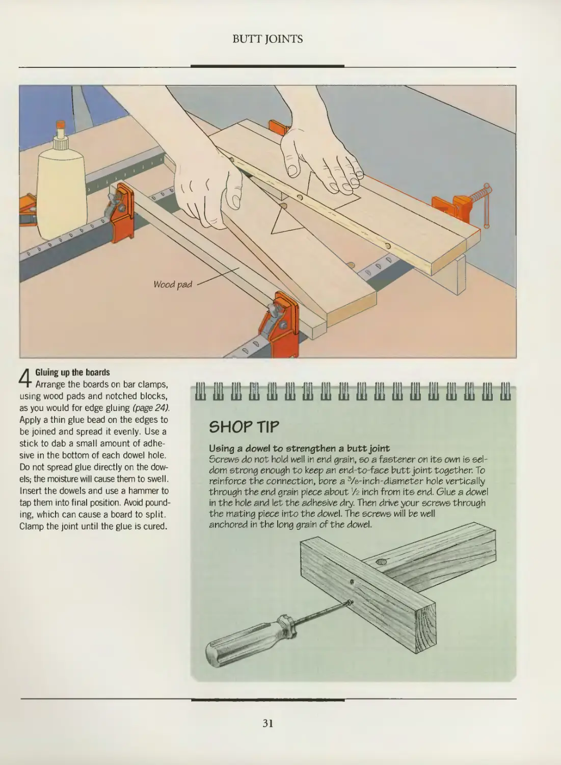
4 Gluing up the boards
Arrange the boards on bar clamps,
using wood pads and notched blocks,
as you would for edge gluing (page 24).
Apply a thin glue bead on the edges to
be joined and spread it evenly. Use a
stick to dab a small amount of
adhesive in the bottom of each dowel hole.
Do not spread glue directly on the
dowels; the moisture will cause them to swell.
Insert the dowels and use a hammer to
tap them into final position. Avoid
pounding, which can cause a board to split.
Clamp the joint until the glue is cured.
111 lil 1 ffi I ffi 1 ffi 1 ffi 111 Hi 111
SHOP TIP
Using a dowe\ to strengthen a butt joint
Screws do not hold well in end grain, so a fastener on its own is
seldom strong enough to keep an end-to-face butt joint together. To
reinforce the connection, bore a 3/8-inch-diameter hole vertically
through the end grain piece about V2 inch from its end. Glue a dowel
in the hole and let the adhesive dry. Then drive your screws through
the mating piece into the dowel. The screws will be well
anchored in the long grain of the dowel.
31
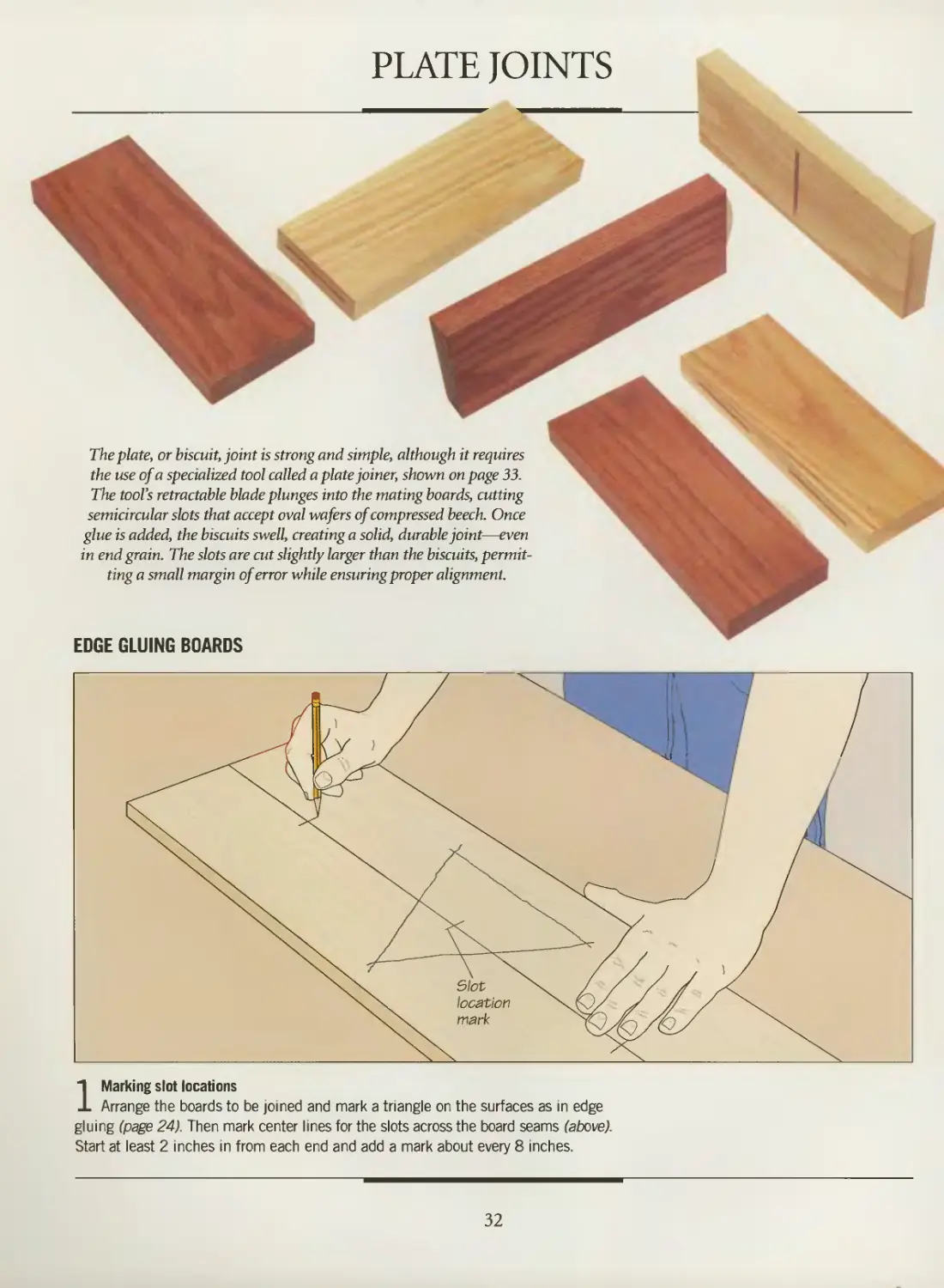
PLATE JOINTS
The plate, or biscuit, joint is strong and simple, although it requires
the use of a specialized tool called a plate joiner, shown on page 33.
The tool's retractable blade plunges into the mating boards, cutting
semicircular slots that accept oval wafers of compressed beech. Once
glue is added, the biscuits swell, creating a solid, durable joint—even
in end grain. The slots are cut slightly larger than the biscuits,
permitting a small margin of error while ensuring proper alignment.
EDGE GLUING BOARDS
1 Marking slot locations
Arrange the boards to be joined and mark a triangle on the surfaces as in edge
gluing (page 24). Then mark center lines for the slots across the board seams (above).
Start at least 2 inches in from each end and add a mark about every 8 inches.
32
BUTT JOINTS
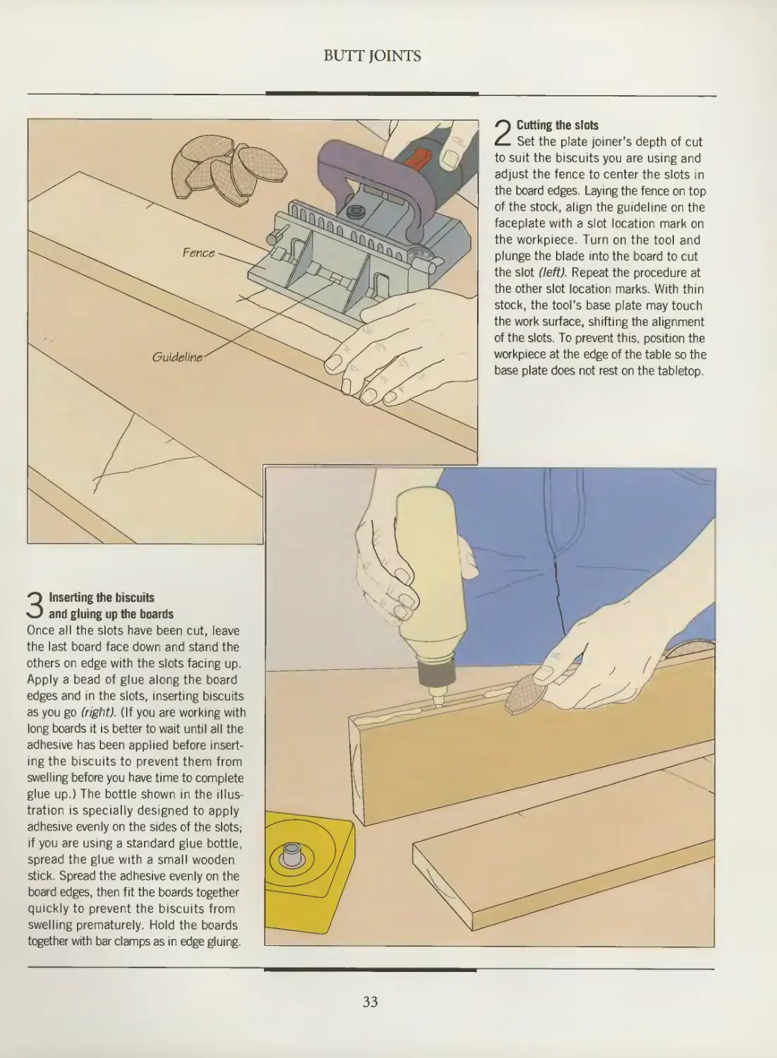
O Cutting the slots
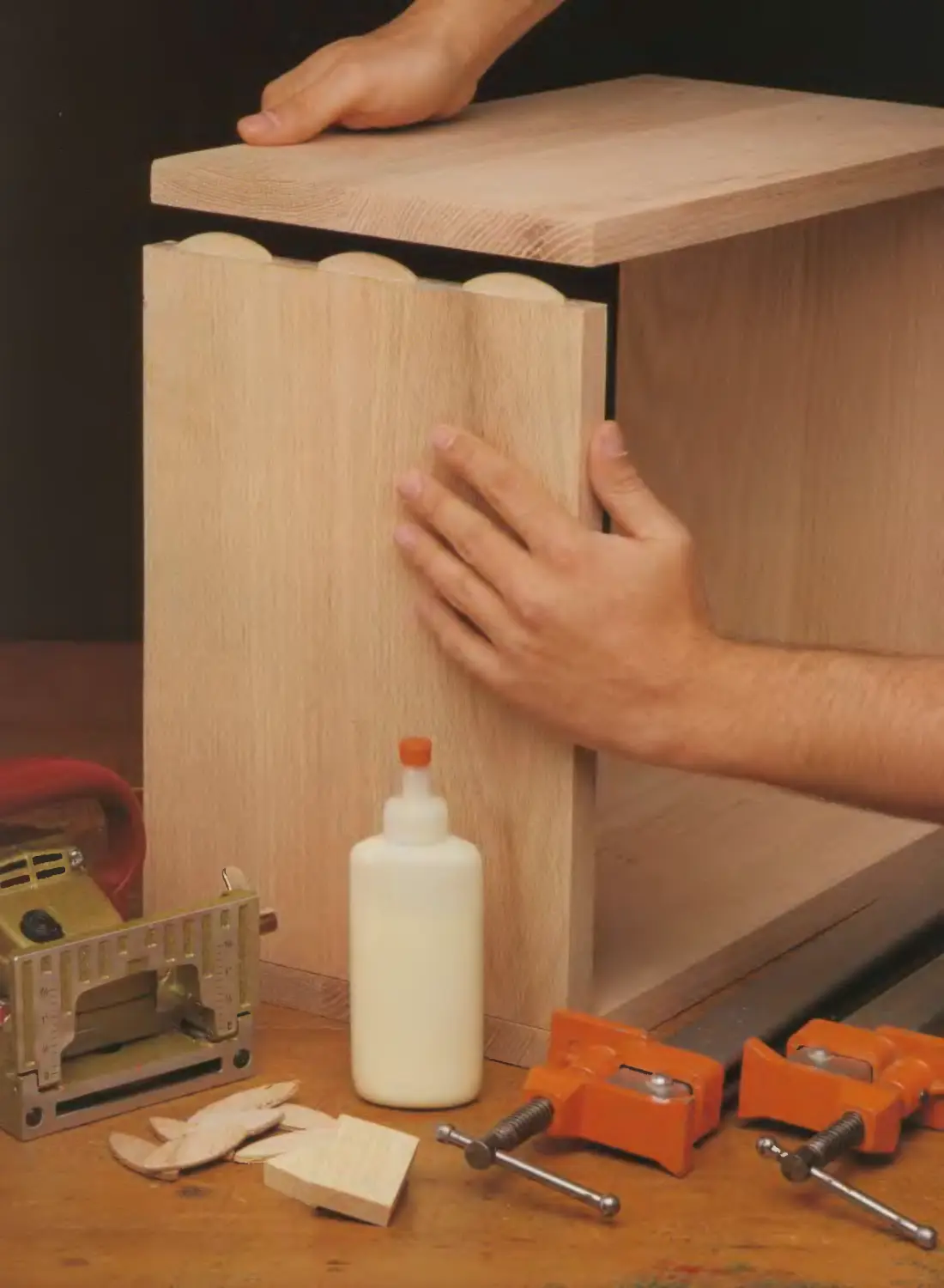
3 Inserting the biscuits
and gluing up the boards
Once all the slots have been cut, leave
the last board face down and stand the
others on edge with the slots facing up.
Apply a bead of glue along the board
edges and in the slots, inserting biscuits
as you go (right). (If you are working with
long boards it is better to wait until all the
adhesive has been applied before
inserting the biscuits to prevent them from
swelling before you have time to complete
glue up.) The bottle shown in the
illustration is specially designed to apply
adhesive evenly on the sides of the slots;
if you are using a standard glue bottle,
spread the glue with a small wooden
stick. Spread the adhesive evenly on the
board edges, then fit the boards together
quickly to prevent the biscuits from
swelling prematurely. Hold the boards
together with bar clamps as in edge gluing.
Set the plate joiner's depth of cut
to suit the biscuits you are using and
adjust the fence to center the slots in
the board edges. Laying the fence on top
of the stock, align the guideline on the
faceplate with a slot location mark on
the workpiece. Turn on the tool and
plunge the blade into the board to cut
the slot (left). Repeat the procedure at
the other slot location marks. With thin
stock, the tool's base plate may touch
the work surface, shifting the alignment
of the slots. To prevent this, position the
workpiece at the edge of the table so the
base plate does not rest on the tabletop.
33
BUTT JOINTS
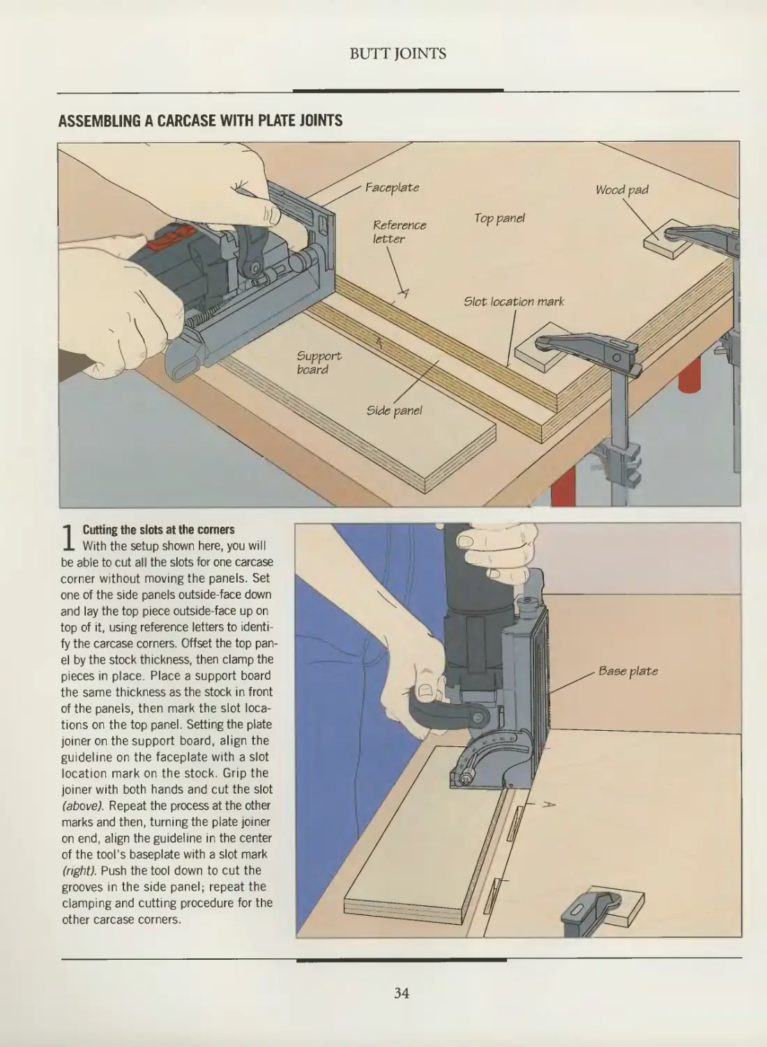
ASSEMBLING A CARCASE WITH PLATE JOINTS
1 Cutting the slots at the corners
With the setup shown here, you will
be able to cut all the slots for one carcase
corner without moving the panels. Set
one of the side panels outside-face down
and lay the top piece outside-face up on
top of it, using reference letters to
identify the carcase corners. Offset the top
panel by the stock thickness, then clamp the
pieces in place. Place a support board
the same thickness as the stock in front
of the panels, then mark the slot
locations on the top panel. Setting the plate
joiner on the support board, align the
guideline on the faceplate with a slot
location mark on the stock. Grip the
joiner with both hands and cut the slot
(above). Repeat the process at the other
marks and then, turning the plate joiner
on end, align the guideline in the center
of the tool's baseplate with a slot mark
(right). Push the tool down to cut the
grooves in the side panel; repeat the
clamping and cutting procedure for the
other carcase corners.
O
34
BUTT JOINTS
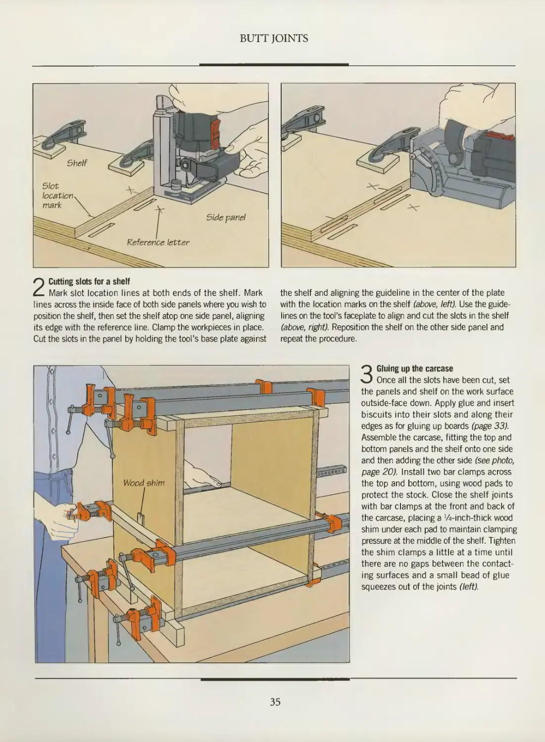
2 Cutting slots for a shelf
Mark slot location lines at both ends of the shelf. Mark
lines across the inside face of both side panels where you wish to
position the shelf, then set the shelf atop one side panel, aligning
its edge with the reference line. Clamp the workpieces in place.
Cut the slots in the panel by holding the tool's base plate against
the shelf and aligning the guideline in the center of the plate
with the location marks on the shelf (above, left). Use the
guidelines on the tool's faceplate to align and cut the slots in the shelf
(above, right). Reposition the shelf on the other side panel and
repeat the procedure.
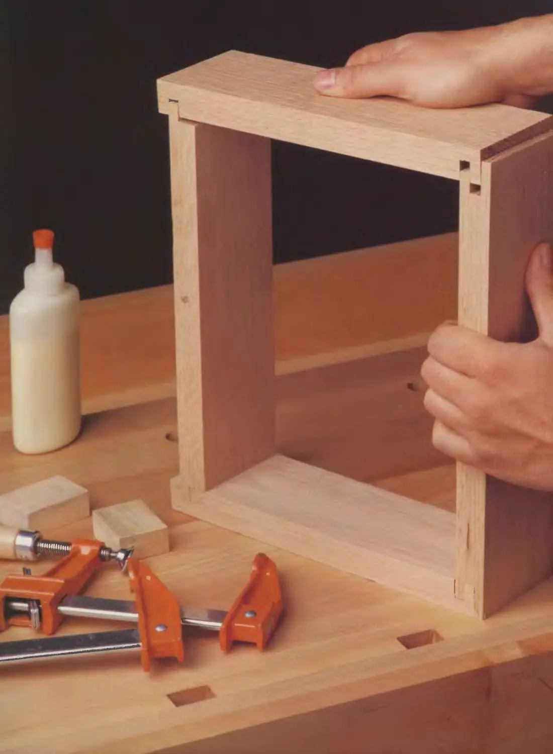
3 Gluing up the carcase
Once all the slots have been cut, set
the panels and shelf on the work surface
outside-face down. Apply glue and insert
biscuits into their slots and along their
edges as for gluing up boards (page 33).
Assemble the carcase, fitting the top and
bottom panels and the shelf onto one side
and then adding the other side (see photo,
page 20). Install two bar clamps across
the top and bottom, using wood pads to
protect the stock. Close the shelf joints
with bar clamps at the front and back of
the carcase, placing a Vi-inch-thick wood
shim under each pad to maintain clamping
pressure at the middle of the shelf. Tighten
the shim clamps a little at a time until
there are no gaps between the
contacting surfaces and a small bead of glue
squeezes out of the joints (left).
35
POCKET HOLES
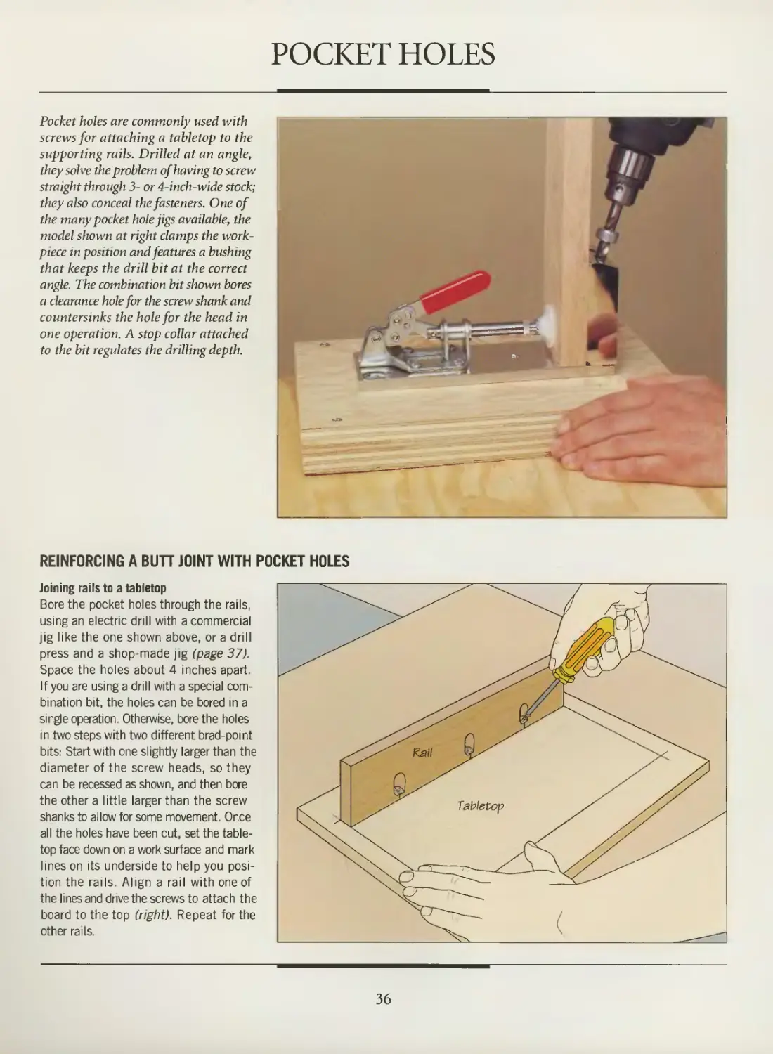
Pocket holes are commonly used with
screws for attaching a tabletop to the
supporting rails. Drilled at an angle,
they solve the problem of having to screw
straight through 3- or 4-inch-wide stock;
they also conceal the fasteners. One of
the many pocket hole jigs available, the
model shown at right clamps the work-
piece in position and features a bushing
that keeps the drill bit at the correct
angle. The combination bit shown bores
a clearance hole for the screw shank and
countersinks the hole for the head in
one operation. A stop collar attached
to the bit regulates the drilling depth.
REINFORCING A BUTT JOINT WITH POCKET HOLES
Joining rails to a tabletop
Bore the pocket holes through the rails,
using an electric drill with a commercial
jig like the one shown above, or a drill
press and a shop-made jig (page 37).
Space the holes about 4 inches apart.
If you are using a drill with a special
combination bit, the holes can be bored in a
single operation. Otherwise, bore the holes
in two steps with two different brad-point
bits: Start with one slightly larger than the
diameter of the screw heads, so they
can be recessed as shown, and then bore
the other a little larger than the screw
shanks to allow for some movement. Once
all the holes have been cut, set the table-
top face down on a work surface and mark
lines on its underside to help you
position the rails. Align a rail with one of
the lines and drive the screws to attach the
board to the top (right). Repeat for the
other rails.
36
BUTT JOINTS
BUILD IT YOURSELF
A POCKET HOLE JIG
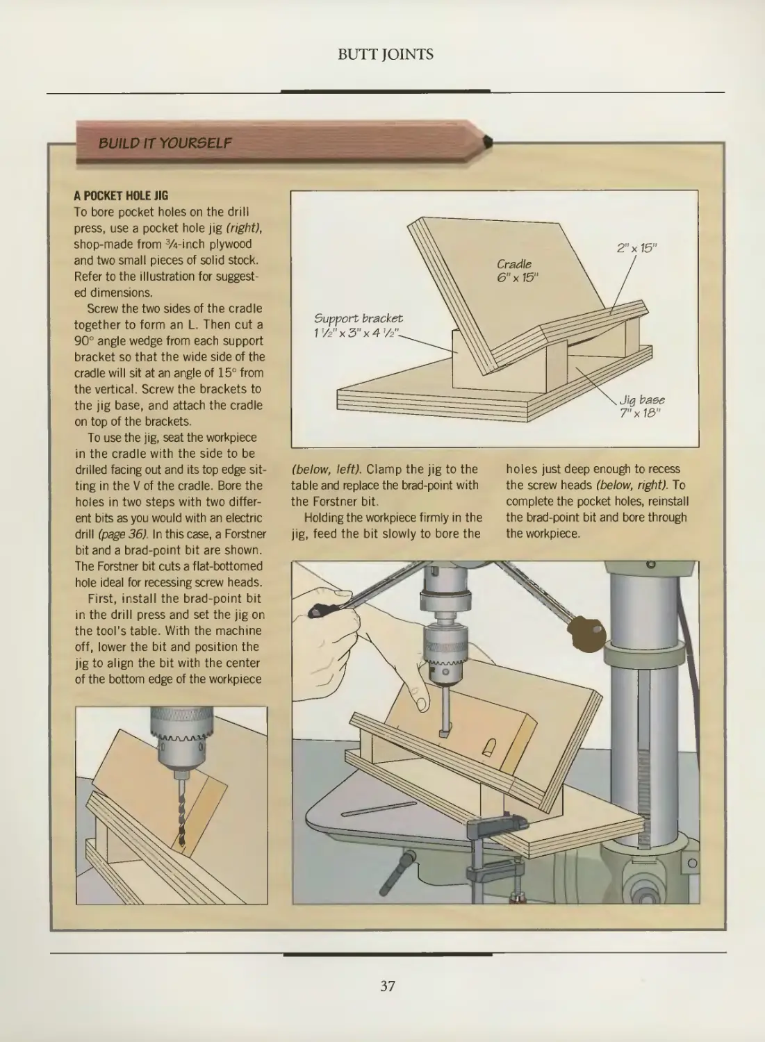
To bore pocket holes on the drill
press, use a pocket hole jig (right),
shop-made from %-inch plywood
and two small pieces of solid stock.
Refer to the illustration for
suggested dimensions.
Screw the two sides of the cradle
together to form an L. Then cut a
90° angle wedge from each support
bracket so that the wide side of the
cradle will sit at an angle of 15° from
the vertical. Screw the brackets to
the jig base, and attach the cradle
on top of the brackets.
To use the jig, seat the workpiece
in the cradle with the side to be
drilled facing out and its top edge
sitting in the V of the cradle. Bore the
holes in two steps with two
different bits as you would with an electric
drill (page 36). In this case, a Forstner
bit and a brad-point bit are shown.
The Forstner bit cuts a flat-bottomed
hole ideal for recessing screw heads.
First, install the brad-point bit
in the drill press and set the jig on
the tool's table. With the machine
off, lower the bit and position the
jig to align the bit with the center
of the bottom edge of the workpiece
Support bracket
V/2"x5"x4'/2"-.
Jig base
7"x13"
(below, left). Clamp the jig to the
table and replace the brad-point with
the Forstner bit.
Holding the workpiece firmly in the
jig, feed the bit slowly to bore the
holes just deep enough to recess
the screw heads (below, right). To
complete the pocket holes, reinstall
the brad-point bit and bore through
the workpiece.
37
SPLINE JOINTS
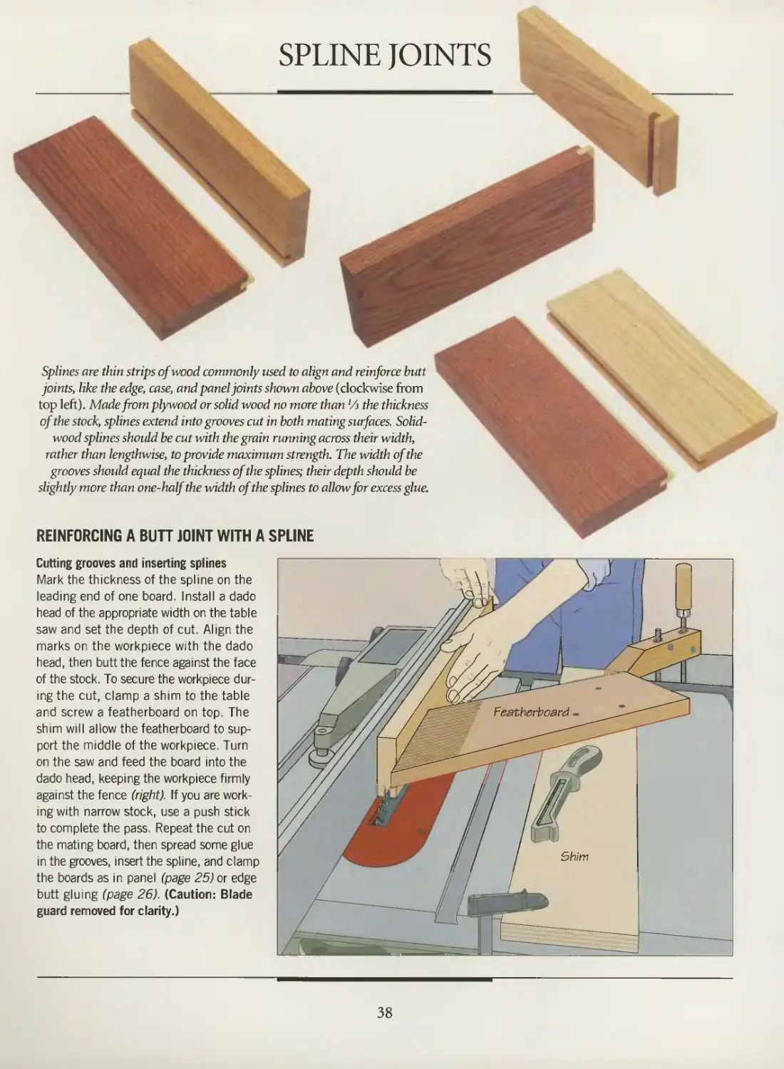
Splines are thin strips of wood commonly used to align and reinforce butt
joints, like the edge, case, and panel joints shown above (clockwise from
top left). Made from plywood or solid wood no more than 'A the thickness
of the stock, splines extend into grooves cut in both mating surfaces. Solid-
wood splines should be cut with the grain running across their width,
rather than lengthwise, to provide maximum strength. The width of the
grooves should equal the thickness of the splines; their depth should be
slightly more than one-half the width of the splines to allow for excess glue.
REINFORCING A BUTT JOINT WITH A SPLINE
Cutting grooves and inserting splines
Mark the thickness of the spline on the
leading end of one board. Install a dado
head of the appropriate width on the table
saw and set the depth of cut. Align the
marks on the workpiece with the dado
head, then butt the fence against the face
of the stock. To secure the workpiece
during the cut, clamp a shim to the table
and screw a featherboard on top. The
shim will allow the featherboard to
support the middle of the workpiece. Turn
on the saw and feed the board into the
dado head, keeping the workpiece firmly
against the fence (right). If you are
working with narrow stock, use a push stick
to complete the pass. Repeat the cut on
the mating board, then spread some glue
in the grooves, insert the spline, and clamp
the boards as in panel (page 25) or edge
butt gluing (page 26). (Caution: Blade
guard removed for clarity.)
38
BUTTERFLY KEY JOINTS
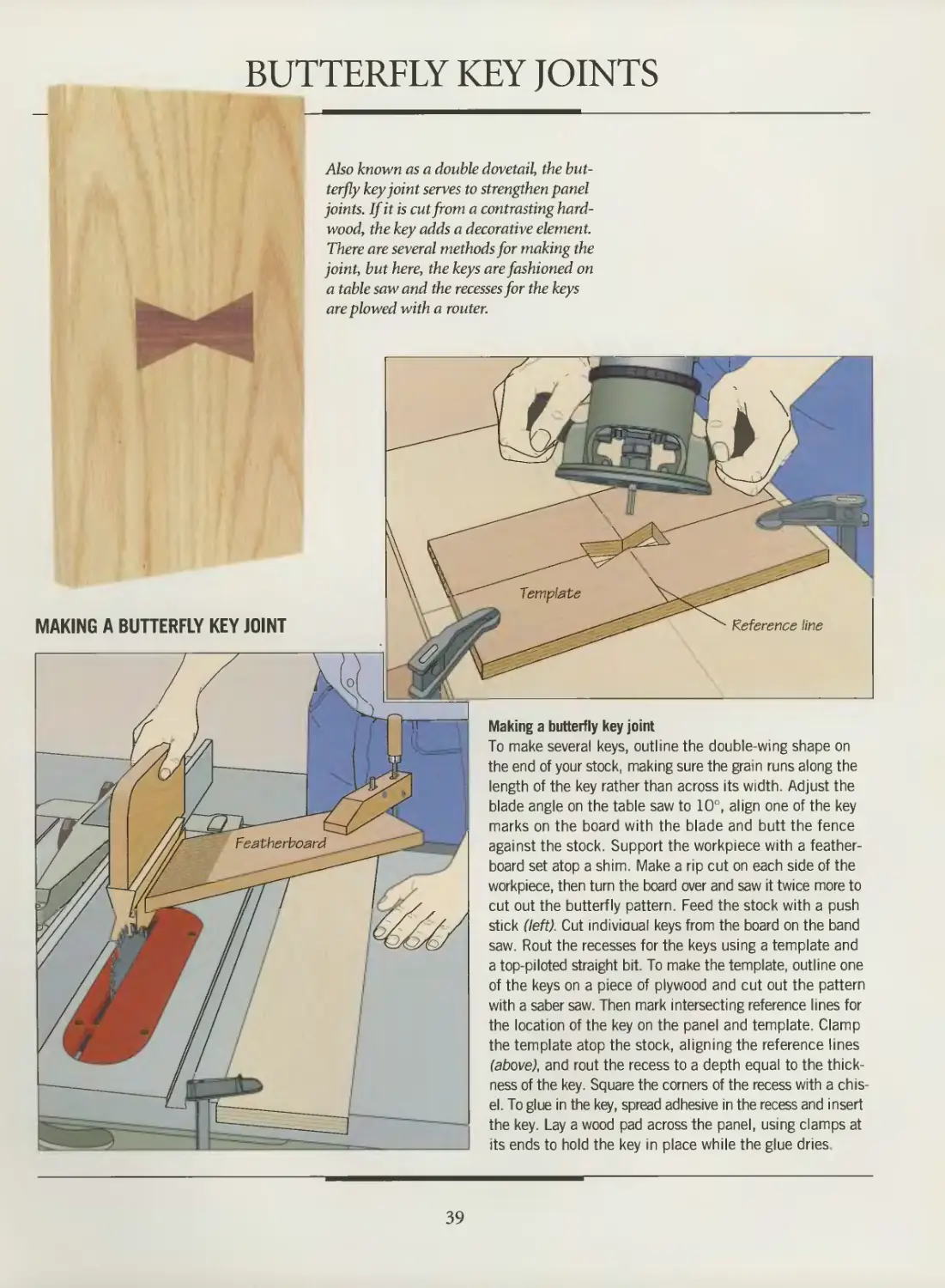
Also known as a double dovetail, the
butterfly key joint serves to strengthen panel
joints. If it is cut from a contrasting
hardwood, the key adds a decorative element.
There are several methods for making the
joint, but here, the keys are fashioned on
a table saw and the recesses for the keys
are plowed with a router.
MAKING A BUTTERFLY KEY JOINT
Making a butterfly key joint
To make several keys, outline the double-wing shape on
the end of your stock, making sure the grain runs along the
length of the key rather than across its width. Adjust the
blade angle on the table saw to 10°, align one of the key
marks on the board with the blade and butt the fence
against the stock. Support the workpiece with a feather-
board set atop a shim. Make a rip cut on each side of the
workpiece, then turn the board over and saw it twice more to
cut out the butterfly pattern. Feed the stock with a push
stick (left). Cut individual keys from the board on the band
saw. Rout the recesses for the keys using a template and
a top-piloted straight bit. To make the template, outline one
of the keys on a piece of plywood and cut out the pattern
with a saber saw. Then mark intersecting reference lines for
the location of the key on the panel and template. Clamp
the template atop the stock, aligning the reference lines
(above), and rout the recess to a depth equal to the
thickness of the key. Square the corners of the recess with a
chisel. To glue in the key, spread adhesive in the recess and insert
the key. Lay a wood pad across the panel, using clamps at
its ends to hold the key in place while the glue dries
39
MITER JOINTS
ii
Miters are among
the commonest of
joints. Builders use them
when trimming around
windows and doors;
cabinetmakers usually miter
carcase corners and picture
frames because the miter
conceals end grain.
Although frames and boxes
usually demand 90°
corners, a miter joint may be
any angle. All are equally
simple to make, so long as
the rules of mitering are
followed: Each
intersecting end must be cut
exactly at one-half the total
angle of the corner. Thus, the two pieces forming a 90° angle are
cut at 45° each; those forming a 45° angle are cut at 22 Vi°.
There are two types of miter joints: face miters and edge
miters. Face miters {page 45) are cut across the faces of the
pieces, and are often used to connect stiles and rails in frame-
and-panel construction or join the members of a picture frame.
Edge miters (page 51) can be made along the edges of the work-
pieces or across the end grain—also known as end miters or
bevel miters. Because edge miters conceal the mating surfaces,
they are used extensively in plywood carcase construction.
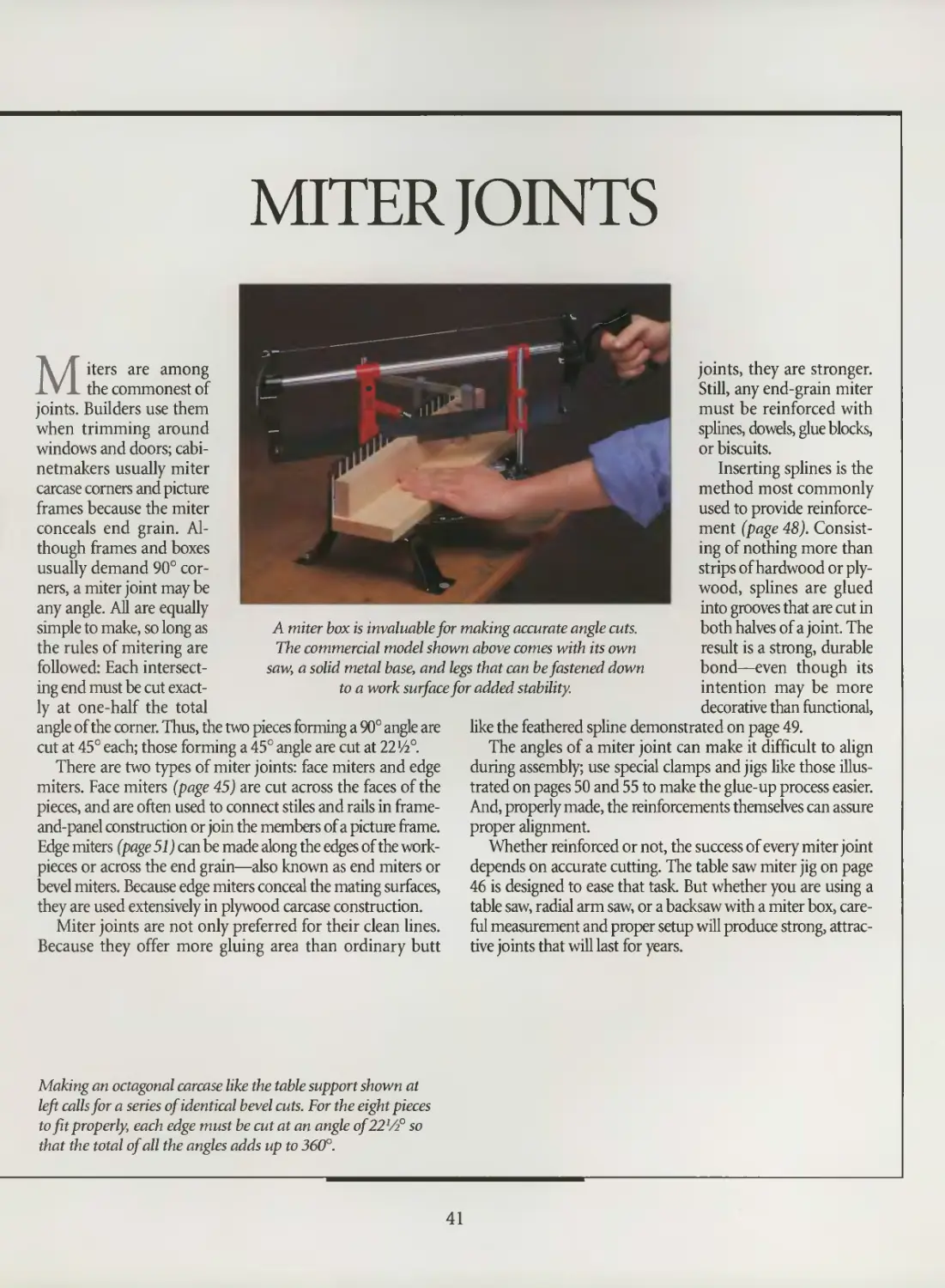
Miter joints are not only preferred for their clean lines.
Because they offer more gluing area than ordinary butt
A miter box is invaluable for making accurate angle cuts.
The commercial model shown above comes with its own
saw, a solid metal base, and legs that can be fastened down
to a work surface for added stability.
joints, they are stronger.
Still, any end-grain miter
must be reinforced with
splines, dowels, glue blocks,
or biscuits.
Inserting splines is the
method most commonly
used to provide
reinforcement (page 48).
Consisting of nothing more than
strips of hardwood or
plywood, splines are glued
into grooves that are cut in
both halves of a joint. The
result is a strong, durable
bond—even though its
intention may be more
decorative than functional,
like the feathered spline demonstrated on page 49.
The angles of a miter joint can make it difficult to align
during assembly; use special clamps and jigs like those
illustrated on pages 50 and 55 to make the glue-up process easier.
And, properly made, the reinforcements themselves can assure
proper alignment.
Whether reinforced or not, the success of every miter joint
depends on accurate cutting. The table saw miter jig on page
46 is designed to ease that task. But whether you are using a
table saw, radial arm saw, or a backsaw with a miter box,
careful measurement and proper setup will produce strong,
attractive joints that will last for years.
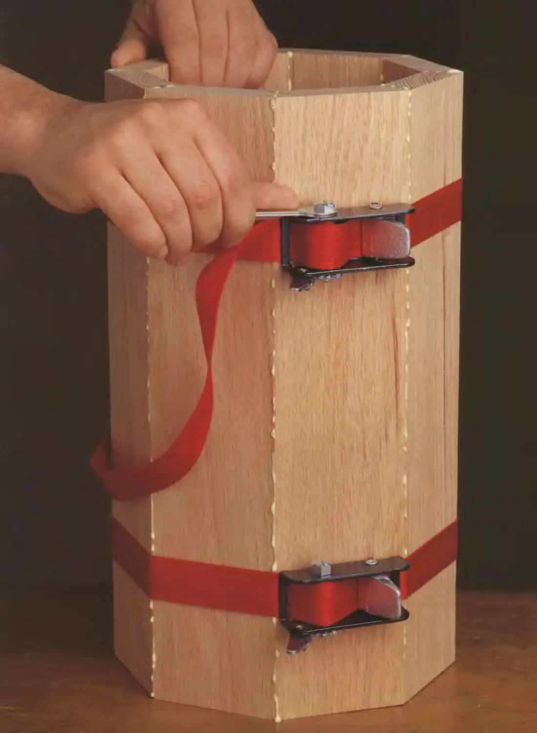
Making an octagonal carcase like the table support shown at
left calls for a series of identical bevel cuts. For the eight pieces
to fit properly, each edge must be cut at an angle of22Vz° so
that the total of all the angles adds up to 360°.
41
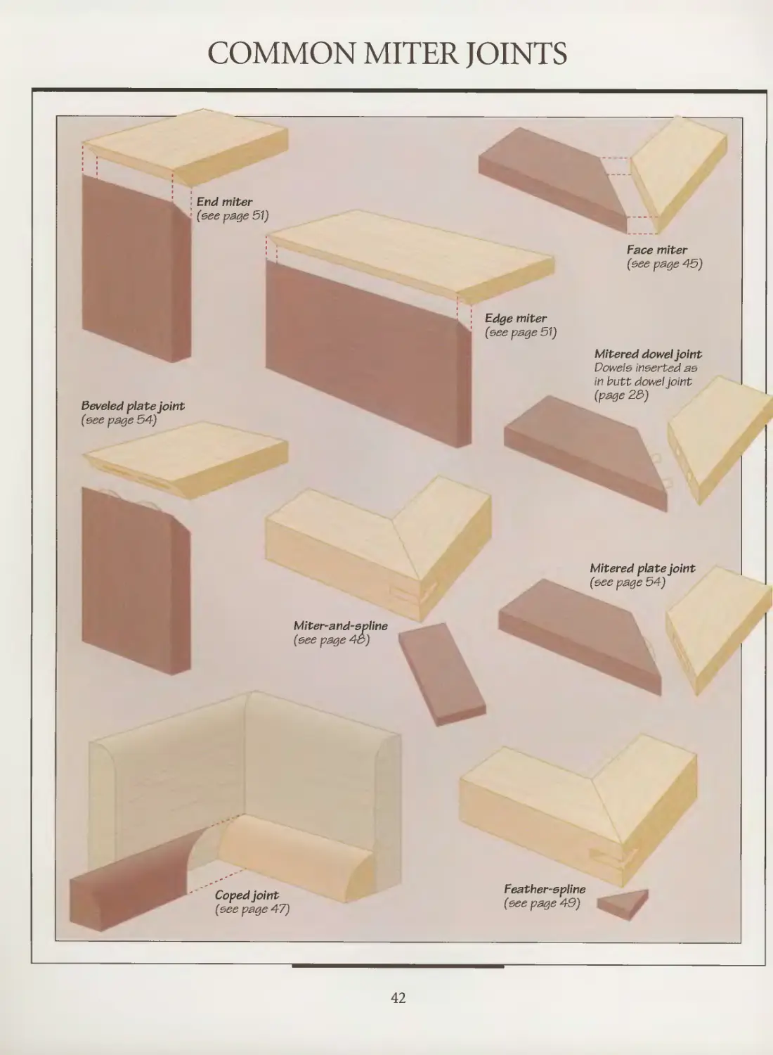
COMMON MITER JOINTS
j,
! End miter
'• (see page 51)
■
Beveled plate joint
(see page 54)
Miter-and-epline
(see page 43)
Coped joint
(see page 47)
-
Face miter
(see page 45)
' : Edge miter
(see page 51)
Mitered dowel joint
Dowels inserted as
in butt dowel pint
(page 23)
Mitered plate joint
(see page 54)
Feather-spline
(see page 49)
42
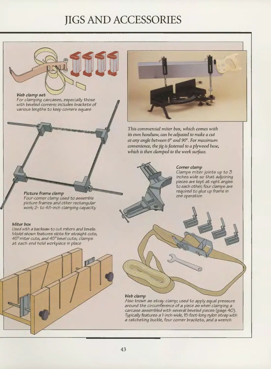
JIGS AND ACCESSORIES
Web clamp set
For clamping carcases, especially those
with beveled corners; includes brackets of
various lengths to keep corners square
A
Picture frame clamp
Four-corner clamp used to assemble
picture frames and other rectangular
work; 2- to 43-inch clamping capacity
Miter box
Used with a backsaw to cut miters and bevels.
Model shown features slots for straight cuts,
45° miter cuts, and 45° bevel cuts; clamps
at each end hold workpiece in place
This commercial miter box, which comes with
its own handsaw, can be adjusted to make a cut
at any angle between 0° and 90°. For maximum
convenience, the jig is fastened to a plywood base,
which is then clamped to the work surface.
Corner clamp
Clamps miter joints up to 3
inches wide so that adjoining
pieces are kept at right angles
to each other, four clamps are
required to glue up frame in
one operation
Web clamp
Also known as strap clamp; used to apply equal pressure
around the circumference of a piece as when clamping a
carcase assembled with several beveled pieces (page 40).
Typically features a 1-inch-wide, 15-foot-long nylon strap with
a ratcheting buckle, four corner brackets, and a wrench
43
MAKING MITER JOINTS
2.75 HP-"
10"
«,"M ™-
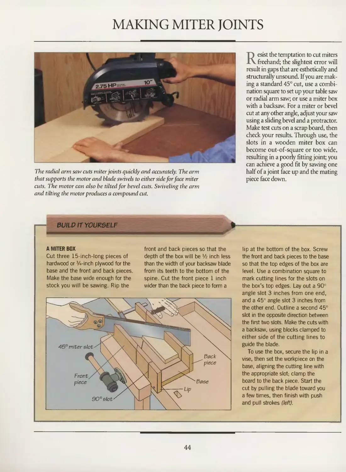
The radial arm saw cuts miter joints quickly and accurately. The arm
that supports the motor and blade swivels to either side for face miter
cuts. The motor can also be tilted for bevel cuts. Swiveling the arm
and tilting the motor produces a compound cut.
Resist the temptation to cut miters
freehand; the slightest error will
result in gaps that are esthetically and
structurally unsound. If you are
making a standard 45° cut, use a
combination square to set up your table saw
or radial arm saw; or use a miter box
with a backsaw. For a miter or bevel
cut at any other angle, adjust your saw
using a sliding bevel and a protractor.
Make test cuts on a scrap board, then
check your results. Through use, the
slots in a wooden miter box can
become out-of-square or too wide,
resulting in a poorly fitting joint; you
can achieve a good fit by sawing one
half of a joint face up and the mating
piece face down.
&UILD IT YOURSELF
A MITER BOX
Cut three 15-inch-long pieces of
hardwood or 3/4-inch plywood for the
base and the front and back pieces.
Make the base wide enough for the
stock you will be sawing. Rip the
front and back pieces so that the
depth of the box will be Vz inch less
than the width of your backsaw blade
from its teeth to the bottom of the
spine. Cut the front piece 1 inch
wider than the back piece to form a
Front
piece
90°5\ot'
lip at the bottom of the box. Screw
the front and back pieces to the base
so that the top edges of the box are
level. Use a combination square to
mark cutting lines for the slots on
the box's top edges. Lay out a 90°
angle slot 3 inches from one end,
and a 45° angle slot 3 inches from
the other end. Outline a second 45°
slot in the opposite direction between
the first two slots. Make the cuts with
a backsaw, using blocks clamped to
either side of the cutting lines to
guide the blade.
To use the box, secure the lip in a
vise, then set the workpiece on the
base, aligning the cutting line with
the appropriate slot; clamp the
board to the back piece. Start the
cut by pulling the blade toward you
a few times, then finish with push
and pull strokes (left).
44
FACE MITERS
MAKING A FACE MITER JOINT
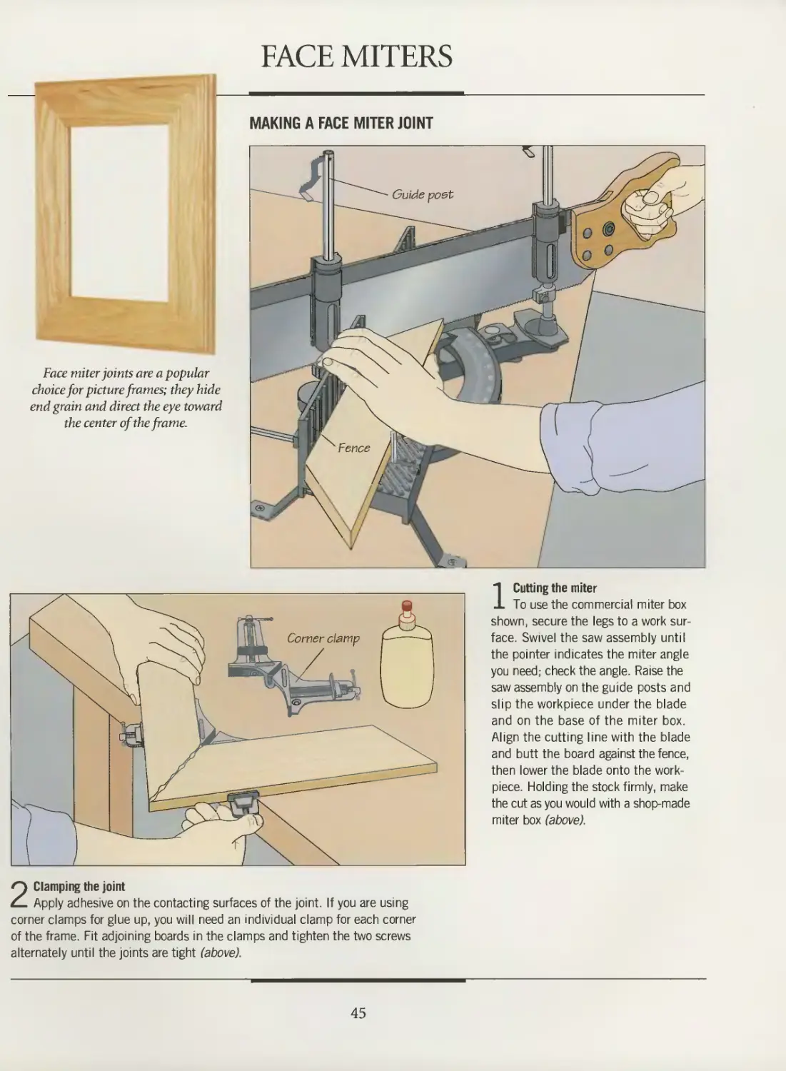
Face miter joints are a popular
choice for picture frames; they hide
end grain and direct the eye toward
the center of the frame.
2 Clamping the joint
Apply adhesive on the contacting surfaces of the joint. If you are using
corner clamps for glue up, you will need an individual clamp for each corner
of the frame. Fit adjoining boards in the clamps and tighten the two screws
alternately until the joints are tight (above).
1 Cutting the miter
To use the commercial miter box
shown, secure the legs to a work
surface. Swivel the saw assembly until
the pointer indicates the miter angle
you need; check the angle. Raise the
saw assembly on the guide posts and
slip the workpiece under the blade
and on the base of the miter box.
Align the cutting line with the blade
and butt the board against the fence,
then lower the blade onto the work-
piece. Holding the stock firmly, make
the cut as you would with a shop-made
miter box (above).
45
MITER JOINTS
3UILD IT YOURSELF
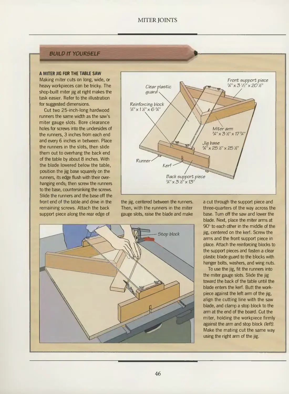
A MITER JIG FOR THE TABLE SAW
Making miter cuts on long, wide, or
heavy workpieces can be tricky. The
shop-built miter jig at right makes the
task easier. Refer to the illustration
for suggested dimensions.
Cut two 25-inch-long hardwood
runners the same width as the saw's
miter gauge slots. Bore clearance
holes for screws into the undersides of
the runners, 3 inches from each end
and every 6 inches in between. Place
the runners in the slots, then slide
them out to overhang the back end
of the table by about 8 inches. With
the blade lowered below the table,
position the jig base squarely on the
runners, its edge flush with their
overhanging ends; then screw the runners
to the base, countersinking the screws.
Slide the runners and the base off the
front end of the table and drive in the
remaining screws. Attach the back
support piece along the rear edge of
Clear plastic
guard v
Reinforcing block /\
%"xVA"x6%" / X
^<\J ^~~^
Runner' ^^~
Kerf-
3ack
3/"x
\ Vv
CJ
Jig
support piece
3'/2nx13"
Front support piece
lfc=^^ 3A"x3Vz"x20Yz"
Miter arm 1
%"x3'/z"x17s/*"l
base I
x25'A"x25'/z" I
g
the jig, centered between the runners.
Then, with the runners in the miter
gauge slots, raise the blade and make
a cut through the support piece and
three-quarters of the way across the
base. Turn off the saw and lower the
blade. Next, place the miter arms at
90° to each other in the middle of the
jig, centered on the kerf. Screw the
arms and the front support piece in
place. Attach the reinforcing blocks to
the support pieces and fasten a clear
plastic blade guard to the blocks with
hanger bolts, washers, and wing nuts.
To use the jig, fit the runners into
the miter gauge slots. Slide the jig
toward the back of the table until the
blade enters the kerf. Butt the work-
piece against the left arm of the jig,
align the cutting line with the saw
blade, and clamp a stop block to the
arm at the end of the board. Cut the
miter, holding the workpiece firmly
against the arm and stop block (left).
Make the mating cut the same way
using the right arm of the jig.
46
COPED JOINTS
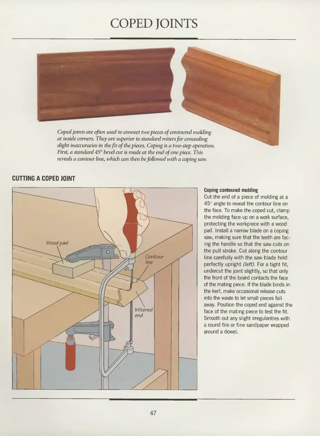
Coped joints are often used to connect two pieces of contoured molding
at inside corners. They are superior to standard miters for concealing
slight inaccuracies in the fit of the pieces. Coping is a two-step operation.
First, a standard 45° bevel cut is made at the end of one piece. This
reveals a contour line, which can then be followed with a coping saw.
CUTTING A COPED JOINT
Coping contoured molding
Cut the end of a piece of molding at a
45° angle to reveal the contour line on
the face. To make the coped cut, clamp
the molding face-up on a work surface,
protecting the workpiece with a wood
pad. Install a narrow blade on a coping
saw, making sure that the teeth are
facing the handle so that the saw cuts on
the pull stroke. Cut along the contour
line carefully with the saw blade held
perfectly upright (left). For a tight fit,
undercut the joint slightly, so that only
the front of the board contacts the face
of the mating piece. If the blade binds in
the kerf, make occasional release cuts
into the waste to let small pieces fall
away. Position the coped end against the
face of the mating piece to test the fit.
Smooth out any slight irregularities with
a round file or fine sandpaper wrapped
around a dowel.
47
MITER-AND-SPLINE JOINTS
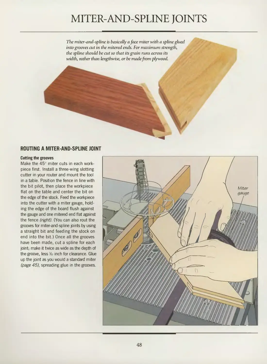
The miter-and-spline is basically a face miter with a spline glued
into grooves cut in the mitered ends. For maximum strength,
the spline should be cut so that its grain runs across its
width, rather than lengthwise, or be made from plywood.
ROUTING A MITER-AND-SPLINE JOINT
Cutting the grooves
Make the 45° miter cuts in each work-
piece first. Install a three-wing slotting
cutter in your router and mount the tool
in a table. Position the fence in line with
the bit pilot, then place the workpiece
flat on the table and center the bit on
the edge of the stock. Feed the workpiece
into the cutter with a miter gauge,
holding the edge of the board flush against
the gauge and one mitered end flat against
the fence (right). (You can also rout the
grooves for miter-and-spline joints by using
a straight bit and feeding the stock on
end into the bit.) Once all the grooves
have been made, cut a spline for each
joint; make it twice as wide as the depth of
the groove, less & inch for clearance. Glue
up the joint as you would a standard miter
(page 45), spreading glue in the grooves.
48
FEATHER-SPLINE JOINTS
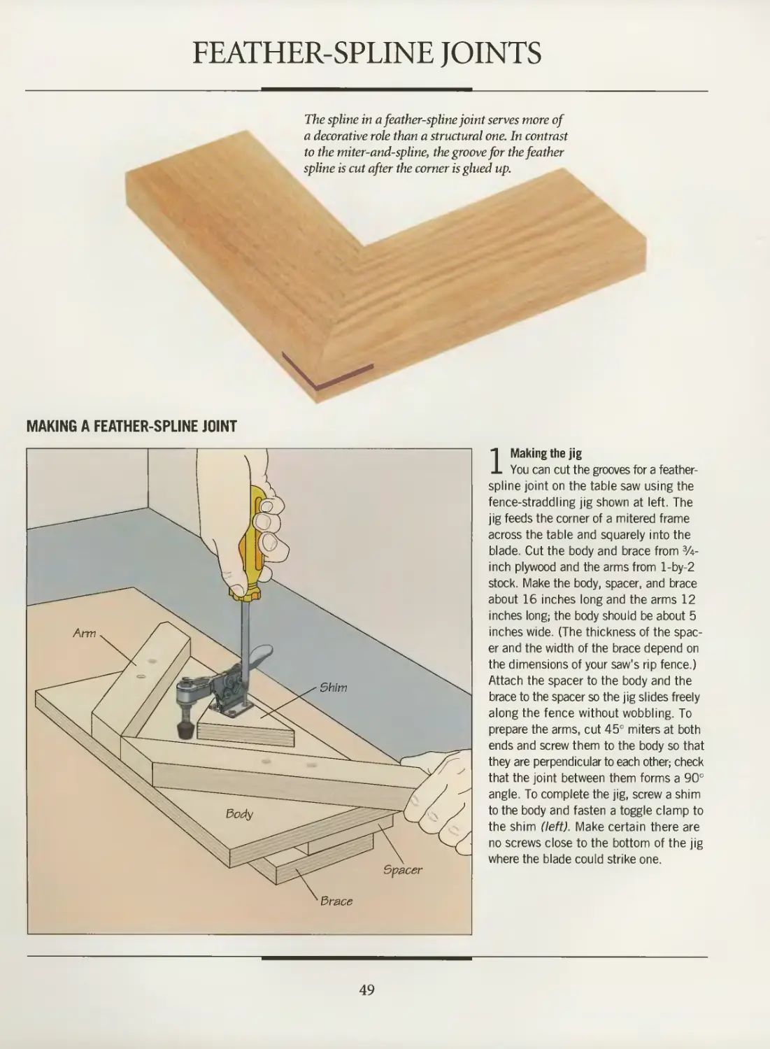
The spline in a feather-spline joint serves more of
a decorative role than a structural one. In contrast
to the miter-and-spline, the groove for the feather
spline is cut after the corner is glued up.
MAKING A FEATHER-SPLINE JOINT
1 Making the jig
You can cut the grooves for a feather-
spline joint on the table saw using the
fence-straddling jig shown at left. The
jig feeds the corner of a mitered frame
across the table and squarely into the
blade. Cut the body and brace from 3A-
inch plywood and the arms from l-by-2
stock. Make the body, spacer, and brace
about 16 inches long and the arms 12
inches long; the body should be about 5
inches wide. (The thickness of the
spacer and the width of the brace depend on
the dimensions of your saw's rip fence.)
Attach the spacer to the body and the
brace to the spacer so the jig slides freely
along the fence without wobbling. To
prepare the arms, cut 45° miters at both
ends and screw them to the body so that
they are perpendicular to each other; check
that the joint between them forms a 90°
angle. To complete the jig, screw a shim
to the body and fasten a toggle clamp to
the shim (left). Make certain there are
no screws close to the bottom of the jig
where the blade could strike one.
49
MITER JOINTS
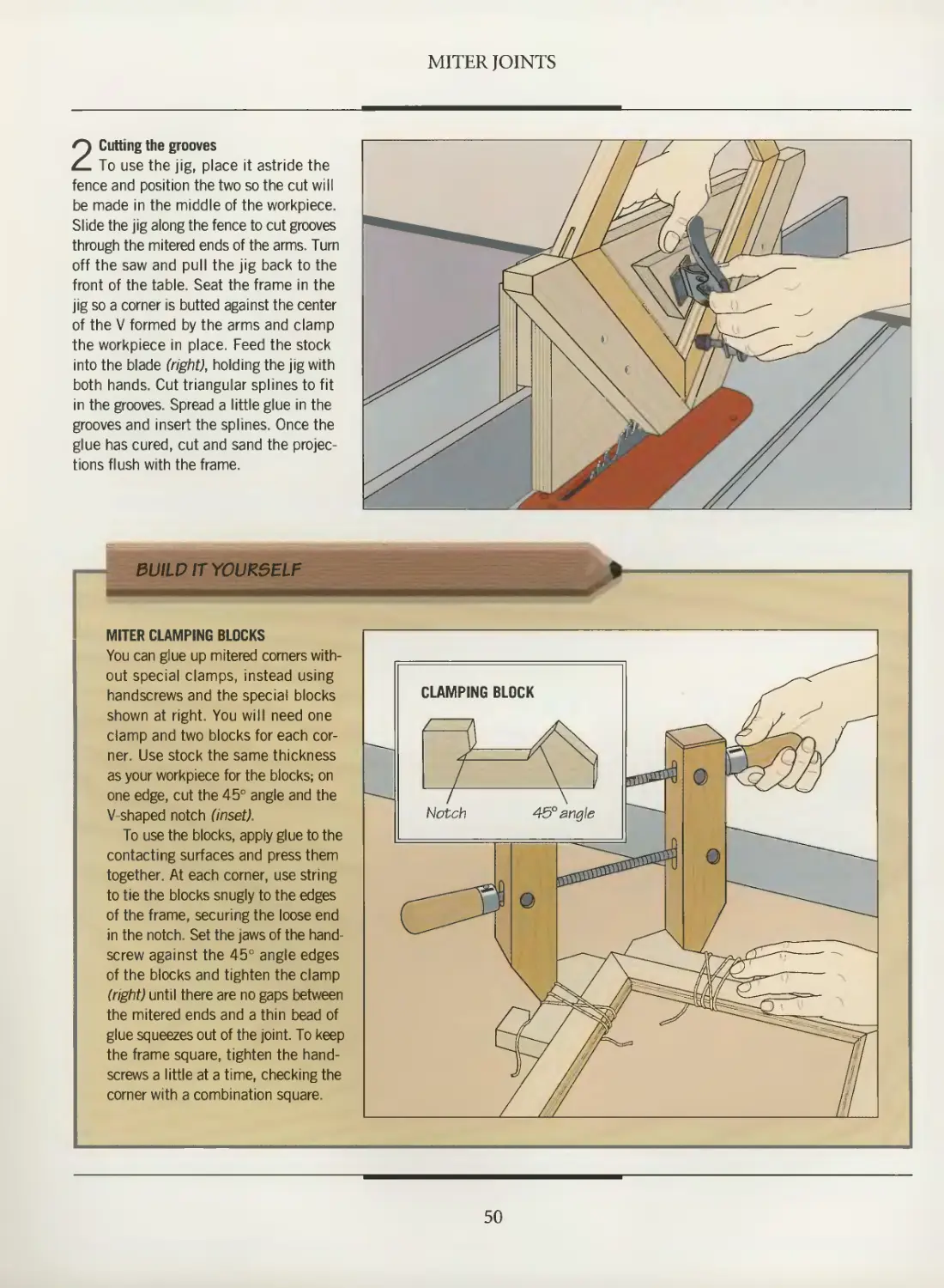
2 Cutting the grooves
To use the jig, place it astride the
fence and position the two so the cut will
be made in the middle of the workpiece.
Slide the jig along the fence to cut grooves
through the mitered ends of the arms. Turn
off the saw and pull the jig back to the
front of the table. Seat the frame in the
jig so a corner is butted against the center
of the V formed by the arms and clamp
the workpiece in place. Feed the stock
into the blade (right), holding the jig with
both hands. Cut triangular splines to fit
in the grooves. Spread a little glue in the
grooves and insert the splines. Once the
glue has cured, cut and sand the
projections flush with the frame.
BUILD IT YOURSELF
MITER CLAMPING BLOCKS
You can glue up mitered corners
without special clamps, instead using
handscrews and the special blocks
shown at right. You will need one
clamp and two blocks for each
corner. Use stock the same thickness
as your workpiece for the blocks; on
one edge, cut the 45° angle and the
V-shaped notch (inset).
To use the blocks, apply glue to the
contacting surfaces and press them
together. At each corner, use string
to tie the blocks snugly to the edges
of the frame, securing the loose end
in the notch. Set the jaws of the hand-
screw against the 45° angle edges
of the blocks and tighten the clamp
(right) until there are no gaps between
the mitered ends and a thin bead of
glue squeezes out of the joint. To keep
the frame square, tighten the hand-
screws a little at a time, checking the
corner with a combination square.
CLAMPING BLOCK
/ZZ.
50
EDGE MITER JOINTS
Edge miter joints feature matching bevel cuts in
the mating pieces, either across the workpiece
end (below) or along the edge (far right). The
edge miter is a popular joint for carcase corners
because it conceals end grain. Both examples
shown are reinforced with splines.
CUTTING AN EDGE MITER JOINT
Making the bevel cut
To cut a standard edge miter joint on the
table saw, set the blade angle at 45° and
position the rip fence for the width of cut,
ensuring that the blade teeth are
pointing away from the fence. Raise the
splitter to keep the kerf open while the cut is
being made, which will prevent binding
and kickback. Feed the workpiece into
the blade, using a push stick to keep the
board flat on the saw table (left). (Caution:
Blade guard removed for clarity.) To cut the
bevel across the end of a board, move the
fence aside and feed the workpiece into
the blade with the miter gauge. Once all the
bevel cuts have been made, reinforce the
joints with splines (page 52), glue blocks
(page 53), or biscuits (page 54).
51
MITER JOINTS
REINFORCING EDGE MITERS WITH SPLINES
Cutting the grooves on a table saw
Install a dado blade, adjusting it to cut a groove
the same width as the thickness of your splines—
often lA inch. Set the blade angle at 45° and make
the cutting depth slightly more than one-half the
width of the splines—often 3A inch. Align the
mitered edge of the workpiece with the dado head
so the groove will be closer to the inside corner
of the joint to ensure that the cut will not
penetrate the top face of the board. Butt the rip fence
against the workpiece. With the saw unplugged,
rotate the dado head by hand to make certain that
it clears the fence. If not, attach an auxiliary wood
fence, reposition the rip fence accordingly, and
make a relief cut. Cut the groove as you would a
bevel, using a push stick to apply pressure on the table
(above). To cut a groove across beveled end grain,
set up the dado head and fence as you would for
a cut along the edge. Then feed the workpiece
with the miter gauge (right), keeping the board
flush against the gauge and the fence. Fashion
splines and glue up the joint as you would a miter-
and-spline joint (page 48).
52
MITER JOINTS
Routing grooves
You can also cut the grooves for a spline-
reinforced edge miter using a router fitted
with a commercial edge guide. Secure the
mating pieces in a vise, beveled surfaces
facing out, making sure that their ends and
edges are flush. Install a straight bit as thick
as your splines and set the cutting depth at
slightly more than one-half the spline width.
Attach an edge guide on the router and
align the bit over one of the beveled edges
so the groove will be closer to the inside
corner of the joint. Then butt the guide
fence against the other beveled edge and
fix it in place. Rout the groove by riding
the base plate flat on the edge to be cut
while pressing the guide fence against the
mating piece. Turn the router around and
repeat the cut in the other piece (right).
REINFORCING EDGE MITERS WITH GLUE BLOCKS
Making and attaching glue blocks
Use 1-by-l stock as long as the
joint. Before assembling the carcase,
screw a block to one piece, aligning
the edge of the block with the inside
edge of the bevel. Spread glue on the
beveled surfaces, press the boards
together, then attach the block to the
other piece (left). Repeat with the
remaining corners of the carcase, using
bar clamps if necessary to hold the
assembly square.
53
MITERED PLATE JOINTS
Plate joinery is a simple way to
fasten boards or panels together,
whether the joining surfaces are
mitered or beveled. Once glue is
added, the biscuits swell, creating
a strong, durable joint.
JOINING BEVELED CORNERS WITH BISCUITS
1 Setting up the plate joiner
Place two adjacent panels on a work surface, inside-face
up, and mark slot locations on both pieces; also add reference
letters for ease of assembly. Start about 2 inches in from the
edges, spacing the lines at 4- to 8-inch intervals. Repeat the
procedure at the other three corners of the carcase. Adjust the
plate joiner's fence to the proper angle, following the
manufacturer's directions. For the model shown, the panel is clamped
to the work surface with one beveled end projecting off the
edge. Rest the tool's faceplate against the end, loosen the
fence locking lever and swivel the fence downward against the
face of the panel. Lock it in place while the faceplate is flush
against the bevel (above).
54
MITER JOINTS
3 Gluing up the carcase
Once all the slots have been cut, set the panels on the work beveled edges from slipping out of alignment as the adhesive
surface inside-face up. Squeeze glue into the slots and along is drying, secure the carcase with web clamps. The type shown
the edges of the panels, inserting biscuits as you go. Assemble here uses corner brackets to distribute pressure evenly along
the carcase, working quickly to prevent the biscuits from swelling the length of each joint. Wrap straps around the unit and tighten
before you have had time to complete the glue up. To keep the them with the buckles before locking them in place (above).
55
"•MMlllll
LAP, RABBET, GROOVE,
AND DADO JOINTS
The three dozen joints featured
in this chapter are used in
applications as varied as building
cabinet carcases and piecing
together frames and doors. This is a
versatile family of joints, with the added
virtue of being strong and simple.
In addition, almost all of these
joints can be made in several ways,
using either hand or power tools.
For example, a dado can be cut with
a router, a table saw, or a radial arm
saw; it can be started with a hand
saw and finished with a chisel.
However, the typical woodworker
will probably produce better-fitting
joints in less time using power tools.
Perhaps the simplest of all joints
are lap joints, the first covered in
this chapter. As the name suggests,
a lap joint is formed by laying one
board over another and fastening the two at the required angle.
The simple lap is weak and unattractive, but the joint can be
rendered strong and elegant by first cutting a dado in one or
both boards so that their faces lie flush with each other. The lap
provides good long-grain surface contact for gluing, and
additional reinforcement is seldom required unless the joint will
be subjected to tensional stress.
Shelves are often fixed to carcase sides
with dado joints. Here, a router plows a through
dado. An edge guide helps keep the cut parallel
to the end of the panel.
Rabbet joints, the second group
described, are most frequently used
to join carcase and drawer corners,
and less often for edge joining.
Some variants, like the stopped
rabbet (page 75) and the mitered
rabbet (page 76), are intended to
conceal the end grain of the pieces.
Remember, however, that any
corner joinery that mates end grain
requires reinforcement in the form
of dowels, screws, or glue blocks.
A third group, tongue-and-groove
joints, are most often used for edge-
to-edge joinery. They may be glued,
but sometimes are assembled dry so
that the wood can move as
humidity alters the moisture content
Dado joints, illustrated at left and
on the opposite page, are simple and
useful; they are the method of
choice for installing shelves or assembling drawers. A
self-locking joint can be made by adding a dovetail.
A catalog of lap, rabbet, groove, and dado joints begins on
page 58; a section on techniques for making them begins on
page 64. Experiment with the methods shown, or alter them
to suit your own skills and the tools you own. The results
should be useful and enlightening.
The dado joint is a popular choice for assembling
drawers. The dado-and-rabbet works well for
joining the back to the sides, while the drawer front
demands a stronger joint such as a double dado.
57
LAP JOINTS
The lap, rabbet, tongue-and-groove,
and dado joints illustrated on the
following pages appear quite different,
but all are linked by a common feature:
Each owes its strength to a channel of
some sort in one piece that accepts a
mating piece. Some joints, like the
dovetailed half-lap (page 69), are essentially
variations on a theme, introducing a
decorative effect or a slight modification
that adds an extra measure of strength.
Others solve a particular problem; for
instance, the glazing bar half-lap (page
70) connects the muntins of a window
sash or a glazed door.
Most of the techniques shown on the
following pages can be applied to make
other joints shown in the chapter when
a similar type of cut is needed. For
example, the handsaw and chisel technique
shown on page 68 can be used to make
a dado, end rabbet, or lap cut; a backsaw
and edge guide clamped onto the work-
piece can take the place of a miter box.
ANATOMY OF A CORNER HALF-LAP JOINT
(See page 64)
Depth -
Cheek
LAP JOINTS
T half-lap joint
Identical to cross half-lap joint
(page <o<o), except one or both
pieces intersect between ends,
rather than at ends
• Shoulder
Length
Width
Mitered half-lap joint
Similar to comer half-lap
(page 64); cheek of one
piece and shoulder of
mating board are
mitered at 45°
Full lap joint
Dado in one piece is
deep enough to house
full thickness of
mating board; dado is cut
as in cross half-lap
(page &o)
58
LAP, RABBET, GROOVE, AND DADO JOINTS
Half-blind
half-lap joint
(see page 67)
Cross half-lap joint
(see page 66)
Edge half-lap joint
Identical to
standard croee half-lap
(page 66), except
joint ie cut in edges
of workpiecee rather
than in facee
Glazing bar half-lap joint
(see page 70)
Angled half-
lap joint
(see page 6&)
Dovetailed
half-lap joint
(see page 69)
Keyed dovetail
half-lap joint
Similar to T half-lap,
except the top edqe
of lap and ehouldere
of mating dado are
beveled to increase
teneional strength
of joint
59
RABBET JOINTS
ANATOMY OF A RABBET JOINT
(See page 73)
Shoulder \ Chfek
% . /
Width
. \ .1 ,
\ Depth
Double
rabbet joint
Features
identical
rabbets
cut //ito the
ends of the pieces;
stronger than a
standard rabbet, this pint
is commonly ueed to
join carcase corners
Dovetail rabbet joint
A double rabbet joint with
matching dovetails cut into
the shoulder of one piece and
the cheek of mating piece;
increases resistance
to tensional stress
Mitered
rabbet joint
(see page 76)
Stopped
rabbetjoint
(see page 75)
Shiplap joint
A double rabbet
joint typically used
to join boards edge-
to-edge
60
TONGUE-AND-GROOVE JOINTS
ANATOMY OF A TONGUE-AND-GROOVE JOINT ^ ^
(Seepag677) / Depth \
f / \
Oroove r / \
":::;;; / \ Width~7
Tongue
Glue joint
(see page 79)
Blind tongue-
and-groove
Tongue and
groove both stop
short of one or
both ende; groove
ie cut like blind
dado (page S>1)
Beveled tongue-and-groove
Identical to standard tongue-and-
groove (page 77), except
surfaces above tongue and groove
are beveled to conceal joint
JOINING SOLID WOOD
EDGING TO PLYWOOD
-
-
Plywood has one major
drawback for cabinetmaking: The
multi-ply composition of the
panels is clearly visible on their
edges and ends. There are
several ways to conceal the
unsightly plies.
Pressure-sensitive wood grain tape or self-
adhesive edge banding can
be applied. The illustration
above shows a number of more
involved edge treatments for
plywood; each is a variation on
the tongue-and-groove joint
in which a strip of wood
banding or molding is bonded to
the edges of the panel.
61
DADO JOINTS
ANATOMY OF A THROUGH DADO JOINT
(See page 80)
Stopped dado joint
Similar to blind dado (page
S>1), except dado stops
short of one end while
mating piece has
matching notch
Blind dado joint
(see page S>1)
Tongue-and-dado joint
Features a tongue (page
7&) houeed in a through
dado (page &0)
Dado-and-rabbet joint
Contains a dado (page &0)
cut to houee the tongue of
a rabbet (page 73)
62
LAP, RABBET, GROOVE, AND DADO JOINTS
Sliding dovetail joint
(see page S>3)
Lock miter joint
Also known as mitered
lock rabbet joint. Type
ehown made up of dado
(page &0) and miter
cut; variation can be
cut with specially
designed shaper
cutter or router bit
Sliding half-dovetail joint
Features a through dado
(page &0) with a half-dovetail
cut along one side (page S3);
mating piece has matching
half-dovetail cut along
one side
Double
dado joint
[see page S>4)
Stopped sliding
half-dovetail joint
Similar to sliding dovetail {'page
S3), except groove stops short
of one edge and dovetail is cut
along only one side of slide
and groove
63
CORNER HALF-LAP JOINTS
MAKING A CORNER HALF-LAP JOINT
The simple corner half-lap joint is
frequently used to make frames.
Adding dowels or screws to the joint
provides an extra measure of strength.
Depth
mark
1 Cutting the shoulders
Make a half-lap on the table saw by cutting the shoulders
first, and then the cheeks. Mark the depth and width of the
half-lap on the edge of the workpiece, then install a crosscut
blade and set the cutting height to one-half the stock
thickness. Clamp a stop block to the rip fence; position the block
so that the stock will clear it before reaching the blade. Align
the width mark with the blade and position the fence for the
width of cut. Then butt the end of the workpiece against
the stop block and holding it in position on the miter gauge,
feed it into the blade (above).
2 Cutting the cheeks
Install a commercial tenoning jig
on the table following the manufacturer's
instructions; the model shown slides in
the miter slot. (Instructions for building a
shop-made tenoning jig are on page 93.)
Clamp the workpiece to the jig, using a
wood pad to protect the stock. Raise the
blade to the width of the half-lap, then
shift the jig laterally to line up the depth
mark with the blade. Push the jig forward
to make the cut (right).
64
LAP, RABBET, GROOVE, AND DADO JOINTS
3UILDITY0UR5ELF
CORNER HALF-LAP JOINT JIG
If you have to make corner half-laps
in several boards of the same size,
it is worth taking the time to build
the jig at right. Cut the two base
pieces and the stop block from
plywood that is the same thickness as
your stock. The base pieces should
be wide enough to accommodate the
edge guides and support the router
base plate as you cut the half-laps.
Use solid wood strips for the four
edge guides.
To assemble the jig, mark the
shoulder of the half-lap on one work-
piece and set the board face-up on a
work surface. Butt the base pieces
against the edges of the board so
that the shoulder mark is near the
middle of the base pieces. Install a
straight bit in the router and align
the cutter with the shoulder mark.
Position one end guide across the
base pieces and against the tool's
base plate. Without moving the work-
piece, repeat the procedure to
position the opposite guide. Now align the
bit with the edges of the workpiece
and attach the side guides, leaving
a slight gap between the router base
plate and each guide. (The first half-
lap you make with the jig will rout
reference grooves in the base pieces.)
Slip the stop block under the end
guide, butt it against the end of the
workpiece, and screw it in place.
Countersink all fasteners.
To use the jig, clamp it to the
work surface and slide the workpiece
between the base pieces until it
butts against the stop block.
Protecting the stock with a wood pad,
clamp the workpiece in place. Adjust
the router's cutting depth to one-half
the stock thickness. Then, with the
router positioned inside the guides,
grip the tool firmly, turn it on and
lower the bit into the workpiece. Guide
the router in a clockwise direction to
cut the outside edges of the half-lap,
keeping the base plate flush against
a guide at all times. Then rout out the
remaining waste, feeding the tool
against the direction of bit rotation.
65
CROSS HALF-LAP JOINTS
Formed by cutting dadoes in two boards
of equal thickness, the cross half-lap is
an excellent method of joining the
intersecting pieces of face frames.This joint
requires no reinforcement.
ROUTING A CROSS HALF-LAP JOINT
Using a router and a shop-made jig
Build a jig like the one shown on page
65, but eliminate the stop block; this will
allow you to align any section of the
workpiece with the middle of the jig.
Make a test cut in a scrap board to rout
reference grooves in the base pieces.
These will make it easy to line up the
cuts. Mark shoulder lines for the half-
laps on the workpieces, then install a
straight bit in the router and set the
cutting depth for half the thickness of the
stock Position the stock in the jig,
aligning the shoulder marks with the
reference grooves in the base pieces. Clamp
the jig to the work surface, then install
a second clamp to secure the workpiece
in place. Rout the half-lap (right) as you
would to make a corner half-lap joint.
66
HALF-BLIND HALF-LAP JOINTS
A variation of the T half-lap, the half-
blind half-lap joint conceals the end
grain of one member. The socket for the
half-lap can be cut with a router, as
shown below, or by hand using a chisel.
MAKING A HALF-BLIND HALF-LAP JOINT
1 Cutting the half-lap
Make this joint by cutting the half-lap on the table saw first, and then routing
out the socket. Mark the shoulder of the half-lap on the leading edge of one piece.
Install a dado head and set the cutting height to one-half the stock thickness. Butt
the shoulder mark against the outside blade of the dado head, then position the rip
fence flush against the workpiece. Cut away the waste in successive passes,
working from the end of the board to the shoulder mark. Make the final pass with the
board flush against the fence (above). (Caution: Blade guard removed for clarity.)
2 Cutting the joint socket
A plywood template is used to rout
out the socket. Outline the half-lap cut
in Step 1 on the template, then cut out
the pattern with a band saw, saber
saw or coping saw. Fasten a fence to
the cut-out edge of the template with
countersunk screws. Secure the template
and the workpiece in a vise, aligning the
cut-out with the outline on the stock.
Install a top-piloted straight bit in your
router and make the cutting depth equal
to one-half the stock thickness plus the
thickness of the template. Rout the
outline of the socket by keeping the bit pilot
against the template, then remove the
remaining waste by moving the router in
a clockwise direction, against the
direction of bit rotation. Use a chisel to square
the corners.
67
ANGLED HALF-LAP JOINTS
Woodworkers use the
angled half-lap—or
oblique lap joint—to
join boards that cross at
angles other than 90°,
such as diagonal table
leg stretchers.
CUTTING AN ANGLED HALF-LAP JOINT
1 Cutting kerfs in the half-lap outline
Mark the shoulders of the half-lap on the face of the
workpiece, angling the lines to suit the job at hand. The cuts
can be made with a radial arm saw, table saw, router, or, as
shown here, a handsaw and miter box. Set the workpiece in
the miter box with the edge against the fence and align one
shoulder mark with the blade. Lock the blade at this angle
and adjust the depth to one-half the stock thickness. Hold
the board in position as you saw into it. Repeat to cut the
other shoulder line. Then saw a number of kerfs between the
two cuts (above).
2 Chiseling out the waste
Clamp the workpiece face-up on the bench, protecting
the stock with wood pads. Holding a wood chisel bevel-up
horizontally, strike the handle with a mallet to split off the
waste between the shoulder cuts (above). After the bulk of
the waste has been removed, pare the bottom of the half-
lap until it is smooth and even.
68
DOVETAILED HALF-LAP JOINTS
Combining the strength of the dovetail
joint with the simplicity of the half-lap,
the dovetailed half-lap is a favorite joinery
method for frames and table stretchers.
The joint strongly resists tension.
MAKING A DOVETAILED HALF-LAP JOINT
Cutting the dovetailed
half-lap and the socket
In one workpiece, cut a corner half-lap
(page 64). Then, outline the dovetail on
the cheek of the half-lap and cut it out on
the band saw (left); use an angle of 1:8
if you are working with hardwood, or a 1:6
angle for softwood. Use the dovetailed
half-lap to outline the socket in the mating
workpiece; make sure the shoulder of the
half-lap is butted against the edge of the
board as you mark the lines (above). Make
the socket using a router with a template
(page 67), a table saw, a radial arm saw,
or a handsaw and miter box (page 68),
cutting to one-half the stock thickness.
69
GLAZING BAR HALF-LAP JOINTS
For many of us, the glazing, or sash, bar half-lap joint
is as familiar as the view from the kitchen window.
Featuring a mitered half-lap cut into a molded wood
strip, the joint has traditionally been used to create a
grid to hold the glass panes of a cabinet door or
window. The panes sit in rabbets routed along the edges of
the bars and are held in place with thin strips of molding.
MAKING A GLAZING BAR HALF-LAP JOINT
1 Molding the glazing bar
This joint is made in three stages: First,
the proper profile is cut into the glazing
bar, as shown at right; next, rabbets are cut
into the opposite side of the bar to hold the
glass and molding strips (step 2); finally,
the mitered half-lap is produced (steps 3
to 5). For the first stage, install a piloted
round-over bit in a router, mount the tool
in a table, and align the fence with the
bit's pilot bearing. The stock should be
wide enough so that making a pass on
each side of the bar will leave a Vi-inch-
wide lip between the cuts. Support the
workpiece during the operation with three
featherboards: Clamp one to the table
opposite the bit and two to the fence on either
side of the cutter. (In the illustration, the
featherboard on the outfeed side of the
fence has been removed for clarity.) Feed
the bar into the bit until your fingers
approach the bit, then use the next piece
as a push stick or move to the other side of
the table and pull the workpiece past the
cutter. Repeat the cut on the other side of
the bar (right). Prepare an extra bar to help
set up the cut in step 3.
70
LAP, RABBET, GROOVE, AND DADO JOINTS
2 Cutting rabbets for the glass panes
Install a dado head on your table saw slightly wider than
the desired rabbets. The tongue remaining after the rabbets
are cut should measure at least lA inch. Install a wooden
auxiliary fence and mark the rabbet depth on it—the
combined thickness of the glass and the molding strip. Position
the auxiliary fence over the dado head, ensuring that the
metal fence is clear of the cutters. Turn on the saw and slowly
crank up the dado head until it forms a relief cut to the
marked line. Turn off the saw and mark the width of the
rabbets on the leading end of the glazing bar. Butt one of the
marks against the outer blade of the dado head, then
position the fence flush against the bar. Use three featherboards
to support the workpiece as in step 1, adding a support
board to provide extra pressure for the featherboard clamped
to the table. (Again in this illustration, one of the
featherboards has been removed for clarity.) Feed the bars by hand
(right) until your fingers approach the featherboards, then use
the next workpiece to push the bar through. Finish the
cuts on the final workpiece by pulling it from the outfeed
side of the table.
Relief
cut
3 Making the miter cuts
Remove the dado head and install a
crosscut blade. Adjust the blade angle to
45°, then attach a miter gauge extension.
To set the blade height, hold the extra
glazing bar on the saw table so the tongue
you cut in step 2 is flush against the
extension. The top of the blade should be level
with the lower side of the lip. Make a test
cut and adjust the blade height until the
cutting edge just scores the lip (inset).
Then mark out the miter cuts on both sides
of the bars; at their widest point the Vs
should be the same width as the stock.
To make the cut, hold the tongue of the
bar flat against the miter gauge extension
and align one of the marks with the blade.
Butt a stop block against the end of the
stock and clamp it to the extension to
line up subsequent cuts. Clamp the work-
piece to the extension and feed the glazing
bar into the blade while holding it firmly
in place. Rotate the piece and repeat to
cut the other side of the V. Repeat the
process to cut the V on the opposite side
of the bar (left).
71
LAP, RABBET, GROOVE, AND DADO JOINTS
<>
v v-cut ---^^N^
Ss 'sTi
jy/-y '
yy
^>x
//^z
/ (p>^
/ c^
T^zr^~
\5l
4 Cleaning up the V-cuts
Once all the miter cuts have been
made, use a narrow chisel to pare away
the waste. The width of the channel at
the bottom of the V should equal the
width of the lip. Holding the chisel
bevel side up, pare away the waste (left)
until the bottom of the V is smooth and
flat. Work carefully to avoid tearout.
5 Cutting the half-laps
Adjust the table saw dado head to
the width of the bar's lip and set the
cutting height to one-half the stock
thickness. You will be cutting a half-lap
in the bottom of one glazing bar, then
making an identical cut in the top of
the mating piece. Set up the cut by
aligning the middle of the V-cut with
the dado head, while holding the bar
flush against the miter gauge
extension. Keep the workpiece flat on the saw
table and flush against the extension
as you cut the half-laps (below).
72
RABBET JOINTS
MAKING A RABBET JOINT
Widely used in carcase and drawer
construction, the rabbet joint is essentially a
modified butt joint in which the end or
edge of one board fits in a rabbet cut in
the mating piece. The rabbet's width
should equal the thickness of the stock;
its depth should be half that amount.
Using a router
You can use either a piloted bit or a non-piloted bit
with an edge guide. In either case, clamp the stock
to a work surface. For a non-piloted bit, mark the
rabbet width on the top face of the stock. Align the
cutting edge of the bit with the mark, then clamp
an edge guide to the workpiece flush against the
router base plate and parallel to the workpiece edge.
Cut the rabbet with the plate butted against the
guide (above). If you are working with a piloted bit,
choose a cutter that will produce the desired width
of rabbet. Then, gripping the router firmly with
both hands, guide the bit into the workpiece at
one end. Ride the pilot bearing along the edge
(right) as you make the cut.
73
LAP, RABBET, GROOVE, AND DADO JOINTS
Cutting a rabbet on the table saw
Install a dado head slightly wider than
the rabbet you wish to make, then
install an auxiliary fence and make a
relief cut in it as you would when
cutting a glazing bar half-lap (page 71).
Mark a cutting line for the inside edge
of the rabbet on the workpiece. Butt
the mark against the outer blade of
the dado head, then position the rip
fence flush against the workpiece.
Clamp two featherboards to hold
the workpiece securely against the
fence and saw table; a support board
provides extra stability. Feed the work-
piece with both hands (above) until
the rabbet is completed. Use a push
stick to finish the pass on narrow stock.
ii ii ii 111111 in i ut 11111
SHOP TIP
Minimizing
tearout
Router bits can
tear wood fibers
as they exit a work-
piece at the end of a
crossgrain rabbet or dado
cut. To prevent splintering,
clamp a wood block the same
thickness as your workpiece along the ^A-
edge from which the bit will exit. The pressure
of the block against the stock will compress
the fibers and reduce the problem of tearout.
>,
"%
a*
A
74
STOPPED RABBET JOINTS
The stopped rabbet joint is similar to the standard
rabbet, with an important difference: The rabbet cut is
stopped short of the front edge of the joint—usually by
no more than 1 inch—and a matching notch is cut in
the mating piece, resulting in an invisible joint.
TWO WAYS TO ROUT A STOPPED RABBET
Routing a stopped rabbet
Make the cut on a router table or with the router hand-held. In
either case, mark a cutting line on the face of the workpiece for
the end of the rabbet. For the router-table method, install a
straight bit, set the depth of cut, and adjust the fence for the
desired width of cut. Draw a reference line on the fence to mark
the position of the cutter where it exits the fence. With the stock
clear of the bit, turn on the router and press the workpiece flush
against the fence while feeding it forward. When the cutting line
on the board lines up with the reference line, pivot the stock
off the fence (above, left). To make the cut with a hand-held
router, install a piloted rabbeting bit and clamp the stock to a
work surface. Align the bit with the cutting line on the work-
piece and clamp a stop block against the router base plate.
Feed the bit into the stock at the starting end of the rabbet,
butting the bit's pilot bearing against the edge. Continue the
cut along the edge (above, right) until the base plate touches
the stop block. For both methods, square the end of the rabbet
with a chisel.
75
MITERED RABBET JOINTS
A combination of rabbet and miter joinery, the
mitered rabbet joint is a variation of the standard
rabbet that conceals the end grain of the mating
pieces. The joint is created by cutting rabbets in
the ends of both pieces, then mitering the
protruding tongues. This joint demands precision, but the
result is a strong and attractive connection.
MAKING A MITERED RABBET JOINT
Cutting the rabbets and miters
Cut rabbets in both pieces. Make the cuts to the same depth—
about two-thirds the thickness of the stock. The width of one
rabbet should equal the stock's thickness, the width of the other
should equal the thickness of the tongue left by the first rabbet
cut. Mark 45° angle lines across both tongues for the miter cuts,
starting each mark at the outside corner of the tongue (inset).
Adjust the blade angle on your table saw to 45°, and set the
cutting height so the blade will cut through the tongue. Next, screw
an extension board to the miter gauge and make a reference cut
in the board. Holding the workpiece flush against the extension,
align the cutting line with the reference cut, then cut the miter
(above). When mitering the workpiece with the shorter tongue,
adjust the cutting height to just sever the waste; otherwise, the
blade will bite into the rabbet shoulder and weaken the joint.
76
TONGUE-AND-GROOVE JOINTS
The tongue-and-groove joint has many uses
for the woodworker—from joining boards edge-
to-edge to fixing shelving to carcases. When
used to form carcase panels, the joint can be
assembled without glue to allow for wood
movement caused by fluctuations in humidity.
A TONGUE-AND-GROOVE JOINT ON THE TABLE SAW
1 Cutting the groove
Mark the outline of the groove on the
end of the workpiece. It should be lA the
stock thickness; the depth is often V2
inch. Install a dado head and adjust it
to the desired width and height. Install
an auxiliary wood fence and make a relief
cut in it (page 71). (Although the
auxiliary fence is only necessary for cutting the
tongue in step 2, it is better to mount
it now.) Align the cutting marks with the
dado head, butt the rip fence against
the stock, and clamp a featherboard to the
table for support. Rest the featherboard
on a wood shim to keep the workpiece
from tipping and clamp a support board
against the featherboard for extra pressure.
Press the workpiece against the fence as
you feed the stock into the dado head
(left). Complete the pass with a push stick.
77
LAP, RABBET, GROOVE, AND DADO JOINTS
2 Cutting the tongue
Mark the tongue on the leading end
of the workpiece, using the groove from
step 1 as a guide. Adjust the dado head
for a slightly wider cut and lower the
cutting height a little so the tongue will not
reach the bottom of the groove. Align
the dado head with one of the cutting
marks and move the fence against the
stock; also position the featherboard
and support board. Feed the board as
you did cutting the groove, using a push
stick to complete the pass. Turn the
workpiece end-for-end and repeat on
the other side of the tongue (above).
Test-fit the tongue in the groove and
adjust the rip fence, if necessary.
SHOP TIP
Rabbeting on the jointer
If your jointer has a
rabbeting ledge, it can cut
rabbets along either the
face or edge of a board. In
fact, many woodworkers
consider the jointer the
best tool for rabbeting
with the grain of a work-
piece. Adjust the cutting
depth to no more than Ve
inch, then align your
cutting mark for the rabbet
with the end of the jointer
knives and butt the fence
against the stock. Keep
the workpiece flat on the table and butted against the
fence as you make the pass. For a rabbet a\on% a board
{ace, use a push block. Make as many passes as
necessary, increasing the cutting depth Ve inch at a time.
78
GLUE JOINTS
The glue joint is a variation of the
standard tongue-and-groove and is easily
produced with the router or the shaper.
MAKING A GLUE JOINT ON THE ROUTER TABLE
Making the cuts
Install a glue joint bit in a router and
mount the tool in a table. Adjust the
cutting depth so that the thickness of the
waste removed by the upper part of the
cutter will equal the thickness of the stock
left below the bottom part of the cutter
(inset). Position the fence so that the bit
makes a full cut in the board, removing
the entire edge. Secure the workpiece with
two featherboards clamped to the fence
on both sides of the bit; in the illustration,
the featherboard on the outfeed side has
been removed for clarity. To make a pass,
feed the stock into the bit with your right
hand while pressing it firmly against the
fence with your left hand. To keep the
entire edge flush against the fence
throughout the operation, adjust the outfeed part
of the fence when the board reaches it.
Stop the cut and turn off the machine, but
do not remove the workpiece. Holding the
workpiece in place, advance the outfeed
fence until it butts against the cut edge.
Then complete the pass (left).
79
THROUGH DADO JOINTS
A THROUGH DADO ON THE RADIAL ARM SAW
The through dado is a popular choice
for fixing shelves to carcase sides or joining
drawer backs to the sides.
^
Stop block
/ / ,^/v
^2^'^
Kerf ^^\\^
#'/
/v7r~*~^-
SHOP TIP
A jig for equally
spaced dadoes
You can cut
precisely spaced
dadoes on your
table saw quickly
and accurately
by using a miter
gauge extension
and a wooden key.
After your dado head %/
is installed and adjusted /
to the proper width, cut two
appropriately spaced dadoes in a miter gauge extension board.
Screw the extension to the gauge, carefully aligning one dado with
the dado head and offsetting the second cut to the right; insert
a wooden key into this dado. Cut the first dado in your workpiece.
To achieve proper spacing for the second cut, slide your workpiece
to the right and place the first dado over the key. Make the second
dado cut and repeat the process until the job is completed.
Cutting repeat dadoes
Install a dado head and adjust it to the
desired width of the dado. Set the saw
in the 90° crosscutting position and
adjust the cutting depth to cut a dado
halfway through the workpiece. Cut a
kerf through the fence, then mark
cutting lines for the width of the dadoes
on the workpiece. Push the saw yoke
and dado head behind the fence and
align one set of cutting marks on the
workpiece with the kerf in the fence.
Then, holding the workpiece snugly
against the fence, make the cut. Slide
the workpiece to the next set of cutting
lines and cut the next dado the same
way. To help line up repeat cuts, clamp
a stop block to the fence (above).
80
BLIND DADO JOINTS
The blind dado joint, in which
the dado stops short of both edges
of the board, is just as strong
as the through dado, but
invisible once it is assembled. The
joint is commonly used for
attaching shelving to cabinets.
ROUTING A BLIND DADO
Using a plunge router
Set the stock on a work surface and mark
out the dado; it should be as wide as the
thickness of the mating board. Install a
straight bit the same width as the dado.
Align the bit over the width marks for the
cut and clamp an edge guide to the work-
piece flush against the router base plate.
Then line up the bit with each of the dado
end marks and clamp stop blocks to the
workpiece. Gripping the router firmly with
both hands, butt its base plate against the
edge guide and one stop block and plunge
the bit into the stock. Cut along the guide
(left) until the base plate touches the
other stop block. You will need to square
the ends of the dado with a chisel and
cut notches at both edges of the mating
board to fit it into the dado.
81
LAP, RABBET, GROOVE, AND DADO JOINTS
BUILD IT Y0UR5ELF
ADJUSTABLE DADO JIG
The jig at right will enable you to
rout dadoes quickly and accurately.
With its adjustable fence, it can also
help solve the problem of making
dadoes that are wider than the
diameter of your largest straight bit. Cut
the parts of the jig from either
plywood or solid wood; the dimensions
shown in the illustration will suit
most routers.
Attach the base pieces to the
cleats so their outer edges are flush.
Fasten the fixed fence in place flush
with the outside edge of the
narrower base piece, countersinking all the
screws. To attach the adjustable
fence, bore holes through the cleats
at each end of the wider base piece
for a hanger bolt. Screw the bolts to
the jig, leaving about 1 inch of each
one protruding above the base piece.
To prepare the adjustable fence, cut
a 1-inch-long slot at each end. Make
the slots slightly wider than the bolts,
ensuring that they will line up with
the bolts when the fence is installed.
(You can make the slots by boring a
row of connected holes on the drill
press and cleaning up the cuts with
a chisel.) Use washers and wing nuts
to attach the adjustable fence to the
wider base piece.
To use the jig, set your stock on
a work surface and outline the dado
on it. Align the edge of the narrower
base piece with one edge of the
outline and clamp the jig to the work
surface. Place the router on the base
pieces, butting its base plate against
the fixed fence. Loosen the wing nuts
and slide the adjustable fence against
the base plate. Tighten the nuts,
check that the fences are parallel,
Adjustable
Vz"x3Va"x
Base piecee (2)
'/2"x43/4"x20V
Vz" x 5 %" x 20"s\<
C?/^
n§5jC 0
Cleat (2) ^^^"n^
//x2"x)2"
fence
20" //
■yy ^\ Fixed fence
' Vz"x2"x20"
and rout the dado, riding the base
plate along the fences throughout
the cut (below). For a dado that is
wider than your bit's diameter, slide
the adjustable fence away from the
base plate by the appropriate amount,
measuring to make sure the distance
between fences is uniform along their
length. Ride the base plate against
the fences to rout the edges of the
dado, then remove the waste between
the cuts.
82
SLIDING DOVETAIL JOINTS
The sliding dovetail is commonly
used to assemble drawers, attach crown
molding to cabinets, and install shelves in
carcases. Because glue is not required to lock
the mating pieces together, the joint is a good
choice for furniture that must be disassembled.
A SLIDING DOVETAIL JOINT ON THE ROUTER TABLE
1 Routing the dovetail groove
Cut the groove in two passes, first with a straight bit to
remove most of the waste, and then with a dovetail bit to
complete the groove. For the first pass, install a Winch straight
bit in the router and mount the tool in a table. Set the cutting
depth, then center an edge of the workpiece over the bit and
butt the fence against its face. To keep the workpiece flush
against the fence, clamp a featherboard to the table. Complete
the pass with a push stick. Install a dovetail bit in the router
and make the second pass the same way (above).
2 Making the dovetail slide
With the dovetail bit still in the router, reduce the cutting
depth slightly. This will make the slide shorter than the depth
of the groove, improving the fit of the joint. Move the fence
toward the bit until about half the diameter of the cutter
projects beyond the fence; reposition the featherboard
accordingly. Cut the slide in two passes: Make the first pass the same
way you routed the groove, pressing the face of the stock flush
against the fence. To complete the slide, turn the workpiece
end-for-end and make the second pass with the opposite face of
the stock running along the fence (above). Test-fit the slide in
the groove, then move the fence away from the bit for
subsequent cuts, until the slide fits.
83
DOUBLE DADO JOINTS
The double dado joint mates two through
dadoes—one on a face and the other, with one
tongue shortened, on an end. The joint is stronger
than an ordinary through dado because it provides
more gluing surface. It works well when pieces of
different thicknesses must be joined together, making it
ideal for joining a drawer front to the sides.
A DOUBLE DADO JOINT ON THE TABLE SAW
Half-tongue ■
1 Making the cuts
Install a dado head on your saw, adjusting its width to
one-third the stock thickness. Also install a tenoning jig; the
commercial model shown slides in the miter slot. Clamp the
workpiece to the jig, protecting the stock with a wood pad.
Adjust the jig to center the edge of the workpiece on the
blades so that the dado will be cut in the middle third of
the board. Slide the jig forward to feed the stock, then turn
the workpiece end-for-end and repeat to cut the dado in the
other end (left)- Next, install an auxiliary fence and notch it
(page 71). Mark a cutting line on one of the tongues on the
inside face of the board to divide it in half. Holding the work-
piece flush against the miter gauge, inside-face down, align
the mark with the dado head. Butt the fence against the
stock and adjust the cutting height to cut the tongue in half.
Feed the workpiece with the miter gauge to make the cut;
repeat on the other end (above). Complete the joint by
cutting matching dadoes in the face of the mating pieces to
accept the half-tongues.
84
LAP, RABBET, GROOVE, AND DADO JOINTS
BUILD IT YOURSELF
drace
4"x12"
Spacer
Z''x12"
Guide
TABLE-SAW END-DADOING JIG
Easy to assemble, the
fence-straddling jig shown at left works well for
cutting dadoes in the ends of boards.
(The jig can also be used to cut half-
lap joints or two-shouldered open
mortise-and-tenon joints.) Refer to the
dimensions suggested in the
illustration, making sure the thickness
of the spacer and width of the brace
allow the jig to slide smoothly along
your rip fence without wobbling.
Cut the body and brace from 3A-
inch plywood and the guide and
spacer from solid wood. Saw an oval
hole for a handle in one corner of
the jig body. Attach the guide to the
body directly in front of the handle
hole, making sure that it is perfectly
vertical. (The screws should be in
the top half of the guide, because
the blade will cut into it for some
cuts.) Screw a small wood block to
the body below the hole and attach a
toggle clamp to the block. Finally,
fasten the spacer and brace in place.
To use the jig, place it astride the
fence. Butt the workpiece against
the jig guide and clamp it in place.
Position the fence to align the
cutting marks on the board with the
blade and slide the jig along the
fence to make the cut (left, bottom).
85
MORTISE-AND-TENON
JOINTS
The mortise-and-tenon joint is
one of the oldest methods of
fastening wood. It was relied upon
by builders of the sarcophagi of
ancient Egypt and, centuries later,
the sailing ships of Columbus.
Today, the joint is used most often
in furnituremaking—most
typically for building frames in frame-and-
panel construction and joining rails
to legs on desks, tables, and chairs.
The joint consists of two key
elements: the tenon, a projection from
the end of one board that fits into a
slot—the mortise—in the mating
piece. The mortise-and-tenon
features a relatively large gluing area,
involving good contact between
long-grain surfaces—the cheeks of
the tenon and the sides of the
mortise. Provided the tenon fits snugly
in the mortise, the joint offers
virtually unparalleled resistance to
most of the stresses that wood joints
endure. Only the dovetail joint is
more difficult to pull apart.
There are dozens of variations of the standard joint, and
many are shown in the inventory of joints on pages 88 and 89.
For example, the tusk tenon is a common way of reinforcing
a trestle table; a variation of the round tenon serves both an
The hollow chisel mortiser can drill mortises
up to 3 inches deep quickly and accurately.
The bench-mounted tool is fitted with the
same chisel bits and mortising attachment
used by the drill press.
esthetic and a structural role in
Windsor chairs.
Whether a tenon is haunched,
wedged, pegged, rounded, or angled,
a few rules of thumb dictate the
proportions when cutting this joint.
The thickness of a tenon should be
one-third the thickness of the work-
piece; its width may be from two-
thirds of the width to the full width
of the workpiece.
A tenon's length depends on
whether it passes completely through
the mortise workpiece or remains
hidden, or blind. The length of a
blind tenon (page 94) is often X inch
or longer, depending on the use
of the mating workpiece; a through
tenon (page 97) will be as long
as the width or thickness of the
mortise workpiece.
The pages that follow show
several hand- and power-tool
methods for cutting mortise-and-tenon
joints. Tenons can be cut on the
table saw (page 92), with a backsaw
(page 95), or on the drill press (page 110). Mortises can be
produced on the table saw or drill press, chiseled out by hand
(page 94), or routed (page 97). Choose the method that suits
your needs and the tools in your shop.
A tenon at the end of a rail fits snugly in a
mortise cut out of a table leg. This blind mortise-
and-tenon joint is both sturdy and long-lasting.
87
MORTISE-AND-TENON JOINTS AND JIGS
ANATOMY OF A MORTISE-AND-TENON JOINT
A COLLECTION OF
MORTISE-AND-TENON
JOINTS
Cheek
Tenon
workpiece
Width
Depth
Shoulder
Length
Width
Mortise
workpiece
Haunched
(see page 101)
Blind
(see page 94)
Through
Mortise passes completely
through workpiece, revealing
end grain of tenon
I
Clamped in a bench vise,
a commercial mortise-
and-tenon jig guides a
router as it cuts a tenon.
The jig template is turned
end-for-end to rout the
matching mortise.
Angled haunched
Also known as a sloping or secret
haunch; identical to
the haunched mor-
tise-and-tenon,
except that t/ie
haunch is angled,
concealing it
when the joint
is assembled
88
MORTISE-AND-TENON JOINTS
Wedged through
{see page 97)
■-€
Pegged through
A through tenon
reinforced by one or more
round pegs passing
through mortise sides
and tenon cheeks; hole
in tenon is offset slightly
to pull pieces together
when peg is inserted
Barefaced blind
A haunched blind
mortise-a nd-tenon
with no shoulders
or cheeks; offers
less gluing surface
than a blind mor-
tise-and-tenon,
but easier to cut
Tusk
(see page 106)
L>
Angled
(see page 103)
Round
(see page 110)
Open
(see page 91)
Twin
(see page 103)
Loose
Features mortises cut in both
halves of the joint and a
splinelike tenon; for maximum strength,
the tenon should be cut so that
the grain runs along its length
89
MORTISE-AND-TENON JOINTS
MORTISE-AND-TENON JIGS
I
I
Mortising jig
Attaches to router baee plate for
routing mortieee; guide pine are poel-
tioned agalnet oppoeite board facee,
centering mortiee in edge
Mortise-and-tenon template
Inetalled on a commercial adjuetable template
jig, it allowe router to cut mortieee
and tenone without reeet-
ting the fingere
90
OPEN MORTISE-AND-TENON JOINTS
Also known as a bridle joint or slip joint, the
open mortise-and-tenon is commonly used in
frame construction. Both the open mortise and
two-shouldered tenon can be cut on a
table saw or radial arm saw.
AN OPEN MORTISE-AND-TENON ON THE TABLE SAW
1 Outlining the tenon
Secure the stock edge-up in a vise and mark a line across
the edge for the tenon length. Then adjust a mortise gauge so
that the gap between its pins equals the tenon
thickness—typically one-third the thickness of the workpiece. Adjust the
mortise gauge so that the tenon outline is centered between opposing
faces of the workpiece. Hold the stock flush against the face
of the workpiece as you guide the gauge along the surface,
scribing the sides of the tenon outline in the wood (above).
2 Cutting the tenon cheeks
Make a tenon with the table saw by cutting the cheeks
first, and then the shoulders. Install a tenoning jig on the
table; the model shown slides in the miter slot. Protecting
the stock with a wood pad, clamp the workpiece to the jig
and raise the blade to the tenon length mark. Position the jig
so that one of the cutting lines for the sides of the tenon is
aligned with the blade. Feed the jig forward to make the cut
(above). Turn off the saw, turn the workpiece around in the
jig, and cut the other cheek.
91
MORTISE-AND-TENON JOINTS
3 Sawing the tenon shoulders
Attach an extension to your miter
gauge. Holding the edge of the work-
piece against the extension, adjust the
blade to the height of one of the
cutting lines for the tenon cheeks. Align
the tenon length mark with the blade,
butt a stop block against the stock, and
clamp it to the extension; cut a small
notch from one corner of the block to
prevent sawdust from accumulating
between it and the board. Holding the
workpiece flush against the extension
and the stop block, use the miter gauge
to feed the stock into the blade. Turn
off the saw and remove the waste, then
flip the workpiece over and repeat to cut
the second shoulder (left). (Caution:
Blade guard removed for clarity.)
4 Cutting the mortise
Reinstall the tenoning jig on the table.
Outline the mortise the same way you
marked the tenon (step 1) and clamp the
workpiece to the jig. Raise the blade to
the mortise depth mark and cut the sides
of the mortise, using the same technique
you used for the tenon cheeks (right).
Once the sides have been cut, make as
many passes as necessary to remove the
waste between them.
92
MORTISE-AND-TENON JOINTS
BUILD IT Y0UR5ELF
A TABLE-SAW TENONING JIG
You can use the jig shown at right to
cut both parts of an open mortise-and-
tenon joint. Adapt the dimensions
suggested in the illustration to customize
the jig for your saw, if necessary.
Cut the jig fence and back from %-
inch plywood and saw a 45° bevel at
one end of each board; the pieces
should be wider than the height of
your saw's rip fence. Fasten two
pieces together face-to-face to
fashion the back, then use countersunk
screws to attach the fence and back
together in an L shape; make sure the
fasteners will not be in the blade's
path when you use the jig. Next, cut
the brace from solid stock, bevel its
ends, and attach it along the top edges
of the fence and back, forming a
triangle. Make the clamp by face
gluing three pieces of 3A-inch plywood
together and cutting the assembly
into the shape shown. Use a hanger
bolt, washer, and wing nut to attach
Runner
Vx2"x24"
Blade guard
Back
V/z"x5Vz"x24"
Brace
5A"x13A"x35V4"
U^
Fence
5A"x5V2"x24'
the clamp to the jig back, leaving a
gap between the edge of the clamp
and the fence equal to the thickness
of the stock you will use. Offset the
bolt so the clamp can pivot
eccentrically. (You can drill additional holes
in the jig back to enable you to shift
the clamp to accommodate different
stock thicknesses.) Next, cut the
runner from solid wood and attach it
to the jig fence so that the jig runs
smoothly across the table without
wobbling. For some models, you will
have to mill a groove down the length
of the runner, as shown, to fit the rip
fence. Finally, cut a piece of clear
plastic as a blade guard and screw it to
the jig back flush with its front face.
To use the jig, set it on the saw
table in front of the blade with the
runner and fence straddling the rip
fence. Clamp the workpiece in the
jig and position the rip fence to align
the cutting mark on the workpiece
with the blade. Feed the jig into the
cutting edge. (Your first use of the jig
will produce a kerf in the back.) Flip
the workpiece around and repeat to
cut the other cheek (left). (Refer to
page 85 fa instructions on making and
using another style of jig that can cut
open mortise-and-tenon joints.)
93
BLIND MORTISE-AND-TENON JOINTS
Completely hidden once
assembled, the blind mortise-
and-tenon is frequently used
to join table legs to rails.
HAND-CUTTING A BLIND MORTISE-AND-TENON
1 Chopping the mortise
Clamp the workpiece to a work surface.
Using a mortise chisel that is the same
width as the mortise, make your first cut
about )i inch inside the mortise end mark.
Hold the chisel vertically, with the bevel
facing the waste, and strike it sharply with
a wooden mallet so it penetrates about %
inch. Make the second cut about V« inch
back from the first (inset), then tilt the
chisel handle down and back to pry out
the waste (right). Continue making cuts
V« inch apart, levering out the waste after
each one. One-eighth inch from the other
end of the mortise, turn the chisel around
so the flat side faces the cutting line and
begin a new series of cuts in the other
direction. Continue to pass back and forth,
cutting and clearing out waste until you
reach the desired depth. Finally, pare away
the waste remaining at each end of the
mortise. Use a lock mortise chisel to smooth the
bottom of the cavity.
94
MORTISE-AND-TENON JOINTS
2 Cutting the tenon cheeks
Make a four-shouldered tenon by cutting
the cheeks first, and then the shoulders. Mark
a shoulder line all around the end of the work-
piece and outline the cheeks with four lines
that intersect on the board end. Secure the
workpiece upright in a vise and cut down the
cheek lines with a backsaw until you reach the
shoulder line (left).
3 Sawing the tenon shoulders
To remove the waste from the tenon
cheeks, clamp the workpiece in a miter
box with the shoulder mark aligned with
the 90° slot. Cut along the shoulder line
on the face of the board (left); turn the
workpiece over and repeat the cut on
the other side. To cut away the waste on
the edges of the tenon, secure the work-
piece end-up in the vise and cut the sides
of the tenon, stopping at the shoulder line.
Then, with the piece edge-up in the vise,
saw along the shoulder line to the tenon.
Finally, turn the board over in the vise and
repeat to saw away the waste on the tenon's
other edge (above).
95
MORTISE-AND-TENON JOINTS
CUTTING A MORTISE ON THE DRILL PRESS
1 Setting up the mortising attachment
A mortising attachment consists of
a drill bit surrounded by a four-sided
hollow chisel that squares the hole cut by the
bit. After installing the attachment on your
drill press, check whether the mortise
chisel will be centered on the workpiece
by securing a scrap board the same width
and thickness as the workpiece to the
mortising attachment fence. Bore a
shallow cut into the board, then turn the board
around end-for-end and make a second
cut next to the first. The cuts should be
aligned. If not, shift the fence by one-
half the amount that the cuts are
misaligned and repeat the test (right). (In
this illustration, the hold-down arm is
raised for clarity.)
SEQUENCE OF CUTS
Narrow mortise
Wide mortise
1 , ' n \
//I M hi hi h\ K\
2 4 3 1 \
fru4
6 ,5\ N \
13 | |\2\\\ \
9 n 10 e, \
Scrap
board
2 Drilling the mortise
Set the drilling depth to the mortise
depth and secure the workpiece to the
fence, centering the mortise outline under
the chisel. Adjust the hold-down arm and
rods so the stock can slide freely along the
fence. Make a cut at each end of the
outline, then a series of staggered cuts,
following the sequence shown above to
complete the mortise. Mark a single row of
cuts if you are using a chisel equal in
width to the mortise, or two parallel rows
if the mortise is too wide to be cut in
a single pass.
96
WEDGED THROUGH MORTISE-AND-TENON JOINTS
Wedges can tighten and strengthen a through mortise-
and-tenon. The wedged mortise-and-tenon joint is made
by cutting slots in the end of the tenon, and driving wedges
into the cuts after the tenon is fitted into the mortise. The
wedges push the tenon more tightly against the mortise walls.
By using wedges cut from contrasting hardwood, the joint
can lend a decorative touch to a piece of furniture.
MAKING A WEDGED THROUGH MORTISE-AND-TENON
1 Routing out the mortise
Secure the workpiece between
two bench dogs, using wood pads to
protect the stock. Since you will be
cutting a through mortise, place a
backup board under the workpiece
to protect your benchtop. Fit a plunge
router with a straight bit the same
diameter as the width of the
mortise, then set the depth of cut. As
this is typically a deep cut, several
passes will be necessary. Attach a
wooden extension to the fence of a
commercial edge guide to increase
its bearing surface, then fasten the
guide to the router base plate. Center
the bit over the mortise outline and
adjust the extension so it rests flush
against the workpiece. Holding the
router firmly, plunge the bit into the
stock at one end of the mortise
outline, then feed the bit to the other end.
When the mortise is cut to the full
depth, square its corners with a chisel.
97
MORTISE-AND-TENON JOINTS
ROUTING DEEP THROUGH MORTISES
If the desired depth of a mortise exceeds your router's
maximum depth of cut, use an electric drill to help
complete the cavity. The illustration above shows the three
steps necessary to cut a deep through mortise. Start by
installing a mortising bit in the router and making as many
passes as you can until you can go no deeper (A). Then
use the drill with a bit that is larger than your router bit
to bore a hole through the remaining waste (B). Install
a piloted flush-trimming bit in the router and turn the
workpiece over. Inserting the bit through the hole made
by the drill, rout out the waste (C); throughout this part of
the operation, keep the pilot bearing pressed against the
walls of the mortise to complete the cut. Use a chisel to
square the mortise corners.
2 Sawing the slots in the tenon
Cut a four-shouldered tenon (page 95),
making sure the tenon is long enough to
pass completely through the mating piece.
Clamp the stock upright in a vise and use
a backsaw to cut two kerfs into the end of
the tenon (right), stopping lM inch short
of the shoulder; space the kerfs in from
each edge of the tenon a distance roughly
equal to the thickness of the tenon.
98
MORTISE-AND-TENON JOINTS
3 Inserting the wedges
Saw two hardwood wedges to fit into
the slots cut in step 2; make them as
wide as the tenon, but a few inches
longer, and no thicker than lA inch at
the broad end. Glue up the joint, then
secure the pieces in a vise with the end
of the tenon facing up. Apply some glue
to the wedges and use a mallet to drive
them into the kerfs as far as they will go;
tap the wedges alternately to keep them
equal. Once the glue has dried, use a
flush-cutting saw to trim the wedges
even with the end of the tenon (above),
then sand the surface smooth.
SHOP TIP
Tightening up a loose tenon
Use a strip of veneer to snug up a loose mortise-and-tenon joint.
Before gluing up the joint, cut the veneer to the same length
and width as the tenon. Assemble the joint with the veneer wedged
in between the tenon and the mortise, or kerf the tenon along its
length and insert a wedge as described above. If a tenon is so
loose that a single wedge or piece of veneer will
not do, cut a new tenon.
99
MORTISE-AND-TENON JOINTS
3UILD IT YOURSELF
A MORTISING JIG FOR THE ROUTER
Use the jig shown at right to secure
the workpiece and guide your router
as you cut a mortise. The dimensions
suggested in the illustration will suit
most routers. Cut the jig base and
sides from 3A-inch plywood. Fasten
three pieces together for the base.
Attach the sides to the base with
countersunk screws, making sure
the pieces are perfectly square to
each other. Fashion each stop block
from solid wood, rout a groove in
one face % inch deep and % inch
wide, then cut a 4-inch-long slot to
accept a ^-inch hanger bolt. Mount
the bolts 3 inches from each end
of one side, slip the stop blocks in
place and fix them with washers
and wing nuts.
To use the jig, set the workpiece
on the base with the mortise outline
between the stop blocks and one
surface flush against the side with
the blocks. Place a shim under the
stock so its top surface is butted
against the blocks, then clamp the
workpiece to the jig and secure the
jig in a vise. To set up the router for
the cut, install a straight bit the same
diameter as the width of the
mortise, set the depth of cut and attach
a commercial edge guide to the base
plate, center the bit over the
mortise outline and adjust the guide so
it rests flush against the opposite side
of the jig. Adjust each stop block
by aligning the bit with the end of
the mortise outline, butting the block
against the router's base plate and
tightening the wing nut. After
confirming the position of the blocks
and edge guide, grip the router
firmly, butt the edge guide against the
jig, press the base plate against one
stop block and plunge the bit into
the work. Hold the edge guide against
the jig as you draw the router through
the cut until it contacts the other
stop block (below).
100
HAUNCHED MORTISE-AND-TENON JOINTS
The haunched mortise-and-tenon features mating notches
cut in the tenon cheek and mortise. The result is a joint that provides
more resistance to twist than the blind mortise-and-tenon. The
haunched joint is often used in frame-and-panel construction,
where the haunch fills the end of the groove that is cut for the
panel, eliminating the need for stopped grooves.
MAKING A HAUNCHED MORTISE-AND-TENON
Auxiliary
wood fence
1 Cutting the tenon cheeks
On a table saw, install a dado head slightly wider than the
length of the tenon, then attach and notch an auxiliary fence
(page 71). Set the width of cut equal to the tenon length;
adjust the cutting height to leave a tenon the same thickness
as the width of the mortise chisel or router bit you will be using.
Feed the stock face-down into the dado head, holding the work-
piece firmly against the fence and the miter gauge. Turn the
workpiece over and repeat the cut on the other side (above).
101
MORTISE-AND-TENON JOINTS
2 Cutting the haunch
Set the blade height to cut a shoulder
on the inside edge of the workpiece. Once
the cut is made, advance the rip fence to
cut the haunch in the tenon. The haunch
should be approximately as wide as the
tenon is thick. (If you are making the rails
and stiles of a frame-and-panel
assembly, the width of the haunch should equal
the depth of the groove for the panel.) With
the workpiece on edge, use the fence and
the miter gauge to guide it over the dado
head (right). If there is no panel groove
in the mating workpiece, you must next
notch the mortise (step 3).
3 Notching the mortise for the haunch
Secure the workpiece in a vise and chop out a mortise as you
would for a blind tenon (page 94). Use the haunched tenon as a
guide to outline the width and depth of the notch on the work-
piece, then kerf the edges of the outline with a backsaw. Use a
chisel to split off the waste in Vs-inch layers between the cuts
until you reach the required depth. Holding the blade bevel-up
and parallel to the surface, strike the handle with a mallet (above).
Pare the sides of the notch with the chisel, if necessary.
102
ANGLED MORTISE-AND-TENON JOINTS
Angled tenons are often used in building chairs to
get around the joinery problem caused by seats that
are wider at the front than at the back—a
traditional design feature. To accommodate the angled side
rails, tenons must be cut at opposite ends at opposing
angles, while the tenon shoulders must be parallel
to each other. Although the tenon is tricky to mark
out and produce, it fits into a standard mortise.
CUTTING ANGLED TENONS
1 Planning the job
To mark out angled tenons, sketch the project full-size on a
piece of plywood or hardboard. In this example, the underside
of a chair frame has been drawn, including the legs and rails.
Standard blind tenons are needed on the front and back rails;
angled tenons must be cut on the side rails; and standard
mortises must be chopped out in the legs. To set the blade angle
on your table saw for cutting the angled tenon cheeks, align two
boards along one corner of the outline and adjust a sliding bevel
to the angle formed by the boards (above). Install a dado head
and transfer the angle to the blades. Install and notch an
auxiliary fence (page 71) and set a cutting width of 3A inch and a
height of % inch. Feed a scrap piece the same size as your stock
face-down into the dado head to make test cuts across both
ends. Then position the test piece on your outline (inset). The
shoulder lines on the piece and the drawing should line up;
if not, increase the cutting width and make another set of cuts,
continuing until the shoulders align. Adjust the cutting height
until the tenon cheeks on the piece line up with the drawing.
103
MORTISE-AND-TENON JOINTS
2 Cutting the tenon cheeks
Once the cutting width and height of
the dado blade have been properly set, put
the test piece aside and make the cuts on
your workpiece. Use the miter gauge and
fence to guide the board for one pass, then
turn the board over and repeat the cut at
the other end (above). To line up the saw
cuts for the other side of the cheeks, set
the workpiece on edge and use the sliding
bevel to extend the shoulder line across the
edge of the board (inset). Then move the
rip fence to the other side of the dado head,
and reposition and notch the auxiliary fence
accordingly. Align the shoulder mark with
the outside blade of the dado head and
butt the fence against the end of the stock.
Cut the remaining cheeks (right) the same
way you produced the first two. (Make
these cuts on the test piece first, and
then adjust the cutting width and height,
if necessary.)
104
MORTISE-AND-TENON JOINTS
3 Setting up the saw for the tenon shoulders
Adjust the angle of the dado head to 90°. Holding a board parallel to the miter slot,
use the sliding bevel to set the miter gauge to the same angle used to adjust the blades in
step 1 (above). Butt the workpiece on edge against the miter gauge. The shoulder should
be parallel to the rip fence; if not, flip the workpiece over to its other edge. Set the width
of cut to the width of the cheek and adjust the dado head to the desired cutting height.
4 Cutting the tenon shoulders
Like the tenon cheeks, the shoulders
are cut in two steps. For the first set of
cuts, guide the workpiece on edge using
the miter gauge and fence (left), then turn
the board end-for-end and repeat the cut.
To make the second set of cuts, use the
sliding bevel as in step 3 to angle the miter
gauge in the opposite direction. Cut the
last two shoulders on the other edge the
same way you made the first two.
105
TUSK TENON JOINTS
The tusk tenon is commonly used to
join the legs and stretcher of a trestle
table. The tenon extends beyond the
through mortise so that a tusk-like
wedge can be inserted to lock the joint
while enabling it to be disassembled.
Depending on the length and width
of the tenon, the wedge can be inserted
through either its thickness or its width.
MAKING A TUSK TENON JOINT
1 Marking the location of the tenon wedge
Cut a four-shouldered tenon (page 94), but make it long
enough to extend from the mortise workpiece by at least
1 inch. This will provide sufficient stock to resist being split
by the wedge. Cut a through mortise to accommodate the
tenon and assemble the joint. Then, holding the pieces
together on a work surface, mark a line along the top of the
cheek where the tenon emerges from the mortise (above).
2 Drilling the hole for the wedge
Disassemble the joint and make a drilling mark l/i6 inch
on the shoulder side of the scribed line; this will ensure a
tight fit when the wedge is driven into place. Set a mortise
gauge to one-third the thickness of the tenon and use the
gauge to outline the hole in the middle third of the top
cheek, bordering on your mark. Using a bit slightly smaller
in diameter than the outline, bore the hole through the
tenon on the drill press (above).
106
MORTISE-AND-TENON JOINTS
3 Angling the wedge hole
Enlarge and square the hole you drilled to
accommodate the wedge. Holding a mortise
chisel at a 10° angle away from the tenon shoulders,
cut a tapered slot, as indicated by the dotted
lines in the illustration. Chop out the waste as
you would cut a blind mortise (page 94).
4 Inserting the tenon wedge
Cut a triangular hardwood wedge that is tapered
to fit the slot you chopped out in step 3; its length
can be up to twice the tenon width. To assemble
the joint, slide the tenon into the mortise and strike
the wedge firmly with a mallet until the joint is tight
(right). Do not use glue, as this joint is designed to
be disassembled.
107
TWIN MORTISE-AND-TENON JOINTS
Cut across the grain into the
face of a workpiece, twin mortises
make for a stronger joint than a
single, wide cavity.
MAKING A TWIN MORTISE-AND-TENON JOINT
1 Laying out the tenons
Begin by cutting an ordinary four-shouldered through tenon as you would for a wedged
joint (page 97). Then use a combination square to mark out the twin tenons (above).
The normal practice is to divide the tenon into thirds, making the width of the tenons and
the gap between them the same. Mark the middle waste portion with Xs to avoid confusion.
108
MORTISE-AND-TENON JOINTS
2 Cutting out the waste
Clamp the tenon workpiece end-up
in a vise and cut along the edges of the
waste section with a backsaw, stopping
at the shoulder. Then use a coping saw
to remove the waste (above), taking care
to avoid cutting into the shoulder. Use
a chisel to pare to the line.
3 Laying out the mortises
Draw two lines representing the width
of the twin mortises on the face of the
mortise workpiece, then set both work-
pieces on a work surface with the tenon
workpiece on top. Align the tenon
shoulder with one of the marked lines and
outline the two mortises using the tenon
cheeks as guides (left), then remove the
waste as you would for any deep through
mortise (page 98).
109
ROUND MORTISE-AND-TENON JOINTS
Round tenons are often produced on turned
workpieces such as chair legs and rungs
with the help of a lathe or band saw, but they
can also be cut in square stock with a drill
press and tenon cutter. The mortise is
also bored on a drill press.
MAKING A ROUND MORTISE-AND-TENON
Cutting a round tenon on a square workpiece
Make a round tenon in two steps, starting on the drill press and
then removing the waste on the table saw. Install a tenon cutter
on the drill press and tilt the table to 90°. Clamp the workpiece
and a support board to the table, using pads to protect the wood,
then bore the hole to the depth of the shoulder (above, left). On
the table saw, adjust the cutting height to cut away the waste
encircling the tenon and screw a board as an extension to the
miter gauge. Align the shoulder line with the blade, butt a stop
block against the end of the workpiece and clamp it to the
extension. Holding the stock flush against the extension and the stop
block, make a cut on each edge of the workpiece (above, right)
to sever the waste. Make the mating mortise on the drill press.
110
MORTISE-AND-TENON JOINTS
1I1M1 111 III III 111 II1111
SHOP TIP
A round-tenon jig for the router table
The simple plywood jig shown here enables you to
rout round tenons in turned pieces. Make the
V-shaped $% higher than your router table's
fence, with a brace that holds the workpiece
snugly. Install a straight
bit in the router and an
insert in the table that
surrounds the cutter as
closely as possible.
Adjust the cutter
height to the
length of the
tenon. Then clamp
the jig to the
center of the fence
and set them for a
partial cut. Holding
the workpiece securely in the jig "
with one hand, turn on the router and lower the stock onto the
bit while turning it clockwise, against bit rotation. Advance
the fence Vfc inch at a time until the tenon is completed.
Cutting a round tenon in turned stock
A band saw can be used to fashion a
round tenon in a turned workpiece.
Clamp the miter gauge to the table so
that the gap between its face and the
cutting edge of the blade is the same
as the desired depth of tenon shoulder.
Align the shoulder line on the workpiece
with the blade, and clamp a board
against the end of the stock as a stop
block; make sure the board is parallel to
the miter gauge slot. Cut the tenon in
two steps. First, rotate the workpiece
clockwise on the table and miter gauge
while cutting a series of concentric kerfs
Vfe inch apart from the end of the stock
to the shoulder line. Then clear the
waste by pushing the workpiece across
the blade while rotating it (above). Cut
deep shoulders in two or three passes,
moving the miter gauge away from the
blade between each pass.
Ill
■X
\
"*
\
A N
DOVETAIL
AND BOX JOINTS
The dovetail joint was
developed centuries ago to
compensate for the unreliable adhesives
available at the time. Compared to
the costly, hand-wrought fasteners
then available, the interlocking pins
and tails of the dovetail offered a
practical and attractive solution to
a construction problem. Although
its execution requires considerable
skill and time, no joint can match
the dovetail's ability to hold a corner
joint together without additional
reinforcement.
Modern adhesives have made the
dovetail almost unnecessary, but it
is still called upon to hold the
corners of carcases and drawers
together. Today, the rationale for using it
is esthetic; the dovetail is visual
shorthand for durability and
woodworking skill.
The joint consists of tapered pins that fit around flared tails
resembling the tail feathers of a dove, which gives the joint its
name. The joint provides good long-grain gluing surface, which
adds to its strength.
Several varieties of the dovetail joint are shown in this
chapter. The through dovetail (page 118) is the strongest, since the
tails and pins are cut through the full thickness of the boards.
The curved and outlined through dovetail joints, shown on
Fitted with a straight bit, a table-mounted
router cuts the notches for a box joint. A
hardwood key glued into the miter gauge extension
guarantees uniform spacing between the cuts.
pages 126 and 128 respectively, are
decorative variations of the basic
design. Half-blind (page 130) and
blind dovetail joints provide
comparable strength while concealing
end grain. This feature makes the
half-blind joint a favorite for
attaching drawer fronts.
Box and finger joints came into
extensive use in the 19fh Century
for production-line assemblies like
telephone boxes, sewing machines,
and packing crates. They are easy
to cut and, although they are not
self-locking, these joints provide
a large area of long-grain contact
for gluing.
Both dovetail and box joints can
be cut by hand or machine. Box and
finger joints can be cut equally well
with the router, the table saw (page
132), or the radial arm saw (page
134). Hand-cutting a dovetail joint is often considered a rite of
passage for apprentice woodworkers. It takes more time and
effort than machine cutting, but the technique allows
complete control over the layout of the joint. Dovetails can be
produced quickly and accurately on the router using a commercial
jig. In many cases, however, the spacing and angle of the pins
and tails cannot be varied, and some woodworkers find that the
resulting joint lacks the esthetic appeal of a handcut joint.
A coping saw is used to cut away the waste between the
pins of a dovetail joint. The narrow blade allows the saw
to curve sharply from the side of the pins to the shoulder
line. The remaining waste will be pared away with a chisel.
113
A SELECTION OF DOVETAIL AND BOX JOINTS
ANATOMY OF A THROUGH DOVETAIL JOINT
(Seepage 118)
Shoulder
Tail \
\
Tail board
Pin board p/n
Socket
Half pin
Boxjoint
(see page 134)
Finger joint
(see page 135)
»
Blind dovetail
Similar to the half-blind
dovetail joint except the ends of
the boards are rabbeted
and the edges are
mitered before the
pins and tails are cut.
concealing the end
grain of both pieces
Curved through dovetail
(see page 126)
Outiined through
dovetail
(see page 123)
Half-blind
dovetail
(see page 130)
Half-blind boxjoint
Similar to the standard box
joint with the shoulder of
one board and the pins
of the mating piece
mitered at 45°;
the end grain
of one board
is hidden
114
DESIGNING AND MARKING DOVETAILS
Spacing and angling the pins
The space between the pins and tails of a dovetail and the
slope angle of the pins affect both the strength of the joint
and its esthetic appeal. Several common spacing ratios—
expressed as tail-to-pin size—are shown at right. The 1-to-
1 ratio creates the strongest joint, but results in the least
attractive layout. The other spacing ratios illustrated are
more attractive and virtually as sturdy. The 3-to-l ratio is
a good choice for a joint that will feature prominently on a
piece. Pin-spacing ratios greater than 3-to-l are weak and
should be avoided.
There is less latitude in marking the angle of the pins. Too
small an angle will prevent the pieces from locking together,
allowing the joint to pull apart; too great an angle stresses the
corners of the tails, causing them to break off. For softwoods,
a ratio of 1:6 or 80° is required; for hardwoods, the ratio
normally used is 1:8 or 83° (inset). Using a dovetail square to mark
the pins will automatically give you the correct angle.
1-to-1
1 Vz-to-1
Z-to-1
mil
2 Vz-to-1
i 1 1 i 1
3-to-l
Pins shown in gray
^
^
\C
\^H
\^
\ r^
Shoulder line
>*«/
x Half-pin
\x x x/
., w v^
X 1 \ X X /
Center
/
r
i
■^-^c. Waste
r\
^\ w
\X x x \x x x/ \ x x
V
\
V * 7
sv \
v ^ /
V V <i J
\ 1
V **^
\X X X
Outlining the pins
The construction of a dovetail joint begins with laying
out, marking and cutting the pins, then using them to
outline the tails on the mating board. Begin laying out
the joint by marking the outside face of the workpiece
with a big X, then use a cutting gauge to scribe the
shoulder line of the joint (page 118). Next, use a
dovetail square to lay out the pins on the ends of the
board as shown in the sequence at left. (See page 119
for instructions on making a dovetail square in the
shop.) Begin with half-pins at each edge, making
sure the narrow ends of the pins are on the outside face
of the board. Next outline the waste sections adjacent
to the half-pins. On a wide workpiece, such as the one
in the illustration, you next mark the center of the board
end. Outline a pin at the center mark, then outline the
remaining pins, marking all the waste sections with Xs.
115
JIGS AND ACCESSORIES
Commercial dovetail jigs are ideal for producing
a series of identical joints. This model consists of two
templates fastened to backup boards. The workpiece
is secured to the jig and a stop block helps with
positioning for repeat cuts. Here, a router fitted
with a dovetail bit moves in and out of the slots
of the tail board template.
116
DOVETAIL AND BOX JOINTS
ml
Top-piloted bits
Non-piloted bits
Dovetail bits, straight bits
and template guides
A selection of straight and dovetail bits
(left) used with routers and commercial
templates to cut dovetail joints. Non-piloted
bits require a template guide (right)
affixed to the sub-base to keep the bit a
uniform distance from the edge of the
template; top-piloted bits are equipped with
ball-bearing pilots to guide cuts
Template guides
and locking ring
Dovetail square
Used to mark the pins of
dovetail joints; available in ratios of
1:6 (30°) for softwood and 1:3
(33°) for hardwood
Adjustable dovetail jig
Adjustable template used to
rout half-blind and through
dovetail joints; width of pins
and tails is set with a single
adjustment. Includes guide
bushing and router bits
Multi-joint jig
Used with router to cut dovetail
and box joints. L-shaped bracket
is fastened to backup board and
secured in vise; appropriate
template is attached to bracket.
Comes with guide bushing,
router sub-base and bits
Sub-base
Dovetail
template,
117
THROUGH DOVETAIL JOINTS
Combining mechanical strength with a
distinctive appearance, the through dovetail
joint is frequently used in fine furniture to
join drawers and carcase corners.
CUTTING A THROUGH DOVETAIL BY HAND
1 Laying out the pins
Mark the outside face of the board with an X. Then set a but for stock of the width shown above—typical for a drawer—a
cutting gauge to the thickness of the stock and scribe a line half-pin at each edge and two evenly spaced pins in between
along the end of the board to mark the shoulder of the pins and will make a strong and attractive joint (above, right). Mark the
tails (above, left). Next, secure the stock end-up in a vise and waste sections with an X as you go. Finally, use a combination
use a dovetail square to outline the pins on the end of the square to extend all the dovetail marks down both faces of the
board. You can follow the sequence illustrated on page 115, board to the shoulder lines.
118
DOVETAIL AND BOX JOINTS
BUILD ITYOURSELF %
DOVETAIL SQUARE
Instead of buying a dovetail square,
you can make your own by
face-gluing four pieces of scrap wood
together at the required dovetail angle.
Cut the pieces of the jig about 6 or
8 inches long and 1^ inches wide.
To prepare the pieces, adjust the
miter gauge of your table saw to the
appropriate angle—1:6 (or 80°) for
softwood or 1:8 (or 83°) for
hardwood. Then make a cut across the
center of the piece, slicing it in
half. Make the same cut at both
ends of the marking guide. Spread
some glue on all the contacting
faces and assemble the jig, butting
the cut ends of the middle pieces
against the marking guide, while
aligning their edges with the other
two boards of the crosspiece above
and below. Trim the ends of the
middle pieces flush with the crosspiece.
To use the jig, lay the marking
guide across the end of the pin board
while butting the edge of the cross-
piece against the face of the board.
2 Cutting the pins
Leave the pin board in the vise with
its outside face toward you. Use a dovetail
saw to cut along the edges of the pins,
aligning the saw blade just to the waste
side of the cutting line. Cut all the right-
hand edges first (left), then complete
the left-hand edges. Use smooth, even
strokes, taking care to keep the blade
perpendicular as you cut to the shoulder lines.
119
DOVETAIL AND BOX JOINTS
3 Chiseling out the waste
Most of the waste wood between the
pins can be removed with a coping saw
(page 112), and a chisel used only to
clean up the gaps. However, it is not much
more difficult to chisel out all the waste.
The key is to work patiently, removing thin
slivers of wood with each cut. Set the pin
board outside-face up on a work surface
and clamp a guide block on top so the
edge is aligned with the shoulder line. Use
a wood chisel no wider than the narrow
side of the waste section. Holding the
chisel bevel-out against the guide block
and perpendicular to the face of the work-
piece, score a l/s-inch-deep cut (left)- Then
butt the chisel blade against the end of
the board to shave off a Vfe-inch layer of
waste (below). Continue removing the
waste until you are about halfway through
the stock. Once you have removed all the
waste from one side of the board, turn
it over, reposition the edge of the guide
block directly over the shoulder line and
remove the waste from the other side.
120
DOVETAIL AND BOX JOINTS
II11IM11M1 III Mill
SHOP TIP
Marking tails on wide boards
Panels and w\de boards may be
too cumbersome to hold
steady while you are
outlining the tails
on a tail board. The
setup shown here
makes the task
easy. Set the tail board
outside-face down on a \
work surface and damp a guide
block on top of it with the edge of
the block flush with the shoulder line.
Then hold the end of the pin board
against the guide block with its
outside face away from the tail board.
Fasten a handscrew to the pin board and use another damp
to hold it firmly in position while you outline the tails.
4 Laying out the tails
Set the tail board outside-face down
on the work surface. Hold the pin board
end-down with its inside face aligned
with the shoulder line of the tail board,
making certain the edges of the boards
are flush. Outline the tails with a pencil
(above), then use a try square to extend
the lines on the end of the board. Mark
all the waste sections with Xs.
121
DOVETAIL AND BOX JOINTS
5 Cutting the tails and
removing the waste
Use a dovetail saw to cut the tails the same
way you cut the pins (step 2). Angling
the board (left), rather than the saw, makes
for easier cutting. Secure the board so that
the right-hand edges of the tails are
vertical. Saw smoothly and evenly along the
edges of the tails, stopping at the shoulder
line. Reposition the board in the vise to cut
the left-hand edges. Once all the saw cuts
have been made, remove the waste with a
chisel as in step 3.
6 Dry-fitting the drawer
Before gluing up the joint, assemble
it to check the fit. Stand the pin board on
end on a work surface, then align the tail
board with it. Press the joint together by
hand as far as it will go, then use the
mallet to tap the boards the rest of the way
into position (right). To avoid marring the
pins and tails, close the joint evenly along
its entire length. The pins and tails should
fit snugly, requiring only a light tapping.
If the joint is too tight, mark the point
where it binds, disassemble the boards,
and use a wood chisel to pare away a little
more wood at the mark. Dry-fit the joint
again and adjust it further, if necessary.
122
DOVETAIL AND BOX JOINTS
5H0P TIP
Cutting several tail boards at once
If you are making several doveta
you can streamline the process
cutting the tails by sawing them
at once. Mark the tails on the
boards, then stack the pieces
together, making ewe their
edges and ends are aligned.
Clamp the stack in a vise,
angling the pieces so the
right-hand edges of the tails
are vertical. Cut the right-
hand edges of all the tails,
then leave the saw blade in the
last kerf as you reposition the
stack to cut the left-hand
edges. The saw blade will keep
the boards in alignment as you
shift the stack in the vise.
7 Gluing up dovetails
When gluing up a dovetail joint,
clamping pressure is applied to the
tail boards. To distribute clamping
pressure properly, make a specially
notched clamping block for each joint.
The blocks should be as long as the
width of the stock and notched so that
they only touch the tails and do not
exert pressure on the pins. Spread
glue evenly on all the contacting
surfaces of the boards, then assemble
the joints. Install a bar clamp along
each pin board, then tighten the clamps
a little at a time (above). Check the
carcase for square and adjust the
clamping pressure, if necessary.
123
DOVETAIL AND BOX JOINTS
CUTTING A THROUGH DOVETAIL ON THE TABLE SAW
Cutting the pins
Lay out the pins (page 118), but mark only
one end of the board. Then, screw an
extension board to the miter gauge that is high
enough to support the workpiece during
the cuts. Set the angle of the miter gauge
to cut the right-hand edges of the pins;
use a dovetail square as a guide. To make
the cuts, hold the pin board with its inside
face against the extension and the marked
end on the table, then raise the blade to the
shoulder line of the pins. Align the blade
with the waste side of the right-hand edge
of the center pin, then clamp a stop block
on the extension flush against the right-
hand edge of the board. Make a cut at the
edge of the pin, then clear out about half
the waste by cutting a series of kerfs,
sliding the piece slightly to the left with each
pass. Turn the board end-for-end, butt it
against the stop block and the extension
and repeat the procedure to make a mirror
image of the first cut at the other end (right,
top). (Repeat the process for all other
identical workpieces.) Then, after turning the
board back to the marked end, align the
blade with the right-hand edge of the next
marked half-pin, reposition the stop block
against the edge of the workpiece, and
repeat the cutting process on both ends
of the board. When the right-hand edges
of all the pins are cut and half the waste
has been cleared away, reverse the angle
of the miter gauge and repeat the
procedure to cut the left-hand edges of the pins.
This time, continue cutting kerfs into the
waste until it is cleared, sliding the board
to the right with each pass (right, bottom).
To complete the joint, trace the pins on
the tail board (page 121) and cut the tails
by hand (page 122) or using a band saw
(page 125).
DOVETAIL AND BOX JOINTS
A THROUGH DOVETAIL JOINT
ON THE BAND SAW
1 Cutting the pins
Mark the pins on one end of the work-
piece (page 118), then cut them in two
stages, first angling the table to the right
for one series of cuts, and then to the left
for the final ones. Start by tilting the table
to match the angle of the dovetail square
(inset). Install the rip fence and fasten a
wooden L-shaped auxiliary fence to it.
Then, set the workpiece outside-face up
on the saw table and align the right-hand edge of the first
half-pin with the blade. Butt the auxiliary fence against the
piece and make the cut, keeping the board flush against the
fence. When the blade reaches the shoulder line, stop the
cut and turn off the saw. With the blade butted on the
shoulder line, hold a stop block against the workpiece and screw
it to the auxiliary fence. Turn the piece end-for-end and cut
the right-hand edge of the first half-pin at the other end of
the board. Turn the workpiece again, align the blade with the
marked line for the right-hand edge of the first full pin, butt
the auxiliary fence against the workpiece and cut to the stop
block (right). Continue turning the work and shifting the rip
fence as necessary to cut the right-hand edge of the pins on
both ends of the board. Cut the left-hand edge of each pin
following the same procedure with the table tilted downward
to the left. Finish by using a chisel to remove the waste
between the pins (page 120).
/ /
\\
V nt\ \. \r~~-S \v^ ^ *
2 Cutting the tails
Use the completed pin board as a
guide to outline the tails on the tail board
(page 121). To make the cuts and remove
the waste, return the table to the
horizontal position. Start by sawing out the waste
at both edges of the piece with two
intersecting cuts. To clear the waste between
the tails, nibble at it with the blade,
pivoting the piece as necessary to avoid
cutting into the tails (left). Test-fit the joint
and make any necessary adjustments
with a chisel.
125
CURVED THROUGH DOVETAIL JOINTS
A decorative and
challenging variation of the through
dovetail joint, the curved
through dovetail adds a
distinctive touch to any
project. The example shown
here is a one-sided curved
through dovetail, in which
only the end of the tail board
is curved; the two-sided
version requires contours on
both the pin and tail boards.
MAKING A CURVED THROUGH DOVETAIL
/
'
\
1
9
/
Tempi
/ o / f
ate' ^^)Cr^
Shoulder line
/ i / 1 **~~ i f
JD^^°
z
u
s-
bN
1 Laying out the tails
It takes three steps to cut a one-sided curved through dovetail.
First, cut standard pins in the pin board (page 118); then cut the
tails along a curved shoulder line, as shown here; and finally, saw
a matching curved rabbet into the bottom of the pins (step 3). To
prepare the tail board, set a cutting gauge to the thickness of the
pin board and scribe shoulder lines on both edges of the tail board.
Make a semicircular template, using as a guide the contour of the
dado head you will use in step 3. With the tail board face-down,
align the template's curve with the shoulder marks. Using a try
square to keep the template perpendicular to the board edges,
mark the curved shoulder line on the face of the board (above,
left). Use the completed pin board as a guide to outline the tails
on the tail board (page 121), extending the marks to the curved
shoulder. Cut the tail sides (page 122), then clamp the board
face-up on a work surface. Also clamp on the template in line
with the shoulder to keep the chisel from straying beyond the
waste (above, right). Chisel out the waste between the tails as
you would for standard through dovetails (page 120).
126
DOVETAIL AND BOX JOINTS
2 Preparing to rabbet the pin board
Install the dado head on your table
saw and adjust its width to slightly more
than the length of the pins. Also install an
auxiliary fence and notch it up to the
thickness of the pin board (page 71). Next, set
the pin board outside-face up on the saw
table and center the end of the piece
against the outside blade of the dado head,
using the miter gauge to keep the board
perpendicular to the blade. Adjust the
cutting height so the points where the dado
head emerges from the table are aligned
with the edges of the workpiece. Then mark
reference lines on the table insert, using
the board edges as a guide (right). Adjust
the fence so that the actual cutting width
equals the length of the pins, then lower the
dado head beneath the table.
4
lf^jS"
A <
^ Auxiliary y^ ^H sJ\/ ^
fence yS ^M j/^s ^^^^
4
3 Cutting the rabbets
Butt the end of the pin board against
the fence and center its edges between
the reference lines on the table insert.
Slide the miter gauge up against the work-
piece, then clamp the gauge in place.
Holding the stock firmly in position, turn
on the saw and raise the dado head to
make a shallow cut in the pins (left). Turn
the saw off and test-fit the joint. Make a
slightly deeper cut and test again,
continuing to cut and test until the joint fits. The
process is painstaking, but the results can
be well worth your effort.
127
OUTLINED THROUGH DOVETAIL JOINTS
The pins and tails of the outlined through
dovetail are framed by thin strips of
wood of a contrasting color.
MAKING AN OUTLINED THROUGH DOVETAIL
1 Rabbeting the pin and tail boards
An outlined through dovetail is like the
conventional joint, except that space must
be created for the contrasting
wood—usually a veneer—around and below all pins
and tails. The process is fairly simple. Start
by cutting rabbets in the inside faces of
both mating pieces of the joint. Set a
cutting gauge to the stock thickness and scribe
a shoulder line around the ends of the
boards. Then install a dado head on your
table saw and adjust its width so that it
is slightly wider than the stock thickness.
Also install and notch an auxiliary fence
(page 71), and adjust it so that the width
of cut equals the stock thickness. Raise
the cutting height to the thickness of the
veneer. Make a test cut on a scrap board
and adjust the cutting height until the
veneer fits perfectly in the rabbet. Then cut
rabbets at both ends of your stock, feeding
each board with the miter gauge (right).
128
2 Gluing in the veneer
The joint is outlined in two stages.
The veneer strips that fill the rabbets
under the pins and tails are glued in before
the joint is cut and assembled, as shown
at right. The veneer between the pins and
tails is inserted after glue-up. For each
workpiece, cut two strips of veneer
slightly longer and wider than the rabbet cheek,
and two clamping blocks with edges the
same size as the cheek. Set the workpiece
inside-face up on a work surface and
spread a thin coating of glue on the cheek.
Then clamp the veneer in place, using the
clamping block to distribute the pressure
evenly (right). Repeat at the other end
of the board. Once the glue on all the
pieces has cured, cut the pins and tails
and glue up the joints.
DOVETAIL AND BOX JOINTS
3 Inserting the veneer between
the pins and tails
Secure the assembled workpiece in a vise
as shown, and use a dovetail saw to cut
grooves along the seams between the pins
and tails (left). Saw smoothly and evenly,
continuing to the shoulder line. Next,
cut triangular veneer splines to fit in the
grooves. Spread a little glue in the grooves
and insert the splines long-edge down
(inset). Once the glue has set, cut and
sand the splines flush with the boards.
129
HALF-BLIND DOVETAIL JOINTS
Half-blind dovetails are often used for drawer fronts.
Virtually as strong as a through dovetail, the half-blind
joint features tails that are visible from the side, but
hidden by the drawer front.
HAND-CUTTING A HALF-BLIND DOVETAIL
1 Marking the pin board
Mark the outside face of the board
with an X. Then adjust a cutting gauge to
the thickness of the tail board and scribe
a line across the inside face of the pin
board to mark the shoulder line of the pins.
Secure the pin board end-up in a vise and
set the cutting gauge to about one-third
the thickness of the pin board and mark a
line across the end, closer to the outside
than the inside face (below). Next, use a
dovetail square to mark the pins on the
end of the board (right). For the narrow
board shown, follow the spacing pattern
described on page 118. To finish marking,
use a try square and a pencil to extend the
lines on the board end down the inside
face to the shoulder line.
130
DOVETAIL AND BOX JOINTS
2 Cutting the pins
Secure one pin board in a vise with the outside face
of the stock toward you, then cut down along the edges of
the pins with a dovetail saw, working from one edge of the
board to the other. Hold the board steady and align the
saw blade just to the waste side of the cutting lines (left).
Use smooth, even strokes, continuing the cuts to the
shoulder line and the line on the board end.
3 Removing the waste
Lay the pin board inside-face up on a work surface and
clamp a guide block along the waste side of the shoulder line.
Use a chisel that is no wider than the narrowest part of the
waste area. Starting at one edge of the stock, hold the flat side
of the chisel against the guide block. With the chisel
perpendicular to the board face, strike the handle with a wooden
mallet, making a '^-inch-deep cut into the waste. Then hold the
chisel bevel-up and square to the board end about lA inch below
the top surface and peel away a thin layer of waste. Continue
until you reach the scribed line on the board end, then pare
away any remaining waste. Repeat the process with the
remaining waste sections (below). Finish the joint by marking and
cutting the tails as you would for a through dovetail joint (page
121). When marking, remember that the tails of this joint will
be shallower than those of a through joint because they extend
only to the bottom of the blind pins.
131
BOX JOINTS
Originally developed for mass-produced
carcases like packing crates and jewelry
boxes, the box joint now lends strength and
a traditional look to modern furniture.
CUTTING A BOX JOINT ON THE TABLE SAW
1 Making the jig
The notches for a box joint are cut one
after another on the table saw using a dado
head and a simple jig made from an
extension board clamped to the miter gauge.
First adjust the width of the dado head
so that the pins and notches on the edges
of the pieces will all be the same size.
Make the cutting height equal to the stock
thickness, clamp the extension onto the
miter gauge, and feed it into the dado head
to cut a notch. Slide the extension along
the miter gauge so the gap between the
notch and the dado head is equal to the
notch width, then screw the extension to
the gauge. Feed the extension into the
blades to cut a second notch (right). Then,
insert a tight-fitting wooden key in the
first notch so it projects at least 1 inch
from the extension.
132
DOVETAIL AND BOX JOINTS
2 Cutting the notches in the first board
Butt the edge of the board against the
key and hold its face flat against the
extension. Turn on the saw and feed the piece
into the dado head, hooking your thumbs
around the extension to steady the piece
during the cut (right). Then lift the work-
piece clear of the dado head and return
the miter gauge to the front of the table.
Fit the notch you just cut over the key and
make the second cut. Continue cutting
notches in this manner until you reach the
opposite side of the workpiece.
3 Cutting the notches in the mating board
Fit the final notch you cut in the first
piece over the key, then butt one edge of
the mating board against the first board.
Holding both boards firmly against the
extension, feed the mating piece into the
dado head (left). Continue cutting notches
in the mating board following the same
procedure you used on the first board.
133
FINGER JOINTS
An attractive and solid variation of the box joint,
the finger joint derives its strength from the
large gluing area provided by its numerous
interwoven fingers and notches. It is most often used
to assemble drawers and small carcases.
A FINGER JOINT ON THE RADIAL ARM SAW
Fence
4'A"x40"
1 Making and setting up the jig
The jig shown above makes cutting accurate finger joints
on the radial arm saw an easy task. Cut the table and fence
from %-inch plywood, and the legs from solid wood. Refer to
the illustration for suggested dimensions. Cut a 3-inch-by-25-
inch corner section from one end of the fence using a band or
saber saw; the cutout will provide clearance for the motor and
blade guard when the jig is installed on the radial arm saw.
Fasten the legs to the underside of the table with countersunk
screws. To assemble the jig, slip the fence into its slot in the
saw table, then position the left edge of the jig table against
the right edge of the fence's cutout, and screw the two pieces
of plywood together.
134
2 Cutting the first notch
Tilt the saw blade to the horizontal
position, then set both workpieces on edge
against the jig fence. The depth of the
fingers and notches will be the thickness of
the stock; set the depth of cut by
extending the boards over the edge of the blade
by the proper amount. Then slip a shim
that is the same thickness as the saw blade
under the workpiece that rests against the
fence. Clamp the boards to the fence,
using protective wood pads and making
sure the board ends are aligned. Install a
handscrew on the saw arm to stop blade
travel as soon as each cut is completed.
For the first cut, adjust the blade to the
same level as the shim. Then, with the
blade guard covering as much of the blade
as possible, pull the blade through the cut
(right). Return the blade behind the fence
and turn off the saw.
DOVETAIL AND BOX JOINTS
3 Cutting the remaining
notches and fingers
For each of the remaining cuts, raise the
blade by an amount equal to twice the
thickness of the shim. Refer to your saw's
manual to calculate the number of turns
of the pedestal crank that will
accomplish this. Use your left hand to feed the
blade, leaving your right hand free to
adjust the blade height; be sure to slide
the blade behind the fence before raising
the cutting height. Continue in this
manner until all the notches and fingers have
been cut (left).
135
JAPANESE JOINERY
Bevel-edged chisel
Mortise chisel-
Corner chisel
Japanese marking knife
; Japanese steel hammer ■■'
\
Mortise marking gauge
Until the great sailing ships
established trade routes between Europe
and the Orient in the 1500s, the two
areas were largely isolated from each
other, and their woodworking traditions
developed separately. In the West, the
evolution of wood joinery can be traced
through the history of furniture styles.
The half-blind dovetail joint, for
example, was born from a need to strengthen
a drawer while hiding the connection.
Japanese joinery, on the other hand,
Push chisel
Japanese miter square
A SELECTION OF JAPANESE WOODWORKING TOOLS
Japanese tools differ from their Western
counterparts in both subtle and obvious
ways. A Japanese mortise gauge works
much like its Western equivalent, except
that it is fitted with small blades instead
of pins. And, the width of a mortise is set
by adjusting the gap between the two
beams, rather than by moving the stock
in relation to the blades.
Like Western-style chisels, the
Japanese versions are designed for
specific purposes: The push chisel has a
triangular blade for cleaning up dovetail
joint pins and tails; the mortise chisel
features a thick, square blade with
slightly concave sides to reduce friction; and
the corner chisel is used to square large
mortises. But a Japanese chisel made
with a steel-hooped handle is strong
enough to withstand being struck by a
steel hammer.
Japanese saws and planes depart from
Western design altogether because they
cut on the pull stroke, rather than the push
stroke. The ryoba is a combination saw,
with rip teeth on one edge and crosscut
teeth on the other. The dozuki, with
slightly set teeth, is used in joinery and
fine bench work. The flush-cutting kugi-
hiki is used for delicate cleanup work. It
has a flexible blade for trimming tenons
or dowels without marking the
surrounding surface because its teeth have no
set. The chamfer plane in the photo
features screw-adjusted fences; the tool is
designed to shape the beveled molding
commonly used in Japanese doors.
Ryoba
f, " Dozuki saw
Kugihlki saw
r-
Trirh saw
Chamfer plane
Bench plane
136
JAPANESE JOINERY
evolved not from furniture making but
from the design and construction of
religious shrines and temples. In addition,
a Japanese woodworker traditionally
wore the hat of architect in addition to
that of artisan and carpenter. In fact, the
closest English equivalent of daiku, the
Japanese word often translated as
"carpenter," is "master builder."
In Japan, carpentry developed
within a family guild system characterized
by fierce competition and secrecy. In
addition to designing joints that fulfilled
the basic requirements of structural
strength and esthetic harmony with
Eastern philosophical concepts, rival
guilds sought to develop increasingly
complex joints whose interlocking
components were invisible when assembled.
Of the 400 joints still in use in Japan
today, many are descended from these
secret joints.
The complexity of Japanese joinery
owes as much to native building
materials as to the philosophy behind the craft.
In Japan, the stone and clay necessary for
brickmaking are scarce, and therefore the
mason's art did not develop to the level
it did in Europe and China. On the
other hand, Japan's rich volcanic soil grows
a wide variety of trees. The abundance
of species, as well as their woods'
structural resistance to earthquakes, fostered
the ancient tradition of building from
wood—everything from sliding rice
paper doors to Shinto temples.
A GALLERY OF JAPANESE JOINTS
Sliding dovetail joint
Commonly used to
attach legs to rails
in chair construction;
features a
stabilizing tenon
Mitered-ehoulder
tenon joint
Similar to the
divided mortise-and-
tenon joint, except
the surfaces
bordering the mortise
and tenons on one
side are beveled
Divided morti&e-
and-tenon joint
Used in large frame-
and-panel pieces;
tenons cut into the
rails mesh together
in a through mortise
in the stile
Mitered corner joint
Typically used on large
frames; the concealed
dovetail tenon and
matching mortise lock
the joint
137
JAPANESE JOINERY
Unlike inorganic building materials
like brick and stone, wood retains a
warmth that serves as a reminder that it
was once a living thing. In Japan,
craftsmen hold the view that wood has a soul,
inspiring a sense of reverence that still
surrounds traditional methods of
joinery in Japan.
For Japanese woodworkers, their art
begins with respect for the tools. Despite
advances in technology that have given
the modern woodworker portable
power tools and stationary machines, many
Japanese woodworkers still rely mainly
on hand tools that have remained
virtually unchanged for centuries (page
136). For example, a traditional Japanese
plane, or kanna, is a simple affair,
having a hardwood body, a thick blade, and
a cap iron. Japanese planes cut on the
pull stroke, and their blades are
laminated with a thin layer of high-carbon
steel forming the cutting edge, backed by
a thick strip of soft, low-carbon steel to
absorb shock when planing knotty
grain. The blades of Japanese chisels, or
nomi, are laminated like plane blades,
with a hard, hollow-ground back
supported by a thick, shock-absorbing top
of soft steel. A Japanese saw, or noko-
giri, also cuts on the pull stroke, so its
blade can be much thinner than the
Western counterpart and its teeth can
be finely set.
Only care, diligent maintenance, and
respect for these tools can produce
I
Interlocking-
tetion joint
Featured in chair
and staircase
construction, this
locking joint attaches
two or more pieces
Pinned carcase joint
A corner joint used in
carcases constructed with
heavy panels; the stopped
tongue provides alignment
while the through tenons
resist shear stress
Shelf support joint
Used for shelves that must bear heavy
loads; end of shelf sits in stopped
dado while blind tenon holds the shelf
straight and tightens joint
138
JAPANESE JOINERY
the elaborate and precise joints seen on
these pages.
Japanese joints are grouped into two
main categories. A splicing joint, or tsu-
gi, joins two pieces end-to-end to create
a longer one. A shiguchi, connects two
or more pieces at an angle. Because
many Japanese houses have few pieces
of furniture, the traditional Japanese
joints originated as carpentry joints used
in the construction of houses. The
shiguchi joints shown on the following
pages are those that can be applied to
cabinetmaking.
In Japan, beauty is an essential
element of the art of wood joinery, and the
ultimate value of a joint is measured by
the subtle combination of its appearance
and the builder's skill and speed. A
Japanese woodworker aims for
perfection with the first saw or chisel cut.
Sanding a workpiece to fit is not part
of the joinery process. Tradition also
requires that any mistake made by a
Japanese craftsman remain on the piece
to remind him of his humble nature, so
every stroke of the saw or plane is crucial,
requiring great concentration.
This concentration is demanded by
the tools themselves. Although they look
deceptively simple to use, Japanese tools
require considerable patience and
practice to master. As the ancient craftsmen
who forged them understood, the key
to success is to learn to use the tool with
skill and respect.
Interlocking-miter joint
Used in heavy frame
construction; a half-lap-like
joint with mitered
shoulders and matching grooves
in the cheeks sized to
accept a spline. The joint
is not glued, allowing it
to be disassembled
Three-way
corner miter joint
A corner joint used
in desks and dining
room tables; all
three pieces have
miters, while the leg
features a tenon
which fits into
notches in
the rails
Three-way pinned corner miter joint
Similar to the three-way comer miter, this joint is
used to reinforce thick rails connected at a face
miter, two tenons in the leg pin the joint together
139
GLOSSARY
ABC
Bench dog: A round or square peg
made of metal or wood that fits
into a hole in a workbench to hold
a workpiece in place.
Bevel cut: A cut made at an angle
from face to face along the length
or width of a workpiece.
Biscuit: A thin oval wafer of
compressed wood, usually beech, that
fits into a semicircular slot cut by
a plate joiner.
Blind joint: A joint in which the
interlocking members are hidden,
as in a blind mortise-and-tenon
joint. Also known as a stopped cut.
Box joint: A corner joint featuring
interlocking fingers.
Butt joinery: A method of joining
wood in which the end or edge of
one board is set squarely against the
face or edge of another; often
reinforced when end grain is involved.
Butterfly key joint: An edge-to-edge
butt joint reinforced by a wing-
shaped key that is often made of a
contrasting hardwood for
decorative effect.
Carcase: The box-like basic
structure of a piece of furniture, formed
of solid panels.
Cheek: In a mortise-and-tenon
joint, that part of the tenon
perpendicular to the shoulder.
Compression: Force that presses
the elements of a joint together.
Countersink: Drilling a hole that
allows a screw head to lie flush with
or slightly below the surface of a
workpiece.
Crosscut: A saw cut made across the
grain of a workpiece.
D-E-F
Dado: A rectangular channel cut
into a workpiece.
Dado head: A blade—or
combination of blades and cutters—used to
shape dadoes.
Dovetail joint: A corner joined by
interlocking pins and tails; the name
derives from the shape of the parts.
Dowel: A wood pin used to
reinforce certain types of joints.
Edges: The narrower surfaces of
a workpiece.
Face jointing: Using a jointer to
shave the face of a workpiece until
it is flat and square.
Faces: The wider surfaces of a
piece of wood.
Featherboard: A board with thin
fingers or "feathers" along one end;
clamped to the fence or table of a
power tool, it holds the workpiece
in position.
Fence: An adjustable guide designed
to maintain the distance between
one edge or face of a workpiece and
the cutting edge of a tool.
Finger joint: Similar to a box joint
but with narrower meshing fingers,
typically less than % inch wide.
G-H-I-J
Grain: The arrangement and
direction of the fibers that make
up wood.
Half-lap joint: A lap joint in which
the dadoes are half the thickness of
the stock; see lap joint.
Hanger bolt: A bolt used to hold
movable parts of a fixture; one end
has screw threads to anchor it in the
wood, while the other end features
machine threads.
Haunch: An extension of one edge
of a tenon intended to increase a
mortise-and-tenon joint's resistance
to twisting; the haunch can also be
used to fill a panel groove,
eliminating the need for stopped grooves.
K-L-M-N
Kerf: The cut made by a saw blade.
Lap joint: A joint in which one or
both of the mating boards are
dadoed to increase gluing area
and allow the surfaces of the pieces
to lie flush with one another when
the joint is assembled.
Miter cut: A cut made obliquely
across the face of a workpiece; see
bevel cut.
Miter joint: A joint in which the
mating surfaces meet at an angle
other than 90°.
Mortise: A rectangular, round or
oval hole.
Mortise-and-tenon joint: A
joinery technique in which the
projecting tenon of one board fits snugly
into the mortise of another.
140
GLOSSARY
O-P-Q
Pins: The tapered protrusions cut
into the end of one board so that
they lock between the tails of the
mating piece.
Plain-sawn lumber: Lumber that
has been sawn so that the wide
surfaces are tangential to the growth
rings. Also known as flat-sawn
lumber when referring to softwood; see
quartersawn lumber.
Pocket hole: An angled clearance
hole that allows a screw head to be
recessed below the surface; often
used when joining rails to a tabletop.
Push block or stick: A device used
to feed a workpiece into the blade,
cutterhead, or bit of a tool to
protect the operator's fingers.
Quartersawn lumber: Lumber that
has been sawn so the wide surfaces
intersect the growth rings at angles
between 45° and 90°. Also known
as vertical-grained lumber when
referring to softwood; see plain-
sawn lumber.
R-S
Rabbet: A step-like cut made in the
edge or end of a board; usually
forms part of a joint.
Racking: The twisting of members
of a joint in relation to each other;
common in frame joints.
Radial section: A viewing plane
across the grain perpendicular to
the growth rings.
Rail: The board joining legs of a
table to which the tabletop is
attached; also, the horizontal member
of a frame-and-panel assembly.
Rip cut: A cut that follows the grain
of a workpiece.
Shear: Stress that causes two halves
of a joint to slide against each other.
Shoulder: In a mortise-and-tenon
joint, the part of the tenon
perpendicular to the cheek. In a dovetail
joint, the gaps between pins and tails.
Spline: A thin piece of wood that fits
in grooves cut in mating workpieces,
reinforcing the joint.
Starved joint: A joint lacking
sufficient adhesive; often caused when
glue is squeezed out by
overtightened clamps.
T-U-V-W-X-Y-Z
Tails: In a dovetail joint, the flaring
protrusions cut into the end of one
board that mesh with pins in the
mating piece.
Tangential: A viewing plane in
wood cut along the grain tangent
to the growth rings; plain-sawn
lumber is sawn tangentially.
Tearout: The ragged edges
produced when a blade or cutter tears
the wood fibers, rather than
cutting them cleanly.
Template: A pattern used with a
power tool to produce multiple copies.
Tenon: The blade-like protrusion
cut to fit into a mortise.
Tension: Stress that pulls a joint
apart at the glue line.
Through bolt: A threaded rod used
to reinforce face-glued boards;
usually used in making a workbench
top or butcher block.
Through joint: A joint in which the
end of one piece passes all the way
through its mate, as in a through
mortise-and-tenon joint.
Tongue-and-groove joint: A joint
in which a tongue cut in the edge or
end of one piece fits into a groove
in the mating piece.
141
INDEX
Page references in italics indicate
an illustration of subject matter.
Page references in bold indicate
a Build It Yourself project.
ABC
Adhesives, 18-19
See also Gluing up
Angle cuts, front endpaper
Band saws:
Dovetail joints, 125
Mortise-and-tenon joints, 111
Bevel cuts:
Edge miter joints, 40, 41, 42, 51-55
Biscuit joints. See Plate joints
Box joints, 113, 114,132-133
Half-blind box joints, 114
See also Finger joints
Build It Yourself:
Butt joints
center-drilling jigs, 30
Dado joints
adjustable dado jigs, 82
table-saw end-dadoing jigs, 85
Dovetail joints
dovetail squares, 119
Lap joints
corner half-lap joint jigs, 65
Miter joints
miter boxes, 44
miter-clamping blocks, 50
miter jigs for the table saw, 46
Mortise-and-tenon joints
mortising jigs for the router, 100
tenoning jigs, 93
Pocket hole jigs, 37
Butcher blocks, 27
Butterfly key joints, 21, 23, 39
Butt joints, 21,22, 24-26
Butterfly key joints, 21, 23
Clamping, 24-26
Reinforced, 21, 26
pocket holes, 21, 23, 36-37
spline joints, 23, 38
through bolts, 27
see also Dowel joints; Plate joints
Scarf joints, 23
Wood types, 17
See also Miter joints
Chairs:
Joinery, 7
Clamping, 18
Butt joints, 24-26
Miter joints, 43, 55
Clamps, back endpaper, 43
Miter-clamping blocks, 50
See also Clamping
Coped joints, 42, 47
D-E
Dado joints, 13, 57, 58, 62-63
Blind dado joints, 62, 81, 82
Dado-and-rabbet joints, 62
Double dado joints, 63, 84
Drawers, 57
Ends of boards, 85
Lock miter joints, 63
Repeat, 80
jigs for equally spaced dadoes
(Shop Tip), 80
Shelves, 57
Sliding dovetail joints, 63, 83
stopped, 13
Sliding half-dovetail joints, 63
stopped, 63
Stopped dado joints, 62
Through dado joints, 62, 80
Tongue-and-dado joints, 62
Wood types, 17
Doors, glazed:
Glazing bar half-lap joints, 59, 70-72
Dovetail joints, 112,113, 114
Blind dovetail joints, 114
Cutting several tail boards at once
(Shop Tip), 123
Half-blind dovetail joints
hand-cut, 114,130-131
Japanese, 137
Jigs, 116-117,119
Marking tails on wide boards
(Shop Tip), 121
Pin design, 115
Through dovetail joints, 114,
124-125
curved, 114,126-127
hand-cut, 118-123
outlined, 114, 128-129
Wood types, 17, 115
See also Box joints; Finger joints
Dowel joints, 23, 28-31
Center-drilling jigs, 30
Doweling jigs (Shop Tip), 29
Using a dowel to strengthen
a dowel joint (Shop Tip), 31
Drawers:
Dado joints, 57
Drill presses:
Center-drilling jigs, 30
Doweling jigs (Shop Tip), 29
Mortise-and-tenon joints, 110
mortising attachments, 96
Pocket hole jigs, 37
Dunbar, Mike, 6-7
Edge gluing, 24-25
See also Butt joints; Gluing up
End grain:
joinery, 21,26, 41, 57
F-G-H-I-J-K
Face gluing, 25
Reinforcement, 27
See also Butt joints; Gluing up
Finger joints, 113,114, 134-135
See also Box joints
Gluing up, 18-19
Face gluing, 23
Wood types, back endpaper
Hollow chisel mortisers, 87
Japanese tools, Z36, 138
Jigs, 8, 9
Drill presses
center-drilling jigs, 30
doweling jigs (Shop Tip), 29
pocket hole jigs, 36-37
Pocket hole jigs, 21
Routers, 11
adjustable dado jigs, 82
box joint jigs, 116
corner half-lap joint jigs, 65
dovetail jigs, 116-117
dovetail squares, 119
lap joints, 65
mortise-and-tenon jigs, 88, 90,100
round-tenon jigs for the router
table (Shop Tip), 111
Table saws
end-dadoing jigs, 85
fence-straddling jigs, 49
jigs for equally spaced dadoes
(Shop Tip), 80
miter jigs for the table saw, 46
tenoning jigs, 64,93
Joinery, 12, 16
Japanese, 136-139
Jointers:
Butt joints, 24
Rabbeting on the jointer (Shop
Tip), 78
Joints:
Japanese, 137-139
Mechanical stress, 15
Types, 12
selection, J 6-17
See also Butt joints; Dado joints;
Dovetail joints; Lap joints; Miter
joints; Mortise-and-tenon joints;
Rabbet joints; Tongue-and-
groove joints
Kruger, Lyle, 8-9
142
L-M-N
Lap joints, 17, 57, 58-59
Full lap joints, 58
Half-lap joints
angled, 59, 68
corner, 58, 64, 65
cross, 59, 66
dovetailed, 59, 69
glazing bar, 59, 70-72
half-blind, 59, 67
keyed dovetail, 59
mitered, 58
T, 58
table-saw end-dadoing jigs, 85
Wood types, 17
Miter boxes, 41, 43, 44
Miter joints, 40, 41, 42, 46, 137, 138, 139
Clamping, 43, 55
Edge miter joints, 40, 41, 42, 51-55
Face miter joints, 41,42, 45, 48-50
Japanese, 137, 139
Reinforced, 41
edge miters with glue blocks, 53
edge miters with splines, 52-53
feather-spline joints, 42, 49-50
miter-and-spline joints, 42, 48
mitered plate joints, 42, 54-55
Wood types, 17
See also Coped joints
Moldings:
Coped joints, 42, 47
Mortise-and-tenon joints, 87, 88-90
Angled mortise-and-tenon joints,
89, 103-105
Blind mortise-and-tenon joints, 86,
88, 94-96
barefaced, 89
Haunched mortise-and-tenon joints,
88, 101-102
angled, 88
Hollow chisel mortisers, 87
Japanese, 137, 138
Locking taper joints, 7
Loose mortise-and-tenon joints, 89
Open mortise-and-tenon joints, 89,
91-92,93
Round mortise-and-tenon joints, 89,
110-111
round-tenon jigs for the router
table (Shop Tip), 111
Through mortise-and-tenon joints, 88
pegged, 89
routing deep mortises, 98
wedged, 89, 97-99
Tightening up loose tenons (Shop
Tip), 99
Tusk tenon joints, 89,106-107
Twin mortise-and-tenon joints, 89,
108-109
Two-shouldered open joints
table-saw end-dadoing jigs, 85
Wood types, 17
O-P
Particleboard:
Joints, 17
Picture frames, 45
Plain-sawn lumber, 14-15
Plate joints, 20, 21, 22, 32-35
Carcase assembly, 34-35
Mitered, 54-55
Plywood:
Edgings, 61
Joints, 17,41
Pocket holes, 21, 23, 36-37
Power tools:
Hollow chisel mortisers, 87
Jointers, 24
See also Band saws; Drill presses;
Radial arm saws; Routers;
Table saws
Q-R
Quartersawn lumber, 14-15
Rabbet joints, 57, 58, 60, 73-74
Double rabbet joints, 60
Dovetail rabbet joints, 60
Minimizing tearout (Shop Tip), 74
Mitered, 60, 76
Rabbeting on the jointer (Shop
Tip), 78
Shiplap joints, 60
Stopped, 60, 75
Wood types, 17
Radial arm saws:
Dado joints, 80
Finger joints, 134-135
Miter joints, 44
Routers, 11
Dado joints, 81, 82
Glue joints, 79
Lap joints, 66, 67, 70
Minimizing tearout (Shop Tip), 74
Miter joints, 48, 53
Mortise-and-tenon joints, 97,100
deep through mortises, 98
Rabbet joints, 73, 74
Round-tenon jigs for the router table
(Shop Tip), 111
Tongue-and-groove joints
sliding dovetail joints, 83
S T-U-V-W-X-Y-Z
Safety precautions, front endpaper
Shelves:
Dado joints, 57
Shop Tips:
Butt joints, 29, 31
Dado joints, 74, 80
Dovetail and box joints, 121,123
Mortise-and-tenon joints, 99, 111
Rabbet joints, 74, 78
Spline joints, 23, 38
Tables:
support rails, 21, 36-37
Table saws:
Box joints, 132-133
Dado joints, 84
end-dadoing jigs, 85
Dovetail joints, 124, 127
Lap joints, 64
Miter joints, 46, 49-50, 51, 52
miter jigs, 46
Mortise-and-tenon joints, 91-92, 93,
103-104
Rabbet joints, 74, 76
Tenoning jigs, 64,93
Tongue-and-groove joints, 77-78
Tongue-and-groove joints, 57, 58, 61,
77-78
glue joints, 61, 79
wood types, 17
Tools:
Japanese, 136-139
Miter boxes, 41, 43, 44
See also Clamps; Jigs; Power tools
Warner, Pat, J 0-11
Windows:
Glazing bar half-lap joints, 59, 70-72
Wood:
Anatomy of a board, front endpaper
Appropriate joints, 17
Basic cuts, front endpaper
Gluing properties, back endpaper
Grain, 13-14
end grain, 21, 26, 41, 57
the importance of grain alignment
(Shop Tip), 15
Particleboard, 17
Shrinking and swelling, 14-15
See also Plywood
Workbenches, 27
143
ACKNOWLEDGMENTS
The editors wish to thank the following:
JOINERY BASICS
Adjustable Clamp Co., Chicago, IL; Steiner-Lamello A.G. Switzerland/Colonial Saw Co. Kingston, MA
BUTT JOINTS
Adjustable Clamp Co., Chicago, IL; American Tool Cos., Inc., Lincoln, NE; Delta International Machinery/Porter
Cable, Guelph, Ont.; Hitachi Power Tools U.S.A. Ltd., Norcross, GA; Robert Larson Company, Inc., San
Francisco, CA; Lee Valley Tools Ltd., Ottawa, Ont.; Shopsmith, Inc., Montreal, Que.; Steiner-Lamello A.G.
Switzerland/Colonial Saw Co. Kingston, MA; Veritas Tools Inc., Ottawa, Ont./Ogdensburg, NY; Vermont
American Corp., Lincolnton, NC and Louisville, KY; M.E. Wyant Distributing Inc., Nottawa, Ont.
MITER JOINTS
Adjustable Clamp Co., Chicago, IL; Black & Decker/Elu Power Tools, Towson, MD; Delta International
Machinery/Porter Cable, Guelph, Ont.; Hempe Manufacturing Co., Inc., New Berlin, WI; Sandvik Saws and Tools
Co., Scranton, PA; Sears, Roebuck and Co., Chicago, IL; Steiner-Lamello A.G. Switzerland/Colonial Saw Co.
Kingston, MA; Vermont American Corp., Lincolnton, NC and Louisville, KY
LAP, RABBET, GROOVE, AND DADO JOINTS
Adjustable Clamp Co., Chicago, IL; American Tool Cos., Inc., Lincoln, NE; Black & Decker/Elu Power Tools,
Towson, MD; Delta International Machinery/Porter Cable, Guelph, Ont.; Freud Westmore Tools, Ltd.,
Mississauga, Ont.; Great Neck Saw Mfrs. Inc. (Buck Bros. Division), Millbury, MA; Griset Industries, Inc., Santa
Ana, CA; Hempe Manufacturing Co., Inc., New Berlin, WI; Sandvik Saws and Tools Co., Scranton, PA; Sears,
Roebuck and Co., Chicago, IL; Shopsmith, Inc., Montreal, Que.
MORTISE-AND-TENON JOINTS
Adjustable Clamp Co., Chicago, IL; American Tool Cos., Inc., Lincoln, NE; Black & Decker/Elu Power Tools,
Towson, MD; Delta International Machinery/Porter Cable, Guelph, Ont.; Freud Westmore Tools, Ltd.,
Mississauga, Ont.; General Tools Manufacturing Co., Inc., New York, NY; Great Neck Saw Mfrs. Inc. (Buck Bros.
Division), Millbury, MA; Frank Klausz, Frank's Cabinet Shop, Inc., Pluckemin, NJ; Robert Larson Company, Inc.,
San Francisco, CA; Leichtung Workshops, Cleveland, OH; Leigh Industries Ltd., Port Coquitlam, B.C.; Sandvik
Saws and Tools Co., Scranton, PA
DOVETAIL AND BOX JOINTS
Adjustable Clamp Co., Chicago, IL; American Tool Cos., Inc., Lincoln, NE; Black & Decker/Elu Power Tools,
Towson, MD; Delta International Machinery/Porter Cable, Guelph, Ont.; Freud Westmore Tools, Ltd.,
Mississauga, Ont.; Great Neck Saw Mfrs. Inc. (Buck Bros. Division), Millbury, MA; Robert Larson Company, Inc.,
San Francisco, CA; Leichtung Workshops, Cleveland, OH; Leigh Industries Ltd., Port Coquitlam, B.C.; Sandvik
Saws and Tools Co., Scranton, PA; Sears, Roebuck and Co., Chicago, IL
JAPANESE JOINERY
Garrett Wade Company, Inc., New York, NY; Henry Lanz, New York, NY; Toshio Odate, Woodbury, CT
The following persons also assisted in the preparation of this book:
Lorraine Dore, Graphor Consultation, Genevieve Monette
PICTURE CREDITS
Cover Robert Chartier
6,7 Bill Truslow
8,9 Doug McKay
10,11 Chris Wimpey
43 Courtesy Stanley Tools, Division of the Stanley Works
87 Courtesy Delta International Machinery/Porter Cable
144
WORKSHOP GUIDE
GLUING PROPERTIES OF VARIOUS WOODS
Good bond
•Afrormosia 'Aider 'Avodire • Basswood • Butternut
•Cedar, western red • Chestnut, American
• Douglas-fir • Elm, white • Hackberry • Iroko • Mahogany
• Pine, ponderosa and white • Poplar, yellow
•Purpleheart • Redwood »Sapele 'Spanish cedar
•Spruce, sitka 'Sycamore • Walnut, black • Willow
Satisfactory bond
•Ash, white • Beech, American
•Birch, yellow »Bubinga
•Cedar, Alaska 'Cherry • Hickory
•Madrone • Maple, hard
•Oak, red and white • Pecan
• Pine, southern
Poor bond
• Lignum vitae
• Osage orange
• Persimmon
• Rosewood
•Teak
INVENTORY OF CLAMPS
Handecrew
Also known as screw
clamp; comes in
various sizes with
jaws that can open
up to 17 inches wide
with a 12-inch
reach. Ideal for
clamping angled work
>*€>
Trigger damp
Available in varying
spans ranging from 6 to
36 inches with a3V«-
inch reach; designed to
be operated with one
hand, features padded
jaws to protect stock
Quick-action bar clamp
Also known as short bar clamp or
cabinetmaker's clamp; features one
fixed jaw and one sliding jaw with an
adjustable screw. Sizes range from
4- to 36-inch clamping capacity
with a maximum 5-inch reach
C clamp
Available in
sizes up to 13
inches; some have
deep throats for
extended clamping reach
Pipe
clamp
Jaws attach to 'A-, Vz-
or 3A-inch-diameter
steel pipe; pipe length
can be customized for
a particular span
Toggle clamp
Quick-acting clamp
that is screwed to a
work surface or jig to
hold stock in place
Picture
frame clamp
four-corner
clamp used to
assemble picture
frames and other
rectangular work; 2- to 43
inch clamping capacity
Pinch dog
Also known as joint clamp or
joiner's dog; the two tapered
points are driven into the end
grain of two adjoining boards,
pulling their contacting £^\
surfaces together. J^^^^S.
Available in S~^^^^ ^^^
Three-way clamp
A C clamp with a
third screw set at
a 90° angle to the
other two; for securing banding
or solid wood edging to narrow
edges. Available with a clamping
capacity and reach ofZ'/2 inches
sizes of 1 to
3 Vz inches
Back-to- \
back clamp \-
Also known <j
as double-sided
clamp; one side is
clamped to the work
surface while the other secures
the stock. Clamping
capacity up to 50 inches
Band clamp
A 2-inch-wide,
pre-stretched
canvas band
applies even c
pressure \
around large
round and irregularly
shaped work; available with
bands from 10 to 30 feet long
Bar clamp
Steel or aluminum
clamps up to 3 feet
in length; most common
sizes are 24, 36, and 43
inches. Typically features
a reach of 1 'A inches
Corner clamp
Clamps miter and butt
joints up to 3 inches wide
so that
adjoining pieces are at
9Crtoeach other
\
Web clamp
Also known as strap
clamp; used to apply ;
pressure in more than
one direction, such as when
clamping rungs in four chair
legs at once. Typically features
a 1-inch-wide, 15-foot-long nylon band
ISBN 0-8094-9941-X