/


Text
TIME
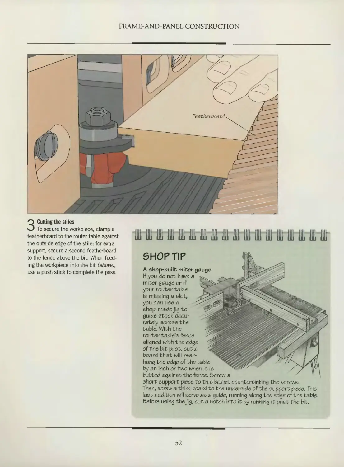
Ю THE ART OF WOODWORKl NG
CABINETMAKING
/999-20^
A Tuckerdude Scan 2005
WORKSHOP GUIDE
POWERTOOLS
• Wear appropriate safety gear: safety
glasses, a face shield for extra protection,
and hearing protectors or ear plugs. If
there is no dust collection system, wear a
dust mask. For exotic woods such as
ebony, use a respirator; the sawdust may
cause an allergic reaction. Wear work
gloves when handling rough lumber.
• Do not use a tool if any part of it is worn
or damaged.
• Keep your hands well away from a
turning blade or bit.
• Drape the power cord of a portable tool
over your shoulder to prevent it from
getting in the way and being damaged.
SAFETY TIPS
• Concentrate on the юЬ; do not rush.
Never work when you are tired, stressed or
have been drinking alcohol or using
medications that induce drowsiness.
• Keep your work area clean and tidy;
clutter can lead to accidents, and sawdust
and wood scraps can be a fire hazard.
HAND TOOLS
• Use the appropriate tool for the job; do
not try to make a tool do something for
which it was not designed.
• Clamp down a workpiece to free both
hands for an operation.
• Cut away from yourself rather than
toward your body.
• Do not force a tool; try removing less
material, or sharpen the cutting edge.
• Keep the edges of cutting tools sharp.
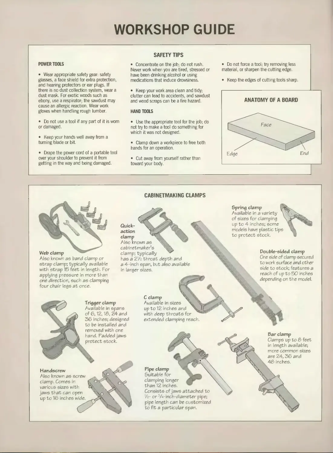
CABINETMAKING CLAMPS
depending on the model.
Web clamp
Also known ae band clamp or
strap clamp; typically available
with strap 15 feet in length. For
applying pressure in more than
one direction, such as clamping
four chair legs at once.
Spring clamp
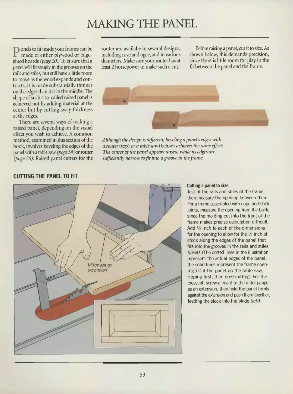
Available in a variety \
of sizes for clamping
up to 4 inches; some
models have plastic tips
to protect stock.
Trigger clamp
Available in spans
of 6,12,16, 24 and
36 inches; designed
to be installed and
removed with one
hand. Padded jaws
protect stock.
C clamp
Available in sizes
up to 12 inches and V.
with deep throats for
extended clamping reach.
Quick- \
action У' ,,
clamp '.'i
Also known as
cabinetmaker’s \
clamp; typically
has a 27z throat depth and
a 4-inch span, but also available
in larger sizes.
Pipe clamp \
Suitable for \
clamping longer
than 12 inches.
Consists of jaws attached to
7z- or T/4-inch-diameter pipe;
pipe length can be customized
to fit a particular span.
Handscrew
Also known as screw
clamp. Comes in
various sizes with
jaws that can open
up to 16 inches wide.
Bar clamp
Clamps up to & feet
in length available;
more common sizes
are 24,36 and
45 inches.
Double-sided clamp
One side of clamp secured
to work surface and other
side to stock; features a
reach of up to 50 inches
THE ART OF WOODWORK! NG
CABINETMAKING
THE ART OF WOODWORKING
CABINETMAKING
TIME-LIFE BOOKS
ALEXANDRIA, VIRGINIA
ST. REMY PRESS
MONTREAL - NEW YORK
THE ART OF WOODWORKING was produced by
ST. REMY PRESS
PUBLISHER
PRESIDENT
Series Editor
Series Art Director
Senior Editors
Art Directors
Designer
Research Editor
Picture Editor
Writers
Contributing Writer
Contributing Illustrators
Administrator
Production Manager
System Coordinator
Photographer
Index
Proofreader
Kenneth Winchester
Pierre Leveille
Pierre Horne-Douglas
Francine Lemieux
Marc Cassini (Text)
Heather Mills (Research)
Normand Boudreault, Solange Laberge
Luc Germain
Jim McRae
Christopher Jackson
Tamsin M. Douglas, Andrew Jones
Stephen Hart
Ronald Durepos, Robert Paquet,
Studio La Perluete inc.
Natalie Watanabe
Michelle Turbide
Jean-Luc Roy
Robert Chartier
Christine M. Jacobs
Judith Yelon
THE CONSULTANTS
Mark Duginske, a cabinetmaker who lives
in Wausau, Wisconsin, is a contributing
editor to Fine Woodworking magazine
and the author of several books on woodwork-
ing power tools.
Leonard Lee is the president of Veritas Tools
and Lee Valley Tools, manufacturers and retail-
ers of fine woodworking hand tools. He is also
the publisher and executive editor of Woodcuts,
a magazine that focuses on the history and
techniques of woodworking.
Giles Miller-Mead has taught advanced cabi-
netmaking at Montreal technical schools for
more than ten years. A native of New Zealand,
he previously worked as a restorer of antique
furniture.
Joseph Truini is Senior Editor of Home
Mechanix magazine. A former Shop and Tools
Editor of Popular Mechanics, he has worked as
a cabinetmaker, home improvement contractor
and carpenter.
Time-Life Books is a division of Time-Life Inc.,
a wholly owned subsidiary of
THE TIME INC. BOOK COMPANY
TIME-LIFE BOOKS
President
Publisher
Managing Editor
Director of Editorial Resources
Associate Publisher
Marketing Director
Editorial Director
Consulting Editor
Production Manager
Mary N. Davis
Robert H. Smith
Thomas H. Flaherty
Elise D. Ritter-Clougb
Trevor Lunn
Regina Hall
Donia Ann Steele
Bob Doyle
Marlene Zack
Cabinetmaking
p. cm.—( The Art of Woodworking)
Includes index.
ISBN 0-8094-9904-5. (trade)
ISBN 0-8094-9905-3 (lib)
1. Cabinetwork.
I. Time- Life Books. II. Series
TT197.C212 1992
684’.04—dc20 92-11188
CIP
For information about any Time-Life book,
please call 1 800-621-7026, or write:
Reader Information
Time-Life Customer Service
P.O. Box C-32068
Richmond, Virginia
23261-2068
© 1992 Time-Life Books Inc.
All rights reserved.
No part of this book may be reproduced in
any form or by any electronic or mechanical
means, including information storage and
retrieval devices or systems, without prior
written permission from the publisher, except
that brief passages may be quoted for reviews.
First printing Printed in U.S.A.
Published simultaneously in Canada.
TIME-LIFE is a trademark of Time Warner
Inc. U.S.A.
CONTENTS
6
12
16
18
20
27
39
41
44
46
48
53
57
59
60
61
64
69
72
74
76
85
87
95
97
INTRODUCTION
CABINETMAKING
TECHNIQUES
CARCASE CONSTRUCTION
Anatomy of a carcase
Making wide panels
Carcase joinery
Edge banding
Shelving
FRAME-AND-PANEL
CONSTRUCTION
Anatomy of a frame-and-panel
assembly
Making the frame
Making the panel
Putting the panel in the frame
Assembling a frame-and-panel
case
Installing a bottom panel
Shelving
Installing a top
Installing molding
DRAWERS
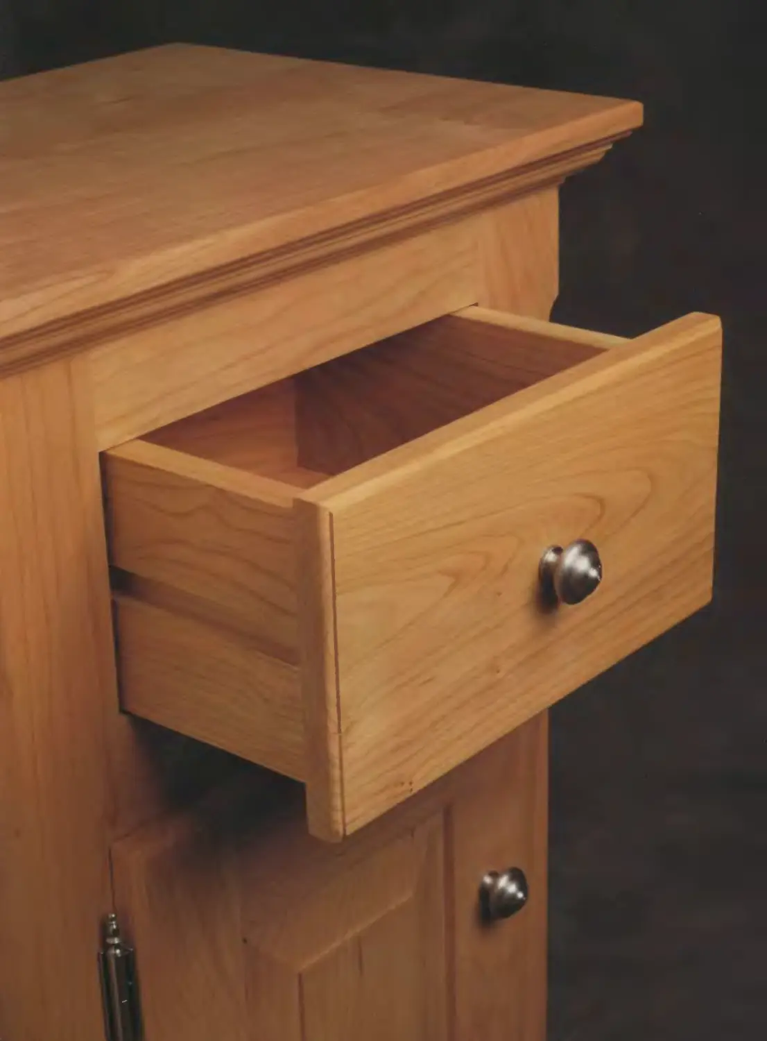
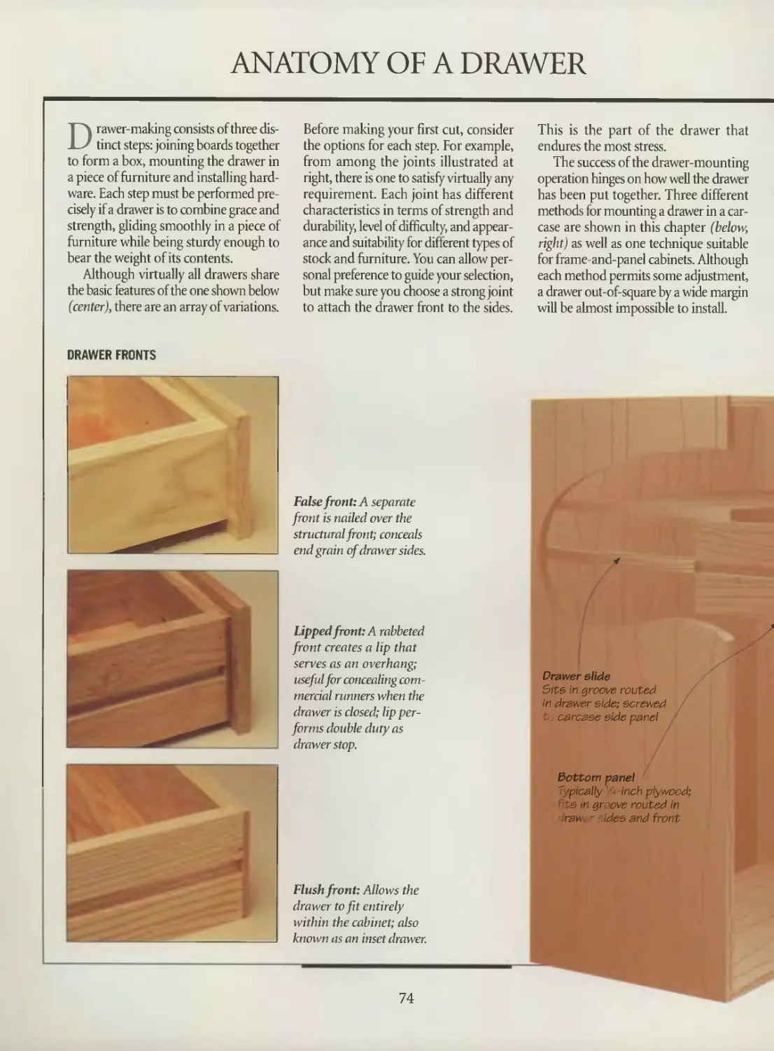
Anatomy of a drawer
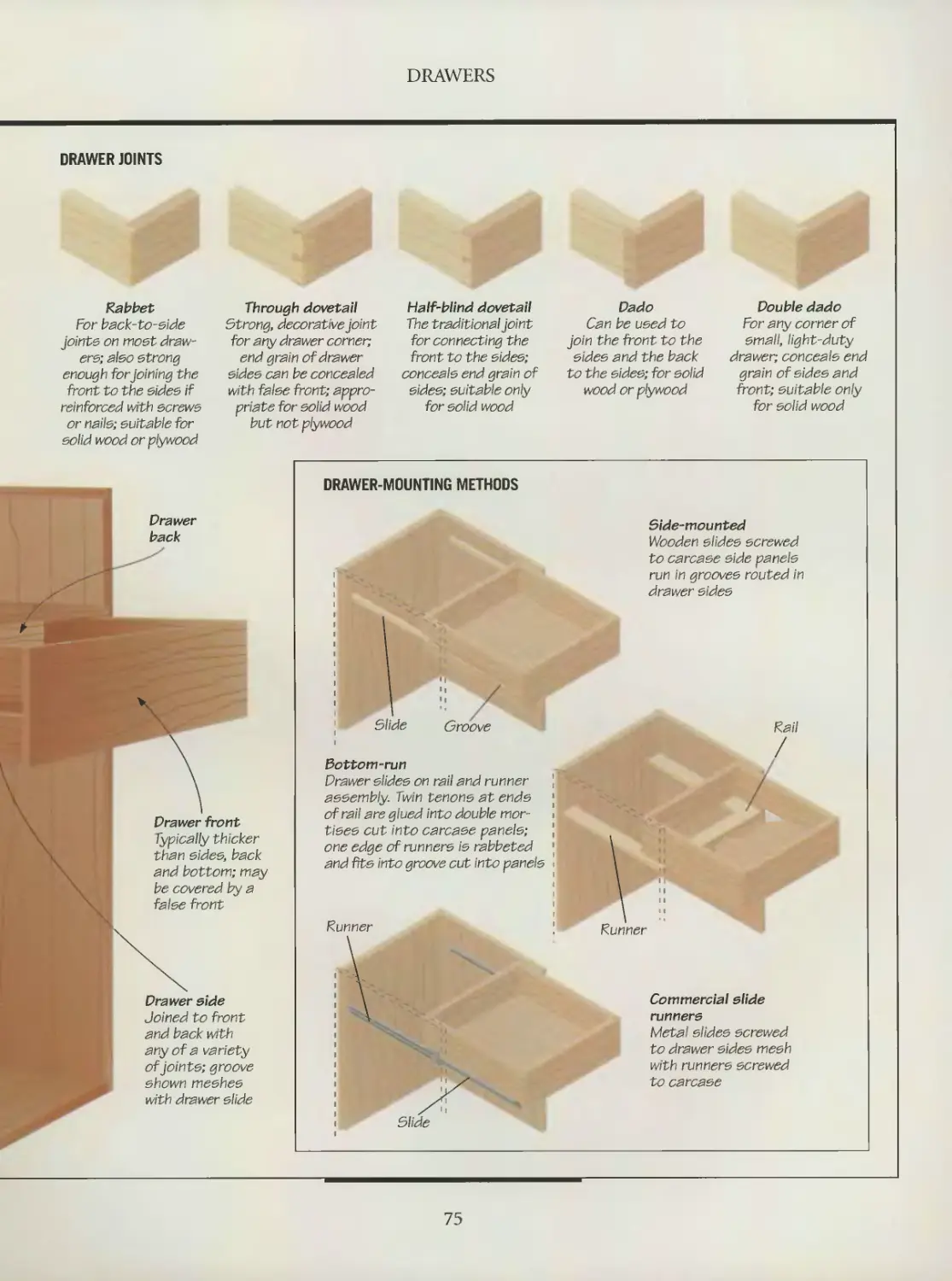
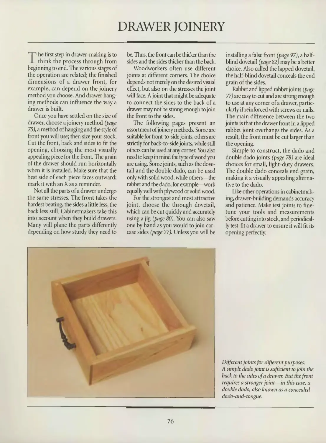
Drawer joinery
Assembling a drawer
Mounting a drawer
Drawer stops
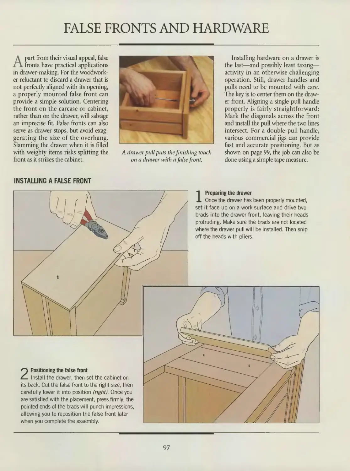
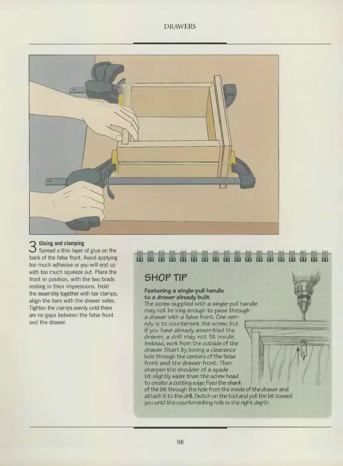
False fronts and hardware
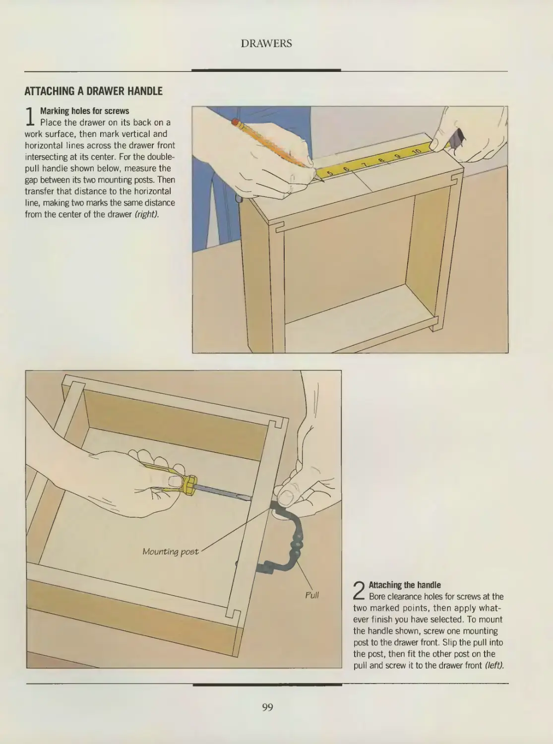
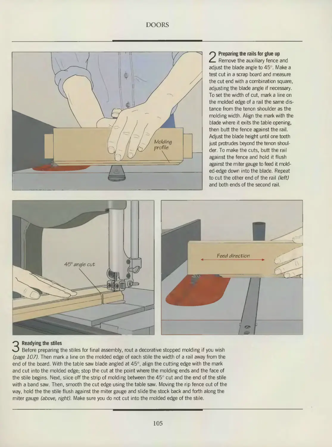
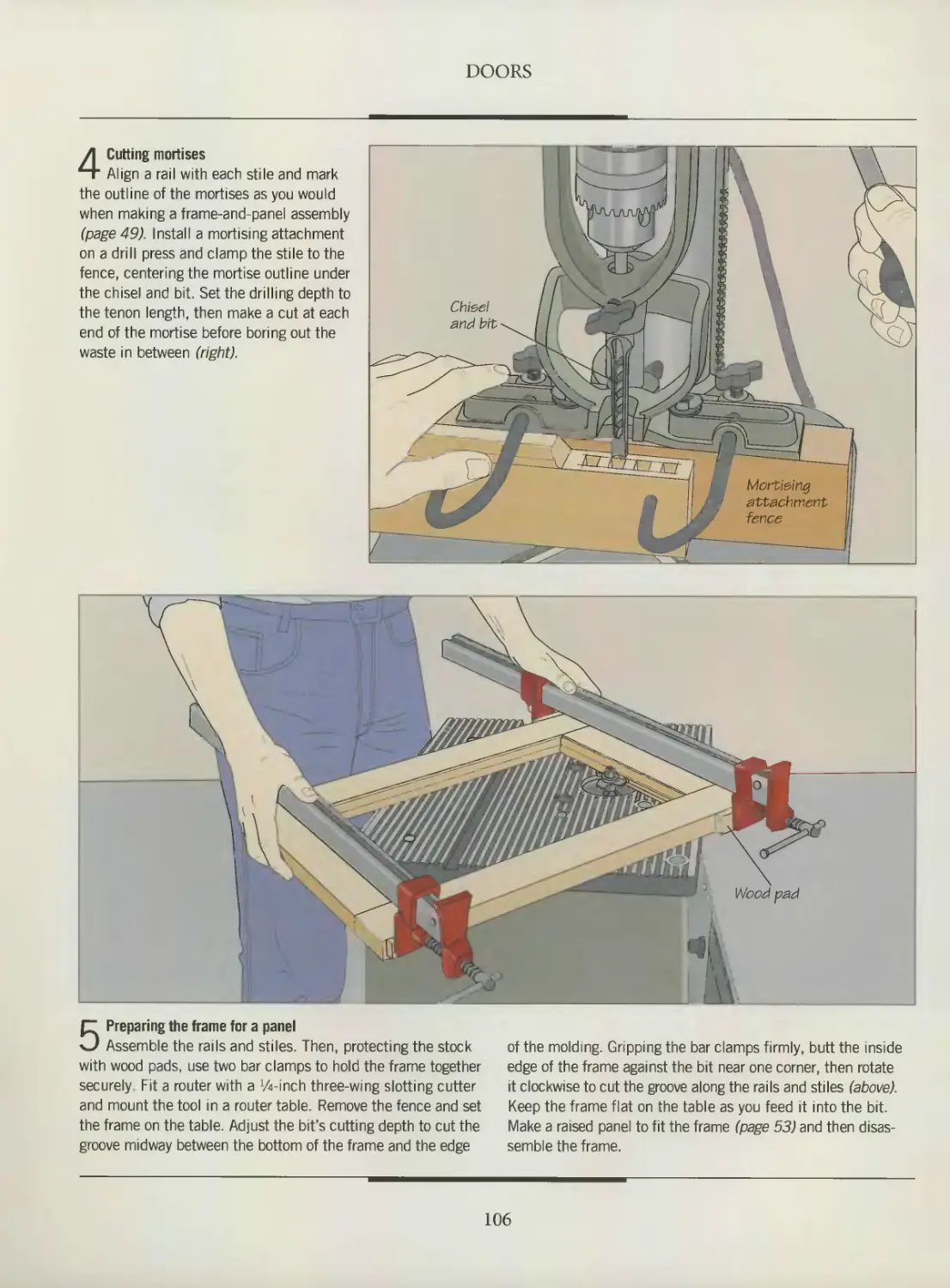
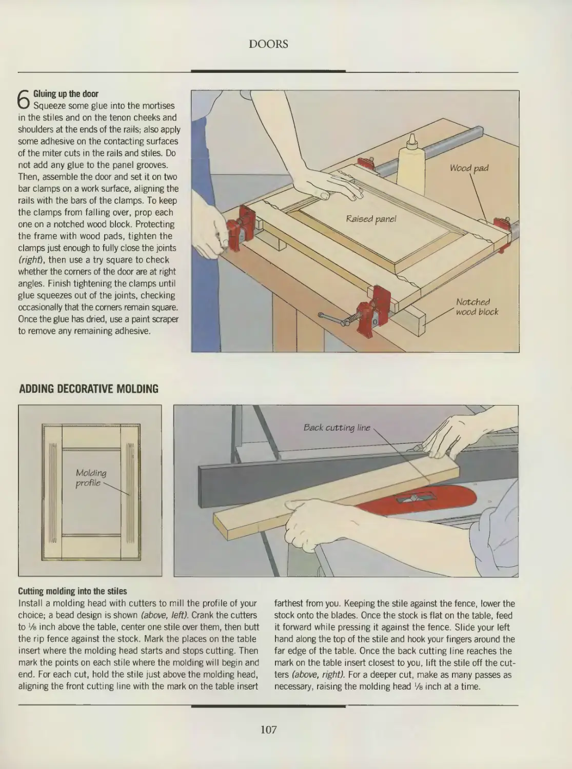
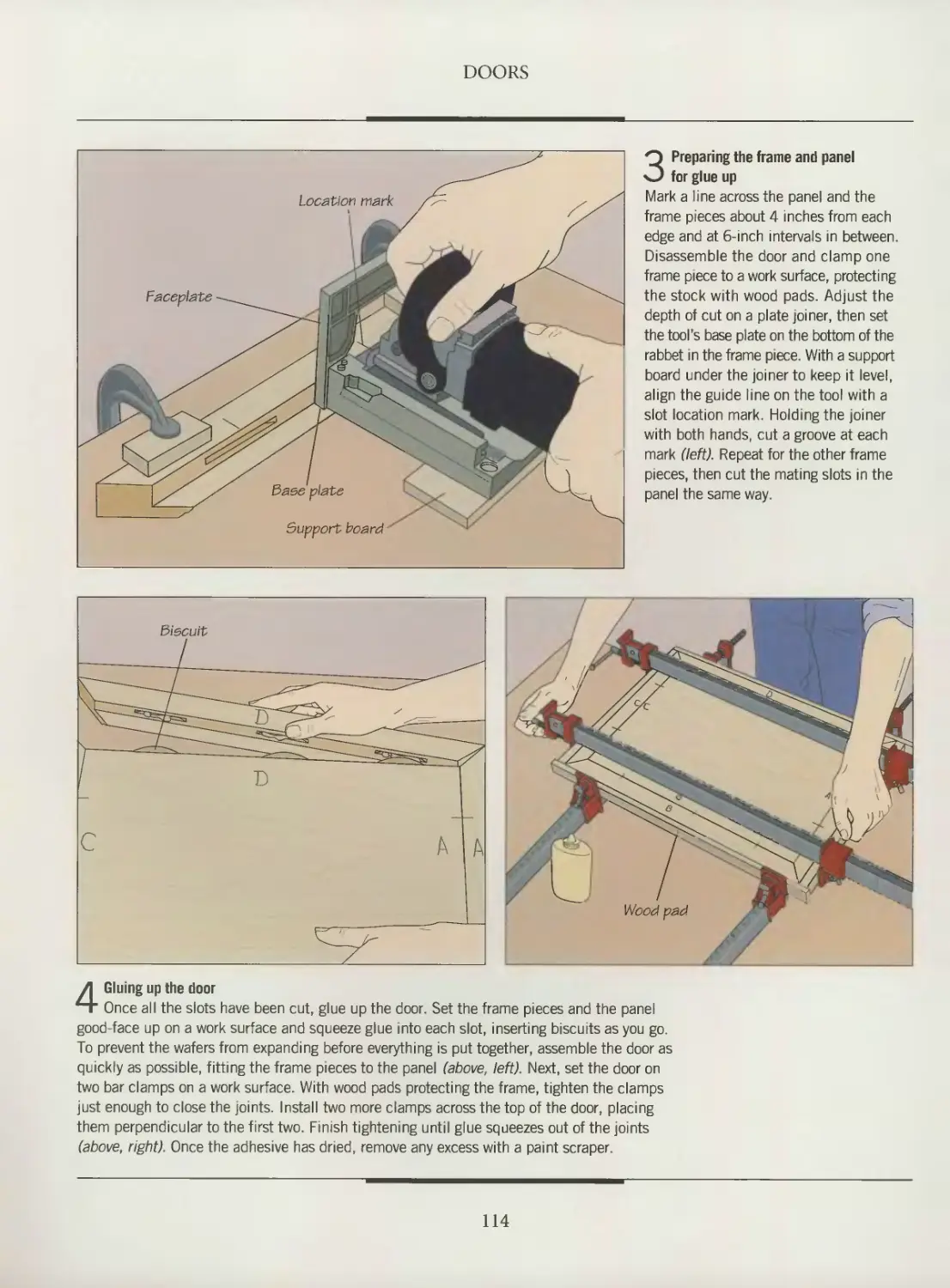
100 DOORS
102 Anatomy of a door
104 Frame-and-panel doors
108 Solid-panel doors
111 Glass doors
113 Veneered-panel doors
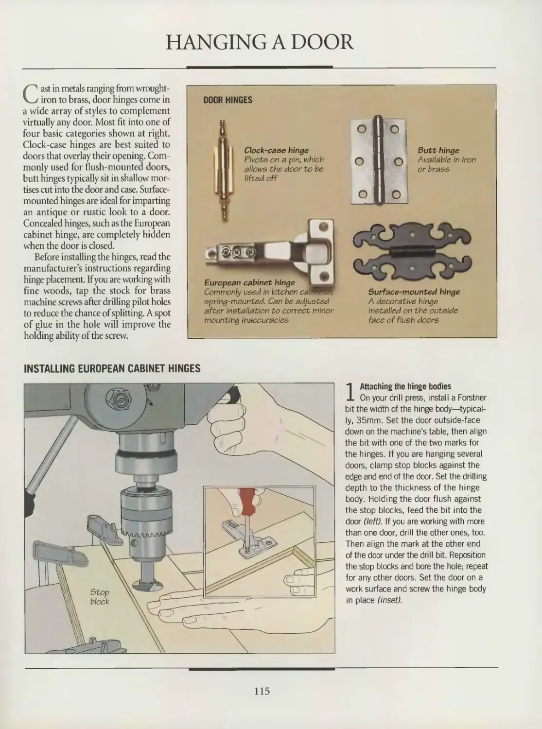
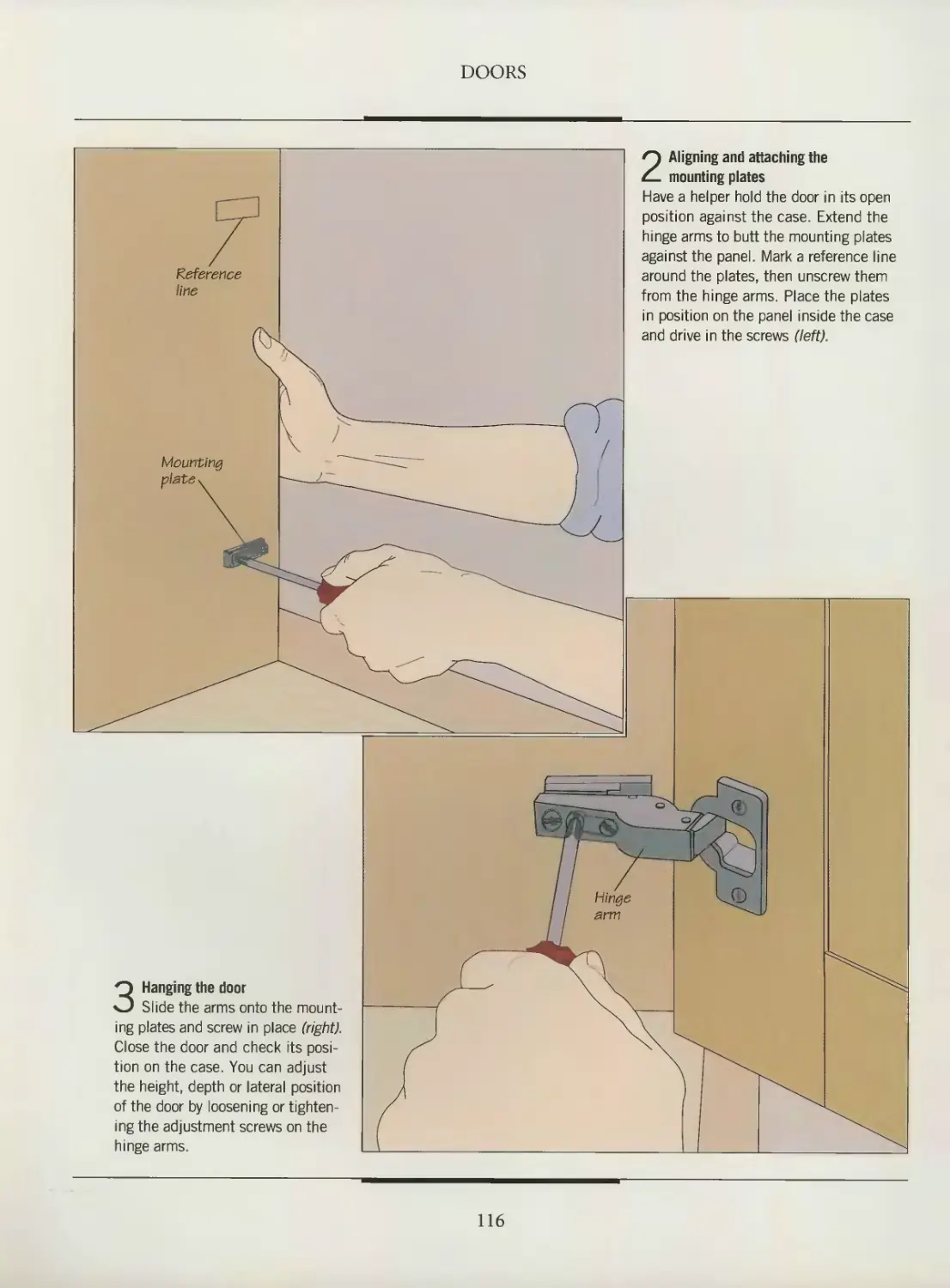
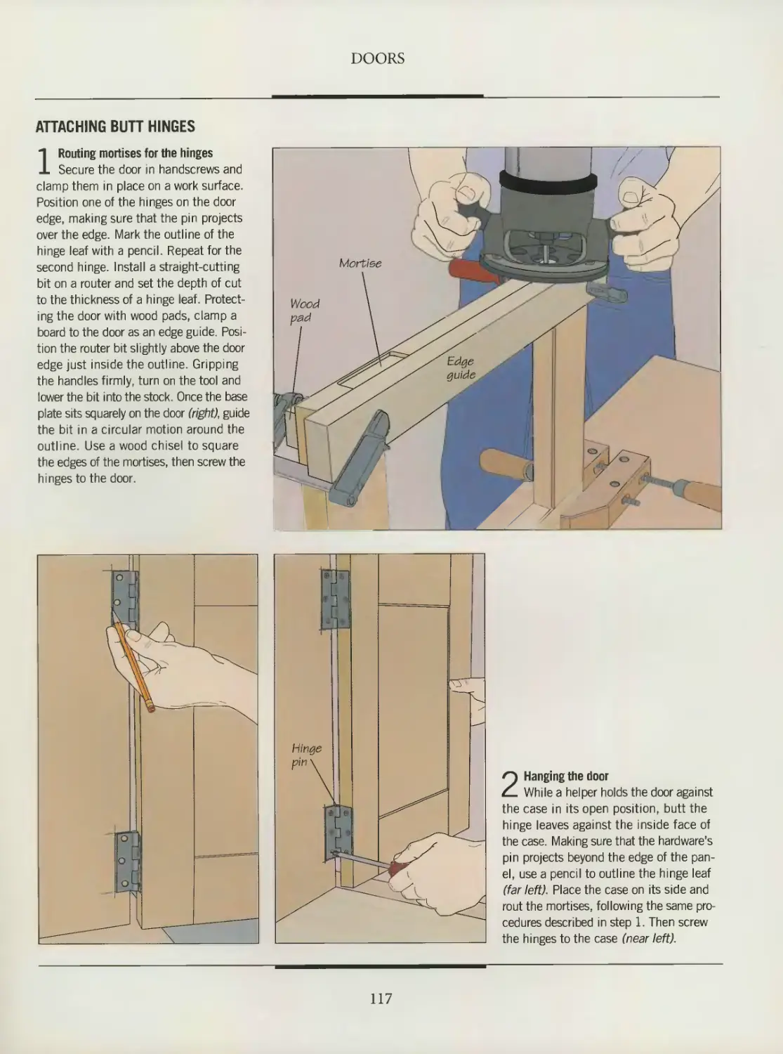
115 Hanging a door
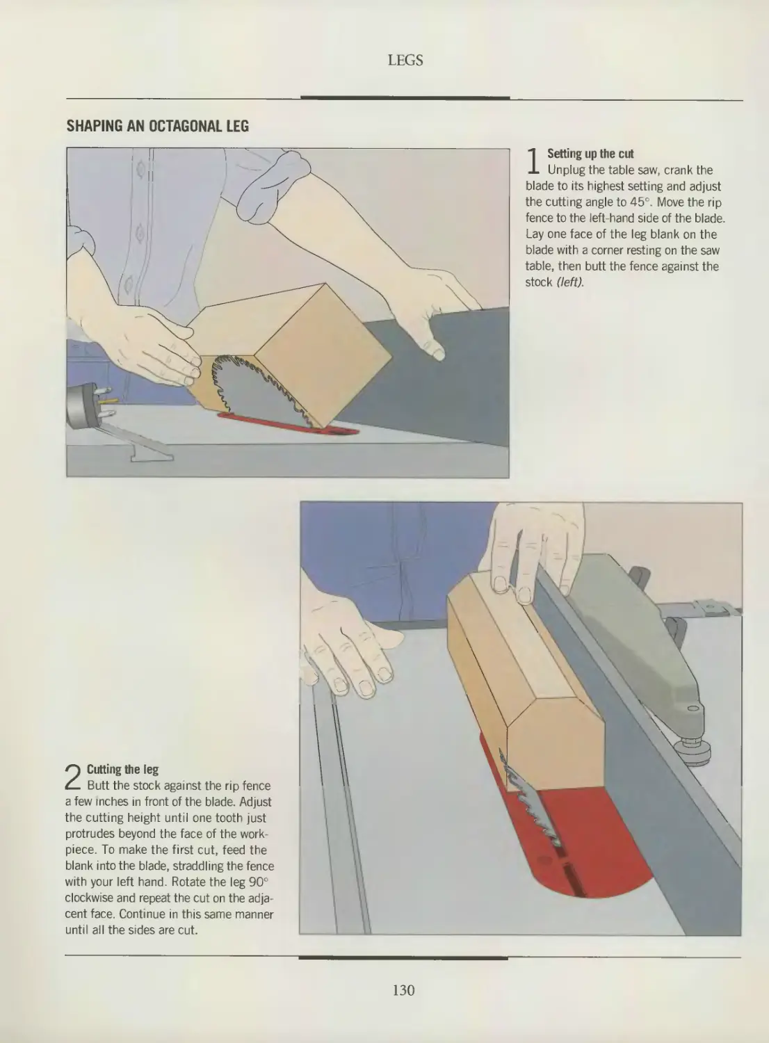
120 LEGS
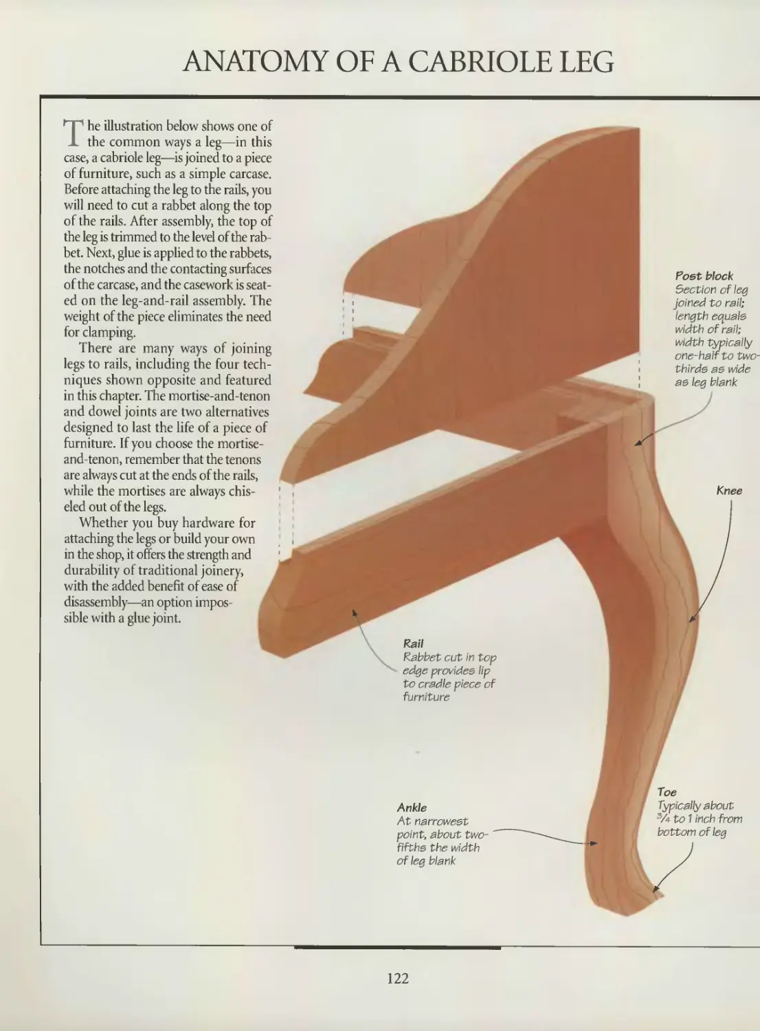
122 Anatomy of a cabriole leg
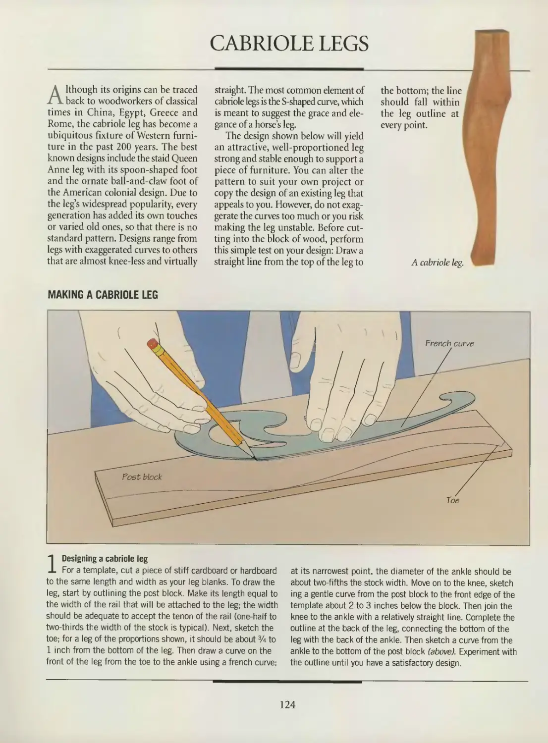
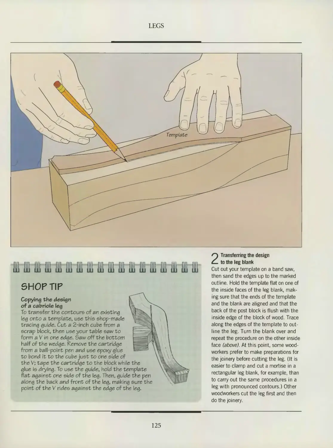
124 Cabriole legs
128 Tapered and octagonal legs
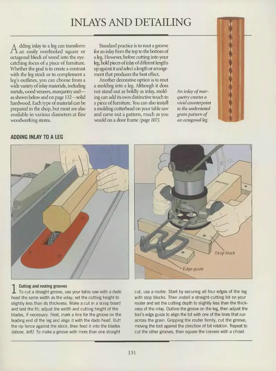
131 Inlays and detailing
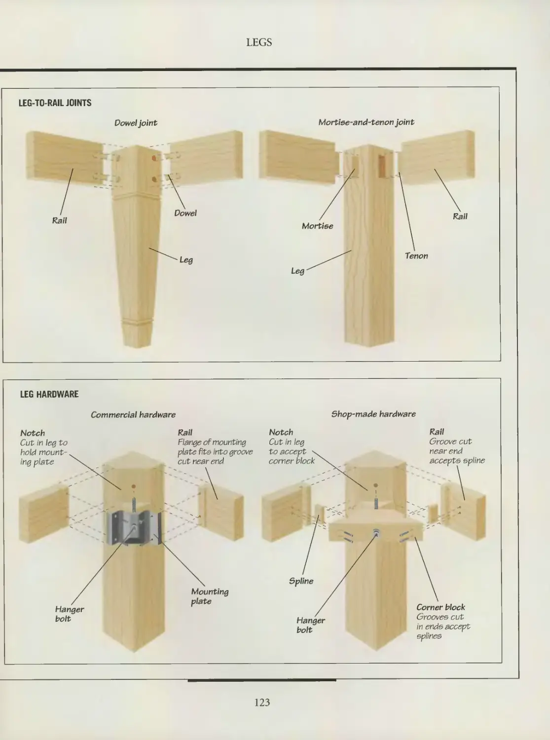
133 Leg joinery
140 GLOSSARY
142 INDEX
144 ACKNOWLEDGMENTS
WLflllnniin^
INTRODUCTION
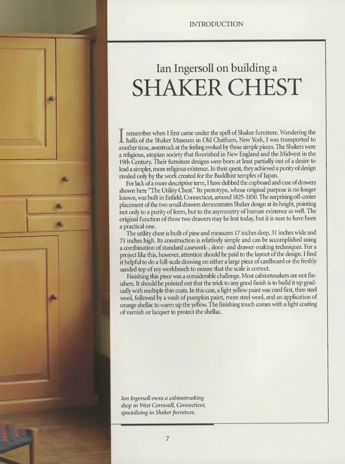
Ian Ingersoll on building a
SHAKER CHEST
I remember when I first came under the spell of Shaker furniture. Wandering the
halls of the Shaker Museum in Old Chatham, New York, I was transported to
another time, awestruck at the feeling evoked by those simple pieces. The Shakers were
a religious, utopian society that flourished in New England and the Midwest in the
19th Century. Their furniture designs were born at least partially out of a desire to
lead a simpler, more religious existence. In their quest, they achieved a purity of design
rivaled only by the work created for the Buddhist temples of Japan.
For lack of a more descriptive term, I have dubbed the cupboard and case of drawers
shown here “The Utility Chest? Its prototype, whose original purpose is no longer
known, was built in Enfield, Connecticut, around 1825-1850. The surprising off-center
placement of the two small drawers demonstrates Shaker design at its height, pointing
not only to a purity of form, but to the asymmetry of human existence as well. The
original function of those two drawers ma)' be lost today, but it is sure to have been
a practical one.
The utility chest is built of pine and measures 17 inches deep, 31 inches wide and
71 inches high. Its construction is relatively simple and can be accomplished using
a combination of standard casework-, door- and drawer-making techniques. For a
project like this, however, attention should be paid to the layout of the design. I find
it helpful to do a full-scale drawing on either a large piece of cardboard or the freshly
sanded top of my workbench to ensure that the scale is correct.
Finishing this piece was a considerable challenge. Most cabinetmakers are not fin-
ishers. It should be pointed out that the trick to any good finish is to build it up grad
ually with multiple thin coats. In this case, a light yellow paint was used first, then steel
wool, followed by a wash of pumpkin paint, more steel wool, and an application of
orange shellac to warm up the yellow. The finishing touch comes with a light coating
of varnish or lacquer to protect the shellac.
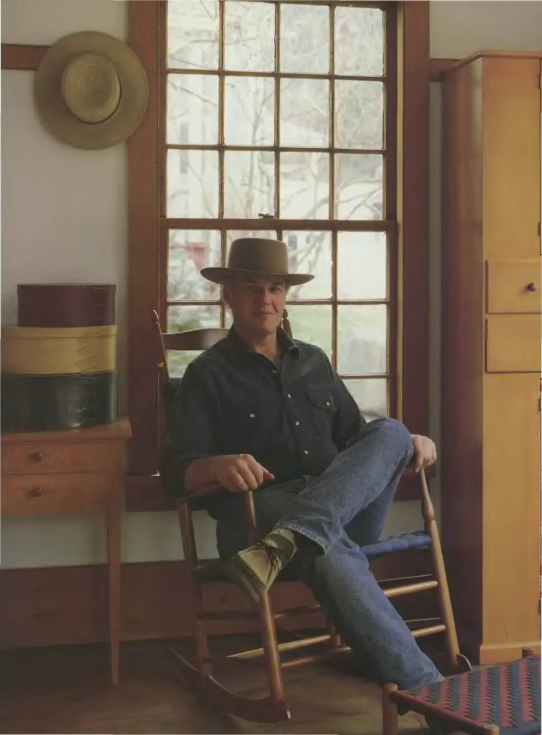
lari Ingersoll owns a cabinetmaking
shop in West Cornwall, Connecticut,
specializing in Shaker furniture.
7
INTRODUCTION
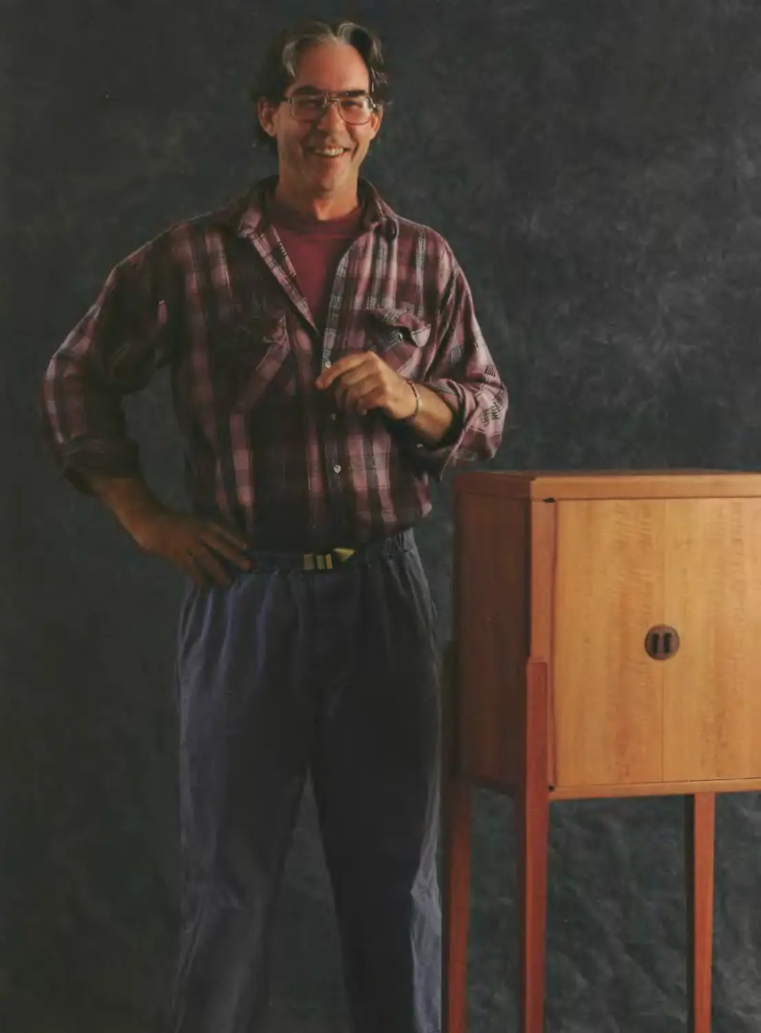
Michael Burns talks about
CRAFTSMANSHIP
The inspiration for this cabinet came from a small billet of Swiss pear given to me
seven years ago. I felt that it had taken me at least that long to acquire the skills
to work with this beautiful, but somewhat difficult wood. The pear was a dark golden
pink and had a soft appearance. I designed the cabinet to highlight the wood’s won-
derful surface and its ability to stand up to the shaping of delicate edge profiles. I want-
ed to show off the raw material.
I resawed the pear into veneers, a scant '/s-inch thick, bookmatched them, and glued
them to a plywood core. I then edge banded and shaped the top and bottom. I doweled
the sides to small 1 ‘A-inch posts, needing solid wood for the joints with the legs. Next,
I doweled the top, bottom and sides together precisely, using one dowel per inch. I
finished all the pieces before gluing up. The legs, made from jarrah, were then notched,
glued and screwed to the corners of the cabinet.
Pear is as demanding as it is beautiful. The joinery must be tight and perfect; slight
imperfections are very noticeable. I spent a great deal of time sharpening my planes
to get the edge joints crisp and the surfaces unflawed. The jarrah, on the other hand,
was a pleasure to work with. It planed in any direction, sawed and shaped easily, and
took the light oil finish I applied very well. I finished the pear with several thin coats
of blond shellac, bringing out its color and surface markings.
Inside the cabinet are two drawers, each made of Andaman padauk and camphor.
Under the drawers, in the middle of the interior, is a curved shelf. I made the L-shaped
knife hinges and door pulls from patinated brass.
My inspiration comes from several sources, including my teacher Jim Krenov, Greek
architecture, Japanese craft and French cabinetmaker Emile Rulilmann. What is impor-
tant in everything I make is that the influences are balanced, the craftsmanship is the
best I can achieve, and the results pleasing.
Michael Burns teaches cabinetmak-
ing at College of the Redwoods in
Fort Bragg, California.
9
INTRODUCTION
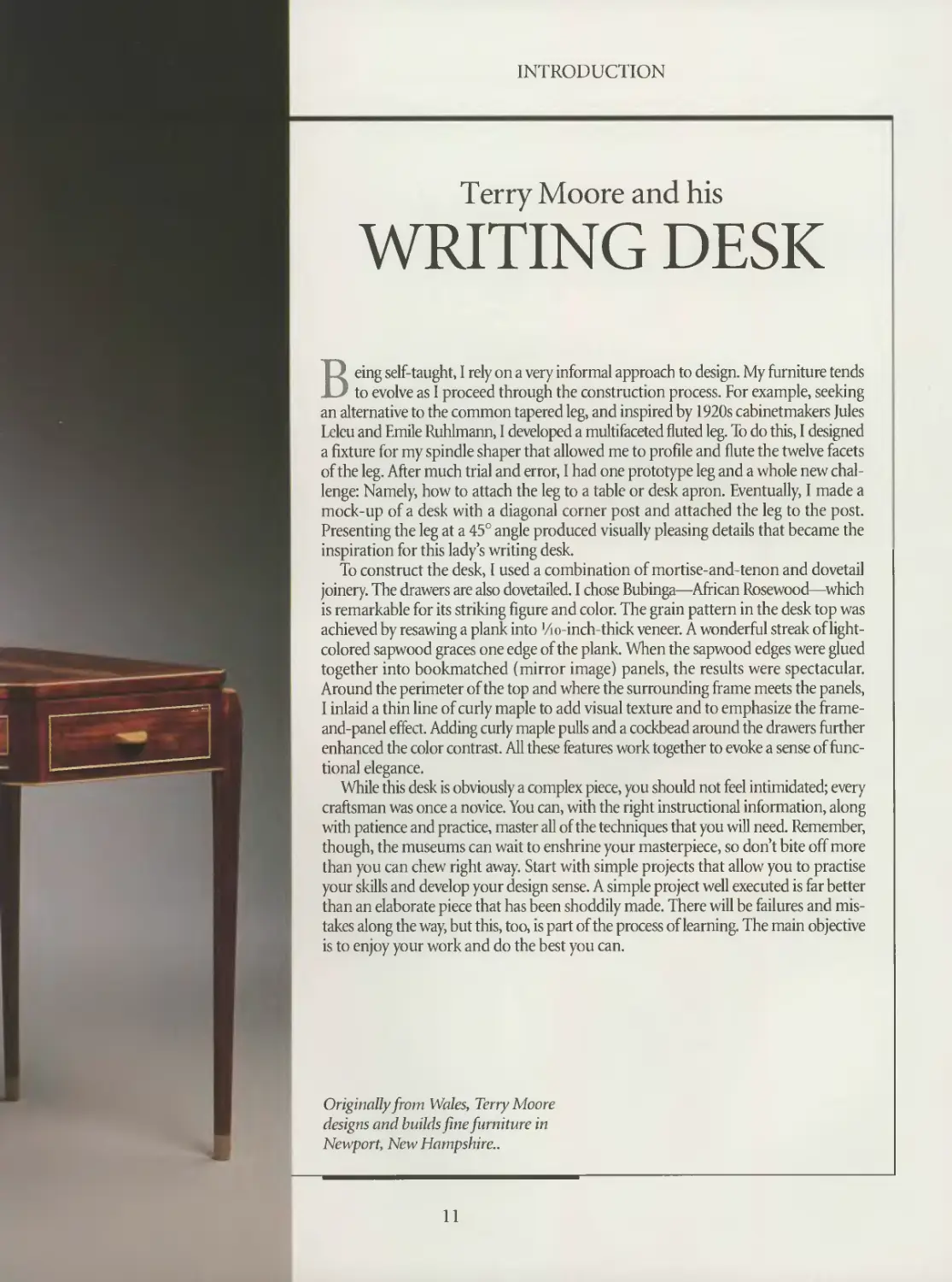
Terry Moore and his
WRITING DESK
Being self-taught, I rely on a very informal approach to design. My furniture tends
to evolve as I proceed through the construction process. For example, seeking
an alternative to the common tapered leg, and inspired by 1920s cabinetmakers Jules
Lclcu and Emile Ruhlmann, I developed a multifaceted fluted leg. To do this, I designed
a fixture for my spindle shaper that allowed me to profile and flute the twelve facets
of the leg. After much trial and error, I had one prototype leg and a whole new chal-
lenge: Namely, how to attach the leg to a table or desk apron. Eventually, I made a
mock-up of a desk with a diagonal corner post and attached the leg to the post.
Presenting the leg at a 45° angle produced visually pleasing details that became the
inspiration for this lady’s writing desk.
To construct the desk, I used a combination of mortise-and-tenon and dovetail
joinery. The drawers are also dovetailed. I chose Bubinga—African Rosewood—which
is remarkable for its striking figure and color. The grain pattern in the desk top was
achieved by resawing a plank into 'Zio-inch-thick veneer. A wonderful streak of light-
colored sapwood graces one edge of the plank. When the sapwood edges were glued
together into bookmatched (mirror image) panels, the results were spectacular.
Around the perimeter of the top and where the surrounding frame meets the panels,
I inlaid a thin line of curly maple to add visual texture and to emphasize the frame-
and-panel effect. Adding curly maple pulls and a cockbead around the drawers further
enhanced the color contrast. All these features work together to evoke a sense of func-
tional elegance.
While this desk is obviously a complex piece, you should not feel intimidated; every
craftsman was once a novice. You can, with the right instructional information, along
with patience and practice, master all of the techniques that you will need. Remember,
though, the museums can wait to enshrine your masterpiece, so don’t bite off more
than you can chew right away. Start with simple projects that allow you to practise
your skills and develop your design sense. A simple project well executed is far better
than an elaborate piece that has been shoddily made. There will be failures and mis-
takes along the way, but this, too, is part of the process of learning. The main objective
is to enjoy your work and do the best you can.
Originally from Wales, Terry Moore
designs and builds fine furniture in
Newport, New Hampshire..
11
CABINETMAKING TECHNIQUES
The first step in any cabinetmaking
project is to select and prepare your
stock. As shown below, not all the wood
at a lumberyard is free of defects, so it
is important to choose boards carefully.
Whether you are building an armoire
or a toy box, most stock is readied in
roughly the same way. The procedures
illustrated on pages 13 to 15 cover the
basic techniques. For rough, or unsur-
faced lumber, first pass one face across
the jointer, then one edge, producing
two surfaces that are at 90° to each oth-
er. Next, plane the second face, making
it parallel to the first. Now you are ready
to rip your stock to width and crosscut
it to length. For diessed, or surfaced lum-
ber, you only have to joint one edge, then
rip and crosscut. Before gluing up a piece
of furniture, be sure to sand any surfaces
that will be difficult to reach afterwards.
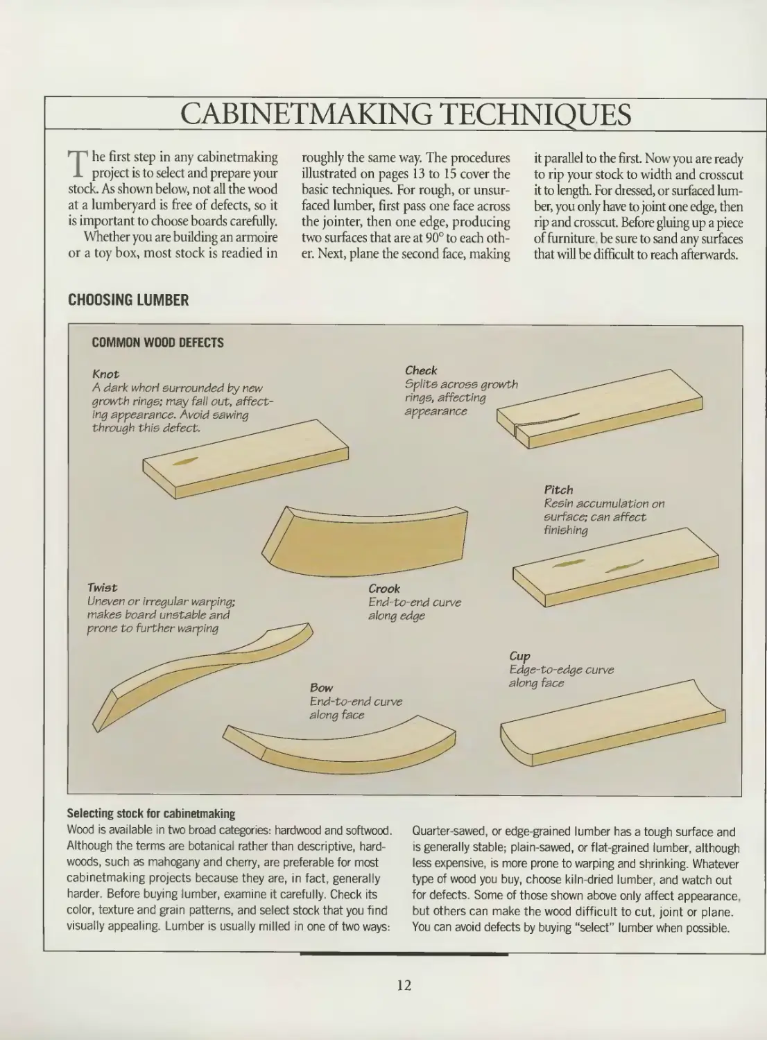
CHOOSING LUMBER
COMMON WOOD DEFECTS
Selecting stock for cabinetmaking
Wood is available in two broad categories: hardwood and softwood.
Although the terms are botanical rather than descriptive, hard-
woods, such as mahogany and cherry, are preferable for most
cabinetmaking projects because they are, in fact, generally
harder. Before buying lumber, examine it carefully. Check its
color, texture and gram patterns, and select stock that you find
visually appealing Lumber is usually milled in one of two ways:
Quarter-sawed, or edge-grained lumber has a tough surface and
is generally stable; plain-sawed, or flat-grained lumber, although
less expensive, is more prone to warping and shrinking. Whatever
type of wood you buy, choose kiln-dried lumber, and watch out
for defects. Some of those shown above only affect appearance
but others can make the wood difficult to cut joint or plane.
You can avoid defects by buying “select" lumber when possible.
12
CABINETMAKING TECHNIQUES
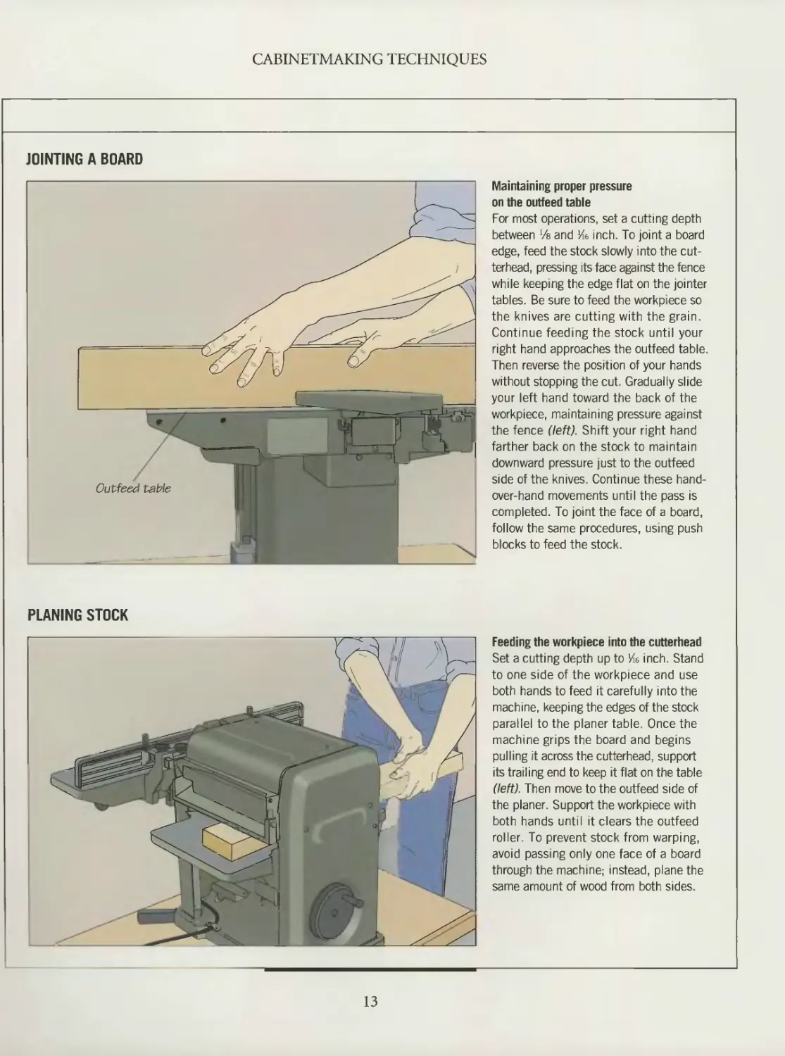
JOINTING A BOARD
Maintaining proper pressure
on the outfeed table
For most operations, set a cutting depth
between Va and Ke inch. To joint a board
edge, feed the stock slowly into the cut-
terhead, pressing its face against the fence
while keeping the edge flat on the jointer
tables. Be sure to feed the workpiece so
the knives are cutting with the grain.
Continue feeding the stock until your
right hand approaches the outfeed table.
Then reverse the position of your hands
without stopping the cut. Gradually slide
your left hand toward the back of the
workpiece, maintaining pressure against
the fence (left). Shift your right hand
farther back on the stock to maintain
downward pressure just to the outfeed
side of the knives. Continue these hand-
over-hand movements until the pass is
completed. To joint the face of a board,
follow the same procedures, using push
blocks to feed the stock.
PLANING STOCK
Feeding the workpiece into the cutterhead
Set a cutting depth up to Ив inch. Stand
to one side of the workpiece and use
both hands to feed it carefully into the
machine, keeping the edges of the stock
parallel to the planer table. Once the
machine grips the board and begins
pulling it across the cutterhead, support
its trailing end to keep it flat on the table
(left). Then move to the outfeed side of
the planer. Support the workpiece with
both hands until it clears the outfeed
roller. To prevent stock from warping,
avoid passing only one face of a board
through the machine; instead, plane the
same amount of wood from both sides.
13
CABINETMAKING TECHNIQUES
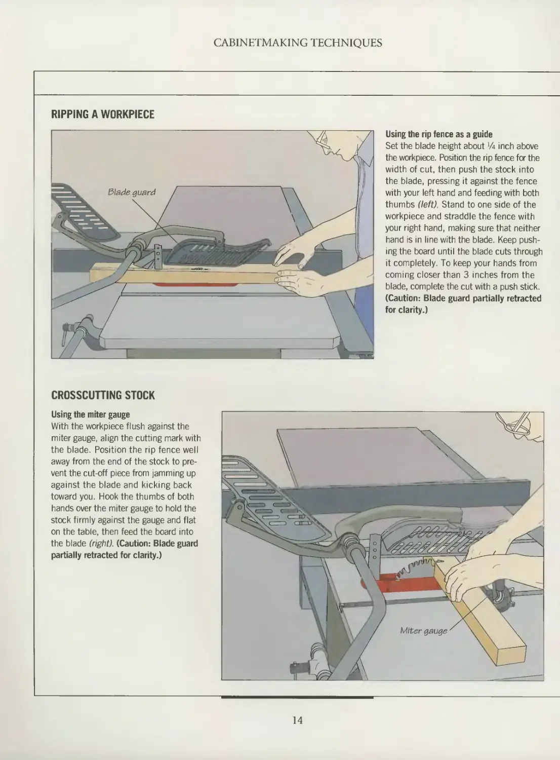
RIPPING A WORKPIECE
Using the rip fence as a guide
Set the blade height about Va inch above
the workpiece. Position the rip fence for the
width of cut, then push the stock into
the blade, pressing it against the fence
with your left hand and feeding with both
thumbs (left). Stand to one side of the
workpiece and straddle the fence with
your right hand, making sure that neither
hand is in line with the blade. Keep push-
ing the board until the blade cuts through
it completely. To keep your hands from
coming closer than 3 inches from the
blade, complete the cut with a push stick.
(Caution: Blade guard partially retracted
for clarity.)
CROSSCUTTING STOCK
Using the miter gauge
With the workpiece flush against the
miter gauge, align the cutting mark with
the blade. Position the rip fence well
away from the end of the stock to pre-
vent the cut-off piece from jamming up
against the blade and kicking back
toward you. Hook the thumbs of both
hands over the miter gauge to hold the
stock firmly against the gauge and flat
on the table, then feed the board into
the blade (right). (Caution: Blade guard
partially retracted for clarity.)
14
CABINETMAKING TECHNIQUES
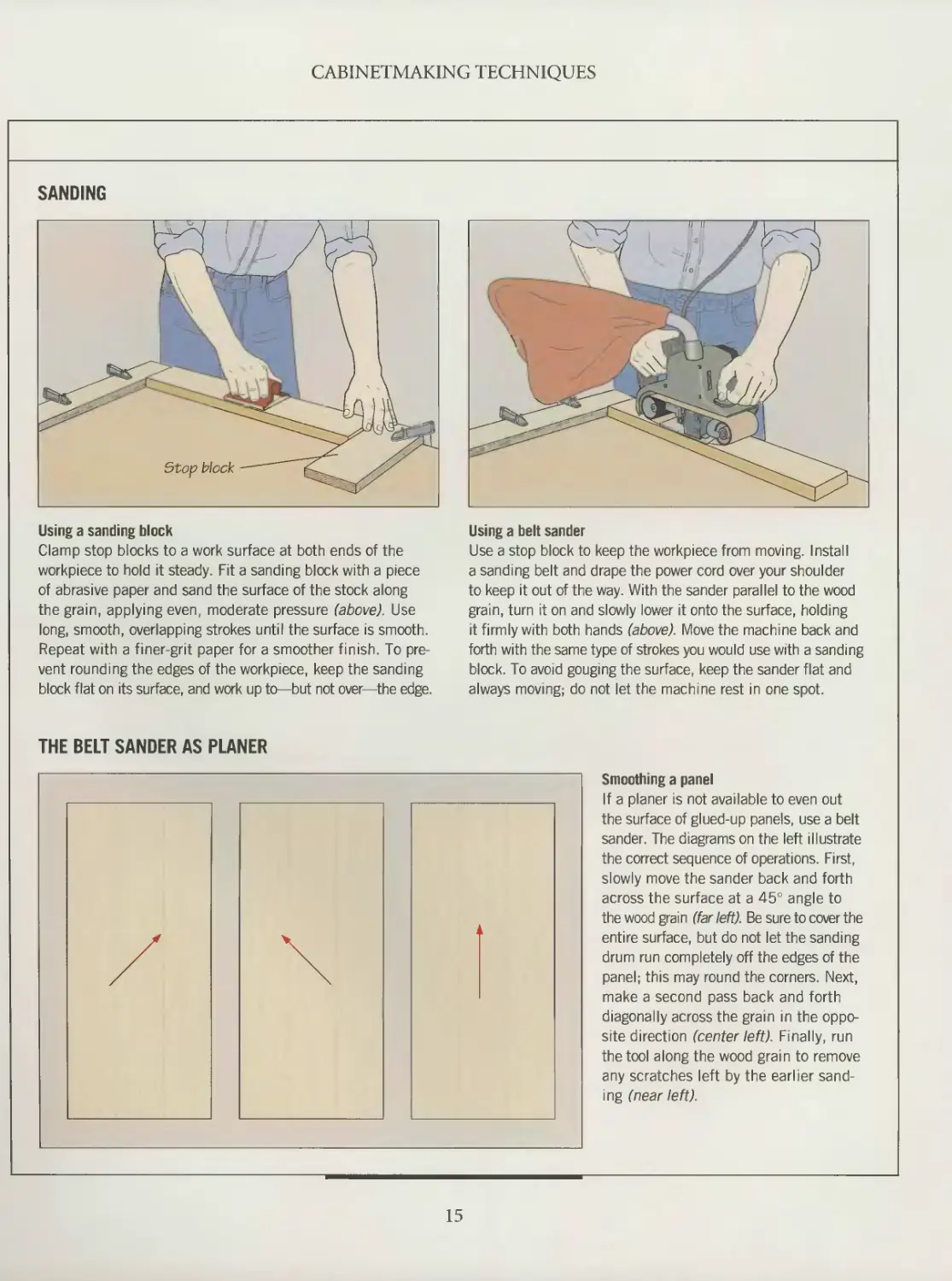
SANDING
Using a sanding block
Clamp stop blocks to a work surface at both ends of the
workpiece to hold it steady. Fit a sanding block with a piece
of abrasive paper and sand the surface of the stock along
the grain, applying even, moderate pressure (above). Use
long, smooth, overlapping strokes until the surface is smooth.
Repeat with a finer-grit paper for a smoother finish. To pre-
vent rounding the edges of the workpiece, keep the sanding
block flat on its surface, and work up to—but not over—the edge.
Using a belt sander
Use a stop block to keep the workpiece from moving. Install
a sanding belt and drape the power cord over your shoulder
to keep it out of the way. With the sander parallel to the wood
grain, turn it on and slowly lower it onto the surface, holding
it firmly with both hands (above). Move the machine back and
forth with the same type of strokes you would use with a sanding
block. To avoid gouging the surface, keep the sander flat and
always moving; do not let the machine rest in one spot.
THE BELT SANDER AS PLANER
Smoothing a panel
If a planer is not available to even out
the surface of glued-up panels, use a belt
sander. The diagrams on the left illustrate
the correct sequence of operations. First,
slowly move the sander back and forth
across the surface at a 45° angle to
the wood grain (far left). Be sure to cover the
entire surface, but do not let the sanding
drum run completely off the edges of the
panel; this may round the corners. Next,
make a second pass back and forth
diagonally across the grain in the oppo-
site direction (center left). Finally, run
the tool along the wood grain to remove
any scratches left by the earlier sand-
ing (near left).
15
CARCASE CONSTRUCTION
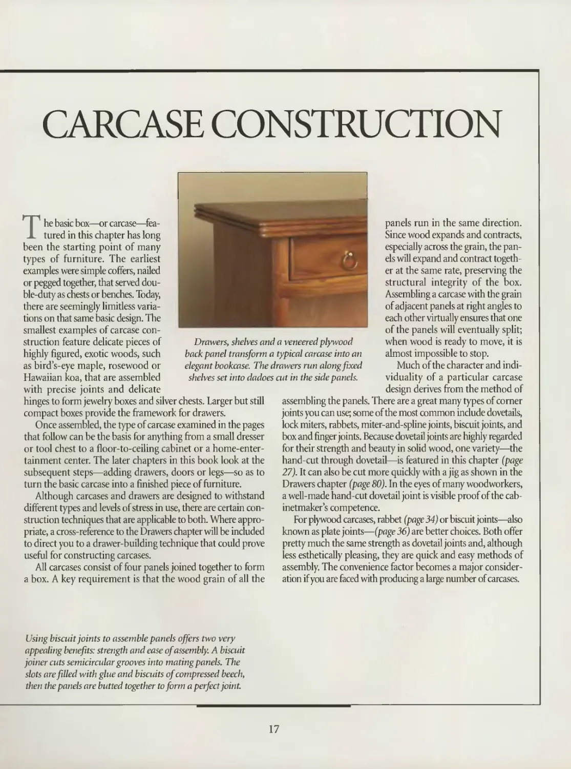
Drawers, shelves and a veneered plywood
backpanel transform a typical carcase into an
elegant bookcase. The drawers run along fixed
shelves set into dadoes cut in the side panels.
The basic box—or carcase—fea-
tured in this chapter has long
been the starting point of many
types of furniture. The earliest
examples were simple coffers, nailed
or pegged together, that served dou-
ble-duty as chests or benches. Today,
there are seemingly limitless varia-
tions on that same basic design. The
smallest examples of carcase con-
struction feature delicate pieces of
highly figured, exotic woods, such
as bird’s-eye maple, rosewood or
Hawaiian koa, that are assembled
with precise joints and delicate
hinges to form jewelry boxes and silver chests. Larger but still
compact boxes provide the framework for drawers.
Once assembled, the type of carcase examined in the pages
that follow can be the basis for anything from a small dresser
or tool chest to a floor-to-ceiling cabinet or a home-enter-
tainment center. The later chapters in this book look at the
subsequent steps—adding drawers, doors or legs—so as to
turn the basic carcase into a finished piece of furniture.
Although carcases and drawers are designed to withstand
different types and levels of stress in use, there are certain con-
struction techniques that are applicable to both. Where appro-
priate, a cross-reference to the Drawers chapter will be included
to direct you to a drawer-building technique that could prove
useful for constructing carcases.
All carcases consist of four panels joined together to form
a box. A key requirement is that the wood grain of all the
panels run in the same direction.
Since wood expands and contracts,
especially across the grain, the pan-
els will expand and contract togeth-
er at the same rate, preserving the
structural integrity of the box.
Assembling a carcase with the grain
of adjacent panels at right angles to
each other virtually ensures that one
of the panels will eventually split;
when wood is ready to move, it is
almost impossible to stop.
Much of the character and indi-
viduality of a particular carcase
design derives from the method of
assembling the panels. There are a great many types of corner
joints you can use; some of the most common include dovetails,
lock miters, rabbets, miter-and-spline joints, biscuit joints, and
box and finger joints. Because dovetail joints are highly regarded
for their strength and beauty in solid wood, one variety—the
hand-cut through dovetail—is featured in this chapter (page
27). It can also be cut more quickly with a jig as shown in the
Drawers chapter (page 80). In the eyes of many woodworkers,
a well-made hand-cut dovetail joint is visible proof of the cab-
inetmaker’s competence.
For plywood carcases, rabbet (page 34) or biscuit joints—also
known as plate joints—(page 36) are better choices. Both offer
pretty much the same strength as dovetail joints and, although
less esthetically pleasing, they are quick and easy methods of
assembly. The convenience factor becomes a major consider-
ation if you are faced with producing a large number of carcases.
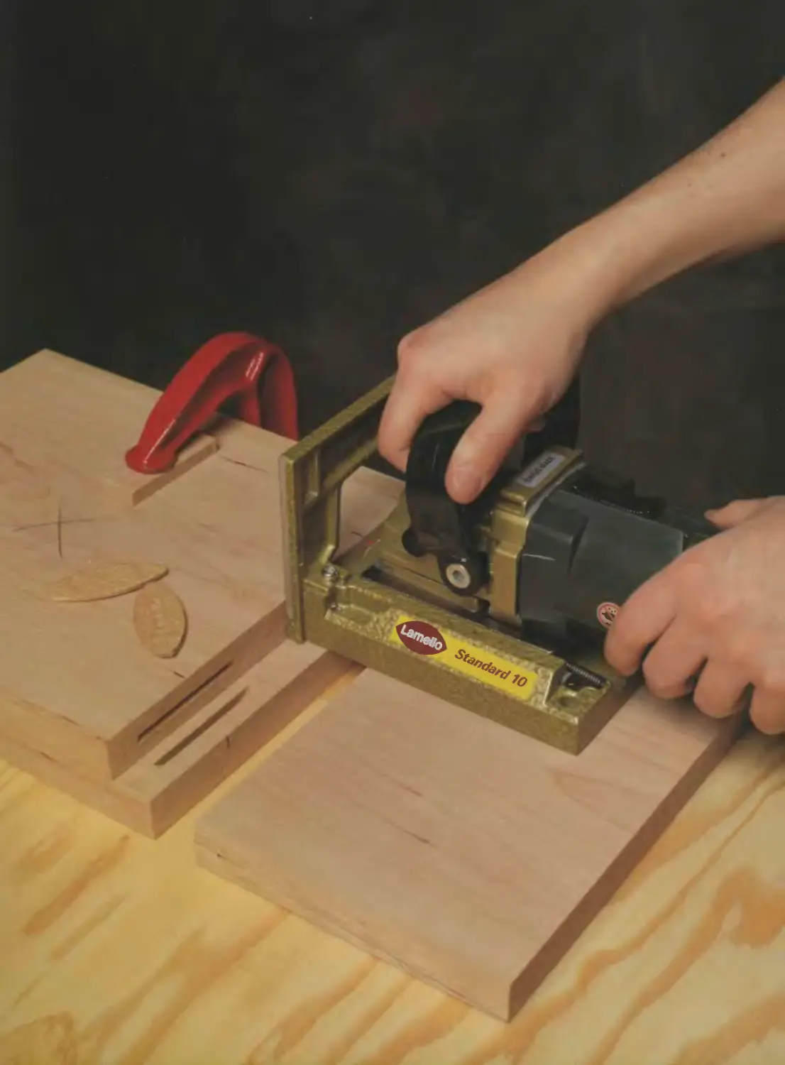
Using biscuit joints to assemble panels offers two very
appealing benefits: strength and ease of assembly. A biscuit
joiner cuts semicircular grooves into mating panels. The
slots are filled with glue and biscuits of compressed beech,
then the panels are butted together to form a perfect joint.
17
ANATOMY OF A CARCASE
Whether it is a box that will house
a couple of drawers and a shelf or
a china cabinet destined to grace your
dining room, the carcase you build will
feature many of the basic elements illus-
trated below. First, it will have four sides,
or panels, which are usually the same
width and thickness. Another require-
ment is that parallel panels must have
the same dimensions.
Although a panel can be made from
a single piece of lumber, it is generally
less expensive to glue narrower boards
edge-to-edge to form the wide surface
(page 20). Once glued up, the panels are
planed, jointed on one edge, cut to size,
and then their surfaces are sanded. A
third option—one which combines the
economy of glued-up panels and the
ease of solid lumber—is to use hard-
wood plywood, which can be made to
look like solid wood, by the addition of a
banding along exposed edges (page 39).
Constructing carcases from plywood
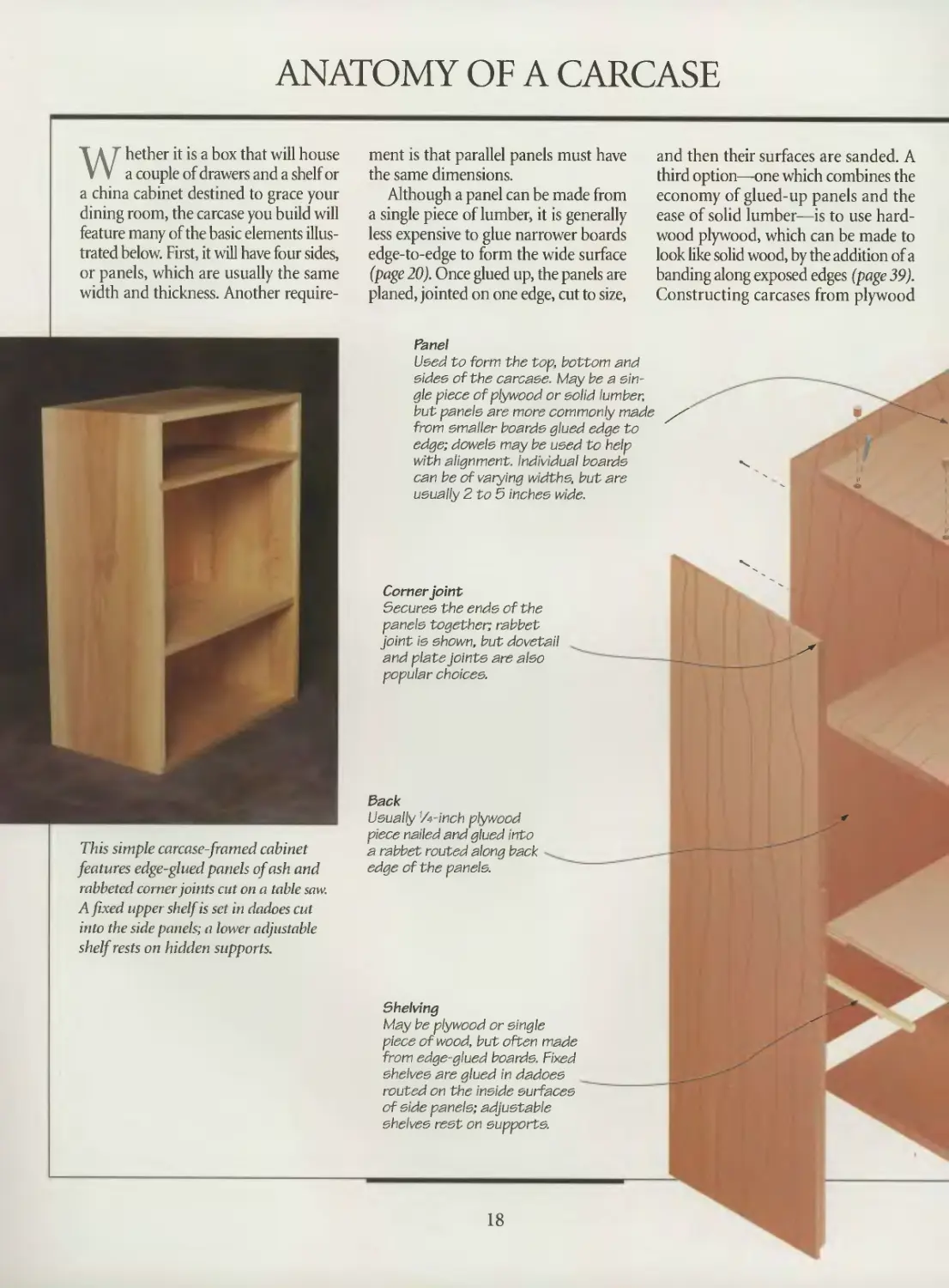
Panel
Used to form the top, bottom and
sides of the carcase. May be a sin-
gle piece of plywood or solid lumber,
but paneis are more commonly made
from smaller boards glued edge to
edge; dowels may be used to help
with alignment. Individual boards
can be of varying widths, but are
usually 2 to 5 inches wide.
Corner joint
Secures the ends of the
panels together; rabbet
joint is shown, but dovetail
and plate joints are also
popular choices.
This simple carcase-framed cabinet
features edge-glued panels of ash and
rabbeted corner joints cut on a table saw.
A fixed upper shelf is set in dadoes cut
into the side panels; a lower adjustable
shelf rests on hidden supports.
Back
Usually ’/t-inch plywood
piece nailed and glued into
a rabbet routed along back -
edge of the panels.
Shelving
May be plywood or single
piece of wood, but often made
from edge-glued boards. Fixed
shelves are glued in dadoes
routed on the inside surfaces
of side panels; adjustable
shelves rest on supports.
18
CARCASE CONSTRUCTION
does have its disadvantages, however.
It reduces your flexibility when it comes
to the joinery; dovetails, for example,
simply will not work. It also rules out
such esthetic possibilities as creating
attractive grain patterns on the
panels by edge gluing carefully
matched boards.
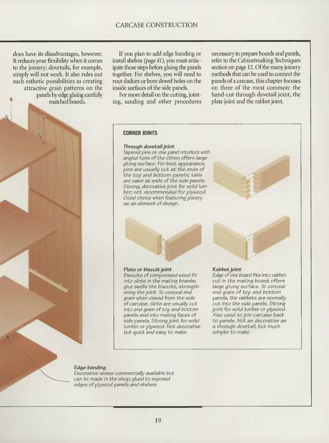
Edge banding
Decorative veneer commercially available but
can be made in the shop; glued to exposed
edges of plywood panels and shelves.
If you plan to add edge banding or
install shelves (page 41), you must antic-
ipate those steps before gluing the panels
together. For shelves, you will need to
rout dadoes or bore dowel holes on the
inside surfaces of the side panels.
For more detail on the cutting, joint-
ing, sanding and other procedures
CORNER JOINTS
Through dovetail Joint
Tapered pins on one panel interlock with
angled tails of the other; offers large
gluing surface. For best appearance,
pine are usually cut at the ends of
the top and bottom panels; tails
are sawn at ends of the side panels.
Strong, decorative joint for solid lum-
ber; not recommended for plywood.
Good choice when featuring joinery
as an element of design.
Plate or biscuit Joint
Biscuits of compressed wood fit
into slots in the mating boards;
glue swells the biscuits, strength-
ening the joint. To conceal end
grain when viewed from the side
of carcase, slots are usually cut
into end grain of top and bottom
panels and into mating faces of
side panels. Strong joint for solid
lumber or plywood. Not decorative
but quick and easy to make.
necesssary to prepare boards and panels,
refer to the Cabinetmaking Techniques
section on page 12. Of the many joinery
methods that can be used to connect the
panels of a carcase, this chapter focuses
on three of the most common: the
hand-cut through dovetail joint, the
plate joint and the rabbet joint.
Rabbet joint
Edge of one board fits into rabbet
cut in the mating board; offers
large gluing surface. To conceal
end grain of top and bottom
panels, the rabbets are normally
cut into the side panels. Strong
Joint for solid lumber or plywood.
Also used to join carcase back
to paneis. Not as decorative as
a through dovetail, but much
simpler to make.
19
MAKING WIDE PANELS
Most woodworkers make up the
wide panels for a carcase by gluing
boards together edge-to-edge. Building
a carcase this way is not a matter of cut-
ting costs at the expense of strength.
Panels of edge-glued boards are every bit
as strong as a single piece of lumber. In
fact, a proper glue joint provides a sturdier
bond than the fibers of a piece of wood.
Follow the steps detailed below and
on the following pages to assemble pan-
els. Apart from a supply of glue and an
assortment of clamps, all you need is a
level work surface or a shop-built glue
rack (page 24). To help keep the boards
aligned, some woodworkers also use
dowels (page 25). For more information
on selecting glue, refer to the inside back
cover of this book
Selecting your wood is an important
part of the process. Do not buy green
wood or stock that is cupped or twisted,
and avoid using wood with a high mois-
ture content, which can adversely affect
the glue. Instead, buy lumber that has
been dried in a kiln. If you are working
from rough stock, begin preparing
boards by jointing a face and an edge,
then planing the other face. Next, cross-
cut the boards, leaving them roughly 1
inch longer than their finished length,
and joint an edge of each piece. Rip the
stock so that the combined width of all
the boards exceeds the finished width
of the panel by about 1 inch, then joint
the cut edges.
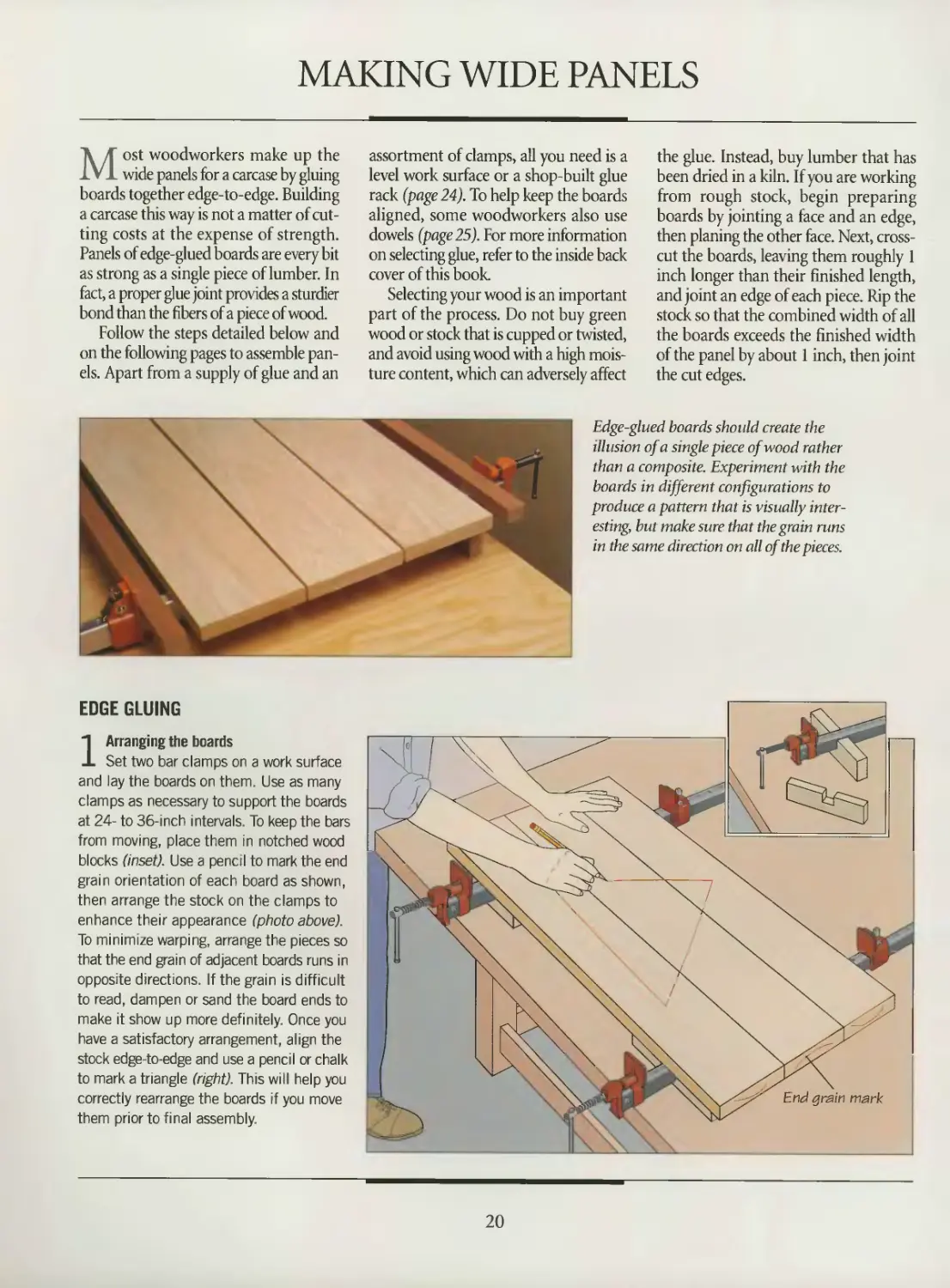
Edge-glued boards should create the
illusion of a single piece of wood rather
than a composite. Experiment with the
boards in different configurations to
produce a pattern that is visually inter-
esting, but make sure that the grain runs
in the same direction on all of the pieces.
EDGE GLUING
1 Arranging the boards
Set two bar clamps on a work surface
and lay the boards on them. Use as many
clamps as necessary to support the boards
at 24- to 36-mch intervals. To keep the bars
from moving, place them in notched wood
blocks (inset). Use a pencil to mark the end
grain orientation of each board as shown,
then arrange the stock on the clamps to
enhance their appearance (photo above).
To minimize warping, arrange the pieces so
that the end gram of adjacent boards runs in
opposite directions. If the grain is difficult
to read, dampen or sand the board ends to
make it show up more definitely. Once you
have a satisfactory arrangement, align the
stock edge-to-edge and use a pencil or chalk
to mark a triangle (right). This will help you
correctly rearrange the boards if you move
them prior to final assembly.
20
CARCASE CONSTRUCTION
Wood
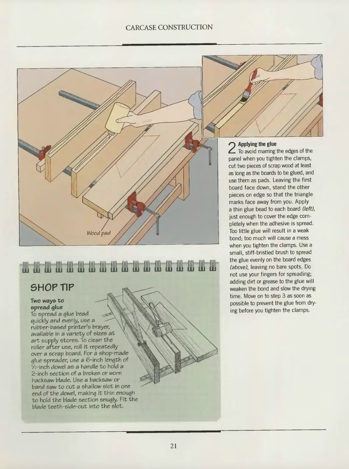
2 Applying the glue
To avoid marring the edges of the
panel when you tighten the clamps,
cut two pieces of scrap wood at least
as long as the boards to be glued, and
use them as pads. Leaving the first
board face down, stand the other
pieces on edge so that the triangle
marks face away from you. Apply
a thin glue bead to each board (left),
just enough to cover the edge com-
pletely when the adhesive is spread.
Too little glue will result in a weak
bond; too much will cause a mess
when you tighten the clamps. Use a
111 IB 111 111 IB III III Hi Ш ГШ III IB 111 in 111 111 HI
small, stiff-bristled brush to spread
the glue evenly on the board edges
(above), leaving no bare spots. Do
not use your fingers for spreading;
SHOP TIP
Two ways to
spread glue
To spread a glue bead
Quickly and evenly, use a
rubber-based printer’s brayer,
available in a variety of sizes at
art supply stores. To clean the
roller after use, roll it repeatedly
over a scrap board. For a shop-made
glue spreader, use a 6-inch length of
1/z-inch dowel as a handle to hold a
2-inch section of a broken or worn
hacksaw blade. Use a backsaw or
band saw to cut a shallow slot in one
adding dirt or grease to the glue will
weaken the bond and slow the drying
time. Move on to step 3 as soon as
possible to prevent the glue from dry-
ing before you tighten the clamps.
end of the dowel, making it thin enough
to hold the blade section snugly. Fit the
blade teeth-side-out into the slot.
21
CARCASE CONSTRUCTION
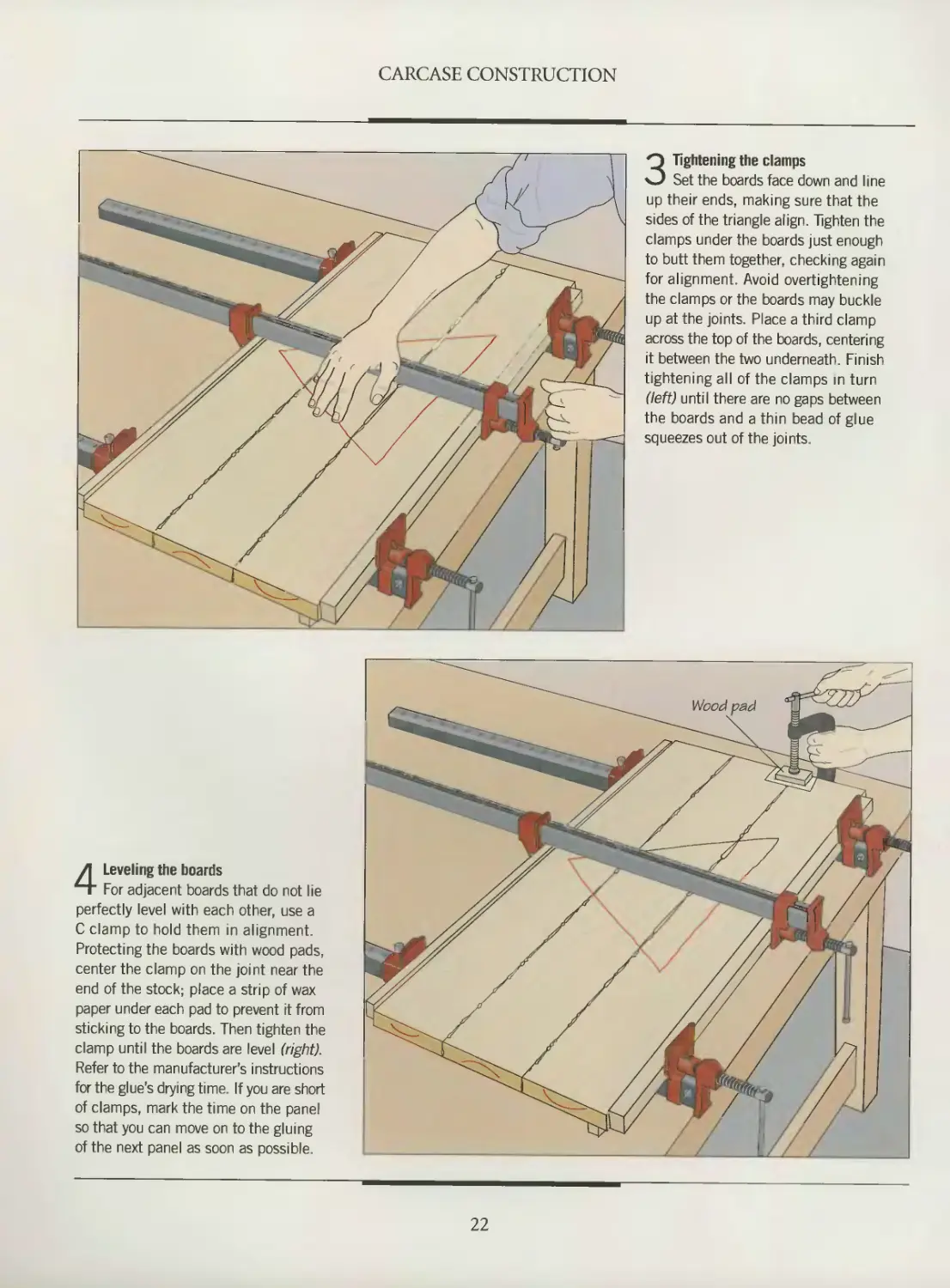
3 Tightening the clamps
Set the boards face down and line
up their ends, making sure that the
sides of the triangle align. Tighten the
clamps under the boards just enough
to butt them together, checking again
for alignment. Avoid overtightening
the clamps or the boards may buckle
up at the joints. Place a third clamp
across the top of the boards, centering
it between the two underneath. Finish
tightening all of the clamps in turn
(left) until there are no gaps between
the boards and a thin bead of glue
squeezes out of the joints.
4 Leveling the boards
For adjacent boards that do not lie
perfectly level with each other, use a
C clamp to hold them in alignment.
Protecting the boards with wood pads,
center the clamp on the joint near the
end of the stock; place a strip of wax
paper under each pad to prevent it from
sticking to the boards. Then tighten the
clamp until the boards are level (right).
Refer to the manufacturer’s instructions
for the glue’s drying time. If you are short
of clamps, mark the time on the panel
so that you can move on to the gluing
of the next panel as soon as possible.
22
CARCASE CONSTRUCTION
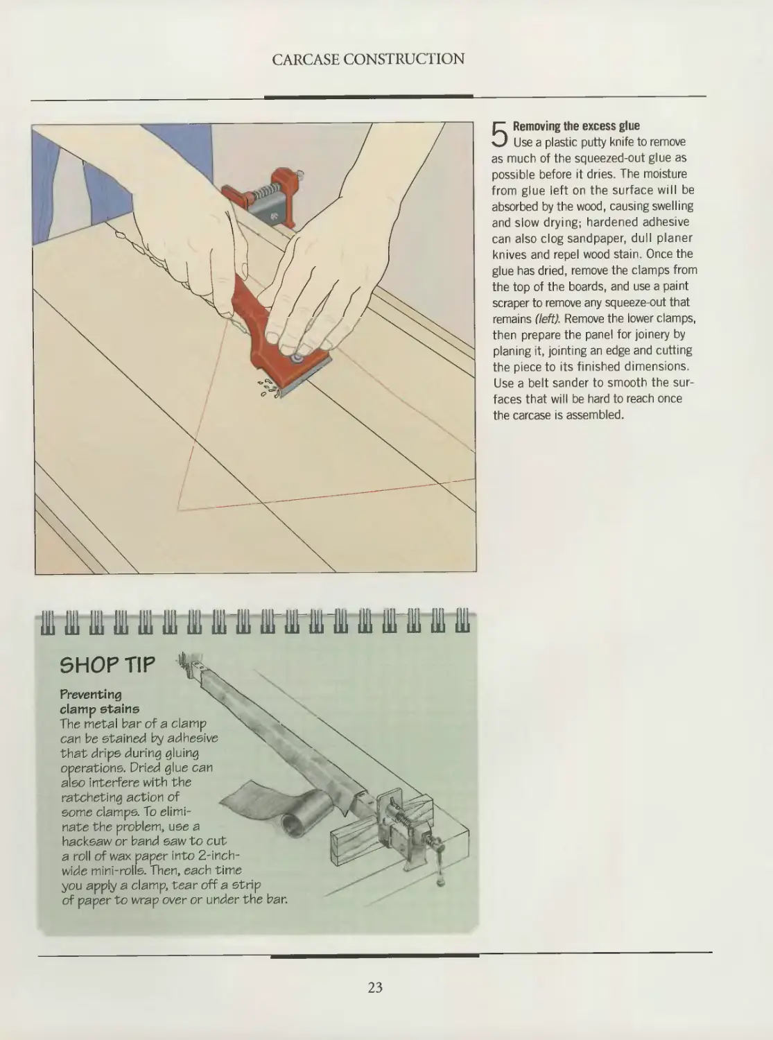
5 Removing the excess glue
Use a plastic putty knife to remove
as much of the squeezed-out glue as
possible before it dries. The moisture
from glue left on the surface will be
absorbed by the wood, causing swelling
and slow drying; hardened adhesive
can also clog sandpaper, dull planer
knives and repel wood stain. Once the
glue has dried, remove the clamps from
the top of the boards, and use a paint
scraper to remove any squeeze-out that
remains (left)- Remove the lower clamps,
then prepare the panel for joinery by
planing it, jointing an edge and cutting
the piece to its finished dimensions.
Use a belt sander to smooth the sur-
faces that will be hard to reach once
the carcase is assembled.
SHOP TIP
Preventing
clamp stains
The metal bar of a clamp
can be stained by adhesive
that drips during gluing
operations. Dried glue can
also interfere with the
ratcheting action of
some clamps. To elimi-
nate the problem, use a
hacksaw or band saw to cut
a roll of wax paper into 2-inch-
wide mini-rolls. Then, each time
you apply a clamp, tear off a strip
of paper to wrap over or under the bar.
23
CARCASE CONSTRUCTION
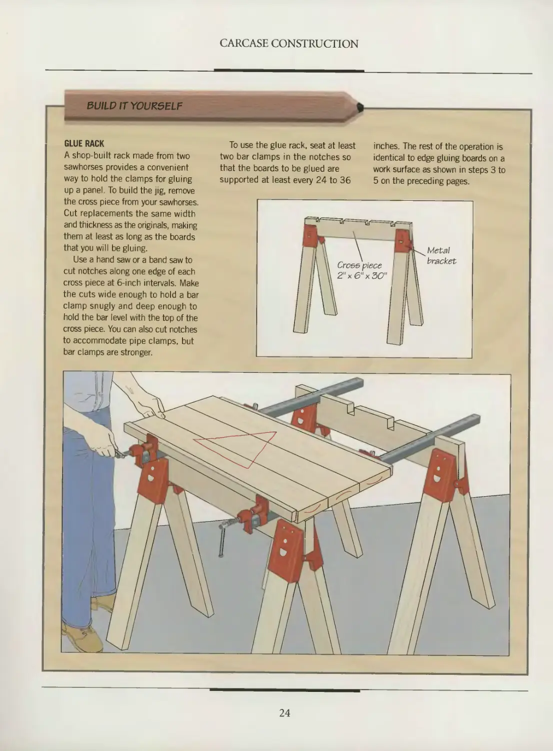
GLUE RACK
A shop-built rack made from two
sawhorses provides a convenient
way to hold the clamps for gluing
up a panel. To build the jig, remove
the cross piece from your sawhorses.
Cut replacements the same width
and thickness as the originals, making
them at least as long as the boards
that you will be gluing.
Use a hand saw or a band saw to
cut notches along one edge of each
cross piece at 6-inch intervals. Make
the cuts wide enough to hold a bar
clamp snugly and deep enough to
hold the bar level with the top of the
cross piece. You can also cut notches
to accommodate pipe clamps, but
bar clamps are stronger.
To use the glue rack, seat at least
two bar clamps in the notches so
that the boards to be glued are
supported at least every 24 to 36
inches. The rest of the operation is
identical to edge gluing boards on a
work surface as shown in steps 3 to
5 on the preceding pages.
24
CARCASE CONSTRUCTION
DOWELS: AN AID TO ALIGNMENT
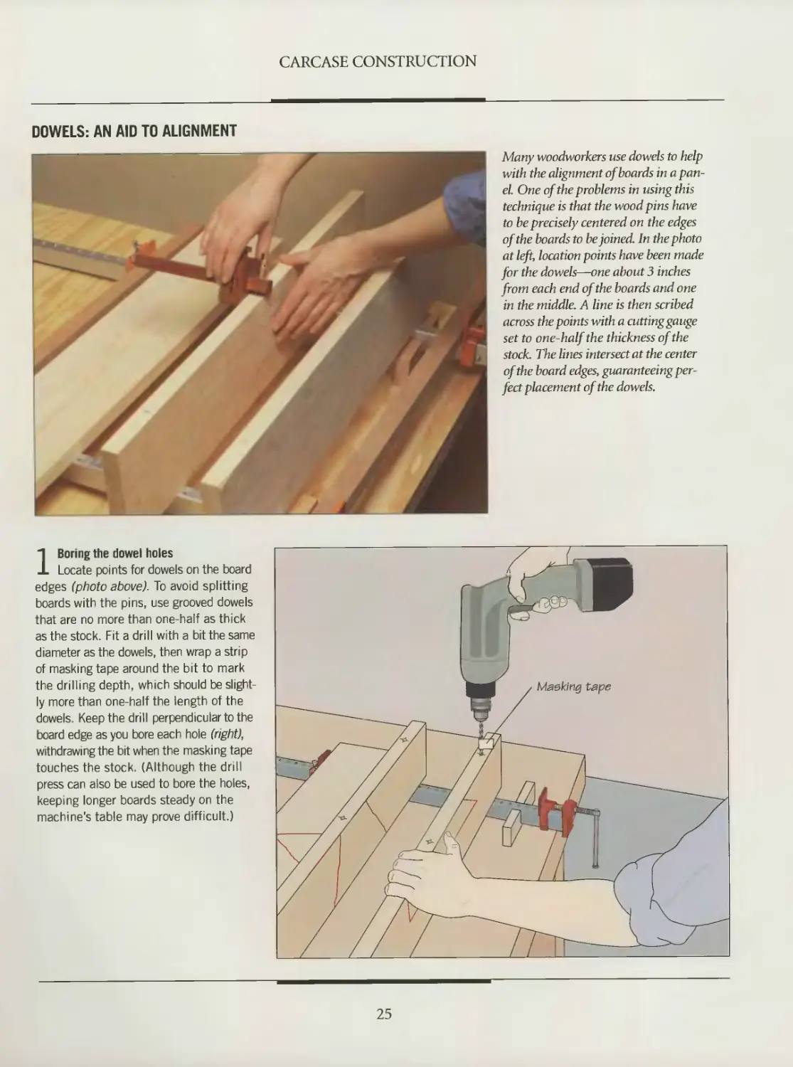
Many woodworkers use dowels to help
with the alignment of boards in a pan-
el. One of the problems in using this
technique is that the wood pins have
to be precisely centered on the edges
of the boards to be joined. In the photo
at left, location points have been made
for the dowels—one about 3 inches
from each end of the boards and one
in the middle. A line is then scribed
across the points with a cutting gauge
set to one-half the thickness of the
stock. The lines intersect at the center
of the board edges, guaranteeing per-
fect placement of the dowels.
1 Boring the dowel holes
Locate points for dowels on the board
edges (photo above). To avoid splitting
boards with the pins, use grooved dowels
that are no more than one-half as thick
as the stock. Fit a drill with a bit the same
diameter as the dowels, then wrap a strip
of masking tape around the bit to mark
the drilling depth, which should be slight-
ly more than one-half the length of the
dowels. Keep the drill perpendicular to the
board edge as you bore each hole (right),
withdrawing the bit when the masking tape
touches the stock (Although the drill
press can also be used to bore the holes,
keeping longer boards steady on the
machine's table may prove difficult.)
25
CARCASE CONSTRUCTION
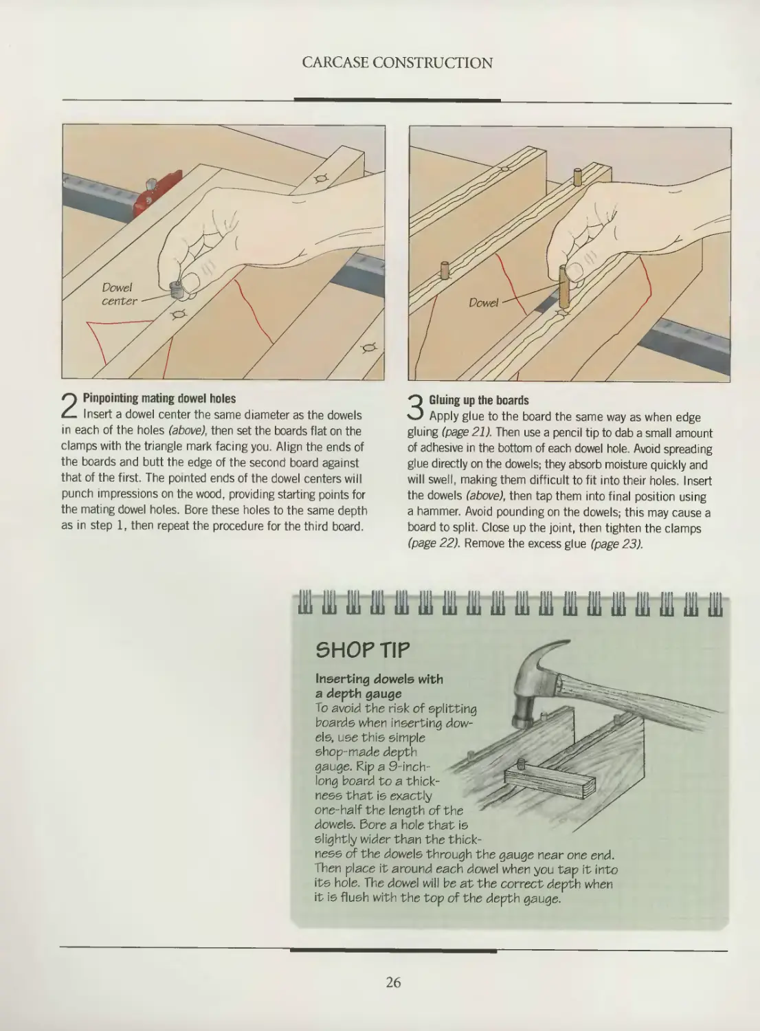
2 Pinpointing mating dowel holes
Insert a dowel center the same diameter as the dowels
in each of the holes (above), then set the boards flat on the
clamps with the triangle mark facing you. Align the ends of
the boards and butt the edge of the second board against
that of the first. The pointed ends of the dowel centers will
punch impressions on the wood, providing starting points for
the mating dowel holes. Bore these holes to the same depth
as in step 1, then repeat the procedure for the third board.
3 Gluing up the boards
Apply glue to the board the same way as when edge
gluing (page 21). Then use a pencil tip to dab a small amount
of adhesive in the bottom of each dowel hole. Avoid spreading
glue directly on the dowels; they absorb moisture quickly and
will swell, making them difficult to fit into their holes. Insert
the dowels (above), then tap them into final position using
a hammer. Avoid pounding on the dowels; this may cause a
board to split. Close up the joint, then tighten the clamps
(page 22). Remove the excess glue (page 23).
Ill IB III 111 111 IB IB IB IB IB IB 111 IB1 111 III IB 111
SHOP TIP
Inserting dowels with
a depth gauge
To avoid the risk of splitting
boards when inserting dow-
els, use this simple
shop-made depth
gauge. Rip a 9-inch-
long board to a thick-
ness that is exactly
one-half the length of the
dowels. Bore a hole that is
slightly wider than the thick-
ness of the dowels through the gauge near one end.
Then place it around each dowel when you tap it into
its hole. The dowel will be at the correct depth when
it is flush with the top of the depth gauge.
26
CARCASE JOINERY
There are many ways of joining car-
case panels together. The pages that
follow will examine three of the most
popular choices: dovetail, rabbet and
plate joinery. As shown in the photo at
right, the interlocking pins and tails
of a through dovetail joint give both
solidity and distinctive appearance.
Cutting such a joint with the tradition-
al hand tools is considered a rite of
passage for aspiring woodworkers. It
requires skill and practice to perfect.
It also leaves room for creativity, since
it allows you to choose the width of
pins and tails to give your joints an
esthetically pleasing look. The same
joint can be executed in far less time, but
with equal precision, using a router and
a jig; that approach is demonstrated
in the Drawers chapter (page 80-81).
You may also want to try the half-
blind dovetail, which is examined on
pages 82-84.
If you prefer somewhat simpler
forms of joinery, try either the rabbet
or the plate joint (page 34-37). Both
are ideal for joining plywood pan-
els, which are not suited for dovetails.
Whichever type of joinery you select,
you must plan ahead for the later stages
of your cabinetmaking projects, such as
installing back panels, shelving, edge
banding or drawers. Some drawer-hang-
ing methods, for example, require you
to rout a groove in the side panels before
the carcase is assembled.
DOVETAIL JOINTS
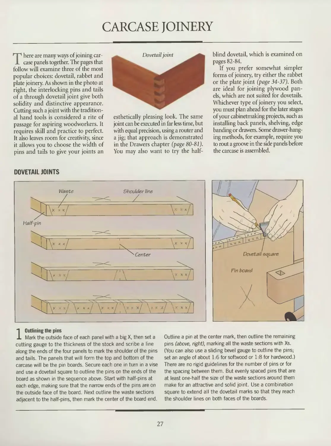
1 Outlining the pins
Mark the outside face of each panel with a big X, then set a
cutting gauge to the thickness of the stock and scribe a line
along the ends of the four panels to mark the shoulder of the pins
and tails. The panels that will form the top and bottom of the
carcase will be the pm boards. Secure each one in turn in a vise
and use a dovetail square to outline the pins on the ends of the
board as shown in the sequence above. Start with half-pins at
each edge, making sure that the narrow ends of the pins are on
the outside face of the board. Next outline the waste sections
adjacent to the half-pins, then mark the center of the board end.
Outline a pin at the center mark, then outline the remaining
pins (above, right), marking all the waste sections with Xs.
(You can also use a sliding bevel gauge to outline the pins;
set an angle of about 1:6 for softwood or 1:8 for hardwood )
There are no rigid guidelines for the number of pins or for
the spacing between them. But evenly spaced pins that are
at least one-half the size of the waste sections around them
make for an attractive and solid joint. Use a combination
square to extend all the dovetail marks so that they reach
the shoulder lines on both faces of the boards.
27
CARCASE CONSTRUCTION
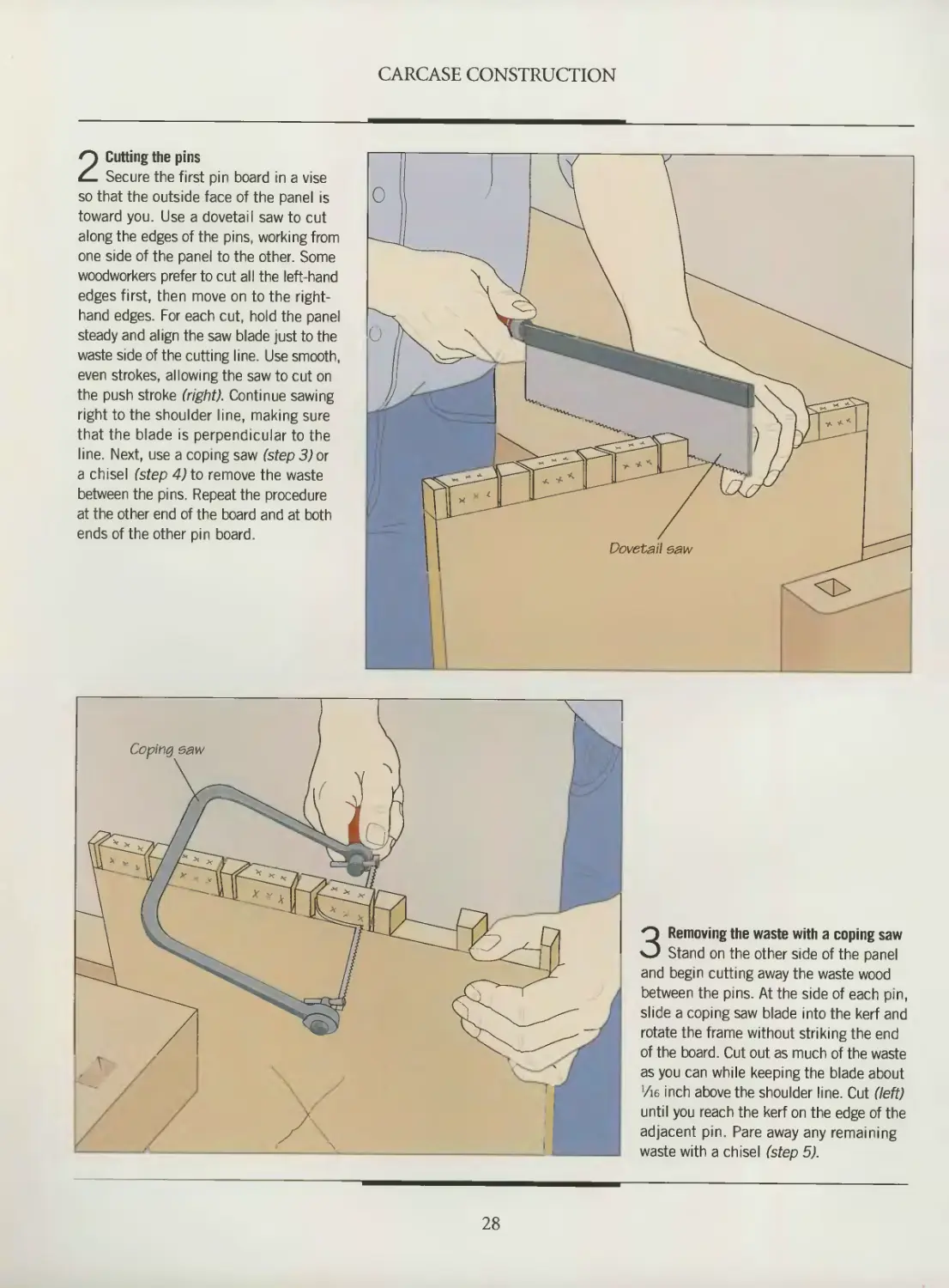
2 Cutting the pins
Secure the first pin board in a vise
so that the outside face of the panel is
toward you. Use a dovetail saw to cut
along the edges of the pins, working from
one side of the panel to the other. Some
woodworkers prefer to cut all the left-hand
edges first, then move on to the right-
hand edges. For each cut, hold the panel
steady and align the saw blade just to the
waste side of the cutting line. Use smooth,
even strokes, allowing the saw to cut on
the push stroke (right). Continue sawing
right to the shoulder line, making sure
that the blade is perpendicular to the
line Next, use a coping saw (step 3) or
a chisel (step 4) to remove the waste
between the pins. Repeat the procedure
at the other end of the board and at both
ends of the other pin board.
3 Removing the waste with a coping saw
Stand on the other side of the panel
and begin cutting away the waste wood
between the pins. At the side of each pin,
slide a coping saw blade into the kerf and
rotate the frame without striking the end
of the board. Cut out as much of the waste
as you can while keeping the blade about
Vie inch above the shoulder line. Cut (left)
until you reach the kerf on the edge of the
adjacent pin. Pare away any remaining
waste with a chisel (step 5).
28
CARCASE CONSTRUCTION
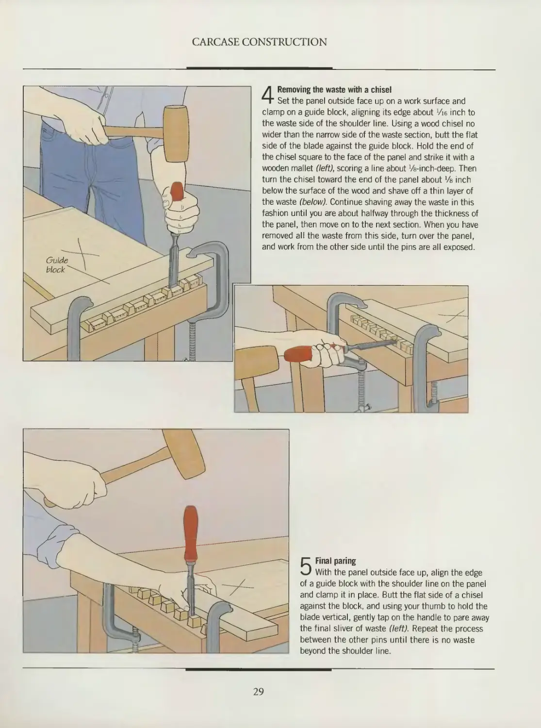
4 Removing the waste with a chisel
Set the panel outside face up on a work surface and
clamp on a guide block, aligning its edge about 716 inch to
the waste side of the shoulder line. Using a wood chisel no
wider than the narrow side of the waste section, butt the flat
side of the blade against the guide block. Hold the end of
the chisel square to the face of the panel and strike it with a
wooden mallet (left), scoring a line about Vs-inch-deep. Then
turn the chisel toward the end of the panel about Ve inch
below the surface of the wood and shave off a thin layer of
the waste (below). Continue shaving away the waste in this
fashion until you are about halfway through the thickness of
the panel, then move on to the next section. When you have
removed all the waste from this side, turn over the panel,
and work from the other side until the pins are all exposed.
5 Final paring
With the panel outside face up, align the edge
of a guide block with the shoulder line on the panel
and clamp it in place. Butt the flat side of a chisel
against the block, and using your thumb to hold the
blade vertical, gently tap on the handle to pare away
the final sliver of waste (left). Repeat the process
between the other pins until there is no waste
beyond the shoulder line.
29
CARCASE CONSTRUCTION
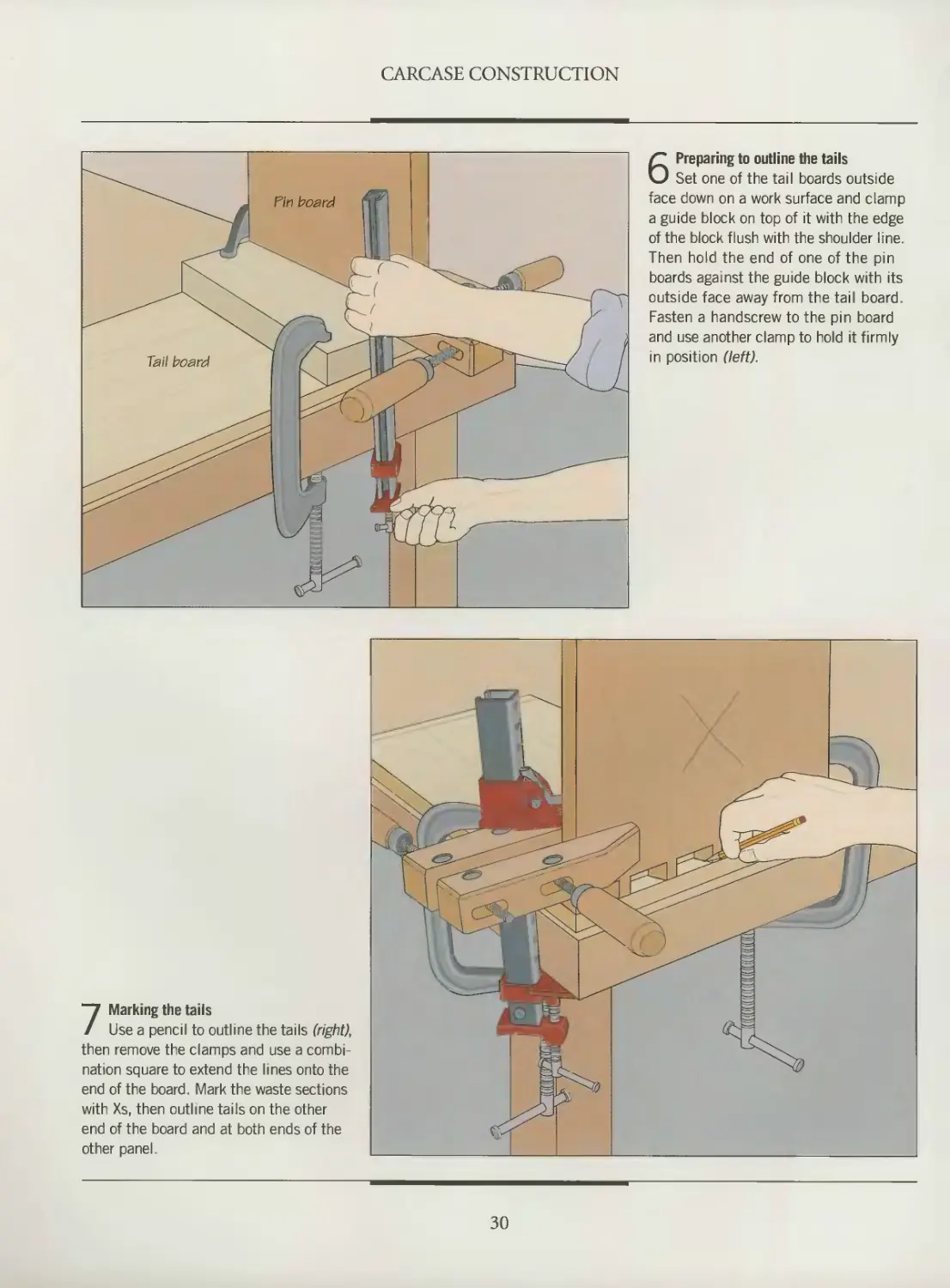
6 Preparing to outline the tails
Set one of the tail boards outside
face down on a work surface and clamp
a guide block on top of it with the edge
of the block flush with the shoulder line.
Then hold the end of one of the pin
boards against the guide block with its
outside face away from the tail board.
Fasten a handscrew to the pin board
and use another clamp to hold it firmly
in position (left).
7 Marking the tails
Use a pencil to outline the tails (right),
then remove the clamps and use a combi-
nation square to extend the lines onto the
end of the board. Mark the waste sections
with Xs, then outline tails on the other
end of the board and at both ends of the
other panel.
30
CARCASE CONSTRUCTION
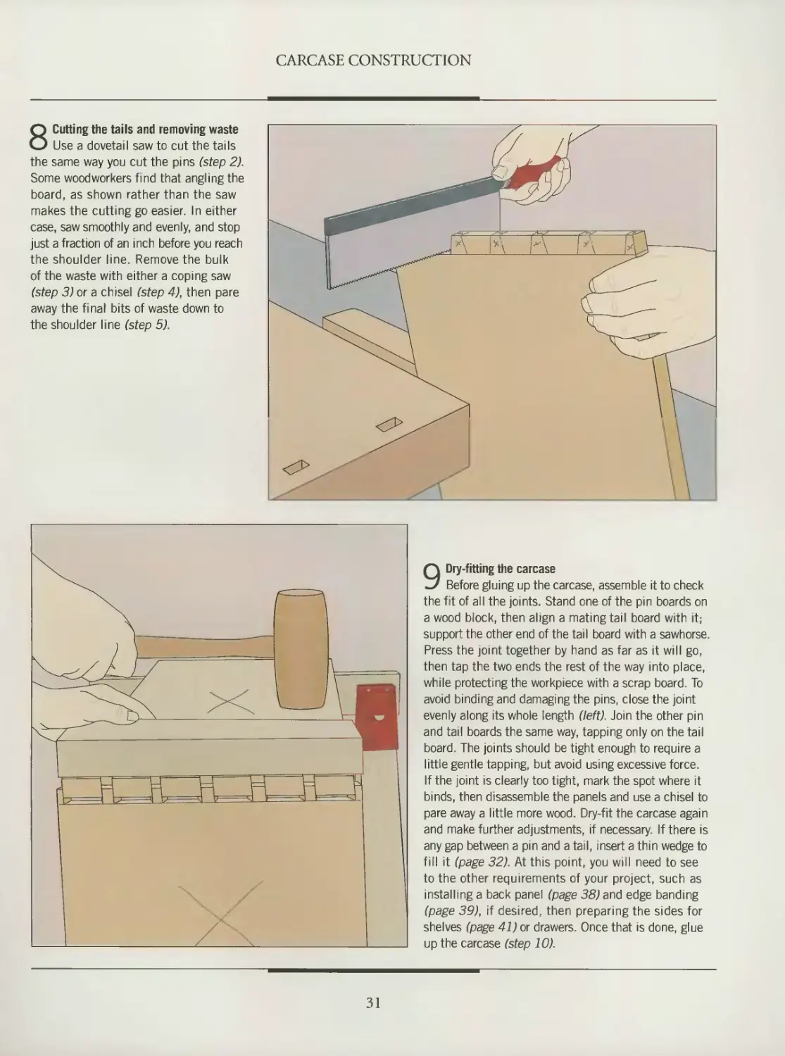
8 Cutting the tails and removing waste
Use a dovetail saw to cut the tails
the same way you cut the pins (step 2).
Some woodworkers find that angling the
board, as shown rather than the saw
makes the cutting go easier. In either
case, saw smoothly and evenly, and stop
just a fraction of an inch before you reach
the shoulder line. Remove the bulk
of the waste with either a coping saw
(step 3) or a chisel (step 4), then pare
away the final bits of waste down to
the shoulder line (step 5).
9 Dry-fitting the carcase
Before gluing up the carcase, assemble it to check
the fit of all the joints. Stand one of the pin boards on
a wood block, then align a mating tail board with it;
support the other end of the tail board with a sawhorse.
Press the joint together by hand as far as it will go,
then tap the two ends the rest of the way into place,
while protecting the workpiece with a scrap board. To
avoid binding and damaging the pins, close the joint
evenly along its whole length (left). Join the other pin
and tail boards the same way, tapping only on the tail
board. The joints should be tight enough to require a
little gentle tapping, but avoid using excessive force.
If the joint is clearly too tight, mark the spot where it
binds, then disassemble the panels and use a chisel to
pare away a little more wood. Dry-fit the carcase again
and make further adjustments, if necessary. If there is
any gap between a pin and a tail, insert a thin wedge to
fill it (page 32). At this point, you will need to see
to the other requirements of your project, such as
installing a back panel (page 38) and edge banding
(page 39), if desired, then preparing the sides for
shelves (page 41) or drawers. Once that is done, glue
up the carcase (step 10).
31
CARCASE CONSTRUCTION
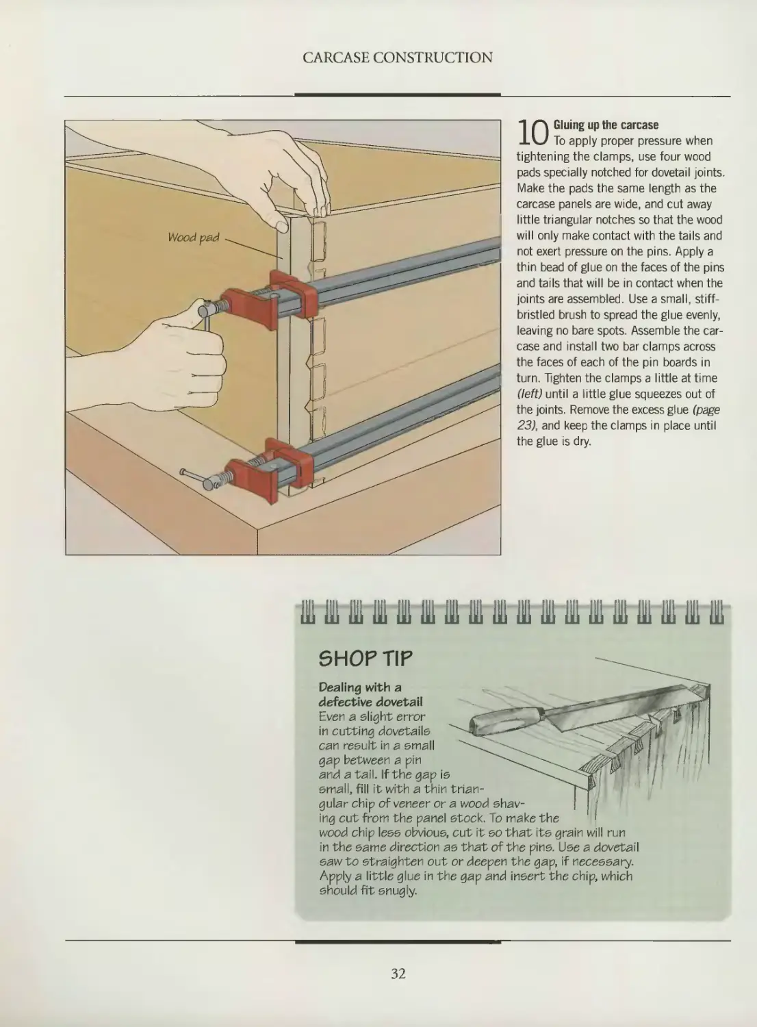
Ю Gluing up the carcase
To apply proper pressure when
tightening the clamps, use four wood
pads specially notched for dovetail joints.
Make the pads the same length as the
carcase panels are wide, and cut away
little triangular notches so that the wood
will only make contact with the tails and
not exert pressure on the pins. Apply a
thin bead of glue on the faces of the pins
and tails that will be in contact when the
joints are assembled. Use a small, stiff-
bristled brush to spread the glue evenly,
leaving no bare spots. Assemble the car-
case and install two bar clamps across
the faces of each of the pin boards in
turn. Tighten the clamps a little at time
(left) until a little glue squeezes out of
the joints. Remove the excess glue (page
23), and keep the clamps in place until
the glue is dry.
Ill IB Bl ill III ill III Hi 111 ill ft IB IB IB ill IB 111 Hi
SHOP TIP
Dealing with a
defective dovetail
Even a slight error
in cutting dovetails
can result in a small
gap between a pin
and a tail. If the gap is
small, fill it with a thin trian-
gular chip of veneer or a wood shav-
ing cut from the panel stock. To make the
wood chip less obvious, cut it so that its grain will run
in the same direction as that of the pins. Use a dovetail
saw to straighten out or deepen the gap, if necessary.
Apply a little glue in the gap and insert the chip, which
should fit snugly.
32
CARCASE CONSTRUCTION
BUILD IT YOURSELF
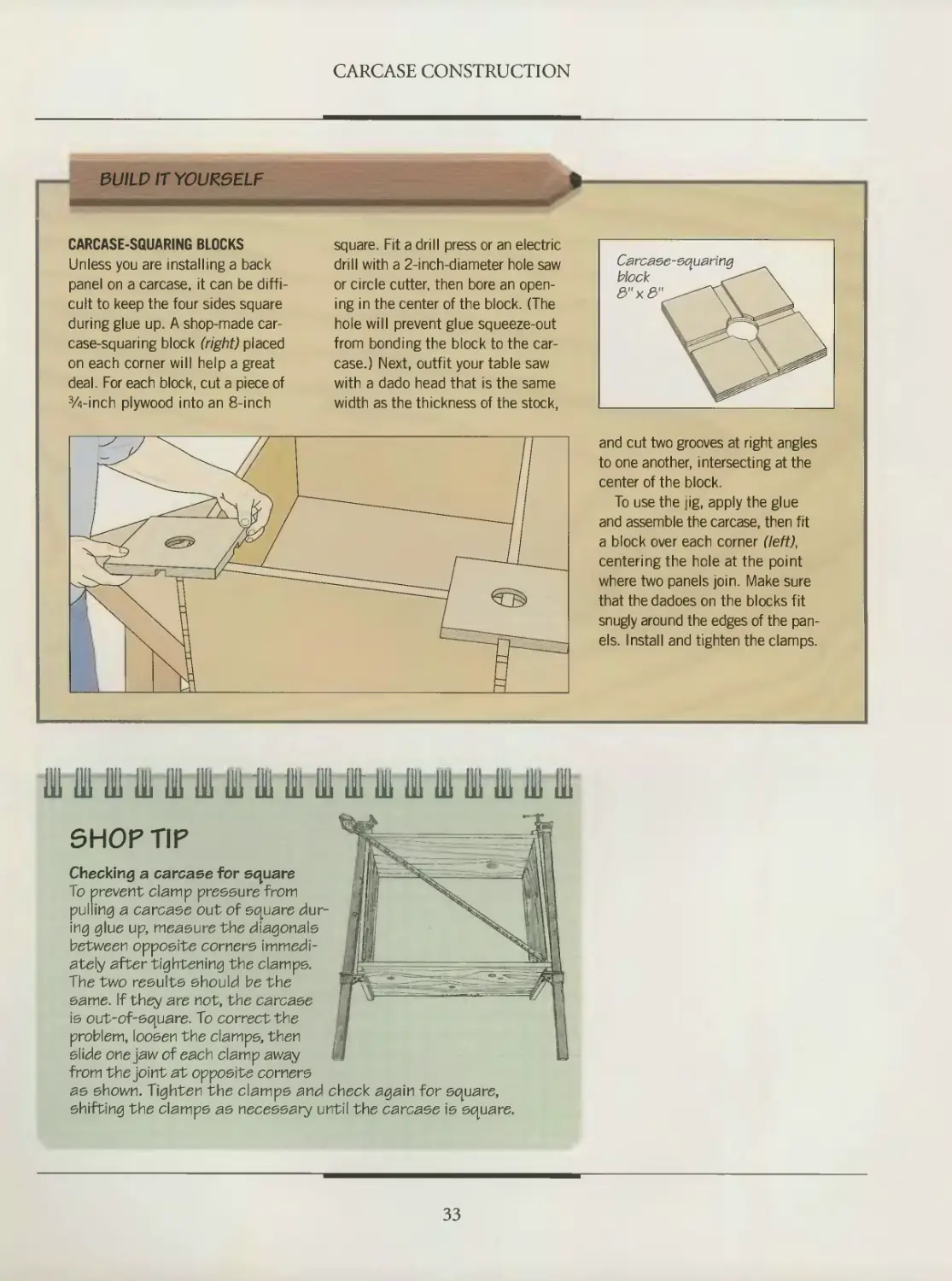
CARCASE-SQUARING BLOCKS
Unless you are installing a back
panel on a carcase, it can be diffi-
cult to keep the four sides square
during glue up. A shop-made car-
case-squaring block (right) placed
on each corner will help a great
deal. For each block, cut a piece of
%-inch plywood into an 8-inch
square. Fit a drill press or an electric
drill with a 2-inch-diameter hole saw
or circle cutter, then bore an open-
ing in the center of the block. (The
hole will prevent glue squeeze-out
from bonding the block to the car-
case.) Next, outfit your table saw
with a dado head that is the same
width as the thickness of the stock,
and cut two grooves at right angles
to one another, intersecting at the
center of the block.
To use the jig, apply the glue
and assemble the carcase, then fit
a block over each corner (left),
centering the hole at the point
where two panels join. Make sure
that the dadoes on the blocks fit
snugly around the edges of the pan-
els. Install and tighten the clamps.
HI 111 ffi Hi Hi HI UTHI Ж ш ffi Ш Ш 111 HI 111 ill di
SHOP TIP
Checking a carcase for square
To prevent clamp pressure from
pulling a carcase out of square dur-
ing glue up, measure the diagonals
between opposite corners immedi-
ately after tightening the clamps.
The two results should be the
same. If they are not, the carcase
is out-of-square. To correct the
problem, loosen the clamps, then
slide one jaw of each clamp away
from the joint at opposite corners
as shown. Tighten the clamps and check again for square,
shifting the clamps as necessary until the carcase is square.
33
CARCASE CONSTRUCTION
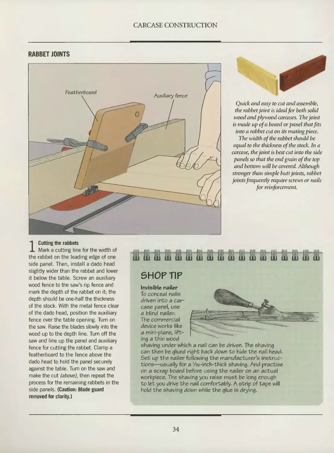
RABBET JOINTS
Quick and easy to cut and assemble,
the rabbet joint is ideal for both solid
wood and plywood carcases. The joint
is made up of a board or panel that fits
into a rabbet cut on its mating piece.
The width of the rabbet should be
equal to the thickness of the stock. In a
carcase, the joint is best cut into the side
panels so that the end grain of the top
and bottom will be covered. Although
stronger than simple butt joints, rabbet
joints frequently require screws or nails
for reinforcement.
1 Cutting the rabbets
Mark a cutting line for the width of
the rabbet on the leading edge of one
side panel. Then, install a dado head
slightly wider than the rabbet and lower
it below the table. Screw an auxiliary
wood fence to the saw’s rip fence and
mark the depth of the rabbet on it; the
depth should be one-half the thickness
of the stock. With the metal fence clear
of the dado head, position the auxiliary
fence over the table opening. Turn on
the saw. Raise the blades slowly into the
wood up to the depth line. Turn off the
saw and line up the panel and auxiliary
fence for cutting the rabbet. Clamp a
featherboard to the fence above the
dado head to hold the panel securely
against the table. Turn on the saw and
make the cut (above), then repeat the
process for the remaining rabbets in the
side panels. (Caution: Blade guard
removed for clarity.)
ill Hi ft IB in 111 Hi IB 111 Hi ill UK lit di IB IB Illi
SHOP TIP
Invisible nailer
To conceal nails
driven into a car-
case panel, use
a blind nailer.
The commercial
device works like
a mini-plane, lift-
ing a thin wood
shaving under which a nail can be driven. The shaving
can then be glued right back down to hide the nail head.
Set up the nailer following the manufacturer’s instruc-
tions—usually for a 1/s2-inch-thick shaving. And practise
on a scrap board before using the nailer on an actual
workpiece. The shaving you raise must be long enough
to let you drive the nail comfortably. A strip of tape will
hold the shaving down while the glue is drying.
34
CARCASE CONSTRUCTION
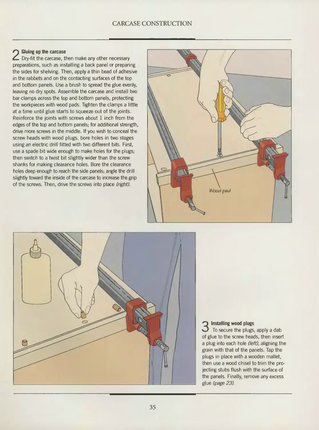
2 Gluing up the carcase
Dry-fit the carcase, then make any other necessary
preparations, such as installing a back panel or preparing
the sides for shelving. Then, apply a thin bead of adhesive
in the rabbets and on the contacting surfaces of the top
and bottom panels. Use a brush to spread the glue evenly,
leaving no dry spots. Assemble the carcase and install two
bar clamps across the top and bottom panels, protecting
the workpieces with wood pads. Tighten the clamps a little
at a time until glue starts to squeeze out of the joints.
Reinforce the joints with screws about 1 inch from the
edges of the top and bottom panels; for additional strength,
drive more screws in the middle. If you wish to conceal the
screw heads with wood plugs, bore holes in two stages
using an electric drill fitted with two different bits. First,
use a spade bit wide enough to make holes for the plugs;
then switch to a twist bit slightly wider than the screw
shanks for making clearance holes. Bore the clearance
holes deep enough to reach the side panels; angle the drill
slightly toward the inside of the carcase to increase the grip
of the screws. Then, drive the screws into place (light).
3 Installing wood plugs
To secure the plugs, apply a dab
of glue to the screw heads, then insert
a plug into each hole (left), aligning the
grain with that of the panels. Tap the
plugs in place with a wooden mallet,
then use a wood chisel to trim the pro-
jecting stubs flush with the surface of
the panels. Finally, remove any excess
glue (page 23).
35
CARCASE CONSTRUCTION
PLATE JOINTS
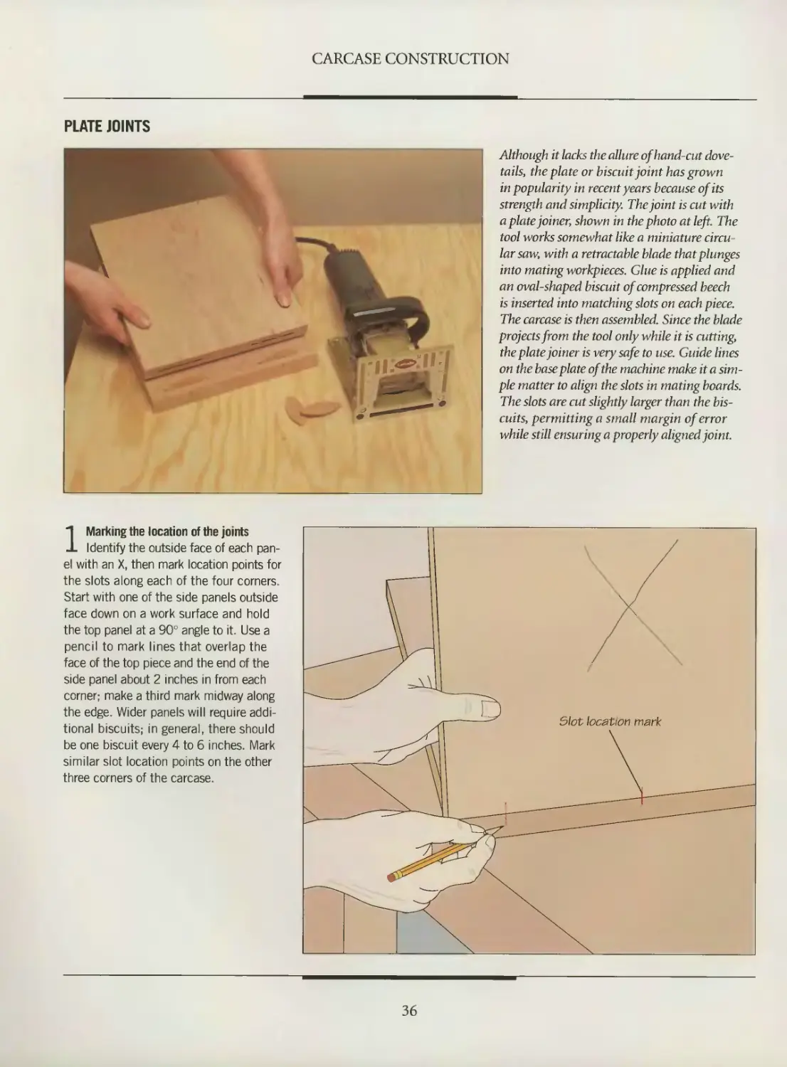
Although it lacks the allure of hand-cut dove-
tails, the plate or biscuit joint has grown
in popularity in recent years because of its
strength and simplicity. The joint is cut with
a plate joiner, shown in the photo at left. The
tool works somewhat like a miniature circu-
larsaw, with a retractable blade that plunges
into mating workpieces. Glue is applied and
an oval-shaped biscuit of compressed beech
is inserted into matching slots on each piece.
The carcase is then assembled. Since the blade
projects from the tool only while it is cutting,
the plate joiner is very safe to use. Guide lines
on the baseplate of the machine make it a sim-
ple matter to align the slots in mating boards.
The slots are cut slightly larger than the bis-
cuits, permitting a small margin of error
while still ensuring a properly aligned joint.
1 Marking the location of the joints
Identify the outside face of each pan-
el with an X, then mark location points for
the slots along each of the four corners.
Start with one of the side panels outside
face down on a work surface and hold
the top panel at a 90° angle to it. Use a
pencil to mark lines that overlap the
face of the top piece and the end of the
side panel about 2 inches in from each
corner; make a third mark midway along
the edge. Wider panels will require addi-
tional biscuits; in general, there should
be one biscuit every 4 to 6 inches. Mark
similar slot location points on the other
three corners of the carcase.
36
CARCASE CONSTRUCTION
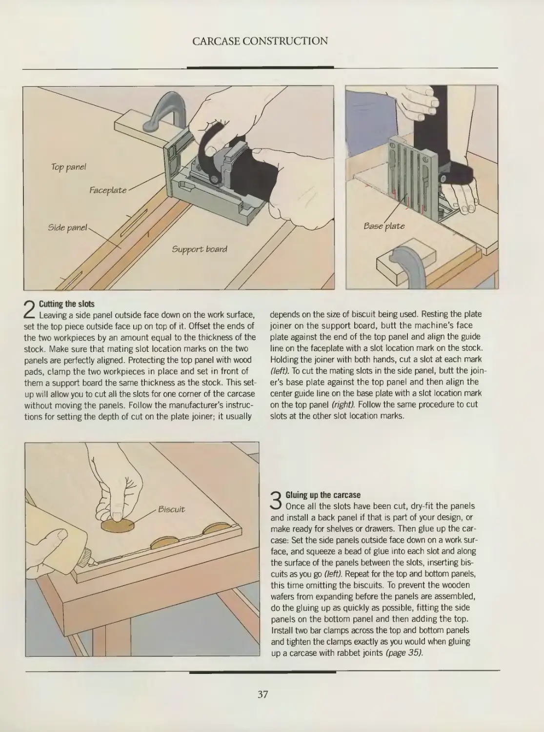
2 Cutting the slots
Leaving a side panel outside face down on the work surface,
set the top piece outside face up on top of it. Offset the ends of
the two workpieces by an amount equal to the thickness of the
stock. Make sure that mating slot location marks on the two
panels are perfectly aligned. Protecting the top panel with wood
pads, clamp the two workpieces in place and set in front of
them a support board the same thickness as the stock. This set-
up will allow you to cut all the slots for one corner of the carcase
without moving the panels. Follow the manufacturer's instruc-
tions for setting the depth of cut on the plate joiner; it usually
depends on the size of biscuit being used. Resting the plate
joiner on the support board, butt the machine's face
plate against the end of the top panel and align the guide
line on the faceplate with a slot location mark on the stock.
Holding the joiner with both hands, cut a slot at each mark
(left). To cut the mating slots in the side panel, butt the join-
er’s base plate against the top panel and then align the
center guide line on the base plate with a slot location mark
on the top panel (right). Follow the same procedure to cut
slots at the other slot location marks.
3 Gluing up the carcase
Once all the slots have been cut, dry-fit the panels
and install a back panel if that is part of your design, or
make ready for shelves or drawers. Then glue up the car-
case: Set the side panels outside face down on a work sur-
face, and squeeze a bead of glue into each slot and along
the surface of the panels between the slots, inserting bis-
cuits as you go (left). Repeat for the top and bottom panels,
this time omitting the biscuits. To prevent the wooden
wafers from expanding before the panels are assembled,
do the gluing up as quickly as possible, fitting the side
panels on the bottom panel and then adding the top.
Install two bar clamps across the top and bottom panels
and tighten the clamps exactly as you would when gluing
up a carcase with rabbet joints (page 35).
37
CARCASE CONSTRUCTION
INSTALLING A BACK PANEL
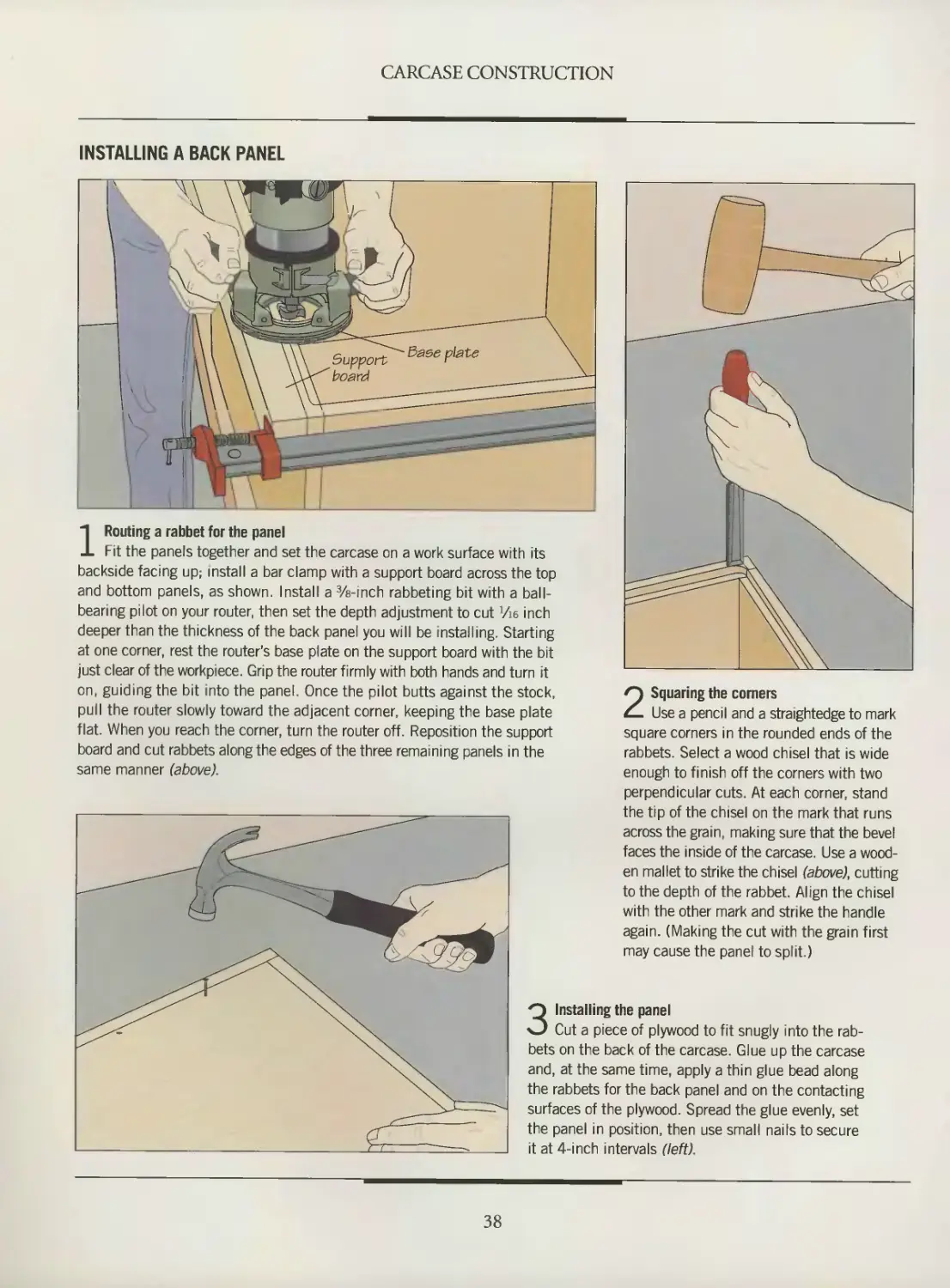
1 Routing a rabbet for the panel
Fit the panels together and set the carcase on a work surface with its
backside facing up; install a bar clamp with a support board across the top
and bottom panels, as shown. Install a %-inch rabbeting bit with a ball-
bearing pilot on your router, then set the depth adjustment to cut Vie inch
deeper than the thickness of the back panel you will be installing. Starting
at one corner, rest the router's base plate on the support board with the bit
just clear of the workpiece. Grip the router firmly with both hands and turn it
on, guiding the bit into the panel. Once the pilot butts against the stock,
pull the router slowly toward the adjacent corner, keeping the base plate
flat. When you reach the corner, turn the router off. Reposition the support
board and cut rabbets along the edges of the three remaining panels in the
same manner (above).
2 Squaring the corners
Use a pencil and a straightedge to mark
square corners in the rounded ends of the
rabbets. Select a wood chisel that is wide
enough to finish off the corners with two
perpendicular cuts. At each corner, stand
the tip of the chisel on the mark that runs
across the grain, making sure that the bevel
faces the inside of the carcase. Use a wood-
en mallet to strike the chisel (above), cutting
to the depth of the rabbet. Align the chisel
with the other mark and strike the handle
again. (Making the cut with the grain first
may cause the panel to split.)
3 Installing the panel
Cut a piece of plywood to fit snugly into the rab-
bets on the back of the carcase. Glue up the carcase
and, at the same time, apply a thin glue bead along
the rabbets for the back panel and on the contacting
surfaces of the plywood. Spread the glue evenly, set
the panel in position, then use small nails to secure
it at 4-inch intervals (left).
38
EDGE BANDING
Edge banding is the usual way of con
cealing the visible edges of plywood
panels and shelves; it creates the illusion
that the carcase is made exclusively of
solid wood. You can choose one of two
options: Commercial edge banding,
shown on page 40, is available in a wide
variety of wood types, colors and thick-
nesses. Installing it is simply a matter of
cutting off the lengths you need from a
roll, setting the banding in place and
heating it with a household iron to melt
the adhesive that bonds it to the surface
of the wood.
Although somewhat more painstak-
ing to apply, shop-made edge banding
offers several advantages over the store-
bought solution. You can make it from
any available wood species and cut it
to whatever thickness you choose;
‘/e-inch-thick banding is typical. The
shop-made variety is also less expen-
sive—a consideration if you plan to
use a lot of banding.
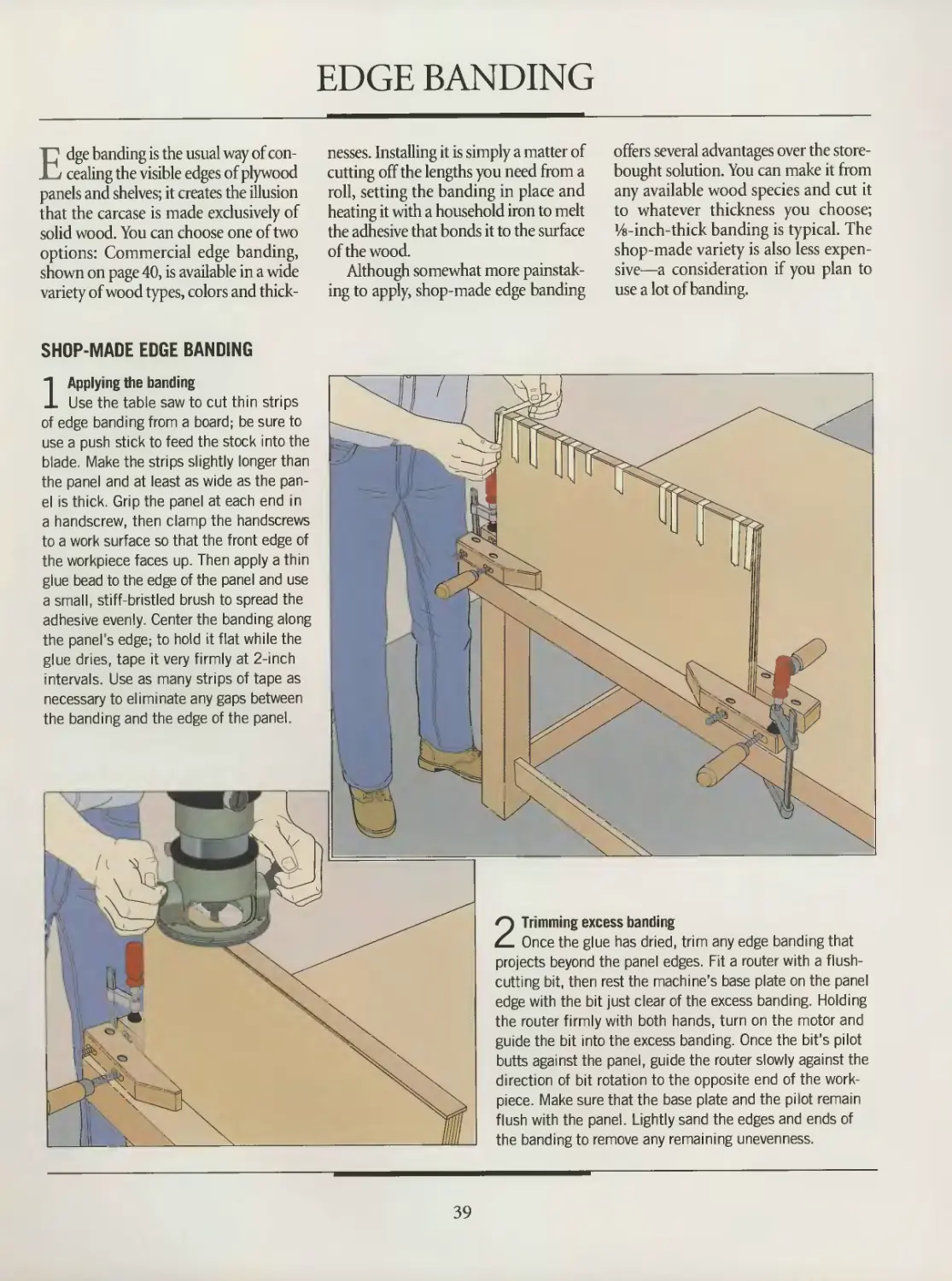
SHOP-MADE EDGE BANDING
1 Applying the banding
Use the table saw to cut thin strips
of edge banding from a board; be sure to
use a push stick to feed the stock into the
blade. Make the strips slightly longer than
the panel and at least as wide as the pan-
el is thick. Grip the panel at each end in
a handscrew, then clamp the handscrews
to a work surface so that the front edge of
the workpiece faces up. Then apply a thin
glue bead to the edge of the panel and use
a small, stiff-bristled brush to spread the
adhesive evenly. Center the banding along
the panel's edge; to hold it flat while the
glue dries, tape it very firmly at 2-inch
intervals. Use as many strips of tape as
necessary to eliminate any gaps between
the banding and the edge of the panel.
2 Trimming excess banding
Once the glue has dried, trim any edge banding that
projects beyond the panel edges. Fit a router with a flush-
cutting bit, then rest the machine’s base plate on the panel
edge with the bit just clear of the excess banding. Holding
the router firmly with both hands, turn on the motor and
guide the bit into the excess banding. Once the bit’s pilot
butts against the panel, guide the router slowly against the
direction of bit rotation to the opposite end of the work-
piece. Make sure that the base plate and the pilot remain
flush with the panel. Lightly sand the edges and ends of
the banding to remove any remaining unevenness.
39
CARCASE CONSTRUCTION
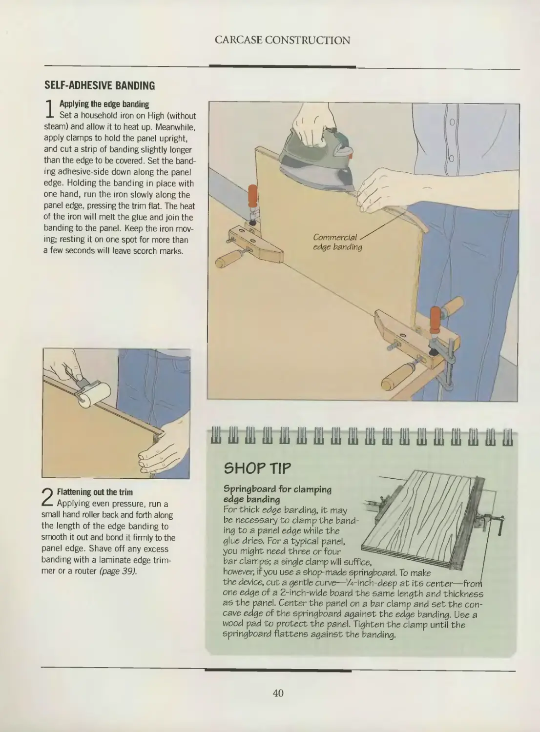
SELF-ADHESIVE BANDING
1 Applying the edge banding
Set a household iron on High (without
steam) and allow it to heat up. Meanwhile,
apply clamps to hold the panel upright,
and cut a strip of banding slightly longer
than the edge to be covered Set the band-
ing adhesive-side down along the panel
edge. Holding the banding in place with
one hand, run the iron slowly along the
panel edge, pressing the trim flat. The heat
of the iron will melt the glue and join the
banding to the panel. Keep the iron mov-
ing; resting it on one spot for more than
a few seconds will leave scorch marks.
HI IB III III in 111 111 I in IB 111 Hi 111 Hl IB IB 111
SHOP TIP
2 Flattening out the trim
Applying even pressure, run a
small hand roller back and forth along
the length of the edge banding to
smooth it out and bond it firmly to the
panel edge. Shave off any excess
banding with a laminate edge trim-
mer or a router (page 39).
Springboard for clamping
edge banding
For thick edge banding, it may
be necessary to clampthe band-
ing to a panel edge while the
glue dries. For a typical panel,
you might need three or four
bar clamps; a single clamp will suffice,
however, if you use a shop-made springboard. To make
the device, cut a gentle curve—’A-inch-deep at its center—fro
one edge of a 2-inch-wide board the same length and thickness
as the panel. Center the panel on a bar clamp and set the con-
cave edge of the springboard againstthe edge banding. Use a
wood pad to protect the panel. Tighten the clamp until the
springboard flattens against the banding.
40
SHELVING
Adding shelves to a carcase is one way
to turn a simple wood box into a
useful piece of furniture. The simplest
method for installing shelves is to bore
two parallel rows of holes in the side
panels of the carcase and insert com-
mercially available plastic or metal shelf
supports. The two alternatives shown in
this chapter require a little more prepa-
ration, but they have a payoff in that
there are no visible shelf supports to mar
the appearance of the finished piece. Like
commercial shelf hardware, hidden sup-
ports (below and page 42) are adjustable;
the difference is that they rely on nar-
row wood strips recessed in rabbets cut
into the underside of the shelves, and
this makes them all but invisible.
For fixed shelves (page 43), you have
to rout dadoes on carcase sides. The
shelves are then glued permanently in
place when the carcase is assembled.
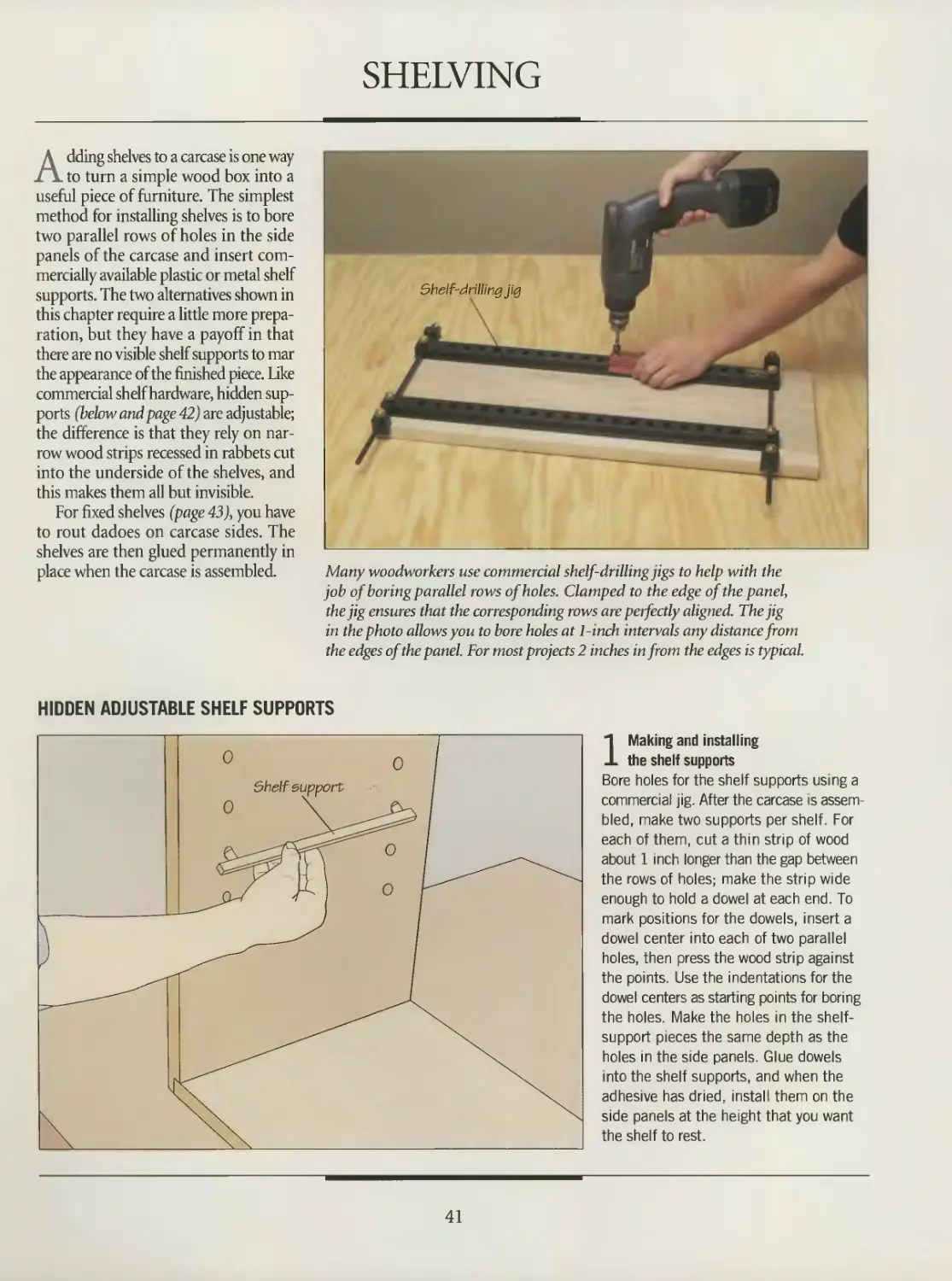
Many woodworkers use commercial shelf-drilling jigs to help with the
job of boring parallel rows of holes. Clamped to the edge of the panel,
the jig ensures that the corresponding rows are perfectly aligned. The jig
in the photo allows you to bore holes at 1-inch intervals any distance from
the edges of the panel. For most projects 2 inches in from the edges is typical.
HIDDEN ADJUSTABLE SHELF SUPPORTS
1 Making and installing
the shelf supports
Bore holes for the shelf supports using a
commercial jig. After the carcase is assem-
bled, make two supports per shelf. For
each of them, cut a thin strip of wood
about 1 inch longer than the gap between
the rows of holes; make the strip wide
enough to hold a dowel at each end. To
mark positions for the dowels, insert a
dowel center into each of two parallel
holes, then press the wood strip against
the points. Use the indentations for the
dowel centers as starting points for boring
the holes. Make the holes in the shelf-
support pieces the same depth as the
holes in the side panels. Glue dowels
into the shelf supports, and when the
adhesive has dried, install them on the
side panels at the height that you want
the shelf to rest.
41
CARCASE CONSTRUCTION
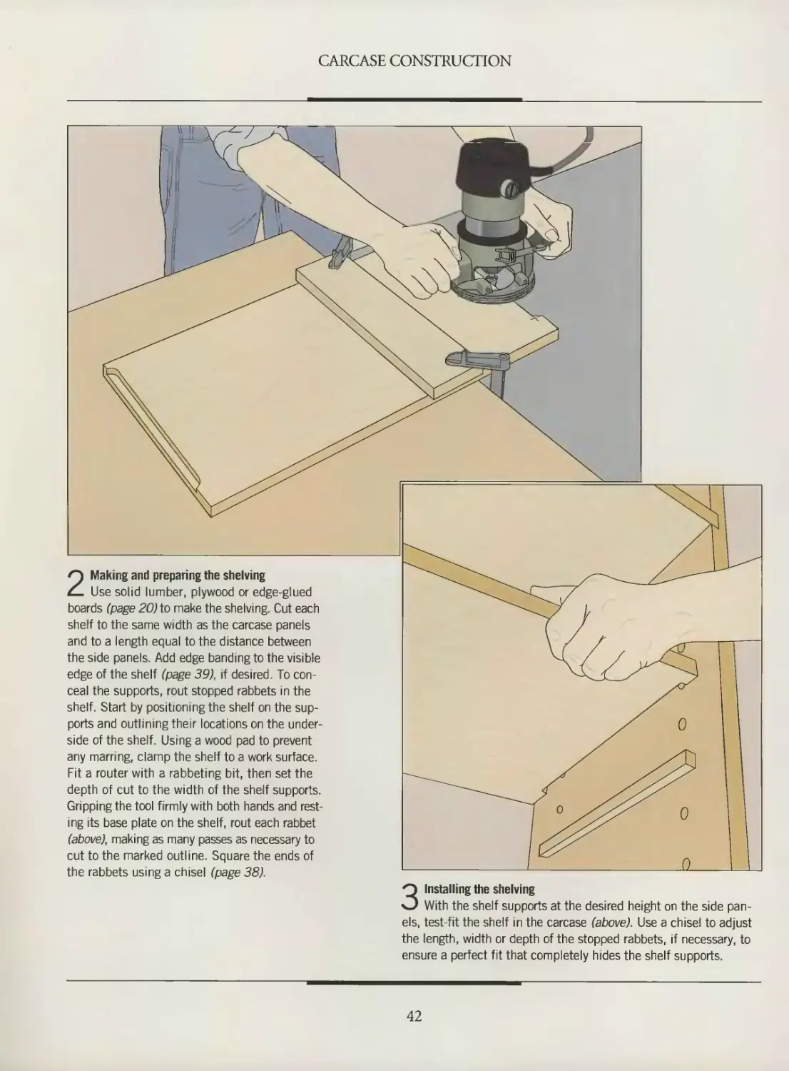
2 Making and preparing the shelving
Use solid lumber, plywood or edge-glued
boards (page 20) to make the shelving. Cut each
shelf to the same width as the carcase panels
and to a length equal to the distance between
the side panels. Add edge banding to the visible
edge of the shelf (page 39), if desired. To con-
ceal the supports, rout stopped rabbets in the
shelf. Start by positioning the shelf on the sup-
ports and outlining their locations on the under-
side of the shelf. Using a wood pad to prevent
any marring, clamp the shelf to a work surface.
Fit a router with a rabbeting bit, then set the
depth of cut to the width of the shelf supports.
Gripping the tool firmly with both hands and rest-
ing its base plate on the shelf, rout each rabbet
(above), making as many passes as necessary to
cut to the marked outline. Square the ends of
the rabbets using a chisel (page 38).
3 Installing the shelving
With the shelf supports at the desired height on the side pan-
els, test-fit the shelf in the carcase (above). Use a chisel to adjust
the length, width or depth of the stopped rabbets, if necessary, to
ensure a perfect fit that completely hides the shelf supports.
42
CARCASE CONSTRUCTION
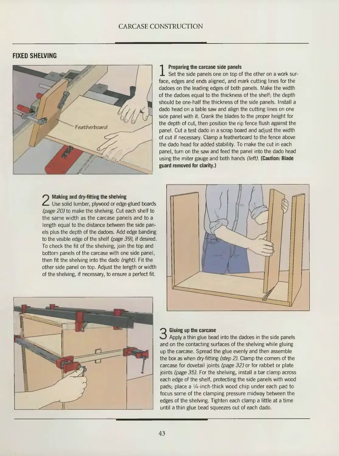
FIXED SHELVING
1 Preparing the carcase side panels
Set the side panels one on top of the other on a work sur-
face, edges and ends aligned, and mark cutting lines for the
dadoes on the leading edges of both panels. Make the width
of the dadoes equal to the thickness of the shelf; the depth
should be one-half the thickness of the side panels. Install a
dado head on a table saw and align the cutting lines on one
side panel with it. Crank the blades to the proper height for
the depth of cut, then position the rip fence flush against the
panel. Cut a test dado in a scrap board and adjust the width
of cut if necessary. Clamp a featherboard to the fence above
the dado head for added stability. To make the cut in each
panel, turn on the saw and feed the panel into the dado head
using the miter gauge and both hands (left). (Caution: Blade
guard removed for clarity.)
2 Making and dry-fitting the shelving
Use solid lumber, plywood or edge-glued boards
(page 20) to make the shelving. Cut each shelf to
the same width as the carcase panels and to a
length equal to the distance between the side pan-
els plus the depth of the dadoes. Add edge banding
to the visible edge of the shelf (page 39), if desired.
To check the fit of the shelving, join the top and
bottom panels of the carcase with one side panel,
then fit the shelving into the dado (right). Fit the
other side panel on top. Adjust the length or width
of the shelving, if necessary, to ensure a perfect fit.
3 Gluing up the carcase
Apply a thin glue bead into the dadoes in the side panels
and on the contacting surfaces of the shelving while gluing
up the carcase. Spread the glue evenly and then assemble
the box as when dry-fitting (step 2). Clamp the corners of the
carcase for dovetail joints (page 32) or for rabbet or plate
joints (page 35). For the shelving, install a bar clamp across
each edge of the shelf, protecting the side panels with wood
pads; place a VA-inch-thick wood chip under each pad to
focus some of the clamping pressure midway between the
edges of the shelving. Tighten each clamp a little at a time
until a thin glue bead squeezes out of each dado.
43
FRAME-AND-PANEL
CONSTRUCTION
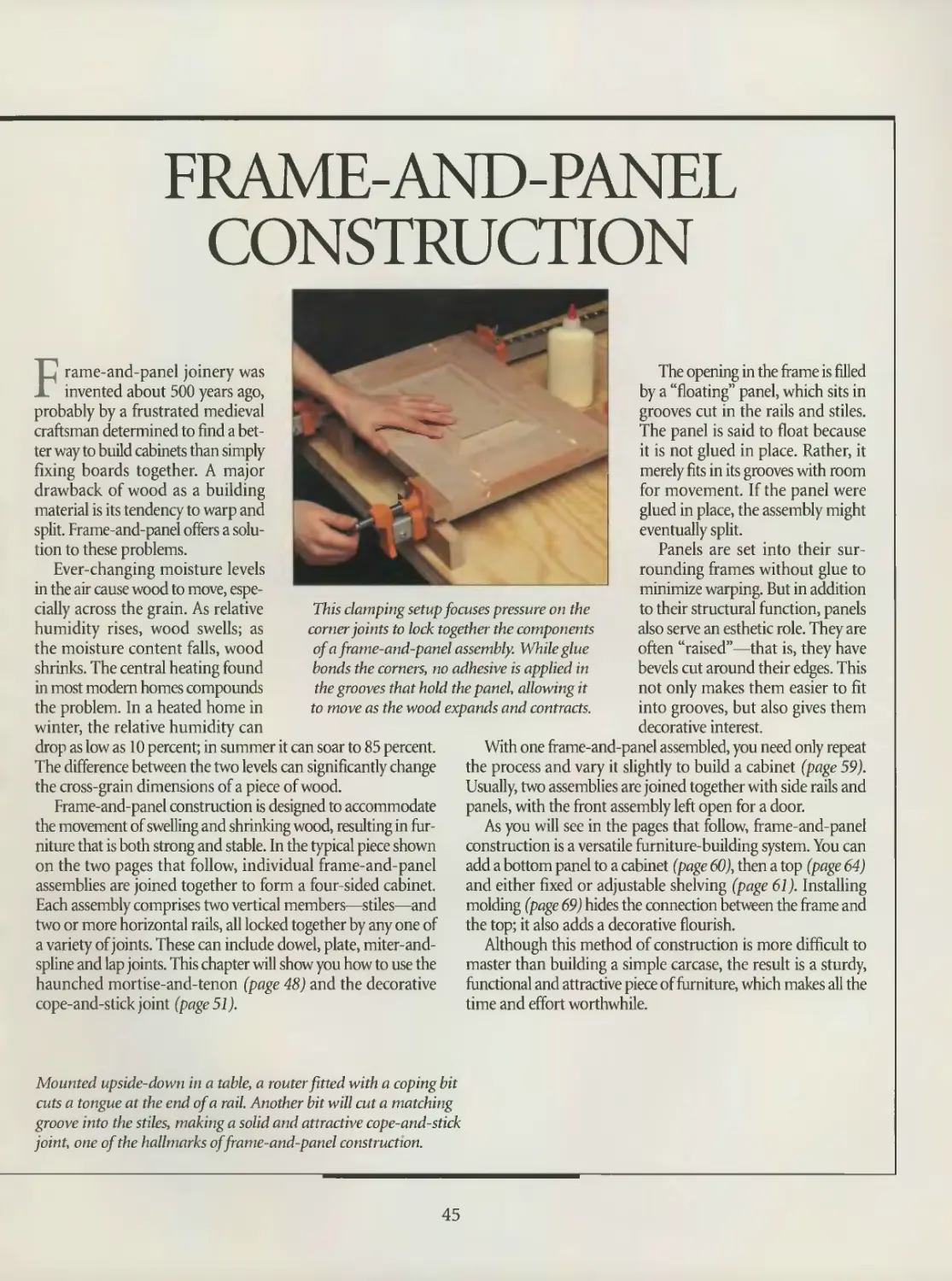
This clamping setup focuses pressure on the
corner joints to lock, together the components
of a frame-and-panel assembly. While glue
bonds the corners, no adhesive is applied in
the grooves that hold the panel, allowing it
to move as the wood expands and contracts.
Frame-and-panel joinery was
invented about 500 years ago,
probably by a frustrated medieval
craftsman determined to find a bet-
ter way to build cabinets than simply
fixing boards together. A major
drawback of wood as a building
material is its tendency to warp and
split. Frame-and-panel offers a solu-
tion to these problems.
Ever-changing moisture levels
in the air cause wood to move, espe-
cially across the grain. As relative
humidity rises, wood swells; as
the moisture content falls, wood
shrinks. The central heating found
in most modem homes compounds
the problem. In a heated home in
winter, the relative humidity can
drop as low as 10 percent; in summer it can soar to 85 percent.
The difference between the two levels can significantly change
the cross-grain dimensions of a piece of wood.
Frame-and-panel construction is designed to accommodate
the movement of swelling and shrinking wood, resulting in fur-
niture that is both strong and stable. In the typical piece shown
on the two pages that follow, individual frame-and-panel
assemblies are joined together to form a four-sided cabinet.
Each assembly comprises two vertical members—stiles—and
two or more horizontal rails, all locked together by any one of
a variety of joints. These can include dowel, plate, miter-and-
spline and lap joints. This chapter will show you how to use the
haunched mortise-and-tenon (page 48) and the decorative
cope-and-stick joint (page 51).
The opening in the frame is filled
by a “floating” panel, which sits in
grooves cut in the rails and stiles.
The panel is said to float because
it is not glued in place. Rather, it
merely fits in its grooves with room
for movement. If the panel were
glued in place, the assembly might
eventually split.
Panels are set into their sur-
rounding frames without glue to
minimize warping. But in addition
to their structural function, panels
also serve an esthetic role. They are
often “raised”—that is, they have
bevels cut around their edges. This
not only makes them easier to fit
into grooves, but also gives them
decorative interest.
With one frame-and-panel assembled, you need only repeat
the process and vary it slightly to build a cabinet (page 59).
Usually, two assemblies are joined together with side rails and
panels, with the front assembly left open for a door.
As you will see in the pages that follow, frame-and-panel
construction is a versatile furniture-building system. You can
add a bottom panel to a cabinet (page 60), then a top (page 64)
and either fixed or adjustable shelving (page 61). Installing
molding (page 69) hides the connection between the frame and
the top; it also adds a decorative flourish.
Although this method of construction is more difficult to
master than building a simple carcase, the result is a sturdy,
functional and attractive piece of furniture, which makes all the
time and effort worthwhile.
Mounted upside-down in a table, a router fitted with a coping bit
cuts a tongue at the end of a rail. Another bit will cut a matching
groove into the stiles, making a soud and attractive cope-and-stick
joint, one of the hallmarks of frame-and-panel construction.
45
ANATOMY OF A FRAME-AND-PANEL ASSEMBLY
Despite their differences, the frame-
and-panel assemblies that make up
a typical cabinet have elements in com-
mon: Namely, frames made from rails
and stiles, and panels that fit into grooves
in the frame. Bottoms and tops are usu-
ally added, along with shelving in many
cases. These components are typically
made of edge-glued boards of the same
stock used for the frame.
Individual cabinets will feature vari-
ations. In some instances, the sides will
share stiles with the front and back
assemblies with rails fitting into both the
edges and the faces of the stiles. To pro-
vide access to the inside of the cabinet,
the front frequently has a frame but
no panel. Sometimes, a median rail is
used to divide the opening into two
discrete sections.
The two most common joints in frame-
and-panel cabinets are the haunched
mortise-and-tenon and the cope-and-
stick. The haunched mortise-and-tenon
offers greater gluing surface than the
standard mortise-and- tenon, making it
a very strong joint. The haunch also
fills in the end of the groove cut into
the stiles, eliminating the need for
stopped grooves. The cope-and-stick
joint provides comparable strength
and adds its own decorative touch.
The router bit that cuts the grooves
for the panel also carves a decorative
molding in the inside edges of the frame.
Whatever the joint, cabinetmakers usu-
ally build frames from 3/4-inch stock
that is at least 2 inches wide; larger
stock may also be used to suit the dimen-
sions of a particular project.
Rail
Provides horizontal
support at top and
bottom of cabinet
Stile
Vertical
component
of frame
Panel
Solid wood piece
that fits into
groove—typically
1/z-inch-deep— in
frame; can be flat
with edges rabbet-
ed or beveled on
four sides to “raise’
center of the panel
Median rail
Used for
additional
horizontal
support
46
FRAME-AND-PANEL CONSTRUCTION
Shelf support
Can be positioned in dadoes
at any height inside cabinet
to provide adjustable shelving
Molding
Conceals joint between top
' and frame; can be purchased
or made in the shop
Bottom
Attached to frame by ledger
strips or glued into groove
cut in inside edges of frame
Wood button
Used to fasten top to frame. One end fits
into groove cut into frame, permitting slight
movement; other end screwed to top
Ledger strip
Used to fasten bottom or
top panel to frame; one
edge screwed to frame; oth-
er edge screwed to panel
Top f'
Usually overhangs outside edges of
frame; attached with wood buttons,
as shown, or with metal fasteners,
ledger strips or pocket holes. Edge
commonly has routed decoration
Shelf
May have
decorative
detail rout-
ed along
front edge
This frame-and-panel cabinet is held
together by haunched mortise-and-
tenon joints. The front has rails and
stiles, but no panel. Instead, a median
rail serves as a dividing line between
the openings for a door and a drawer.
47
MAKING THE FRAME
This section of the book examines
the framing techniques for building
a typical frame-and-panel case. Remem-
ber, however, you need a careful design
for the whole piece of furniture before
you make the first cut on a project of
your own.
Whether you will be using the stan-
dard mortise-and-tenon joint, the
haunched version of that joint (right,
top), or the cope-and-stick joint (right,
bottom), calculate the number of rails
and stiles you will be needing so you can
cut them all to length and width at the
same time. This permits you to use the
same tool setup for all the cutting.
For the haunched mortise-and-tenon
and the cope-and-stick, you must cut a
Haunched mortise-and-tenon joint
Cope-and-stick joint
groove for the floating panel along the
inside edges of the rails and stiles. The
groove is typically Vt inch wide and
Vi inch deep, and the panel is cut to
dimensions that allow Vi inch of its edges
to sit in the groove. If you opt for mor-
tise-and-tenon joints, you also need to
cut a haunched—or notched—tenon at
the ends of each rail to accommodate the
panel. For frames with no panels, such as
the front of the case shown on page 59,
you have to cut standard mortise-and-
tenons. To produce this joint, follow the
same procedures used in making the
frame of a frame-and-panel door (page
104). Whatever type of tenon you decide
to make, cut it % inch long and the same
thickness as the groove in the stiles.
HAUNCHED MORTISE-AND-TENON JOINTS
1 Cutting the tenons in the rails
Install a dado head slightly wider than the length of the tenons
on a table saw, then attach an auxiliary fence and raise the blades
to cut a notch in it. Set the width of cut equal to the tenon
length. To cut the tenon cheeks, butt the stock against the
fence and the miter gauge, then feed it face-down over the blades.
Turn the rail over and repeat the cut on the other side. Test
the tenon in a scrap piece of wood cut with a dado the same
size as the grooves in the stiles; adjust the height of the dado
head and repeat the cuts, if necessary. Next, cut the tenon
cheeks at the other end of the rail (above, left). Position the
fence to leave a haunch equal in width to the depth of the groove
for the panel; set the height of the dado head to cut about
W inch into the tenon. With the stock on its edge, use the
fence and the miter gauge to guide it over the blades. Repeat
to cut the haunch on the other side of the tenon (above, right).
For the rails of an assembly with no panel, cut standard tenons
(page 104), making the shoulders equal to the width of the
notch you cut into the haunched tenons.
48
FRAME-AND-PANEL CONSTRUCTION
2 Planning the mortises in the stiles
First, evaluate the appearance of the boards for the
stiles and arrange them on a work surface with their best
sides facing down. For a four-sided cabinet, such as the
one shown on page 59, set the stiles in their relative posi-
tions—one at each corner—and number them in sequence,
beginning with the front left stile. This will help you rear-
range the stiles should they get out of sequence. Next,
mark the approximate locations of the mortises, putting
Xs on the inside edges and the inside faces at the tops
and bottoms of the stiles (left). For stiles with a median
rail, mark an additional X at the appropriate location on
the edge of the stock.
Outlining the mortises
Clamp the stiles together face to face, ends aligned. To
mark the length of the mortises, use a rail with a standard
tenon. Hold the cheek of the tenon flush against the edge of
a stile so that the edge of the rail is aligned with the end of
the stile. Outline the width of the tenon (above, left). Then
use a try square to extend the marks (dotted lines in the illus-
tration) across all the stiles. Repeat at the other end and for
any marks for median rails. To mark the width of the mortises,
remove the clamps and hold the edge of the tenon flush
against the edge of the stile (above right, top)-, repeat for the
other stiles. Extend the marks along the edge of the stile
(dotted lines). To outline the mortises on the faces of the
stiles, first mark the length by extending the lines across the
edges of the stiles to the faces. For the width, hold the edge
of the tenon flush against the marked face of the stile and
outline the cheeks of the tenon on the stile (above right,
bottom). Extend the lines along the face (dotted lines).
Repeat for the other stiles.
49
FRAME-AND-PANEL CONSTRUCTION
Routing the mortises
Secure a stile in a vise. Install a commercial edge guide on
a plunge router, then screw onto the guide a wood extension as
wide as the edge of the stile. Fit the router with a straight bit
the same diameter as the width of the mortise you will be cut-
ting, then set the cutting depth. Center the bit over the marks
for the mortise and adjust the edge guide to butt the extension
against the stile. Gripping the router firmly with both hands,
turn it on and plunge the bit into the stock (above, left). (If you
are using a conventional router, carefully pivot the tool’s base
plate on the stock to lower the bit.) Guide the bit from one end
of the mortise to the other. Make as many passes as necessary
to cut the mortise to the required depth. Then, square the ends
of the mortise using a chisel. Cut with the beveled edge of the
chisel facing into the mortise (above, right).
5 Cutting the grooves
On the rails and stiles, mark loca-
tions for the grooves that will hold the
panel. Then set up your table saw with
an auxiliary fence and a dado head
the same width as the groove. Place the
edge of a rail or a stile on the table with
the dado head aligned to run right along
its middle, and adjust the fence to butt
against the stock. Use featherboards to
hold the workpiece against the fence
while making the cut. To cut grooves
on the faces of the stiles, keep the fence
in the same position; use featherboards
both above and to the sides of the
stock (left), and complete each pass
with a push stick.
50
FRAME-AND-PANEL CONSTRUCTION
COPE-AND-STICK JOINTS
1 Making the cope cuts in the rails
Insert a coping bit—also known as
a rail cutter—with a ball-bearing pilot
in a router, and mount the machine in a
router table. You will be cutting tongues in
the ends of the rails to fit into grooves in the
stiles. Butt the edge of the rail against
the bit and adjust the router's depth setting
so that the top of the uppermost cutter
is slightly above the stock. Position the
fence parallel to the miter gauge slot
and in line with the edge of the bit pilot.
Make the cuts with a miter gauge fitted
with an extension and with the end of the
stock butted up against the fence (left).
2 Adjusting the height of the sticking bit
Install a sticking bit—or stile cutter—
with a ball-bearing pilot. This setup will,
in a single procedure, shape the edges
of the stiles with a decorative profile and
cut grooves for the rails and the panels.
To set the cutting height, butt the end of
one of the completed rails against the
bit, then adjust the spindle setting on
the router so that one of the teeth on the
bit is level with the tongue on the rail
(right). Align the fence with the edge
of the bit pilot.
51
FRAME-AND-PANEL CONSTRUCTION
3 Cutting the stiles
To secure the workpiece, clamp a
featherboard to the router table against
the outside edge of the stile; for extra
support, secure a second featherboard
to the fence above the bit. When feed-
ing the workpiece into the bit (above),
use a push stick to complete the pass.
mi iii ш in ш ib ib hi in mi ibib ib ib io in i
SHOP TIP
A shop-built miter gauge
If you do not have a
miter gauge or if
your router table
is missing a slot,
you can use a
shop-made jig to
guide stock accu-
rately across the
table. With the
router table’s fence
aligned with the edge
of the bit pilot, cut a
board that will over-
hang the edge of the table
by an inch or two when it is
butted against the fence. Screw a
short support piece to this board, countersinking the screws.
Then, screw a third board to the underside of the support piece. This
last addition will serve as a guide, running along the edge of the table.
Before using the jig, cut a notch into it by running it past the bit.
52
MAKING THE PANEL
Panels to fit inside your frames can be
made of either plywood or edge-
glued boards (page 20). To ensure that a
panel will fit snugly in the grooves on the
rails and stiles, but still have a little room
to move as the wood expands and con-
tracts, it is made substantially thinner
on the edges than it is in the middle. The
shape of such a so-called raised panel is
achieved not by adding material at the
center but by cutting away thickness
at the edges.
There are several ways of making a
raised panel, depending on the visual
effect you wish to achieve. A common
method, examined in this section of the
book, involves beveling the edges of the
panel with a table saw (page 54) or router
(page 56). Raised panel cutters for the
router are availabe in several designs,
including cove and ogee, and in various
diameters. Make sure your router has at
least 2 horsepower to make such a cut.
Before raising a panel, cut it to size. As
shown below, this demands precision,
since there is little room for play in the
fit between the panel and the frame.
Although the design is different, beveling a panel’s edges with
a router (top) or a table saw (below) achieves the same effect:
The center of the panel appears raised, while its edges are
sufficiently narrow to fit into a groove in the frame.
CUTTING THE PANEL TO FIT
Cutting a panel to size
Test-fit the rails and stiles of the frame,
then measure the opening between them.
For a frame assembled with cope-and-stick
joints, measure the opening from the back,
since the molding cut into the front of the
frame makes precise calculation difficult.
Add 72 inch to each of the dimensions
for the opening to allow for the ‘A inch of
stock along the edges of the panel that
fits into the grooves in the rails and stiles
(inset). (The dotted lines in the illustration
represent the actual edges of the panel;
the solid lines represent the frame open-
ing.) Cut the panel on the table saw,
ripping first, then crosscutting. For the
crosscut, screw a board to the miter gauge
as an extension, then hold the panel firmly
against the extension and push them together,
feeding the stock into the blade (left).
53
FRAME-AND-PANEL CONSTRUCTION
MAKING A RAISED PANEL WITH A TABLE SAW
1 Cutting the end grain
To set the blade angle, begin by mark-
ing a cutting line: Draw a Vi-inch square
at the bottom corner, then mark a line
from the front face of the panel through
the inside corner of the square to a point
on the bottom edge Vs inch from the back
face (inset). Rest the panel against an
auxiliary wood fence and adjust the angle
of the blade until it aligns with the marked
line. Adjust the blade height until one
tooth just protrudes beyond the front face
of the panel, then clamp a guide block to
the panel to ride along the top of the fence.
Feed the panel into the blade, keeping it
flush against the fence with your right
hand while pushing it forward along with
the guide block with your left hand (left).
Test-fit the cut end in a groove. If less
than 7д inch of the panel enters the groove,
move the fence a little closer to the blade
and make another pass. Repeat the cut at
the other end of the panel.
2 Cutting with the grain
Set the panel on edge and feed
it into the blade, keeping the back
flush against the fence. Turn the
panel over to cut the remaining
edge (right). Cutting into the end
grain of the panel first—beveling
the top and bottom before the
sides—helps reduce tearout.
54
FRAME-AND-PANEL CONSTRUCTION
A JIG FOR CUTTING RAISED PANELS
To raise a panel on the table saw with
out adjusting the angle of the blade,
use the shop-built jig shown at left.
Refer to the illustration for suggested
dimensions.
Screw the lip along the bottom edge
of the angled fence, making sure to
position the screws where they will
not interfere with the blade. Prop the
angled fence against the auxiliary fence
at the same angle as the cutting line
marked on the panel (page 54). (Use a
sliding bevel to transfer the angle.) Cut
triangular-shaped supports to fit precise-
ly in the space between the two fences,
then fix them in place with screws.
To use the jig, position it on the saw
table with the joint between the lip and
the angled fence directly over the blade;
ensure that the screws are well clear of
the table opening. Slide the rip fence to
butt against the jig's auxiliary fence, and
screw the two together. Turn on the saw
and crank the blade slowly up to cut a
kerf through the lip. Next, seat the pan-
el in the jig and adjust the height of the
blade until a single tooth is protruding
beyond the front of the panel. Make
a test cut in a scrap board the same
thickness as the panel, feeding it into
the blade and then testing its fit in a
groove. Adjust the position of the fence
or blade, if necessary. Then cut the actu-
al panel, beveling the sides with the end
grain first (left).
55
FRAME-AND-PANEL CONSTRUCTION
MAKING A RAISED PANEL WITH A ROUTER
1 Setting up the router
Fit a router with a panel raising bit,
then mount the tool in a router table. To
ensure that the cutting width is uniform,
position the fence parallel to the miter
gauge slot and in line with the edge of
the bit pilot. With the router turned off,
place a scrap board along the fence and
across the bit to check the position of
the fence. The bit pilot should turn as the
board touches it (left); adjust the fence’s
position, if necessary. Set the router for
a '/в-inch depth of cut.
2 Raising the panel
Lower the guard over the bit and
turn on the router. To minimize tearout,
cut into the end grain of the panel first,
beveling the top and bottom before the
sides. While running the stock past the
bit, keep it flush against the fence with
your left hand and push it forward with your
right (right). The outside face of the pan-
el must be down on the table. Turn off
the router, then test-fit the cut end in
a groove. If the panel sits less than Vt
inch deep into the groove, increase the
cutting depth by ’/в inch and make
another pass.
56
PUTTING THE PANEL IN THE FRAME
Before gluing up the rails, stiles and
panel, take the time to dry-fit the
parts. If the pieces do not fit perfectly,
make final adjustments, as necessary. A
slight shaving with a wood chisel will
usually do the trick.
Since the individual frame-and-panel
assembly is only one component of a
piece of furniture, some further planning
is required at this stage. You need to
decide which methods you will use to
install a bottom panel (page 60) and a
top (page 64). Some of the methods of
installing those components require you
to bore pocket holes in the rails or rout
grooves in the rails and stiles. In either
case, the stock will have to be prepared
prior to gluing up.
A belt sander provides a quick and
efficient start in smoothing the sur-
faces of a frame-and-panel. Here, the
glued-up piece is clamped to a work
surface for sanding the faces of the
stiles and rails. The panel and the
inside edges of the rails and stiles
should be sanded prior to glue up.
ASSEMBLING THE FRAME-AND-PANEL
ITest assembling the pieces
Join a rail and a stile, then seat the panel between them. Set the stile on a work sur-
face, and add the second rail and stile (above). Mark each of the joints using a pencil to
help you in the final assembly, when you apply the glue. If any of the joints is too tight,
mark the binding spots, disassemble the pieces and use a wood chisel to pare away some
wood at the ill-fitting joint. Assemble the frame again. Once you are satisfied with the fit,
disassemble the frame and sand any surfaces that will be difficult to reach once the
assembly has been glued up.
57
FRAME-AND-PANEL CONSTRUCTION
2 Applying the glue
Make four clamping blocks, cutting
them as long as the rails are wide and as
wide as the stiles are thick. Lay out all of
the components in their relative positions
with their outside surfaces facing down.
For mortise-and-tenon joints, squeeze
glue into the mortises and on the tenon
cheeks and shoulders; for cope-and-stick
joints, apply glue to all the contacting
surfaces. In either case, use just enough
adhesive to cover the surfaces completely
when it is spread out evenly (right). Do
not insert glue in the panel grooves; the
panel must be free to move within these
joints. After applying the glue, assemble
the frame and-panel.
Notched
wood block
3 Tightening the clamps
Lay two bar clamps on the work surface and place the
glued-up assembly face down on them, aligning the rails
with the bars. To keep the clamps from falling over, prop
them up in notched wood blocks. Place clamping blocks
between the stiles and the jaws of the clamps to avoid mar-
ring the stock and to distribute the pressure evenly along the
joint. Tighten each clamp in turn just enough to close
the joints (left), then use a try square to make sure that the
corners of the frame are at 90° angles. Continue tightening
the clamps until a thin bead of glue squeezes out of the
joints, checking for square as you go. Once the glue has
dried, remove the clamps. Protecting the surface with
a wood pad, clamp the assembly to a work surface. Use a
paint scraper to remove any dried glue that remains on the
wood, pulling the scraper along each joint (inset)
58
ASSEMBLING A FRAME-AND-PANEL CASE
With a few variations, you can repeat
the procedures shown on pages 57
and 58 to join individual frame-and-
panel assemblies into a piece of furniture.
A single frame and panel make up the
back of a small cabinet. The front is put
together in roughly the same way using
mortise-and-tenon joints. On this side,
however, there is no panel in the frame,
but a median rail running between the
stiles. In this situation, the rails and stiles
can be joined with standard mortise-
and-tenons (page 104), rather than the
haunched variety used for the other
three sides.
The side assemblies are identical to
the back, except for one feature: Instead
of having stiles of their own, the sides
fit into the stiles of the front and back
assemblies. If you are using mortise-and-
tenon joints, as in the piece of furniture
shown below and on the following pages,
the tenons of the side rails fit into mor-
tises cut into the inside faces of the stiles;
for cope-and-stick joints, tongues cut in
the rails fit in grooves routed in the stiles.
In both cases, the panels fit into grooves
routed along the inside faces of the front
and back stiles and the edges of the rails
between them.
GLUING UP A CABINET
Putting the case together
Test-fit the case as you would when dry assembling a single
frame-and-panel side (page 57), then sand the inside surfaces
of all the pieces Apply glue to the joints—with the excep-
tion of the grooves that hold the panels—and make your final
assembly: Set the back of the cabinet face down and fit the
four side rails into its stiles. Install the two side panels in the
groove in the back stiles and the inside edges of the side rails.
Finally, put on the front, placing the mortises in the stiles over
the haunched tenons on the side rails. Set the case upright and
install four bar clamps running from front to back over the rails,
protecting the surfaces of the stiles with wood pads. lighten the
clamps evenly (right) until a thin glue bead squeezes out of the
joints. Use a measuring tape to check whether the case is
square, measuring the distance between opposite corners;
the two measurements should be equal. If not, install another
bar clamp across the longer of the two diagonals, setting the
clamp jaws on those already in place. Tighten the clamp a lit-
tle at a time, measuring as you go (below) until the two diago-
nals are equal. Once the glue has dried, remove the clamps and
use a paint scraper to remove any dried adhesive.
59
INSTALLING A BOTTOM PANEL
There are several ways to install a bot-
tom on a frame-and-panel case. One
method that is popular among cabinet-
makers calls for grooves along the inside
faces of the bottom rails and the stiles
prior to gluing up the individual frame-
and-panel assemblies. The grooves can be
made with a dado head on the table saw,
and they should fall about 1 inch from
the top edge of the bottom rails. They
should be about */2 inch wide and half as
deep as the thickness of the stock; stop
the groove in the stiles at the point where
the side rails butt up against them. To
install the panel, narrow its edges slightly
with a plane, allowing the piece to fit
snugly in the grooves, but not completely
restricting its movement.
Another type of installation, shown
below, relies on ledger strips, which are
screwed to the bottom rails. With this
approach, the bottom can be installed
after glue up. Using either method, the
bottom is made from the same stock
used for the rest of the case. Make the
width of the panel slightly narrower than
its opening to allow for wood expansion.
ATTACHING THE PANEL
Installing ledger strips
Saw four 1-inch-square ledger strips to fit along the rails at the
bottom of the cabinet, cutting them slightly short to make them
easier to install. Bore two sets of holes in each strip one in
the center along one edge, for screwing the strip to the case, and
another to the side of an adjacent edge for attaching the bot-
tom panel. Bore the holes in two steps with two different brad-
point bits: one bit slightly larger than the diameter of the screw
heads for recessing the fasteners and another bit slightly larger
than the diameter of the screw shanks to provide clearance
holes. (The wider hole will allow for movement.) Position the
strips on the inside surface of a rail about 1 inch from its top
edge and mark the positions of the screw holes with an awl.
Bore a pilot hole for a No 8 screw at each marked point, then
use a drill fitted with a screwdriver bit to fasten the strips to
the case (above, left). To install the bottom panel, set the case
on its back. Holding the panel flush against the strips with one
hand, screw the bottom panel in place (above, right).
60
SHELVING
The number and placement of shelves
in a frame-and-panel cabinet will
depend on the use you have in mind for
the furniture. If the cabinet will hold
books, for example, you may need fewer
shelves than if it will be the place for your
compact discs.
Although some shelf-support systems
can be put in place after the cabinet is
glued up, a little advance planning will
make the installation easier. First, choose
between fixed and stationary shelves;
each has its advantages.
Fixed shelves can add to the structural
integrity of a case, but once installed they
cannot be moved. One way to install per-
manent shelves is to mount cleats on the
frame inside the cabinet and then screw
the shelving to them. Fixed shelves can
also be glued into dadoes routed in the
frame before the cabinet is assembled.
While adjustable shelves do not add
strength to a piece of furniture, they
allow greater flexibility. As in simple car-
case construction, adjustable shelves are
commonly held in place with wooden
dowel pins, plastic or metal shelf pins, or
adjustable shelf standards. 1 he method
shown below and on the following pages
uses corner strips and wooden supports.
Notched corner strips allow
shelf supports—and the shelves
that rest on them—to be shift-
ed easily to different levels.
INSTALLING ADJUSTABLE SHELVES
1 Making the corner strips
Rip a board to a 4-inch-width and then cut it to length to
reach from top to bottom inside the cabinet. Install a dado
head on the radial arm saw, setting the blades to a width to
accommodate the thickness of the shelf supports (page 62).
Starting at the end that will be at the bottom of the cabinet,
cut a dado across the board for the lowest shelf. Slide the
board along the fence to cut the second dado at the next
shelf position. Before making the cut, to make dadoes the
same distance apart, drive a screw into the fence with the
head of the fastener against the left edge of the first dado
Then cut the second dado and slide the board along until
the left edge of this dado is up against the screw head. Cut
the remaining dadoes in this fashion (above), then rip the
board into four equal strips.
61
FRAME-AND-PANEL CONSTRUCTION
2 Installing the corner strips
Cut a rabbet at the bottom end of
each corner strip to allow it to sit on the
bottom of the cabinet while fitting around
the rail. To mount the strips, bore two
screw holes in each of them near the ends.
Make the holes on a drill press in a two-
step procedure as for ledger strips in the
bottom of a cabinet (page 60). Position
each strip in a corner of the cabinet, mak-
ing sure that the dadoes face the interi-
or as shown. Mark the screw holes in
the stiles using an awl, then bore a pilot
hole for a No. 8 screw at each point. Use
a screwdriver to fasten the strip to the
cabinet (left).
3 Inserting the shelf supports
Measure the distance between the
front and back stiles on both sides of the
cabinet. Cut shelf supports to fit the gaps
between matching pairs of dadoes. Make
sure that the supports are wide enough to
buttress the shelves properly, and test-fit
them (right) to ensure that they fit snugly
in the dadoes.
62
FRAME-AND-PANEL CONSTRUCTION
4 Cutting the shelving to fit
Use plywood or edge-glued boards
to make the shelving, cutting each piece to
size on a table saw so that the ends will
be flush against the cabinet sides and
the edges will butt against the stiles. Add
edge banding to the visible edge if you
are using plywood (page 39). To make a
shelf fit, set it on top of the corner strips
and outline their shape on the underside
of the shelf. Then, secure the shelf in
a vise and cut out the corners with a
backsaw (right). With edge-glued shelving,
you have the option of routing a decora-
tive molding contour along the front
edges (step 5).
5 Routing a molding
Place the shelves momentarily inside
the cabinet, and mark two lines on the
front edge of each one to indicate the begin-
nings and ends of the moldings. Draw a
third line for the desired depth of cut.
Protecting the shelf with a wood pad,
clamp it to a work surface. Fit a router
with an edge-shaping bit, then set the
depth of cut. Gripping the router firmly
with both hands and resting its base plate
on the shelf, turn on the tool. Move the
bit pilot up against the edge of the shelf
and guide the router against the direction
of its bit rotation to cut the molding (left).
63
INSTALLING A TOP
Like the bottom, the top of a frame-
and-panel cabinet is made from the
same stock as the rest of the piece, usu-
ally individual boards edge-glued togeth-
er. To determine the size, measure the
frame and add the width of any molding
you plan to install under the lip. Also
take into consideration a small amount
of overhang at the front and sides. Unless
the cabinet will be featured in the middle
of a room, make the top panel flush with
the back of the case.
Four common methods of attaching
tops are illustrated below. One technique
features rabbeted blocks, called “but-
tons,” which fit into a groove cut around
the top rails. Metal fasteners can be used
in the same way. Ledger strips, such as
those used to attach a bottom panel to
the cabinet, will work equally well for
securing a top. Another method calls for
the creation of pocket holes in the rails
before the case is glued up.
"Whatever approach you choose, allow
some play in anticipation of wood move-
ment; otherwise, the top will buckle,
warp and force the frame apart. Also,
remember to install any drawer-hanging
hardware (page 92) before putting the
top on the cabinet.
TOP-FASTENING OPTIONS
Wood buttons
Pocket holes
Ledger strips
WOOD BUTTONS TO LATCH ON A TOP
1 Cutting a groove in the top rails
Fit a router with a three-wing slot-
ting cutter and set the tool's cutting
depth for about % inch. Protecting the
surface of the cabinet with wood pads,
use bar clamps to hold a guide board
flush along the edge on which the router
will be riding; this will provide a surface
to brace the tool as you cut the groove.
For each rail, guide the router along the
top edge, moving from left to right (left).
Reposition the edge guide before cutting
subsequent sides of the cabinet.
64
FRAME-AND-PANEL CONSTRUCTION
2 Making the buttons
You will need to produce a series of 1-inch-square buttons—
at least three for each side and one for about every 6 inches for
larger tops. You can mass-produce these pieces from a single
board, but choose stock of a thickness equal to the gap between
the bottom of the groove cut in step 1 and the top of the rails,
less 716 inch. Cut a %-inch rabbet at each end of the board.
Then rip the board into 1-inch-wide strips and cut off the but-
tons about l3/4 inches from the ends (inset). To make holes in
the buttons for installation, use a 3/ie-inch bit and a corner jig
fashioned from a scrap of %-inch plywood and L-shaped sup-
port brackets. Clamp the jig to the drill press table and steady
the buttons with a push stick. Bore through the centers of the
buttons on the unrabbeted portion (above).
3 Installing the buttons
Set the cabinet top face down on a work surface, and
position the case upside down on top of it. Align the back
of the cabinet with the back edge of the top and center
the case between its sides. Fit the rabbeted ends of three
buttons into the groove in the rail at the back of the cabi-
net, positioning one in the middle and the other two near
the ends. Leave a Tie-inch gap between the lipped ends
of the buttons and the bottom of the groove to allow for
movement of the wood. Drive screws with a drill to fasten
the buttons in place (left).
65
FRAME-AND-PANEL CONSTRUCTION
4 Squaring the top
Install a bar clamp across the front of
the case, aligning the bar with the front
rail. Using wood pads to focus pressure
on the corners, butt one jaw of the clamp
on the edge of the top and the other jaw on
the front stile. To test for square, measure
the gap between the edge of the cabinet
and the edge of the top at several points
on both sides. The gap should be uniform.
If it is not, tighten the clamp (right) until
the top is correctly positioned on the case.
Install the remaining buttons (page 65), at
least three per side. The buttons on the
sides should be firmly seated in the groove;
the buttons on the front—like those on
the back—should be backed off slightly
from the bottom of the groove.
POCKET HOLES
1 Boring holes with a commercial jig
Use a drill to bore holes in two steps
with two different brad-point bits-, one
slightly larger than the diameter of the
screw heads, so they can be recessed, and
one a little larger than the screw shanks to
allow a little movement. Clamp a stop
block to a work surface, then fit the first
bit on the drill. Wrap a strip of masking
tape around the bit to mark the drilling
depth. Butt the top edge of an upper rail for
the cabinet against the stop block, inside
surface up, and clamp a commercial pocket
hole jig close to one end. Holding the rail
firmly, bore the hole, stopping when the
strip of tape touches the jig. Reposition the
jig to bore another hole at the middle (left)
and a third one near the other end. Fit the
second bit on the drill and bore the clear-
ance holes in the same manner.
66
FRAME-AND-PANEL CONSTRUCTION
2 Attaching the top
Once the cabinet has been glued
up (page 59), set the top face down
on a work surface, and position the
case upside down on it as you would
when installing wood buttons (page
65). Fit a drill with a screwdriver bit
and drive screws to attach the back
rail of the cabinet to the top (left).
Square the cabinet top the same way
you would when installing wood but-
tons (page 66), then drive screws
through the remaining rails.
SECURING A TOP WITH LEDGER STRIPS
Installing the wood strips
Cut four ledger strips and bore two sets
of holes in them for mounting (page 60).
To install the top, first screw the strips in
place flush with the top edges of the upper
rails of the cabinet (right). Then, set the
top panel face down on a work surface and
place the cabinet in position on top of it.
Screw the top to the strip attached to the
back rail and square the top (page 66). Run
screws through the remaining ledger strips.
67
FRAME-AND-PANEL CONSTRUCTION
BUILD IT YOURSELF
A POCKET HOLE JIG
Use a pocket hole jig, shop-built
from %-inch plywood, to bore pock-
et holes on a drill press. Refer to
the illustration at left for suggested
dimensions. For the jig, screw
together the two sides of the cradle
to form an L. Cut a 90° wedge from
each support bracket so that the
wide side of the cradle is angled
about 15° from the vertical when
it sits in the brackets. Screw the
brackets to the jig base and glue
the cradle to the brackets.
To use the jig, seat the pieces to
be drilled in the cradle with their
inside surfaces facing out and their
top edges in the V of the cradle.
Bore the holes in two steps with
two different bits as described in
step 1, page 66. In this case, use
a Forstner bit and a brad-point bit.
With the brad-point bit in the
chuck, position the jig on the drill
press table so that the bit will exit
in the center of the top edge of the
rail. Clamp the jig to the table and
install the Forstner bit in the chuck.
Holding the workpiece firmly in
the jig, feed the bit slowly to bore
three holes into the rail just deep
enough to recess the screw heads.
Then, install the brad-point bit in
the chuck and bore through the
workpiece to complete the pocket
holes (left, bottom).
68
INSTALLING MOLDING
Whether it is store-bought or shop-
made, molding fulfills a key role
for the cabinetmaker. On a frame-and-
panel cabinet, its principal function
is to hide the joint between the top and
the rails, creating the illusion of a seam-
less connection. But molding also gives
a piece of furniture a decorative and
distinctive look.
By shaping the edges of a piece of
hardwood with a router or—as shown
below and on the following pages—with
a table saw, you can transform some of
the same stock used for the cabinet into
attractive moldings. Crown, cove, bead
and ogee curve are just a few of the com-
mon profiles used in cabinetmaking.
When cutting the moldings, make the
final pass a very shallow one at half the
speed of previous passes. Such a finishing
touch should produce a smooth finish
that will require only minimal sanding.
The molding for this frame-and-
panel cabinet was cut on a table saw
equipped with a set of ogee knives.
PREPARING AND INSTALLING MOLDING
1 Cutting the molding on a table saw
Select a board long enough to yield moldings for two sides
and the front of the cabinet. After fitting out a molding head
with the appropriate cutters, screw an auxiliary fence to the
metal rip fence. With the metal fence clear of the molding
head, position the auxiliary fence over the table opening and
turn on the saw. Crank up the head to cut a notch in the wood.
To secure the workpiece, clamp featherboards to the fence
above the molding head and to the saw table bearing against
the edge of the stock. Then, raise the cutters Vfe inch above the
table and feed the workpiece into the molding head. Finish the
pass with a push stick. For a deeper cut, make additional pass-
es, raising the cutters Vb inch at a time. Repeat the procedure to
shape the opposite edge of the workpiece (above). Install a com-
bination blade on the saw, then rip the molding from the edges
of the stock. Cut the molding to length for one side of the cabi-
net, making a 45° miter at one end of the piece.
69
FRAME-AND-PANEL CONSTRUCTION
Wood pad
Clamping block
Mitered
end
3 Tightening the clamps
Protecting the opposite side of
the cabinet with wood pads, install
two clamps across the top of the case.
To hold the molding firmly, place the
clamping block between the molding
and the wood pads. Tighten each
clamp a little at time (right) until a
thin bead of glue squeezes out of the
joint. Remove any excess adhesive.
2 Installing the molding on one side
Cut four wood pads and two short
pieces of molding to serve as special
clamping blocks. Turned upside down,
the blocks will mesh with the molding
being glued in place. Apply an even layer
of adhesive to the back of the molding,
being careful not to slop any glue on the
top edge. The decorative trim should
bond to the rails, not to the top of the
cabinet. Position the molding on the
side rail (left), making sure that it butts
against the cabinet top and that its
mitered end is flush with the front stile.
70
FRAME-AND-PANEL CONSTRUCTION
4 Installing molding
on the cabinet front
With the piece of side molding still
clamped to the cabinet, measure the
width of the front of the case. Cut a
piece of molding slightly longer than
this width, making a 45° miter cut
at the end that will butt against the
molding already ,n place. Hold the new
piece in place and use a pencil to
mark a cutting line on the unmitered
end (above), angling out from the cor-
ner. Cut the piece of molding to length,
making a 45° miter in line with your
cutting mark. Once the glue for the side
piece has dried, remove the clamps and
install the piece of front molding (page
70). Repeat the process to cut and install
the remaining piece of molding
Hi IB IB IB IB IB IB IB IB IB IB IB IB 111 111 ill IB 111
SHOP TIP
An alternative method
for clamping on moldings
To simplify the clamping
operation, make two
triangular wood pads,
which will enable you to
use C clamps to hold
the molding in place.
Glue a strip of sandpaper
to the edge of each pad
to prevent it from slipping
when clamping pressure
is applied.
71
DRAWERS
In essence, a drawer is nothing more
than a box without a top—a front, a
back, two sides and a bottom. Individual
examples, however, belie this simplicity.
They run the gamut from the modern
kitchen drawer slamming shut on metal
slides to the drawer of a well-made
Victorian desk whispering home with a
nearly airtight sigh. The former is often
an anonymous, interchangeable unit
with a false front. The latter may be a
finicky individual precisely fit to an
opening in a particular piece of furniture,
its unique face blending beautifully with
the grain of the wood surrounding it.
Pulled open, a drawer reveals more of
its personality. Each of its five pieces may
be cut from a different wood. The front,
which shows most, is chosen for its
species, color and grain; the thinner sides for long wear; the back
for strength; the bottom for stability.
Not only is the front the most visible part of a drawer, it also
takes the most abuse. As you will discover in the joinery sec-
tion of this chapter (page 76), keeping it attached to the sides
requires a durable, solid joint. Front-to-side joints range from
the utilitarian rabbet joint to the handsome, hand-cut half-
blind dovetail. The rabbet is quick and easy to cut; producing
the dovetail can be an art form in itself.
The joint between the back and sides also requires strength,
but it shows less, so simpler joints such as dadoes suffice. Lastly,
the bottom slides into grooves in the sides and front.
A drawer’s most basic function is to hold things. But it must
also slip in and out of the piece of furniture housing it without
Sized to fit between grooves cut in
the sides of a drawer, a plywood
bottom panel slides into position.
The panel will bottom out in a
groove in the front and be nailed to
the back to secure it in place.
jamming or chattering. As with joinery,
mounting a drawer offers many choices
(page 87). Every method must support
the drawer, prevent it from tipping as it
is pulled out and stop it as it slides
home. The perfect drawer will glide
nearly out, then hesitate a bit; drawer
stops (page 95) prevent the unit from
being inadvertently pulled all the way
out or pushed too far in.
Different types of furniture demand
different methods of mounting drawers.
In carcases, drawers can be side-mount-
ed: grooves routed in their sides slide
on thin strips of wood attached directly
to the cabinet sides. They can also be
supported by a U-shaped frame with
runners at the sides and a rail at the
front. Here, the drawer slides on the bot-
tom edges of its sides—a traditional technique called bottom-
run. In frame-and-panel cases, drawer supports sit on strips
attached to the frames only.
Commercial metal drawer slide runners—like those found
on file drawers—provide a wheeled side-mounting option.
One-half of the hardware attaches to the carcase and the other
half to the drawer sides. Used extensively in kitchen cabinet-
work, metal slides can support great weight and provide access
to the very back of the drawer.
Whether meant to hold pajamas in a quickly made child’s
chest or nightgowns in an heirloom highboy, drawers will form
an integral part of many of your cabinetmaking projects. Each
of the thousands of times someone opens one of these drawers,
he or she will be reminded of the care you took to build them.
Set off by the simplicity of a metallic single-pull handle,
a solid wood drawer glides smoothly in and out of a frame-
and-panel cabinet. Grooves routed into the drawer sides
run along supports attached to the frame of the cabinet.
73
ANATOMY OF A DRAWER
Drawer-making consists of three dis-
tinct steps: joining boards together
to form a box, mounting the drawer in
a piece of furniture and installing hard-
ware. Each step must be performed pre-
cisely if a drawer is to combine grace and
strength, gliding smoothly in a piece of
furniture while being sturdy enough to
bear the weight of its contents.
Although virtually all drawers share
the basic features of the one shown below
(center), there are an array of variations.
Before making your first cut, consider
the options for each step. For example,
from among the joints illustrated at
right, there is one to satisfy virtually any
requirement. Each joint has different
characteristics in terms of strength and
durability, level of difficulty, and appear-
ance and suitability for different types of
stock and furniture. You can allow per-
sonal preference to guide your selection,
but make sure you choose a strong joint
to attach the drawer front to the sides.
This is the part of the drawer that
endures the most stress.
The success of the drawer-mounting
operation hinges on how well the drawer
has been put together. Three different
methods for mounting a drawer in a car-
case are shown in this chapter (below,
right) as well as one technique suitable
for frame-and-panel cabinets. Although
each method permits some adjustment,
a drawer out-of-square by a wide margin
will be almost impossible to install.
DRAWER FRONTS
False front: A separate
front is nailed over the
structural front; conceals
end grain of drawer sides.
Lipped front: A rabbeted
front creates a lip that
serves as an overhang;
useful for concealing com-
mercial runners when the
drawer is closed; lip per-
forms double duty as
drawer stop.
I .
Drawer slide
Sits in groove routed
in drawer side; screwed
t carcase side panel
Bottom panel
typically' о-inch plywood;
fits m groove routed in
,‘raw ides and front
Flush front: Allows the
drawer to fit entirely
within the cabinet; also
known as an inset drawer.
74
DRAWERS
DRAWER JOINTS
Rabbet
For back-to-side
joints on most draw-
ers; also strong
enough forJoining the
front to the sides if
reinforced with screws
or nails; suitable for
solid wood or plywood
Through dovetail
Strong, decorative joint
for any drawer corner;
end grain of drawer
sides can be concealed
with false front; appro-
priate for solid wood
but not plywood
Half-blind dovetail
The traditional joint
for connecting the
front to the sides;
conceals end grain of
sides; suitable only
for solid wood
Dado
Can be used to
join the front to the
sides and the back
to the sides; for solid
wood or plywood
M
Double dado
For any corner of
small, light-duty
drawer; conceals end
grain of sides and
front; suitable only
for solid wood
DRAWER-MOUNTING METHODS
Drawer
back
Side-mounted
Wooden slides screwed
to carcase side panels
run in grooves routed in
drawer sides
4
Drawer front
Typically thicker
than sides, back
and bottom; may
be covered by a
false front
Drawer side
Joined to front
and back with
any of a variety
of joints; groove
shown meshes
with drawer slide
Rail
Slide
Slide
Groove
Bottom-run
Drawer slides on rail and runner
assembly. Twin tenons at ends
of rail are glued into double mor-
tises cut into carcase panels;
one edge of runners is rabbeted
and fits into groove cut into panels
Runner
Runner
Commercial slide
runners
Metal slides screwed
to drawer sides mesh
with runners screwed
to carcase
75
DRAWER JOINERY
The first step in drawer-making is to
think the process through from
beginning to end. The various stages of
the operation are related; the finished
dimensions of a drawer front, for
example, can depend on the joinery
method you choose. And drawer hang-
ing methods can influence the way a
drawer is built.
Once you have settled on the size of
drawer, choose a joinery method (page
75), a method of hanging and the style of
front you will use; then size your stock.
Cut the front, back and sides to fit the
opening, choosing the most visually
appealing piece for the front. The grain
of the drawer should run horizontally
when it is installed. Make sure that the
best side of each piece faces outward;
mark it with an X as a reminder.
Not all the parts of a drawer undergo
the same stresses. The front takes the
hardest beating, the sides a little less, the
back less still. Cabinetmakers take this
into account when they build drawers.
Many will plane the parts differently
depending on how sturdy they need to
be. Thus, the front can be thicker than the
sides and the sides thicker than the back.
Woodworkers often use different
joints at different corners. The choice
depends not merely on the desired visual
effect, but also on the stresses the joint
will face. A joint that might be adequate
to connect the sides to the back of a
drawer may not be strong enough to join
the front to the sides.
The following pages present an
assortment of joinery methods. Some are
suitable for front-to-side joints, others are
strictly for back-to-side joints, while still
others can be used at any corner. You also
need to keep in mind the type of wood you
are using. Some joints, such as the dove-
tail and the double dado, can be used
only with solid wood, while others—the
rabbet and the dado, for example—work
equally well with plywood or solid wood.
For the strongest and most attractive
joint, choose the through dovetail,
which can be cut quickly and accurately
using a jig (page 80). You can also saw
one by hand as you would to join car-
case sides (page 27). Unless you will be
installing a false front (page 97), a half-
blind dovetail (page 82) may be a better
choice. Also called the lapped dovetail,
the half-blind dovetail conceals the end
grain of the sides.
Rabbet and lipped rabbet joints (page
77) are easy to cut and are strong enough
to use at any corner of a drawer, partic-
ularly if reinforced with screws or nails.
The main difference between the two
joints is that the drawer front in a lipped
rabbet joint overhangs the sides. As a
result, the front must be cut larger than
the opening.
Simple to construct, the dado and
double dado joints (page 78) are ideal
choices for small, light-duty drawers.
The double dado conceals end grain,
making it a visually appealing alterna-
tive to the dado.
Like other operations in cabinetmak-
ing, drawer-building demands accuracy
and patience. Make test joints to fine-
tune your tools and measurements
before cutting into stock, and periodical-
ly test-fit a drawer to ensure it will fit its
opening perfectly.
Different joints for different purposes:
A simple dado joint is sufficient to join the
back to the sides of a drawer. But the front
requires a stronger joint—in this case, a
double dado, also known as a concealed
dado-and- tongue.
76
DRAWERS
RABBET JOINTS
Using a dado head on the table saw
On your table saw install a dado head slightly
wider than the thickness of the drawer sides
and crank it below the table. Attach an auxil-
iary fence and set the width of cut equal to
the thickness of the sides. Turn on the saw
and raise the blades to notch the auxiliary
fence. Set the cutting height to no more than
one-half the thickness of the drawer front. To
cut the rabbets, butt the edge of the front
against the fence. Holding the workpiece
flush against the miter gauge, feed it face
down into the dado head. Flip the board around
and repeat the cut at the opposite end (right).
LIPPED RABBET JOINTS
Cutting a lip in a drawer front
To cut lipped rabbets around the edges of a drawer
front, mark lines on its inside face to allow for an over-
hang of at least % inch. Also mark the rabbet depth on
its edges—up to one-half the thickness of the drawer
front. Cut the rabbets in two steps, first notching the
inside face of the front, then feeding the stock into
the blade on end and on edge. To make the first cuts,
set the blade height to the depth of the rabbet. Then
feed the stock inside face down into the blade to cut
along the marked lines (inset). To make the remaining
cuts, set the blade height to the width of the rabbets.
Align the blade with the marks for the rabbet depth,
then butt the fence against the stock. Keeping the
drawer front flush against the fence, feed it on end
into the blade to complete one rabbet. Turn the board
over and repeat to cut the rabbet at the other end (left).
Then feed the stock into the blade on edge to cut the
rabbets on the top and bottom edges.
Inside face of drawer front
77
DRAWERS
DADO JOINTS
Cutting dadoes in drawer sides
A dado cut about V2 inch from the back
end of each side serves as an effective
back-to-side joint. On your table saw install
a dado head the same width as the drawer
back. Position the rip fence about Чг inch
from the blades and set the cutting height
no higher than one-half the stock thick-
ness. Butt the drawer side against the
fence. Then, holding the board firmly
against the miter gauge, make the cut.
DOUBLE DADO JOINTS
1 Cutting dadoes in a drawer front
Mark one end of the board to divide
its thickness into thirds. Then, on your
table saw attach a dado head whose
width equals one-third the thickness of
the drawer front. Next, install a commer-
cial tenoning jig; the model shown slides
in the miter slot. Protecting the stock with
a wood pad, clamp the drawer front to the
jig. Move the jig sideways to align the marks
on the stock with the dado head to cut out
the dado in the middle third of the board.
Slide the jig along to feed the stock into
the blades. Turn the drawer front over and
clamp it to the jig to cut the dado at the
other end (right).
78
DRAWERS
2 Trimming the dado tongues
Install an auxiliary fence, then mark
a cutting line on the edge of the drawer
front to divide one of the tongues on its
inside face in half. With the stock flush
against the miter gauge, inside face
down, align the marked line with the dado
head. Butt the fence against the stock.
Notch the fence (page 77), then set the
cutting height to trim the half-tongue.
Holding the drawer front firmly against
the gauge, feed it into the dado head.
Turn the board around and repeat the
procedure at the other end (right).
3 Cutting matching dadoes in the
drawer sides
To join the drawer sides to the front, cut
a dado near the front end of each side. The
dadoes need to mesh with the half-tongues
on the front. First, set the cutting height to
the length of the half-tongues. To set the
width of cut, butt the drawer side against
the front and use a pencil to outline the
half-tongue on the drawer side. Align
the marks with the dado head, then butt the
rip fence against the stock. Holding the board
flush against the miter gauge, feed it into
the blades. Then repeat the cut on the
other drawer side.
79
DRAWERS
THROUGH DOVETAIL JOINTS
Scale
Fin scale
Lock screw
Spacer
board
Finger
1 Setting up the router jig
Set up a router jig for cutting dovetails following the manu-
facturer's instructions. For the model shown, adjusting the tails
on a finger assembly automatically sets the proper width for the
pins on the opposite side of the same assembly. To begin, cut
a piece of 2 3/4-inch plywood to fit across the top of the jig as a
spacer board, then clamp the board between the jig body and
the finger assembly. The spacer board serves as a solid base
for the assembly and helps reduce tear-out. Make sure that the
assembly lock screws face up; if they do not, loosen the scale
thumbscrews, remove the finger assembly from its support arms
and flip it over. Fit a router with a dovetail bit, then set the pin
scale on both ends of the finger assembly to the bit diameter
(inset). Tighten the thumbscrews. Clamp the tail board (one of
the drawer's sides) to the jig, outside-face out. Loosen the lock
knobs on each side of the jig, then slight-
ly raise the finger assembly and tighten
the knobs. Lay out the fingers across the
end of the tail board to set the size and
spacing of the tails. Leave a few fingers
on each side of the tail board to keep the
router steady when it is cutting. There
should be one finger at each edge of
the board to make half-tails. Once you
are satisfied with the spacing—symmetri-
cal or asymmetrical, depending on your
preference—tighten the lock screws (left).
2 Cutting the tails
With the tail board still clamped to the jig, loosen
the scale thumbscrews. Turn over the finger assembly
and slide it along the support arms until both scales
indicate the ALL position. Loosen the lock knobs on
the side of the jig, lower the finger assembly on the
spacer board and tighten the knobs, making sure
the assembly is sitting squarely on the spacer board.
Use a pin board as a guide to scribe a line across the
tail board marking the cutting depth. Then, position
the router on the jig, its base plate resting on the fin-
ger assembly, and set the tip of the bit Vie inch below
the marked line. Turn on the router and cut out the
waste between the tails (right). Rout from right to left,
keeping the tool flat against the finger assembly. Turn
the board over, secure it to the jig and cut the tails
at the other end the same way. Follow the same pro-
cedure to cut the tails of the other drawer side.
80
DRAWERS
3 Cutting the pins
Remove the tail board and turn over
the finger assembly. Set the pin scale
to the diameter of the dovetail bit as in
step 1. Then fit the router with a straight-
cutting bit and clamp the pin board—the
drawer front—to the jig, outside-face out.
Use a tail board butted against the pin
board to mark a line for the cutting depth.
Place the router on the jig and set the
tip of the bit 716 inch below the marked
line. Cut out the waste between the pins
the same way you routed out the tails (left).
Then, remove the pin board and test-fit
the joint. If the fit is too tight, loosen
the scale thumbscrews and slide the
finger assembly about Vs inch toward the
back of the jig. Tighten the thumbscrews
(below). Make another pass with the router
to remove more waste between the fin-
gers. Test-fit the joint again, and make
any necessary adjustments. Once you
are satisfied with the fit, turn the board
over, secure it to the jig and cut the pins
at the other end. Cut the pins at both
ends of the drawer back the same way.
81
DRAWERS
HALF-BLIND DOVETAIL JOINTS
The half-blind dovetail makes an
ideal joint for building drawers:
The tails on the side piece are visible
but their end grain is concealed by
the drawer front. The joint can be cut
by hand, as shown in the following
pages, or by a router in combination
with a template ora jig.
1 Marking the pin board
Mark the outside faces of the boards with an X. Then set a
cutting gauge to about two-thirds the thickness of the pin board
and mark a line across the end, closer to the outside than the
inside face (above). Adjust the cutting gauge to the thickness of
the stock and scribe a line around the ends of the pin boards to
mark the shoulder line of the tails. Next, use a dovetail square
to outline the pins on an end of the pin board; the wide part
of the pins should be on the inside face of the stock. There are
no strict guidelines for spacing dovetail pins, but for most draw-
ers, starting with a half-pin at each edge and adding two evenly
spaced pins in between makes for a strong and attractive joint.
To complete the marking, secure the pin board in a vise and use
a try square and a pencil to extend the lines on the board end
to the shoulder line on its inside face (right). Mark the waste
sections with an X as you go.
82
DRAWERS
2 Cutting the pins
Secure one pin board in a vise with
the outside face of the stock toward
you, then cut along the edges of the pins
with a dovetail saw, working your way
from one board edge to the other. (Some
woodworkers prefer to cut all the left-hand
edges of the pins first, then all the right-
hand edges.) Hold the board steady and
align the saw blade just to the waste side
of the cutting line; angle the saw toward
the waste to avoid cutting into the pins.
Use smooth, even strokes, allowing the
saw to cut on the push stroke. Continue
the cut just to the shoulder line, then
repeat to cut the pins at the other end
of the board.
3 Removing the bulk of the waste
Set the panel inside-face up on a
work surface and clamp a guide block to
it, aligning its edge with the waste side of
the shoulder line. Starting at one edge
of the stock, hold the flat side of a chisel
about 7i6 inch from the guide block; the
tool should be no wider than the narrow-
est part of the waste section. With the
chisel square to the face of the board,
use a wooden mallet to strike it, scoring
a line about Vs-inch-deep into the waste
section. Then hold the chisel flat side
down and square to the end of the board
about Vs inch below the top surface.
Strike the chisel to remove a thin layer
of waste. Continue until you reach the
scribed line on the end of the board,
then pare away any excess (step 4).
Repeat the process with the remaining
waste sections.
83
DRAWERS
4 Final paring
Working on one waste section at a
time, press the flat side of the chisel
against the walls of the section with the
thumb of your left hand; with your right
hand, push the chisel toward the shoul-
der line, shaving away the last slivers of
waste (left). If necessary, tap the chisel
gently with a wooden mallet.
5 Marking and cutting the tails
Set a tail board inside-face up on a
work surface. Hold one of the pin boards
end-down with its inside face aligned
with the shoulder line of the tail board.
Use a pencil to outline the tails on the
tail board (right), then extend the lines
on the board end using a try square. Mark
the waste with Xs, then outline the tails
on the other end of the board the same
way. Remove the waste as you would when
cutting dovetail joints for carcase panels
(page 30). Repeat the procedure for the
other tail board.
84
ASSEMBLING A DRAWER
DRAWER ASSEMBLY
1 Preparing the drawer for a bottom panel
Dry-fit the parts of the drawer, then
clamp the unit securely, aligning the bars
of the clamps with the drawer sides. Use
a pencil to identify the parts that fit togeth-
er to make reassembly easier later when
you glue up. To install a bottom panel,
rout a groove along the inside of the draw-
er. First, mark a line */2 inch from the bot-
tom edge of the front, back and sides.
Then, fit a router with a Winch three-
wing slotting cutter and mount the tool
in a router table. Set the drawer right-side
up on the table and align the cutter with
the marked line. Starting at the middle of
one drawer side, feed the stock into the
cutter. Keeping the pilot bearing butted
against the workpiece, feed the drawer
clockwise (right). Continue pivoting the
drawer on the table until you return to
your starting point.
2 Making the bottom panel
and preparing the back
For the bottom panel, cut a piece of Winch
plywood to fit the opening, adding the depth
of the grooves to its width and the depth of
one groove and the thickness of the back to
its length. Next, remove the clamps and trim
the bottom of the drawer back with a table
saw to allow you to slide the bottom panel
into position. With the back inside face up
on the saw table, align the top edge of the
groove you cut in step 1 with the blade. Butt
the rip fence against the stock, then feed
the back into the blade to make the cut,
straddling the fence with the fingers of your
right hand. (Caution: Blade guard removed
for clarity.)
85
DRAWERS
ш 1 ш ш мм ш ai
SHOP TIP
Fixing a loose drawer bottom
If a drawer bottom is loose, use shop-made wedges
to tighten the fit. Begin by using a table saw to rip
a few thin strips of wood from a board, angling the
blade to produce one narrow edge. Then, cut the
strips into smaller pieces. Set the drawer upside
down on a work surface and install a wedge
into any gap between the bottom
panel and the sides or front of
the drawer. Coat the strips
with glue, then insert the
tapered end into the gap; use
a hammer to tap them snugly
into place. Once the glue has
dried, use a wood chisel to
sever any part of the wedges
protruding from the grooves.
3 Gluing up the drawer
Before gluing up the drawer, decide
how you will mount it (page 87), since
some methods require you to prepare the
drawer sides before final assembly. Then,
sand the surfaces that will be difficult to
access after glue up. Squeeze some glue
on the contacting surfaces of the joints
and spread the adhesive evenly with a
brush. Assemble the drawer, then arrange
two bar clamps on a work surface and lay
the drawer on them, aligning the drawer
sides with the bars of the clamps. Install
two more clamps along the top of the
drawer and two more across the back
and front. Place a wood pad between the
stock and the clamp jaws to avoid mar-
ring the wood. (Do not place a pad on a
lipped drawer front, as it will prevent the
joints from closing.) Tighten the clamps
just enough to fully close the joints (left),
then use a try square to check whether
the corners are at right angles. If they
are not, use a bar clamp placed diagonal-
ly to correct the problem (page 59).
Finish tightening the clamps until a bead
of glue squeezes out of the joints, check-
ing as you go that the corners are square.
Once the adhesive has dried, remove any
dried glue with a paint scraper. Slide
the bottom panel into place, then drive
a few finishing nails through it and into
the bottom edge of the drawer back to
fix it in position.
86
MOUNTING A DRAWER
There are probably as many draw-
er-mounting methods as there are
drawer joints. The technique you
select is determined by the piece of
furniture in which the drawer will be
housed: a frame-and-panel cabinet
requires different hanging methods
than does a carcase. The following
pages consider both types of casework.
A drawer can be supported in one
of two ways: along its sides or along
its bottom. As shown below and on
page 88, a side-mounted drawer has
grooves routed in its sides before glue
up, allowing it to run along slides
attached to the carcase. A side-mount-
ed drawer in a frame-and-panel case
(page 92) is held in place by the same
Л side mounted drawer is slid into
a carcase for test-fitting. A lipped
front conceals the runners and
grooves when the drawer is closed.
system of corner strips and supports
used to install shelves.
Commercial slide runners (page 93)
offer another method for side-mount-
ing drawers in a carcase. Although
many purists regard them as a poor
alternative, commercial runners are
actually stronger than wood runners,
making them ideal for drawers that
will bear heavy loads.
A popular way to support a bot-
tom-run drawer is by a system of run-
ners and rails affixed to a carcase, as
shown on pages 90 and 91. Some
woodworkers prefer to rout a groove
in the carcase sides and install a shelf,
which serves not only as a drawer sup-
port but as a dust panel as well.
SIDE-MOUNTING: CARCASE
1 Cutting grooves in the drawer sides
Before final assembly, cut a groove
in the outside face of each drawer side.
There are no rigid guidelines for the
groove width, but it should be able
to accommodate slides that are large
enough to support the drawer. On your
table saw install a dado head the same
width as the groove. Draw cutting lines
for the groove width in the middle of
the leading end of one drawer side;
also mark the depth of the groove—no
more than one-half the stock thickness.
Butt the lines for the groove width
against the dado head, then crank the
blades up to the depth line; position
the rip fence flush against the stock
and make the cut. If the groove width
exceeds the width of the dado head,
turn the board end for end and make
another pass. Repeat to cut the groove
in the other drawer side.
87
DRAWERS
2 Ripping the drawer slides
Install a combination blade on your
table saw. Crosscut a board so that its length
is a few inches shorter than the width of
the carcase side panels. Then position the
rip fence to set a cutting width equal to the
width of the grooves you cut in the drawer
sides (step 1), less Узг inch for clearance.
Cut two slides from the edge of the board,
using a push stick to feed the stock into
the blade (right). Smooth one edge of the
slides with a hand plane to make sure that
they will rest flush against the side panels
of the carcase. (Caution: Blade guard
removed for clarity.)
3 Installing the slides
Insert the drawer into the carcase
and hold it in place while using a pencil
to mark the location of the grooves on
the front edges of the side panels. Then
use a carpenter’s square to extend the
marks across the inside faces of the
panels To mount the slides, bore three
holes for countersinking screws; make
the clearance holes slightly wider than
the screw shanks to allow for wood move-
ment. Holding the slides back from the
front edge of the carcase between the
marked lines on the side panels, screw
them in place (left). Test-fit the drawer.
If it is too loose, add shims under the
slides; if it is too tight, enlarge the
groove in the drawer side. You can also
recess the slides in the carcase sides
using a jig (page 89).
88
DRAWERS
SUILP IT YOURSELF
DADO-ROUTING JIG
FOR DRAWER SUPPORTS
To rout a series of evenly spaced
dadoes in the side panels of a car-
case for drawer runners, use the
shop-made jig shown at right.
Dimensions depend on the size of
the carcase and the spacing between
the runners.
For the jig, cut a piece of Winch
plywood as a base. Make it about
the same width as the carcase side
panels and a few inches longer than
the gap between the runners. Set
the jig base on a work surface and
place a router on it near one end.
Mark the screw holes in the router
base plate on the jig base; also draw
a spot directly below the tool’s chuck.
Bore holes for the screws; cut a hole
below the chuck wide enough to
allow clearance for the router bit.
Screw the jig base to the machine’s
base plate and install a straight-cut-
ting bit the same width as the dadoes
you wish to rout.
Next, cut a spacer to fit snugly in
the dadoes; make it slightly longer
than the width of the panels. Screw
the spacer to the bottom of the jig
base, making the distance between
it and the router bit equal to the spac-
ing you want between the runners.
To use the jig, clamp a side panel
inside-face up to the work surface.
Set the jig on the panel with the
spacer flush against one end of the
workpiece and the router bit at one
edge. Gripping the router firmly, turn
it on and feed the tool across the
panel to rout the dado; keep the
spacer flush against the panel. Turn
off the router, then insert the spacer
in the dado, repositioning the clamps,
as necessary. Rout the next dado,
sliding the spacer in the first dado.
Continue until all the dadoes have
been cut, then repeat the operation
on the other side panel.
89
DRAWERS
BOTTOM-RUN: CARCASE
1 Preparing the rail
Crosscut a board long enough to
span the gap between the side panels,
adding the thickness of one panel to allow
for twin tenons at the ends of the rail. For
the twin tenons, mark the ends of the
stock to divide its width into fifths. Then,
install a dado head wide enough to cut
out the waste between two of the marks.
Set the cutting height at one-half the
thickness of the panels. Next, install
a commercial tenoning jig on your saw
table. Clamp the rail to the jig end up;
shift the device sideways to align the
marks on the rail with the dado head to
cut the shoulder in the middle fifth of
the board. To make the cut, push the jig
forward, feeding the stock into the blades.
Move the jig to cut the shoulders at the
outside edge of the rail. Turn the stock
around to cut the remaining shoulder
(left). Then cut the twin tenons at the
other end.
2 Chiseling the double mortises
Hold the end of the rail against each carcase side panel at
the desired height of the drawer bottom and outline the mortis-
es. Extend the lines to the edge of the panels, then butt the two
workpieces face to face to make sure the marks are at the same
height. To cut the mortises, first clamp a panel to a work sur-
face. Then, starting at an end of one outline, hold a mortising
chisel square to the face of the panel and strike the handle
with a wooden mallet. Use a chisel the same width as the mor-
tise and be sure that the beveled side is facing the waste. Make
another cut Vb inch from the first. Continue until you reach
the other end of the outline, using the chisel to lever out the
waste to the required depth. Chop out the adjacent mortise
and the double mortise on the other panel the same way.
Test-fit the twin tenons; widen or deepen a mortise with
the chisel, as required.
90
DRAWERS
3 Installing the rail and runners
Cut two runners for the side panels
of the carcase; make them the same
width and thickness as the rail and as
long as the width of the panels, less
the width of the rail. Cut a tongue in the
middle of one edge of the runners about
one-third the width and thickness of the
runner. Rout a matching groove in the car-
case side panels; center the slot on the
double mortise for the twin tenons
(inset). To mount the runners, first bore
a series of holes for countersinking
screws; the clearance holes should
allow for wood movement. Then, fit
Irt 111 Ш11 ill IB Hi 111 111 in III Ml 111 ill IE
SHOP TIP
Fixing a bowed drawer side
A bowed side can prevent
a drawer from sliding
properly; a shop-made
glue block will correct the
problem. Cut the block
slightly narrower than
the gap between the
bottom panel and
the bottom edge of the
drawer side. Spread some
glue on the surfaces of the
block that contact the drawer,
then butt the piece of wood against
the bottom panel and drawer side as
shown, centering it between the front and back. Install a clamp
the rail into the double mortise in one
side panel and slot the runner into the
panel. Making sure that the runner is
butted squarely against the rail, screw
it in place. Repeat to mount the runner
to the other carcase side panel. At the
same time that you glue up the carcase,
spread some adhesive on the rail’s twin
tenons and the double mortises in the
side panels and fit the two together.
The clamping setup for the carcase will
hold the rail in place while the glue dries.
across the middle of the drawer, tightening it until the side
straightens out. Once the glue has dried, remove the clamp.
91
DRAWERS
SIDE-MOUNTING: FRAME-AND-PANEL
The same system of corner strips and
supports for installing adjustable shelves
in frame-and-panel cabinets can be
used to mount a drawer. Before the cor-
ner strips are screwed to the stiles of
the cabinet, they are held in place with
handscrews. This way, the drawer can be
test-fitted in the opening and the strips
can be raised or lowered as needed. Once
the drawer slides smoothly and is cen-
tered, the strips are fixed to the cabinet.
Attaching corner strips and supports
Prepare the drawer sides as you would
to side-mount the drawer in a carcase
(page 87). Glue up the drawer, then hold
it at the desired height in the cabinet and
mark the position of its grooves on the stiles.
To mount the drawer, use corner strips
and supports (page 61). Make the strips
long enough to reach from the top edge
of the cabinet to the bottom of the drawer.
Rout a dado across the strips, aligning it
with the marks you made on the stiles.
Cut two supports to fit between the dadoes,
less ¥16 inch for clearance. Hold the
corner strips flush against the stiles
with handscrews, lining up the dadoes with
the position marks. Fit the supports in the
dadoes, then slide the drawer into posi-
tion. It should move smoothly and sit
centered and level in the opening. If not,
loosen the handscrews and adjust the
height of the corner strips, as necessary
(above). Screw the wood strips to the stiles
92
DRAWERS
COMMERCIAL SLIDE RUNNERS: CARCASE
1 Installing the runners
Install commercial slide runners
following the manufacturer's instruc-
tions. The type shown consists of two
parts: runners that attach to the car-
case and slides that are screwed to the
drawer. To help position the runners,
cut a piece of Winch plywood to fit
between the bottom of the carcase and
the bottom edge of the runner. If the
drawer is directly under a shelf or the
carcase top, trim У2 inch from the ply-
wood jig to allow for clearance during
installation, when the drawer must be
lifted slightly to fit the wheels into the
runners. With the carcase on its side,
butt the plywood piece against the bot-
tom of the side panel. Then place the
runner against the jig, setting it back
from the front edge of the panel to
allow for the thickness of the drawer
front. Mark the screw holes on the side
panel, then bore a pilot hole at each
point. Screw the runner to the panel
(above). Repeat to fasten a runner to
the other side panel.
2 Installing the slides
Hold the slides on the drawer, then test-fit it in the carcase.
If the drawer is loose, shim the runners; if the drawer binds, plane
some stock from its sides (page 94). Then set the drawer upside
down, position the slides and mark the screw holes on the drawer.
Bore pilot holes, then screw the slides in place (above).
ш ш ш ш ш ш-ш isi m iiii iiii-ill iii ш iiii ш > till
SHOP TIP
Positioning Jig
To help you correctly position
commercial slides on
drawer sides, use a
shop-madejig. Cut
a rabbet in a scrap
board; make the
depth of the rab-
bet equal to the
des'red distance
between the slide
and the bottom of
the drawer side. To
use the jig, hold it up against the bottom of the drawer side as
shown. Then set the slide on the drawer side, bottom edge butted
against the jig. Holding the slide and jig in place, mark the screw
holes. Then bore pilot holes and screw the slide to the drawer.
93
DRAWERS
FINE-TUNING DRAWER FIT
1 Planing the drawer sides
A drawer may bind in a piece of
furniture even after a thorough sanding.
If the top or bottom of the drawer rubs
against part of the casework, plane the
top (step 2). If the sides bind, remove
the drawer and mark any shiny areas
on the sides—high spots that can be
shaved off with a hand plane. To secure
the drawer for planing, clamp a wide
board to a workbench with one edge
extending over the side. Hang the drawer
on the board so that the binding side is
facing up. Then clamp another board
to the workbench, butting it against the
drawer; use a bench dog to keep the second
board from moving. Gripping the plane
with both hands, shave off the marked
spots with smooth, even strokes (right).
Test-fit the drawer in its opening peri-
odically, planing the sides until the
drawer fits perfectly.
2 Planing the top of a drawer
To hold the drawer in place, set
it on a work surface and nail three scrap
boards to the table flush against the sides
and back of the drawer. Gripping a hand
plane firmly, make a smooth pass on the
top edges of the drawer sides from the front
of the drawer to the back. Move to the
adjacent side of the table to plane the top
edges of the front and back. Test-fit and
continue planing until you are satisfied
with the fit.
94
DRAWER STOPS
As the name suggests, a drawer stop
controls how far a drawer can slide
in or out. There are two basic types
depending on where they are located on
a piece of furniture. Inward stops are
placed near the back and keep a drawer
from being pushed in too far. Outward
stops are installed near the front and pre-
vent a drawer from sliding in beyond a
certain point or pulling right out.
There is a drawer stop for every piece
of furniture. Inward stops are ideal for
carcases with side-mounted drawers
since they can be mounted at any point
on the side panels. Outward stops work
well for any piece, but they are simpler to
install on frame-and-panel furniture.
OUTWARD STOPS: CARCASE
Attaching an inward stop
With a band saw or saber saw cut a 1- to 1 Winch-diameter disk from a
piece of scrap wood the same thickness as the drawer sides. Bore an off-
center hole in the stop, then screw the disk to a side panel near the back.
Set the carcase on its side and close the drawer. Loosen the screw slightly
and rotate the stop until it just touches the drawer, then tighten the screw.
1 Preparing the drawer
Before gluing up the drawer, cut a
notch for the stop on the drawer back
with a table saw. Mark cutting lines in
the middle of the top edge for a 1-inch-
wide notch. Set the blade high enough
so that the notch will clear the stop
when you install the drawer. Screw a
board to the miter gauge as an exten-
sion. Aligning one of the cutting lines
on the stock with the blade, butt a hand-
screw against the end of the drawer back
and clamp it to the extension as a stop
block. Turn on the saw, hold the stock
flush against the extension, and feed
the two into the blade. Turn the work-
piece around and cut the other side of
the notch. Remove the waste in between
by making repeat cuts (left).
95
DRAWERS
2 Screwing the stop in place
Cut a drawer stop from a scrap board;
make it longer and narrower than the
width of the notch in the drawer back. To
mount the stop, install the drawer and
mark the location of the notch on the bot-
tom of the panel or shelf under which the
drawer will slide. Bore a pilot hole through
the stop, then screw it in position (right),
aligning its edges with the lines on the
carcase. Do not tighten the screw all the
way. With the long edge of the stop paral-
lel to the drawer slides, install the drawer
(inset). Once the stop passes completely
through the notch, rotate it 90° so that its
long edge is parallel to the drawer back.
OUTWARD STOPS: FRAME-AND-PANEL
Installing a stop on the front rail
Cut a drawer stop from a scrap board. It
should be long enough to extend below
the front rail of the cabinet when one end
is attached to the rail. To mount the stop,
bore a pilot hole through it near one end.
With the cabinet top off, screw the stop
to the middle of the rail. Leave the screw
just loose enough so that you can rotate
the stop out of the way. Install the drawer.
Once the drawer back clears the front rail,
rotate the stop 90° so that it extends below
the rail (right).
96
FALSE FRONTS AND HARDWARE
Apart from their visual appeal, false
fronts have practical applications
in drawer-making. For the woodwork-
er reluctant to discard a drawer that is
not perfectly aligned with its opening,
a properly mounted false front can
provide a simple solution. Centering
the front on the carcase or cabinet,
rather than on the drawer, will salvage
an imprecise fit. False fronts can also
serve as drawer stops, but avoid exag-
gerating the size of the overhang.
Slamming the drawer when it is filled
with weighty items risks splitting the
front as it strikes the cabinet.
A drawer pull puts the finishing touch
on a drawer with a false front.
Installing hardware on a drawer is
the last—and possibly least taxing—
activity in an otherwise challenging
operation. Still, drawer handles and
pulls need to be mounted with care.
The key is to center them on the draw-
er front. Aligning a single-pull handle
properly is fairly straightforward:
Mark the diagonals across the front
and install the pull where the two lines
intersect. For a double-pull handle,
various commercial jigs can provide
fast and accurate positioning. But as
shown on page 99, the job can also be
done using a simple tape measure.
INSTALLING A FALSE FRONT
2 Positioning the false front
Install the drawer, then set the cabinet on
its back. Cut the false front to the right size, then
carefully lower it into position (right). Once you
are satisfied with the placement, press firmly; the
pointed ends of the brads will punch impressions,
allowing you to reposition the false front later
when you complete the assembly.
1 Preparing the drawer
Once the drawer has been properly mounted,
set it face up on a work surface and drive two
brads into the drawer front, leaving their heads
protruding. Make sure the brads are not located
where the drawer pull will be installed. Then snip
off the heads with pliers.
97
DRAWERS
3 Gluing and clamping
Spread a thin layer of glue on the
back of the false front. Avoid applying
too much adhesive or you will end up
with too much squeeze out. Place the
front in position, with the two brads
resting in their impressions. Hold
the assembly together with bar clamps;
align the bars with the drawer sides.
Tighten the clamps evenly until there
are no gaps between the false front
and the drawer.
HU IB III И riiil till! IB IB IB IB 1 Im IB IB Ш
SHOP TIP
Fastening a single-pull handle
to a drawer already built
The screw supplied with a single-pull handle
may not be long enough to pass through
a drawer with a false front. One rem- ______
edy is to countersink the screw, but ft
if you have already assembled the \ ~
drawer, a drill may not fit inside. \ r—
Instead, work from the outside of the \ .
drawer. Start by boring a clearance
hole through the centers of the false I II
front and the drawer front. Then
sharpen the shoulder of a spade
bit slightly wider than the screw head
to create a cutting edge. Feed the shank
of the bit through the hole from the inside of the drawer and
attach it to the drill. Switch on the tool and pull the bit toward
you until the countersinking hole is the right depth.
98
DRAWERS
ATTACHING A DRAWER HANDLE
1 Marking holes for screws
Place the drawer on its back on a
work surface, then mark vertical and
horizontal lines across the drawer front
intersecting at its center. For the double-
pull handle shown below, measure the
gap between its two mounting posts. Then
transfer that distance to the horizontal
line, making two marks the same distance
from the center of the drawer (right).
2 Attaching the handle
Bore clearance holes for screws at the
two marked points, then apply what-
ever finish you have selected. To mount
the handle shown, screw one mounting
post to the drawer front. Slip the pull into
the post, then fit the other post on the
pull and screw it to the drawer front (left).
99
DOORS
A brad driver secures a strip of molding
to a doorframe, sandwiching a central pane
of glass between the molding and a rabbet
cut into the edge of the frame.
As a fine piece of furniture nears
completion, the last major
task before finishing the wood is
often constructing and mounting
the doors. A project within a pro-
ject, assembling a door demands
the same care as building the piece
it accompanies. Nothing is more
frustrating than seeing a carefully
crafted cabinet offset by a door that
is warped or ill-fitting.
In addition to providing a visu-
al focus, doors serve the simple
function of protecting the contents
stored inside a piece of furniture.
One of the first recorded uses in
cabinetmaking of a door as a phys-
ical barrier was the medieval aumbrey, a large cabinet used
to protect food from vermin. The design of the door was prim-
itive: a single piece of wood held in place with simple forged
strap hinges.
Today’s woodworkers have far more choices than their
counterparts from the Middle Ages. This chapter will exam-
ine five different door types, each with its own visual appeal
and application, ranging from the rustic board-and-batten
door to the finely crafted frame-and-panel model. You will
also learn how to build tongue-and-groove doors, glass doors
and veneered-panel doors.
To some degree, the design of a piece of furniture dictates
the type of door you will install on it. A board-and-batten
door would be most appropriate
on a simple carcase, whereas a fine
period piece normally demands a
frame-and-panel door. Glass doors
are a good choice for a china or
curio cabinet.
Since wood is prone to swelling
and warping, solid doors should
only be installed on relatively small
pieces of furniture. With a larger
cabinet—a floor-to-ceiling hutch,
for example—a broad, solid door,
such as the board-and-batten or
tongue-and-groove door, would be
more likely to buckle than would a
frame-and-panel, veneered-panel
or glass door, whose construction
is calculated to accommodate changes in wood movement
due to shifting heat and humidity levels.
Another point to ponder is the degree of precision a door
requires. A flush-mounted door permits little margin for error.
A gap as little as Vs inch can spoil the look of an otherwise
finely executed piece. Overlay doors, on the other hand, do
not require the same exactness since they are designed to
exceed the size of their openings.
A vast range of hardware is available for doors of all types,
from rustic iron hinges reminiscent of the aumbrey to fine
cast-brass hinges for flush doors. Most of these accessories
can be purchased with one of several finishes, including black
or polished iron, antique or polished brass, and chrome.
A frame-and-panel door ts hung on a cabinet
with detachable cabinet hinges, which allow the
door to be easily removed after installation.
101
ANATOMY OF A DOOR
A frame-and-panel door may be built
the same way as one side of a frame-
and-panel cabinet (page 48). Although
the door illustrated below features stan-
dard mortise-and-tenons, you can also
use haunched mortise-and-tenons or
cope-and-stick joints. The floating pan-
el in the center of the door can be raised,
as shown, divided into a pattern of small-
er panels or inlaid. The rails and stiles
have an integrated molding cut into
them; for added embellishment, you
may choose to cut an arch or curve into
the upper rail.
The tongue-and-groove door is a
popular choice for modern, European-
style furniture. It has stiles with grooved
edges that accept tenons at the ends of
the rails. The rails have grooves on their
bottom edges and tongues on their tops,
allowing them to interlock. Should the
wood contract and the rails separate
slightly, the matching tongues and
grooves will hide any gaps.
The board-and-batten door is assem-
bled without glue. Rabbets are cut into
the edges of the boards, which are held
together by battens screwed across the
back of the door. Wood plugs are used
to conceal the screw heads. The glass
FRAME-AND-PANEL DOOR
BOARD-AND-BATTEN DOOR
102
DOORS
door is essentially a frame-and-panel
door with a glass panel rather than a
panel between the rails and stiles.
Standard mortise-and-tenon joints are
shown in the door below. The piece of
glass sits in rabbets cut along the inside
edges of the frame; it is held in place by
strips of molding.
The veneered-panel door features a
frame joined to the panel. To conceal the
plate joints that connect the panel to the
frame, rabbets are cut into the inside
edges at the back of the frame. The pan-
el then fits snugly into the rabbets.
Although a door is always made to fit
a piece of furniture, it does not have to
be sized exactly to its opening, as shown
below in the drawer-mounting meth-
ods. A flush-mounted door can be dif-
ficult and time-consuming to construct
because of the fine tolerances required
to build and hang the door. Both lip-
rabbeted and overlay doors are usually
simpler to make.
The entire thickness of an overlay
door projects beyond the front of a cab-
inet or carcase. The lip-rabbeted door
has rabbets cut around its outside edges
at the back so that only a part of its thick-
ness is exposed.
103
FRAME-AND-PANEL DOORS
A frame-and-panel door imparts style
to a piece of furniture without sac-
rificing durability or strength. Its solid
frame construction accounts for the
structural integrity. At the same time,
any one of several stylistic touches can
be added to make it more attractive.
These include designing an arched top rail
or, if the door is large enough, dividing the
Like the frame-and-panel assembly
used to build the sides of furniture,
the frame-and-panel door features
a sturdy frame of rails and stiles
encasing a decorative floating panel.
panel into smaller sections with hori-
zontal cross rails and vertical mullions.
You can build a frame-and-panel door
the same way you would construct a
frame-and-panel assembly, using either
haunched mortise-and-tenons or cope-
and-stick joints (page 48). This section
features a door assembled with standard
mortise-and-tenon joints and integrated
molding. The first step is to size your
stock. Make the stiles equal to the door
height; the rails should be as long as
the width of the door, including two
tenons at each end, minus the stile width.
The tenons typically are cut about
% inch long.
MAKING A FRAME-AND-PANEL DOOR
1 Cutting the tenons
Install a dado head slightly wider
than the tenon length on your table
saw. Attach and notch an auxiliary
fence (page 48), then set the width
of cut equal to the length of the tenon
to cut the tenon cheeks; adjust the
cutting height to about one-third the
thickness of the stock. Butting the rail
against the fence and the miter gauge,
feed the stock face down into the
blades. Turn the rail over and make
the same cut on the other side of the
tenon. Then repeat the process at the
opposite end of the rail (left, above)
and with the second rail To cut the
tenon shoulders, set the height of the
dado head at about 7? inch. With the
rail flush against the fence and the
miter gauge, feed the workpiece edge
down into the blades. Turn the rail
over and repeat on the other side of
the tenon. Cut the tenon shoulders at
the opposite end of the rail the same
way (left, below). Repeat the process
with the second rail. To add integrated
molding, fit a router with the appropri-
ate bit and mount the tool in a router
table. Cut along the inside edges of the
rails and stiles as you would for making
a veneered panel door (page 113).
104
DOORS
2 Preparing the rails for glue up
Remove the auxiliary fence and
adjust the blade angle to 45°. Make a
test cut in a scrap board and measure
the cut end with a combination square,
adjusting the blade angle if necessary.
To set the width of cut, mark a line on
the molded edge of a rail the same dis-
tance from the tenon shoulder as the
molding width. Align the mark with the
blade where it exits the table opening,
then butt the fence against the rail.
Adjust the blade height until one tooth
just protrudes beyond the tenon shoul-
der. To make the cuts, butt the rail
against the fence and hold it flush
against the miter gauge to feed it mold-
ed-edge down into the blade. Repeat
to cut the other end of the rail (left)
and both ends of the second rail.
3 Readying the stiles
Before preparing the stiles for final assembly, rout a decorative stopped molding if you wish
(page 107). Then mark a line on the molded edge of each stile the width of a rail away from the
end of the board. With the table saw blade angled at 45°, align the cutting edge with the mark
and cut into the molded edge; stop the cut at the point where the molding ends and the face of
the stile begins. Next, slice off the strip of molding between the 45° cut and the end of the stile
with a band saw. Then, smooth the cut edge using the table saw. Moving the rip fence out of the
way, hold the the stile flush against the miter gauge and slide the stock back and forth along the
miter gauge (above, right). Make sure you do not cut into the molded edge of the stile.
105
DOORS
4 Cutting mortises
Align a rail with each stile and mark
the outline of the mortises as you would
when making a frame-and-panel assembly
(page 49). Install a mortising attachment
on a drill press and clamp the stile to the
fence, centering the mortise outline under
the chisel and bit. Set the drilling depth to
the tenon length, then make a cut at each
end of the mortise before boring out the
waste in between (right).
5 Preparing the frame for a panel
Assemble the rails and stiles. Then, protecting the stock
with wood pads, use two bar clamps to hold the frame together
securely Fit a router with a '/«-inch three-wing slotting cutter
and mount the tool in a router table. Remove the fence and set
the frame on the table. Adjust the bit’s cutting depth to cut the
groove midway between the bottom of the frame and the edge
of the molding. Gripping the bar clamps firmly, butt the inside
edge of the frame against the bit near one corner, then rotate
it clockwise to cut the groove along the rails and stiles (above).
Keep the frame flat on the table as you feed it into the bit.
Make a raised panel to fit the frame (page 53) and then disas-
semble the frame.
106
DOORS
6 Gluing up the door
Squeeze some glue into the mortises
in the stiles and on the tenon cheeks and
shoulders at the ends of the rails; also apply
some adhesive on the contacting surfaces
of the miter cuts in the rails and stiles. Do
not add any glue to the panel grooves.
Then, assemble the door and set it on two
bar clamps on a work surface, aligning the
rails with the bars of the clamps. To keep
the clamps from falling over, prop each
one on a notched wood block. Protecting
the frame with wood pads, tighten the
clamps just enough to fully close the joints
(right), then use a try square to check
whether the corners of the door are at right
angles. Finish tightening the clamps until
glue squeezes out of the joints, checking
occasionally that the corners remain square.
Once the glue has dried, use a paint scraper
to remove any remaining adhesive.
Cutting molding into the stiles
Install a molding head with cutters to mill the profile of your
choice; a bead design is shown (above, left). Crank the cutters
to Vb inch above the table, center one stile over them, then butt
the rip fence against the stock. Mark the places on the table
insert where the molding head starts and stops cutting. Then
mark the points on each stile where the molding will begin and
end. For each cut, hold the stile just above the molding head,
aligning the front cutting line with the mark on the table insert
farthest from you. Keeping the stile against the fence, lower the
stock onto the blades. Once the stock is flat on the table, feed
it forward while pressing it against the fence. Slide your left
hand along the top of the stile and hook your fingers around the
far edge of the table. Once the back cutting line reaches the
mark on the table insert closest to you, lift the stile off the cut-
ters (above, right). For a deeper cut, make as many passes as
necessary, raising the molding head Vb inch at a time.
107
SOLID-PANEL DOORS
Solid-panel doors offer the same com-
bination of strength and charm as
their frame-and-panel counterparts. This
section features two styles: tongue-and-
groove and board-and-batten doors.
Sizing stock for a board-and-batten
door is a matter of making the length of
the boards equal to the door height; their
combined width should equal the door
width. Dimensioning stock for a tongue-
and-groove door requires making the
length of the stiles the same height as
the door. The width of the door will be
the length of the rails—without the
tenons—added to the width of the stiles.
In building a board-and-batten door,
some woodworkers use two horizontal
battens instead of the standard Z-shaped
pattern; for added strength, the two
pieces are recessed in dadoes cut into the
back of the door. A more elaborate
method is to rout a sliding dovetail
across the back and fit the batten snug-
ly into it, securing the support piece of
wood with a single screw in the center
of the door.
A modern, European-style door (near left) is assembled
from rails and stiles that interlock with tenons and tongue
and-groove joints. For the more rustic board-and-batten
door (far left), boards are joined with rabbet joints rein-
forced by battens screwed to the back of the door.
MAKING A TONGUE-AND-GROOVE DOOR
1 Milling the stock
To prepare the rails and stiles you will
have to cut a series of grooves, tenons and
tongues. Begin by sawing a groove along
one edge of each board, except for the
bottom rail. Install a 'A-inch-wide dado head
on your table saw and set the cutting
height at V2 inch. Center a board edge over
the blades, then butt the rip fence against
the stock; clamp a featherboard to the table
for support. To cut each groove, feed the
stock into the blades, pressing the board
against the fence (far left). Then cut a
tenon at the ends of each rail the same
way you would for a frame-and-panel door
(page 104), but do not make the shoulder
cut. Finally, cut a tongue along the non-
grooved edge of each rail, except for the
top piece. Install and notch an auxiliary
fence (page 48). Set the cutting height at
% inch, then clamp one featherboard to
the fence above the dado head and install
a second featherboard on the table. To cut
each tongue, use a push stick to feed the
rail into the dado head. Turn the board
over to complete the cut (near left).
108
DOORS
2 Gluing up the door
Fit the parts of the door together,
then number each rail to help you
reassemble the door for final glue up.
If any joint is too tight, use a wood
chisel to pare some wood from the
edges of the tenon or the groove, as
required. Once you are satisfied with
the fit, take the pieces apart and
spread some glue on the tenons.
Reassemble the door and place it on
two bar clamps, propping them up
with notched wood blocks. Protect-
ing the stock with wood pads, tight-
en the clamps until glue squeezes
from the joints (above). Once the
adhesive has dried, remove the
excess with a paint scraper.
ш iii i in ib m ui ib hi iii in is uu hi m in hi in
SHOP TIP
Preventing
sanding
scratches
Sanding the
etiles of a solid-
frame door may
cause cross-grain
scratches on the rails.
An easy solution is to
sand the rails first, then
apply strips of masking
tape to the rails, aligning
the edge of the tape with the
joints between the rails and
stiles. Then sand the stiles.
109
DOORS
BUILDING A BOARD-AND-BATTEN DOOR
1 Cutting the rabbets
On your table saw install a dado head
one-half as wide as the stock thickness.
Attach and notch an auxiliary fence (page
48), then set the cutting height—again,
one-half the thickness of the boards. To
secure the workpiece, clamp two feather-
boards and a support board to the table
saw as shown. Feed the stock into the
blades using a push stick. Then flip the
board over and repeat the cut along the
other edge (left).
2 Assembling the door
Dry-clamp the door inside-face up using the same setup as
for a tongue-and-groove door (page 109). Then cut two battens
slightly shorter than the door width and narrower than the door
boards. Position the two pieces of wood across the top and bot-
tom of the assembly. Then fit an electric drill with a combination
bit and counterbore holes for screws and wood plugs at 2-inch
intervals along the battens, alternating between the top and bot-
tom of each board. Make clearance holes except in the places
where the screw will join the batten to an outside door board.
Then, holding the batten square to the edge of the door, drive
in each screw (above, left). Cut a third batten to fit diagonally
between the two already in place and screw it in position. To
conceal the screws, apply a dab of glue to their heads, then
insert plugs in the holes. Tap them in place with a wooden
mallet (above, right), then use a chisel to trim the projecting
stubs flush with the door surface.
110
GLASS DOORS
Popular features of large cabinets,
hutches, and shelving units, glass
doors are constructed in much the same
way as frame-and-panel doors (page
104). The frame is held together by mor-
tise-and-tenon joints; a decorative mold-
ing adorns its inner edges. The difference
is that on a glass door the molding is not
routed into the frame; instead, a rabbet
is cut, then a separate glass-stop mold-
ing is nailed in place. The advantage of
this design is that the molding can eas-
ily be pried off should the glass break.
In larger pieces of furniture, the door
is often divided by horizontal rails and
vertical mullions into several smaller
panels, each holding its own pane. In
addition to its aesthetic appeal, this
design makes the glass less prone to
breaking and also cheaper to replace.
Glass is available in various thick-
nesses and types. For door-making pur-
poses, the most commonly used variety
is sheet or window glass, available in
thicknesses up to 'A inch.
Glass doors solve the problem of
shielding the contents of a piece
of furniture from dust while still
allowing them to be displayed.
CONSTRUCTING A GLASS DOOR
1 Cutting a rabbet to hold the pane of glass
Clamp the frame to a work surface, using a wood pad for
protection. Then install a %-inch rabbeting bit on a router and
set the depth of cut to the combined thickness of the glass and
the molding. Hold the tool firmly with both hands while resting
the baseplate on the frame near one corner, then turn on the
router and guide the bit into the inside edge of the door. Move
the router clockwise along the edges (above, left) until the cut
is completed. Square the corners with a wooden mallet and a
wood chisel (above, right). Make the cuts with the grain first to
avoid splitting the frame.
Ill
DOORS
2 Routing the molding
Install a decorative molding bit on the
router, then mount the tool in a router table.
Choose a board long enough to produce
the length of molding you need. To secure
the stock, install two featherboards on the
router table—one pressing the workpiece
toward the fence and one pressing down
directly above the router. (Here, the upper
featherboard has been removed for clari-
ty.) Turn on the tool and feed the work-
piece into the bit while keeping the board
flush against the fence. Finish the pass
using a push stick. Repeat the step to rout
a second molding in the opposite edge
of the workpiece (left), then rip the two
from the stock with a table saw. Saw the
molding to the proper length, making 45°
miter cuts at the ends of each piece. Cut
and fit one piece at a time, making sure
you align the miter cuts with the corners
of the rabbets.
3 Final assembly
Set the frame and the glass on a work surface, then place the molding in position.
Bore a pilot hole every 2 inches using an electric drill fitted with a small finishing nail
with the head snipped off. Then drive the brads in place using either a hammer or a
brad driver. With the hammer, hold the molding flush against the frame of the door;
use a piece of cardboard to protect the glass (above, left). To use a brad driver, insert
a brad into the pilot hole, then position the jaws and tighten the locking nut. Holding
the frame steady, squeeze the jaws to set the nail (above, right).
112
VENEERED-PANEL DOORS
As ornamental as the frame-and-
panel door, the veneered-panel door
is much simpler to make. First of all, it
does not require mortise-and-tenon
joints. In fact, the frame adds no strength
to the door at all; the four sides are sim-
ply mitered at each end. The assembly
is held together by biscuit joints that
affix it to a plywood panel, which serves
as the structural backbone of the door.
The veneered plywood is formed by
up to nine plies of thin veneer glued
together. The outer skin is typically ‘As
inch thick for hardwoods and ’/io inch
thick for softwoods.
Since plywood is not affected by
humidity, no allowance has to be made
for changes in the size of the panel.
Therefore, it does not need to have a bev-
el cut along its edge to fit into a groove
on the frame. The plywood simply rests
in a rabbet cut in the frame.
The panel of a veneered-panel
door— with its typically dark-
hued wood—offers a visual con-
trast to the lighter-colored frame.
MAKING A VENEERED-PANEL DOOR
1 Routing a molding in the frame pieces
Rip the four frame pieces to width,
then crosscut them slightly longer than
their finished length. Fit a router with a
decorative molding bit, then install the
machine in a router table. For each cut,
feed the workpiece good-face down into
the bit (above), using a featherboard to
brace the stock against the fence and a
push stick to complete the pass.
2 Cutting a rabbet and sizing the stock
Cut a rabbet just as you would to make a board-and-batten door (page 110).
Set the cutting height at the thickness of the panel; the width should be one-half
the stock thickness. Clamp featherboards to the saw table to support the workpiece.
Insert a shim between the vertical featherboard and the fence to keep the pressure
off the rabbeted part of the stock. Feed the workpiece good-face up into the dado
head (above). Then cut the frame pieces to size, making 45° miter cuts at each end.
Dry-assemble the frame, then cut the panel to fit. Identify the panel edges and their
mating frame pieces to help you correctly assemble the door for glue up.
113
DOORS
3 Preparing the frame and panel
for glue up
Mark a line across the panel and the
frame pieces about 4 inches from each
edge and at 6-inch intervals in between.
Disassemble the door and clamp one
frame piece to a work surface, protecting
the stock with wood pads. Adjust the
depth of cut on a plate joiner, then set
the tool’s base plate on the bottom of the
rabbet in the frame piece. With a support
board under the joiner to keep it level,
align the guide line on the tool with a
slot location mark. Holding the joiner
with both hands, cut a groove at each
mark (left). Repeat for the other frame
pieces, then cut the mating slots in the
panel the same way.
4 Gluing up the door
Once all the slots have been cut, glue up the door. Set the frame pieces and the panel
good-face up on a work surface and squeeze glue into each slot, inserting biscuits as you go.
To prevent the wafers from expanding before everything is put together, assemble the door as
quickly as possible, fitting the frame pieces to the panel (above, left). Next, set the door on
two bar clamps on a work surface. With wood pads protecting the frame, tighten the clamps
just enough to close the joints. Install two more clamps across the top of the door, placing
them perpendicular to the first two. Finish tightening until glue squeezes out of the joints
(above, right). Once the adhesive has dried, remove any excess with a paint scraper.
114
HANGING A DOOR
Cast in metals ranging from wrought-
iron to brass, door hinges come in
a wide array of styles to complement
virtually any door. Most fit into one of
four basic categories shown at right.
Clock-case hinges are best suited to
doors that overlay their opening. Com-
monly used for flush-mounted doors,
butt hinges typically sit in shallow mor-
tises cut into the door and case. Surface-
mounted hinges are ideal for imparting
an antique or rustic look to a door.
Concealed hinges, such as the European
cabinet hinge, are completely hidden
when the door is closed.
Before installing the hinges, read the
manufacturer’s instructions regarding
hinge placement. If you are working with
fine woods, tap the stock for brass
machine screws after drilling pilot holes
to reduce the chance of splitting. A spot
of glue in the hole will improve the
holding ability of the screw.
DOOR HINGES
spring-mounted. Can be adjusted
after installation to correct minor
A decorative hinge
installed on the outside
mounting inaccuracies
face of flush doors
INSTALLING EUROPEAN CABINET HINGES
1 Attaching the hinge bodies
On your drill press, install a Forstner
bit the width of the hinge body—typical-
ly, 35mm. Set the door outside-face
down on the machine's table, then align
the bit with one of the two marks for
the hinges. If you are hanging several
doors, clamp stop blocks against the
edge and end of the door. Set the drilling
depth to the thickness of the hinge
body. Holding the door flush against
the stop blocks, feed the bit into the
door (left). If you are working with more
than one door, drill the other ones, too.
Then align the mark at the other end
of the door under the drill bit. Reposition
the stop blocks and bore the hole; repeat
for any other doors. Set the door on a
work surface and screw the hinge body
in place (inset).
115
DOORS
2 Aligning and attaching the
mounting plates
Have a helper hold the door in its open
position against the case. Extend the
hinge arms to butt the mounting plates
against the panel. Mark a reference line
around the plates, then unscrew them
from the hinge arms. Place the plates
in position on the panel inside the case
and drive in the screws (left).
3 Hanging the door
Slide the arms onto the mount-
ing plates and screw in place (right).
Close the door and check its posi-
tion on the case. You can adjust
the height, depth or lateral position
of the door by loosening or tighten-
ing the adjustment screws on the
hinge arms.
116
DOORS
ATTACHING BUTT HINGES
1 Routing mortises for the hinges
Secure the door in handscrews and
clamp them in place on a work surface.
Position one of the hinges on the door
edge, making sure that the pin projects
over the edge. Mark the outline of the
hinge leaf with a pencil. Repeat for the
second hinge. Install a straight-cutting
bit on a router and set the depth of cut
to the thickness of a hinge leaf. Protect-
ing the door with wood pads, clamp a
board to the door as an edge guide. Posi-
tion the router bit slightly above the door
edge just inside the outline. Gripping
the handles firmly, turn on the tool and
lower the bit into the stock. Once the base
plate sits squarely on the door (right), guide
the bit in a circular motion around the
outline. Use a wood chisel to square
the edges of the mortises, then screw the
hinges to the door.
2 Hanging the door
While a helper holds the door against
the case in its open position, butt the
hinge leaves against the inside face of
the case. Making sure that the hardware's
pin projects beyond the edge of the pan-
el, use a pencil to outline the hinge leaf
(far left). Place the case on its side and
rout the mortises, following the same pro-
cedures described in step 1. Then screw
the hinges to the case (near left).
117
DOORS
INSTALLING CLOCK-CASE HINGES
1 Positioning the hinges
Set the case on its back and fix strips of masking tape
across the corners of the door opening. Place small sandpa-
per shims on top of the pieces of tape, then set the door in
place Once you are satisfied with the positioning^ mark the
door corners on the tape with a pencil. Next, butt the hinges
against the edge of the door; use a tape measure to make
sure that they are equally spaced from the top and bottom
of the door (above). Holding the upper half of the hinge in
place, slip off the bottom half and the hinge pin. Then mark
the screw holes on the door edge (inset).
2 Mounting the hinges on the door
Secure the door to a work sur-
face with handscrews and clamps,
then bore pilot holes at each marked
point. Hold the top half of each hinge
square to the door edge and screw
it in place (right).
118
DOORS
3 Hanging the door
Reassemble the hinge and reposi-
tion the door on the case. Check that
the corners of the door are aligned with the
marks on the masking tape. Holding
the bottom half of one of the hinges, dis-
assemble the hinge and move the door
aside, then mark the screw holes on the
case. Repeat for the other hinge. Bore
pilot holes, then screw the bottom half
of each hinge to the case (left). Remove
the shims and tape strips, insert the pin
in the bottom part of the hinge and then
place the door on the case.
ADDING SURFACE-MOUNTED HINGES
Mounting the hinges
With the door good-face up on a work
surface, position the hinges on the door,
making sure that the pins extend just
beyond the edge of the door. Also check
that the hinges are the same distance
from the top and bottom of the door.
Mark the screw holes on the door with a
pencil, then bore pilot holes. Screw the
hinges to the door. To mount the hinges
to the piece of furniture, set the case on
its back. Hold the door in the case and
place a piece of sandpaper between the
two to serve as a shim. With the hinge
pin centered over the edge of the door
opening, mark the screw holes on the
case. Bore pilot holes and drive in
the screws (right).
119
LEGS
The cabriole leg harkens back to the
time-honored art of shaping wood with hand
tools. Here, the leg's unmistakable contours
are revealed and smoothed by a spokeshave,
traditional cousin of the hand plane.
Like their counterparts in human
anatomy, legs in cabinetmak-
ing serve mainly as supports. But
furniture legs play an equally
important esthetic role, comple-
menting and setting off for display
anything from a carcase to a chair.
Whatever the style of legs, the chal-
lenges of making them are several:
shape and proportion must be per-
fectly in balance with the rest of the
piece of furniture, and the leg must
also provide adequate support. The
goal is to achieve a balance between
strength and beauty.
This chapter will show you how
to make four popular leg types:
cabriole, tapered, octagonal and square legs. Several methods
of attaching legs are also presented. Taken together, these leg
types and joinery techniques offer attractive alternatives for a
wide range of furniture styles.
Among the most distinctive of designs for legs, the cabriole
is best suited to traditional styles of furniture, such as Queen
Anne and Hepplewhite. But as American furnituremakers have
shown since the 19th Century, accomplished craftsmanship
can keep this design fresh and appropriate. As you will see, the
cabriole leg does have certain design requirements that should
be respected (page 124). The characteristic contours of the leg
are more than simply random shapes. Incorporating animal
profiles in the design, for example, has always been a feature.
The Italian word capriolare, an antecedent of the English term,
refers to an animal leaping into the air, an action which many
versions of the leg are calculated to suggest.
In general, legs should be
attached to furniture with the
strongest of joinery techniques (page
133), such as the mortise-and-tenon
or the dowel joint. Another option
is leg hardware, which is commer-
cially available but can also be eas-
ily made in the shop. This alter-
native allows a leg to be detached,
but it is usually only appropriate
when the piece is large enough to
make detachable legs an advantage
during moving.
For most leg projects, you will
need thicker stock than is com-
monly available. You can either
order proper-sized wood from a
specialized supplier, or make your own leg blanks from thin-
ner stock, using a process called face-gluing. Start by prepar-
ing the stock slightly larger than the final size of the leg: To
make a leg whose finished dimensions will be 3 by 3 by 29
inches, cut three 1 'A-inch by 3 'A-inch by 30-inch boards. To
ensure a seamless fit, joint tbe mating surfaces. Then glue up
the boards face to face, alternating the end grain of the pieces
and arranging the stock to maximize grain and color.
The process is identical to edge-gluing boards into panels
(page 20), except that more clamps should be used. Before cut-
ting into your leg blank, joint a face and an edge to create two
surfaces that are at a 90° angle to one another, then use the
planer or the table saw to bring the blank to its final width
and thickness. Lastly, crosscut the leg to length. Refer to the
Cabinetmaking Techniques chapter (page 12) for information
on these basic woodworking operations.
A router etches a rectangular groove
for an inlay into a square leg.
121
ANATOMY OF A CABRIOLE LEG
The illustration below shows one of
the common ways a leg—in this
case, a cabriole leg—is joined to a piece
of furniture, such as a simple carcase.
Before attaching the leg to the rails, you
will need to cut a rabbet along the top
of the rails. After assembly, the top of
the leg is trimmed to the level of the rab-
bet. Next, glue is applied to the rabbets,
the notches and the contacting surfaces
of the carcase, and the casework is seat-
ed on the leg-and-rail assembly. The
weight of the piece eliminates the need
for clamping.
There are many ways of joining
legs to rails, including the four tech-
niques shown opposite and featured
Post block
Section of leg
joined to rail;
length equals
width of rail;
width typically
one-half to two-
thirds as wide
as leg blank
in this chapter. The mortise-and-tenon
and dowel joints are two alternatives
designed to last the life of a piece of ,,
furniture. If you choose the mortise- JebBM
and-tenon, remember that the tenons
are always cut at the ends of the rails, .•!**’
while the mortises are always chis- Knee
the
Whether you buy hardware for * ” /
attaching the legs or build your own /
in the shop, it offers the strength and - * * /
durability of traditional joinery, ' /
with the added benefit of ease of . /
disassembly—an option impos- ‘ /
sible with a glue joint. \ 1 >
Ankle
At narrowest
point, about two-
fifths the width
of leg blank
Toe
Typically about
% to 1 inch from
bottom of leg
122
LEGS
LEG HARDWARE
Commercial hardware
Shop-made hardware
Notch Rail
Notch
Rail
Cut in leg
Groove cut
123
CABRIOLE LEGS
Although its origins can be traced
back to woodworkers of classical
times in China, Egypt, Greece and
Rome, the cabriole leg has become a
ubiquitous fixture of Western furni-
ture in the past 200 years. The best
known designs include the staid Queen
Anne leg with its spoon-shaped foot
and the ornate ball-and-claw foot of
the American colonial design. Due to
the leg’s widespread popularity, every
generation has added its own touches
or varied old ones, so that there is no
standard pattern. Designs range from
legs with exaggerated curves to others
that are almost knee-less and virtually
straight. The most common element of
cabriole legs is the S-shaped curve, which
is meant to suggest the grace and ele-
gance of a horse’s leg.
The design shown below will yield
an attractive, well-proportioned leg
strong and stable enough to support a
piece of furniture. You can alter the
pattern to suit your own project or
copy the design of an existing leg that
appeals to you. However, do not exag-
gerate the curves too much or you risk
making the leg unstable. Before cut-
ting into the block of wood, perform
this simple test on your design: Draw a
straight line from the top of the leg to
the bottom; the line
should fall within
the leg outline at
every point.
A cabriole leg.
1 Designing a cabriole leg
For a template, cut a piece of stiff cardboard or hardboard
to the same length and width as your leg blanks. To draw the
leg, start by outlining the post block. Make its length equal to
the width of the rail that will be attached to the leg; the width
should be adequate to accept the tenon of the rail (one-half to
two-thirds the width of the stock is typical). Next, sketch the
toe; for a leg of the proportions shown, it should be about % to
1 inch from the bottom of the leg Then draw a curve on the
front of the leg from the toe to the ankle using a french curve
at its narrowest point, the diameter of the ankle should be
about two-fifths the stock width. Move on to the knee, sketch
ing a gentle curve from the post block to the front edge of the
template about 2 to 3 inches below the block. Then join the
knee to the ankle with a relatively straight line. Complete the
outline at the back of the leg, connecting the bottom of the
leg with the back of the ankle. Then sketch a curve from the
ankle to the bottom of the post block (above). Experiment with
the outline until you have a satisfactory design.
124
LEGS
SHOP TIP
Copying the design
of a cabriole leg
To transfer the contours of an existing
leg onto a template, use this shop-made
tracing guide. Cut a 2-inch cube from a
scrap block, then use your table saw to
form a V in one edge. Saw off the bottom
half of the wedge. Remove the cartridge
from a ball-point pen and use epoxy glue
to bond it to the cube just to one side of
the V; tape the cartridge to the block while the
glue is drying. To use the guide, hold the template
flat against one side of the leg. Then, guide the pen
along the back and front of the leg, making sure the
point of the V rides against the edge of the leg.
2 Transferring the design
to the leg blank
Cut out your template on a band saw,
then sand the edges up to the marked
outline. Hold the template flat on one of
the inside faces of the leg blank, mak-
ing sure that the ends of the template
and the blank are aligned and that the
back of the post block is flush with the
inside edge of the block of wood. Trace
along the edges of the template to out-
line the leg. Turn the blank over and
repeat the procedure on the other inside
face (above). At this point, some wood-
workers prefer to make preparations for
the joinery before cutting the leg. (It is
easier to clamp and cut a mortise in a
rectangular leg blank, for example, than
to carry out the same procedures in a
leg with pronounced contours.) Other
woodworkers cut the leg first and then
do the joinery.
125
LEGS
3 Making the cuts on one face of the leg
Set the leg blank on the band saw
table with one of the marked outlines fac-
ing up and the bottom of the leg pointing
away from you. Aligning the saw blade
just to the waste side of the marked line
for the back of the leg, feed the stock into
the blade. Turn off the saw about halfway
through the cut and remove the workpiece.
Then cut along the same line from the
opposite end. To avoid detaching the waste
piece from the blank and losing the marked
outline on the adjacent face, stop the cut
about 7? inch from the first kerf, leaving a
short bridge between the two cuts. Retract
the workpiece, then cut along the line for
the front of the leg (left).
4 Making the cuts on the adjacent face
Turn over the blank so that the marked outline on its
adjacent side is facing up. Cut along the marked lines, begin-
ning at the foot (above). This time, complete the cut, letting
the waste fall away.
5 Cutting the bridges
Rotate the blank so that the first face you cut faces up.
With the saw off, slide the blank forward to feed the blade
into the kerf at the back of the leg. Turn on the saw and cut
through the bridge to release the waste piece (above). Then cut
through the bridge between the kerfs at the front of the leg.
126
LEGS
6 Shaping and smoothing the leg
To finish shaping the cabriole leg
and to remove any blemishes left by
the band saw blade, smooth its surfaces
with a spokeshave, followed by a rasp
and sandpaper. In preparation for this
smoothing process, secure the leg in a
bar clamp and fix the clamp to a work
surface with a handscrew and a C clamp
as shown. Holding a spokeshave with
both hands at the top of a curved edge
of the leg, pull the tool slowly toward
you, cutting a thin shaving and following
the grain (left). Repeat until the surface
is smooth. Turn the leg in the bar clamp
to clean up the other edges. To smooth
an area that the spokeshave cannot reach,
use the rasp. The tool works best when
pushed diagonally across the grain. Fin-
ish the job with sandpaper, using progres-
sively finer-grit papers until the surface
is smooth.
in ui in hi mi in m in in in in in in in a in ш in
SHOP TIP
Sanding a cabriole leg
Smoothing the curved
surfaces of a cabriole
leg using only a
sheet of sandpaper
or a sanding block
risks creating bumps or
valleys or flattening out
the curves if excessive
pressure is applied. Use a
shop-made sanding pad
that will follow the contours of
the leg. Wrap a sheet of sandpa-
per around a thick sponge that
you can comfortably grip and
hold the paper around the sponge as
you smooth the leg. Even with firm hand
pressure, there is no risk of oversanding.
127
TAPERED AND OCTAGONAL LEGS
Cabinetmakers taper legs strictly
for visual effect. A taper adds no
strength, but neither does it take any
away. Its principal effect is to reduce the
stolid heaviness of a leg, imparting a
sleek appearance to furniture as diverse
as traditional English and contemporary
Scandinavian designs.
A leg can be tapered on one inside
face, on two outside faces, or, as illus-
trated below and on page 129, on all four
sides. Before settling on the amount of
taper for a leg—expressed in either
degrees or inches per foot—you can
evaluate the visual impact of the finished
product without cutting into your leg
blank. Experiment with different tapers
by simply masking off the part to be cut
away with a piece of light-colored card-
board. There are no prescriptions for the
ideal amount of taper, but as a general
rule, the thicker and longer the leg, the
greater the angle.
Another option well-suited to many
furniture styles is the octagonal leg.
Despite its appearance of intricacy, it is
easy to create using a table saw, as shown
on page 130. For either style of leg, be
sure to sand the stock thoroughly before
preparing it for joinery.
Cut on a table saw
fitted with a mold-
ing head and cut-
ters, a bead profile
adds a distinctive
decorative touch to
this tapered leg.
1 Setting up and starting the cut
Use a cutting gauge to outline the taper on the bottom
end of the leg blank (inset). Then mark lines on the four faces
of the stock near the opposite end to indicate where the taper
will begin. Install a clamp on the jointer’s infeed table to hold
the guard out of the way during the operation. Set the depth of
cut for Vb inch and, holding the blank against the fence, align
the taper start line with the front of the outfeed table. Butt a
stop block against the leg as shown and clamp it to the
infeed table. To start each pass, carefully lower the blank
onto the cutterhead while holding it firmly against the fence
with your left hand (above). Straddle the fence with your right
hand, using your thumb to keep the blank flush against the
stop block. Make sure both hands are over the infeed side
of the cutterhead.
128
LEGS
2 Jointing the taper
Feed the leg across the cutterhead
with a push stick, pushing down on the
trailing end of the stock while pressing
it flush against the fence (left). Keep
your left hand away from the cutterhead.
Make as many passes as necessary until
you have trimmed the stock down to the
taper outline, then repeat the process to
shape the remaining faces.
ADDING DECORATIVE MOLDING
Cutting molding into a leg
On your table saw install a molding head with the appropri-
ate cutters; a bead profile is shown. Mark a cutting line for
each molding on one face of the leg, then hold the leg against
the miter gauge. For a tapered leg, you will have to adjust
the angle of the gauge. Use a carpenter’s square to make
sure that the square part of the leg is perpendicular to the
miter slot. Crank the cutters to Ve inch above the table and
align one of the cutting lines with the molding head. Then
butt the rip fence against the leg. To cut the first molding,
press the leg firmly against the miter gauge and the fence,
while feeding the stock into the cutters. Repeat the cut on
the adjacent face, then continuing in the same manner until
you have cut the molding on all four sides. For a deeper cut,
make as many passes as necessary, raising the molding head
Vb inch at a time. (Caution: Blade guard removed for clarity.)
129
LEGS
SHAPING AN OCTAGONAL LEG
1 Setting up the cut
Unplug the table saw, crank the
blade to its highest setting and adjust
the cutting angle to 45°. Move the rip
fence to the left-hand side of the blade.
Lay one face of the leg blank on the
blade with a corner resting on the saw
table, then butt the fence against the
stock (left).
2 Cutting the leg
Butt the stock against the rip fence
a few inches in front of the blade. Adjust
the cutting height until one tooth just
protrudes beyond the face of the work-
piece. To make the first cut, feed the
blank into the blade, straddling the fence
with your left hand. Rotate the leg 90°
clockwise and repeat the cut on the adja-
cent face. Continue in this same manner
until all the sides are cut.
130
INLAYS AND DETAILING
Adding inlay to a leg can transform
an easily overlooked square or
octagonal block of wood into the eye-
catching focus of a piece of furniture.
Whether the goal is to create a contrast
with the leg stock or to complement a
leg’s outlines, you can choose from a
wide variety of inlay materials, including
metals, wood veneers, marquetry and—
as shown below and on page 132—solid
hardwood. Each type of material can be
prepared in the shop, but most are also
available in various diameters at fine
woodworking stores.
Standard practice is to rout a groove
for an inlay from the top to the bottom of
a leg. However, before cutting into your
leg, hold pieces of inlay of different lengths
up against it and select a le ngth or arrange-
ment that produces the best effect.
Another decorative option is to rout
a molding into a leg. Although it does
not stand out as boldly as inlay, mold-
ing can add its own distinctive touch to
a piece of furniture. You can also install
a molding cutterhead on your table saw
and carve out a pattern, much as you
would on a door frame (page 107).
An inlay of mar-
quetry creates a
vo'id counterpoint
to the understated
grain pattern of
an octagonal leg.
ADDING INLAY TO A LEG
1 Cutting and routing grooves
To cut a straight groove, use your table saw with a dado
head the same width as the inlay; set the cutting height to
slightly less than its thickness. Make a cut in a scrap board
and test the fit; adjust the width and cutting height of the
blades, if necessary. Next, mark a line for the groove on the
leading end of the leg and align it with the dado head. Butt
the rip fence against the stock, then feed it into the blades
(above, left). To make a groove with more than one straight
cut, use a router. Start by securing all four edges of the leg
with stop blocks. Then install a straight-cutting bit on your
router and set the cutting depth to slightly less than the thick-
ness of the inlay. Outline the groove on the leg, then adjust the
tool’s edge guide to align the bit with one of the lines that run
across the grain. Gripping the router firmly, cut the groove,
moving the tool against the direction of bit rotation. Repeat to
cut the other grooves, then square the corners with a chisel.
131
LEGS
2 Setting the inlay in the groove
Cut the inlay to fit in the groove with a
table saw, a backsaw and miter box, or a wood
chisel. For the rectangular groove shown, make
45° miter cuts at the ends of the inlay pieces.
It is easiest to cut and fit one piece at a time,
making sure you align the miter cuts with the
corners of the grooves. Next, spread a little
glue in the slot and on the mitered ends of
the inlay pieces. Insert one strip at a time,
tapping it gently with a wooden mallet (right).
Once the glue has dried, gently sand the leg
to remove any excess adhesive and to trim the
inlay perfectly flush with the surface of the
wood. If you are using metal inlay, cut it with
a hacksaw and sand the surfaces that will con-
tact the groove to improve adhesion. Then
bond the strip in place with epoxy glue.
DETAILING THE SURFACE OF A LEG
Routing detailing
Hold the leg in place with stop blocks
screwed to a work surface. Mark lines
on the leg for the beginning and end of
the cut. Then install a decorative bit on
your router; a cove bit with a ball-bear-
ing pilot is shown. Set a cutting depth
appropriate to the profile you want to
make, then align the bit with the start
line. Gripping the router with both hands,
guide the bit along the corner of the
leg against the direction of bit rotation,
stopping when you reach the end line.
Repeat to rout the detailing on the other
corner of the leg (left).
132
LEG JOINERY
This section features two time-test-
ed methods for permanently joining
legs to the rails of a piece of furniture:
the mortise-and-tenon joint and the
dowel joint. Two more contemporary
ways are also featured; both involve using
knock-down leg hardware—suitable for
furniture that must be taken apart and
reassembled periodically.
To some extent, the type of leg will
dictate the way you join it to the rails.
You would be unlikely, for example, to
use a hanger bolt to fix a cabriole leg to
a fine frame-and-panel cabinet. A mor-
tise-and-tenon joint would be a more
appropriate choice.
There are several techniques for mak-
ing the mortise-and-tenon. You can use
a table saw to cut the tenons (page 104);
The tenon at the end of a rail fits snugly
in a mortise cut out of a square leg,
creating a sturdy, long-lasting joint.
the mortises can be bored with a router
(page 50) or a drill press (page 106). You
may also choose to use hand tools. As
shown below and on page 134, tenons cut
with a handsaw and mortises chopped
out with a chisel are traditional meth-
ods that many woodworkers consider
particularly suitable for the cabriole leg.
Whatever method you choose, the
strength of the joint will be enhanced
by its large gluing area.
As a rule of thumb, the length of the
tenon should generally be about three-
quarters the thickness of the leg. The
tenon is typically about one-third as
thick as the rail, but many woodworkers
base the tenon’s thickness instead on the
width of the chisel with which they will
chop out the mortise.
HAND-CUT MORTISE-AND-TENON JOINTS
1 Cutting the tenons
Outline the tenons on the rails, then secure one of the
workpieces end up in a vise. Cut along the lines on the end
of the rail with a backsaw; tilt the saw forward and cut to the
shoulder line of the tenon (above, left). Then complete the cut
with the saw level. To remove the waste from the tenon cheeks,
clamp the rail face-up to a work surface, protecting the stock
with a wood pad. Cut along the shoulder line on the face of the
rail; turn over the stock and repeat the operation on the other
side (above, right). To cut away the waste on the edges of the
tenon, secure the rail end-up again and saw along the edges
of the tenon to the shoulder line. Finally, clamp the rail edge-
up and cut through the shoulder lines on both edges of the
rail. Repeat to cut the tenons at the other end of the rail and
at both ends of the other rails.
133
LEGS
Tenon cheek
Mortise length marks
3 Chiseling the mortises
For each of the mortises, clamp the
leg to a work surface, protecting the stock
with a wood pad. Then, starting at one
end of an outline, hold a mortising chisel
square to the face of the leg and strike
it with a wooden mallet. Use a chisel the
same width as the tenon and be sure
that the beveled side of the blade is fac-
ing the waste. Make another cut Vb inch
from the first. Continue until you reach
the other end of the outline, levering
out the waste to a depth that slightly
exceeds the length of the tenon. Test-fit
the tenon and widen or deepen the mor-
tise as required.
2 Outlining the mortises
Mark mortise outlines on each leg
in two steps, using one of the rail tenons
as a guide. First, hold the cheek of the
tenon flush against the leg, with the top
of the rail aligned with the end of the
leg. Draw a pencil along the edges of
the tenon to outline the length of the
mortise, then use a try square to con-
tinue the lines across the leg. To mark
the width of the mortise, hold the edge
of the tenon centered flush against the
leg (left). Extend the marks along the leg
until the two outlines intersect Repeat
to mark another mortise on the adjacent
face of the leg for the adjoining rail.
Mortising chisel
Wood pad
134
LEGS
4 Gluing up the leg and rail
Spread a little glue in the mortise
and on the cheeks and shoulders of the
tenon. Fit the two together, making sure
that the tops of the rail and the leg are
flush. Protecting the leg with a wood
pad, hold the joint together with a bar
clamp. Align the bar of the clamp with
the rail, then tighten it until a bead of
glue squeezes out of the joint. Once the
adhesive has dried, remove any excess
glue with a paint scraper. Repeat the pro-
cedure to fasten the adjoining rail to the
adjacent face of the leg and to glue up
the remaining legs with the other rails.
DOWEL JOINTS
1 Locating and boring dowel holes
in the rails
First, mark location points for the dowel
holes. Holding one of the rails end-up, set
a cutting gauge to one-half the thickness
of the stock and scribe a line across the
end of the board. With the gauge at a
slightly wider setting, etch two marks on
the end of the rail that intersect with the
first line (right) To avoid splitting the stock,
use grooved dowels no more than one-half
the thickness of the rails. Fit a drill press
or an electric drill with a bit the same diam-
eter as the dowels, then bore a hole at
each location point; the depth should be
slightly more than one-half the length of
the dowels Use the same technique to
bore the dowel holes at the opposite end
of the rail and in the other rails.
135
LEGS
2 Pinpointing mating dowel holes
Insert dowel centers in the holes.
Then align the top of the rail with the top
of the leg (right), and swing the rail up so
that its outside face is flush with the edge
of the leg. Tap the other end of the rail
with a wooden mallet. The pointed ends of
the dowel centers will punch impressions
on the leg, providing starting points for
boring the mating dowel holes. Repeat
for the other rails and legs.
3 Boring the mating dowel holes
and gluing up
Bore the holes in the leg to the same
depth as those in the rail (page 135).
If you are drilling into a tapered leg on
a drill press, be sure to keep the square
part of the leg flat on the machine's
table. Spread a little glue on the sur-
faces of the leg and rail that will come
into contact with each other, then dab
a small amount of adhesive in the bottom
of the dowel holes with a pencil tip.
Avoid spreading glue directly on the
dowels; they absorb moisture quickly
and will swell, making them difficult
to fit into the holes. Insert the dowels
into the legs, then tap them into posi-
tion with a hammer Remember not to
pound on the dowels, which can cause
the leg to split. Fit the rail onto the leg,
then close up the joint with the same
clamping setup used for the mortise-
and-tenon joint (page 135). Glue up the
other legs and rails the same way.
136
LEGS
COMMERCIAL LEG HARDWARE
1 Preparing the rails
Install commercial hardware to attach rails to a leg fol-
lowing the manufacturer’s instructions. For the type shown
in this section (page 138), test assemble the leg, the rails
and the mounting plate, then mark the location of the plate
flanges on the rails. To cut the slots for the flanges, align
each mark with the blade, then butt the rip fence against the
rail. Set the blade height to the length of the flanges, adding
'Ле inch for clearance. Feed the rail into the blade with the
miter gauge (left). (Caution: Blade guard removed for clarity.)
Repeat for the other rail. Slip the flanges into their slots and
mark the screw holes on the stock. Bore pilot holes at each
point and then screw the mounting plate to the rails.
2 Preparing the leg
First, cut a notch out of the leg for the
mounting plate. Stand the leg up and hold
the rail-and-plate assembly on top of it,
aligning the ends of the rails with adja-
cent sides of the leg. Mark a diagonal line
across the top of the leg along the mount-
ing plate. Next, align the top of the plate
with the top of the leg and mark a line
along the bottom edge of the plate across
the inside corner of the leg adding Vie
inch for clearance. To cut the notch, set
the leg on a band saw table and tilt the
table to align the blade with the diagonal
line. Butt a board against the leg and
clamp it to the table as a rip fence. Feed
the leg into the blade to make the cut,
then clamp a stop block in place to help
with repeat cuts (right). Complete the notch
using a handsaw. Test-assemble the leg
and rail-and-plate assembly again and
mark the hole on the stock for the hanger
bolt provided. Fit your drill press with a
brad-point bit and bore a clearance hole
for the bolt using a shop-made V-block
jig (inset).
137
LEGS
3 Fastening the leg to the rails
Insert the screw thread end of the
hanger bolt into the clearance hole in
the leg. Unlike other fasteners, a hanger
bolt has two types of threads: screw
threads at one end and bolt threads at
the other; it also has no head. Screw
nuts onto the bolt-thread end and tight-
en them against each other with a wrench,
forming a temporary head on the bolt.
Tighten the bolt with one of the wrenches
to drive the screw threads completely
into the leg, then unscrew the nuts from
the bolt. Slip the rail-and-plate assembly
over the bolt and screw a nut on it, mak-
ing sure that the flanges are in their slots.
Keeping the top of the rails flush with the
top of the leg, tighten the nut deft).
SHOP-MADE LEG HARDWARE
1 Cutting the corner block
To attach the rails to a leg using shop-
made hardware, first make a corner block. Rip
a piece of wood narrow enough to drive a hang-
er bolt through it into the leg. Then make 45°
miter cuts at both ends. Next, cut grooves for
splines, which will help join the block to the
rails. Install a dado head on your table saw with
a width and cutting height equal to one-third
the thickness of the rails. Screw a board to the
miter gauge as an extension, then align the mid-
point of one end of the block with the blades.
Clamp the block to the extension. Butt a
waste piece from the miter cuts against the
workpiece to serve as a stop block and clamp
it to the extension. Feed the stock into the
blades, then turn it over and cut the groove
in the other end (right). Test-fit the block
against the rails, then mark and cut the
grooves. Next, cut a spline for each groove.
Plane the splines carefully to make sure that
they fit precisely in the matching grooves,
remembering to cut them 716 short to allow
for clearance. For maximum strength, make
sure that the gram of the splines runs across
their width, rather than along their length
138
LEGS
2 Boring pilot and clearance holes
Install a brad-point bit on your drill
press and mark the center of the long
edge of the block for a hanger bolt. Secure
the workpiece in a handscrew and clamp
it in place as shown, with the center
aligned with the bit. Then bore the hole.
Next, mark two holes on each side of the
clearance hole and drill pilot holes (right),
repositioning the block in the handscrew
as necessary.
3 Fastening the leg to the rails
First, fasten the corner block to the rails:
Spread some glue in the grooves in the block and
the rails, then fit the splines into the grooves in the
block. Press the block up against the rails to fit
the splines into the rails. Then, keeping the rails
snugly against the block, screw the block to the
rails (left)- Prepare the leg as you would for com-
mercial hardware (page 137), cutting a notch out
of the top for the corner block and boring a clear-
ance hole for a hanger bolt. Fasten the leg to the
rails with the bolt (page 138), slipping a washer
between the nut and the corner block. Tighten the
nut (below) until the leg and rails fit snugly together.
Hanger bolt
139
GLOSSARY
A-В
Ankle: The narrowest part of a cabri-
ole leg, typically about two-fifths as
wide as the widest part of the leg.
Auxiliary fence: A wood fence
screwed to the metal rip fence of a
table saw, usually to avoid accidental
damage to the fence when the blade
will cut close to it.
Batten: A board screwed across the
back of a board-and-batten door to
provide reinforcement.
Bench dog: A pin that fits into a slot
on a workbench to help keep a work-
piece in place.
Biscuit joint: See plate joint.
Biscuit: A thin oval-shaped wafer of
compressed wood, usually beech,
which fits into slots in mating boards
cut by a plate joiner.
Bow: A defect in lumber character-
ized by an end-to-end curve along the
face of the stock.
Brad driver: A locking pliers-like tool
designed for driving finishing nails.
Brad-point bit: A drill bit featuring
a sharpened centerpoint and two cut-
ting spurs; produces cleaner holes
than a twist bit.
C
Cabriole leg: A type of furniture leg
characterized by rounded contours
designed to imitate the graceful leg
of a leaping animal.
Cheek: In a mortise-and-tenon joint,
the part of the tenon perpendicular
to the shoulder.
Carcase: A piece of furniture with a
box-like construction; made from
solid panels.
Coping bit: A router bit that cuts a
decorative molding and a tongue at
the end or edge of a workpiece, allow-
ing the stock to be joined to a board
with a matching groove.
Crossgrain: A lumber defect appear-
ing as an edge-to-edge curve, produc-
ing a concave face.
Cup: A lumber defect appearing as an
edge-to-edge curve, producing a con-
cave face.
Cutting gauge: A marking tool fea-
turing a handle, a fence and sharp
cutting edge for scribing a line on a
workpiece parallel to its end or edge.
D-E
Dado: A rectangular channel cut into
a workpiece.
Double dado joint: A method of
joining wood at corners by means
of a tongue in each piece that inter-
locks with a groove in the other; also
known as a concealed dado-and-
tongue joint.
Dowel center: A metal cylinder that
is inserted into a dowel hole to pin-
point a matching hole in a mating
workpiece.
Edge banding: Decorative veneer
glued to the exposed edges of a ply-
wood panel in a piece of furniture.
Edge gluing: Bonding several boards
together edge-to-edge to form a panel.
End grain: The arrangement and
direction of the wood fibers running
across the width of a workpiece when
viewed from the ends.
F
Face gluing: Similar to edge gluing,
except that boards are bonded
together face-to-face.
Featherboard: A piece of wood cut
with fingers or “feathers” at one end;
used in conjunction with clamps to
hold a workpiece against the fence or
table of a saw or a router table.
Fence: An adjustable guide to keep
the edge of a workpiece a set distance
from the cutting edge of a tool. Also
called a rip fence on the table saw.
Forstner bit: A drill bit with a razor
rim and cutters for boring perfectly
flat-bottomed holes.
Frame: An assembly of horizontal
rails and vertical stiles; used to form
a door or one side of a frame-and-
panel piece of furniture.
G-H-I
Glass-stop molding: Decorative
strips of wood used to hold a pane of
glass in place in a door.
Grain: The arrangement and direc-
tion of the fibers that make up wood.
Half-blind dovetail: Similar to the
through dovetail joint, except that
the pins are not cut through the
entire thickness of the workpiece,
thus concealing the end grain of the
tail boards.
Hanger bolt: A bolt with no head;
one end of the bolt has screw threads
while the other end features machine
threads.
Haunched mortise-and-tenon:
Similar to the standard mortise-and-
tenon, except that one edge of the
tenon has a notch cut out of it.
Inlay: A decorative strip of metal,
hardwood or marquetry that is glued
in a groove cut into a workpiece.
J-K-L
Kerfi A cut made in wood by a saw
blade.
140
Kickback: The tendency of a work-
piece to be thrown back in the direc-
tion of the saw operator by a moving
blade or cutter on a woodworking
machine or tool.
Ledger strip: A short, narrow piece
of wood used to support the top and
bottom of a piece of furniture.
Leg blank: A solid piece of wood
made of several thinner boards face-
glued together; used as the basis of a
furniture leg.
M-N
Miter gauge: A device that slides in a
slot on a saw or router table, provid-
ing support for the stock as it moves
past the blade or bit.
Molding: Decorative strips of wood
that can be carved on a router or
table saw.
Mortise: A rectangular hole cut into a
piece of wood.
Mortise-and-tenon joint: A joinery
technique in which a projecting
tenon on one board fits into a mor-
tise on another.
Mullion: A vertical member between
the stiles of a frame; also called
muntin.
O-P-R
Ogee bit: A decorative router bit or
stationary saw molding head cutter
that produces an S-shaped profile.
Plate joint: A method of joining
wood in which biscuits of wood fit
into slots cut in mating boards.
Pocket hole: An angled hole bored
into the face of a workpiece and exit-
ing from its top edge.
Push block or stick: A device used to
feed a workpiece into a blade, cutter
or bit to protect the operator’s fingers.
Rabbet joint: A method of joining
wood in which the end or edge of one
workpiece fits into a channel cut
along the edge or end of another
workpiece.
Rail: A horizontal member of a
frame-and-panel assembly; also, a
board running across the front open-
ing of a piece of furniture designed
to support a drawer.
Rail cutter: See coping bit.
Raised panel: A piece of wood that
fits into grooves cut into the inside
edges of a frame-and-panel assembly.
Beveling the edges of the panel cre-
ates the illusion that the middle por-
tion is “raised”.
S-T-U
Shoulder: In a mortise-and-tenon
joint, the part of the tenon perpen-
dicular to the cheek. In a dovetail
joint, the valleys between the pins
and tails.
Spline: A small piece of wood that fits
in mating grooves in two workpieces,
reinforcing the joint between them.
Spokeshave: A plane-like hand tool
with an adjustable cutter for shaping
curved surfaces.
Squeeze out: The excess glue that is
forced from a glue joint when clamp-
ing pressure is applied.
Sticking bit: A router bit that cuts a
decorative molding and a groove at
the end or edge of a workpiece, allow-
ing the stock to be joined to a board
with a matching tongue.
Stile: A vertical member of a frame-
and-panel assembly.
Stile cutter: See sticking bit.
Stop collar: An electric drill accessory
that fits around a bit to stop a drilling
operation at a certain depth.
Tearout: The tendency of a blade or
cutter to tear the fibers of the wood it
is cutting, leaving ragged edges on the
workpiece.
Tenon: A protrusion from the end of
a board that fits into a mortise.
Three-wing slotting cutter: A router
bit designed to cut a groove.
Through dovetail joint: A method of
joining wood at corners by means of
interlocking pins and tails; the name
derives from the distinctive shape cut
into the ends of joining boards.
Tongue: In a tongue-and-groove or
cope-and-stick joint, a protrusion
from the edge or end of one board
that fits into the groove in another.
Twin tenon: Two tenons at the end
of a board that fit into two side-by-
side mortises.
Twist: A lumber defect characterized
by uneven or irregular warping.
V-W-X-Y-Z
Veneered panel: A panel with a thin
layer of decorative wood laid onto
or over it.
Wood button: A small, square-
shaped block with a rabbet at one
end that fits into a groove; used to
secure the top of a piece of furniture.
141
INDEX
Page references in italics indicate
an illustration of subject matter.
Page references in bold indicate
a Build It Yourself project.
A-B
Adhesives, back endpaper
Bar clamps, front endpaper
Belt sanders, 15, 57
Beveled panels, 53-54, 55, 56
Biscuit joints. See Plate joints
Blind nailers:
Shop Tip, 34
Board-and-batten doors, 102, 108, 110
Build It Yourself:
Carcase construction
carcase-squaring blocks, 33
glue racks, 24
Drawers
dado-routing jigs for drawer
supports, 89
Frame-and-panel construction
jigs for cutting raised panels, 55
pocket hole jigs, 68
Burns, Michael, 8-9
Butt hinges, 115, 117
Buttons (rabbeted blocks), 47, 64-65
c
Cabinetmaker’s clamps, front endpaper
Cabinets. See Carcases; Frame-and-panel
construction
Cabriole legs, 121, 122, 124-127
Copying the design of a cabriole leg
(Shop Tip), 125
Sanding a cabriole leg (Shop Tip), 127
Carcases, 17, 18-19
Assembly, 31-32, 35, 37, 43
Back panels, 38
Carcase-squaring blocks, 33
Checking a carcase for square
(Shop Tip), 33
Joinery
dovetail joints, 17, 19, 27-32
plate joints, 16, 17, 19, 36-37
rabbet joints, 19, 34-35
See also Edge banding; Edge-glued
boards; Shelves
C clamps, front endpaper
Clamping:
Carcases, 32, 35, 37, 43
checking a carcase for square
(Shop Tip), 33
Doors, 107, 109,114
Drawers, 86, 98
Edge-glued boards, 22
preventing clamp stains
(Shop Tip), 23
Frame-and-panel construction, 45,
58,59
Glue racks, 24
Moldings, 70-71
an alternative method for clamping
on moldings (Shop Tip), 71
Springboards for clamping edge
banding (Shop Tip), 40
Clamps, front endpaper
See also Clamping
Clock-case hinges, 115, 118-119
Concealed dado and tongue joints, 76,
78-79
Cope-and-stick joints, 44, 46, 48, 51-52
Craftsmanship, 6-11
See also Hand-crafting
Crosscutting, 14
D
Dado joints:
Drawers, 75, 76, 78-79
Dado-routing jigs, 89
Decorative techniques:
Inlays, 120, 131-132
Moldings
doors, 107
legs, 128, 129, 131, 132
shelves, 63
Depth gauges:
Inserting dowels with a depth gauge
(Shop Tip), 26
Doors, 101
Board-and-batten, 102, 108, 110
Decorative moldings, 107
Frame-and-panel, 101, 102, 104-107
Glass, 101, 103, 111-112
Hinges, 101, 115-119
Mounting, 103, 115-119
Tongue-and-groove, 102, 108-109
preventing sanding scratches
(Shop Tip), 109
Veneered-panel, 103, 113-114
Double dado joints, 76, 78-79
Double-sided clamps, front endpaper
Dovetail joints:
Carcases, 17, 19, 27-32
Drawers, 75, 76, 80-84
Hand-cut, 27-32, 82-84
dealing with a defective dovetail
(Shop Tip), 32
Dowel joints, 123, 135-136
Dowels:
Edge-glued boards, 25-26
inserting dowels with a depth gauge
(Shop Tip), 26
Drawers, 17, 72, 73, 74-75
Assembly, 85 -86
Bottom panels, 73, 74, 85-86
False fronts, 74, 97-98
Fitting, 91, 94
Flush fronts, 74
Joinery, 73, 75, 76
dado joints, 75, 76, 78-79
dovetail joints, 75, 76, 80 -84
rabbet joints, 75, 76, 77
Lipped fronts, 74, 87
Mounting, 86
bottom-run, 75, 90-91
positioning jig for slide runners
(Shop Tip), 93
side-mounting, 75, 87-88, 89, 92
slide runners, 73, 75, 87, 93
slides, 73, 74, 75
Pulls and handles, 97, 99
single pulls for drawers already
built (Shop Tip), 98
Repair
fixing a bowed drawer side
(Shop Tip), 91
fixing a loose drawer bottom
(Shop Tip), 86
Stops, 95-96
Drill presses:
Pocket hole jigs, 68
E-F
Edge banding, 19,39-40
Springboards for clamping edge
banding (Shop Tip), 40
Edge-glued boards, 20-26
Clamping, 22
glue racks, 24
preventing clamp stains
(Shop Tip), 23
Dowels, 25-26
inserting dowels with a depth gauge
(Shop Tip), 26
Sanding, 15
Two ways to spread glue
(Shop Tip), 21
European cabinet hinges, 115-116
Face-gluing, 121
Frame-and-panel construction, 45,
46-47, 53
Assembly, 57-59
Cabinets
alternative method for clamping on
moldings (Shop Tip), 71
bottom panels, 47, 60
drawers, 92, 96
moldings, 47, 69-71
shelves, 47, 61-63
top panels, 64-67, 68
Cope-and-stick joints, 44, 46, 48,
51-52
Doors, 101, 102, 104-107
Haunched mortise-and-tenon joints,
46, 47, 48-50
Raised panels, 53-54, 55, 56
G
Glass doors, 101, 103, 111-112
Glossary, 140-141
Glue racks, 24
Glues, back endpaper
Gluing:
Carcases, 32, 35, 37, 43
carcase-squaring blocks, 33
Doors, 107, 109, 114
Drawers, 86, 98
Edge-glued boards, 21-23, 24
preventing clamp stains
(Shop Tip), 23
spreading glue (Shop Tip), 21
142
Face-gluing, 121
Frame-and-panel construction, 58,
59, 107
H
Half-blind dovetail joints, 75, 76, 82-84
Hand-crafting:
Dovetail joints, 27-32, 82-84
Mortise-and-tenon joints, 133-135
Handscrews, front endpaper
Hardware:
Doors, 101, 115-119
Drawers, 74
pulls and handles, 97, 99
pulls for drawers already built
(Shop Tip), 98
slide runners, 73, 75, 87, 93
Legs, 121, 122, 123, 137-139
Meta] top fasteners, 64
Haunched mortise-and-tenon joints,
46, 47, 48-50
Hinges, 101, 115-119
I-J-K
Ingersoll, Ian, 6-7
Inlays:
Legs, 120, 131-132
Invisible nailers:
Shop Tip, 34
Jigs:
Drawer slide runners
positioning jigs for slide runners
(Shop Tip), 93
Drill presses
pocket hole jigs, 68
Routers
dado-routing jigs for drawer
supports, 89
Shelf-drilling jigs, 41
Table saws
raised panels, 55
Joinery:
Plywood, 17, 18-19, 113
See also Dado joints; Dovetail
joints; Mortise-and-tenon joints;
Plate joints; Rabbet joints
Jointing, 13
L
Ledger strips, 47, 60, 64, 67
Legs, 121
Cabriole legs, 121, 122, 124-127
copying the design of a cabriole leg
(Shop Tip), 125
sanding a cabriole leg
(Shop Tip), 127
Decoration, 128
inlays, 120, 131-132
moldings, 128, 129, 131
Detachable legs, 121, 122, 123,
137-139
Joinery, 121, 122, 123, 133-139
Octagonal, 128, 130
Tapered, 128-129
Lipped rabbet joints, 76, 77
Lumber. See Wood
M-N-O
Miter gauges, 14, 52
Moldings:
Frame-and-panel construction, 47,
69-71
Glass doors, 101, 111-112
See also Decorative techniques:
moldings
Moore, Terry, 10-11
Mortise-and-tenon joints:
Frame-and-panel construction, 46, 47,
48-50, 59
Hand-cut, 133-135
Legs, 122, 123, 133-135
Nails:
Concealment
invisible nailers (Shop Tip), 34
wood plugs, 35
Octagonal legs, 128, 130
P-Q-R
Panels:
Carcases, 18
Frame-and-panel construction, 45,
46,53
raised panels, 53-54, 55, 56
Veneered-panel doors, 103, 113-114
See also Edge-glued boards
Pipe clamps, front endpaper
Planing, 13
Plate joiners, 16
Plate joints, 16, 17, 19, 36-37
Veneered-panel doors, 103, 113, 114
Plywood:
Edge banding, 39-40
Joinery, 17, 18-19, 113
Veneered-panel doors, 103, 113-114
Pocket holes, 64, 66-67, 68
Power tools:
Belt sanders, 75, 57
Drill presses:
Pocket hole jigs, 68
Plate joiners, 16
Safety precautions, front endpaper
See also Routers; Table saws
Pulls and handles, 97, 99
Single pulls for drawers already built
(Shop Tip), 98
Quick-action clamps, front endpaper
Rabbet joints:
Carcases, 19, 34-35
Drawers, 75, 76, 77
Rip fences, 14
Ripping, 74
Routers:
Dado-routing jigs for drawer sup-
ports, 89
Dovetail joints, 80-81
Raised panels, 56
Shop-built miter gauges
(Shop Tip), 52
s
Safety precautions, front endpaper
Sanding, 75
Cabriole legs (Shop Tip), 127
Frame-and-panel construction, 57
Preventing sanding scratches
(Shop Tip), 709
Screws:
Concealment
invisible nailers (Shop Tip), 34
wood plugs, 35
Shelf-drilling jigs, 47
Shelves, 18-19, 41-43
Adjustable, 41-42, 61-63
Edge banding, 39-40
Frame-and-panel cabinets, 67-63
Shop Tips:
Carcase construction, 21, 23, 26, 32,
33, 34, 40
Doors, 109
Drawers, 86, 91, 93, 98
Frame-and-panel construction, 52, 77
Legs, 725, 727
Slide runners, 73, 75, 87, 93
Spring clamps, front endpaper
Square construction:
checking, 33, 59
Surface-mount hinges, 775, 779
T-U-V-W
Table saws, 14
Raised panels, 53-54, 55
Tapered legs, 128-129
Through dovetail joints, 27-32, 75, 76,
80-81
Tongue-and-groove doors, 702, 108-109
Preventing sanding scratches
(Shop Tip), 709
Tools:
Clamps, front endpaper
Safety precautions, front endpaper
See also Power tools
Trigger clamps, front endpaper
Veneered-panel doors, 703, 113-114
Web clamps, front endpaper
Wood:
Anatomy of a board, front endpaper
Defects, 72
Face-gluing, 121
Grain
carcases, 17, 20
Preparation of stock, 12, 13-15
Selection, 12
carcases, 20
legs, 121
Shrinking and swelling, 101
Types, back endpaper
See also Panels; Plywood
Wood plugs, 35
143
ACKNOWLEDGMENTS
The editors wish to thank the following:
CABINETMAKING TECHNIQUES
Adjustable Clamp Co., Chicago, IL; Delta International Machinery/Porter Cable, Guelph, Ont.; Freud
Westmore Tools, Ltd., Mississauga, Ont.; Hitachi Power Tools U.S.A. Ltd., Norcross, GA
CARCASE CONSTRUCTION
Adjustable Clamp Co., Chicago, IL; Delta International Machinery/Porter Cable, Guelph, Ont.; Freud
Westmore Tools, Ltd., Mississauga, Ont.; Lee Valley Tools Ltd., Ottawa, Ont.; Sandvik Saws and Tools Co.,
Scranton, PA; Sears, Roebuck and Co., Chicago, IL; Steiner-Lamello A.G. Switzerland/Colonial Saw Co.,
Kingston, MA; Veritas Tools Inc., Ottawa,Ont./Ogdensburg, NY
FRAME-AND-PANEL CONSTRUCTION
Adjustable Clamp Co., Chicago, IL; American Tool Cos., Lincoln, NE; Delta International Machinery/Porter
Cable, Guelph, Ont.; Freud Westmore Tools, Ltd., Mississauga, Ont.; Lee Valley Tools Ltd., Ottawa, Ont.;
Richards Engineering Co. Ltd., Vancouver, BC; Sandvik Saws and Tools Co., Scranton, PA; Sears, Roebuck
and Co., Chicago, IL; Shopsmith, Inc., Montreal, Que.; Stanley Tools, Division of the Stanley Works, New
Britain, CT; Vermont American Corp., Lincolnton, NC and Louisville, KY
DRAWERS
Adjustable Clamp Co., Chicago, IL; American Tool Cos., Lincoln, NE; Belwith International, Grand Rapids, MI;
Delta International Machinery/Porter Cable, Guelph, Ont.; Freud Westmore Tools, Ltd., Mississauga, Ont.;
Hafele Canada, Mississauga, Ont.; Lee Valley Tools Ltd., Ottawa, Ont.; Leigh Industries Ltd., Port Coquitlam,
BC; Mohawk Finishing Products Inc., Amsterdam, NY/Montreal, Que.; Sandvik Saws and Tools Co.,
Scranton, PA; Sears, Roebuck and Co., Chicago, IL; Stanley Tools, Division of the Stanley Works, New Britain,
CT; Vermont American Corp., Lincolnton, NC and Louisville, KY
DOORS
Adjustable Clamp Co., Chicago, IL; Delta International Machinery/Porter Cable, Guelph, tint.; Freud
Westmore Tools, Ltd., Mississauga, Ont.; Lee Valley Tools Ltd., Ottawa, Ont.; Mohawk Finishing Products
Inc., Amsterdam, NY/Montreal, Que.; Richards Engineering Co. Ltd., Vancouver, BC; Sears, Roebuck and Co.,
Chicago, IL; Shopsmith, Inc., Montreal, Que.; Stanley Tools, Division of the Stanley Works, New Britain, CT;
Steiner-Lamello A.G. Switzerland/Colonial Saw Co., Kingston, MA; Vermont American Corp., Lincolnton,
NC and Louisville, KY
LEGS
Adjustable Clamp Co., Chicago, IL; Anglo-American Enterprises, Corp., Somerdale, NJ; Delta International
Machinery/Porter Cable, Guelph, Ont.; Freud Westmore Tools, Ltd., Mississauga, Ont.; Lee Valley Tools Ltd.,
Ottawa, Ont.; Richards Engineering Co. Ltd., Vancouver, BC; Sears, Roebuck and Co., Chicago, IL; Vermont
American Corp., Lincolnton, NC and Louisville, KY
The following persons also assisted in the preparation
of this book:
Renaud Boisjoly, Lorraine Dore, Graphor Consultation,
Josee Laperriere, Gerard Mariscalchi,
Jennifer Meltzer, James Therien
PICTURE CREDITS
Cover Paul McCarthy/Au Puits de Lumiere
6,7 Paul Rocheleau
8,9 Robert Holmes
10,11 Thomas Ames, Jr.
144
WORKSHOP GUIDE
TYPES OF LUMBER TYPE CHARACTERISTICS
SOFTWOOD Pine White to pale or red-brown, with red streaks; fine to coarse, straight grain • Strong; low shrinkage and warpage when dried; light to heavy • Most types easy to shape; holds fasteners well • Glue and clear finish bond well
HARDWOOD Ash White to dark brown; coarse, uneven, straight or wavy grain • Strong with excellent bending qualities; heavy and hard • Easy to shape; holds fasteners well • Glue and clear finish bond well
Birch White to pale brown; fine, uneven, straight or wavy grain • Strong with good bending qualities; heavy and hard • Easy to shape; holds fasteners well, but often splits when screwed • Glue and clear finish bond well
Cherry Pale to dark red-brown, often with hints of green; fine, uneven, straight or wavy gram • Strong with medium benoing qualities; moderately heavy and hard • Easy to shape; holds fasteners well • Glue and clear finish bond well
Mahogany Brown to dark red-brown; fine, even, straight grain, often with vivid, flecked patterns • Strong with good bending qualities; moderately heavy and hard • Easy to shape, but tends to scuff when planed; holds fasteners well • Glue and clear finish bond well
Maple White to pale red-brown; fine, even, straight grain, often with bird’s eye or burl patterns • Exceptionally strong with good bending qualities; heavy and hard • Easy to shape; holds fasteners well • Glue and clear finish bond well
Oak Pale gray to red-brown; coarse, even, straight grain • Strong with good bending qualities; heavy and very hard • Hard to shape; holds fasteners well, but often splits when nailed • Glue and clear finish bond well
Walnut Gray- to dark brown, often with hints of purple; coarse, even straight grain • Exceptionally strong with good bending qualities; moderately heavy and hard • Easy to shape; holds fasteners well • Glue and clear finish bond well
EXOTIC WOOD Rosewood Dark brown to black, often with hints of dark purple or streaks of orange; coarse, uneven grain with highly figured patterns • Exceptionally strong with good bending qualities; heavy, hard and very oily • Hard to shape, tending to dull blades; holds fasteners well • Glue bonds well; usually finished with penetrating oil
Teak Medium to dark brown, often with hints of yellow; coarse, even, straight grain • Strong with good bending qualities; heavy, very hard and oily • Easy to shape, but tends to dull blades and suffer burn marks from power tools; holds fasteners well • Glue bonds well; usually finished with penetrating oil
MANUFACTURED Hardboard PANELS Plywood Brittle; fairly heavy and hard • Easy to cut, but tends to shred; holds fasteners poorly • Glue bonds well Strong; heavy and fairly hard • Easy to cut; holds fasteners well • Glue bonds well
CABINETMAKING ADHESIVES
TYPE CHARACTERISTICS USES
White glue Polyvinyl-acetate-based; not toxic or flammable • Strong bonding; working time 3 to 5 minutes • Setting time about 30 to 45 minutes; cures fully in 24 to 72 hours • Dries clear and colorless • Does not sand as well as yellow glue General woodworking
Yellow glue Aliphatic resin-based; not toxic or flammable • Better wet tack for faster grab than white glue; working time 3 to 5 minutes • Setting time about 30 to 45 minutes; cures fully in 24 to 72 hours • Dries opaque (faded yellow); more heat resistant for better sanding properties than white glue General woodworking
Contact cement Solvent-based; may be toxic and flammable • Drying time 10 to 20 minutes • After drying, instant bond on contact; cures fully in 72 hours • Non-toxic water-based contact cements also available, with similar bonding properties but slower drying; water-based may cause thin veneers to warp Bonding dissimilar materials such as plastic laminate and veneers to wood and plywood
Epoxy glue Resin and hardener typically mixed together prior to use; not flammable but may be toxic • Strong, waterproof bonding; working time 5 minutes to 2 hours (depending on type) • Setting time 5 minutes to 2 hours (depending on type); cures fully in 24 hours Bonding acidic woods such as oak and mahogany; other exotic woods difficult to glue
Hide glue Protein-based, available in granular or liquid form; not toxic or flammable • Strong bonding; working time 3 to 5 minutes • Setting time 1 hour; cures fully in 24 hours • Sandable and dries a dark color • Not water-resistant: glue bond can be softened with water for disassembly Cabinet construction, antique restoration and veneering
Case n glue Milk-based, ava lable in powdered form; nonflammable • Average bonding; working time 15 to 20 minutes • Setting time 15 to 20 minutes; cures in 8 to 12 hours • High resistance to water and dries an opaque color; sands well, but stains acidic woods Oily woods that bond poorly with other glues (teak, yew and lemonwood); laminating
ISBN 0-8094-9904-5