/


Text
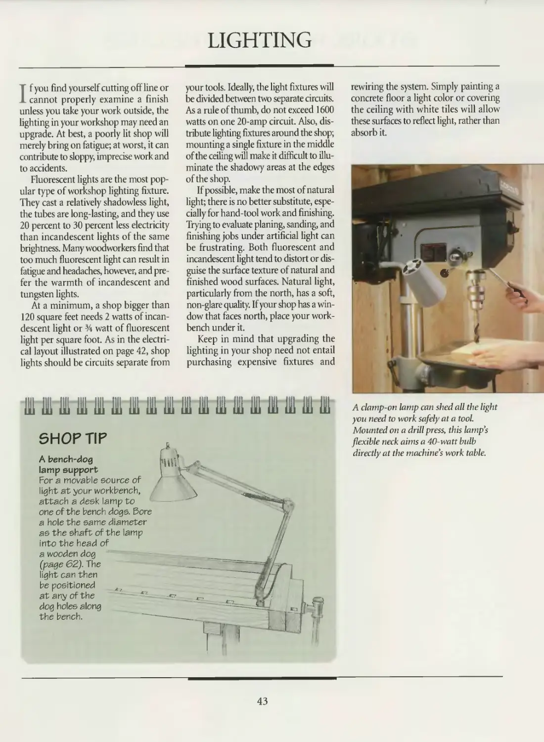
TIME
И*Ч THE ART OF WOODWORK! NG
HOME
WORKSHOP
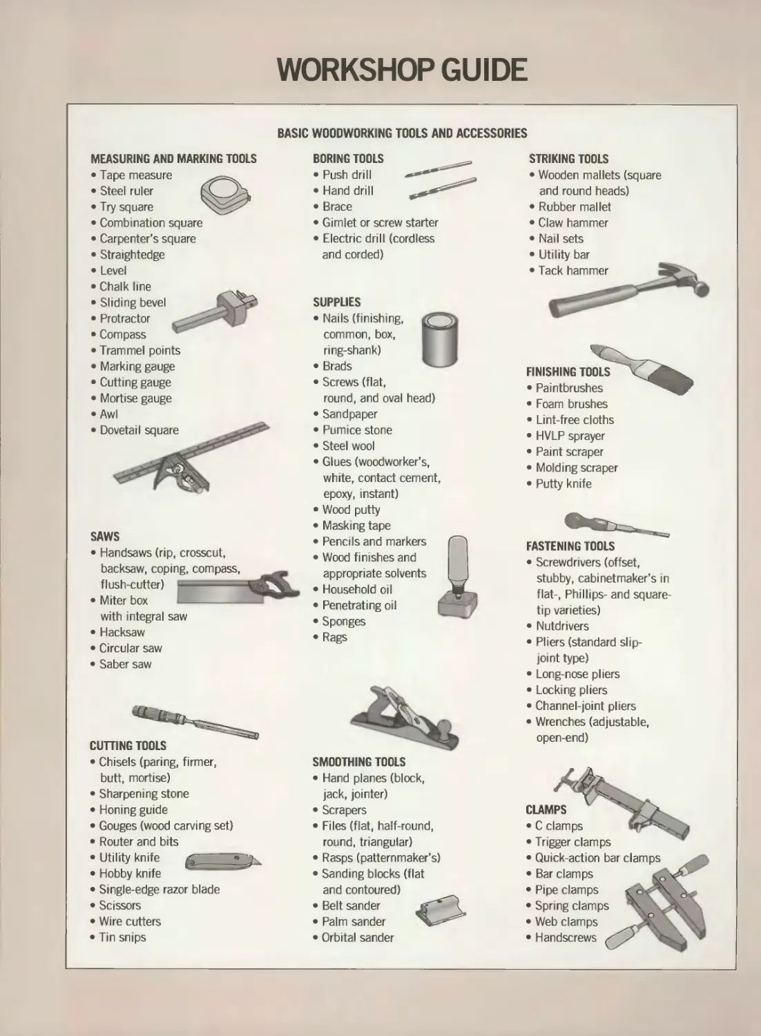
WORKSHOP GUIDE
BASIC WOODWORKING TOOLS AND ACCESSORIES
MEASURING AND MARKING TOOLS
• Tape measure
• Steel ruler
• Try square
• Combination square
• Carpenter's square
• Straightedge
• Level
• Chalk line
• Sliding bevel
• Protractor
• Compass
• Trammel points
• Marking gauge
• Cutting gauge
• Mortise gauge
• Awl
• Dovetail square
BORING TOOLS
• Push drill
• Hand drill
• Brace
• Gimlet or screw starter
• Electric drill (cordless
and corded)
STRIKING TOOLS
• Wooden mallets (square
and round heads)
• Rubber mallet
• Claw hammer
• Nail sets
SUPPLIES
• Nails (finishing,
common, box,
ring-shank)
• Brads
• Utility bar
• Screws (flat,
round, and oval head)
• Sandpaper
• Pumice stone
• Steel wool
• Glues (woodworker’s,
white, contact cement,
FINISHING TOOLS
• Paintbrushes
• Foam brushes
• Lint-free cloths
• HVLP sprayer
• Paint scraper
• Molding scraper
• Putty knife
SAWS
Handsaws (rip, crosscut,
backsaw, coping, compass,
flush-cutter) =
Miter box
with integral saw
• Hacksaw
• Circular saw
• Saber saw
epoxy, instant)
• Wood putty
• Masking tape
• Pencils and markers
• Wood finishes and
appropriate solvents
• Household oil
• Penetrating oil
• Sponges
• Rags
CUTTING TOOLS
• Chisels (paring, firmer,
butt, mortise)
• Sharpening stone
• Honing guide
• Gouges (wood carving set)
• Router and bits
• Utility knife
• Hobby knife
• Single-edge razor blade
• Scissors
• Wire cutters
• Tin snips
FASTENING TOOLS
• Screwdrivers (offset,
stubby, cabinetmaker’s in
flat-, Phillips- and square-
tip varieties)
• Nutdrivers
• Pliers (standard slip-
joint type)
• Long-nose pliers
• Locking pliers
• Channel-joint pliers
• Wrenches (adjustable,
open-end)
SMOOTHING TOOLS
• Hand planes (block,
jack, jointer)
• Scrapers
• Files (flat, half-round,
round, triangular)
• Rasps (patternmaker’s)
• Sanding blocks (flat
and contoured)
• Belt sander
• Palm sander
• Orbital sander
CLAMPS
• C clamps
• Trigger clamps
Quick-action bar clamps
Bar clamps
Pipe clamps
Spring clamps
Web clamps
Handscrews
THE ART OF WOODWORKING
HOME WORKSHOP
TIME-LIFE BOOKS
ALEXANDRIA, VIRGINIA
ST. REMY PRESS
MONTREAL* NEW YORK
THE ART OF WOODWORKING was produced by
ST. REMY PRESS
PUBLISHER
PRESIDENT
Series Editor
Series Art Director
Senior Editors
Art Directors
Designers
Research Editor
Picture Editor
Writers
Contributing Illustrators
Administrator
Production Manager
System Coordinator
Photographer
Kenneth Winchester
Pierre Leveille
Pierre Home-Douglas
Francine Lemieux
Marc Cassini (Text)
Heather Mills (Research)
Normand Boudreault, Luc Germain,
Solange Laberge
lean Guy Doiron, Michel Giguere
Jim McRae
Christopher Jackson
Andrew Jones, Rob Lutes
Gilles Beauchemin, Rolland Bergera,
Jean-Pierre Bourgeois, Michel Blais,
Nicole Chartier, Ronald Durepos,
Philippe Gauvreau, Gerard Mariscalchi,
Jacques Perrault, Robert Paquet,
James Therien
Natalie Watanabe
Michelle Turbide
Jean-Luc Roy
Robert Chartier
Time-Life Books is a division of Time-Life Inc.,
a wholly owned subsidiary of
THE TIME INC. BOOK COMPANY
THE CONSULTANTS
Jon Arno is a consultant, cabinetmaker and
freelance writer who lives in Troy, Michigan.
He also conducts seminars on wood identifica-
tion and early American furniture design.
Giles Miller-Mead taught advanced cabinet-
making at Montreal technical schools for more
than ten years. A native of New Zealand, he has
worked as a restorer of antique furniture.
Joseph Truini is Senior Editor of Home
Mechanix magazine. A former Shop and Tools
Editor of Popular Mechanics, he has worked as
a cabinetmaker, home improvement contractor
and carpenter.
Home Workshop
p. cm.—(The Art of Woodworking)
Includes index.
ISBN 0-8094-9920-7.1 trade)
ISBN 0-8094-9921-5 (lib)
1. Woodshops.
2. Woodwork—Equipment and supplies.
I. Time-Life Books. II. Series
TT152.H6 1993
684’.08—dc20 92-6821
CIP
TIME-LIFE BOOKS
President
Vice-President
Editor-in-Chief
Director of Editorial Resources
John D. Hall
Nancy K. Jones
Thomas H. Flaherty
Elise D. Ritter-Clough
Marketing Director
Editorial Director
Consulting Editor
Production Manager
Regina Hall
Lee Hassig
John R. Sullivan
Marlene Zack
For information about any Time-Life book,
please call 1-800-621-7026, or write:
Reader Information
Time-Life Customer Service
P.O. Box C-32068
Richmond, Virginia
23261-2068
© 1993 Time-Life Books Inc.
All rights reserved.
No part of this book may be reproduced in
any form or by any electronic or mechanical
means, including information storage and
retrieval devices or systems, without prior
written permission from the publisher, except
that brief passages may be quoted for reviews.
First printing. Printed in U.S.A.
Published simultaneously in Canada.
TIME-LIFE is a trademark of Time Warner
Inc. U.S.A.
CONTENTS
6
12
14
15
16
17
18
23
28
30
32
36
41
43
44
45
46
48
50
53
56
62
INTRODUCTION
SAFETY
Accident prevention
Working with safe finishes
Fire safety
Electrical safety
Personal safety gear
First aid
SHOP LAYOUT
Workshop planning
Planning for stationary tools
Shop organization
Electrical power
Lighting
Floors, walls, and ceilings
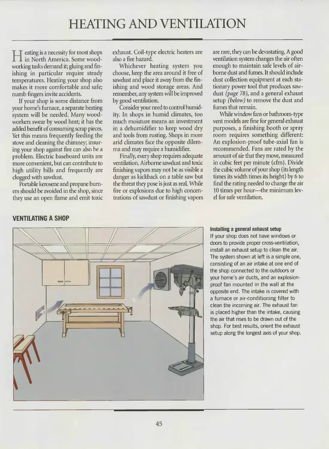
Heating and ventilation
WORKBENCH
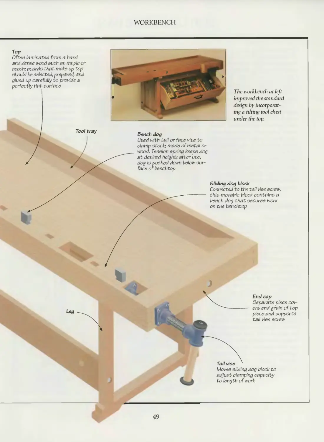
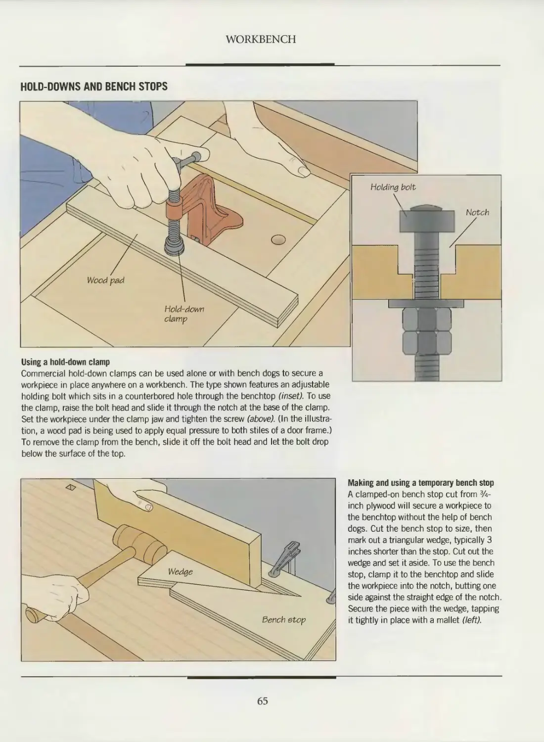
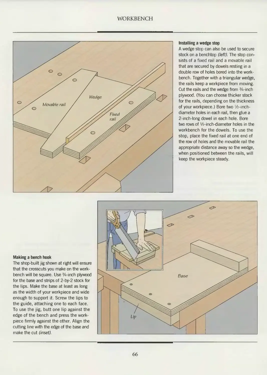
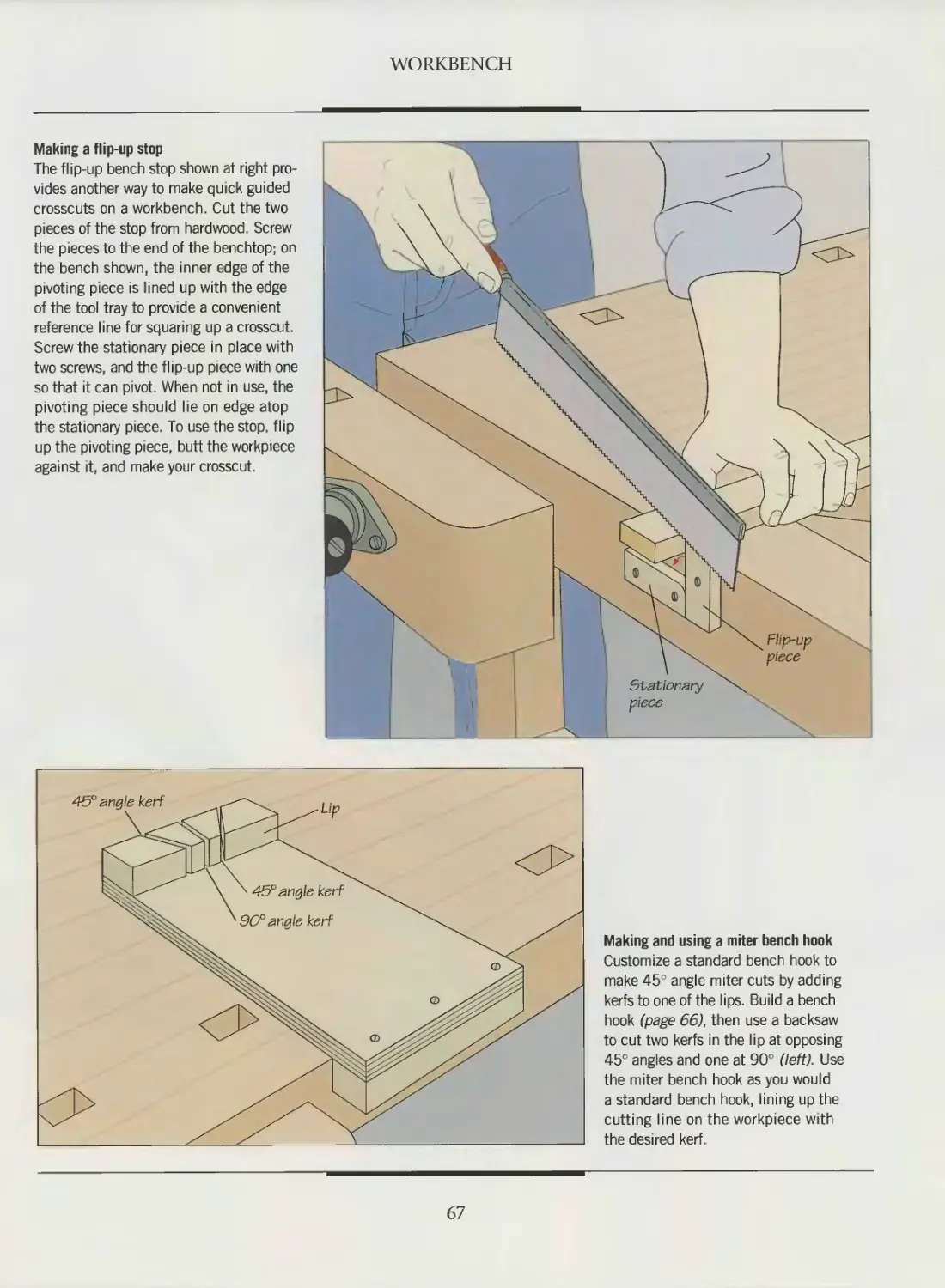
Anatomy of a workbench
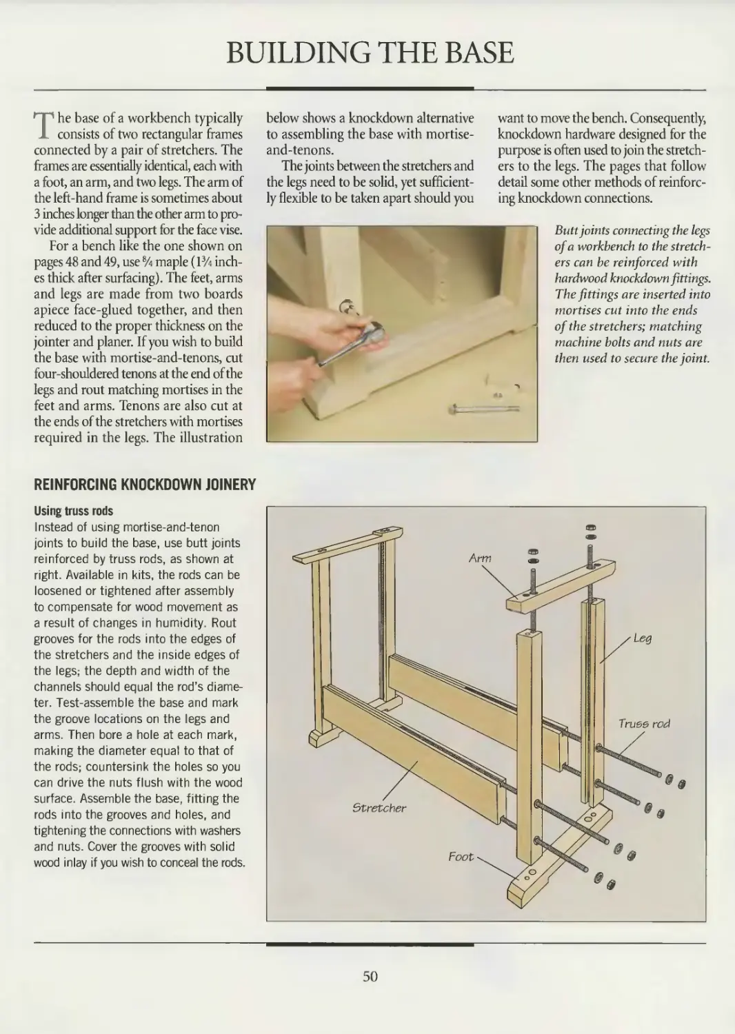
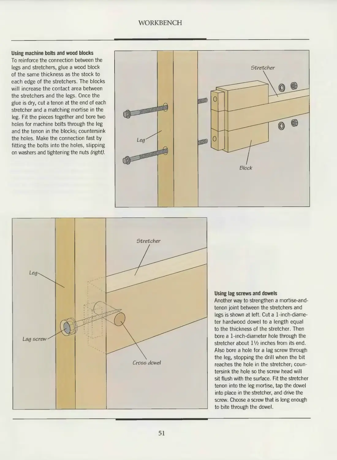
Building the base
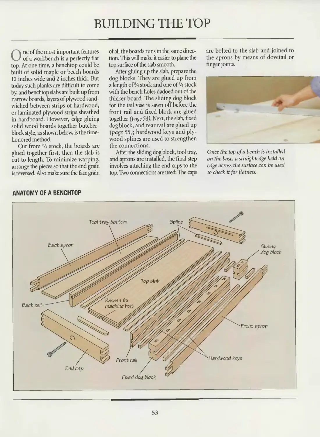
Building the top
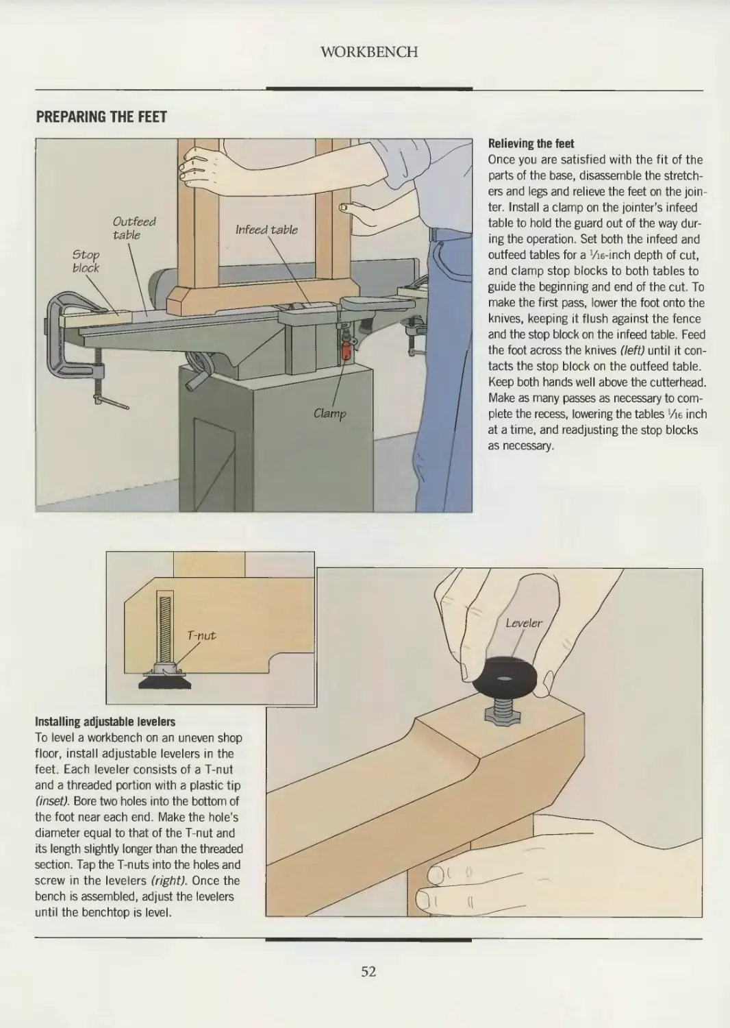
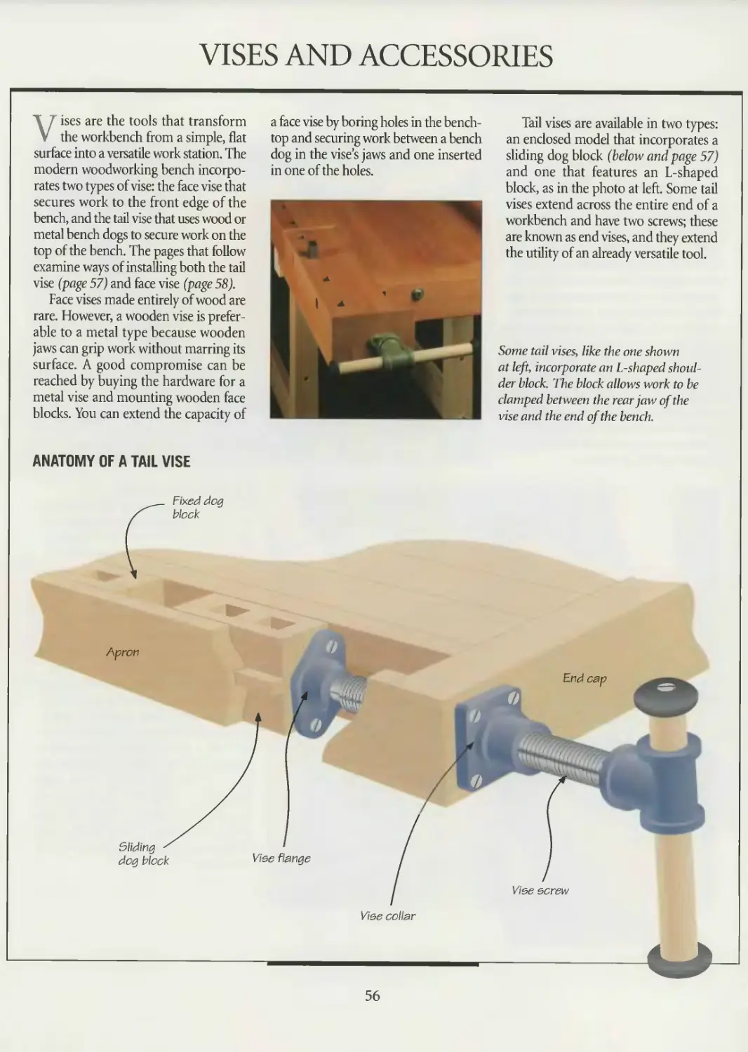
Vises and accessories
Bench dogs and hold downs
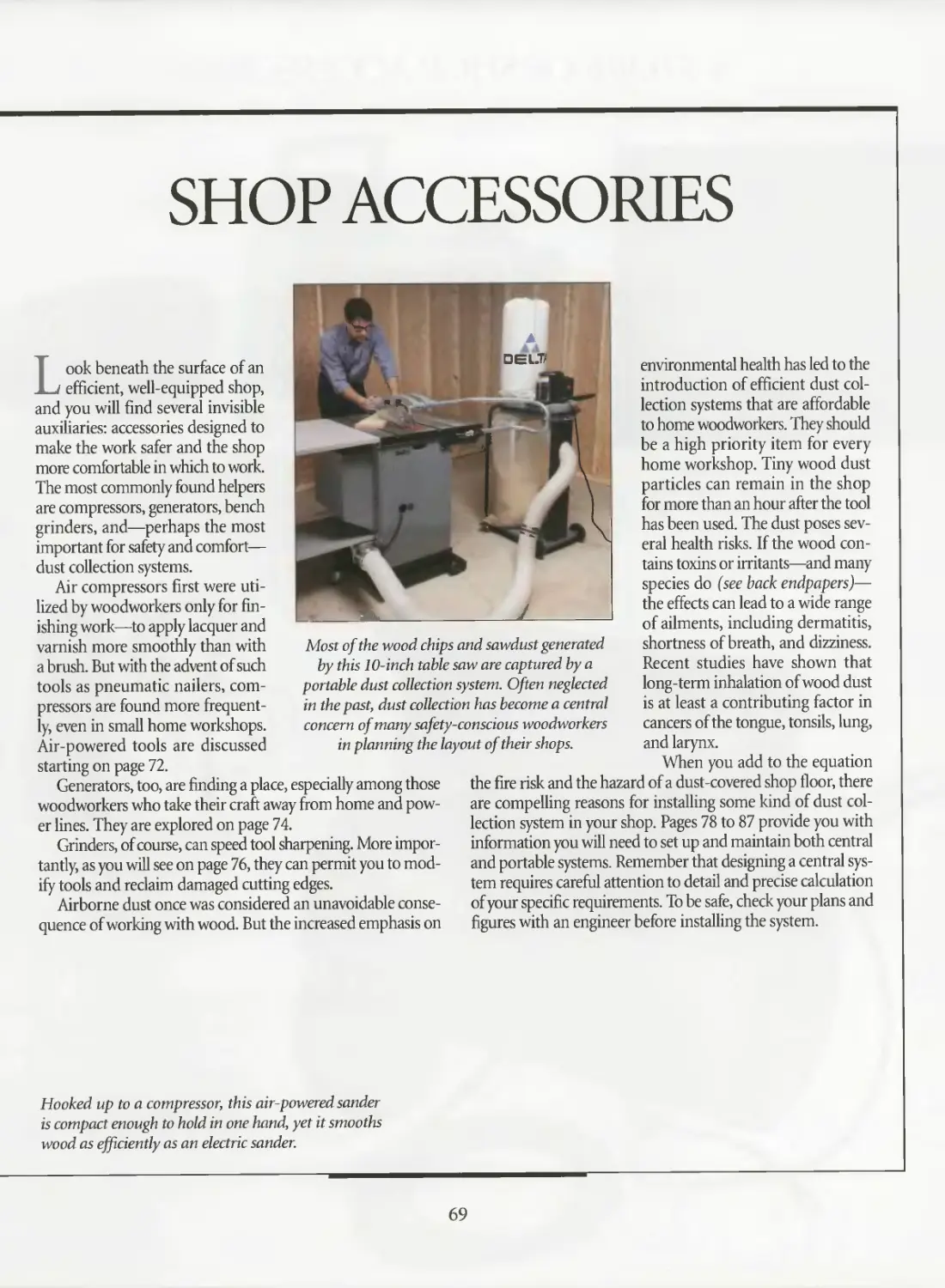
68 SHOP ACCESSORIES
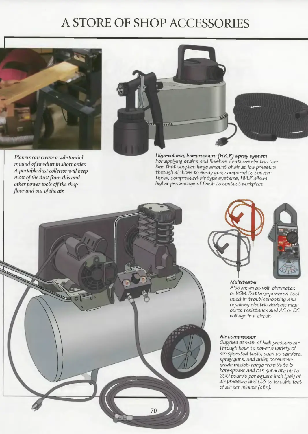
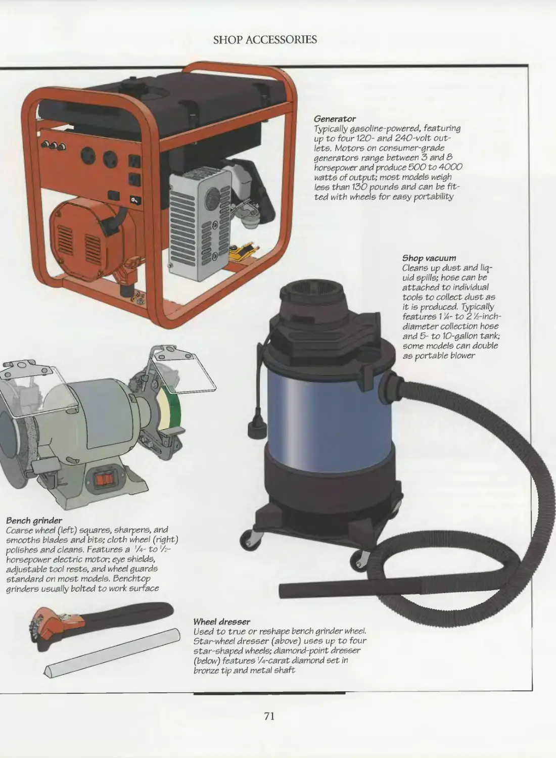
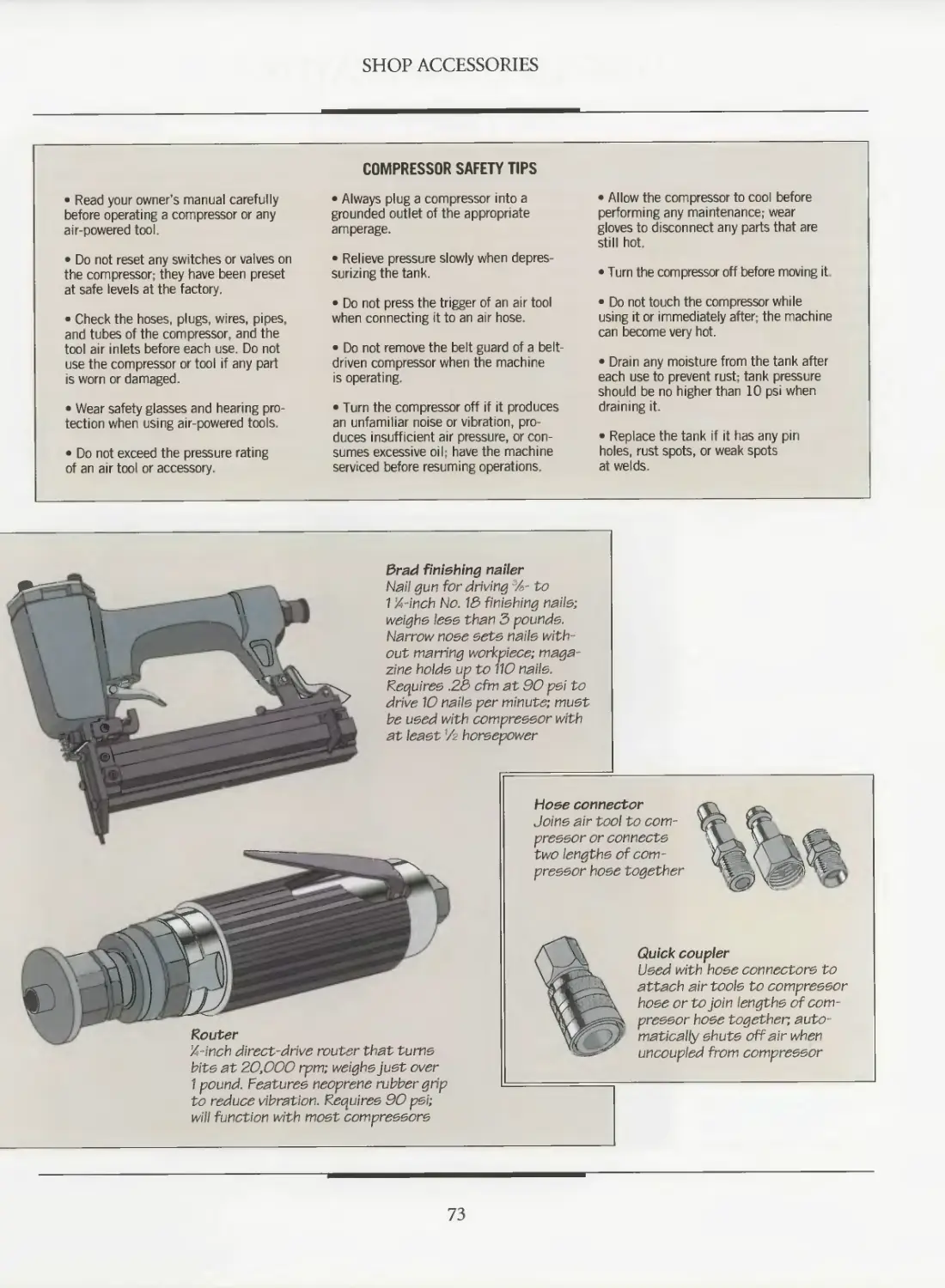
70 A store of shop accessories
72 Air compressors
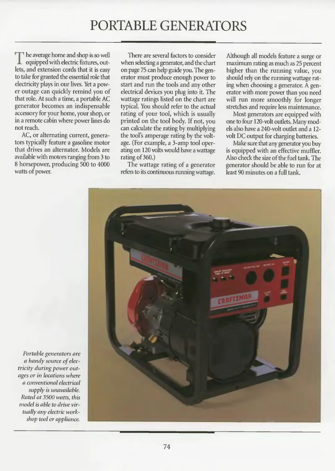
74 Portable generators
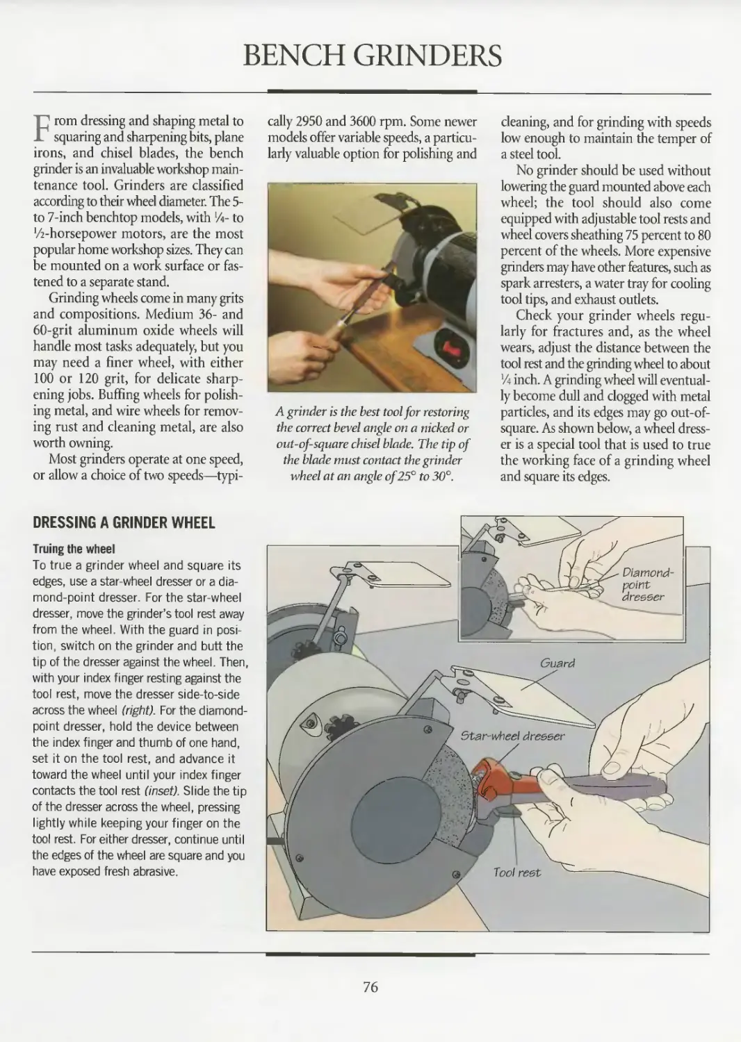
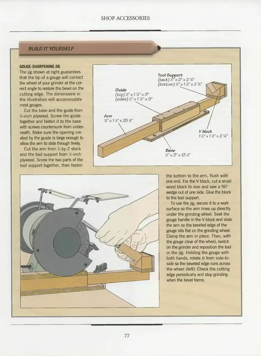
76 Bench grinders
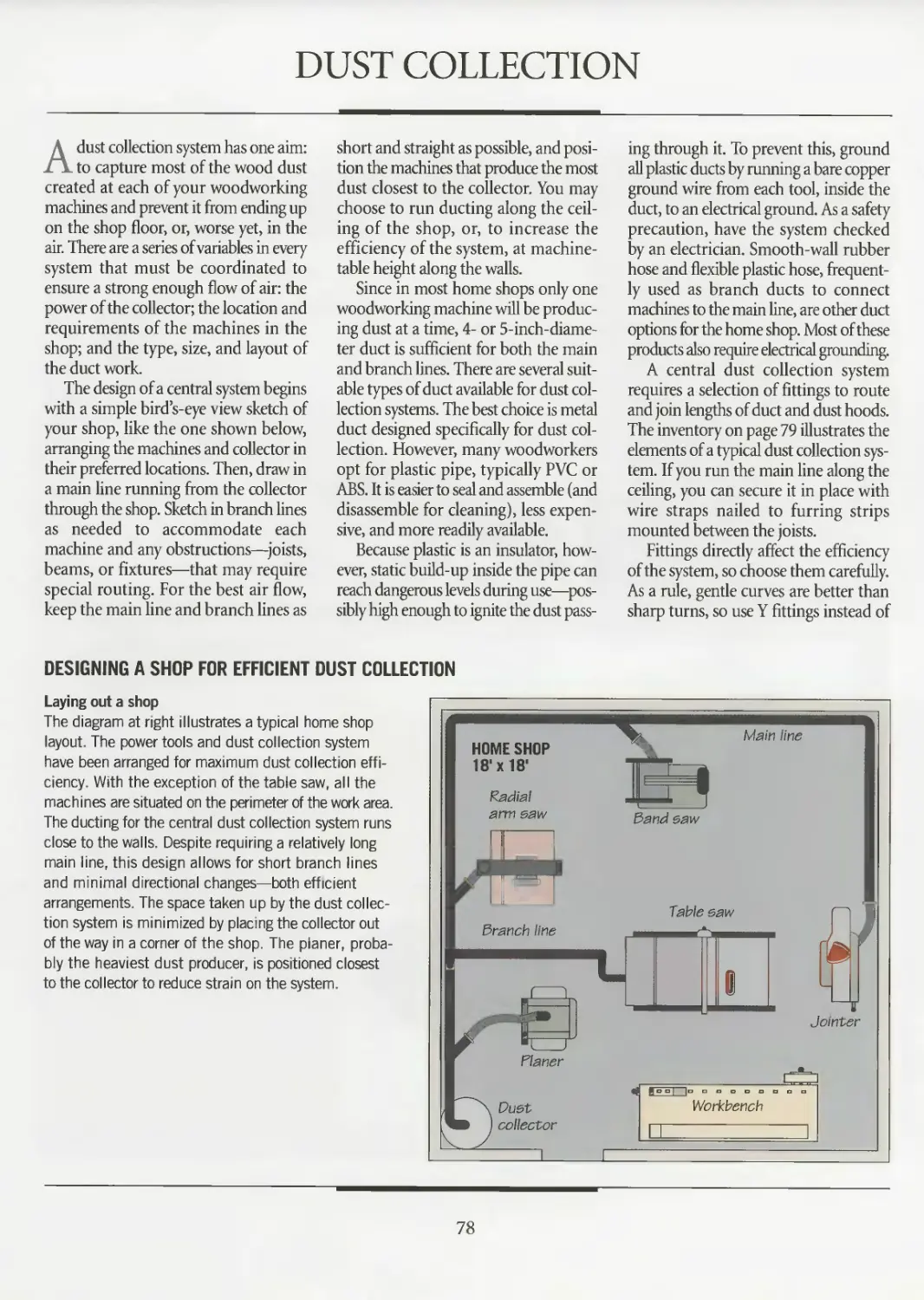
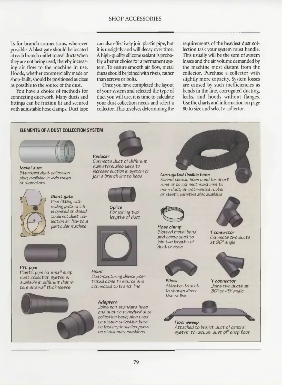
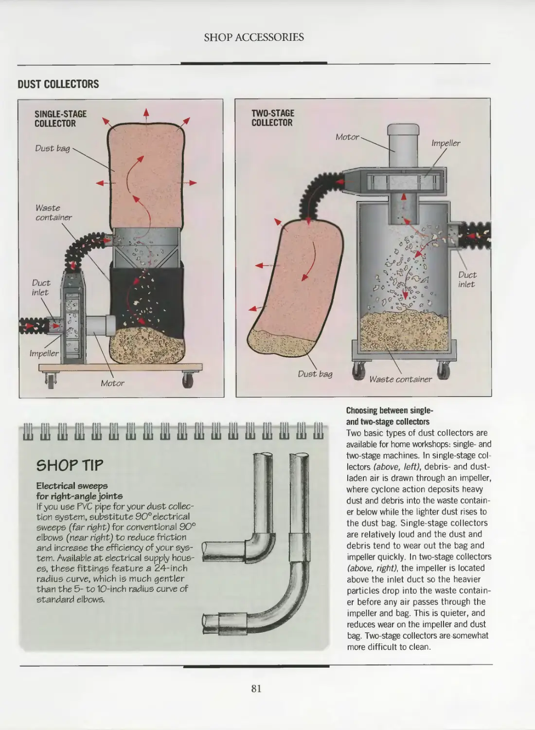
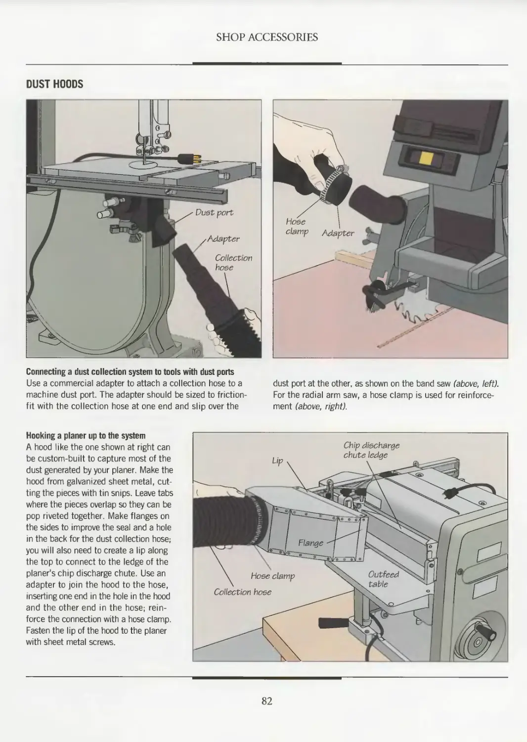
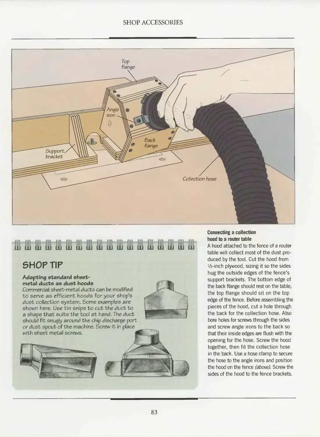
78 Dust collection
85 Portable dust collection
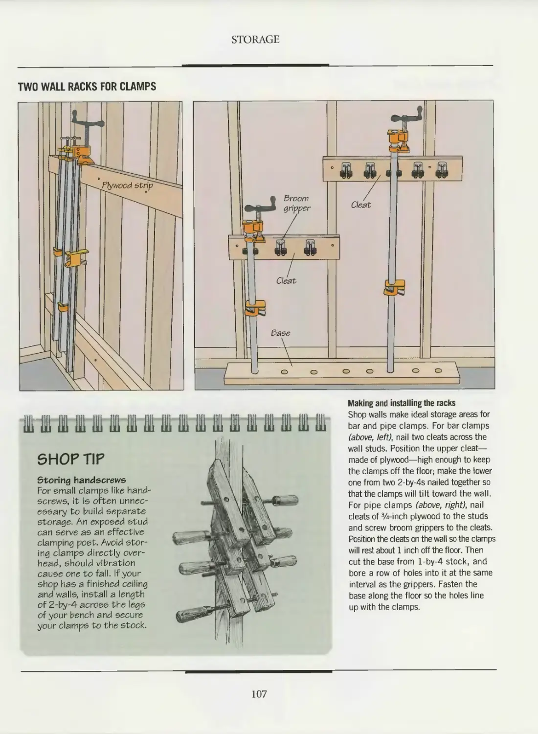
88 STORAGE
90 Storing wood
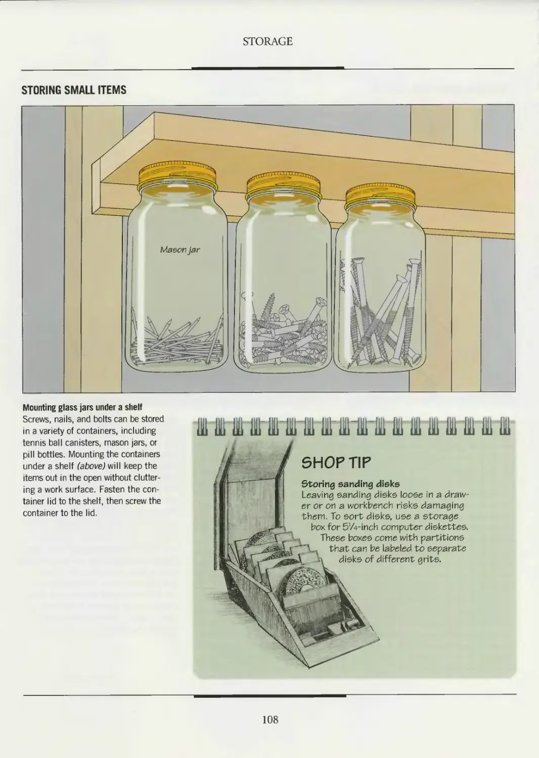
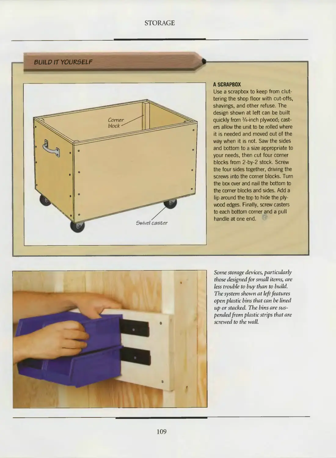
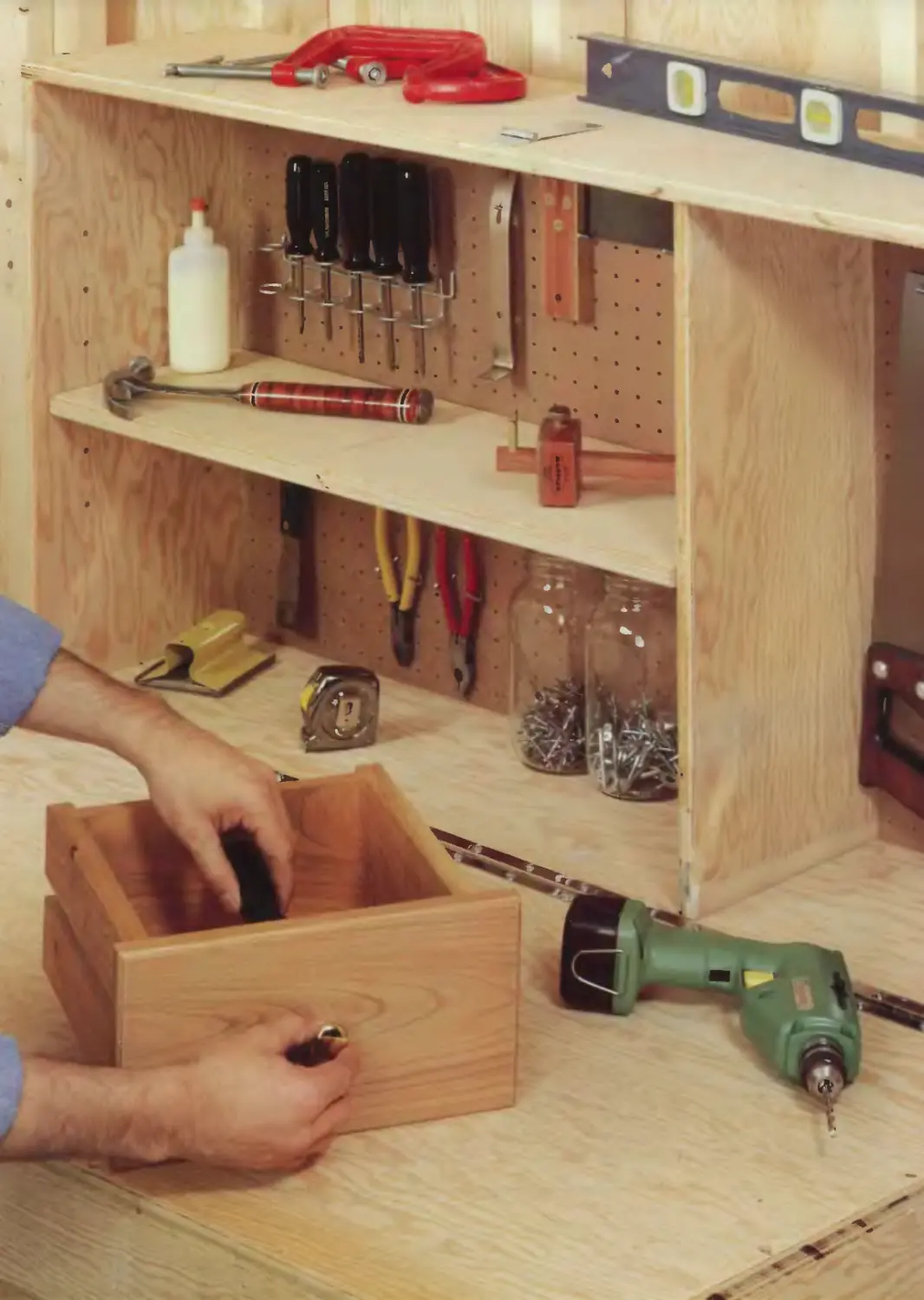
94 Storing tools and supplies
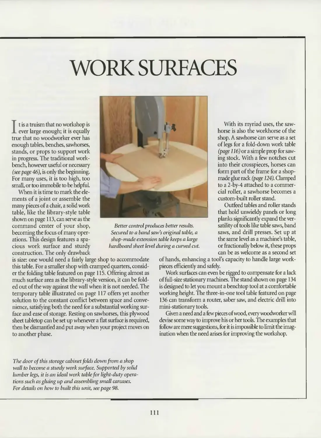
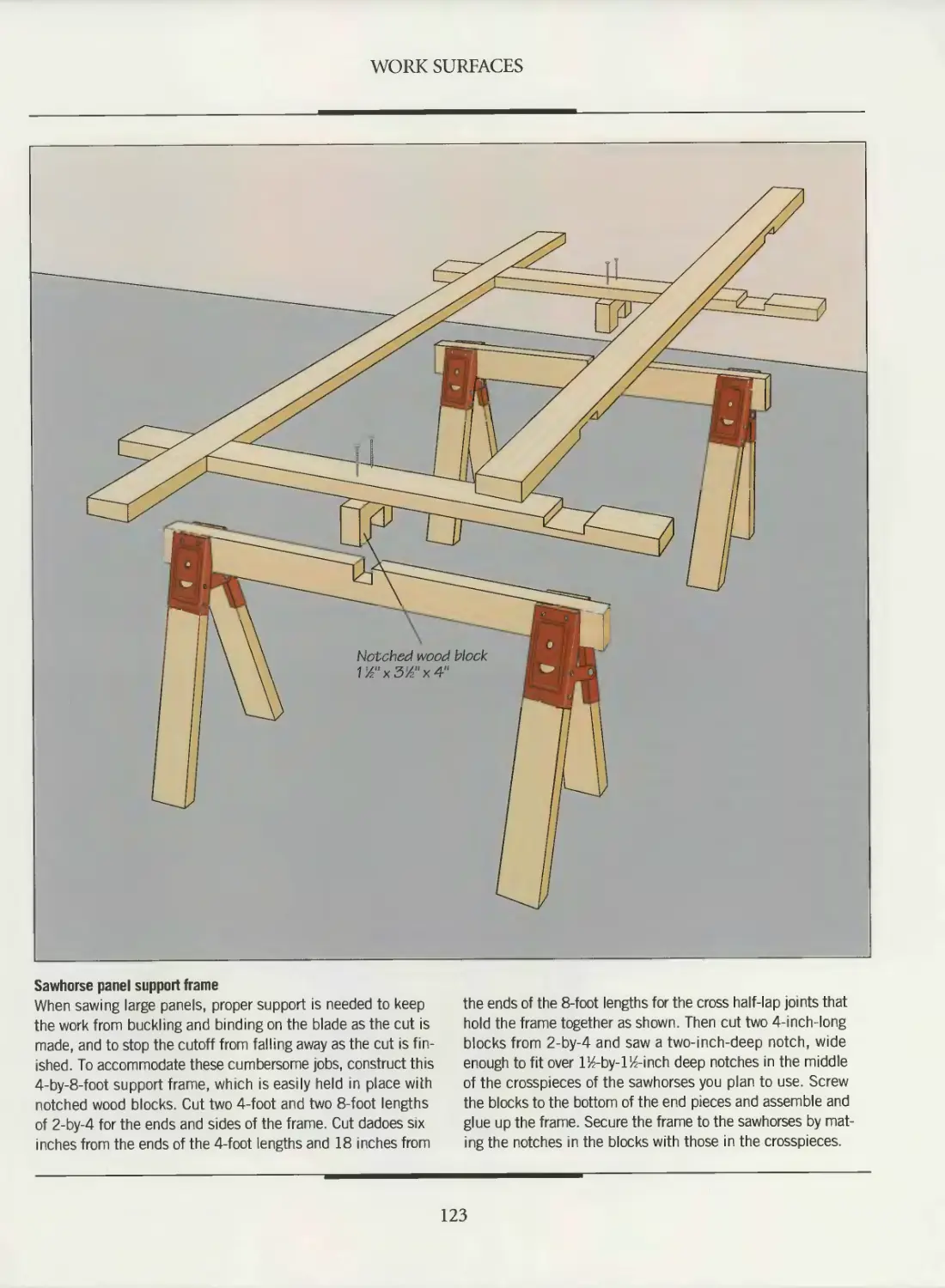
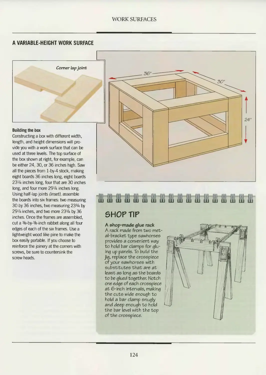
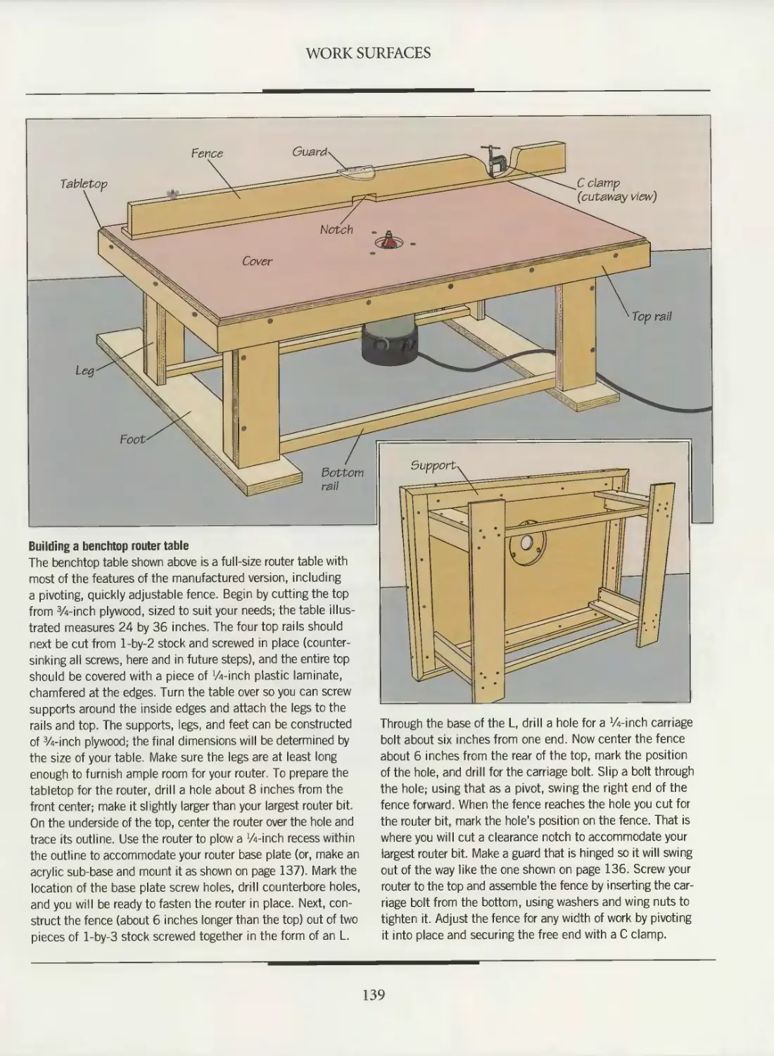
110 WORK SURFACES
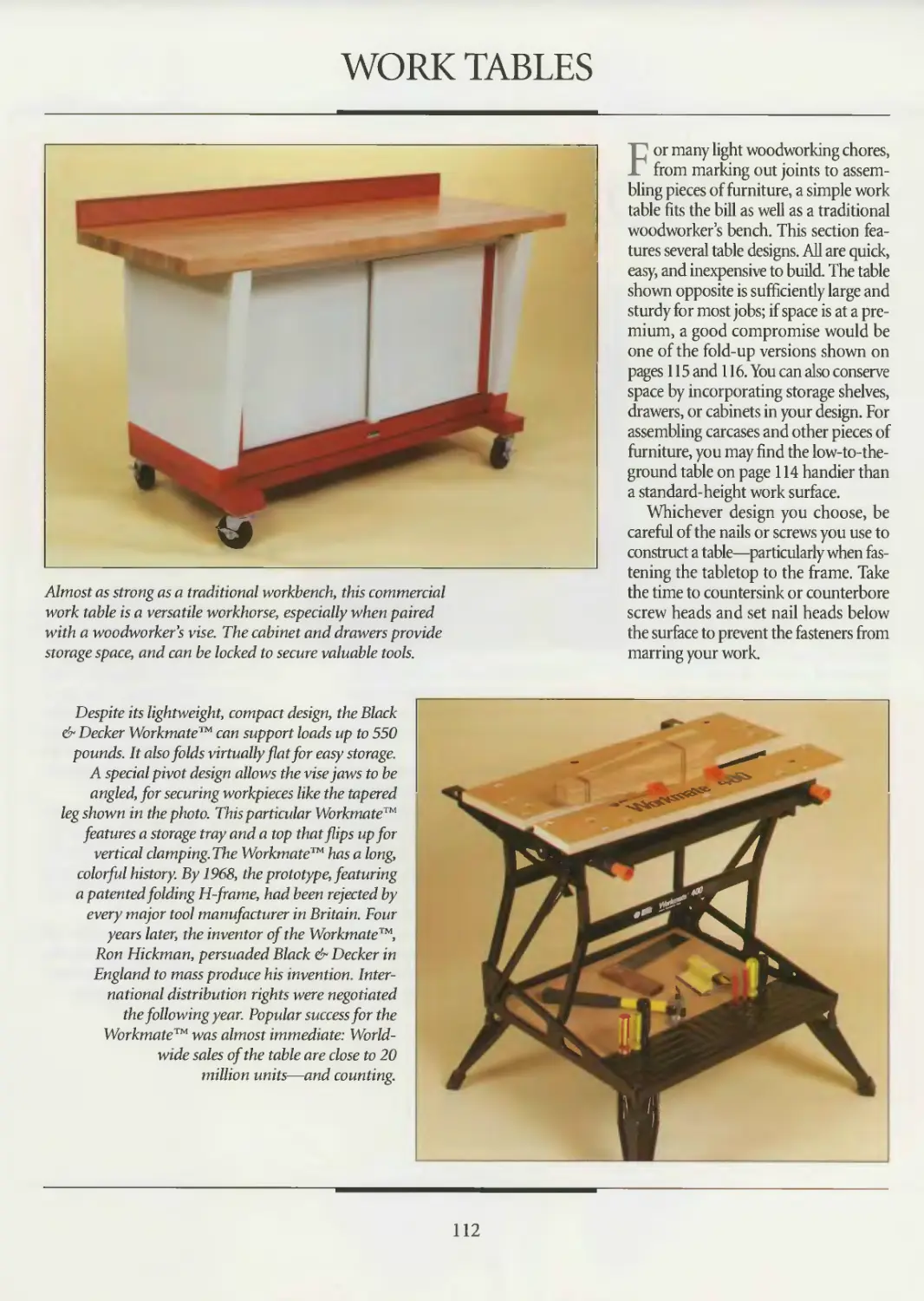
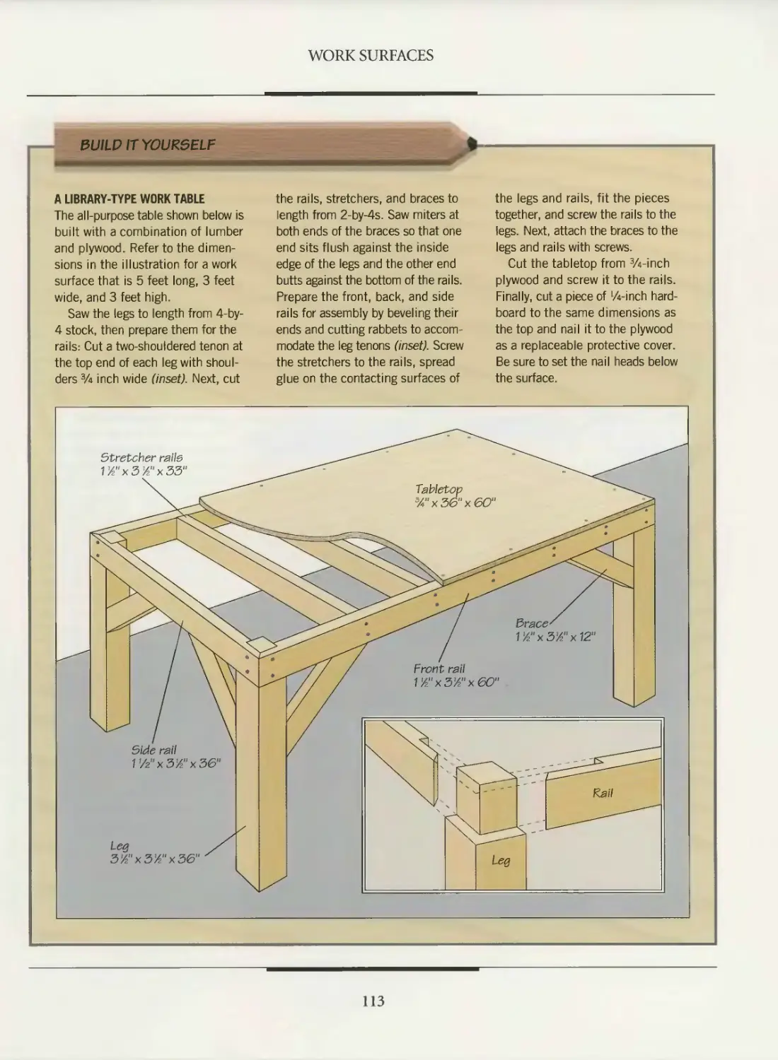
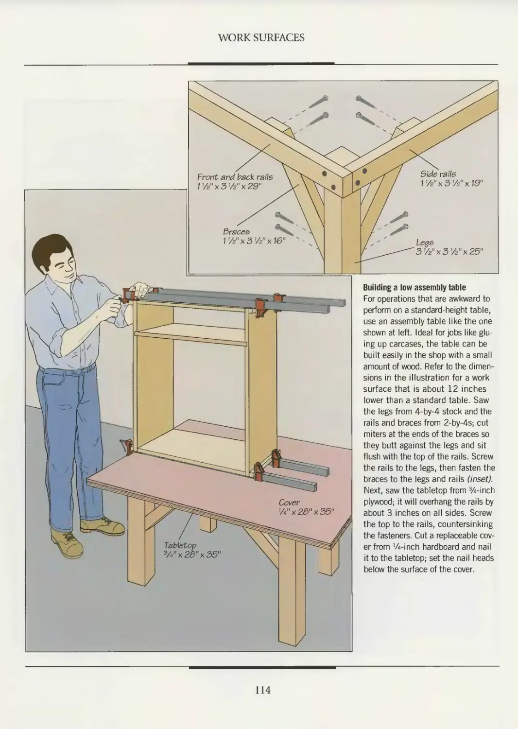
112 Work tables
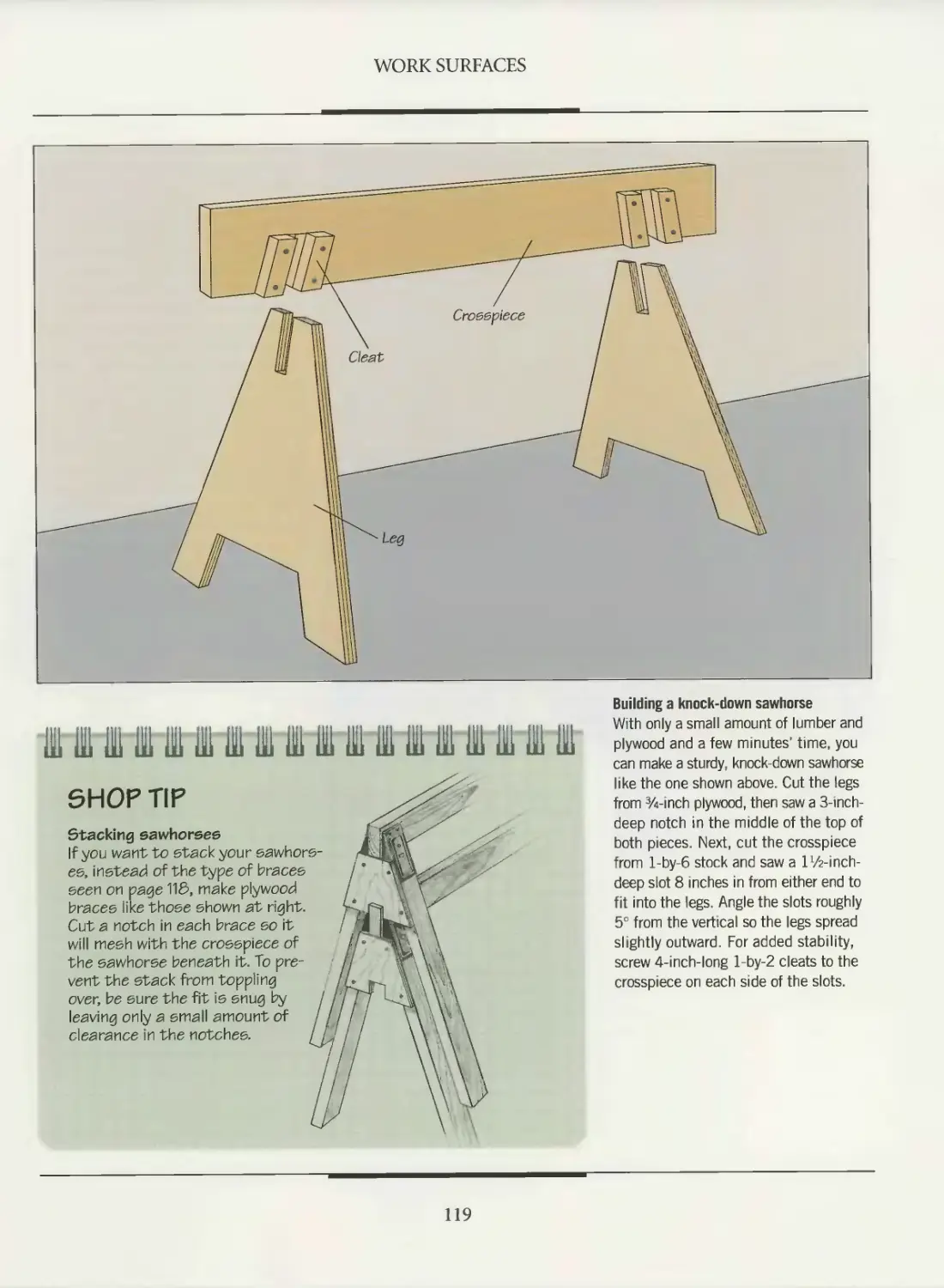
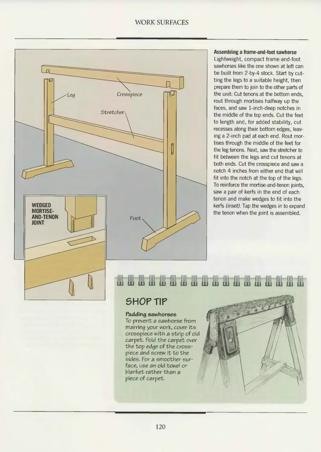
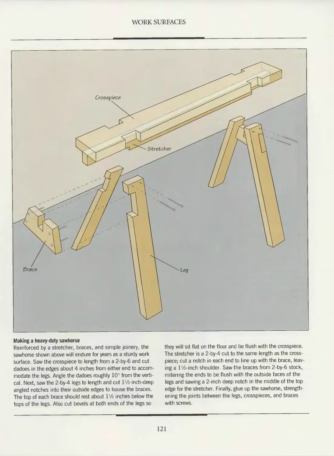
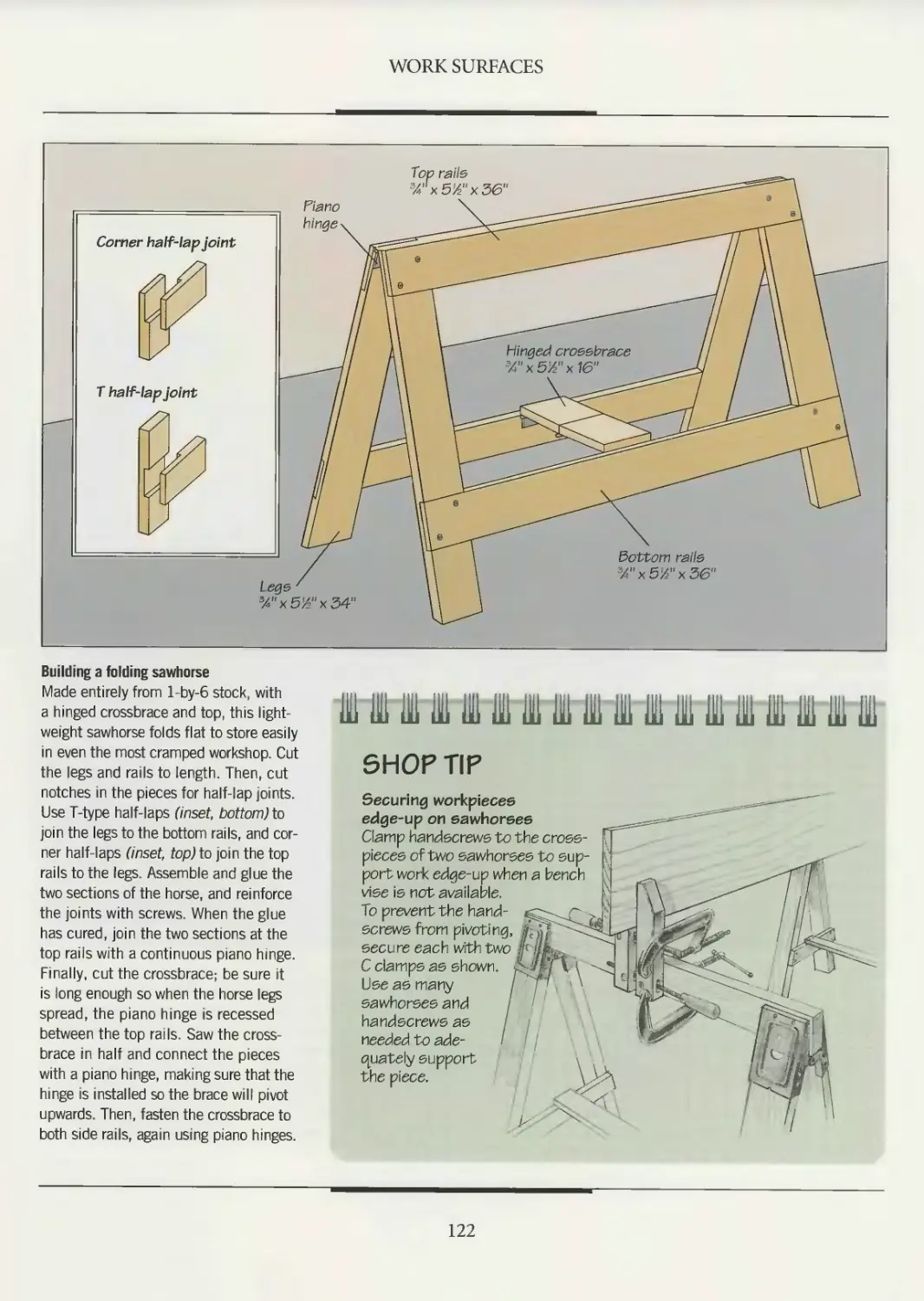
118 Sawhorses
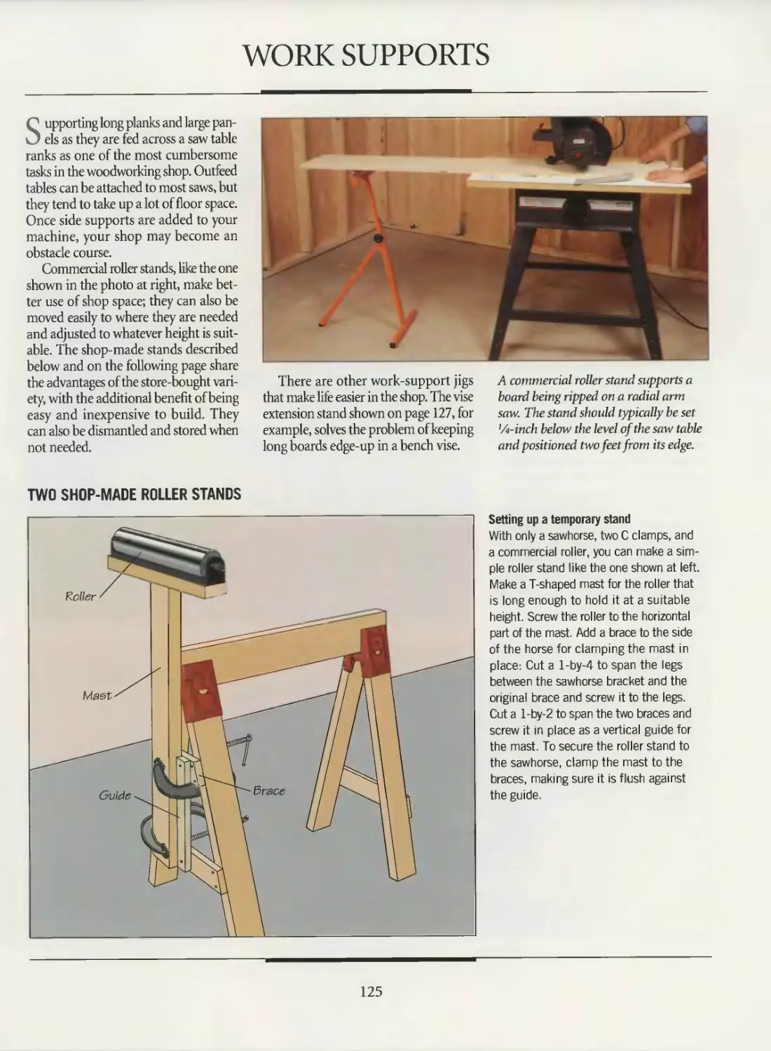
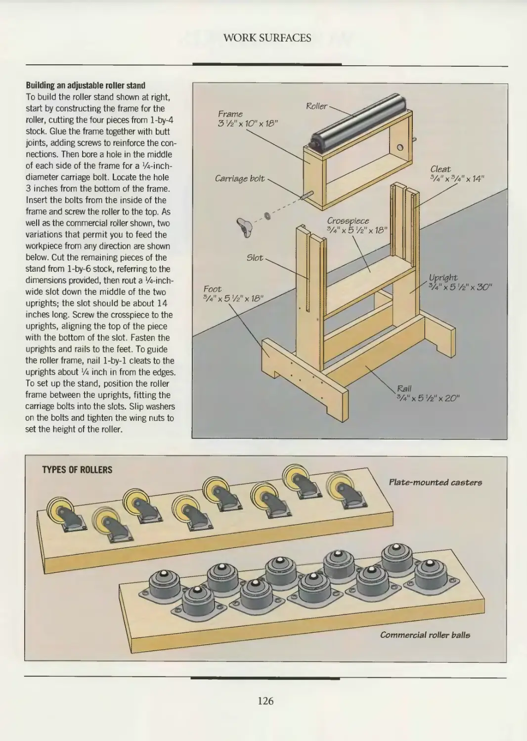
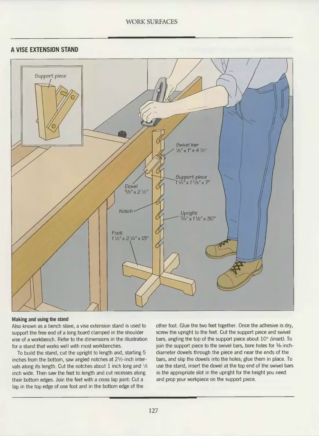
125 Work supports
129 Extension tables
134 Tool stands and tables
140 GLOSSARY
142 INDEX
144 ACKNOWLEDGMENTS
INTRODUCTION
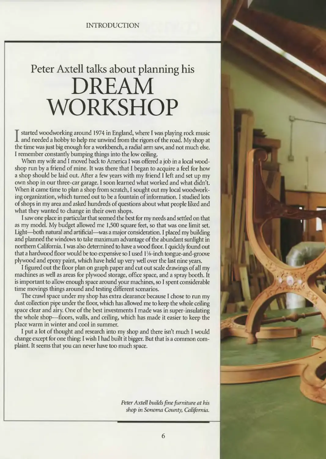
Peter Axtell talks about planning his
DREAM
WORKSHOP
I started woodworking around 1974 in England, where I was playing rock music
and needed a hobby to help me unwind from the rigors of the road. My shop at
the time was just big enough for a workbench, a radial arm saw, and not much else.
I remember constantly bumping things into the low ceiling.
When my wife and I moved back to America I was offered a job in a local wood-
shop run by a friend of mine. It was there that I began to acquire a feel for how
a shop should be laid out. After a few years with my friend I left and set up my
own shop in our three-car garage. I soon learned what worked and what didn’t.
When it came time to plan a shop from scratch, I sought out my local woodwork-
ing organization, which turned out to be a fountain of information. I studied lots
of shops in my area and asked hundreds of questions about what people liked and
what they wanted to change in their own shops.
I saw one place in particular that seemed the best for my needs and settled on that
as my model. My budget allowed me 1,500 square feet, so that was one limit set.
Light—both natural and artificial—was a major consideration. I placed my building
and planned the windows to take maximum advantage of the abundant sunlight in
northern California. I was also determined to have a wood floor. I quickly found out
that a hardwood floor would be too expensive so I used 1 ‘/«-inch tongue-and-groove
plywood and epoxy paint, which have held up very well over the last nine years.
I figured out the floor plan on graph paper and cut out scale drawings of all my
machines as well as areas for plywood storage, office space, and a spray booth. It
is important to allow enough space around your machines, so I spent considerable
time movings things around and testing different scenarios.
The crawl space under my shop has extra clearance because I chose to run my
dust collection pipe under the floor, which has allowed me to keep the whole ceiling
space clear and airy. One of the best investments I made was in super-insulating
the whole shop—floors, walls, and ceiling, which has made it easier to keep the
place warm in winter and cool in summer.
I put a lot of thought and research into my shop and there isn’t much I would
change except for one thing: I wish I had built it bigger. But that is a common com-
plaint. It seems that you can never have too much space.
Peter Axtell builds fine furniture at his
shop in Sonoma County, California.
r I /
INTRODUCTION
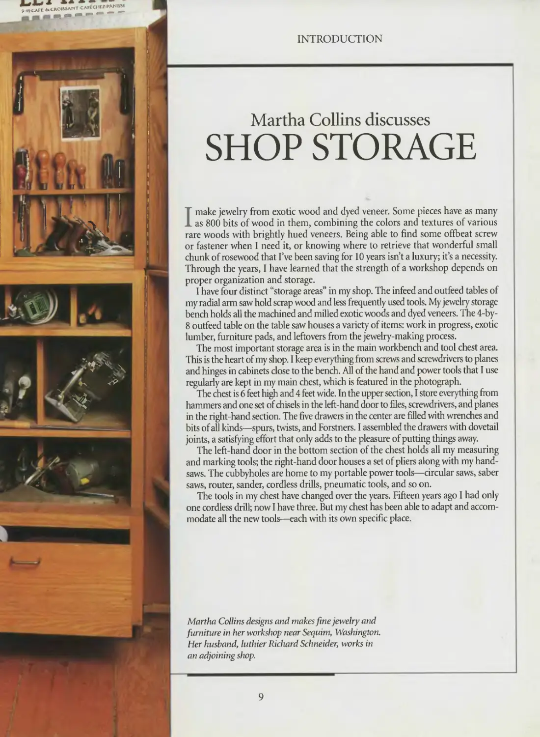
Martha Collins discusses
SHOP STORAGE
I make jewelry from exotic wood and dyed veneer. Some pieces have as many
as 800 bits of wood in them, combining the colors and textures of various
rare woods with brightly hued veneers. Being able to find some offbeat screw
or fastener when I need it, or knowing where to retrieve that wonderful small
chunk of rosewood that I’ve been saving for 10 years isn’t a luxury; it’s a necessity.
Through the years, I have learned that the strength of a workshop depends on
proper organization and storage.
I have four distinct “storage areas” in my shop. The infeed and outfeed tables of
my radial arm saw hold scrap wood and less frequently used tools. My jewelry storage
bench holds all the machined and milled exotic woods and dyed veneers. The 4-by-
8 outfeed table on the table saw houses a variety of items: work in progress, exotic
lumber, furniture pads, and leftovers from the jewelry-making process.
The most important storage area is in the main workbench and tool chest area.
This is the heart of my shop. I keep everything from screws and screwdrivers to planes
and hinges in cabinets close to the bench. All of the hand and power tools that I use
regularly are kept in my main chest, which is featured in the photograph.
The chest is 6 feet high and 4 feet wide. In the upper section, I store everything from
hammers and one set of chisels in the left-hand door to files, screwdrivers, and planes
in the right-hand section. The five drawers in the center are filled with wrenches and
bits of all kinds—spurs, twists, and Forstners. I assembled the drawers with dovetail
joints, a satisfying effort that only adds to the pleasure of putting things away.
The left-hand door in the bottom section of the chest holds all my measuring
and marking tools; the right-hand door houses a set of pliers along with my hand-
saws. The cubbyholes are home to my portable power tools—circular saws, saber
saws, router, sander, cordless drills, pneumatic tools, and so on.
The tools in my chest have changed over the years. Fifteen years ago I had only
one cordless drill; now I have three. But my chest has been able to adapt and accom-
modate all the new tools—each with its own specific place.
Martha Collins designs and makes fine jewelry and
furniture in her workshop near Sequim, Washington.
Her husband, luthier Richard Schneider, works in
an adjoining shop.
UIHIII hlilillliiliiiiijiiiiiiiiiiiliiiii
INTRODUCTION
Leonard Lee on
THE VALUE OF
A WORKBENCH
A workshop can be anywhere you can fit a solid surface. A retired carver friend
built a superb workshop in the linen closet of his apartment. He only had to open
the closet door, pull out a stool, and go to work. Everything he needed was fitted
into a space of less than 10 square feet.
I built the small cherry bench in the photograph to fit an awkward alcove in
my office that measures only 23 by 37 inches. For years I had been using my
desk as a makeshift workbench and I was frustrated by both the lack of any
decent clamping system and enough clear work surface. The desk is often as
cluttered as the bookcase in the background.
With the workbench in place, I can now clamp wood for testing saws, chisels,
bits, and so on, without knocking a coffee cup to the floor or spilling papers every-
where. The bench is also just the right height for using an inspection microscope,
an invaluable tool for analyzing failures and successes in the world of sharp edges.
The bench occupies an otherwise unusable space next to a doorway. Since the
floor space next to it can be used only for foot traffic, the bench only adds to
the usability of my office; it does not detract anything. Incidentally, the bench
was pulled out of the alcove for this photo.
More important than its utility, my bench adds a wonderfully relaxing and
humanizing element. Like many people, I tire quickly of administrative detail.
With a workbench handy, I can get up from my desk, wander over to the bench
and tinker with tools for a while. It is like a mini-vacation in the middle of the day.
The humanizing part comes from surrounding yourself with things you like.
I like everything about woodworking. My office is filled with old tools as well as
books about their history and use. To add a workbench to the general clutter is
just another layer to the cocoon. The world looks much better when viewed from
an office with a workbench in it.
Leonard Lee is the president of Veritas Tools and Lee Valley Tools in
Ottawa, Canada, manufacturers and retailers of fine woodworking
hand tools. He is also the publisher and executive editor o/Woodcuts,
a magazine that focuses on the history and techniques of woodworking.
n
SAFETY
For most woodworkers, the home
workshop is a peaceful refuge, where
craft gives shape to creative ideas. It is
also the place where accidents may occur,
owing to the very nature of the activity.
But the likelihood of mishap can be
reduced by a few simple precautions.
First, an informed woodworker is a safe
woodworker. Read the owner’s manu-
als supplied with all your tools. Before
starting a job, make sure you know how
to use the safety accessories that are
designed to protect you from injury
while working with a tool.
Most accidents are the result of care-
lessness or inattention—failure to use a
safety guard when cutting a board on a
table saw, face jointing stock with bare
hands (rather than with a push block),
or using a router without safety goggles. Refer to the safety tips
on page 14 for ways of avoiding some of the more common
accidents in the shop.
Although the big stationary machines receive most of
the attention from safety-conscious woodworkers, there are
other potential sources of danger that, though less apparent,
cannot be ignored. Many finishing products, particularly
those containing solvents, can be toxic, although their effects
may only become apparent after years of prolonged expo-
sure. Certain species of wood can cause allergic or toxic
reactions in some people. Page 15 presents information on
choosing safe finishing products and on the possible health
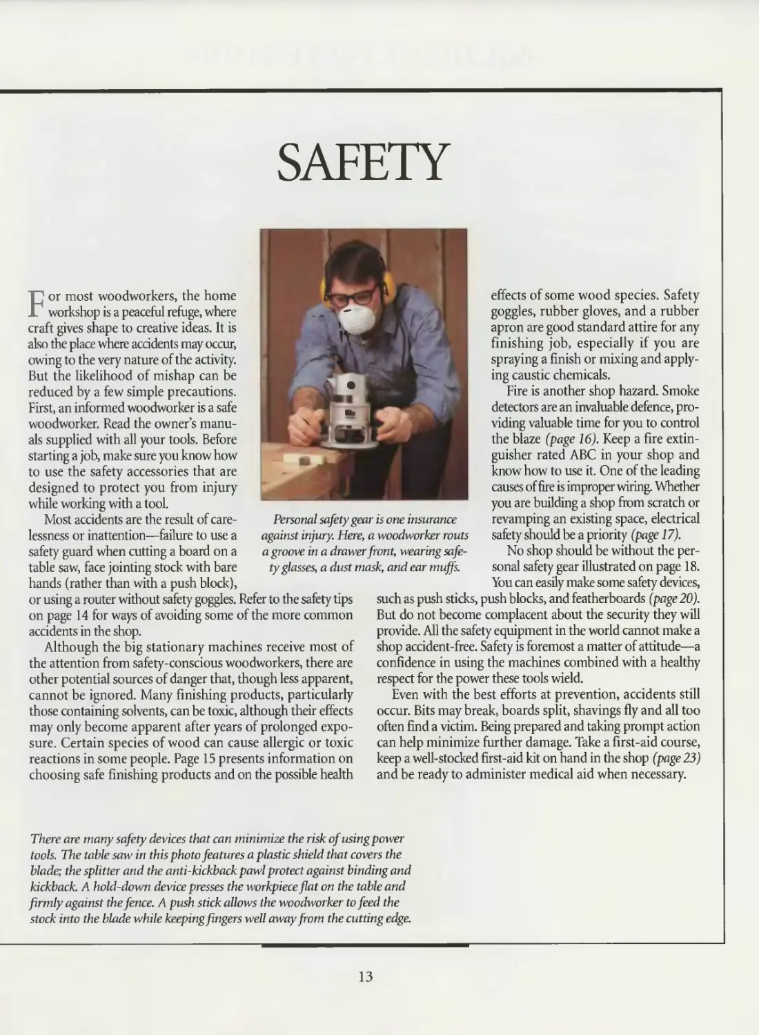
Personal safety gear is one insurance
against injury. Here, a woodworker routs
a groove in a drawer front, wearing safe-
tyglasses, a dust mask, and ear muffs.
effects of some wood species. Safety
goggles, rubber gloves, and a rubber
apron are good standard attire for any
finishing job, especially if you are
spraying a finish or mixing and apply-
ing caustic chemicals.
Fire is another shop hazard. Smoke
detectors are an invaluable defence, pro-
viding valuable time for you to control
the blaze (page 16). Keep a fire extin-
guisher rated ABC in your shop and
know how to use it. One of the leading
causes of fire is improper wiring. Whether
you are building a shop from scratch or
revamping an existing space, electrical
safety should be a priority (page 17).
No shop should be without the per-
sonal safety gear illustrated on page 18.
You can easily make some safety devices,
such as push sticks, push blocks, and featherboards (page 20).
But do not become complacent about the security they will
provide. All the safety equipment in the world cannot make a
shop accident-free. Safety is foremost a matter of attitude—a
confidence in using the machines combined with a healthy
respect for the power these tools wield.
Even with the best efforts at prevention, accidents still
occur. Bits may break, boards split, shavings fly and all too
often find a victim. Being prepared and taking prompt action
can help minimize further damage. Take a first-aid course,
keep a well-stocked first-aid kit on hand in the shop (page 23)
and be ready to administer medical aid when necessary.
There are many safety devices that can minimize the risk of using power
tools. The table saw in this photo features a plastic shield that covers the
blade; the splitter and the anti-kickback pawl protect against binding and
kickback. A hold-down device presses the workpiece flat on the table and
firmly against the fence. A push stick allows the woodworker to feed the
stock into the blade while keeping fingers well away from the cutting edge.
13
ACCIDENT PREVENTION
GENERAL
• Make sure workshop lighting and venti-
lation are adequate.
• Keep children, onlookers, and pets away
from the work area.
• Concentrate on the job; do not rush or
take shortcuts. Never work when you are
tired, stressed, or have been drinking
alcohol or using medications that induce
drowsiness.
• Find a comfortable stance; avoid over-
reaching.
• Keep your work area clean and tidy;
clutter can lead to accidents.
HAND TOOLS
• Use the appropriate tool for the job;
do not try to make a tool do something
for which it was not designed.
• When possible, cut away from your-
self rather than toward your body.
• Keep tools clean and sharp.
SAFETY TIPS
POWER TOOLS
• Wear appropriate safety gear: safety
glasses or face shield and hearing protec-
tion. If there is no dust collection system,
wear a dust mask. For allergenic woods,
such as ebony, use a respirator.
• Read your owner’s manual carefully
before operating any tool.
• Tie back long hair and avoid loose-fit-
ting clothing. Remove rings and other
jewelry that can catch in moving parts.
• Unplug a tool before performing setup
or installation operations.
• Whenever possible, clamp down the
workpiece, leaving both hands free to
perform an operation.
• Keep your hands well away from a turn-
ing blade or bit.
• Turn off a tool if it produces an unfa-
miliar vibration or noise; have the tool
serviced before resuming operations.
• Do not use a tool if any part of it is
worn or damaged.
FINISHING
• Do not eat, drink, or smoke when using
finishing products.
• Avoid exposure to organic solvents if
you are pregnant or breast-feeding.
• Install at least one smoke detector on
the ceiling of your shop above potential
fire hazards; keep a fully charged ABC
fire extinguisher nearby.
• Never store solvents or chemicals in
unmarked containers. Chemical solutions
should always be stored in dark glass jars
to shield them from light, which may
change their composition.
• Store finishing products in a locked
cabinet.
• To prevent eye injury, wear safety gog-
gles, and don rubber gloves when working
with caustic or toxic finishing products.
• Do not flush used solvents down the
drain. Consult the Yellow Pages to find
out who handles chemical disposal in
your area, or check with your local fire
department.
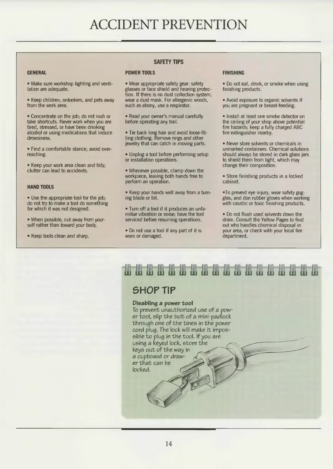
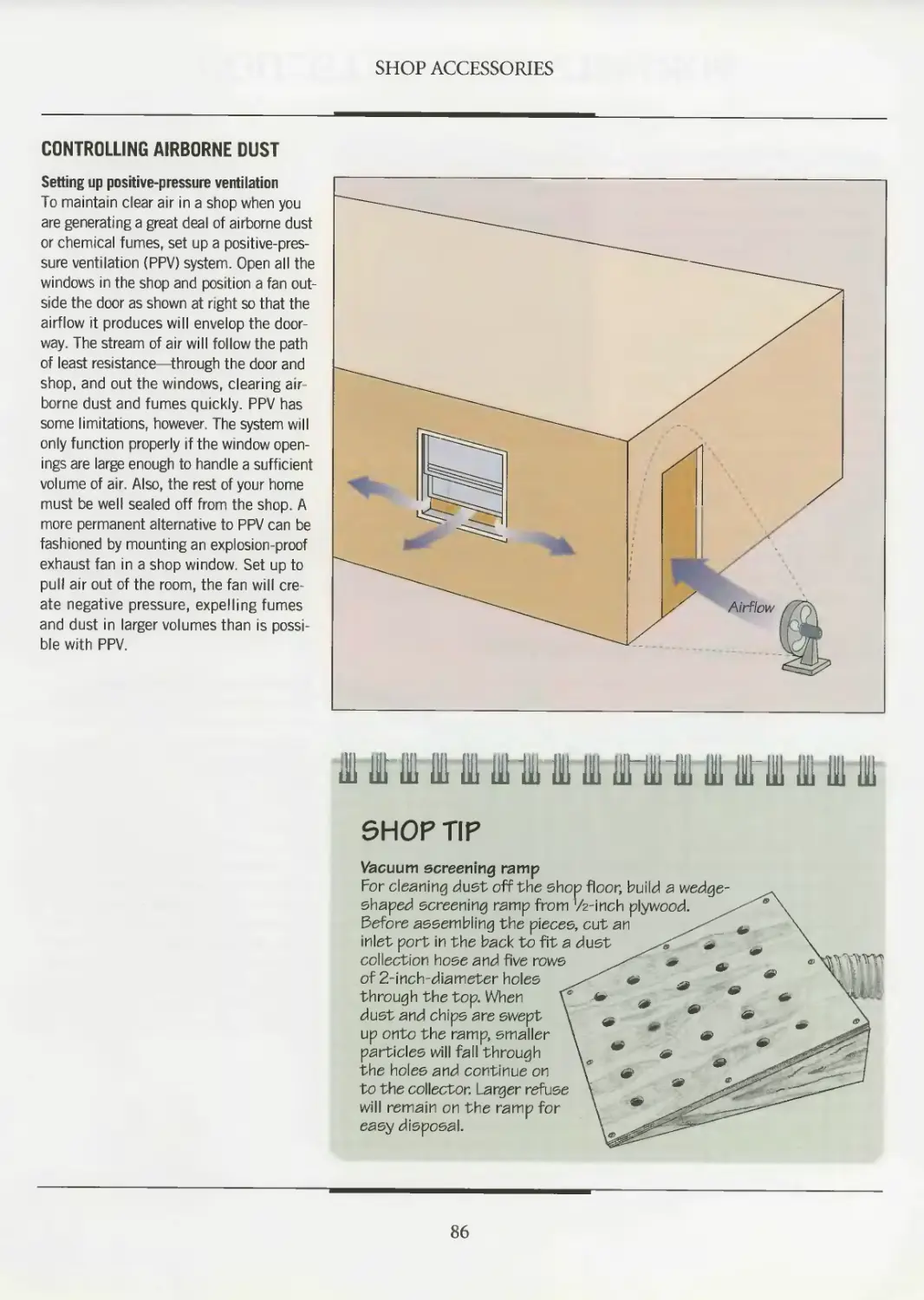
SHOP TIP
Disabling a power tool
To prevent unauthorized use of a pow-
er tool, slip the bolt of a mini-padlock
through one of the tines in the power
cord plug. The lock will make it impos-
sible to plug in the tool. If you are
using a keyed lock, store the
keys out of the way in
a cupboard or draw-
er that can be
locked.
14
WORKING WITH SAFE FINISHES
Although a number of high-quality
water-based finishes have become
available recently, solvent-based finish-
ing products are still widely used, and
considered superior for some applica-
tions. Thus woodworkers must learn to
protect themselves against the health
hazards associated with organic solvents.
Organic solvents can have a number of
health effects. Short-term use can result
in ailments ranging from headaches and
nausea to skin and eye irritation. With
extended use, many solvents are known
to damage the central nervous system
or respiratory tract. Some glycol ethers
are suspected of causing birth defects,
while other solvents, like methylene chlo-
ride, have been linked with cardiac arrest.
Solvents can be absorbed into the
bloodstream in a number of ways: after
being inhaled, or ingested along with
food left in the shop, absorbed through
the skin, or swallowed when vapors set-
tle in saliva. Most solvent-based finish-
es are unlikely to cause harm when used
occasionally, and are only poisonous if
swallowed. But you still need to be aware
of the combination and concentration
of organic solvents in a particular finish
if you plan to use the product in large
quantities or over an extended period of
time.The chart below lists the solvents
contained in a variety of finishing prod-
ucts and assesses the relative toxicity of
each one. Be sure to choose the safest
product for the job at hand.
TOXIC SOLVENTS
FINISHING PRODUCT
Wood filler (paste and liquid)
Stains (aniline, wiping, NGR, gel and glaz-
ing stains; color pigments)
Shellacs (white and orange)
Lacquers (spray and brush, sanding sealers)
Lacquer thinner
Rubbing oils (Danish oil, antique oil)
Drying oils (boiled linseed oil, polymerized tung oil)
Varnishes (tung oil varnish, spar varnish, varnish stain)
Polyurethanes (poly varnish, urethane stains)
Lacquer/varnish removers
Waxes (paste wax, furniture wax)
SOLVENT
Petroleum naphtha,* mineral spirits,* acetone,** methyl ethyl ketone,** methyl
isopropanol,** isobutyl ketone***
Ethanol,* mineral spirits,* toluene,*** xylene,*** methanol,*** glycol ethers***
Ethanol,* methanol***
Acetone,** methyl ethyl ketone,** isopropanol,** methanol,*** xylene,*** glycol ethers***
Acetone,** methyl ethyl ketone,** isopropanol,** glycol ethers,*** toluene***
VM&P naphtha,* turpentine.** toluene***
Mineral spirits,* turpentine**
Mineral spirits,* VM&P naphtha*
Mineral spirits,* toluene***
Acetone,** xylene,*** methanol,*** methyl isobutyl ketone,*** toluene***
Petroleum naphtha,* turpentine**
* Safest product ** Mildly hazardous product *** Product to be avoided if possible
TOXIC WOODS
As anyone who has suffered through
an allergic or irritating reaction to
wood dust will testify, working with
certain woods can pose serious
health risks. The dust from many
species, like black cherry, Douglas-
fir, and pine, is known to cause respi-
ratory ailments such as rhinitis (or
nasal inflammation) and asthma.
Other woods, including oak, ash, and
birch, can irritate the skin and eyes.
Some species, like ebony, South
American mahogany, and Western
red cedar, contain toxic chemicals
that can be inhaled, ingested, or
absorbed through cuts and scratch-
es. Although the chemicals are pre-
sent in minute quantities, they may
cause problems ranging from head-
aches to irregular heartbeat.
Protect yourself from direct exposure
to wood dust by keeping your shop
clean and well ventilated. Wear a
dust mask for cutting operations.
When handling a species which you
know or suspect may trigger an aller-
gic reaction, spread a barrier cream
on your skin or wear protective gear,
including gloves, safety glasses, and
long sleeves and pants. Refer to the
back endpaper for a chart listing a
variety of toxic woods and their pos-
sible health effects.
15
FIRE SAFETY
Considering the number of flamma-
ble materials and potential ignition
sources in a woodworking shop, fire pre-
vention should be one of your foremost
safety concerns. Sawdust, wood, paint,
and thinners tend to accumulate; often
they are near tools that produce sparks
and heat. The combination can prove
volatile: When vaporized in a small
enough concentration of air, a small
quantity of lacquer thinner, for exam-
ple, can be ignited by a spark from a tool
and cause a life-threatening explosion.
The first step in fire safety is preven-
tion. All finishing products and solvents,
for example, should be stored away from
heat sources in airtight glass or metal
containers, preferably in a fireproof cab-
inet (page 89). Hang rags soaked with
flammable chemicals to dry outdoors,
or soak them in water and store them in
sealed metal containers. When working
with finishing products, keep windows
open and the shop well ventilated.
Be prepared to deal with a fire effec-
tively. Install a smoke detector on the
shop ceiling or a wall, and keep an ABC
fire extinguisher nearby. Design a fire
evacuation plan that maps out two pos-
sible escape routes from each room of
the building in which the shop is locat-
ed. If the fire involves an electric tool, a
power cord, or an electrical outlet, shut
off the power. Call the fire department
immediately, inform them of the nature
of the fire, and try to extinguish the blaze
yourself. But if the flames cannot be con-
tained, or the fire is coming from inside
a wall or ceiling, evacuate the building.
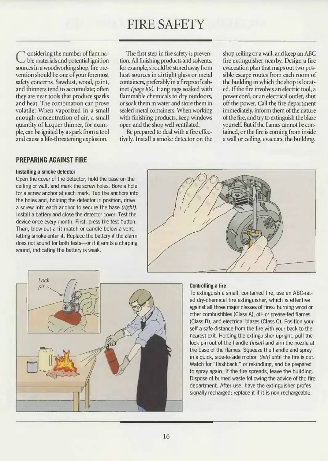
PREPARING AGAINST FIRE
Installing a smoke detector
Open the cover of the detector, hold the base on the
ceiling or wall, and mark the screw holes. Bore a hole
for a screw anchor at each mark. Tap the anchors into
the holes and, holding the detector in position, drive
a screw into each anchor to secure the base (right).
Install a battery and close the detector cover. Test the
device once every month. First, press the test button.
Then, blow out a lit match or candle below a vent,
letting smoke enter it. Replace the battery if the alarm
does not sound for both tests—or if it emits a chirping
sound, indicating the battery is weak.
Controlling a fire
To extinguish a small, contained fire, use an ABC-rat-
ed dry-chemical fire extinguisher, which is effective
against all three major classes of fires: burning wood or
other combustibles (Class A), oil- or grease-fed flames
(Class B), and electrical blazes (Class C). Position your-
self a safe distance from the fire with your back to the
nearest exit. Holding the extinguisher upright, pull the
lock pin out of the handle (inset) and aim the nozzle at
the base of the flames. Squeeze the handle and spray
in a quick, side-to-side motion (left) until the fire is out.
Watch for “flashback,” or rekindling, and be prepared
to spray again. If the fire spreads, leave the building.
Dispose of burned waste following the advice of the fire
department. After use, have the extinguisher profes-
sionally recharged; replace it if it is non-rechargeable.
16
ELECTRICAL SAFETY
Electricity plays a major role in the
modern woodworking shop, pow-
ering machines and tools, lighting fix-
tures and lamps, and heating systems.
Electricity is so commonplace that it is all
too easy to forget its potential for danger.
An electrical shock, even one that can
hardly be felt, can be deadly. For this rea-
son, the electrical system is strictly reg-
ulated by codes and standards designed
to protect you from fire and shock.
Living safely with electricity also
requires following basic precautions
designed to prevent mishaps. Inspect
plugs for cracks and power cords for
fraying, and replace any worn or dam-
aged part before using a tool. Never
replace a blown fuse with one of a high-
er amperage. Do not plug a three-prong
plug into a two-slot outlet by remov-
ing the grounding prong from a three-
prong plug. Instead, replace the outlet
with a GFCI (right).
Before undertaking a repair, shut off
the power at the service panel. To work
on the system, wear rubber gloves and,
where possible, use only one hand, keep-
ing your free hand behind your back.
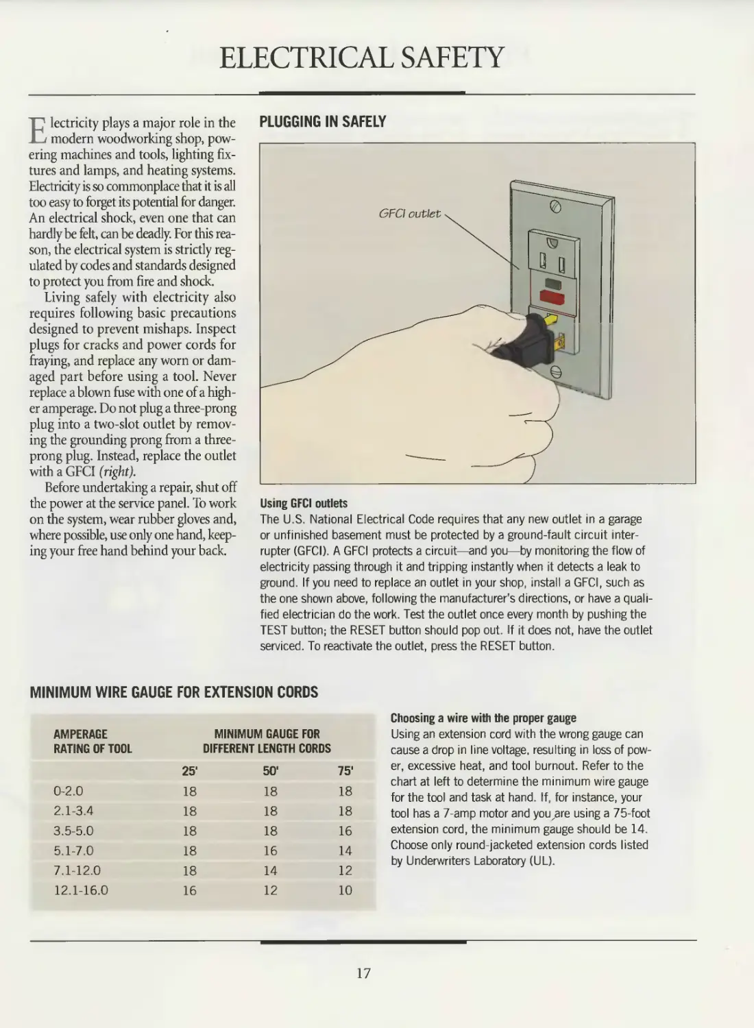
PLUGGING IN SAFELY
Using GFCI outlets
The U.S. National Electrical Code requires that any new outlet in a garage
or unfinished basement must be protected by a ground-fault circuit inter-
rupter (GFCI). A GFCI protects a circuit—and you—by monitoring the flow of
electricity passing through it and tripping instantly when it detects a leak to
ground. If you need to replace an outlet in your shop, install a GFCI, such as
the one shown above, following the manufacturer’s directions, or have a quali-
fied electrician do the work. Test the outlet once every month by pushing the
TEST button; the RESET button should pop out. If it does not, have the outlet
serviced. To reactivate the outlet, press the RESET button.
MINIMUM WIRE GAUGE FOR EXTENSION CORDS
AMPERAGE MINIMUM GAUGE FOR
RATING OF TOOL DIFFERENT LENGTH CORDS
25' 50' 75'
0-2.0 18 18 18
2.1-3.4 18 18 18
3.5-5.0 18 18 16
5.1-7.0 18 16 14
7.1-12.0 18 14 12
12.1-16.0 16 12 10
Choosing a wire with the proper gauge
Using an extension cord with the wrong gauge can
cause a drop in line voltage, resulting in loss of pow-
er, excessive heat, and tool burnout. Refer to the
chart at left to determine the minimum wire gauge
for the tool and task at hand. If, for instance, your
tool has a 7-amp motor and youxare using a 75-foot
extension cord, the minimum gauge should be 14.
Choose only round-jacketed extension cords listed
by Underwriters Laboratory (UL).
17
PERSONAL SAFETY GEAR
The personal safety equipment shown
below can go a long way toward
shielding you from most dangers in the
workshop. But carrying an inventory
of safety gear is not enough; the items
must be properly used to protect you
from injury.
The need for some items may not be
readily apparent, although the dangers
are very real. Few woodworkers need to
be reminded of the cutting power of a
spinning saw blade or jointer cutterhead.
Less well known are the long-term effects
of being exposed to the sound generated
by power tools. The chart on the next
page lists a variety of power tools along
with their approximate noise levels in
decibels. The chart also indicates the
longest recommended time that an
unprotected person can be exposed to
various levels before risking permanent
hearing loss.
Remember, too, that even short-term
exposure to some noise, while it may
not lead to hearing loss, can dull the
senses and cause a woodworker’s alert-
ness to flag—a setup for an accident.
A PANOPLY OF SAFETY EQUIPMENT
Rubber gloves
Household rubber
gloves or disposable
vinyl gloves protect
against mild chemicals
or finishes; neoprene rub-
ber gloves shield skin
from caustic finishing
products
Face shield
Clear plastic shield pro-
tects against flying debris
and splashes; features
adjustable head gear
Safety goggles
Flexible, molded plastic
goggles protect eyes.
Type with perforated vent
holes shields against impact
injury and sawdust; type with
baffled vents protects against
chemical splashes; nonvented
goggles also available.
Disposable dust mask
Fits over nose and mouth
for one-time-use protec-
tion against inhalation of
dust or mist; features a
cotton or fiber shield with
an adjustable head strap
and a metal nose clip
Ear muffs
Cushioned muffs with
adjustable plastic head
strap protect hearing
against high-intensity
noise from power tools
Dual-cartridge respirator
Protects against fumes when working
with chemicals or spraying a finish.
Interchangeable filters and chemical
cartridges shield against specific haz-
ards; filter prevents inhalation of dust.
Cartridges purify air and expel toxins
through exhalation valve
Ear plugs with neckband
Detachable foam-rubber plugs compressed
and inserted into ear canals provide hearing
protection from high-intensity power tool
noise; plastic neckband fits around neck
Reusable dust mask
Features a neoprene rubber
or soft plastic frame with
an adjustable head strap
and a replaceable cotton
fiber or gauze filter, protects
against dust and mist
Work gloves
For handling rough
lumber; typically fea-
tures leather or thick
fabric palms and finger- ' v,
tips with elasticized or
knitted wrists
Safety glasses
Standard plastic frames
fitted with shatterproof
lenses protect eyes from flying
wood chips and other debris;
typically feature side shields
18
SAFETY
NOISE LEVELS PRODUCED BY POWER TOOLS
While a '/-horsepower drill press is unlikely to damage your hearing—unless you run the machine all day
long—unprotected exposure to the noise produced by a 1 /-horsepower router can be dangerous after only
30 minutes. The above chart shows approximate noise levels produced by a variety of power tools. Keep in
mind that tools with dull cutters or blades generate more noise than those with well-sharpened cutting edges.
TESTING A RESPIRATOR
Checking for air leaks
A respirator is only as good as its seal against your face. No
seal, no protection. To test your respirator, place it over your
face, setting the top strap over the crown of your head. Adjust
the side straps for a snug fit. To test the respirator, cover the
outlet valve with your hand and breathe out gently (right). There
should be no air leakage around the facepiece. If air leaks out
of the respirator, readjust the straps for a tighter fit. Replace
the facepiece when necessary following the manufacturer’s
instructions, or replace the respirator. Use the appropriate fil-
ters for the job at hand. (If you have a beard, use a full-face
mask with forced-air ventilation.)
19
SAFETY
BUILD IT YOURSELF
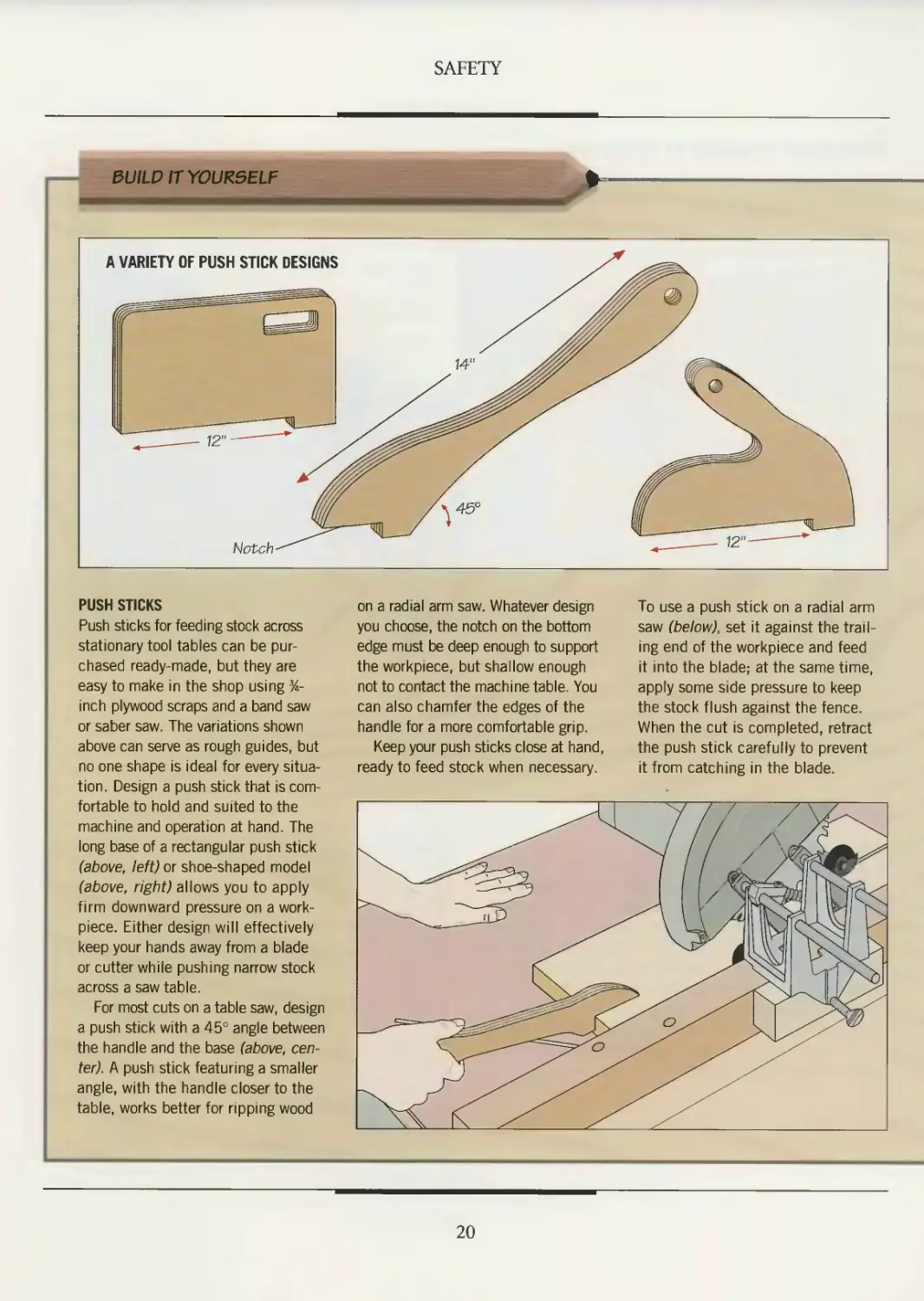
PUSH STICKS
Push sticks for feeding stock across
stationary tool tables can be pur-
chased ready-made, but they are
easy to make in the shop using %-
inch plywood scraps and a band saw
or saber saw. The variations shown
above can serve as rough guides, but
no one shape is ideal for every situa-
tion. Design a push stick that is com-
fortable to hold and suited to the
machine and operation at hand. The
long base of a rectangular push stick
(above, left) or shoe-shaped model
(above, right) allows you to apply
firm downward pressure on a work-
piece. Either design will effectively
keep your hands away from a blade
or cutter while pushing narrow stock
across a saw table.
For most cuts on a table saw, design
a push stick with a 45° angle between
the handle and the base (above, cen-
ter). A push stick featuring a smaller
angle, with the handle closer to the
table, works better for ripping wood
on a radial arm saw. Whatever design
you choose, the notch on the bottom
edge must be deep enough to support
the workpiece, but shallow enough
not to contact the machine table. You
can also chamfer the edges of the
handle for a more comfortable grip.
Keep your push sticks close at hand,
ready to feed stock when necessary.
To use a push stick on a radial arm
saw (below), set it against the trail-
ing end of the workpiece and feed
it into the blade; at the same time,
apply some side pressure to keep
the stock flush against the fence.
When the cut is completed, retract
the push stick carefully to prevent
it from catching in the blade.
20
SAFETY
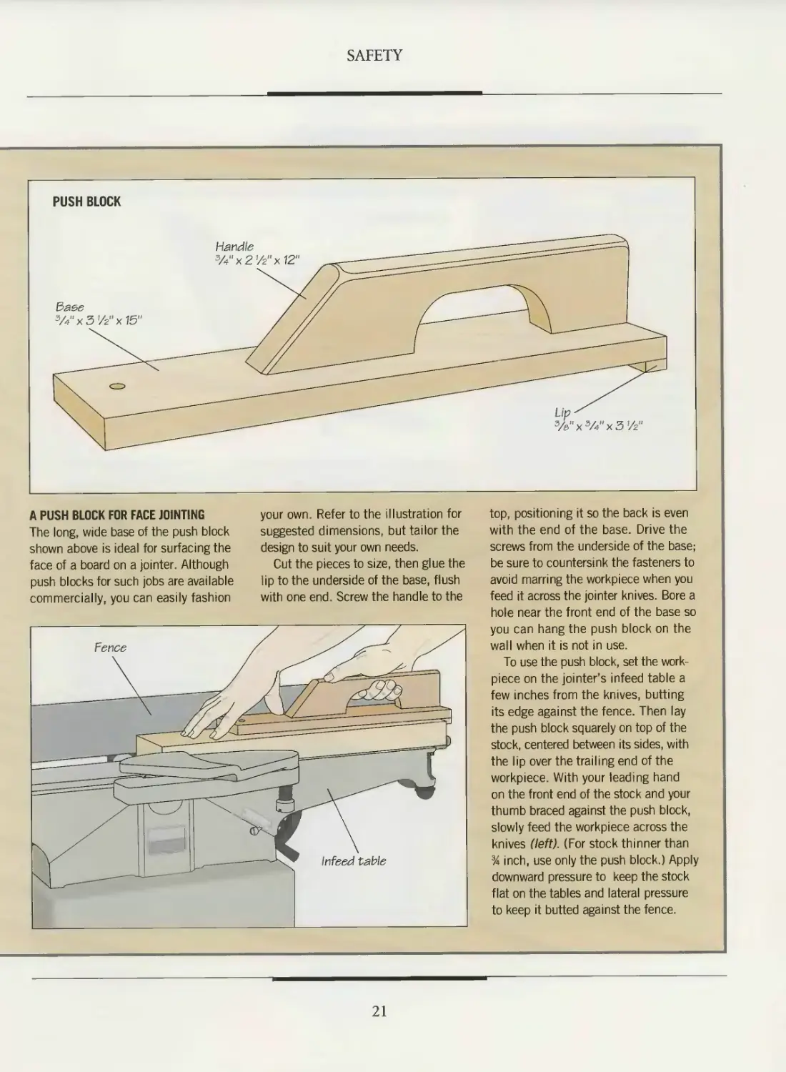
A PUSH BLOCK FOR FACE JOINTING
The long, wide base of the push block
shown above is ideal for surfacing the
face of a board on a jointer. Although
push blocks for such jobs are available
commercially, you can easily fashion
your own. Refer to the illustration for
suggested dimensions, but tailor the
design to suit your own needs.
Cut the pieces to size, then glue the
lip to the underside of the base, flush
with one end. Screw the handle to the
top, positioning it so the back is even
with the end of the base. Drive the
screws from the underside of the base;
be sure to countersink the fasteners to
avoid marring the workpiece when you
feed it across the jointer knives. Bore a
hole near the front end of the base so
you can hang the push block on the
wall when it is not in use.
To use the push block, set the work-
piece on the jointer's infeed table a
few inches from the knives, butting
its edge against the fence. Then lay
the push block squarely on top of the
stock, centered between its sides, with
the lip over the trailing end of the
workpiece. With your leading hand
on the front end of the stock and your
thumb braced against the push block,
slowly feed the workpiece across the
knives (left). (For stock thinner than
% inch, use only the push block.) Apply
downward pressure to keep the stock
flat on the tables and lateral pressure
to keep it butted against the fence.
21
SAFETY
BUILD IT YOURSELF (continued)
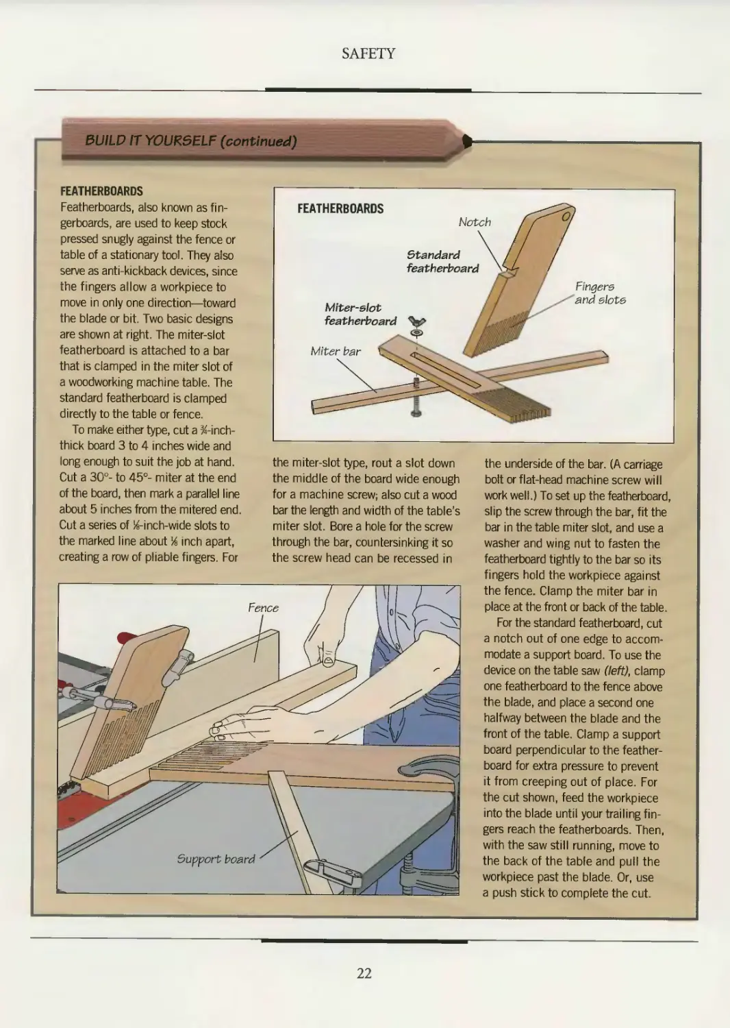
FEATHERBOARDS
Featherboards, also known as fin-
gerboards, are used to keep stock
pressed snugly against the fence or
table of a stationary tool. They also
serve as anti-kickback devices, since
the fingers allow a workpiece to
move in only one direction—toward
the blade or bit. Two basic designs
are shown at right. The miter-slot
featherboard is attached to a bar
that is clamped in the miter slot of
a woodworking machine table. The
standard featherboard is clamped
directly to the table or fence.
To make either type, cut a ^-inch-
thick board 3 to 4 inches wide and
long enough to suit the job at hand.
Cut a 30°- to 45°- miter at the end
of the board, then mark a parallel line
about 5 inches from the mitered end.
Cut a series of %-inch-wide slots to
the marked line about % inch apart,
creating a row of pliable fingers. For
the miter-slot type, rout a slot down
the middle of the board wide enough
for a machine screw; also cut a wood
bar the length and width of the table’s
miter slot. Bore a hole for the screw
through the bar, countersinking it so
the screw head can be recessed in
the underside of the bar. (A carriage
bolt or flat-head machine screw will
work well.) To set up the featherboard,
slip the screw through the bar, fit the
bar in the table miter slot, and use a
washer and wing nut to fasten the
featherboard tightly to the bar so its
fingers hold the workpiece against
the fence. Clamp the miter bar in
place at the front or back of the table.
For the standard featherboard, cut
a notch out of one edge to accom-
modate a support board. To use the
device on the table saw (left), clamp
one featherboard to the fence above
the blade, and place a second one
halfway between the blade and the
front of the table. Clamp a support
board perpendicular to the feather-
board for extra pressure to prevent
it from creeping out of place. For
the cut shown, feed the workpiece
into the blade until your trailing fin-
gers reach the featherboards. Then,
with the saw still running, move to
the back of the table and pull the
workpiece past the blade. Or, use
a push stick to complete the cut.
22
FIRST AID
Most woodworking accidents arise
from the improper use of tools
and safety guards, unsafe work habits,
and mishandling hazardous materials.
Take the time to set up properly for a
job, gathering together the tools, equip-
ment, and materials you need. Always
use the appropriate safety gear. Work
methodically; never hurry through a job.
Be especially careful—or stop working—
if you are fatigued.
Accidents can befall even the most
careful woodworker. Boards split, blades
nick, and liquids splash. Many finishing
products contain chemicals that emit
toxic fumes, causing dizziness or nau-
sea. Keep in mind the potential hazards
of any tool or material you use. Store a
first-aid kit, stocked with the basic sup-
plies shown below, in an easily accessible
spot in your shop. In the event of an acci-
dent, you will want anyone to be able to
find it quickly to administer first aid.
Keep emergency telephone numbers
handy. Techniques for handling some
common shop mishaps are shown on
the following pages.
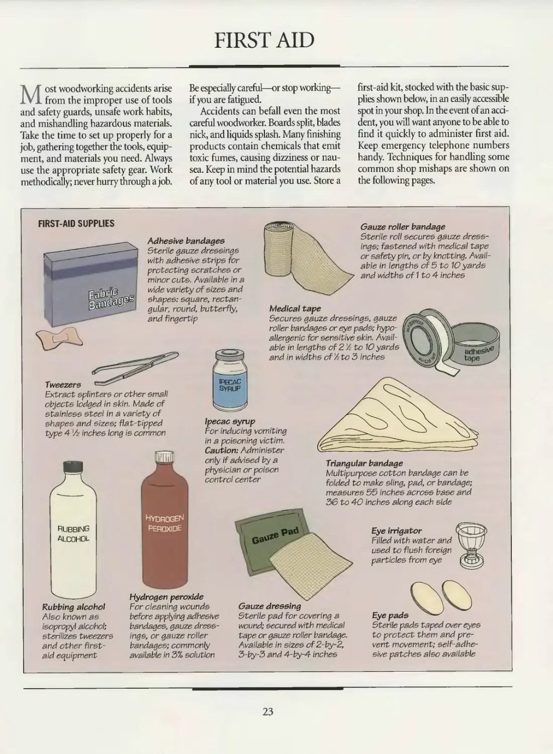
FIRST-AID SUPPLIES
Adhesive bandages
Sterile gauze dressings
with adhesive strips for
protecting scratches or
minor cuts Available in a
wide variety of sizes and
and fingertip
ipecac
SYRUP
^apes: square rectan-
-- gular, round, butterfly,
Gauze roller bandage
Sterile roll secures gauze dress-
ings; fastened with medical tape
or safety pin, or by knotting. Avail-
able in lengths of 5 to 10 yards
and widths of 1 to 4 inches
Medical tape
Secures gauze dressings, gauze
roller bandages or eye pads; hypo-
allergenic for sensitive skin. Avail-
able in lengths of 2 A to 10 yards
and in widths of'A to 3 inches
Tweezers
Extract splinters or other small
objects lodged in skin. Made of
stainless steel in a variety of
shapes and sizes; flat-tipped
type 4 /z inches long is common
adhesiv6
tape
Ipecac syrup
For inducing vomiting
in a poisoning victim.
Caution: Administer
only if advised by a
physician or poison
control center
RUBBING
ALCOHOL
Rubbing alcohol
Also known as
isopropyl alcohol;
sterilizes tweezers
and other first-
aid equipment
Hydrogen
peroxide
Hydrogen peroxide
For cleaning wounds
before applying adhesive
bandages, gauze dress-
ings, or gauze roller
bandages; commonly
available in 3% solution
pad
Triangular bandage
Multipurpose cotton bandage can be
folded to make sling, pad, or bandage;
measures 55 inches across base and
3& to 40 inches along each side
Gauze dressing
Sterile pad for covering a
wound; secured with medical
tape or gauze roller bandage.
Available in sizes of 2-by-2,
3-by-3 and 4-by-4 inches
Eye irrigator
Filled with water and
used to flush foreign
particles from eye
Eye pads
Sterile pads taped over eyes
to protect them and pre-
vent movement; self-adhe-
sive patches also available
23
SAFETY
PROVIDING MINOR FIRST AID
Clearing a particle from the eye
Hold your affected eye open with the forefinger and thumb of
one hand. Slowly rotate your eye, if necessary, to help expose
the particle. Gently wipe away the particle using the twisted
end of a tissue moistened with water (above, left). Or, fill an
eye irrigator with cool water and use it to flush out the particle
Lean forward with both eyes closed and press the rim of the
irrigator against the affected eye, and tilt back your head. Open
your eyes (above, right) and blink several times to flush out the
particle. If you cannot remove the particle, seek medical help
immediately. Caution: Do not remove a particle that is on the
cornea, is embedded, or has adhered to the eye.
Flushing a chemical from the eye
Holding the eyelids of the affected eye
apart, flush the eye thoroughly for at least
15 minutes under a gentle flow of cool
water from a faucet (right) or pitcher; tilt
your head to one side to prevent the chem-
ical from being washed into the uninjured
eye If you are outdoors, flush the eye
using a garden hose. Gently cover both
eyes with eye pads or sterile gauze dress-
ings and seek medical help immediately.
24
SAFETY
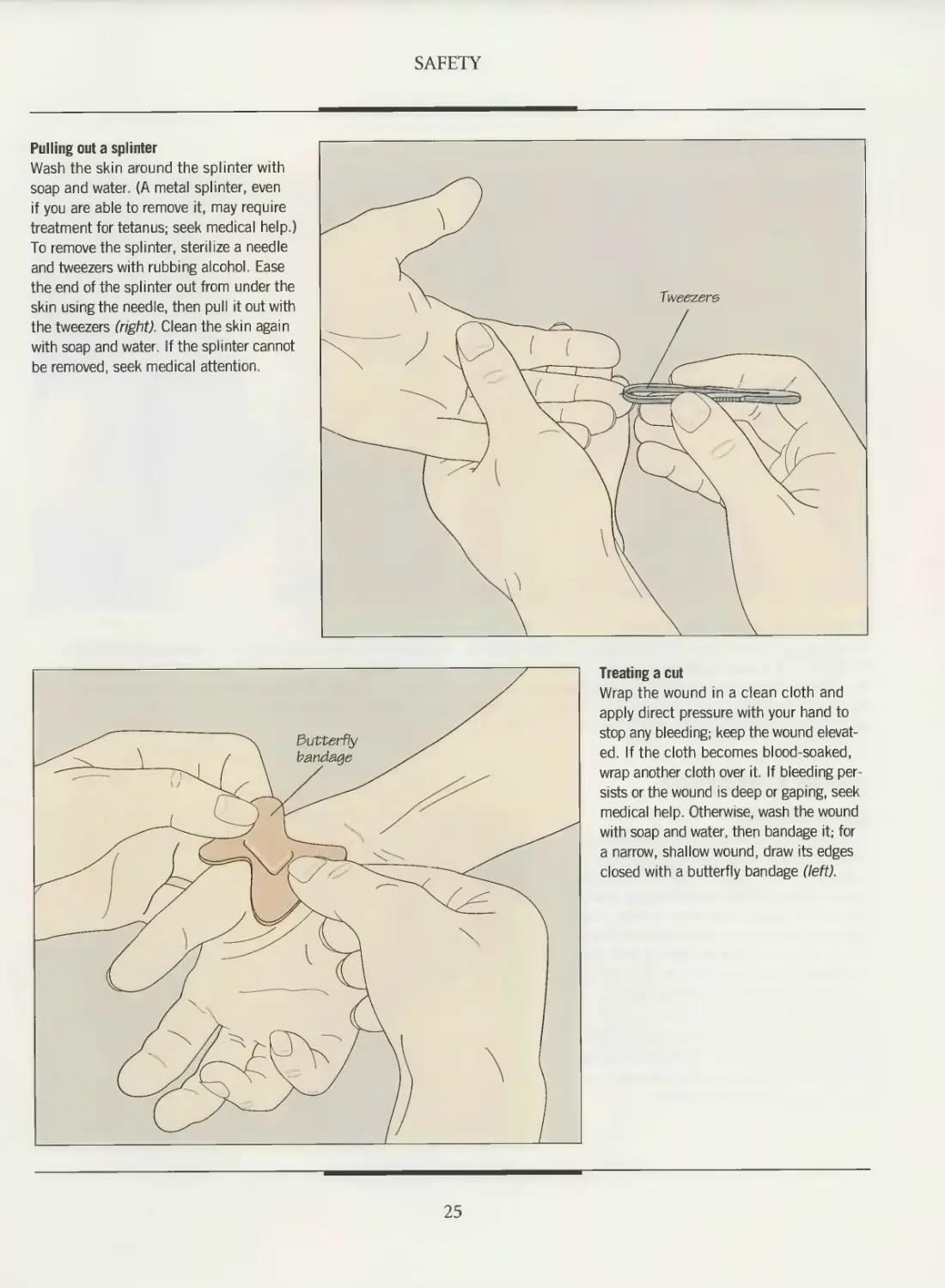
Pulling out a splinter
Wash the skin around the splinter with
soap and water. (A metal splinter, even
if you are able to remove it, may require
treatment for tetanus; seek medical help.)
To remove the splinter, sterilize a needle
and tweezers with rubbing alcohol. Ease
the end of the splinter out from under the
skin using the needle, then pull it out with
the tweezers (right). Clean the skin again
with soap and water. If the splinter cannot
be removed, seek medical attention.
Treating a cut
Wrap the wound in a clean cloth and
apply direct pressure with your hand to
stop any bleeding; keep the wound elevat-
ed. If the cloth becomes blood-soaked,
wrap another cloth over it. If bleeding per-
sists or the wound is deep or gaping, seek
medical help. Otherwise, wash the wound
with soap and water, then bandage it; for
a narrow, shallow wound, draw its edges
closed with a butterfly bandage (left).
25
SAFETY
CONTROLLING BLEEDING
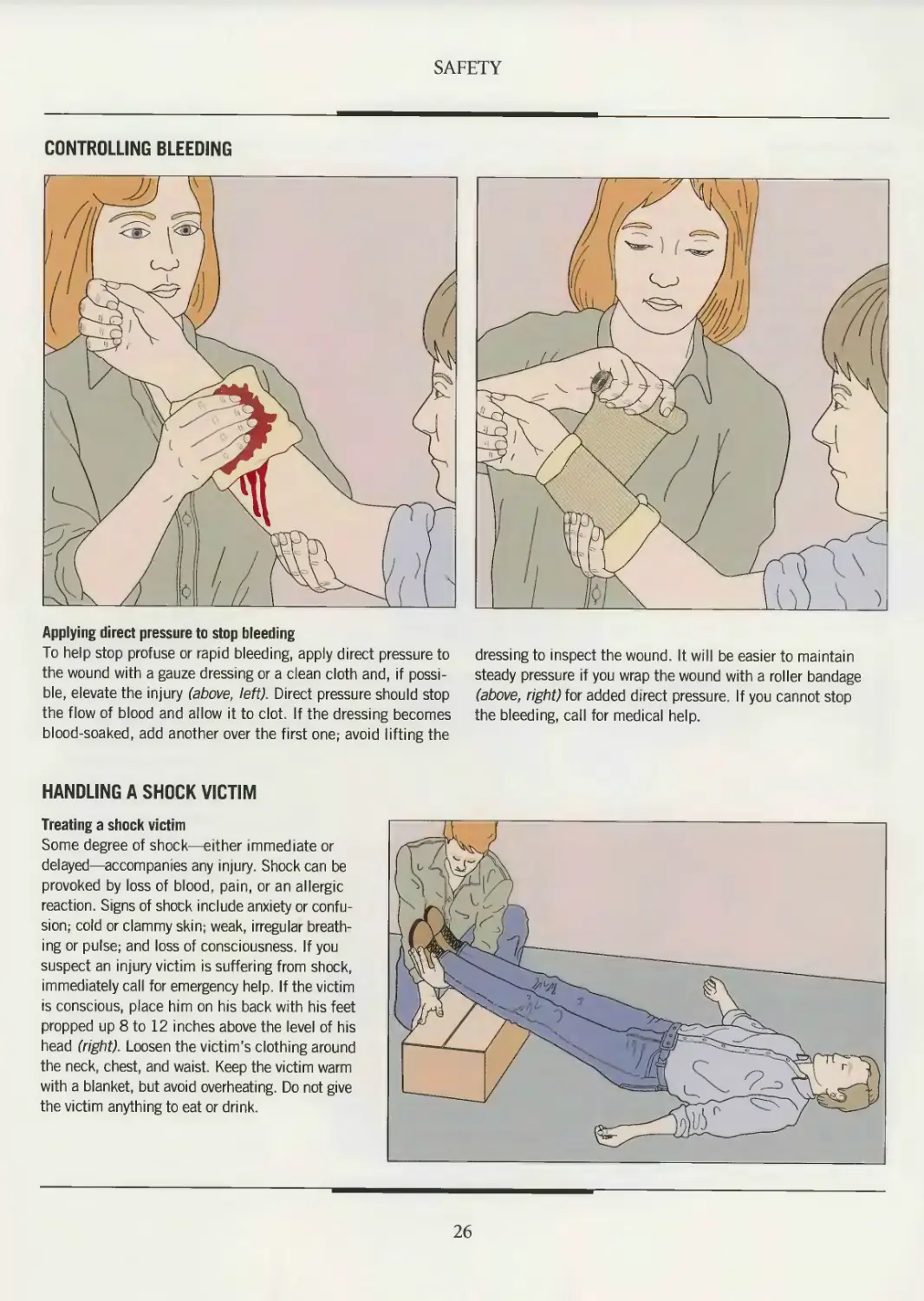
Applying direct pressure to stop bleeding
To help stop profuse or rapid bleeding, apply direct pressure to
the wound with a gauze dressing or a clean cloth and, if possi-
ble, elevate the injury (above left). Direct pressure should stop
the flow of blood and allow it to clot. If the dressing becomes
blood-soaked, add another over the first one; avoid lifting the
dressing to inspect the wound. It will be easier to maintain
steady pressure if you wrap the wound with a roller bandage
(above, right) for added direct pressure. If you cannot stop
the bleeding, call for medical help.
HANDLING A SHOCK VICTIM
Treating a shock victim
Some degree of shock—either immediate or
delayed—accompanies any injury. Shock can be
provoked by loss of blood, pain, or an allergic
reaction. Signs of shock include anxiety or confu-
sion; cold or clammy skin; weak, irregular breath-
ing or pulse; and loss of consciousness. If you
suspect an injury victim is suffering from shock,
immediately call for emergency help. If the victim
is conscious, place him on his back with his feet
propped up 8 to 12 inches above the level of his
head (right). Loosen the victim's clothing around
the neck, chest, and waist Keep the victim warm
with a blanket, but avoid overheating. Do not give
the victim anything to eat or drink.
26
SAFETY
TREATING A VICTIM OF ELECTRICAL SHOCK
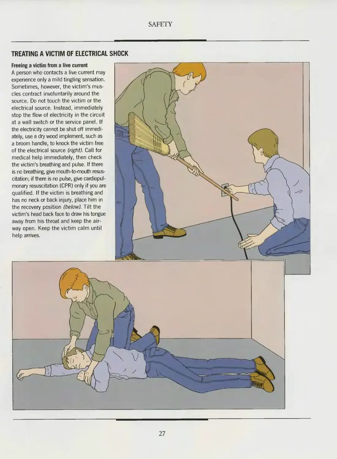
Freeing a victim from a live current
A person who contacts a live current may
experience only a mild tingling sensation.
Sometimes, however, the victim’s mus-
cles contract involuntarily around the
source. Do not touch the victim or the
electrical source. Instead, immediately
stop the flow of electricity in the circuit
at a wall switch or the service panel. If
the electricity cannot be shut off immedi-
ately, use a dry wood implement, such as
a broom handle, to knock the victim free
of the electrical source (right). Call for
medical help immediately, then check
the victim’s breathing and pulse. If there
is no breathing, give mouth-to-mouth resus-
citation; if there is no pulse, give cardiopul-
monary resuscitation (CPR) only if you are
qualified. If the victim is breathing and
has no neck or back injury, place him in
the recovery position (below). Tilt the
victim’s head back face to draw his tongue
away from his throat and keep the air-
way open. Keep the victim calm until
help arrives.
27
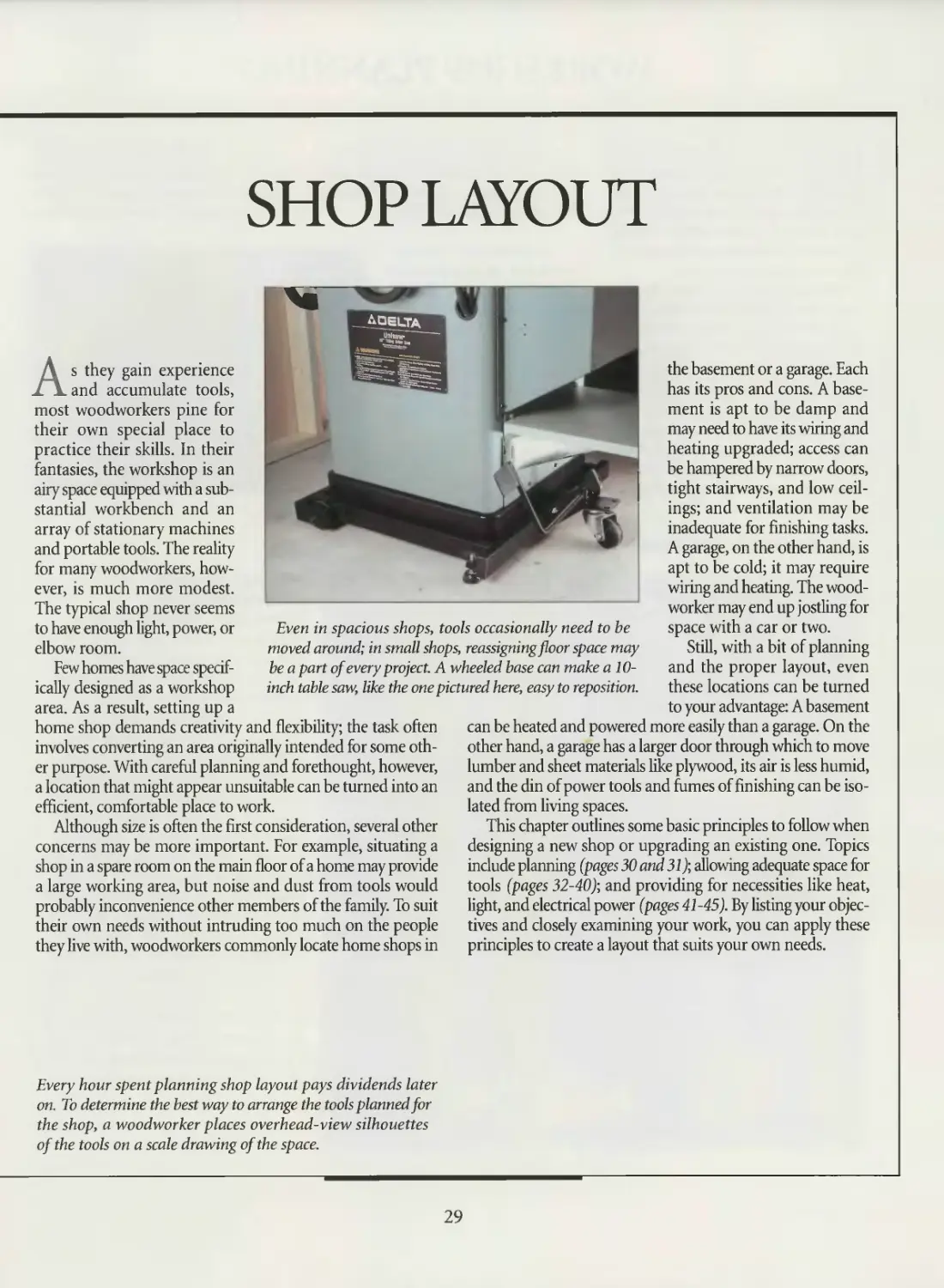
SHOP LAYOUT
Even in spacious shops, tools occasionally need to be
moved around; in small shops, reassigning floor space may
be a part of every project. A wheeled base can make a 10-
inch table saw, like the one pictured here, easy to reposition.
As they gain experience
and accumulate tools,
most woodworkers pine for
their own special place to
practice their skills. In their
fantasies, the workshop is an
airy space equipped with a sub-
stantial workbench and an
array of stationary machines
and portable tools. The reality
for many woodworkers, how-
ever, is much more modest.
The typical shop never seems
to have enough light, power, or
elbow room.
Few homes have space specif-
ically designed as a workshop
area. As a result, setting up a
home shop demands creativity and flexibility; the task often
involves converting an area originally intended for some oth-
er purpose. With careful planning and forethought, however,
a location that might appear unsuitable can be turned into an
efficient, comfortable place to work.
Although size is often the first consideration, several other
concerns may be more important. For example, situating a
shop in a spare room on the main floor of a home may provide
a large working area, but noise and dust from tools would
probably inconvenience other members of the family. To suit
their own needs without intruding too much on the people
they live with, woodworkers commonly locate home shops in
the basement or a garage. Each
has its pros and cons. A base-
ment is apt to be damp and
may need to have its wiring and
heating upgraded; access can
be hampered by narrow doors,
tight stairways, and low ceil-
ings; and ventilation may be
inadequate for finishing tasks.
A garage, on the other hand, is
apt to be cold; it may require
wiring and heating. The wood-
worker may end up jostling for
space with a car or two.
Still, with a bit of planning
and the proper layout, even
these locations can be turned
to your advantage: A basement
can be heated and powered more easily than a garage. On the
other hand, a garage has a larger door through which to move
lumber and sheet materials like plywood, its air is less humid,
and the din of power tools and fumes of finishing can be iso-
lated from living spaces.
This chapter outlines some basic principles to follow when
designing a new shop or upgrading an existing one. Topics
include planning (pages 30 and 31); allowing adequate space for
tools (pages 32-40); and providing for necessities like heat,
light, and electrical power (pages 41 -45). By listing your objec-
tives and closely examining your work, you can apply these
principles to create a layout that suits your own needs.
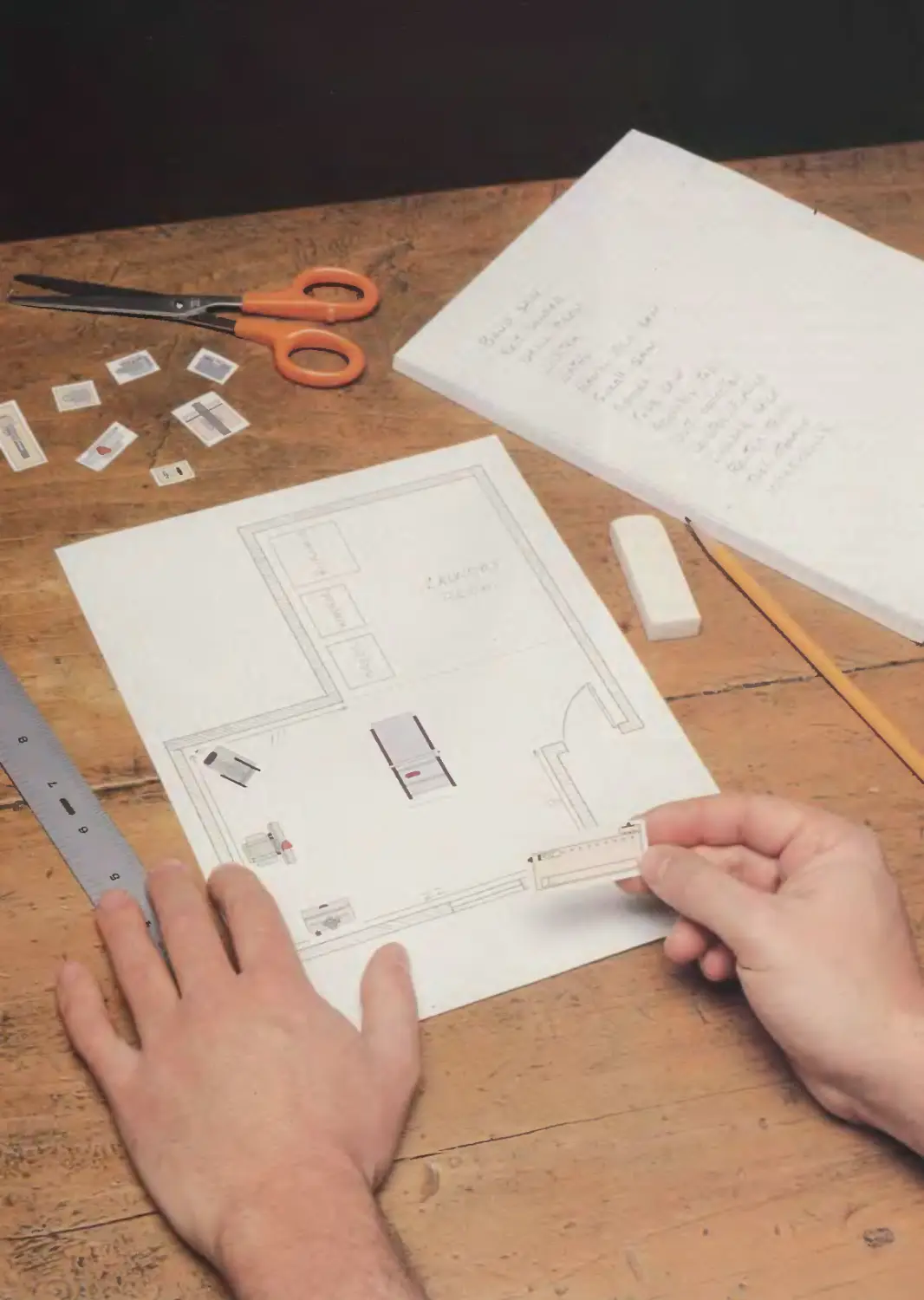
Every hour spent planning shop layout pays dividends later
on. To determine the best way to arrange the tools planned for
the shop, a woodworker places overhead-view silhouettes
of the tools on a scale drawing of the space.
29
WORKSHOP PLANNING
It is far easier to shuffle paper cutouts
of your tools on a template than it is to
drag a table saw halfway across the shop.
Time spent planning the layout of your
shop will be more than amply rewarded
in reduced frustration and increased effi-
ciency when you go to work.
Designing a shop involves juggling
many interdependent variables, from
local humidity and the type of work you
do to the height of the ceiling and the
cost of wiring. To help sort them out,
ask yourself a set of questions, like those
in the checklist on page 31, to help
determine the kind of shop most suit-
able for your needs and remind you of
factors that may affect its design.
Remember, too, a basic principle for
any shop, illustrated below, that the lum-
ber should take a relatively straight path
as it is processed—almost as though the
shop were an assembly line.
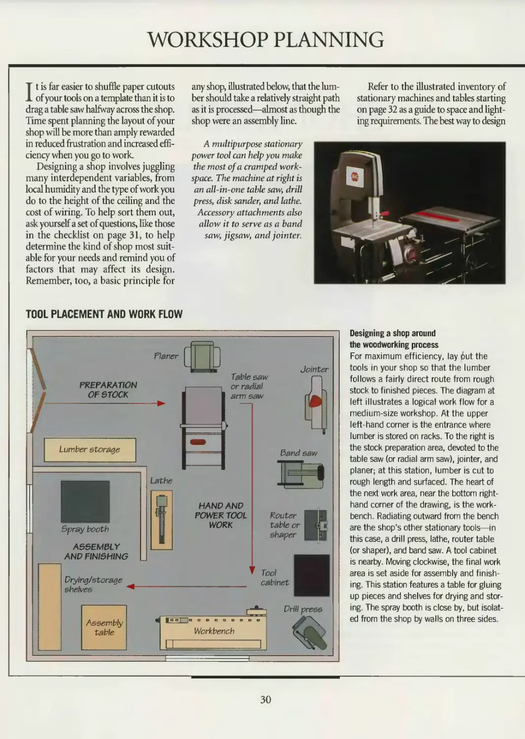
A multipurpose stationary
power tool can help you make
the most of a cramped work-
space. The machine at right is
an all-in-one table saw, drill
press, disk sander, and lathe.
Accessory attachments also
allow it to serve as a band
saw, jigsaw, and jointer.
Refer to the illustrated inventory of
stationary machines and tables starting
on page 32 as a guide to space and light-
ing requirements. The best way to design
TOOL PLACEMENT AND WORK FLOW
Designing a shop around
the woodworking process
For maximum efficiency, lay 6ut the
tools in your shop so that the lumber
follows a fairly direct route from rough
stock to finished pieces. The diagram at
left illustrates a logical work flow for a
medium-size workshop. At the upper
left-hand corner is the entrance where
lumber is stored on racks. To the right is
the stock preparation area, devoted to the
table saw (or radial arm saw), jointer, and
planer; at this station, lumber is cut to
rough length and surfaced. The heart of
the next work area, near the bottom right-
hand corner of the drawing, is the work-
bench. Radiating outward from the bench
are the shop’s other stationary tools—in
this case, a drill press, lathe, router table
(or shaper), and band saw. A tool cabinet
is nearby. Moving clockwise, the final work
area is set aside for assembly and finish-
ing. This station features a table for gluing
up pieces and shelves for drying and stor-
ing. The spray booth is close by, but isolat-
ed from the shop by walls on three sides.
30
SHOP LAYOUT
the layout is to experiment with arrang-
ing photocopies of scale drawings of
the tools (page 35) on a sheet of graph
paper. Remember that a tool should be
positioned so that an access door is vis-
ible from it. In addition, a workpiece
kicked back from the tool should not
be able to strike someone working at
another station.
Consider dedicating spaces for spe-
cific woodworking tasks. A finishing area
or spray booth requires priority in plan-
ning because of light, temperature, and
ventilation needs.
Depending on the extent of your shop
and local zoning and building codes, you
may need to obtain permits; consult
your local building inspection office.
Ill 111 111 111 111 111 111 111 111 111 111 111 111 111 HI M 111
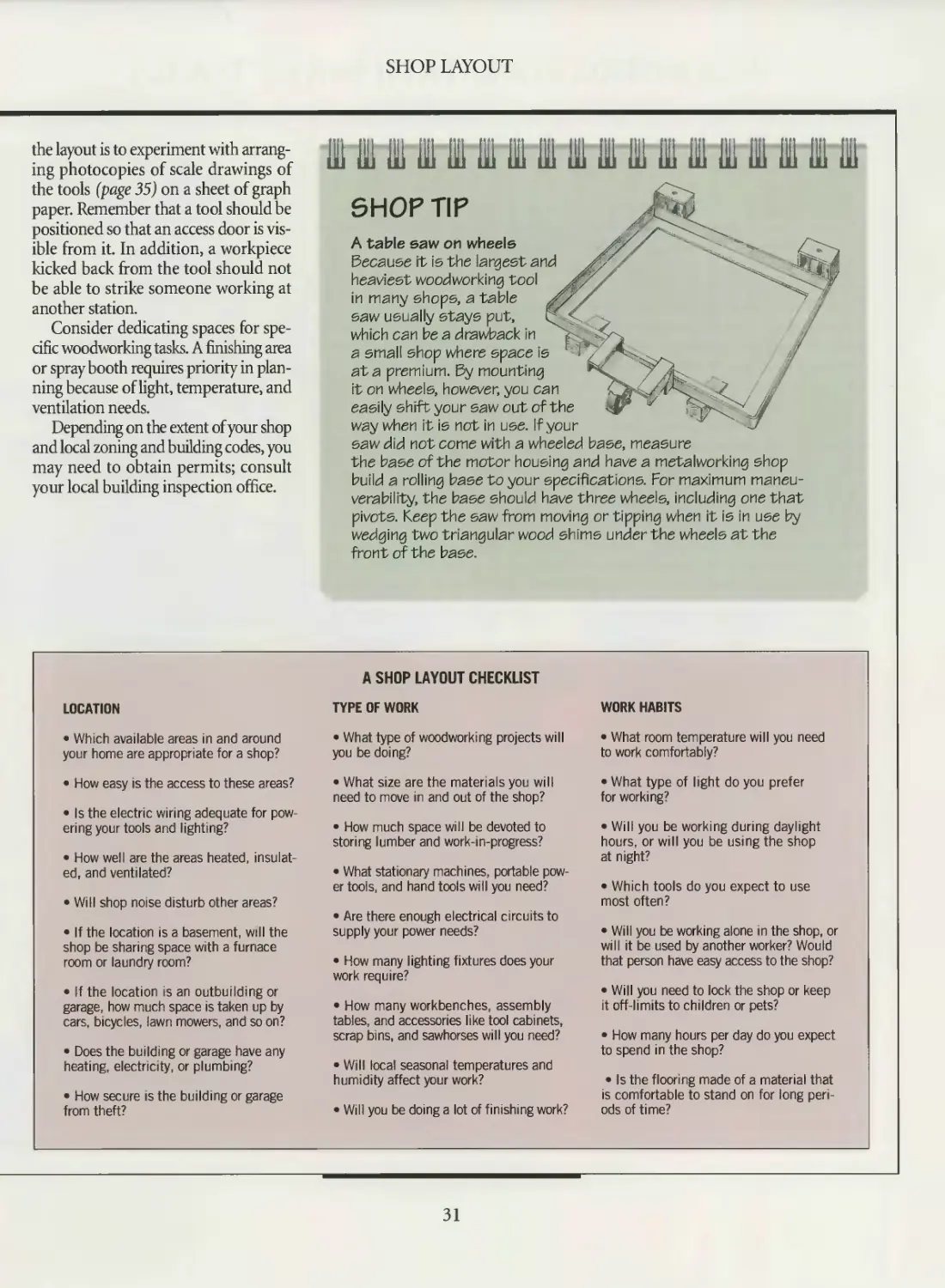
SHOP TIP
A table saw on wheels
Because it is the largest and
heaviest woodworking tool
in many shops, a table
saw usually stays put,
which can be a drawback in
a small shop where space is
ata premium. By mounting
it on wheels, however, you can
easily shift your saw out of the
way when it is not in use. If your
saw did not come with a wheeled base, measure
the base of the motor housing and have a metalworking shop
build a rolling base to your specifications. For maximum maneu-
verability, the base should have three wheels, including one that
pivots. Keep the saw from moving or tipping when it is in use by
wedging two triangular wood shims under the wheels at the
front of the base.
LOCATION
• Which available areas in and around
your home are appropriate for a shop?
• How easy is the access to these areas?
• Is the electric wiring adequate for pow-
ering your tools and lighting?
• How well are the areas heated, insulat-
ed, and ventilated?
• Will shop noise disturb other areas?
• If the location is a basement, will the
shop be sharing space with a furnace
room or laundry room?
• If the location is an outbuilding or
garage, how much space is taken up by
cars, bicycles, lawn mowers, and so on?
• Does the building or garage have any
heating, electricity, or plumbing?
• How secure is the building or garage
from theft?
A SHOP LAYOUT CHECKLIST
TYPE OF WORK
• What type of woodworking projects will
you be doing?
• What size are the materials you will
need to move in and out of the shop?
• How much space will be devoted to
storing lumber and work-in-progress?
• What stationary machines, portable pow-
er tools, and hand tools will you need?
• Are there enough electrical circuits to
supply your power needs?
• How many lighting fixtures does your
work require?
• How many workbenches, assembly
tables, and accessories like tool cabinets,
scrap bins, and sawhorses will you need?
• Will local seasonal temperatures and
humidity affect your work?
• Will you be doing a lot of finishing work?
WORK HABITS
• What room temperature will you need
to work comfortably?
• What type of light do you prefer
for working?
• Will you be working during daylight
hours, or will you be using the shop
at night?
• Which tools do you expect to use
most often?
• Will you be working alone in the shop, or
will it be used by another worker? Would
that person have easy access to the shop?
• Will you need to lock the shop or keep
it off-limits to children or pets?
• How many hours per day do you expect
to spend in the shop?
• Is the flooring made of a material that
is comfortable to stand on for long peri-
ods of time?
31
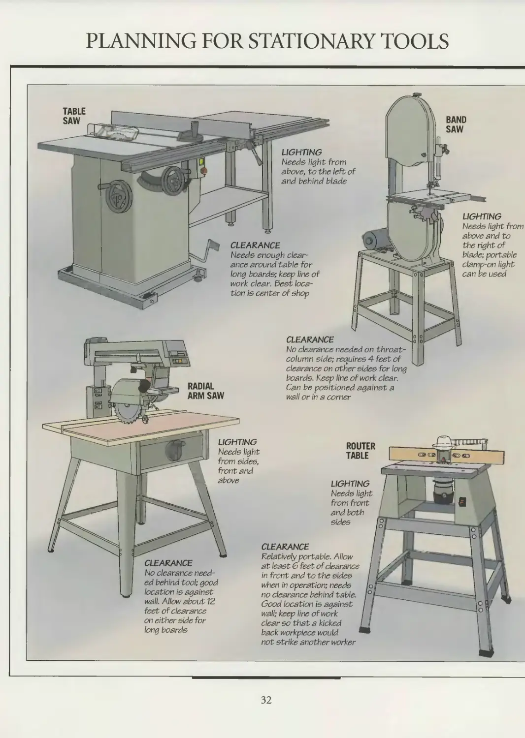
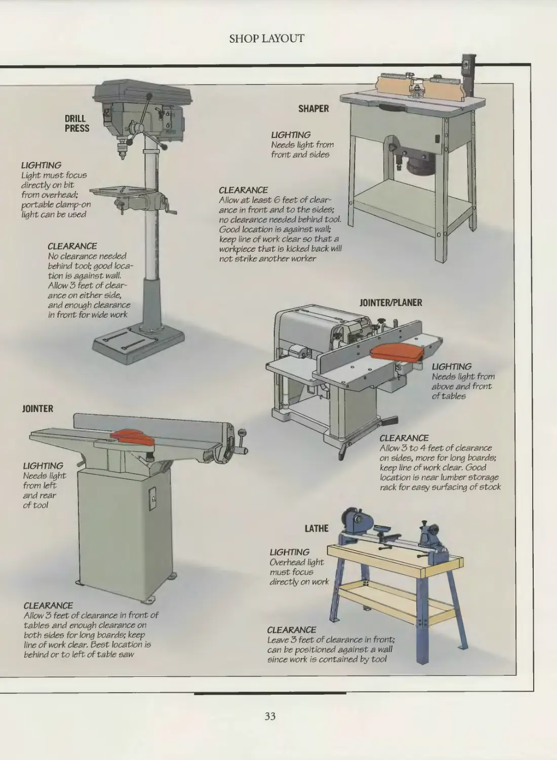
PLANNING FOR STATIONARY TOOLS
TABLE
SAW
LIGHTING
Needs light from
above, to the left of
and behind blade
LIGHTING
Needs light
from front
and both
sides
LIGHTING
Needs light
from sides,
front and
above
CLEARANCE
Needs enough Clear-
ance around table for
long boards; keep line of
work clear. Best loca-
tion is center of shop
LIGHTING
Needs light from
above and to
the right of
blade; portable
clamp-on light
can be used
RADIAL
ARM SAW
CLEARANCE "
No clearance needed on -throat-
column side; requires 4 feet of
clearance on other sides for long
boards. Keep line of work clear.
Can be positioned against a
wail or in a comer
CLEARANCE
No clearance need-
ed behind tool; good
location is against
wall. Allow about 12
feet of clearance
on either side for
long boards
ROUTER
TABLE
CLEARANCE
Relatively portable. Allow
at least 6 feet of clearance
in front and to the sides
when in operation; needs
no clearance behind table.
Good location is against
wall; keep line of work
clear so that a kicked
back workpiece would
not strike another worker
32
SHOP LAYOUT
LIGHTING
SHAPER
LIGHTING
Needs light from
front and sides
Light must focus
directly on bit
from overhead;
portable clamp-on
light can be used
CLEARANCE
No clearance needed
behind tool; good loca-
tion is against wall.
Allow 5 feet of clear-
ance on either side,
and enough clearance
in front for wide work
JOINTER
CLEARANCE
Allow 3 feet of clearance in front of
tables and enough clearance on
both sides for long boards; keep
line of work clear. Best location is
behind or to left of table saw
CLEARANCE
Allow at least 6 feet of clear-
ance in front and to the sides;
no clearance needed behind tool.
Good location is against wall;
keep line of work clear so that a
workpiece that is kicked back will
not strike another worker
JOINTER/PLANER
LIGHTING
Needs light from
above and front
of tables
CLEARANCE
Allow 3 to 4 feet of clearance
on sides, more for long boards;
keep line of work clear. Good
location is near lumber storage
rack for easy surfacing of stock
LIGHTING
Overhead light
must focus
directly on work
CLEARANCE
Leave 3 feet of clearance in front;
can be positioned against a wall
since work is contained by tool
LATHE
33
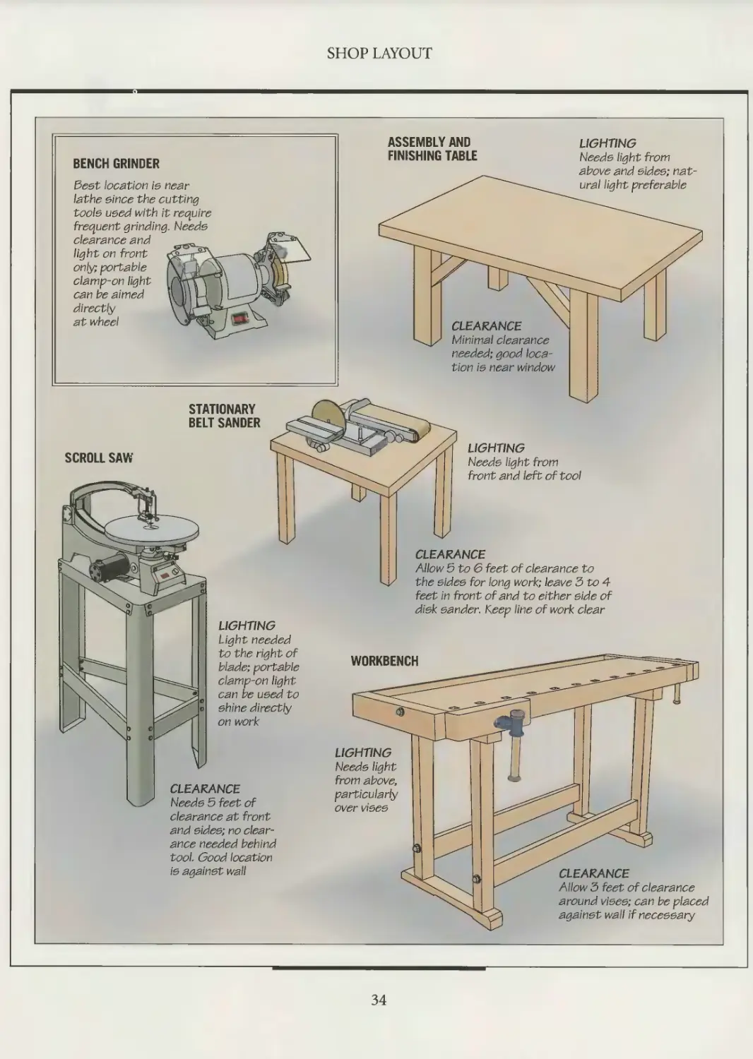
SHOP LAYOUT
34
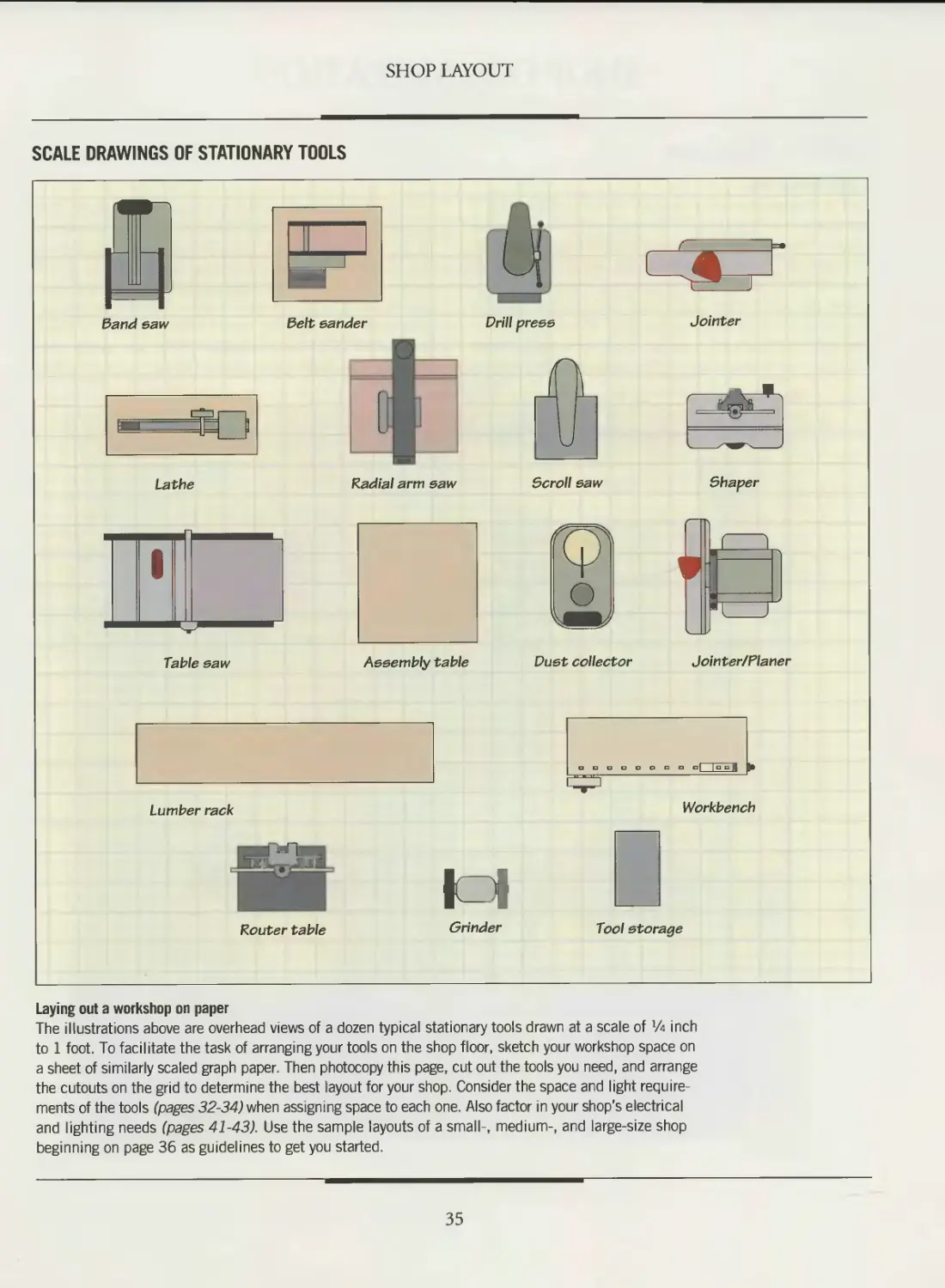
SHOP LAYOUT
Laying out a workshop on paper
The illustrations above are overhead views of a dozen typical stationary tools drawn at a scale of ’Л inch
to 1 foot. To facilitate the task of arranging your tools on the shop floor, sketch your workshop space on
a sheet of similarly scaled graph paper. Then photocopy this page, cut out the tools you need, and arrange
the cutouts on the grid to determine the best layout for your shop. Consider the space and light require-
ments of the tools (pages 32-34) when assigning space to each one. Also factor in your shop’s electrical
and lighting needs (pages 41-43). Use the sample layouts of a small-, medium-, and large-size shop
beginning on page 36 as guidelines to get you started.
35
SHOP ORGANIZATION
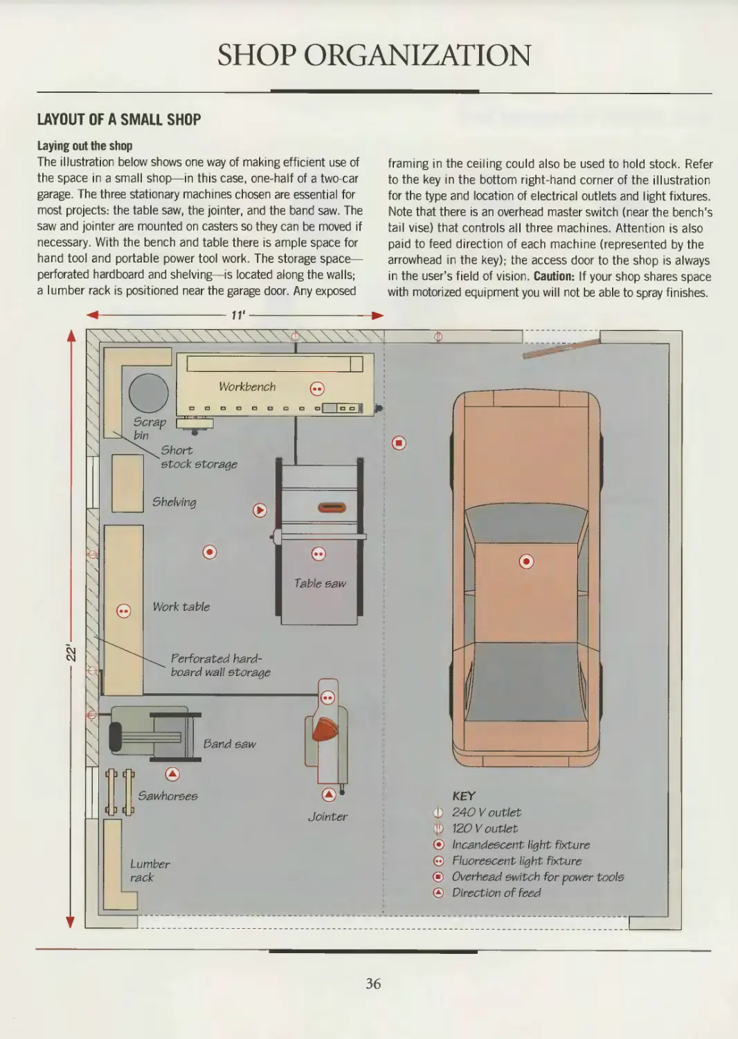
LAYOUT OF A SMALL SHOP
Laying out the shop
The illustration below shows one way of making efficient use of
the space in a small shop—in this case, one-half of a two-car
garage. The three stationary machines chosen are essential for
most projects: the table saw, the jointer, and the band saw. The
saw and jointer are mounted on casters so they can be moved if
necessary. With the bench and table there is ample space for
hand tool and portable power tool work. The storage space—
perforated hardboard and shelving—is located along the walls;
a lumber rack is positioned near the garage door. Any exposed
framing in the ceiling could also be used to hold stock. Refer
to the key in the bottom right-hand corner of the illustration
for the type and location of electrical outlets and light fixtures.
Note that there is an overhead master switch (near the bench's
tail vise) that controls all three machines. Attention is also
paid to feed direction of each machine (represented by the
arrowhead in the key); the access door to the shop is always
in the user’s field of vision. Caution: If your shop shares space
with motorized equipment you will not be able to spray finishes.
Workbench
Table saw
Sand saw
Sawhorses
Perforated hard-
board wall storage
Г
Short
stock storage
Scrap
Shelving
Work table
Jointer
Lumber
rack
©
KEY
240 V outlet
120 V outlet
Incandescent light fixture
Fluorescent light fixture
Overhead switch for power tools
Direction of feed
36
SHOP LAYOUT
Ш 111 ш Hl HI Ш Hl 111 111 Hi 111 til III Hl 111 III Hl III
SHOP TIP
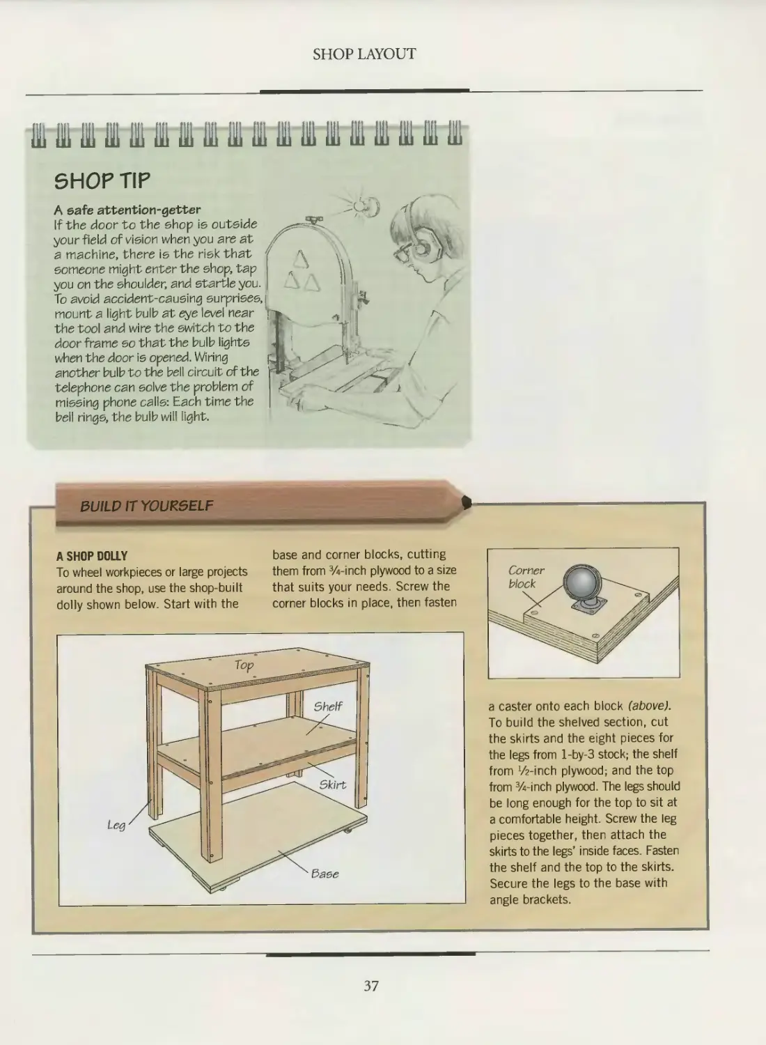
A safe attention-getter
If the door to the shop is outside
your field of vision when you are at
a machine, there is the risk that
someone might enter the shop, tap
you on the shoulder, and startle you.
To avoid accident-causing surprises,
mount a light bulb at eye level near
the tool and wire the switch to the
door frame so that the bulb lights
when the door is opened. Wiring
another bulb to the bell circuit of the
telephone can solve the problem of
missing phone calls: Each time the
bell rings, the bulb will light.
0L//LP IT YOURSELF
A SHOP DOLLY
To wheel workpieces or large projects
around the shop, use the shop-built
dolly shown below. Start with the
base and corner blocks, cutting
them from 3/4-inch plywood to a size
that suits your needs. Screw the
corner blocks in place, then fasten
a caster onto each block (above).
To build the shelved section, cut
the skirts and the eight pieces for
the legs from l-by-3 stock; the shelf
from '/z-inch plywood; and the top
from 3/4-inch plywood. The legs should
be long enough for the top to sit at
a comfortable height. Screw the leg
pieces together, then attach the
skirts to the legs’ inside faces. Fasten
the shelf and the top to the skirts.
Secure the legs to the base with
angle brackets.
37
SHOP LAYOUT
SAVING SPACE
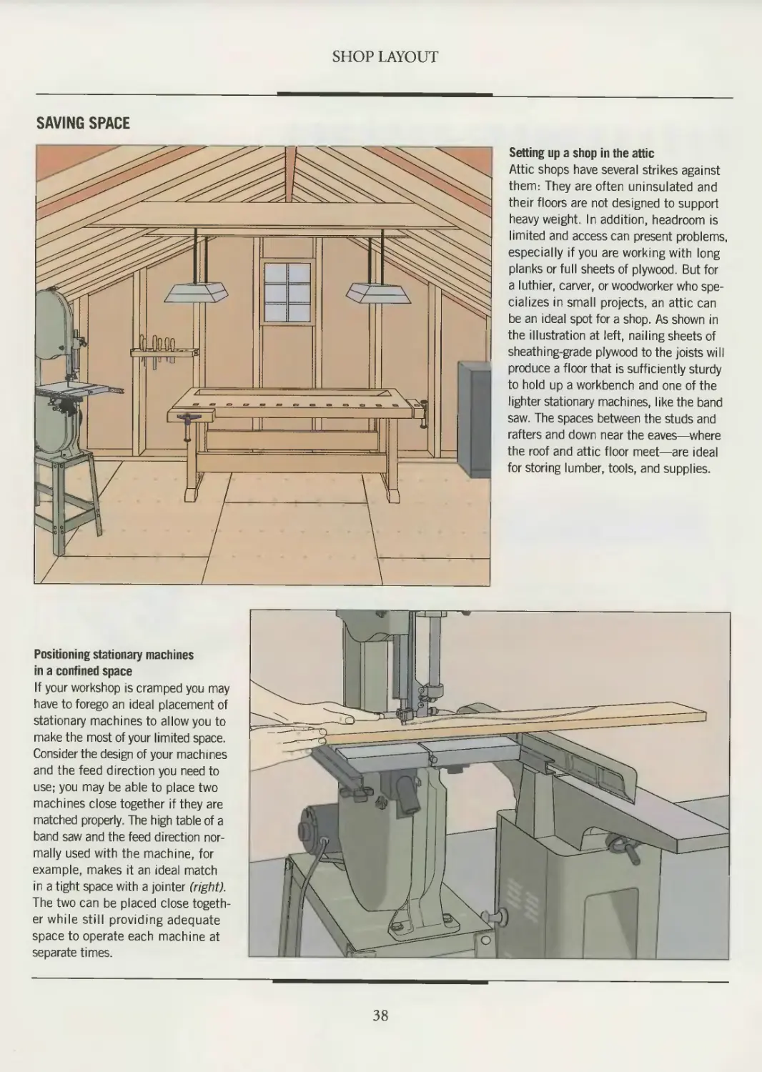
Setting up a shop in the attic
Attic shops have several strikes against
them: They are often uninsulated and
their floors are not designed to support
heavy weight. In addition, headroom is
limited and access can present problems,
especially if you are working with long
planks or full sheets of plywood. But for
a luthier, carver, or woodworker who spe-
cializes in small projects, an attic can
be an ideal spot for a shop. As shown in
the illustration at left, nailing sheets of
sheathing-grade plywood to the joists will
produce a floor that is sufficiently sturdy
to hold up a workbench and one of the
lighter stationary machines, like the band
saw The spaces between the studs and
rafters and down near the eaves—where
the roof and attic floor meet—are ideal
for storing lumber, tools, and supplies.
Positioning stationary machines
in a confined space
If your workshop is cramped you may
have to forego an ideal placement of
stationary machines to allow you to
make the most of your limited space.
Consider the design of your machines
and the feed direction you need to
use; you may be able to place two
machines close together if they are
matched properly. The high table of a
band saw and the feed direction nor-
mally used with the machine, for
example, makes it an ideal match
in a tight space with a jointer (right).
The two can be placed close togeth-
er while still providing adequate
space to operate each machine at
separate times.
38
SHOP LAYOUT
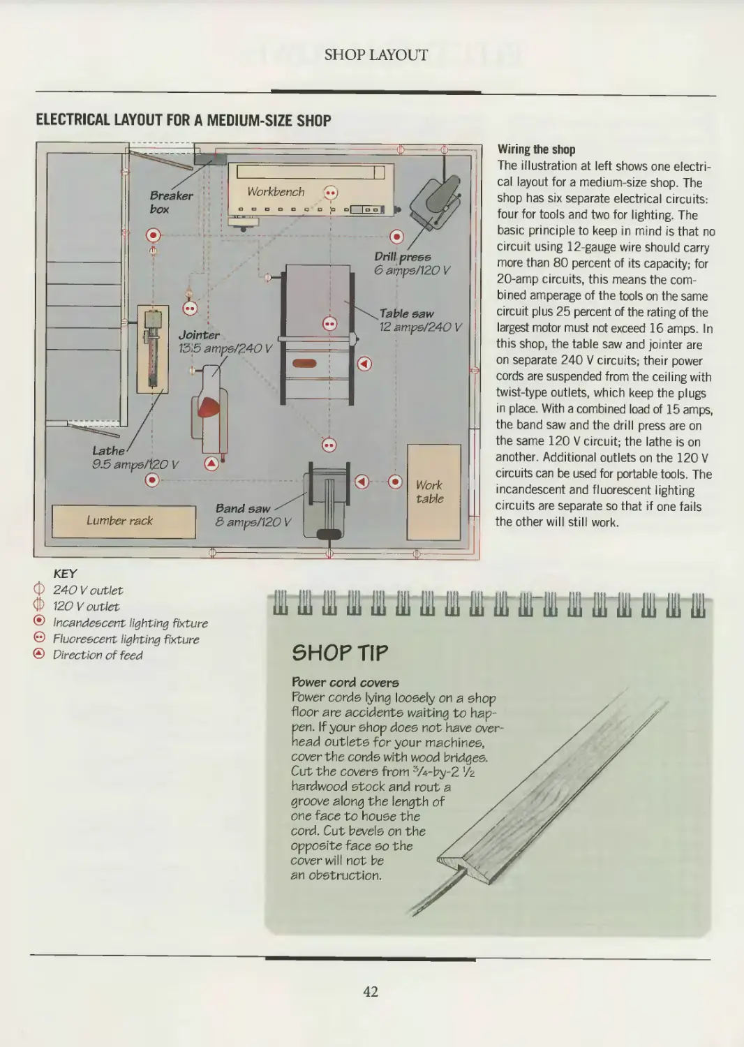
LAYOUT OF A MEDIUM-SIZE SHOP
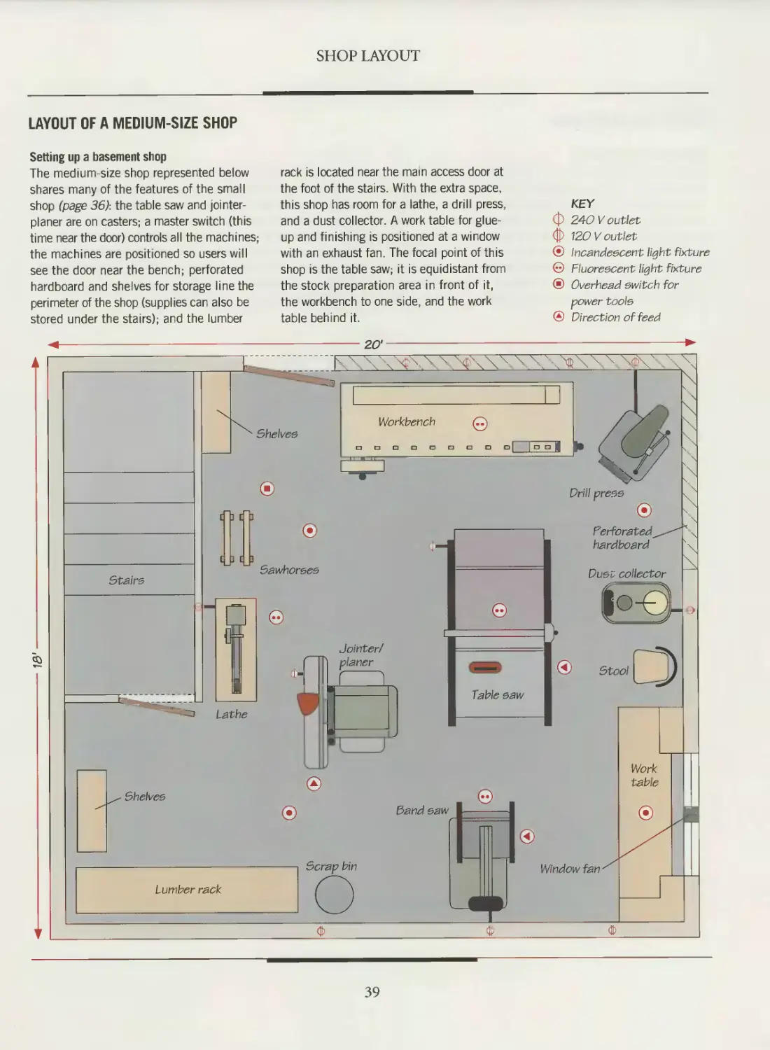
Setting up a basement shop
The medium-size shop represented below
shares many of the features of the small
shop (page 36): the table saw and jointer-
planer are on casters; a master switch (this
time near the door) controls all the machines;
the machines are positioned so users will
see the door near the bench, perforated
hardboard and shelves for storage line the
perimeter of the shop (supplies can also be
stored under the stairs); and the lumber
rack is located near the mam access door at
the foot of the stairs. With the extra space,
this shop has room for a lathe, a drill press,
and a dust collector. A work table for glue-
up and finishing is positioned at a window
with an exhaust fan. The focal point of this
shop is the table saw; it is equidistant from
the stock preparation area in front of it,
the workbench to one side, and the work
table behind it.
KEY
Ф 240 V outlet
ф 120 V outlet
® Incandescent light fixture
© Fluorescent light fixture
@ Overhead switch for
power tools
® Direction of feed
39
SHOP LAYOUT
LAYOUT OF A LARGE SHOP
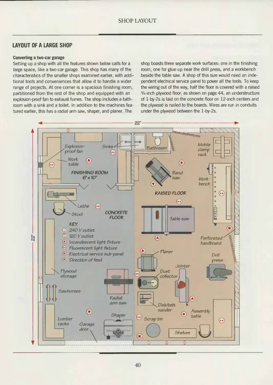
Converting a two-car garage
Setting up a shop with all the features shown below calls for a
large space, like a two-car garage. This shop has many of the
characteristics of the smaller shops examined earlier, with addi-
tional tools and conveniences that allow it to handle a wider
range of projects. At one corner is a spacious finishing room,
partitioned from the rest of the shop and equipped with an
explosion-proof fan to exhaust fumes. The shop includes a bath-
room with a sink and a toilet. In addition to the machines fea-
tured earlier, this has a radial arm saw, shaper, and planer. The
shop boasts three separate work surfaces: one in the finishing
room, one for glue-up near the drill press, and a workbench
beside the table saw. A shop of this size would need an inde-
pendent electrical service panel to power all the tools. To keep
the wiring out of the way, half the floor is covered with a raised
%-inch plywood floor; as shown on page 44, an understructure
of l-by-2s is laid on the concrete floor on 12-inch centers and
the plywood is nailed to the boards. Wires are run in conduits
under the plywood between the l-by-2s.
◄--------------------------------------------22'--------------------------------------------►
L\\r<
©
©
t
[ ] [ ]
Plywood
storage
Lumber
racks
CM
CM
Mobile
clamp ।— ।
Sinks
rack
RAISED FLOOR
Jointer
Perforated-
hardboard
FINISHING ROOM
6'x10'
Explosion-
prooffan
table
Sand
saw
Work-
bench
Stool
CONCRETE
FLOOR
Table saw
©
©
KEY
240 V outlet
120 V outlet
Incandescent light fixture
Fluorescent light -fixture
Electrical service sub-panel
Direction of feed
[ ] [ ]
Sawhorses
Radial
arm saw
sander
Shaper
Assembly
Garage
door
Shelves
Drill
press
40
ELECTRICAL POWER
Electric power requirement should be
considered early in the process of
planning a shop’s layout. Allow for
growth. Then, as you add new tools and
light fixtures, you will avoid the headaches
of an inadequate system: repeated trip-
ping of circuit breakers or blowing of fus-
es, and octopus adapters funneling several
power cords into one outlet.
If you plan to wire your shop to your
home’s main service panel, be sure that
your electrical supply has enough addi-
tional power. You can get a rough idea
of how many amperes your shop will
draw from the system by totaling the
amperage of all the tools you plan to use
and dividing the result in half. If your
system is barely able to handle the
demands being placed on it by your
household, you probably will need to
upgrade your service entrance—in oth-
er words, increase the number of amps
the service panel can draw from the util-
ity company. If the shop will be some
distance from the main service panel, it
is a good idea to install a 50-amp sub-
panel dedicated to the shop. Another
point to remember: Any woodworking
machine that draws more than six amps
should be on a separate (dedicated) cir-
cuit, unless the tool's motor is shielded.
Refer to the illustration on page 42 as
a guide to planning the electrical layout
of your shop. As you plan, remember
that even simple electrical jobs, like
extending a circuit or replacing an out-
let, can be dangerous. They can also
cause a fair amount of damage—ranging
from burned-out tool motors to a house
fire—if they are carried out improperly.
Unless you are qualified and comfort-
able with the idea of wiring your shop
to the electrical system, have a qualified
electrician do the job.
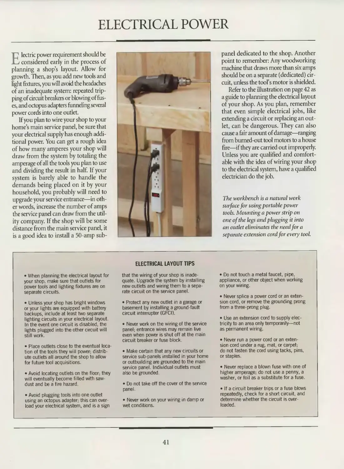
The workbench is a natural work
surface for using portable power
tools. Mounting a power strip on
one of the legs and plugging it into
an outlet eliminates the need for a
separate extension cord for every tool.
• When planning the electrical layout for
your shop, make sure that outlets for
power tools and lighting fixtures are on
separate circuits.
• Unless your shop has bright windows
or your lights are equipped with battery
backups, include at least two separate
lighting circuits in your electrical layout.
In the event one circuit is disabled, the
lights plugged into the other circuit will
still work.
• Place outlets close to the eventual loca-
tion of the tools they will power; distrib-
ute outlets all around the shop to allow
for future tool acquisitions.
• Avoid locating outlets on the floor; they
will eventually become filled with saw-
dust and be a fire hazard.
• Avoid plugging tools into one outlet
using an octopus adapter; this can over-
load your electrical system, and is a sign
ELECTRICAL LAYOUT TIPS
that the wiring of your shop is inade-
quate. Upgrade the system by installing
new outlets and wiring them to a sepa-
rate circuit on the service panel.
• Protect any new outlet in a garage or
basement by installing a ground-fault
circuit interrupter (GFCI).
• Never work on the wiring of the service
panel; entrance wires may remain live
even when power is shut off at the main
circuit breaker or fuse block.
• Make certain that any new circuits or
service sub-panels installed in your home
or outbuilding are grounded to the main
service panel. Individual outlets must
also be grounded.
• Do not take off the cover of the service
panel.
• Never work on your wiring in damp or
wet conditions.
• Do not touch a metal faucet, pipe,
appliance, or other object when working
on your wiring.
• Never splice a power cord or an exten-
sion cord, or remove the grounding prong
from a three-prong plug.
• Use an extension cord to supply elec-
tricity to an area only temporarily—not
as permanent wiring.
• Never run a power cord or an exten-
sion cord under a rug, mat, or carpet;
do not fasten the cord using tacks, pins,
or staples.
• Never replace a blown fuse with one of
higher amperage; do not use a penny, a
washer, or foil as a substitute for a fuse.
• If a circuit breaker trips or a fuse blows
repeatedly, check for a short circuit and
determme whether the circuit is over-
loaded.
41
SHOP LAYOUT
ELECTRICAL LAYOUT FOR A MEDIUM-SIZE SHOP
Wiring the shop
The illustration at left shows one electri-
cal layout for a medium-size shop. The
shop has six separate electrical circuits:
four for tools and two for lighting. The
basic principle to keep in mind is that no
circuit using 12-gauge wire should carry
more than 80 percent of its capacity; for
20-amp circuits, this means the com-
bined amperage of the tools on the same
circuit plus 25 percent of the rating of the
largest motor must not exceed 16 amps. In
this shop, the table saw and jointer are
on separate 240 V circuits; their power
cords are suspended from the ceiling with
twist-type outlets, which keep the plugs
in place. With a combined load of 15 amps,
the band saw and the drill press are on
the same 120 V circuit; the lathe is on
another. Additional outlets on the 120 V
circuits can be used for portable tools. The
incandescent and fluorescent lighting
circuits are separate so that if one fails
the other will still work.
KEY
Ф 240 V outlet
Ф 120 V outlet
® Incandescent lighting fixture
@ Fluorescent lighting fixture
® Direction of feed
iirowfflrrrrrnilllfrl
SHOP TIP
Power cord covers
Power cords lying loosely on a shop
floor are accidents waiting to hap-
pen. If your shop does not have over-
head outlets for your machines,
cover the cords with wood bridges.
Cut the covers from 3/4-by-2 1/г
hardwood stock and rout a
groove along the length of
one face to house the
cord. Cut bevels on the
opposite face so the
cover will not be
an obstruction.
42
LIGHTING
If you find yourself cutting offline or
cannot properly examine a finish
unless you take your work outside, the
lighting in your workshop may need an
upgrade. At best, a poorly lit shop will
merely bring on fatigue; at worst, it can
contribute to sloppy, imprecise work and
to accidents.
Fluorescent lights are the most pop-
ular type of workshop lighting fixture.
They cast a relatively shadowless light,
the tubes are long-lasting, and they use
20 percent to 30 percent less electricity
than incandescent lights of the same
brightness. Many woodworkers find that
too much fluorescent light can result in
fatigue and headaches, however, and pre-
fer the warmth of incandescent and
tungsten lights.
At a minimum, a shop bigger than
120 square feet needs 2 watts of incan-
descent light or % watt of fluorescent
light per square foot. As in the electri-
cal layout illustrated on page 42, shop
lights should be circuits separate from
111 in 111 111 111 HI 111 111 111 111 III 111 III Hl 111 III III III
SHOP TIP
A bench-dog
lamp support
For a movable source of
your tools. Ideally, the light fixtures will
be divided between two separate circuits.
As a rule of thumb, do not exceed 1600
watts on one 20-amp circuit. Also, dis-
tribute lighting fixtures around the shop;
mounting a single fixture in the middle
of the ceiling will make it difficult to illu-
minate the shadowy areas at the edges
of the shop.
If possible, make the most of natural
light; there is no better substitute, espe-
cially for hand-tool work and finishing.
Trying to evaluate planing, sanding, and
finishing jobs under artificial light can
be frustrating. Both fluorescent and
incandescent light tend to distort or dis-
guise the surface texture of natural and
finished wood surfaces. Natural light,
particularly from the north, has a soft,
non-glare quality. If your shop has a win-
dow that faces north, place your work-
bench under it.
Keep in mind that upgrading the
lighting in your shop need not entail
purchasing expensive fixtures and
rewiring the system. Simply painting a
concrete floor a light color or covering
the ceiling with white tiles will allow
these surfaces to reflect light, rather than
absorb it.
A clamp-on lamp can shed all the light
you need to work safely at a tool.
Mounted on a drill press, this lamp’s
flexible neck aims a 40-watt bulb
directly at the machine’s work table.
light at your workbench,
attach a desk lamp to
one of the bench dogs. Bore
a hole the same diameter
as the shaft of the lamp
into the head of
a wooden dog
(page 62). The
light can then
be positioned
at any of the
dog holes along
the bench.
43
FLOORS, WALLS, AND CEILINGS
Standing in one place for hours on
a concrete floor can strain your feet
and legs. An old piece of carpet or a
commercial anti-fatigue mat pro-
vides a cushion that can be easily
moved about the shop.
Since most workshops are set up
in basements or garages, concrete
floors are a common feature. Yet for
anyone who has to spend much time
standing on concrete or sweeping it
clean, the material can prove both
uncomfortable and inconvenient. The
hard surface is particularly tough on
tools that are dropped accidentally.
Simply painting a concrete floor with
a paint made specifically for the purpose
will keep down the dust and make the
surface easier to clean. Adhesive vinyl
floor tile can be laid down as well. Yet
many woodworkers prefer the comfort
of a raised wooden floor. A simple floor
can be constructed from sheets of %-
inch plywood laid atop a grid of 1 -by-
2s on 12-inch centers. Not only is this
type of floor easier on the feet, but wiring
for stationary power tools can be rout-
ed underneath the raised surface in Уг-
inch plastic or steel conduit.
Unlike the walls of most homes, those
of separate workshops seldom are insu-
Ill ill HI ill й ш 1 HI lil ill Hi Hi li, t ш HI Hi t
SHOP TIP
lated. If you live in a northern climate,
you can increase the thermal efficiency
of your shop by covering its walls with
wood paneling or sheet material, and
filling the gap in between studs with
insulation. Wood paneling in particular
creates a warm, comfortable atmosphere.
Interior wall covering will make your
shop quieter too, since the walls will
absorb some of the din of your power
tools. As a bonus, you can conceal wiring
behind the walls. Make sure the base-
ment walls do not leak before covering
them with insulation and paneling.
To hide the exposed joists, ducts,
and wiring above your head, consider
installing a ceiling. A suspended tile ceil-
ing, in which the tiles sit in a framework
of supports hanging from the joists, is
one popular option. In a large shop, a
dropped ceiling such as this will also help
retain heat. Acoustical ceiling tiles are
an inexpensive alternative; the tiles are
attached to furring strips that are nailed
to the joists.
Making the transition to a raised floor
If part of your shop has a raised floor, you can make a smooth
transition from the lower concrete floor with several beveled
2-by-6s laid end-to-end. Cut a rabbet in one edge of each
2-by-6 to accommodate the plywood floor and the 1-by-2
grid underneath. Then bevel the opposite edge, forming a ramp
to facilitate moving items from one floor to the other. Nail or
screw the plywood to the 2-by-6s.
44
HEATING AND VENTILATION
Heating is a necessity for most shops
in North America. Some wood-
working tasks demand it; gluing and fin-
ishing in particular require steady
temperatures. Heating your shop also
makes it more comfortable and safe;
numb fingers invite accidents.
If your shop is some distance from
your homes furnace, a separate heating
system will be needed. Many wood-
workers swear by wood heat; it has the
added benefit of consuming scrap pieces.
Yet this means frequently feeding the
stove and cleaning the chimney; insur-
ing your shop against fire can also be a
problem. Electric baseboard units are
more convenient, but can contribute to
high utility bills and frequently are
clogged with sawdust.
Portable kerosene and propane burn-
ers should be avoided in the shop, since
they use an open flame and emit toxic
exhaust. Coil-type electric heaters are
also a fire hazard.
Whichever heating system you
choose, keep the area around it free of
sawdust and place it away from the fin-
ishing and wood storage areas. And
remember, any system will be improved
by good ventilation.
Consider your need to control humid-
ity. In shops in humid climates, too
much moisture means an investment
in a dehumidifier to keep wood dry
and tools from rusting. Shops in more
arid climates face the opposite dilem-
ma and may require a humidifier.
Finally, every shop requires adequate
ventilation. Airborne sawdust and toxic
finishing vapors may not be as visible a
danger as kickback on a table saw but
the threat they pose is just as real. While
fire or explosions due to high concen-
trations of sawdust or finishing vapors
are rare, they can be devastating. A good
ventilation system changes the air often
enough to maintain safe levels of air-
borne dust and fumes. It should include
dust collection equipment at each sta-
tionary power tool that produces saw-
dust (page 78), and a general exhaust
setup (below) to remove the dust and
fumes that remain.
While window fans or bathroom-type
vent models are fine for general exhaust
purposes, a finishing booth or spray
room requires something different:
An explosion-proof tube-axial fan is
recommended. Fans are rated by the
amount of air that they move, measured
in cubic feet per minute (cfm). Divide
the cubic volume of your shop (its length
times its width times its height) by 6 to
find the rating needed to change the air
10 times per hour—the minimum lev-
el for safe ventilation.
VENTILATING A SHOP
Installing a general exhaust setup
If your shop does not have windows or
doors to provide proper cross-ventilation,
install an exhaust setup to clean the air.
The system shown at left is a simple one,
consisting of an air intake at one end of
the shop connected to the outdoors or
your home's air ducts, and an explosion-
proof fan mounted in the wall at the
opposite end. The intake is covered with
a furnace or air-conditioning filter to
clean the incoming air. The exhaust fan
is placed higher than the intake, causing
the air that rises to be drawn out of the
shop. For best results, orient the exhaust
setup along the longest axis of your shop.
45
WORKBENCH
The makei s of this workbench capitalized
on the classic lines of a centuries-old design,
creating a scaled-down bench that doubles
as a living room table.
The workbench is the corner-
stone of the woodshop, with
a history almost as old as wood-
working itself. Examples of primi-
tive workbenches have been found
dating back more than 2,000 years.
Woodworkers in ancient Rome
advanced the basic design, devising
benches with simple stops that
allowed them to secure pieces of
wood. Until that time, craftsmen
were forced to hold their work, cut-
ting or shaping it with one hand
while chopping or planing with the
other. Further improvements came
slowly, however, and vises were only added centuries later.
With each refinement the workbench has assumed an
increasingly indispensable role in the workshop. It is little sur-
prise that many call the workbench the most important tool a
woodworker can own.
A good workbench does not take an active role in the wood-
working process—it does not cut wood or shape it—but the
bench and its accoutrements perform another essential task:
They free your hands and position the work so you can cut,
drill, shape, and finish efficiently. In the past, even the most-
used benches have fallen short of the ideal. With its massive, sin-
gle-plank top, the Roubo Bench of the 18th Century was
popular throughout Europe, yet it had no tail vise or bench
dogs to hold a workpiece; instead, the task was done by a sys-
tem of iron holdfasts and an optional leg vise. One hundred
years later, the American Shakers improved on the Roubo.
Their bench was a large affair that
sported a laminated top, a system
of bench dog holes, an L-shaped tail
vise, and a leg vise. The Shaker
bench was not too different from
the modern cabinetmaker’s bench
pictured on page 46.
The design of the workbench has
changed little since the early 19th
Century; only its accessories and
manner of assembly have been
altered. In fact, some claim that the
only true innovation has been
inventor Ron Hickmans ubiquitous
Workmate™. Developed in the
1960s, the Workmate™ revolutionized the way many people
look at work surfaces, because it provided some of the clamp-
ing abilities of a standard workbench with a collapsible, portable
design.
Although the Workmate™ has found a niche in workshops
around the world, many woodworkers—both amateur and
professional—still opt for nothing less than a solid maple or
beech bench. Often they choose to build their own, believing
that the care and attention paid in crafting such a bench will
be reflected in their later work. The chapter that follows
shows how to assemble a modern cabinetmaker’s workbench,
and how to install the vises and accessories needed to turn an
ordinary bench into a more flexible work station.
The design of the workbench shown on the following pages,
and many of the drawings and techniques, are based on a plan
that appeared in Woodsmith magazine.
With its origins rooted in an era without
power tools, the standard cabinetmakers
bench now incorporates vises designed
for use with both power and hand tools.
47
ANATOMY OF A WORKBENCH
The workbench shown at right is
patterned after a traditional cabi-
netmaker’s bench, and is crafted from
solid maple. The bench incorporates two
vises considered to be standard equip-
ment: a face vise on the front, left-hand
end of the bench, and a tail vise with
a sliding dog block mounted on the
opposite end.
You can build such a workbench from
a kit supplied with materials and instruc-
tions. You can buy the plans for a bench
and order the materials yourself. Or, you
can follow the instructions presented in
this chapter and construct a bench to
suit your needs. Whichever route you
take, a workbench is assembled in three
distinct phases: the base (page 50); the
top (page 53); and the clamping acces-
sories—vises (page 56), bench dogs, and
hold-downs (page 62).
The top surface of most benches is
generally between 33 and 36 inches high.
The height that is best for you can be
determined by measuring the distance
between the floor and the inside of your
wrist while you stand upright with your
arms at your sides.
Finish your workbench with two coats
of a penetrating oil-based product, such
as tung oil. Not only do these products
penetrate the surface and protect the
wood, but the finish can be refurbished
simply by scrubbing it with steel wool
and recoating.
Bench dog hole
Holds a bench dog
for securing work
Face vise
Also known as front
vise; jaw secures work
Arm
Supports top; top edge of
arm at face-vise end relieves
in same manner as feet.
Usually attached to legs by
mortise-and-tenon joints
Stretcher
Provides lateral stability to
bench; attached to the legs
in one of several ways (pages
50 and 51)
Foot
Bottom edge is “relieved
with a recess for better
contact with floor; ordinar-
ily attached to the leg with
mortise-and-tenon joints
Attaching the end caps of a workbench to the
aprons calls for a strong and attractive joinery
method. The finger joint (also known as the box
joint) and the dovetail joint shown at left are
traditional favorites.
48
WORKBENCH
Top
Often laminated from a hard
and dense wood such as maple or
beech- boards that make up top
should be selected, prepared, and
glued up carefully to provide a
perfectly flat surface
The workbench at left
improved the standard
design by incorporat-
ing a tilting tool chest
under the top.
Tool tray
Sliding dog block
Connected to the tail vise screw,
this movable block contains a
bench dog that secures work
on the benchtop
Bench dog
Used with tail or face vise to
clamp stock; made of metal or
wood. Tension spring keeps dog
at desired height; after use,
dog is pushed down below sur-
face of benchtop
End cap
Separate piece cov-
ers end grain of top
piece and supports
tail vise screw
Moves sliding dog block to
adjust clamping capacity
to length of work
49
BUILDING THE BASE
The base of a workbench typically
consists of two rectangular frames
connected by a pair of stretchers. The
frames are essentially identical, each with
a foot, an arm, and two legs. The arm of
the left-hand frame is sometimes about
3 inches longer than the other arm to pro-
vide additional support for the face vise.
For a bench like the one shown on
pages 48 and 49, use % maple (PA inch-
es thick after surfacing). The feet, arms
and legs are made from two boards
apiece face-glued together, and then
reduced to the proper thickness on the
jointer and planer. If you wish to build
the base with mortise-and-tenons, cut
four-shouldered tenons at the end of the
legs and rout matching mortises in the
feet and arms. Tenons are also cut at
the ends of the stretchers with mortises
required in the legs. The illustration
below shows a knockdown alternative
to assembling the base with mortise-
and-tenons.
The joints between the stretchers and
the legs need to be solid, yet sufficient-
ly flexible to be taken apart should you
want to move the bench. Consequently,
knockdown hardware designed for the
purpose is often used to join the stretch-
ers to the legs. The pages that follow
detail some other methods of reinforc-
ing knockdown connections.
Butt joints connecting the legs
of a workbench to the stretch-
ers can be reinforced with
hardwood knockdown fittings.
The fittings are inserted into
mortises cut into the ends
of the stretchers; matching
machine bolts and nuts are
then used to secure the joint.
REINFORCING KNOCKDOWN JOINERY
Using truss rods
Instead of using mortise-and-tenon
joints to build the base, use butt joints
reinforced by truss rods, as shown at
right. Available in kits, the rods can be
loosened or tightened after assembly
to compensate for wood movement as
a result of changes in humidity. Rout
grooves for the rods into the edges of
the stretchers and the inside edges of
the legs; the depth and width of the
channels should equal the rod's diame-
ter. Test-assemble the base and mark
the groove locations on the legs and
arms. Then bore a hole at each mark,
making the diameter equal to that of
the rods; countersink the holes so you
can drive the nuts flush with the wood
surface. Assemble the base, fitting the
rods into the grooves and holes, and
tightening the connections with washers
and nuts. Cover the grooves with solid
wood inlay if you wish to conceal the rods.
50
WORKBENCH
Using machine bolts and wood blocks
To reinforce the connection between the
legs and stretchers, glue a wood block
of the same thickness as the stock to
each edge of the stretchers. The blocks
will increase the contact area between
the stretchers and the legs. Once the
glue is dry, cut a tenon at the end of each
stretcher and a matching mortise in the
leg. Fit the pieces together and bore two
holes for machine bolts through the leg
and the tenon in the blocks; countersink
the holes. Make the connection fast by
fitting the bolts into the holes, slipping
on washers and tightening the nuts (right).
Using lag screws and dowels
Another way to strengthen a mortise-and-
tenon joint between the stretchers and
legs is shown at left. Cut a 1-inch-diame-
ter hardwood dowel to a length equal
to the thickness of the stretcher. Then
bore a 1-inch-diameter hole through the
stretcher about P/2 inches from its end.
Also bore a hole for a lag screw through
the leg, stopping the drill when the bit
reaches the hole in the stretcher; coun-
tersink the hole so the screw head will
sit flush with the surface. Fit the stretcher
tenon into the leg mortise, tap the dowel
into place in the stretcher, and drive the
screw. Choose a screw that is long enough
to bite through the dowel.
51
WORKBENCH
PREPARING THE FEET
Relieving the feet
Once you are satisfied with the fit of the
parts of the base, disassemble the stretch-
ers and legs and relieve the feet on the join-
ter. Install a clamp on the jointer’s infeed
table to hold the guard out of the way dur-
ing the operation. Set both the infeed and
outfeed tables for a Vie-inch depth of cut,
and clamp stop blocks to both tables to
guide the beginning and end of the cut. To
make the first pass, lower the foot onto the
knives, keeping it flush against the fence
and the stop block on the infeed table. Feed
the foot across the knives (left) until it con-
tacts the stop block on the outfeed table.
Keep both hands well above the cutterhead.
Make as many passes as necessary to com-
plete the recess, lowering the tables Vie inch
at a time, and readjusting the stop blocks
as necessary.
Installing adjustable levelers
To level a workbench on an uneven shop
floor, install adjustable levelers in the
feet. Each leveler consists of a T-nut
and a threaded portion with a plastic tip
(inset). Bore two holes into the bottom of
the foot near each end. Make the hole's
diameter equal to that of the T-nut and
its length slightly longer than the threaded
section. Tap the T-nuts into the holes and
screw in the levelers (right). Once the
bench is assembled, adjust the levelers
until the benchtop is level.
52
BUILDING THE TOP
One of the most important features
of a workbench is a perfectly flat
top. At one time, a benchtop could be
built of solid maple or beech boards
12 inches wide and 2 inches thick. But
today such planks are difficult to come
by, and benchtop slabs are built up from
narrow boards, layers of plywood sand-
wiched between strips of hardwood,
or laminated plywood strips sheathed
in hardboard. However, edge gluing
solid wood boards together butcher-
block style, as shown below, is the time-
honored method.
Cut from % stock, the boards are
glued together first, then the slab is
cut to length. To minimize warping,
arrange the pieces so that the end grain
is reversed. Also make sure the face grain
of all the boards runs in the same direc-
tion. This will make it easier to plane the
top surface of the slab smooth.
After gluing up the slab, prepare the
dog blocks. They are glued up from
a length of % stock and one of 4/4 stock
with the bench holes dadoed out of the
thicker board. The sliding dog block
for the tail vise is sawn off before the
front rail and fixed block are glued
together (page 54). Next, the slab, fixed
dog block, and rear rail are glued up
(page 55); hardwood keys and ply-
wood splines are used to strengthen
the connections.
After the sliding dog block, tool tray,
and aprons are installed, the final step
involves attaching the end caps to the
top. Two connections are used: The caps
are bolted to the slab and joined to
the aprons by means of dovetail or
finger joints.
Once the top of a bench is installed
on the base, a straightedge held on
edge across the surface can be used
to check it for flatness.
ANATOMY OF A BENCHTOP
53
WORKBENCH
PREPARING THE FIXED DOG BLOCK
Cutting the bench dog holes
Bench dogs are fabricated from two boards,
so it is simple to cut the dog holes in the
thicker piece before glue-up. Two steps
are involved. First, cut a row of evenly
spaced dadoes wide enough to accept
the dogs; angle the fixed-block dadoes
slightly toward the tail vise, and the slid-
ing-block dadoes away from the tail vise
so that the dogs will grip the work firmly
when clamping pressure is applied. Next,
clamp the board to a work surface and
use a chisel to notch the top of each
dado to accept the dog heads (left). That
way, the dogs can be pushed down flush
with the bench surface when they are not
in use. Now the two parts can be glued
up to form the finished blocks.
SUILPIT YOURSELF
A JIG FOR DRILLING BENCH DOG HOLES
If you plan to use round bench
dogs, you can use the shop-made
jig shown below to bore their holes
after you glue up the bench top.
The jig should be about 10 inches
long; the lip is cut from a l-by-2
and the base from a l-by-4. After
screwing them together, bore guide
holes about 8 inches apart and
3 inches from the lip. The holes
should accommodate the dogs you
will use.
To use the jig, clamp it to the right
end of the dog block so the lip is
against the front edge and the right-
hand guide hole is over the position
of the first dog hole. Using the guide
holes, bore the first two holes in
the bench. For each subsequent hole,
remove the clamp and slide the jig
to the left until the right-hand guide
hole is aligned with the last hole
bored. Slip a bench dog through
the holes, clamp the jig and bore
the left-hand hole (right). Repeat the
process until you are finished boring
all the holes.
54
WORKBENCH
ASSEMBLING THE BENCHTOP
1 Gluing up the top
First, glue up the top slab. Before glu-
ing up the benchtop. rout grooves on both
sides of the dog blocks and front rail, on
one face of the front apron and back rail,
and along the edges and ends of the top
slab. Cut matching keys and splines. Refer
to the drawing on page 53 for the size
and placement of the grooves, keys, and
splines. If you want to incorporate a tool
tray in your bench, cut Winch rabbets
into the bottom edges of the back rail and
apron; later in the assembly process you
will fit a piece of Winch plywood to form
the tray. Set aside the sliding dog block
(with the hardwood keys glued in place)
and front and back aprons, spread glue
on all mating surfaces, and clamp (right),
alternating the bar or pipe clamps on the
top and bottom of the work.
2 Attaching the end caps
The end caps can be applied while
the tail vise is being installed (page 57).
When that is done, invert the benchtop
and rout a T-shaped recess at each end,
centered between the edges. Cut two rec-
tangular fittings from scrap hardwood so
that they fit in the base of each recess.
Notch one side of each fitting to accept
a 3/s-inch nut, and place a fitting and nut
in each recess. Set the end caps in posi-
tion and mark where they contact the
recesses. At each mark bore a hole for a
%-inch bolt, counterboring so the bolt
heads are flush. Rout a groove in each
end cap to accept the plywood spline,
and rout a ’Winch rabbet on the bottom
inside edge of the back rail to accept the
tool tray. Install the tail vise on the right-
hand end cap (page 57). Spread glue on
the contacting surfaces, fit the end caps
(left), and bolt them in place (inset). Finally,
fit the front and rear aprons and tool tray
and clamp.
55
VISES AND ACCESSORIES
Vises are the tools that transform
the workbench from a simple, flat
surface into a versatile work station. The
modern woodworking bench incorpo-
rates two types of vise: the face vise that
secures work to the front edge of the
bench, and the tail vise that uses wood or
metal bench dogs to secure work on the
top of the bench. The pages that follow
examine ways of installing both the tail
vise (page 57) and face vise (page 58).
Face vises made entirely of wood are
rare. However, a wooden vise is prefer-
able to a metal type because wooden
jaws can grip work without marring its
surface. A good compromise can be
reached by buying the hardware for a
metal vise and mounting wooden face
blocks. You can extend the capacity of
a face vise by boring holes in the bench-
top and securing work between a bench
dog in the vise’s jaws and one inserted
in one of the holes.
Tail vises are available in two types:
an enclosed model that incorporates a
sliding dog block (below and page 57)
and one that features an L-shaped
block, as in the photo at left. Some tail
vises extend across the entire end of a
workbench and have two screws; these
are known as end vises, and they extend
the utility of an already versatile tool.
Some tail vises, like the one shown
at left, incorporate an L-shaped shoul-
der block. The block allows work to be
clamped between the rear jaw of the
vise and the end of the bench.
ANATOMY OF A TAIL VISE
56
WORKBENCH
INSTALLING A TAIL VISE
1 Installing the vise hardware
To install a tail vise on a bench with
a sliding dog block, position the vise col-
lar against the right-hand side end cap
and outline the hole for the vise screw.
Then set a support board on the drill press
table and clamp the end cap on top of it.
Fit the drill press with a spade bit slightly
larger than the vise screw and bore a hole
through the end cap (near right). Screw
the vise collar to the end cap so the two
holes line up. Next, secure the sliding dog
block end-up in handscrews and clamp the
handscrews to a work surface. Position
the vise flange on the block and mark
its screw holes. Bore a pilot hole at
each mark, then screw the flange to the
block (far right).
2 Assembling the vise
Fit the sliding dog block in the bench
so the hardwood keys in the block run
in the grooves in the sides of the rail.
Thread the vise screw through the vise
collar, test-fit the end cap on the bench-
top and lock the ball joint on the end of
the screw into the vise flange. Set the
front apron in position against the dog
blocks (left) and test the movement of
the vise by turning the screw. If the slid-
ing block binds, remove the end cap,
apron, and sliding dog block, and ease
the fit by paring the keys with a chisel.
Once you are satisfied with the vise’s
movement, attach the aprons, end caps,
and trays following the procedures out-
lined on page 55.
57
WORKBENCH
ANATOMY OF A FACE VISE
INSTALLING A FACE VISE
1 Preparing the face block
Cut an 18-inch-long з/д-Ьу-ЗУг inch
hardwood support block and screw it in
place under the front left corner of the
bench, after boring a row of clearance
holes for the bench dogs. Next, build
up the face block by gluing two pieces of
8/4 hardwood together; cut it to a final size
of 5-by-18 inches. To mark and bore the
holes for the vise screw and guide rods,
mark a line across the face of the face
block; offset the line from the top edge by
the thickness of the benchtop slab (not the
front apron depth). Now use the carriage
as a template: Center its top edge on
the line and use a brad-point bit to accu-
rately mark the position of the three
holes (right) and bore them.
58
WORKBENCH
2 Preparing the bench
Once the holes have been drilled
through the face block, transfer their
location to the workbench apron. Set the
face block and benchtop on sawhorses
and use bar clamps to hold the block in
position against the apron; protect the
stock with wood pads. Make sure the top
edge of the block is flush with the bench-
top and its end is flush with the end cap.
Mark the hole locations on the apron using
the brad-point bit (right) Remove the
face block and bore the holes through
the apron and bench dog block.
3 Mounting the vise
Attach the vise assembly—the face-
plate, screw, and guide rods—to the face
block. Turn the benchtop upside down,
place the vise carriage on the bench’s
underside, and feed the vise screw and
guide rods through the holes in the apron
and into the carriage. Make pilot holes
on the underside of the bench and fasten
the carriage in place. Next, fasten the
guide rod bushings to the apron: Remove
the vise assembly, fit the bushings on
the rods, remount the assembly, and
outline the bushings' location on the apron.
Then remove the vise assembly again and
secure the benchtop so the apron is fac-
ing up. With a router and straight bit, cut
recesses for the bushings within the out-
lines (left). Screw the bushings to the
recesses in the apron and attach the vise
to the bench. Now the workbench top is
ready to be attached to the base. Lay the
top upside down on the floor, place the
base in position, and drive lag screws
through the arms into the top
59
WORKBENCH
JIGS FOR IRON-JAWED BENCH VISES
Fitting wooden inserts to metal jaws
If your bench is equipped with a metal-
jawed vise like the one shown at the top
of page 61, fitting interchangeable aux-
iliary jaws can extend the vise's versatil-
ity. The wooden inserts shown above will
not only be less damaging to workpieces
than metal jaws, but they can also be
custom-made for special jobs. Each insert
is made from ^-inch-thick solid stock
with a rabbeted 1-by-l block glued at
each end to hug the ends of the vise
jaw. Although a pair is required, only
one of each sample is illustrated. The
basic jaw (above, left) will do most stan-
dard clamping jobs.The tapered jaw
(above, center) features a wedge-shaped
strip for holding tapered stock efficiently.
The V-groove jaw (above, right) includes
a strip with a groove cut down its middle
for securing cylindrical work.
ISi Ш 111 Ш 111 J1E Ш Illi 1Ш Ш 111 Ш
SHOP TIP
A quick-switch vise
If you are reluctantto bolt
your bench vise onto your
workbench, attach it
instead to a T-shaped
base made of 3/4-inch
plywood. Join the
two pieces of the base
together with a dado
joint and screws. Secure
the vertical part of the
base in either the tail or
face vise of the bench.
60
WORKBENCH
BUILP IT YOURSELF
A SLIDING BENCH STOP
If your “workbench” is a standard
table with a bench vise fastened to
one edge, the jig and fence shown at
right can lend it some versatility. Cut
the auxiliary vise jaws from 1-inch
stock and the pieces of the T-shaped
vise jig from Winch wood. You will
need two pieces for the jig: a top and
a lip. Rout a dado across one auxiliary
jaw to accommodate the lip of the vise
jig and another on the underside of
the jig top. Screw the auxiliary jaws
to the vise jaws, making a cut for the
vise screw if necessary, then glue and
screw the lip to the top of the jig.
Cut the sliding fence from Winch-
thick stock and cut two stopped
grooves through it for Winch carriage
bolts. To mount the fence, bore two
holes through the table for the bolts,
feed the bolts through the holes and
the grooves and fasten them with
washers and wing nuts. To use the jig
and fence, slide the lip into the auxil-
iary jaw, adjust the sliding fence to
hold the workpiece snugly and clamp
it in place by tightening the vise jaw
and wing nuts.
PREVENTING VISE RACKING
Using a stepped block
When securing a workpiece at one end
of a face vise, the other end of the vise
is likely to rack—or tilt toward the
bench—and cause the work to slip. To
prevent racking, use a stepped hardwood
block to keep the jaws square. Cut a
series of steps in one face of the block,
spacing them at equal intervals, such as
V2 inch. Place the block in the open
end of the vise at the same time you are
securing the workpiece so that the vise
is parallel to the edge of the bench (left).
61
BENCH DOGS AND HOLD DOWNS
Bench dogs are as important as vises
in maximizing the flexibility and
utility of a well-designed workbench. A
set of bench dogs works like a second
pair of hands to secure workpieces for
planing, chiseling, mortising, carving,
or other woodworking tasks.
Although the bench dog looks like a
deceptively simple peg, it incorporates
design features that enable it to hold a
workpiece firmly without slipping in
its hole. One feature usually is a thin
metal spring attached to one side that
presses against the inside wall of the dog
hole in the workbench. To help strength-
en the grip of bench dogs, the holes
are also angled toward the vise at 4°.
Bench dogs can be either round
or square. Round dogs are easier to
incorporate in a bench that does not
yet have dog holes; it is simpler to bore
holes than to make square dog holes.
Since round dogs can swivel, their
notched, flat heads enable them to
clamp stock in practically any direc-
tion. This can be a disadvantage: Some
woodworkers claim that round dogs
tend to slip in their holes more than
square dogs, which cannot rotate.
Bench dogs can be made of either
metal or wood. Metal dogs have a weight,
strength, and stiffness that wooden ones
cannot match. Yet wooden dogs have
their advantages—as any woodworker
who has nicked a plane blade on a met-
al dog will attest.
Bench dogs are not the only method
of securing stock; bench hooks, carving
hooks, wedges, and hold downs are also
useful for keeping stock in place. The
following pages illustrate a number of
commercial and shop-made options to
keep workpieces put while you work.
This bench dog features a threaded screw that converts
it into a miniature tail vise. Used in conjunction with
other bench dogs, it excels at clamping small or irregu-
lar work, like the panel shown above.
Making a wooden bench dog
Bench dogs can be crafted from hardwood
stock; the one shown at left uses an angled
wooden tongue as a spring. Cut the dog to
fit the holes in your workbench, then chis-
el out a dado from the middle of the dog.
Saw a short kerf into the lower corner of
the dado, angling the cut so the tongue
will extend beyond the edge of the dado.
Cut the tongue from hardwood, making it
about as long as the dado, as wide as the
dog, and as thick as the kerf. Glue the
tongue in the kerf.
62
WORKBENCH
Making a spring-loaded bench dog
A wooden bench dog can be made to fit snugly
by equipping it with a metal spring cut from
an old band saw or hacksaw blade. Cut your
dog to size, then chisel out a small recess for
the spring. The width and depth of the recess
should equal the width and thickness of the
spring, but its length should be slightly shorter
than that of the spring. Press the spring into
the recess; the metal will bow outward, hold-
ing the dog firmly in its hole.
SHOP-MADE EDGE DOGS
Edge dogs like those shown at right
are ideal for securing a workpiece
along the edge of your bench. They
feature a round dowel at one end
that drops into a bench dog hole
and angled heads that butt up against
the edge of the bench and hold
the work.
Start by cutting the dogs from
hardwood stock. Both left-hand and
right-hand dogs are needed, with
the heads angled in opposing direc-
tions. Bore a ^-inch-diameter hole
through the ends, and drive a 3-inch
length of dowel in each hole. Then
insert the dowel in a bench dog
hole and angle the dog so it extends
beyond the edge of the table. Mark
a 90° notch for the head perpen-
dicular to the edge of the bench and
cut it out. To hold the edge dog in
place when clamping pressure is
applied, saw a Vi-inch-slice off the
bottom of the dog, except for the
head. This provides a lip that will butt
against the edge of the bench (left).
To use the edge dogs, place the
left-hand dog in a hole in the fixed
dog block and the right-hand one in
the sliding dog block of the tail vise.
Tighten the vise until the workpiece
is held in the notches (below).
63
WORKBENCH
Making and setting up carving dogs
Using a standard bench dog as a model,
you can fashion a pair of customized dogs
that will grip a carved or turned work-
piece, or secure irregular-sized work, such
as mitered molding. To make these
accessories, cut bevels on either side of
the head of a standard bench dog and
drive a small screw or nail into the cen-
ter of the head; snip off the fastener’s
head to form a sharp point. To use the
devices, place one dog in a dog hole of
the bench’s fixed dog block and the other
in the tail vise or a sliding dog block hole
(above). Tighten the vise screw until
the points contact the ends of the work-
piece and hold it securely.
и in in in m in in in nt in inti i in in in mi
SHOP TIP
Carving screws
A pair of hanger bolts can enable you to secure an irreg-
ular-shaped workpiece, such as a carving block, to your
bench. The bolts feature wood screw threads on one
end and machine screw
threads on the other.
To secure a work-
piece, bore two holes
through the bench-
top for the bolts.
Screw the bolts into
the carving block from
underneath the top
and hold the bolts
to the underside
of the top with
washers and
wing nuts.
64
WORKBENCH
HOLD-DOWNS AND BENCH STOPS
holding bolt which sits in a counterbored hole through the benchtop (inset). To use
the clamp, raise the bolt head and slide it through the notch at the base of the clamp.
Set the workpiece under the clamp jaw and tighten the screw (above). (In the illustra-
tion, a wood pad is being used to apply equal pressure to both stiles of a door frame.)
To remove the clamp from the bench, slide it off the bolt head and let the bolt drop
below the surface of the top.
Making and using a temporary bench stop
A clamped-on bench stop cut from %-
inch plywood will secure a workpiece to
the benchtop without the help of bench
dogs. Cut the bench stop to size, then
mark out a triangular wedge, typically 3
inches shorter than the stop. Cut out the
wedge and set it aside. To use the bench
stop, clamp it to the benchtop and slide
the workpiece into the notch, butting one
side against the straight edge of the notch
Secure the piece with the wedge, tapping
it tightly in place with a mallet (left).
65
WORKBENCH
Installing a wedge stop
A wedge stop can also be used to secure
stock on a benchtop (left). The stop con-
sists of a fixed rail and a movable rail
that are secured by dowels resting in a
double row of holes bored into the work-
bench. Together with a triangular wedge,
the rails keep a workpiece from moving.
Cut the rails and the wedge from 3/4-inch
plywood. (You can choose thicker stock
for the rails, depending on the thickness
of your workpiece.) Bore two '/2-inch-
diameter holes in each rail, then glue a
2-inch-long dowel in each hole. Bore
two rows of V^-inch-diameter holes in the
workbench for the dowels. To use the
stop, place the fixed rail at one end of
the row of holes and the movable rail the
appropriate distance away so the wedge,
when positioned between the rails, will
keep the workpiece steady.
Making a bench hook
The shop-built jig shown at right will ensure
that the crosscuts you make on the work-
bench will be square. Use %-inch plywood
for the base and strips of 2-by-2 stock for
the lips. Make the base at least as long
as the width of your workpiece and wide
enough to support it. Screw the lips to
the guide, attaching one to each face.
To use the jig, butt one lip against the
edge of the bench and press the work-
piece firmly against the other. Align the
cutting line with the edge of the base and
make the cut (inset).
66
WORKBENCH
Making a flip-up stop
The flip-up bench stop shown at right pro-
vides another way to make quick guided
crosscuts on a workbench. Cut the two
pieces of the stop from hardwood. Screw
the pieces to the end of the benchtop; on
the bench shown, the inner edge of the
pivoting piece is lined up with the edge
of the tool tray to provide a convenient
reference line for squaring up a crosscut.
Screw the stationary piece in place with
two screws, and the flip-up piece with one
so that it can pivot. When not in use, the
pivoting piece should lie on edge atop
the stationary piece. To use the stop, flip
up the pivoting piece, butt the workpiece
against it, and make your crosscut.
Making and using a miter bench hook
Customize a standard bench hook to
make 45° angle miter cuts by adding
kerfs to one of the lips. Build a bench
hook (page 66), then use a backsaw
to cut two kerfs in the lip at opposing
45° angles and one at 90° (left). Use
the miter bench hook as you would
a standard bench hook, lining up the
cutting line on the workpiece with
the desired kerf.
67
SHOP ACCESSORIES
Look beneath the surface of an
efficient, well-equipped shop,
and you will find several invisible
auxiliaries: accessories designed to
make the work safer and the shop
more comfortable in which to work.
The most commonly found helpers
are compressors, generators, bench
grinders, and—perhaps the most
important for safety and comfort—
dust collection systems.
Air compressors first were uti-
lized by woodworkers only for fin-
ishing work—to apply lacquer and
varnish more smoothly than with
a brush. But with the advent of such
tools as pneumatic nailers, com-
pressors are found more frequent-
ly, even in small home workshops.
Air-powered tools are discussed
starting on page 72.
Generators, too, are finding a place, especially among those
woodworkers who take their craft away from home and pow-
er lines. They are explored on page 74.
Grinders, of course, can speed tool sharpening. More impor-
tantly, as you will see on page 76, they can permit you to mod-
ify tools and reclaim damaged cutting edges.
Airborne dust once was considered an unavoidable conse-
quence of working with wood. But the increased emphasis on
Most of the wood chips and sawdust generated
by this 10-inch table saw are captured by a
portable dust collection system. Often neglected
in the past, dust collection has become a central
concern of many safety-conscious woodworkers
in planning the layout of their shops.
environmental health has led to the
introduction of efficient dust col-
lection systems that are affordable
to home woodworkers. They should
be a high priority item for every
home workshop. Tiny wood dust
particles can remain in the shop
for more than an hour after the tool
has been used. The dust poses sev-
eral health risks. If the wood con-
tains toxins or irritants—and many
species do (see back endpapers)—
the effects can lead to a wide range
of ailments, including dermatitis,
shortness of breath, and dizziness.
Recent studies have shown that
long-term inhalation of wood dust
is at least a contributing factor in
cancers of the tongue, tonsils, lung,
and larynx.
When you add to the equation
the fire risk and the hazard of a dust-covered shop floor, there
are compelling reasons for installing some kind of dust col-
lection system in your shop. Pages 78 to 87 provide you with
information you will need to set up and maintain both central
and portable systems. Remember that designing a central sys-
tem requires careful attention to detail and precise calculation
of your specific requirements. To be safe, check your plans and
figures with an engineer before installing the system.
Hooked up to a compressor, this air-powered sander
is compact enough to hold in one hand, yet it smooths
wood as efficiently as an electric sander.
69
A STORE OF SHOP ACCESSORIES
Planers can create a substantial
mound of sawdust in short order.
A portable dust collector will keep
most of the dust from this and
other power tools off the shop
floor and out of the air.
For applying stains and finishes. Features electric tur-
bine that supplies large amount of air at low pressure
through air hose to spray gun; compared to conven-
tional, compressed-air type systems, HYLP allows
higher percentage of finish to contact workpiece
Multitester
Also known as volt-ohmmeter,
or VOM. Battery-powered tool
used in troubleshooting and
repairing electric devices; mea-
sures resistance and AC or DC
voltage in a circuit
Air compressor
Supplies stream of high pressure air
through hose to power a variety of
air-operated tools, such as sanders,
spray guns, and drills; consumer-
grade models range from 7e to 5
horsepower and can generate up to
200 pounds per square inch (psi) of
air pressure and 0.5 to 15 cubic feet
of air per minute (cfm).
SHOP ACCESSORIES
Generator
Typically gasoline-powered, featuring
up to four 120- and 240-volt out-
lets. Motors on consumer-grade
generators range between 5 and &
horsepower and produce 500 to 4000
watts of output; most models weigh
less than 150 pounds and can be fit-
ted with wheels for easy portability
Shop vacuum
Cleans up dust and liq-
uid spills; hose can be
attached to individual
tools to collect dust as
it is produced. Typically
features 1 %- to 2 '/г-inch-
diameter collection hose
and 5- to 1O-gallon tank;
some models can double
as portable blower
Bench grinder
Coarse wheel (left) squares, sharpens, and
smooths blades and bits; cloth wheel (right)
polishes and cleans. Features a 'A- to Vz-
horsepower electric motor, eye shields,
adjustable tool rests, and wheel guards
standard on most models Benchtop
grinders usually bolted to work surface
Wheel dresser
Used to true or reshape bench grinder wheel.
Star-wheel dresser (above) uses up to four
star-shaped wheels; diamond-point dresser
(below) features A-carat diamond set in
bronze tip and metal shaft
71
AIR COMPRESSORS
An air compressor can be fitted with
a large number of tools and attach-
ments, making it a convenient shop
accessory. In some shops, a compressor
can represent an alternative to some
electric tools. For others, it can be a valu-
able supplement.
Air-powered tools work best at a
specific pressure indicated in the
owner’s manual for the particular
tool. Before starting a job, the com-
pressor’s air regulator should be
adjusted to the proper setting for
the task at hand.
Pneumatic drills, grinders, sanders,
and wrenches perform at least as effec-
tively as their electric-powered coun-
terparts. Some tools, like sprayers,
nailers, and abrasive cleaners, are clear-
ly superior to the alternatives.
Compressors and the tools they
drive are inherently simple: The air is
drawn in, pressurized by a diaphragm
or one or more pistons, and usually
stored in a tank. When the trigger on an
air-driven tool is pressed, the air travels
through a hose to power the tool.
Because they contain no heavy elec-
tric motor, most air tools are lighter,
cheaper, and easier to repair than their
cousins. They cannot overheat, and there
is no danger of electrical shock.
AIR-POWERED TOOLS AND ACCESSORIES
Jitterbug sander
Orbital sander capable of pro-
ducing 2500 strokes per
minute; weighs less than 5
pounds. Requires 6.5 cfm at
90 psi; must be used with
tank-mounted compressor
with at least 3 horsepower
Spray gun
Heavy-duty sprayer with
adjustable fluid and air
controls. Requires 5.5 cfm
at 40 psi; can be used with
any compressor with more
than 1 horsepower
Compressed-air power does have
some drawbacks, chiefly the cost of the
compressor itself and maintenance. Air
drills and the like must be oiled daily.
And you will invest several hundred dol-
lars in a compressor that is capable of
driving typical shop tools.
Some air-powered tools require a siz-
able volume of air, usually measured in
cubic feet per minute (cfm); others need
a minimum level of air pressure in
pounds per square inch (psi). When
choosing a compressor, consider the cfm
or psi requirements of the air-powered
tools you plan to use and buy a com-
pressor with slightly more power. You
never know when you will want to
expand your tool inventory.
Drill
%-inch drill that turns bite
at 2500 rpm; weighs only
2 % pounds. Requires 3
cfm at 90 psi; must be
used with tank-mounted
compressor with at least
horsepower
72
SHOP ACCESSORIES
• Read your owner’s manual carefully
before operating a compressor or any
air-powered tool.
• Do not reset any switches or valves on
the compressor; they have been preset
at safe levels at the factory.
• Check the hoses, plugs, wires, pipes,
and tubes of the compressor and the
tool air inlets before each use. Do not
use the compressor or tool if any part
is worn or damaged
• Wear safety glasses and hearing pro-
tection when using air-powered tools.
• Do not exceed the pressure rating
of an air tool or accessory.
COMPRESSOR SAFETY TIPS
• Always plug a compressor into a
grounded outlet of the appropriate
amperage.
• Relieve pressure slowly when depres-
surizing the tank.
• Do not press the trigger of an air tool
when connecting it to an air hose
• Do not remove the belt guard of a belt-
driven compressor when the machine
is operating.
• Turn the compressor off if it produces
an unfamiliar noise or vibration, pro-
duces insufficient air pressure, or con-
sumes excessive oil; have the machine
serviced before resuming operations.
• Allow the compressor to cool before
performing any maintenance; wear
gloves to disconnect any parts that are
still hot.
• Turn the compressor off before moving it
• Do not touch the compressor while
using it or immediately after the machine
can become very hot.
• Drain any moisture from the tank after
each use to prevent rust tank pressure
should be no higher than 10 psi when
draining it.
• Replace the tank if it has any pin
holes, rust spots, or weak spots
at welds.
Brad finishing nailer
Nail gun for driving %- to
1 %-inch No. 13 finishing nails;
weighs less than 3 pounds.
Narrow nose sets nails with-
out marring workpiece; maga-
zine holds up to 110 nails.
Requires .23 cfm at 90 psi to
drive 10 nails per minute; must
be used with compressor with
at least '/г horsepower
Router
%-inch direct-drive router that turns
bits at 20,000 rpm; weighs just over
1 pound. Features neoprene rubber grip
to reduce vibration. Requires 90 psi;
will function with most compressors
Hose connector
Joins air tool to com-
pressor or connects
two lengths of com-
pressor hose together
Quick coupler
Used with hose connectors to
attach air tools to compressor
hose or to join lengths of com-
pressor hose together, auto-
matically shuts off air when
uncoupled from compressor
PORTABLE GENERATORS
The average home and shop is so well
equipped with electric fixtures, out-
lets, and extension cords that it is easy
to take for granted the essential role that
electricity plays in our lives. Yet a pow-
er outage can quickly remind you of
that role. At such a time, a portable AC
generator becomes an indispensable
accessory for your home, your shop, or
in a remote cabin where power lines do
not reach.
AC, or alternating current, genera-
tors typically feature a gasoline motor
that drives an alternator. Models are
available with motors ranging from 3 to
8 horsepower, producing 500 to 4000
watts of power.
There are several factors to consider
when selecting a generator, and the chart
on page 75 can help guide you. The gen-
erator must produce enough power to
start and run the tools and any other
electrical devices you plug into it. The
wattage ratings listed on the chart are
typical. You should refer to the actual
rating of your tool, which is usually
printed on the tool body. If not, you
can calculate the rating by multiplying
the tool’s amperage rating by the volt-
age. (For example, a 3-amp tool oper-
ating on 120 volts would have a wattage
rating of 360.)
The wattage rating of a generator
refers to its continuous running wattage.
Although all models feature a surge or
maximum rating as much as 25 percent
higher than the running value, you
should rely on the running wattage rat-
ing when choosing a generator. A gen-
erator with more power than you need
will run more smoothly for longer
stretches and require less maintenance.
Most generators are equipped with
one to four 120-volt outlets. Many mod-
els also have a 240-volt outlet and a 12-
volt DC output for charging batteries.
Make sure that any generator you buy
is equipped with an effective muffler.
Also check the size of the fuel tank The
generator should be able to run for at
least 90 minutes on a full tank.
Portable generators are
a handy source of elec-
tricity during power out-
ages or in locations where
a conventional electrical
supply is unavailable.
Rated at 3500 watts, this
model is able to drive vir-
tually any electric work-
shop tool or appliance.
74
SHOP ACCESSORIES
Choosing a generator with
TYPICAL POWER TOOL WATTAGE RATINGS a suitable wattage rating
All electric tools require more power to
Tool Watts (Start-up) Watts (Running) start up than for continuous running. The
Air compressor (%-hp) 4000 2000 chart at left gives typical power require-
Table saw (10") 4000 1500 ments for a number of tools. When select-
Saber saw 2500 1200 ing a generator, make sure its wattage rat-
ing is higher than the start-up wattage
Circular saw (7%") 2500 1200 of your most powerful tool. Add a safety
Circular saw (б1/11) 2200 1000 margin of about 20 percent to the com-
Belt sander 1500 600 bined running wattage of all tools you
Bench grinder (’Z-hp) 1500 1200 will plug into the device and operate at
the same time.
Orbital sander 900 360
Router 900 700
Electric drill CZ") 800 600
Electric drill (3Z") 600 350
Power plane 600 450
Electric drill (%') 500 250
Random-orbit sander 500 360
HVLP spray system 400 240
• Read your owner’s manual carefully
before operating a generator.
• Never run a generator indoors; like any
internal combustion engine, it produces
carbon monoxide fumes that are deadly
in a confined space.
• Do not fill the generator’s fuel tank
while the motor is running or hot.
• Add fuel to the fuel tank at least 10 feet
from your work area and any sources of
heat or flames. Do not fill the tank right to
the brim; the fuel can expand and overflow.
• Do not smoke while filling the fuel tank.
• Clean up any gas or oil spills immedi-
ately, wiping up the area with a clean
cloth, or soaking it up with an absorbent
material such as cat litter or vermiculite;
avoid using sawdust, which is com-
bustible. Place fuel-soaked rags in sealed
metal containers and dispose of them fol-
lowing local environmental regulations.
• Do not remove any safety guards, cov-
ers, or screens from the generator while
the machine is operating
GENERATOR SAFETY TIPS
• Keep gas and oil only in containers
designed specifically for fuel storage
and clearly marked FUEL. Keep the
containers away from sources of heat
and flames.
• Check the engine oil level each time
you refuel the generator.
• Check the generator's fuel lines and
connections regularly; if you notice any
leakage, turn the machine off and have
it serviced before resuming operations.
• Never use a generator with a faulty
or damaged exhaust system.
• Ground the generator following the
manufacturer’s instructions; this will
divert any stray current from a short cir-
cuit to ground, reducing the risk of elec-
trical shock.
• Do not connect a 240-volt tool or appli-
ance to a 120-volt receptacle.
• Do not overload the generator by plug-
ging in power tools or appliances with
higher wattage ratings than that of the
generator.
• Never wire the generator to the electri-
cal system of your home or shop in an
attempt to provide power during an out-
age. This practice, known as “backfeed-
ing," is unlawful in some areas, as it
poses a risk to anyone working on the
electrical system.
• Keep your hands and face away from
carburetor whenever the air cleaner has
been removed; a sudden backfire—or
explosion of fuel in an engine cylinder—
can cause serious burns
• Do not touch the generator engine or
exhaust piping while the machine is run-
ning or immediately after turning it off;
these parts can become very hot. Allow
the generator to cool before performing
any maintenance.
• Turn the generator off before performing
any maintenance on it; also disconnect
the spark plug wire and the battery to pre-
vent accidental startup of the motor.
• Generator use is regulated by federal
and state legislation in some areas; con-
tact the appropriate authorities in your
community for any applicable laws.
75
BENCH GRINDERS
From dressing and shaping metal to
squaring and sharpening bits, plane
irons, and chisel blades, the bench
grinder is an invaluable workshop main-
tenance tool. Grinders are classified
according to their wheel diameter. The 5-
to 7-inch benchtop models, with A- to
A-horsepower motors, are the most
popular home workshop sizes. They can
be mounted on a work surface or fas-
tened to a separate stand.
Grinding wheels come in many grits
and compositions. Medium 36- and
60-grit aluminum oxide wheels will
handle most tasks adequately, but you
may need a finer wheel, with either
100 or 120 grit, for delicate sharp-
ening jobs. Buffing wheels for polish-
ing metal, and wire wheels for remov-
ing rust and cleaning metal, are also
worth owning.
Most grinders operate at one speed,
or allow a choice of two speeds—typi-
cally 2950 and 3600 rpm. Some newer
models offer variable speeds, a particu-
larly valuable option for polishing and
A grinder is the best tool for restoring
the correct bevel angle on a nicked or
out-of-square chisel blade. The tip of
the blade must contact the grinder
wheel at an angle of 25° to 30°.
cleaning, and for grinding with speeds
low enough to maintain the temper of
a steel tool.
No grinder should be used without
lowering the guard mounted above each
wheel; the tool should also come
equipped with adjustable tool rests and
wheel covers sheathing 75 percent to 80
percent of the wheels. More expensive
grinders may have other features, such as
spark arresters, a water tray for cooling
tool tips, and exhaust outlets.
Check your grinder wheels regu-
larly for fractures and, as the wheel
wears, adjust the distance between the
tool rest and the grinding wheel to about
!4 inch. A grinding wheel will eventual-
ly become dull and clogged with metal
particles, and its edges may go out-of-
square. As shown below, a wheel dress-
er is a special tool that is used to true
the working face of a grinding wheel
and square its edges.
DRESSING A GRINDER WHEEL
Truing the wheel
To true a grinder wheel and square its
edges, use a star-wheel dresser or a dia-
mond-point dresser. For the star-wheel
dresser, move the grinder’s tool rest away
from the wheel. With the guard in posi-
tion, switch on the grinder and butt the
tip of the dresser against the wheel. Then,
with your index finger resting against the
tool rest, move the dresser side to-side
across the wheel (right). For the diamond-
point dresser, hold the device between
the index finger and thumb of one hand,
set it on the tool rest, and advance it
toward the wheel until your index finger
contacts the tool rest (inset). Slide the tip
of the dresser across the wheel, pressing
lightly while keeping your finger on the
tool rest. For either dresser, continue until
the edges of the wheel are square and you
have exposed fresh abrasive
76
SHOP ACCESSORIES
Г SUILP IT YOURSELF
—
GOUGE-SHARPENING JIG
The jig shown at right guarantees
that the tip of a gouge will contact
the wheel of your grinder at the cor-
rect angle to restore the bevel on the
cutting edge. The dimensions in
the illustration will accommodate
most gouges.
Cut the base and the guide from
Z-mch plywood. Screw the guide
together and fasten it to the base
with screws countersunk from under-
neath. Make sure the opening ere
ated by the guide is large enough to
allow the arm to slide through freely.
Cut the arm from l-by-2 stock
and the tool support from 'Z-inch
plywood. Screw the two parts of the
tool support together, then fasten
Guide
(Кр)7г"х1%"х9"
(sides) 7" x 17з" x 9'
Tool Support
(back) /" x 2" x 2 3A"
(bottom) '/г хГ/г" x23A‘
Arm
72’xV/z"x25/z"
V block
1%"хГА"х272'
%"x3"x13%"
the bottom to the arm, flush with
one end. For the V block, cut a small
wood block to size and saw a 90°
wedge out of one side. Glue the block
to the tool support.
To use the jig, secure it to a work
surface so the arm lines up directly
under the grinding wheel. Seat the
gouge handle in the V block and slide
the arm so the beveled edge of the
gouge sits flat on the grinding wheel
Clamp the arm in place. Then, with
the gouge clear of the wheel, switch
on the grinder and reposition the tool
in the jig. Holding the gouge with
both hands, rotate it from side-to-
side so the beveled edge runs across
the wheel (left). Check the cutting
edge periodically and stop grinding
when the bevel forms.
77
DUST COLLECTION
Adust collection system has one aim:
to capture most of the wood dust
created at each of your woodworking
machines and prevent it from ending up
on the shop floor, or, worse yet, in the
air. There are a series of variables in every
system that must be coordinated to
ensure a strong enough flow of air: the
power of the collector; the location and
requirements of the machines in the
shop; and the type, size, and layout of
the duct work.
The design of a central system begins
with a simple bird’s-eye view sketch of
your shop, like the one shown below,
arranging the machines and collector in
their preferred locations. Then, draw in
a main line running from the collector
through the shop. Sketch in branch lines
as needed to accommodate each
machine and any obstructions—joists,
beams, or fixtures—that may require
special routing. For the best air flow,
keep the main line and branch lines as
short and straight as possible, and posi-
tion the machines that produce the most
dust closest to the collector. You may
choose to run ducting along the ceil-
ing of the shop, or, to increase the
efficiency of the system, at machine-
table height along the walls.
Since in most home shops only one
woodworking machine will be produc-
ing dust at a time, 4- or 5-inch-diame-
ter duct is sufficient for both the main
and branch lines. There are several suit-
able types of duct available for dust col-
lection systems. The best choice is metal
duct designed specifically for dust col-
lection. However, many woodworkers
opt for plastic pipe, typically PVC or
ABS. It is easier to seal and assemble (and
disassemble for cleaning), less expen-
sive, and more readily available.
Because plastic is an insulator, how-
ever, static build-up inside the pipe can
reach dangerous levels during use—pos-
sibly high enough to ignite the dust pass-
ing through it. To prevent this, ground
all plastic ducts by running a bare copper
ground wire from each tool, inside the
duct, to an electrical ground. As a safety
precaution, have the system checked
by an electrician. Smooth-wall rubber
hose and flexible plastic hose, frequent-
ly used as branch ducts to connect
machines to the main line, are other duct
options for the home shop. Most of these
products also require electrical grounding.
A central dust collection system
requires a selection of fittings to route
and join lengths of duct and dust hoods.
The inventory on page 79 illustrates the
elements of a typical dust collection sys-
tem. If you run the main line along the
ceiling, you can secure it in place with
wire straps nailed to furring strips
mounted between the joists.
Fittings directly affect the efficiency
of the system, so choose them carefully.
As a rule, gentle curves are better than
sharp turns, so use Y fittings instead of
DESIGNING A SHOP FOR EFFICIENT DUST COLLECTION
Laying out a shop
The diagram at right illustrates a typical home shop
layout. The power tools and dust collection system
have been arranged for maximum dust collection effi-
ciency. With the exception of the table saw, all the
machines are situated on the perimeter of the work area.
The ducting for the central dust collection system runs
close to the walls. Despite requiring a relatively long
main line, this design allows for short branch lines
and minimal directional changes—both efficient
arrangements. The space taken up by the dust collec-
tion system is minimized by placing the collector out
of the way in a corner of the shop. The planer, proba-
bly the heaviest dust producer, is positioned closest
to the collector to reduce strain on the system.
78
SHOP ACCESSORIES
Ts for branch connections, wherever
possible. A blast gate should be located
at each branch outlet to seal ducts when
they are not being used, thereby increas-
ing air flow to the machine in use.
Hoods, whether commercially made or
shop-built, should be positioned as close
as possible to the source of the dust.
You have a choice of methods for
connecting ductwork. Many ducts and
fittings can be friction fit and secured
with adjustable hose clamps. Duct tape
can also effectively join plastic pipe, but
it is unsightly and will decay over time.
A high-quality silicone sealant is proba-
bly a better choice for a permanent sys-
tem. To ensure smooth air flow, metal
ducts should be joined with rivets, rather
than screws or bolts.
Once you have completed the layout
of your system and selected the type of
duct you will use, it is time to calculate
your dust collection needs and select a
collector. This involves determining the
requirements of the heaviest dust col-
lection task your system must handle.
This usually will be the sum of system
losses and the air volume demanded by
the machine most distant from the
collector. Purchase a collector with
slightly more capacity. System losses
are caused by such inefficiencies as
bends in the line, corrugated ducting,
leaks, and hoods without flanges.
Use the charts and information on page
80 to size and select a collector.
ELEMENTS OF A DUST COLLECTION SYSTEM
Metal duct
Standard dust collection
pipe; available in wide range
of diameters
Reducer
Connects duct of different
diameters; also used to
increase suction in system or
Join a branch line to hood
Corrugated flexible hose
Ribbed plastic hose used for short
runs or to connect machines to
main duct; smooth-sided rubber
or plastic varieties also available
Blast gate
Pipe fitting with
sliding gate which
is opened or closed
to direct dust col-
lection air flow to a
particular machine
Splice
For joining two
lengths of duct
Hose clamp
Slotted metal band
and screw used to
join two lengths of
duct or hose
PVC pipe
Plastic pipe for small shop
dust collection systems;
available in different diame-
ters and wall thicknesses
Hood
Dust-capturing device posi-
tioned close to source and
connected to branch line
Tconnector
Connects two ducts
at 90° angle
Elbow
Attaches to duct
to change direc-
tion of line
Yconnector
Joins two ducts at
Adapters
Joins non-standard hose
and duct to standard dust
collection hose; also used
to attach collection hose
to factory-installed ports
on stationary machines
30° or 45° angle
Attached to branch duct of central
system to vacuum dust off shop floor
79
SHOP ACCESSORIES
CALCULATING DUST COLLECTION NEEDS
Determining static pressure loss
Dust collectors are rated by their ability to
move a certain number of cubic feet of air per
minute (cfm) against a specific static pres-
sure. The most important variable to keep in
mind when choosing a dust collector for your
shop is static pressure loss, which is a mea-
sure of the friction air encounters as it passes
through a duct. The longer the ducting and the
more numerous the system losses, the greater
the static pressure loss. To determine the
size of collector you need, calculate the static
pressure loss for the heaviest collection task
in the shop. In the diagram on page 78, it is
the jointer. The following calculations are
based on it. For your own shop, you may need
to do the calculations for a few machines—
those farthest from the collector and at the
end of branch lines—and choose a collector
based on the highest result you obtain.
Start with chart 1 (right, top) to calculate
the equivalent length of the ducting running
to the machine. In our example, there are
45 straight feet of smooth 4-inch-diameter
duct and two 90° curved elbows. The equiv-
alent length therefore is: 45 feet + 20 feet =
65 feet. Then use chart 2 (middle) to deter-
mine the exhaust requirements in cfm of the
machine; for the jointer, it is 300 cfm.
Finally, use chart 3 (txttom) to determine
static pressure loss for dust collection at the
machine. Choose from either the third or fourth
column of the chart depending on whether
the machine is joined to a main-line duct
(3500 feet per minute of air velocity, or fpm)
or a branch line (4000 fpm). In this example,
a 300-cfm machine connected to a 4-inch-
diameter main line has a static pressure loss
of .05 inches per foot. Thus the static pres-
sure loss for this jointer is: 65 feet x .05
inches/foot = 3.25 inches. Add two inches
for unmeasured losses like air leaks and the
value rises to 5.25 inches. The shop on page
78 would need a collector with a 300 cfm
rating at 5.25 inches of static pressure. A
system 20 percent larger would allow for
future expansion.
(1) EQUIVALENT LENGTH OF SYSTEM ELEMENTS
Duct or Fitting
Smooth-wall pipe
Corrugated pipe or hose
Unflanged duct, hose, or hood connections
90° sharp elbow
90° curved elbow
90° hose bend
45° curved elbow
45° hose bend
Side leg of 90° T
Side leg of 45° Y
Equivalent Length, in Feet
Actual length
1.5 x actual length
10
20
10
10
5
5
20
5
(2) AIR EXHAUST VOLUME REQUIREMENTS FOR MACHINES
Machine
Jointer (4-12")
Disc sander (up to 12")
Vertical belt sander (up to 6")
Band saw (up to 2" blade)
Table saw (up to 16")
Radial arm saw
Planer (up to 20")
Shaper (Уг' spindle)
Shaper (1" spindle)
Lathe
Floor sweep
Drill press
Jig saw
Cubic Feet per Minute (CFM)
300
300
350
400
300
350
400
300
500
500
350
300
300
(3) STATIC PRESSURE LOSS PER FOOT OF DUCT AT 3500 AND 4000 FPM
CFM Duct diameter 3500 fpm 4000 fpm
300 4» .05 in/ft .07 in/ft
350 4" .05 in/ft .07 in/ft
400 4" .05 in/ft .06 in/ft
500 5" .04 in/ft .06 in/ft
80
SHOP ACCESSORIES
DUST COLLECTORS
111 Ш in 111 Ш Ill 111 111 111 111 11! 111 111 111 111 111 111 HI
SHOP TIP
Electrical sweeps
for right-angle joints
If you use FVC pipe for your dust collec-
tion system, substitute 90°electrical
sweeps (far right) for conventional 90°
elbows (near right) to reduce friction
and increase the efficiency of your sys-
tem. Available at electrical supply hous-
es, these fittings feature a 24-inch
radius curve, which is much gentler
than the 5- to 10-inch radius curve of
standard elbows.
Choosing between single-
and two-stage collectors
Two basic types of dust collectors are
available for home workshops: single- and
two-stage machines. In single-stage col-
lectors (above, left), debris- and dust-
laden air is drawn through an impeller,
where cyclone action deposits heavy
dust and debris into the waste contain-
er below while the lighter dust rises to
the dust bag. Single-stage collectors
are relatively loud and the dust and
debris tend to wear out the bag and
impeller quickly. In two-stage collectors
(above, right), the impeller is located
above the inlet duct so the heavier
particles drop into the waste contain-
er before any air passes through the
impeller and bag. This is quieter, and
reduces wear on the impeller and dust
bag. Two-stage collectors are somewhat
more difficult to clean.
81
SHOP ACCESSORIES
DUST HOODS
Connecting a dust collection system to tools with dust ports
Use a commercial adapter to attach a collection hose to a
machine dust port. The adapter should be sized to friction-
fit with the collection hose at one end and slip over the
dust port at the other, as shown on the band saw (above, left).
For the radial arm saw, a hose clamp is used for reinforce-
ment (above, right).
Hooking a planer up to the system
A hood like the one shown at right can
be custom-built to capture most of the
dust generated by your planer. Make the
hood from galvanized sheet metal, cut-
ting the pi ices with tin snips. Leave tabs
where the pieces overlap so they can be
pop riveted together. Make flanges on
the sides to improve the seal and a hole
in the back for the dust collection hose;
you will also need to create a lip along
the top to connect to the ledge of the
planer’s chip discharge chute. Use an
adapter to join the hood to the hose,
inserting one end in the hole in the hood
and the other end in the hose; rein-
force the connection with a hose clamp.
Fasten the lip of the hood to the planer
with sheet metal screws.
82
SHOP ACCESSORIES
SHOP TIP
Adapting standard sheet-
metal ducts as dust hoods
Commercial sheet-metal ducts can be modified
to serve as efficient hoods for your shop’s
dust collection system. Some examples are
shown here. Use tin snips to cut the duct to
a shape that suits the tool at hand. The duct
should fit snugly around the chip discharge port
or dust spout of the machine. Screw it in place
with sheet metal screws.
Connecting a collection
hood to a router table
A hood attached to the fence of a router
table will collect most of the dust pro-
duced by the tool. Cut the hood from
1/2-inch plywood, sizing it so the sides
hug the outside edges of the fence’s
support brackets. The bottom edge of
the back flange should rest on the table;
the top flange should sit on the top
edge of the fence. Before assembling the
pieces of the hood, cut a hole through
the back for the collection hose. Also
bore holes for screws through the sides
and screw angle irons to the back so
that their inside edges are flush with the
opening for the hose. Screw the hood
together, then fit the collection hose
in the back. Use a hose clamp to secure
the hose to the angle irons and position
the hood on the fence (above). Screw the
sides of the hood to the fence brackets.
83
SHOP ACCESSORIES
Setting up a shop-made sanding station
To reduce the amount of dust generated
by power sanding, build a portable stall
that fits on a table or workbench. Cut the
back, top, and sides from ‘Z- or %-inch
plywood. Taper the top edges of the sides
to create a comfortable, open working
space, like the one shown above. Cut an
outlet in the back of the station for a dust
collection hose or branch duct. Assemble
the station with screws. Position the sand-
ing station securely on your work surface;
attach the collector hose to the outlet.
Turn on the collector before you begin
a sanding operation.
Hi ill Bl 111 HI Bl Ш Bl HI lii HI Hi III Hi 111 in IL Hl
SHOP TIP
Shop-made blast gate
To fashion an inexpensive blast gate for a
plastic duct, saw halfway through the pipe.
Cut a gate from plywood or hardboard to fit
in the kerf. Saw a semicircle in one half of
the gate the same size as the inside
diameter of the pipe; the other half
should protrude from the kerf
to form a handle. To seal the
slot when the machine is in
use, cut a sleeve from the
same size of pipe with
a diagonal slit to allow
it to slide over the kerf.
84
PORTABLE DUST COLLECTION
A central dust collection system may
sound like overkill to the craftsman
with a small home shop. Although such
systems are generally more efficient than
independent collectors, they can be cost-
ly and consume considerable space. If
your shop area is restricted, and only
one machine will be operated at a time,
consider a portable dust collector.
Many types of portable dust collec-
tors are available. Most are strong
enough to power a central system, yet
light enough to be toted around the
shop. If you are planning to set up a
portable collection system, shop around
for the most transportable collector that
can handle your needs. Keep in mind
that you may want to expand to a cen-
tral system later.
Many home woodworkers will find
that a shop vacuum, although not ideal,
can do a satisfactory job most of the time
if you are willing to work around the
Although you can hook up a band saw
to a central dust collection system,
another solution is to attach it to a
portable shop vacuum. The vacuum’s
hose can often be slipped around an
existing port on the machine using
a simple commercial reducer.
drawbacks. Shop vacuums are designed
to move a small volume of air at high
velocity through a small-diameter hose.
Dust collectors, on the other hand,
move a large amount of air at a lower
speed. A shop vacuum dust hood, there-
fore, should be positioned very close to
the tool. Larger chips will tend to clog
vacuum hoses, requiring frequent clean-
ing. And, vacuums powered by univer-
sal motors tend to wear out quickly.
Models with induction-type electric
motors will last longer, but cost more
than a portable dust collector of the
same power.
If there is no dust collection system—
portable or central—in your shop, try
the methods described starting on page
86 to control airborne dust. These meth-
ods are also effective supplements to
collectors that suck up a majority of
shop dust, but still leave some particles
floating in the air.
AN AUXILIARY PORTABLE DUST COLLECTION SYSTEM
Expanding a dust collector's capacity
You can more than double the capacity
of your portable dust collector or shop
vacuum by attaching a 55-gallon drum or
a large plastic barrel as a mid-stage col-
lector. Install plastic intake and exhaust
ports on the drum as shown at left and
mount a hose to the intake port on the
drum to collect wood dust and chips. The
90° elbow on the intake port will create a
cyclone effect inside the barrel, forcing
chips and heavier sawdust against the
walls of the barrel. Lighter dust will be
drawn through the exhaust port into the
shop vacuum or dust collector. For easy
assembly and disassembly, use pipe fit-
tings that form a friction fit with the hose
from your vacuum or collector.
85
SHOP ACCESSORIES
CONTROLLING AIRBORNE DUST
Setting up positive-pressure ventilation
To maintain clear air in a shop when you
are generating a great deal of airborne dust
or chemical fumes, set up a positive-pres-
sure ventilation (PPV) system. Open all the
windows in the shop and position a fan out-
side the door as shown at right so that the
airflow it produces will envelop the door-
way. The stream of air will follow the path
of least resistance—through the door and
shop, and out the windows, clearing air-
borne dust and fumes quickly. PPV has
some limitations, however. The system will
only function properly if the window open-
ings are large enough to handle a sufficient
volume of air. Also, the rest of your home
must be well sealed off from the shop. A
more permanent alternative to PPV can be
fashioned by mounting an explosion-proof
exhaust fan in a shop window. Set up to
pull air out of the room, the fan will cre-
ate negative pressure, expelling fumes
and dust in larger volumes than is possi-
ble with PPV.
тшшгтшш!
SHOP TIP
Vacuum screening ramp
For cleaning dust off the shop floor, build a wedge-
shaped screening ramp from 72-inch plywood.
Before assembling the pieces, cut an
inlet port in the back to fit a dust
collection hose and five rows
of 2-inch-diameter holes
through the top. When
dust and chips are swept
up onto the ramp, smaller
particles will fall through
the holes and continue on
to the collector. Larger refuse
will remain on the ramp for
easy disposal.
86
SHOP ACCESSORIES
О О О M 111 О III 111 111 Illi 111 IU III
SHOP TIP
Panty hose shop vacuum filter
Used parity hose can serve as an
inexpensive alternative to replace-
able shop vacuum dust filters. Fit
the waist band around the foam
filter sleeve on the underside of
the motor housing of the vacuum
and knot the legs. Slide the retain-
ing ring around the panty hose to
secure it in place.
Filtering shop air
Another quick and easy method of rid-
ding the shop of airborne dust uses a fur-
nace filter on the back of a portable room
fan (above). When the fan is turned on,
suction will hold the filter in place and
draw dust out of the air. The dust will
remain on the filter, which can then be
brushed off outside or vacuumed.
87
STORAGE
Clutter is the woodworker’s
enduring enemy. Whether
your workshop is shoehorned into
the corner of the basement or
spread out in a two-car garage, it
no doubt accumulates things at an
astonishing rate: Lumber, plywood,
saws, saw blades, drills, drill bits,
planes, clamps, chisels, files, grinders,
screwdrivers, punches, wrenches,
and hammers are just a few of the
hand and power tools that must be
conveniently available when need-
ed—and out of the way when not.
Add to these the lumber scraps,
locks, hinges, screws, nails, spare
parts, and containers half full of fin-
ishes—all sure to be invaluable some day very soon—and you
may have the makings of a monumental storage problem.
Adequate workshop storage should accomplish two goals:
Tools and materials should be kept within easy reach of each
operation, and the storage devices should encroach as little as
possible on work space. No matter what your particular needs,
you should find a number of storage ideas that conserve space
in this chapter.
In evaluating your own storage options begin by taking two
inventories: one of your tools and materials and the other of
Flammable products like lacquers, shellacs,
and paint thinners require special attention.
Storing these items in a double-lined, explosion-
proofsteel cabinet is one sensible solution.
unused space—corners, spaces
under the stairs, between wall studs,
below the workbench, and between
the ceiling joists. Lumber and ply-
wood are best stored on racks that
prevent warping and water damage,
keeping the wood out of the way
and easy to reach. Shelves, drawers,
and cabinets are the most conve-
nient and economical spaces for
storing tools. There are a variety of
commercial storage devices on the
market, but you can build a tool
cabinet customized to your needs
easily and inexpensively (page 96).
The design shown on page 98 fulfills
two needs in one: a storage cabinet
that folds down and serves as a sturdy work surface. Hardware
can be sorted in drawers, subdivided into separate compart-
ments or, for greater visibility, in glass containers. For tools
like clamps that are used all over the shop, consider a wheeled
rack (page 105).
No matter what devices and techniques you choose, you
may find that proper storage not only provides more space
and convenience, but conveys a sense of order and purpose
that will make your shop an even more pleasant and produc-
tive place to work.
Whatever its size, a tool chest can serve as a cabinetmak-
ers calling card. This portable carvers chest keeps tools
organized, safe from damage, and within easy reach.
89
STORING WOOD
Properly stored lumber and plywood
are not only kept out of the way but
straight and dry, too. For most shops,
this involves storing lumber in racks that
hold the wood off the floor. Wood
shrinks and expands according to the
amount of humidity to which it is
exposed. A wet floor can warp lumber
and delaminate some plywoods. The
lumber racks featured in this section are
easy and inexpensive to build; you
should be able to find a suitable design
and adapt it to your needs.
If you have the space, you can set up
an end-loading lumber rack like the one
shown on page 91. Such a system is rel-
atively easy to construct but you will need
a wall twice the length of your lumber to
allow for loading and unloading. If space
in your shop is at a premium, consider a
front-loading rack like the one shown
below. If versatility is needed, examine
the rack on page 92, which allows you to
store boards both horizontally and ver-
tically. Avoid using Z-shaped brackets;
they waste too much space.
The typical shop can stock hundreds
of pounds of lumber, so it is crucial to
anchor your rack firmly—to at least
every second wall stud or floor joist.
Make the most of spaces that you
would not ordinarily consider as prime
storage areas. If your ceiling is unfin-
ished, nail furring strips across the joists
for handy shelving to store short stock
and dowels.
Every item in a workshop demands
its own storage method. The dowel
rack at left, built from 3/t-inch ply-
wood, 1 -by-4 stock and 6-inch-diam-
eter cardboard tubes, sorts different
sizes of dowels while taking up a min-
imum of floor space.
A LUMBER RACK
Storing planks and boards
The storage rack at right features vertical
supports screwed to wall studs. Cut from
2-by-4 stock, the supports buttress shop-
made wood brackets, which hold up the
lumber. You will need one support at each
end of the rack, with an additional one
every 32 inches along the wall. After bolt-
ing the supports to the studs, prepare the
brackets by cutting the sides from %-inch
plywood and the middle shelf piece from
2-by-4 stock IV2 inches shorter than the
brackets. Angle the top edge of the sides
by about 5° so the
brackets will tilt up
slightly (inset) and
prevent the lumber
from falling off the
rack. Screw the mid-
dle shelf piece to
the sides, then screw
the bracket to the
vertical supports.
90
STORAGE
SUILP IT YOURSELF
A LUMBER-AND-PLYWOOD RACK
Designed to accommodate both
boards and plywood panels, the rack
shown rests on the shop floor and
attaches to joists in the ceiling.
Lumber is loaded onto the rails
from the end, while plywood can be
stacked in the trough at the front
and held in place by the hinged bar.
Refer to the cutting list for suggest-
ed dimensions.
To build the rack, first cut the rails
and stiles from 2-by-4 stock, then
notch them together (inset)-. Starting
24 inches from the bottom end of the
stiles, cut a series of SA-inch-wide,
P/s-inch-deep dadoes every 24 inch-
es. Cut rabbets at both ends of each
rail to match the dadoes in the stiles.
Screw the rails and stiles together,
then bolt the top ends of the stiles
to every third joist, making them 48
inches apart. Once the grid is fixed to
the ceiling joists, screw the crossbars
to the front stiles, centering them
between the rails.
Assemble the plywood trough with
screws before fastening it to the bot
tom of the front stiles. Finally, attach
the hinged bar to the trough lip with
a butt hinge, and cut two notches in
the free end of the bar for a looped
cord to hold the bar upright.
Rail
Crossbar
Trough
Hinged bar
CUTTING LIST
Rails (9): 1 7г" x 3 7г" x 36"
Stiles (6): 1 7г"хЗ 7г" x 96"
Crossbars (2): 3/4" x 3 7г" x 1O&
Trough
— back: 1" x 3" x 103"
— bottom: 1" x 10" x 103"
— Up: 1" x 3" x 103"
Hinged bar: 3A" x 3 7г" x 65"
Stile
91
STORAGE
ADJUSTABLE LUMBER RACKS
Building an adjustable pipe rack
The rack shown above, made of 4-by-4 stock and steel pipe, is
attached to wall studs. The steel pipes should be roughly 24
inches long and % inch in diameter. They can be inserted into
any of the holes drilled into the vertical supports or cross-
pieces, allowing lumber to be piled on the pipes or stacked on
end between them. Begin by cutting the uprights to length and
mark each point on them where you want to locate a cross-
piece. Cut dadoes in the sides of the uprights to accommodate
the crosspieces (inset), making sure all the crosspieces in
the same horizontal row will be at the same level. Bore holes
into the uprights and crosspieces for the pipes; drill the
holes 3 inches deep and 6 inches apart, angling them by
about 5° so the pipes will tilt up slightly. Bolt the uprights
to the studs, then cut the crosspieces to length and tap
them in between the uprights with a mallet. Fix them in
place with glue or by driving in screws at an angle.
92
STORAGE
Hi in iii ш in m ш ib hi hi ш ini in ш iii m in m
SHOP TIP
Anchoring lumber racks in concrete
Since ordinary wood or sheet metal screws do not
hold well in concrete, you will need different fasteners
than you would use for wood. Lead anchors (top) com-
bined with lag bolts are ldea\ for anchoring to concrete.
Inserted into a hole drilled in the concrete, the anchor
expands as the bolt is driven
into it, gripping the sides of
the hole tightly. Another
option is the self-tapping con-
crete screw (bottom). Its ser-
rated threads hold
4
-d
"4
Setting up adjustable lumber shelves
A commercial lumber storage system
like the one shown above consists of
metal strapping and brackets that fit
into holes in the strapping. The rack
is similar to the wooden one on page
90, but because it is metal, this rack
can typically support heavier loads.
Bolt the strapping directly to the wall
studs, or to vertical supports fastened
to non-exposed studs. Make sure the
straps are aligned laterally to allow
you to position each row of brackets at
the same height. For most applications,
attach the brackets to the strapping
about 24 to 36 inches apart vertically.
fast in concrete.
93
STORING TOOLS AND SUPPLIES
Shelves are an ideal tool storage option. This shop-built
unit features grooves and cleats custom-cut to hang a
panoply of tools in full view over a workbench.
Д place for everything and every-
il thing in its place.” That time-
worn adage is especially appropriate for
the home workshop. From shelves and
racks to tool chests and partitioned
drawers, many devices will eliminate
clutter while keeping tools and supplies
easily accessible. A few methods are
shown in the following pages.
For certain tools, particularly items
that are valuable or dangerous enough to
be out of the reach of children, wall-
mounted boxes like those shown below
are ideal. For a more traditional system
of enclosed storage, you can build a tool
cabinet or cupboard in the shop (page
96). But not every storage device needs
to be elaborate. As shown on page 101,
suspending a tool from a fastener dri-
ven into a wall can work just fine.
WALL STORAGE
Installing portable cabinets
The box at right can be hung secure-
ly on a shop wall and easily moved if
necessary. Build it from 3/4-inch ply-
wood with a hinged top. To hang the
cabinet on the wall, cut a 45° angle
bevel down the middle of a l-by-6,
then crosscut the two pieces slightly
less than the width of the box. Screw
one of the pieces to the wall as a bat-
ten, with the bevel pointing up and
facing the wall; anchor as many
of the fasteners as possible in wall
studs. Screw the other piece to the
back of the box with its flat edge
butting against the lip and the bevel
pointing down and facing the back.
The two pieces interlock when the
box is hung on the wall (inset).
94
STORAGE
shown above keeps different-sized jars in order. The shelf rais-
es the smaller jars to make them more accessible. Begin by
collecting the jars: Find some larger ones nearly the same
height as the drawer and some smaller ones about half that
height. Make the divider by trimming a piece of Vz-inch ply-
wood to fit inside the drawer. Lay out the jars on the plywood
and mark their positions. Use a hole saw to cut holes for the
jars slightly larger than their actual diameters. Hold the divider
and the shelf in place with a pair of plywood supports (above).
Another useful drawer organizer is the sliding tray (inset). The
tray is a basic box that fits inside the drawer. The dividers are
notched together and then secured with finishing nails. Attach
a pair of slides to the drawer sides to support the tray.
95
STORAGE
A TOOL CABINET
The tool cabinet shown above is
handy for storing and organizing
hand tools. Although the entire unit
is portable, the drawers are remov-
able, making it possible to carry
around only the tools that are need-
ed. Build the cabinet from either %-
inch plywood or solid lumber. The
size of the box will depend on your
needs but 40 inches high by 30
inches wide by 15 inches deep is
a good starting point. Position the
divider in the center of the cabinet
so that the spaces on both sides of
it are equal, making the drawers
interchangeable.
Cut the pieces to size, then prepare
the sides of the cabinet and the divider
for the drawers: Rout a series of 74-
by-74-inch dadoes on one face of the
sides and on both faces of the divider.
Make the space between the dadoes
equal to the height of the drawers, plus
Ti-inch for clearance. Glue up the cab-
inet, shelf, divider, and door, using
the joint of your choice. The cabinet
in the illustration was assembled with
plate, or biscuit, joints. Nail a leather
strap to the inside of the door for
hanging tools, add a wood strip to
prevent small items from falling out,
then attach the door to the cabinet
with butt hinges.
Next, build the drawers. Saw the
pieces to size, using 74-inch plywood
for the bottom; orient the panels so
the grain of the face veneer runs from
the front of the drawer to the back.
Cut the sides slightly shorter than the
depth of the cabinet if you are work-
ing with lumber, to allow for wood
movement. Make the drawer front 74-
inch wider and cut a rabbet along
its bottom edge to conceal the bot-
tom, and notch the top edge for a
handle. Cut dadoes in the sides for
dividers. Glue up the drawers; the
bottoms should extend beyond both
sides by 7i inch to form sliders that
fit in the cabinet dadoes.
96
STORAGE
SUILP IT YOURSELF
A TOOL CUPBOARD
The cupboard above features twin
doors for storing small, light tools like
chisels and screwdrivers, as well as a
large main compartment for bigger
tools. Cut the components from 3A-
inch plywood or lumber to the appro-
priate size, depending on the number
of tools you own; the cupboard shown
above is 48 inches square and 5
inches deep with 3-inch-deep doors.
Next, assemble the cupboard using
the joinery method of your choice. A
through dovetail joint is one of the
strongest and most visually pleasing
options. But you could choose a
method as simple as counterbored
screws concealed under wood plugs,
as shown above.
To help you install the shelves,
lay the cupboard on its back and
place the tools to be stored in their
designated spots. Position the shelves
accordingly and screw them in place.
To keep supplies from rolling off a
shelf or the bottom of the doors,
glue a ledge along the front edge.
If you want to subdivide a shelf,
screw 1 -by-1 cleats across it or
install vertical dividers between
the shelves.
Equip one or both doors with slot-
ted shelves to hold tools like chisels
and screwdrivers. Bore a series of
holes slightly smaller than the tool
handles, then saw a kerf from the
edge of the shelf to the hole to
enable you to slip in the blade.
Screw the shelves to the door.
Hang the doors on the cupboard
with butt or piano hinges. Use
three butt hinges per door. Mount
the cupboard to the wall above your
workbench, if desired, by screwing
it to the wall studs.
97
STORAGE
BUILD IT Y0UR5ELF
A FOLD-DOWN WORKBENCH
AND TOOL CABINET
Ideal for small workshops, the storage
cabinet shown below and opposite fea-
tures a door that serves double-duty as
a sturdy work surface that folds up out
of the way when it is not needed.
Mounted on a frame that is anchored
to wall studs, the unit is built with an
adjustable shelf and a perforated
hardboard back for organizing and
hanging tools as well as a work table
supported by folding legs. The cabinet-
bench can be made entirely of 3/4-inch
plywood, except for the legs and leg rail,
which are cut from 2-by-4 stock; the
l-by-3 frame; the l-by-4 hinge brace
assembly; and the hardboard back.
98
STORAGE
Build the unit in three steps, start-
ing with the frame, then making the
cabinet section, and finally cutting
and attaching the work table and legs.
Referring to the cutting list for sug-
gested dimensions, cut rabbets in the
frame rails and stiles, then glue and
screw them together. Next, screw the
frame to the studs in your shop. Be
sure to position the frame so that the
work surface will be at a comfortable
height, typically about 36 inches off
the floor. Now build the cabinet sec-
tion, cutting the parts to size. Before
assembling the pieces, bore two paral-
lel rows of holes on the inside face of
one side panel and the opposing face
of the divider. Drill the holes at 1-inch
intervals about 2 inches in from the
edges of the panels. By inserting com-
mercially available shelf supports in
the holes, the height of the shelf can
be adjusted to suit your particular
needs. With the exception of the shelf,
screw the parts together, then cut the
hardboard to size and nail it to the
cabinet. Fit the unit against the frame
and use screws to attach the cabinet
to the frame.
Saw the parts of the workbench to
size, then screw the hinge brace rails
and stiles and the benchtop rail and
stiles to the underside of the bench-
top (above, right). Attach the bench-
top to the bottom of the cabinet section
with a piano hinge, making sure the
two edges are perfectly aligned.
With the workbench folded down
and held parallel to the floor, mea-
sure the distance from the hinge
brace rail to the floor and cut the
legs to fit. Attach the legs to the
rail with hinges, then screw levelers
to the bottom of the legs and adjust
them as necessary to level the bench-
top. Add a folding metal brace to each
leg for added support, screwing the
flat end of the brace to the hinge
brace stile and the other end to the
outside edge of the leg. Also cut a
leg rail to fit between the legs and
screw it in place Finally, install a
hasp lock, screwing one part to the
top of the cabinet and the other part
to the benchtop rail.
99
STORAGE
STORING SAWS AND BLADES
Building a handsaw storage rack
The handsaw storage rack shown at left
saves space by storing saws upright. The
handles fit on pieces of wood the same
shape as the hole in the handle. The blocks
are mounted to a holder that slides in
grooves cut in the top and bottom of the
box. Cut the parts of the box to size, then
equip your table saw with a Vi-inch dado
blade. To accommodate the outside saw
holders, cut Vi-inch-deep grooves 2 Vi
inches from each end of the top and bot-
tom. Saw another groove on each piece
centered between the first two for the third
saw holder. Screw the top and bottom to
the sides, then tack the back in place.
Trace the outline of the hole in each saw
handle on a block of wood and cut out the
piece. Glue and screw it to the saw hold-
er, then screw a pivoting piece of wood to
the top of the block to serve as a turnbuck-
le that will keep the saw in place when it
is being stored. Use a saber saw or a band
saw to cut handles in the holders to make
it easier to slide the saws in and out of the
box. Place them at staggered heights so
they do not interfere with each other. The
dimensions shown will make a box that
can hold saw three saws. If you want to
store more saws, simply make the top and
bottom wider and space additional
grooves 1% inches apart.
100
STORAGE
BUILD IT Y0UR5ELF
AHANDSAW HOLDER
Build a wall-mounted rack for hand-
saws with a few wood scraps, dow-
eling, and some rubber hose. Cut
the base from ‘A-inch plywood
and the dividers from 4-by-4 stock;
the dividers should be 10 inches
long. Cut a taper at the end of each
4-by-4, as shown at right. Screw a
2-by-4 along one edge of the base,
then screw the dividers in place,
leaving a 'A-inch gap between
them. The stoppers are cut from 4-
inch lengths of 1A-inch dowel and
slightly larger rubber hose; use
hose with ridges rather than smooth
garden hose. Slip a saw into the
rack from below, then tug down on
the handle. The stopper will pinch
the blade in place. Mark the dow-
el’s position and screw it to the base.
1ШШ1У H Ш M Ш
SHOP TIP
Hanging portable power tools from the wall
A simple but easily overlooked solution to the
problem of storing tools where they can be
seen is to hang them from the shop wall.
Drive a nail, screw, or threaded eye hook
into the wall, making sure it is anchored to
a stud. Loop a length of nylon rope around
the tool handle, then hang the rope from
the fastener. Leave the rope hanging from
the wall when you are using the tool as a
reminder to return it to its rightful place
when you are finished.
101
STORAGE
Organizing circular saw blades
Keep your circular saw blades visible
and protected in a custom-made stor-
age box like the one above. Build the
box from Vi-inch plywood, cutting it
a few inches larger than your largest
blade and wide enough to hold all your
blades. Make the dividers out of Vi-
inch plywood; first cut rectangles 1
inch less than the size of the sides,
then saw them in half diagonally.
Screw the frame together, then glue
and nail the dividers to the bottom
and back. Leave Уд inch between the
dividers. To keep the blades from rolling
out of the box, cut a batten from scrap
stock and nail it to the dividers near
the bottom of the box.
SHOP TIP
A circular saw blade carrier
To avoid damaging your circular
saw blades, or nicking your-
self when the blades are
being stored or transport-
ed, use a commercial blade
carrier. The model shown
accommodates up to 10
blades, protecting the cut-
ting edges with a plastic
rim while leaving the blades
visible. When storing several
blades at once, separate
them with cardboard spacers
to prevent the teeth from
making contact.
102
STORAGE
KEEPING TOOLS ORGANIZED
Adding tool-tray dividers
To protect tool edges in storage drawers, saw a 2-by-4 to a
length equal to the space between the drawer sides. Then cut
dadoes across one side of the board to hold the tools—in this
case, narrow dadoes to accommodate file blades (above)
Storing hand tools
The tool tray shown above keeps different tools apart and sim-
ilar ones together, helping to protect them while making a need-
ed item easy to locate. The tray has the additional advantage of
being suspended from overhead joists so that it takes up no valu-
able work space. Start by bolting two 2-by-4s to joists, spacing
them to accommodate the tray. Cut off the bottom ends of the
2-by-4s at a convenient height. Next, build the tray, cutting
the sides from /г-inch stock, and the bottom and the dividers
from 74-inch plywood Cut dadoes for the dividers according to
how you wish to group your tools, then screw the sides together
and to the bottom. Glue the dividers in the dadoes and screw
the sides to the 2-by-4s. Screw the back to wall studs, or,
using lead anchors, to a concrete wall. If you plan to install
the tray at an angle, as shown, drive the screws through wood
wedges placed between the tray and the wall.
103
STORAGE
Using a Lazy Susan-type storage cupboard
If your workshop has an unused corner
—an area under a counter, for exam-
ple, install a commercial Lazy Susan-
type cupboard to store workshop tools
and supplies. The design of the device
makes any item on the trays easily acces-
sible. The model shown above features
a carousel with two trays that revolve
around a metal shaft Using 3/4-inch ply-
wood, build a cabinet like the one shown
above to house the carousel and support
the metal shaft at both the top and bot-
tom. Assemble the carousel following the
manufacturer's instructions.
ш mi hi hi m mo mtn
SHOP TIP
A magnetic tool rack
Keep metal tools
organized and
accessible on a
commercial magnet-
ic tool rack. The
model shown fea-
tures a heavy-duty
bar magnet that will
hold any iron-based tool securely—from screwdrivers,
chisels, and hammers to try squares and scissors. To
mount the rack, screw the magnet to a wood strip and
anchor the strip to wall studs above your workbench.
104
STORAGE
PUILP IT YOURSELF
A MOBILE CLAMP RACK
Clamps can be a nuisance to store.
The sheer number accumulated in
most shops—and their awkward
size and shape—can stretch even the
most organized storage system to the
CUTTING LIST
—Rails (top, bottom, and median) (6): 1 %" x 37г" x 23 /2
—Stiles (2): 1 ’/z" x 3 7г" x 44 ’/z"
—Crosspieces (3): 1 7z"x 3 7г" x 23 7г"
—Base: 72' x 23 7г" x 23 7г"
—Skirt pieces (4): 7г" x 3 7г" x 23 7г"
limit. The mobile clamp rack shown
below stores a wide variety of clamps.
With casters mounted under the
base, the rack can be rolled to any
part of the shop where clamps are
needed, then stored against the wall.
Refer to the cutting list for suggest-
ed dimensions.
Start by cutting the rails, stiles, and
crosspieces to size from 2-by-4 stock.
Then join the pieces together using
lap joints and notches. To prepare the
rails for the joinery, rout end rabbets
that will fit into the notches and
dadoes cut into the stiles. The rabbets
should be V/г inches wide and %
inch deep. Next, notch the top end of
each stile on three sides as shown,
then rout back-to-back dadoes near
the bottom end and middle of the
stiles; make the dadoes ЗУг inches
wide and % inch deep. Also cut a
notch ЗА inches wide and % inch
deep from the bottom of each stile.
When you assemble the rails and
stiles, align the two halves of each rail
face-to-face and assemble with the
stile. Screw the pieces together, dri-
ving the fasteners through the joints.
To join the crosspieces to the rack,
cut SA-inch-wide dadoes in the mid-
dle of each and screw them in place.
The middle crosspieces will rest on
the median rail. The top pieces will
rest on the outside shoulders of the
notched top of each stile.
Finish the rack by cutting the
four pieces for the skirt from 2-by-
4 stock and the base from ‘Л-inch
plywood. Saw two notches in the
base and skirt to accommodate the
stiles, rabbet the ends of the skirt
pieces, and screw them together to
form a box. Use screws to attach
the skirt to the base. Finally, attach
casters to the underside of the skirt
at each corner of the rack and fasten
the base to the stiles and bottom
rail, driving the screws from under-
neath the base.
105
BUILD IT Y0UR5ELF
A SHELF FOR CLAMPS
Built from Vz-inch plywood, the
shelf shown at right features a
series of notches for supporting
bar and pipe clamps along a shop
wall. Cut the shelf about 10
inches wide and as long as you
need for the number of clamps
you wish to store. Cut the notch-
es at 3-inch intervals with a
saber saw and make them wide
enough for the clamp bars or
pipes; I1/* inches is about right
for most clamps. Then screw
shelf brackets to the underside
of the shelf, centering them
between the notches. Fasten the
shelf to a backing board of ’/z-
inch plywood, then anchor the
board to the wall studs.
«
I»
STORAGE
Backing board
Shelf
bracket
Shelf
s
s
s
in hi in in ш 111 111 in 111111 iii in ш mt 111
SHOP TIP
Storing clamps in a can
A trash can fitted with a shop-
made lid serves as a convenient
way to store small bar or pipe
clamps. Cut a piece of’/z-inch ply-
wood into a circle slightly smaller
than the diameter of the can’s rim.
Then scribe a series of concentric
circles on the plywood to help you
locate the holes for the clamp bars.
Space the circles about 3 inches
apart and mark points every 3 inch-
es along them. Bore a 1-inch-diame-
ter hole through each point, fit the
piece of plywood in the can and drop
the clamps through the holes.
106
STORAGE
TWO WALL RACKS FOR CLAMPS
in i ш m ui mi ifl in in in ш in ai in in in in in
SHOP TIP
Storing handscrews
For small clamps like hand-
screws, it is often unnec-
essary to build separate
storage. An exposed stud
can serve as an effective
clamping post. Avoid stor-
ing clamps directly over-
head, should vibration
cause one to fall. If your
shop has a finished ceiling
and walls, install a length
of 2-by-4 across the legs
of your bench and secure
your clamps to the stock.
Making and installing the racks
Shop walls make ideal storage areas for
bar and pipe clamps For bar clamps
(above, left), nail two cleats across the
wall studs. Position the upper cleat—
made of plywood—high enough to keep
the clamps off the floor; make the lower
one from two 2-by-4s nailed together so
that the clamps will tilt toward the wall.
For pipe clamps (above, right), nail
cleats of %-inch plywood to the studs
and screw broom grippers to the cleats.
Position the cleats on the wall so the clamps
will rest about 1 inch off the floor. Then
cut the base from l-by-4 stock, and
bore a row of holes into it at the same
interval as the grippers. Fasten the
base along the floor so the holes line
up with the clamps.
107
STORAGE
STORING SMALL ITEMS
Mounting glass jars under a shelf
Screws, nails, and bolts can be stored
in a variety of containers, including
tennis ball canisters, mason jars, or
pill bottles. Mounting the containers
under a shelf (above) will keep the
items out in the open without clutter-
ing a work surface. Fasten the con-
tainer lid to the shelf, then screw the
container to the lid.
11 i urm i m 1111111
SHOP TIP
Storing sanding disks
Leaving sanding disks loose in a draw-
er or on a workbench risks damaging
them. To sort disks, use a storage
box for S’A-inch computer diskettes.
These boxes come with partitions
that can be labeled to separate
disks of different grits.
108
STORAGE
0UILPIT Y0UR5EI.F
ЛSCRAPBOX
Use a scrapbox to keep from clut-
tering the shop floor with cut-offs,
shavings, and other refuse. The
design shown at left can be built
quickly from 3/4-inch plywood; cast-
ers allow the unit to be rolled where
it is needed and moved out of the
way when it is not. Saw the sides
and bottom to a size appropriate to
your needs, then cut four corner
blocks from 2-by-2 stock. Screw
the four sides together, driving the
screws into the corner blocks. Turn
the box over and nail the bottom to
the corner blocks and sides. Add a
lip around the top to hide the ply-
wood edges. Finally, screw casters
to each bottom corner and a pull
handle at one end.
Some storage devices, particularly
those designed for small items, are
less trouble to buy than to build.
The system shown at left features
open plastic bins that can be lined
up or stacked. The bins are sus-
pended from plastic strips that are
screwed to the wall.
109
WORK SURFACES
Better control produces better results.
Secured to a band saw’s original table, a
shop-made extension table keeps a large
hardboard sheet level during a curved cut.
It is a truism that no workshop is
ever large enough; it is equally
true that no woodworker ever has
enough tables, benches, sawhorses,
stands, or props to support work
in progress. The traditional work-
bench, however useful or necessary
(seepage 46), is only the beginning.
For many uses, it is too high, too
small, or too immobile to be helpful
When it is time to mark the ele-
ments of a joint or assemble the
many pieces of a chair, a solid work
table, like the library-style table
shown on page 113, can serve as the
command center of your shop,
becoming the focus of many oper-
ations. This design features a spa-
cious work surface and sturdy
construction. The only drawback
is size: one would need a fairly large shop to accommodate
this table. For a smaller shop with cramped quarters, consid-
er the folding table featured on page 115. Offering almost as
much surface area as the library-style version, it can be fold-
ed out of the way against the wall when it is not needed. The
temporary table illustrated on page 117 offers yet another
solution to the constant conflict between space and conve-
nience, satisfying both the need for a substantial working sur-
face and ease of storage. Resting on sawhorses, this plywood
sheet tabletop can be set up whenever a flat surface is required,
then be dismantled and put away when your project moves on
to another phase.
With its myriad uses, the saw-
horse is also the workhorse of the
shop. A sawhorse can serve as a set
of legs for a fold-down work table
(page 116) or a simple prop for saw-
ing stock. With a few notches cut
into their crosspieces, horses can
form part of the frame for a shop-
made glue rack (page 124). Clamped
to a 2-by-4 attached to a commer-
cial roller, a sawhorse becomes a
custom-built roller stand.
Outfeed tables and roller stands
that hold unwieldy panels or long
planks significantly expand the ver-
satility of tools like table saws, band
saws, and drill presses. Set up at
the same level as a machine’s table,
or fractionally below it, these props
can be as welcome as a second set
of hands, enhancing a tool’s capacity to handle large work-
pieces efficiently and safely.
Work surfaces can even be rigged to compensate for a lack
of full-size stationary machines. The stand shown on page 134
is designed to let you mount a benchtop tool at a comfortable
working height. The three-in-one tool table featured on page
136 can transform a router, saber saw, and electric drill into
mini-stationary tools.
Given a need and a few pieces of wood, every woodworker will
devise some way to improve his or her tools. The examples that
follow are mere suggestions, for it is impossible to limit the imag-
ination when the need arises for improving the workshop.
The door of this storage cabinet folds down from a shop
wall to become a sturdy work surface. Supported by solid
lumber legs, it is an ideal work table for light-duty opera-
tions such as gluing up and assembling small carcases.
For details on how to built this unit, seepage 98.
Ill
WORK TABLES
Almost as strong as a traditional workbench, this commercial
work table is a versatile workhorse, especially when paired
with a woodworker's vise. The cabinet and drawers provide
storage space, and can be locked to secure valuable tools.
For many light woodworking chores,
from marking out joints to assem-
bling pieces of furniture, a simple work
table fits the bill as well as a traditional
woodworker’s bench. This section fea-
tures several table designs. AU are quick,
easy, and inexpensive to build. The table
shown opposite is sufficiently large and
sturdy for most jobs; if space is at a pre-
mium, a good compromise would be
one of the fold-up versions shown on
pages 115 and 116. You can also conserve
space by incorporating storage shelves,
drawers, or cabinets in your design. For
assembling carcases and other pieces of
furniture, you may find the low-to-the-
ground table on page 114 handier than
a standard-height work surface.
Whichever design you choose, be
careful of the nails or screws you use to
construct a table—particularly when fas-
tening the tabletop to the frame. Take
the time to countersink or counterbore
screw heads and set nail heads below
the surface to prevent the fasteners from
marring your work.
Despite its lightweight, compact design, the Black
Decker Workmate™ can support loads up to 550
pounds. It also folds virtually flat for easy storage.
A special pivot design allows the vise jaws to be
angled, for securing workpieces like the tapered
leg shown in the photo. This particular Workmate™
features a storage tray and a top that flips up for
vertical clamping.The Workmate™ has a long,
colorful history. By 1968, the prototype, featuring
a patented folding H-frame, had been rejected by
every major tool manufacturer in Britain. Four
years later, the inventor of the Workmate™,
Ron Hickman, persuaded Black & Decker in
England to mass produce his invention. Inter-
national distribution rights were negotiated
the following year Popular success for the
Workmate™ was almost immediate: World-
wide sales of the table are close to 20
million units—and counting.
112
WORK SURFACES
A LIBRARY-TYPE WORK TABLE
The all-purpose table shown below is
built with a combination of lumber
and plywood. Refer to the dimen-
sions in the illustration for a work
surface that is 5 feet long, 3 feet
wide, and 3 feet high.
Saw the legs to length from 4-by-
4 stock, then prepare them for the
rails: Cut a two-shouldered tenon at
the top end of each leg with shoul-
ders % inch wide (inset). Next, cut
the rails, stretchers, and braces to
length from 2-by-4s. Saw miters at
both ends of the braces so that one
end sits flush against the inside
edge of the legs and the other end
butts against the bottom of the rails.
Prepare the front, back, and side
rails for assembly by beveling their
ends and cutting rabbets to accom-
modate the leg tenons (inset). Screw
the stretchers to the rails, spread
glue on the contacting surfaces of
the legs and rails, fit the pieces
together, and screw the rails to the
legs. Next, attach the braces to the
legs and rails with screws.
Cut the tabletop from Winch
plywood and screw it to the rails.
Finally, cut a piece of Winch hard-
board to the same dimensions as
the top and nail it to the plywood
as a replaceable protective cover.
Be sure to set the nail heads below
the surface.
113
WORK SURFACES
Building a low assembly table
For operations that are awkward to
perform on a standard-height table,
use an assembly table like the one
shown at left. Ideal for jobs like glu-
ing up carcases, the table can be
built easily in the shop with a small
amount of wood. Refer to the dimen-
sions in the illustration for a work
surface that is about 12 inches
lower than a standard table. Saw
the legs from 4-by-4 stock and the
rails and braces from 2-by-4s; cut
miters at the ends of the braces so
they butt against the legs and sit
flush with the top of the rails. Screw
the rails to the legs, then fasten the
braces to the legs and rails (inset).
Next, saw the tabletop from Winch
plywood; it will overhang the rails by
about 3 inches on all sides. Screw
the top to the rails, countersinking
the fasteners. Cut a replaceable cov-
er from Vi-inch hardboard and nail
it to the tabletop; set the nail heads
below the surface of the cover.
114
WORK SURFACES
STOW-AWAY WORK TABLES
Making and installing a fold-down work table
The table shown above incorporates a large and sturdy work sur-
face, but still conserves space by folding up against a wall when
it is not in use. The dimensions in the illustration yield a work
surface measuring 20 by 48 inches. Cut the bracing, legs, rails,
and stretchers from 2-by-4 stock and screw the bracing between
the wall studs (inset); there should be one brace for every pair of
studs along the table’s length. Fasten the front legs to the side
rails using carriage bolts and lock nuts; place washers on both
sides of the legs. Leave the bolts just loose enough to allow the
legs to pivot when the table is folded up. To complete the frame,
attach the front rails to the side rails. Add a 45-inch-long top
rear rail and fasten two 17-inch-long stretchers between the rear
rail and the top front rail to provide added support for the top.
Next, screw the top to the rails, countersinking the fasteners.
To allow the table to fold down without binding, screw shims to
the ends of the bottom side rails, then attach the table to the
bracing with butt hinges; use two hinges for each outside brace.
Finally, drive an eye bolt into the bottom front rail and a catch
into the wall to secure the table when it is folded up.
115
WORK SURFACES
Supporting a fold-down work surface on sawhorses
Rather than building a framework for a fold-down work sur-
face, you can use a panel of %-inch plywood hinged to the
wall and supported by sawhorses. The surface can be of any
size. Begin by setting the panel on two sawhorses; one edge
of the panel should be flush against the wall. Mark a point
on the panel at every wall stud, then install butt hinges,
screwing one leaf of each hinge to a stud and the other leaf
to the panel at a pencil mark. To secure the panel when it is
folded up, screw a notched piece of 2-by-4 to the stud clos-
est to the middle of the panel at a height that will allow the
notched end to slip over the edge of the panel (inset).
116
WORK SURFACES
Ш11иит1мжш-иш
SHOP TIP
Stabilizing a temporary
work surface
Tables consisting of ply-
wood panels laid across
two sawhorses are a cinch
to set up, but they tend to
slide and twist. Attaching
cleats to the underside of
the panel on either side of
the sawhorses’ crosspieces
helps to stabilize these makeshift
work surfaces. To position the cleats,
mark the outline of each crosspiece on
the panel, then screw a length of 1-by-3
to the panel on either side of each out-
line, leaving as little clearance as possible between the
cleats and the crosspieces. For extra stability, attach
1-by-3s between the pairs of cleats to serve as rails.
Setting up a temporary work surface
Consisting of two sawhorses, six 2-by-4s
and a plywood panel, the unit shown
above is inexpensive and easy to put
together, yet it provides a large and sta-
ble work surface that can be set up and
disassembled quickly. Start by fitting
the sawhorses with crosspieces cut from
2-by-6 stock, then cut the 2-by-4s to
the same length as the panel. In three
of the boards, cut a notch about 8 inch-
es from each end; the notches should
be about 2 inches deep and as wide as
the thickness of the crosspieces. Cut
matching notches in the top edges of
the crosspieces. Center the unnotched
edge of the notched boards along the
face of the other 2-by-4s and screw
them together to form three T-shaped
tabletop supports. The sawhorse sup-
ports can be used to hold a large sheet
of plywood for ripping, or a permanent
top can be screwed to the 2-by-4s.
117
SAWHORSES
Sawhorses have countless uses in the
woodworking shop, from table legs
to tool stands. Occasionally it seems
that their original purpose—to support
boards for sawing—is only an after-
thought. It is easy to see why sawhorses
are considered so versatile, for their com-
pact design makes them especially use-
ful in shops with limited floor space.
Some commercial models, like the ones in
the photo at right, can be adjusted to dif-
ferent heights and folded up for easy stor-
age. With commercial brackets (below),
you can size sawhorses to suit your
needs. The shop-made horses featured
on page 119 can be disassembled and
put away after use.
Different operations require differ-
ent-sized sawhorses. For supporting
stock for handsawing or holding large
workpieces at a comfortable height,
small horses about 18 inches high are
ideal. Taller sawhorses are needed if they
are to be used to hold up a work surface
or as outfeed supports for a table saw.
They should be about !4 inch lower than
the saw table. Whatever the dimensions
of your sawhorses, never make them
taller than their length, as they will tend
to be unstable.
This sawhorse features leg extensions
that can be adjusted to a variety of
heights. The legs retract into the cross-
piece, making the unit compact and
portable. A pair of these slender metal
horses can support one ton of material.
MAKING SAWHORSES
Using commercial sawhorse brackets
A pair of metal sawhorse brackets can
help you transform a couple of 2-by-4s
and l-by-3s into a sturdy sawhorse, like
the one shown at right. Saw the legs and
crosspiece from 2-by-4s, then cut a bevel
at the bottom of the legs so they will sit
flat on the floor. Fit the legs into the bot-
tom of the brackets, insert the crosspiece
and spread the legs; the brackets will grip
the crosspiece and stabilize the horse.
Screw the brackets to the legs and cross-
piece. For added stability, add braces
and a stretcher. The braces are cut from
l-by-3s and screwed to the legs, making
sure that the ends are flush with the out-
side faces of the legs. For the stretcher,
cut a l-by-3 to size and screw it between
the braces.
118
WORK SURFACES
can make a sturdy, knock-down sawhorse
SHOP TIP
Stacking sawhorses
If you want to stack your sawhors-
es, instead of the type of braces
seen on page 11S>, make plywood
braces like those shown at right.
Cut a notch in each brace so it
will mesh with the crosspiece of
the sawhorse beneath it. To pre-
vent the stack from toppling
over, be sure the fit is snug by
leaving only a small amount of
clearance in the notches.
like the one shown above. Cut the legs
from %-mch plywood, then saw a 3-mch-
deep notch in the middle of the top of
both pieces. Next, cut the crosspiece
from l-by-6 stock and saw a P/z-inch-
deep slot 8 inches in from either end to
fit into the legs. Angle the slots roughly
5° from the vertical so the legs spread
slightly outward. For added stability,
screw 4-inch-long l-by-2 cleats to the
crosspiece on each side of the slots.
119
WORK SURFACES
Assembling a frame-and-foot sawhorse
Lightweight, compact frame-and-foot
sawhorses like the one shown at left can
be built from 2-by-4 stock. Start by cut-
ting the legs to a suitable height, then
prepare them to join to the other parts of
the unit: Cut tenons at the bottom ends,
rout through mortises halfway up the
faces, and saw 1-inch-deep notches in
the middle of the top ends. Cut the feet
to length and, for added stability, cut
recesses along their bottom edges, leav-
ing a 2-inch pad at each end. Rout mor-
tises through the middle of the feet for
the leg tenons. Next, saw the stretcher to
fit between the legs and cut tenons at
both ends. Cut the crosspiece and saw a
notch 4 inches from either end that will
fit into the notch at the top of the legs.
To reinforce the mortise-and-tenon joints,
saw a pair of kerfs in the end of each
tenon and make wedges to fit into the
kerfs (inset). Tap the wedges in to expand
the tenon when the joint is assembled.
SHOP TIP
Padding sawhorses
To prevent a sawhorse from
marring your work, cover its
crosspiece with a strip of old
carpet. Fold the carpet over
the top edge of the cross-
piece and screw it to the
sides. For a smoother sur-
face, use an old towel or
blanket rather than a
piece of carpet.
120
WORK SURFACES
Making a heavy-duty sawhorse
Reinforced by a stretcher, braces, and simple joinery, the
sawhorse shown above will endure for years as a sturdy work
surface. Saw the crosspiece to length from a 2-by-6 and cut
dadoes in the edges about 4 inches from either end to accom-
modate the legs. Angle the dadoes roughly 10° from the verti-
cal. Next, saw the 2-by-4 legs to length and cut 1 Winch-deep
angled notches into their outside edges to house the braces.
The top of each brace should rest about 17г inches below the
tops of the legs. Also cut bevels at both ends of the legs so
they will sit flat on the floor and lie flush with the crosspiece.
The stretcher is a 2-by-4 cut to the same length as the cross-
piece; cut a notch in each end to line up with the brace, leav-
ing a 1 Winch shoulder. Saw the braces from 2-by-6 stock,
mitering the ends to be flush with the outside faces of the
legs and sawing a 2-inch deep notch in the middle of the top
edge for the stretcher. Finally, glue up the sawhorse, strength
eningthe joints between the legs, crosspieces, and braces
with screws.
121
WORK SURFACES
Building a folding sawhorse
Made entirely from l-by-6 stock, with
a hinged crossbrace and top, this light-
weight sawhorse folds flat to store easily
in even the most cramped workshop. Cut
the legs and rails to length. Then, cut
notches in the pieces for half-lap joints.
Use T-type half-laps (inset, bottom) to
join the legs to the bottom rails, and cor-
ner half-laps (inset, top) to join the top
rails to the legs. Assemble and glue the
two sections of the horse, and reinforce
the joints with screws. When the glue
has cured, join the two sections at the
top rails with a continuous piano hinge.
Finally, cut the crossbrace; be sure it
is long enough so when the horse legs
spread, the piano hinge is recessed
between the top rails. Saw the cross-
brace in half and connect the pieces
with a piano hinge, making sure that the
hinge is installed so the brace will pivot
upwards. Then, fasten the crossbrace to
both side rails, again using piano hinges.
SHOP TIP
Securing workpieces
edge-up on sawhorses
Clamp handscrews to the cross-
pieces of two sawhorses to sup-
port work edge-up when a bench
vise is not available.
To prevent the hand-
screws from pivoting,
secure each with two . ул»
C clamps as shown. / \
Use as many / p '
sawhorses and
handscrews as
needed to ade- I
quately support
the piece.
122
WORK SURFACES
Sawhorse panel support frame
When sawing large panels, proper support is needed to keep
the work from buckling and binding on the blade as the cut is
made, and to stop the cutoff from falling away as the cut is fin-
ished. To accommodate these cumbersome jobs, construct this
4-by-8-foot support frame, which is easily held in place with
notched wood blocks. Cut two 4-foot and two 8-foot lengths
of 2-by-4 for the ends and sides of the frame. Cut dadoes six
inches from the ends of the 4-foot lengths and 18 inches from
the ends of the 8-foot lengths for the cross half-lap joints that
hold the frame together as shown. Then cut two 4-mch-long
blocks from 2-by-4 and saw a two-inch-deep notch, wide
enough to fit over l^-by-l'/-inch deep notches in the middle
of the crosspieces of the sawhorses you plan to use. Screw
the blocks to the bottom of the end pieces and assemble and
glue up the frame. Secure the frame to the sawhorses by mat-
ing the notches in the blocks with those in the crosspieces.
123
WORK SURFACES
A VARIABLE-HEIGHT WORK SURFACE
Corner lap joint
Building the box
Constructing a box with different width,
length, and height dimensions will pro-
vide you with a work surface that can be
used at three levels. The top surface of
the box shown at right, for example, can
be either 24, 30, or 36 inches high. Saw
all the pieces from l-by-4 stock, making
eight boards 36 inches long, eight boards
23V4 inches long, four that are 30 inches
long, and four more 29V4 inches long.
Using half-lap joints (inset), assemble
the boards into six frames: two measuring
30 by 36 inches, two measuring 23V4 by
29V4 inches, and two more 23Мд by 36
inches. Once the frames are assembled,
1Ш 111 111 Hi HI И 111 ill Hl1111111 111 It III Hl
SHOP TIP
cut a 3/e-by-3/8-inch rabbet along all four
edges of each of the six frames. Use a
lightweight wood like pine to make the
box easily portable. If you choose to
reinforce the joinery at the corners with
screws, be sure to countersink the
screw heads.
A shop-made glue rack
A rack made from two met-
al-bracket type sawhorses
provides a convenient way
to hold bar clamps for glu-
ing up panels. To build the
jig, replace the crosspiece
of your sawhorses with
substitutes that are at
least as long as the boards
to be glued together. Notch
one edge of each crosspiece
at 6-inch intervals, making
the cuts wide enough to
hold a bar clamp snugly
and deep enough to hold
the bar level with the top
of the crosspiece.
124
WORK SUPPORTS
Supporting long planks and large pan-
els as they are fed across a saw table
ranks as one of the most cumbersome
tasks in the woodworking shop. Outfeed
tables can be attached to most saws, but
they tend to take up a lot of floor space.
Once side supports are added to your
machine, your shop may become an
obstacle course.
Commercial roller stands, like the one
shown in the photo at right, make bet-
ter use of shop space; they can also be
moved easily to where they are needed
and adjusted to whatever height is suit-
able. The shop-made stands described
below and on the following page share
the advantages of the store-bought vari-
ety, with the additional benefit of being
easy and inexpensive to build. They
can also be dismantled and stored when
not needed.
There are other work-support jigs
that make life easier in the shop. The vise
extension stand shown on page 127, for
example, solves the problem of keeping
long boards edge-up in a bench vise.
A commercial roller stand supports a
board being ripped on a radial arm
saw. The stand should typically be set
Vi-inch below the level of the saw table
and positioned two feet from its edge.
TWO SHOP-MADE ROLLER STANDS
Setting up a temporary stand
With only a sawhorse, two C clamps, and
a commercial roller, you can make a sim-
ple roller stand like the one shown at left.
Make a T-shaped mast for the roller that
is long enough to hold it at a suitable
height. Screw the roller to the horizontal
part of the mast. Add a brace to the side
of the horse for clamping the mast in
place-. Cut a l-by-4 to span the legs
between the sawhorse bracket and the
original brace and screw it to the legs.
Cut a l-by-2 to span the two braces and
screw it in place as a vertical guide for
the mast. To secure the roller stand to
the sawhorse, clamp the mast to the
braces, making sure it is flush against
the guide.
125
WORK SURFACES
Building an adjustable roller stand
To build the roller stand shown at right,
start by constructing the frame for the
roller, cutting the four pieces from l-by-4
stock. Glue the frame together with butt
joints, adding screws to reinforce the con-
nections. Then bore a hole in the middle
of each side of the frame for a Winch-
diameter carriage bolt. Locate the hole
3 inches from the bottom of the frame.
Insert the bolts from the inside of the
frame and screw the roller to the top. As
well as the commercial roller shown, two
variations that permit you to feed the
workpiece from any direction are shown
below. Cut the remaining pieces of the
stand from l-by-6 stock, referring to the
dimensions provided, then rout a Winch-
wide slot down the middle of the two
uprights; the slot should be about 14
inches long. Screw the crosspiece to the
uprights, aligning the top of the piece
with the bottom of the slot. Fasten the
uprights and rails to the feet. To guide
the roller frame, nail 1-by-l cleats to the
uprights about Уд inch in from the edges.
To set up the stand, position the roller
frame between the uprights, fitting the
carriage bolts into the slots. Slip washers
on the bolts and tighten the wing nuts to
set the height of the roller.
126
WORK SURFACES
A VISE EXTENSION STAND
Making and using the stand
Also known as a bench slave, a vise extension stand is used to
support the free end of a long board clamped in the shoulder
vise of a workbench. Refer to the dimensions in the illustration
for a stand that works well with most workbenches.
To build the stand, cut the upright to length and, starting 5
inches from the bottom, saw angled notches at 21/z-inch inter-
vals along its length. Cut the notches about 1 inch long and Уг
inch wide. Then saw the feet to length and cut recesses along
their bottom edges. Join the feet with a cross lap joint: Cut a
lap in the top edge of one foot and in the bottom edge of the
other foot. Glue the two feet together. Once the adhesive is dry,
screw the upright to the feet. Cut the support piece and swivel
bars, angling the top of the support piece about 10° (inset). To
join the support piece to the swivel bars, bore holes for 3/s-inch-
diameter dowels through the piece and near the ends of the
bars, and slip the dowels into the holes; glue them in place. To
use the stand, insert the dowel at the top end of the swivel bars
in the appropriate slot in the upright for the height you need
and prop your workpiece on the support piece.
127
WORK SURFACES
CUTTING LARGE PANELS ON THE BAND SAW
Making and using the jig
For making circular cuts out of large panels on the band saw, use
a jig like the one shown above. Build the jig from 3/4-inch plywood,
cutting the pieces so the top of the jig is level with the saw table
when the feet are screwed or clamped to a work table. Before
assembling the jig, drive a I'A-inch-long screw as a pivot point
through the center of the top piece so the tip of the screw pro-
jects from the surface by about ¥2 inch (inset). Then screw the
top and feet to the sides of the jig, and attach the triangular-
shaped support brackets to the top and sides; be sure to counter-
sink the fasteners. Before setting up the jig, mark the center and
circumference of the circle on the workpiece. Then cut from the
edge of the piece to the marked circumference and back to the
edge, creating a starting point for the circular cut. Now set up the
jig: Attach it to a table and place the workpiece on the jig so the
marked center of the circle contacts the pivot point. Position the
table so the blade butts against the marked circle and the pivot
point is aligned with the center of the blade and the machine's
center line. Cut the circle by rotating the workpiece into the blade.
128
EXTENSION TABLES
Stationary machines like table saws,
band saws, and drill presses come
from the manufacturer equipped with
tables that are adequate for most rou-
tine operations. But there are some
tasks—crosscutting long planks or pan-
els on the table saw, performing long
cuts on the band saw, and smoothing
large pieces with a sanding drum on the
drill press—that can be awkward or
even dangerous to attempt without
extending the size of the machine’s table.
Often, the solution creates a new prob-
lem, however, because increasing the
size of a stationary machine with a per-
manent addition can crowd even the
roomiest workshop.
The following pages illustrate a vari-
ety of devices for extending the work
area of woodworking machines. Al-
though easy to build and use, each jig
is designed to be removed or folded out
of the way.
IK ill ill ill 111 Hl 111 Hl Hl 111 HI ill III 111 111 lu 111 Bl
SHOP TIP
Double-duty work table
To get maximum use from
the work table in your shop,
build it so the top is at the
same height or slightly lower
than the level of your table
saw. In addition to being
a handy work surface
for light Jobs, the
table can butt
against the
saw table to
serve as an
outfeed sup-
port. If neces-
sary, modify
the table to
mate tightly with your saw
by cutting a notch in the
top to clear the blade guard
or other obstructions.
An extension table greatly simpli-
fies the task of crosscutting wide
panels on the table saw. This com-
mercial model more than doubles
the saw table’s surface area. It also
features a specially designed rip
fence that can be moved to any
position across the table.
129
WORK SURFACES
EXTENSION TABLES
Building an extension table for a radial arm saw
Made entirely from 2-by-4 and l-by-3 stock, the extension
table shown above can be attached to the outfeed or infeed
ends of a radial arm saw table. Using 2-by-4s, cut the legs,
rails, and stretchers to suit the dimensions of your saw, mak-
ing the length of the legs equal to the distance between the
top of the saw table and the shop floor, less the thickness of
the stretchers. Attach the rail stretchers so that their tops are
flush with the rail’s top edges. Attach the leg stretchers to
the legs, then screw the legs to the inside edges of the rails.
Make certain the outside rail stretcher is butted against the
tops of the legs. Cut the braces from l-by-3s to reach from
the bottom of the second rail stretcher to the inside edges of
the legs. Miter the ends of the braces and screw them in
place. To fasten the extension table to the saw table shown,
cut two wood strips and screw one end of each piece to the
underside of the inside rail stretcher. Set the extension table
flush against the saw table and fasten the other end of the
strips to the underside of the table, using shims or spacers
as needed. If you prefer to span the table’s rails with rollers
(inset), rather than wood stretchers, cut the rail stretchers
long enough to fasten them to the bottom edge of the rails.
Then screw commercial rollers to the tops of the stretchers,
placing shims under the rollers, if necessary, to set them lev-
el with the top of the saw table.
130
WORK SURFACES
Brace
the top against the saw table, making sure the two surfaces are
level; leave a slight gap between the top and saw table so the
braces to the sides with bolts spaced about 8 inches from
Outfitting a table saw with a fold-down outfeed table
A handy extension to your saw table for cutting long stock, the
shop-made jig shown above swings down out of the way when
it is not needed. Start by cutting the top, sides, and support
brackets from %-inch plywood, sizing the pieces to suit your
needs. Then saw the braces and cleat from l-by-2 stock, adding
an angled notch at the bottom end of both braces. Screw the
sides to the top, countersinking the fasteners. Next, get ready to
attach the jig to the saw housing. First, attach an angle iron to
each side of both support brackets. Then, have a helper hold
jig will fold down without jamming against the table. Now deter-
mine the position of the support brackets by butting each against
the inside face of a side piece. Mark the holes in the angle irons
on the saw housing. Drill a hole for a machine screw at each
mark and fasten the angle irons to the housing. Reposition the
jig against the saw table and bore holes for a carriage bolt through
the sides and support brackets. Use washers under the nuts and
bolt heads, and between the sides and brackets. Attach the
Side
the bracket bolts. Leave all the bolts loose enough for the
sides and braces to pivot. Then, holding the jig level again,
swing the braces toward the saw housing. Mark the points
where the braces contact the housing and screw a cleat to
the housing so the cleat’s top surface aligns with the two
points. To set the jig in position, rest the braces on the cleat.
To fold the table down (inset), raise the top slightly, move
the braces off the cleat and swing the jig down.
131
WORK SURFACES
Building an extension table for a band saw
An auxiliary band saw table will significantly increase the
machine's versatility. The extension table shown above is
especially handy for cutting long or wide pieces. Using 3Л-
inch plywood, cut the top of the jig to a suitable diameter.
Cut out the center and the edge to fit the top around the saw
table and throat column. Saw a 1 Winch-wide channel between
the cutouts so the top can be installed without removing the
blade. Next, prepare two cleats that will be used to attach the
saw table to the jig top. For these, two l-by-3s should be cut a
few inches longer than the saw table. Then position each one
in turn against the side of the saw table with threaded holes,
so that they are % inch below the table surface, with at least
74 inch of stock above the holes. (Make sure your machine
has these holes; most band saws have them for mounting an
accessory rip fence.) Depending on the position of the thread-
ed holes on your saw table, you may have to position the top
of the cleats closer than % inch to the machine tabletop. In
that case you will have to rout grooves for the cleats on the
underside of the top to allow the tabletop to sit flush with
the machine’s table (inset, left). Mark the hole locations
on the cleats, bore a hole at each spot, and fasten the cleats
to the saw table with the screws provided for the rip fence.
Then place the tabletop on the cleats and screw it in place
(inset, right); be sure to countersink the screws. The top should
sit level with the saw table. You may need to cut clearance notch-
es so that you can reach the machine screws once the jig is
completed. To remove the jig, loosen only the machine screws,
leaving the cleats attached to the top permanently.
132
WORK SURFACES
Fitting a drill press with an extension table
The small table typical of most drill presses will not ade-
quately support many large workpieces. A customized exten-
sion table for the tool will enable you to keep a workpiece
level as you feed it into an accessory like a sanding drum
(above). Start by cutting a piece of %-mch plywood into a
square with dimensions that suit your needs. Then mark a
line down the middle of the piece and draw two circles cen-
tered on the line. Locate one about 4 inches from the back
edge, sizing it to fit snugly around the drill press column.
Locate the second hole under the chuck; make its diameter
about V2 inch greater than the largest accessory you plan to
insert into the chuck. To help you pinpoint the center of hole,
install a bit in the chuck and measure the distance from the
column to the bit. Prepare to install the jig on the drill press
table by cutting two recesses along its back edge, leaving a
rectangular “ear” that protrudes behind the back hole. Then
bore a hole through the ear for a Vi-inch-diameter carriage
bolt. Next, saw the jig in two along the centerline and cut
out the two circles. You may need to make other cuts to clear
protrusions on your particular drill press. On the model shown,
a notch was needed for the table height adjustment rack.
Finally, screw a butt hinge to the front edge of the jig to join
the two halves together (inset). The carriage bolt and wing
nut will clamp the table in place.
133
TOOL STANDS AND TABLES
A stand or table can transform a
portable power tool into a reason-
able facsimile of a full-size stationary
machine. What they concede in power
to their larger cousins, bench-mounted
tools compensate with portability, ease
of storage, and lower price.
There are commercial stands for
benchtop tools, but you can easily build
a stand like the one shown below. Storage
shelves and drawers can be added to cus-
tomize the basic design. There is one
requirement, however: Ensure the stand s
surface area is large enough for your
needs and that it supports the tool at a
comfortable height. The extension router
table shown opposite not only converts
a router into a mini-shaper, but can be
easily removed when it is not needed. A
more elaborate, but versatile option is
illustrated on page 136. The three-in-one
portable power tool table features
replaceable inserts for a router, an electric
drill, and a saber saw.
Because of its central role in wood-
working, the router merits a dedicated
table in most shops. The shop-built
benchtop version illustrated on page 139
allows you to take advantage of this tool’s
great versatility.
Held upside down in a commercial table, a router becomes a
stationary tool. Here, it is cutting a groove for a sliding dovetail
joint. Many woodworkers consider the router table to be the
single most important accessory you can add to your tool.
SUPPORTS FOR PORTABLE POWER TOOLS
Building a benchtop tool stand
The stand shown at right is constructed
from 4-by-4 and 2-by-4 lumber and ply-
wood. Saw the legs from 4-by-4s and the
rails from 2-by-4s, sizing the pieces to
suit your needs. Notch the legs at the top
and 6 inches down from the top to fit
the rails, then cut matching rabbets at the
ends of all the rails (inset). Glue up the
legs and rails, adding countersunk screws
to reinforce the joints. Cut the top from
%-inch plywood. If you plan to place a
table saw on the stand, saw a square
hole out of the center of
the top as shown to allow
sawdust to fall through;
place a box underneath to
catch the waste. Finally,
screw the top to the legs
and rails, again coun-
tersinking the fasteners.
When using a tool on
the stand, secure it to the
top with screws or clamps
134
WORK SURFACES
Making and mounting a removable router table
Attached to a workbench or table, the extension table shown
above serves as a compact router table that can be stored when
it is not needed. Size the parts according to your needs. Start
by cutting the top from Winch plywood, and the rails and
braces from 2-by-4 stock. Saw the rails 6 inches longer than
the width of the top so they extend under the top and can be
fastened to the underside of the bench using nuts and hanger
bolts. The hinged braces should be long enough to reach from
the underside of the rails to a leg rail on the bench. Cut a bevel
at the top end of the braces and an angled notch at the bottom
end The router is attached to the top with a square sub-base
made of Winch clear acrylic. Several steps are necessary to fit
the base to the tabletop and then to the router. First, lay the
square sub-base in the center of the table, clamp it in place,
and mark its edges with a pencil. Mark the center of the sub-
base and drill a pilot hole completely through the base and the
tabletop. Remove the sub-base and turn your attention to
the tabletop. Use your router to plow a Winch-deep recess
within the pencil outline of the sub- base Then, using the pilot
hole as a center and your router as a template, cut a round
hole through the tabletop the size of your router’s standard
base. The tabletop is now ready. In the sub-base, drill a hole
in the center that is slightly larger than your largest router bit,
and screw the base to the router, using countersunk machine
screws. Lay the sub-base in the table recess and screw it
down, countersinking the wood screws. All surfaces should
be flush. For a fence, cut two pieces of Winch plywood and
screw them together in an L shape. Saw a notch out of the
fence’s bottom edge to accommodate your largest bit, then
screw on four fence supports for added stability. Attach a
clear semicircular plastic guard with a hinge to allow it to be
raised out of the way (inset). The fence is clamped in place.
135
WORK SURFACES
BUILD IT YOURSELF
PORTABLE POWER TOOL TABLE
Easy and inexpensive to build, the ver-
satile table shown below allows you to
convert three different portable power
tools into stationary tools: the electric
drill, the router, and the saber saw.
The table features a spacious table-
top, an adjustable fence, a storage
shelf, and a conveniently located
On/off switch. The tabletop includes
a rectangular cutout to accept a cus-
tom-made insert for each of the three
power tools.
Use Winch plywood for the table-
top, the shelf, the cleats, the inserts
— Front and back rails (4): У" x 2'/" x 40"
— Side rails (4):’%" х2У"х 25"
— Shelf: У x 25" x 33"
— Cleats (2): У x 3" x 9 У"
— Cleats (2):Ух 5" x16"
— Inserts (3): У x 12 Уг” x 14 %"
136
WORK SURFACES
and the fence; Winch plywood for
the support brackets; and solid lum-
ber for the other parts (2-by-4s for
the legs and l-by-3s for the rails).
Refer to the cutting list for suggested
dimensions.
Start building the table by prepar-
ing the tabletop for the tool inserts.
Cut a rectangular hole out of its center
the same size as the inserts. Then
screw the cleats to the underside of
the top, forming a ledge to which the
inserts can be fastened (below).
Before assembling the table, rout a %-
inch-deep dado across the table about
12 inches from the left-hand end to
accommodate a miter gauge. Then
screw the parts of the table together
Use lap joints for the top rails (placed
flat), then screw this frame onto the
top of the legs. Screw the bottom rails
(placed on edge) to the legs, then
attach the shelf. You can either coun-
tersink the fasteners or counterbore
the holes, and then conceal the screw
heads with wood plugs.
Next, saw the three tool inserts, siz-
ing them to fit precisely m the hole in
the tabletop. Prepare the router insert
as you would the top of the removable
137
WORK SURFACES
BUILD IT YOURSELF (continued)
router table shown on page 135. To
mount the insert in the table, set
it in place on the cleats and bore
a hole through the insert and the
cleats at each corner; the holes
should be countersunk. Screw the
insert to the cleats.
For the electric drill insert, bore
a hole through the center of the
insert that is slightly wider than the
largest accessory you plan to use.
Then screw a commercial drill guide
to the underside of the insert so the
drill chuck will be centered in the
hole. (You may need to drill holes
through the base of the drill guide
to fasten it in place.) The bit or
accessory in the drill chuck should
protrude from the top of the insert
without the chuck being visible.
Place wooden washers under the
guide rods of the drill guide to
UNDERSIDE VIEW
Drill guide
Washer
Electric
drill
adjust the height of the drill, if nec-
essary (above).
For the saber saw insert, position
the tool’s base plate so the blade
will be in the center. Make a plunge
cut to pass the blade through the
insert, then screw the saw's base
plate to the insert (left). If there are
fewer than four screw holes in the
base plate, drill additional holes.
Mount the drill and saber saw
inserts to the cleats as you would
the router insert.
Make the fence the same way you
would for the router table on page
135, and attach it in the desired
position with clamps.
138
WORK SURFACES
Building a benchtop router table
The benchtop table shown above is a full-size router table with
most of the features of the manufactured version, including
a pivoting, quickly adjustable fence. Begin by cutting the top
from Winch plywood, sized to suit your needs; the table illus-
trated measures 24 by 36 inches. The four top rails should
next be cut from l-by-2 stock and screwed in place (counter-
sinking all screws, here and in future steps), and the entire top
should be covered with a piece of Winch plastic laminate,
chamfered at the edges. Turn the table over so you can screw
supports around the inside edges and attach the legs to the
rails and top. The supports, legs, and feet can be constructed
of Winch plywood; the final dimensions will be determined by
the size of your table. Make sure the legs are at least long
enough to furnish ample room for your router. To prepare the
tabletop for the router, drill a hole about 8 inches from the
front center; make it slightly larger than your largest router bit.
On the underside of the top, center the router over the hole and
trace its outline. Use the router to plow a Winch recess within
the outline to accommodate your router base plate (or, make an
acrylic sub base and mount it as shown on page 137) Mark the
location of the base plate screw holes, drill counterbore holes,
and you will be ready to fasten the router in place. Next, con-
struct the fence (about 6 inches longer than the top) out of two
pieces of l-by-3 stock screwed together in the form of an L.
Through the base of the L, drill a hole for a Winch carriage
bolt about six inches from one end. Now center the fence
about 6 inches from the rear of the top, mark the position
of the hole, and drill for the carriage bolt. Slip a bolt through
the hole; using that as a pivot, swing the right end of the
fence forward. When the fence reaches the hole you cut for
the router bit, mark the hole’s position on the fence. That is
where you will cut a clearance notch to accommodate your
largest router bit. Make a guard that is hinged so it will swing
out of the way like the one shown on page 136. Screw your
router to the top and assemble the fence by inserting the car-
riage bolt from the bottom, using washers and wing nuts to
tighten it. Adjust the fence for any width of work by pivoting
it into place and securing the free end with a C clamp.
139
GLOSSARY
A-B-C
Bench dog: A round or square peg
of metal or wood that fits into a hole
in a workbench to grip and hold a
workpiece in place.
Bevel cut: A cut at an angle from
face to face along the length or width
of a workpiece.
Box joint: Identical interlocking
fingers that mesh to form
a corner joint.
Butt joinery: A method of joining
wood in which the end or edge of
one board is set squarely against
the face or edge of another.
Carcase: A box-like construction
that constitutes the body of a piece
of furniture.
Cheek: The face of the projecting
tenon in a mortise-and-tenon joint.
Circuit: Continuous path for electri-
cal current; from the main service
panel in a house or garage, a branch
circuit runs to a series of outlets,
wall switches, and light fixtures, and
returns to the panel.
Counterbore: To drill a hole that
permits the head of a screw or bolt
to sit below a wood surface so it can
be concealed by a wood plug.
Countersink: To drill a hole so that
the head of a screw or bolt will lie
flush with or slightly below the sur-
face of a workpiece.
Crosscut: A saw cut across the wood
grain of a workpiece.
D-E-F
Dado: A rectangular channel cut
into a workpiece.
Decibel: The standard measuring
unit of sound intensity; the decibel
(db) scale extends from 0 to about
130, with 0 representing barely
perceptible sounds and 130 delin-
eating the average pain level.
Dedicated circuit: An electrical cir-
cuit to which only one tool or fixture
is connected.
Dovetail joinery: A method of
joining wood at corners by means
of interlocking pins and tails; the
name is derived from the distinc-
tive shape cut into the ends of
the joining boards.
Dowel: A wood pin used to rein-
force certain types of wood joints.
End cap: A piece of wood that covers
each end of the top slab of a work-
bench; bolted to the slab and glued
to the aprons by means of dovetail
or finger joints.
Face gluing: Bonding several
boards together face-to-face to
form a thicker workpiece.
Face jointing: Using a jointer to
cut shavings from the face of a
workpiece until it is flat and square
with the edge.
Face vise: A vise that holds work
against the front apron of a work-
bench.
Featherboard: A piece of wood cut
with thin fingers or “feathers” at one
end; used in conjunction with clamps
to hold a workpiece secure against
the fence or table of a power tool.
Fence: An adjustable guide designed
to keep the edge or face of a work-
piece a fixed distance from the cut-
ting edge of a tool.
Furring strip: A thin board that is
nailed to a wall or ceiling to provide
a flat or level surface for securing
drywall or paneling.
G-H-I-J
Ground-fault circuit interrupter
(GFCI): A type of electrical outlet
that trips instantly when it detects
a short-circuit leak in current.
Hanger bolt: A bolt with no head;
one end of the bolt has screw
threads while the other end fea-
tures machine threads.
Inlay: A decorative strip of metal,
hardwood, or marquetry that is glued
in a groove cut into a workpiece.
Joist: A horizontal support for
a floor.
140
GLOSSARY
K-L
Kerf: A cut made in wood by the
thickness of a saw blade.
Kerf splitter: A metal device that
holds a kerf slightly open during a
saw cut to prevent the blade from
binding.
Kickback: The tendency of a work-
piece to be thrown back in the direc-
tion of the operator of a power tool.
Knockdown fitting: A piece of
hardware that accepts a screw or
bolt, allowing the quick assembly
and disassembly of a workbench
or other furniture.
Lap joint: A type of joint in which
matching dadoes or rabbets overlap
to connect two boards.
Lead anchor: A type of fitting that
is inserted into a hole in concrete
or masonry; expands to hold a screw
or bolt securely.
Leg vise: A vise that secures stock
to the front left-hand leg of a work-
bench.
M-N-O-P-Q-R-S
Miter cut: A cut that angles across
the face of a workpiece.
Mortise: A rectangular, round,
or oval-shaped hole cut into a piece
of wood.
Mortise-and-tenon: A joint in
which a projecting tenon on one
board fits into a mortise on another.
Push block or stick: A device used
to feed a workpiece into the blade,
cutterhead, or bit of a tool to protect
the operator’s fingers.
Rabbet: A step-like cut in the edge
or end of a workpiece; usually forms
part of a joint.
Rail: A board running along the
bottom edge of a tabletop to which
the legs of a table can be attached.
Service entrance: A box contain-
ing circuit breakers or fuses, from
which power is distributed to house
branch circuits.
Shoulder: In a mortise-and-tenon
joint, the part of the tenon that is
perpendicular to the cheek.
Shoulder vise: A fixed type of face
vise with a jaw that moves to clamp
a workpiece against the front apron
of a workbench.
Sliding dog block: A wood block,
part of the tail vise of a workbench,
that applies the clamping face to hold
a workpiece between the bench dogs.
Static pressure: A measure of the
friction encountered by air as it
moves through a duct; often
expressed in inches per foot.
Stretcher: A board running between
the legs of a workbench to provide
additional support.
Stud: A vertical member forming
walls and supporting the framework
of a building.
T-U-V-W-X-Y-Z
Tail vise: A screw-type vise on the
right-hand end of a workbench
incorporating a sliding dog block
to secure stock on the top surface
of the bench.
Tenon: A protrusion from the end
of a board that fits into a mortise.
Truing: Squaring the end of a blade
or the working surface of a grinder
wheel so that it conforms to its orig-
inal shape.
Truss rod: A type of threaded metal
rod used to reinforce the legs and
stretchers of a workbench.
Wheel dresser: A star-wheel or dia-
mond-point device used to true the
working surface of a grinding wheel
and expose fresh abrasive particles.
141
INDEX
Page references in italics indicate
an illustration of subject matter.
Page references in bold indicate
a Build It Yourself project.
ABC
Air compressors, 69, 70, 72, 73
Air-powered tools, 68, 72-73
Attics:
Workshop layout, 38
Axtell, Peter, 6-7
Band saws:
Curved cuts
circle-cutting support jigs, 128
Dust collection systems, 82, 85
Extension tables, 111, 132
Workshop layout, 32, 38
Bar clamps:
Shop-made glue racks (Shop Tip), 124
Storage, 106, 107
storing clamps in a garbage can
(Shop Tip), 106
Basements:
Workshop layout, 39
Bench dogs, 62-63
Carving dogs, 64
Edgedogs, 63
Holes, 54, 54
Bench grinders, 71,76
Gouge-sharpening jigs, 77
Workshop layout, 34
Bench slaves, 127
Black & Decker Workmate™, 47, 112
Build It Yourself:
Bench grinders
gouge-sharpening jigs, 77
Safety equipment
featherboards, 22
push sticks, 20-21
Shop layout
shop dollies, 37
Storage
fold-down workbench and tool
cabinet, 98-99,110
handsaw holders, 101
lumber-and-plywood racks, 91
mobile clamp racks, 105
scrapboxes, 109
shelves for clamps, 106
tool cabinets, 96
tool cupboards, 96
Workbenches
bench dog holes, 54
edgedogs, 63
sliding bench stops, 61
Work surfaces
library-type work tables, 113
portable power tool tables, 136-138
Carving dogs, 64
Circular saws:
Blades
circular saw blade carriers (Shop
Tip), 102
storage, 102
Clamps:
Storage, 105,106, 107
Storing handscrews (Shop Tip), 107
Collins, Martha, 8-9
Compressed-air tools. See Air-powered
tools
DE
Doors:
Opened-door signals
safe attention getters (Shop Tip), 37
Dowel racks, 90
Drill presses:
Extension tables, 133
Workshop layout, 33
Drills:
Air-powered, 72
See also Electric drills
Dust collection systems, 69, 70, 78-81
Dust hoods, 82-84
adapting standard sheet metal ducts
as dust hoods (Shop Tip), 83
Electrical sweeps for right-angle joints
(Shop Tip), 81
Portable, 85, 87
shop vacuums, 71, 85, 87
Shop-made blast gates (Shop Tip), 84
Vacuum screening ramps (ShopTip), 86
Electrical systems:
Electrical shock, 27
Portable generators, 71, 74-75
Power cord covers (Shop Tip), 42
Power tool ratings, 75
Safety precautions, 17
Shop layout, 41-42, 44
Electric drills:
Tables, 136-138
Emergency procedures:
Fire, 16
See also First aid; Safety precautions
Extension cords, 17
FGHIJ
Fasteners:
Anchoring lumber racks in concrete
(Shop Tip), 93
Storage, 108, 109
Featherboards, 22
Finishes:
Safety precautions, 14, 15
Fire, 13, 16
Fire extinguishers, 16
First aid, 23-27
Eyes, 24
Shock, 26
electrical, 27
Wounds, 25-26
Garages:
Workshop layout, 36, 40
Generators, 71, 74-75
Glue racks:
Shop-made glue racks (Shop Tip), 124
Ground-fault circuit interrupters
(GFCIs), 17
Handsaws:
Storage, 100,101
Hand tools, front endpaper
Safety precautions, 14
Hearing protection, 18, 19
Heating systems, 45
Hickman, Ron, 47,112
High-volume, low-pressure (HVLP)
spray systems, 70
Jigs:
Band saws
circular cuts, 128
Bench dog holes, 54
Bench grinders
gouge-sharpening jigs, 77
Vises
stepped blocks to prevent racking, 61
Workbenches
bench stops, 61, 65-67
carving dogs, 64
edgedogs, 63
wooden inserts for metal-jawed
vises, 60
Jointer/planers:
Workshop layout, 33
Jointers:
Push blocks, 21
Workshop layout, 33, 38
KLMNO
Lathes:
Workshop layout, 33
Lee, Leonard, 10-11
Lighting:
Bench-dog lamp support (Shop
Tip), 43
Shop Layout, 43
Lumber:
Sizes, back endpaper
Lumber racks, 90, 91
Adjustable, 92-93
Anchoring lumber racks in concrete
(Shop Tip), 93
Multitesters, 70
Nail guns:
Air-powered, 73
Outfeed tables, 125,129-133
PQR
Pipe clamps:
Storage, 106, 107
storing clamps in a garbage can
(ShopTip), 106
Planers:
Dust hoods, 82
142
Plywood:
Storage racks, 91
Power tools:
Hanging portable power tools from
the wall (Shop Tip), 101
Multipurpose, 30
Safety precautions, 14
disabling a power tool (Shop
Tip), 14
featherboards, 22
noise levels, 19
push sticks, 20-21
Wattage ratings, 75
Workshop placement, 30
space and light requirements, 32-34
See also Air-powered tools
Protective clothing, 13, 18-19
Push sticks, 20-21
Radial arm saws:
Dust hoods, 82
Extension tables, 130
Workshop layout, 32
Respirators, 18, 19
Roller stands, 125-126
Routers:
Air-powered, 73
Tables, 134,136-137, 139
dust hoods, 83
removable router tables, 135
workshop layout, 32
STUV
Saber saws:
Tables, 136-138
Safety precautions, 13
Anti-fatigue mats, 44
Compressed air, 73
Door-opened signals
safe attention-getters (Shop Tip), 37
Electrical systems, 17
Finishes, 14, 15
Flammable products, 89
Generators, 75
Hand tools, 14
Power tools, 14
disabling a power tool (Shop
Tip), 14
Protective clothing, 13, 18-19
Tool storage, 94
See also Toxic substances
Sanders:
Air-powered, 68, 72
Sanding stations, 84
Storing sanding disks (Shop Tip), 108
Workshop layout, 34
Sawhorses, 118-120
Folding, 122
Heavy-duty, 121
Padding sawhorses (Shop Tip), 120
Panel support frames, 123
Securing workpieces edge-up on
sawhorses (Shop Tip), 122
Shop-made glue racks (Shop Tip), 124
Stacking sawhorses (Shop Tip), 119
Scrapboxes, 109
Scroll saws:
Workshop layout, 34
Shapers:
Workshop layout, 33
Shop dollies, 37
Shop Tips:
Dust collection systems, 81, 83, 84,
86,87
Safety precautions, 14
Storage systems, 93,101, 102, 104, 106,
107,108
Workbenches, 60, 64
Workshop layout, 37, 42, 43, 44
Work surfaces, 117, 119, 120, 122, 124,
129
Shop vacuums, 71, 85
Panty-hose shop vacuum filters (Shop
Tip), 87
Smoke detectors, 16
Solvents, 15
Spray guns:
Air-powered, 72
Storage systems, 8-9, 89
Flammable products, 89
Tool chests, 88
Tools, 94-95, 96, 97, 103-104
clamp racks, 105,106
fold-down workbench and tool
cabinet, 98-99, 110
handsaw racks, 100,101
hanging portable power tools from
the wall (Shop Tip), 101
magnetic tool racks (Shop Tip), 104
See also Lumber racks
Tables, 111, 112
Assembly and finishing tables, 34
Extension tables, 129-133
double-duty work tables (Shop
Tip), 129
Library-type work tables, 113
Low assembly tables, 114
Stow-away tables, 115-116
Temporary, 117
stabilizing a temporary work
surface (Shop Tip), 117
See also Workbenches
Table saws:
Extension tables, 129
double-duty work tables (Shop
Tip), 129
fold-down outfeed tables, 131
Safety devices, 12
Wheel bases, 29
table saw on wheels (Shop Tip), 31
Workshop layout, 29, 31, 32
Telephones:
Visual ringing signals, 37
Toxic substances:
Finishes, 15
Woods, backendpaper, 13, 15
Ventilation systems, 45
Positive-pressure ventilation, 86
See also Dust collection systems
Vises:
Extension stands, 127
Workbenches, 56
face vises, 56, 58-59, 60, 61
quick-switch vises (Shop Tip), 60
tail vises, 56-57, 60, 62
wooden inserts for metal jaws, 60
WXYZ
Wheel dressers, 71, 76
Wide panels:
Circle-cutting support jigs, 128
Support frames, 123
Table saws, 129
Wood:
Toxic effects, back endpaper, 13,15
See also Lumber
Workbenches, 10-11, 46-49
Bases, 50-52
Bench hooks, 66, 67
Bench stops, 65-67
sliding bench stops, 61
Black & Decker Workmate™, 47,112
Carving screws (Shop Tip), 64
Fold-down workbench and tool
cabinet, 98-99, 110
Hold-downs, 65
Tops, 43-55
Vises, 56
face vises, 56, 58-59, 60, 61
tail vises, 56-57, 60, 62
wooden inserts for metal jaws, 60
Workshop layout, 34
See also Bench dogs
Workshop layout, 29-31
Dust collection systems, 78
Electrical systems, 41-42, 44
Floors, 44
Large spaces, 40
Lighting, 43
Medium-sized spaces, 39, 42
Scale drawings, 28, 30, 36, 39, 40, 42
tools, 35
Small spaces, 36-39
Workshops:
Ceilings, 44
Floors, 44
making the transition to a raised
floor (Shop Tip), 44
power cord covers (Shop Tip), 42
Heating systems, 45
Planning, 6
Ventilation systems, 45, 86
Walls, 44
See also Dust collection systems;
Workshop layout
Work surfaces:
Tool stands, 134, 135,136-138, 139
Variable-height work surfaces, 124
See also Tables; Workbenches
143
ACKNOWLEDGMENTS
The editors wish to thank the following:
SAFETY
Adjustable Clamp Co., Chicago, IL; Black & Decker/Elu Power Tools, Towson, MD; Delta International
Machinery/Porter Cable, Guelph, Ont.; Fisher Hill Products, Inc., Fitzwilliam, NH; Freud Westmore Tools, Ltd.,
Mississauga, Ont.; Lee Valley Tools Ltd., Ottawa, Ont.; Sears, Roebuck and Co., Chicago, IL;
Vermont American Corp., Lincolnton, NC and Louisville, KY
SHOP LAYOUT
Black & Decker Power Tools, Towson, MD; Delta International Machinery/Porter Cable, Guelph, Ont.;
Hitachi Power Tools U.S.A. Ltd., Norcross, GA; Lee Valley Tools Ltd., Ottawa, Ont.; Sears, Roebuck and Co.,
Chicago, IL; Thoroughbred Sawhorses and Equipment, Division of the Ivy Group, Inc., Valparaiso, IN
WORKBENCH
Adjustable Clamp Co., Chicago, IL; Black & Decker/Elu Power Tools, Towson, MD; Delta International Machinery/Porter
Cable, Guelph, Ont.; Freud Westmore Tools, Ltd., Mississauga, Ont.; Great Neck Saw Mfrs. Inc. (Buck Bros. Division),
Millbury, MA; Hitachi Power Tools U.S.A. Ltd., Norcross, GA; The Workbench Book (Taunton Press, 1987) by Scott Landis;
Lee Valley Tools Ltd., Ottawa, Ont.; Record Tools Inc., Pickering, Ont.; Robert Larson Company, Inc., San Francisco, CA;
Sandvik Saws and Tools Co., Scranton, PA; Sears, Roebuck and Co., Chicago, IL; Thoroughbred Sawhorses
and Equipment, Division of the Ivy Group, Inc., Valparaiso, IN; Vermont American Corp., Lincolnton,
NC and Louisville, KY; Woodsmith, 2200 Grand Ave., Des Moines, IA 50312
SHOP ACCESSORIES
Campbell Hausfeld, Harrison, OH; Delta International Machinery/Porter Cable, Guelph, Ont.; Dewait Industrial
Tool Co., Hampstead, MD; Great Neck Saw Mfrs. Inc. (Buck Bros. Division), Millbury, MA; Ingersoll-Rand
Canada Inc., Rexdale, Ont.; Sears, Roebuck and Co., Chicago, IL; Wagner Spray Tech Corp., Minneapolis, MN
STORAGE
Adjustable Clamp Co., Chicago, IL; American Tool Cos., Lincoln, NE; Freud Westmore Tools, Ltd., Mississauga, Ont.;
Hitachi Power Tools U.S.A. Ltd., Norcross, GA; The Workshop Book (Taunton Press, 1991) by Scott Landis;
Lee Valley Tools Ltd., Ottawa, Ont.; Robert Sorby Ltd., Sheffield, U.K./Busy Bee Machine Tools, Concord, Ont.;
Sandvik Saws and Tools Co., Scranton, PA; Stanley Tools, Division of the Stanley Works, New Britain, CT;
Vermont American Corp., Lincolnton, NC and Louisville, KY
WORK SURFACES
Adjustable Clamp Co., Chicago, IL; Black & Decker Power Tools, Towson, MD; Delta International Machinery/Porter Cable,
Guelph, Ont.; Freud Westmore Tools, Ltd., Mississauga, Ont.; Hitachi Power Tools U.S.A. Ltd., Norcross, GA; The Workshop Book
(Taunton Press, 1991) by Scott Landis; Lee Valley Tools Ltd., Ottawa, Ont.; RecordTools Inc., Pickering, Ont.;
Sandvik Saws and Tools Co., Scranton, PA; Sears, Roebuck and Co., Chicago, IL; Shopsmith, Inc., Montreal, Que.; Stanley Tools,
Division of the Stanley Works, New Britain, CT; Thoroughbred Sawhorses and Equipment, Division of the Ivy Group, Inc.,
Valparaiso, IN; Tru-Align Manufacturing Inc., Tempe, AZ; Vermont American Corp., Lincolnton, NC and Louisville, KY
The following persons also assisted in the preparation of this book:
Rene Bertrand, Elizabeth (.ameron, Donna Curtis, Lorraine Dore, Rejean Garand, Graphor Consultation,
Irene Huang, Carolyn Jackson, Leonard Lee, Genevieve Monette
PICTURE CREDITS
Cover Robert Chartier
6,7 Robert Holmes
8,9 Raymond Gendreau
10,11 Ron Levine
30 Courtesy Shopsmith, Inc.
47 Courtesy Sjobergs of Sweden
49 Courtesy Woodcraft Supply Corp.
70 Courtesy Makita Canada Ltd.
89 Courtesy Justrite Manufacturing Co.
112 (upper) Courtesy Shure Manufacturing Corp.
144
WORKSHOP GUIDE
TOXIC WOODS
Protecting yourself from toxic species
The dust from many wood species can pose health
risks ranging from respiratory ailments to skin and
eye irritations. Some woods contain chemicals that
can cause toxic effects (page 15). The chart below
lists a number of species and their possible health
effects. To reduce direct exposure to dust from a
wood that may trigger an allergic reaction, keep your
shop clean and well ventilated, and wear a dust mask
for cutting operations. Before handling the species,
spread a barrier cream on your skin or wear protective
gear, including long pants and sleeves, gloves, and
safety glasses.
Arbor vitae R
Ash S
Black cherry RS
Black spruce RS
Boxwood RS
California redwood RST
Cashew S
Chestnut RS
Cocobolo RS
Douglas-fir RS
Ebony RST
European larch RS
European spruce RS
Imbuia RS
Iroko RS
Lacewood RS
Mahogany, African RS
Mahogany, South American RST
Oak RS
Pine RS
Red cedar RS
Rosewood, Brazilian S
Rosewood, East Indian S
Satinwood, Ceylon S
Silky oak RS
Teak S
Walnut RS
Wenge RS
Western red cedar RST
White cedar RST
R = Respiratory ailments
S = Skin and eye irritations
T = Toxic effects
NOMINAL AND ACTUAL SOFTWOOD LUMBER SIZES
Nominal (Inches) Actual (Inches)
Surfaced dry Surfaced green
l-by-2 ЗД-Ьу-РЛ 25/зг-Ьу-19/16
l-by-3 зд-ьу-г1/? 25/зг-Ьу-29/1б
l-by-4 з/д-Ьу-ЗУг 25/з2-Ьу-39/1б
l-by-6 з/д-Ьу-б/г 25/зг-Ьу-5%
l-by-8 3/4-by-7% 25/32-Ьу-7!/2
l-by-10 3/4-by-9!/4 25/з2-Ьу-9¥2
l-by-12 3/4-Ьу-Ц1/4 25/з2-Ьу-1 Р/2
2-by-2 Р/г-Ьу-Р/г 19Лб-Ьу-19/1б
2-by-4 Р/г-Ьу-ЗУг 19/1б-Ьу-39/1б
2-by-6 Р/г-Ьу-бУг l9/i6-by-5%
2-by-8 Р/г-Ьу-УУд 19/16-Ьу-7!/2
2-by-10 Р/г-Ьу-ЭУд 19/1б-Ьу-91/г
2-by-12 11/2-by-11 ¥4 19/1б-Ьу-1Р/г
3-by-4 2 Уг-Ьу-ЗУг 29/i6-by-39/i6
4-by-4 3 Уг-Ьу-ЗУг 39/i6-by-39/i6
4-by-6 ЗУг-Ьу-бУг 39/i6-by-55/e
STANDARD THICKNESSES FOR SURFACED HARDWOOD
Nominal (rough) Actual (surfaced two sides)
%" 3/6"
W 6/б"
%• 7/б"
9/б"
Г %" or %"
iw Р/б"
iw 16/6"
2" PZ" or I3//'
3" 23/д"
4" 33/д"