/


Text
TIME
йЮ THE ART OF WOODWORKING
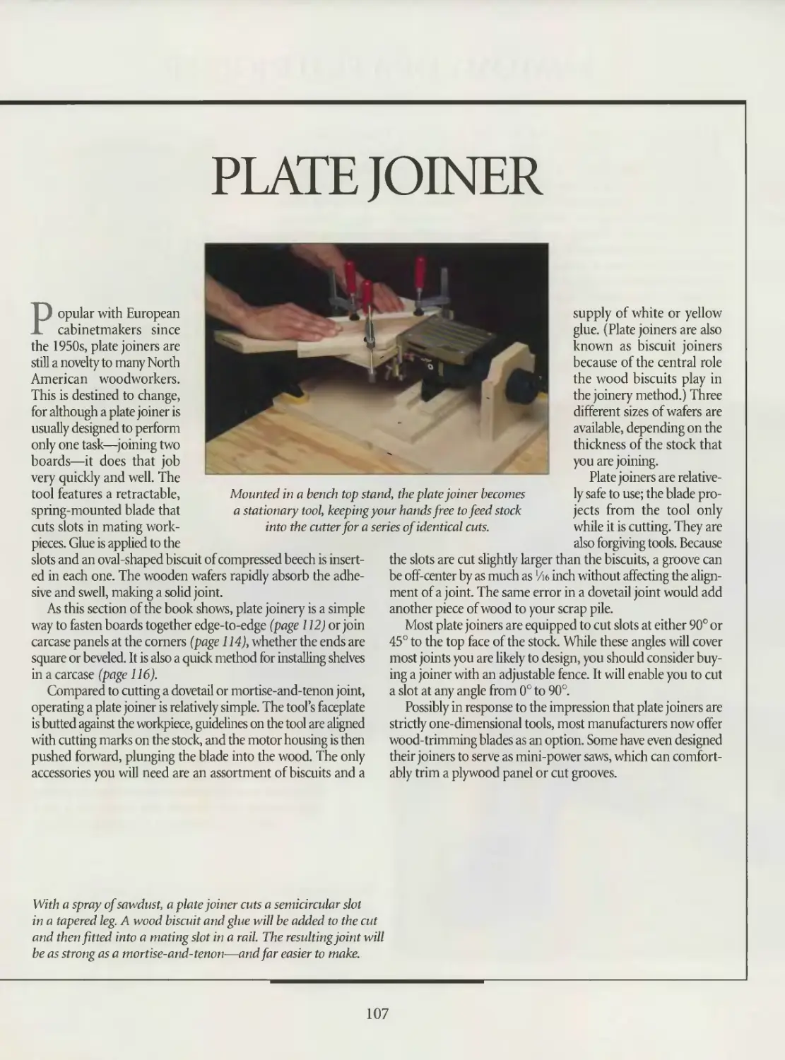
PORTABLE
POWERTOOLS
A Tuckerdude Scan 2004
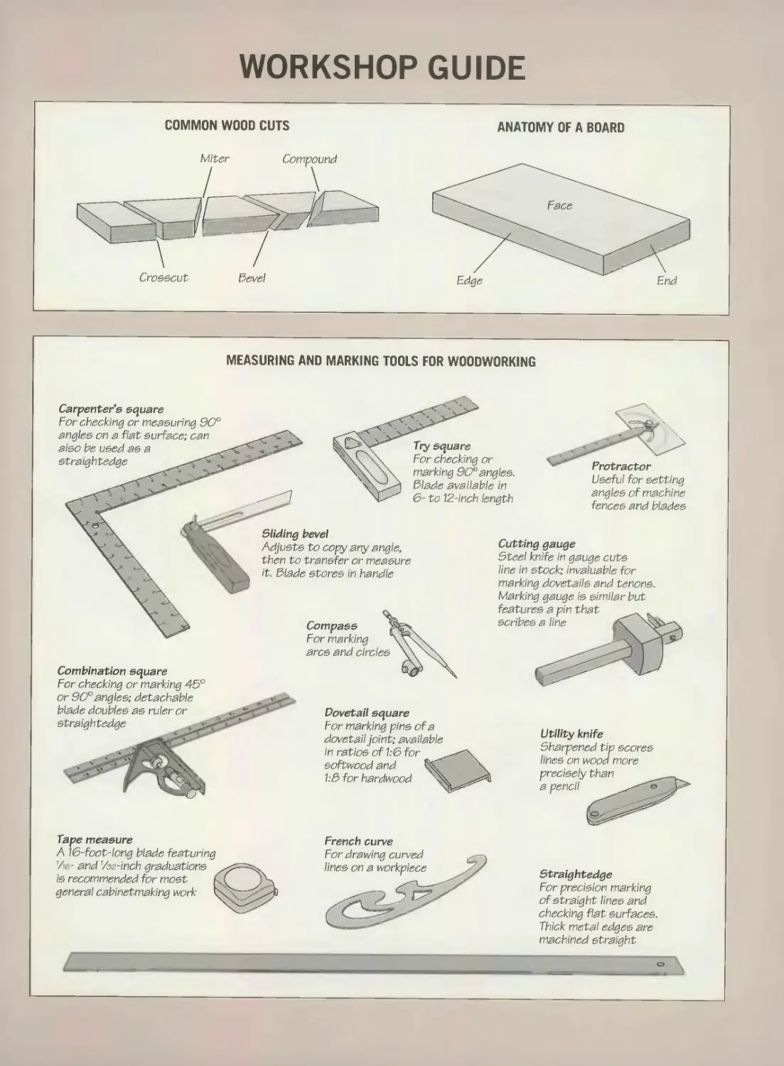
WORKSHOP GUIDE
• Wear appropriate safety equipment:
safety glasses, a face or dust mask if
you are using sanding accessories, and
hearing protection if you are operating
tools for an extended period of time.
• Clamp all workpieces securely wherever
possible to keep both hands free to oper-
ate the tool.
• Be aware of the position of the power
cord at all times.
• Make all adjustments to a tool with the
tool unplugged.
SAFETY TIPS
• Maintain and clean tools regularly.
Keep all blades and bits sharp, clean and
undamaged. Check regularly for loose
parts and frayed cords.
• Never carry a connected tool with your
finger on the trigger.
• Tie back long hair, roll up sleeves,
and avoid wearing loose clothing. Remove
rings and other jewelry that can catch
accidentally in moving parts.
• Do not over-reach. Keep proper footing
and balance at all times.
• Make sure that lighting and ventilation
in the work area are adequate. Do not
use tools if the floor is damp or wet.
• Keep your work area clean and tidy;
clutter can lead to accidents.
• Keep pets, children and onlookers
away from the work area.
• Concentrate on the job. Do not rush
or take shortcuts. Never work if you are
tired, stressed or have been drinking
alcohol or using any medication that
induces drowsiness.
MINIMUM WIRE GAUGE FOR EXTENSION CORDS
AMPERAGE RATING OF TOOL MINIMUM GAUGE FOR DIFFERENT LENGTH CORDS Choosing the proper wire gauge Using an extension cord with the wrong
50' 75‘ 100' 0-2.0 18 18 18 2.13.4 18 18 16 3.5-5.0 18 16 14 5.1-7.0 16 14 12 7.1-12.0 14 12 10 12.1-16.0 12 10 8 gauge may cause a drop in line voltage, resulting in loss of power, excessive heat and tool burnout. To determine the minimum wire gauge needed for the tool and task at hand, see the chart at left. If, for instance, your tool has a 4-amp motor and you are using a 50-foot exten- sion cord, the minimum gauge should be 18 Choose only round-jacketed extension cords listed by Underwriters Laboratory (UL).
BUILDING A SAWHORSE
There are many designs for building
a sawhorse, from complex plans
that use sliding joints and hinges
to simple ones where inexpensive
pairs of metal jaws grip 2-by-4s to
make guick sets of legs. You can
also make a sturdy, knock-down
sawhorse in a few minutes with just
three pieces of wood. First, cut
two legs from 3A" plywood; saw a
4-inch-deep notch in the middle
of the top of both pieces. Then
cut a crossbar to length from a
1-by-6 and saw a slot one foot in
from either end to fit into the legs.
Angle the slots roughly 5°from
the vertical so the legs spread
slightly outward.
THF ART OF WOODWORKING
PORTABLE
POWERTOOLS
THE ART OF WOODWORKING
PORTABLE
POWER TOOLS
TIME-LIFE BOOKS
ALEXANDRIA, VIRGINIA
ST. REMY PRESS
MONTREAL - NEW YORK
THE ART OF WOODWORKING was produced by
ST. REMY PRESS
PUBLISHER
PRESIDENT
Series Editor
Series Art Director
Senior Editors
Art Directors
Designer
Research Editor
Picture Editor
Writers
Contributing Illustrators
Administrator
Production Manager
System Coordinator
Photographer
Index
Proofreadei
Kenneth Winchester
Pierre Leveille
Pierre Home-Douglas
Francine Lemieux
Marc Cassini (Text!
Heather Mills (Research)
Normand Boudreault, Solange Laberge
Luc Germain
Jim McRae
Christopher Jackson
Tamsin M. Douglas, Andrew Jones
Ronald Durepos, Robert Paquet,
Studio La Perluete Inc.
Natalie Watanabe
Michelle Turbide
Jean-Luc Roy
Robert Chartier
Christine M. Jacobs
Judith Yelon
THE CONSULTANTS
Ted Fuller is the product manager at Delta
International Machinery/Porter Cable
(Canada). He is currently working in new
product development and marketing for
woodworking tools and equipment. He is
also an amateur woodworker.
Giles Miller-Mead has taught advanced cabi-
netmaking at Montreal technical schools for
more than ten years. A native of New Zealand,
he previously worked as a restorer of antique
furniture.
Mike O’Malley is a Canadian industrial
designer as well as Contributing Editor,
Power Tools, for Woodcuts magazine .
Joseph Truini is Senior Editor of Home
Mechanix magazine. A former Shop and Tools
Editor of Popular Mechanics, he has worked as
a cabinetmaker, home improvement contractor
and carpenter.
Time-Life Books is a division of Time-Life Inc.,
a wholly owned subsidiary of
THE TIME INC. BOOK COMPANY
TIME-LIFE BOOKS
President
Publisher
Managing Editor
Director of Editorial Resources
Associate Publisher
Marketing Director
Editorial Director
Consulting Editor
Production Manager
Mary N. Davis
Robert H. Smith
Thomas H. Flaherty
Elise D. Ritter-Clough
Trevor Lunn
Regina Hall
Donia Ann Steele
Bob Doyle
Marlene Zack
Portable power tools
p. cm.—(The Art of Woodworking)
Includes index.
ISBN 0-8094-9908-8 (trade)
ISBN 0-8094-9909-6 (lib)
1. Power tools. 2. Woodwork
I. Time- Life Books. II. Series
TT186.P67 1992
684’ .083—dc20 92-25558
CIP
For information about any Time-Life book,
please call 1-800-621-7026, or write:
Reader Information
Time-Life Customer Service
P.O. Box C-32068
Richmond, Virginia
23261-2068
© 1992 Time-Life Books Inc.
All rights reserved.
No part of this book may be reproduced in
any form or by any electronic or mechanical
means, including information storage and
retrieval devices or systems, without prior
written permission from the publisher, except
that brief passages may be quoted for reviews.
First printing. Printed in U.S.A.
Published simultaneously in Canada.
TIME-LIFE is a trademark of Time Warner
Inc. U.S.A.
R 10 987654321
CONTENTS
6
12
14
16
20
29
32
34
36
38
40
41
44
46
48
50
52
54
58
60
64
67
68
70
72
76
77
81
INTRODUCTION
CIRCULAR SAW
Anatomy of a circular saw
Circular saw blades
and accessories
Basic cuts
Advanced cuts
SABER SAW
Anatomy of a saber saw
Saber saw blades
Straight cuts
Angle cuts
Curved cuts
Plunge cutting
Cutting duplicate pieces
ELECTRIC DRILL
Anatomy of an electric drill
Drill bits and accessories
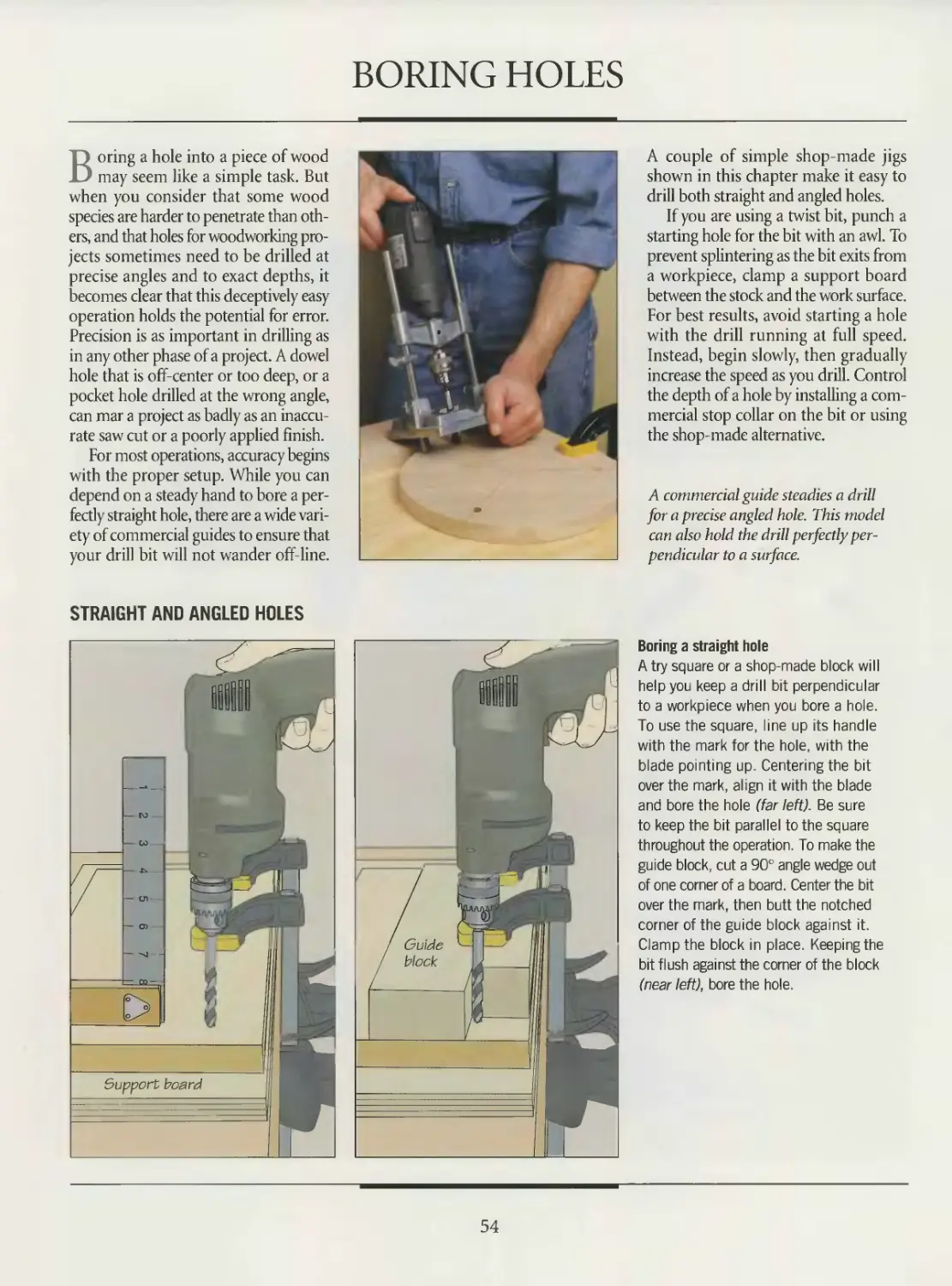
Boring holes
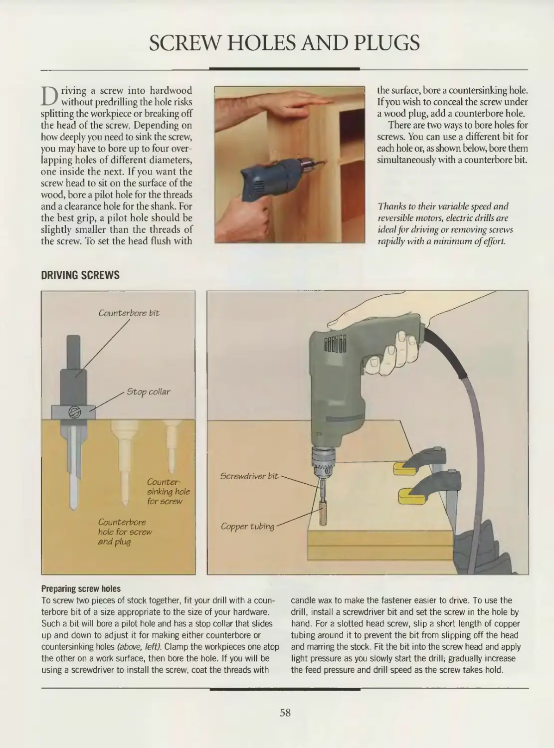
Screw holes and plugs
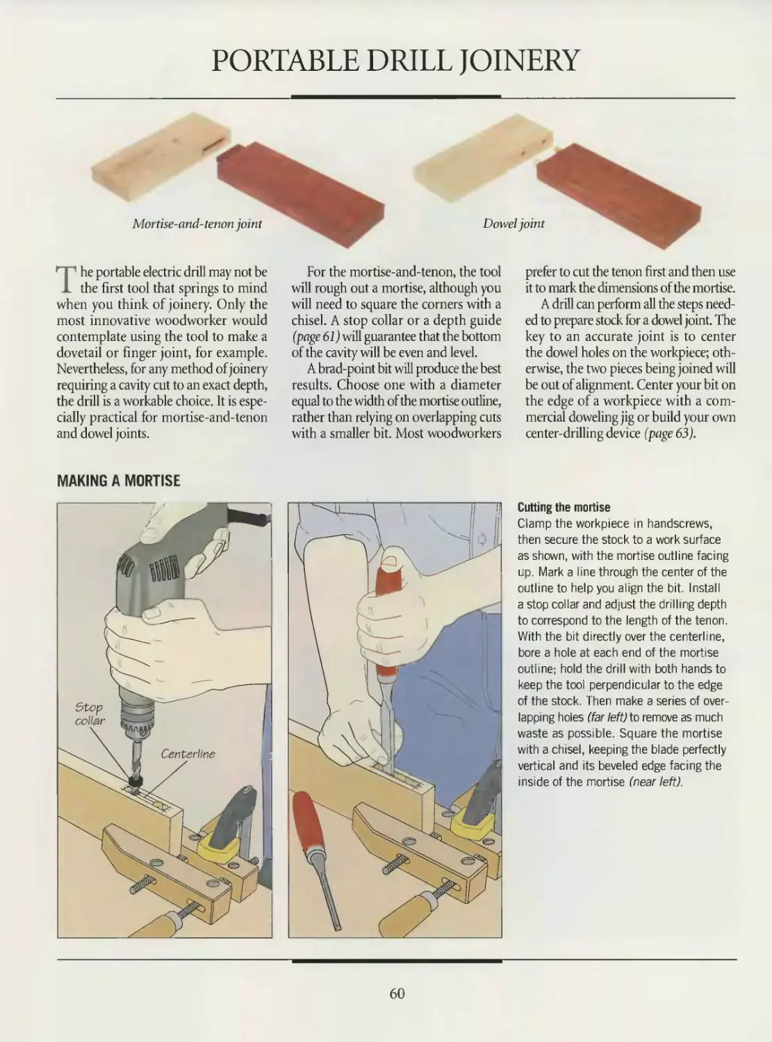
Portable drill joinery
Sanding, scraping
and smoothing
The portable drill as
drill press
ROUTER
Anatomy of a router
Bits
Router accessories
Edge forming
Dado cuts
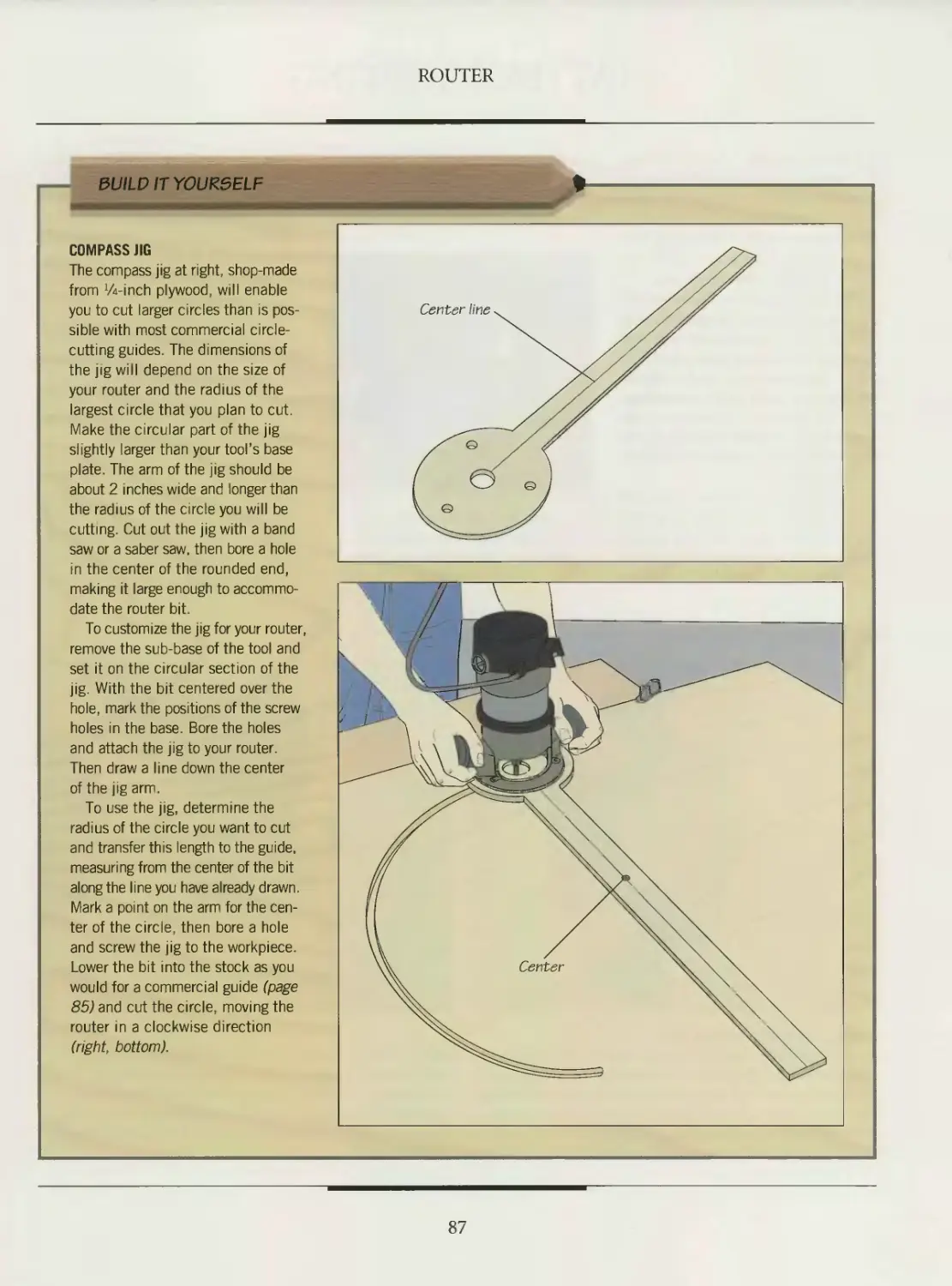
85 Routing circles
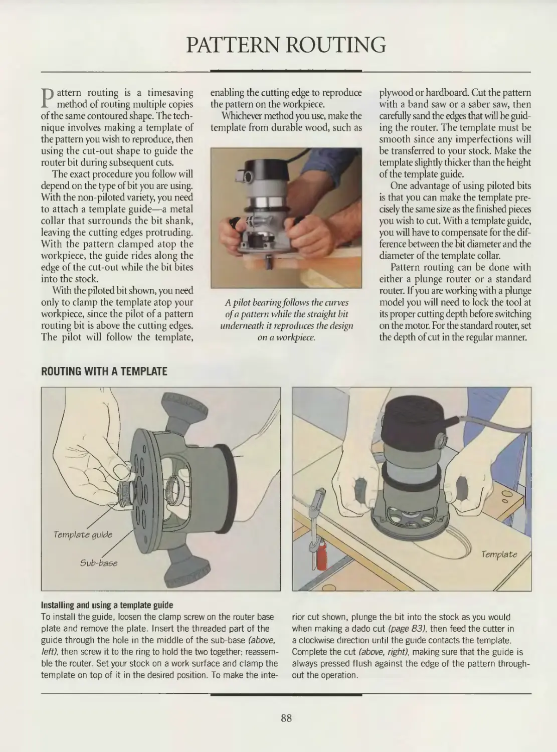
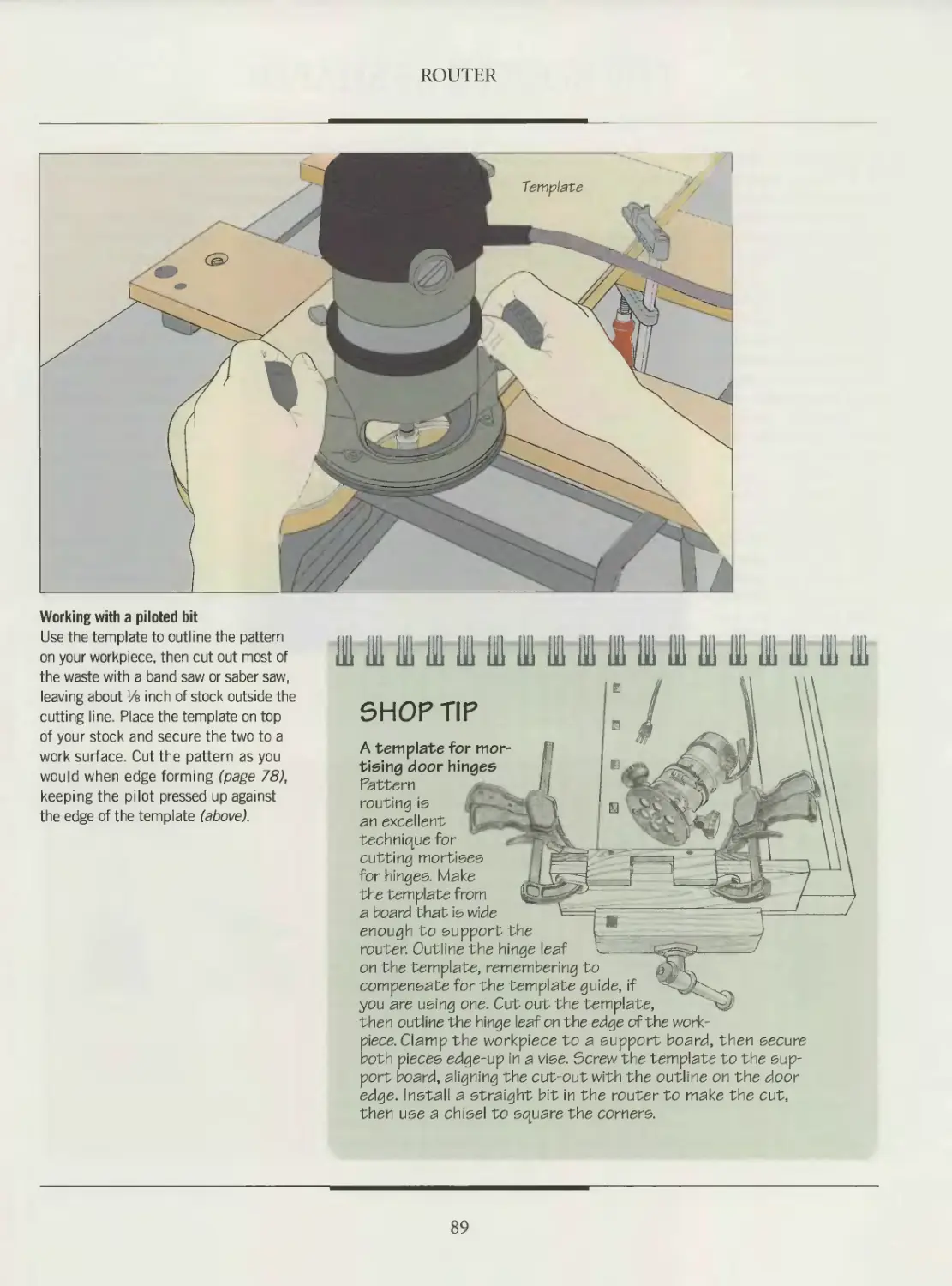
88 Pattern routing
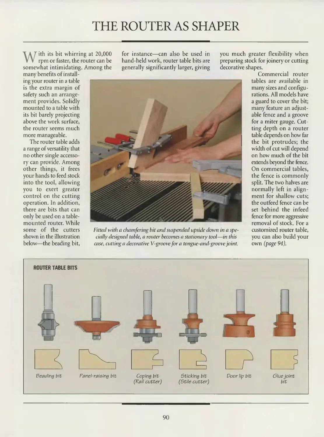
90 The router as shaper
97 Router joinery
106 PLATE JOINER
108 Anatomy of a plate joiner
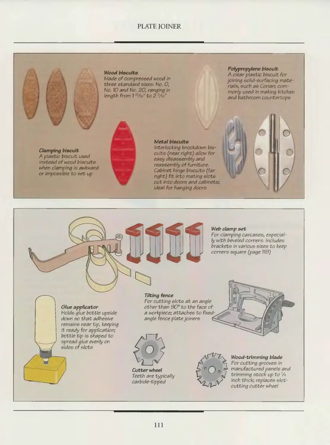
110 Plate joiner accessories
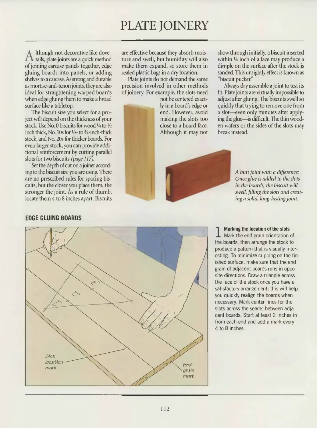
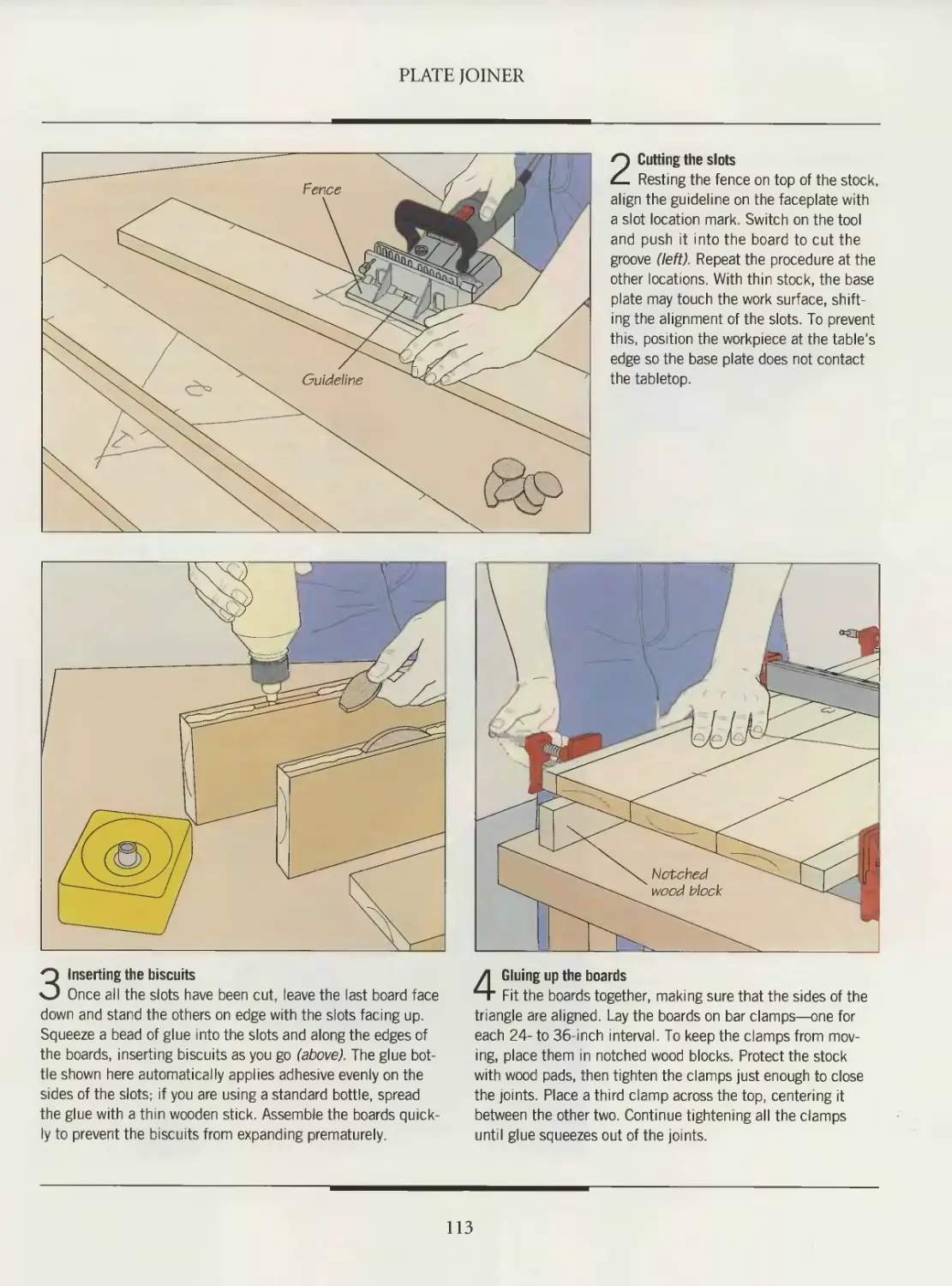
112 Plate joinery
121 The plate joiner as groover
and trimmer
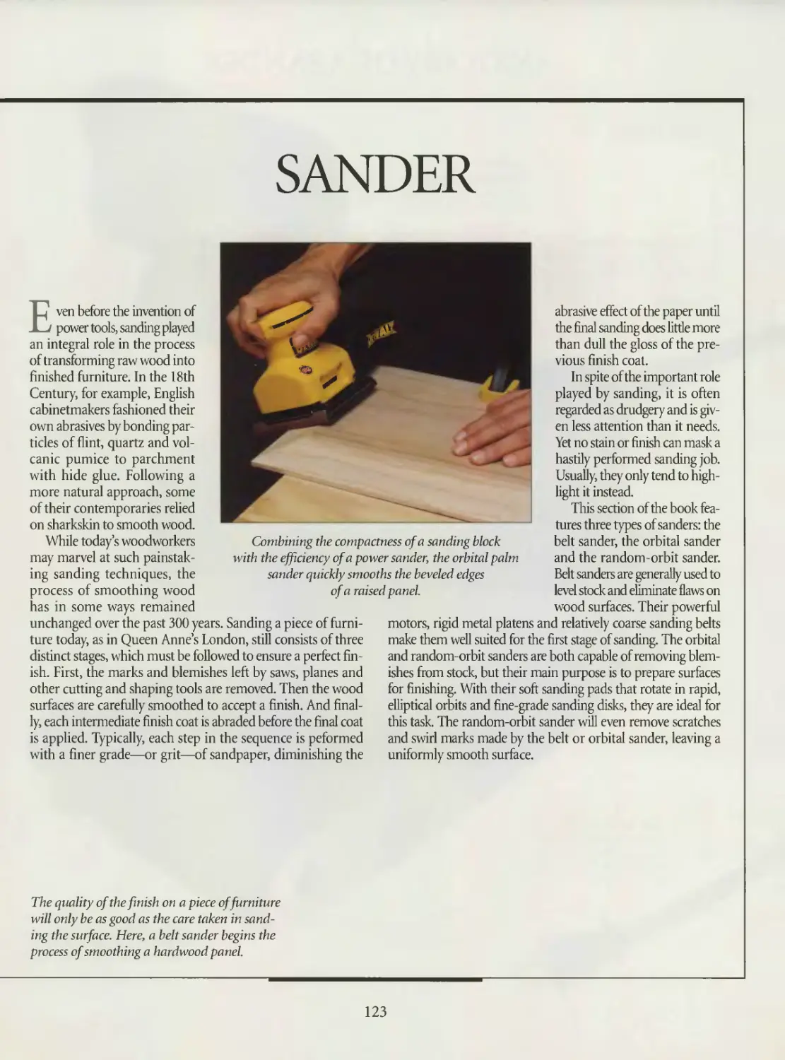
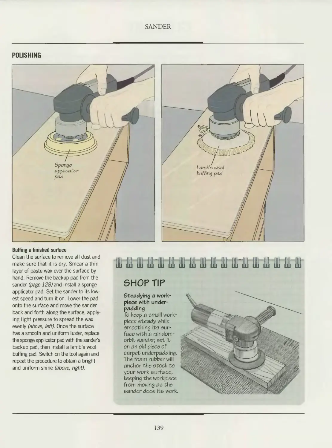
122 SANDER
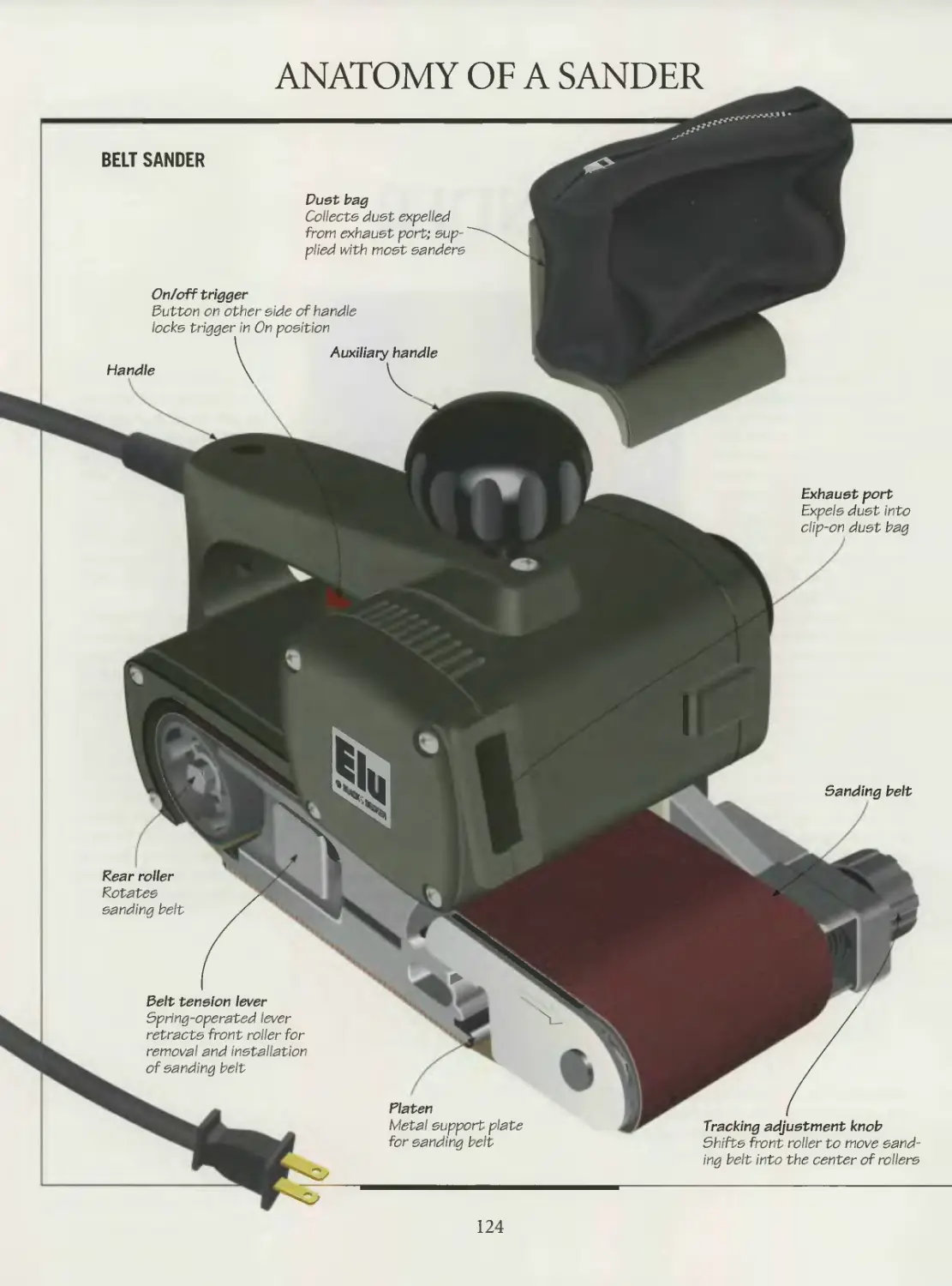
124 Anatomy of a sander
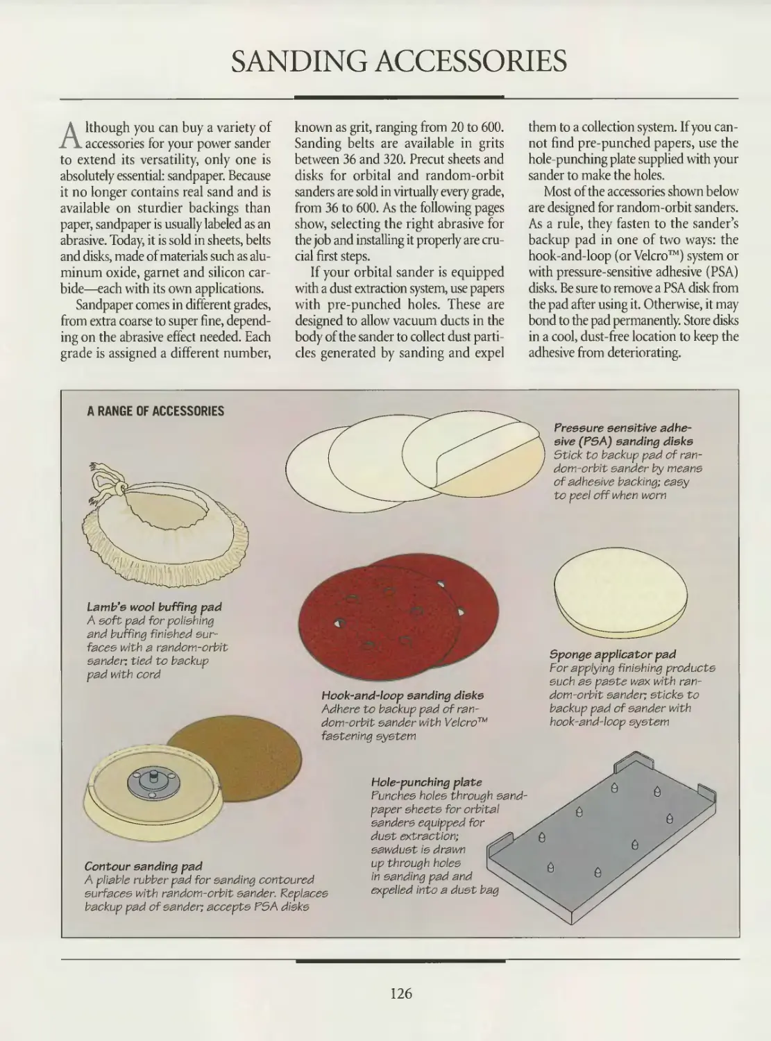
126 Sanding accessories
129 Belt sander
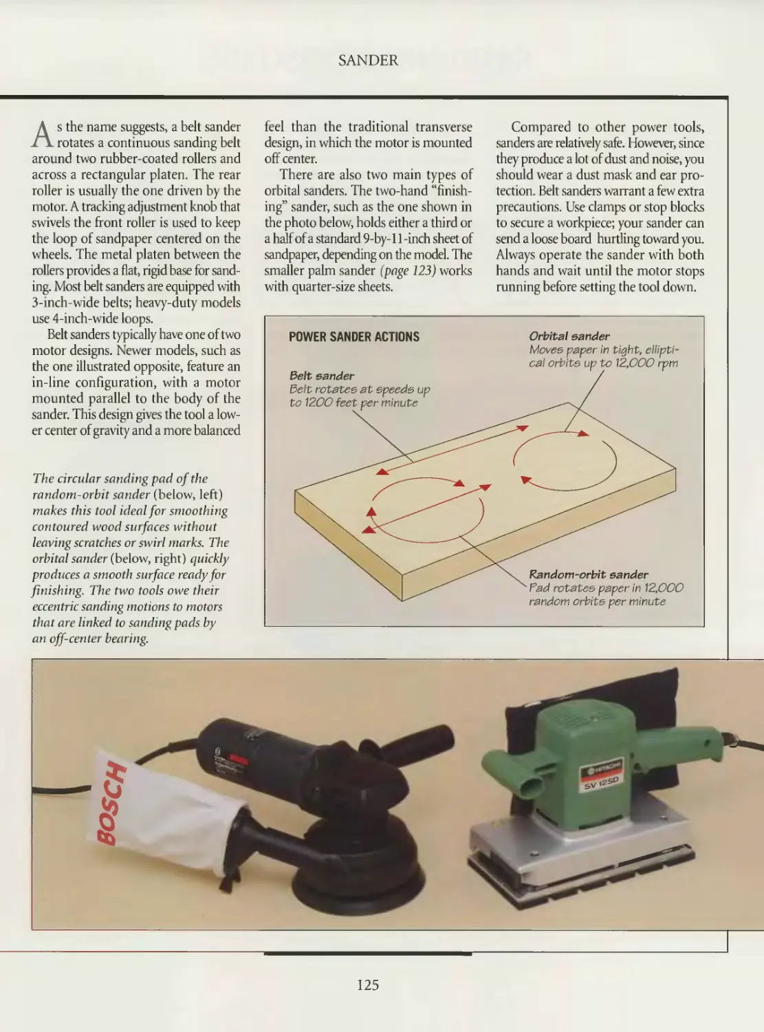
135 Orbital sander
138 Random-orbit sander
140 GLOSSARY
142 INDEX
144 ACKNOWLEDGMENTS
INTRODUCTION
John Leeke talks about his
TOOL
COLLECTION
I grew up working in my father’s cabinetmaking shop. He learned woodworking
from an English woodcarver and my early training was in that same tradition with
plenty of experience using hand tools such as chisels, planes and saws. Through this
work I gained a fundamental knowledge of wood as a material and how to work with
it. Since this was a commercial shop, the use of power tools was a natural extension
of that training.
In the early 1970s I left my father’s shop and began to earn a living on my own. I
was interested in the old hand woodworking methods and especially in applying my
knowledge of wood in the preservation of historic buildings. I quickly learned that
power tools gave me the same results as hand work, but with much less time and effort,
leaving me with more time to apply my woodworking skills with hand tools to the
details that really matter.
When I began collecting my own set of power tools the first things I bought were
a %-inch drill and a saber saw. Later I added a 3-by-21 belt sander and a router to my
kit, and—eventually—an 8-inch circular saw. These tools had all-aluminum housings
that were bright and shiny when new. They were weighty and substantial tools that
you just knew could stand a lifetime of wear and use. And, with regular maintenance
and occasional repairs, they have. I still use those same tools in my shop, although
the shiny polish has worn to a dull grey.
As time passed, manufacturers began to offer power tools with plastic housings.
At first I didn’t think much of them and credited myself with having bought my tools
back when they were still made of good solid metal. Slowly, however, I began to realize
that the plastic housing’s lighter design makes a lot of sense when you’re using the tools
all day long. So I bought another circular saw—this one with a plastic housing.
And then came cordless tools. At first they were unreliable. It took more time fid-
dling with near-dead batteries and recharging than it did to just stretch out an exten-
sion cord and use the old ones. But, as the electronics of the chargers improved and
battery technology developed, these handy tools began to save enough time to increase
productivity. Now, I have a cordless drill, sander and right-angle grinder.
Something to keep in mind: While these tools allow you to work faster, they also
allow accidents to happen a lot quicker. It doesn’t take much more than one stroke
of a hand saw to know you are cutting yourself. But a power saw can cut off a finger
in less than a tenth of a second—before you even realize that something’s going wrong.
You have to be careful.
John Leeke works as a preservation consultant, helping home-
owners, architects and contractors maintain and understand
their historic buildings. He lives in Sanford, Maine.
7
INTRODUCTION
Jan Hoffman discusses
THE SABER SAW
I design and build Pennsylvania-German folk furniture. The inspiration for my work
comes from the people who lived and farmed around this region during the
18th and 19th Centuries. They produced utilitarian furniture that was colorfully
painted and wonderfully scrolled. The elaborateness of that scrollwork has prompt-
ed at least one wag to suggest that the Pennsylvania Germans seemed incapable
of cutting anything in a straight line.
When I first expressed an interest in working with wood, my father gave me a 30-
year-old table saw and a circular saw of about the same vintage. They were followed
shortly by a drill and a good-quality saber saw. For years, these machines—plus a box
full of old wooden hand planes—were the extent of my tool inventory.
In the beginning, I used the saber saw only rarely. But I learned to appreciate the
value of this much-overlooked tool. Some woodworkers seem to think that bigger
means better. They equate the size of the machine and the hum it makes with its pro-
ductivity. For me, the saber saw proves that is not a valid equation.
My saw comes in handy for everything from cleaning out the rectangular mortises
in bench tops to sawing triangular spoon slots in the shelves of cupboards. But where
the tool really excels is in cutting the intricate scroll designs in the large side panels
of open kitchen dressers or in the pieces of furniture known as bucket benches. Those
are the things people used to leave out on the back porch to hold the buckets for bring-
ing in water from the well. If I tried to use a band saw, the whole operation would
become very cumbersome, requiring a lot of maneuvering or flipping of the stock.
With the saber saw, the wood remains stationary while I simply pivot the tool.
Some woodworkers might choose the band saw if they could only take one machine
to a desert island. I’d reach for my saber saw instead.
Jan Hoffman has owned a cabinetmaking shop for
the last 10 years. Proud of her Pennsylvania-German
lineage, she lives in East Berlin, Pennsylvania.
9
INTRODUCTION
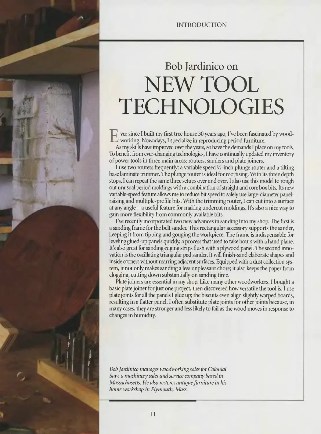
Bob Jardinico on
NEW TOOL
TECHNOLOGIES
Ever since I built my first tree house 30 years ago, I’ve been fascinated by wood-
working. Nowadays, I specialize in reproducing period furniture.
As my skills have improved over the years, so have the demands I place on my tools.
To benefit from ever-changing technologies, I have continually updated my inventory
of power tools in three main areas: routers, sanders and plate joiners.
I use two routers frequently: a variable speed ‘/2-inch plunge router and a tilting
base laminate trimmer. The plunge router is ideal for mortising. With its three depth
stops, I can repeat the same three setups over and over. I also use this model to rough
out unusual period moldings with a combination of straight and core box bits. Its new
variable-speed feature allows me to reduce bit speed to safely use large-diameter panel-
raising and multiple-profile bits. With the trimming router, I can cut into a surface
at any angle—a useful feature for making undercut moldings. It’s also a nice way to
gain more flexibility from commonly available bits.
I’ve recently incorporated two new advances in sanding into my shop. The first is
a sanding frame for the belt sander. This rectangular accessory supports the sander,
keeping it from tipping and gouging the workpiece. The frame is indispensable for
leveling glued-up panels quickly, a process that used to take hours with a hand plane.
It’s also great for sanding edging strips flush with a plywood panel. The second inno-
vation is the oscillating triangular pad sander. It will finish-sand elaborate shapes and
inside comers without marring adjacent surfaces. Equipped with a dust collection sys-
tem, it not only makes sanding a less unpleasant chore; it also keeps the paper from
clogging, cutting down substantially on sanding time.
Plate joiners are essential in my shop. Like many other woodworkers, I bought a
basic plate joiner for just one project, then discovered how versatile the tool is. I use
plate joints for all the panels I glue up; the biscuits even align slightly warped boards,
resulting in a flatter panel. I often substitute plate joints for other joints because, in
many cases, they are stronger and less likely to fail as the wood moves in response to
changes in humidity.
Bob Jardinico manages woodworking sales for Colonial
Saw, a machinery sales and service company based in
Massachusetts. He also restores antique furniture in his
home workshop in Plymouth, Mass.
11
CIRCULAR SAW
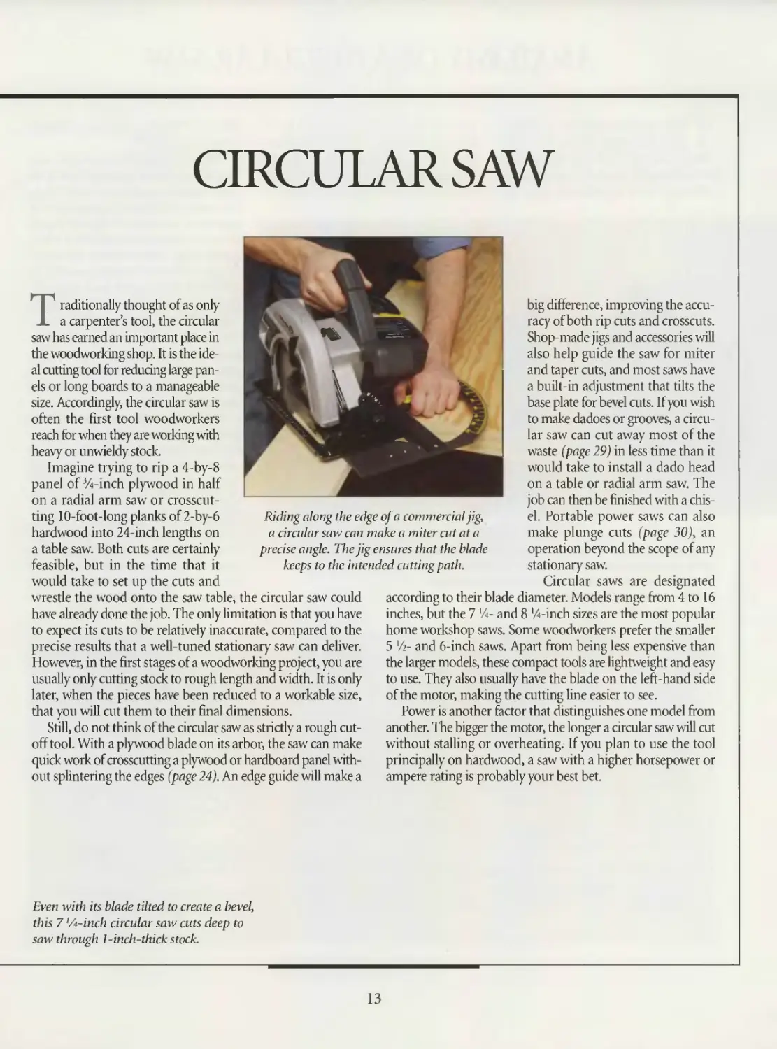
Riding along the edge of a commercial jig,
a circular saw can make a miter cut at a
precise angle. The jig ensures that the blade
keeps to the intended cutting path.
Traditionally thought of as only
a carpenter’s tool, the circular
saw has earned an important place in
the woodworking shop. It is the ide-
al cutting tool for reducing large pan-
els or long boards to a manageable
size. Accordingly, the circular saw is
often the first tool woodworkers
reach for when they are working with
heavy or unwieldy stock.
Imagine trying to rip a 4-by-8
panel of Vi-inch plywood in half
on a radial arm saw or crosscut-
ting 10-foot-long planks of 2-by-6
hardwood into 24-inch lengths on
a table saw. Both cuts are certainly
feasible, but in the time that it
would take to set up the cuts and
wrestle the wood onto the saw table, the circular saw could
have already done the job. The only limitation is that you have
to expect its cuts to be relatively inaccurate, compared to the
precise results that a well-tuned stationary saw can deliver.
However, in the first stages of a woodworking project, you are
usually only cutting stock to rough length and width. It is only
later, when the pieces have been reduced to a workable size,
that you will cut them to their final dimensions.
Still, do not think of the circular saw as strictly a rough cut-
off tool. With a plywood blade on its arbor, the saw can make
quick work of crosscutting a plywood or hardboard panel with-
out splintering the edges (page 24). An edge guide will make a
big difference, improving the accu-
racy of both rip cuts and crosscuts.
Shop-made jigs and accessories will
also help guide the saw for miter
and taper cuts, and most saws have
a built-in adjustment that tilts the
base plate for bevel cuts. If you wish
to make dadoes or grooves, a circu-
lar saw can cut away most of the
waste (page 29) in less time than it
would take to install a dado head
on a table or radial arm saw. The
job can then be finished with a chis-
el. Portable power saws can also
make plunge cuts (page 30), an
operation beyond the scope of any
stationary saw.
Circular saws are designated
according to their blade diameter. Models range from 4 to 16
inches, but the 7 ’A- and 8 'Zi-inch sizes are the most popular
home workshop saws. Some woodworkers prefer the smaller
5 'A- and 6-inch saws. Apart from being less expensive than
the larger models, these compact tools are lightweight and easy
to use. They also usually have the blade on the left-hand side
of the motor, making the cutting line easier to see.
Power is another factor that distinguishes one model from
another. The bigger the motor, the longer a circular saw will cut
without stalling or overheating. If you plan to use the tool
principally on hardwood, a saw with a higher horsepower or
ampere rating is probably your best bet.
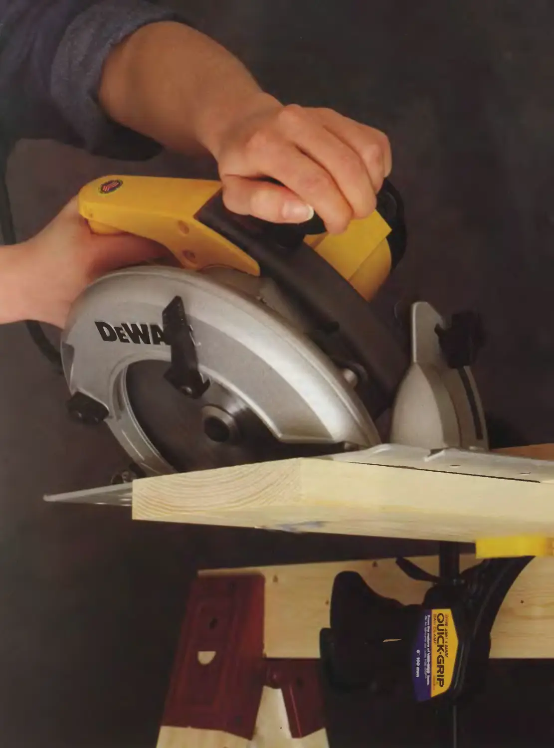
Even with its blade tilted to create a bevel,
this 7 '/4-inch circular saw cuts deep to
saw through 1-inch-thick stock.
13
ANATOMY OF A CIRCULAR SAW
There are approximately 40 million
portable circular saws in the United
States. They vary widely in their design,
but all models share certain common
features; most importantly, they are
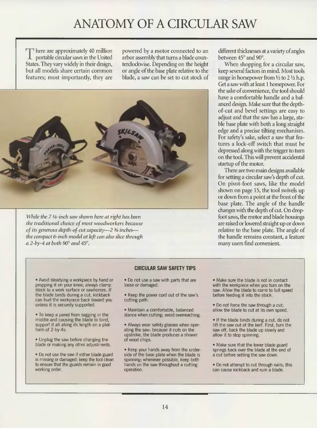
While the 7 M-inch saw shown here at right has been
the traditional choice of most woodworkers because
of its generous depth-of-cut capacity—2 % inches—
the compact 6-inch model at left can also slice through
a 2-by-4 at both 90° and 45°.
powered by a motor connected to an
arbor assembly that turns a blade coun-
terclockwise. Depending on the height
or angle of the base plate relative to the
blade, a saw can be set to cut stock of
different thicknesses at a variety of angles
between 45° and 90°.
When shopping for a circular saw,
keep several factors in mind. Most tools
range in horsepower from Vi to 2 Vi h.p.
Get a saw with at least 1 horsepower. For
the sake of convenience, the tool should
have a comfortable handle and a bal-
anced design. Make sure that the depth-
of-cut and bevel settings are easy to
adjust and that the saw has a large, sta-
ble base plate with both a long straight
edge and a precise tilting mechanism.
For safety’s sake, select a saw that fea-
tures a lock-off switch that must be
depressed along with the trigger to turn
on the tool. This will prevent accidental
startup of the motor.
There are two main designs available
for setting a circular saw’s depth of cut.
On pivot-foot saws, like the model
shown on page 15, the tool swivels up
or down from a point at the front of the
base plate. The angle of the handle
changes with the depth of cut. On drop-
foot saws, the motor and blade housings
are raised or lowered straight up or down
relative to the base plate. The angle of
the handle remains constant, a feature
many users find convenient.
• Avoid steadying a workpiece by hand or
propping it on your knee; always clamp
stock to a work surface or sawhorses. If
the blade binds during a cut, kickback
can hurl the workpiece back toward you
unless it is securely supported.
• To keep a panel from sagging in the
middle and causing the blade to bind,
support it all along its length on a plat-
form of 2-by-4s.
• Unplug the saw before changing the
blade or making any other adjustments.
• Do not use the saw if either blade guard
is missing or damaged; keep the tool clean
to ensure that the guards remain in good
working order.
CIRCULAR SAW SAFETY TIPS
• Do not use a saw with parts that are
loose or damaged.
• Keep the power cord out of the saw’s
cutting path.
• Maintain a comfortable, balanced
stance when cutting; avoid overreaching.
• Always wear safety g asses when oper-
ating the saw; because it cuts on the
upstroke, the blade produces a shower
of wood chips.
• Keep your hands away from the under-
side of the base plate when the blade is
spinning; whenever possible, keep both
hands on the saw throughout a cutting
operation.
• Make sure the blade is not in contact
with the workpiece when you turn on the
saw. Allow the blade to come to full speed
before feeding it into the stock.
• Do not force the saw through a cut;
allow the blade to cut at its own speed.
• If the blade binds during a cut, do not
lift the saw out of the kerf. First, turn the
saw off, back the blade up slowly and
allow it to stop spinning.
• Make sure that the lower blade guard
springs back over the blade at the end of
a cut before setting the saw down.
• Do not attempt to cut through nails; this
can cause kickback and ruin a blade.
14
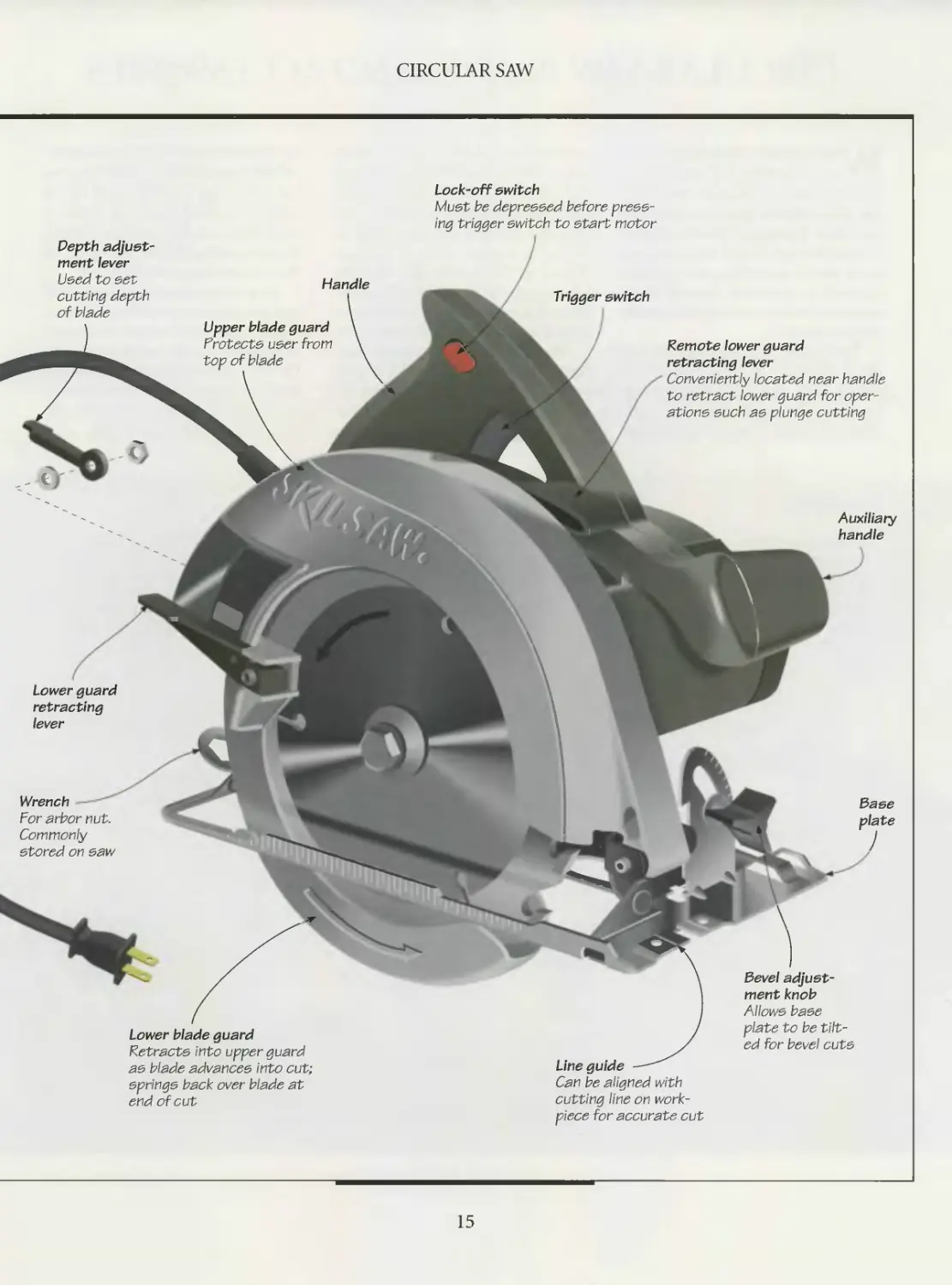
CIRCULAR SAW
Lock-off switch
Must he depressed before press-
ing trigger switch to start motor
Handle
Trigger switch
Auxiliary
handle
Lower guard
retracting
lever
Depth adjust-
ment lever
Used to set
cutting depth
of blade
Remote lower guard
retracting lever
Conveniently located near handle
to retract lower guard for oper-
ations such as plunge cutting
Upper blade guard
Protects user from
top of blade
Base
plate
Bevel adjust-
ment knob
Allows base
plate to be tilt-
ed for bevel cuts
Lower blade guard
Retracts into upper guard
as blade advances into cut;
springs back over blade at
end of cut
Line guide
Can be aligned with
cutting line on work-
piece for accurate cut
Wrench
For arbor nut.
Commonly
stored on saw
15
CIRCULAR SAW BLADES AND ACCESSORIES
With the dozens of specialty blades
on the market it is entirely pos-
sible to transform a circular saw from a
job site workhorse into a precision cut-
ting tool. Equipped with a standard
combination blade and ones designed
to cut specific materials, a saw can cross-
cut and rip accurately through hard-
wood, softwood or manufactured panels
such as plywood.
The cutting ability of a circular saw
blade depends on several factors. A
blade’s hook angle, which determines
how much bite it will take, is a key vari-
able. (The angle is formed by the inter-
section of one line drawn from the tip
of a tooth to the center of the arbor hole
and one drawn parallel to the tooth’s
face.) The width of the kerf that the cut-
ting edge creates is also important; so
too is the number of teeth per inch
(TPI). A 40 TPI crosscut blade will do its
job more slowly than a 20 TPI combi-
nation blade, for example, but the finer-
toothed model will produce a cleaner cut.
Although all of the blade types illus-
trated below are available in high-speed
steel, carbide-tipped models have for
years been the first choice of the major-
ity of woodworkers. While they are more
expensive than their steel counterparts,
carbide-tipped blades are more econom-
ical in the long run. The small tips of
carbide alloy welded onto the bodies of
these blades can be sharpened dozens
of times and hold their edge up to 50
times longer than steel blades.
But even carbide-tipped blades dull
with extended use. Smoking, burning,
off-line cutting and frequent binding are
all signs of a blade in need of sharpening.
The best way to keep a blade sharp is to
choose the right one for the material you
are cutting and to avoid cutting into fas-
teners or accumulations of pitch.
BLADE TYPES
Combination Blade
The blade type
usually supplied with
the saw; a general-
purpose blade for
ripping and cross-
cutting.
Crosscut Blade
For fast, smooth cuts
across the grain; the
blade’s teeth are
sharpened on the
face and back, form-
ing sharp cutting
points.
Rip Blade
Also known as a
framing blade; the
large, hooked teeth
make it ideal for
fast cuts along
the grain.
Hollow Ground
Planer Blade
For very smooth rip cuts,
crosscuts and angle cuts;
ideal for precision cabi-
net work. The blade’s body
is thinner than the hub
and teeth, reducing the
chance of binding in
the kerf.
Plywood Blade
For smooth cuts in
plywood and veneered
stock; small, pointed
and finely ground
teeth help reduce
splintering.
16
CIRCULAR SAW
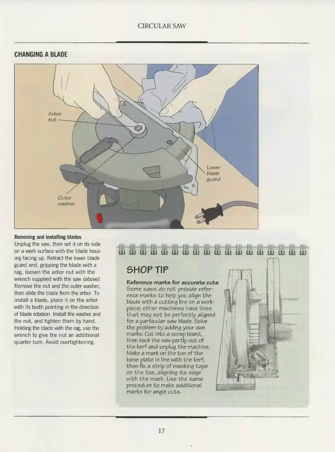
CHANGING A BLADE
Removing and installing blades
Unplug the saw, then set it on its side
on a work surface with the blade hous-
ing facing up. Retract the lower blade
guard and, gripping the blade with a
rag, loosen the arbor nut with the
wrench supplied with the saw (above).
Remove the nut and the outer washer,
then slide the blade from the arbor. To
install a blade, place it on the arbor
with its teeth pointing in the direction
of blade rotation. Install the washer and
the nut, and tighten them by hand.
Holding the blade with the rag, use the
wrench to give the nut an additional
quarter turn. Avoid overtightening.
SHOP TIP
j jj
Reference marks for accurate cuts
Some saws do not provide refer-
ence marks to help you align the
blade with a cutting line on a work-
piece; other machines have lines
that may not be perfectly aligned
for a particular saw blade. Solve
the problem by adding your own
marks. Cut into a scrap board,
then back the saw partly out of
the kerf and unplug the machine.
Make a mark on the toe of the
base plate in line with the kerf,
then fix a strip of masking tape
on the toe, aligning its edge
with the mark. Use the same
procedure to make additional
marks for angle cuts.
17
CIRCULAR SAW
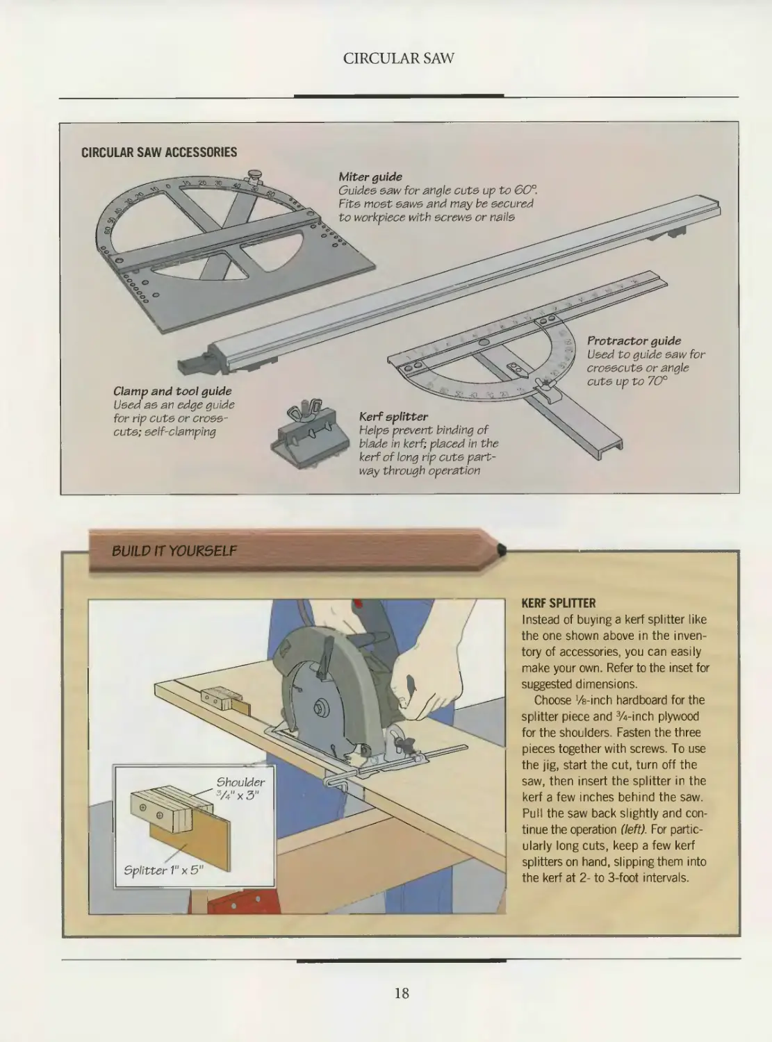
BUILD IT YOURSELF
KERF SPLITTER
Instead of buying a kerf splitter like
the one shown above in the inven-
tory of accessories, you can easily
make your own. Refer to the inset for
suggested dimensions.
Choose '/a-inch hardboard for the
splitter piece and Winch plywood
for the shoulders. Fasten the three
pieces together with screws. To use
the jig, start the cut, turn off the
saw, then insert the splitter in the
kerf a few inches behind the saw.
Pull the saw back slightly and con-
tinue the operation (left). For partic-
ularly long cuts, keep a few kerf
splitters on hand, slipping them into
the kerf at 2- to 3-foot intervals.
18
CIRCULAR SAW
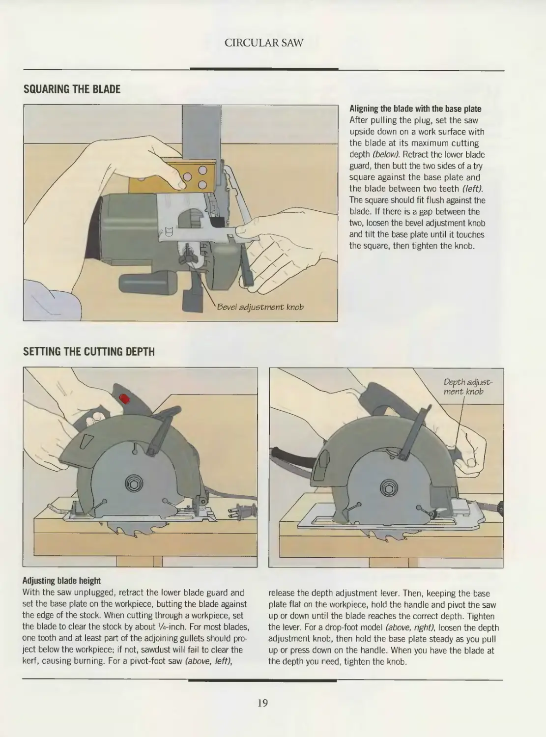
SQUARING THE BLADE
Aligning the blade with the base plate
After pulling the plug, set the saw
upside down on a work surface with
the blade at its maximum cutting
depth (below). Retract the lower blade
guard, then butt the two sides of a try
square against the base plate and
the blade between two teeth (left).
The square should fit flush against the
blade. If there is a gap between the
two, loosen the bevel adjustment knob
and tilt the base plate until it touches
the square, then tighten the knob.
SETTING THE CUTTING DEPTH
Adjusting blade height
With the saw unplugged, retract the lower blade guard and
set the base plate on the workpiece, butting the blade against
the edge of the stock. When cutting through a workpiece, set
the blade to clear the stock by about Winch. For most blades,
one tooth and at least part of the adjoining gullets should pro-
ject below the workpiece: if not, sawdust will fail to clear the
kerf, causing burning. For a pivot-foot saw (above, left),
release the depth adjustment lever. Then, keeping the base
plate flat on the workpiece, hold the handle and pivot the saw
up or down until the blade reaches the correct depth. Tighten
the lever. For a drop-foot model (above, right), loosen the depth
adjustment knob, then hold the base plate steady as you pull
up or press down on the handle. When you have the blade at
the depth you need, tighten the knob.
19
BASIC CUTS
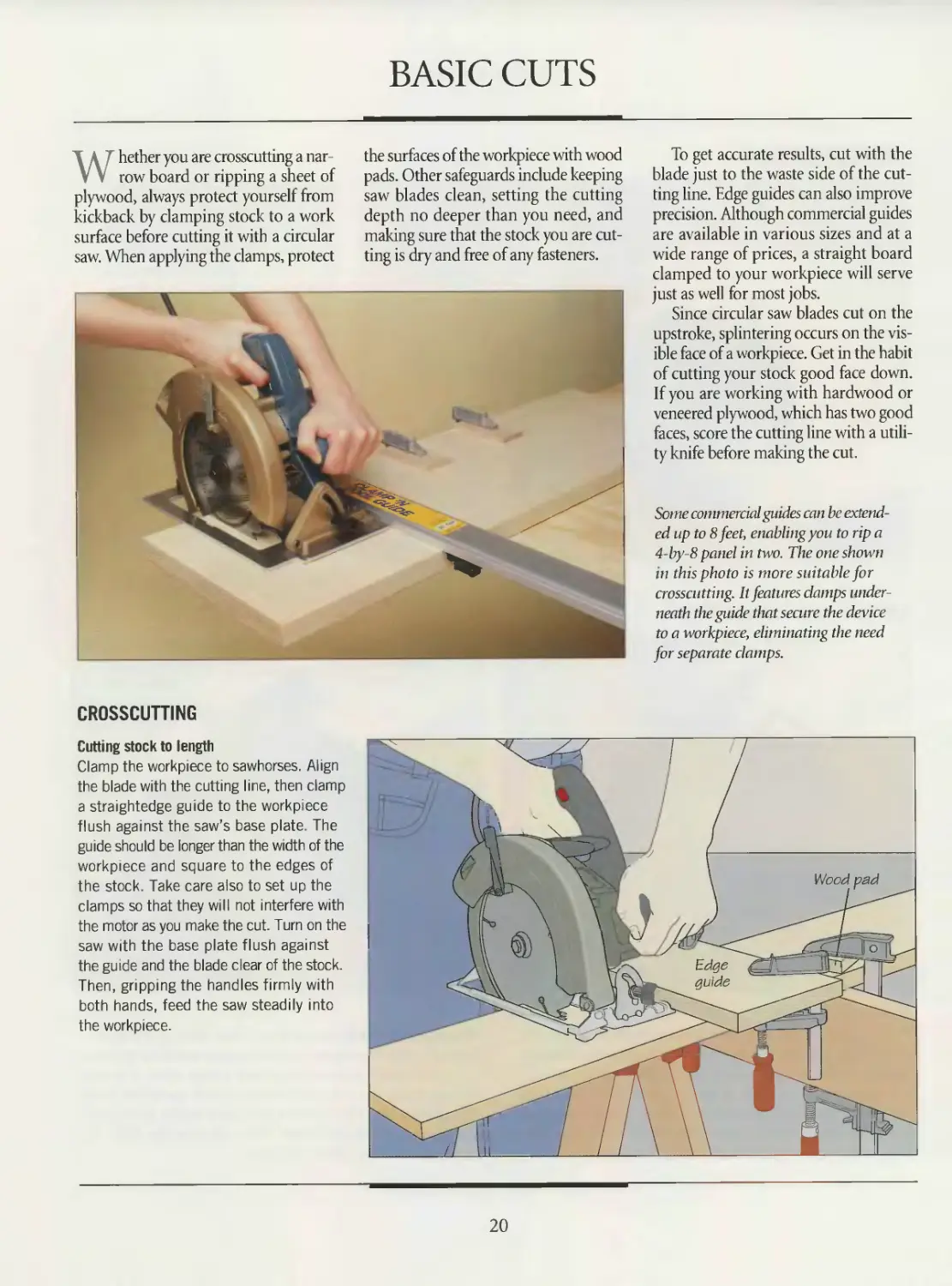
Whether you are crosscutting a nar-
row board or ripping a sheet of
plywood, always protect yourself from
kickback by clamping stock to a work
surface before cutting it with a circular
saw. When applying the clamps, protect
the surfaces of the workpiece with wood
pads. Other safeguards include keeping
saw blades clean, setting the cutting
depth no deeper than you need, and
making sure that the stock you are cut-
ting is dry and free of any fasteners.
To get accurate results, cut with the
blade just to the waste side of the cut-
ting line. Edge guides can also improve
precision. Although commercial guides
are available in various sizes and at a
wide range of prices, a straight board
clamped to your workpiece will serve
just as well for most jobs.
Since circular saw blades cut on the
upstroke, splintering occurs on the vis-
ible face of a workpiece. Get in the habit
of cutting your stock good face down.
If you are working with hardwood or
veneered plywood, which has two good
faces, score the cutting line with a utili-
ty knife before making the cut.
Some commercial guides can be extend-
ed up to 8 feet, enabling you to rip a
4-by-8 panel in two. The one shown
in this photo is more suitable for
crosscutting. It features clamps under-
neath the guide that secure the device
to a workpiece, eliminating the need
for separate clamps.
CROSSCUTTING
Cutting stock to length
Clamp the workpiece to sawhorses. Align
the blade with the cutting line, then clamp
a straightedge guide to the workpiece
flush against the saw’s base plate. The
guide should be longer than the width of the
workpiece and square to the edges of
the stock. Take care also to set up the
clamps so that they will not interfere with
the motor as you make the cut. Turn on the
saw with the base plate flush against
the guide and the blade clear of the stock
Then, gripping the handles firmly with
both hands, feed the saw steadily into
the workpiece.
20
CIRCULAR SAW
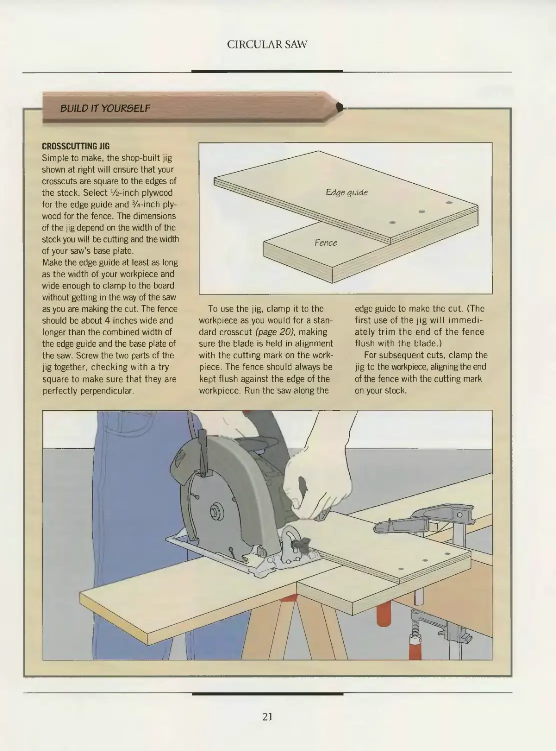
CROSSCUTTING JIG
Simple to make, the shop-built jig
shown at right will ensure that your
crosscuts are square to the edges of
the stock. Select Winch plywood
for the edge guide and Winch ply-
wood for the fence. The dimensions
of the jig depend on the width of the
stock you will be cutting and the width
of your saw's base plate.
Make the edge guide at least as long
as the width of your workp'ece and
wide enough to clamp to the board
without getting in the way of the saw
as you are making the cut. The fence
should be about 4 inches wide and
longer than the combined width of
the edge guide and the base plate of
the saw. Screw the two parts of the
jig together, checking with a try
square to make sure that they are
perfectly perpendicular.
To use the jig, clamp it to the
workpiece as you would for a stan-
dard crosscut (page 20), making
sure the blade is held in alignment
with the cutting mark on the work-
piece. The fence should always be
kept flush against the edge of the
workpiece. Run the saw along the
edge guide to make the cut. (The
first use of the jig will immedi-
ately trim the end of the fence
flush with the blade.)
For subsequent cuts, clamp the
jig to the workpiece, aligning the end
of the fence with the cutting mark
on your stock.
21
CIRCULAR SAW
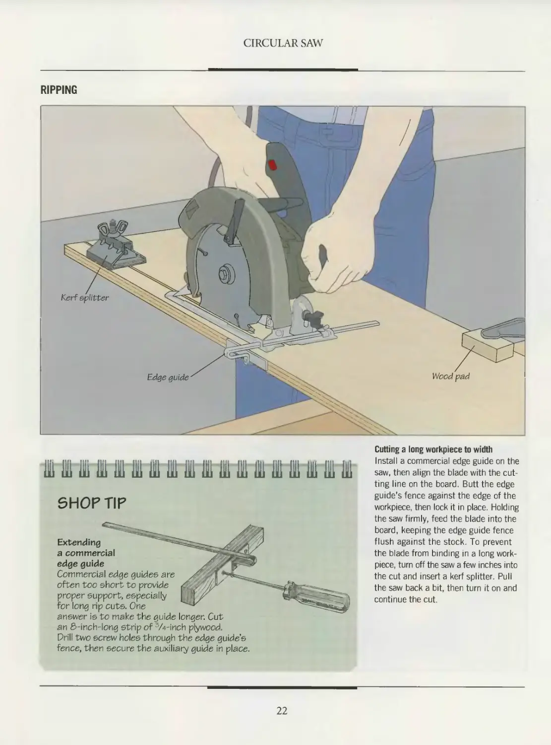
RIPPING
МГНШИЩИШИМО
SHOP TIP
Extending
a commercial
edge guide
Commercial edge guides are
often too short to provide
proper support, especially
for long rip cuts. One
answer is to make the guide longer. Cut
Cutting a long workpiece to width
Install a commercial edge guide on the
saw, then align the blade with the cut-
ting line on the board. Butt the edge
guide's fence against the edge of the
workpiece, then lock it in place. Holding
the saw firmly, feed the blade into the
board, keeping the edge guide fence
flush against the stock. To prevent
the blade from binding in a long work-
piece, turn off the saw a few inches into
the cut and insert a kerf splitter. Pull
the saw back a bit, then turn it on and
continue the cut.
an S-inch-long strip of W-inch plywood.
Drill two screw holes through the edge guide’s
fence, then secure the auxiliary guide in place.
22
CIRCULAR SAW
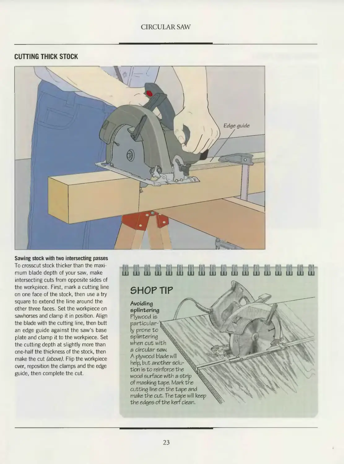
CUTTING THICK STOCK
Sawing stock with two intersecting passes
To crosscut stock thicker than the maxi-
mum blade depth of your saw, make
intersecting cuts from opposite sides of
the workpiece. First, mark a cutting line
on one face of the stock, then use a try
square to extend the line around the
other three faces. Set the workpiece on
sawhorses and clamp it in position. Align
the blade with the cutting line, then butt
an edge guide against the saw's base
plate and clamp it to the workpiece. Set
the cutting depth at slightly more than
one-half the thickness of the stock, then
make the cut (above). Flip the workpiece
over, reposition the clamps and the edge
guide, then complete the cut.
Avoiding
splintering
F”ywood is
SHOP TIP
ly prone to
splintering
when cut with
я circular saw.
A plywood blade will
he.p, but another solu-
tion is to reinforce tFie
wood surface with a strip
of masking tape. Mark the
cutting line on the tape and
make the cut. The tape will keep
the edges of the kerf clean.
23
CIRCULAR SAW
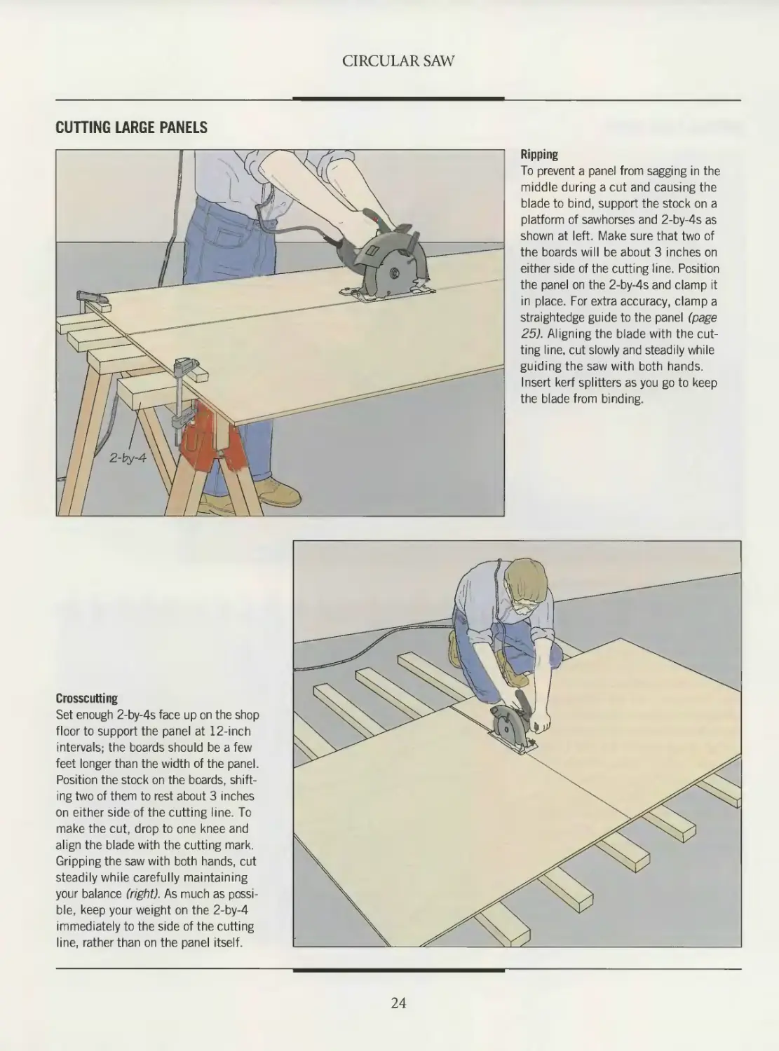
CUTTING LARGE PANELS
Ripping
To prevent a panel from sagging in the
middle during a cut and causing the
blade to bind, support the stock on a
platform of sawhorses and 2-by-4s as
shown at left. Make sure that two of
the boards will be about 3 inches on
either side of the cutting line. Position
the panel on the 2-by-4s and clamp it
in place. For extra accuracy, clamp a
straightedge guide to the panel (page
25). Aligning the blade with the cut-
ting line, cut slowly and steadily while
guiding the saw with both hands.
Insert kerf splitters as you go to keep
the blade from binding.
Crosscutting
Set enough 2-by-4s face up on the shop
floor to support the panel at 12-inch
intervals; the boards should be a few
feet longer than the width of the panel.
Position the stock on the boards, shift-
ing two of them to rest about 3 inches
on either side of the cutting line. To
make the cut, drop to one knee and
align the blade with the cutting mark.
Gripping the saw with both hands, cut
steadily while carefully maintaining
your balance (right). As much as possi-
ble, keep your weight on the 2-by-4
immediately to the side of the cutting
line, rather than on the panel itself.
24
CIRCULAR SAW
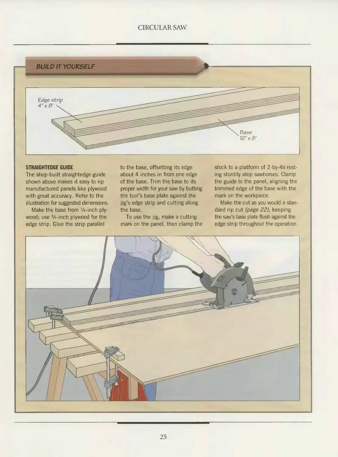
SUILP IT YOURSELF
STRAIGHTEDGE GUIDE
The shop-built straightedge guide
shown above makes it easy to rip
manufactured panels like plywood
with great accuracy. Refer to the
illustration for suggested dimensions.
Make the base from 74-inch ply-
wood; use Winch plywood for the
edge strip. Glue the strip parallel
to the base, offsetting its edge
about 4 inches in from one edge
of the base. Trim the base to its
proper width for your saw by butting
the tool’s base plate against the
jig’s edge strip and cutting along
the base.
To use the jig, make a cutting
mark on the panel, then clamp the
stock to a platform of 2-by-4s rest-
ing sturdily atop sawhorses. Clamp
the guide to the panel, aligning the
trimmed edge of the base with the
mark on the workpiece.
Make the cut as you would a stan-
dard rip cut (page 22), keeping
the saw's base plate flush against the
edge strip throughout the operation.
25
CIRCULAR SAW
Ш Ш III 1111Ш111111111 III Ш Ш Illi Ш ill! 1111 Illi 1Ш
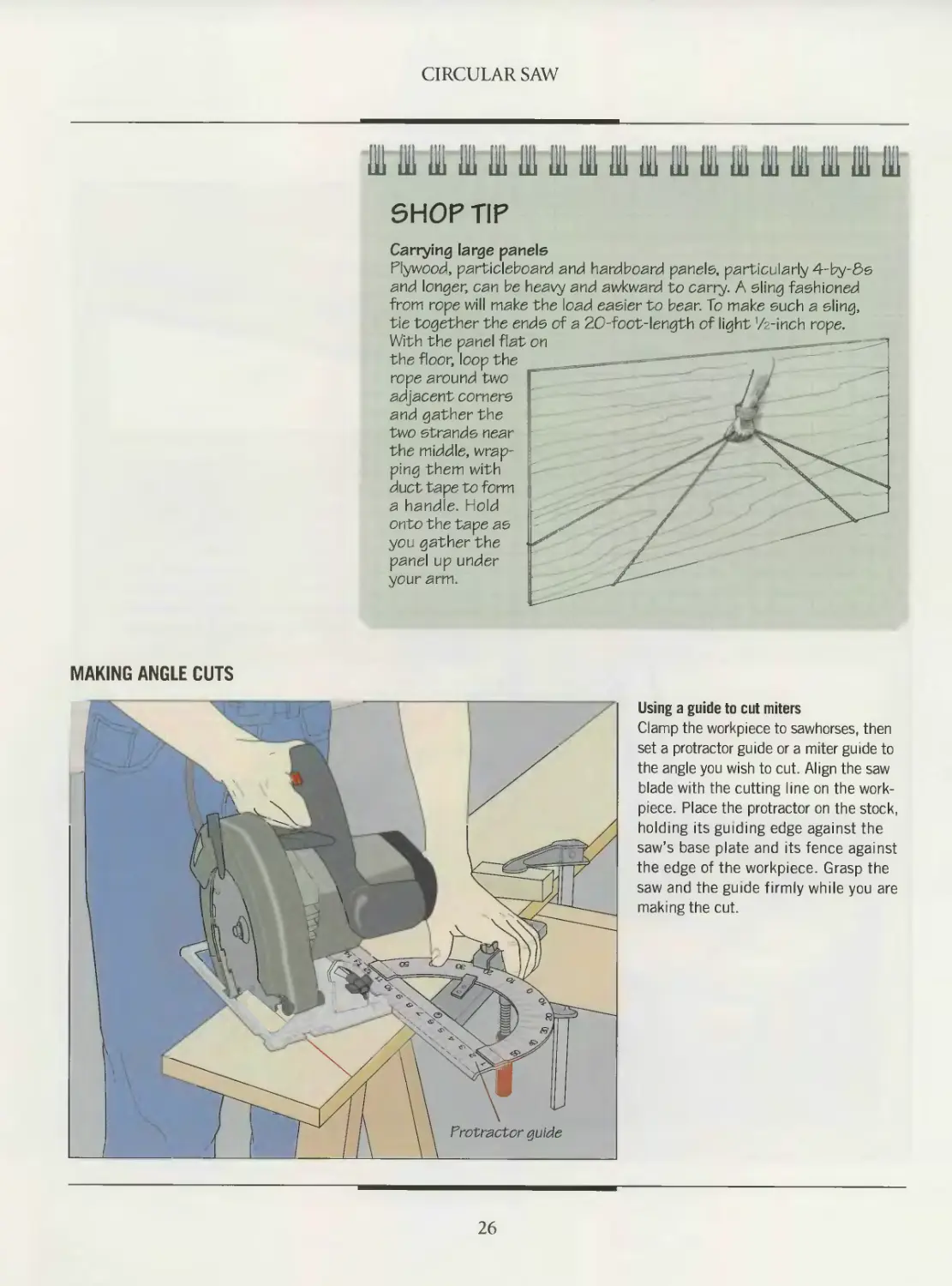
SHOP TIP
Carrying large panels
Plywood, particleboard and hardboard panels, particularly 4-by-Ss
and longer, can be heavy and awkward to carry. A sling fashioned
from rope will make the load easier to bear. To make such a sling,
tie together the ends of a 20-foot-length of light 1/z-inch rope.
With the panel flat on
the floor, loop the
rope around two
adjacent corner5
and gather the
two strands near
the middle, wrap-
ping them with
duct tape to form
a handle. Hold
onto the tape as
you gather the
panel up under
your arm.
MAKING ANGLE CUTS
Using a guide to cut miters
Clamp the workpiece to sawhorses, then
set a protractor guide or a miter guide to
the angle you wish to cut. Align the saw
blade with the cutting line on the work-
piece. Place the protractor on the stock,
holding its guiding edge against the
saw’s base plate and its fence against
the edge of the workpiece. Grasp the
saw and the guide firmly while you are
making the cut.
26
CIRCULAR SAW
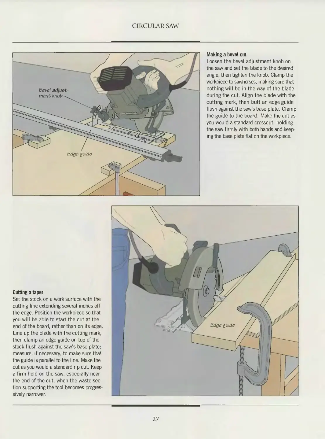
Making a bevel cut
Loosen the bevel adjustment knob on
the saw and set the blade to the desired
angle, then tighten the knob. Clamp the
workpiece to sawhorses, making sure that
nothing will be in the way of the blade
during the cut. Align the blade with the
cutting mark, then butt an edge guide
flush against the saw’s base plate. Clamp
the guide to the board. Make the cut as
you would a standard crosscut, holding
the saw firmly with both hands and keep-
ing the base plate flat on the workpiece.
Cutting a taper
Set the stock on a work surface with the
cutting line extending several inches off
the edge. Position the workpiece so that
you will be able to start the cut at the
end of the board, rather than on its edge.
Line up the blade with the cutting mark,
then clamp an edge guide on top of the
stock flush against the saw’s base plate;
measure, if necessary, to make sure tha*
the guide is parallel to the line. Make the
cut as you would a standard rip cut. Keep
a firm hold on the saw, especially near
the end of the cut, when the waste sec-
tion supporting the tool becomes progres-
sively narrower.
27
CIRCULAR SAW
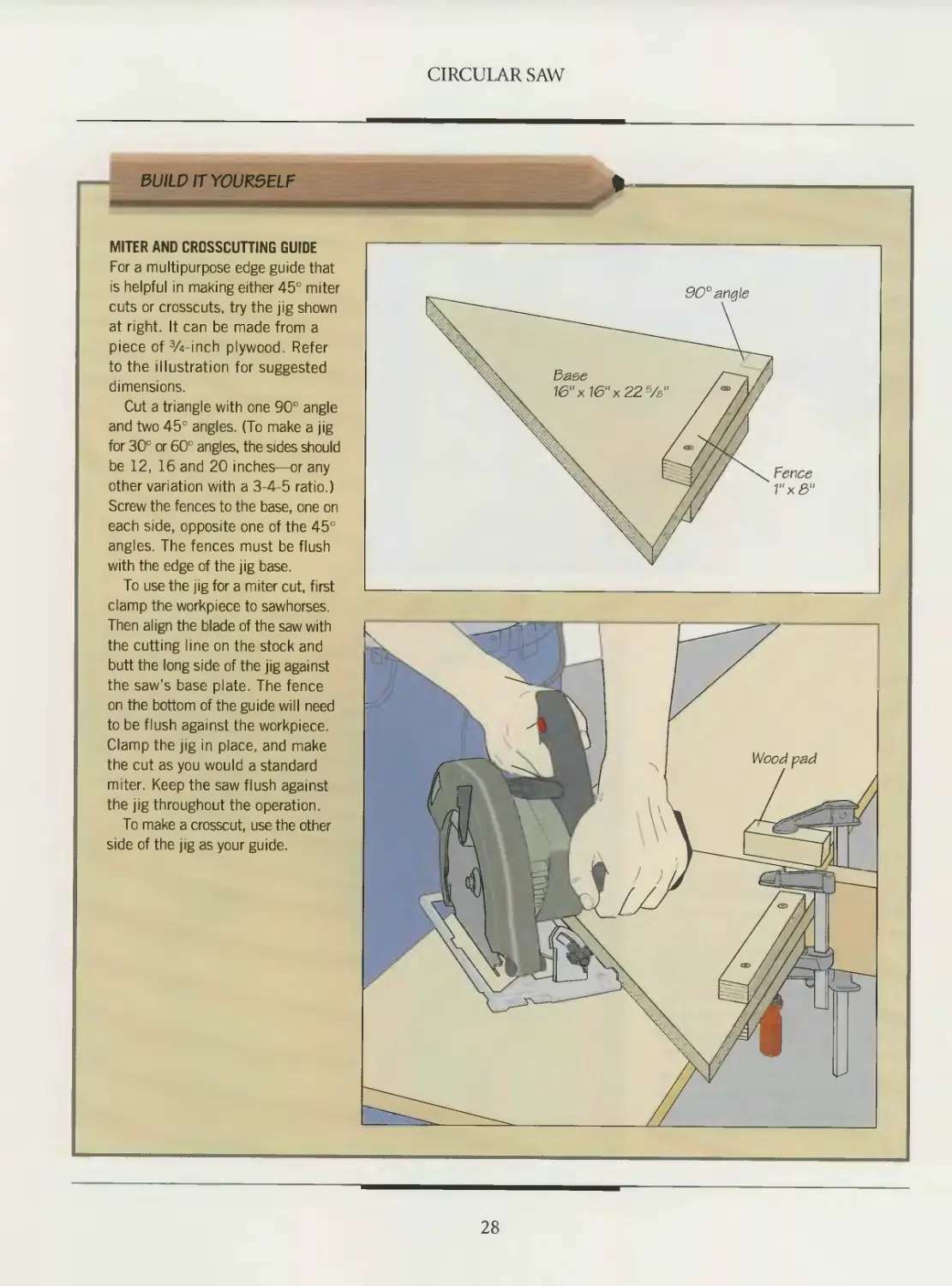
BUILD IT YOURSELF
MITER AND CROSSCUTTING GUIDE
For a multipurpose edge guide that
is helpful in making either 45° miter
cuts or crosscuts, try the jig shown
at right. It can be made from a
piece of Winch plywood. Refer
to the illustration for suggested
dimensions.
Cut a triangle with one 90° angle
and two 45° angles. (To make a jig
for 30c or 60° angles, the sides should
be 12, 16 and 20 inches—or any
other variation with a 3 4 5 ratio.)
Screw the fences to the base, one on
each side, opposite one of the 45°
angles. The fences must be flush
with the edge of the jig base.
To use the jig for a miter cut, first
clamp the workpiece to sawhorses.
Then align the blade of the saw with
the cutting line on the stock and
butt the long side of the jig against
the saw’s base plate. The fence
on the bottom of the guide will need
to be flush against the workpiece.
Clamp the jig in place, and make
the cut as you would a standard
miter. Keep the saw flush against
the jig throughout the operation.
To make a crosscut, use the other
side of the jig as your guide.
28
ADVANCED CUTS
A little ingenuity—along with the
appropriate jigs and setups—can
greatly expand the versatility of a cir-
cular saw. Although the tool is not a
substitute for a table saw or radial arm
saw, it can do much more than simple
dimensioning of stock.
When it is inconvenient to use a larg-
er stationary saw, you can call on your
portable tool to cut some of the joints
for cabinetmaking projects, for instance.
Dadoes, rabbets and miters can be
formed with precision approaching that
of a stationary saw. For cleaner results
and less tearout, use a fine-tooth blade
when performing such tasks.
Although the circular saw may not
always cut wood as quickly as the table
saw or radial arm saw, the tool’s porta-
bility allows it to work in places that are
off limits to the stationary machines.
The saw can plunge into the middle
of a panel, for example, cutting a rec-
tangular hole out of it while leaving the
edges intact (page 30). You can also
saw arcs or circles by making a series of
tangent cuts.
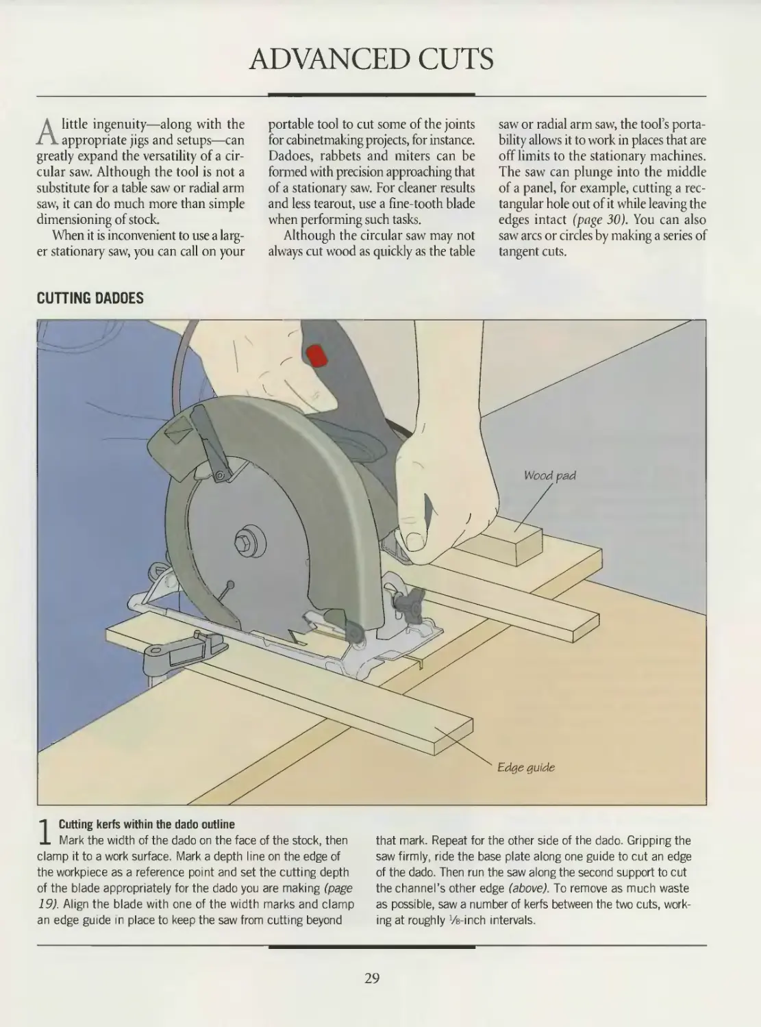
CUTTING DADOES
1 Cutting kerfs within the dado outline
Mark the width of the dado on the face of the stock, then
clamp it to a work surface. Mark a depth line on the edge of
the workpiece as a reference point and set the cutting depth
of the blade appropriately for the dado you are making (page
19). Align the blade with one of the width marks and clamp
an edge guide in place to keep the saw from cutting beyond
that mark. Repeat for the other side of the dado. Gripping the
saw firmly, ride the base plate along one guide to cut an edge
of the dado. Then run the saw along the second support to cut
the channel’s other edge (above). To remove as much waste
as possible, saw a number of kerfs between the two cuts, work-
ing at roughly Ve-inch intervals.
29
CIRCULAR SAW
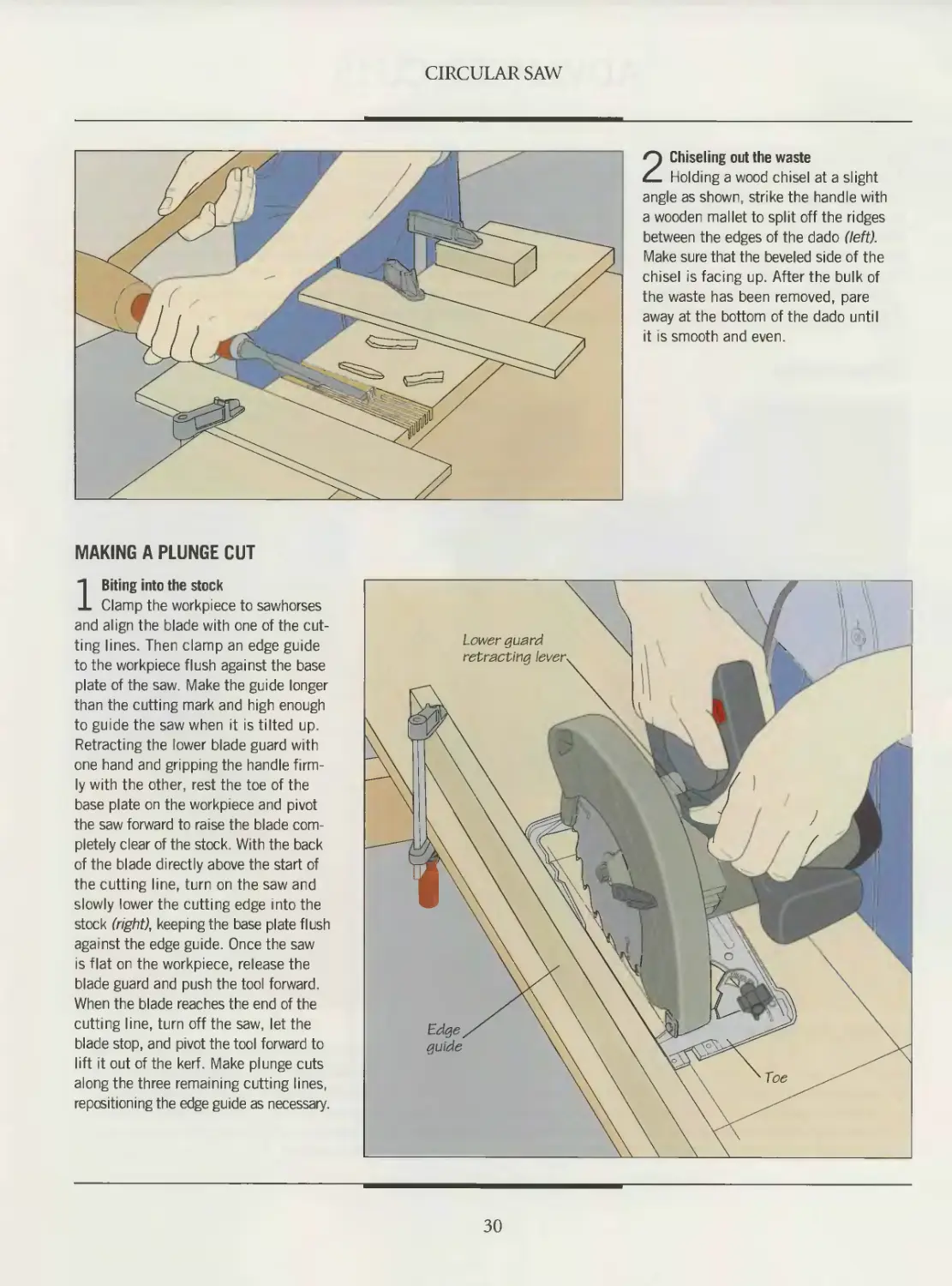
2 Chiseling out the waste
Holding a wood chisel at a slight
angle as shown, strike the handle with
a wooden mallet to split off the ridges
between the edges of the dado (left).
Make sure that the beveled side of the
chisel is facing up. After the bulk of
the waste has been removed, pare
away at the bottom of the dado until
it is smooth and even.
MAKING A PLUNGE CUT
1 Biting into the stock
Clamp the workpiece to sawhorses
and align the blade with one of the cut-
ting lines. Then clamp an edge guide
to the workpiece flush against the base
plate of the saw. Make the guide longer
than the cutting mark and high enough
to guide the saw when it is tilted up.
Retracting the lower blade guard with
one hand and gripping the handle firm-
ly with the other, rest the toe of the
base plate on the workpiece and pivot
the saw forward to raise the blade com-
pletely clear of the stock. With the back
of the blade directly above the start of
the cutting line, turn on the saw and
slowly lower the cutting edge into the
stock (right), keeping the base plate flush
against the edge guide. Once the saw
is flat on the workpiece, release the
blade guard and push the tool forward.
When the blade reaches the end of the
cutting line, turn off the saw, let the
blade stop, and pivot the tool forward to
lift it out of the kerf. Make plunge cuts
along the three remaining cutting lines,
repositioning the edge guide as necessary.
30
CIRCULAR SAW
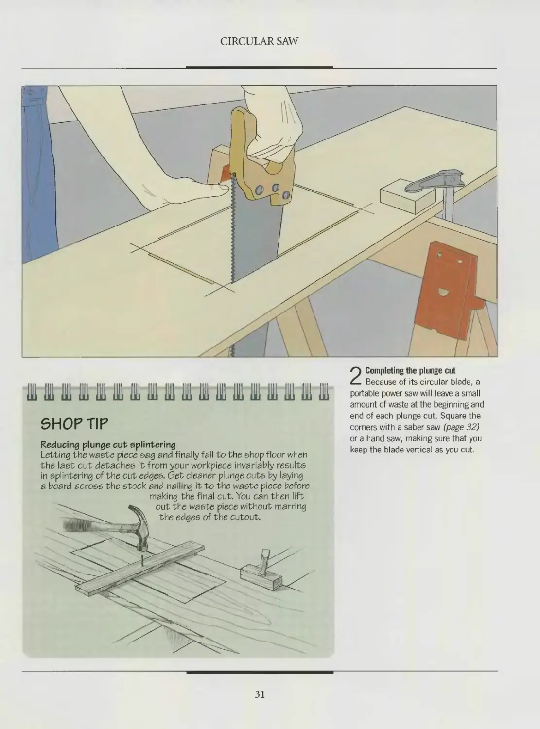
SHOP TIP
Reducing plunge cut splintering
Letting the waste piece sag and finally fall to the shop floor when
the last cut detaches it from your workpiece invariably results
in splintering of the cut edges. Get cleaner plunge cuts by laying
a board across the stock and nailing it to the waste piece before
making the final cut. You can then lift
2 Completing the plunge cut
Because of its circular blade, a
portable power saw will leave a small
amount of waste at the beginning and
end of each plunge cut. Square the
corners with a saber saw (page 32)
or a hand saw, making sure that you
keep the blade vertical as you cut.
31
SABER SAW
The saber saw is often likened to its
larger shop cousin, the band saw.
Although few woodworkers would con-
sider using the portable tool to resaw a
hardwood plank or carve out a cabriole
leg, the comparison is apt in other ways.
With its relatively narrow blade, the saber
saw makes straight and curved cuts with
equal ease and accuracy. Aided by com-
mercial or shop-made jigs, it can carve
out a perfect circle. And like the band
saw, the saber saw can be set up to cut
identical copies of a curved pattern.
In certain situations, a portable saw
may even be a better choice than its sta-
tionary counterpart. If you are working
with a long board or wide panel that
might require a time-consuming setup
on a saw table, it is sometimes simpler to
carry the saber saw to the work for a
quick cut. Because one end of the blade
is free, the cutting edge can be plunged into a workpiece for
interior cuts on which a band saw would have to begin at the
edge of the stock (page 44).
The saber saw has come a long way since its introduction.
Woodworkers complained that the first generation of saws
were plagued by inconsistent motor speeds and blades that
tended to bend, making it difficult to follow a cutting line. The
newest models feature electronic motors
that can maintain a constant speed under
changing load conditions. And blade
manufacturers offer a wide variety of
sturdy blades suitable for any situation.
Making precise, splinter-free cuts
requires attention to several factors. A
key variable is choosing the best blade for
the job at hand (page 36). For straight and
angled cuts, an edge guide will be of great
assistance in keeping the blade in line.
Since the saber saw blade cuts on the
upstroke, there is a tendency for splin-
tering to occur on the top face of a work-
piece. One way to counteract this problem
is to slow the rate at which you make the
cut. And remember to buff the bottom
of your saw’s base plate occasionally with
steel wool to remove dirt, grime and
burrs that could scratch the workpiece.
There is no prescribed way to grip a
saber saw. The manner in which you handle the tool will
depend on the design of your particular model. Many cuts can
be performed with one hand on the handle squeezing the trig-
ger, while the other hand is set on the workpiece safely away
from the blade. Other woodworkers prefer to keep both hands
on the saw: one on the handle and the other wrapped around
the front of the body or barrel of the tool.
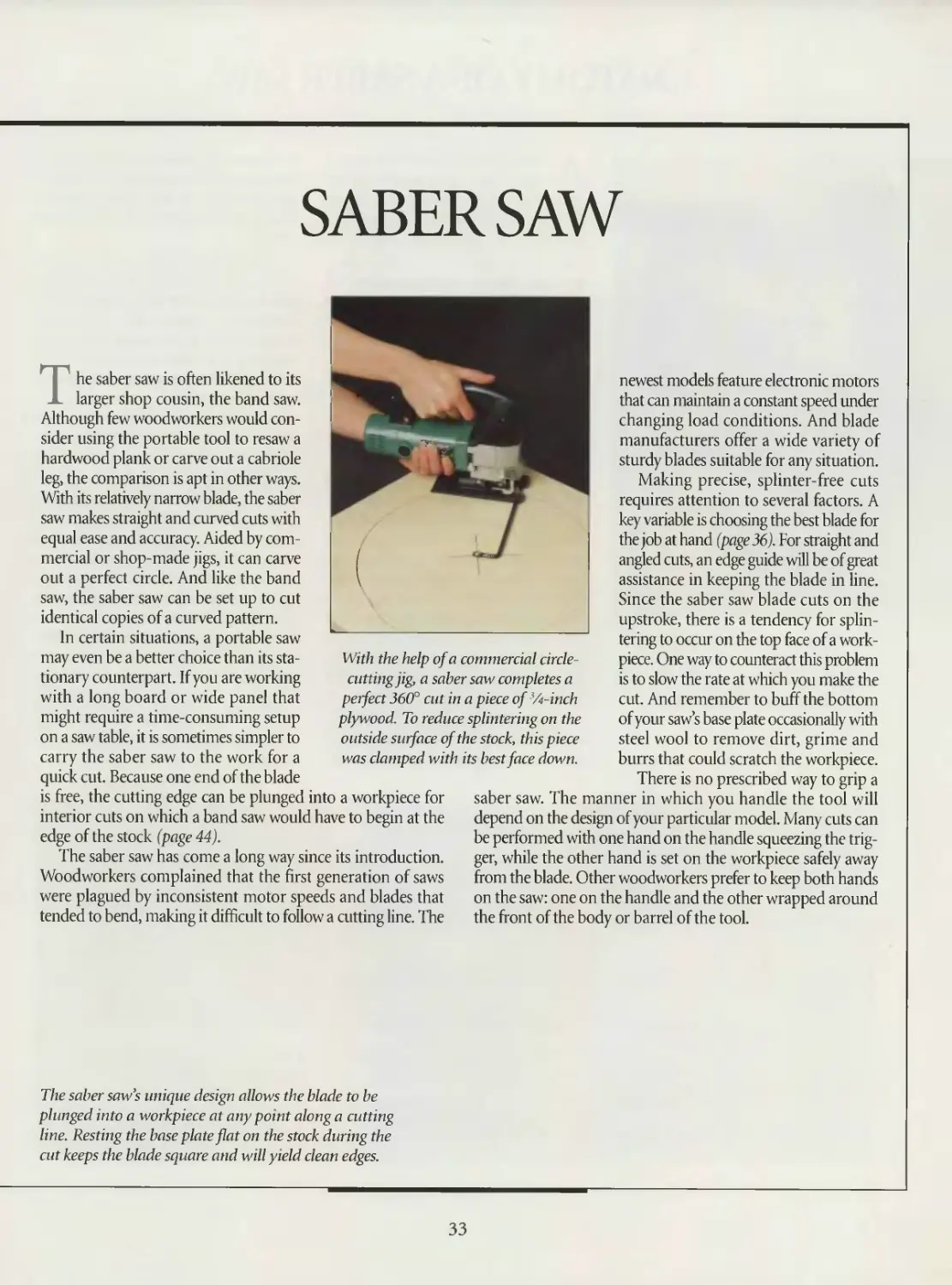
With the help of a commercial circle-
cutting jig, a saber saw completes a
perfect 360° cut in a piece of '/t-inch
plywood. To reduce splintering on the
outside sutface of the stock, this piece
was clamped with its best face down.
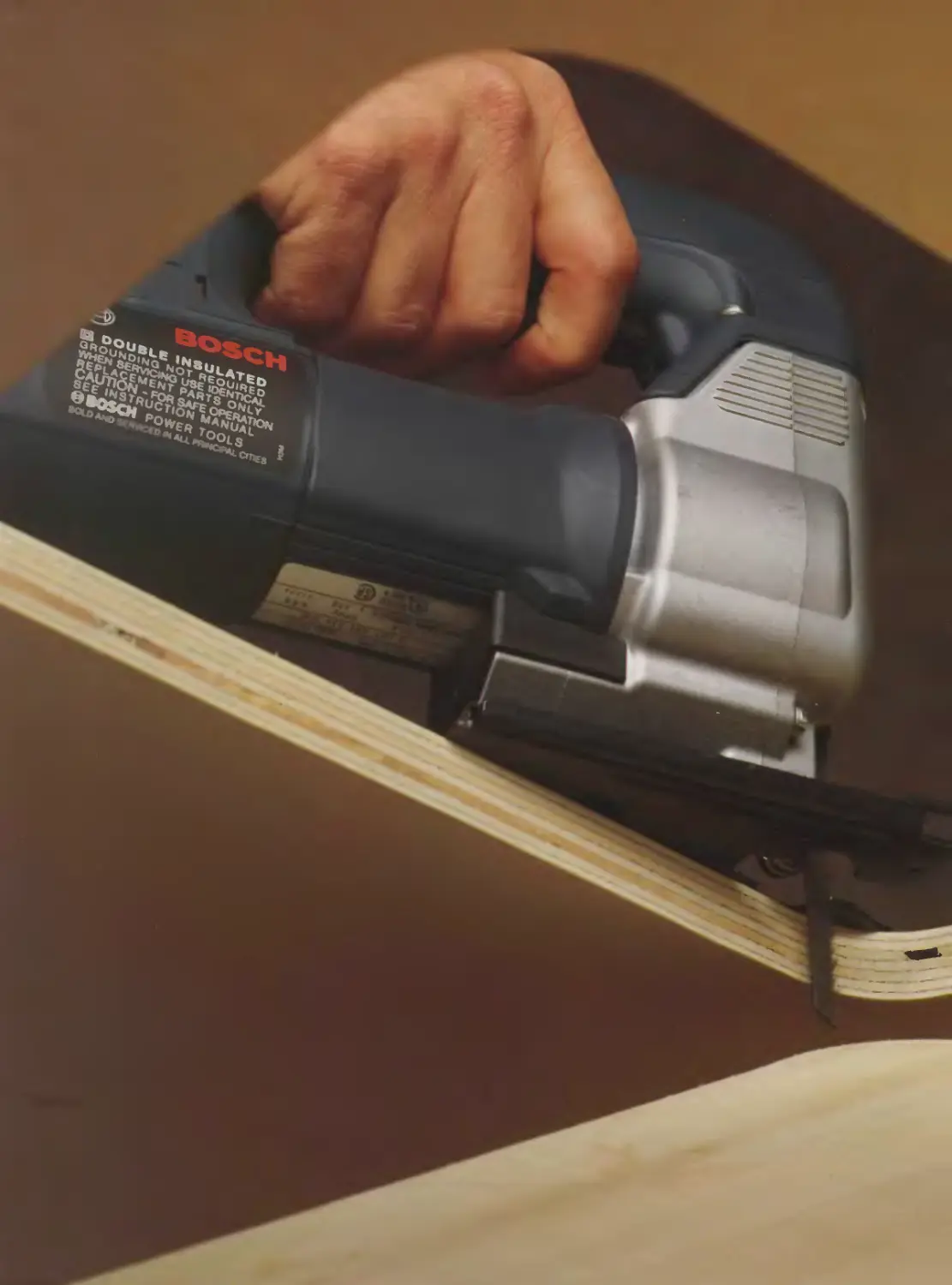
The saber saw’s unique design allows the blade to be
plunged into a workpiece at any point along a cutting
line. Resting the base plate flat on the stock during the
cut keeps the blade square and will yield clean edges.
33
ANATOMY OF A SABER SAW
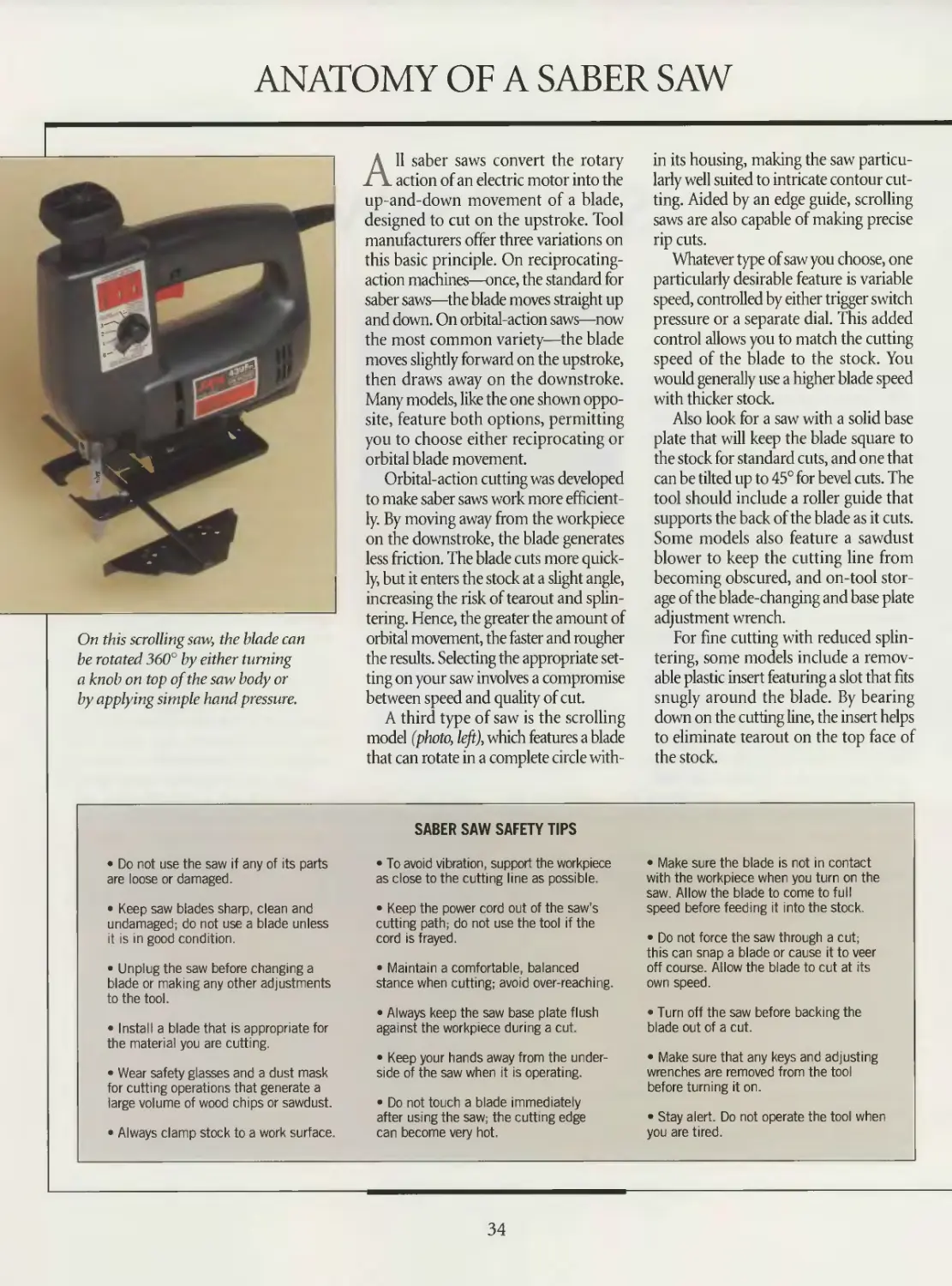
On this scrolling saw, the blade can
be rotated 360° by either turning
a knob on top of the saw body or
by applying simple hand pressure.
All saber saws convert the rotary
action of an electric motor into the
up-and-down movement of a blade,
designed to cut on the upstroke. Tool
manufacturers offer three variations on
this basic principle. On reciprocating-
action machines—once, the standard for
saber saws—the blade moves straight up
and down. On orbital-action saws—now
the most common variety—the blade
moves slightly forward on the upstroke,
then draws away on the downstroke.
Many models, like the one shown oppo-
site, feature both options, permitting
you to choose either reciprocating or
orbital blade movement.
Orbital-action cutting was developed
to make saber saws work more efficient-
ly. By moving away from the workpiece
on the downstroke, the blade generates
less friction. The blade cuts more quick-
ly, but it enters the stock at a slight angle,
increasing the risk of tearout and splin-
tering. Hence, the greater the amount of
orbital movement, the faster and rougher
the results. Selecting the appropriate set-
ting on your saw involves a compromise
between speed and quality of cut.
A third type of saw is the scrolling
model (photo, left), which features a blade
that can rotate in a complete circle with-
in its housing, making the saw particu-
larly well suited to intricate contour cut-
ting. Aided by an edge guide, scrolling
saws are also capable of making precise
rip cuts.
Whatever type of saw you choose, one
particularly desirable feature is variable
speed, controlled by either trigger switch
pressure or a separate dial. This added
control allows you to match the cutting
speed of the blade to the stock. You
would generally use a higher blade speed
with thicker stock.
Also look for a saw with a solid base
plate that will keep the blade square to
the stock for standard cuts, and one that
can be tilted up to 45° for bevel cuts. The
tool should include a roller guide that
supports the back of the blade as it cuts.
Some models also feature a sawdust
blower to keep the cutting line from
becoming obscured, and on-tool stor-
age of the blade-changing and base plate
adjustment wrench.
For fine cutting with reduced splin-
tering, some models include a remov-
able plastic insert featuring a slot that fits
snugly around the blade. By bearing
down on the cutting line, the insert helps
to eliminate tearout on the top face of
the stock.
• Do not use the saw if any of its parts
are loose or damaged.
• Keep saw blades sharp, clean and
undamaged; do not use a blade unless
it is in good condition.
• Unplug the saw before changing a
blade or making any other adjustments
to the tool.
• Install a blade that is appropriate for
the material you are cutting.
• Wear safety glasses and a dust mask
for cutting operations that generate a
large volume of wood chips or sawdust.
• Always clamp stock to a work surface.
SABER SAW SAFETY TIPS
• To avoid vibration, support the workpiece
as close to the cutting line as possible.
• Keep the power cord out of the saw's
cutting path; do not use the tool if the
cord is frayed.
• Maintain a comfortable, balanced
stance when cutting; avoid over-reaching.
• Always keep the saw base plate flush
against the workpiece during a cut.
• Keep your hands away from the under-
side of the saw when it is operating.
• Do not touch a blade immediately
after using the saw; the cuttmg edge
can become very hot.
• Make sure the blade is not in contact
with the workpiece when you turn on the
saw. Allow the blade to come to full
speed before feeding it into the stock.
• Do not force the saw through a cut;
this can snap a blade or cause it to veer
off course. Allow the blade to cut at its
own speed.
• Turn off the saw before backing the
blade out of a cut.
• Make sure that any keys and adjusting
wrenches are removed from the tool
before turning it on.
• Stay alert. Do not operate the tool when
you are tired.
34
SABER SAW
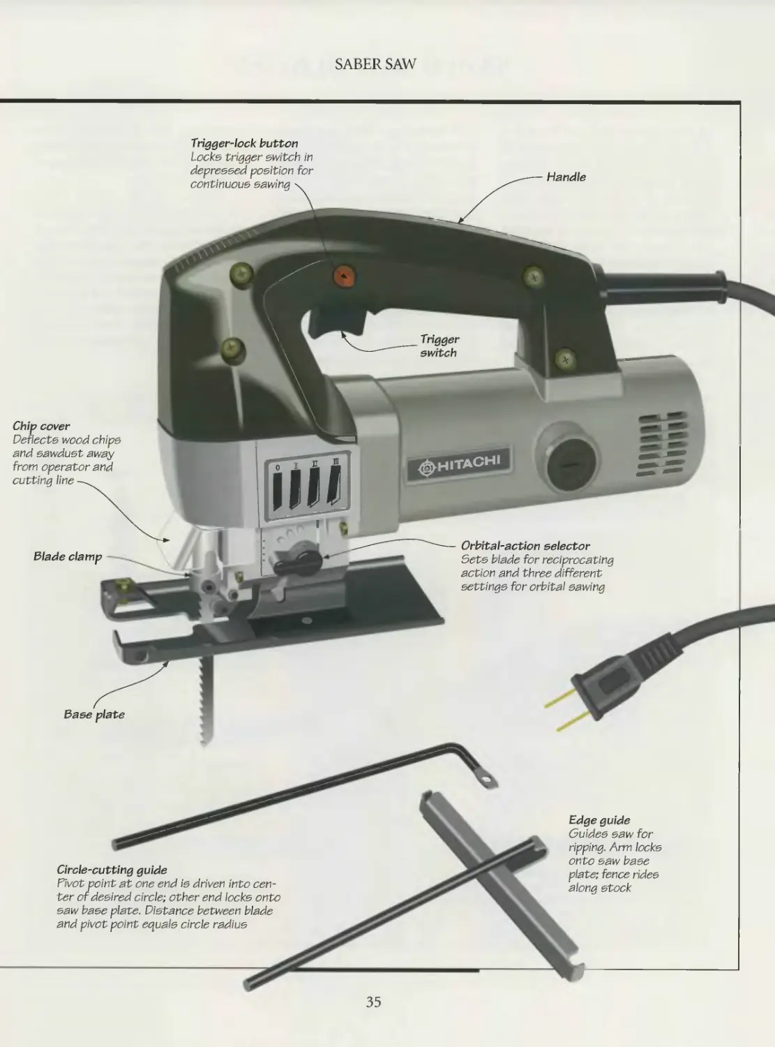
Chip cover
Deflects wood chips
and sawdust away
from operator and
cutting line —
Blade clamp
Circle-cutting guide
Divot point at one end is driven into cen-
ter of desired circle; other end locks onto
saw base plate. Distance between blade
and pivot point equals circle radius
Handle
Trigger-lock button
Locks trigger switch in
depressed position for
continuous sawing
Orbital-action selector
Sets blade for reciprocating
action and three different
settings for orbital sawing
Base plate
Edge guide
Guides saw for
ripping. Arm locks
onto saw base
plate; fence rides
along stock
35
SABER SAW BLADES
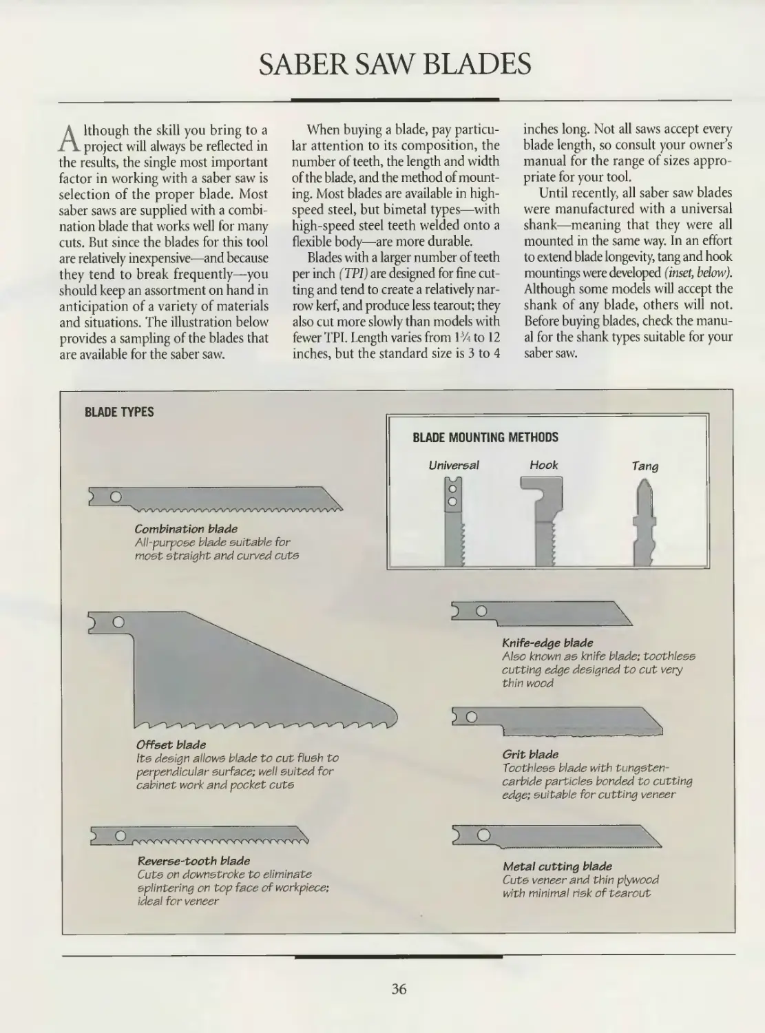
Although the skill you bring to a
project will always be reflected in
the results, the single most important
factor in working with a saber saw is
selection of the proper blade. Most
saber saws are supplied with a combi-
nation blade that works well for many
cuts. But since the blades for this tool
are relatively inexpensive—and because
they tend to break frequently—you
should keep an assortment on hand in
anticipation of a variety of materials
and situations. The illustration below
provides a sampling of the blades that
are available for the saber saw.
When buying a blade, pay particu-
lar attention to its composition, the
number of teeth, the length and width
of the blade, and the method of mount-
ing. Most blades are available in high-
speed steel, but bimetal types—with
high-speed steel teeth welded onto a
flexible body—are more durable.
Blades with a larger number of teeth
per inch (TP1) are designed for fine cut-
ting and tend to create a relatively nar-
row kerf, and produce less tearout; they
also cut more slowly than models with
fewer TPI. Length varies from 1% to 12
inches, but the standard size is 3 to 4
inches long. Not all saws accept every
blade length, so consult your owner’s
manual for the range of sizes appro-
priate for your tool.
Until recently, all saber saw blades
were manufactured with a universal
shank—meaning that they were all
mounted in the same way. In an effort
to extend blade longevity, tang and hook
mountings were developed (inset, below).
Although some models will accept the
shank of any blade, others will not.
Before buying blades, check the manu-
al for the shank types suitable for your
saber saw.
BLADE TYPES
Combination blade
All-purpose blade suitable for
most straight and curved cuts
Offset blade
Its design allows blade to cut flush to
perpendicular surface; well suited for
cabinet work and pocket cuts
Knife-edge blade
Also known as knife blade; toothless
cutting edge designed to cut very
thin wood
Grit blade
Toothless blade with tungsten-
carbide particles bonded to cutting
edge; suitable for cutting veneer
Reverse-tooth blade
Cuts on downstroke to eliminate
splintering on top face of workpiece;
ideal for veneer
Metal cutting blade
Cuts veneer and thin plywood
with minimal risk of tearout
36
SABER SAW
CHANGING A BLADE
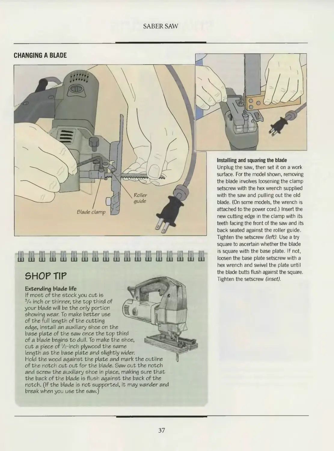
Installing and squaring the blade
Unplug the saw, then set it on a work
surface. For the model shown, removing
the blade involves loosening the clamp
setscrew with the hex wrench supplied
with the saw and pulling out the old
blade. (On some models, the wrench is
attached to the power cord.) Insert the
new cutting edge in the clamp with its
teeth facing the front of the saw and its
back seated against the roller guide.
Tighten the setscrew (left). Use a try
square to ascertain whether the blade
111 III 111 Hi HI III 111 III Hl 31 III ill 111 III 111 111 Hi Hl
SHOP TIP
is square with the base plate. If not,
loosen the base plate setscrew with a
hex wrench and swivel the plate until
the blade butts flush against the square.
Tighten the setscrew (inset).
Extending blade life
If most of the stock you cut is
3A inch or thinner, the top third of
your blade will be the only portion
showing wear. To make better use
of the full length of the cutting
edge, install an auxiliary shoe on the
base plate of the saw once the top third
of a blade begins to dull. To make the shoe,
cut a piece of ’/z-inch plywood the same
length as the base plate and slightly wider.
Hold the wood against the plate and mark the outline
of the notch cut out for the blade. Saw out the notch
and screw the auxiliary shoe in place, making sure that
the back of the blade is flush against the back of the
notch. (If the blade is not supported, it may wander and
break when you use the saw.)
37
STRAIGHT CUTS
With a firm hand, a slow, steady
feed rate, and a straight cutting line
on your workpiece, you can make an
accurate crosscut and rips using a saber
saw freehand. Part of the attraction of
this tool, after all, is that it cuts quickly
and with a minimum of setup time.
For added precision, you can make
use of an edge guide with your tool. Most
saw base plates have holes machined in
them to accept the arm of such a guide.
The fence of the device is set for the
appropriate cutting width, then the arm
is fixed in place. However, the length of
most commercial guides is limited, mak-
ing them impractical for virtually any
crosscut and for rip cuts in wide stock.
As shown at right and on page 39, you
can also guide the saw with a straight
edge, such as a board or a try square.
For best results when making straight
cuts, install a wide blade, especially if
you are sawing through thick stock.
Make sure the blade is long enough to
cut through the wood in one pass.
Resist the temptation to hold the
stock with your free hand as you are
cutting. Take the an extra moment to
clamp down the workpiece to a work
surface, avoiding the risk of a spoiled cut
or an accident.
CROSSCUTTING
Using a try square as a guide
Clamp the stock to a work surface, arranging the board so that the cutting line is
beyond the edge of the table. Align the blade with the cutting mark, then butt one
edge of a try square against the saw’s base plate. Make sure that the handle of the
square is flush against the edge of the stock. With the saw blade clear of the stock,
squeeze the trigger. Feed the cutting edge steadily into the workpiece (above).
A piece of masking tape applied along
the cutting line will reduce splintering
while you are ripping or crosscutting.
SHOP TIP
Reducing splintering
To reduce tearout, you can either
saw stock with its good face down,
score the cutting line with a utility
knife or cover the cutting line with
a strip of tape. One other option
to install an anti-tea rout jig on the
underside of the base plate. The jig
is similar to the auxiliary shoe shown
on page 37, but the notch for the blade
is only as wide as the kerf of the blade you
are using. The pressure the jig exerts on the
stock will keep splintering to a minimum.
38
SABER SAW
RIPPING
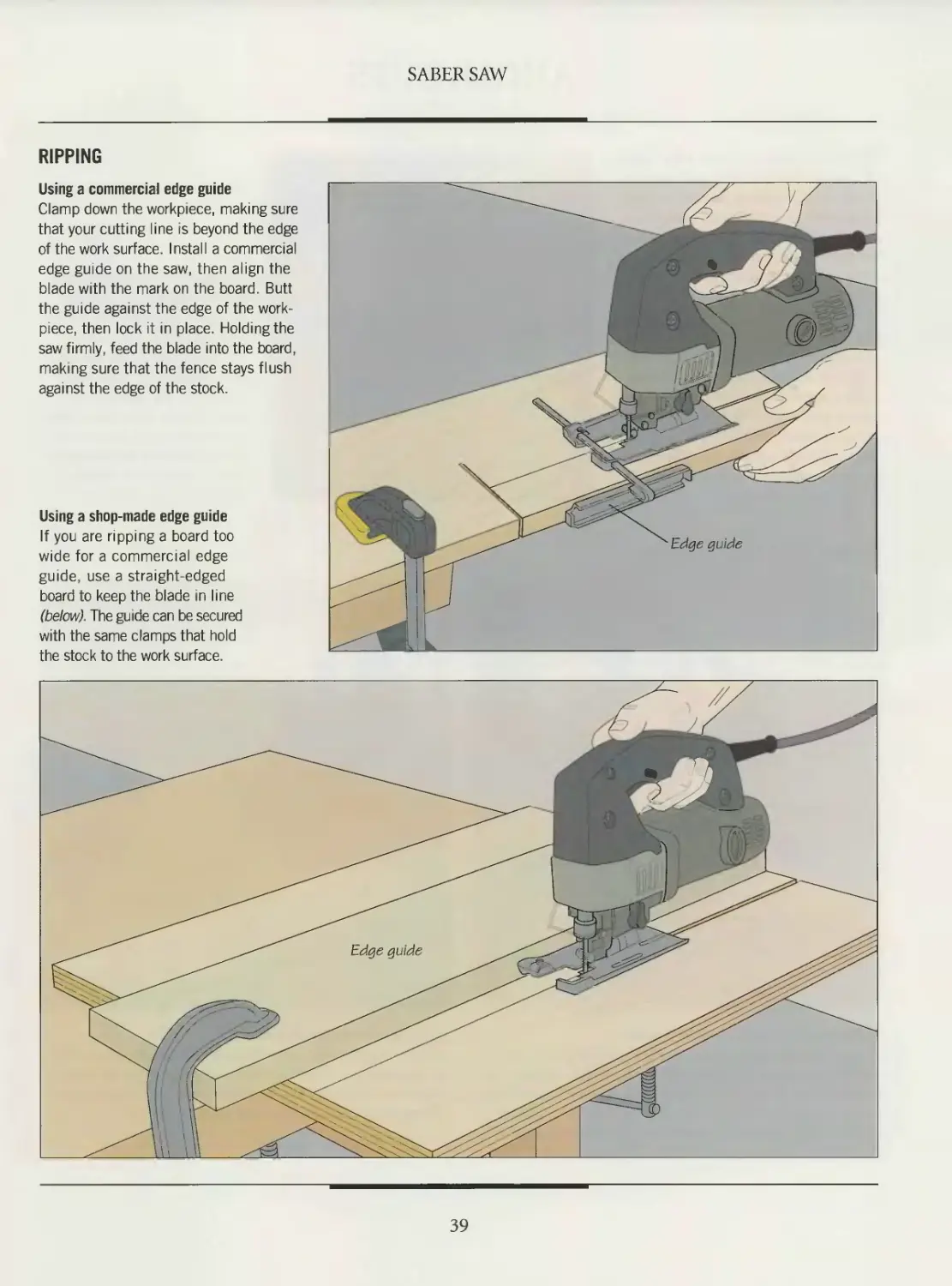
Using a commercial edge guide
Clamp down the workpiece, making sure
that your cutting line is beyond the edge
of the work surface. Install a commercial
edge guide on the saw, then align the
blade with the mark on the board. Butt
the guide against the edge of the work-
piece, then lock it in place. Holding the
saw firmly, feed the blade into the board,
making sure that the fence stays flush
against the edge of the stock.
Using a shop-made edge guide
If you are ripping a board too
wide for a commercial edge
guide, use a straight-edged
board to keep the blade in line
(below). The guide can be secured
with the same clamps that hold
the stock to the work surface.
39
ANGLE CUTS
The base plate on most saber saws
can be tilted to either side up to an
angle of 45°, enabling the tool to make
both bevel and compound cuts. Some
models include a gauge that indicates
the bevel angle, but you should always
make a test cut to confirm that the saw
is set for the angle you need.
Because the saw blade will be in con-
tact with more of the wood surface, use
a slower feed rate when making these
angle cuts. For the same reason, it is gen-
erally a good idea to use a wider blade
on the saw; a thin blade will be more
prone to getting twisted. Although any
angle cut can be made freehand, you will
get better results if you take the time to
set up an edge guide.
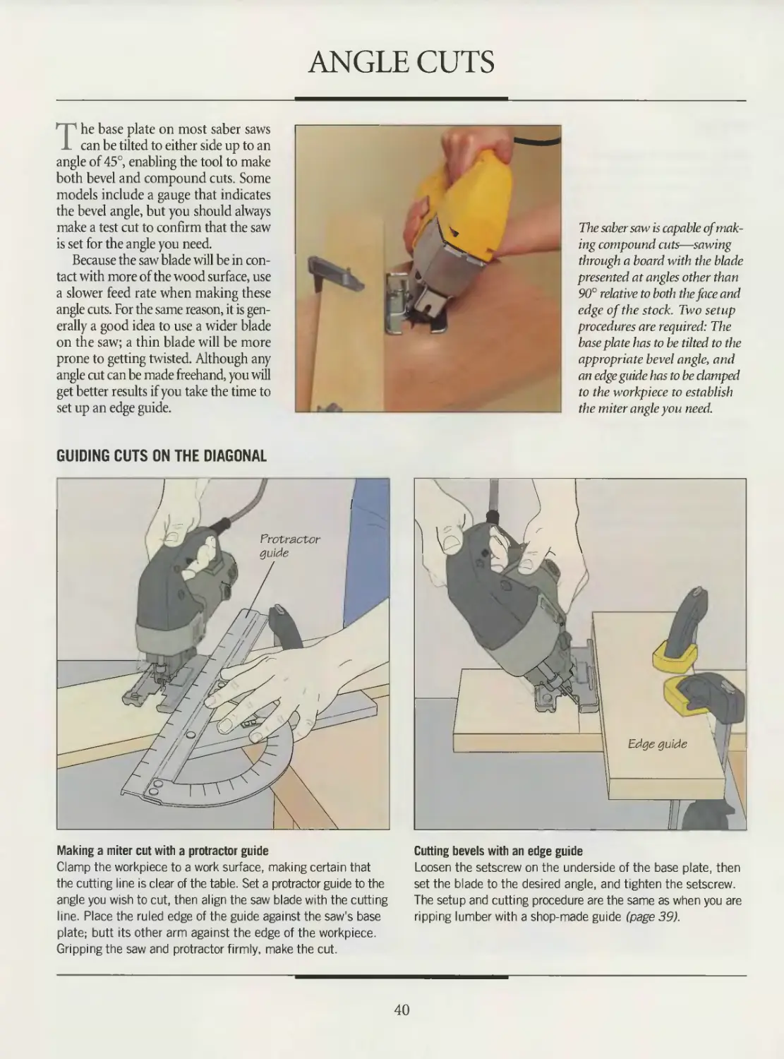
The saber saw is capable of mak-
ing compound cuts—sawing
through a board with the blade
presented at angles other than
90° relative to both the face and
edge of the stock. Two setup
procedures are required: The
baseplate has to be tilted to the
appropriate bevel angle, and
an edge guide has to be clamped
to the workpiece to establish
the miter angle you need.
GUIDING CUTS ON THE DIAGONAL
Making a miter cut with a protractor guide
Clamp the workpiece to a work surface, making certain that
the cutting line is clear of the table. Set a protractor guide to the
angle you wish to cut, then align the saw blade with the cutting
line. Place the ruled edge of the guide against the saw's base
plate; butt its other arm against the edge of the workpiece.
Gripping the saw and protractor firmly, make the cut.
Cutting bevels with an edge guide
Loosen the setscrew on the underside of the base plate, then
set the blade to the desired angle, and tighten the setscrew.
The setup and cutting procedure are the same as when you are
ripping lumber with a shop-made guide (page 39).
40
CURVED CUTS
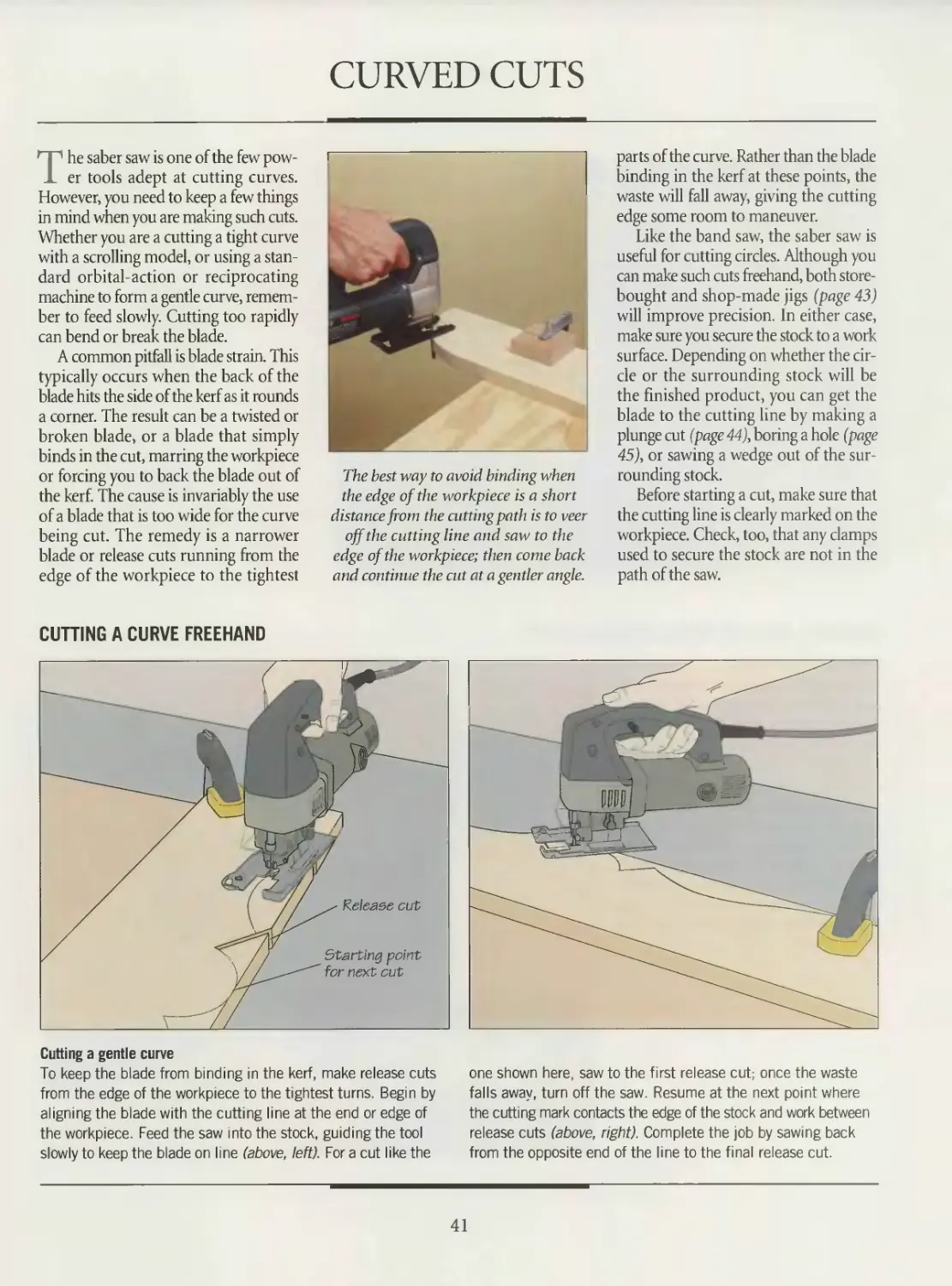
The saber saw is one of the few pow-
er tools adept at cutting curves.
However, you need to keep a few things
in mind when you are making such cuts.
Whether you are a cutting a tight curve
with a scrolling model, or using a stan-
dard orbital-action or reciprocating
machine to form a gentle curve, remem-
ber to feed slowly. Cutting too rapidly
can bend or break the blade.
A common pitfall is blade strain. This
typically occurs when the back of the
blade hits the side of the kerf as it rounds
a corner. The result can be a twisted or
broken blade, or a blade that simply
binds in the cut, marring the workpiece
or forcing you to back the blade out of
the kerf. The cause is invariably the use
of a blade that is too wide for the curve
being cut. The remedy is a narrower
blade or release cuts running from the
edge of the workpiece to the tightest
The best way to avoid binding when
the edge of the workpiece is a short
distance from the cutting path is to veer
off the cutting line and saw to the
edge of the workpiece; then come back
and continue the cut at a gentler angle.
parts of the curve. Rather than the blade
binding in the kerf at these points, the
waste will fall away, giving the cutting
edge some room to maneuver.
Like the band saw, the saber saw is
useful for cutting circles. Although you
can make such cuts freehand, both store-
bought and shop-made jigs (page 43)
will improve precision. In either case,
make sure you secure the stock to a work
surface. Depending on whether the cir-
cle or the surrounding stock will be
the finished product, you can get the
blade to the cutting line by making a
plunge cut (page 44), boring a hole (page
45), or sawing a wedge out of the sur-
rounding stock.
Before starting a cut, make sure that
the cutting line is clearly marked on the
workpiece. Check, too, that any clamps
used to secure the stock are not in the
path of the saw.
CUTTING A CURVE FREEHAND
Cutting a gentle curve
To keep the blade from binding in the kerf, make release cuts
from the edge of the workpiece to the tightest turns. Begin by
aligning the blade with the cutting line at the end or edge of
the workpiece. Feed the saw into the stock, guiding the tool
slowly to keep the blade on line (above, left). For a cut like the
one shown here, saw to the first release cut; once the waste
falls away, turn off the saw. Resume at the next point where
the cutting mark contacts the edge of the stock and work between
release cuts (above, right). Complete the job by sawing back
from the opposite end of the line to the final release cut.
41
SABER SAW
m III Ш
SHOP TIP
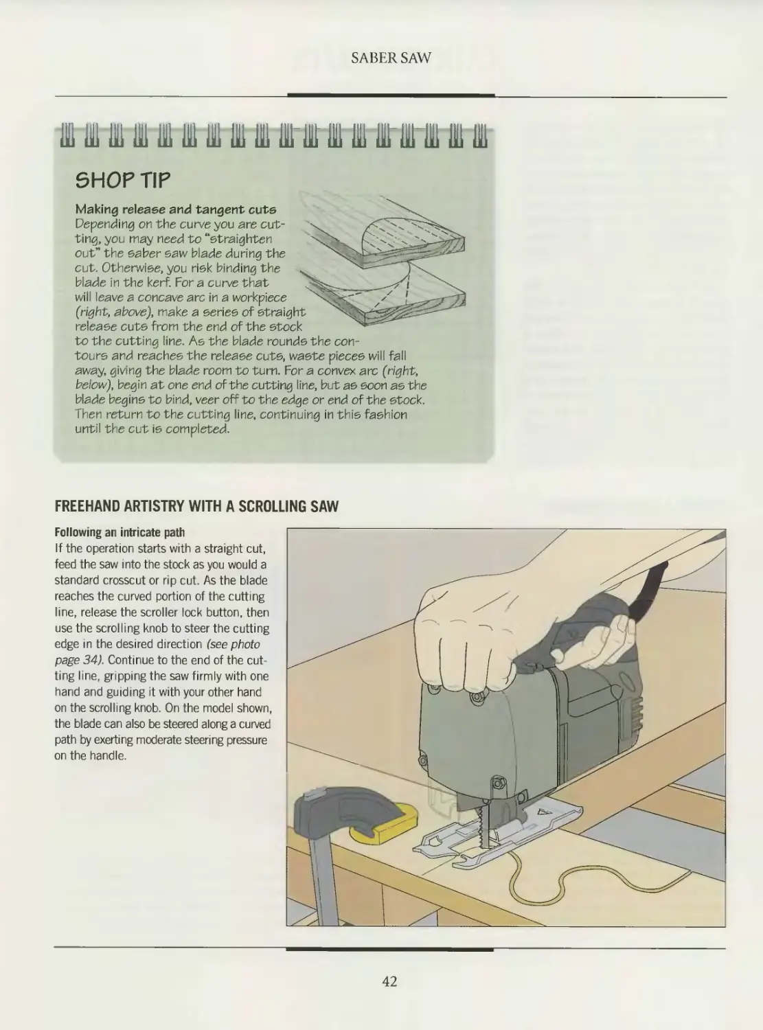
Making release and tangent cuts
Depending on the curve you are cut-
ting, you may need to “straighten
out” the saber saw blade during the
cut. Otherwise, you risk binding the
blade in the kerf. For a curve that
will leave a concave arc in a workpiece
(right, shove), make a series of straight
release cuts from the end of the stock
to the cutting line. As the blade rounds the con-
tours and reaches the release cuts, waste pieces will fall
away, giving the blade room to turn. For a convex arc (right,
below), begin at one end of the cutting line, but as soon as the
blade begins to bind, veer off to the edge or end of the stock.
Then return to the cutting line, continuing in this fashion
until the cut is completed.
FREEHAND ARTISTRY WITH A SCROLLING SAW
Following an intricate path
If the operation starts with a straight cut,
feed the saw into the stock as you would a
standard crosscut or rip cut. As the blade
reaches the curved portion of the cutting
line, release the scroller lock button, then
use the scrolling knob to steer the cutting
edge in the desired direction (see photo
page 34). Continue to the end of the cut-
ting line, gripping the saw firmly with one
hand and guiding it with your other hand
on the scrolling knob. On the model shown,
the blade can also be steered along a curved
path by exerting moderate steering pressure
on the handle.
42
SABER SAW
CIRCLE CUTTING
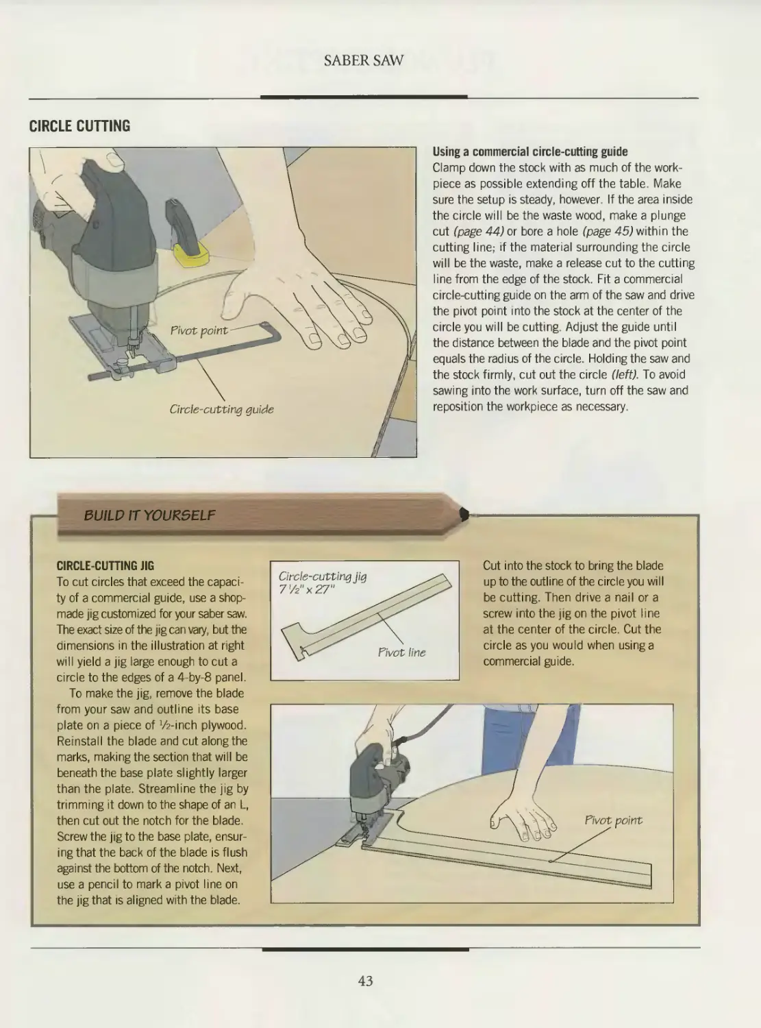
Using a commercial circle-cutting guide
Clamp down the stock with as much of the work-
piece as possible extending off the table. Make
sure the setup is steady, however. If the area inside
the circle will be the waste wood, make a plunge
cut (page 44) or bore a hole (page 45) within the
cutting line; if the material surrounding the circle
will be the waste, make a release cut to the cutting
line from the edge of the stock. Fit a commercial
circle-cutting guide on the arm of the saw and drive
the pivot point into the stock at the center of the
circle you will be cutting. Adjust the guide until
the distance between the blade and the pivot point
equals the radius of the circle. Holding the saw and
the stock firmly, cut out the circle (left). To avoid
sawing into the work surface, turn off the saw and
reposition the workpiece as necessary.
SUILP IT YOURSELF
CIRCLE-CUTTING JIG
To cut circles that exceed the capaci-
ty of a commercial guide, use a shop-
made jig customized for your saber saw.
The exact size of the jig can vary, but the
dimensions in the illustration at right
will yield a jig large enough to cut a
circle to the edges of a 4-by-8 panel.
To make the jig, remove the blade
from your saw and outline its base
plate on a piece of Winch plywood.
Reinstall the blade and cut along the
marks, making the section that will be
beneath the base plate slightly larger
than the plate. Streamline the jig by
trimming it down to the shape of an L,
then cut out the notch for the blade.
Screw the jig to the base plate, ensur-
ing that the back of the blade is flush
against the bottom of the notch. Next,
use a pencil to mark a pivot line on
the jig that Is aligned with the blade.
Cut into the stock to bring the blade
up to the outline of the circle you will
be cutting. Then drive a nail or a
screw into the jig on the pivot line
at the center of the circle. Cut the
circle as you would when using a
commercial guide.
Pivot point
43
PLUNGE CUTTING
The saber saw’s design makes it ide-
al for the tricky job of making inte-
rior cuts. There are two ways to begin
the operation. You can use a drill to bore
a hole (page 45) or plunge the blade into
the workpiece, as shown below.
This second method will make the
cut much more quickly, but it is also a
little more challenging to perform. It
takes some practice to keep the blade
from skating on the surface of the stock.
For best results, work with a short, stiff
blade in the saw.
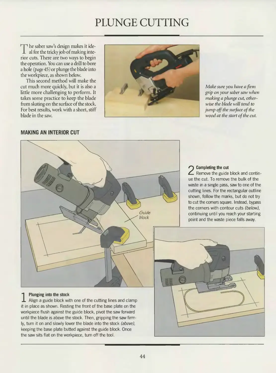
Make sure you have a firm
grip on your saber saw when
making a plunge cut, other-
wise the blade will tend to
jump off the surface of the
wood at the start of the cut.
MAKING AN INTERIOR CUT
Guide
block
2 Completing the cut
Remove the guide block and contin-
ue the cut. To remove the bulk of the
waste in a single pass, saw to one of the
cutting lines. For the rectangular outline
shown, follow the marks, but do not try
to cut the corners square. Instead, bypass
the corners with contour cuts (below),
continuing until you reach your starting
point and the waste piece falls away.
1 Plunging into the stock
Align a guide block with one of the cutting lines and clamp
it in place as shown. Resting the front of the base plate on the
workpiece flush against the guide block, pivot the saw forward
until the blade is above the stock. Then, gripping the saw firm-
ly, turn it on and slowly lower the blade into the stock (above),
keeping the base plate butted against the guide block. Once
the saw sits flat on the workpiece, turn off the tool.
44
SABER SAW
isi Hi 111 uj iii 111 in ib 111 in in in in ш m ш in ai
SHOP TIP
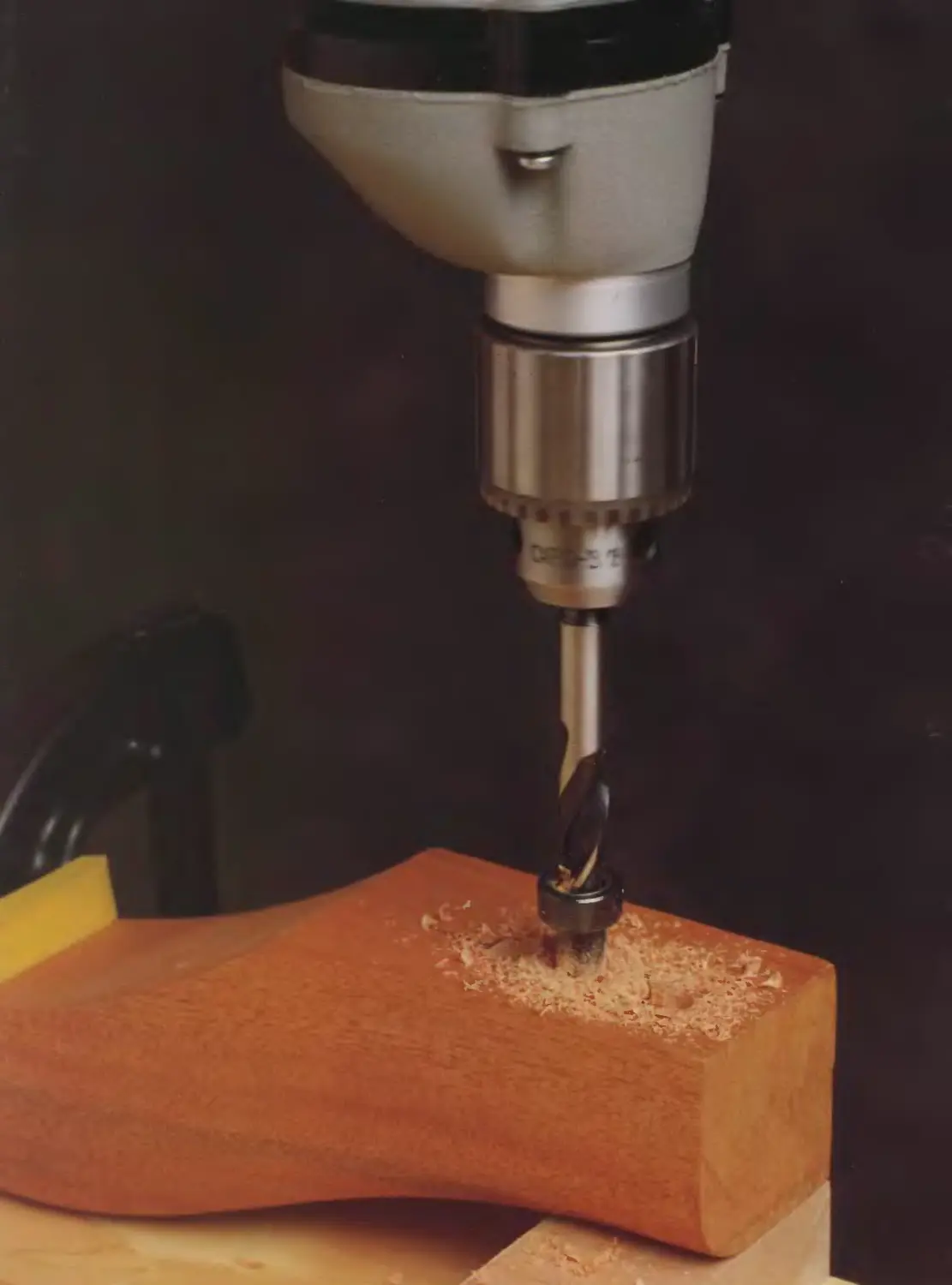
Boring access holes
An alternative to making a plunge
cut in a workpiece is to bore a hole
in which you can insert the blade.
Install a brad-point bit on a drill
press or electric drill; the bit diam-
eter should be wider than the width
of the blade. At each corner
bore a hole thatjus"
touches the cut-
ting lines on both
sides. The saw
blade can then
be inserted in the
hole to cut to the
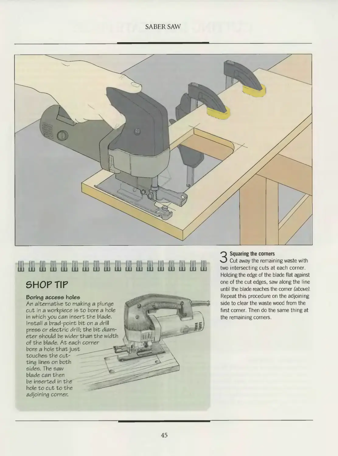
3 Squaring the corners
Cut away the remaining waste with
two intersecting cuts at each corner.
Holding the edge of the blade flat against
one of the cut edges, saw along the line
until the blade reaches the corner (above).
Repeat this procedure on the adjoining
side to clear the waste wood from the
first corner. Then do the same thing at
the remaining corners.
adjoining corner.
45
CUTTING DUPLICATE PIECES
The saber saw lends itself to the pro-
duction of multiple copies of a
shape. Provided the stock is not too
thick, stack sawing is an effective method
for cutting duplicate pieces. Using this
approach, layers of stock are fastened
together and the pieces are cut in a sin-
gle operation. Not only is stack sawing
more efficient than cutting all the pieces
separately, it ensures that the finished
products are exact copies.
Some woodworkers use nails or
screws to bond the layers together in
preparation for cutting; others prefer
clamps. Both approaches can be haz-
ardous, however, if the blade acciden-
tally strikes a fastener or clamp. A safer
way is to use double-sided tape to hold
the pieces together.
There are some limitations on stack
sawing with a saber saw. First, the blade
must be longer than the combined thick-
nesses of the workpieces. Depending
on the model you have, you can buy
saber saw blades up to 12 inches long,
but do not attempt to use a blade that is
too short. You will also probably need
to make the cut fairly slowly.
Another option for repeat curved cuts
is to use the first piece you cut as an edge
guide for subsequent cuts. Clamping the
guide to the workpieces can make a con-
tour cut as straightforward as a crosscut.
STACK SAWING
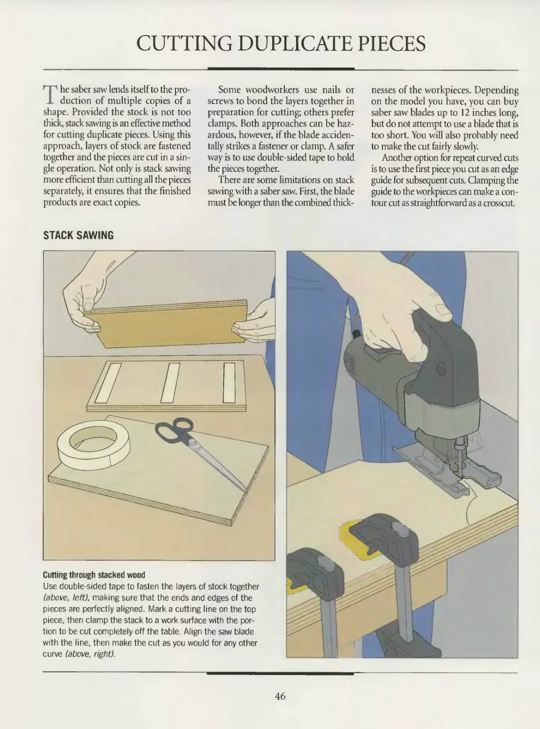
Cutting through stacked wood
Use double-sided tape to fasten the layers of stock together
(above, left), making sure that the ends and edges of the
pieces are perfectly aligned. Mark a cutbng line on the top
piece, then clamp the stack to a work surface with the por-
tion to be cut completely off the table. Align the saw blade
with the line, then make the cut as you would for any other
curve (above, right).
46
SABER SAW
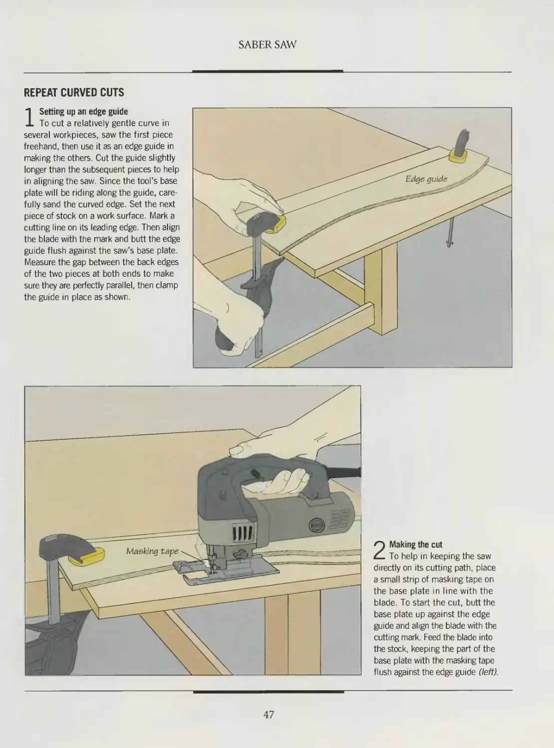
REPEAT CURVED CUTS
1 Setting up an edge guide
To cut a relatively gentle curve in
several workpieces, saw the first piece
freehand, then use it as an edge guide in
making the others. Cut the guide slightly
longer than the subsequent pieces to help
in aligning the saw. Since the tool’s base
plate will be riding along the guide, care-
fully sand the curved edge. Set the next
piece of stock on a work surface. Mark a
cutting line on its leading edge. Then align
the blade with the mark and butt the edge
guide flush against the saw’s base plate.
Measure the gap between the back edges
of the two pieces at both ends to make
sure they are perfectly parallel, then clamp
the guide in place as shown.
2 Making the cut
To help in keeping the saw
directly on its cutting path, place
a small strip of masking tape on
the base plate in line with the
blade. To start the cut, butt the
base plate up against the edge
guide and align the blade with the
cutting mark. Feed the blade into
the stock, keeping the part of the
base plate with the masking tape
flush against the edge guide (left).
47
ELECTRIC DRILL
Despite the fact that it is capa
ble of one basic action—
rotating whatever is clutched in its
jaws—the electric drill is probably
the most frequently used portable
power tool in a woodworker’s shop.
The better-quality models are suited
for more than simply boring holes;
they are true multipurpose tools.
You can rely on your drill to
make precise holes, ranging in size
from tiny l/32-inch incisions to 4-
inch cavities cut with a hole saw.
With a stop collar or shop-made
depth guide fastened to the bit, you
have the ability to precisely control
the depth of tbe hole you are mak-
ing. Certain specialized bits for the
power drill let you control the shape
of the hole as well. A counterbore
bit, for example, makes three sizes of
holes in a single operation: one as a pilot hole for a screw tip,
a slightly larger opening for the screw shank, and a hole large
enough for a wood plug to conceal the head of the screw.
Other accessories greatly expand the portable drill’s capa-
bilities. Depending on the attachment, a drill can drive screws
and nails; shape, sand and scrape wood surfaces; and power a
grinding wheel for sharpening bits. Attached to a guide, the
tool gains enough stability to cut wood plugs, a task that would
be difficult to perform well with a hand-held drill. Mounted in
a stand, the drill becomes a stationary tool, freeing your
Coupled with a commercial doweling jig,
this cordless drill can bore holes for dowels
at any interval. The depth collar on the bit
controls the drilling depth precisely.
hands to manipulate the workpiece.
A stand will also give your drill a
level of precision approaching that
of a drill press.
Portable drills are classified accord-
ing to the maximum bit shank
diameter that can be fitted into
their chucks. The most common
home workshop sizes are I4-, %-,
and Vi-inch drills. A system of gears
between a drill’s chuck and motor
rotates the chuck at a certain speed
and with a certain amount of torque,
or twisting force. Depending on the
job at hand, either drill speed or
torque will be the crucial factor.
Higher speeds are needed for small-
diameter holes and for jobs like
sanding or scraping; higher torque
will help out when you are making
larger holes.
In general, the higher a drill’s maximum speed, the less
torque it can generate. A typical 'A-inch drill rated at 3 amps can
produce speeds up to 4000 rpm, but it will lack the necessary
power for boring larger holes in hardwood. A Vi-inch hammer
drill rated at 4.5 amps develops enough torque to punch a hole
in concrete, but the tool will not run faster than 850 rpm, insuf-
ficient to spin a sanding disk rapidly enough for smoothing
wood. Between the two extremes is the %-inch drill. With typ-
ical speeds as high as 1200 rpm and ample torque, it is consid-
ered the best all-purpose drill for most woodworkers.
A 'A-inch brad-point bit bores a series of over-
lapping holes for a mortise in a cabriole leg.
After a chisel has squared the mortise corners,
the leg will be ready to accept a rail tenon.
49
ANATOMY OF AN ELECTRIC DRILL
Although all electric drills operate in
essentially the same way, wood-
workers often keep several different
models on hand to take care of any
drilling operation. For most applica-
tions, a corded Ye-inch variable speed,
reversible drill, such as the model illus-
trated on page 51, is the best choice. A
‘A-inch drill also has its special uses.
Although it lacks the power and bit
capacity of a larger drill, a 14-inch mod-
el can generate more rpm, enabling it to
bore cleaner small diameter holes.
A third choice of many woodwork-
ers is the cordless drill. Early models
often sacrificed power for portability,
but more recent versions have solved this
problem and can produce enough
torque for most drilling jobs. A com-
mon feature is an adjustable slip-clutch
mechanism, designed to make driving
and removing screws easy and precise.
The clutch allows the bit to spin only as
fast as the screw turns; when the screw
stops rotating so too does the bit. This
This cordless drill/driver takes
the portability of the electric
drill one step further. Powered
by rechargeable nickel-cadmi-
um batteries, the tool can be
taken anywhere in the shop.
prevents the bit from stripping the screw
head or slipping off the screw and pos-
sibly marring tbe workpiece. For maxi-
mum flexibility, many cordless drills
offer a range of slip-clutch settings.
Whatever the type or size of a drill,
there are several other features you
should keep in mind. A reversing switch
is essential for removing screws; it can
also be useful for withdrawing a bit that
is stuck in a hole. A chuck key that can
be stored on the drill or the power cord
is a small but significant convenience.
For prolonged operations such as sand-
ing or scraping, make sure your drill has
a locking switch that will keep the motor
running without requiring that the trig-
ger switch be depressed.
• Always wear safety glasses when oper-
ating a drill; also put on a dust mask
if you are using a sanding or scraping
accessory.
• Do not use the drill if any of its
parts is loose or damaged; inspect
your drill bits and accessories
before drilling.
• Keep all cords clear of the cutting area.
• Disconnect the drill from its power
source before changing a bit or acces-
sory, or making any other adjustments
to the tool.
ELECTRIC DRILL SAFETY TIPS
• Keep your hands away from the under-
side of a workpiece when the bit is cut-
ting into it.
• When installing a bit, make sure you
insert it fully into the chuck.
• Do not tighten the chuck by hand;
insert the chuck key in each of the three
holes in the chuck to tighten.
• Remove the chuck key after installing
a bit or accessory.
• Keep the drill’s air vents clear of saw-
dust to avoid overheating the motor.
• Avoid steadying a workpiece by hand;
clamp your stock to a work surface when-
ever possible to keep both your hands
free to operate the tool.
• Maintain a comfortable, balanced
stance when operating the drill; avoid
over-reaching.
• Do not force the drill; allow it to bore
at its own speed, withdrawing the bit
from the hole periodically to clear out
the waste, if necessary.
• Do not wear loose-fitting clothing or jew-
elry. They can be caught by a spinning bit.
50
ELECTRIC DRILL
Chuck collar
Loosened or tightened to open or
close chuck jaws; may be remov-
able to allow installation of certain
accessories, such as a drill guide
Trigger switch
On variable speed drills, motor
speed varies with pressure
applied to switch
Chuck jaws
Hold and rotate
bit or accessory
Reversing switch
Changes direction
of motor rotation
Locking switch
Keeps motor running
when trigger switch
Chuck key
Fitted into holes
of chuck collar to
open or close jaws
51
DRILL BITS AND ACCESSORIES
Your electric drill’s versatility is limit-
ed only by the range of bits and acces-
sories you accumulate in the shop. With
the appropriate attachment in its chuck,
the drill can be an ideal tool for a great
many jobs, making it invaluable at many
stages of a project. A flap sander and a
stand, for example, transform the drill
into a stationary tool for smoothing wood.
With a rotary rasp, the tool can shape dec-
orative contours. A right-angle head or a
flexible shaft will get a bit into tight spots.
Once the job is done, a bit sharpener will
restore sharp cutting edges to ensure that
you bore cleanly drilled holes.
Nevertheless, bits are likely to be the
accessories you use most. As shown
below, a wide array of these implements
is available, from twist and brad-point
bits for boring holes of different diame-
ters and depths to counterbore bits for
drilling recessed screw holes.
The popular twist bit bores holes
from V32 to V2 inch in diameter. Origi-
nally designed for drilling into metal,
twist bits have a tendency to skate on a
surface before penetrating it. You can
improve their performance by punch-
ing a starting hole in your workpiece
with an awl before boring a hole.
Most woodworkers prefer brad-point
bits. Available with either carbon steel,
high-speed steel or carbide-tipped cut-
ting edges, the sharpened centerpoint of
a brad-point bit allows accurate posi-
tioning. Better-quality bits feature two
spurs on the perimeter that score the cir-
cumference of the hole before the chip-
ping bevels clear away the stock. Twist
bits, however, are a better choice for
angled holes.
Although drill bits are virtually main-
tenance-free, remember that they will
only work properly for as long as they
are kept sharp.
A RANGE OF BITS
Brad-point bit
Produces smooth, precise holes from '/e to % inch in
diameter. Features a sharpened centerpoint to guide
bit and two spurs which score the circumference of the
hole before the chipping bevels begin removing stock
Twist bit
The least expensive of commonly
used drill bits; flutes expel wood
chips during drilling
Screwdriver bit
For driving slotted, Phillips
or Robertson screws of
various diameters.
Counterbore bit
Adjustable combination
bit that simultaneously
bores pilot hole, screw
shank clearance hole,
countersinking hole
and counterbore hole
for screws
sharp centerpoint guides bit while flat blade
slices into stock. Some bits have spurs on
shoulders for cleaner holes
г—r j. t-r
Extractor bit
For removing screws with
stripped heads; features
reverse threads
Hole saw
Bores large diameter holes—typically, larger than 1 '/2 inches
in diameter. A pilot bit, or mandrel, guides cutting edges
52
ELECTRIC DRILL
A SAMPLE OF ACCESSORIES
Plug cutter
Cuts wood plugs up to '/2 inch
long to conceal counterbored
screws; chamfers one end of
plug for easy installation
Drill guide
For keeping drill at
fixed angle to flat
or round stock.
Bushings accom-
modate various bit
diameters.
Stop collar
Also called drill stop or depth gauge; for drilling to an exact
depth. Available in sets matching bit diameters, typically
from ’/a to '/2 inch. Hex wrench supplied for installing on bit
Right-angle head
For working in tight corners;
allows accessory in chuck to
operate at 90° angle to body
of drill. Installed between
chuck and drill body
Bit sharpener
Hones dull bits; has
4 J grinding wheels and
chuck to hold bits
Nail spinner
Drives finishing
nails from 1 to 3
inches long into
hardwood without
predrilled pilot hole
Flexible shaft
For drilling in tight areas;
sleeve can bend up to 90°.
Chuck accepts most bits
Clutch adapter
Drives screws without having to drill pilot
holes; holds screw securely until head is
flush with surface, then clutch disengages
to avoid stripping screw head
Flap sander
For sanding curved
or contoured sur-
faces; features alu-
minum head which
spins sanding strips
53
BORING HOLES
Boring a hole into a piece of wood
may seem like a simple task. But
when you consider that some wood
species are harder to penetrate than oth-
ers, and that holes for woodworking pro-
jects sometimes need to be drilled at
precise angles and to exact depths, it
becomes clear that this deceptively easy
operation holds the potential for error.
Precision is as important in drilling as
in any other phase of a project. A dowel
hole that is off-center or too deep, or a
pocket hole drilled at the wrong angle,
can mar a project as badly as an inaccu-
rate saw cut or a poorly applied finish.
For most operations, accuracy begins
with the proper setup. While you can
depend on a steady hand to bore a per-
fectly straight hole, there are a wide vari-
ety of commercial guides to ensure that
your drill bit will not wander off-line.
A couple of simple shop-made jigs
shown in this chapter make it easy to
drill both straight and angled holes.
If you are using a twist bit, punch a
starting hole for the bit with an awl. To
prevent splintering as the bit exits from
a workpiece, clamp a support board
between the stock and the work surface.
For best results, avoid starting a hole
with the drill running at full speed.
Instead, begin slowly, then gradually
increase the speed as you drill. Control
the depth of a hole by installing a com-
mercial stop collar on the bit or using
the shop-made alternative.
A commercial guide steadies a drill
for a precise angled hole. This model
can also hold the drill perfectly per-
pendicular to a surface.
STRAIGHT AND ANGLED HOLES
Boring a straight hole
A try square or a shop-made block will
help you keep a drill bit perpendicular
to a workpiece when you bore a hole.
To use the square, line up its handle
with the mark for the hole, with the
blade pointing up. Centering the bit
over the mark, align it with the blade
and bore the hole (far left). Be sure
to keep the bit parallel to the square
throughout the operation. To make the
guide block, cut a 90° angle wedge out
of one corner of a board. Center the bit
over the mark, then butt the notched
corner of the guide block against it.
Clamp the block in place. Keeping the
bit flush against the corner of the block
(near left), bore the hole.
54
ELECTRIC DRILL
Guiding an angled hole
with a bevel gauge
Set a sliding bevel to the appropriate
angle, then line up its handle beside
the point where you need the hole.
Center the bit over the mark, then
bore the hole (above), keeping the bit
parallel to the blade while you drill.
SHOP TIP
Guide block for angled holes
To make a guide block for drilling into
a workpiece at an angle, bore at
a 90°angle through a small wood
block with the same bit you will be
using for the angled hole. Then make
a miter cut at one end of the block
trimming the wood at the same angle
as the hole you will be drilling. Cut a
notch in one side of the block to
facilitate clamping, and make a
V-shaped notch at the bottom
to help you pinpoint the tip of
the bit. Clamp the block in
place when using it to bore _ _
a hole.
55
ELECTRIC DRILL
WIDE AND DEEP HOLES
Using spade bits and hole saws
Drill holes up to IVz inches in diameter with
a spade bit; for wider holes, use a hole
saw. In either case, punch a starting hole
in the workpiece with an awl. For the spade
bit, put the centerpoint in the indentation
left by the awl. Holding the tool steady as
shown, bore the hole (near right). If you
are using a hole saw, install an auxiliary
handle whenever possible to give the drill
more stability. In any case, center the pilot
bit over the starting point, and holding the
drill with both hands, start drilling slowly.
Increase the speed gradually, feeding with
only enough pressure to keep the bit cut-
ting into the wood (far right).
First hole
Boring a deep hole
To bore a hole that is deeper than your bit is long,
make intersecting holes from opposite ends of the
workpiece. Begin by punching starting holes at
the same point on both ends of the stock. Then
secure the workpiece in a handscrew and clamp it
to a work surface with one of the starting points
facing up. Centering the bit over the mark, bore
a hole slightly more than halfway through the
stock. Flip the workpiece over and clamp it in
position. Center the bit over the other starting
point and complete the drill.ng operation (left).
56
ELECTRIC DRILL
Widening a hole
To widen a hole that has already been
bored by a brad-point or a spade bit, you
will need a solid surface to brace the cen-
terpoint of the bit against. First plug the
hole by tapping a dowel into it. Use a
dowel the same diameter as the hole for
a snug fit and make sure that it is flush
with the surface of the workpiece. Mark
the center of the dowel, then install the
appropriate bit in the drill and bore the
wider hole (inset).
3UILP IT YOURSELF
A HOLE-DRILLING TEMPLATE
To bore a row of equally spaced
holes, use a hole-drilling template
made in the shop from Vi-inch
plywood. The dimensions of the
jig will depend on the size of your
workpiece.
To make the template, mark a
line on the plywood to align the
holes, then drill at the spacing you
require. Cut a piece of 1-by-l stock
to the same length as the base and
rout a Vz-inch-deep, Vk-inch-wide
groove along one edge. Glue the 1-
by-1 to the base to serve as a fence.
Set your workpiece on a support
board, then clamp the template to
the stock with the fence flush against
its edge. Use the holes in the tem-
plate to guide the bit into the work-
piece (left).
57
SCREW HOLES AND PLUGS
Driving a screw into hardwood
without predrilling the hole risks
splitting the workpiece or breaking off
the head of the screw. Depending on
how deeply you need to sink the screw,
you may have to bore up to four over-
lapping holes of different diameters,
one inside the next. If you want the
screw head to sit on the surface of the
wood, bore a pilot hole for the threads
and a clearance hole for the shank. For
the best grip, a pilot hole should be
slightly smaller than the threads of
the screw. To set the head flush with
the surface, bore a countersinking hole.
If you wish to conceal the screw under
a wood plug, add a counterbore hole.
There are two ways to bore holes for
screws. You can use a different bit for
each hole or, as shown below, bore them
simultaneously with a counterbore bit.
Thanks to their variable speed and
reversible motors, electric drills are
ideal for driving or removing screws
rapidly with a minimum of effort.
DRIVING SCREWS
Preparing screw holes
To screw two pieces of stock together, fit your drill with a coun-
terbore bit of a size appropriate to the size of your hardware.
Such a bit will bore a pilot hole and has a stop collar that slides
up and down to adjust it for making either counterbore or
countersinking holes (above, left). Clamp the workpieces one atop
the other on a work surface, then bore the hole. If you will be
using a screwdriver to install the screw, coat the threads with
candle wax to make the fastener easier to drive. To use the
drill, install a screwdriver bit and set the screw in the hole by
hand. For a slotted head screw, slip a short length of copper
tubing around it to prevent the bit from slipping off the head
and marring the stock. Fit the bit into the screw head and apply
light pressure as you slowly start the drill; gradually increase
the feed pressure and drill speed as the screw takes hold.
58
ELECTRIC DRILL
CUTTING WOOD PLUGS
Using a plug cutter
Fit your drill into a commercial guide
following the manufacturer's instructions.
On the model shown, you must remove
the chuck from the drill, attach the cen-
ter spindle of the guide to the tool, then
replace the chuck on the spindle. Next,
install a plug cutter in the chuck and
slip the spindle onto the guide rods.
Adjust the cutting depth with the lock-
ing collar. Keeping the guide steady on
the workpiece, raise the tool to hold the
cutter just above the stock. Turn on
the power and push the drill down to
feed the cutter into the wood. Release
the pressure when the center spindle
hits the locking collar. Free the plug
from the stock with a chisel.
in in in rrrrrim in rail m
SHOP TIP
Boring pilot holes
for finish-
ing nails
Like screws,
finishing nails need
predrilled holes to prevent hard-
wood from splitting. Rather than
searching for a very small diameter
drill bit, use a nail. Snip off its head
with pliers and insert the fastener into
the chuck. Sharpen the tip with a file, then
use the nail to bore holes as you would with
an ordinary bit.
59
PORTABLE DRILL JOINERY
The portable electric drill may not be
the first tool that springs to mind
when you think of joinery. Only the
most innovative woodworker would
contemplate using the tool to make a
dovetail or finger joint, for example.
Nevertheless, for any method of joinery
requiring a cavity cut to an exact depth,
the drill is a workable choice. It is espe-
cially practical for mortise-and-tenon
and dowel joints.
For the mortise-and-tenon, the tool
will rough out a mortise, although you
will need to square the corners with a
chisel. A stop collar or a depth guide
(page 61) will guarantee that the bottom
of the cavity will be even and level.
A brad-point bit will produce the best
results. Choose one with a diameter
equal to the width of the mortise outline,
rather than relying on overlapping cuts
with a smaller bit. Most woodworkers
prefer to cut the tenon first and then use
it to mark the dimensions of the mortise.
A drill can perform all the steps need-
ed to prepare stock tor a dowel joint. The
key to an accurate joint is to center
the dowel holes on the workpiece; oth-
erwise, the two pieces being joined will
be out of alignment. Center your bit on
the edge of a workpiece with a com-
mercial doweling jig or build your own
center-drilling device (page 63).
MAKING A MORTISE
Cutting the mortise
Clamp the workpiece in handscrews,
then secure the stock to a work surface
as shown, with the mortise outline facing
up. Mark a line through the center of the
outline to help you align the bit. Install
a stop collar and adjust the drilling depth
to correspond to the length of the tenon.
With the bit directly over the centerline,
bore a hole at each end of the mortise
outline; hold the drill with both hands to
keep the tool perpendicular to the edge
of the stock. Then make a series of over-
lapping holes (far left) io remove as much
waste as possible. Square the mortise
with a chisel, keeping the blade perfectly
vertical and its beveled edge facing the
inside of the mortise (near left).
60
ELECTRIC DRILL
SHOP TIP
Depth guides
To bore a hole to an exact
depth, use a masking tape
flag or a depth stop block. If
you are using the tape, mea-
sure the drilling depth from
the tip of the bit, then wrap
a strip of tape around its
shank. Withdrawthe bit when
the tape just touches the
stock. To use a block, sub-
tract the drilling depth from
the length of the bit protruding
from the chuck. Cut a piece of
1 -by-1 stock to this length, then
bore a hole through its middle. Slip the bit through the block
and bore your hole. When the piece of wood touches the work-
piece and stops spinning with the bit, retract the tool.
DRILLING A DOWEL JOINT
1 Boring the dowel holes
Secure one of the boards to be
joined with handscrews as you would
when drilling a mortise (page 60). Clamp
a doweling jig onto the edge of the work-
piece. The model shown centers the dow-
el holes on the stock and spaces them at
the interval you choose. To avoid splitting
the boards, use grooved dowels that are
no more than half the thickness of the
stock. Fit your drill with a bit the same
diameter as the dowels, then install a
stop collar to mark the drilling depth,
which should be slightly more than half
the length of the dowels. Slide the bush-
ing carrier along the jig and insert the
appropriate bushing in the hole through
which you are planning to drill. (The
bushing ensures that the bit is kept per-
fectly square to the board.) Holding the
drill firmly, bore the hole. Make the remain-
ing holes for the dowels.
61
ELECTRIC DRILL
2 Gluing up the boards
Apply a thin bead of glue and spread
it evenly along the edges that will be
joined. Also dab a small amount of adhe-
sive in the bottom of each dowel hole; a
pencil can be useful in getting the glue
in the holes. Avoid spreading glue direct-
ly on the dowels; they absorb moisture
quickly and will swell, making them diffi-
cult to fit into their holes. Insert the
dowels, then tap them into final position
with a mallet. Avoid pounding, which
can cause a board to split. Close up
the joint, then use bar clamps to hold the
pieces in place until the glue is dry.
SHOP TIP
Using dowel centers
Instead of relying on a jig when boring dowel holes, you can use
dowel centers to ensure that the holes are precisely centered
on the boards being joined. After making the holes in one board,
insert the proper-sized dowel centers. Then set the board on a
flat surface alongside the board to which it will be joined. Align
their ends and butt the two boards together. The pointed ends
of the dowel centers will punch impressions on the stock, provid-
ing starting points for the mating dowel holes.
ELECTRIC DRILL
CENTER-DRILLING JIG
To bore holes that are centered on
the surface of a board, use the shop-
made center-drilling jig shown
above. The illustration provides
suggested dimensions.
Use a straight piece of 1-by-l
stock for the jig arm. You can make
such a device any length you choose,
but cutting it to the length shown
allows it to accommodate even the
widest stock used in a typical pro-
ject. Mark the center of the top face
of the arm and bore a hole through
it for a guide bushing. The hole should
be Vfe inch larger in diameter than
the bushing, which should be slight-
ly larger than the holes you wish
to make with the jig. Press the bush-
ing into place.
Next, turn the arm over and mark
a line down the middle. Mark points
on the line % inch from each end,
then bore holes halfway through the
stock at these points, making them
large enough to hold a 3/e-inch grooved
dowel. Dab some glue into the holes
and insert the dowels.
To use the jig, position it on the
stock and pivot the arm until the dow-
els are up against the opposite edges
of the workpiece. Holding the jig with
one hand, fit the drill bit into the bush-
ing and bore the hole (below).
For a hole centered on the edge of
a board, first secure the workpiece
edge-up in a vise. Then position the jig
on the edge of the stock with the dow-
els flush against its opposite faces.
63
SANDING, SCRAPING AND SMOOTHING
Coupled with a sanding drum, flap
sander, or rasp, your drill can per-
form many tasks, from smoothing stock
to shaping contoured edges. As illustrat-
ed below, you can bring the drill to the
job or, if you prefer to feed the stock into
the tool, mount the drill in a stand,
transforming it into a stationary sander.
If you are holding the tool by hand, make
sure you clamp the stock to a work sur-
face to keep it steady during the sand-
ing operation.
Sanding drums are ideal for smooth-
ing curved edges. Often sold in sets, the
drums typically consist of replaceable
sanding sleeves that fit tightly around
solid rubber ones, ranging in diameter
from */2 inch to 3 inches.
Flap sanders are made up of abrasive
strips with pliable brush backing that
Mounted in a stand and fitted with a
flap sander, an electnc drill becomes a
stationary sander, ideal for smoothing
the contours of a cabriole leg.
can be forced into corners and small
openings. Unscored strips are best for
flat surfaces, while scored strips work
well on contours. Whichever sanding
accessory you insert in your drill, use a
fast drill speed along with a light feed
pressure. The finer the grit of the abra-
sive, the faster the drill speed should be.
For quick stock removal, use a rotary
or disk rasp. The type or shape of rasp
you choose will depend on the job at
hand. Cylindrical rasps are ideal for
forming edges and corners, while coni-
cal rasps work best in tight spots. Disk
rasps are for use on flat surfaces.
As with sanding drums, rasps should
be applied only with light feed pressure.
Too much force will cause a buildup of
heat, possibly burning the surface of the
stock and clogging the teeth of the rasp.
SANDING AND SMOOTHING STOCK
Using a drum sander
Holding the drill parallel to the surface to be sanded, turn on the power and move the
sanding drum from left to right while applying light pressure (above, left). To produce a
more even finish and prolong the life of the sanding sleeve, reverse the direction of the
drill's motor midway through the operation; finish the job sanding from right to left. For a
workpiece that is awkward to clamp down, you may prefer to use a commercial drill stand.
Screw the stand to a plywood base, then attach the drill. Lock the motor in the On posi-
tion, then feed the stock across the sleeve against the direction of drum rotation (above,
right). Once again, switch the direction of the motor at some point during the process.
64
ELECTRIC DRILL
BUILD IT YOURSELF
SANDING DISK TABLE
To use your drill as a stationary
sander, construct a sanding disk
table for your tool from %-inch ply-
wood. The table will allow you to
feed stock into the rotating abrasive
surface in a controlled fashion,
keeping the workpiece square to
the tool. Refer to the illustration at
right for suggested dimensions.
Cut a notch in the edge of the
jig top that will sit nearest the sand-
ing disk. Temporarily affix the drill
stand to the base, then mount the
tool in the stand and install the
disk in the drill chuck. Trim the
two sides so that the upper surface
of the table top sits just above the
level of the washer on the disk.
Screw the sides to the top; if you
wish to conceal the screws, counter-
bore them and cover their heads
with wood plugs. Screw the sides
to the base.
Position the stand so that the disk
will rotate freely within the notch
in the top, then screw the stand to
the base.
Before beginning to sand, bolt or
clamp the table to a work surface.
Lock the motor in the On position,
then feed the workpiece at a uni-
form speed across the disk, working
against the direction of drill rotation
(right, below). Avoid burning or
gouging the wood by feeding the
stock with one smooth, continuous
motion. To even out wear of the
sanding disk, reverse the direction
of the drill motor midway through
the operation, and feed the stock
from the other side of the table.
Drill stand
Notch
Vz" x width of disk
Jig base
20"x24‘
Top
12"xi3Vz'
Side
5%"х72'
Sanding disk
65
ELECTRIC DRILL
SCRAPING AND SURFACING STOCK
Rotary rasp
Working with a rotary rasp
A rotary rasp is an effective tool for rough-
ing out decorative curves along the edges
of a workpiece. To cut a tight curve, hold
the drill with both hands and apply mod-
erate pressure to the surface until the
rasp cuts the shape you need (right). To
rough out a gentle curve, press more lightly
and move the rasp along the wood sur-
face, proceeding opposite the direction
of drill rotation.
Using a disk rasp
If you want to remove stock more quickly
than a sander will permit, use a disk
rasp. With a firm grip on the drill, hold
the tool perpendicular to the surface,
applying only enough pressure to allow
the rasp teeth to cut into the wood. (Too
much pressure may cause the disk to
bite too deeply into the wood, stalling
the drill motor.) Move the tool across the
surface following the grain of the wood.
66
THE PORTABLE DRILL AS DRILL PRESS
If your workshop does not include a
drill press, and you have no immedi-
ate plans to buy one, mounting your
portable tool in a drill press stand can
provide some of the capabilities of the
stationary tool. Naturally, such a com-
promise solution cannot rival the real
thing when it comes to precision and
versatility. Depending on your needs,
however, a drill press stand may serve
you just fine, and you will probably find
that it allows you to do some jobs much
better than if you had been holding the
drill in your hand.
With the added stability afforded by
the stand, you can install a small-diam-
eter Forstner bit in the drill and produce
perfectly perpendicular, flat-bottomed
holes. Most stands include a depth
adjustment feature, useful if you want
to bore a uniform series of holes. In
selecting a stand, keep in mind that some
models can accommodate any make
of drill while others will only accept
certain varieties.
For convenience and maximum sta-
bility, bolt your drill press stand to a base
of %-inch plywood, then clamp the base
to a work surface.
With a tiltable work table, this drill
press stand enables a portable drill
to bore precise angled holes. The
V-groove in the table is designed to
hold a cylinder securely.
BORING HOLES
Drilling with a commercial stand
Install a bit in the drill and mount
the tool in the stand following the
manufacturer's instructions. Set your
stock on the table of the stand and
align the drilling mark directly under
the bit before clamping the work-
piece in place. If you are boring a
stopped hole, set the drilling depth.
Lock the motor in the On position, then
rotate the feed lever steadily to feed
the bit into the workpiece (left).
67
ROUTER
Comprising little more than a
base plate and a motor that
spins a cutting edge, the router’s
simplicity belies its versatility. Unlike
other portable power tools, the router
has no stationary counterpart that
can outperform it. As such, the
router is a must-have tool for most
woodworkers; some claim that it
is the single most important shop
tool invention of the twentieth
century. The earliest model, devel-
oped during the First World War,
featured a cutter created from the
worm gear of an electric barber’s
clipper. Within 10 years, more than
100,000 “Electric Hand Shapers”
had been produced.
Shaping the edge of a workpiece
with a decorative profile is proba-
bly the router’s most common task. It can do the job as reliably
on a circular workpiece as on a straight board. Tbe great num-
ber of bits available—from rabbet and chamfering cutters to
corner round and beading bits—allows you to create dozens of
distinctive profiles. There are also a number of accessories
designed to keep the cut consistent from the beginning of a
pass to the end. For straight cuts, an edge guide keeps the bit
from veering off the cutting path (page 79). For shaping the
circumference of a circle, or cutting out a circle, special guides
will hold the bit a uniform distance from the center (page 85),
A router can fashion more joints than any
other portable power tool. Here, one is used
to shape a tenon at the end of a board, aided
by a mortise-and-tenon jig.
ensuring perfect results. Both types
of guides can be purchased, but you
can also make them in the shop.
Mounting the router in a table
transforms it into a stationary tool
and frees your hands for feeding
stock into the bit. You can also
install certain bits in a table-mount-
ed router that offer profiles you can-
not use when operating the router
by hand. A table also makes the
router an excellent tool for cutting
joints (page 97), including the
tongue-and-groove and the sliding
dovetail. But with one of the many
commercial jigs on the market, you
can produce accurate mortise-and-
tenon joints and dovetail joints with
a hand-held router.
Despite the various design dif-
ferences, all routers fall into two basic categories: standard
and plunge models. The main difference between them has
to do with the way the bit bites into the wood at the beginning
of a stopped-groove cut. The base plate of a standard router
must be held at an angle to the surface so that the bit can be
lowered gradually into the wood. The plunge router can be
held flat on the surface before the cut since the entire motor
assembly, along with the bit, is mounted above the base on spring-
loaded columns. Downward pressure on the handles feeds
the bit into the wood.
A dovetail bit carves a channel in a hardwood panel. Run-
ning the router base plate along a guide keeps the cut square
to the edges of the boards. The joint is a good one for install-
ing shelves in a bookcase
69
ANATOMY OF A ROUTER
While all routers are designed to spin
bits, no two makes or models share
exactly the same features or design. Some
of the differences, such as the location of
the On/off switch, are strictly a matter
of convenience or personal preference;
other variations determine the kind of
work you can perform with the tool.
The collets of many smaller routers
only accept bits with '/4-inch-diameter
shanks. Larger models can also accom-
modate 3/s- or 'Л-inch cutters. Tool pow-
er and bit capacity typically go hand in
hand. Smaller routers start at '/2 horse-
power, while manufacturers claim as
much as 3 horsepower for some larger
models. Greater power enables a router
to turn larger bits and make deeper cuts,
so it is worth buying a tool with at
least 1 horsepower.
Many routers feature variable speed
control, which enables you to match the
bit speed to the job at hand. Depending
on the model, you can set the speed at
levels between 8,000 and 24,000 rpm.
Slow speeds are best for deep cuts such
as when you are using a panel-raising
bit; very high speeds come in handy for
jobs such as trimming laminate. In gen-
eral, high speed will produce a cleaner
STANDARD ROUTER
On/off switch
Base plate clamp screw
Loosened to set cutting
depth of bit or remove base
plate from body; tightened
to lock plate in position
Sub-base
Screw holes allow acces-
sories to be attached to
router; can be unscrewed
from the base plate.
Base plate
Supports motor. Removable
for bit changing or for mount-
ing router in table; adjustable
for setting cutting depth
Depth adjustment ring
Used for setting cutting
depth of bit
Handle
Collet
Jaws accept shank
of router bit; nut
directly above collet
is turned to open or
close jaws to secure
cutter in place
70
ROUTER
cut. Its one drawback is the increased
risk of burning.
While some routers, like the one fea-
tured on page 70, include a plunge base
(below) that can be added to the standard
PLUNGE BASE
Depth scale stop clamp
Loosened to release depth
stop bar, tightened to set
cutting depth
Depth scale
Indicates cut-
ting depth
Turret stop screw
Height is adjustable to
vary cutting depth of
intermediate passes
Plunge base
plate
Replaces
standard base
plate to con-
vert router
into a plunge-/
type tool
Turret stop
Rotates to posi-
tion appropriate
stop screw
under depth
stop bar
machine, you can also buy a tool specifi-
cally designed for plunge routing. Pressing
down on the handles plunges the bit
directly into the stock—ideal if you have
to start a cut in the middle of a workpiece.
Depth stop bar
Used to set cutting
depth; gap between
bar and turret stop
screw equals depth
of cut I
Plunge lock knob
Bit can be plunged
when knob is loosened;
tightened when cutting
depth is reached to
lock in place
ROUTER SAFETY TIPS
• Keep router bits clean and sharp;
replace any damaged cutters.
• Unplug the router before chang-
ing a bit.
• Wear safety glasses and a dust
mask for cutting operations.
• Always clamp stock to a work sur-
face for hand-held routing; do not
use your hands to support a work-
piece unless the router is mounted
in a table.
• Switch the router off before plug-
ging it in.
• Grip the router firmly when switch-
ing it on; the startup torque, or twist-
ing power of the tool, can make it
difficult to control at the start of
a cut.
• Allow the motor to reach full
speed before feeding the cutter
into the workpiece.
• Do not attempt to make a deep
cut in a single pass; make two or
more passes at intermediate depths.
• Keep your hands away from the
underside of the workpiece when
the router is operating.
• Do not touch a bit immediately
after using the router; the cutting
edge can become very hot.
• Turn off the router as soon as
a pass is completed; do not set
the tool down until the bit has
stopped spinning.
Wrenches
Supplied with
router for changing
bits. One wrench turns
collet nut; other wrench
holds shaft stationary
Edge guide
Keeps bit square
to board edge for
dado cuts. Rods attach
to router base plate; fence
rides along workpiece edge
71
BITS
Fitted with the right bit for the job at
hand, a router can cut anything from
a rabbet to an intricate molded edge.
The selection of cutters available today is
very broad. Some tool and hardware cat-
alogs boast page after page of router bits,
with scores of different profiles—each
available in several cutting diameters.
No matter what kind of cut you have in
mind, you can almost always find the
appropriate bit.
Standard bits for portable routers
consist of a steel body with one or
more cutting surfaces and a shank
that fits into the collet. Cutters for
this tool are generally available in two
materials: high-speed steel (HSS) and
high-speed steel with carbide cutting
edges. Although carbide-tipped bits
are more expensive, they stay sharp
longer and cut more easily through
tough materials. One drawback, how-
ever, is that they tend to chip if they
strike a hard surface.
Router bits fall into two categories;
those for shaping edges and those for
cutting grooves. As their name implies,
edge-forming bits are used to cut deco-
rative profiles into stock or prepare
board edges for joinery. These bits gen-
erally have a pilot located below the
cutter to ride along the edge of the
workpiece and guide the bit. Ball-bear-
ing pilots are preferable to fixed pilots
because they do not generate heat from
friction and thus will not cause burns
or compression marks on your stock.
Grooving bits are used for making
dadoes, if the dado will not run to the
edge of the stock, a plunge router is
the best choice.
Your router’s performance will
benefit from proper storage and care-
ful maintenance of your bits. Use a
clean cloth to wipe off dust and dirt.
Protect bits from damage in a simple-
to-make holder (page 74). Keep the
edges sharp and avoid using cutters
that are dirty, rusted or damaged. Be
sure to unplug the tool whenever
you change a bit.
72
ROUTER
SHOP TIP
Maintaining and replacing
pilot bearings
Accumulated dirt will eventu-
ally jam the pilot bearing of a
router bit. This may lead to
burning of the stock. To ser-
vice a pilot bearing, secure
the bit bearing-end up in
a vise or handscrews.
Wipe off burn marks,
pitch and gum with a
cloth and an oil-free,
non-silicone-based lubricant. If the pilot is
damaged or worn—or if you want to alter the bit’s
cutting profile—replace the pilot by loosening its setscrew
with a hex wrench. Remove the pilot and install a new one.
CHANGING A BIT
Removing and installing bits
Set the router upside down on a work
surface and loosen the clamp screw to
remove the base plate. Change bits using
the two wrenches supplied with the
machine. To remove a cutter, hold the
shaft steady with one wrench and loosen
the collet with the other tool. For extra
leverage, position the wrenches so that
you can squeeze them together (left).
Pull the bit out of the collet; if it is
stuck, gently tap the collet with the
wrench. Do not strike the bit or try to
extract it from the collet with pliers;
this may damage the cutting edge.
Before installing a new bit, clean any
sawdust from the collet. Insert the
replacement all the way into the collet,
then raise it about Vie inch. Then
retighten the collet.
73
ROUTER
SHOP TIP
Storing router bits
The cutting edges of router bits, particularly
those made of carbide, can be nicked if
they are thrown together in storage.
Frotectyour bits with a simple
shop-made holder. In a
block of wood, bore a
series of holes the
size of the bit
shanks
and store
them with
the cutting
edge up.
SETTING THE CUTTING DEPTH
Adjusting a standard router
Set the router on the workpiece. Loosen
the clamp screw with one hand and
rotate the motor to raise or lower it, also
raising or lowering the bit. For the straight
bit shown, align its tip with the depth
line, then tighten the clamp screw. An
alternative method is to set the router
upside down on a work surface, loosen
the clamp screw and rotate the base
plate until the bit protrudes by the
amount you want.
74
ROUTER
Adjusting a plunge router
Set the router on the workpiece and
rotate the turret stop to position the
shortest stop screw directly under the
depth stop bar. Loosen the clamp
screw to release the bar and seat it
111 ill Hi 111 Hi ilrlll Uli Hi 111 Ш Ш 111 111 111 111 НГН1
SHOP TIP
on the turret screw. Then loosen the
plunge lock knob and push the motor
down until the bit contacts the work-
piece. Tighten the knob and raise the
stop bar until the gap between it and
the turret stop screw equals the depth
of cut. Tighten the depth stop clamp
screw and loosen the plunge lock knob,
allowing the motor and bit to spring
back up (above, left). When you plunge
the bit into the stock, it will penetrate
until the bar contacts the turret stop
screw. For deep cuts, it is generally
preferable to reach your final depth
in stages. On the model shown, you can
set the height of the other two turret
stop screws to make passes at interme-
diate depths: loosen the nut with a
wrench and then raise or lower the
screw with a screwdriver (above, right).
An auxiliary sub-base for wider cuts
To make a cut that is wider than a particular
router bit, you would normally make
one pass, move your edge
guide and make a
second pass. Instead,
use an off-square sub-
base. Cut a piece of 1A-
inch plywood into an
S-inch square. Remove the
router’s sub-base and
bore the screw holes and
clearance hole for the bit
through the auxiliary sub-base.
Next, shave 7ie inch of wood from
one edge of the plywood, Ve inch
from an adjacent edge and 'A inch
from a third edge. Mark the amounts
you removed on each side. Screw the
auxiliary base to the router and make a pass with the
unshaved edge riding against the guide. Rotate the base
and make a second pass that is 7ie, Ve or ’A inch wider
than the first, depending on which edge you use.
75
ROUTER ACCESSORIES
Since the development of the portable
router, an entire segment of the pow-
er tool industry has burgeoned. The pur-
pose of the new activity is to design
accessories that widen the router’s use-
fulness and enhance its capabilities. The
photo below illustrates a few of the more
popular devices.
Some of these products, like the foot
switch, make the router more convenient
to use. The switch is especially handy
with routers whose on/off controls are
not close to the handles. If you use such
a device, be sure to disconnect it from
the tool when you are changing a bit or
performing any other maintenance oper-
ation. This will prevent accidental start-
up of the motor.
The edge and circle guide enables a
router to cut grooves a set distance in
from the workpiece edge, rout a mold-
ing or follow the contours of curves. As
shown on page 86, the jig also can be
used to keep a router bit a uniform dis-
tance from the center of a workpiece,
ensuring accurate circle cuts.
The dovetail jig is one of several acces-
sories designed to make the router a key
part of the joint-making process. The
model shown below features adjustable
fingers that allow you to create your own
dovetail pattern by varying the widths
and spacing of the pins and tails.
A SAMPLING OF ACCESSORIES
Plate joiner conversion kit
Allows router to cut slots for
plate or biscuit joints. Body
of jig attaches to router base
plate; kit includes compressed
wood biscuits and three-wing
slotting cutter
Clamping system permits pin and tail
boards to be cut with same setup
Foot switch
For turning router on
and off without using
tool’s switch; allows
operator to keep both
hands on router handles
Dovetail and box joint jig
Installed on router table to
replace standard fence; features
fine adjustments that allow fence
to be shifted by precise amounts
Edge and circle guide
Adjustable guide rods
attach to router base
plate. Edge guide holds
bit a set distance from
cutter for straight cuts;
fulcrum pin allows jig to
pivot around a center-
point for cutting circles
76
EDGE FORMING
Whether you are carving a decora-
tive molding into a workpiece or
preparing boards for a joint, shaping
edges will probably be one of your most
common uses of the router. As illus-
trated in the pages that follow, the man-
ner in which you guide the bit along the
stock depends on the type of cutter you
are using. With piloted bits, the pilot
rides along the edge, keeping penetra-
tion of the cutting edges constant. With
non-piloted bits, the router base plate
runs along an edge guide clamped to
the workpiece, achieving the same result.
Either method will work on a straight
edge, but for a curved cut you will need
a piloted bit. One note of caution:
Kickback can occur at any time until
the pilot contacts the stock. So main-
tain a firm grasp on the router.
For any routing operation, be aware
of the feed direction. As illustrated below,
it should generally be counter to the
direction of bit rotation. Before starting
a cut, clamp your stock to a work sur-
face and make sure that the clamps will
not get in the way of the router.
An edge-forming bit etches a decorative profile
on the circumference of a table top. The cutter’s
ball-bearing pilot rides along the stock to keep
the cut at a uniform depth.
Feeding the router
Moving the router in the wrong direction
can make the tool difficult to control,
resulting in kickback and tearout. For
most operations, guide the bit into a work-
piece against the direction of bit rotation;
this will tend to pull the bit into the wood.
On an outside edge, move the router in a
counterclockwise direction; on an inside
edge, feed the tool clockwise (left). Start
with cuts that are against the grain; this
way, you will be able to eliminate any
tearout with the cuts along the grain that
follow . Position yourself so that you can
pull the router toward you, rather than
having to push it; this will enable you to
see the bit at all times. Throughout the
operation, maintain a firm hold on the tool
and apply moderate pressure to keep the
bit biting into the wood.
77
ROUTER
STRAIGHT AND CURVED CUTS
Routing with a piloted bit
Clamp your stock to a work surface with
the edge you want to shape extending
off the table by several inches. Holding
the router with both hands, rest its
base plate on the workpiece at one end
with the bit clear of the wood and turn
on the tool. Ease the bit into the stock
until the pilot contacts the edge, keep-
ing the base plate flat on the workpiece
(above, left). For deep cuts, make two
or more passes to reach your final
depth. On a curved cut, the router bit
will round off any inside corners along
the edge of the workpiece (above, right)-,
square these corners with a chisel.
SHOP TIP
Steadying a router for curved cuts
A support board will help keep your
router flat on a w'orkpiece
during an edge-forming
operation. For contour
cuts, you can use the
waste piece that
remains after sawing
the curve. Clamp the
w'orkpiece to a w'ork sur-
face, then tack-nail the
waste piece alongside it, far
enough away from the edge
you are shaping to allow'for
clearance of the bit. When you make the
cut, the router will be supported by both the w'orkpiece
and the support board. The only limitation is that the bit
pilot cannot protrude beyond the bottom of the stock.
78
ROUTER
SHOP TIP
Wobble-free
edge routing
It can be diffi-
cult to pre-
vent a router
from wobbling
when you feed the
tool along the top edge
of a workpiece. One solu-
tion is to clamp a support
board to your stock, making
sure that the top edges of the
two boards are exactly level. The
support piece will create a wider
surface on which to rest the
router as you make the cut.
Using a поп-piloted bit
To prepare for the cut, install a commer-
cial edge guide on the router. Set the
tool upside down on a work surface and
insert the rods of the guide into the
predrilled holes in the router base plate.
Hold a scrap board on the bit to help
you position the guide for the width of
cut, then butt its fence against the
board. Tighten the screws in the router
base plate to fix the guide in position
(above, left). To make the cut, clamp
your stock to the work surface. Then,
keeping the guide fence flush against
the edge you wish to shape, start the cut
at one end of the workpiece and feed
the router along the board edge (above,
right) until you reach the other end.
79
ROUTER
MAKING A STOPPED RABBET
Stop block
Using a поп-piloted bit
Clamp your stock to a work surface, then
mark a line for the end of the stopped
rabbet on the edge of the workpiece.
(The rabbet shown in the illustration is
stopped at only one end.) Align the bit
on the top face of the stock for the width
of the rabbet, then clamp an edge guide
to the workpiece flush against the router
base plate. With a firm grip on the router,
feed the bit into the stock at the starting
end of the rabbet, butting the router base
plate against the edge guide. Then feed
the bit along the edge of the workpiece,
keeping the base plate flush against the
guide (right). Stop the cut when the bit
reaches the rabbet end line.
Cutting with a piloted bit
Set your stock on a work surface and
mark lines for the beginning and end of the
stopped rabbet on the edge you wish to
cut. Align the rabbetting bit with one of the
marks and clamp a board as a stop block
to the workpiece flush against the router
base plate. Then line up the bit with the
other mark and clamp another stop guide
in place. Gripping the router firmly with
both hands, butt its base plate against one
stop block and guide the bit into the stock
at the rabbet start line. Continue the cut
along the edge until the base plate touches
the other stop block.
Edge guide
80
DADO CUTS
Although any router can be used to
make dado cuts, it is much easier
to cut channels that stop in the middle of
a workpiece if you have access to a
plunge router. With the tool flat on your
workpiece, you simply press the bit
straight down into the wood and feed it
to the end of the cut. With a standard
router, you need to raise the bit clear of
the stock and pivot it into the wood. In
either case, the end of the stopped dado
or groove will be rounded and will have
to be squared off with a chisel.
Most dado cuts are made with
straight bits. The maximum depth of a
single pass will depend on the hardness
A grooving bit carves a dado in a
board. Riding the router base plate
along an edge guide produces a cut
perpendicular to the board edges.
of the wood you are milling and the
power of your router. As a rule of thumb,
make several passes for deep channels
in hardwood. For cuts whose width
exceeds the diameter of the bits you have
on hand, make two or more passes,
repositioning your edge guide after each
pass by an amount equal to the bit diam-
eter. Three adjacent passes with a %-inch
bit, for example, will yield a %-inch-wide
dado or groove.
As shown below, the edge guide sup-
plied with routers is a handy prop for
cuts close to the edge or end of a work-
piece. But you can easily set up a guide
for cuts that are farther in from the sides.
MAKING A DADO CUT
Cutting a groove
Make a cutting mark for the groove on the face of the workpiece,
then screw a board to a commercial edge guide to serve as an
extension. Align the bit with the cutting mark and install the
guide on your router so that the extension is flush against the
edge of the workpiece. Starting at one end of the board, feed
the bit into the stock with the edge guide extension flat against
the edge of the stock. Continue the cut until you reach the
other end, repositioning your clamps as necessary.
Routing a dado
Set your stock on a work surface and make a cutting mark for
the dado on its face. Align the bit with the mark and clamp
a board as an edge guide to the workpiece flush against the
router base plate. The board should be longer than the width
of your workpiece; make sure that it is square to the edges of
the stock. Grip the router firmly with both hands and butt its
base plate against the edge guide. Feed the bit into the stock
at the cutting line and make the cut.
81
ROUTER
Ш M Ш IM 1O Ш 111 111 111 111 111 111 1 111
SHOP TIP
Eliminating tearout
Router bits can cause tearout and
splintering as they exit a workpiece
at the end of a crossgrain dado
cut. To help guaran-
tee splinter-
free results,
set up for the
procedure by
clamping an edge
guide to the
workpiece
(page 31)
Then clamp a
wood block the same thickness as your
workpiece along the edge from which
the bit will emerge. The pressure of the
block against your stock will keep
BUILD IT YOURSELF
T-SQUARE JIG FOR DADO CUTS
The T-square at right will make
quick work of dadoes and grooves.
Built from %-inch plywood, the jig
ensures that dado cuts will be
square to the edges of your stock.
The dimensions of the jig
depend on the width of the stock
you will be using and the diameter
of your router base plate. Make
the edge guide at least as long as
the workpiece is wide. The fence
should be about 4 inches wide and
long enough to clamp to the stock
without getting in the way of the
tearoutto a minimum.
82
ROUTER
MAKING A STOPPED GROOVE
1 Plunging the bit into the stock
Set the stock on a work surface, then
align the bit with one edge of the outline.
Clamp a board as a stop block to the work-
piece flush with the router base plate.
Repeat on the other edges until you have
a stop block on all four sides of the out-
line. To start the cut with a plunge router,
set the tool flat on the workpiece with
the bit above the outline and clear of the
stock. Then loosen the plunge lock knob,
turn the router on and use both hands to
plunge the bit into the stock (right). Once
the bit reaches the required depth, lock
the knob. To start the cut with a standard
router, rest its sub-base on the workpiece
with the bit clear of the stock and above
the outline (inset). Then, gripping the
tool firmly, turn it on and lower the bit
into the workpiece until the sub-base is
flat on the surface.
router. Screw the two parts of the jig
together, checking with a try square
to make certain that they are perfect-
ly perpendicular to each other. Then
clamp the T-square to a work sur-
face and rout a dado acioss the
fence. Keep the router base plate
butted against the edge guide as you
make the cut.
To use the jig, clamp it to the
workpiece with the dado in the fence
aligned with the cutting mark on the
stock. Make the cut, pressing
the router base plate firmly against
the edge guide (right).
83
ROUTER
2 Completing the groove
Guide the router in a clockwise
direction to cut the outside edges of
the groove, keeping the base plate
flush against a stop block at all times
(above). To complete the groove, rout
out the remaining waste, feeding the
tool against the direction of bit rota-
tion as much as possible.
ui iu m in m iii ni Hi in in m in in in in in ill ui
SHOP TIP
Routing two dadoes
in a single pass
For a she'f to sit
level in a carcase,
it must rest in
dadoes at the
same height in
both side pan-
els. One way
to ensure that
the cuts will match up is to rout the two
dadoes at the same time. Clamp your stock
to a work surface, making sure that the ends
of the boards are aligned. Then line up the
dadoes you wish to cut with the pne-cut chan-
nel in the fence of a T-square jig (page 32),
and complete the job in a single pass.
84
ROUTING CIRCLES
Aided by a guide that keeps the bit a
set distance from a centerpoint,
your router can cut arcs and circles or
add a decorative flourish by carving
rings in a workpiece. Different styles of
guides are available, but sometimes you
can make do with the edge guide sup-
plied with your router. Some wood-
workers even improvise with a chain
tether attached to the tool’s handle.
While commercial guides can be
adjusted to cut circles of varying diam-
eters, the length of some guides will lim-
it the size of your circles. You can always
use a shop-built jig, however, to rout
larger disks (pages 86 and 87).
As with the cutting of dadoes, plunge
routers are more convenient than their
standard counterparts for circle cutting.
For through cuts, to prevent the bit from
marring your work surface when it fin-
ishes severing the circle, work atop a thin
sheet of scrap wood. You can also shift
the workpiece so that the part being
routed sticks over the edge of the work
surface as you complete the cut.
Attached to a commercial guide,
a router can sever circles from
stock—ideal for forming table-
tops and stool seats.
CUTTING A CIRCLE
Using a standard router
Set your stock on a work surface. Butt wood scraps against
the edges of the workpiece to act as stop blocks, then nail
them in place. Install a straight bit in the router. To attach the
commercial circle-cutting guide shown, remove the tool’s sub-
base, then screw the guide to the base plate through the pre-
drilled holes. Determine the radius of the circle you wish to
cut—the distance between the circumference and the cen-
ter—and mark this length on the guide, measuring from the
center of the bit. Drill a hole through the guide at the center
of the circle, halfway between the edges of the jig. Then screw
it to the workpiece until it is secure but still able to swivel.
Gripping the router firmly, tilt the tool until the bit is clear of
the stock. Turn it on and lower the cutter into the workpiece
until the guide is flat on the surface. Move the router clock-
wise, readjusting the cutting depth as necessary until you fin-
ish routing the circle.
85
ROUTER
Working with a plunge router
Set up your stock and router as you
would for working with a standard router
(page 85), then mark the radius of the
circle and mark its centerpoint. For a
deep cut, set the cutting depth so that
you can gradually reach the final depth
with two or more passes. Fix the pivot
point of a commercial :rrcle-cutting
guide to the center of the circle, then
install the guide on the router so that
the bit is aligned with the radius mark.
With the cutter clear of the workpiece,
grip the router firmly and plunge the bit
into the stock. Feed the tool steadily in
a clockwise direction until the circle
is completed, keeping the router flat on
the workpiece throughout the operation.
SUILD IT YOURSELF
ADJUSTABLE CIRCLE-CUTTING JIG
For cutting circles of different sizes,
use the shop-made jig shown at
right. Refer to the illustration for
suggested dimensions of the center
block. The diameter of the dowels
depends on the size of the predrilled
slots in the base plate of your router;
make the wooden rods at least as
long as the radius of the largest cir-
cle you expect to cut.
To assemble the jig, insert the
dowels into the slots on the router,
then set the tool flat on a work sur-
face. Butt one edge of the center
block against the ends of the dowels
and mark the two points where they
touch. At each spot, bore a hole at
least halfway through the block with
a drill bit the same diameter as the
dowels. Dab some glue into the
holes and insert the dowels, then
fix them in place with small finish-
ing nails. Next, mark the center of
the block and bore a hole through
it for a screw.
Use the jig as you would a com-
mercial circle-cutting guide (above).
Screw the block to the center of the
circle and slide the dowels along
the router base plate until the bit is
aligned with the outline. Then rout
the circle, feeding the router in a
clockwise direction.
86
ROUTER
BUILD IT YOUf&ELF
COMPASS JIG
The compass jig at right, shop-made
from Winch plywood, will enable
you to cut larger circles than is pos-
sible with most commercial circle-
cutting guides. The dimensions of
the jig will depend on the size of
your router and the radius of the
largest circle that you plan to cut.
Make the circular part of the jig
slightly larger than your tool’s base
plate. The arm of the jig should be
about 2 inches wide and longer than
the radius of the circle you will be
cutting. Cut out the jig with a band
saw or a saber saw, then bore a hole
in the center of the rounded end,
making it large enough to accommo-
date the router bit.
To customize the jig for your router,
remove the sub-base of the tool and
set it on the circular section of the
jig. With the bit centered over the
hole, mark the positions of the screw
holes in the base. Bore the holes
and attach the jig to your router.
Then draw a line down the center
of the jig arm.
To use the jig, determine the
radius of the circle you want to cut
and transfer this length to the guide,
measuring from the center of the bit
along the line you have already drawn.
Mark a point on the arm for the cen-
ter of the circle, then bore a hole
and screw the jig to the workpiece.
Lower the bit into the stock as you
would for a commercial guide (page
85) and cut the circle, moving the
router in a clockwise direction
(right, bottom).
87
PATTERN ROUTING
Pattern routing is a timesaving
method of routing multiple copies
of the same contoured shape. The tech-
nique involves making a template of
the pattern you wish to reproduce, then
using the cut-out shape to guide the
router bit during subsequent cuts.
The exact procedure you follow will
depend on the type of bit you are using.
With the non-piloted variety, you need
to attach a template guide—a metal
collar that surrounds the bit shank,
leaving the cutting edges protruding.
With the pattern clamped atop the
workpiece, the guide rides along the
edge of the cut-out while the bit bites
into the stock.
With the piloted bit shown, you need
only to clamp the template atop your
workpiece, since the pilot of a pattern
routing bit is above the cutting edges.
The pilot will follow the template,
enabling the cutting edge to reproduce
the pattern on the workpiece.
Whichever method you use, make the
template from durable wood, such as
A pilot bearing follows the curves
of a pattern while the straight bit
underneath it reproduces the design
on a workpiece.
plywood or hardboard. Cut the pattern
with a band saw or a saber saw, then
carefully sand the edges that will be guid-
ing the router. The template must be
smooth since any imperfections will
be transferred to your stock. Make the
template slightly thicker than the height
of the template guide.
One advantage of using piloted bits
is that you can make the template pre-
cisely the same size as the finished pieces
you wish to cut. With a template guide,
you will have to compensate for the dif-
ference between the bit diameter and the
diameter of the template collar.
Pattern routing can be done with
either a plunge router or a standard
router. If you are working with a plunge
model you will need to lock the tool at
its proper cutting depth before switching
on the motor. For the standard router, set
the depth of cut in the regular manner.
ROUTING WITH A TEMPLATE
Installing and using a template guide
To install the guide, loosen the clamp screw on the router base
plate and remove the plate. Insert the threaded part of the
guide through the hole in the middle of the sub-base (above,
left), then screw it to the ring to hold the two together; reassem-
ble the router. Set your stock on a work surface and clamp the
template on top of it in the desired position. To make the inte-
rior cut shown, plunge the bit into the stock as you would
when making a dado cut (page 83), then feed the cutter in
a clockwise direction until the guide contacts the template.
Complete the cut (above, right), making sure that the guide is
always pressed flush against the edge of the pattern through-
out the operation.
88
ROUTER
Working with a piloted bit
Use the template to outline the pattern
on your workpiece, then cut out most of
the waste with a band saw or saber saw,
leaving about Уз inch of stock outside the
cutting line. Place the template on top
of your stock and secure the two to a
work surface. Cut the pattern as you
would when edge forming (page 78),
keeping the pilot pressed up against
the edge of the template (above).
Ill 111 111 111 111 111 111 111 111 111 III 111 111 111 111 111 Ifi 111
SHOP TIP
A template for mor-
tising door hinges
Pattern
routing is
an excellent
technique for
cutting mortises
for hinges. Make
the template from
a board that is wide
enough to support the
router. Outline the hinge leaf
on the template, remembering to
compensate for the template guide, if
you are using one. Cut out the template,
then outline the hinge leaf on the edge of the work-
piece. Clamp the workpiece to a support board, then secure
both pieces edge-up in a vise. Screw the template to the sup-
port board, aligning the cut-out with the outline on the door
edge. Install a straight bit in the router to make the cut,
then use a chisel to square the corners.
89
THE ROUTER AS SHAPER
With its bit whirring at 20,000
rpm or faster, the router can be
somewhat intimidating. Among the
many benefits of install-
ing your router in a table
is the extra margin of
safety such an arrange-
ment provides. Solidly
mounted to a table with
its bit barely projecting
above the work surface,
the router seems much
more manageable.
The router table adds
a range of versatility that
no other single accesso-
ry can provide. Among
other things, it frees
your hands to feed stock
into the tool, allowing
you to exert greater
control on the cutting
operation. In addition,
there are bits that can
only be used on a table-
mounted router. While
some of the cutters
shown in the illustration
below—the beading bit,
for instance—can also be used in
hand-held work, router table bits are
generally significantly larger, giving
Fitted with a chamfering bit and suspended upside down m a spe-
cially designed table, a router becomes a stationary tool—in this
case, cutting a decorative V-groovefor a tongue-and-groove joint.
you much greater flexibility when
preparing stock for joinery or cutting
decorative shapes.
Commercial router
tables are available in
many sizes and configu-
rations. All models have
a guard to cover the bit;
many feature an adjust-
able fence and a groove
for a miter gauge. Cut-
ting depth on a router
table depends on how far
the bit protrudes; the
width of cut will depend
on how much of the bit
extends beyond the fence.
On commercial tables,
the fence is commonly
split. The two halves are
normally left in align-
ment for shallow cuts;
the outfeed fence can be
set behind the infeed
fence for more aggressive
removal of stock. For a
customized router table,
you can also build your
own (page 94).
ROUTER TABLE BITS
Beading bit
Sticking bit Door lip bit Glue joint
(Stile cutter) bit
Coping bit
(Fail cutter)
90
ROUTER
SETTING UP A ROUTER TABLE
1 Mounting the router in the table
Install your router in a table following the manufacturer’s
instructions. For the model shown, loosen the clamp screw on
the router base plate and remove the plate from the body
of the tool. Unscrew the sub-base and fasten the base plate to
the underside of the router table, aligning the predrilled
holes in the plate with those in the table. Install a bit in the
router, then screw the body of the tool into the base plate.
Tighten the clamp screw (above).
2 Adjusting the fence
Loosen the four adjustment screws and move the two
halves of the fence as close as possible to the bit without touch-
ing the cutting edges. Tighten the screws, then set the width of
cut, moving the fence back from the bit for a wide cut and
advancing it for a shallow pass. For a cutting width equal to the
diameter of the piloted panel-raising bit shown (page 90), loosen
the four thumbscrews behind the fence. Then hold a straight
board against the fence and move both halves together until the
board contacts the pilot (above). Tighten the thumbscrews.
ROUTING A MOLDING
Making the pass
To hold the workpiece in place, clamp
two featherboards to the table as shown.
Be sure to feed the stock into the cutter
against the direction of bit rotation. With
your workpiece clear of the bit, turn on the
router and slowly feed the stock into
the cutting edge while holding it flush
against the fence. To keep your hands
safely away from the bit, finish the pass
with a push stick. Position the safety guard
over the bit whenever possible.
91
ROUTER
SUILPIT YOURSELF
ROUTER TABLE MITER GAUGE
If you do not have a miter gauge or
if your router table does not have a
slot for one, use the shop-made jig
shown at right to guide stock accu-
rately across the table. This device
is especially helpful for keeping
long, narrow boards perpendicular
to the fence while cutting into their
ends. Since the fence butts against
the workpiece, the jig also helps to
reduce tearout.
The dimensions of the jig will
depend on the size of your table, but
those suggested in the illustration are
suitable for most commercial models.
The length of the gauge—less the
thickness of the guide—should not
exceed the distance between the bit’s
pilot and the edge of the table.
To assemble the jig, screw togeth-
er the gauge and support board, mak-
ing sure that they are aligned at one
end. Countersink the screws into
the face of the gauge. Then screw
this assembly into the top edge
of the guide.
To use the miter gauge, position
it on the infeed side of the bit with
the guide flush against the edge
of the table. Then butt the end of
the workpiece against the fence
while holding its edge flush against
the gauge. With the thumbs of both
hands hooked over the jig, push the
workpiece and the gauge together
to make the cut (right).
92
ROUTER
MAKING A STOPPED CUT ON A ROUTER TABLE
1 Setting up the cut
Mark a cutting line on the face
of the workpiece for the end of the
cut. Align the end of the stock with
the cutting edge of the bit, then
draw a line on a strip of masking
tape to mark the position of the cut-
ter when it is hidden by the work-
piece (right).
Bit position mark
Guard
2 Feeding the stock
With the workpiece clear of the
bit, position the guard and turn on
the router. Press the stock flush
against the fence while feeding it
into the bit. Stop the cut once the
cutting line of the workpiece meets
the bit location mark (left).
93
ROUTER
BUILD IT YOURSELF
ROUTER TABLE
Easy and inexpensive to build, the
table shown below allows you to use
your router as a stationary tool for
shaping, molding and grooving. It
features a good-sized tabletop, an
adjustable fence, a storage shelf and
a conveniently located On/off switch.
Use Vi-inch plywood for the tabletop
and the shelf, Vi-inch plywood for
the support brackets, and solid lum-
ber for the other pe'is Refer to the
cutting list for suggested dimensions.
Start building the table by prepar-
ing the top for the router. Bore a small
hole through the center of the plywood,
then outline the router base plate on
its underside, aligning the collet over
the hole. Use the router to plow a Vi-
inch-deep recess within the outline to
accept the plate. Unscrew the tool’s
94
ROUTER
sub-base from the base plate. Remove
the plate from the router and use an
awl to mark its screw holes within the
recess (right, top). Bore holes for the
screws, then fit a drill with a hole saw
or spade bit wider than your largest
router bit and cut a hole through the
center of the top. Mount the base
plate underneath the tabletop.
Use screws to assemble the parts of
the table. You can either countersink
the fasteners or counterbore the holes
for them, and then conceal the screw
heads with wood plugs.
To make the fence, cut a notch out
of its bottom edge to accommodate
your largest bit. Next, cut slots for bolts
in the fence supports. (The slots will
allow you to move the fence to set the
width of cut.) Then screw on the sup-
ports. Bore holes for bolts and secure
the fence supports to the tabletop
with wing nuts, bolts and washers.
Attach a clear plastic guard with a
hinge to allow it to be raised out of
the way if necessary (right, below).
Fasten a combination switch-
receptable to one of the legs. Wire a
power cord long enough to reach a
nearby outlet. When you use the table,
plug in the router and leave its motor
on. Use the table’s switch to turn
the tool on and off.
The router table can be used the same
way as a commercial model (page 91).
To set the width of cut, loosen the wing
nuts, slide the fence to the appropriate
position and tighten the nuts.
95
ROUTER
JOINTING WITH A ROUTER TABLE
1 Setting up the table
Install a straight bit in the router,
with a cutting edge longer than the thick-
ness of your workpiece. To remove 716
inch of wood from your stock—a typical
amount when jointing—adjust the posi-
tion of the fence for a cut of that amount.
Make a test cut a few inches into a scrap
board, then hold the board in place against
the fence. For a router table with an adjust-
able split fence, loosen the fence thumb-
screws (left) and advance the outfeed half
until it butts against the cut part of the
stock. Tighten the thumbscrews. If your
router table has a one-piece fence, fasten
a strip of veneer on the outfeed side the
same width as the amount of stock removed
in the test cut.
2 Jointing an edge
Butt the workpiece against the
router table fence a few inches from
the bit. Slowly feed the stock into
the cutter (right), while keeping it
pressed snugly against the fence.
Apply side pressure just to the
outfeed side of the bit.
96
ROUTER JOINERY
The router’s ability to plunge into
wood and cut precise grooves makes
it an excellent tool for joinery. The pages
that follow provide a sampling of the
joints you can cut with the router. You
can rough out a mortise freehand, as
shown below. But many jobs are best
executed with the aid of a special-pur-
pose jig or a router table. Commercial
mortise-and-tenon and dovetail jigs, for
example, can help make joints quickly
and with unerring accuracy.
For the long cuts required in making
tongue-and-groove and sliding dovetail
joints, the router table is considered by
many woodworkers to be a necessity. It
will give you much greater control in
feeding the stock past the bit.
MAKING A MORTISE
Routing out the cavity with a plunge router
Cut the tenon with a table saw or hand-
saw and use it to outline the mortise
on your stock. Secure the workpiece in
a workbench, along with a board of the
same width. The board will provide extra
support for the router as you make the
cut; make sure that the top edges of the
two pieces are level. Install a mortising
bit in the router the same diameter as the
width of the mortise, then set the depth
of cut. For a deep mortise, adjust the
tool to make one or more intermediate
passes. Center the bit over the outline and
install a commercial edge guide on the
router with the fence flush against the edge
of the workpiece. Holding the tool firmly,
plunge the bit into the stock at one end
of the outline, then feed the cutter to the
other end (left). Secure the workpiece
in handscrews as shown in the inset and
square the corners of the mortise with a
chisel, keeping the blade square to the
workpiece and the bevel facing the waste
97
ROUTER
ROUTING WITH A MORTISE-AND-TENON JIG
л
Fence
2 Routing the mortise with
a plunge router
Hold the router flat on the jig template
with the bit centered over one end of
the mortise slot. Plunge the bit into the
stock (right), then feed the tool along
the template to the other end of the slot
to finish the cut. Make sure you keep the
bit pilot against the inside edges of the
slot throughout the operation. (Router
sub-base removed for clarity.) Remove
the workpiece from the jig and the jig
from the vise.
1 Setting up the jig
Assemble a commercial mortise-
and-tenon jig following the manufacturer’s
instructions. The model shown allows
you to cut both the mortise and tenon with
the same setup. To prepare the jig to
make the cut, fit the stop in the fence at
the mortise-end of the device. Secure the
jig in a vise, then clamp the workpiece to
it with the end of the board butted against
the stop and the edge flush against the
template as shown. Protect the stock with
wood pads (left). Install the bit supplied
with the template in your router. To set
the cutting depth, hold the tool’s base
plate against the edge of the template
and align the tip of the bit with the bot-
tom of the depth-of-cut notch.
98
ROUTER
3 Adjusting the jig for the tenon
Fit the stop in the slot in the fence
at the the opposite end of the jig. Unscrew
the template and shift it toward the
tenon-end slots so that one of the align-
ment pins on the jig body is exposed as
shown. Refasten the template, then
secure the jig and the tenon workpiece
in the vise; position the board so that its
edge butts against the stop and its end
rests against the template (right).
4 Routing the tenon
The tenon is cut in two passes. Make the
first cut the same way you routed the mor-
tise in step 2, riding the pilot along the
inside edges of the tenon-end slots (left).
Then turn off the router and unscrew the
template from the jig body. Turn the tem-
plate over end-for-end and refasten it to
the jig, keeping the same alignment pin
exposed as for the first pass, then finish
routing the tenon.
99
ROUTER
MAKING A TONGUE-AND-GROOVE JOINT
1 Cutting the groove
Install an appropriate-sized three-
wing slotting cutter in the router, then
mount the tool in a table. Adjust the
fence to make the width of cut equal to
the bit diameter (page 91). To set the
cutting depth, place the workpiece flat
on the table and center the bit on the
edge of the stock. For added stability,
clamp one featherboard to the table, and
a second one to the fence above the bit.
(In the illustrations on this page, the
upper featherboard is removed for clari-
ty.) With the stock clear of the bit, turn
on the router and slowly feed the work-
piece into the cutter (left). Finish the
pass with a push stick.
2 Cutting the tongue
Remove the router from the table,
insert a straight-cutting bit and remount
the tool. Aojust the fence to make the
width of cut equal to the depth of the
groove you have already cut. The cutting
depth should equal the amount of stock
remaining on either side of the groove.
Feed the workpiece into the cutter
as in step 1.
100
ROUTER
CUTTING A HALF-BUND DOVETAIL JOINT
1 Securing the boards in the jig
Set up a router jig for cutting dovetails
following the manufacturer’s instructions.
The model shown allows you to rout the
pins and tails of a half-blind dovetail joint
with a single setup. To get the jig ready,
slide the two stop bars on the left-hand
side of the jig body out of the way by
loosening the setscrews and hex nuts
holding them in place. Loosen the
template knobs and remove the pattern.
Install both boards inside face out in the
jig: the tail board against the front of
the jig body with its end projecting ’Л inch
above the body, and the pin board flat
on the jig butted against the tail board.
Position the template on the workpieces
leaving a gap of 19/зг inch between the
end of the pin board and the bottom of
the template slots (inset). Turn the rod
nuts for fine adjustment of the template's
position, then tighten the template knobs
to secure the pattern in place. To posit'on
the stock for the cut, mark a line 3/i6 inch
from the left-hand edge of the pin board.
Slide the board over to align the mark
with the left-hand edge of the first tem-
plate slot. Use the clamping knob to
secure the board in position (left, top).
Then move the tail board so that its left-
hand edge is 7/i6 inch from the edge of
the pin board (left, bottom). Butt the
two stop bars against the boards and
fix them in place.
101
ROUTER
2 Routing the dovetails
To prepare your router to cut Vz-inch
dovetails, install a %-inch template guide
on the tool (page 88). Insert a Vz-inch
dovetail bit and set the cutting depth to
21/зг inch. Rout the pins and tails in two
passes. Start the first pass at the right-
hand edge of the tail board; cut in a
straight line to its left-hand edge, running
the template guide along the tips of the
slots. This will remove about half of the
waste wood from the tail board. Then rout
back in the opposite direction, following
the contours of the template. Move in
and out of the slots, keeping the guide
flush against the edges of the fingers at
all times. Continue to the right-hand edge
of the boards (right). This pass will cut
the pins and remove the remaining waste
from the tail board.
ROUTING A MITER-SPLINE JOINT
Cutting the grooves
Make 45° miter cuts at both ends of the
workpiece. Then mount your router in a
table with a three-wing slotting cutter
and set the width and depth of cut as you
would to cut the groove for a tongue-and-
groove joint (page 100). Feed the stock
into the bit with a miter gauge, holding
the edge of the board flush against the
gauge and one mitered end flat along the
fence. Repeat to cut the groove in the oth-
er board end (left). Cut a spline for each
joint, making each one twice as wide as
the groove depth, less Vie inch for clear-
ance. For maximum strength, use plywood
or solid wood cut with the grain of the
splines running across their width, rather
than along their length.
102
ROUTER
MAKING A SLIDING DOVETAIL JOINT
1 Cutting a preliminary straight groove
Cut a dovetail groove in two passes,
first with a straight-cutting bit to remove
most of the waste wood, and then with a
dovetail bit to complete the groove. For
the first pass, install a straight-cutting
bit in your router, then mount the tool
in a table. Set the cutting depth, then
position the fence for the width of cut by
centering an edge of the workpiece over
the bit and butting the fence against the
face of the stock. Clamp a featherboard
to the table to secure the workpiece dur-
ing the cut. Feed the stock into the bit with
both hands, making sure you keep the
workpiece flush against the fence (right).
Complete the pass with a push stick,
then remove the router from the table.
2 Making the dovetail groove
For the second pass, install a dovetail
bit in the router. Feed the workpiece into
the bit the same way you cut the straight
groove, taking care to press the edge of
the stock flat against the table through-
out the operation (left).
103
ROUTER
3 Routing the matching dovetail slide
With the dovetail bit still in the router,
lower the cutting depth slightly to make
the slide shorter than the depth of the
groove; this will improve the fit of the
joint. Move the fence toward the bit until
exactly half the diameter of the cutter
projects beyond the fence, then shift the
featherboard accordingly. Cut the slide
in two passes, removing the waste from
each side at a time. Make the first pass
the same way you cut the groove, running
the face of the workpiece along the fence.
To finish cutting the slide, turn the work-
piece around and make the second pass
with the opposite face of the stock flush
against the fence (left).
CUTTING A DOVETAIL SPLINE JOINT
1 Preparing the jig
To cut perfectly matching grooves into
the ends of two boards for a dovetail spline
joint, use the jig shown at right, shop-built
from %-inch plywood. Refer to the illustra-
tion for suggested dimensions. Before assem-
bling the jig, cut the oval-shaped slot in the
middle of the base with a saber saw; the
hole should be large enough to accommo-
date the router bit you will use to cut the
grooves. Then make 45° bevels at the top
ends of the arms and the bottom ends of the
support brackets. Fasten the arms to the
base and the support brackets to both the
base and the arms with screws and glue.
Make sure that the arms are perfectly per-
pendicular to each other; check that the
joint between them is centered under the
slot. Install a dovetail bit in your router,
secure the jig in a vise, then cut a channel
through the slot across the mitered ends of
the arms. Turn off the tool and, with the bit
still in the channel, butt a board as an edge
guide against the tool's base plate, then
screw it to the jig base (right).
104
ROUTER
2 Routing the grooves
Make 45° bevel cuts at the mating
ends of both workpieces, then mark cut-
ting lines for the grooves. Position the
workpieces in the jig under the arms,
with their beveled ends butted against
each other under the channel you routed
in step 1. Align the cutting lines on the
boards with the edges of the channel,
then secure them in place with a clamp.
To rout the grooves, repeat the cut you
made to rout the channel, feeding the
bit through the ends of both workpieces.
Be sure to keep the router flat on the jig
base as you make the cut (right).
3 Making the dovetail splines
You will need splines to fit into the
grooves cut in step 2. To make enough
splines for several joints, rout a dovetail
slide as you would for a sliding dovetail
joint (page 104), using the same dovetail
bit that cut the grooves. Then cut the
slide from the edge of the board on a
table saw. Feed the stock with your right
hand as shown, making sure that your
fingers are not in line with the blade.
(Caution: Blade guard removed for clarity.)
Cut the slide into individual splines. Then
clamp the mating boards to a work sur-
face, spread some glue in the grooves
and on the splines and drive them in
place with a mallet. Once the glue has
dried, cut and sand the ends of the splines
flush with the boards.
105
PLATE JOINER
Mounted in a bench top stand, the plate joiner becomes
a stationary tool, keeping your handsfree to feed stock
into the cutter for a series of identical cuts.
Popular with European
cabinetmakers since
the 1950s, plate joiners are
still a novelty to many North
American woodworkers.
This is destined to change,
for although a plate joiner is
usually designed to perform
only one task—joining two
boards—it does that job
very quickly and well. The
tool features a retractable,
spring-mounted blade that
cuts slots in mating work-
pieces. Glue is applied to the
slots and an oval-shaped biscuit of compressed beech is insert-
ed in each one. The wooden wafers rapidly absorb the adhe-
sive and swell, making a solid joint.
As this section of the book shows, plate joinery is a simple
way to fasten boards together edge-to-edge (page 112) or join
carcase panels at the corners (page 114), whether the ends are
square or beveled. It is also a quick method for installing shelves
in a carcase (page 116).
Compared to cutting a dovetail or mortise-and-tenon joint,
operating a plate joiner is relatively simple. The tool’s faceplate
is butted against the workpiece, guidelines on the tool are aligned
with cutting marks on the stock, and the motor housing is then
pushed forward, plunging the blade into the wood. The only
accessories you will need are an assortment of biscuits and a
supply of white or yellow
glue. (Plate joiners are also
known as biscuit joiners
because of the central role
the wood biscuits play in
the joinery method.) Three
different sizes of wafers are
available, depending on the
thickness of the stock that
you are joining.
Plate joiners are relative-
ly safe to use; the blade pro-
jects from the tool only
while it is cutting. They are
also forgiving tools. Because
the slots are cut slightly larger than the biscuits, a groove can
be off-center by as much as !/i6 inch without affecting the align-
ment of a joint. The same error in a dovetail joint would add
another piece of wood to your scrap pile.
Most plate joiners are equipped to cut slots at either 90° or
45° to the top face of the stock. While these angles will cover
most joints you are likely to design, you should consider buy-
ing a joiner with an adjustable fence. It will enable you to cut
a slot at any angle from 0° to 90°.
Possibly in response to the impression that plate joiners are
strictly one-dimensional tools, most manufacturers now offer
wood-trimming blades as an option. Some have even designed
their joiners to serve as mini-power saws, which can comfort-
ably trim a plywood panel or cut grooves.
With a spray of sawdust, a plate joiner cuts a semicircular slot
in a tapered leg. A wood biscuit and glue will be added to the cut
and then fitted into a mating slot in a rail. The resulting joint will
be as strong as a mortise-and-tenon—and far easier to make.
107
ANATOMY OF A PLATE JOINER
Though all plate joiners cut slots in
essentially the same way, their
designs differ. Most joiners, like the one
shown opposite, have motors mount-
ed in line with the cutter wheel; to cut a
slot the housing is pushed forward so
the blade protrudes through its open-
ing and plunges into the stock An alter-
nate design features a motor and a
handle mounted at an angle to the cut-
ter wheel—either with the motor com-
pletely upright or, as in the joiner
illustrated in the photo (below, right),
at a 45° angle to the blade. In this case,
the handle must be pivoted forward to
cut a biscuit slot. A third, less-common
option is the stationary plate joiner
(below, left), a useful addition for a shop
that depends heavily on plate joinery.
All joiners have a depth-of-cut adjust-
ment for each of the three biscuit sizes.
Some models offer additional settings
to cut slots for accessories such as hinges
and knockdown fittings. Other desir-
able features to look for when buying a
tool include an adjustable fence for cut-
ting slots in beveled surfaces, a fixed-
angle fence that references the cutter
wheel to the top face of a workpiece, and
a dust collection bag.
PLATE JOINER SAFETY TIPS
• Unplug the plate joiner before
changing a cutter wheel or blade.
• Keep cutter wheels and blades
clean and sharp; replace any dam-
aged cutting edges.
• If your joiner is equipped with a
blade guard, keep it in place and
in good working order when oper-
ating the tool.
• Keep your hands away from the
cutter wheel slot of the joiner
when the tool is operating.
• Always clamp stock to a work
surface when cutting into end
grain or into a mitered surface.
Thanks to its diagonally mounted motor and handle
assembly, this jointer/spliner does more than cut slots
for biscuits; it can also serve as a power saw for cutting
and trimming stock. As with other joiners, it is a good
idea to try a cut first in a scrap piece of wood.
This stationary plate joiner cuts down on the setup time
required for production joinery. The machine features a
metal fence and miter gauge to guide stock across its table
when cutting grooves, a hold-down clamp to secure a
workpiece for plate joining and afoot switch.
108
PLATE JOINER
Blade slot
Depth stop
Stops plunging action of
cutter wheel when it touch-
es bottom of hole in depth
adjustment knob
Spindle lock
Depressed to keep
spindle from turning
when cutter wheel or
blade is changed
On/off switch
Can be locked
in On position
Locking nut
Secures base plate
to motor housing
Locking lever
Sets adjustable
fence at any angle
from O°to 90°
Adjustable fence
Keeps faceplate perpendicular
to beveled surface; fence rests
on top of workpiece during cut
Tension spring
Retracts cutter
wheel into its
housing once
slot is cut
Base plate
Faceplate
Keeps cutter wheel perpendicu-
lar to surface of workpiece; fea-
tures anti-slip spurs to prevent
faceplate from moving while
Fixed-angle fence
Sets gap between cutter wheel
and top face of workpiece; slides
up ana down on adjustable fence
Depth adjustment knob
For setting cutting depth
of cutter wheel. Usually
has settings for three
different-sized biscuits;
each setting aligns a hole
of different depth to
accept depth stop. May
have additional settings
for other uses
wheel is plunging into stock
109
PLATE JOINER ACCESSORIES
The most important accessories for
a plate joiner are the biscuits used
to join boards or panels. Wood biscuits
come in three sizes (photo, opposite); as
a general rule, the size of the biscuit
increases with the thickness of the stock
being joined.
Beech biscuits are much stronger than
they appear. The wooden wafers are cut
with the grain running diagonal to their
edges, making them virtually impossi-
ble to snap down the middle. Their sur-
faces also feature an embossed crosshatch
pattern. This helps glue adhere to the
biscuits, which swell as they absorb
the adhesive.
Other types of biscuits are also avail-
able. There are plastic types that help to
hold a joint together when clamping the
pieces is difficult or impractical. And
there are metal knockdown fittings that
mesh together, so as to allow furniture to
be assembled without glue, and then be
taken apart again. These specialty bis-
cuits are only available in the large size.
The standard cutter wheel supplied
with some plate joiners can be exchanged
for a wood-trimming or grooving blade,
transforming the joiner into a power saw
that can make quick work of cutting
grooves for splines or trimming thin ply-
wood panels to width. Although the
teeth on the cutter wheel should hold a
sharp cutting edge through years of use,
they may need to be sharpened from
time to time.
INSTALLING A WOOD-TRIMMING BLADE
Changing a blade
Unscrew the nuts holding the guard in place and set it aside. Fit the open-end
wrench supplied with the tool around the inner clamp washer under the cutter wheel
Then loosen the outer clamp washer by turning it clockwise with the pin wrench.
Wear leather gloves to protect your hands in case one of the wrenches slips. Remove
the washer and the cutter wheel from the spindle, then install the wood-trimming
blade with its teeth pointing in a clockwise direction. Retighten the outer clamp
washer (above) and screw the guard back in place.
110
PLATE JOINER
Wood biscuits
Made of compressed wood in
three standard sizes: No. O,
No. 10 and No. 20, ranging in
length from 1,3/ie" to 2 3/r"
Polypropylene biscuit
A clear plastic biscuit for
joining solid-surfacing mate-
rials, such as Corian; com-
monly used in making kitchen
and bathroom countertops
Clamping biscuit
A plastic biscuit used
instead of wood biscuits
when clamping is awkward
or impossible to set up
> set
. clamping carcases, especial-
ly with beveled corners. Includes
brackets in various sizes to keep
corners square (page 119)
Cutter wheel
Teeth are typically
carbide-tipped
Glue applicator
Holds glue bottle upside
down so that adhesive
remains near tip, keeping
it ready for application;
bottle tip is shaped to
spread glue evenly on
sides of slots
Tilting fence
For cutting slots at an angle
other than 90° to the face of
a workpiece; attaches to fixed-
angle fence plate joiners
Wood-trimming blade
For cutting grooves in
manufactured panels and
trimming stock up to 'A
inch thick; replaces slot-
cutting cutter wheel
111
PLATE JOINERY
Although not decorative like dove-
tails, plate joints are a quick method
of joining carcase panels together, edge
gluing boards into panels, or adding
shelves to a carcase. As strong and durable
as mortise-and-tenon joints, they are also
ideal for straightening warped boards
when edge gluing them to make a broad
surface like a tabletop.
The biscuit size you select for a pro-
ject will depend on the thickness of your
stock. Use No. 0 biscuits for wood Ц to ¥2
inch thick, No. 10s for Vi- to %-inch-thick
stock, and No. 20s for thicker boards. For
even larger stock, you can provide addi-
tional reinforcement by cutting parallel
slots for two biscuits fpuge 117).
Set the depth of cut on a joiner accord-
ing to the biscuit size you are using. There
are no prescribed rules for spacing bis-
cuits, but the closer you place them, the
stronger the joint. As a rule of thumb,
locate them 4 to 8 inches apart. Biscuits
are effective because they absorb mois-
ture and swell, but humidity will also
make them expand, so store them in
sealed plastic bags in a dry location.
Plate joints do not demand the same
precision involved in other methods
of joinery. For example, the slots need
not be centered exact-
ly in a board’s edge or
end. However, avoid
making the slots too
close to a board face.
Although it may not
A butt joint with a difference:
Once glue is added to the slots
in the boards, the biscuit will
swell, filling the slots and creat-
ing a solid, long-lasting joint.
show through initially, a biscuit inserted
within 14 inch of a face may produce a
dimple on the surface after the stock is
sanded. This unsightly effect is known as
“biscuit pucker.”
Always dry assemble a joint to test its
fit. Plate joints are virtually impossible to
adjust after gluing. The biscuits swell so
quickly that trying to remove one from
a slot—even only minutes after apply-
ing the glue—is difficult. The thin wood-
en wafers or the sides of the slots may
break instead.
EDGE GLUING BOARDS
1 Marking the location of the slots
Mark the end grain orientation of
the boards, then arrange the stock to
produce a pattern that is visually inter-
esting. To minimize cupping on the fin-
ished surface, make sure that the end
grain of adjacent boards runs in oppo-
site directions. Draw a triangle across
the face of the stock once you have a
satisfactory arrangement; this will help
you quickly realign the boards when
necessary. Mark center lines for the
slots across the seams between adja-
cent boards. Start at least 2 inches in
from each end and add a mark every
4 to 8 inches.
112
PLATE JOINER
2 Cutting the slots
Resting the fence on top of the stock,
align the guideline on the faceplate with
a slot location mark. Switch on the tool
and push it into the board to cut the
groove (left). Repeat the procedure at the
other locations. With thin stock, the base
plate may touch the work surface, shift-
ing the alignment of the slots. To prevent
this, position the workpiece at the table's
edge so the base plate does not contact
the tabletop.
3 Inserting the biscuits
Once all the slots have been cut, leave the last board face
down and stand the others on edge with the slots facing up.
Squeeze a bead of glue into the slots and along the edges of
the boards, inserting biscuits as you go (above). The glue bot-
tle shown here automatically applies adhesive evenly on the
sides of the slots; if you are using a standard bottle, spread
the glue with a thin wooden stick. Assemble the boards quick-
ly to prevent the biscuits from expanding prematurely.
4 Gluing up the boards
Fit the boards together, making sure that the sides of the
triangle are aligned. Lay the boards on bar clamps—one for
each 24- to 36-inch interval. To keep the clamps from mov-
ing, place them in notched wood blocks. Protect the stock
with wood pads, then tighten the clamps just enough to close
the joints. Place a third clamp across the top, centering it
between the other two. Continue tightening all the clamps
until glue squeezes out of the joints.
113
PLATE JOINER
JOINING CARCASE CORNERS
Base plate
Support
board
Reference Top panel
letter
Slot location mark
2 Cutting slots in the side panel
Once all the grooves have been cut in
the top panel, align the guideline in the
center of the tool’s base plate with a slot
mark (right). Cut all the grooves in the
side panel, then repeat the clamping and
cutting procedure on the other corners of
the carcase.
1 Cutting slots in the top panel
Lay one of the side panels outside-
face down on a work surface and set the
top piece outside-face up on top of it,
adding reference letters to identify the
corners. Set back the edge of the top
panel by an amount equal to the thick-
ness of the stock, then clamp the two
pieces in place. Set a support board the
same thickness as the stock in front of
the workpieces, then mark slot location
lines on the top panel. This setup will
allow you to cut all the grooves for one
corner of the carcase without moving the
panels. Resting the plate joiner on the
support board, align the guideline on the
faceplate with a slot location mark on the
stock. Hold the joiner with both hands
and make the cut (left). Repeat the
process at the other marks.
114
PLATE JOINER
3 Gluing up the carcase
Set the side panels on the work sur-
face outside face down. Apply glue and
insert biscuits into their slots as for edge
gluing boards (page 113). On the top
and bottom panels, squeeze a bead of
glue into each slot and along the edges
between the slots. Assemble the carcase,
fitting the top and bottom panels onto
one side and then adding the other side
(above). Install two bar clamps across
the top and bottom, protecting the
workpieces with wood pads. Tighten the
clamps a little at a time (inset) until
glue starts to squeeze out of the joints.
To check whether the carcase is square,
measure the diagonals between oppo-
site corners immediately after tighten-
ing the clamps. The results should be
the same. If not, install a fifth clamp
across the longer diagonal and tighten
it until the carcase is square.
-„uiniiiuiwiiiiiiiiiiiiaiiiiJiiiiiii
SHOP TIP
Wooden gauge blocks
To set your plate joiner’s fence so that slots will be cut pre-
cisely in the center of board edges, make a series of gauge
blocks. The thickness of each block should be the distance
between the base plate and the middle of the cutter wheel
plus one-half the thickness of the workpiece. To use a gauge
block, place the joiner flat on a work surface and adjust the
fence until it rests on the appropriate-sized block.
115
PLATE JOINER
ADDING A SHELF TO A CARCASE
1 Marking the slot locations
Cut slots for the corner joints (page
114), then lay the side panel on the work
surface, outside-face down. Draw slot
location marks at both ends of the shelf.
Decide where you want the shelf and draw
a line on the side panel with a carpenter’s
square to mark its position (left). Draw a
corresponding line on the other side pan-
el, making sure that the ends of the two
pieces are aligned so the opposite ends
of the shelf will be perfectly level. To help
you keep track of how the parts join
together, use matching reference letters.
2 Cutting the slots
Position the shelf atop one side panel, its edge aligned
with the reference line. Place a support board the same thick-
ness as the panel under the shelf to keep it level, then clamp
the workpieces in position. To cut the slots in the panel, butt
the tool's base plate against the shelf, aligning the guideline
in the center of the plate with the shelf's slot location marks (above
left). To cut the slots in the shelf, line up the guide line on the face-
place with each of the marks (above, right). Reposition the shelf
with its uncut end on the reference line of the other side panel, and
repeat the slot-cutting procedure.
116
PLATE JOINER
3 Gluing up the carcase
Apply glue and add biscuits to the
shelf and corner joints following the
procedure for gluing a carcase without a
shelf (page 115). Assemble the carcase
with the shelf in place and clamp it at
top and bottom. Close the shelf joints
with bar clamps at front and back, pro-
tecting the side panels with wood pads;
place a 1/4-inch-thick wood chip under
each pad to focus some of the pressure
midway between the edges of the shelf.
Tighten the clamps a little at a time until
a trace of glue squeezes out of the joints.
Ш ill Hl 111 111 111 Hl Hl 111 III HI ill ill III Hl III Hl ill
SHOP TIP
Double biscuit joining
A single row of biscuits may not be strong enough to join stock
more than 1 inch thick. Mitered corners and leg-to-rail joints typi-
cally require reinforcement with a second row of biscuits parallel
to the first. You can cut the first slot halfway between an edge
and the middle of the surface, then flip the stock over and cut the
second slot. Alternatively, use gauge blocks (page 115) to adjust
the fence to cut two slots that are at least /4 inch apart.
117
PLATE JOINER
JOINING BEVELED CORNERS
1 Marking the location of the slots
Place two adjacent panels on a work
surface, inside-faces up. Use a tape mea-
sure and pencil to mark slot locations on
both pieces (left). Start about 2 inches in
from the edges, spacing the lines at 4- to
8-inch intervals. Repeat the procedure at
the other three corners of the carcase.
2 Cutting the slots
Clamp a panel to a work surface with one of its beveled ends projecting off the edge
of the table. Butt the plate joiner’s faceplate against the end and loosen the locking lever
to release the adjustable fence. Swivel the fence downward against the face of the panel,
then lock it in place while the faceplate is perfectly flush against the bevel (above, left).
If your joiner does not have an adjustable fence, use an angled block instead (page 119).
Align the guideline on the faceplate with a slot location and plunge the cutter into the
stock (above, right). Use the same technique to cut all the remaining slots.
118
PLATE JOINER
3 Gluing up the carcase
Apply glue and insert biscuits in the
slots the same way you would for a car-
case without beveled corners (page 115).
To prevent the beveled edges from slip-
ping out of alignment as the adhesive
is drying, secure the carcase with web
clamps. To use the type shown here,
set the carcase on its back on a work
surface and fit the corner brackets in
place. The brackets will help to distrib-
ute pressure evenly along the length of
the joint. Wrap straps around the unit
and tighten them with the buckles
before locking them in place (above).
Ill 111 111 IB IB 1 111 ill 111 ill HU«HI111 111 Ill 111
SHOP TIP
An angled block for beveled surfaces
You can use your plate joiner to cut slots into beveled surfaces
even if it is not equipped with an adjustable fence. Cut a wood
block to the same length and width as your tool’s fixed-angle
fence, then cut a bevel on the block with the same angle as
that of the workpiece. Screw the block to the fence
with the cut edge facing down. Cut the slots
as you would with an adjustable fence
(page 11&), butting the block
against the face of the
workpiece and the face-
plate against the
beveled surface.
119
PLATE JOINER
SUILP IT YOURSELF
PLATE JOINER STAND
To reduce the setup time needed
to cut slots in a series of workpieces,
mount your plate joiner in a shop-
made stand like the one shown at
left. Build the jig from %-inch ply-
wood, except for the barrel support,
which should be solid wood. Refer
to the illustration for suggested
dimensions.
Screw the handle support to the
base, then attach the handle brack-
ets, spacing them to fit your tool.
With the plate joiner resting upside
down on the handle support, butt
the barrel support against the motor
housing and trace the out'ine of the
barrel on the stock. Cut or bore a
hole for the barrel, then cut the sup-
port in two across its width, through
the center of the hole. Screw the
bottom part to the base and fit the
other half on top. Bore holes for
hanger bolts through the top on each
side of the opening, then drive the
hanger bolts into the bottom of the
support. For quick installation and
removal of the tool, use wing nuts
to hold the two halves together.
Screw the auxiliary table to the
fixed-angle fence of the joiner. (It
may be necessary to drill holes in
the fence for the screws.)
To use the stand, secure the joiner
in it, then clamp the base to a work
surface. Set the fence at the correct
height and, for repeat cuts, clamp stop
blocks to the auxiliary table to center
the workpiece on the cutter wheel. To
cut a slot, put the workpiece flat on
the table and butted against the join-
er’s faceplate, then turn on the tool
and push the stock and the table
toward the cutter (left, below).
120
THE PLATE JOINER AS GROOVER AND TRIMMER
Some plate joiners are designed to do
more than cut slots for biscuits. The
model shown on this page—dubbed
a jointer/spliner by its manufacturer—
can also serve as a small circular saw.
Equipped with the appropriate blade, it
can make an accurate crosscut or rip
through a 'Zt-inch plywood panel, or mill
a groove from one end of a workpiece to
the other.
The cutter wheels that joiners nor-
mally use have 6 to 12 teeth. To ensure
smooth cuts, the wood-trimming blade
(page 110) available for the jointer/splin-
er has more than double that number.
Always attach an edge guide to the
base plate to keep the tool cutting in a
straight line. And remember to always
push the tool, never pull it.
Equipped with a wood-trimming
blade and an edge guide, this plate
joiner makes quick work of cutting
a groove in a hardwood board.
TRIMMING A PANEL
1 Setting the cutting depth
Clamp down the panel so that its edge extends beyond the
work surface. Unscrew the pins that are normally fixed to the
bottom of the guard to prevent them from gouging your stock.
Set the joiner on the workpiece, tilt the barrel forward to lower
the blade, and butt the blade against the edge of the stock.
Turn the depth adjustment knob on the opposite side of the
guard until the bottom teeth are about lA inch below the stock.
2 Making a crosscut
Install the joiner’s auxiliary handle, then attach a commer-
cial edge guide; the type shown features rods that fit into the
tool’s base plate. Align the blade with the cutting line, butt
the fence of the guide against the end of the panel, and lock
the guide in place. Clamp the workpiece with the cutting line
beyond the edge of the work surface. Holding the joiner by the
barrel and the auxiliary handle, turn it on. Tilt the blade down
and push it into the panel, keeping the edge guide fence flush
against the stock as you make the cut.
121
SANDER
Even before the invention of
power tools, sanding played
an integral role in the process
of transforming raw wood into
finished furniture. In the 18th
Century, for example, English
cabinetmakers fashioned their
own abrasives by bonding par-
ticles of flint, quartz and vol-
canic pumice to parchment
with hide glue. Following a
more natural approach, some
of their contemporaries relied
on sharkskin to smooth wood.
While today’s woodworkers
may marvel at such painstak-
ing sanding techniques, the
process of smoothing wood
has in some ways remained
Combining the compactness of a sanding block
with the efficiency of a power sander, the orbital palm
sander quickly smooths the beveled edges
of a raised panel.
unchanged over the past 300 years. Sanding a piece of furni-
ture today, as in Queen Anne’s London, still consists of three
distinct stages, which must be followed to ensure a perfect fin-
ish. First, the marks and blemishes left by saws, planes and
other cutting and shaping tools are removed. Then the wood
surfaces are carefully smoothed to accept a finish. And final-
ly, each intermediate finish coat is abraded before the final coat
is applied. Typically, each step in the sequence is peformed
with a finer grade—or grit—of sandpaper, diminishing the
abrasive effect of the paper until
the final sanding does little more
than dull the gloss of the pre-
vious finish coat.
In spite of the important role
played by sanding, it is often
regarded as drudgery and is giv-
en less attention than it needs.
Yet no stain or finish can mask a
hastily performed sanding job.
Usually, they only tend to high-
light it instead.
This section of the book fea-
tures three types of sanders: the
belt sander, the orbital sander
and the random-orbit sander.
Belt sanders are generally used to
level stock and eliminate flaws on
wood surfaces. Their powerful
motors, rigid metal platens and relatively coarse sanding belts
make them well suited for the first stage of sanding. The orbital
and random-orbit sanders are both capable of removing blem-
ishes from stock, but their main purpose is to prepare surfaces
for finishing. With their soft sanding pads that rotate in rapid,
elliptical orbits and fine-grade sanding disks, they are ideal for
this task. The random-orbit sander will even remove scratches
and swirl marks made by the belt or orbital sander, leaving a
uniformly smooth surface.
The quality of the finish on a piece of furniture
will only be as good as the care taken in sand-
ing the surface. Here, a belt sander begins the
process of smoothing a hardwood panel.
123
ANATOMY OF A SANDER
BEIT SANDER
Auxiliary handle
Handle
On/off trigger
Button on other side of handle
locks trigger in On position
Dust bag
Collects dust expelled
from exhaust port; sup-
plied with most sanders
Exhaust port
Expels dust into
clip-on dust bag
Rear roller
Rotates
sanding belt
Tracking adjustment knob
Shifts front roller to move sand-
ing belt into the center of rollers
Platen
Metal support plate
for sanding belt
Belt tension lever
Spring-operated lever
retracts front roller for
removal and installation
of sanding belt
Sanding belt
124
SANDER
As the name suggests, a belt sander
rotates a continuous sanding belt
around two rubber-coated rollers and
across a rectangular platen. The rear
roller is usually the one driven by the
motor. A tracking adjustment knob that
swivels the front roller is used to keep
the loop of sandpaper centered on the
wheels. The metal platen between the
rollers provides a flat, rigid base for sand-
ing. Most belt sanders are equipped with
3-inch-wide belts; heavy-duty models
use 4-inch-wide loops.
Belt sanders typically have one of two
motor designs. Newer models, such as
the one illustrated opposite, feature an
in-line configuration, with a motor
mounted parallel to the body of the
sander. This design gives the tool a low-
er center of gravity and a more balanced
The circular sanding pad of the
ratidom-orbit sander (below, left)
makes this tool ideal for smoothing
contoured wood surfaces without
leaving scratches or swirl marks. The
orbital sander (below, right) quickly
produces a smooth surface ready for
finishing. The two tools owe their
eccentric sanding motions to motors
that are linked to sanding pads by
an off-center bearing.
feel than the traditional transverse
design, in which the motor is mounted
off center.
There are also two main types of
orbital sanders. The two-hand “finish-
ing” sander, such as the one shown in
the photo below, holds either a third or
a half of a standard 9-by-11 -inch sheet of
sandpaper, depending on the model. The
smaller palm sander (page 123) works
with quarter-size sheets.
Compared to other power tools,
sanders are relatively safe. However, since
they produce a lot of dust and noise, you
should wear a dust mask and ear pro-
tection. Belt sanders warrant a few extra
precautions. Use clamps or stop blocks
to secure a workpiece; your sander can
send a loose board hurtling toward you.
Always operate the sander with both
hands and wait until the motor stops
running before setting the tool down.
125
SANDING ACCESSORIES
Although you can buy a variety of
accessories for your power sander
to extend its versatility, only one is
absolutely essential: sandpaper. Because
it no longer contains real sand and is
available on sturdier backings than
paper, sandpaper is usually labeled as an
abrasive. Today, it is sold in sheets, belts
and disks, made of materials such as alu-
minum oxide, garnet and silicon car-
bide—each with its own applications.
Sandpaper comes in different grades,
from extra coarse to super fine, depend-
ing on the abrasive effect needed. Each
grade is assigned a different number,
known as grit, ranging from 20 to 600.
Sanding belts are available in grits
between 36 and 320. Precut sheets and
disks for orbital and random-orbit
sanders are sold in virtually every grade,
from 36 to 600. As the following pages
show, selecting the right abrasive for
the job and installing it properly are cru-
cial first steps.
If your orbital sander is equipped
with a dust extraction system, use papers
with pre-punched holes. These are
designed to allow vacuum ducts in the
body of the sander to collect dust parti-
cles generated by sanding and expel
them to a collection system. If you can-
not find pre-punched papers, use the
hole-punching plate supplied with your
sander to make the holes.
Most of the accessories shown below
are designed for random-orbit sanders.
As a rule, they fasten to the sander’s
backup pad in one of two ways: the
hook-and-loop (or Velcro™) system or
with pressure-sensitive adhesive (PSA)
disks. Be sure to remove a PSA disk from
the pad after using it. Otherwise, it may
bond to the pad permanently. Store disks
in a cool, dust-free location to keep the
adhesive from deteriorating.
A RANGE OF ACCESSORIES
Lamb’s wool buffing pad
A soft pad for polishing
and buffing finished sur-
faces with a random-orbit
sander, tied to backup
pad with cord
Pressure sensitive adhe-
sive (PSA) sanding disks
Stick to backup pad of ran-
dom-orbit sander by means
of adhesive backing; easy
to peel off when worn
Hook-and-loop sanding disks
Adhere to backup pad of ran-
dom-orbit sander with Velcro™
fastening system
Sponge applicator pad
For applying finishing products
such as paste wax with ran-
Contour sanding pad
A pliable rubber pad for sanding contoured
surfaces with random-orbit sander. Kepiaces
backup pad of sander; accepts PSA disks
Hole-punching plate
Punches holes through sand-
paper sheets for orbital
sanders equipped for
dust extraction;
sawdust is drawn
up through holes
in sanding pad and
expelled into a dust bag
dom-orbit sander, sticks to
backup pad of sander with
hook-and-loop system
126
SANDER
USING SANDPAPER
GRIT
60, 80
100, 120
150, 180
220, 240
280, 320
360, 400, 600
USES
Preliminary surfacing of rough stock; levels
deep scratches
Initial smoothing of stock; levels shallow
depressions and scratches
Final smoothing of stock; prepares surfaces
for finishing
Light sanding of primer or sealer coats
Removing air bubbles'between coats of finish
Fine sanding to remove flaws before applying
final coat of lacquer
Choosing sandpaper
For most finishing jobs, you should prepare the surface of
your stock with papers from the grit categories shown in the
chart at left. Start with a paper up to 80 grit for leveling a
surface and aggressively removing stock. Move to a grit
between 100 and 180 for smoothing. Use finer papers for
sanding between finish coats. When buying sandpaper,
consider its composition. Aluminum oxide paper is best for
use with a belt sander. For grits above 150 with an orbital
sander, garnet paper is the ideal. The hardest and sharpest
abrasive material—silicon carbide—is recommended in grits
above 220 for finish sanding with an orbital sander. Buy
closed-coat paper for sanding hardwood and open-coat
paper for softwood. The abrasive particles in open-coat paper
are spaced farther apart, reducing clogging.
SETTING UP A SANDER
Changing a sanding belt
Set the sander on its side, then pull
the belt tension lever all the way out
and slip the old belt off the rollers;
slide a new belt in place (right, above).
To avoid tearing a belt, refer to the
arrows marked on the inside of the belt
to orient it in the direction that the
rollers revolve (some tools feature a
directional arrow marked on the tool
next to the front roller). Center the
sandpaper on the drums, then push
the tension lever back in place to
lock the belt in position. To adjust the
belt tracking, hold the sander upside
down and switch it on. Turn the track-
ing adjustment knob as the belt rotates
until the abrasive loop is centered on
the front roller (right, below).
127
SANDER
Removing the backup pad from
a random-orbit sander
The backup pad of a random-orbit sander
may need to be removed to install a fin-
ishing accessory in its place. Set the
sander upside down on a work surface.
Fit the wrench supplied with the tool
around the motor shaft between the pad
and the body of the sander, then turn the
pad counterclockwise to loosen it (right).
Changing sandpaper on an orbital sander
Stand the tool on end and retract one of
the paper clamps to free one end of the
sheet; then remove the other end. To
install a new sheet, retract a clamp and
fold one end of the paper over the edge
of the platen and tuck it under the clamp.
Release the clamp to lock the sheet in
place. Making certain that the paper is cov-
ering the platen completely, pull the other
end taut (left) and clamp it in position.
128
BELT SANDER
A belt sander can perform two
types of smoothing operations,
depending on its orientation to the
wood grain. At a 45° angle to the grain,
it will remove stock quickly from a
surface; running parallel to the grain,
the tool will smooth even the rough-
est board.
Whatever the operation, clamp or
nail stop blocks to your work surface to
keep the workpiece from moving. Use
straight, smooth, overlapping strokes,
and avoid sweeping the sander in a cir-
cular pattern. To prevent gouges or
rounded edges, do not turn on the
sander while it sits on the workpiece.
Instead, start the tool above the sur-
face and gently lay the belt on the
stock, never allowing more than one-
half its length to run off the end or
edge of the workpiece.
For removing stock, no tool is as effective
as a belt sander. Here, it smooths the
surface of a rough mahogany board.
FACE AND EDGE SANDING
Sanding a board
To remove stock quickly, set the sander
flat on the surface at a 45° angle to the
grain of the wood at one end of the work-
piece (left). Move the sander forward
immediately. Once the tool reaches the
edge of the board, pull it back, overlap-
ping your forward stroke by one-half the
width of the belt. To smooth the surface,
use the same method, but this time, work
with the sander parallel to the grain, as
shown in the photo above.
129
SANDER
Sanding a panel
Starting at one edge of the panel, make
a pass along the stock as you would when
sanding a board (page 129). Shift the
sander over by one-half the width of the
belt and pull the tool back toward you.
Continue sanding back and forth, fol-
lowing a U-shaped pattern as shown in
the illustration.
3U/LP IT YOURSELF
Bridge piece
Support board
EDGE-SANDING GUIDE
It can be tricky keeping a belt
sander perfectly level while sanding
a board edge, but the jig shown at
left solves the problem. Cut two
support boards from 3/4-inch stock
to about the length of your work-
piece. Then saw bridge pieces and
nail them to the support boards
leaving a gap equal to the thick-
ness of the workpiece.
To use the jig, secure the work-
piece in handscrews as shown,
then position the jig on the edge.
Move the sander along the edge of
the workpiece following the wood
grain. Smooth the portions of the
edge that are covered by the bridge
pieces with a sanding block.
130
SANDER
Sanding a mitered corner
To avoid the scratches created by sanding stock against the
grain, smooth the boards that meet at a mitered corner in two
steps. First, sand one of the boards with the grain, sanding the
other board against the grain at the same time. Then make a
pass on the second board; this time avoiding contact with the
first board. Slide the tool diagonally toward the outside edge of
the second board, lifting it off the stock as it reaches the joint
between the boards (above).
Sanding a board end
Install your belt sander in a commercial
bench stand or the shop-built equiva-
lent (page 132), then secure the device
to a work surface. Draw a line with a
combination square at the end of the
workpiece to mark the point where you
want the sanding to stop. Turn on the
tool. Holding the workpiece with both
hands, rest it flat on the stand’s auxiliary
table. Slowly advance the board until the
end touches the belt, keeping your hands
clear of the sandpaper (above). Apply
only moderate pressure; let the belt do
the work. For a smooth finish, flip the
board over several times during the oper-
ation. Sand up to the marked line on
the workpiece.
SHOP TIP
Cleaning sandpaper belts
You can remove built-up
sawdust and loose abra-
sive grit from sanding
belts with a block of neo-
prene rubber or an old
running shoe with a nat-
ural rubber sole. Set the
sander on its side and
lock the motor on. Hold
the piece of rubber
against the rotating
belt for a few seconds.
The dust and grit will
rub off onto the rubber.
131
SANDER
--- eU/LD IT YOURSELF
BELT SANDER STAND
To sand the ends and edges of a
workpiece as well as mitered and
beveled surfaces, mount your belt
sander in a shop-built stand. The
setup will free your hands to con-
trol stock as you feed it into the
sanding belt. The stand shown at
right is customized for the model
of sander in the i11ustration. The
dimensions of your jig will depend
on the size of your tool
Cut the base and the raised
table from %-inch plywood. The
base should be large enough to
hold the sander and the table.
Next, cut the support posts to fit
in the handles of the sander. Set
the tool on its side on the jig and
slip the posts in place, then screw
them to the base. Screw the raised
table in place, with its edge just
clear of the sanding belt. Check
that the belt is parallel to the
raised table. Turn on the tool and
make sure that it operates smooth-
ly without moving about in the jig.
Clamp the stand to a work sur-
face and set the sander in place.
To sand the mitered end shown,
secure a stop block to the raised
table at the same angle as the
miter. The block will help you hold
the mitered end parallel to the
sanding belt. Lock the sander’s
trigger in the On position. To sand
the workpiece, follow the same pro-
cedure you would use for a square
end (page 131), keeping the edge
of the board butted against the
stop block.
132
SANDER
Gang sanding
To smooth the edges of several work-
pieces of the same width, sand them
together in a single operation known as
gang sanding. Place the stock face to
face and align their ends, then secure
them with handscrews and clamps.
Working with the grain, sand the pieces
just as though they were a single board.
in hi in in in ai mi mi i iu in in in in Hi in m in
SHOP TIP
Sanding a circular workpiece
To keep circular stock from moving as you smooth its surface
with a belt sander, secure it in a V-shaped stop block. Make the
jig from a piece of plywood that is thinner than your workpiece,
and roughly the width of the circle’s diameter. Cut
out a wedge large enough to hold the stock.
Clamp the jig to a work surface and place ths
workpiece in the wedge so you can work
parallel with the grain. Sand the
workpiece the same way you
would a panel (page 130).
133
SANDER
CIRCLE-SANDING JIG
The jig shown at left will allow you
to smooth the edges of a circular
workpiece with a belt sander in a
uniform and controlled fashion.
The dimensions of the jig will
depend on the size of your sander.
Make the base and the support
posts the same way as a sander
stand (page 132). but without
the raised table. Use l-by-2 stock
for the support boards and the piv-
ot bar, cutting the boards longer
than the diameter of your work-
piece and making the bar longer
than the boards. Screw the boards
to the work surface so they will
support the workpiece near its cir-
cumference.
Drive a nail through the middle
of the pivot bar and press it into
the center of the underside of the
stock. Flip the two pieces over and
screw one end of the pivot bar to
the work surface midway between
the support boards, leaving the
screw loose enough to allow you
to pivot the bar’s other end.
To use the jig, set the sander
in place on the base, fitting the
support posts through the tool's
handles. Turn on the sander and,
if necessary, readjust the tracking
to move the belt down to the jig
base; lock the trigger. To sand the
workpiece, pull the free end
of the pivot bar toward the sander
until the stock touches the sanding
belt. Clamp the free end of the bar
to the work surface. Then rotate the
workpiece steadily against the direc-
tion of belt rotation until the edge
is smooth, periodically shifting the
pivot bar toward the sander.
134
ORBITAL SANDER
Its pad moving in tight circles at up to 12,000 orbits per minute,
the orbital sander excels at producing silky smooth surfaces. Here,
it prepares a frame-and-panel door for a coat of finish.
Orbital sanders are sometimes called
“finish sanders” because they are
ideal for smoothing surfaces between fin-
ish coats. But their fast and tight orbiting
movements (the sanding pad moves only
*/i6 to %2 inch with each stroke), make
them equally handy for knocking down
edges or smoothing wood prior to fin-
ishing. In fact, two-handed and palm
orbital sanders do most of the sanding
in many woodworking shops.
The orbital sander’s single drawback
is its tendency to leave swirl marks on a
surface. These are actually dozens of tiny
spiral scratches in the wood. To avoid
such imperfections, use high quality
paper. Do not skip grades when moving
to a finer paper, and set the sander down
on your workpiece gently when you start
a job. To remove any remaining swirl
marks, use a sanding block.
FACE AND EDGE SANDING
Sanding a board face
After clamping the board to a work surface, hold the sander
above it and turn on the tool. Bring the sander gently down
onto the wood surface parallel to the grain at one end of the
board. Move the tool forward, applying light downward pres-
sure (above). Do not let the sander rest in one place. At the
end of the board, pull the sander back, overlapping your for-
ward stroke. Continue in this manner until you cover the entire
surface. To avoid rounding the edges of your stock, do not let
more than one-half of the platen extend off the workpiece.
Sanding inside a carcase
Smooth the interior surfaces of a carcase the same way you
would sand a board (step left). To avoid marring adjoining
panels with protruding parts of the sander such as the paper
clamp handles, place a sheet of cardboard up against the
vertical surfaces (above).
135
SANDER
Rounding edges and ends
Holding your stock securely on the work
surface, grip an orbital palm sander
firmly and turn it on. Set the tool on the
end of the workpiece at a 45° angle and
move it back and forth until the end or
edge is rounded to your satisfaction. For
best results, make a series of passes
with progressively finer-grit sandpaper.
и; и; hi in al i ui i in in m hi in in in in mi in
SHOP TIP
Making a polishing pad
Most orbital sanders can be outfitted with various polishing and
buffing accessories. You can make your own polishing pad by folding
sheets of cheesecloth into a pad several layers thick. Install the
cheesecloth on the sander as you would a sheet of sandpaper, mak-
ing sure that the pad is taut and covers the platen completely.
136
SANDER
Sanding in a drawer
An orbital palm sander is your best bet
for smoothing interior surfaces in con-
fined areas, such as small drawers. To
sand the drawer bottom, hold the piece
steady on a work surface and turn on
the tool. Set the sander flat on the
drawer bottom at one corner, then move
it along the surface in overlapping, par-
allel strokes until the surface is smooth
(above). Ride the edges of the sander
along the drawer sides; the design of
the palm sander will enable you to sand
right up to the adjoining surfaces.
« „ H ill III 111 III ill Ui III O IB 111
SHOP TIP
The corner
sander
For smoothing
surfaces in
tight spots such
as corners and
rabbets, use the
corner sander. It
operates like an
orbital sander, but
has a 3-inch-wide
triangular sanding
pad instead of a
rectangular one. The
pad can be rotated
to any position relative to the body of the sander. Specially
designed triangular sanding sheets, from 40 to 120 grit, are
available for the tool. They are fastened with either the hook-
and-loop or the PSA system, depending on the model.
137
RANDOM-ORBIT SANDER
Standard equipment in auto body
shops for many years, the random-
orbit sander has recently found a well-
deserved home in woodworking shops.
This tool’s ability to remove stock quick-
ly while leaving the surface underneath
relatively scratch- and swirl-free makes
it a good choice for many jobs. Its rapid,
random orbits are good for removing
old finishes from an antique or buffing
final coats of lacquer. The tool’s round
backup pad also makes it ideal for sand-
ing contoured and curved surfaces.
For best results, keep the sanding
disk flat on the surface while you are
sanding. Follow the direction of the
wood grain, moving the sander in a
circular pattern. When polishing a sur-
face with the sander, avoid excessive
downward pressure; the pad should
“float” over the finish. And remem-
ber to use the sander’s lowest speed set-
ting; high-speed buffing tends to wipe
off the finish.
CONTOUR SANDING
The random-orbit sander is an ideal
choice for smoothing the rails and stiles
of a tongue-and-groove door. Because
its sanding pad rotates in random
orbits, the tool does not leave swirl
marks or scratches when sanding
against the grain.
Smoothing a contoured surface
Clamp your stock to a work surface. Remove the backup pad from the sander (page
128) and replace it with a contour sanding pad; install a sanding disk. Holding the
tool with both hands above the workpiece, turn it on and lower the pad onto the sur-
face. Apply moderate downward pressure while you move the sander back and forth
along the workpiece until the surface is smooth; reposition any clamps and turn the
workpiece as necessary.
ui ijii iii m m mi i [iiu iii ib m 1Ш iuiu in
SHOP TIP
A random-orbit
head for grinders
You can convert a
variable-speed
grinder into a ran-
dom-orbit sander with a money-sav-
ing accessory that duplicates the
unique motion of a random-orbit
tool. The backup pad for the sanding
head accepts ESA abrasive disks. To
install the device, remove the grinder’s backup disk and screw on
the random-orbit head. A variable-speed grinder will give you the
range of speeds needed for sanding operations.
138
SANDER
POLISHING
Buffing a finished surface
Clean the surface to remove all dust and
make sure that it is dry. Smear a thin
layer of paste wax over the surface by
hand. Remove the backup pad from the
sander (page 128) and install a sponge
applicator pad. Set the sander to its low-
est speed and turn it on. Lower the pad
onto the surface and move the sander
back and forth along the surface, apply-
ing light pressure to spread the wax
evenly (above, left). Once the surface
has a smooth and uniform luster, replace
the sponge applicator pad with the sander’s
backup pad, then install a lamb’s wool
buffing pad. Switch on the tool again and
repeat the procedure to obtain a bright
and uniform shine (above, right).
ill iii ill и ill ш ш ill iii ffi n Hi ui ill hi ill
SHOP TIP
Steadying a work-
piece with under-
padding
To keep a small work-
piece steady while
smoothing its sur-
face with a random-
orbit sander, set it
on an old piece of
carpet underpadding.
The foam rubber will
anchor the stock to
your work surface,
keeping the workpiece
from moving as the
sander does its work.
139
GLOSSARY
A-В
Bevel cut: Sawing at an angle from
face to face along the length or width
of a workpiece.
Biscuit: A thin oval-shaped wafer
of compressed wood, usually beech,
which fits into a semicircular slot cut
by a plate joiner.
Biscuit joint: See plate joint.
Biscuit pucker: A blistering of the
surface of a workpiece caused by
inserting biscuits too close to the sur-
face of the stock.
Brad-point bit: A drill bit featuring
a sharpened centerpoint and two cut-
ting spurs on its circumference.
C
Cabriole leg: A type of furniture leg
characterized by rounded contours
designed to imitate the graceful leg
of a leaping animal.
Carbide-tipped blade: A saw blade
on which the teeth are made of a
compound of carbon and steel; such
blade edges are stronger and stay
sharper longer than conventional
high-speed steel blades.
Carcase: A box-like construction
that makes up the body of a piece
of furniture.
Chamfer: A decorative bevel cut
along the edge of a workpiece.
Chuck: Adjustable jaws on a drill for
holding bits or other cutting or sand-
ing accessories.
Collet: The sleeve on a router that
holds the shank of a bit.
Combination blade: A circular saw
blade designed for making both
crosscuts and rip cuts.
Compound cut: Sawing through a
board with the blade presented at
angles other than 90° relative to the
face and edge of the stock.
Counterbore bit: An adjustable com-
bination bit for the electric drill that
bores a pilot hole, clearance hole,
countersinking hole and counterbore
hole in one operation.
Contour cut: Sawing along a curved
line, usually with a saber saw.
Countersink: Drilling a hole that
permits the head of a screw or bolt
to lie flush with or slightly below a
wood surface.
Crosscut: Sawing across the wood
grain of a workpiece.
D-E
Dado: A rectangular channel cut into
a workpiece.
Direction of feed: The direction that
a tool is fed into a workpiece when
making a cut.
Dovetail joint: A method of joining
wood at corners by means of inter-
locking pins and tails; the name
derives from the distinctive shape
cut into the ends of joining boards.
Dowel: A wood pin used to reinforce
certain types of joints.
Dowel center: A metal cylinder that
is inserted into a dowel hole to pin-
point a matching hole in a mating
workpiece.
Drop-foot: A type of circular saw on
which the depth of cut is changed by
moving the entire saw up and down
relative to its shoe. See pivot-foot.
Edge gluing: Bonding several boards
together edge-to-edge to form a sol-
id panel.
End grain: The arrangement and
direction of the wood fibers running
across the width of a workpiece when
viewed from the ends.
F-G
Featherboard: A piece of wood cut
with fingers or “feathers” at one end;
used in conjunction with clamps to
hold a workpiece against the fence
or table of a power tool.
Fence: An adjustable guide designed
to keep the edge or face of a work-
piece a set distance from the cutting
edge of a tool.
Forstner bit: A drill bit with a razor
rim and cutters for boring flat-bot-
tomed holes.
Grain: The arrangement and direc-
tion of the fibers that make up wood.
Grit: The concentration of abrasive
particles on a piece of sandpaper or
sanding disk.
Grooving blade: A plate joiner blade
that cuts continuous grooves.
Gullet: The gap between teeth on a
saw blade.
H-I-J-K-L
Hardwood: Wood cut from decidu-
ous (leaf-shedding) trees; some types
may actually be soft and easy to cut.
140
Hook-and-loop disk: A sanding or
polishing disk with a Velcro ™ back-
ing; used with random orbit-sanders.
Jig: Device for guiding a tool or
holding a workpiece in position.
Jointing: Cutting thin shavings from
the edge of a workpiece until it is flat
and square to the face.
Kerf: A cut made in wood by the
thickness of a saw blade.
Kerf splitter: A device that holds a
kerf slightly open during a cut to pre-
vent the saw blade from binding.
Kickback: The tendency of a work-
piece to be thrown back in the direc-
tion of the operator of a power tool.
M-N-O
Miter cut: A cut that angles across
the face of a workpiece.
Miter gauge: A device that slides in a
slot on the table of a power tool, pro-
viding support for the workpiece as it
is fed into the bit or blade.
Molding: Decorative strips of wood
that can be carved on a router.
Mortise: A rectangular or oval-shaped
hole cut into a piece of wood.
Mortise-and-tenon joint: A join-
ery technique in which a projecting
tenon on one board fits into a mor-
tise on another.
Orbital action: The up-and-forward
movement of some saber saw blades
on their upstroke; replaces the tradi-
tional straight up-and-down action of
a reciprocating-type saber saw. Also, the
eccentric rotation of the abrasive disk
on an orbital or random-orbit sander.
P-Q
Pilot hole: A hole bored into a work-
piece to prepare for insertion of a
screw; usually made slightly smaller
than the threaded part of the screw.
Pivot-foot: A circular saw with a
depth-of-cut adjustment that is
made by pivoting the saw up and
down at a point near the front of
the saw. See drop-foot.
Plate joint: A method of joining
wood in which biscuits of wood fit
into slots cut in mating boards.
Plunge cut: A cut by a saw blade into
the interior of a workpiece without
slicing in from the edge of the stock.
Pressure-sensitive adhesive
(PSA) disk: A sandpaper disk with
an adhesive backing: for use with
random-orbit and orbital sanders;
available in different grits.
Push block or stick: A device used
to feed a workpiece into the bit or
blade of a tool to protect the fingers
of the operator.
R
Rabbet: A step-like cut in the edge
or end of a board; usually forms
part of a joint.
Release cut: A preliminary incision
from the edge of a workpiece to a
line about to be cut; such prepara-
tions allow a saber saw to cut along
tighter turns by facilitating the
removal of waste wood.
Rip cut: A cut that follows the grain
of a workpiece—usually made along
its length.
S-T-U-V-W-X-Y-Z
Scrolling saber saw: A saber saw that
features a blade that rotates 360° for
easier cutting of tight curves.
Shoe: The metal base on a saber saw
or circular saw, which rests on a
workpiece during a cut.
Softwood: Wood cut from logs of
cone-bearing (coniferous) trees.
Spade bit: A flat drill bit for boring
holes up to 1 */2 inches in diameter.
Spline: A small piece of wood that
fits in mating grooves in two work-
pieces; serves to reinforce the joint
between them.
Stop collar: An electric drill accesso-
ry that fits around a bit to stop a
drilling operation at a certain depth.
Stopped hole: A hole that does not
pass all the way through a workpiece;
also known as a blind hole.
Stopped rabbet: A rabbet that does
not run the full length or width of a
workpiece.
Taper cut: An angled cut along the
length of a workpiece that reduces its
width at one end.
Tearout: The tendency of a blade or
bit to tear the fibers of the wood it is
cutting, leaving ragged edges on the
workpiece; a problem especially when
making dado cuts.
Three-wing slotting cutter: A pilot-
ed groove-cutting router bit.
Tenon: A protrusion from the end
of a board; fits into a mortise.
Torque: The twisting force of a drill
or router bit as it rotates in the tool.
141
INDEX
Page references in italics indicate
an illustration of subject matter.
Page references in bold indicate
a Build It Yourself project.
A
Abrasives, 126, 127
Cleaning sandpaper belts
(ShopTip), 131
Angle cuts, back endpaper
Circular saws, 12, 26, 27, 28
miter guides, 13, 18, 28
Saber saws, 40
Angled joints, 107
Angled blocks for beveled surfaces
(Shop Tip), 119
Beveled corners, 118-119
В
Belt sanders, 122, 123, 124, 125
Changing belts, 127
Stands, 132
See also Sanders
Bevel cuts, 12, 27, 40
Biscuit joints. See Plate joints
Biscuits (plate joinery), 110, 111, 112
Bits:
Electric drills, 48, 52
see also Routers: Bits
Blades. See Circular saws; Saber saws
Build It Yourself:
Circular saws
crosscutting jigs, 21
kerf splitters, 18
miter and crosscutting
guides, 28
straightedge guides, 25
Electric drills
center-drilling jigs, 63
hole-drilling templates, 57
sanding disk tables, 65
Plate joiners
stands, 120
Routers
adjustable circle-cutting jigs, 86
compass jigs, 87
router table miter gauges, 92
router tables, 94-95
Saber saws
circle-cutting jigs, 43
Sanders
belt sander stands, 132
circle-sanding jigs, 134
edge-sanding guides, 130
T-square jigs for dado cuts, 82-83
C
Carcases:
Plate joints, 114-115, 116-117
Sanding, 135
Center-drilling jigs, 63
Circles:
Routers, 85-86, 86, 87
Saber saws, 33, 35, 41, 43
Sanding, 134
sanding a circular workpiece
(Shop Tip), 133
See also Curved cuts
Circular saws, 13, 14, 15
Accessories, 18, 18
edge guides, 18, 20, 22, 28
Angle cuts, 12, 26-27
Blades, 16, 17, 19
Dado cuts, 29-30
Miter guides, 13, 18, 28
Plunge cuts, 30-31
Reference marks for accurate cutting
(Shop Tip), 17
Ripping, 22, 24
Safety precautions, 14, 20
Shop Tips, 17, 22, 23, 26, 31
See also Crosscutting
Clamp and tool guides, 18
Cordless drills, 50
Corner sanders (Shop Tip), 137
Crosscutting:
Circular saws, 20, 21, 23
avoiding splintering
(ShopTip),23
large panels, 24, 25
Jointer/spliners, 121
Saber saws, 38
Curved cuts:
Routers
circles, 85-86, 86, 87
steadying a router for curved
cuts (Shop Tip), 78
Saber saws, 41
circle-cutting jigs, 33, 33, 35,
41,43
freehand cuts, 41, 42
making release and tangent
repeat cuts, 47
D
Dadoes:
Circular saws, 29-30
Routers, 81-84
routing two dadoes in a single
pass (Shop Tip), 84
T-square jigs for dado cuts, 82-83
Depth collars, 49, 53
Depth guides (Shop Tip), 61
Door hinges:
Templates for mortising door hinges
(Shop Tip), 89
Dovetail joints, 101-102, 103-105
Doweling jigs, 49
Dowel joints, 60, 61-62
Using dowel centers
(Shop Tip), 62
Drawers:
Sanding, 137
Drilling: 54, 56-57, 57, 67
Angled holes, 54, 55, 67
guide block for angled holes
(Shop Tip), 55
Boring access holes [for saber
saws] (Shop Tip), 45
Boring pilot holes for finishing
nails (Shop Tip), 59
Center drilling jigs, 63
Doweling jigs, 49
Joinery, 60-62
Screw holes, 58
See also Electric drills
Drum sanders, 64
EFGHI
Edge-glued boards:
Plate joints, 112-113
Electric drills: 48, 49, 50-51
Accessories, 49, 52, 53
rasps, 64, 66
sanders, 53, 64-65
Bits, 48, 52
Depth guides (Shop Tip), 61
Driving screws, 58
Shop Tips, 55, 59, 61, 62
Stands. 65, 67
See also Drilling
Extension cords, front endpaper
Flap sanders, 53, 64
Gang sanding, 133
Grooves, 81, 83, 121
Half-blind dovetail joints, 101-102
Hoffman, Jan, 8-9
Holes. See Drilling
J
Jardinico, Bob, 10-11
Jigs:
Circular saws
clamp and tool guides, 18
crosscutting jigs, 21, 28
edge guides, 18, 20, 22, 28
kerf splitters, 18
miter guides, 13, 18, 28
Electric drills
center-drilling jigs, 63
doweling jigs, 49
guide block for angled holes
(Shop Tip), 55
hole-drilling templates, 57
sliding bevels, 55
Routers
adjustable circle-cutting jigs, 86
compass iigs, 87
edge guides, 71, 76
miter gauges, 92
mortise-and-tenon jigs, 69, 98
T-square jigs for dado cuts, 82-83
Saber saws
anti-tearout jigs, 38
circle-cutting jigs, 33, 35, 43
edge guides, 35, 39, 40
protractor guides, 40
Sanders
circle-sanding jigs, 134
edge-sanding guides, 130
V-shaped stop blocks, 133
Jointer/spliners, 108, 121
Joinery:
Electric drills, 60-62
Routers, 69, 69, 76, 97-105
Jointing, 96
KLMN
Kerf splitters, 18, 18
Large panels, 24, 25
Carrying large panels
142
(Shop Tip), 26
Sanding, 130
Leeke, John, 6-7
Marking tools, back endpaper
Measuring tools, back endpaper
Miter gauges, 92
Miter guides, 13, 18, 28
Miter-spline joints, 102
Moldings, 91
Mortise-and-tenon joints,
60, 69, 97-99
Nails:
Boring pilot holes for finishing
nails (Shop Tip), 59
OPQ
Orbital-action saber saws, 34
Orbital sanders, 723, 125, 128,
135-137
See also Sanders
Pattern routing, 88-89
Plate joiners, 106-107, 108, 109, 112
Accessories, 110-111
Angled joints, 107
angled blocks for beveled
surfaces (Shop Tip), 119
beveled corners, 118-119
Biscuits, 110, HI, 112
Edge-glued boards, 112-113
Grooves, 121
Jointer/spliners, 108, 121
Routers, 76
Safety precautions, 108
Stands, 120
Wooden gauge blocks
(Shop Tip), 115
Wood-trimming blades, 110, 110,
111, 121
Plate joints:
Carcase construction, 114-115,
116-117
Double biscuit joining (Shop
Tip), 117
See also Plate joiners
Plug cutters, 53, 59
Plunge cuts:
Circular saws, 30-37
reducing plunge cut splintering
(Shop Tip), 37
Saber saws, 32, 44-45
boring access holes (Shop
Tip), 45
Plunge routers, 69, 70, 71, 75, 81,
86,88
Plywood:
Avoiding splintering (Shop
Tip), 23
See also Large panels
Polishing, 726, 139
Making a polishing pad (Shop
Tip), 736
Protractor guides, 18, 26, 40
R
Random-orbit sanders, 123, 725,
728, 738-739
random-orbit heads for grinders
(Shop Tip), 738
steadying a workpiece with under-
padding (Shop Tip), 739
See also Sanders
Rasps, 66
Reciprocating-action saber saws, 34
Ripping:
Circular saws, 22, 24
extending a commercial edge
guide (Shop Tip), 22
Saber saws, 39
Routers, 68-69, 70-71
Accessories, 76
Adjustment, 74-75
Auxiliary sub-bases for wider
cuts (Shop Tip) 75
Bits, 72, 73, 90
maintaining and replacing pilot
bearings (Shop Tip), 73
piloted, 72, 73, 80, 88, 89
storing router bits (Shop
Tip), 74
Curved cuts
circles, 85-86, 86, 87
steadying a router for
curved cuts (Shop Tip), 78
Dado cuts, 81-84
routing two dadoes in a
single pass (Shop Tip), 84
Edge-forming, 77-80
steadying a router for curved
cuts (Shop Tip), 78
wobble-free edge routing
(Shop Tip), 79
Edge guides, 77, 76
Joinery, 69, 76, 97-105
Jointing, 96
Plunge routers, 69, 70, 71, 75, 81,
86,88
joinery, 97-99
Safety precautions, 71, 77
Shop Tips, 73, 74, 75, 78, 79, 82,
84,89
Splintering, 77
eliminating tearout (Shop
Tip), 82
Table-mounted, 69, 90-96
miter gauges, 92
router tables, 94-95
Templates, 88-89
templates for mortising door
hinges (Shop Tip), 89
T-square jigs for dado cuts, 82-83
Saber saws, 9, 33, 34, 35
Angle cuts, 40
Blades, 36, 38
curved cuts, 41, 42
extending blade life (Shop
Tip), 37
installation, 37
Crosscutting, 38
Curved cuts, 41
circle-cutting jigs, 33, 35, 41, 43
freehand cuts, 41,42
making release and tangent
cuts (Shop Tip), 42
repeat cuts, 47
Multiple duplicate pieces, 46-47
Plunge cuts, 32, 44-45
boring access holes (Shop
Tip), 45
Ripping, 39
Safety precautions, 34
Shop Tips, 37, 38, 45
Splintering, 33, 34
reducing splintering (Shop
Tip), 38
Safety precautions, front endpaper
Circular saws, 14, 20
Plate joiners, 108
Routers, 71, 77
Saber saws, 34
Sanders, 11, 123
Accessories, 126
Corner sanders (Shop Tip), 137
Electric drills, 53, 64, 65
Orbital sanders, 723, 725, 128,
135-137
Shop Tips, 737, 133, 136, 137,
138, 139
See also Abrasives; Belt sanders;
Polishing; Random-orbit sanders
Sanding, 729-737, 735
Circles, 134
sanding a circular workpiece
(Shop Tip), 733
Edge-sanding guides, 131
Gang sanding, 733
See also Abrasives; Polishing; Sanders
Sandpaper. See Abrasives
Sawhorses, front endpaper
Screws, 58
Scrolling saber saws, 34, 42
Shop Tips:
Circular saws, 77, 22, 23, 26, 37
Electric drills, 55, 59, 67, 62
Plate joiners, 775, 117, 119
Routers, 73, 74, 75, 78, 79, 82, 84, 89
Saber saws, 37, 38, 42, 45
Sanders, 737, 733, 736, 137, 138, 139
Sliding bevels, 55, back endpaper
Sliding dovetail joints, 103-104
Splintering:
Circular saws
avoiding splintering (Shop
Tip), 23
reducing plunge cut splintering
(Shop Tip), 37
Routers, 77
eliminating tearout (Shop Tip), 82
Saber saws, 33, 34
reducing splintering (Shop
Tip), 38
Stack sawing, 46
Stopped cuts, 80, 83-84, 93
T-U-V-W-X-Y-Z
Taper cuts, 27
Tearout. See Splintering
Tongue-and-groove joints, 100
Wood:
Anatomy of a board, back endpaper
143
ACKNOWLEDGMENTS
The editors wish to thank the following:
CIRCULAR SAW
Adjustable Clamp Co., Chicago, IL; American Tool Cos., Lincoln, NE; Delta International Machinery/Porter
Cable, Guelph, Ont.; Dewait Industrial Tool Co., Hampstead, MD; Griset Industries, Inc., Santa Ana, CA;
Makita Canada, Inc., Whitby, Ont.; Sandvik Saws and Tools Co., Scranton, PA; Sears, Roebuck and Co.,
Chicago, IL; Skil Power Tools Canada, Markham, Ont.; Stanley Tools, Division of the Stanley Works, New
Britain, CT; Vermont American Corp., Lincolnton, NC and Louisville, KY
SABER SAW
Adjustable Clamp Co., Chicago, IL; American Tool Cos., Lincoln, NE; Delta International Machinery/Porter
Cable, Guelph, Ont.; Dewait Industrial Tool Co., Hampstead, MD; Hitachi Power Tools U.S.A. Ltd., Norcross,
GA; Robert Bosch Power Tools Inc., (Canada) Mississauga, Ont.; Rule Industries, Burlington, MA; Sears,
Roebuck and Co., Chicago, IL; Skil Power Tools Canada, Markham, Ont., Stanley Tools, Division of the
Stanley Works, New Britain, CT; Vermont American Corp., Lincolnton, NC and Louisville, KY
ELECTRIC DRILL
Adjustable Clamp Co., Chicago, IL; American Tool Cos., Lincoln, NE; Black and Decker Power Tools, Hunt
Valley, MD; Delta International Machinery/Porter Cable, Guelph, Ont.; Dewait Industrial Tool Co.,
Hampstead, MD; Griset Industries, Inc., Santa Ana, CA; Lee Valley Tools Ltd., Ottawa, Ont.; Leichtung
Workshops, Cleveland, OH; Makita Canada, Inc., Whitby, Ont.; Robert Bosch Power Tools Inc., (Canada)
Mississauga, Ont.; Sandvik Saws and Tools Co., Scranton, PA; Sears, Roebuck and Co., Chicago, IL; Skil Power
Tools Canada, Markham, Ont.; Stanley Tools, Division of the Stanley Works, New Britain, CT; Tru Align
Manufacturing Inc., Tempe, AZ; Veritas Tools Inc., Ottawa, Ont./Ogdensburg, NY; Vermont American Corp.,
Lincolnton, NC and Louisville, KY
ROUTER
Adjustable Clamp Co., Chicago, IL; American Tool Cos., Lincoln, NE; Black and Decker/Elu Power Tools,
Hunt Valley, MD; Delta International Machinery/Porter Cable, Guelph, Ont.; Freud Westmore Tools, Ltd.,
Mississauga, Ont.; Griset Industries, Inc., Santa Ana, CA; Hitachi Power Tools U.S.A. Ltd., Norcross, GA;
Leigh Industries Ltd., Port Coquitlam, BC; Linemaster Switch, Corp., Woodstock, CT; Makita Canada, Inc.,
Whitby, Ont.; Oak Park Enterprises, Ltd., Elie, Man.; Robert Bosch Power Tools Inc., (Canada) Mississauga,
Ont.; Sandvik Saws and Tools Co., Scranton, PA; Sears, Roebuck and Co., Chicago, IL; Shopsmith, Inc.,
Montreal, Que.; Stanley Tools, Division of the Stanley Works, New Britain, CT; Taylor Design Group, Inc.,
Dallas, TX
PLATE JOINER
Adjustable Clamp Co., Chicago, IL; American Tool Cos., Lincoln, NE;
Black and Decker/Elu Power Tools, Hunt Valley, MD; Delta International Machinery/Porter Cable, Guelph,
Ont.; Stanley Tools, Division of the Stanley Works, New Britain, CT; Steiner-Lamello A.G.
Switzerland/Colonial Saw Co., Kingston, MA
SANDER
Adjustable Clamp Co., Chicago, IL; American Tool Cos., Lincoln, NE; Black and Decker/Elu Power Tools,
Hunt Valley, MD; Delta International Machinery/Porter Cable, Guelph, Ont.; Dewait Industrial Tool Co.,
Hampstead, MD; Fein Canadian Power Tool Company (Que). Ltd., Montreal, Que.; Hitachi Power Tools
U.S.A. Ltd., Norcross, GA; Marshco Products, Brooks, ME; Robert Bosch Power Tools Inc., (Canada)
Mississauga, Ont.; Sears, Roebuck and Co., Chicago, IL; 3M Canada Inc., Dorval, Que.
The following persons also assisted in the preparation
of this book:
Renaud Boisjoly, Jean-Pierre Bourgeois, Lorraine Dore, Dominique Gagne,
Graphor Consultation, Christiane L’ltalien, Gerard Mariscalchi,
James ТЬёпеп, Jocelyn Veillette
PICTURE CREDITS
Cover Robert Chartier
6-7,8-9,10-11 Ian Gittler
144
WORKSHOP GUIDE
MEASURING AND MARKING TOOLS FOR WOODWORKING
Compass
For marking
arcs and circles
Sliding bevel
Adjusts to copy any angle,
then to transfer or measure
it. Slade stores in handle
Carpenter’s square
For checking or measuring 90°
angles on a fiat surface; can
also be used as a
straightedge
Try square
For checking or
marking 90° angles.
Slade available in
6- to 12-inch length
Protractor
Useful for setting
angles of machine
fences and blades
Cutting gauge
Steel knife in gauge cuts
line in stock: invaluable for
marking dovetails and tenons.
Marking gauge is similar but
features a pin that
scribes a line
Combination square
For checking or marking 45°
or 90° angles; detachable
blade doubles as ruler or
straightedge
Dovetail square
For marking pins of a
dovetail joint; available
in ratios of 1:6 for
softwood and
1:3 for hardwood
Utility knife
Sharpened tip scores
lines on wood more
precisely than
a pencil
Tape measure
A 16-foot-long blade featuring
'/>6- and '/sz-inch graduations
is recommended for most
genera! cabinetmaking work
French curve
For drawing curved
lines on a workpiece
Straightedge
For precision marking
of straight lines and
checking flat surfaces.
Thick metal edges are
machined straight
ISBN 0-8094-9908-8