/
Tags: means of protection
Year: 1987
Text
United States Patent [i9j
Fritch
[ii] Patent Number:
[45] Date of Patent:
4,660,223
Apr. 28, 1987
[54] PROTECTIVE BODY ARMOR
[75] Inventor: Donald P. Fritch, Baldwin, N.Y.
[73] Assignee: Point Blank Body Armor, Inc.,
Freeport, N.Y.
[21] Appl. No.: 863,085
[22] Filed: May 14, 1986
[51] Int. Cl.4............................. F41H 1/02
[52] U.S. Ci...........................2/2.5; 428/911
[58] Field of Search...................2/2.5; 428/911
[56] References Cited
U.S. PATENT DOCUMENTS
2,771,384 11/1956 Collins ............... 2/2.5 X
3,867,239 2/1975 Alesi et al............ 2/2.5 X
3,894,472 7/1975 Davis ................. 2/2.5 X
3,971,072 7/1976 Armellino............. 2/2.5
4,316,286 2/1982 Klein ................ 2/2.5
4,413,357 11/1983 Sacks ................ 2/2.5
4,529,640 7/1985 Brown et al.......... 428/911 X
4,578,821 4/1986 Zufle................. 2/2.5
FOREIGN PATENT DOCUMENTS
2069318 8/1981 United Kingdom . 2/2.5
OTHER PUBLICATIONS
*
“Army’s Armored Vest”, The Washington Post, p.
A14, Jan. 4, 1962.
Primary Examiner—Louis K. Rimrodt
Attorney, Agent, or Firm—McAulay, Fields, Fisher,
Goldstein & Nissen
[57] ABSTRACT
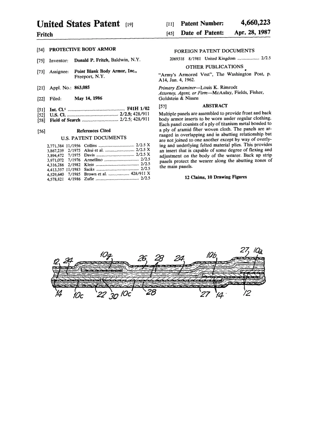
Multiple panels are assembled to provide front and back
body armor inserts to be worn under regular clothing.
Each panel consists of a ply of titanium metal bonded to
a ply of aramid fiber woven cloth. The panels are ar-
ranged in overlapping and in abutting relationship but
are not joined to one another except by way of overly-
ing and underlying felted material plies. This provides
an insert that is capable of some degree of flexing and
adjustment on the body of the wearer. Back up strip
panels protect the wearer along the abutting zones of
the main panels.
12 Claims, 10 Drawing Figures
U.S. Patent Apr. 28,1987 Sheet 1 of4 4,660,223
FIG.2
FIG.3
U.S. Patent Apr. 28,1987 Sheet2 of4 4,660,223
U. S. Patent Apr. 28,1987 Sheet 3 of4 4,660,223
U.S. Patent Apr. 28,1987 Sheet4of4 4,660,223
FIG.8
4,660,223
1
PROTECTIVE BODY ARMOR
BACKGROUND OF THE INVENTION
This invention relates to protective body armor and
more particularly to such body armor which protects
the wearer from both sharp objects and bullets.
The use of protective body armor comprising cloth
woven from aramid fibers to protect wearers from bul-
lets is known in the art. Commercial cloth is available
that is made from an aramid fiber sold by Dupont under
the trademark Kevlar. The cloth, depending upon its
thickness, provides varying degrees of protection.
In various circumstances the danger of bodily harm is
not from bullets, but rather sharp objects such as knives,
ice picks and pointed weapons. In particular, in correc-
tive facilities, most attacks against correction officers
are made with various types of blades.
Although it has been found that the woven aramid
fabric protects from bullets, it does not afford protec-
tion from blades which cut the fabric to allow the blade
to enter the body or from ice picks which part fibers to
permit penetration.
Protective armor must be comfortable to wear. If not,
there is a likelihood that it will not be used. Thus, in
addition to providing a garment which prevents injury,
manufacturers must provide garments which are rela-
tively lightweight and flexible.
Accordingly, it is a purpose of this invention to pro-
vide protective body armor which can protect the
wearer from thrusts of sharpened objects.
Additionally, it is another purpose of this invention to
provide such armor which also protects the wearer
from injury caused by bullets.
A further purpose of this invention is to provide pro-
tective armor which is worn under an outer jacket or in
specially developed pockets of a covering jacket so that
it will not be evident on visual inspection that it is being
worn.
The requirements of comfort and concealability place
great constraints on the design of body armor and thus
it is an object of this invention to provide the protective
features in a design that is concealable and reasonably
comfortable to wear for an extended period.
BRIEF DESCRIPTION OF THE DRAWINGS
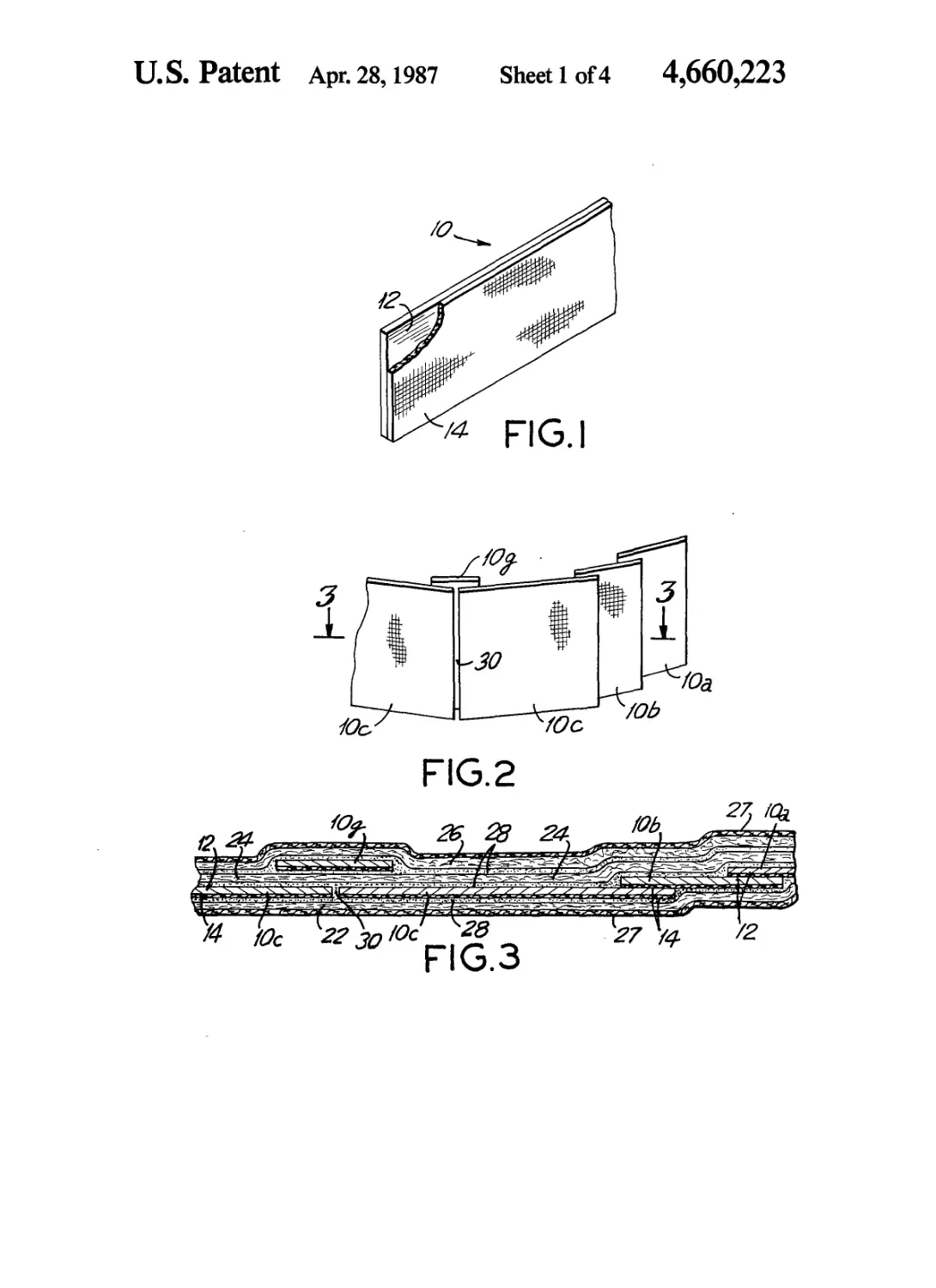
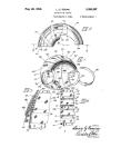
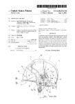
FIG. 1 is a perspective view of a typical panel of this
invention showing the two ply arrangement of titanium
metal and woven ballistic cloth.
FIG. 2 is a perspective assemblage of a number of
panels having the composition of the FIG. 1 panel ar-
ranged in overlapping and in butt relationship as they
are in a portion of the item of body armor made from
the FIG. 1 panels.
FIG. 3 is a cross-sectional view along plane 3—3 of
FIG. 2 to show the multi-layer relationship of panels,
felted layers and bonding material. FIG. 2 shows only
the panels while FIG. 3 shows other layers of the body
armor insert.
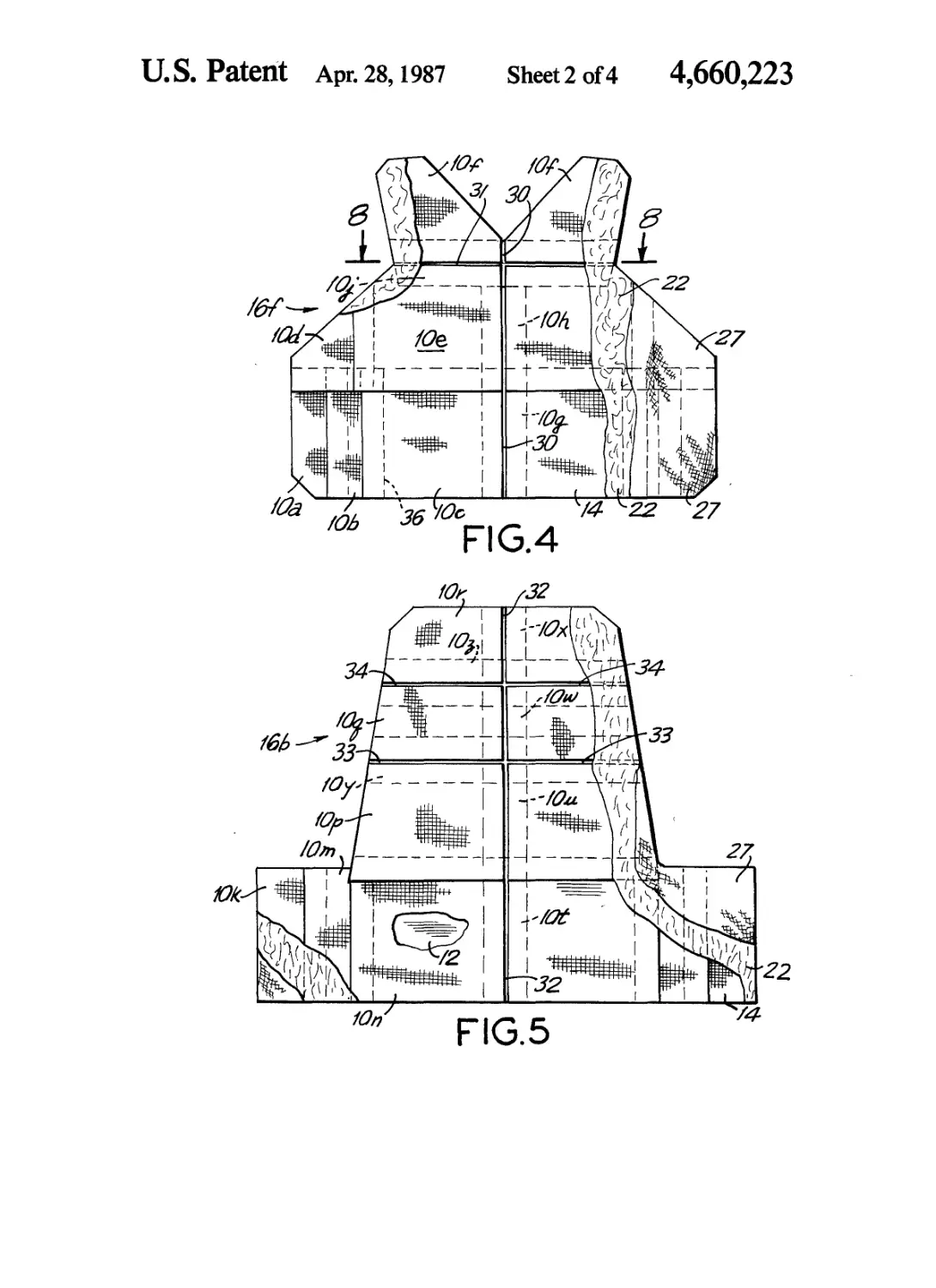
FIG. 4 is an elevation view, partially broken away, of
a front body armor insert to be worn over the front
torso of the individual wearing the entire body armor
garment.
FIG. 5 is a view similar to that of FIG. 4 except it is
of the back insert. Like FIG. 4, FIG. 5 is broken away
to show various layers and plies.
5
10
15
20
25
30
35
40
45
50
55
60
65
2
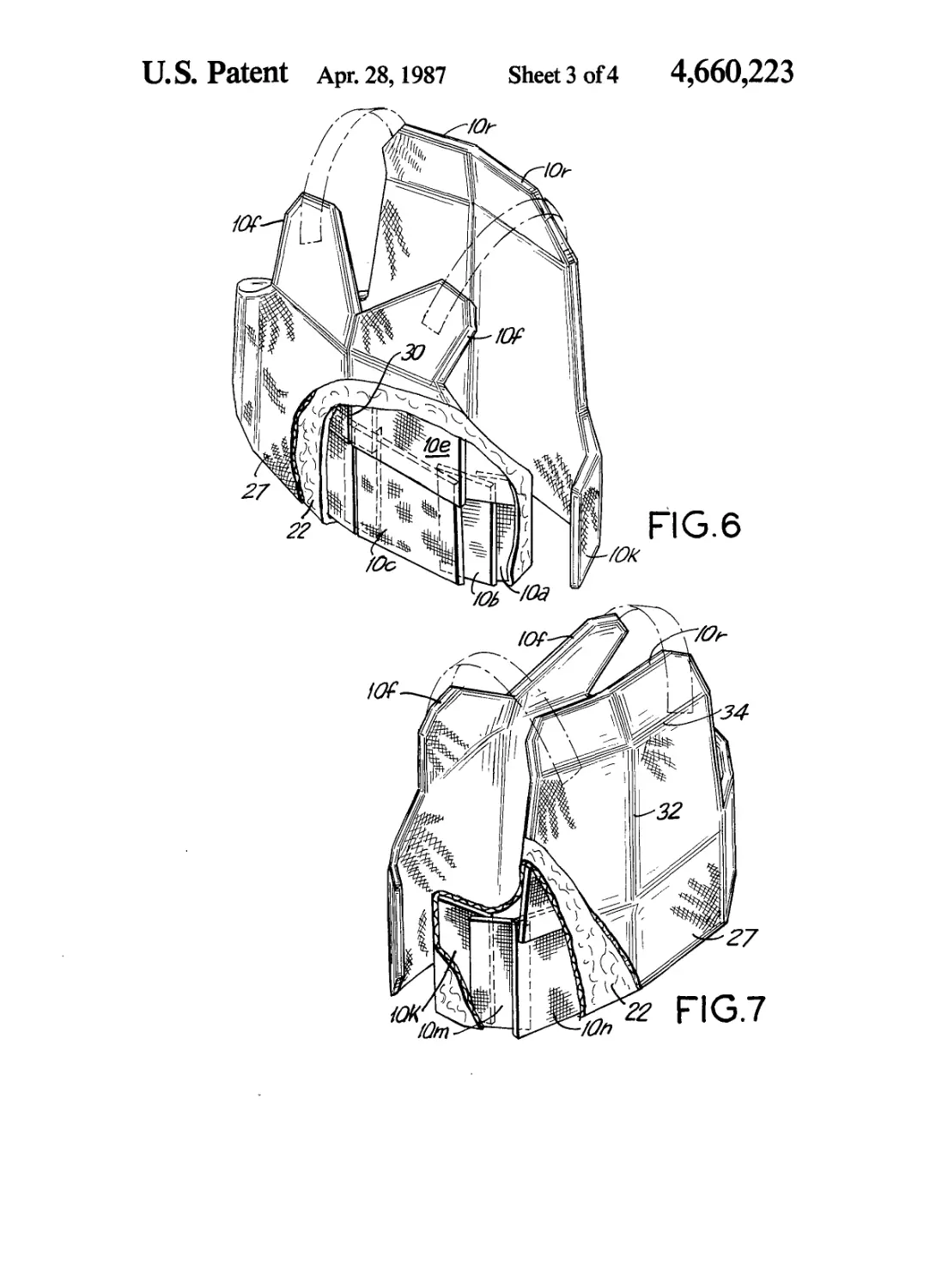
FIGS. 6 and 7 are perspective views, partially broken
away, of the two body armor inserts in relationship to
one another.
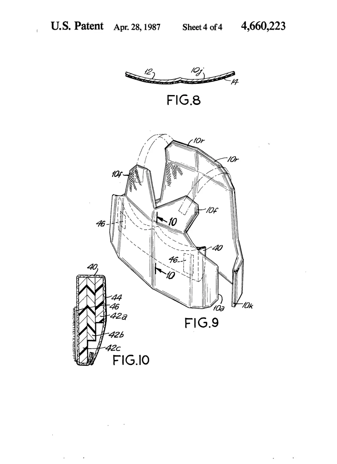
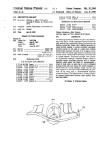
FIG. 8 is a cross sectional view along the plane 8—8
of FIG. 4 illustrating a cross section of a “seagull”
shaped back-up strip of body armor plate. To clarify the
illustration, FIG. 8 shows only the back-up strip plate
and does not illustrate the various felted layers and main
plates that are behind or in front of the FIG. 8 strip
plate.
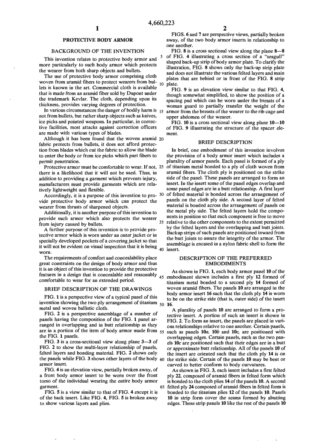
FIG. 9 is an elevation view similar to that FIG. 4,
though somewhat simplified, to show the position of a
spacing pad which can be worn under the breasts of a
woman guard to partially transfer the weight of the
armor from the breasts of the wearer to the rib cage and
upper abdomen of the wearer.
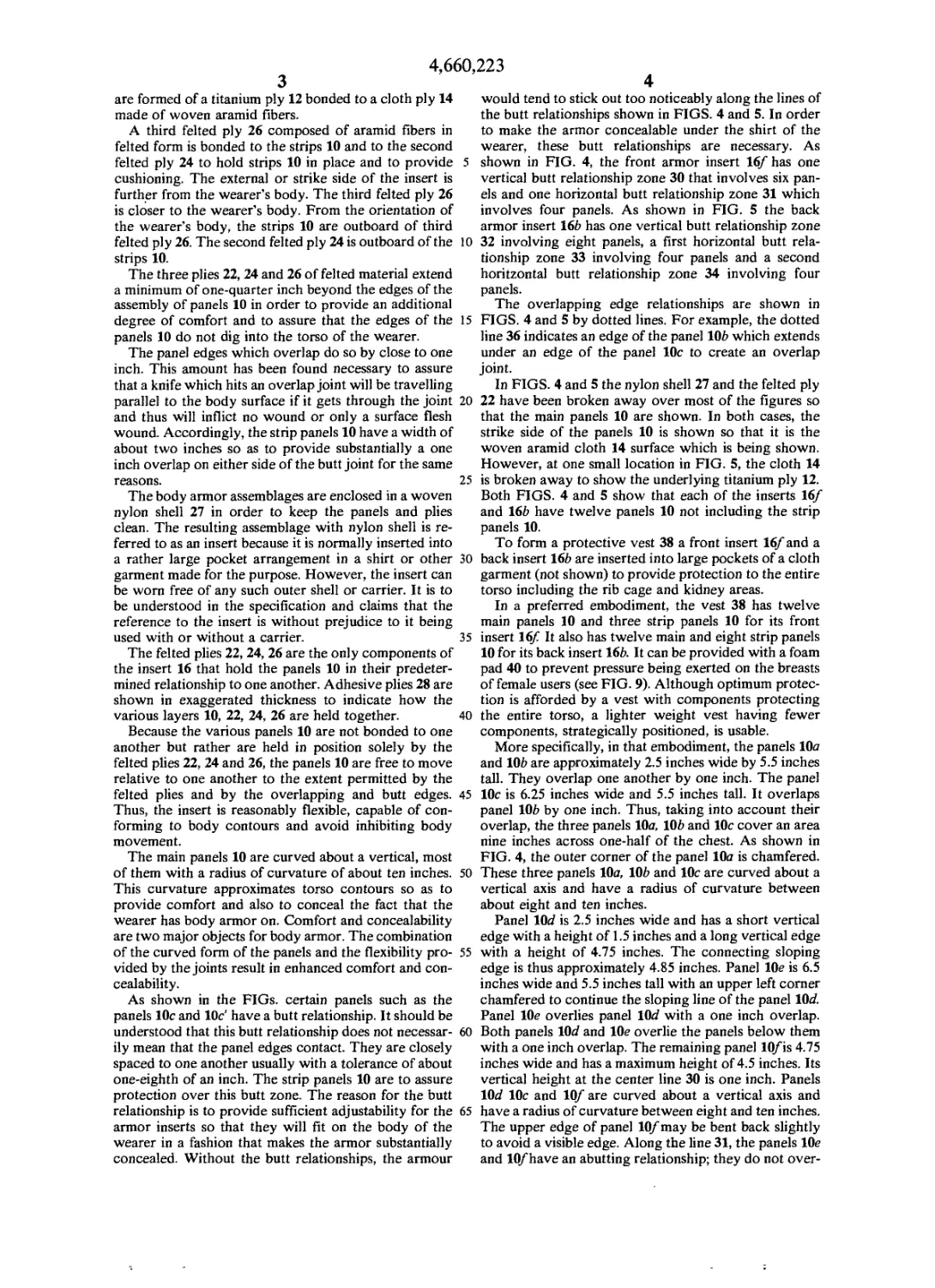
FIG. 10 is a cross sectional view along plane 10—10
of FIG. 9 illustrating the structure of the spacer ele-
ment.
BRIEF DESCRIPTION
In brief, one embodiment of this invention involves
the provision of a body armor insert which includes a
plurality of armor panels. Each panel is formed of a ply
of titanium metal bonded to a ply of cloth woven from
aramid fibers. The cloth ply is positioned on the strike
side of the panel. These panels are arranged to form an
insert. In the insert some of the panel edges overlap and
some panel edges are in a butt relationship. A first layer
of felted material is bonded across the arrangement of
panels on the cloth ply side. A second layer of felted
material is bonded across the arrangement of panels on
the metal ply side. The felted layers hold the compo-
nents in position so that each component is free to move
relative to the other components to the extent permitted
by the felted layers and the overlapping and butt joints.
Backup strips of such panels are positioned inward from
the butt joints to assure the integrity of the armor. The
assemblage is encased in a nylon fabric shell to form the
insert.
DESCRIPTION OF THE PREFERRED
EMBODIMENTS
As shown in FIG. 1, each body armor panel 10 of the
embodiment shown includes a first ply 12 formed of
titanium metal bonded to a second ply 14 formed of
woven aramid fibers. The panels 10 are arranged in the
body armor insert 16 such that the cloth ply 14 is worn
to be on the strike side (that is, outer side) of the insert
16.
A plurality of panels 10 are arranged to form a pro-
tective insert. A portion of such an insert is shown in
FIG. 2. To form an insert, the panels are placed in vari-
ous relationships relative to one another. Certain panels,
such as panels 10a, 101? and 10c, are positioned with
overlapping edges. Certain panels, such as the two pan-
els 10c are positioned such that their edges are in a butt
or approximate butt relationship. All of the panels 10 of
the insert are oriented such that the cloth ply 14 is on
the strike side. Certain of the panels 10 may be bent or
curved to better conform to body curvatures.
As shown in FIG. 3, each insert includes a first felted
ply 22, composed of aramid fibers in felted form which
is bonded to the cloth plies 14 of the panels 10. A second
felted ply 24 composed of aramid fibers in felted form is
bonded to the titanium plies 12 of the panels 10. Panels
10 in strip form cover the seams formed by abutting
edges. These strip panels 10 like the rest of the panels 10
4,660,
3
are formed of a titanium ply 12 bonded to a cloth ply 14
made of woven aramid fibers.
A third felted ply 26 composed of aramid fibers in
felted form is bonded to the strips 10 and to the second
felted ply 24 to hold strips 10 in place and to provide 5
cushioning. The external or strike side of the insert is
further from the wearer’s body. The third felted ply 26
is closer to the wearer’s body. From the orientation of
the wearer’s body, the strips 10 are outboard of third
felted ply 26. The second felted ply 24 is outboard of the 10
strips 10.
The three plies 22, 24 and 26 of felted material extend
a minimum of one-quarter inch beyond the edges of the
assembly of panels 10 in order to provide an additional
degree of comfort and to assure that the edges of the 15
panels 10 do not dig into the torso of the wearer.
The panel edges which overlap do so by close to one
inch. This amount has been found necessary to assure
that a knife which hits an overlap joint will be travelling
parallel to the body surface if it gets through the joint 20
and thus will inflict no wound or only a surface flesh
wound. Accordingly, the strip panels 10 have a width of
about two inches so as to provide substantially a one
inch overlap on either side of the butt joint for the same
reasons. 25
The body armor assemblages are enclosed in a woven
nylon shell 27 in order to keep the panels and plies
clean. The resulting assemblage with nylon shell is re-
ferred to as an insert because it is normally inserted into
a rather large pocket arrangement in a shirt or other 30
garment made for the purpose. However, the insert can
be worn free of any such outer shell or carrier. It is to
be understood in the specification and claims that the
reference to the insert is without prejudice to it being
used with or without a carrier. 35
The felted plies 22, 24, 26 are the only components of
the insert 16 that hold the panels 10 in their predeter-
mined relationship to one another. Adhesive plies 28 are
shown in exaggerated thickness to indicate how the
various layers 10, 22, 24, 26 are held together. 40
Because the various panels 10 are not bonded to one
another but rather are held in position solely by the
felted plies 22, 24 and 26, the panels 10 are free to move
relative to one another to the extent permitted by the
felted plies and by the overlapping and butt edges. 45
Thus, the insert is reasonably flexible, capable of con-
forming to body contours and avoid inhibiting body
movement.
The main panels 10 are curved about a vertical, most
of them with a radius of curvature of about ten inches. 50
This curvature approximates torso contours so as to
provide comfort and also to conceal the fact that the
wearer has body armor on. Comfort and concealability
are two major objects for body armor. The combination
of the curved form of the panels and the flexibility pro- 55
vided by the joints result in enhanced comfort and con-
cealability.
As shown in the FIGs. certain panels such as the
panels 10c and 10c' have a butt relationship. It should be
understood that this butt relationship does not necessar- 60
ily mean that the panel edges contact. They are closely
spaced to one another usually with a tolerance of about
one-eighth of an inch. The strip panels 10 are to assure
protection over this butt zone. The reason for the butt
relationship is to provide sufficient adjustability for the 65
armor inserts so that they will fit on the body of the
wearer in a fashion that makes the armor substantially
concealed. Without the butt relationships, the armour
,223
4
would tend to stick out too noticeably along the lines of
the butt relationships shown in FIGS. 4 and 5. In order
to make the armor concealable under the shirt of the
wearer, these butt relationships are necessary. As
shown in FIG. 4, the front armor insert 16/ has one
vertical butt relationship zone 30 that involves six pan-
els and one horizontal butt relationship zone 31 which
involves four panels. As shown in FIG. 5 the back
armor insert 16b has one vertical butt relationship zone
32 involving eight panels, a first horizontal butt rela-
tionship zone 33 involving four panels and a second
horitzontal butt relationship zone 34 involving four
panels.
The overlapping edge relationships are shown in
FIGS. 4 and 5 by dotted lines. For example, the dotted
line 36 indicates an edge of the panel 10£> which extends
under an edge of the panel 10c to create an overlap
joint.
In FIGS. 4 and 5 the nylon shell 27 and the felted ply
22 have been broken away over most of the figures so
that the main panels 10 are shown. In both cases, the
strike side of the panels 10 is shown so that it is the
woven aramid cloth 14 surface which is being shown.
However, at one small location in FIG. 5, the cloth 14
is broken away to show the underlying titanium ply 12.
Both FIGS. 4 and 5 show that each of the inserts 16/
and 16b have twelve panels 10 not including the strip
panels 10.
To form a protective vest 38 a front insert 16/ and a
back insert 16b are inserted into large pockets of a cloth
garment (not shown) to provide protection to the entire
torso including the rib cage and kidney areas.
In a preferred embodiment, the vest 38 has twelve
main panels 10 and three strip panels 10 for its front
insert К/ It also has twelve main and eight strip panels
10 for its back insert 16Z>. It can be provided with a foam
pad 40 to prevent pressure being exerted on the breasts
of female users (see FIG. 9). Although optimum protec-
tion is afforded by a vest with components protecting
the entire torso, a lighter weight vest having fewer
components, strategically positioned, is usable.
More specifically, in that embodiment, the panels 10a
and 10Z? are approximately 2.5 inches wide by 5.5 inches
tall. They overlap one another by one inch. The panel
10c is 6.25 inches wide and 5.5 inches tall. It overlaps
panel 10£> by one inch. Thus, taking into account their
overlap, the three panels 10a, 10£> and 10c cover an area
nine inches across one-half of the chest. As shown in
FIG. 4, the outer corner of the panel 10a is chamfered.
These three panels 10a, 10Z? and 10c are curved about a
vertical axis and have a radius of curvature between
about eight and ten inches.
Panel 10c? is 2.5 inches wide and has a short vertical
edge with a height of 1.5 inches and a long vertical edge
with a height of 4.75 inches. The connecting sloping
edge is thus approximately 4.85 inches. Panel lOe is 6.5
inches wide and 5.5 inches tall with an upper left corner
chamfered to continue the sloping line of the panel 10c?.
Panel lOe overlies panel 10c? with a one inch overlap.
Both panels 10c? and lOe overlie the panels below them
with a one inch overlap. The remaining panel 10/is 4.75
inches wide and has a maximum height of 4.5 inches. Its
vertical height at the center line 30 is one inch. Panels
10c? 10c and 10/ are curved about a vertical axis and
have a radius of curvature between eight and ten inches.
The upper edge of panel 10/may be bent back slightly
to avoid a visible edge. Along the line 31, the panels lOe
and 10/have an abutting relationship; they do not over-
4,660,
5
lap. A mirror image set of panels is provided to consti-
tute the other half of the front insert 16/ As shown in
FIG. 4, the two sets of panels that provide the two
halves of the front insert 16/are arranged in an abutting
relationship along the vertical line 30. 5
There are a total of three strip panels used in connec-
tion with the front insert 16/ to provide additional pro-
tection along the abutting zones 30 and 31. These strip
panels are a first strip panel 10g which is two inches
wide and 5.5 inches tall along the lower portion of the 10
zone 30. A second strip panel 10A is two inches wide
and 4.5 inches tall along the upper portion of the zone
30. The lower end of 10A overlaps the upper end of 10g
by one inch. Thereby providing a nine inch length of
strip panels. A somewhat more complex bowed strip 15
panel 10/ is two inches wide and approximately 9.5
inches long. It is arranged behind the zone 31 and ex-
tends across the entire front insert 16/ As shown, this
strip panel 10/ has a somewhat complex “seagull” pro-
file shape so as to conform to a line across the torso of 20
the wearer and to avoid a chicken breast effect. Each
half of the panel 10/ has a radius of curvature of between
eight and ten inches to match the curvature of the pan-
els 10/ The upper portion of panel 10A is creased along
a vertical line so as to approximately match the profile 25
of the strip panel 10/ at the horizontal zone 31. The strip
panels 10k and 10/ have an abutting relationship and do
not overlap.
The back insert 16b has overlapping end panels 10k
and lOzn which are each 3.0 inches wide and 6.5 inches 30
tall. A center bottom panel lOn is 6.5 inches by 6.5
inches and overlaps panel 10m by one inch thereby
providing approximately a ten inch horizontal distance
over the bottom portion of one half of the back insert
16b. The panel lOp is 5 inches tall and overlaps by one 35
inch the panel lOn. The panel lOp is 6.5 inches at its base
line and tapers to approximately 5.8 inches along its top
at the zone 34. The panel 10g is 3.25 inches high and
tapers from 5.8 inches to 5.25 inches. The panel 10г has
a 3 inch vertical dimension and continues the edge taper 40
to a small chamfer at the upper comer which results in
a 4 inch horizontal dimension at the top of the panel 10г.
As shown in FIG. 5, the panels lOp, 10g and 10г have an
abutting relationship to one another at zones 33 and 34.
The set of panels 10k through 10г are matched by a 45
mirror image set of panels to form the other half of the
back insert 16b. The two halves of the insert 16b have an
abutting relationship along the vertical zone 32. How-
ever, panels lOn, lOp, 10g and 10г are curved about a
vertical axis and have a radius of curvature between ten 50
and twelve inches. Panels 10k and 10m are curved
about a vertical axis and have a curvature comparable
to that of the front panels 10a through 10/ Because of
the abutting zones, the amount of curvature of the pan-
els is minimized and, in particular, the upper panels 10/ 55
10g and lOp need not be curved about a horizontal axis
and thus complex curvatures are avoided.
A number of strip panels are employed to provide
protection along the abutting zones 32, 33 and 34. All of
these strip panels are two inches wide and thus only 60
their lengths are indicated here. The vertically aligned
strip panels 10Z, lOu, 10n> and lOx are respectively 6.5,
5.0, 3.25 and 3.0 inches long. The panels 10г and lOu
have a one inch overlap whereas the rest of the relation-
ships among these four strip panels are abutting rela- 65
tionships. The horizontal strip panel lOy has a center
length of approximately 5.85 inches and the horizontal
strip panel lOz has a center length of approximately 5.35
,223
6
inches. These two panels lOy and lOz provide protective
back-up along the zones 33 and 34 and are matched by
mirror image panels on the other side of the insert 16£>.
The outer end of the panels lOy and lOz are tapered to
conform to the taper defined by the panels lOp, 10g and
10г.
In a preferred embodiment, each titanium ply 12 is .
about 0.04 inches (0.10 cm) thick. This is effective to
prevent a sharp instrument from penetrating. Each
cloth ply 14 has a woven texture which provides a
non-skid surface that serves to mechanically catch a
blade tip or ice-pick tip. This prevents the tip from
moving along the surface to a joint in the insert or to
another area through which it could penetrate.
In a preferred embodiment, each felted ply is made of
high density, high tensile, felt fabric having a thickness
of about 0.090 inches (0.22 cm), a weight of about 10
ounces/sq. yard. The total thickness of a vest 38 formed
from the inserts 16/ and 16b is approximately three-
eighth of an inch (0.95 cm) and has a weight, in a me-
dium size, of about 6.1 pounds (2.76 kg) making the vest
comfortably wearable for about eight hours.
In tests, it has been found that a vest employing these
inserts 38 will resist eighty ft. lbs. of energy applied to
ice picks and bowie knives. The vest also stopped the
following threats at 0° obliquity.
BULLET TYPE BARREL LENGTH (inches) VELOC- ITY
.38 CAL - 158 GR. 4" 775 F.P.S.
S.W.C. LEAD
.32 CAL - AUTO 88 GR. 3" ' 680 F.P.S.
12 Gauge - NO. 4 LEAD 18" —
SHOT
Bullet resistance may be increased by the addition of
aramid fabric layers on the body side.
In California, as much as one third of the correction
officers are female. Accordingly, it is important that the
body armor be designed to minimize the weight or
pressure on a woman’s breasts. The spacer element 40
serves to prevent undue pressure being exerted on the
breasts of female users. The spacer 40 rests on the lower
part of the wearer’s rib cage. The armor, in turn, rests
on the spacer 40 and thus the weight of the armor and
the pressure that results is partially transferred to the
lower part of the rib cage. Thus, the spacer 40 holds the
front armor insert 16/ outward and takes the pressure
from that insert 16/
The embodiment of this spacer 40 shown has a num-
ber of stepped plies 42. It could be a molded insert. In
addition, the number of steps is a function of the breast
size of the individual for whom it will be used. It has
been found when the foam is stepped as shown, that the
manner in which it responds to the weight of the body
armor provides a fairly even distribution of weight over
the rib cage and body of the wearer. The spacer 40 is
enclosed within a woven nylon shell 44. Vertically
running separable fasteners 46 such as Velcro strips are
attached near the outward ends of the nylon cover and
mate with corresponding fastener strips that are at-
tached to the nylon shell 27 within which the body
armor insert 16/ is contained. The vertical fastener
strips on the nylon cover of the body armor insert 16/
are longer than the corresponding strips on the spacer
40 so that the spacer 40 can be positioned at a level
desired by the individual wearing the item. The smallest
4,660,223
8
3. The body armor of claim 1 further comprising:
at least one of said panels in strip form positioned in
alignment with a butt joint and positioned inward
from said second layer of felted material; and
a third layer of felted material inward from said panel
in strip form, said third layer of felted material
being bonded to said third panel and to said second
layer of felted material.
4. The insert of claim 3 wherein the cloth ply of said
10 panel form is on the strike side of said insert.
5. The insert of claim 3 wherein said titanium ply is
approximately at least one mm (40 mils) thick.
6. The insert of claim 5 wherein said felted layers are
substantially composed of aramid fibers in felt fabric
15 form.
7. The insert of claim 3 wherein said felted layers are
substantially composed of aramid fibers in felt fabric
form.
8. The insert of claim 3 wherein certain of said panels
are curved.
9. The insert of claim 1 wherein said titanium ply is
approximately at least one mm (4C mils) thick.
10. The insert of claim 1 wherein said felted layers are
substantially composed of aramid fibers in felt fabric
25 form.
11. The insert of claim 1 wherein certain of said pan-
els are curved.
12. The insert of claim 11 wherein certain of said
panels are curved.
7
ply 42<? is positioned closest to the body and thus the
fastener element is along the nylon cover which adja-
cent to the largest ply 42c.
What I claim is:
1. A body armor insert comprising: 5
an assemblage of substantially adjacent panels, each
of said panels comprising a first ply of titanium
metal and a second ply of ballistic cloth woven
from aramid fibers, said first and second plies
bonded to one another, said assemblage having a
strike face and an inner face, said cloth ply consti-
tuting the strike side of each of said panels,
a first layer of felted material across said strike face of
said assemblage of panels and a second layer of
felted material across said inner face assemblage of
panels, said first and second layers of felted mate-
rial being bonded to said strike and interior faces
respectively of said assemblage of panels to hold
said assemblage of panels in substantially predeter-
mined relationships. 20
2. The body armor insert of claim 1 wherein certain
edges of adjacent ones of said panels are positioned in an
overlapping relationship to provide an overlap joint and
certain edges of adjacent ones of said panels are posi-
tioned in a butt relationship to provide a butt joint,
said adjacent ones of said panels, whether in said edge
overlapping or edge abutting relationship, being
held in position solely by said felted layers and
being free to move relative to one another to the
extent permitted by said felted layers. 30
35
40
45
50
55
60
65