/
Tags: means of protection
Year: 1988
Text
United States Patent пя пи e
Aileo et al.
Patent Number: Re. 32,569
[45] Reissued Date of Patent: Jan. 5, 1988
[54] PROTECTIVE HELMET
[75] Inventors: Jackson A. Aileo, Carbondale;
Leonard P. Frieder, Jr., Dalton, both
of Pa.
[73] Assignee: Gentex Corporation, Carbondale, Pa.
[21] Appl. No.: 515,217
[22] Filed: Jul. 20,1983
Related U.S. Patent Documents
Reissue of:
[64] Patent No.: 3,897,596
Issued: Aug. 5,1975
Appl. No.: 500,547
Filed: Aug. 26,1974
[51] Int. Cl?.............................A42B 3/00
[52] UJS. Cl.............................. 2/416; 2/6;
2/420; 2/171.1
[58] Field of Search............. 2/416, 417, 418, 419,
2/420, 421, 6; 2/171.1
[56] References Cited
U.S. PATENT DOCUMENTS
2,177,145 10/1939 Lewis................... 2/416
2,351,235 6/1944 Shroyer et al........... 2/416
2,739,309 3/1956 Frieder et al.............2/3 R
2,805,419 9/1957 Funken ................ 2/423
2,853,708 9/1958 Austin................... 2/416
2,855,604 10/1958 Austin................... 2/416
2,983,923 5/1961 Aileo.................... 2/418
3,154,788 11/1964 Simpson................. 2/418
3,223,086 12/1965 Denton.................... 2/6 X
3,353,188 11/1967 Crincic ............ 2/171.1 X
3,442,459 1/1969 Bowers, Jr. ............. 2/416
3,613,114 10/1971 Hill et al...................... 2/416
3,958,276 5/1976 Clausen........................... 2/2.5
FOREIGN PATENT DOCUMENTS
0865015 2/1941 France .................. 2/416
0323631 12/1934 Italy ................... 2/417
0350142 6/1931 United Kingdom........... 3/420
0539577 9/1941 United Kingdom ............ 2/6
Primary Examiner—Peter Nerbun
Attorney, Agent, or Firm—Shenier & O’Connor
[57] ABSTRACT
An improved protective helmet for use by an infantry-
man or the like in which a suspension frame of relatively
rigid material has a peripheral channel provided at one
location around the frame with a slightly inwardly in-
clined portion adapted to receive a slightly outwardly
directed portion of the edge of a rigid outer ballistic
helmet body to permit the body to be swung to a posi-
tion in which the entire edge thereof is received in the
channel and in which position the body is securely held
by a single fastener. The frame is formed with a plural-
ity of generally upwardly extending fingers which re-
movably receive envelopes carrying pads of resilient
material which adapt the frame to accommodate a
range of head sizes. A light line or cord is threaded
through holes and slots around the frame releasably to
secure both the crown assembly straps and the chin
strap supports to the frame while maintaining the posi-
tions of the strap ends at predetermined locations
around the frame. The helmet body is formed of ballis-
tic material sandwiched between rigid molded inner
and outer shells.
49 Claims, 10 Drawing Figures
/34
US. Patent Jan. 5,1988
Sheet 1 of 5 Re.32,569
021
US. Patent Jan. 5,1988
Sheet 2 of 5
Re.32,569
foe
U.S. Patent Jan. 5,1988
Sheet 3 of 5
Re32,569
US. Patent Jan. 5,1988
Sheet 4 of 5
Re.32,569
U.S. Patent Jan. 5,1988
Sheet 5 of 5
Re.32,569
Re. 32
10
15
20
25
30
35
PROTECTIVE HELMET
Matter enclosed in heavy brackets [ ] appears in the
original patent but forms no part of this reissue specifica- 5
tion; matter printed in italics indicates the additions made
by reissue.
BACKGROUND OF THE INVENTION
There are known in the prior art various forms of
protective helmet for use by military personnel such as
infantrymen to protect the head of the wearer against
injury from missiles and shrapnel. All of these helmets
of the prior art incorporate some form of suspension
system for supporting the helmet in position on the
wearer’s head. Most of the headband suspensions are
secured to the rigid helmet body by the use of metal
fasteners such as screws, for example. One type of such
a helmet and suspension assembly is shown in Frieder et
al U.S. Pat. No. 2,739,309. These helmet and suspension
assemblies of the prior art incorporate a number of more
or less serious defects. First, the metal fasteners which
are used to secure the suspension to the helmet shell
often act as secondary missiles when struck by a piece
of flying shrapnel or the like. As a result, the wearer
may suffer a more serious injury than that which would
occur from the shrapnel. Secondly, suspension systems
of the prior art permit “bottoming” of the hard outer
shell on the wearer’s head under the force of an impact
on the outer shell, with the attendant danger of injury to
the wearer.
In addition to the defects pointed out hereinabove,
the protective helmet assemblies of the prior art suffer
from a number of disadvantages. Generally adjustment
of the size of the suspension is difficult to accomplish.
Most of the suspensions of the prior art accommodate
only a very small range of head sizes. The helmets of the
prior art are heavy. Suspensions of the prior art are
permanently attached to the rigid shell with the result
that the parts thereof are difficult to clean.
There have recently been developed a class of materi-
als including aromatic polyimide resins which have
been found to have superior ballistic properties. At-
tempts in the prior art to develop a ballistic helmet
incorporating such materials have been unsuccessful in
that mass production at relatively low cost has not been
feasible.
We have invented an improved protective helmet
which overcomes the disadvantages of helmets of the
prior art. Our helmet minimizes the danger of injury
from fasteners acting as secondary missiles. It prevents
bottoming of the hard shell on the wearer’s head. Our
helmet accomodates a wide range of head sizes. The
suspension system of our helmet is readily removable
from the rigid shell. Our helmet is lightweight. It per-
mits of the mass production at relatively low cost of a
helmet having ballistic properties.
SUMMARY OF THE INVENTION
One object of our invention is to provide an im-
proved protective helmet which overcomes the disad-
vantages of protective helmets of the prior art. 65
Another object of our invention is to provide an
improved protective helmet which minimizes the dan-
ger of injury from fasteners acting as secondary missiles.
40
45
50
55
60
,569
2
Still another object of our invention is to provide an
improved protective helmet in which bottoming of the
hard outer shell on the wearer’s head is inhibited.
A further object of our invention is to provide an
improved protective helmet which accomodates a wide
range of head sizes.
Yet another object of our invention is to provide an
improved protective helmet construction which per-
mits of the mass production at relatively low cost of a
helmet having ballistic properties.
A further object of our invention is to provide an
improved protective helmet having a suspension system
which can readily be removed for cleaning or replace-
ment.
A still further object of our invention is to provide an
improved protective helmet which is lightweight.
Other and further objects of our invention will ap-
pear from the following description.
In general our invention contemplates the provision
of an improved protective helmet including a suspen-
sion frame of relatively rigid material formed with a
peripheral channel having a slightly inwardly directed
portion at one location therearound, which portion is
adapted to receive a slightly outwardly directed portion
of the edge of a rigid protective helmet body to permit
the body to be swung to a position at which its entire
edge is received in the channel and in which position
the body can be retained by use of a single fastener. A
cord threaded through holes and slots around the pe-
riphery of the frame releasably retains the crown struc-
ture and the chin strap supports to the frame. A plural-
ity of pouch-forming elements releasably carried by
fingers extending upwardly from the frame receive pads
which may vary in size to accommodate a range of head
sizes.
BRIEF DESCRIPTION OF THE DRAWINGS
In the accompanying drawings which form part of
the instant specification and which are to be read in
conjunction therewith and in which like reference nu-
merals are used to indicate like parts in the various
views:
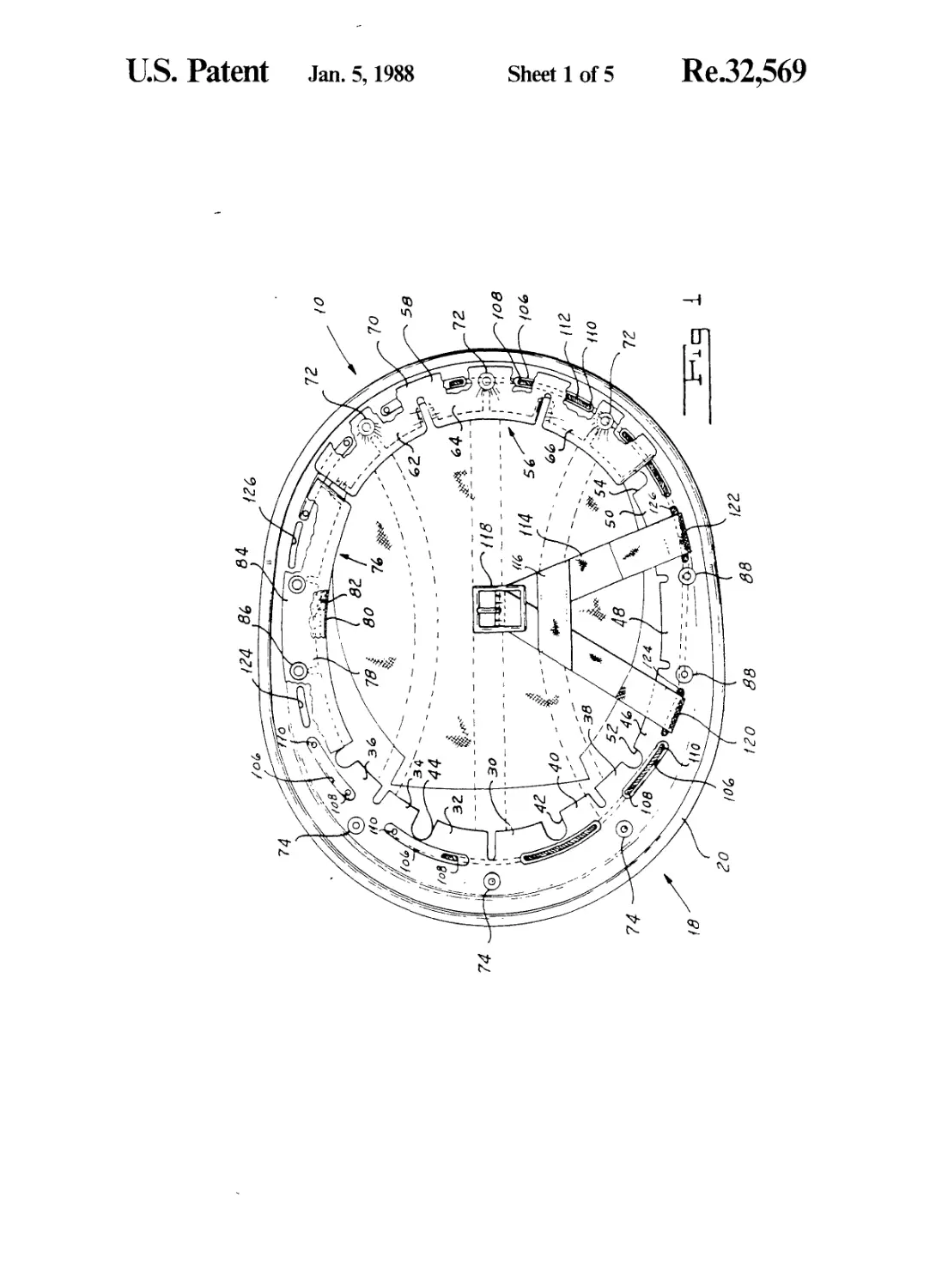
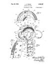
FIG. 1 is a bottom plan view of our improved protec-
tive helmet.
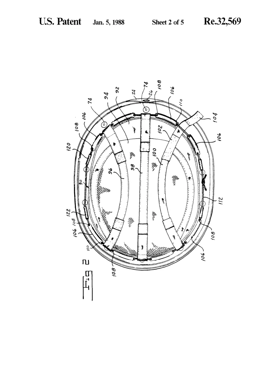
FIG. 2 is a top plan view of our improved protective
helmet with the outer helmet body removed.
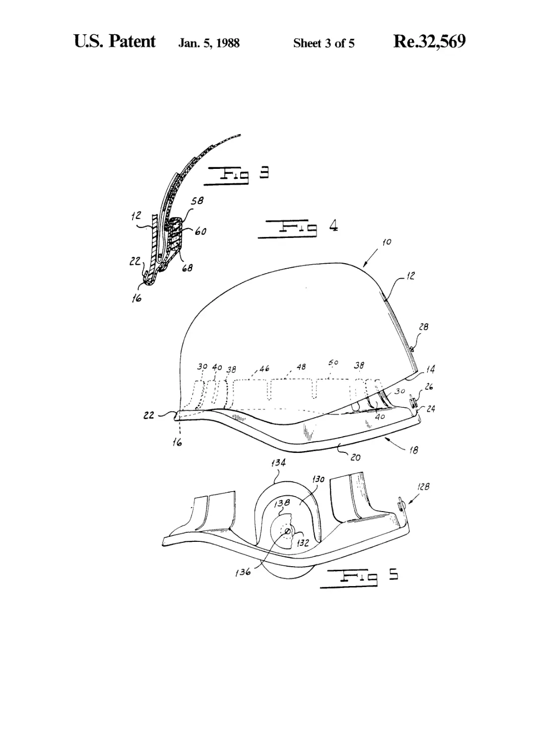
FIG. 3 is a fragmentary sectional view of our im-
proved protective helmet.
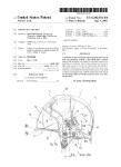
FIG. 4 is a side elevation illustrating the manner in
which the body is assembled with the suspension frame
in our improved protective helmet.
FIG. 5 is a side elevation of an alternate embodiment
of our improved protective helmet.
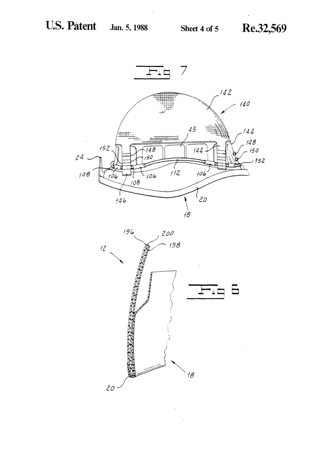
FIG. 6 is a fragmentary sectional view illustrating the
preferred form of helmet body incorporated in our
improved protective helmet.
FIG. 7 is a side elevation of our improved protective
helmet with the body removed illustrating an alternate
form of crown structure which we may employ.
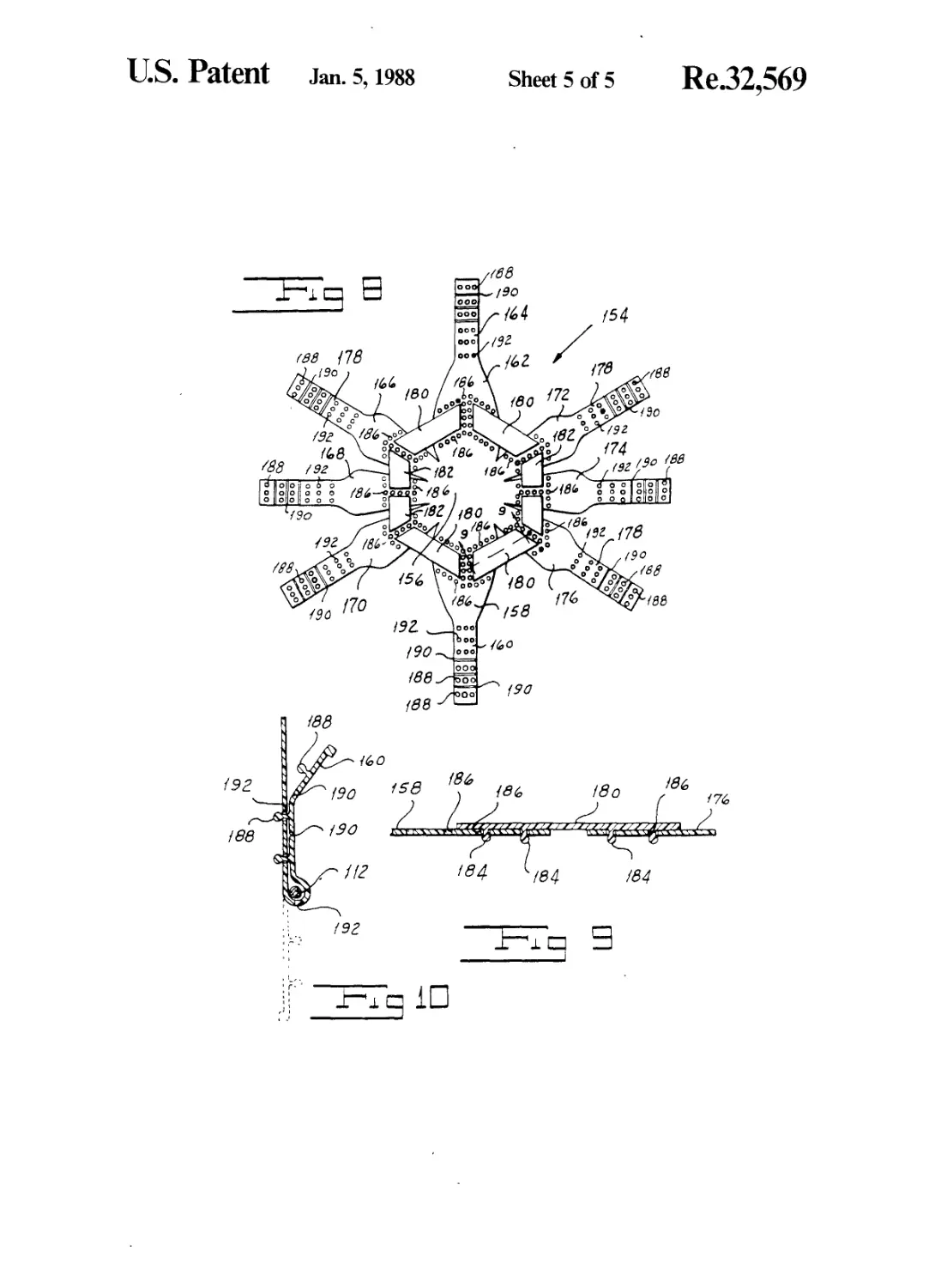
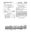
FIG. 8 is a plan view of yet another form of crown
structure which we may employ.
FIG. 9 is a fragmentary sectional view of the crown
structure illustrated in FIG. 8 taken along the line 9—9
of FIG. 8 and drawn on an enlarged scale.
FIG. 10 is a fragmentary sectional view illustrating
one of the features of the crown structure shown in
FIG. 8.
Re. 32,569
3
DESCRIPTION OF THE PREFERRED
EMBODIMENT
Referring now to FIGS. 3, 4 and 6, our improved
protective helmet, indicated generally by the reference
character 10, includes a body 12 having superior ballis-
tic properties. In its preferred form the body 12 includes
respective inner and outer shells 198 and 196 formed
from a suitable material such, for example, as a polycar-
bonate resin provided with a coating of a suitable elasto-
mer which is applied to the shells either by compression
molding or by a spray coat or dip coating method.
Sandwiched between the shells 196 and 198 is a layer
200 of ballistic material. While any high elongation,
high tensile strength fibrous material having a high
melting point may be employed, preferably we select
one of the “aromids” which include aromatic polyimide
resins developed by E. I. duPont de Nemours Com-
pany, and sold under the trademarks “Kevlar” and
“Nomex.” The fibrous material making up the center
layer 200 may be woven, or it may be needlepoint felt,
or it may be fibrous material loosely bound together by
the use of any suitable binder. We form the body with
an edge 14 having a slightly outwardly-directed portion
16 at the front of the helmet.
Referring now to FIGS. 1 to 4, our helmet includes a
suspension frame 18 formed of any suitable synthetic
resin. This frame 18 has a peripheral channel 20, a por-
tion 22 of which adjacent to the front of the frame is
slightly inwardly directed. In assembling the body 12 on
the frame 18, the edge portion 16 is inserted in the chan-
nel portion 22 in the manner illustrated in FIG. 3, and
the helmet body can then be swung down to a position
at which the edge 14 is received in the channel 20
around the entire periphery of the helmet. When the
body 12 has thus been assembled on the frame 18, it can
securely be held in assembled relationship by use of a
single fastener. In the particular embodiment illustrated
in the drawings, an upwardly-directed extension 24 at
the back of the frame 18 carries a female fastener ele-
ment 26 adapted to receive a male fastener element 28
secured to the hard outer shell. It will readily be appre-
ciated that we have thus provided an assembly of a
suspension frame and ballistic body with the use of only
a single fastener.
We form each of the back and front of the frame 18
with a plurality of pairs of upwardly-directed exten-
sions or fingers 30 and 32, 34 and 36, and 38 and 40.
Relatively wide gaps 42 and 44 separate the central
group of fingers [34] 30 and [36] 32 from the outer
groups of fingers [30] 34 and [32] 36 and 38 and 40
at the back and at the front of the frame 18.
In addition to the fingers at the front and at the back
of the frame, we provide three side fingers 46,48 and 50
on each side of the frame 18. Relatively larger spaces 52
and 54 separate the side fingers from the front and back
fingers for a reason to be described more fully hereinbe-
low. Preferably the fingers 30, 32, 34, 36, 38, 40, 46, 48
and 50 all are molded integrally with the channel-form-
ing portion 20 of the frame 18.
While the material of which the frame is formed is
relatively rigid, the upwardly directed fingers are thin
and are thus somewhat resilient. Further, as will more
fully be understood from the description hereinbelow,
the fingers and the portion of the frame connecting the
fingers to the channel 20 serve to hold the ballistic shell
12 in spaced relationship to the wearer’s head. More-
over, these parts of the frame 18 prevent bottoming of
5
10
15
20
25
30
35
40
45
50
55
60
65
4
the helmet on the wearer’s head in response to a blow
on the side of the outer shell. Thus the wearer’s head is
protected against injury which might otherwise result
from the hard outer shell being driven into engagement
with his head.
We provide our helmet with front and back pad-car-
rying envelopes, the front one of which is indicated
generally by the reference character 56. Envelope 56
includes an inner skin 58 and an outer skin 60 which
may be cut from a single piece of a suitable material
such, for example, as glove leather, and stitched to form
three compartments 62, 64 and 66. Each of the compart-
ments 62, 64 and 66 carries an insert 68 of any suitable
relatively soft material such, for example, as foamed
natural or synthetic rubber. The envelope 56 is assem-
bled on the frame by slipping the outer skin 60 over the
front fingers 30, 32, 34, 36, 38 and 40 so that each of the
compartments 62, 64 and 66 receives one set of fingers
and so that the edges of the compartment-forming por-
tions of the envelope 56 are received in the spaces 42
and [40] 44. This assembly operation further is carried
out so that the insert pads 68 are disposed inside of the
fingers. We provide the inner skin 58 with a flap 70
carrying a plurality of female snap fastener elements 72
adapted to receive male snap fastener elements 74 se-
cured to the frame 18.
In addition to the front and rear envelopes 56, our
helmet includes a pair of side envelopes 76, each of
which is made up of an inner skin 78 and an outer skin
80, which may be cut and stitched from a single piece of
suitable material such as glove leather to form a com-
partment for receiving an insert 82 made of foam rubber
or the like. In assembling the envelope 76 on the frame
18, the outer skin 80 is slipped over the fingers 46, 48
and 50 so that the side edges of the envelope are re-
ceived in the spaces 52 and 54 and so that the pad 82 is
inside of the fingers. A flap 84 on the [outer] inner skin
78 of the envelope 76 carries a plurality of spaced fe-
male snap fastener elements 86 adapted to engage male
fastener elements 88 carried by the frame 18.
It will readily be appreciated that the envelopes 56
and 76 may manually be applied to the frame 18 and
may manually be removed therefrom. This operation
permits of the insertion of pads 68 and 82 of different
sizes, or of different numbers of pads, to accomodate a
wide range of head [sized] sizes. In addition, the re-
movable feature of the envelope permits cleaning and
replacement of wom parts.
Our protective helmet includes a crown structure,
indicated generally by the reference character 90,
which may be any one of a number of variations of a
basic crown structure. In the particular crown structure
90 illustrated in FIGS. 1 to 4, a relatively closely-woven
fabric is cut and stitched to form the peripheral portion
92 of the crown structure 90. We stitch or otherwise
secure a central mesh portion 94 to the peripheral por-
tion 92 to ensure adequate ventilation. In the crown
structure 90 there are three crown straps 96, 98 and 100.
The crown strap 98 is stitched to the peripheral and
central portions [90] 92 and [92] 94 so that it extends
generally in a fore-and-aft direction over the wearer’s
head. The other two crown straps 96 and 100 are
slightly curved so as to extend over the wearer’s head
adjacent to the sides thereof. Each of the crown straps
96, 98 and 100 has two free ends, each of which carries
a length 104 of readily releasable attaching elements
adapted to cooperate with a pad 102 of complementary
elements secured to the strap at a location somewhat
32
Re.
5
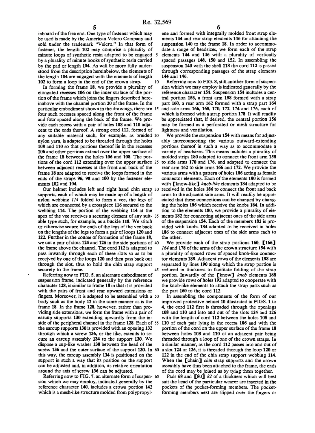
inboard of the free end. One type of fastener which may
be used is made by the American Velcro Company and
sold under the trademark “Velcro.” In that form of
fastener, the length 102 may comprise a plurality of
minute loops of synthetic resin adapted to be engaged
by a plurality of minute hooks of synthetic resin carried
by the pad or length 104. As will be more fully under-
stood from the description hereinbelow, the elements of
the length 104 are engaged with the elements of length
102 to form a loop in the end of the crown strap.
In forming the frame 18, we provide a plurality of
elongated recesses 106 on the inner surface of the por-
tion of the frame which joins the fingers described here-
inabove with the channel portion 20 of the frame. In the
particular embodiment shown in the drawings, there are
four such recesses spaced along the front of the frame
and four spaced along the back of the frame. We pro-
vide each recess with a pair of holes 108 and 110 adja-
cent to the ends thereof. A strong cord 112, formed of
any suitable material such, for example, as braided
nylon yam, is adapted to be threaded through the holes
108 and 110 so that portions thereof lie in the recesses
106 and other portions extend over the upper surface of
the frame 18 between the holes 106 and 108. The por-
tions of the cord 112 extending over the upper surface
between adjacent recesses at the front and back of the
frame 18 are adapted to receive the loops formed in the
ends of the straps 96, 98 and 100 by the fastener ele-
ments 102 and 104.
Our helmet includes left and right hand chin strap
supports, each of which may be made up of a length of
nylon webbing 114 folded to form a vee, the legs of
which are connected by a crosspiece 116 secured to the
webbing 114. The portion of the webbing 114 at the
apex of the vee receives a securing element of any suit-
able type such, for example, as a buckle 118. We stitch
or otherwise secure the ends of the legs of the vee back
on the lengths of the legs to form a pair of loops 120 and
122. Further in the course of formation of the frame 18,
we cut a pair of slots 124 and 126 in the side portions of
the frame above the channel. The cord 112 is adapted to
pass inwardly through each of these slots so as to be
received by one of the loops 120 and then pass back out
through the slot, thus to hold the chin strap support
securely to the frame.
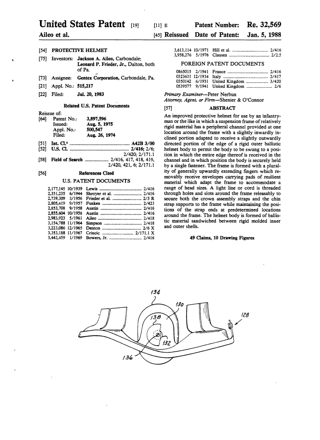
Referring now to FIG. 5, an alternate embodiment of
suspension frame, indicated generally by the reference
character 128, is similar to frame 18 in that it is provided
with the pairs of front and rear upward extensions or
fingers. Moreover, it is adapted to be assembled with a
body such as the body 12 in the same manner as is the
frame 18. In the frame 128, however, rather than pro-
viding side extensions, we form the frame with a pair of
earcup supports 130 extending upwardly from the in-
side of the peripheral channel in the frame 128. Each of
the earcup supports 130 is provided with an opening 132
through which a screw 136, or the like, extends to se-
cure an earcup assembly 134 to the support 130. We
dispose a cup-like washer 138 between the head of the
screw 136 and the outer surface of the support 130. In
this way, the earcup assembly 134 is positioned on the
support in such a way that its position on the support
can be adjusted and, in addition, its relative orientation
around the axis of screw 136 can be adjusted.
Referring now to FIG. 7, an alternate form of suspen-
sion which we may employ, indicated generally by the
reference character 140, includes a crown portion 142
which is a mesh-like structure molded from polypropyl-
60
65
20
30
35
40
45
50
55
,569
6
ene and formed with integrally molded front strap ele-
ments 144 and rear strap elements 146 for attaching the
suspension 140 to the frame 18. In order to accommo-
date a range of headsizes, we form each of the strap
elements 144 and 146 with a plurality of vertically
spaced passages 148, 150 and 152. In assembling the
suspension 140 with the shell 118 the cord 112 is passed
through corresponding passages of the strap elements
144 and 146.
Referring now to FIG. 8, still another form of suspen-
sion which we may employ is indicated generally by the
reference character 154. Suspension 154 includes a cen-
tral portion 156, a front arm 158 formed with a strap
part 160, a rear arm 162 formed with a strap part 164
and side arms 166, 168, 170, 172, 174 and 176, each of
which is formed with a strap portion 178. It will readily
be appreciated that, if desired, the central portion 156
may be formed as a perforated or mesh structure for
lightness and ventilation.
We provide the suspension 154 with means for adjust-
ably interconnecting the various outward-extending
portions thereof in such a way as to accommodate a
variety of headsizes. This means includes a plurality of
molded strips 180 adapted to connect the front arm 158
to side arms 170 and 176, and adapted to connect the
rear arm 162 to side arms 166 and 172. We provide the
various arms with a pattern of holes 186 acting as female
connector elements. Each of the elements 180 is formed
with [know-like] knob-like elements 184 adapted to be
received in the holes 186 to connect the front and back
arms to the adjacent side arms. It will readily be appre-
ciated that these connections can be changed by chang-
ing the holes 186 which receive the knobs 184. In addi-
tion to the elements 180, we provide a plurality of ele-
ments 182 for connecting adjacent ones of the side arms
of the suspension 154. Each of the members 182 is pro-
vided with knobs 184 adapted to be received in holes
186 to connect adjacent ones of the side arms each to
the other.
We provide each of the strap portions 160, [166]
164 and 178 of the arms of the crown structure 154 with
a plurality of spaced rows of spaced knob-like connec-
tor elements 188. Adjacent rows of the elements 188 are
separated by lines 190 along which the strap portion is
reduced in thickness to facilitate folding of the strap
portion. Inwardly of the [know] knob elements 188
we provide rows of holes 192 adapted to cooperate with
the knob-like elements to attach the strap parts such as
the part 160 to the cord 112.
In assembling the components of the form of our
improved protective helmet 10 illustrated in FIGS. 1 to
4, the cord 112 first is threaded through the openings
108 and 110 and into and out of the slots 124 and 126
with the length of cord 112 between the holes 108 and
110 of each pair lying in the recess 106 and with the
portion of the cord on the upper surface of the frame 18
between holes 108 and 110 of an adjacent pair being
threaded through a loop of one of the crown straps. In
a similar manner, as the cord 112 passes into and out of
a slot 124 or 126, it is threaded thorugh the loop 120 or
122 in the end of the chin strap support webbing 114.
When the [chain] chin strap supports and the crown
assembly have thus been attached to the frame, the ends
of the cord may be joined as by tying them together.
Pads 68 and [80] 82 of a thickness which will best
suit the head of the particular wearer are inserted in the
pockets of the pocket-forming members. The pocket-
forming members next are slipped over the fingers or
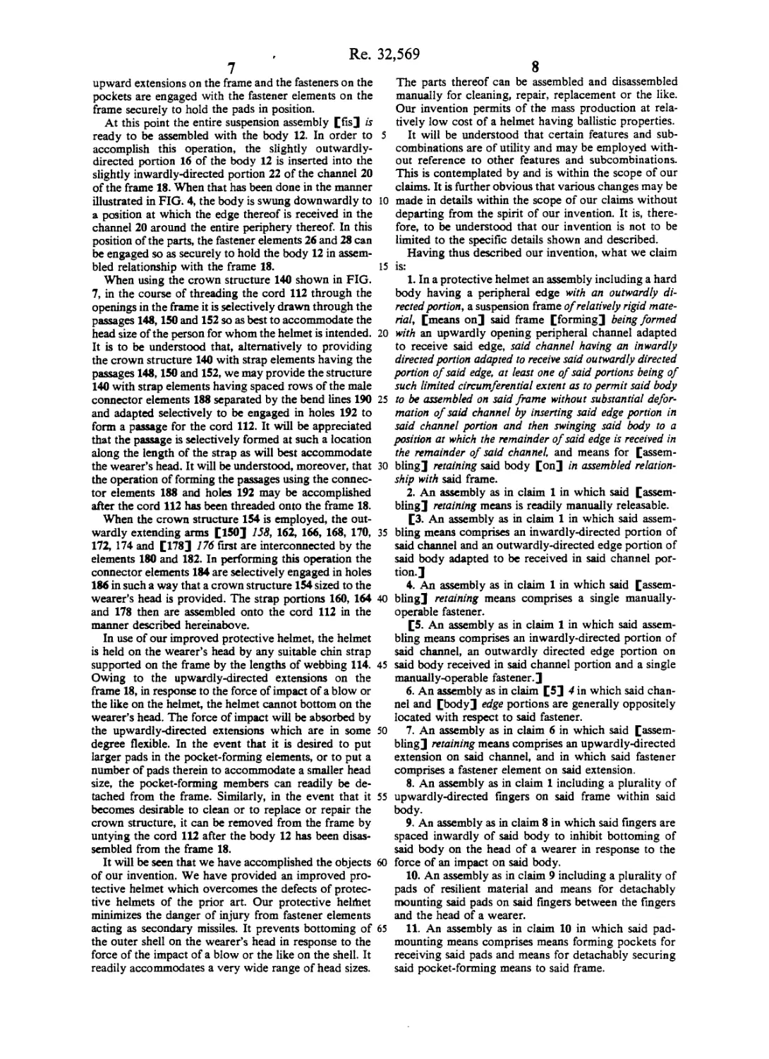
Re.
7
upward extensions on the frame and the fasteners on the
pockets are engaged with the fastener elements on the
frame securely to hold the pads in position.
At this point the entire suspension assembly [fis] is
ready to be assembled with the body 12. In order to
accomplish this operation, the slightly outwardly-
directed portion 16 of the body 12 is inserted into the
slightly inwardly-directed portion 22 of the channel 20
of the frame 18. When that has been done in the manner
illustrated in FIG. 4, the body is swung downwardly to
a position at which the edge thereof is received in the
channel 20 around the entire periphery thereof. In this
position of the parts, the fastener elements 26 and 28 can
be engaged so as securely to hold the body 12 in assem-
bled relationship with the frame 18.
When using the crown structure 140 shown in FIG.
7, in the course of threading the cord 112 through the
openings in the frame it is selectively drawn through the
passages 148,150 and 152 so as best to accommodate the
head size of the person for whom the helmet is intended.
It is to be understood that, alternatively to providing
the crown structure 140 with strap elements having the
passages 148,150 and 152, we may provide the structure
140 with strap elements having spaced rows of the male
connector elements 188 separated by the bend lines 190
and adapted selectively to be engaged in holes 192 to
form a passage for the cord 112. It will be appreciated
that the passage is selectively formed at such a location
along the length of the strap as will best accommodate
the wearer’s head. It will be understood, moreover, that
the operation of forming the passages using the connec-
tor elements 188 and holes 192 may be accomplished
after the cord 112 has been threaded onto the frame 18.
When the crown structure 154 is employed, the out-
wardly extending arms [150] 158, 162, 166, 168, 170,
172, 174 and [178] 176 first are interconnected by the
elements 180 and 182. In performing this operation the
connector elements 184 are selectively engaged in holes
186 in such a way that a crown structure 154 sized to the
wearer’s head is provided. The strap portions 160, 164
and 178 then are assembled onto the cord 112 in the
manner described hereinabove.
In use of our improved protective helmet, the helmet
is held on the wearer’s head by any suitable chin strap
supported on the frame by the lengths of webbing 114.
Owing to the upwardly-directed extensions on the
frame 18, in response to the force of impact of a blow or
the like on the helmet, the helmet cannot bottom on the
wearer’s head. The force of impact will be absorbed by
the upwardly-directed extensions which are in some
degree flexible. In the event that it is desired to put
larger pads in the pocket-forming elements, or to put a
number of pads therein to accommodate a smaller head
size, the pocket-forming members can readily be de-
tached from the frame. Similarly, in the event that it
becomes desirable to clean or to replace or repair the
crown structure, it can be removed from the frame by
untying the cord 112 after the body 12 has been disas-
sembled from the frame 18.
It will be seen that we have accomplished the objects
of our invention. We have provided an improved pro-
tective helmet which overcomes the defects of protec-
tive helmets of the prior art. Our protective helrhet
minimizes the danger of injury from fastener elements
acting as secondary missiles. It prevents bottoming of
the outer shell on the wearer’s head in response to the
force of the impact of a blow or the like on the shell. It
readily accommodates a very wide range of head sizes.
32,569
8
The parts thereof can be assembled and disassembled
manually for cleaning, repair, replacement or the like.
Our invention permits of the mass production at rela-
tively low cost of a helmet having ballistic properties.
5 It will be understood that certain features and sub-
combinations are of utility and may be employed with-
out reference to other features and subcombinations.
This is contemplated by and is within the scope of our
claims. It is further obvious that various changes may be
10 made in details within the scope of our claims without
departing from the spirit of our invention. It is, there-
fore, to be understood that our invention is not to be
limited to the specific details shown and described.
Having thus described our invention, what we claim
15 is:
1. In a protective helmet an assembly including a hard
body having a peripheral edge with an outwardly di-
rected portion, a suspension frame of relatively rigid mate-
rial, [means on] said frame [forming] being formed
20 with an upwardly opening peripheral channel adapted
to receive said edge, said channel having an inwardly
directed portion adapted to receive said outwardly directed
portion of said edge, at least one of said portions being of
such limited circumferential extent as to permit said body
25 to be assembled on said frame without substantial defor-
mation of said channel by inserting said edge portion in
said channel portion and then swinging said body to a
position at which the remainder of said edge is received in
the remainder of said channel, and means for [assem-
30 bling] retaining said body [on] in assembled relation-
ship with said frame.
2. An assembly as in claim 1 in which said [assem-
bling] retaining means is readily manually releasable.
[3. An assembly as in claim 1 in which said assem-
35 bling means comprises an inwardly-directed portion of
said channel and an outwardly-directed edge portion of
said body adapted to be received in said channel por-
tion.]
4. An assembly as in claim 1 in which said [assem-
40 bling] retaining means comprises a single manually-
operable fastener.
[5. An assembly as in claim 1 in which said assem-
bling means comprises an inwardly-directed portion of
said channel, an outwardly directed edge portion on
45 said body received in said channel portion and a single
manually-operable fastener.]
6. An assembly as in claim [5] 4 in which said chan-
nel and [body] edge portions are generally oppositely
located with respect to said fastener.
50 7. An assembly as in claim 6 in which said [assem-
bling] retaining means comprises an upwardly-directed
extension on said channel, and in which said fastener
comprises a fastener element on said extension.
8. An assembly as in claim 1 including a plurality of
55 upwardly-directed fingers on said frame within said
body.
9. An assembly as in claim 8 in which said fingers are
spaced inwardly of said body to inhibit bottoming of
said body on the head of a wearer in response to the
60 force of an impact on said body.
10. An assembly as in claim 9 including a plurality of
pads of resilient material and means for detachably
mounting said pads on said fingers between the fingers
and the head of a wearer.
65 11. An assembly as in claim 10 in which said pad-
mounting means comprises means forming pockets for
receiving said pads and means for detachably securing
said pocket-forming means to said frame.
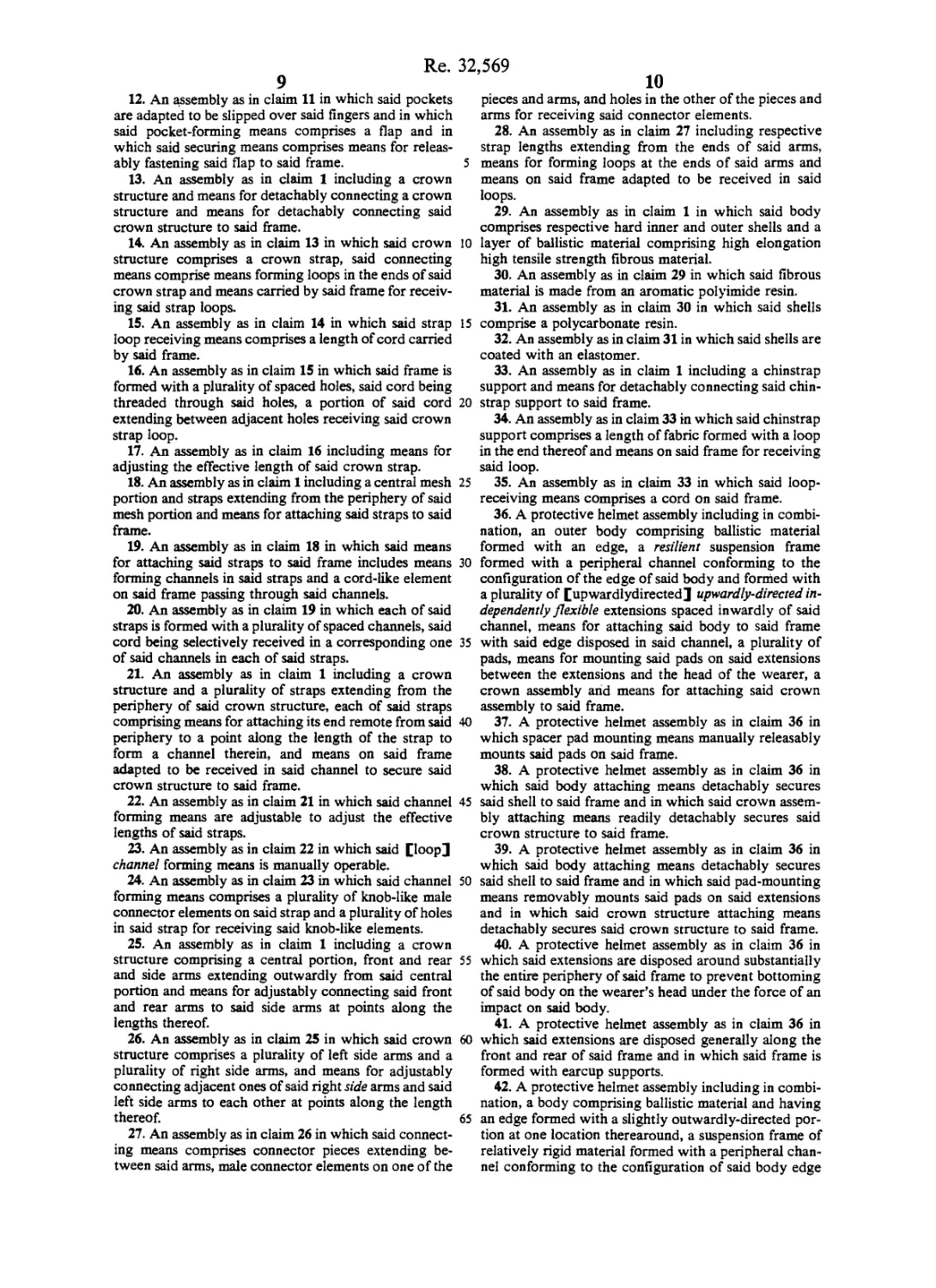
Re. 32,569
9
12. An assembly as in claim 11 in which said pockets
are adapted to be slipped over said fingers and in which
said pocket-forming means comprises a flap and in
which said securing means comprises means for releas-
ably fastening said flap to said frame.
13. An assembly as in claim 1 including a crown
structure and means for detachably connecting a crown
structure and means for detachably connecting said
crown structure to said frame.
14. An assembly as in claim 13 in which said crown
structure comprises a crown strap, said connecting
means comprise means forming loops in the ends of said
crown strap and means carried by said frame for receiv-
ing said strap loops.
15. An assembly as in claim 14 in which said strap
loop receiving means comprises a length of cord carried
by said frame.
16. An assembly as in claim 15 in which said frame is
formed with a plurality of spaced holes, said cord being
threaded through said holes, a portion of said cord
extending between adjacent holes receiving said crown
strap loop.
17. An assembly as in claim 16 including means for
adjusting the effective length of said crown strap.
18. An assembly as in claim 1 including a central mesh
portion and straps extending from the periphery of said
mesh portion and means for attaching said straps to said
frame.
19. An assembly as in claim 18 in which said means
for attaching said straps to said frame includes means
forming channels in said straps and a cord-like element
on said frame passing through said channels.
20. An assembly as in claim 19 in which each of said
straps is formed with a plurality of spaced channels, said
cord being selectively received in a corresponding one
of said channels in each of said straps.
21. An assembly as in claim 1 including a crown
structure and a plurality of straps extending from the
periphery of said crown structure, each of said straps
comprising means for attaching its end remote from said
periphery to a point along the length of the strap to
form a channel therein, and means on said frame
adapted to be received in said channel to secure said
crown structure to said frame.
22. An assembly as in claim 21 in which said channel
forming means are adjustable to adjust the effective
lengths of said straps.
23. An assembly as in claim 22 in which said [loop]
channel forming means is manually operable.
24. An assembly as in claim 23 in which said channel
forming means comprises a plurality of knob-like male
connector elements on said strap and a plurality of holes
in said strap for receiving said knob-like elements.
25. An assembly as in claim 1 including a crown
structure comprising a central portion, front and rear
and side arms extending outwardly from said central
portion and means for adjustably connecting said front
and rear arms to said side arms at points along the
lengths thereof.
26. An assembly as in claim 25 in which said crown
structure comprises a plurality of left side arms and a
plurality of right side arms, and means for adjustably
connecting adjacent ones of said right side arms and said
left side arms to each other at points along the length
thereof.
27. An assembly as in claim 26 in which said connect-
ing means comprises connector pieces extending be-
tween said arms, male connector elements on one of the
5
10
15
20
25
30
35
40
45
50
55
60
65
10
pieces and arms, and holes in the other of the pieces and
arms for receiving said connector elements.
28. An assembly as in claim 27 including respective
strap lengths extending from the ends of said arms,
means for forming loops at the ends of said arms and
means on said frame adapted to be received in said
loops.
29. An assembly as in claim 1 in which said body
comprises respective hard inner and outer shells and a
layer of ballistic material comprising high elongation
high tensile strength fibrous material.
30. An assembly as in claim 29 in which said fibrous
material is made from an aromatic polyimide resin.
31. An assembly as in claim 30 in which said shells
comprise a polycarbonate resin.
32. An assembly as in claim 31 in which said shells are
coated with an elastomer.
33. An assembly as in claim 1 including a chinstrap
support and means for detachably connecting said chin-
strap support to said frame.
34. An assembly as in claim 33 in which said chinstrap
support comprises a length of fabric formed with a loop
in the end thereof and means on said frame for receiving
said loop.
35. An assembly as in claim 33 in which said loop-
receiving means comprises a cord on said frame.
36. A protective helmet assembly including in combi-
nation, an outer body comprising ballistic material
formed with an edge, a resilient suspension frame
formed with a peripheral channel conforming to the
configuration of the edge of said body and formed with
a plurality of [upwardlydirected] upwardly-directed in-
dependently flexible extensions spaced inwardly of said
channel, means for attaching said body to said frame
with said edge disposed in said channel, a plurality of
pads, means for mounting said pads on said extensions
between the extensions and the head of the wearer, a
crown assembly arid means for attaching said crown
assembly to said frame.
37. A protective helmet assembly as in claim 36 in
which spacer pad mounting means manually releasably
mounts said pads on said frame.
38. A protective helmet assembly as in claim 36 in
which said body attaching means detachably secures
said shell to said frame and in which said crown assem-
bly attaching means readily detachably secures said
crown structure to said frame.
39. A protective helmet assembly as in claim 36 in
which said body attaching means detachably secures
said shell to said frame and in which said pad-mounting
means removably mounts said pads on said extensions
and in which said crown structure attaching means
detachably secures said crown structure to said frame.
40. A protective helmet assembly as in claim 36 in
which said extensions are disposed around substantially
the entire periphery of said frame to prevent bottoming
of said body on the wearer’s head under the force of an
impact on said body.
41. A protective helmet assembly as in claim 36 in
which said extensions are disposed generally along the
front and rear of said frame and in which said frame is
formed with earcup supports.
42. A protective helmet assembly including in combi-
nation, a body comprising ballistic material and having
an edge formed with a slightly outwardly-directed por-
tion at one location therearound, a suspension frame of
relatively rigid material formed with a peripheral chan-
nel conforming to the configuration of said body edge
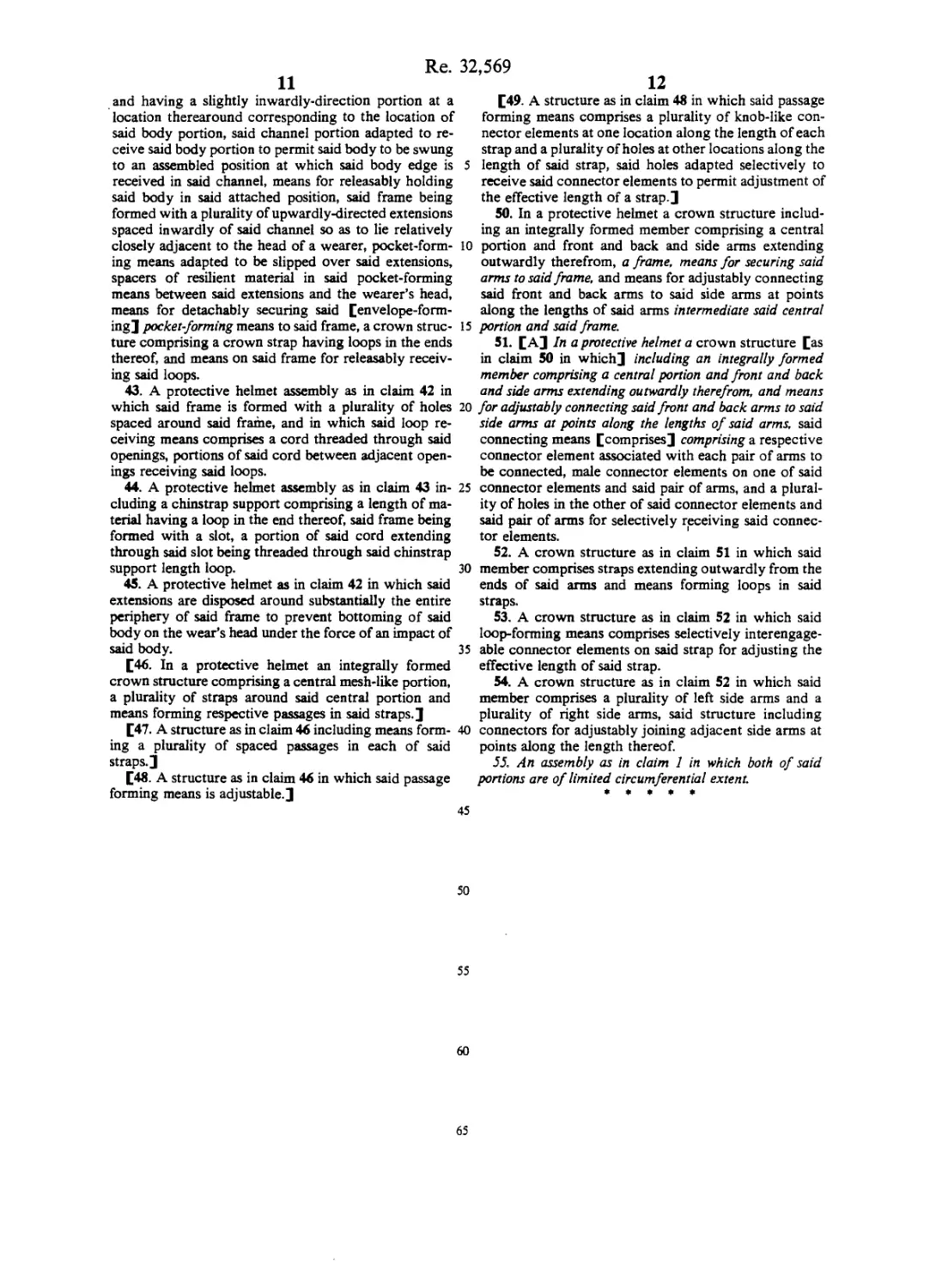
Re. 32,569
11
and having a slightly inwardly-direction portion at a
location therearound corresponding to the location of
said body portion, said channel portion adapted to re-
ceive said body portion to permit said body to be swung
to an assembled position at which said body edge is
received in said channel, means for releasably holding
said body in said attached position, said frame being
formed with a plurality of upwardly-directed extensions
spaced inwardly of said channel so as to lie relatively
closely adjacent to the head of a wearer, pocket-form-
ing means adapted to be slipped over said extensions,
spacers of resilient material in said pocket-forming
means between said extensions and the wearer’s head,
means for detachably securing said [envelope-form-
ing] pocket-forming means to said frame, a crown struc-
ture comprising a crown strap having loops in the ends
thereof, and means on said frame for releasably receiv-
ing said loops.
43. A protective helmet assembly as in claim 42 in
which said frame is formed with a plurality of holes
spaced around said frame, and in which said loop re-
ceiving means comprises a cord threaded through said
openings, portions of said cord between adjacent open-
ings receiving said loops.
44. A protective helmet assembly as in claim 43 in-
cluding a chinstrap support comprising a length of ma-
terial having a loop in the end thereof, said frame being
formed with a slot, a portion of said cord extending
through said slot being threaded through said chinstrap
support length loop.
45. A protective helmet as in claim 42 in which said
extensions are disposed around substantially the entire
periphery of said frame to prevent bottoming of said
body on the wear’s head under the force of an impact of
said body.
[46. In a protective helmet an integrally formed
crown structure comprising a central mesh-like portion,
a plurality of straps around said central portion and
means forming respective passages in said straps.]
[47. A structure as in claim 46 including means form-
ing a plurality of spaced passages in each of said
straps.]
[48. A structure as in claim 46 in which said passage
forming means is adjustable.]
5
10
15
20
25
30
35
40
45
50
55
60
12
[49. A structure as in claim 48 in which said passage
forming means comprises a plurality of knob-like con-
nector elements at one location along the length of each
strap and a plurality of holes at other locations along the
length of said strap, said holes adapted selectively to
receive said connector elements to permit adjustment of
the effective length of a strap.]
50. In a protective helmet a crown structure includ-
ing an integrally formed member comprising a central
portion and front and back and side arms extending
outwardly therefrom, a frame, means for securing said
arms to said frame, and means for adjustably connecting
said front and back arms to said side arms at points
along the lengths of said arms intermediate said central
portion and said frame.
51. [A] In a protective helmet a crown structure [as
in claim 50 in which] including an integrally formed
member comprising a central portion and front and back
and side arms extending outwardly therefrom, and means
for adjustably connecting said front and back arms to said
side arms at points along the lengths of said arms, said
connecting means [comprises] comprising a respective
connector element associated with each pair of arms to
be connected, male connector elements on one of said
connector elements and said pair of arms, and a plural-
ity of holes in the other of said connector elements and
said pair of arms for selectively receiving said connec-
tor elements.
52. A crown structure as in claim 51 in which said
member comprises straps extending outwardly from the
ends of said arms and means forming loops in said
straps.
53. A crown structure as in claim 52 in which said
loop-forming means comprises selectively interengage-
able connector elements on said strap for adjusting the
effective length of said strap.
54. A crown structure as in claim 52 in which said
member comprises a plurality of left side arms and a
plurality of right side arms, said structure including
connectors for adjustably joining adjacent side arms at
points along the length thereof.
55. An assembly as in claim 1 in which both of said
portions are of limited circumferential extent.
65