/
Tags: means of protection
Year: 1945

Text
Aug. 28, 1945
2,383,597
L. G. FEMAN
PROTECTIVE HELMET
Aug. 28, 1945.
L. G. FEMAN
2,383,597
Patented Aug. 28, 1945
2,383,597
UNITED STATES PATENT OFFICE
2,383,597
PROTECTIVE HELMET
Louis G. Fenian, Jamaica, N. Y.
Application March 6,1944, Serial No. 525,177
10 Claims.
This invention relates to helmets.
One object of the invention is to provide a hel-
met having a head-protective member formed of
a plurality of projectile-proof or resistant plates
and means of improved construction for holding
said plates in cooperative relation.
Another object is the provision of a projectile-
proof or resistant helmet which is well adapted
to be worn by the crew of a war plane over the
helmets which they usually wear to keep their
heads warm, said projectile-proof or resistant
helmet comprising a head-protective member
formed of a plurality of projectile-proof or resis-
tant plates and means of improved construction
for holding said plates in cooperative relation.
A further object is to provide a helmet of such
construction as to afford the wearer excellent
protection against projectiles, missiles, impact,
etc., and of such construction that the manufac-
ture of the helmet with a head-protective mem-
ber formed of a plurality of projectile-proof or
resistant plates is facilitated.
A yet further object is generally to improve
the construction and to facilitate the manufac-
ture of helmets of the above designated type.
The above and other objects, features and ad-
vantages of the invention will be fully understood
from the following description considered in con-
nection with the accompanying illustrative draw-
ings.
In the drawings:
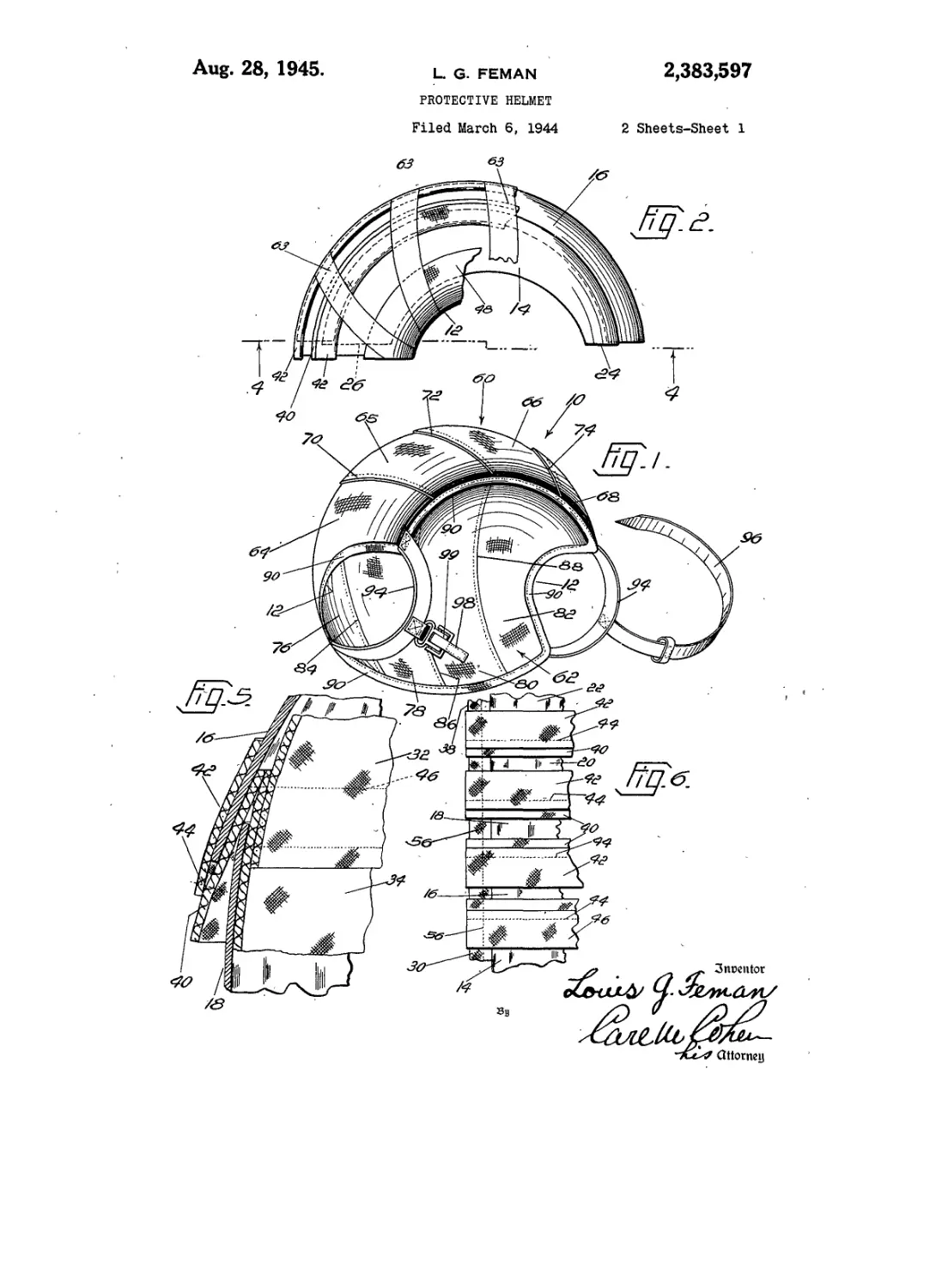
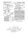
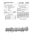
Figure 1 is a perspective view of a helmet em-
bodying the present invention;
Figure 2 is a side view of the helmet, the outer
cover being removed and with other parts being
cut away for purpose of illustration;
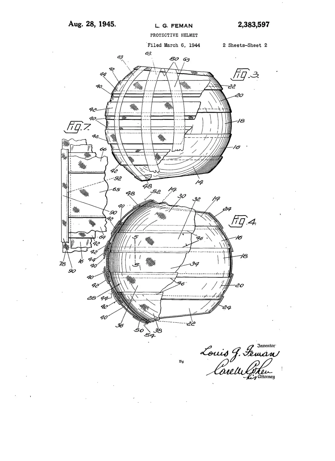
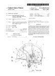
Figure 3 is a top plan view of the helmet, the
outer cover being removed and with other parts
cut away for the purpose of illustration;
Figure 4 is a sectional view, partly in elevation,
on the line 4—4 of Figure 2;
Figure 5 is a fragmentary sectional view on a
larger scale on the line 5—5 of Figure 4;
Figure 6 is a fragmentary view in elevation of
the lower marginal edge portion of the helmet
without its cover, as seen looking from the left
of Figure 2; and
Figure 7 is a view similar to Figure 6 but with
the cover of the helmet applied.
Referring now to the drawings in detail, the
helmet 10, here shown as a soldier’s helmet, is
shaped to enclose the wearer’s head and with
portions of the bottom edge of the helmet at the
opposite sides thereof recessed as indicated at 12
so as not to cover the wearer’s ears or ear phones.
5
10
15
20
25
30
35
40
45
50
55
(CI. 2—6)
The main protective portion or head protective
member of the helmet is preferably formed of
Hatfield steel and as here shown is constituted by
a plurality of sheet steel plates 14, 16, 18, 20, 22
which as shown in Figures 2 to 4 are curved later-
ally and from front to rear so that in the assem-
bled relation of said plates they define the shape
of the helmet. It will be observed by reference
to Figures 3 and 4 that the helmet is wider at the
back than at the front thereof and that this is
accomplished by providing the side plates 14 and
22 of such shape that they progressively increase
in width from their front ends 24 to their rear
ends 28. The helmets (0 are particularly well
adapted to be worn by the crew of a war plane
over the usual leather helmets which are worn by
the members of the crew to keep their heads
warm.
The helmet iO is of such construction that it
possesses a desirable degree of resiliency in all
directions so that it is better able to resist impact,
shock, and penetration of projectiles, missiles,
etc. For this purpose the steel plates 14 to 22 are
disposed in such relation and are so held with
respect to each other as to be relatively movable
to a limited extent. More specifically, steel plates
14 to 22 inclusive are disposed with their adjacent
marginal side edge portions in overlapping rela-
tion, as illustrated in Figure 4, for the full lengths
thereof. These steel plates are held in this rela-
tion by a jacket 28 formed of a strong fabric,
preferably a fabric such as canvas. Said jacket
comprises a plurality of strips 30, 32, 34, 36 and 38
stitched to each other with their adjacent side
edges in overlapping relation. Said fabric strips
are cut to shape at their side edges so that when
they are stitched together they form a concavo-
convex inner lining conforming to the concave
surface of the assembly of steel plates. As illus-
trated more clearly in Figure 5, the adjacent steel
plates disposed with their marginal side edge por-
tions in overlapping relation as described above
are not in contact with each other but are re-
ceived in pockets provided for that purpose. Some
of said pockets are formed by inner and. outer
fabric strips 40 and 42, which are stitched to each
other as indicated at 44, the inner strip 40 being
stitched to the overlapped marginal edge portions
of the adjacent lining strips of the jacket 28 by
a line of stitching as indicated at 46 in Figures 4
and 5. Pockets are also provided between the
inner strips 40 and the adjacent lining strips.
Thus, as shown in Fig. 5 adjacent edge portions
of the overlapping steel plates 16 and i8 are re-
ceived, respectively, in the pocket formed be-
2,383,597
tween strips 40 and 42 and in the pocket formed
between strip 40 and the adjacent lining strip 34.
In the construction shown, there are four inter-
mediate pairs of strips 40, 42 and at the side ends
of the helmet there are single strips 48, 50 which 5
are stitched to the lining strips 30 and 38 respec-
tively inwardly of the side edges thereof by lines
of stitching 52 and 54 respectively providing end
pockets which receive the lower marginal edge
portions of the steel plates 14 and 22 respectively. 10
The jacket 28 is thus constituted by the lining
strips 30 to 38, by a plurality of strips 40, 42,
which are stitched to each other and to said lin-
ing strips as described above and by said side end
strips 48 and 50 which are stitched to the lining is
strips 30 and 38 respectively. Describing more
specifically the overlapped relation of plates 14,
16, 18, 20 and 22 and the arrangement of the edges
of said plates in the pockets therefor, it will be
noted by reference to Fig. 4 that one side edge of 29
plate 16 is received in the pocket provided by one
pair of strips 40, 42 and that the opposite side
edge of plate 16 is received in the pocket provided
by a strip 40 and the lining strip 32. Plate 18
has one of its side edges in a pocket provided by 23
a strip 40 and one side edge portion of the lining
strip 34, and said plate 18 has its opposite side
edge in the pocket provided by a strip 40 and the
other side edge portion of lining strip 34. Plate 20
has one side edge thereof received in the pocket 30
provided by a pair of strips 40 and 42 while its
opposite side edge is received in a pocket provided
by a strip 40 and the lining strip 30. End plate 22
has one side edge thereof received in the pocket
provided by a pair of strips 40 and 42 while its 35
opposite side edge is received in the pocket pro-
vided by end strip 50 and lining strip 38. The
other end plate 14 has one side edge thereof re-
ceived in the pocket provided by a pair of strips
40 and 42 while the opposite side edge of said 40
plate is received in the pocket provided by end
strip 48 and the adjacent lining strip 30. The
outer ends of strips 40, 42, 48 and 50 project be-
yond the front and rear ends of the steel plates,
as illustrated more clearly in Figure 6 and said 4:1
strips 40, 42, 48 and 50 are secured to the project-
ing end portions of the adjacent lining strips 30
to 38 by lines of stitching 56 at the front and
back of the helmet. As the strips 48 and 50 are
stitched to the strips 30 and 38 respectively be- 50
yond the adjacent lower edges of said plates 24
and 22, the jacket 28 has a line of stitching com-
pletely around the lower edge of the helmet out-
wardly of the edges of the steel plates and the
jacket has a lower marginal edge portion project- r,:>
ing beyond the edges of the steel plate assembly
to which the helmet cover 60 and the lining 62
hereinafter described are stitched. Before the
cover 60 is applied, the plates 14 to 22 are held
against separation from the jacket 28 by a plural- CO
ity of adhesive tapes 63 such as strips of “Scotch”
tape which can remain permanently in the hel-
met. More specifically, as illustrated in Figs. 2
and 3, the adhesive tapes 63 extend from one side
of the helmet to the other side edge thereof and cr>
are adhered at their ends to the end strips 48
and 50 which are stitched to lining strips 30 and
38, respectively, and said adhesive strips are ad-
hered to the other surfaces of strips 42 and the
outer surface portions of the metal plates. Thus, 70
tapes 63 hold the plates in assembled relation,
with their edges disposed in the pockets as de-
scribed above, it being understood that after the
cover 60 is applied said cover and lining 62 main-
tain the plates in position in the helmet. 75
The helmet cover 60 comprises a plurality of
fabric strips 64, 65, 66 and 68 shaped at their side
edges so that when they are stitched together the
cover is concavo-convex to conform to the convex
curvature of the steel plate assembly, said strips
being stitched together at the seams 70, 72, and 74
which extend from the front end of the helmet
to the back end thereof. Similarly the lining 62
of the helmet comprises a plurality of fabric strips
76, 78, 80 and 82, shaped at their side edges so
that when they are stitched together the lining
is concavo-convex to conform to the concave cur-
vature of the steel plate assembly and of the fab-
ric jacket 28, said lining strips being stitched to
each other by the seams 84, 86 and 88, extending
from the front of the helmet to the back thereof.
The front and rear ends of the cover and lining
strips extend beyond the front and rear ends of
the metal plates and the outer edges of the cover
strips 64 and 68 and of the lining strips 76 and 82
extend beyond the lower or outer edges of the
side metal plates 14 and 22 respectively. The
projecting portions of said cover and lining strips
are covered by a folded edging strip 90 which
extends completely around the edge of the helmet
and which is secured to the projecting portions
of said cover and lining strips and to the project-
ing portions of the strips of the jacket 28 by a
line of stitch 92 illustrated in Figure 7, said line
of stitching 92 also serving to secure the adjacent
projecting end portions of the cover and lining
strips to each other and to the adjacent project-
ing edge portions of the strips of the jacket 28.
As illustrated in Figure 1 suitable means are
provided for fastening the helmet on the wearer’s
head. For this purpose strips 94 of leather or
other suitable material are secured at their ends
to the fabric edge of the helmet at the opposite
ends of the adjacent recessed portion 12 of the
helmet. A chin strap 96 formed of leather is
secured to one of the strips 94 and a companion
buckled strap 98 is secured to the other strip 94,
straps 96 and 98 being adjustably securable to
each other by the engagement of strap 96 in the
buckle 99 of strap 98.
It will be understood that while the helmet SO
has been described in reference to its use for
military purposes and is constructed and arranged
to afford protection against bullets and other
projectiles or missiles, said helmet can also be
utilized for other purposes, for example, as the
head gear of foot-ball players, polo players, and
other athletes, and in general as a protective hel-
met for military or civilian use. Also it will be
understood that while I have shown and described
the preferred embodiment of my invention, the
latter may be embodied otherwise than as herein
specifically illustrated or described, and that in
the illustrated embodiment certain changes in the
details of construction and in the arrangement of
parts may be made without departing from the
underlying idea of the invention within the scope
of the appended claims.
I claim:
1. A helmet having a head-protective member
comprising a plurality of concavo-convex plates
formed of impact-resisting material and assem-
bled in side by side position in’ head covering
relation, said plates being relatively movable and
having their adjacent marginal edge portions in
overlapped relation for substantially the full
lengths thereof, and means formed of flexible
sheet material for holding said plates in said
relatively movable overlapped relation.
2,383,£
2. A helmet comprising a plurality of sheet
metal projectile-resistant plates of concavo-con-
vex form disposed In side by side relation in rela-
tively movable relation and extending from one
edge of the helmet to the opposite edge thereof 5
and forming in combination a head-protective
member having a concave inner surface adapted
to conform generally to the wearer’s head in cov-
ering relation thereto, and means securing said
plates in said relation comprising means having 10
recesses in which opposite side edge portions of
said plates, respectively, are received and which
hold said plates against outward lateral move-
ment relatively to each other,
3. A helmet comprising a plurality of relatively 15
movable plates of concavo-convex form disposed
in side by side relation and extending from one
edge of the helmet to the opposite edge thereof
and forming in combination a head-protective
member having a concave inner surface adapted 20
to conform generally to the wearer’s head in cov-
ering relation thereto, and means securing said
plates in said relatively movable relation com-
prising means having recesses in which opposite
side edge portions of said plates, respectively, are 25
received and which hold said plates against out-
ward lateral movement relatively to each other,
and means for limiting other movement of said
plates relatively to each other.
4. A helmet comprising a plurality of relatively 30
movable plates of concavo-convex form disposed
in side by side relation and extending from one
edge of the helmet to the opposite edge thereof
and forming in combination a head-protective
member having a concave inner surface adapted 35
to conform generally to the wearer’s head in cov-
ring relation thereto, and means securing said
plates in said relatively movable relation com-
prising means having recesses in which opposite
side edge portions of said plates, respectively, are
received and which hold said plates against out-
ward lateral movement relatively to each other,
and covers disposed at and conforming to the
convex and concave surfaces, respectively, of said
head-protective member, said covers extending
outwardly beyond the peripheral edge of said
head-protective member, and secured to each
other peripherally of the helmet beyond said pe-
ripheral edge of the head-protective member.
5. A helmet comprising a plurality of relatively
movable plates of concavo-convex form disposed
in side by side relation and extending from one
edge of the helmet to the opposite edge thereof and
forming in combination a head-protective mem-
ber having a concave inner surface adapted to
conform generally to the wearer’s head in cov-
ering relation thereto, adjacent marginal edge
portions of adjacent plates being disposed in
overlapping relatively movable relation, a jacket
having a body portion overlying and conforming
to said inner concave surface of said head-pro-
tective member and having a plurality of strips
attached thereto and forming recesses in which
opposite side edge portions of said plates, respec-
tively, are received and which hold said plates
against outward lateral movement relatively to
each other, and means for limiting other move-
ment of said plates relatively to each other, said
last mentioned means comprising means overlap-
ping the outer surface of said head-protective
member and secured in fixed relation to said
jacket.
6. A helmet comprising a plurality of sheet
metal plates of concavo-convex form disposed in
side by side relation and extending from one
97 3
edge, of the helmet to the opposite edge thereof
and forming in combination a head-protective
member having a concave inner surface adapted
to conform generally to the wearer’s head in cov-
ering relation thereto, adjacent marginal edge
portions of adjacent plates being disposed in
overlapping relation for the full lengths of said
adjacent parts, and means engaging said adja-
cent overlapped marginal edge portions and hold-
ing said plates in said relation,
7. A helmet comprising a plurality of relatively
movable plates of concavo-convex form disposed
in side by side relation and extending from one
edge of the helmet to the opposite edge thereof
and forming in combination a head-protective
member having a concave inner surface adapted
to conform generally to the wearer’s head in
covering relation thereto, adjacent marginal edge
portions of adjacent plates being disposed in
overlapping relation for the full lengths of said
adjacent parts, and a fabric casing enclosing said
head-covering member and including portions en-
gaging said adjacent overlapped marginal edge
portions and limiting the movement laterally of
each other and portions limiting other movement
of said plates relatively to each other.
8. A helmet comprising a plurality of rela-
tively movable plates of concavo-convex form dis-
posed in side by side relation and extending from
one edge of the helmet to the opposite edge
thereof and forming in combination a head-pro-
tective member having a concave inner surface
adapted to conform generally to the wearer’s
head in covering relation thereto, adjacent mar-
ginal edge portions of adjacent plates being dis-
posed in overlapping relation, a jacket having a
body portion overlying and conforming to said
inner concave surface of said head-protective
member and having a plurality of strips attached
thereto and forming recesses in which opposite
side edge portions of said plates, respectively, are
received and which hold said plates against out-
ward lateral movement relatively to each other,
certain of said strips being disposed between the
0 overlapped surfaces of said marginal edge por-
. tions of adjacent plates, respectively, and others
of said strips being disposed over the upper sur-
faces of the uppermost marginal edge portions,
50 respectively, of adjacent plates, and means for.
holding said marginal edge portions in overlapped
relation in said recesses, respectively.
9. A helmet comprising a plurality of relatively
movable sheet metal parts of concavo-convex
55 form disposed in side by side relation and ex-
tending from one edge of the helmet to the op-
posite edge thereof and forming in combination
a head-protective member having a concave in-
ner surface adapted to conform generally to the
60 wearer’s head in covering relation thereto, ad-
jacent marginal edge portions of adjacent-plates
being disposed in overlapping relation, a jacket
having a body portion overlying and conforming
to said concave inner surface, a plurality of strips
65 disposed in laterally spaced relation on and se-
cured to said body portion and forming a plu-
rality of recesses therewith, certain of said metal
plates having marginal edge portions thereof po-
sitioned in said recesses, respectively, and over-
70 lapped by said strips, respectively, and a plurality
of strips disposed in laterally spaced relation and
secured to said first mentioned strips, respective-
ly, and forming therewith a plurality of recesses,
certain of said metal plates having marginal edge
75 portions thereof positioned in said last mentioned
2,383,597
4
recesses, respectively, and means for holding, said
marginal edge portions in said recesses.
10. A helmet having a head-protective mem-
ber comprising a plurality of curved plates formed
of impact-resisting material and assembled in
side by side position in head covering relation,
said plates being relatively movable and having
adjacent marginal edge portions thereof in over-
lapped relation, said overlapped portions being
relatively movable, means formed of flexible sheet
material disposed between the overlapped sur-
face portions of said plates, and means includ-
j>. ing said first mentioned means for holding said
plates in said overlapped relation.
LOUIS G. FEMAN.