/
Tags: means of protection
Year: 2001

Text
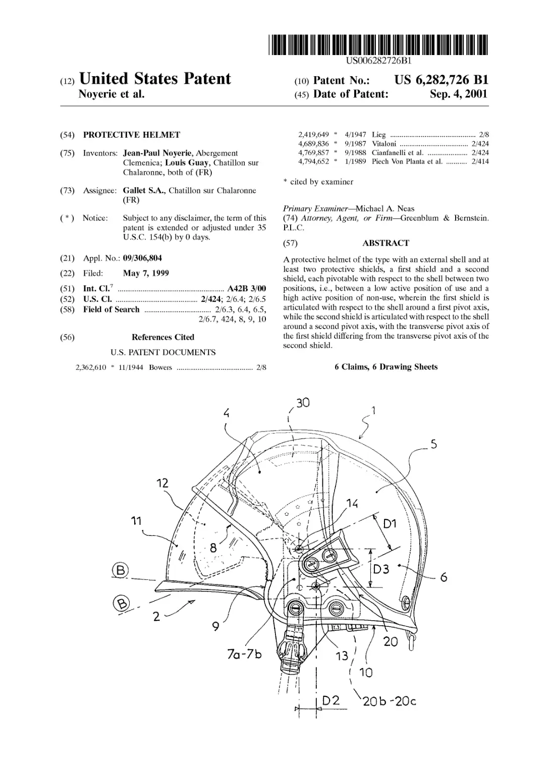
US006282726B1
(12) United States Patent
Noyerie et al.
(io) Patent No.: US 6,282,726 Bl
(45) Date of Patent: Sep. 4,2001
(54) PROTECTIVE HELMET
(75) Inventors: Jean-Paul Noyerie, Abergement
Clemenica; Louis Guay, Chatillon sur
Chalaronne, both of (FR)
(73) Assignee: Gallet S.A., Chatillon sur Chalaronne
(FR)
( * ) Notice: Subject to any disclaimer, the term of this
patent is extended or adjusted under 35
U.S.C. 154(b) by 0 days.
(21) Appl. No.: 09/306,804
(22) Filed: May 7, 1999
(51) Int. Cl.7 ...............................A42B 3/00
(52) U.S. Cl........................ 2/424; 2/6.4; 2/6.5
(58) Field of Search .................. 2/6.3, 6.4, 6.5,
2/6.7, 424, 8, 9, 10
(56) References Cited
U.S. PATENT DOCUMENTS
2,362,610 * 11/1944 Bowers
2/8
2,419,649 * 4/1947 Lieg ......................... 2/8
4,689,836 * 9/1987 Vitaloni ................... 2/424
4,769,857 * 9/1988 Cianfanelli et al........... 2/424
4,794,652 * 1/1989 Piech Von Planta et al...... 2/414
* cited by examiner
Primary Examiner—Michael A. Neas
(74) Attorney, Agent, or Firm—Greenblum & Bernstein.
P.L.C.
(57) ABSTRACT
A protective helmet of the type with an external shell and at
least two protective shields, a first shield and a second
shield, each pivotable with respect to the shell between two
positions, i.e., between a low active position of use and a
high active position of non-use, wherein the first shield is
articulated with respect to the shell around a first pivot axis,
while the second shield is articulated with respect to the shell
around a second pivot axis, with the transverse pivot axis of
the first shield differing from the transverse pivot axis of the
second shield.
6 Claims, 6 Drawing Sheets
U.S. Patent
Sep. 4,2001
Sheet 1 of 6
US 6,282,726 Bl
13
U.S. Patent
Sep. 4,2001
Sheet 2 of 6
US 6,282,726 Bl
10
U.S. Patent
Sep. 4,2001 Sheet 3 of 6
US 6,282,726 Bl
11b
/ 1
U.S. Patent
Sep. 4,2001
Sheet 4 of 6
US 6,282,726 Bl
U.S. Patent
Sep.4,2001
Sheet 5 of 6
US 6,282,726 Bl
U.S. Patent
Sep. 4,2001
Sheet 6 of 6
US 6,282,726 Bl
US 6,282,726 Bl
1
PROTECTIVE HELMET
BACKGROUND OF THE INVENTION
1. Field of the Invention
The present invention relates to an improvement for a
protective helmet, and more particularly for a helmet includ-
ing at least two pivotable front protective shields.
2. Description of Background and Relevant Information
Protective helmets have been commonly used for a very
long time in various fields, either professional, as is the case
for military personnel, airplane or helicopter pilots, police
officers or firefighters, or civilian or private, as is the case for
users of motorcycles, rally or race cars, or employees of
work sites.
There is no shortage of applications, and a large number
of helmets which have a rigid external shell substantially
spherical in shape adapted to closely fit the skull of the user,
with a face opening at the front for the face, are already
known. Moreover and generally, the helmet includes an
internal envelope made of synthetic foam adapted to absorb
shocks. Some helmets have a transparent face shield mov-
able between a low protective position and a high retracted
position. To that end, the shield is mounted on the helmet
pivotably around a transverse axis, with the shield being
displaced by pivoting to be positioned in front of the nose of
the user.
Some helmets have a smaller second shield, or an eye
shield, mounted to pivot coaxially with the face shield.
The result is that the second shield is pivoted into the low
position under the same pivoting conditions as the face
shield, adapted to cover the nose of the user. As a result, the
eye shield in the low position is not in a good position.
SUMMARY OF THE INVENTION
An object of the invention is to overcome the drawbacks
found in helmets having two pivoting shields by proposing
a particularly simple construction according to which the
respective axes of the two shields are not coaxial, but which
are distinct and different in their positions, in contrast with
the prior art helmets. Thus, because of the proposed
construction, each of the shields has its own pivot path,
appropriate to its destination.
Thus, the protective helmet according to the invention is
of the type with an external shell and at least two protective
shields, i.e., a first shield and a second shield, both pivotable
with respect to the shell between two positions, i.e., between
a low active position of use and a high inactive position of
non-use, whereby the first shield is pivotable around a
transverse axis different from the transverse pivot axis of the
second shield.
According to further preferred characteristics, the first
shield is a face shield with larger dimensions than the second
shield. Thus, the two shields are each comprised of a
transparent wall which is substantially a portion of a sphere,
and the radius of the transparent wall of the first shield is
greater than the radius of the transparent wall of the second
shield, while in the low position of use and/or in the high
position, the front wall of the second shield is arranged
behind the front wall of the first shield.
In addition, according to a preferred embodiment, in the
high position of use, the front wall of the second shield is
substantially parallel to the front wall of the first shield.
According to another characteristic, the two shields are
mounted to pivot on an internal intermediate part attached to
the external shell.
5
10
15
20
25
30
35
40
45
50
55
60
65
2
It is also noted that, advantageously, the pivot axis of the
second shield is arranged farther forward and higher than the
pivot axis of the first shield.
BRIEF DESCRIPTION OF DRAWINGS
Other characteristics and advantages of the invention will
become apparent from the following description, with ref-
erence to the annexed drawings which are only provided as
non-limiting examples.
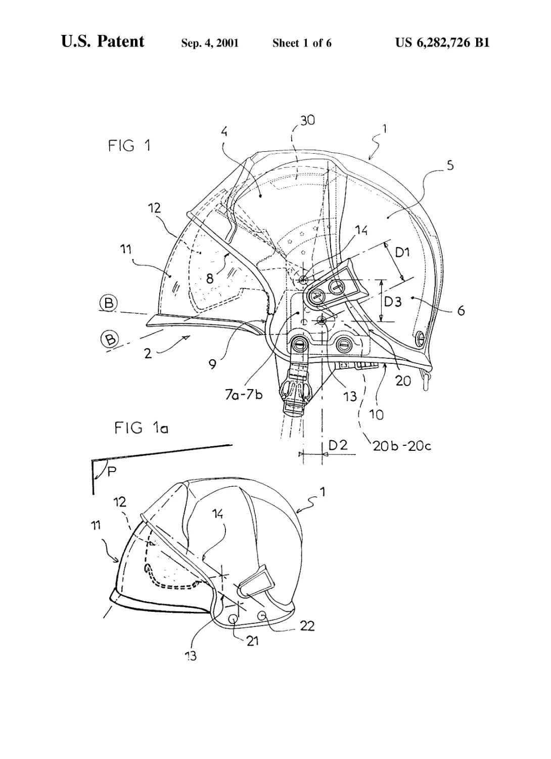
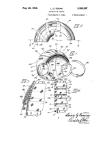
FIG. 1 is a side view of the helmet of the invention, with
the two shields in the low position of use;
FIG. la is a perspective view of the helmet of the
invention, with the two shields in the low position of use;
FIG. 2 is a side view of the helmet of the invention, with
the two shields in the high inactive position of non-use;
FIG. 2a is a perspective view of the helmet of the
invention, with the two shields in the high inactive position
of non-use;
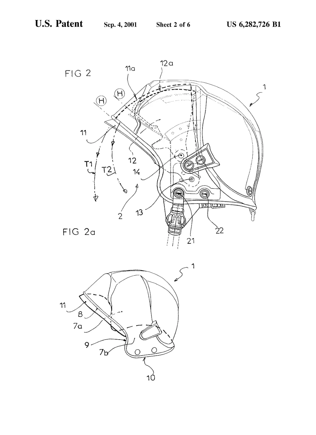
FIG. 3 is a side view of the helmet of the invention with
only the first shield in the low position of use;
FIG. 3a is a perspective view of the helmet of the
invention with only the first shield in the low position of use;
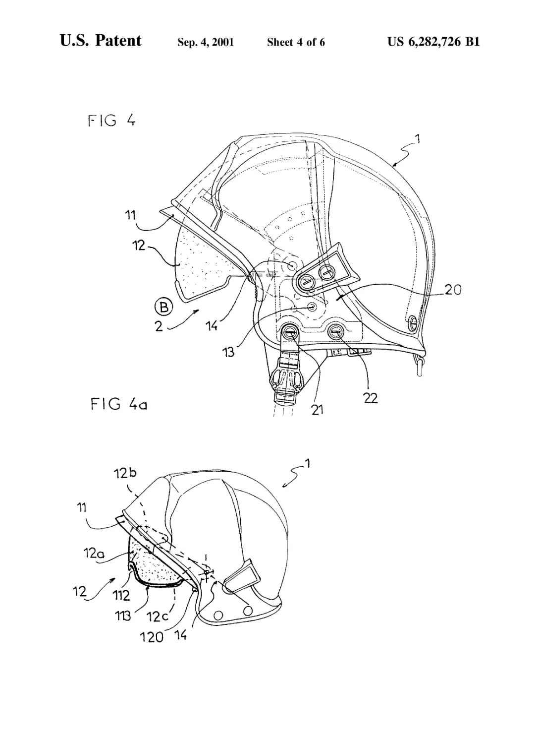
FIG. 4 is a side view of the helmet of the invention with
only the second shield in the low position of use;
FIG. 4a is a perspective view of the helmet of the
invention with only the second shield in the low position of
use;
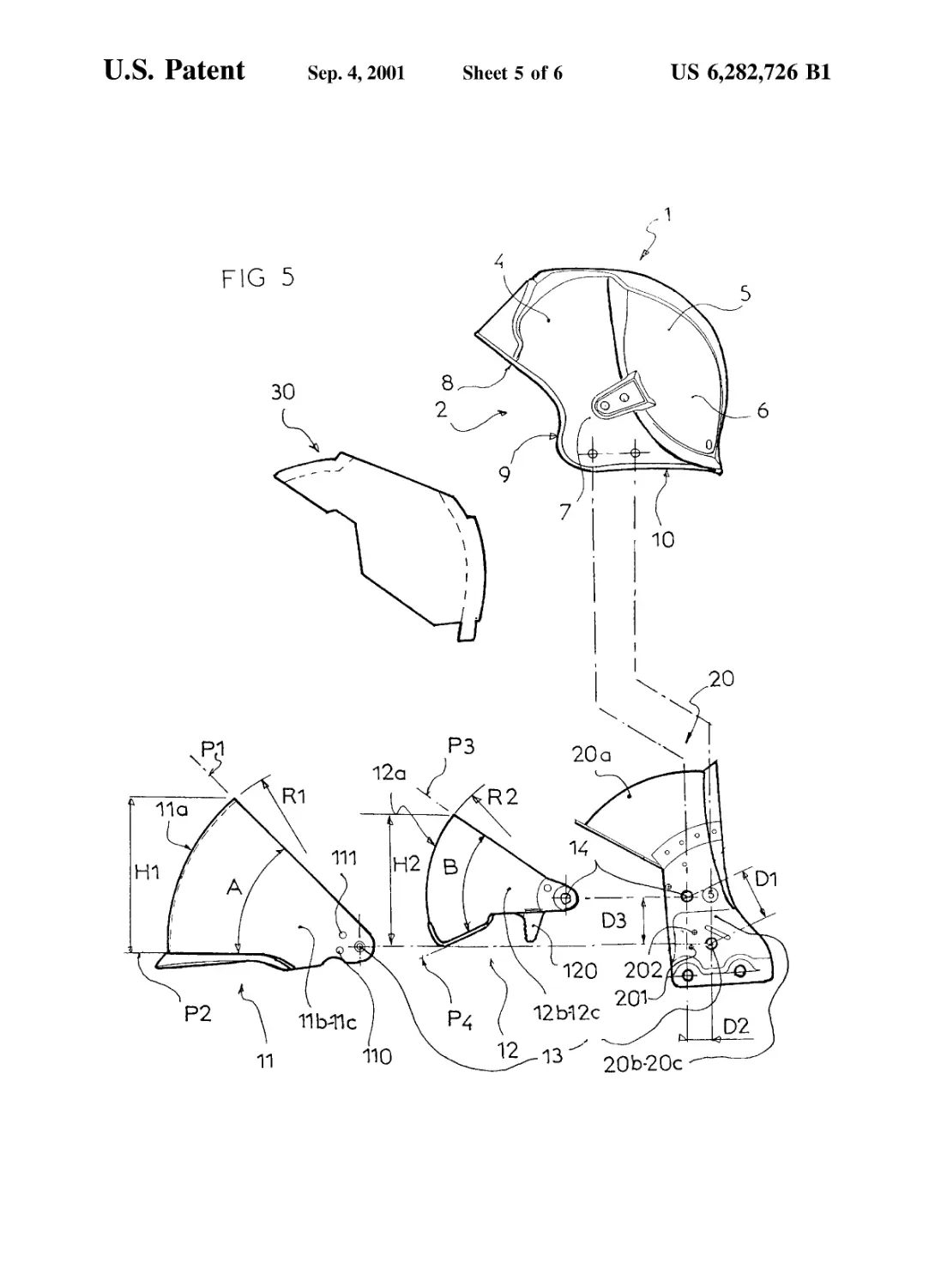
FIG. 5 is an exploded side view of the helmet depicting
the essential elements of the helmet;
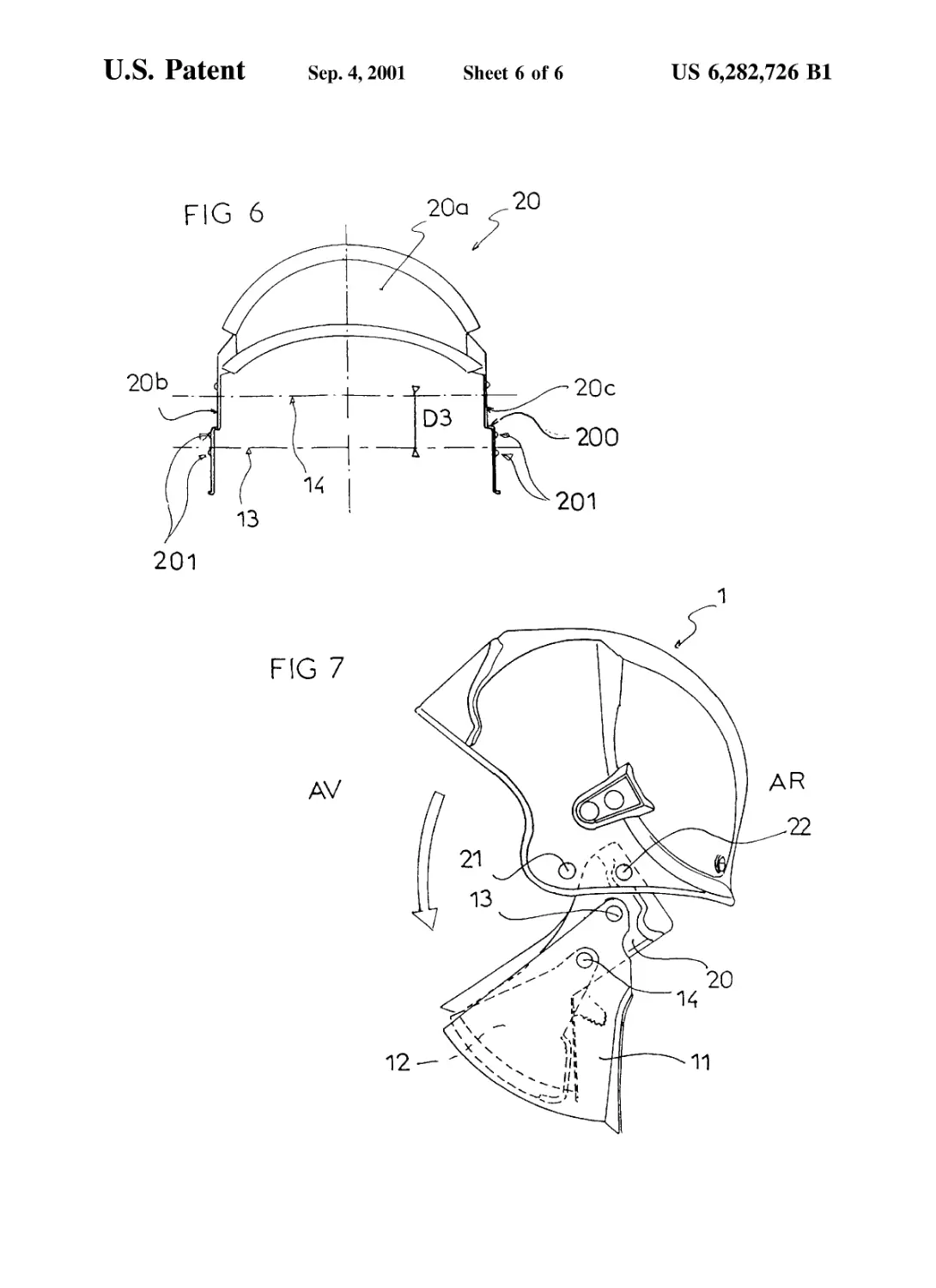
FIG. 6 is a front view of the internal intermediate part; and
FIG. 7 is a side view of the helmet after the internal
intermediate part bearing the two shields has been pivoted
toward the front.
DETAILED DESCRIPTION OF THE
INVENTION
The helmet equipped with the protective shields accord-
ing to the invention may be of any kind, such as, for
example, the type used by firefighters, military personnel, or
motorcyclists, even bikers or skiers, and has a primary
external shell 1 protecting the cranium and the nape of the
neck of the user and has a front face opening 2 in the zone
occupied by the actual face of the user, with the helmet
having a vertical longitudinal plane of symmetry P.
The shell is made of a rigid material and may be of any
appropriate material such as plastic, steel, aluminum, or a
composite material of the type having a stack of layers of
reinforcement fibers, impregnated and interconnected by a
resin matrix. The external shell is made up of a substantially
spherical wall having a plurality of wall portions, i.e., a front
top wall 4 extended toward the rear by a rear top wall portion
5, itself extended toward the bottom by a rear bottom wall
portion 6, and has, moreover, two side wall portions 7, a
right side wall portion 7a, and a left side wall portion 7b. The
front top wall portion 4 corresponds to the zone occupied by
the forehead of the user and is demarcated by the top rim 8
of the face opening 2, which is itself demarcated laterally by
two side rims 9. The rear top wall portion 5 corresponds to
the zone occupied by the cranium of the user, while the rear
bottom wall portion 6 corresponds to the zone occupied by
the nape of the neck of the user. In addition, the wall of the
shell is demarcated toward the bottom by a lower rim 10.
The side wall portions 7, 7a, 7b correspond to the zones
occupied by the ears of the user and are demarcated toward
US 6,282,726 Bl
3
the front by the corresponding side rim 9 of the face opening
2, and toward the bottom by the front ends of the lower rim
10.
The helmet of the invention has, according to one of its
characteristics, at least two protective shields 11, 12 pivot-
able with respect to the shell 1, between two positions, i.e.,
between a low active position of use В and a high inactive
position of non-use H.
Thus, the helmet has a first shield 11 and a second shield
12.
The first shield is a face shield with large dimensions
adapted in its position of use to cover a large part of the face
of the user, whereas the second shield 12 is an eye shield of
smaller dimensions than the face shield adapted, more
specifically, to protect the eyes of the user in the position of
use.
Each of the protective shields is pivotable around a
transverse axis and, according to the invention, the pivot
axis of the first shield is distinct and different from the pivot
axis of the second shield. Thus, the first shield or face shield
11 is articulated with respect to the shell 1 around a first
pivot axis 13, whereas the second shield or eye shield 12 is
articulated with respect to the shell 1 around a second pivot
axis 14. Therefore, the two axes are not coaxial, but have
different positions.
It must be remembered that, according to the invention,
the second axis 14 is different from the first axis 13. Thus,
the second axis 14 is spaced from the first axis 13 by a
distance DI to be farther forward than the first axis by a
distance D2 and higher by a distance D3.
It is important to note that the shields 11, 12 are each
mounted individually articulated with respect to the shell.
Thus, their respective rotational movements occur around a
fixed pivot axis in a locator linked to the shell. Moreover, the
positioning of the pivot axes 13, 14 of the shields 11, 12 as
well as the configuration, i.e., the shape and size, of the
shields are selected to enable the shields to pivot freely and
independently of each other between their respective
extreme active and inactive positions. The pivoting of each
of the shields is independent of the pivoting of the second
shield; the respective paths of the shields 11,12 are distinct
and do not cross each other, such that regardless of the
position of one of the shields, the second shield can pivot
freely from its inactive position to its active position and
vice versa. Thus, each of the shields has its own defined path
and has the same path regardless of the other shield.
The first shield 11 is composed of a transparent wall
made, for example, of a plastic material of the polycarbonate
type or other type. This wall is substantially a portion of a
sphere limited so as to be contained between two converging
transverse planes Pl, P2 forming a dihedral angle A open
toward the front. The face shield is composed of a front wall
Ila formed by a substantially spherical portion with a radius
R1 extended laterally toward the rear by two side arms 11b,
11c. The second shield 12 is composed of a transparent wall
made, for example, of a plastic material of the polycarbonate
type or another type. This wall is substantially a portion of
a sphere limited so as to be contained between two con-
verging planes РЗ, P4 forming a dihedral angle В open
toward the front. The face shield is made up of a front wall
12o formed by a substantially spherical portion with a radius
R2 extended laterally toward the rear by two side arms 12b,
12c. In addition, the angle A formed by the two planes Pl,
P2 is larger than the angle В formed by the two planes P3,
P4, and the radius R1 of the spherical wall of the first shield
11 is greater than the radius R2 of the spherical wall of the
second shield 12.
5
10
15
20
25
30
35
40
45
50
55
60
65
4
As described previously, the second shield 12, or ocular
shield, has smaller dimensions than the first shield 11, or
face shield. Thus, the front wall Ila of the first shield 11 has
a height Hl, measured in the plane P of general symmetry,
which is greater than the height H2 of the front wall 12o of
the second shield 12, measured under the same conditions.
Also, the radius R1 of the front wall Ila of the first shield
11 is greater than the radius R2 of the front wall 12o of the
second shield. Also, as is clearly seen in the drawings, in the
low position of use В and/or in the high position H, the front
wall 12o of the second shield 12 is arranged behind the front
wall Ila of the first shield 11, and in the high position of use
H, the front wall 12o of the second shield is substantially
parallel to the front wall Ila of the first shield 11, as appears
more specifically in FIG. 2. In addition, the dihedral angle
A formed by the plane Pl, P2 including the first shield 11 is
larger than the dihedral angle В formed by the plane РЗ, P4
including the second shield.
According to an advantageous arrangement, the two
shields 11, 12 are not mounted directly on the shell 11 but
on an internal part 20 attached to the interior of the helmet
on each of its sides, by utilizing two attachment bolts 21, 22
or any other mechanism.
This internal part 20 appears in the form of a top spherical
wall portion 20 a extended laterally toward the bottom by
two side walls 20b, 20c, with the two shields mounted
pivotably on these side walls, while the bottom rim of the
side walls is attached in the vicinity of the side rim 10 of the
side walls 7a, 7b of the shell 1 by the aforementioned bolts
or screws 21, 22. Thus, as depicted in FIG. 7, it is possible,
after removing the front bolts 21, to pivot the unit composed
of the internal intermediate part 20 with the two shields 11,
12, which enables cleaning or possibly replacing the shields
whose joints are then outside the shell 1, and therefore
perfectly accessible.
It is noted that a protective, shock-absorbing padding
commonly called a skull-cap 30 made of synthetic foam,
such as expanded polystyrene foam or polyurethane foam,
with the skull-cap 30 providing the actual protection of the
skull of the user.
To facilitate the pivot maneuvers of the eye shield 12, at
least one gripping member composed of a tab 120 formed by
a downward extension of one or both of the side arms 12b,
12c is advantageously provided. Also, the gripping tab is
arranged in proximity to the face opening 2 and, more
specifically, to the side rim 9 to be able to be readily
accessible to the user.
Moreover, it is possible to provide mechanism to retain
one or both shields in the low and/or high position to
implement a sort of position indexing of one or both extreme
positions of the corresponding shield such that the extreme
position(s) is(are) correctly defined.
In order to correctly define the pivot positions, it is noted
that a stop system restricting the downward and/or upward
pivoting of one or both of the shields could also be provided.
Also, the pivoting of one or both shields could be free or
retarded, for example, by friction at the level of its joint 13
and/or 14, or elsewhere in an appropriate zone.
Thus, according to the exemplary embodiment, a stop
restricting downward pivoting of the face shield 11 is
provided, with the stop composed of a side flange 200
implemented in the side walls 20b, 20c of the internal
intermediate part 20. Moreover, the first shield is indexed
and retained in its low and high position by the cooperation
of protrusions 201,202 implemented in the lateral walls 20b,
20c of the internal intermediate part 20 with corresponding
US 6,282,726 Bl
5
holes 110, 111 implemented in the side arms 11b, 11c of the
shield 11. The same is true of the eye shield.
It is discernible from the drawing that, at the time of its
pivoting, the eye shield, more specifically its front wall 121/,
has a very short path T2 such that the shield is very close to
the face, particularly to the eyes of the user, as are simple
goggles.
In fact, a central indentation 112 open toward the bottom,
adapted to the passage of the nose of the user is advanta-
geously provided, with a comfort and finishing gasket 113
also provided on the bottom rim of the shield. During
pivoting, the face shield 11 has, of course, a more distant
path Tl, enabling the shield to move forward and beyond the
zone occupied by the nose of the user.
It is to be understood that the user may place either one
or the other of the shields individually, or both shields
simultaneously, in the low or high position.
The invention is not to be limited to the embodiments that
have been specifically described and shown by way of
example, but it also includes all equivalent structures and
combinations thereof.
What is claimed is:
1. A protective helmet of the type comprising an external
shell and at least two protective shields, a first shield and a
second shield, each said shield being pivotable with respect
to the external shell between two positions, said two posi-
tions being a low active position of use and a high inactive
position of non-use, said first shield being articulated with
respect to said external shell around a first pivot axis, and
said second shield is articulated with respect to said external
shell around a second pivot axis, said transverse pivot axis
of said first shield being different from said transverse pivot
axis of said second shield;
wherein said first shield is a face shield with larger
dimensions than said second shield, said second shield
being an eye shield;
wherein said two shields are each composed of a trans-
parent wall, each said transparent wall being substan-
tially a portion of a sphere.
5
10
15
20
25
30
35
6
2. A protective helmet according to claim 1, wherein said
transparent wall of said first shield has a radius greater than
a radius of said transparent wall of said second shield.
3. A protective helmet according to claim 2, wherein in
said low position of use and/or in said high position of
non-use, said second shield has a front wall arranged behind
a front wall of said first shield.
4. A protective helmet according to claim 3, wherein in
said high position of use, said front wall of said second
shield is substantially parallel to said front wall of said first
shield.
5. A protective helmet of the type comprising an external
shell and at least two protective shields, a first shield and a
second shield, each said shield being pivotable with respect
to the external shell between two positions, said two posi-
tions being a low active position of use and a high inactive
position of non-use, said first shield being articulated with
respect to said external shell around a first pivot axis, and
said second shield is articulated with respect to said external
shell around a second pivot axis, said transverse pivot axis
of said first shield being different from said transverse pivot
axis of said second shield;
wherein said two shields are mounted to pivot on an
internal intermediate part attached to said external
shell.
6. A protective helmet of the type comprising an external
shell and at least two protective shields, a first shield and a
second shield, each said shield being pivotable with respect
to the external shell between two positions, said two posi-
tions being a low active position of use and a high inactive
position of non-use, said first shield being articulated with
respect to said external shell around a first pivot axis, and
said second shield is articulated with respect to said external
shell around a second pivot axis, said transverse pivot axis
of said first shield being different from said transverse pivot
axis of said second shield;
wherein the pivot axis of said second shield is arranged
farther forward and higher than the pivot axis of said
first shield.