/


Tags: means of protection
Year: 1920

Text
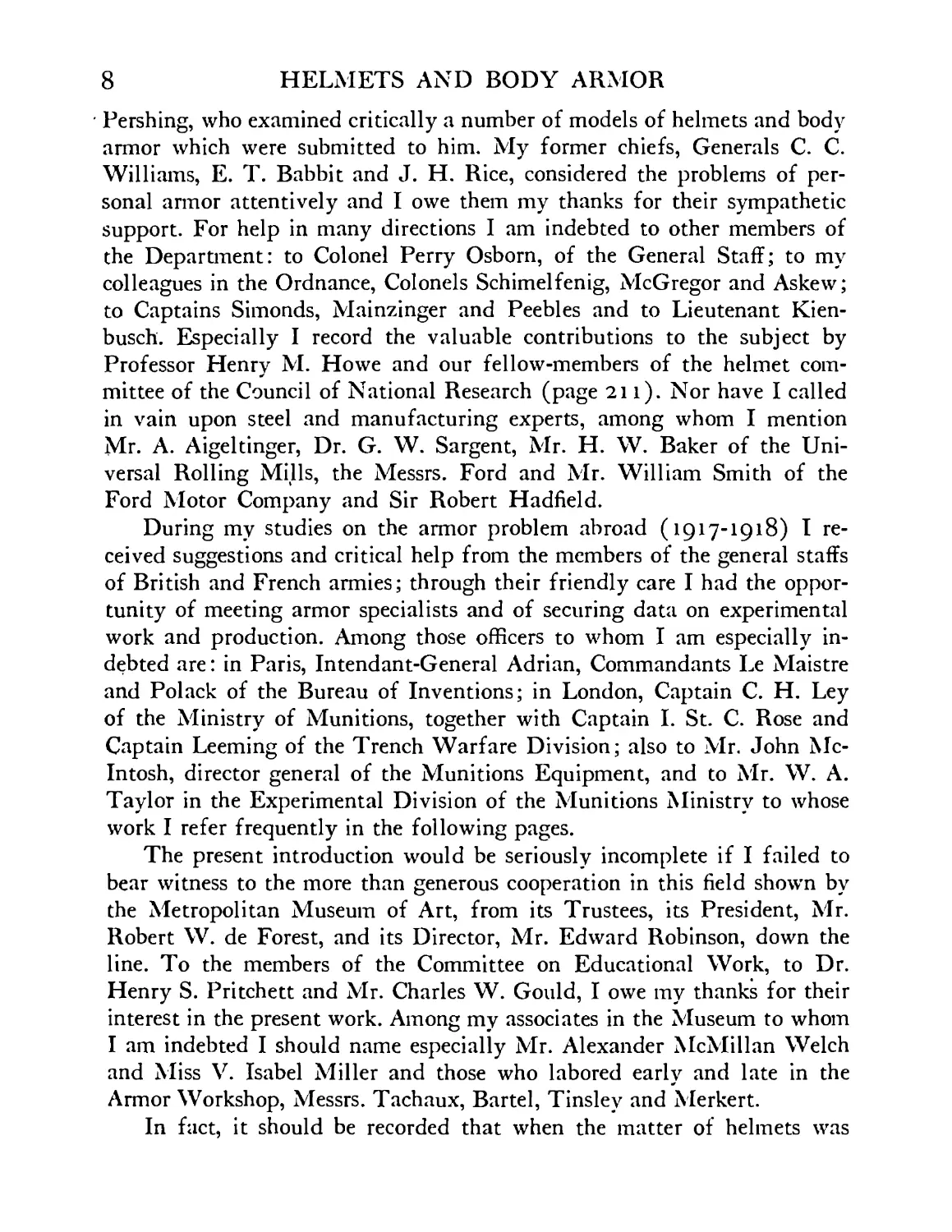
HELMETS AND BODY ARMOR
IN MODERN WARFARE • DEAN
HELMETS AND BODY ARMOR IN
MODERN WARFARE
THE METROPOLITAN MUSEUM OF ART
PUBLICATION OF THE COMMITTEE ON EDUCATION
HENRY S. PRITCHETT, Ph.D., LL.D., CHAIRMAN
HELMETS AND BODY ARMOR IN MODERN
WARFARE. BY BASHFORD DEAN, Ph.D.
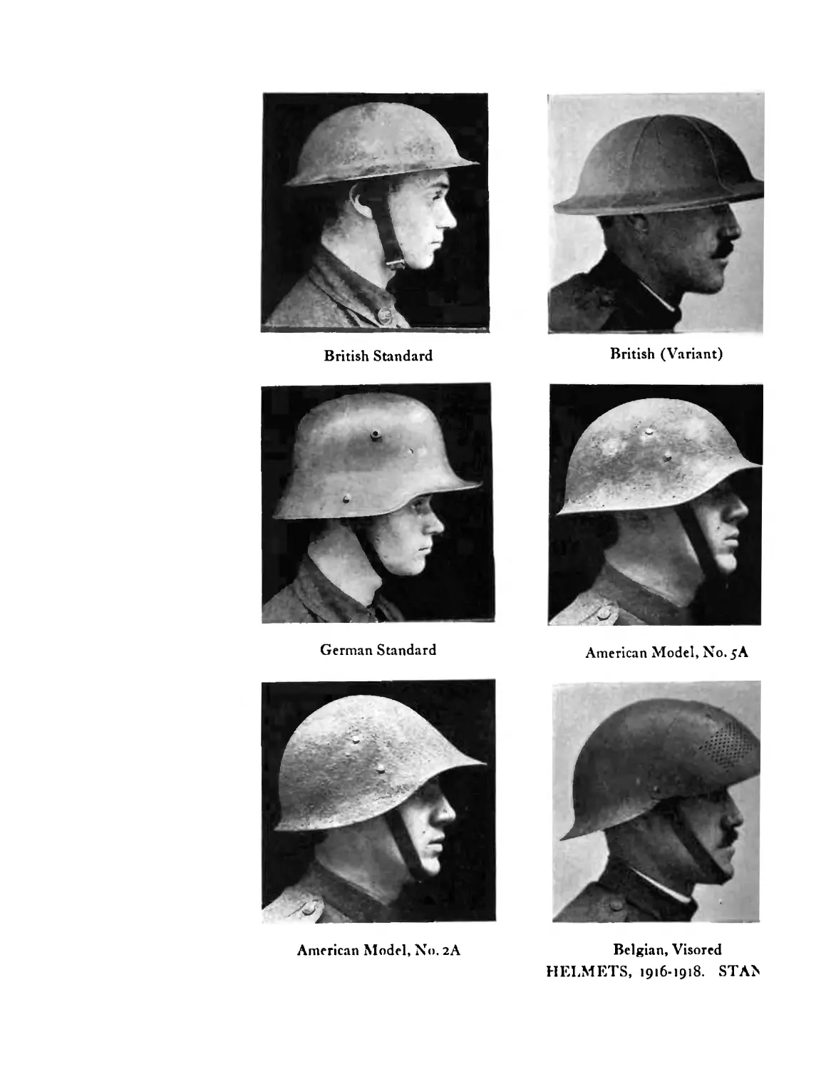
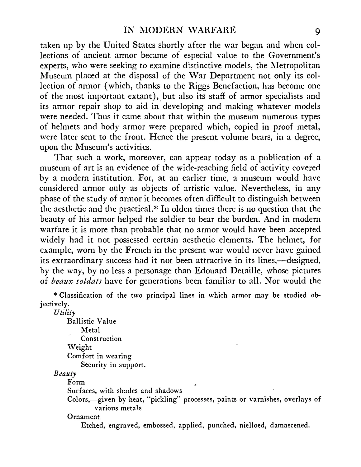
British Standard
British (Variant)
German Standard
American Model, No. 5A
American Model, No. 2A
Belgian, Visored
HELMETS, 1916-1918. STA>
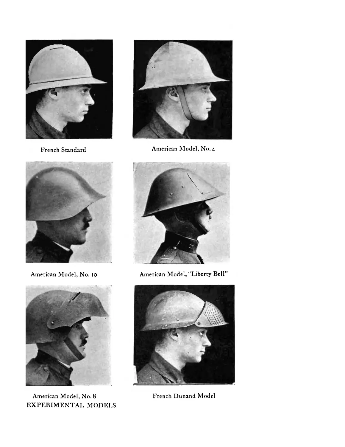
French Standard
American Model, No. 4
American Model, “Liberty Bell”
American Model, No. 10
French Dunand Model
American Model, Nd. 8
EXPERIMENTAL MODELS
THE METROPOLITAN MUSEUM OF ART
HELMETS AND BODY ARMOR
IN MODERN WARFARE
BY
BASHFORD DEAN, Ph.D.
CURATOR OF ARMOR, METROPOLITAN MUSEUM OF ART
FORMERLY MAJOR OF ORDNANCE, U. S. A., IN CHARGE OF ARMOR UNIT,
EQUIPMENT SECTION, ENGINEERING DIVISION, WASHINGTON
FORMERLY CHAIRMAN OF THE COMMITTEE ON HELMETS AND BODY ARMOR,
ENGINEERING DIVISION OF THE NATIONAL RESEARCH COUNCIL
“Effort should be continued towards the development of a satis-
factory form of personal body armor.”—General Pershing, 1917.
NEW HAVEN:
YALE UNIVERSITY PRESS
LONDON • HUMPHREY MILFORD • OXFORD UNIVERSITY PRESS
MDCCCCXX
COPYRIGHT, 1920, BY
YALE UNIVERSITY PRESS.
PREFACE
Г I ЛНЕ present book aims to consider the virtues and failings of hel-
I mets and body armor in modern warfare. To this end it brings
I together materials collected from all accessible sources; it shows
the kinds of armor which each nation has been using in the Great
War, what practical tests they will resist, of what materials they are made,
and what they have done in saving life and limb. As an introduction to
these headings there has now been added a section which deals with ancient
armor; this enables us to contrast the old with the new and to indicate, in
clearer perspective, what degree of success the latest armor may achieve in
its special field.
The results of our inquiry will show:
(1) That the helmet has been adopted as part of the regular military
equipment of many nations.
(2) That helmets and body armor have been found, in broad aver-
ages, of distinct advantage to the wearers.
(3) That body armor, in spite of the protection which it affords, finds
little favor with the soldier. For numerous reasons, he would rather take
his chances of injury.
(4) That effort should be made, none the less, to demonstrate more
clearly the protective value of body armor, to improve its material and
design, and to reduce to a minimum the discomfort which will always be
experienced by its wearer,—in a word, to meet the objections to the use
of armor which have been brought up on the sides both of theory and of
practice.
In preparing the following pages I have sought and secured aid from
many sources. I am most of all indebted to the Department of War of the
United States, for access to documents and materials as well as for per-
mission to make use of them in publication. The theme of the present
studies touched matters of no little practical importance; the Secretary of
War, Mr. Baker, as well as his colleagues, Secretaries Crowell and Keppel,
were pleased to show a personal interest in them; as did also General
8
HELMETS AND BODY ARMOR
Pershing, who examined critically a number of models of helmets and body
armor which were submitted to him. My former chiefs, Generals С. C.
Williams, E. T. Babbit and J. H. Rice, considered the problems of per-
sonal armor attentively and I owe them my thanks for their sympathetic
support. For help in many directions I am indebted to other members of
the Department: to Colonel Perry Osborn, of the General Staff; to my
colleagues in the Ordnance, Colonels Schimelfenig, McGregor and Askew;
to Captains Simonds, Mainzinger and Peebles and to Lieutenant Kien-
busch. Especially I record the valuable contributions to the subject by
Professor Henry M. Howe and our fellow-members of the helmet com-
mittee of the Council of National Research (page 211). Nor have I called
in vain upon steel and manufacturing experts, among whom I mention
Mr. A. Aigeltinger, Dr. G. W. Sargent, Mr. H. W. Baker of the Uni-
versal Rolling Mills, the Messrs. Ford and Mr. William Smith of the
Ford Motor Company and Sir Robert Hadfield.
During my studies on the armor problem abroad (1917-1918) I re-
ceived suggestions and critical help from the members of the general staffs
of British and French armies; through their friendly care I had the oppor-
tunity of meeting armor specialists and of securing data on experimental
work and production. Among those officers to whom I am especially in-
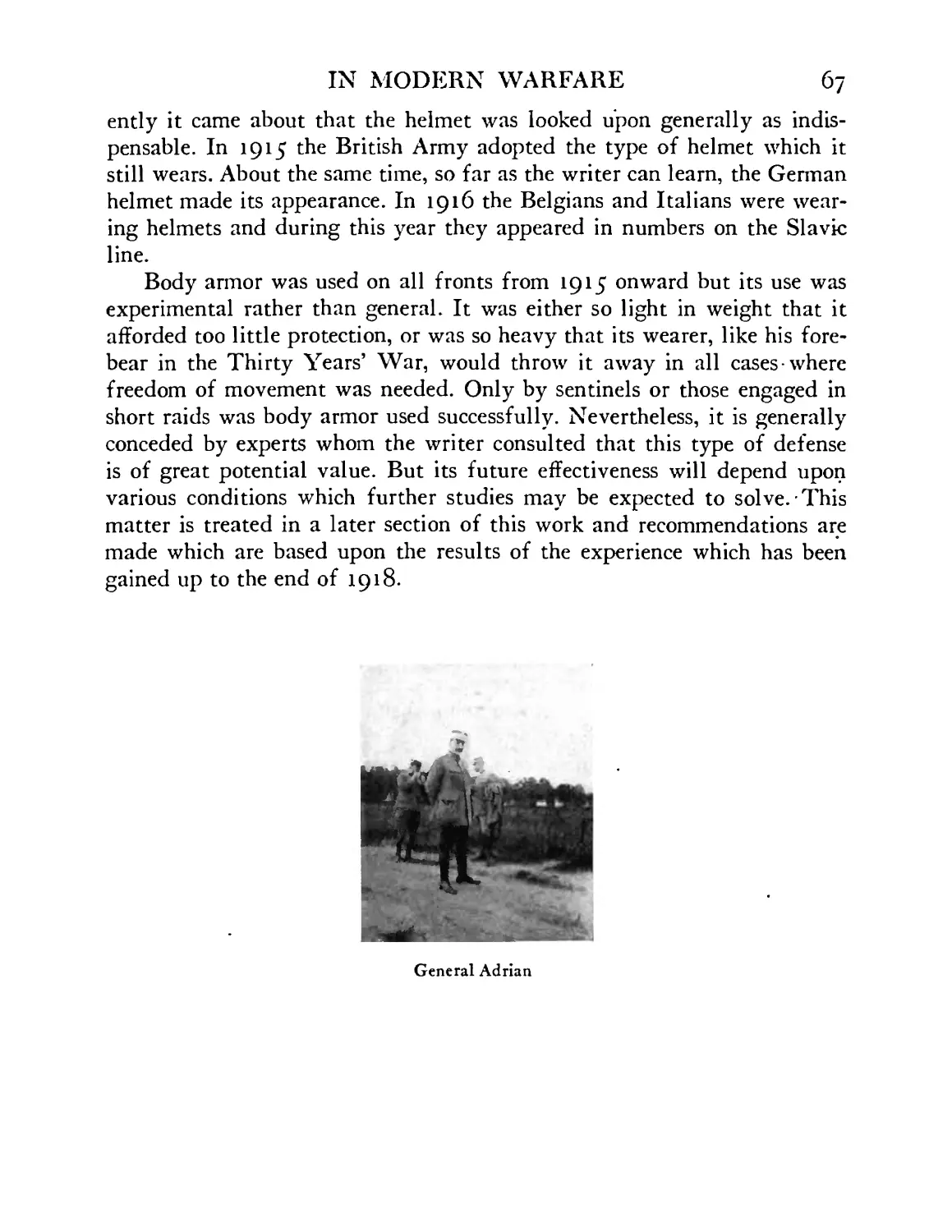
debted are: in Paris, Intendant-General Adrian, Commandants Le Maistre
and Polack of the Bureau of Inventions; in London, Captain С. H. Ley
of the Ministry of Munitions, together with Captain I. St. C. Rose and
Captain Leeming of the Trench Warfare Division; also to Mr. John Mc-
Intosh, director general of the Munitions Equipment, and to Mr. W. A.
Taylor in the Experimental Division of the Munitions Ministry to whose
work I refer frequently in the following pages.
The present introduction would be seriously incomplete if I failed to
bear witness to the more than generous cooperation in this field shown by
the Metropolitan Museum of Art, from its Trustees, its President, Mr.
Robert W. de Forest, and its Director, Mr. Edward Robinson, down the
line. To the members of the Committee on Educational Work, to Dr.
Henry S. Pritchett and Mr. Charles W. Gould, I owe my thanks for their
interest in the present work. Among my associates in the Museum to whom
I am indebted I should name especially Mr. Alexander McMillan Welch
and Miss V. Isabel Miller and those who labored early and late in the
Armor Workshop, Messrs. Tachaux, Bartel, Tinsley and Merkert.
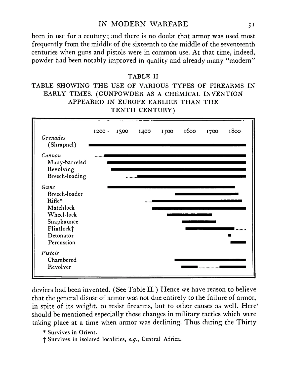
In fact, it should be recorded that when the matter of helmets was
IN MODERN WARFARE 9
taken up by the United States shortly after the war began and when col-
lections of ancient armor became of especial value to the Government’s
experts, who were seeking to examine distinctive models, the Metropolitan
Museum placed at the disposal of the War Department not only its col-
lection of armor (which, thanks to the Riggs Benefaction, has become one
of the most important extant), but also its staff of armor specialists and
its armor repair shop to aid in developing and making whatever models
were needed. Thus it came about that within the museum numerous types
of helmets and body armor were prepared which, copied in proof metal,
were later sent to the front. Hence the present volume bears, in a degree,
upon the Museum’s activities.
That such a work, moreover, can appear today as a publication of a
museum of art is an evidence of the wide-reaching field of activity covered
by a modern institution. For, at an earlier time, a museum would have
considered armor only as objects of artistic value. Nevertheless, in any
phase of the study of armor it becomes often difficult to distinguish between
the aesthetic and the practical.* In olden times there is no question that the
beauty of his armor helped the soldier to bear the burden. And in modern
warfare it is more than probable that no armor would have been accepted
widely had it not possessed certain aesthetic elements. The helmet, for
example, worn by the French in the present war would never have gained
its extraordinary success had it not been attractive in its lines,—designed,
by the way, by no less a personage than Edouard Detaille, whose pictures
of beaux soldats have for generations been familiar to all. Nor would the
* Classification of the two principal lines in which armor may be studied ob-
jectively.
Utility
Ballistic Value
Metal
Construction
Weight
Comfort in wearing
Security in support.
Beauty
Form
Surfaces, with shades and shadows
Colors,—given by heat, “pickling” processes, paints or varnishes, overlays of
various metals
Ornament
Etched, engraved, embossed, applied, punched, nielloed, damascened.
io HELMETS AND BODY ARMOR
extremely simple British helmet have been accepted generally and promptly
had it not an especial set and swing of. its own.
BASHFORD DEAN.
Metropolitan Museum of Art,
July 20, 1919.
TABLE OF CONTENTS
PAGE
Introduction: Including an Outline of the Earlier Use of Armor / 25
I. The Early Use of Armor in the Present War ... 64
II. Armor as a Protection against Missiles of Low and Middle
Velocity ........ 68
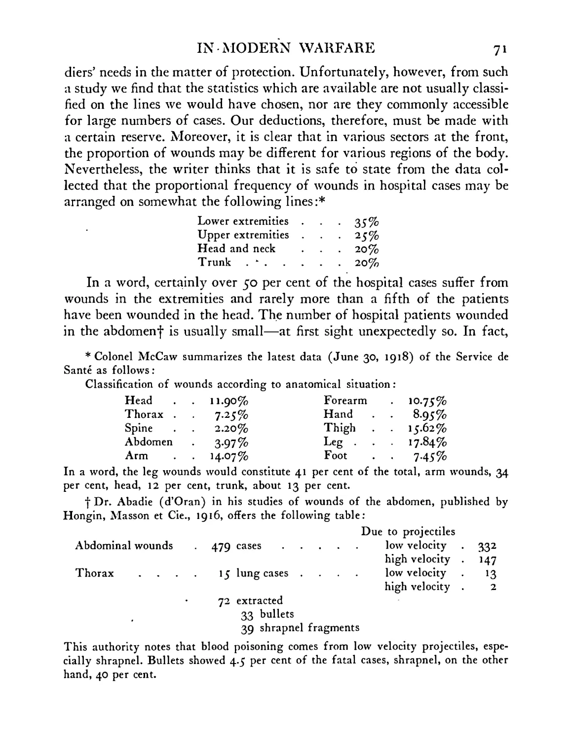
(a) Statistics which Demonstrate the Usefulness of Modem
Armor, Notably the Helmet. The Medical Viewpoint 69
(b) Frequency in the Location of Wounds and Its Bearing
upon the Armor Problem ..... 70
III. Foreign Types of Modern Helmets and Body Armor. Their
Origin and Fate . . . . . .74
(A) French ........ 74
(B) English . . . . . . . .110
(C) German (and Austrian) . . . . 133
(D) Italian ........ 148
(E) Belgian . . . . . . . .156
(F) Portuguese . . . . . . .160
(G) Slavic ........ 161
(H) Swiss ........ 163
(I) Spanish ........ 171
(J) Japanese . . . . . . . .172
IV. Shields and Their Use during the Present War . . .178
V. American Helmets and Body Armor . . . .193
VI. Steel Used in Making Modern Armor. Can Other Metal than
Steel Be Used for this Purpose, ^.<7., Aluminum Al-
loys? ........ 270
VII. Soft Armor (?>., Armor of Textiles), Its Beginning, Devel-
opment and Possible Value ..... 282
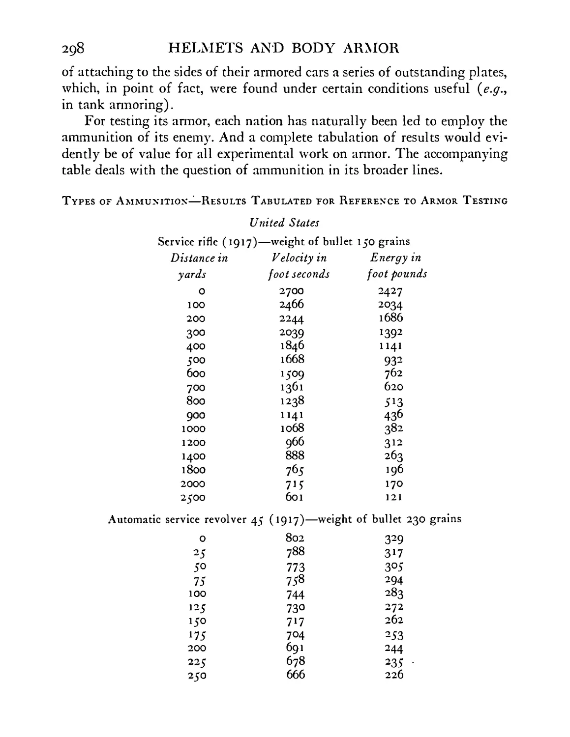
VIII. Concerning Tests of Modern Armor .... 294
IX. What Should Be Done to Improve Helmets and Body Armor
at the Present Time? Summary and Conclusions . 313
Index . . . . . . . . . .319
LIST OF FIGURES
FIGURE
Frontispiece
1
2
3
ЗА
4
5
6
6A
7
7A
8
9
9A
io
и
A dozen types of modern helmets
European armor and its development during a period
of a thousand years ......
Complete armor for man and horse, 1508, prepared
for the Emperor Maximilian I
Model wearing costume worn under chain mail shirt
and cap (coiffe) ......
Model wearing chain mail of the fourteenth century
(Mail in Metropolitan Museum of Art)
Half-armor, tested by musket ball, worn by the Due
de Guise (f 1583). Weight 94 pounds. Artillery
Museum, Paris .......
Armor of Pedro II of Portugal. About 1700. Weight
43 pounds. Shows marks of testing bullets on re-
inforcing plate for corselet. Specimen in Metropoli-
tan Museum of Art ......
Three-quarters suit of armor of “proof,” showing
mark of testing bullet (near right shoulder plate).
Weight 84 pounds. About 1620; believed to have
been worn by the Marquis de Bassompierre. Riggs
Collection, Metropolitan Museum of Art
Rear view of same armor; backplate showing testing
mark ........
Stages in making a helmet after the ancient fashion
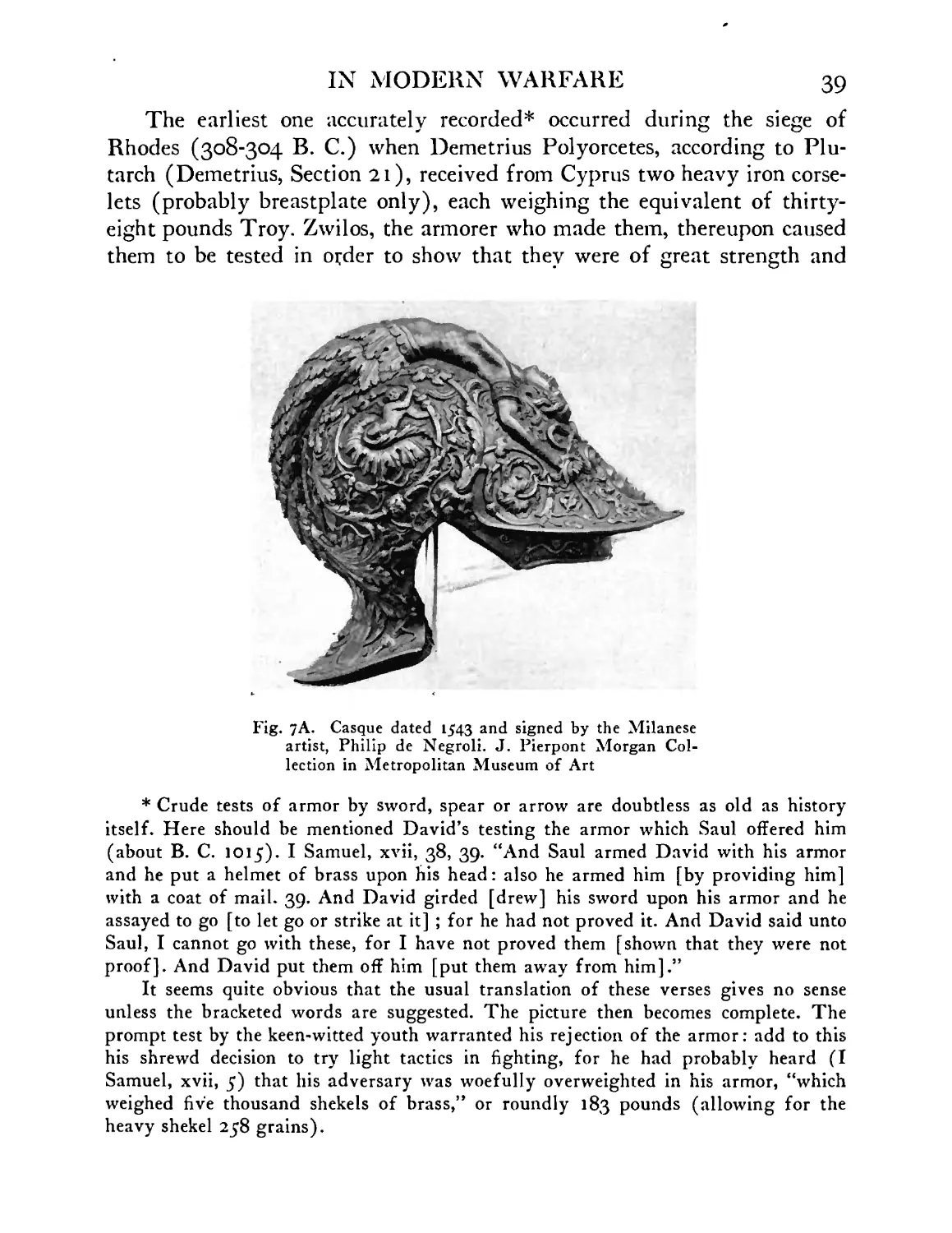
Casque dated 1543 and signed by the Milanese
artist, Philip de Negroli .....
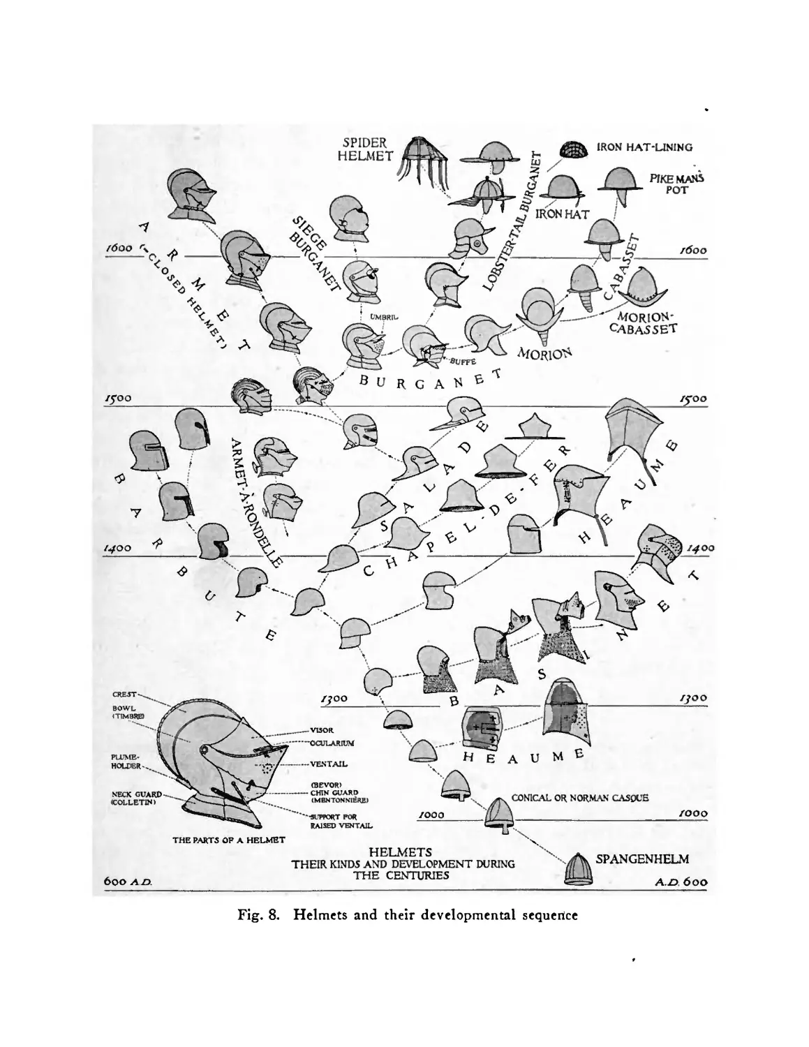
The various kinds of helmets and their develop-
mental sequence ......
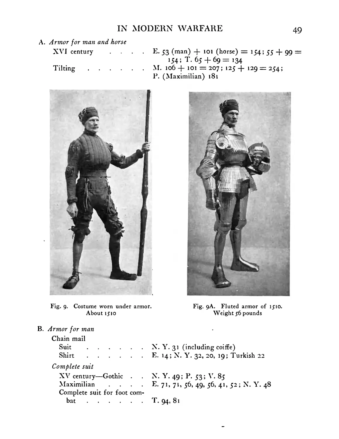
Model showing costume worn about 1510 under
fluted (Maximilian) armor; note laces or “points”
used for supporting the defenses of the arm and leg
Fluted armor of 1J10. Suit weighing 56 pounds,
exhibited in Metropolitan Museum of Art
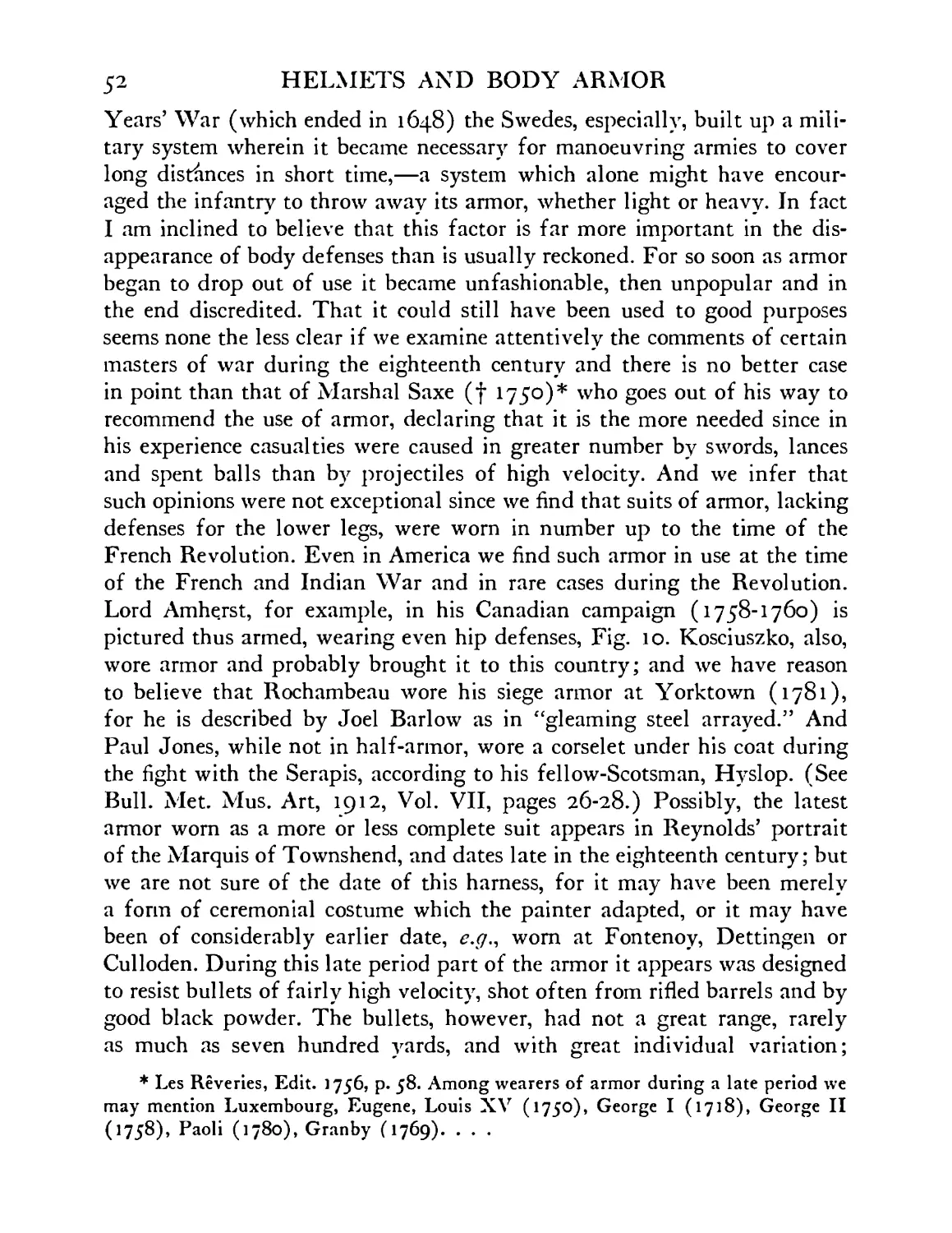
Half-armor worn about 1760 by Jeffrey Lord
Amherst; after painting by Sir Joshua Reynolds .
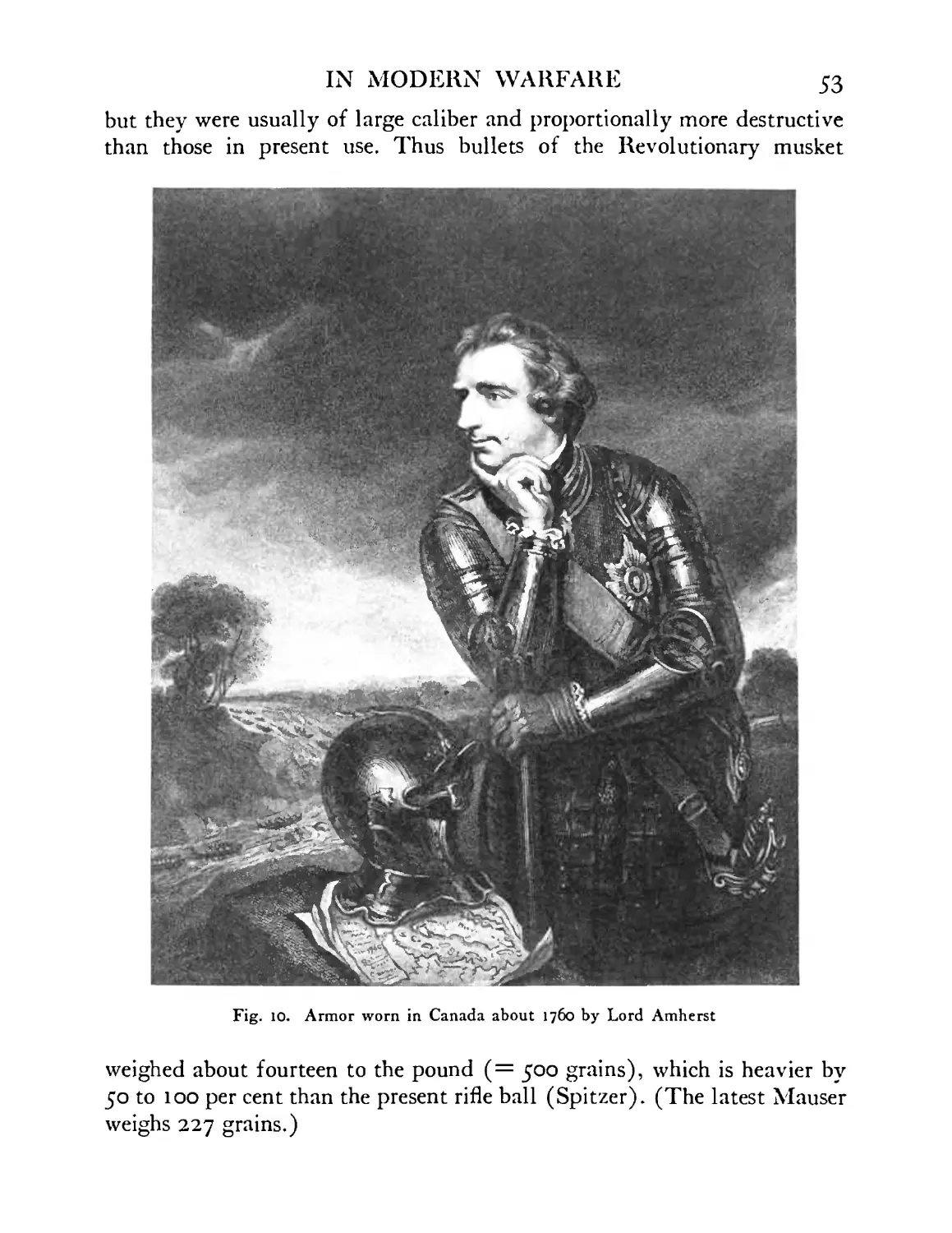
Gorget of Captain Fanning, American Revolution.
About half actual size .....
PAGE
28
29
31
31
32
33
35
35
37
39
47
49
49
53
54
и
FIGURE
12
13
Ч
15
16
17
18
19
20
21
22
23
24
25
26
27
28
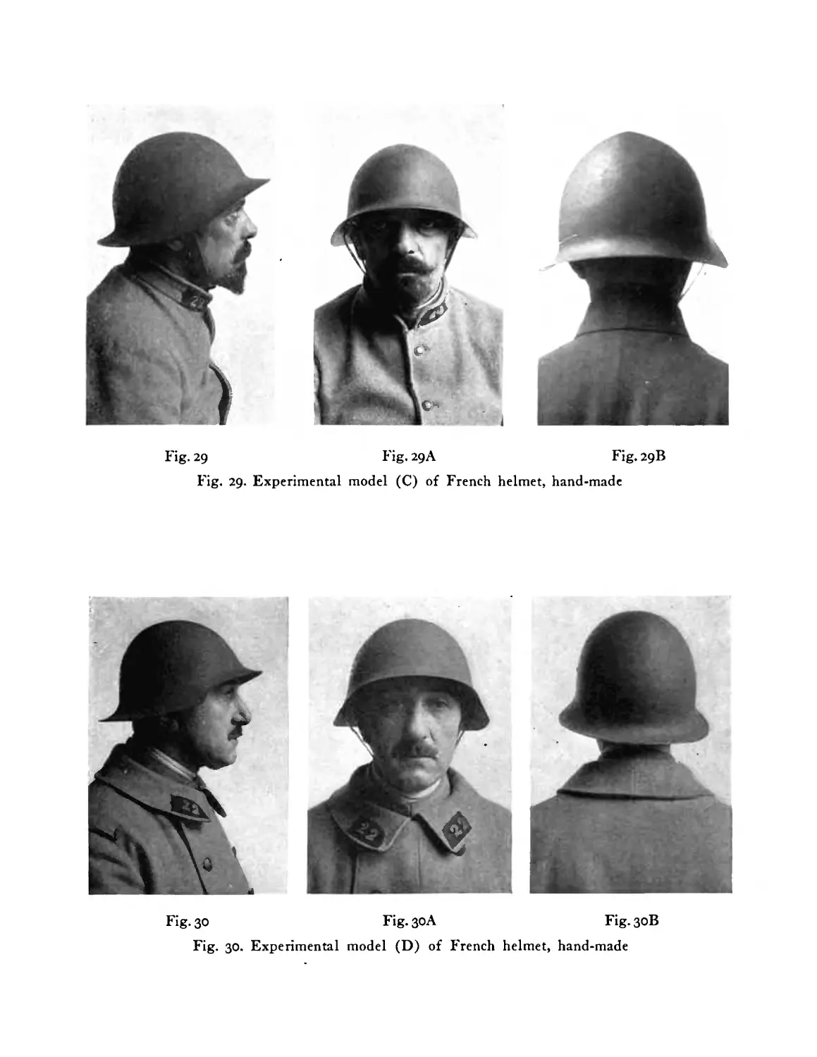
29
30
31
32
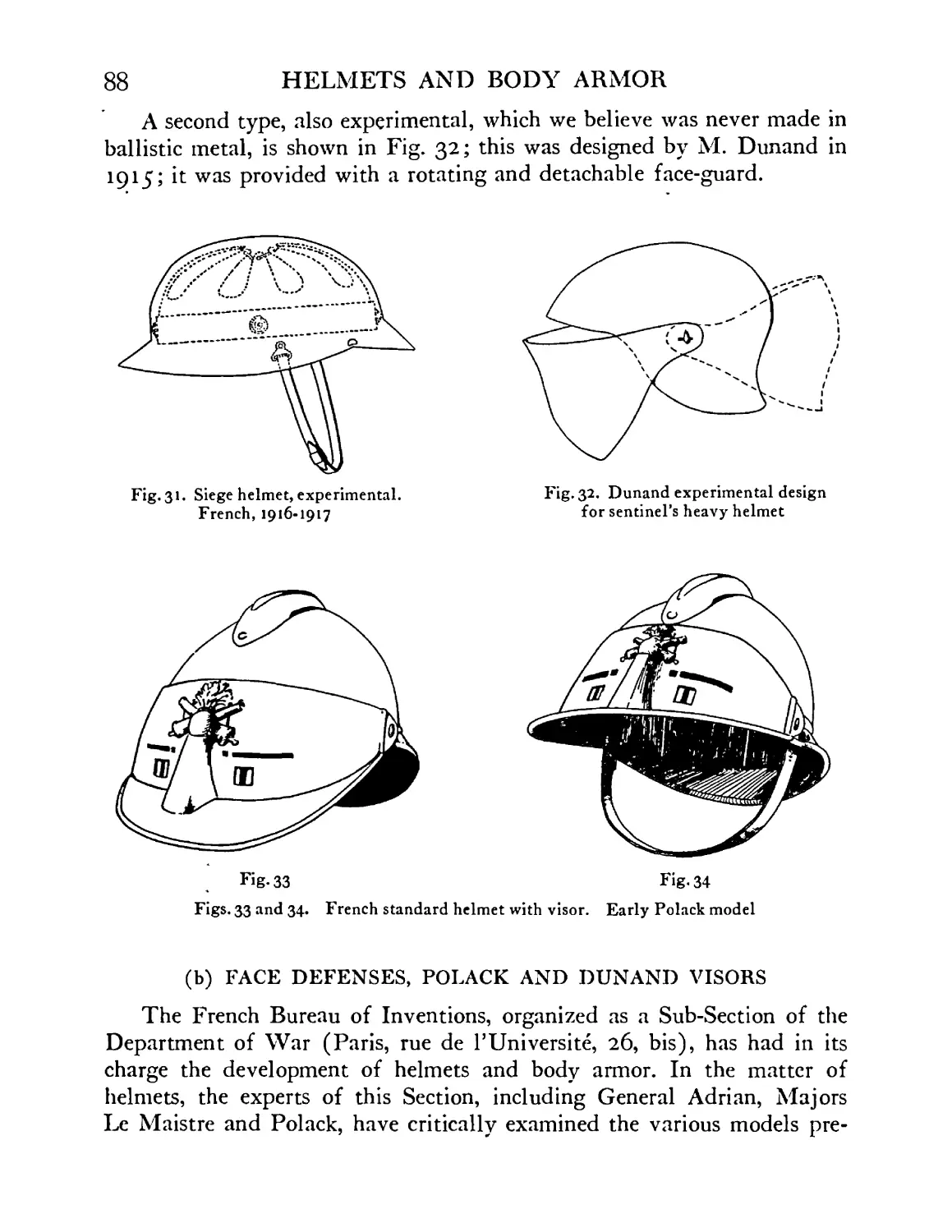
33
34
35
HELMETS AND BODY ARMOR
PAGE
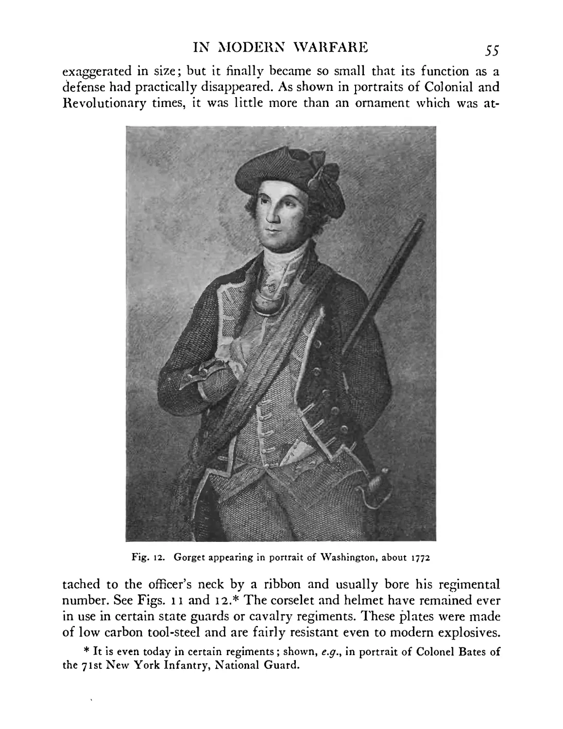
Gorget, as last piece of armor worn; appearing in
the Dickinson portrait of Washington, about 1772 . 55
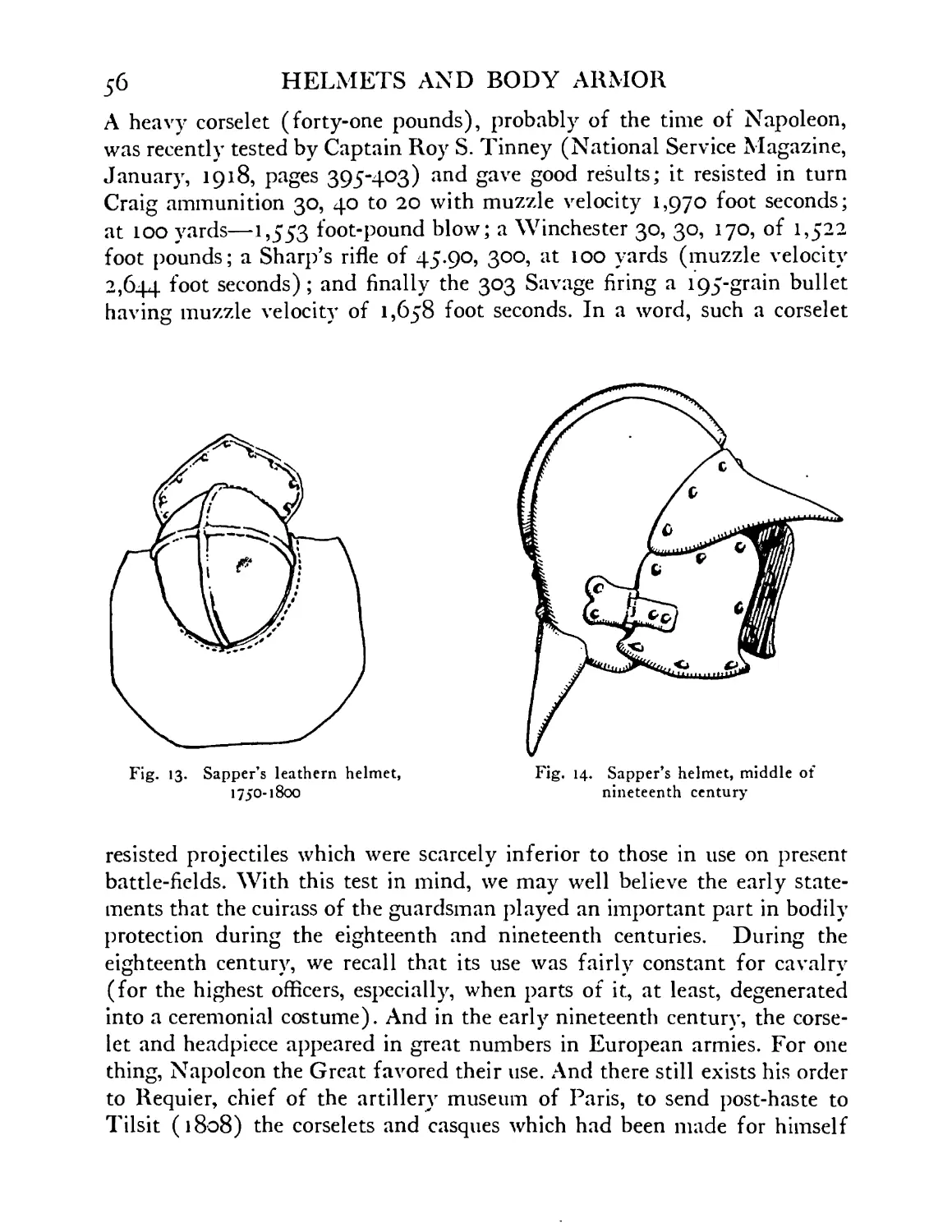
Sapper’s leathern helmet, eighteenth-nineteenth cen-
tury. Specimen in Tower of London ... 56
Sapper’s helmet, middle of nineteenth century. Speci-
men in Tower of London ..... 56
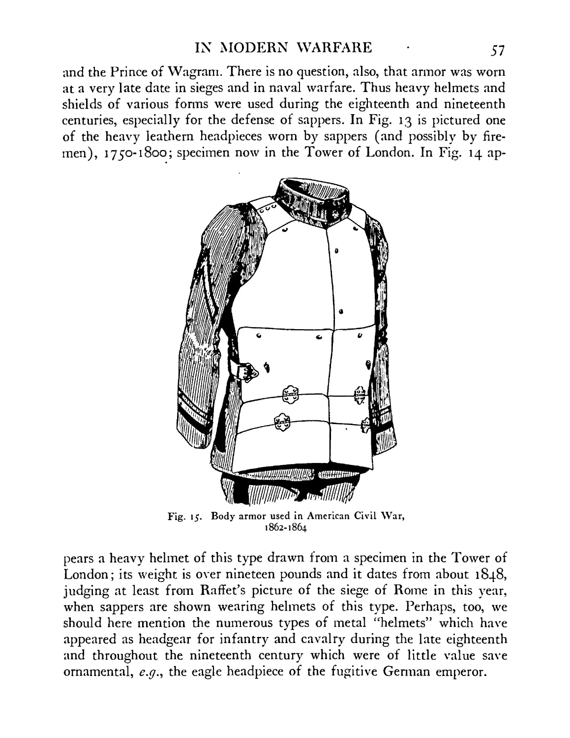
Body armor used in American Civil War, 1862-1864;
specimen preserved in Museum Military Institute,
Richmond, Va. ....... 57
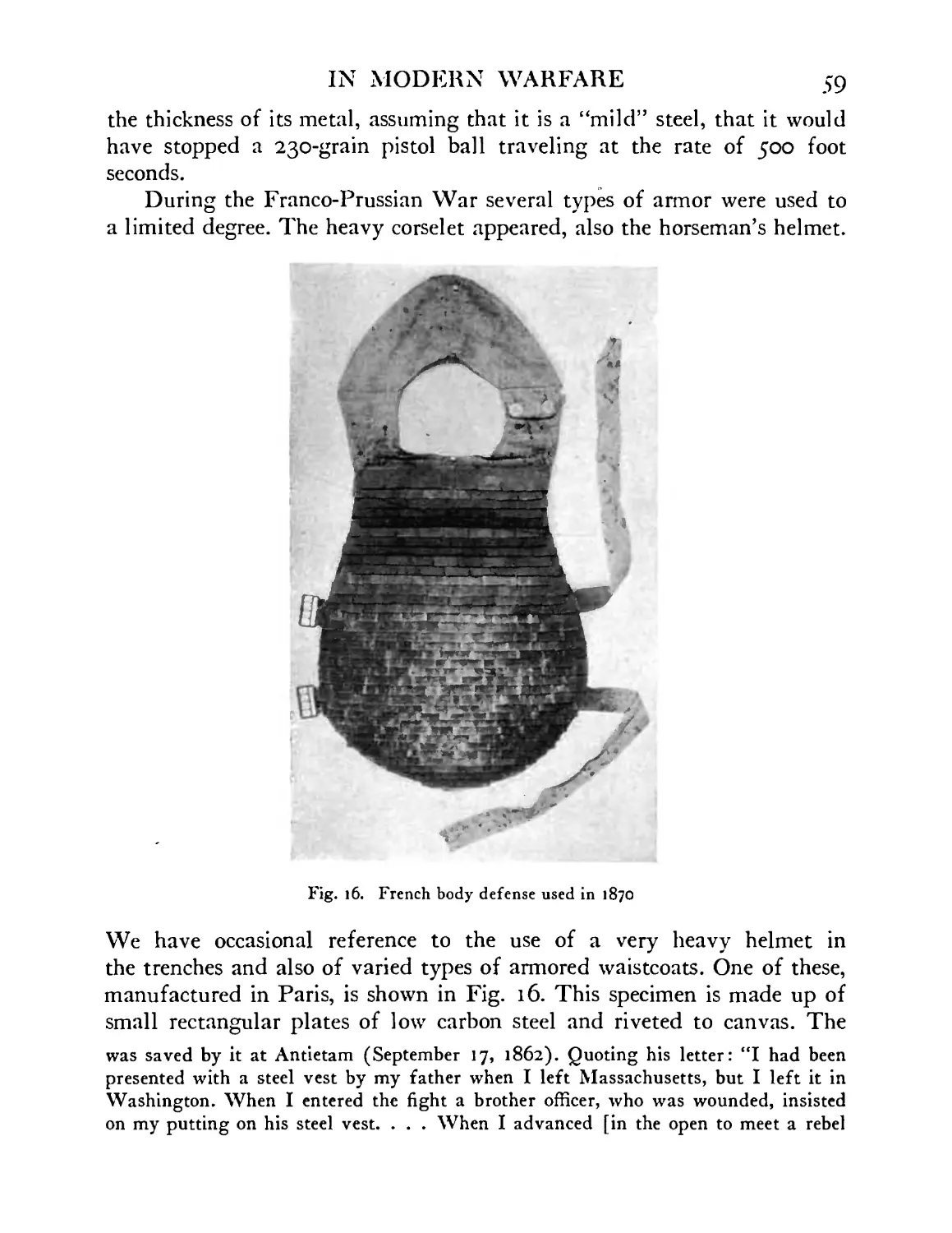
French breast defense (jazeran) used during the
war of 1870 ....... 59
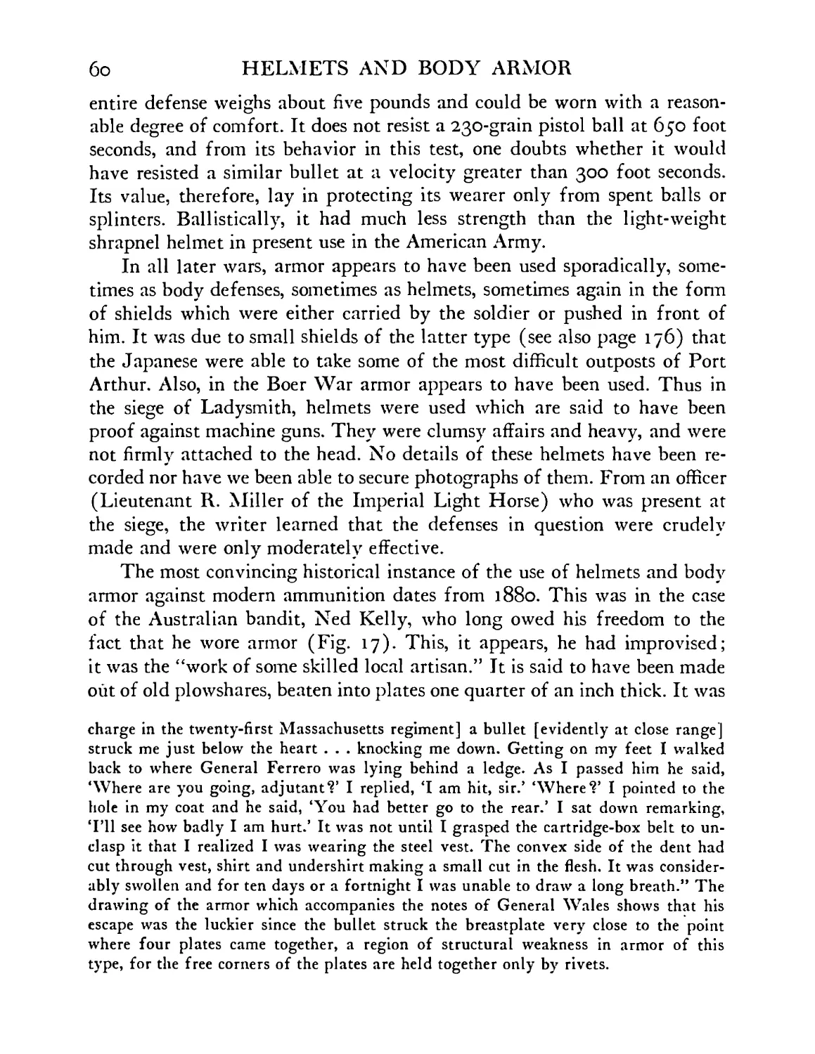
Rifle-proof armor worn by the Australian bandit,
Ned Kelly, 1894 . . ... . . 61
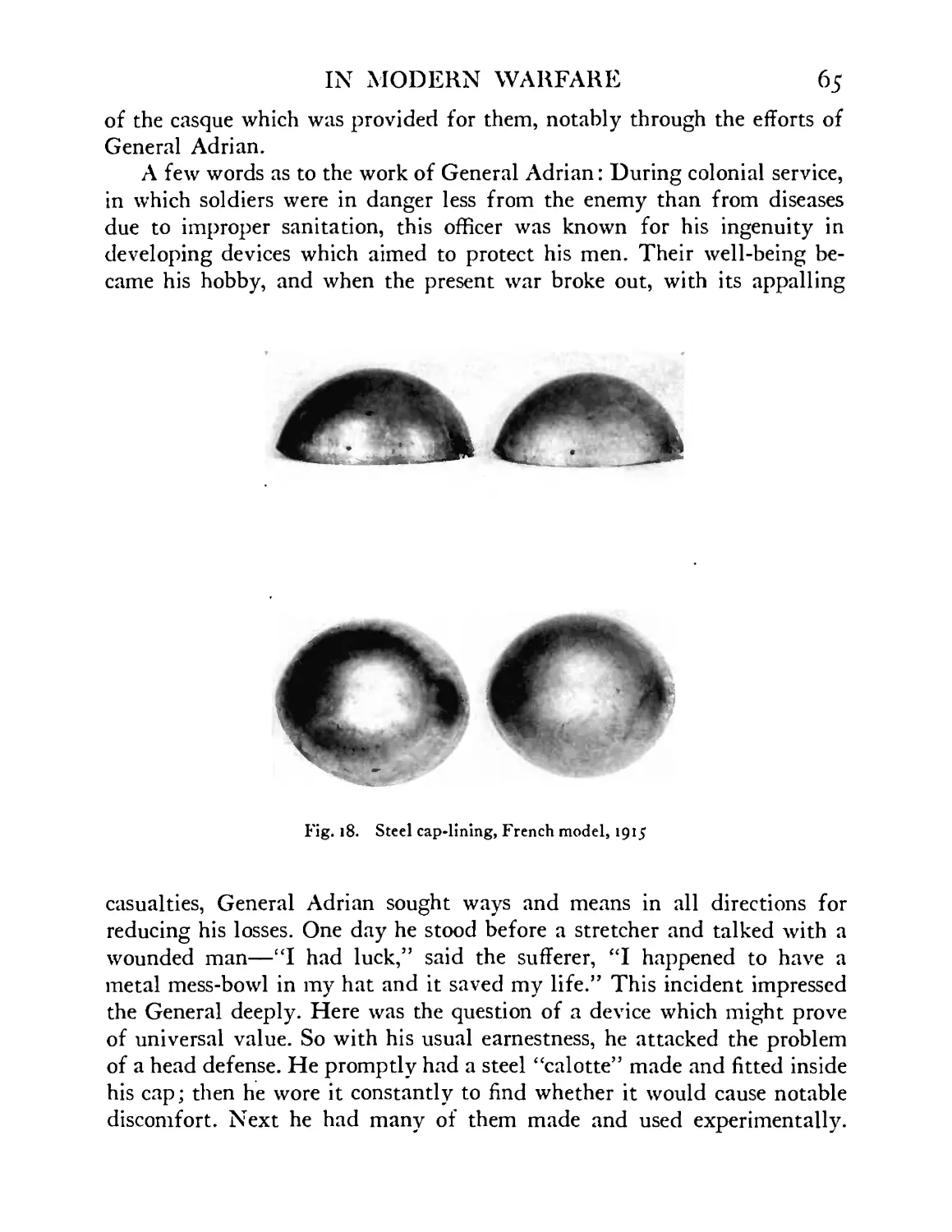
Steel calotte used as cap-lining—French (Adrian)
model, 1915..........................................65
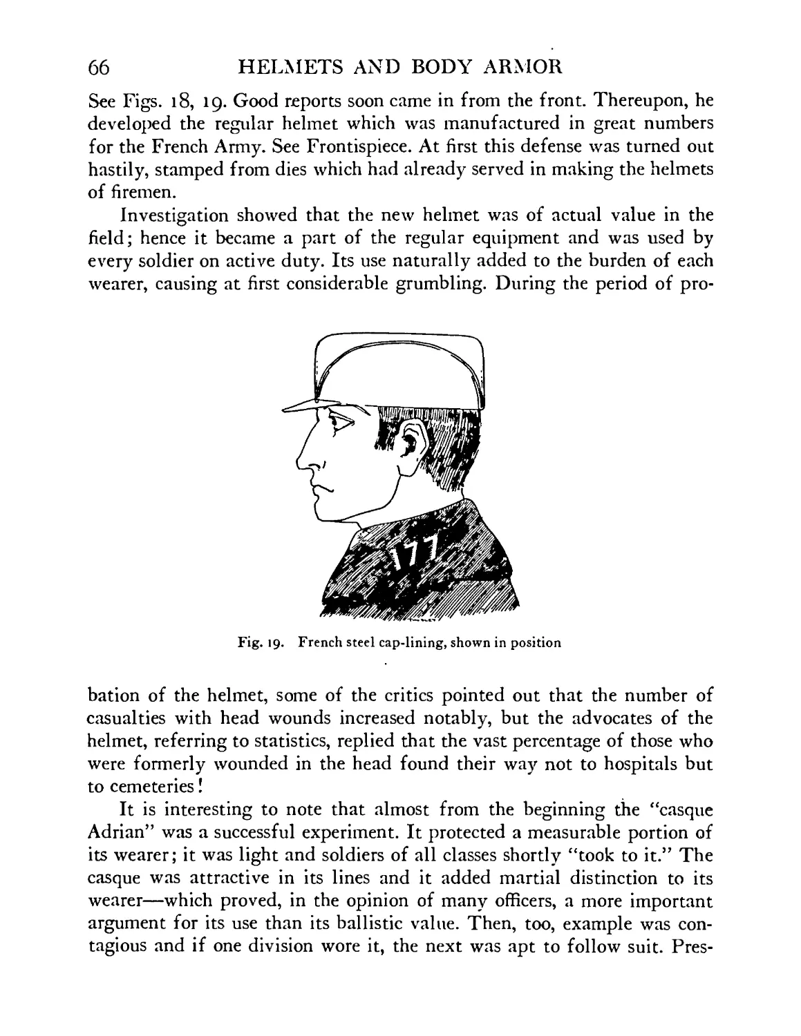
French steel helmet-lining (calotte), shown in posi-
tion ........ 66
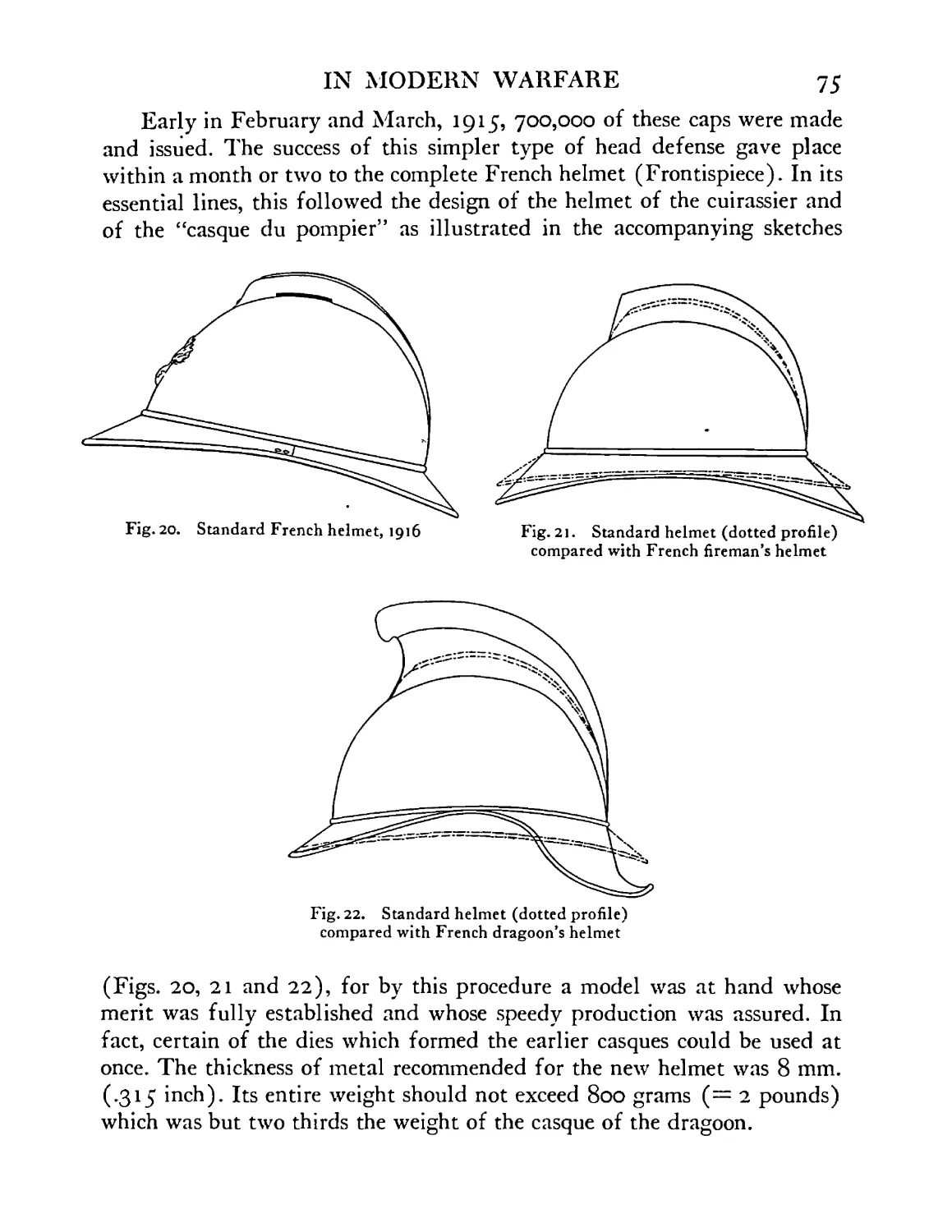
Standard French helmet, 1916, shown in profile . 75
Standard helmet shown in profile (in dotted lines)
over French fireman’s helmet • • • • 75
Standard helmet shown in profile (in dotted lines)
over French dragoon’s helmet .... 75
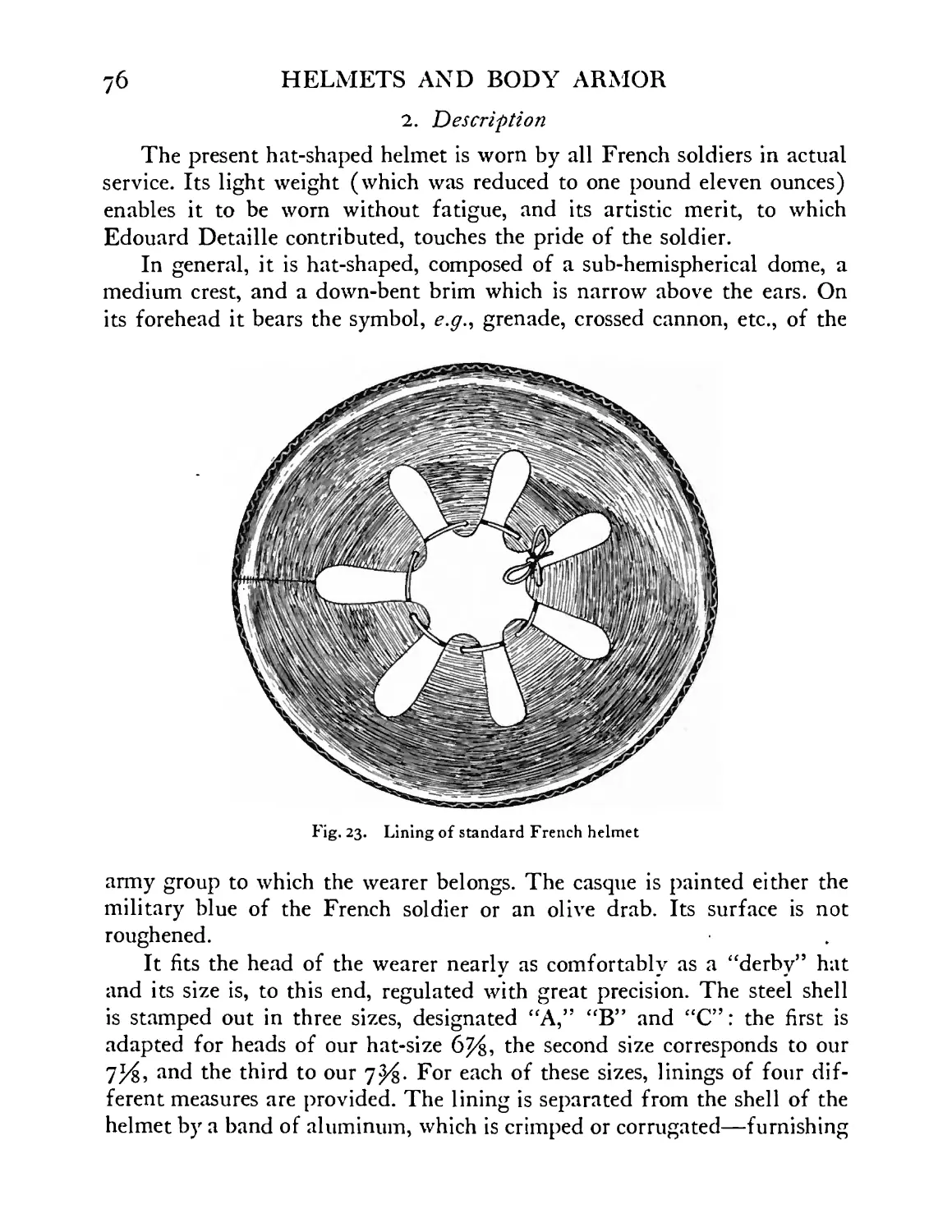
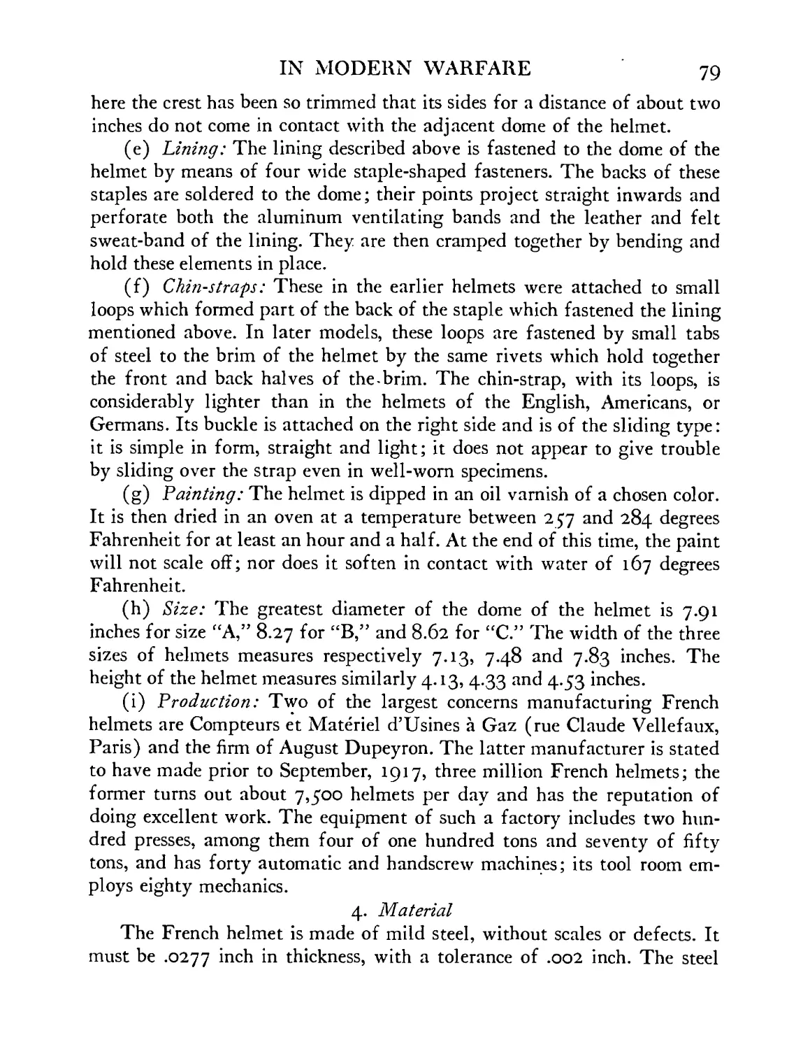
Lining of standard French helmet ... 76
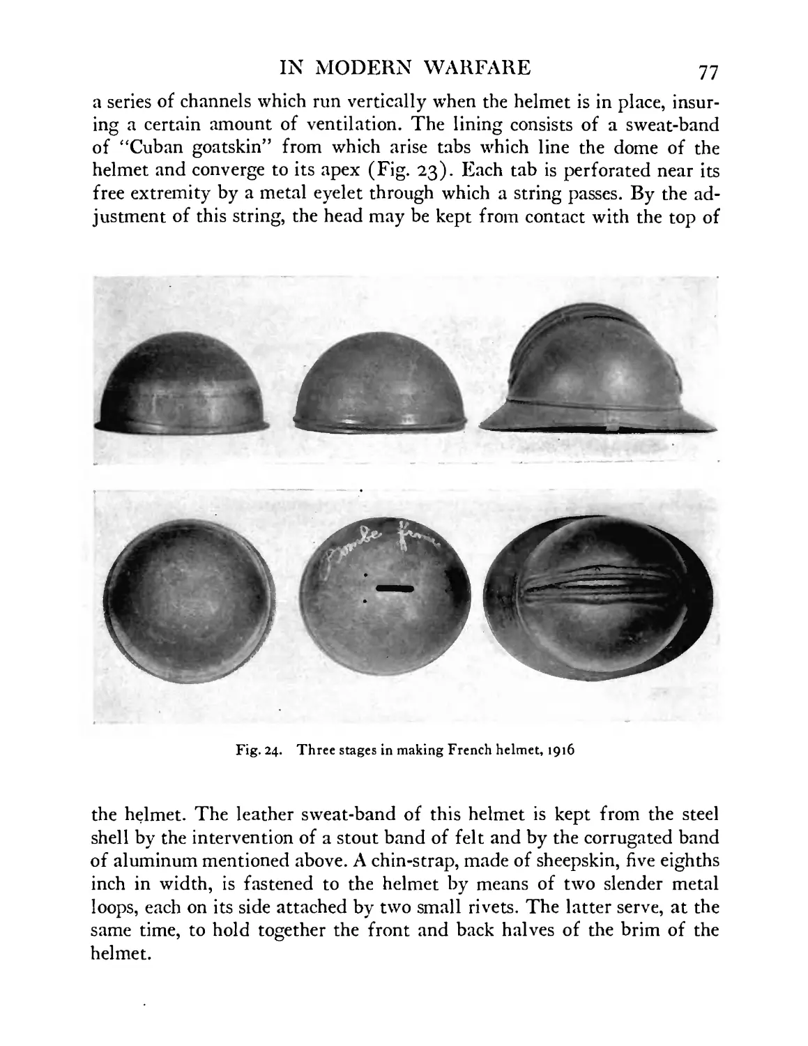
Standard French helmet, Adrian model, 1916, show-
ing steps in manufacture ..... 77
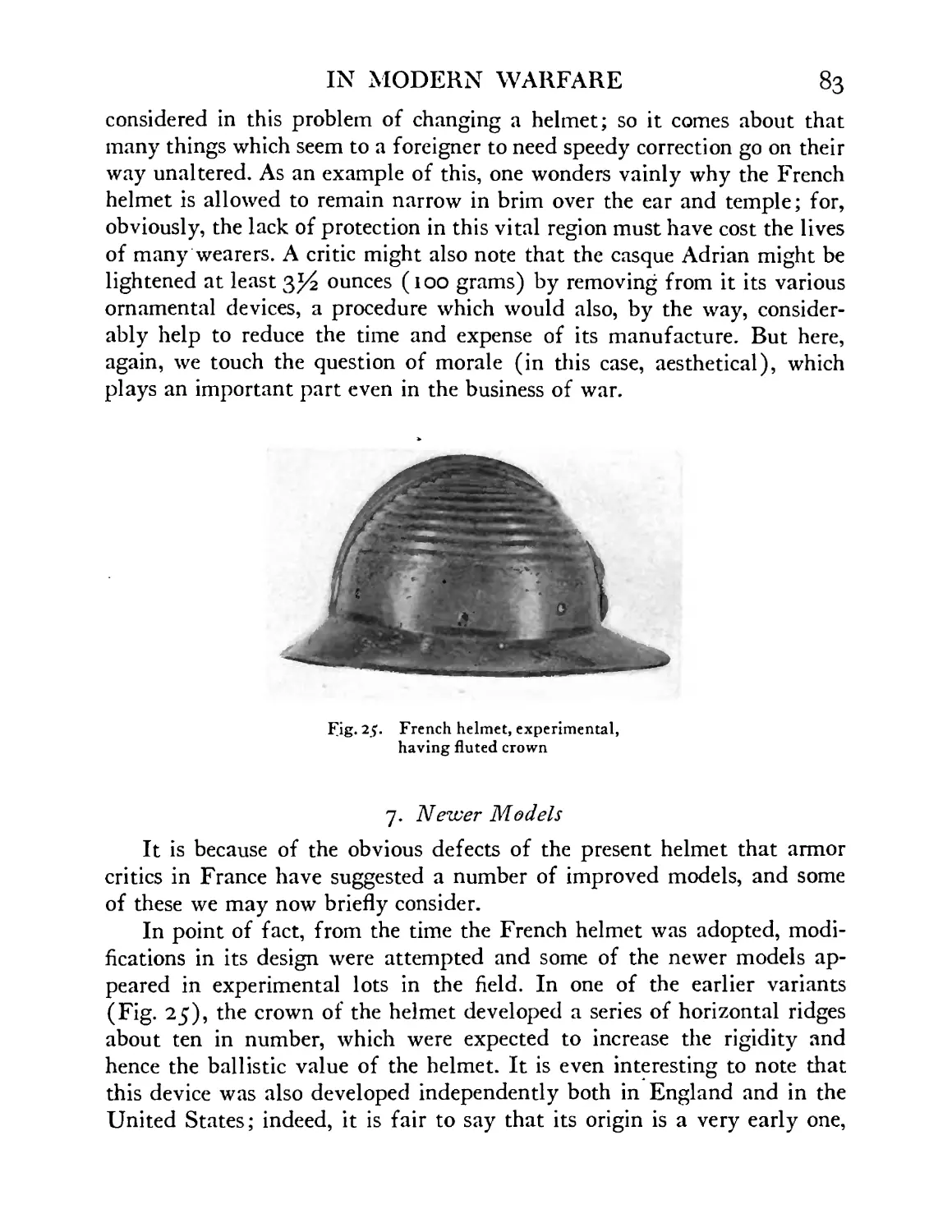
French helmet, experimental, with concentric flutings
on crown ........ 83
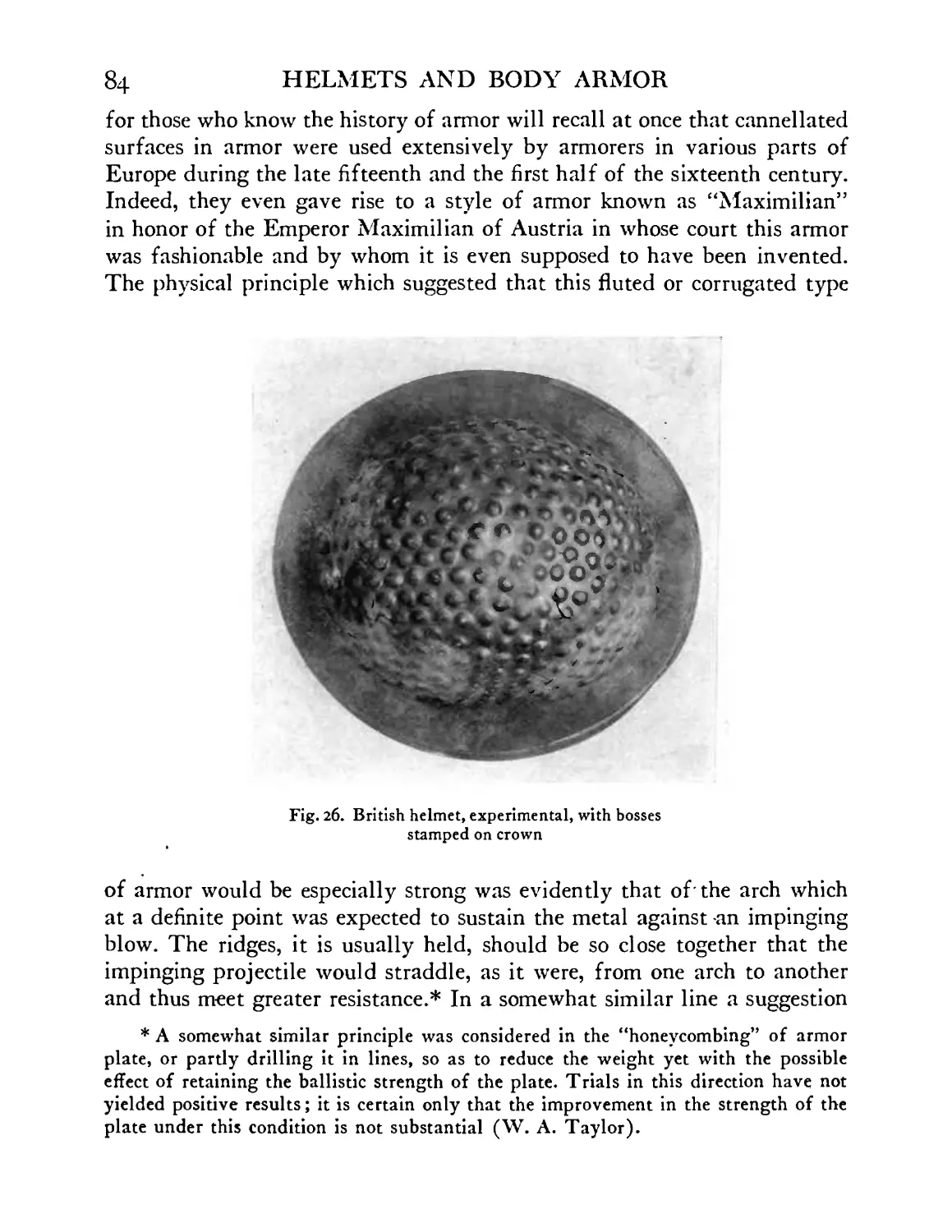
British standard helmet, experimental model, having
bosses stamped on crown ..... 84
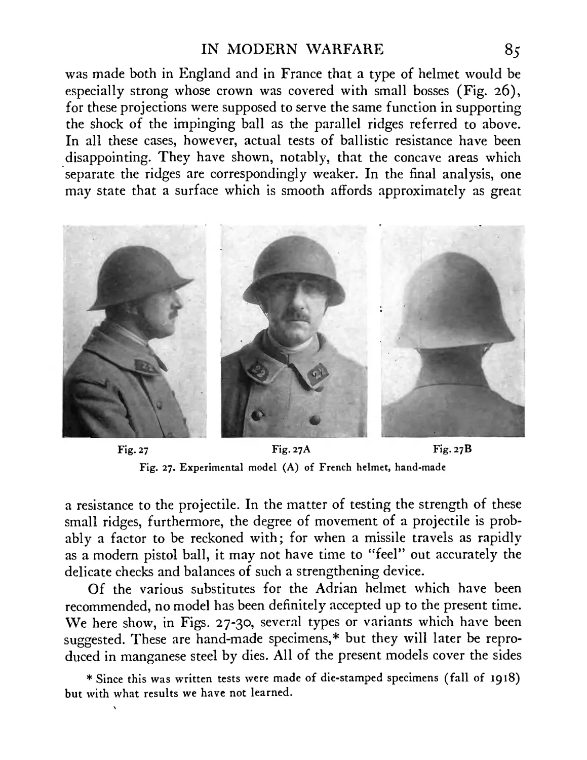
Revised model of French helmet, experimental hand-
made model (A) ...... 85
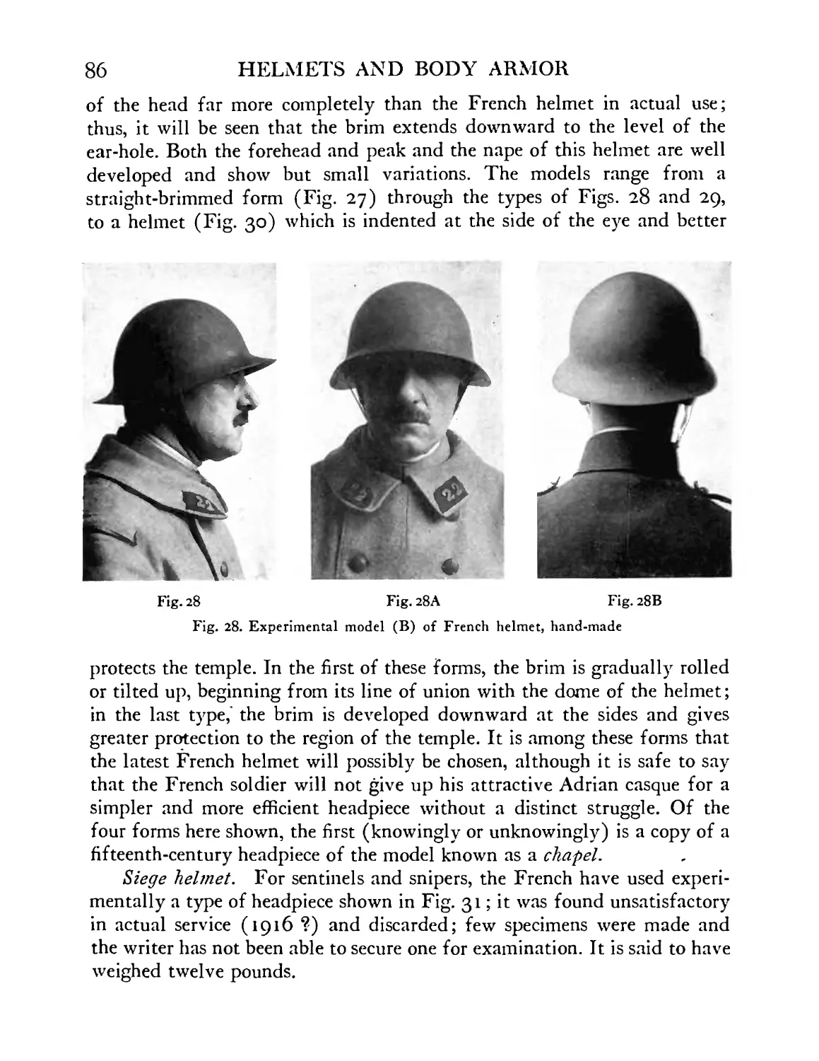
Revised model of French helmet, experimental hand-
made model (B) ...... 86
Revised model of French helmet, experimental hand-
made model (C) . . . . . .87
Revised model of French helmet, experimental hand-
made model (D) ...... 87
Siege helmet, French, 1916-1917 .... 88
Experimental design for sentinel’s heavy helmet.
Model by MM. Dunand ..... 88
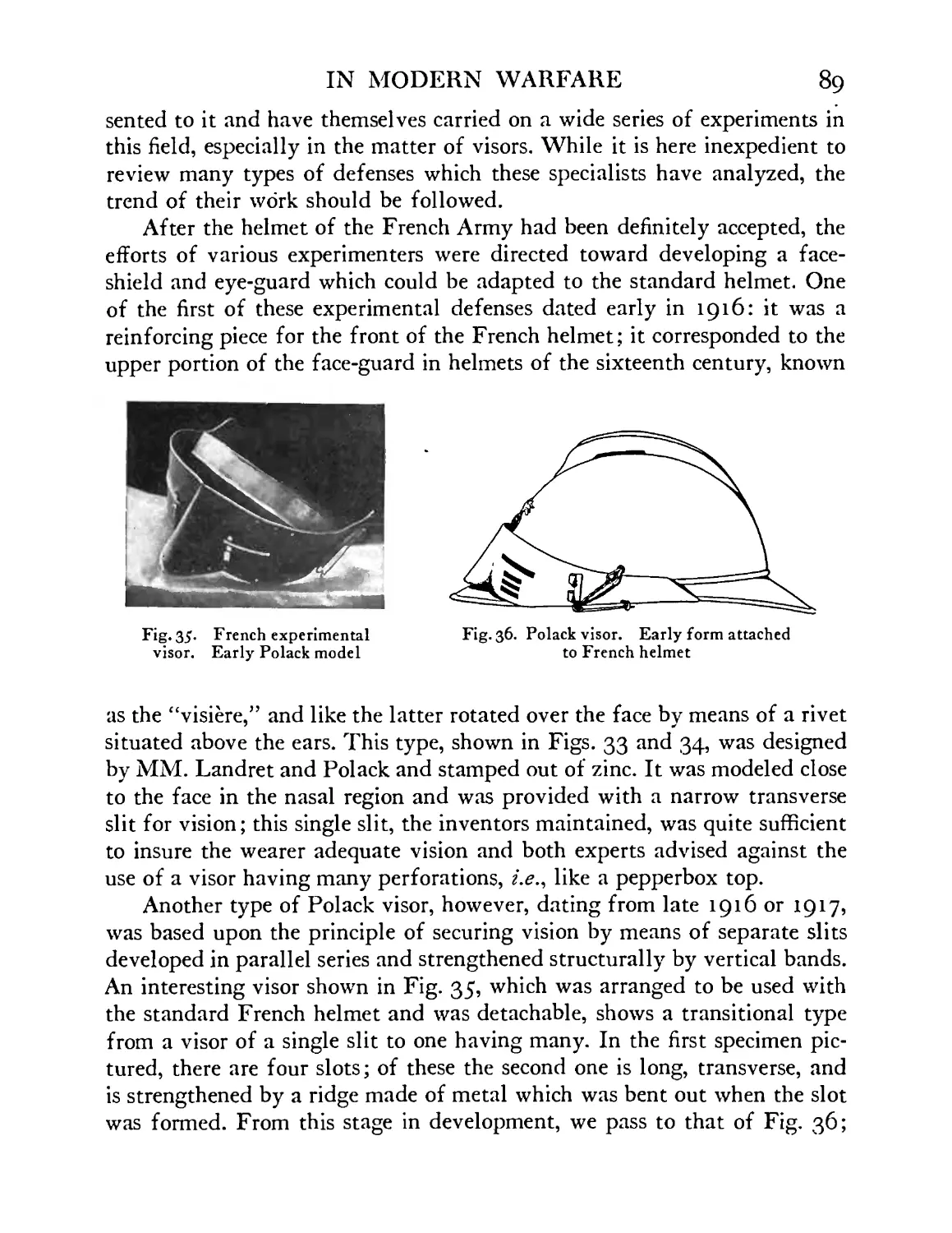
French experimental visor, Polack model . . 88
French standard helmet with experimental visor.
Early Polack model ...... 88
Polack visor. Early experimental form arranged to
FIGURE
Зб
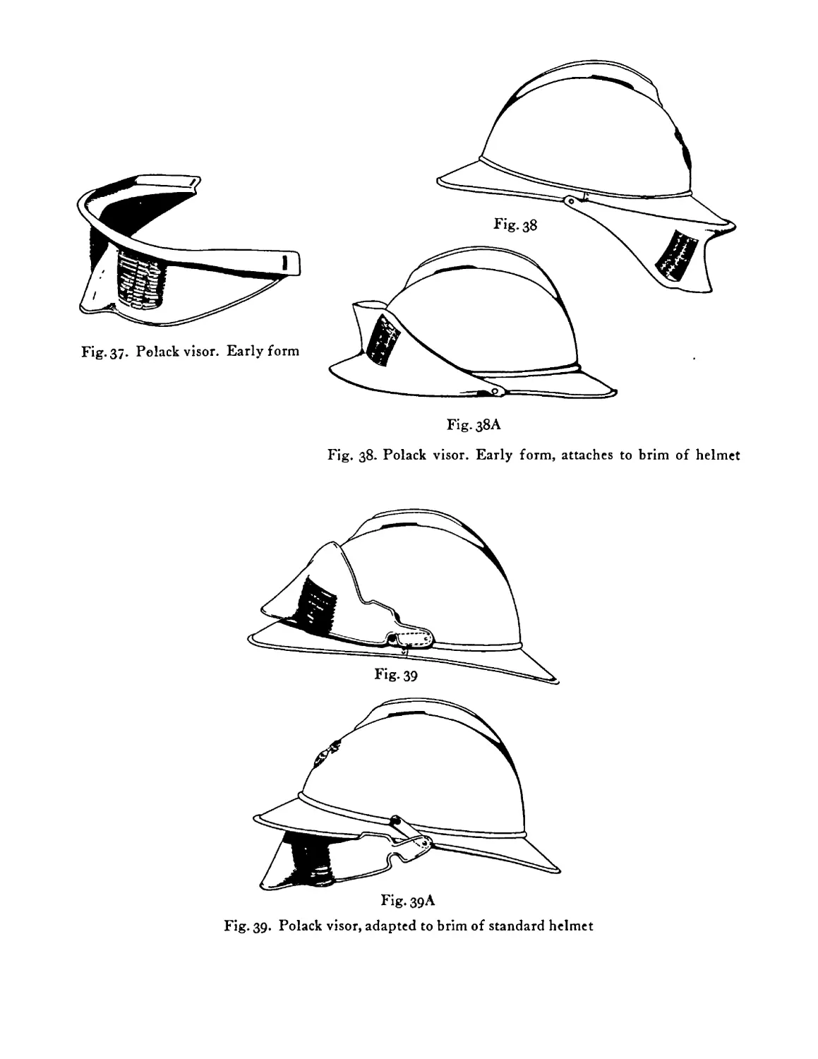
37
з8
39
40
4i
42
43
44
45
46
47
48
49
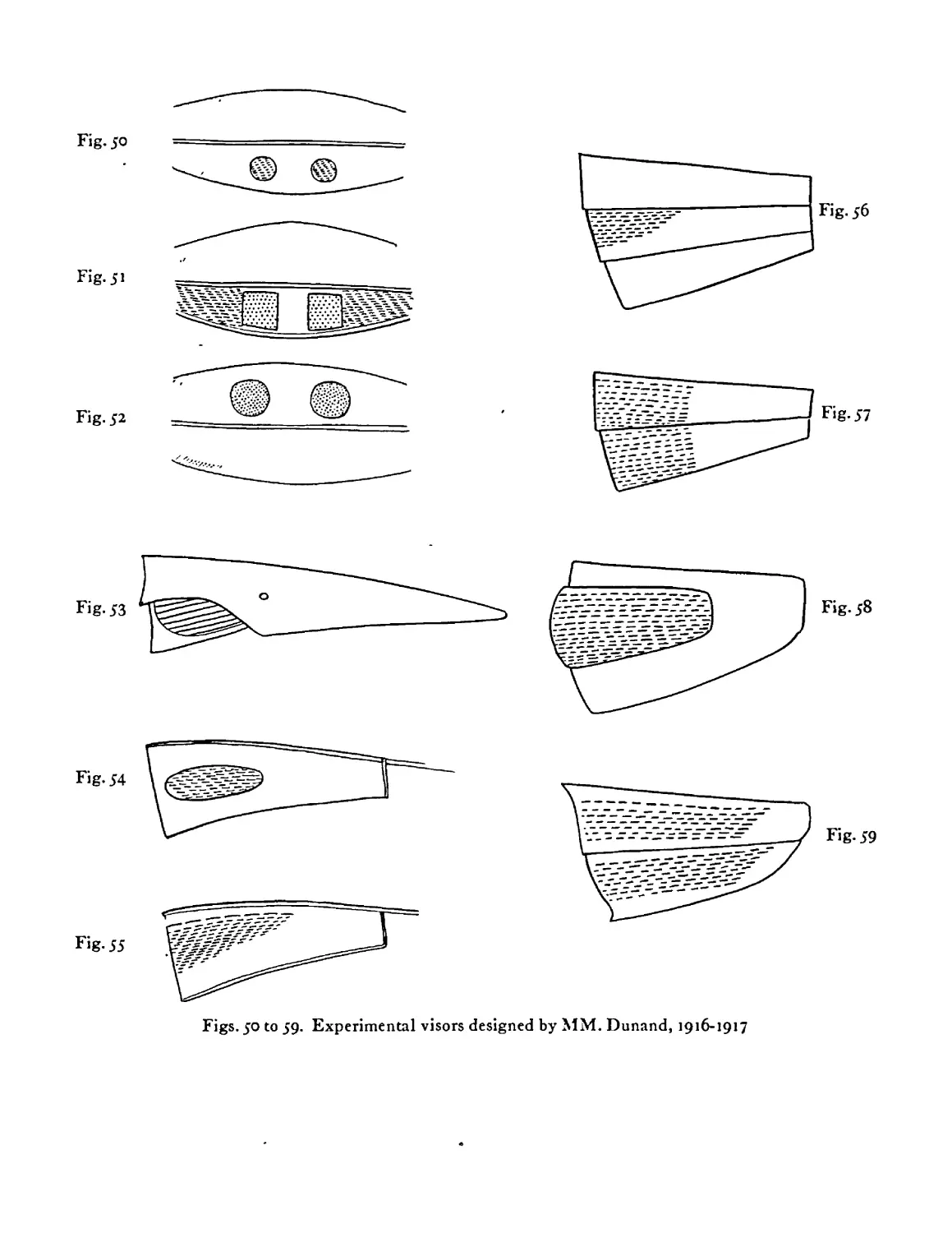
50-59
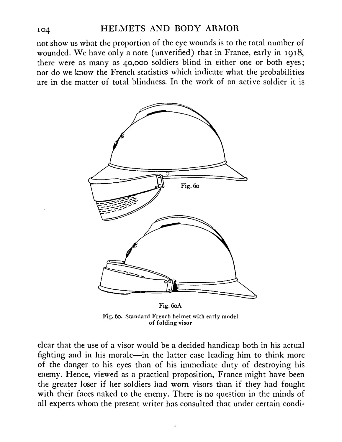
6o
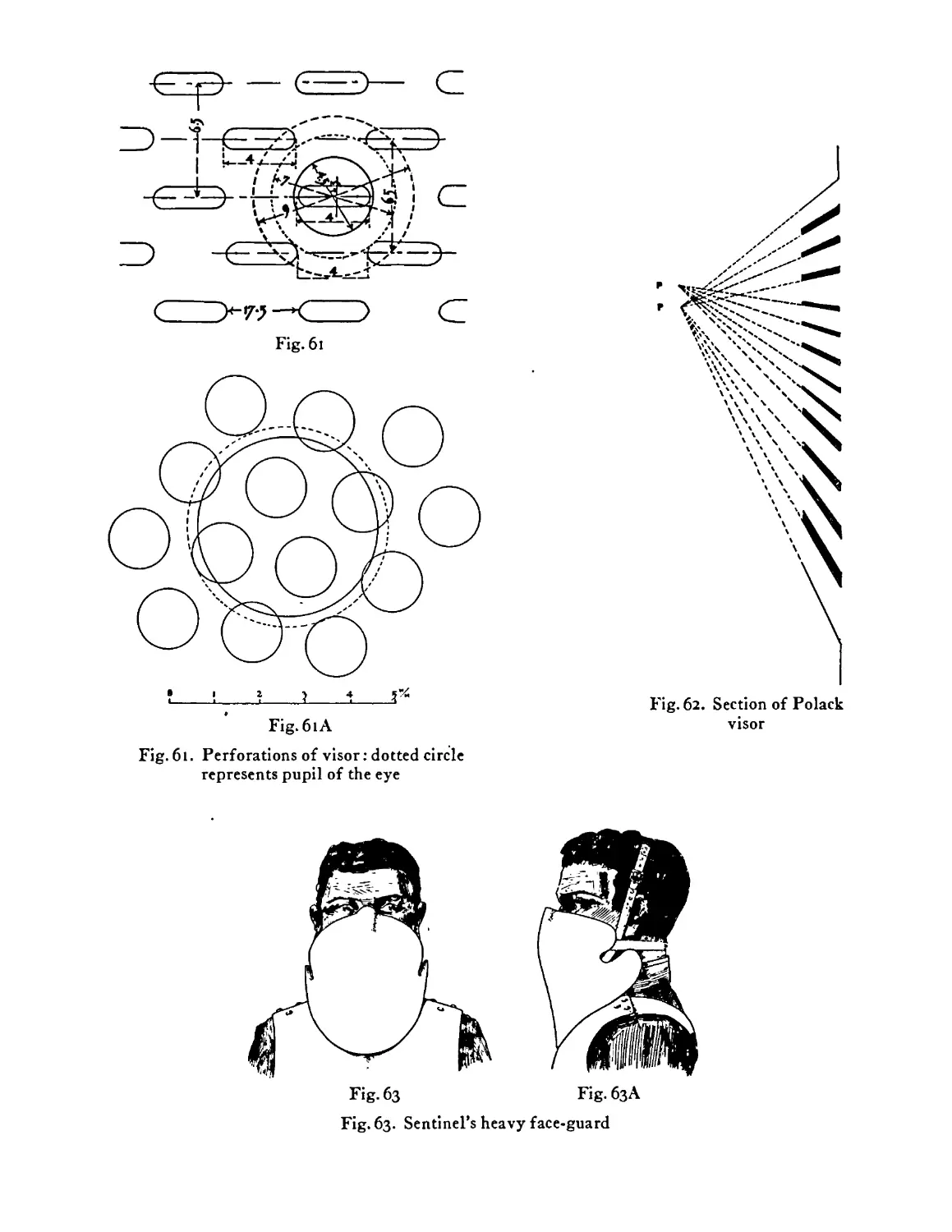
61
62
63
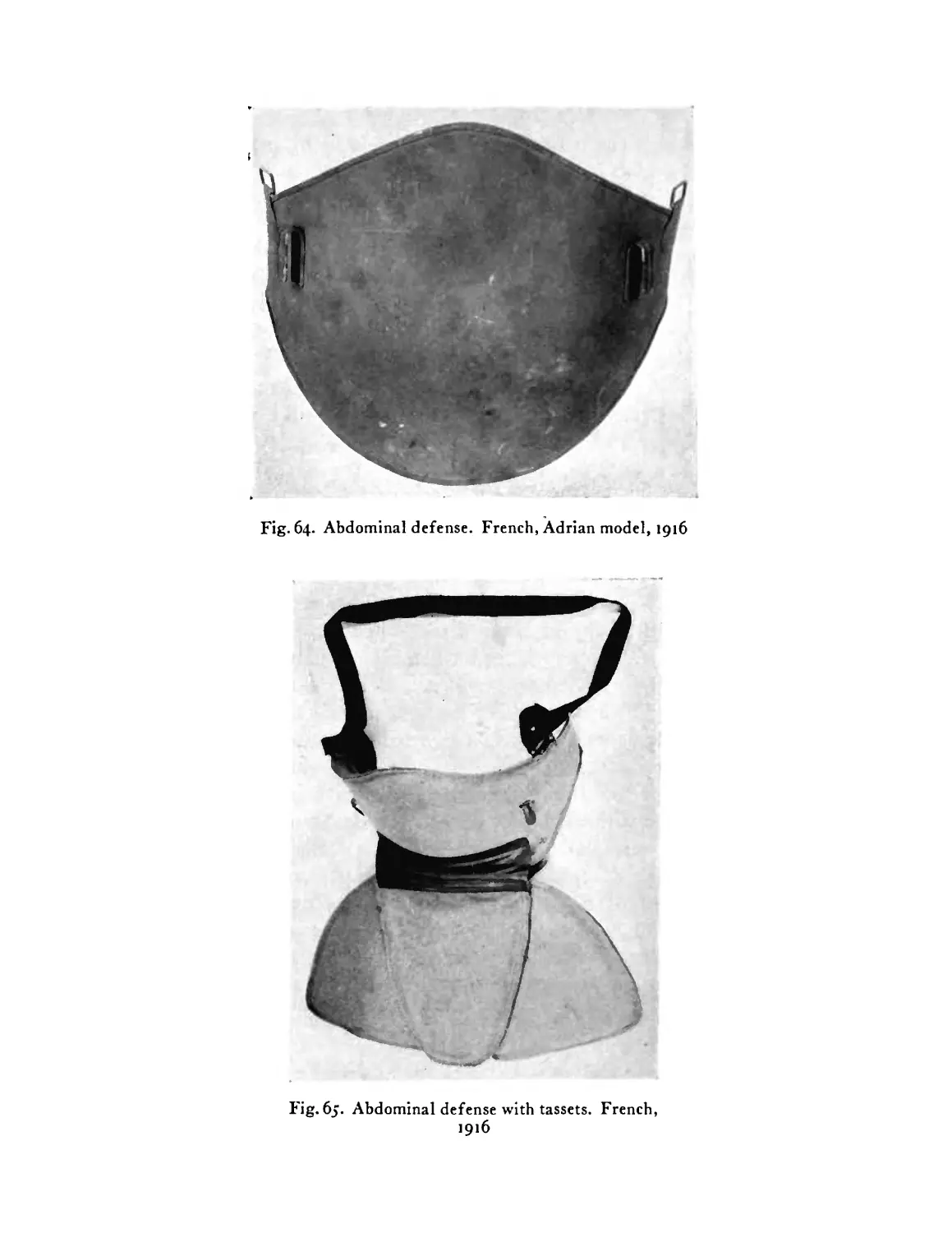
64
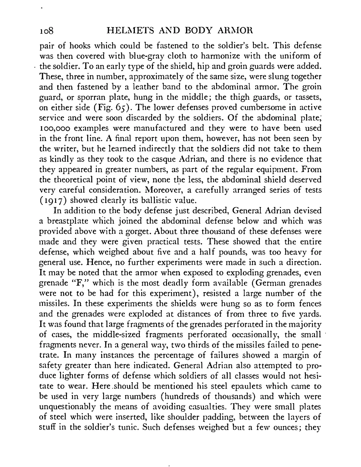
б5
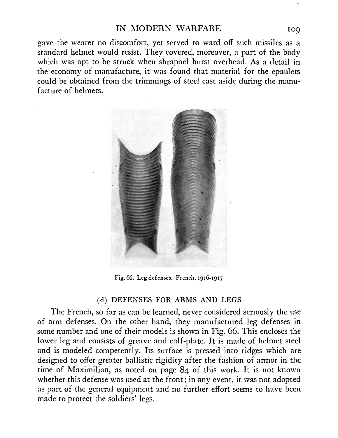
66
67
IN MODERN WARFARE 15
PAGE
be attached by elastic band to side of standard
French helmet ....... 89
Polack visor. Early experimental form. Attaches to
standard helmet and rotates into position . . 89
Polack visor. Early experimental form, arranged to
be slipped over brim of standard helmet . . 90
Polack visor adapted to experimental headpiece of
similar type to one shown in Fig. 28 . . .90
Polack visor, experimental model, adapted to brim
of standard French helmet. Shown also in rotated
position, when not in use ..... 90
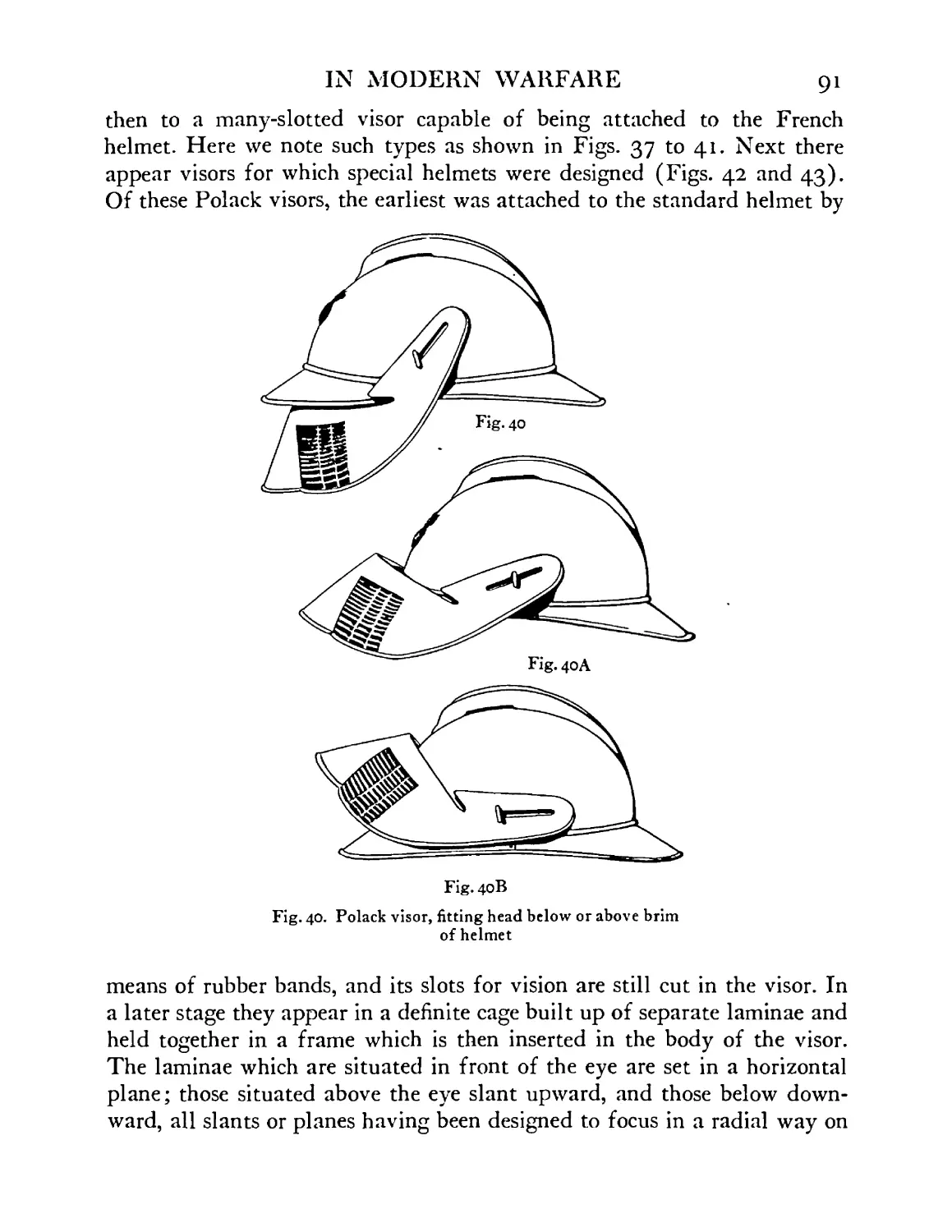
Experimental form of Polack visor, arranged for
fitting head below or above brim of standard French
helmet ........ 91
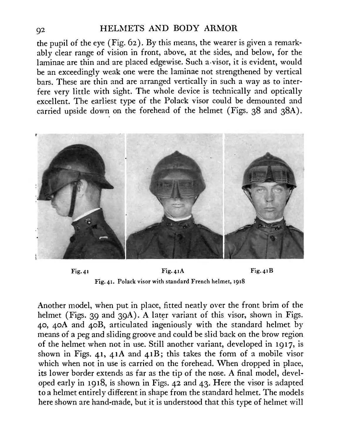
Polack visor arranged with standard French helmet
(1917-1918) . . . . . . . 92
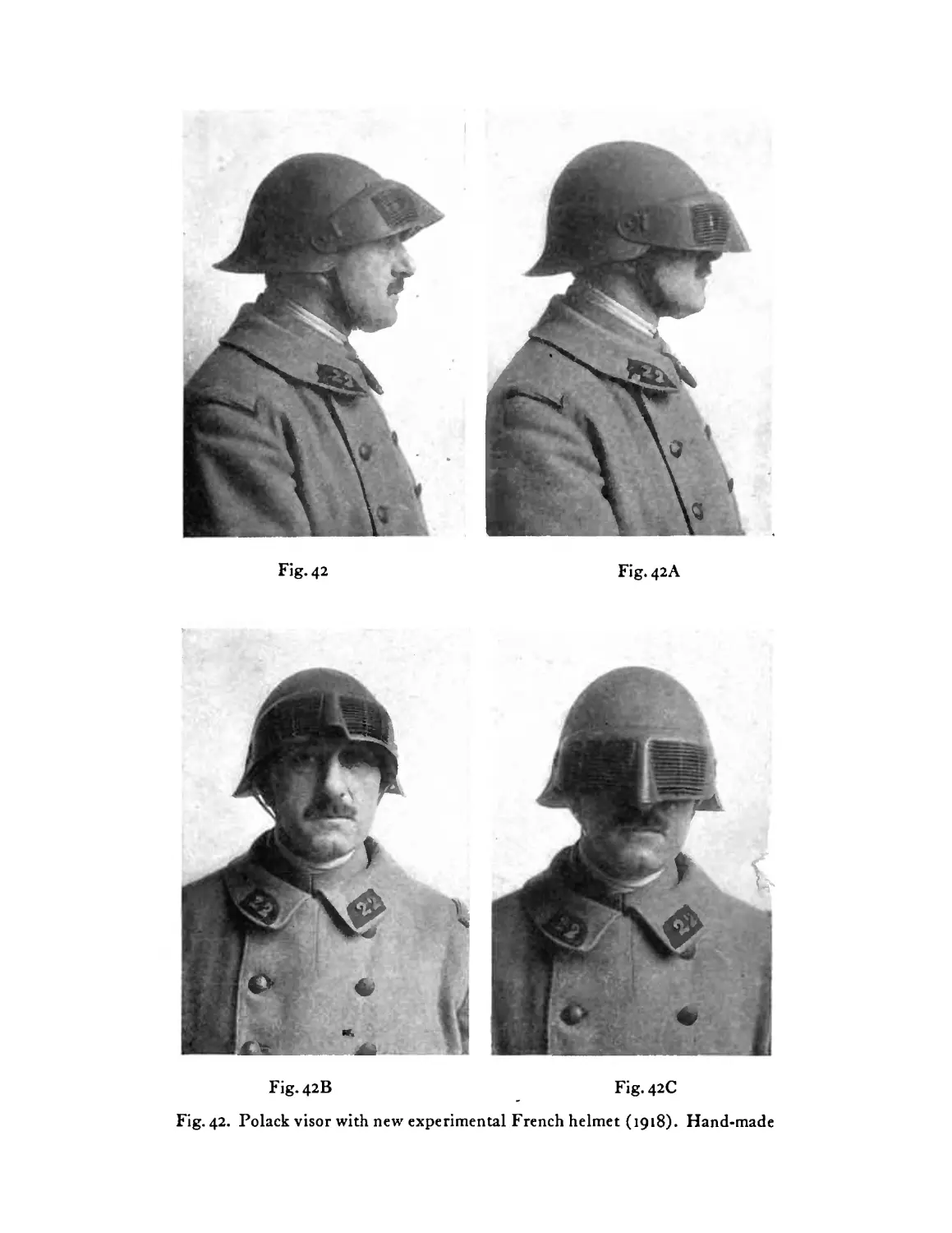
Polack visor arranged with new experimental model
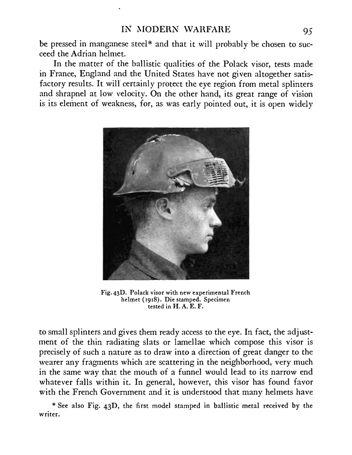
French helmet (1917-1918) .... 93
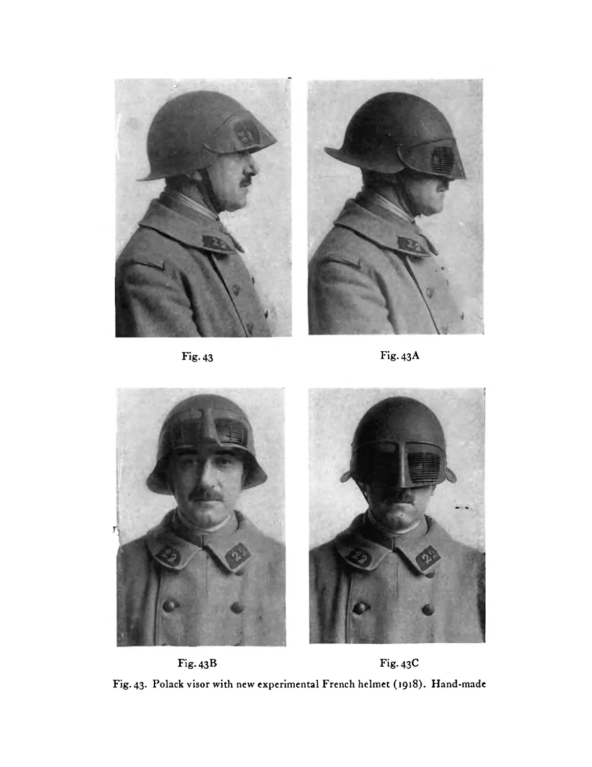
Polack visor arranged with new experimental model
French helmet (1917-1918) .... 94,95
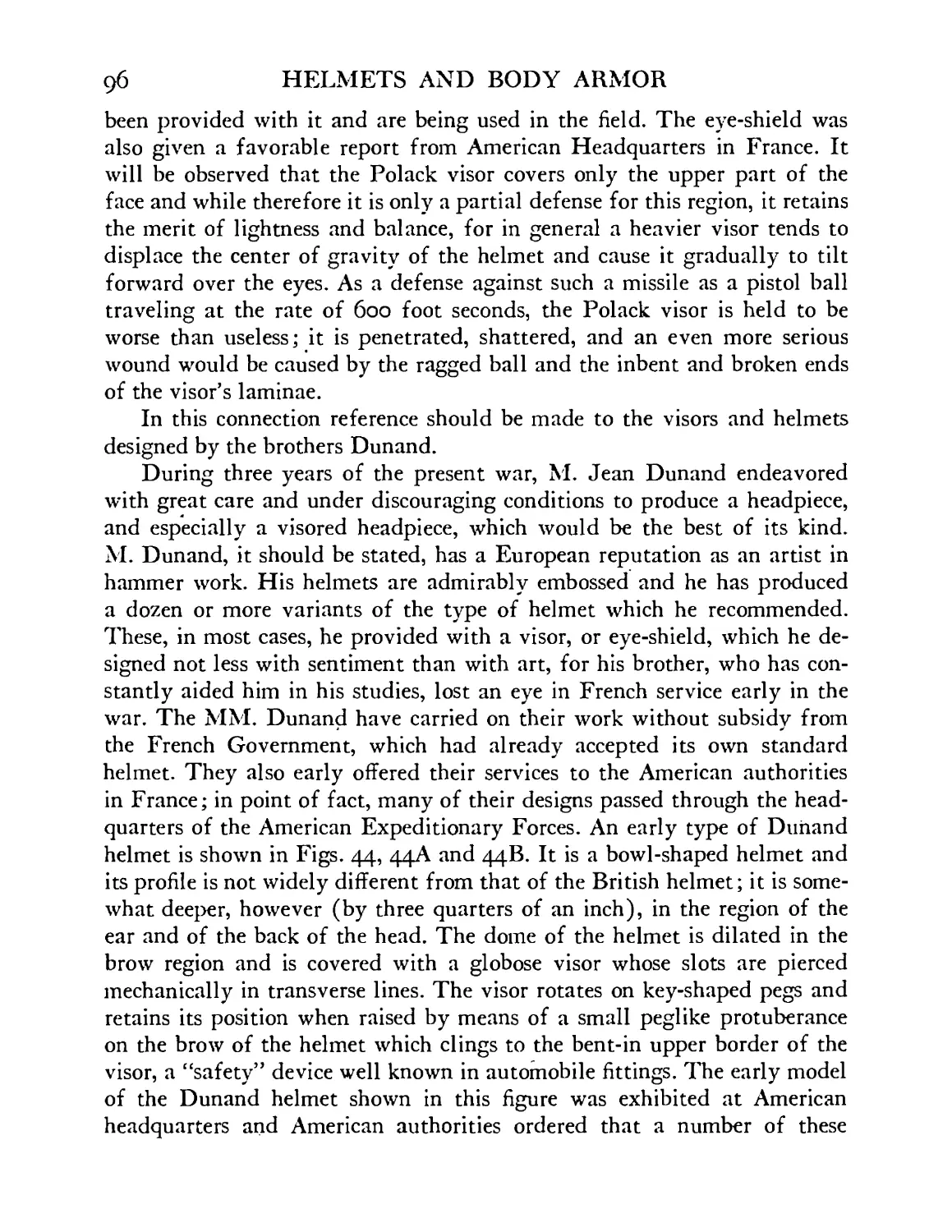
Dunand helmet, hand-made model, 1916-1917 . 97
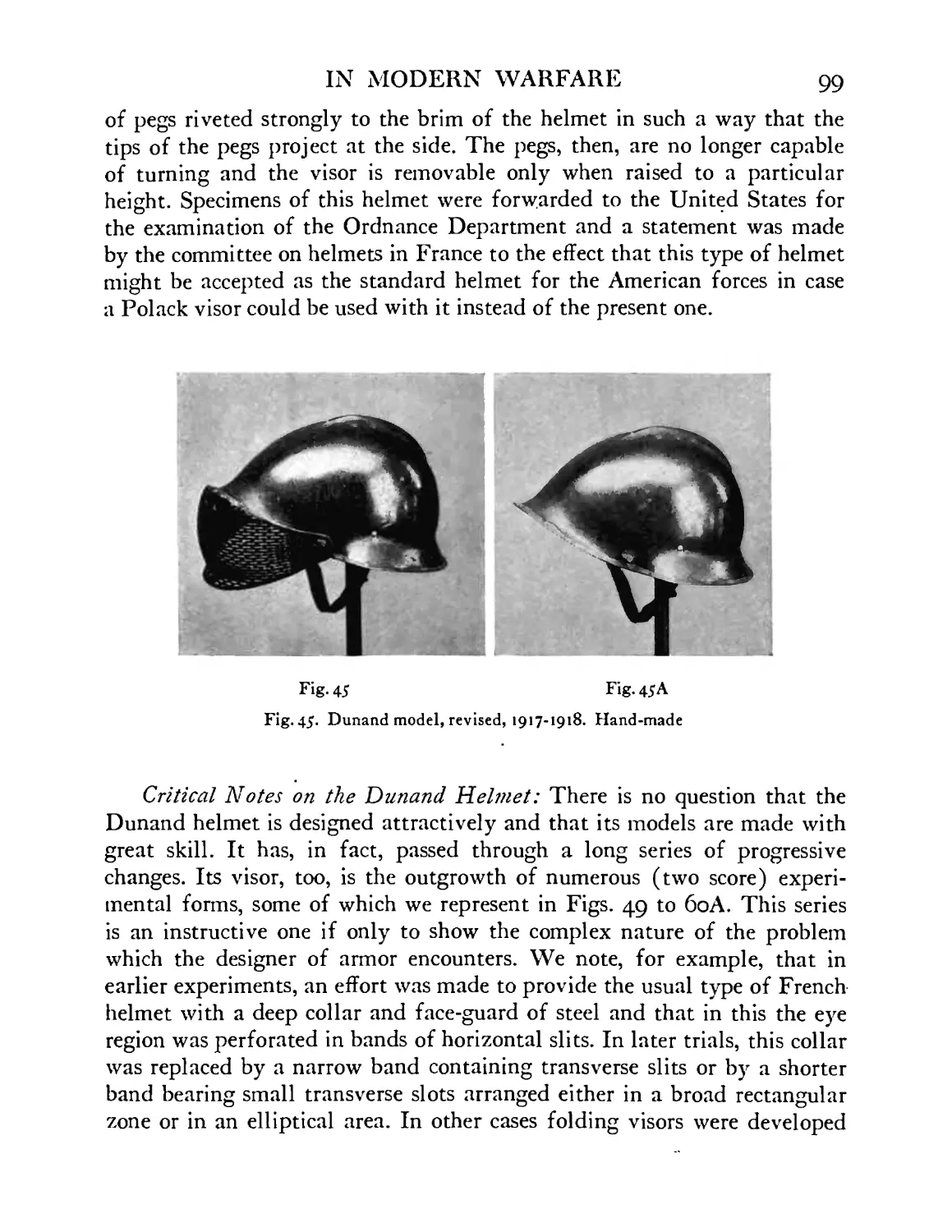
Dunand revised model, 1917-1918. Hand-made . 99
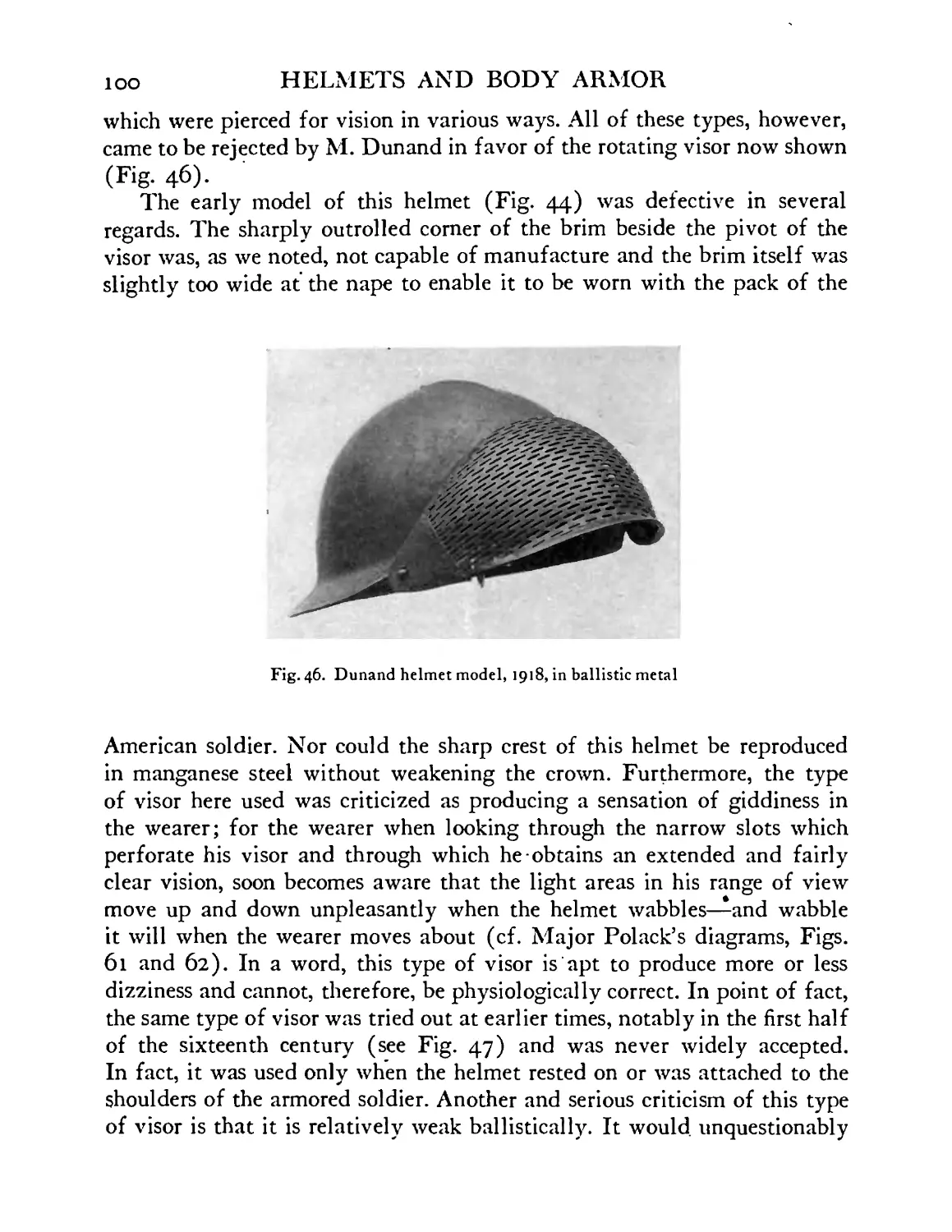
Dunand helmet model, 1918, in ballistic metal . 100
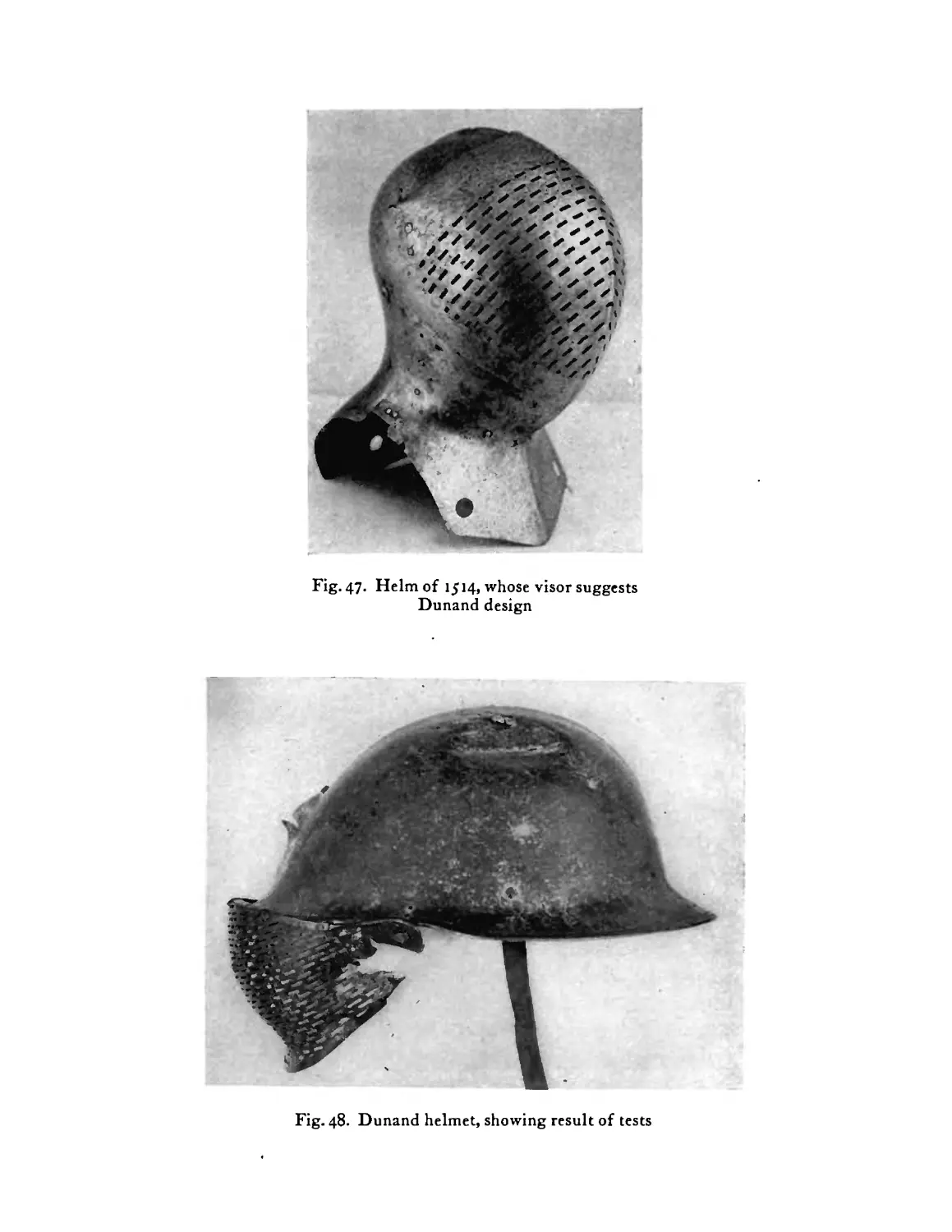
Helm of Sir Giles Capel, 1514 (Metropolitan Mu-
seum of Art), showing visor to which Dunand design
is similar ....... 101
Dunand helmet, showing result of tests . . 101
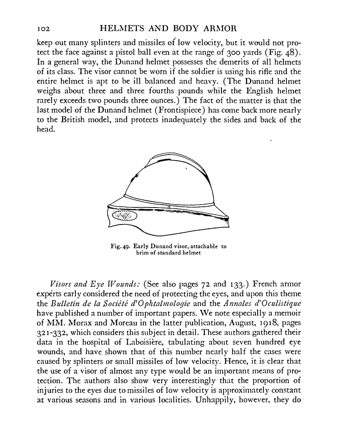
Early model of Dunand visor, attachable to brim of
standard helmet ...... 102
Various types of experimental visors designed by the
MM. Dunand, 1916-1917 ..... 103
Standard French helmet to which is adjusted an early
model of folding visor . . . . .104
Studies of perforations of visor: the large dotted
circle represents the pupil of the eye . . .105
Section of Polack visor showing the arrangement of
planes of the eye-plates . . . . .105
Sentinel’s heavy face-guard . . . .105
Abdominal defense—French, Adrian model, 1916 . 107
Abdominal defense with tassets and sporran plate.
French, Adrian model, 1916-1917 . . . 107
Leg defenses, French, 1916-1917 .... 109
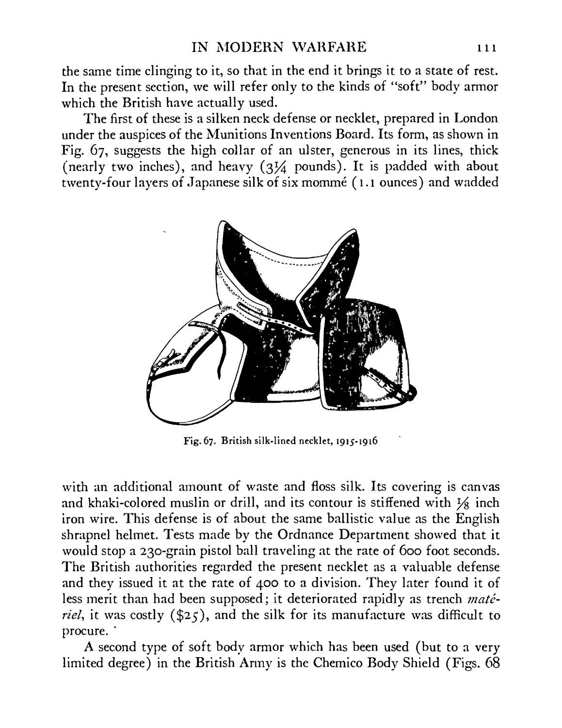
British necklet lined with silk and covered in khaki.
Wire frame support for collar, 1915-1916 . . ill
16
FIGURE
68
69
70
71
72
73
74
75
76
77
78
79
80
81
82
83
84
85
86
87
88
89
90
91
92
93
94’
95
96
97
HELMETS AND BODY ARMOR
PAGE
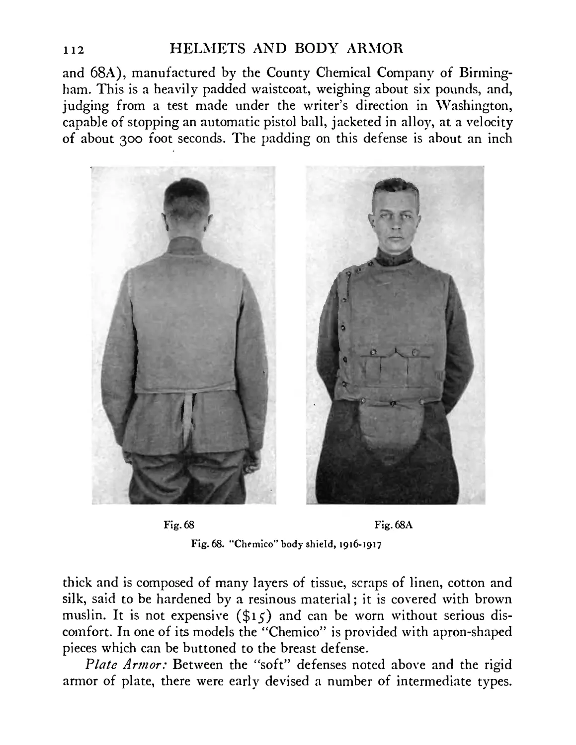
British “Chemico” body shield, 1916-1917 . . 112
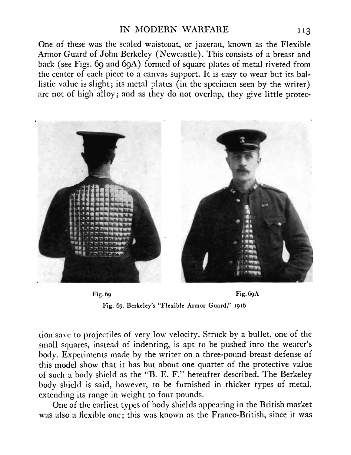
Berkeley experimental jazeran, 1916-1917 . 113
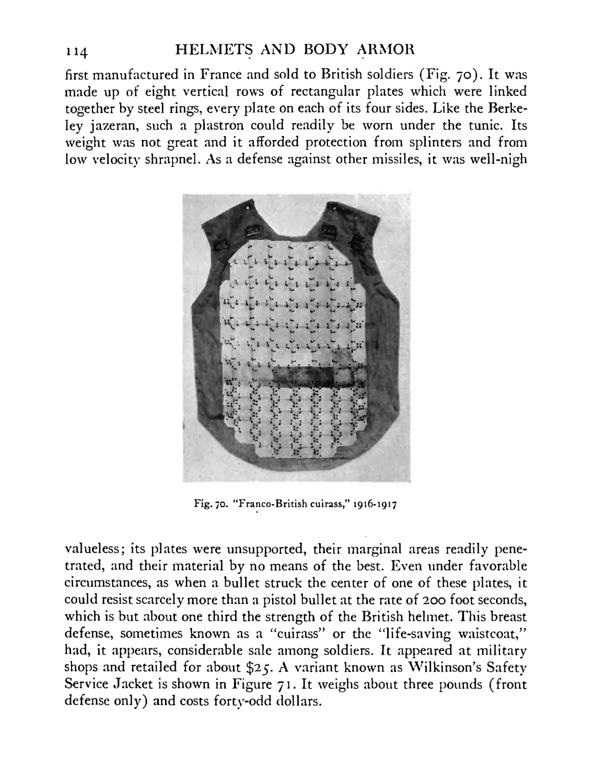
“Franco-British cuirass,” 1916-1917 . . .114
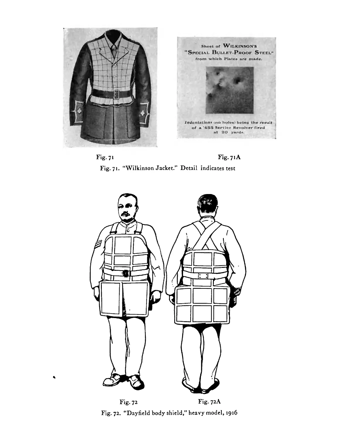
“Wilkinson Safety Service Jacket.” Detail indicates
result of test . . . . . . .115
British “Dayfield body shield,” heavy model, 1916 . 115
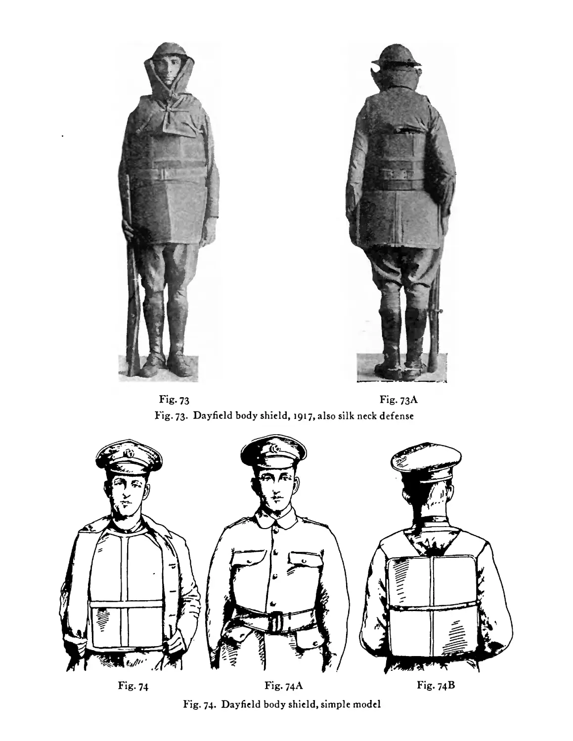
Dayfield body shield, 1916-1917 model; here also
appears the silk-lined neck defense . . . 116
Dayfield body shield, simple model . . 116
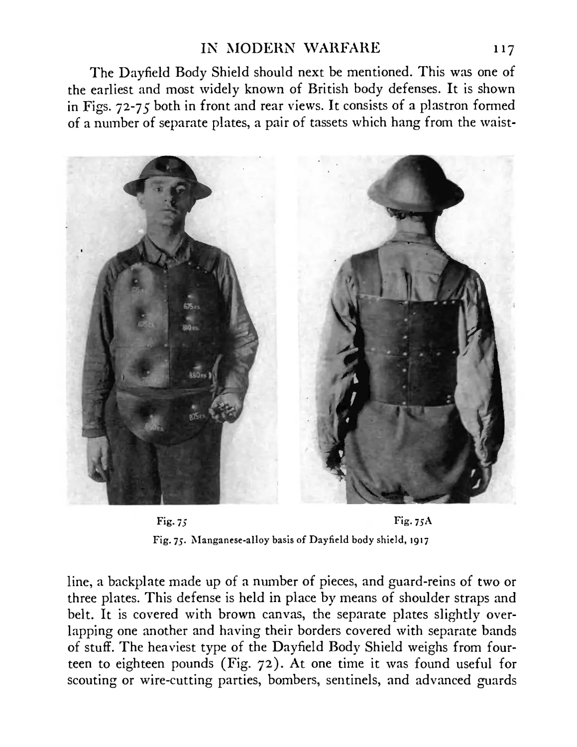
Metal foundation of simpler type of Dayfield body
shield, 1917 . . . . . .117
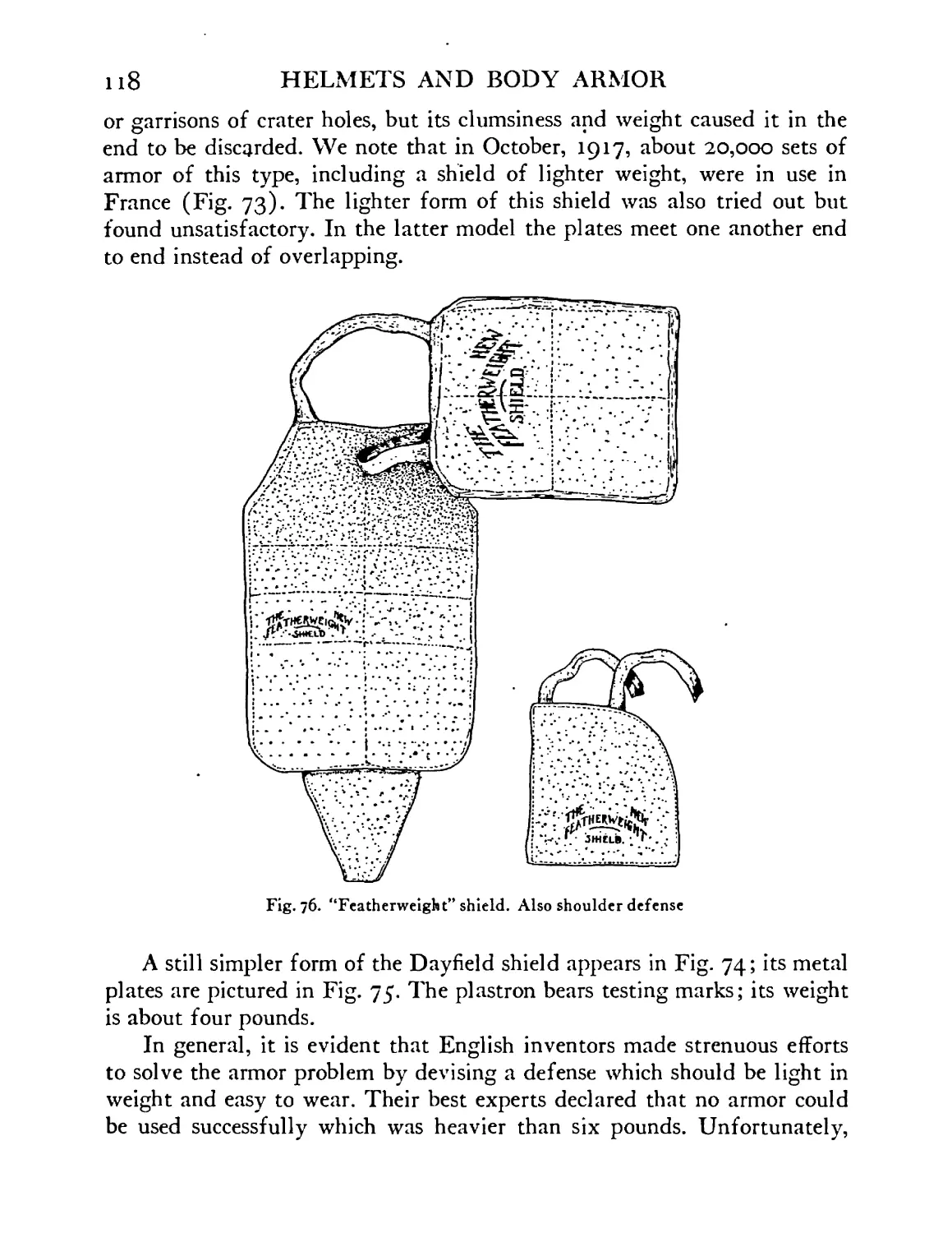
British “Featherweight” shield. A shoulder defense
appears as a detached piece . . . . .118
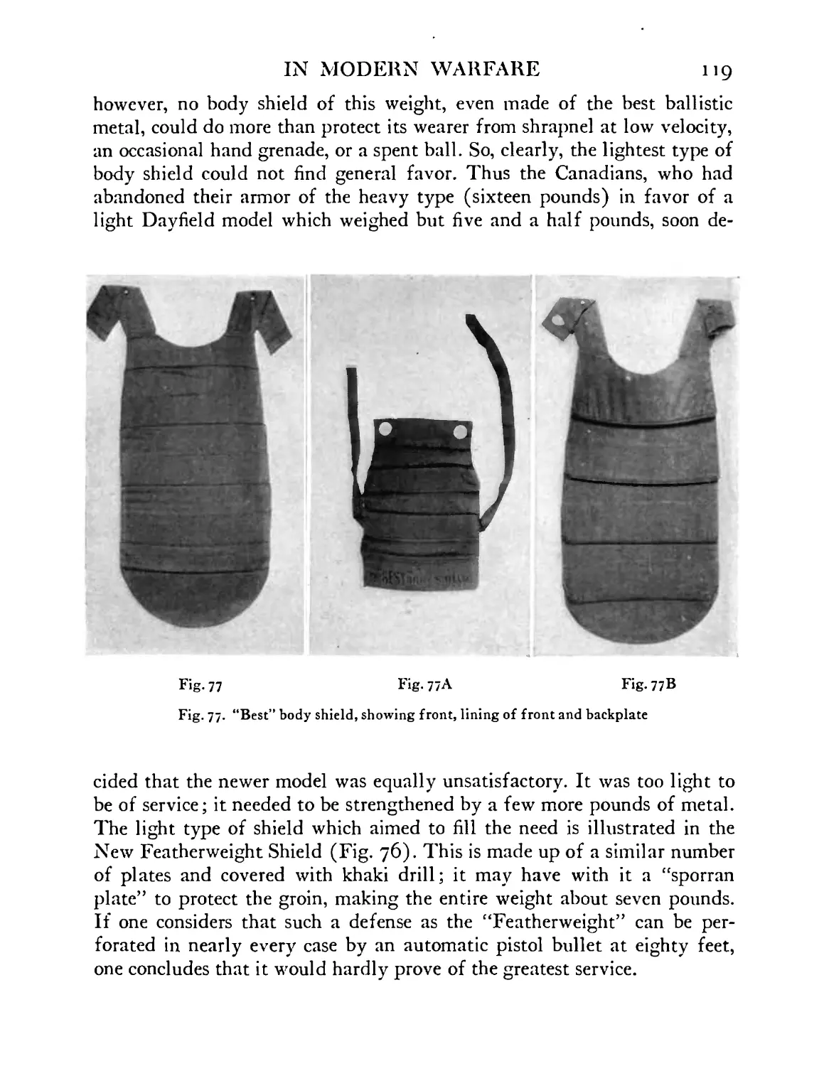
British “Best” body shield, showing front, lining of
front and backplate . . . . . .119
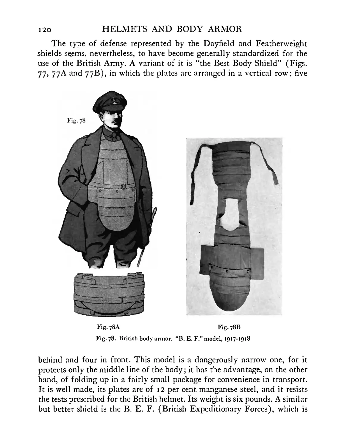
British body armor. “В. E. F.” model, 1917-1918 . 120
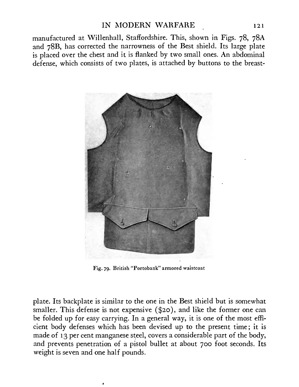
British “Portobank” armored waistcoat . . .121
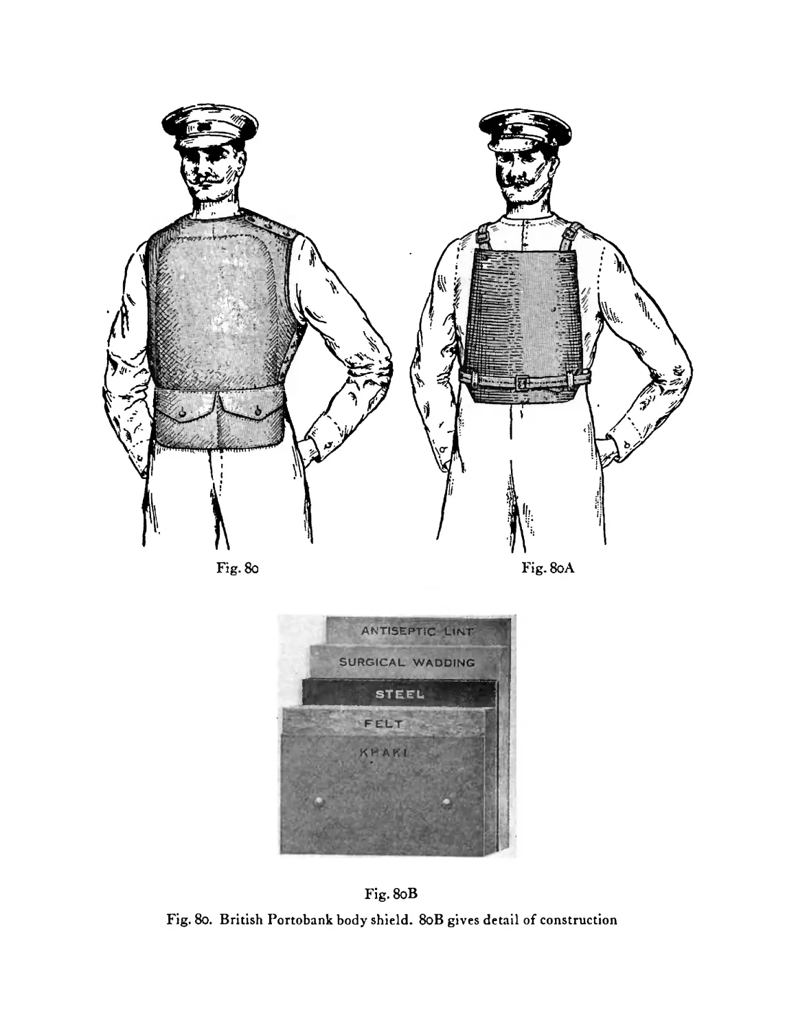
British Portobank body shield. 80B gives detail of
construction . . . . . . .122
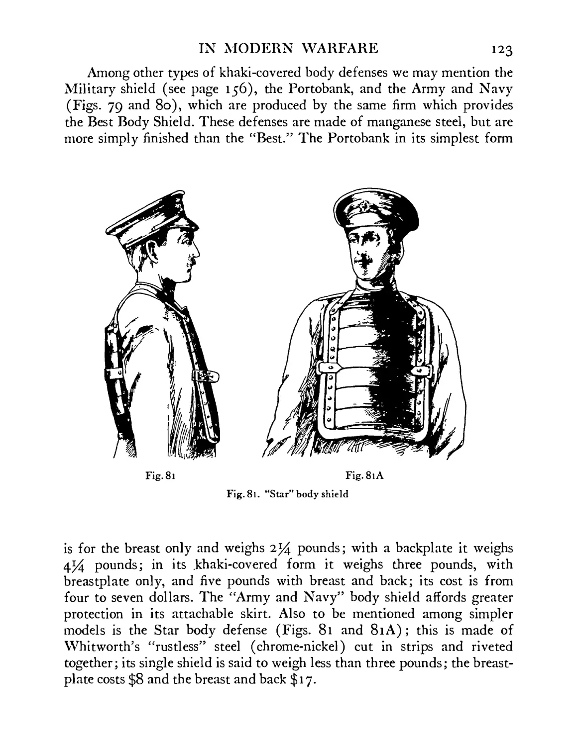
“Star” body shield . . . . . .123
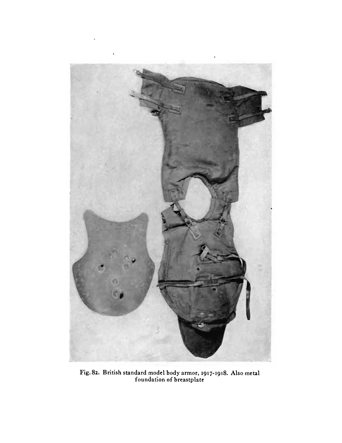
British standard model body armor, 1917-1918. The
detached piece represents the metal foundation of the
breastplate . . . . . . .124
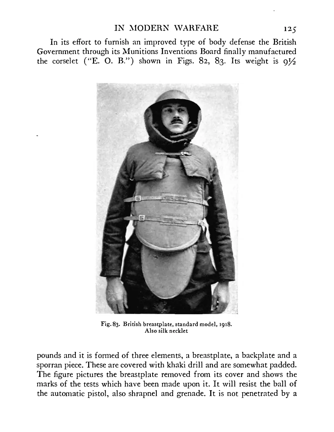
British breastplate, standard model, 1918 . . 125
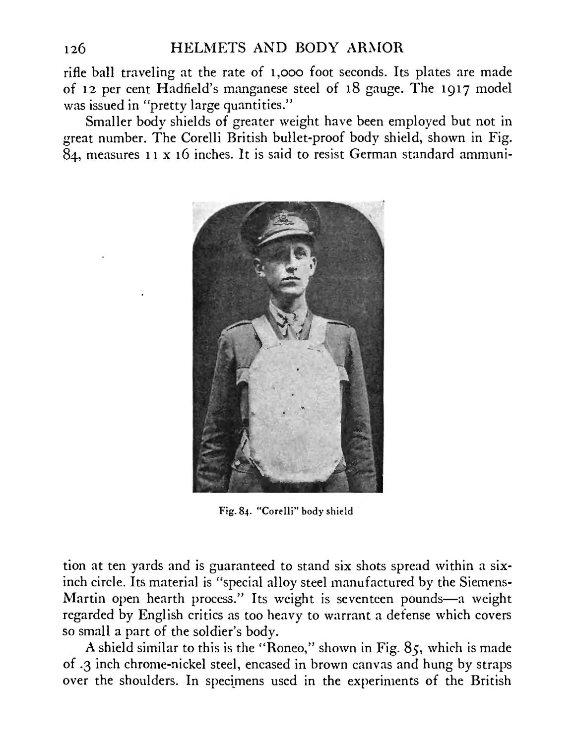
“Corelli” body shield . . . . .126
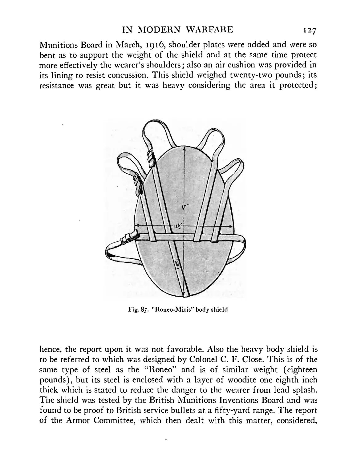
“Roneo-Miris” body shield . . . . .127
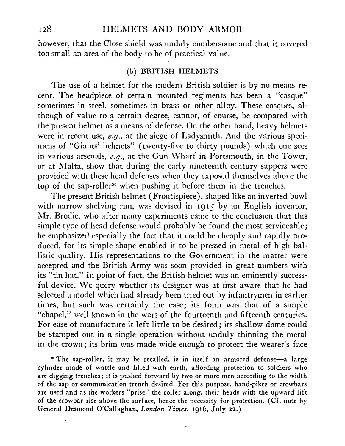
British standard helmet showing indentation caused
by glancing machine gun bullet . . . .129
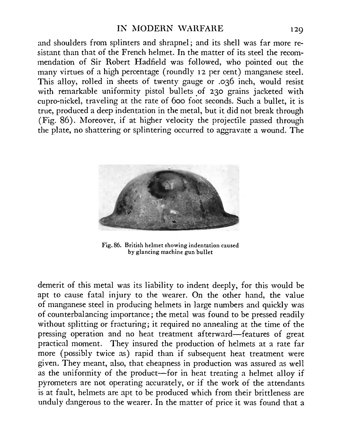
British helmet viewed from below, showing chin-
strap and lining . ... . . . 130
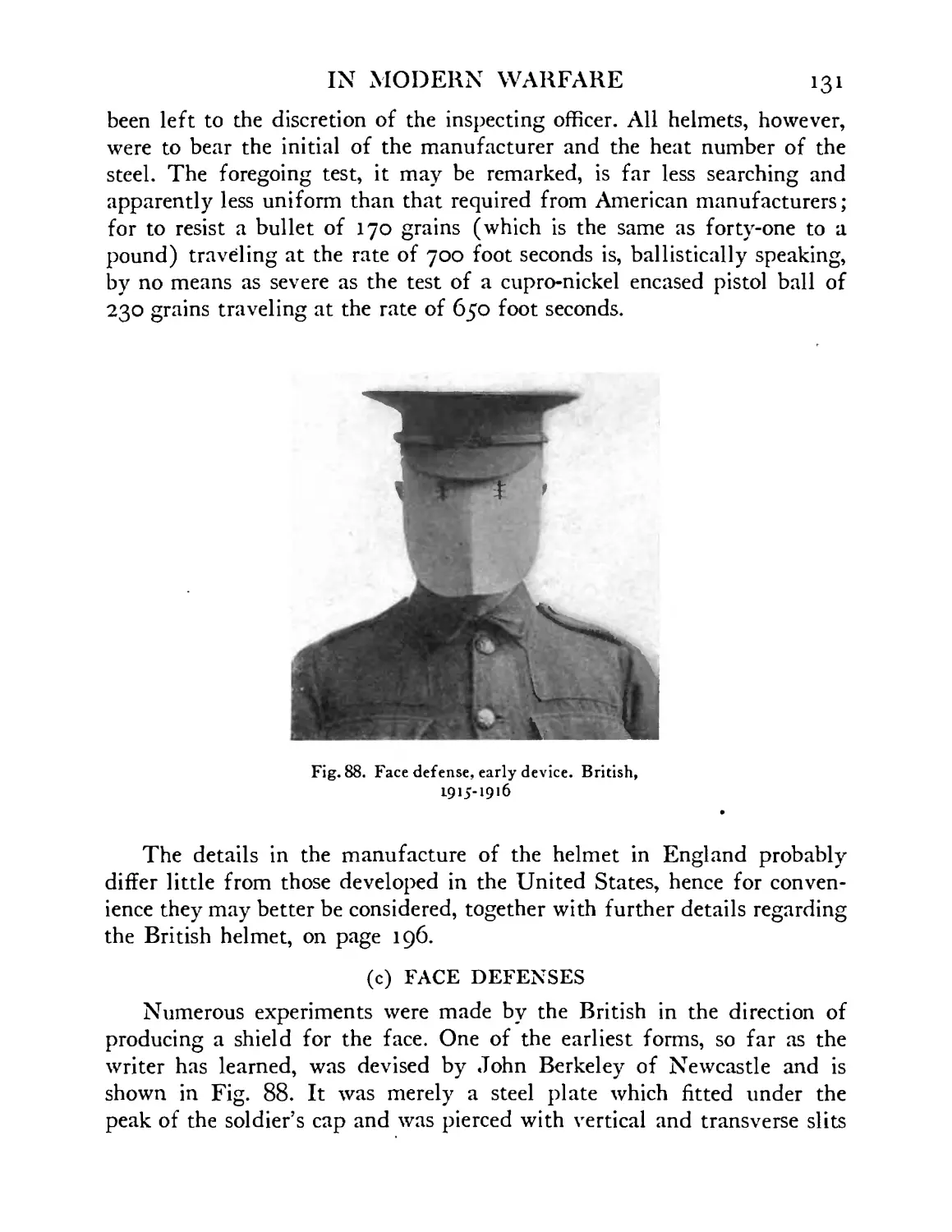
Early experimental model of face defense. British,
1915-1916 ....... 131
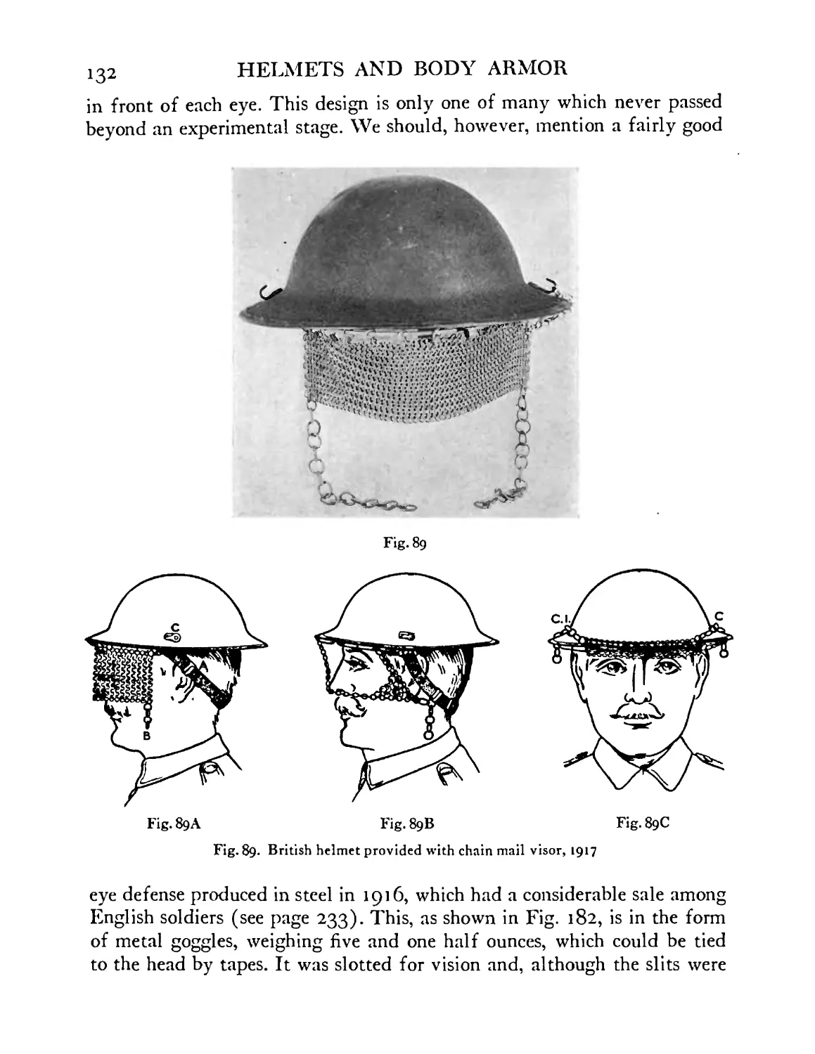
British helmet provided with chain mail visor, 1917 132
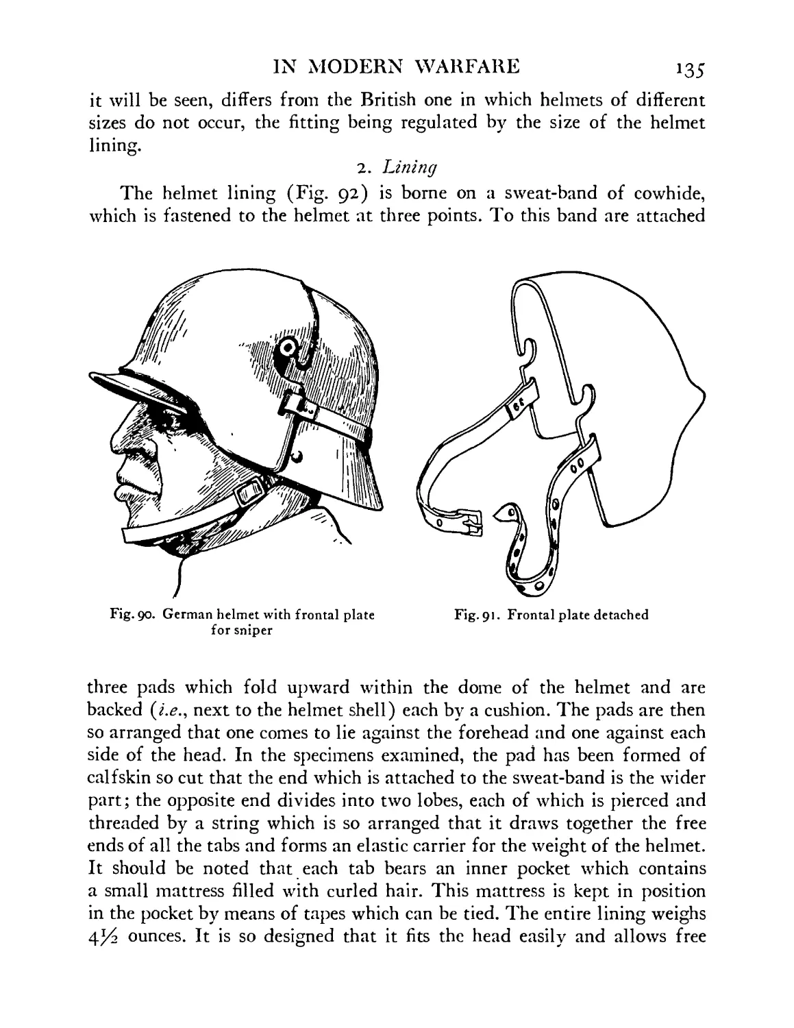
German helmet showing sniper’s frontal plate in
position ........ 135
Frontal plate detached . . . . 135
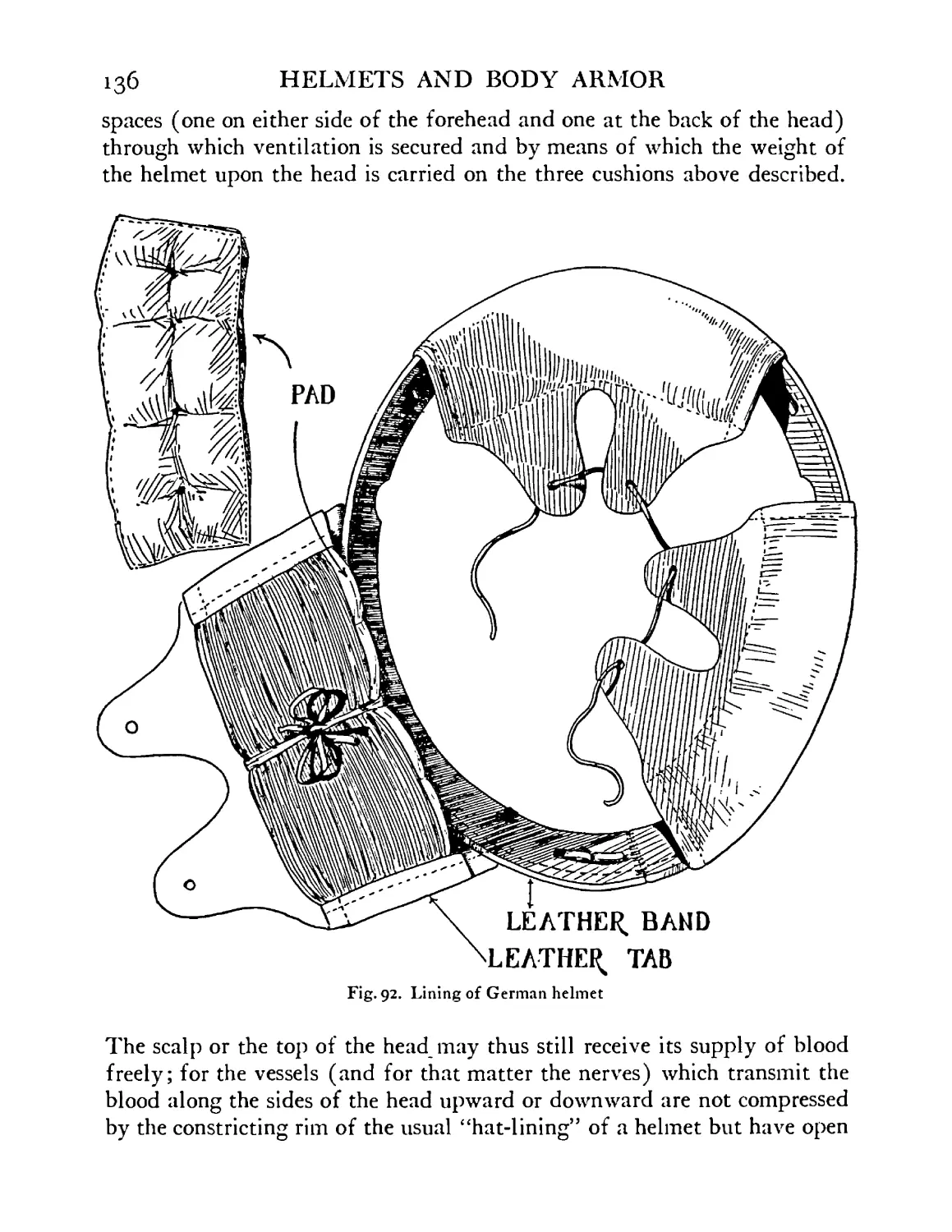
Lining of German helmet . . . . .136
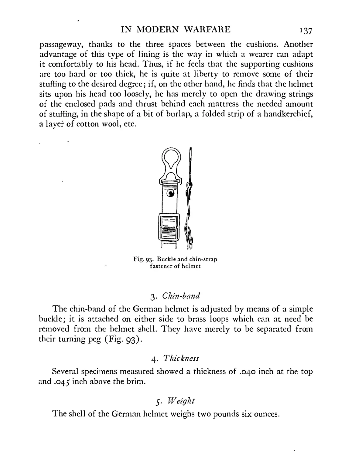
Buckle and chin-strap metal fastener of German
helmet ........ 137
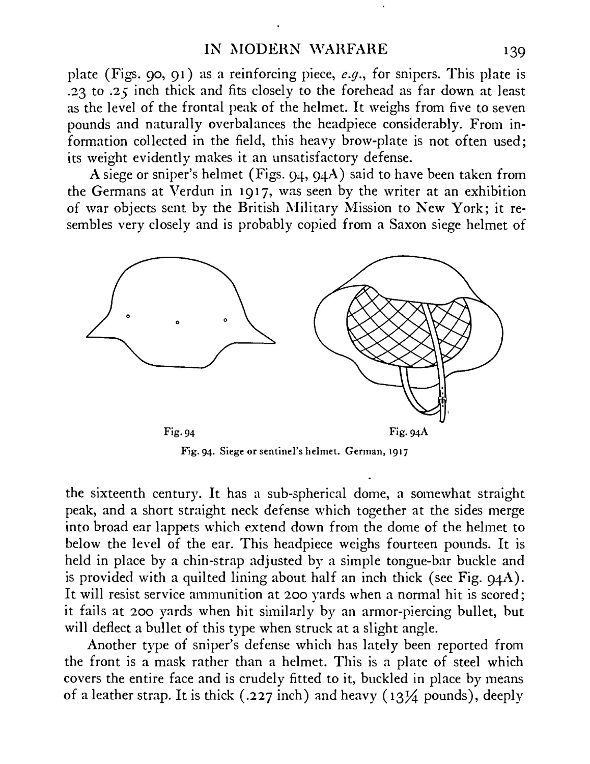
Siege or sentinel’s helmet. German, 1917 model . 139
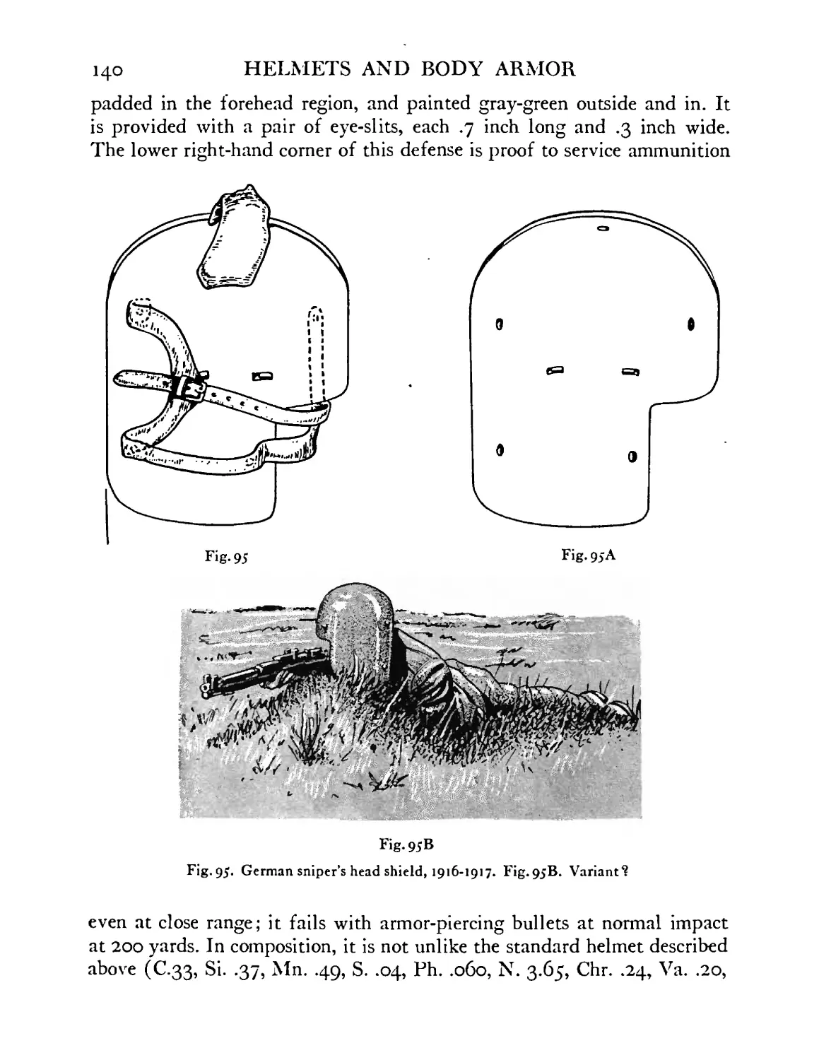
German sniper’s head shield, 1916-1917 . . 140
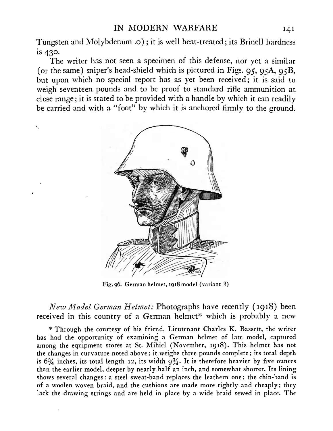
German helmet, 1918 model (variant?) . . 141
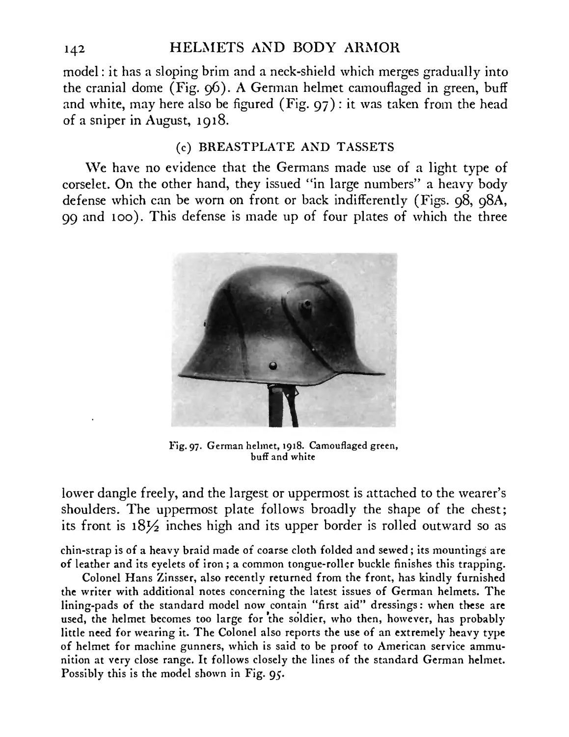
German helmet, 1918 model, as used by sniper. Cam-
ouflaged green, buff and white . . . .142
FIGURE
98
99
100
101
102
103
104
105
106
107
108
109
110
111
i12
ИЗ
114
и;
116
и?
ii8
И9
120
121
122
123
124
12J
126
127
128
129
IN MODERN WARFARE 17
PAGE
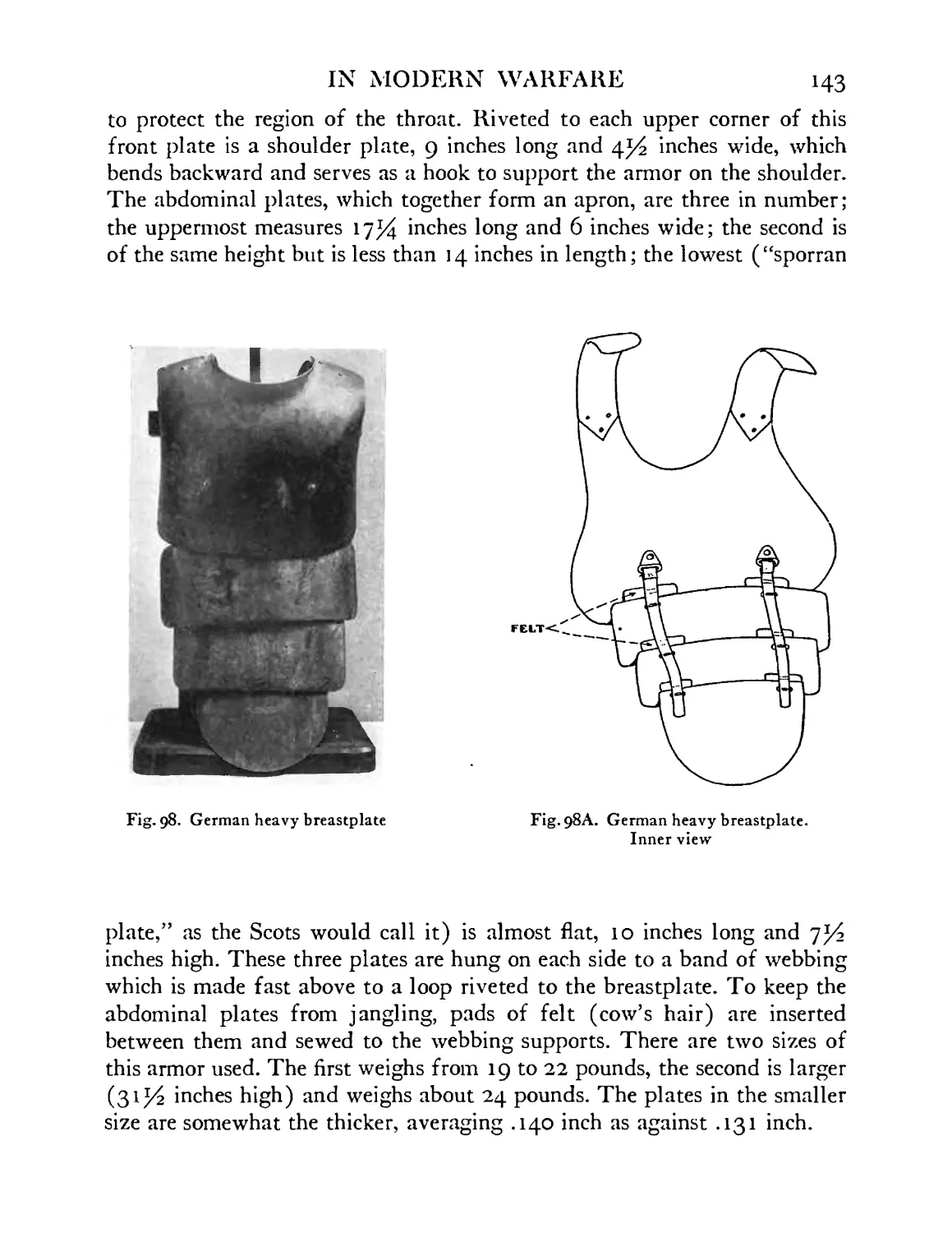
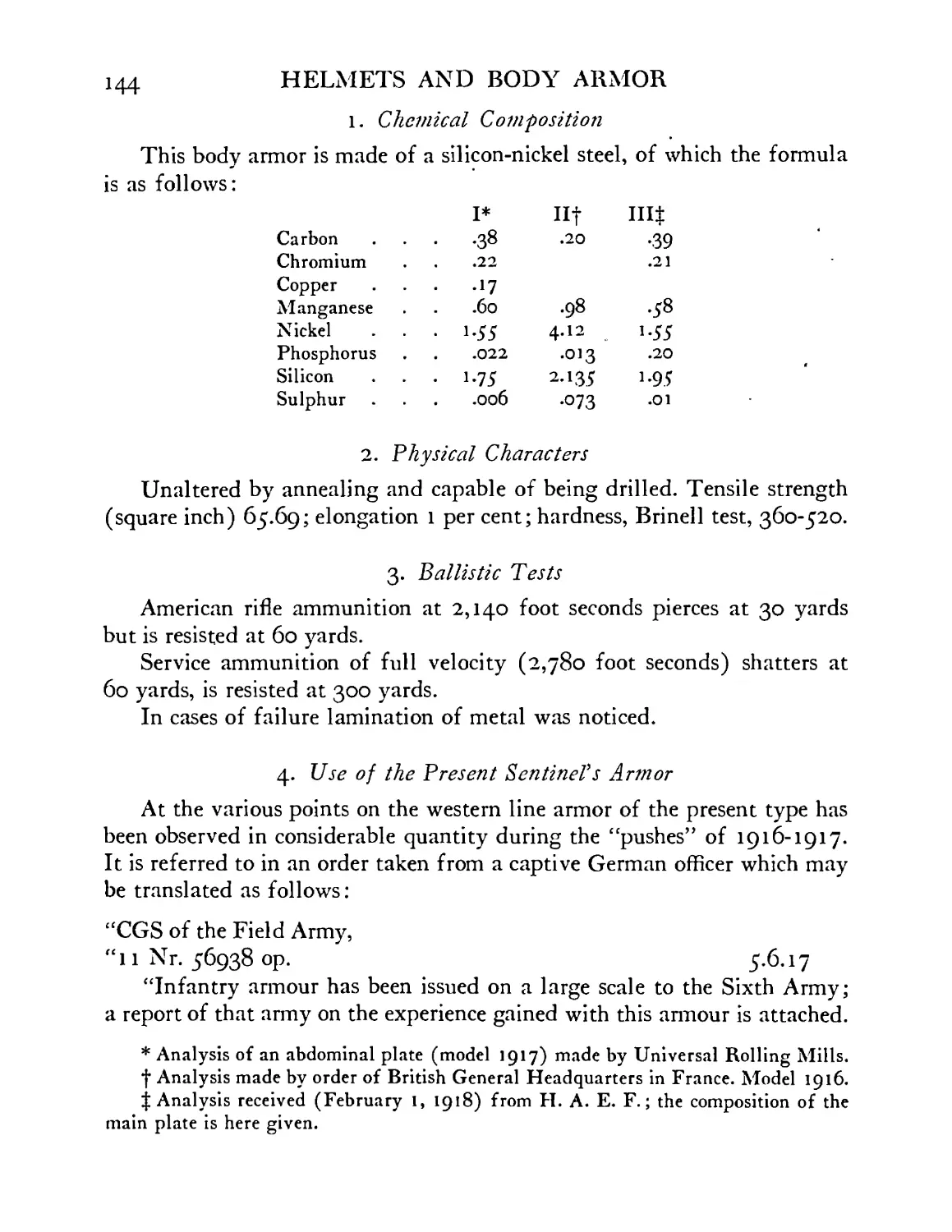
German heavy breastplate, viewed from without and
from within ....... 143
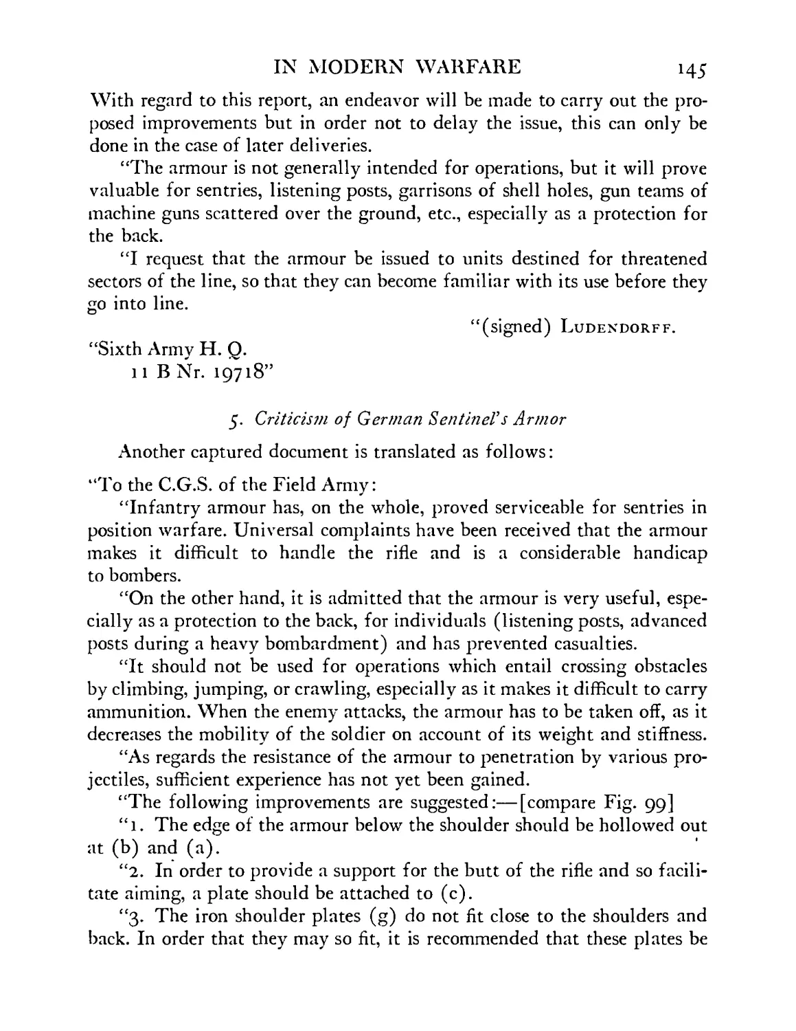
German breastplate. Improvements suggested, 1917 146
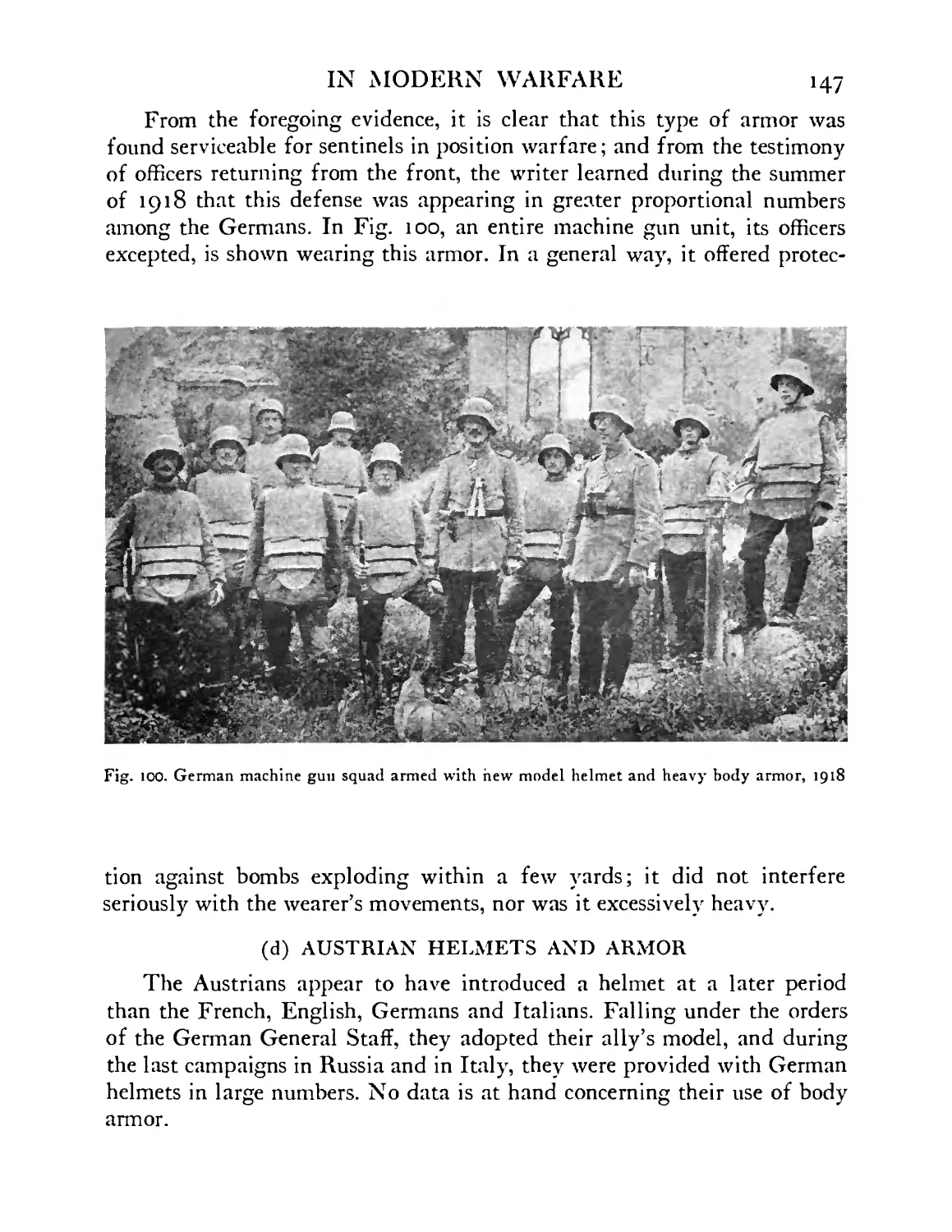
German machine gun squad armed with new model
helmet and heavy body armor, 1918 . . 147
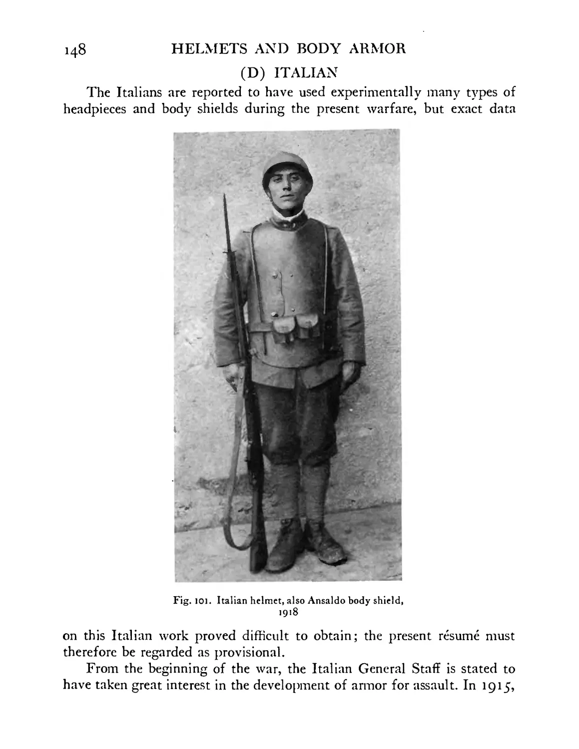
Italian helmet, also body shield, Ansaldo model, 1918 148
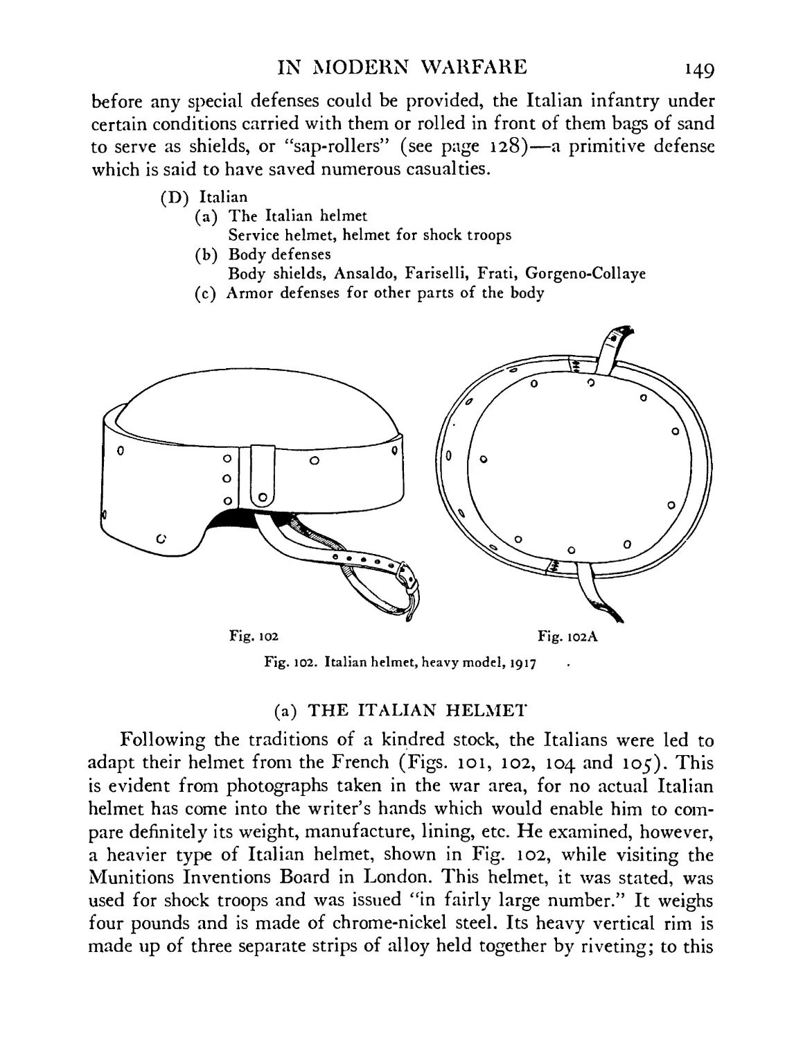
Italian helmet, heavy model, 1917 . . . 149
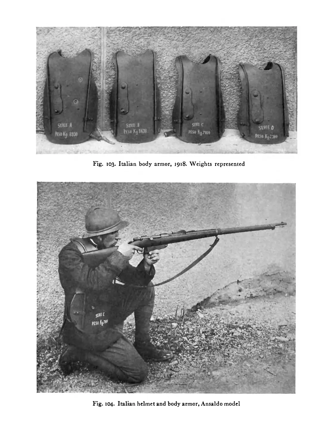
Italian body armor. Weights represented, 1918 . 150
Italian helmet and body armor, Ansaldo model . 150
Italian body armor shown dismounted and used as
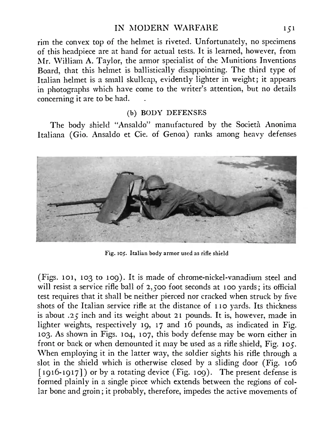
rifle shield. Ansaldo model . . . . 151
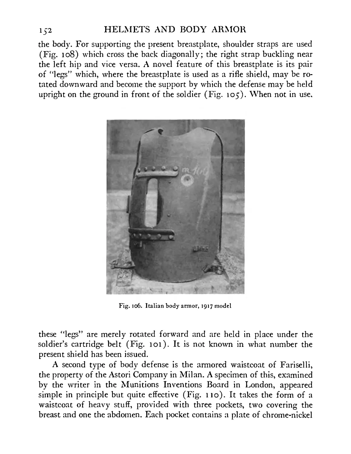
Italian body armor, 1917 model . . . .152
Italian body armor, Ansaldo model, shown carried on
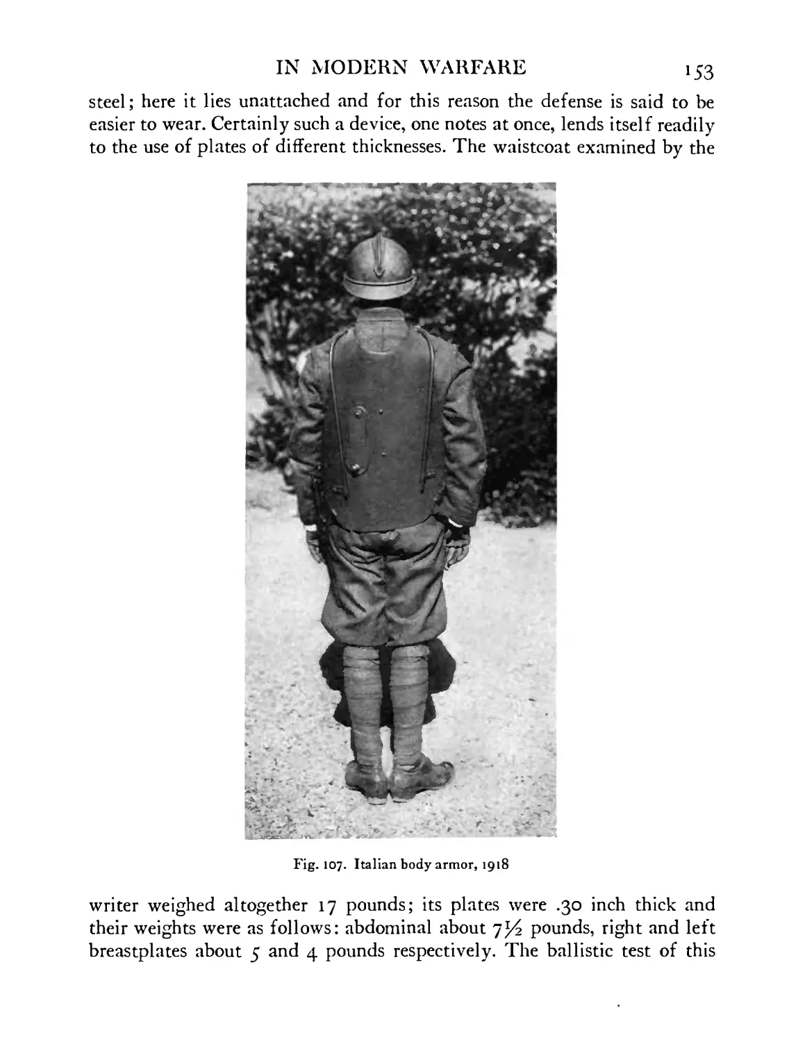
back of soldier. Note also Italian helmet in rear view 153
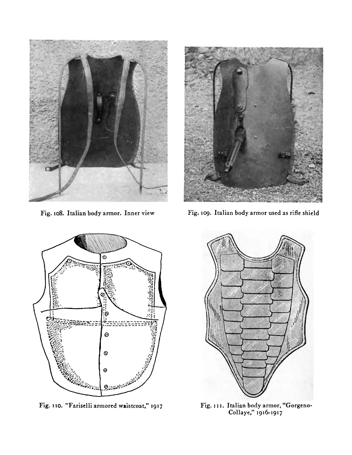
Italian body armor. Inner view . . . .154
Italian body armor. Shown in use as rifle shield . 154
“Fariselli” armored waistcoat, 1917 . . . 154
Italian body armor—“Gorgeno-Collaye” model,
1916-1917 ....... 154
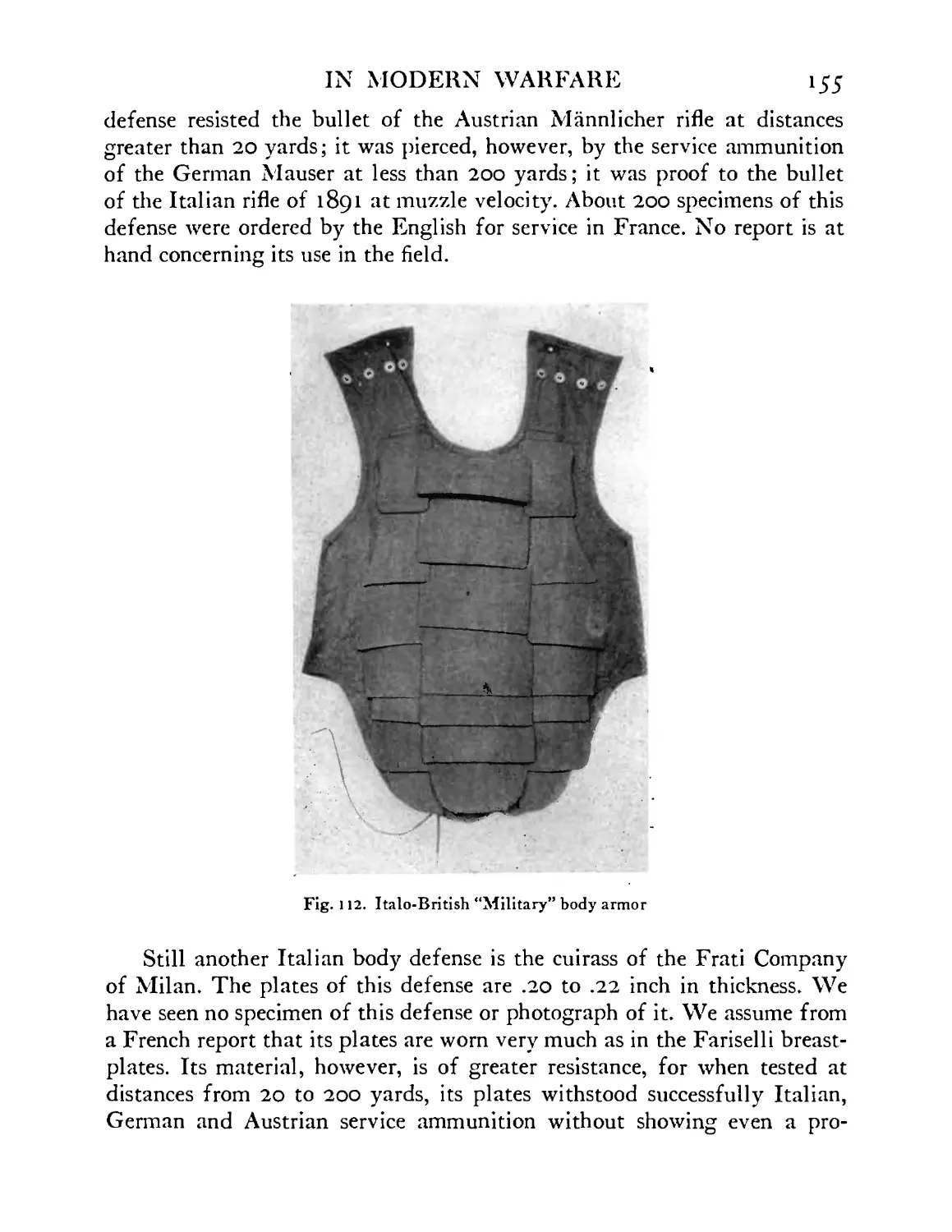
Italo-British “Military” body armor . . . 155
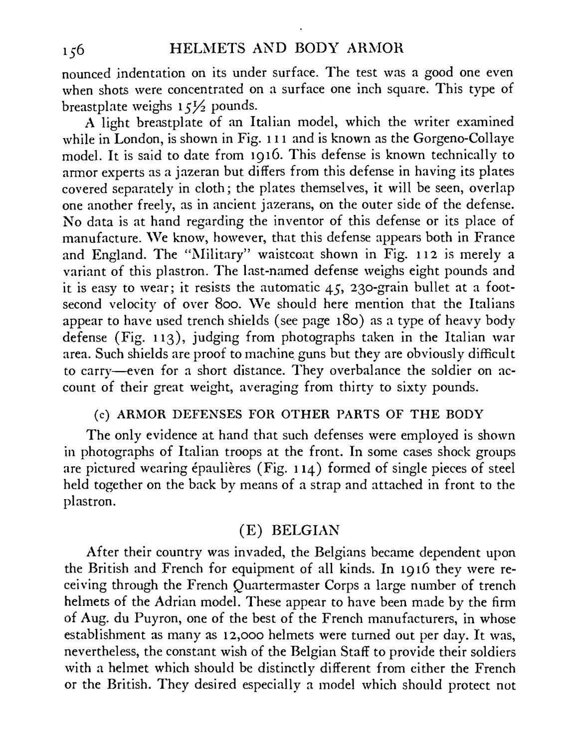
Italian trench shield used as body armor . . 157
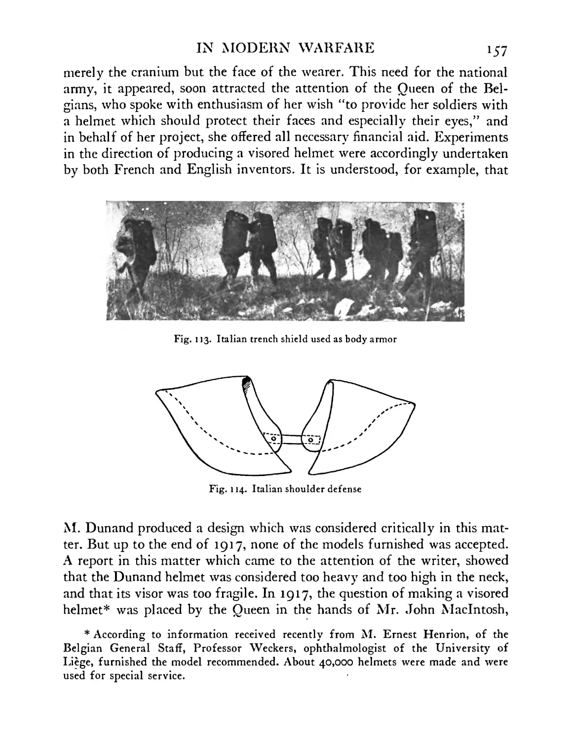
Italian shoulder defense . . . . .157
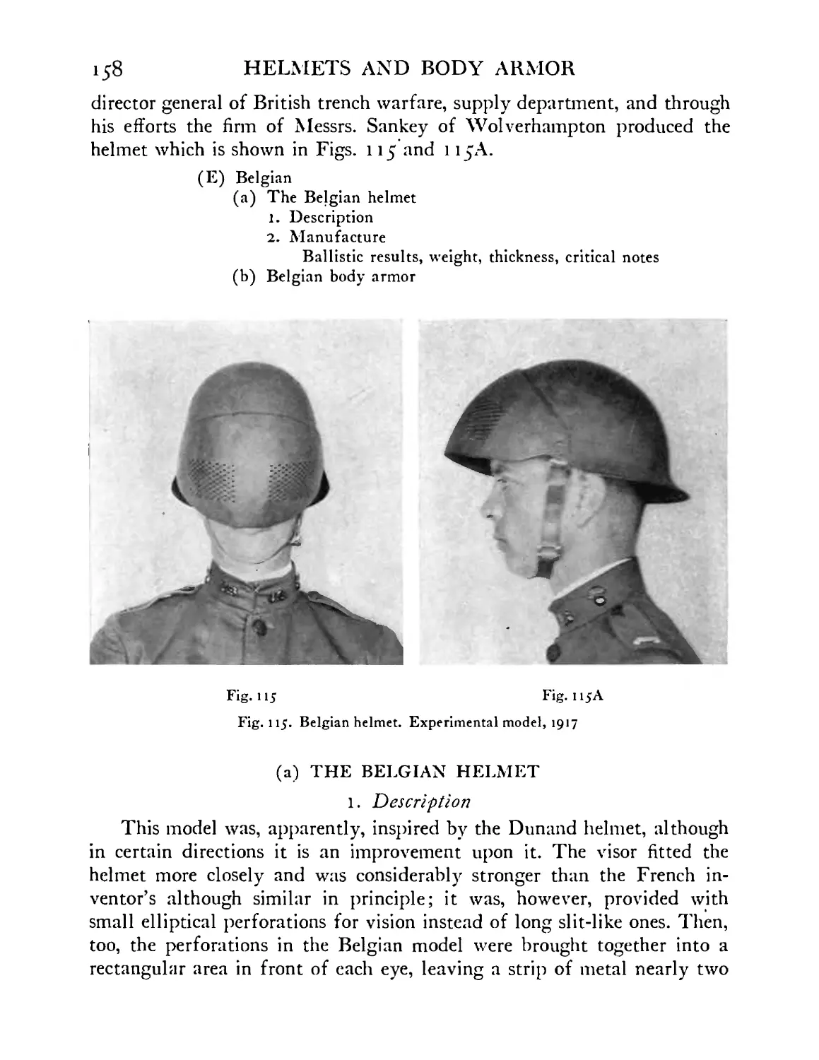
Belgian helmet. Experimental model, 1917 . 158
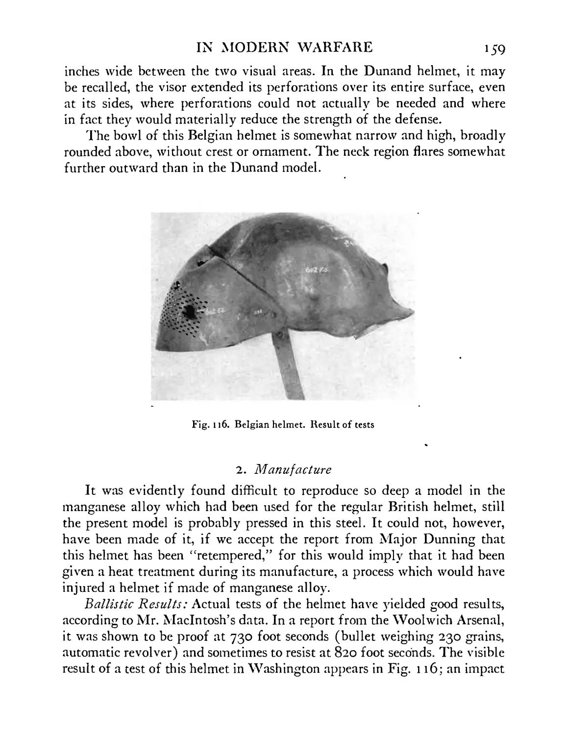
Belgian helmet. Result of tests . . .159
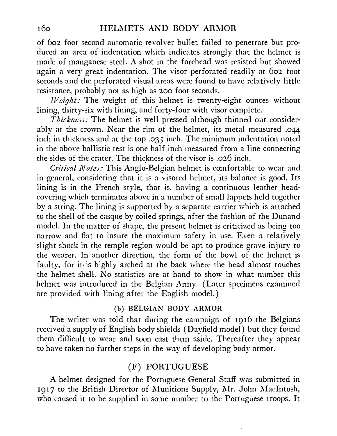
Portuguese helmet . . . . . .161
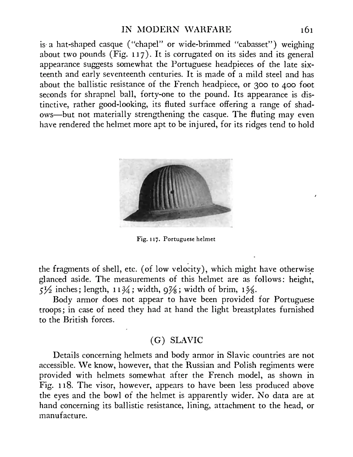
Slavic helmet (Polish), 1917 .... 162
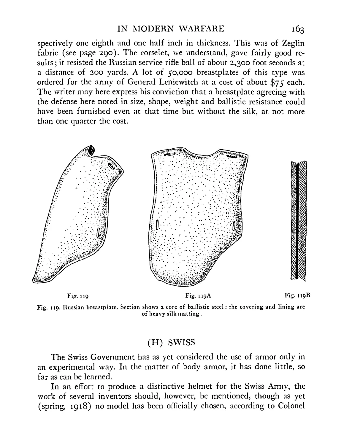
Russian breastplate. The section shows (in black) a
core of ballistic steel: the covering and lining are of
heavy silk matting . . . . . .163
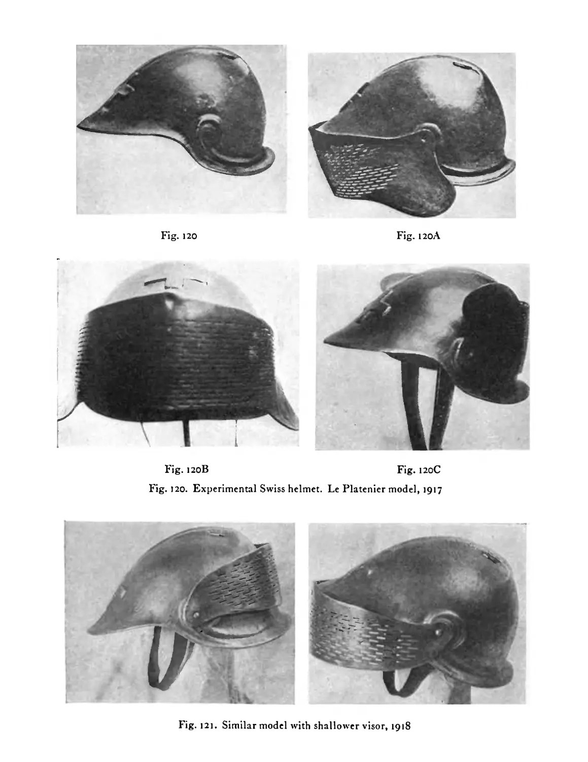
Experimental Swiss helmet. LePlatenier model, 1917 164
Similar model with shallower visor, 1918 . . 164
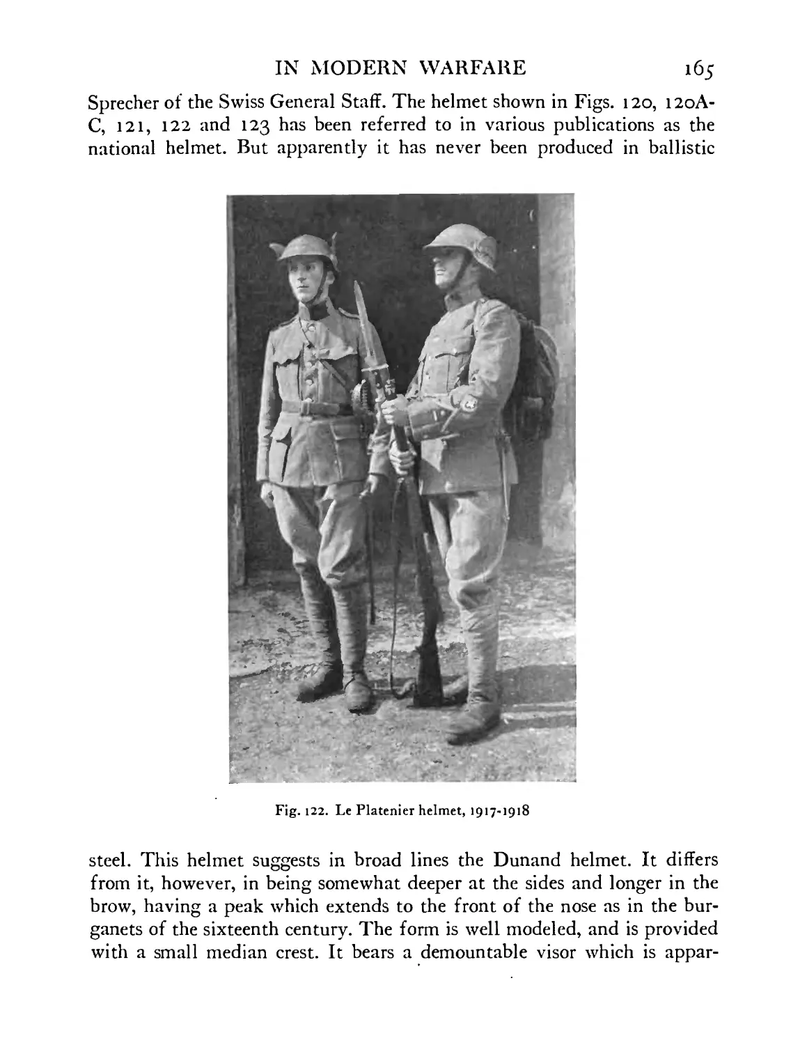
Experimental Swiss helmet. LePlatenier model, 1917-
1918..................................................165
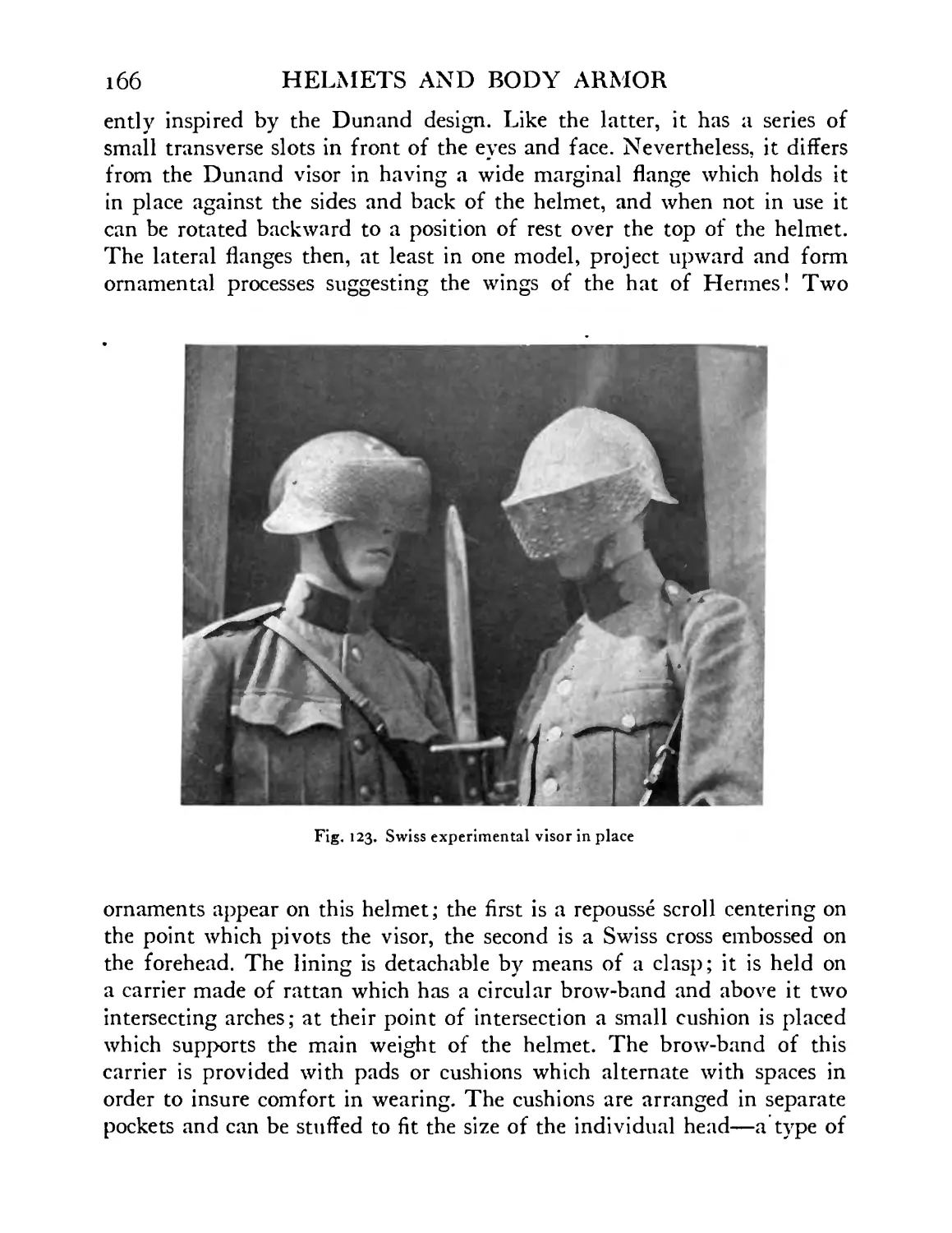
Experimental visor in place (Swiss) . . .166
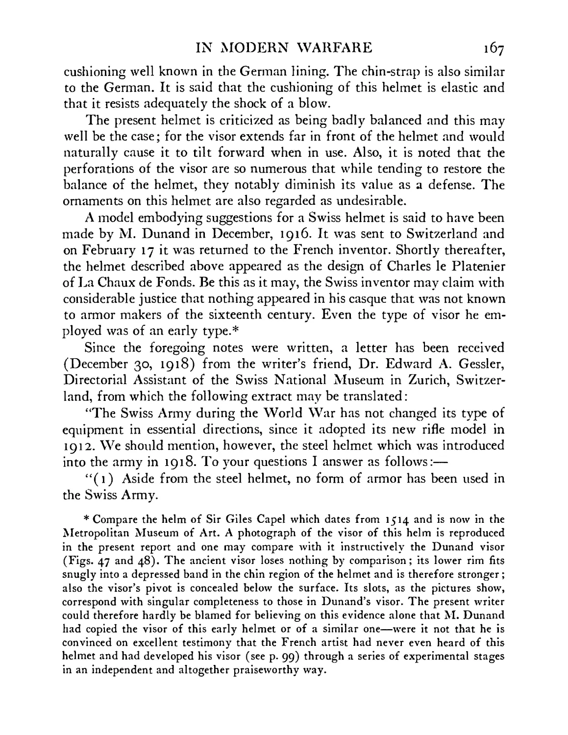
Swiss helmet. Standard model, 1918 . . .169
Swiss helmet compared with American helmet model
No. 5—the latter represented in dotted lines . . 169
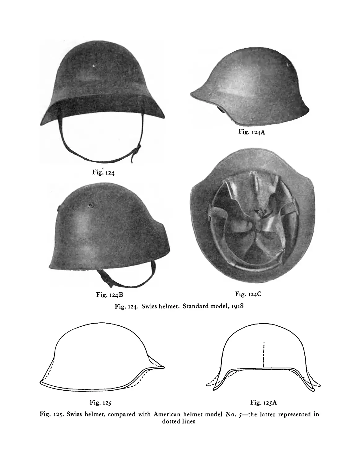
Swiss standard helmet in process of manufacture . 170
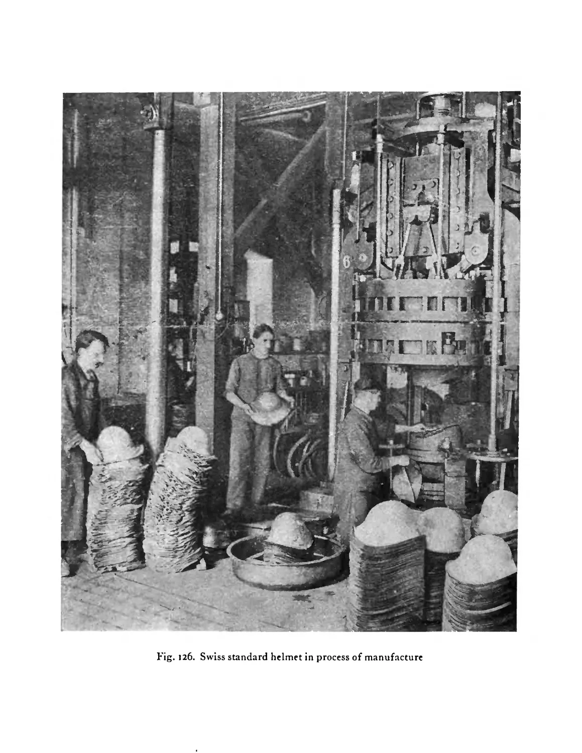
Standard Swiss helmet shown in use by machine
gunners who are wearing their gas masks . . 171
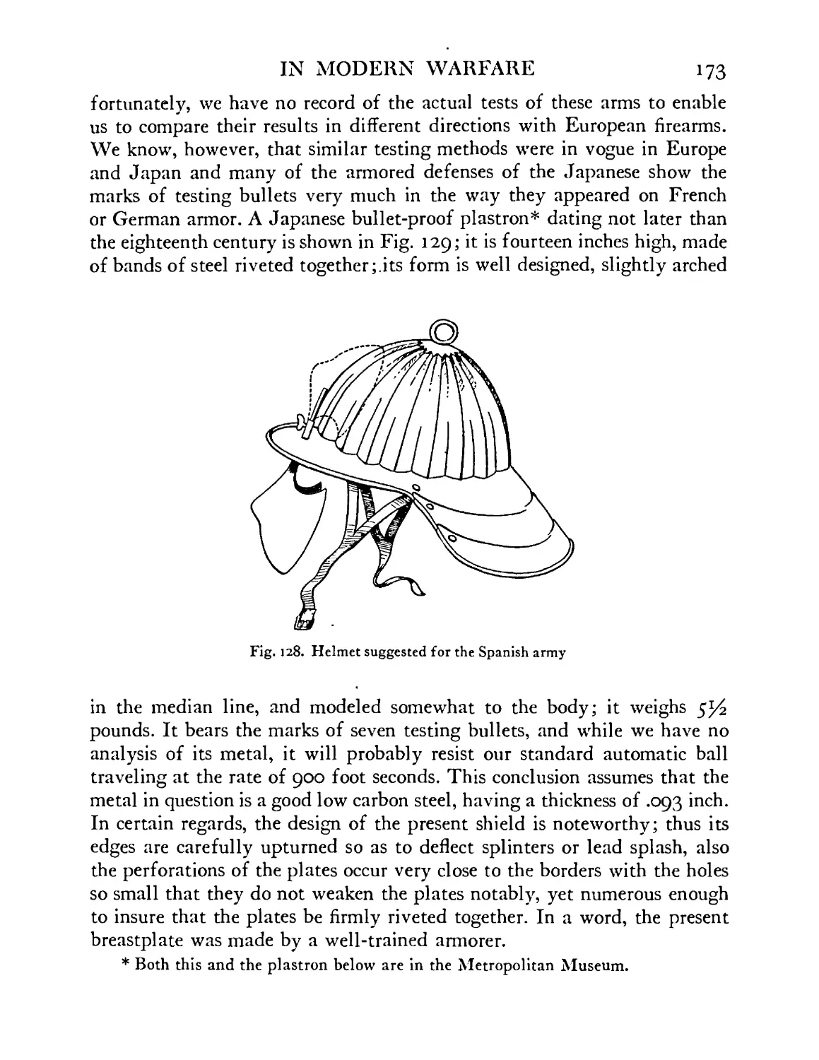
Helmet suggested for the Spanish army . . 173
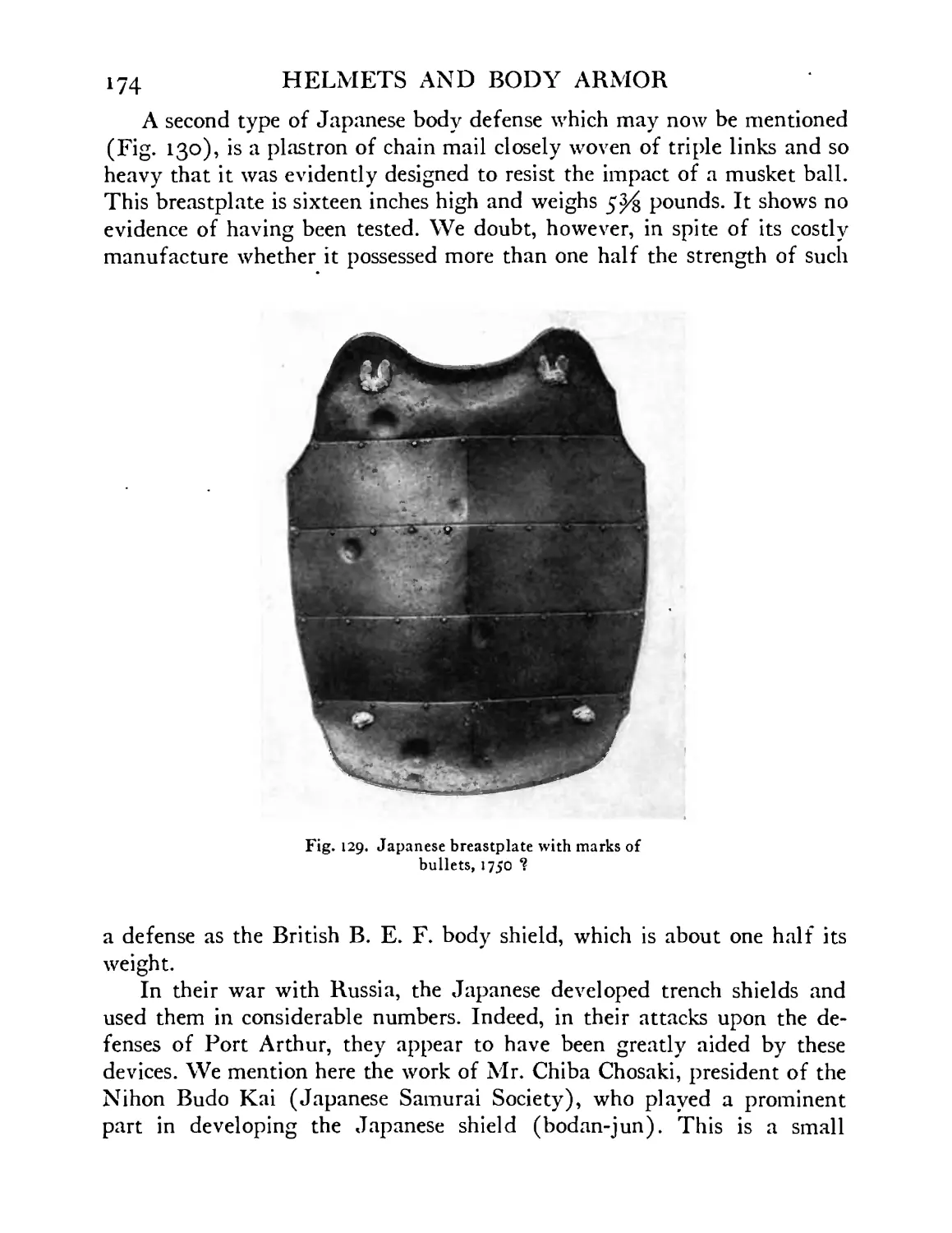
Japanese breastplate showing marks of seven testing
bullets, eighteenth century . . . . .174
18
FIGURE
130
I30A, I30B
130C
130D
13»
>32
133
134
135
I36
>37
>38
>39
140
141
142
>43
>44
>45
146
147-148
149
HELMETS AND BODY ARMOR
PAGE
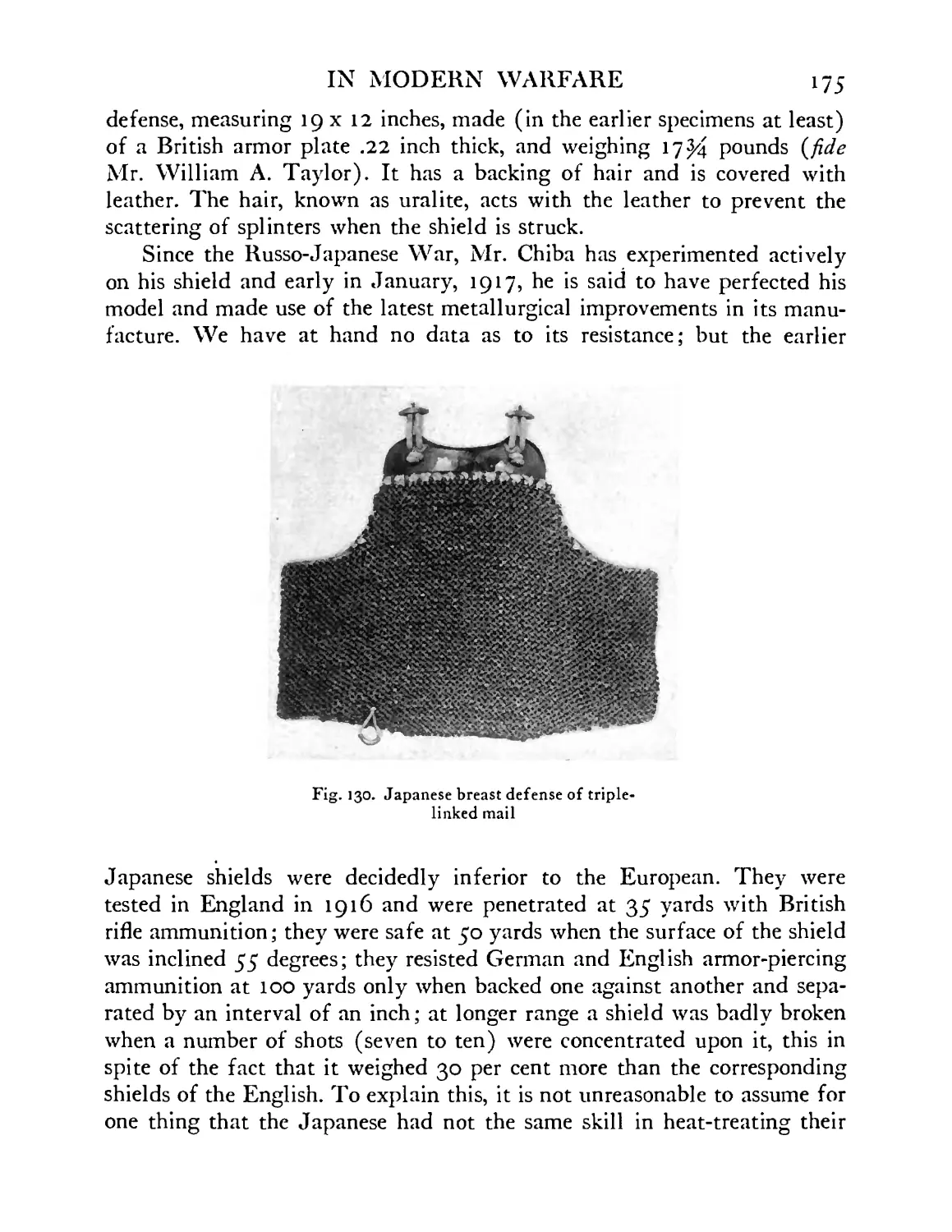
Japanese breast defense of triple-linked chain mail 175
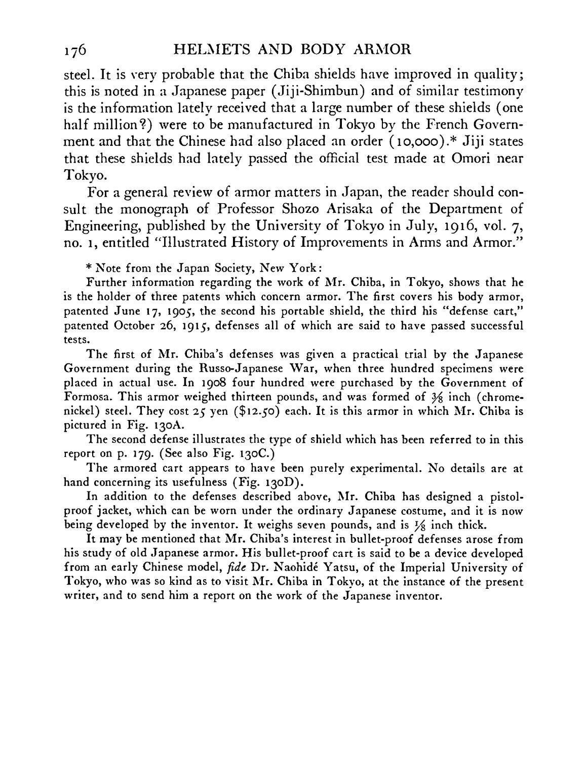
Body defense: Chiba model, 1905 . .177
Portable shield: Chiba model, 1908 . . . 177
Mantlet mounted on wheels: Chiba model, 1915 . 177
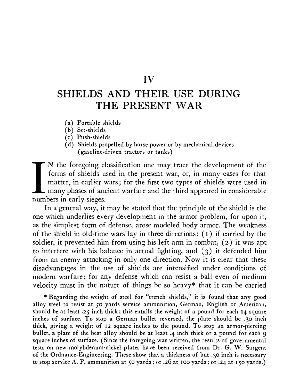
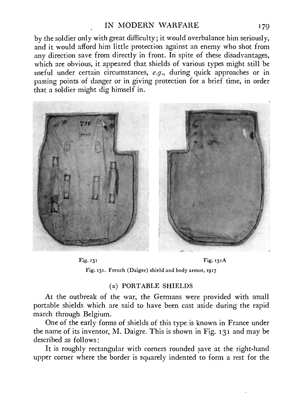
French (Daigre) shield and body armor. Model 1917 179
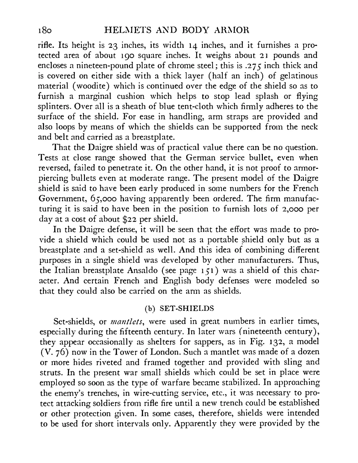
Sapper’s mantlet, nineteenth century. In Tower of
London . . . . . . . .181
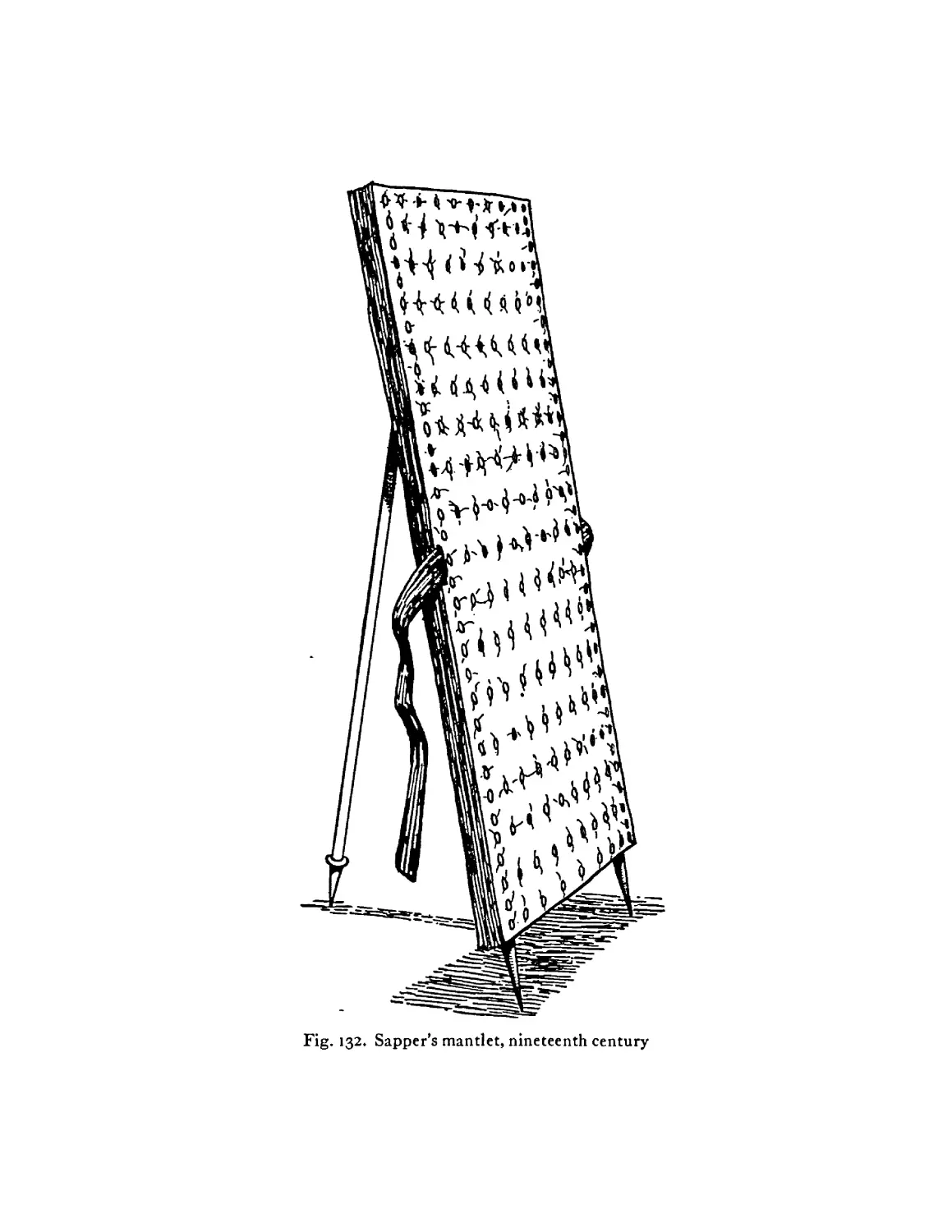
German trench shield, 1916. (Similar shields were
manufactured in England, France and the United
States) ........ 182
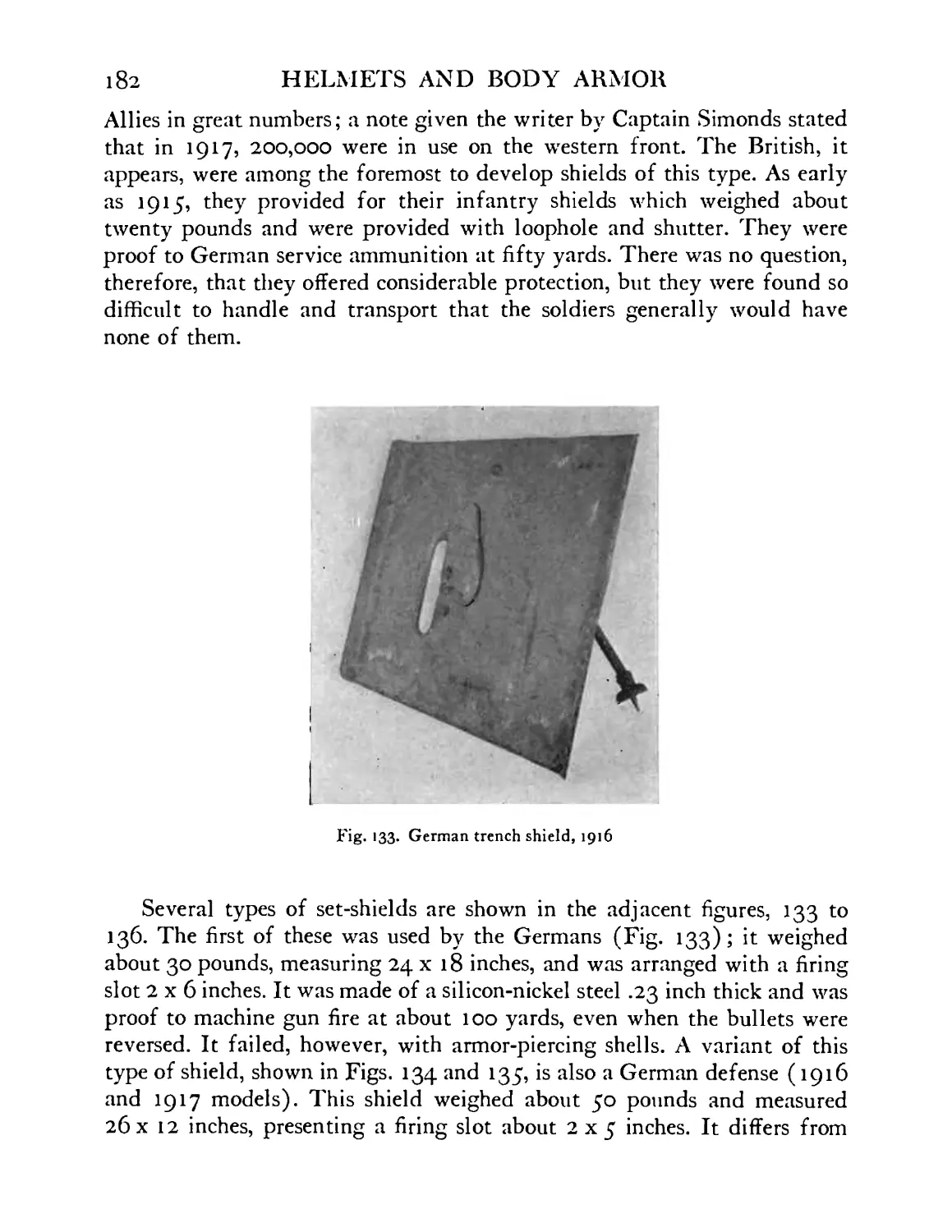
German trench shield, 1916-1917 model . . 183
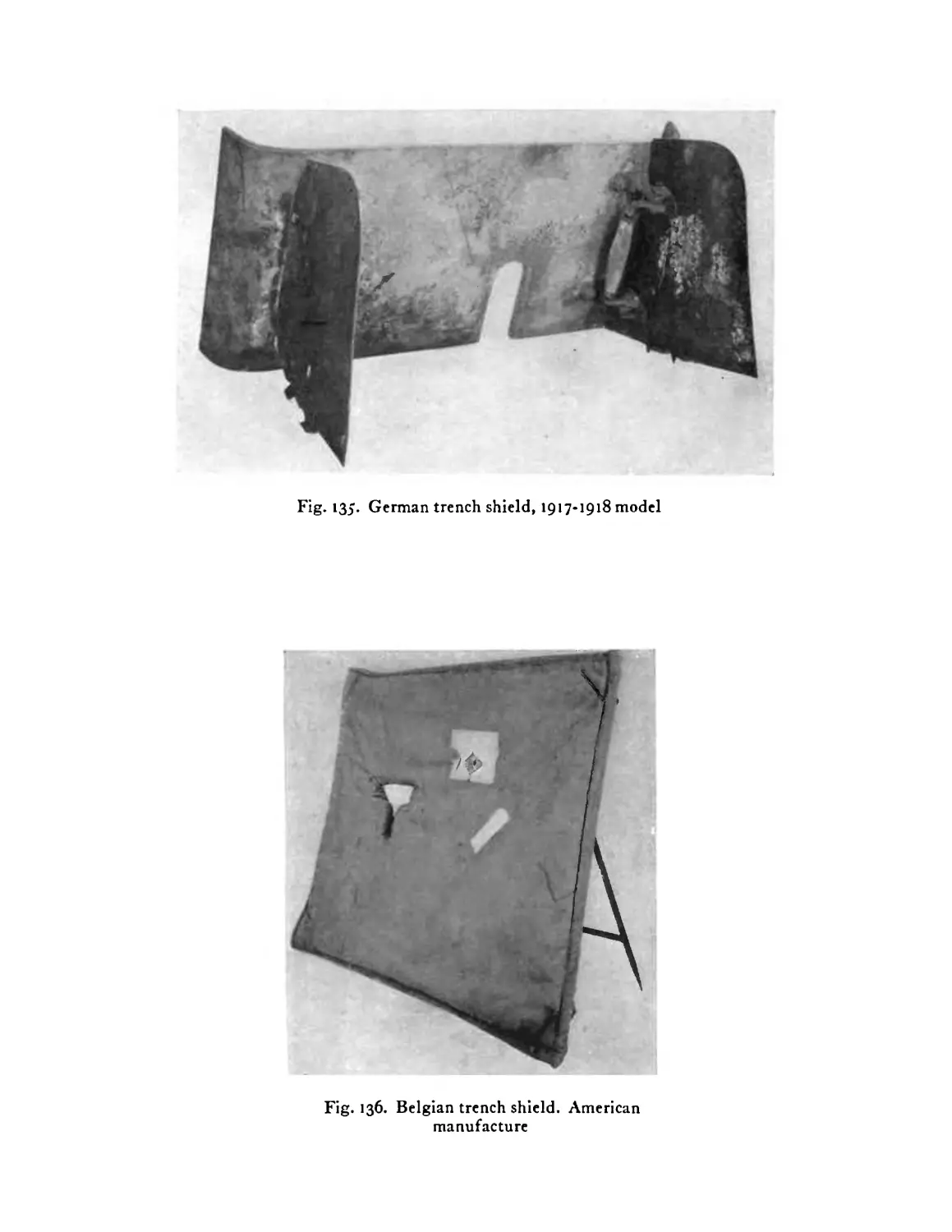
German trench shield, 1917-1918 model . . 184
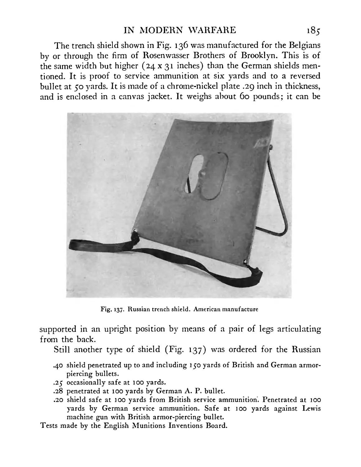
Belgian trench shield. American manufacture . 184
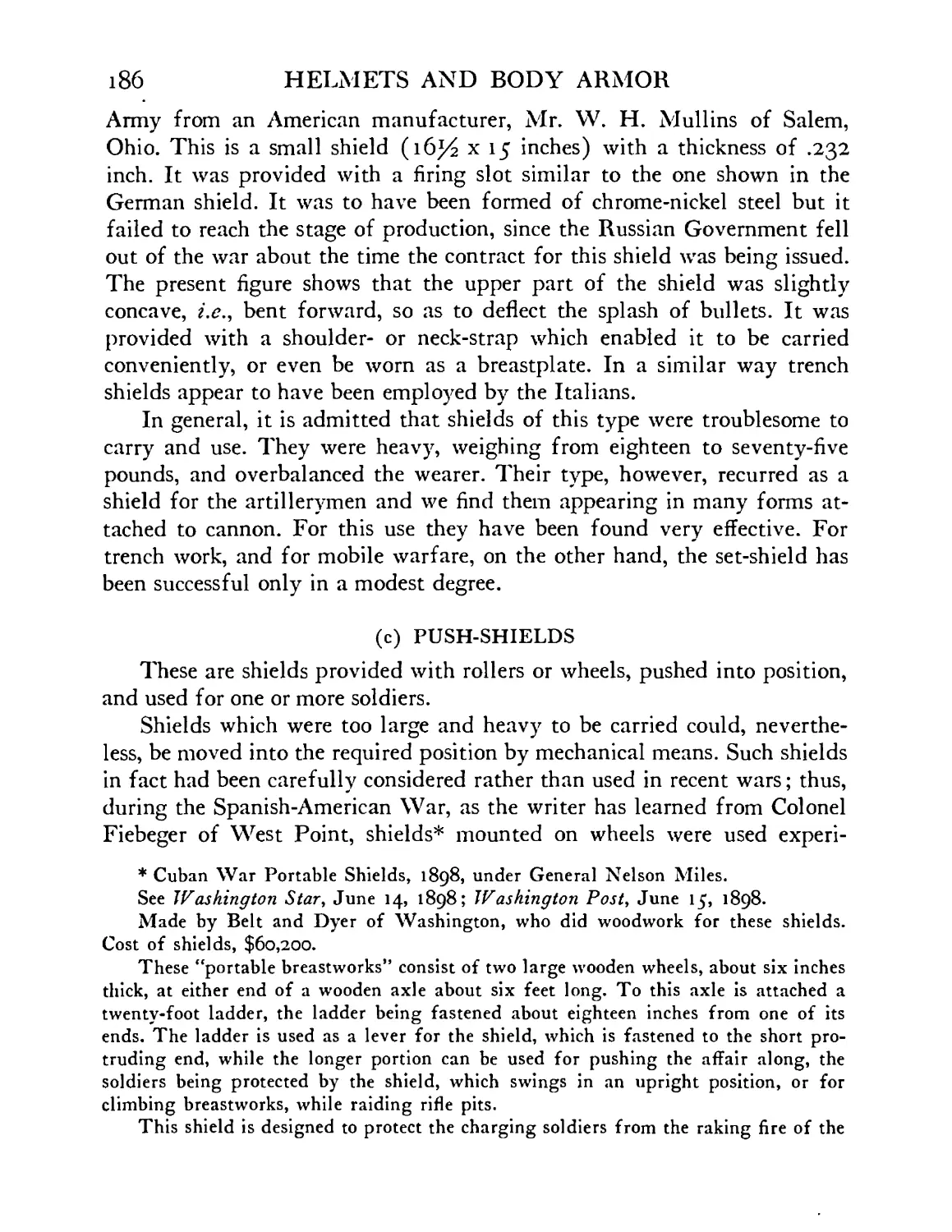
Russian trench shield. American manufacture . 185
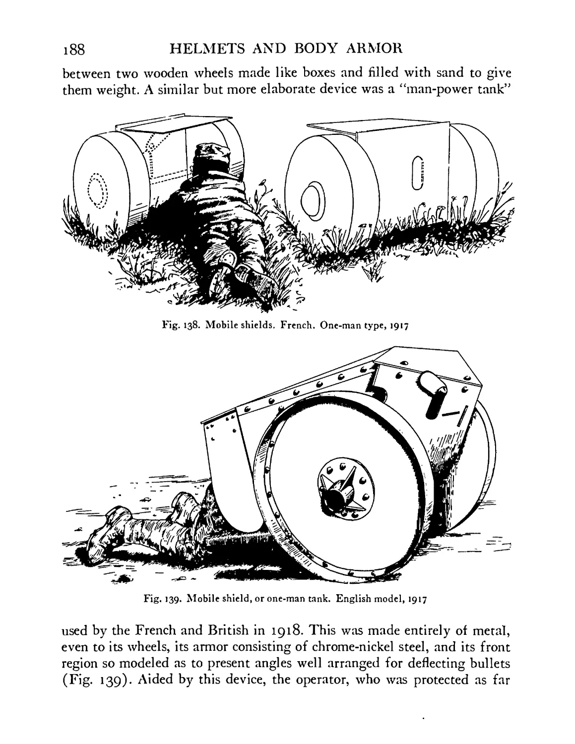
Mobile shields. French. One-man type. Used in wire
cutting, 1917 ....... 188
Mobile shield, or one-man tank. Used in wire cutting.
English model, 1917 ...... 188
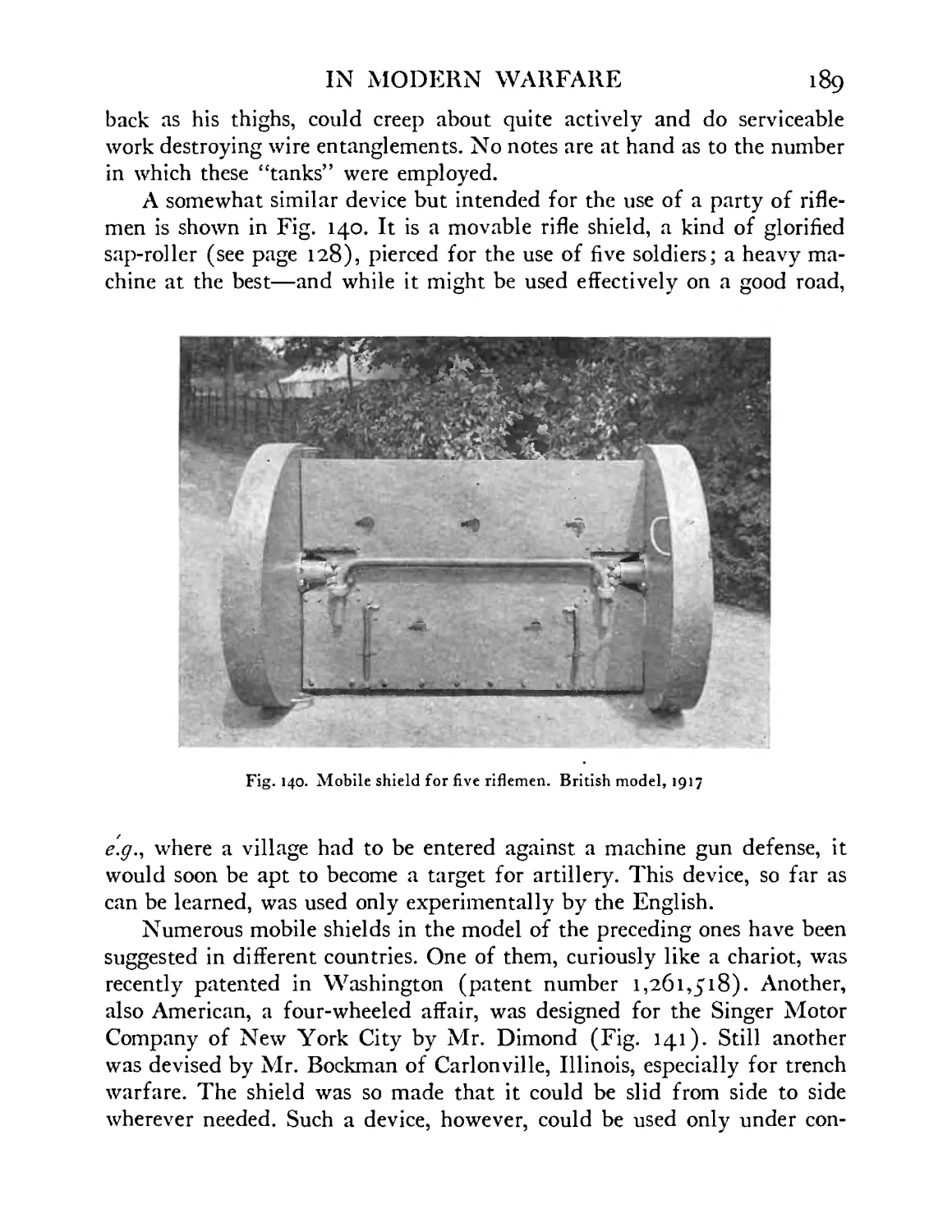
Mobile shield for five riflemen. British experimental
model, 1917 ....... 189
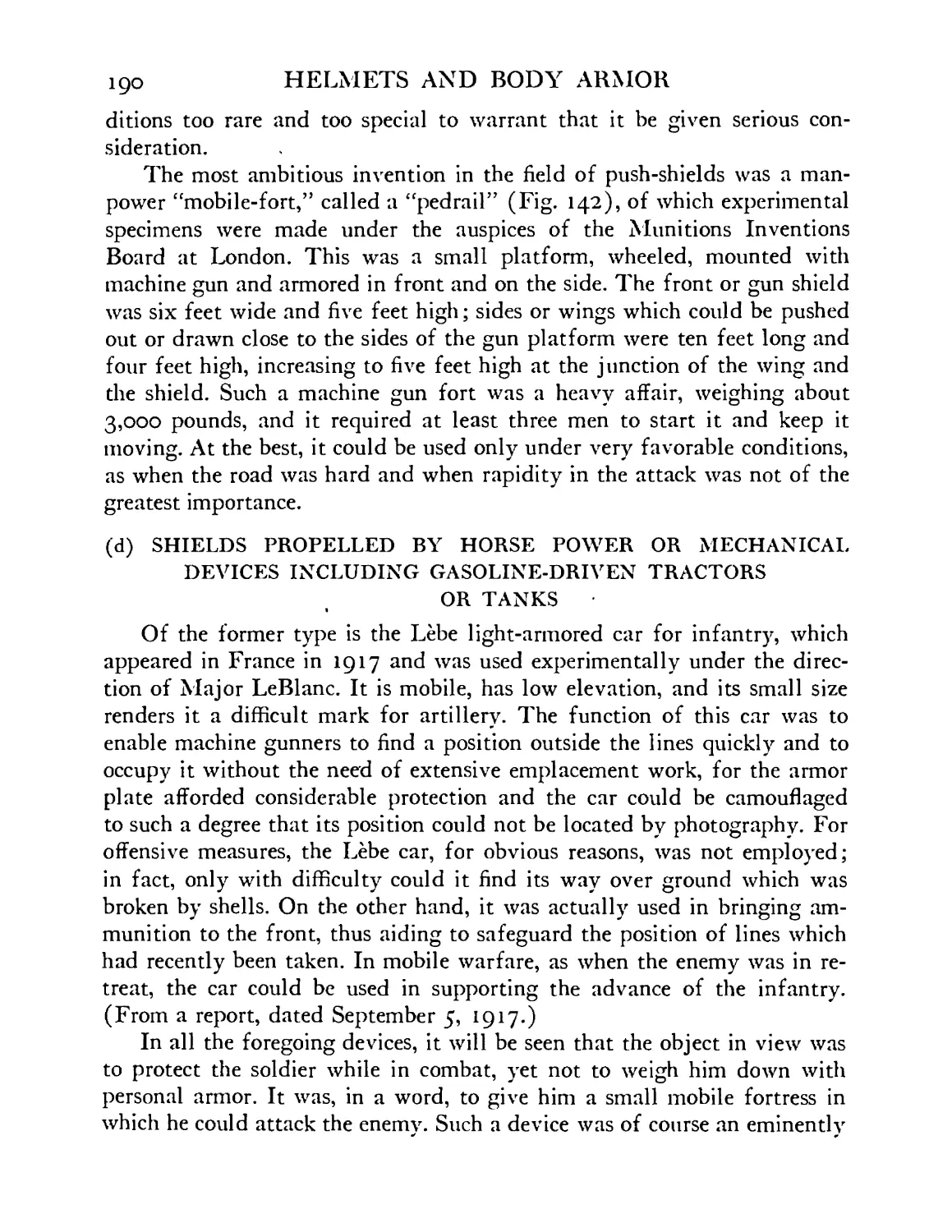
Mobile shield for nine riflemen. American experi-
mental model . . . . . . .191
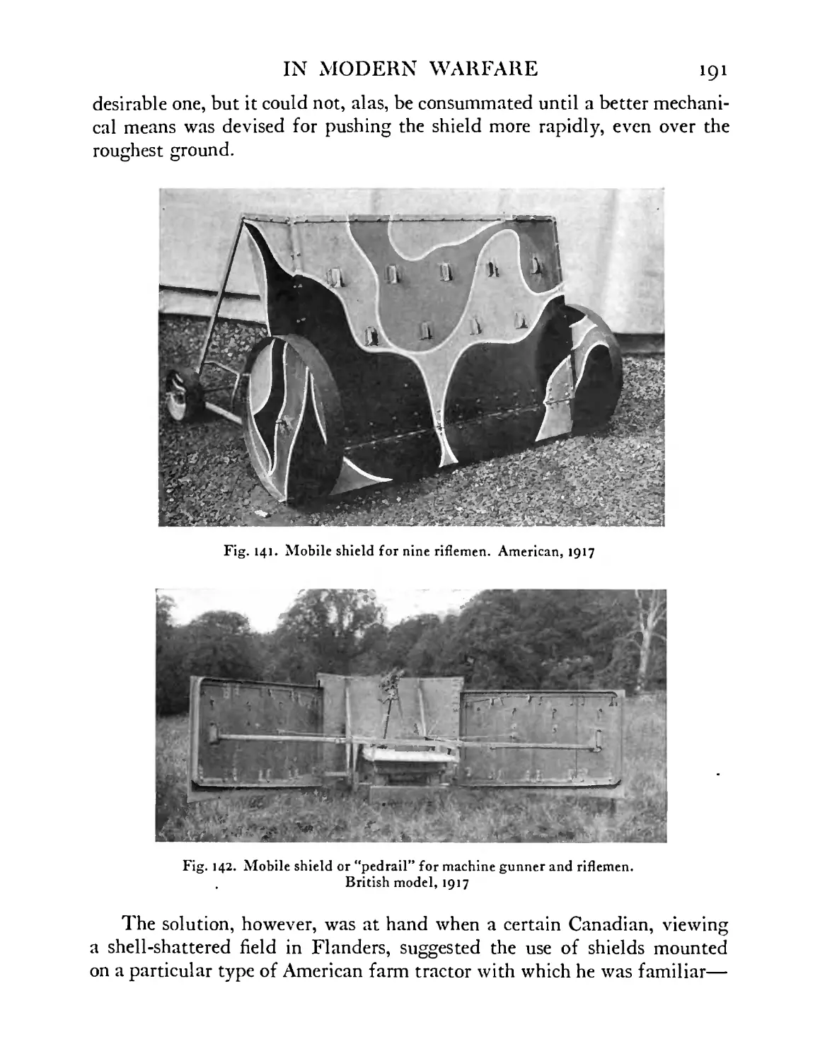
Mobile shield or “pedrail” for machine gunner and
riflemen. British model, experimental, 1917 . . 191
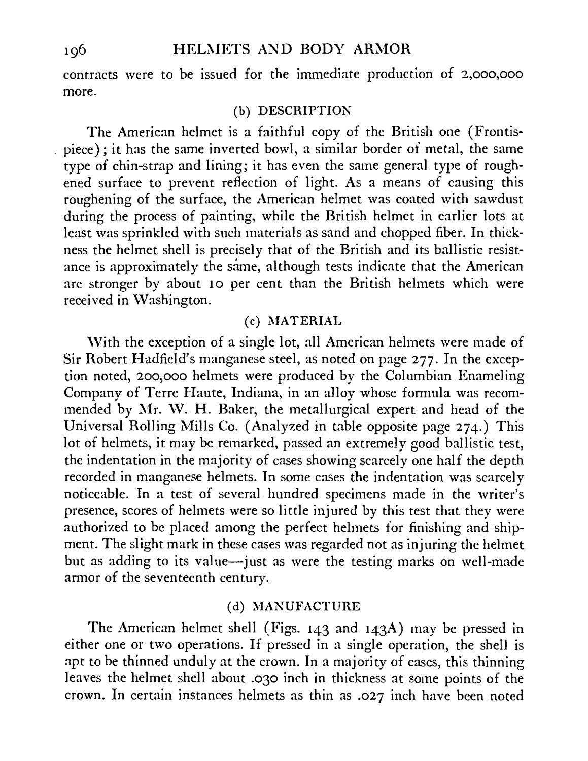
British-American helmet. Completed shell with at-
tached rim and chin-strap loops, in condition in which
it leaves the manufacturer’s plant . . .197
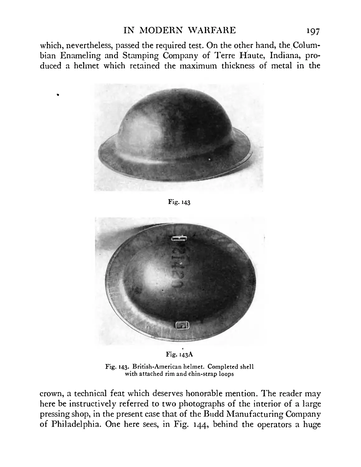
British-American helmet in process of manufacture,
shown in background at the right. The double-action
press stamps out the helmet in a single “draw.” Budd
Mfg. Co., Philadelphia . . . .198
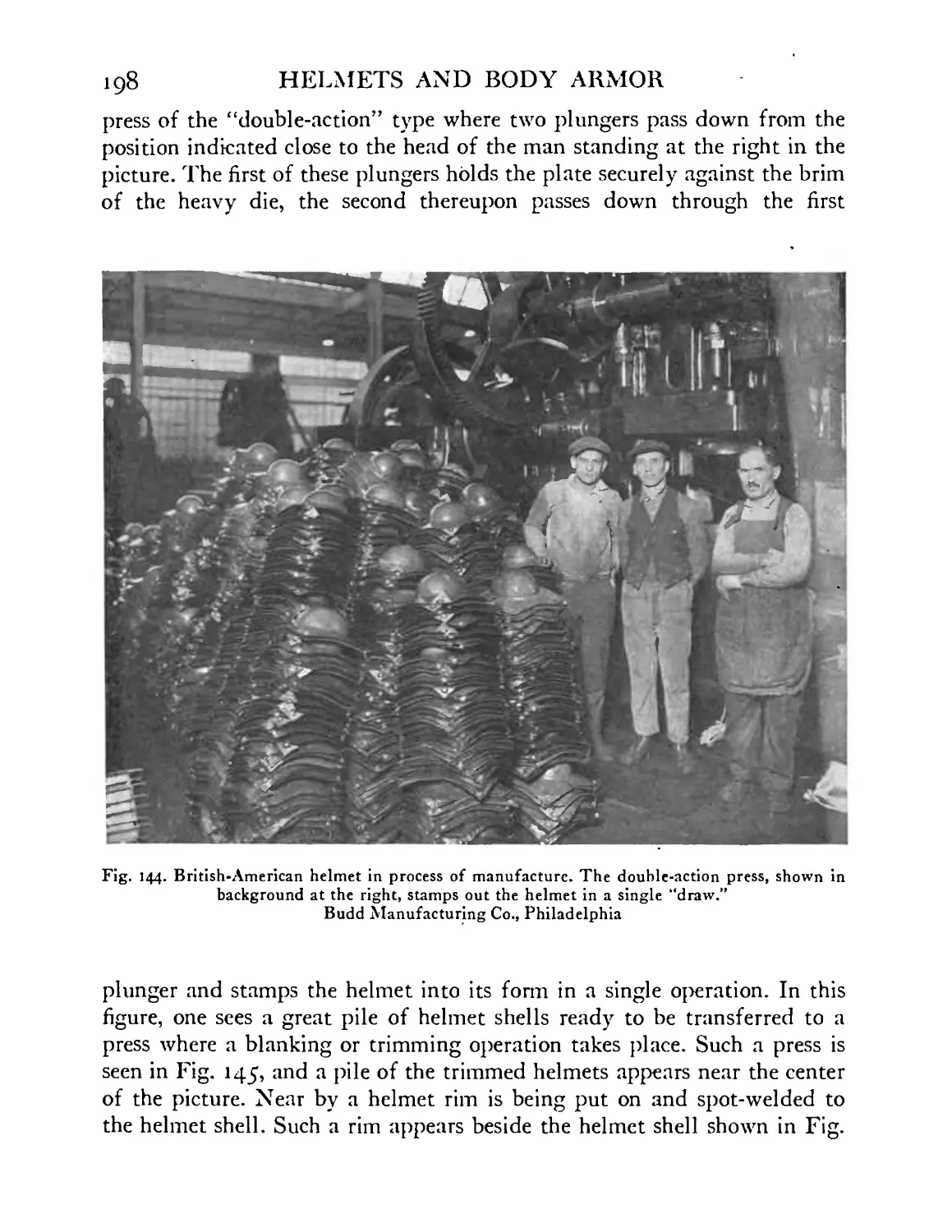
British-American helmet in process of manufacture.
The plate is being “blanked out” so as to form the
helmet rim; in another part of the picture the thin
separate metal rims are being spot-welded in place.
Budd Mfg. Co., Philadelphia .... 199
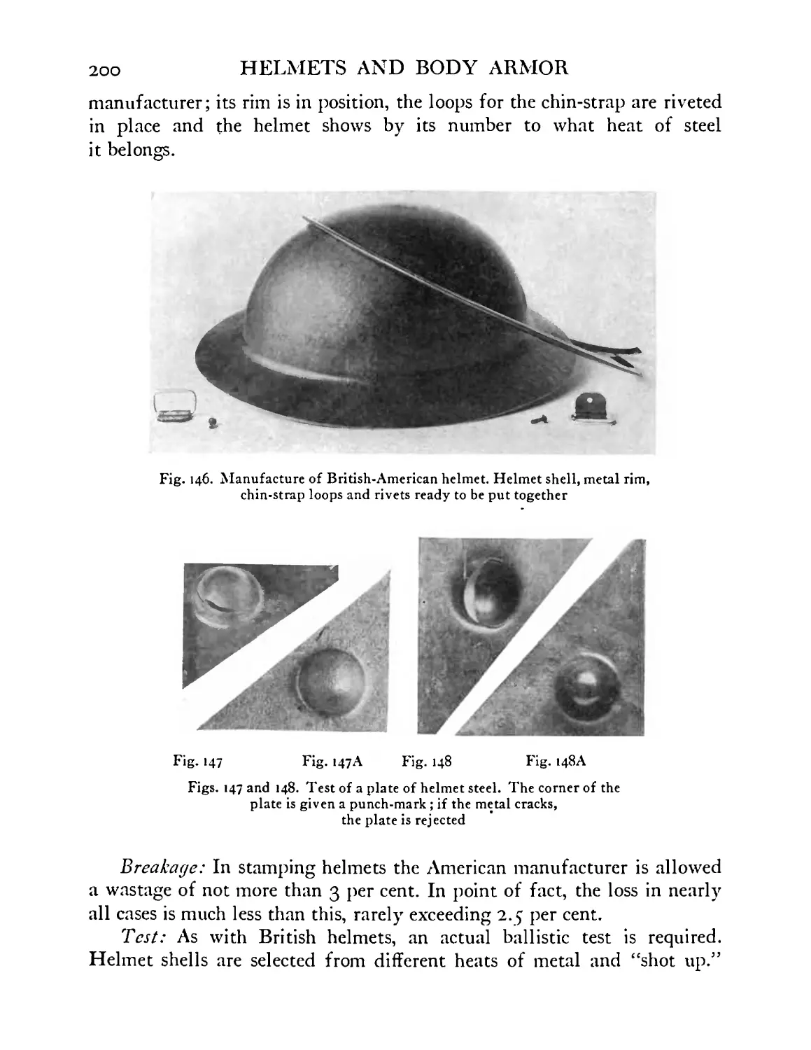
British-American helmet in process of manufacture.
Helmet shell, metal rim, chin-strap loops and rivets
ready to be put together ..... 200
Test of a plate of helmet steel. The corner of the
plate is given a punch-mark; if the metal cracks, the
plate is rejected ...... 200
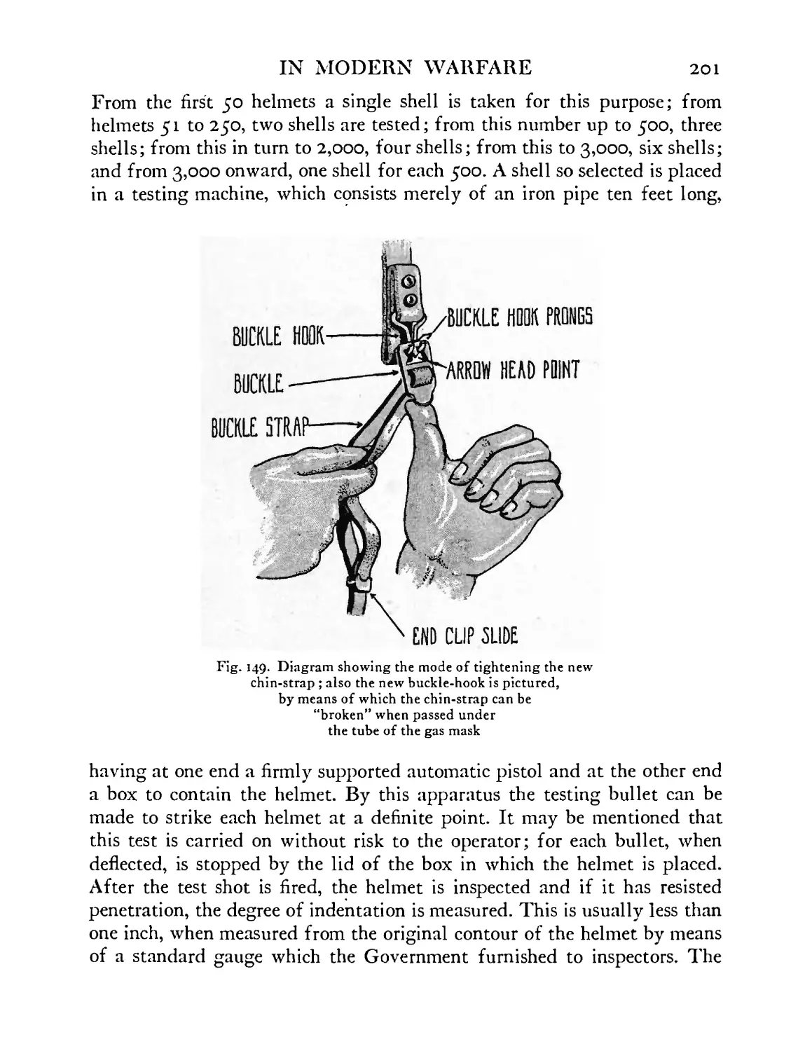
Diagram showing the mode of tightening the new
chin-strap; also the new buckle-hook is pictured, by
IN MODERN WARFARE
19
FIGURE
150, 1J1A,
152
153
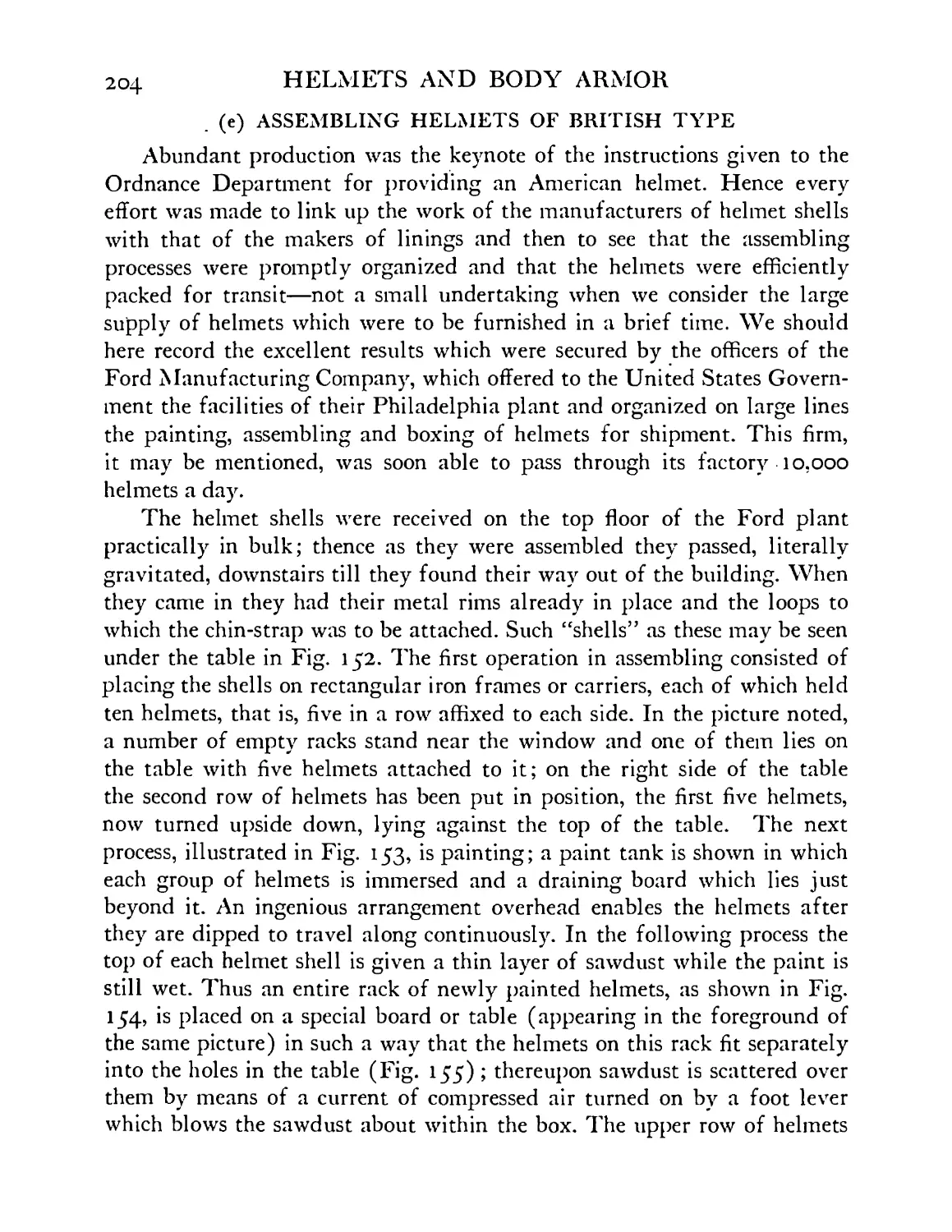
154
155
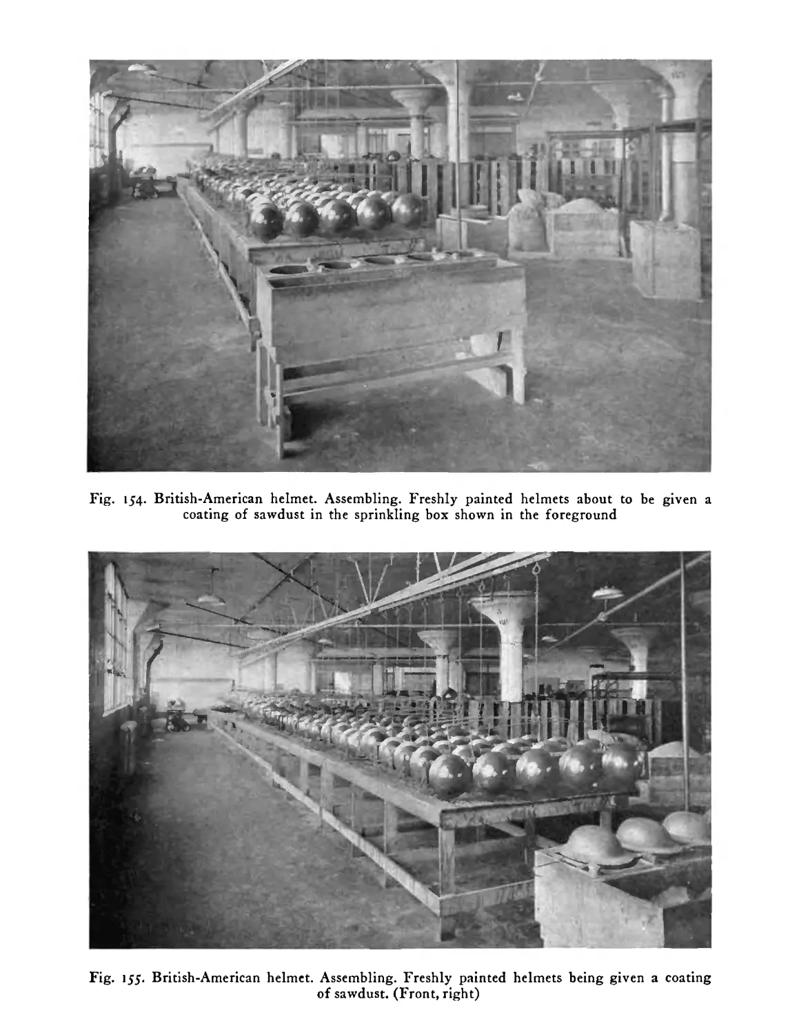
I56
47
158
49
16O
160 A
161
162
163
164
165
166
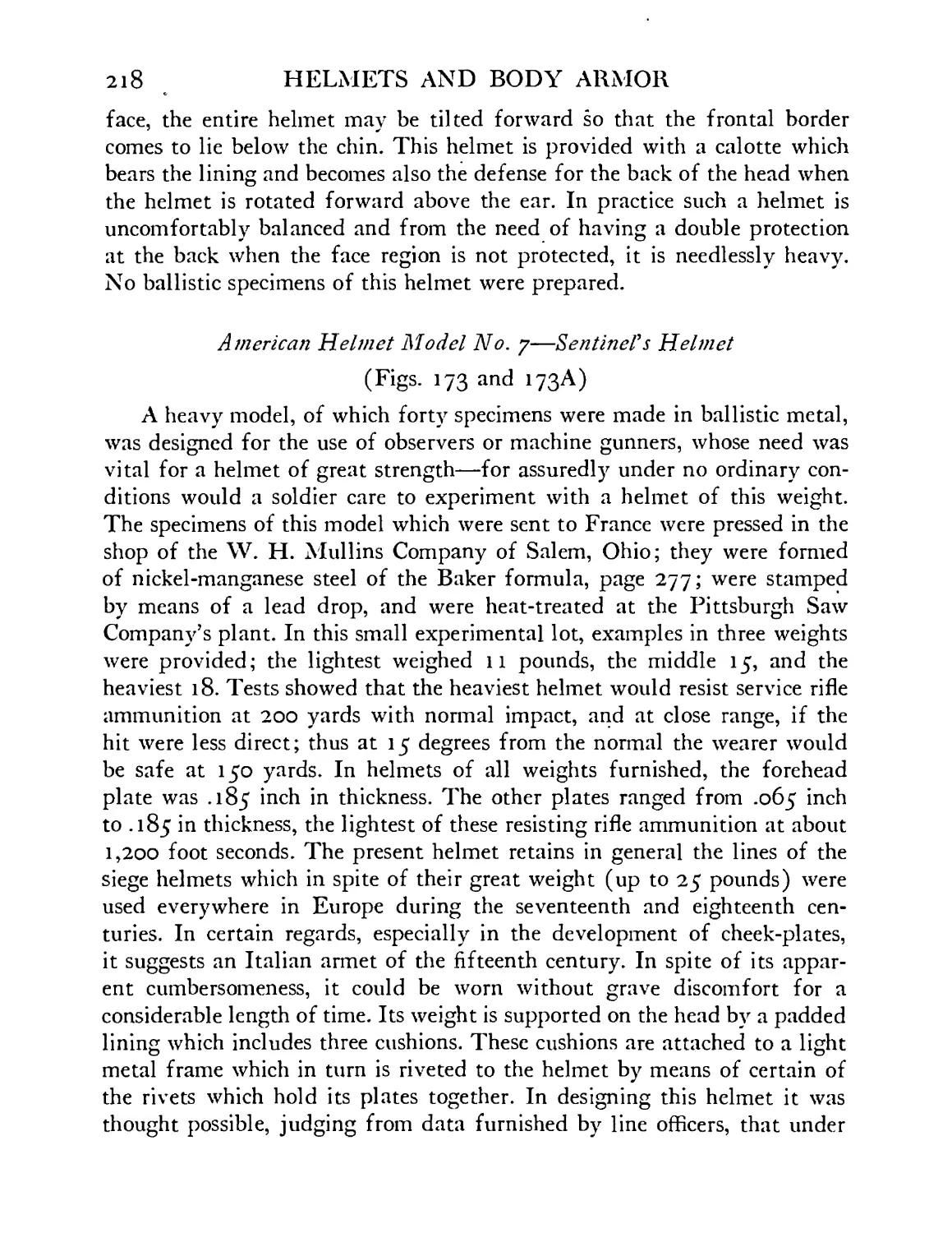
167
168
169
170
PAGE
means of which the chin-strap can be “broken” when
it is passed under the tube of the gas mask . . 201
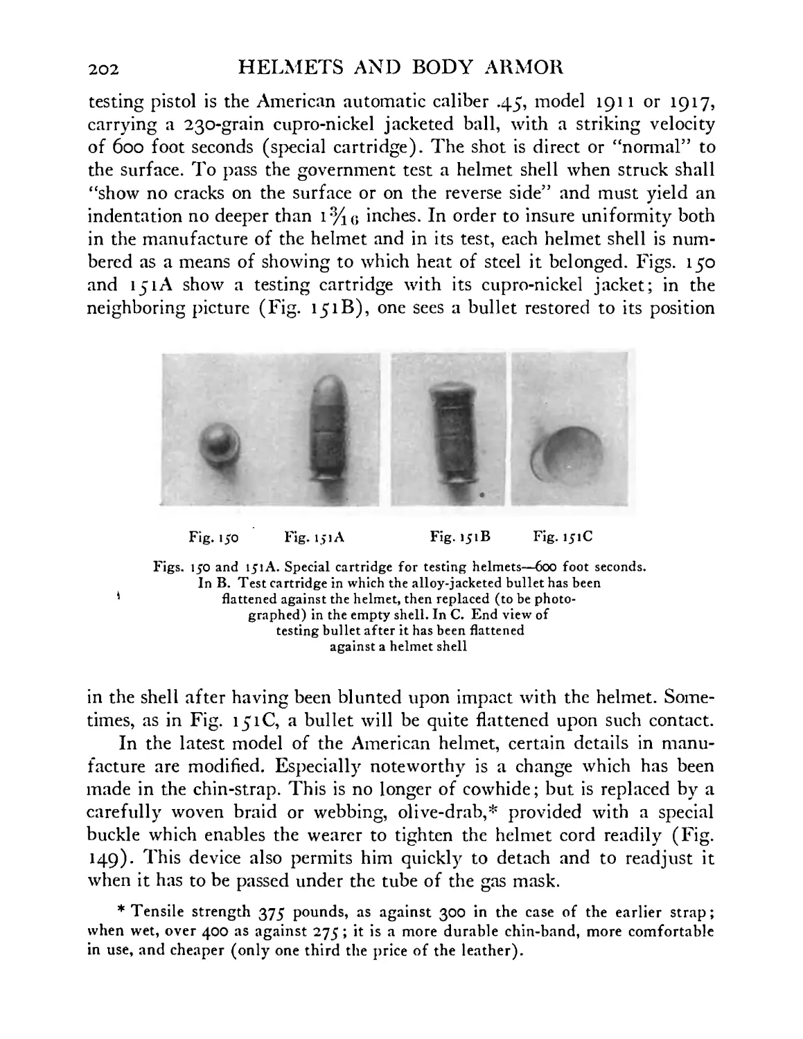
151B, 151C Cartridges and bullets used in testing British-
American helmets ...... 202
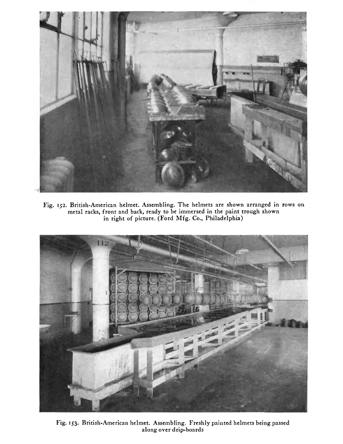
British-American helmet. Assembling. The helmets
are shown arranged in rows on metal racks, front
and back, ready to be immersed in the paint trough
shown in right of picture. Ford Mfg. Co., Philadel-
phia ........ 203
British-American helmet. Assembling. Freshly
painted helmets being passed along over drip-boards 203
British-American helmet. Assembling. Freshly
painted helmets about to be given a coating of saw-
dust in the sprinkling box shown in the foreground 205
British-American helmet. Assembling. Freshly
painted helmets being given a coating of sawdust . 20J
British-American helmet. Assembling. Shells ar-
ranged on racks about to be passed into the heated
drying chamber ...... 206
British-American helmet. Assembling. Helmet shells
being passed down an inclined plane to tables where
linings and chin-straps are put in place . . . 206
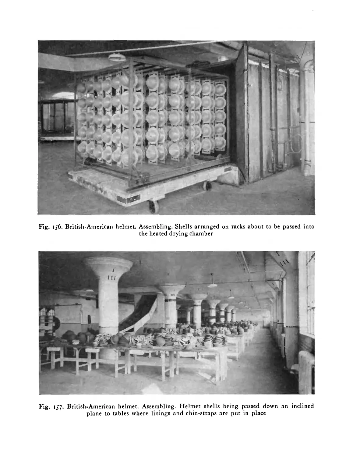
Lining of British-American helmet. From below . 207
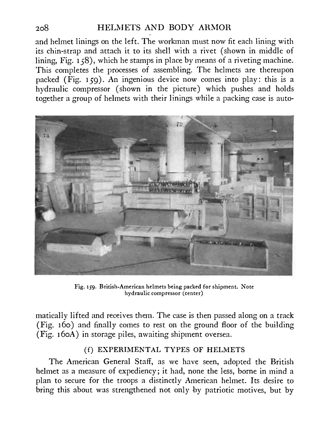
British-American helmets being packed for shipment 208
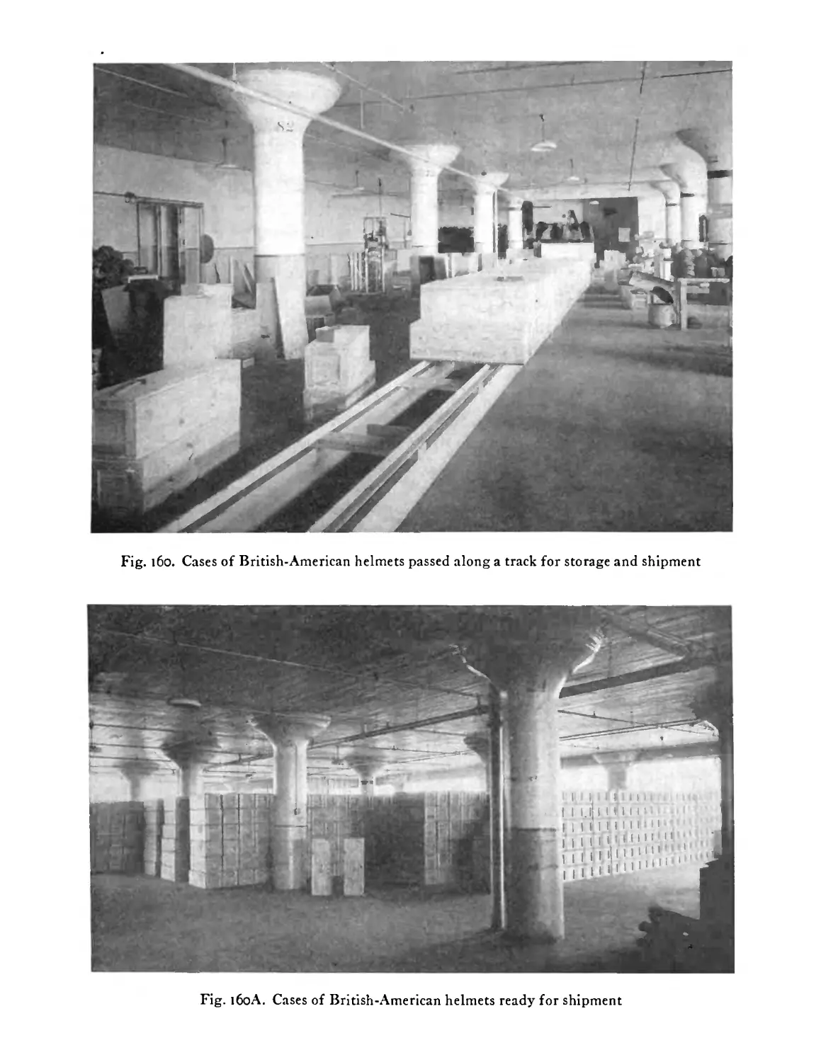
Cases of British-American helmets passed along a
track for storage and shipment .... 209
Cases of British-American helmets ready for ship-
ment ........ 209
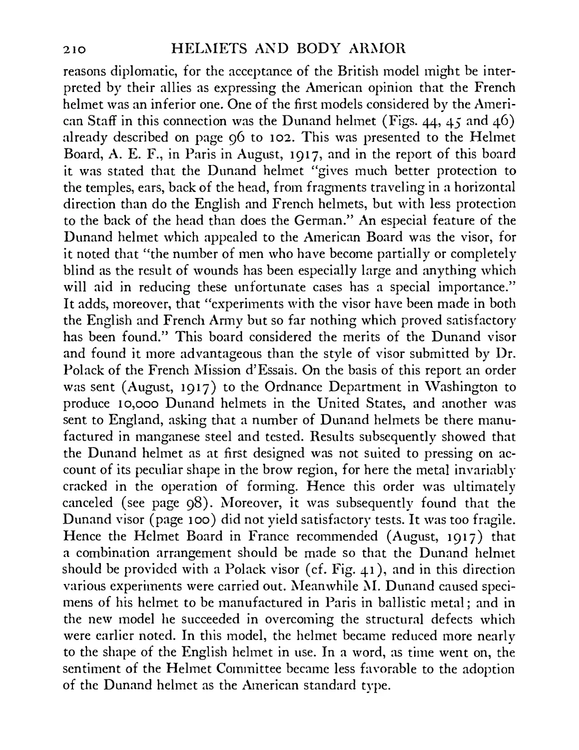
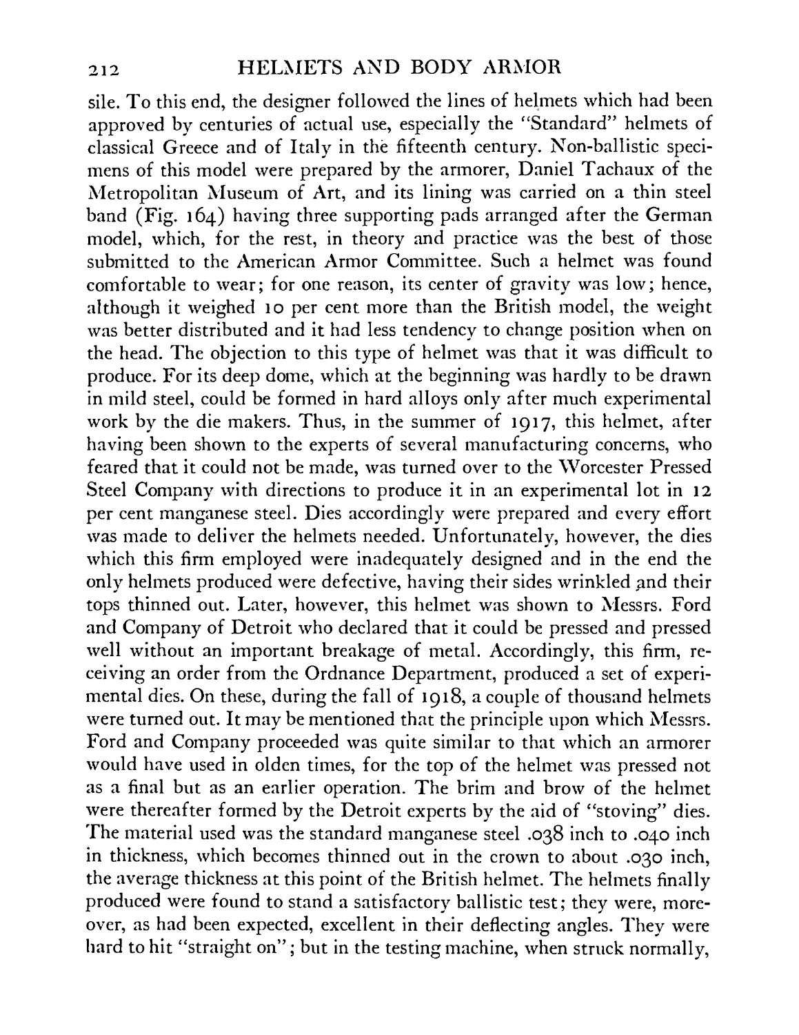
Helmet model No. 2 “deep salade.” This helmet pro-
tects the head more completely than any modern
model hitherto manufactured . . . . 211
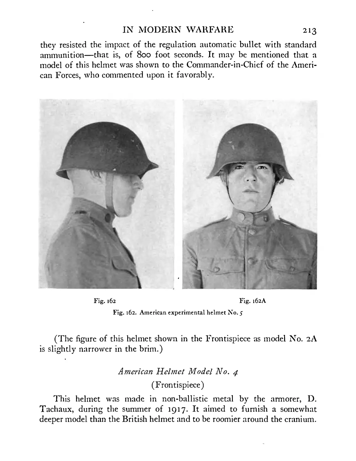
American experimental helmet model No. 5 . . 213
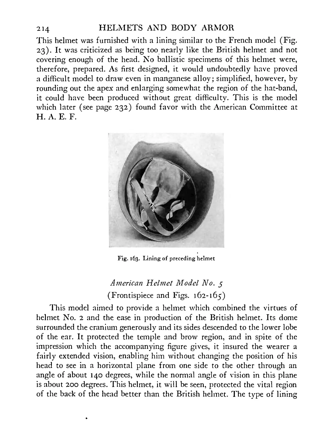
Lining of preceding helmet . . . . .214
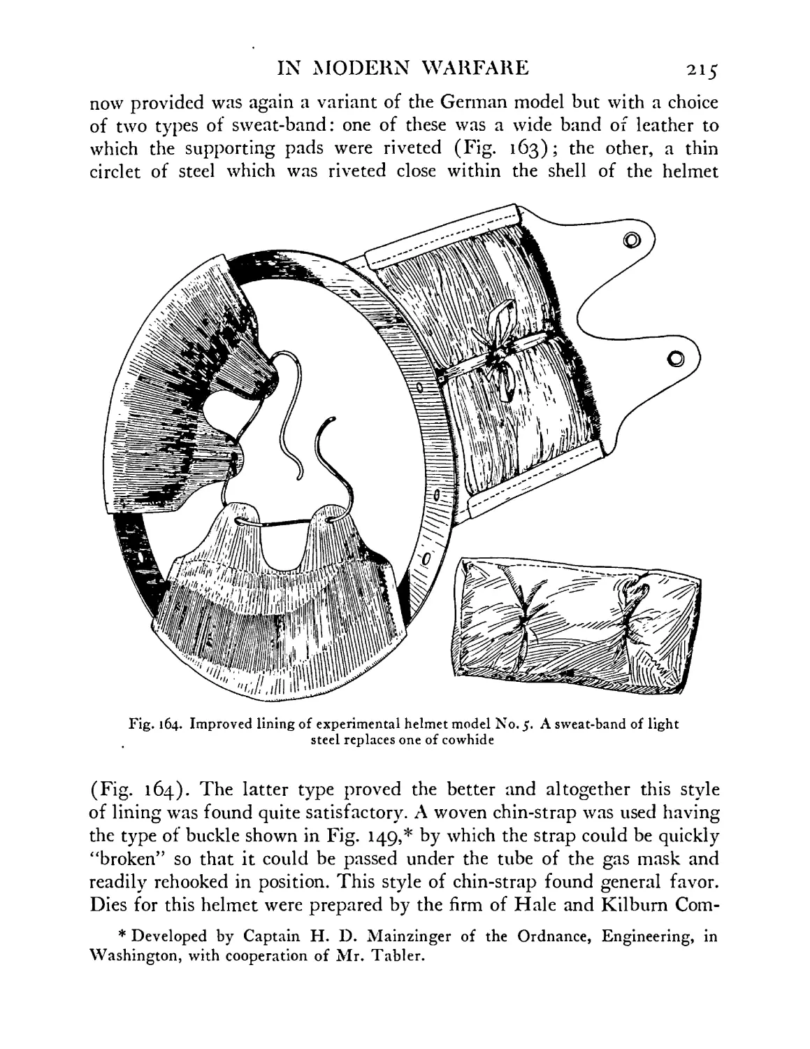
Improved lining of experimental helmet model No.
5. A sweat-band of light steel replaces one of cowhide 215
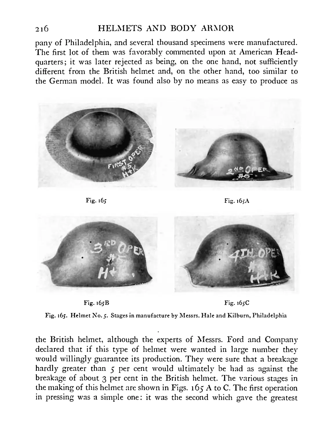
Helmet model No. 5. Stages in manufacture . . 216
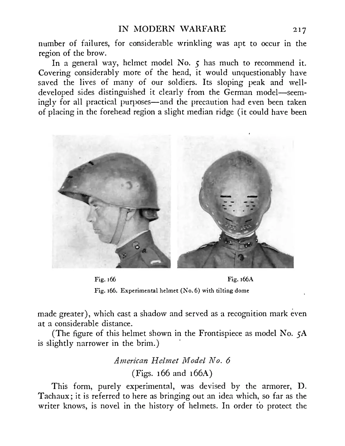
Experimental helmet model No. 6 . . .217
American experimental helmet model No. 8 . . 219
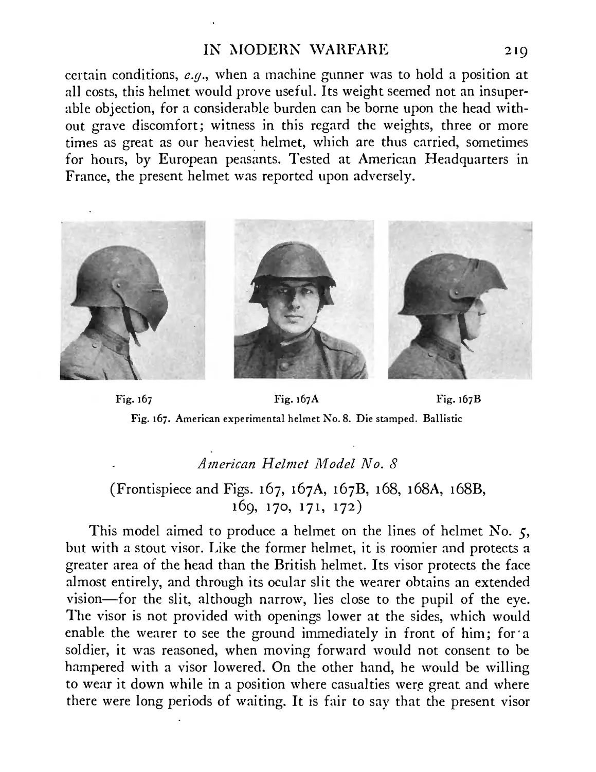
Earlier model of helmet No. 8 . . . 220
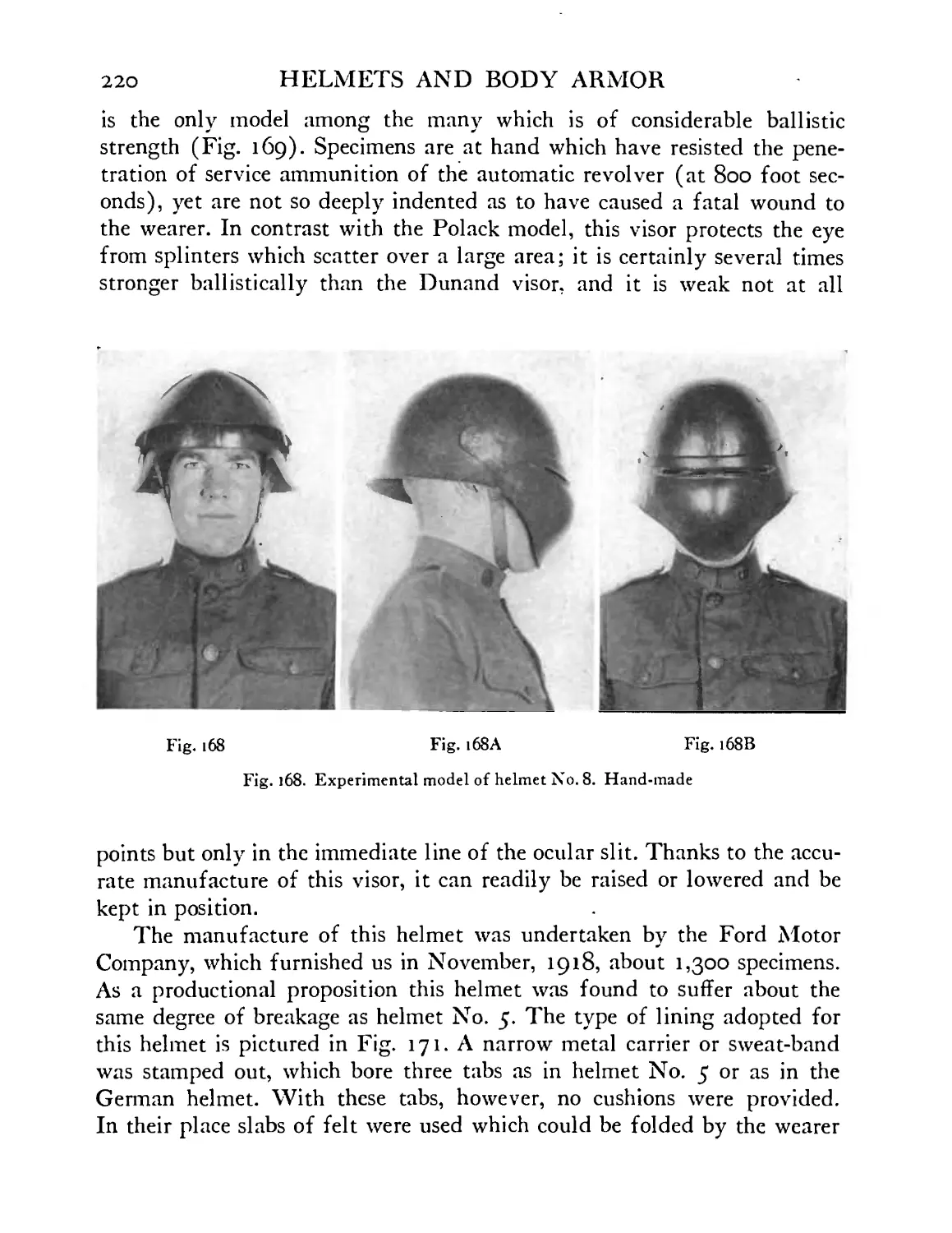
Experimental helmet model No. 8. Result of test by
pistol bullet at 800 foot seconds. Outline of head
within helmet is shown by dotted line. Present helmet
bears marks of six testing bullets . . . .221
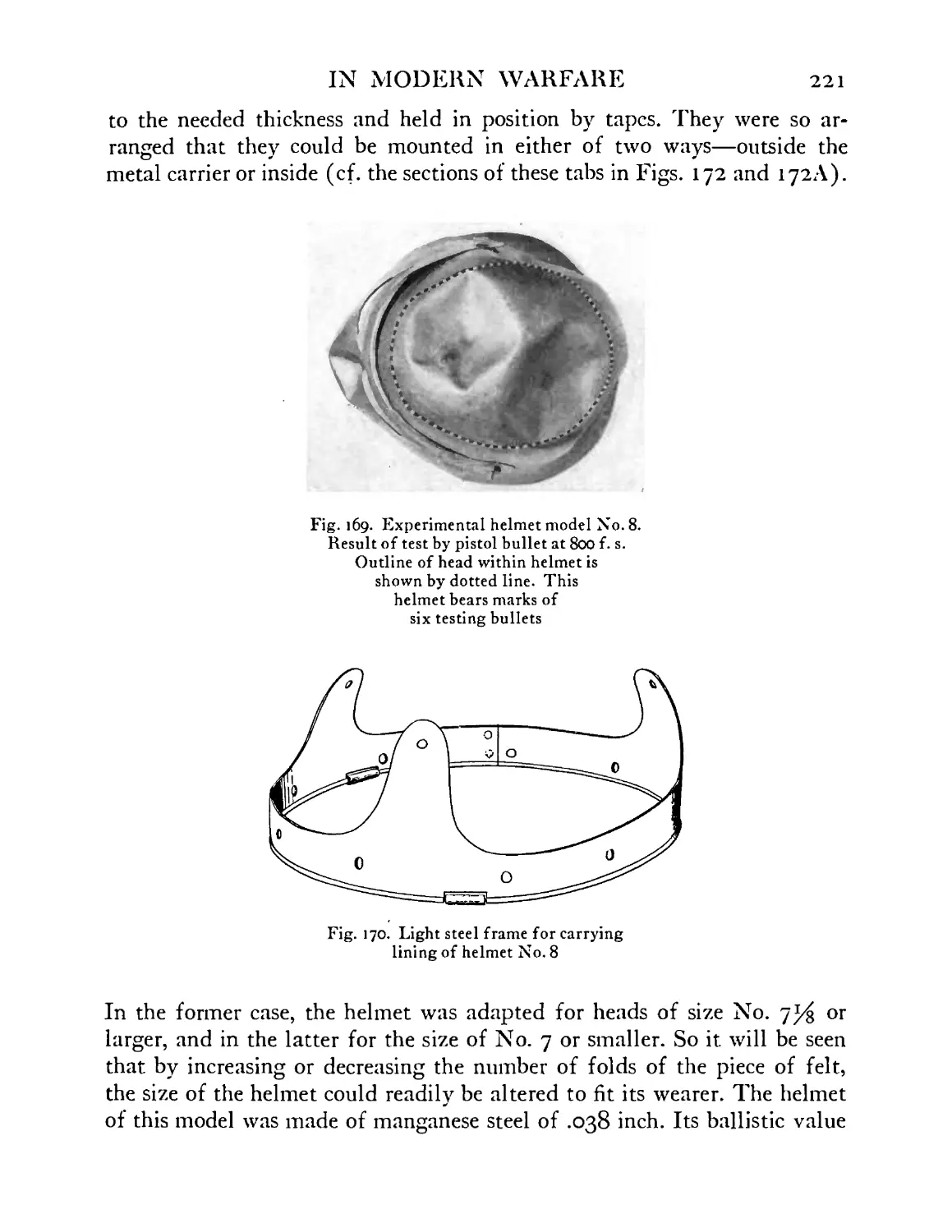
Light steel frame for carrying lining of helmet No. 8 221
20
FIGURE
>7>
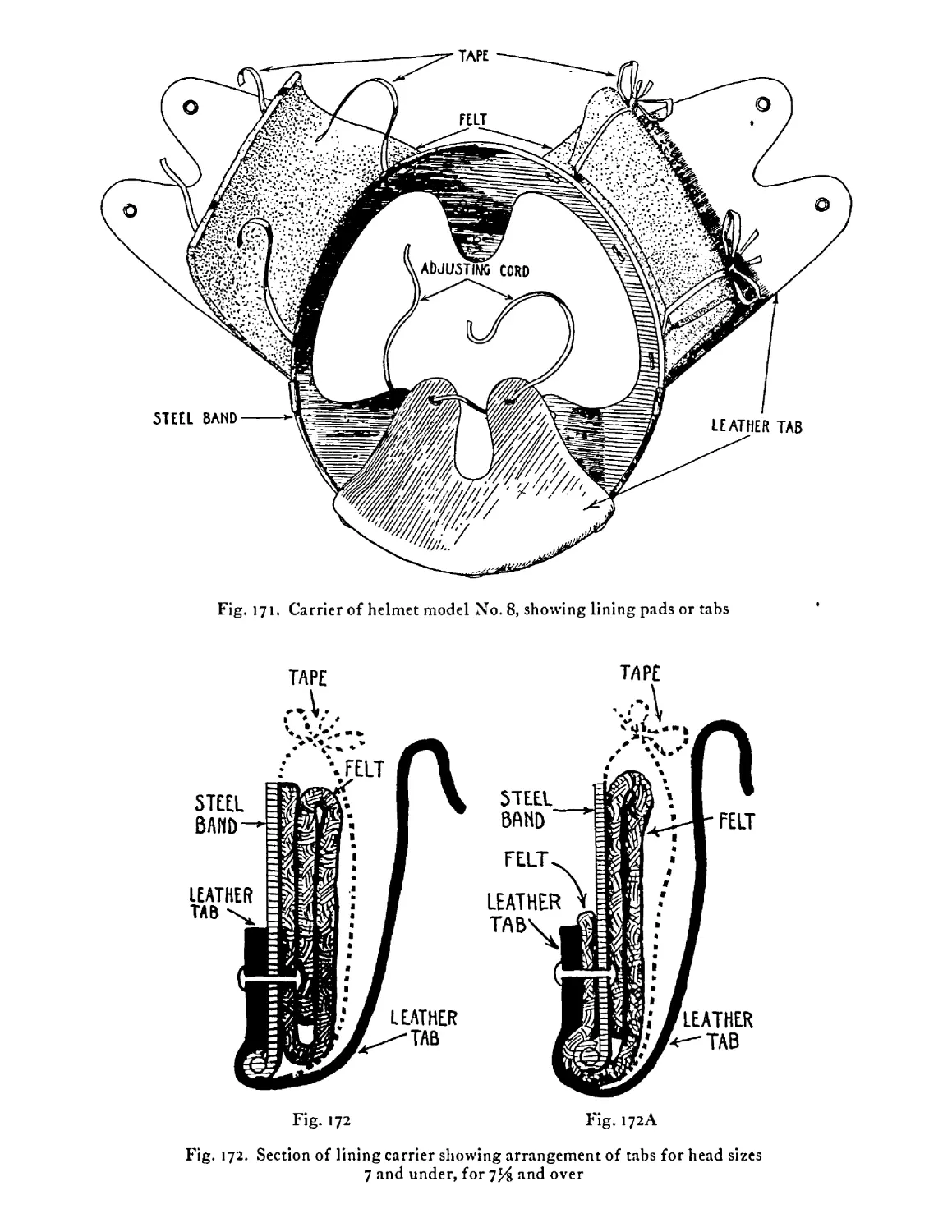
172
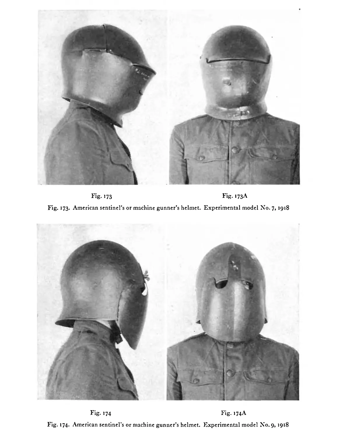
173
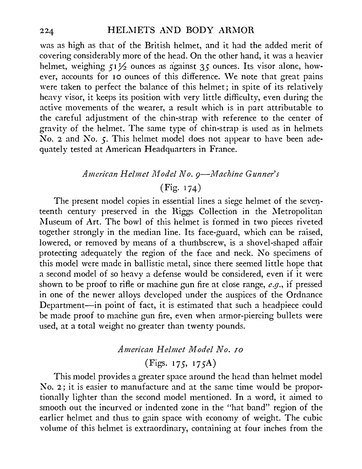
>74
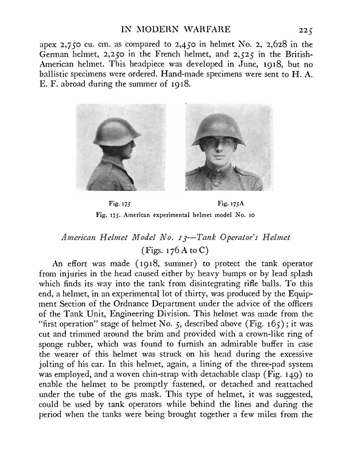
>75
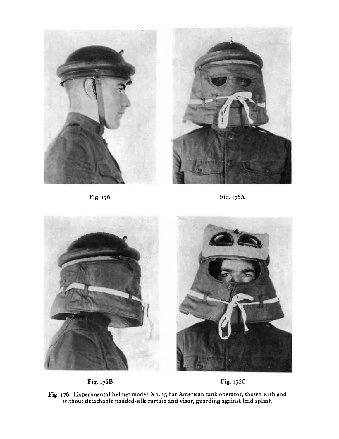
i76
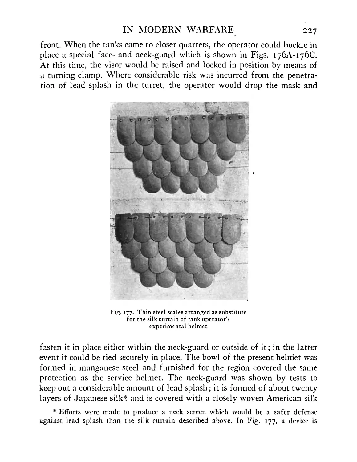
177
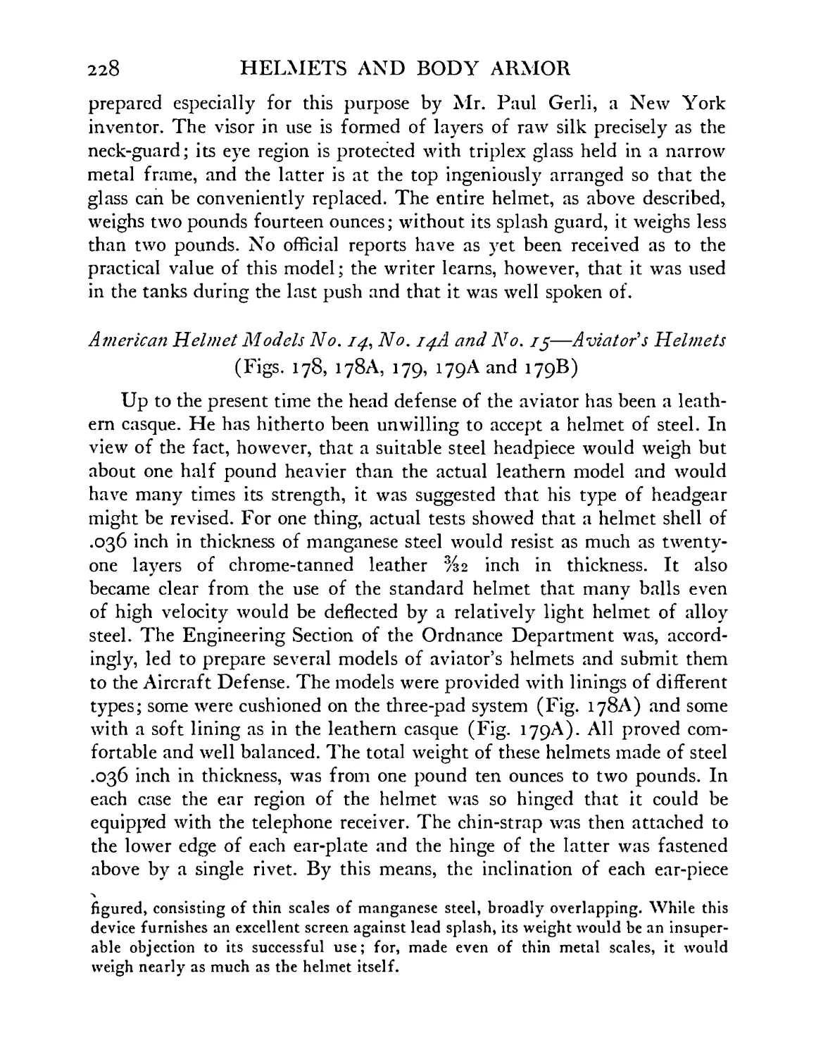
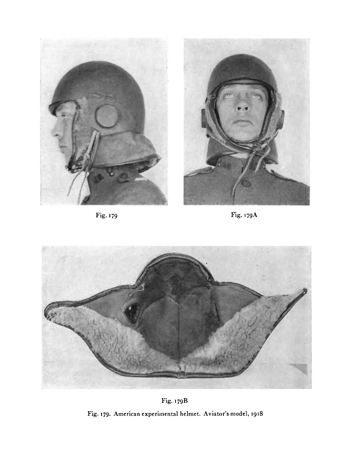
178
>79
180
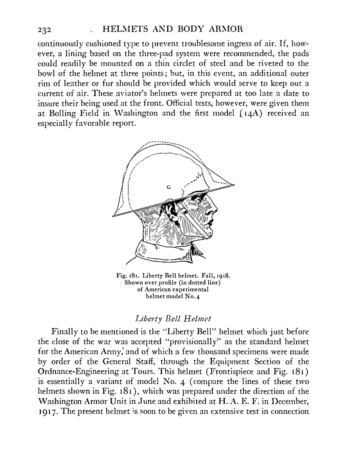
i8i
182
>83
184
>85
186
187
188
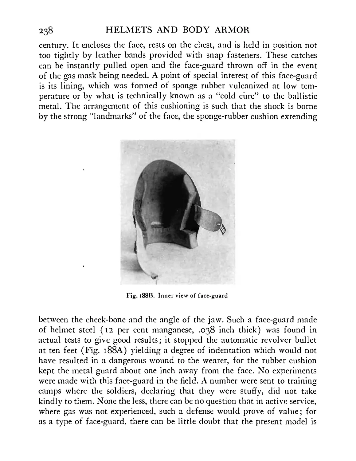
188 A
188B
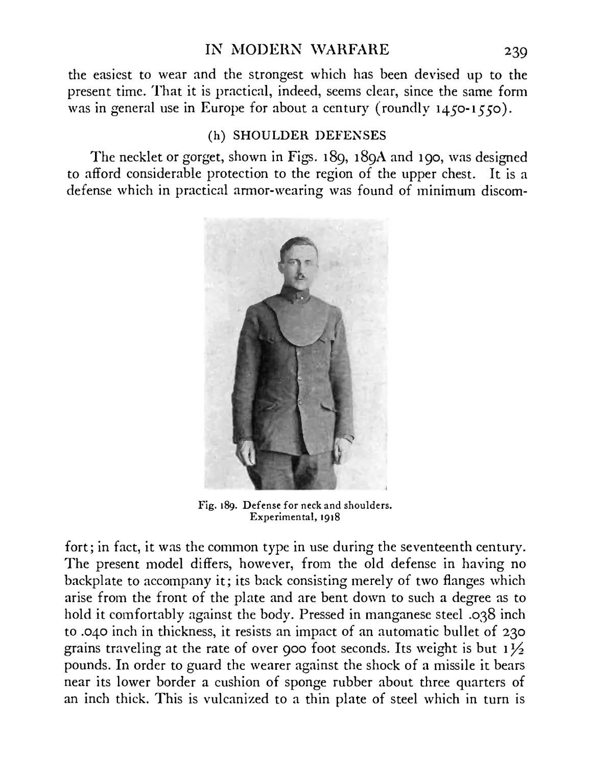
189
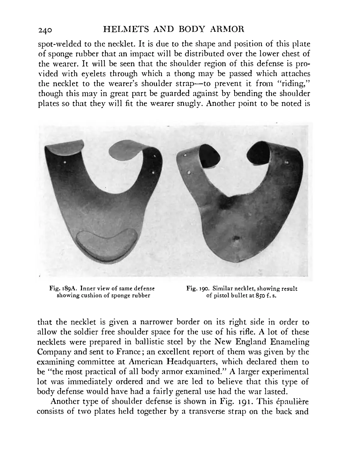
189 A
190
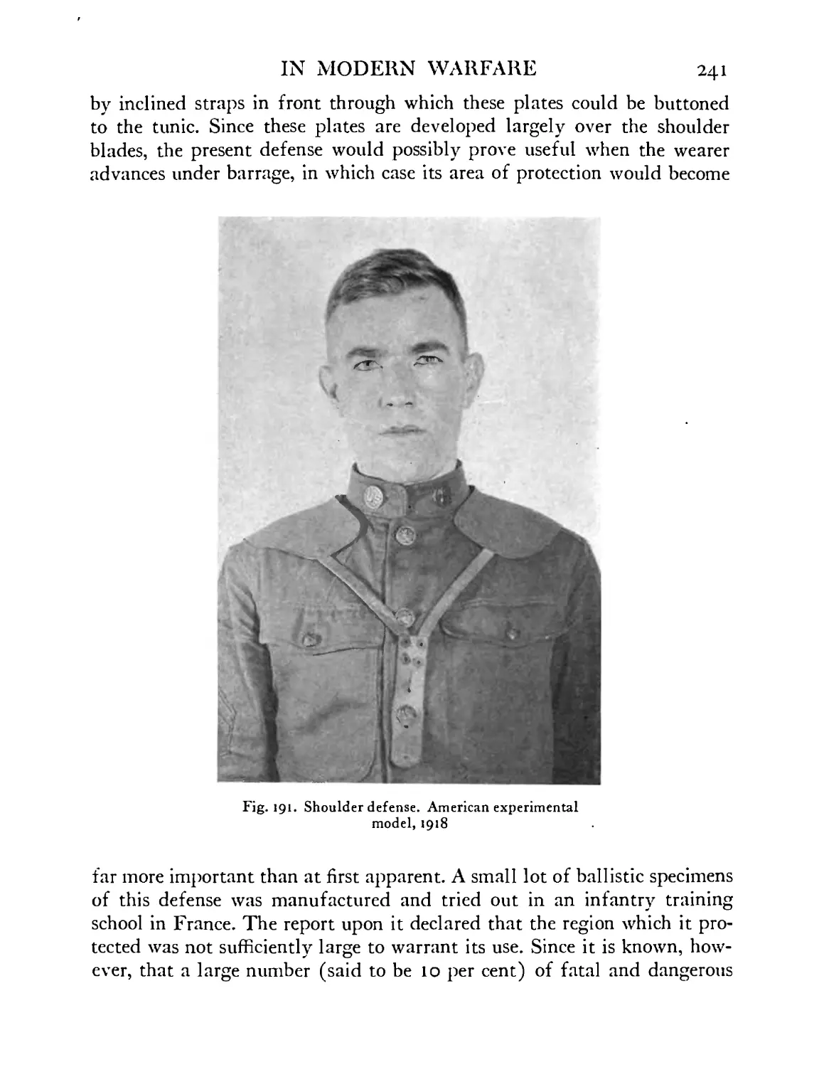
191
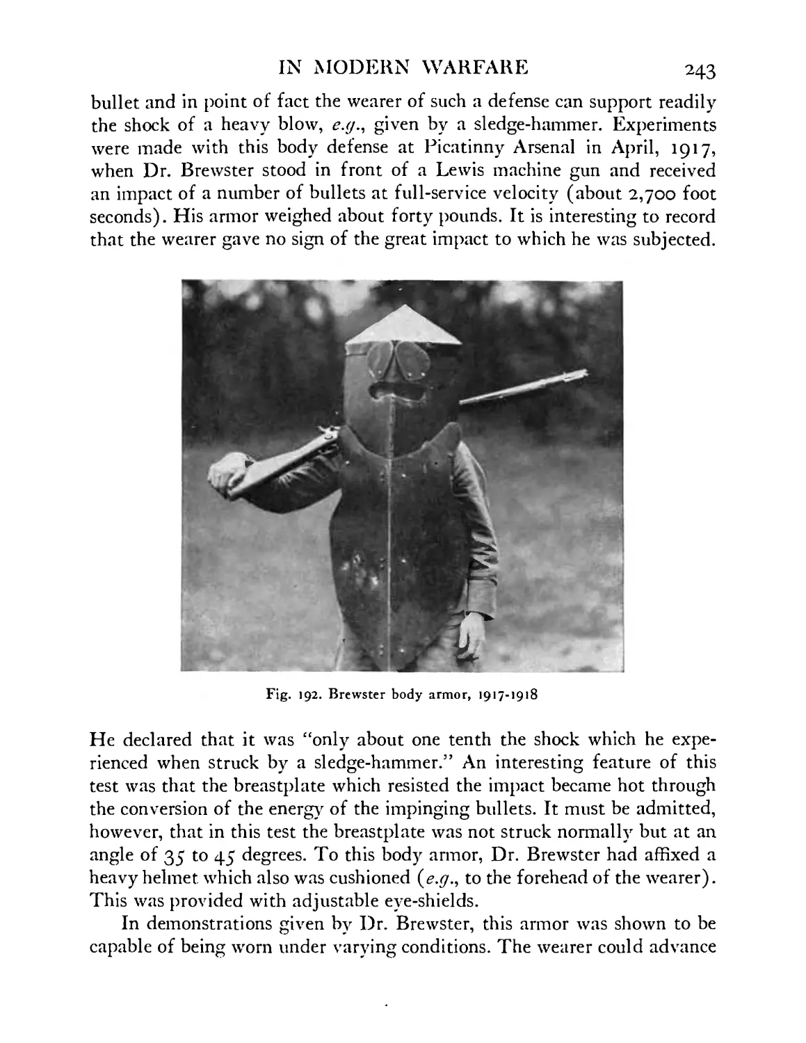
192
HELMETS AND BODY ARMOR
PAGE
Carrier of helmet model No. 8, showing lining pads
or tabs ........ 222
Section of lining-carrier showing arrangement of tabs
for head sizes 7 and under, or 7% and over . . 222
American sentinel’s or machine gunner’s helmet.
Experimental model No. 7, 1918 . . . . 223
American sentinel’s or machine gunner’s helmet.
Experimental model No. 9, 1918 . . . . 223
American experimental helmet model No. 10 . . 225
Experimental helmet model for American tank opera-
tor, shown with and without detachable padded-silk
curtain and visor, guarding against lead splash . 226
Thin steel scales arranged as substitute for the silk
curtain of tank operator’s experimental helmet . 227
American helmet. Aviator’s model, No. 14, 1918 . 229
American helmet. Aviator’s model, No. 14A, 1918 . 230
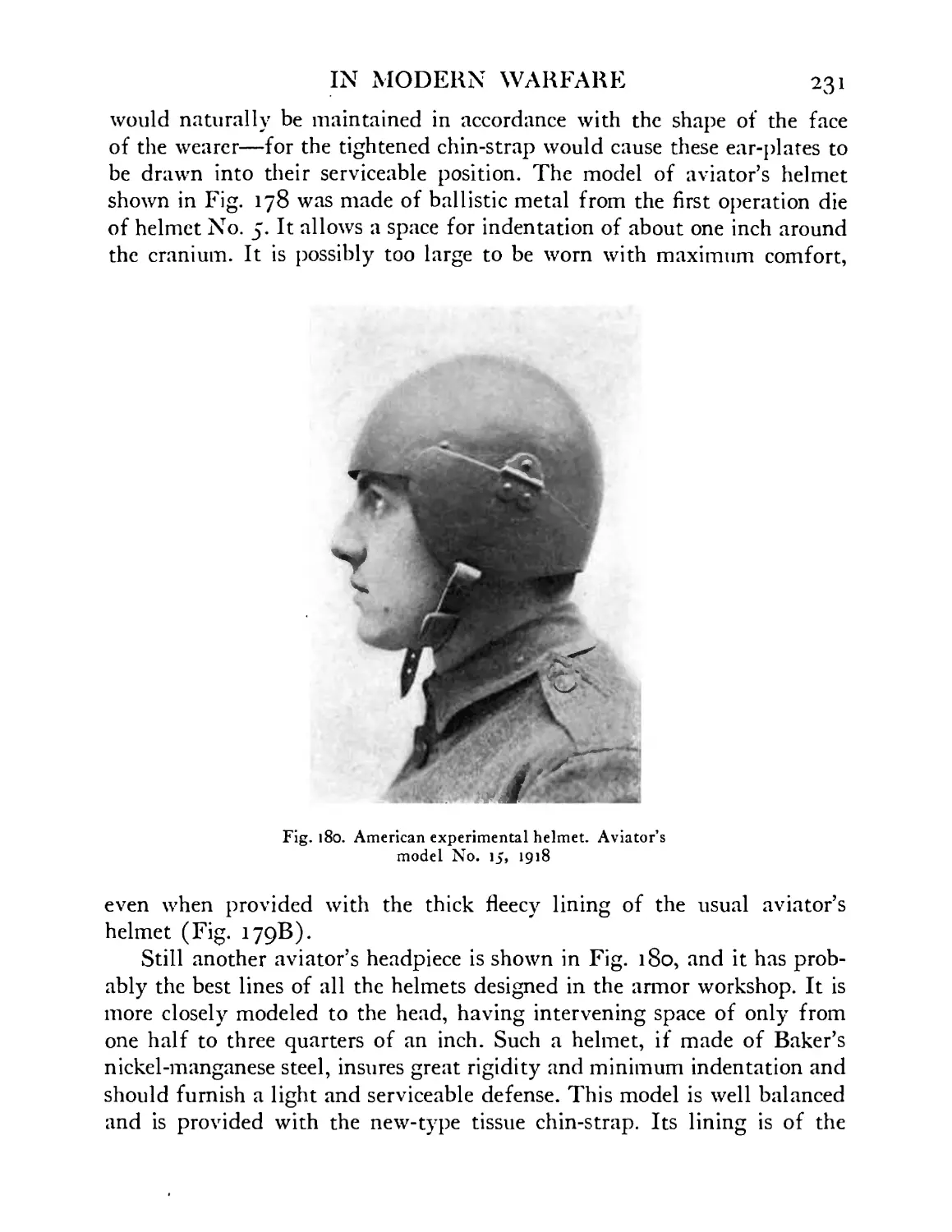
American helmet. Aviator’s model, No. 15, 1918 . 231
Liberty Bell helmet. Fall, 1918. Shown over profile
(in dotted line) of American experimental helmet
model No. 4 ...... . 232
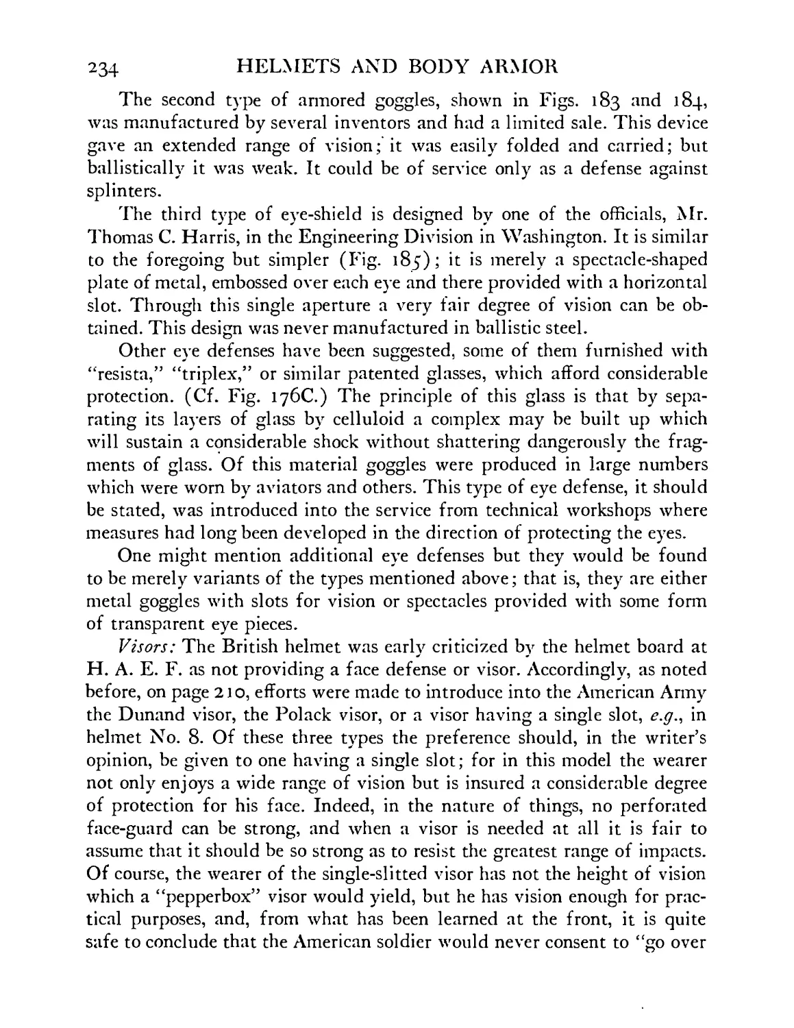
Splinter goggles and face defense. British, 1917 . 235
Splinter goggles, American. Reproduction of French
design, 1918 ....... 235
Splinter goggles. Variation of model shown in 183.
Manufactured through Arthur Dunn of Quincy, Ill. 235
Splinter goggles having single visual slit. Model by
Thomas C. Harris, Washington, D. C. . . . 235
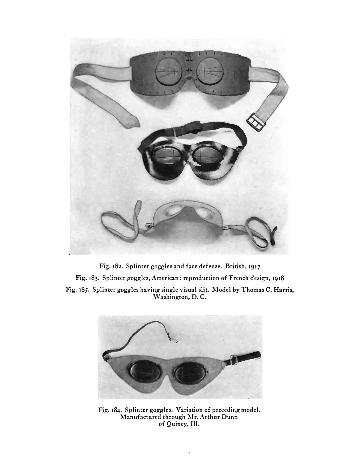
Eye-shield. Wilmer model, adaptable to British-
American helmet ...... 236
Wilmer model eye defense. The latter figure show-
ing a marginal supporting cushion of sponge rubber 236
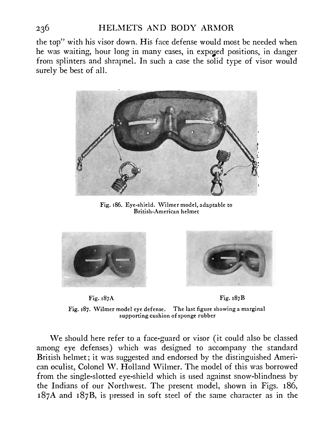
Face defense or baviere. American experimental
model, 1918 ....... 237
Result of test on foregoing face-guard, with pistol
bullet at 850 foot seconds ..... 237
Inner view of face-guard ..... 238
Defense for neck and shoulders. Experimental, 1918 239
Inner view of same defense showing cushion of
sponge rubber ....... 240
Similar necklet, showing result of pistol bullet at
850 foot seconds ...... 240
Shoulder defense, American experimental model,
1918................................................241
Brewster body armor, 191^1918 . . . . 243
IN MODERN WARFARE
21
FIGURE
193
194
195
196
197
198
199
200
201
202
203
204
20J
20б
207
208
PAGE
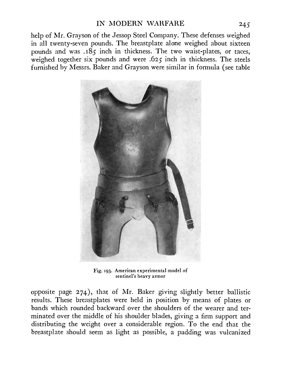
American experimental model of sentinel’s heavy
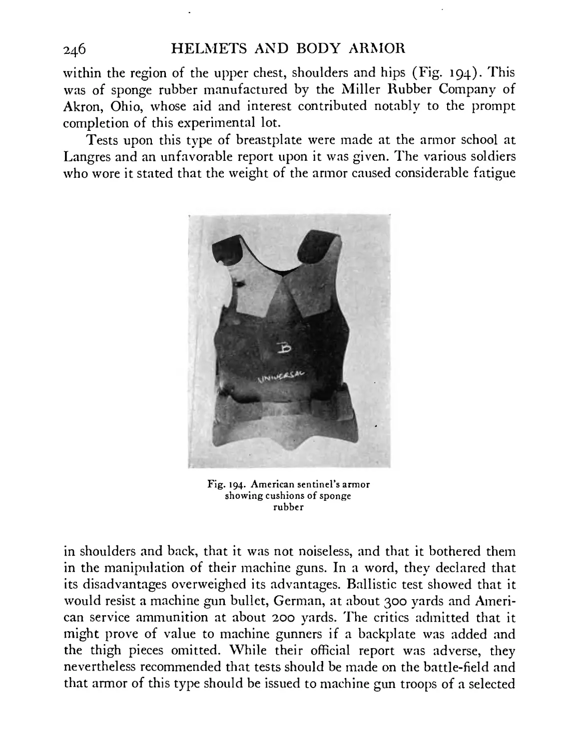
armor ........ 245
American sentinel’s armor showing cushions of
sponge rubber ....... 246
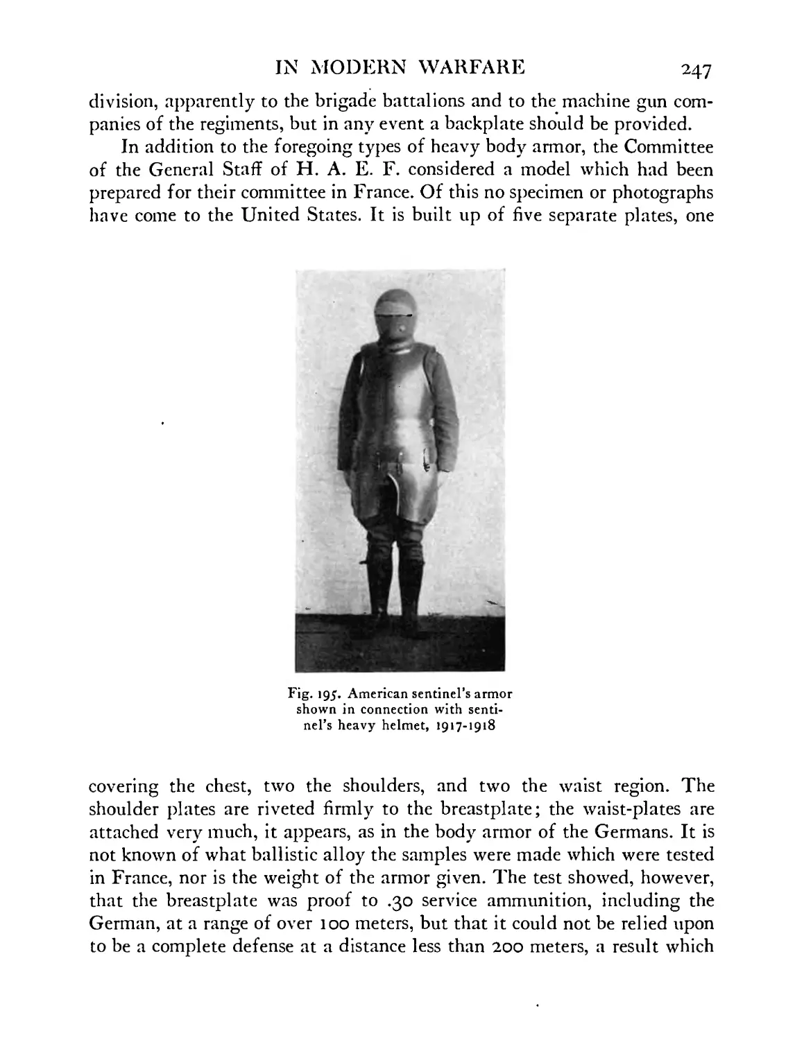
American sentinel’s armor shown with sentinel’s
heavy helmet, 1917-1918 ..... 247
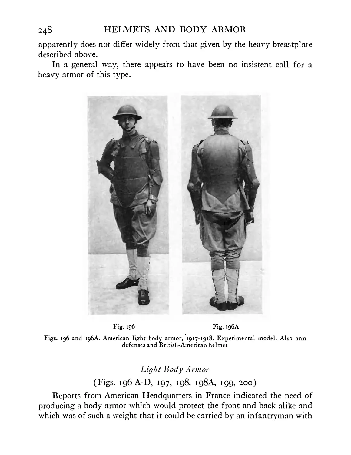
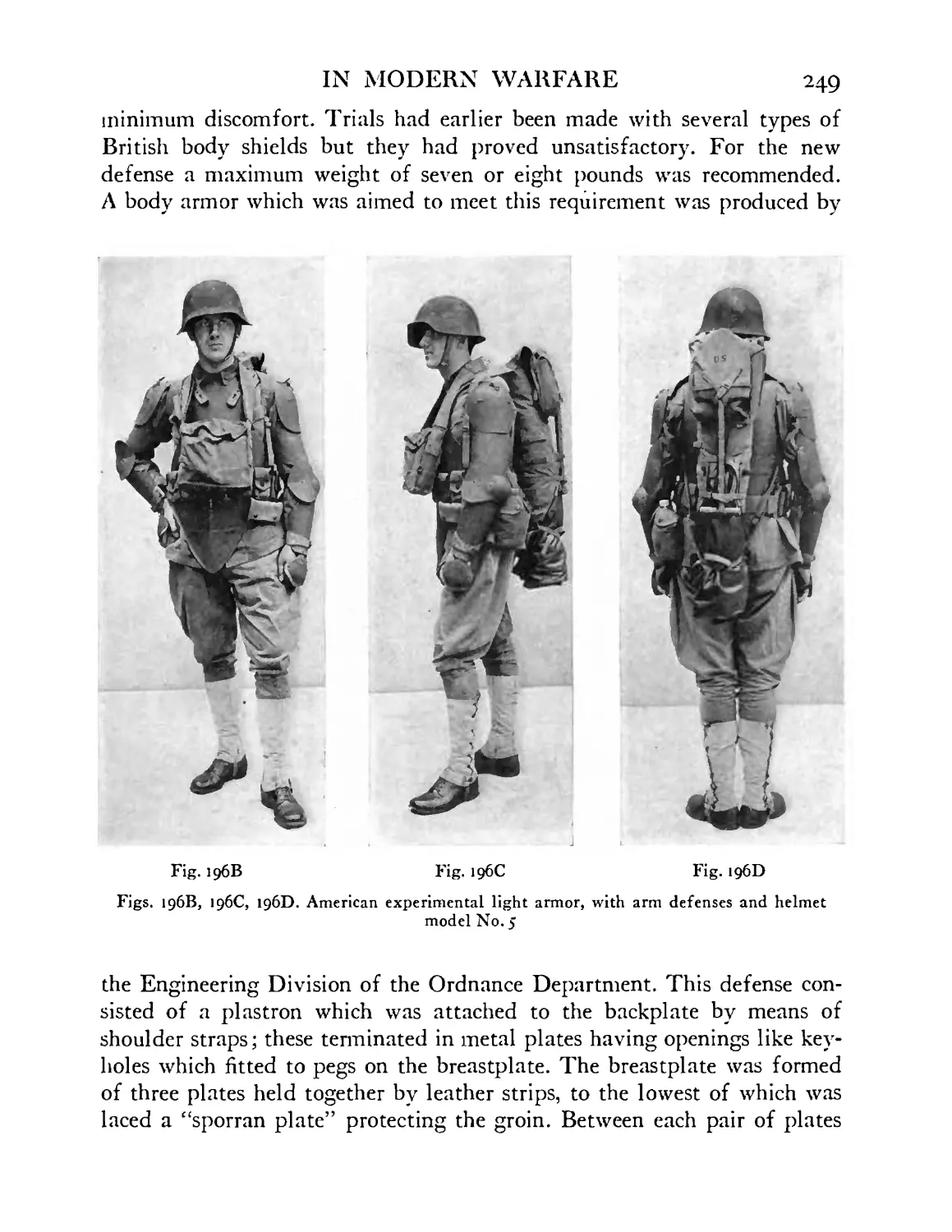
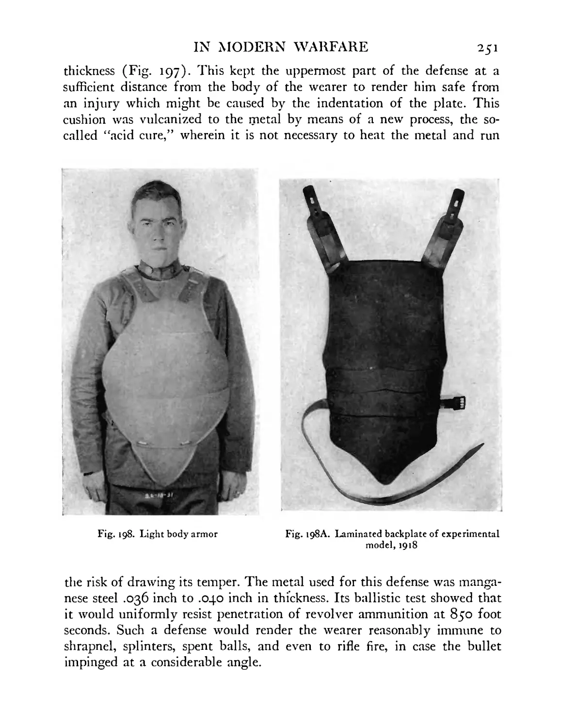
American light body armor, 1917-1918. Experimental
model. Also arm defenses and British-American
helmet or American helmet model No. 5 . 248, 249
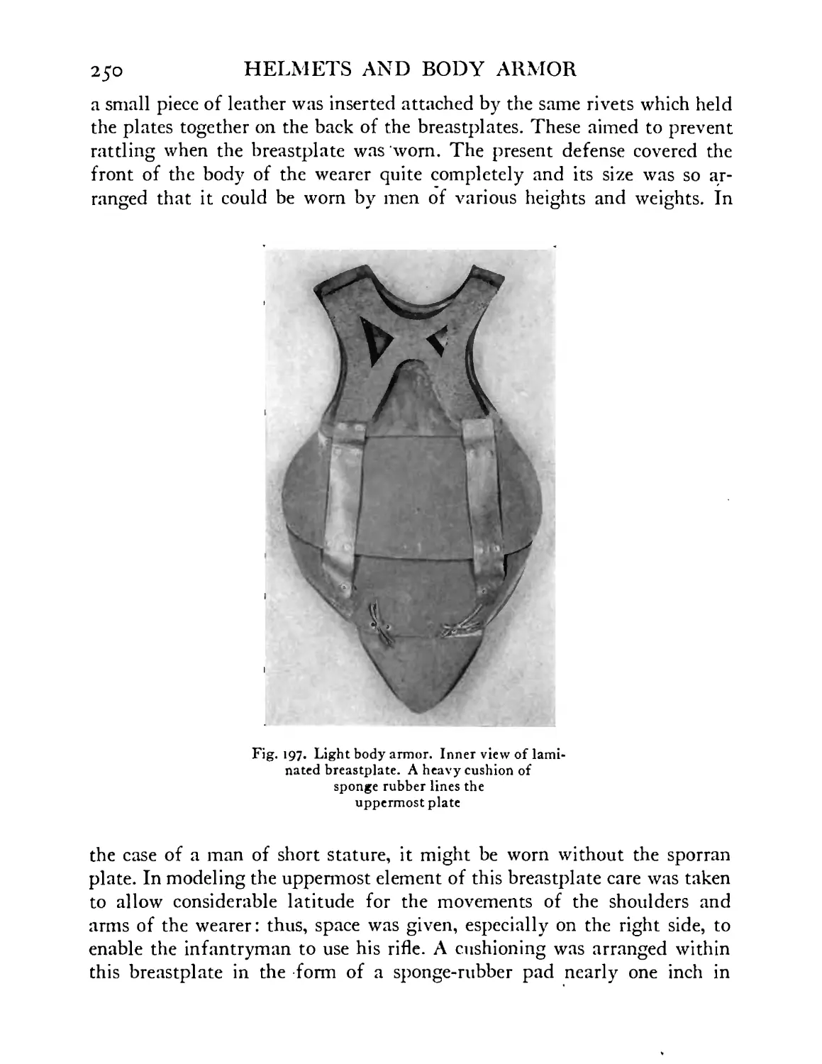
Light body armor. Inner view of laminated breast-
plate. A heavy cushion of sponge rubber lines the
uppermost plate ...... 250
Light body armor. Laminated backplate of experi-
mental model, 1918 ...... 251
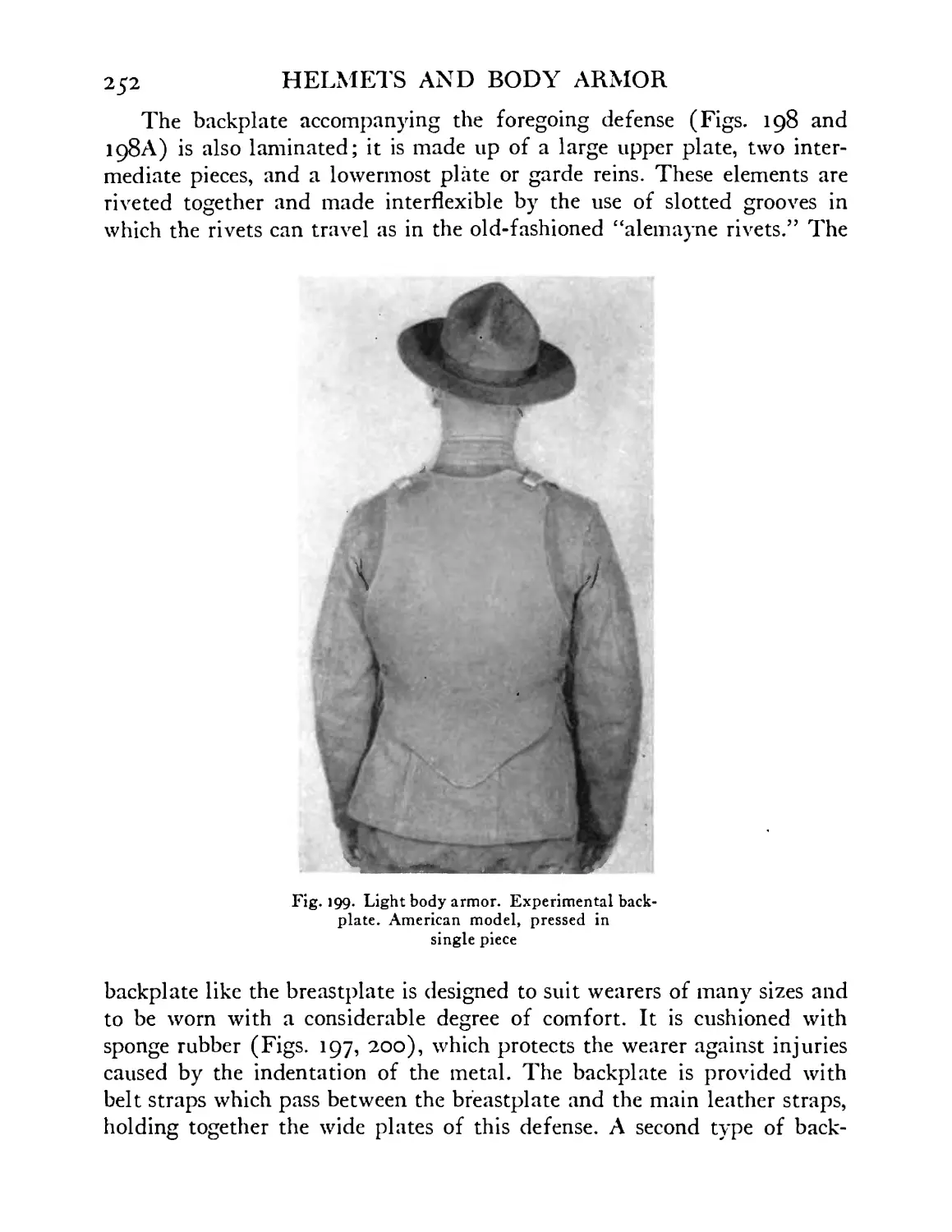
Light body armor. Experimental backplate. American
model, pressed in single piece .... 252
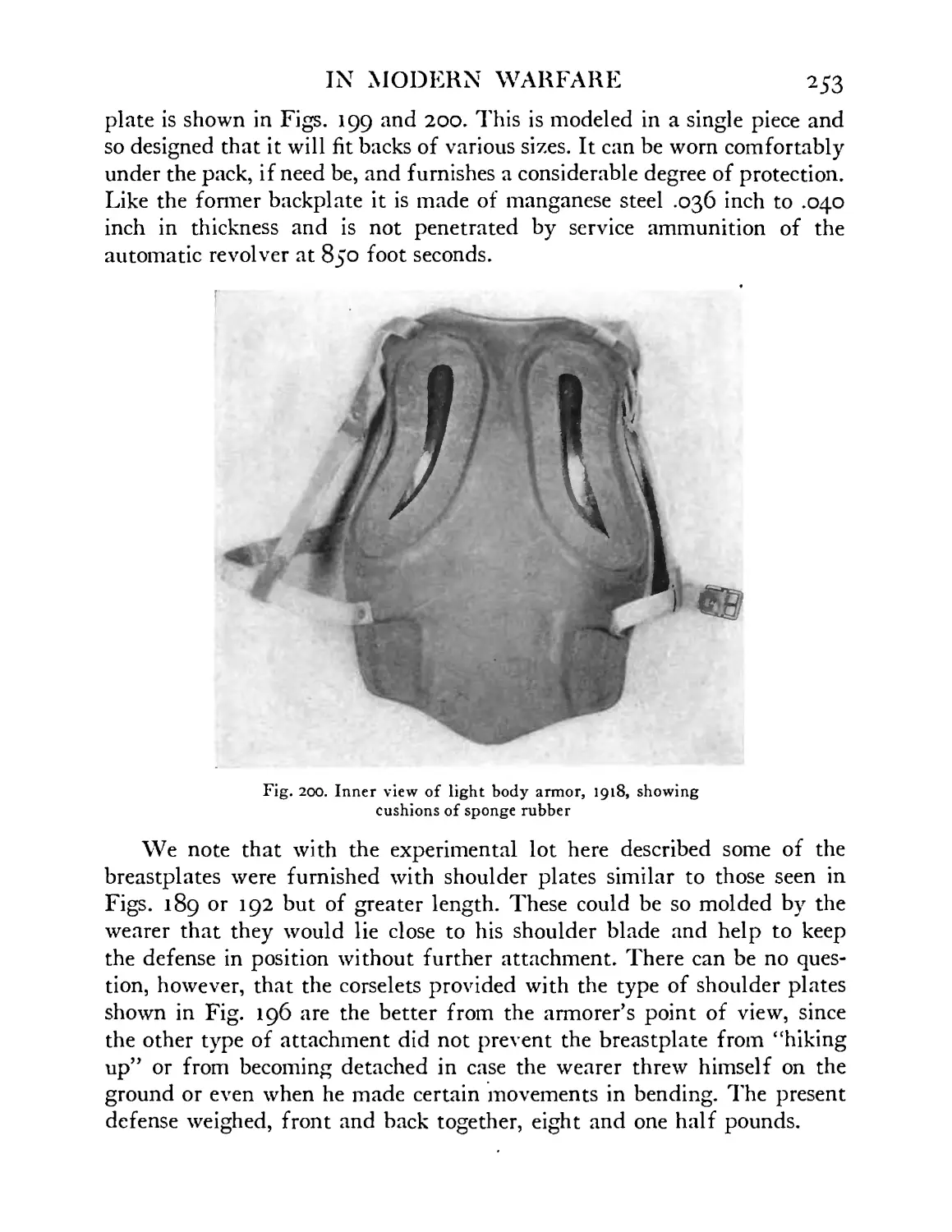
Inner view of light body armor, 1918, showing cush-
ions of sponge rubber ..... 253
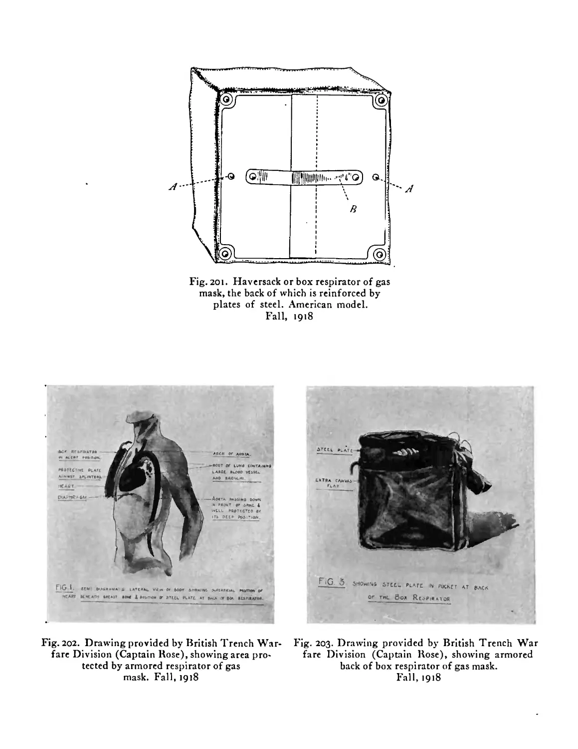
Haversack or box respirator of gas mask, the back of
which is reinforced by plates of steel. American
model. Fall, 1918 ...... 254
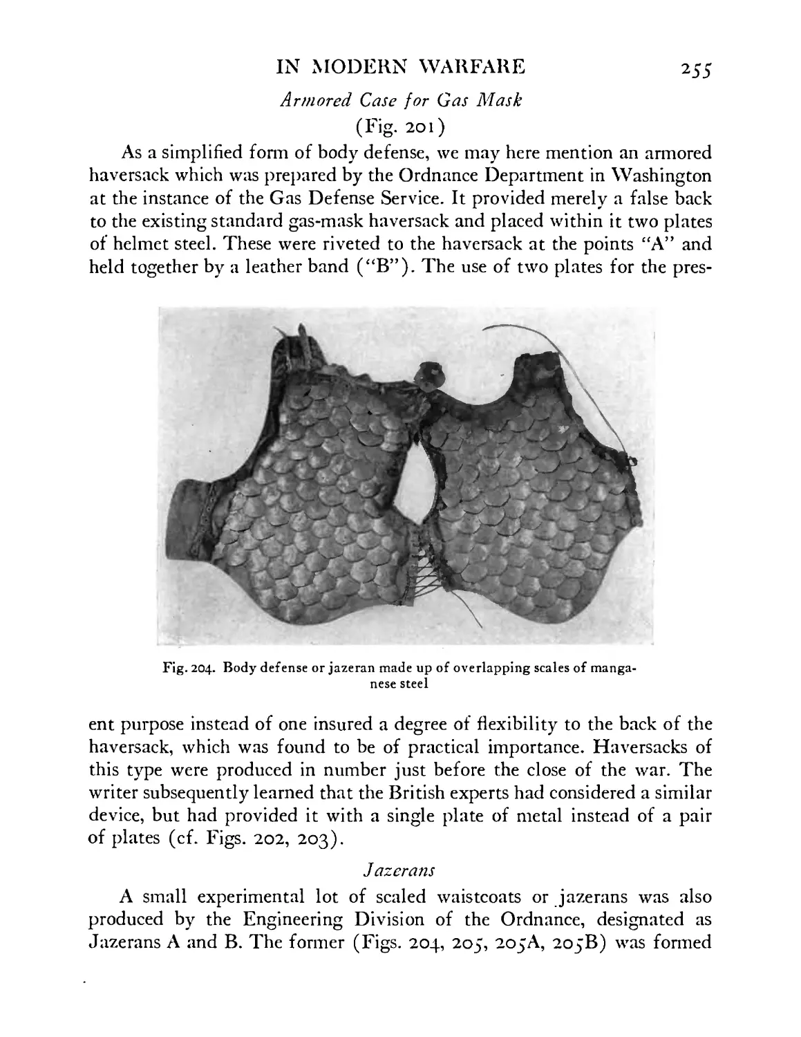
Drawing provided by British Trench Warfare Divi-
sion (Captain Rose), showing area protected by ar-
mored respirator of gas mask. Fall, 1918 . . 254
Drawing provided by British Trench Warfare Divi-
sion (Captain Rose), showing armored back of box
respirator of gas mask. Fall, 1918 . . . 254
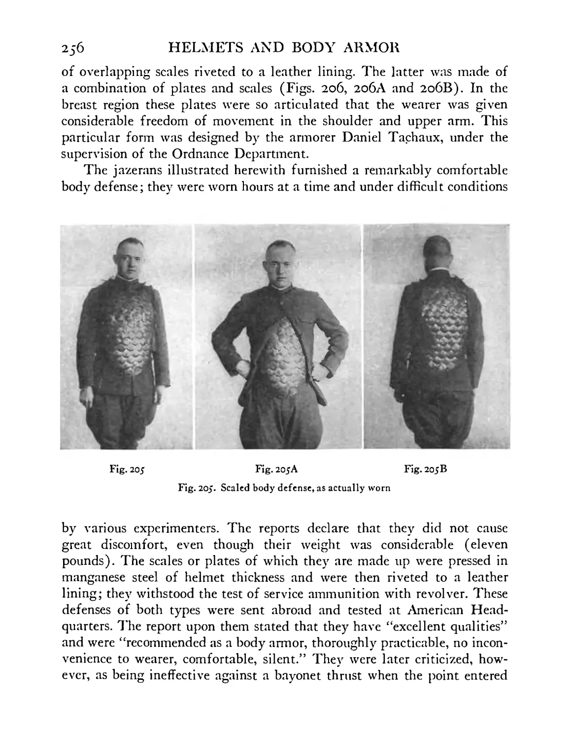
Body defense or jazeran made up of overlapping
scales of manganese steel. Above in middle of picture
a separate scale is shown which has resisted the im-
pact of automatic bullet at 850 foot seconds . . 255
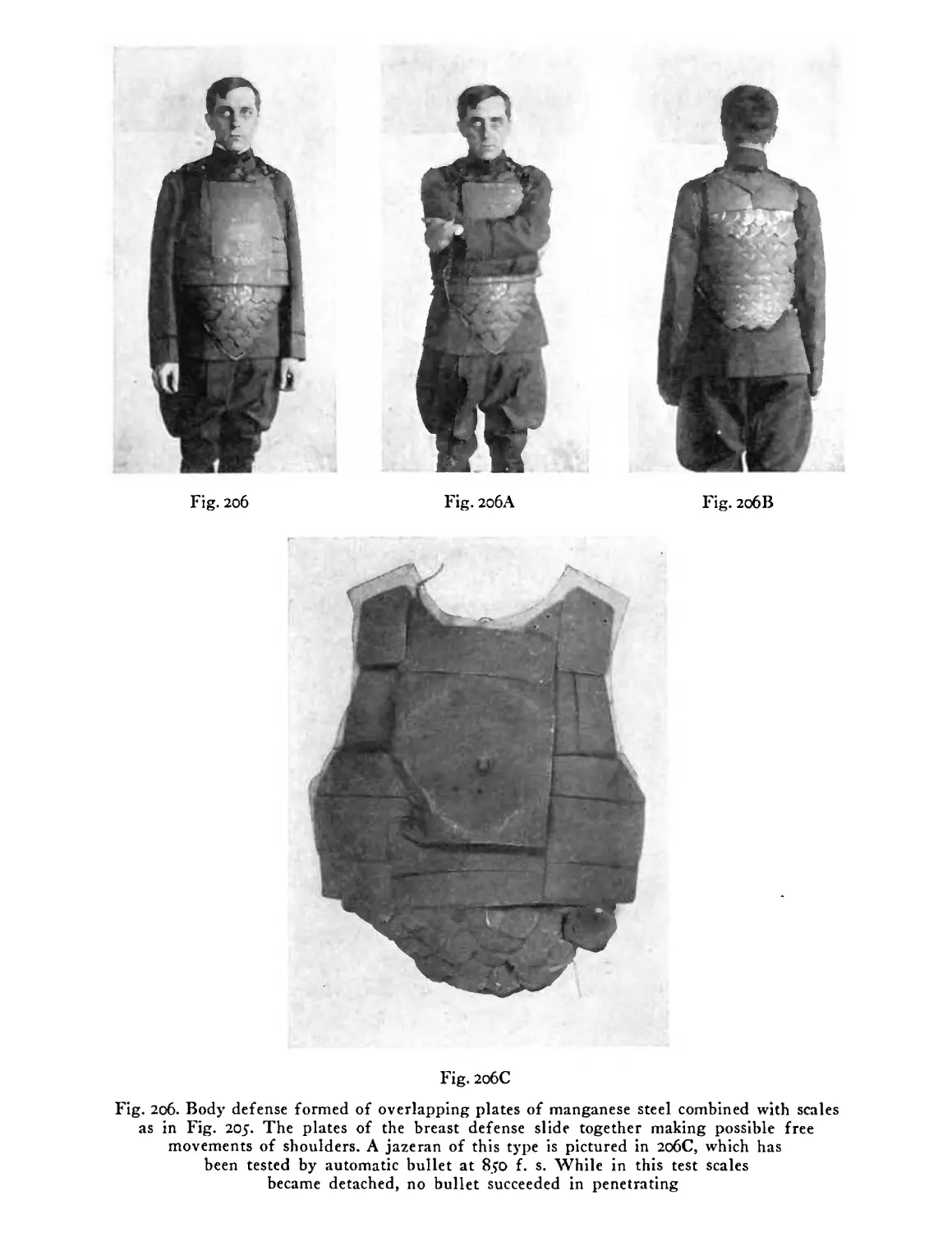
Scaled body defense. As actually worn . . . 256
Body defense formed of overlapping plates of man-
ganese steel combined with scales as in Fig. 205. The
plates of the breast defense slide together, making
possible free movements of shoulders. A jazeran of
this type is pictured in 206C, which has been tested
by automatic bullet at 850 foot seconds. While in this
test scales became detached, no bullet succeeded in
penetrating ....... 257
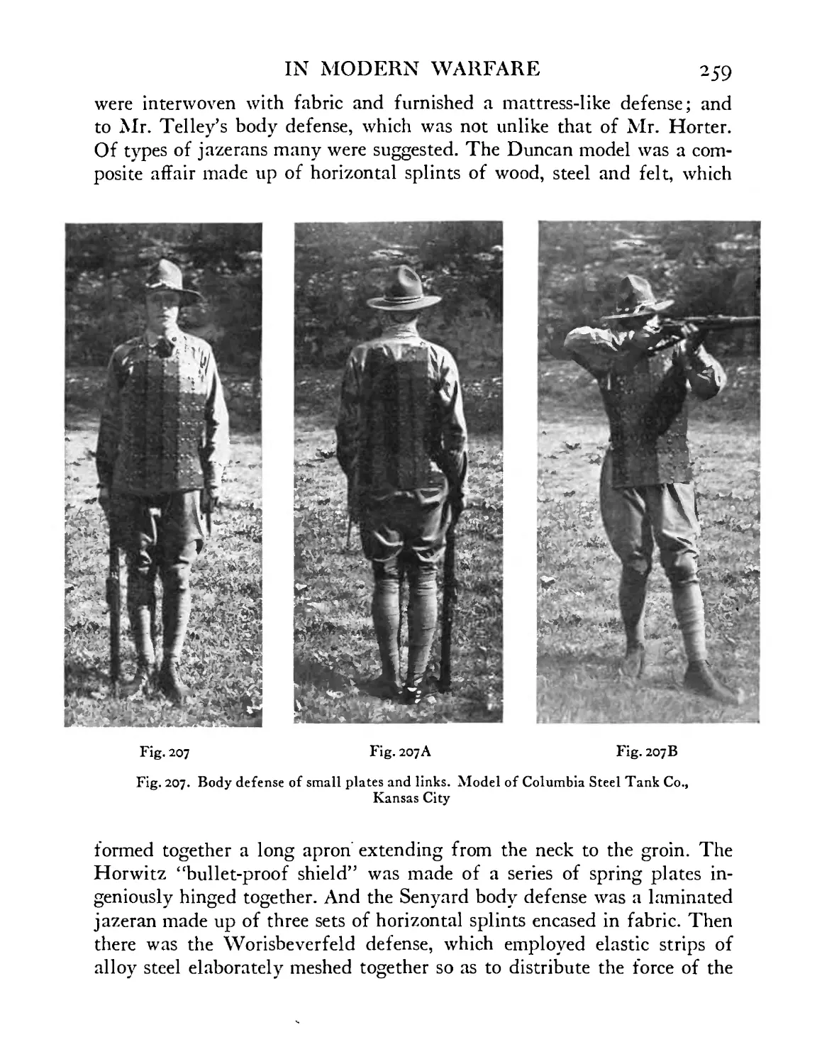
Body defense of small plates and links. Model of
Columbia Steel Tank Co., Kansas City . . . 259
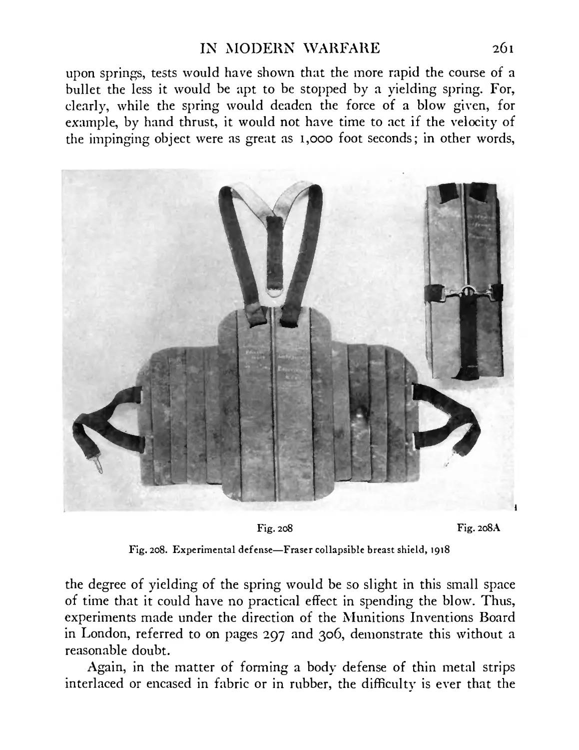
Experimental defense—Fraser collapsible breast
shield, 1918 ....... 261
22
HELMETS AND BODY ARMOR
FIGURE PAGE
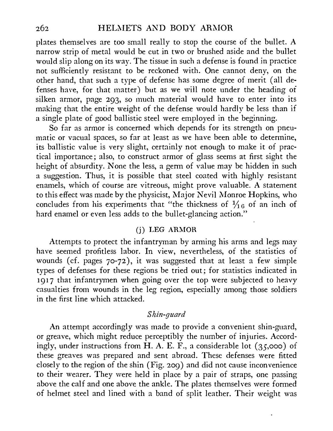
209 Shin-guards. American experimental model, 1917 263
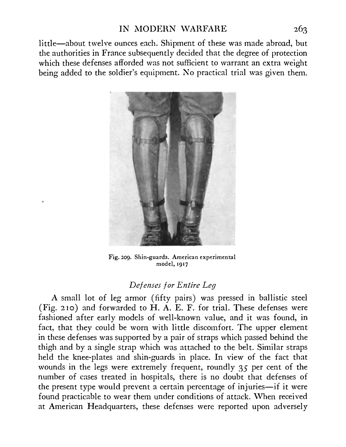
210 Complete leg defenses—American experimental model, 1917 ....... 264
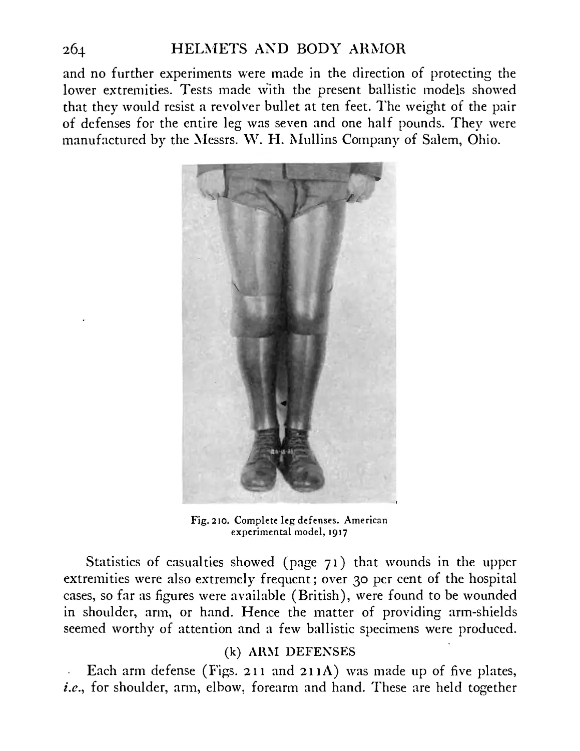
211 Arm defenses, American experimental model, 1918 . 265
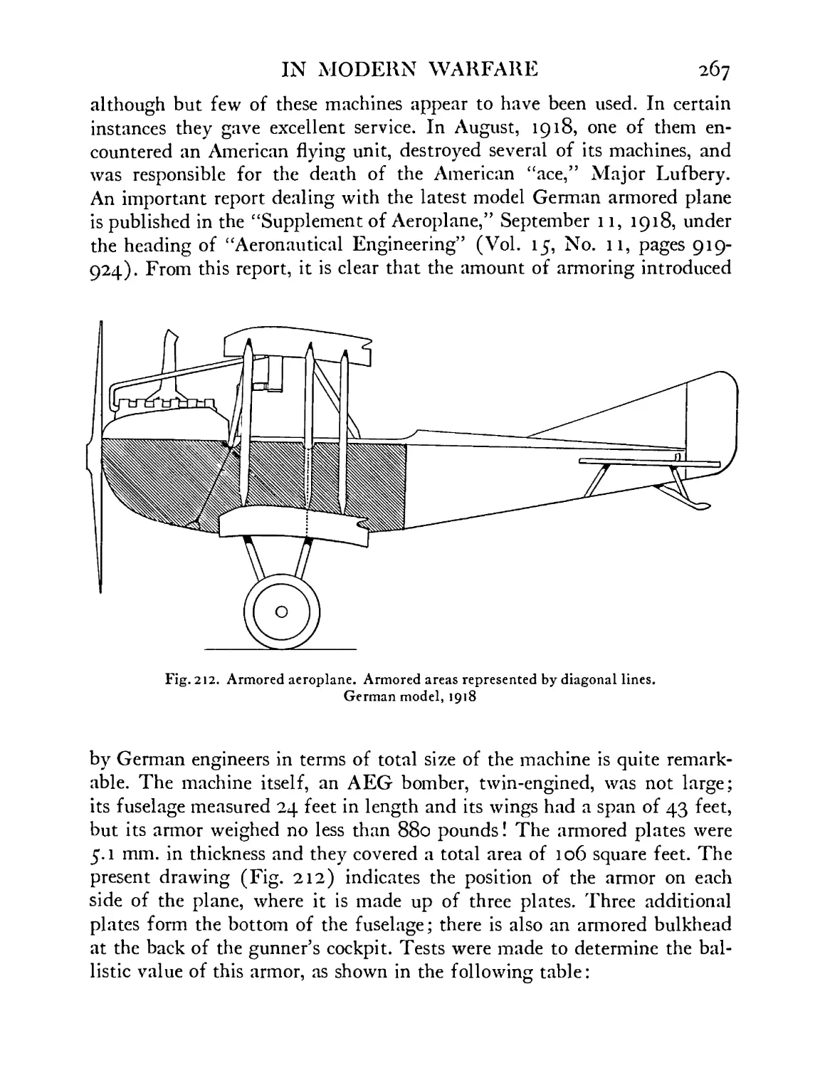
212 Armored aeroplane. Armored areas represented by diagonal dotted lines. German model, 1918 . 267
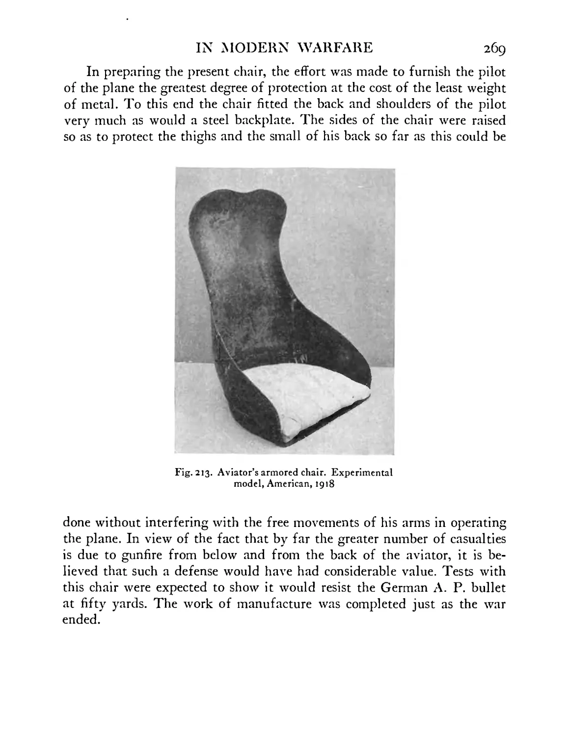
213 Aviator’s armored chair. Experimental model, Ameri- can, 1918 ....... 269
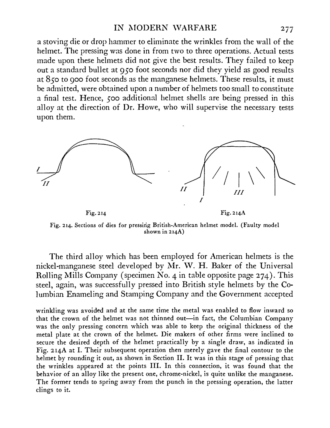
214 Sections of dies for pressing British-American helmet model. Faulty model shown in 214A 277
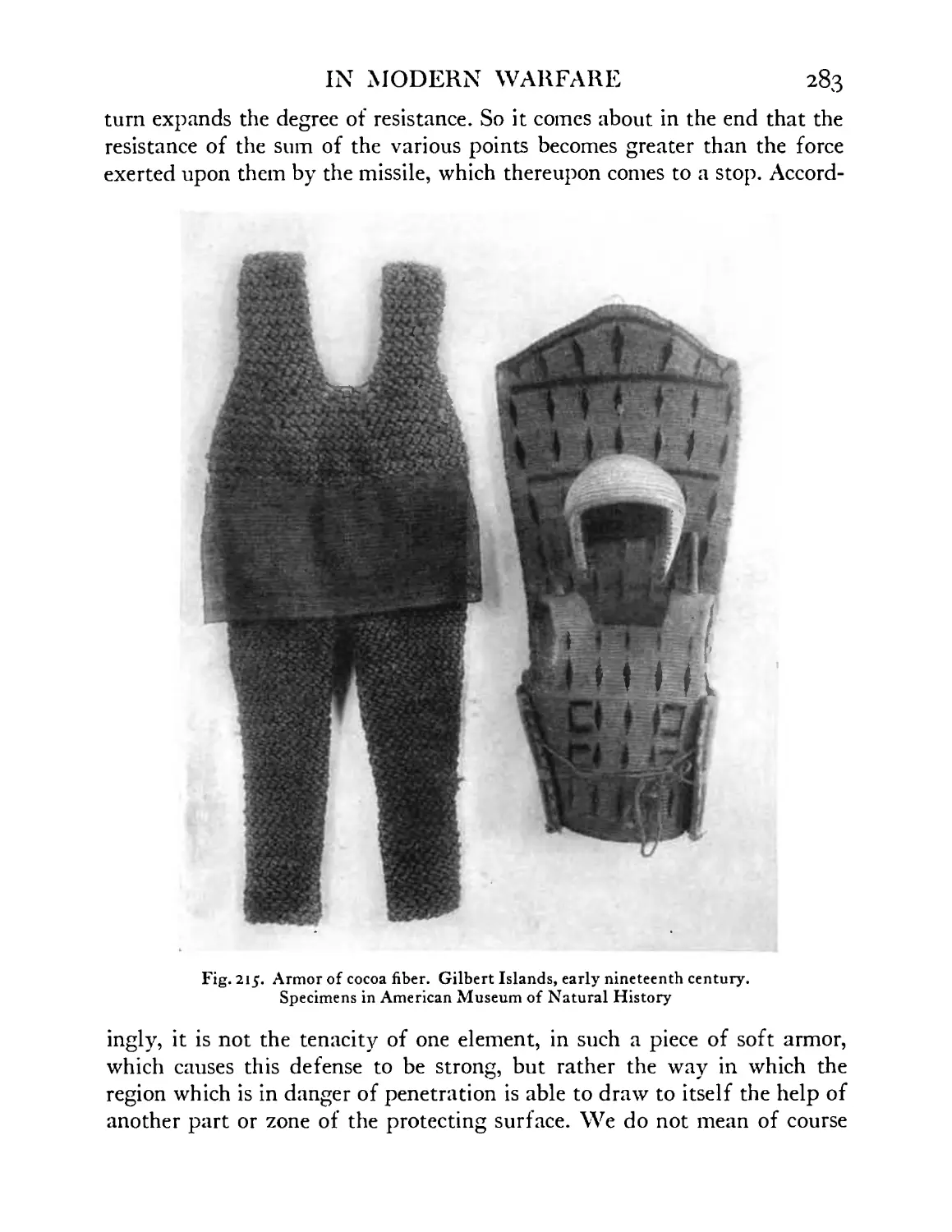
215 Armor of cocoa fiber. Gilbert Islands. Early nine- teenth century. American Museum of Natural His-
tory ........ 283
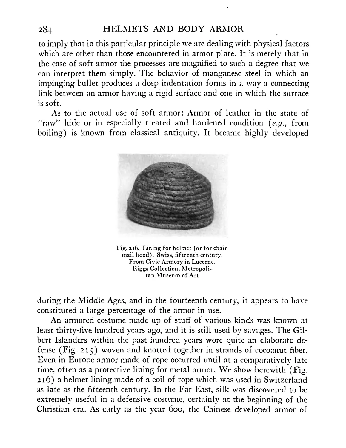
216 217-219 Lining for helmet (or for chain mail hood). Swiss, fifteenth century. From Civic Armory in Lucerne. Riggs Collection, Metropolitan Museum of Art Arm defenses, woven and tufted, sixteenth century. 284
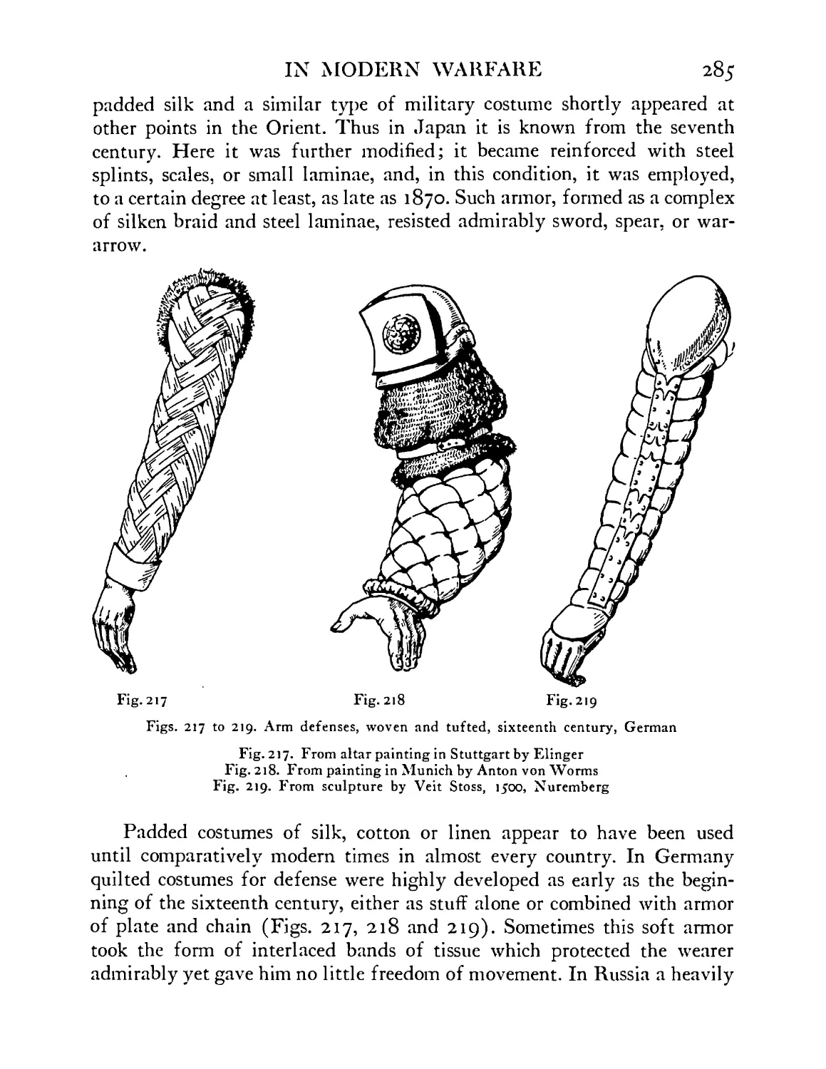
German ........ 285
217 from altar painting in Stuttgart by Elinger 218 from painting in Munich by Anton von Worms 219 from sculpture by Veit Stoss, 1J00, Nuremberg
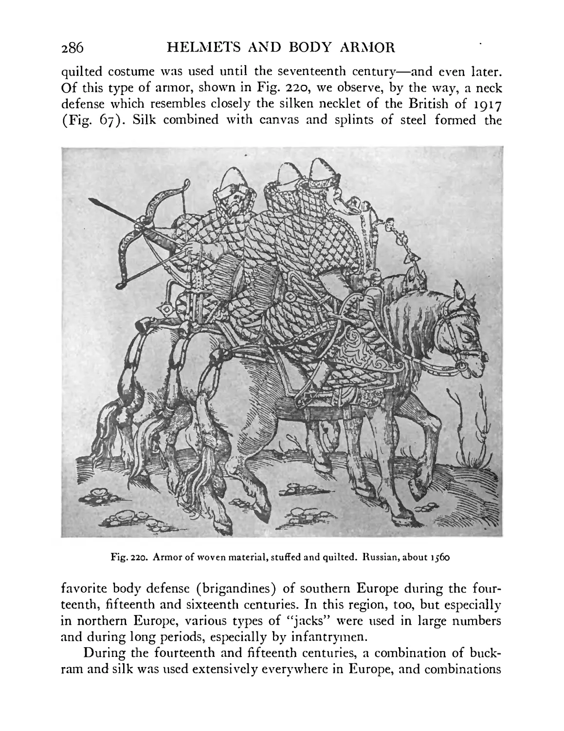
220 Armor of woven material, stuffed and quilted. Rus- sian. About 1560 ...... 286
221-222 Detail of armor (“buttonhole” jacks) of woven ma- terial, sixteenth century ..... 287
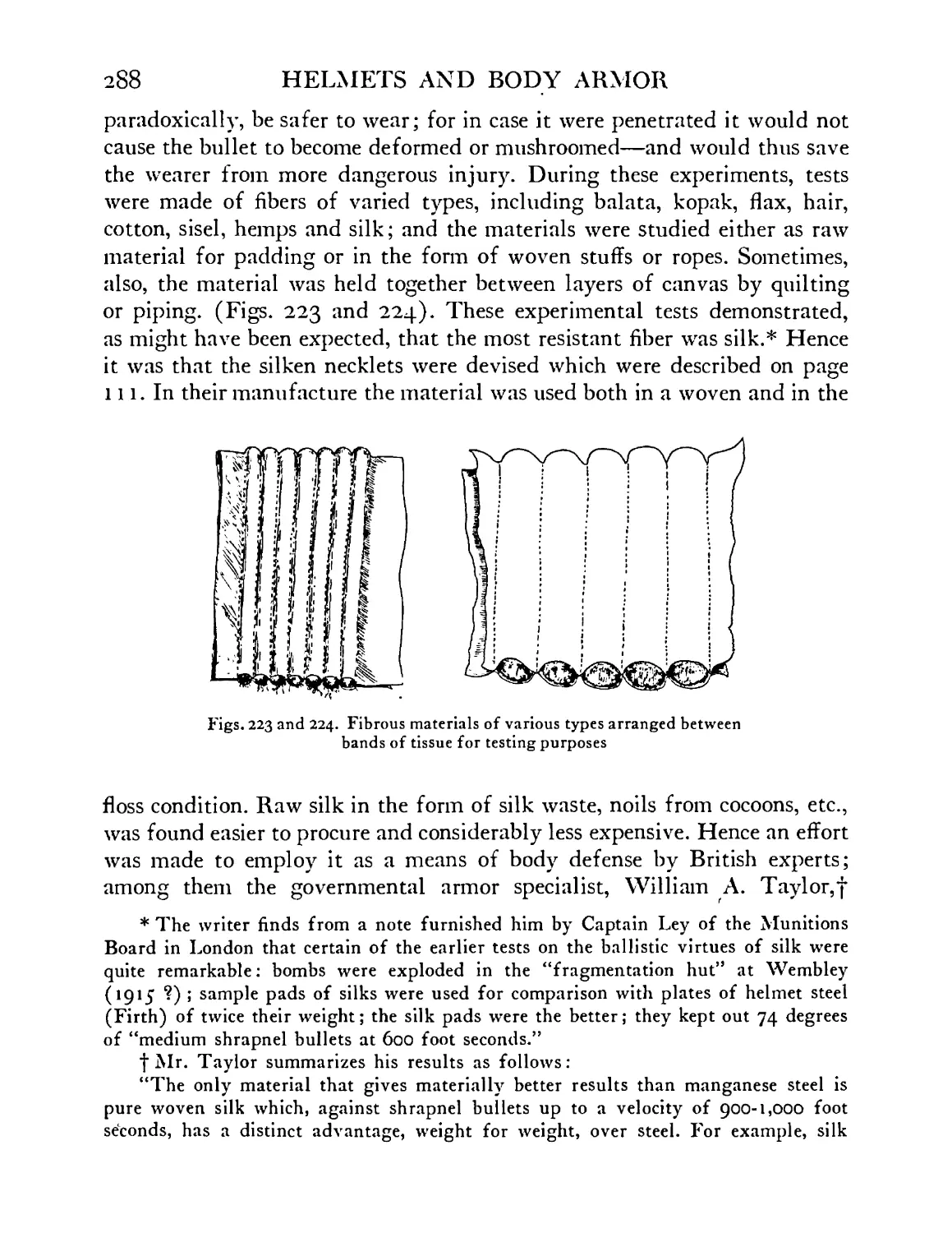
223-224 Fibrous materials of various types arranged between bands of tissue for testing purposes 288
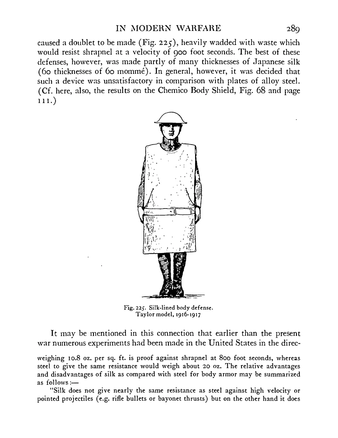
225 Silk-lined body defense. Taylor model, 1916-1917 . 289
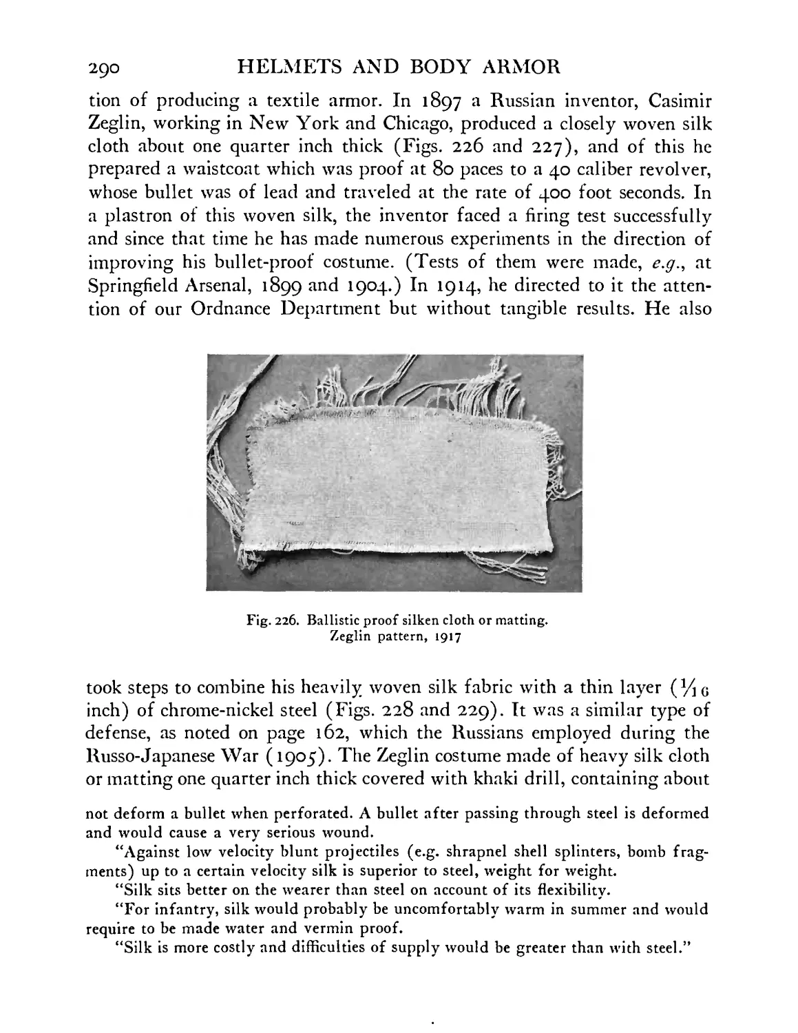
226 Ballistic proof silken cloth or matting, Zeglin pattern, 1917 • • 290
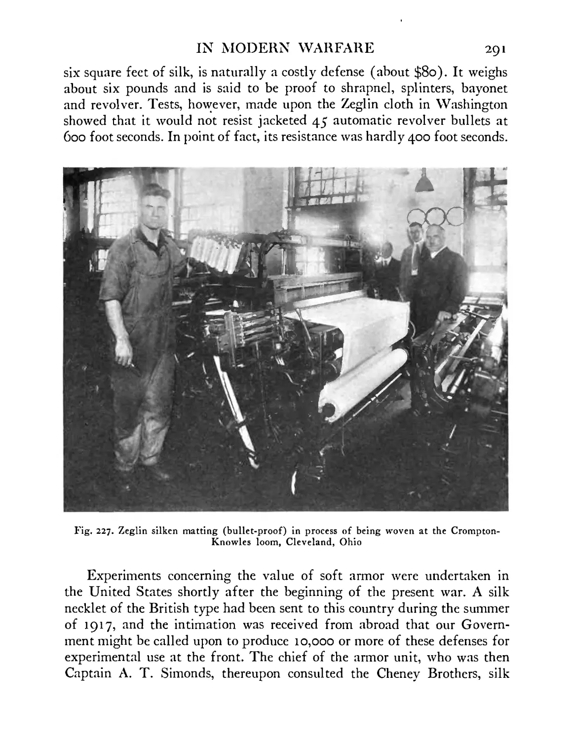
227 Zeglin silken matting (bullet proof) in process of being woven at the Crompton-Knowles loom, Cleve- land, Ohio ....... 291
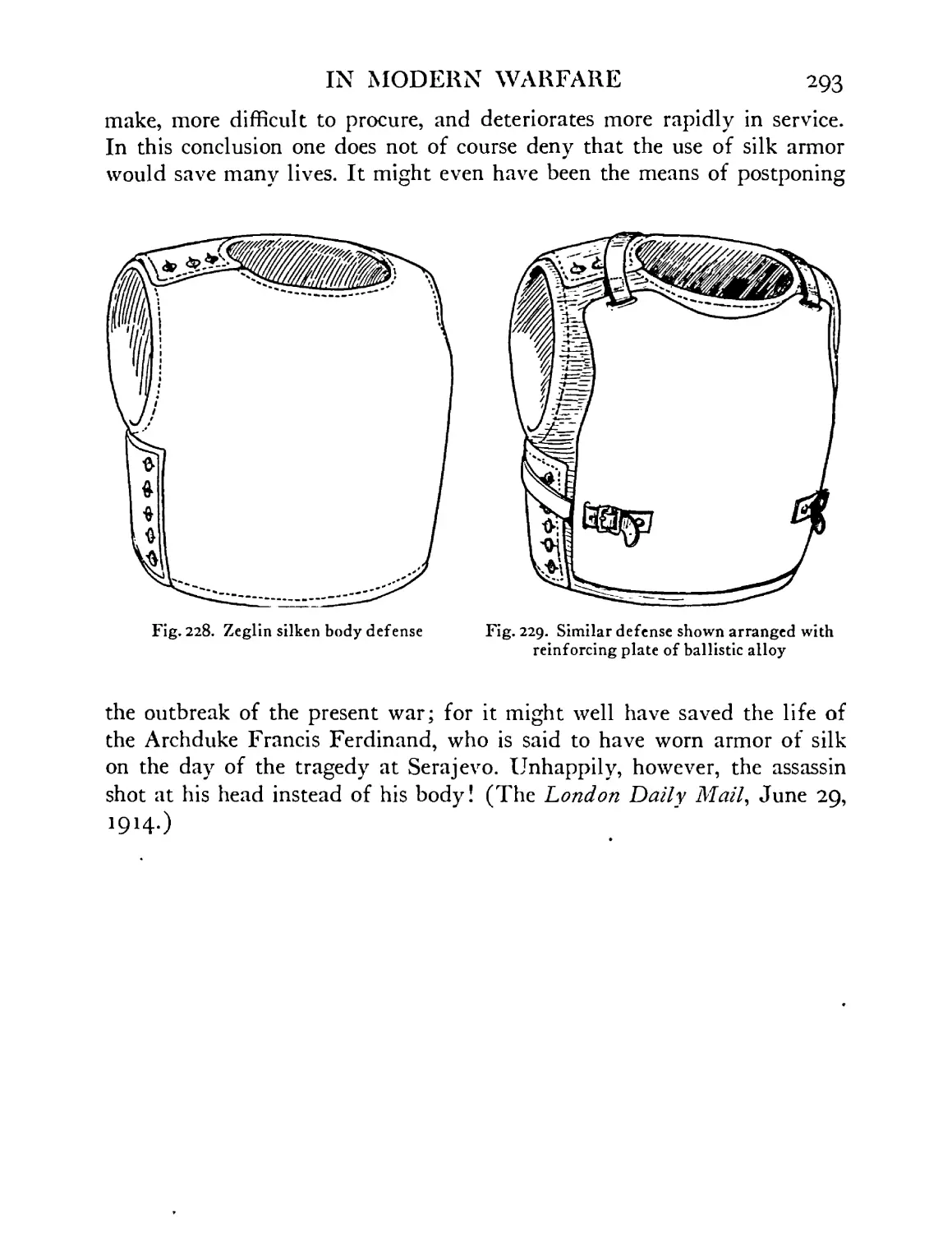
228 Zeglin silken body defense ..... 293
229 Similar defense arranged with reinforcing plate of ballistic alloy ....... 293
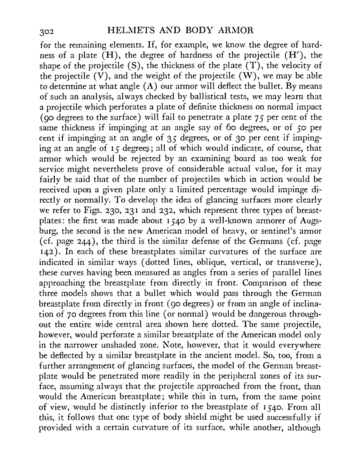
230-232 Three breastplate models in which similar curvatures of surface are indicated by similar types of shading 230 Breastplate of 1540 231 Experimental heavy breastplate for sentinel, American 232 German heavy body armor 303
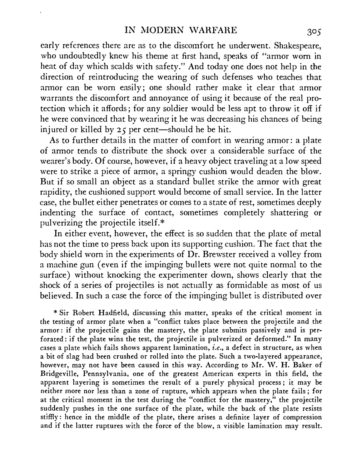
233 Cylindrical shield (white central circle) balanced on
IN MODERN WARFARE 23
FIGURE ball bearings. The line A В represents the course of PAGE
bullet ........ 3O6
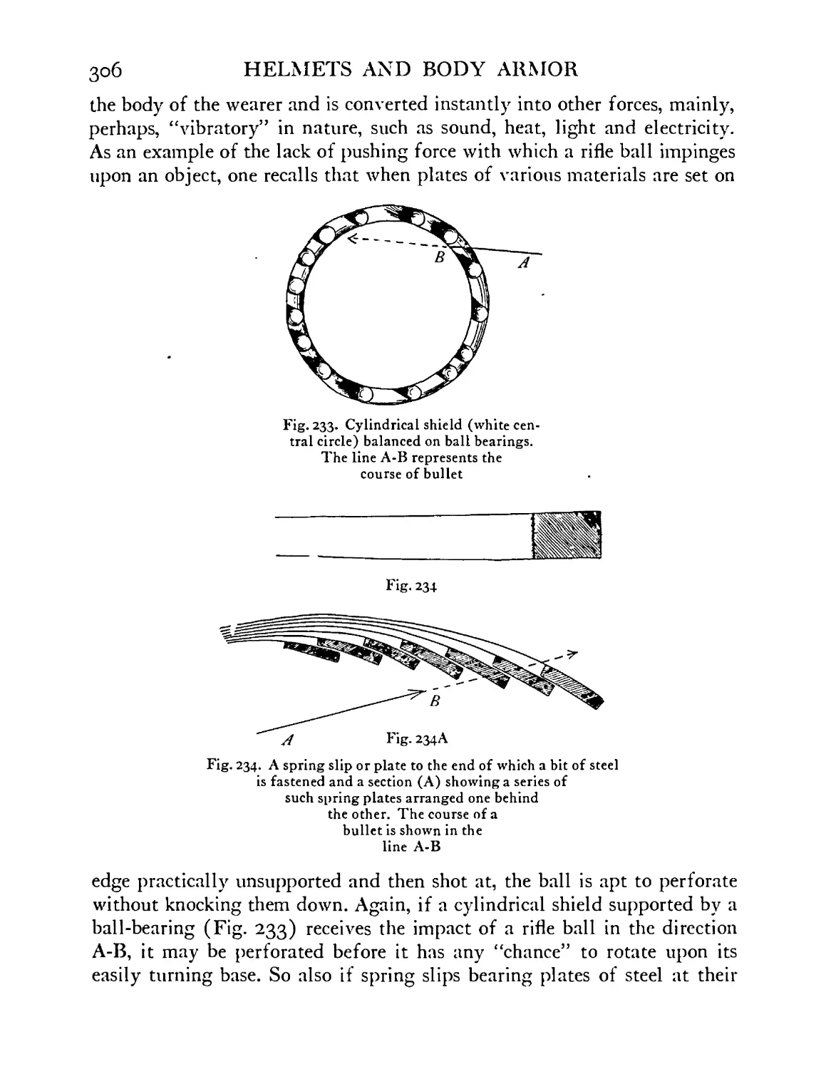
234 A spring slip or plate to the end of which a bit of steel is fastened, and a section (A) showing a series of such spring plates arranged one behind the other. The course of a bullet is shown in the line A В 3O6
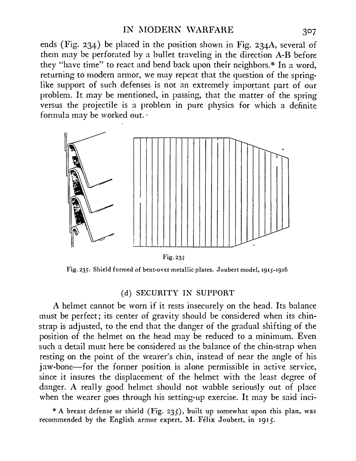
235 Shield formed of bent-over metallic plates. Joubert model, 1915-1916 ...... 307
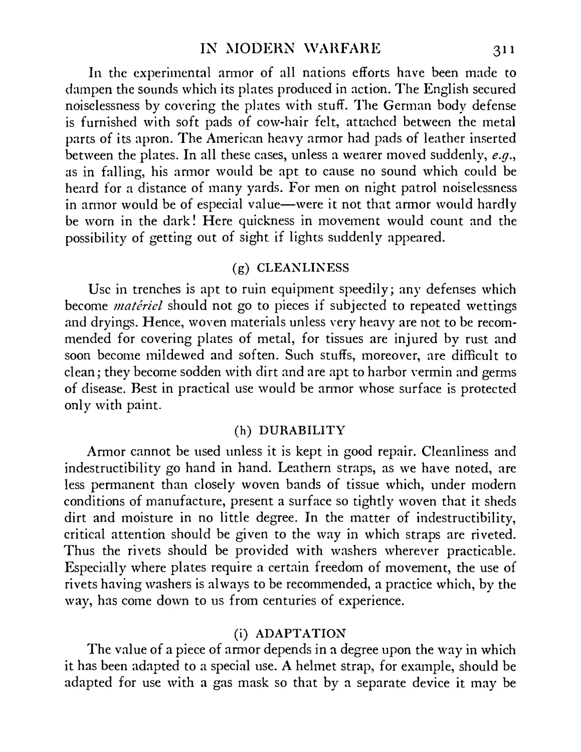
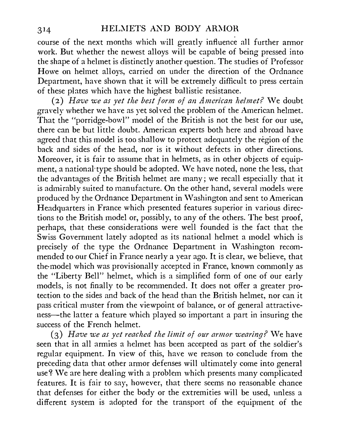
23б Soldiers, one with and one without camouflaged body gear . . . 309
237-239 Anatomical diagrams furnished by Trench Warfare Section, London (Captain Rose); these indicate “areas of danger” and tabulate “entry wounds” in chest and abdomen, 1918 . 315
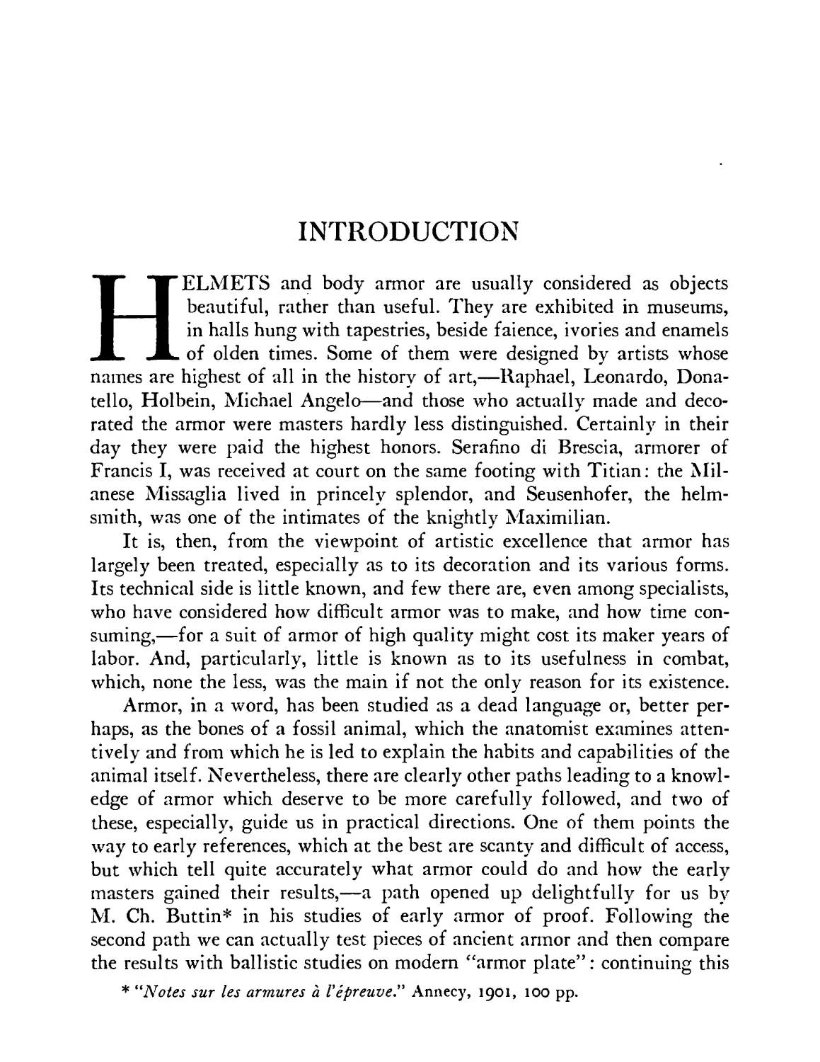
INTRODUCTION
HELMETS and body armor are usually considered as objects
beautiful, rather than useful. They are exhibited in museums,
in halls hung with tapestries, beside faience, ivories and enamels
of olden times. Some of them were designed by artists whose
names are highest of all in the history of art,—Raphael, Leonardo, Dona-
tello, Holbein, Michael Angelo—and those who actually made and deco-
rated the armor were masters hardly less distinguished. Certainly in their
day they were paid the highest honors. Serafino di Brescia, armorer of
Francis I, was received at court on the same footing with Titian: the Mil-
anese Missaglia lived in princely splendor, and Seusenhofer, the helm-
smith, was one of the intimates of the knightly Maximilian.
It is, then, from the viewpoint of artistic excellence that armor has
largely been treated, especially as to its decoration and its various forms.
Its technical side is little known, and few there are, even among specialists,
who have considered how difficult armor was to make, and how time con-
suming,—for a suit of armor of high quality might cost its maker years of
labor. And, particularly, little is known as to its usefulness in combat,
which, none the less, was the main if not the only reason for its existence.
Armor, in a word, has been studied as a dead language or, better per-
haps, as the bones of a fossil animal, which the anatomist examines atten-
tively and from which he is led to explain the habits and capabilities of the
animal itself. Nevertheless, there are clearly other paths leading to a knowl-
edge of armor which deserve to be more carefully followed, and two of
these, especially, guide us in practical directions. One of them points the
way to early references, which at the best are scanty and difficult of access,
but which tell quite accurately what armor could do and how the early
masters gained their results,—a path opened up delightfully for us by
M. Ch. Buttin* in his studies of early armor of proof. Following the
second path we can actually test pieces of ancient armor and then compare
the results with ballistic studies on modern “armor plate”: continuing this
* “Notes sur les armures а ГергеиоеУ Annecy, 1901, 100 pp.
26 HELMETS AND BODY ARMOR
comparison we can then submit the old material to metallurgical exami-
nation, chemical and physical (including microscopical), and thereby gain
definite information as to how the ancient steel was produced. (See here-
after, page 270.)
From early records we can clearly show that armor yielded excellent
results in its day, and that during many centuries it was sought eagerly by
soldiers of all classes. We learn that the prince, no less than the peasant,
was quite willing to bear the discomfort of wearing it, under all conditions,
even in the heat of Palestine. Indirectly we know that had it not been use-
ful it would not have appeared in numbers in every European field of
battle from early times until the epoch of Napoleon. Moreover, we dis-
cover that it was used not by adults merely, but by young as well, for many
suits of armor are preserved which were made for children.* So important,
indeed, was armor in the history of from 1400 to 1700 that by its means
we could still give a convincing summary of the cultural and artistic
changes which took place in European civilization if all other sources of
human knowledge were wiped away.f
The reason for the present lack of information as to the practical nature
of armor is not far to seek. Little was written systematically upon this
theme in olden times, and later, when armor disappeared from general use,
little was remembered about it. That it would again appear as part of the
regular equipment of a soldier seemed to nearly everyone a possibility in-
finitely remote; for, it was reasoned, if armor were discarded even in the
seventeenth century, in days of primitive gunpowder, how could any form
* See also Ch. ffoulkes, “The Armorer and his Craft.” Methuen, London, 1912.
f That this statement may be given more definitely we point out that arms and
armor unquestionably furnish the best expression of the art and the science of the
metal worker of the Middle Ages and of the Renaissance: armor includes in its decora-
tion, gilding, silvering, tinning, damascene, niello, even jewel-setting: its ornamental
designs explain to us stages in the development of religious and civil customs, includ-
ing pageants and sports,—not forgetting falconry. It furnished also an important
medium for the art of painting: its enriched variants copy for us types of secular ap-
parel of each period; by means of etching it pictures the stuff of which the costumes
were made; it also offered an excellent medium for ornament, with lettering and bor-
ders. In its mounting it summarizes the textile art of various periods: here ap-
pear tissues from the commonest to the most costly, including galloon and fringes, and
with these are adequate materials for the study of the art of the leather worker. The
size of armor gives us, finally, convincing data as to the state of physical development
among the men of many nations.
IN MODERN WARFARE 27
of armor reappear in warfare when high explosives were used? Hence the
field of the practical nature of helmets and body armor was abandoned to
an occasional antiquarian. Nevertheless, as in so many other phases of the
Great War, armor did reappear in use, and thereupon there arose at once
an interest, and a very practical one, in the discarded work of the armorer.
Questions were speedily raised by the general staff of every warring country
as to what helmets and body armor could do in protecting the soldier, what
were their best forms and how they could be most speedily prepared? It
may be safely said that there was not an important collection of ancient
armor in Europe which was not visited by commissions, collectively or
individually, in an effort to learn from the experience of the past.
Before proceeding to the already highly developed field of modern
armor, let us review briefly the work of the ancient armorer* from the view-
point of its practical value. This aspect of the subject, as we have noted,
is surprisingly little known, not merely to the student of recent armor but
to the antiquarian as well. The modern expert, as I have found, has often
the belief that ancient armor was but a semi-barbarous defense, serviceable
only against arrows, slings and swords. The antiquarian, on the other hand,
is apt to forget that its primary virtue was serviceability and that the keen-
est minds had studied it from this standpoint from the earliest times.
Let us now attempt to answer several questions:
(A) What kinds of armor were early used?
(B) Was armor actually an important means of saving life and limb?
(C) How was it made?
(D) How was it tested?
(E) How heavy, irksome and even dangerous was it to wear?
(F) What in summary was its use in later times but prior to the Great
War?
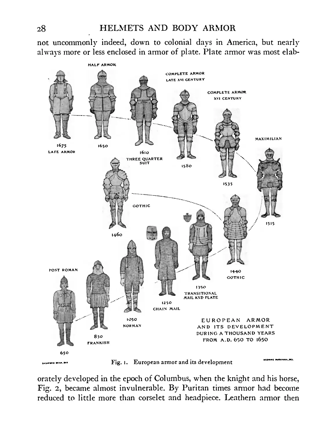
(A) What kinds of armor were early used?
Let us refer to Fig. 1, which illustrates the various types of armor used
in Europe during a thousand years. In early times we see a jacket of
padded hide discarded in favor of a coat of scales; and this in turn give
place to a garment of ring or chain mail worn over a padded costume.
Chain mail more or less complete was used for centuries,—it was worn,
* For critical help in preparing this section I am greatlv indebted to Mr. Charles
W. Gould.
28
HELMETS AND BODY ARMOR
not uncommonly indeed, down to colonial days in America, but nearly
always more or less enclosed in armor of plate. Plate armor was most elab-
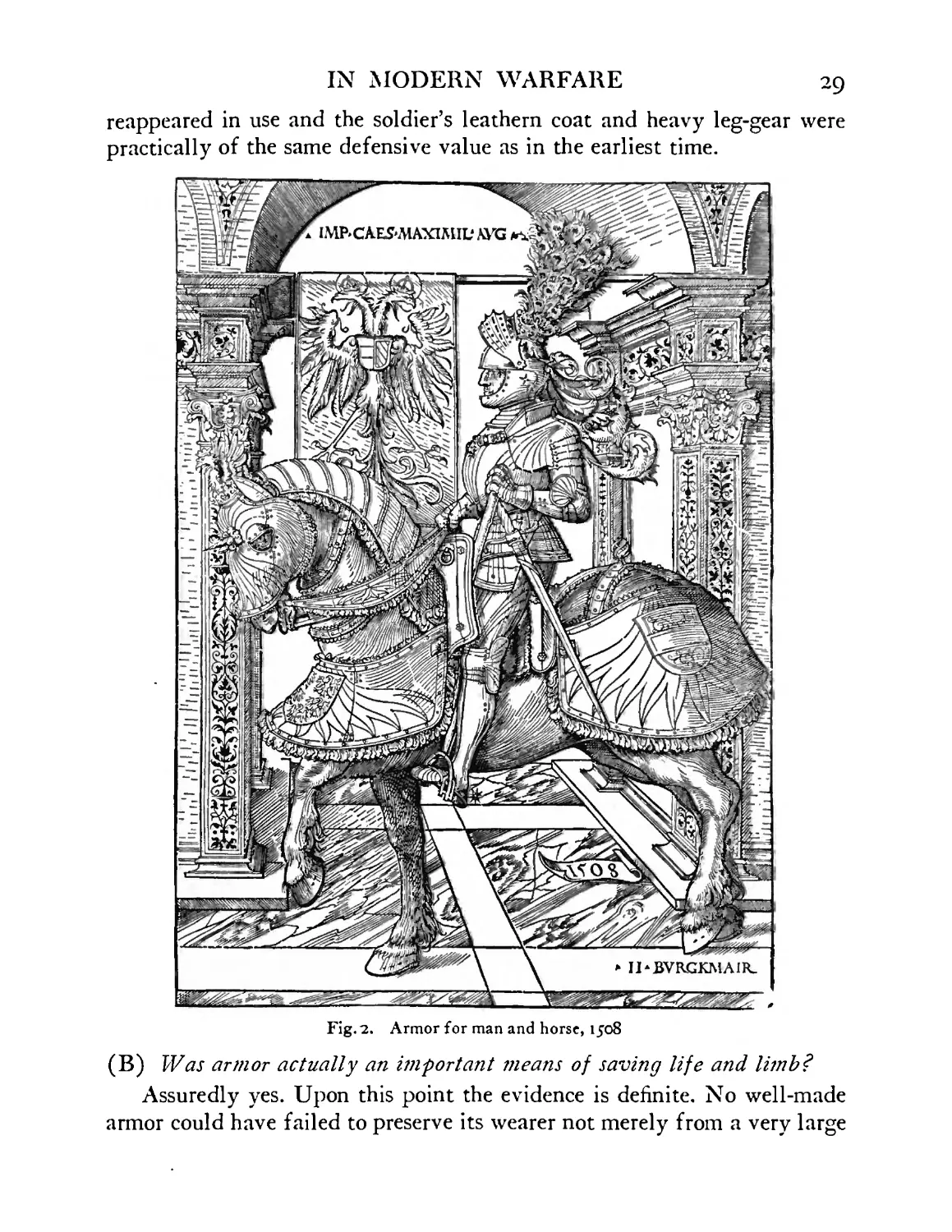
orately developed in the epoch of Columbus, when the knight and his horse,
Fig. 2, became almost invulnerable. By Puritan times armor had become
reduced to little more than corselet and headpiece. Leathern armor then
IN MODERN WARFARE 29
reappeared in use and the soldier’s leathern coat and heavy leg-gear were
practically of the same defensive value as in the earliest time.
Fig. 2. Armor for man and horse, 1508
(B) Was armor actually an important means of saving life and limb?
Assuredly yes. Upon this point the evidence is definite. No well-made
armor could have failed to preserve its wearer not merely from a very large
30 HELMETS AND BODY ARMOR
percentage of thrusts of arrows, bolts, lances, swords and daggers, but from
blows of heavy impact, given, e.g.9 by military hammers, flails, maces, war
axes; also from the firearms of the day. As token of this one may point to
the evidence of ancient and formidable injuries which numerous specimens
of armor exhibit today; and one may even affirm that there was scarcely a
famous soldier in those days who did not owe his life, directly or indi-
rectly, to his armor. In fact, in tilts and single combats each wearer demon-
strated many times the value of his defenses; thanks to them we know that
such an artist in ring-duelling (champs dos) as “le bon chevalier” Jacques
de Lalain,* withstood the heaviest blows of a combat-axe wielded by both
hands of a “fearful adversary.” And we know that the blows of such an
axe were trenchant indeed: its head weighed from three to five pounds; its
shaft, weighing about two pounds, was over five feet long, to enable it to
be swung with great effect. Can we picture, too, the thrusts which the armor
of such a duellist resisted when a similar arm was used reinforced with a
heavy blade or spike? Chain mail, which one rolls in his hand today, won-
dering how so “flimsy” a material could have been a protection, was also'of
the greatest value. Against sword, dagger, arrow, bolt and light lance it was
unquestionably proof. Indeed, no better testimony is needed as to its merits
than the fact that for at least two thousand years it was worn constantly
and in large numbers, in spite of the fact that its average price of purchase
appears to have been greater than that of any other type of armor.f A
single instance may here be cited as evidence of the virtue of chain mail.
At Tiberias (1187) when the crusaders were hemmed in by the Saracens,
after two days of hard fighting, when most of the foot soldiers were killed
or wounded, when hardly a horse in the army could carry its rider, the
mail-clad knights are known to have suffered no serious casualties.:;: Yet
* Lefevre de Saint-Remy, “Chronique de Jacques de Lalain'' [1421-1453], pub-
lished in 1842, Pantheon litter aire.
f A shirt of mail in the collection of the Metropolitan Museum of Art contains a
quarter of a million hand-made and tempered rings, each carefully formed and each
separately riveted. If one estimates that a skilful armorer might make and weave
together two hundred and fifty of these links in a day, it is easy to see that this mail
would have cost its maker, working every day, nearly three years’ work,—a low esti-
mate, we believe, for making this particular mail. Such a shirt would therefore have
cost its purchaser in round figures, at modern prices, six thousand dollars, allowing the
maker six dollars a day for a thousand days!
J 1898, Oman, Ch., “A History of the Art of War.” Methuen, London, pp. 323 et
seq. “To their [the Moslems’] great surprise they found that very few of the knights
IN MODERN WARFARE 31
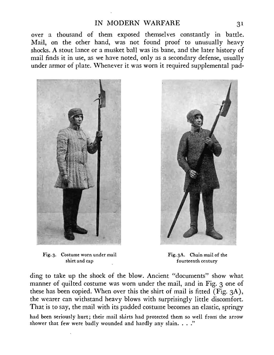
over a thousand of them exposed themselves constantly in battle.
Mail, on the other hand, was not found proof to unusually heavy
shocks. A stout lance or a musket ball was its bane, and the later history of
mail finds it in use, as we have noted, only as a secondary defense, usually
under armor of plate. Whenever it was worn it required supplemental pad-
Fig. 3. Costume worn under mail
shirt and cap
/Jl
Fig. 3A. Chain mail of the
fourteenth century
ding to take up the shock of the blow. Ancient “documents” show what
manner of quilted costume was worn under the mail, and in Fig. 3 one of
these has been copied. When over this the shirt of mail is fitted (Fig. 3A),
the wearer can withstand heavy blows with surprisingly little discomfort.
That is to say, the mail with its padded costume becomes an elastic, springy
had been seriously hurt; their mail shirts had protected them so well from the arrow
shower that few were badly wounded and hardly any slain. . . .”
32 HELMETS AND BODY ARMOR
complex or shield which deadens a blow with unexpected ease. Experi-
ments made by the writer in this direction converted him to the faith that
mail as a type of armor is by no means to be despised.
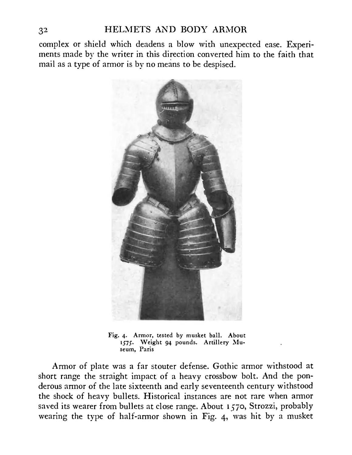
Fig. 4. Armor, tested by musket ball. About
1575. Weight 94 pounds. Artillery Mu-
seum, Paris
Armor of plate was a far stouter defense. Gothic armor withstood at
short range the straight impact of a heavy crossbow bolt. And the pon-
derous armor of the late sixteenth and early seventeenth century withstood
the shock of heavy bullets. Historical instances are not rare when armor
saved its wearer from bullets at close range. About 1 570, Strozzi, probably
wearing the type of half-armor shown in Fig. 4, was hit by a musket
IN MODERN WARFARE
33
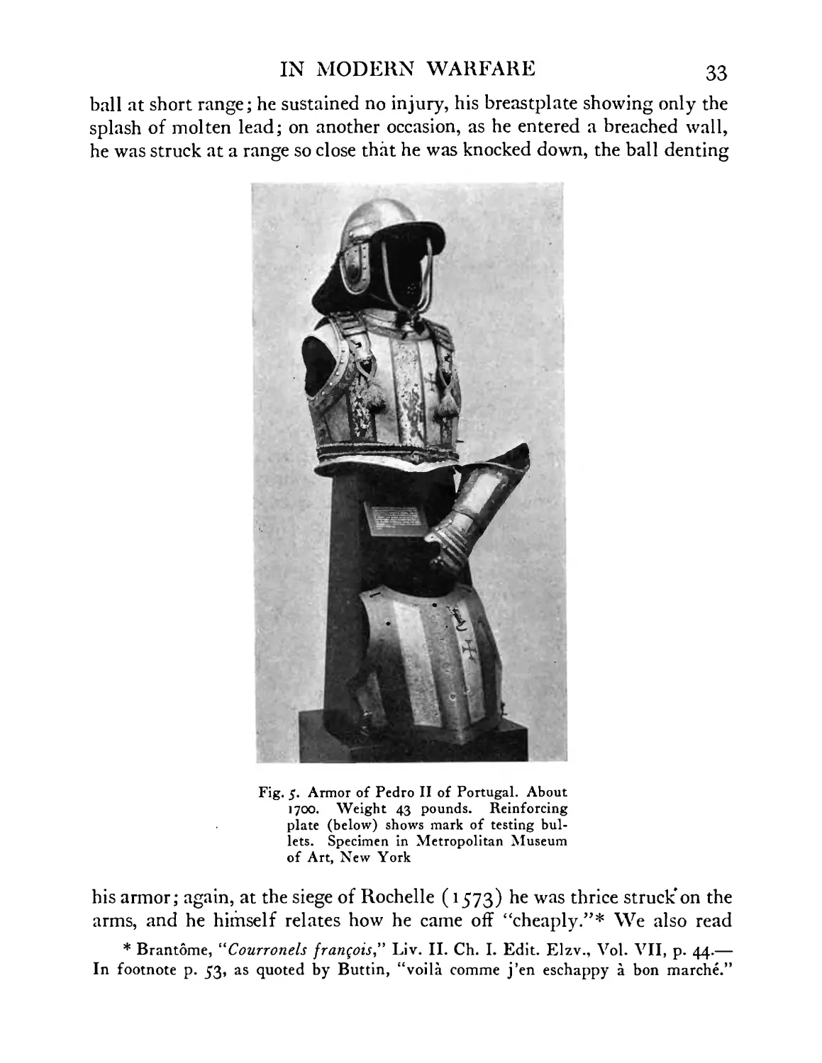
ball at short range; he sustained no injury, his breastplate showing only the
splash of molten lead; on another occasion, as he entered a breached wall,
he was struck at a range so close that he was knocked down, the ball denting
Fig. 5. Armor of Pedro II of Portugal. About
1700. Weight 43 pounds. Reinforcing
plate (below) shows mark of testing bul-
lets. Specimen in Metropolitan Museum
of Art, New York
his armor; again, at the siege of Rochelle (1573) he was thrice struck*on the
arms, and he himself relates how he came off “cheaply.”* We also read
* Brantome, “Courronels frangois” Liv. II. Ch. I. Edit. Elzv., Vol. VII, p. 44.—
In footnote p. 53, as quoted by Buttin, “voila comme j’en eschappy a bon marche.”
34 HELMETS AND BODY ARMOR
in Brantome that in 1563, at the siege of Orleans, Dandelot was saved from
a musket ball by the round shield which he carried; here the impact was so
severe that he, too, was knocked down.
If we examine these old records we are surprised to find how often
armor saved its wearer. His corselet, for example, saved Francis I “several
times” at Pavia. At the siege of Rochelle mentioned above we learn
that a certain Captain St. Martin remained uninjured after having been
struck by musket balls no less than thirty times! So, too, the great Conde,
armed probably after the style of Fig. 5 or 6, was saved many times by his
armor; we have a contemporary note (1652) that at Port St. Antoine his
cuirass was “full of dents.” And so it goes. There is no question, therefore,
that armor was useful even at a time when gunpowder was in general use.
Moreover, the bullet of that period was usually of large caliber; its crush-
ing effect must have been great, and its shock formidable.
The fact is clear that had cases not been numerous in which the soldier
was saved by his armor, the armor would not have been worn. Nor was the
burden too great, considered from every viewpoint, if by means of his
armor a particular person could be preserved. For those were days of indi-
vidualism. And the personality, courage and resourcefulness of a leader
would often spell the difference between the victory and the defeat of a
nation. Had Marlborough been shot, whom his soldiers followed blindly,
what might have been the outcome of the battles of Malplaquet, Ramillies,
or Blenheim? Or was it not of the greatest importance to the French nation
that Joan of Arc should be protected by armor of best possible proof? We
know indeed that she was several times saved by her armor. Fancy, too,
how the history of the world might have changed had the Black Prince been
killed in battle; or Cromwell, or William of Orange, or Francis I or
Charles V. Yet we know that all of them exposed themselves with reckless
determination, and that all of them were armored by masters. One has only
to visit the royal armory in Madrid today to know what such a man as
Charles V thought of the practical value of armor. He was literally a spe-
cialist in its study and he provided himself with armor for every even-
tuality and of every weight. He graded his armor as an optician classifies
his lenses; in one instance he had at least eight reinforcing pieces for a single
helmet. And for tilting he did not hesitate to wear armor which would stand
a supreme shock. He was a man of modest stature and proportions, yet
his tilting armor in one instance weighed no less than a hundred and twenty-
five pounds and his helmet alone over forty pounds!
IN MODERN WARFARE
35
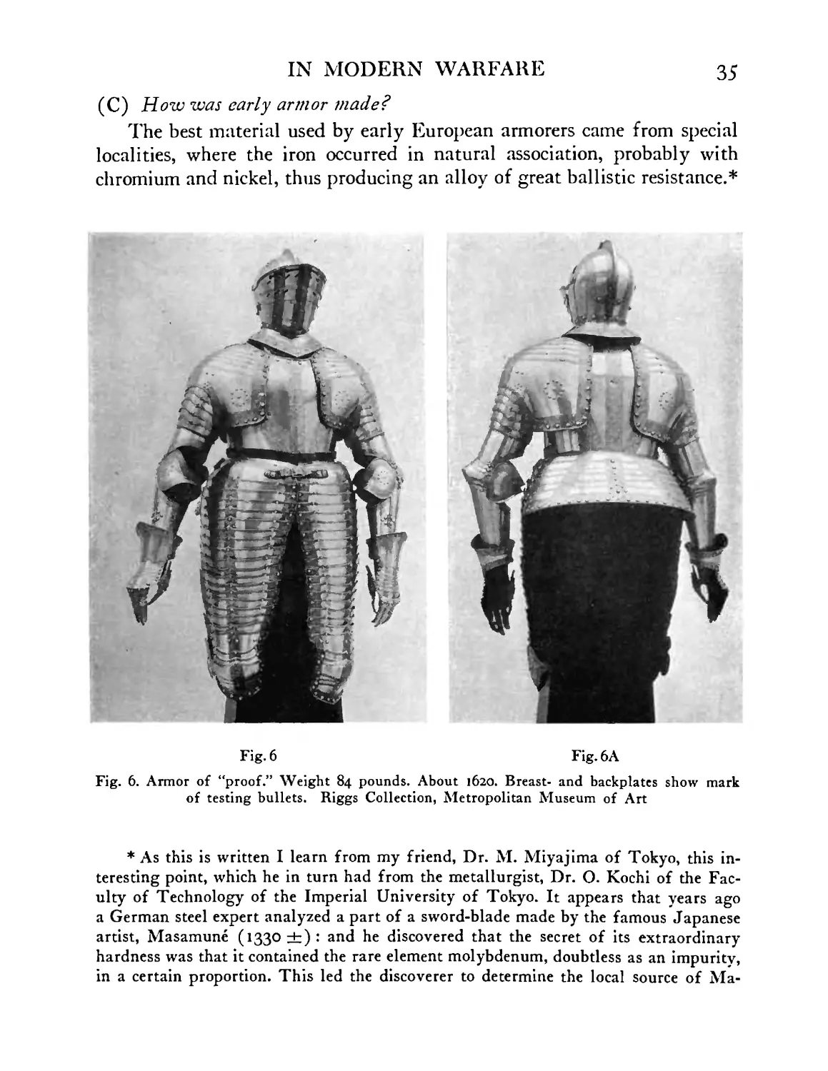
(C) How was early armor made?
The best material used by early European armorers came from special
localities, where the iron occurred in natural association, probably with
chromium and nickel, thus producing an alloy of great ballistic resistance.*
Fig. 6 Fig. 6A
Fig. 6. Armor of “proof.” Weight 84 pounds. About 1620. Breast- and backplates show mark
of testing bullets. Riggs Collection, Metropolitan Museum of Art
* As this is written I learn from my friend, Dr. M. Miyajima of Tokyo, this in-
teresting point, which he in turn had from the metallurgist, Dr. O. Kochi of the Fac-
ulty of Technology of the Imperial University of Tokyo. It appears that years ago
a German steel expert analyzed a part of a sword-blade made by the famous Japanese
artist, Masamune (1330 ±): and he discovered that the secret of its extraordinary
hardness was that it contained the rare element molybdenum, doubtless as an impurity,
in a certain proportion. This led the discoverer to determine the local source of Ma-
36 HELMETS AND BODY ARMOR
Cf. pages 270-272. This material, e.g^ from Innsbruck or Bilbao, became a
staple article of commerce during the Middle Ages; it was sold in bars or
in plates; the latter had been hammered out, sometimes by hand, but
usually by a trip-hammer operated by water power. (See Agricola,
Georgius, De re metallic a, Basel, 1546.) In making armor the armorer
worked his metal sometimes hot, sometimes cold, depending upon the kind
and quality of work which had to be performed. The details in making
armor need here be noted only in so far as they furnish materials for com-
parison or contrast with the modern methods. Thus we comment upon the
extremely laborious methods of the ancient craftsman; we know that he
had no stamping presses, and we have only to follow the steps in fashioning
such a piece of armor as a helmet after the original method to understand
why armor making was a difficult and costly task. It had, we will find, a
technique of its own; and its kinds of anvils, stakes, hammers, and special
apparatus may even today be counted by scores. Unfortunately we cannot
illustrate helmet making from early documents; none the less we can here
follow it, and I believe very accurately, for we are so fortunate as to have
the various steps or stages in such a piece of work demonstrated by
the armorer, D. Tachaux, of the staff of the Metropolitan Museum of Art,*
who in turn had them from the Dresden armorer, Klein (1825-1882), who
himself was trained in the armory of the Dukes of Saxony where the art
of armor making had been handed down from the earliest centuries. These
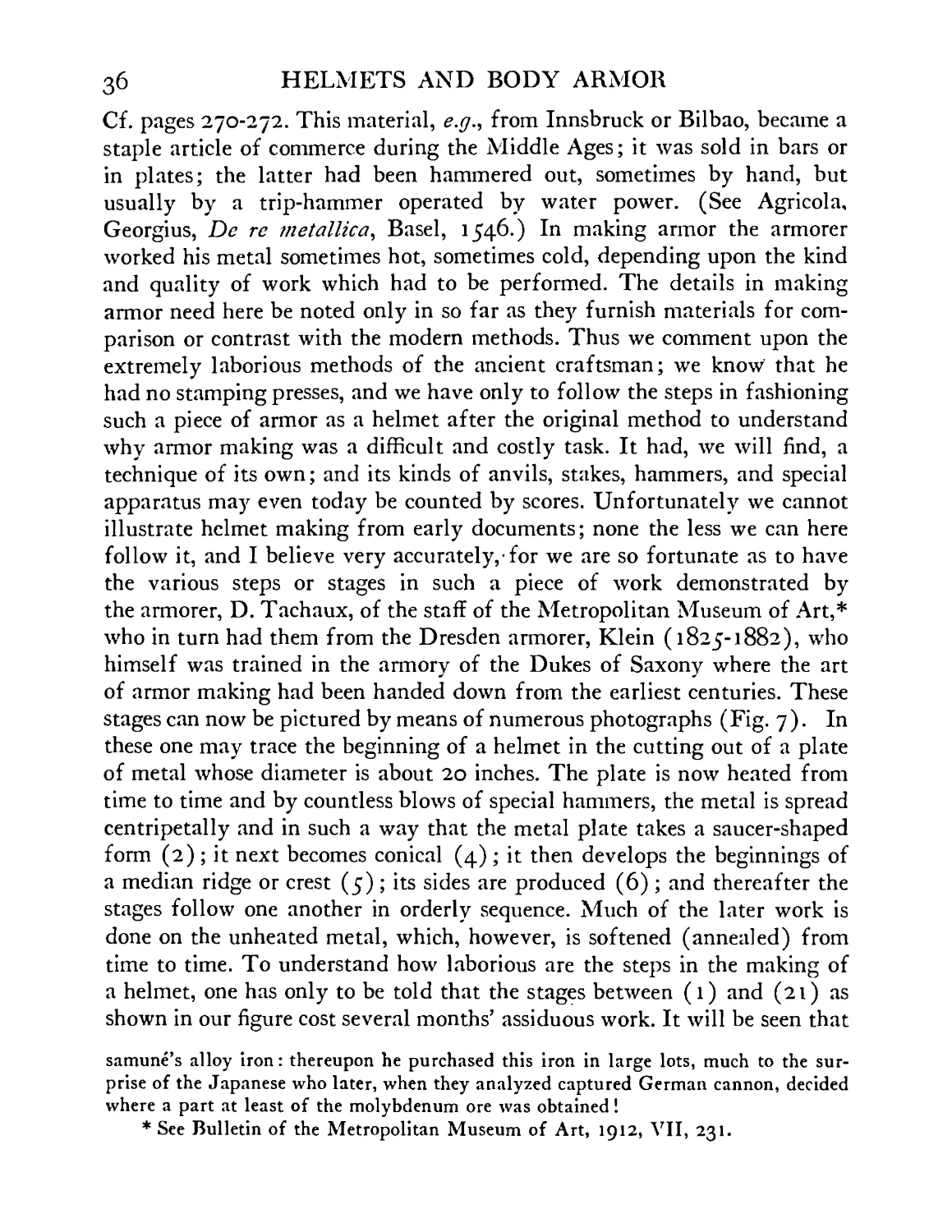
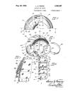
stages can now be pictured by means of numerous photographs (Fig. 7). In
these one may trace the beginning of a helmet in the cutting out of a plate
of metal whose diameter is about 20 inches. The plate is now heated from
time to time and by countless blows of special hammers, the metal is spread
centripetally and in such a way that the metal plate takes a saucer-shaped
form (2) ; it next becomes conical (4) ; it then develops the beginnings of
a median ridge or crest (5); its sides are produced (6) ; and thereafter the
stages follow one another in orderly sequence. Much of the later work is
done on the unheated metal, which, however, is softened (annealed) from
time to time. To understand how laborious are the steps in the making of
a helmet, one has only to be told that the stages between (1) and (21) as
shown in our figure cost several months’ assiduous work. It will be seen that
samune’s alloy iron: thereupon he purchased this iron in large lots, much to the sur-
prise of the Japanese who later, when they analyzed captured German cannon, decided
where a part at least of the molybdenum ore was obtained!
* See Bulletin of the Metropolitan Museum of Art, 1912, VII, 231.
1. PLATLOF MACHINE-TOOL STEEL
(n/KX> In.ihlcR) FROM WHICH
HELMET IS MADE
SIMILAR STAGE
17 FILED AND POLISHED.
BORDERS FINISHED.BANDS
READY FOR DECORATION
2. PLATE GIVING FIRST CURVATURE
CHALKUSE DENOTES FUTURE
CREST
3. PLATE DEVELOPED BOWL SHAPED.
NOTE DEEP MARKS OF HAMMER
4 BOWL ASSUMES CONICAL FORM
6. SIDES NOW DEVELOPED
16. BOWL,CHEEK-PIECES.
VISOR.AND VENTAIL
IN PLACE
PHOTOGRAPHS SHOWING HOW A HELMET IS MADE
IB. READY FOR ETCHING
PATTERN PAINTED IN
AC1 D-PROOF VARNISH
19. DECORATED BANDS
FIRE-GILT.
HELMET FINISHED
20. TRONT VIEW OF
FINISHED HELMET
WEIGHT B* POUNDS
21. SIDE VIEW OF
FINISHED helmet
1-13. BOWL HAMMERED OUT OF A SINGLE PIECE OF STEEL-. 14-16, PARTS PUT TOGETHER!
17, FILED AND POLISHED) IB, READY FOR ETCHING; 19-21,FIRE-GILT AND FINISHED.
HELMET NOW IN GALLERY H-8 CASE 95,WORK BY D.TACHAUX.I915,
IN RESTORING THE MISSING HEAD-PIECE OF SCUDAMORE ARMOR.
Fig. 7. Stages in making a helmet after the ancient fashion
38 HELMETS AND BODY ARMOR
by this mode of production the artist controls his metal with extraordinary
precision. He may push it into regions where it will be later required, e.g.b
the median crest or the forehead where the helmet is apt to encounter a
heavy blow. In all cases he must keep in mind not the next phase of his
work merely but the later stages. Thus the armorer could not have devel-
oped the crest in the present helmet had he begun to produce it in stage (10)
instead of stage (4) ; and should the crest have been taller still (in ancient
armor it is sometimes six inches high, embossed with such skill that it is
heaviest at its top) he would probably have begun to form it at stage (2).
Even then he could not have developed it successfully had he not under-
stood the special technique of spreading his metal “elastically,”—by using
special hammers (which are believed not to cut the grain of the metal) and
highly polished stakes and anvils on which the “fibers” of the metal are
said to spread apart, “slipping over one another and not becoming entangled
or broken.” Be this as it may, in the hands of the ancient armorer refrac-
tory metal was controlled with incredible skill; and a master like Philip
de Negroli could work his steel into ornamental designs, Fig. 7A, in a
way unexcelled even by an artist in so soft a material as gold. Moreover,
the armorer, it is well worth noting, rarely forgot, even in his most ornate
work, that the metal should be so embossed that the uplifted points or
ridges should include not the thinnest metal but the thickest.
With this type of armor making we shall later contrast the modem
method of manufacture, where by means of a single press thousands of
helmets are stamped out daily—a greater number, perhaps, than the ancient
armorer could have hammered out in a lifetime. But by the new method one
is sadly limited as to the shape and depth of the object to be produced, and
the system is also faulty, since the armor it presses is apt to be thinnest and
weakest in the very region where the greatest strength is needed.
( D) How was armor tested?
It is not hard to conclude that the armorer, during all periods, took
practical means of showing to the purchaser of his armor that it was of
good quality, or “proof.” And the early records when carefully examined*
bring out numerous details indicating in what way and under what condi-
tions the testing or proving of armor took place. That it was often done
on standard lines there can be no doubt. And it was occasionally carried out
under particularly severe conditions. In this connection let us review a
number of tests.
* Cf. Ch. Buttin, op. cit.
IN MODERN WARFARE 39
The earliest one accurately recorded* occurred during the siege of
Rhodes (308-304 В. C.) when Demetrius Polyorcetes, according to Plu-
tarch (Demetrius, Section 21), received from Cyprus two heavy iron corse-
lets (probably breastplate only), each weighing the equivalent of thirty-
eight pounds Troy. Zwilos, the armorer who made them, thereupon caused
them to be tested in otder to show that they were of great strength and
Fig. /А. Casque dated 1543 and signed by the Milanese
artist, Philip de Negroli. J. Pierpont Morgan Col-
lection in Metropolitan Museum of Art
* Crude tests of armor by sword, spear or arrow are doubtless as old as history
itself. Here should be mentioned David’s testing the armor which Saul offered him
(about В. C. 1015). I Samuel, xvii, 38, 39. “And Saul armed David with his armor
and he put a helmet of brass upon his head: also he armed him [by providing him]
with a coat of mail. 39. And David girded [drew] his sword upon his armor and he
assayed to go [to let go or strike at it] ; for he had not proved it. And David said unto
Saul, I cannot go with these, for I have not proved them [shown that they were not
proof]. And David put them off him [put them away from him].”
It seems quite obvious that the usual translation of these verses gives no sense
unless the bracketed words are suggested. The picture then becomes complete. The
prompt test by the keen-witted youth warranted his rejection of the armor: add to this
his shrewd decision to try light tactics in fighting, for he had probably heard (I
Samuel, xvii, 5) that his adversary was woefully overweighted in his armor, “which
weighed five thousand shekels of brass,” or roundly 183 pounds (allowing for the
heavy shekel 258 grains).
4o HELMETS AND BODY ARMOR
hardness; to this end they were shot at by a catapult at a range of twenty
paces. The iron resisted the shock and the head of the catapult bolt merely
nicked the surface “as though with a stylos.” Thus the test was made under
war conditions and it is noteworthy that the armor was not placed on racks
or models but on living men. “One of the corselets was worn by Demetrius
himself, the other by Alkinos of Epeiros.”
It would be interesting to know just what this test represented in terms
of modern ballistics. That it was severe goes without saying, especially
since the bolt of a catapult, which represented the siege artillery of that
day, had a weight which would have been hard to stop (perhaps as much
as ten ounces, г.е.ь double the weight of a heavy war-bolt of a windlass
crossbow). In modern terms it is even fair to assume that had the breast-
plates in question been of low carbon steel, and they probably were, they
would have stopped a machine gun bullet at about three hundred yards
(cf. page 144).* It is surprising, therefore, that the earliest instance of a
military proof of body armor recorded,—occurring some twenty-three hun-
dred years ago,—should have given essentially modern results, but, natu-
rally, at the cost of greater weight.
Detailed records of proving European armor do not next occur until
the fourteenth century. But from this it does not follow that during the
intervening time there were made no efforts to prove the armor and to
standardize the tests. We incline rather to the belief that each purchaser of
armor had a clear idea of the degree of resistance his shirt of mail and his
iron headpiece should offer, and that even in his tests he did not fail to
make use of crossbow, lance and sword. Unfortunately we do not know
from actual experiment, ancient or modern, what a good shirt of mail
(weighing, say twenty pounds) will resist, when each link is riveted and
hardened, but it was evidently of greater strength than modern shirts of
mail unriveted, which, of about equal weight, are claimed by their makers to
resist service-revolver ammunition at less than fifty yards. (See page 62.)
In general we know that early armor of this type was often tried out by the
chopping.cut (estrama^on) of a sword, and that a similar test was used
throughout Europe down to the seventeenth century. (Fide Gaya, 1623.)
The thrust of a heavy poignard was also a severe test. In this connection
I recall in Paris many years ago discussing the proof of fifteenth-century
* A well-made modern breastplate of alloy steel weighing twenty pounds will stop
a machine gun bullet at 200 to 300 yards. In the conclusion noted above we assume
that carbon steel offers about half the resistance of alloy steel. See, however, p. 81.
IN MODERN WARFARE 4]
Italian armor with M. V. R. Bachereau, the well-known antiquary of
ancient arms: “That armor is indestructible,” declared M. Bachereau, and
“it would surprise you to know how flinty hard its surface is.” He told
me he had taken from a vitrine a headpiece hall-marked by the great
Milanese maker, Antonio di Missaglia, and placed it on a block. He had
then struck it with all his strength with a heavy-bladed dagger; the head-
piece hardly showed where the point had struck. This incident I mention
since it is the only one in which I have known an early helmet to be given
a practical test. Perhaps it is not to be wondered at, for museums and col-
lectors can hardly be expected to permit some of their most valuable speci-
mens to be used in ballistic or similar tests!
As early as 1340 we have records that armor of two degrees of strength
was in use, known respectively as “proof” and the “half proof.” The former
would withstand the bolt of a heavy crossbow, which was set with a wind-
lass, the latter only the arrow of the war-bow and the bolt of the small
crossbow. Two expressions to distinguish the strength of armor date also
from this time (Italy and Savoy*), armor “proof to every thrust” (de
toute botte), applying apparently to plate armor, and “to thrust broken”
(botte cassee) in the sense that the armor yielded and thus broke the thrust.
The latter armor, including apparently chain mail and armor of small
plates or scales (jazerans, from Spanish Jazerino = Algerian) was appar-
ently the more highly prized; and it was more costly (one fifth or more).
Records of proving armor become frequent during the fifteenth century.
And by this time measures appear to have been taken to standardize the
test. Many cities had their stamps (poincons') and made use of them in
certifying to the excellence of their armor. Thus numerous helmets and
breastplates in our museums bear the proof mark of Nuremberg (demi-
eagle and fesse), Venice (lion of St. Mark), Augsburg (pine-cone);
together in some cases with the individual mark of the maker. Occasionally
not only is one piece of the armor thus marked but nearly every piece,
including gauntlets and leg pieces. And in extremely rare cases (to show
what store was set by tests of this kind) the same piece was hall-marked at
many points. A Milanese armet in my collection bears the poingon of proof
on its back on the left side, on the right cheek and on the left, and the mark
of “double proof” near the back on its right side. The double mark men-
tioned is believed to record a test of much greater strength. These tests were
made with special crossbows and special bolts or quarrels; and tests of this
* Ch. Buttin, “Les flee lies d’epreuve” . . . Annecy, 1917.
42 HELMETS AND BODY ARMOR
nature were still in force well into the sixteenth century.* Occasionally we
read of armor which was tested in the presence of the purchaser, who
brought with him special bolts and a “good windlass crossbow” to make
sure that the proof was severe. This test, we may add, is not easily compared
with a modem one, but it was fairly searching, for the projectile was heavy
(four or five ounces), revolved in flight, and its point was well adapted to
punching holes through metal plates (cf. page 297, that the effect upon
armor plate is greater when a bullet is reversed). Such a bolt flew with an
initial velocity of about 300 feet a second (writer’s estimate) and it
attained a distance of 400 to 500 yards; at 60 yards it would penetrate
a deal plank three fourths of an inch thick.f
Early in the sixteenth century guns became used in large numbers and
shattered much armor of “proof.” Thus in 1517, Ariosto advised the soldier
to send his armor and sword back to the forge and to adopt the musket or
arquebus. (“Orlando furioso” Canto IX, stanza 29.) So, too, we find in
1523 a note in Montiuc’s “Commentaries” (Ed. 1821, Petitot, Vol. I, page
342) which deplores the death of “so many brave and valiant men, often at
the hand of the most cowardly and timid, who did not dare to meet face to
face the men whom they shot down with their miserable bullets!” Hence it
came about that the conditions of proving armor were changed, and that by
about the middle of the sixteenth century armor was made heavier, and the
terms “proof” and “half proof” acquired a new significance, suits of the
former type resisting the (war) musket, the latter the lighter firearms,
including pistols. Sometimes a suit of armor was made up partly of “proof”
(front of helmet, breastplate and upper thigh defenses and circular shield)
and partly of “half proof” (backplate, arm defenses^). To compensate for
the increase of the weight of the breastplate it was even advocated that no
armor for the back be worn, on the ground that it was unnecessary, and that
its absence would discourage cavalry from turning its back to the enemy.||
For the rest it becomes clear that testing by firearms was an important
* Crossbows were not discarded in the French army until 1566, when, indeed,
many soldiers still preferred them to muskets; and in England the use of the musket
did not become obligatory until 1596.
f See Payne-Galway, Sir Ralph, “The Crossbow, Medieval and Modern, Military
and Sporting.” 1903, London, XXII, p. 328.
Jin instances all parts were designated as half proof, including even the groin-
plate (brayette). v. Catalogue of the armory of the Dukes of Lorraine, 1629.
|| A similar reason for abandoning the backplate was recommended by Alexander
the Great. (Rollin, “De la science miliiaire” liv. XXV, § 3.)
IN MODERN WARFARE 43
factor in the decadence of armor, and that, little by little, each plate grew
heavier, till at length the entire panoply became literally unbearable.
During this time the competition became intense between the armorer and
the gun-maker, whose clients added insult to injury by rejecting a musket
if it did not shatter the armor, and rejecting the armor if it did not resist
the musket. “Of course my fine armor failed,” complained the armorer
Colombo of Brescia (1574), “when my patron used an inch charge of
powder!” And we can understand how the earlier armor, elegant in its
lines, with its delicately adjusted curves, grooves and angles, designed
especially to deflect the crossbow bolt, should in time give place to armor,
solid and compact, rounded in contour. But even then the proof demanded
by the wearer of the armor mounted always higher (“high-proof,” “caliber
proof,” “musket proof”) so the armorer was obliged constantly to resort
to new devices. He knew little of the metallurgy of steel (see page 271),
so he did not experiment with ballistic alloys; he did, however, like Vulcano
of Brescia, strengthen the “fiber” of his heavy plates by the laborious
process of hammering them out cold and by using various processes of tem-
pering them; but in general he had either to make his armor of fewer and
heavier pieces, or to use the earlier designed reinforcing plates by means
of which a patron who had complete armor could strengthen his breast-
plate or headpiece and at the same time reduce the total weight of his
equipment by discarding other pieces, according to his actual need. The
result, however, tended ever in the same direction, the armor became far
too heavy; and its wearer began to complain that he had become little more
than a “living anvil,”* for he was so burdened with his harness that his
value in active combat became small. Thus, even if dismounted, he could
hardly get back into his saddle. + (ffoulkes, “The Armorer and his Craft,”
page 117.) In the end, throughout the seventeenth century, the best the
* La Noue in his “Discours politiques et mil it air es” translated by “E. A.,” 1587,
writes on page 185, quoted by ffoulkes, “For where they had some reason in respect
to the violence of harquebuzes and dagges (muskets and pistols) to make their armor
thicker and of better proofe than before, they have now so farre exceeded, that most
of them have laden themselves with stithies (anvils) in view of clothing their bodies
with armour.”
f Thus, Gaspard de Saulx-Tavannes, in his memoirs (“Collection des Mem. rela-
tiv. d rhistoire de France” Paris, Didier et Cie., 1866), notes “that it is impossible for
captains in their heavy casques and cuirasses to strike many times, as is their duty. If
one who commands wishes the help of a casque and breastplate, proof to the musket
ball, he must take them only at the moment he charges.”
44 HELMETS AND BODY ARMOR
armorer could do was to keep his clients well mounted at the head of their
troops where their presence and beaux gestes could inspire their men to
further efforts. And they certainly found their way into the thick of the
battle, for we recall that in those days princes and generals exposed them-
selves in a fashion which would seem to modern tactics little less than
criminal. But while the opposing heroes rarely met in single combat in
Homeric fashion, it is none the less true that they had often the opportunity
of recognizing one another and at close range during the fortunes of battle.
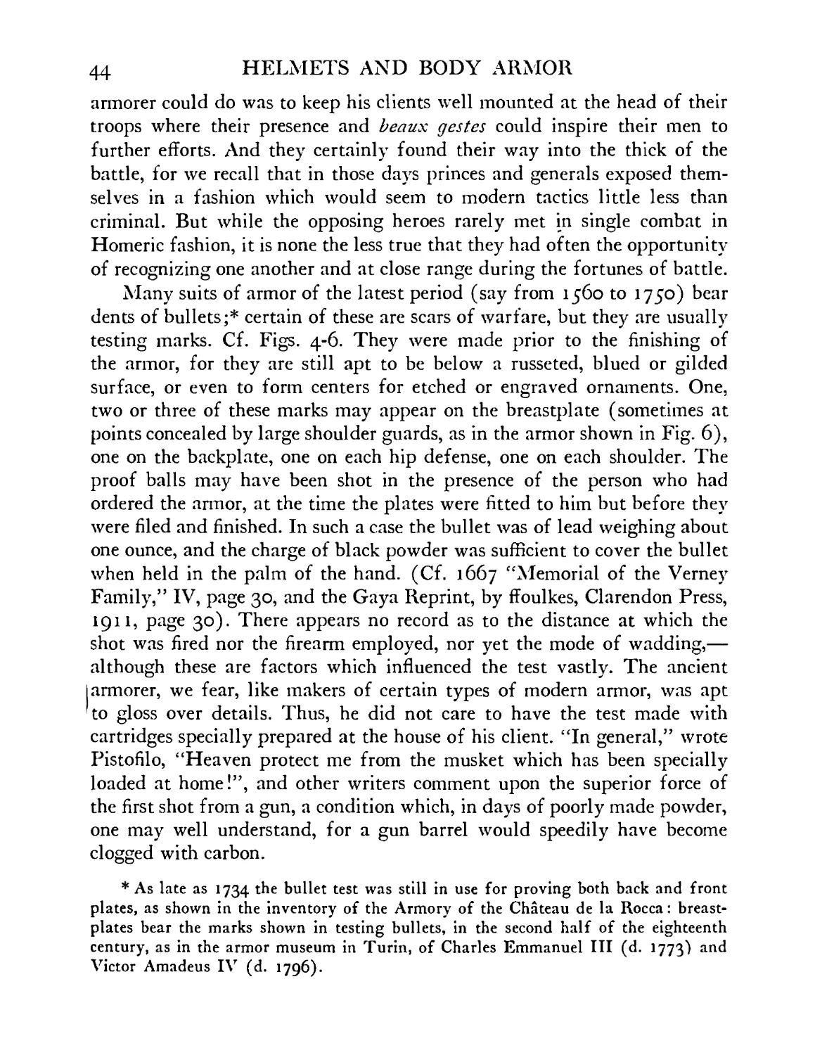
Many suits of armor of the latest period (say from 1560 to 1750) bear
dents of bullets;* certain of these are scars of warfare, but they are usually
testing marks. Cf. Figs. 4-6. They were made prior to the finishing of
the armor, for they are still apt to be below a russeted, blued or gilded
surface, or even to form centers for etched or engraved ornaments. One,
two or three of these marks may appear on the breastplate (sometimes at
points concealed by large shoulder guards, as in the armor shown in Fig. 6),
one on the backplate, one on each hip defense, one on each shoulder. The
proof balls may have been shot in the presence of the person who had
ordered the armor, at the time the plates were fitted to him but before they
were filed and finished. In such a case the bullet was of lead weighing about
one ounce, and the charge of black powder was sufficient to cover the bullet
when held in the palm of the hand. (Cf. 1667 “Memorial of the Verney
Family,” IV, page 30, and the Gaya Reprint, by ffoulkes, Clarendon Press,
1911, page 30). There appears no record as to the distance at which the
shot was fired nor the firearm employed, nor yet the mode of wadding,—
although these are factors which influenced the test vastly. The ancient
armorer, we fear, like makers of certain types of modern armor, was apt
to gloss over details. Thus, he did not care to have the test made with
cartridges specially prepared at the house of his client. “In general,” wrote
Pistofilo, “Heaven protect me from the musket which has been specially
loaded at home!”, and other writers comment upon the superior force of
the first shot from a gun, a condition which, in days of poorly made powder,
one may well understand, for a gun barrel would speedily have become
clogged with carbon.
* As late as 1734 the bullet test was still in use for proving both back and front
plates, as shown in the inventory of the Armory of the Chateau de la Rocca: breast-
plates bear the marks shown in testing bullets, in the second half of the eighteenth
century, as in the armor museum in Turin, of Charles Emmanuel III (d. 1773) and
Victor Amadeus IV (d. 1796).
IN MODERN WARFARE 45
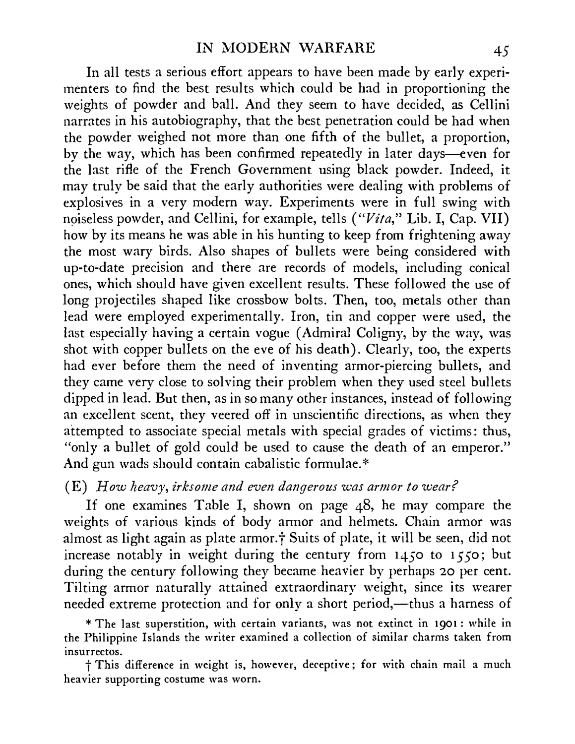
In all tests a serious effort appears to have been made by early experi-
menters to find the best results which could be had in proportioning the
weights of powder and ball. And they seem to have decided, as Cellini
narrates in his autobiography, that the best penetration could be had when
the powder weighed not more than one fifth of the bullet, a proportion,
by the way, which has been confirmed repeatedly in later days—even for
the last rifle of the French Government using black powder. Indeed, it
may truly be said that the early authorities were dealing with problems of
explosives in a very modern way. Experiments were in full swing with
noiseless powder, and Cellini, for example, tells (“Гг7я,” Lib. I, Cap. VII)
how by its means he was able in his hunting to keep from frightening away
the most wary birds. Also shapes of bullets were being considered with
up-to-date precision and there are records of models, including conical
ones, which should have given excellent results. These followed the use of
long projectiles shaped like crossbow bolts. Then, too, metals other than
lead were employed experimentally. Iron, tin and copper were used, the
last especially having a certain vogue (Admiral Coligny, by the way, was
shot with copper bullets on the eve of his death). Clearly, too, the experts
had ever before them the need of inventing armor-piercing bullets, and
they came very close to solving their problem when they used steel bullets
dipped in lead. But then, as in so many other instances, instead of following
an excellent scent, they veered off in unscientific directions, as when they
attempted to associate special metals with special grades of victims: thus,
“only a bullet of gold could be used to cause the death of an emperor.”
And gun wads should contain cabalistic formulae.*
(E) How heavy, irksome and even dangerous was armor to wear?
If one examines Table I, shown on page 48, he may compare the
weights of various kinds of body armor and helmets. Chain armor was
almost as light again as plate armor.f Suits of plate, it will be seen, did not
increase notably in weight during the century from 1450 to 1550; but
during the century following they became heavier by perhaps 20 per cent.
Tilting armor naturally attained extraordinary weight, since its wearer
needed extreme protection and for only a short period,—thus a harness of
* The last superstition, with certain variants, was not extinct in 1901 : while in
the Philippine Islands the writer examined a collection of similar charms taken from
insurrectos.
f This difference in weight is, however, deceptive; for with chain mail a much
heavier supporting costume was worn.
46 HELMETS AND BODY ARMOR
a hundred and twenty-five pounds might be tolerated if it were to be taken
off again within half an hour. Helmets, of which the various kinds are
pictured in Fig. 8, may be divided conveniently into four groups, light,
medium, heavy and very heavy. Light headpieces average three pounds in
weight and include early bassinets, certain burganets, morions and cabas-
sets, iron hats and hat-linings. Medium helmets weighing about six pounds
occur in visored bassinets, salades, barbutes, armets and certain burganets.
Heavy helmets weigh ten pounds, e.g., closed burganets and tilting armets.
And very heavy helmets, say of twenty pounds, are represented by heaumes
and siege burganets. The last-named headpieces would probably stand a
good ballistic test with the most recent firearms. In their day they were
proof to shot of large caliber, which were justly reckoned as most dangerous
in crushing armor; they are said to have withstood a quarter pound ball,
and even a one pounder when largely spent. In the matter of the discomfort
of wearing armor, there can be no question that it was always irksome.
But soldiers became used to it and the literature of the subject shows that
they rarely complained of its burden until late in the sixteenth century. In
earlier times the hardened wearer used it in active service all day long.
If exceptionally active he could vault into his saddle (or over it) in full
panoply, weighing, say fifty-five pounds, and while his horse was galloping
he could jump to the ground without using stirrups;* he could throw him-
self on his back at full length and gain his feet in hardly more than double
the time he could do it unarmed, the last a result which I have confirmed by
actual experiment. But these things can be done only when armor fits
the individual and is worn over the kind of costume adapted to it, with
the necessary “points” for supporting the elements of the suit. See Figs.
9 and 9A. In fact, under these conditions armor is worn with surprisingly
little discomfort. I can bear witness that a suit of half-armor weighing
thirty-five pounds can be worn for a stretch of three hours, and by a novice,
without extraordinary fatigue or subsequent lameness.
It was only from the latter part of the sixteenth century, when armor
weighed over sixty pounds that we find the old-time soldier grumbling
about his equipment. Pikemen would have none of it, “many throw it
away,” complained Saulx-Tavannes and Pistifilo. Horsemen would put it
* “The Bohemian Ulysses, v. Gentlemen Errant,” by Mrs. Henry Cust, London,
Murray, 1909, p. 23. Also, “this Spaniard, tho’ clad in full armor, could run for six
miles and beat all other men in ordinary clothes: placing his hand on Zehrowitz’
shoulder he vaulted with feet together right over his head,” etc. Ibid., p. 74.
Fig. 8. Helmets and their developmental sequence
48 HELMETS AND BODY ARMOR
on only at the last moment; and Montaigne (1587, Essays) deplores “the
vicious habits of his times and full of weakness to take up one’s armor only
at the call of extreme necessity, and to get rid of it at the very moment
when the danger appears to have passed, for this gives rise to much dis-
order” . . . “the old fashion was better which insured that each soldier
had on a part of his armor all the time.” Still the fashion was spreading
that the armor was to be carried as part of the equipment of the camp,
rather than of the individual. Thus Saulx-Tavannes pleads that “captains
and soldiers in close touch with the enemy should accustom themselves to
carry their armor without confiding it to their servants in order to avoid the
confusion which appears when there is need to look up their luggage.”
But the fact of the matter was that so far as long marching service in
war was concerned armor had become a physiological failure. Not merely
was the wearer rendered inactive when wearing it, but in time he became
actually crippled or “broken” by its use. A droll writer, whose stories were
read everywhere, commented audibly upon the shortcomings of men who
had worn armor. Brantome declared that he himself had known them to
be spent at thirty years. Montaigne says that “today (1587) the officer
is so heavily armed that by the time he becomes thirty-five his shoulders
are completely humpbacked.” And La None (1587) repeats the same
story.* The result of this was, according to Buttin, that “officers and sol-
diers not wishing to be crippled by thirty-five threw away their armor as
often as possible, to the detriment of their discipline and to the advance-
ment of much improvised quarrelling.” This marked an important if not
a final stage in the armorer’s decline.
TABLE I
WEIGHT OF ARMOR AND HELMETS
Weight in pounds: no allowance made for loss of weight after centuries of cleaning.
Parade armor in each class would have weighed less by perhaps 50 per cent. Letters^
refer to various collections.
* 11 Discours politiques et militaires.” “Neither was their armor heavie (those
days) but that they might wel bear it 24 hours, while those that are now worne are so
waightie that the peiz of them will benumme a Gentleman’s shoulders of 35 years
of age.”
(Collections here referred to are:
B. Zeughaus, Berlin; D. Johanneum, Dresden; E. Riistkammer, Wartburg,
Eisenach; F. Bargello, Florence; G. Musee de Ville, Geneva; M. Real Armeria, Ma-
drid; N. Y. Metropolitan Museum of Art, New York; P. Musee d’Artillerie, Paris;
T. Tower of London; Tur. Armeria Reale, Turin; V. К. u. K. Sammlung, Vienna.
IN MODERN WARFARE
49
A. Armor for man and horse
XVI century
Tilting ....
E. 53 (man) 101 (horse) = 154; 55 + 99 =
154; T-65 + 69= 134
M. 106 + 101 = 207 ; 125 + 129 = 254;
P. (Maximilian) 181
Fig. 9A. Fluted armor of 1510.
Weight 56 pounds
Fig. 9. Costume worn under armor.
About 1510
B. Armor for man
Chain mail
Suit ........................X. Y. 31 (including coiffe)
Shirt......................E. 14; X7. Y. 32, 20, 19; Turkish 22
Complete suit
XV century—Gothic . . XT. Y. 49; P. 53; V. 85
Maximilian .... E. 71, 71, 56, 49, 56, 41, 52; N. Y. 48
Complete suit for foot com-
bat .......................T. 94, 81
5°
HELMETS AND BODY ARMOR
Middle XVI century
Tilting, XVI century
Half suits .
XVII century .
Round shields .
Helmets
Bassinet (early)
Bassinet (dog faced)
Heaume
Chapel-de-fer
Salade ....
Barbute
Armet-a-rondelle
Armet Maximilian
Armet late .
Armet parade .
Burganet
Burganet siege .
Burganet lobster-tail
Morion-cabasset
Iron hat
Pikeman’s hat .
Iron hat-linings
E. 48, 59, 59; T. 67, 66
. E. 70; T. 70, 79, 106, 80, 70; N. Y. 80
. E. (black and white) 54, 32, 35, 35, 35, 75;
M. (bullet proof) (Philip III) 97; T. 35,
(bullet proof) 93
E. (bullet proof) 76; T. (3 pieces) 35, 43
. M. (Philip III) 35; N. Y. 36, 12, 10, 9
P. (diam. 61 cm.) 42
. T. 2.5
. N. Y. 6.5, 7, 11; T. 5.5
English, various, 13, 17, 18, 18, 22, 25;
M. 42; N. Y. 19, 13, 17; T. 13, 10
. N. Y. 10, 3, 4; T. 3, 6
. N. Y. 6.5, g-s, 7; T. 8, 3, 4, 3.5, 4.5, 5, 4.5
. N.Y. 6, 6.5, 6;T. 4, 5, 6.5, 4, 6
. N. Y. 6.5, 6, 6
. N. Y. 6, 4.5, 6; T. 7.5, 8
. T. 8, 9, 9, 7, 6, 8, 8, 5, 8, 5, 6, 6, 8, 9.5, 7, 7
. T. 4
. N. Y. 9, 3.5, 4, 5, 9, 10, 11; T. 8, 12
. B. 25; D. 20; F. 25; G. 20, 18; M. 27; N. Y.
22; P. 22; Tur. 21
. N.Y. 4,3
. T. 2, 2.5, 3, 3, 3.5, 3.5, 2, 3
. N. Y. 4
. N. Y. 3;T. 3, 4
. N. Y. 1.5, 4, 5, 5, .7, 1.5
(F) What in summary was the use of armor in later times, but prior to the
Great War?
In the preceding paragraphs we have seen that from the late sixteenth
century the soldier complained bitterly of the weight of his armor: it
crippled him, it prevented him from taking an active part in battle, and
he threw it aside if he could. In spite of all this he admitted that armor was
an extraordinary means of protection. It was for this reason that it did
not disappear at the first flash of a gun, as is popularly believed, but re-
mained in use for centuries while powder was being developed, and when
it was in general use in warfare. In fact at the time of the highest develop-
ment of armor at the end of the fifteenth century hand-guns had already
IN MODERN WARFARE 51
been in use for a century; and there is no doubt that armor was used most
frequently from the middle of the sixteenth to the middle of the seventeenth
centuries when guns and pistols were in common use. At that time, indeed,
powder had been notably improved in quality and already many “modern”
TABLE II
TABLE SHOWING THE USE OF VARIOUS TYPES OF FIREARMS IN
EARLY TIMES. (GUNPOWDER AS A CHEMICAL INVENTION
APPEARED IN EUROPE EARLIER THAN THE
TENTH CENTURY)
1200' 13ОО ЦОО IJOO 1600 17ОО 1800
Grenades
( Sh rapnel)
Cannon ...
Many-barreled
Revol ving
В reech-loading ....
Guns
Breech-loader
Rifle* * ..
Matchlock
Wheel-lock
Snaphaunce ммшшмн
Flintlockf ..
Detonator
Percussion
Pistols
Chambered
Revolver .......
devices had been invented. (See Table II.) Hence we have reason to believe
that the general disuse of armor was not due entirely to the failure of armor,
in spite of its weight, to resist firearms, but to other causes as well. Here'
should be mentioned especially those changes in military tactics which were
taking place at a time when armor was declining. Thus during the Thirty
* Survives in Orient.
•(•Survives in isolated localities, e.g., Central Africa.
52 HELMETS AND BODY ARMOR
Years’ War (which ended in 1648) the Swedes, especially, built up a mili-
tary system wherein it became necessary for manoeuvring armies to cover
long distances in short time,—a system which alone might have encour-
aged the infantry to throw away its armor, whether light or heavy. In fact
I am inclined to believe that this factor is far more important in the dis-
appearance of body defenses than is usually reckoned. For so soon as armor
began to drop out of use it became unfashionable, then unpopular and in
the end discredited. That it could still have been used to good purposes
seems none the less clear if we examine attentively the comments of certain
masters of war during the eighteenth century and there is no better case
in point than that of Marshal Saxe (f 1750)* who goes out of his way to
recommend the use of armor, declaring that it is the more needed since in
his experience casualties were caused in greater number by swords, lances
and spent balls than by projectiles of high velocity. And we infer that
such opinions were not exceptional since we find that suits of armor, lacking
defenses for the lower legs, were worn in number up to the time of the
French Revolution. Even in America we find such armor in use at the time
of the French and Indian War and in rare cases during the Revolution.
Lord Amherst, for example, in his Canadian campaign (1758-1760) is
pictured thus armed, wearing even hip defenses, Fig. 10. Kosciuszko, also,
wore armor and probably brought it to this country; and we have reason
to believe that Rochambeau wore his siege armor at Yorktown (1781),
for he is described by Joel Barlow as in “gleaming steel arrayed.” And
Paul Jones, while not in half-armor, wore a corselet under his coat during
the fight with the Serapis, according to his fellow-Scotsman, Hyslop. (See
Bull. Met. Mus. Art, 1912, Vol. VII, pages 26-28.) Possibly, the latest
armor worn as a more or less complete suit appears in Reynolds’ portrait
of the Marquis of Townshend, and dates late in the eighteenth century; but
we are not sure of the date of this harness, for it may have been merely
a form of ceremonial costume which the painter adapted, or it may have
been of considerably earlier date, e.g., worn at Fontenoy, Dettingen or
Culloden. During this late period part of the armor it appears was designed
to resist bullets of fairly high velocity, shot often from rifled barrels and by
good black powder. The bullets, however, had not a great range, rarely
as much as seven hundred yards, and with great individual variation;
* Les Reveries, Edit. 1756, p. 58. Among wearers of armor during a late period we
may mention Luxembourg, Eugene, Louis XV (1750), George I (1718), George II
(1758), Paoli (1780), Granby (1769). . . .
IN MODERN WARFARE 53
but they were usually of large caliber and proportionally more destructive
than those in present use. Thus bullets of the Revolutionary musket
Fig. 10. Armor worn in Canada about 1760 by Lord Amherst
weighed about fourteen to the pound (= 500 grains), which is heavier by
50 to 100 per cent than the present rifle ball (Spitzer). (The latest Mauser
weighs 227 grains.)
54
HELMETS AND BODY ARMOR
Armor of this kind showed, for one thing, that there was no evident
ground for the common belief that the severe shock of a projectile against
armor would in itself be fatal to the wearer—even when the armor remained
unbroken. In fact, we shall see (page 242) that armor which resists a
machine gun, say at fifty yards, did not cause its wearer grave discomfort
from the impact even of a series of projectiles. In a word, from the study
of the history of armor one can find no reason why it could not be used
Fig. 11. Gorget worn during American Revolution
under certain modern conditions: hence it follows that if armor were re-
quired in actual warfare, there would be no need of developing a new sys-
tem of wearing armor. We should advance merely a step further in its
historical development.
There is no question, then, that armor passed out of general use not
at once but gradually. Thus after the year 1620, leg armor rarely appeared
and defenses of the hips and thighs are uncommon from about 1670. De-
fenses for the arms were abandoned piece by piece somewhat later, although
complete arms continued to be used for about a century in ceremonial
armor, as worn by highest officers. For a long time the neckplate or
gorget was retained as part of the regular equipment and it even became
IN MODERN WARFARE 55
exaggerated in size; but it finally became so small that its function as a
defense had practically disappeared. As shown in portraits of Colonial and
Revolutionary times, it was little more than an ornament which was at-
Fig. 12. Gorget appearing in portrait of Washington, about 1772
tached to the officer’s neck by a ribbon and usually bore his regimental
number. See Figs. 11 and 12.* The corselet and helmet have remained ever
in use in certain state guards or cavalry regiments. These plates were made
of low carbon tool-steel and are fairly resistant even to modern explosives.
* It is even today in certain regiments; shown, e.g., in portrait of Colonel Bates of
the 71st New York Infantry, National Guard.
56 HELMETS AND BODY ARMOR
A heavy corselet (forty-one pounds), probably of the time of Napoleon,
was recently tested by Captain Roy S. Tinney (National Service Magazine,
January, 1918, pages 395-403) anc^ gave g°°d results; it resisted in turn
Craig ammunition 30, 40 to 20 with muzzle velocity 1,970 foot seconds;
at 100 yards—1,553 foot-pound blow; a Winchester 30, 30, 170, of 1,522
foot pounds; a Sharp’s rifle of 45.90, 300, at 100 yards (muzzle velocity
pI foot seconds) ; and finally the 303 Savage firing a 195-grain bullet
having muzzle velocity of 1,658 foot seconds. In a word, such a corselet
Fig. 13. Sapper’s leathern helmet,
1750-1800
Fig. 14. Sapper’s helmet, middle of
nineteenth century
resisted projectiles which were scarcely inferior to those in use on present
battle-fields. With this test in mind, we may well believe the early state-
ments that the cuirass of the guardsman played an important part in bodily
protection during the eighteenth and nineteenth centuries. During the
eighteenth century, we recall that its use was fairly constant for cavalry
(for the highest officers, especially, when parts of it, at least, degenerated
into a ceremonial costume). And in the early nineteenth century, the corse-
let and headpiece appeared in great numbers in European armies. For one
thing, Napoleon the Great favored their use. And there still exists his order
to Requier, chief of the artillery museum of Paris, to send post-haste to
Tilsit (1808) the corselets and casques which had been made for himself
IN MODERN WARFARE • 57
and the Prince of Wagram. There is no question, also, that armor was worn
at a very late date in sieges and in naval warfare. Thus heavy helmets and
shields of various forms were used during the eighteenth and nineteenth
centuries, especially for the defense of sappers. In Fig. 13 is pictured one
of the heavy leathern headpieces worn by sappers (and possibly by fire-
men), 1750-1800; specimen now in the Tower of London. In Fig. 14 ap-
Fig. 15. Body armor used in American Civil War,
1862-1864
pears a heavy helmet of this type drawn from a specimen in the Tower of
London; its weight is over nineteen pounds and it dates from about 1848,
judging at least from Raffet’s picture of the siege of Rome in this year,
when sappers are shown wearing helmets of this type. Perhaps, too, we
should here mention the numerous types of metal “helmets” which have
appeared as headgear for infantry and cavalry during the late eighteenth
and throughout the nineteenth century which were of little value save
ornamental, e.g.^ the eagle headpiece of the fugitive German emperor.
58 HELMETS AND BODY ARMOR
In the Orient armor was used practically up to our own time and is
probably still worn in out-of-the-way localities in Persia and India, more as
a ceremonial costume, perhaps, than for use in warfare. Moreover, we know
that the Japanese wore armor regularly until about 1870, and fairly good
armor it was. Chain mail reappears in the East with curious persistency.
As late as the Younghusband Expedition to Thibet (1903) cases occurred
where natives were captured whose costume, reinforced with chain mail,
had successfully resisted the bayonet thrusts of the English. Hardly earlier
than this, chain mail appears to have been worn in the region of the
Caucasus. Similarly, we note that coats of mail are still worn secretly
wherever danger is dreaded from personal attacks, especially by sword or
knife. The writer learns from good authority that a well-known armorer
in Paris derived, until about 1908, a substantial part of his income from
making shirts of chain mail which were shipped to South America and
Africa for actual service.
To trace in further detail the use of armor in relatively recent times:
It is known that breastplates were worn more or less frequently during the
American Civil War. In the museum in Richmond, there is preserved such
a “suit” of armor, Fig. 15, which at the time of the siege was taken from
a dead soldier in one of the trenches. He was shot in the side or back, for
the breastplate, it appears, was not penetrated. This armor was of northern
origin. Further inquiry shows that a factory for the making of such defenses
was established at New Haven about 1862. The metal employed was a
mild steel, .057 inch thick, and the “suit” weighed about seven and one
half pounds. While no tests of this armor are available,* we estimate from
* Since this was written Miss Helen Gibbs, curator of the Museum of the Virginia
Military Institute, has very kindly forwarded to the writer a hip-guard belonging to
this body shield. A test shows that it will resist a 45 Colt-revolver bullet of 200 grains
at about 700 foot seconds velocity. A second test was made with standard ammunition
(800 foot seconds), 230-grain jacketed bullet from the 45 automatic: one shot failed
to penetrate at ten feet, two penetrated but without splintering the metal. The body
shield was, accordingly, a surprisingly good one for its period—before the develop-
ment of higher ballistic alloys. Again, thanks to General Nathaniel Wales of Jamaica
Plain, Mass., I have just received very interesting data regarding this “steel vest”
of 1862. He states that “it was worn more often than we had any idea of, but many
officers felt they should not be protected better than their men, consequently those
who wore the armor did not advertise it.” . . . Thus “two of as brave officers as I
ever knew wore it, my colonel . . . and my major who was killed, a bullet grazing
the bottom edge of the vest and passing through his body.” He states also that his life
IN MODERN WARFARE 59
the thickness of its metal, assuming that it is a “mild” steel, that it would
have stopped a 230-grain pistol ball traveling at the rate of 500 foot
seconds.
During the Franco-Prussian War several types of armor were used to
a limited degree. The heavy corselet appeared, also the horseman’s helmet.
Fig. 16. French body defense used in 1870
We have occasional reference to the use of a very heavy helmet in
the trenches and also of varied types of armored waistcoats. One of these,
manufactured in Paris, is shown in Fig. 16. This specimen is made up of
small rectangular plates of low carbon steel and riveted to canvas. The
was saved by it at Antietam (September 17, 1862). Quoting his letter: “I had been
presented with a steel vest by my father when I left Massachusetts, but I left it in
Washington. When I entered the fight a brother officer, who was wounded, insisted
on my putting on his steel vest. . . . When I advanced [in the open to meet a rebel
6о
HELMETS AND BODY ARMOR
entire defense weighs about five pounds and could be worn with a reason-
able degree of comfort. It does not resist a 230-grain pistol ball at 650 foot
seconds, and from its behavior in this test, one doubts whether it would
have resisted a similar bullet at a velocity greater than 300 foot seconds.
Its value, therefore, lay in protecting its wearer only from spent balls or
splinters. Ballistically, it had much less strength than the light-weight
shrapnel helmet in present use in the American Army.
In all later wars, armor appears to have been used sporadically, some-
times as body defenses, sometimes as helmets, sometimes again in the form
of shields which were either carried by the soldier or pushed in front of
him. It was due to small shields of the latter type (see also page 176) that
the Japanese were able to take some of the most difficult outposts of Port
Arthur. Also, in the Boer War armor appears to have been used. Thus in
the siege of Ladysmith, helmets were used which are said to have been
proof against machine guns. They were clumsy affairs and heavy, and were
not firmly attached to the head. No details of these helmets have been re-
corded nor have we been able to secure photographs of them. From an officer
(Lieutenant R. Miller of the Imperial Light Horse) who was present at
the siege, the writer learned that the defenses in question were crudely
made and were only moderately effective.
The most convincing historical instance of the use of helmets and body
armor against modern ammunition dates from 1880. This was in the case
of the Australian bandit, Ned Kelly, who long owed his freedom to the
fact that he wore armor (Fig. 17). This, it appears, he had improvised;
it was the “work of some skilled local artisan.” It is said to have been made
out of old plowshares, beaten into plates one quarter of an inch thick. It was
charge in the twenty-first Massachusetts regiment] a bullet [evidently at close range]
struck me just below the heart . . . knocking me down. Getting on my feet I walked
back to where General Ferrero was lying behind a ledge. As I passed him he said,
‘Where are you going, adjutant4?’ I replied, 4I am hit, sir.’ ‘Where4?’ I pointed to the
hole in my coat and he said, ‘You had better go to the rear.’ I sat down remarking,
‘I’ll see how badly I am hurt.’ It was not until I grasped the cartridge-box belt to un-
clasp it that I realized I was wearing the steel vest. The convex side of the dent had
cut through vest, shirt and undershirt making a small cut in the flesh. It was consider-
ably swollen and for ten days or a fortnight I was unable to draw a long breath.” The
drawing of the armor which accompanies the notes of General Wales shows that his
escape was the luckier since the bullet struck the breastplate very close to the point
where four plates came together, a region of structural weakness in armor of this
type, for the free corners of the plates are held together only by rivets.
IN MODERN WARFARE
61
badly fashioned and extremely heavy, weighing ninety-seven pounds, but
it covered the body completely. On various occasions it was badly “shot
up” but not penetrated. Its wearer was captured after a several months’
chase and then only after he had been shot in the legs. To give one an idea
Fig. 17. Rifle-proof armor of Australian
bandit, 1894
of the efficacy of this armor against Martini rifles at close range, we insert
the following quotations from the official account of this case written by
one of the attacking party.
“I have no hesitation in stating,” writes Superintendent Hare, “that
had the man been without armor when we first attacked . . . and could
62
HELMETS AND BODY ARMOR
have taken proper aim, not one of us would have escaped being shot. He
was obliged to hold the rifle at arm’s length to get anything of a sight.”
“His armor included a great headpiece which was like an iron pot which
rested on the wearer’s shoulders and completely protected the throat. The
outlaw as he advanced toward the policemen had taken the precaution to
conceal his armor under a long gray overcoat.” “The first policeman closed
in upon him and a strange fight began. The soft Martini-Henry bullets
dinted his armor but did not penetrate and he coolly returned the fire.”
“It appeared as if he were a fiend with a charmed life.” “For one half-hour
this strange combat lasted.” “Then one of the party rushed in and shot the
outlaw in the leg, then sprang upon him and disarmed him.”
This instance of the use of armor against modern gunfire is of especial
interest since it shows that an armored man could stand in front of a squad
of riflemen, even at close range, and be reasonably immune. He could even
kill them all, as Superintendent Hare admits, if he were a skilful marks-
man.
From the time of Kelly’s practical “experiments” up to 1914 the matter
of body armor had not been held altogether in abeyance. And he who fol-
lows the literature of the subject will be surprised to find how many types
of “bullet-proof” devices have been invented. A breastplate known by the
name of its promoter, Rowe, apparently patented, was experimented with
extensively prior to the year 1901. It gave results so promising that it at-
tracted the personal interest and support of the German emperor. Another
body defense known as the corselet Loris was also “tried out” about this
time; its inventor demonstrated its effectiveness, if I am correctly informed,
in various theatres in France. So, too, a bullet-proof waistcoat (see page
290) was designed by Casimir Zeglin and worn about 1897 in spectacular
tests in a New York theatre. And in London similar demonstrations, more
or less serious, were made by inventors, whose results, by the way, Sir Hiram
Maxim accurately followed up, he himself suggesting a certain type of
high alloy plates (containing tungsten) for their armor.
Even chain mail was developed by these experimenters. Thus in the
military retrospective exhibition of 1889 in Paris types of mail were shown
which were “proof” to dagger thrust and to the lead ball (.433 inch) of a
service revolver. The former mail was made up in alternate rows of links
solid and open (i.e,, formed so that the tips of the wire merely butted
together), made of tempered spring-steel; the better quality of mail had its
links fused or riveted.
IN MODERN WARFARE 63
About the year 1900, in fact, a dozen or more types of armor were being
exploited. A well-known establishment at St. Etienne was then advertising
a light breastplate proof to service revolver. A cuirass made by Alphonse
Payot of La Rochelle, Savoie, was in the market, and one devised by
Ernest Benedetti was tried out in Rome (1901) before a military commis-
sion and was given a favorable report. And at that time military writers
were impressed with the necessity of reconsidering the armor problem. “If
out of a thousand soldiers not one can reach even an improvised trench
when it is defended by machine guns we must arrive at the adoption of
some kind of a portable defense,” writes Captain Danritt (“L# Guerre de
Demain” page 600). Ch. Buttin notes at that time (1901, “Les Armures a
I'efreuve” Annecy, pages 99-100) that the “question of proof, far from
being a dead issue, is the order of the day,” and that “nothing is more sure
than that science has never said its last word. And perhaps there will be
found,—even if it has not already been found,—a process of making again
in a scientific way that which the earlier armorers were unable to produce
in their day, in spite of the superiority of their workmanship,—a corselet,
light and truly proof, this time to the test of an armor piercing bullet!”
I
THE EARLY USE OF ARMOR IN
THE PRESENT WAR
WHEN war began, in August, 1914, a soldier, even under
special conditions, was given no defenses for head or body,
in the sense of personal armor. It is true that the Germans
in certain formations wore their familiar “Pickelhaube,”
which was a stamped leathern helmet, sometimes reinforced by steel bands
and weighing in general less than a pound and a half. In certain instances,
also, the Germans were provided with shields which, during the rapid ad-
vance through Belgium and France, appear soon to have been cast aside.
These shields, we learn, were a distinct protection against small projectiles
of low and middle velocity (less than i,joo feet a second) but they were
difficult to transport, for they could not be carried by the individual soldier
in addition to his regular equipment. They were said even to be dangerous
to use since, when struck, the shock would be apt to injure the bearer
seriously, £.<7., break his arm (although on what evidence the writer has
been unable to learn). It is also true that in 1914 the cuirassiers of the
present guards, German, French and English, wore their panoplies, as a
reminiscence of the state guards of olden times, but as cavalry was speedily
sent to the rear, no satisfactory data could be gathered concerning in what
degree armor actually appeared. That the panoply of the cuirassier was of
considerable protective value is learned from several sources (see page 56).
If his headpiece or corselet were struck by a projectile, it deflected a bullet
of high velocity if its angle of incidence were great (over sixty degrees to
the normal), but in this case the bullet was apt to disintegrate completely,
producing a “splash” which itself was capable of inflicting a dangerous
wound. In one instance recorded, a cuirassier was nearly decapitated by a
lead splash of this kind which passed upward over the border of his breast-
plate.
The French appear to have been the first to accept the helmet in actual
service and thousands of soldiers today bear witness to the practical value
IN MODERN WARFARE 65
of the casque which was provided for them, notably through the efforts of
General Adrian.
A few words as to the work of General Adrian: During colonial service,
in which soldiers were in danger less from the enemy than from diseases
due to improper sanitation, this officer was known for his ingenuity in
developing devices which aimed to protect his men. Their well-being be-
came his hobby, and when the present war broke out, with its appalling
Fig. 18. Steel cap-lining, French model, 1915
casualties, General Adrian sought ways and means in all directions for
reducing his losses. One day he stood before a stretcher and talked with a
wounded man—“I had luck,” said the sufferer, “I happened to have a
metal mess-bowl in my hat and it saved my life.” This incident impressed
the General deeply. Here was the question of a device which might prove
of universal value. So with his usual earnestness, he attacked the problem
of a head defense. He promptly had a steel “calotte” made and fitted inside
his cap; then he wore it constantly to find whether it would cause notable
discomfort. Next he had many of them made and used experimentally.
66
HELMETS AND BODY ARMOR
See Figs. 18, 19. Good reports soon came in from the front. Thereupon, he
developed the regular helmet which was manufactured in great numbers
for the French Army. See Frontispiece. At first this defense was turned out
hastily, stamped from dies which had already served in making the helmets
of firemen.
Investigation showed that the new helmet was of actual value in the
field; hence it became a part of the regular equipment and was used by
every soldier on active duty. Its use naturally added to the burden of each
wearer, causing at first considerable grumbling. During the period of pro-
Fig. 19. French steel cap-lining, shown in position
bation of the helmet, some of the critics pointed out that the number of
casualties with head wounds increased notably, but the advocates of the
helmet, referring to statistics, replied that the vast percentage of those who
were formerly wounded in the head found their way not to hospitals but
to cemeteries!
It is interesting to note that almost from the beginning the “casque
Adrian” was a successful experiment. It protected a measurable portion of
its wearer; it was light and soldiers of all classes shortly “took to it.” The
casque was attractive in its lines and it added martial distinction to its
wearer—which proved, in the opinion of many officers, a more important
argument for its use than its ballistic value. Then, too, example was con-
tagious and if one division wore it, the next was apt to follow suit. Pres-
IN MODERN WARFARE 67
ently it came about that the helmet was looked upon generally as indis-
pensable. In 1915 the British Army adopted the type of helmet which it
still wears. About the same time, so far as the writer can learn, the German
helmet made its appearance. In 1916 the Belgians and Italians were wear-
ing helmets and during this year they appeared in numbers on the Slavic
line.
Body armor was used on all fronts from 1915 onward but its use was
experimental rather than general. It was either so light in weight that it
afforded too little protection, or was so heavy that its wearer, like his fore-
bear in the Thirty Years’ War, would throw it away in all cases-where
freedom of movement was needed. Only by sentinels or those engaged in
short raids was body armor used successfully. Nevertheless, it is generally
conceded by experts whom the writer consulted that this type of defense
is of great potential value. But its future effectiveness will depend upon
various conditions which further studies may be expected to solve. This
matter is treated in a later section of this work and recommendations are
made which are based upon the results of the experience which has been
gained up to the end of 1918.
General Adrian
II
ARMOR AS PROTECTION AGAINST MISSILES
OF LOW AND MIDDLE VELOCITY
f—W—^HERE is no better evidence that armor is of practical impor-
I tance in actual warfare than the testimony of physicians as to
I the value of the “shrapnel” helmet. In this case, at least, all
> criticism was overcome, although in the beginning there cer-
tainly were many objections to its use. Indeed, so severe was the criticism
that had the French helmet not been introduced in very large numbers
(the first lot included over a million copies), insuring it a thorough trial
and under many conditions, the experiment might not have succeeded.
Various estimates have been made as to the number of casualties saved
by the use of the shrapnel helmet. But these estimates are based on statistics
obtained in different localities under different conditions, hence they are
apt to be discordant. In a general way, however, hospital records (French,
1915) show that before the introduction of helmets about one head wound
in four proved fatal. After the introduction of the helmet, however, statis-
tics indicate that head wounds were fatal in, at the worst, one case in four
and a half, and at the best one case in seven, a bettering of condition which
is certainly appreciable. Add to this the saving of those men—and their
number, although unreported, is great—whose helmets had resisted mis-
siles which would otherwise have indicted serious, if not fatal wounds.*
As a protection against missiles of low and middle velocity, there is
no better evidence that armor has a definite usefulness in modern warfare
than the fact that one type of armor (j.e., the helmet) is accepted by many
nations as a part of their military equipment; for if such a defense, even
when made of light metal, is capable of resisting small missiles of middle
and low velocity, it is clear that similar defenses must have a definite value
when worn on chest, abdomen, or extremities. So far as the writer is aware,
* Major Samuel Getty, in charge of the American Base Hospital at Vittel, 1917-
19)8, was shown a helmet which had saved its wearer no less than seven times.
IN MODERN WARFARE
the only practical objections to the introduction of armor for these regions
are its weight and the discomfort it causes its wearer—objections which,
frankly, are grave, but they become the less serious if it can be shown that
the advantages in wearing armor more than compensate for the disad-
vantages. Thus, important evidence as to the usefulness of armor is to be
sought in the records of casualties.
(a) STATISTICS WHICH DEMONSTRATE THE USEFULNESS
OF MODERN ARMOR, NOTABLY THE HELMET. THE
MEDICAL VIEWPOINT
If it can be shown that a large percentage of the wounded soldiers in
hospitals are suffering from wounds caused by missiles of low and medium
velocity, it becomes clear that there is already a practical scope for the intro-
duction of armor. The effort has therefore been made to collect data from
various hospital sources, and it is now safe to say that the results of this in-
quiry have been conclusive. The statistics which cover the casualties of the
English through the year igi6 indicate that more than three fourths of the
cases could have been saved if armor had been worn* French statistics give
similar results, the casualties caused by missiles of middle and low velocity
averaging from 60 to 80 per cent in round numbers. The American statistics,
so far as can be determined, vary from 65 to 80 per cent. In a letter to the
writer, dated February 14, 1918, Major Charles H. Peck, Assistant Di-
rector General Surgeon, A. E. F., states that “wounds caused by missiles
of middle and low velocity constitute about 80 per cent of all.” In general,
however, it should be admitted that complete statistics as to the percentage
of the wounds caused by missiles of low and middle velocity are not always
easy to obtain;f for the tabulation of wounds is not apt to be made from
* In a report from Colonel Walter D. McCaw, who has reviewed (June 30, 1918)
the latest data at the Service de Sante, the following percentages are given:
Shrapnel or shell fragments . . . 50.66%
Grenades . . - . . . . 1.02%
Rifle or machine gun bullets . . . 34.05%
Bombs from aeroplanes .... .10%
Mine explosions ..... .15%
Accidental missiles, undetermined . . 14.00%
Certainly the majority of these wounds might have been avoided by the use of armor,
f According to the American surgeon, Dr. Walter Martin, whose experience was
wide on the western front (1916-1917), “a large proportion” of wounds examined in
70 HELMETS AND BODY ARMOR
this point of view, although it is usually possible to determine from the
nature of the lesion whether it was caused by a missile of high velocity.
Summarizing the situation, we will come far within the mark if we state
that the proportion of wounds due to middle and low velocity projectiles
is not less than 60 per cent. In fact, this is the lowest estimate which we
have been able to gather from medical experts who have sometimes declared
that such a proportion would attain the surprising figure of 95 per cent!
For, as Colonel Joseph A. Blake, director of one of the largest American
military hospitals, notes in a letter to the writer, dated April 30, 1918,
an accurate list of the “smaller wounds is not forthcoming because a large
number of wounded whose injuries are not infected, are returned at the
front and do not enter, therefore, in the statistics of the hospitals.” If we
accept accordingly that a large number of the wounded (estimates varying
from 60 to 95 per cent) could have been saved by the use of armor it follows
that the armor problem is a real and a very important one. One may note,
also, that in cases not infrequent, armor might have saved victims of pro-
jectiles of high velocity. For it is well known that armor, if struck at an
angle, will deflect projectiles of great velocity. In other words, from this
source, too, the percentage of men whom armor would have saved becomes
appreciably greater.
In this connection, we have at hand the medical report of a case which
shows that a shrapnel helmet, which resists normally a projectile of 230
grains at 600 foot seconds, saved the life of its wearer when hit by a Ger-
man machine gun bullet at a range of 100 yards—traveling, therefore, at
the rate of not less than 1,800 foot seconds.
(b) FREQUENCY IN THE LOCATION OF WOUNDS AND ITS
BEARING UPON THE ARMOR PROBLEM
There can be no question that the usefulness of armor is conditioned by
a curve of frequency. In other words, if it is definitely established that a
certain region of the body is particularly susceptible to injury, it is
obviously that region which we should make an effort to protect. Hence
the study of hospital statistics should furnish practical hints as to the sol-
thc European war hospitals was due to missiles of low and middle velocity. Colonel
McCaw states (June 30, 1918) “that in the hospital records, it is not the custom to
note the probable velocity of the missile causing wounds in soldiers. As far as the
writer knows, this is not done in any army.”
IN MODERN WARFARE 71
diets’ needs in the matter of protection. Unfortunately, however, from such
a study we find that the statistics which are available are not usually classi-
fied on the lines we would have chosen, nor are they commonly accessible
for large numbers of cases. Our deductions, therefore, must be made with
a certain reserve. Moreover, it is clear that in various sectors at the front,
the proportion of wounds may be different for various regions of the body.
Nevertheless, the writer thinks that it is safe to state from the data col-
lected that the proportional frequency of wounds in hospital cases may be
arranged on somewhat the following lines:*
Lower extremities . . . 35%
Upper extremities . . . 25%
Head and neck . . . 20%
Trunk . ‘..............20%
In a word, certainly over 50 per cent of the hospital cases suffer from
wounds in the extremities and rarely more than a fifth of the patients
have been wounded in the head. The number of hospital patients wounded
in the abdomenf is usually small—at first sight unexpectedly so. In fact,
* Colonel McCaw summarizes the latest data (June 30, 1918) of the Service de
Sante as follows:
Classification of wounds according to anatomical situation:
Head . . 11.90% Forearm . 10.75%
Thorax . 7-25% Hand . . 8.95%
Spine 2.20% Thigh . . 15.62%
Abdomen 3-97% Leg . . . 17-84%
Arm 14.07% Foot • 7-45%
In a word, the leg wounds would constitute 41 per cent of the total, arm wounds, 34
per cent, head, 12 per cent, trunk, about 13 per cent,
j- Dr. Abadie (d’Oran) in his studies of wounds of the abdomen, published by
Hongin, Masson et Cie., 1916, offers the following table:
Due to projectiles
Abdominal wounds 479 cases.............................. low velocity . 332
high velocity . 147
Thorax .... 15 lung cases .... low velocity . 13
high velocity . 2
• 72 extracted
33 bullets
39 shrapnel fragments
This authority notes that blood poisoning comes from low velocity projectiles, espe-
cially shrapnel. Bullets showed 4.5 per cent of the fatal cases, shrapnel, on the other
hand, 40 per cent.
72 HELMETS AND BODY ARMOR
this proportion is the smallest of those injured, usually representing less
than 3 per cent of the total. In such computations, however, it must be
borne in mind that the frequency of wounds as shown in hospital records
is by no means the frequency in which they occur in the held; for, as in
the case of abdominal wounds, only a small proportion of these casualties
survive long enough to be brought in. And this is true as well in the case
of injuries of the head and of the thorax. We may note, however, that the
consideration of these cases accentuates the importance of armor wearing,
for it is evident that many a death occurs in the held from an injury to the
thorax or abdomen where a missile of even low velocity readily enters the
thin body wall.
The question of injury to the eyes has played also an important part
in the discussion of armor. The peril of blindness affects the morale of
troops and has led the general staff of almost every army to consider the
problem of introducing visors for the helmet (see page 88). In fact, it may
at once be stated that all experts agree as to the distinct usefulness of a
visor of almost any type as a means of protection against eye.wounds; for
of such injuries over 50 per cent were caused by small fragments which
could readily have been kept out by means of an eye-shield.*
We refer here especially to the extended studies of the French eye
surgeons, MM. Morax and Moreau,f who show that over 43 per cent of
* Of those recorded in French hospitals about 93 per cent were due to missiles of
low velocity.
f ММ. V. Morax et T. Moreau in the Annales d'Oculistique of August, 1916,
show that about 43.4 per cent of eye wounds are caused by very small fragments, 303
out of 698 cases. These experts also indicate that about JO per cent (170 out of 341)
of the cases of shell wounds are caused by small fragments and that a larger per cent
of wounds are due to grenades and bombs. From the statistics in the hands of these
writers, the following represents, in a general way, the frequency of wounds to the
eye caused in various ways:
Shell fragments . . .341
Rifle or machine gun . 191
Grenade ....................82
Fragments of bomb ... 63
Shrapnel ball .... 21
Bayonet ................... 1
These authors declare that JO per cent of these cases could readily be saved by the
use of visors of various types. This result is corroborated by British specialists, one
of whom, Captain Grove White, states that JO per cent of eye wounds could be pre-
vented by the use of the chain visor (see p. 133) designed by Dr. Cruise. LaPersonne
IN MODERN WARFARE 73
eye wounds in about 700 cases were caused by very small fragments and
that 50 per cent of them were caused by small fragments, all of such a
nature that they could readily have been prevented from entering the eye.
On the other hand, the question of armor for the eyes should evidently
be given less attention if it can be shown that the cases of total blindness
are extremely rare; for in this event the loss in efficiency would be costly
if an army would be compelled to wear visors. In point of fact, eye wounds
are proportionally rare, judged from statistics obtainable. The Canadian
records are here extremely accurate and they show us that of 150,520
casualties there were only 20 cases of total blindness. That is to say, a case
of blindness occurs among their casualties only once in seven thousand cases.
In a word, following the statistics in question and taking into account the
total number of troops involved, the chance of any particular soldier be-
coming totally blind is certainly very remote. Thus, in the English Army,
in general, the percentage of cases of blindness is known to be low. and
indeed not more than three thousand cases of blindness were recorded up
to January,. 1918, in an army of about three millions. In other words, the
chance of any individual English soldier becoming blind is as one is to one
thousand. And from the data concerning the armies of all nations, so far
as the writer was able to determine, it seems clear that the number of cases
of total blindness is not excessive, in no instance higher apparently than
one in five hundred, or one fifth of one per cent. Hence in the work of war
it would hardly be expedient to give to a thousand men an eye defense which
would confuse them and which would possibly be a cause of slowness in
action and consequent danger of casualties, to the end that only one person
in this number should escape blindness.
and Terron note that 80 per cent of the eye lesions studied in French hospitals were
due to missiles of low velocity; they also declare that in general the majority (75
per cent) of all wounds treated in military hospitals are caused by similar missiles.
Ill
FOREIGN TYPES OF HELMETS AND BODY
ARMOR, THEIR ORIGIN AND FATE
(A) French
(a) The French helmet
1. Origin
2. Description
3. Manufacture
4. Material
5. Ballistic value
6. Criticism
7. Newer models
(b) Face defenses, Polack and Dunand visors
(c) Body shields
(d) Defenses for arms and legs
(A) FRENCH
(a) THE FRENCH HELMET
1. Its Origin
FRANCE, as we noted in the introduction of this report, was the
first nation in the present war to adopt steel helmets for its sol-
diers. The earlier form of this helmet appears in Figs. 18 and 19.
This was a steel cap designed by General Adrian before Decem-
ber, 1914.
It was stamped out of soft steel .197 inch (5 mm.) thick and weighed
but nine ounces. It had its initial inspiration in the metal hat-lining of the
sixteenth century which was termed a “secrete.” This metal lining was
merely pressed into the cap and held in place by a sweat-band. It was a
simple device but it was found to resist 60 per cent of the shrapnel hits.
This was determined by experiments in the actual field in the “polygon of
Bourges.”
IN MODERN WARFARE 75
Early in February and March, 1915, 700,000 of these caps were made
and issued. The success of this simpler type of head defense gave place
within a month or two to the complete French helmet (Frontispiece). In its
essential lines, this followed the design of the helmet of the cuirassier and
of the “casque du pompier” as illustrated in the accompanying sketches
Fig. 20. Standard French helmet, 1916
Fig. 21. Standard helmet (dotted profile)
compared with French fireman’s helmet
Fig. 22. Standard helmet (dotted profile)
compared with French dragoon’s helmet
(Figs. 20, 21 and 22), for by this procedure a model was at hand whose
merit was fully established and whose speedy production was assured. In
fact, certain of the dies which formed the earlier casques could be used at
once. The thickness of metal recommended for the new helmet was 8 mm.
(.315 inch). Its entire weight should not exceed 800 grams (=2 pounds)
which was but two thirds the weight of the casque of the dragoon.
76 HELMETS AND BODY ARMOR
2. Description
The present hat-shaped helmet is worn by all French soldiers in actual
service. Its light weight (which was reduced to one pound eleven ounces)
enables it to be worn without fatigue, and its artistic merit, to which
Edouard Detaille contributed, touches the pride of the soldier.
In general, it is hat-shaped, composed of a sub-hemispherical dome, a
medium crest, and a down-bent brim which is narrow above the ears. On
its forehead it bears the symbol, e.g., grenade, crossed cannon, etc., of the
Fig. 23. Lining of standard French helmet
army group to which the wearer belongs. The casque is painted either the
military blue of the French soldier or an olive drab. Its surface is not
roughened.
It fits the head of the wearer nearly as comfortably as a “derby” hat
and its size is, to this end, regulated with great precision. The steel shell
is stamped out in three sizes, designated “A,” “B” and “C”: the first is
adapted for heads of our hat-size 6%, the second size corresponds to our
7%, and the third to our 7^. For each of these sizes, linings of four dif-
ferent measures are provided. The lining is separated from the shell of the
helmet by a band of aluminum, which is crimped or corrugated—furnishing
IN MODERN WARFARE 77
a series of channels which run vertically when the helmet is in place, insur-
ing a certain amount of ventilation. The lining consists of a sweat-band
of “Cuban goatskin” from which arise tabs which line the dome of the
helmet and converge to its apex (Fig. 23). Each tab is perforated near its
free extremity by a metal eyelet through which a string passes. By the ad-
justment of this string, the head may be kept from contact with the top of
Fig. 24. Three stages in making French helmet, 1916
the helmet. The leather sweat-band of this helmet is kept from the steel
shell by the intervention of a stout band of felt and by the corrugated band
of aluminum mentioned above. A chin-strap, made of sheepskin, five eighths
inch in width, is fastened to the helmet by means of two slender metal
loops, each on its side attached by two small rivets. The latter serve, at the
same time, to hold together the front and back halves of the brim of the
helmet.
78
HELMETS AND BODY ARMOR
3. Manufacture
The French helmet, while apparently simple in structure, requires no
less than seventy operations in manufacture. This number, moreover, does
not include stages in the preparation of the metal for manufacture, cutting
out the plates, etc. (Several stages are shown in Fig. 24.)
(a) Dome: The dome of the helmet is stamped out cold in two opera-
tions. “Blanking” (trimming) operations follow, then a hole is pierced
at the apex for ventilation and other holes for attachment of the crest and
the emblem. Last of all, a crimped border is formed around the dome,
within which the brim of the helmet is attached.
(b) Brim: The brim of the helmet is stamped in two pieces, which,
when fastened together, articulate with the dome of the helmet by means
of marginal crimping. This upper or crimped border of the brim comes to
lie in a horizontal plane and from it the brim slopes downward. The brow-
peak bends downward at an angle of 22 degrees; the back of the brim,
which forms a peak to protect the back of the neck, inclines at an angle of
45 degrees; while the sides of the brim are directed downward at an angle
of 70 degrees. The peak at the brow is two inches wide, at the back of the
head one and three fourths inches, at the side five eighths inch. The free
edge of the brim is rolled over in the direction from bottom to top so as to
make a neat finish.
(c) Crest: The median axis of the dome of the helmet is covered by
an embossed convex plate of metal which extends from the region of the
hind peak of the helmet over the dome forward to a distance of about three
and one half inches from the base of the brow-peak. This forms a median
ornament and is fastened to the roof of the helmet by four rivets. The crest
is manufactured in two operations, in one of which the outer curved portion
is formed. The emblem (bomb, crossed guns, initials of the republic, etc.)
which represents the branch of the service of the wearer and which has
already been embossed in steel, is now attached to the brow region of the
helmet by means of cramping points.
(d) V entilation: The French helmet is well ventilated. Air enters the
dome of the helmet from the region of the brow-band through the channels
provided by the encircling strip of crimped aluminum (cf. Fig. 23). The
air then passes out of the dome through a median slot which is half an inch
wide and an inch and three quarters long; thus it enters the hollow median
crest of the helmet from under the margins of which it finally escapes; for
IN MODERN WARFARE 79
here the crest has been so trimmed that its sides for a distance of about two
inches do not come in contact with the adjacent dome of the helmet.
(e) Lining: The lining described above is fastened to the dome of the
helmet by means of four wide staple-shaped fasteners. The backs of these
staples are soldered to the dome; their points project straight inwards and
perforate both the aluminum ventilating bands and the leather and felt
sweat-band of the lining. They are then cramped together by bending and
hold these elements in place.
(f) Chin-straps: These in the earlier helmets were attached to small
loops which formed part of the back of the staple which fastened the lining
mentioned above. In later models, these loops are fastened by small tabs
of steel to the brim of the helmet by the same rivets which hold together
the front and back halves of the-brim. The chin-strap, with its loops, is
considerably lighter than in the helmets of the English, Americans, or
Germans. Its buckle is attached on the right side and is of the sliding type:
it is simple in form, straight and light; it does not appear to give trouble
by sliding over the strap even in well-worn specimens.
(g) Painting: The helmet is dipped in an oil varnish of a chosen color.
It is then dried in an oven at a temperature between 257 and 284 degrees
Fahrenheit for at least an hour and a half. At the end of this time, the paint
will not scale off; nor does it soften in contact with water of 167 degrees
Fahrenheit.
(h) Size: The greatest diameter of the dome of the helmet is 7.91
inches for size “A,” 8.27 for “B,” and 8.62 for “C.” The width of the three
sizes of helmets measures respectively 7.13, 7.48 and 7.83 inches. The
height of the helmet measures similarly 4.13, 4.33 and 4.53 inches.
(i) Production: Two of the largest concerns manufacturing French
helmets are Compteurs et Materiel d’Usines a Gaz (rue Claude Vellefaux,
Paris) and the firm of August Dupeyron. The latter manufacturer is stated
to have made prior to September, 1917, three million French helmets; the
former turns out about 7,500 helmets per day and has the reputation of
doing excellent work. The equipment of such a factory includes two hun-
dred presses, among them four of one hundred tons and seventy of fifty
tons, and has forty automatic and handscrew machines; its tool room em-
ploys eighty mechanics.
4. Material
The French helmet is made of mild steel, without scales or defects. It
must be .0277 inch in thickness, with a tolerance of .002 inch. The steel
8o HELMETS AND BODY ARMOR
should be clean and heat-treated. Its tensile strength is 62,000 pounds per
square inch, its percentage of elongation 18 degrees. From this physical
character, it may without special annealing be pressed into the needed
form, and it is sufficiently tenacious not to be shattered when struck by a
bullet—the last a feature of great importance, for if the helmet be pene-
trated, there must be no danger of the bullet carrying fragments of steel
into the wound. Hence it is that “half hard” steel is safer to use than hard
steel. The composition of the French steel, two types, A and B, considered,
is as follows:
Early “A” “B”
Composition: . Carbon .225 .19%% .10%
Manganese .490 .46% .42%
Phosphorus .025 .025% •03%
Thickness: .026" .026"
Treatment: “A” annealed once in course of pressing
“B” not annealed in course of pressing
According to information given the writer by General Adrian, the compo-
sition of the helmet steel is about to be changed; in the new steel the carbon
content is to be .150, the manganese .450. It is noted that the French spe-
cialists lay less stress upon the composition of the metal demanded of con-
tractors than upon the physical characters of the steel.
5. Ballistic Value
The French helmet, which is probably the most popular of headpieces
in actual service, is functionally the least effective. So far as the writer can
leam, it receives no ballistic test at the hands of the French Government;
the contract merely prescribes that the metal sheet to be used in the manu-
facture shall have certain physical characters. It must show a tensile
strength of about 60,000 pounds per square inch and an elongation of 18
per cent and it shall have a certain thickness. But nothing is stated as to
the degree of the thinning out of the plate which may be tolerated in the
crown of the helmet. In this and in some other details a sacrifice appears
to have been made by the French Government in the interest of speedy
production—which was of the utmost importance at the time the French
helmet was introduced. In a general way, it may be stated that the ballistic
value of the French helmet is about one half that of the British helmet.
Thus, while the British helmet will resist perforation by an automatic
revolver at ten feet, which has a bullet weighing 230 grains and a muzzle
IN MODERN WARFARE 81
velocity of 700 foot seconds, the French helmet would be perforated by a
similar missile having muzzle velocity of about 400 foot seconds. Some-
times a somewhat better result is shown, e,g,^ 450 foot seconds, according
to Mr. John Macintosh of the British Ordnance Department. Similar
results, we may mention, are recorded by French investigators. To cite one
type of testing, we refer to the results obtained by Dr. E. Dupuy of the
Chemical Laboratory of the Sorbonne, who found that the Browning re-
volver having a caliber of .25 penetrates the French helmets readily at two
yards’ distance. Even then, the ball is not spent, for it penetrates hard wood
behind it to a depth of 3% to 5% inches. Dr. Dupuy, we note, devised
a mechanism for determining the ballistic value of the metal without a
firing test; his device is based upon the principle of a punch which descends
upon the plate (or helmet) which, in this case, is cramped between rings
3% inches in diameter. The punch is .28 inch in thickness, is round at its
point, and is connected with a dynamometer to register the force of the
blow. By the aid of this device, Dr. Dupuy examined the two types of steel
used in the French helmets (indicated as “A” and “B” on page 80 of the
present section) and found that “A” was perforated at a pressure of 756
pounds while “B” ruptured at 674. In one case, “A,” the ball before ruptur-
ing the plate indented it to a distance of .25 inch, while in “B” it caused
an indentation of .20 inch. In similar tests made by Dr. Dupuy on the
English helmet, which was pressed from manganese alloy of 13 per cent
and was .035 inch thick, the metal was ruptured only after a blow equiva-
lent to 1,578 pounds had'been given; it then showed an indentation meas-
uring only .28 inch. His results, therefore, indicate that the French helmet
has less than one half the ballistic strength of the English helmet, while
it suffers an indentation almost twice as great. The latter condition we infer,
since in the case noted above the French helmet indented .25 inch while
the English helmet at more than double the shock indented only .28 inch.
6. Criticism
There can be no question, accordingly, that the French helmet does not
take high rank ballistically. It is penetrated at about one half the blow
which the English helmet is able to resist. On the other hand, it weighs
nearly one fourth less and can, therefore, be carried with minor fatigue.
Indeed, it can safely be said that in the matter of bearing a weight upon the
head during protracted periods each extra ounce becomes an important mat-
ter ;hence in any criticism of the French helmet, one should take into careful
82 HELMETS AND BODY ARxMOR
consideration the type of missile which the defense is intended to resist;
for it may be quite strong enough for its purpose. The French helmet is
stated, as the basis of numerous and careful tests, to resist about three
fourths of the shrapnel hits. The British helmet by similar tests would
probably be effective against nearly all. Hence, it would seem that the
superiority of the British headpiece was demonstrated beyond a doubt and
that the French Government would speedily be led to improve the quality
of its helmet. Not only is the French helmet less effective in its metal but
in its construction as well; indeed, no one can question that it is greatly
weakened by the numerous perforations in its bowl. We refer here espe-
cially to the long slot which pierces the crown of the helmet, which should
have been avoided at almost any cost; also, every effort should have been
made to gain strength in the helmet by fashioning the brim and the crown
out of the same piece of steel, for one can only believe that many lives have
been lost through the weakness of the brow line of the French helmet where
the bowl and the brim are merely crimped together. In spite of this criti-
cism, however, we note that its especial form of helmet was resolutely
maintained by the French Government through four years of warfare.
Hence, this headpiece must have been a satisfactory and a serviceable one.
Perhaps it was not the very best for its purpose, for the French experts
themselves are not blind to its shortcomings, but some of their most com-
petent chiefs lay stress upon the fact that there is much to be gained in the
management of the soldier’s equipment by conserving standard patterns.*
It is by this means that speedy and economical production is maintained.
Also it is fair to say that each helmet has a morale of its own. That of the
French helmet is high: its wearer takes it seriously and it would do him no
good to tell him that his is not the best model for his needs. He becomes
fond of his helmet and his feeling toward it is a distinct asset in the prob-
lem. He is convinced that its shape is excellent, he is accustomed to its
lighter weight, and he would gladly wear it under conditions in which he
would probably cast aside a heavier and a better helmet. Hence, in the long
run, the protective coefficient of the present casque is probably not far from
that of a newer and improved design. Assuredly, there are many points to be
* This argument was recently emphasized by the Ordnance in Washington, and a
circular was issued quoting the General Staff of Charles I, which deplored the many
novelties in equipment which were then being demanded for the army! While the
principle is a deserving one, the writer suggests that the illustration was chosen un-
fortunately, for one recalls the fate of the royal army at the hands of the innovators!
IN MODERN WARFARE 83
considered in this problem of changing a helmet; so it comes about that
many things which seem to a foreigner to need speedy correction go on their
way unaltered. As an example of this, one wonders vainly why the French
helmet is allowed to remain narrow in brim over the ear and temple; for,
obviously, the lack of protection in this vital region must have cost the lives
of many wearers. A critic might also note that the casque Adrian might be
lightened at least 3% ounces (100 grams) by removing from it its various
ornamental devices, a procedure which would also, by the way, consider-
ably help to reduce the time and expense of its manufacture. But here,
again, we touch the question of morale (in this case, aesthetical), which
plays an important part even in the business of war.
Fig. 25. French helmet, experimental,
having fluted crown
7. Newer Models
It is because of the obvious defects of the present helmet that armor
critics in France have suggested a number of improved models, and some
of these we may now briefly consider.
In point of fact, from the time the French helmet was adopted, modi-
fications in its design were attempted and some of the newer models ap-
peared in experimental lots in the held. In one of the earlier variants
(Fig. 25), the crown of the helmet developed a series of horizontal ridges
about ten in number, which were expected to increase the rigidity and
hence the ballistic value of the helmet. It is even interesting to note that
this device was also developed independently both in England and in the
United States; indeed, it is fair to say that its origin is a very early one,
84 HELMETS AND BODY ARMOR
for those who know the history of armor will recall at once that cannellated
surfaces in armor were used extensively by armorers in various parts of
Europe during the late fifteenth and the first half of the sixteenth century.
Indeed, they even gave rise to a style of armor known as “Maximilian”
in honor of the Emperor Maximilian of Austria in whose court this armor
was fashionable and by whom it is even supposed to have been invented.
The physical principle which suggested that this fluted or corrugated type
Fig. 26. British helmet, experimental, with bosses
stamped on crown
of armor would be especially strong was evidently that of'the arch which
at a definite point was expected to sustain the metal against an impinging
blow. The ridges, it is usually held, should be so close together that the
impinging projectile would straddle, as it were, from one arch to another
and thus meet greater resistance.* In a somewhat similar line a suggestion
* A somewhat similar principle was considered in the “honeycombing” of armor
plate, or partly drilling it in lines, so as to reduce the weight yet with the possible
effect of retaining the ballistic strength of the plate. Trials in this direction have not
yielded positive results; it is certain only that the improvement in the strength of the
plate under this condition is not substantial (W. A. Taylor).
IN MODERN WARFARE 85
was made both in England and in France that a type of helmet would be
especially strong whose crown was covered with small bosses (Fig. 26),
for these projections were supposed to serve the same function in supporting
the shock of the impinging ball as the parallel ridges referred to above.
In all these cases, however, actual tests of ballistic resistance have been
disappointing. They have shown, notably, that the concave areas which
separate the ridges are correspondingly weaker. In the final analysis, one
may state that a surface which is smooth affords approximately as great
Fig. 27
Fig. 27. Experimental model (A) of French helmet, hand-made
a resistance to the projectile. In the matter of testing the strength of these
small ridges, furthermore, the degree of movement of a projectile is prob-
ably a factor to be reckoned with; for when a missile travels as rapidly
as a modem pistol ball, it may not have time to “feel” out accurately the
delicate checks and balances of such a strengthening device.
Of the various substitutes for the Adrian helmet which have been
recommended, no model has been definitely accepted up to the present time.
We here show, in Figs. 27-30, several types or variants which have been
suggested. These are hand-made specimens,* but they will later be repro-
duced in manganese steel by dies. All of the present models cover the sides
* Since this was written tests were made of die-stamped specimens (fall of 1918)
but with what results we have not learned.
86 HELMETS AND BODY ARMOR
of the head far more completely than the French helmet in actual use;
thus, it will be seen that the brim extends downward to the level of the
ear-hole. Both the forehead and peak and the nape of this helmet are well
developed and show but small variations. The models range from a
straight-brimmed form (Fig. 27) through the types of Figs. 28 and 29,
to a helmet (Fig. 30) which is indented at the side of the eye and better
Fig.28
Fig. 28A
Fig. 28В
Fig. 28. Experimental model (B) of French helmet, hand-made
protects the temple. In the first of these forms, the brim is gradually rolled
or tilted up, beginning from its line of union with the dome of the helmet;
in the last type,' the brim is developed downward at the sides and gives
greater protection to the region of the temple. It is among these forms that
the latest French helmet will possibly be chosen, although it is safe to say
that the French soldier will not give up his attractive Adrian casque for a
simpler and more efficient headpiece without a distinct struggle. Of the
four forms here shown, the first (knowingly or unknowingly) is a copy of a
fifteenth-century headpiece of the model known as a chapel.
Siege helmet. For sentinels and snipers, the French have used experi-
mentally a type of headpiece shown in Fig. 31; it was found unsatisfactory
in actual service (1916 ?) and discarded; few specimens were made and
the writer has not been able to secure one for examination. It is said to have
weighed twelve pounds.
Fig. 29A
Fig. 29
Fig. 29B
Fig. 29. Experimental model (C) of French helmet, hand-made
Fig. 30
Fig. 30A
Fig. 30B
Fig. 30. Experimental model (D) of French helmet, hand-made
88
HELMETS AND BODY ARMOR
A second type, also experimental, which we believe was never made in
ballistic metal, is shown in Fig. 32; this was designed by M. Dunand in
1915; it was provided with a rotating and detachable face-guard.
Fig. 31. Siege helmet, experimental.
French, 1916-1917
Fig. 32. Dunand experimental design
for sentinel’s heavy helmet
Fig. 33 Fig. 34
Figs. 33 and 34. French standard helmet with visor. Early Polack model
(b) FACE DEFENSES, POLACK AND DUNAND VISORS
The French Bureau of Inventions, organized as a Sub-Section of the
Department of War (Paris, rue de I’Universite, 26, bis), has had in its
charge the development of helmets and body armor. In the matter of
helmets, the experts of this Section, including General Adrian, Majors
Le Maistre and Polack, have critically examined the various models pre-
IN MODERN WARFARE 89
sented to it and have themselves carried on a wide series of experiments in
this held, especially in the matter of visors. While it is here inexpedient to
review many types of defenses which these specialists have analyzed, the
trend of their work should be followed.
After the helmet of the French Army had been definitely accepted, the
efforts of various experimenters were directed toward developing a face-
shield and eye-guard which could be adapted to the standard helmet. One
of the first of these experimental defenses dated early in 1916: it was a
reinforcing piece for the front of the French helmet; it corresponded to the
upper portion of the face-guard in helmets of the sixteenth century, known
Fig. 35. French experimental
visor. Early Polack model
Fig. 36. Polack visor. Early form attached
to French helmet
as the “visiere,” and like the latter rotated over the face by means of a rivet
situated above the ears. This type, shown in Figs. 33 and 34, was designed
by MM. Landret and Polack and stamped out of zinc. It was modeled close
to the face in the nasal region and was provided with a narrow transverse
slit for vision; this single slit, the inventors maintained, was quite sufficient
to insure the wearer adequate vision and both experts advised against the
use of a visor having many perforations, i.e., like a pepperbox top.
Another type of Polack visor, however, dating from late 1916 or 1917,
was based upon the principle of securing vision by means of separate slits
developed in parallel series and strengthened structurally by vertical bands.
An interesting visor shown in Fig. 35, which was arranged to be used with
the standard French helmet and was detachable, shows a transitional type
from a visor of a single slit to one having many. In the first specimen pic-
tured, there are four slots; of these the second one is long, transverse, and
is strengthened by a ridge made of metal which was bent out when the slot
was formed. From this stage in development, we pass to that of Fig. 36;
Fig. 38A
Fig. 38. Polack visor. Early form, attaches to brim of helmet
Fig. 39A
Fig. 39. Polack visor, adapted to brim of standard helmet
IN MODERN WARFARE 91
then to a many-slotted visor capable of being attached to the French
helmet. Here we note such types as shown in Figs. 37 to 41. Next there
appear visors for which special helmets were designed (Figs. 42 and 43).
Of these Polack visors, the earliest was attached to the standard helmet by
Fig. 40B
Fig. 40. Polack visor, fitting head below or above brim
of helmet
means of rubber bands, and its slots for vision are still cut in the visor. In
a later stage they appear in a definite cage built up of separate laminae and
held together in a frame which is then inserted in the body of the visor.
The laminae which are situated in front of the eye are set in a horizontal
plane; those situated above the eye slant upward, and those below down-
ward, all slants or planes having been designed to focus in a radial way on
92 HELMETS AND BODY ARMOR
the pupil of the eye (Fig. 62). By this means, the wearer is given a remark-
ably clear range of vision in front, above, at the sides, and below, for the
laminae are thin and are placed edgewise. Such avisor, it is evident, would
be an exceedingly weak one were the laminae not strengthened by vertical
bars. These are thin and are arranged vertically in such a way as to inter-
fere very little with sight. The whole device is technically and optically
excellent. The earliest type of the Polack visor could be demounted and
carried upside down on the forehead of the helmet (Figs. 38 and 38A).
Fig. 41 Fig. 41A Fig. 41В
Fig. 41. Polack visor with standard French helmet, 1918
Another model, when put in place, fitted neatly over the front brim of the
helmet (Figs. 39 and 39A). A later variant of this visor, shown in Figs.
40, 40A and 40B, articulated ingeniously with the standard helmet by
means of a peg and sliding groove and could be slid back on the brow region
of the helmet when not in use. Still another variant, developed in 1917, is
shown in Figs. 41, 41A and 41В; this takes the form of a mobile visor
which when not in use is carried on the forehead. When dropped in place,
its lower border extends as far as the tip of the nose. A final model, devel-
oped early in 1918, is shown in Figs. 42 and 43. Here the visor is adapted
to a helmet entirely different in shape from the standard helmet. The models
here shown are hand-made, but it is understood that this type of helmet will
Fig. 42В Fig. 42C
Fig. 42. Polack visor with new experimental French helmet (1918). Hand-made
Fig. 43 Fig. 43A
Fig. 43В Fig. 43C
Fig. 43. Polack visor with new experimental French helmet (1918). Hand-made
IN MODERN WARFARE 95
be pressed in manganese steel* and that it will probably be chosen to suc-
ceed the Adrian helmet.
In the matter of the ballistic qualities of the Polack visor, tests made
in France, England and the United States have not given altogether satis-
factory results. It will certainly protect the eye region from metal splinters
and shrapnel at low velocity. On the other hand, its great range of vision
is its element of weakness, for, as was early pointed out, it is open widely
Fig. 43D. Polack visor with new experimental French
helmet (1918). Die stamped. Specimen
tested in H. A. E. F.
to small splinters and gives them ready access to the eye. In fact, the adjust-
ment of the thin radiating slats or lamellae which compose this visor is
precisely of such a nature as to draw into a direction of great danger to the
wearer any fragments which are scattering in the neighborhood, very much
in the same way that the mouth of a funnel would lead to its narrow end
whatever falls within it. In general, however, this visor has found favor
with the French Government and it is understood that many helmets have
* See also Fig. 43D, the first model stamped in ballistic metal received by the
writer.
96 HELMETS AND BODY ARMOR
been provided with it and are being used in the held. The eye-shield was
also given a favorable report from American Headquarters in France. It
will be observed that the Polack visor covers only the upper part of the
face and while therefore it is only a partial defense for this region, it retains
the merit of lightness and balance, for in general a heavier visor tends to
displace the center of gravity of the helmet and cause it gradually to tilt
forward over the eyes. As a defense against such a missile as a pistol ball
traveling at the rate of 600 foot seconds, the Polack visor is held to be
worse than useless; it is penetrated, shattered, and an even more serious
wound would be caused by the ragged ball and the inbent and broken ends
of the visor’s laminae.
In this connection reference should be made to the visors and helmets
designed by the brothers Dunand.
During three years of the present war, M. Jean Dunand endeavored
with great care and under discouraging conditions to produce a headpiece,
and especially a visored headpiece, which would be the best of its kind.
M. Dunand, it should be stated, has a European reputation as an artist in
hammer work. His helmets are admirably embossed and he has produced
a dozen or more variants of the type of helmet which he recommended.
These, in most cases, he provided with a visor, or eye-shield, which he de-
signed not less with sentiment than with art, for his brother, who has con-
stantly aided him in his studies, lost an eye in French service early in the
war. The MM. Dunand have carried on their work without subsidy from
the French Government, which had already accepted its own standard
helmet. They also early offered their services to the American authorities
in France; in point of fact, many of their designs passed through the head-
quarters of the American Expeditionary Forces. An early type of Dunand
helmet is shown in Figs. 44, 44A and 44B. It is a bowl-shaped helmet and
its profile is not widely different from that of the British helmet; it is some-
what deeper, however (by three quarters of an inch), in the region of the
ear and of the back of the head. The dome of the helmet is dilated in the
brow region and is covered with a globose visor whose slots are pierced
mechanically in transverse lines. The visor rotates on key-shaped pegs and
retains its position when raised by means of a small peglike protuberance
on the brow of the helmet which clings to the bent-in upper border of the
visor, a “safety” device well known in automobile fittings. The early model
of the Dunand helmet shown in this figure was exhibited at American
headquarters and American authorities ordered that a number of these
Fig. 44A
Fig. 44
Fig. 44B
Fig. 44. Dunand helmet, hand-made model, 1916-1917
98 HELMETS AND BODY ARMOR
helmets (10,000) be prepared in the United States and forwarded to
France for experimental use. This was in August, 1917. Accordingly, the
Ordnance Department in Washington directed one of the most efficient
pressing concerns in this country to undertake the work, Messrs. Crosby and
Company of Buffalo. The dies for this work were promptly prepared, but
great difficulty was experienced in the operation of pressing, so that in the
end the Messrs. Crosby declared that the Dunand helmet could not be
pressed in the manganese metal prescribed. They had called in vain upon
their experienced die makers and press operators, and had sought expert
advice upon their problem in other directions, but the verdict was ever the
same. Their criticism of the helmet, as a pressing proposition, was that while
the needed depth of the draw might be had in the desired metal, the sharp
crest shown in the model could not thereafter be formed nor was it prac-
ticable to cause the metal at the side of the visor to be sharply inbent (it
was already strained) without cracking. Now the difficulty with the crest
could be avoided by simply omitting the median ridge, but unfortunately
the indentation at the side of the visor could not be ignored since this in
the model conditioned the attachment of the visor. Hence, it was found
necessary to forward the word to American headquarters abroad that the
present type of helmet could not be produced commercially. Shortly after
this, early in 1918, the contract with the American firm was canceled.
In the. meanwhile, however, Dunand continued his work energetically
and developed his helmet on similar lines; and in January, 1918, a large
pressing concern in Paris (the Compteurs et Materiel d’Usines a Gaz)
undertook to produce one of his newly developed models in English manga-
nese steel. In this model, the inventor, it will be seen, had modified certain
technical details which had earlier been stumbling-blocks in manufacture.
One of the later Dunand models is shown in Figs. 45 and 45A in which the
side of the helmet is given a rounded lower border, causing it to resemble
closely certain “hunting helmets” of the early sixteenth century. The model
still retains the earlier comb or crest but this element has been rounded to
facilitate manufacture. The visor is here attached by a rotating peg as in the
earliest design but its position is somewhat higher; its form is the same but
its sides are not perforated. Dunand developed finally the helmet which
is shown in the Frontispiece and in Figs. 45 and 45A, which was ultimately
pressed in manganese steel. It has approximately the same depth as the
early model; its brim, however, is less abruptly out-turned and it is lower
in front. The attachment of the visor was now ingeniously effected by means
IN MODERN WARFARE 99
of pegs riveted strongly to the brim of the helmet in such a way that the
tips of the pegs project at the side. The pegs, then, are no longer capable
of turning and the visor is removable only when raised to a particular
height. Specimens of this helmet were forwarded to the United States for
the examination of the Ordnance Department and a statement was made
by the committee on helmets in France to the effect that this type of helmet
might be accepted as the standard helmet for the American forces in case
a Polack visor could be used with it instead of the present one.
Fig. 45 Fig. 45A
Fig. 45. Dunand model, revised, 1917-1918. Hand-made
Critical Notes on the Dunand Helmet: There is no question that the
Dunand helmet is designed attractively and that its models are made with
great skill. It has, in fact, passed through a long series of progressive
changes. Its visor, too, is the outgrowth of numerous (two score) experi-
mental forms, some of which we represent in Figs. 49 to 60A. This series
is an instructive one if only to show the complex nature of the problem
which the designer of armor encounters. We note, for example, that in
earlier experiments, an effort was made to provide the usual type of French
helmet with a deep collar and face-guard of steel and that in this the eye
region was perforated in bands of horizontal slits. In later trials, this collar
was replaced by a narrow band containing transverse slits or by a shorter
band bearing small transverse slots arranged either in a broad rectangular
zone or in an elliptical area. In other cases folding visors were developed
1ОО
HELMETS AND BODY ARMOR
which were pierced for vision in various ways. All of these types, however,
came to be rejected by M. Dunand in favor of the rotating visor now shown
(Fig. 46).
The early model of this helmet (Fig. 44) was defective in several
regards. The sharply outrolled corner of the brim beside the pivot of the
visor was, as we noted, not capable of manufacture and the brim itself was
slightly too wide at the nape to enable it to be worn with the pack of the
Fig. 46. Dunand helmet model, 1918, in ballistic metal
American soldier. Nor could the sharp crest of this helmet be reproduced
in manganese steel without weakening the crown. Furthermore, the type
of visor here used was criticized as producing a sensation of giddiness in
the wearer; for the wearer when looking through the narrow slots which
perforate his visor and through which he obtains an extended and fairly
clear vision, soon becomes aware that the light areas in his range of view
move up and down unpleasantly when the helmet wabbles—and wabble
it will when the wearer moves about (cf. Major Polack’s diagrams, Figs.
61 and 62). In a word, this type of visor is apt to produce more or less
dizziness and cannot, therefore, be physiologically correct. In point of fact,
the same type of visor was tried out at earlier times, notably in the first half
of the sixteenth century (see Fig. 47) and was never widely accepted.
In fact, it was used only when the helmet rested on or was attached to the
shoulders of the armored soldier. Another and serious criticism of this type
of visor is that it is relatively weak ballistically. It would unquestionably
Fig. 47. Helm of 1514, whose visor suggests
Dunand design
Fig. 48. Dunand helmet, showing result of tests
102
HELMETS AND BODY ARMOR
keep out many splinters and missiles of low velocity, but it would not pro-
tect the face against a pistol ball even at the range of 300 yards (Fig. 48).
In a general way, the Dunand helmet possesses the demerits of all helmets
of its class. The visor cannot be worn if the soldier is using his rifle and the
entire helmet is apt to be ill balanced and heavy. (The Dunand helmet
weighs about three and three fourths pounds while the English helmet
rarely exceeds two pounds three ounces.) The fact of the matter is that the
last model of the Dunand helmet (Frontispiece) has come back more nearly
to the British model, and protects inadequately the sides and back of the
head.
Fig. 49. Early Dunand visor, attachable to
brim of standard helmet
Visors and Eye Wounds: (See also pages 72 and 133.) French armor
experts early considered the need of protecting the eyes, and upon this theme
the Bulletin de la Societe d'Ophtalmologie and the Annales d'Oculistique
have published a number of important papers. We note especially a memoir
of MM. Morax and Moreau in the latter publication, August, 1918, pages
321-332, which considers this subject in detail. These authors gathered their
data in the hospital of Laboisiere, tabulating about seven hundred eye
wounds, and have shown that of this number nearly half the cases were
caused by splinters or small missiles of low velocity. Hence, it is clear that
the use of a visor of almost any type would be an important means of pro-
tection. The authors also show very interestingly that the proportion of
injuries to the eyes due to missiles of low velocity is approximately constant
at various seasons and in various localities. Unhappily, however, they do
Fig.50
Figs. 50 to 59. Experimental visors designed by MM. Dunand, 1916-1917
104 HELMETS AND BODY ARMOR
not show us what the proportion of the eye wounds is to the total number of
wounded. We have only a note (unverified) that in France, early in 1918,
there were as many as 40,000 soldiers blind in either one or both eyes;
nor do we know the French statistics which indicate what the probabilities
are in the matter of total blindness. In the work of an active soldier it is
Fig. 60A
Fig. 60. Standard French helmet with early model
of folding visor
clear that the use of a visor would be a decided handicap both in his actual
fighting and in his morale—in the latter case leading him to think more
of the danger to his eyes than of his immediate duty of destroying his
enemy. Hence, viewed as a practical proposition, France might have been
the greater loser if her soldiers had worn visors than if they had fought
with their faces naked to the enemy. There is no question in the minds of
all experts whom the present writer has consulted that under certain condi-
Fig. 61. Perforations of visor: dotted circle
represents pupil of the eye
visor
Fig. 63A
Fig. 63. Sentinel’s heavy face-guard
ю6
HELMETS AND BODY ARMOR
tions of bombardment a visor would be of very distinct value; unfortu-
nately, however, one cannot pick and choose his equipment in actual war-
fare as occasion demands and the soldier soon finds that the requirements
for a special attack or for a special defense may change not merely day by
day but even hour by hour. Hence, in the present matter, he would have
either to carry his visor with him constantly or, in practice, to go without it.
Face-shields for Sniper: The French used experimentally during the
siege of Verdun, a type of heavy face-guard shown in Fig. 63, a specimen
of which was seen by the writer in 1917. It was crudely fashioned to the
face, modeled above more closely to the nose, and egg-shaped; it was said
to be of chrome-nickel steel; was painted helmet-blue and was held in place
by strap and buckle. It weighed about ten pounds. No information could
be had as to its serviceability.
(c) BODY SHIELDS
The French have considered very carefully the possible value of body
shields in the present war and they have issued them in considerable num-
ber at various times and places. In no instance, however, have they used
them with conspicuous success. The corslet of the French cuirassier does not
appear to have been worn, at all events in any number, even in the early
period of the war. Nor do we note the appearance in actual service of such
a jazeran as that shown in Fig. 16, which was used in the Franco-Prussian
War.* Of the various types of body shields which were submitted to the
Bureau of Inventions in Paris, none seems to have found special favor.
Nevertheless, the French governmental experts recognized the need of an
improved model of a body defense. In fact, General Adrian had himself
given careful thought to the problem, for even at the beginning of the war
he had noticed that soldiers ,when wounded in either of two regions had a
scant chance of recovery; the one region was the head, for which he devised
the present French casque, and the other was the abdomen, where even
slight wounds were apt to be fatal. Accordingly, by the end of 1916 General
Adrian had provided an abdominal shield (Fig. 64) which was light in
weight (two pounds) and easy to wear. It was made of an oblong plate of
metal bent in a curve and molded somewhat to the abdomen. This was held
iu place by a woven belt and was prevented from sagging by means of a
* Its weight was five pounds; test shows that it does not withstand a 230-grain
automatic revolver at 600 foot seconds; its resistance will be scarcely more than half
this figure.
Fig. 64. Abdominal defense. French, Adrian model, 1916
Fig. 65. Abdominal defense with tassets. French,
1916
ю8
HELMETS AND BODY ARMOR
pair of hooks which could be fastened to the soldier’s belt. This defense
was then covered with blue-gray cloth to harmonize with the uniform of
the soldier. To an early type of the shield, hip and groin guards were added.
These, three in number, approximately of the same size, were slung together
and then fastened by a leather band to the abdominal armor. The groin
guard, or sporran plate, hung in the middle; the thigh guards, or tassets,
on either side (Fig. 65). The lower defenses proved cumbersome in active
service and were soon discarded by the soldiers. Of the abdominal plate,’
100,000 examples were manufactured and they were to have been used
in the front line. A final report upon them, however, has not been seen by
the writer, but he learned indirectly that the soldiers did not take to them
as kindly as they took to the casque Adrian, and there is no evidence that
they appeared in greater numbers, as part of the regular equipment. From
the theoretical point of view, none the less, the abdominal shield deserved
very careful consideration. Moreover, a carefully arranged series of tests
(1917) showed clearly its ballistic value.
In addition to the body defense just described, General Adrian devised
a breastplate which joined the abdominal defense below and which was
provided above with a gorget. About three thousand of these defenses were
made and they were given practical tests. These showed that the entire
defense, which weighed about five and a half pounds, was too heavy for
general use. Hence, no further experiments were made in such a direction.
It may be noted that the armor when exposed to exploding grenades, even
grenade “F,” which is the most deadly form available (German grenades
were not to be had for this experiment), resisted a large number of the
missiles. In these experiments the shields were hung so as to form fences
and the grenades were exploded at distances of from three to five yards.
It was found that large fragments of the grenades perforated in the majority
of cases, the middle-sized fragments perforated occasionally, the small
fragments never. In a general way, two thirds of the missiles failed to pene-
trate. In many instances the percentage of failures showed a margin of
safety greater than here indicated. General Adrian also attempted to pro-
duce lighter forms of defense which soldiers of all classes would not hesi-
tate to wear. Here should be mentioned his steel epaulets which came to
be used in very large numbers (hundreds of thousands) and which were
unquestionably the means of avoiding casualties. They were small plates
of steel which were inserted, like shoulder padding, between the layers of
stuff in the soldier’s tunic. Such defenses weighed but a few ounces; they
IN MODERN WARFARE 109
gave the wearer no discomfort, yet served to ward off such missiles as a
standard helmet would resist. They covered, moreover, a part of the body
which was apt to be struck when shrapnel burst overhead. As a detail in
the economy of manufacture, it was found that material for the epaulets
could be obtained from the trimmings of steel cast aside during the manu-
facture of helmets.
Fig. 66. Leg defenses. French, 1916-1917
(d) DEFENSES FOR ARMS AND LEGS
The French, so far as can be learned, never considered seriously the use
of arm defenses. On the other hand, they manufactured leg defenses in
some number and one of their models is shown in Fig. 66. This encloses the
lower leg and consists of greave and calf-plate. It is made of helmet steel
and is modeled competently. Its surface is pressed into ridges which are
designed to offer greater ballistic rigidity after the fashion of armor in the
time of Maximilian, as noted on page 84 of this work. It is not known
whether this defense was used at the front; in any event, it was not adopted
as part of the general equipment and no further effort seems to have been
made to protect the soldiers’ legs.
1 ю
HELMETS AND BODY ARMOR
(B) ENGLISH
(a) Types of British body armor
(b) Helmets
(c) Face defenses
Of all the nations in the present war, the English have been the most
persistent in their effort to solve the problem of light armor. Upward of
eighteen designs of body shields have been produced commercially; and the
Government has spent large sums in purchasing armor of various types and
in itself producing revised models. There has, moreover, been no little
expenditure in this direction on the part of British soldiers themselves.
In shops in England, armor could be bought everywhere. Even the poorer
types of it seem occasionally to have had good results, for all manufacturers
received unsolicited letters from the front which tell of saving life and
limb. It appears that defenses of the various models to be noted were worn
only on special service and that he who wished the protection of armor
must have been willing to carry it about with him, at the cost of no little
discomfort, as part of his regular equipment. In view of this, several
manufacturing companies endeavored to provide a body armor which would
be light in weight and folded readily, so as to be carried in the soldier’s
pack. In the matter of general results, however, it should be stated that the
British Government did not recommend body armor as a part of each sol-
dier’s equipment; it provided it only in sufficient quantity for arming about
two men in each hundred. It was then kept at such points that it could
conveniently be placed at the service of scouting parties, sentinels and
bombers. Hence it was apt to be seen along the front as part of the regular
materiel,
(a) TYPES OF BRITISH BODY ARMOR
Inventional work in Great Britain in regard to body defense has fol-
lowed two lines of development which represent, for the rest, the types
of armor known in early times, i.e., “yielding” and “rigid.” “Yielding”
armor corresponds to the quilted or cushioned defenses and to the chain
mail and banded armor of the Middle Ages; the latter corresponds to armor
of plate.
“Yielding” Armor: The general subject of armor made of silk and other
fibers, woven or padded, will be referred to in a later section of this report
(page 282). A defense of this kind aims to prevent injury to the wearer by
deadening the blow—that is, by yielding to the impinging missile yet at
IN MODERN WARFARE
111
the same time clinging to it, so that in the end it brings it to a state of rest.
In the present section, we will refer only to the kinds of “soft” body armor
which the British have actually used.
The first of these is a silken neck defense or necklet, prepared in London
under the auspices of the Munitions Inventions Board. Its form, as shown in
Fig. 67, suggests the high collar of an ulster, generous in its lines, thick
(nearly two inches), and heavy (3% pounds). It is padded with about
twenty-four layers of Japanese silk of six momme (1.1 ounces) and wadded
Fig. 67. British silk-lined necklet, 1915-1916
with an additional amount of waste and floss silk. Its covering is canvas
and khaki-colored muslin or drill, and its contour is stiffened with % inch
iron wire. This defense is of about the same ballistic value as the English
shrapnel helmet. Tests made by the Ordnance Department showed that it
would stop a 230-grain pistol ball traveling at the rate of 600 foot seconds.
The British authorities regarded the present necklet as a valuable defense
and they issued it at the rate of 400 to a division. They later found it of
less merit than had been supposed; it deteriorated rapidly as trench mate-
riel, it was costly ($25), and the silk for its manufacture was difficult to
procure.
A second type of soft body armor which has been used (but to a very
limited degree) in the British Army is the Chemico Body Shield (Figs. 68
112 HELMETS AND BODY ARMOR
and 68A), manufactured by the County Chemical Company of Birming-
ham. This is a heavily padded waistcoat, weighing about six pounds, and,
judging from a test made under the writer’s direction in Washington,
capable of stopping an automatic pistol ball, jacketed in alloy, at a velocity
of about 300 foot seconds. The padding on this defense is about an inch
Fig. 68A
Fig. 68
Fig. 68. “Chemico” body shield, 1916-1917
thick and is composed of many layers of tissue, scraps of linen, cotton and
silk, said to be hardened by a resinous material; it is covered with brown
muslin. It is not expensive ($15) and can be worn without serious dis-
comfort. In one of its models the “Chemico” is provided with apron-shaped
pieces which can be buttoned to the breast defense.
Plate Armor: Between the “soft” defenses noted above and the rigid
armor of plate, there were early devised a number of intermediate types.
IN MODERN WARFARE 113
One of these was the scaled waistcoat, or jazeran, known as the Flexible
Armor Guard of John Berkeley (Newcastle). This consists of a breast and
back (see Figs. 69 and 69A) formed of square plates of metal riveted from
the center of each piece to a canvas support. It is easy to wear but its bal-
listic value is slight; its metal plates (in the specimen seen by the writer)
are not of high alloy; and as they do not overlap, they give little protec-
Fig. 69A
Fig.69
Fig. 69. Berkeley’s “Flexible Armor Guard,” 1916
tion save to projectiles of very low velocity. Struck by a bullet, one of the
small squares, instead of indenting, is apt to be pushed into the wearer’s
body. Experiments made by the writer on a three-pound breast defense of
this model show that it has but about one quarter of the protective value
of such a body shield as the “В. E. F.” hereafter described. The Berkeley
body shield is said, however, to be furnished in thicker types of metal,
extending its range in weight to four pounds.
One of the earliest types of body shields appearing in the British market
was also a flexible one; this was known as the Franco-British, since it was
114 HELMETS AND BODY ARMOR
first manufactured in France and sold to British soldiers (Fig. 70). It was
made up of eight vertical rows of rectangular plates which were linked
together by steel rings, every plate on each of its four sides. Like the Berke-
ley jazeran, such a plastron could readily be worn under the tunic. Its
weight was not great and it afforded protection from splinters and from
low velocity shrapnel. As a defense against other missiles, it was well-nigh
Fig. 70. “Franco-British cuirass,” 1916-1917
valueless; its plates were unsupported, their marginal areas readily pene-
trated, and their material by no means of the best. Even under favorable
circumstances, as when a bullet struck the center of one of these plates, it
could resist scarcely more than a pistol bullet at the rate of 200 foot seconds,
which is but about one third the strength of the British helmet. This breast
defense, sometimes known as a “cuirass” or the “life-saving waistcoat,”
had, it appears, considerable sale among soldiers. It appeared at military
shops and retailed for about $25. A variant known as Wilkinson's Safety
Service Jacket is shown in Figure 71. It weighs about three pounds (front
defense only) and costs forty-odd dollars.
Fig. 71
Fig. 71A
Fig. 71. “Wilkinson Jacket.” Detail indicates test
Fig. 72 Fig. 72A
Fig. 72. “Dayfield body shield,” heavy model, 1916
Fig. 73 Fig. 73А
Fig. 73. Dayfield body shield, 1917, also silk neck defense
Fig. 74B
Fig. 74
Fig. 74. Dayfield body shield, simple model
IN MODERN WARFARE 117
The Dayfield Body Shield should next be mentioned. This was one of
the earliest and most widely known of British body defenses. It is shown
in Figs. 72-75 both in front and rear views. It consists of a plastron formed
of a number of separate plates, a pair of tassets which hang from the waist-
Fig. 75. Manganese-alloy basis of Dayfield body shield, 1917
Fig. 75A
line, a backplate made up of a number of pieces, and guard-reins of two or
three plates. This defense is held in place by means of shoulder straps and
belt. It is covered with brown canvas, the separate plates slightly over-
lapping one another and having their borders covered with separate bands
of stuff. The heaviest type of the Dayfield Body Shield weighs from four-
teen to eighteen pounds (Fig. 72). At one time it was found useful for
scouting or wire-cutting parties, bombers, sentinels, and advanced guards
118 HELMETS AND BODY ARMOR
or garrisons of crater holes, but its clumsiness and weight caused it in the
end to be discarded. We note that in October, 1917, about 20,000 sets of
armor of this type, including a shield of lighter weight, were in use in
France (Fig. 73). The lighter form of this shield was also tried out but
found unsatisfactory. In the latter model the plates meet one another end
to end instead of overlapping.
Fig. 76. “Featherweight” shield. Also shoulder defense
A still simpler form of the Dayfield shield appears in Fig. 74; its metal
plates are pictured in Fig. 75. The plastron bears testing marks; its weight
is about four pounds.
In general, it is evident that English inventors made strenuous efforts
to solve the armor problem by devising a defense which should be light in
weight and easy to wear. Their best experts declared that no armor could
be used successfully which was heavier than six pounds. Unfortunately,
IN MODERN WARFARE 119
however, no body shield of this weight, even made of the best ballistic
metal, could do more than protect its wearer from shrapnel at low velocity,
an occasional hand grenade, or a spent ball. So, clearly, the lightest type of
body shield could not find general favor. Thus the Canadians, who had
abandoned their armor of the heavy type (sixteen pounds) in favor of a
light Dayfield model which weighed but five and a half pounds, soon de-
Fig. 77 Fig. 77A Fig. 77B
Fig. 77. “Best” body shield, showing front, lining of front and backplate
cided that the newer model was equally unsatisfactory. It was too light to
be of service; it needed to be strengthened by a few more pounds of metal.
The light type of shield which aimed to fill the need is illustrated in the
New Featherweight Shield (Fig. 76). This is made up of a similar number
of plates and covered with khaki drill; it may have with it a “sporran
plate” to protect the groin, making the entire weight about seven pounds.
If one considers that such a defense as the “Featherweight” can be per-
forated in nearly every case by an automatic pistol bullet at eighty feet,
one concludes that it would hardly prove of the greatest service.
120
HELMETS AND BODY ARMOR
The type of defense represented by the Dayfield and Featherweight
shields seems, nevertheless, to have become generally standardized for the
use of the British Army. A variant of it is “the Best Body Shield” (Figs.
77, 77A and 77B), in which the plates are arranged in a vertical row; five
Fig. 78A
Fig. 78В
Fig. 78. British body armor. “В. E. F.” model, 1917-1918
behind and four in front. This model is a dangerously narrow one, for it
protects only the middle line of the body; it has the advantage, on the other
hand, of folding up in a fairly small package for convenience in transport.
It is well made, its plates are of 12 per cent manganese steel, and it resists
the tests prescribed for the British helmet. Its weight is six pounds. A similar
but better shield is the В. E. F. (British Expeditionary Forces), which is
IN MODERN WARFARE
121
manufactured at Willenhall, Staffordshire. This, shown in Figs. 78, 78A
and 78В, has corrected the narrowness of the Best shield. Its large plate
is placed over the chest and it is flanked by two small ones. An abdominal
defense, which consists of two plates, is attached by buttons to the breast-
Fig. 79. British “Portobank” armored waistcoat
plate. Its backplate is similar to the one in the Best shield but is somewhat
smaller. This defense is not expensive ($20), and like the former one can
be folded up for easy carrying. In a general way, it is one of the most effi-
cient body defenses which has been devised up to the present time; it is
made of 13 per cent manganese steel, covers a considerable part of the body,
and prevents penetration of a pistol bullet at about 700 foot seconds. Its
weight is seven and one half pounds.
Fig. 8oB
Fig. 80. British Portobank body shield. 8oB gives detail of construction
IN MODERN WARFARE 123
Among other typos of khaki-covered body defenses we may mention the
Military shield (see page 156), the Portobank, and the Army and Navy
(Figs. 79 and 80), which are produced by the same firm which provides
the Best Body Shield. These defenses are made of manganese steel, but are
more simply finished than the “Best.” The Portobank in its simplest form
Fig. 81 Fig. 81A
Fig. 81. “Star” body shield
is for the breast only and weighs 2% pounds; with a backplate it weighs
4% pounds; in its .khaki-covered form it weighs three pounds, with
breastplate only, and five pounds with breast and back; its cost is from
four to seven dollars. The “Army and Navy” body shield affords greater
protection in its attachable skirt. Also to be mentioned among simpler
models is the Star body defense (Figs. 81 and 81A); this is made of
Whitworth’s “rustless” steel (chrome-nickel) cut in strips and riveted
together; its single shield is said to weigh less than three pounds; the breast-
plate costs $8 and the breast and back $17.
Fig. 82. British standard model body armor, 1917-1918. Also metal
foundation of breastplate
IN MODERN WARFARE 125
In its effort to furnish an improved type of body defense the British
Government through its Munitions Inventions Board finally manufactured
the corselet (“E. О. B.”) shown in Figs. 82, 83. Its weight is 9%
Fig. 83. British breastplate, standard model, 1918.
Also silk necklet
pounds and it is formed of three elements, a breastplate, a backplate and a
sporran piece. These are covered with khaki drill and are somewhat padded.
The figure pictures the breastplate removed from its cover and shows the
marks of the tests which have been made upon it. It will resist the ball of
the automatic pistol, also shrapnel and grenade. It is not penetrated by a
12б
HELMETS AND BODY ARMOR
rifle ball traveling at the rate of 1,000 foot seconds. Its plates are made
of 12 per cent Hadfield’s manganese steel of 18 gauge. The 1917 model
was issued in “pretty large quantities.”
Smaller body shields of greater weight have been employed but not in
great number. The Corelli British bullet-proof body shield, shown in Fig.
84, measures 11x16 inches. It is said to resist German standard ammuni-
Fig. 84. “Corelli” body shield
tion at ten yards and is guaranteed to stand six shots spread within a six-
inch circle. Its material is “special alloy steel manufactured by the Siemens-
Martin open hearth process.” Its weight is seventeen pounds—a weight
regarded by English critics as too heavy to warrant a defense which covers
so small a part of the soldier’s body.
A shield similar to this is the “Roneo,” shown in Fig. 85, which is made
of .3 inch chrome-nickel steel, encased in brown canvas and hung by straps
over the shoulders. In specimens used in the experiments of the British
IN MODERN WARFARE 127
Munitions Board in March, 1916, shoulder plates were added and were so
bent as to support the weight of the shield and at the same time protect
more effectively the wearer’s shoulders; also an air cushion was provided in
its lining to resist concussion. This shield weighed twenty-two pounds; its
resistance was great but it was heavy considering the area it protected;
Fig. 85. “Roneo-Miris” body shield
hence, the report upon it was not favorable. Also the heavy body shield is
to be referred to which was designed by Colonel C. F. Close. This is of the
same type of steel as the “Roneo” and is of similar weight (eighteen
pounds), but its steel is enclosed with a layer of woodite one eighth inch
thick which is stated to reduce the danger to the wearer from lead splash.
The shield was tested by the British Munitions Inventions Board and was
found to be proof to British service bullets at a fifty-yard range. The report
of the Armor Committee, which then dealt with this matter, considered,
128 HELMETS AND BODY ARMOR
however, that the Close shield was unduly cumbersome and that it covered
too small an area of the body to be of practical value.
(b) BRITISH HELMETS
The use of a helmet for the modern British soldier is by no means re-
cent. The headpiece of certain mounted regiments has been a “casque”
sometimes in steel, sometimes in brass or other alloy. These casques, al-
though of value to a certain degree, cannot, of course, be compared with
the present helmet as a means of defense. On the other hand, heavy helmets
were in recent use, e.g., at the siege of Ladysmith. And the various speci-
mens of “Giants’ helmets” (twenty-five to thirty pounds) which one sees
in various arsenals, e.g., at the Gun Wharf in Portsmouth, in the Tower,
or at Malta, show that during the early nineteenth century sappers were
provided with these head defenses when they exposed themselves above the
top of the sap-roller* when pushing it before them in the trenches.
The present British helmet (Frontispiece), shaped like an inverted bowl
with narrow shelving rim, was devised in 1915 by an English inventor,
Mr. Brodie, who after many experiments came to the conclusion that this
simple type of head defense would probably be found the most serviceable;
he emphasized especially the fact that it could be cheaply and rapidly pro-
duced, for its simple shape enabled it to be pressed in metal of high bal-
listic quality. His representations to the Government in the matter were
accepted and the British Army was soon provided in great numbers with
its “tin hat.” In point of fact, the British helmet was an eminently success-
ful device. We query whether its designer was at first aware that he had
selected a model which had already been tried out by infantrymen in earlier
times, but such was certainly the case; its form was that of a simple
“chapel,” well known in the wars of the fourteenth and fifteenth centuries.
For ease of manufacture it left little to be desired; its shallow dome could
be stamped out in a single operation without unduly thinning the metal
in the crown; its brim was made wide enough to protect the wearer’s face
* The sap-roller, it may be recalled, is in itself an armored defense—a large
cylinder made of wattle and filled with earth, affording protection to soldiers who
are digging trenches; it is pushed forward by two or more men according to the width
of the sap or communication trench desired. For this purpose, hand-pikes or crowbars,
are used and as the workers “prise” the roller along, their heads with the upward lift
of the crowbar rise above the surface, hence the necessity for protection. (Cf. note by
General Desmond O’Callaghan, London Times, 1916, July 22.)
IN MODERN WARFARE 129
and shoulders from splinters and shrapnel; and its shell was far more re-
sistant than that of the French helmet. In the matter of its steel the recom-
mendation of Sir Robert Hadfield was followed, who pointed out the
many virtues of a high percentage (roundly 12 per cent) manganese steel.
This alloy, rolled in sheets of twenty gauge or .036 inch, would resist
with remarkable uniformity pistol bullets of 230 grains jacketed with
cupro-nickel, traveling at the rate of 600 foot seconds. Such a bullet, it is
true, produced a deep indentation in the metal, but it did not break through
(Fig. 86). Moreover, if at higher velocity the projectile passed through
the plate, no shattering or splintering occurred to aggravate a wound. The
Fig. 86. British helmet showing indentation caused
by glancing machine gun bullet
demerit of this metal was its liability to indent deeply, for this would be
apt to cause fatal injury to the wearer. On the other hand, the value
of manganese steel in producing helmets in large numbers and quickly was
of counterbalancing importance; the metal was found to be pressed readily
without splitting or fracturing; it required no annealing at the time of the
pressing operation and no heat treatment afterward—features of great
practical moment. They insured the production of helmets at a rate far
more (possibly twice as) rapid than if subsequent heat treatment were
given. They meant, also, that cheapness in production was assured as well
as the uniformity of the product—for in heat treating a helmet alloy if
pyrometers are not operating accurately, or if the work of the attendants
is at fault, helmets are apt to be produced which from their brittleness are
unduly dangerous to the wearer. In the matter of price it was found that a
13O HELMETS AND BODY ARMOR
British helmet could be turned out with lining complete (Fig. 87) at the
rate of less than $2 apiece.
We may note, however, that the specifications for the manufacture of
the British helmet in 1917 do not stipulate that manganese steel shall alone
be used. They prescribe merely that the steel shall not be thicker than
twenty gauge (.036 inch) nor shall it be heavier in the stamped-out shell
Fig. 87. British helmet viewed from below
than one pound eleven ounces. In point of fact, a ballistic test was made
the criterion of the quality of the steel, rather than a physical or chemical
analysis (contrast the specifications for the French helmet, page 80). The
manufacturer was required to demonstrate that his product was proof to
shrapnel ball, forty-one to a pound with a striking velocity of 700 foot
seconds. This test was given to ten helmets in the first thousand, three
helmets in the second and third thousand, and two helmets in each suc-
ceeding thousand. No requirement was given as to the depth of indentation
or the deformation allowed, the decision in this regard having apparently
IN MODERN WARFARE 131
been left to the discretion of the inspecting officer. All helmets, however,
were to bear the initial of the manufacturer and the heat number of the
steel. The foregoing test, it may be remarked, is far less searching and
apparently less uniform than that required from American manufacturers;
for to resist a bullet of 170 grains (which is the same as forty-one to a
pound) traveling at the rate of 700 foot seconds is, ballistically speaking,
by no means as severe as the test of a cupro-nickel encased pistol ball of
230 grains traveling at the rate of 650 foot seconds.
Fig. 88. Face defense, early device. British,
1915-1916
The details in the manufacture of the helmet in England probably
differ little from those developed in the United States, hence for conven-
ience they may better be considered, together with further details regarding
the British helmet, on page 196.
(c) FACE DEFENSES
Numerous experiments were made by the British in the direction of
producing a shield for the face. One of the earliest forms, so far as the
writer has learned, was devised by John Berkeley of Newcastle and is
shown in Fig. 88. It was merely a steel plate which fitted under the
peak of the soldier’s cap and was pierced with vertical and transverse slits
i32 HELMETS AND BODY ARMOR
in front of each eye. This design is only one of many which never passed
beyond an experimental stage. We should, however, mention a fairly good
Fig. 89
Fig. 89A Fig. 89В Fig. 89C
Fig. 89. British helmet provided with chain mail visor, 1917
eye defense produced in steel in 1916, which had a considerable sale among
English soldiers (see page 233). This, as shown in Fig. 182, is in the form
of metal goggles, weighing five and one half ounces, which could be tied
to the head by tapes. It was slotted for vision and, although the slits were
IN MODERN WARFARE 133
narrow, they were situated close enough to the pupil of the eye to give a
remarkably clear and wide vision. No regular issue of these goggles to
soldiers in the field was made. The only eye defense which the British pro-
duced in large number was the chain-mail veil, as shown in Figs. 89 and
89A to C, which was devised by Captain Cruise, R. A. M. C., oculist to
the King. This visor was made of closely woven links and was attached to
a metal rod which passed immediately under the brim of the helmet. In
Fig. 89A, the visor is shown hanging in front of the soldier’s face. One
notes a hook at the point “A” on the helmet strap, also a hanging chain at
“B” and a hook on the brim of the helmet at “C.” In Fig. 89В, the visor is
shown in correct position; it is drawn taut, touching the nose and cheek
region, and is fastened firmly in position by looping the chain “B” on the
hook “A.” When not in use, the visor may be detached from the point “A,”
then turned up over the brim of the helmet and fastened again by the side
chains to the hook “C,” as shown in Fig. 89C. In 1916-1917, this type of
visor found favor with English authorities and was manufactured in large
numbers. Some of the lots found their way to the front but we do not know
to what degree they were actually worn. Certain it is that they were not
given a kindly reception by the soldiers, who are said to have found them
annoying and soon cast them off. A report states that in actual use they pro-
duce dizziness, for the links of the visor change position in front of the
wearer’s eyes, following every movement of the helmet. In designing this
visor, it should be explained, the British authorities took into careful
account the statistics as to the nature of the eye wounds, and it was demon-
strated that about 50 per cent of the eye cases were of such a character that
they might have been prevented by the use of the chain veil. On the other
hand, it should have been pointed out that as there were only from two to
three thousand cases of blindness reported in the entire British Army, which
included about three million soldiers, the use of such a visor would prob-
ably be inexpedient—on the ground that it might hamper the efficiency
of the men. (Cf. pages 72-73.)
(C) GERMAN
No information, unfortunately, is at hand dealing with the experi-
mental results of the Germans in this field. There is no doubt, however, that
they have considered this subject in an extended way, for a careful study
of their present helmet and body armor shows clearly that they have con-
sulted not only able metallurgists but technical experts in the field of armor.
134 HELMETS AND BODY ARMOR
They have probably secured the best results for the protection of the soldier
during the present war.
(C) German
(a) The German helmet
1. Description
2. Lining
3. Chin-band
4. Thickness
5. Weight
6. Composition
7. Manufacture
8. Ballistic tests
(b) Siege helmets
(c) Breastplate and tassets
1. Chemical composition
2. Physical characters
3. Ballistic tests
4. Use
5. Criticism
(d) Austrian helmets and armor
(a) THE GERMAN HELMET
The leathern helmet sometimes reinforced with steel in the familiar
form of “Pickelhaube” need not be considered in the present discussion.
The actual “trench helmet” (see Frontispiece and Figs. 90 to 93) while
the heaviest of those in actual use—weighing two pounds ten and one half
ounces, against the two pounds two and one half ounces of the British
helmet—protects a lower zone of the head; it covers, in fact, the neck
region, temples, and ears to a depth over two inches greater than the British
helmet. We may, therefore, fairly assume that from this reason alone it
has saved a greater proportional number of its wearers. Its metal, we may
note, is hardly inferior to the British manganese alloy.
1. Description
The German helmet consists of dome, peak and neck-guard. The dome
is cylindrical, somewhat flat at the top. Its measurements are 9 x 7^ x 4%
inches. Its peak is 6^ inches broad and 1^$ inches long. Its neck-guard,
which is 2% inches high, flares below at the brim, where its greatest diame-
ter is 9.28 inches. These measurements concern the usual specimens of
German helmet. A smaller model is, however, recorded. This arrangement,
IN MODERN WARFARE 135
it will be seen, differs from the British one in which helmets of different
sizes do not occur, the fitting being regulated by the size of the helmet
lining.
2. Lining
The helmet lining (Fig. 92) is borne on a sweat-band of cowhide,
which is fastened to the helmet at three points. To this band are attached
Fig. 90. German helmet with frontal plate
for sniper
Fig. 91. Frontal plate detached
three pads which fold upward within the dome of the helmet and are
backed (i.e., next to the helmet shell) each by a cushion. The pads are then
so arranged that one comes to lie against the forehead and one against each
side of the head. In the specimens examined, the pad has been formed of
calfskin so cut that the end which is attached to the sweat-band is the wider
part; the opposite end divides into two lobes, each of which is pierced and
threaded by a string which is so arranged that it draws together the free
ends of all the tabs and forms an elastic carrier for the weight of the helmet.
It should be noted that each tab bears an inner pocket which contains
a small mattress filled with curled hair. This mattress is kept in position
in the pocket by means of tapes which can be tied. The entire lining weighs
4^4 ounces. It is so designed that it fits the head easily and allows free
i36 HELMETS AND BODY ARMOR
spaces (one on either side of the forehead and one at the back of the head)
through which ventilation is secured and by means of which the weight of
the helmet upon the head is carried on the three cushions above described.
Fig. 92. Lining of German helmet
The scalp or the top of the head may thus still receive its supply of blood
freely; for the vessels (and for that matter the nerves) which transmit the
blood along the sides of the head upward or downward are not compressed
by the constricting rim of the usual “hat-lining” of a helmet but have open
IN MODERN WARFARE 137
passageway, thanks to the three spaces between the cushions. Another
advantage of this type of lining is the way in which a wearer can adapt
it comfortably to his head. Thus, if he feels that the supporting cushions
are too hard or too thick, he is quite at liberty to remove some of their
stuffing to the desired degree; if, on the other hand, he finds that the helmet
sits upon his head too loosely, he has merely to open the drawing strings
of the enclosed pads and thrust behind each mattress the needed amount
of stuffing, in the shape of a bit of burlap, a folded strip of a handkerchief,
a layer of cotton wool, etc.
Fig. 93. Buckle and chin-strap
fastener of helmet
3. Chin-band
The chin-band of the German helmet is adjusted by means of a simple
buckle; it is attached on either side to brass loops which can at need be
removed from the helmet shell. They have merely to be separated from
their turning peg (Fig. 93).
4. Thickness
Several specimens measured showed a thickness of .040 inch at the top
and .045 inch above the brim.
5. Weight
The shell of the German helmet weighs two pounds six ounces.
138 HELMETS AND BODY ARMOR
6. Composition
A sample analysis of a helmet shell showed:
Carbon..............37
Silicon .... 1.54
Manganese . . . .90
Nickel .... 1.94
7. Manufacture
No definite information could be obtained in this matter. The helmet
is said to be pressed hot, probably on electrically heated dies. In confirma-
tion of this statement, it is known that the Budd Manufacturing Company
(Philadelphia) tried in vain to press steel of this formula cold; they failed
to give it even the simpler shape of the British helmet. The surface finish
of the helmet, according to studies made for us by the Schenectady Labora-
tory of the General Electric Company, is a coating of japan in which the
helmet was dipped. It was air dried without artificial heat.
8. Ballistic Tests
A German helmet tested at British
penetrated by:
General Headquarters was not
Special rifle cartridge
Colt revolver
Automatic pistol
Cal. .45 G. B. 117 vel. f. s. 670
Cal. .38 G. B. 148 vel. f. s. 750
Cal. .45 G. B. 230 vel. f. s. 800
Test made in the Ordnance Department at Washington (several specimens)
(Captain Simonds, 1917) showed that the helmets resisted the Govern-
ment automatic revolver, 1917 model, and automatic pistol, model of 1911,
bullet weighing 230 grains and velocity up to 900 foot seconds. The present
writer confirms this result and notes that a helmet tested at Ford’s plant
in Detroit gave even better results—or about 1,000 foot seconds; he learns,
however, that considerable variation exists in the ballistic strength of Ger-
man helmets. Thus, Mr. William A. Taylor of the British Inventions
Board states that he has seen instances in which the German helmet failed
at 650 foot seconds.
(b) SIEGE HELMETS
Each standard German helmet can be used at need as a defense against
rifle fire at close range. On its forehead appears, above and on each side,
a deep peg formed of cylindrical tubing, which serves to attach a brow-
IN MODERN WARFARE 139
plate (Figs. 90, 91) as a reinforcing piece, <?.#., for snipers. This plate is
.23 to .25 inch thick and fits closely to the forehead as far down at least
as the level of the frontal peak of the helmet. It weighs from five to seven
pounds and naturally overbalances the headpiece considerably. From in-
formation collected in the field, this heavy brow-plate is not often used;
its weight evidently makes it an unsatisfactory defense.
A siege or sniper’s helmet (Figs. 94, 94A) said to have been taken from
the Germans at Verdun in 1917, was seen by the writer at an exhibition
of war objects sent by the British Military Mission to New York; it re-
sembles very closely and is probably copied from a Saxon siege helmet of
Fig. 94A
Fig. 94
Fig. 94. Siege or sentinel’s helmet. German, 1917
the sixteenth century. It has a sub-spherical dome, a somewhat straight
peak, and a short straight neck defense which together at the sides merge
into broad ear lappets which extend down from the dome of the helmet to
below the level of the ear. This headpiece weighs fourteen pounds. It is
held in place by a chin-strap adjusted by a simple tongue-bar buckle and
is provided with a quilted lining about half an inch thick (see Fig. 94A).
It will resist service ammunition at 200 yards when a normal hit is scored;
it fails at 200 yards when hit similarly by an armor-piercing bullet, but
will deflect a bullet of this type when struck at a slight angle.
Another type of sniper’s defense which has lately been reported from
the front is a mask rather than a helmet. This is a plate of steel which
covers the entire face and is crudely fitted to it, buckled in place by means
of a leather strap. It is thick (.227 inch) and heavy (13% pounds), deeply
14O HELMETS AND BODY ARMOR
padded in the forehead region, and painted gray-green outside and in. It
is provided with a pair of eye-slits, each .7 inch long and .3 inch wide.
The lower right-hand corner of this defense is proof to service ammunition
Fig. 95B
Fig.95. German sniper’s head shield, 1916-1917. Fig.9jB. Variant4?
even at close range; it fails with armor-piercing bullets at normal impact
at 200 yards. In composition, it is not unlike the standard helmet described
above (C.33, Si. .37, Mn. .49, S. .04, Ph. .060, N. 3.65, Chr. .24, Va. .20,
IN MODERN WARFARE 141
Tungsten and Molybdenum .0) ; it is well heat-treated; its Brinell hardness
is43°-
The writer has not seen a specimen of this defense, nor yet a similar
(or the same) sniper’s head-shield which is pictured in Figs. 95, 95A, 95B,
but upon which no special report has as yet been received; it is said to
weigh seventeen pounds and to be proof to standard rifle ammunition at
close range; it is stated to be provided with a handle by which it can readily
be carried and with a “foot” by which it is anchored firmly to the ground.
Fig. 96. German helmet, 1918 model (variant ?)
New Model German Helmet: Photographs have recently (1918) been
received in this country of a German helmet* which is probably a new
* Through the courtesy of his friend, Lieutenant Charles K. Bassett, the writer
has had the opportunity of examining a German helmet of late model, captured
among the equipment stores at St. Mihiel (November, 1918). This helmet has not
the changes in curvature noted above; it weighs three pounds complete; its total depth
is 6% inches, its total length 12, its width 9%. It is therefore heavier by five ounces
than the earlier model, deeper by nearly half an inch, and somewhat shorter. Its lining
shows several changes: a steel sweat-band replaces the leathern one; the chin-band is
of a woolen woven braid, and the cushions are made more tightly and cheaply; they
lack the drawing strings and are held in place by a wide braid sewed in place. The
142 helmets and body armor
model: it has a sloping brim and a neck-shield which merges gradually into
the cranial dome (Fig. 96). A German helmet camouflaged in green, buff
and white, may here also be figured (Fig. 97) : it was taken from the head
of a sniper in August, 1918.
(c) BREASTPLATE AND TASSETS
We have no evidence that the Germans made use of a light type of
corselet. On the other hand, they issued “in large numbers” a heavy body
defense which can be worn on front or back indifferently (Figs. 98, 98A,
99 and 100). This defense is made up of four plates of which the three
Fig. 97. German helmet, 1918. Camouflaged green,
buff and white
lower dangle freely, and the largest or uppermost is attached to the wearer’s
shoulders. The uppermost plate follows broadly the shape of the chest;
its front is 18% inches high and its upper border is rolled outward so as
chin-strap is of a heavy braid made of coarse cloth folded and sewed ; its mountings are
of leather and its eyelets of iron; a common tongue-roller buckle finishes this trapping.
Colonel Hans Zinsser, also recently returned from the front, has kindly furnished
the writer with additional notes concerning the latest issues of German helmets. The
lining-pads of the standard model now contain “first aid” dressings: when these are
used, the helmet becomes too large for the soldier, who then, however, has probably
little need for wearing it. The Colonel also reports the use of an extremely heavy type
of helmet for machine gunners, which is said to be proof to American service ammu-
nition at very close range. It follows closely the lines of the standard German helmet.
Possibly this is the model shown in Fig. 95.
IN MODERN WARFARE 143
to protect the region of the throat. Riveted to each upper corner of this
front plate is a shoulder plate, 9 inches long and 4^ inches wide, which
bends backward and serves as a hook to support the armor on the shoulder.
The abdominal plates, which together form an apron, are three in number;
the uppermost measures 17% inches long and 6 inches wide; the second is
of the same height but is less than 14 inches in length; the lowest (“sporran
Fig. 98. German heavy breastplate
plate,” as the Scots would call it) is almost flat, 10 inches long and 7%
inches high. These three plates are hung on each side to a band of webbing
which is made fast above to a loop riveted to the breastplate. To keep the
abdominal plates from jangling, pads of felt (cow’s hair) are inserted
between them and sewed to the webbing supports. There are two sizes of
this armor used. The first weighs from 19 to 22 pounds, the second is larger
(31J/2 inches high) and weighs about 24 pounds. The plates in the smaller
size are somewhat the thicker, averaging .140 inch as against .131 inch.
144 HELMETS AND BODY ARMOR
1. Chemical Composition
This body armor is made of a silicon-nickel steel, of which the formula
is as follows:
I* nt nit
Carbon .38 .20 -39
Chromium .22 .21
Copper •17
Manganese .60 .98 .58
Nickel i-55 4-12 . i-55
Phosphorus .022 •013 .20
Silicon i-75 2.135 i-95
Sulphur .006 -073 .01
2. Physical Characters
Unaltered by annealing and capable of being drilled. Tensile strength
(square inch) 65.69; elongation 1 per cent; hardness, Brinell test, 360-520.
3. Ballistic Tests
American rifle ammunition at 2,140 foot seconds pierces at 30 yards
but is resisted at 60 yards.
Service ammunition of full velocity (2,780 foot seconds) shatters at
60 yards, is resisted at 300 yards.
In cases of failure lamination of metal was noticed.
4. Use of the Present Sentinel's Armor
At the various points on the western line armor of the present type has
been observed in considerable quantity during the “pushes” of 1916-1917.
It is referred to in an order taken from a captive German officer which may
be translated as follows:
“CGS of the Field Army,
“11 Nr. 56938 op. 5-6.17
“Infantry armour has been issued on a large scale to the Sixth Army;
a report of that army on the experience gained with this armour is attached.
* Analysis of an abdominal plate (model 1917) made by Universal Rolling Mills.
I Analysis made by order of British General Headquarters in France. Model 1916.
$ Analysis received (February I, 1918) from H. A. E. F.; the composition of the
main plate is here given.
IN MODERN WARFARE 145
With regard to this report, an endeavor will be made to carry out the pro-
posed improvements but in order not to delay the issue, this can only be
done in the case of later deliveries.
“The armour is not generally intended for operations, but it will prove
valuable for sentries, listening posts, garrisons of shell holes, gun teams of
machine guns scattered over the ground, etc., especially as a protection for
the back.
“I request that the armour be issued to units destined for threatened
sectors of the line, so that they can become familiar with its use before they
go into line.
“(signed) Ludendorff.
“Sixth Army H. Q.
11 В Nr. 19718”
5. Criticism of German Sentinel's Armor
Another captured document is translated as follows:
“To the C.G.S. of the Field Army:
“Infantry armour has, on the whole, proved serviceable for sentries in
position warfare. Universal complaints have been received that the armour
makes it difficult to handle the rifle and is a considerable handicap
to bombers.
“On the other hand, it is admitted that the armour is very useful, espe-
cially as a protection to the back, for individuals (listening posts, advanced
posts during a heavy bombardment) and has prevented casualties.
“It should not be used for operations which entail crossing obstacles
by climbing, jumping, or crawling, especially as it makes it difficult to carry
ammunition. When the enemy attacks, the armour has to be taken off, as it
decreases the mobility of the soldier on account of its weight and stiffness.
“As regards the resistance of the armour to penetration by various pro-
jectiles, sufficient experience has not yet been gained.
“The following improvements are suggested:—[compare Fig. 99]
“1. The edge of the armour below the shoulder should be hollowed out
at (b) and (a).
“2. In order to provide a support for the butt of the rifle and so facili-
tate aiming, a plate should be attached to (c).
“3. The iron shoulder plates (g) do not fit close to the shoulders and
back. In order that they may so fit, it is recommended that these plates be
i46 HELMETS AND BODY ARMOR
attached to the breastplate by means of bolts and nuts, round which they
will be free to revolve.
“4. The armour should be provided with two straps (d) and two eyes
(e) so that it can be secured by means of hooks or spring hooks, as otherwise
the armour is liable to slip from the shoulders when jumping and especially
when lying down, crawling through obstacles, etc.
“5. When lying down or crawling, the edge of the armour presses
against the body unless the edge is hollowed out at (b).
Fig. 99. German breastplate.
Improvements suggested, 1917
“6. In front of the armour two hooks should be provided at (f) from
which bags for tools or for carrying bombs, etc., can be slung.
“7. If worn for any length of time, the weight of the armour becomes
very oppressive. As a remedy for this, it is recommended that the shoulders
should be padded, which would relieve the pressure considerably. An issue
of this armour, even in small quantities, is requested.
“Note: The scale of issue to the 2nd Battn. 95th Inf. Regt, on the 19th
June 1917, was 2 per company, including the machine gun company.”
IN MODERN WARFARE 147
From the foregoing evidence, it is clear that this type of armor was
found serviceable for sentinels in position warfare; and from the testimony
of officers returning from the front, the writer learned during the summer
of 1918 that this defense was appearing in greater proportional numbers
among the Germans. In Fig. 100, an entire machine gun unit, its officers
excepted, is shown wearing this armor. In a general way, it offered protec-
Fig. 100. German machine gun squad armed with hew model helmet and heavy body armor, 1918
tion against bombs exploding within a few yards; it did not interfere
seriously with the wearer’s movements, nor was it excessively heavy.
(d) AUSTRIAN HELMETS AND ARMOR
The Austrians appear to have introduced a helmet at a later period
than the French, English, Germans and Italians. Falling under the orders
of the German General Staff, they adopted their ally’s model, and during
the last campaigns in Russia and in Italy, they were provided with German
helmets in large numbers. No data is at hand concerning their use of body
armor.
148
HELMETS AND BODY ARMOR
(D) ITALIAN
The Italians are reported to have used experimentally many types of
headpieces and body shields during the present warfare, but exact data
Fig. 101. Italian helmet, also Ansaldo body shield,
1918
on this Italian work proved difficult to obtain; the present resume must
therefore be regarded as provisional.
From the beginning of the war, the Italian General Staff is stated to
have taken great interest in the development of armor for assault. In 1915,
IN MODERN WARFARE 149
before any special defenses could be provided, the Italian infantry under
certain conditions carried with them or rolled in front of them bags of sand
to serve as shields, or “sap-rollers” (see page 128)—a primitive defense
which is said to have saved numerous casualties.
(D) Italian
(a) The Italian helmet
Service helmet, helmet for shock troops
(b) Body defenses
Body shields, Ansaldo, Fariselli, Frati, Gorgeno-Collaye
(c) Armor defenses for other parts of the body
Fig. 102 Fig. 102A
Fig. 102. Italian helmet, heavy model, 1917
(a) THE ITALIAN HELMET
Following the traditions of a kindred stock, the Italians were led to
adapt their helmet from the French (Figs. 101, 102, 104 and 105). This
is evident from photographs taken in the war area, for no actual Italian
helmet has come into the writer’s hands which would enable him to com-
pare definitely its weight, manufacture, lining, etc. He examined, however,
a heavier type of Italian helmet, shown in Fig. 102, while visiting the
Munitions Inventions Board in London. This helmet, it was stated, was
used for shock troops and was issued “in fairly large number.” It weighs
four pounds and is made of chrome-nickel steel. Its heavy vertical rim is
made up of three separate strips of alloy held together by riveting; to this
Fig. 103. Italian body armor, 1918. Weights represented
Fig. 104. Italian helmet and body armor, Ansaldo model
IN MODERN WARFARE 151
rim the convex top of the helmet is riveted. Unfortunately, no specimens
of this headpiece are at hand for actual tests. It is learned, however, from
Mr. William A. Taylor, the armor specialist of the Munitions Inventions
Board, that this helmet is ballistically disappointing. The third type of
Italian helmet is a small skullcap, evidently lighter in weight; it appears
in photographs which have come to the writer’s attention, but no details
concerning it are to be had.
(b) BODY DEFENSES
The body shield “Ansaldo” manufactured by the Societa Anonima
Italiana (Gio. Ansaldo et Cie. of Genoa) ranks among heavy defenses
Fig. 105. Italian body armor used as rifle shield
(Figs. 101, 103 to 109). It is made of chrome-nickel-vanadium steel and
will resist a service rifle ball of 2,500 foot seconds at 100 yards; its official
test requires that it shall be neither pierced nor cracked when struck by five
shots of the Italian service rifle at the distance of 110 yards. Its thickness
is about .25 inch and its weight about 21 pounds. It is, however, made in
lighter weights, respectively 19, 17 and 16 pounds, as indicated in Fig.
103. As shown in Figs. 104, 107, this body defense may be worn either in
front or back or when demounted it may be used as a rifle shield, Fig. 105.
When employing it in the latter way, the soldier sights his rifle through a
slot in the shield which is otherwise closed by a sliding door (Fig. 106
[1916-1917]) or by a rotating device (Fig. 109). The present defense is
formed plainly in a single piece which extends between the regions of col-
lar bone and groin; it probably, therefore, impedes the active movements of
152 HELMETS AND BODY ARMOR
the body. For supporting the present breastplate, shoulder straps are used
(Fig. 108) which cross the back diagonally; the right strap buckling near
the left hip and vice versa. A novel feature of this breastplate is its pair
of “legs” which, where the breastplate is used as a rifle shield, may be ro-
tated downward and become the support by which the defense may be held
upright on the ground in front of the soldier (Fig. 105). When not in use.
Fig. 106. Italian body armor, 1917 model
these “legs” are merely rotated forward and are held in place under the
soldier’s cartridge belt (Fig. 101). It is not known in what number the
present shield has been issued.
A second type of body defense is the armored waistcoat of Fariselli,
the property of the Astori Company in Milan. A specimen of this, examined
by the writer in the Munitions Inventions Board in London, appeared
simple in principle but quite effective (Fig. no). It takes the form of a
waistcoat of heavy stuff, provided with three pockets, two covering the
breast and one the abdomen. Each pocket contains a plate of chrome-nickel
IN MODERN WARFARE 153
steel; here it lies unattached and for this reason the defense is said to be
easier to wear. Certainly such a device, one notes at once, lends itself readily
to the use of plates of different thicknesses. The waistcoat examined by the
Fig. 107. Italian body armor, 1918
writer weighed altogether 17 pounds; its plates were .30 inch thick and
their weights were as follows: abdominal about 7J/2 pounds, right and left
breastplates about 5 and 4 pounds respectively. The ballistic test of this
Fig. 108. Italian body armor. Inner view
Fig. 109. Italian body armor used as rifle shield
Fig. 110. “Fariselli armored waistcoat,” 1917
Fig. ill. Italian body armor, “Gorgeno-
Collaye,” 1916-1917
IN MODERN WARFARE 155
defense resisted the bullet of the Austrian Mannlicher rifle at distances
greater than 20 yards; it was pierced, however, by the service ammunition
of the German Mauser at less than 200 yards; it was proof to the bullet
of the Italian rifle of 1891 at muzzle velocity. About 200 specimens of this
defense were ordered by the English for service in France. No report is at
hand concerning its use in the field.
Fig. 112. Italo-British “Military” body armor
Still another Italian body defense is the cuirass of the Frati Company
of Milan. The plates of this defense are .20 to .22 inch in thickness. We
have seen no specimen of this defense or photograph of it. We assume from
a French report that its plates are worn very much as in the Fariselli breast-
plates. Its material, however, is of greater resistance, for when tested at
distances from 20 to 200 yards, its plates withstood successfully Italian,
German and Austrian service ammunition without showing even a pro-
156 HELMETS AND BODY ARMOR
nounced indentation on its under surface. The test was a good one even
when shots were concentrated on a surface one inch square. This type of
breastplate weighs 15% pounds.
A light breastplate of an Italian model, which the writer examined
while in London, is shown in Fig. ill and is known as the Gorgeno-Collaye
model. It is said to date from 1916. This defense is known technically to
armor experts as a jazeran but differs from this defense in having its plates
covered separately in cloth; the plates themselves, it will be seen, overlap
one another freely, as in ancient jazerans, on the outer side of the defense.
No data is at hand regarding the inventor of this defense or its place of
manufacture. We know, however, that this defense appears both in France
and England. The “Military” waistcoat shown in Fig. 112 is merely a
variant of this plastron. The last-named defense weighs eight pounds and
it is easy to wear; it resists the automatic 45, 230-grain bullet at a foot-
second velocity of over 800. We should here mention that the Italians
appear to have used trench shields (see page 180) as a type of heavy body
defense (Fig. 113), judging from photographs taken in the Italian war
area. Such shields are proof to machine guns but they are obviously difficult
to carry—even for a short distance. They overbalance the soldier on ac-
count of their great weight, averaging from thirty to sixty pounds.
(c) ARMOR DEFENSES FOR OTHER PARTS OF THE BODY
The only evidence at hand that such defenses were employed is shown
in photographs of Italian troops at the front. In some cases shock groups
are pictured wearing epaulieres (Fig. 114) formed of single pieces of steel
held together on the back by means of a strap and attached in front to the
plastron.
(E) BELGIAN
After their country was invaded, the Belgians became dependent upon
the British and French for equipment of all kinds. In 1916 they were re-
ceiving through the French Quartermaster Corps a large number of trench
helmets of the Adrian model. These appear to have been made by the firm
of Aug. du Puyron, one of the best of the French manufacturers, in whose
establishment as many as 12,000 helmets were turned out per day. It was,
nevertheless, the constant wish of the Belgian Staff to provide their soldiers
with a helmet which should be distinctly different from either the French
or the British. They desired especially a model which should protect not
IN MODERN WARFARE 157
merely the cranium but the face of the wearer. This need for the national
army, it appeared, soon attracted the attention of the Queen of the Bel-
gians, who spoke with enthusiasm of her wish “to provide her soldiers with
a helmet which should protect their faces and especially their eyes,” and
in behalf of her project, she offered all necessary financial aid. Experiments
in the direction of producing a visored helmet were accordingly undertaken
by both French and English inventors. It is understood, for example, that
Fig. 113. Italian trench shield used as body armor
Fig. 114. Italian shoulder defense
M. Dunand produced a design which was considered critically in this mat-
ter. But up to the end of 1917, none of the models furnished was accepted.
A report in this matter which came to the attention of the writer, showed
that the Dunand helmet was considered too heavy and too high in the neck,
and that its visor was too fragile. In 1917, the question of making a visored
helmet* was placed by the Queen in the hands of Mr. John Macintosh,
* According to information received recently from M. Ernest Henrion, of the
Belgian General Staff, Professor Weckers, ophthalmologist of the University of
Liege, furnished the model recommended. About 40,000 helmets were made and were
used for special service.
158 HELMETS AND BODY ARMOR
director general of British trench warfare, supply department, and through
his efforts the firm of Messrs. Sankey of Wolverhampton produced the
helmet which is shown in Figs. 115 and 115A.
(E) Belgian
(a) The Belgian helmet
1. Description
2. Manufacture
Ballistic results, weight, thickness, critical notes
(b) Belgian body armor
Fig. 115A
Fig. 115
Fig. 115. Belgian helmet. Experimental model, 1917
(a) THE BELGIAN HELMET
1. Description
This model was, apparently, inspired by the Dunand helmet, although
in certain directions it is an improvement upon it. The visor fitted the
helmet more closely and was considerably stronger than the French in-
ventor’s although similar in principle; it was, however, provided with
small elliptical perforations for vision instead of long slit-like ones. Then,
too, the perforations in the Belgian model were brought together into a
rectangular area in front of each eye, leaving a strip of metal nearly two
IN MODERN WARFARE 159
inches wide between the two visual areas. In the Dunand helmet, it may
be recalled, the visor extended its perforations over its entire surface, even
at its sides, where perforations could not actually be needed and where
in fact they would materially reduce the strength of the defense.
The bowl of this Belgian helmet is somewhat narrow and high, broadly
rounded above, without crest or ornament. The neck region flares somewhat
further outward than in the Dunand model.
Fig. 116. Belgian helmet. Result of tests
2. Manufacture
It was evidently found difficult to reproduce so deep a model in the
manganese alloy which had been used for the regular British helmet, still
the present model is probably pressed in this steel. It could not, however,
have been made of it, if we accept the report from Major Dunning that
this helmet has been “retempered,” for this would imply that it had been
given a heat treatment during its manufacture, a process which would have
injured a helmet if made of manganese alloy.
Ballistic Results: Actual tests of the helmet have yielded good results,
according to Mr. Macintosh’s data. In a report from the Woolwich Arsenal,
it was shown to be proof at 730 foot seconds (bullet weighing 230 grains,
automatic revolver) and sometimes to resist at 820 foot seconds. The visible
result of a test of this helmet in Washington appears in Fig. 116; an impact
16о
HELMETS AND BODY ARMOR
of 602 foot second automatic revolver bullet failed to penetrate but pro-
duced an area of indentation which indicates strongly that the helmet is
made of manganese steel. A shot in the forehead was resisted but showed
again a very great indentation. The visor perforated readily at 602 foot
seconds and the perforated visual areas were found to have relatively little
resistance, probably not as high as 200 foot seconds.
Weight: The weight of this helmet is twenty-eight ounces without
lining, thirty-six with lining, and forty-four with visor complete.
Thickness: The helmet is well pressed although thinned out consider-
ably at the crown. Near the rim of the helmet, its metal measured .044
inch in thickness and at the top .035 inch. The minimum indentation noted
in the above ballistic test is one half inch measured from a line connecting
the sides of the crater. The thickness of the visor is .026 inch.
Critical Notes: This Anglo-Belgian helmet is comfortable to wear and
in general, considering that it is a visored helmet, its balance is good. Its
lining is in the French style, that is, having a continuous leather head-
covering which terminates above in a number of small lappets held together
by a string. The lining is supported by a separate carrier which is attached
to the shell of the casque by coiled springs, after the fashion of the Dunand
model. In the matter of shape, the present helmet is criticized as being too
narrow and flat to insure the maximum safety in use. Even a relatively
slight shock in the temple region would be apt to produce grave injury to
the wearer. In another direction, the form of the bowl of the helmet is
faulty, for ibis highly arched at the back where the head almost touches
the helmet shell. No statistics are at hand to show in what number this
helmet was introduced in the Belgian Army. (Later specimens examined
are provided with lining after the English model.)
(b) BELGIAN BODY ARMOR
The writer was told that during the campaign of 1916 the Belgians
received a supply of English body shields (Dayfield model) but they found
them difficult to wear and soon cast them aside. Thereafter they appear
to have taken no further steps in the way of developing body armor.
(F) PORTUGUESE
A helmet designed for the Portuguese General Staff was submitted in
1917 to the British Director of Munitions Supply, Mr. John Macintosh,
who caused it to be supplied in some number to the Portuguese troops. It
IN MODERN WARFARE
161
is a hat-shaped casque (“chapel” or wide-brimmed “cabasset”) weighing
about two pounds (Fig. 117). It is corrugated on its sides and its general
appearance suggests somewhat the Portuguese headpieces of the late six-
teenth and early seventeenth centuries. It is made of a mild steel and has
about the ballistic resistance of the French headpiece, or 300 to 400 foot
seconds for shrapnel ball, forty-one to the pound. Its appearance is dis-
tinctive, rather good-looking, its fluted surface offering a range of shad-
ows—but not materially strengthening the casque. The fluting may even
have rendered the helmet more apt to be injured, for its ridges tend to hold
Fig. 117. Portuguese helmet
the fragments of shell, etc. (of low velocity), which might have otherwise
glanced aside. The measurements of this helmet are as follows: height,
5У2 inches; length, 11^4; width, 9%; width of brim, 1%.
Body armor does not appear to have been provided for Portuguese
troops; in case of need they had at hand the light breastplates furnished
to the British forces.
(G) SLAVIC
Details concerning helmets and body armor in Slavic countries are not
accessible. We know, however, that the Russian and Polish regiments were
provided with helmets somewhat after the French model, as shown in
Fig. 118. The visor, however, appears to have been less produced above
the eyes and the bowl of the helmet is apparently wider. No data are at
hand concerning its ballistic resistance, lining, attachment to the head, or
manufacture.
162
HELMETS AND BODY ARMOR
From photographs of Russian troops at the front, there appears no evi-
dence that body defenses of any kind were employed. A trench shield was
used to a certain degree (see page 185) and one form of shield was devel-
oped in the United States at the instance of the Russian Commission which
visited the United States in 1916. The firm of W. H. Mullins and Company
of Salem, Ohio, prepared this, which, however, was not carried to produc-
tion on account of the collapse of the Russian front. The shield in question,
Fig. 118. Slavic helmet (Polish), 1917
when made of alloy, proof to machine gun at fifty yards, would have
weighed about thirty pounds. It could be carried on the soldier’s breast or
back or could be stood in front of him when he assumed a prone position.
An early effort of the Russians should be recorded in the matter of
armor. During the Russo-Japanese War, bullet-proof waistcoats were
issued in considerable number to Russian officers. These were manufactured
by Captain Aveniro Czemcrzin in Petrograd. This defense covered only
the front of the body and weighed about nine pounds (Figs. 119, 119A,
119B); it was made up of a chrome-nickel plate, one eighth inch thick,
which was covered and lined with a silken fabric, or mat, measuring re-
IN MODERN WARFARE 163
spectively one eighth and one half inch in thickness. This was of Zeglin
fabric (see page 290). The corselet, we understand, gave fairly good re-
sults; it resisted the Russian service rifle ball of about 2,300 foot seconds at
a distance of 200 yards. A lot of 50,000 breastplates of this type was
ordered for the army of General Leniewitch at a cost of about $75 each.
The writer may here express his conviction that a breastplate agreeing with
the defense here noted in size, shape, weight and ballistic resistance could
have been furnished even at that time but without the silk, at not more
than one quarter the cost.
(H) SWISS
The Swiss Government has as yet considered the use of armor only in
an experimental way. In the matter of body armor, it has done little, so
far as can be learned.
In an effort to produce a distinctive helmet for the Swiss Army, the
work of several inventors should, however, be mentioned, though as yet
(spring, 1918) no model has been officially chosen, according to Colonel
Fig. 121. Similar model with shallower visor, 1918
IN MODERN WARFARE 165
Sprecher of the Swiss General Staff. The helmet shown in Figs. 120, 120A-
C, 121, 122 and 123 has been referred to in various publications as the
national helmet. But apparently it has never been produced in ballistic
Fig. 122. Le Platenier helmet, 1917-1918
steel. This helmet suggests in broad lines the Dunand helmet. It differs
from it, however, in being somewhat deeper at the sides and longer in the
brow, having a peak which extends to the front of the nose as in the bur-
ganets of the sixteenth century. The form is well modeled, and is provided
with a small median crest. It bears a demountable visor which is appar-
166
HELMETS AND BODY ARMOR
ently inspired by the Dunand design. Like the latter, it has a series of
small transverse slots in front of the eyes and face. Nevertheless, it differs
from the Dunand visor in having a wide marginal flange which holds it
in place against the sides and back of the helmet, and when not in use it
can be rotated backward to a position of rest over the top of the helmet.
The lateral flanges then, at least in one model, project upward and form
ornamental processes suggesting the wings of the hat of Hermes! Two
Fig. 123. Swiss experimental visor in place
ornaments appear on this helmet; the first is a repousse scroll centering on
the point which pivots the visor, the second is a Swiss cross embossed on
the forehead. The lining is detachable by means of a clasp; it is held on
a carrier made of rattan which has a circular brow-band and above it two
intersecting arches; at their point of intersection a small cushion is placed
which supports the main weight of the helmet. The brow-band of this
carrier is provided with pads or cushions which alternate with spaces in
order to insure comfort in wearing. The cushions are arranged in separate
pockets and can be stuffed to fit the size of the individual head—a type of
IN MODERN WARFARE 167
cushioning well known in the German lining. The chin-strap is also similar
to the German. It is said that the cushioning of this helmet is elastic and
that it resists adequately the shock of a blow.
The present helmet is criticized as being badly balanced and this may
well be the case; for the visor extends far in front of the helmet and would
naturally cause it to tilt forward when in use. Also, it is noted that the
perforations of the visor are so numerous that while tending to restore the
balance of the helmet, they notably diminish its value as a defense. The
ornaments on this helmet are also regarded as undesirable.
A model embodying suggestions for a Swiss helmet is said to have been
made by M. Dunand in December, 1916. It was sent to Switzerland and
on February 17 it was returned to the French inventor. Shortly thereafter,
the helmet described above appeared as the design of Charles le Platenier
of La Chaux de Fonds. Be this as it may, the Swiss inventor may claim with
considerable justice that nothing appeared in his casque that was not known
to armor makers of the sixteenth century. Even the type of visor he em-
ployed was of an early type.*
Since the foregoing notes were written, a letter has been received
(December 30, 1918) from the writer's friend, Dr. Edward A. Gessler,
Directorial Assistant of the Swiss National Museum in Zurich, Switzer-
land, from which the following extract may be translated:
“The Swiss Army during the World War has not changed its type of
equipment in essential directions, since it adopted its new rifle model in
1912. We should mention, however, the steel helmet which was introduced
into the army in 1918. To your questions I answer as follows:—
“(1) Aside from the steel helmet, no form of armor has been used in
the Swiss Army.
* Compare the helm of Sir Giles Capel which dates from 1514 and is now in the
Metropolitan Museum of Art. A photograph of the visor of this helm is reproduced
in the present report and one may compare with it instructively the Dunand visor
(Figs. 47 and 48). The ancient visor loses nothing by comparison; its lower rim fits
snugly into a depressed band in the chin region of the helmet and is therefore stronger;
also the visor’s pivot is concealed below the surface. Its slots, as the pictures show,
correspond with singular completeness to those in Dunand’s visor. The present writer
could therefore hardly be blamed for believing on this evidence alone that M. Dunand
had copied the visor of this early helmet or of a similar one—were it not that he is
convinced on excellent testimony that the French artist had never even heard of this
helmet and had developed his visor (see p. 99) through a series of experimental stages
in an independent and altogether praiseworthy way.
168
HELMETS AND BODY ARMOR
“(2) In the following documents sent you, you will have at hand the
desired details in the matter of helmets:—
Zuricher Post No. 250—1918
Zuricher Wochen Chronik 20B No. 24—1918
Schweizer Illustrierte Zeitung Nos. 24, 28, 32—1918
LaRevue Nos. 200, 298—1918.
“The first experiment in the way of a steel helmet to be seriously
considered by the Bundesrath was the model designed by the painter Le
Platenier. This is the helmet which was pictured in numerous journals.
It was, however, in no way chosen and was known only in experimental
models. It copied inadequately a model of the sixteenth century. The
mobile visor which was pictured in various positions was never intro-
duced. After this time, the Technical Warfare Section of the Military
Department of the Swiss Government caused a review of the whole helmet
matter to be made in the National Museum, and, in broad lines, the new
helmet was thereupon chosen (Figs. 124, 124A, 124В, 124C). This is
now being introduced for the entire army and it is pleasant to note that
it finds great favor with the soldiers. The helmet was designed by myself
and First-Lieutenant Paul Boesch of the General Staff, who at the same
time is a sculptor and who executed the model. The Swiss War Technical
Division added a few improvements during the manufacture of the first
model.
“From the illustrations which accompany this letter, you will see
exactly the form of this headpiece. It is not provided with a visor, for this
we found could not be used in actual warfare; also, the Swiss cross in the
forehead region was not introduced, since the entire helmet was pressed
from a single plate of nickel steel and its mode of construction did not lend
itself to this embossing. Besides the articles sent you, nothing has been
published in the matter of armor. The new steel helmet, model 1918, at
first found a lukewarm reception in non-German-speaking cantons. Now,
however, they have taken to it as kindly as have the rest of our soldiers.”
In the present report, we show in Figs. 124, 124A, 124В, 124C pictures
of the new Swiss helmet taken in various positions. Also compare Figs. 125,
125A, which show its outline in terms of American helmet model No. 5.
It resembles our helmet so closely that it could readily be mistaken for it—
yet there is no doubt whatever that the two models were designed inde-
pendently on either side of the ocean. American model No. 5, it will be
observed, has its side produced farther forward as a protection to the orbit.
Fig. 124A
Fig. 124
Fig. 124C
Fig. 124. Swiss helmet. Standard model, 1918
Fig. 125 Fig. 125 A
Fig. 125. Swiss helmet, compared with American helmet model No. 5—the latter represented in
dotted lines
Fig. 126. Swiss standard helmet in process of manufacture
IN MODERN WARFARE
171
In the accompanying illustration (Fig. 126) we show a photograph of the
interior of a Swiss factory, in which the helmets are being prepared; also
a cut (Fig. 127) copied by consent of the Schweizer Illustrierte Zeitung,
in which Swiss soldiers are shown using a machine gun and wearing both
helmets and gas masks.
Fig. 127. Standard Swiss helmet worn with gas mask
(I) SPANISH
As yet Spain has not selected a ballistic helmet for her army. The matter
of its choice, however, was taken up by a military commission in 1916,
which, after examining types of headpieces in the Royal Armory of Ma-
drid, came to the conclusion that the “chapelle” worn by the Spanish Army
in the fifteenth century could be so modified as to produce an effective
model for present use. Alas, however, they did not know how difficult such
a form would be to press in ballistic metal! The Director of the Royal
/\rmory, it may be mentioned, Don Jose Florit, had earlier taken up the
problem of the modern helmet and had produced in non-ballistic metal
the burganet shown in outline in Fig. 128. This reproduces essentially the
vp HELMETS AND BODY ARMOR
late model of the lobster-tailed burganet of an earlier century. It is,
however, provided with a detachable visor which, after the fashion of the
seventeenth-century headpieces, was held in place by a channel-groove and
thumbscrew. Senor Florit, it will be seen, fluted the surface of the dome
of the helmet, aiming thereby to increase its ballistic strength. (Cf. page
84.) It will be noted that in the Spanish expert’s design the chin-strap was
arranged with a double attachment on either side. This would certainly
prevent the casque from rotating uncomfortably on the head. On the other
hand, it would be apt to hold the helmet so firmly that it would endanger
its wearer in case the headpiece received a severe jolt, for thus the jolt
would be communicated directly to the bones of the neck.
(J) JAPANESE
Bullet-proof armor in old Japan
Chain mail as a defense against musket ball
Trench shields for the Russo-Japanese and for the present war
The Japanese, in a sense, never abandoned the practice of wearing
armor. Until about 1870, it was still in use in various parts of Japan;
since then, it has hardly been out of sight, in some form or another. In many
households the young Japanese learned to dress themselves in it cap-a-pie;
parts of it were sometimes used as defenses in sword-play, although of
course it was no longer worn for service. During the Tokugawa Shogunate
(a period of over two centuries) the empire was-not at war; yet, paradoxical
as it may appear, military affairs continued to flourish and many experi-
ments were made as to the value of various defenses. The ruling caste wore
armor on ceremonial occasions and the testing of armor was a part of the
regular training of the soldier. The practical exclusion of Europeans, how-
ever, kept from Japan noteworthy improvements in matters of armor and
firearms. A number of western helmets and suits of complete armor, never-
theless, found their way to Tokyo and they there enjoyed high reputation.
A number of helmets for daimyos were adaptations of European headpieces
(cabassets), and a particular form of bullet-proof breastplate (hatomu-
nedo) had unquestionably its origin in Europe. But the Japanese appear not
to have taken kindly to improvements in firearms. So far as we know, they
introduced no wheel-locks, snaphaunces or flintlocks. Their matchlock,
however, which came to them through the Portuguese in the late sixteenth
century, underwent a series of improvements which resulted in guns and
pistols of diversified designs, sizes, calibers and ranges in shooting. Un-
IN MODERN WARFARE 173
fortunately, we have no record of the actual tests of these arms to enable
us to compare their results in different directions with European firearms.
We know, however, that similar testing methods were in vogue in Europe
and Japan and many of the armored defenses of the Japanese show the
marks of testing bullets very much in the way they appeared on French
or German armor. A Japanese bullet-proof plastron* dating not later than
the eighteenth century is shown in Fig. 129; it is fourteen inches high, made
of bands of steel riveted together;.its form is well designed, slightly arched
Fig. 128. Helmet suggested for the Spanish army
in the median line, and modeled somewhat to the body; it weighs $у2
pounds. It bears the marks of seven testing bullets, and while we have no
analysis of its metal, it will probably resist our standard automatic ball
traveling at the rate of 900 foot seconds. This conclusion assumes that the
metal in question is a good low carbon steel, having a thickness of .093 inch.
In certain regards, the design of the present shield is noteworthy; thus its
edges are carefully upturned so as to deflect splinters or lead splash, also
the perforations of the plates occur very close to the borders with the holes
so small that they do not weaken the plates notably, yet numerous enough
to insure that the plates be firmly riveted together. In a word, the present
breastplate was made by a well-trained armorer.
* Both this and the plastron below are in the Metropolitan Museum.
174
HELMETS AND BODY ARMOR
A second type of Japanese body defense which may now be mentioned
(Fig. 130), is a plastron of chain mail closely woven of triple links and so
heavy that it was evidently designed to resist the impact of a musket ball.
This breastplate is sixteen inches high and weighs 5^4 pounds. It shows no
evidence of having been tested. We doubt, however, in spite of its costly
manufacture whether it possessed more than one half the strength of such
Fig. 129. Japanese breastplate with marks of
bullets, 1750 ?
a defense as the British В. E. F. body shield, which is about one half its
weight.
In their war with Russia, the Japanese developed trench shields and
used them in considerable numbers. Indeed, in their attacks upon the de-
fenses of Port Arthur, they appear to have been greatly aided by these
devices. We mention here the work of Mr. Chiba Chosaki, president of the
Nihon Budo Kai (Japanese Samurai Society), who played a prominent
part in developing the Japanese shield (bodan-jun). This is a small
IN MODERN WARFARE 175
defense, measuring 19 x 12 inches, made (in the earlier specimens at least)
of a British armor plate .22 inch thick, and weighing 17^4 pounds {fide
Mr. William A. Taylor). It has a backing of hair and is covered with
leather. The hair, known as uralite, acts with the leather to prevent the
scattering of splinters when the shield is struck.
Since the Russo-Japanese War, Mr. Chiba has experimented actively
on his shield and early in January, 1917, he is said to have perfected his
model and made use of the latest metallurgical improvements in its manu-
facture. We have at hand no data as to its resistance; but the earlier
Fig. 130. Japanese breast defense of triple-
linked mail
Japanese shields were decidedly inferior to the European. They were
tested in England in 1916 and were penetrated at 35 yards with British
rifle ammunition; they were safe at 50 yards when the surface of the shield
was inclined 55 degrees; they resisted German and English armor-piercing
ammunition at 100 yards only when backed one against another and sepa-
rated by an interval of an inch; at longer range a shield was badly broken
when a number of shots (seven to ten) were concentrated upon it, this in
spite of the fact that it weighed 30 per cent more than the corresponding
shields of the English. To explain this, it is not unreasonable to assume for
one thing that the Japanese had not the same skill in heat-treating their
i76 HELMETS AND BODY ARMOR
steel. It is very probable that the Chiba shields have improved in quality;
this is noted in a Japanese paper (Jiji-Shimbun) and of similar testimony
is the information lately received that a large number of these shields (one
half million?) were to be manufactured in Tokyo by the French Govern-
ment and that the Chinese had also placed an order (10,000).* Jiji states
that these shields had lately passed the official test made at Omori near
Tokyo.
For a general review of armor matters in Japan, the reader should con-
sult the monograph of Professor Shozo Arisaka of the Department of
Engineering, published by the University of Tokyo in July, 1916, vol. 7,
no. 1, entitled “Illustrated History of Improvements in Arms and Armor.”
* Note from the Japan Society, New York:
Further information regarding the work of Mr. Chiba, in Tokyo, shows that he
is the holder of three patents which concern armor. The first covers his body armor,
patented June 17, 1905, the second his portable shield, the third his “defense cart,”
patented October 26, 1915, defenses all of which are said to have passed successful
tests.
The first of Mr. Chiba’s defenses was given a practical trial by the Japanese
Government during the Russo-Japanese War, when three hundred specimens were
placed in actual use. In 1908 four hundred were purchased by the Government of
Formosa. This armor weighed thirteen pounds, and was formed of inch (chrome-
nickel) steel. They cost 25 yen ($12.50) each. It is this armor in which Mr. Chiba is
pictured in Fig. 130A.
The second defense illustrates the type of shield which has been referred to in this
report on p. 179. (See also Fig. 130C.)
The armored cart appears to have been purely experimental. No details are at
hand concerning its usefulness (Fig. 130D).
In addition to the defenses described above, Mr. Chiba has designed a pistol-
proof jacket, which can be worn under the ordinary Japanese costume, and it is now
being developed by the inventor. It weighs seven pounds, and is J4 inch thick.
It may be mentioned that Mr. Chiba’s interest in bullet-proof defenses arose from
his study of old Japanese armor. His bullet-proof cart is said to be a device developed
from an early Chinese model, fide Dr. Naohide Yatsu, of the Imperial University of
Tokyo, who was so kind as to visit Mr. Chiba in Tokyo, at the instance of the present
writer, and to send him a report on the work of the Japanese inventor.
Fig. 130A Fig. 130 В
Figs. 130A and 130B. Body defense. Chiba model, 1905
Fig. 130D. Mantlet mounted on wheels.
Chiba model, 1915
Fig. 130C. Portable shield. Chiba model, 1908
IV
SHIELDS AND THEIR USE DURING
THE PRESENT WAR
(a) Portable shields
(b) Set-shields
(c) Push-shields
(d) Shields propelled by horse power or by mechanical devices
(gasoline-driven tractors or tanks)
IN the foregoing classification one may trace the development of the
forms of shields used in the present war, or, in many cases for that
matter, in earlier wars; for the first two types of shields were used in
many phases of ancient warfare and the third appeared in considerable
numbers in early sieges.
In a general way, it may be stated that the principle of the shield is the
one which underlies every development in the armor problem, for upon it,
as the simplest form of defense, arose modeled body armor. The weakness
of the shield in old-time wars’lay in three directions: (1) if carried by the
soldier, it prevented him from using his left arm in combat, (2) it was apt
to interfere with his balance in actual fighting, and (3) it defended him
from an enemy attacking in only one direction. Now it is clear that these
disadvantages in the use of shields are intensified under conditions of
modem warfare; for any defense which can resist a ball even of medium
velocity must in the nature of things be so heavy* that it can be carried
* Regarding the weight of steel for “trench shields,” it is found that any good
alloy steel to resist at 50 yards service ammunition, German, English or American,
should be at least .25 inch thick; this entails the weight of a pound for each 14 square
inches of surface. To stop a German bullet reversed, the plate should be .30 inch
thick, giving a weight of 12 square inches to the pound. To stop an armor-piercing
bullet, a plate of the best alloy should be at least .4 inch thick or a pound for each 9
square inches of surface. (Since the foregoing was written, the results of governmental
tests on new molybdenum-nickel plates have been received from Dr. G. W. Sargent
of the Ordnance-Engineering. These show that a thickness of but .30 inch is necessary
to stop service A. P. ammunition at 50 yards ; or .26 at 100 yards ; or .24 at 150 yards.)
IN MODERN WARFARE 179
by the soldier only with great difficulty; it would overbalance him seriously,
and it would afford him little protection against an enemy who shot from
any direction save from directly in front. In spite of these disadvantages,
which are obvious, it appeared that shields of various types might still be
useful under certain circumstances, e.g., during quick approaches or in
passing points of danger or in giving protection for a brief time, in order
that a soldier might dig himself in.
Fig. 131 Fig. 131A
Fig. 131. French (Daigre) shield and body armor, 1917
(a) PORTABLE SHIELDS
At the outbreak of the war, the Germans were provided with small
portable shields which are said to have been cast aside during the rapid
march through Belgium.
One of the early forms of shields of this type is known in France under
the name of its inventor, M. Daigre. This is shown in Fig. 131 and may be
described as follows:
It is roughly rectangular with corners rounded save at the right-hand
upper corner where the border is squarely indented to form a rest for the
i8o
HELMETS AND BODY ARMOR
rifle. Its height is 23 inches, its width 14 inches, and it furnishes a pro-
tected area of about 190 square inches. It weighs about 21 pounds and
encloses a nineteen-pound plate of chrome steel; this is .275 inch thick and
is covered on either side with a thick layer (half an inch) of gelatinous
material (woodite) which is continued over the edge of the shield so as to
furnish a marginal cushion which helps to stop lead splash or flying
splinters. Over all is a sheath of blue tent-cloth which firmly adheres to the
surface of the shield. For ease in handling, arm straps are provided and
also loops by means of which the shields can be supported from the neck
and belt and carried as a breastplate.
That the Daigre shield was of practical value there can be no question.
Tests at close range showed that the German service bullet, even when
reversed, failed to penetrate it. On the other hand, it is not proof to armor-
piercing bullets even at moderate range. The present model of the Daigre
shield is said to have been early produced in some numbers for the French
Government, 65,000 having apparently been ordered. The firm manufac-
turing it is said to have been in the position to furnish lots of 2,000 per
day at a cost of about $22 per shield.
In the Daigre defense, it will be seen that the effort was made to pro-
vide a shield which could be used not as a portable shield only but as a
breastplate and a set-shield as well. And this idea of combining different
purposes in a single shield was developed by other manufacturers. Thus,
the Italian breastplate Ansaldo (see page 151) was a shield of this char-
acter. And certain French and English body defenses were modeled so
that they could also be carried on the arm as shields.
(b) SET-SHIELDS
Set-shields, or mantlets, were used in great numbers in earlier times,
especially during the fifteenth century. In later wars (nineteenth century),
they appear occasionally as shelters for sappers, as in Fig. 132, a model
(V. 76) now in the Tower of London. Such a mantlet was made of a dozen
or more hides riveted and framed together and provided with sling and
struts. In the present war small shields which could be set in place were
employed so soon as the type of warfare became stabilized. In approaching
the enemy’s trenches, in wire-cutting service, etc., it was necessary to pro-
tect attacking soldiers from rifle fire until a new trench could be established
or other protection given. In some cases, therefore, shields were intended
to be used for short intervals only. Apparently they were provided by the
182
HELMETS AND BODY ARMOR
Allies in great numbers; a note given the writer by Captain Simonds stated
that in 1917, 200,000 were in use on the western front. The British, it
appears, were among the foremost to develop shields of this type. As early
as 1915, they provided for their infantry shields which weighed about
twenty pounds and were provided with loophole and shutter. They were
proof to German service ammunition at fifty yards. There was no question,
therefore, that they offered considerable protection, but they were found so
difficult to handle and transport that the soldiers generally would have
none of them.
Fig. 133. German trench shield, 1916
Several types of set-shields are shown in the adjacent figures, 133 to
136. The first of these was used by the Germans (Fig. 133); it weighed
about 30 pounds, measuring 24 x 18 inches, and was arranged with a firing
slot 2x6 inches. It was made of a silicon-nickel steel .23 inch thick and was
proof to machine gun fire at about 100 yards, even when the bullets were
reversed. It failed, however, with armor-piercing shells. A variant of this
type of shield, shown in Figs. 134 and 135, is also a German defense (1916
and 1917 models). This shield weighed about 50 pounds and measured
26 x 12 inches, presenting a firing slot about 2 x 5 inches. It differs from
IN MODERN WARFARE 183
the former shield in covering a wider space and in being provided with
hinged cheek-plates which keep it upright and help to stop lead splash and
the ricochet of bullets. It was nearly double the thickness of the preceding
Fig. 134. German trench shield, 1916-1917 model
shield (.42 inch). It was designed to stop an armor-piercing bullet at close
range.*
Both of the foregoing models of shield appear to have been used in
large numbers.
* The resistance of German armor plate may be summarized as follows:
Fig. 135. German trench shield, 1917-1918 model
Fig. 136. Belgian trench shield. American
manufacture
IN MODERN WARFARE 185
The trench shield shown in Fig. 136 was manufactured for the Belgians
by or through the firm of Rosenwasser Brothers of Brooklyn. This is of
the same width but higher (24 x 31 inches) than the German shields men-
tioned. It is proof to service ammunition at six yards and to a reversed
bullet at 50 yards. It is made of a chrome-nickel plate .29 inch in thickness,
and is enclosed in a canvas jacket. It weighs about 60 pounds; it can be
Fig. 137. Russian trench shield. American manufacture
supported in an upright position by means of a pair of legs articulating
from the back.
Still another type of shield (Fig. 137) was ordered for the Russian
.40 shield penetrated up to and including 150 yards of British and German armor-
piercing bullets.
.25 occasionally safe at 100 yards.
.28 penetrated at 100 yards by German A. P. bullet.
.20 shield safe at 100 yards from British service ammunition. Penetrated at 100
yards by German service ammunition. Safe at 100 yards against Lewis
machine gun with British armor-piercing bullet.
Tests made by the English Munitions Inventions Board.
186 HELMETS AND BODY ARMOR
Army from an /\merican manufacturer, Mr. W. H. Mullins of Salem,
Ohio. This is a small shield (16% x 15 inches) with a thickness of .232
inch. It was provided with a firing slot similar to the one shown in the
German shield. It was to have been formed of chrome-nickel steel but it
failed to reach the stage of production, since the Russian Government fell
out of the war about the time the contract for this shield was being issued.
The present figure shows that the upper part of the shield was slightly
concave, г.е., bent forward, so as to deflect the splash of bullets. It was
provided with a shoulder- or neck-strap which enabled it to be carried
conveniently, or even be worn as a breastplate. In a similar way trench
shields appear to have been employed by the Italians.
In general, it is admitted that shields of this type were troublesome to
carry and use. They were heavy, weighing from eighteen to seventy-five
pounds, and overbalanced the wearer. Their type, however, recurred as a
shield for the artillerymen and we find them appearing in many forms at-
tached to cannon. For this use they have been found very effective. For
trench work, and for mobile warfare, on the other hand, the set-shield has
been successful only in a modest degree.
(c) PUSH-SHIELDS
These are shields provided with rollers or wheels, pushed into position,
and used for one or more soldiers.
Shields which were too large and heavy to be carried could, neverthe-
less, be moved into the required position by mechanical means. Such shields
in fact had been carefully considered rather than used in recent wars; thus,
during the Spanish-American War, as the writer has learned from Colonel
Fiebeger of West Point, shields* mounted on wheels were used experi-
* Cuban War Portable Shields, 1898, under General Nelson Miles.
See Washington Star, June 14, 1898; Washington Post, June 15, 1898.
Made by Belt and Dyer of Washington, who did woodwork for these shields.
Cost of shields, $60,200.
These “portable breastworks” consist of two large wooden wheels, about six inches
thick, at either end of a wooden axle about six feet long. To this axle is attached a
twenty-foot ladder, the ladder being fastened about eighteen inches from one of its
ends. The ladder is used as a lever for the shield, which is fastened to the short pro-
truding end, while the longer portion can be used for pushing the affair along, the
soldiers being protected by the shield, which swings in an upright position, or for
climbing breastworks, while raiding rifle pits.
This shield is designed to protect the charging soldiers from the raking fire of the
IN MODERN WARFARE 187
mentally under the direction of General Nelson Miles. During the second
year of the present war, however, determined efforts were made to develop
heavy shields of mobile types; and in this field the French appear to have
been foremost. Various types were designed, made in proof alloy and used
experimentally,* notably in training camps, but none were found effective
on account of their great weight; for it was learned that these shields could
not be pushed forward rapidly unless the terrain was exceptionally favor-
able. In nine cases out of ten, roughness of ground caused these shields
soon to be brought to a standstill, for their weight was great and their
wheels would be driven into the sod or gravel. Moreover, in the case of
heavy mobile shields, where progress was apt to be slow, danger was ever
present from accurate artillery fire. Among the devices which aimed to
overcome the difficulty of moving such a defense quickly over rough
ground was a small mobile shield mounted on wide wheels (Fig. 138). This
was a model used in considerable numbers by wire cutters during the year
1917-1918; it was merely a gun shield of St. Chaumont alloy, mounted
sharpshooters, and it is believed that, with this apparatus, a small detachment of men
can take a rifle pit filled with soldiers. When up against the breastworks, the ladder
is let go, the shield swings down in a horizontal position between the wheels, while
the ladder is brought to a perpendicular position. One of the machines has been put
together, and stands in front of Belt and Dyer’s shop on Thirteenth Street. This one
machine will be shipped as it is so as to show the army how to put the rest together.
All the woodwork for the protector was made by this firm of woodworkers, and
the steel plates by a New Jersey foundry. The whole affair is constructed in a strong
but rather rough manner, so that the plan can be followed and new protectors built
by soldiers in the field. The wooden wheels, made of seven layers of plank, are four
feet six inches in diameter, the rims being six inches wide and eight inches deep. Four
boards at right angles take the place of spokes. The wheels are made wide and light,
in order that they may be easily pushed through the soft earth and sand. The axle is
about six inches in diameter and is turned of hard wood.
The shield is constructed of two plates of Harveyized steel, one eighth of an inch
thick, bolted on either side of hardwood seven eighths of an inch in thickness. This
shield has been tested and found to be absolutely bullet-proof, although a small
machine gun would doubtless play havoc with it. The ladder levers are well-made
affairs of oiled wood, with round rungs. Pushing from between these rungs the soldiers
will be safely protected from any infantry fire from the front, the shield at the other
end of the ladder being 5 x 6 feet in size.
(Mem. furnished by Nathaniel Hazen, Chief Clerk of Office, Chief of Ordnance,
April 8, 1919.)
* The Japanese inventor, Mr. Chiba, holds a patent (1915) for a wheeled shield
shown in Fig. 130D.
188 HELMETS AND BODY ARMOR
between two wooden wheels made like boxes and filled with sand to give
them weight. A similar but more elaborate device was a “man-power tank’"
Fig. 138. Mobile shields. French. One-man type, 1917
Fig. 139. Mobile shield, or one-man tank. English model, 1917
used by the French and British in 1918. This was made entirely of metal,
even to its wheels, its armor consisting of chrome-nickel steel, and its front
region so modeled as to present angles well arranged for deflecting bullets
(Fig. 139). Aided by this device, the operator, who was protected as far
IN MODERN WARFARE
189
back as his thighs, could creep about quite actively and do serviceable
work destroying wire entanglements. No notes are at hand as to the number
in which these “tanks” were employed.
A somewhat similar device but intended for the use of a party of rifle-
men is shown in Fig. 140. It is a movable rifle shield, a kind of glorified
sap-roller (see page 128), pierced for the use of five soldiers; a heavy ma-
chine at the best—and while it might be used effectively on a good road,
Fig. 140. Mobile shield for five riflemen. British model, 1917
e.g., where a village had to be entered against a machine gun defense, it
would soon be apt to become a target for artillery. This device, so far as
can be learned, was used only experimentally by the English.
Numerous mobile shields in the model of the preceding ones have been
suggested in different countries. One of them, curiously like a chariot, was
recently patented in Washington (patent number 1,261,518). Another,
also American, a four-wheeled affair, was designed for the Singer Motor
Company of New York City by Mr. Dimond (Fig. 141). Still another
was devised by Mr. Bockman of Carlonville, Illinois, especially for trench
warfare. The shield was so made that it could be slid from side to side
wherever needed. Such a device, however, could be used only under con-
19O HELMETS AND BODY ARMOR
ditions too rare and too special to warrant that it be given serious con-
sideration.
The most ambitious invention in the field of push-shields was a man-
power “mobile-fort,” called a “pedrail” (Fig. 142), of which experimental
specimens were made under the auspices of the Munitions Inventions
Board at London. This was a small platform, wheeled, mounted with
machine gun and armored in front and on the side. The front or gun shield
was six feet wide and five feet high; sides or wings which could be pushed
out or drawn close to the sides of the gun platform were ten feet long and
four feet high, increasing to five feet high at the junction of the wing and
the shield. Such a machine gun fort was a heavy affair, weighing about
3,000 pounds, and it required at least three men to start it and keep it
moving. At the best, it could be used only under very favorable conditions,
as when the road was hard and when rapidity in the attack was not of the
greatest importance.
(d) SHIELDS PROPELLED BY HORSE POWER OR MECHANICAL
DEVICES INCLUDING GASOLINE-DRIVEN TRACTORS
OR TANKS
Of the former type is the Lebe light-armored car for infantry, which
appeared in France in 1917 and was used experimentally under the direc-
tion of Major LeBlanc. It is mobile, has low elevation, and its small size
renders it a difficult mark for artillery. The function of this car was to
enable machine gunners to find a position outside the lines quickly and to
occupy it without the need of extensive emplacement work, for the armor
plate afforded considerable protection and the car could be camouflaged
to such a degree that its position could not be located by photography. For
offensive measures, the Lebe car, for obvious reasons, was not employed;
in fact, only with difficulty could it find its way over ground which was
broken by shells. On the other hand, it was actually used in bringing am-
munition to the front, thus aiding to safeguard the position of lines which
had recently been taken. In mobile warfare, as when the enemy was in re-
treat, the car could be used in supporting the advance of the infantry.
(From a report, dated September 5, 1917.)
In all the foregoing devices, it will be seen that the object in view was
to protect the soldier while in combat, yet not to weigh him down with
personal armor. It was, in a word, to give him a small mobile fortress in
which he could attack the enemy. Such a device was of course an eminently
IN MODERN WARFARE
191
desirable one, but it could not, alas, be consummated until a better mechani-
cal means was devised for pushing the shield more rapidly, even over the
roughest ground.
Fig. 141. Mobile shield for nine riflemen. American, 1917
Fig. 142. Mobile shield or “pedrail” for machine gunner and riflemen.
British model, 1917
The solution, however, was at hand when a certain Canadian, viewing
a shell-shattered field in Flanders, suggested the use of shields mounted
on a particular type of American farm tractor with which he was familiar—
i92 HELMETS AND BODY ARMOR
a machine which would find its way with some degree of speed even over
the roughest ground. It was this hint which furnished the military engineer
the needed stage for the development of the “tank.”* The tractor, in point
of fact, even in its first trials demonstrated that it could do the work—
which, needless to note, was of the utmost practical importance in pene-
trating the enemy’s lines and in saving the attacking forces. Indeed, it is
hardly too much to say that had movable shields of this type not been
brought into use, the armies on the western front might still be locked
together in battle. It was the “tank” which demonstrated that even the
strongest works could be taken.
To consider the tank in further detail and to discuss its variants would
require a special work. We need merely to recall that within a few months
we have seen the development of tanks of various degrees of movement,
some of the small models (“whippets”) operating at a fair rate of speed,
and all of the types making it practicable for their operators to carry with
them a large stock of ammunition and to travel over almost impossible
ground. We have here only called attention to the successive steps which
resulted in the evolution of this new engine of war. Thus, we have seen the
various types of bullet-proof shields advance structurally and functionally
in the direction of small mobile forts. And in the pedrail we have clearly
reached a stage in the development of such a defense which foreshadowed
tanks. It had developed armored and loopholed walls built upon a
mobile platform which mounted a machine gun. It required, in fact, only
a gasoline-driven motor and endless “caterpillar” bands for progression
to insure its transformation into the completed tank.
* From the historical development of the land-forts, land-ships, mobile shields
and armored vehicles, we are not surprised to learn that the question as to who was
directly responsible for the origin of tanks is closely contested. The British Commis-
sion on Awards to Inventors is now dealing with the claims of eleven inventors who
are seeking honor and bounties. Secretary of War Churchill testified (October 7, 1919)
before the Commission that eighteen working models of these mobile defenses were
constructed during the war and tried out, and that the original tank, first used in the
Somme offensive in 1916, was the result of collective experience.
V
AMERICAN HELMETS AND BODY ARMOR
(a) Introduction
(b) Description
(c) Material
(d) Manufacture
(e) Assembling
(f) Experimental types of helmets
(g) Face defenses
(h) Shoulder defenses
(i) Body armor, heavy and light
(j) Leg armor
(k) Arm defenses
(1) Aviator’s armored chair
(a) INTRODUCTION
IN June, 1917, the American General Staff considered the selection
of a type of helmet for general use in the American Army. A helmet
committee was appointed and its report aimed to consider the virtues
and failings of various designs, including French, British and more
recently devised types. In view of the need of production, the decision
was shortly made to adopt the British helmet. The committee agreed,
nevertheless, that their choice was only a provisional one; they noted
that the model selected was by no means ideal. They deplored the fact
that it protected so small an area of the head and that it was heav-
ier than the French helmet. On the other hand, the ballistic value
of the British helmet, as we have noted on page 80, was great. It had
also the especial merit that it was simple to manufacture in hard metal,
hence a considerable number of these helmets were ordered through the
Ordnance Department, Equipment Section, at Washington, with the view
of meeting the immediate needs of the American Army. It was learned also
that a considerable number of these helmets could be purchased “ready
made” through the British Quartermaster’s Department, and in this way,
194 HELMETS AND BODY ARMOR
the first 400,000 of our helmets were secured in England and shipped to
France, the first lots in July, the last in November, 1917. This arrangement,
it will be seen, gave the Ordnance Department in Washington the neces-
sary time to develop the manufacture of these helmets in the United States.
Accordingly, from the fall of 1917 it became possible to ship abroad
/\merican-made helmets. Of these, the first hundred thousand were for-
warded packed in special cases; the rest, from the early summer of 1918,
were carried on the heads of the soldiers.
When the first examples of the British trench helmet were received in
this country, the authorities in the War Department showed them to a
number of manufacturers of objects in alloy steel in order to secure bids
for their production. Among the experts consulted in this matter was Mr.
A. T. Simonds, president of the Simonds Saw Company of Fitchburg,
Massachusetts, who showed the greatest interest in the necessary technical
details which governed their manufacture. It appeared that the Simonds
Saw Company had already entered largely into armor work for the Govern-
ment, especially in the manufacture of rifle shields in chrome-nickel-
vanadium steel, and through its efforts it seemed possible to procure the
needed helmets without loss of time and to insure for them even better
ballistic results than the British headpiece offered. Accordingly the Simonds
Saw Company set to work at once on its own account to secure the pressing
of sample helmets, and in order to effect the needed production through
associated manufacturers, Mr. Simonds was attached to the Ordnance
Department with grade of Captain. It was under his supervision that our
first helmets were manufactured. It should be stated at once that the task
which was undertaken by the Ordnance Department was by no means an
easy one; for the art of pressing harder alloys into the deep shape of a
helmet was altogether undeveloped in this country and to get results re-
quired many fruitless experiments and the closest cooperation with expert
manufacturers. Among the firms to be mentioned for their pioneer work
in this field is the Crosby Company of Buffalo, which succeeded at last in
pressing a helmet in chrome-nickel steel in five operations. Here, even,
wrinkling could not in all cases be avoided in the region either of the sides
of the helmet or of its brim. In fact, from the difficulty in handling the
tougher alloys, which entailed delicate processes of annealing and heat
treatment, it presently became evident that an effort should be made to
secure steel of the 12 per cent manganese type for experimental use in
IN MODERN WARFARE 195
manufacture. But here again difficulties were encountered, since the manu-
facture of manganese steel in thin sheets had first to be developed. Hence
for the earlier experiments 4,000 sheets of it were imported from England.
We should mention that the American Car and Foundry Company and the
Taylor-Wharton Company in Pittsburgh were among the first of those
called upon to make experiments in pressing this material for the Govern-
ment. In the end it was found, as the English declared, that the manganese
steel lent itself readily to pressing and that a result which in tougher alloys
was to be accomplished only in several operations could in manganese be
secured by a single “draw.” Hence the idea was abandoned of using vana-
dium steel (C. .35, Mn. .097, Van. .15) for the first lot of helmets, and
every effort was made to produce an adequate supply of manganese plates
according to the British formula. This supply was presently assured from
the mills at Gary, Indiana, through the efforts of the American Sheet and
Tin Plate Company, and the work of pressing the helmets was thereupon
distributed in lots of 200,000 each among a number of American firms, in-
cluding the Crosby Company of Buffalo, the Budd Manufacturing Com-
pany, Philadelphia, the Taylor-Wharton Company, Pittsburgh, the
Worcester Pressed Steel Company, the American Can Company and the
Sparks-Withington Company. Through their efforts good helmet shells
were soon being stamped out in large numbers—due allowance of time
being made, of course, for the production of dies and for the manufacture
and delivery of the manganese steel. The first lots were being produced in
October, 1917, г.е., six months after the entrance of the United States into
the war. From that time onward helmets could be obtained, not always as
promptly and in as huge lots as were called for, yet always in the quantity
needed for active service. Thus, such a firm as Messrs. Budd and Company
of Philadelphia would readily turn put as large a number of helmet shells
as 12,000 in a day and was presently able to maintain this number in aver-
age production.
The manufacture of helmet linings had also to be carefully organized
before production was assured. Among the firms contributing to this work
may be mentioned the Leatherwear Company of America, the Progressive
Knitting Works, both of New York, the Taylor Company of Buffalo and
the Curtain Supply Company of Chicago. The work of these firms soon
assured the appearance of the finished helmets in the desired numbers.
To give an idea of the production required, it may be mentioned that
6,500,000 helmets were to have been made by January 1, 1919. Thereafter
i96 HELMETS AND BODY ARMOR
contracts were to be issued for the immediate production of 2,000,000
more.
(b) DESCRIPTION
The American helmet is a faithful copy of the British one (Frontis-
piece) ; it has the same inverted bowl, a similar border of metal, the same
type of chin-strap and lining; it has even the same general type of rough-
ened surface to prevent reflection of light. As a means of causing this
roughening of the surface, the American helmet was coated with sawdust
during the process of painting, while the British helmet in earlier lots at
least was sprinkled with such materials as sand and chopped fiber. In thick-
ness the helmet shell is precisely that of the British and its ballistic resist-
ance is approximately the same, although tests indicate that the American
are stronger by about 10 per cent than the British helmets which were
received in Washington.
(c) MATERIAL
With the exception of a single lot, all xAmerican helmets were made of
Sir Robert Hadfield’s manganese steel, as noted on page 277. In the excep-
tion noted, 200,000 helmets were produced by the Columbian Enameling
Company of Terre Haute, Indiana, in an alloy whose formula was recom-
mended by Mr. W. H. Baker, the metallurgical expert and head of the
Universal Rolling Mills Co. (Analyzed in table opposite page 274.) This
lot of helmets, it may be remarked, passed an extremely good ballistic test,
the indentation in the majority of cases showing scarcely one half the depth
recorded in manganese helmets. In some cases the indentation was scarcely
noticeable. In a test of several hundred specimens made in the writer’s
presence, scores of helmets were so little injured by this test that they were
authorized to be placed among the perfect helmets for finishing and ship-
ment. The slight mark in these cases was regarded not as injuring the helmet
but as adding to its value—just as were the testing marks on well-made
armor of the seventeenth century.
(d) MANUFACTURE
The American helmet shell (Figs. 143 and 143A) may be pressed in
either one or two operations. If pressed in a single operation, the shell is
apt to be thinned unduly at the crown. In a majority of cases, this thinning
leaves the helmet shell about .030 inch in thickness at some points of the
crown. In certain instances helmets as thin as .027 inch have been noted
IN MODERN WARFARE
197
which, nevertheless, passed the required test. On the other hand, the Colum-
bian Enameling and Stamping Company of Terre Haute, Indiana, pro-
duced a helmet which retained the maximum thickness of metal in the
Fig. 143
Fig. i43A
Fig. 143. British-American helmet. Completed shell
with attached rim and chin-strap loops
crown, a technical feat which deserves honorable mention. The reader may
here be instructively referred to two photographs of the interior of a large
pressing shop, in the present case that of the Budd Manufacturing Company
of Philadelphia. One here sees, in Fig. 144, behind the operators a huge
i98 helmets and body armor
press of the “double-action” type where two plungers pass down from the
position indicated close to the head of the man standing at the right in the
picture. The first of these plungers holds the plate securely against the brim
of the heavy die, the second thereupon passes down through the first
Fig. 144. British-American helmet in process of manufacture. The double-action press, shown in
background at the right, stamps out the helmet in a single “draw.”
Budd Manufacturing Co., Philadelphia
plunger and stamps the helmet into its form in a single operation. In this
figure, one sees a great pile of helmet shells ready to be transferred to a
press where a blanking or trimming operation takes place. Such a press is
seen in Fig. 145, and a pile of the trimmed helmets appears near the center
of the picture. Near by a helmet rim is being put on and spot-welded to
the helmet shell. Such a rim appears beside the helmet shell shown in Fig.
IN MODERN WARFARE 199
146, and beside it are the loops and rivets which are attached one to each
side of the helmet in the region of the sweat-band.
It will be noted that the metal plate in which the form of a helmet has
just been stamped (Fig. 145) shows at the corners curious little knobs.
These had earlier been given in order to test the quality of the individual
Fig. 145. Manufacture of British-American helmet. The plate is being “blanked out” so as to
form the helmet rim; in another part of the picture the thin
separate metal rims are being spot-welded in place
sheet, г.е., to learn whether or not it would stand the operation of pressing
the helmet. To this end, a punch was driven into each corner of the plate
to a certain depth. If this ruptured the plate (Figs. 147, 148) the manu-
facturer was given a practical hint that he could not press a helmet from it.
If, however, it is perfect, as shown in Figs. 147A and 148A, the plate of
steel may be drawn into a helmet with an excellent result assured. In Figs.
143 and 143A appears a helmet shell as it passes from the hands of the
200
HELMETS AND BODY ARMOR
manufacturer; its rim is in position, the loops for the chin-strap are riveted
in place and the helmet shows by its number to what heat of steel
it belongs.
Fig. 146. Manufacture of British-American helmet. Helmet shell, metal rim,
chin-strap loops and rivets ready to be put together
Fig.147
Figs. 147 and 148. Test of a plate of helmet steel. The corner of the
plate is given a punch-mark ; if the metal cracks,
the plate is rejected
Fig.147A Fig. 148
Fig. 148A
Breakage: In stamping helmets the American manufacturer is allowed
a wastage of not more than 3 per cent. In point of fact, the loss in nearly
all cases is much less than this, rarely exceeding 2.5 per cent.
Test: As with British helmets, an actual ballistic test is required.
Helmet shells are selected from different heats of metal and “shot up?’
IN MODERN WARFARE
201
From the first 50 helmets a single shell is taken for this purpose; from
helmets 51 to 250, two shells are tested; from this number up to 500, three
shells; from this in turn to 2,000, four shells; from this to 3,000, six shells;
and from 3,000 onward, one shell for each 500. A shell so selected is placed
in a testing machine, which consists merely of an iron pipe ten feet long,
Fig. 149. Diagram showing the mode of tightening the new
chin-strap ; also the new buckle-hook is pictured,
by means of which the chin-strap can be
“broken” when passed under
the tube of the gas mask
having at one end a firmly supported automatic pistol and at the other end
a box to contain the helmet. By this apparatus the testing bullet can be
made to strike each helmet at a definite point. It may be mentioned that
this test is carried on without risk to the operator; for each bullet, when
deflected, is stopped by the lid of the box in which the helmet is placed.
After the test shot is fired, the helmet is inspected and if it has resisted
penetration, the degree of indentation is measured. This is usually less than
one inch, when measured from the original contour of the helmet by means
of a standard gauge which the Government furnished to inspectors. The
202 HELMETS AND BODY ARMOR
testing pistol is the American automatic caliber .45, model 1911 or 1917,
carrying a 230-grain cupro-nickel jacketed ball, with a striking velocity
of 600 foot seconds (special cartridge). The shot is direct or “normal” to
the surface. To pass the government test a helmet shell when struck shall
“show no cracks on the surface or on the reverse side” and must yield an
indentation no deeper than inches. In order to insure uniformity both
in the manufacture of the helmet and in its test, each helmet shell is num-
bered as a means of showing to which heat of steel it belonged. Figs. 150
and 151A show a testing cartridge with its cupro-nickel jacket; in the
neighboring picture (Fig. 151B), one sees a bullet restored to its position
Fig. 150 Fig. 151A Fig. 151B Fig. 151C
Figs. 150 and 151A. Special cartridge for testing helmets—600 foot seconds.
In B. Test cartridge in which the alloy-jacketed bullet has been
flattened against the helmet, then replaced (to be photo-
graphed) in the empty shell. In C. End view of
testing bullet after it has been flattened
against a helmet shell
in the shell after having been blunted upon impact with the helmet. Some-
times, as in Fig. 151C, a bullet will be quite flattened upon such contact.
In the latest model of the American helmet, certain details in manu-
facture are modified. Especially noteworthy is a change which has been
made in the chin-strap. This is no longer of cowhide; but is replaced by a
carefully woven braid or webbing, olive-drab,* provided with a special
buckle which enables the wearer to tighten the helmet cord readily (Fig.
149). This device also permits him quickly to detach and to readjust it
when it has to be passed under the tube of the gas mask.
* Tensile strength 375 pounds, as against 300 in the case of the earlier strap;
when wet, over 400 as against 275; it is a more durable chin-band, more comfortable
in use, and cheaper (only one third the price of the leather).
Fig. 152. British-American helmet. Assembling. The helmets are shown arranged in rows on
metal racks, front and back, ready to be immersed in the paint trough shown
in right of picture. (Ford Mfg. Co., Philadelphia)
Fig. 153. British-American helmet. Assembling. Freshly painted helmets being passed
along over drip-boards
204
HELMETS AND BODY ARMOR
. (e) ASSEMBLING HELMETS OF BRITISH TYPE
Abundant production was the keynote of the instructions given to the
Ordnance Department for providing an American helmet. Hence every
effort was made to link up the work of the manufacturers of helmet shells
with that of the makers of linings and then to see that the assembling
processes were promptly organized and that the helmets were efficiently
packed for transit—not a small undertaking when we consider the large
supply of helmets which were to be furnished in a brief time. We should
here record the excellent results which were secured by the officers of the
Ford Manufacturing Company, which offered to the United States Govern-
ment the facilities of their Philadelphia plant and organized on large lines
the painting, assembling and boxing of helmets for shipment. This firm,
it may be mentioned, was soon able to pass through its factory 10,000
helmets a day.
The helmet shells were received on the top floor of the Ford plant
practically in bulk; thence as they were assembled they passed, literally
gravitated, downstairs till they found their way out of the building. When
they came in they had their metal rims already in place and the loops to
which the chin-strap was to be attached. Such “shells” as these may be seen
under the table in Fig. 152. The first operation in assembling consisted of
placing the shells on rectangular iron frames or carriers, each of which held
ten helmets, that is, five in a row affixed to each side. In the picture noted,
a number of empty racks stand near the window and one of them lies on
the table with five helmets attached to it; on the right side of the table
the second row of helmets has been put in position, the first five helmets,
now turned upside down, lying against the top of the table. The next
process, illustrated in Fig. 153, is painting; a paint tank is shown in which
each group of helmets is immersed and a draining board which lies just
beyond it. An ingenious arrangement overhead enables the helmets after
they are dipped to travel along continuously. In the following process the
top of each helmet shell is given a thin layer of sawdust while the paint is
still wet. Thus an entire rack of newly painted helmets, as shown in Fig.
154, is placed on a special board or table (appearing in the foreground of
the same picture) in such a way that the helmets on this rack fit separately
into the holes in the table (Fig. 155) ; thereupon sawdust is scattered over
them by means of a current of compressed air turned on by a foot lever
which blows the sawdust about within the box. The upper row of helmets
Fig. 154. British-American helmet. Assembling. Freshly painted helmets about to be given a
coating of sawdust in the sprinkling box shown in the foreground
Fig. 155. British-American helmet. Assembling. Freshly painted helmets being given a coating
of sawdust. (Front, right)
Fig. 156. British-American helmet. Assembling. Shells arranged on racks about to be passed into
the heated drying chamber
big- *57- British-American helmet. Assembling. Helmet shells being passed down an inclined
plane to tables where linings and chin-straps are put in place
IN MODERN WARFARE 207
having thus been dusted, the entire rack is turned over and the second tier of
helmets is given its coating of sawdust. In the next stage of assembling,
the paint is dried by heat. For this purpose a large cage is employed (Fig.
156) which is capable of containing about 600 helmets on their racks; and
this cage, when filled with freshly painted helmets, is pushed bodily into a
FELT
Fig. 158. Lining of British-American helmet. From below
heat-drying pantry. Here a temperature of 200 degrees Fahrenheit is main-
tained for one hour. After this process the helmets are again dipped and
dried. They are then detached from their racks, passed down an inclined
plane to the room where the linings are assembled, and here (Fig. 157) they
are speedily distributed to the tables of operatives. One may distinguish
in the picture piles of helmet shells on the right-hand side of a worktable
208 HELMETS AND BODY ARMOR
and helmet linings on the left. The workman must now fit each lining with
its chin-strap and attach it to its shell with a rivet (shown in middle of
lining, Fig. 158), which he stamps in place by means of a riveting machine.
This completes the processes of assembling. The helmets are thereupon
packed (Fig. 159). An ingenious device now comes into play: this is a
hydraulic compressor (shown in the picture) which pushes and holds
together a group of helmets with their linings while a packing case is autO-
Fig. *59- British-American helmets being packed for shipment. Note
hydraulic compressor (center)
matically lifted and receives them. The case is then passed along on a track
(Fig. 160) and finally comes to rest on the ground floor of the building
(Fig. 160A) in storage piles, awaiting shipment oversea.
(f) EXPERIMENTAL TYPES OF HELMETS
The American General Staff, as we have seen, adopted the British
helmet as a measure of expediency; it had, none the less, borne in mind a
plan to secure for the troops a distinctly American helmet. Its desire to
bring this about was strengthened not only by patriotic motives, but by
Fig. 16o. Cases of British-American helmets passed along a track for storage and shipment
Fig. 160A. Cases of British-American helmets ready for shipment
210
HELMETS AND BODY ARMOR
reasons diplomatic, for the acceptance of the British model might be inter-
preted by their allies as expressing the American opinion that the French
helmet was an inferior one. One of the first models considered by the Ameri-
can Staff in this connection was the Dunand helmet (Figs. 44, 45 and 46)
already described on page 96 to 102. This was presented to the Helmet
Board, A. E. F., in Paris in August, 1917, and in the report of this board
it was stated that the Dunand helmet “gives much better protection to
the temples, ears, back of the head, from fragments traveling in a horizontal
direction than do the English and French helmets, but with less protection
to the back of the head than does the German.” An especial feature of the
Dunand helmet which appealed to the American Board was the visor, for
it noted that “the number of men who have become partially or completely
blind as the result of wounds has been especially large and anything which
will aid in reducing these unfortunate cases has a special importance.”
It adds, moreover, that “experiments with the visor have been made in both
the English and French Army but so far nothing which proved satisfactory
has been found.” This board considered the merits of the Dunand visor
and found it more advantageous than the style of visor submitted by Dr.
Polack of the French Mission d’Essais. On the basis of this report an order
was sent (August, 1917) to the Ordnance Department in Washington to
produce 10,000 Dunand helmets in the United States, and another was
sent to England, asking that a number of Dunand helmets be there manu-
factured in manganese steel and tested. Results subsequently showed that
the Dunand helmet as at first designed was not suited to pressing on ac-
count of its peculiar shape in the brow region, for here the metal invariably
cracked in the operation of forming. Hence this order was ultimately
canceled (see page 98). Moreover, it was subsequently found that the
Dunand visor (page 100) did not yield satisfactory tests. It was too fragile.
Hence the Helmet Board in France recommended (August, 1917) that
a combination arrangement should be made so that the Dunand helmet
should be provided with a Polack visor (cf. Fig. 41), and in this direction
various experiments were carried out. Meanwhile M. Dunand caused speci-
mens of his helmet to be manufactured in Paris in ballistic metal; and in
the new model he succeeded in overcoming the structural defects which
were earlier noted. In this model, the helmet became reduced more nearly
to the shape of the English helmet in use. In a word, as time went on, the
sentiment of the Helmet Committee became less favorable to the adoption
of the Dunand helmet as the American standard type.
IN MODERN WARFARE
211
In the meanwhile, the Ordnance Department in Washington endeav-
ored to produce helmet models which should be better suited to the Ameri-
can needs. Of these helmets several forms may now be referred to. All of
these, it may be said, were developed under the auspices of the Armor
Committee of the American Council of National Research—the chair-
man of the committee becoming a member of the Ordnance Department
(Engineering Division, Equipment Section). This committee consisted
of many prominent American students of armor and metallurgists, includ-
ing Dr. G. O. Brewster, George K. Burgess, William F. Durand, Henry
Fig. 161 Fig. 161A Fig. 161B
Fig. 161. Helmet model No. 2, “deep salade.” This protects the head more com-
pletely than any other modern helmet
M. Howe, Edward H. Litchfield, Clarence Mackay, Thomas Robins,
David B. Rushmore, A. T. Simonds, and its chairman, Bashford Dean.
In this connection it may be mentioned that the Metropolitan Museum of
Art, New York City, placed its armor workshop and its important collec-
tion of helmets at the disposal of the Government. Thereafter throughout
the war, numerous models of armor were here designed and made. In con-
nection with the work on experimental helmets, compare the accompanying
table, opposite page 212.
American Helmet Model No. 2
(Figs. 161, A and B, and Frontispiece)
This form, designed in June, 1917, aimed to protect more completely
the sides and back of the head and to present the best arrangement of
“glancing angles” or surfaces adapted to turning aside an impinging mis-
212
HELMETS AND BODY ARMOR
sile. To this end, the designer followed the lines of helmets which had been
approved by centuries of actual use, especially the “Standard” helmets of
classical Greece and of Italy in the fifteenth century. Non-ballistic speci-
mens of this model were prepared by the armorer, Daniel Tachaux of the
Metropolitan Museum of Art, and its lining was carried on a thin steel
band (Fig. 164) having three supporting pads arranged after the German
model, which, for the rest, in theory and practice was the best of those
submitted to the American Armor Committee. Such a helmet was found
comfortable to wear; for one reason, its center of gravity was low; hence,
although it weighed 10 per cent more than the British model, the weight
was better distributed and it had less tendency to change position when on
the head. The objection to this type of helmet was that it was difficult to
produce. For its deep dome, which at the beginning was hardly to be drawn
in mild steel, could be formed in hard alloys only after much experimental
work by the die makers. Thus, in the summer of 1917, this helmet, after
having been shown to the experts of several manufacturing concerns, who
feared that it could not be made, was turned over to the Worcester Pressed
Steel Company with directions to produce it in an experimental lot in 12
per cent manganese steel. Dies accordingly were prepared and every effort
was made to deliver the helmets needed. Unfortunately, however, the dies
which this firm employed were inadequately designed and in the end the
only helmets produced were defective, having their sides wrinkled and their
tops thinned out. Later, however, this helmet was shown to Messrs. Ford
and Company of Detroit who declared that it could be pressed and pressed
well without an important breakage of metal. Accordingly, this firm, re-
ceiving an order from the Ordnance Department, produced a set of experi-
mental dies. On these, during the fall of 1918, a couple of thousand helmets
were turned out. It may be mentioned that the principle upon which Messrs.
Ford and Company proceeded was quite similar to that which an armorer
would have used in olden times, for the top of the helmet was pressed not
as a final but as an earlier operation. The brim and brow of the helmet
were thereafter formed by the Detroit experts by the aid of “stoving” dies.
The material used was the standard manganese steel .038 inch to .040 inch
in thickness, which becomes thinned out in the crown to about .030 inch,
the average thickness at this point of the British helmet. The helmets finally
produced were found to stand a satisfactory ballistic test; they were, more-
over, as had been expected, excellent in their deflecting angles. They were
hard to hit “straight on”; but in the testing machine, when struck normally,
HELMETS OF VARIOUS MODELS:-
BY ALEXANDER McMILLAN WELCH, ARMO
Wt. Ounces Entire Helmet Wt. Ounces Lining Only Wt. Ounces Visor Only Depth Over All Width Over All Length Over AU width at । Band , Lenj 1 at Bar
English 34-35 6 41" Hl7' I 2'/ 8|" 9l
French 26 3 51 8f ]I1 71
German .... 391> 43> 48 4-5 6f 91 I2| 7f 9i
Dunand .... 46| 6 IO1 6i 11 12 81 9|
Belgian 441 8 8 6 9 I2f 71 IO|
American No. 2 . 431 8 or 51 81 IO 12} 71 IO-
American No. 5 . 391 8 or 51 104 IZ1 81 91
American No. 8 . 54 8 or 51 IO? 71 Ю1 >31 81 9i
American No. 10 371 8 or 51 71 IO1 121 9 1 9l 1
COMPARISON OF MEASUREMENTS
XPERT, ORDNANCE DEPARTMENT, U. S. A.
Space at Back Space at Front Rim from Center of Hole of Ear Rim Above Center of Eye Brim in Front of Nose Rim Beyond Back of Head Rim Beyond Ears at Side Cubic Contents 4" from Top in Cubic Centimeters
I" r I above r 4" zzz zzz 2620 (2525 to edge of brim)
4 f Q above f 4 1 t 2250
I •j below i 2t 4 4 2625
i I i-J- above I 2 z 4 2560
f I £ above I 4 4 i 2528
i below 1 4 4 2450 to base of ridge
i I £ below 2 2 4 2650
i i i below tV 4 4 2 2750
I I i| below t 4 4 2 2750
IN MODERN WARFARE 213
they resisted the impact of the regulation automatic bullet with standard
ammunition—that is, of 800 foot seconds. It may be mentioned that a
model of this helmet was shown to the Commander-in-Chief of the Ameri-
can Forces, who commented upon it favorably.
Fig. 162 Fig. 162A
Fig. 162. American experimental helmet No. 5
(The figure of this helmet shown in the Frontispiece as model No. 2A
is slightly narrower in the brim.)
American Helmet Model No. 4
(Frontispiece)
This helmet was made in non-ballistic metal by the armorer, D.
Tachaux, during the summer of 1917. It aimed to furnish a somewhat
deeper model than the British helmet and to be roomier around the cranium.
214 HELMETS AND BODY ARMOR
This helmet was furnished with a lining similar to the French model (Fig.
23). It was criticized as being too nearly like the British helmet and not
covering enough of the head. No ballistic specimens of this helmet were,
therefore, prepared. As first designed, it would undoubtedly have proved
a difficult model to draw even in manganese alloy; simplified, however, by
rounding out the apex and enlarging somewhat the region of the hat-band,
it could have been produced without great difficulty. This is the model
which later (see page 232) found favor with the American Committee at
H. A. E. F.
Fig. 163. Lining of preceding helmet
American Helmet Model No. 5
(Frontispiece and Figs. 162-165)
This model aimed to provide a helmet which combined the virtues of
helmet No. 2 and the ease in production of the British helmet. Its dome
surrounded the cranium generously and its sides descended to the lower lobe
of the ear. It protected the temple and brow region, and in spite of the
impression which the accompanying figure gives, it insured the wearer a
fairly extended vision, enabling him without changing the position of his
head to sec in a horizontal plane from one side to the other through an
angle of about 140 degrees, while the normal angle of vision in this plane
is about 200 degrees. This helmet, it will be seen, protected the vital region
of the back of the head better than the British helmet. The type of lining
IN MODERN WARFARE 215
now provided was again a variant of the German model but with a choice
of two types of sweat-band: one of these was a wide band of leather to
which the supporting pads were riveted (Fig. 163); the other, a thin
circlet of steel which was riveted close within the shell of the helmet
Fig. 164. Improved lining of experimental helmet model No. 5. A sweat-band of light
steel replaces one of cowhide
(Fig. 164). The latter type proved the better and altogether this style
of lining was found quite satisfactory. A woven chin-strap was used having
the type of buckle shown in Fig. 149,* by which the strap could be quickly
“broken” so that it could be passed under the tube of the gas mask and
readily rehooked in position. This style of chin-strap found general favor.
Dies for this helmet were prepared by the firm of Hale and Kilburn Com-
* Developed by Captain H. D. Mainzinger of the Ordnance, Engineering, in
Washington, with cooperation of Mr. Tabler.
216
HELMETS AND BODY ARMOR
pany of Philadelphia, and several thousand specimens were manufactured.
The first lot of them was favorably commented upon at American Head-
quarters; it was later rejected as being, on the one hand, not sufficiently
different from the British helmet and, on the other hand, too similar to
the German model. It was found also by no means as easy to produce as
Fig. 165C
Fig. 165 В
Fig. 165. Helmet No. 5. Stages in manufacture by Messrs. Hale and Kilburn, Philadelphia
the British helmet, although the experts of Messrs. Ford and Company
declared that if this type of helmet were wanted in large number they
would willingly guarantee its production. They were sure that a breakage
hardly greater than 5 per cent would ultimately be had as against the
breakage of about 3 per cent in the British helmet. The various stages in
the making of this helmet are shown in Figs. 165 A to C. The first operation
in pressing was a simple one: it was the second which gave the greatest
IN MODERN WARFARE 217
number of failures, for considerable wrinkling was apt to occur in the
region of the brow.
In a general way, helmet model No. 5 has much to recommend it.
Covering considerably more of the head, it would unquestionably have
saved the lives of many of our soldiers. Its sloping peak and well-
developed sides distinguished it clearly from the German model—seem-
ingly for all practical purposes—and the precaution had even been taken
of placing in the forehead region a slight median ridge (it could have been
Fig. 166 Fig. 166A
Fig. 166. Experimental helmet (No. 6) with tilting dome
made greater), which cast a shadow and served as a recognition mark even
at a considerable distance.
(The figure of this helmet shown in the Frontispiece as model No. 5A
is slightly narrower in the brim.)
American Helmet Model No. 6
(Figs. 166 and 166A)
This form, purely experimental, was devised by the armorer, D.
Tachaux; it is referred to here as bringing out an idea which, so far as the
writer knows, is novel in the history of helmets. In order to protect the
218
HELMETS AND BODY ARMOR
face, the entire helmet may be tilted forward so that the frontal border
comes to lie below the chin. This helmet is provided with a calotte which
bears the lining and becomes also the defense for the back of the head when
the helmet is rotated forward above the ear. In practice such a helmet is
uncomfortably balanced and from the need of having a double protection
at the back when the face region is not protected, it is needlessly heavy.
No ballistic specimens of this helmet were prepared.
American Helmet Model No, у—Sentinel's Helmet
(Figs. 173 and 173A)
A heavy model, of which forty specimens were made in ballistic metal,
was designed for the use of observers or machine gunners, whose need was
vital for a helmet of great strength—for assuredly under no ordinary con-
ditions would a soldier care to experiment with a helmet of this weight.
The specimens of this model which were sent to France were pressed in the
shop of the W. H. Mullins Company of Salem, Ohio; they were formed
of nickel-manganese steel of the Baker formula, page 277; were stamped
by means of a lead drop, and were heat-treated at the Pittsburgh Saw
Company’s plant. In this small experimental lot, examples in three weights
were provided; the lightest weighed 11 pounds, the middle 15, and the
heaviest 18. Tests showed that the heaviest helmet would resist service rifle
ammunition at 200 yards with normal impact, and at close range, if the
hit were less direct; thus at 15 degrees from the normal the wearer would
be safe at 150 yards. In helmets of all weights furnished, the forehead
plate was .185 inch in thickness. The other plates ranged from .065 inch
to .185 in thickness, the lightest of these resisting rifle ammunition at about
1,200 foot seconds. The present helmet retains in general the lines of the
siege helmets which in spite of their great weight (up to 25 pounds) were
used everywhere in Europe during the seventeenth and eighteenth cen-
turies. In certain regards, especially in the development of cheek-plates,
it suggests an Italian armet of the fifteenth century. In spite of its appar-
ent cumbersomeness, it could be worn without grave discomfort for a
considerable length of time. Its weight is supported on the head by a padded
lining which includes three cushions. These cushions are attached to a light
metal frame which in turn is riveted to the helmet by means of certain of
the rivets which hold its plates together. In designing this helmet it was
thought possible, judging from data furnished by line officers, that under
IN MODERN WARFARE 219
certain conditions, e.g., when a machine gunner was to hold a position at
all costs, this helmet would prove useful. Its weight seemed not an insuper-
able objection, for a considerable burden can be borne upon the head with-
out grave discomfort; witness in this regard the weights, three or more
times as great as our heaviest helmet, which are thus carried, sometimes
for hours, by European peasants. Tested at American Headquarters in
France, the present helmet was reported upon adversely.
Fig. 167
Fig.167A
Fig. 167В
Fig. 167. American experimental helmet No. 8. Die stamped. Ballistic
American Helmet Model No. 8
(Frontispiece and Figs. 167, 167A, 167B, 168, 168A, 168B,
169, 170, 171, 172)
This model aimed to produce a helmet on the lines of helmet No. 5,
but with a stout visor. Like the former helmet, it is roomier and protects a
greater area of the head than the British helmet. Its visor protects the face
almost entirely, and through its ocular slit the wearer obtains an extended
vision—for the slit, although narrow, lies close to the pupil of the eye.
The visor is not provided with openings lower at the sides, which would
enable the wearer to see the ground immediately in front of him; for a
soldier, it was reasoned, when moving forward would not consent to be
hampered with a visor lowered. On the other hand, he would be willing
to wear it down while in a position where casualties were great and where
there were long periods of waiting. It is fair to say that the present visor
220 HELMETS AND BODY ARMOR
is the only model among the many which is of considerable ballistic
strength (Fig. 169). Specimens are at hand which have resisted the pene-
tration of service ammunition of the automatic revolver (at 800 foot sec-
onds), yet are not so deeply indented as to have caused a fatal wound to
the wearer. In contrast with the Polack model, this visor protects the eye
from splinters which scatter over a large area; it is certainly several times
stronger ballistically than the Dunand visor, and it is weak not at all
Fig. 168 Fig. 168A Fig. 168B
Fig. 168. Experimental model of helmet No. 8. Hand-made
points but only in the immediate line of the ocular slit. Thanks to the accu-
rate manufacture of this visor, it can readily be raised or lowered and be
kept in position.
The manufacture of this helmet was undertaken by the Ford Motor
Company, which furnished us in November, 1918, about 1,300 specimens.
As a productional proposition this helmet was found to suffer about the
same degree of breakage as helmet No. 5. The type of lining adopted for
this helmet is pictured in Fig. 171. A narrow metal carrier or sweat-band
was stamped out, which bore three tabs as in helmet No. 5 or as in the
German helmet. With these tabs, however, no cushions were provided.
In their place slabs of felt were used which could be folded by the wearer
IN MODERN WARFARE
221
to the needed thickness and held in position by tapes. They were so ar-
ranged that they could be mounted in either of two ways—outside the
metal carrier or inside (cf. the sections of these tabs in Figs. 172 and 172A).
Fig. 169. Experimental helmet model No. 8.
Result of test by pistol bullet at 8oo f. s.
Outline of head within helmet is
shown by dotted line. This
helmet bears marks of
six testing bullets
Fig. 170. Light steel frame for carrying
lining of helmet No. 8
In the former case, the helmet was adapted for heads of size No. 7% or
larger, and in the latter for the size of No. 7 or smaller. So it will be seen
that by increasing or decreasing the number of folds of the piece of felt,
the size of the helmet could readily be altered to fit its wearer. The helmet
of this model was made of manganese steel of .038 inch. Its ballistic value
Fig. 171. Carrier of helmet model No. 8, showing lining pads or tabs
Fig. 172. Section of lining carrier showing arrangement of tabs for head sizes
7 and under, for 7% and over
Fig. 173* American sentinel’s or machine gunner’s helmet. Experimental model No. 7, 1918
Fig.174
Fig. 174A
Fig. 174. American sentinel’s or machine gunner’s helmet. Experimental model No. 9, 1918
224 HELMETS AND BODY ARMOR
was as high as that of the British helmet, and it had the added merit of
covering considerably more of the head. On the other hand, it was a heavier
helmet, weighing 51/4 ounces as against 35 ounces. Its visor alone, how-
ever, accounts for 10 ounces of this difference. We note that great pains
were taken to perfect the balance of this helmet; in spite of its relatively
heavy visor, it keeps its position with very little difficulty, even during the
active movements of the wearer, a result which is in part attributable to
the careful adjustment of the chin-strap with reference to the center of
gravity of the helmet. The same type of chin-strap is used as in helmets
No. 2 and No. 5. This helmet model does not appear to have been ade-
quately tested at American Headquarters in France.
American Helmet Model No. g—Machine Gunner's
(Fig. 174)
The present model copies in essential lines a siege helmet of the seven-
teenth century preserved in the Riggs Collection in the Metropolitan
Museum of Art. The bowl of this helmet is formed in two pieces riveted
together strongly in the median line. Its face-guard, which can be raised,
lowered, or removed by means of a thurhbscrew, is a shovel-shaped affair
protecting adequately the region of the face and neck. No specimens of
this model were made in ballistic metal, since there seemed little hope that
a second model of so heavy a defense would be considered, even if it were
shown to be proof to rifle or machine gun fire at close range, e.g., if pressed
in one of the newer alloys developed under the auspices of the Ordnance
Department—in point of fact, it is estimated that such a headpiece could
be made proof to machine gun fire, even when armor-piercing bullets were
used, at a total weight no greater than twenty pounds.
American Helmet Model No. 10
(Figs. 175, 175A)
This model provides a greater space around the head than helmet model
No. 2; it is easier to manufacture and at the same time would be propor-
tionally lighter than the second model mentioned. In a word, it aimed to
smooth out the incurved or indented zone in the “hat band” region of the
earlier helmet and thus to gain space with economy of weight. The cubic
volume of this helmet is extraordinary, containing at four inches from the
IN MODERN WARFARE 225
apex 2,750 cu. cm. as compared to 2,450 in helmet No. 2, 2,628 in the
German helmet, 2,250 in the French helmet, and 2,525 in the British-
American helmet. This headpiece was developed in June, 1918, but no
ballistic specimens were ordered. Hand-made specimens were sent to H. A.
E. F. abroad during the summer of 1918.
Fig.175A
Fig.175
Fig. 175. American experimental helmet model No. 10
American Helmet Model No. zj—Tank Operator s Helmet
(Figs. 176 A to C)
An effort was made (1918, summer) to protect the tank operator
from injuries in the head caused either by heavy bumps or by lead splash
which finds its way into the tank from disintegrating rifle balls. To this
end, a helmet, in an experimental lot of thirty, was produced by the Equip-
ment Section of the Ordnance Department under the advice of the officers
of the Tank Unit, Engineering Division. This helmet was made from the
“first operation” stage of helmet No. 5, described above (Fig. 165) ; it was
cut and trimmed around the brim and provided with a crown-like ring of
sponge rubber, which was found to furnish an admirable buffer in case
the wearer of this helmet was struck on his head during the excessive
jolting of his car. In this helmet, again, a lining of the three-pad system
was employed, and a woven chin-strap with detachable clasp (Fig. 149) to
enable the helmet to be promptly fastened, or detached and reattached
under the tube of the gas mask. This type of helmet, it was suggested,
could be used by tank operators while behind the lines and during the
period when the tanks were being brought together a few miles from the
Fig. 176C
Fig. 176В
Fig. 176. Experimental helmet model No. 13 for American tank operator, shown with and
without detachable padded-silk curtain and visor, guarding against lead splash
IN MODERN WARFARE 227
front. When the tanks came to closer quarters, the operator could buckle in
place a special face- and neck-guard which is shown in Figs. 176A-176C.
At this time, the visor would be raised and locked in position by means of
a turning clamp. Where considerable risk was incurred from the penetra-
tion of lead splash in the turret, the operator would drop the mask and
Fig. 177. Thin steel scales arranged as substitute
for the silk curtain of tank operator’s
experimental helmet
fasten it in place either within the neck-guard or outside of it; in the latter
event it could be tied securely in place. The bowl of the present helmet was
formed in manganese steel and furnished for the region covered the same
protection as the service helmet. The neck-guard was shown by tests to
keep out a considerable amount of lead splash; it is formed of about twenty
layers of Japanese silk* and is covered with a closely woven American silk
* Efforts were made to produce a neck screen which would be a safer defense
against lead splash than the silk curtain described above. In Fig. 177, a device is
228
HELMETS AND BODY ARMOR
prepared especially for this purpose by Mr. Paul Gerli, a New York
inventor. The visor in use is formed of layers of raw silk precisely as the
neck-guard; its eye region is protected with triplex glass held in a narrow
metal frame, and the latter is at the top ingeniously arranged so that the
glass can be conveniently replaced. The entire helmet, as above described,
weighs two pounds fourteen ounces; without its splash guard, it weighs less
than two pounds. No official reports have as yet been received as to the
practical value of this model; the writer learns, however, that it was used
in the tanks during the last push and that it was well spoken of.
American Helmet Models No. zy, No. 14A and No. zj—Aviator s Helmets
(Figs. 178, 178A, 179, 179A and 179B)
Up to the present time the head defense of the aviator has been a leath-
ern casque. He has hitherto been unwilling to accept a helmet of steel. In
view of the fact, however, that a suitable steel headpiece would weigh but
about one half pound heavier than the actual leathern model and would
have many times its strength, it was suggested that his type of headgear
might be revised. For one thing, actual tests showed that a helmet shell of
.036 inch in thickness of manganese steel would resist as much as twenty-
one layers of chrome-tanned leather %2 inch in thickness. It also
became clear from the use of the standard helmet that many balls even
of high velocity would be deflected by a relatively light helmet of alloy
steel. The Engineering Section of the Ordnance Department was, accord-
ingly, led to prepare several models of aviator’s helmets and submit them
to the Aircraft Defense. The models were provided with linings of different
types; some were cushioned on the three-pad system (Fig. 178A) and some
with a soft lining as in the leathern casque (Fig. 179A). All proved com-
fortable and well balanced. The total weight of these helmets made of steel
.036 inch in thickness, was from one pound ten ounces to two pounds. In
each case the ear region of the helmet was so hinged that it could be
equipped with the telephone receiver. The chin-strap was then attached to
the lower edge of each ear-plate and the hinge of the latter was fastened
above by a single rivet. By this means, the inclination of each ear-piece
figured, consisting of thin scales of manganese steel, broadly overlapping. While this
device furnishes an excellent screen against lead splash, its weight would be an insuper-
able objection to its successful use; for, made even of thin metal scales, it would
weigh nearly as much as the helmet itself.
Fig.178
Fig. 178A
Fig. 178. American experimental helmet. Aviator’s
model, 1918
Fig. 179A
Fig.179
Fig. 179B
Fig. 179. American experimental helmet. Aviator’s model, 1918
IN MODERN WARFARE 231
would naturally be maintained in accordance with the shape of the face
of the wearer—for the tightened chin-strap would cause these ear-plates to
be drawn into their serviceable position. The model of aviator’s helmet
shown in Fig. 178 was made of ballistic metal from the first operation die
of helmet No. 5. It allows a space for indentation of about one inch around
the cranium. It is possibly too large to be worn with maximum comfort,
Fig. 180. American experimental helmet. Aviator’s
model No. 15, 1918
even when provided with the thick fleecy lining of the usual aviator’s
helmet (Fig. 179B).
Still another aviator’s headpiece is shown in Fig. 180, and it has prob-
ably the best lines of all the helmets designed in the armor workshop. It is
more closely modeled to the head, having intervening space of only from
one half to three quarters of an inch. Such a helmet, if made of Baker’s
nickel-manganese steel, insures great rigidity and minimum indentation and
should furnish a light and serviceable defense. This model is well balanced
and is provided with the new-type tissue chin-strap. Its lining is of the
232 . HELMETS AND BODY ARMOR
continuously cushioned type to prevent troublesome ingress of air. If, how-
ever, a lining based on the three-pad system were recommended, the pads
could readily be mounted on a thin circlet of steel and be riveted to the
bowl of the helmet at three points; but, in this event, an additional outer
rim of leather or fur should be provided which would serve to keep out a
current of air. These aviator’s helmets were prepared at too late a date to
insure their being used at the front. Official tests, however, were given them
at Bolling Field in Washington and the first model (14A) received an
especially favorable report.
Fig. 181. Liberty Bell helmet. Fall, 1918.
Shown over profile (in dotted line)
of American experimental
helmet model No. 4
Liberty Bell Helmet
Finally to be mentioned is the “Liberty Bell” helmet which just before
the close of the war was accepted “provisionally” as the standard helmet
for the American Army,’ and of which a few thousand specimens were made
by order of the General Staff, through the Equipment Section of the
Ordnance-Engineering at Tours. This helmet (Frontispiece and Fig. 181)
is essentially a variant of model No. 4 (compare the lines of these two
helmets shown in Fig. 181), which was prepared under the direction of the
Washington Armor Unit in June and exhibited at H. A. E. F. in December,
1917. The present helmet ;s soon to be given an extensive test in connection
IN MODERN WARFARE 233
with other models. Already, however, it has been found unsatisfactory in
the following regards: (1) it rests too high on the head to be well bal-
anced; (2), it does not protect adequately the sides and back of the cranium;
(3) from its sub-conical shape it gives greater space than is needed at the
top, which entails unnecessary weight; (4) its shape, also, makes it a diffi-
cult model to manufacture, for its broadly conical dome is formed only
after a severe stoving operation, which tends to thin out the sides of the
crown dangerously: in point of fact, the latest model of this helmet pre-
sents a thickness of .029 inch to .030 inch at the sides of the crown, as
against .046 inch to .047 inch near the brim; (5) as at present manufac-
tured, it is probably too heavy (39^4 ounces, against 34 or 35 ounces in the
British helmet); (6) its present lining is unsatisfactory, for it follows a
model which exerts continuous pressure on the scalp instead of a three-pad
system. Its latest variant is without the reinforcing plate which is seen in
the figure (Frontispiece). The merits of the Liberty Bell helmet are easy
recognition and reversibility, for it can be shifted fore and aft at the will
of the wearer. It must be noted, finally, that the aesthetic value or “morale”
of this helmet is low; it suggests less a helmet for serious service than the
dome-like hat of a Chinese fisherman.
(g) FACE DEFENSES
Defenses for the Eyes
The peril of blindness has stimulated inventors of all countries to pro-
duce protective shields for the eyes. One of the earliest devices was a pair
of goggles which were made of metal and slotted for vision. A horizontal
slit was intersected by a vertical one which was designed to be opposite the
pupil of the eye; and to insure still better vision, one or more oblique slots
were added. Such slots, although extremely narrow, .02 to .06 inch, gave
a surprisingly extended and clear vision. The first example of this armored
goggle (Fig. 182) is English (see page 132). It is made of ballistic steel
and weighs about 5^2 ounces. It can be adapted to foreheads of various
shapes by means of a median hinge. Such a device would obviously be a
useful defense against splinters—under certain conditions it would even
deflect a bullet; and there is no doubt that its general use would have
prevented casualties. Its use, however, as in the case of most armor defenses,
was never general; it appeared as a privately manufactured article and is
known to have had a certain sale among the soldiers of the Allies.
234 HELMETS AND BODY ARMOR
The second type of armored goggles, shown in Figs. 183 and 184,
was manufactured by several inventors and had a limited sale. This device
gave an extended range of vision; it was easily folded and carried; but
ballistically it was weak. It could be of service only as a defense against
splinters.
The third type of eye-shield is designed by one of the officials, Mr.
Thomas C. Harris, in the Engineering Division in Washington. It is similar
to the foregoing but simpler (Fig. 185); it is merely a spectacle-shaped
plate of metal, embossed over each eye and there provided with a horizontal
slot. Through this single aperture a very fair degree of vision can be ob-
tained. This design was never manufactured in ballistic steel.
Other eye defenses have been suggested, some of them furnished with
“resista,” “triplex,” or similar patented glasses, which afford considerable
protection. (Cf. Fig. 176C.) The principle of this glass is that by sepa-
rating its layers of glass by celluloid a complex may be built up which
will sustain a considerable shock without shattering dangerously the frag-
ments of glass. Of this material goggles were produced in large numbers
which were worn by aviators and others. This type of eye defense, it should
be stated, was introduced into the service from technical workshops where
measures had long been developed in the direction of protecting the eyes.
One might mention additional eye defenses but they would be found
to be merely variants of the types mentioned above; that is, they are either
metal goggles with slots for vision or spectacles provided with some form
of transparent eye pieces.
Visors: The British helmet was early criticized by the helmet board at
H. A. E. F. as not providing a face defense or visor. Accordingly, as noted
before, on page 210, efforts were made to introduce into the American Army
the Dunand visor, the Polack visor, or a visor having a single slot, e.g., in
helmet No. 8. Of these three types the preference should, in the writer’s
opinion, be given to one having a single slot; for in this model the wearer
not only enjoys a wide range of vision but is insured a considerable degree
of protection for his face. Indeed, in the nature of things, no perforated
face-guard can be strong, and when a visor is needed at all it is fair to
assume that it should be so strong as to resist the greatest range of impacts.
Of course, the wearer of the single-slitted visor has not the height of vision
which a “pepperbox” visor would yield, but he has vision enough for prac-
tical purposes, and, from what has been learned at the front, it is quite
safe to conclude that the American soldier would never consent to “go over
Fig. 182. Splinter goggles and face defense. British, 1917
Fig. 183. Splinter goggles, American : reproduction of French design, 1918
Fig. 185. Splinter goggles having single visual slit. Model by Thomas C. Harris,
Washington, D. C.
Fig. 184. Splinter goggles. Variation of preceding model.
Manufactured through Mr. Arthur Dunn
of Quincy, Ill.
236 HELMETS AND BODY ARMOR
the top” with his visor down. His face defense would most be needed when
he was waiting, hour long in many cases, in exposed positions, in danger
from splinters and shrapnel. In such a case the solid type of visor would
surely be best of all.
Fig. 186. Eye-shield. Wilmer model, adaptable to
British-American helmet
Fig. 187В
Fig. 187A
Fig. 187. Wilmer model eye defense. The last figure showing a marginal
supporting cushion of sponge rubber
We should here refer to a face-guard or visor (it could also be classed
among eye defenses) which was designed to accompany the standard
British helmet; it was suggested and endorsed by the distinguished Ameri-
can oculist, Colonel W. Holland Wilmer. The model of this was borrowed
from the single-slotted eye-shield which is used against snow-blindness by
the Indians of our Northwest. The present model, shown in Figs. 186,
187A and 187В, is pressed in soft steel of the same character as in the
IN MODERN WARFARE 237
French helmet; it fits against the brow and cheeks snugly by means of a
marginal band of sponge rubber; and it is held in place by means of springs
which are attached above to the sides of the helmet. When not needed, this
visor is lifted from the face and snapped in position on the forehead
region of the helmet. The defense, by the way, is a light one (seven ounces)
yet will safeguard the wearer against the type of missiles to which a French
helmet is proof. The present visor has the additional merit of furnishing
its wearer a wide range of vision, for its ocular slit is close to the pupil of
Fig. 188. Face defense or baviere.
American experimental
model, 1918
Fig. 188A. Result of test on foregoing face-
guard, with pistol bullet at
850 f. s.
the eye; it has also a small aperture on either side and below, through which
the wearer may see the ground immediately in front of him—and he sees
it through apparently a single hole, since the opening under each eye is
placed at the correct distance from its fellow to insure stereoscopic vision.
The present visor was manufactured in an experimental number of thirty
thousand by the order of H. A. E. F.; when the lot was made, however, it
was rejected by a special committee at H. A. E. F. The report stated that
these visors were not readily kept in position.
We should refer also to a second type of face-guard (Figs. 188, 188A
and 188B) devised to accompany a helmet of the British type. This is
merely adapted from the usual type of face-guard (baviere) of the fifteenth
238 helmets and body armor
century. It encloses the face, rests on the chest, and is held in position not
too tightly by leather bands provided with snap fasteners. These catches
can be instantly pulled open and the face-guard thrown off in the event
of the gas mask being needed. A point of special interest of this face-guard
is its lining, which was formed of sponge rubber vulcanized at low tem-
perature or by what is technically known as a “cold cure” to the ballistic
metal. The arrangement of this cushioning is such that the shock is borne
by the strong “landmarks” of the face, the sponge-rubber cushion extending
Fig. 188B. Inner view of face-guard
between the cheek-bone and the angle of the jaw. Such a face-guard made
of helmet steel (12 per cent manganese, .038 inch thick) was found in
actual tests to give good results; it stopped the automatic revolver bullet
at ten feet (Fig. 188A) yielding a degree of indentation which would not
have resulted in a dangerous wound to the wearer, for the rubber cushion
kept the metal guard about one inch away from the face. No experiments
were made with this face-guard in the field. A number were sent to training
camps where the soldiers, declaring that they were stuffy, did not take
kindly to them. None the less, there can be no question that in active service,
where gas was not experienced, such a defense would prove of value; for
as a type of face-guard, there can be little doubt that the present model is
IN MODERN WARFARE 239
the easiest to wear and the strongest which has been devised up to the
present time. That it is practical, indeed, seems clear, since the same form
was in general use in Europe for about a century (roundly 1450-1550).
(h) SHOULDER DEFENSES
The necklet or gorget, shown in Figs. 189, 189A and 190, was designed
to afford considerable protection to the region of the upper chest. It is a
defense which in practical armor-wearing was found of minimum discom-
Fig. 189. Defense for neck and shoulders.
Experimental, 1918
fort; in fact, it was the common type in use during the seventeenth century.
The present model differs, however, from the old defense in having no
backplate to accompany it; its back consisting merely of two flanges which
arise from the front of the plate and are bent down to such a degree as to
hold it comfortably against the body. Pressed in manganese steel .038 inch
to .040 inch in thickness, it resists an impact of an automatic bullet of 230
grains traveling at the rate of over 900 foot seconds. Its weight is but 1
pounds. In order to guard the wearer against the shock of a missile it bears
near its lower border a cushion of sponge rubber about three quarters of
an inch thick. This is vulcanized to a thin plate of steel which in turn is
240 HELMETS AND BODY ARMOR
spot-welded to the necklet. It is due to the shape and position of this plate
of sponge rubber that an impact will be distributed over the lower chest of
the wearer. It will be seen that the shoulder region of this defense is pro-
vided with eyelets through which a thong may be passed which attaches
the necklet to the wearer’s shoulder strap—to prevent it from “riding,”
though this may in great part be guarded against by bending the shoulder
plates so that they will fit the wearer snugly. Another point to be noted is
Fig. 189A. Inner view of same defense
showing cushion of sponge rubber
Fig. 190. Similar necklet, showing result
of pistol bullet at 850 f. s.
that the necklet is given a narrower border on its right side in order to
allow the soldier free shoulder space for the use of his rifle. A lot of these
necklets were prepared in ballistic steel by the New England Enameling
Company and sent to France; an excellent report of them was given by the
examining committee at American Headquarters, which declared them to
be “the most practical of all body armor examined.” A larger experimental
lot was immediately ordered and we are led to believe that this type of
body defense would have had a fairly general use had the war lasted.
Another type of shoulder defense is shown in Fig. 191. This epauliere
consists of two plates held together by a transverse strap on the back and
IN MODERN WARFARE 241
by inclined straps in front through which these plates could be buttoned
to the tunic. Since these plates are developed largely over the shoulder
blades, the present defense would possibly prove useful when the wearer
advances under barrage, in which case its area of protection would become
Fig. 191. Shoulder defense. American experimental
model, 1918
far more important than at first apparent. A small lot of ballistic specimens
of this defense was manufactured and tried out in an infantry training
school in France. The report upon it declared that the region which it pro-
tected was not sufficiently large to warrant its use. Since it is known, how-
ever, that a large number (said to be 10 per cent) of fatal and dangerous
242 HELMETS AND BODY ARMOR
injuries are suffered in the region protected by this defense, one regrets that
more extended tests of this defense were not made.
(i) BODY ARMOR, HEAVY AND LIGHT
A communication received from General Pershing in the summer of
1917, referred to the importance of developing an effective body armor and
directed that experiments to this end should be continued. The Ordnance
Department accordingly made an extensive review of the work in this field,
examining upward of thirty types of body shields which were submitted to
be manufactured, and sent abroad several models in greater or smaller lots.
None of these types of body armor, however, so far as can be learned, was
given a favorable report from American Headquarters.
Heavy and Light Armor
Two general types of body defenses were considered; the first aimed
to be a reasonably adequate protection against service rifle and machine
gun. The second was to be worn with minimum discomfort and was to
protect the body from missiles of low and medium velocity—in other
words, to be proof to shrapnel and the automatic revolver. The former
type of armor could evidently be worn only for a short period and would
render the wearer practically immobile; it would be an armor of defense,
suited for sentinels, machine gunners and defenders of shell craters. The
latter armor would serve for shock troops and in general for advancing in-
fantry. In explaining the experimental work on body armor carried on in
the United States, we may consider these two types in order.
Heavy Body Armor
The first armor of this type to be developed practically in the United
States was the Brewster Body Shield, shown in Fig. 192; this consists of
a shield-shaped plate of chrome-nickel steel (Bethlehem Steel Company)
supported by a complex frame or cradle of wire which in the shoulder
region develops bands which pass one over each shoulder and spring in
position close to a shoulder blade. By means of these shoulder clasps the
heavy shield is borne with a minimal degree of discomfort, for the weight
is thereby widely distributed—in fact, most of it is borne apparently on
the wearer’s back. The inventor of this armor, Dr. Guy Otis Brewster of
Dover, New Jersey, lays great stress upon the spring frame which supports
the breastplate. This he devised to distribute the shock of the impinging
IN MODERN WARFARE 243
bullet and in point of fact the wearer of such a defense can support readily
the shock of a heavy blow, e.g., given by a sledge-hammer. Experiments
were made with this body defense at Picatinny Arsenal in April, 1917,
when Dr. Brewster stood in front of a Lewis machine gun and received
an impact of a number of bullets at full-service velocity (about 2,700 foot
seconds). His armor weighed about forty pounds. It is interesting to record
that the wearer gave no sign of the great impact to which he was subjected.
Fig. 192. Brewster body armor, 1917-1918
He declared that it was “only about one tenth the shock which he expe-
rienced when struck by a sledge-hammer.” An interesting feature of this
test was that the breastplate which resisted the impact became hot through
the conversion of the energy of the impinging bullets. It must be admitted,
however, that in this test the breastplate was not struck normally but at an
angle of 35 to 45 degrees. To this body armor, Dr. Brewster had affixed a
heavy helmet which also was cushioned (<?.#., to the forehead of the wearer).
This was provided with adjustable eye-shields.
In demonstrations given by Dr. Brewster, this armor was shown to be
capable of being worn under varying conditions. The wearer could advance
244 HELMETS AND BODY ARMOR
rapidly, change position, and use a rifle, although evidently his aiming
would not have been of the best. The thickness of his armor, .21 inch, made
it a fairly safe defense from rifle fire, and the spring frame which formed
the lining was held to reduce notably the shock of the impinging bullet.
The Brewster armor .could have been improved in the following details: it
might have been worn more comfortably if it had been modeled to the body
of the wearer; its headpiece should have been designed after a better model;
as it stood it was clumsy and needlessly large. The main objection to the
armor was that it was too heavy to be profitably used. The American sol-
dier, critics maintained, could not be induced to carry its weight. Nor in
wearing it would he be adequately protected, for even if he were immune
from a bullet from in front, he could still readily be shot from the side and
back; then, too, at close range, his unarmored legs would make him an easy
mark for a machine gunner. To arm a soldier so that he would be proof to
machine gun at thirty yards, his breastplate alone would weigh forty
pounds and his complete suit of armor would represent a total burden of
at least no pounds. Dr. Brewster, it should be mentioned, is an armorer
expert of wide experience; he has devoted himself for over a decade to the
development of body defenses and, so far as the writer is aware, he is the
only inventor who, firm in his faith, has Stood in his own armor in front of
service ammunition fired from a machine gun.
Heavy Breastplate—Ordnance Model
(Figs. 193, 194, 195, also 231)
A heavy breastplate designed to include the virtues of the German
model (page 142), and to be worn more easily than the type of armor de-
signed by Dr. Brewster, was prepared in the armor workshop of the Metro-
politan Museum of Art in February, igiS.Tts lines followed those of the
breastplates of the fifteenth century, which for the rest are known to have
been excellent expressions of the ancient armorer’s art. The model was
sent to Messrs. Mullins and Company of Salem, Ohio, who produced dies
for its manufacture and “turned out” the first lot of fifty ballistic speci-
mens in a remarkably short time. In point of fact, within twenty-six days
from the time they began work upon this defense, the specimens were on
shipboard leaving for France. The steel for this work was produced
promptly through the personal cooperation of Mr. W. H. Baker of the
Universal Rolling Mills of Bridgeville, Pennsylvania, and by the similar
IN MODERN WARFARE 245
help of Mr. Grayson of the Jessop Steel Company. These defenses weighed
in all twenty-seven pounds. The breastplate alone weighed about sixteen
pounds and was .185 inch in thickness. The two waist-plates, or taces,
weighed together six pounds and were .625 inch in thickness. The steels
furnished by Messrs. Baker and Grayson were similar in formula (see table
Fig* >93* American experimental model of
sentinel’s heavy armor
opposite page 274), that of Mr. Baker giving slightly better ballistic
results. These breastplates were held in position by means of plates or
bands which rounded backward over the shoulders of the wearer and ter-
minated over the middle of his shoulder blades, giving a firm support and
distributing the weight over a considerable region. To the end that the
breastplate should seem as light as possible, a padding was vulcanized
246 HELMETS AND BODY ARMOR
within the region of the upper chest, shoulders and hips (Fig. 194). This
was of sponge rubber manufactured by the Miller Rubber Company of
Akron, Ohio, whose aid and interest contributed notably to the prompt
completion of this experimental lot.
Tests upon this type of breastplate were made at the armor school at
Langres and an unfavorable report upon it was given. The various soldiers
who wore it stated that the weight of the armor caused considerable fatigue
Fig. 194. American sentinel’s armor
showing cushions of sponge
rubber
in shoulders and back, that it was not noiseless, and that it bothered them
in the manipulation of their machine guns. In a word, they declared that
its disadvantages overweighed its advantages. Ballistic test showed that it
would resist a machine gun bullet, German, at about 300 yards and Ameri-
can service ammunition at about 200 yards. The critics admitted that it
might prove of value to machine gunners if a backplate was added and
the thigh pieces omitted. While their official report was adverse, they
nevertheless recommended that tests should be made on the battle-field and
that armor of this type should be issued to machine gun troops of a selected
IN MODERN WARFARE 247
division, apparently to the brigade battalions and to the machine gun com-
panies of the regiments, but in any event a backplate should be provided.
In addition to the foregoing types of heavy body armor, the Committee
of the General Staff of H. A. E. F. considered a model which had been
prepared for their committee in France. Of this no specimen or photographs
have come to the United States. It is built up of five separate plates, one
Fig. 195. American sentinel’s armor
shown in connection with senti-
nel’s heavy helmet, 1917-1918
covering the chest, two the shoulders, and two the waist region. The
shoulder plates are riveted firmly to the breastplate; the waist-plates are
attached very much, it appears, as in the body armor of the Germans. It is
not known of what ballistic alloy the samples were made which were tested
in France, nor is the weight of the armor given. The test showed, however,
that the breastplate was proof to .30 service ammunition, including the
German, at a range of over 100 meters, but that it could not be relied upon
to be a complete defense at a distance less than 200 meters, a result which
248 HELMETS AND BODY ARMOR
apparently does not differ widely from that given by the heavy breastplate
described above.
In a general way, there appears to have been no insistent call for a
heavy armor of this type.
Fig. 196 Fig. 196A
Figs. 196 and 196A. American light body armor, 1917-1918. Experimental model. Also arm
defensesand British-American helmet
Light Body Armor
(Figs. 196 A-D, 197, 198, 198A, 199, 200)
Reports from American Headquarters in France indicated the need of
producing a body armor which would protect the front and back alike and
which was of such a weight that it could be carried by an infantryman with
IN MODERN WARFARE 249
minimum discomfort. Trials had earlier been made with several types of
British body shields but they had proved unsatisfactory. For the new
defense a maximum weight of seven or eight pounds was recommended.
A body armor which was aimed to meet this requirement was produced by
Fig. 196B Fig. 196C Fig. 196D
Figs. 196В, 196C, 196D. American experimental light armor, with arm defenses and helmet
model No. 5
the Engineering Division of the Ordnance Department. This defense con-
sisted of a plastron which was attached to the backplate by means of
shoulder straps; these terminated in metal plates having openings like key-
holes which fitted to pegs on the breastplate. The breastplate was formed
of three plates held together by leather strips, to the lowest of which was
laced a “sporran plate” protecting the groin. Between each pair of plates
250 HELMETS AND BODY ARMOR
a small piece of leather was inserted attached by the same rivets which held
the plates together on the back of the breastplates. These aimed to prevent
rattling when the breastplate was worn. The present defense covered the
front of the body of the wearer quite completely and its size was so ar-
ranged that it could be worn by men of various heights and weights. In
197* Light body armor. Inner view of lami-
nated breastplate. A heavy cushion of
sponge rubber lines the
uppermost plate
the case of a man of short stature, it might be worn without the sporran
plate. In modeling the uppermost element of this breastplate care was taken
to allow considerable latitude for the movements of the shoulders and
arms of the wearer: thus, space was given, especially on the right side, to
enable the infantryman to use his rifle. A cushioning was arranged within
this breastplate in the form of a sponge-rubber pad nearly one inch in
IN MODERN WARFARE 251
thickness (Fig. 197). This kept the uppermost part of the defense at a
sufficient distance from the body of the wearer to render him safe from
an injury which might be caused by the indentation of the plate. This
cushion was vulcanized to the metal by means of a new process, the so-
called “acid cure,” wherein it is not necessary to heat the metal and run
the risk of drawing its temper. The metal used for this defense was manga-
nese steel .036 inch to .040 inch in thickness. Its ballistic test showed that
it would uniformly resist penetration of revolver ammunition at 850 foot
seconds. Such a defense would render the wearer reasonably immune to
shrapnel, splinters, spent balls, and even to rifle fire, in case the bullet
impinged at a considerable angle.
252 HELMETS AND BODY ARMOR
The backplate accompanying the foregoing defense (Figs. 198 and
198A) is also laminated; it is made up of a large upper plate, two inter-
mediate pieces, and a lowermost plate or garde reins. These elements are
riveted together and made interflexible by the use of slotted grooves in
which the rivets can travel as in the old-fashioned “alemayne rivets.” The
Fig. 199. Light body armor. Experimental back-
plate. American model, pressed in
single piece
backplate like the breastplate is designed to suit wearers of many sizes and
to be worn with a considerable degree of comfort. It is cushioned with
sponge rubber (Figs. 197, 200), which protects the wearer against injuries
caused by the indentation of the metal. The backplate is provided with
belt straps which pass between the breastplate and the main leather straps,
holding together the wide plates of this defense. A second type of back-
IN MODERN WARFARE 253
plate is shown in Figs. 199 and 200. This is modeled in a single piece and
so designed that it will fit backs of various sizes. It can be worn comfortably
under the pack, if need be, and furnishes a considerable degree of protection.
Like the former backplate it is made of manganese steel .036 inch to .040
inch in thickness and is not penetrated by service ammunition of the
automatic revolver at 850 foot seconds.
Fig. 200. Inner view of light body armor, 1918, showing
cushions of sponge rubber
We note that with the experimental lot here described some of the
breastplates were furnished with shoulder plates similar to those seen in
Figs. 189 or 192 but of greater length. These could be so molded by the
wearer that they would lie close to his shoulder blade and help to keep
the defense in position without further attachment. There can be no ques-
tion, however, that the corselets provided with the type of shoulder plates
shown in Fig. 196 are the better from the armorer’s point of view, since
the other type of attachment did not prevent the breastplate from “hiking
up” or from becoming detached in case the wearer threw himself on the
ground or even when he made certain movements in bending. The present
defense weighed, front and back together, eight and one half pounds.
Fig. 201. Haversack or box respirator of gas
mask, the back of which is reinforced by
plates of steel. American model.
Fall, 1918
Fig. 202. Drawing provided by British Trench War-
fare Division (Captain Rose), showing area pro-
tected by armored respirator of gas
mask. Fall, 1918
Fig. 203. Drawing provided by British Trench War
fare Division (Captain Rose), showing armored
back of box respirator of gas mask.
Fall, 1918
IN MODERN WARFARE 255
Armored Case for Gas Mask
(Fig. 201)
As a simplified form of body defense, we may here mention an armored
haversack which was prepared by the Ordnance Department in Washington
at the instance of the Gas Defense Service. It provided merely a false back
to the existing standard gas-mask haversack and placed within it two plates
of helmet steel. These were riveted to the haversack at the points “A” and
held together by a leather band (“B”)- The use of two plates for the pres-
Fig. 204. Body defense or jazeran made up of overlapping scales of manga-
nese steel
ent purpose instead of one insured a degree of flexibility to the back of the
haversack, which was found to be of practical importance. Haversacks of
this type were produced in number just before the close of the war. The
writer subsequently learned that the British experts had considered a similar
device, but had provided it with a single plate of metal instead of a pair
of plates (cf. Figs. 202, 203).
Jazerans
A small experimental lot of scaled waistcoats or jazerans was also
produced by the Engineering Division of the Ordnance, designated as
Jazerans A and B. The former (Figs. 204, 205, 205A, 205B) was formed
256 HELMETS AND BODY ARMOR
of overlapping scales riveted to a leather lining. The latter was made of
a combination of plates and scales (Figs. 206, 206A and 206B). In the
breast region these plates were so articulated that the wearer was given
considerable freedom of movement in the shoulder and upper arm. This
particular form was designed by the armorer Daniel Tachaux, under the
supervision of the Ordnance Department.
The jazerans illustrated herewith furnished a remarkably comfortable
body defense; they were worn hours at a time and under difficult conditions
by various experimenters. The reports declare that they did not cause
great discomfort, even though their weight was considerable (eleven
pounds). The scales or plates of which they are made up were pressed in
manganese steel of helmet thickness and were then riveted to a leather
lining; they withstood the test of service ammunition with revolver. These
defenses of both types were sent abroad and tested at American Head-
quarters. The report upon them stated that they have “excellent qualities”
and were “recommended as a body armor, thoroughly practicable, no incon-
venience to wearer, comfortable, silent.” They were later criticized, how-
ever, as being ineffective against a bayonet thrust when the point entered
Fig. 206
Fig. 206A
Fig. 206B
Fig. 206C
Fig. 206. Body defense formed of overlapping plates of manganese steel combined with scales
as in Fig. 205. The plates of the breast defense slide together making possible free
movements of shoulders. A jazeran of this type is pictured in 206C, which has
been tested by automatic bullet at 850 f. s. While in this test scales
became detached, no bullet succeeded in penetrating
258 HELMETS AND BODY ARMOR
at a great angle below. Under usual conditions, however, it is still believed,
from careful tests which were made under the Ordnance’s supervision, that
this defense is proof to the bayonet, especially when worn under an officer’s
tunic, which would naturally tend to hold the scales tightly together. We
can only regret that these defenses were not given a test under conditions
of actual combat. Indeed, in the fighting that took place during the last
weeks of the war, it is by no means improbable that jazerans of the present
type could have saved many wounds and lives.
Other Body Defenses
In addition to the foregoing body shields which were made in ballistic
metal and subjected to trial abroad, there should now be mentioned a
number of defenses which were submitted to the experts of the Ordnance
Department at various times during the war. Some of these were merely
variations of types manufactured abroad, others were distinctly novel in
principle, and others still were revolutionary. In the first category, we may
mention the “Selecta” body armor which resembled closely the “Feather-
weight Body Shield” of England. This body armor was produced, though
we do not know in what quantity, by the Select a Body Armor Company of
Long Island City. Another type (Figs. 207, 207A and 207B) is the jazeran
of the Columbia Steel Tank Company of Kansas City, Missouri, which
resembles closely the “Anglo-French” body armor shown in Fig. 70. It is
somewhat longer, however, in the hip region. We understand that this
defense was produced only in a small experimental lot. We should also
mention the “Whyler” jazeran of steel bands .or plates, these encased in
fabric with the intervening joints covered again with steel strips somewhat
after the plan of the Dayfield Body Shield.
In the second category, i.e., of defenses novel in principle, we include
a number of body shields in which springs play a prominent part—not
springs in the sense in which they appear in the frame which supported the
body armor of Dr. Brewster, but coiled springs having a considerable degree
of elasticity. Among these, we refer to the plastron designed by Mr. Horter
of the American Museum of Natural History of New York: this was scaled
defense in which each scale was supported by a series of coiled springs.
We refer, too, to the ingenious shield-like devices of Mr. Van Allen, which
include intercoiled springs whose combined elasticity aimed to soften the
impact of the projectile; to the armor of Mr. Montez, in which springs
IN MODERN WARFARE 259
were interwoven with fabric and furnished a mattress-like defense; and
to Mr. Telley’s body defense, which was not unlike that of Mr. Hotter.
Of types of jazerans many were suggested. The Duncan model was a com-
posite affair made up of horizontal splints of wood, steel and felt, which
Fig. 207
Fig. 207B
Fig. 207. Body defense of small plates and links. Model of Columbia Steel Tank Co.,
Kansas City
formed together a long apron extending from the neck to the groin. The
Horwitz “bullet-proof shield” was made of a series of spring plates in-
geniously hinged together. And the Senyard body defense was a laminated
jazeran made up of three sets of horizontal splints encased in fabric. Then
there was the Worisbeverfeld defense, which employed elastic strips of
alloy steel elaborately meshed together so as to distribute the force of the
збо
HELMETS AND BODY ARMOR
blow. We should mention here, also, the Carlson jazeran made of rectan-
gular bits of steel; and finally the Fraser Collapsible Breast Shield, shown
in Figs. 208, 208A, which is formed of vertical bands of steel ingeniously
articulated and folding into compact space. This form of defense is one
of the most finished of the designs submitted to the Ordnance Department.
It weighs four and one half pounds, is easily worn, and when made of
helmet steel affords considerable protection. Its demerit is that it does not
protect a large area of the body and that, when placed in position, it sepa-
rates its plates somewhat widely along their outer edges, so that if struck
at an angle, it would not be difficult to penetrate.
Of defenses of a still lighter type, Prince’s “Armored Belt” should be
mentioned, which proves, however, to be but a variant of the abdominal
armor recommended by General Adrian (see page 106). Also, Duryea’s
bayonet shield, which covers the body from chin to groin and is made of
a woven belting, deserves notice. For bayonet practice it should prove
fairly satisfactory. The smallest defense of all was the “Ryto heart pro-
tector,” manufactured by a Boston company and sold in some number. It
hardly was larger than the wearer’s fist—entirely too small to be of
practical value.
Belonging to the third type of body defenses, i.e., those of revolutionary
design, which were submitted to the Ordnance Department in models or
drawings, we should mention the glass armor of Szmyt, which endeavors
to utilize the great hardness of glass as a means of protection. In this
curious device a “non-fragile” glass is placed over a cushion-like layer of
cotton material and with it is encased in a fibrous material heavily paraf-
fined. So, too, we should refer to the pneumatic armor of various inventors,
Keegan and others, or the body defense suggested by the Lee Tire Com-
pany, which is really the model known in ancient times as “penny plate
armor.” In the recent model the metal disks were banked between layers
of a fabric saturated with rubber—after the manner of certain puncture-
proof automobile tires. We may finally notice a type of armor in which
the device of ball-bearings plays a part and is believed to cause the plate
when struck to rotate in such a way as either to deflect the projectile or
else to reduce greatly its impact.
In the various forms of armor mentioned above, certain ballistic prin-
ciples are found to be involved which the inventors had evidently not
considered in a practical way. Thus in those defenses whose value depended
IN MODERN WARFARE
261
upon springs, tests would have shown that the more rapid the course of a
bullet the less it would be apt to be stopped by a yielding spring. For,
clearly, while the spring would deaden the force of a blow given, for
example, by hand thrust, it would not have time to act if the velocity of
the impinging object were as great as 1,000 foot seconds; in other words,
Fig. 208 Fig. 208A
Fig. 208. Experimental defense—Fraser collapsible breast shield, 1918
the degree of yielding of the spring would be so slight in this small space
of time that it could have no practical effect in spending the blow. Thus,
experiments made under the direction of the Munitions Inventions Board
in London, referred to on pages 297 and 306, demonstrate this without a
reasonable doubt.
Again, in the matter of forming a body defense of thin metal strips
interlaced or encased in fabric or in rubber, the difficulty is ever that the
262 HELMETS AND BODY ARMOR
plates themselves are too small really to stop the course of the bullet. A
narrow strip of metal would be cut in two or brushed aside and the bullet
would slip along on its way. The tissue in such a defense is found in practice
not sufficiently resistant to be reckoned with. One cannot deny, on the
other hand, that such a type of defense has some degree of merit (all de-
fenses have, for that matter) but as we will note under the heading of
silken armor, page 293, so much material would have to enter into its
making that the entire weight of the defense would hardly be less than if
a single plate of good ballistic steel were employed in the beginning.
So far as armor is concerned which depends for its strength on pneu-
matic or vacual spaces, so far at least as we have been able to determine,
its ballistic value is very slight, certainly not enough to make it of prac-
tical importance; also, to construct armor of glass seems at first sight the
height of absurdity. None the less, a germ of value may be hidden in such
a suggestion. Thus, it is possible that steel coated with highly resistant
enamels, which of course are vitreous, might prove valuable. A statement
to this effect was made by the physicist, Major Nevil Monroe Hopkins, who
concludes from his experiments that “the thickness of ViG °f an inch of
hard enamel or even less adds to the bullet-glancing action.”
(j) LEG ARMOR
Attempts to protect the infantryman by arming his arms and legs may
have seemed profitless labor. In view, nevertheless, of the statistics of
wounds (cf. pages 70-72), it was suggested that at least a few simple
types of defenses for these regions be tried out; for statistics indicated in
1917 that infantrymen when going over the top were subjected to heavy
casualties from wounds in the leg region, especially among those soldiers
in the first line which attacked.
Shin-guard
An attempt accordingly was made to provide a convenient shin-guard,
or greave, which might reduce perceptibly the number of injuries. Accord-
ingly, under instructions from H. A. E. F., a considerable lot (35,000) of
these greaves was prepared and sent abroad. These defenses were fitted
closely to the region of the shin (Fig. 209) and did not cause inconvenience
to their wearer. They were held in place by a pair of straps, one passing
above the calf and one above the ankle. The plates themselves were formed
of helmet steel and lined with a band of split leather. Their weight was
IN MODERN WARFARE
263
little—about twelve ounces each. Shipment of these was made abroad, but
the authorities in France subsequently decided that the degree of protection
which these defenses afforded was not sufficient to warrant an extra weight
being added to the soldier’s equipment. No practical trial was given them.
Fig. 209. Shin-guards. American experimental
model, 1917
Defenses for Entire Leg
A small lot of leg armor (fifty pairs) was pressed in ballistic steel
(Fig. 210) and forwarded to H. A. E. F. for trial. These defenses were
fashioned after early models of well-known value, and it was found, in
fact, that they could be worn with little discomfort. The upper element
in these defenses was supported by a pair of straps which passed behind the
thigh and by a single strap which was attached to the belt. Similar straps
held the knee-plates and shin-guards in place. In view of the fact that
wounds in the legs were extremely frequent, roundly 35 per cent of the
number of cases treated in hospitals, there is no doubt that defenses of
the present type would prevent a certain percentage of injuries—if it were
found practicable to wear them under conditions of attack. When received
at American Headquarters, these defenses were reported upon adversely
264 HELMETS AND BODY ARMOR
and no further experiments were made in the direction of protecting the
lower extremities. Tests made with the present ballistic models showed
that they would resist a revolver bullet at ten feet. The weight of the pair
of defenses for the entire leg was seven and one half pounds. They were
manufactured by the Messrs. W. H. Mullins Company of Salem, Ohio.
Fig. 210. Complete leg defenses. American
experimental model, 1917
Statistics of casualties showed (page 71) that wounds in the upper
extremities were also extremely frequent; over 30 per cent of the hospital
cases, so far as figures were available (British), were found to be wounded
in shoulder, arm, or hand. Hence the matter of providing arm-shields
seemed worthy of attention and a few ballistic specimens were produced.
(k) ARM DEFENSES
Each arm defense (Figs. 211 and 211 A) was made up of five plates,
i.e,, for shoulder, arm, elbow, forearm and hand. These are held together
IN MODERN WARFARE
265
by bands of leather and are attached to the arms by straps with snap catches.
The weight of each arm-guard is two and one fourth pounds; this is partly
supported by the soldier’s shoulder strap, which, for the rest, would have
to be somewhat strengthened if such a defense were generally used. The
present arm-guard, we may mention, could be worn by men of different
length of arm; for it may be lengthened or shortened by means of a pair
Fig.211 Fig.211A
Fig. 211. Arm defenses. American
experimental model, 1918
of thongs which could be tied through different holes in the pieces of leather
which attach the upper arm-guard to the shoulder. Tests of these arm de-
fenses, which were made of helmet steel, showed them proof to service
ammunition of the automatic revolver at ten feet. A small number (200
pairs) of these arm-shields were sent abroad for actual trial. They were not
found satisfactory.
(1) AVIATOR’S ARMORED CHAIR
The problem of armoring aeroplanes touches only indirectly the theme
of the present report; it belongs rather to the general subject of armor
plate, e.g.b for shields for machine guns, cannon or ships. Nevertheless, a
266 HELMETS AND BODY ARMOR
brief reference to the protection of aircraft may be made, since the Armor
Unit of the Equipment Section was directed to prepare ballistic models of
an armored chair for the aviator.
Reports from the Aircraft Service of Great Britain note that attempts
have been made to armor the seats of aeroplanes; their results, however, are
not known to us in detail. A statement, dated April 8, 1918, from the
Armament Section of the American Expeditionary Forces (Air Service)
merely states that “in the new English chasse planes the pilot seat is of
steel and was shaped to protect the pilot as much as possible; also that a
blue print of one type of seat is on file (in the Paris office)/’ And from the
same source we learn that “the English Air Service is building at the present
time (April, 1918), some air 'tanks.’ These planes will have the motor
radiator, gasoline tanks, pilot and gunner protected with 13 mm. nickel-
chrome steel and 11 mm. nickel-chrome steel on the sides and on the top.
Preliminary experiments have shown that such armor is a suitable protec-
tion against rifle and machine gun fire at a distance of 40 meters provided
the inclination of the bullet is greater than 15 degrees to a line perpen-
dicular to the armored plate.”
The French, it further appears, were experimenting extensively with
armor in aeroplanes during the early months of 1918. We learn from H. A.
E. F. that “the Salmson Army Corps two seater of type LL is provided
with 5 mm. chrome-steel plate beneath and is furnished with 4 mm. plates
of chrome steel on the sides and on top. In this experimental plane the
motor, tanks, radiator and pilot are completely protected. The pilot has
but a limited vision and must peer through the slits in the armored plate.
The gunner is partially protected; on the sides he is completely enclosed
and below his chair he has an armored plate which may be slid aside so
as to provide him with an opening through which he could shoot below him.
An additional plate separates the gunner and the pilot protecting the latter
when the floor plate beneath the gunner is open. This plane tested on the
practice field was found safe from rifle and machine gun fire at distances
greater than 400 meters.” It is also to be recorded that the Italian Govern-
ment has up to the present time done no more than experiment with arming
the sides of an experimental plane with 7 mm. nickel-chrome steel and the
top with 6 mm. As yet no tests of this machine have been made.
Accordingly, by the month of September, 1918, the Germans had been
the only ones to place heavily armored aeroplanes in actual combat,
IN MODERN WARFARE 267
although but few of these machines appear to have been used. In certain
instances they gave excellent service. In August, 1918, one of them en-
countered an American flying unit, destroyed several of its machines, and
was responsible for the death of the American “ace,” Major Lufbery.
An important report dealing with the latest model German armored plane
is published in the “Supplement of Aeroplane,” September 11, 1918, under
the heading of “Aeronautical Engineering” (Vol. 15, No. 11, pages 919-
924). From this report, it is clear that the amount of armoring introduced
Fig. 212. Armored aeroplane. Armored areas represented by diagonal lines.
German model, 1918
by German engineers in terms of total size of the machine is quite remark-
able. The machine itself, an AEG bomber, twin-engined, was not large;
its fuselage measured 24 feet in length and its wings had a span of 43 feet,
but its armor weighed no less than 880 pounds! The armored plates were
5.1 mm. in thickness and they covered a total area of 106 square feet. The
present drawing (Fig. 212) indicates the position of the armor on each
side of the plane, where it is made up of three plates. Three additional
plates form the bottom of the fuselage; there is also an armored bulkhead
at the back of the gunner’s cockpit. Tests were made to determine the bal-
listic value of this armor, as shown in the following table:
1 о
268
HELMETS AND BODY ARMOR
Ammunition Degrees Angle to Normal Yards Safe Range Yards Unsafe Range
German Armor-Piercing . 0 600
4 500 400
30 400 300
Mark Mil Armor-Piercing 0 700 600
400 300
30 300 200
German Spitze . . . . 0 150 100
15 100 50
30 50
Mark VII 0 50
4 50
30 50
From this data the plane is evidently too lightly armored to afford pro-
tection against British armor-piercing bullets fired from the ground at a
lower height than 700 yards.
The German plane here described appears to have been made more or
less for experimental use, since it was found that the armor formed no part
of the essential framework of the fuselage. A standard plane appears to
have been merely opened up and the present armored plates fitted in place
by means of set screws attached to clips which in turn were clamped to
the framework of the machine. In general, of course, the great weight of
armor required for the protection of such a plane would so retard its move-
ments that it would be apt to fall an easy victim to anti-aircraft guns.
The American authorities have as yet, it appears, made no definite
experiments with armored planes (September 29). The suggestion to pro-
vide an armored chair for a de Haviland machine came recently to the
Equipment Section of the Engineering Division through Colonel MacFar-
land, chief of the Aeroplane Armament Section. Such a chair was modeled
at the armor workshop at the end of September, 1918 (Fig. 213). It re-
ceived the comments of instructors at the Mineola school and after certain
changes it was fitted in the fuselage of the de Haviland car at the Standard
Aircraft Corporation works at Elizabeth, New Jersey. The model then was
forwarded to the W. H. Mullins Company of Salem, Ohio (October 11)
for manufacture. The plates furnished the Mullins Company were .3 inch
thick; they were of a nickel-molybdenum alloy (see page 279) recom-
mended by Dr. George W. Sargent, metallurgical consultant of the
Ordnance Department.
IN MODERN WARFARE 269
In preparing the present chair, the effort was made to furnish the pilot
of the plane the greatest degree of protection at the cost of the least weight
of metal. To this end the chair fitted the back and shoulders of the pilot
very much as would a steel backplate. The sides of the chair were raised
so as to protect the thighs and the small of his back so far as this could be
Fig. 213. Aviator’s armored chair. Experimental
model, American, 1918
done without interfering with the free movements of his arms in operating
the plane. In view of the fact that by far the greater number of casualties
is due to gunfire from below and from the back of the aviator, it is be-
lieved that such a defense would have had considerable value. Tests with
this chair were expected to show it would resist the German A. P. bullet
at fifty yards. The work of manufacture was completed just as the war
ended.
VI
STEEL USED FOR ARMOR-CAN OTHER
METAL THAN STEEL BE USED
FOR THIS PURPOSE?
STEEL to be used in the manufacture of armor should be ex-
tremely hard, yet must not shatter when struck by a projectile.
The latter quality is by far the more difficult to control; for if by
altering its chemical components an alloy is obtained which is
extraordinarily hard, and many alloys can be given this physical character,
it is usually found to break to pieces when strained beyond its limit of
resistance.
Early Armor Elate
It is well known that some if not much of the armor of antiquity was
made of good metal and highly resistant; indeed, the armorers’ “com-
panies” laid the greatest stress, naturally, upon the ballistic value of their
armor. Guilds in many cases required the armorer to “hall-mark” his work
after it had been subjected to tests at or under the direction of the guild-
hall. In some cases tests of graded severity were prescribed for armor of
“single,” “double,” or “triple” proof (cf. page 41). Up to the present time,
however, no studies have been undertaken to show what had been accom-
plished in the metallurgy of armor in earlier centuries. Hence at the in-
stance of the writer, Professor William Campbell of Columbia University
examined (giving his time unstintingly in behalf of our work) some two
score fragments of ancient armor with a view of obtaining hints which
might be used in modern work. His studies showed that there existed a great
range in the metallurgical results of the early workers, a conclusion which
was not unexpected in view of the fact that the bits of armor submitted to
him were made during various periods (roundly, from 1390 to 1600) and
at various places, by armorers of different degrees of skill. Dr. Campbell
IN MODERN WARFARE 271
determined, in a number of cases, that the ancient armor was made in the
fashion of the best Damascus blades; the plate was forged out of a bloom,
folded in two, reheated to welding point, and hammered out again. By this
procedure it came about that the plate of armor was built up of thin layers
of harder and softer metal interwoven. This indicated, of course, that a
highly resistant material was secured which at the same time did not
shatter when struck. The metallurgical explanation of the well-known
virtues of the armor of Milan of the fifteenth century was also this, that
the plate of metal was highly carburized at the surface, while its back
remained relatively soft; the metal then would resist the entrance of a
projectile but it would not shatter. How this result was obtained is another
story; the high carbon content at the surface of the plate was obviously
obtained by some process of cementation or case hardening, but in what
way this could be brought about to the needed degree without carburizing
the remainder of the plate is by no means clear. Certainly, however, the
Milanese plates were tempered, as indeed the old records show, by quench-
ing the heated plate in cold water. In a word, the experience of centuries
in armor making appears to have shown that a plate should be given a hard
surface—as hard as possible—and that it should be backed with soft metal.*
It may be mentioned incidentally that it is the development of this system
which has given rise to the blade of the Japanese sword, which practically
and metallurgically considered is the best material of its kind which has
ever been produced.
The great artists of the Middle Ages, we are reasonably sure, did not
know that the superiority of one kind of iron over another was due to spe-
cific differences in the chemical and physical nature of the metal itself.
They had no means of dividing up alloys into their component parts and
ascertaining the effects of certain ingredients which would make the steel
more resistant, yet which would not gravely interfere with its workable
quality. They knew in practice, however, that metal from a certain mine
was better than another for the use of the armorer. Thus, English iron
produced armor of poor quality, but iron from Innsbruck was long famous.
There can be no doubt that metal which they found best for their purpose
was a natural alloy; hence it served for the making of steel just as the
copper of certain mines which contained cobalt or tin was used in much
earlier times for the manufacture of the best grades of bronze swords and
* Mr. William H. Taylor believes, none the less, that “Laminated plates have no
advantage over solid plates” (1917).
HELMETS AND BODY ARMOR
armor. The mediaeval armorer understood clearly, on the other hand, the
importance of many technical processes which seem to be quite modern. In
the annealing of steel he was well posted. He had no little knowledge con-
cerning its tempering and “drawing its temper” when brittleness was to be
removed. He knew, for example, that the higher the temperature he used
in his technical processes, the less brittle his material was apt to become;
i.e., he burned out his excess carbon. He understood practically the point in
temperature when the structure of his material became again granular
(from 600 to 650 degrees Centigrade). If he hammered his steel at tem-
peratures above the critical range, he found that its grain became smaller;
his work was then more difficult and his steel became stronger but not
harder. When he hammered out his metal cold, and much of the earlier
work appears to have been done in this way, he noted that the grains in the
steel were drawn out and elongated in the direction of the working, creating
a harder material, stronger, but proportionally less ductile. He observed,
also, that the higher the temperature to which he brought his metal the
coarser became its grain. He did not know the properties of the large
polygonal grains of iron called in our modern jargon, ferrite. Nor did he
know the properties of the mechanical mixture of iron and iron carbide,
FesC, which shows under a lens a pearly granulation {'pearlite'). So far as
carbon was concerned he knew this only in a practical way, for he found
that the iron acquired certain virtues in armor making when it had been
produced by the aid of a blast from charcoal fire. He “cemented” or “case
hardened” his plates by packing them in a fireproof box filled with waste
scraps of leather (cyaniding) and subjected them apparently for a long
time to heat of a relatively low temperature.
In a word, the maker in olden times produced in his best workshops an
armor plate which, while decidedly inferior to the latest alloys, was never-
theless surprisingly good. In terms of the modern (standard English)
helmet-metal, we believe that it was about 70 per cent as resistant.
Steel for Modern Armor
The metallurgist today examines with surprise plates of ancient armor
produced by cementation and declares that this process is not reproduced
today in a plate of this degree of thinness; for by any modern process of
case hardening, the carbon would penetrate not merely the outer layer of
the plate but its entire thickness. A plate, in other words, which has passed
through the modern process of cementation is found of no greater ballistic
IN MODERN WARFARE 273
value, according to the studies of Professor Howe, than a plate of steel
made in open hearth or by electric furnace. Hence little encouragement can
be given to him who aims to restore the physical type of metal used in
ancient times for body armor. Not, of course, but that heavy plates of steel
could be had in which the surface was made extremely hard by cementation
or other processes; but the difficulty appears so soon as one attempts to
reduce such a plate, with its brittle veneer and its back of soft steel, into
dimensions of thinness. It has been suggested that the armorer may easily
have cemented his plates in a heavier condition and then worked them down
by hand. But this process could hardly be developed commercially today.
Alloy for Helmet and Body Armor, a New Development
The development of alloy plate has until recently been undertaken only
for ship’s armor, rifle shields and similar heavy defenses. When, accord-
ingly, at the beginning of the war, a demand suddenly arose for light armor
plate, the manufacturer of steel was at a loss to know precisely what type
of steel should be recommended. In fact, as noted on page 80, the Adrian
helmet was made of nothing more efficient than a low carbon steel. This
had at least the merit of being fairly resistant; and it did not shatter when
struck by a bullet. Metallurgists, however, soon realized that alloys could
be obtained in thin sheets which offered far greater resistance than low
carbon steel. Among them two main types were speedily developed. The
first was the manganese steel adopted by the English, the Americans, and
in the latest days the French. This alloy had been developed for other uses
as early as 1900 by a well-known manufacturer in Sheffield, Sir Robert
Hadfield. It had also been produced in the United States with certain
variants by the Manganese Steel Shoe and Rail Company, under patents
of Messrs. Kellogg and Aigeltinger. The second alloy is known as German
silicon steel, which shortly appeared in German helmets and body armor.
The characteristics of these steels may be reviewed briefly.
Manganese steel (cf. I in the tabular analysis opposite page 274) is an
open hearth basic alloy;* it is extremely tough in fiber, is not shattered
when struck by a bullet but clings to it, suffering indentation. Thus a helmet
.036 inch in thickness will readily resist a revolver bullet, jacketed, weigh-
ing 230 grains when traveling at the rate of 650 foot seconds; in many cases
* Cf. esp. Guillet, Reunion de membres fran^ais et beiges de 1’association inter-
nationale des methodes d’essais; proces-verbal de la seance du 25 avril, 1903, pp.
71-88.
274 HELMETS AND BODY ARMOR
it will not be penetrated by the same bullet when traveling at 850 foot
seconds. Its indentation, however, at the point of impact is often very great.
In the usual test (600 foot seconds) it indents to a depth of to %o of
an inch, measured from the original contour of the surface. In some cases
the indentation will be one inch deep, or about 1% inches deep when struck
by a similar bullet traveling at the rate of 850 foot seconds. Occasionally
such a helmet will withstand a shot at the rate of 1,000 foot seconds, but
its indentation then becomes hopelessly deep (i1/? inches). When per-
forated the ball slips through the steel and is apt to leave behind only an
irregular tear. In such cases, however, the deforming of the helmet would
probably produce a fatal wound. The extraordinary feature of the present
manganese alloy is that, while extremely resistant, it may be pressed into
such a form as the British helmet without serious breakage—sometimes
less than 2 per cent of the plates rupturing in the operation—and all this
without the need of annealing or without heat treatment and “drawing”
after having been pressed into a helmet. In this regard it differs from all
other alloys used in modern armor. Moreover, while other alloys heated and
quenched in cold water become brittle, manganese steel then acquires a
condition best suited for stamping into shapes; that is, in an hydraulic
press—not hammered into shape, for then it soon regains its brittleness,
cracking and breaking. In fact, it is known that “the colder the water in
which the manganese steel is quenched, the more perfectly it becomes an-
nealed for the armorer’s work” (Sir Robert Hadfield). It is the toughness
of the manganese alloy which originally caused it to be developed in the
steel industry, where it was used, for example, in the shoes of brakes where
resistance to friction is of prime importance. It should be noted that this
extraordinary alloy occurs in (at least) two types, one having a low degree
of manganese, centering about 1 per cent, the other having a high degree,
centering about 13 per cent. In the former type of manganese alloy the
carbon content is about .40, and in the latter type this rises to about 1.3.
Ballistically speaking, no manganese alloy is seriously to be considered in
the intervening range. Elaborate experiments carried on under the auspices
of the Munitions Inventions Board of London have demonstrated that
while the higher manganese resists projectiles admirably in thin plates of
metal, it does not give as satisfactory results in heavier plates, say from .060
inch, as some of the alloys later to be noted. While not an ideal material
for use in light armor on account of its liability to deep indentation, its
virtues of easy pressing and of requiring no time-consuming and delicate
ARMC
Tabular Statement of Physical and Chemical Characters: Data furnished by various autl
Carbon Manga- nese Sulphur Phos- phorus Nickel Silicon Molyb- denum Vana- dium Chro- mium Zirco- nium Elastic Limit per Sq. Inch
1.20 1.50 •32 .42 •32 .42 •37 •5° •35 •45 .20 •3° •3° .40 •3° .40 12. ’5- .28 .42 .20 .40 •9° ’•35 .05 .70 .90 1.10 .60 •9° •45 .64 .20 .30 47,000
anganese Helmet Steel *t i Sexonary .04 .IO 3. IO 3-5° 3*5° 4.25 ’•75 2-35 ’•75 2.25 4.00 4-5° 6o,OOO
•35 .20 I.05 ’•25 ’•75 2.25 230,000 250,000 230,000 240,000
•°3 •°3
»t 3 Nickel-Chrome
•04 .025 .04 .04 .015 .04 .18 .18 .21 1.50 ’•75 2.00 2.25
ckel-Manganese (Baker) :rman Silicon-Nickel «‘A” . . . :rman Silicon-Nickel “B” . . . irome-Molybdenum (Sargent) ckel-Molybdenum (Sargent) . . anganese-Chromium (Howe) . rconium Alloy (Ford)
•’7 .28
•23 .06
I 8o,OOO 190,000 215,000 225,000 2 10,000 225,000 215,000 225,000
•°3 •°3
•03 •°3
•5° 1.00 •75 1.00 •’5 •25 1.00 1.25
.OI •45 5.00 6.00 •25
•’4 •92 •7’ •73
1.64 •34 •44 •’5 •75 1.00 •°3 .216 .12 .62 2.62 3-25 1.04 ’•25 ’•32
•25 •5° 236,000 240,000
Aigeltinger maintains that the elastic limit is not proportional to the ballistic strength. This is apt to be greater Mr. William Sr late strength and elastic limit are widely different. Respecting this note, Dr. George W. Sargent queries whether Captain John T. Ur anger had not in mind results from tests with “pistol ball, which has a very decidedly different action upon the observations obtained i either the soft rifle projectile or the armor-piercing ball.1’ possessing the highest r
ALLOYS
ies, notably Dr. H. M. Howe, Dr. G. W. Sargent, A. Aigeltinger and W. T. Wrighton
Itimate length Elongation Reduction of Area Quenched at Fahrenheit Drawn at Fahrenheit Brinnell Test Results on Helmets. c$6,f Thick: 230 gr. Jacketed Bullet Source
0,000 7,000 35-4°% 25 35-45% i8oo°-2ooo° Water 217-302 800 f.s. American Sheet & Tin
>0,000 Г5,ооо 9-10 30-35 I4oo°-i6oo° Water 3oo°-475° Oil of 700 495‘512 IOOO American Sheet & Tin
;o,ooo ^0,000 8-9 9-10 3°-35 1400° Oil of ioo° 2570-1 20° 495-512 IOOO American Sheet & Tin
I25o°-i8oo° 30 min. Oil of ioo° 45о°-5зо° 578 IOOO Universal Rolling Mills
30,000 to, ООО 3-5 10-12 О. T. 850° 45°° 444-500 Cyclops Steel Co.
JO, ООО 13,000 7-9 25’3° 850° 4500 460 Cyclops Steel Co.
JO, ООО 75,000 10-12 30-40 О. T. 16000 900° 495’555 Carbon Steel Co.
JO,ООО 10,000 10-13 30-40 495°-555° 495-555 Carbon Steel Co.
1 5000 Oil Taylor Wharton
Jo,ООО J$,ooo 10 13-5 3°-37 400° Oil 512-557 578 Ford Motor Co., Detrc
expert of the Ford Motor Co., holds that “a low elongation, together with great ultimate strength and elastic limit, should produce good armor plate
>f the same Company features elongation as the desired physical property, at the expense of elastic limit. Mr. Smith’s note, Dr. Sargent believes,
armor-piercing ball at high velocity, and “rather thinks that Mr. Smith holds to the view that steel with the greatest ultimate strength and c
ation, even though that elongation be relatively low, produces the best light armor.”
IN MODERN WARFARE 275
processes in heat treatment have caused it to be used extensively. It is
especially good as a medium for resisting projectiles of low velocity.*
Silicon-Nickel Steel
The second type of alloy used largely for helmets and body armor (cf.
table 3, opposite page 274) appears under two formulae: in the first of
these (A) the carbon content is about one third higher and the manganese
and silicon about one third lower. In the first formula the amount of nickel
is about 50 per cent lower. The ballistic results given by these alloys are not
widely different, though the second alloy (B), which has the higher nickel
and silicon content, is somewhat the better. It is believed that the Germans
developed formula A, in which the carbon content is higher, on account of
the difficulty they experienced in getting nickel in sufficient quantity. The
present armor alloy appears to be a combination of the regular silicon alloy
which is well known in the manufacture of automobile springs, ring gears,
etc., and a nickel steel which has been also largely developed in the auto-
mobile industry. In this combination an effort has been made to produce a
sound steel of a high elastic limit and of great tensile strength, character-
istics present in the silicon steel proper, to which are added certain advan-
tages known in a nickel alloy. Nickel, it appears, has the effect of making
the heat-treating processes less delicate to apply, for in a physical way, this
element apparently dissolves in iron in various degrees, instead of merely
mixing with it in a granular way. Then, too, it does not tend to segregate
and produce inequalities; it has even the effect of hindering the segregation
of other elements and thus keeps them from producing alloys which would
be irregular in quality. The present alloy, while harder than carbon steel,
has the further advantage that it can be machined and worked hot by forg-
ing; moreover, it does not require the closest attention during the processes
of heat treatment so long as its nickel content does not exceed 4 per cent.
It can be pressed (hot) and the Germans, judging from their product, were
able to get excellent results even in a drawing operation which was a con-
siderably deeper one than the English helmet demanded. They have, more-
over, been able to get the weight of the metal well into the crown of the
helmet, the thinning out in this region being rarely greater than .005 inch.
Details in the annealing and heat treatment of this steel as practised by the
* Against shrapnel bullets 41 to the pound in plate of 18 gauge (.048 inch) it is
proof at 1,100 foot seconds; 20 gauge (.036 inch) at 900 foot seconds; 22 gauge
(.028 inch) at 700 to 800 foot seconds.
276 HELMETS AND BODY ARMOR
Germans are not known to us. Ballistic tests upon helmets and breast-
plates made of this steel are referred to on pages 138 and 182. It is debated
whether the present alloy is better for helmet manufacturing than man-
ganese steel. In thicker plates the silicon-nickel steel (.128 mm.) has about
the same ballistic results as the American nickel-manganese-vanadium steel.
It may finally be remarked that the Germans have apparently been satis-
fied with their steel for its present purpose and they have made large issues
of it in the form of helmets and heavy breastplates.
Additional Armor Alloys
A chrome-nickel-vanadium steel whose analysis is shown in specimen
No. 2 in the table opposite page 274, was early considered in the making of
the American helmet. Manufacturers, however, found it extremely difficult
to press into the required form, the plates rupturing in large numbers. The
Columbian Enameling and Stamping Company, however, succeeded in
pressing a small lot of helmets in this steel, and early in 1918, fourteen
helmets were transmitted to Professor Henry M. Howe, metallurgist of the
Ordnance Department, for ballistic examination. These gave results which
while indecisive were encouraging, for they indicated that when the heat
treatment was accurately prescribed, helmets of this alloy might be made
which would stop a bullet at 1,000 foot seconds without causing severe
indentation of the metal. Hence additional experiments were recommended;
in November, 1918, Messrs. Budd and Company succeeded in pressing a
number of helmets of this steel and the Columbian Company produced
specimens in alloy having the same analysis. These will shortly be tested
by Professor Howe.
A chrome-nickel steel, lacking, however, vanadium (analysis shown in
No. 3, table opposite page 274), was also considered for use in the Ameri-
can helmet. The Columbian Enameling Company had again the distinction
of producing the best dies and the best results in this work, their helmets
showing none of the radial ridges or wrinkles which appeared in the experi-
mental die-work undertaken elsewhere.* Nor was it found necessary to use
* In this connection, one may refer to the dies developed by the experts of the
Columbian Enameling Company. As shown in Figs. 214 and 214A, the first die
formed the alloy plate into the shape of a comparatively shallow saucer, its border
being quite flat (Fig. 214 at I). The next die extended the crown of the helmet to its
needed depth (Section II) and caused the brim of the helmet to be more inclined,
producing the effect of what the manufacturer calls “a stoving die.” By this means
IN MODERN WARFARE 277
a stoving die or drop hammer to eliminate the wrinkles from the wall of the
helmet. The pressing was done in from two to three operations. Actual tests
made upon these helmets did not give the best results. They failed to keep
out a standard bullet at 950 foot seconds nor did they yield as good results
at 850 to 900 foot seconds as the manganese helmets. These results, it must
be admitted, were obtained upon a number of helmets too small to constitute
a final test. Hence, 500 additional helmet shells are being pressed in this
alloy at the direction of Dr. Howe, who will supervise the necessary tests
upon them.
Fig. 214. Sections of dies for pressing British-American helmet model. (Faulty model
shown in 214A)
Fig. 214A
The third alloy which has been employed for American helmets is the
nickel-manganese steel developed by Mr. W. H. Baker of the Universal
Rolling Mills Company (specimen No. 4 in table opposite page 274). This
steel, again, was successfully pressed into British style helmets by the Co-
lumbian Enameling and Stamping Company and the Government accepted
wrinkling was avoided and at the same time the metal was enabled to flow inward so
that the crown of the helmet was not thinned out—in fact, the Columbian Company
was the only pressing concern which was able to keep the original thickness of the
metal plate at the crown of the helmet. Die makers of other firms were inclined to
secure the desired depth of the helmet practically by a single draw, as indicated in
Fig. 214A at I. Their subsequent operation then merely gave the final contour to the
helmet by rounding it out, as shown in Section II. It was in this stage of pressing that
the wrinkles appeared at the points III. In this connection, it was found that the
behavior of an alloy like the present one, chrome-nickel, is quite unlike the manganese.
The former tends to spring away from the punch in the pressing operation, the latter
clings to it.
HELMETS AND BODY ARMOR
them to the number of about one quarter of a million. For ballistic data
upon this lot, we are indebted to the studies of Professor Howe, who
showed that these helmets were on an average of high merit:* 90 per cent of
them passed test with standard automatic ammunition (850 foot seconds)
and showed a degree of indentation decidedly less than in manganese hel-
mets. Thus, while at 800 foot seconds the latter indented to the degree of
1.25 inches, the nickel manganese indented only to the point of 1.02
inches; at 850 foot seconds the depth of indentation was as 1.33 to 1.17
inches. The only practical difficulty in producing helmets in this alloy,
Professor Howe explained, lay in their heat treatment, for there always
existed the possibility, e.g., that through the carelessness of an individual
operator, a lot of helmets of this steel might not be given the temperature
prescribed; hence they would shatter when tested. A number of instances of
this kind were recorded. None appeared, however, in a lot of 200 helmets
chosen from various heats and tested in the presence of the writer; the re-
sults then obtained were excellent, especially in the matter of depth of
indentation. In numerous cases, the testing mark on the helmet showed
hardly more than a deep thumb-print; in fact, many helmets thus tested
were not rejected but finished for shipment overseas, having in the eyes of
an expert an added value for having withstood the required test so success-
fully. It goes without saying, however, that the production of helmets in
nickel-manganese steel could hardly be carried on at the same rate as in
manganese steel. The former require greater care in pressing and very con-
siderable care in heat treatment; on these accounts they would, incidentally,
be more expensive to produce. In the end, it may be fairly queried whether
the slightly improved results obtained with the Baker alloy compensated
either the Government or the manufacturer for continuing its use in helmet
making. If its ballistic value were 30 per cent better than that of manganese
steel, there would of course be no question that an increased expense were
warranted and a greater loss of time in manufacture.f
* At 1,000 foot seconds 80 per cent failed; at 950, 50 per cent; 900, 25 per cent;
850, 10 per cent.
f Since the foregoing paragraphs were written an admirable report has been re-
ceived from Mr. W. J. Wrighton, of the Armor Committee, C. N. R., summarizing
the results of his tests on various types of helmet steel entrusted him by Professor
H. M. Howe, chairman of the Metallurgical Section of the Council of National Re-
search. The tests were made upon a large series of helmets, which were pressed for the
purpose by the Budd Manufacturing Company in ten kinds of alloy steel of .036 inch
IN MODERN WARFARE 279
A chrome-molybdenum alloy and a nickel-molybdenum alloy, both
developed by Dr. G. W. Sargent, metallurgist of the Ordnance Department
(specimens Nos. 7 and 8 in table opposite page 274), we believe, represent
an important advance in the history of American armor plate. These have
not as yet reached the stage of production but the results upon them show
that they are about one third stronger than any of the preceding alloys; at
a thickness of 7/1q of an inch, they will resist an armor-piercing bullet at
2,700 foot seconds. Either material can be pressed and machined, but
whether they can be successfully pressed into so deep a shape as a helmet
remains undetermined. From the first experiments made by the Ordnance
thickness. Mr. Wrighton’s results, which emphasize again the value of Baker’s nickel-
manganese steel for helmet work, are summarized as follows:
Helmet steels classified in order of their ballistic value and ease of manufacture. Cf. Table opposite p. 274 for analysis of a number of the present alloys. Others I have omitted in the present note.
Order Ballistic Resistance Degree of Indentation Ease of Pressing Range of Treatment Ease of Securing Material Cost of Manufacture
1 Baker’s nickel- manganese Nickel- manganese Regular manganese Regular manga- nese (requires no treatment) Regular manganese Regular manganese
2 Silicon- nickel A Nickel- manganese Nickel- manganese Nickel- manganese Nickel- manganese
3 Nickel- chrome 3 Nickel- chrome 3
4 Silicon- nickel A Silicon- nickel A
5 Nickel- chrome 3 Nickel- chrome 3
6 Nickel- chrome 3 Chrome- nickel 3
7 Silicon- nickel В
8 Regular manganese Silicon- nickel A Silicon- nickel В
9 Silicon- nickel В Regular manganese Silicon- nickel В Regular manganese
IO Chrome- manganese Chrome- manganese Chrome- manganese
28o HELMETS AND BODY ARMOR
Department it seems doubtful if helmets can be produced commercially
from these alloys; from nickel-molybdenum this may be accomplished but
probably not from chrome-molybdenum.
Another alloy to be recorded is the zirconium steel developed by Mr.
William Smith of the Ford Motor Company of Detroit. This alloy (speci-
men io in the table) has also not reached the stage of production but it has
given very promising tests. Such a steel, it is claimed, will stop an armor-
piercing rifle bullet at 2,750 foot seconds in a plate .375 inch in thickness
at a distance of fifty yards. As yet little is known as to the degree to which
this alloy may be pressed into the shape of a helmet; the only experiments
in this direction made by the Ordnance Department were failures. All sheets
cracked, according to the testimony of Lieutenant Kienbusch of the Armor
Unit of the Ordnance.
Summarizing the situation of our work upon ballistic alloys, it is hardly
too much to say that, had the war been continued another six months, our
armor plate* would have improved to an appreciable degree. When the
war began, the field was almost a new one in so far as armor in thin plates
was concerned. To stop an armor-piercing bullet then required a thickness
of an inch and a quarter of steel or about three quarters of an inch of chrome-
nickel steel; in the last months of the war the same result could be had by
an alloy of about three eighths of an inch in thickness. Thanks to similar
advances, it might reasonably have been expected that a soldier’s helmet
having the same ballistic merit as the present one could have been made at
least 20 per cent lighter or, if it retained its present weight, it might regu-
larly have resisted the impact of the standard bullet at 1,200 foot seconds.
Can Alloys Other Than Steel Be Used in Armor Making?
The question remains to be answered whether any material or alloy
other than steel may be used for armor. In this direction, one would nat-
urally seek a material which shall be highly resistant, so that it will stop a
missile; it must also possess the property of elongation to such a degree
that it will permit the necessary shapes of armor to be pressed. The mate-
rial also shall not shatter; and it should be light to carry—a feature of great
* A final steel to be mentioned is a tungsten alloy very recently developed by the
experts of the Remington Typewriter Company. This, assuming that the tests are
accurately reported, resists an armor-piercing bullet at a hundred yards in a plate no
thicker than .20 inch. It is extremely unlikely that this alloy can be pressed into
helmets; but as a material for body defenses it may well prove of great value.
IN MODERN WARFARE
281
importance. It must be frankly admitted at the outset that up to the present
time no material for armor is forthcoming to replace alloy steel, although
many combinations of likely elements have been tested. The alloy known
as stellite, developed by an American chemist, Elwood Haynes, has the
property of hardness to an extraordinary degree; unhappily, however, it is
utterly refractory; it cannot be pressed and it shatters when struck, hence
its use in armor is not for a moment to be considered. Efforts have also been
made to develop aluminum compounds (^.<7., duralumin and others) which
under some conditions are extremely hard. Thus an alloy known as naval-
then was used experimentally in armor work, according to information
received from an armor specialist in England, M. Felix Joubert. It was
finally decided, however, that this material weight for weight did not give
as promising results as steel. The Germans, also, attempted to develop an
aluminum alloy, and they used this in ballistic plates which were backed
with steel. This armor was given tests which it appeared to pass brilliantly.
Hence efforts were made by the British Government to determine its nature
and to learn the details of its manufacture. Specimens were accordingly
procured, but the tests of these plates in England proved disappointing. In
one case a German shield made of the new combination was found to owe
its main value to the metal to which the aluminum alloy was attached.
This turned out to be an extremely good tungsten steel which alone would
have given an excellent test as armor plate.
The two-layered condition above noted in the German plate is but a
reappearance of the ancient principle (cf. page 271) that the best armor
should have an outer “skin” of extreme hardness, which prevents the en-
trance of a missile, while the inner substance of the plate should be tena-
cious and prevent the armor from shattering. This principle should again
be referred to, since suggestions are constantly made by students of armor
that enamels of various types might profitably be used for coating armor
plates.
VII
SOFT ARMOR: ITS BEGINNING, DEVELOP-
MENT, AND POSSIBLE VALUE
SOFT materials made up in various ways for personal defense
were unquestionably used at earlier periods than mail or plate
armor, and they followed more numerous lines of development;
for the principle is a primitive one which attempts to stop or
deaden the effect of a blow by presenting a yielding surface. A cushion
which dissipated the force of a blow was probably known even to Stone
Age man, who may well have had an armor built up of numerous layers
of furry hides. The underlying principle in such a type of defense was not
that any of its component elements would be proof to the point of an arrow
or spear, but that it would be at least sufficiently resistant to diffuse the
impact over a large surface and thus by producing a constantly increasing
strain upon the impinging weapon to bring it finally to a standstill.* To
make this meaning clearer, let us assume that the resistance of a piece of
soft armor is represented by some number, say 100, at the point A upon
which a projectile impinges; by the time the projectile has produced a strain
of, say, 75, the material at this point becomes pushed in and the strain upon
it is relieved; the strain thereupon is carried along the soft material cen-
trifugally to a circle of neighboring points (B-B-B-) which in turn, of
course, combine to resist the impinging object. Each of these points in turn
has a resistance equal, say, to the original number 100. Hence it is clear that
by the time the points В respond to the need of point A, the entire resist-
ance of the soft armor to the original impact has become much greater than
the original resistance of the armor at the point A. Continuing our illustra-
tion: the strain of a projectile upon the soft material proceeds centrifugally,
г.е., at all points, from one circle of elements to the next, each of which in
* We here assume that the projectile is not traveling so rapidly that it perforates
the soft armor before it has time to operate in the manner we have described.
IN MODERN WARFARE 283
turn expands the degree of resistance. So it comes about in the end that the
resistance of the sum of the various points becomes greater than the force
exerted upon them by the missile, which thereupon comes to a stop. Accord-
Fig. 215. Armor of cocoa fiber. Gilbert Islands, early nineteenth century.
Specimens in American Museum of Natural History
ingly, it is not the tenacity of one element, in such a piece of soft armor,
which causes this defense to be strong, but rather the way in which the
region which is in danger of penetration is able to draw to itself the help of
another part or zone of the protecting surface. We do not mean of course
284 HELMETS AND BODY ARMOR
to imply that in this particular principle we are dealing with physical factors
which are other than those encountered in armor plate. It is merely that in
the case of soft armor the processes are magnified to such a degree that we
can interpret them simply. The behavior of manganese steel in which an
impinging bullet produces a deep indentation forms in a way a connecting
link between an armor having a rigid surface and one in which the surface
is soft.
As to the actual use of soft armor: Armor of leather in the state of
“raw” hide or in especially treated and hardened condition (e.g., from
boiling) is known from classical antiquity. It became highly developed
Fig. 216. Lining for helmet (or for chain
mail hood). Swiss, fifteenth century.
From Civic Armory in Lucerne.
Riggs Collection, Metropoli-
tan Museum of Art
during the Middle Ages, and in the fourteenth century, it appears to have
constituted a large percentage of the armor in use.
An armored costume made up of stuff of various kinds was known at
least thirty-five hundred years ago, and it is still used by savages. The Gil-
bert Islanders within the past hundred years wore quite an elaborate de-
fense (Fig. 215) woven and knotted together in strands of cocoanut fiber.
Even in Europe armor made of rope occurred until at a comparatively late
time, often as a protective lining for metal armor. We show herewith (Fig.
216) a helmet lining made of a coil of rope which was used in Switzerland
as late as the fifteenth century. In the Far East, silk was discovered to be
extremely useful in a defensive costume, certainly at the beginning of the
Christian era. As early as the year 600, the Chinese developed armor of
IN MODERN WARFARE 285
padded silk and a similar type of military costume shortly appeared at
other points in the Orient. Thus in Japan it is known from the seventh
century. Here it was further modified; it became reinforced with steel
splints, scales, or small laminae, and, in this condition, it was employed,
to a certain degree at least, as late as 1870. Such armor, formed as a complex
of silken braid and steel laminae, resisted admirably sword, spear, or war-
arrow.
Fig. 217. From altar painting in Stuttgart by Elinger
Fig. 218. From painting in Munich by Anton von Worms
Fig. 219. From sculpture by Veit Stoss, 1500, Nuremberg
Padded costumes of silk, cotton or linen appear to have been used
until comparatively modern times in almost every country. In Germany
quilted costumes for defense were highly developed as early as the begin-
ning of the sixteenth century, either as stuff alone or combined with armor
of plate and chain (Figs. 217, 218 and 219). Sometimes this soft armor
took the form of interlaced bands of tissue which protected the wearer
admirably yet gave him no little freedom of movement. In Russia a heavily
286
HELMETS AND BODY ARMOR
quilted costume was used until the seventeenth century—and even later.
Of this type of armor, shown in Fig. 220, we observe, by the way, a neck
defense which resembles closely the silken necklet of the British of 1917
(Fig. 67). Silk combined with canvas and splints of steel formed the
Fig. 220. Armor of woven material, stuffed and quilted. Russian, about 1560
favorite body defense (brigandines) of southern Europe during the four-
teenth, fifteenth and sixteenth centuries. In this region, too, but especially
in northern Europe, various types of “jacks” were used in large numbers
and during long periods, especially by infantrymen.
During the fourteenth and fifteenth centuries, a combination of buck-
ram and silk was used extensively everywhere in Europe, and combinations
IN MODERN WARFARE 287
of these elements covered with “leather, fustian or canvas” are referred to
in documents of the time of Queen Elizabeth (1586). In England, special
armorers forming a guild of “linen armorers” were well known during the
thirteenth and fourteenth centuries. Curiously enough, soft armor was quite
in vogue at the time of the colonization of America. In 1663 Roger North
records that “an abundance of silken back and breast plates were made and
sold that were pretended to be pistol proof in which any man dressed was
safe as in a house, for it was impossible that any one could strike at him
for laughing, so ridiculous was the figure, as they say of ‘hogs in armor.’ ”
We know, indeed, that in 1663 when the new English uniform was fixed,
officers wore no armor of plate save headpiece and steel gorget. Their tufted
Figs. 221 and 222. Detail of armor (buttonhole jacks) of woven
material, sixteenth century
armor, it may be remarked, was covered with an olive-drab stuff very simi-
lar to our modern khaki drill. In Connecticut we have records that our sol-
diers wore jackets and breeches stuffed with wool as a defense against
Indian arrows. All these types of soft armor, however, the wearer found
hot and uncomfortable. Hence efforts were made to secure for them better
means of ventilation; eyelet doublets came into use of which the structure
is shown in Figs. 221 and 222. Here the tissue of the armor was perforated
at many points, and elaborate and strongly wrapped eyelets were worked
into them.
With these earlier defenses in mind, the British Bureau of Munitions
caused numerous experiments to be made to determine the ballistic value
of soft materials in terms of modern projectiles. This investigation seemed
the more desirable since “soft” armor, if it were equally resistant, would,
288 HELMETS AND BODY ARMOR
paradoxically, be safer to wear; for in case it were penetrated it would not
cause the bullet to become deformed or mushroomed—and would thus save
the wearer from more dangerous injury. During these experiments, tests
were made of fibers of varied types, including balata, kopak, flax, hair,
cotton, sisel, hemps and silk; and the materials were studied either as raw
material for padding or in the form of woven stuffs or ropes. Sometimes,
also, the material was held together between layers of canvas by quilting
or piping. (Figs. 223 and 224). These experimental tests demonstrated,
as might have been expected, that the most resistant fiber was silk.* Hence
it was that the silken necklets were devised which were described on page
111. In their manufacture the material was used both in a woven and in the
Figs. 223 and 224. Fibrous materials of various types arranged between
bands of tissue for testing purposes
floss condition. Raw silk in the form of silk waste, noils from cocoons, etc.,
was found easier to procure and considerably less expensive. Hence an effort
was made to employ it as a means of body defense by British experts;
among them the governmental armor specialist, William A. Taylor,f
* The writer finds from a note furnished him by Captain Ley of the Munitions
Board in London that certain of the earlier tests on the ballistic virtues of silk were
quite remarkable: bombs were exploded in the “fragmentation hut” at Wembley
(1915 ?) ; sample pads of silks were used for comparison with plates of helmet steel
(Firth) of twice their weight; the silk pads were the better; they kept out 74 degrees
of “medium shrapnel bullets at 600 foot seconds.”
t Mr. Taylor summarizes his results as follows:
“The only material that gives materially better results than manganese steel is
pure woven silk which, against shrapnel bullets up to a velocity of 900-1,000 foot
seconds, has a distinct advantage, weight for weight, over steel. For example, silk
IN MODERN WARFARE 289
caused a doublet to be made (Fig. 225), heavily wadded with waste which
would resist shrapnel at a velocity of 900 foot seconds. The best of these
defenses, however, was made partly of many thicknesses of Japanese silk
(60 thicknesses of 60 momme). In general, however, it was decided that
such a device was unsatisfactory in comparison with plates of alloy steel.
(Cf. here, also, the results on the Chemico Body Shield, Fig. 68 and page
111.)
Fig. 225. Silk-lined body defense.
Taylor model, 1916-1917
It may be mentioned in this connection that earlier than the present
war numerous experiments had been made in the United States in the direc-
weighing 10.8 oz. per sq. ft. is proof against shrapnel at 800 foot seconds, whereas
steel to give the same resistance would weigh about 20 oz. The relative advantages
and disadvantages of silk as compared with steel for body armor may be summarized
as follows:—
“Silk does not give nearly the same resistance as steel against high velocity or
pointed projectiles (e.g. rifle bullets or bayonet thrusts) but on the other hand it does
290 HELMETS AND BODY ARMOR
tion of producing a textile armor. In 1897 a Russian inventor, Casimir
Zeglin, working in New York and Chicago, produced a closely woven silk
cloth about one quarter inch thick (Figs. 226 and 227), and of this he
prepared a waistcoat which was proof at 80 paces to a 40 caliber revolver,
whose bullet was of lead and traveled at the rate of 400 foot seconds. In
a plastron of this woven silk, the inventor faced a firing test successfully
and since that time he has made numerous experiments in the direction of
improving his bullet-proof costume. (Tests of them were made, e,g.^ at
Springfield Arsenal, 1899 and 1904*) directed to it the atten-
tion of our Ordnance Department but without tangible results. He also
Fig. 226. Ballistic proof silken cloth or matting.
Zeglin pattern, 1917
took steps to combine his heavily woven silk fabric with a thin layer (Vi g
inch) of chrome-nickel steel (Figs. 228 and 229). It was a similar type of
defense, as noted on page 162, which the Russians employed during the
Russo-Japanese War (1905). The Zeglin costume made of heavy silk cloth
or matting one quarter inch thick covered with khaki drill, containing about
not deform a bullet when perforated. A bullet after passing through steel is deformed
and would cause a very serious wound.
“Against low velocity blunt projectiles (e.g. shrapnel shell splinters, bomb frag-
ments) up to a certain velocity silk is superior to steel, weight for weight.
“Silk sits better on the wearer than steel on account of its flexibility.
“For infantry, silk would probably be uncomfortably warm in summer and would
require to be made water and vermin proof.
“Silk is more costly and difficulties of supply would be greater than with steel.”
IN MODERN WARFARE 291
six square feet of silk, is naturally a costly defense (about $80). It weighs
about six pounds and is said to be proof to shrapnel, splinters, bayonet
and revolver. Tests, however, made upon the Zeglin cloth in Washington
showed that it would not resist jacketed 45 automatic revolver bullets at
600 foot seconds. In point of fact, its resistance was hardly 400 foot seconds.
Fig. 227. Zeglin silken matting (bullet-proof) in process of being woven at the Crompton-
Knowles loom, Cleveland, Ohio
Experiments concerning the value of soft armor were undertaken in
the United States shortly after the beginning of the present war. A silk
necklet of the British type had been sent to this country during the summer
of 1917, and the intimation was received from abroad that our Govern-
ment might be called upon to produce 10,000 or more of these defenses for
experimental use at the front. The chief of the armor unit, who was then
Captain A. T. Simonds, thereupon consulted the Cheney Brothers, silk
292 HELMETS AND BODY ARMOR
manufacturers of South Manchester, Connecticut, in regard to the produc-
tion of this lot of samples, but nothing came of the matter, since further
advice from abroad indicated that the necklets would not be required. The
Messrs. Cheney, however, became interested in the problem of producing
armor of woven material, and, led to further inquiry by the promising
results of their first trials, they carried on privately a series of experiments
which duplicated in a way those made by the Munitions Inventions Board
in London. Among the materials they considered were ramie, cotton in
various states and weaves, cloths and silks of various kinds, including crepe
waste, noils and boiled-out silk waste. Their best results were obtained
with loom-waste silk having a slight admixture of cotton. The latter addi-
tion, they maintain, hardly weakens the ballistic quality of the silk. In
this conclusion, however, they are opposed by the results of the inventor
Zeglin, who declared that for ballistic tests silk is two thirds better than
cotton. It should here be explained that the Messrs. Cheney caused a large
number of pads to be made and stuffed in various degrees with silk, cotton
waste and other fibers, their series including pads which weighed from six
to twelve pounds per square yard. These they then tested with shotgun
(twelve gauge, buckshot, 3-J/2 grain powder), revolvers of 32, 31, and 45
caliber, and Remington rifle (35, having soft-nosed ball). The tests were
at thirty feet, save in the case of the rifle, which was fired at a distance of
one hundred and fifty feet. The results showed that pistol shots usually
failed to penetrate any of the samples, that the shotgun tests failed in the
eleven and twelve pound, usually failed in the nine and ten pound samples,
sometimes penetrated the pads of seven and eight pounds, and always those
of six pounds. Rifle fire presented a too severe test for even the heaviest
sample. The Messrs. Cheney Brothers produced also a heavy silk cloth very
much like that of Casimir Zeglin, which had apparently the same ballistic
strength. This, however, proved so little better in tests than the waste silk
that its use did not warrant its greater cost ($27 per yard of 24 inches as
against $8 or $10).
In a general way, the studies upon soft armor made during the present
war show convincingly that the ballistic value of this type of armor is not
great enough to warrant its use; for when such a defense is constructed
to resist not tests in “fragmentation huts” but ammunition of known veloci-
ties, it is found invariably that the weight of soft armor is so increased that
there is little economy in its use. It becomes, in a word, about as heavy and
as difficult to use as a defense of steel. Moreover, it is more expensive to
IN MODERN WARFARE 293
make, more difficult to procure, and deteriorates more rapidly in service.
In this conclusion one does not of course deny that the use of silk armor
would save many lives. It might even have been the means of postponing
Fig. 228. Zeglin silken body defense
Fig. 229. Similar defense shown arranged with
reinforcing plate of ballistic alloy
the outbreak of the present war; for it might well have saved the life of
the Archduke Francis Ferdinand, who is said to have worn armor of silk
on the day of the tragedy at Serajevo. Unhappily, however, the assassin
shot at his head instead of his body! (The London Daily Mail, June 29,
1914.)
VIII
CONCERNING TESTS FOR ARMOR
Г"|......^HE value of armor depends upon many factors: the first and
I greatest of these is obviously its resistance to bullets of high
I impact—but even when made of the best steel in the world, no
JL armor would be of practical value if it were too heavy or too
uncomfortable to be worn. So the factors of weight, balance, ease, and
security of attachment have justly to be considered. It seems, therefore,
desirable to define what shall be the actual tests demanded for modern
armor.
In a general way, as already noted, the total value of armor is not to be
measured absolutely by its resistance to a projectile of a definite weight
striking the armor at a certain rate of speed, for it is clear that the safety of
the wearer would depend upon numerous, varying, and to no little degree
fortuitous conditions. Among the first of these to be named is the exact
way in which the projectile impinged upon the armor, z>., regarding espe-
cially its angle of approach. Also, it is clear that under certain conditions,
the ball may even have perforated the armor, yet have lost its velocity to
such a degree that it would not cause a fatal wound. Many instances,
indeed, are cited to show that a comparatively light defense, which would
have little value in an absolute test, has saved its wearer from a machine
gun bullet. A helmet lately received in Washington is known to have saved
the life of an infantryman who was struck in the head by such a bullet fired
at a range hardly greater than 100 yards; yet the resistance of this helmet
to a normal impact of a similar ball was hardly greater than 700 foot
seconds while the machine gun bullet probably traveled at a rate of 2,400
foot seconds. So, too, the French helmet which resists the normal impact
of a pistol ball at about 400 foot seconds is known to have deflected bullets
at three times this velocity; in other cases, when it came to be pierced, it
had, nevertheless, reduced the velocity of the projectile to such a degree
that the wearer’s skull had not been penetrated. In other cases still, such
IN MODERN WARFARE 295
a helmet had deflected the ball slightly during the act of perforation and
had caused it to inflict a scalp wound only.
In a word, it is unfair to state that a helmet or breastplate is valueless
because it failed at the normal impact from service rifle ammunition at 100
yards; for it may still save its wearer from similar shots at longer range
or from shots at close range which do not impinge directly. Whoever,
therefore, deals with the problem of modern armor will go far astray if he
does not consider on generous lines the index of probability.
By these reflections, however, one does not diminish the need of estab-
lishing a definite test by which the value of a piece of armor is to be gauged.
And a diagnosis of the factors, conditions or criteria which determine its
usefulness is given below. The degree to which each criterion is looked upon
as essential is indicated by percentage.
Factors arranged in the order of importance, as determining the value
of modern armor:
(a) Ballistic value .... 45%
(b) Weight......................15%
(c) Comfort in wearing . . 10%
(d) Security in support . . . 10%
(e) Ease of recognition and the
opposite (non-visibility) . 10%
(f) Noiselessness . 3%
(g) Cleanliness..................3%
(h) Durability...................2%
(i) Adaptation..................2%
(a) BALLISTIC VALUE
As noted in the preceding pages all armor should at a minimum test
resist the impact of an automatic revolver ball weighing 230 grains, jack-
eted, traveling at the rate of 650 foot seconds. Most defenses mentioned
in the foregoing pages were proved with standard ammunition in which
the projectile traveled at the rate of 800 foot seconds. The tendency, how-
ever, in practical tests is ever to demand greater resistance. A body defense
should resist 1,000 foot seconds, better still 1,200 foot seconds, though at
the present time it is difficult to insure uniformity in the case of a body
defense of this ballistic value which will weigh, back and front, covering a
considerable portion of the trunk, less than eight pounds. One heat of metal
might give an excellent practical test and the next one would fail. In order
to gauge its strength, an old and reliable method was to place the armor
in position on a dummy and shoot at it. In testing American helmets, how-
296 HELMETS AND BODY ARMOR
ever, where quick and precise results were necessary (see page 200) the shell
tested was placed on a slanting board, so as to present a convenient point
on its crown to the fixed line of fire of the automatic revolver; whether the
helmet lay unattached to the supporting and inclined board or whether it
was firmly clamped to the board made (in the writer’s experience) little
difference in the proof.
In testing the French helmet, earlier model, as noted on page 81, a
mechanical device was sometimes employed by means of which a small
punch recorded the strength of the shell in measuring a depth of indenta-
tion. For proving their helmets, the British, on the other hand, made use
of “fragmentation huts” wherein the objects to be tested were arranged,
c.g., on sandbags, about the point (say at a distance of four feet) where
a bomb was to be exploded. Under the conditions prescribed, shrapnel
bullets weighing forty-one to the pound, struck the objects to be tested
at a velocity of from 600 to 1,200 foot seconds. Such a test is obviously an
easy one in practice but not very exact. In the same way tests were arranged
in England for webbing of various kinds, waterproof covering, hide,
fabrics saturated with resinous material, etc. In all instances cards are
placed in front of and behind each object so as to record faithfully the
number of hits and perforations. Similar methods were employed by the
French, who also made numerous tests of armor in the open air, e.g., in
the study of the French abdominal defense, where plates were so suspended
as to form a kind of screen in front of which grenades were exploded. Spe-
cial loaded cartridges, however, with standard bullets which register 450
foot seconds, 600 foot seconds, 750 foot seconds, 1,000 foot seconds, etc.,
have been employed in various countries to great advantage. In fact, these
tests are obviously the most definite of all. In conducting such experiments,
however, numerous details must be considered which have been found to
modify results materially. Thus, as Mr. W. A. Taylor emphasizes, it is
not fair to conclude that because one plate of metal of definite thickness
will resist impact at 800 foot seconds, two thicknesses, closely apposed, of
the same plate, would resist 1,600 foot seconds. On the contrary, it was
ascertained that the resistance of the two plates was sometimes scarcely
more than the resistance of a single plate; for the part of the first plate
which was “shot in” or indented appeared to strike the plate behind with
almost the same force which was shown by the bullet at the time of its
initial impact; obviously, therefore, the second plate was apt to behave
just as though it were itself struck by the fresh projectile. This result, how-
IN MODERN WARFARE 297
ever, did not appear if the two plates were separated one from the other
by an interval.
In studying ammunition and armor in general the British have made a
great number of instructive tests. Thus, their analysis of German ammu-
nition demonstrated its effect on armor plate of many kinds and at various
distances, and the conditions which govern various cases were carefully
recorded. Thus, compared to the usual service ammunition, the A. P. bullet
is shown to maintain a much evener energy during its flight: the service
bullet starts with a slightly greater energy (1.3 foot tons as opposed to 1.2),
then it drops to about a third of its energy, in comparison with, the armor-
piercing bullet, at a distance of 500 yards; thereafter, however, it ap-
proaches continuously the energy of the A. P. bullet and gives similar re-
sults at about 2,500 yards. The British have also investigated in detail the
effect upon armor plate of the service bullet reversed, for it was a well-
known trick of the Germans in the early part of the war to remove a bullet
from its cartridge and replace it back foremost; by this means, the punching
effect of the bullet became much more severe than in normal tests. They
studied further the mode of supporting the plate to be tested in order to
determine whether or not this had any relation to the test, their results
indicating that this factor was not an important one. In this series of experi-
ments the armor plate was clamped on wood or steel either by the center
of the tested plate or at the edges; they also backed it by springs. Differ-
ences, it is true, were thereupon recorded, but the results of these tests were
not constant enough to warrant one’s believing, e.g., that a spring frame
rendered a plate notably more resistant. A plate, however, clamped in
position at its edges was always severely strained. In the study of the
deflection of bullets, the British record material progress. They examined,
also, the penetrating power of bullets of high velocity when passing through
a plate at an angle.
In their studies the British analyzed their results from two points of
view: from the first of these, a plate struck at an angle presents more metal
to the impinging ball; from the second, a bullet which is passing through
a plate changes its course to such a degree that it tears rather than drills
its way through the armor. This process was further analyzed in the matter
of the effect of this “tumbling” bullet upon succeeding plates; for, not
striking such a plate “nose on,” it cannot pierce the second plate neatly but
must rotate through its substance and thus encounter greater resistance.
The result of such a study led the British to experiment in the direction
298 HELMETS AND BODY ARMOR
of attaching to the sides of their armored cars a series of outstanding plates,
which, in point of fact, were found under certain conditions useful (e.g.,
in tank armoring).
For testing its armor, each nation has naturally been led to employ the
ammunition of its enemy. And a complete tabulation of results would evi-
dently be of value for all experimental work on armor. The accompanying
table deals with the question of ammunition in its broader lines.
Types of Ammunition—Results Tabulated for Reference to Armor Testing
United States
Service rifle (1917)—weight of bullet 150 grains
Distance in Velocity in Energy in
yards foot seconds foot pounds
0 2700 2427
100 2466 2034
200 2244 1686
300 2039 1392
400 1846 1141
500 1668 932
600 1509 762
700 1361 620
800 1238 513
900 1141 436
1000 1068 382
1200 966 312
1400 888 263
1800 765 196
2000 74 170
2500 601 121
Automatic service revolver 45 (1917)—weight of bullet 230 grains
0 802 329
25 788 317
50 773 3°5
75 758 294
100 744 283
125 730 272
150 717 262
175 704 253
200 691 244
225 678 235
250 666 226
IN MODERN WARFARE 299
U. S. Army Colt 45—weight of bullet 230 grains
809 336
Penetration 8 in. white pine
U. S. Army Colt 45—weight of bullet 200 grains
368
Penetration 8 in. white pine
Under the heading of ballistic value, the matter of indentation should
be considered. No helmet should pass the standard test which suffers an
indentation greater than about one inch measured from the original surface-
contour of the helmet. Body armor when struck by a bullet of 230 grains
traveling at the rate of 700 foot seconds might safely yield a somewhat
greater indentation. Thus, in plates protecting the abdomen, an indentation
of this depth would not be apt to be dangerous, nor elsewhere on the body
save over the breastbone. Here a cushioning should be present, preferably
of sponge rubber and at least three fourths of an inch thick.
British
Shrapnel B. L. at 3,000 yards
Remaining velocity . . 819
Equivalent .... 100
919 f. s. speed of bullets contained
Add bursting charge velocity, say 600 foot seconds
Rifle Martin-Enfield (1883) 45—weight of bullet 85 grains
Range in
yards
0
French
Service rifle D/05
о
500
IOOO
1500
Velocity in
foot seconds
1350
2380
1639
1141
942
German
Mauser automatic pistol 300—weight of bullet 85 grains
Energy in Velocity in
foot seconds foot seconds
366 1394
Зоо
HELMETS AND BODY ARMOR
Mauser service automatic 303 Mark VI
Range in Velocity in
yards foot seconds
0 2060
500 1281
700 ИОЗ
1000 961
Service S/05
0 2820
500 1741
1000 1086
Field Gun 3.3 inches (1906)
1525
Howitzer
Initial velocity less than 1,100 foot seconds
Krupp 75 m/m. (1908) 14.3 Shell 2 Dit.
Range in Velocity in
yards foot seconds
о 1640
looo 1140
2000 953
3000 838
Austrian
Mannlicher 1895—315 steel bullet: weighing 244 grains
Velocity in
foot seconds
2034
Field gun 3.01
1525
Under this heading should also be considered the question of glancing
angles which each model of armor presents; for armor should be considered
not merely as a resistant plate of alloy but as a device skilfully designed
to deflect an impinging projectile. Thus, a breastplate with a flat surface
obviously offers less protection than one which is well arched and modeled,
for this would oftener be struck at such angles as to cause the bullets to be
deflected. And the same principle is obviously true of every kind of armor:
thus a helmet which presents a cylindrical curve arranged on a vertical axis
would be apt to be pierced oftener by projectiles coming from a point in
front of the wearer than a helmet whose axis of curvature is tilted back-
IN MODERN WARFARE 301
ward at an angle of 45 degrees. The former type of curvature is shown in
the forehead of the German helmet; the latter in helmet model No. 2,
described on page 211. In this regard the second helmet had only to com-
bine in its curves those of standard models of early armorers in order to ob-
tain greater ballistic resistance without using heavier plates; a study, by the
way, which few can appreciate who have not examined closely the work
of master armorers. In the matter of providing deflecting surfaces, one
should, of course, not lose sight of the fact that projectiles do not always
impinge from the exact direction which an armor wearer might prudently
have selected. But, everything considered, chances favor the armor which
bears well-curved surfaces. Such surfaces, it .will be seen, strengthen the
plate against a projectile by bringing into play the physical principle of
the arch as a resistant device. That is to say, a flat plate will resist a pro-
jectile less perfectly than a plate pressed into hemispherical form (assum-
ing, of course, that in the process of pressing the metal be not thinned out
at the height of the curve). And conversely it is known that armor gives
a poor test if struck upon a surface which is concave. Thus the helmet of
the British model which resists adequately a projectile impinging on its
crown is apt to fail (10 to 20 per cent weaker) if struck in or near the
concave zone where the rounded crown spreads outward to join the flattened
rim. This strength and weakness is an obvious condition of the arch which
resists a blow of a certain strength from above and fails if a similar blow
be given from within.
The angle at which a projectile impinges is unquestionably an impor-
tant factor in the proof of armor. In a general way, it may be stated that
this angle becomes less important ballistically the greater the velocity of
the impinging projectile. That is to say, a bullet which travels at the
rate of 2,500 foot seconds may penetrate a plate struck at an angle of 75
or 80 degrees from the normal. A similar bullet traveling at the rate of
1,000 foot seconds would, on the other hand, probably be deflected at an
angle of 40 degrees from the normal. Into these considerations, however,
many factors enter which are difficult to analyze; and at the present time
we are unable to establish a formula which will determine the angle of
deflection for projectiles of different weights and different velocities when
striking armor plates of different thicknesses and different degrees of hard-
ness. It may be said, however, that an effort is now being made to deter-
mine such a formula; in this, when definite values can be assigned to
definite elements, we may then be able to calculate what the value will be
302 HELMETS AND BODY ARMOR
for the remaining elements. If, for example, we know the degree of hard-
ness of a plate (H), the degree of hardness of the projectile (H'), the
shape of the projectile (S), the thickness of the plate (T), the velocity of
the projectile (V), and the weight of the projectile (W), we may be able
to determine at what angle (A) our armor will deflect the bullet. By means
of such an analysis, always checked by ballistical tests, we may learn that
a projectile which perforates a plate of definite thickness on normal impact
(90 degrees to the surface) will fail to penetrate a plate 75 per cent of the
same thickness if impinging at an angle say of 60 degrees, or of 50 per
cent if impinging at an angle of 35 degrees, or of 30 per cent if imping-
ing at an angle of 15 degree?; all of which would indicate, of course, that
armor which would be rejected by an examining board as too weak for
service might nevertheless prove of considerable actual value, for it may
fairly be said that of the number of projectiles which in action would be
received upon a given plate only a limited percentage would impinge di-
rectly or normally. To develop the idea of glancing surfaces more clearly
we refer to Figs. 230, 231 and 232, which represent three types of breast-
plates: the first was made about 1540 by a well-known armorer of Augs-
burg, the second is the new American model of heavy, or sentinel’s armor
(cf. page 244), the third is the similar defense of the Germans (cf. page
142). In each of these breastplates similar curvatures of the surface are
indicated in similar ways (dotted lines, oblique, vertical, or transverse),
these curves having been measured as angles from a series of parallel lines
approaching the breastplate from directly in front. Comparison of these
three models shows that a bullet which would pass through the German
breastplate from directly in front (90 degrees) or from an angle of inclina-
tion of 70 degrees from this line (or normal) would be dangerous through-
out the entire wide central area shown here dotted. The same projectile,
however, would perforate a similar breastplate of the American model only
in the narrower unshaded zone. Note, however, that it would everywhere
be deflected by a similar breastplate in the ancient model. So, too, from a
further arrangement of glancing surfaces, the model of the German breast-
plate would be penetrated more readily in the peripheral zones of its sur-
face, assuming always that the projectile approached from the front, than
would the American breastplate; while this in turn, from the same point
of view, would be distinctly inferior to the breastplate of 1540. From all
this, it follows that one type of body shield might be used successfully if
provided with a certain curvature of its surface, while another, although
IN MODERN WARFARE 303
made of the same thickness and of the same ballistic metal, might utterly
fail in its tests. The principle which is here considered is a practical one,
although it has been given but scanty notice in all work on modern armor.
Figs. 230 to 232. Three breastplate models in which similar curvatures of surface are
indicated by similar types of shading. Below each model is its transverse section
Fig. 230. Breastplate of 1540
Fig. 231. Experimental heavy breastplate for sentinel—American
Fig. 232. German heavy body armor
(b) WEIGHT
Weight is a factor of great importance in determining whether armor
may be used; for without weight and, alas, in a very material degree, no
complete protection can be promised,—yet with the needed weight the
armor becomes unendurable. One may safely say, from the developments
of the last months, that unless armor wearing should be made obligatory,
there is little chance that American soldiers will consider wearing any type
304 HELMETS AND BODY ARMOR
of body defense which is heavier than six or seven pounds. A greater weight
than this the soldier would surely throw off at his first opportunity. Here
we assume that he would be expected to carry his armor for considerable
distances. However, should he be given his armor at the point where he is
about to attack or where a defense is to be made, it is quite possible that
armor of ten to twenty pounds (possibly more) might be considered—that
is, for use during short intervals. This, however, even under favorable con-
ditions, would entail considerable discomfort to the wearer and its use
would by no means be probable except in the case of special men prepared
to do special work.
The additional questions dealing with the weight of armor are closely
akin to the present headings three (c) and four (d), q.v.
(c) COMFORT IN WEARING
Each headpiece or body defense should, in order to give its wearer a
minimum degree of discomfort, be cushioned at the points of support. And
every effort should be made to localize the weight of the armor where it
will be best supported. Certain points of shoulder, neck, back, head and
hips are well adapted for bearing weights. Pressure, however, upon other
regions, sometimes near by, produces serious fatigue. Thus, on such a point
as the temple, any degree of pressure would cause great discomfort and
around the head in general means should be taken to insure abundant
ventilation, for upon this depends notably the ease with which a helmet
may be worn. It is for this reason, as we have seen in preceding pages, that
a helmet lining was recommended which was cushioned at three points, for
by this means ventilation was assured through the intervening spaces, z.^.,
over each temple as well as over the occiput. In regions where a sudden
shock or a deep indentation of metal would be dangerous, a space of about
one inch should be left under the armor.
Examination of old armor shows with what care the matter of comfort
in wearing was considered, and this is not to be wondered at since the soldier
was then expected to wear his defense daily and often for many hours at a
stretch. It should not be gathered from this, however, that even under the
best conditions armor was comfortable; that it was not intolerable was the
best that the wearer could expect, and in wearing “war-harness,” as indeed
in most details which concern physical training, great stress was ever laid on
the matter of discipline. In early times, the soldier was required literally to
grow up in his armor. He thus became inured to his burden, and many
IN MODERN WARFARE 305
early references there are as to the discomfort he underwent. Shakespeare,
who undoubtedly knew his theme at first hand, speaks of “armor worn in
heat of day which scalds with safety.” And today one does not help in the
direction of reintroducing the wearing of such defenses who teaches that
armor can be worn easily; one should rather make it clear that armor
warrants the discomfort and annoyance of using it because of the real pro-
tection which it affords; for any soldier would be less apt to throw it off if
he were convinced that by wearing it he was decreasing his chances of being
injured or killed by 25 per cent—should he be hit.
As to further details in the matter of comfort in wearing armor: a plate
of armor tends to distribute the shock over a considerable surface of the
wearer’s body. Of course, however, if a heavy object traveling at a low speed
were to strike a piece of armor, a springy cushion would deaden the blow.
But if so small an object as a standard bullet strike the armor with great
rapidity, the cushioned support would become of small service. In the latter
case, the bullet either penetrates or comes to a state of rest, sometimes deeply
indenting the surface of contact, sometimes completely shattering or
pulverizing the projectile itself.*
In either event, however, the effect is so sudden that the plate of metal
has not the time to press back upon its supporting cushion. The fact that the
body shield worn in the experiments of Dr. Brewster received a volley from
a machine gun (even if the impinging bullets were not quite normal to the
surface) without knocking the experimenter down, shows clearly that the
shock of a series of projectiles is not actually as formidable as most of us
believed. In such a case the force of the impinging bullet is distributed over
* Sir Robert Hadfield, discussing this matter, speaks of the critical moment in
the testing of armor plate when a “conflict takes place between the projectile and the
armor: if the projectile gains the mastery, the plate submits passively and is per-
forated : if the plate wins the test, the projectile is pulverized or deformed.” In many
cases a plate which fails shows apparent lamination, i.e., a defect in structure, as when
a bit of slag had been crushed or rolled into the plate. Such a two-layered appearance,
however, may not have been caused in this way. According to Mr. W. H. Baker of
Bridgeville, Pennsylvania, one of the greatest American experts in this field, the
apparent layering is sometimes the result of a purely physical process; it may be
neither more nor less than a zone of rupture, which appears when the plate fails; for
at the critical moment in the test during the “conflict for the mastery,” the projectile
suddenly pushes in the one surface of the plate, while the back of the plate resists
stiffly: hence in the middle of the plate, there arises a definite layer of compression
and if the latter ruptures with the force of the blow, a visible lamination may result.
3o6 HELMETS AND BODY ARMOR
the body of the wearer and is converted instantly into other forces, mainly,
perhaps, “vibratory” in nature, such as sound, heat, light and electricity.
As an example of the lack of pushing force with which a rifle ball impinges
upon an object, one recalls that when plates of various materials are set on
Fig. 233. Cylindrical shield (white cen-
tral circle) balanced on ball bearings.
The line A-В represents the
course of bullet
Fig.234
Fig. 234. A spring slip or plate to the end of which a bit of steel
is fastened and a section (A) showing a series of
such spring plates arranged one behind
the other. The course of a
bullet is shown in the
line A-B
edge practically unsupported and then shot at, the ball is apt to perforate
without knocking them down. Again, if a cylindrical shield supported by a
ball-bearing (Fig. 233) receives the impact of a rifle ball in the direction
A-В, it may be perforated before it has any “chance” to rotate upon its
easily turning base. So also if spring slips bearing plates of steel at their
IN MODERN WARFARE 307
ends (Fig. 234) be placed in the position shown in Fig. 234A, several of
them may be perforated by a bullet traveling in the direction A-В before
they “have time” to react and bend back upon their neighbors.* In a word,
returning to modern armor, we may repeat that the question of the spring-
like support of such defenses is not an extremely important part of our
problem. It may be mentioned, in passing, that the matter of the spring
versus the projectile is a problem in pure physics for which a definite
formula may be worked out.'
Fig. 235
Fig. 235. Shield formed of bent-over metallic plates. Joubert model, 1915-1916
(d) SECURITY IN SUPPORT
A helmet cannot be worn if it rests insecurely on the head. Its balance
must be perfect; its center of gravity should be considered when its chin-
strap is adjusted, to the end that the danger of the gradual shifting of the
position of the helmet on the head may be reduced to a minimum. Even
such a detail must here be considered as the balance of the chin-strap when
resting on the point of the wearer’s chin, instead of near the angle of his
jaw-bone—for the former position is alone permissible in active service,
since it insures the displacement of the helmet with the least degree of
danger. A really good helmet should not wabble seriously out of place
when the wearer goes through his setting-up exercise. It may be said inci-
* A breast defense or shield (Fig. 235), built up somewhat upon this plan, was
recommended by the English armor expert, M. Felix Joubert, in 1915.
3o8 HELMETS AND BODY ARMOR
dentally that few of our modern helmets will stand this test! Nevertheless,
it is clearly possible to support a helmet firmly without the need of drawing
a chin-strap so tight as to cause serious discomfort.
Body defenses are held in place by being squarely supported on the
shoulders and on the hips. In this connection, it is important to adjust the
broad shoulder straps at such an angle that they shall not press upon the
shoulders of the wearer save throughout their entire breadth. If properly
adjusted, armor even of considerable weight can be worn with surprisingly
little discomfort. Experiments with armor of the fifteenth and sixteenth
centuries show how carefully this problem was considered by the armorer;
his straps need not be tightened to such a degree that the wearer of the
armor felt burdened* by his trappings. In modern armor the arrangement
of buckles and snap-catches should be devised for special cases; in their
arrangement the degree of security is to be considered and the ease with
which the pieces may be put on and taken off. The strong leathern straps
of old armor have now given place to bands of webbing which may be had
in many widths and thicknesses. These woven straps are stronger by about
25 per cent, more durable, and more safely attached. They deteriorate less
speedily from moisture and drying; and their use is a distinct war-time
saving; not only are they cheaper but cotton is far easier to secure than
leather, which for the rest is greatly needed elsewhere.
To be securely supported does not mean that a piece of armor need be
attached rigidly. Elastic supports, e.g., of sponge rubber, are on the con-
trary often to be recommended, for they break the jolt of the armor, espe-
cially when heavy, during the wearer’s quick movements. This is aside from
the question as to whether cushioning helps to resist the impact of a
projectile.
(e) EASE OF RECOGNITION AND NON-VISIBILITY
The headpiece of each nation should for obvious reasons be easily recog-
nized even at a considerable distance. It is important, therefore, that the
design of a helmet should present a distinct and characteristic profile. To
this end the shape of the brow or nape should be especially considered. In
front view such a detail as a median ridge may become an important means
in recognition, for it is apt to throw a shadow which can be seen distinctly
* Experiments with authentic armor have convinced the writer that it may be
worn even by a novice three hours at a stretch without causing extraordinary fatigue or
subsequent lameness.
IN MODERN WARFARE 309
at long range. The outline of the crown of the helmet can be distinguished
readily whether flat, hemispherical or peaked. A straight line passing from
the brow region to the nape of the helmet differentiates instantly the Eng-
lish from the German helmet, or a down-bent line in this region identifies
the helmet as French. Every effort made to produce an American helmet
which would protect the side of the head of the soldier did not meet the
favor of the General Staff in France, since each model of this kind pre-
sented was held to resemble too closely the headpiece of the German.*
Fig. 236. Soldiers, one with and one
without camouflaged body gear
Similarly, all body armor should bear marks of recognition. A lack of
symmetry in the upper plate of a breast defense, which enables a rifle to
be aimed, would be considered a favorable feature since it distinguishes
this model at a considerable distance. A back defense terminating below
in a point differentiates it readily from one in which the lower border is
squarely cut.
Non-visibility, it must also be admitted, is similarly important as a
test, for while a recognition mark in armor may deliver the wearer from
his friends, it might well make him a conspicuous mark for his enemies.
* Whether such a model, by its additional degree of protection, would prevent a
greater number of casualties than it would cause by its possible resemblance to the
German helmet is a problem about which the General Staff gives no data.
3io HELMETS AND BODY ARMOR
Thus, an unusual contour may be fatal which causes a piece of armor to
bring its wearer into greater prominence. To be inconspicuous, therefore,
in certain phases of warfare means to be safe. Color should be neutral. The
surface of plates should be slightly roughened in order to avoid reflection of
light. In some cases this result may be obtained by covering a plate in cloth
which, incidentally, renders it noiseless and helps to make harmless the
splash of lead which follows a glancing bullet. To camouflage armor is
worthy of careful attention, for it falls clearly in line with efforts made in
all armies to render their men invisible to the enemy. It may here be
mentioned that a study in the direction of camouflaging a breastplate was
undertaken in the United States by an artist-naturalist, Mr. Dwight Frank-
lin, whose results, however, were disappointing inasmuch as they showed
that no single method could be used to make the colors of an individual
merge into his background. In other words, Mr. Franklin’s results indicated
that for each locality and for varied conditions of lighting, widely different
methods would have to be employed to gain the needed color values. Hence,
it would be necessary to train each armored sniper, observer and machine
gunner to become his own camouflage artist (Fig. 236). In the meanwhile
his defenses could only be painted a color, c.g., olive-drab, useful in as many
instances as possible. This in fact was the procedure which had already been
adopted in experimental work generally.
(f) NOISELESSNESS
This factor is of less importance than at first appears; for in the majority
of cases where armor might be worn to advantage, any rattling sounds
which, even at close distance, it would produce, would readily be drowned
by gunfire. In fact, when used at close quarters, armor would be apt rather
to disconcert the enemy by any sound it would cause. The Japanese, who,
it may be recalled, wore armor almost within our own time, have regarded
this feature as of great protective value. And in this direction they took into
account not only the noise which armor produces but also the effect upon
the enemy’s nerves caused by grotesque steel masks—a war device in con-
nection with armor used in close combat, which seems at first sight hardly
worthy of a moment’s consideration—childish, in fact—until we admit
that the Japanese are among the most resourceful soldiers in the world and
that their war mask as a means of inspiring an adversary with wholesome
respect, if not panic, was recommended in Japanese tactics for over 600
years.
IN MODERN WARFARE 311
In the experimental armor of all nations efforts have been made to
dampen the sounds which its plates produced in action. The English secured
noiselessness by covering the plates with stuff. The German body defense
is furnished with soft pads of cow-hair felt, attached between the metal
parts of its apron. The American heavy armor had pads of leather inserted
between the plates. In all these cases, unless a wearer moved suddenly, e.g.^
as in falling, his armor would be apt to cause no sound which could be
heard for a distance of many yards. For men on night patrol noiselessness
in armor would be of especial value—were it not that armor would hardly
be worn in the dark! Here quickness in movement would count and the
possibility of getting out of sight if lights suddenly appeared.
(g) CLEANLINESS
Use in trenches is apt to ruin equipment speedily; any defenses which
become materiel should not go to pieces if subjected to repeated wettings
and dryings. Hence, woven materials unless very heavy are not to be recom-
mended for covering plates of metal, for tissues are injured by rust and
soon become mildewed and soften. Such stuffs, moreover, are difficult to
clean; they become sodden with dirt and are apt to harbor vermin and germs
of disease. Best in practical use would be armor whose surface is protected
only with paint.
(h) DURABILITY
Armor cannot be used unless it is kept in good repair. Cleanliness and
indestructibility go hand in hand. Leathern straps, as we have noted, are
less permanent than closely woven bands of tissue which, under modern
conditions of manufacture, present a surface so tightly woven that it sheds
dirt and moisture in no little degree. In the matter of indestructibility,
critical attention should be given to the way in which straps are riveted.
Thus the rivets should be provided with washers wherever practicable.
Especially where plates require a certain freedom of movement, the use of
rivets having washers is always to be recommended, a practice which, by the
way, has come down to us from centuries of experience.
(i) ADAPTATION
The value of a piece of armor depends in a degree upon the way in which
it has been adapted to a special use. A helmet strap, for example, should be
adapted for use with a gas mask so that by a separate device it may be
3i2 HELMETS AND BODY ARMOR
passed immediately under the “proboscis” of a gas mask and made fast
again to the helmet. So, too, a breastplate becomes of greater value if it is so
laminated that the wearer can keep his position close to the ground yet push
his way forward. A helmet also should not cover the ear region so completely
that a telephone receiver cannot be used if needed. In this connection should
be mentioned the adaptational value of a helmet of which the nape region
could be used as a brow defense in case of need.
IX
SUMMARY AND CONCLUSIONS
IN the foregoing pages we have traced the development of helmets
and body armor up to the present time, i.e., throughout the period
of the war, and have shown broadly in what lines modern armor
has been successfully employed. It remains for us to consider the
possibilities for its future development. In a word, we have still to attempt
to answer such questions as these: (1) Whether we have attained the final
development in our ballistic alloys for thin plates; (2) whether we have
solved the problem of the best helmet; (3) whether it is possible still to
develop a body armor which shall be willingly used.
(1) Have we as yet solved the problem of providing the best alloy for
helmets and body armor? Many eminent metallurgists, European and Amer-
ican, have attacked this problem constantly and intensively during the past
few years. Their results, we believe, show clearly that the end in the im-
provement of thin plates for ballistic uses is not yet in sight. At the present
time a sheet of metal of twenty gauge (.0368) can be made in newer alloys
which will resist the impact of the standard bullet (230 grains) jacketed,
traveling at the rate of about 1,000 feet per second. Their result nets an
advance of about 30 per cent over the conditions of a couple of years ago.
It seems only a fair conclusion, therefore, that metallurgists, attacking the
problem with similar industry, will be able to add an appreciable percent-
age to the value of armor plate during succeeding years. From all this, it
follows that if the helmet of 1917-1918 was a useful defense, the helmet
of 1920-1921 will be a decidedly more efficient one. The struggle, however,
between bettering the armored defense on the one hand and increasing the
destructive action of the missile on the other, is keener today than it was in
the early history of armor. Still, judging from present data, we are con-
vinced that recent developmental advances have favored armor rather than
projectiles. Viewing the problem at closer range, we believe that an im-
provement in the quality of ballistic alloy may be expected even in the
314 HELMETS AND BODY ARMOR
course of the next months which will greatly influence all further armor
work. But whether the newest alloys will be capable of being pressed into
the shape of a helmet is distinctly another question. The studies of Professor
Howe on helmet alloys, carried on under the direction of the Ordnance
Department, have shown that it will be extremely difficult to press certain
of these plates which have the highest ballistic resistance.
(2) Have we as yet the best form of an American helmet? We doubt
gravely whether we have as yet solved the problem of the American helmet.
That the “porridge-bowl” model of the British is not the best for our use,
there can be but little doubt. American experts both here and abroad have
agreed that this model is too shallow to protect adequately the region of the
back and sides of the head, nor is it without defects in other directions.
Moreover, it is fair to assume that in helmets, as in other objects of equip-
ment, a national-type should be adopted. We have noted, none the less, that
the advantages of the British helmet are many; we recall especially that it
is admirably suited to manufacture. On the other hand, several models were
produced by the Ordnance Department in Washington and sent to American
Headquarters in France which presented features superior in various direc-
tions to the British model or, possibly, to any of the others. The best proof,
perhaps, that these considerations were well founded is the fact that the
Swiss Government lately adopted as its national helmet a model which is
precisely of the type the Ordnance Department in Washington recom-
mended to our Chief in France nearly a year ago. It is clear, we believe, that
the-model which was provisionally accepted in France, known commonly as
the “Liberty Bell” helmet, which is a simplified form of one of our early
models, is not finally to be recommended. It does not offer a greater pro-
tection to the sides and back of the head than the British helmet, nor can it
pass critical muster from the viewpoint of balance, or of general attractive-
ness—the latter a feature which played so important a part in insuring the
success of the French helmet.
(3) Have we as yet reached the limit of our armor wearing? We have
seen that in all armies a helmet has been accepted as part of the soldier’s
regular equipment. In view of this, have we reason to conclude from the
preceding data that other armor defenses will ultimately come into general
use? We are here dealing with a problem which presents many complicated
features. It is fair to say, however, that there seems no reasonable chance
that defenses for either the body or the extremities will be used, unless a
different system is adopted for the transport of the equipment of the
♦. NECK STRUCTURES
LARGE BLOOD VE88EL K-S
TRACHEA
CHE8T MINUS THE
DANGEROUS AREA 1
7. COMPOUND FRACTURE OF >
THIGH BONE WHICH 8TILL
HAS A HIGH MORTALITY
RATE
8. IMPORTANT
2. LARGE BLOOD VE88EL MARKED
AN UNPROTECTED POSITION
Fig. 237. Anatomical structures marked
HEART AND ROOTS OF GREAT BLOOD VESSEL LYING
JUST BENEATH CHE8T WALL WHICH AT THI8 PART
PRESENTS VERY LITTLE RESISTANCE TO 8PUNTER8.
M08T DANGEROUS AREA BOUNDED BY - - - - LINE.
LYING IN
8. MAIN VE88EL8 OF UMS WHOSE INJURY WOULD
ENTAIL SEVERE AND DANGEROUS HEMORRHAGE
BUT NOT NECESSARILY IMMEDIATE DEATH
HERE THE LARGE VE86EL8 LIE AT THE BACK OF
THE ABDOMEN AND ARE THEREFORE BETTER
PROTECTED
3. IMPORTANT STRUCTURES (v!8CERAl). INJURY BY
A 8MALL SPLINTER HERE CAUSES A HIGH REMOTE
BUT NOT NECESSARILY A HIGH IMMEDIATE MORTALITY
out in numbered topographical areas
Fig.238
Fig. 239
Fig. 238. Diagram showing the anterior portion of the chest and indicating by dots entry wounds
in 163 cases. Heart and roots of large vessels are here indicated.
Fig. 239. Diagram indicating by small dots entry wounds in chest and abdomen as recorded in
about a thousand cases (163 thoracic, 834 abdominal). The deeper the shading,
as here indicated, the greater the danger.
Figs. 237 to 239. Anatomical diagrams furnished by Trench Warfare Section, London (Captain
Rose) : these indicate “areas of danger” and tabulate “entry wounds”
in chest and abdomen, 1918
316 HELMETS AND BODY ARMOR
soldier. He cannot be expected to carry his armor from point to point in
addition to his regular kit, for very careful studies made on the western
front have shown that even without armor the infantryman carried into
actual combat as great a weight as he can be expected to bear, and that even
a few extra pounds would burden him to a degree which would interfere
with his effectiveness. Hence at the most he would not be apt to be given
any armor which would weigh more than a couple of pounds, e.g., in the
form of an abdominal defense, as suggested by General Adrian, or the neck-
let developed by the Ordnance Department in Washington, or the gas mask
container.*
In summary, the whole major problem, so far as the writer can inter-
pret it, hinges upon the possibility of assuring adequate transport for
armored defenses to regions where they are actually required. The writer
is firmly convinced that if defenses of various types were kept in reserve,
capable of being furnished at short notice to points where they were
promptly needed for either defense or offense, the usefulness of armor
would presently be admitted and many lives and much suffering could be
saved. In some operations even a heavy breastplate could be worn, e.g., in
an advance of a few hundred yards. It seems also not beyond the limits of
belief that future infantrymen might begin their attack wearing a number
of body defenses which, having served their purpose, could be thrown off
bit by bit. Such a procedure in our opinion would have been a means of
saving many casualties during the advance of the American Army in the
Argonne.
Certain it is, however, that the theory of modern defenses would have
to be more clearly understood by both the officers and men before armor
would be generally accepted—even under the most favorable conditions.
They should come to realize that while no armor is proof, many types of it
* The writer has just received a report written by his friend, Captain I. St. C.
Rose of the Trench Warfare Division, London, who has charge of the armor work
in that field, which indicates that, had the war lasted, some small defense (armored
gas-mask container or associated trenching tools) might have come into standard
use in the British Army. Captain Rose also reconsiders the possible use of silk for a
body defense for other parts of the body. Bullets would pass through the material
without appreciably “setting up” (mushrooming), while shrapnel bullets would be
stopped at a velocity of 800 foot seconds. In connection with his report some interest-
ing figures appear which are here reproduced (Figs. 237, 238, 239). They show more
accurately than hitherto recorded the anatomical zones of danger which the designer
of armor must consider.
IN MODERN WARFARE 317
are useful. At the present stage of our development of armor plate no
defense can be expected to render its wearer immune from a large percent-
age of possible injuries; nevertheless, it will serve an important function
if it is able to protect its wearer from one “hit” in five—or even one in ten.
The fact is that in a matter of this kind the average soldier is hard to con-
vince. He knows that the armor is heavy and that to wear it causes him
progressive annoyance. Hence he will have none of it, unless he knows that
it will save him from imminent risk. Still, it is a hopeful sign that he has
now reached the stage in his education in armor matters when he is willing
to look with respect upon the helmet. In this particular case, he has had
time to compare notes with his fellows along the line, and he has himself
counted many dented headpieces which have saved their wearers from injury
or death. So he may some day conclude that body armor, like his helmet, is
“all right”—then he will submit to the discomfort of wearing it.
INDEX
Abadie (d’Oran), Dr., 71
Adrian, General, 8, 65, 66, 74, 80, 88, 260,
316; abdominal shield, 106; breastplate,
108; epaulets, 108; helmets, 66, substitutes
for, 85, used by Belgians, 156
Aeroplanes, armored, 266-268
Agricola, Georgius, 36
Aigeltinger, 8, 273
Alloys for armor, 273-281 ; improvement in,
280, 313; resistance, 273, 276, 277, 278, 279,
280; tabular analysis, opp. 274
America, armor worn in, 52, 58
American armor, 242-265; in Richmond Mu-
seum, 58; see also Body armor
American Can Co., 195
American Car & Foundry Co., 195
American helmet, see Helmet, American
American Sheet & Tin Plate Co., 195
Amherst, Lord, wore armor, 52
Anatomical diagrams tabulating entry wounds,
3’5
Ansaldo body shield, Italian, 151-152
Archduke Francis Ferdinand at Serajevo, silk
armor of, 293
Arisaka, Prof. Shozo, 176
Arm defenses, American, 264-265; French,
109; woven and tufted, 285
Armeria Reale, Turin, weight of armor in,
48-50
Armor, artistic value of ancient, 26; discom-
fort of wearing, 26, 46; disuse of, causes
for, 26, 42, 51, 54; early forms, 27; effect of
wearing, 48; importance of ancient, 34;
metallurgy of ancient, 35, 43, 270-272;
practical value of ancient, 27, 29; reap-
pearance of, in Great War, 27 ; resistance
of, 30» 52 J saved by, historical instances,
30, 32-34, 52; testing of ancient, 38-45,
modern, 295-300; utility, beauty of ancient,
9, 26; weight of ancient, 43, 45, 46, 48-50
Armor Committee, National Research Coun-
cil, 211
Armor making, aesthetic value in, 9; ancient
and modern, 36; difficulty of, 36; special
tools used in, 36
Armor of proof, 25
Armored cart, Japanese, 176
Armored case for gas mask, 255
Army and Navy body defense, 123
Askew, Colonel, 8
Astori Co., Milan, 152
Austrian helmets and armor, 147
Aviator’s, armored chair, 265, 266, 269; hel-
mets, American, 228-232
Babbit, Gen. E. T., 8
Bachereau, V. R., 41
Baker, Hon. N. D., Secretary of War, 7
Baker, W. H., 8, 196, 244, 277, 305
Ballistic tests, American helmet, 196, 200-202;
Belgian helmet, 159; British helmet, 130;
German body armor, 144; German helmet,
138; soft materials, 287
Ballistic value of armor, 295-303; of French
and British helmets compared, 80-81
Bargello, Florence, weight of armor in, 48-
50
Barlow, Joel, 52
Bartel, Raymond, 8
Bassett, Lieut. Charles K., 141
Bates, Colonel, wears gorget, 55
Belgian armor, 160
Belgian helmet, see Helmet, Belgian
Belt and Dyer, 186-187
Benedetti, Ernest, cuirass mounted by, 63
Berkeley, John, 113, 131
Best Body Shield (folding), 120
Bethlehem Steel Co., 242
Blake, Col. Joseph A., 70
Blindness, see Eye wounds
Bockman, Mr., 189
Body armor, American, 242-265; Austrian,
147; Belgian, 160; British, 110-128, 131;
French, 106-109, 179; German, 142-147;
Italian, 151-156; Japanese, 172-177; Portu-
guese, 161; Slavic, 162, 186; Swiss, 163;
use in World War, 67
Body armor, see Arm defenses, Breastplate,
Epaulets, Epaulieres, Face defenses, Face-
320 HELMETS AND
guard, Face-shields, Jazerans, Leg armor,
Neck-guard, Neck and shoulder defenses,
Pneumatic armor, Portable shields, Senti-
nel’s armor, Set-shields, Shields, Silk armor,
Soft armor, Visor
Boer War, armor used in, 60
Boesch, Lieut. Paul, 168
Brantome, 33, 34, 48
Breastplate, Adrian, 108; American, 233-245;
Ansaldo (Italian), 151 ; Daigre (French),
179; German, 142-147; Japanese, 173, 174;
resistance of modern, 40; Russian, 162, 186
Brescia, Serafino di, 25
Brewster, G. O., 211, 242
Brewster body armor, 242-244, 305
British armor, 110-128, 131; see Body armor
B.E.F. (British Expeditionary Forces) shield,
120
British helmet, see Helmet, British
British Munitions Inventions Board, ill, 125,
127, 128, 138, 274
British tests of armor, 297
Brodie, Mr., 128
Budd Manufacturing Co., 138, 195, 197-199,
276, 278
Bullets, armor piercing, 45; dents of, las
centers for ornament, 44; penetration de-
pendent on, 45; shapes, 45
Bullet-proof jacket (Chiba), Japanese, 176;
plastron, Japanese, 173; waistcoat, tested in
New York, 62
Burgess, George K., 211
Buttin, Charles, 25, 33, 39, 41, 48, 63
Camouflaged body gear, 309
Campbell, Prof. Wm., 270
Canadians abandon heavy armor, 119
Cannelated armor, resistance of, 84
Cannelated helmet, Portuguese, 161
Capel, Sir Giles, helm of, 167
Carlson jazeran, 260
Casualties saved by use of shrapnel helmet,
68
Cellini, 45
Chain mail, efficiency of, in Crusades, 30; in
Metropolitan Museum of Art, 30; Japa-
nese, 174; modern use of, South America,
Africa and the East, 58; original price of,
30; padding needed with, 31 ; resistance of,
30, 40; time consumed in making, 30; use
of, 27; weapons used in testing, 40
Chain mail visor, British, as eye protector,
72, 133; dizziness produced in wearing, 133
BODY ARMOR
Charles V as armor expert, 34; reinforcing
pieces of helmet of, 34; weight of armor
of, 34
Charles Emmanuel III, proof of armor of,
44
Chateau de la Rocca, armory of, 44
Chemico Body Shield, 111
Cheney Brothers, 291
Chiba, Chosaki, 174, 175, 176, 187
Chin-band of German helmet, 137
Chin-strap, of American helmets, 202, 215,
224, 228; of French helmet, 79
Chrome-molybdenum alloy, 279
Civil War, armor worn during, 58
Cleanliness of armor, 311
Close Body Shield, British, 127
Cocoa fiber armor, 284
Coligny, Admiral, shot with copper bullets,
45
Colombo of Brescia, 43
Columbia Steel Tank Co., 258
Columbian Enameling & Stamping Co., 196,
197, 276, 277
Combat-axe resisted by early armor, 30
Comfort in wearing armor, 304, 305
Committee on Educational Work, Metropoli-
tan Museum, 8
Compteurs et Materiel d’Usines a Gaz, 79, 98
Conde saved by armor, 34
Corelli British bullet-proof body shield, 126
Corselet of time of Napoleon, resistance of,
56
Cost, of British body defenses, 111, 112, 114,
121; British helmet, 130; Czemcrzin waist-
coat, 162; Daigre shield, 180; Zeglin de-
fense, 291
Council of National Research, 8, 211
County Chemical Co. of Birmingham, 112
Crosby Co., 98, 194, 195
Crossbows discarded in France, 42
Crowell, Hon., Assistant Secretary of War, 7
Cruise, Captain, designer of British eye de-
fense, 72, 133
Cuirass of XVIII-XIX centuries, protection
afforded by, 56
Curtain Supply Co., 195
Cust, Mrs. Henry, 46
Czemcrzin bullet-proof waistcoat, Russian,
162
Daigre portable shield, 179
Dandelot, saved by shield, 34
Danritt, Captain, 63
David’s armor, 39
IN MODERN WARFARE
321
Dayfield Body Shield, early British defense,
117-118
Dean, Bashford, 211
de Forest, Robert W., 8
Demetrius Polyorcetes, corselet of proof worn
by, 39
Detaille, Edouard, 9, 76
Dimond, Mr., designer of mobile shield, 189
Donatello, 25
Dukes of Savoy, armory of, 36
Dunand Brothers, 96; helmet, 88, 96-102, 157,
165, 167, 210, criticism, 99; visor, 88, 96.
98, 99, 102, 210
Duncan model, American body defense, 259
Dunning, Major, 159
Dupeyron, Auguste, 79, 156
Dupuy, Dr. E., 81
Durability of armor, 311
Durand, William F., 211
Duryea’s bayonet shield, American, 260
Early use of armor in Great War, 64-67
Emblem, see Symbol
E.O.B. corselet, British body defense, 125
Epaulets, General Adrian’s, 108; economy in
manufacture, 108
Epaulieres, Italian, 156
Eye defenses, American, 234-237; British, 132-
133, 233
Eye wounds, statistics, 72, 73, 102, 104, 133
Eyes, injury to the, 72-73
Face defenses, British, 131 ; see also Eye de-
fenses, Visors
Face-guard (baviere), American, 237-239
Face shield, American, silk, 227 ; French, for
sniper, 106; German, 139-141
Fariselli armored waistcoat, Italian, 152-155
Featherweight Shield, British, 119
ffoulkes, Charles, 26, 43, 44
Fiebeger, Colonel, 186
Firearms, types of, used in early times, 51
Fitting of armor, 46
Flexible Armor Guard of John Berkeley,
British, 113
Florit, Don Jose, 171
Fluted armor, see Cannelated
Ford, Edsel, 8
Ford, Henry, 8
Ford Manufacturing Co., Э04-208, 212, 216,
220
Formosa Government purchases Japanese
shields, 176
Francis I, 25; saved by armor, 34
Franco-Prussian War, types of armor used,
59-60, 106
Franklin, Dwight, 310
Fraser Collapsible Breast Shield, American,
260
Frati breastplate, Italian, 155
French armor, 106-109, 179; see Body armor
French Bureau of Inventions, 88, 106
French first to accept helmet, 64, 74
French helmet, see Helmet, French
Gaya, 40, 44
General Electric Co., 138
Gerli, Paul, 228
German armor plate, resistance of, 183, 185
German armored plane, 267; ballistic test of,
268
German body armor (breastplate), see Ger-
man sentinel’s armor
German helmet, see Helmet, German
German sentinel’s armor, 142-147
Gessler, Dr. Edward A., 167
Getty, Maj. Samuel, 68
Giants’ helmets, weight of, 128
Gibbs, Miss Helen, 58-60
Glancing angles of armor, 300-303
Glass armor, value of (Szmyt), 262
Goggles, armored, 234; metal, as eye defense,
132; see also Eye defenses
Gorgeno-Collaye breastplate, Italian, 156
Gorget, 54
Gould, Charles W., 8, 27
Grayson, Mr., 245
Gun Wharf in Portsmouth, Giants’ helmets
in, 128
Hadfield, Sir Robert, 8, 129, 196, 273, 274,
305
Hale & Kilburn Co., 215
Harris, Thomas C., designer of eye-shield,
234
Haynes, Elwood, 281
Hazen, Nathaniel, 187
Headpiece, modern test on ancient, 41
Helmet, American, assembling, 204-208; bal-
ance of model No. 8, 224; ballistic tests,
196, 200-202; breakage allowed, 200; chin-
strap, 202, 215, 224, 228; description, 196;
lining, 195, 212, 215, 218, 220, 228, 233;
manufacture, 194, 195, 196, 212, 216; mate-
rial, 196; model, aviator’s, 228-232, Liberty
Bell, 232-233, No. 2, 211-213, No. 4, 213-
214, No. 5, 214-217, No. 6, 217, No. 7, for
322
HELMETS AND BODY ARMOR
sentinel, 218-219, No. 8, 219-224, No. 9, for
machine gunner, 224, No. 10, 224-225, No.
13, for tank operator, 225-228; packing, 208;
painting, 204; resistance, 218, 228; table,
comparison of measurements, opp. 212;
visor, 210, 219-220, 228; weight, 218, 224,
228, 233
Austrian, 147
Belgian, ballistic results, 159; criticism,
160; description, 158; manufacture, 159;
weight, 160; see also Adrian helmet
British, adopted provisionally by Ameri-
cans, 193; composition, 129; cost, 130; de-
scription, 128; resistance, 129; test, 130;
weight, 130, comparison with French and
Dunand helmets, 81, 102
French, ballistic value, 80; chin-strap, 79;
composition, 79-80; criticism, 81-83; de-
scription, 76; Dunand models, 88, 96-102;
introduced in large numbers, 68; lining,
77, 79; manufacture, 78-79; morale, 82-83;
newer models, 83; origin, 74-75; size, 79;
symbol, 76, 78; ventilation, 78; visors, 89-
99; weight, compared with British, 81,
Dunand and British compared, 102
German, ballistic test, 138; chin-band, 137 ;
composition, 138; description, 134; lining,
135-137» 142; manufacture, 138; new model,
141 ; reinforcing piece, siege, 139; thickness,
137; ventilation, 136; weight, 137, 139, com-
pared with British, 134
Italian, 149-151
Portuguese, composition, description, re-
sistance, weight, 160-161
Slavic, description, 161
Spanish, description, 171
Swiss, criticism, 167; description (experi-
mental model), 165; lining, 166; resem-
blance to Dunand helmet, 165, 167; stand-
ard model, 168; symbol, 166
Helmet, see also Adrian, Dunand, Ladysmith,
Shrapnel, Siege
Helmet making, stages and time consumed
in, 36
Helmet steel, results of tests on various types
of, 279
Helmets, developmental sequence, 47; orna-
mental metal of XVIII-XIX centuries, 57;
weight of ancient, 46, 48-50
Henrion, Ernest, 157
Holbein, 25
Hopkins, Maj. Nevil Monroe, 262
Horter, Mr., plastron designed by, 258
Horwitz “Bullet-Proof Shield,” 259
Howe, Prof. Henry M., 8, 211, 273, 276, 277,
278, 3'4
Hyslop, 52
Iron, for Japanese swords, source of, 3> ;
sources of ancient armorers, 36
Italian armor, 151-156
Italian helmet, 149-151
Japan, armor wearing in, 58
Japanese armor, 172-177
Jazerans, American, 255-258; Franco-Prussian
War, 106
Jessop Steel Co., 245
Johanneum, Dresden, weight of armor in,
48-50
Jones, Paul, wore corselet, 52
Joubert, Felix, 281, 307
Keegan pneumatic armor, 260
Kellogg, Mr., 273
Kelly, Ned, Australian bandit, armor worn
by, 60-62
Keppel, Hon., Assistant Secretary of War, 7
Kienbusch, Lieutenant, 8, 280
Klein, Dresden armorer, 36
Kochi, Dr. O., 35
К. u. K. Sammlung, Vienna, weight of armor
in, 48-50
Kosciuszko, wore armor, 52
Laboisiere, Hospital of, statistics of eye
wounds tabulated at, 102
Ladysmith, siege of, heavy helmets used, 60,
128
Lalain, Jacques de, 30
La Noue, 43, 48
La Personne, 72
Leather and steel compared, 228
Leathern armor, 28, 284; casque for aviators,
228; headpiece for sappers, 57; helmet, see
Pickelhaube
Leatherwear Co. of America, 195
Le Blanc, Major, 190
Lee Tire Company body defense, American,
260
Leeming, Captain, 8
Leg armor, American, 262-264; French, 109
Le Maistre, Commandant, 8, 88
Leniewitch, General, 163
Leonardo, 25
Le Platenier, Charles, 167
Ley, Capt. С. H., 8, 288
IN MODERN WARFARE
32З
Liberty Bell helmet, 232-233, 314
Lining, of American helmet, 218, 220, 221,
228; of French helmet, 77, 79; of German
helmet, 135-137, 142; of Swiss helmet, 166;
rope, for helmet, 284
Litchfield, Edward H., 211
Loris corselet, 62
Lorraine, Dukes of, armory of, 42
Ludendorff, signed letter on issue of armor to
soldiers, 145
Lufbery, Major, 267
McCaw, Col. Walter D., 69, 70, 71
McGregor, Colonel, 8
MacFarland, Colonel, 268
Macintosh, John, 8, 81, 157, 159, 160
Mackay, Clarence, 211
Mail of proof at Military Retrospective Ex-
hibition of 1899 in Paris, 62
Mainzinger, Capt. H. D., 8, 215
Malta, arsenal at, Giants’ helmets in, 128
Manganese steel, 129, 273; value of, in pro-
ducing helmets, 129
Manganese Steel Shoe & Rail Co., 273
Martin, Dr. Walter, 69
Masamune, Japanese sword artist, 35
Matchlocks, Japanese, improvements in, 172
Maxim, Sir Hiram, 62
Maximilian, Emperor of Austria, 25, 84
Merkert, J., 8
Metallurgy of ancient armor, 35, 270; an-
cient armorers’ knowledge of, 43
Metropolitan Museum of Art, making of
armor models in workshop of, 9, 211 ; weight
of armor in, 48-50
Michael Angelo, 25
Miles, Gen. Nelson, 187
Military’ shield, British, 123
Military waistcoat, Italo-British, 156
Miller, Lieut. R., 60
Miller, V. Isabel, 8
Miller Rubber Co., 246
Missaglia, Antonio di, 25, 41
Missiles of low and middle velocity, armor
as protection against, 68
Miyajima, Dr. M., 35
Mobile-fort, man-power, 190
Modern armor, factors determining value of,
295-312; instance of use of, 60-62; statis-
tics showing usefulness, 69-73; testing of,
295-300
Montaigne, 48
Montez armor, with springs, 258
Montluc, 42
Morale, French helmet aid to, 82-83; visor
handicap in, 104
Мотах, V., 72, 102
Moreau, T., 72, 102
Mullins, W. H., Co., 162, 218, 244, 264, 268
Musee d’Artillerie, Paris, weight of armor in,
48-50
Musee de Ville, Geneva, weight of armor in,
48-50
Napoleon favors use of corselet and head-
piece, 56
Neck and shoulder defense, American, 239-
242
Neck-guard, silk, American tank operator’s,
227 ; British, 111
Negroli, Philip de, 38
New England Enameling Co., 240
Nickel-manganese steel, 277; helmets, 278
Nickel-molybdenum alloy, 279
Noiselessness of armor, 310
North, Roger, 287
O’Callaghan, Gen. Desmond, 128
Oman, Ch., 30
Orient, armor wearing in, 58
Ornaments, see Symbol
Osborn, Col. Perry, 8
Payne-Galway, Sir Ralph, 42
Payot, Alphonse, cuirass mounted by, 63
Peck, Maj. Charles H., 69
Pedrail, see Mobile-fort
Peebles, Captain, 8
Penny plate armor, 260
Pershing, General, 8, 242
Picatinny Arsenal, experiments with armor
at, 243
Pickelhaube, 64
Pistofilo, 44, 46
Pittsburgh Saw Co., 218
Plate armor, 112; increase in weight of, 45
Pneumatic armor, ballistic value of, 262
Poimjons used to certify excellence of armor,
41
Polack, Commandant, 8, 88, 100, 210; visor,
89-96, 210
Portable shields, French (Daigre), 179-180;
German, 179; Japanese (Chiba), 174, 176
Portobank, British body defense, 123
Portuguese, armor, 161 ; helmet, 161
Prince’s “Armored Belt,” American, 260
324
HELMETS AND BODY ARMOR
Pritchett, Dr. Henry S., 8
Progressive Knitting Works, 195
Proof and half proof, see Tests
Proof armor of plate, 32
Proof of armor, 270
Puritan armor, 28
Push-shields, device for overcoming difficulty
of movement, 187, 189; Spanish-American
War, 186
Queen of the Belgians, assistance in helmet
making offered by, 157
Raphael, 25
Real Armeria, Madrid, weight of armor in,
48-50
Recognition of armor, 308
Reinforcing piece for German helmet, 138;
weight, 139
Reinforcing plates, use of, in ancient armor,
43
Remington Typewriter Co., 280
Resistance of, American helmet No. 7, 218;
Belgian trench shield, 185; British E.O.B.
corselet, 125; British helmet, 129; Corelli
body shield, 126; Daigre portable shield,
180; Frati breastplate, 155; French helmet,
80; German armor plate, 183, 185 ; German
siege helmet, 139; Military waistcoat, 156;
Portuguese helmet, 161 ; Russian bullet-
proof waistcoats, 163; steel alloys, 273, 276,
277, 278, 279, 280
Reynolds, Sir Joshua, 52
Rhodes, siege of, proof armor worn at, 39
Rice, Gen. J. H., 8
Richmond Museum, American armor in, 58
Riggs Benefaction, 9, 224
Ring-duelling, 30
Robins, Thomas, 211
Robinson, Edward, 8
Rochambeau, wore armor at Yorktown, 52
Rochelle, siege of, armor in, 33
Rome, siege of, Raffet’s picture of, 57
“Roneo,” British shield, 126-127
Rope armor, 284
Rose, Capt. I. St. C., 8, 316
Rosenwasser Bros., 185
Rowe breastplate, 62
Rushmore, David B., 211
Russian armor, 162, 186
Russo-Japanese War, bullet-proof waistcoats,
162; Japanese trench shield, 174
Rustkammer, Wartburg, Eisenach, weight of
armor in, 48-50
Ryto Heart Protector, American, 260
St. Martin, Captain, saved by armor, 34
Saint-Remy, Lefevre de, 30
Sankey, Messrs., 158
Sap-roller, 128
Sargent, Dr. G. W., 8, 178, 268, 279
Saulx-Tavannes, Gaspard de, 43, 46
Saved by armor, historical instances, 32-34
Saxe, Marshal, recommends use of armor, 52
Schimelfenig, Colonel, 8
Security in support, 307
Selccta body armor, American, 258
Sentinel’s armor, American, 246-247 ; German,
142-147
Senyard body defense, American, 259
Set-shields, 180; Belgian, 185; British, 182;
German, 182; Italian (Ansaldo), 151; Rus-
sian, 186
Seusenhofer, 25
Shields, Adrian abdominal, 106-108; Belgian
trench, 185; British body, 110-128; disad-
vantages in use of, 178; German use of, in
advance through Belgium and France, 64;
Italian, proof to machine guns, 156; Japa-
nese, used in siege of Port Arthur, 60,
trench, 174; Russian, 162, 186
Shields, see Portable shields, Push-shields,
Set-shields
Shrapnel helmet, casualties saved, 68
Siege burganets proof to shot of large cali-
ber, 46
Siege helmet, French, 86, 88; German, 138-
141 ; in Riggs Collection, model for Ameri-
can helmet No. 9, 224
Silicon-nickel steel, 275
Silk armor, advantages and disadvantages of,
289-290, 292; ballistic tests, 288; resistance
of, 292; used in Far East, Europe and
America, 284-287; worn by Archduke
Francis Ferdinand at Serajevo, 293; see
also Neck-guard, Visor
Simonds, Capt. A. T., 8, 138, 182, 194, 211,
291
Simonds Saw Co., 194
Singer Motor Co., 189
Slavic helmet (Russian), 161
Smith, William (Ford Motor Co.), 8, 280
Societa Anonima Italiana (Gio. Ansaldo et
Cie.), 151
Soft armor, 110-112, 282-293; resistance of,
282
IN MODERN WARFARE
Spanish helmet, 171
Sparks-Withington Co., 195
Sprecher, Colonel, 165
Springs, value of, in deadening force of blow,
260
Standard Aircraft Corporation Works, 268
Star Body Defense, British, 123
Statistics of wounds, 68-73, 264
Steel, for modern armor, 272-280; resistance
of, compared with leather, 228; see Alloys
Stellite, alloy, 281
Strozzi, saved by armor, 32
Swiss body armor, 163
Swiss helmet, see Helmet, Swiss
Swiss War Technical Division, 168
Sword blade, Japanese, analysis, hardness of,
35
Symbol, French helmet, 76, 78; Swiss hel-
met, 166
Szmyt glass armor, 260
Tablet, Mr., 215
Tachaux, Daniel, armorer and designer, 8,
36, 212, 213, 217
Tank, development of, 192; man-power, 188;
operator’s helmet, American, 225
Taylor, Wm. A., 8, 84, 138, 151, 175, 271,
288, 296
Taylor Co., 195"
Taylor-Wharton Co., 195
Telley body defense, American, 259
Terron, 73
Test of British helmet, 130
Testing marks on armor, 44
Tests, ancient, 38-45 ; degrees of strength used
in proof and half proof, 41, 42; modern,
294-300; types of ammunition used, 298-300
Tiberias, battle of, 30
Tilting armor, extraordinary weight of, 45
Tinney, Captain Roy S., 56
Tinsley, Francis X., 8
Titian, 25
Tower of London, Giants* helmets in, 128;
leather headpieces . in, 57; set-shields in,
180; weight of armor in, 48-50
Townshend, Marquis of, portrait in armor,
52
Tungsten alloy, 280
Universal Rolling Mills Co., 8, 144, 196, 244,
277
Use of armor in later times, 50-63
325
Van Allen, Mr., shield-like devices of, 258
Ventilation, French helmet, 78; German hel-
met, 136
Verney Family, memorial of, 44
Victor Amadeus IV, proof of armor of, 44
Visor, American helmet, 219-220, 228, 234;
Dunand, 88, 96, 98, 99, 102; considered by
Helmet Board, A.E.F., 210; handicap of,
104; Landret and Polack, 89; Polack, 89-
96, 210; perforated, sensation produced in
wearing, 100; silk, American, 228; useful-
ness for helmet, 72
Vulcano of Brescia, 43
Wagram, Prince of, wears corselet and casque,
57
Wearing armor, 314-317
Weckers, Prof., 157
Weight, ancient armor, 43, 4J, 46, in various
collections, 48-50; Ansaldo shield, 151 ; Bel-
gian trench shield, 185; British E.O.B.
corselet, 125; Corelli British body shield,
126; Daigre portable shield, 180; Dayfield
Body Shield, 117; Fariselli armored waist-
coat, 153; Frati breastplate, 156; French
face-shields, 106; General Adrian’s abdom-
inal shield, 106; helmets, see under Hel-
mets; Military waistcoat, 156; modern
armor, 303-304; Russian breastplates, 162;
steel for trench shields, 178; tilting armor,
45
Welch, Alexander McMillan, 8
White, Capt. Grove, 72
Whyler jazeran, 258
Wilkinson’s Safety Service Jacket, 114
Williams, Gen. С. C., 8
Wilmer, Col. W. Holland, 236
Worcester Pressed Steel Co., 195
Worisbeverfeld defense, 259
Wounds, anatomical diagrams tabulating
entry, 315; classification of, 71; frequency
in location of, 70-71 ; proportion due to
middle and low velocity projectiles, 69-71
Wrighton, W. J., 278
Yatsu, Dr. Naohide, 176
Yielding armor, 110-112, 282-293
Younghusband Expedition to Thibet, 58
Zeglin, Casimir, silk armor, 62, 290
Zeughaus, Berlin, weight of armor in, 48-50
Zinsser, Col. Hans, 142
Zirconium steel (William Smith), 280
PRINTED IN THE UNITED STATES OF AMERICA