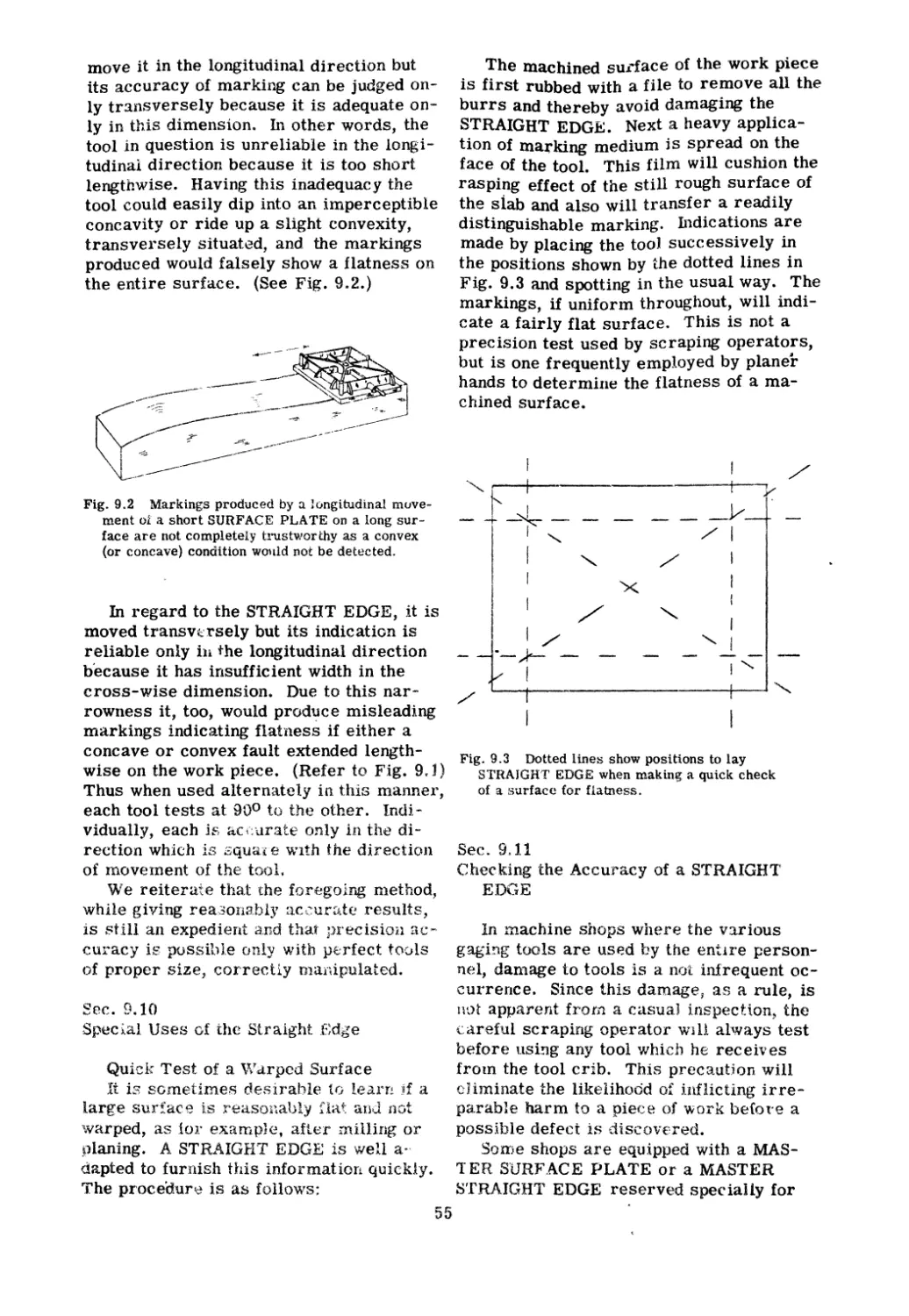
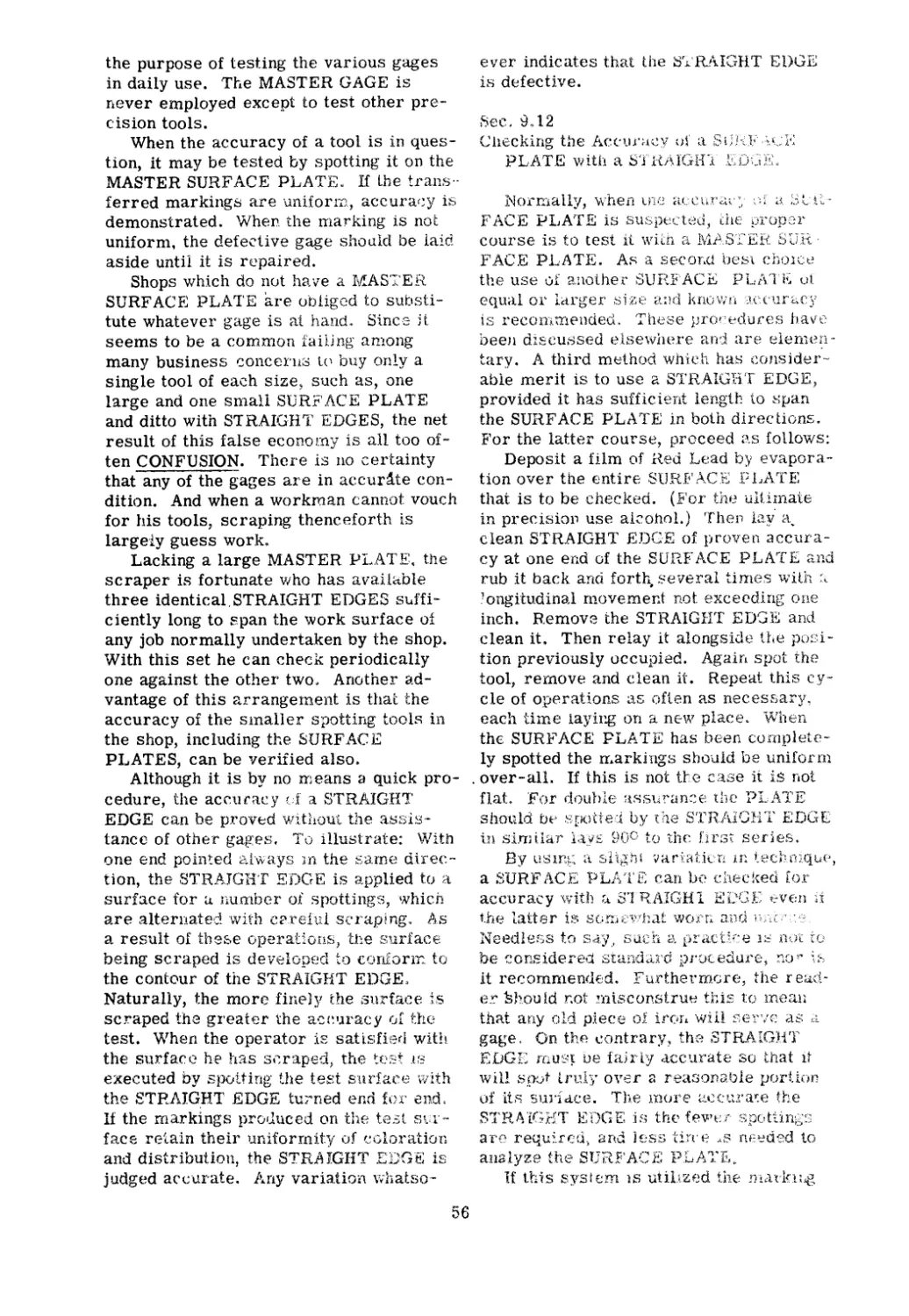
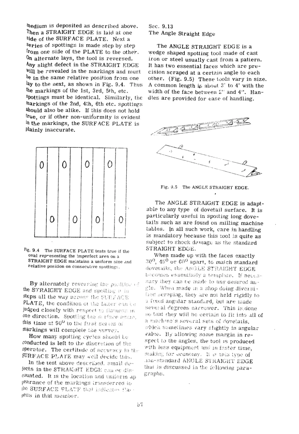
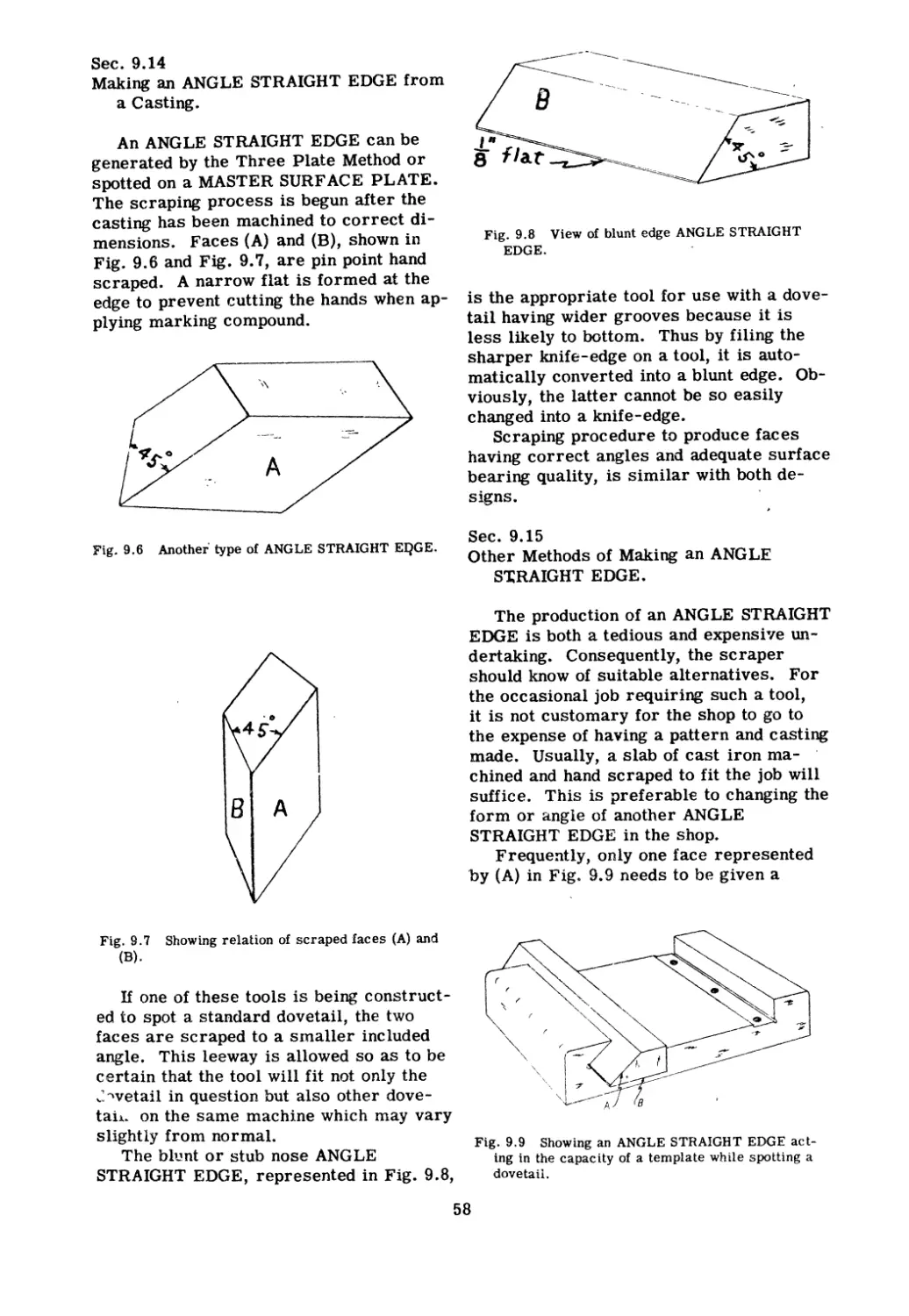
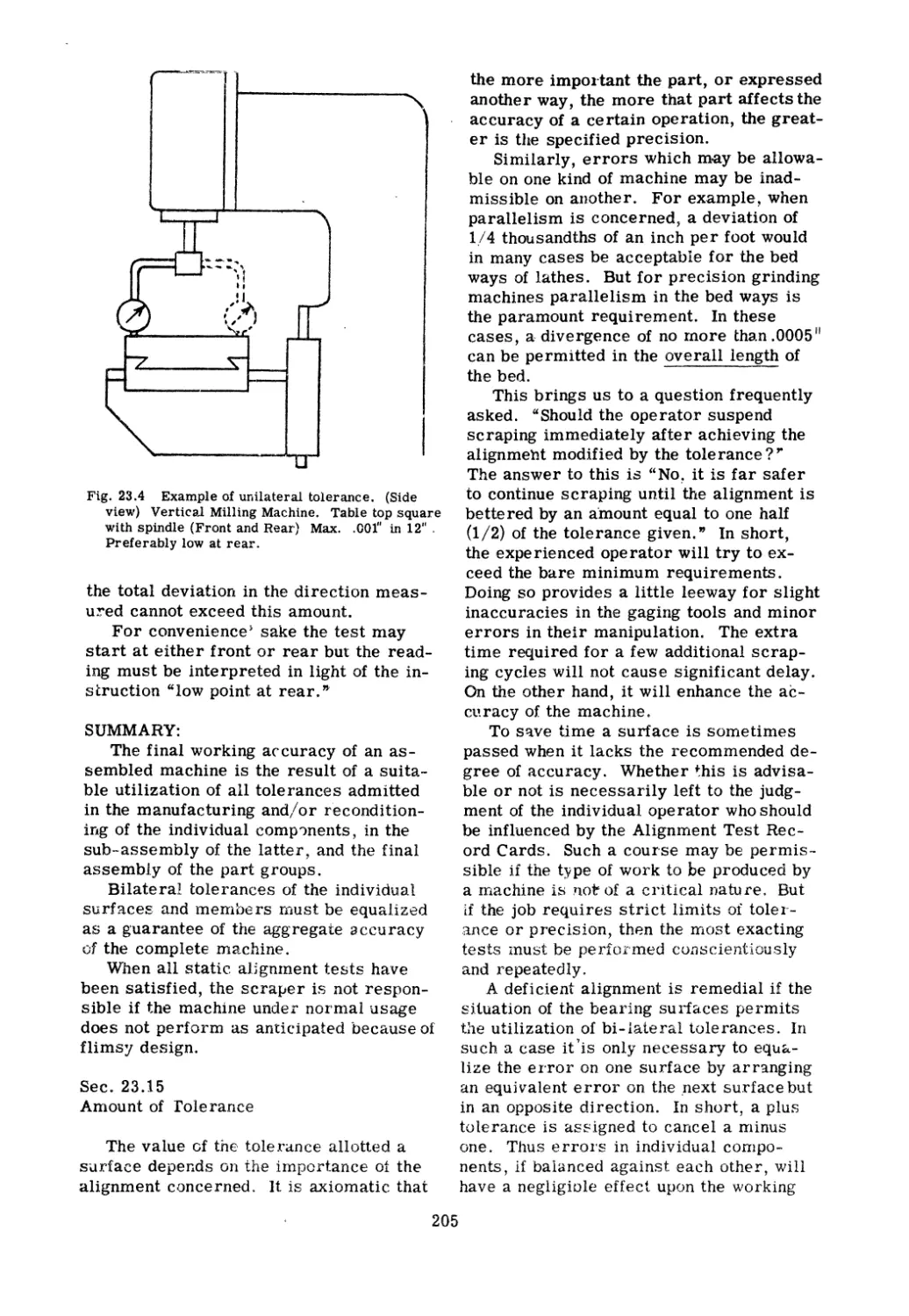
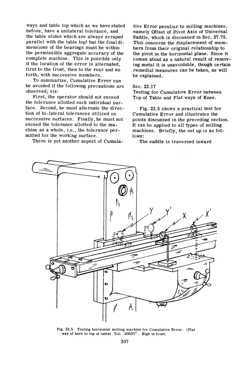
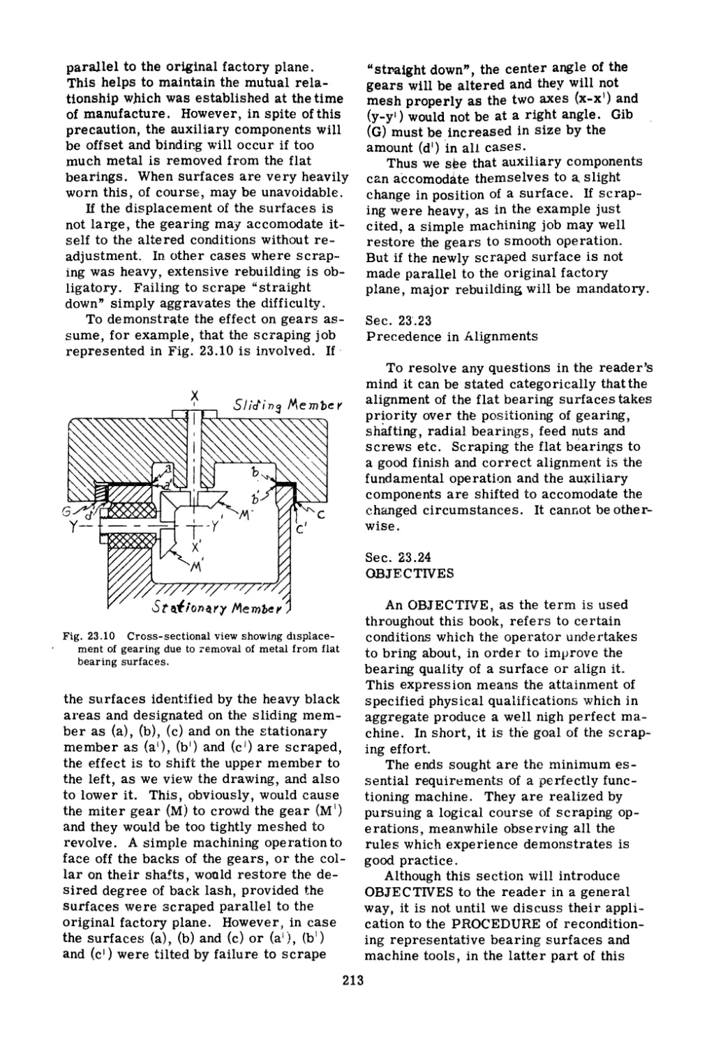
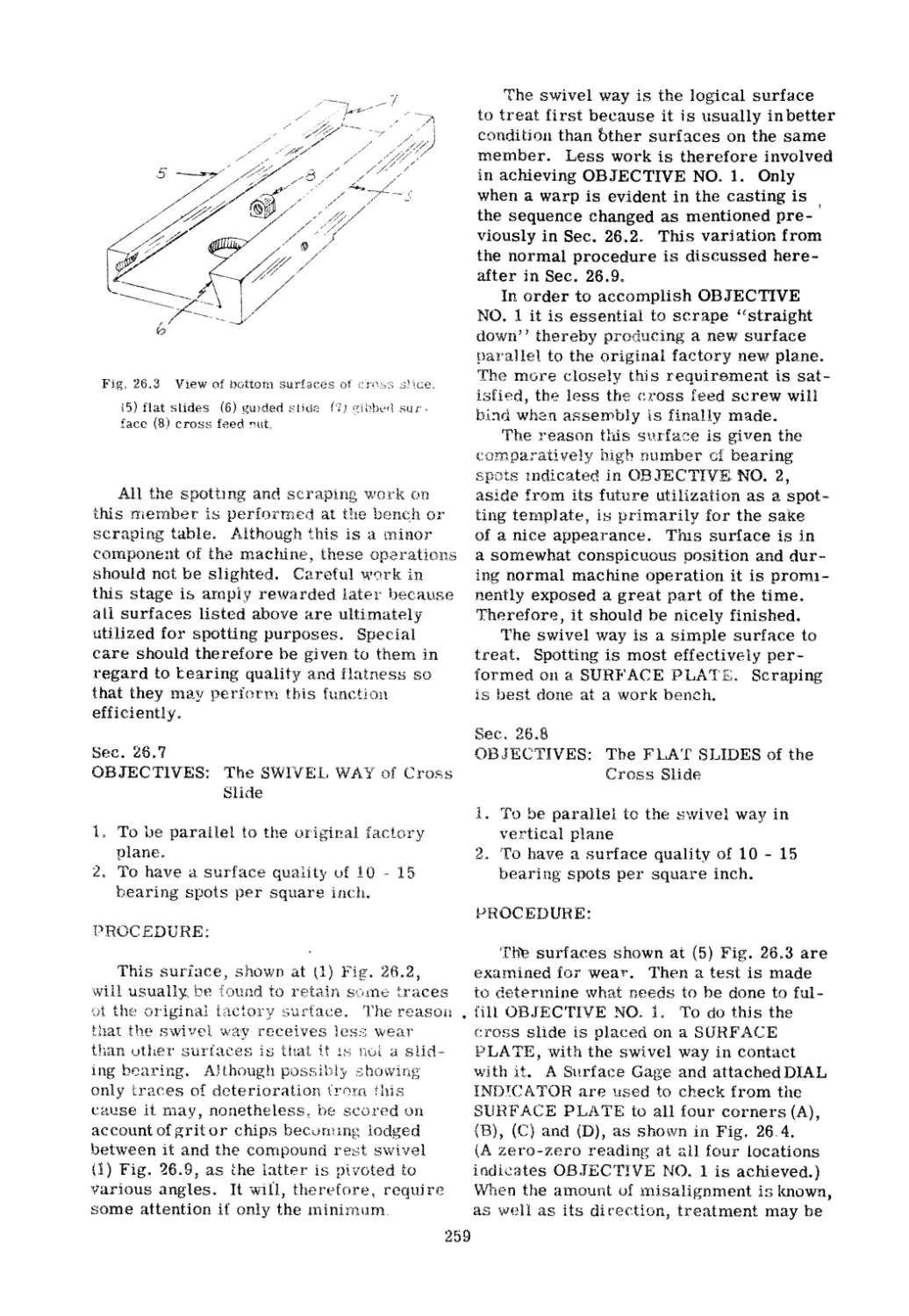
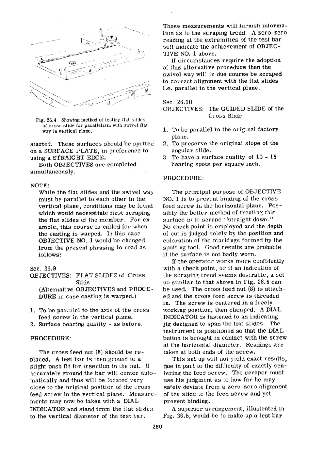
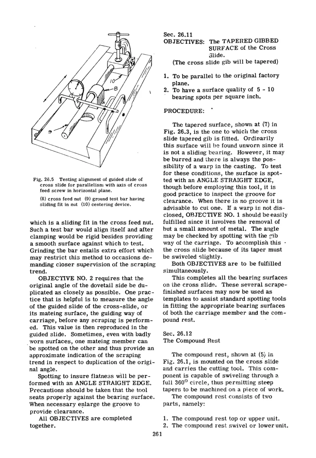
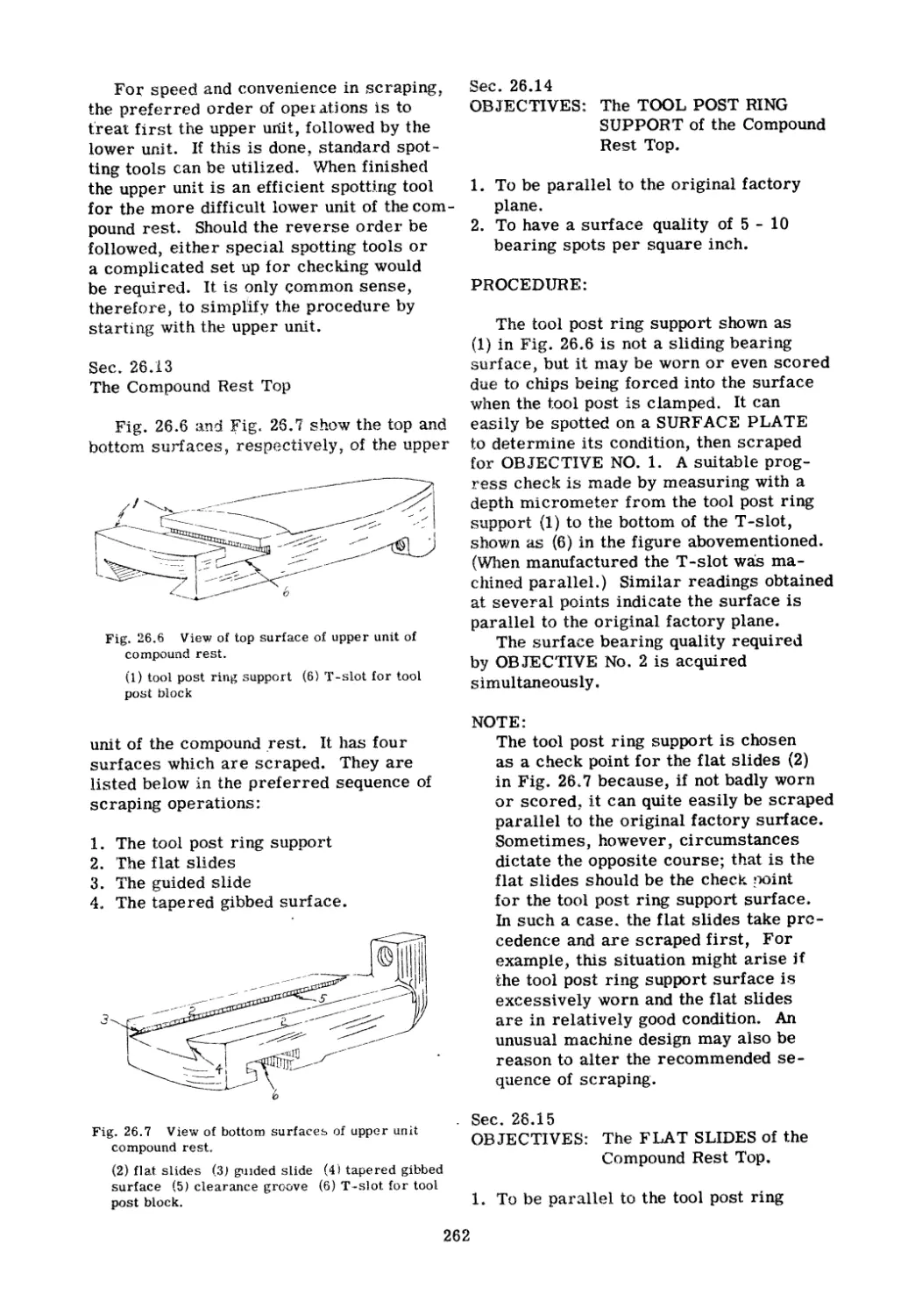
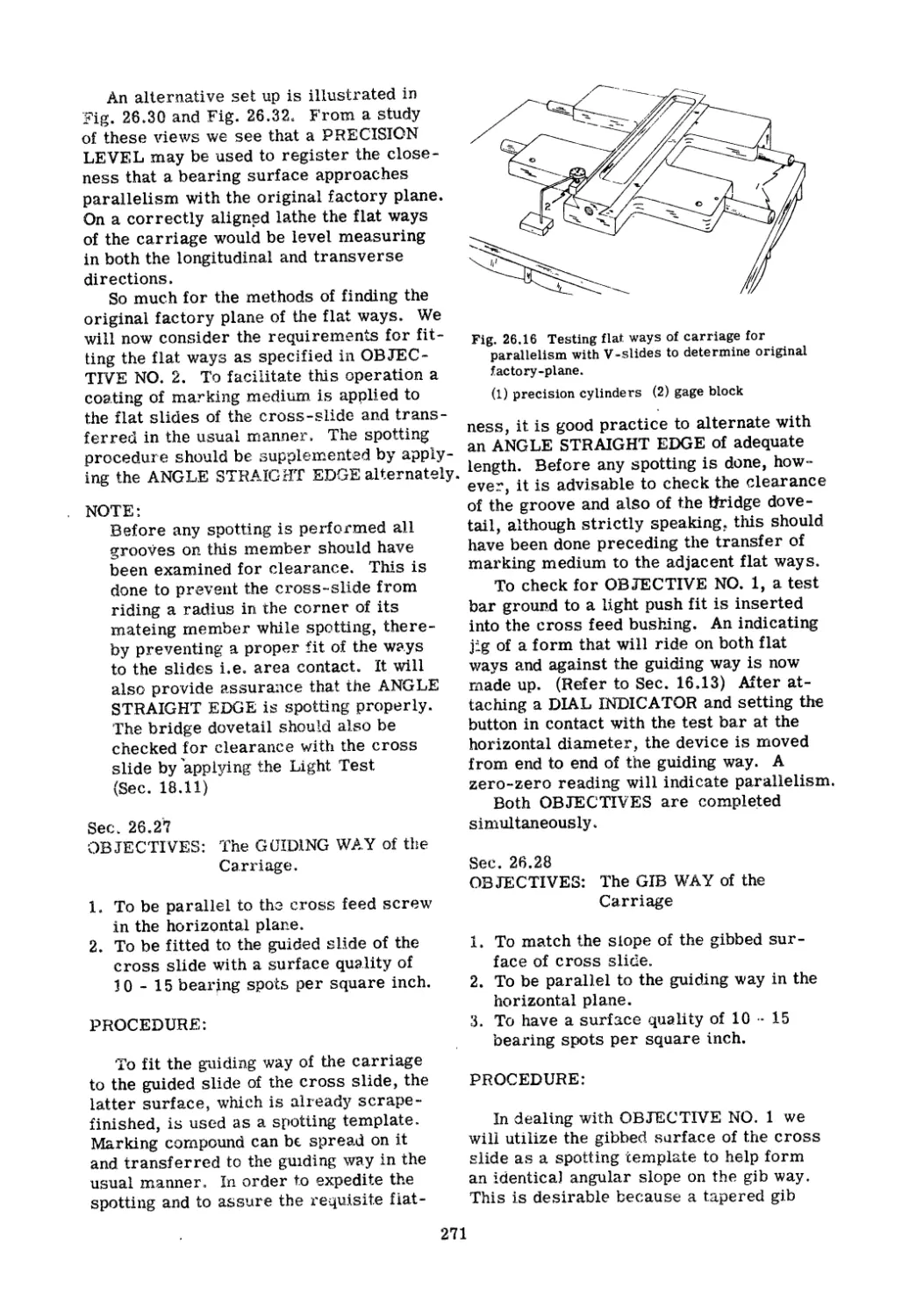
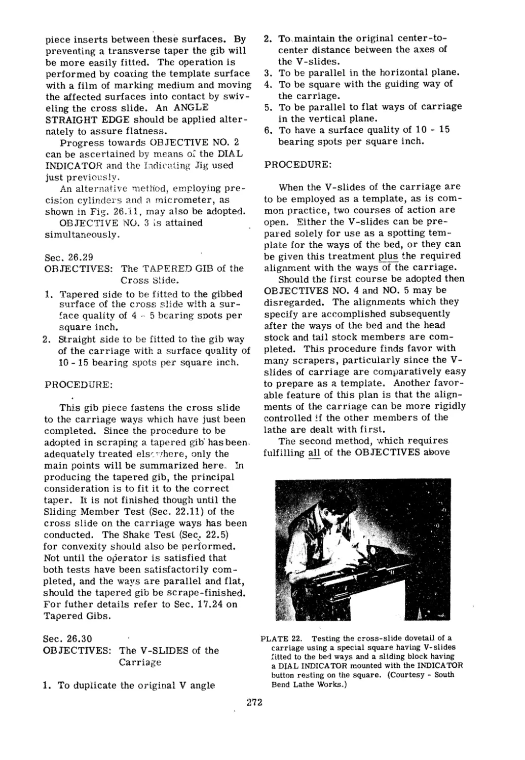
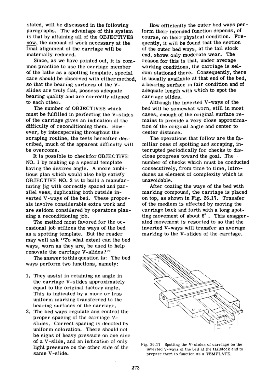
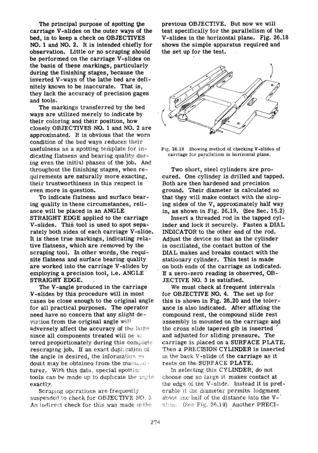
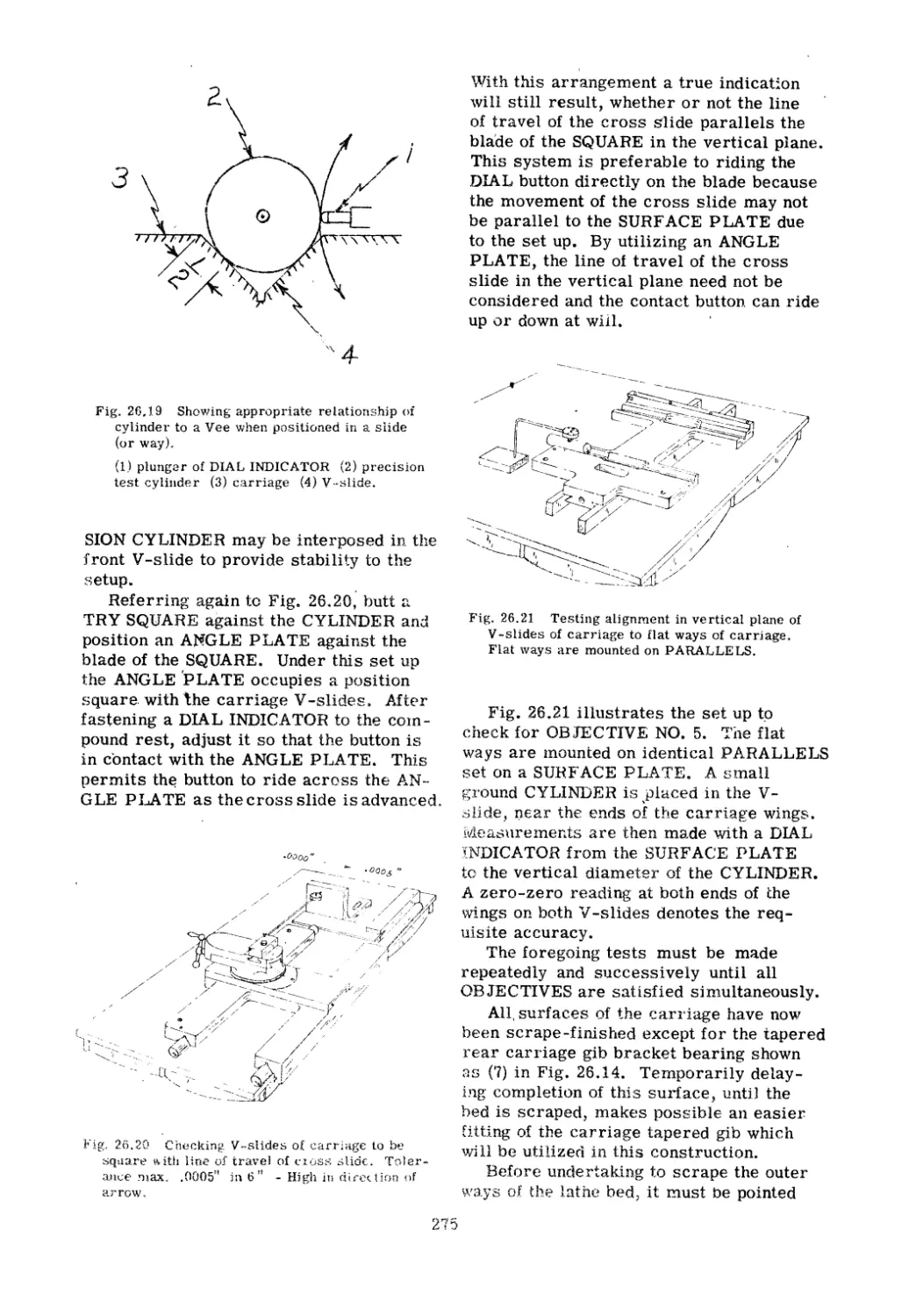
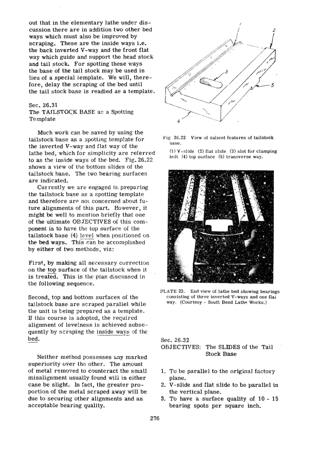
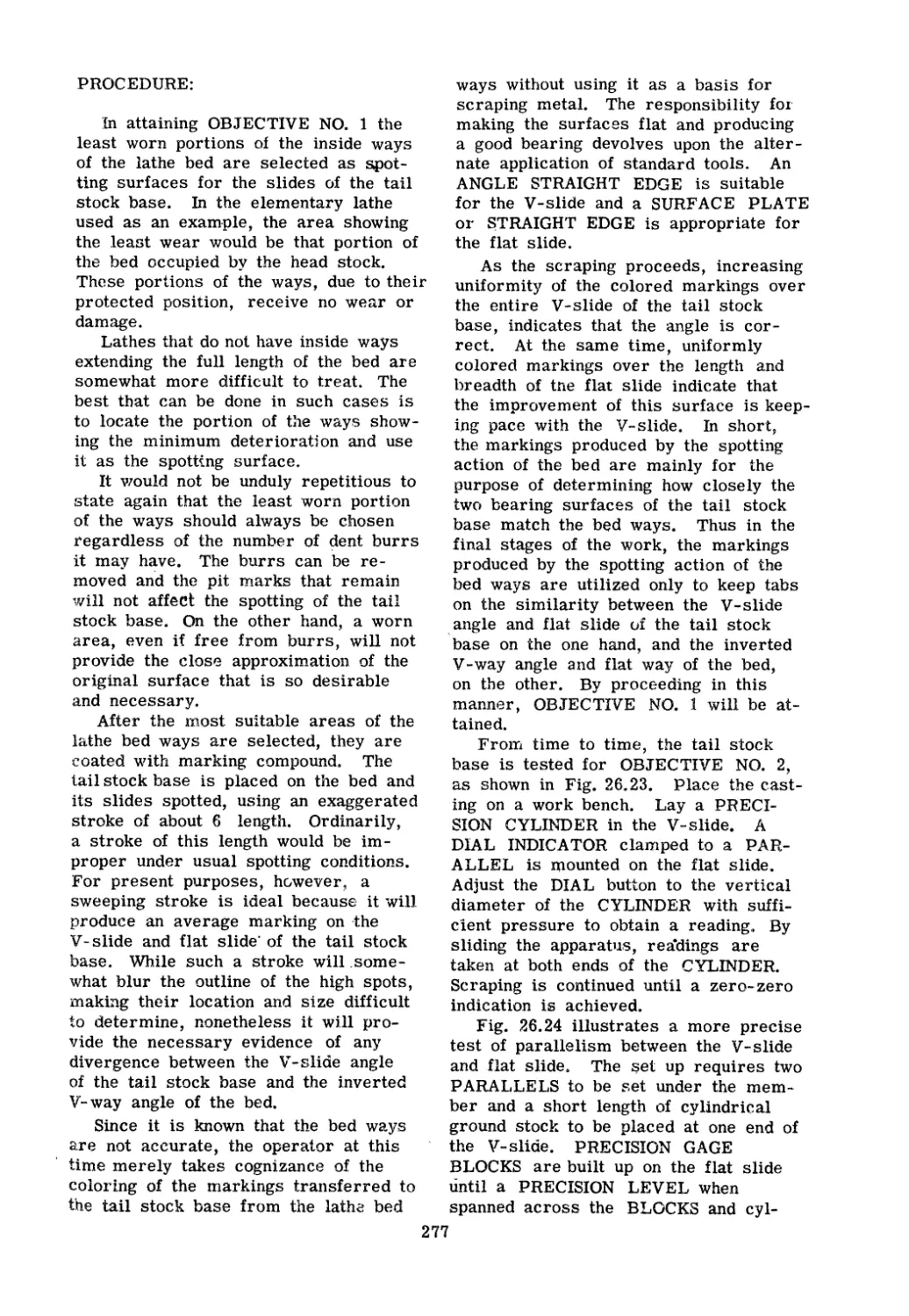
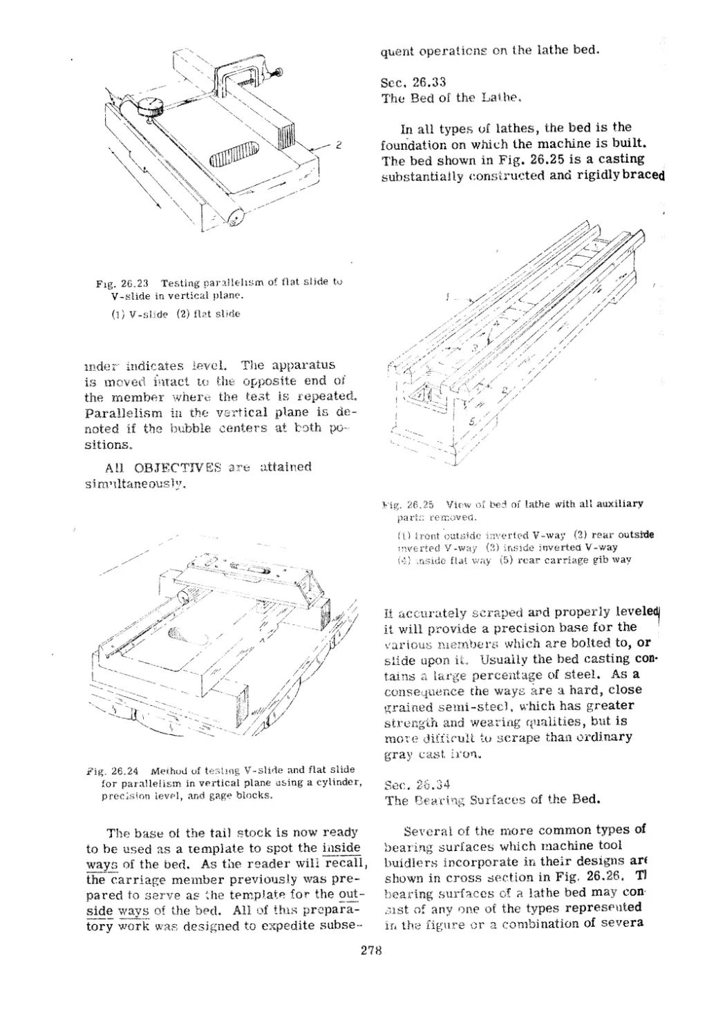
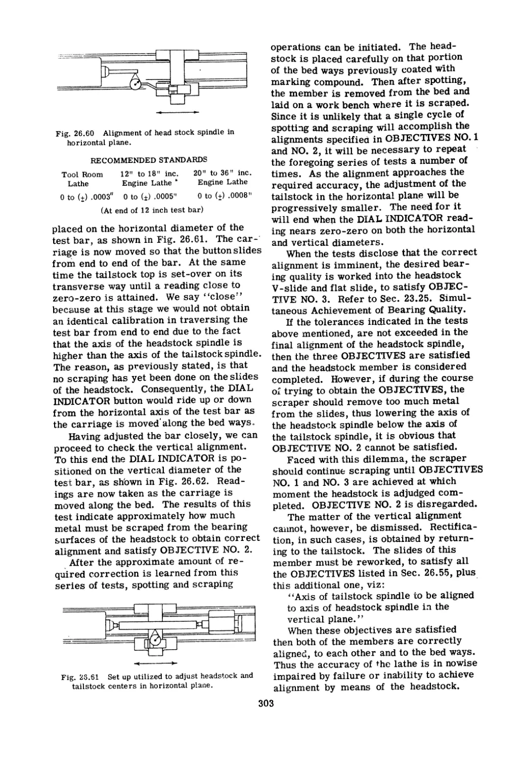
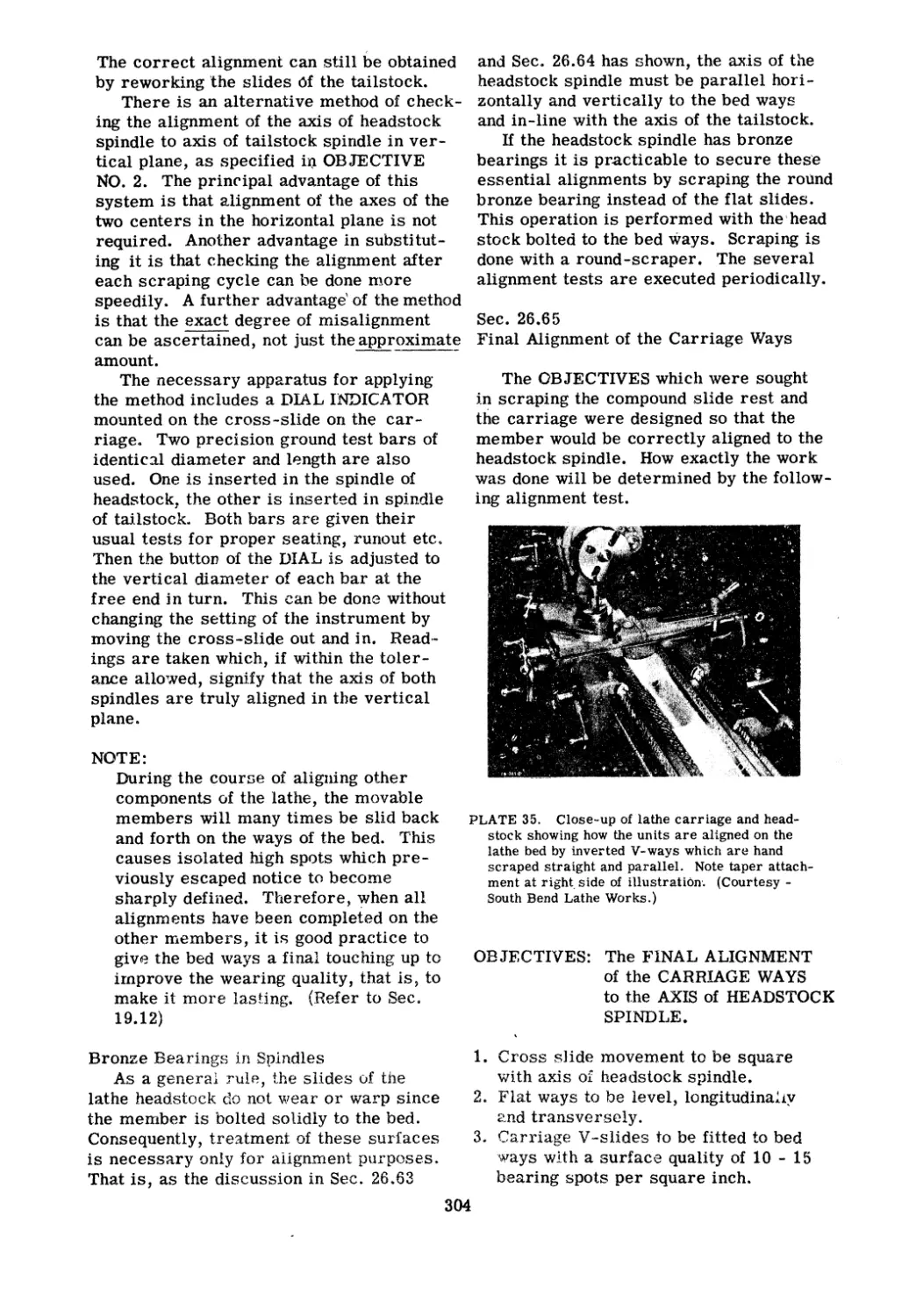
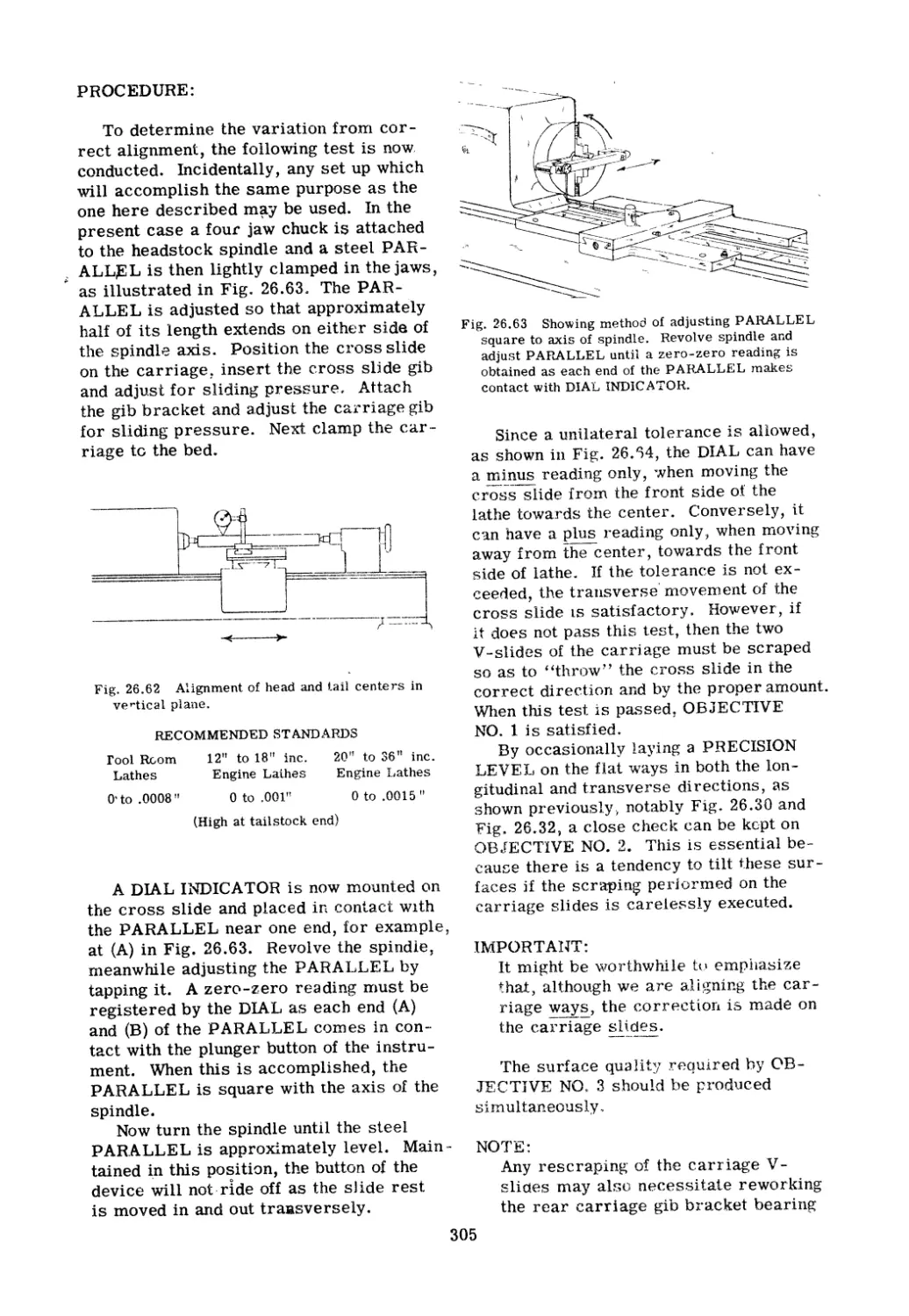
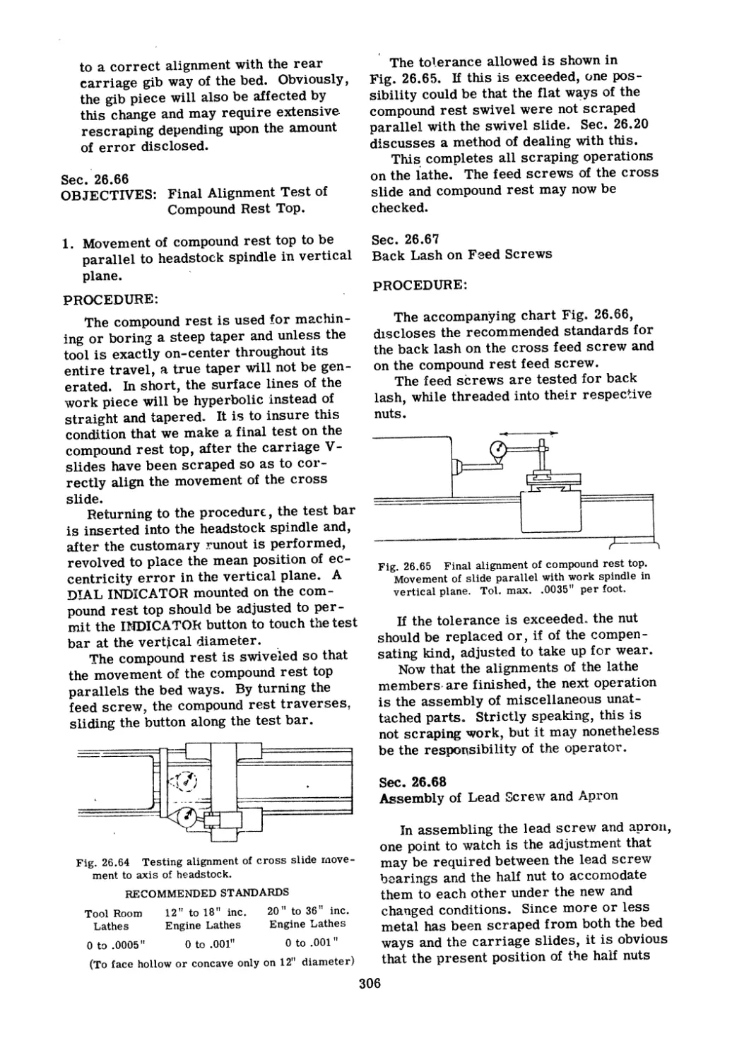
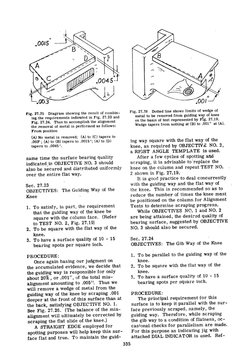
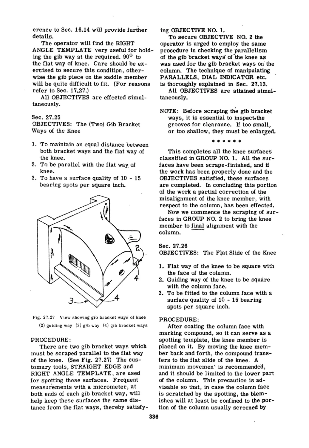
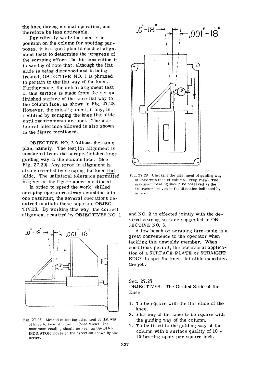
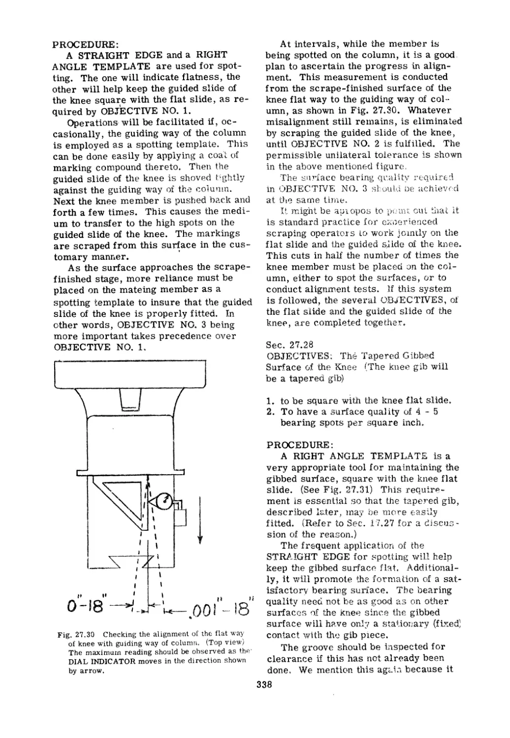
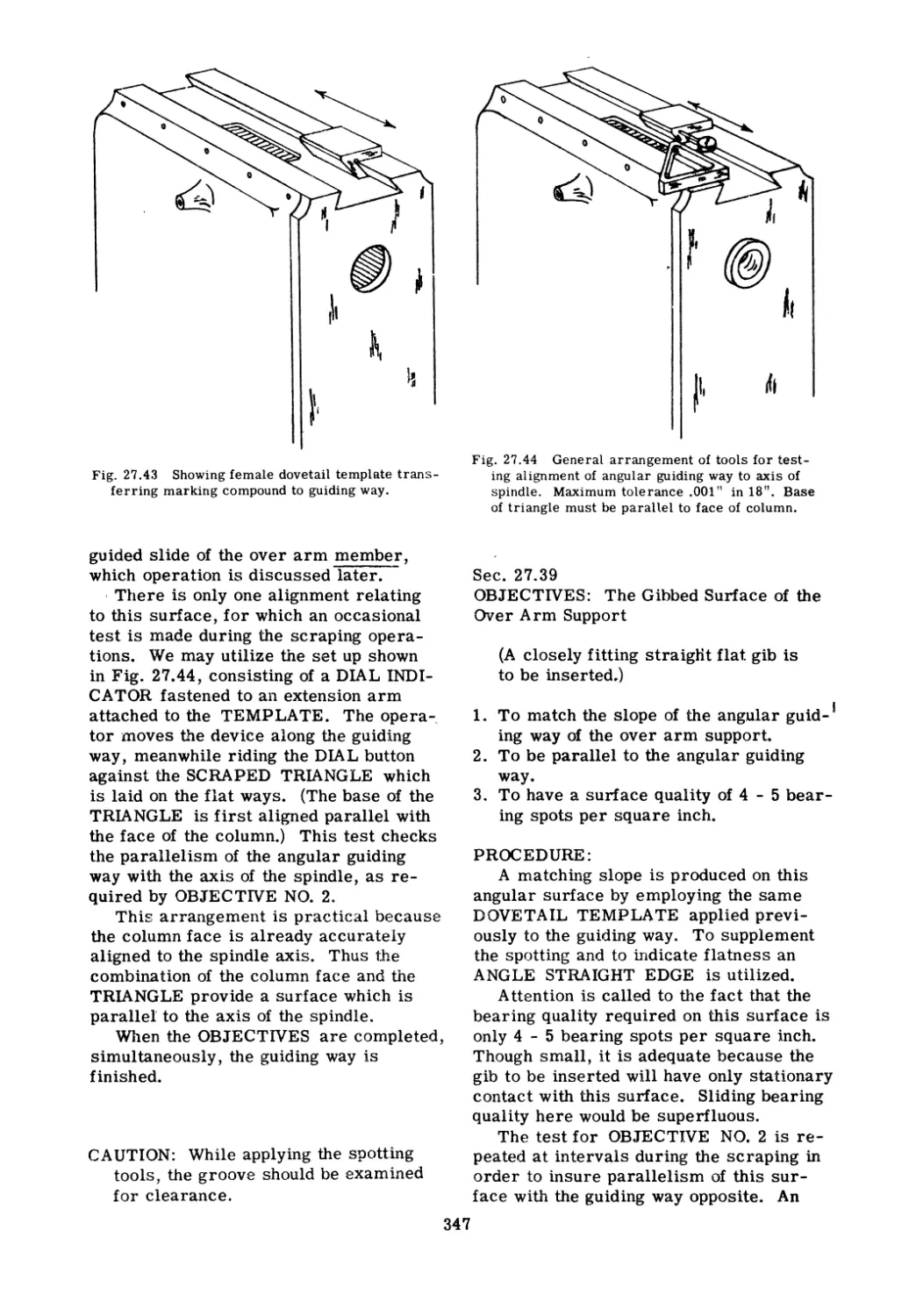
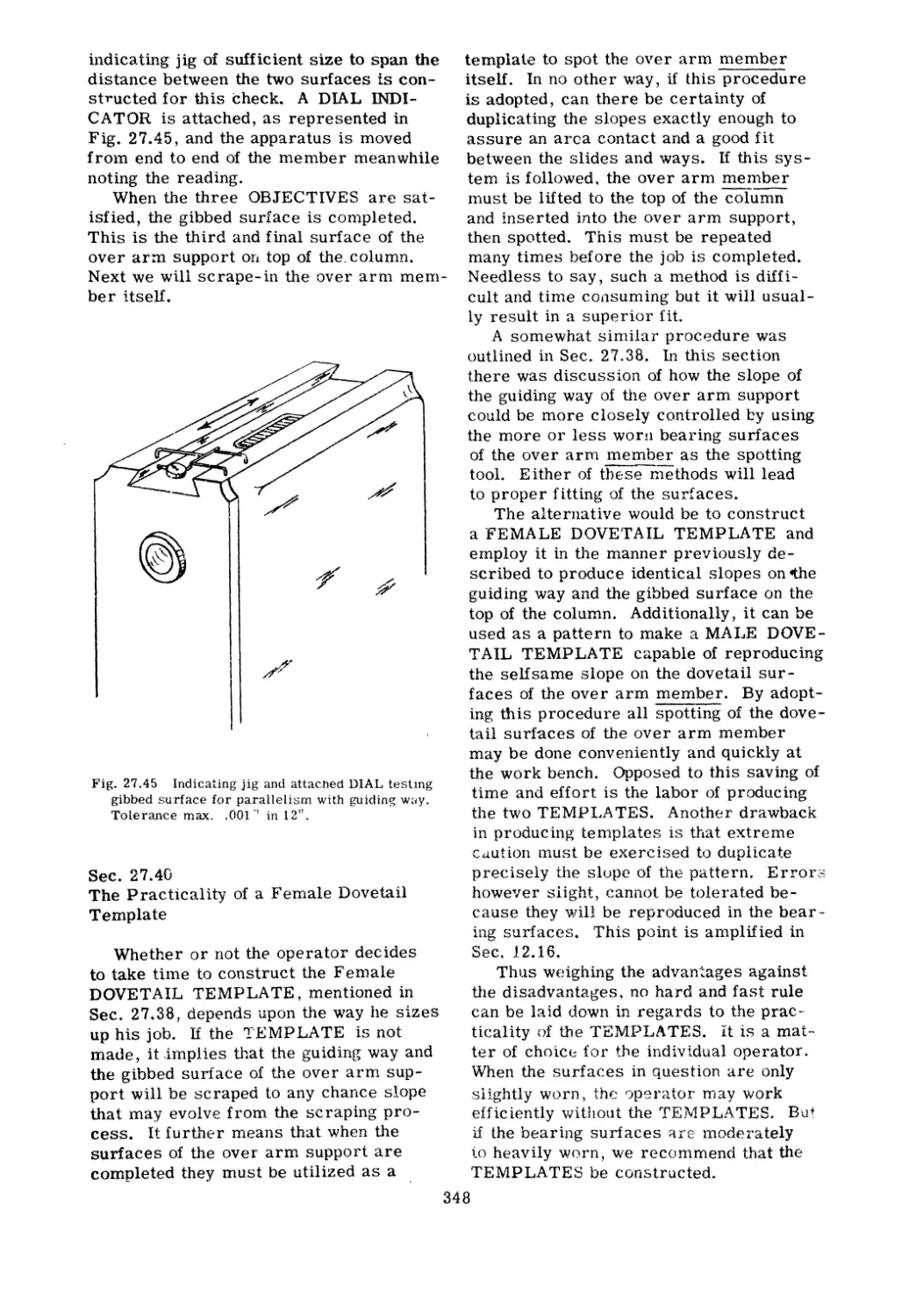
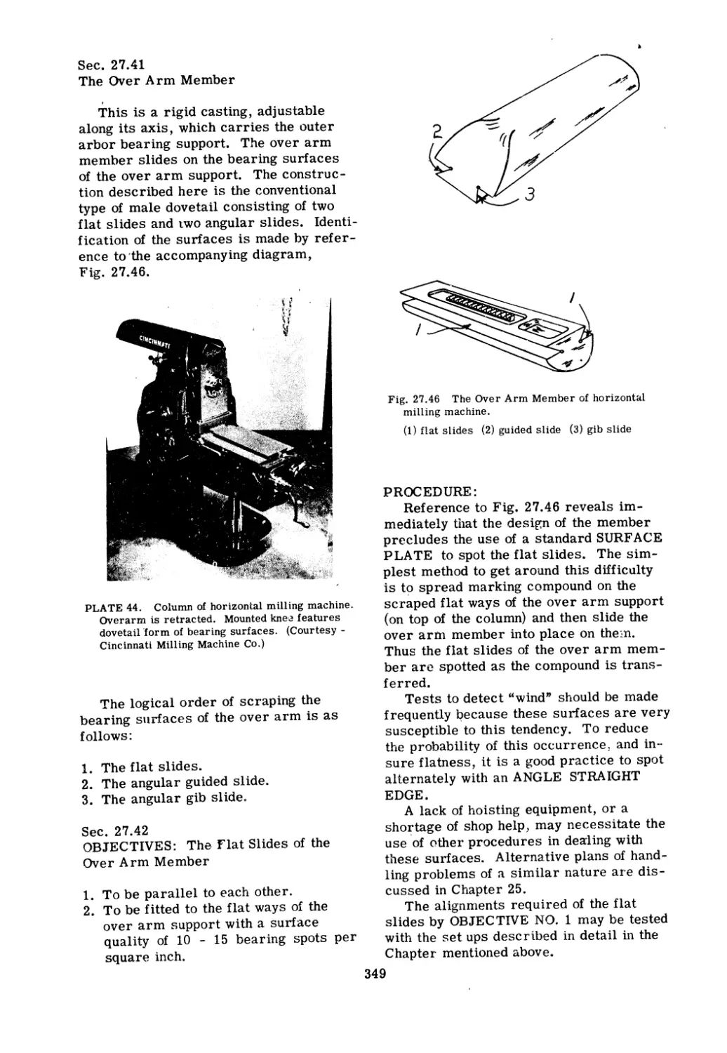
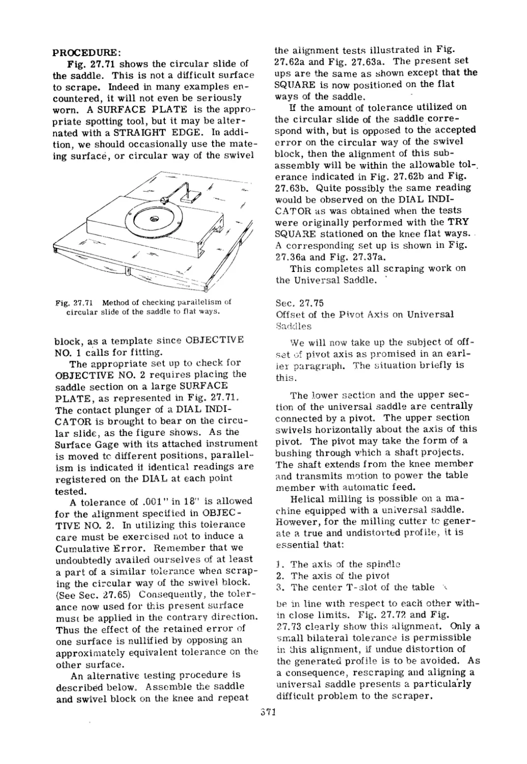
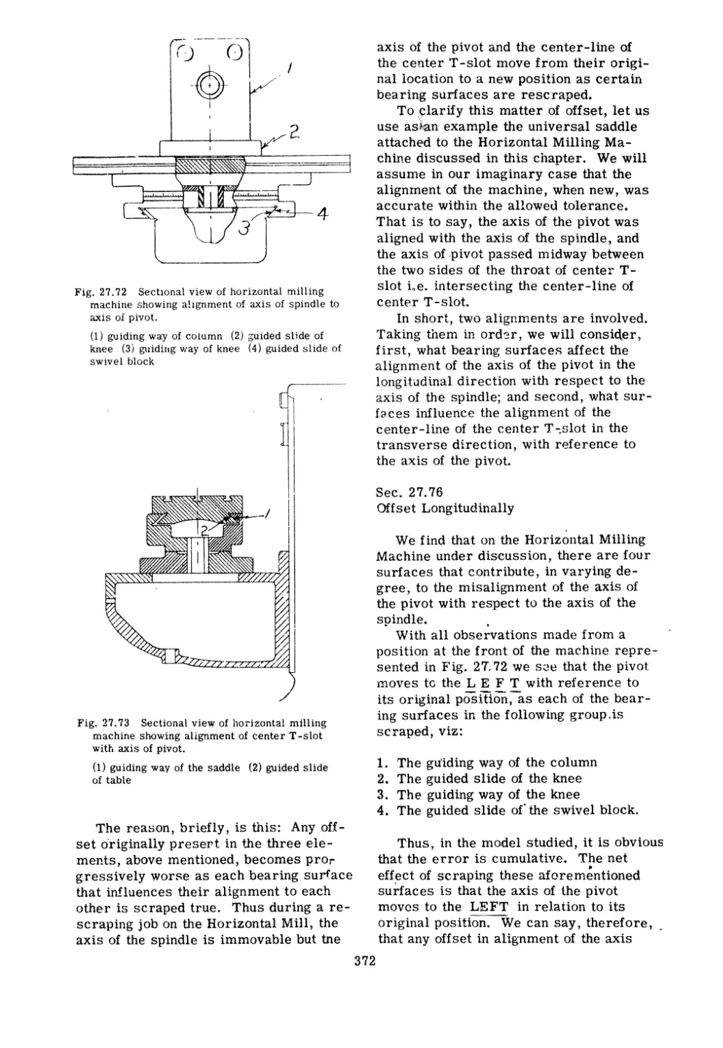
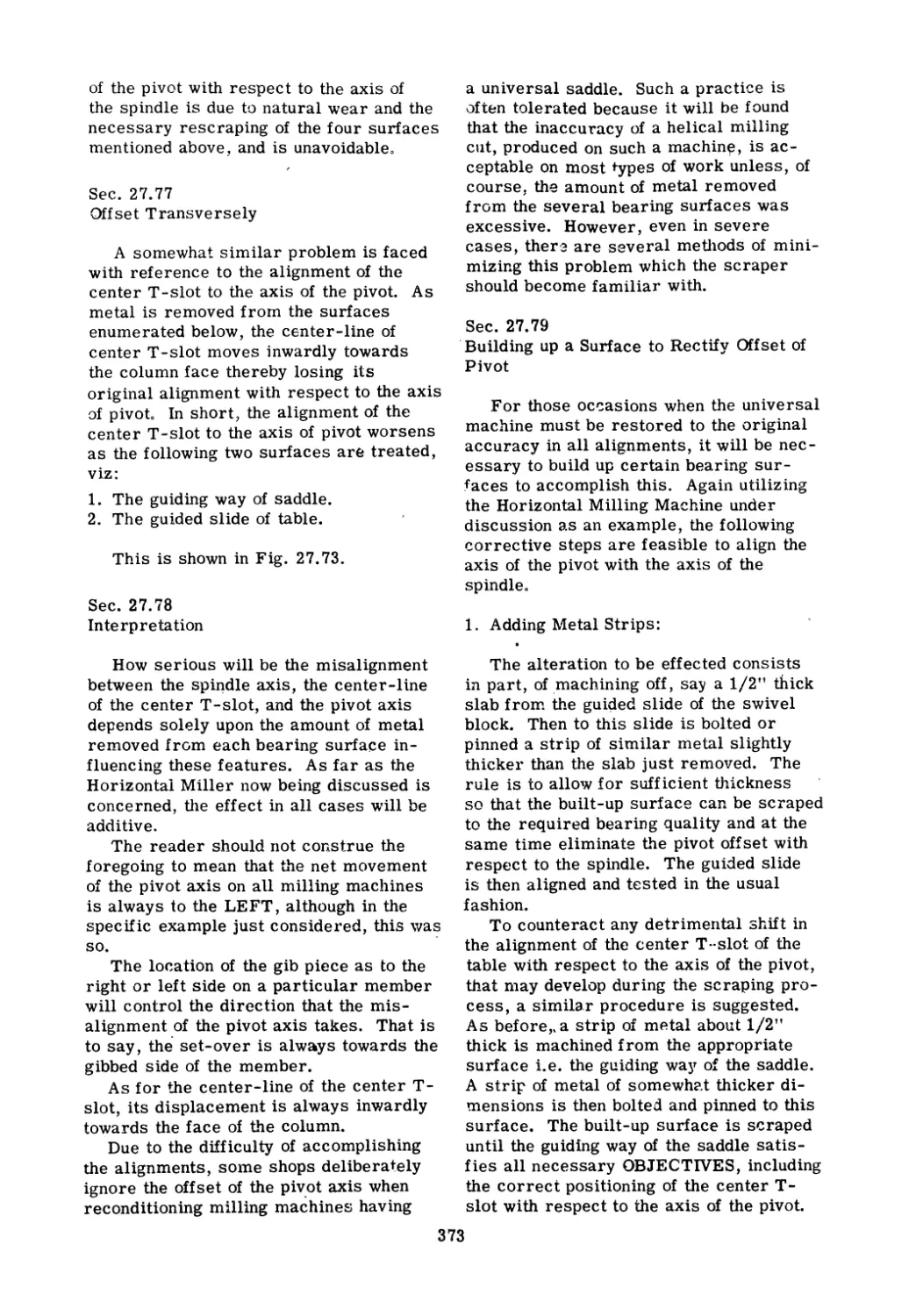
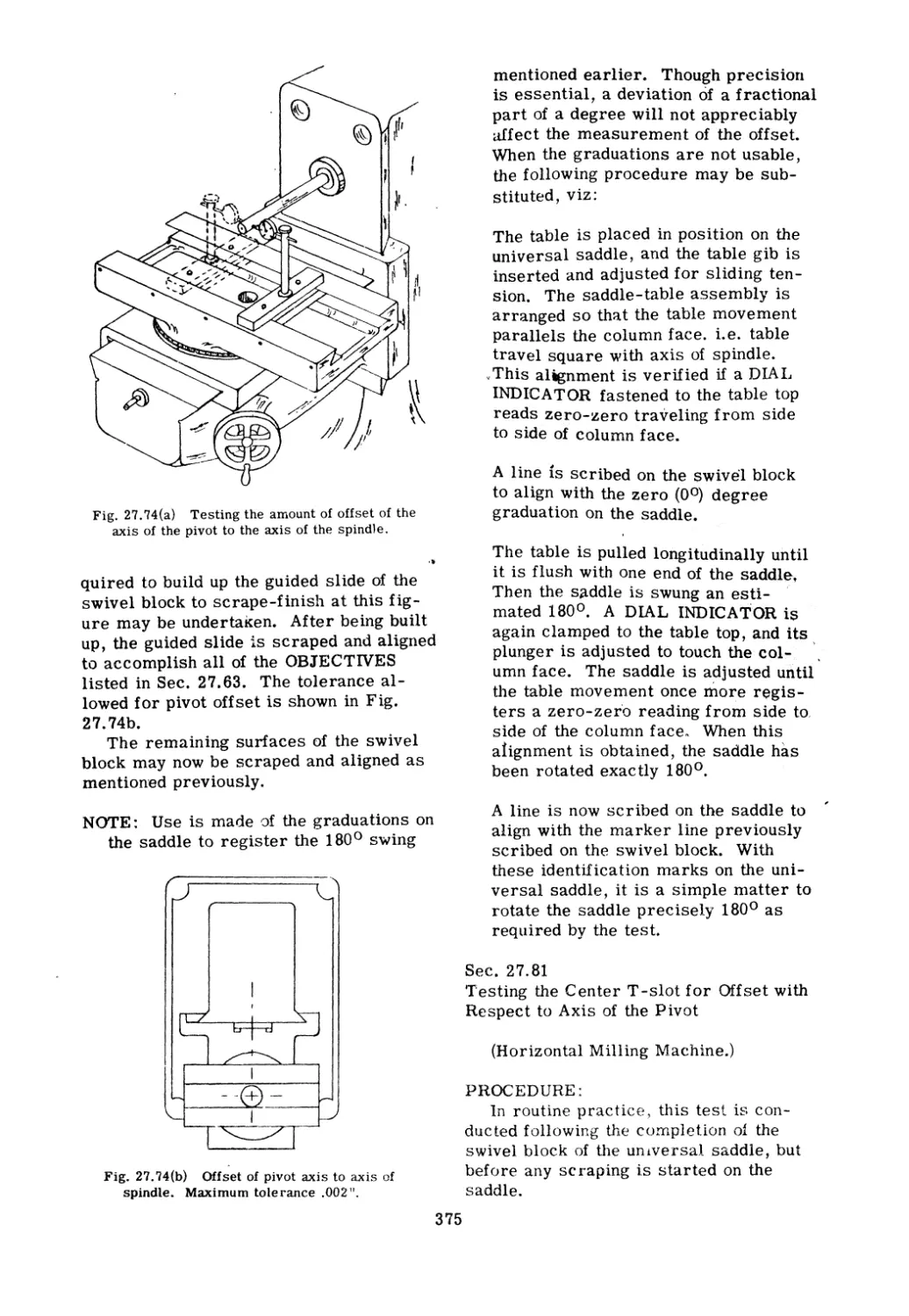
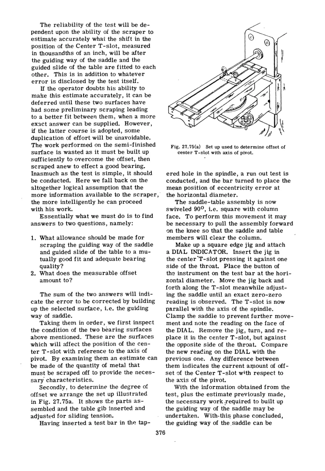
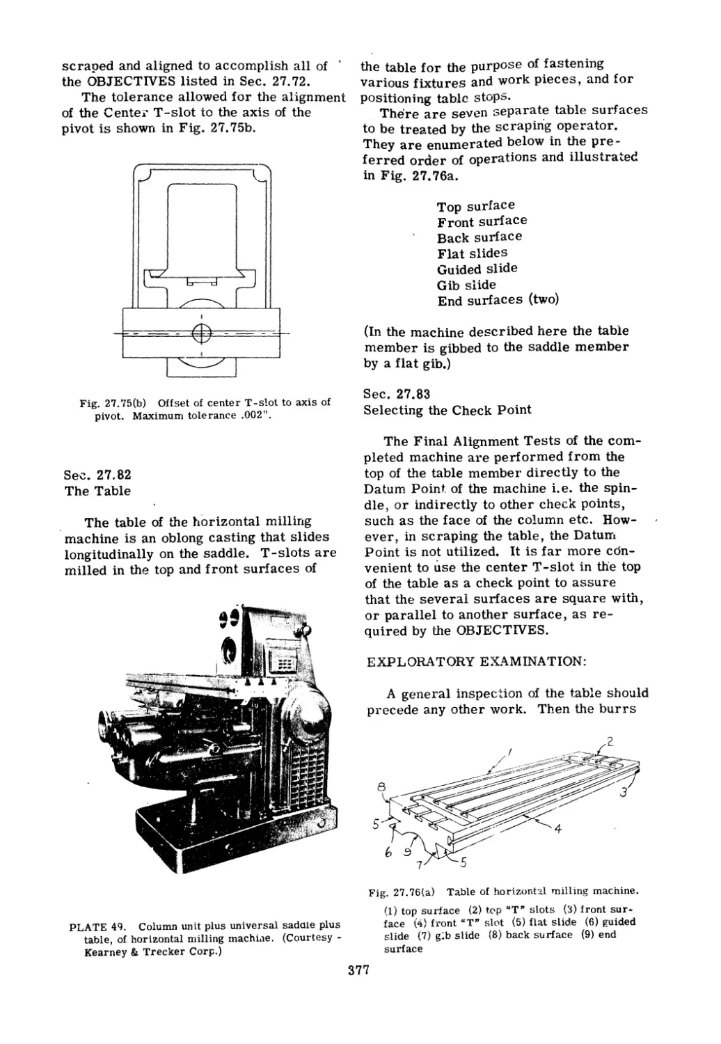
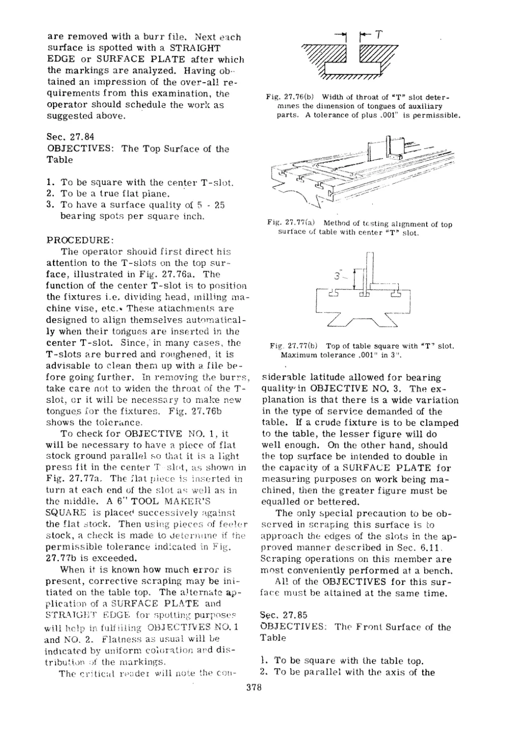
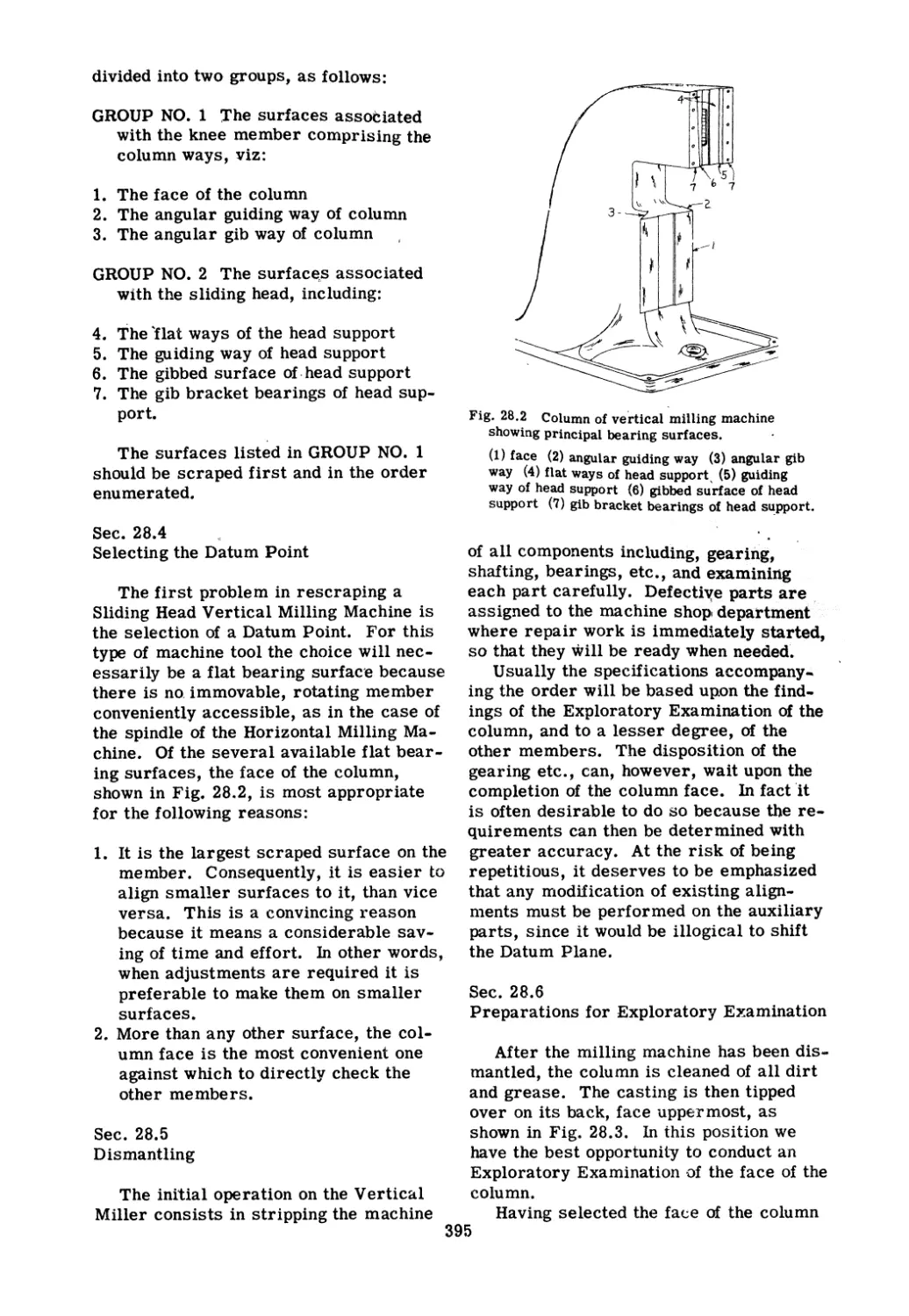
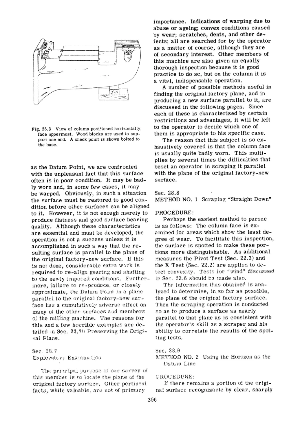
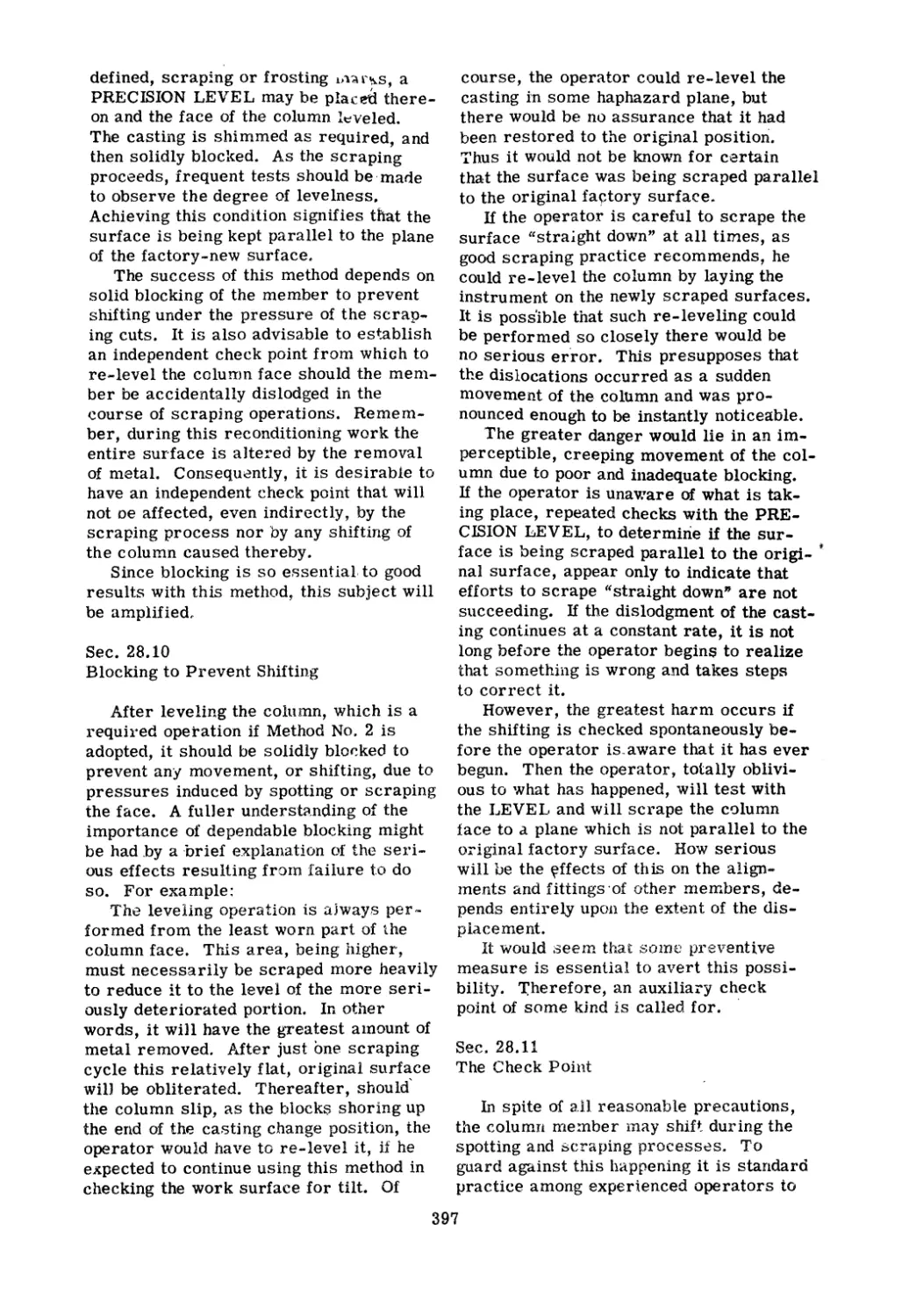
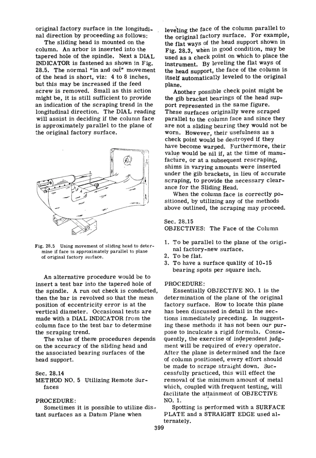
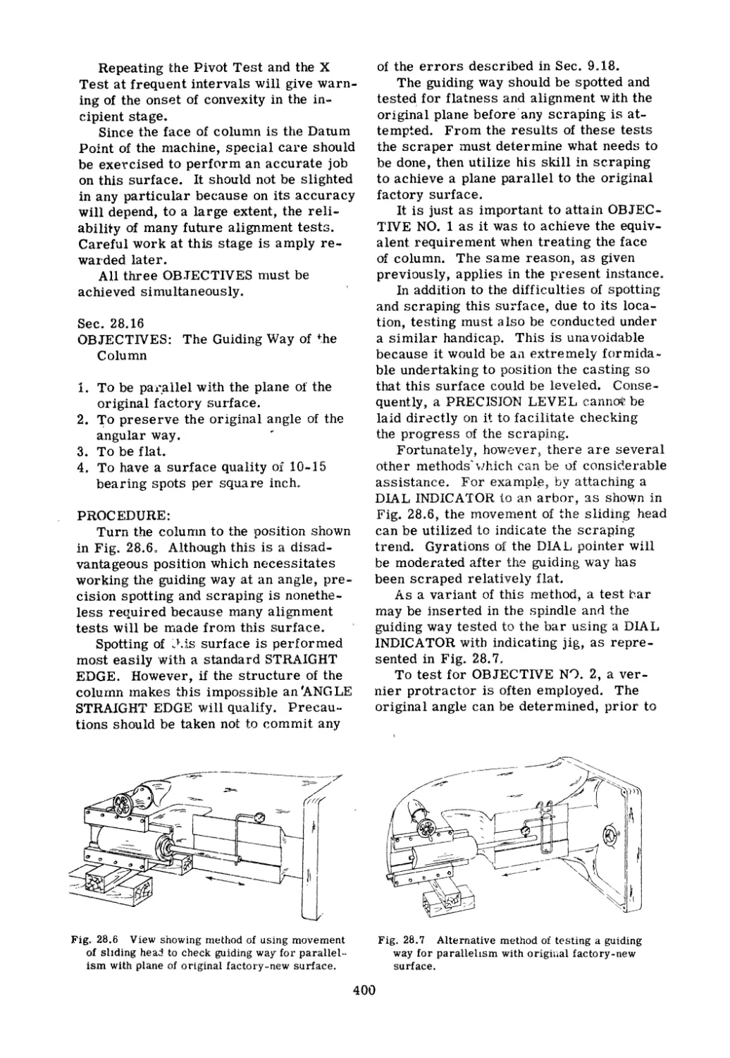
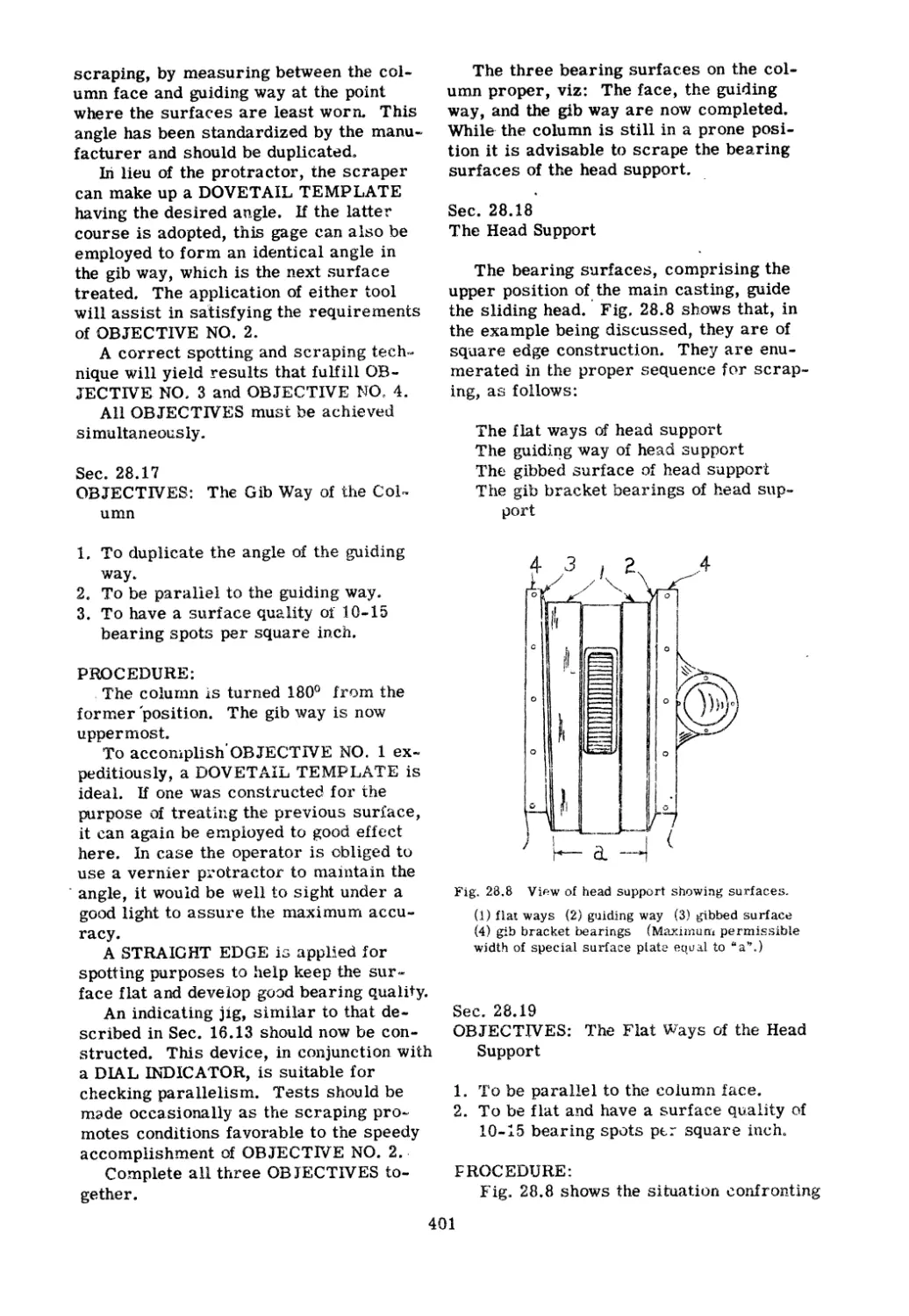
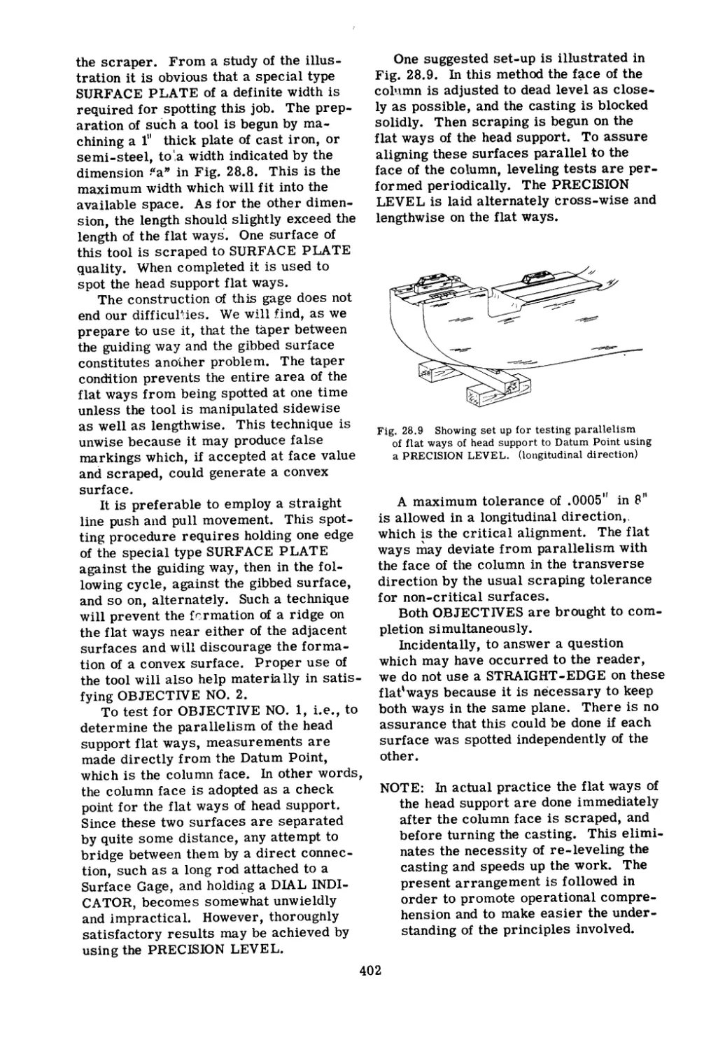
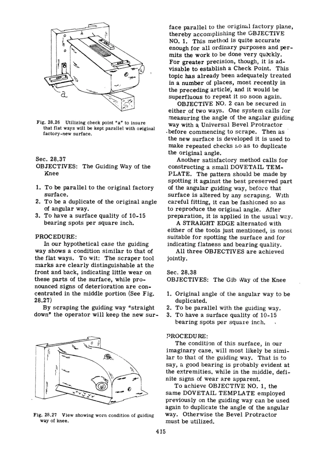
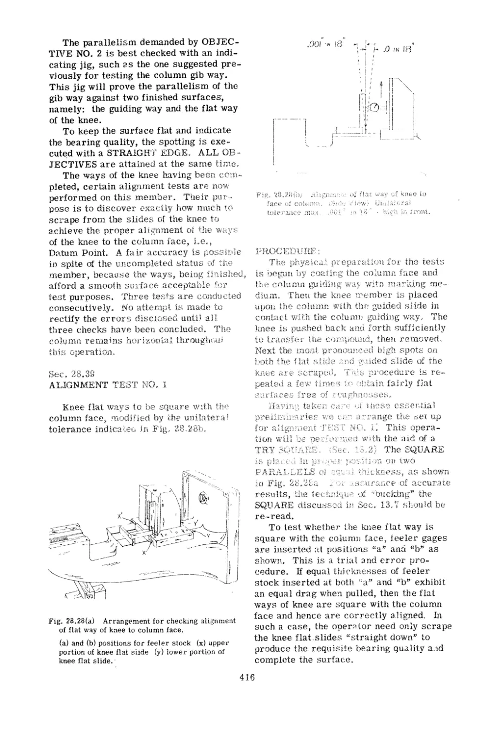
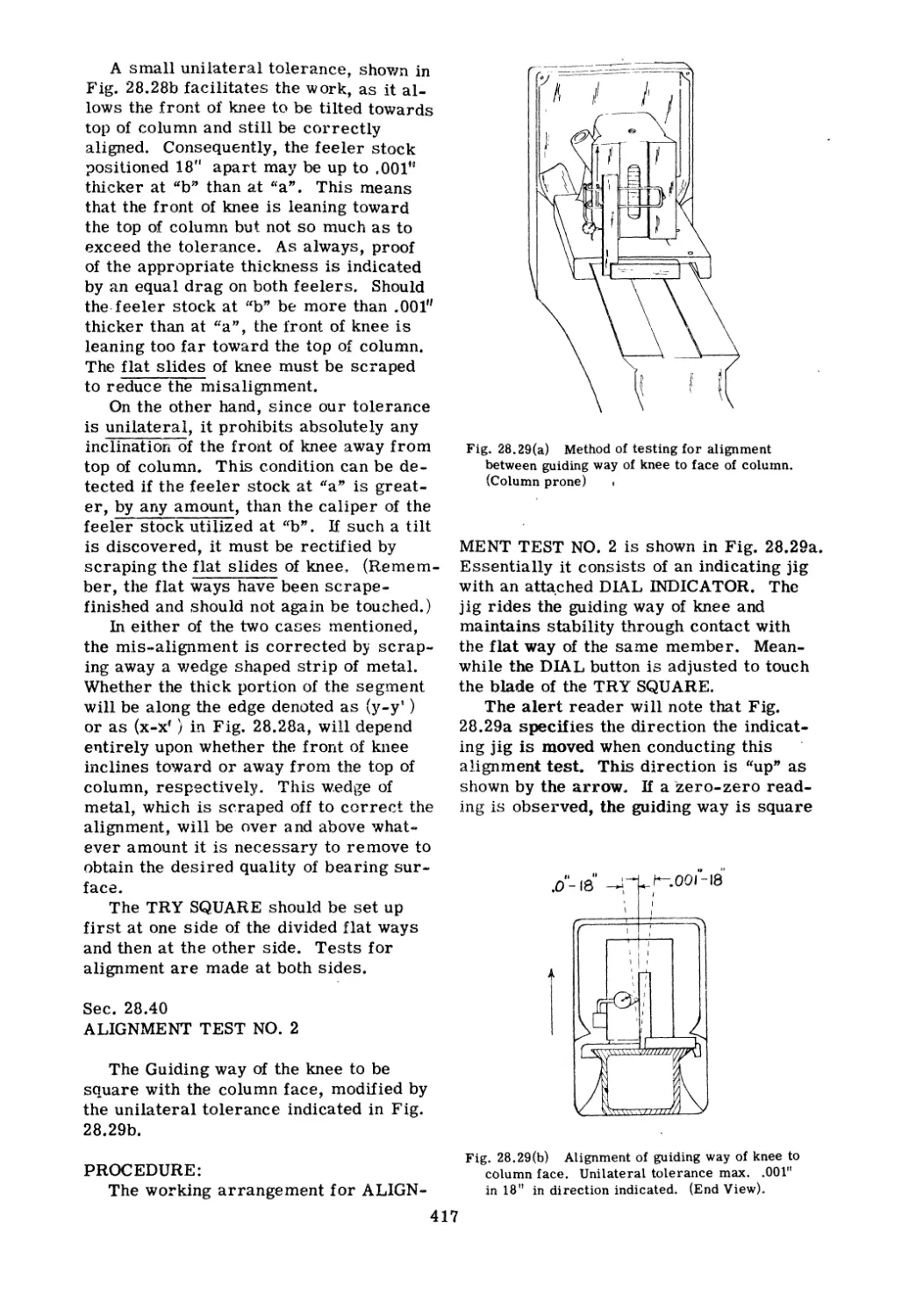
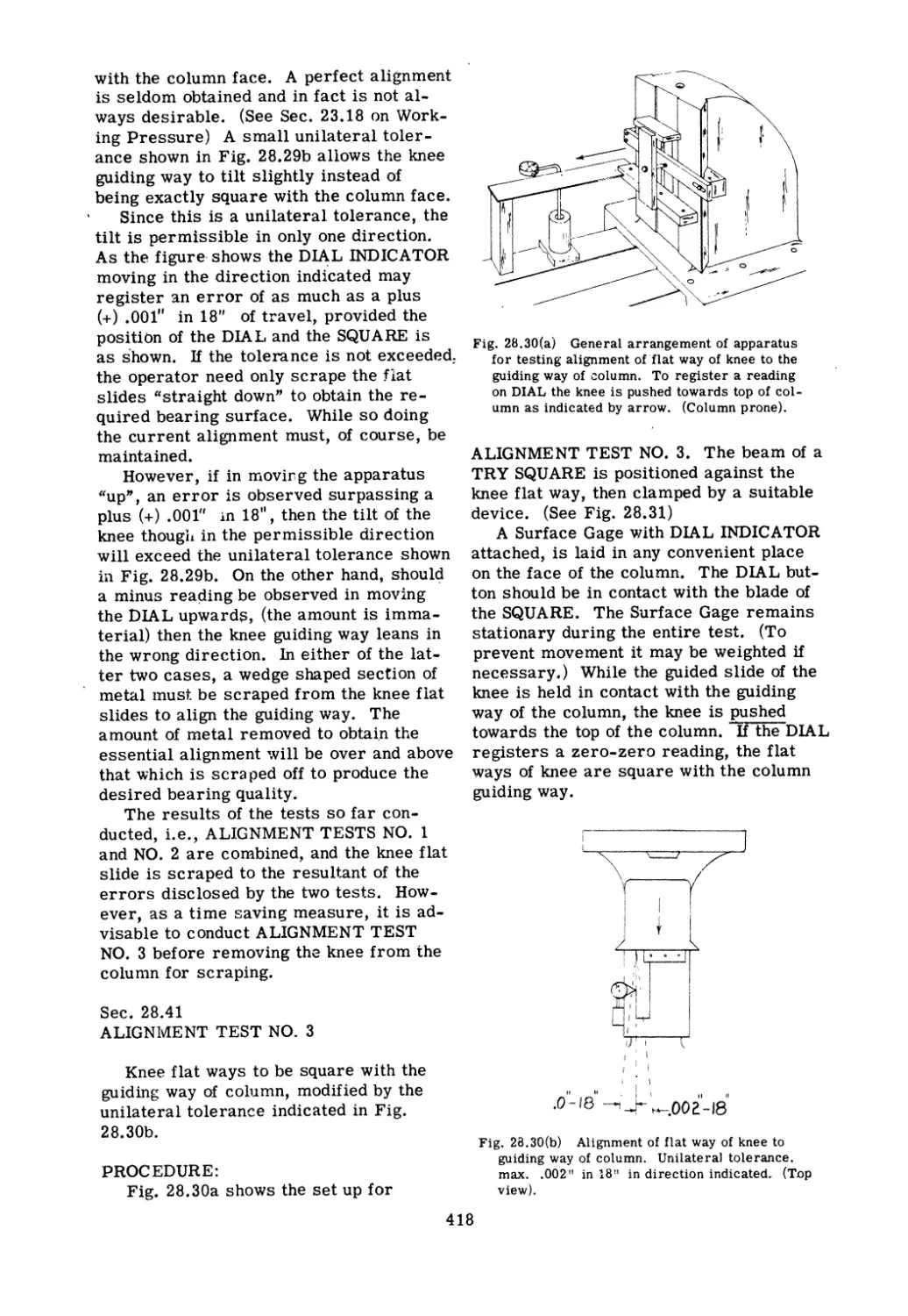
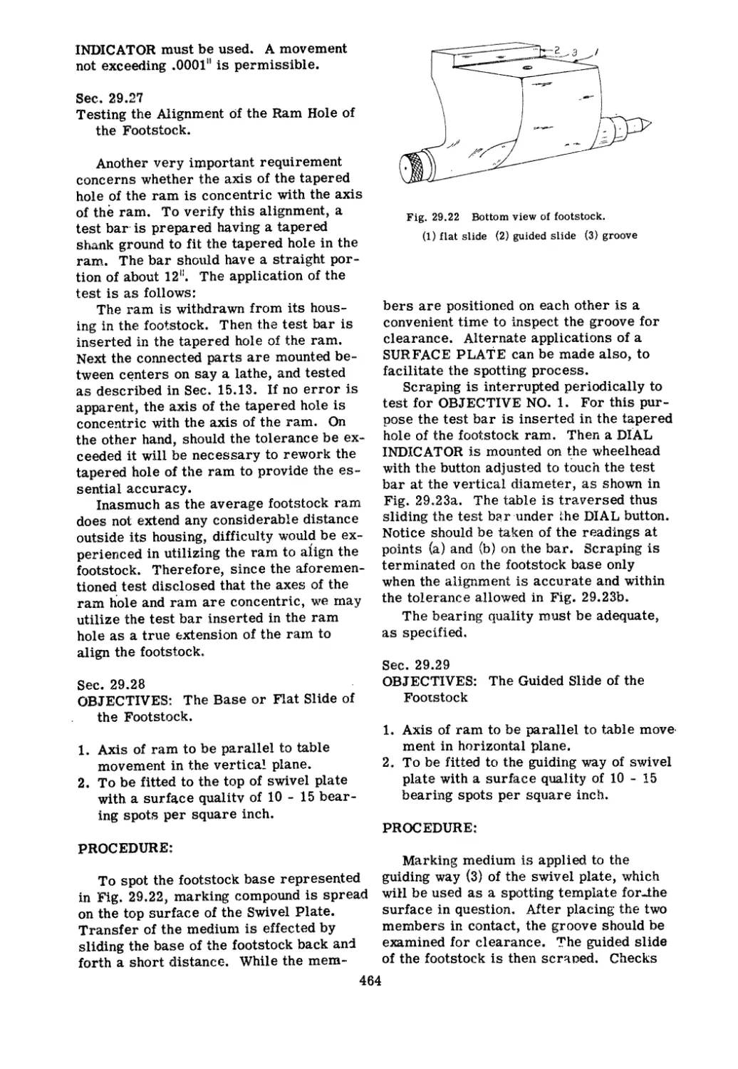
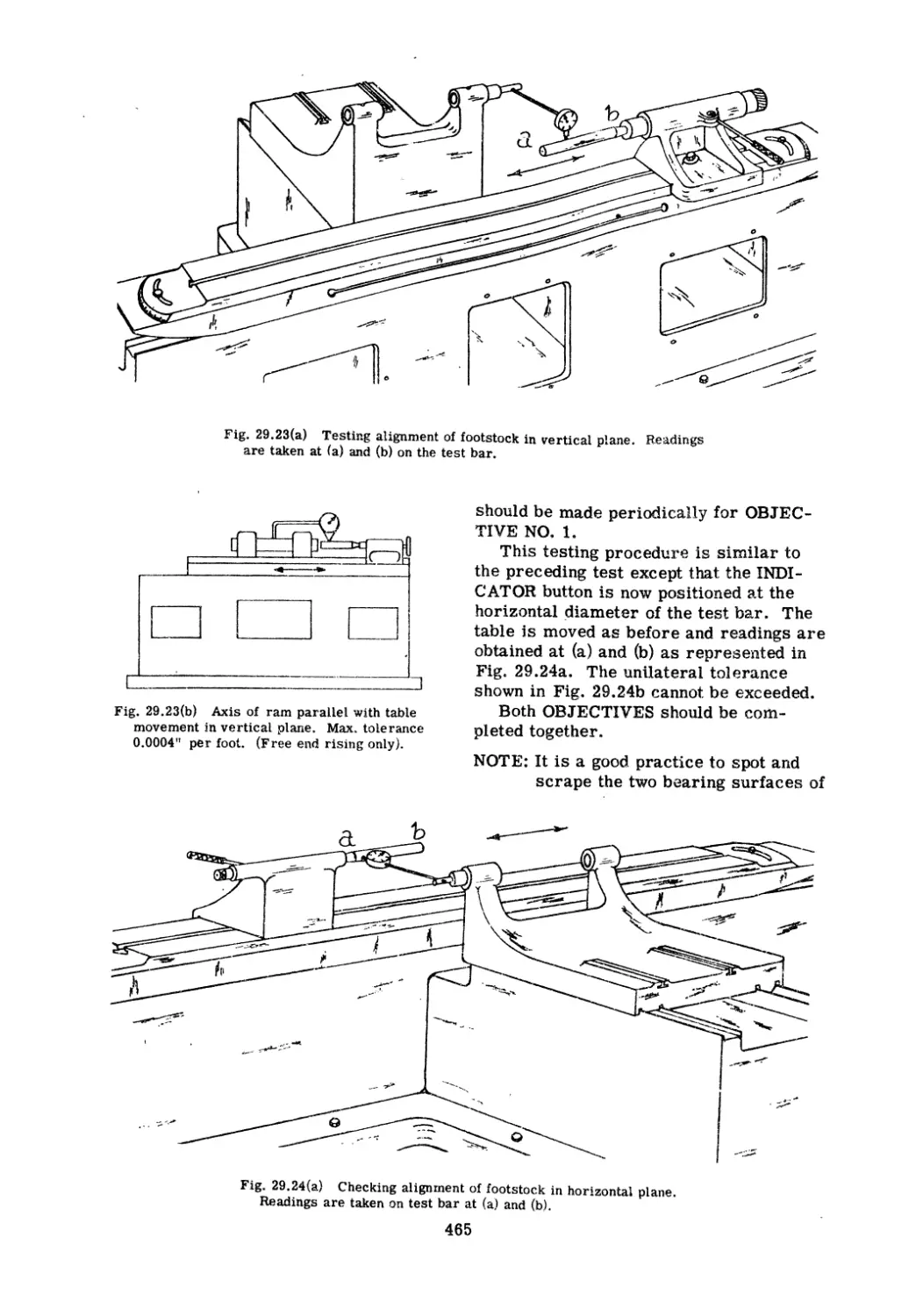
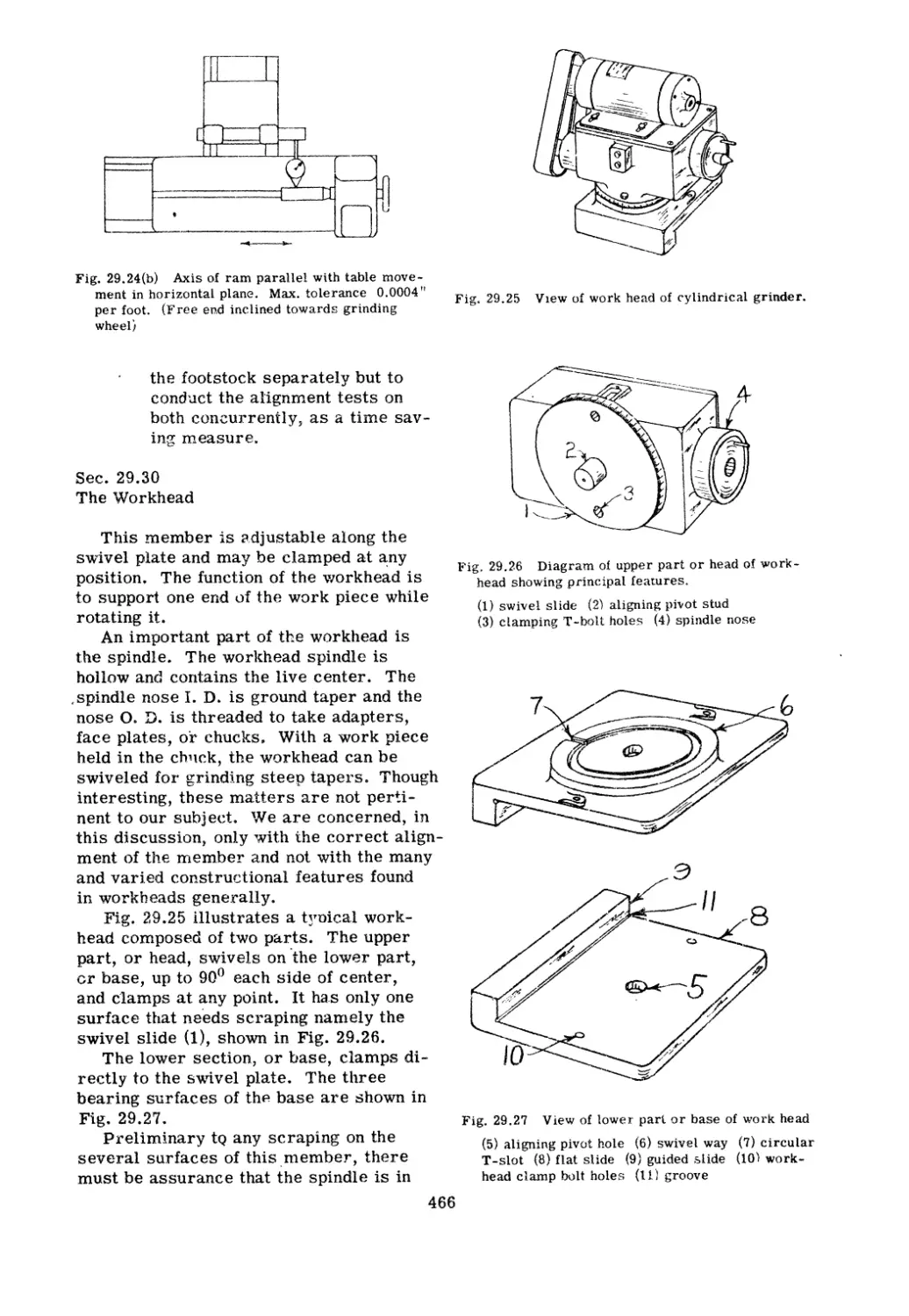
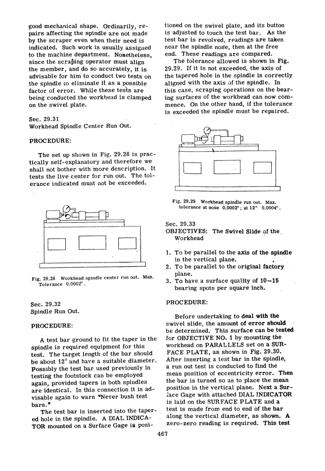
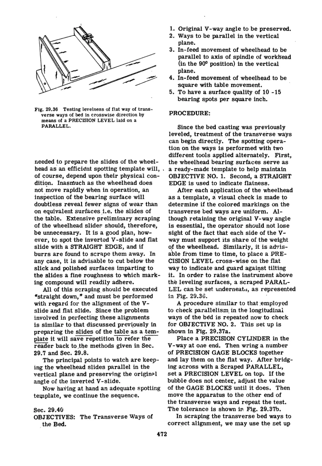
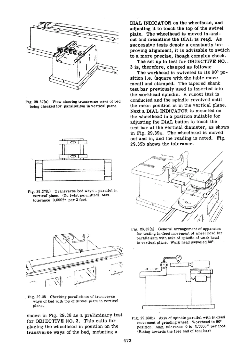
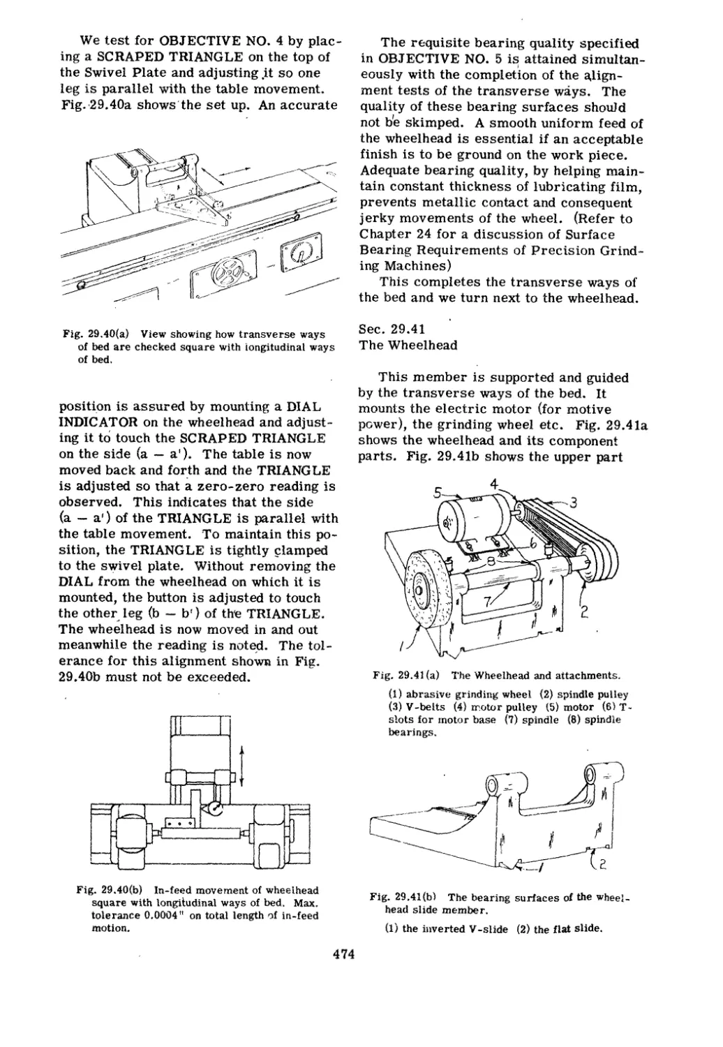
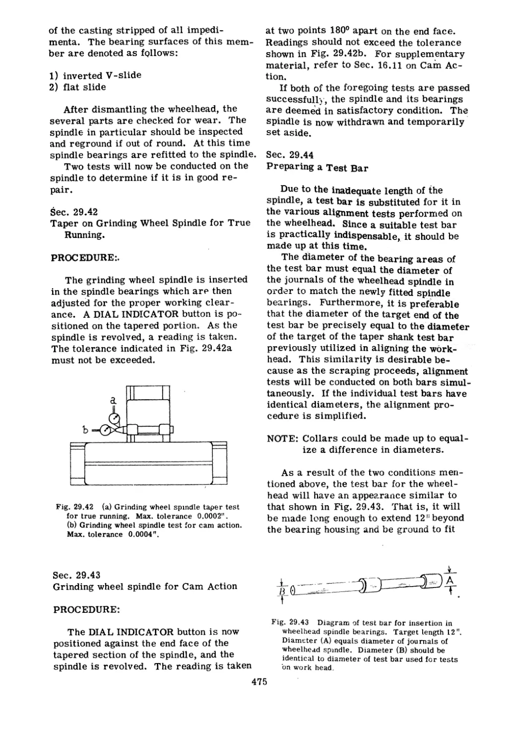
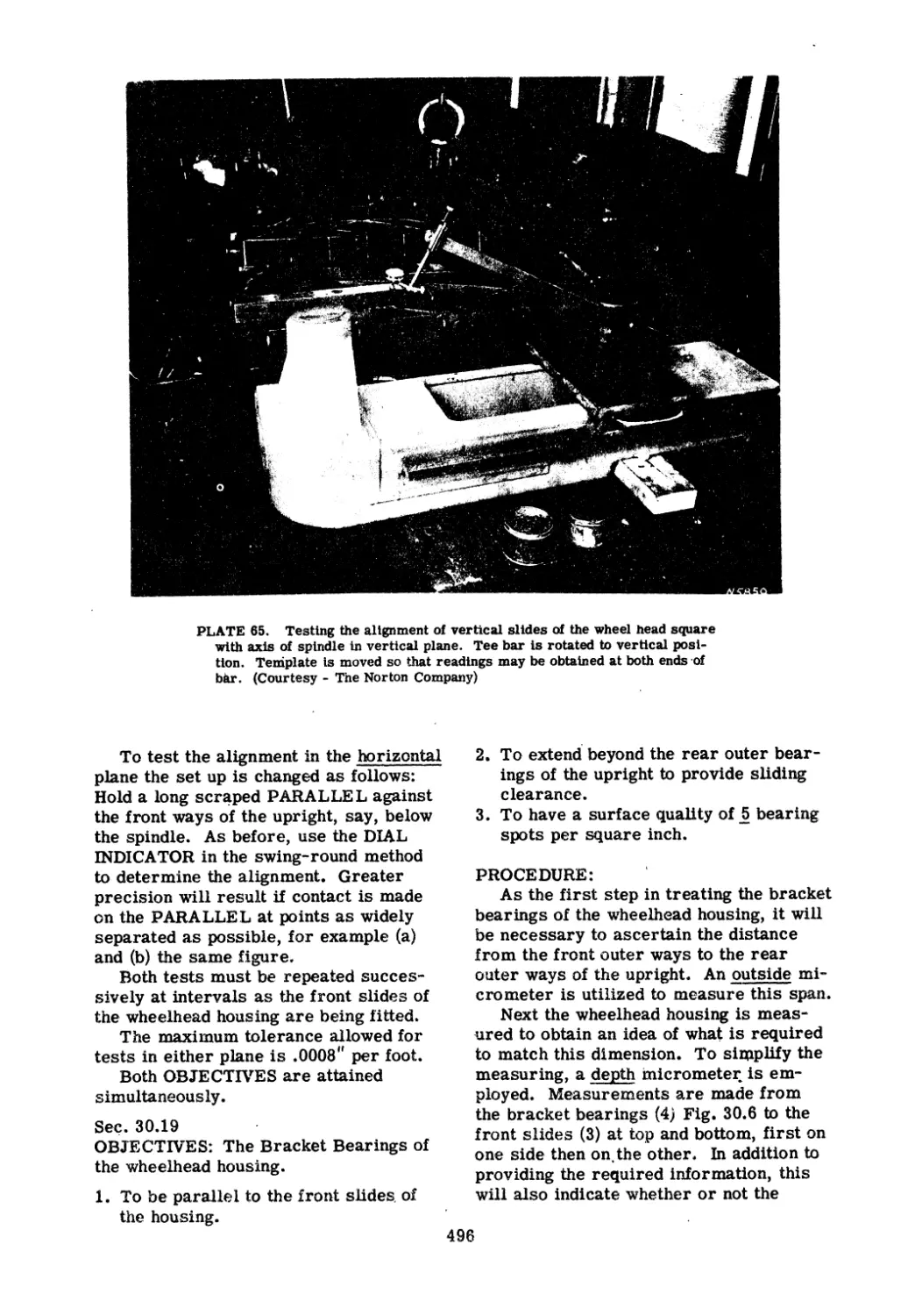
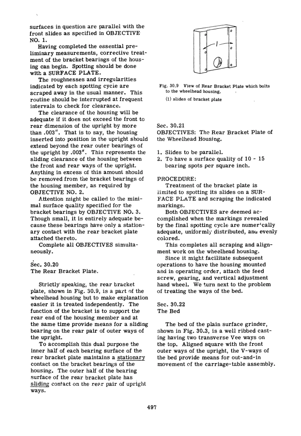
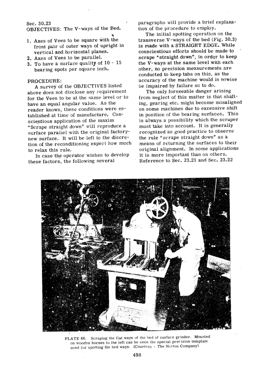
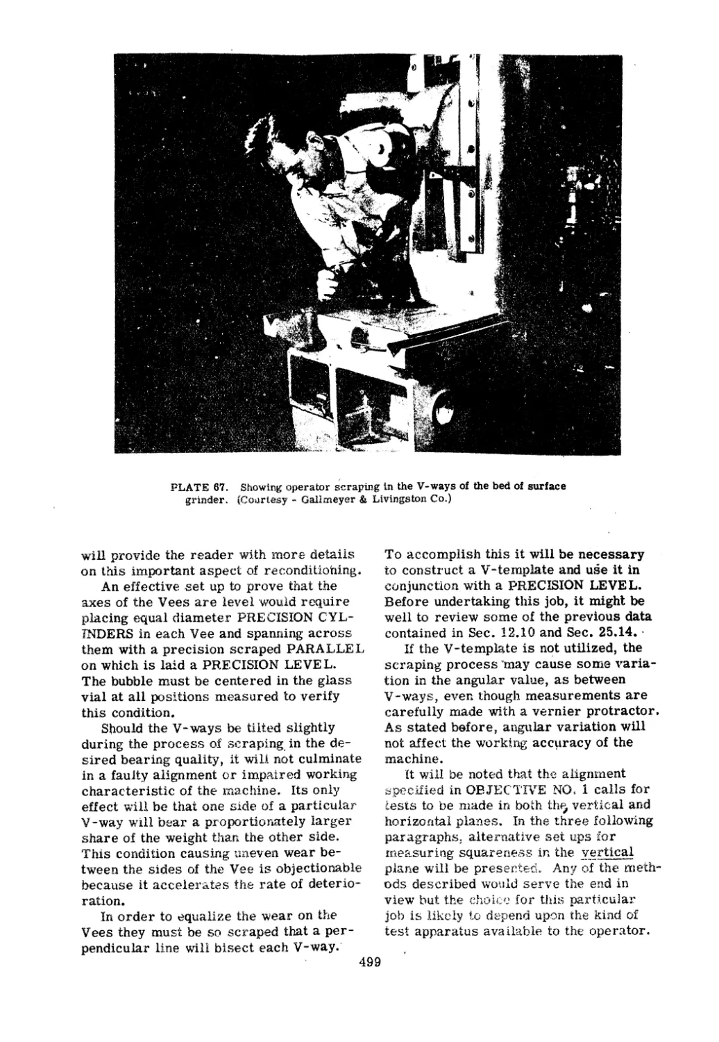
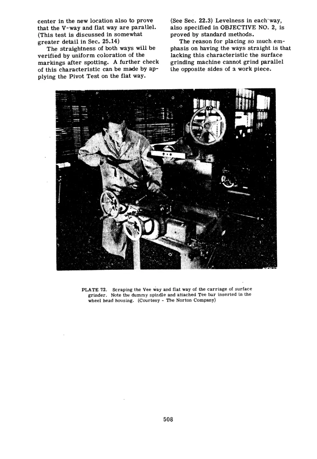
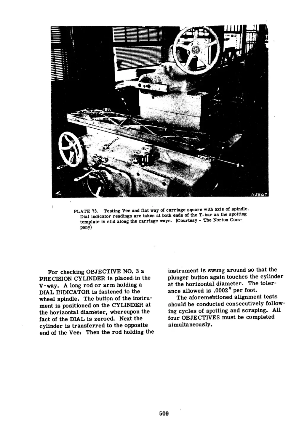
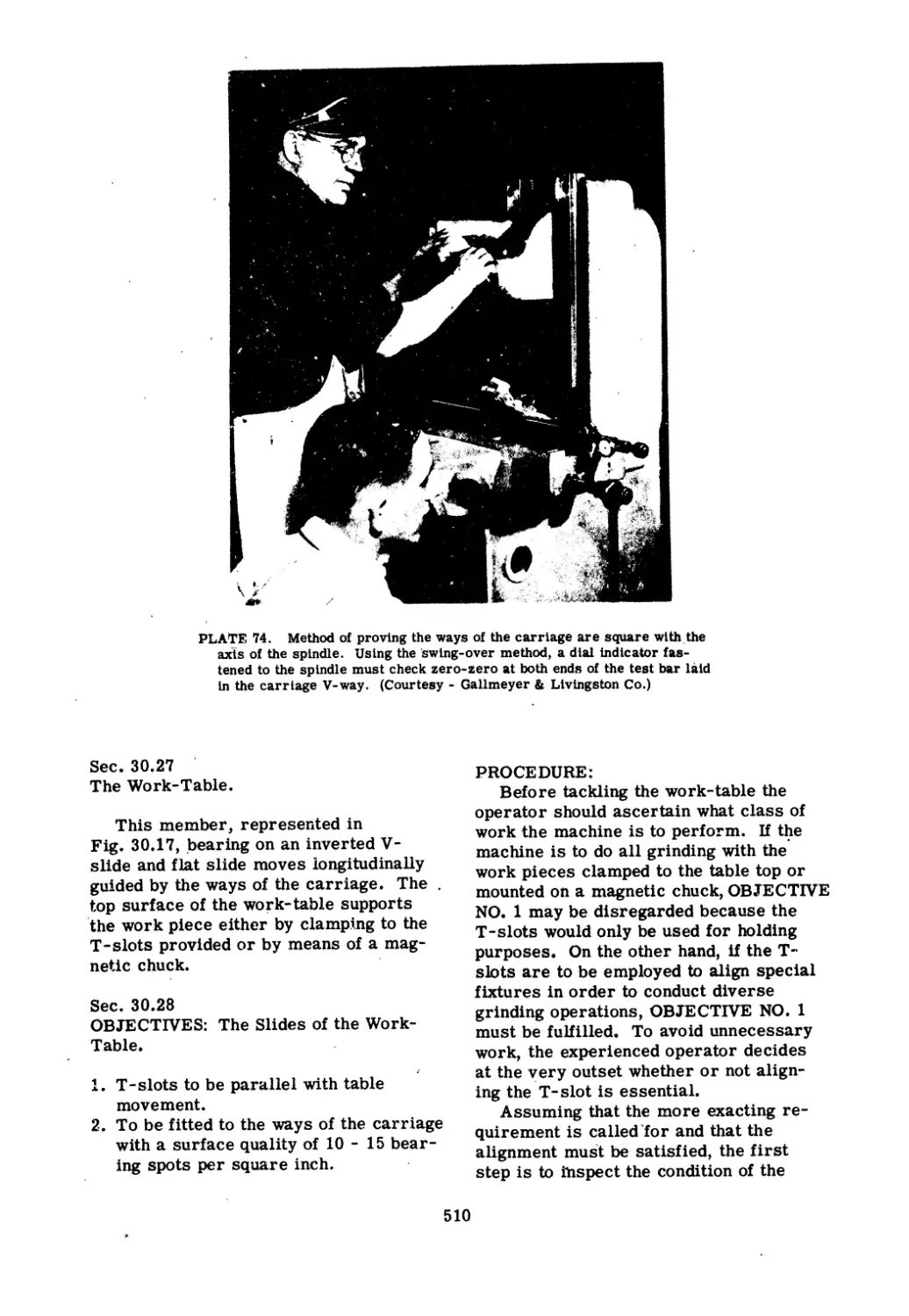
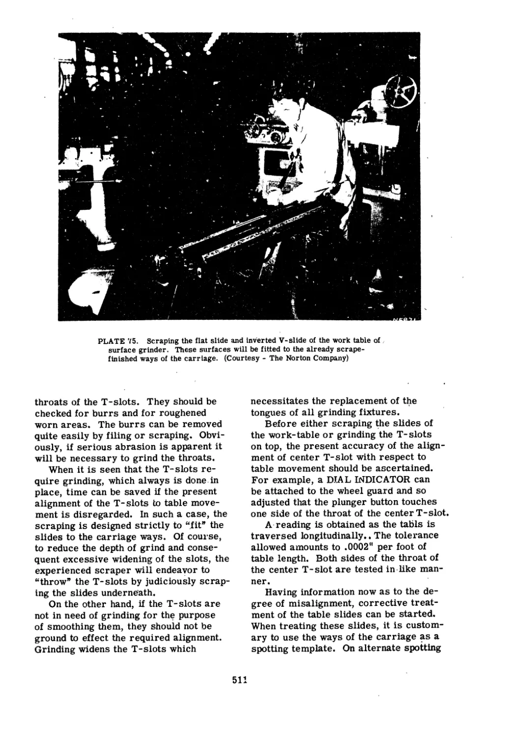
/


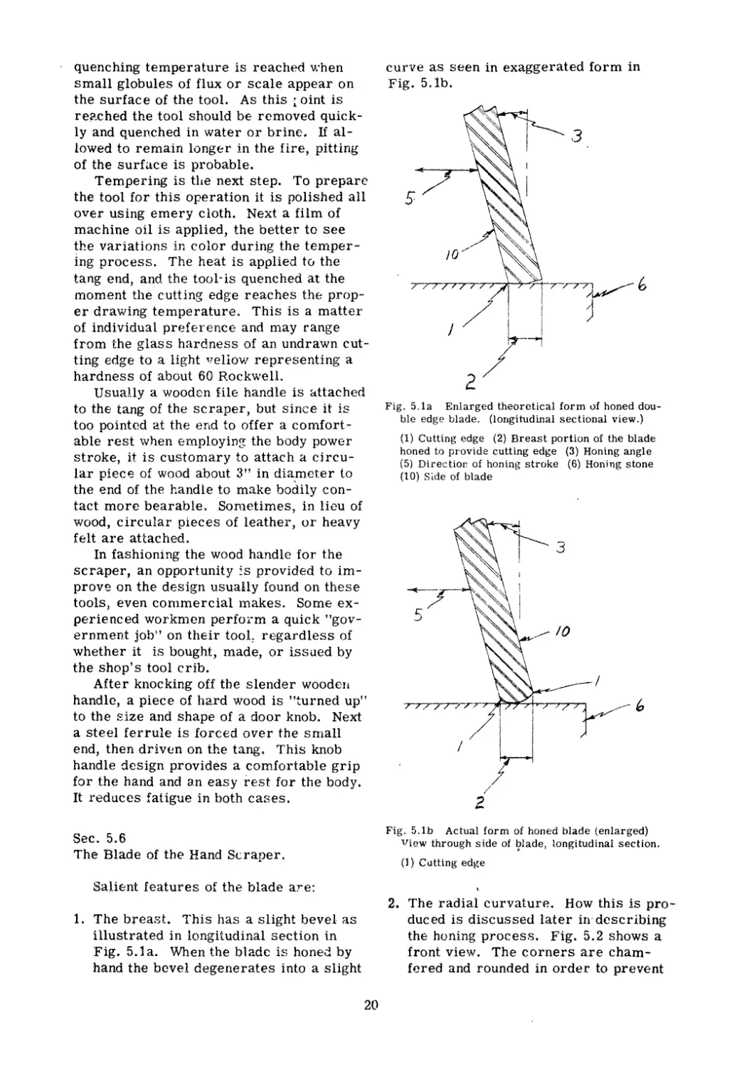
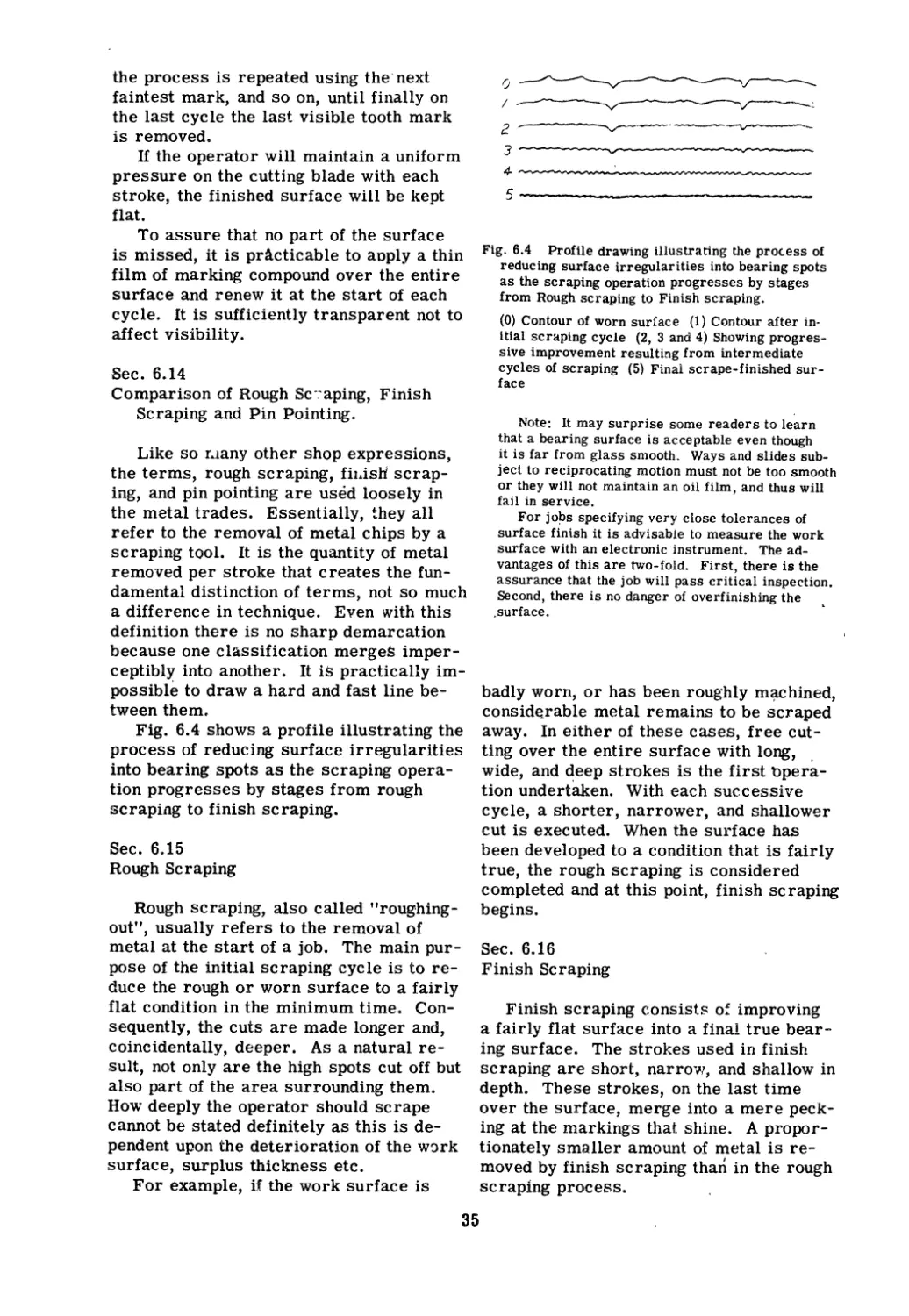
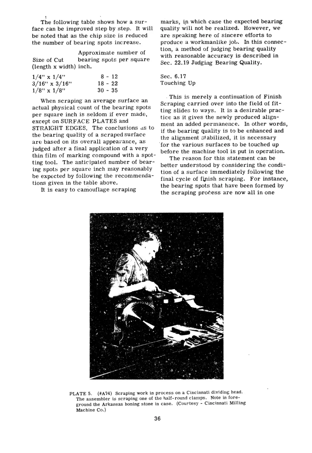
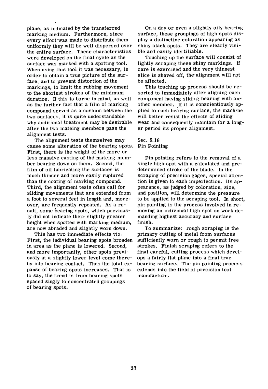
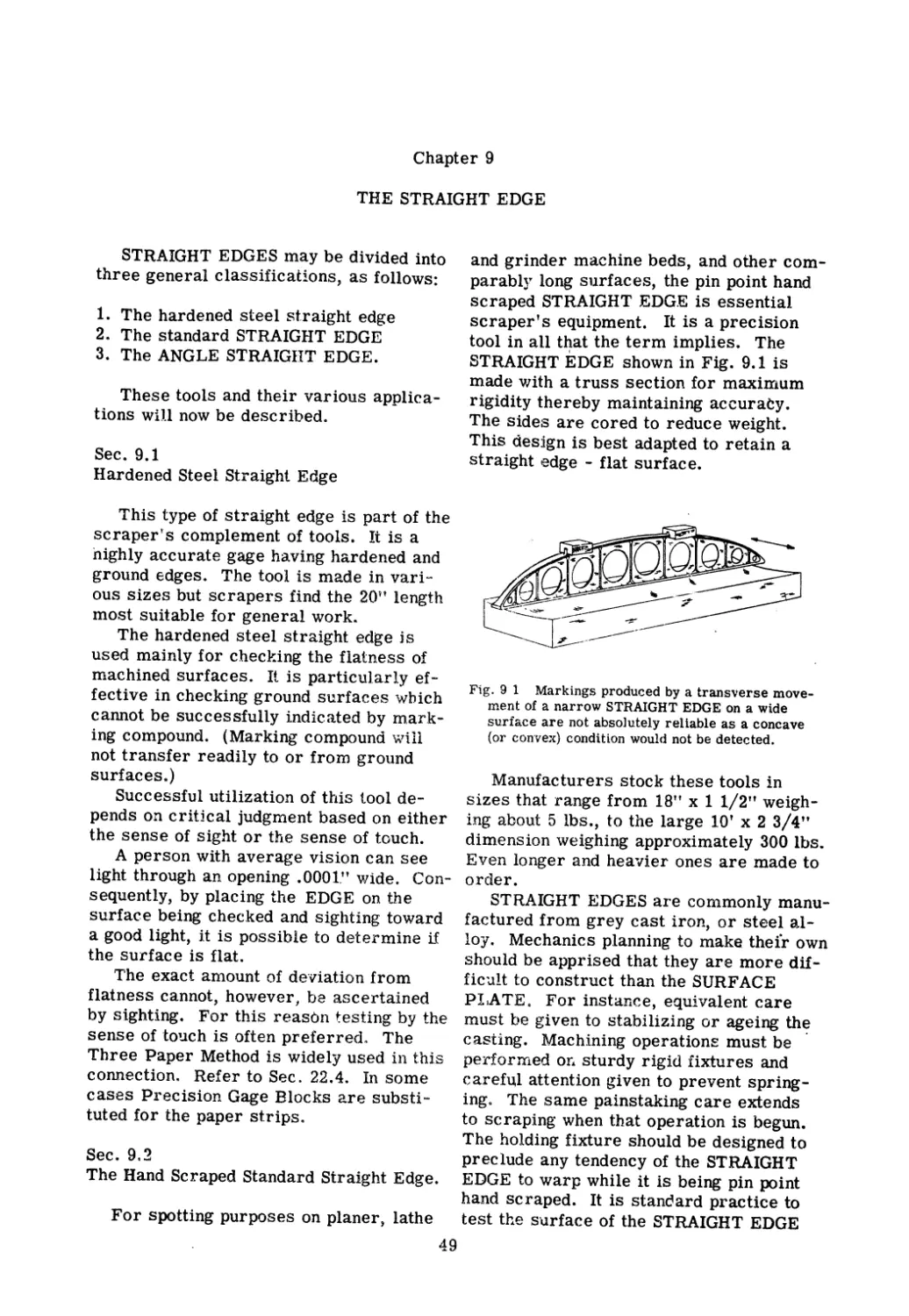


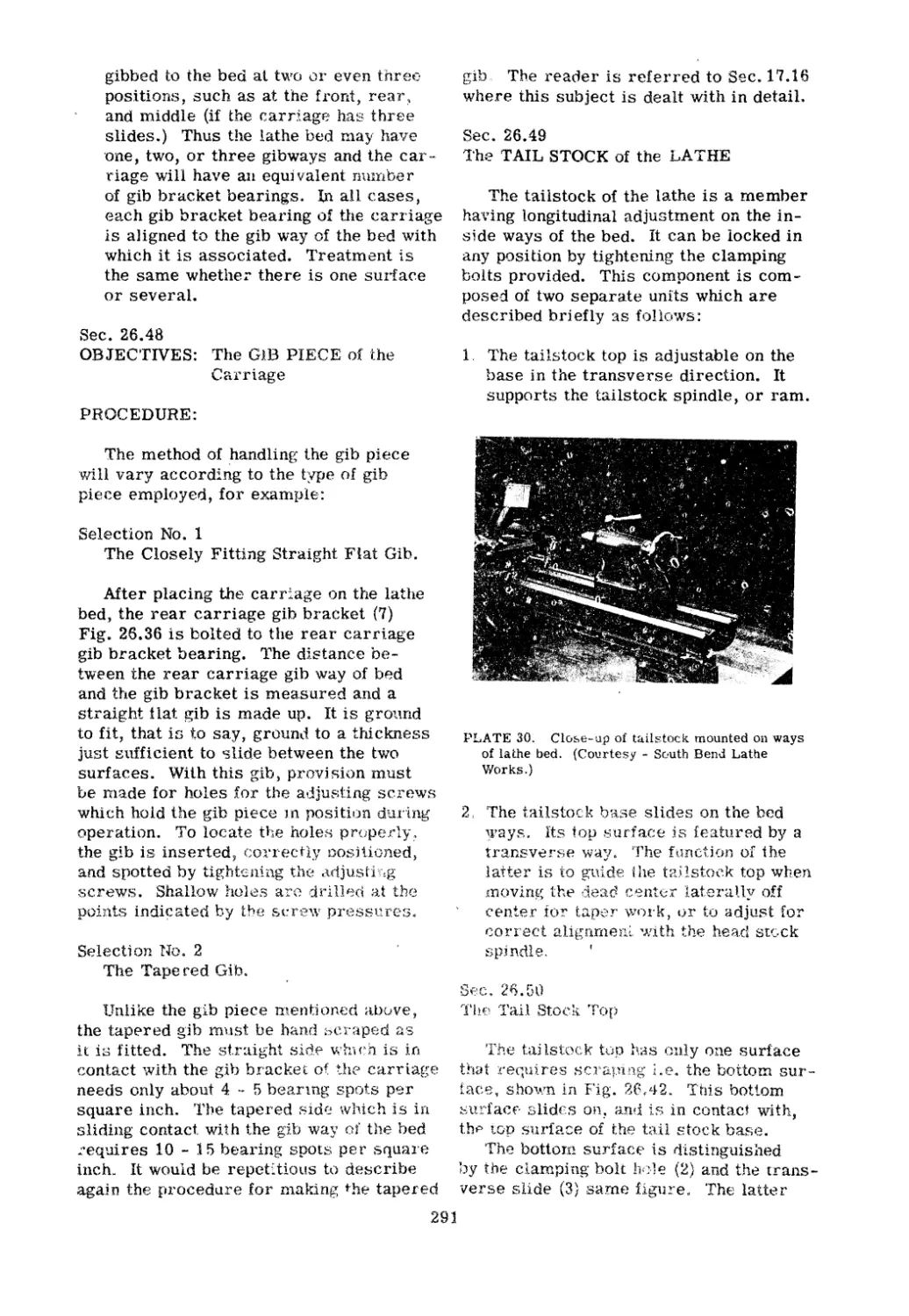
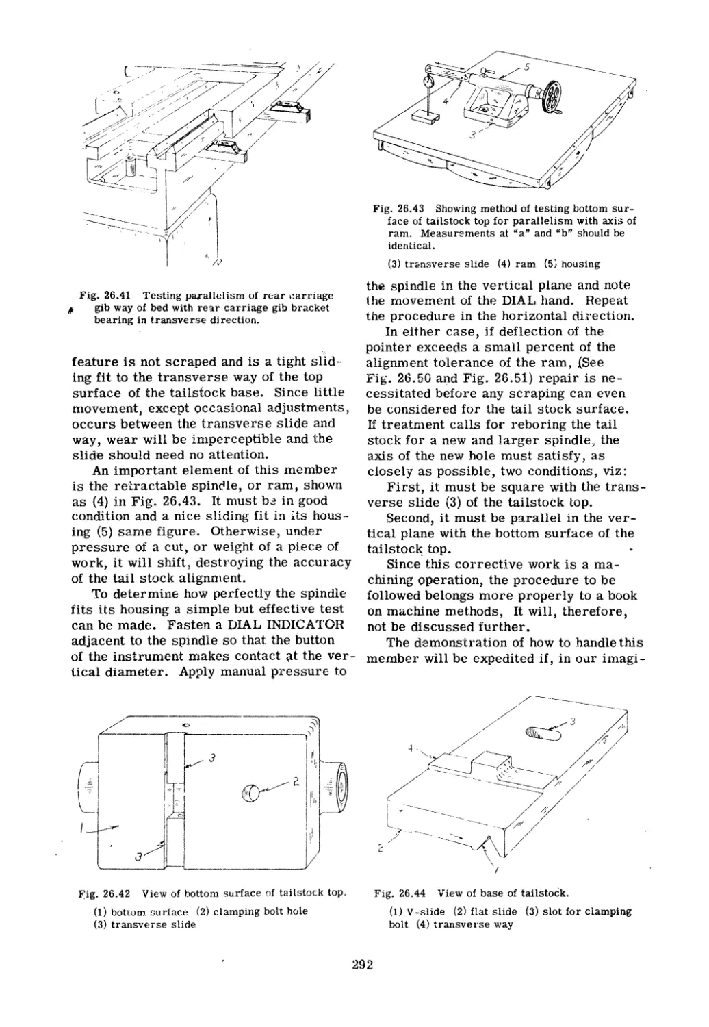
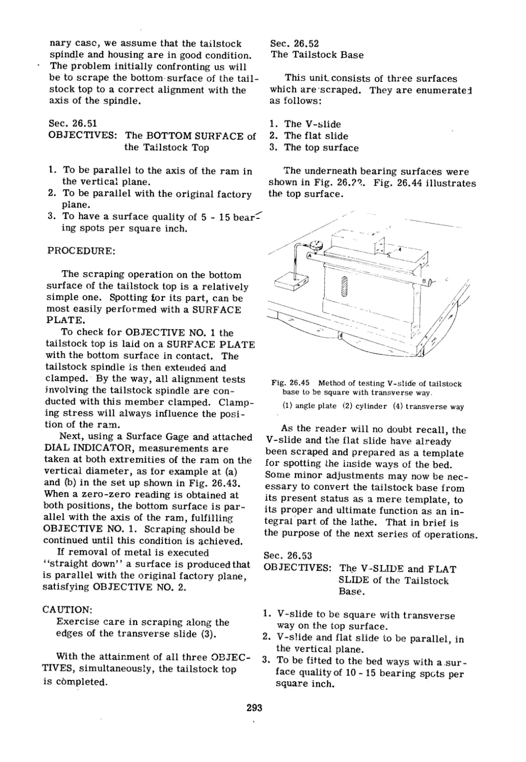
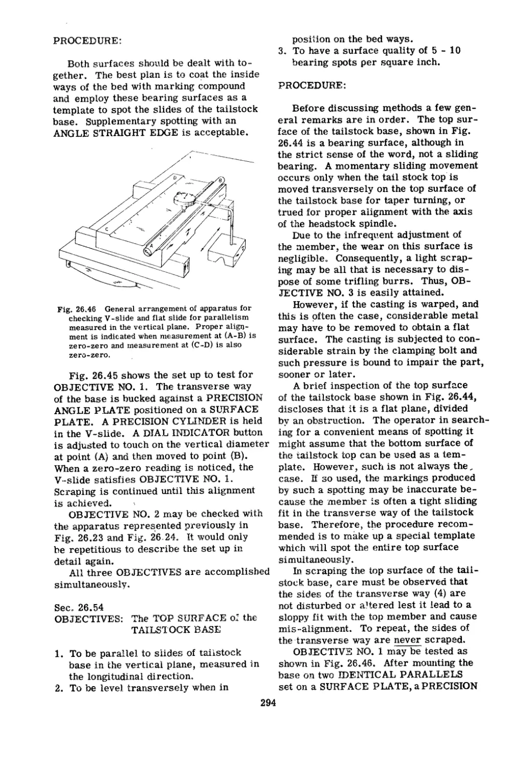
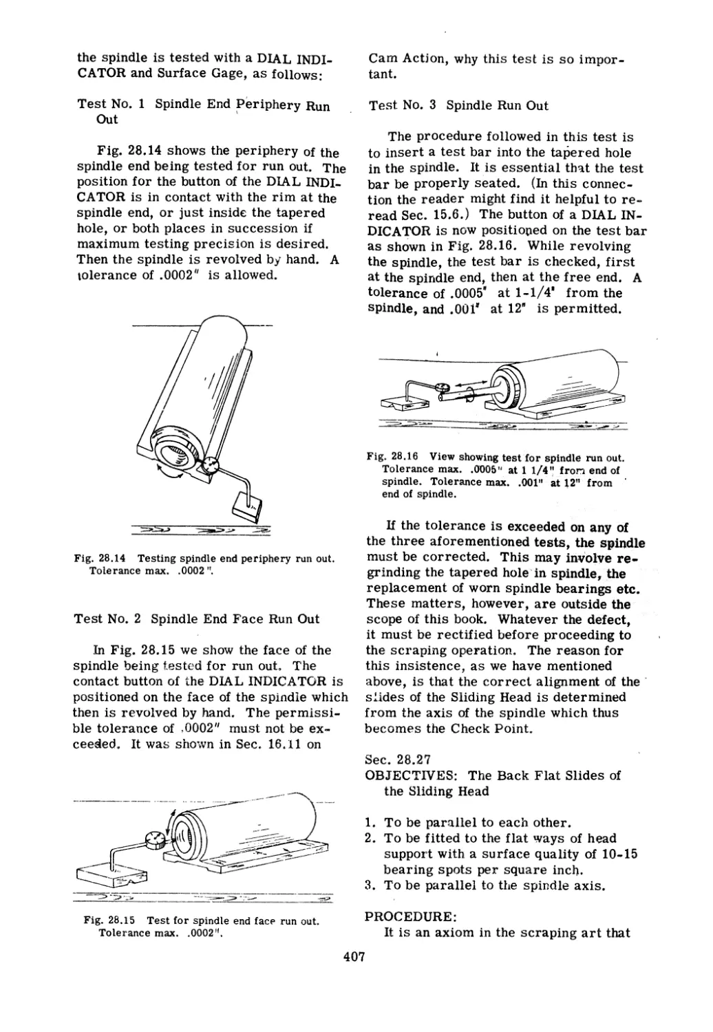
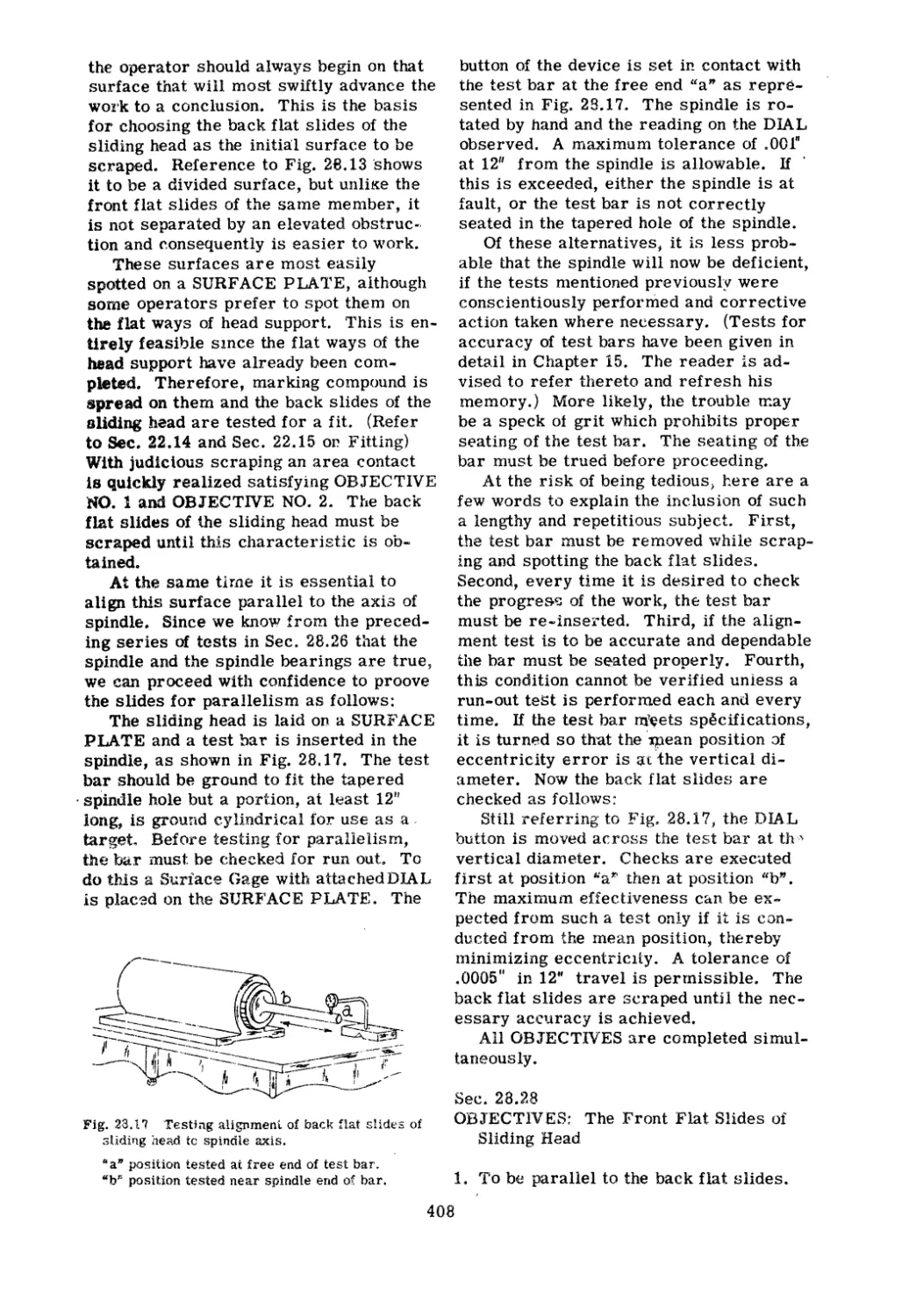

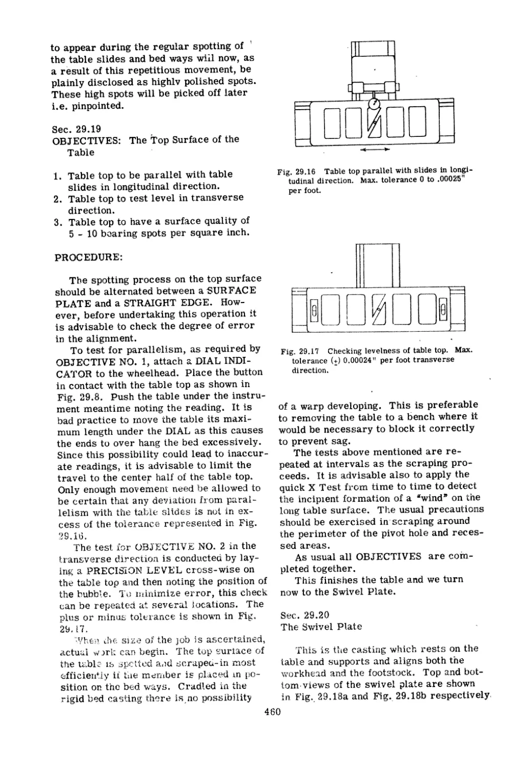


Tags: machines machine repairs
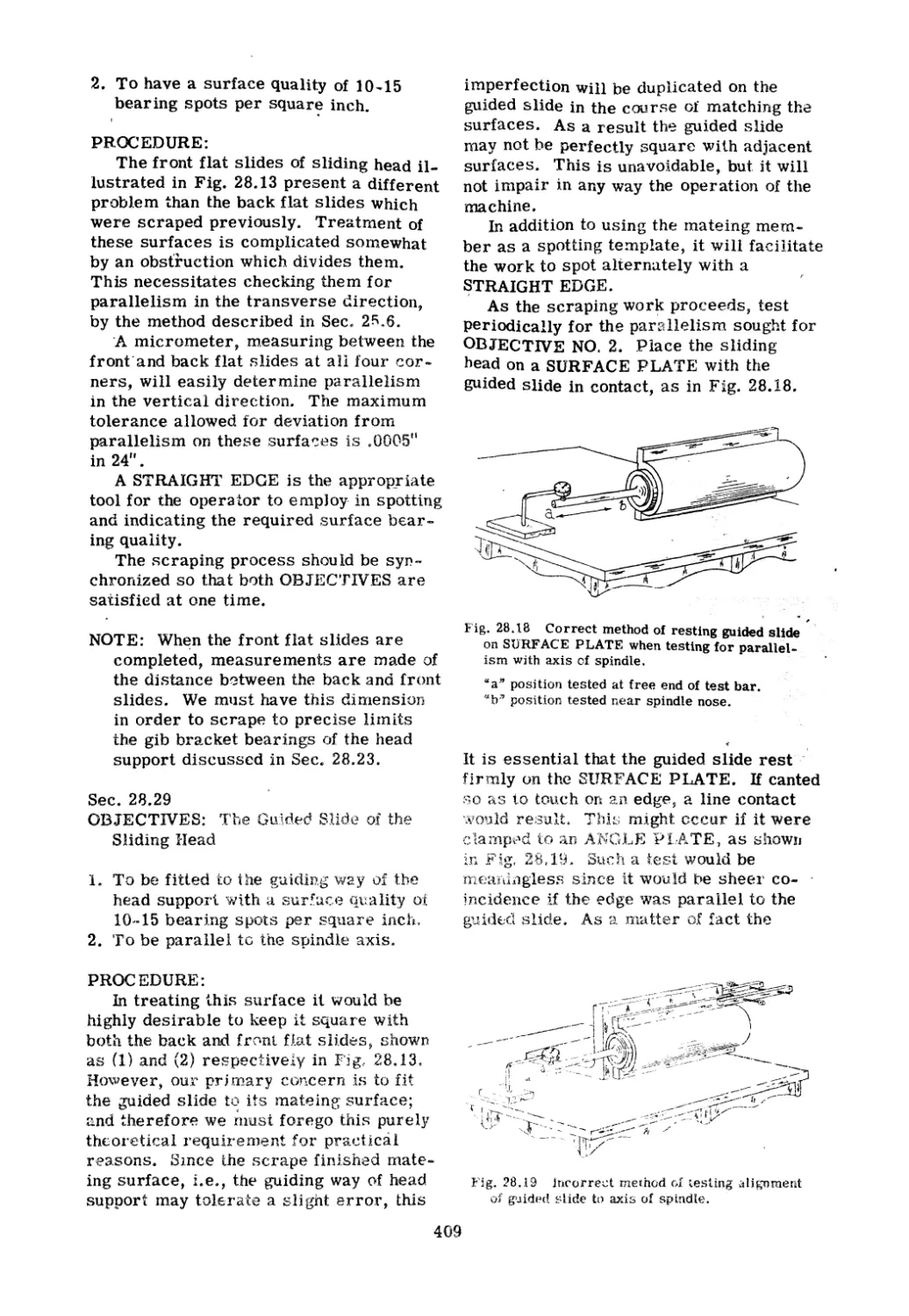
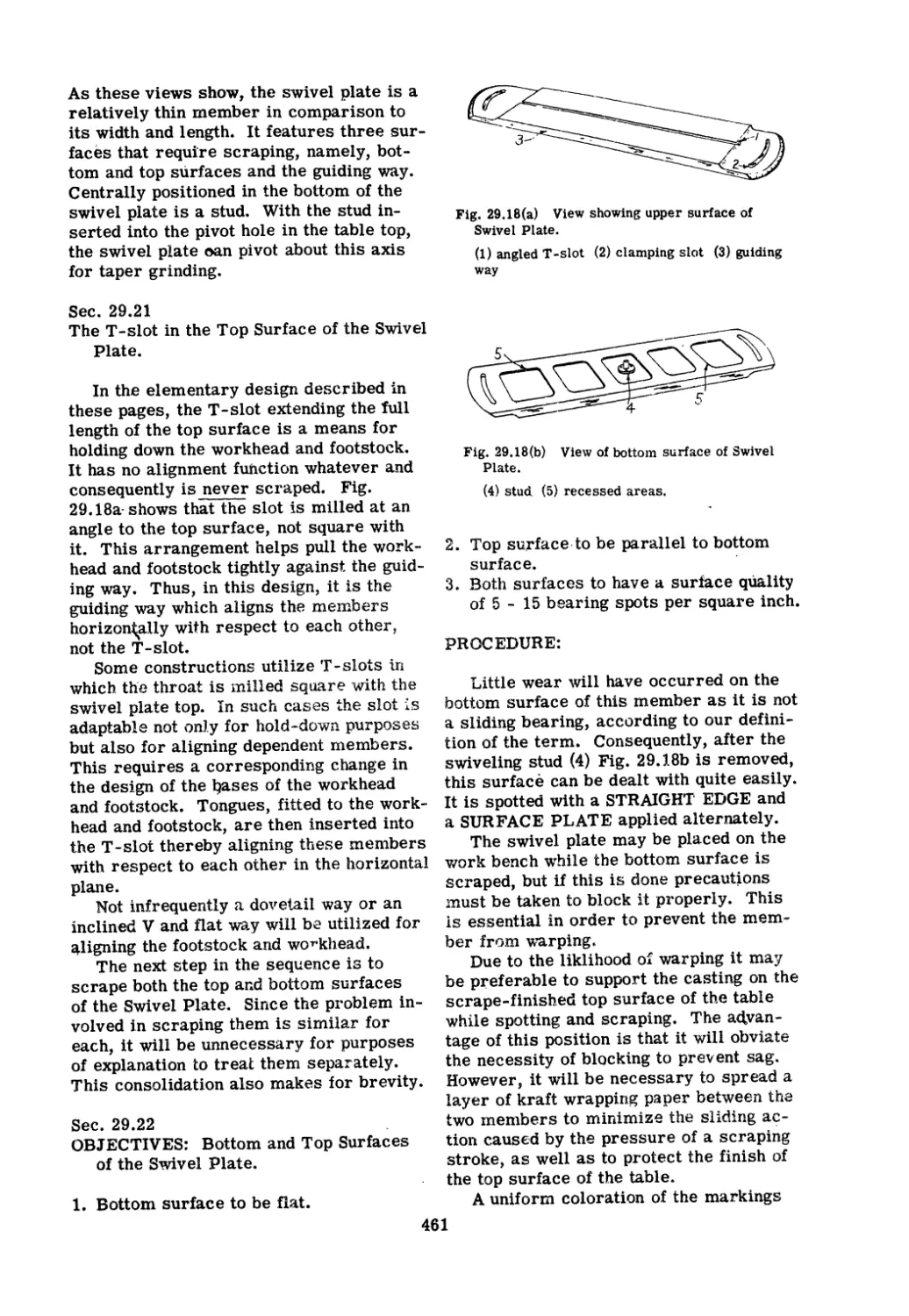
Year: 1955


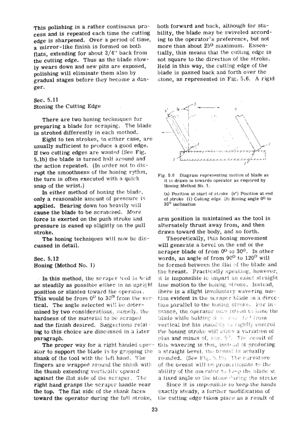
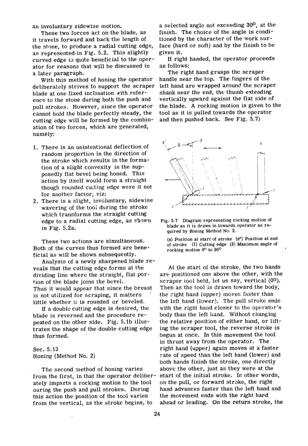
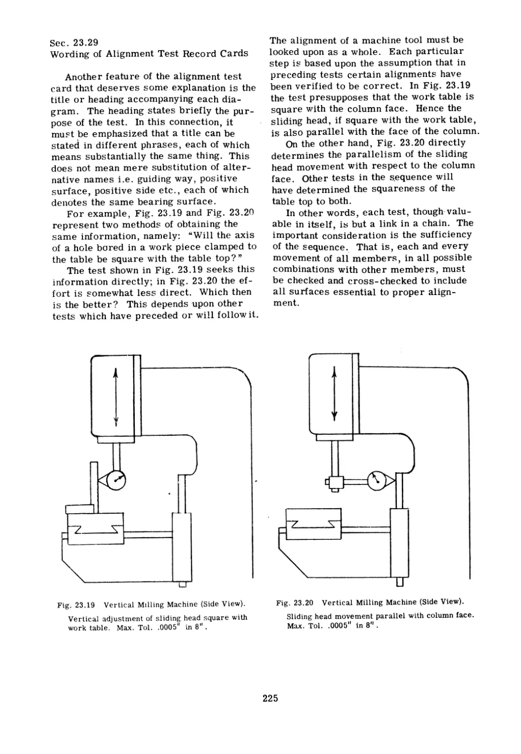
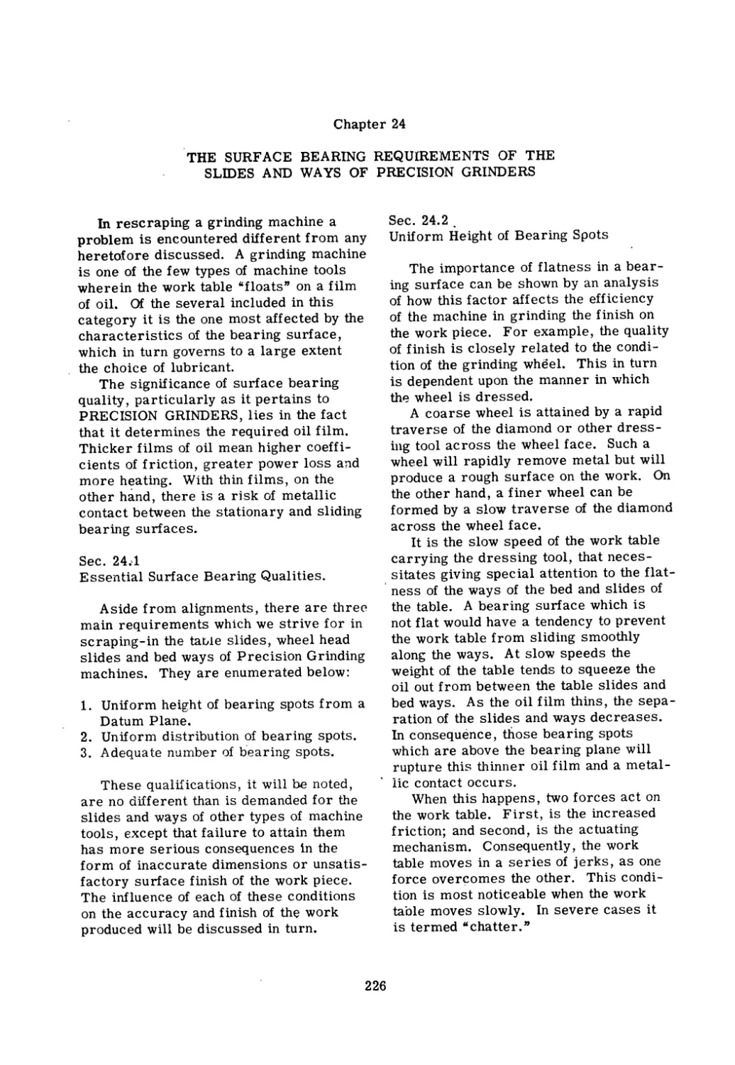
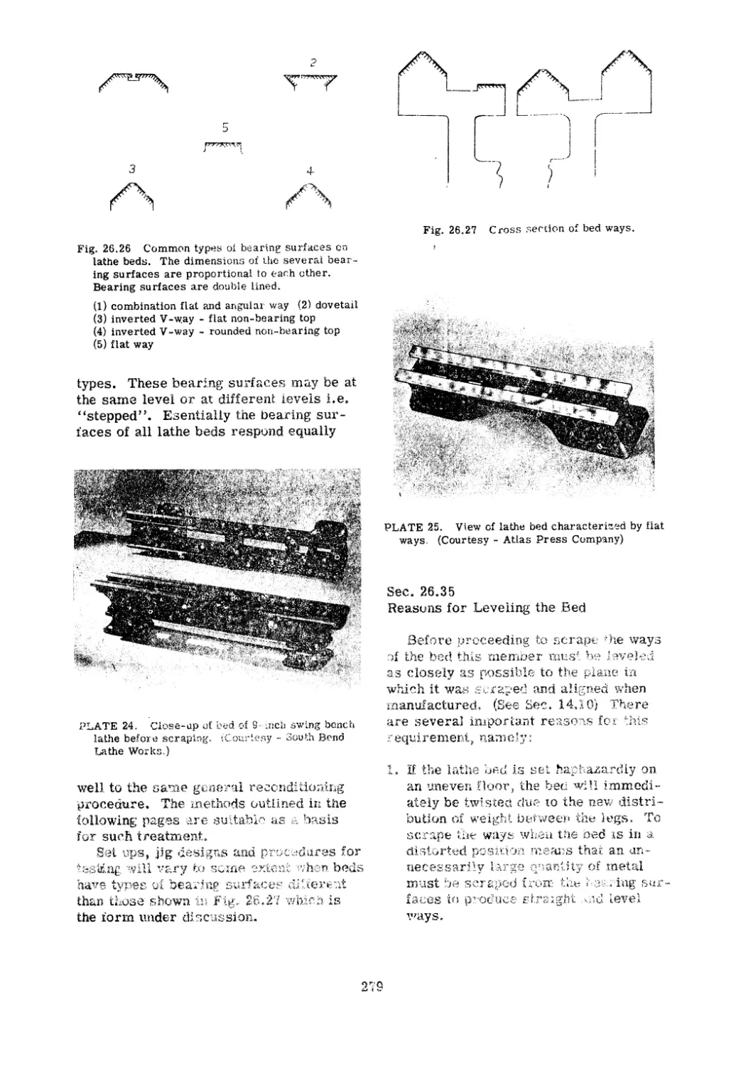
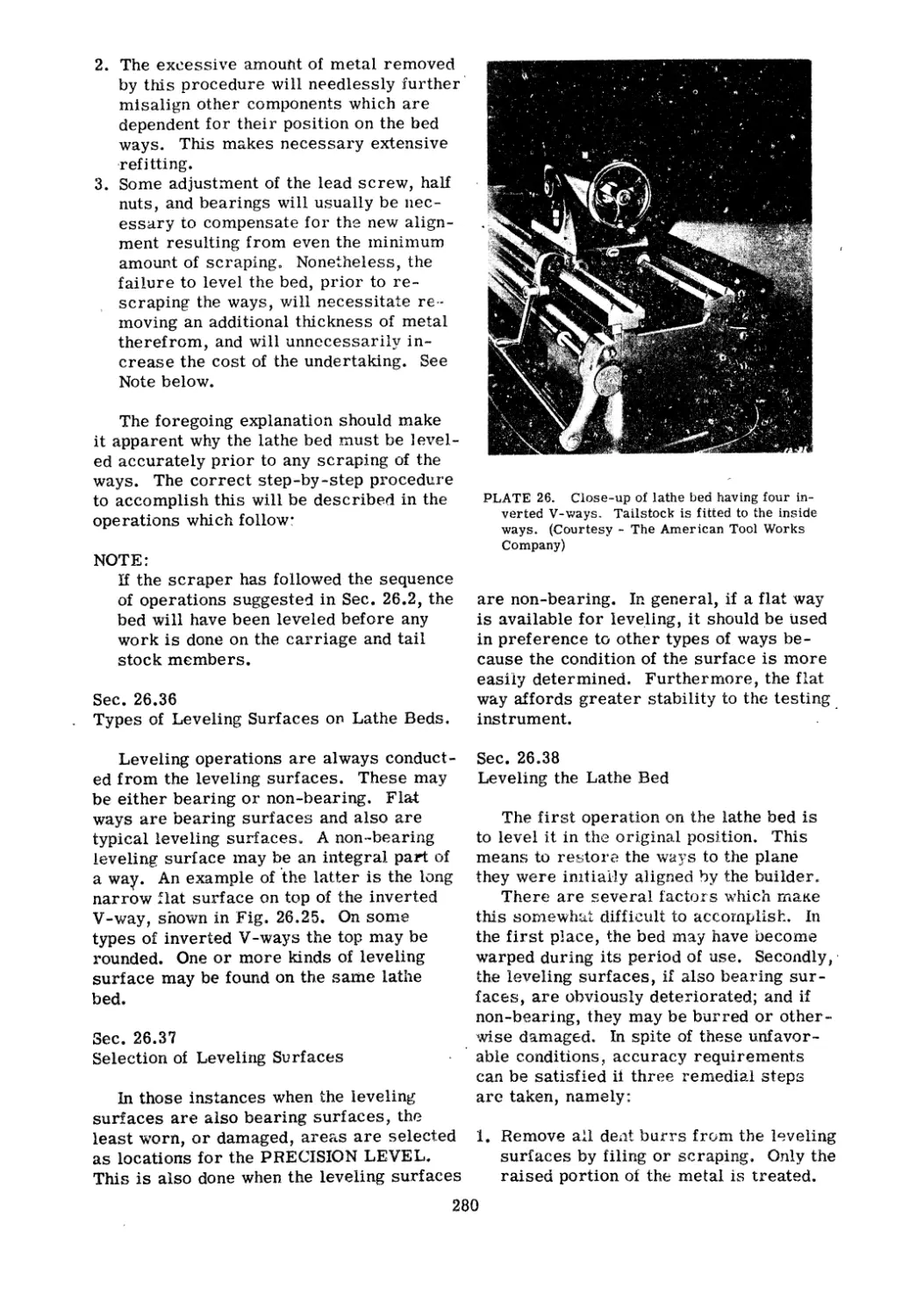
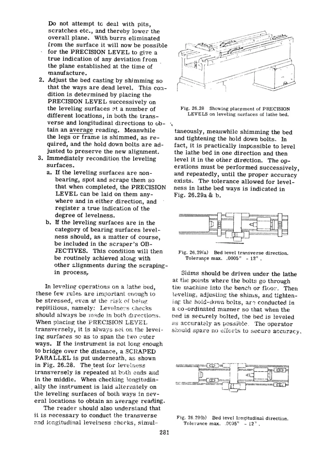
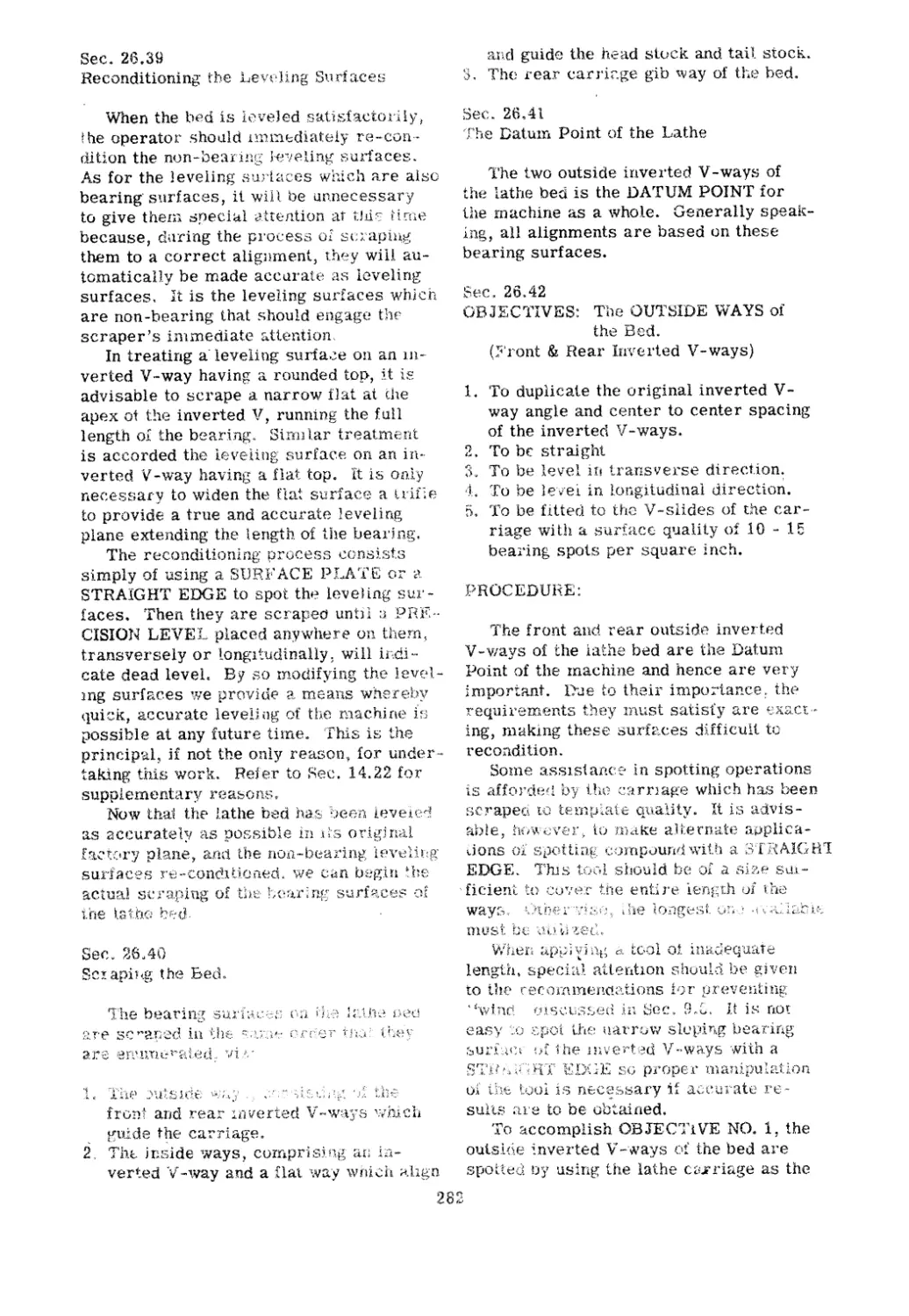
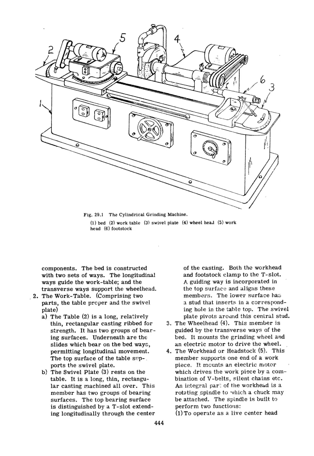
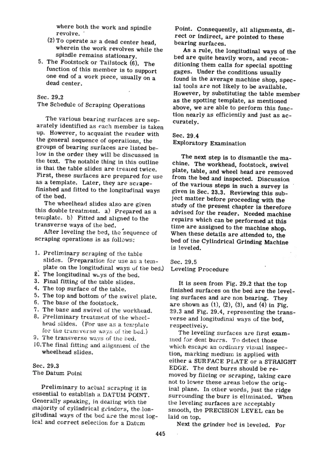
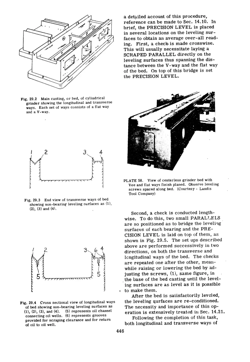
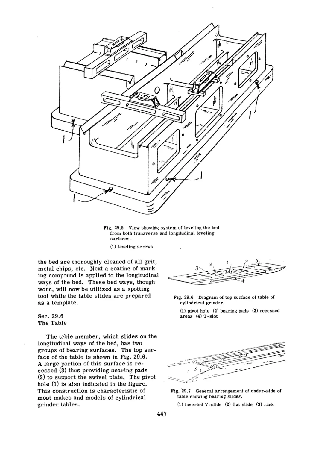
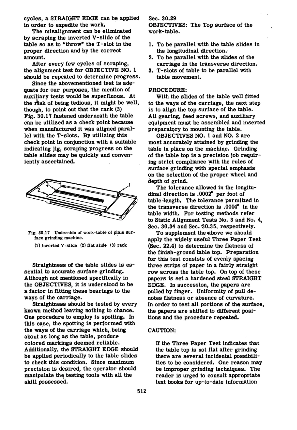
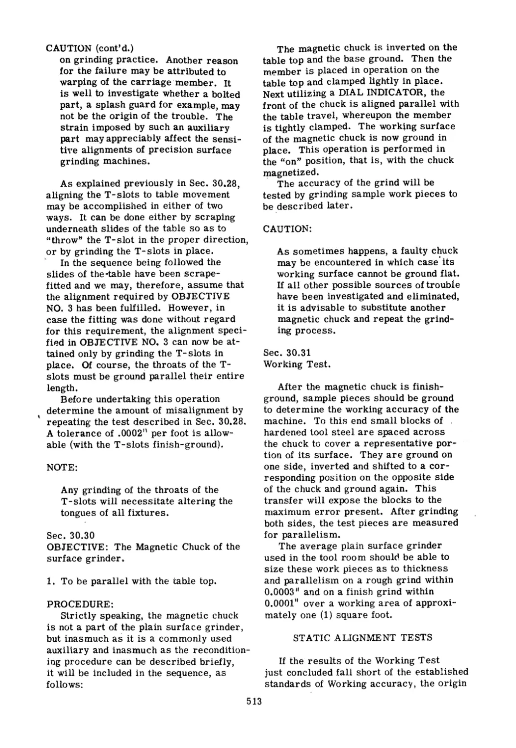
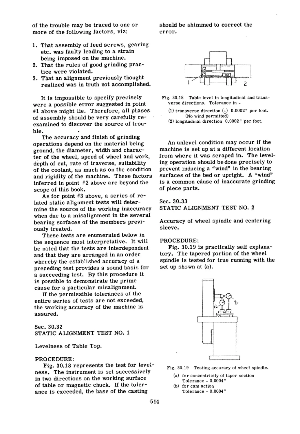
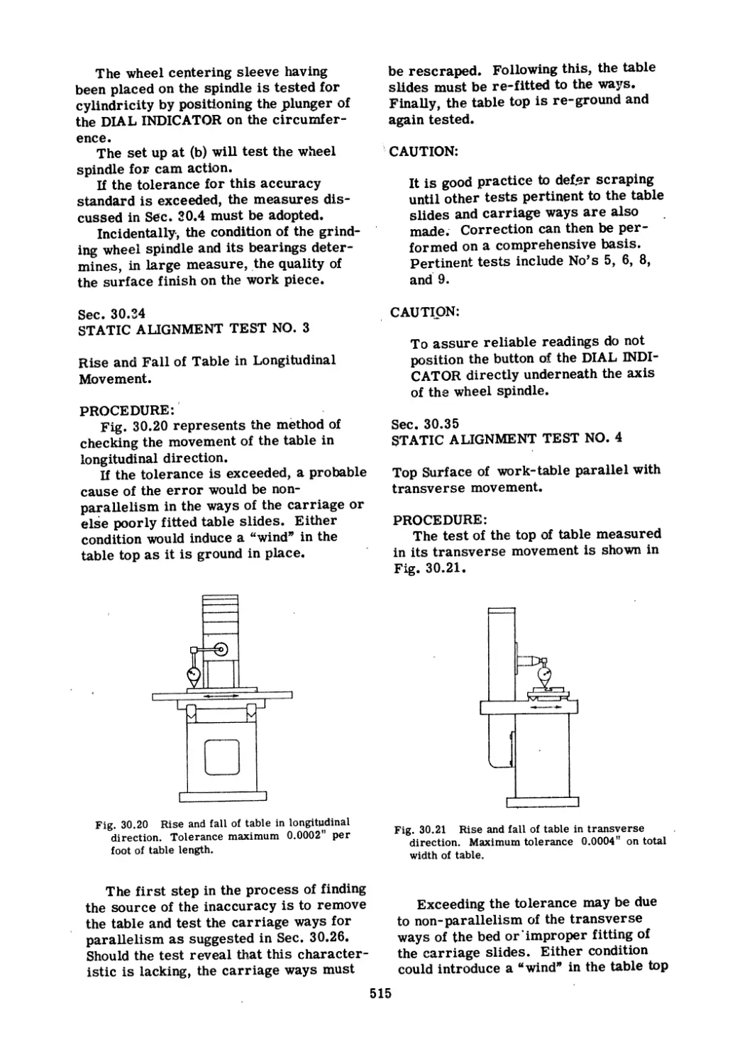
Text
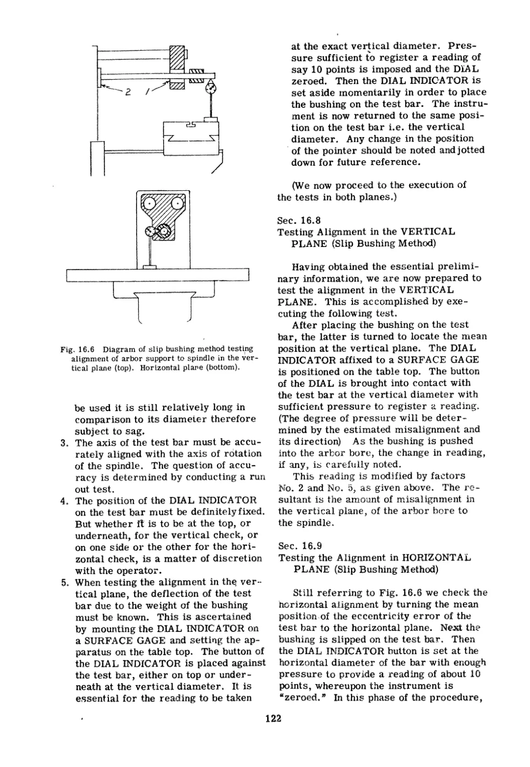
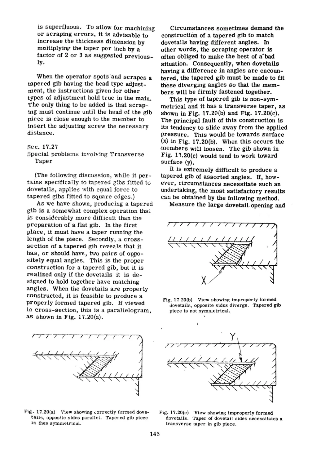
MACHINE TOOL RECONDITIONING
and
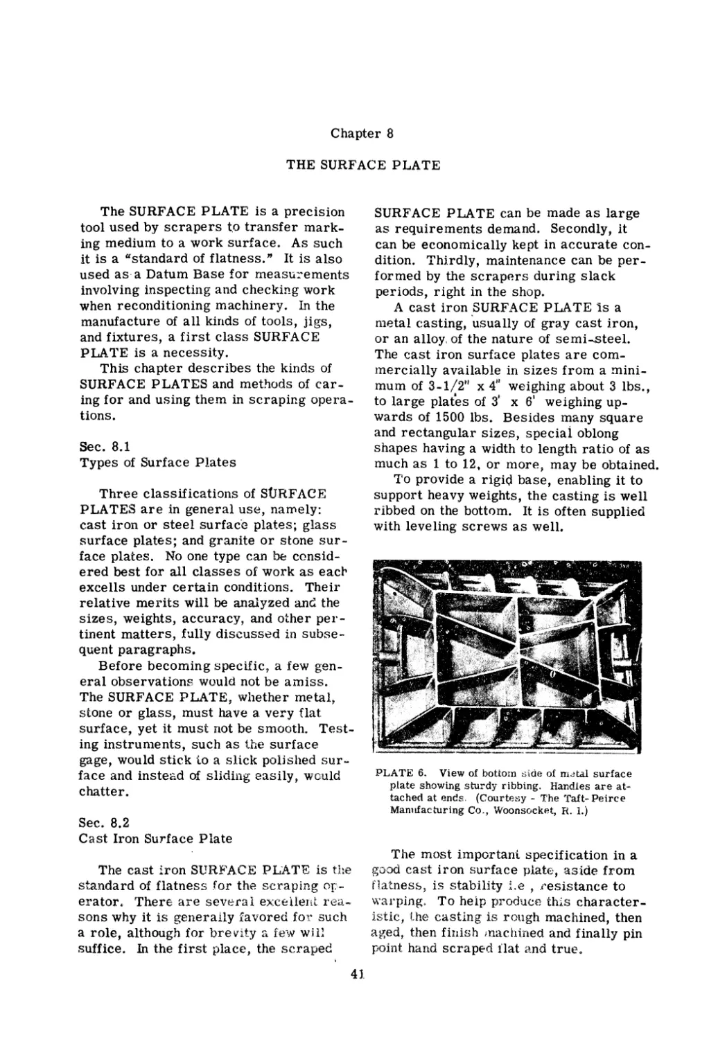
Applications of Hand Scraping
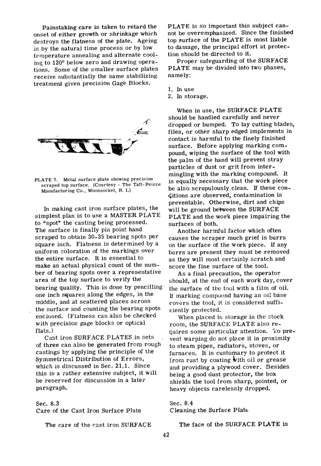
by
Edward F. Connelly
1955
Machine Tool Publications
St. Paul, U.S.A.
Copyright 1954
Machine Tool Publications
saint paul, minne
ota
All rights reserved. No part of this book ma
v be
reproduced ill an.,,! form, by mimeograph Ir any
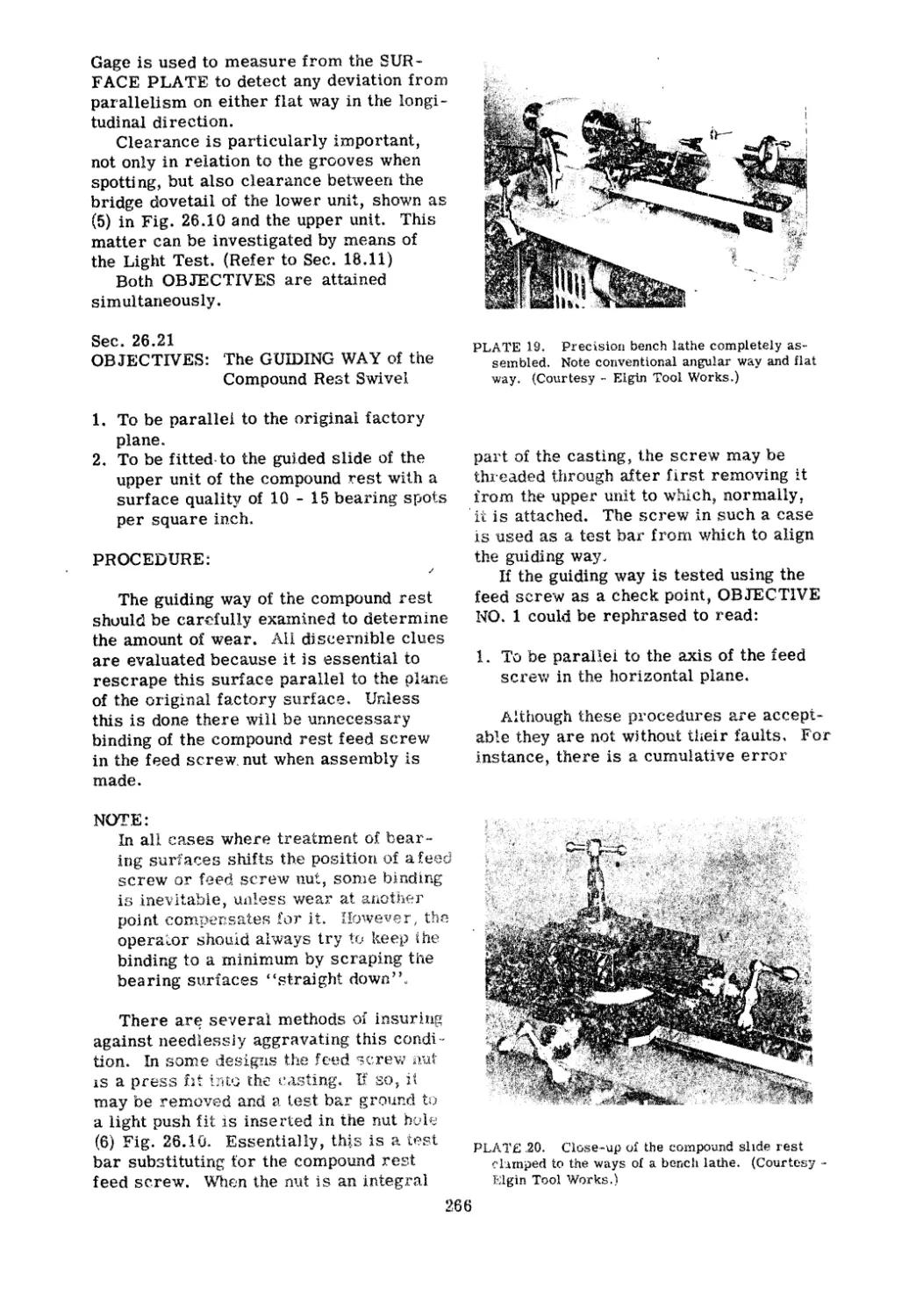
other n:eans, without permission in 'writing from
the publishers.
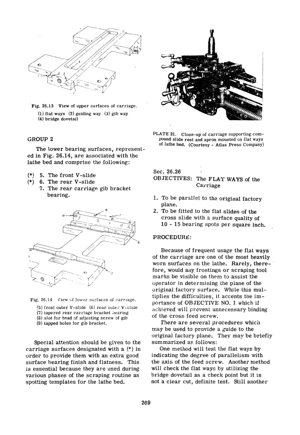
Third Printing, 1957
PREFACE
The purpose of this book is to supply a
deficiency of long standing jn the n1etal
trades for a comprehensive exposition of
the hand scraping art and its principal ap-
plication, the reconditioning of machine
tools. The author has atten1pted to set
down in simple language, not only the basic
principles and practices, but also the more
advanced techniques utilized by skilled,
experienced scrape s.
The arrangement of this book has a two
fold purpose. First, to acq"laint the nov-
ice with the basic scraping procedures
and to teach the principles involved. Sec-
ond, to apply this knowledge to the specific
problems of machine tool reconditioning.
In describing the methods employed in
treati:Qg the various machine tools, a i...ro-
gressive, step by step procedure is fol-
lowed. Starting with an outline of the com-
ponents, each part is sub-divided into its
constituent bearing surfaces. The OB-
JECTIVES required of each surface are
established, and accompanied by a more
or less detailed explanation of the recom..
mended treatment. In other words, each
part of the entire operation is given and
presented in the logical order. It should
. answer the questions "Where do I start?"
and "What'next?" Where sound alterna-
tive procedures are possible, they are
mentioned. This has been done, not to
make the work encylopedic in content, but
to suggest the use of other apparatus
equally appropriate.
Each major operation, and many Ininor
ones, are graphically illustrated by, per-
spective and mechanical dra\vings.. These
show the physical set-ups and utilize the
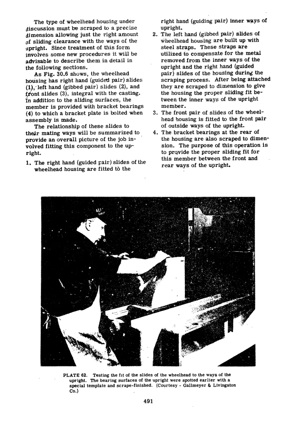
very minimum of standard equipment.
Many of the diagrams show the permis-
sible tolerances in connection with align-
ments.
The subject matter has been arranged,
as far as possible, to make it useful as a
hand book for foremen and other super-
visory personnel. Both the section head-
ings and index should make possible the
rapid finding of essential information.
For experienced operators, the illustra-
tions alone should solve many problems
,with little reference to the text.
Most of thIs information cannot be
found 'in standard engineering handboo s,
machinist's manuals, or even in books
dealing with the mechanical trades gener-
ally, but it is nonetheless indispensable to
anyone charged with the responsibility for
maintaining, at highest efficiency, the pro-
duction machinery of mill, factory, or
shop.
The status of hand scraping in modern
industry is an important one. It is an in-
tegral operation of machine tool building
and repair, which is the key industry of
America's mass production system of
manufacture. Moreover, it is an essential
process in the production of master gages
for factories.
Although there have been many techno-
logical advances in machine design, new
processes developed in metallurgy, in-
novations in metal hardening and in grind-
ing practice, this progress has not dimin-
ished the need for hand scraping. Machines
have not yet replaced the skjlled scraping
operator, nor are they likely '0. In the
manufacture of industry's master tools,
such a development is even less probable.
. Naturally, scraping ability cannot be
cultivated in a day. 1'0 become a skilled
scraping operator requires not only much
practice and varied experience, malj,ual
dexterity and physical strength, but also
great patience and an equ ble tempera-
Inent. Thus it is obvious that not all are
fitted for the task. However, for those
qualified, the period of learning may be
materially shortened by a study of this
book and correct application of its prin-
ciples. While an occasional short cut may
be taken on some of the procedures dis-
cussed, these ::tre for the skilled practi-
tioner and not for the novice. Experimen-
tation, legitimate as it is, ought not to be
too freely exercised when recondi tioning
costly machines. If the novice will con-
form to the procedures hereiri described,
there \\lill be reasonable efficiency for the
effort expended.
iii
ACKNOWLEDGMENTS
The author wishes to exp
ess thanks to
a number of industrial concerns who greatly
aided the preparation of this Ms. by provid-
ing photographs and technical information. .
American Tool Works
Cincinnati, Ohio
Anderson Bros. Mfg. Co.
Rockford, Ill. .
Atlas Press Company
Kalamazoo, Mich.
Brown & Sharpe Co.
Providence, R. I.
Cincinnati Grinders, Incorporated
Cincinnati, Ohio
Cincinnati Milling Machine Co.
Cincinnati, Ohio
DoAll Company
Des Plaines, Ill.
Dykem Company
St. Louis, Mo.
Elgin Tool Works
Chicago, Ill.
Franklin Institute of the 5'tate of
Pennsylvania J
Philadelphia, Pennsylvania
Gallmeyer and Livingston Co.
Grand Rapids, Mich.
Credit lines accompanying the illustrations
indicate those who so generously helped.
In addition, .the author's appreciation is
extended to the following:
Herman Stone Conlpany
Dayton, Ohio
Kearney & Trecker Corp.
Milwaukee, Wis.
Landis Tool Company
Waynesboro, Pa.
Library of Congress
General Reference and Bibliography
Division
National Lead Company - Research
Laboratories
Brooklyn, N. Y.
National Machine Tool Bailders'
Association
Cleveland, Ohio
Norton Company
Wqrcester, Mass.
Sheffield Bronze Paint Corp.
Cleveland, Ohio
South Bend Lathe Works
South Bend., Ind.
Starrett, L. S., Company
Athol, Mass.
Taft-Peirce Manufacturing Co.
Woonsocket, R. I.
Preface
1.
2.
3.
4.
5.
6.
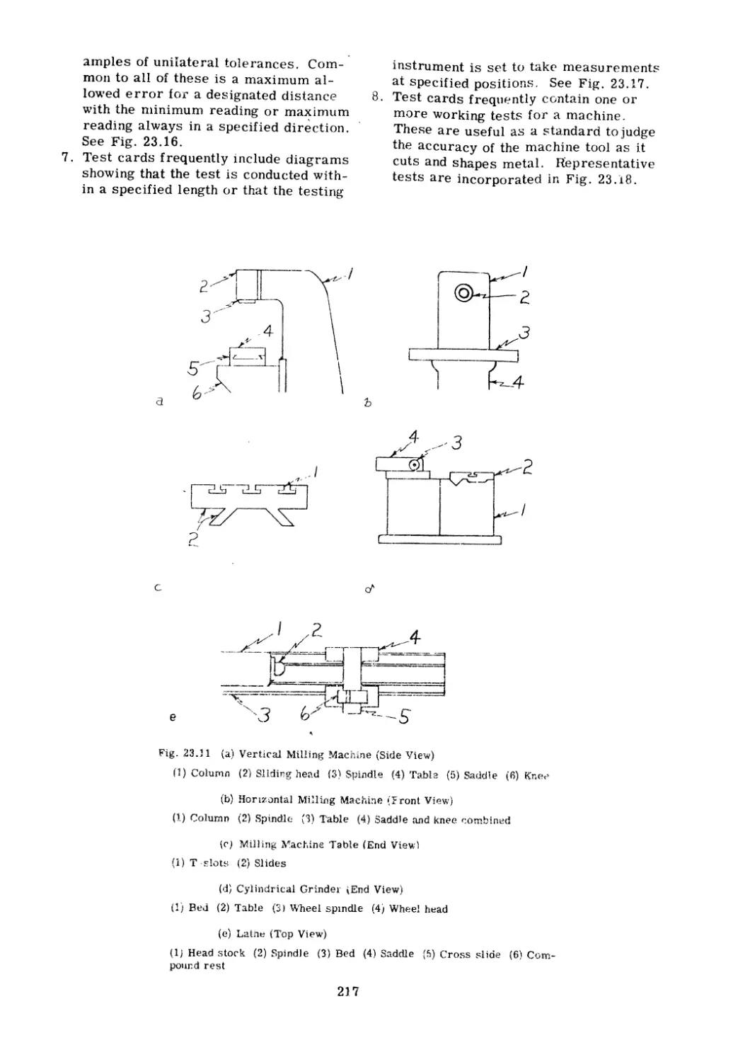
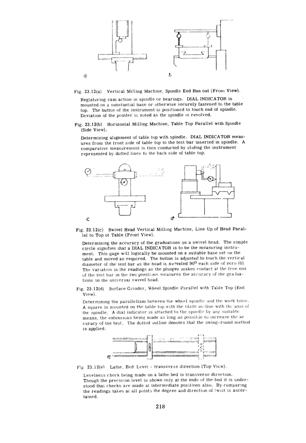
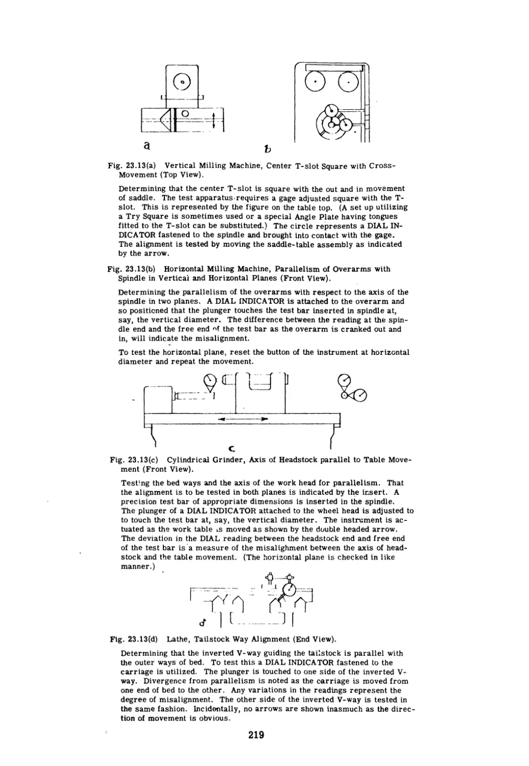
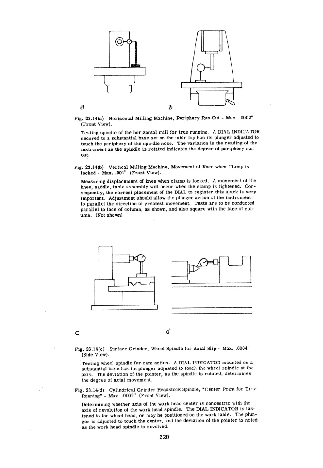
7.
8.
9.
10.
11.
12.
13.
14.
15.
16.
17.
18.
19.
20.
21.
22.
23.
24.
25.
26.
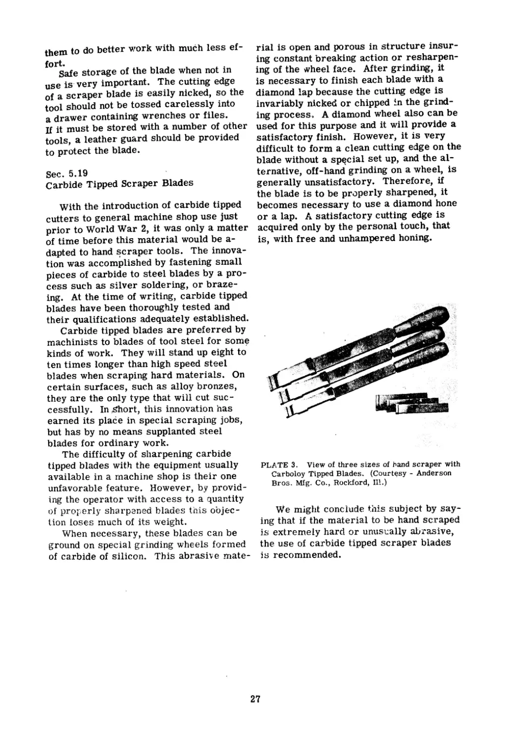
27.
28.
29.
30.
TABLE OF CONTENTS
The Art of Scraping. . . . . . . . . . . . . . " . . . . .
Personal Requirements . . . . . . . . . . . . . . . " .
Characteristics of Metal . . . . . . . . . . . . . . . . .
Tools .. . . . . . . . . . . . . . "
. . .
. . . . . . . " .
The Hand Scraper .....................
Manipulating the Scraping Tool. . . . . . . . . . . . . .
Bench Oilstones. . . . . . . . . . . . . . . . . . . .
The Surface Plate. . . . . . . . . . . . . . . . . . . . .
I
The Straight Edge. . . . . . . . . . .. . . . . . . . . . .
Marking Mediums. . . . . . . . . . . . . . . . . . . . .
Markings . . . . . . . . .
. . . . . . . .
. . . . . . . .
Other Spotting Tools
. ..................
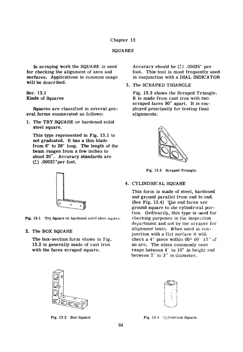
Squares . . . . . . . . h . . . .
. . . .
. . . . . . . . .
Levels and Leveling ....................
Test Bars . . . . e . . . . . . . . . . . . . . . . . . . .
The Dial Indicator. . . . . . . . . . . . . . . . . .
Gibs: Function, Construction and Adjustment . . . . . .
Grooves .........................
Hints on Routine. . . . . . f> . . . . . . . . . . . . . . .
Frosting Techniques . . . . . .
_
utomatic Generation of Gages .
. . . . . . . . . . .
. . . . . . . . .. . . . .
Standard Tes ts . . . . . . . . . . . . . . . . .
. . . . .
Factor s in Recondj ti oning . . . . . . . . . . . . . . . . .
The Surface Bearing Requirelnents of the Sli<.
es and
Ways of Precision Grinders . . . . . . . . . . . . . .
Problems in Alignments .................
T
e Engine Lathe . . . . . . . . . . " " . . . . . . . . .
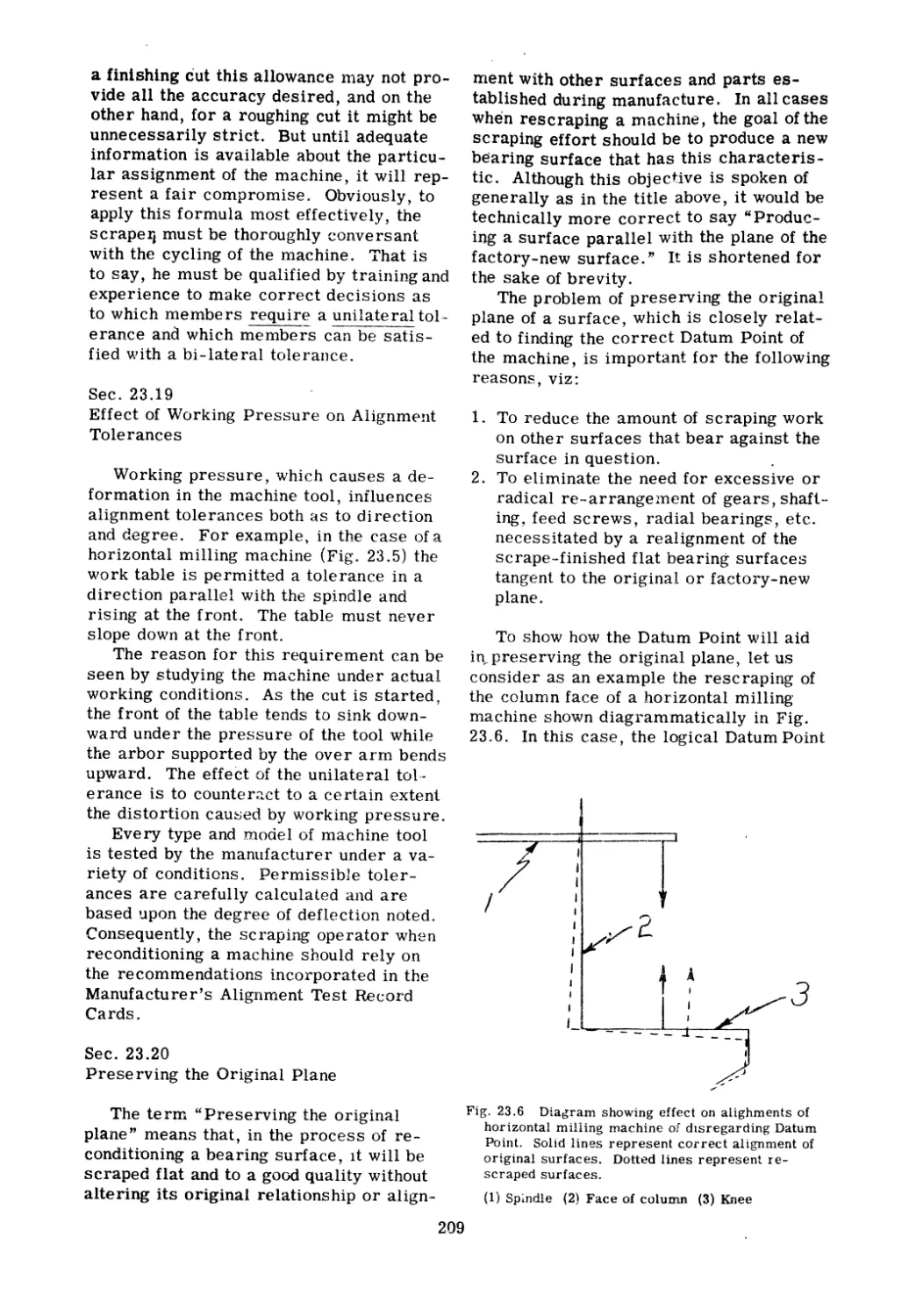
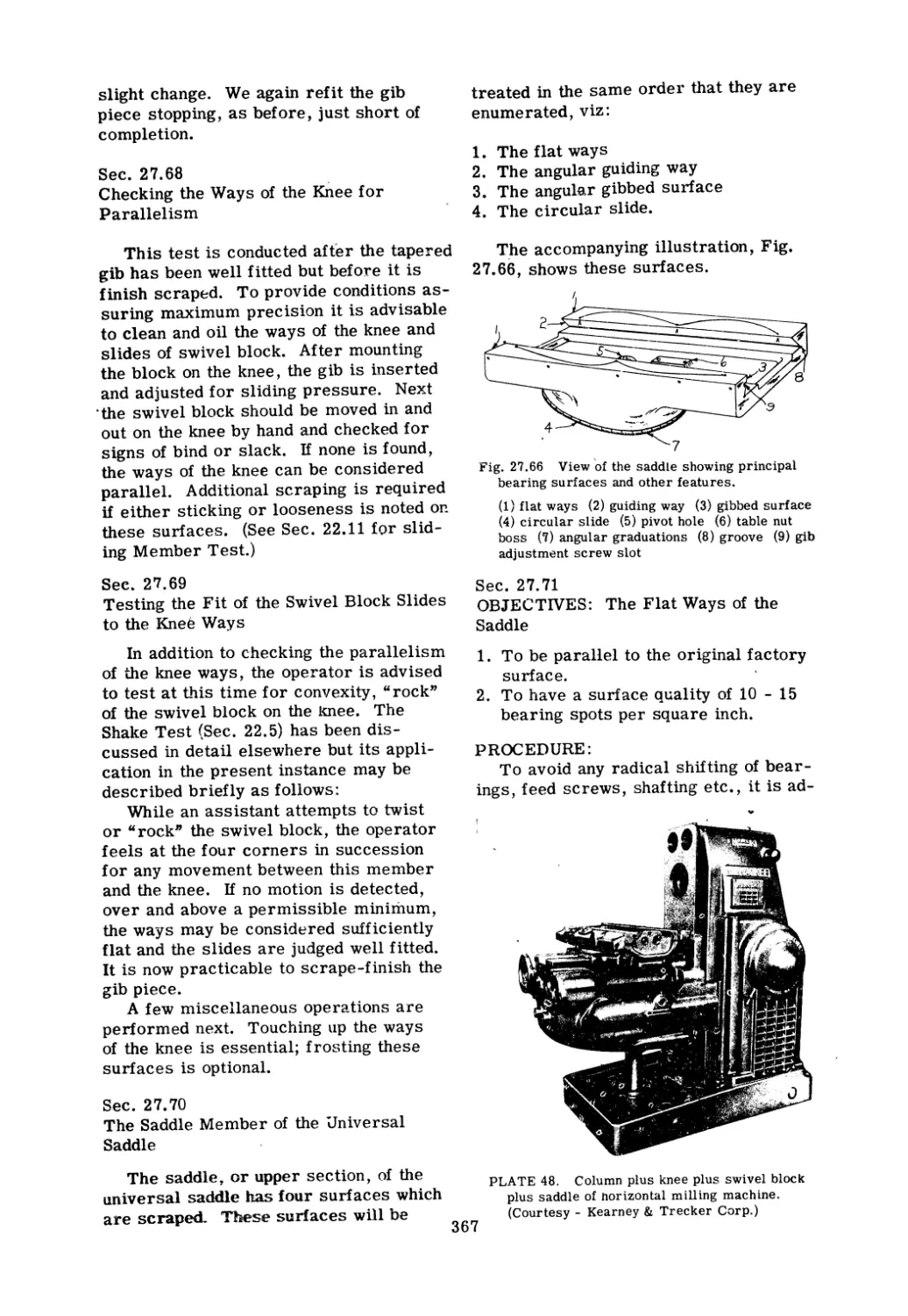
The Horizontal J.\t1illing Machine . . . . . . . . . . . . .
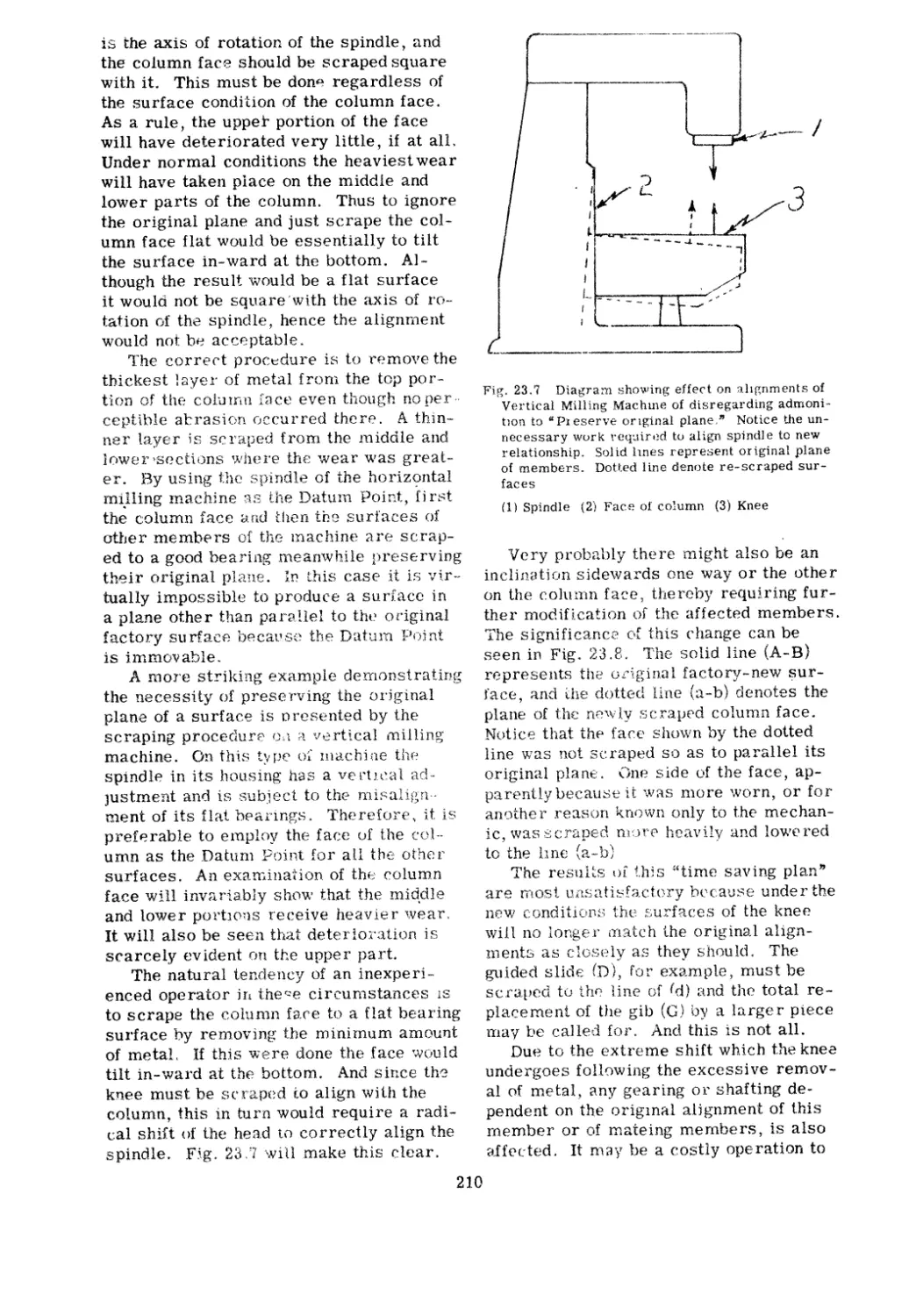
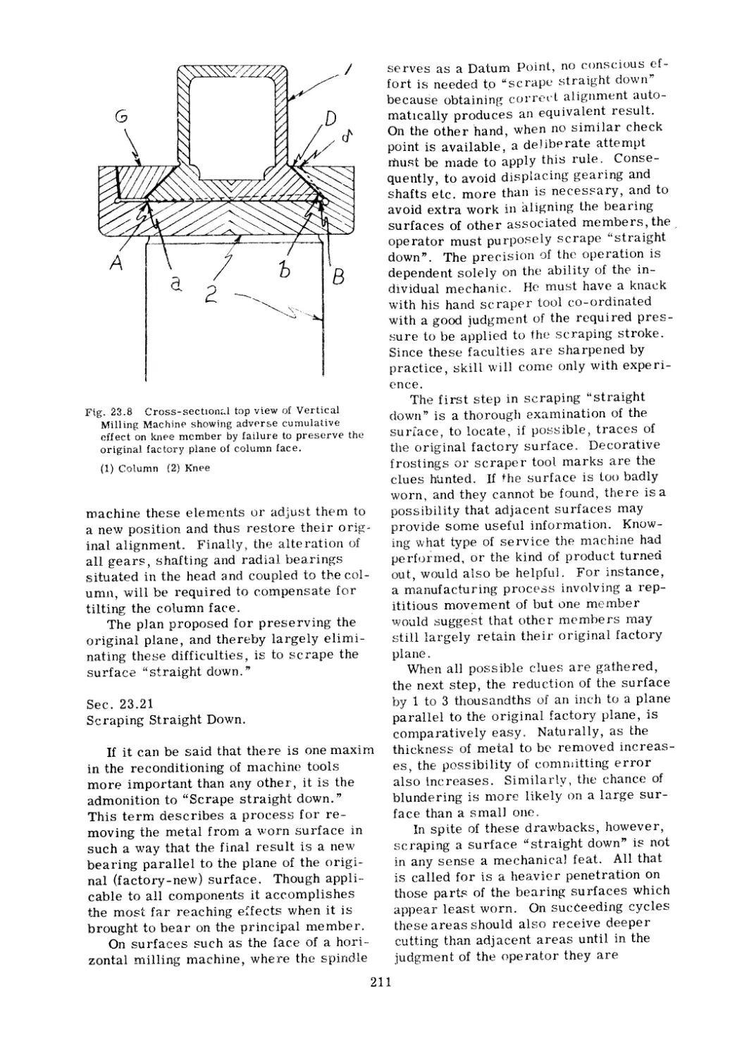
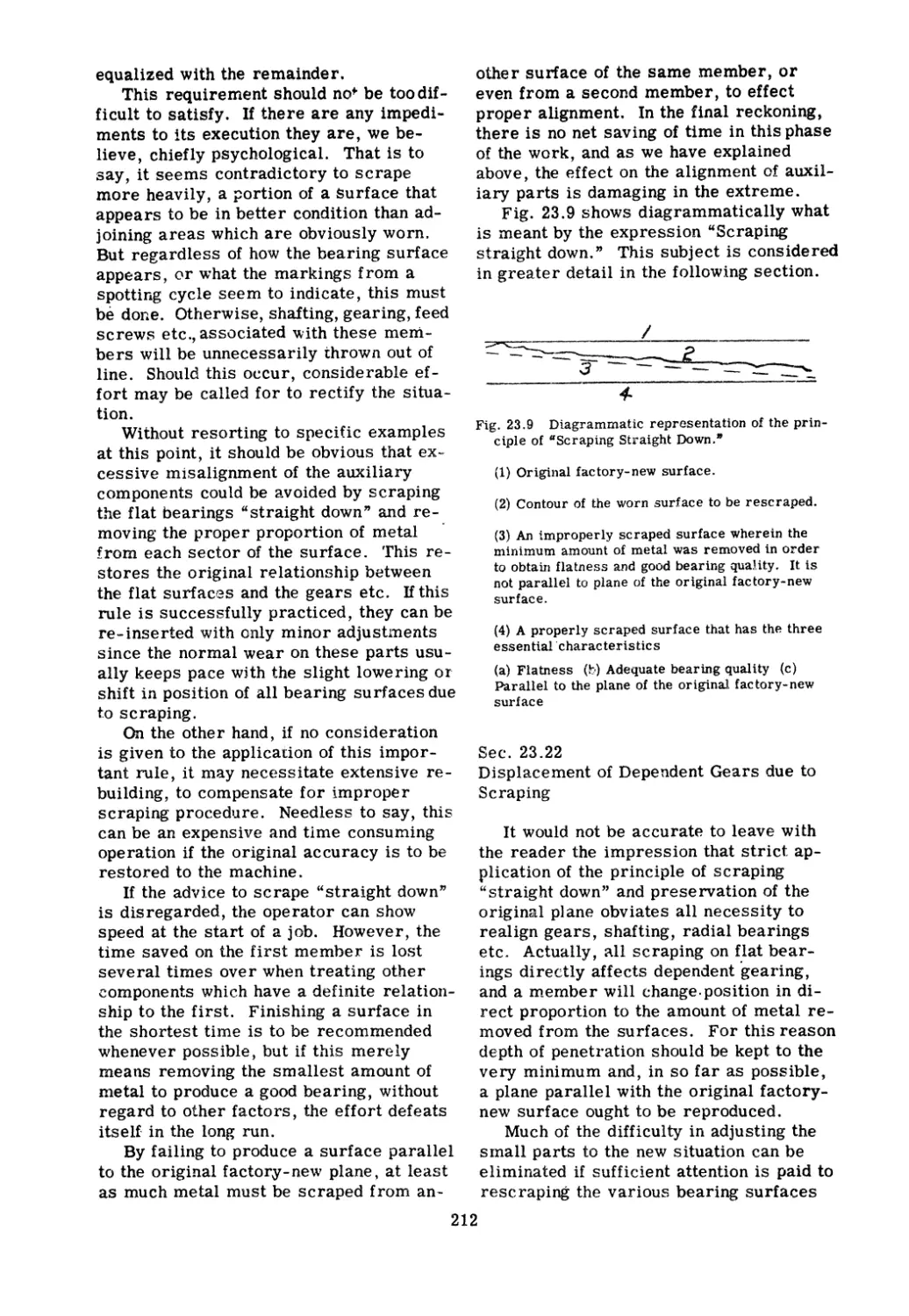
The Vertical Milling Idachine . . . . . . . . . . . . . . .
The Cylindrical Grinding 1\1achine . . . . . . . . . . . .
The Surface Grinding Machine . . . . . . . . .
Glossary ............... . . . · .
. . . . .
. . . . .
Index .....
.t'........ ..........
Page
1
6
8
11
18
28
38
41
49
62
73
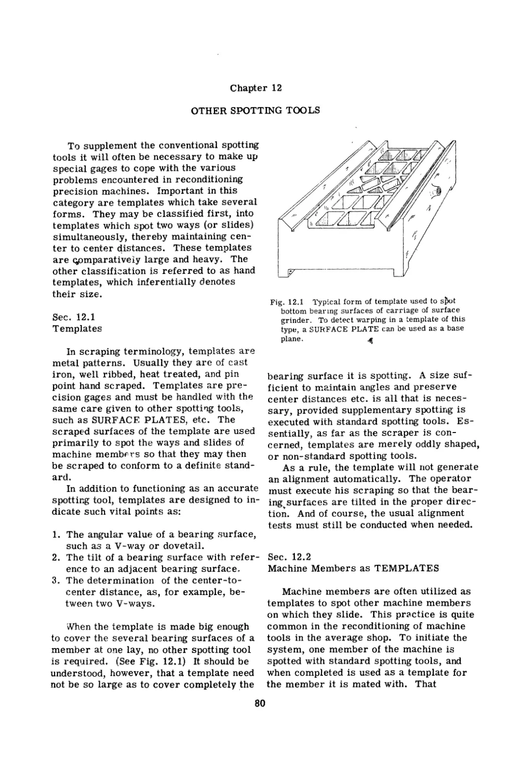
80
94
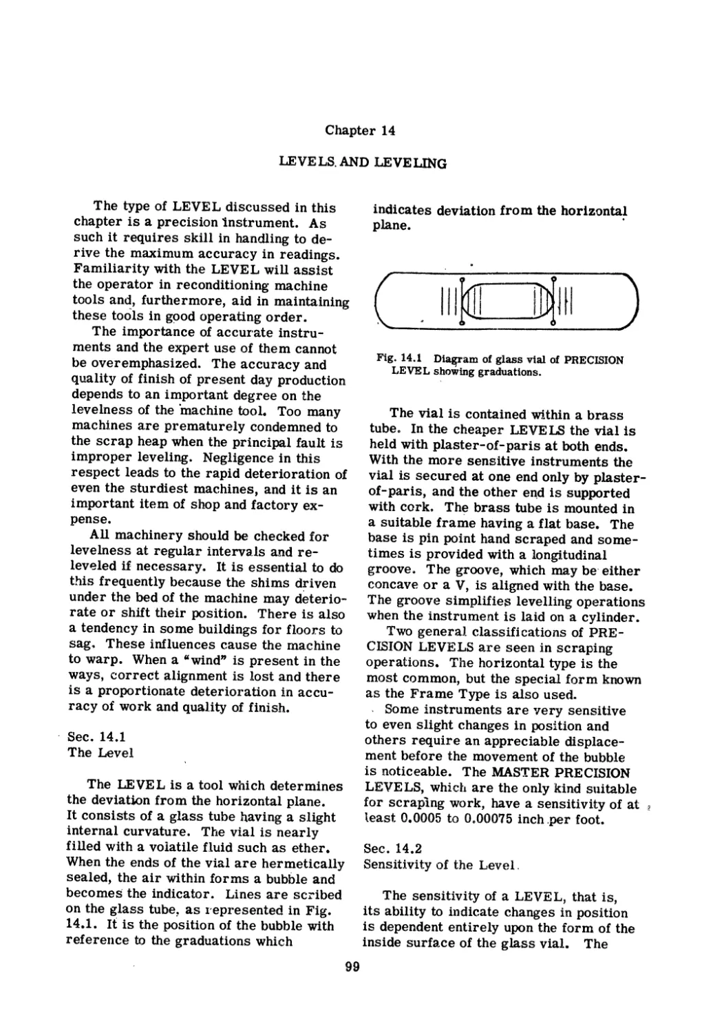
99
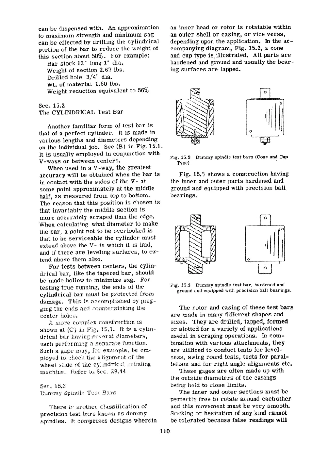
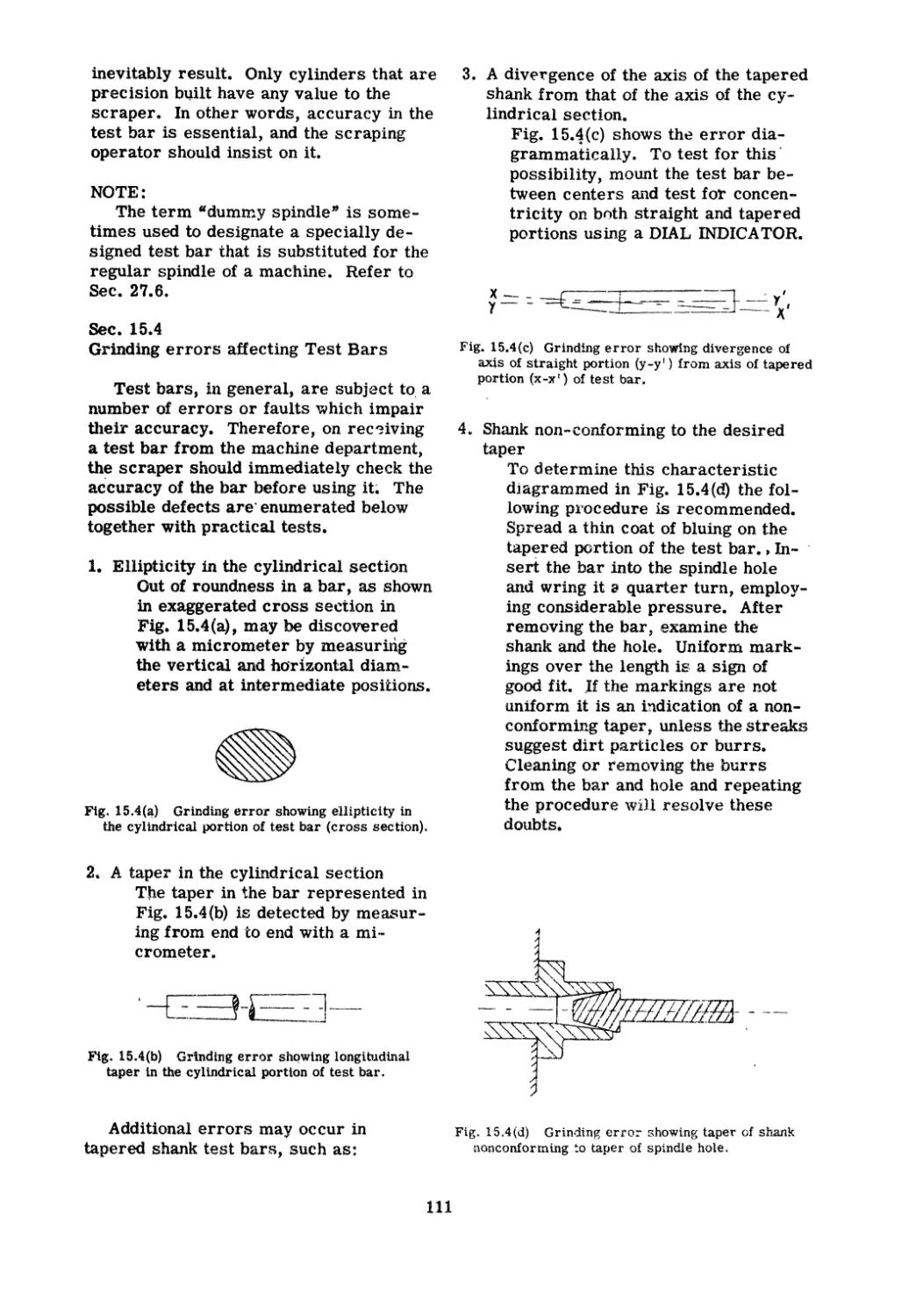
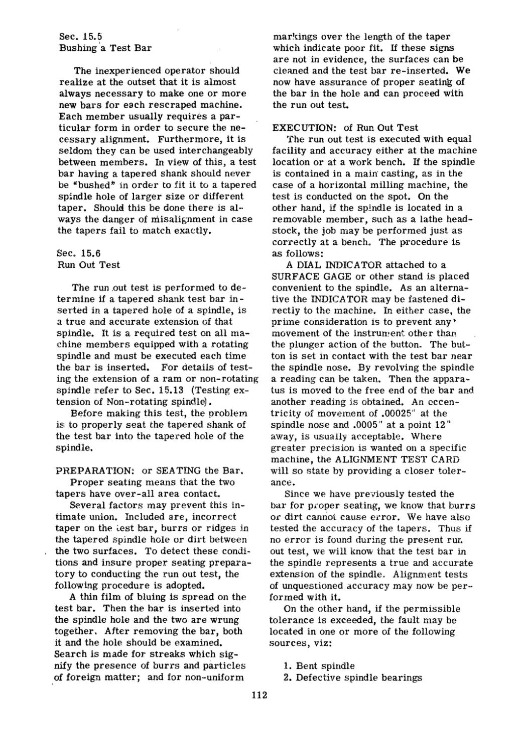
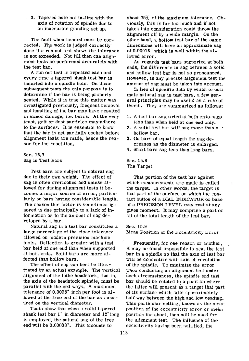
109
117
129
150
157
164
175
185
199
226
229
256
316
393
442
482
519
527
Chapter 1
THE ART OF SCRAPLNG
In this chapter we will introduce hand
scraping to the beginner in the machin-
ist's trade. This subject scarcely needs
any introduction to experienced machin-
ists who know well its laborious process-
es. The tedium arid the difficulty of the
work have been, and still are, standing
invitations to "Yankee ingenuity" to make
improvements' in the metal working
trades. Undoubtedly, great strides have
been n1ade, but despite the rapid advance
of technology in the mechanical fields it
still is not possible to produce with either
a reciprocating or rotary tool, except
under special conditions, the true, flat,
close-grained surfaces that are essential
for a first class bearing. This is the
reason that practice in hand scraping is
desirable in the training of apprentices.
It is also the reason why proficiency in
this- art ranks high among the machinist's
acquired skills.
Seco 1.1
Definition of Scraping
Scraping is that hnnd process which
produces a flat, close grained surface on
work which is finish machined. It is the
final delicate ren10val, flake by flake,
with a hand tool, of the minute irregu-
larities which, though scarcely percepti-
ble to the eye, stand up like saw teeth on
the metal surface of the work. The re--
moval of this roughness, without destruc-
tive effect to the remainder of the sur-
face, comprise,s the art of scraping.
Another way to express the same
thought is to define scraping as an opera-
tion to eliminate the high spots on ma-
chined surfaces thereby producing bear-
ing spots that are in one plane.
Sec. 1.2
Plane Surface in Theory and Practice
.
To prevent future misunderstanding it
is important to realize exactly what the
term plane surface, or flat surface signi-
fies. A plane surface is defined as a sur-
face such that if any two points on the sur-
face be joined by a straight line, every
point on the line will be in contact with the
surface. In other words, it is a surfac,e
without rotundity, curvature, depression
or other variation or inequality. Prac-
tically speaking, it cannot be achieved by
any ..nown process, be it hand craping,
surface grinding, super-finishing, lapping,
etc&
A flat surface, therefore, is merely
relative. It is usually considered to be a
surface which will bear on a theoretical
plane at a sufficient number of places to
satisfy accepted standards.
In each trade or art, the ter m "flat"
will be accorded a different meaning.
The carpenter accepts the smoothly
finished wooden level, or steel square,
accurate within thousandths of an inch, as
sufficiently flat to be used as a reference
to gage his work.
This basis is not acceptable to the ma-
chinist because it is too crude. His meas-
urements range into tenths of thousandths
of an inch. The SURFACE PLATE,
STRAIGHT EDGE, and PRECISION LEVEL
are his representative standards of flat-
ness.
This is not the ultimate by any means.
Even higher requirements are demanded
by the gage maker, whose gages must be
accurate, to millionths of an inch. For-
tunate ly, such precision is not required
it) the hand scraping process.
It thus can be seen that in referring to
flatness, we are not alluding to some
theoretical ideal but rather have in mind
the practical possibilities of producing a
flat metal surface by hand scraping.
Sec. 1.3
Hand Scraping Sliding Bearings
The principal use of the hand scraping
process is to improve the bearing quality
1
of slides and ways and at the same time
to correct the alignment of machine mem-
bers. During manufacture, hand scraping
is required in greater or lesser degree
on nearly all machine tools. It is also
extensively, employed in the reconditioning
of worn machines.
As an alternative procedure for hand
scraping, precision surface grinding may
be utilized, but ordinarily this requires
special purpose rnachines. Furthermore,
this proces's would be economical only for
mass production manufacturing. The cost
of reconditioning a single machine, or
small lots of miscellaneous types and
sizes, would be prohibitive. Consequent-
ly, in this field, hand scraping is the un-
disputed choice.
Sec. 1.4
Hand Scraping a Fixed Bearing
In addition to sliding bearings another
classification of machine parts is often
scraped, namely members that bolt to-
gether. This is r,equired when it is nec-
essary to preserve a definite alignment
or to prevent warping one or both mem-
bers when clamping two uneven surfaces
together
.
Another use for hand scraping is in
fitting two members to form a seal against
the leakage of oil or other fluid.
When scraping members to a close fit
for any of the purposes above stated,
smoothness and flatness of the surfaces
should be the main considerations.
Sec. 1.5
Comparing Methods of Producing Flat
Surfaces
As stated previously, there are several
methods of producing flat surfaces be-
sides hand scraping. 'But these alterna-
tives, machining, surface grinding, lap-
ping, are not universally applicable. For
example, planing machines can produce
surfaces that are practically flat and true
but to do so they must be in good condi-
tion and perfect alignment. It is standard
practice among shops which use planers
in the building of precision machinery to
reserve one or more machines for finish
machining while others are used for
roughing. Incidentally, after finish plan-
ing a work piece of, say, cast iron ma-
terial, a sort of fuzz is left on the ma-
chined surface by the planer tool. It is
customary to scrape it off lightly, not to
make the surface flatter, but merely to
improve its looks. Sometimes a fuzzed
surface is rubbed down with abrasive
blocks or frosted with a scraping tool.
These operations should not be mistaken
as processes to produce a flat surface.
They are simply expedients performed
for appearance' sake only.
As for surface grinding, producing
flat surfaces by this method is restricted
by the size of the machine. A surface
grinder, because of limitations of size,
produces flat surfaces of comparatively
small proportions measurable in square
inches." When flat areas of many square
feet are required, hand scraping is often
the machinist's only recourse. It is
seldom that he has at his disposal a ma-
chine capable of grinding surfaces of
sizeable dimensions to an accuracy equiv-
alent to hand scraping. This is the gen-
eral rule because the average machine
shop is equipped with only the smaller
size of surface grinder. We do not mean
to imply that large, specially built,
grinding and lapping machines are not
capable of producing extremely flat sur-
faces of ample extent.
The process of lapping can be dis-
missed by saying that it is very laborious
and resorted to only when the metal sur-
face is too resistant to the penetration of
the edge of a cutting tool.
Thus we can see that due to the limi-
tations of machine methods for producing
flat surfaces, hand scraping is frequently
the logical alternative for the average
machine shop to apply.
Sec. 1.6
Definition of High Spots
A high spot in scraping parlance,
means an elevated area, such as a point
or ridge that is higher than the average
height of the work surface. On a smooth-
ly scraped surface, a high spot is imper-
ceptible to the eye because it is only
thousandths, or tenths of thousandths of
an inch above the average level of the
surface. However, after spreading a
film of marking compound on the true
plane of a tool or template and applying
the gage to the work surfare, a portion of
2
the thin film is transferred to the individ-
ual high spot Le., rubbed off.. The high
spot so treated is then plainly visible. It
is this process that makes hand scraping
feasible.
. At the initial spotting of a worn sur-
face, the markings disclose that the high
spots are comparatively large in extent
as well as relatively high. This is re-
vealed by the expanse of the marked areas
and by their coloration. After the scrap-
ing operation begins, the end of each cycle
sees the concentrations of high spots
broken up into successively smaller sizes
and simultaneously reduced in height.. By
degrees, they are worked over with the
scraping tool, until they are of the same
height and uniformly distributed. At this
point the objectionable high spots merge
into what is known as bearing spots.
Thus bearing spots are simply the high
spots scraped until they are of one even
height, or plane, and uniformly distributed.
The scraping process is one wherein
the high spots are gradually changed in
form from relatively broad patches of un-
even height, as the process begins, to
bearing points which have many shapes,
varying from small spiked cones to razor-
edged ridges, all lying in one plane, by the
time the surface is finished. The bearing
spots do not remain in this condition for
long though. As soon as the machine is
placed in use, the sliding pressure of the
mateing member begins- to wear down
these sharp points. Gradually they broad-
en and merge with others to form an ex-
panse that is plainly discernible if a fi-lm
of marking compound is applied.
The heavier the bearing pressure im-
posed, the more rapid the transformation
of these points and the broader and more
conspicuous they bec9me. Long periods
of normal operation, causing wear also
produces this effect.
In other words, the surface is more
accurate immediately after it is scraped.
Thereafter, abrasion begins and deteri-
oration ets in. By degrees the size of
the individual bearing spot increases.
Gradually it merges with adjacent spots.
Wear continues until the bearing quality
of the surface is inlpaired by the evolu-
tion of new high spots, whereupon recon-
ditioning is again imperative..
#
Sec. 1.. 7
Generating Bearing Spots
Bearing spots, which cornprise the
contact surface of ways (or slides), are
formed in the process of scraping high
spots to one overall plane. Bearing
spots so produced do not have any uni-
form shape. Some will be oval or rec-
tangular, others will be irregular, but
this variation does not affect their func-
tion. Their size, that 'is the area of their
contact surface, will be determined
largely by the length, idth, and depth of
the strokes that form them.
A stroke producing a short, narrow,
shallow scraping cut is requisite to gen-
erate bearing spots. Varying these
characteristics in any respect changes
proportionately the number of bearing
spots per square inch of surface.
Sec. 1.8
Relationship of Scraper Marks to Bear-
ing Spots
The area of the average scraping
mark determines the number of bearing
spots per square inch. The greater the
area, the fewer the number and vice
versa. Bearing spots invariably form
along the junction between two individual
scraping marks and not in the hollow
shaped by the scraping stroke. The rea-
son that a concave incision is made is
that the cutting edge of the flat scraper
blade is curved, as shown in Fig. 5.2a.
Obviously, therefore, the rim and not the
middle of the depression will constitute
the bearing spots. An examination of the
surface of a work piece fOllov,jing a
scraping cycle will reveal this. For ex-
ample, if the length of the scraping
strokes applied to a surface are short-
ened, the area of chip removal is also
reduced. The effect is to increase the
number of bearing spots per square inch.
On the other hand) longer strokes each
gouging a greater area results in fewer
bearing spots per square inch of surface.
The scraper proportions his strokes
to the type of bearing surfaces needed,
although speaking generally, the cuts
made at the start of a job are both longer
and deeper than those executed at the
finish.
3
Sec. 1.9
Quality of Surface Bearing
How many bearing spots should a
scrape-finished surface have? This ques-
tion can only be answered by consi.dering
the type of bearing desired. Surfaces
having stationary, or fixed, contact with
each other will be found satisfactory with
1-5 bearing spots per square inch. When
ways and slides, whic h perforln avt-;rage
service are involved, a'bout 5-10 bearing
spots per square inch are specified. For
sliding bearing surfaces designed for pre..
cision work, such as the general run of
machine tools, 10-20 bearing spots per
square inch will be necfssary. Precision
gages, SURF AC E P 1.14-'\ TIES, etc., require
30-35 bearing spots per square inch. In
short, the requirements of €8ch individual
surfaee must be judged in the light of the
experIence of the scraper, with du(; con-.
sideration given to the type of serv}ce it
is to perforn1.
As a rule on the ..1 verage job, the nu 1'11-
ber of bearing pots per squa yoe inch of
surface are not physically counted by the
scraper. 1"his would be \lnneCessar j ly
tedious. Instead the quality of the surface
bearing is judged. by a well trained f: ye
(Naturally, this ability is not cuJtivated in
a day.) 'rhus on the final spotting cycle an
estimate is mage of the bearing quality
from the appearance of the colored rnark-
ings. (Incidentally, such factors as the
thickness of marking medium used, and
the degree of spotting pre sure can i In..
pair the correctness of this esti n13 te. )
This conclusion Inust be correlated with
the anticipated conditions of service. A
decision ts then rnade as to vlhether or
not the bearing surface can be cunsidered
scrape-finished. Th is is often expressed
by a term "percent of bedring. "
Sec. 1.10
Percent of Bearing
Not infrequently instructions are given
to a mechanic to scrape a surface to, say,
a 7510 bearing. The diversity of opinion
as to the meaning of the expression "Per-
cent of Bearing" is one of the greatest
sources of confusion in the machine shop.
It is easy to see how it could lead to ser 1-
ous rnistakes in the interpretation of
orders. This is all the !nore understand
able when consideration is given to the
seve ral factors that necessar ily enter
into the term.
Percent of bearing, broadly speaking,
refers to the proportion of a surfa\ce that
is covered by a marking medium, such
as bluing, transferred to it by a SURFACE
PLATE, STRAIGHT EDGE or other spot-
ting gage. Obviously, the quantity of
bluing (or other media) spread on .the tool
determines in large rneasure the amount
transferred to the work surface. Simi-
larly, the oil content of the marking com-
pound affects results> The expertness in
handling the spotting: tool also exerts an
influence because clumsy application in-
duces added pressure. Likewise exces-
sive rubbing causes more bluing to be
transferred. Then there is the question
of lighting and vision. Under conditions
of bright daylight the bluing marks are
i.nore visible than under poor artificial
lightirlg. 'rhe weight of the spotting tool
in re lation to the area of the work sur-
face spotted i.e., pounds per squal'e inch,
should also be considered. As a final
factor, there is the condition of the work
surface itself. When finely scraped it is
sornewhat more retentive of bluing than
when it is less smooth.
It ean be seen from this that any pre-
cise definition of percent of bearing sur-
face is utterly futile because of the va.::.
riety of conditions that prevail and the
individual interpretation of the trans-.
ferred Inarkings. Each operator, conse-
quently, would ha ve a different opinion as
to the percent of bearing of C\ny given
surface.
On a few thiflgS, however, all do agree,
nanlely:
1. 'The amount df marking rnedium trans-
ferred to the work surface should be
the very rninirnurn so that the operator
rnust look closely under a good light,
to observe the rna rkings
2. The tool must be handled expertly,
wIth a minin1u t n alnount of rubbing
m.otion.
If this explanation leaves the reader
with a sense of frustration, it is only
naturaL In the final analysis the percent
of bearing is subject to individual judg-
ment and is nut calculable by any silnple
for!TIula.
4
Sec. 1.11
The Scraping Cycle
In the language of the trade, a number
of diverse operations are lumped together
under the category of scraping, although
to be techni ally correct the t rm should
be restricted to the process of shaving
small particles from metal surfaces.
However, no confusi'On results from this
looseness.
Speaking generally, scraping comprises
a series of r "ocedures leading toward the
production of a flat metal surface. To
produce an accurate flat bearing plane,
the high spots, wpich may be t'NO or three
thousandths of an inch higher than the
average height of "the vlork surface, must
be removed. 'fo detect them requires the
application of marking compound by either
the spotting or reverse spotting methods.
One object of scraping is to redu( e
these irregular high spots to a uniform
height or plane at ' lhich time they can be
classified as bearing spots. Other funda-
n1entals of scraping require that the bear-
ing spots be uniformly distributed and
adequate in number for the class of work
intended for the machine.
To accomplish these results, scraping
is conducted in an. orderly sequence of
operations, dubbed a cycle. This routine
is repeated as often as necessary until the
OBJEC'T'IVES are accomplished. The
logical order is as follows:
1. Removal of burrs.
2. Spreading of marking medium.
3. Application of spotting tool.
4. Analysis of the markings.
5. Scraping of indicated high spots.
6. Cleaning of surface.
7. Rernoval of burrs etc., as the cycle is
repeated.
Each of these steps is taken up separ-
ately in this book, though not necessarily
in the order enumerated.
When treating a worn surface, the first
cycle will usually show only a few high
spots and these will be more or less iso-
lated and apt to be large. They are
scraped off, hurrs are relTIoved etc. The
next cycle will reveal an increase in the
number of high spots and a diminution of
f
their size. l\s the scraping operations
continue, the number of high spots multi-
plies and their area is reduced. Ultimate-
ly, these high spots are well distributed
over the scraped surface and gradually
rnerge into what is called bearing spots.
This result is achieved as rnuch by a cal-
culating judgnlent of where and how much
to scrape, as by the actual mechanical
removal of the metal ,particles.
It should be pointed out that the attain-
ment of flatness and satisfactory bearing
q lality in a surface is fundarnental to
every scraping job, but frequently more
than that is needed. An additional consid-
eration would often be the need to ali'gn
the surface being scraped 'with another
pJane. In actual practice, dealing with
such cases calls for a].ignnlent tests to
be performed periodically at the conclu-
sion of operation # 7 (removal of burrs)
Chapter 2
PEf{SONAL REQUlRErvlENTS
Before discussing the tools and methods
of the scraping art, it would be advisable
to say a few words about the men who use
them.
Sec. 2.1
Qualifica tions
IIand scraping, as anyone who has tried
it knows, is a tedious job demanding rig-
orous concentration. Whi Ie it is possibJe
for any person to manipulate a hand
scraper, expert handling requires know-
how', practice, and the possession of a
natural aptitude.
Training in handling the various tools
.. and gages, in applying marking medium,
and in conducting scores of complex tests,
is requisite to success as a scraping op-
erator. If, in addition to this experience,
the individual possesses certain physical
and mental characteristics for the work,
he is more likely to be successful at it.
Since the work is very fatiguing, the
mechanic should have a liking for muscu-
lar activity as well as the stanlina to keep
going. Good vision is essential to detect
individual high spots, often minute in size.
Proficient scrapers have a high degree
of manual dexterity and a delicate touch.
The need for this is understandable when
it is realized that in the final pin pointing
of gages, precision tools etc., the metal
may be flaked off in .0001" thicknesses,
much finer than a human hair.
Unsteadiness of hand rules out many
otherwise acceptable mechanics. Hard
drinkers eliminate themselves. Age is
seldom a limitative factor. The older
man possesses patience and experience
not usually found in younger men.
Personality has a lot to do with making
a scraping specialist. The work is monot-
onous, yet demands intensive effort and
unflagging concentration. There lnust be
meticulous attention to d tails. Dogged
perseverance, in the face of unexpected
set-backs, is as imperative as t.he ability
to hold one's temper. Anyone disposed
to throw his tools around under slight
provocation is not like ly to be a success
at this work. The individual with calm,
phlegmatic temperament is superior as
a scraper to his peppery counterpart.
rrhose who crave company, who keep
ur a eonstant line of chatter, and Inove
around the shop to visit friends, are defi-
nitely out of place as scraping operators.
Self reliance and confidence in one's
ability are required in scraping work.
This is only natural considering that
responsibility IT1USt be assumed for ma-
chines worth, many thousands of dollars.
Another desirable characteristic is
independent judgInent.. There is more
than a little reason to believe that it is
essential to success in this trade, at
least in some degree. For instance, al-
though a certain raechanical routine must
be followed without deviation ,vhile scrap-
ing, there is, nonetheless, ample oppor-
tunity for the scraper to display discrim-
ination. There is a wide field of choice
as to scraping strokes, selections of
marking compound, kinds of tools etc.
Procedures, too, can be varied because
scraping is not so inelastic a process as
machining metaL Then there is the mat- .
ter of the choice of methods for improv-
ing the attractiveness of the work surface,
which is an important requirement in
commercial scraping work.. This IneanE
much more than discerning and camou-
flaging scratches and blemishes on work
surfaces.. It connotes an appreciation of,
and the ability to produce, decorative ef-
fects such as frostings, whenever needed..
There is one final quality, essential to
success in any trade but especially im-
portant in scraping. This is pride in
craftsmanship. In scraping operations
it is often possible to skirnp a job be-
cause fellow workmen of average me.-
chanical ski 11 are unable to recognize
whether the work is properly done or
not. Only experts are qualified to conduct
6
accuracy tests. Thus so long as the
scraping improves the work surface
slightly, even though telnporarily, a neg-
ligent operator "gets by" for a tirrle.
Eventually, however, his lack of integri-
ty will be discovered. This type of man
is particularly unsuited for a scraping
specialist.
BY J. R. WilliAMS
THATS WHY
I ALWAYS
HATED TO
BE PUT
ON SOME
OL' BOY'S
MACHINE
WHE HE
WAS OFF!
'YES, '1DU
MIGHT
AS WELL
BE OFF;
TOO) FOR
ALL YOU
GET DONE
LEARt'-J'N'
HIS
SECRETS
OF sue.
CE55!
7
C,bapter 3
CHAf{ACTERlSTICS OF l'vtETAL
To enhance their usefulness to industry
a va!"iety of metals are hand scraped.
These include steel, cast iron, copper,
lead, aluminum, brasB, and babbitt metal,
in various grades and alloys,
Cast iron, or grey iron, as it is better
known in the trade, is perhaps the most
extensively used material for rnachine
parts, jigs and fixtures. A high percent-
age of ma hine members that are scraped
is made of this material. Semi-steel is
a Iso widely utilized.
Doubtless much more that is both
learned and interesting could be said
about metals, though such a subject is
hardly appropriate for a book of this na-
ture. However, scrapers will experience
in the course of their work, several phe-
nomena that deserve added comment.
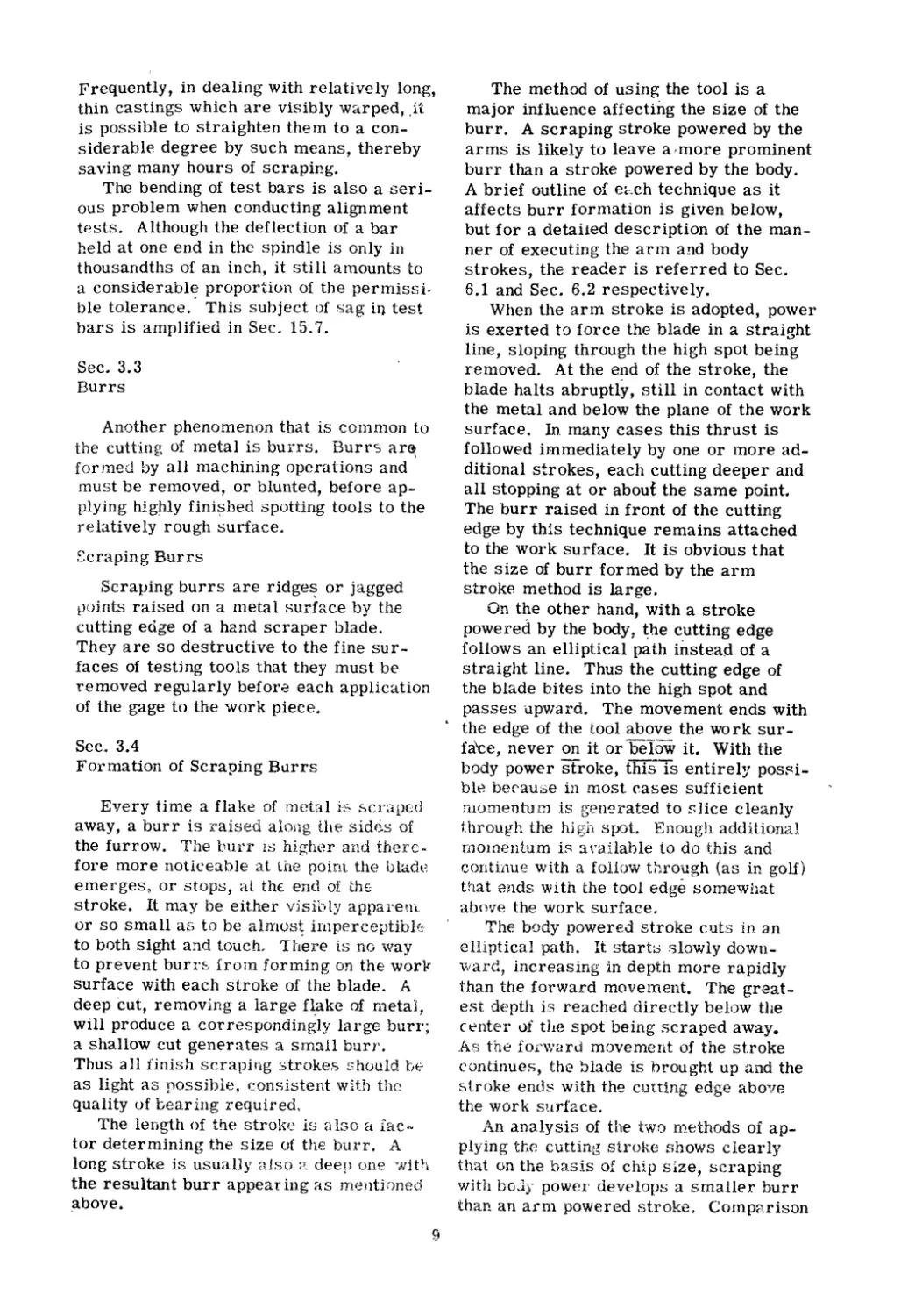
Sec. 3.1
Expansion of Metal
1'0 the layman, metal is a hard materi-
al which holds it shape to a remarKable
degree even under great stress. But to
men who work with it, metal is something
less than rigid. For exam le, the ma-
chinist is in a very good positi9n to judge
the effect of heat on ITletals. He realizes
that, if dimenstons must be held, no
finishing cut ean be taken on a work piece
while it is hot. It is a silnple experirnent
to prove '\vith a "tenth" nljcrometer that
metal expands froin the eifect of heat.
Vvith high accuracy toolE: at his dis-
posal, the scraper is well prepared to de-
tect the twist or warp induced in a surfaee
by heat. Spotting with a SURFACE PLA'TE
or S'rRAIGHT EDGE, it is an easy n:Jatter
to determine the efff)ct of the summer sun
shining on a earner of a rnachine mernber.
Even a few Iniootes of exposure will so
distprt the surface that further spottii1g
rnust be suspended until the work piece is
renl0ved frorn the sunlight and reco112rs
an even ten1p: rature. Only then is it
feasible to resun1e ope rat ions.
If the effect of heat on metal is fully
appreciated, the seraping operator will
never be found guilty of placing preci.sion
s potting and testing tools where sunlight
can reach tr\em. They were scraped-in
at room temperature (68°) and their ac-
curacy decreases as they vary above or
below that figure. Thus if new spotting
tools should be received from the factory
in the dead of winter, they must be al-
lowed to warm to room temperature be-
fore being used. For tne same reason,
precision tools n1ust never be stored in
proximity to furnaces, radiators, steam
pipes etc. ·
Sec. 3.2
Bending of Metal
Another indication that metal is not as
rigid as popular opinion has it is evident
in its tendency to warp when unbalanced.
All machines will warp unless they are
supported solidly and occupy the same
level position that they were in when
scrape-finished. The horizontal plane
being the universally accepted datum
line, machines are scrape.. finished in a
level position. If moved, they lnust be
releveled after relocation in order tR.at
, the flat bearing surfaces will straighten
oat and re-aSSUITle their original align...
rnent. When re-erected, weight distri-
bution - of the main casting must be the
same as it was when the machine was
first scraped-in at the factory.
Individual machine members also need
to be adequately supported. For example,
a grinding or milling machine table, if
supported on blocks placed at.each end
during scraping operations will imme-
diately begin to sink in the middle. The
curvature is apparent in a matter of
ITlinutes if a spotting tool is applied. The
trend can be halted by balancing the
table on one block, only, set under the
middle. Jf this is dor:e, th,'? ends will
COlTIlnenCe to sag, reversing the process.
8
Frequently, in dealing with relatively long,
thin castings which are visibly warped, .it
is possible to straighten them to a con-
siderable degree by such means, thereby
saving many hours of scraping.
The bending of test bars is also a seri-
ous problem when conducting alignment
tests. Although the deflection of a bar
held at one end in the spindle is only in
thousandths of an inch, it still arnounts to
a considerabl proportion of the perlnissi-
ble tolerance. This subject of sag ill. test
bars is amplified in Sec.. 15.7.
Sec. 3.3
Burrs
Another phenomenon that is cornnlon to
the cutting of n1etal is burrs. Burrs ar
for nled by all nlachining operations and
rnust be removed, or blunted, before ap-
plying hj,g ly fini hed spotting tools to the
relatively rough surface..
E:craping Burrs
Scraping burrs are ridge or jagged
oi.nts raised on a ll1etal surface by the
cutting edge of a hand scraper blade.
They are so destructive to the fine sur-
faces of testing tools that they must be
removed regularly before each application
of the gage to the work piece.
Sec 3.4
Formation of Scraping Burrs
Every time a flake of oletal is 5craped
away, a burr is raised along the side.s of
the furrow. TIlle burr IS higher and there-
fore more noticeable at the point the bladl:
emerges or stops, at thE end of thE:
stroke. It may be either visibly apparent
or so small as to be alrrlos irnperceptibl( '
to both sight and touch There is no \vay
to prevent burrf:. irorn forming on the wor
surface with each stroke of the blade, A
deep cut, removing a large f ake of rneta},
will produce a correspondingly large burr;
a shallow cut generates a small burr.
Thus all :finish scraping strokes should be
as light as possible, eonsistent with the
quality of bear ing required.
The length of the stroke 1s also a lac....
tor deternlining the size of the burr. A
long stroke is usually also ?" deep one "Nith
the resultant burr appearing as JrH:ntjoned
bove.
The method of using the tool is a
major influence affecting the size of the
burr. A scraping stroke powered by the
arms is likely to leave a/more prominent
burr than a stroke powered by the body.
A brief outline of e,,;.ch technique as it
affects burr formation is given below,
but for a detailed description of the man-
ner of executing the arlTI and body
strokes, the reader is referred to Sec.
6.1 and Sec. 6.2 respectively.
When the arm stroke is adopted, power
is exerted to force the blade in a straight
line, sloping through the high spot being
rellloved. At the end of the stroke, the
blade halts abruptly, still in contact with
the metal and below the plane of the work
surface. In rnany cases this thrust is
followed immediately by one or Inore ad-
ditional strokes, each cutting deeper and
all stopping at or about the same point.
The burr raised in front of the cutting
edge by this technique remains attached
to the work surface. It is obvious that
the size of burr formed by the arm
stroke method is large.
On the other hand, with a stroke
powered by the body, he c.utting edge
follo\vs an elliptical path instead of a
straight line. Thus the cutting edge of
the blade bites into the high spot and
passes upward. The movement ends with
the edge of the tool above the work sur-
fa"ce, never on it or below it. With the
body power str oke, this is entirely pos i-
hie beeause in most. eases sufficient
nlon1enturn is gen rated to sJice cleanly
t.hrough the hi gh spot. Enough additional
nloloentum is a \ ailable to do this and
continue with a follow through (as in golf)
that ends with the tool edge somewhat
ab(Vl€ the work surface.
The body powered stroke cuts in an
elliptical path. It starts slowly dowu-
viard, Increasing in depth more rapidly
than the forward mOVelTIent. The great-
est depth i.s reached directly below the
ct2nter of the spot being scraped away.
.As the fO.r,v£ rd movement of the st.roke
continues, the blade is hrought up and the
stroke ends with the cutting edge above
the work surface.
j\n analysis of the t"W'o n1.€thods of ap-
plying the cutting stroke ShO NS clearly
that on the basis of chip size, scraping
'.vjth body power develop a srnal1er burr
than an arnl powered stroke v ComparisDn
9
further reveals that \vith eit6er method;
short, light strokes produce b',lrrs that
are almost imperceptible"
Sec. 3.5
Types of Metals Affecting Burrs
Burrs raised on steel work surfaces
are larger and harder than the burrs af-
fecting casi. iron and other metals. Re-
gardless of the kind of metal being
scraped, however, burrs must l?e re-
moved from the work surface before the
STRAIGHT EDGE or SURFACE P'LATE is
placed on it. Otherwise, rapid destruction
of the tool's face will result, due to
roughening and scratching.
Sec. 3.6
Removal of Scraping Burrs
To remove burrs formed in the scrap-
ing process, a burr file is p,referable to a
bench stone. The latter will produce no-
ticeable scratches in the work surface,
and the coarser the grit, the deeper the
scratches. On the softer metals, such as
lead, aluminum, and brass, the bench
stone will soon be loaded and become use-
less. A well worn burr file (See Sec. 4.1)
is more satisfactory as it will neither
scratch nor clog.
When removing scraping burrs tIle
most satisfactory technique is to rub
either of the abovementioned tools in a to
and fro, not a circular motion. This
should be continued until the hand can no
longer detect the presence of burrs. After
cleaning away the debris it is again safe
to apply the spotting tool.
Sometimes a hardened flat steel block
is used. This block doesn't actually re-
move burrs; it merely knocks down, or
blunts, their sharp points. It is not as ef-
fective as the apparatus discussed above,
except on non-ferrous surfaces.
Sec. 3.7
Dent Burrs
In addition to scraping burrs, such as
we have described, there is another type
of blen1ish known in the t.rade as a dent
burr. A dent burr is caused when a tool
or heavy object is dropped on a bearing
surface. The blow forms a small de-
pression, surrounded by a raised area.
This protuberance cannot be economical.
ly removed by the tools suitable for re-
ducing scraping burrs. It must be filed
or scraped away.
Sec. 3.8
Chilled Surfaces
Scrapers sometimes encounter bear-
ing surfaces that are notable for their
exceeding hardness. This characteristic
is produced when the member is cast.
A portion of the molten metal flows
against a cold metallic insert in a sand
mold and is instantly chilled. Th sur-
face so formed is extremely hard and
will resist ordinary abrasion much bet-
ter than the softer mateing surfaces,
such as cast iron or semi-steel, which
may be fitted to it. Most of the deteri"",
oration cauEed by sliding friction will,
therefore, take place on the softer ma-
terial.
H realignment of a" chilled 'surface is
ever required, hand scraping is out of
the qusstion because the skin is prac-
tically impenetrable to the blade; only
surface grinding can cope with it. COll-
sequently, it will often be more con-
venient to align such a machine member
, by hand scraping its other bearing sur-
" faces which have not been chilled.
Generally speaking, iron chills are
used on surfaces subject to intensive
wear. For instance, manufacturers of
milling machines sometimes condition
the top of the table, the slides of the
knee, and other surfaces in this fashion.
In passing, it might be noted that
flame hardened surfaces belong in the
category of hardened surfaces, although
they are produced by different techno-
logical methods.. The bed ways of some
types of lathes, for example, are manu-
factured by this process.
10
Chapter 4
'rOOLS
The essential eqqiprnent used in scrap-
ing is divided generally into three classi-
fications. There is no hard and fast divi-
sion between theIn, but for clarity the.y.
ITlay be grouped as follows:
1. Perbonal tools and auxiliary shop
equipment, including:
I-Iand scraper; marking mediums, such
as Prussian Blue, blue spotting paste,
Red IJead, alcohol etc.; bench oil stone;
files; groove cutter's; lead ha mmer;
hardened steel blocks; turn tables;
povler scrapers; and hand sanding disc
grinders.
2.. Spotting Tools, which include:
" The SURFACE PLAtTE, standard
STRAIGHT EDGE, ANGIJE STI'tAIGHT
EDGE and hand 1"'EMPLA TES.
3.. Alignment tools, sueh as:
Steel Tr y Square Box Square scraped
triangle j thickness gages, ground and
scraped PARALLELS, Precision angle
plate , V blocks, ground cylinders,
Test Bars, PRECISION LEVEL, Sur-
face Gage and indicating jigs, DIAL
TES1 INDI(;A TOR, telescopic gage and
lnicromete r
Independent trealrrH nt and greater en1-
phasis 'will be given to SOUle of these items
when such a course is warranted, either by
their importance, or by the complexity of
handling the apparatus. On the other hand,
it 'w!ll n1ake for eonvenlence if a number of
iterns of lesser irnportance but of general
interest are combined together, as is done
in this ch.apter.
See.. 4.1
The B U.t' r File
Files of Inany shapes and si zes are f re-
llt. ntly used by the scraper for incidental
purposes, but only one of special interest
will be discussed.. Included in every
scraping operator's tool box shOuld be a
"burr" file. This is simply a flat, double
cut, smooth file, 8" to 10" in length, hav-
ing no handle.. A flat safe edge is ground
on one edge and a bevel of appl oximately
30 0 is ground on the other edge. The safe
edge facilitates the relnoval of burrs close
to a square corner while the beveled edge
allows access all the way to the bottom of
a dovetaiL
The flat sides of the file are used to
knock down the burrs. For this reason an
old, well worn file is preferred to one with
sharp teeth.. Our purpose is not to abrade
the metal work surface, as the term
"filing" in1plies, but to eliminate rough-
nesses. We accomplish this by applying
pressure to the file and rubbing it over
the burrs, removing them but without
scratching the nicely scraped surface.
If circumstances require a new file to
be used the teeth should_ irst be dulled on
a bench stone.
Sec 4..2.
Groove Cutter
F r cutting or enlarging grooves ad-
jacent to corners, or in dovetails, one of
the handiest tools is a groove cutter" 1 his
little gadget is often more convenient to
use than a knife edge file and is efficient
tinder all conditions.,
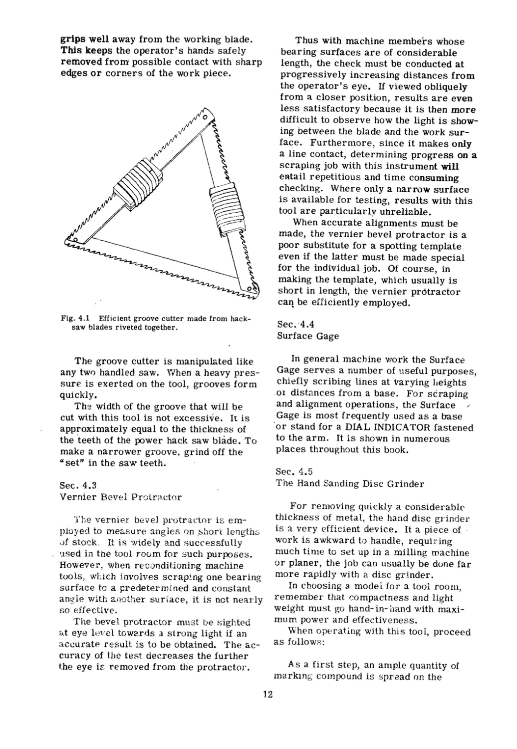
rrhe construction of such a device is
simple. It is made by riveting together
three 12" power hacksaw blades in a tri-
angular shape, as shown in Fig. 4.1.
Before riveting the blades together, the
rounded ends are first ground off straight..
By eliminating the double thickness in this
way, it is possible to use the blade in nar-
rower dovetails. To protect the hands
fron} the sharp saw blade teeth, tape is
wrapped around two of the blades to form
handles. Owing to the rigidity of the truss
design it is possible to place the ha ,d
11
grips well away froln the working blade.
This keeps the operator's hands safely
removed from l possible contact with sharp
edges or corners of the work piece.
Fig. 4.1 Efficient groove cutter made from hack-
saw blades riveted together.
The groove cutter is nlanipulated like
any two handled saw. 'fyhen a heavy pres-
sure is exerted on the tool, grooves form
quickly.
Th'8 width of the groove that will be
cut with this tool is not excessive. It is
app oximately equal to the thickness of
the teeth of the power hack saw blade. To
make a narrower groove, grind off the
"set" in the saw teeth.
Sec 4.3
Vernier Iievel Protraetor
rrhe vernier b( 'Ve] protractor is em-
ployed to measure angles on ,short lengths
of stock. It is widely and successfully
I used in the tool room for such purIX>ses.
However when re l)nditioning machine
tools} '\;Jlhich involves scraping one bearing
surface to a predetermined and constant
angle with another sur(ace, it is net nearly
so effective.
'The bevel protractor must be sighb::d
&,t eye lovel towards a strong light if an
ac uratf.' result is to be obtained. The ac-
curacy of the test decreases the further
the eye i removed from the protractor.
Thus with machine members whose
bearing surfaces are of considerable
length, the check must be conducted at
progressively in reasing distances from
the operator's eye. If viewed obliquely
from a closer position, results are even
less satisfactory because it is then more
difficult to observe how the light is show-
ing between the blade and the work sur-
face. Furthern10re, since it makes only
a line contact, determining progress on a
scraping job with this instrument will
eRtail repetitious and time consuming
checking. Where only a narrow surface
is available for testing, results with this
tool are particularly unreliable.
When accurate alignments must be
made, the vernier bevel protractor is a
poor substitute for a spotting template
even if the latter must be made special
for the individual job. Of course, in
making the template, which usually is
short in length, the vernier protractor
caq be ef.ficiently employed.
Sec.'4.4
Surface Gage
In general machine vlork the Surface
Gage serves a number of useful purposes,
chiefly scribing lines at varying lteights
.01 distances from a base. For scraping
and alignment operations, the Surface /
Gage is most frequently used as a base
or stand for a DIAL INDICATOR fastened
to the arm. It is shown in numerous
places throughout this book.
Sec. 4.5
The Hand Sanding Disc Grinder
For rernoving quickly a considerable
thickness of metal, the hand disc grinder
is a very efficient device. It a piece of '
work is awkward to handle, requiring
much tirHe to set up in a milling machine
or planer, the job can usually be done far
n10re rapidly wi th a disc grinder.
In choosing a model for a tool roorn,
remernbeI' that compactness and light
weight must go hand- in- hand with maxi-
mum power and effectiveness.
When operating with this tool, proceed
as follows:
A s a first stpp, an ample quantity of
Inarkln ; cOlnpound is spread on the
12
spotting tool because the work surface
'will become quite rough as the operation
proceeds. This thick coating of compound
will protect the tool against scoring and,
furthermore, provide reCl.dily distinguish-
able markings to aid in identifying the
high areas.' .
After the compound is transferred, the
disc grinder is pplied with short, brief
strokes to the high areas of the work
piece indicated by'distinctive markings.
The proper technique is to merely poke at
the markings, meanwhile holding the flat
side of the disc at a slight angle to the
work surface so that the face of the disc
is turned slightly at the rim. Since the
sanding disc is flexible, it will bend
readily.
Grinding should never be continued
overlong in one place lest there be formed
a destructive hollow that requires hours
of hand scraping to rectify. It is better by
far, to grind too little, than to risk going
below the finishing level of the work.
Extreme care is needed when worki g
near an edge on a work piece to avoid
turning it, i.e. grinding an irregular curve
or beveL In the hands of an unsupervised
novice, the disc grinder is apt to be a dan-
gerous implement, but with experience
and reasonable care, it saves much time
and back .breaking labor.
/ 4
7
3
To prevent possible injury to the eyes
from flying grit, safety goggles should be
worn.
Sec. 4.6
Turn Tables
Modern scraping departments are
equipped with one or more turn tables.
Their use enables the operator to place
his work in the most convenient position
for spotting and scrapping and to obtain
the advantage of the best light. When the
work piece can be turned about easily,
speed and efficiency are increased.
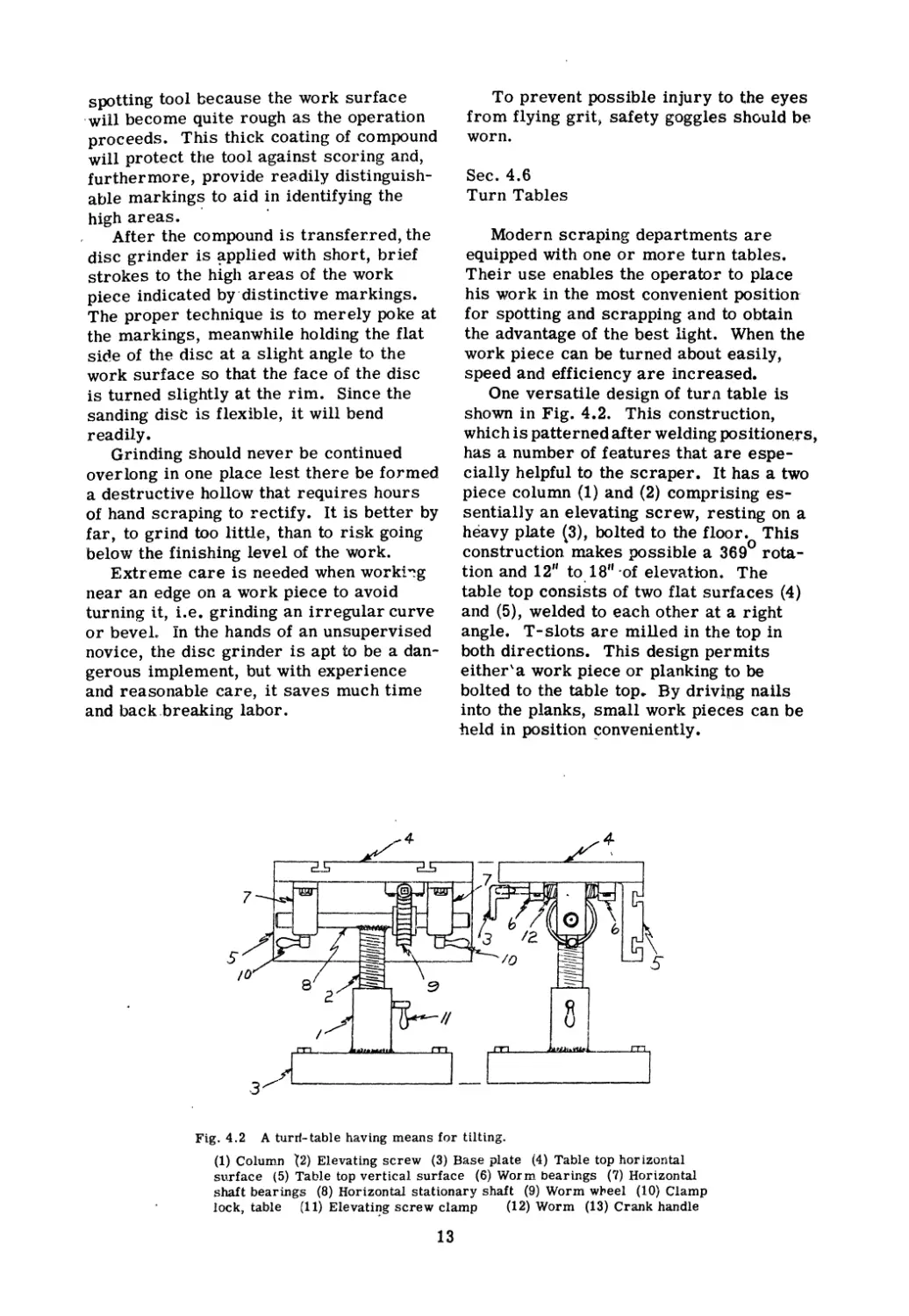
One versatile design of tur 11 table is
shown in Fig. 4.2. This construction,
which is patterned after welding (X>sitioners,
has a number of features that are espe-
cially helpful to the scraper. It has a two
piece column (1) and (2) comprising es-
sentially an elevating screw, resting on a
heavy plate (3), bolted to the floor. This
construction makes possible a 369 0 rota-
tion and 12" to 18" of elevation. The
table top consists of two flat surfaces (4)
and (5), welded to each other at a right
angle. T-slots are milled in the top in
both directions. This design permits
either\a work piece or planking to be
bolted to the table top. By drivipg nails
into the planks, small work pieces can be
'held in position onveniently.
4-
II
B
en l
Fig. 4.2 A turrl- table having means for tilting.
(1) Column \2) Elevating screw (3) Base plate (4) Table top hor izontal
surface (5) Table top vertical surface (6) Worm bearings ("l) Horizontal
shaft bearings (8) Horizontal stationary shaft (9) Worm w"eel (10) Clamp
lock, table (11) Elevatil}g screw clamp (12) Worm (13) Crank handle
13
The table turns on bearings (6) and (7),
on a stationary shaft (8), welded to the
elevating screw. It can, therefore, tilt
through 90 0 by revolving the wornl (12)
which is fastened to the underside of the
table. The worm acts on the stationary
worm wheel (9). Clamp locks (10), (11),
prevent any Inovelnent of the table during
the scraping operations.
This design has a number of points that
are appreciated by the experienced scrap-
er. In ad(ji i.on to the advantages me!1-
tioned previously, it is also very suitable
for holding the always difficult "L" type
casti.ngs, such as the knee men1bers of
milling Iriachines. Further rnore, the tilt-
ing feature facilitates spotting and scrap-
ing the angularly inclined sU.ll. faces of
dovetails and V-ways.
SecD 4.7
Power Scraper
A power scraper is almost a necessity
\vhen considerable scraping is done in a
shop. It will pay for itself very quickly
whenever machine tools or production
machinery are reconditioned in any quan-
tity. The power scraper is one labor
saving Inachine that is actually popular.
It is appreciated by all users because it
saves so much back breaking labor.
Fer straightening out a badly worn sur-
face it is often speedier and nlore econOln-
ical to employ the power scraper than to
set up a planing or milling machine for a
cut. This is particularly true if more
than one set up is necessary to machine
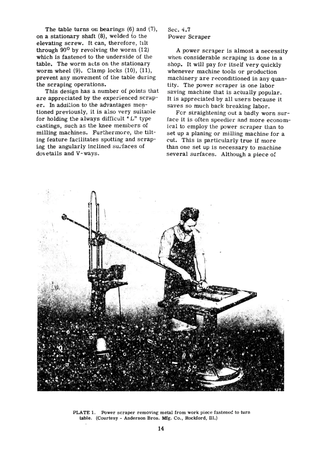
several surfaces. Although a piece of
PLATE 1. Power scraper removing metal from work piece fastened to turn
table. (Courtesy - Anderson Bros. Mfg. Co., Rockford, ill.)
14
work can't be scrape-finished with this
tool, nonetheless, in the hands of a work-
man of average skill, the surface can be
reduced to, an error of a few thousandths
of an inch. The balance is then hand
scraped.
The preparation for power scraping
is very nluch the same as for hand scrap-
ing. Marking medium should be applied
liberally as the work surface becomes
quite rough, especially if long and deep
strokes are made. This thick film \viII
protect the s{X>tting tool from scor ng
when indicating the high areasC)
The method of using the power scraper
is somewhat similar to hand scraping em-
ploying the body power stroke. When the
blade is laid on the work, the left hand
leads and serves as a gu.ide for the blade..
Pressure with the left hand controls the
depth of the cut. The right hand supports
the blade and controls the forward and
reverse Inechanism.
Whet) the blade touehes the surface, the
operator in1mediate]y advances his right
hand and the power stroke begins\! The
forward nlovement continues until the left
hand eases the dO.vVnward pressure and
the right hand lifts the blade from the
,york. The forward stroke is checked in
mid-air, as the right hand is pulled back.
This causes the ram to reverse.
.A. fe\v precautions are necessary when
employing the power scraper, to preyent
damage to the work piece. In the first
place, it is best to anchor the work piece
solidly so that it can't be pushed off the
\vork bench onto the floor. This may hap
pen if the blade is allowed to dig too deeply
into the surface, or is not reversed in
time and engages a shoulder. Anofher
safeguard the beginner should take, in
order to prevent possible damage, is
short scraping strokes" Although the for-
ward stroke can be regulated from 1/4
of an inch to three and a half feet, it
doesn't pay to execute long sweeps with
this tool unless there is a considerable
thickness of n1etal to be removed. Even
then this method should not be adopted by
beginners for they are likely, quite inno-
cently, to abuse the freedom of the method
f:nd i£1adverte1)tly score the work piece.
3horter strokes interrupted by"frequent
spottings are preferable, as they enable
the operator to scrape H straight down."
This results in a smoother, strai hter
surface.
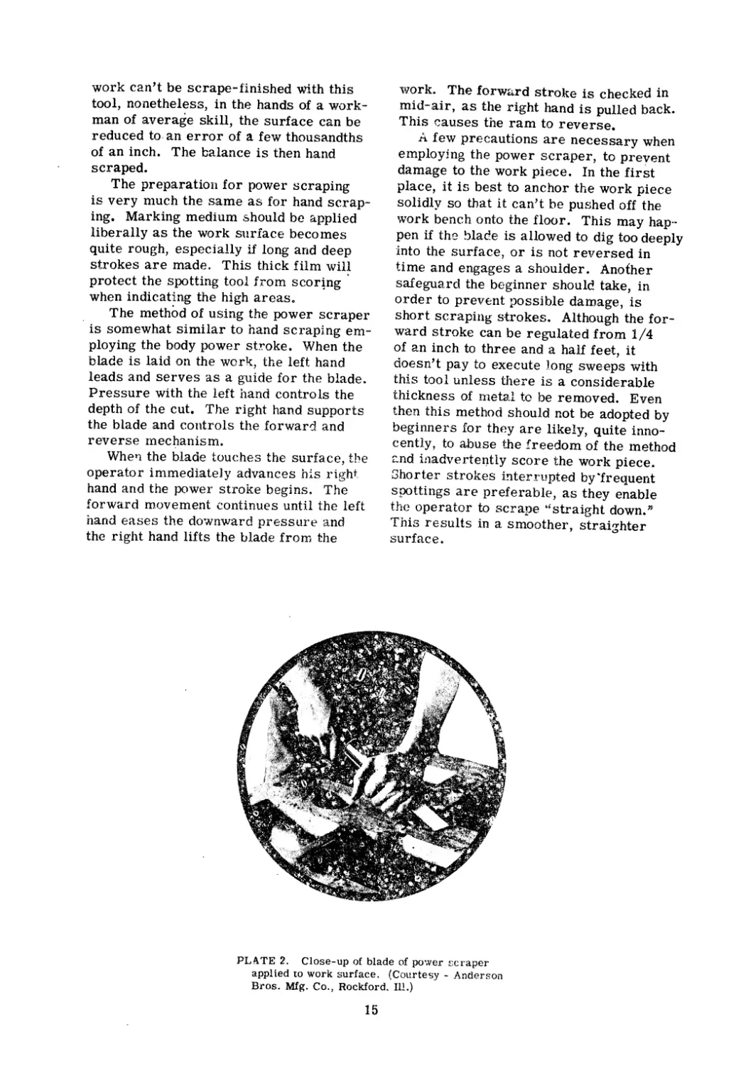
PLATE 2. Close-up of blade of power scraper
applied to work surface. (Courtesy - Anderson
Bros. Mfg. Co., Rockford. Ill.)
15
Power scrapers are constructed to
swing laterally and the scraper blade
holder is rotatable. The angle of the
scraping arm can be increased or de-
creased with an elevating lever. These
features adapt the machine to scrape sur-
faces at varIous heig ts and angles. They
also make it possible to scrape extensive
areas of the work before moving the ma-
chine.
When the scraping blade :r:equires re-
sharpening it is easily removed from the
holder. It is sharpened. in exactly the
same way as a hand scraper blade.
It was not intended to leave the impres-
sion that the power scraper is unusually
difficult to operate. While it is true that
a novice's first attempt to '1se it is like
having a bull by the horns and daring not
to let go, yet after a little practice, excel-
lent results are possible.
Sec. 4.8
Parallels
Parallels are units of standard equip-
ment employed by scrapers, machinists,
inspectors etc. Most modern tool rooms
are equipped with several sets in various
sizes. Essentially they are rectangular
metal pieees having two opposite sides
accurately finished and parallel. Some-
times all four surfaces are finished and
opposite surfaces made parallel.
Speaking genprally, parallels are divid-
ed into two main classifications; viz s rIand
scraped parallels and Hardened and Ground
parallels.
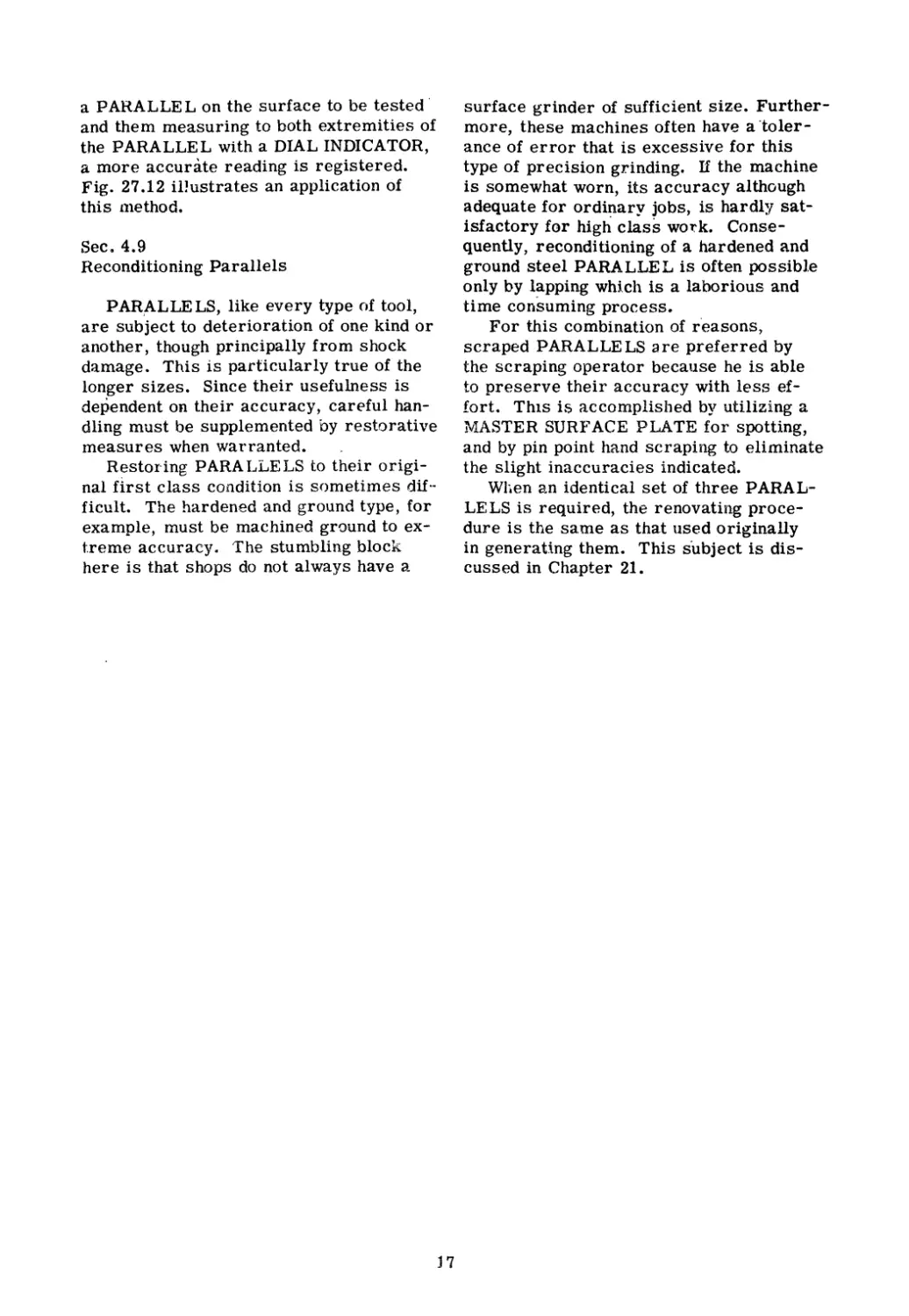
. -
b
Fig. 4.3 Forms of Hand Scraped Parallels.
(a) Standard type (b) Box type (c) Box.type
Fig. 4.3 shows a cast iron scraped
parallel. This tool is cast, machined,
and scrape-finished to SURFACE PLATE
bearing qua ity. It is often cored to re-
duce weight and thereby facilitate han-
dling. The accuracy of a scraped paral-
lel can be checked easily by spotting it
on a MASTER SURFACE PLATE.
Returning to Fig. 4.3 we see two types
of box parallels. Usually these forms
are so scraped that opposite sides are
parallel and all four sides are 90 0 to
each other.
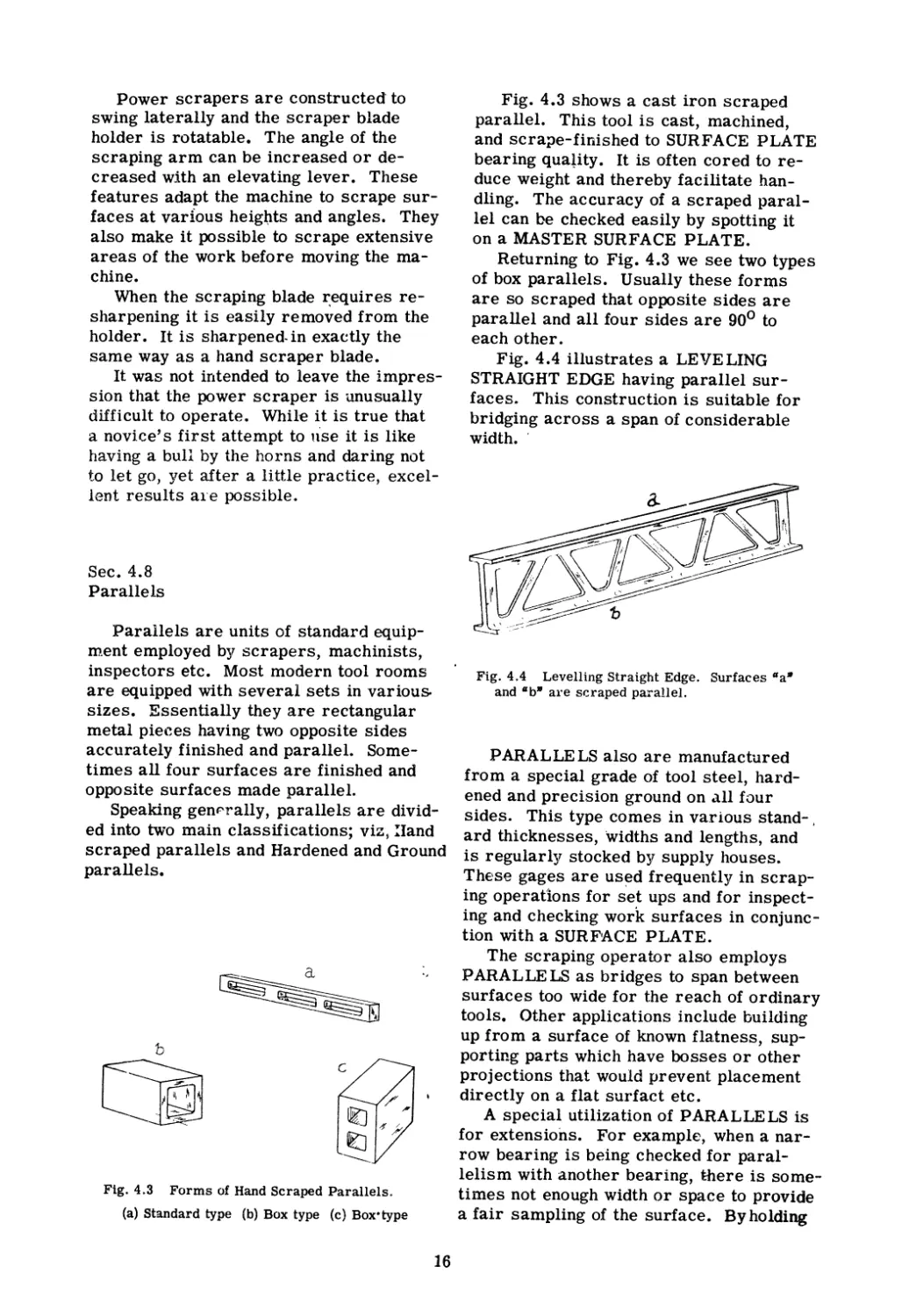
Fig. 4.4 illustrates a LEVELING
STRAIGHT EDGE having parallel sur-
faces. This construction is suitable for
bridging across a span of considerable
width. .
Fig. 4.4 Levelling Straight Edge. Surfaces "a"
and "b" are scraped parallel.
PARALLELS also are manufactured
from a special grade of tool steel, hard-
ened and precision ground on all four
sides. This type comes in various stand- .
ard thicknesses, widths and lengths, and
is regularly stocked by supply houses.
These gages are us d frequently in scrap-
ing operations for set ups and for inspect-
ing and checking work surfaces in conjunc-
tion with a SURF CE PLATE.
The scraping operator also employs
PARALLELS as bridges to span between
surfaces too wide for the reach of ordinary
tools. Other applications include building
up from a surface of known fla.tness, sup-
porting parts which have bosses or other
projections that would prevent placement
directly on a flat surfact etc.
A special utilization of P ARALLE LS is
for extensions. For example, when a nar-
row bearing is being checked for paral-
lelism with another bearing, there is some-
times not enough width or space to provide
a fair sampling of the surface. By holding
16
a P ARALLE L on the surface to be tested'
and them measuring to both extremities of
the PARALLEL with a DIAL INDICATOR,
a more accurate reading is registered.
Fig. 27.12 il!ustrates an application of
this nlethod.
Sec. 4.9
Reconditioning Parallels
PAR,ALLELS, like every type of tool,
are subject to deterioration of one kind or
another, though principally from shock
damage. This is particularly true of the
longer sizes. Since their usefulness is
dependent on their accuracy, careful han-
dling must be supplemented by restorative
measures when warranted.
Restoring PARALLELS to their origi-
nal first class condition is sometimes dif...
ficult. The hardened and ground type, for
example, must be machined ground to ex-
t.reme accuracy.. 'The stumbling block
here is that shops do not always have a
surface grinder of sufficient size. Further-
more, these machines often have a "toler-
ance of error that is excessive for this
type of precision grinding. If the machine
is somewhat worn, its accuracy although
adequate for ordiJ;lary jobs, is hardly sat-
isfactory for high class wo k. Conse-
quently, reconditioning of a hardened and
ground steel PARALLEL is often possible
only by l pping which is a laborious and
time consuming process.
For this combination of r'easons,
scraped PARALLELS are preferred by
the scraping operator because he is able
to preserve their accuracy with less ef-
fort. ThIS is accomplished by utilizing a
rvlASTER SURFACE PLATE for spotting,
and by pin point hand scraping to eliminate
the slight inaccuracies indicated.
When an identical set of three P ARAL-
LELS is required, the renovating proce-
dure is the sarrle as that used originally
in generating them. This subject is dis-
cussed in Chapter 21.
j7
Chapter 5
THE HAND SCRAPER
.
In this chapter we describe the tool
used in scraping metal surfaces. Being
relevant to the subject, the preparation of
the blade for this duty is also amply dis-
cussed. Techniques covering both grind-
ing and honing practice are included
Sec. 5..1
Types of Hand Scrapers
One of the indispensable tools used by
the scraping operator is the hand scraper.
This tool somewhat resembles a cold
hisel or a flat file.. In fact many rnechan-
ics make their own scrapers from v/orn
out flat files by grinding and honing an ap-
propriate cutting edge on them..
There are two general types of scrap-
ers for scraping flat surfaces, namely:
1.. The flat sc'raper
2. The hook scraper
We are not concerned in this discus-
sioT'. with bearing scrapers or three-
cornered scrapers for working curved
bearing surfaces.. .
Hand scrapers vary in size from short
12" and 15" lengths to 20" and 22" sizes,
and some are even longer. The blade may
be 3/4ft to over 1 1/4" wide and 1/16" to
1/4" thick. Individual preferenc e deter-
mines the operator's choice of a hand
scraping tool although most mechanics fa-
vor the short to medium lengths. Other
dimensions are proportional.
Sec. 5.2
The Flat Scrape.r
The most frequently used kind of hand
scraping tool is the flat scraper, known
also as an ?tend scraper." \Vhen utilized
to scrape a surface smooth and flat., the
cutting edge of this tool is ground, then
honed, to the correct shape by a technique
fully described in a later paragraph.. The
flat scraper is also employed for produc-
\
ing various designs of frosting and flaking
marks, but for these processes the cutting
edge is usually ground and honed in special
ways.
A detailed explanation of the correct
method of handling a flat scraper, under
different conditions, is given in other sec-
tions.. Briefly though, the tool is pushed
in scraping operations and either pushed
or pulled for frosting and flaking, depend-
ing on the design required,.
One of the nlore desirable qualities in
the scraping tool is a degree of flexibility..
(The care with which the blade was dra wn
. vhen manufactured \vill determine whether
this quali.ty is present..) Springing action
is conducive to scraping a srnooth finish
on the work surface. Elasticity alsQ re
duees scraping fatigue.. J:i'lexibiJ.ity in the
tool will promote the maximum efficiency
in the body power stroke. With the arm
po,vered S rap ng' stroke, this characteris-
t " . 1 . t f
1C IS ess lmpor an\,.
See.. 5 3
The Hook Scraper
,}'he hook scraper gets its name from
the form of the cutting end which is bent
in a short, sharp curve. A cutting edge is
ground and finished by hon.ing at the hooked
end. Vlith this form of tool ihe renloval of
n1etal is accoDlplished by pu lliflg the b tad€
tov/ards the operator. 'Thjs typ of scraper
is used n1flinly for flaking and fIosting
work, seldoJn fOl conventional scraping of
flat surfac es..
For producing various styles of frosting
and flaking, some operators fa\lOr the fiat
scraper and others preff r the hook scrap-
er. Personal preference, rather than ef-
ficiency, is the basis for the selection.
Sec.. 5.4
Commercial Makes of Hand Scraper Tools
PopUlar factory-made hand scrapers
featuring replaceable cu:ting blades are
18
constructed with four con1ponent parts,
namely:
1.. Tbe cutting blade, ab0ut 4" long, of
.special tool steel.. When worn the
blade is replaceable.
2. The shank, or main body of the tooL
3.. The clamp, which fastens blade and
shank together in a sort of splice.
4. The wooden handle, which fits on the
end of the shank.
As the cutting blade wears it can be
pulled out. However, not tnore than 1"
should protrude beyond the shank and clip
A great€r extension is not adequately sup-
ported and consequently there is a ten
dency to breakage u lder the straIn of a
deep sc raping cut.
See.. 5..5
IIand Made 'rypes of Scraper 'Tools
Although commercial tnakes are popu-
lar, many mechanics prefer to lrlake their
own scrapers, either from flat files that
have outlived theil' usefulness, or frorn
flat stock tool steeL \Vc will diseuss the
process of making a flat seraper from a
worn'-out file* Since considerable tip1e
and effort will be expended in con\rerting
a file into a scraper'i it is only sensible to
use good nUiterial to start \vith., 'The best
aSSllranee that the steel is the lighest
quality is to take a file made by a \vell
knovlu and reputable cOJnpany..
Solect a 12" or 14" flat file v;ith fir&e
teeth. A single cut snlooth or double cut
dead <:nnooth fi]e is best for the purpose..
A fine tooth file is chosen becaus\(? in
grinding off the teeth, 'Nhich is the fi rs
operation, we must ren10ve enough InetaJ
to get well belo\v any line fault developed
,yhilv forn1ing the teeth.. ()therv/ise: t the
scraper ITlay eventually break along this
line.
Next the file is annealed.. 1'his is ae
compUshed by heating the steel to a dark
red heat, \vhich corresponds to about
1300 0 F'e, and cooling slowly by packing in
limec The longer the period of cooling the
more thoroughly the strains which were
set up during manufacture will be elimI-
nated.
The file is now shaped to the'de8ired
form by forgi.ng. This process requires
it to be heated to a dull cherry red., Ex-
cessively high temperatures should be
avoided as this tends to impair the density
of the grain. (A charcoal o:r soft coal fire
is preferred as a heating medium.) Natur-
alJy, there is a difference of opInion a-
mong machinists as to the most desirable
form for a scraper tool. Some operators
favor a file lengthened out so that it tapers
unifornlly fron1 end to end. Other equally
qualified mechanics prefer a tool having
uniforrn thickness, except for a taper ex-
tending back about 3" from the cutting end..
In either case the cutting end may be
flared out or kelJt the sarne \vidth as the
body of the scraper, as desi r-ed. T0 pro-
duce a filetal forging of fj,ne texture, many
ljgh blows rather than a few heavy blows
should be struck ,vith a hammer preferably
not exe eeding 2 Ius.
(; A UTI()l'- =
If only part of the tool 1S forged, the
entire piece should be anrlc leq to re-
Inove the inte:cnal strains before harrl .
ening because the density of the metal
as between the hamn1ered and unham-
,
mered section will have changed..
At this stage of the \:vork, consideration
should be given to flexibtlity in the tool.
The taper will influence this characteris-
tic to a certain extpnt.. .For those opera-
tors v/ho prefer springiness in their tool,
the thiekn<::ss of the steel n1ay be reduced
until the tank end is 1/8" apering to 1/16"
at the cutting edge. Sorne operators favor
a stiffer scraper in which case the cutting
end n1ay be kept 1/8" thick with the tang
{ nd 3/16° to .l/4 H . Pfh€ average , idth of
the scrapel' \viLt vary b t\li;ree:l 3/4" and
1 1/41'. (.Elasticity in the tool is a desir-
able quality, but what' is best for one kind
of job rnay not he suitable for another type
of vvork.. To perrnit a selection as needed,
it is the custonl of 11any ope rators to keep
an assortment of several s . rapers of vary-
ing flexibility,)
After th{ steel is forged to the .shape
desired it is allowed to cool, and then all
hammer marks are renloved by grindi.ng.
At the same time the ragged edges are
smoothed off) forming a c lean-cut, sym-
metrical shape.
1'he tool is now hardened by heating
evenly and slowly in a coal fire until it is
cherry red (about 1650 0 F\) The proper
19
quenching temperature is reached v. hen
small globules of flux or scale appear on
the surfac e of the tool. As this i oint is
re ..ched the tool should be removed quick-
ly and quenched in water or brine. If al-
lowed to remain long r i.n the fire, pitting
of the surface is probable.
Tempering is the next step. To prepare
the tool for this operation it is polished all
over using emery cloth. Next a film of
Inachine oil is applied, the better to see
he variations in color during the temper-
ing process. The heat is applied to the
tang end, and the tool" is quenched at the
fi10ment the cutting edge reaches th prop-
er drawing temperature. This is a matter
of individual preference and may range
from the glass hardness of an undrawn cut-
ting edge to a light ve 110vl representing a
hardness of about 60 Rock\vell.
Usually a wooden file handle is attached
to the tang of the scraper, but since it is
too pointed at the end to offer a comfort-
able rest when ernploying the body power
stroke, it is custon1ary to attach a circu-
lar piec€ of wood about 3" in dia,meter to
the end of the handle to make bodily con-
tact more bearable. Sometimes, in lieu of
wood, circular pieces of leather, or heavy
felt are attached.
In fashioning the wood handle for the
scraper, an opport.unity is provided to irrl-
prove on the design usually found on these
tools, even conlmercial makes" Some ex-
perienced worknlen perfol"m a quick "gov-
ernment job.' on their tool regardless of
whether it is bought, made, or issued by
the shop's tool crib.
After knocking off the slender wooden
handle, a piece of hard wood is "turned up"
to the size and shape of a door knob. Next
a steel ferrule is forced over the snlall
end, then driven on the tangs 'rhis knob
handle design provides a comfortable grip
for the hand and an easy rest for the body.
It reduces fatigue in both cases.
Sec. 5..6
The Blade of the Hand Scraper$
Salient features of the blade are:
1. The breast. 'rhis has a slight bevel as
illustrated in longitudinal section in
Fig. 5.1a. When the blade is honed by
hand the bevel degenerates into a slight
curve as seen in exaggerated form in
Fig. 5., lb.
\3
//
J /
Fig. 5.la Enlarged theoretical form of honed dou-
ble edge blade. (longitudinal sectional view.)
(1) Cutting edge (2) Breast portion of the blade
honed to provide cutting edge (3) Honing angle
(5) Direction of honing stroke (6) Honing stone
(10) Side of blade
3
111(
-----6
TT
/
j/
2
Fig. 5.lb Actual form of honed blade (enlarged)
View through side of blade, longitudinal section.
j>
(1) Cutting edge
2. The radial curvature. How this is pro-
duced is discussed later in'describing
the honing process. Fig. 5.2 shows a
front view. The corners are cham-
fered and rounded in order to prevent
20
the tool from scoring the work piece if
accidentally canted.
9
I' ,
I
I
\
\ /4
\
\
\
\
\
i-----
---
Fig. 5.2a Front view of scraper blade showing
radial curvature caused by involuntary lateral
rocking of tool during honing stroke.
(4) Flat of bla,de (6) Honing stone
,1/ 1
t,
1/ 1
8
8
b
Fig. 5.2b Front view of :3craper blade.
(6) Honing stone (8) Rounded, cha fered corners
3. The cutting edge is represented at work
in Fig. 5.3.
----J B I
"0 /1''''3
Qj " I
T?/'/' r T 2
7
"
9
Fig. 5.3 Side view of scraper blade applied to a
work surface and held at scrapIng angle.
(1) Cutting dge (2) Breast (3) Angle of honed
bevel O ) to 30 0 (7) Scraping angle 10 0 to 300
(9) Work surface being scraped (10) Side of blade
Sec. 5.7
SharpeJ)ing the Blade
Sharpening the scraper blade is done in
two steps. First, is grinding. Second, is
honing. They will be discussed in that or-'
der.
We will assume that the steel blade is
properly hardened and tempered. Com-
mercial blades n1ay be purchased in this
condition. Since the basic principleb of
hardening and tempering steel are ade-
quately treated in many technical books,
no further mention will be made of that
subject. It is enough to point out that the
blade must be hard enough to keep its cut-
ting edge over long periods of time, yet be
tough enough so that the tdge does not chip
and break down easily.
Putting a cutting edge on a scraping
blade is startEd at the bench grinder ,and
must be done carefully. It cannot be em-
phasized too strongly that in rough grind-
ing, the temper must not be drawn from
the blade. Better still, the cutting edge
should never be heated so that it becomes
uncomfortably warm to the touch. If the
rough grinding is properly done the first
time, it need be repeated only at infre-
quent intervals as the blade wears down.
Thertfore, the few extra minutes spent in
doing a conscientious job is time well
spe!1t.
Sec. 5.8
Grinding the Blade
The first operation is quite elementary
21
as the end of the blade, shown in Fig. f'.,,4,
A-
n
I
,
I
I
I
I__J
I I
C:="-::J
? /-..;
>
C- ..,f(' I
8 - -"" t l -i--- 4
! I
I(J ! I )
I i ;.../
I I ,./
y
--'---.
I I
I
I
_I()
! I
I I
____ l J
-- ->-:--:.>...
I ---- f- :';:7-- :
, __-+-t I
, I I I
, : I
I I I
I I I
! .
! I I
I I
I ! I
, ,./
IJ. -'
Fig. 5.4 Assorted V 0WS of enrt of Sl. rdper blade.
(1) Cutting edge (2) Hrca t (4) Flat of blade (8)
Rounded corners of blade (10) Side of blade
,
is ground flat and straight across, trans-
versely. For this operation an emery
wheel of fine grit is ernployed. Selecting
the proper abrasive wiH tend tc :-educe the
depth of grinding wheci marks on the
breast (2) of the blade" ....<\11 of these must
be removed by honing before the tool can
be safely used.. rrhe blade is further in-
spected for pits on the flats (4)" These
pits when found in a commercial blade are
probably due to improper heat treatment..
In the case of the homemade tool, they ai.-
so may be attributed to carelessness dur-
ing the forging process. II either front or
back flat of the blade is visibly pitted, this
condition is .rectified by additional grind-
ing.
The preferred rnethod is to pre 3s the
flat (4) of the blad against the flank of the
grinding wheel and burnish the surfaces,
front and back, for a distance of about 1/2"
to 3/4H back froni the cutting edge (1)
lJnless this grinding is properly done}
the pits will survive the final honing on the
flats. If a pit develops or €l11erges at the
cutting edge of the blade, after a period of
use 1 blernishes will be .corrned on the work
piece by the blade during a scraping
stroke. To the casual glance these blem-
ishcs appear to };>e scratches, but actually
they arc ridges" One tell-tale sign of poor,
even amateurish work, is na.rrow ridge
lines on the surface being scraped.
Finally, the sides (10) of the bladB are
touched lightly against the face of the
\vheel to knock off the large ragged fringes.
A smooth surface on these sides is not re-
quired as they do no cutting. The practice
of sInoothing the sides is followed merely
to glve the blade a Inore finished appear-
ance..
Sec-
t 9
I '" .
.10",U
the 131 .de
.Pi fie r the brea cst of the blade is grolmd
straight across and pits on the flats are
no longer visible, it is' ready for honing on
thf bench oil stonE... lIoning involves three
S ., f i:'J '1'''' C '(, i .., .
io.. 1...'-' ,.....'), y _.(.ju
1 r" O ' l ','.l' l .r' g t l'p fl ats
> .t'" 1...':'1 ,d. !j. 0 - t . .1..,,,, ·
2.. Ston ing the eutting edge..
3" Roundjng the eorners
Ifhese operations will be discussed
separately..
.. 5 10
I'olishlng the Flats
1'hc honing operation is started by
briefly rubbing both flats (4) of the blade
on an oil stone as represented in Fig. 5.5.
0 A b
/ .
;/ / (, .
//; . "- ,: :. <)
/L-
,/ . '/ 7 ----
/ c . . / . '. " -__.
H.,
;v, ..f/ t1 U
I. / ' " H
c.. ..
/ , ". . . '" :,./'
t -<. .. ".'" - / /:. v. >/
. -"--T' - l. . /
: ,c": f //
. -: V'
Fig. 5.5 P(\Hshing the flats to prevent pits from
iermIng at the cutting edge. Arrow shows direc-
tion of pol ishini stro ..e.
6) Bench oilst\'me
22
This polishing is a rather continuous pro-
cess and is repeated each tilDe the cutting
edge is sharpened. Over a period of time,
a Inirror -like finish is formed on both
flats, extending for about 3/4H back from
the cutting edge. Thus as the blade slow-
ly wears down and nevI pits are exposed,
polishing will eliminate thelll also by
gradual stages before they beCOlne a dan-
ger..
Sec. 5. 11
Stoning the Cutting Edge
There are two honing techniques for
preparing a blade for scraping. The blade
is stroked differently in each Incthod.
Eight to ten strokes, 1.n either case, are
usually sufficient to produce a good edge.
If two cutting edges ar8 wanted (See Fig.
5a Ib) the blade is turned haJj' around and.
the action repeated.. (In order not to dis
rupt the smoothness of the honing rythln,
the turn is often executed wi.th a quick
snap of the \vrist..)
In either method of honing the bladc:.,
only a reasonable an10unt of pr€ssure is
applied. Bearing down too heavily 'Yvill
cause the blade to be scrateJ1ecL Jl)re
force is exerted on the push stroke and
pressure is eased up slightly on the pull
stroke.
The honing techniques will now be dis'
cussed in detail.
Sec. 5.12
Honing (Method No.1)
, In this method, the se ra.per t.(toJ is .tF." id
as steadily as possibl either in an uprIght
position or slanted towa.rd the op :ratol .
This would be from 0° to 30° frorn the v(.r.
tical. The angle selected wi be detpr-
mined by two conslderations;.n,arnelY7 the
hardness of the mat rial to be scraped
and the finish desired. S' .lgg( E2t:ions relat
ing to this choice are discussed jn a later
paragraph.
The proper way for a right handed upe l ('.'
ator to support the blade is by grIpping the
shank of the tool with the l(":fi hand" 'fhe
fingers a.re wrapped (lround the shank '\vitt ,
the thun1b extendtn,g v ... l'tjeaU\' up\\?ard
against the flat side of the scraper. 'I'hp
right hand grasps the seraper handle near
the top. The flat side of the shank faces
toward the operator during the full stroke,
both forward and back, although for sta-
bility, the blade may be swiveled accord-
ing to the operator's preference, but not
more than about 25 0 n1axinlum. Essen-
tially, this means that the cutting edge is
not square to the direction of the stroke.
Held in this way, the cutting edge of the
blade is passed back and forth over the
stone, as represented in l ig. 5.6 1\ rigid
/3
X I ,/ {j ---1 "",,*"-- -... x
\;' " I .'" ' "A' /'\
::\' r \ ". \
\ ,\ \ \
\' ':,\\ \ \ \
""'1---- \ \ \ ' \
\ " \
" \, ,\ \
\,,\1, , \
\'r ',I , \ \ \ -.1
\ I ) yv
f.. ,....,'.'--r-T"F r7"-n -7 ". '-r/"/'; 7 T77'rt 9 -r'1
} /, " " "" I ,.:
t...t...L...1 L.L.LL.J _L_LL-L__ .. L.L ... _J .L _L__ -Li-../ --" ..L -'.
I
Fig, 5'.6 Diagram representing tnotion of blade as
it is drawn in towards operator as required by
Honing Method No.1.
(x) Position at start of st.i:oke (x') Position at end
of stroke (1) Culhng edge (a) Honing angle 00, to
30° ine Hnation
arn1 position is maintained as the tool is
alternately thrust away {ronl, and then
drawn toward the body, and so forth.
rheoretically, tflis honing Inovernent
viill generate a bevel on the (>nd 01 the
scraper blade of from 0° to 30°. In other
'Nords, an angJe of from 90° to 120 0 will
be formed bet\veen the flai (if th( bl ade and
t. 1 0 ' fA }"' reast P ra( .. t 'i("' } lly !M ."',c. .:t1}'<;"Ip' h , ) urp.,, ( -,!t'''
l 'It,J r....; . b.. ."r .,r h) p'l..... '!.. .t...., \. V'V ., f w ..... "'" ,
It is irnpossibie to tn1part an exact st raigbt
lllll motion to lhe huning (;;troKf.:. Instead,
there is a slight involunta.ry \1./;;t vf1ring rno-'
tjon evident in the scraper bl ide 3n :1 dircc
ttOH lJarallel to tth honi st p For in-'
st.ance, the operato.f' )n(; th(-;
b 1 ad e \ r h i1 i.;:; h old i i '-:: ). ;,) 1'0 J n
vertical bllt his InaJji 19ic} control
the honing st.roke 'tNU 1.;"1 (1:V a v ..1rjahon 01
plus and n1itli.,lS oC E: ,; );)" T'lH ce ..;ult of
th ib \va vel' ing is th tl, in 3t f(,d :)1 producing
a. straight LeveL t ea <lctually
r (HInd ed.. {Sf' e l ' ,:), 1 h j '1 e C '"a"y" Zttu re
of the area st wiJJ pruncd U.onate v) th .
ability of the Op(;I"ator t p tht: olade at
a fixed angle to the stonp ,.jur the strcke
Since it is lrnpcnQsible to keep the hands
exactly steady, a furth() r THOr! ification of
t1U? cutting t dge tak(::s place as a result. of
23
an involuntary sidewise motion.
These two forces act on the blade, as
it travels forward and back the length of
the stone, to produce a radial cutting edge,
as represented in Fig. 5.2. This slightly
curved edge i3 quite beneficial to the oper-
ator for reasons that will be discussed in
a later paragraph.
With this method of honing the operator
deliberately strives to'support the scraper
blade at one fixed inclination Nith refer-
ence to the stone during both the push and
pull strokes. However, since the operator
cannot hold the blade perfectly steady, the
cutting edge will be formed by the combin-
ation of two forces, which are generated,
namely:
1. There is an unintentional deflection of
random proportion in the direction of
the stroke which results in the forma-
tion of a slight convexity in the sup-
posedly flat bevel being honed. This
action by itself would form a straight
though rounded cUltjng edge were it not
for another factor, viz:
2. There is a slight, involuntary, sidew'ise
wavering of the tool during the stroke
which transforms the straight cutting
edge to a radial cutting edge, as sb()'\ rn
in Fig. 5.2a..
These two actions are simultaneous.
Both of the curves thus formed are bene-
ficial as will be shown subsequently.
Analysis of a newly sharpened blade re-
veals that the cutting edge forms at the
dividing line where the straight, flat por-
tion of the blade joins the bevel.
Thus it would appear that since the breast
is not utilized for scraping, it matters .
little whether it is rounded or beveled"
If a double cutting edge is r.lesired, the
blade is reversed and the procedure re-
peated on the other side. Fig. 5.1b illus-
trates the shape of the double cutting edge
thus for!ned.
Sec. 5" 13
Honing (Method No.2)
The second method of honing varies
from the first, in that the operator deliber-
ately imparts a rocking motion to the tool
during the push and pull strokes. During
tnis action the position of the tool varies
from the vertical, as the stroke begins, to
a selected angle not exceeding 30 0 , at the,
finish. The choice of the angle is condi-
tioned by the character of the ,vork sur-
face (hard or soft) and by the finish to be
given it.
If right handed, the operator proceeds
as follows:
The right hand grasps the scraper
handle near the top. The fingers of the
left hand are wrapped around the scraper
shank near the end, the thumb extending
vertically upward against the flat side of
the blade. A rocking motion is given to the
tool as it is pulled towards the operator
and then pushed back. See'Fig. 5.7)
Xl 3
\ 9 -<r
I
x
....----...
I
f'-;':\./<'
..,11/"',
/
\
\ ' ,
\' \)
\ , '
, I
\ \
\'. \ 1 . ' ,-..
\\ : '- " \,
\ ,,'., I " , I
'1\ ' \' \ /
'.} \.. ... ; \ ) .,...-
I' I' I' '-, " I' , " , , , T
,:/ " )')' " " .I' ./ ./" , '" ./ 1 " ./ ./" ./ " r;
I
\
\
Fig. 5.7 Diagram representing rocking motion of
blade as it is drawn in towards operator as re-
quired by Honing Method No.2.
(x) Position at start of stroke (x') Position at end
of stroke (1) Cutting edge (3) Maximum angle of
rocking motion 00 to 30°
At the start of the stroke, the two hands
art? positioned one above the other, with the
scraper tool held, let us say, vertical (0 0 ).
Then as the tool is drawn toward the body,
the :-ight hand (upper) moves faster than
the left hand (lower). The pull stroke ends
with the right hand closer to the operator's
body than the left hand. Without changing
the relative position of either hand, or lift-
ing the scraper tool, the reverse stroke is
begun at once. In this movement the tool
is thrust away from the operator. The
right hand (upper) again moves at a faster
rate of speed than the left hand (lower) and
both hands finish the stroke, one directly
abo,v€ ,the other, just as they were at the
start of the initial stroke. In other words,
on the pull, or forward strake, the right
hand advances faster than the left hand and
the movernent ends with the right hand
ahead or leading. On the return stroke, the
24
right hand overtakes the left and both
finish in position as they started, one
above the uther. Thus the blade is rocked
forward and back, intentionally, and a cur-
vature is deliberately honed on it. How
curved the edge will be depends u'pon the
degree of the arc through which the tool
is rocked. That is, the tool may be held
vertical as the stroke is started and have
as much as a 30° inclination when the
stroke stops. Or, for example, the start
and stop angles could be 50 a!\d 15 0 re-
spectively leaving a net rnovement of 10 0 ..
Due to better physical control it is
easier to rock the blade while honing than
to hold it i:1 a straight line.. Consequently,
each time the blade is resharpened, using
this technique, it is possible to obtain a
very close facsimile of the type of edge
desired. For example, if a cutting edge
capable of removing large chips of metal
is needed, the rocking motion imparted is
slight. On the other hand, if an edge
adapted to shaving off delicate flakes of
metal is called for, the rocking motion re-
quired is considerable. In either extreme,
or any intermediate case, the cutting edge
can be duplicated very closely during the
perio ic resharpening process because it
is not produced by a straight line motion,
but by a curved line movement Thich is
the more natural and automatic of the two
methods.
With this process, as with the one pre-
viously described) an involuntary sidewise
moti.on is likewise evident because it is
virtually impossible to keep the hands in
position one above the other during the
oscillating (rocki1"g) honing stroke. 1'he
slight lateral movement which deve10ps
in the right (tipper) hand causes the blade
to form a small radial cutting :dge" (See
Fig. 5.2)
Analysis of a biadt honed by the n1eth-
od described above, reveals that in this
case also the cutting edge farIns at that
line where the curve merges into the
straight flat portion of the blade. Hence
in either method the breast of the blade is
curved; involuntarily, in the first instance;
deliberately, in the second.
To provide two cutti.ng edges the L]ad
is turned front to back and the proc dure
repeated.
With Edther honing method, the purpose
in view is to provide the most efficIent
cutting edge for any given work piece.
This calls for some eAperiment and the
novice when in doubt is advised tnat it is
better to be conservative and keep the
angle of inclination of the blade as small
as possible i. e. c lose to vertic al. Wheth-
er to increase it or not can be deterlTIined
by the effect produced on the work surface
by a few trial cuts. Should some modifica-
tion be required, increasing the angle
slightly at the next honing is a relatively
easy matter. On the other hand, if the
operator has erred in the first instance by
honing at too great an angle froln vertical,
considerable surplus metal must be re-
moved from the breast of the blade before
its efficiency can be restored. In such a
case it is often necessary to grind the
breast flush with the cutting edge and be-
gin anew. It is obvious that an error of
judgment, sueh as this, is wasteful of both
time and blades. A few suggestions on
selecting the proper angle for honing are
contained in a later paragraph.
Sec. 5" 14
Rounding the Corners.
After a satisfactory keeness is ac-
quired, the tool should be held at about a
45 0 angle to the oil stone. The four cor-
ners of the end of the blade are then
rubbed a few times in a circular manner
to round them slightly.. This prevents
scoring a work surface if the blade is ac-
cidentally canted during a scraping stroke..
t .r - 5 1 ;:.:
I,w)C(.. . J
Advantages of the Radial F dge '
'rhe slight curve pr.Jdueed on the cut--
ting edge by both Inethods of honing pe.c-
rnits the blade to be used during all phases
of a scrapIng job. 'That is to say" a blade
with this forrn has the fae i 1 ity to pin point
tS w'ell as scrape deeply. Moreover 1 by
holding it at varyir:g angles to the work in
process, the width of the cut can be
changf:d as needed. This convertibility is
1m partant b( canse, as i he hIgh spots are
reduced in size they i.ncrease in number
and rnnst be picked off without impairing
the surrounding surface. With the radial
edge this can be done quite ea.sily. To
vary the width of thf\ cut it is necessary
only to increase or decrease the angle of
the scraper tool wHh respect to the work
surface and vary the pressure applied.. In
25
this way it is possible to have at all tirnes
a blade proportioned to imlnediate needs.
Sec. 5.16
Selecti.og the Honing .l\ngle
The type of \\lork surface which is to be
scraped is an important consideration
when honing a cutting edge. It is a faetor
in determining at what angle the tool Inust
be h ld to produce the best re ults. Al-.
though all Dletals can be successfully
scraped, each has its peculIarities.. Con-
sequently, a blade suitably honed for Ot1e
type of metal if; st:ldon1 satisfactory for
another kind until the cutting edge is nl0di-
fied.
Some experienee i.s necessary to pre-
pare a blade that will be ideally suited for
fast BC raping Orl a given jobo Generally
speaking, ,,"hen the work piece consists of
a hard metal it will be hecessary to hold
the tool closer to vertical when honing it
than when preparing a cutting edge for ap-
plication to a softer metal.
For example, the scraping tool that is
satisfactorily honed for cast iron surfaces
requires some rnodification of the cutting
edge before it is equally efficient on serni-
steele When intended for application to a
senli-steel surface the blade should b.e
honed at about 10° from the verticaL The
cutting edge thereby produced is consid-
ered the best for t:nis n1aterial. If the
blade is held vertically and honed so that
the cutting edge is flat ac ross, it tends to
hog in when applied to the work. On the
other hand) if canted to an angle in excess
of 10° when honed, the blade resists pf.::ne.- .
tration into the \vork surfae0 and additional
pressure is necessary" A.s a general .rule,
the harde: the metal, Ul(:; close r to vert;-
ca1 the blade should be held \vhe-n hOUt:d.
ii. r f<:!.c be CUH;::jloered hi hon-
(: 1 t 1 r:.:, :i c.\. f T " j"' f:" t' ( J . t ' f' h 1 , 1 1
'..k. ....'S . ., \"'--"'\.-"t:""!.J.. <v :t.c...,"'). J.h.
l ' r y' n'::1 r t - p,.: 0 t , p -. a ,,-' 4 1 ""T t n b f'.l. S . C r ' ':1, r j ' .fA d
A 'i: """ ., -" ,- .1.1..... I..... ....1tA t5 \.' ...." """1 \.., ·
Usually the lldnnpr th( casting the harder
its skin. (:onscquent! y, for eff( cti ve
scraping on 3uch a surface t the tool rnust
be held n10re nearly vert1_cal \vhen honjng
1 t h ,"'n l ' f .(.l :. """.)c t r {'n,o'''',- :1 .. ',(::'_.
A ' " ,, ...,.. u1t.. \ O_'"; . H!"'t '.'\' <1 e td.rge 01 n1a,.:.>
;:') '.
tf
C' 1 ' V fJ <, '''1 d i"'),",,, , ,'
':.} _, f). ",.. L\ -,.i, t. ::..
er..
Th kinc'{ of ish [0 bp pl'oduced .)TI a
work piecE< a ls{) infltH- ::1ces t.n.e angl{ Ole
tool is held 'Nhen honed. As a rule 'JJhen
J
honing a blade for finish f5c!'aplng or pin
pointing, it should be held in a position
farther from vertical than when it is
honed in preparation for a roughing cut..
No hard and fast formula can be laid down
and rnuch depends on the skill and experi-
cnc e of the operator.
Sec. 5.17
Blade Assortments
Many operators \vho work regularly on
different metals lave assortlnents oi
either scrapers or attachable blades honed
to various appropriate cutting angles.
Since the efficient cutting angle for one
type of metal varJes ironl that requjre';i
for another kind, and because rough scrap-
ing necessitates a different cutting edge
than finish scrtlping, as we have explaIned
above, therefore this practice might well
be univf rsally followed. Its prine Ipal ad-
vantage, of course, is the ready availabil'-
ity when a particular cutting angle is
needed.
Another inlportant benefit froln this
practice is that the individual bladeR will
last longer. There is a sizeable loss in
length in radically ehanging the edge fraIn
one cutting angle to another angle to accom-
modate dissimilar Inetals. If this altera-
tion is made repeatedly, the wastage is
high. On the other hand, when several
blades re kept, eaeh ground to a different
angle, a sl ght change in one will usually
modify it sufficiently so that it will be
ideal for any given set of CirCUl'flstances.
This pract"ice is sinlply economical man-
agenlent that will help the operator to con-
serve a favorite blad( fhat cut::> readily and
holds its edge welL
t-::JC' I) 18
u......_. t.i
Care of the l{and Scraper
I!and sc rap81 s which are forged \nd
Hardened fron) tool ei do not; un.fortu.'
nately, all have the sarne abilJty to hold a
cutting edge Comrnercial blades ordinar-
ily do have uniforrn quality and temper be-
cause their u1anpfacture is rigidly con-
trolted by a series of factory inspeetions.
Tf { ccasional1y, one is ncountered that
dulls rapidly} this lnay he due to improper
In;tlal-grindlng vlhich irnpaired the temper
'rhjs is tht" fault (:if th first user" Experi-
enced operators possessing a to()l that re-
tains a keen cutting edge will take every
precaution to safeguard it, as it er ables
26
them to do better work with much less ef-
fort.
Safe storage of the blade when not in
use is' very important. The cutting edge
of a scraper blade is easily nicked, so the
tool should not be tossed carelessly into
a drawer containing wrenches or files.
H it must be stored with a number of other
tools, a leather guard should be provided
to protect the blade.
Sec. 5.19
Carbide Tipped Scraper Blades
With the introduction of carbide tipped
cutters to general machine shop use just
prior to World War 2, it was only a matter
of time before this material would be a-
dapted to hand craper tools. The innova-
tion was accomplished by fastening small
pieces of carbide to steel blades by a pro-
cess such as silver soldering, or braze-
ing. At the time of writing, carbide tipped
blades have been thoroughly tested and
their qualifications adequately established.
Carbide tipped blades are preferred by
machinists to blades of tool steel for som
kinds of work. They will stand up eight to
ten times longer than high speed steel
blades when scraping hard materials. On
certain surfaces, such as alloy bronzes,
they are the only type that will cut sue-
cessfully. In IShort, this innovation has
earned its place in special scraping jobs,
but has by no means supplanted steel
blades for ordinary work.
The difficulty of sharpening carbide
tipped blades with the equipment usually
available in a rnachine shop is their one
unfavorable feature. However, by provid-
ing the operator with access to a quantity
of properly sharpened blades this objec-
tion loses much of its weight.
When necessary, these blades can be
ground on special grinding wheels forlned
of carbide of silicon" This abrasive mate-
rial is open and porous in structure insur-
ing constant breaking action or resharpen-
ing of the wheel face. After grinding, it
is necessary to finish each blade with a
diamond lap because the cutting edge is
invariably nicked or chipped n the grind-
ing process A diamond wheel also can be
used for this purpose and it will provide a
satisfactory finish. However, it is ,rery
difficult to form a clean cutting edge on the
blade without a spf(cial set up, and the al-
ternative, off-hand grinding on a wheel, is
generally unsatisfactory. Therefore, if
the blade is to be pruperly sharpened, it
becomes necessary to use a diamond hone
or a lap. A satisfactory cutting edge is
acquired only by the personal touch, that
is, with free and unhampered honing.
PLA TE 3. View of three sizes of hand scraper with
Carboloy Tipped Blades" (Court sy - Anderson
Bros. Mfg. Co., Rocyjord, Ill.)
We IIllght conclude t.i1is subject by say-
ing that if the material to be hand scraped
i.s extremely hard or unusl.:a.lly aLrasive,
the use of carbide tipped scraper blades
is recomInended.
27
Chapter 6
MANIPULATING THE SCRAPING TOOL
In general there are two correct meth-
ods of using the flat hand scraper, each of
which excels under certain conditions.
Skilled operators use both techniques in-
terchangeably as the nature of the work
demands.
In addition to describing these strokes,
this chapter will discuss the proper scrap-
ing met ods under average condi ions.
These practices can be learned by experi-
,nentation, but the cost, particularly in
time, is apt to be high. A careful study
of how to cope with these situations, which
are part and parcel of routine scraping
operations, will prove profitable in the
form of l?etter work and superior speed.
Sec. 6.1
The Arm Power Stroke
In this method of scraping, the scraper
h ndle is held by the right hand for push-
ing. The left hand grasps the .shank some-
what below the mid-point and bears down.
The scraper tool is usually held between
a 10 0 and 30 0 angle with the work surface.
Experienced mechanics who do consider-
able scraping re in general agreement
that an inclination between these extremes
is best for fast cutting without excessive
gouging of the work surface.
I'
The exact angle of attack is determined
by the operator after a few tentative
strokes. The smaller angle is favored for
a keen blade because it cuts better when
so held. As the cutting edge grows duller,
the angle should be increased slightly to
compensate for the decreased efficiency
of the blade.. When working on soft, ten-
acious metals, greater competence will be
shown by holding the tool handle nearer to
the work s.lrface, that is to say, closer to
horizontal.
With the arm power stroke the tool is
thrust forward by effort of the arms alone.
The h nds serve to guide and direct the
blade. Removal of metal takes place dur-
ing the forward movement.
The muscular effort required of the
arms, shoulders and back, combined with
the necessity for simultaneous hand con-
trol of the blade, is undoubtedly fatiguing.
It is the least desirable technique for sus-
tained effort. Nonetheless, it is probably
used nlore often than any other stroke be-
cause the work surface frequently cannot
be positioned to accomodate to best advan-
tage the alternative body power stroke.
This is particularly true in machine tool
reconditioning and repair wherein factory
technjque cannot be economically applied.,
For scraping dovetails, V-ways etc.,
the arm power stroke is employed exclu-
sively because the positi0n of the work
surface is seldom suitable for the alterna-
tive method. Furthermore, this method is
the logical choice for pin pointing because
the removal of metal must be delicately
performed. Superior accuracy is the ma-
jor consideration in such a case. ThE: fact
that speed is slower and fatigue greater is
of secondary importance.
Incidentally, one adaptation of this
method, applicable to the 20" - 22" length.
tool, is to hold the blade with both hands
near the cutting edge. To steady the
stroke the end of the handle is tucked be-
tween the arm and body.
With the arm power stroke the length of
the cut seldom exceeds 1/291 and for the
final pin pointing is but a fraction of that.
The path of the cutting edge as it pene-
trates the metal is a straight line move-
ment. When momentum stops, the blade
is drawn back over the work surface to a
. I
starting point for the next thrust. Whether
this would be to the left or right of the
previous start ng position depends upon
the placenlent of the colored markings.
The tool is moved gradually from the far
side of the work surface to the near side,
or vice versa, depending on conditions
which are discussed in a later paragraph.
28
PLA TE 4. Harid sc aping the base of a turret to fit the bed of a South Bend
lathe. (Courtesy - South Bend Lathe Works.)
Sec. 6.2
The Body Power Stroke
The second method of hand scraping is
known as the body power stroke.. It takes
advantage of the weight of the operator's
body to effect the removal of metaL This
lnetho perrnits unhan1pered 1 two handed,
directional control in guiding the cutting
edge to the proper spot, as well as to the
precise depth.
Using the body power stroke, the oper-
ator plac2s both hands on the scraper tool
in the following positions:
The right hand firmly grasps the tool
shank at about the center with the fingers
curled under the shank and the thumb ex-
tending downward. The palm of the left
hand is pressed against the shank but
closer to the cutting edge and then shifted
up or down as conditions warrant. When
the work surroundings are safe the fingers
may be curled naturally. Otherwise, they
should be stiffly extended. The left hand
regulates the applied pressure which helps
control the depth of penetration.
The butt end of the scraping tool is held
against the body, usually the upper thigh
or at the waist. The exact location is de-
termined by the height of the work. With
the body power stroke, th.e angle of the
scraping tool in relation to the work is ap-
proximately 100 to 30°.
By swaying the body forward, the cut- .
ting edge is forced into the metal in an
elliptical path. The movement is down-
ward, forward, upward, and out. The
carry-through of the stroke ends with the
cutting edge of the tool bove the work
surface.
The blade is drawn back and again
placed on the surface ready for the next
thrust. This may be either to the left or
right of the previous starting position
29
depending on the situation of the indicated
high spots.. The general direction of move-
ment of the, tool when employing body pow-
er, particularly on tl).e initial cycles, is \
from the far to the near side of the s 1 1rface.
The length of the stroke is governed by
the condition of the work surface. If a con-
siderable thickness of n1etal must be re-
moved, the stroke is long, up to one or two
inches. The depth is proportional and n1ay
be increased by applying more down\vard
pressure on the tool with the hands. This
naturally requires increased effort by the
body to power the stroke. \\then the work
surface is nearing completion the strokes
are shortened, merging into light pecks
with a decreased downward pressure on
the tool. Thus merely the tips of the high
spots are shaved off.
Sec. 6.3
Comparison of the Two Strokes
With the body po Ner stroke, a uniform
cut can easily be maintained over the en-
tire \\Tork surface. But with the arm power
stroke, uniformity is difficult to preserve
over long periods of sustained effort be-
cause the arms must supply all the force
behind the thrust and sirnultaneously guide
it. ' In other words, the arms tire rapidly
and are unable to deliver the cut with regu
larity as to length and depth.
Another factor that is important to con-
sider whet:l comparing the relative merits
of th two contrasting techniques, is the
speed v/ith which a rough surface can be
smoothed. An operator ernploying body
power can remQve ,vith one stroke as lTIueh
metal as an equally exper'ienced operator
I,
can scrape in two, or thre strokes, using
the strength of his arrns alone.
In genera!, hoth. methods are accepted
techniques in the rnetal working trades..
The arm powered stroke, is always utilized
for the final pin pOInting process and also
whenever the body stroke is !.nconv(::,nient
to apply. .
To achi eve speed, unjfornlity of the cut,
and reduction of fatigue, when scraping for
prolonged periods, the operator will find it
advisable to apply the body power stroke;
v/henever conditions are favorable. In
scraping spacious surfaees, this method
finds its greatest usefulness.
Sec. 6.4
Scraping in Unsafe Surroundings
When employing the body power stroke
on a surface close by a sharp corner or
edge, precautionary measures are called
for to prevent injury to the leading hand,
which will usually be the left. Instead of
curving the left hand down and around the
shank of the blade, as is normally done,
the palm is pressed against the shank and
the fingers are extended rigidly outward.
In this way the operator is warned of the
nearness of sharp projections by the
sense of touch. Experience demonstrates
that the rigidly extended finger tips will
instinctively recoil as they lightly brush
a projection thus vlarning of the proximity
of danger. At this physical sensation the
operator \viII shift his left hand.
This scraping hint is mor'e than a little
important, not (){1Iy because it prevents
SOID.e rather painful lacerations that oc-
asionally re disabling, but prinlarily
for a psychological reason. Considerable
emphasis is laid on the necessity for the
operator to keep "cool, calm and collect-
ed" and nothing is rnore likely to be up..
setting than the probability of personal
injury. Since the actual process of scrap-
ing is purely mee hanical, anything that
will relieve the operator of anxiety or
worry is bound to be reflected In im-
proved output.
See.. 6.5
Routine of Scraping"
'\ lhen stal'ting to scrape a worn bearing
surface, the strokes delivered during the
initial cycles are l )ng'er and deeper than
those en!ployed when the fj uishing stage
Is reached This is the correct apf,roach
to scraping 81fice it IS econornjcal to com-
plete a piece of ',vark in the shortest tirne,
provided of course there is no s:1crifice
in quality 3 rro accolnplif,l. th.e j b 8ffi...'
ciently, the work is roughed out 'rhat is)
in the ( arly stages as much T.n€ t1,1 per cut
is removed as po sibleo Thi,s fast scrap-,
ing should not be tapered oif until the
,
tnarkings ShO'1; l that the entire '\j lork sU..r'
face has an approxiluately unjform, tho'ugh
superfici.al} bearing overall. Vv'hen a fair-
ly true plane js aehieved, the length,
\vidth, and depth of the strokes is leuuced.
30
It is understood that the initial rough-
ing cuts are proportioned to the character
of the work surface. The more worn the
work piece, the more freely an operator
may scrape when he starts a job.
If the blade is correctly honed and used,
eutting may be practiced with greater free-
dom, and the appearance or finish of the
work will be very little inferior to the
quality of the final finishing strokes. When
the work is done as recommended, the high
spots will be lowered evenly over the en-
tire surfac€.
The mistake of switchi:1g prematurely
from rough scraping to finish scraping
should, by all means, be avoided. Should
this blunder be committed, the operator
will spend considerable time pin pointing
one section of the work surface 'while an-
other portion may show only skimpy
traces of marking compound, thereby in-
dicating a negligible bearing. 'fhis makes
for much wasted work which has only to be
done over because neglected areas cannot
be touched up indeppndently of the areas
of superior bearing without inlpairing flat-
ness.
The scraping operator should never be
reluctant to rough out ruthlessly, a fj fie
finish immediately he discovers a low
area not working into the over-all hearing
surface. Failure to act decisively in sHch
a case i.s, of rourse, only human because
no one likes to destroy a fine appearing I
surface secured only after much hard la-
bor. Nevertheless, situa ions like this of-
ten occur and leave the operator with but
these two alternatives, viz: First, to be-
gin over again and start right. Or, second,
to putter along hoping for the favorable
turn that never con1es.
Sec. 6.6
Depth of the Scraping Cut
During scraping operations on, say,
cast iron, the depth of metal per cut
scraped from the surface will vary from
.001 n to about .000lff. The usual depth of
the cut is within this range when the scrar-
ing tool is p(}wered by the body stroke.
(In cases where the scraping tool is
powered by the arm stroke, the average
depth of cut is somewhat less For the
final pinpointing of a surface, the depth of
the cut rnay be as little as .00001 11 .)
rrhere are a number of causes influ-
encing the depth of the cut. The most ob-
vious, of course, is a chang in tool pres-
sure. .A few of the other principal factors
are as follows:
1. The type of material and the degree of
surface hardness.
2. The design of the work piece and its
placement for ease and naturalness of
scraping.
3 The quantity of metal to be removed..
4.. The keeness and cutting quality of the
blade..
These major considerations and others
of minor importance definitely affect the
depth of the cut.
Sec. 6.7
Length of the Scraping Stroke
The length of the scraping stroke
varies according to the method to be ap-
plied. Body powered strokes are 1 tf to
2'1 rnaximurn)' while arn1 po\vered strokes
seldom exceed l". These lengths vvould
pc rtdin to the initial eye les only.
.J\s the work surface approaches the
desired condition of bearing quality:,
shorter cutting thrusts should be taken.
Shortening the stroKe will promote the
formatio!l of a better bearing surfac e and
also an irnproved surface finish. The
length of the scraping stroke can be re-
duced by degrees until it is Equivalent' to
the diameter of one high spot. This type
of scraping is known as "pin pointing".
There is an add tional reason for re-
stricting the length of the stroke when we
are scraping steel, or semi -t;teeL Long
strokes have a tendency to produce deep
scratches on these materials.
This penchant toward long strokes 1S
extremely hard to resi t when "roughing
out" at the start of a reseraping job. Or.
dinarily, the bearing ways are oil soaked
and slick from wear and resist penetra-
tion except 'Nhen the initial starting pres-
sure is heavy. ConBequently, there is an
inc linatjon to keep the bl ade c.utting, once
started, thereby exaggerating the stroke.
Extended strokes, we know, induce
scratches, perhaps because a metal par-
ticle 4dhere 3 to the cutting edge. A dull
blade will also scratch IT10re perceptibly
on a lengthy cut. Without theorizing
31
further as to causes, the evidence shows
that no comparable blemish result . from
the ordinary sc raping thrust of 1/4" to 1"
...
length.
The characteristics of some metals en-
able them to withstand long strokes with-
out disfiguring scratches, but others are,
quite susceptible. Any carelessness that
results in scratches entails much extra
effort and time to restore the appearance.
The seriousness of such incidents can be
minimized if the length of the stroke is
proportioned to the characteristic'S of the
metal.
The contention that long strokes save
time has no basis in/fact. Actually, time
and effort are both materially increased
as a result of this practice because the
work piece is scratched more frequently
and deeply. R moving the scratches often
necessitates lowering the entire surface
below the plane at which it could have been
scrape-finished.
Sec. 6.8
Direction of the Scraping Stroke
If the body powered stroke is employed
during the initial roughing cuts, the usual
practice is to begin scraping at that point
on the surface farthest fronl the operator,
gradually approaching the near side. This
procedure is followed to prevent pushing
the debris forward onto other unscraped
high spots, thereby partially covering and
obscuring their E ize and position.. It is
particularly recommended for the prelimi-
nary scraping cycles when marking com-
pound is liberally used and deep cuts re-
move large amounts of metal. (On soft
cast iron, for instance, the size of chip
removed per troke may be considerable.)
The direction of the body power stroke
during subsequent cycles is left to the
judgment of the operator because progres-
sively smaller quantities of shavings litter
the surface.
On the other hand, when utilizing the
arm po\\7er stroke, it is custoInary to work
from the near to the far side unless the
quantity of material removed is so large it
obscures the high spots ahead of the cutting
edge. Pin pointing is always conducted
from the near to the fa.r side.
As we have explained previously, the
body powered stroke and the arm powered
stroke are forward thrusts followed by a
retracting movement to place the cuttipg
edge to the side in position for another
pass. Another type of stroking a.pplicable
to arm power requires, a short forward
thrust to be made. The blade is then pulled
back a trifle and slid side'N"ise, which
brings it to a starting-point ahead and to
the side of the initial position.
A series of such strokes comprises a
chain moving at a tangent to the first
thrust. When the chain is extended to a
point beyond which it is inconvenient to
continue, the scraper blade is returned to
near the initial starting point in prepara-
tion for another series.
Sec. 6.9
Varying the Direction of the Scraping
Stroke.
The direction of the scraping stroke af-
fects to an important degree the quality of
the surface finish. One of the peculiarities
of scraping, familiar to all operators, is
chatter marks. It is also known as wash ,
board effect. This term needs no defini - #
tion as its appearance is exactly what the
name implies. Chatter marks are the re-
sult of pointing too II\any scraping strokes
in the same direction.
I
To prevent c4atter marks, the operator
should on successive cycles vary the direc-
tion of the scraping thrust. That is, on
consecutive cycles the direction of the
strokes should be tangent to the previous
cycle. How much of a/change depends on
a number of conditions. For example, on
cast iron surfaces a shift up to a maximum
of 90 0 is permissible. A shift of between
20 0 and 45 0 is sufficient to eliminate chat-
ter marks for ordinary requirements 1 . The
characteristics of this metal makes such a
procedure both possible and safe. On spe-
cial jobs, where the most pleasing appear-
ance is desirable, the direction of the
scraping strokes in successive cycles,
should be approximately at 60 0 to each
other. This variation is usually suffic ient
to secure a good finish.
Ordinarily this 60 0 turn is made con-
secutively from three directions and then
repeated It will be found that the greater
the number of shifts the more uniform the
-surface will appear. However, rotating the
worK piece through more than 180 0 improves
the appearance little if any, regardless of
how many changes in direction are made.
32
The softer metals and alloys, such as
copper, aluminum, bronze etc. also re-
quire alternating the direction of the
scraping stroke. To what eA1:ent can be
quickly determined by the condition of the
surface after a few cycles.
When working on steel surfaces a
swing of 10 0 to 45 0 is about right. Steel
is a most tenacious material to scrape.
Exceeding the maximum suggested will
only aggravate the difficulty and cause a
scratchy surface besides raising large
burrs and chatter marks. With a limited
directional change in the thrust of the tool,
it is possible to produce a smooth surface
even on steel.
The design of the work piece also de-
termines in large measure ths procedure
to be applied. If the construction is such
that the operator can work on it equally
well f:r:om all sides, we have the ideal sit-
uation.. Usually, however, scraping can be
executed only from one side, thereby re-
stricting the freedom of movement.
On some jobs it is feasible to alternate
the scraper tool, using first the right hand
then the left hand to guide the blade. Sub-,
stantially, the effect of this would be to al-
ter the angle of the scraping stroke up to
about 90 0 . In all cases, it is inadvisable
to scrape overly long in the same direc-
tion, as chatter marks are bound to appear.
To summarize: It is impossible to ob-
tain a satisfactory surface finish on any
kind of metal by scraping consistently in
one direction. Therefore, the aim of the
stroke Inust be shifted 10 0 to 90 0 on suc-
cessive cycles, depending on the type of
metal and quality of finish desired.
Sec. 6.10
Approaching the Edge of a Work Surface
The operator should strive to prevent
the formation of chatter marks when
scraping towards the edge of a piece of
work. This can be done by directing the
cut diagonally towards the edge, never
parallel with it, and never broadside to it.
It is also necessary, as we have explained
before, to change the direction of the
strokes on consecutive scraping cycles.
Another precaution is to avoid having
more than a small part of the blade over-
hand the edge during a scraping stroke. If
this occurs there is a natural tendency to
cant the tool and gouge the edge. leedless
to sa.y this is a sign of poor workmanship.
On jobs where appearance is bf major im-
portance, even one such careless pass can
ruin the appearance of the piece beyond re-
pair. On other work, whose requirements
in respect to appearance are not so exact-
ing, the slip probably can be overlooked,'
except that it denotes incompetence on the
part of the operator. Literally thousands
of scraping cuts will be tnade to finish a
surface and it' only takes one blundering
thrust in the vital place to set at nought
hours of painstaking effort. Extreme cau-
tion in scraping the edge of a surface is a
fundamental axiom of the scraping art.
There is yet another factor the operator
should take into account. Experience
shows that as the scraping cuts are direct-
ed from the middle of the work surface to-
wards an edge, a progressively deeper
penetration is made, quite unconsciously.
The effect is to induce the formation of a
convexity in the central area of the work
surface. Anticipating this, skilled opera-
tors make a deliberate effort to keep their
thrusts uniform overall.
After the surface is crape":'finished the
ragged-edges of the work piece should be
dressed. Filing a small bevel or flat of
uniform width not only completes the job
in a workmanlike fashion, it also guards
against injury.
Sec. 6.11
Scraping the Perimeter of a Hole or Slot
When scraping a work surface which is
slotted or drilled, it is best to direct the
strokes of, the scraper tool angularly to-
wards the hole or slot. That is, the blade
should never be thrust directly towards
the axis of the hole. The correct approach
necessitates a number of strokes converg-
ing on the hole from all directions as illus-
trated in Fig. 6.1. On the other hand, it is
advisable to avoid guiding the tool around
the opening. In other words, strokes cir-
cling around the opening, as shown in
Fig. 6.2, may not only cause chatter marks,
they may also produce a bevel.
Fig. 6.3 illustrates the right and wrong
ways to scrape the edge of a slot .
Sec. 6.12
Off-Hand Scraping
"
When scraping operations are conducted
33
It is seldom that a scraping operator
will be confronted with the job of scraping
a .aurface flat without the assistance of at
least some kind of a spotting tool. Rare
though such occasions may be, this adapta':'"
tion of off-hand scraping still merits some
attention.
A fairly satisfactory sol tion is possi-
ble, in spite of this handicap, when the "-
work surface has been finished Ipachined ,
by a machine tool of known accuracy.. Then
in lieu of using a. spotting tool to indicate
the contour, the operator can use the tooth
marks of the cutting tool as a guide. Each
tooth of t.he cutter of, say, a vertical mill-
ing machine, generates tooth marks which
vary in depth and appearance and therefore
are distinguishable from the marks pro-
duced by other teeth of the same cutter
tool. In other words, the scratch of each
tooth can be traced unerringly across the
work surface.. Thus by utilizing as a guide
the distinctive tooth mark of a certain in-
dividual tooth as it tracks from end to end
of the work piece, a scraped surface can
be produced whose flatness will correspond
to the accuracy of the machine.
The technique is to sc'rape away the
metal in such a way that the pattern of
tooth marks formed by the milling cutter
remains at an even depth below the plane
of the scraped surface" On the first cycle,
the entire surface is scraped over lightly
to smooth the roughness. This serves to
remove the faintest scratches. There now
with only a minimum of attention given to remains traces of several tooth marks
applying spotting tools, or making tests, it which are deeper than any of those re-
is called off-hand scraping. This method moved. Selecting the faintest mark as a
of scraping is particularly adapted to the guide the surface is again scraped allover
initial roughing cuts. It is a so efficiently to eliminate it wherever it appears. Then
34
Fig. S.l Showing correct way to shave metal at lip
of circular hole. To avoid rounding lip of hole do
not let blade overhang too far.
Fig. 6.2 Sketch of inc9rrect method of scraping
around the circumference increase the likelihood
of rounding off edges.
.,.
Fig.. 6.3 (above) Correct method of scraping to edge
of a slot. Strokes approa h at a tangent.
(below) Incorrect method because all strokes par-
j
allel the edge. A rounded, or turned, edge ma.y
result.
employed at other times when the excess
of metal to remove is considerable and
when it is thought safe to scrape over the
work surface a few times without alternate
applications of marking compound. How
often or how deeply to scrape, without
follow-up checks with a spotting tool, will
be, naturally, a matter of individual judg-
ment.
There are certain hazards attendant to
the adoption of the practice. A novice
would be well advised to defer employing
it until experience has been gained.
Sec. 6.13
Using 'rool Marks as Guides for Off- Hand
Sc raping
the process is repeated uSing the' next
faintest mark, and so on, until finally on
the last cycle the last visible tooth mark
is removed.
If the operator will maintain a uniform
pressure on the cutting blade with each
stroke, the finished surface will be kept
flat.
To assure that no part of the surface
is missed, it is prA.cticable to aoply a thin
film of marking compound over the entire
surface and renew it at the start of each
cycle. It is sufficiently transparent not to
affect visibility.
Bec. 6.14
Comparison of Rough Sc-:aping, Finish
Scraping and Pin Pointing.
Like so r...lany other shop expressions,
the terms, rough scraping, fit...isl1 scrap-
ing, and pin pointing are used loosely in
the metal trades. Essentially, they all
refer to the removal of metal chips by a
scraping tool. It is the quantity of metal
removed per stroke that creates the fun-
damental distinction of terms, not so much
a difference in technique. Even with this
definition there is no sharp demarcation
because one classification merges imper-
ceptibl into another. It is practically im-
possible to draw a ha.rd and fast line be-
tween them"
Fig. 6.4 shows a profile illustrating the
process of reducing surface irregularities
into bearing spots as the scraping opera-
tion progresses by stages from rough
scraping to finish scraping.
Sec. 6.15
Rough Scraping
Rough scraping, also called "roughing-
out", usually refers to the removal of
n1etal at the start of a job.. The main pur-
pose of the initial scraping cycle is to re-
duce the rough or worn surface to a fairly
flat condition in the minimum time. Con-
sequently, the cuts are made longer and,
coincidentally, deeper. As a natural re-
sult, not only are the high spots cut off but
also part of the area surrounding them.
How deeply the operator should scrape
cannot be stated definitely as this is de-
pendent upon the deterioration of the w rk
surface, surplus thickness etc.
For example, if the work surface is
o
I
2. -- --_.
3
,...".... --...:I "......
v-------.:
.... --v--
- --
5 .........
T b..&.-
- J.. , .
Fig. 6.4 Profile drawing illustrating the protess of
reducing surface irregularities into bearing spots
as the scraping operation progresses by stages
from Rough scraping to Finish scraping.
(0) Contour of worn surface (1) Contour after in-
itial scraping cycle (2, 3 and 4) Showing progres-
sive improvement resulting from intermediate
cycles of scraping (5) Finai scrape-finished sur-
face
Note: It may surprise some readers to learn
that a bearing surface is acceptable even though
it is far from glass sn10oth. Ways and slides sub-
ject to reciprocating motion must not be too smooth
or they will not maintain an oil film, and thus will
fail in service.
For jops specifying very close tolerances of
surface finish it is advisable to measute the work
surface with an electronic instrument. The ad-
vantages of this are two-fold. First, there is the
assurance that the job will pass critical inspection.
Second, there is no danger oi overfinishing the
. surface.
badly worn, or has been roughly m hined,
consid rable metal remains to be scraped
away. In either of these cases, free cut-
ting over the entire surface with long, .
wide, and eep strokes is the first t>pera-
tion undertaken. With each successive
cycle, a shorter, narrower, and shallower
cut is executed. When the surface has
been developed to a condition that is fairly
true, the rough scraping is considered
completed and at this point, finish scraping
begins.
Sec. 6.16
Finish Scraping
Finish scraping eonsists of improving
a fair ly flat surfac e into a final true bear-
ing surface. The strokes used in finish
scraping are short, narro71, and shallow in
depth. These strokes, on the last time
over the surface, merge into a mere peck-
ing at the marking's that shine. A propor-
tionately smaller amount of metal is re-
I
moved by finish scraping than in the rough
"
scrapIng process.
35
t
The following table shows how a sur-
face can be improved step by step It will
be" noted that as the chip size is reduced
the number of bearing spots increase.
Approxin1ate number of
Size of Cut bearing spots per square
(length x width) inch.
1/4" x 1/4"
3/16" x 3/16"
1/8" x 1/8"
8 - 12
18 - 22
30 - 35
When scraping an average surface an
actual physical count of the bearing spots
per square inch is seldom if ever n1ade,
except on SURF'ACE PLATES and
STRAIGHT EDGES. The conclusions d.S to
the bearing quality of a scraped surface
are based on its overall appearance, as
judged after a final application Qf a very
thin film of marking compound with a spot-
ting tooL The anticipated number of bear-
ing spots per square inch may reasonably
be expected by following the recommenda-
tions given in the table above.
It is easy to caniouflage scraping
n1arks, i..n which case the expected bearing
quality will not be realized. However, we
are speaking here of sillcere efforts to
produce a workmanlike job. In this COlmec-
tion, a 111ethod of judging bearing quality
with reasonable accuracy is described in
Sec. 22.19 Judging Bearing Quality.
Sec. 6.]7
Touching Up
. This is merely a continuation of Finish
Scraping carried over into the field of fit-
ting slides to ways. It is a desirable prac-
tice as it gives the newly produced align-
ment an added permanence. In other words
if the bearing quality is to be enhanced and '
. the alignment sf abilized, it is necessary
for the various surfaces to be touched up
before the machine tool is put in operation.
The reason for this statement can be
better understood by considering the condi-
tion of a surface immediately following the
final cycle of finish scraping. For instance
the bearing spots that have been formed by ,
the scraping process are now all in one
PLA TE 5. (#A 74) Scraping work in process on a Cincinnati dividing head.
The assembler is scraping one of the half-round clan1ps. Note in fore-
ground the Arkansas honing stone in case. (Courtesy - Cincinnati Milling
Machine Co.)
36
plane, as indicated by the transferred
marking medium. Furthermore, since
every effort.was .made to distribute them
uniformly they will be well dispersed over
the entire surface. These characteristics
were developed on the final cycle as the
surface was marked with a spotting tool.
When using this tool it was necessary, in
order to obtain a true picture of the sur-
face, and to prevent distortion of the
markings, to limit the rubbing movement
to the shortest strokes of the minimum
duration. If this i borne in mind, as well
as the further fact that a film of marking
compound served as a cushion between the
two surfaces, it is quite understandable
why additional treatment may be desirable
after the two mateing members pass the
alignment tests.
The alignment tests themselves may
cause some alteration of the bearing spots.
First, there is the weight of the more or
less massive casting of the mateing meln-
ber bearing down on them. Second, the
film of oil lubricating the surfaces is
much thinner and more easily ruptured
than the coating of marking compound.
Third, the alignment tests often call for
sliding movements that are extended from
a foot to everal feet in length and, more-
over, are frequently repeated. As a re-
sult, some bearing spots, which previous-
ly did not indic ate their slightly greai:er
height when spotted with marking medium,
are now abraded and slightly worn down.
This has two immediate effects viz:
First, the individual bearing spots broaden
in area as the plane is lowered. Second,
and more importantly, other spots previ-
ously at a slightly lower level come there-
by into bearing contact. Thus the total ex-
panse of bearing spots increases. That is
to say, the trend is from bearing spots
spaced singly to concentrated groupings
of bearing spots.
On a dry or even a slightly oily bearing
surface, these groupings of high spots dis-
playa distinctive coloration appearing as
shiny black spots. They are clearly visi-
ble and easily ideLtifiable.
Touching up the surface will consist of
lightly scraping these shiny markings. If
care is exercised and the very thinnest
slice is shaved off, the- alignment will n()t
be affected..
This touching up process should be re-
sorted to immediately after aligning each
component hav-ing sliding bearing with an-
other member. If it is conscientiously ap-
plied to each bearing surface, the machine
will better resist the effects of sliding
wear and consequently maintain for a long-
er period its proper alignment.
Sec. 6.18
Pin Pointing
Pin pointing refers to the removal of a
single high spot with a calculated and pre-
determined stroke of the blade. In the
scraping of precision gages, special atten-
tion is given to each imperfection. Its ap-
pearance, as judged by coloration, size,
and position, will determine the pressure
to be applied to the scraping tool. In short,
pin pointing is the process involved in re-
rnoving an individual high spot on work de-
m nding highest accuracy and surface
finish.
To summarize: rough scraping is the
primary cutting of metal from surfaces
sufficiently worn or rough to permit free
strokes. Finish scraping refers to the
final careful, cutting process which devel-
ops a fairly flat plane into a final true
bearing surface. The pin pointing process
extends into the field of precision tool
manufacture.
37
Chapter 7
BENCH OILSTONES
Bench oilstones CJln be grouped in t\\70
general classifications: synthetic stones
and natural stones. Each group may be
further subdivided into a multiplicity of
types. To discuss them all would un-
doubtedly be an interestin though for
our purposes, an unnecessary undertaking.
Therefore, 'Ne will confine ourselves to a
description of those kinds having specific
interest to the scraper. The selection,
use, and care of the stone is discussed
solely from the standpoint of the scraping
operator. These needs, it will be found,
differ some\vhat fronl those of the general
machini.st.
Sec. 7.1
Bench Oilstones: Synthetic or Artificial
The bench oilstone commonly em-
ployed for sharpening the scraping tool is
an artificial or synthetic stone. 'ro obtai
the best results from these stones, there
are a few things about them and th£ir ac-
tion upon metal surfaces that should be
understood.
When select.ing an artificial stone for
the purpose of honing a scraping tool, an
important consideration is the capacity of
the stone to retain its surface in a flat
condition. Even a slight anlount of un-
equal wear in the artificial stone will pro-
duce an undesirable distortion of the cut-
ting edge. Therefore, in making a
selection of a bench oilstone, durability
should be considered. Because they re-
tain their shape and flatness longer under
severe use, aluminum oxide abrasive
stones are preferred by most scraping
departments.
Another important reason for the popu-
larity of this stone is the remarkable uni-
formity of the abrasive particles. Regard-
less of the type of grit, coarse, medium,
or fine, the abrasive particles are of uni-
form size. This is important to the
scraper because even one 'crystal, larger
or harder than the rest, can nick his
blade, thereby requiring expensive time to
repair it. Medium grit, aluminum oxide
stones are usually satisfactory for most
work. The fine grit artificial stones are
preferred for honing the very fine, keen
edge required for some special scraping
jobs"
Thus we see that in scraping work,
aside from durability, it is uniforrnity of
grit that counts, not its .coarseness or
fineness or sharpness. Incidentally, all
coarse stones are not necessarily rapid
cutting, nor are all fine stones slow cut-
ting. Because silicon carbide is the
sharper of the manufactured abrasives,
such stones are usually found in the m8o .
. .
chine shop where fast s arpening of tools
is desired, but in scraping departments
such a characteristic has Jess importance.
Sec. 7.2
Bench Oilstones: Natura]
Natural oilstones are often used for
sharpening the scraping tools. 'Two natu-
ral stoneS in common use are thp Wishita
and the Arkansas. The first named is the
coarser and nlore rapid cutting stone; the
latter produces the better edge.
The Arkansas stones, coming in two
grades (hard and soft) are the finest type
of natural honing $tone obtainable. Accord-'
ing to geologists, the hard Arkansas stone
(pure Novaculite) was formed by terrific
heat and pressure, nlillions of years ago,
when the earth's crust was molded.. Al-
though the colors range from clear white,
to black and grey mixture, these variations
do not affect the quality of the stone in the
slightest. The hard Arkansas stone pro-
duces a superlative finish on the scraper
blade. It holds its shape well even under
severe duty.
Soft Arkansas stones are used where a
very keen edge on the scraper blade is
desired but where the exceedingly fine
finish given by the hard Arkansas is not
essential. Both types have an acutely
38
sharp grit and will cut ,and polish very
hard metal.
In spite of being more expensive than
artificial stones, as well as conspicuously
fragile, the Arkansas stones are favorites
with many machinists. They are preferred
because they can produce a keen, smooth,
super fine edge on a scraper blade. A
blade having this characteristic i5 essen-
tial on jobs requiring a velvety finish on
,the scraped work surface. Incidentally,
an equally good or even better finish may
be had by using a cast iron, dianlond im-
bedded lap, although sueh an extrerne is
seldonl necessary.
Before putting a new Arkansas stone
into service it should be soaked in oil
overnight. Sin1ilar ly before honing, it is
advisable always to apply a light, non-
ganlming oi to the stone. 1'he oil prevents
the tiny particles of steel from loading
the surface of the stone.
Seco 7.3
Care of the BENC!H rrONE
AU. bench stones 3uitahle for honing
purposes are adequately protected if kept
cased in a wooden box. A piece 01 oiled
felt at the bottom will assure-that the
stone does not dry out.. With the Washita
and Arkansas stone this attention is al-
roost mandatory because both are espe-
cially brittle and subject to breakage.
Being expensive stones they deserve this
extra care. A few drops of oil spread on
the stone before honing will prevent glaz-
ing, but this should be a non-gumming and
non-drying kind such as PIke t)il. In a
plnch kerosene may be used. After using y
the dirty oil should be w lp d off vv"ith a
clean rag or a handful of cotton waste"
See. 7.4
Renov.ating an Abrasive Sterne
If the stone has becorne clogged with
foreign substances it can be reno'vated by
bei.ng heated in an oven or over a fi,1"H"
When so treated it should be plaeed in a
pan even i.f it seE rns dry, because a con-
siderable quantity of oil and dIrt 'ATill
corne out as heat is applied.. lleating js
continued as long as foreign nlatter is
e :uded. Then wtnl(: the stone is still hut
it is wiped with clean cloths. Follcwing
this treatment, it hould perform practi-
cally as good as a new one.
A stone that is only gummed up can
usuall.y be restored to use by cleaning it
with gasoline or ammonia. II more dras-
tic ItleaSUres are needed an abrasive cloth
or paper can be employed.
In case the honing stone is worn ap-
preciably, it may be straightened by rub-
bing dry on a cast iron plate into which
are cut grooves, as shown in Figs 7 s 1. To
facilitate the process a handful of the grit
particles removed by previous truings
may be gathered and strewn on the C.I.
plate. A figure eight (8) rubbing motion
is adopted to smooth the stone. The work
must be done carefully or a slight radius
may be formed on the surface.
- -
I _ .-.:-.r
-- T ..- -
------- ,.,... .------
--------- ---
--- ----
-- ----.L------
Fig. 7.1 Cast iron lap for smoothing and straight-
ening bench oilstones. Serrations are milled in
lap.
Another method of smoothingthe bench
stone is to clamp it in a vise and grind it
flat on a Surface Grinder.
See.. 7.5
Preferred Size of Bench Stone
In suggesting the ideal size of bench
,s,tone for purposes of honing:> we cannot
bf specific. The only recomnlendation we
can rflake is to use a stone of approximately
the sanle width or a li.ttle narrower than
the s raper blade ordinarily ernployed by
the operator. There are two advantages
in selecting this size.
I irst) therf is assuranee that the stone
will wear doVv'll uniformly" .A. stone nearly
( qual to the width of the blade will retain
lts flatness indefinitely over rnost of its
. ,
length. Only at the e;:{treme ends, 'Nhere
the stroke is started and stopped, will
lhere be a raised portLJrL, F'ig.. 7..2
represents such a stone after long usage.
Despite it appreciably "worn appearance
it is still capable of honing a sharp cut-
ting edge.
39
Fig. 7.2 Showing a bench oilstone heavily worn but
still capable of imparting a keen edge to the
scraper blade.
Second, a properly dimensioned stone
helps materially in the formation of the
very slight, radially curved edge so nec-
essary in a correctly sharpened blade.
This is explained in Sec. 5.11 discussing
the honing stroke.
In practice, it will be found that a stone
as wide as the blade will usually retain its
flatness the full extent of the honing stroke.
Experienced operators find that it wears
dow so unifortply that truing is seldom
necessary.
The principal objection to using a stone
wider than the scraping blade is that its
.,
surface wears down unevenly. Unless the
stone is "trued" frequently, the cutting
edge of a tool honed. on jt can assume any
haphazard shape, though usually it degen-
erates into a pronounced radial curvature,
or spade shape. Two effects of a pro-
nounced curved edge on the tqol are slow
speed in scraping and inefficiency. Speed
is slow because only a fraction of the edge
is in contact with the work surface. Ef-
ficiency is impaired because the spade
shaped blade naturally cuts deeper, there-
by requiring extreme and tiring vigilance
on the part of the operator to avoid goug-
ing the work surface.
There has been considerable discus-
sion of the width of the stone because it
so vitally afiects the cutting edge of the
tool sharpened on it. The length of the
cutting stone, on the other hand, does not
influence the shape of the scraper blade
honed on it. This dimension is not im-
portant, and the length is determined
mainly by availability or convenience, al-
though 6" is considered the practical mini-
mum.
Sec. 7.6
Stoning Burrs
Another use of the bench oilstone in
scraping practice is for stoning burrs.
Before the initial application of the spot-
ting tool, the machined work surface must
be smoothed to remove, or blunt sharp
projections and thereby prevent damage
to the face of the tool. Similarly, after
each scraping cycle, and before re-Iaying
the spotting tool, the operation must be
repeated.
The bench stone, either natural or syn-
thetic, employed for reducing burrs on a
scraped surface should be a fine grit type.
Although such a stone scratches the work ..
surface somewhat, it is usually satisfac-
tory for average requirements, even in the
final stages when the finish is quite velvety.
The choice of most scrapping operators,
who use bench oil stones for smoothing
burrs, is one with a knife blade shape.
This form allows the stone to reach all the
way into the hard-to-reach dovetails.
On the soft, malleable metals, such as
copper, bronze, aluminum, and lead, a
bench stone will glaze if rubbed on a
burred surface. It is preferable, therefore,
to employ other nlethods of dealing with
troublesome burrs. For alternatives,
refer to Sec. 4.1 on the Burr File and to
Sec. 3.6 on the hardened steel block.
40
Chapter 8
THE SURFACE PLATE
The SURFACE PLATE is a precision
tool used by scrapers t.o transfer mark-
ing medium to a work surface. As such
it is a "standard of flatness." It is also
used as- a Datum Base for measu:. ements
involving inspecting and checking work
when reconditioning machinery. In the
manufacture of all kinds of tools, jigs,
and fixtures, a first class SURFACE
PLA'rE is a necessity.
This chapter describes the kinds of
SURFACE PLATES and methods of car-
ing for and using them in scraping opera-
tions.
Sec. 8.1
Types of Surface Plates
Three classifications of StJRFACE
PLATES are in general use, namely:
cast iron or steel surfac'c plates; glass
surface plates; and granite or stone sur-
face plates. No one type can 00 consid-
ered best for all classes of work as eacr
excells under certain conditions.. Their
relative merits will be analyzed anG. the
sizes, weights, accuracy, and other per-
tinent matters, fully discussed in subse-
quent paragraphs.
Before becoming specific, a few gen-
eral observations would not be amiss.
The SURFACE PLATE, whether metal,
stone or glass, must have a very flat
surface, yet it must not be smooth.. Test-
ing instrun1ents, such as the surface
gage, would stick to a slick polished sur-
face and instead of sliding easily, would
chatter.
Sec. 8.2
Cast Iron Surface Plate
The cast iron SURF'ACE PLATE is the
standard of flatness .for the scraping oF'''''
eratorll There are several excellent rea-
sons why it is generally favored for such
a role, although for brevity" fe'J.l wi11
suffice. In the first place, the scraped
SURFACE PLATE can be made as large
as requirements demand. Secondly, it
can be economically kept in accurate con-
dition. Thirdly, maintenance can be per-
formed by the scrapers during slack
periods, right in the shop.
A cast iron SURFACE PLATE'ls a
nletal casting, usually of gray cast iron,
or an alloy, of the nature of semi-steel.
The cast iron surface plates are com-
mercially available in sizes from a mini-
mum of 3_1/2" x 4" weighing about 3 lbs.,
to large plates of 3' x 6' weighing up-
wards of 1500 lbs. Besides many square
and rectangular sizes, speciai oblong
shapes having a width to length ratio of as
much as 1 to 12, or n1ore; may be obtained.
'110 provide a rigid base, enabling it to
support heavy weights, the casting is well
ribbed on the bottom. It is often supplied
with leveling screws as well.
PLA TE 6. View of bottorn side of ni tal surface
plate showing sturdy ribbing. Handles are at-
tached at ends. (Courtesy - The Taft- Peirc e
Manufacturing Co., Woonsocket, R. 1.)
T he most i.mportant specification in a
go.ad cast iron surface plate, aside from
flatnesb, is stability 1. e , .tesistance to
\Yarplng To help produce this character-
istic, the casting' is rough machined, then
a?;ed,. then finish lnachtned and finally pin
point hand scraped flat and tru€o)
41
Painstaking care is taken to retard the
onset of either growth or shrinkage whi( h
destroys the flatness of the plate. Ageing
is by the natural time process or by low
tenlperature annealing and alternate cool-
ing, to 120 0 elow zero and drawing opera-
tions. Some of the smaller surface plates
receive substantially the same stabilizing
treatment given precision Gage Blocks.
A4!)
/_
1l' ''i -- /It,,,.,
, -- '--;...,' .>j - -, 11
PLATE 7. Metal surface plate showing precision
scraped top surface. (Courtesy - The Taft- Peirce
Manufacturing Co., Woonsocket, R. I.)
In making cast iron surface plates, the
simplest plan is to use a MASTER PI.,ATE
to "spot" the casting being processed.
The surface is finally pin point hand
scraped to obtain 30-35 bearing spots per
square inch. Flatness is determined by a
uniform eoloration of the markings over
the entire surface. It is essential to
make an actual physical count bf the num-
ber of bearing spots over a representative
area of the top surface to verify the
bearing quality. This is done by pencilling
one inch squares along the edges, in the
middle, and at scattered places across
the surface and counting the bearing spots
enciosf d. (Flatness can also be checked
with precision gage blocks or optical
flats.. )
Cast iron SURF l\CE PLATES in sets
of three can also be generated from rough
castings by applying the principle of the
SYl'nmetrical Distribution of Errors,
which is discussed in Sec_ 21.1. Since
this is a rather extensive subject, it will
be reserved for discussion in a later
paragraph.
Sec. 8.3
Care of the Cast Iron Surface PJate
The care of the east iron S{TRFACE
PLATE is s'O important this subject can-
not be overemphasized. Since the finished
top surface of the PLATE is most liable
to darnage, the principal effort at protec-
tion should be directed to it.
Proper safeguarding of the SURIt"ACE
PLATE n1ay be divided into two phases,
namely:
1. In use
2. In storage.
When in use, the SlJRFACE PLATE
should be handled carefully and never
dropped or bumped. To lay cutting blades,
files, or other sharp edged implements jn
contact is harmful to the finely finished
surface. Before applying marking com-
pound, wiping the surface of the tool with
the palm of the hand will prevent stray
particles of dust or grit from inter-
mingling with the marking compound. It
is equally necessary that the work piece
be also scrupulously. clean. If these con- .
c1itions are observed, contamination is
preventable. Otherwise, dirt and' chips
will be ground between the SURFACE
PLATE and the work piece impairing the
surfaces of both.
Another harmful factor which often
causes the scraper much grief is burrs
on the surface of the work piece. If any
burrs are present they nlust be removed
as they will most certainly scratch and
score the fine surface of the tool.
As a final precaution, the operator
should, at the end of each work day, cover
the surface of the tool with a film of oil.
If marking cOlnpound having an oil base
covt2rs the tool, it is considered suffi-
ciently protected.
When placed in storage in the stock
room, the SURFACft PLATE also re-
quires some particular attention." '1'0 pre-
- vent warping do not place it in proximity
to steanl pipes, r diators, stoves, or
furnaces. It is customary to protect it
fron1 rust by coating \vith oil or grease
and providing a plywood cover. Besides
being a good dust protector, the box
shields the tool from sharp, pointed, or
heavy objects carelessly dropped.
Sec. 8..4
Cleaning the Surface Platt;
The face of the SURFACE PLATE is
42
always cleaned of its rURt- prevention
coating when it is removed from the stock
room or tool crib and readied for use.
The oil or marking compound, as the case
might be, covering the surface is loosened
with a solvent such as gasoline , benzine
t ,
or alcohol. A clean cloth is then rubbed
over the PLATE surface removing the
coating. Immediately., thereafter, the
palm of the hand should be stroked across
the PLATE to detect and remove stray
particles of grit adhering to the surface
or lint that may have shredded from the
cloth. Only the bare hand is sensitive
enough to detect all foreign matter on the
surface.
Sec. 8.5
Testing the Cast Iron Surface Plate for
Accuracy
From time to time, it is necessary to
check the cast iron SURFACE PLATE for
accuracy. To make such a test a MASTER
SURFACE PLATE is relied on. This is a
tool that is reserved solely for testing
other SURFACE PLATES. As its name
implies, it is of supren1e quality, a worthy
gage for precision tools.
When checking for accuracy proceed as
follows: Clean thoroughly both the MAS-
TER SURFACE PLATE and the PLATE
being tested. Cover the surface of the tool
being tested with a thin film of alcohol.
After it dries, which takes but a few mo-
ments, a darkish film is formed. The
microscopically thin coating constitutes
the marking medium.
The reason that alcohol is used is that
it leaves a dull back-ground against which
the bearing spots stand out distinctly,
thereby helping to register accurately the
condition of the PLATE. Other marking
medium's are not favored because they
are relatively too crude, although Red
Lead deposited by evaporation in a very
thin solution is sometimes utilized for
this precision test.
Now lay the SURFACE PLATE care-
fully on the MASTER PLATE. Do not
slide it on. After a few slight push and
pull movements, remove the SURFACE
PLATE. Avoid sliding it off.. Invert the
tool and exami,ne the numerous" small,
shiny marks. If they appear to be uni-
formly distributed over the entire sur-
face, continue with the test.
The next step is to lightly pencil a
number of one inch squares over the sur-
face at widely separated points. Distrib-
ule them to all four corners, the cente:r
portion and at scattered places. Cover
ten to fifteen percent of the total area
with these inch squares. Then count the
number of shiny marks each square en-
closes. All should contain thirty, or
more, by actual tally. If this standard of
flatness has not been attained, the tool is
not of sufficiently high quality to be con-
sidered a SURFACE PLATE. When a
PLATE has thirty bearing spots per
square inch, or better, over its entire
area, it is considered A-l and suitable
for precision spotting work.
Sec. 8.6
Ground Surface Plates
In addition to production by hand scrap-
ing methods, metal SURFACE PLATES
are sometimes manufactured b' surface
grindiflg.. However, the shortcomings of
th mechanical process limit the useful
ness of such gages. In the first place, if
large SURFACE PLATES are required it
will be found difficult to produce and
maintain them in a sufficiently flat condi-
tion with th equipment usually found in
the average machine shop. Of course, if
special machinery is available and is in
first class condition, this objection can-
not be raised.
Secondly, ground SURFACE PLATES
do not transfer marking medium readily
and are, therefore, restricted primarily
to use as a measuring base or Datum
Plane.
Sec. 8.7
Hardened Steel Flats
Flats are made of steel, hardened,
ground, stabilized and lapped to obtain a
very accurate surface. Necessarily, they
are made in a small size which limits
the ir usefulness to the scraping operator.
Furthermore, 'being a lapped surface, .
they will neither "take" marking compound
nor transfer it satisfactorily. Their chief
use to the scraper is as a measuring base..
Steel flqts are obtainable with an ac-
curacy of flatness within 10 millionths of
an inch per inch of length. They have a
43
surface finish of between 1 and 2 micro
inches R. M. S.
Sec. 8.8
Glass Surface Plates
The Glass surface plate is a war baby
developed during World War No.2 to off-
set a serious shortage of metal surface
plates. Since their introduction they have
attained a widespread use and popularity.
Glass surface plates range up to 18"
square for standard sizes. Special sizes
and shapes may also be procured. Thick-
ness varies between one and hvo inches.
Two types are made; solid one-piece
and laminated. The one-piece glass sur-
face plates are manufactured from heavy
polished plate glass or from structural
glass. The latter does not have the clear,
high surface that is characteristic of
plate glass. The laminated glass surface
plate which has a high resistance to frac-
ture, is made frorn numerous layers..
PLATE 8. Close-up of ProfUm Lami.nated glass
surface plate consisting of numerous layers of
glass. Fine grou..'1d surface accurate to within
.00005 ". (Courtesy - The DoAll Con!pany, Des
Plaines Ill.)
Glass surface plates ha\'e a numher of
advantages over metal or cast iron sur-
face plates and also over stone surface
plates. One important advant ige i.s that
glass has a very lo'w co.. effici nt of ex-
pansion and is les affected by tempera...
ture changeR. 'Ilh ref()re it WIll not \varp
aE easily as a C:lst iron plate" It is im-
pervious to body heat,
Glass surface plates t:au be :used for
either spotting or reverse spotting. They
are light in weight compared to either
metal or stone surface plates and prove
less tiring to the operator who works with
them. Altho gh not provided with handles,
holes may be drilled for this purpose if
desired.
Some types of glass surface plates are
transparent, allowing instructions or data
to be placed underneath for ready refer-
ence.
Being a hard, non-porous, Jense ma-
terial, glass does not absorb oil or other
matter and is easily cleaned of any
gummy formations by wiping with a cloth
soaked in solvent. It will not rust and is
not subject to ccrrosion as a result of
acid on the operator's hands. Glass
plates do tlot require oiling before putting
them in storage.
Glass is subject to scratches, but
these do not affect accuracy unles.s
grouped densely. Even when hard ob-
jects drop on a glass surface p1ate, burrs
are not formed. While small chips may
,
be actually removed by the force of the
blow, the remalning surface is still in a
perfect plane. The surface does not be-
come warped due to this peening action'
and no burrs are raised to destroy its
accuracy. Glass surface plates are,
therefore, very durable.
Surface plates made of glass are pro-
duced by a grinding and polishing method.
Durh1g the grinding operation the surface
can be given a very fine, uniforn1 "rough-
ness" which will "take" a marking com-
pound. Another characteristic of this
"roughness" is that it prevents a vacuum
from forming between the plate and a tool
being used upon it" 'rhis feature is nec-
essary so that tools and gages will not
vibrate or "chattet" while being slid"
Another method of eliminating vibration
consists of etching lines in the glass 'Nlth
aeid.. ':rhe lines formed by this process
du not affect the accuracy of the plate in
anyway..
Glass surfaee plates can be checked
"aith a naster optical flat and rnono-.
chrornatic light. 'The accurac.y is deter-
1ined by the number of Ne'wtol1 rings
'vtsible.. F'or SOUie tYPtS a uniform over-
all acc.uracy of from ..0002\1 to .0005: 1 is
standard. C;thel"s have an accuracy as
;liCJ' ' as OOOO !I
.t. <,,'),.M . G 9. It
44
ct9
C raHite Surface IJ lates
u CQ
(r nnother
l ,n the
iug inlpor-
the ir ad-
ct to
E:;t
f:.ds
( r : n i
riUi8nted 'xH
!",.inds have
nla te s..
t:":: j{ ,,
rJI'faee
('"
PLATF 9. VIew df (i' x IH Granite surf,tcc plate
)howing lapped ;;urface. (C,Yllrte:::y' ' The Her:nan
Stone Conlpany, nay-toll, Oni()
The rock is quarried fronl strata, rnil-
OilS of years old, v/hlch has not beerl
".1't )J ' e( t t r ) r' res c::
) '" ,,-. .I... II':.' t "-'
( onsequently \vhen sav/ed to size t
. " . '"' . ':)n l "1,,",.) Ii ";,H . t :).' r t t l r. 1 P:....'r " t ' t o
. 4_ "::>Ll'G...iI. , .;:.. ,... ..J "' . ",;;. 1I\,,,,ly ",f.
l '-i r (r, '); iJ j ( ) 1 7'/' tU h .:., r' (.., " 1 ;':: ,,:\ 1.'1 \ f. ... I'"
<l.i.;.I. C} ." (] 4. ,;,.,.1. i,", .t <l" J ..., .J, \0.. ' . .. ... '" I .'.,. .J ,.
a V'E! n G IJ i)'e J"r';;L . r (.i j ItS., iJ k..{:A
lias no "C,\'
' .:, ",:i
'The fine ..
i,..:. f .l i>
t ;) --
''::- P ' Y' (J · e , "" . : . . -' S . ") f .. ' ., ' .3 ' j- - .., w '. e
i. A "'" ,::- .... t\ :::.) (" ,.:. ,U 0"
finished to an accura,,:, V uf _ ('iOOO!);:.. {)n
He :target' SlZ( S a tOleraUf:e of a,!' Htue
.0002!1 o"',ler.;ill can be obtalnecL (:er-
1 ' ty r ) i :j,e 0 4. , t 'h",:, (..t('. 't{..'; r')'..' ' )e '.1 ';:)(' !-' l '.;,d )" 0
..1.4 " '.' _J 1 \ i. J....:. :) ",, j t. J....... . d,.a 1 .. i.;J..., ..." ., "" ,.
finer degr t e aecl.u: ?_t. Y tf':..cUi any ether
i-i' . ! ). O W ' l :\':P:'::;- ' . . , l . r (.'I-i n l....( r r '-' l \ (.l a t e " :;<';)f'
" , _ 1. I _.&.... t. ... )I., ._), J....", '..' i., C.t,. I "J,,- '.., ..') ....0:..\'. l
t.H- fUftshed in ::;Dch i irlrtJ sizes lN ';:Jl Dt'€.."
t1' ..
;.se ai....curacy)l ti]ey are 1 ! U.-){ 101'
fleckIng the aJignluents 01 large a.nd.
1 1 ('avy HUt( hlne 'tpcluber:, an( (Jthel' vvc)rk
rrIect;s
This material is rust-proof and corro-
sion-proof anC;i does not require oiling or,
any kind of special protective covering.
Marking compound, metal particles
and foreign matter are easily cleaned
from the surface without impairing ac-
curacy. Granite surface plates are
naturally non-abrasive and there is no
danger of impregnating them with grit.
Granite is notable for its great hard-
ness and resistance to chipping. Even the
hardest blow from a falling object will
not cause dent burrs to form on its sur-
fa,\ !3.
PLA TE 10. Shovving n1ethod of using Granite Sur-
face pl te as a Datu!TI P:ane. (CI.)UI'tesy - The
Herman Stone Company, DaytoJ1, 01110)
Having a natural porosity of approxi-
nlately one per cent (110), whjch is suffi-
cien.t to provide the necessary break in
the air seal, granite allows smooth opera-
Lion <If t he various. gages without chatter.
I 'jreedon1 of rnovement is such that a dial
test indicator of ten thousandths sensj...
VilY can be used at the top of a 24"
., ght fJ.'agE-' 'JV ithout vibration" Gage blocks
.' v 1 , rd '1, t " 4. t'.'. "' f "" ,"t
\\11 1 nv.. wrLlg u tAle " U;. ,cL__e.
Cirar..ite plates ,11";2 non-magr!etic and
cne:reior'e ie. is nnecess:a.ry to dernagnetize
the vlork before placing it on the plate.
In the lnatter of weight theTe is not
nlucl, differenee bet\veen granite and cast
iron surface plates" Consequently, re-
\leX"Se spotting is entire ly feasible. FOl
<...n 18 11 x 24" plate, the stone weighs 160
Ibs., wh Je iron tips the beam at 143 Ibs.
jnce the surfaee is ve'cy durable and
resists \vear and even abuse, there is
little reason to rnake frequent checks for
45
PLATE 11. View of Granite Straight Edge. Rigid
handles can be attached for pushing ur lifting.
(Courtesy - The Herman Stone Company, Dayt0n,
Ohio)
flatness. The plates cannot be tested by
placing optical flats on the surface be-
cause they will n t wring and therefore
light bands are not formed. Should a
granite plate become darnaged it must be
returned to the manufacturer who has
proper facilities for refinishing it.
Sec. 8.10
How to Use the Surface Plate to Transfer
Marking Compound
There are two possible ways to use the
SURFACE PLATE so as to indicate the
surface bearing quality of the work" One
method is known as reverse spotting, It
is performed by placjp.g the tool on the
work surface. This system is applied
when the work piece is large or other-
wise difficult to handle.
The other method is called spotting
In this process the work piece is placed
on the tool, which implys that it is small
and convenient to Inanipulate. 'rhe pre-
cautions to be taken with both arrange&
ments are very much the sarne ae 'NiJ}
hereafter be explained..
While not teclutlt:a correct, the
term spott ing is often used interehange-
ably in t he Inachinist's lrade for both
techniques. 'rhe alert reader w'ill note
that this practice is also followed in this
book.
Sec" 8.11
ReverSl'! Spotting \vith a Suriace Plate
The first step in reverse spotting pro-
cedure consists of applying marking conl-
pound t.o the surface of the tooL Details
of this work are described elsewhere.
'rhe second step is to lay the SUR...
FACE PLATE on the work. Never siide
it on the work piece, and when removing
it, do not slide it off. It should be lifted
by its handles to a point over the work,
then lowered s raight down. To remove
the SURFACE PLA'fE, lift it directly up.
There is only one exception. to this
rule and it pertains as much to spotting
as to reverse spotting. For example,
when using a liberal quantity of any mark-
ing medium having an oily base, the oily
nature of the paste helps create a suction
which is sornetinles difficult to break by
lifting directly oft, \Vith some marking
11lediums, such as Red Lead, this charac-
teristic is not so pronounced_ However,
faced by such a predicament the only re-
course of the operator is to slide the
upper member off far enough to break the
suction, then lift it up. Such a practice
can be tolerated because it will be used
only at the start of a job when the film of
compound is thiekest and accuracy re-
quiren1ents least exacting.
After the SURFACE PLATE is placed
on the work, it is rubbed back and forth,
four to six times to transfer the marking
medium to the high spots on th work sur-
face. This Inovement is acconlplished by
grasping the tool, with one or both hands, .
at one side only # The fewer the rubs and
the shorter the movernent, t.he more ac-
curate will be the results beeause less
r.oarking mediuIn is stripped off.. Thus
the quantity of cornpound which can be
forced by PLATE pressure into low areas
surrounding the high spots is reduced.
'J he shortest length of 111overrlent, say
one or t.wo inches, and the application of
t.he thinnest film,. minimize the tendency
of the marking corupound to snlear.. As
experience is gained it becoD1es less and
less probletrJ to gua rr1 against this
It is al\vays inadvisabJe to force the
p L.l\ 'J. E down.\vard by hand.. !'rhe res l1tin .;
... ...,,'J
prt ssorc causes the marking mediulXl to
run rnore UtaH it norrnally would, thereby
e:l\.aggE rating the size of the nlarkings..
Sorne opera tors are ine lined to do this
when working with the s!11aller and lighter
PL1 TE S" It should scid( Tn be ne(' ssary
to apply any pressure to the P IJAlrE .
Usually the -weight of the tool alone ls suf-
ficient to transfer the con"lpotlnd adequate-
ly to the work surfaee..
... I t .". SU " R 1i' It. :'" 'G" '" L !J L'" t '
In se ec .111g a j 1"),,;'--' ,['oJ j;" ,,\: J;:"', he
best choice is one as n al' ly equal to the
size of the work surface as possible. Th
necessity for this is expJained in detaillD
Sec. 9,,9.
46
The actual manner of handling the
SURFACE PLATE is another important
factor in accurate reverse spotting..
After the operator has laid the P J.....A.T E on
the surface of the work piece, he selects
the most advantageous side of the work
from which to push and pull the tool.
After each scraping cycle the operator
returns to this selected position and again
applies the tool.
When speaking here of the ad"lantageous
side, we do not refer to such things as
lighting, nearness, convenience of posi-
t tion, or any factor which could be altered
or eliminated by a mere rearrangement
of fixtures, tool, stance etc. What is
meant by "advantageous" is the selection
of that side of the work from which the op-
erator may 1110St speedily redu e the work
surface to flatness. Bow to choose the
most advantageous side and tht reasons
for the choice, are discussed in detail in
the 3ec. 11.. 7 on Stabilized C onditi ons.
Sec. 8.12
Spotting with the Surface Plate
Spotting is the term applied to the
method of transferring rnarking rnediurn
by rubbing a work piece back and forth on
a SURFACE PLATE.. Whenever this pro".
cedure is utilized, the work piece pref-
erably should be of a size and wejght, con-
venient to handJe" The teclmique is to
coat the surface of the PLPA.TE with rnark-
ing medium and tht n put the work pieee
on top. In laying the work piece on th€
PL... TE, it is positioned directly without
sliding" And after spotting, it must be
removed in a similar inanner, again with-
out sliding.. For the purpose of lnotivity,
the hand, or hands, are always placed at
one side of the work pieee. The side s€-
lected should be the most advantageous
for stabilizing the n1arkings" For rea-
sons refer to Sec" 11.. 7.. As cycle f0110\V8
spotting cycle, the proeedure described
above is repeated without change. i\l-
though this scrupulousness may seem
unduly fussy, it is surprising hov! n1uch
trouble even a slight deviation can cause"
Sec. 8.13
])uration of Spotting
Elsewhere we have diseussed thf' rea,,,,
sons for restricting the luovement of the
spotting tool to the minirr\Un1 length nec-
essary to transfer the cOInpound. Closely
allied to this, but more insidious in .its
effect, is the error of prolonged rubbing.
A spotting cycle should be limited to four
to six back and forth movements of the
tool.
It is a human. failing to hope that the
surface being spotted will show a good
bearing. To achieve this condit,ion, the
mechanic often is inclined to rub the tool
overlong on the work surface, even if he
does not otherwise improperly handle it.
While the results may be visually gratify-
ing, this procedure will not produce ac-
curate spotting.
All marking n1ediums, bluing especial-
ly, tend to ooze out under the effects of
pressure generated by spotting. The flow
is into surrounding lo\v places. The ef-
fect of this is falsely to indicate a high
spot where actually none exists. Another
unfortunate consequence is to strip away
from the tool some of the marking com-
pound which should remain in place. Due
to excessive rubbing a particular high
spot may come in contact with a much
larger area of the tool than would be the
( ase with normal manipulation. In this
way it "will accun1ulate around itself an
excess amount of marking medium thereby
giving a cOtnpletely erroneous in1pression
of the condition of the bearing surface.
Different effects from protracted spot-
ting are noted when Red Lead deposited by
evaporation on a work surface and then
filarked with a clean tool is empd.oycd as
the n1edium. Oozing would not be so
noticeable with this less oily corn pound
although the high spots indicated by brown-
iS l or blackish markings would increase
slightly in area.. The rnore probable re_ f
suIt of exc ssive rubbing is scoring of the
spotting tooL (With an oil base ITlarking
mediurn 9 such .S bluing, that hazard is
less likely but is still possihle.)
The degree of movement of the tool and
the time it rernains in contact with the
work surface should both be kept to a min-
imum.. 'These safeguards, combined with
proper handling of the spott.ing tools, will
assure accurate ll1arkings.
Sec. 8.11
General Instructions for Spotting
1.. Excessive hand pressure on the work
piece is as detrimental to good spotting
47
as is pressure on the SURFACE,
PLATE during reverse spotting.
2. It is'preferabie to have the work piece
near ly equal in size to the tool. How -
ever, if the tool is much larger, the
work piece may be rubbed on a differ-
ent portion of the surface at each
spotting. By thus shifting the work
piece around, no one part of the SUft-
FACE PLATE receives excessive
wear and its accuracy is l'naintained
longer. Another reason for using a
PLA TE approxima tely equal in size to
the work, is to discourage any tend-
ency to long sweeps when rubbing..
The movernent ought to be restricted
to one or two inches in length. Unless
una'!o dable, the work pieee should
never be larger than the SURFACE
PLATE because accurate spotting js
very difficult under such conditions.
3. It is advisable always to level the
SURFACE PLATE before placing any
work on top. Otherwise, there is a
danger of warping the tool, especially
if the ',vork piece is heavy. PlATES
are sometImes eqJ.ipped \vith adjusting
screws for this purpose.
4 Allowing dire t sunlight, particularly
in the summer time, to strike one end
or side of a Cast Iron SURF'AC E
PLATE is detr im:f:.ntal to aecura-cy b(::",.
cause that part ,viiI e,tpand djsprop(n',,
tionately to the rernajnder
Sec. 8.15
Q. What are the disadvantages uf using ':1
SURFACE PLA'rE of jneorrect size,
that is, one considerably larger or
smaller than the ,vork piece?
.A. The fiI'Gt obj8ctlon that cornes to rnind
is that if the SURFACE Pl.,ATE is
much larger than the average work ·
piece handled, it costs more to keep in
good repair than one of correct size.
The second drawback is that \vear is
not uniforrn, leading to accelerated
deterioration? Even if saIne pffort is
made to distf Ihute ,vear by r.-:}tating
the rubbing frnn1 plclce to plclc(}y it
cannot be wholly suec L IVfore-
over, it tends to distr H" t the sc 'raIJer' S
attentjon fro111 n10re i rnat"..
ter A tl "'i l " ( J d l 's":\r .I';',) i)....l p't:\ 'i"h";) t- "n
, u" _ A . . 1 L (' . .. t ¥ .I, .,1 t. it '1.:,"" I J: J.C" I. J .J...
experienced operalc :rsl c,sjng sU'2h '3
PIJA"rF. are prone g S'\Vf
whJ ' ch 1 1ea , r1 .; "1 r.'.1"i'ri ' }" l f ' {' n "' , . , . ,a . .. . r tt . ...
. F' \. i !t.t , V .. t:..", rjoJ' 1.' i oJ<" ,,').. - ,1,""
ings.,
O J h .."""'.. h'" '''<d ''''1 } ' "'\'"
, }).,..t e d \..he r aa J .1.\", \ ..t:;. H
F A c 1;' D r j "' f 'i.7 ." t" ,....., t ' ( " } 1 (. 't'y'.
.l"lt. J:: J. r ..,..L, .. 1. I .t..) i.... ." I, .,', . ,','"
1VO ,}-.....
,;, \,'; td,
' n o "T'hp f'(,'> A" ( }r ' c
J... b "'""") 1 ...;. h.'Ii. "'... , " , ,,' "., , .-.' ".... _1, t. ....,:
t ho....":',,) t' ,':;; ,:,, ;,'-:'
... £{,..,;,..:1,, ",-", {....I;.".,.., '-:'.., .
.. the "' or k P ..l" ' C "f.1 Fh E :)Y'< '
:,'""1 ,!,2., ;., \..:.- ....1' 4.....!L .,. "'..., 1\.'...
dOtlb r .') C' t o t .. , . l ( ,""' 1 ""< ,, r"
, \. 'V' C\. .J, .\ ,.. C .... . ',.. \, .1.. ',;" '\,..
gra lE;
do'?"n f01
{'11 ] '''' f ''' ce . ( . o . u r
..J """ '. a '., c., . . Jt,1. 4
!"'tr..) '1'1' in L"ti'."' . ....
,," ..'. \."';:"'I< cz,
'. .,!,: .., J. f ] ' """lc'-,;".' c h,'
J.LuJ ca "e i. (". UI.\;;..L,;). )uc.. a
"J.l\
\ lill
genera
"' Nhieh :;',;eprn
note
t ev'en \Jvhen
rif3ties
; ..i '" "' . ....'.. . . . 1t":..I'.' . .'.. ... '
Jl ') '\...\,,11. ¥ ';/ 'e. ."'.
a
'",
t..,i
}''' u..
nate appliea.Uons cd a
ED(IE of
the t.>hort , nrn
).\.rA' ;:rrD:'ne .
48
Chapter 9
THE STRAIGHT EDGE
STRAIGHT EDGES may be divided into
three general classifications, as follows:
1. The hardened steel st.raight edge
2.. The standard STRAIGHT EDGE
3. The ANGLE STRAIGIIT EDGE.
These tools and their various applica-
tions will now be described.
Sec. 9.1
Hardened Steel Straight Edge
This type of straight edge is part of the
scraperts complement of tools. It is a
nighly accurate gage having hardened and
ground edges. The tool is made in vari....
ous sizes but scrapers find the 20 n length
most suitable for general work..
The hardened steel straight edge is
used mainly for checking the flatness of
machined surfaces. It is particularly ef-
fective in checking ground surfaces which
cannot be successfully indicated by mark-
ing compound. (Marking compound will
not transfer readily to or from ground
surfaces.)
Successful utilization of this tool de-
pends on critical judgment based on either
the sense of sight or the sense of touch.
A person with average vision can see
light through an opening .0001" wide. Con-
sequently, by placing the EDGE on the
surface being checked and sighting toward
a good light, it is possible to determine if
the surfac e is flat.
The exact an10unt of deviation from
flatness cannot, however J be ascertained
by sighting. For this reason testing by the
sense of touch is often preferred 'I'he
Three Paper Method is widely used in this
connection8 Refer to See a 22.4. In some
cases Precision Gage Blocks are substi-
tuted for the paper strips..
and grinder machine beds, and other com-
parably long surfaces, the pin point hand
scraped STRAIGHT EDGE is essential
scraper's equipment. It is a precision
tool in all that the term implies. The
STRAIGHT EDGE shown in Fig. 9.1 is
made with a truss section for maxizrium
rigidity thereby maintaining accuracy.
The sides are cored to reduce weight.
This design is best adapted to retain a
straight edge - flat surface.
Fig. 9 1 Markings produced by a transverse move-
ment of a narrow STRAIGHT EDGE on a wide
surface are not absoJutely reliable as a concave
(or convex) condition would not be detected.
Manufacturers stock these tools in
sizes that range from 18" x 1 1/2" weigh-
ing about 5 Ibs., to the large 10' x 2 3/4"
dimension weighing approximately 300 Ibs.
Even longer and heavier ones are made to
order.
STRAIGHT EDGES are con1monly manu-
factured from grey cast iron, or steel al-
loy. Mechanics planning to make thefr own
should be apprised that they are more dif-
ficult to construct than the SURFACE
PIiATE. For instance, equivalent care
must be given to stabilizing or ageing th
casting. Machining operationE must be
performed orA sturdy rigid fixtures and
carefu,l attention given to prevent spring-
ing. "fhe same painstaking care extends
to seraping when that operation is begun.
The holding fixture should be designed to
Sec. 9s2 preclude any tendency of the STRAIGHT
The Hand Scraped Standard Straight Edge. EDGE to warp while it is being pin point
hand scraped. It is standard practice to
For spotting purposes on planer) lathe test the surface of the STRAIGHT EDGE
49
for flatness by means of a MASTER SUR-
FACE PLATE or MASTER STRAIGHT
EDGE. Incidentally, it is possible to
generate these precision tools by the
Three Plate Method utilizing the principle
of the Symmetrical Distribution of Error.
(See Sec. 21.5)
As a final detail, two wooden handles
are attached to the curved arch of the
STRAIGHT EDGE. They are used to make
easier the lifting and placement of the
tool on the work piece. When actually
manipulating the tool for spotting purposes
they are seldom touched. Most experi-
enced operators prefer instead to grasp
the iron frame at the end of the tool. This
is considered better practice because it
makes for more accurate spotting.
Handling the Straight Edge
The STRAIGHT EDGE is one of the two
principal spotting tools utilized by the
scraper, the other being the SURFACE
PLATE. Accurate information on how to
handle the STRAIGHT EDGE will improve
the technique of the operator and make for
greater efficiency and more dependable
markings. The recommended procedures
are as follows:
Sec. 9.3
Correct Handling in a Horizont'll Position
After applying a film of marking com-
pound to the STRAIGHT EDGE place it
carefully on the 10rk" surfa e. Then
grasp either a handle, or the frame at one
end, using only one hand. Move the tool
back and forth on the work about four to
six times. Meanwhile apply just enough
pressure to the gripped end to keep that
end of the tool in contact with the work
surface. Any tendency of the gage to
teeter-t.otter on a convex surfac e is there-
by overcome. The weight of the tool does
the actual spotting; the hand merely over-
comes the instability and 'provides the
motive power.
On a concave surface, or on a relative-
ly flat surface, the weight of the tool alone
is sufficient to spot the work. Little or no
hand pressure is called for as the tool
shows no tendency to teeter in such cases.
When accurate directional control is
necessary, both hands are used. The guid- 4.
ing hand is placed on the tool, slightly
ahead of the propelling hand. One hand
may hold the handle while the other grasps
the frame at the usual end position.
If there is danger of the tool sliding off
the work piece, only one hand should re-
main on the tool to propel it. The other is
touched to the work surface or adjacent
thereto for uiding purposes. A finger, or
the thumb of the guiding hand, is extended
so that it bears against the lower side of
the tool. Incidentally, the heat of the hands
on the tool for the short period while spot-
ting the work, will not impair the accuracy
of the markings.
The length of movement of the tool,
back and forth, should be the very mini-
mum. One or two inches is usually suffi-
cient and gives a more accurate spotting
than a longer stroke. An extended motion
strips larger quantities of marking com-
pound from the tool, causing it to flow off
the high spots into adjacent low areas.
This tendency to run is more noticeable
with bluing than with red lead.
The tool must never be manipulated by
holding both handles, or opposite ends; at
the same time. If this improper technique
is used, even a slight downward force, im-"
posed simultaneously with each hand, will
cause the tool to bend. The STRAIGHT
EDGE is designed to resist any deflection
due to its own weight, but with additional
pressure, the tool sags and thereby loses
its accuracy.
Even if no pressure is applied, manipu-
lation with a hand grasping each end of the
tool is still objectionable because it in-
duces a teeter-totter effect. The
STRAIGHT EDGE will ride up one side of
a contour and down the other side produc-
ing markings that seem to indicate an ap-
parently flat surface. Unfortunately, these
indications will be inaccurate and cannot
be relied on.
To re-capitulate:
1. Keep the tool in contact with the work
only long enough to transfer the mark-
ing medium. Usually four to six to and
f.ro movements will suffic e.
2. Move the tool the minimum distance r
one or two inches.
3. Manipulate the tool from one end only.
Do not see-saw the tool with a hand
placed at each extremity.
To avoid false markings, allow only the
weight of the tool to do the spotting.
50
Any hand pressure applied should be
just sufficient to keep the manipulated
end in contact with the work at all
times.
5. Always take a stance at the most ad-
vantageous side of the work piece.
This subject is discussed in Sec. 11.7.
Sec. 9.4
Correct Handling in a Vertical Position.
Spotting is much more difficult when
conditions require the STRAIGHT EDGE
to be held vertically than when positioned
horizontally. Accordingly, it is preferable
to set the work piece in the horizontal po-
sition whenever possible. Frequently,
however, the STRAIGHT EDGE must be
applied to work not so conveniently located.
In such circumstances the recommenda-
tions in the following paragraphs are per-
tinentCl
The correct way to support the weight
of tool on a vertical surface is from the
lower end with one hand. The other hand
is placed no farther up than is necessary
to steady the tool and to transfer the
marking medium with a light pressure.
This pressure should no more than equal
what the tool itself would normally apply,
if it was in a horizontal position. How
much this might be is, of course, a matter
of individual judgment developed by experi-
ence. The movement of the tool, while
rubbing it up and down, should not exceed
the customary one or two inches.
A very prevalent error, when spotting
with the STRAIGHT EDGE held in a verti-
,
cal position, is to grip the tool at the lower
end, meanwhile grasping the upper end
with the other hand. Demonstrably, this is
the most convenient way to hold it. But
whether convenient or not it is the wrong
method of support because the same com-
mon error is committed. In short, the
hand pressure at the extreme ends, either
bows the STRAIGHT EDGE, or induces a
teeter-totter effect when it is moved back
and forth on a convex surface. As a result
false markings are inevitable.
Sec. 9.5
Handling the Large Straight Edge
For the accurate spotting of the ways of
planer, lathe and grinder beds, a
STRAIGHT EDGE is indispensable. If the
machine is of large size, the spotting tool
must necessarily be of considerable
length. Some made-to-order STRAIGHT
EDGES attain a length of 180" x 3 1/2"
width. The weight in such cases runs
upwards of 800 Ibs. These very heavy
types are usually lifted onto the work
piece by a chain hoist and lowered into
position. Removal is by the same means.
It is obvious that utilization of such a tool
calls for somewhat different spotting
methods than described heretofore.
When ('4. STRAIGHT EDGE is too heavy
to be handled capably by one operator
alone, an assistant can be used with good
effect. The operator takes a p6sition at
one end of the tool and pushes and pulls
in the customary manner. Meanwhile the
assistant stations himself at the far end
of the tool to guide it. If the work surface
is sloping, he also supports the tool to
prevent it from sliding off. While so act-
ing, the assistant should not apply pressure
to his end.
When the STRAI.GHT EDGE is too heavy
for the operator to move by himself, he
needs another helper at his end of the tool.
The tool shpuld always be manipulated
from just one end.
Handling from both ends after the fash-
ion of two men using a lumberman's saw
is improper technique. Detection of a con-
vex surface is made difficult as the
STRAIGHT EDGE will ride up one side of
the contour, tilt when overbalanced, and
then slide down the other side. Long
strokes with the tool simply make matters
worse.
Sec. 9.6
Uti.lity of the Straight Edge
In spotting surfaces of broad area.
There are occasions when it becomes
necessary to scrape some piece of work of
broad area, using only a STRAIGHT EDGE
for applying compound. For example, as-
sume a work piece size 30" x 30" must be
scraped flat and that the only spotting tool
available is a STRAIGHT EDGE, size
36" x 2".
In these imaginary circumstances it will
be found that there are two principal obsta-
cles to overCOlne if accurate work is to be
performed. First 1 difficulty will be experi-
enced in spotting a uniform film of com-
pound with the undersized tool. Much can
51
be done to minimize this factor if a spot-
ting procedure similar to the fol 1 0\ving is
adopted.
1. The STRAIGHT EDGE is coated with a
suitable n1ediuln and laid at one end of
the work surfa(' .. Then it is rubbed
> lengthwise with a slight reciprocating
motion. Simultaneous}y, It should be
pushed slowly sidewards, all the \\lay
across the work surface On alternate
spotting cycles, the direction that the
tool is pointed IS changed by 90° to
prevent the formation of concavity or
convexity <
2c \X/hen the work surface is very largp
and the tool cornparatively sInall, as
descr:bed above, the quan1ity of com-
pound available on the tool rnay be i.n-
sufficient to cover the 'Nork uniformly
as it i8 puslled fron1 one side to the
other. When the scraper f=xperienc c:s
difficulty in spreading uniforlf1 fj!rns,
it v/iil be necessary occasionally to re-'
nlove the too] and re"vvork the con1-
pound. More cornpound i : added to it
when nE':'eded. 'rhe tool is then rela.id
on the work surface at the !)oint 01 re->
moval and the spotting cycle is reo.
surned. Cirellrnstances sornetimes
favor spreading the marking coxnpound
on the vlork surfat e.. S110tting 1S ITIOre
accurate with this arrangen1ent.. If trns
alternative process is adopted, there
is no change in the rnanner the tool is
n1anipulated.
3. Another n1easure WhICh c an be prat.-
ticed with good effect is for the opera-
tor to alternate the dj rpctio 1 frani
which the freshly coated tool is pushed.
That 1S to say, v.rhile conducti.ng the to
and fro IT!OVen1ent, the operator should
propel the tool from right to left ior
one spotting cycle; shift bY 90° [or the
second cycle as described in # 1; return
to the initial f3tance fc r the third spot
ting cycle but this tixne propel the tDol
in the opposit e dir'petion, that is, frorn
left to right, and so onlb In the long run,
this \vilJ equaii:z.e thl:) Quantity of fUrn
0 PI ,l l 'e d over i ',p P n t" t "' C &:..:' U ''''' l :'Q''C r..:! 1 7ra."' "
l-.I,. I j .., ,., 1 4. \.... 1_'" ,. l ....:1.... \;. '\.-' '-"" 9 }...I J.. J. \.... ..... #
it is obvious that th{ portion of the sur ,-
fare first spotted \vill recrd ve n1(}re
cornpound than othel areas sr.y)tted
thereafter, any n1 ans 'l:Nhieh will aver"
a.ge out the over-all distribution of
compound \viil ensure greater aceurc-J.cy..
The second obstacle mentioneQ l:1bove
is the fact that the undersized tool pro-
duces markings which cannot be complete-
ly relied on, particularly in the initial
.stages of the job. Consequently, during
the early phases it is advisable to supple-
ment the procedure outlined above with the
to llowing routine.
4. After the STRAIGHT EDGE traverses
the work, the surfaee reveals a pattern
of markings. These are carefully noted
on the _Markings C:hart (See Sec. 1t.B)
as a n1emo of the fi.rst potting.
5. The enti1 4 e work surface is wiped clean..
No scraping is attempted yet because,
';.vhile the J11arkings nJ.ay be true indica-
tions of high spots, they ITlay, on the
other hand, be only half true or even
wholly false $
6. COlnpound is again applied to the tool
(or .vvork).. The STR.L\IGHT EDGE is
pla( ed in position.. This time, howeve.r,
it ts Dloved across the surface in a di-
rection 90° to the first application.
T'lle :sidewards n10vement across the
work is accompanied, as usual, by a
short to and fro rubbing action.
'7" On con1pletion of the second spotting,
the location of the rnarks on the work
surface is penciled on the Markings
Chart.
f:L A th..oughtful analysis of the Chart will
pI'crvi.de the c 11.1e to the character of the
surface. rhe true high spots being now
indicated can be scraoed do\vn.
.I.
9.. 'The 11arkings Chart can be dispensed
\'lith when the 'work surface becolnes
reasonably flat.. The processes of spot-
ting and sc taping are continued as long
as necessary.
Sec. 9,7
YY t 11i.t r 0 .; the C,'1 tral ')" ht L' dge
f....) ,L,_l).ll .....) b..f'...
In t ap;ing surfctces parrDwer and longer
than the tool.
SOinetirnes the w01 k surface is longer,
but na:r CO\4.7( r, than Ole available S1'RAIGHT
D ,r!r("i' \ U}- e .'r\ t li s C l ' tl i atl ' on preval .l....... the
.'<_... ..J J.... If .:t.\ .! I .,. ,\1 ,. ..:I H: ... ."",
f.oUo\ving n1ethod \\7111 produce satisfactory
.fcsul:8.
1. 'I'he STHAICr.HI E:DGE is coated with
.n arking cornpound.. Then it is laid at
one end of the "iork surface. A slight
rer:'i procati.ng :notion, lengthwise, is
-')
U.iJ
gi ven to it (about one or t\VO inches)
2" After removing the tooL the location of
the n1arkings should be sketched on the
Markings Chart. (See Sec. 11.8)
39 The 'Nork surface is thoroughly cleaned;
n0 scraping is as yet undertaken"
4. NPht the filnl of rnarking eompound on
the tool is reworked, more being added,
if req li:ed.. The tool is relaid on the
wo-rk surface g but this tinle fronl the
f)DDosite end.. It is oushed back and
. .... L
rt h or i efly) as hefore.,
), (}n reI!1oving the S'rI{AIGHT :EI)GE, the
J aJion of the rnark.s is penciled., for
tht' SeC1)na tiJ:ne, on the Ma rkings Chart.
6. .Nc: scrt. ping is at enlpted; and the snr--
face i.s cleaned of n1arking compound.
c)f"" e '''''' tr »" ( ' ""' la ' l r )-rf:.nrt1 ' a 1f" n t 'r'a ry (Y'n C'
;'., '.1 .... .I.:: L' I:) t. . \ .. J." '':':1. I<. ,C !. I. '41 '? ,.'1 . b ....6. ">' ... ;"'J
r e d on the viork surIace midvJay be.-
VF{:'J,C,' , I ;p.' ( ' h . ' I i 1 ': T"' l i u t )ed a fo \ y,
't, ,''\.1 \..... ". 'Io.....:.t .. ., ",',"" :,',' _ t ,J_ .,. t.. : N
j nr' r.' 1'(1 -:.i,l, ! '.. .y ,'i' r ' t -,,,,, tl ' ( ,,,,, anc r a 1X ' ( Y1T" (1
'I_' '" :,. f t t../ . L ,r.. .- , ,. 'th,A." , . \"., ...';! ,..Ii,. ....:... ..." \.... &
7
8
is opera.tion m.ay be dispensed \vith
f e t'vo prev.io;.Is Lays overlapped. by
:1,. r: ;::tsonab ..( (J Inourlt.,)
he n.''1ark!s sho'\ving on thl-: work are
il! rr:.'cc' rdf.\d on th(') C;hart
uH!JyzhlE thp nf: neiled records and
in mind the various positions
oeclrpied by the tool;; a clear pIcture of
the condit ion of the \i\]ork: surface \vill
be f'eadily apparent.. }Iot tin then rnay
the Opf rator safeJy p.r('ceed \vith the
seraping..
/.\\ 1) J 'v 11.!{r :t r . t;- "' 1'10' c: ( '"" h a rt 'n ' I ' ] 1. b (:., ' rJ ,.. d t:\ f a 1"
.,.. .1....'1;..' I< LVI",,,, r'-.,,, j,f)!.J "".d. Y'/...iI. '". A (t \..., >t. "-
each. of the next seve:ral spotting cycles
or until the true conditton of rhe \vork
C
i>J.
,')
t{.t.
"1 " r. f ':.\ I:, ' . r", t..:'ii...J' t . ')......, -. 4,... r , .' ,. . J
S I.. ..d.J (e 1 S -" J X"u j n ltL o }er a.t.,L, d .\nl nQ"
it H:av then be d iE';Densed \vith. 1'he
1..7 ,';"
'>"n'1f'\. 1 'n"" t r:.....hY."\ nI 1 '"'.;s hn \ ""'''''''f e . r "t on ' l ' n
\') }. >.,. t. .; ...{ '( \._ .I..i. X .1 J. '1" t: .1 ..... " I t. .y e . , \ , > .< t -
UE'd \vith those variations thought hest,
untl] UH t'cr'''ni-l g J ").r( ) (.e (." has t-'rqdtl,"'p'j
I...,. ... .:::'), Ctt" ",..., .....J."'!) 1-' Ji"''1.,.",'
"i !"(" f :.\ p t"} )l L,) b( ),"'3ri n e' {:"' li Y' f '''' ( '' ( '
!..{ 4. "" t,' '\,"" "'..i ," ,,)"I,.J.,. ".... ..", "tI,, _ " It''J ,..J ...1.. (... -' '''
, S .,.., · f .' !; ,.'.' I 1 r r> 0 C' r l ., C. '7 t I : Q 'II'" t . .
I. u Jer lCl(.1U.1J "", n.::h.!€J ...:,(t, 1L..) t. au Inc
y:n ight appear to he ' rvlurh ado about noth-
1 > . p(r ' .,., h C) c.\ XI) t: - t ''> "' t ' ';:'.1'1,r- e d S ( " l ' r.} p o r € l( Y' !'P V t.) r
l , Z t,. . .1 g v \: \.. , " " ,t f. ...' .. .,', iC'- . \. j I .p "\.J '-'.,
i,.t'H VTC." th ' 3 t ' t . (>, t "f'" ," ....,h ::\"':rn' r > d <l); D' Cl '''
!'''',h.; (, ,'J ".. Q. 1. 1,-." ,JO,,,L:_g, 'to v <CH tA.nr.... '.. rOd;:"
. -"
\. t'!'::\(T;' (....,' ''' ''''f v i'\'), f ">''t.. \.., 1 t ',), t J
[0 ......f,LH 1....rc_i.'Jtng J C ,CA.,,, a (Iunp e..E, an(
elceu rate picture of the entire surface is
obtainpd.
A .3 fnore ft lly expJ.ained in See. 11.8} on
Markings Charts, .a IHarkint?; Indicated on
a. certain area, under some conditions,
does not necessarj.lSf represent a high spot.
;" ,'",'),i l " .it -t, ( b t 1(:", t . ...."+'., q .
) H \Ii.";\.J. Y J.I\. (-\\)e, .", U _ ",l,n}e ,lme.::> h, IS uesw
tionable and at other tjmes it is obviously
and totaJJy false. Consequently I to avoid
scraping low spots even lower, thereby
exaggerating the difficulties of the job, it
is best to proceed in the rnanner just out-
lined.. With care, the operator can pro- ,
d\lce a flat bearing surface, in spite of
,
the handicap of inadequate tool .
Sec. 9.8
Spotting an Inverted V-Bearing Surface
With a STRAIGHT EDGE.
Accurately sp.otting the sloping sides
of an invelted V is a difficult procedure
since part of the weight of the STRAIGHT
EDGE must be supported by the operator
at the same time he is transf3rring the
c0mpound., rrh0' situation is improved
somewhat if the bearing surface can be
positioned so that it is approximately
horizo nta 1. Unfortunately, this is not
feasible in n10st cases.
The probabiltty of accurate spotting is
enhanced if the STl1AIGHT EDGE is
slightly longer than the work piece. HO"N-
ever, sinc.e conditions are not always
jdeal, it n1ight be ,veIL to outline an ac-
ceptable procedure for a case where the
STRAIGIIT EDGE is shorter than the
\vork surface..
'ftle will (J,ssume an imaginary C3se
vlherej n a three foot tool is used to spot
a. foul' i:'00t long 'inverted V" 'The proper
utilization of a short STRAJGII'r EDGE
on an inverted "'v that is longer is to lay
the teol from th '? end to\vards the middle
and ransfer the r:nediurn ,vith a short
rno'(l' rnent of l't or ?"'. (See Note) 'rhe
othQr sloping f)'ide of the inverted V is
tt eated in like fash.1ona
l\J'te:f rnerriortzing the lc,ca.tion of the
rnarkings, the 3u.rface is cleanedc Then
the SpOttiilg i& repea ed, but this tin1ft the
tool is laid fro In the epposite end toward
the ITliddle. ;;"'..8 before, both inclined
sid( s of the inverted V are dealt vlith
successively.. T 1 h(;' foul' ronsecutive spot-
tingB should provide a good idea of sur-
face conditiolls d.espit\\ i he several !'-iandi-
caps l nder "'lhieh thp operations are per-
forrned..
1'0 cJd th J app:rc ce in 1JlOiding pit-
falls jt lnay be 'N.e} 0 describe a spotting
prrJcednre th'.lt is definitely ba(1 practice.
}T'Ol' IDstanc 8) vvHJt th .; 'dOl k surface and
tool t11entibned abo'v ( it is a COJnn10n
habit for the ':,Jns :tlJed to centrally posi-
tion the gage on the inve:i"'t€d \jf! bearing
53
and move it the 6" to the right, then to the
left, to spot the surface at one application.
Many and varied will be the curves or
"wind" which can develop from a spotting
executed in this fashion. Yet judged by
the uniformity of the markings, a flat sur-
face appears to be indicated.
Another thing to be considered when
spotting an inverted V is that the longer
the tool, the greater the weight. As the
size increases the tool becomes less re-
sponsive to muscular control. The opera-
tor is in the best position to judge when a
second man is needed to guide and sup-
port, but not propel, the other end.
V's are somewhat easier to spot with a
STRAIGHT EDGE than the inverted V's.
It is usually possible. to support the weight
of the tool by resting it against one slop-
ing side while spotting the other. By us-
ing this guide, stabilized markings are
facilitated. An inverted \T, on the other
hand, has no comparable guirie" a.nd only
the skill of the operator will enSli e favor-
able results.
NOTE:
It might be well to remind the reader
again that a long sweeping movement
with a spotting tool is ill advised unless
additional measures are taken to pre-
vent "wind." See Sec. 22..8 Taut Wire
, Method.
Sec. 9.9
Combination Use of a Surface Plate and a
Straight Edge.
'On some scraping jobs, work surfaces
are of such size and shape that both a
SURFACE PLATE and STRAIGHT EDGE
are required to spot them efficiently. ¥'or
purposes of illustration 'we will take a rec-
tangular surface measuring 30" in the lon-.
gitudinal direction and 12" across.
In our imaginary case, assume that
there are available two spotting tools nei-
ther of which is large enough to cover the
entire work surface at one lay. \Ve might
have, for example, a SURFACE PLATE
16" square and a STRAIGHT EDGE mea-
suring 36 9f x 2".. The one is a little wider
but shorter than the work piece, and the
other is somewhat longer than the work
but much too narrow. Though individually
inadequate, they would suffice for a work
piece of this size if used jointly.
These tools are applied alternately in
the following manner:
The first step is to clean the work sur-
face and then remove all burrs. Next
spread a coat of marking compound, say,
bluing on the SURF ACE PLATE. Lay the
tool on the work, approximately in the
middle. Then push it to one end. Lift off,
rework the compound, and replace the
SURF ACE PLATE at the center position
of the work. Now push the tool to the other
end and remove.
As an alternative method it could be
pushed from one extremity to the other
but on the next spotting cycle the start and
finish positions should be reversed.
In either n.lethod, or va.riation, the irn-
portant requirement is to alternate the di-
reetion of the movement. The reason for
this is that a thicker film of bluing is
transferred at the outset of the spotting
application than at the close. Consequent-
ly, it is best to equalize the quantity of
marking medium deposited over all parts
of the surface, during a nurnber of applica-
tions, by reversing the start and finish"
IXJints. Used in this way, the SURFACE
PLATE accurately tests the flatness of the
surface in the transverse direction only.
After each appl1cation of the SU'RF AC E
PLATE, and following the scraping cycle,
we should alternate with the STRAIGHT
EDGE. This tool is laid paralleJ to the
long side of the work piece. Then accom-'
panied by a slight reciprocating action
lengthwise, it is moved sidewards across
the work to the opposite edge.. The direc-
tion of movement from the left edge to the
right edge, or vice versa, is changed each
time the tool is placed on the work in or-
der to average the amount of marking com-
pound applied during several spotting cy-
cles. Manipulated in this manner the
STRAIGHT EDGE will accurately test the
flatness of the surface in the longitudinal
direction only.
Individually each tool is inadequate for
spotting this type of surface, but used to-
gether they form an eifective combination..
By alternating them and also by reversing
the direction they are pushed, a surface as
accurate as the operator desires can be
produced..
If the above is some '}lhat ohscure it can
perhaps be elarified this way.. In pushing
the SURFACE PLATE, as described, we
54
move it in the longitudinal direction but
its accuracy of marking can be judged on-
ly transversely because it is adequate on-
ly in this dimension. In other words, the
tool in question is unreliable in the longi-
tudinal direction because it is too short
lengthwise.. flaving this inadequacy the
tool could easily dip into an imperceptible
concavity or ride up a slight convexity,
transversely situated, and the markings
produced would falsely show a flatness on
the entire surface. (See Fig. 9.2.)
....-- ",-
!Oi
....-
---- . \
----- , '
-------- ""' ""
.-- ------.
- -- -
""...-- <:::;:: -------".--- ...... ::'!-'" '-:.:---
..---'--- .----.---
;:r- ----'-
- -''"'''''..-- - .----
...;::,;. ...--------
.----
_.- ------
Fig. 9.2 Markings produced by a lungitudinal muve-
ment of a. short SURFACE PLATE on a long sur-
face are not completely trustworthy as a convex
(or concave) condition would not be detected.
In regard to the STRAIGHT EDGE, it is
moved transvt:rsely but its indication is
reliable only iu the longitudinal direction
b'ecause it has insufficient width in the
cross-wise dimension. Due to this nar-
rowness it, too, would prod,:!ce misleading
markings indicating flatness if either a
concave or convex fault extended length-
wise on the work piece. (Refer to F'ig. 9 1)
Thus when used alternately in this manner,
each tool tests at 90 0 to the other. Indi-
vidually, each is ac ,urate only in the di-
rection which is square wIth the direction
of Inovement of the tooL
Vl e reiterate that the forf golng nlethod,
while giving rea30:nably ac,.:,:urate results,
is still an expedient and that precision ac-.
curacy is possible only with perfect tools
of proper size, correctly D1anipulated.
Q Q 10
....,ec.. ,.J.
Special Uses of the Straight f ;dge
Quick Test of a \Varpcd Surface
It is sometimes desiral:;le to learn jf a
large surface is reasonably flat and not
warped, as 101' exampJe, after n1illing or
planing. A STRi\IGfIT EDGE is well a.,
da.pted to furnish this information quickly.
The proceaur is as follo\\rs:
The machined sUi'face of the work piece
is first rubbed with a file to remove all the
burrs and thereby avoid damaging the
STRAIGHT EDGE. Next a heavy applica-
tion of marking medium is spread on the
face of the tool. This film will cushion the
rasping effect of the still rough surface of
the siab and also will transfer a readily
distinguishable marking. Indications are
made by placing the too] successively in
the positions shown by the dotted lines in
Fig. 9.3 and spotting in the usual way. The
markings, if uniform throughout, will indi-
cate a fairly flat surface.. This is not a
precision test used by scraping operators,
but is one frequently employed by planer
hands to determine the flatness of a ma-
chined surface.
I
"
-+- _.
I,
I
I
I /'
1/
- t-r- -
/ f -
I
"
I
f y
- _Y---t
/1
/ I
I
I
I
'I
I'
/
x
'"
.,
Fig. 9.3 Dotted lines show positions to lay
STRAIGHT EDGE when making a quick check
of a surface for Hatness.
See.. 9 11
Checking the Accuracy of a STRAIGHT
EDGE
In machine shops where the various
gagi!1g tools are used by the entIre person-
nel, dan1age to tools is a not infrequent oc-
currence. Since this damage, as a rule, is
not apparent fro In a casual insp( ction, the
careful scraping operator wl11 alvvays test
before usi!lg any tool which he receives
froln. the tool crib. This precaution will
cJhninate the likelihood of inflicting irre-
parable harm to a pie( e of work before a
possible defect is diseovered.
SOITje shops are equipped with a MAS-
TER S'UR:F,ACE PLATE or a MASTER
S'fRAIGHT EDGE reserved specially for
55
the purpose of testing the various gages
in daily use. The MASTER GAGE is
never employed except to test other pre-
cision tools.
When the accuracy of a tool is in ques-
tion, it may be tested by spotting it on the
MASTER SURF!1.CE Pl.;ATI
" If lhe trans..
ferred markings are uniforr.r::., accura(
y is
demonstrated. \"'hen the 111arking is not
uniforn1, the defective gage should be laid
aside until it is repaired.
Shops which do not have a rvrAS'I'E!i.
SURFACF
PLA'I'E are obliged to substi-
tute whatever gage is at hand
Since jt,
seems to be a common faiUng an10ng
many business concerH
t() buy only a
single tool of each size
such as, one
large and one sInall SURF AC"E PLATE
and ditto with STR.AIGHrr EDGES, the net
result of this false econorny is all too of-
ten CONFUSION . There is no certainty
that any of the gages are in aecurite con-
dition. And when a workman cannot vouch
for his tools, scraping thenceforth is
largely guess work"
Lacking a large MASTER PLAT'E:'I the
scraper is fortunate v/ho has available
three identical. STRAIGHT EDC
ES Sttffi-
ciently long to span the work surface of
any job normally undertaken by the shop.
With this set he can check periodically
one against the other two.. Another ad-
vantage of this arrangernent is that the
accuracy of the slnal1er spotting toolR in
the shop, inc luding the SUftF A(; E
PliATES, can be verified also.
Although it is by no rneans a quick pro-
cedure, the accuracy cf a S'fRAIGIf1 1
EDGE can be provt:d vlithout the assis'-
tancc of other gages. 1'0 illustrate: \\'ith
one end pointed aJvvays H1 the saIne diree
tion, the S1
R.AJGII'r EfJ(r E is applied to a
surface for tl nun1ber of spottings,
Nhieh
are alternate(1 \vith e2reful se rap
ng,. P1S
a result of th
5e operations, the surface
being scraped is developed to cC*Ilfarn: to
the contour of the STRAIGHT El)GE
Naturally, the more fine)y the surfaee 1.5
scraped the greater the aC{
11racy (Jf the
test. V\'hen the operator i8 satisfied ".;lith
the surface he has si
rap€d)! the te;-
t U3
t;xecuted by spotting the test surface '\:vith
the STRAIGH1' .EDC1E tU7'ned end for end.
If the ITlarkings produced on thf
te
::;t st:r-
face retain their uniforrnity of coloration
and distribution, the STRA IGII'1'" .E1JG E is
judged accurate. l
ny varia.tion v..
hatso'-
ever indicates that the sri'RAIC
JIT EI)GI
is d
fective.
Sec. 8" 12
(;hecking the ,Aecu.rfH
Y of a SU
P . Lf !\ 1T" £;\ \ J-i t t- l ':Ji 8 ""1' U' .
} >C'I {
\'
, "1.L .c, 'I... 1 '" .:.( \. J .- . ..
T .. .l
l'J o 1'" r{ial ly, 'vvhen l
le. a.cCtlX'at'j ';f a
3t:
F!\CE PLAtTE is suspec, te.::!d the
course is to test it \\rith a IVlj\STI
11. S
f"1ACE PLATE" AR a secorld bCBl choIce
the use of another 8lJFtFACE Pt;t\.l'E ot
equal or larger size (uKIl\rlo\vfi a(:
is recornrrlended. These proct
dul'es have
oeeH discussed els€\vhere and are elernen-
tary. 1\ third method which has consider-'
abie rnerit is to use a srr11.AI(}ffr EDGE,
provided it has sufficient length to span
the SUI{FACE PLi\'TE in both directions.
For the latter course, proceed as follows:
Deposit a film of Red l.iead by evapora-
tion over the entire SURft 1 AC l.d\rrE
that is to be checked. (.FoI' the ultill1ate
in precisioll use al
ohoL) fI'hen lay" a..
clean srrR.AIGH1" EJ)(J.E of proven accura-
cy at one end of the SUrrFACE PLA'TE and
rub it back and forth several tinH.;S '\-vilh
t
1#
ongitudinal rnovemeGt not exceeding one
inchll R_emove the STRAIGII'r ED
}l
and
clean it. Then relay it alongside tbe po
:
i-
tion previously occupied. Again spot the
tool, remove and clean it. Repeat this cy-
cle of operations as often as necessary,
each tilne layiI
on a n€'Vl plaee.. 'V{hen
thE: SUR
"AC,E PI.,ATE has been cornplete->
ly spotted the rr
arkjngs should be uniforrn.
. over-all. If this is not the case it is not
flat, For douhle aSSlrran"
e the I>t,A1 ' E
should be spotted by ST'JlJ\l(}}rr ED(
E
1 . l' \ c:d i"'r J ' n '
y' !;:;I v j;: q fj 0 t n t
11 ( ' I .. !"' _ '" t
E
I , j .: c:.f::;. .
.It A JiJAl'.1 ""....
t .1 "
1.,,,.;,;;..,..; 1..'-
... ""'....... \...f ._,)....._
.....J
By uSlr:g a sli.ghi ':,Ja!
iRticn lr
technlqup,
a SU'}-1Fi\CE lJLlj/fE ean be cheeked for
accuracy \vith
.t Slf{AI(
'}f 1 E; 1:: t2'Vf::n
the latter ts sorn \VOJ'ti and
I
eedle
)s to S;(I" such a iff e IS
b e r
0 1r'ic l ' d i'..:.\'on e "
i--1 ,:;:'i-f
rl-:
",'''' d
)I ';"',.f" e " ....
u '''.. e }' )
'.r ) '
'"
,J., .... l;.lI_ \;;..L ."'"' U
(......)IU"'"l. A: v
_ U 4 ., ,...,
it recornnlended.. FurtherrnGre, the r e
l.d-
e.: shou ld r:ot rnisconstrue this to rnean
th . '}
. c . , · 1
at any O.icd pleee 01 1,rOh 'Wll_ ::1erv
: at
t
gage. (,n the l:ontrary, th'r
STRAIGJ1T'
EDGE rnus
be fajrly accurate so that it
,viII spot truly" over a rea
.HJna
Jle IJOrtion
of lt
surl4.ee. The l"O():re {LCttU
av:e the
<:;;iN'
RAlr"
[T l
".;t )( '"'"
j(' tr> ( 'J fev'f......,
...
r.r t '). l ' rl .."f.
,,' 1.
, 6 .:r ,:;. J.:., t 11 L1 .:' t ,,
; ;:".. i.J.) t fS
:
<:1".'t-:; r ' ea ,d r (,\i
.::t r '
it. S ',;;' ,I."Y
'J::, ..
rt
::p d p d to
(:II. \.., :J.\..ti.....:.. >..,.;o\.A-;. ..... \
J.........'
... \).., l....,,..
\",. .A It... 'II!,,
.'-_ .."I .,)
analyze the STJR.F.t\.c;E 1) A1"E..
I . f tt d s "'trQt£:qrr
\(;;;' ,.1 t '. 1 ' 1 . Z f ll d
hr).
"' } !)'''' .l: j{' 1
,0
. .. A { "-' ,Y hJ
.". II. i...) U '.0 ... 1...1. I.
,
' ..,
I. ,. .
"t="
56
lQedium is deposited as described above.
'then a STFtAIGHT EDGE is laid at one
side of the SURF ACE PI.;ATE. Next a
Series of spottings is made step by step
froln one side of the PLA 'fE to the other.
On alternate lays, the tool is reversed.
Any slight defect in the STIlAIGHT EI)C;E
Will be revealed in the nlarkings and rl1ust
be in the same relative position from one
la.y to the next, as shown in Fig. 9.4 Thus
the markings of the 1st, 3rd, 5th, etc"
SPottings must be identical. Sirnilarly, the
Il1arkings of the 2nd, 4 h, 6th etc.. spottings
Should also be alike. If this does not hold
tru.e, or if other non-uniformity is evident
in the Inarkings, the SlJRF ACE pI.,ArrE is
Plainly inaccurate.
!
0 0 °1 10
I
I
I
o 0' 0
IJ] j
.....-l..... L _
--r.-'.
I
I
I
I,
1 J
Fig. 9.4 The SURFACE PLATE tests true if the
oval rep....esenting the imperfect area 011 a
STRAIGHT EDGE ma:ntains a uniform size (lnd
relative position on consecuttve SIJotUngs.
By alternately r(;Verf;
the rY' l :> AIG ' f :r"i""i Ji"rv" 'I' ""
I>.Ji F 4,. .. 1.1. JL-l I..... U £..
st€ PS r, 11 tt ! '.:\ \ l "jo Y ',;..... }"j"IS;
· Q ...11::.. (.4. ''' ''''''
PLA.T I ;I the conditIon c't (;
judged closely 1vith respc.('1 r
one dl ' re r" t Z e i n Sn o t ' t ,'j c. .;;; , , ;." J!, !
.. \.... A .. .....' \-' __ , ,', 1 (;,. ,.' . "' \
thts tirl1€ at 90() to tllt; IU'Sf sel .2S
m rkings will cornpJete : he survey.
HO\\7 many potting (:yc }es shtjulri L(
condueted is left to thp discrFtion of t
operator. The certitude of c \Jr' c y j ) t
SURF1l\.C'E P .JA rI£ may '(;ll L 1 ecicte Ud ),
In t ' e t A t :.j h OVE ::1 d e \CJ' 'r- 1 : ', } pd S ! ""' 13 ' 1 '1
-.,.1" w:; f ....,. ,.;.. "'-' ... '.. j,1.,. ', ; -...,,,: ). ._, I"
fects in the S'ffli\IC,J-rr EI)G}; CJH (It; (: ::::;-
count ed rt IS t \..tLu . 1 1 0C ": ' l " 1 '("n <:)n a \ 1 \ I ,i'{r,?':r n 1)'-,
.I " .. J. .. \-. "....' ';....1..t dO' .t. . 11,.", 1.A.l." ,I"" J.. .1 1..-\.1.1
pearclnCe of the markings Lr er reci
! 11( q - 11 f? F Ar' Ti' C T / " ' f ' '1 f' i ,: ' 'l. -t o : . ' " ;: , :i j .
\.... ... . A \." "'_4 .; _( 1. . .1\ ,' . '. ,,(.
r :;
ItP;',:
) f\
l1 ef3 8 in that HH:Hnbe r.
See.. 9.13
The Angle Straight dge
1 he ANGLE STRAIGHT EI)G E is a
Tedge shaped spotting- tool rnade of cast
iron or steel usually cast froni a pattern.
It has two essential faces which are pre-
cision scraped at a certain angle to each
other. (Fig. 9.5) These tuols vary in size.
A common length i about : ' to 4' with the
width of the fa e betv/een n and 4 it. Han.-
dles are provided for ease of handling.
_... .;' .-
_.. ..:::..:;;, '(;---' ;; /3 (-
-'-- a ' - r-- !-£;;j t--='::::: :__: ----
<.-::.;:::::::: -/I A .,... /- b-:::---- --.---.
./";/:,; /d ' ----=---_..-
c" ':::-: :: ---
/r-......_..Li!
/ . ---
z___ ___' ;- ---;- _ --..___ "__
------ -....
---<-- ---!..- -. . -:;
- --_______ .' I
-----.....---- '"
Fig. v,5 The ANGLE STHAIGHT EDGE,
11
The ANGI.lE S'fRA,IGHT EDGE is adapt-
able to any type of dovetaiJ surface. It is
particularly useful in spotting long dove-
tails such as are found on n1illing machine
taLles,. all such \vork, care jn handling
is rnandatory hecause this tool is quite as
subject to Ehock dHfnagL; as the standard
ST'l{AIGJ-rr EDC E.
'Nhep n1ade up 'Nith the faces exactly
! , r { 1n 4 ,-\0 U '" no r-1j pa ' l t 4- G ffi <: t 1n n ' stand rd
,.I u ,:I, \), c, '.- _, t 4. . '.... ... ....,.,
tail i SIT'I' .E!JGE
b ,::; C () U:1 e b e s
n e l- ( ,,' :=) .'.'
Iv a rn axe"
, :;a r.\l eye an t>:e ;'n,(: d.(! to an V cief.H r'QC! aH
'If r;' ....z {-.: t::. ,' ;;.1' ,c:: h ( ) J", ,-{ t I ' n (J' j - i V ":"'- 1 ' '.: 1 , ..
J. .( t t>';"1 .f A "" ",,\1, ".......I W )I l.... I") ""P";"'; A A-t,.. ..... 1<""...... (,,_.1
cr<: ping, they are n01 held ril;idly to
fL' { d angtd ar s tan(h.:trd ,bu t arf: ' In ade
qlJ')""jC "j" i o r I 'p e ("; n a ' rrC'fvp r ' l " h ' l 'S l Or..:: CI () r lt
:...- -- \\.,.- I ,, ,J. ,"'" ...._".. '\,.,0 0 .",,,, ...... ,...--4 w. . ....J '("""-'. '-... f j .,,..f, ".\,......
(\ ttiai [hey \vi H ht; certain to lit into .111 of
a U2' S sev(;:ral se s of dO letal1sq
ic h SCrlne .irups 11 ary Lightly in angular
val (.. 13i ,dl(nvirlg SOJne rnargin in re-
r::ect to the a,ngles the tool JS produced
-\11 it h leE:. s equ iprn(; pt 1 Ii f n.SY e r ti rne,
. n''' , ' , ! , . l ',,:i L ) '" J l " U "\ ' r l (\ ] ,r l ,c; 1 »{'" '\T J CI Ii )f
. -, - I L" C. "-- .' 1 )' I 11.. , A....:) . '} ;, ',. ...
.l(}n -stand:.l,t'd A.l'\{C;LJ STJ{/\J( rrr f: l)GE
thCif js discussed in the' icllio\",jng para-
(T . '\''' '::' 1" i ) c;:
b'" J i-'! }.
, t'"
) .
Sec. 9.14
Making an ANGLE STRAIGHT EDGE from
a Casting.
An ANGLE STRAIGHT EDGE can be
generated by the Three Plate Method or
spotted on a MASTER SURF ACE PLATE.
The scraping process is begun after the
casting has been machined to correct di-
mensions. Faces (A) and (B), shown in
Fig. 9.6 and Fig. 9.7, are pin point hand
scraped. A narrow flat is formed at the
edge to prevent cutting the hands when ap-
plying marking compound.
\\
A
Fig.9.6 Another' type of ANGLE STRAIGHT EQGE.
Fig. 9.7 Showing relation of scraped faces (A) and
(B).
If one of these tools is being construct-
ed to spot a standard dovetail, the two
faces are scraped to a smaller included
angle. This leeway is allowed so as to be
certain that the tool will fit not only the
,,: '-"vetail in question but also other dove-
tai.,, on the same machine which may vary
slightly from normal.
The blunt or stub nose ANGLE
STRAIGHT EDGE, represented in Fig. 9.8,
------- ----......
--------
-------
'----------
---------
B
I/
Fig. 9.8 View of blunt edge ANGLE STRAIGHT
EDGE.
is the appropriate tool for use with a dove-
tail having wider grooves because it is
less likely to bottom. Thus by filing the
sharper knife-edge on a tool, it is auto-
matically converted into a blunt edge. Ob-
viously, the latter cannot be so easily
changed into a knife-edge.
Scraping procedure to produce faces
having correct angles and adequate surface
bearing quality, is similar with both de-
signs.
Sec. 9.15
Other Methods of Making an ANGLE
S1:RAIGHT EDGE.
The production of an ANGLE STRAIGHT
EDGE is both a tedious and expensi"/e un-
dertaking. Consequently, the scraper
should know of suitable alternatives. For
the occasional job requiring such a tool,
it is not customary for the shop to go to
the expense of having a pattern and casting
made. Usually, a slab of cast iron n1a- '
chined and hand scraped to fit the job will
suffice. This is preferabl€ to changing the
form or angle of another ANGLE
STRAIGHT EDGE in the shop.
Frequently, only one face represented
by (A) in Fige 9.9 needs to be given a
, ---
(-
I
17
" ! ----- )
'1..---- A (8
Fig.9.9 Showing an ANGLE STRAIGHT EDGE act-
ing in the capacity of a template while spotting a
dovetail.
58
surface plate quality, the other face (B)
merely being scraped flat. When this is
done, the pin pointed surface acts as the
spotting tool and the less finished face
merely serves as a guide against a flat
bearing.
To save additional time, one face may
be scrape-finished while the other face is
left as it comes from the milling machine
or planer. If this expedient is resorted to
the spotting can be effectiyely performed ,
by manipulating the scraped face in con-
tact with the side of the dovetail, as re-
presented in Fig. 9.10.
NOTE:
Stabilized marking"s are promoted by
allowing the groove to support the
weight of the tool.
Fig. 9.10 Showing ANGLE STRAIGHT EDGE sup-
ported by groove.
Sec. 9.16
Reconditioning the ANG LE STRAIGHT
EDGE
Since use and abuse take their toll, pre-
cision gages 'must be rescraped from time
to time in order to maintain them at high-
est efficiency. This task is often under-
, taken by the ,mechanics in the shop. Or-
dinarily, it is not a difficult operation,
since usually the work is attempted before
the tool is too badly worn. However, be-
cause it does appear to be easy, the job is
sometimes botched, and all because of one
small but distressing oversight.
In rescraping a worn ANGLE
STRAIGHT EDGE the salient point to re-
member is that the border area, lying
near the knife-edge must be just as flat
and true as the center portion. The rea-
son for this is apparent from a study of a
few horrible examples, as shown in the ac-
companying figures.
It .will be seen that the ANGLE
"
STRAIGHT EDGE shown in Fig. 9.11 will
not spot accurately when inserted into a
Fig. 9.11 View of ANGLE STRAIGHT EDGE imper-
fectly scraped near knife edge.
dovetail. The reason is that one of the
spotting faces of the tool is not perfectly
flat and true, instead it is curved. If a
machined surface is spotted by such a tool,
and the scraping is conducted in accor-
dance with the markings thus transferred,
the curve is reproduced on the bearing
surface, as shown n Fig. 9.12. The draw-
ing necessarily exaggerates the curvature
of the bearing surface but no'netheless sug-
gests the difficulty of securing a true
plane under such conditions.
..
\1
F 1 ig. 9.12 Showing effect on bearing surface of sta-
tionary member as a result of spotting with an
imperf ec t tool.
A secondary effect of poorly scraped
testing gages is seen when the female
dovetail is fitted onto the male dovetail,
as shown in Fig. 9.13. It will be noted
that the upper member rides the curvature
and that excessive wear, or even scoring,
59
, ; / / ;' , .
I;' .
! I
/
Fig. 9.13 Showing line contact resulting as sliding
member is mounted on a stationary n1ember made
,
deiective by improper spotting.
inevitably occurs at these locations. The
gib piece, also shown In Fig. 9..13, is sim-
ilar ly affected. The result is that the
mateing member will be prematurely
thrown out of alignment. This may neces-
sitate the complete overhaul, of not just
the one member concerned, but possibly
other members dependent on it. Thus the
work snowballs, as one surface after an-
other requires rescraping to adjust 1t to
new and correct positions.
Q. When rescraping a worn ANGLE
STRAIGHT
DGE is any special pro-
c edure used?
A. The necessity of scraping the faces of
the. tool flat and true right up to the
knife-e
ge has been discussed above.
Except for that precaution, it can pe
treated like any other small, fiat wOf'k
piece. However, it must be spotted Oh
a MASTEl1 SURFi\(;E PIJA'l'E as a
guarantee of aCC 1 1 t
acy. l.Jastly, the op-
eration cannot be con\
luded ul1til a
SURF ACE PLA
E bearing quality is
achieved on one, or both faces, aE re-
quired.
Sec. 9.17
Spotting a Dovetail with an .l\.NGLE
STRAIGliT EDGE
way. Meanwhile, the other hand supports
the weight and serves to guide and steady
the gage in contact with the angular side 4
of the dovetail, as shown in. Fig. 9.14..
< ' "
Fig. 9.14 Demonstrating method of spotting a dove-
tail by holding ANGLE STRATGHT EDGE against
inclined surface.
This is a difficult feat to perform, consid-
ering the weight of the tool and its tenden
cy to slide down against the flat way.
An alternative system can be employed
if the groove is sufficiently large to acco-
mod,ate the l\.NGLE STRAIGHT EnGE vlith-
out bottoming. In this method the tool is
allowed to slip down as far as it will, with
the knife
e
ge entering the groove.. (See
Fig. 9.15) The arrangement shown allows
Fig. 9.15 Alternative method of spotting a dovetail
by alJow'ing ANGLE STR,,!\lGHT EDGE to Fliclp.
down into groovA for suppor t
the fiat \vay to bear part of the weight of
the tool at the point ,\\There the groove
makes a juncture '}lith the dovetaiL How
T'he correct n1ethod of applying Inark- ever, it nlust not bottom ig the groove.,
Ing cOP1pGund to a do'vt:)tail "\vith an AI"iG L,E Thus with the sides of the grDOV€ support.
STRAIGHT EDCiE i.S by grasping th(; end ing the weight, the tool can be tilted by
of the tool with one hand, This hand hand against the surface to spot it.. 'rhe
pushes and pulls the to()l a fev
. inches each hand regulates the spotting pressure.
60
Stabilized spotting conditions and true
markings are consistently produced with
this technique because the tool assumes
the same position each time it is inserted.
Sec. 9.18
Improper Method of Holding the ANG LE
STRAIGHT EDGE Against a Dovetail.
Never place one hand at each end of the
ANGLE STRAIGHT EDGE and pr2ss it
against the dovetail. rfhis practice will
bow the tool if it is slender. Even if the
tool is substantial enough to resist the
pressure, the p1ethod will nevertheless,
lead to errors in the markings. Invari-
ably the end result is the development of
a convexity on the dovetail surface.
61
Chapter 10
MARKING MEDIUMS
Any solid, semi-solid, or fluid em-
ployed for spotting is terlned a marking
medium. There is a considerable diver-
sity of opinion among machinists as to
which of the substances commonly used
is best for this purpose. The selection
of compound must be made upon the basis
of the conditions of use. That is, each
type is perhaps best suited to a particular
class of work, although two or more kinds
may
rforln equally well on certain jobs.
Some operators, from force of habit, em-
'ploy only one marking compound regard-
less of the character of the work. But it
is frequently advantageous to vary the
medium or even to apply two kinds on the
same surface to obtain contrasting colors
for grea ter visibility. A discussion of
this technique is reserved for a later
paragraph.
The various marking media: are brack-
eted under the general heading of l\tlarking
Compound, or ,simply compound, although
sometimes the terms, transfer medium,
paste, bluing etc., are used interchan,ge-
ably. This inclusive term embraces
Commercial Bluing, Prussian Blue, Red
Lead; various solvents, such as alcohol,
benzine etc.; also the powdered pigments,
Lamp Black, Indian Red etc. It further
denotes all the diverse shades and mix-
tures of these materials. It will be left
to the reader's initiative to try them all,
and select the one best suited to his class
of work.
Sec. 10.1
Bluing
I
Bluing is a general term rather loose,.
1
ly employed in the scraping art to identify
a marking compound, or a spotting paste
having an oil base. Included in this cate-
gory are Prussian Blue and various com-
mercial makes of paste.
It is the function of "bluing" to indicate
. the irregularities on a work surface.
This is accomplished by spreading the
bluing in a thin film on the face of a tool,
such as a SURFACE PLATE or STRAIGHT
EDGE. When the tool is rubbed on the
work, some of the bluing transfers from
the tool to the high spots on the surface.
In this way the high spots are made visi-
ble.
Sec. 10.2
Pru8sian Blue
Prussian Blue is a concenirated oil
paint used in coloring by artists. It Ind.Y
be PU1'chased at most stores selling ar-
tist's supplies. This substance leaves
clear, sharp and distinct markings add in
these characteristics it has no peer among
the bluings. For this one reason, many
operators are willing to put up with...its
several disadvantages, especially when
engaged on precision work.
The disadvantages inherent in- Prus-
sian Blue are as follows:
1. It is diIficult to spread quickly and uni-
.r formly on the spotting tool because it
is both viscid and adhesive.
2. It has
tendency to dry out in a short
time \vhen applied thinly. However 9
little or no difficulty is- experienced on
average jobs when the time interval
between scraping cycles is brief. For
speeding the distribution of Prussian
Blue, a solvent is very helpful. A few
drops of benzine also improves the
consistency of the compound when re-
working a film on. a surface.
3. The Prussian Blue must be completely
removed from the tools and the work
surface after each day's .Nork. If this
is not done the tool will be caked and
unserviceabl(
until it has been cleaned.
The cleansing may be done with any
solvent.
62
Sec. 10.3
commercial Bluings
There are on the market a number of
trade marked commercial bluings, known
by the general term of "bearing bluing."
In producing these spotting pastes, sev-
eral manufactureI:s combine Prussian
Blue with oil, others utilize special
formulas. In tinctorial power, some of
these products closely match the intense
blue coloring of Prussian Blue. Further-
more, having been developed specifically
for the scraping art, they possess a 'num-
ber of additional advantages. Their most
notable improvement has been the e imi-
nation of the objectionable tendency to
dry out. The better commercial bluings
will neither skin nor dry'out, even if
spread very thin. They can be left on the
to'ols or work surface over night, or for
several weeks duration, if need be. The
film remains wet and transferable
throughout this period. Thus considerable
labor and time is saved in cleaning up
and spreading fresh coats. COIrlmercial
bluings are also very soft and smooth,
without grit, and are non-injurious to
metal.
Sec. 10.4
Inferior Co mercial Bluings
There are offered for sale a few com-
mercial biuings whose chief claim seenlS
to be that they won't dry out. While this
claim is undoubtedly true, these sub-
stances are, nonetheless, worthless for
scraping purposes. The reason is that,
having scarcely any coloring, they are
practically invisible when spread thin.
Common lard could hardly be less effec-
tive.
Under heavy pressure, which -naturally
produces heat, some types of bluing will
run like oil and spread allover the bear-
ing surface. This characteristic make
it very difficult, if not impossible, to de-
termine the high spots. This condition is
most frequently observed ,vhen elnploying,
as a spotting t rllplate, a machine mem- .
ber having considerable weight.
The scraping operator will have to
learn by trial and error which brand, or
make, of comnlercial bluing is most
satisfactory to him.
Sec. 10.5
Applying Bluing to the Tool
When applying the bluing, press the
tube and keep a slow a'nd steady flow
coming. bot the SURFACE PLATE, or
other spotting tool, at spaced intervals
over its entire surface. Experience will
show how copious each dot should be and
how many are required. Speaking general-
ly, the mor worn and rough the work sur-
face, the more compound will be initially
needed for the job. NEVER squeeze a
stream of bluing out of the tube into a
pool in the middle of the SURFACE
PLATE because it is then difficult to
judge the quantity.
After enough bluing has been dotted
over the SURFACE PLATE it should be
spread with the fingers and palm of the
hand until it covers the entire surface (or
that portion to be used). Apply an even
coat, rubbing from several directions.
Continue until there are no streaks of
thick, unworked, unspread material.' This
condition is indicated by a uniforn1 colora-
tion overall. It is judged entirely by eye.
,
A single coating of bluing on the spotting
tool is usua.lly enough for one average
job, because the medium can be easily
reworked.
Commerci l bluing;s with an oil base
are more readily applied than Prussian
Blue, and no difficulty is experienced in
obtaining a uniform coating. Should it be
desired to thin the' compound, the applica-
tion of a few drops of a volatile liquid,
such as benzine, will accomplish this.
Some operators apply bluing with a
cloth or felt pad but this method is not as
safe as application by the hand. The rea-
sons are not difficult to find. In the first
place, the bare hand is highly sensitive in
detecting damaging grit or foreign parti-
cles on the tool. Another reason is the
fact that lint ravels off the cloth and ad-
heres to the bluing on the SURFACE
PLATE. This happens occasionally and
is something to be guarded against be-
cause it would affect the accuracy of the
markings.
Sec. 10.6
Reworking the Bluing on the Tool
After the bluing is spread over the
SURFACE PLATE, as evenly and as thinly
63
as required, the tool is rubbed on the
work surface. This spotting procedure
removes a portion of the bluing from the
face of the tool. Before the tool can again
be used with accuracy, the compound
must be replaced. Usually there is on
adjacent areas of the tool sufficient ex-
cess to distribute over the bare places.
Obviously, as this process is continued,
the quantity available for this purpose is
progressively reduced. This trend, how-
ever, proves to be very advantageous be-
cause, as the surface is scraped smooth-
er, proportionately less bluing is needed
to obtain accurate markings. It is an
axiom of the scraping art that the thinnest
possible filn1 of marking c0l11pound, con-
sistent with full coverage, increases' the
accuracy of the markings.
Thi act of brushing, or rubbing out,
the bar'e places with the hand, is known
as reworking . Needless to say, this
process can be carried just so far, and
then extra compound must be added, if
needed.
Sec. 10.7
Cleaning off the Bluing
Cleaning the surface of the work piece
''\0
after each and every scraping cycle, is
one of the more humdrum tasks per-
formed by the scraper. While this is a
common chore, it is nonetheless an im-
portant one. During the process of scrap-
ing a residue of metal particles and blu-
ing is strewn over the surface of the wo!'k
piece. The loose debris can be removed
with a brush or cloth. Then the burr file
is applied over the entire scraped area,
to smooth the roughness. .Any metal par-
ticles resulting from this operation are
whisked away. See Sec. 3.6 on Burrs.
Next the sensitive bare hand is rubbed
across the surface to detect and remove
any stray pieces of grit All this must be
repeated after each and every scraping
cycle, before again applying the spotting
tool to the work surface. This routine
cannot be shirked without nviting danlage
to the tool, as welJ as rjsking inaccurate
.. ' ,
markings.
The directions specifying a thorough
cJeaning of the surface of the work piece
with the bare hand, before again applying
the tool for spotting, run counter to funda-
mental shop n1ethods governing the ma-
\
chining of metal. Si!lce the foregoing is
recommended as standard practice in
scraping operations, it might be well to
explaIn the seemIng discrepancy.
It is the common rule in the machine
shop to avoid touching a piece of cast iron
with the fingers or hand just before taking
the final n1achining cut. Any oil smudged
on will cause the cutting tool to skid
across this particular area of the work
surface leaving an imperfection in the
finish.
Different condItions apply, however, in
scraping operations. Here it is essential
to explore carefully the work surface with
the b!lre hand, to detect the presence of
burrs, grit and all foreign matter. The
palm of the hand is also ideal for the r -
moval of loose contaminations.
Sec. 10.8
Applying Bluing to the Work Surface
.
Sometimes operators, at variance to
the usual practice of coating the tool, .
spread a thin film of bluing over the en-
tire surface .of the work piece . The high
spots are then located by applying a cl an
SURFACE PLATE or STRAIC;HT EDGE to
the coated surface. Where the spotting
tool touches on the high spots, the bluing
is, more or less, rubbed off. The opera-
tor then scrapes these colorless, or off-
colored areas. While the spotting tool
may not remove all the bluing from the
high spots, it will remove some. This de-
creases the thickness of the original, uni...
formly blue film and lTIodifies the colora-
tion. Thus to an experienced operator,
the change in shading of the color will dif-
ferentiate the various heights of the ir-
regularities.
The disadvantage of this system of
spotting is that, after each cycle of scrap-
ing, metal particles wiU be intermingled
\\ith the fil1n of conlpound on the work sur-
face. Therefore, all of the bluing must be
cleaned off the entire wo.sk piece before
the burrs can be rernoved and a ne'w coat-
ing of compound applied.. The considerable
time required to remove the bluing causes
this method to compare uma vorably, from
the standpoint of speed, with the ordin2.ry
method of SpI eading bluing on the tool..
The principal advantage of the practice
is the im pr oved visibility of the high spots
whi£h stand out vividly against the blue
64
background. Although op rations are
slower, this technique is favored by SOffle
experienced operators when illumination
is inadequate.
Sec. 10.9
Spreading Marking Compound: Choice of
Surfaces
As we have pointed out above, it is
standard practice to apply marking com-
pound either to the spotting tool or to the
work surface, but there is nothing hap-
hazard about this. Knowing when one
method of application is n10re appropr iate
than the other is important, as proper se-
lection improves accuracy and efficiency.
In addition to the suggestions on this sub-
ject given above, the follo\ving pointers
will assist the apprentice in choosing
procedures most suitable to any given
case.
The size of the available tool in rela-
tion to tne work surface influences the
decision as to where the rnarking com-
pound is to .be applied. For instance,
when the spotting tool and the work sur-
face are equal in size, or nearly so, ideal
conditions prevail and the rnarking me-
dium can be spread on either without
noticeable advantage.
"'Nhen the tool, say a STRAIGH1' :EDGE,
is longer in one dimension, though nar-
rower in the other dimension than the
work surface, the practice of spreading
compound on the work surface has con-
siderable merit. However, each situation
must be studied individually. IIaving a
uniform film on the work surface, the
STRAIGHT EDG will ndicate the high
spots with maximum accuracy. In con-
trast, when the marking compound is
spread on the tool, a non-uniform applica...
tion is inevitable because more cornpound
is transferred at the start of the sidewise
movelnent than at the finishe In other
words, the maximum quantity is on the
tool to start with and the alnount available
is gradually reduced by the longitudinal
rubbing movement as the tool is pushed
- sidewards from one end of the work sur-
face to the other. The result of this is
that the high spots, at that side of the
work piece which was spotted fjrst, wil]
appear' .!TIore prorninent than those high
spots on adjacent portIons which were-
spotted next, and so on progressively.
rhis condition can lead to serious mis-
takes when analyzing the markings as
they must be judged entirely by eye on
the basis of their coloration.
On the other hand, if the work piece is
larger than the tool in both directions, the
marking compound should be spread on
the tool, not on the work. The latter
course would lead only to confusion in in-
terpreting the markings. The reason for
this statement is that on account of the
inadequate size of the tool, it would be
necessary to lay it two or more times on
some portions of the work piece in the
process of spotting the entire area. Ob-
viously, if this were done, the markings
would be distorted, even obliterated, in
those places where the spottings over-
l pped.
To demonstrate this, assun1e that we
are utilizing a STRAIGHT EDGE thatfis
both shorter and narrower than our-
inlaginary work surface. H accurate
markings are to be obtained the medium
should be applied only to the tool. The
procedure would involve spotting the work
,
surface in orderly steps a portion at a
time. This problem of applying a
srrRAIGHT EDGE to a work surface that
is much larger than itself, has been de-
scribed at'length in Sec. 9.7 and it would
be repetitious to explain again. However,
we will mention once more that an im-
portant feature in the success of such a
spotting technique is a Marking:s Chart..
(Sec. 11.8)
Another factor to be weighed, before
deciding whether to coat the tool or the
work surface, is the relative smoothness
of the latter. For example, when starting
to scrape' a rough surface, the marking
compound should be applied to the tool.
This is advisable because the compound
will be transferred to only a few very high
spots on the work surface. When these
are removed with the scraping tool it is '\
an easy matter to brush off the debris
froIn the clean, dry work surface. This
would not be possible If the work piece
has been coated. Only careful cleaning of
the entire area could then prepare it for
another spotting cyc Ie.
On the other hand, when the work sur-
face is nearing completion and is showing
a fine finish, there are advantages in pro-
ceedin differently. It is often advisable
to coat the work piece with marking
65
compound during the late stages of a job
because then the scraping strokes are
usually directed quite generally over the
entire work surface. Consequently, the
aforementioned objection to grit littering
the surfac is no longer a valid one since
the surface must be cleaned in its entire-
ty anyway.
In cases where illumination is sub-
standard, or when improved visibility is
desirable for very particular jobs, the
compound should be spread on the work
surface providing the spotting tool is the
appropriate size.
Sec. 10.10
Quantity of Bluing
Under most conditions, the minimllm
)
of bluing is applied to the tool because
experience shows that a thin film renders
more accurate resu'lts. The reason for
this is that the curvature (convex or con-
cave) on the work surface will be cush-
ioned, and to a degree, concealed by a
thick coating of compound. Moreover,
with a thick coating of marking medium
the quantity stripped off the tool by the
rubbing movement would tend to exagger-
ate the size of the high spots and give
poor definition.. Therefore, to increase
the probability of accuracy when scraping
a suIiace flat, the thinnest film of com-
pound should be spread during the final
cycles. On jobs requiring the highest
preci.sion, the se 1 oction of the medium
should be made with discrirnination. That
is, a type depositing the thinnest prac-
ticable film is chosen. 1
On the other hand, when the operator
is confronted with a very rough surface,
the application of a liberal amount of
compound will actually expedite the work.
Until the surface hac; been made fairly
smooth, accuracy of markings is of
secondary importance and speed, obvi-
ously, is paramount.
In scraping extremely rough surfaces,
we are concerned not so much with indi-
vidual high spots as with extensive high
areas. The latter require marking com-
pound in generous quantities to show up
vividly. Consequently, there should be
sufficient bluing available to transfer
readily from the spotting tool to the work.
surface.
Another reason why a thick coat is
desirable at such times is to lubricate or
cushion the tool from the rasping effects
of the roughnesses and irregularities of
the work piece.
Sec. 10.11
Interpreting the Markings when Using
Bluing
Knowing where to scrape and how deep-
ly to shave off the metal is fundamental if
scraping is to be conducted with efficiency
and accuracy. This calls for unerring
identification of the high spots. The op-
erator must realize that high spots are
revealed by the medium only after being
acted an by a tool of known flatness.
Whether the medium is spread on th
work surface or coated on the tool is im-
material. It 1s the rubbing action and the
pressure between the wor k surface and
the tool that causes the roughnesses to
assume an appearance different than ad-
jacent portions of the same surface.
Thus if we apply a coat of bluing com-
pound to the entire work surface it will..be
the variations from the uniform overall
\
coloration that will be the criterion of sur-
face irregularity. Areas coated with the
natural color of the marking substance
indicate that the underlying surface may
be flat or even concave. These portions
should not be scraped. H the bluing is a
lighter color, it signifies that a slight
pressure was imposed on that particular
place. Scraping here should be delicately
performed and may even safely be post-
poned until a following cycle if other areas
show signs of heavier pressure, such as
off-color or brownish markings. Both of
these are indicative of prominent high
spots and should be dealt with first. Off-
colored markings signify that most if not
all of the medium has been stripped away
by the rubbing action of the tool. The
brownish markings indicate that there has
been actual metal to metal contact between
the tool and the work piece.
As the work piece is scraped flatter
the coloration of the markjngs becomes
progressively more uniform. This condi-
tion l1ecessita es the most exacting atten-
tion on the part of the scraper. Needless'
to say, keen vision and color perception
are requisite if the markings are to be
correctly interpreted.
When the markings are unilorm in color
66
and evenly distributed, and additional
spotting and scraping cycles do not show
perceptible improvement, either in
coloration or placement, the work sur-
face is considered scrape-finished. Of
course, by changing the medium to Red
Lead -deposited by evaporation, or better
yet, alcohol, further refinement could be
made. For work demanding the highest
precision th would, no doubt, be done.
These techniques are discussed in a later
paragra.ph.
Sec. 10.12
Red Lead or Minium
Red Lead is a heavy powder of a beau-
tiful red color much favored by scrapers.
The fineness of the particles is an im-
portant reason for its popularity as a
marking medium. Its cheapness is also
a factor which recommends its usage.
Procured in powder form, in a very
uniform range of particle size, Red Lead
when mixed with oil makes an efficient
marking medium. To prepare it, a quan-
tity of the powder is placed in a container
and machine oil is added. Being in fine
powdery form it does not mix readily with
the oil and considerable pounding and
kneading is required to unite them. When
the preparation has reached the consist-
ency of shoe polish it is placed in a con-
venient package, such as a snuff box, and
is ready for use. Since the Red Lead
compound improves with ageing, it is bet-
ter after one year of storage than the day
it was made. The reason for the im-
provement is that the oil dries out and
the compound becomes caked. In this
condition it is most conveniently applied
to the work surface or to the spotting
tool, as will be described.
There are two practical methods of
applying Red Lead. One is known as
"depositing by evaporation" and is suit-
able for work surfaces. In this applica-
tion the Red Lead serves simultaneously
as a background and as a marking medi-
um. In the other method, the Red Lead is
applied with oil to the spotting tool and
used like any other oil base marking me-
dium. A complete explanation of both ap-
plications is made in a later pa;ragraph.
Incidentally, Red Lead being capable
of absorbing large quantities of oil doesn't
flow as readily under pressure as bluing.
In circumstances when more accurate
markmgs are desired, this proves to be
a decided advantage.
Se . 10.13
Red Lead Mixture
One of the techniques employed by' the
experienced operator to secure the ad-
vantages of improved visibility is the ap-
plication of a contrasting color to the .
work surface via his spotting tool. To
,provide this contrast, it is possible to
alter the color of the .basic Red Lead.
This is done in several ways, and the re-
sult of the operation is known as Red Lead
Mixture.
Indian Red when added ,to Red Lead
will produce a richer J de per red. The
addition of Prussian Blue will turn it to a
dark olive ,drab. .' Lampblackcanb added
to produce a range of browns' from 'li t
copper to a very dark brown. .....
The addition of these' PigD1el1 . .,JIl.not
appreciably affect the spQttingqw..ut¥'9f '
the compound since their gartlcle.size:',.
closely approximates Red Lead.'1'b . ..
ture is prepared in the same way as tie:
unadulterated Red Lead, namely, by 8.dd....
ing machine oil. It should be stored in
the ever-handy snuff box for future use.,
Ability to prepare various shades, tbits
and hues of Red Lead Mixture, by mixing
a pigment with the Red Lead, proves use-
ful when different colored metals are
scraped. By compounding the appropriat
mixture the operator provides himself
with a marking medium having the great-
est possible visual contrast between the
work surface and the high spots.
As with unadulterated Red Lead, the ·
Red Lead Mixture is applied either to a
work surface by "depositing by evapora-
tion", or spread on the tool with oil.
Sec. 10.14
Comparing Red Lead and Red Lead Mix-
ture
There should be no confusion between
Red Lead and Red Lead Mixture, despite
the similarity of the terms. Both are.
marking mediums; both may be deposited
by evaporatien on the work surface; and
both may be spread with oil on the spot-
ting tooL The particular selection of
one or th other d pends on the situation.
67
For example;
1. Either substance Inay b'2 deposited by
evaporation on the work surface to
provide a contrasting background for
a different colored com.pound applied
by the tool. Thi[: procedure is fre-
quently adopted for-the average scrap-
ing job.
2. Similarly, either substance may be de-
posited on the work surface, as men....
tioned above, and then rnarked by ap-
, plying a clean dry tooL This pro
cedure is suitable for precision jobs.
3. FiQally; either substance may be
spread on the tool using oiL This
practice is fo llo\ve d on ordinary jobs,
whether the work surface is coated
with a contrasting filrn deposited by
evaporation, or is covered vlith a
marking Inedium having oil as a base"
When they are used simultaneously,
Red I ead, having the smallest and
most uniform particle size is depos-
ited on the work by evaporation only.
Then for maximum ontrast, Red t,ead
Mixture is spread on the spotting tool,
using oil.
The technique of performing each of
these operatiol1s will be described sep-
arately. Then the complete spotting cyeJe
will be discussed.
Sec. 10..15
Depositing Red I.Jead by Evaporation
The technique which consists of de....
positing Red Lead (or Red IJead rvlixture)
on the work surface; removing the excess
by lightly wiping with a cloth; and retain-,
ing a thin film, whi h drys on the surfac'2
is knov/n as "depositing by evaporation."
The evaporation method for producing
thin films is simple in its rnechanism
and in its practical application. Details
of this procedure are as follows:
A piece of felt t\\'O or three inches
square and about 1/2" thick, is m istened
with alcohol, naptha or benzine, and
rubbed once or twice across the Red IJead
in the container.
(This initial application of the solvE;nt
will last for &everal cycles. When the
felt is too dry, more liquid is added.
A pint size bottle n1akes a ccnvenient
container for the fluid )
The Red I ead clings to the felt which
then is applied to the \'\lork surface.. Being
thus mixed witl} a volatile fluid, it spreads
easily and flows into all the tiny scratches
nlade by the scraper blade.
To ensure a uniform coating, a cloth is
wiped across the work surface a few tin1es
to remove the surplus. The remainder
drys quickly to a uniformly thin, powdery
film of light reddish orange color. Once
dry, this coating should not be touched
\vith the fingers as it brushes off easily..
The work surface is now in a. condition to
be spotted '.\t 1 ith the tooL
The process of scraping away the high
spots indicated by the spotting operation
neeessarily rernoves part of the film of
l=ted Lead. Fresh coats, therefore, are
applied in the same manner foJlowing each
sCrapiJ1g cycle..
The critical reader has no doubt no-
ticed that "Ale suggest using a felt pad to
spread the Red l,ead and a cloth to wipe
off any excess. l'his is at odds with the
recommendation for applying bluing,
vvherein the danger of lint or shreds
raveling froln the felt or cloth was
stres d. However, in the present case,
there is no other practical method of ap-
plication so the risk of lint falling must
be chanced. F'ortunate ly, this is not very
likely since the powder gathered on the
pad is in a solution and spreads ea )ily.
Furthermore, no prolonged rubbing is re-
quired to distribute a uniforrn filn1 as is
necessary with bluing. ()bjeetions to the
enlployrnent of a wiping cloth can be simi-
larly disrnissed because the cloth is only
lightly brushed along the ,vork surfacf: and
little if any fraying occurs. ..
Red Lead (Red Lead lVnxture) is applied
to the spotting too] with oil as follows:
Sec. 10.18
.Application with the Fingc rs
Moisten the finger tips of one hand with
a drop or t\VO of oiL Then brush the fir.gel"
tips of ,both hands briskly together to
spread the oil uniformly. ext gather a
quantity of cornpound from the container
by wiping the oiled fingers across the
compound and apply it evenly over the
tool.. ri'he advantage of using the fingers
is that any stray particle of grit can be
detected and removed while applying the
compound. After the first spotting cycle
68
.
the compound on the tool may be reworked..
This operation likewise consists of rub-
bing the oiled fingers over the entire sur-
face of the tool \\Thi h spreads the medium
evenly and, of course, somewhat more
thinly.
Sec. 10.17
Application with a,Dauber
.,.,
Since the operation is speeded up con-
siderably by spreading with a: cloth or
felt pad and smoothing with a brush, many
scrapers prefer this rnethod in spite of
the attendant hazards. When the corn-
pound is applied in this way, moisten the
dauber with a few drops of oil. Gather a
quantity of compound and spread it across
the tool. ,Distribute it more evenly with
two or three quick swipes of a dust-pan
type brush Then after the first spotting
cycle it may be reworked, p-rovided there
is sufficient compound remaining on the
tool face. Reworking consists of whisking
the brush back and forth a few tirnes giv-
ing a uniform spread. Ordinarily, the
bristleR become sufficiently saturated
after a few cycles to obviate the need for
additional oiL
This practice, in spite of its s eed, is
not wH.hGut its disadvantage. There is a
serious danger that in using the brush a
stray partie Ie of gr it clinging to the
br istles n1.ay be deposited on the tool
face. Since the face ''''QuId not be ex-
plored for such foreign rnatter AFT E R
spreading the con1pound, it wou ld gO\.l n- -
discovered. A score on the tools or on
the work, would be first indication of its
presence.
To avoid stith misfortune take all pre-
cautibns to prevent contarnina ting the
brush ,vith grit or chips" Never use the
same brush for spreading the compound
and also for sweeping away the cuttings.
Sec. 10.18
Red llead and Red IJead Mixture in the
Spotting Cycle
i\ssuming both the work surface and
the spotting tool have been prepared, we
will now bring then1 together and com-
plete the cycle.
The spotting tool is laid on the work,
rubbed a few times and removed.. Before
I
any scraping is attempted, the markings
must be correctly interpreted. This sub-
ject is discussed in the very next section
but first we will conclude the mechanical
routine. Now to continue: After the
markings are analyzed, the indicated high
spots are scraped. The metal particles
are brushed off; burrs are removed; and
the grit is swept away. Then anothe'r
coating of Red Lead is deposited by evap-
oration on the work surfa(;e. 1deanwhile
the ked Lead Mixture on the tool surface
is rewor ed with the oil moistened fin-
gers. Now that the tool is ready to spot
the work surface again, the cycle is com-
plete. This sequence of operation is re-
peated until the requisite flatness, align-
ment, and surface bearing quality are
achieved.
Incidentally, the chief reason why oil
n1ust be used to rework the Mixture is
that at each spotting, the film of Red Lead
evaporated on the work 5urface absorbs ,,"
much of the oil from the Mixture coating
the tool.. The Red Lead deposited by
evaporation on the "Nork surface has a
powerful drymg action on the oil mingled
with the Mixture. Therefore, unless oil
is added \vhen the Mixture is reworked it
soon becornes dry and crumbly and will
not spread.
Sec. 10.19
Interpreting the Markings when Using
Red Lead
When working with a Red Lead Mixture
coating on the tool, and a film of Red Lead
deposited by evaporation on the work
piece, the operator judges the relative
height of the various irregularities by
their coloration. This combination of sub-
stances has the property to register a
considerable range of surface inequalities
by the difference in color. The shadings
vary according to the pressure applied to
the high spots by the weight of the spotting
tool. The highest pDints, \vhich bear the
n1aximum load, are denoted by a polished
black mark-. The next highest are indi- .
cated by shades of brown. \Vhere the
natural color of the Red Lead Mixture is
seen, very little pressure has been ap-
plied.. (The high spots obviously, are lo-
cated where the Mixture overlays the Red
Lead.) The balance of the work surface,
which was not srneared by contact with
the tool, retains the original distinctive
69
coating of Red Lead.
When black marks are in evidence
these highest spots are given priority for
scraping. As the surface becomes
smoother, ,the black disappears and the
coloration of the markings becomes more
uniform. This condition necessitates
careful judgment as to where and how
much to scrape to make the surface pro-
gressively flatter.
Haying explained the proper spotting
procedure for average jobs of work, we
will now describe briefly certain prac-
tices that make for more efficient use of
these materials.
See.. 10.20
Re-working the Red Lead Mixture on the
Tool
After the first spotting cycle the rem-
nants of the initial application of the Red
Lead Mixture must be re-worked. This
is done by moistening the fingers with oil
and thoroughly rubbing the entire surface
of the tool. It is the only way to prevent f\
the Mixture from becoming crumbly. As
each sucfessive spotting transfers more
of the Mixture to the work surface, the
residue on the tool is gradually diluted
with oil. Eventually, the amount of com-
I
pound on the tool becomes, for all prac-
tical purposes, non-existent. Thence-
forth, spotting is poss,ible only because
oil from the tool acts on the Red Lead
deposited by evaporation on the work su -
face. This transition occurs during the
final stages on the average job. The ac-
curacy of the marking is high if the quan-
tity of oil is kept to a minimUln. As
before variations in coloring indicate the
relative height of the high spots.
Sec. 10.21
Initial Application of Red Lead
One peculiarity the operator will dis..
cover when depositing Red Lead by evap-
oration is that it does not adhere very
well to bearing surfaces that are slick
from wear and thoroughly saturated with
oil. Such a condition is encountered when
comnlencing to rescrape the slides and
ways of worn machine tools. After the
first few scraping cycles, the Red Lead
begins to cling more evenly, and no
further difficulty on this score is experi-
enced.
Sec. 10.22
Hints to Improve Technique
1. After SaIne use the wiping cloth be-
comes soiled and a trifle oily. This is
a desirable condition because it is then
possible to remove the Red Lead more
sparingly. It helps retain just the right
filrn density on the work surface.
2. In the process of depositing Red Lead
by evaporation the first and subsequent
deposits may be made thicker or thin-
ner, merely by varying the quantity of
volatile fluid on the fe It pad. Increas-
ing the quantity of the solution has the
effect of decreasing the thickness of
the deposit of compound, and vice
versa. The compound can be spread
as thin as desired and very uniformly.
This characteristic is of great impor-
tance especially when the work is in
the critical finishing stages.
3. After the light film deposited on the ..
work surface has dried, avoid touching
it with the fingers or these areas will .
not show up so well when spotted by
the t-ool.
4. The condition of the work surface is
the principal factor in determining the
required thickness of the Red Lead
compound deposited by evaporation.
The actual quantity deposited is regu-
h:ted by the solvent.
Sec. 10.23
Red Lead for Precision Work
Red Lead is also suitable for high qual-
ity jobs, such as reconditioning SURFACE
PLATES. On precision work of this na-
ture, the work surface is coated by de-
positing Red Lead by evaporation. The
excess is removed with a cloth. The fin-
gers, as we have said repeatedly, are
never touched to the thin film that remains
because such places will not mark when
spotted with the tool. This much is stand-
ard practice for all types of work. The
variation occurs in the preparation of the
spotting tool.
For precision work the spotting tool is
treated differently than when readied for
ordinary jobs.. In the first place a clean
tool is used. That is, no oil is applied to
it, except what may by coincidence happen
to be on the operator's hands when he
wipes the tool to detect grit. In other
70
words, the tool applied to the work sur-
face spots dry. The weight of the tool
will form highly polished blackish marks
which are prominent against the reddish
orange work surface.. Their high visi-
bility makes it a comparatively easy mat-
ter to pin point them.
Sec. 10.24
Red Lead Contrasting with Red Lead
Mixture
I
As mentioned before, Red Lead is
sometimes deposited on the work surface
and there used as a background against
which a Red Lead Mixture spots ITI0re
vivid y. The method of applying either of
these compounds separately to the work
surface and to the tool, has previously
been adequately explained. A few para-
graphs may no".v be necessary to corre-
late the use of the two compounds when
they are used together on work surfaces
of varying grades of smoothness. For
instance:
1. During the initial and interlnediate
scraping cycles when the work sur-
face is still quite rough, use ample
quantities of Red Lead Mixture and
apply it to the tool with oil. Taper off
the amount of m ture as the scraping
proceeds, adding a fresh batch only if
needed.
2. As the work surface nears completion
and acquires a good finish, apply only
oil to the spotting tool as a marking
medium. This will mark the Red Lead
which has already been deposited by
evaporation on the work surface.
3. For those occasional jobs when work
of the highest precision, such as re-
conditioning SURFACE !.)LATES or
STRAIGH EDGES etc., is called for,
keep the spotting tool clean and. dry.
Use neither compound nor oil. The
marks will be forlned by pressure of
the tool rubbing on the thin film of. de-
posited Red Lead covering the work
surface.
Sec. 10c25
hlcidental USPS of Red Lead
Red Lead may often be used to advan-
tage in conjunction w Ith bluing 1'he l ed
Lead is deposited by evaporation on the
work surface and the tool is coated with
bluing. After the tool is applied to (he
work, the high spots are very prominent
as blue marks against the reddish orange
background of the work. Under condit ons
of poor lighting thi method is very effec-
tive.
Sometimes a quantity of Red Lead and
kerasen1e are mixed together and applied
with a dauber to the work surface. It is
worked well into the tiny scratches and
remains there as a background. Bluing
applied to a spotting tool and transferred
to the Red Lead background will provide a
vivid contrast. The Red Lead remains
caked in the tiny scratches until removed
by scraping which usually will be several
cycles later.
Sec. 10.26
Lamp Black or Carbon Black
.. Lamp black is a soot, jet black -in
color, obtained by burning bodies rich in
carbon in an inadequate supply of air. In
the metal trades it is used by some me-
chanics as a marking medium. Its intense
blackness shows up well especially against
a light background, such"as provided by
the lighter colored metals, aluminum, tin,
copper, brass etc. On cast iron or, steel
surfaces, lamp black, when' applied in a
very fine film, does not have the staining
quality possessed by Prussian Blue.
Its cheapness, especially where large
quantities are involved, is a point in its
favor <> More irnportant, hovlever, is the
fact that the composition of the substance
can be varied to meet individual require-
ments and made up by the mechanic') as
needed. f
To mix lamp black so that it is suitable
for spotting purposes is not unusually dif-
ficult. A quantity_ of the material is placed
in a container. Oil is slowly added to the
contents meantime stirring vigorously.
The lamp black does not combine readily
with the oil and prolonged kneading of tne
ingredients is necessary. When the mix-
ture has reached the consistency of shoe
polish it is ready for use.
Lamp black is applied in the .same way
as the commercial biuings. It is readily
cleaned off the work surface and tools by
the usual methods..
71
Sec. 10.27
Alcohol
When a surface requires extreme ac-
curacY:I the marking medium usually em-
ployed to indicate the irregularities is
alco&ol. It is used principally in the final
pin pointing of precision tools, such as,
SURFACE PLATES, STRAIGHT EDGES
etc.
Application of the alcohol is with the
hand. A small quantity of the fluid is
poured onto the work surface and then
spread over and around with the bare
hand, till the entire area has been covered.
The liquid evaporates very quickly leav-
ing a dull film. After the clean spottif\g
tool is rubbed on the work surface, the
presence of all high spots is indicated by
a bright shiny mark against the dull back-
ground.
The greatest care is necessary in
working with this alcohol residue.. It is
not a lubricant and therefore the rubbing
movement should be the very minimum
needed to produce the bright marks. An
excessive movement may cause the face
of the tool to be scored by the high spots
on the work surface.
Sec. 10.28
Indian Red or Persian Red
This earthy substance 'was originally
brought from the Persian Gulf, hence the
name. It is a dark, purplish red earth,
or pigment, occurring naturally. It is
also made artificially. A very fine va-
riety is used in scraping operations to
vary the shade of other maryjng com-
pounds. When added to Red Lead it pro-
duces a richer, deeper red, that is valu-
able for contrasting effects.
Sec. 10.29
Venetian Red
Venetian Red is an earthy variety of
hematite (ferric oxide)" It is also pro-
duced artificially. In color it is a bril-
1ia!lt red and, like Prussian Blue, is con-
sidered an artist's color.' It may be pur-
chased at the local artist supply store in
tube form.. The substance is of little
importance in the scraping art hecause
the particle size, normally, is much
larger than the Prussian Blue and conse-
quently gives an inferior spread on a
smooth work surface.
Sec" 10.30
Jeweler's Rouge
This is a reddish powder of fine par-
ticle size made froIn iron oxide. The
nlethexi of preparation and use is the
same as for Red Lead.
72
Chapter 11
MA.RKINGS
In this chapter are discussed methods
of analyzing the markings resulting from
the spotting process.. However.. there is
no assurance that this analysis \vill be
correct unless the work surface is first
stabilized. Consequently, it should be the
foremost concern of the operator to
achieve this condition promptly. The fol-
lowing sections are devoted to explaining
these subjects which are closely related.
Sec.. 11.1
Analysis of the Markings on the Work
Surface
It is important for the scraping spe-
cialist to understand the significance of
the various colors of the markings as
they appear on the work surface aft r it
has been rubbed by the spotting tooL
During the early stages of the job, the
quantity of rnarking compound applied to
the test gage is greater than when the
scraping is well advanced. A S a conse-
quence, the nlarks disclosed during the
initial cycles are of one color.. (A few
isolated high spots Inay constitute an ex-
eeption but, since this condition ,viII not
affect the general :'ule, it vlill be disre,...
g arded durin r. the ;)re3t;;nl discussion»)
rJ' ... /
A s the scr.:t p ln o ' oJ'( H5 re<.:' (;;'ef.' 'l"ld the ntl'-U 'Q
· , c_ , t>... -" t> 'I..h..., ....)" c: i . (' ..
tity of marking nlediuu1 applIed to the snr-
faces is gradually redueed;J differeHces in
coloring of the marks VII] 1 beco'rne no ..
ticeably apparent.
Close ohservation and eor l ect inter...
pretatjon of these rnarkings speed the
wvrk and improve its quality,
IJeposits of natural co!or') red, blue
etc. i.e., the basic hue of the cornpound
being used, signify tha t the work surface
underneath is flat or possib ly eVc l J1 con .
cave. Lighter tints interlTIingling with
the natural shade dPHote sligb.t underlYHlg
convex irregularities. 1\Ihlrkings of a
brownish tinge interspers€ d arnong the
other shade indieate roughnesses }n st.i n
hIgher relif::f. Shadings of all gr'adation::-
will be seen during the intermediate scrap-
ing cycles, merging into one uniform tint
as the surface is scraped flat. At the
scrape-finished stage the coloration,
though uniform, will be rnore or less pale
depending on the thinness of the marking
f' 1 '
.!I.1 m.
A little reflection discloses what
eauses the brownish discolorations to
materialize when the work surfaee is
nearing completion. With a relatively
uniform bearing plane, each high spot is
colored the natural hue of the marking
medium transferred to it by the testing
gage. In such a case the tool deposits tb.e
coating of compound onto so many irregu-
larities, representing in the aggregate a
considerable area, that the pressure per
square inch is relatively light. As a re-
sult the marking medium is not squeezed
off of the high points. On the other hand,
when the inequalities are few in nurnber
and small in size, the pressure on each
one increases pnoportionately... Conse-
quently, the weight of the heavy spotting
tool is too much for the film of marking
lnedium to support. The pressure rup-
iures the fj p 111. Then the tool and the work
surface are brought into a Ir)etal to il1etaJ
<:ontftct causIng the discoloration.. lnci-
derrtal]y, this explains why burrs are so
\lery dangerol1s and so apt to ruin a good
testing gage.
\Vhen both naturally colorf 'rl rnarks and
brownish rnarks appear sirnuJtaneously on
a '\vork surface OI,Jy the latter should he
scraped" After this is done the work sur-
face is wIped clean. At the next applica-
tion of the cornpoundjt the rnarkings will
appear rnore uniCorn1 in coloration.. This
Indicates 3 tru€ r surfa,ce..
J - t .') c:: t . ,;;:. "'.' ' t ' '"t 'I f' o . t . b ',) " ,
«us 1".... i L.,. e...>sen lc.,l I.:{ dH? E(:.,,! Jng
spots to be uniforrnly tngh j so it is equally
necessary that the bear i..ng spots be evenly
dispersed. The only -<'Nay to deterrn ine
this is by the appearanee of the marks
Sirnila r eoloration and overall distribution
as juciged ty a weJl trained. eye, .indicates
73
that the bearing spots have the desired
characteristics. As time goes on, the
novice will acquire a sense of color value
aI)d be better qualified to evaluate the
markings.
Sec. 11.2
Analysis of the Markings on the Spotting
Tool
As we have mentioned previously the
usual way to detect h gh spots is to ob-
serve the markings formed on a work
surface by the transfer of compound from
a spotting tool. Considerable emphasis
has been placed on correct analysis of
these m rkings. T is is justifiable be-
cause much can be learned about a sur-
face by studying the indicated high spots.
However, the markings on the work
surface do not always provide an accurate
picture of conditions. There are several
reasons for this. In the first place, the
spotting tool may have been rubbed on the
work surface for an excessive time.
While some of the compound transfers to
the high spots, the markings are dis-
torted because even ore compound is
forced down into the adjacent low areas.
Another factor contributing to error, be-
cause it exaggerates the size of the
markings, is a surplus quantity of com-
pound on the surface of tpe test ng gage.
A further cause of inaccurate markings
is an over-extended movement of the
spotting tool. The longer the stroke the
more compound is stripped off. This is
the reason why it is repeatedly urged that
the length of the rubbing movement be
curtailed to the minimunl.
Experienced scrapers understand how
easy it is to misjudge the character of a
work surface, especially during the early
stages, by wrongly interpreting the size
and location of, the markings. Therefore,
to avoid scraping low areas filled with
compound to an even greater depth, the
true condition of the work surface is
cross-checked by also inspecting the
markings on the gage. This is done after
the STRAIGHT EDGE or SURFACE
PLATE is separated from the work piece"
The tool's surface formerly coated with
compound is rubbed clear where it has
been in contact with the roughnesses on ·
the work surface and partially clear<:d off
by other inequalities not quite so high.
Translating these clear marks on the tool,
in terms of irregularities on the work, the
operator e'asily locates the true high spots
and discounts those marks where the com-
pound has filled in low areas.
The operator should train himself to
identify and interpret significant changes
in the film of I marking co pound coating
the tool surface. Frequently, the impres-
sion gained from such a study is more in-
formative than an equally close scrutiny
of the markings appearing on the 'work
surface. This advantage holds during all
stages of the job. "
The study and analysis of a tool, after
the marking compound has been trans-
ferred, is especially recommended as a
method for the rapid detection of scat-
tered and inconspicuous burrs. For ex-
ample, assume a certain work surface has
been nicked but the extent of the damage
has not been fully ascertained. It would
be a very tedious job to explor the entire
area, particularly a large one, in order to
locate the offending burrs. The reason
for the difficulty is that the few irregulari-
ties may be so small as to be practically
indistinguishable from the remainder of
the work surface. Their coating of mark-
ing medium makes their concealment even
more complete. Under these conditions,
only a keen eye is able to detect the burrs
readily by scanning the work surface.
Better results are possible if first the
tool is examinede
Sometimes only a single, small high
spot or burr holds the tool from intimate
contact with the work surface. It rnay be
so diminutive as to be all but invisible to
ordinary inspection. Not infrequently it
is the direct cause of the novice operator
heavily craping unoffending portions of
the work surface in the erroneous belief
that they represent high areas. It may
take the more obtuse mechanic several
scraping cycles to realize that something,
somewhere, is wrong when no improve-
ment is noted.
Having learned this from experience,
the expert scraper will, in addition to in-
specting the markings on the work surface,
always glance at the coated surface of the
spotting tool immediately after transfer-
ring the compound by rubbing. The ap-
pearance of a narrow streak on the tool
surface, or sometimes a clear spot, es-
tablishes the presence of a burr. By
74
correctly translating distances and direc-
tions on the gage surface, in relation to
the work surface, the location of the of-
fending burr is quickly determined. Time
and effort can be reduced, and possible
darnage to the tuol avoided, if this prac-
tice is routine ly f ollo\ved.
While it is a fact that the transfer of
the COITlpOUlld cannot be accomplished
without some change in the fj 1m on the
tool surface, nevertheless streaks do not
logically belong there.. Therefore, if a
burr cannot be found after a close exanli-
nation of the \vork surface, the streak
might just as likely be caused by a par-
ticle of foreign matter.. When the opera-
tor entertains that opinion, both of the
surfaces should be thoroughly cleaned
and a fresh start nlade.
Sec. 11.3
Stabilized Conditions
A stabilized condition is said to exist
when it is possible to produce with a
SURFACE Pl.,ATE, STRAIGH'f EIJGE or
other spotting tool or ternplate, a pattern
of markings that tr\ ly jndicates the high
spots on a work surface. It neans ob...
taining conditions wherein the nlediuln
transferred by the spotting tool actually
represents irregularities. In other words,
\\"hen the colorations appearing on the
'work surface are repeated consistently
both in form a d location. in consecutive
applications of the spotting tool, the
markings are reliable.
It should be undersiood that we do not
rnean there is no variation \vhatever in
the pattern. SOn1€ lTIodHlcations from
cycle to cycle, as the result of scraping,
is irnplied. Exceptjng s.: ight ehanges)
reasonably expeeted froln the scraping
effort, any radical shift in the positiorl of
the markings during successive applica-
tions of the spottIng tool, is irJ.dicative of
instability and correct steps should be
undertakenc
J\llerely placing SlJRF1\CF F'LATE on
a piece of work and rubbing it back and
forth a few tilnes is no guarantee that the
l11arkings thus for lrled \vill provide a true
picture of the character of the \vork su:r'- .
face. Scraping is never an autonlatic
process, eve:n thuugh observing the ae-
tions of a skilled worker rnight tend to
leave that impression with the uninitiated,.
It requires intelligent use of tools and
constant vigilance in analysis, first to
secure, then to maintain a situation where
the markings will be stabilized..
In scraping par lance, a surface that
"Won' t lie do\V n" denote instability. It is
recognized by areas which after being
spotted and scraped do not reappear at the
next cycle in improved form, as could
normally be expected. Instead the high
part, as indicated by the markings, sud-
denly shifts to a different portion of the
work surface. On scraping this new loca-
tion, the nlarkings disappear only to re-
aI)pear ,.at the next cycle wheTe originally
observed, or possibly at still another
plZtce ..
The oceurrence of this phenomena is
not ordinarily as dramatic as described
above, but it happens occasionally. Us-
ually, hovlever, it is an ins idious state
which comes sJowly into being and it is
not until after considerable scraping has
been done that the novice scraper"realizes
that son1ething is wrong and hastily takes
steps to discover what it is. 4
Stabilized 111arkings are highly desirable
to the scraping operator because the at
tainment of this condition expedites his
work. One of th8 errors, most wasteful of
tiIne and effort, is the failure to stabilize
the markings on the work surface as
promptly as possible" It is the inability to
understand the true state of the work sur-
face that is at the root of the trouble and
the m.isapplica tion of the s potting tool
sirnply aggravates the situation.
Sec. 11.4
Cause of Unstabilized Conditions
The chief cause of unstabil.izeu eondi-
tions is a convex work surface. The
gravity of this defect an.a the frequency it
is enc:,)untered {Hakes it desirable to dis-
cuss it at on1e length. 1\. secondary cause
of unstabllized conditions could b( the un-
l11ethodical application of ( ornpound in
non-uniform films" l ather than risk
repetition, the read.er IS urged to revie\v
data contained in Sec. 10.5.
Convex surfaces 8.re often forn1ed on
slides and ways of n1 lchj -H3 tools 85 the
result of natural \ lear, in thp rnatter of
the slidIng Inember 1> this deterioration is
caused cillefly by dust CJnd gt'it getting
under the wiper.:) and atta.cking the
75
extremities of the slides.
As reg-cirds the stationary melnber,
the harm results principally fronl the in-
creased pressures pe square inch on the
ways, and the consequent destruction of
the oil film which occurs when the sliding
member overhangs the ways at the end of
a traverse. Except for .careful adjust-
ment of the wipers, and adequate lubrica-
tion of the bearing surfaces, little can be
done to slow the trend.
In addition to this natural or sponta-
neous formation seen on surfaces in need
of reconditioning, convex curvatures are
also generated by faulty scraping and im-
'proper spotting methods. Although skill,
derived from experience, will do much to
prevent such mistakes, even experts en-
counter difficulty on this score. Without
theorizing as to causes, it is definitely
known that there is a universal inclination
to scrape, both harder -and deeper, near
the edges of a work surface than in the
center. This leads to the creation of a
high middle area. By improper manipu-
lation of the spotting tool, which subject
is discussed in Secs. 8..11 and 9.3, this
tendency is aggr3.vated.
The vast majority of scraping jobs, and
this is especially true of rescraping ma-
chinery, will involve reducing a convex
surface to a flat conditioil. Whether it is
a flat way, a dovetail, or a V-way, it is
usually the ends of the bearing surface
that will wear the most. The problem es-
sentially is to scrape the hfgh middle
area level with the ends, while giving to
the whole an adequate surface bearing
quality. A convex surface is then the
chief cause of unstabilized conditions. It
acts as a pivot point for the SURF ACE
PLATE or STRAIGHT EDGE. Refer to
Sece 11.7 (Choosing the advantageou$ side
of the work piece.)
The defect usually occurs in an area
approximately at the middle of a rnachine
bearing surface. The only exception is
when it is caused by warping. If, as the
result of the warp, a convexity is gen-
erated, the tdgh area will naturally occut
at the poi:r.t where thf; strain di.3torted the
casting.
1t if: obvious that if the c on vex area or
pivot point Is nearer on end of the work
surface than the other the tool, whether
SURFACE PLATE or STRAIGHT EDGE,
\-viII be unbalanced when placed thereon.
That is, the pivot point divides the tool
into two unequal lengths. The longer part
will rest on the surface at one side of the
pivot while the shorter end of the tool will
be, more or less, up in the air on the other
side. It is, in other words, just a simple
case of balance
The closer the pivot point is toward
either end of the work piece, the easier it
becomes to locate it 'and secure stabilized
markings. Conversely, when the position
of the pivot point is at the approximate
center of the work piece, the greatest dif-
ficulty will be experie-nced in detecting it
and in obtaining stabilized markings.
Sec. 11.5
Prolonging Unstabilized Conditions
Irnproper manipulation of the spotting
tool will prolong the unstabilized condition
of a surface. On a convex surface par-
ticularly, it will produce some rather as-
tonishing, and always inaccurate, results.
In these circun1stances, unstabilized con-
ditions are inevitable. For example. if
the pivot point is off -center it is incorrect
to grasp the short end of the tool to spot
the surface. (i.e., short as n1eaqured
from the pivot point) This necessitates
pressing the short end down with some
force, to bring it into contact with the
work. The long end is thereby elevated.
If it were possible always to balance
delicately the long end of the tool in the
air away from the work surface, no harm
would result from improper handling, and
the convex middle area or pivot point
would be gradually reduced. However, the
convexity of the 'ork surface may be so
slight, only a thousandth of an inch or so,
that the operator will be unaware that the
ordinary pressur€ on the short length of
the tool has not completely raised the
longer half away from the surface. Pos-
sibly during one or two strokes, and with-
out the operator knowing it, th.e short sec-
tion of the teal was not in contact with the
surface, even though manipulated from
that end. Consequently, after th.e tool is
rubbed back and forth a nUll1ber of times,
a set of markings will appear on both
sides of the pivot giving a false impres-
sion of the surface condition.
NC)TE: A heavy coating of compound thick-
er than the pivot point is high would
76
produce the same effect by causing the
tool to spot simultaneously on both
sides of the pivot.
If this incorrect method of tool han-
dling is persisted in, the pivot point will
creep, more or less, and the markings
that are produced will be strange and un-
familiar. ill other words, each time the
tool is applied to the surface, the mark-
ings change form, or position or both. No
definite trend is observable, and scraping
fails to produce a flatter surface..
NOTE: It might be appropriate to inter-
ject here that in spotting a convex sur-
face the correct handling of either
SURFACE PLATE or STRAIGHT
EDGE should be from the longer side,
as measured from the pivot point.
That is to say, the tool is grasped at
one end only and this end should be the
one farthest from the pivot. This is
discussed more fully in the next sec-
tion.
An unstabilized condition on a work
surface may be produced quite uninten-
tionally by an operator. Basically it re-
sults from mishandling the spotting tools,
especially the STRAIGHT EDGE. Im-
proper manipulation of a tool invariably
generates a convex surface which is the
cause of the unstabilized condition.
For example, if we wish to produce a
better bearing on a long narrow work
su face and the STRAIGHT EDGE is se-
lected for spotting, it should never be
grasped at both ends or by both handles
when transferring compound. If grasped
this way, pressures are applied at the
extremities of the tool causing it to bow
and consequently to mark the surface
more heavily towards the ends. Thus
even if the original surface was fairly
flat to begin with, several cycles of spot-
ting and scraping would generate a con-
vex curvature which would become pro-
gressively worse the longer it was
treated. The trend is easy enough to see.
The formation of a convex surface is
accelerated by applying a slight pressure
to both handles. This would not happen if
th e too l were held correctly at one end
only. It may be advisable for the reader
to refresh his memory by rereading
Sees. 9.3 and 9.4. (Handling the
STRAIGHT EDGE) for here is an error
that the novic occasionally slips into.
This lapse from good practice is most
likely to Occur when the film ,of marking
con.1pound on the tool is not commensurate
with the requirements of the work surface.
When the medium is too thin, the markings
formed are very light in coloration. To
obtain a more conspicuous marking, the 4
operator applies, perhaps unconsci9usly,
a slightly heavier pressure to the tool or
prolongs the rubbiQg and thereby initiates
a chain of events culminating in an un-
stabilized condition on the work surface.
Sec. 11.6
Stabilizing Procedure
The task of stabilizing the markings on
the work surface is handled differently ac-
cording to whether;
1. The work piece is placed on top of the
tool i.e., the process known as spotting .i
2. The SURFACE PLATE, STRAIGHT
EDGE or other spotting tool is laid en
top of the piece of work Le., reverse
sp@tting .
When the work is placed on the SUR-
FACE PLATE (NO.1 above) perhaps the
best approach is as follows:
The work piece is examined for signs
of wear. If the deterioration is most con-
spicuous at the ends, it suggests that the
middle area is probably high Le" convex.
When the areas of major abrasion are not
noticeably apparent, the Spin Test, is ap-
plied to locate the pivot po nt.
Having investigated and obtained tenta-
tive answers to the preceding survey, the
work piece is laid on the SURFi\CE
PLATE. Now comes the very important
decision of where to place the hands while
rubbing the work piece Lack and forth on
the tool. The correct ehoice of position
is located as follows:
Sec. 11.7
I
Choosing the Stabilizing Side of the Work
Piece
When the high area or pivot point is
very close to the center of the \vork sur-
face, as determined by the Spin Test, the
operator may grasp the work piece from
any side, but once the choice is made it
77
must be kept until the job is completed.
In other words, there can be no alterna-
tion.
Should the pivot point be closer to one
side or end of the work piece, it is the
opposite end or side that must be gripped.
It is often advisable to chalk or otherwise
indicate this side so no mistake will be
made during the course of the spotting.
The operator may be certain that he
has selected the correct side of the work
to take hold of, if after spotting and ..
scraping the work several times, the
markings appear to have stabilized. In
other words, the markings should reap-
pear con istently after each spotting
cycle in the same places and in approxi-
mately the same form. Of course, there
is some change or improvement in the
appearance of the markings as a result of
the scraping performed but it is not
abrupt.
On the other hand, if the marks shift
their location, appearing and disappearing
mysteriously, or change form radically in
successive cycles, it is obvious that the
selection was ill advised. In such a: case
conditions must be re-examined and a
new and more effective position found.
If the initia.l selection has been made
judiciously, it is not often that a substitu-
tion will be necessary, unless the opera-
tor becon1es careless and allows a new
high area to develop. Constant vigilance
is the only way to preserve stabilized
markings.
In the other method (NO.. 2 above)
technically known as reverse spotting,
the SURF t\CE PLATE or STRAIGHT
EDGE is applied to the work. 1'he pro-
cedure of finding the correct pas Ition
frorn which to work is somewhat different
with this system, as can be seen from -the
following measures which are taken.
1. The Spin Test is applied where feasi-
ble to ascerta i.n the loeation of the
pivot point. Then thp tool is grasped
at the end of its longest arm Le., that
end which has the greatest length be-
yond the pivot point as it rests on the
work surface.
2.. The operator should al\vays resume
this same advantageous position with
reference to the work piece each time
the tool is reapplied to the surface. If
this is done the long end of the spotting
tool will automatically be grasped. To
avoid confusion this side of the work
piece should be identified with some
distinguishing sign.
The procedure above outlined should be
strictly followed since it is not at all dif-
ficult to cant a spotting tool on a crowned
surface. Novice scrapers, sadly enough,
quickly learn this to be a fact. Should the
operator thoughtlessly place himseJf each
time at a different side of the wor1 , an
unstabilized or variable form of marking
may result. In other words, it is not per-
missible to apply the spotting tool indis-
crirninately from just. any side of the work
piece. For example, if we start our re-
.
verse spotting while working from a cer-
tain side, we must continue from that side
until the job is done.
If the work surface is crowned, and no
effort at stabilization is made, the mark-
ings indicating the high areas may appear
at a different location at each spottlng
cycle and no general trend will be 'p b -
served. The inconclusiveness of his ef-
forts may not ir..amediately be perceived
by the scraper, particularly if he is not
keenly observant and possessed of a good
memory. To minimize such a possibility,
which makes for much fruitless labor, and
to avoid the detrimental effects of many
distractions, SOIne operators resort to the
control system kno\vn as the Markings
Chart.
Sec. 11..8
The Markings Chart
A Markings Chart IS simply a sketch
drawn, say, on paper to deptct the location
and outline of the areas of marks which
appear on the work surface after applying
a spotting tooL The purpose of the Mark-
ings Chart is to assist the merrio y of the
operator with respect to the positioD of
the high areas on the surface. In effect,
the Charts advise whether or not the sur....
face : s stabiliz ed.
By referring to the diagran1s he has
drawn, the operator can analyze the prog-
ress of the work frotu cycle to cycle and
will be able to forsee the course of the
work.. With this i.nforrnat on, it is safe in
some infrequent c.aSHS to adopt off-hand
$craping to expedite the job. (See Sec.
6.12)
78
The Markings Chart is not the solution
to nor a guarante' of good scraping re-
sults, but it is a convenient aid to mem-
ory. Consider for instance the fact that a
scraping assignment is not always car-
ried through to a swift conclusion. Other
more pressing work sometimes inter-
venes, or a week-end or holiday shuts
down the shop. When operations are re-
sun1ed, the Charts will re,,;'eal what has
been accomplished and eliminate the need
for re-examining work previously per-
formed.
Once the trend of the scraping is known
and the surface is stabilized, the charting
may be discontinued. This is usually
after four or five consecutive applicat ons
of the marking medium.
In drawing the Charts, any convenient
scale is satisfactbry because nothing has
to be precise. It may be the crudest ap-
proximation so long as it indicates rough-
ly the information desired. The prepara-
tion of the diagrams is co-ordinated with
the scraping. Each time as the surface
is spotted, the C hart is sketched, in on any
convenient piece of paper showing the lo-
cation and outline of the marked areas.
It should be realized that ill the ear ly
stages of spotting the mar.:.ed areas are
of some size, and no.: minute dots, as is
the case after the surface has been
scraped relatively smooth. Consequently,
it is entire ly practicable to prepare a
Markings Chart at the -start of a job and
obviously impracticable later on when the
drawing of such a diagram would involve
too much detail.
The Charts are more valuable for use
'Nith large surfaces than for small ones
.. simply because on the former there is
more to remember. The Charts also pro-
vide assistance when working with tools of
inadequate size. For exampte, applying a
STRAIGHT DGE to a very long surface
necessitates laying the tool in two or even
three steps in order to cover the whole.
This procedure has been explained in Sec.
9.. 7. However, we might state briefly that
under these difficult conditions, portions
of the markings must be cleaned away. so
that the compound fronl each application
of the tool will not be in layers. Th
Chart provides the necessary information
as to the general surface condition.
When utilIzing the principle of the
Symn1etrical Distribution of Errors, say
to generate three SURFACE PLATES
from machine-finished castings, the
Markings Chart is also helpful. (See
Sec. 21.4)
79
Chapter 12
OTHER SPOTTING 'fOOLS
To supplement the conventional spotting
tools it will often be necessary to make up
special gages to cope with the various
problems encountered in reconditioning
precision machines. Important in this
category are templates which take several
forms. They D1ay be classified first, into
templates which spot two ways (or slides)
simultaneously, thereby maintaining cen-
ter to center qistances. 'rhese templates
are GPmparatively large and heavy. The
other classifi ation is referred to as hand
templates, which inferentially denotes
their size.
See.. 12.1
Templates
In scraping terminology, templates are
metal patterns. Usually they are of cast
iron, well ribbed, heat treated, and pin
point hand scraped. Tem lates are pre-
cision gages and must be handled with the
same care given to other spotti'1g tools,
such as SURFACE PLATES, etc. The
scraped surfaces of the template are used
primarily to spot the ways and slides of
machine membf'rs so that they may then
be scraped to conform to a definite stand-
ard.
In addition to functioning as an accurate
spotting tool, templates are designed to in-
dicate such vital points as:
1. The angular value of a bearing surface,
such as a V -way or dovetail.
2. The tilt of a bearing surface with refer-
ence to an adjacent bearing surface"
3. The determination of the center-to-
center distance, as, for example, be-
tween two V'-vlays.
When the template is made big enough
to cover the several bearing surfaces of a
member at one lay, no otner spotting tool
is required. (See Fig. 12.1) It should be
understood, however, that a template need
not be so large as to cover completely the
Fig. 12.1 Typical form of template used to spot
bottom bearIng surfaces of carriage of surface
grinder. To detec t warping in a template of this
type, a SURFACE PLATE can be used as a base
plane. ..
bearing surface it is spotting. A size suf-
ficient to maintain angles and preserve
center distances etc. is all that is neces-
sary, provided supplementary spotting is
executed with standard spotting tools. Es-
sentially, as far as the scraper is con-
cerned, templates are merely oddly shaped,
or non-standard spotting tools.
As a rule, the template will not generate
an alignment autornatically. The operator
Inust execute his scraping so that the bear-
ing surfaces are tilted in the proper direc-
tion. And of course, the usual alignment
tests must still be conducted when needed.
Sec. 12.2
Machine Members as TEMPLATES
Machine Inembers are often utilized as
templates to spot other machine members
on which they slide. This pr .ctice is quite
common in the reconditioning of Irlachine
tools in the average shop. To initiate the
system, one member of the machine is
spotted with standard spotting tools, and
when completed is used as a template for
the member it is mated with. That
80
member in turn acts as a template for a
third part etc. This technique is unques-
tionably the siInplest and least expensive
way to fit two mateing parts.
However, when attempting to match the
ways and slides of large, heavy machine
members it is often more efficient to pre-
pare special templates even though this
involves additional scraping. In many
cases, such a course is necessary be-
cause there is a lack of adequate hoisting
equipment for handling massive castings.
Actually in making such a template,
two patterns mUbt be constructed to trans-
fer the dimensions of one machine mem-
ber to a second member. The procedure
would be as follows:
The bearing surfaces of the first mem-
ber are developed to the desired bearing
quality. Simultaneously, the angular v lue,
the correct alignment etc., of the bearIng
surfaces are produced and the center-to-
center distance, such as between two in-
verted V -ways, is establishedo A pattern,
call it No.1, is made up and fitted to the
scrape:'finished member.. Then pattern
No.1 is utilized to form the desired di-
mensions on another metal pattern desig
nated template No.2. Template No.2,
when \completed becomes the actual tool
which is employed to spot the second ma-
chine part. 'remplate No.1, having no
further useful purpose, is discarded im-
mediately when template No. 2 is finished.
For example, assume it is desired to
scrape the bearing surfaces of machine
member (B) to fit member (A) as repre-
sented in Fig. 12.2. And further assume
that for good and sufficient reasons, one
member cannot be directly applied as a
template to spot the other. To cope with
this problem two templates are required
to transfer the surface bearing dimensions.
The procedure is as follows:
After machine member (A) is scrape-
finished, template No. 1 ;is sc I"'aped to
match it. Then ternplate No.2 is made up
and fitted to the first template, following
which No.2 is used to spot in member (B).
Finally, when (B) is cOlnpleted it may be
placed on (A) with complete assurance that
the bearing surfaces will match. Inciden-
tally in manufacturing processes, these
are two commonly used techniques. First,
ten1plates are constructed to spot the bear-
ing surfaces of machine n1en1bers. Second,
a scrape-finished part is employed to spot
its mateing member.
..
1/
I --____
-
Fig. 12.2 Diagram illustrating the several ste
requi red in matching bearing surfaces of cas mg
(B) to bearing surfaces of casting (A), assumIng
they cannot be placed directly together. Tem-
plates NO. 1 and NO. 2 represent intermediate
stages in the fitting process.
.
Sec. 12.3
:fand Templates
In addition to the large pattern noted
above, templates are also made in the
small hand size. They are constructed
in several different forms, each being
suitable for only one type of bearing sur-
face. For easy identification they are
named for the kind of surface they are
applied to.. Detailed descriptions of vari-
ous applications are reserved for later
paragraphs.
Small hand templates are preferred
for the occasional job, as they eliminate
the need for the large template designed
to cover the entire work surface. The
latter require considerable labor to make,
while the small hand templates are pro-
duceG: in a fraction of the time.
'rheir principal use in spotting work is
to furnish the desired angle. This they'
do effectively.. Due to limitc:tions of size,
however, they do not indicate flatness ac.-
curately. To compensate for this inade-
quacy it is conlmon practice to alternate
them with a standard spotting tool suffi-
ciently large to cover the entire surface
at one lay.
81
Sec. 1204
Right Angle Template
The right angle template, which derives
its name from the 90 0 separation of its
spotting surfaces, is a very efficient tool
in produ.cing a- square edge on a piece of
vlork. \X/ith it, the operalor is able to f:pot
accurately v/hile maintaining one surface
square with an adjacent surface. Besides
being convenient to apply, it is simple in
design and easy to construct.. On lnany
scraping jobs it is practica1]y indispens-
able, and the operator will find the tirne
and effort in nlaking one '(Nell spent..
The right angle terrlplate perforrns
three functions that. expedite the scraping
operation) viz:
1.. By transferring marking co pound, it
provides visual indication of high spots
and areas out of true
2. It maintains a constant angle between
one surfa e and an adiacent surface..
'OJ
3. It produces an area contact, which is
mOTe reliable than the line contact of
a vernier protractor or a tool maker. s
square..
Sec. 12.5
Spec ific ations
When specjfying the dilnensions for a
sn1all tel11plate, thf\ angle (x) is based up-
on the \\Tork surfaces it is applied to. The
other dimensions are a luatter of cholce..
The follovllng table indicates the general
requjren1ents for a ternp!atc used t'J spot
square edgcs6
L Length suffjcient to overlap
sligr t 1y the surface b jng spotted.
W WIdth, adequate to provide stabjl-
ity to t he gage
L' Length, proportionate to other di-
mensions, to furnish balance to the
tool..
x
Angle between critical spottjng
surfaces
M & N Contact surfaces- scraped to SlJR..
F.A(;E PJ AT£ quality..
M'N'
Reverse sllrJ 41:e:s sOITletirnes also
hand scraped..
G
(}roove
l' 1'hir kness, about 1".
F'ig 12c3 sho\vs the templat ln com-
pleted form. l'he tool is rn.ade fran1 a cast
iron block, machinpd to size, and hand
scraped. Ther :; are no hard and fast spec
ificatlons for size J\ template 4" on a
side \vill be adequate for most jobs"
t
I
J
, "'I :
N ,/ i I
r ---
N' -,
, ---- - 1 , ""'" ::--
I..::, :. :- -- ;-- / ''-
G ----t --
-',- ----,'
---<.
./'" . --_.-/ '----
'
/ /?
/'\ /
, I
: L'
r"'-.(
L I '..;.
-:-:.1 t --- ;-, L
t
--- ' '"'i
------- I
..-- _'::1 --1 -
--- - - I !'
r - .:::-. --' -i.
,..:- -- _...- - -- - -",---
, L----- - ___- \.0,(
'--- -
Fig. 12.3, View of right angle tCB}plate.
(M and N) inside scraped surfacen (M' - Nt) uut-
side scraped sU:i'faee.s (1., - L') h.),ugth ( ') width
(T) th cknesfj (A) anRle (90 0 ) (G) r(J()ve
Sec 12..6
.Applying the Right Angle T'ernplate
One of the scraped faces of the tern-
l t p ' s 'c:: d t ",ft t h t :1 k -. 't'..frr.. th -'
p ,,;,_ 1 ti e 0 SPlh __ v war u,.. AcL..,e, e
other face is Leld flat agajnst thp adja(,flnt
scrape--finlshed sHie of the work. 'I'he
gage is rubbed back and forth to transfer
the conlpound. _Any variation f:earn a right
1 0 - '" - d 1,..,. l . . k - m h o
ang, e ] S InGlC ate tlY t ne n1ar ..1 ngs. 1 IS
subject \Xv"as disc ussed iu] ly in Sec. 10" 11
(Interpreting the IVla rkings).
Returning to Fig.. 12.3 we :see that pIn
point hand s raping the outer surfaces
(rv!')-(N'), as well as (M)-.(i'1), \A.'ill pre-vide
the r ght angJe {emplckte with a dual utility.,
If the outer surfaces are uspd, an inside
corner cant'be spotted. 9y using the inner
surfaces it can be appli.ed to a square edge.
(See Ii'ig. 12..4)
Sec. 12."1
Obtuse Angle TetupJate
'rhe obtuse angle templat is often use-
ful in developing identical angles on angu-
lar bearing surfaces 'The forrn illustrated
in Fig. 12.5 is nla,df' of cast iron in one
piece., After flnish- rnar.hining i the contac
82
/.".-.--_.._--
/ --- 1
/' /J
/ /'""/
///
/ // / 71
;-_ / ///1
// - ._ 0' ///;/
/ /;y//
/ / ;t ll / /
__ / ' ,II .. / ;
----- 0 -
. ------ /' Y
__ 1:
----. -- , /
P--- y.}; !:
l \ ://
--l --- ( ? //
-'-- V
...... -----........
Fig. 12.4 Showing application of a right angle l€:ln-
plal to a square edgf\.
- ' ._---- -- ---"
I 7/- :.:.--
./.... -_/'/ --- --r----
-</ //' //"
- .....____ / /'--r
I ---/>£.i 1-
10.__.._ J /""
J"'f-_ ," -.. -.-1/
- --..,. I
I
-"...
'r
,.J_"-_
.....----
".------- --
//' /fr-- --
// //:;
1-. / ):
-( // I I ' ------.
, I .---- . '"'
I I,' / ., -- '--, N
I I G
l..____y __ "
1'1\
I
I
._---.J
Fig. 12.5 Obtuse angle teruplate.
(M and N) scraped surfaces (L - L') length (W)
wIdth (T\ thickness (G) groove
surJaces are scraped to a SURF .Ar;E
PLA'r.E qualJ.ty. At the sarne tu-ne an e -
act, predetermined angle, al\vay.s n'lore
than 90°, is develcpecL Referring to
F'ig. 12. ») surface (N) is designed to gujde"
and surface (1\/0 to :.spot the work piece.
Fig. 12 C illustrates the obi use angle ten)<-
plat€ in nper'ating position on the anguld.r
Way of a \\/ork surfacea 'To spot the other
angular VJay. the ;age U3 revcr H:rL
Sec. 12.8
Dovetaj 1 1 elnp]ates (Male & Fernale)
Thp ( perator has frequent oceasinn to
make up dovetai 1 ternplates of both the
male and fernale type" FundarnentallY5 the
only difference betvleen the two is in the
spotting st),rfacesc In the ca.se of the n1ale
dovetail template the scraped surfaces
"'. ....,
-o...
_,_.::,.._ '..)o.. ,_.' -
. 1
....- -
;' " ;"
I, :
'-7 '- ...'
I / ----
( '/ I "- I
I /
, I I
J 'I' --- -- , (
-. I 'I ;:_:-
I
I
I
:1
. I
(
--..-'0-
Fig. 12.6 Showing application of nhtuse angle em-
plate for spotting an angular way. DevIce keeps
beth inclined surfaces at same angle Jlth respect
to flat way.
USE,rj for spotting ar( the xterio{' faces..
See (M) anrl (N) in Fig 12070 The nlethod
cf 'xse is represented in :Fig.. 12 8o Fe-
Jl1alp dovetaU ternplates, on the other hand,
are seraped to high beari ng quality on f he
inside fgces J \vhich are then employed for
SpOttiflg purposeso Refer to }'ig. 12.9 and
Fig.. 12.. 100
"".......
-r-- ---_ ·
iT / ------. ----,----
II // -- --.-------7
L / 7:J J- ' '
/ /
/ / I ____________ \
I I / , ---_.'" _,1--
i / I ,.' I ,J.- - . '- . -,, \ ,--,
/ g " L " ----_._- ....;; . 1 \ i_
-'- . . . -."'" -'.' ----1-
- '- . --- \ -. ..-- .Y
t::::::::::.:.. -"'-_ . '. . ':-. ". .. ::' _'-' __ .. ____
4.. --...:::::::::::::::::--. -- /; - ).-<_:. ..... ---;- .....' -- \
I ---- W -. ''''1 \ -- .:., -- - L.. ""-
, ---, .... N
-. i \.AI- - ,
'- \ /lA r
I J . \
Fig. 1.2.7 Male dovetail templatp having blunt edge.
( ',If '\ Ild n <-(' r J 'in..i " '.ll . f .... ce '.. ( r I I'! I n'''0' t l.. (W)
1 V . (-'.. j. / 0 .. ,,;\ ." (l...; '" ,,:) ",."'''...j i \... J .1 r.;, J...
\ :Idth iT) thickne2S (X) angh?
"::::..- - - -- --rr!tr,'r IT / I :- - -- -
. .:::-'- -=.>__ ..u..l. Ul: III I I
__ >.. ::_ :;;_ ,-=- . / _;:.-1 .:..
-----. - '_'_ ---- . I I :.) , :Y ,,-' I
'( ,., -'-'--{ - _.: :y: :: -- - j
,- p
--.
Fig. 12.J View of male dovetail template spotting
a dovetail.
Ivrakin ' c' do-vetail ten1plate, ejthc'Y' n1ale
or female, begins with the detern1ination
of the correct angle. This, obviously $ is
taken frO:'Il the dovetaj 1 of th E' rnac hine
member being reconditioned. The othcr
dimensions are then selected and lhe
H3
/'"'--- --
// _ r _
" '- ------ /
/ "' --/
/;/ // /
/,,/ --- -- / /
_____ - , - / II
f ..>--- .--- --- ----.. ,. y / /
-- v /
//y . . //' / I
I < - /
! ------ \---- ( /
------.. --\ ,
, I
I
{
Fig. 12.9 Showing female dovetail template spotting.
-::::=-
:::--
I
,I'
--,.
'
=::..
Fig. 12.10 View of female dove taU template in spot-
ting position.
template is machined from a piece of cast
iron. Then it is pin point hand scraped.
It will be noted that the template re-
sembles closely a segment of an ANGLE
STRAIGHT EDGE, but it does have one
important difference.. The template is
scrape-finished to the exact angle that is
required for the dovetail of the particular
machine member being reconditioned,
)hereas the ANGJ...JE ST'RAIGHT EDGE is
usually made so that it is adaptable for
inclusion in dovetails deviating froal
standard.
Sec. 12.9
V-Template
Scraping operations on V-ways are fa-
c ilitated when spotting is executed with
the V -templatp described in the following
pages. This tool, shown in the accompany-
ing Fig. 12.11a, performs four functions
in connection with V-ways, viz:
1. As a spotting t001 it maintains a definite
included angle between the two angular
sides of the V -way.
2. In combination with a PRECISION
EVEL it is used to determine if a per-
pendicular line 'will bisect the angle of
the V -way. The purpose of thIS opera-
tion is to learn if the V -way is tilted.
r
(See Fig. 12.11b)
3. Again in conjunction with a PRECISION
LEVEL it is used to detect any devia-
tion of a single V-way from levelness
in the longitudinal direction.
4. With a PRECISION LEVEL it is used to
compare parallelism in the vertical
plane of a single V-way against another
bearing surface.
4
Fig. 12.11a Showing form of V-way template.
- - -----1--- . -- ---
I
r 1 l /",--,
I -(i I t) Y
1/
,
I
Fig. 12.11b Showing an essential factor in making
templates for V -ways. Template must form the
Vee so that a perpendicular line will bisect it.
H angles (a) and (b) are equal tilt is eliminated
and wear on each side is equalized.
84
Sec. 12.10
Construction of the V-Template
The first step in constructing the tem-
plate is to decide on its angles and dimen-
sions. A piece of cast iron is machined to
conform as closely as possible to the out-
line shown in Fig. 12.12, wherein:
Z Equals the angle of the V-way
x 8Ir Y Represent equal angles
N & M Are the pin point hand scraped
spotting surfaces
K
The leveling surface (pin point
hand scraped)
h
Equals the height of the template.
Make an allowance for surface K
to pr6ject above the V-way so that
a PRECISION LEVEL may be
placed on it cross-wise.
L
Any convenient length bet'.veen 6"
and 18".
}4'
A flat edge about 1/8" wide.
-*--
f)
7: F
z_-L L
I-rf
L --
J
!'
N I
I
WI'
Fig. 12.12 Showing essential dimensions of a V
tern plate.
(Z) equals angle ot the V-way (X and Y) repre-
sent equal angles (N and M) denote pin point hand
scraped spotting surfaces (K) scraped leveling
surface (h) equals the height of template (L)
length (f) flat edge
After machining the block, the ne t step
is to scrape the essential surfaces to SUR-
FACE PLATE quality, and to obtain the
exact angles; i.e. angle (X) to equal angle
(Y). Surfaces (K), (M) and (N), shown in
Fig. 12..12, are scraped in any sequence
desired. Either a vernier protractor or
a sine bar may be used to measure the
angles.
An alternative method which gives pos-
itive assurance that angle (Z) will be bi-
sected by a line square with surface (K)
is executed as follows:
First, surface (K) is sc rape-finished.
A female dovetail template is then made
up to the proper angle by utilizing the fol-
lowing formula, viz:
Angular Value equals 1/2 (180 0 -Z)
"'lith this template laying from surface
(K) as represented in Fig. 12.13b, sur-
faces (N) and (M) are spotted.
Sec. 12.11
Typical Set Ups with a V-TEMPLATE
and a PRECISION LEVEL
After the template is completed it is
utilized primarily as a spotting tool to
maintain the specified angle between th
two sides of a V -way. It may also be
used in co bination with a PRECISION
LEVEL as follows:
1. To check a V-way for tilt, the tem-
plate is inserted and a PRECISION
LEVEL is set crosswise on top. (See
Fig. 12.13a) If the bubble centers, the
V-way has no tilt. In other words, an
imaginary vertical line will bisect the
V-way member making angles (a) and
(b) equal, as indicated previously in
Fig.. 12.11b. Each side of the V-guide
will thus carry an equal share of the
weight of the sliding member. Uniform
distribution of wear is the principal
advantage of this practice.
2. By turning the PRECISION LEVEL by
90 0 , we rnay examine the V-way for
levelness, longitudinally.. The bubble
must be centered to signify this condi-
tion. (See Fig. 12.14)
3 With this template it is also possible
to determine if a V-way is parallel (in
the vertical plane) with another bear-
ing surface. In conjunction with a
PRECISION LEVEL we can use it to
check each of two V-ways independent-
ly. Then if the bubble centers on each,
85
/
// /
_/'// ///
./" '//'
// // //
/./ // / /
// ____-...:: /-;;:--c-_ ________ ,/;// ,,//
./ . - --- ? /
-j{--==: ::D" %'. ;/ '
, ----.-::..-.:.. -__ __ ... . . r \\,. ,
/ ----:5--::::::::-.::-- - 1/,,: i. I '\
__' ' c : . ;y
,/ --- - /
\
-'v - I"
\..
Fig. 12.13a Checking V-way for tilt using Template
and PRECISION LEVEL.
//"--- --
//
/ /1
, ___ _ ,;f/'
, / ------- #
/ ' / -----"-{/
--'"71
// //
/ -J/ [ -==._ ( / ,
.(/ --- d//
i: //
. "< ---------..--/
\ tV
\_///
Fig. 12.13b Female dovetail ten1plate spotting a V-
way temj.>late to insure that angles X and Yare
equal.
'>f ':;;';,;?;,:,",;'y' ';'< ".- -- ;: , --- c:-t
i: r;:r .?- ----::::::: -:r =':::::-/ ---
1\ < !1 gfj t} ff0 '-/ .- -
I Vl-
I I ---
I L- --- '- '- '
---
--
Fig. 12.14 Showing application of V-template for
checking a V-way for levelness longitudinally.
.
we may be certain that they are aligned.
Fig. 12.15 illustrates the application.
In passing, it might be noted that the V-
template cannot be pmployed to ascer-
tain whether the two V-way bearing sur-
faces of the machine are parallel in the
horizontal plane. Other methods must
be employed.
,/--;:,/ \ ij/ /"/ L f.
//( ;' f/ / - (! ' , /
// ); ft: .0) / , c ,_ -- -I
, . f/;/ {g; /jQ/' l L. ,/,' :: > ) //1 ; 1
: #; // / ,:/,( //'
I ,, '/ /:/ 1\ " '-=, ,;' ':' ,/
)1 ', f f/ / / // \::: ,.:><- '0..".. "
\ £ {/ / / ;;-:-- ,,:/ / :,, / :,
z / ,// -- / : ). -',;' , ' ,;'
\V 1t( /l - _7,/// / I'
I '...:::....-----, S "::.. ----:: y /'
I -- tt-' I
! J I /;
I \ 1/
\ 'l
I
Fig. 12.15 Illustrating method of using V-template
for testing the V -ways for parallelism in vertical
plane.
Sec. 12.12
Inverted V-template
In order to scrape an inverted V-way
(see Fig. 12.16) to an accurate alignnlent,
it is necessary to make u.p a special pre-
cision testing tool, the inverted v-tem-
plate. 'This gage is simiJar in design to
the well known V-block, familiar to every
machinist. By interposing this device be-
tween the angular sides of an inverted
\'-way and a PRECISION LEVEL, tests fo
levelness can be made which otherwise
would not be possible.
Fig. 12.16 Diagram of invnrted V-ways showing
types of leveling surfaces.
(a) flat top (b) rounded top
86
A novice scraper may be reluctant to
expend the time and effort required to pro-
duce such a template for the specific job.
It may seeln unnecessary to devise a pre-
cision tool that is, perhaps, useful 'for just
one occasion. However, there is no other
way to obtain accuracy of alignment in
such a work piece without first making a
template. It is primarily because the
scraping operator will be obliged to pre-
pare, in the course of his work, many of
bis ov;n tools and gages that their con-
structi::>n is described in considerable de-
tail here and in other portions of this
book.
\\'hert constructing such a template, the
inverted V -way angle of the bearing sur-
face of the member which is to be nlatched
{11ust be carefully measured. This angle
is then reproduced in the template. The
other dimensions are left to the judgment
of the scraper. See Fig. 12.17..
I
I
I
X I x'
I
A I A'
ii
\
y
I
-i d'r- t---- L -----1
. wiT
__ _ j _ _ I
¥I' !
-1_
-.,cr-
-TYlJ.
+lG I
I J T
__ D/ __
-1 C' 1r +! d" I+-
fT- I -n
I I I:! I I
I 'I' I
I I B III Ii ! I
I:! 1,1 IJ
U_-4l _-l_J
('
FIg. 12.17 Inverted V - U n1plate used for alIgning
operations on invert ed V -. li!,iays.
{L) length (H) minimum height (F and G) dilnen-
sion of groove for yok clan1p (Y :.lnd Y') diln('n-
iDns determined by (H) (Wand W') ditto (a) and
(b) identical angles
DII\1E..NSJONS:
.
L Length between 6 n and 12"
H IvlinimUln height to provide greater
stability
F & (} Dimensioned to receive a yoke
clalnp
Y - Y' Determined by din1cnsion (H)
W-W' Determined by dilnension (H)
a & b Identical angles.
Sec. 12.13
Constructing an Inverted V Template
When the V-angle of the template is
decided on. a cast iron block is Inachined
on the basis of this n easurement. It is
machined as closely to the required di-
mensions ac:; possible, and then scrape-
finished to the pattern shown in
Fig. 12.17. One effic ient method of pro-
ducing this template is by the following
procedure:
OPERA TION Surfaces (X) and {X') are
NO. 1 scraped flat and true us-
ing a SURFACE PLATE
for spotting purposes.
OPERATION Surfaces (Z) and (Z') are
NO.2 scraped parallel to (X-X').
To check progress, lay
the template on a SURFACE PLATE and
measure for height to all corners with a
DIAL INDICA,,'rOR affixed to a surface
gage.
OPERATIOt.J The inclined sides (A-A')
No.. 3 are scraped. To assure
that the angle n aft of the \'
is bisected j an obtuse angle template is
ITlade up to equal aI1{.;le 0,. Lay this gage
along surface (X) and spot side (A) Then
support it on (X') and spot side (A f),
OPERATIOl'J 'The aXIS of the\l formed
No.4 by the junction of sides
(A. - A') nUlst be a1 i gned to
stlrfaces (Z-Z') and (XuX') in the vertical
plane. The Sf2t up to check this is given
in Fig. 12.18. In brief, the V-block is set
on a SURFii\CE PLl.TE with surfaces
(Z-Z') in contact.. l PI-1ECISION C:YIJN-
I)ER is placed in the 'V.. v1eaSJ.1renlents
are made with a DIAL INDICIA TOR to
pc ints (M) and (N) on the C;Yl.JINDER. 'The
readings rr:ust be zero- zero. Any devia-
tion from alignraent nlust be corrected
beiore proeeeding to the next step.
OPE ItA.TION
NO.5
To expeditp the prodt;ction
of this inverted V --tern-
plate only one of the tTNO
87
OPERATION Sides (B-B') of the V (b)
NO. 6 are spotted using the ob-
tuse angle template previ-
0usly constructed. When these surfaces
are finished, angles (a) and (b) are equal.
In addition to good surface bearing, the
axis of the ,V (bi must be aligned with the
axis of the V (a) in both the vertical and
horizontal planes. The manner of testing
the alig mel1t in the vertical plane is iden-
tical to that illustrated in Fig. 12.18 ex-
, .
cept that now the test bar is inserted in the
... V-(b) and the template rests on surfaces
Fig. 12.18 Method of checking paral el:klighment . c;,;;./ -?,'). The che k for th alip-nment in the
of axis of V-way in vertical plane. With surfaces'::,!""horlzontal plane .IS a duplIcate of
(Z-Z') resting on SURFACE PLATE a zero-zero Fig. 12.19, except that in the present in-
reading between points (M) and (N) is required. stance the test bar is inserted in the V (b).
Scraping continues on the V (b) until
these conditions are satisfied.
sides, either (Y-Y')'"'or (W-W') need be
scraped. The other side may be ignored.
In this discussion vie wilL-scrape side
(W-W') only. Surfaces (W-W') are
scraped square with (X-X') and (Z-Z'). A
useful spotting tool wfll be the right angle
spotting template mentioned previously.
While this work is being carried on, the
operator is obliged to lnake checks for
alignment as follo,vs:
Check the alignment of surfaces (W-W')
with the axis of the '''" (a). This operation
is illustrated in F1ig. 12.19. In checking
the alignment of surface (W - W') to the
axis of the V(a) the template is turned so
that surface (W-W') rests on the SURFACE
PLATE. Measurements taken at points
(M) and (N) on the test bar must be zero-
zero to indicate correct alignment of sur-
face (W-W') to the axis of the V-way.
- ------- ; :------------
____ __ -.-J -._.J.. f-<l-
I! __ ________- ___
I -, .1 ;)
I - N/
. f1 - } I
, __.,--::.::::>-------t; I' J__
"'---::: C ' , ---- "
"
"
-- - \"'y -!-
__ __ ',1.. ::
- --
--;-- ---::::::: "'-- ----- -- -
-..... !, - "'__, ":--.. ..___--;;".-::J /- --I '1, ,/
'--, -... - i ........ "'-- -----........ ---- / /
--... ..- -- ;
----- -..." "'--- ------------ - .,---------
Fig. 12.19 Checking parallel alignment of surfaces
(W-W') to axis of the V-way. With surfaces (W-
wi) in contact with SURFACE PLATE, test bar
must test zero-zero at (M-N).
NOTE:
The inverted V-template is made singly
unless the member being scraped-in
has two inverted V-ways. In that c:tse,
two identical gages are constructed.
Although producing an inverted V-
template is a sizeable undertaking, the se-
quence of operations just outlined should
expedite the job. Once prepared, a gage
may be used for many essential checks
. '
and In that way, will assist in bringing the
work rapidly to completion. The advan-
tages it offers far outweigh the effort to
construct it.
Sec. 12" 14
Functions of the Inverted V Template
(Employing one gage and suitable auxil-
iary apparatus)
1. To maintain a definite angle for the
sloping sides of the inverted V-way.
2. To assist in aligning the inverted V-
way so that a vertical line will bisect
the angle, thereby preventing tilt.
3. To test levelness, longitudinally.
4. To determine parallelism in the verti-
cal plane between the inverted V-way
and another form of bearing surface.
(Employing two gages and other appara-
tus)
1. In conjunction with a PRECISION LEVEL
and CYLINDER, to test two inverted
88
V -ways for parallelism in the vertical
plane and for levelness in the trans-
verse and ongitudinal directions. Re-
fer to Fig. 25.36, Fig. 25.37 and
Fig. 25.38.
2. Jointly with a DIAL I 1)ICATOR, a
PRECISIO I CYLINDER, and a dummy
spindle test bar, to check two inverted
V-ways for parallelisrn in the horizon-
tal plane" See Fig. 25.39.
Sec. 12.15
Simple Inverted V Template
The complex gage described above may
under some circumstances be produced in
a simplified form as shown in Fig. 12.20.
When this is feasible, both time and effort
can be saved. The opportunity is present-
ed when the gage is to be used principally
for spotting purposes. This eliminates as
critical constructional requirements all
but the development of an apgle of definite
value.
--
Fig. 12.20 Simplified version of lllverted V-tem-
plate.
(1) length 6" to aU (2) minimum width flat to
clear obstruction (3) angular side dimensioned
to overlap V-way
To produce this version of the inverted
V template proceed as follows:
A block of cast iron 6" to 8" long is
procured. Its width and thicknEtss Vi ill be
governed by the size of the inverted V-
way. 'rhe block is finish-machined and a
V is cut in it to correspond to the desired
angle. The only treatn1ent necessary will
be on the two sides of the V which are
scraped to SURFACE PLAl"E accur .cy.
Spotting can be performed with an ANGLE
STRAIGHT EDGE. To maintain the proper
angle, measurements are occasionally
made with a vernier protractor.
An incidental use of this template, in
conjunction with a DIAL INDICATOR, is
for alignment testing, as shown in
Fig. 12.21.
r---/1
1r /1 J /' I
I )...., I
---- - ef/) /
/f "",
//
Fig. 12.21 Showing inverted V-template with at-
tached DIAL INDICATOR.
Sec. 12.16
Limitations of the Small Hand Template
One special precaution should be ob-
served when making a hand template to
spot two mateing members, as shown in
Fig.. 12.22. The casting (A) is the station-
ary member and the casting (B) is the slid-
ing member. It is essential that the 90 0
square edge way (W) have full area contact
with the 90 0 square edge slide (S) when the
two parts are finally placed together.
A template constructed to spot both of
these surfaces must be exactly 90 0 . No
tolerance can be perlnitted, otherwise area
contact will be lacking. If the template
varies even the slightest from a true 90°,
and both the way (W) and the slide (8) are
scraped to conform to it, a sloppy fit be-
tween the rnateing parts is the inevitable
result. Fig. 12.23 shows the condition
which could develop. The contrast between
(a) and (b) in the figure is deliberately ex-
aggerated in order to clarify our ilnaginary
case.
StiJl referring to the F ig.. 1 L23, it can
be seen that the angular value transferred
to both the Way (W) and the Slide (8) is
identical, but in opposite diJ:ections. Con-
sequently, when the n1ernbers are placed
in contact as in (c) the effect of the inher-
ent error in the template vlill be doubled"
rrhe better' practice is to rnake the
89
Fig. 12.22 Showing method of spotting a stationary way and mateing slide
utilizing the same template.
t( mplate .with preciSiOn but ,vithout an ex-
travagant expenditure of time trying to at-
tain perfection. Then apply it to either
one O.i. the other rnel'nber as convenience
suggests. After the Rel( cted rner.nber haH
been scrape-finished it should Le used as
a ten1plate for its mateing part. This pro-
cedure assures good fit and firea contact,
as represented at (d).
Sec. 12.17
Spottin.g T'echrd.que \ lith 8m3ll Band rren1 '
J lo+- es
t 1UI. ,"
SInall spotting telTtplates whIch }I'e
l'seful in preserving det:in5.te angles and
indiea.ting high spotR, rnust ue employed
with skill tv render their rna1 imurn bene--
fit. One obvious disadvantage is their
smaJlness and (:onsequent Ina.biltty to in-
dicate the overall flatness of the 'Nork
surface. T iR can be con1pensat.ed for by
Spottirl11: a1ternately v/ith a S1"'R AIGfIT
.EDl-;.E, or SUI F ACE PLATE, of adequate
s j ze &
.1\ second problem is non'.uniforrn spot-
ting which also derives from the small
size of the templates It is easy to see
how!his hapiJens. If the ter:lplate is
coated with p1arking cOlnpound and then
rubbed the full length of the \vork surface, .
the portion \vhere the gage is first la.id
will be covered nlore thickly 11ith the com-
pound than the rernaining area. This v/iil
be the case e len should an atternpt be
n1ade o equalize the distribution of the
film by pushing the template back and
forth several tinles frOln end to end of the
work Such an undertak ng is generally
i.neffec:tiJ.a] b{: eause the fibl1 is sticky and
tends adb{. rf' \vhere origtnally deposited,
and repeated fi:l0'vernents only olc.r t.he
n1arkin.gs.. ThE,' portion of t!H: '\,york surface
first [)potted by the tool willlnva:riably bE'
rnosl hecri.,'ilv coated., l.t nd a pror . }oItionate-
ih ,f i
ty thinner film of mediulr.t will be applied
to the areas farther from the point of first
p lac e I'll € nt .
Or .:Hnarily, on a rough or de{ ply worn
surface, unequal applications of corn pound
ar no:. too serious because deep cutting is
pr ctice1'j when roughing out at the start of
a job.. In othet words, the slightly inac-
curate markiI gs, resulting from variations
tn film thickness, are of no great conse-
quence jn the initial stagt"'s.
. The rpal drawback of a small template
is most noticeabl<: when treatjng surfaces
90
a
/:k
1,
//////?
. t if
'(<.
- Fig. 12.23 Diagranl of results of spotting with a
template not precisely 900.
(a) spotting a slide (b) spotting a way (e) showing
line contact when Inembers are assembled (d)
showing area contact of properly fitted members
I
having a better be!:1.ring quality. On these,
an unequal distribution of compound leads
invariably to inaccurate markings which
affect the judgment of the operator.
To handle the tool capably in such cir-
cumstances and to obtain accurate results,
it is preferable to spread the marking
compound on the work piece instead of on
the tool. That is, the surface of the work
is coated as thinly as desired. If bluing
is used it is spread evenly by hand. In
case Red Lead is utilized, it is similarly'
applied or it may be deposited by evapora-
tion. (See - Sec. 10.15). Then the clean
template is rubbed across the coa.ted sur-
face of the work. This action strips away
or discolors, the compound on the high
spots thereby revealing their location. As
an aftermath of each scraping cycle, the
entire work surface must be cleaned of
compound and metal chips. This, however,
involves no additional labor because in the
final stages of the job the surface is usual-
91
ly scraped over in its entirety anyway.
By adopting the proc edures outlined a-
hove, the precision and utility of small
templates .will be augmented. '
Sec. 12.18
Utilizing Mate ng Member-s as Templates
The reader, who has carefully studied
the content of the preceding sections deal-
ing with the construction of small hand
.
templates, will have been impressed with
the difficulty of the work. . It is not the in-
tention of the author to over-emphasize
this phase of scraping. On the other hand,
this subject was treated comprehensively
because Wider some conditions small
templates offer the only feasible method
of performing a job.
These gages should never be made
merely for the sake of making them.
Frequently, standard spotting tools will
serve the purpose just as well. The use
of mateing members as templates should
also receive earnest consideration be-
cause they offer an alternative method of
spotting. A few remarks on the subject
will be advisable.
There are three principal advantages
in utilizing a machine member to spot its
mate. First, it frequently eliminate3 the
time and the effort required in making up
a special spotting tool for a single time
use. Second, spotting with a Inateing
member is the best assurance of area
contact and good fit" Third, alignment
testing is simplified in most cases, and
as a result the incidence of error is re-
duced.
Ordinarily, when a machine member
is to be used as a spotting tool for anoth-
er member or part, it s first scraped to
a bearing finish approximating SURF ACE
PLATE quality. This needs some quali-
fication. We mean that the finish devel-
oped should approach this high quality
only to the extent demanded of the job.
Slides are usually fitted to ways,
though for convenience the opposite se-
quence is often used. One or the other
set of beartngs, after being scrape-
finished, is used in the capacity of a tem-
plate to spot its mateing member e Since
the technique of spotting with bulky and
heavy machine 1)1embers is a tricky busi-
ness it will be described in some detail
in the following section.
After it has served its purpose as a
spotting tool the template member may be
deeply flaked, flowered or frosted to
break up the relatively slnooth bearing
surface thereby providing oil pockets.
While still being used for spotting pur-
. poses, a machine member acting as a
template should never be decorated by
frosting, etc. because such treatment
would impair its quasi SURF ACE PLATE
quality.
Sec. 12.19
Spotting Technique with a Mateing Member
The proper methods of applying the
SURF ACE PLATE, STRAIGHT EDGE and
the various small hand templates to the
work have been discussed under their re-
.
spective sections. The chief precaution
to be taken with all these gages is to set
them fully in place without sliding and to
remove them in the same fashion.
Machine parts when used as templates
to spot work surfaces require equivalent
care. The utilization of one component to
spot a mateing member is a frequently
employed procedure in machine tool re-
conditioning. It is highly effective if pro-
perly applied but a source of false mark-
ings if incorrectly used.
The manner in which the actual physi-
cal contact takes 'place bet,veen the spot-
ting tool and the work surface -is a matter
of supreme importance i.n obtaining ac-
curate markings. We do not refer here to
rough handling, bumping, etc., which is
harmful at all times and places. Instead,
we mean specifically the Inanipulation of
the spotting gage or template so that there
is no accidental contact of these tools with
the work surface being spotted" Should
this occur the markings v,riii be .blurred,
modified or otherwise ITlade inaccurate..
In discussing spotting procedures with
mateing members, perhaps t'he principal
thing to emphasize is that usually only one
face of the tenlpla.tt is used at a time.
Thus each surtace of the work piece is
treated individually Starting with the
first surface, which is always a flat slide
or flat way, as the case n1ight be, the pro-
cedure is as follov/s;
Place the work surface in a horizontal
position if possiblee Apply markjng medi-
um to the spotting surface of the template
member. Maneuver tjle template in rnid-
air until lined up properly, then seat '
with one movement. The usual spotting
motion of short duration is performed,
and the template is removed. This sep-
aration is as critical a procedure as the
original placement. It must be done
cleanly without any sliding. Otherwise,
additional and consequently false mark-
ings will be formed. This routine is re-
peated as often as necessary until the
first surface of the work piece has been
scrape-fini hed. The smooth finished
plane can now be used as a rest or sup-
port for the template while the next bear-
ing i.e. an adjacent guiding way or guided
slide is spotted.
For this phase the template is laid on
the surface first scraped (which is lightly
oiled to prevent scoring.) Then by pull-
ing or pushing, as required, the template
is seated in one direct movement against
the second surface to be spotted. After
the marking compound has been trans-
ferred, the members must be cleanly
separated.
....
For a practical example of this proce-
dure the routine of spotting the slides or
under surfaces of the saddle of the hori-
zontal milling machine, described in
Sec. 27.52, should be studied.
In this example, we will use the flat
way of the knee as a template, first coat-
ing it with marking medium. Then the
saddle is maneuvered over the knee until
correctly lined up. Next it is required to
make full and complete contact in one
movement. After spotting is completed,
the saddle -is separated abruptly. This
procedure is repeated tilTle after tirne
until the saddle flat slid e is judged to be
adequately serape--finished"
We V{ill now use the g iding way of the
knee as a ten1plate, first coating it with
. marking mediunl. ':rhe next step is to fit
the guided slide of the saddle to ite This
is done by resting the saddle flat slide on
the lightly oiled flat way 01: knee mean-
while keeping the guid.ed slide from n1ak-
ing any contact with the coated surface"
"hen it is correctly positioned, the i::-5ad-
die ,guided slide is pulled against the knee
guiding way, making full contact vlith on':.
puil$ Separation of these surfaces is in
like fashion. In short, disengagement
must be irrlnlediate and complete \\lith one
rnovement to avoid false Inarkingso
In summary, we c-an say that the
92
surfaces should make a complete overall
contact instantaneouly. If one member is
carelessly slid into position against the
other, false rnarkings are inevitable.
While transferring the marking cOlnpound,
firln pressure is applied to keep both sur-
faces in full contact for the duration of
the spotting nlovement. Then the template
surface is cleanly separated from the
work surface.
This practice of using a matE:ing meIll-
ber as a template is especially appropri-
ate when spotting dovetails. At best, it is
not easy to spot them properly, but the
method above outlined will minimize the
difficulty.
93
Chapter 13
SQUARES
In scraping work the SQUARE is used
for checking the alignment of axes and
surfaces. Applications in common usage
will be described.
Sec. 13.1
Kinds of Squares
Squares are classified in several gen-
eral forms enumerated as follows:
1. The TRY SQUARE or hardened solid
steel square.
This type represented in Fig. 13.1 1.S
not graduated. It has a thin blade
from 6" to 26" long. The length of the
beam ranges from a few inches to
n
about 20 . Accuracy stand.ards are
(!.) .00025 n per foot.
Fig. 13.1 Try Square or hardened solid steel square.
2. The BOX SQUARE
The box-section form shown in I'4""\ig.
13.2 is generally made of cast iron
with the faces scraped square.
Cd I
Fig. 13.2 Box Square.
Accuracy should be (+ ) .00025" per
foot. 'rhis tool is most frequently used
in conjunction with a DIAL INDICA TOR
3. The SCRAPED TRIANGLE
Fig. 13.3 shows the Scraped Triangle.
It is made from cast iron with two
scraped faces 90° apart. It is em-
ployed principally for testing final
alignments.
Fig. 13.3 Scraped Triangle.
4. CYLINDRICAL SQUARE
1'his forin is filade of steel, hardened
and ground parallel from end to end..
(See }4-'ig. 13.4) '!Jhe end faces are
ground square to (he cylindrIcal por-
tion. Ordjna.rily, this type is used for
checking purposes in the inspection
departnlent and not by the scraper for
alignrnent tests.. When used in con....
junction with a flat surface it will
chec k a 4 II piece within 000 00: 15 H uf
all arc. The sizes commonly used
range between 41' to lOn in ,height and
b t ? " t "'jH .' t
e .ween 4/4 O ) In (name er"
--
d:
I I
I !.: I
" \ !
" 'j
.............._"""""
Fig. 13.4 Cylindrical Square.
94
Sec. 13.2
The Try Square
....
The TRY SQUARE, known variously
as the hardened solid steel square, MAS""
TER SQUARE) etc., is shown in Fig. 13.1.
It is found in most machine shops where
it is used regularly for many purposes.
For example, it is utilized in laying out
and setting up work; fer checking ma-
chined surfaces; and more relevant to
the scraper, for alignment testing.
For some applications the TRY
SQUARE is not as suitable as either the
SCRAPED TRIANGLE or the BOX
SQUARE. However, one of the aims of
this book is to demonstrate hovi equip-
ment usually found in the average shop
can be efficiently employed. Therefore,
from time to time, this tool will be in-
corporated in a number of practical set
ups. For such work the TRY SQUARE
should be adequate in size and in perfect
condition.
The blade of the TRY SQUARE is
relatively thin and hence semi-flexible.
Since it is subject to bending, consider-
able care must be exercised when using
it while testing alignments.
The tool is applied by the scraper in a
number of different ways, including the
following: '
1. Sighting
2. Tapping with the fingers
3. Testing with feeler gages
4. Testing with a DIAL INDICATOR
Each of these applications wjll be dis-
cussed in the order enumerated above.
Sec. 13.3
Sighting a TRY SQUARE
Sighting a TR-::'" SQUARE is a matho
of checking the flatness of a surface or
its squareness with respect to another
surface. The operation consists of lay-
ing the beam of the SQUARE on a surface
and butting the blade against another sur-
face situated at 90° to the first. The op-
t
erator sights between the blade and the
adjacent surface towards the source of a
bright light, such as a window a Since
this is a very common practice in ma-
chinist work and familiar to all mechan-
ics, it need not be further descrlbed.
Within limits it is a qualified test, there-
fore the following criticism is not meant
to under-rate its practicality in its p oper
field.
Despite its wide acceptance in the ma-
chine trade, the scraper does not find
sighting with a SQUARE either an efficient
or accurate test when he tries to check a
scraping alignment. In the first place, the
kind of finish has a considerable influence
on the reliability of visual testing. A
ground surface, for example, being
smoother is checked somewhat more
accurately by this n1ethod than one that
is in process of being scrape-finished.
Another objection is that the kind of
work pieces usually scraped by hand are
generally too large or too heavy to lift or
otherwise shift around with facility. Then
too, the window frequently is not in line
with the work surface being tested.
To overcome this obstacle artificial
illumination is sometimes resorted to.
However '. an ordinary electric lamp drop
cord assembly is usually unsatisfactory
because the light must be visible at one
time along the entire area being sighted.
Frorn a stationary position the illumina-
tion provided by the lamp is insufficient
to range uniformly over the full length of
the bearing being checked. While it would
be possible to move it along, as the op- ,
etator scans the space between blade and
work, this is ineffectual due to the inabil,ity
of the retina to compare present with past
images.
Over short lengths, the average eye is
quite efficient at determining parallelism,
or divergence therefrom. However, as
the distance increases to a point where
the eye cannot take. in the complete pic-
ture at one glance, its dependability de-
clines. Moreover, t is not capable of
esti.mating the an:; ,of such deviation,
which information is so necessary for
most alignn1epts. The scraping operator
is frequently confronted with situations
wherein he must know the degree of error
and not merely be aware of the direction
such divergence takes.
The reason that the deficiencies of this
method have been stressed is that sighting
a TRY SQUARE is an accepted test and
standard procedure in ma hine shop prac-
tice and for that reason might erroneously
be assumed to be equally appropriate for
checking scraping alignments. From the
95
explanation given it will be seen this is
not the case. ·
Sec. 13.4
Tapping the TRY SQUARE
In the preceding section we have
shown that under most conditions it is in-
advisable to attenlpt to judge the align-
ment of the scraped surface by butting a
SQUARE against it and sighting between.
For scraping requirements this proce-
dure will not be precise enough after the
surfaces are scraped nearly square.
A better practice, which may be easily
applied, is called tapping the SQUARE.
After butting the blade against the sur-
face being tested, the top of the blade is
tapped gently with the fingers. By noting
the drag or its absence, as the blade
sways sidewise, it is possible to deter-
mine the relationship of the surface to
the tool. In other words, the reaction to
the tapping tells whether the tested sur-
face is square with the beam of the TRY
SQUARE, and if not, in which direction
the misalignment is. Experienced
scrapers are able to estimate closely the
amount of deviation; for the novice the
following method is recommended.
Sec. 13.5
Testing with FEELER GAGES on surfaces
which are nearly square.
This method of determining whether
two surfaces are squdre is one that
scrapers fr quently employ. Not only
does it indicate the lack of squa"reness
and the direction of the error but also its
approximate scope. To employ it, for
example, in testing the relationship of a
vertical surface to a horizontal surface,
the TRY SQUARE is set upright, the beam
resting on the horizontal plane. Two
pieces of feeler stock of equal thickness
are held against the vertical test surfac€fI
They should be as widely separated fronl
each other as circun1st2nces permit.
I Tnen 'I: e blade of the SQlJ.Af{E is brouGht
up against the feeler s toe k so that it
bal'ely touches..
Just enough pressure is applied so that
a slight drag is felt as the feeler stock is
pull l out from under the blade. The
feeler stock is withdrawn in 1/4 It steps
by puJling on each piece alternately. By
the time the feelers have been totally re-
moved, a definite opinion will have been
formed of the cOlnparative pull necessary.
If the effort required is equal, the sur-
faces are square. When one feeler can be
drawn out more easily than the other, it is
evident the surfaces are not square and
further indicates the direction of the error.
This test is very accurate \/hen per-
formed by a mechanic with a delicate
sense of touch. However, even the aver-
age workman is able to detect a variation
of a few tenths of thousandths. The feeler
test is far superior to any calibr ...tion
relying solely on visual inspection. The
acquisition of a sense of touch is the re-
ward of practice and experiencet I Natu-
rally, this ability is not cultivated in a day.
.A word about handling the square when
em.ploying feeler stock is advisable. For
the average person best results will be
had by manipulating the SQUARE with the
left hand grasping the beam. Heavy pres-
sure should not be applied to the beam nor
...
should the SQ'UARE be rammed tightly
against the test surface. It is so easy to
cock or bend the blade of the SQUARE
that, unless definite restraint is exer-
cised, serious errors in testing align-
ments for squareness between surfaces
will inevitably occurfl The left hand must
exert a rl1edium pressure on the beam of
the SQUARE!) It should be only enough to
move the tool steadily and vlithout hesita-
ti n into positioJ1 At the moment of con-
tact further pressure Inust cease instantly.
It is definitely good practice to withdraw
and advance the tool into posiLion several
times to obtain just the right contact
pressure before any attempt is made to
withdraw the feeler stock. The sense of
touch in manipulating the SQUARE is of
equal if not greater importance than that
'required to sense the "drag" of the feeler
stock.
Seco 13,6
Alternative Met.hods of testing with l'""'eelers o
rfhere is an alternative rnethod of utiliz-
ing the TRY SQUAI E and feelers whereby
it is possible to n1easure closely the de-
gree cf variation froIn squareness, ,vhen
ch cking the alignment of one surface \vith
another. It requires the use of feelers of
different i-hickncsses. By substituting
various calipers, feelers are fine} lJy
96
selected that exhibit an equal resistance
or drag when pulled. The difference in
their thickness represents the misalign-
ment.
When applying this method the pre-
ferred practice is for two men to work
together. While an assistant h,->lds one
feeler against the test surface, near either
the top or bottom of the blade, the me-
chanic manipulates the other feeler. This
arrangement permits the mechanic to use
his free hand to buck the SQUARE against
the feeler stock with the required steady
pressure.
It is also entirely practicable for one
mechanic to work by himself. He should
proceed as follows:
A few drops of oil are spread on the
surface being tested at the point where
one of the pieces of feeler stock will be
placed. Then a single piece of feeler
stock about 2" l.ong is "glue"l" there. The
oil film will prevent it from falling. With
this arrangement the blade of the TRY
SQU.ARE can be properly butted against
the feeler stock with one hand while the
other hand is free to make selections and
to manipulate the second piece of feeler
stock to determine the amount of plus or
nlinus.
I There is nothing haphazard about
where to locate the thinner of the two
feeler gages. If, for example, it is rea-
soned that the top of the vertical test sur-
face inclines awaY,from the blade of the
tool, the thinner feeler is positioned near
the bottom. On the other hand, if it is
thought the bottom is open wider, the
thinner feeler is held against the vertical
work surface, at the top of the SQUARE.
Under both conditions the second or thick-
er feeler is placed at the end opposite.
When both feelers have an equal "drag"
or tightness (hey are correctly sized. The
value of the thin feeler is subtracted from
the caliper of the thick one, and the dif-
ference represents the amount the surface
is out of square. When the feelers are of
equal value, it denotes an exact 90° align-
ment.
Sec. 13.7
Hints on using TRY SQUARE and FEELERS
Skill in manipulating the T Y SQUARE
and feelerb comes only with practice, but
in lieu of experience, a few pointers will
be helpful.
1. To judge the suitability of the selec-
tion, partially withdraw, in alternate steps,
first one piece of feeler stock from be-
tween the test surface and the SQUARE,
then the other piece. From the drag felt,
the operator is able to judge whether the
correct thickness bas been chosen. When
an equal pull is required to withdraw both
feelers, the proper izes hav been in-
serted.
2. Under no circumstances should the
operator attempt to insert various sizes
of feeler stock at one end of the blade
while the. opposite end is bucked against
another piece of feeler stock held next to
the test surface. Such a course can lead
only to erroneous results. This is es-
pecially true if the feeler stock is being
inserted at the tip of the blade, where the
lateral movement may be considerable.
3.. A feeler should never be inserted
when the TRY SQUARE is bucked directly
against the test surface. It is virtually
impossible to gage correctly in this way.
,
When attempted, errors of two to six
thousandths of an inch are common. One
reason for this is the operator's inability
to hold the SQUARE with just the right
tension against the test surface while
simultaneously inserting the feeler. Com-
plicating the operation further is the ex-
treme flexibility of the feeler stock, es-
pecially in the thinner gages. In short,
two feelers should always be used and the
blade advanced to touch them.
4. Always work with the thinnest feeler
stock available because any error in gaging
is magnified as their thickness increases.
Since two pieces of stock are required for
a test, it is advisable always to select a
.0015 rY caliper as the thin feeler. Then
choose progressively thicker pieces until
the proper one is found.
5. .'for accurate results, and in scrap-
ing, precision alignments are of paramount
importance, the feelers are held next to
the test surface and the TRY SQUARE is
butted against them. This procedure is
repeated until the proper feelers are se-
lected and proved correct by their equal
t.ightness between the test surface and the
too 1.
6. The use of a Thickness Gage con-
sisting of leaves of prog essive caliper is
not recommended for alignment work
where extreme accuracy is required, as
for example, on nlachine tools. These
operations are usually conducted with a
97
SQUARE centrally positioned on the bear-
ing surface and thus more or less re-
moved from the edge. ConsequentlYt due
to the design of the Thickness Gage, in-
serting one of the leaves would necessi-
tate bending it in a curveo Part of this
bending pressure may react against the
SQUARE, forcing it sidevlise or away
from the test surface. This effect is es-
pecially noticeable when manipulating the
thicker and less flexible leaves. The
bending tension of the leaf affects the
nicely applied pressure which must be
exerted on the TRY SQUARE befQre it is
consid€red properly "butted". More ac.-
curate results v/ill always be realized
when individual pieces of feeler stock are
used instead of Thickness Gages.
Sec. 13.8
Testing with a TR'Y SQUARE and a DIAL
INDICA TOR
In lieu of feeler gages a DIAL IN-
DICA TOR is often used in conjunction
vith a TRY SQUARE to ascertain whe-
th.er one sur,face is square with another.
Performing this operation is quite diffi-
culi because the blade of the SQUARE is
both thin and flexible. Consequently, the
accuracy is never equal to that possible
with a SCRAPED TRIANGLE. Much can
be done though to counteract this flexi-
bility, For example, when the tool is in
the horizontal position, one simple plan
is to support the end of the blade with a
metal block of suitable size. Fig. 28.30a
shows how such an arrangement can be
applied when checking whether the flat
ways of the milling machine knee 'are
square with the guiding way of the mill-
ing machine column. This expedient will
hold the blade steady and unbending at
the point where the button of the DIAL
touches it.
Another way to enhance the reliability
of the test is to position the button of the
DIAL INDICA TOR exactly on the center
.
line of the blade's thin, flat edge. This
precaution permits a small movement to
either side without riding off the edge.
It compensates to some extent for any
displacement should the test surface
diverge from the blade or the blade bend
due to its position. With the wide edge- of
of 9. SCRAPE'D TRIANGLE or BOX
SQUARE such problems would not occur
and hence readings are more accurate
with these tools.
98
Chapter 14
LEVELS. AND LEVELING
The type of LEVEL discussed in this
chapter is a precision 1nstrument. As
such it requires skill in handling to de-
rive the maximum accuracy in readings.
Familiarity with the LEVEL will assist
the operator in reconditioning machine
tools and, furthermore, aid in maintaining
these to()'ls in g90d operating order.
The importance of accurate instru-
ments and the expert use of them cannot
be overemphasized. The accuracy and
quality of finish of present day production
depends to an important degree on the
levelness of the "machine tool. Too many
machines are prematurely condemned to
the scrap heap when the principal fault is
improper leveling. Negligence in this
respect leads to the rapid deterioration of
even the sturdiest machines, and it is an
important item of shop and factory ex-
pense.
All machinery should be checked for
levelness at regular interva.ls and re-
leveled ii necessary. It is essential to do
this frequently because the shims d!iven
under the bed of the machine may deterio-
rate or shift their position. There is also
a tendency in some buildings for floors to
sag. These influences cause the machine
to warp. When a "wind" is present in the
ways, corre t alignment is lost and there
is a proportionate deterioration in accu-
racy of work and quality of finish.
Sec. 14.1
The Level
The LEVEL is a tool which determines
the deviation from the horizontal plane.
It consists of a glass tube having a slight
internal curvature. The vial is nearly
filled with a volatile fluid such as ether.
When the ends of the vial are hermetically
sealed, the air within forms a bubble and
becomeS the indicator. Lines are scribed
on the glass tube as I'epresented in Fig.
14.1. It is the position of the bubble with
reference to the graduations which
indicates deviation from the horlzonta
pJane.
Fig. 14.1 Dia am of glass vial of PRECISION
LEVE L showing graduations.
The vial is contained within a brass
tube 0 In the cheaper LEVELS the vial is
held with plaster-of-paris at both ends.
With the more sensitive instruments the
vial is secured at one end only by plaster-
of-paris, and the other el1:d is supported
with corke The brass tube is mounted in
a suitable frame having a flat base. The
base is pin point hand scraped and some-
times is provided with a longitudinal
groove. The groove, which may be' either
concave or a V, is aligned with the base.
The groove simplifies levelling operations
when the instrument is laid on a cylinder.
Two general classifications of PRE-
CISION LEVELS are seen in scraping
operations. The horizontal type is the
most common, but the special form known
as the Frame Type is also used..
. Some instruments are very sensitive
to even slight changes in position and
others require an appreciable displace-
ment before the movement of the bubble
is noticeable. The MASTER PRECISION
LEVELS, which are the only kind suitable
for scrapIng work, have a sensitivity of at ,
least 0.0005 to 0.00075 inch .per foot.
Sec. 14.2
Sensitivity of the Level.
The sensitivity of a LEVEL, that is,
its ability to indicate changes in position
is dependent entirely upon the form of the
inside surface of the glass vial. The
99
cheaper LEVE tiS have vials which are
straight pieces of glass tubing bent to a
slight curve. -This type will not be di )-
cussed as it is of no value to the scraper.
The other kind, known as a PRECISION
I..EVE L, has a glass tube whose inside is
ground to a barrel shape, that is, slightly
concave. The greater toe radius of cur-
vature of the inside surface of the glass,
the more responsive the instrument to
changes in position.
0.000125 inch per foot. This data is very
pertinent to scraping operations because
properly selected tools are essential to
accurate work.
For precision alignments of machine
tools, the LEVEL should have a sensi-
tivity of about 0.0005 to 0.000'15 inch per
foot for each graduation. Anything in ex-
cess of this is not practical for the aver-
age shop because the vibration of ma-
chinery will not permit the bubble to
PLA TE 12. Master Precision Level. A uracy - 1 division equals 0005" - 1 ft. (Courtesy - Lo S.
Starrett Company, "World's Greatest Toolmakers" Athol, Mass.)
Thu in Fig. 14.2, the radiu of the
curvature (R) of the inside surface of the
glass, determines the sensitivity. Radius
is indicated in Feet. The distance be-
tween each graduation on the vial is known
as a division and is usually equal to ..050
or 0100 of an inch"
R
'1
- l
"- l
- \ , J
\ , .
.......::..-
Fig. 14.2 Horizontal St ction of gl3.sS vial showing
concave curvature.
(R) radius of curvature
It is cCITlparatively easy to estimate to
within 1/4 of a division because the q.uar-
ter divisions are directly proportionaL
Thus with a LEVEL of ten second sensi-
tivity, one division is equal to 0.0005 inch
per foot and a quarter division is equal to
come to rest On the other hand, an
instrument below that standard is not
satisfactory because it is difficult to
judge small fractions of a division. The
sensitivity of the j ilstrument should
always be commensurate with the stand-
ard of precision of the machine being
measured.
The operator should know the sensi-
tivity of his LEVE L in order to ,vork
intelligently. This information is indi-
cated on the instrument by some of the
manufac.turers. When not given, this data
may be obtained from the maker..
While the length of the bearing surface
of a PRECISION LEVEL has nothing to do
with sensitivity, nonetheless, the longer
base can measure between points farther
apart, which often is an advantage. For
application to the average medium size
machine tool, the length of a spirit LEVEL
should be between 8 u and 15". To increase
its effective length, a SCRAPED PARAL-
LEL can be placed underneath as a bridge.
Sec 14.3
Testing the Precision Level for accuracy.
\Vhen the PRECISION LEV L is first
, purchased it has alrpady been ci1 cked
for accuracy.. Factory inspection i most
thorough and the PosslS'\le error WOUi'1
less than 1/4 of a divl.', which can b\.
100
ignored. After being placed in shop use
the tool should be tested at frequent inter-
vals and adjustments made when neces-
sary. Tests are best carried out in the
inspection department where room tem-
perature (68 0 F.) is maintained. Allowing
the LEVEL to reach this temperature
before commencing a test, or before
scraping or adjusting it in any way, is
good practice.
To check the tool proceed as follows:
1. The base of the instrument is spotted
on a SURF'ACE PLATE using as a
medium either Red Lead or alcohol
deposited by evaporation. If flatness
is indicated, the second step can be
taken imnlediately. However, in case
dent burrs or a warp is evident in the
base, it must be scraped till flat. .In
doing this take care not to warp the
base further by improper clamping
methods. \\Then a flat condition is
achieved, the bubble is adjusted to the
scrape-finished base, as described in
the next te st.
2. The LEVEL is placed on a SURFACE
PI-ATE which previously was leveled
by an instrunlent of known accuracy.
The bubble in the LEVE L being checked
must center. If this condition is ob-
. served L'1e instrument is reve-rsed by
180 0 and another' observation made.
Perfect accuracy is indicated if there
is no change in the position of the bub-
ble. When a shift of more than G:) 0 25
of a scale division in either direction
is noted, the vial should be adjusted
within this tolerance.
In case the operator doesn't have a
second LE'tIEL of proven ccuracy, the
test can be perforrned if the SURFACE
PLATE is made approximately horizontal..
The LEVEL being checked is then placed
on the PLATE and a line is traced around
it. After noting the position of the bubble,
the gage is reversed 180 0 and set within
the penciled outline. If the bubble moves
in the same direction and an equal nunl-
ber of divisions as before, the LEVE L is
accurate. Otherwise, the alignment of the
vial with the ba.se is faulty.
Sec.. 14.4
'resting Precision Levels having V grooves
When a groove is incorporated in the
flat bafJe of a PRECISION LEVEL it
introduces an additional factor in the
alignment of the instrument. In addition
to scraping the base flat and aligning the
vial to it, as we explained above, we must
now align the groove to the base.
On some PRECISION LEVE LS the
groove is in the form of a V.. On others,
it is circular, usually a segment of a 1"
circle. Since there are some differences
in reconditioning and testing the alignment
of each type of groove, they will be dis-
cussed separately.
When checking a "{J-groove, the appara-
tus required consists of several hardened
and ground PRECISION CYLINDERS hav-
ing diameters progressively sized and
small enough to permit them to enter the
V -groove. These cylinders are employed
to check the surface of the groove, i'1 so <4
far as it is practicable, by line contacts.
The test is executed by laying a PRE-
CISION CYLINDER on top of a SUR FACE
PLATE which has been adjusted exactly
horizontal. Next the LEVEL being
checked1is set on the CYIJNDER in uch
a way that the cross-level is centered.
We now observe the large bubble which
· should be centered if the V-groove is
proper Iy aligned to the flat base. For
double assurance, the test is repeated
with several sizes of CYLIr DERS. In all
cases the bubble must center to indicate
that the V -groove is properly aligned to
the. base. If a discrepancy is apparent, it
can be corrected by scraping the V-groove.
A sinall STRAIGHT EDGE will be handy
for spotting purposes.
Sec. 14.5
Testing Precision Leyels having circular
grooves
When checking the alignment of a cir-
cular groove VJith the base of a PRECI-
SION LEVEL, a hardened, ground PRECI-
SION CYLINDER is used. The diameter
of the CYLINDER must match the groove.
To rnake the test the CYLINDER is set on
101
the SURFACE PLATE, and the PRECI-
SION LEVEI..J is placed on the CYiJNDER.
The instrument is held so that the cross-
level is centered. If the bubble in the
large vial is also centered, the gl>oove is
accurately aligned in the vertical plane
with the flat base. Any indicated error is
rectified by treating the groove, not the
base. In this operation, spotting is done
with the same CYLINDER used in the test.
After a film of Red -Lead or alcohol is
deposited by evaporation in the groove of
the LEVE L, the CYLINDER is applied to
test for bearing quality. 1"he scraping
procedure is similar to that of scraping-
in a round bearing.
Sec. 14.6
Causes of incorrect readings with a
Precision Level
Accurate results can be obtained with
a PRECISION LEVEL only if proper
methods are used. Inexperienced opera-
tors, particularly, are often puzzled by
unstable readings an are at a loss for a
reason. The fault in most cases can be
traced to one or more of the following
f9.ctors, viz:
1. Condition of the surface being te8ted
The bubble will register its position ..
only in reference to the base of the
LEVEL. If the base is not resting on
a smooth surface, obviously the bubble
will not truly indicate the condition of
the surface. Thus the surface being
checked should alvlays be spotted to
make certain that it has no burrs.
Loose grit or chips can cause trouble
also.
2. Improper manipulation
When readirlg the LEVEL both eyes
should be open and the operator should
look in a direction perpendicular to the
bubble in the vial, the L1.tter to prevent
parallax. The cross-level will facili-
tate corr ct measuring especially in
testing inclined surfaces. If this i
lacking, the measuring direction must
be adjusted by trial and error.
It must be remembered, too, that
the indication of the bubble refers only
to a straight line in the direction of
measuring. Thus it is a line measuring
device. When planes are to be tested,
the LEVEL must be placed in two posi-
tions at right angles to each other.
3. Temperature variations
The PRECISION LEVE L is very
sensitive to ten1perature changes
whether due to sunlight, drafts of air,
breathing on the vial or touching with
the hands. All will lead to faulty indi-
cations. By suitable precautions, dis-
turbances due to such causes can be
- practically eliminated"
4. Placement of the instrument
Improper placement of the PRECI-
SION LEVEL when measuring the
straightness of a ,..,ay can result in
error even though the bubble centers.
To assure accuracy the bearing base
of the instrument rnust always be par-
aIel wi.th the axis of the way. With flat ·
ways this is a simple c.o.atter of laying
the instrument longitudinally on the
surface and lining it up. A V-way or
inverted V-way, on the other hand, can
be tested for straightness only by inter-
posing a PRECISION CYLINDER or an
inverted V-gage between the bearing
and the LEVEL. Thus the LEVEL is
align d to\ the axi.s of the way auto-
matically and exactly"
Sec. 14.7
Leveling Applications
Leveling, as it is treated in this book,
i5 essentially two distinct- operationsQ
First, there is leveling that attends
t.he erection of a machine tool on a factory
floor. There is no difference in the meth-
od of doing this as between a new D1achine
direct frorn the manufacturer and a m -
chine newly reconditioned. The process
should be familiar to most readers be-
cause the subject has been adequately
treated in r.:umerous boqks on machine
shop practice, as well as ip manufa.cturer's
manuals. If anything needs to be repeated
here it is the recommendation to utilize
a PRECISION LEVEIJ of high sensitivity,
at least equal to thf! tolerances it must
check.
102
The chief obstacle to overcome is a
sagging floor. Even the IrlOst strongly
trussed machine tool cannot surmount
such a handicap and continue indefinitely
to produce work of dimensional accuracy
and quality finish. This is to sa:y nothing
of the detrimental effect on the bearing
surfaces of the slides and ways. On such
a floor, leveling tests must be performed
very frequently, or risk serious damage
to the machine.
Second, is the technique of leveling the
main casting, prior to rescraping a ma-
chine. Here we touch upon the question
of reworking the leveling surfaces and
related matters. This aspect of leveling
should be thoroughly understood by the
scrape engaged in machine tool recon-
ditioning because it is the fundamental
operation.
Closely allied with this is the execution
of alignnlent tests during routine scraping
operations. For example, the PRECISION
LEVEL may be used to keep one surface
parallel with another. Speaking generally,
.it is applicable to such operations when
conditions are unsuitable for the employ....
ment of' a DIAL INDICATOR, the gage
ordinarily used" This might be the case
when one surface is too distant from the
other. Then an attelnpt to use the DIAL
INDICA TOR by spanning across with a
long extension rod, will automatically in-
troduce errors in excess of the tol( rance
allowed. 'rhis would be due to the flinlsy
set up nor rnally utilizE::d.
To cope with this situation the dis-
tance can often be bridged with a SCR.A.I)ED
PARALLEL. The Pli.ECISIO.r LEVEL is
placed upon it, a:ld the eheck made"
Errors attributed to unsubstantial set ups
are thus elin1inated F'ig.. 25'135 shows
such an application..
See. 14.8
Leveling Surfaces (1ft Nia.chine 'roo!.:::
Leveling can bf eonducted only j'rorn a.
leveling surface. This is a pla.ne incor-
porated in the design of a machine and
used as a base on Nhich tG set the PRE-
CISION LE11EL Fan1iliarity 'iNith thJ
constructj,on and function of rnachine to01&
is essential to locate the i feling sr,lI'fa(; s.
Orr some roachines the vlork surface is the
leveling surfa('e a;s for eX{ nlpJe the top of
the table on a hortzontal or vertj,cal
milling machine. Sometimes the bearing
ways are u ilized for leveling. Typical
of this are the bed ways of the planer or
the lathe. Frequently, the maker pro-
vides surfaces intended specifically for
leveling, such as the top finished sur...
faces on large grinding IIlachines.
Sec. 14.9
The Importance of Leveling the Main
Casting.
Immediately after dismantling a ma-
chine tool, and preparatory to rescraping
it, the bed, frame or casting, as it is
variously called, should be leveled. The
purpose of the leveling operation is to
distribute the weight of the machine bed
to n1atch the distribution that was estab-
lished at the original scraping-in opera-
tion at the factory.
The importance of leveling this mem-
ber cannot be overemphasized. This
proced\lre should always be performed
from the leveling surfaces and in both
directions, longitudinal and transverse.
When the leveling surfaces are in good
condition, the original plane may be very
closely duplicated, otherwise, only an ap-
proxinlation is possible. Naturally, the
more accurately the job is performed the
less "wind" remains to be scraped out of
the bearing 'Nays.
The necessity for precision leveling
increases with the length of the bed. A
short, compact, main casting is compar:-
tively rIgid and less subjf! ct to II wind" in
the bearing ways, than a long frarne. For
exalnple, the milling machine and sha.per
are less critical from that standpoint
than a planer, grind r or lathe 'Nhich
have notably long beds..
If the bf aring ways were to be re-
scraped to a correct alignr:aent vlithout
fi rst leveling the bed, or nlain casting,
there v/ouJd be two unfortunate conse-
quences:
1. Due to a "\vind" in t.. e bearing sur-
faces, (all unJeveled castings have a
twist) more lncta.l llHJ.8t be reinovea
than "';NouJd bE:": required ;J the bed were
first. levpJed to jts oJ"1g inaj fa :to:('y
pian *
2 As a result Df the bN'ist in the waY8 of
the bE-Jd, they are less suitable as pat-
terns in the prepar'ation of mateing
103
members as spotting templates. For
example, in rescraping a lathe, the
bed ways even in their worn condition
can be used in this capacity. From the
standpoint of greater accuracy it is
advantageous, therefore, to eliminate
from the ways as many errors as pos-
sible of which" wind" is the most.
serious.
Sec. 14.10
Technique of Leveling a main casting to
the Original Plane.
This operation is begun. by iaying a
PRECISIO N' LEVEL; on.the leveling sur-
faces of the machine tool. Incidentally,
make sure that these surfaces, as well as
the base of the instrument itself, are
clean. The instrument is laid succes-
sively both lengthwise and cross-wise.
Meanwhile, lhe leveling screws ranged
along the base of the casting are adjusted
slowly and evenly until the bubble in the
vial indicates absolute levelness with the
instrument set both ways iQ turn. When
this condition is achieved, the bed is cor-
rectly leveled. (Machines not provided
with leveling screws will require the
driving of tapered steel wedges or shims
under the base to equalize the uneveness
of a floor.)
Sometimes a machine bed is so badly
worn or abused that leveling it becomes
a major problem. The leveling surfaces
on which the LEVE L should be set may
be daInaged or warped thereby casting
spspicion on the re liabj Ii ty of the read-
ings. Under these trying circumstances
the approved procedure is as follows:
1. All burrs should be carefully rel110ved
from the leveling surfaces prior to
using a PRECISION !..,EVE:l,. A
STRAIGHT EDGE or SURF'ACE PL1\1\E
will reveal these projections 'Nhich can
be filed or scraped away. ,
2. 'The machine is th n lcveh.:d to the orig-
inal factory plane. By this we mean
that the bed casting is adjusted so that
the bubble centers as closely as pOSSl'"
ble after laying the instrunient in malLY
different posi.tions. While doln€!, this
WE also take- into ol}sider :..tion the In-
(Heated wear if a beai.ing su.rface is
bAing used :is a leveli.ng surface. A
perraanent warp in the casting will) ;1f
course, prevent any exact leveling,
therefore, an average calibration of
many locations is taken as the selected
reading and the machine so adjusted.
3. After the machine bed is leveled as
closely as practicable, the leveling
surfaces should now Le scraped flat.
This eondition is deemed fulfilled
hen a PRECISION LEVEL set any-
where on them will indicatt dead level.
4. When this is conlpleted the rescraping
of the bearing ways of the bed may be
commenced. Occasionally a PltECI-
SION LEVEL is placed on the leveling
surfaces to 1ndicate whether the cast-
ing is shifting position during the
scraping of the vlays.
Sec. 14.11
Use of the Level as an aid to scrapi"ng
"straight down" .
Essential in the reconditioning process
is the practice of scraping" straight
down." The necessity for such proced11re
is dealt with elsewhere, and we ar'e now
interested primarily in the part that the
PRECISION LEVEL plays in the manipu-
lative procecure. In short, the PRECI-
SION LEVEL is used as continuing
check concurrent with the removal of
metal from the work surface of a given
membero While this is an accessory
application of the PRECISION LEVEL, it
is, nonetheless, of considerable impor-
tan c e.
Briefly, the technique is to set the
It
instrument, at the concllsion of each
scraping cycle, on the surface being
scraped. The position of the bubble vlill
guide the operator in s ra.ping "straight
down" at the succeeding cycle, and so on.
When the PRECISION LEVEI.J is used
as mentioned above, it is absolutely es-
sential to block the work piece solidly
aftpr leveling it, preparatory to scraping.
This Is necessary so that the casting does
not shift, slip, or otherwIse change posi-
tion during scraping ope:.. ations..
A little thought will reveai the reason
for thi orecaution.. The loeatlon of the
p'REt;rsION L.EVEL during pl'eliuli.nary
leveiing operations would,. naturally be
on the portIon ( f the work surface least.
aflected by wear. By using this remnant
of the original surface, a closer z.pproxi-
mation to accuracy 5,8 possIble. However,
104
this portion of the original surface must
also be scraped. In fact, it is the part
that will have the most metal removed
because, in the first place, we must
lower the surface to a plane parallel
with the origival factory new surface; i.e.,
scrape" straight down.» And secondly,
this new plane will be but very little be-
neath the most worn portion of the bear-
. ing surface but may be quite far beneath
the relatively un\vorn portion of the sur-
face on which we first laid our LEVE L.
Therefore, unless the casting is kept im-
rnobile after it has been leveled, our
ability to replace it in the original plane
is practically nil because the last trace
of the original surface will have been
scraped away during the initial scraping
cycle. After it is destroyed any attempt
at releveling in the original plane amounts
to guess work.
Failure to block the \vork piece solidly
is the cause of much trouble for the neg-
lectful operator. Additional information
on this subject is given in Sec. 28.10 on
Vertical Mill.
QUESTIONS and ANSWERS
Sec. 14.12
Q. Who decides how' the main casting
of a machine tool is to be adjusted so that
it is considered level?
A. This matter is determined by the
manufacturer who provides top finished
surfaces, or levebng surfaces, u the
main casting..
See. 14.13
Q.. What is a levelh!g ! urface?
A. It is a flat 3rea on wnich to place a
PRE CISION LEVEL \vhen levelIng a cast-
ing.
.
Sec. 14.14
Q. What is the function of a lE:veilng
surface?
1\. It is introduced into ttH?' dtsign to
provide U1e rnaker wIth .a Datu:rn Plane .fox
the scraping-in of the bed easU,ng* It is
equally useful to the scr3..pe ' who recon-'
ditions the casting. ,!'he ultiluate user is
also benefited because leveling stLrfaces
nlake possible the accurate adjustment of
the machine to ex .ctly the same position
it occupied when it was scrape-finished
at the factory.
Sec. 14.15
Q. Is'it always necessary to level a
machine before rescraping it?
A. Theoretically speaking, if a ma-
chine were to remain in exactly the same
position and place where it was rescraped
and aligned, there would be no necessity
to level it. This, however, i3 an imprac-
tical supposition as all machines shift
their ground for one reason or another,
not to mention that they are frequently
moved to new locations. When the align-
nlent or relation of the members to each
other changes, inaccuracy results, and
there is an immediate and noticeable de-
terioration in the dimensional accuracy
of output as well as the quality of finish.
Sec. 14.16 .
Q. Why is it necessary to provide
leveling surfaces?
A. To cite one reason, if the founda-
tion settles the nlachine becomes mis-
aligned, there0Y causing inaccurate work
to be produced. In a lat e, for example,
f;'wind" may develop. 1 i his condition is
revealed when the nlachine will no longer
bore a straight hole. It is necessary,
therefore, to have some method whereby
the Inachine may be restored to its origi-
nal position; hence; leveling surfaces are
provided.
Sec. 14,,17
Q" \Vhy is it so irnportanl 1.0 level a
D1.aehine tool preparatory to rescraptng it?
A c It is pssential to If:ve 1 a. ma chine
before scraping for just one I'Bason;
nalnely, to ren10ve any warping. No mat-
ter how well designeci and ruggedly con-
stru<:ted the bed. frarfle or base of a. l"na..
chine nlay be, it is subject to strains
:-fherefore, to rernove distortions and
'N2i.rping, Vi1hich IurthE!r t:npaJ.r ;'lJhatever
accuracy the machine rnay still lJ<)ssess,
it should be leveled.
105
Sec. 14.18
Q. Why is it desirable to level a ma-
chine tool to its original or factory..-- ne, r
position before rescraping it?
A. When a machine is leveled to its
original or factory-new position, prior to
rescraping, all pressures and distortions,
due to imbalance, are eliminated from
the beaL ing surfaces. As a consequence,
the bearing ways are not in a warped posi-
tion, thus less metal need be scraped
from. them to restore the correct align-
ment. Furthermore, the displacement of
gearing, shafts, etc. will be held t? a
minimum.
Sec. 14.19
Q. How can leveling surfaces which
are worn be used to level a machine '(ool?
A. The leveling surfaces should be
used to adjust the machine tool as nearly
as possible to dead level. Not infrequently
the leveling surfaces are so badly dam-
aged that only a close approximation to
the original plane of the machine may be
obtained. This close approximation is all
that is immediately necessary. Since the
new position assumed by the machine be-
comes the basis for all future reuleveling,
the leveling surfaces should be recondi-
tioned so that a PRECISION LEVE L placed
upon them will register dead level. This
must be done before dealing with the bear-
ing surfaces.
Sec. 14.20
Q. Why should the leveling surfaces be
dead level before commencing to scrape
the ways of the main casting?
A. Before undertaking to answer this
question it will be conceded that the ways .
of a bed can be scraped to accurate align-
ment even if dead level is not used as a
Datum Point. However, it is a risky
business for the operator to begin scrap-,
lng the ways of the bed before the bubble
in. the glass vial of the instrument is cen-
tered, i.e. dead level without tolerance.
In the first place) the casting may shut
position during the scraping process.
Should this occur it can be releveled only
by guess which, quite understandably, is
not favored for precision work. But the
more serious difficulty is encountered
later when the finished machine is
erected for use elsewhere, for then it be-
comes almost impossible to keep in mind
what tolerance was allowed and in wpich
direction. In other words, the question
confronting the erector will be "How far
from dead level shall the machine be set
when it is installed in its assigned place
on the factory floor?" Remember, it is
essential that a machine be erected in
the same plane as that in which it was
scraped, in order to retain the acc\}.racy
of alignment. Otherwise, the machine is
seriously deformed by any new distribu-
tion of the weights of the various heavy
sub-assemblies. If dead level is used as
a Datum Point, there is little or, no likli-
hood that experienced mechanics wi l
mistake instructions.
. Sec. 14.21
Q. Can the leveling surfaces be ig-
nored during a rescraping operation?
A. No, the leveling surfaces cannot be
disregarded under any conceivable set of
circu stances" If not in good condition
at the start, they must be treated until
they are. This may require their modifi-
cation by filing or scraping, Treatment
of the leveling surfaces is continued until
a PRECISION LEVEL can be placed on
them and read dead level in both direc-
tions. The value of this practice is that
at any time thereafter, the machine can
be easily re-Ieveled if for any reason it
shifts position. In other words, the condi-
tion of the leveling surfaces should be the
first concern of the operator Defore any
rescraping operations are begun on the
ways of the bed.
Sec. 14.22
Q. When should the leveling surfaces
be modified.?
A. It is good scraping practice to
modify these leveling surfaces immedi-
ately after the leveling process, i.e. after
leveling the bed. They should be spotted
with a STRAIGHT EDGE and/or SURFACE
PLATE and then filed or 8craped until
their condition is such that a PRECISION
LEVEL placed in any }X>sition on them
will check dead level.. This precaution-
ary measure should be performed before
undertaking to scrape the ways of the
106
main casting. The advisability of this
course can be better appreciated by the
novice after becoming familiar with con-
ditions. For instance, scraping operations
on a certain job are sometimes suspended
for days at a time due to pressure of more
urgent work. Upon return to the scraping
job, a LEVEL placed on the leveling sur-
faces will show at once whether the ma-
chine has shifted during this interval.
Sec. 14.23
Q. What can be done to remedy the
situation, assuming that the leveling sur-
faces were not modified before the recon-
ditioning operation on the ways was begun
and that subsequently, while the machine
was in use, the foundation settled throwing
the machine out of alignment?
A. Two solutions suggest themselves,
viz:
1. The operator can use the bearing
surfaces as a base on which to rest the
PRECISION LEVEL" This is feasible
provided their form is adaptable. Other'-
wise, it is necessary to make up special
templates, precision V -blocks, cylinders,
etc. so tha.t a Datum. Plane for testing can
be established. This solution presupposes
that the bearing surfaces were scraped
level at the time they were aligned.
2. Since accurate leveling surfaces
are not available', thL operator e,an initiate
a trial and error procedure. This is a
long, tedious process, involving the driv-
ing of shims, one at a tilne, under various
parts of the machine and observing the
results on the machine's finished wo!'k, i.e.
actual machine output.
From the foregoing recornmendations
it is obvious that accurate leveling sur-
faces can do much to expedite re-align-
ment when the foundation settles. Expe-
rienced mechanics know that for all
practical purposes leveling surfaces are
indispensable.
Sec. 14.24
,
Q. Arlie all leveling surfaces flat in
appearance?
A. Usually these surfaces are flat but
on one type of inverted V-way, represented
in Fig. 26.26, the upper portion of the in-
verted V is rounded. The rounded portion
is not a bearing surface but may be
roughened bv dent burrs. After removing
these it is feasible to file or scrape a
very narrow flat space here to modify
the leveling surfaces to new conditions.
Sec. 14.25
Q. Why are leveling surfaces usually
non- bearing surfaces?
A. Since a machine may require re-
leveling from time to time, it is well to
have a leveling surface that is not subject
to wear and therefore able to retain its
original accuracy.
Sec. 14.26
Q. Is there any relationship between
leveling surfaces and bearing' surfaces?
A. There is no alignment involved
between the two types of surface. The
leveling surfaces are in the horizontal
plane, but the ways 00 not q.ecessarily
have to be like\viselJ In other words, the
bearing surfaces may assume any hap-
hazard angular r latj.onship to the Ievel
ing surfaces without affecting the align-
ment of the machine.
Sec. 14.27
Q. Is there any significance attached
to the fact the leveling surfaces and bear-
ing surfaces of a machine are usually
parallel to each other?
A. One reason why there seems to be
some relationship is that due to manu-
facturing practice they often are ma-
chined parallel for convenience and
economy.
Another reason why the two types of
surfaces appear to be parallel is that
rn ch of the reconditiol1icg work done on
both of then1 is ehecked vlith a PI-{ECISIO
LEVEL. Since this tool will fnnetion only
in a close approxin1ation to dead level, it
is uI:derstandable why there seems to be
a definit attempt to Dlaintain parallelism
between the two surfaces. Actually such
parallelism, when it exists, is purely
coincidental, and no significance should
be attached thereto
107
Sec. 14.28
Dead Level
The expressions" level transversely
and "levelloftgitudinally" a.re used fre-
quently throughout this book. As used
here, these terms Sil11ply bring to the
reader's attention the idea that the sur-
face must be leveled in the direction
specified, and other considerations are
disregarded for the tin e being. The sur-
face jn question mayor rnay not be level
in the other direction. If it is level, both
transversely and longitudinally, without
tolerance, it is called "dead level.."
108
Chapter 15
TEST BARS
Although the devices known variously
as test bars, precision cylinders) or
dummy spindles are ground on cylindri-
al grinding machines and are not Hand
scraped, "they nonetheless belong in a
book on scraping. In the first place, test
bars are indispensable in conducting
alignment tests on Inany machine mem-
bers. Secondly, they are made up by the
machine shop at the order of the scraping
operator and aceording to his specifica-
tions. Therefore, the scraper should be
informed as to the types of test bars most
frequently utilized in scraping work and
the advantages and applications of et' h.
Sec. 15.1
Kinds of Test Bars
Test bars are preferably made of tool
steel, hardened and precision ground.
However for less critical work they' are
often considered adequate if made of bar
stock, turned and polished or ground, de-
pending upon the (:egree of accuracy
needed.
There are several designs of test bars
that are commonly used, each being
suited for a limited type of service.
The Tapered Shank Test Bar
This is a type of test bar having a
tapered shank formed on one end to RUP'-
port the bar. The shank is made to fit a
spindle having a tapered. hole, and the
cylindrical portion is made 12" in length,
or in multiples thereof, to accommodate
the job. Sag will be reduced if the bar is
designed so that the diameter of the
s:rtaight portion is somewhat snlaller
than the largest diameter of the tapered
portion. The har is sonletimes tapped
or threaded at the tapered end so that it
may be held in place with a draw-in bolt
See (A) in Fig. 15.1"
A tapered shank test bar designed for
maximum strength and Ininimum sag will
have the cylindrical portion of the bar
hollow. The formation of the inside diam-
eter is a process calling for careful
mathematical calculation. For those who
have need of them, Tables and Methods
are available in standard works of ref-
erence. Suffice to say that the hollowed
out portion is of varying diameters. That
is, the diaraeter closest to the taper is
the smallest and it becomes progressive-
ly large towards the free end.
After the insIde diameter has been
formed, the end is ;.>lugged and the center
holes at both ends are recessed for pro-
tection. Next the bar is precision ground
to the- specified O. D.
Each and every time before the test
bar is used it should be given a precau-
tionary check to determine if the axis of
the cylindrical portion and the axis of the
taper shank are in-line with their axis of
rotation@ 'rhis can bE;: ascertained by exe-
cuting a Test Between Center:=:. (See Sec.
15.11)
NOTE:
For occasions requiring less than
maximum accuracy, the close calculation
of the inside diameters, mentioned above,
_---------- } - ------lJ1II
_- ..-J.
f - -----
r ; - - :=--_...
oJ ;;C -
v..---
Fig. Ib.l(a) Tapered shank test bar.
- J
..-........'..- p-'--
- _...- ...
_.. _ __1"'----
-----
.------- -:::::--: -----
CL ----- . -----
\
" } ---.-------
--
Fig. 15.1 (b) Cylindrical test bar.
;or-'--- -;J= --1
------------- -. - -----.----- 1 .:3:::;-. ':::-::- I
--"-- -' ------------ -
C .JL;: -}-----
]<"'ig. 13 1 (c) Cylindrical test bar ground to rnultiple
diaL"leters.
109
can be dispensed with. An approximation
to maximum strength and minimum sag
can pe effected by drilling the cylindrical
portion of the bar to reduce the weight of
this section about 50%. For example:
Bar stock 12!' long lU dia.
Weight of section 2.6"1 Ibs.
Drilled hole 3/4" dia.
Wt. of material 1.50 Ibs.
Weight reduction equivalent to 56%
See" 15.2
The CYLINDRICAL Test Bar
Another familiar form of tS5t bar is
that of a perfect cylinder.. It is made in
various lengths and diamet.ers depending
on the individual job. See (B) in Fig. 15.1.
It is usually employed in conjunction with
V -ways or between centers.
When used in a V -way, the greatest
accuracy will be obtained when the bar is
in contact with the sides of the V - at
some point approximately at the middle
half, as measured from top to bottom.
The reason that this position is chosen is
that invariabl 7 the middle section is
nlore accurately scraped than the edge.
W"hen calculating what diameter to make
the bar, a point not to be overlooked. is
that to be serviceable the cylinder must
extend above the V - in which i.t is laid,
and if there are levelIng surfaces, to ex-
tend above them also.
For tests between centers, the cylin-
drical bar, like the tapered bar, should
be made hollow to Ininirnize sag. For
testing true running, the ends of the
cylindrical bar rnust be p:.:otected from
damage. This is acco!nplished by plug.
. . h :) r ,..., '"'1'1 '''1,'' t,yo -, .\1.", g the
fS'lng ... ,e etl(lS aL..,. ( C lln!"'( J- Sln "An '"'Ii
center holes.
1-). Inure curnplf.:!x construction 18
shown at (C) in Fig. 15,,1. It is a cylin-
drical bar having several dian)eters,
ach perfnrnling a separate function.
Such a ga{Ze rnay, for example, be em...
ployed to ' heel . the f.i.lignmcHt of the
wheet slide of the cylindrical grinding
. -:' h . R f ' S .:\' '; 9 4 1. 1
In Ci.tue '1 ...e....er tt t c., £..I <I .
'''' e (b 1 "':
O. -'", v.v
D ,"" n 'i m '\i Sp .'ind l t') 'r :. . R, 'II' S
\ j., J 1... J. "'" .\......':) 11. .... \..... A
rhere i another classification of
precision test bars kno'\vn as dummy
bpindles. It con1pris f )s designs w'herein
an inner head or rotor is rotatable within
an outer shell or casing, or vice versa,
depending upon the application. In the ac-
companying diagram, Fig. 15.2, a cone
and cup type is illustrated. All parts are
hardened and ground and usually the bear-
ing surfaces are lapped.
o
'I
o
'I
j
o
Fig. 15.2 Dummy spindle test bars (Cone and Cup
Type)
Fig.. 15. '3 shows a construction having
the inner and outer parts hardened ani
ground and equipped with precision ball
bearings.
o
'0
fill
o
3
Fig. 15.3 Dumn1Y spindle test bar, hardened and
ground and equipped with prec ision ball bearings.
The rotor and casing of these test bars
are made in many different shapes and
sizeso They are drilled, tapped, formed
or slotted for a variety of applications
useful in scraping operations. In com-
bination with various attachments, they
are utilized to conduct tests for level-
ness, swing round tests, tests for paral-
lelisfi1 and for right angle alignments etc.
,:['hese gage-s are often made up with
the outside diameters of the casings
being held to close limits.
The inner and outer sections nlust be
pBI'fectty fr"ee to rotate- around each other
and this nlCf\lement must be very smooth.
.Stlcking or hesitation of any kind cannot
be tol rated because false readings will
110
inevitably result. Only cylinders that are
precision bq.ilt have any value to the
scraper. In other words, accuracy in the
test bar is essential, and the scraping
operator should insist on it.
NOTE:
The term "dummy spindle" is some-
times used to designate a specially de-
signed test bar that is substituted for the
regular spindle of a machine. Refer to
Sec. 27.6.
Sec. 15.4
Grinding errors affecting Test Bars
Test bars, in general, are subject to, a
number of errors or faults which impair
their accuracy. Therefore, on rec iving
a test bar from the machine department,
the scraper should immediately check the
accuracy of the bar before using it The
possible defects are" enumerated below
together with practical tests.
1. Ellipticity in the cylindrical section
Out of roundness in a bar, as shown
in exaggerated cross section in
Fig. 15.4(a), may be discovered
with a micrometer by measurmg
the vertical and horizontal diam-
eters and at intermediate positions.
.
Fig. 15.4( ) Grinding error showing ellipticity in
the cylindrical portion of test bar (cross section).
2. A taper in the cylindrical section
Tne taper in the bar represented in
Fig. 15.4(b) is detected by measur-
ing from end to end with a mi-
crometer It
_ 3 E --"
' - - -..- - -1-----
-=-- ---_J
Fig. 15.4(b) Grinding error shQwtng longitudinal
taper in the cylindrical portion of test bar.
Additional errors may occur in
tapered shank test bars, such as:
3. A divfCt'"gence of the axis of the tapered
shank from that of the axis of the cy-
lindrical section.
Fig. 15.1(c) shows the error dia-
grammatically. To test for this'
possibility, mount the test bar be-
tween centers and test for concen-
tricity on both straight and tapered
portions using a DIAL INDICA TOR.
i::= :: -==( -=-- _1
=-=-_1 I
- :- _ - --=- I
Fig. 15.4(c) Grinding error showing divergence of
axts of straight portion (y-y' ) from axis of tapered
portion (x-x') of test bar,.
4 Shank non-conforming to the desired
taper
To determine this characteristic
diagrammed in Fig. 15.4(d.) the fol-
lowing procedure is recommended.
Spread a thin coat of bluing on t.he
tap red portion of the test bar. . In-
sert the bar into the spindle hole
and wring it a quarter turn, employ-
ing considerable pressure. After
removing the bar, examine the
shank and the hole. Uniform mark-
ings over the length is a sign of
good fit. .If the markings are not
uniform it is an indication of a non-
conforming taper, unless the stre4ks
suggest dirt particles or burrs.
Cleaning or removing the burrs
from the bar and hole and repeating
the procedure ,viIi resolve these
doubts.
- - ---
Fig. 15.4(d) Grinding erro:r showing taper of shank
nonconforrning :0 taper of spindle hole.
111
Sec. 15.5
\
Bushing a Test Bar
The inexperienced operator should
realize at the outset that it is almost
always necessary to make one or more
new bars for each rescraped machine.
Each member usually requires a par-
ticular form in order to secure the ne-
cessary alignment. Furthermore, it is
seldom they can be used interchangeably
between men1bers. In view of this, a test
bar having a tapered shank should never
be "bushed" in order to fit it to a tapered
spindle hole of larger size or different
taper. Should this be done there is al-
ways the danger of niisalignment in case
the tapers fail to match exactly.
Sect! 15.6
Roo Out Test
The run .out test is perforn1ed to de-
termine if a tapered sh qk test bar in-
serted in a tapered hole of a spindle, is
a true and accurate extension of that
spindle. It is a required test on all ma-
chine nlembers equipped with a rotating
spindle and must be executed each time
the bar is inserted. For details of test-
ing the extension of a ram or non-rotating
spindle refer to Sec. 15.13 (Testing ex-
tension of Non-rotating spindle) .
Before Dlaking this test, the problern
is to properly seat the tapered shank of
the test bar into the tapered hole of the
spindle.
PR.EPARATION: or SEATING the Bar.
Proper seating nleans that the two
tapers have over-all area contact,
Several factors may prevent this in-
timate union. Included are, incorrect
taper on the est bar, burrs or ridges in
the tapered spindle hole or dirt between
I the two surfaces. To detect these condi-
tions and insure proper seating prepara-
tory to conducting the run out test, the
following procedure is adopted.
A thin film of bluing is spread on the
test bar. Then the bar is inserted into
the spindle hole and the two are wrung
together After removing the ba.r, both
it and the hole should be examined.
Search is made for streaks which sig-
nify the presence of burrs and particles
of foreign matter; and for non-uniform
mar {ings over the length of the taper
which indicate poor fit. If these signs
are not in evidence, the surfaces can be
cleaned and the test bar re-inserted. We
now have assurance of proper seatin of
the bar in the hole and can proceed with
the run out test.
EXECUTION: of Run Out Test
".r'he run out test is executed with equal
facility and accuracy either at the machine
location or at a work bench. If the spindle
is contained in a main' casting, as in the
case of a horizontal milling machine, the
test is conducted on the spot. On the
other hand, if the spindle is located in a
removable member such as a lathe head-
stock, the job rnay be performed just as
correctly at a bench. The procedure is
as follows:
A DIAL INDICATOR attached to a
SURFACE GAGE or other stand is placed
convenient to the spindle. As an alterna-
tive the ThTf)I( A TOR .may be fastened di-
rectly to the Inachine. In either case, the
prime consideration is to prevent any t
movement of the instrun ent other than
the plunger action of the button.. The but-
ton is set in contact with the test bar near
the spindle nose. By revolving the spindle
a reading can be taken", Then the appara-.
tus is moved to the free end of the bar and
another reading is obtained. An eccen-
tricity of movelnent of .00025 'f at the
spindle nose and .0005 If at a point 12 n
a\ lay, is usually acceptable. \Vhere
greater precision is wanted on a specific
machine, the ALIGNMENT TES1" CARl)
will so state by providing a closer toler-
ance.
Since we have previously tested the
bar for pi."oper seating, we know that burrs
or dirt cannot cause error. We have also
tested the accuracy of the tapers. Thus if
no error is found during the present rUT"
out test, we will know' that the test bar in
the spindle represents a true and accurate
extension of the spindle,. Alignn1ent tests
of unquestioned accuracy may no'!.; be per..
forrned with it.
On the other hand, if the permissible
tolerance is exceeded, the fault may be
located in one or more of the following
sources, viz:
1. Bent spindle
2. Defective spindle bearings
112
, 3. Tapered hole not in-line with the
axis of rotation of spindle due to
an inaccurate grinding set up.
The fault when located must be cor-
rected. T e work is judged correctly
done if a run out test shows the tolerance
is not exceeded. Not till then can align-
ment tests be performed accurately with
the test bar.
A run out test is repeated ea h and
every time a tapered shank test bar is
inserted into a spindle hole,) On these
subsequent tests the only purpose is to
determine if the bar is being properly
seated. While it is true this matter was
investigated previously, frequent ren1.oval
and handling of the bar may have resulted
in minor damage, i.e. burrs. At the very
least, grit or dust particles may- adhere
to the surfaces. It is essential to knovl
that the bar is not partially cocked before
alignment tests are made, hence the rea,-
son for the repetition.
Sec. 15.7
Sag in Test Bars
Test bars are subject to natural sag
due to their own weight. The effect of
sa.g is often overlooked and unless al-
lowed for during alignment tests it be-
conles a major source of error, particu-
larly on bars having considerable length.
The reason this factor is sometimes ig-
nQred is due principally to a lack of in-
formation as to the amount of sag de-
veloped by a bar.
Natural sag in a test bar constitutes a
large percentage of the close tolerance
allowed on modern precision machine
tools. Deflection is greater with a test
bar held at one end than when supported
at both ends. Solid bars are more af-
fected than hollow bars.
The effect of sag can best be ilius-
trated by an actual example. The vertical
alignment of the lathe headstock, that is,
the axis of the headstock spindle, must be
parallel with the bed ways. A maximum
tolerance of 0.0005'" inc.h per foot is al-
lowed at the free end of the bar as meas-
ured on the vertical diameter.
Tests show that when a solid tapered
shank test bar lit in diameter and 12 1f long
is employed) the natural sag of the free
end will be 0.00038" I» This alnounts to
about 75% of the maximum tolerance.. Ob-
viously, this is far too much and if not
taken into consideration could throw the
alignment off by a wide margin. On the
other hand, a hollow test bar of the same
dimensions will.have an approximate sag
of 0.00016" which is well within the al-
lowed error.
As regards test bars supported at both
ends, the difference in sag between a solid
and hollow test bar is not so pronounced.
However, in any precise alignment test the
amount of sag must be taken into account.
!.n lieu of specific data by which to esti-
mate natural sag in test bars, a few gen-
eral principles may be useful as a rule of
thumb. They are sunlmarized as follows:
1.. A test bar supported at both ends sags
less than when held at one end only.
2 A solid test bar ,viII sag mor-a than a II
hollo,v bar.
3s On bars of equal length the sag de-
creases as the diameter is enlarged.
4. Short bars sag less than long bars.
Sec. 15.8
The Target
.
That portion of the test bar against
which measurelnents are made is called
the target. In other words, the target is
that part of the surface on which the con-
tact button of a DIAL INDICA TOR or base
of a PRECISION I...EVEL may rest at any
given moment. It may comprise a part or
all of the total length of the test bar.
Sec. 15.9
Mean Position of the Eccentricity Error
Frequently, for one reason or another,
jt may be foqnd impossible to seat the test
bar in a spindle so that the axIS of test" bar
will be concentric with axis of revolution
of the spindle. To minimize the error
when condu'cting an alignInent test under
such circumstances, the spindle and test
bar should be rotated to a position where
1
the latter will present as a target that part
of its surface which falls approxin18,tely
half way between the high and lovl t"eading.
This particular setting, known as the mean
position of the eccentricity error or mean
position for short, then will be uRed for
the alignment test. The influence of the
eccentricity having been rlull.ified, the
113
aligument of the test bar to the spindle
will be as perfect as it is possible to
make it..
Finding the mean position of eccen-
tricity error is a first step in all tests
wherein the bar is checked end to end in
either the vertical or horizontal planes.
However, the mean position of the ec-
centricity error can be located only if
the test bar is inserted in a rotating
spindle. It is not a factor when the test
bar is inserted in a ram or stationary
type spindle..
Fig. 15.5 illustrates the method of
finding the mean position on a test bar.
As an example, we will use the problem
of checking the vertical head stock align-
ment of a lat.he. The tolerance for this
test permits a 0.0005 inch per foot rise
in the test bar h)"fards the free end o
'
1--.
- - --d
tIFf C -=_ :: - - -== b 0
L-n
?- :=1)
Fig. 15.5 Per'forming 'run out test to locate nlean
position of eccentricity error.
Since the test must be conducted in
the vertical plane, we place the contact
point of the DIAl., INDICA TOR on the tar-
get at the 'Vertical diameter., The spindle
and test bar are rotated 360 0 and a maxi-
rnum reading, a at "a" and a minimum
reading, as at "b" will be observed. The
test bar must now be turned until the
position halfway between the high and low
readings is situated at the vertical diam-
eter. This will be the Inean position of
its eccentricity error.
The spindle remains stationary in this
position while the aiignment test is being
conducted.
Sec. 15.10
Adjusting a DIAL INDICATOR button to a
test bar.
As we have explained heretofore, a
test bar is often utilized to extend the
axis of a spindle to facilitate the align-
ment of ways and slides. When a DIAL
INDICATOR is employed as the m'easur-
ing device to test this alignment, e;ertain
precautions must be taken to ensure ac-
curate readings in both the vertical and
horizontal planes.
I'l preliminary tests it is unnecessary
to be unduly fussy when adjusting the but-
ton of the instrument to the test bar.
Usually the button is positioned on the
vertical diameter (or horizontal diameter)
quite satisfactorily judging by eye. It is
only when the final tests are being con-
ducted and minute details have added im-
portance, that more elaborate procedures
need be taken.
If the ve rtical diameter is to be located,
the DIAL-INDICA TOR button is moved
horizontally back and forth across, (or
uJlderneath) the test bar in a direction
square with the axis of bar. In practice
this is done by manually moving the Sur-
face Gage and attached DIAL or by me-
chanically traversing a machine-part to
which the instrument is fastened Maxi-
I:9um readings are taken at both endsJof
the test bar and the difference represents
the mjsalignment between the surface sup-
porting the DIAL and the axis of the bar.
See Fig. 27.90a.
NOTE:
The position of the pointer before it
begins to recede is the maximum reading
or -deflection referred to. This is shown
diagrammatically in Fig. 15.6.
....
'""*E
"'III!t---
c
a
Fig. 1.5.6 1\1ethod of loc ting the plunger button of
DIAL INDICATOR precisely at the vertical diam-
eter of test bar.
(a) Start - INDICA TOR haud is actuated a.s instru-
ment is advanced (b) Vf:rtical diameter is reached
wh\ n INDICA TOR hand registers maximum swing.
(c) As vertical dia.meter is passed j INDICA TOR
hand begins to recede.
To locate the 'horizontal diameter of a
test bar the button of the DIAL RIDIC.ATOR
is moved vertically in a .direction square
with axis of bar. This is accomplished by
114
raising and lowering the DIAL INDICA-
TOR. Elevating the machine part hold-
ing the instrument is the sinlplest way to
actuate it The maximunl deflection is
noted at both ends of the bar and the dif-
ference in readings represents the mis-
alignment existing between the surface
guiding the DIAL INDICATOR and the
axis of test bar. See Fig. 27. gOb.
Sec. 15.11
Test Between Centers
Test bars whether cylindrical or taper
shank, are supported at the ends between
dead centers while being ground to size.
When finished the axis of the bar is, or
should be in-line with the axis of revolu-
, tion.
Since use and abuse have a cumulative
effect, the accuracy of the test bar should
be verified from time to time. It is ob-
vious that a bent test bar has no value,
whatsoever, to a scraper.
One practical method whereby the ac-
curacy of a test bar can be determined
would be to duplicate the set up by which
it was first produced. This is done by
mounting the test bar in question between
centers, usually on a lathe. By this test
we seek to prove that the axis of the bar
is in-line with its axis of rotation. And
if such is found to be the case, the test
bar has retained its original accuracy.
The testing procedure is as follows:
1. The center holes of the test bar are
thoroughly cleaned and if thought ne-
cessary are tested for burrs with a
60 0 center using marking compound
as the indicating Inedium.
2. The centers of the lathe, grinder or
other testing machine are inspected
and replaced if found defective due to
wear or abuse. The centers used
must be perfect cones of a 60° angle.
3. The test bar is placed between cen-
ters which are adjusted to provide a
slight tension to the bar. This elimi-
nates all looseness or end play and
provides the most favorable conditions
for accurate testing.
4. A DIAL INDICATOR is mounted adja-
cent to the test bar and adjusted so
that the plunger makes contact with
the surface of the bar at, say, one end.
5. The bar is revolved by hand betw el1
dead centers and the pointer of the
DIAL is watched for any movement.
6. A reading is taken successively at
each end of the bar and at intermedIate
positions.
7. If each reading taken is constant
throughout 360 0 of revolution, the test
bar is perfect. That -is, its axis coin-
cides with the axis of revolution of the
bar.
B. If out of true is indicated by a fluctua-
tion of the pointer at one or more of
the positions tested, the operator must
decIde whether it constitutes too large
a percent of the tolerance allowed for
the application for which the test bar
is intended.
9. The type of test bar, cylindrical or
taper shank, is unimportant. Both are
tested in precisely the same manner.
The contact pressure of the DIAL IN-
DICA TOR at various points along the
bar is also immaterial. The all im-
portant thing is whether 01' not the
pointer is displaced while the test bar
is revolved.
Sec. 15.12
Alternative Test for Eccentricity of Test
Bar
All test bars should have their center
holes recessed or otherwise well pro-
tected from damage so that if an error is
obse ved during the test it can be logical-
ly assumed that the fault lies not with the
center holes but with the surface of the
test bar.
If the cel!ter holes of the test bar ha e
been damaged it is advisable to adopt an
alternative procedure, namely:
Lay the test bar in precision V.... blocks
placed on a SURFACE..PLATE. Set a
Surface Gage with attached DIAL INDICA-
TOR close by. Adjust the button of the in-
strument to touch the test bar. Revolve
the bar slowly through 360::> being careful
not to nlove the V -blocks. "rake readings
at several places on the cylindrical por-
tion and on the tapered section if any. A
movement of the pointer arm as the bar
is turned indicates eccentricity.
Sec. 15.13
Testing Extension of Non-rptating Spindle
The test between centers has another
115
useful application in testing the alignment
of the axis of the tapered hole with the
axis of movement of a ram or non.-rotat-
ing spindle. ,The test bar is utilized on
these occasions to extend the target
length, thereby permitting alignment
tests to be performed indirectly on the
ram or non-rotating spindle.
The procedure is as follows:
1. The tapered shank test bar has lJre-
viously been tested and found to be
ac curate..
2. The ram is removed from its housing
and its tapered hole cleaned.
3. Proper seating between the test bar
and ram is assured by inspecting for
burrs and proving the equality of
tapers. These matters are deter-
mined by applying a thin coating of
n1arking compound in a ribbon-like
strip to the tapered portion of the
test bar, rrhe bar is inserted in the
tapered hole of the ram The two
parts are wrung together, separated
and inspected. Streaks on the trans-
ferred marki g denote burrs. If the
marki'lgs are w1iform it signifies that
the test bar can be properly seated in
the ram.
4. The test bar is inserted into the ram
and the unit placed between centers.
The testing procedl1re is the same as
previously described for the test bar
alone.
5. If the pointer of the DIAL INDICA TOR
shows no fluctuation at any point tested
on either the bar or ram, while the unit
is revolved, then the axis of the tapered
hole in the ram is in....line 'JJith the axis
of revolution of the ram (and hence of
its axis of movement.) It is possible,.
therefore, to treat the inserted test
bar as a true extenston of the ram,
and alignment tests made to the test
bar may be construed as being per-
formed on the ram itself.
116
a Datum Point. It is a type of measuring
instrument wherein the personal factor is
not an influence of major importance.
The sense of touch, so essential to the
accurate utilization of some tools, for
example, micrometers or feeler gages,
is not required when employing this de-
vice.
The DIAL INDICATOR is used most
often in conjunction with either a surface
gage or an indicating jig, though when
conditions permit, it can be affixeG di-
rectly to a machine member. Incidentally,
apparatus employed to hold the DIAL IN-
DICA TOR should be as compact and rigid
as possible to minim ize any error due to
bending of the support.
DIAL INDICATORS are usually gradu-
ated into "thousandths' , "half thousandth ',
and in "tenths." Those graduated in "half
thousandths" are sufficiently precise for
alignment tests on most machine tools.
The pressure required to
actuate a DIAL INDICATOR
varies from instrument to
instrument. For alignment
testing it is preferable to se-
lect & model having low con-
tact pressure (minimum
spring tension.) This is an
important consideration on
some tests where the tension
imposed by the spring of the
jnstrument vlould bend the
rod holding the device there-
by impairjng accuracy.
When readings are taken
\vith a DIAL rNDICA TOR, a
movement across the test
surface is permissible in
only one direction. The
choice of direction is at the
discretion of the operator.
Whether the INDICA TOR but-
ton moves or the test surface
traverses is immaterial. The
important consideration is
that the reading be taken only
Chapter 16
THE DIAL INDICATOR
The DIAL INDICATOR will record
with suitable accuracy only when proper....
ly used. Since there are a number of
reasons why eccentricities creep into
the readings, it might be advisable to
point out their cause and suggest pre-
ventive measures. Although this instru-
ment js a familiar device" both Inachin-
ist.s and novices will benefit by a study of
.
its special applications to reconditioning
work on machine tools.
Sec. 16.1
1 he I)ial Indicator
The DIA L INDIC A TOR is one of the
lnost frequently used tools for aligning
operations. It provides the operator with
a means for making comparative meas-
u.rements. That is, it indicates hov.r test
surfaces compare in height,.distance f
concentricity, or angular inclination frorn
rr' .. 1fIIIII _...-.......
II.... ·
... - I III. ......-.11
A' . 1111 . II III'" iii
11-. ., .. IS fIIiJjfjjJ ...... ..1111
I .- III:IBI KdF _ t1 IIIiiI .. II Ii
I.. . 9-'"I!". · · 1- ii
I' d .IS."'., "'::11
.. .
a .. ... I iii II'I!I II II
-1[, . - .. ., - .. .. -11-'"
11..'- -c'-.... . II.... !(dl- III II
.. ...... -JIll I!II ....a ...... If.] l1li I
II! 1t1"' .-' ___ .. rII 111_
m IlAiBW"- I II I II .. III
I'" ...... IIWItJ .. ,- .. fill III 111 11 II!!I
l1li111 ."""L II lEI m. .,. ..
I ..... m- 3''' II1II."
..._ _._u l1l3I .. C II _.
.. .. iii.. a. -1'.1 .. _ ,.,..
......... . iii III - .. 1'»11 IiiI!I
-81 .y a- .III. 1-.'.
I .. - .. J. .... __ __'iI
.. ........ . Ilia. I
WI .. _. III
II - R ""
.. III. 11-,11" I -, II
. " II " ..
.. ...... - .......1fJ ' ,.,.
. . -. - , --.
.
II .. " VII'rJ
r 111- '-'..1
- 1lia1
!II ...... ... .. - .
.' -
PLA TE 13. Teshng the alignment of the turret
slide, us ing a DIAL INDICA TOR nlounted in the
turret head, with the indicator button resting on
a test bar in the headstock spindle of tile lathe.
(Courtesy - South Bend Lathe Works,)
117
when moving in the selected direction.
Fluctuations in the pointer while the but-
ton is returning to the starting point for
a repeat test, are to be disregarded.
Se c. 16. 2
The Dial Indicator in testing methods
,
In general, four methods of utilizing
the DIAL INDICA. TOR for alignment test-
ing are employed, although there are
numerous variations of these fundamental
procedures. Each Inethod will be de-
scribed together with its advantages and
disadvantages. Exan1ples are supplied
where further clarification is desirable.
The applications are enumerated as fol....
lows:
1. The direct metaod
2. The swing-round method
3. 1'he double test bar method
4.. The slip bushing method
Sec. 16.3
The Direct Methc.xl
This is the most common system of
applying the DIAL INDICA TOR. The Di-
rect Method is so-called because it can
be utilized without the preliminary
preparation of special fixtures. The in-
strument nlay be stationary a.nd give
readings as the surface to be indicated
moves past. The device can also be af-
fixed to a Surface Gage or Indicating Jig
and provide readings as it is moved
along the surface to be checked. Rigidity
of the holder for the DIAL INDICA'rOR is
of paramount importance in these appli-
cations. On most set ups ample room is
usually available so that substantial sup-
ports can be used.
An example of the straight line rnove-
ment is shown in Fig. 16.19 wherein
dovetails are being tested for parallel-
ism.
A rotary movement is illustrated in
Fig. 15.5. Here the axes of the spindle
and test bar are being checked for con-
entricity .
Se c. 16.4
The Swing-Round Method
This is a basic measuring method
employing a DIAL ll'IDICATOR.. The
instrument should be of dependable quality
so the results of the tests may be relied
on.
The alignnlent tests performed by this
method fall into two classificatio s,
name ly:
1. 90 0 alignments
2. Center line or parallel alignments.
An example of the first procedure is
represented in Fig. 27 Ii 7. It shows the
face of the column of a horizontal milling
machine being checked for alignment with
the spindle.. The DIAL INDICA TOR is
fastened to the spindle by a rod and meas-
urements are taken 180 0 apart. The dif-
ference between the two readings gives
the amount of error in the alignment be-
tween the points measured.
With the set up described above, the
flexibility of the extension rod will be the
n1ain source of error.
The sec0nd classification is illustrated
in Fig. 16.1. Here the hole in the arbor
support is being checked for alignment
with the horizontal milling machine
spindle. The alignment of two shafts or
spindles is concerned with the deviation.
of their axes from a common center line.
When the swing-round method is utilized
r-
["'1_ _ _ _ _ _ _ _,' ::i"" A
...- ----- I
: t ,,_ f
: . \ ,
L -
B
1
Fig. 16.1 View sho ,.'ing swing-round Inethod of
applying DIAL INDICATOR to cheek alignment of
arbor support hole Wlth spindle of Horizontal
Mining 1\1achine.
118
for the test, the deflection of the pointer
on the Dial Gage rnay deviate by twice the
allowed error.
This set up is subject to a number of
possible errors, among them are:
1. The natural sag of the test bar affects
accuracy, but this can be minim zed by
making the bar hollow:
2. Maintaining rigidity in the holder for
the DIAL INDICA TOR is of nlajor im-
rx>rtance in securing accuracy. Flexi-
b ';tv must be eliminated to Y"educe
For exa4nple, a holder consist-
.lug ot rods of various lengths and
small diameters, fastened together by
pressure through some locking mech-
anism is always subject to distortion,
particularly from careless handling, .
and should never be used.
The potential error in this set up
can be effectively cancelled out by
using a hollow cylindrical housing, in-
stead of a holder made of rods. The
cylinder should be about 3 II O.D. with
1/8 " w It need not be ground.
This hollow tube is pressed on a
tapered shank inserted into the spindle..
Centering is not required. A DIAL
rnDICA TOR is mounted at the free end
of the cylinder, as represented in Fig",
16.2. The natural sag in this arrange-
ment is imperceptible. A DIAL actu-
ated by a low contact pressure is
preferable with this setup.
3. The eccentricity of the spindle during
rotation, due to a fault in the bearings,
will be another cause of inaccuracies..
Fig. 16.2 Example of ri«id holder used to increase
accuracy of swing-round test. A cylinder press
fit on a taper shank is inserted in spindle.
It can be rectified only by fitting new
bearings.
Sec" 16 5
The Double Test Bar Method
With this system we can check an
alignment, not directly, but from a Datum
Plane. Such a pla.ne may take the form of
a SURFACE PLATE, a bearing surface or
any other suitable base.
An adaptation of this method is the
alignment of the arbor support hole to the
spindle of a horizontal milling machine.
Two test bars of identical diameter are
required. One bar must have a tapered
shank to fit the spindle. The axis of the
tapered test bar must be aligned with the
axis of the spindle. This is determined
by a run out test. Next the test bar is
turned to the lnean position of its eccen-
tricity error placing it at either the ver-
tical or Qorizontal diameter, as required.
The other test bar which is the straight
cylindrical type is now inserted into the
arbor support bearing.
Since testing the vertical plane is
somewhat different from testing the hori-
zontal plane, each procedure will be sepa-
rately explained.
We test one bar against the other in the
vertical plane as follows:
A DIAL INDICA TOR is affixed to a
Surface Gage and the assembly clamped
to the top of the table of the milling ma-
chine, as shown in Fig. 16.3(aL In this
1==
r
A
I
)-'
:!j
';r
: ,
._ .1L..,
h :_4 !._l_
1
. ,,- - - ---'""? ,
...... £-4
. .
.......!-.. "- j
. .
-- -
I
--- j
----/
Fig. 16.3(a) Exanlple of double test bar method
checking on vertical diameter.
119
application the knee flat ways serve as
the Datum Plane.
The button of the DIAL INDICA'rOR
can be positioned either at the top or un-
derneath the bara This choice will depend
upon convenience only as the same accu-
racy is obtainable in either location.
As the table is moved longitudinally,
the DIAL is passed underneath the free
end of test bar (A). The motion of the
table is halted when the maximum swing
of the DIAL painter indicates that the
vertical diameter has been located. This
reading is noted.
Then the saddle-table assembly is
moved outward until1.he INDICA l'OR
reaches a position underneath the free
end of test bar (B). 'fhe table is again
moved longitudinally until the DIAL indi..
cates by the maXimu.ln deflection of the
pointer that it is positioned at the verti-
cal diameter. This reading is noted and
compared with the previous reading to
determine whether or not the tolerance
for this particular alignn1ent has been
exceeded. This set up illust.rates a
method of checking the alignment of t.he
arbor hole with the axis of the spindle in
the vertical plane.
To check test bar (A) against bar (B)
in the horizontal plane some chang0s in
the set up previously used are ca.lled for.
In the first place, test bar (A) is turned
so that the mean position of eccentricity
error is located at the horizontal diam-
eter The button of the DIAL is touched
to the free end of the bar approximately
at the horizontal diarlleter, as ShO' \\1H In
Fig. 15.3(b). A slight pressure should
be applied to the plunger to actuate the
pointer.
The knee-f-;addle-table asserrlbly is
raised and lowered until the pointer of
the DL L attains its maximum swing
which denotes the horizontal diameter of
the test bar. The DIAL is now zeroed.
Next the saddle-table assembly is
moved outward on the knee and the mo-
tion is stopped when the INDICli TOR
plung r is resting on the free end of tt) (
bar (B). Any change in the reading 'will
denote the amount of misalignment "3nd
its direction.
In analyzing the above procedure, the
critical reader m.ight objeet that the knee
flat ways are slightly higher towards the
front of the machine due to the unilateral
tolerance usually required (See Sec.
'27.35) However) the slight error thus de-
veloped in moving the saddle-table assem-
bly from one test bar to another is small
and may be ignored if the vertical align-
ment of these Inembers is within the tol-
erance allowed for that particular machine.
This alignment will, of course) have been
previously checked.
Similarly, the accuracy of alignment of
the knee guiding way will affect the read-
ing in the hor izontal plane. (See Sec..
27.35) But it, too, may be jgnored as
trifling, if the alignment of the knee guid-
ing way to the column face is within the
tolerance allowed.
I..Iisted below are other possible faults
affecting the reliability of the Double Test
Bar Method in all applications.
1. The elongated support for the DIAL IN-
DICA TOR is another weak point. Un-
less the supporting rod is very rigid
and resistant to bending, and used in
conjunction with an instrurnent of low
contact pressure, the readings may be
adversely affected. .
2. Natural sag of the test bars is always
present. However, its influence can
be diminished by utilizing hollow test
barsD \
3. Incompatibility of a test bar to fhe
spindle is also a frequent obstacle to
accurate results in alignment ttsting.
This is the case when a spindle hole is
- - .._-- --, - - "-- [1J
._-"- .. -'-,,-'-- _____M____--:--- r
_ .._ . f' . .. . e 8 9 P
T '. -
--- "'
;
I I_-
I I'
I I I _._ ;
i'
r -.. L r- 1 -.
rJs--1 c.--:' ..1
, '
-lY- _\--- - -'4:.
tL__ _
)
I'
.. _J
r
Fig, 16. 3(b) Exarnple of dou01e iest bai' n1ethl d
. ehec king on hor iLontal dla.m t r.
120
neither tapered nor possessed of a
collet attachment. Consequently,
neithel a tapered shank nor straight
test bar is insertable. However t if
the test is to be exec uted at all, a test
bar must be aligned with the spindle.
Of course, some sort of attachment
can always be fastened to the spindle,
but to fit the test bar to the attachment
and then align the bar with the spindle
axis is not an easy matter. The axis
of the test bar must be in line with the
axis of rotation of the spindle0 Con-
siderable testing and adjustment of the
set up will be necessary in these cases.
Sec. 16.6
Universal Test Bars
Many types of universal test bat's have
been developed to cope with the problem
just mentioned, namely, aligping the test
bar with the axis of spindle. One solution
is shown in Fig. 16.4. The bar illustrated
"<....!
I
3 L'. T -2
- :J; _ - ---
Fig. 16.4 Longitudin.ll section l VIew of a ufnversal
type tes t bar.
(1) Test bar (2) Plug (:) BaH and socket (4) Ball
bearings (5) Adjusting c:rews (6) Outer a :Hnf:
(7) Locking nut (8) Shank
is designed to be gripped by a chuck, or
with some modification to be bolted to a
face plate. It is completely universal and
is adaptable to a quick truing up. Such
devices need not always be so complex to
be efficient.
One alternati;,re arrangement shown in
Fig. 16.5 represents a round flange (1)
welded on the end of a tube (2) w'hich is
ground to match the diameter of the bar
used opposite. The flange is clamped to
a face plate, shimrned where needed and
trued up.
Regardless of the set up us€d by the
operator, the double test bar method 1s
/-----.- -------
----,
/' -----==---------
,)Ji . @
---.....r' I :;; _
r /--
/ :::- C-
--:::----.. ....
' l
. , --...... :---.::::--- ::--,......
/> ----,-:-"-... --......... --...:
1--- --.. ___--..:::.-....
-. .. I -<: _........ ....... <:......:--:::....___
'-- -" '-. ........ I , -. --------, ---..----:::.._
--- -....... 1_. ___ __ ..........
---- . ----. ' I'; " / 1 '.f .- --:.::.
'. - ----........ / :::-.:.:--
. .......... .... ---- ./ /./ /' I. I -___ -.. _......
-.......::-......... --....,-......... "/; I / .
::.::.-:.:-...... ': -.......-............:.... .:::-................-.... . -', ' ) /,)
- -----...:: ......-- . -----. I J: },
"".......... ---, ............. ............ ,I
:--. ---'...:--- ....... -.............___ //1
........... ............ --,.:------<___ --............. .'....__...... I
Fig. 16.5 (top) Adjustable test bar consisting of a
hollow tube (2) welded to a flange (1).
(bottorn) Showing lnethod of adjusting test bar by
clamping to a faee plate and shimming.
dependent upon the accuracy 'Nith which
the axis of the test bar associated with the
spindle is centered with respect to the axis
of the spindle. The eccentricity error is
eliminated as a factor in the measuring
results by turning the test bar to the mean
position.
On the other hand, a test bar for a non-
rotating spindle or rarn usually presents
no comparable problem. To assure its
correct positioning the ram is removed
from its member. The test bar is. in-
serted into the ram and both are placed
between centers and tested for alignment
one to the other. If accuracy requirements
are satisfied, they are returned to the
member and inserted intact.. (See Sec
tionn 29.2? and 29.28 and 26..50)
Sec 16.7
The Slip Bushing Method
This testing procedure is sometimes
used for checking the alignrnent of a hole
to a spindle.. For example, the arbor sup-
port bore (1) is aligned to the spindle (2)
of a horizontal milling machine, as shown
in F1ig. 16.6. 'l'he alignnlent is tested in
both the vertical and horizontal planes.
Before this test is conducted several
facts must be established, namely:
1. The bushing en ust be a nie e slid ing fit
on the test bar and in the bore of arbor
sUP110rt.
2. 'I'he natural sag of the test bar must be
known. Even though a hollow bar may
121
--2 /
Fig. 16.6 Diagram of slip bushing method testing
I
alignment of arbor support to spindle in the ver-
tical plane (top). Horizontal plape (bottom).
be used it is still relatively long in
comparison to its diamet.er therefore
subject to sag.
3. The axis of the test bar must be accu-
rately aligned with the axis of rotation
of the spindle. The question of accu-
racy is detertnined by conducting a run
out test..
4. The position of the DIAL INDICATOR
on the test bar lT1USt be definitely fixed.
But whether rt is to be at the top, or
underneath, for the vertical check, or
on one side or the other for the hori-
zontal check, is a matter of discretion
with the operator.
5. When testing the alignment in th ver..
tical plane, the deflection of the test
bar due to the weight of the bushing
must be known. This is ascertained
by mounting the DIAL INDICA TOR on
a SURFACE GAGE and setting the ap-
paratus on the table top. The button of
the DIAL INDICATOR is placed against
the test bar, either on top or under-
neath at the vertical diameter. It is
essential for the reading to be taken
at the exact vertical diameter. Pres-
"
sure sufficient to register a reading of
say 10 points is imposed and the Dl.A L
zeroed.. Then the DIAL INDIC..A TOR is
set aside Inomentarily in order to place
the bushing on the test bar. The instru-
ment is now returned to the same posi-
tion on the test bar i. e. the ve rtical
diameter. Any change in the position
- of the pointer should be noted and jotted
down for future reference.
(We now proceed to the execution of
the tests in both planes.)
Sec. 16.8
Testing Alignment in the VERTICAL
PI..ANE (Slip Bushing Method)
Having obtained the essential prelimi-
nary information, we are now prepared to
test the alignment in the VERTICAL
PLANE. 1"his is accomplished by exe-
cuting the following test.
After placing the bushing on the test
bar, the latter is turned to locate the rnean
position at the vertical plane. The DIAL
INDICATOR affixed to a SURFACE GAGE
is positioned on the table top. The button
of the DIAL is brought into contact wit.h
the test bar at the vertical diameter with
sufficierlt pressure to register a reading
(The degree of pressure will be deter-
mined by the estimated misalignment and
its direction) .As the bushing is pushed
into the arbor bore, the change in reading,
if any, it> carefully noted.
This reading is modified by factors
No.2 and No.5, as given above. The re-
sultant is the amount of misalignment in
the vertical plane, of the arbor bore to
the spindle..
Sec. 16.9
Testing the Alignment in HORIZONTAL
PLANE (Slip Bushing lVlethod)
Still referring to Fig. 16.6 we check the
hori.zontal alignment by turning the nlean
position.of the eccentricity error of the
test bar to the horizontal plane. Next the
bushing is slipped on the test bar. Then
the DIAL I IDICA TOR button is set at the
horizontal diameter of the bar with enough
pressure to provide a reading of bout 10
points, whereupon the instrument is
"zeroed." In this phase of the procedure,
122
the weight of the bushing and also the
natural sag of the bar can be disregarded.
By inserting the bushing into the arbor
hole, the DIAL pointer will be deflected
if there is a misalignment in the horizon-
tal plane.
Sec. 16.10
Adjusting the DIAL INDICA TOR
It is possible to adjust the DIAL IN-
DICA TOR to show the variation, over or
under, the permissible error on a given
surfac e. To accomplish this the DIAL
INDICATOR must be "zeroed." That is,
when adjusted, it is set to give a reading
either way, i.e. plus or minus. The ad-
justment is made as follows:
1. After securing the instrument to a
suitable base, the button is placed in
contact with the test surface. Just
enough pressure is exerted to give a
reading on the DIAL of, say, 10 or 20
points. This pressure is sufficient to
provide the necessary plus or minus
readings normally expected. On the
other hand, it is not excessive to the
extent of causing shock damage to the
delicate works if it is necessary for
the button to make or break contact
with the test surface.
2. Holding the instrument in place, the
enameled face of the DIAL is spun
around so that the index pointer stops
on the numeral zero (0). Now any
movement of the plunger will cause
the pointer to veer to one side or the
other of the zero (0) thus providing a
plus or minus reading.
3. To assure the re liability of the setting,
backlash in the instrument must be
cOlnpensated. When a straight line
movement is involved, this can be
done by the simple exp dient of de-
liberately moving the contact poinl of
the DIAL off the test surface. Its path
is th( n retraced to its exact original
position, which will be the starting
point for the ensuing test. This action
should be repeated three or four times.
If the index pointer invariably returns
to zero (0), no other adjustment of the
DIAL face is necessary. It may then
be assumed that the action of the work-
ing parts of the instrument is stabilized
and that the gage is henceforth capable
of giving uniform readings in the direc-
tion to be tested.
In cases where the swing- round
method is utilized, and no oppurtunity
is presented to vacate the test s\lrface,
free working of the plunger may be
assur d by lifting the button with the
finger nail and allowing it to drop back.
Then several trial sweeps should be
made in the direction the test is to be
executed. If backlash has been effec-
tively removed, the pointer will always
return to zero (0) after the instruraent
has completed the circuit to the start-
ing point.
4. All adjustments to the DIAL face to
"zero" it are keyed to the readings to
be taken. That iS 1 if it is proposed to
move the instrument in a certain direc-
tion when testing an alignment, the
rnovement to the starting point, to ob-
serve if the DIAL face requires read-
justment, must be filade in the same
direction.
For example, a test chart may show
that the reading is made, say, from
LEFT to RIGHT. If so, the adjustment
is keyed to this direction. On the other
hand, if the alignment test requires a
reading taken, say, when moving from
top to bottom , the DIAL setting is made
similarly. Any rotary movement given
the DIAL INDICA TOR during a test,
such as a swing round test, must also
be exclusively in one direction, either
clockwise or counter-clockwise, but not
both ways indiscriminately. The DIAL
must be adjusted with this requirement
in mind.
5. With the INDICArrOR "zeroed" by the
approved method ready at the starting
point, the test Inay nOVl be conducted
along the test surface. It should be
emphasized that the setting is of a tem-
porary naturE:. l'he DI.At; nlust be re-
adjusted as each new surface is tested.
The same routine; v.iz, "zeroing", com-
pensating for backlash and moving to
the starting point in the same direction
that the test run is to be1lnade, is re-
peated each and every time. Departing
from this proven method results in in-
stability of the instrument and unre liable
readings. Testing should not begin until
stability is assured.. It must then be
rnaint<dned by unidirectitHlal,motion,
otherwise the readlngs obtained cannot
123
be depended on.
NOTE:
On account of the time necessarily
spent in "zeroing" the DIAL, many
operators prefer not to undertake this
operation when conducting alignlnent
tests, particularly if the instrument is
of uncertain quality. Even though the
numbered face is not "zeroed", it is
nonetheless essential to stabilize the
instrument. With the single exception
of adjusting the face, all instructi(' s
given above must be faithfully ob-
served if the instrument is to function
reliably. ,
Sec. 16.11
Testing 'Cam' Action with a Dial Indicator
Cam action is a sliding motion of a
spindle parallel to the axis of rotation,
which repeats once each revolution. T:1e
sliding motion may be due to manufactur-
ing errors, either in the spindle bearings .
or in the face of the l:>catmg shoulder and
collar which may not be in a plane square
with the axis of rotation. (See Fig. 16.7)
Another cause of cam action might be a
bent spindle.
- LL=A
- - - - - - -- : , \ p \ , 8
\\ \
'\' , \ \
'\\
\ \
\ \,
, \\\
\\ 01
:Fig. 16.7 Showing Itlachining error in locating
shoulder and collar as one cause oX C(,Hn acUon
in f:. pi:1dl e.
Cam action, if excessi le, inlpair s the
accuracy of the rnachine. l'herefore, it
is necessary to conduct this test on all
rotating spindles..
'T'o measure eam action aceurately,
end play nlust be fdl!11inated as a factor.
End play refers to the InovelTlent of a
sptndJe in 1 he axhd direction. tinder ac-
tual world.cig conditions a certain amount
of end play is necessal'Y to prevent the
spindle froro "seizing :rom the effc'cfs
of heat under load. However, this condi..
tion is undesirable when trying to make
accurate tests for earn action. It can be
controlled by applying an axial thrust of
constant force against the spindle. This
enhances the reliability of subsequent
readIngs because the end play remains
uniform throughout the test.
The test for carn action is executed
with a DIAL INDICATOR which should be
of highest preeision. The instrument is
located near the spindle S0 that the button
can be brought into contact with the face
as shown.in Fig. 16.8. The spindle is
slowly revolved and a reading is taken.
Then the DIAL button is removed and
positioned 180 0 from the first location.
The test is now repeated.
:I
..,,;. ,
.-(
I \
I \
L- \
-----;
f,T , -' , ,, ' , , -' 7 "A
. A
,
Fig. 16.8 Testing for earn action on face at two
points 180 0 apart to avoid error. (top view)
A \vord of explanation for this proce-
dure is appropriate. In testing for carn
action of a spindle, the DIAL INDICATOR
will not be actuated if the DIAL button
should inadvertently be positioned at the
same height at which a turning tool, ma-
chined - or a grinding wheel, ground -
the spindle face being tested. To avoid
making this ITlistake, the test for cam ac-
tion nlust always be conducted at two
points 180 0 apart on the face of the work
spindle. Thus in testing for eam action,
the diagrams in alignment test cards will
always show the INDIC A TOR Inounted in
a position opposite the logical point of
rnachining. Refer to F'ig. 26.57 IJathe,
C' aIn J\ction of Spindle. In this illusira-
tion the instrument is positioned on the
rear side of the Test Plate.
The hiet criticIsm of the foregoing
test is that any surface irregularit.y will
contr Ibute towards increasing the amount
of er or noted, although usually this will ·
bf' bdt a minor part of the whole. To
elin1inate altogethex surface irregularity
as a factor in testing caITi action., either
of two alternative measures can be
124
adopted. Since both require the prepara-
tion of a special plug, if a spindle is to
be tested, it is unlikely that either will
be used except when the need for the
highest precision justifies the extra ex-
pense. (Other components, such as lead
screws, can be directly tested by these
methods without using the plug.)
Essentially what is done is to arrange
the line of movement of the DIAL plunger
to coincide with the axis of the spindle
being tested. That is to say, the button
is set on a point in-line with the axis of
rotation, such as against the steel ball
shown in Fig. 16.9, or in contact with a
surface which is square with the axis of
rotation, as represented in Fig. 16.10$
I
L-
r r+-" ,,'/, >/ 71
!
Fig. 16.9 Testing for cam action on point in-line
with axis of spindle. Plug is inserted in spindle
hole and DIAL button is plared in contact with
steel ball. (top view)
As the Spi1 1 dle is revolved it should be
subject to a constant axial force acting
towards the bearing which supports the
end thrust. Any mover..;:ent of the DIAL
plunger will now represent earn action
only, the factor of surface irregularity
having been totally eliminated.
Sec. 16.12
Zero-Zero
The syrrJ.bol zero- zero appears fre
quently throughout this book in speaking
of readings taken from the DIAL INDI-
CATOR. These readings are made, from
and to, a variety' of surfaces but in all in-
stances they represent identical heights,
widths, slopes, etc. V/hen these tests
are performed, it is unnecessary for the
DIAL hand to point always to the 'leJrO (0)
numeral on the face. Any position on the
DIAL fare may be indicated. r-rhe only
requirements are that the reading be
taken at two separate places on a work
surface as far apart as possible, and be
identical. If the graduations are 2 - 2 or
9 - 9 or any other number, they are for
all practical purposes identical. In other
words, when two measurements disclose
equal values on the instrument, they are
spoken of as a zero-zero reading.
It would be a serious mistake to leave
with the reader the impression that when
a zero-zero alignment is called for in an
alignment test, it means an inelastic di-
mension. Such a condition might be highly
desirable in many instances but for prac-
tical reasons some tolerance will always
be acceptable. This tolerance may be
specified in the alignment test card or
left to the discretion of the scraper. In
short$ the term zero-zero should be con-
g
Fig. 16.10 Alternative method of testing for eam
action. WIth DIAL INDICA TOR pos ition d at a..xis
of spindle the effect of surface irregularities is
eliminated. (top view)
strued to mean the theoretical limits
modified by the tolerance.
The use of the term is illustrated in
Fig. 16.11 where two stepped flat ways,
B
':': ! ) I
r -:-::.:::j b
--- :::J
-/
J/
Fig. 16.11 Showing method of measuring stepped
flat ways for parallelism. Assume that readings
taken at left side are 20- 20 and those on right
side ar 5 - 5. If circumstances required both
flat ways to be in the same plane, as well as
parallel, then readings at all four positions would
have to be identical.
(A) and (B), are measured for parallelism
from a common Datum Plane, such as a
SURFACE PLA TE. In the problem pOBed,
assume the readings taken at a-ct are
zero-zero and those taken at b-b' are also
125
zero-zero. Further assume that this is
indicated by the DIAL hand pointipg to dif-
ferent numerals in each case thereby
showing that each flat way is a varying
distance from the SURFACE PLA TE. The
conclusion to be drawn is that the two flat
ways are parallel, although not at the
same level. They would be in the same
plane (and also parallel) only if the DIAL
hand registers identical readings i.e.
points to the same numeral at all four
points measured.
In order to perform such a test a
scraped PARALLEL is held on one flat
way and measurements with a DIAL IN-
DICATOR attached to a Surface Gage are
made to the extremities of the PARAL-
LEL. The set up is then moved around to
the other flat way, and readings are again
taken in the same fashion. Although the
accompanying illustration, Fig. 16.11,
shows only. one application of this term,
many examples of a zero-zero reading
will be demonstrated throughout this book.
Sec. 16.13
The Indicating Jig
The indicating jig, shown in various
stages of construction, Fig. 16.13 through
Fig. 16 16, is a practical device for
checking the parallelism of many types
of surfaces which can be convenientl
bridged by an apparatus of this kind. It
may be constructed in any number of de-
signs to satisfy a variety of test require-
ments. Though we shall discuss only one
form in the fcllowing paragraphs', a little
ingenuity will'enable the reader to devise
many others. The indicating jig is usually
used in combination with a DIAL INDICA-
TOR.
To illustrate the construction of an in-
dicating jig, the several necessary steps
are outlined belo\v, step by step. To fur-
ther clarify the probleln, the indicating
jig is built to conform to the hypothetical
dimensions of the column of a vertical
milling machine. Fig. 16.12 is a cross-
sectional, dimensioned top view of the
machine.
CONSTRUCTION DETAILS
Take two pieces of 1/4" square cold
rolled steel about 15 II long and bend each
rod as shown in Fig. 16.13. The point
marked (A) is rounded bff and smoothed
1<
Fig. 16.12 Dimensioned cross- sectional top view of
milling machine for which an indicting jig is to be
constructed for test purposes.
r<-----. ----
I
/2/1
1- L
A OO
-11 J
Fig. 16.13 Arm of indicating jig made from 1/4"
square C. R. rod.
t-- 5 {" =11-
A T )
Fig. 16.14 Cross piece of jIg.
Fig.16.15 F'irst weld on jig.
rb/
j)
Fig. 16.16 Leg of jig.
126
with emery cloth. This point rides on
the guiding surface of the member, so it
is preferable to have a smooth contact
that will not scratch ttte surface. Round
off the contact points of all rods that bear
on scraped surfaces.
Next take one piece of, 1/4" square x
7 " long, cold rolled steel and bend it as
shown in Fig. 16.14. Now braze, or weld,
the three pieces together as shown in
Fig. 16.15. Then weld together the two
pieces illustrated in Fig. 16.16. Finally,
assemble the parts as representpd in
Fig Q 16.1 7. I
>.:7'l
»/"- / . -::::::::--
, / , -- --. -- - / '
/ / W ----- -.....,../:.&::l.!
' ..('Y'./ _---
/' '/" // --
::::"':y" > =-- . / ;>../ lJr"
t.::_j, ____ //y
---- --==- r - ---
?;Y - -" -1"1
Fig. 16.1 7 Frame assembled.
Fig. 16.18 shows how a piece of 5/16"
round cold rolled steel bent at one end is
welded to the device to provide a holder
arm. The bent section of this rOW1d rod
is made sufficiently long so as to provide
the DIAL INDICATOR with room to adjust
to different positions for a variety of
working conditions.' In Fige 16.19 the jig
is shown con\pletely assembled with the
DIAL INDICATOR attached.
While rather precise specifications
were given above, the jig may be con-
structed of rods of almost any material,
even scrap. Furthermore, it is not nec-
essary for the dimensions to be adhered
to exactly as they are given here. Even
if one or more legs are longer or short-
er than the others by 1/4" or so, the jig
will automatically center itself and
equalize these variations. Thus since
Fig. 16.18 Holder rod attached.
precision is not a requirement, a properly
functioning jig. can be speedily assembled
with a minimum of pains.
1'he one vital requirement is that the
jig should have sufficient strength and
rigidity so that the pressures and strains
imposed while handling it during a check
will not cause appreciable bending. This
should be prevented because distortion of
any kind will induce inaccurate readings
in the DIAL INDICA TOR.
An e8sential consideration in the design
of an indicating jig is that all of its, sup-
porting legs touch surfa ces other than the
one being testeC:. Thus a minimum of two
surfaces of proven accuracy must be
available and adjacent to the test surface
before t.he device can be employed. If
this condition cannot be satisfied then
other means of testing, such as a PRE-
CISION LEVEL, must be utilized.
In the jig under discussion the legs are
arranged as follows:
1. A two point contact should be made on
one scrape-finished surface that is
being used as the guide for checking
parallelism. For example (A) and (B)
in Fig. 16.19.
---
7.- D
-:::::-
,--..
I //
-- I /
- I
I
Fig.16.19 Showing indicating jIg with DIAL IN-
DICA TOR attached testing dovetails for parallel-
ism.
2. A three point contact should be made
on an adjacent surface that is also flat
and true For example, (C), (D) and
(E) in Fig. 16 .19
3. The contact point of the DIAL INDICA-
TOR must ride against the surface
being checked. For example, (F) in
Fig. 16.19.
127
Sec. 16.14
Using the Indicating Jig
Fig. 16.19 shows the indicating jig in
actual use testing the parallelism of a
dovetail. It will be noted that attached to
the jig is a DIAL INDICATOR for which
complete instructions were given else,-
'»here ..
Oaly one precaution is necessary in
handling this jig, namely; Hold all of its
contact points firmly on the several sur-
faces of the machine member. Hand pres-
sure will suffice for this. But, conditionR
permitting, more dependable results are
possible if it is weighted by laying any
handy pieces of steel across it. This
added weight improves its stability. In
case weights are added, then the jig re-
quires hand pressure only to hold its legs
against the dovetail side and to move it
along the surface..
128
Chapter 17
GIBS: FUNCTION, CONSTRUCTION AND ADJUSTMENT
These essential components in machine
design are so commonplace they scarcely
need an introduction. However, there are
numerous problems involved in making
them with which many machinists are not
too familiar. Therefore, to clarify vari-
ous obscure points this important subject
is treated in detail.
Se c. 17.1
The function of a GIB
The function of the relatively lO:lg, thin
strip of metal called a gib is to hold to-
gether two mateing members of, a ma-
chine in such a way that neither their
alignment nor their ability to slide freely
is impaired, These requirements can be
better understood by a prior considera-
tion of mateing members which al'e con-
nected by gibs.
Any two parts which have sliding bear-
ing, one on the other, are called mate'ing
members. One is designated the station-
ary member, the other is termed the slid-
ing member. This is not an arbitrary
division but is one based on their relation
to each other. That is to say, the part
that traverses is called the sliding mem-
ber, and the part across which the sliding
member moves is termed the stationary
member. Another way to differentiate
between theln is to say that the member
which guides is the stationary member,
and the part which is guided is tile sliding
member.
If a machine menlber has two groups
of bearing surfaces, which is frequently
the case, it can be assigned to both clas-
sifications. In determining its categpry,
the position of a member whether on top
of or underneath another is immaterial,
as is the plane of its bearing surfaces..
Thus the knee of a milling machine in re-
lation to the column is a sliding member,
but in relation to the saddle it is a sta-
tionary member.
The form or des.ign of the bearings has
no significance in determining the classi-
fication of the member. Thus stationary
..
members and sliding members may have
either the form of dovetails or square
edges.
The bearing surfaces of the stationary
member are Spo en of generally as Ways ,
and the bearing surfaces of a sliding mem-
ber are referred to in a broad sense as
sli es . We will now describe these terms
more specifically using Fig. 17.1 for ref-
erence. For example, on the stationary
2. r-----
. /I.
- "\ ..." \ ,
. "
4
I
Fig. 17.1{a) Example of square edge type of bearing
construction with bearing surfaces identified in
list below. (Contact areas between bearing sur-
fac8s are double lined)
(1) Stati0nary member (2) Sliding member (Gib
attached) (3) Flat way (4) Flat slide (5) Guiding
way (6) Guided slide (7) Gib opening or slot (8)
Gib way (9) Gibbed surface (10) Opening for the
adjusting screw head of tapered gib piece (11)
Clearance
· member the bearings which support the
sliding member are titled flat waY5 , and
on the sliding member the corresponding
bearing surfaces which traverse the afore-
said flat ways are called flat slides .
On the stattonary member, the bearing
which guides is designated the g iding way.
The bearing on the sliding member which
is in contact with it is termed the gui.ded
slid e .
NOTE:
The bearing which guides is also known
as the positive side. To avoid confu-
sion, the latter term will not be used.
129
The bearings opposite the guiding way
and gqided slide receive the gib piece.
The designation given these bearings, on
what is called the gib side of the castings
varies according to whether the gi.b is
fastened, i.e. gibbed to the stationary or
to the sliding member. This subject is
discussed at length inia lat.er paragraph.
Suffice to say,. that if, as in the construc-
tions shown in Fig. 17.1 (a), the sliding
member is gibbed, the surfaces on the
gib side of the members would be named
as indicated. On the other hand, assum-
ing that the stationary member was
gibbed, the designations given the sur-
faces on the gib side would be as repre-
sented in Fig. 17.1 (b).
/ r-; //// , 1
1
A
3
Fig. 17.1(b) Example of dovetail type of bearing
construction with bearing surfaces identified in
list below. (Contact areas of bearing surfaces
are double lined.)
(1) Stationary member (gib attached) (2) Sliding
member (3) Flat way (4) Flat slide (5) Guiding
way (6) Guided 81 i.de (7) Gib opening or slot (8)
Gib sl de (9) Gibbed surface (10) Opening for
adjustmg screw t E''ld of tapered gib piece (11)
Clearance
NOTE:
In the great majority of cases, gibs
will be used in conjunction with either
dovetails or square edge constructions,
less frequently w:th inverted Vees, and
seldom if ever with Vees. Strictly
speaking, inverted Vees are not gibbed
themselves but usually have an adjacent
surface which can be adapted to this pur-
pose. As an example of this, the prob-
lem of gibbing a carriage to a lathe bed
having inverted Vees is discussed in
Sec. 26.46 to which the interested reader
is referred.
Sec. 17.2
Preliminaries to Constructing a GIB
'The process of producing a gib begins
with. the careful preparation of the mate-
130
ing machine members which are to be as-
sembled together. All sliding bearings
must first be accurately scrape-finished,
not only so that they wi1l perform effi-
ciently when placed in service, but also to
provide accurate planes from ,vhich exact
measurements can be made for the gibe
Exclusive of the gibbed surface, which
is discussed separately, the requirements
for the various bearing surfaces, com-
prising both male and feInale dovetails,
and also the square edge construction,
are as follows:
Sec. 17.3
Requirements of the Bearing Surfaces of
the STATIONARY MEMBER
1. Flat ways must be parallel. This con-
dition must be satisfied regardless of
which member the gib is fastened to.
2. Gib way (8) Fig. 17 .1(a) must be paral-
lel to the guiding way. This is a re- "
quirement when the gib is fastened to ·
the sliding member.
3. Gibbed surface (9) Fig. 17.1 (b) oppo-
site the guiding way must be treated
so as to qualify it for the type of gib
to be attachede This is a requirement
when the gib is fastened to the sta-
tionary member.
Thus the flat ways, the guiding way and
the gtb way of stationary members are
scraped and aligned without regard for the
kind of gib piece involve(l. On the other
hand, the treatment given to the gibbed
surface will vary according to the type of
gib piece which is to be used.
Se c. 1 7 . 4
Requirements of the bearing surfaces of
the SLIDING MEMBER
1. Flat slides must be fitted to the flat
ways i.e. area contact. This provi-
sion is always necessary.
2. Guided slide must have full area con-
tact with the guiding way. This is
spec ified under all conditions.
3. Gib slide (8) Fig. 17.1 (b) must be
parallel to guided slide. This condi-
tion is in effe ct when the gib is fas-
tened to the stationary member.
4. Gibbed surface (9) Fig. 17.1(a) oppo-
site the guided slide must be dealt
with in accordance with the kind of
gib to be attached. This is a require-
ment when t:le gib is fastened to the
sliding member.
In other words, the flat slides, the
guided slide and the gib slide of sliding
members are scraped and fitted or
aligned as the case requires ,vithout con-
sideration for the kind of gib piece in-
volved. On the other hand, the treatment
given to the gibbed surface will vary ac-
cording to the type of gib piece utilized.
Sec. 17.5
Kinds of Gibs
Gibs are made from several kinds of
metal, such as cast iron, cold rolled
steel, bronze or brass.
Three general forms of gib piece are
found in con1mon use on machine tools,
namely:
1. The straight flat gib
(for dovetail and square edge mern-.
bers)
2. The angular flat gib
(for dovetail n1,embers only)
3. The tapered gib
(for dovetail and square edg mem-
be rs)
Frequently, two or more types of gibs
will be used in different places on a ma-.
chine tool. Sometimes due to 111achine ·
design two or more gibs are utilized on
a single member.
Gibs of aU kinds are attachable to
either stationary or sliding Inembers
Fig. 17.1 (a) shows provision for attaching
a gib (tapered) to a s1iding member of
square edge construction. The location
of the hole (10) for the adjusting screw
indicates this. In Fig. 17.1 (b) the dove--
tail construction employs a gib (tapered)
attached to the stationary member. "rhis
is shown by the placement of the opening
(10) for the adjusting screw head
The gib is fitted into the space called
the gib opening or gib slot between two
mateing members.
To allow the sliding n1enlber to tra..
verse freely without looseness or bind,
gibs are provided 'with nleans for adjust-
ment to the proper tension. 1'he usuc:J
method of obtaining the proper sliding
tension is by means of sc re"\\l adjustrneat.
Se c. 1 7 . 6
S1'RAIGHT FL...4\T GIBS
Straight flat gibs vary slightly in forDl
whe fitted to different types of gib slots.
For square edge openings between mem-
bers flat gibs resen1ble rectangles when
viewed in cross-section$ (See Fig. 17.2(a))
When straight flat gibs are inserted in
dovetail openings they look like parallelo-
graIns if show'n in cross .section. (See
Fig. 17.2 (b) )
- --.:::;:-"- --... - " " , " ,, --"'-:-
$ . - -
TT7 -;r-/ /' ,/ "7
,
o,
Fig. 17.2(a) Showing gib slot for square edge con-
struction with loosely httlng straight flat Igib in-
serted.
/ /' //,, 7' ", ,- ,-,\-,
Fig. 17.2(b) ShowU1g glb sJot lor dovetail type of
construction with closely fitting straight flat gib
inserted.
Straight f]at gibs are further classIfied
according to how they fit the gib slot,
nan1ely:
1. Closely fitting straight flat gib Con-
ditions sornetiInes require this type.
In Fig. 17.2(b) it c an be se en that the
gib is a c lose fit in gib opening.
2. IJoosely fitting straight flat gib. Con-
ditIons s ometirrles per In it this type.
The gib piece sho wnin Fi g. 1 i'1.2(a) is
a loose fita
1'here is no essential difference ill the
n1ethod of producing gibs for either type
of opening or type of fit.
After the dimensions are ascertained,
the straight flat gib is usually ground to
size on a surface grinder. Due to the dif-
fi: ulty of n1aintaining an oil film on a
131
ground surface, provision ordinarily is
made for oil grooves on one side.. On the
other side small indentations, re drilled
to receive the ends (tips) of the adjusting
screws which will be inserted in the holes
drilled and tapped through the glbbed sur-
face of the casting. 'rension on these
screws adjusts the gib piece to correct
sliding pressure.
Se c . 1 7 . 7
Closely Fitting Straight Flat Gib
This type demands exact measure-
ments since it must make a close fit in
the opening) or gib slot, shown in Fig.
17.3. To be completely satisfactory in
this respect, the gib must conform to
certain conditions, as follows:
1. The two contact sides (A) and (B) of
the gib, shown in Fig. 17.4, must be
flat and parallel.
//,/ /'/ r/ 71'/ 1"/,/"
Fig. 17.3(a) Diagrams showing required measure-
ments of gib slot in preparing straight flat gibe
(T) thickness (W) width
.
Fig. 17.3(b) Diagrams showing requ;red measure-
ments of gib slot in preparing straight flat gibe
(T) thjckness (W) widt}:l
2. The thickness (T) of the flat gib is de-
termined by DJeasurement of the gib
opening (T) in Fig. 17.3. An allowance
of .0005" to .001" is made for oil film.
3. The width (W) of the gib piece should
correspond to the width of the gib slide
(or gib way.)
4. The length (L) of the gib piece should
equal the length of the member to
which it is fastened, i.e. gibbed. This
may be either the stationary member
or the sliding member.
Fig. 17 A(a) Showing required din1ension of straight
flat gib for square edge openings.
(T) thickness (W) width (L) length (H) small
identations which receive screw tips (A) side of
gib which contacts gib way or gib slide \B) side
of gib which contacts gibbed surface
H
----
Fig. 17.4(b) Showing required diInensions of
straight flat gib for dovetail opening.
(T) thickness (W) width (L) length (H) small in-
dentations for screw tips (A) side of gib which
contacts gib way or gib slide (B) Ride of gib
which contact:) gibbed surface
132
5. The side of the gib piece having s tiding
contact will usually have a surface
bearing quality equal to that of the gib
slide (or gib way) with whichever it
may have a bearing contact.
6. The side of the gib having fixed con-
tact will usually have a surface bear-
ing quality equal to that of the gibbed
surface with which it is in contact. As
a rule this need be but 4 - 5 bearing
spots per square inch. SInall indenta-
tions are drilled on this side to receive
the ends of the adjustment screws.
NOTE:
Since flat gibs are, as a rule, produced
by surface grinding, the bearing quality
is usually adequate without further
treatment.
Sec. 17. B
Necessary Qualifications of a Gibbed
Sl:1rface Utilizing a CLqSEL Y FITTING
STRAIGHT FLA T GIB
1.. The slope of the gibbed surface must
equal the slope of the gib \vay (or gib
slide.) See J:"'ig. 1 7.2 (b). This is es-
sential if the parallel sided gib piece
is to have area contact on both its
sides.
2. The gibhed surface must be scraped
parallel to the gib slide or gib way, as
the case might be, in order to permit
the insertion of the parallel sided gib
piece.
3. A surface quality of 4 - 5 bearing
spots per square inch is adequate for
the gibbed surface.
It can be seen that the preparation of
the gibbed surface for the closely fitting
straight flat gib necessitates precision
scraping and measuring, but a stronger,
smoother, operating job justifies the
extra effort. The adjusting screws play
a Ininor. part in securing rigidIty in this
type of construction.
Sec. 17.9
Loosely Fitting Straight Flat Gib
The requirements for this type differ
somevlhat from the closely fitting straight
flat gib previously discussed. That they
are less stringent can be seen from the
specifications enumerated below.
1. The loosely fitting flat gib need have
but one truly flat side with adequate
bearing quality. The opposite ide is
not required to be parallel to it. In
practice it i usually parallel, though
sometimes only rough machined.
2. It is always desirable to make the gib
piece the maximum thickness possible
to promote rigidity. Yet dimension (T),
shown in Fig. 17.4, must be k€pt suffi-
ciently thin so that the gib will be
adaptable to the gib slot and be able
to make full area contact with the
mateing surface it slides against. This
essential conditior must be established,
other'11ise the gib piece cannot perform
.
jts proper function. When he gib is
unable to m.ove freely to accommodate
itself and provide adequate bearing it
may be placed under a bending stress
when finally adjusted for sliding ten-
sion. Should thi.s situation oc cur" the
members will separate and thereby be
thrown out of alignment.
3. The width (W) of the gib piece should
correspond to the width of the gib slide
or gib way, as the case might be.
4. The length of the bib piece should equal
the le g1h of the member to which it is
att ched.
. The side of the gib piece having sliding
contact will usually have a surface
bearing quality equal to that of the ;ib
slide or way it bears agai.nst. The
other side is treated only to the extent
of drilling small indentations to receive
the tips of the adjustment screws"
Sec. 17..10
Necessary Qualifications of a Gibbed
Surface Utilizing a LOOSELY FITTING
STRAIGHT FLAT GIB
1. The angle of the gibbed surface is not
critical.
2. 'Parallelism 1(}f the gibbed surface' \vith
any other surface is not a requirement.
3. The gibbed surface does not have to be
flat. Furthermore, no bearing quality
is specified, so it need not be scraped.
However, if a warp is present it should
be removed as it will prevent the utili-
zation of a gib piece of maximum thick-
ness which is al,vays desirable.
Thus we see that when a loosely fitting
flat gib is to be used, the gibbed surface
133
norn1ally needs no preparation whatso..
ever because it is not in contact with the
gib. The rigidity f)f the assen1bly is ob-
tained through the small pressure areas
provided by the adjusting screws .which
force the gib into contact with the gib way
or the gib slide, as the case might be..
When a greater rigidity is wanted in
the asselnbly, it can be achieved by in-
serting a thicker gib. In such a case the
gibbed surface may have to be nlachined
or scraped somewhat to remove local lr.-
regularities, thereby facilitating the ad-.
mission of a thicker gib pit:ce HowevEr
there are no changes called for in the
specifications for this surface,
Se c.. 1 7 .11
At GULAR FLA Ti GIBS
The angular flat gib can be attached
only to dovetail designs; it is never ap-
plicable to square edges. It nlay be
fastened to either a stationary or sliding
n1errlber.
This type of gib when viewed in cross-
section resembles a!1 isosceles trape-
zoid, as shown in Fig" 17.. 5. The form
shown in the figure is not to be regarded
,
.; T-T-:r---:r---7.--- -:;---;r-;r--,--r"7 -/,,7 T-'-7 -;,- -;r 7'
S / / / ' / , " ,-. ; ., j 'l
I -...:: '4....t......_ '-'_ .. 'L_'LL.LL__L./1' .
' " '. J t .
,,?' f (
, v- ',. T ') r
Y () t ' t
J-L / f l' , \,1' r l LLLL
. -.,. ':i
"""' ' 1
/ : :=::::> ,: . 1
, __ J
Fig. 1'7.5 Sho\1.'lng nleaSUi ernents of gib slot for
angular f] at gib,
(T) thIckness (W) width (a) angJe (b) angle
as unchangeable. Rather th€ angle (a) on
the fixed side of the gib is variable and
may be from 45 0 up to 90°" The angle (b)
may be 30°, 45 n or 60° to inatch the con-
ventional dovetail angle in the member
with which it has sliding contact.
J. djustment of this forln' of gib is ac-
complished by two or more bolts or studs
which draw the gib up against the gibbed
surface and gib way (or gib slide)" For
this purpose bolt holes are drilled
through the non-bearing sides of the gib
piece, as represented in Fig. 17. 6(a).
Fig. 1 rl. 6(b) shows the gib fastened to
the sliding melnber with the adjusting bolt
underneath. In Fig. 17.7 it is gibbed to
o
/ /
0 / A'
' // /'"
./ /
/ <:>E- 5Z- 7 ' - I
,:;/ / ,
j -. " / ., ;' /.-
--...... / ,., /'
' 0 , .;/
,.r -____ //,/ _ .../
/ / ;r-/ /,"'-
----;--..,-1' ' LyL -- 4
/ ,-j/
f
}
c:..
Fig. 17. 6(a) V iew of anglllar flat gib pIec .
(1) Bolt hdles (2) Non-bea rIng sides (3) Side
having area C'onta...:t wIth gib way (4) Side having
area contact with glbbed surface ..
/T-7 -T'-T---r7-: r 7 r;TT77 1
f-f,, " ,i1 .. ',:-.L/ / ,/ 4
,: 4 -"""
3 -- ---' s.; 'i - I J c:..
\ '-:\ '! I
"
5 . ,<7 J J
Fig,. l7. 6(b) View showi.ng 311gular flat gib assem-
bled.
(1) Adjusting bolt (2) Slidillg Inen1bt.:r (3) Gib
wa::, (4) Gibbed surface (5) Stationary men1ber
... - - '\ "- ,, " '\... '\ ''\.
'"
4-
---- 2
-
v
1/
Fig. 17. Angular flat sib fastened to stationary
nlernbe:r 2nd adjusted fron1 undern ath.
(1) Stud (2) Adjusting nut (3) Locking nul (4)
Gibbed surface (5) ,Gib shde (6) Stationary mem-
ber (7) Slid iug rnenlber
134
the stationary member with adjusting nuts
underneath. 'rhe gib is secured to the
sliding member in Fig. 17.8, but in this
case the adjusting nuts are on top.
-- 4-
Fig. 17.8 Angular flat gib attached to sl1ding mem-
ber and adjusted fraIn above.
(1) Stud (2) Adjusting nut (3) LockIng nut (4)
Gibbed surface (5) Gib way (6) 3tationary mern.'
ber (7) Sliding rnember
The bearing sides of the angular gib
are hand scraped, but to expedite the job,
the stock is machined approximately to
size before hand operations are under-
taken. The following outline indicates
the information required before construe-
tion can begin..
L l,ength overalL This is deter-
mined by the length of the Inernber
to which it is gibbed..
W Width (See Note bel()\v)
T Thickness (See l' ote belov/)
"a" Angle adjacent to the gibbed
surface. (F ig" 17 5)
"hY.: Angle adjacent to the gib way"
(F ig. 1 7. 5)
NOTE:
These measurernents for (V+/) and (T)
are taken from the dovetajJ opening
with the sliding nlember in position
on the stationarv Inember as sho Nn
in Fig. 17.5. A srnall addltion, say
10 or }5 thousandths of an inch) to
the width and thickness of the finish
machined gib pipce is essential to
allo'\\' for fitting, ,vhi( h is a spotting
and scraping operation..
Sec. 17.12
Preparing the ANGULAR GIB for use with
Parallel Surfaces
If the gibbed surface of one member is
parallel lengthwise with the gib way (or
gib slide) of the other member, as it
should be) the angular flat gib is not d if-
ficult to spot accurately. The method re-
quires spreading rnarking compound on
both the gibbed surface and gib way (or
gib slide). A liberal application is de-
sirable on the first application. (It can
be re1Norked on succeedLr1g cycles.)
To transfer the medium the sliding
member is positioned on the stationary
mernber in such a way as to expand the
gib slot to its widest extent. The gib
piece is now placed in contact with both
surfaces above named and rubbed back
and forth with about a one inch n1overnent.
The value of this spotting lies in its de...
ternlination of the trend towards the
requisite angles. After withdrawing the
gib, both sides are scraped as the mark-
ings indicate. To speed the work, alter-
nate spottings can he l11ade on a SURFACE
PLATE. Spot ing and scraping are con-
tinued until the gib is completed. This
condition is indicated by attaining 4 - 5
bearing spots per square inch on the
gibbed or fixed side of the gib piece, and
by 10 - 15 bearing spots per square inch
on the sliding bearing side, Le. the side
in contact with the gib way (or gib slide).
In other words, the angular gib must be
fitted to both the gibbed surface of one
mpmber and the gib sUde (or gib way) of
the other member.
Scraping may he continued until the
angular gjb has a clearance of about 1/64":
as shown at (x) h Fig. 17$ 9(a). This
clearance permits limited takc""up as
wear occurs on the sliding bea.rings..
Sec, 17.13
P repar lng the ANGlJL.A l ,3113 for use
''vvith Non-"parallel surfaces
The angular flat gib must sometimes
be produced for insertion into nlembers
wherein the gibbed surface varies slightly
from pa ra]lelism ]pngthv.;jse \vith the gib
lvay (or glb 81 ide).. Obviously} in such a
case, the spotting procedure is somewhat
mo ce d iffic 1 11L Sinc,;> a length\vise taper
between the gjbbed sl.lrf::lce and the gib
135
?
--7
" .
b
Fig. 17,9(a) Angular flat gib with clearance at (x).
(1) Stud (2) Adjusting tension nut (3) Lock nut
(4) Flat slide' (5) Gib way (6) Gibbed surface
(7) Sliding member (8) Stationary member
way (or gib slide) is now present, false
markings would be produced by rubbing
the gib piece back and forth to spot it as
discussed in the previous section. Con-
sequently, the marking medium must be
transferred in another way..
This is accomplished most easily by
positioning the gib in the proper relation-
ship to the stationary member and the
sliding member, and then applying pres-
sure. The technique is described as fol-
lows:
We will use for an example the gib
piece shown in Fig. 17. 9(a). Screw the
studs fif-mly into the sliding member.
Apply marking compound to the gib way
and to the gibbed surface. Slip the gib
onto the studs to align it properly. By
}?)ulling the adjusting nu'ts up tight, the
marking compound will transfer frorn
the spotting surfaces to the gib, and the
resultant markings will vary 111 color, in
proportion to the pressure applied to the
various parts of the gibe The gib is re-
moved and the coloring of the markings
analyzed. Although correct analysis of
the markings is important if the angular
gib is to be accurately fitted, this af;pect
of the work is even more important in the
preparation of tapered gibs. Consequent-
ly, to avoid repetition, this subject is re-
served for detailed discussion in Sec.
17.22. This potting procedure will de.-
termine the trend, towards achieving the
correct angles. The operation is supple-
mented, as before, with alternate spotting
on a SURFACE PLATE to speed the job
/,"'7"" /" ./
A
r2.
Fig. 1 7. 9(b) Angular flat gib without clearance at
(x). (Shows three surface contact)
(A) Gib way (B) Gibber] surface (C) Flat slide
(1) Sliding rnembc-r (2) stationary mernber
and to obtain flatness and bearir:g quality.
To compensate for wear on the sliding
bearings a clearance of about 1/64" is
provided at (x) on t e angular gib; as
shown in Fig. 17. 9(a). Scraping is con-
tinued until this condition prevails..
Sec. 1"1.14
ANGULAR GIBS without clearance
Some machine designs favor angular
gibs fitted to three surfaces. In this case
two sides of the an gular gib will be fitted
to the surfaces previously described. The
third side of the gib piece is made to bot-
tom on the member to which it is attached,
as represented in Fig. 17. 9(b). (In this
particular applic ation the gib is fastened
to the sliding member..) A study of the
figure above :l1 ntiGiled reveals that the
gib piece is solidly bolted and there is no
provision for flexible adjustlnent.
A limited adjustment is possible if
several layers of thin shiIi1.s are placed
between the sliding member and the gib
piece at (x) ilJ Fig. 17.. 9(b) after the gib is
fitted. Tte advantage of this practice is
that as the bearing surfaces wear, shirn
stock can be ren10ved one layer at a time
to take up the lack and thereby maintain
f1.irly satisfactory gib tension.
In the example shown in Fig. 17. 9(b} no
shi1I1S ,were used, therefore scraping must
be continued on surfaces (A), (B) and (C) of
the gib piece until full area contact is
achlpved. '"fhis 1S determined by a uniform
coloration and distribution of markings on
136
each surface.. To provide clearance be-
tween the stationary and sliding members,
surface (A) of the gib is lo ered slightly
by an additional cycle or two of scraping
In this case it will be necessary to utilize
a StTRFACE PLATE for spotting pur-
poses. This done, the gib is bolted solid-
ly in place. Conditions are now favorable
for the proper sliding fit between the
members.
To obtain proper fit with angular gibs
lacking clearance, surfaces (A), (B), and
(C) must be scraped until area contact is
achieved on each. Fig. 17.10 show::; the
\. \ \ \ \ y\ \ \ -y-\ -\ ,,- -\ '"1
I
c
LLLJJ
d'
"2
.
Fig.17.10 Improperly scraped angular flat gib bot-
toming at point\Sd"on flat way.
(A) Side of gib having area contact with gibbed
surface (B) Side of gib haviI,g area contac.t with
gib slide (C) Side of gin which should have area
contact with flat way (1) Sliding rnember (2) Sta-
tionary menlber
results if surface (C) of the gib piece is
not fitted to the surface it botton1s on.
The clamping bolts when pulled tight.>tend
. to create a greater pressure to one side
or the other, depeItding upon which side
of the gib is bottorning. In the present
instance this would bf' point (d). Under
these or similar circumstances it is im-
possible to obtain the correct gib t nsion.
Sec. 17.15
Essential Qualifications of a GIBBED
SURFACE when utilizing an ANGULA11
FL.AT GIB
1. It should be paralle 1 wi th the guided
slide or with the gu iding way, as the
case might be.
2. It must be flat.
3. A surface quality of 4 - 5 be'1ring
spots per square in h is required.
Sec. 1 7 .16
The TAPERED GIB PIECE
,
A tapered gib is a wedge shaped piece
of metal having a longitudinal taper. When
properly fitted between two mateing mem-
bers it provides the assen:.bly with maxi-
lnum rigidity and in this respect is su-
perior to other types of gibs. A tapered
gib is essentially an integral part of the
members it ties together.
This form of gib can be used with equal
facility on either the sc[uare edge or dove-
tail construction.
Tapered gibs are variously shaped.
Fig. 17.11 shows a common form for a
square ( dge construction. Sometinles the
Fig. 17.11 Common form of taper€d gib for square
edge constructions.
(1) Straight side (2) Tapered side (3) Slot for
heaC: of adjusting screw
tapered side. of the gib, Le. the side mak-
ing contact with the gibbed surface, is
n10dified as shown in Fig.. 1 7.12. The
theory underlying this practice is that
the two point contact thereby established
reduces the tendency of the tapered gib to
bow, whjch could lead to rocking of the
nlember . Occasionally, the rnid-section
-----.------=:::::::: ]
----------- - ..-----------:-
- :::.:-- .... :..
r<:..._ --]".. ---::.:: -, - . ; .-'
I r - ---- !/" . , -
J jij Ir. r-,--
C<;L1- 3
-- ----- -;,
L
Fig.1"'.12 Tapered gib providing two point contact.
(1) Straight side (2) Tapered side (3) Recessed
por tion
137
of tapered gibs is deliberately dished out
on both sides to provide two point contact
forthe sliding side also. By thus reduc-
ing' the area to be scraped, both time and
efiort are saved)' but this plan should be
adopted only if the length of the traverse
t of sliding member js restricted so as not
to lose the two point contact.. Son1etirnes
the tapered side of the gib is provided
with narrow bearing surfaces at top and
bottom, as repres nted in Fig, 17.13.
...---- d ----- I
2 .-.' ----
/ ---- .-------
--... 11 -----' -:=----..'....- I
,,,..,,... / ------ -----.,--
\ ;/ ---- -- --
. .:::--- -- - - - ,,- \
\, ------ -- - --, !
..----- ...- I "...-----.....,..,..- ...- ... ....,.-
--; ------ ----.------ ---- ----
----- ---
..- .---------; -
....------ ....------
_____ ...._----- '"'-- ___ ;:J
-- ,-
Fig. 17.13 Tapered gib for dovetail constr1lctions
showing recessed center.
(1) Straight side (2) Bearing portions of tapered
side (3) Recessed center
Tapered gibs are differentiated also
by their method of adjustment of which
there are three kinds.. They are enumer-
ated below but reserved for discussion in
a later paragraph:
1. Single end headless type adjustment.
2" Double end headless type adjust-
ment.
3. Head type adjustment.
Adjustment of the tapered gib provides
the menlbers with proper sliding pres-
sure. 1'he gib piece is adjusted by screw
t nsion imposed at one or both ends.
In practice;. the tapered side of the gib
is placed in fixed contact with the gibbed
surface of either the sliding or the sta-
tionary Inember, F'cr explanatory pur-
poses, the following text and diagrarns
illustrate the tapered gib fastpned to the
sliding component. There would be no
essential difference in the form of the
tapered gib, or in the method of prnduc
tion, if it ,vere seeu red instead to the
stationary menibt\r.
"The st a ight s ide of a gib has s J iding
contact with Either the gi _ _a of a sta-.
tiona ry nlpmhe r or the g !)_ _ of the
sliding lYlernber. Iil the follovling discus-
sion and drawings it will be placed as
noted above in sliding contact with the gib
,\\lay of the stationary n1ember.
When making a tapered gib, the piece
of stock is first D1achined to approximate-
ly the correct taper and exact angles.
'rhese measuren1ents are computeci by
reference to the dovetails, or to the
square edges! as the 'case might b . The
description which follows deals \vith dove-
tails but the procedure \vould be exactly
the same if the tapered gib were fitted to
a square edge construction..
Sec. 17.1 7
Measuring for a TAIJEREf) GIB
The first step in producing a tapered
gib is to calculate the taper. As a prelude
to this, the two mateing rnaehine lnembers
are placed together.. The guided slide of
the sliding Inember is pushed by hand
tightly against the guiding way of the sta-
tionary n1ember.. This action widens to
its fullest extent the opening for the gibe
The opening or slot between the dove-
tails, w11ich determines the thickness of -
the gib, is now measured with a telescopic
or ball gage. Measurements in inches are
made at both the large and small openings,
as shown in Fig. 17.14.. Maximunl accu-
racy will be assured if the gage is cen-
trally located in the opening so as to span
between he points indicated by the arrow..
Next the length of the sliding member
is ascertained. We assume here that the
gib is fastened to the sliding mernber
which js usually the case. IT the gib were
,r -7' -;1'" ----;;r- ..;,.-,.-- 7---;;'T -7 - --;;;r-----;;r--7 r 7'
/,/ /'/ /' ,"- "/ L
., --..,._, -------_...<... _/._--_.::. -_......_._- ._- ,r
- ._ ... --,:-. :. -,-- >,,? 7-- cD.
, { / -A r
\..''/ .,./ " --'1" \
, /' // ' /__.t- \j
" V \ '
, \/ -, , ,
, '/ / / .-/'
,yO A/ /
» /'/ / /
?-J(_L..."",,-::--, -«;"" . ."..:;.-"'" , / "' . , {f J:
" " ... ""'. '" '-. ".
Fig. 1 7.14 (:3) Frunt Vie-PAl uf Mem bers. Method of
I11P8Si.;f i ng UH glb :1ot at rnedlan.
{OJ\ 'l,,',( P... (' I ) t l,;;.L) 1f ")C::' ( ) Re f' ( ,cr ',, ( i hol( ) (' )l
\ ¥. I " (), 1 )" l"\,. "" I.,' ..J 1. ..., ...)...)".. '._ t
; H';* d fad J 11 S U Ii g ' c r e \v (f}) A n g 1 e
138
fastened to the stationary member the
latter would be measured instead.
Having at hand the necessary data as
to thiclQ1ess and length, the taper per inch
can now be computed by the following for-
mula:
FORMULA: To find the TAPER per inch.
Taper
per equa,ls
inch
Large .Small
opening minus opening
(in inches) (in inches)
divided by
Length of the member to
which the gib will be
attached (in inches)
Taper per inch =
t - t '
L
Se c. 1 7 .18
Supplementary Calculations for
TAPERED GIB
In addition to measuring the gib open-
ing and calculating therefrom the taper
per inah, an allowance must be made for
fitting the gibe Essentially, this involves
a modification of two dimensions of the
gib, namely the length (L) and the thick-
ness (t). The calculations must be per-
formed and the complete specifications
made known before the machine shop can
proceed with the construction of the gib
. ,
pIece.
In order to make clear how these two
factors will modify the dimensions taken
from the,dovetail, an example is supplied
as follows:
EXAMPLE
Information - obtained from dovetail
openings (assumed case) shown .in Fig.
17.14.
or taper per inch = .010"
In this example we decide to have, as a
safety factor, an excess length in the ma-
chined gib piece of, say, 3". Now \ve have
Total length of gib piece 10" + 3" = 13 II
Total taper in 13" 13" x .010" = .130 11
Therefore: Thickness of gib piece --
At small end will be .400"
At large end will be .400" + .130" == .530"
We will now allow ourselves an addi-
tional thickness of .020" for purposes of
fitting. Consequently, we must again
modify the dimensions of the gib piece as
follows:
Small end = .400" + .020" = .420"
L d 530 " n" 0 " 550 "
arge en = . + . , =.
Length of gib piece = .13"
Angle of gib piece = 45 0
Width of gib piece = 2 "
This represents the final calculation for
the dimensions of the finish machined gib
piece. Such measurements are never cl
matter for guess work but should be close-
ly figured. If the piece is made too thick,
extra scraping is necessitated. On the
other hand, if the surplus provided is in-
adequate for good fitting, it results in
either an incorrect taper or a poor bear-
ing quality.
Should the length be measured closely,
leaving no spare, even a slight scraping
error cannot be compensated. Conse-
quently, the operator must either discard
the piece and st rt anew, or be content
with a poorly fitting gibe
L Length of sliding member 10 "
45 0 ,
9 - Angle of dovetail '-'-
t Thickness of opening
(large end) 0.500 " '" "'
'" -
t l - Thic kness of. opening
(small enli) 0.400 II /
W- Width of gib opening or slot 2" /
Calculation for taper
t - t' .500" - .400"
L equals 10"
Fig. 17.14(b) Rear View of Members.
(t') thickness
139
When preparing a taper 3d gib having
the Head Type Adjustment an !idditional
length must be allowed. This portion is
then taken into account when calculating
the thickness at the large end of the gibe
The thickness of metal allowed for fit-
ting purposes on the average gib should
be one or two times the taper per inch
On the other hand, when the taper per
inch is small, the surplus retained for
fitting purposes should be somewhat
more, say three or four times the taper.
How much to increase the length and
thickness is a question for the individual
operator to decide. The decision will be
based primarily upon his ability to meas-
ure dimensions correctly and scrape ex-
rtly 0
Sec. 17.19
Checking the TAPERED GIB PIECE
before scraping it
satisfied, the operator is obliged to make
up a new gib piece
It was for the p'Jrpose of having a mar-
gin vi safety that three additional inches
were allowed for scraping errors. With
this extl'a length available, there is no
cause for concern if the small end of the
gib appears at the small dovetail opening
before the correct taper and adequate
bearing are attained. The three inches,
Inore or less, of gib still protruding froln
the large dovetail opening can be utilized
to compensate for any scraping e.rrors
that may bf: committed.
When the gib is finally completed a.ny
portion extending from the small end is
cut off. What remains at the large end is
cut off, too, after provision is Inade for an
adjusting scre'\v ,slot.
Sec. 17.20
Spotting and scraping the TAPERED GIB
After the gib piece is machined to
specifications it is given a test preli1111.-
nary to any scraping. First, it is checked
for flatness. If warped 1 it must be
straightened, either by peening or in an
arbor press. Then it is examined for
size in the following manner: The sliding machine rn,eInber is re n
The small end of the rnachined gib Inoved from the stationary member.
piece is inserted into the larger or front. IvIarkL,g tompound is applied liberally to
side of the dovetail opening.. Because of the dovetail side of each 111ember against
the excess metal which was deliberately which the sideD of the gib piece 7ill bear.
retained in the example discussed, the gib (In operation the gib has a sliding contact
piece will not slide all the way in. 'In- with one melnber and fixed contact with
stead about 5" will protrude if the piece the othBr.,)
was accurately machined to the specified After the marking has been spread
dimensions. Of this amount two inches evenly )n the appropriate dovetail sur v
will be utilized to obtain thp correct faces;1 the sJl,iing i11ember is replaced
taper, adequate bearing surface arId exact OIi the stationary Dlernbe r e '1'he guided
fit, by means of the, scraping process. slide cf thf' slidb1g member is pushed
The balance of the extended portion rep- tightly against the guiding way of the sta-
resents the safety factor OJ tionary men1ber so as to widen the gib slot
An adequate alldwance is especially to its fullest ex::ent
necessary if the taper per inch is snlall, The gib is Ll1serted by hand until it
even if the machining has been very pre- sticks. 'I'hen it is ently tapped in a little
cisc. This is advisable because the ini.. farther, using a lead hammer. 'rhis pro '
tial scraping cycle may a.llow a consider- cedure ""viII SPQt the gib. Next it is with-
abIe part. of the protruding stock to slide drawn by hand" If it sticks, a brass r(xi
in place. After several scraping cyeles can be inserted in the small openJng- b'3-
it n ay he possible to slide the whoie t"W"een the rrH mbers and tapped with ligt t
length. into the do'vetall, but thls might blows until the gib iE' freed
occur bt fore it has attained t.he cor1"ect f rhen loose, the gib is placed in a vise
taper or even adequat beaxing over its for scraping, or bettE'r yat laid flat on. a
entire surface. L?J case the total length is work bench" In :he latter asp the gib carS.
insertable before these qualifications are be !H: ld jrnmovable by nails driven arou.nd
140
"fwo methods of producing the tapered
gib are regularly used.. 'The first method
described takes l nger but is more satis-
factory. Proceed as follows:
METHOD NO 1
it into the bench
Metal is removed from those spots
where. the markings indicate the greatest
pressure waS imposed. Both sides are
scraped one after the other. After the
burrs are relI'1oved, the gib is wiped clean
and re.-inserted between the two merIl-
bers. This procedure is repeated as
Dlany times as necessary until the gib is
finished. By suitably identifying the sur-
faces, it is possible always to insert the
gib so that the tapering side is adjacent
to the gibbed surface and the straight side
is in contact with the gib way (or slide).
The idea underlying this is to prevent a
mix-up.
Theoretically, it should be possible to
reverse a headless type gib in the open-
ing Practically speaking, however, the
gib way (or gib slide) and the gibbed sur-
face will seldom have exactly the same
slope. Hence as a result of the initial
spotting and scraping cycles, the gib
piece will develop a small transverse
taper to match the surfaces it contacts..
This vliII \ lead to unstabilized markin5's
if, subsequently, the gib is inserted in-
discriminately. Sec. 17 27 explains this
in greater detail. Obviously, with a head
type gib no mistake on this score is li.kely
to be made.
After each spotting the marking l'nedi-
urn should be reworked to p:i"oviqe a uni-
form coating on the dovetaiJ sides. Natu-
rally, this causes the film of compound to
become progressively thinner the-reby
making for greater accl"racy in spotting.
In as much as only the inserted portion
of the gib i spotted, the trend of the taper
in determined by it. The balance of the
pjece must be scraped in-.step so that the
surfaces are kept flat at all times. After
the trend of the tapf r becornes apparent,
each alternate spotting' operation is con-
dueted with a SUR"FA('I,f PIJ.ATE as the
spotting tool.. Thus durlng one cycle the
inserted part of the gib . vill be s{)otted by
the dovetail sides. On the following cycle,
the full length of the gfb should be spotted
on a SURFACE PLATE to maintain over-
.
all flatness.
Sec. 17..21
Spotting and seraping the l'APERED OIB
METHOD NO.2
The other rnethod of spotting arAd
scraping a tapered gib is frequently em-
ploy.ed. Being faster than the procedure
first described, it is popular with many
operaturs. The system is as follows:
1. That side of the gib which has a
fixed bearing with the gibbed surface of
the member is dealt with first of all. This
is intended to be the tapered side.. The
spotting is done on a SURFACE PLA'I'E.
A condition of flatness aad a bearing qual-
ity of 4 - 5 bearing spots per square inch
are requisite bgfore this surface is deerned
scrape - fin iShed.
2. Apply marking medium to the dove-
tail side of that member which has slidi'1g
contact ,with the gibe Place the sliding
Inember on the stationary member so that
the dovetail opening is maxim um width.
Insert the gib, small end first, until it
binds.. Then tap the large end lightly once
or hvice with a lead halnmer to transfer
the Inedium. Remove the piece by tapping
the small end.
3. Scrape the gib where the coloration
of the compound indicates the greatest
pressures. Continue the routine until the
gib is fitted. In short, one surface, the
so-called tapered side Qf the gib, is
spotted on a SURFACE PLATE and com-
pleted. 'The other surface of, the gib piece
is then spotted by insert g it in the usual
way into the dovetail opening between the
mateing me!nbers.. rfhis latter operation
should not require added comment as it is
no different than the method first dis-
cussed. (Method NO.1)
See.. 17.22
Interpre ing the Pressure Markings on a
TAPERED GIB
After transferring marking, medium to
the gib, by either method just described,
the operator Irlust be able to interpret the
111arks correctly" The areas of heavy or
light pressure are differentiated by the
coloring or shading of the compoWld. The
marks are variously colort-'d and to !nake
the analysis nlore diffic ult, not all of them
can be taken at face value.
, Assun1ing in our imaginary case that
bJuing is the mediuITl utilized, the inter- .
pretation \\ ould follow this lilte.. The dark
blue, Le" (Natural color) of the spotting
nledium denotes an absence of contact
pressure Areas of the gib lnarked in
this fashion are not to be scraped, as
141
this coloration indicates the cOlnpound
was transferred to the gib by accidentraJ
brushing against the sides of the dovetail
during either insertion or removal and
consequently has no importance. Where
the color is a light blue, some pressure
though not much was applied, so this part
of the gib is only lightly scraped. Places
where the coloring i's allnost white have
been squeezed more and need to be
scraped heavier. Those high spots which
appear brown or burned, received the
maximum compression and should be
scraped the heaviest.
From the foregoing it will be seen that
the marks transferred to a gib are the
result of pressure. Their significance is
similar to the marks formed on ordinary
flat surfaces by usual spotting methods.
However, the considerable variatioh in
coloring is due to the ve""y heavy force
normally applied in spotting a tapered
gib as contrasted with the relatively ligtlt
pressure when spo.tting other types of
work with standard tools.
Se c. 17.23
Preliminaries to Finish Scraping a
'rAPERED GIB
Referring again to our example shown
in Fig. 17.14, we should make certain that
the ways of the stationary member are
truly parallel before the tape red gib is
scrape-finished. To finish the gib piece
under the mistaken assumption that the
ways are parallpl and then discover, fol-
lowing () sliding member test, that this
charact ristic is lac king, nlea41S that the
gib must be re-worked 1';he task 1n-
volved in correctiI\g the taper could cun-
ceivably be so extensive as to destroy
much of the bearing surface already de-
veloped. Consequently, to avoid the pos-
sibility of wasthlg much tin1C and effort
when fitting a tapered gib, it is advisable
to stop just short of completion and check
the bearing ways of the stationary mem-
ber for parallelism.
The procedure is to insert the gib in
the dovetail opening as far as it will go.
Then holdillg the gib in place with one
hand, the sliding men1.ber is pushed back
and forth with the other hand. If either
loo eness or binding is noted, it would be
a futile effort to scrape-finish the gibe
Instead the gib way of the stationary
member must be rescraped till par llel-
ism with the guiding way is thought to be
achieved. Following this the Sliding
Member Test is rcpe ted. If the sliding
n1ember moves from end to end of the
stationary member, smoothly and without
hesitation, parallelism is established. It
is now perlnissible to complete fitting the
gibe (See Sliding Member Test Sec. 22.11)
When the gib is attached to a stationary
member, the procedure to be followed is
comparatively the same as that described
above. In short) tbe work is interrupted
before the piece is completely inserted,
in order to perform the Sliding Memb r
Test. If either slack or bind is detected
in the parts, this deficiency is remedied
by scraping the gib slide of the sliding
member parallel to the guided slide. Not
until the sliding nlember can move from
end to end of the stationary member,
snl00thly and without looseness, should
the gib be scrape-finished.
Sec. 17.24
Finis ing the TAPERED GIB
Scraping must continue on the tapered
gib piece until three conditions are satis-
fied, name ly:
1. Adequate bearing on both sides of the
gibe
The surface of the gib having sliding
contact should be flat, with about 10 - 15
bearing spots per square inch uniformly
distributed. The other side of the giIJ
having,the fixed contact rnust be flat with
about 4 - 5 bearing spots per square inch
unifornl1y distributed.
2. Correct taper..
The taper must be correct the full
length of the gib so that the sliding pres-
sure ill be evenly distributed. We. judge
this by a uniform coloration of the mark-
ings.
3. Well fitt( d..
The glb should e}"rtend the full length
of the dovetaillo which it is attached.
lTsually the small end of the gib will pass
through the sInall opening between the
members before the first and second con-
ditions, as given above 7 are attained.
The portion which protrudes serves no
useful purpose and is cut off flush with
142
the opening. Whatever s'Jrplus length re-
mains at the 'large opening is also cut off
to the correct size. Before doing so,
r:Jwever, the piece is slotted in a milling
machine and fitted with an adjusting
screw. This completes the gibe
The critical reader will have noted
that we say, "Cut off the superfluous
length of the gib, at the large end, after
providing for a slot." This depends upon
the type of gib adjustment. In case either
a single or double headless type gib is
used, the instructions in See. 17.25 will
he lp to locate the slot.
If the Head Type of gib adjustment is
selected, several additional inches of
stock at the large end of the gib will be
required to provide the necessary adjust-
ment. This must be anticipated when de-
signing the gibe
Se c. 1 7.25
LOCATING the ADJUSTING SCREW SLOT
in a TAPERED GIB
(For single or double headless type
tapered gibs)
1. Adjust the sliding member flush with
the stationary member.
2. Force the gfb into the dovetail opening
until it is snug. Then scribe a line on
the gib to indicate the length of the in-
serted portion. Now withdraw the gibe
3. Insert and'thread the adjusting screw
all the way into its tapped hole. Meas-
ure the distance (X) from the dovetail
opening to the head of the scr,ew, as
shown in Fig. 17.15. Next back the
screw all the way out, except for sev-
- - - - j// 7; //-
:20 _ LL_-L_ _/
r---- :-
r y, r '
j I
Fig. 17.15 Method of locating positioTJ for adjusting
screw slot for single or double headless type ta-
pered gibs.
(X) Distance from dovetail opening to head of
screw run in (Y) Distance frorn dovetail open ing
to hea d o( sc rew backed out
143
turns, and measure the distance (y)
from the dovetail opening to the he d
of the screw. By doing this we have
learned the distance the screw can
travel. With a well fitted gib. allow ap-
proximately 1/2 the travel of the screw
for adjustment of the gibe
4. Measure out this distance, say 1/2 the
screw tratrel froln the scribed line on
,
the gib, towards either the thin end of
the gib, as in Fig. 17.16(a), or the thick
. end of the gib, as in Fig. 17.16(b), de-
pending on whether the head of the ad-
justing screw is located inside the
casting or outside, respective ly. This
will indicate the point where the adjust-
ment slot should be cut. Incidentally,
this slot will always be on the tapered
side of the gib piece, i.e. the side in
contact with the gibbed surface of the
member.
5. Cut the slot. Having allowed several
extra inches of length on the gib, the
Fig. 17.16(a) Longitudinal sectional view of adjust-
ing screw positioned in slot of a tapered gjb lo-
cated i!lside casting.
(1) Gib (2) Adjusting screw (3) Sliding member
(4) Stationary menlber
"
" " " " " " " . " , '" '\, " "
2
Fig. 17.16(b) Longitudinal sectional view of adjust-
ing screw positioned in slot of a tapered gib lo-
cated outside of casting.
fl) Gib (2' Adjusting screw (3) Sliding member
(4) Stationary member
operator should have ample stock re-
maining to positioI1 the slot correctly.
After the slot is formed, the gi is cut
, II
off about 1/2 from the slot towards
the thick end, or at the original scribed
line in case the adjusting screw is lo-
cated inside the casting. Fig. 17.16(a)
and Fig. 17.16(b) merit some close
study as they are representative of
the single headless type tapered gib
fastened to the stationary member..
6. With the double headless type adjust-
ment, a circular groove (a) Fig.. 17.17,
'""
;r: (:1
--
Fig. 17.]!"' Tapered gib piece prepared for doubJe
t> headless type of adjustment. A circular groove
(a) is sometimes C\1t in the small end to r,eceive
the locking screw head which prevents transverse
slipping of gib. The circular slot (b) receives the
adjusting screw head. "
is sometimes cut in the tapered side
of the gib piece ( t the small end. Its
function is to receive the round lock-
ing screw head which keeps the gib
from slipping upward or downward at
this end. This groove is eliminated
from other designs. In all cases,
however, a. circular slot (b) is cut at
the large end of the tapered gib to re-
ceive the round adjusting screw head.
The method of measuring to locate
. the proper poEition for the slot has
been explained in the several preced-
ing paragraphs.. Fig.. 17..18 illustrates
the double headless type gib without a
circular groove for the locking screw..
Except for saying that he milling cut-
r used to fornl the slot should match
the thickness and diameter of the adjust-
ing screw rim, we will not discuss the
actual set up and machining operation as
these matters are beyond the scope of
this book.
4.
Fig. 17.18 Diagram showing longitudinal sectional
view of double headless type tapered gib with ad-
justing screw tightened to workthe; pressure and
locking screw of type nut requiring groove holding
small end of gib.
(.1) Lo!:king screw (2) Adjusting screw (3) Sliding
rnember (4) Stationary member (5) Gib piece
Sec. 17,,26
Specifications for the HEAD TYPE'
'rAPERED (3IB
When producing a tapered gib with
head type adjllstment, the measurement
form,ula. previously given in Sec. 17..18 is
satisfactory except for a fevv slight modi-
fIcations, to wit:
1. The length) width and thickn ss of the
gib head (4) shown in Fig. 17.19 must
be determined. These dimensions are
optional vlith .the operator..
2. rhe overaillength of a tapered gib de-
signe for th head type adjustl"nent is
calculated by adding to the length of
the dovetail Io{-:mber the thickness of
the head, plus the allowance for gib
adjustment. Anythjng more than this
Fig. 17.19 Longtudinal sectional view of head type
tapered gib piece secured (gibbed) to slidi.ng mem-
ber.
(1) Tapered gib piece (2) Locking nut (3) Adjust-
ing screw (4) Gib head (5) Gibbed men1ber (slid-
ing) (6) S ati.onary tnenlber (7) IVfaximum gib
adjustment (8) Thiclt,..ness of gib head
144
is superfluous.. rro allow for machining
or scraping errors, it is advisable to
increase the thickness dimension by
n'lnltiplyinp: the taper per inch by a
factor of 2 or 3 as suggested previous-
ly.
When the operator spots-and scrapes a
tapered gib having the head type adjust-
:alent, the instructions given for other
types of adjustment hold true in the main.
The only thing to be added is that scrap-
ing must continue until the head of the gib
piece is close enough to the member to
insert the adjusting screw the necessary
distance.
Sec. 17.,,27
Specjal proble;:ns involvi11g Transverse
'rape r
(The following discussion, while it per-
tains specifically tt) tapered gibs fitted to
dovetails, applies ' ith equal force to
tapered gibs fitted to square edges.)
As we have shown, producing a tapered
gib is a sor.a€what cornplex op ration that
is considerably more difficult than the
preparation of a flat gib. In th first
place,; it must have a taper running the
length of the piece. Secondly, a cross-
section of a tapered gib reveals that it
has, or should havE, hvo pairs of o po-
sitely equal angles. This is the proper
construction for a tapered gib, but it is
realized only if the dovetails it is de-
si.gned to hold together have matching
angles. When the dovetails are properly
constructed, it is feasible to produce a
properly formed tapered gib.. If viewed
in cross-section, this is a para1lelograrn,
as sho'Nn in Fig. 17 .20(a) e
//-7- 7 7 1 -'l--r-IT 7 / -,7 .
Jo"ig. 17.20(a) View showing \:orrectly formed dove-
tails, opposite sides parallel. Tapered gib piece
is then symluetrical.
Circumstances sometimes demand the
construction of a tapered gib to match
dovetails 'having different angles. In
other words, the scraping operator is
often obliged to make the best of a 4 bad
situation. Consequently, when dovetails
having a difference in angles are ,encoun-
tered, the tapered gib must be made to fit
these diverging angles so that the mem-
bers will be firmly fastened together.
This type of tapered gib is non-sym-
metrical and it has a transverse taper, as
shown in Fig. 17.20(b) and Fig. 17.20( ).
The principal fault of this construction is
its tendency to slide away from the pplied
pressure. This would be towards surface
(x) in Fig 17.20(b)e When this occurS the
,menlbers will loosen. The gib shown in
Fig. 17.20(c) wouid tend to work toward
surface (y).
It is extremely difficult to produce a
tapered gib of assorted angles. If, how-
ever, circumstances necessitate such an
undertakin , the most satisfactory results
can be obtained by the following IUethod..
Measure the large dovetail, opening and
I
x.
Fig. 17.20(b) View showing improperly formed
dovetails, opposite sides div rge. Tapered gib
piece is not sym11letrical.
7 '7' ) --:7 /' / /
Fig. 17.20(c) View showing improperly formed
dovetails. Taper of dovetail sides necessitates a
tra,nsverse taper in gib piece.
145
determine which is wider, the top or bot-
tom. In Fig. 17. 20(b) the bottom is wider,
whereas in Fig. 17.20(c) it is the top which
is wider.
Next insert the gib piece for spotting.
The important thing to remember when
doing this is always to press it toward
either the surface indfcated as (X) in Fig.
17.20(b) or toward the surface denoted as
(Y) in Fig. 17. 20( c), whichever is wider..
While pressing the gib by hand against
the wider surface it is struck lightly at
the large end with a lead hammer until it
sticks. The gib piece must be held and
tapped in this manner during every in-
sertion for spotting purposes until it is
fitted.
If tqis instruction is ignored, and the
recommended routine omitted, the opera-
tor will soon discover that spotting is not
producing stabilized markings, and no.'
positive results will be forthcoming. See
Sec. 11.3 on Stabilized Conditions. Should
the gi:J be inserted in a haphazard fashion,
it may each time a sume a different posi-
tion, with one or the other end canted up
or down. Stabilized markings under these
circumstances are virtually impossible to
obtain.
Sec. 17.28 .
Alternative Measurement for a TAPERED
GIB
Even if the scraping operator does not
perform the actual machine work on the
gib piece, he will 8..t least be obliged to
specify its dimensions, including the
taper. One suggested plan of measure-
ment for a tapered gib was outlined in
Sec. 17.17, but if it isn't feasible to place
the two bearing members together and
calculate the taper with the formula there
discussed, the following method will do
very well.
The first step is to make a jig similar
to the one shown in Fig. 17.21 and mount
a DIAL ll-IDICATOR on it. Then a pen-
ciled line is drawn on the flat way" After
measuring off 12" or multiples thereof,
nother line is drawn. The contact point
of the bIAL is placed at the starting line
and moved to the stop line. While doing
this the legs of the jig must be held
against the angular way and flat during
the complete move ent. A record is kept
Fig. 17.21 Method of using INDICA TOR jig and
DIAL INDICA TOR to measure the taper of a dove-
taU.
of the DIAL reading which will express
the taper in thousandths of an inch per
foot. .
The average DIAL INDICATOR will
allow slightly more than two complete
revolutions of the pointer, or a total ex-
ceeding 0.20". This swing is sufficient to
register the taper for most gibs.
--
Sec. 17.29 ·
Utilization of the OLD TAPERED GIB
To save both time a.nd effort when re-
conditioning a machine tool, and thereby
lower! costs, the tapered gib accompanying
the part is utilized whenever possible. It
will most likely be kept in those ,cases
where only a small quantity of metal was
removed from the ways and slides of those
members which influence the size of the
gib slot or opening. In other words, if it
is judged that the gib will have sufficient
surplus length after fitting to permit a
reasonahle adjustment, it can be retained
and used again.
Since the old gib is already equipped
with an adjusting screw and slot, spotting
operations to locate worn areas on the gib
are much simplified. To take advantage
of this, it is suggested that the adjusting
screw be inserted into the slot to provide
the necessary pressure for spotting. The
screw will also expedite the removal of the
gib piece in order to scrape it.
146
Sec. 17. O
Preventing a Warp
To reduce the likelihood of warping a
tapered gib during production, the most
efficacious measure that can be taken is
careful handling. If the operator will
work cautiously from the very start of
the job, beginning with the initial insertion
of the gib piece into the gib slot, much can
be done to prevent the development of this
fault.
The gib piece should be inserted by
hand till it binds, then tapped lightly with
a soft lead hammer. Equal care should
be taken withdrawing it, so that the piece
is subjected to the minimum amount of
shock. Essentially, the chief factor caus-
ing warping is haste. It is trying to in-
sert too much of the gib piece into the gib
slot, too fast, that warps the material and
necessitates doing the job ove.r.
After withdrawing the gib, both sides
should be dealt with simultaneous y, that
is in step. One si4e is scraped to the
taper, while the other side is being
scraped straight. If this method is fol-
lowed, a warp can be corrected as it de-
velops.. This procedure is preferred to
scraping one surface to completion be-
fore starting the other because a warp
is then more difficult to eliminate.
Sec. 17.31
Reducing a Warp
In the process of being tapped into
place with a hammer, or forced into po-
sition by screw pressure, the tapered gib
is often permanently warped, that is, bent
at an angle, or bowed. This warping will
be readily apparent when it is rubbed on
a SURFACE PLATE for alternate spot-
tings.
Only careful workmanship can prevent
such damage. However, should one of
these distressing mishaps occur, its ef-
fect can be minimized by appropriate
steps. The selection of remedial meas-
ures depends on the kind of warp, its
magnitude, and the thickness and strength
of the gib piece. When the warp is defi-
nite, with a measurable angle, it may be
\
straightened, either by peening or in an
arbor press. Then if there is sufficient
metal, spotting and scraping can be re-
sumed in the usual manner. Sometimes
the excess of metal remaining on the
tapered gib will not be enough to allow the
removal of all traces of the warping and
of the efforts to straighten it. Rather than
discard the tapered gib piece and start
over, there is a fair chance of salvaging
it if circumstances will permit the scraper
to produce one having a somewhat battered
appearance.
The first step is to concentrate the
scraping effort on producing a good bear-
ing on the face which has a sliding contact.
Then the gib piece is scraped to the cor-
rect taper by removing the metal from the
side having fixed contact. Even though a
few low places remain on the latter side,
the gib when completed will probably be
satisfactory, unless the depressions are
too large and are positioned near the ends
whi.ch would tend to instability, i.e.! "rock"
in the sliding member.
When the gib piece is thin and the de-
fect is a uniform though not excessive bow,
a satisfactory fit can be obtained by the
following method:
The tapered gib is inserted into the gib
slot either by tapping it in or by turning
the adjusting screw. The pressure applied
in this spotting process straightens out the
gib sufficiently so that it will be marked
correctly. Guided by the coloration of the
markings, the gib piece is scraped and a
correct taper is generated. Although the
warp is not eliminated by this technique,
the gib piece will, nonetheless, function
properly when inserted and held in place.
The above procedure cannot be applied
when the gib is warped at a pronounced
\
angle, or when the gib piece is thick or is
excessively bowed. In such instances the
defect must be removed before spotting.
Otherwise, the pressure of the gib as it is
forced into a straight line by the dovetail
sides will produce markings of its own.
Unfortunately, these would be indistin-
guishable from the true marks produced
in spotting to obtain the proper tape .
Sec. 17.32
Gib Adjustment
All machines having sliding members
which are gibbed require adjustment from
time to time as parts and bearing surfaces
wear. For this purpose flat bearings are
pruvided with gibs. Adjustments, when
required, should be promptly made lest
147
the accuracy of the machine be impaired.
As wear increases, the lost motion be-
comes greater, causing affected parts and
bearing surfaces to deteriorate even more
J
rapidly. It is essential, the refore, to
nlake examinations from time to time; so
that the accuracy of - machine can be
. r
maintained and its working life prolonged.
Regular and dtligent inspections'} because
they are an important feature of the
"stitch in time" rinciple, will help to
lower maintenance costs.
All types of gibs have some method of
easy adjustment to provide the correct
sliding pressure of one mernber upon an--
other member Flat gibs, for example,
are usually equipped \vith bolt.s or studs
with locking nuts, which are adjustable tq
supply a proper tension anci Inainta.in it"
(See Fig. 1 '1.2 and "ig. 17.. 7) Since the
technique is elementary it need not bt
further amplified.
Tapered gibs, on the other hand, merit
some further com\nent as they are ad,,,,
justable from, either one end or both ends.
There are three rnain types of adjustrnent
for tapered gibs, nanlely:
1. The single headless type gibe It ad-
justs from 3. single end.
2. The double headless type gibe This
form adjusts from one end and locks
ironl the other.
3. T.he head type gibe It adjusts and locks
from one end.
(One CAUTION applies to all types of
gibs. DO NOT ADJUST TIlE GIBS 1 OO
TIGHTI,Y. Excessive p.ressure squeezes
out the oil film thereby causing scoring
and untimely wear.)
Sec. 17.33
Adjusting the SINGLE HEADLESS T1tJ.'}E
tapered gib for wear or sliding
pressure
(Fig.. 17.16 shows ,the desi{?1 .referred to*)
1. P.\djustment is made by turning the
screw in a clockwise direction until
the gib is tight. 1'hen back the scre'H
away until the slide moves freely but
without shake..
. 148
See" 1 'r.34
Adjusting the DOtJBLE HE.ADLESS TYPE
of tapered gib for wear or sliding pres-
sure
1.. The adjustrnent of the double headless
type tapered gib (Fig 17.18) is similar
to that of the single headless type gib,
with this difference: The double head-
less type enlploys two screws, one at
each end. The first screw adjusts the
gib anc' the other screw loeks it in po-
sition.. 1"hus the gib is easier to keep
in place.. 'The n1echanical arrangements
shown in Fig, 17 16 and Fig" 17,,18 may
be used to adi-lpt the tapered gib to
either type of openjng Le. dovetail o!:'
square edge..
.qLi. C ', 17 ,,?')
'''.,.. ".v v
Adjusting the HEA!) T"YPE tapered gib for
wear or sliding pressure
l'J Loosen the IGcking nut (2) shown in
Fig. 1. 7 .19.
2. Revolve th( screw (3) in. a clockwise
direction for two or three revolutions.
3. Turn the locking nut (2) in a clockwise
dirf;ction until thE:; gib is tight) then
back it away two or three turns.
4.. 'rurn screw {3} in a counter-clock Nise
direction until the flange touches the
gib head, then continue in the same di....
rection about one turn Inore.. This ac-
tion provides the proper slidIng tension..
5.. Lock the gib (and screw) in position by
tightening ,nut (2)..
Sec. 17..36
SlJ ill I:r () P li:E S S U f{2
This tern! r fers to a condition of ten-
sion between the sliding bearing surfaces
of two rnateing machine men1bers 1"the
tension is supplied by the adjus ment of a
gib piece which rnay be of a straight flat,
angular fla t, 01'" tape red construc ion.. By
tightening the adjusting SCre\JllS of the gib,
the sliding pressure between tht:? affected
rnembers '.vill be inereased.
In adjusting a giL piece for sliding
pressure, the operator attenlpts to recon....
cile two c0nflicting and dian1etrically op-
posed condjtions namely:
1. Rigidity of the rnem.hers"
This charaetf:l'isttc is desirable
because it reduces side-play between the
members. Thus a tight gib adjustment
would tend to induce truer machining by
the cutting tool. The t eoretical improve-
ment in accuracy of output, however, is
modifiedjJy other factors) For instance,
tight sliding pressure causes the sliding
member to traverse with hesitation and
chatter may develop. Another unfavor-
able reaction is that the bearing surfaces
themselves deteriorate faster when tight-
ly squeezed because this thins the oil film.
It is frequently accon'1panied by scoring.
2. Freedom of movement..
Loose adjustments permitting this dis-
tinguishing action r.nake fo:: a steady, even
traverse, without bind, hesitation, or skip..
It facilitates the lubrication of the bear-
ings and prevents scoring due to inade-
quate oil fi]m. Accuracy, however, is
inlpaired when the gib is loosely adjusted
and allows side play bet\ e€n me!nbers..
Since it is cbvious that neither o:f these
conditions 1s un.qua.1ifiedly favorable i it
v/ill be necessary to effect a con1promise.
The proper adjustment for correct sliding
pressure va.ries for each gib. Among the
factors to be considered are the type of
me111Qers being connected, the frequency
of uses the rapidity of traverse, the type
of oil and its tern perature and viscosity_
Another inlDortant consideration is the
.. .
condition of the bearing surface. A higher
quality of bearing, evidenced by more
bearing spots per square inch, calls for
less tension on the gib piece) and vice
versa. Allowance also must be made for
tile degree of deviation from parallelism
between the ways (or slides as the case
might be,.) The straighter the ways (or
slides) the more the tension can be in-
creased with safety because there will be
less chance of. binding.. Other matters to
be studied are the type of metal, the
depth of cut, the kind of feed, whether
screw, geared or hydraulic, and the travel
in feet per minute..
Speaking generally, there are three
ways to judge whether the gib binding two
machine members is adjusted to the cor- ,
rect sliding pressure. Each nlethod can
be applied by moving the sliding member
back and forth meanwhile testing as fol-
lows
1. By the feel of the hand which is a con-
venient and sensitive gage. This
method is preferred.
2. By hand, but through a mechanical ad-
vantage!.such as a screw or gearing.
Here the hand is in a position to judge
the amount of muscular power required
to traverse the member, though not so
accurately because of its indirect ap-
plication. Large heavy members must
be moved this way. ..
3. By power drive. In. this application the
hand laid on the mechanically driven
member can feel the smoothness or
hesitation of the sliding action. The
ear is able to distinguish between the
sOW1d of a n1elnber which is moving
freely and one which is being forced...
1tlisual inspection can deterlnine by the
appearance of the oil film on the sta.-
tionary bearing surfaces, after the
sliding rnember has traversed them,
whether pressure ,vas excessive.
Finally the smoothness of finish that
the cutting tool Imparts to the machined
stock is a most convincing test.
The reason that gib adjustment has been
discussed at such length is that, while
lnore immediately a concern of the ma-
chine adjuster, it is also a matter of in-
terest to the scraper. In tracing down the
cause of inaccurate or otherwise unsatis-
factory output of a machine tool, the ad-
justment and condition of all gibs should
receive careful consideration
1490
Chapter 18
GROOVES
This chapter is devoted mainly to a dis-
cussion of clearance grooves and to a con-
sideration of various machine designs
which require them. Although not directly
related to the general subject, the chapter
is concluded with a brief mention of Oil
Grooves.
Sec. 18.1
Clearance Grooves
One of the less prom inent, though by
no means unimportant, features seen on
machine members are clearance grooves.
A clearance groove is simply a channel
that is cut, filed, machined, or ground into
a square edge or dovetail. The purpose of
the groove is to accomodate the edge of a
SURFACE PLATE or other spotting
template when applying marking compound
to the bearing surface. It makes possible
a 100% coverage of t.he surface when
spotting. It has one other function, namely,
to provide the blade of the scraping tool
with clearance room when scraping these
bearing surfaces. When the scraper blade
can pass over the edge of the groove, it
cuts more cleanly and the tendency to form
chatter marks on the bearing being scraped
is thereby lessened.
By reason of these advantages, a
clearance groove is incorporated into the
design Q/. nearly all slides and ways.
When a scraper must work into a dove-
tailor against a square edge lacking this
feature, the difficulties are considerably
increased.
Sec. 18.2
Testing the Clearance of the Groove.
Before commencing scraping operations
on a machine part, it is good practice to
test the groove for clearance. Proceed
as follows:
1. Place the spotting tool on the bearing
surface thus in effect forming a tunnel
in combinati.on with the groove.
2. Position a bright electric light at one
end of the tunnel.
3. Sight fron1 the other end of the tunnel
toward the light.
4. If the light is clearly visible, the groove
is adequflte in depth and the spotting
tool may be used with safety.
5. In case the light is not seen clearly, the
groove should be deepened with either
a groove cutter, hacksaw blade, or
knife edge file.
Sec. 18.3
Adequacy of Clearance qrooves
Reconditioning a worn machine is a
problem vastly different from manu-
facturing a new one. Usually the slid.es
and ways are badly deteriorated and con-
siderable metal must be scraped away to
produce a flat surface. Ordinarily, special
spotting templates are not available and it
is necessary to rescrape the machine
making the best use of whatever shop tools
are on hand. Their suitability will de-
termine to a large extent whether a fillet
or a sharp corner can be retained or
whether a groove must be cut. It is also
a factor in deciding if the design, form,
size or depth of existing grooves must be
modified.
Fig. 18.1 represents a groove that is
too shallow for the knifA- dge of the ANGL
STRAIGHT EDGE being employed. The
inadequacy of the groove will cause the
tool to bottom and will thereby prevent
stabilized markings on the angular slide.
Such a groove would, however, be adequate
for spotting the flat slide adjacent. To
spot both surfaces successfully with a
knife-edge type of tool, deepening the
groove IS a necessary first step.
Fig. 18.2 shows a member featured by
a groove that is amply deep but is too
narrow to admit the available tool WhlCh
is represented as a blunt or stub edge,
ANGLE STRAIGHT EDGE. It can be seen
150
that a part of the dovetail angular way, as
well as a portion of the flat \\7ay of the
dovetail would not be spotted by the tool.
This kind of groove requires widening be-
fore the blunt edge ANGLE STRAIGHT
EDGE can be expected to spot accurately
Fig. 18.1 View showing that groove of inadequate
depth prevents ANGLE STRAIGHT EDGE from
making proper contact with dovetail.
Fig. 18.2 Diagram of well formed groove which is
nonetheless inadequate due to the form (stub edge)
of the ANGLE STRAIGHT EDGE.
Fig. 18.3 illustrates a groove which is
adequate in all respects for the shape of
the spotting tool. It is obvious that one
should not alter the shape of shop tools to
accomodate thern to son1e casual job. It
is far better to widen or deepen the ex-
isting grooves, or even cut new ones when
none are present in a machine member,
than to change the form of the spotting
tools.
Sec. 18.4
Bottoming the Tool
When a groove is incorrectly pro-
portioned or is too shallow to receive the
available ANGLE STRAIGHT EDGE, there
are two }X)ssible solutions. 'fhe most
obvious one is to enlarge the groove to
adequate size.
Fig. 18.3 Showing a groove correctly formed and
of adequate depth for the inserted tool,
The other solution seeks to avoid ex-
panding the groove because to do so
reduces somewhat the area of the ad-
jacent bearing surfaces. Furthermore,
an enlarged groove may be unsightly and
consequently undesirable. Then too,
widening the groove requires additional
work and often time is short. It is neces-
sary, therefore, to devise a means of
spotting the dovetail surface accurately,
takiag the groove as it comes.
,
/'
Fig. 1B.4(a) Utilizing shim stock to support tool
when spotting dovetail having a fillet.
Fig. 18.4b illustrates a simple procedure
which can be adopted to solve such a
problem.
In this method a thin feeler gage or
a piece of thin shim stock, about I" x 3" ,
is placed at each end of the flat way under-
151
neath the srrRAIGHT' ED(;E. tThe piect;s
at each extremity are of equal thickness.
When selecting the feelers, consider-
ation must be given to the depth of the
groove. 1\ thicker piece of shim stock is
called for when the groove is very shallow,
than when it is moderately deep.
Th( thickness of the feeler or shinl
stock should be sufficient to elevate the
tool to provide clearance room at the
bottom. This allows the weight of the
ANGLE STRAIGHT EDGE to be carried
at the junction of the groove so that stabj-
llzed spotting is pos sible.
Incidentally, this procedure m'ay also be
adopted when a fillet is encountered on a
machine member. Fig. 18.4a illustrates
how the thickness of the feeler gage or
shin1 stock supports the tool and prevents
it from touchiI1g the fillet.
i
I
Fig. 18.4(b) Using shinl stock to cnr.i.1pensate for a
groove unsuited to the available to(;J.
The reason that this system works suc-
cessfully is that by canting the machine
member the weight of the S'TR.l\IGHT
EDGE s balanced equally against the
anguJar way of the dovetail and against the
feeler gage. Conditions then are rnost
favorable for stabilized markings and th(=
tool will spot the dovetail angular way
correctly. Substantially, what this pro-
'cedure does is increase the eff(1etive depth
of the groove without physically altering
it. As for the flat way it can be spotted
l1;ost effectively If it is positioned hori-
zontally. To facilitate this work the use
of a tilting turn table is recon1n1ended.
Consult Sec 4 .6
A word of caution is in order regarding
the use of shim stock This material
conles in coils and seems to tetain a
slight curvature even when presumably
rolled flat and cut in short lengths. The
tendency to curl is 1110re noticeable in
the thicker calipers. It is advisable,
therefore, to avoid using the latter be-
cause the weight of th(; STRAIGHT EDGE
may not be sufficient to flatten the ,
material against the machined surface.
It is the better pra ctice to utilize two or
more t.hin pieces when additional thickness
is required. A helper may assist by
holding the shim stock in position while
the operator manipulates the tool.
Sec. 18.5
Clearance Grooves on Square Edges
Although more en1phasis has been
placed on the necessity of having properly
proportioned, correctly sized grooves
when applying an ANGI"JE STRAIGIIT EDGE
to dovetails, it was not rneant to imply
that the provision of suitable grooves for
square edges was not equally important..
With the latter it is custonlary to use
either' a SURFACE PLATE or a con-
ventional STRAIGHT EDGE. for reverse
spotting. When a correct groove is cut,
these spotting tools are then capable of
applying n1arking compound all the way
into the corner. Similarly during the
scra.ping process, the blade of the scraping
tool will have sufficjent roorn to cut flush
with the vertieal \vall, leaving no fillet.
(See Fig. 18.5)
' "'"
..,...
. ....." . :::. - ..., ::-., <,
' ' '......." -----
, r'I ,...... ........ -.., ...., --- ...-----
"' 411 I ", , l -------------
-=?#ill , . :,' ll _ y
I IIi ;\," - ;"--
\ .,1 \ _ _ ._- ..,. ... ' I
"t --" - ..--:... ___ ----:; -- '_:
_--- :-:-.. _- -..--;---. -- t ..:..::.:-:J - , d ----
- - .- -.,- Ii . II .-.- - -';',<,--- (i,1 . -
...:::...= -:ir- .....-L:;::: ::.::.. ..:;;;;:--- - ...-:-:-" - --- -- ---
II __----:- --- ',,- Y ---
:-:::::.::"-- - -- - :: -:- <::.. -.. --.....,--.-----..-
-* -------
------------_?
Fig. 18.5 View sh!)'wlng ho ' a prOpt::;r iy designed
groove (g) faelJib: t s spotting the entire bearing
':,urface (Y).
152
Sec. 18.11
Clearance Grooves on V-ways.
The oil channel machined at the bottom
of "'v -ways, illustrated in Fig. 29.4, serves
the same purpose as a clearance groove.
It allows the scraping tool to pass cleanly
over the be ring surface thereby pre-
venting chatter marks. Furthermure, it
facilitates accurate spotting.
Sec. 18.7
Fillet
Another design feature that is a souree
of trouble to the scraper is the fillet"
This is fa concave forra of an inside corner.
It is produced when material is left in the
corner during machintng.
A comparison of Fig. 18.5 and :Fig. 18.6
will indicate the difference between a
groove and a fillet.
" "\'
'
", " "
A ", , ''',\. .-:'-
r " ", ---
':':--., " '
. i t 1 ' '- - "'''''''r '''''-'::: ><''' ,..0:"-"
- IiI t l ,..'
--1f i 'z
, \1\ ! 11 _--'-- -:: . , - F - .-_---
. .".. :J to ...'_-
___' ' i
.... ---- ; -;;----
-- '1 p"#''''
-'
. T '
-...
Fig. 18.6 Diagram sho\i\ring pffe( t (If fillet (F) on
bearing surface (Y) when tonl i , buc .ed agairw-t
bearing s lt'face ;.?J Coniae.::t i.R m:::t.de on .y ,\ F)
and (E).
{Z) Vertical side wa.n (Y) Flat wrcy ≺.hcd
(F) Fillet (E) Edge o.f' be,a4-1ug surface
Fig. 18. (1 also illustrEtf'S the scraping
difficulties inherHnt in a design having a
f " } t I J... ... """ t .... t · ,r. h S J R "L""' '" ( ., t::"
.IL e, L IS OOV)OU qa l) (Le '\ .1.:..."\ ...JJ.:J
PLArrE shovtn is pcshed agalnst the side
(Z), then surfaf;'" e Cf) ill not bf; spotted
except at the fillet (F) and at the ('H 'lg\f (E '.
B 'iI t 't::. r t'" c (> . r r. "::t. ( {:. t'f"' . f""nn ' h;: ;Ci p ,t.... t ' \ d
u '"",L.ij,. .,. "'" .. j >,4... JI< 1-4 .,., "oil' \ .it.;, -.;.' i-\.AI.d.n'.' . , ' ." V \. ",.,1
?1 (!> f' 'J. ' r -:J. { n. " 1 hix t h . r:. t r,. c. , 'llr \"';, r.\ l., l" . :; -..; f1 'j 0 " i
AIr"- ,;,.,4. #P,,,,, -'.' LV' , ,);, , " 1.J _ou'tj'", 1-t 1,;,..,\;.,'#';'1, M ."-,..,,..!t!,.' '. .IE
f
only t 'NO pont ,{ Ii') and ( :) j t 1 s nf,\C ( S,.
sa " y t ' o ( r 'G nr t'.A;n "'rhr.;. t 'tf' l r"( n ' '.. -;;;: dt,:.,
.. " (ifc." Z I! .,!-" '..,iJt..-. ,i ,,"', , Ji,' Iii .. ....,'.,... ,,'.... ..
ir-.t' ) ' rh N''t ,r::'I' ."'\"\ n o t,. ;<;., f.P OW R'i . ('( .) t l l{
, L,!" ., ,,-, "", ht ,,; ....."'.. fJ....e \. ",v ,!. .) [:;I.,} '_' 11. .- - .
it he -#ithdraVrn I'!
It can be seen that it is irnpossibie to
determine at exactly what point on the
surface (Y) that the radius of the fillet
begins.. Therefore, to play it sale, the
operator will be obliged to lay his
SURFACE PLATE farther from the fillet
area for each new spotting cycle. And
since, normally, onlv the indicated
markings are removed, the operator will
not scrape into the fil et. Consequently,
the fillet is constantly enlarged while the
bearing surface (Y) decreases proportion-
atel,Y with each scraping cycle.
The solution to the problen1 is found by
providing a posi ive stop for the SURFACE
PLATE, such as a straight flat board.
(See Fig. 18.7) U this is done, the fillet
can be retained and the difficulty with
surfa e (Y) overcome In addition to
scraping all the markings that are indi-
cated, it is advisable to extend the strokes
slightly beyond the spotted area into the
fillet.
.... ,
--:'"
-
";$-
-
----
\ ::-------
"Fig lB.7 fro provide a positive stop fer the SUR-
}c"'ACE PY...A T short of the fillet, :i straight flat
board is used.
(\ 11 \ ( " 18 8
, ) , Ai e _
(;orners
Most lnachlne rnernbers are designed
\Itlith either a gro0ve ()1:' fillet. Occasional-
ly, however, a rnachine is found that has
neither grooves Hor fillets. Instead the
adjacent surfaces are characterized by
a design such as shown in Fig. la.8c and
F'ig. 18 .ad.
This form ereates a special problem
for UH. scraping operator who is recon-
dJ,tioning the surfaces. J'or a vJ,riety of
X"'( ;JJ.sons the stoek advice to "Cut a
r:''t'5'' ) '' 'p.': l . n( "' t nl :H ''-'(.1 Jt'j,'::J!>:!''\.'' 1 1l.'.) On "
t., ,. ,.,'i. V _ c-:') .' Co..t. r. ..:.t'J,::.) .t ,-,; 1oJ"" ' ,:,.,. ",
instanct vilhen the design cannot be altered.
153
; Sf , '?
/ /// T
Fig. 18.8(a) Dovetails machined with a 1Ulet.
"'''''' ' 1 Y?////
"-. ""<........... , ' / ////'
,Fig. 18.8(b) Square edge machined with a fillet.
r///
Fig. 18.8(c)
Dovetails Jn8,chined with a corner.
Fig. 18.8(d) Square edge m.achtned with a corner.
is when slides and ways are pressure
lubricated. In'such cases the effect of a
clearance groove would be to drain off
the oil too rapidly.
To handle such a problem appropriately
calls for two requisites. First, to apply,
marking compound, the operator must
have a spotting tool that has over-all
accuracy. Thus for spotting dovetails, an
ANGLE STRAIGHT EDGE with a knife-
edge is essential. For spotting a square
corner construction a SURFACE PLATE
or a standard STRAIGHT .EDGE is needed.
Second, for efficient scraping the blade
of the scraper tool must be altered to cope
with the new condition. When a dovetail
is to be scraped it is nece'ssary to grind
the scraper blade so that it tapers longi-
tudinally being thinnest at the cutting ede:e.
Such a blade will reach effectively into
the bottom of the dovetail. (Refer to Fig.
18.11) Except for grinding the taper on
the blade, there is no other variation from
the conventional sharpening technique.
The honing is performed in a strictly
orthodox manner, as explained previously.
After the tool has been given a keen edge,
it is applied to the dovetail surfaces in the
usual way.
For shaving metal from a square edge
or corner it is preferable to employ two
cutting blades. One is prepared as de-
cribed above, namely with a taper, but the
second blade is sharpened in a manner
differing from the standard method. The
principal modification is that the side of
the &craper blade must be ground square
with the cutting edge of the blade, as
, [
t' fl
,
-;]&!-') =
fIt
,
I
.f
Fig. 1,8.9 Showmg form of cutting edge after honing
and grinding edge of blade 90° to cutting edge.
(Corners are not rounded.)
represented in Fig. 18.9. The cutting
edge is then honed in the customary
fashion.
To scrape the inside. corner of a square
edge effectively, the tapered blade is
applied in a direction square with or
angled obliquely towards the vertical
side. The blade ground square is stroked
in a direction parallel to the side, as
shown in Fig. 18.10. If chatter marks are
to be avoided, the two blades must be
alternated.
By observing these few precautions,
corners of both dovetail and square edge
construction can be successfully scraped
without cutting a groove.
Sec. 18.9
Fillets and Corners as Manufacturing
Expedients
To the scraper who has to wrestle with
the problem presented by the fillets
shown in Fig. l8.8a and Fig. 18.8b and
the corners illustrated in Fig. 18.8c and
Fig. l8.8d, it is somewhat. mystifying
why they are used at all. One reasonable
assumption is that these designs are
adopted by machinery builders in order
to reduce production costs. By
154
"
"
"
----
----- i
_____________-- --' It
-- JI \
,,: I J'l,
,
#7
r l l
"-
- '"
___"F " 1
- ---------
-_......
Fig. 18.10 Application of spec tall}: ground blade to
inside corner of a square edge construction.
-----.-----
----------
,i I
"
Fig. 18.11 Vsing a tapered blade on a corner of a
dovetail construction.
eliminating the gr00ve, one fewer oper-
ation is performed at the factory. Since
there is no sacrifice of accuracy or ade-
quacy of bearing surface in such designs,
it is quite logical from a builder's poi.nt
of view to use them. These stilt'faces can
be produced at the factory, with high pre-
cision machinery generating extrerneiy
flat planes. Hand scraping is need.2d onIy
to develop a close grained surface fin'(sh.
ThIS can be accon1plished by the removal
of very little metal, possibly a fe"
thousandths of an inch.
"'
rrhe further faet that rnass production
factory techniques are widely followed,
rnakes the employment of expensive, pre-
cision built spotting terrlplates ent irely
feasible. Consequently, Nhen treating
rnachine members similar to those repre-
sented in Fig. 18.8a and Fig. 18.8b the
templates referred to are constructed to
spot the fut} width of the bearing surfaces,
stoPPIng just short of touching the fillet.
The machine Dlember engaging these
bearing surfaces is also designed to clear
the fillet by a safe margin.
When working into corners, as repre-
sented by Fig. l8.8c and Fig. 18.8d, pre-
cision templates which w l spot accurate-
ly into the full depth of a dovetail or
again t a square edge are again used.
It is the nearly perfect "finish
machined" operation which makes practi-
cal designs such as these. Surfaces can
be "finish machined" so flat and true 'on
today's master machine tools that any
scraping resorted to is not to obtain a fit
but merely to provide a c}oser grained
surface finish than can be obtained by the
cutting tool. Sometimes in lieu of scrap-
ing, an abrasive block is simply rubbed
along the bearing ways to remove the fuzz
on a cast iron bearing surface. The slides
and ways may be further finis4ed by frost-
ing or t1aking if desired. .
Sec. 18.10
Clearance of Mateing Members
Machine tools are designed so that the.
sliding rnembers can traverse the station-
ary members without hindrance. At the
time they are manufactured, they are
provided with clearance between non-
bearing parts \vhich, though small, is
nonetheless adequate. Placed in use,
de e.eioration sets in and the cl ar space
narrows. Reconditioning, involving the
scraping of the bearing surfaces, reduces
the margin of safety still qIore, and not
infrequently, it is exceeded. Unless this
point is checked, it is not unusual for the
members when retuI ned to use to begin
to rub together where they should not. If
this condition prevails alignn1ents are
thrown out and the accur aey of the machine
c t " f f r'-' J '.... S
uil '_,h.
Sec. 18.11
rrhe Llght Test
There is one practical test whereby
clearance cap be proved adequate, namely,
the Light Test. 'This is a sinlple pro-.
cedure that calls for placing the mateing
members together with gibs adjusted to
siidblg pressure. A bl jght iight located
at one end of the members should be visi-
ble to the operator sighting between the
155
members from the opposite end. It should
be seen clearly from all angles as the
sliding member is moved to different po-
s itions. If this condition is lacking, the
protruding portion of the casting needs to
be filed away until there is sufficient
clearance.
Sec. 18.12
Oil Grooves
Oil Grooves are channels, machined,
ground or chiseled into the bearing
surfaces of slides and ways. Their function
is to provide a reservoir for oil or grease
so that by maintaining a properly lubri-
cated condition the service life of both
ground and scraped surfaces will be
lengthened.
The size of the oil groove, its form and
its length, are not matters that concern
the scraper except when it proves to be
inadequate and must be enlarged. This is
sometimes necessary when extra lubri-
cation is required.
The oil grooves that are cut into the
bearing surfaces of machine members may
be formed in straight lines, curves etc.
These grooves are not laid out with deco-
ration in mind but are simply functional.
Their sole purpose is to provide sui-
ficient lubrication for the entire surface.
If the surface is vertically positioned, the
hole for the grease fitting or oil cup is
drilled into the casting close to the top.
The oil groove leads off from that point.
Bearings positioned in the horizontal plane
usually require several cups at spaced
intervals.
Oil grooves may be pIt in before or
after the scraping is completed. The
important consideration is that the burrs
and adjacent area which is raised by the
blows (see NOTE) rnust be smoothed. If
groove enlargement precedes the scraping,
then the ensuing operations performed on
the work surface will effectively eliminate
all traces of the raised surface. On the
other hand, should the oil grooves be
chiseled i.nto the work surface, or existing
grooves be enlarged after the scraping is
finished, then a spotting tool must again
be rubbed on the work surface. This will
indicate all raised areas and burrs. Do
not depend on the unaided eye or the sepse
of touch alone to determine this.
NOTE:
In chiseling an oil groove the impact
of the hammer blow slightly raises the
metal surface forming a ridge. The
raised area may extend on both sides
/ H
of the groove for 1 8 or more, de-
pending on the force applied. The bulge
thus formed should not be c.onfused
with the burrs which form on the very
edge of the groove. Formation of this
ridge is a natural effect of concussion.
Since hand chiseling is the least satis-
factory method of cutting grooves,
some operators prefer to use a small
hand grinder when it is necessary
either to cut a groove or enlarge an
existing one.
156
Chapter 19
HINTS ON ROUTINE
After the fundamentals of scraping
have been mastered, the operator who
aspires to be a specialist must practice
the art more intensively. This chapter
aims to fill in a number of important
points which though miscellaneous in
character are conducive to proficiency.
Sec. 19.1
Starting a job
Before any scraping is attempted on a
finish-machined work piece, the scraper
should always measure it to make ce,rtain
that a sufficient thickness of metal is
available to enable him to accomplisp his
OBJECTIVES. These requirements usual-
ly include a condition of flatness, adequate
surface bearing quality, correct dimen-
sions and proper alignment of the work
piece.
As a first step, the bearing surfaces
should be roughly checked to determine if
the relationship of the surfaces is correct
so as to permit the necessary alignment
to be performed. :Jnless this is done,
there may be a considerable sacrifice of
time and effort and even loss of material.
For instance, it may be discovered too
late that a partially scraped work piece
cannot be fitted onto another part because
excessive machining left insufficient metal
to accomplish the OBJECTIVES by scrap-
ing.
On the other hand, it, is a dubious ad-
vantage to have a thicknes of metal in
excess of actual needs. If an exaj.:1ination
of a machined surface reveals a surplus
it should not be hand scraped as this
would be inefficient. It is preferable to
employ a time saving alternative, namely,
the power scraper. Possibly it may even
be expedient to return the casting to the
machine shop for a planing or milling op-
eration if that " ould be more economical.
Sec. 19.2
Taking Over a Partially Completed Job
Sometimes an operator is assigned to
replace another mechanic on a job. Be-
cause poor scraping can be so eaRily
camouflaged, most scrapers dislike to
take over unless they know that the pre-
ceding operator has a reputation as a
conscientious workman. Even then they
may be reluctant primarily because the
second maR will be held accountable for
the entire assignment.
When a scraper assumes responsibil-
ity for a partially completed piece of
work, it is advisable in any case to ex-
amine closely the results previously ac-
complished. One good procedure is to
spot, at the very least, the last surface
that was scrape-finished to determine its
flatness and surface bearing quality.
From this an inkling can be gained as to
the care with which the former operator
worked.
It is also worth-while to conduct align-
ment tests on those members of the ma-
chine declared completed by the retiring
operator. This information should be
recorded. All alignments of so-called
complete parts must be within the al-
lowed tolerances, and surface bearing
conditions must be satisfactory, before
the scraper may safely complete the un-
finished work. These points are ampli-
fied in Chapter 23.
Sec. 19.3
Ren10ving Excess Metal
The removal of a large surplus thick-
ness from a bearing surface should
always be done preparatory to hand
scraping. This is only common sense.
In studying ways and means to save labor,
the relative merits of several alternative
157
methods, surface grinding, power scrap-
ing, milling or planing'should be com-
pared. Employing anyone of these
methods would effectively reduce the ex-
cess amount of metal to a thickness
suitable for hand scraping, say 2 or 3 .
thousandths of an inch.
If scraping is to be the fir1ishing op...
eration, then the work piece should not be
rface ground because grinding produces
a very slick surface or skin that resists
the penetrating action of the cutting edge"
A considerable pressure is necessary to
cut through a ground surface, and if rup-
tured forcibly, the tool marks formed will
very likely lack the smooth finish re-
quired for a first class job. Further-
more; for the sake of appearance, it is
essential to remove all traces of the
grinding. Otherwise, the dissimilarity of
two types of finish on the same surface
will be incongruous and displeasing.
Machine grinding simply exaggerates
the difficulty of the scraper's work, and
the time element is increased not re-
duced. A high grade milling or planing
operation is preferable to surface grind-
ing iTl every case where scraping is to
follow.
When a considerable quantity of metal
must_be removed, but not enough to justi-
fy machining, the employment of a power
scraper, if one is available, is the prac-
tical solution. Consult Sec. 4.7.
Sec. 19..4
Lighting for the lob
To perform an expert scraping job all
of the numerous minute surface irregu-
larities must be seen before they can be
r'emoved. Thus good lighting becomes a
prerequisite in this work. The preferred
illumination for general scraping is day-
light but the glare from direct sunlight is
objectionable. When the natural light is
insufficient, as it is in some shops, an
artificial source is required to provide
good working conditions.
Ceiling mounted, fluorescent lighting,
provided it is adequate, is the best choice..
Sometimes this can be supplemented with
a small, adjustable bench or floor lamp
whic!1 is useful for concentrating a beam
on a particular part of the work surface.
In any event, shadows on the work surface
are to be avoided because it is the
variation in color of the marking medium
that the operator uses to judge his scrap-
ing operation. Anything that tends to
impair or obscure acuity of vision will
induce eye strain and be. a direct cause
of inferior workmanship.
Lighting requirements for pin pointing
are necessarily somewhat more strin-
gent and they are discussed in Sec. 21.7.
Sec. 19.5
Selecting the Proper Spotting Tooi for
the Job
The preferred choice of a spotting
tool is the SURFACE PLATE, provided
it is large enough to cover the work sur-
face completely. Unless the URFACE
PLATE has the requisite dimensions,
plus the additional inch or two that the
tool is moved while spotting, it is ad-
visable to spot alternately with a
STRAIGHT EDGE.
With long narrow surfaces such as
flat ways, V's or inverted V's, the stand-
ard STRAIGHT EDGE is obviously the
only practicable tool. For dovetails, and
some V -ways an ANGLE STR.1\IGHT
EDGE is compulsory because of the
limitations of space.
Small templates (right angle, obtuse
.ngle and dovetail types) 3;re frequently
employed for spotting purposes. These
tpols, though, are primarily intE:nded for
indicating angles, not to show the bearing
quality. Ordinarily, 'they are not con-
structed large enough to indicate flatness
over long surfaces. They must, there-
fo:'e, be supplemented with other stand-
ard spotting tools.
Sec. 19.6
Alternation of the Spotting Tools
Many admonitions to vary the applica-
tion of the spotting tools will be given in
subsequent chapters. The reader is ad-
vised to alternate the SURFACE PLATE
with the STRAIGHT EDGE and the
STRAIGHT EpGE with some other kind
of spotting tool, and so on. This should
not be construed to mean that one must
follow the other in an inflexible order,
not at all. It simply means a wise selec--
tion. and correct use of suitable gages to
produce a good bearing surface in the
shortest time. In other words, the
158
inadequacies of one type can be compen-
sated in this way by the complementary
qualifications of another.
When a spotting tool is slightly larger
in both directions than the work surface,
nothing is gained by substituting another
in its place. However, ideal conditions
do not always obtain and it is frequently
necessary to em loy two types inter-
changeably when neither by. itself will
completely cover the wor.k. This practice
is advisab/le because it reduces the pos-
sibility of forming a convex or concave
surface when spotting with a tool of in-
adequate size.
Alternation of spottutg tools is also
,.
recommended when scraping a bearing
that must be kept at a definite angle to
another surface. In such a case the inter-
mIttent application of a standard spotting
tool with a small spatting template is
urged. Incidentally, while the ordinary
machinist's measuring instruments, such
as tele sine bar, vernier protractor etc.,
can and often will be used to check the
angle in question, in many cases, a more
appropriate tool will actually shorten the
time element and produce superior work.
This explains why the construction of
small spotting templates having precise
angles is so strongly urged for many
scraping operations.
Sec. 19.7
The IDEAL POSITION for Spotting a
Work Surface
Even when a work s rface is located
in the most suitable position i.e. the hori-
zontal plane, it is difficult at best to spot
it properly. To make matters worse,
this choice position does not occur very
frequently. On an average machine tool,
the operator is fortunate if one out of ten
surfaces to be scraped falls in this cate-
gory. However, supel . '-r work can be
peIiormed if the two fVJ..lowing conditions
prevail.
1. The casting should be adjusted so that
the spotting tool is fully supported by
the bearing surface to be spotted. With
flat bearings he work surface will,
of course, be placed in a horizontal
plane. If -angular surfaces cannot be
similarly accommodated, they should
be tilted sufficiently so that the groove
supports the weight. Thus only a
light force is needed to press the
s{Jottlng tool against the bearing .to be
spotted.
2. There should be ample room in which
to manipulate the sp0tting tool.
Any abridgment of the qualifications
noted above impairs the opportunity"to
spot a surface properly. Such design
factors as dovetails, V-ways, inverted
V -ways and square edges, all contribute
to prevent the operator from attaining
the ideal" scraping position. Li&nitations
of space and Variations from a horizon-
tal plane also rnilitate against efficiency.
In short, the absence of either of these
tVlO conditions is one of the several fac-
tors tending towards the formation of a
convex surface :which, as the experienced
scraper well knows, is an ever-present
hazard.
Whe the ideal spotting position exists
or if adjustments can be arranged to
bring it about, the formation of a convex
surface is less likely to occur. For this
reason the tool room should be equipped
with a turn table such as is shown in -
Fig. 4.2. Small machine members when
placed on this device can be tilted as
required and even inclined surfaces may
be adjusted to "the horizontal..
Sec. 19.8
Position for Dovetail Members
The ideal position for scraping or
spotting any dovetail surface is horizon-
tal. This is easily achieved if the mem-
ber can be mounted ou a turn-table, such
as shown in Fig" 4.2, and adjusted back
and forth as needed. As an alternative,
the c )lnponent can be shifted around by
hand, although it is pertinent to point out
right here that the machine part cannot
alwaY$ be easily tilted from one plane to
another. Usually the casting is so heavy,
large or awkward to support that once it
is fixed firmly in a reasonably convenient
position, it is not moved until the dove- "
tail is completed.
Under these unfavorable conditions
the most accommodating arrangement is
secured when the men1ber is canted, so
that the dovetail is situated about as
shown in Fig. 18.4. This degree of tilt
is simply a compromise that provides
159
maximum visibility and greatest freedom
of movement for the scraping stroke con-
sistent with convenient access to the work
surface for the ANGLE STRAIGHT EDGE.
Sec. 19.9
Variations in Bearing Quality on Machine
Members
Are all machine members scraped to
tl:e same density of surface bearing?,
No, some discrimin .tion should be ex....
ercised. In the process of producing a
surface bearing on various types of ma-
chine members, consideration must be
given to the function of the member, the
frequency of cycling, its speed of traverse,
the required precision of movement etc.
These factors determine the nunlber of
bearing spots to be scraped into different
types of sliding and fixed bearing sur-
faces. Quite properly the number should
vary bet,,'een surfac'es, and the scraper
will formulate his own OBJECTIVES
accordingly.
The operator will evince good judgment
by supplying to each type of surface the
required bearing quality and will demon-
strate efficiency by not providing more .
than is warranted under the circumstances.
Surfaces having sliding contact require
from 10 to 20 bearing spots per square
inch. On the other hand, a surface which
is connected to another n1ember by bolt-
ing, and therefore not having a sliding
movement, is adequately treated with a
quality of 4 - 5 be.) :ing spots per square
inch.
Incidentally, when producing precision
tools such as a SURFACE' PLA TE or
STRAIGHT EDGE, a superior quality of
30 - 35 bearing spots per square inch is
demanded. Even finer scraping is prac-
ticed on a few types of precision instru-
ments. Spotting tools, templates, gages
etc., vary from 10 to 30 bearing spots per
square inch.
We have noted that the bearing quality
supplied to one surface will vary from an-
other having a dissimilar functiQn. In this
connection, it is sometimes advantageous
to give a different quality of bearing to
adjac.ent portions of the same surface. No
rule of thumb has been formulated to gov-
ern this matter but the following classi-
fication may be informative.
1. The ways of stationary machine mem-
bers are scraped unuormly overall,
as a general rule.
2. With sliding machine mem ers the
answer is not so simple. In many
cases, the short, sliding members
that do not overlap the member they
bear on can be deliberately dished in
the central area to utilize an end sur-
face contact. Lathe carr'iages typiIy
this procedure. Another practice re-
sorted to is to produce a heavier bear-
ing at the ends of the sliding member
i.e. a compound bearing.
These practices have as their purpose
the equalization of wear ';lhen conditions
are such that the ends deteriorate faster
than the center area. This is frequently
necessary in order to keep the machine
tool in good operating condition for a
longer period between overhauls.
Sec. 19.10
Compound Bearing Surface
A surface possessing an overall flat-
ness, but with some parts of the total
area provided with a greater or lesser
number of bearing spots per square inch
than other parts, is said to have a com-
pound bearing. In other words, it is a
surface divided into areas with varying
degrees of bearing quality. This type of
bearing may be applied to both flat and
angular bearing surfaces on both station-
ary and sliding members.
It deserves to be emphasized that a
compound bearing is 110t the result of ac-
cident but is deliberately created. Some-
times the surfaces of machine members
are treated this way in order to equalize
wear as between the ends and the middle
area. The former are given a heavier
bearing so that they will wear more slow-
ly than the intermediate part which is
given a lighter bearing. This is neces-
sary because the extremities are subject
to accelerated abrasion and consequently
deteriorate faster than the center zone.
To equalize the rate of wear over the
entire surface as a whole, and to delay
the formation of convexity, it is standard
practice to develop a compound bearing.
When we speak of areas with varying
numbers of bearing spots per square
160
inch, we do not mean that they are sep-
arated by sharp and distinct boundaries.
Rather the lightest bearing is found in the
middle, and a progressively better or
heavier bearing is developed towards the
ends. We begin to produce this physical
condition only after the entire surface
"-
has first been scrapGd flat. Then the
final bearing quality is worked in.
Skill in producing a compound bearing
surface comes only with much practice
but while experience is being gained a
correct echnique will help immeasurably.
To scrape a compound bearing surface
successfully, proceed as follows:
After a condition of flatness and uni-
form bearing quality has been imparted
to the work piece, the surface is altered
to attain the compound bearing. To do
this the surface is again spotted, and all
the high spots indicated by the colored
markings are shaved off. This must be
done with discrimination. In the middle
area selected for the lighter bearing,
more pressure is applied to the scraping
11lade. The effect of this is to lower these
high spots below the level of those at the
ends. Consequently, the irregularities
that are more heavily scraped do not re-
appear again for several spotting cycles.
On the other hand, having been scraped
more lightly, those nearer the ends will
reappear at the very next spotting, or
certainly after the succeeding one, to-
gether with additional high spots. In other
words, the density of bearing at .the ends
increases progressively, while in the
middle area, due to the method of scrap-
ing, it remains relatively unchanged.
There is no set rule whereby the
operator can determine whether a surface
should be given a compound bearing. It
is necessary to analyze each case indi-
vidually. Speaking generally, a cornpound
bearing can be applied under the follow-
ing circumstances:
1. To Slides:
It is permissible when a sliding mem-
ber has complete bearing contact
throughout its full length of travel.. In
other" words, the bearing surfaces of
the sliding member must be shorter
than the ways of the stationary mem-
ber, and ,remain in full bearing contact
throughout the end to end traverse.
Example: The lower carriage sur-
faces i.e. slides of a lathe main-
tain full contact with the ways of
the bed at all times"
2. To ways:
When a stationary member is shorter
, tha11 the sliding member, a compoun d
bearing can be applied to the ways if
they remain in full bearing contact
with the' slides throughout the end to
end traverse.
Example: The upper saddle sut;iaces
i.e. ways, of a milling machine,
have full bearing with the table
slides in all positions.
Sec. 19.11
Compound Bearing for Sliding Members
Sometimes the slides of a moving part
can effectively use a better bearing at
the ends than in the central area. This
will retard the premature onset of rock-
ing caused by a more rapid wear at these
points. When the sliding surface moves
back and forth across the st tionary sur-
face, the extremities are constantly
attac.ked by dirt, chips and grit. (Wipers
effectively reduce this abrasion but do
not eliminate it entirely) The nlid-area,
protected by its relatively remote posi-
tion, deteriorates at a correspondingly
slower rate. With normal use, this in-
equality of wear causes the surface to
assume a convex curvature i.e. higher in
the miCidle because of less Vlear. When
the surface becomes sufficiently convex,
the member "gives" or "rocks" under the
pressure of a powered cut. The effect is
quickly reflected in the lowered qualit:
of work output. As this declines it indi-
cates that the accurac.y of the machine is
impaired. Unless the tool is rescraped,
its condition becomes progressively
worse.
In attempting to secure a uniform rate
of abrasion bet\\7een the middle and the
ends of a member, and thus prolong its
useful life, either one of two courses may
be adopted, namely:
1. Scrape the ends to a very dense bear-
ing to exclude the dirt and grit. At
the same time scrape the central por-
tion giving it an averag bearing.
This treatment equalizes the rate of
161
wear between the different locations.
It is known as a compound bearing
surface.
2. Some operators think that prevention
of "rock" iA so impo:i'tant they deliber-
ately hollow out, the central port1.on of
the surface and develop an end bearing
contact. This plan usually eliminates
all danger of "rock", although now all
of the wear will he concentrated on a
smaller arf'a. A lathe carriage ,vith
four pads bearing on the bed ways is a
good example of this procedure.
Sec. 19.12
Touching tJp
One particularly useful method of im-
proving the bearing surfaces of machine
members and making them more uniform
is known as «touching up.." E ssentia11y
it is a process of (a) removing the iso-
lated high spots and (b) breaking up group..,
ings of bearing spots.
The detection of these high spots, whi.ch
is a necessary first step, is made pos-
sible by a brief use of the machine tool
under simulated working conditions, such
as when +.he members are slid back and
orth a few tinles during a alignment
test. This practice is often resorted to
because the nornlal appli.cation. of stand-
ard hand spotting tools will not always
indicate the minute variations in height
with sufficient definition to be readily ap-
parent.
To prepare for this operation the bear-
ing surfaces of the machine members are
coated with a thin film of marking com-
pound which acts as a lubricant as well as
a medium. Next the slidll1g member is
moved baclt and forth several times on
the stationary mernber. This amount of
movenlent .s cllstomary during the routine
of an alignment t.est.. Fortunately, even
such a transient use of two mateing mem-
bers will color a high spet so that it is
readily distinguishable. Fundamentally,
this is a spotting operation with the slid-
ing member serving as a template while
in the course of norlnal movement.
AfteI locating the irregularities, the
scraping blade should be applied lightly.
The several isolated bearing points above
the scrape-finished plane are shaved down
and any clusters of bearing spots grouped
densely are subdivided to produce a
surface condition of maximum u!1i-
formity.
Sef . 19.13
F : 1 1\ · J..r'1} 1 '*Tl" th 0 ....
,lua ':'''1.1'gnn1Cnw., """,leCK i 1 11
The final alignn1ent check is made
\\7hel1 the ope.ratoT is satisfied that he hr s
done his best in pro ucing good surface
bearing qual\ty and accurate alignment of
all members. To prepaY't1 for the opera-
tion, the machine tool is completely as-
sembled in full operating order ¥ and as
each pi.ece is attached, the beari.ng'sur-
facas ar coated with a film 0-[ light oil.
This is essentjal b cat1se all of the D1ark-
ing compound, vlhich in preli!ninary
caecks served as cUS:'lion between L;.e
surfaces, has beerl \viped aYlay Witll0ut
'some kind of lub:'ricant, lile sliding sur-
faces v/ouid undoubtecU"fJ SCO'l'e ,,,hen
,.,t
moved during the ali.gnment tests.. Fur-
thermore, siI1ce .oil ,viii nOTlnally be used
between the bearing surfaces, the ma-
chine should be tested for alignment under
a tual operating conditions. The oil ap-
plied should be the kind recommended
by the Il1al1ufactu:rer of the rn.achine. Tt is
is particularly advisable with those mov-
ing metallic surfaces \vhich mUEt -main-
tain an accurate height in relati.on to
othersc The type of oil, heavy or light,
will have an appreciable effect on Inain-
taining thi.s height because of the thick-
ness of the oil ftlnl. .
Sec(; 19.14
Final Alignn1ent Check with Graase
Not infrequently, a machine tool is
designed for grea.se instead of oillubri-
cation. In these cases it is preferable to
make the final alignment checks with the
same type of grease that is ultimately to
be used in it during routine operations in
factory or shop..
While it may be nlore convenient to
perform these tests using oil rather than
grease to lubricate thr surfaces, con-
ventence is not the criterion. Instead,
the design of the lIlachine should decide
the nature of the lubricant employed for
the final checks.
For example, when flat bearing sur-
faces are lubricated with a light oil, a
machine may pass every alignment test
O.I{. But when the flat bearings are
102
pumped full of grease, preparatory to
regular operation, a recheck shows the
alignment is off by a wide margin..
T\vo factors are responsible for this
phenomena. In the first place, a light oil
may have been us
d during the alignment
checking although the machine was de-
signed to operate with grease lubrication.
The difference in the film thickness may,
therefore, be considerable. Secondly
the
quantity of grease '.ntroduced to the sys-
tem may be unequal on opposite bearings..
This affects the alignment of the mem-
bers by throwing them out by 1 to 5 thou-
sandths of an inch.. Since a terrific pres-
sure is exerted by the hydraulic acti.cn of
the'grcase gun, it is only common sense
to be conservative when greasing the bear-
ing ways. In a word, caution is impera-
tive when p.erformhlg this operation"
Grease lubrication on a machine in-
troduces a problem that is not erlcoun-
tered in 011 lubrication. While oil "Till
flow freely from the high spots and spread
unuormly, even when not under pressure)
grease on the other hand, responds differ-
ently. Grease tends to remain inert and
stationary and actually resists the appli-.
cation of pressure applied to it.. When
greasing the knee of a milling rnachine,
for example, the bearing surfaces are
forced away from the colum:1 ways by the
pressure of the grease gun.. Therefore j
after greasing, it is advisable alwa
rs t.o
move the member so treatftd up anti do':.'vn
a few times to di.stribute the lubricant
unilormly over the entire bearing Eurface
'l at)
. \h)
Jf too much was used it ,;rill take con-
siderable time and repeatHd movement
of the parts before these melnbers will
return to tlteir original alignment.
, 1 9
Sec. .J.. .15
Securing Alignments by Shimming
Before concluding this chapter it
might be profitable to broach a new sub-
ject and discuss an aspect of alignment
work which i[: rather frequently en-
countered. One pract.ice that is some-
tirrles expedient to employ is the insertion
of shims 'Nhen aligning two membet"s
having fixed bearing contact. The shims
referred to consist of thin pieces of
Inet
l or paper laid bet'Nen two surfaces
to separate them by a calculated distance.
By placing a strip underneath a member
that is bolted against another it is pos-
sible to raise one end or side..
Though expedieney is served in this
way, it is not considered good workman-
ship to so effect an 21ignn1ent which
could be achieved by scrrtping. The prin-
cipal objection is that \vhen material is
inserted behveen t.vvo castings there is
an ever--present hazard that the pressure
apr:;lif:.d by bolting '
,virl induce a warp in
one or hot.h n<len11H.
rs4 If d. rnachine is
tor-n dO\4/n, hov/ever) and shirrls are dis-
covered bet"'
ven the parts J t11ey should
b{
saved and replaced as found when the
:11DChine ts reasserobled. Othl.::rwise,
resort rDust be r
1ad8 to s
raping to cor-
r'eel the error..
Chapter 20
FROSTING 1
ECHNIQUES
The scraper should always be alert to
methods which will enhance the appearance
of his work. First and foremost anlong
these are preventive measures to guard
against accidental damage. This can best
be done by observing all of the rules given
in other chapters regarding scraping tech-
niques, handling of tools and parts, and
removal of destructive scraping burrs.
The present chapter will deal mainly with
procedures for decorating bearing surfaces
and practical ways of removing minor
surface defects.
Sec. 20.1
Determining Proper Treatlnent for
Surface Flaws
The surface defects tha J are common
to all machines, and especiall: r to those
with several years of service, are as
follows:
1. New scratches. If these are found they
should be turned under utilizing the
method explained in Sec. 20.2 Camou-
flaging Scratches.
2. Old scratches. Sometimes these are
so deep they cannot be removed during
the scraping process. However, if the
surface in question is to be decorated,
they can be made less noticeable by
blending them into the patte
n of flaking
or frosting marks. Y
3. Blemishes.. Blemishes are small
hollows that are too deeply worn into
the surface to scrape out. These areas
can be camo(Jlaged with hand scraper
tool marks while the surface is being
scraped, if the subsequent application
of a decorative pattern is not contem-
plated.
4. Dent burrs. These should also be
scraped away before any decorative
pattern is applied. The burrs spoken
of here are not caused by the scraping
process itself, but rather are humps
raised when tools or other metallic
objects are carelessly dropped on the
bearing surfaces. At this time there
should not remain even a trace of
scraping burrs.
5. Blow holes. This subject is discussed
in See.. 20,,3.
Sec. 20.2
Camouflaging Scratches
Although every operator does his best
to avoid scratchiltg the work surface, this
mishap sometimes occurs. One common
agent is the accidental lodging of grit
particles between the work surface and
the spotting tool. Regardless of the
cause, when this happens the vital Ciuestion
is "How can I camouflage it?"
Fortunately
something can and should
be done to disguise a blemish that impairs
the appearance of the surface. This is
not to say that there is any method, short
of scraping below the scratch, that will
make the surface as good as new. A care-
ful, painstaking search can discover all
attempts to cover up and hide a flaw.
Nonetheless, the results of camouflaging
are well worth the small effort.
An analysis of a newly abraded scratch
shows that it is a channel or furrow
bordered by ejected material called a
burr. Due to the tenacity of metal, the
burr formed by the scratch is seldom
completely severed from connection with
the parent surface. This fact alone makes
possible the restoration of most surfaces,
at least in part.
When a scratch is to be covered up,
the following procedure works effectively.
With the scraping tool held in the usual
scraping position, the cutting edge is
placed on the surface at the end of the
scratch farthest from the operator. (See
Fig. 20.1) Heavy pressure is applied as
the blade is drawn slowly towards the
body. The blade in this one. motion, quite
effectively pushes most of the raised
material lying on either side back into
164
T777 J I I , ,
/// //1 / / I' . I .Ii'
Fig. 20.1 Using heavy downward pressure and slow
drawing movement of blade towards operator to
fox:ce burr back into furr.uw.
the furrow. (Complete restoration is im-
possible) Experience demonstrates that
there is no subsequent disintegration of
this pressed-in material into particles to
cause new scratches.
After the furrow is partially refilled,
it is finished off with a series of light
scraping strokes, directed from various
angles, towards and across the scratr ,
blending it with the adjacent surface. The
appearance of a surface having even a
very unsightly scratch can be considerably
improved if this method is applied with
care.
Sec. 20.3
Blowholes and Their Treatment
A blowhole is defined as a cavity in a
metal part formed by an air or gas bubble
at the time the metal is cast. Blowholes
are frequently encountered on scraping
jobs and the operator should know the
proper treatment for such contingencies.
Sometimes new holes are discovered
following a machining operation. Then
again old ones are found to need attention,
as when the plug already in them becomes
loosened and must be renewed.
A blowhole located in the sliding
member is an especially serious flaw and
must be sealed off. If neglected, the core
sand usually found inside will work loose,
fall on the bearing surface of the way
underneath and deeply score both it and
the sliding member. Another reason for
attending promptly to blowholes is for the
sake of appearance. Even the small vents
are unsightly and detract from the excel-
lence of a scraping job.
Any number of materials may be suc-
cessfully used as fillings. The selection
depends on the size and construction of the
member. Where the casting is suf-
ficiently massive to stand localized heating
without danger of warping, arc welding,
brazeing, or sil ver soldering are suitable
processes for sealing the cavity.
On small castings which might be ad-
versely affected by excessive heat, molten
lead which has a low melting point is often
employed. To prepare the blowhole for
filling with this metal, the perimeter or
edge is cut back until it is free of all pit
marks. Then the lip of the hole is under-
cut with a hand grinder or chisel so that
when the metal is poured in, hardens, and
contracts, it cannot fallout. This works
well on large holes.
On the smaller holes, and those which
cannot be undercut satisfactorily, it is
advisable to use lead bismuth alloy. The
notable property of this eutectic alloy is
expansion while cooling, thereby providing
a very secure and tight seal. It melts at
a comparatively ow temperature (approxi-
mately 240 o F.) and it can be poured at
about 300 P F. After the filling is made the
excess metal is scraped away.
See. 20.4
Frosting
()n definiti()Jv of frosting is the appli-
cation of a decorative effect, resembling
frost, to the conspicuous bearing surfaces
of machines. (It is also called flowering.)
Frosting consists of an ornamental
pattern of marks covering prominently
exposed areas of the bearing surface. It
is produced by shallow cutting with a
frosting tool.
The chief reason for the practice is to
improve the appearance of a surface. A
supplementary reason for frosting is to
facilitate the lubrication of extremely
smooth scraped metal surfaces subject to
rapid or frequent traverses by other
surfaces equally smooth. Here the purpose
of the frosting is to rough.en the surfaces
slightly to provide oil holding pockets for
adequate lubrication of the flat bearings.
Many manufacturers do not apply
frostings to their machines believing that
careful pin point hand scraping, while
developing the requisite bearing quality,
will produce a sufficiently attractive
finish.
In frosting terminology "mark" r(,fers
to the cut made on the surface being
165
l
:> , .
;. "*
h"";',,:<-
"":'h '.
PLATE 14. Frosting (flowering) in process on the
column face of horizontal milling machine.
(Courtesy - Kearney & Trecker Corp., Milwaukee,
Wi sc . )
decorated. The tool is held by the oper-
ator in a suitable way and this is the
"method" of handling the tool. The manner
that the tool is struck, pulled or manipu-
lated by the hand is designated "tactics. "
The shape of the frost 1J1az:ks formed is
termed their "design." The arrangement
of the marks on the surface of the work is
called the "pattern.» Th'?se defin:tions
are amplified in later paragraphs.
Sec. 20.5
Talent and, Dexterity
The possession of considerable artistic
talent, in addition to a high degree of
manual skill on the part of the operator
is requisite for success in this work.
Since tbe personal touch is sc much a part
of frosting, and with the mechanic con
sistently favoring one or another mark or
pattern, the appearance of the decorated
surface often serves to identify his work.
Every mechanic who undertakes to be-
cor1e proficient at frosting will experi-
ment with the many possible designs.
Since mastery in their application is
acquired only by long practice, it is urged
that advantage be taken of every oppor-
tunity to acquire proficiency.
Sec. 20 6 .
The Frosting Tool
The tool used in applying frost marks
is the same familiar hand scraper em-
ployed for producing flat surfaces. To
qualify for this new use the cutting edge
111Ust be ground and honed in a different
manner and as a res\!lt the shape of the
blade varies. This in turn aifects the
contour of the lnark produced.
Sec. 20.7
Grinding the Blade
There are a number of ways to grind
the cutting edge of the frosting tool.
Variations in the method affect the form
of the cutting edge, radial, straight etc
As stated before, these influence the
design of the frosting mark. We will
discuss one commonly used method.
The frosting tool is prepared for use
by off-hand grinding the cutting edge of
the blade with a pronounced arc. 'rhis
operation is performed by holding one
hand near the top of the handle to serve
as a fixed pi vat. The other hand is placed
fairly close to the cutting edge. Then
keeping the wide flat side of the blade
parallel with the floor, the cutting edge
is applied to the rotating wheel. Grinding
is accomplished by moving the blade from
left to right, that is, from side to side
across the operator's body.
The hand holding the end of the handle
acts as a stationary pivot, while the ad-
vanced hand swings the tool in an arc.
In this way a curve having a considerable
radius is ground on the cutting edge. Inci-
dentally, if the cutting edge is pitted,
grinding should be continued until smooth.
Sec. 20.8
Honing the Blade
Next the blade is honed. One method
166
of honing, which produces a cutting edge
capable of making the arrow head or
crescent mark and modifications, will be
described. ·
This operation is similar to the grinding
method just discussed. In brief, the tool
is gripped by the left hand fairly close to
the cutting edge, keeping the narrow, thin
side of the blade facing to\\"ards the oper-
ator's body. The end of the handle is
grasped with the right hand and held in a
vertical position over the bench stone.
The right hand will serve as an immovable
pivot point. By using the left hand to
supply the movelnent and pressure for the
honing stroke, he blade is honed, to and
fro. Fig. 20.2 illustrates the shape of the
properly formed cutting edge after honing.
,....-..,\,.,.
t :
I 1,
I . I
I I I
\ ' t
I : :
t t
t , ,
, I I
I I ·
., : :
I:
: I
. I
, ':
I · ,
I I,
I I,
, : .
I I I
I I I
I ' I
I I:
, It
t I.
----4
'--/
Fig. 20.2 Showing method of honing a blade ci1:pable
of producing crescent frostings. With narrow side
of blade facing toward operator, the tool is swung
back and forth, pivoting fronl end of handle to de-
velop a ra.dial edge.
Recapitulation
During the grinding operation the frost-
ing tool is so grasped that the flat or wide
side of the blade is pa.rallel to the floor.
The end of the handle is held stat.ionary
and pivots the cutting edge of the tool frorn
left to right in an arc against tl e grinding
wheel.
In the honing procedurE!, the blade is
supported vertically with the narrow side
always fa,cing towards the operator. T'he
cutting edge is stroked to and fro along the
length of the \bench stone. .A pendulum
motion is imparted, with the end of the tool
handle fiAed and pi voting from this end
while the cutting edge swings in an arc
in contact with the bench oil stone.
Sec 20.9
Holding the Frosting Tool while rosting
A common method of holding the frosting
tool to p oduce artistically patt rned
fro':d marks, is as follows:
1. Rest the handle against the left
shoulder, so that the tool is held up-
right approximately between 70 0 and
85 0 with the work.
2. Apply downward pressure to the tool,
at about the midpoint, 'Nith the left hand.
3. Rap the flat of the blade sharply with
either the open palm or the closed
fist of the right hand. Direct the blow
close to the cutting edge. The harder
the tool is hit the farther the dge will
skid. Since this affects the formation
c,f the mark, hitting should be uniform.
With light pressure the surface is only
bruised; heavier pressure makes a
deeper cut
4. Draw the frosting tool closer to the
body with each blow struck against the
blade in preparation fo1' the next.
Sec. 20.10
The Frosting Stance
When frosting a work surface the oper-
ation should be started at the far side.
To get into the proper position, the oper-
ator rnust lean over and, if necessary,
stretch. The tool is placed at the "'"rery
.
edge and hit sD.1artly. This is repeated
many times nleaJ1While guiding the blade
straight across the surface or diagonally.
But in either case, the blade is drawn
closer to the body with each blow struck,
finishing at the near side of the surface.
In ord r to obtain uniforrrdty of frost
marks the operator sho ld aSSUUle the
most natural positiuf' pcssjble. Whether
sitting or standing, his posture should be
relaxed so that the elenlent of physical
strain will not contrihute exc.essively to
the tendency to vary the rnarks.
When frosting is continued for any
extended period, the need for controlling
the physical iliclinath)n to relax and ehange
position becolnes even rnore urgent.
Changes in body position affect the force
167
of the blow, its direction and depth, all of
which alter the mark. Since frost marks
must be similar in design to be attractive,
they should be inspected indi viduqlly and
continuously as they are formed; and if
non-conforming, steps sh uld be taken to
correct the cause of the distortion before
forming the next mark. That is to say, a
running inspection is made in step with
the necessary modifications of stance,
hitting tactics etc. so that there is no
interruption of the frosting routine. Inci-
dentally, the need for uniformity is the
reason that only one operator should be
assigned to frost a given piece of work.
Two men cannot produce identical designs.
Sec. 20.11
Hitting Tactics
There are several techniques by which
spacing between frost marks is ac-
complished. For example, the operator
nlay hit the tool continuousl 7 without de-
liberately moving the blade and produce
a chain-like formation of marks from one
end of the work to the other. Then skip-
ping a space equal to the width of one frost
mark another row of marks is worked onto
the surface, again from the far to the near
side. After the surface is decorated by
rows of frost marks, with alternate un-
marked strips, the work is given a 90°
turn and the process completed in the
undecorated portions. In addition to re-
lieving monotony in the pattern, this
practice will cause the frostings to be
more clearly seen when viewed from dif-
ferent angles.
Another tactic is to start at the far side
of the surface and hit the tool towards thf;
near side. After each blow the tool is
pulled slightly closer to the body before
hitting again. This wiil space each mark
from the next one. Row after row is made
separated by strips of unmarked surface.
After turning the work 90° the blank strips
are frosted.
A third tactic that makes an attractive
pattern is to stagger the marks. Starting
at the far end of the work piece the blade
is struck once. From where it stops the
blade is shifted to either left or right the
width of a frost mark and hit again.
Shifting back and forth in this fashion
makes a double row of marks spaced at
intervals. When the surface has been
worked over, it can be turned 90° and
the unmarked gaps filled in. After the
work is completed, a checker-board
pattern is revealed.
In the three examples of tactics just
given, the operator hits the blade directly
toward himself meanwhile drawing it in
the same direction. By hitting obliquely,
that is at a tangent to the direction the
blade is pulled, the mark produced may
be mOQuted in appearance.
Sec. 20.12
Design of Frosting Marks
The frost marks that are formed on
the bearing surfaces with the frosting .
tool, range from simple designs to others
quite elaborate. Arrowheads, crescents,
butterflys, quarter-moons and rectangular
chain effects are some of the possibilities.
This is not to say, however, that all kinds
are jumbled haphazardly together. Rather,
the operator selects one design and applys
it uniformly to the surface' in question.
Uniformity in the applied marks is
very desirable but it is difficult to main-
tain for long periods due principally to
muscular fatigue. Therefore, the operator
should a void undertaking too large a
surface until considerable skill and ex-
perience has been acquired.
Sec. 20.13
Consistent Reproduction of Frost Marks
Many factors enter into the consistent
reproduction of a particular mark. The
operator soon discovers that a frosting
tool of a certain keeness, held at a fixed
cutting angle, tilted slightly off center,
when struck by the hand with a blow of
a definite force, directed in a particular
dI?ection, will produce a mark that best
suits his taste. With experience it is
possible to closely approximate the con-
ditions which will duplicate it. No one
else will be able to imitate his mark
exactly and it \\.i11 be as personal as
handwriting. It will be a kind of trade-
mark of the scraping specialist Ma-
chinery bearing this mark would be identi-
fiable throughout the world.
168
Sec. 20.14
Factors Modifying Design
The factors influencing the design pro-
duced on the frosted surface are sum-
marized as follows:
1. The sharpness of the tool, ranging from
fairly sharp to very keen.
2. The manner of holding the frosting tool.
3. The blade's angle df inclination -to the
work surface.
4. The manner the cutting edg contacts
the surface, either at the apex of the
well curved blade or canted to the left
or right.
5. The degree of pressure applied to the
cu tting edge.
6. The force of the blow against the bla e.
7. The direction of the blow, either
straight toward the operator's body or
oblique. .
Some of these points will now be
amplified.
It is obvious that when one factor is
emphasized more than another, <it be-
comes a major influence in determining
the design of the frosting mark and also
modifications thereof. For example:
1. With the frosting tool honed to the shape
suggested in Sec. 20.8, the design of
the mark can be vapied quite radically
by changing the angle of the tool with
respect to the work. To pose an imagi-
nary case, let us examine the effect o
a variation of tilt from 85° maximum,
to say 70°. If the blade is held at the
extreme angle of 85°, it will produce a
thin crescent mark that has widely
separated points. See (a) in Fig. 20.3.
a.
b
Cae
» =»
Fig. 20.3 Several patterns of crescent frostings
produced by the same cutting edge by varying the
angle blade inclines toward work surface (en-
larged) .
As the blade's angle of attack is lower-
ed, othE:r factors remaining the same,
the distance across the points of the
crescent mark decreases progressive-
ly, as seen at (b), (c) and (d) re-
spectively. At the minimum angle for
efficient work, about 70°, the points of
the crescent mark are closest, as
shown in (e). It is plain, therefore,
that even with slight changes in the
angle of penetration, the frosting tool
can produce assorted crescent de-
signs. These finally merge into other
forms which might be classified more
descriptively as arrow-heads.
2. A fairly sharp blade will produce a
mark of a certain width and depth. On
the other hand, a ke ner edge will
create a narrower and deeper Inark
because it is more penetrating. By
honing the blade to a selected degree
of sharpness, from fairly sharp to
very keen, and qlaintaining it that way,
a uniform frosting mark is easily
achieved.
3. Marks may be made wider by hitting
the blade of the tool with greater force.
Conversely, the marks produced are
narrower if the blows are less vigorous.
4. Continuous, rapid hitting, without
consciously moving the blade, causes
a chain of marks to form. Deliberate-
ly shifting the blade after each rap
generates a completely different
pattern.
5. Tilting the blade to the left 1 or right,
so that some point off center rests on
the work surface, gives the mark a
new individuality.
6. Propelling the tool across the work
surface by striking the blade towards
the body, makes a mark of.a certain
kind. It is possible to vary it, pro-
vided other factors remain constant,
by merely striking the blade obliquely
to the left (or right).
Sec. 20.15
A voiding a Mechanical Pattern
While the individual marks frosted
on the work surface should be kept uni-
form, it is best to avoid applying them in
a too regular or too monotJnous fashion.
Their position when altered slightly intro-
duces variety and interest and thus trans-
forms an otherwise purely mechanical
appearance. One of the devices by Nhich
this is done is diversified spacing.
Another method calls for rotating the
169
work piece.
Marks are usually frosted on the
surfac with 50% of them runnjng in one
direction and the other half of the marks
formed after tu:tn.ing the \vo:"k piece by
90 0 . If this. prvce(1.llre is adopted, the
arrangenlent of r('8.rks creates <t pleas\ng
pattern. Should sornething rnore orna-
mental be s."equired, the rows of rnarks
can be frosted ii1 three directions. Thus
one third of the work surface i::: frosted
with the marks laid in one direction. Then
the work piece is turned 60° and another
one third of the surtace is treated. Again
the work piece is rotated by 60 0 and the
balance of the surface is dealt with.
To create another interesting pattern,
the frostings can be applied in an irr€gular
fashion. That is to say, about one third
of the entire surface is frosted scattering-
ly with marks running in one direction.
After turning the piece by 60 0 another
third of the surface is similarly treated.
Following another 60° turn the balance of
the marks is applied.
Sec. 20.16
Special Method of Holding the Frosting tool
Certain types of bearing surfaces, such
as dovetails, are difficu1t if not impossible
to frost if the tool is held in the manner
previously prescribed. This n1ethod,
though satisfactory for horizontal surfaces,
places body and hands in a\vkward po-
sitions with respect to the hard-to-get-at
surfaces. To cope with this problem,
experienced frosting operators hold their
tool in a special way.
The tool is grasped about in the mitldle
with the left hand. The tool handle should
not point towards the body, ilor rest
agaiilst t.he shoulder, as in the method first
described. Rather, the tool blad is held
with the wide flat side in front of, and
broadside to, the body. The cutting edge
is to the left. in contact with the work
. '
surface, while the handIt- inclines, obliquely
upward to the right at about 45 c'. When
the end of the handle is rapped srnartly
with the pal n1 of the right hand the eu tting
edge skids under the inlpetus of the blow
and a frost l:1ark is formed.
With this method of frosting, the possi-
ble variatIon jn design is not so extensive,
ranging perhaps from (c) througt1 (e) Fig.
20.3. This is due to the one point
suspension and relati vely inflexible attack
. angle of the blade. Nonetheless, this
method produces good designs having
adequate penetration. And even more
irnportant, surfaces which are angularly
inclined, or in an otherwise awkward po-
sition, can be easily and competently
frosted.
The grinding and honing of the blade
. is performed in the same manner as
previously described. Consequently,
there is no change in the shape of the
cutting edge.
The appearance of the frosting rnark
produced by this method is also influenced
by certain factors, such as keeness of the
blade, force of the blow, pressure in1posed
on the cutting epge by the left hand etc.,
which were touched on before.
Either method of frosting is not too
difficult to learn, and as experience is
gained, any mark or design may be closely
duplicated whenever the occasion. denlands.
(We have mentioned but two of several
methods of producing frosting marks.
Space will not permit a discussion of
other and equally effective techniques of
a si n1ilar character.)
Sec. 20.1"/
Preparing the Work Surface for Frosting.
Before applying the frosting tooi, a
thin fillt} of bluing is often spread on the
work surface. The advantage of this
practice becomes quickly apparent as the
cutting edge of the tool removes a portion
of this bluing with each stroke. Against
the overall blue background, the frost
ITlarks begin to stand out quite clearly as
a sharply contrasting color as the bluing
is shaved away, making it easy to observe
the progress of the work. Slight errors
in handling the tool, changes in the fo.rce
of the blo'N and ('ther non-uniform factors
causing variations from mark to mark,
can thus be more quickly detected and
remedied. In short, the blue background
helps to secure uniformity.
Sec. 20.1.8
Removing Scraping Marks before Frosting
Frosting marks a.te applied either
directly over the seraper tool mat'ks or
after the latter are removed by lapping.
As a general rule, where a distinctive
170
appearance is an important factor, a uni-
form background, minus scraping marks
and with frosting marks closely spaced
and shallowly cut, is preferaple.
A simple method of lapping a work
surface to obliterate scraping marks is
'as follows:
The first step is to co'at the surface
with a film of kerosene. Then a sheet of
fine grit emery cloth is wrapped around
a flat piece of metal of handy size. The
surface is lapped striving to apportion
the strokes uniformly. Unless deeply cut,
the scraping marks are removed quickly
without any appreciable deterioration in
surface flatness.
Lapping is not always resorted to.
Sometimes the desire for ornamentation
is superseded by the necessity to improve
lubrication on a surface receiving severe
duty. Then the scraping marks are re
tained and the frost marks are overlaid.
They may be cut more or less deeply de-
pending on the class of service the machine
is subjected to. The spacing between
marks can also be varied. Either practice
increases the oil reservoir capacity pro-
portionately.
Sec. 20.19
Butterfly Frosting
Another unusual type of decoration that
produces a quite attractive mark is butter-
fly frosting. The mark is different, not
only in its design, but also unique in the
method of production. Fig. 20.4 illus-
trates the frost mark which resembles a
'butterfly, with wings outstretched, hence
the name.
Fig. 20.4 Example of butter fly frosting mark.
. To make this design, the common hand
scraper is again used. However, contrary
to the method previously discussed, it is
ground square across. Then it is honed
to a very keen edge, while held in a verti-
cal position over the stone. No matter
what method of honing is employed, the
cutting edge should be made as square and
flat -as 'possible without curvature. The
four corners are rounded slightly to
avoid scratching the work.
PLATE 15. Showing butterfly frosting on Universal
3-slide grinder attachment. Three grinding wh,eel
collets are shown in foreground. (Courtesy - Elgin
Tool Works, Chicago, nl.)
At the start of the b tterfly frosting
stroke, the tool is placed on the work
surface in front of the operator and so
held that the narrow side of the shank
faces the operator. The tool is tilted to
the right approximately 30° from vertical"
The left hand presses forcibly down on
the tool from a position near the cutting
edge. The right hand holds the end of the
handle and swings it around quick1y with
a circular motion, in a clockwise di-
rection: A turn of about 60° is made. In
spite of the pressure 'of the left hand, the
design is not incised very deeply into the
surface. Actually, the metal is just
slightly grazed.
Uniformity of design depends upon
keeping' the cutting .edge from skidding as
the turn is made. To prevent this the lefr
hand steadies the tool so that the pivot
point will be in the center of the blade's
cutting edge. It takes a conscious effort
on the part of the operator to achieve and
maintain this centralized pivot point.
This axis cannot be allowed to move be-
cause if it does the design will be spoiled.
Practice will enable the operator to twist
the blade without slippage.
The positions occupied by the cu ting
edge of the tool at start and finish of the
clockwise movement are represented
diagrammatically in Fig. 20.5.
171
"
, "',
.. "
.,., ......
'.,., .....
"" "
"'
"
,
Fig. 20.5 Start and stop positions of cutting edge
of frosting blade on work surface as required in
producing butterfly frosting marks. Pivot point
is at center of blade. .
Sec. 20.20
Mechanical Frosting Methods
To expedite the job of decorating large
areas of sUI:face with frosting marks,
mechanical devices, own to the trade
as "spotters" or "frosters" have been
developed. One type consists of a tool
very similar to the ordinary hand scraper.
Attached to the shank is a small wheel
which engages a slotted. steel guide track.
The spotter is held at an angle of about
30° and pushed across the work surface
with the small wheel engaging the guide
track. This guide induces a rocking
motion causing the blade to cut crescent
shaped spots as the tool is advanced. By
adjusting a thumb screw on the tool, vari-
ous shapes of frostings are obtained, thus
making it possibl to adopt the dE:sign
most suitable for different types of work.
Using this apparatus, almost any un-
skilled workman can perform decorative
marking at a speed several times faster
than an expert can frost by hand. Frost-
ings produced with the "spotter" are
nearly as attractive as expertly produced
hand frostings, and they are lTIOre uni-
form Vlithout being too mechanical in ap-
pearance. Of course, such frostings are
easily distinguishable froIT! hand frostings.
The principal drawback of the mecha-
nical froster is that it cannot be used in
co.uined quarters, such as dovetails. Here
the limited spaces make hand frosting
necessary. Usually in' such a case, as
much of the work piece as possible is
mechanically frosted and' then the dove-
tails and sin1ilar "ha.rd-to-g3t-at" places
are finished with hand frostings. This is
pnti rely feasible because the mechanical
"spotter" rIlakes a mark of simple design
that may be closely duplicated by skilled
manual operators.
PLA TE 16. The single hand spotter for Jight work.
(Courtesy - Ander.son Bros. Mfg. Co. Rockford,
Ill.)
PLA TE 17. The long spotter for heavier spotting.
The guide is clamped rigidly to work piece.
(Courtesy - Anderson Bros. l\fig. Co., Rockford,
'Ill. )
Sec. 2().21
Flaking
Flaking is the term denoting a decor....
ati ve patchwork effect given to both bear-
ing and non-bearing surfaces. (This
terminology is also descriptive of the
formation of oil pockets to aid lubrication
on bearing surfaces requiring them.
There is very little similarity between
flaking and frosting. The designs gener-
ated by each process are different, as
well as the technique employed in pro-
ducing them. These differences, notwith-
· standing, a certain laxness of language
has developed among practitioners of the
art, when referring to the two processes.
Among some operators the expressions
172
are used interchangeably as though they
were synonymous. Others erroneously
confuse the techniques by giving the name
of one to the other and vice versa,. It is
hoped that the attempt of this book to
clarify the terms will be well received.
Sec. 20.22
Size, Shape and Pattern of Flaking Marks
When flaking for decorative effect the
entire work surface is covered by markE'
cut very slightly into the surface.
Generally speaking, flaking marks arf;
formed as squa es or rectangles. They
may b2 either large or small and laid on
in either a regular or irregular pattern.
To make, the regular pattern as pleasing
as possible, the, flaking marks can be
applied in checkerboard fashion with 50%
I
cut in one direction and the remainder
incised at 90 0 to the first half. Not in-
freqnently, the flaking marks are laid on
in a staggered pattern to provide greater
variety.
Sec. 20.23
Handling the Flaking Tool
In preparation for flaking, the blade of
the tool is ground and honed as flat as
possible especially when the marks to be
formed are large. No curvature is given
the cutting edge except for lightly rounding
the corners to prevent sc.natching the
surface.
Flaking marks for ornamental purposes
are produced as follows:
The tool is held in a fashion similar to
hand scraping, with the left hand below
the middle and the right hand grasping the
end of the handle. The tool incline.s to the
work at about a 30° angle. When the cutting
edge is str0ked across the work it is done
lightly so. as to only graze the surface. A
reciprocnting, to and fro, motion is im-
parted to the tool and this regulates the
length of the flaking mark.
Following the initial forward stroke,
the cutting edge is shifted sidewards, say
to the left, without lifting the tool, a.nd
additional overlapping strokes are,de-
livered. The number of shifts determines
the width. of the il1ark produced. For a
large flaking design of say lit square, the
lpngthof the cut is extended 1". Then
dependi:lg upon the dimension of the tool
blade the cntting edge is shifted side-
wards a number of times until a mark
having a width of tllis attained." Fewsr
shifts and a shorter forward stroke
are required when the flaking mark
is smaller, as for example a 1/2"
square.
As an aid to flaking a surface for deco-
rative effect, bluing may be spread on the
work surface. The marks will show dis-
tinctly against the blue background making
uniform results somewhat easier to
achieve.
Sec. 20.24
Flaking Oil Pockets
If the purpose of flaking is strictly
utilitarian, that is, designed to provide a
nunlber of oil reservoirs, the marks are
cut deeper and no definite pattern is
attempted. Usually the marks are flaked
half in one direction and the other half at
90° to the first group. However, instead
of completely covering the surface, a
mere one or two marka every few inches
is considered sufficient for most jobs,
even fewer in some cases.
To produce flaking marks suitable for
oil pockets, grasp the tool with the left
hand and hold it across the body. The
blaae should incline at an angle of 30° to
45° vlith the work. By str king the end of
the handle a smart blow Wit:l the palm of
the right hand, either a square or rec-
tangular mark is formed depending on the
force Employed.
The work surface should be "burr
filed" after flaking to remove the burrs
that inevitably are raised by this process.
Secw 20.25
Circular Flaking
A circular flaking mark is sometinles
given to a surface by charging a piece of
soft material, such as wood or cork, with
an abrasive substance. This block of
material is then fastened in a drill chuck
in either a drill press or a hand electric
drill. By pressing the rapidly revolving
abrasive material against the wo:-k
surface, circular flaking marks are pro-.
duced. Multiple patterns are possible.
This type of flaking mark, however, is
never found on a piece of high grade
machinery: Essentially it distinguishes
173
the handicraft of the home workshop
enthusiast.
Sec. 20.26
High Quality Scraping Marks
Work surfaces that are carefully pin
point hand scraped are, in most instances,
attractive enough without adding refine-
ments. This effect is achieved not only
by the painstaking removal of metal but
by a methodical change in the direction
of the scraping strokes on alternate cycles
to prevent the formation of chatter marks,
as discussed previously in Sec. 6.9. Thus
not only is the bearing quality improved
but the appearance is enhanced simul-
taneously as the surface is given a regular
pattern of scraper tool marks. From a
practical stand-point, such a surface is
truer than if some form of decorative
marking were applied.
174
Chapter 21
AUTOMATIC GENERATION of GAGES
Automatic generation of gages and tools
is possible only through resort to the
Principle of the Symmetrical Distribution
of Er.rors. This expression is applied to
any method in precision work which re-
sults in dividing, or splitting, errors witil
they finally disappear. The basic princi-
ple of dividing errors is one of the oldest
known in mechanics, yet is still frequently
employed tod&y. For example, it is uti-
lized in the production of SURFACE
PLA TES, STRAIGHT EDGES, ANGLE
PLATES, SCRAPED PARALLELS, CUBES,
etc.
By the application of this principle, a
high degree of precision in scraping 9Per-
ations is possible. In theory, splitting
t e error may continue until it reaches
the vanishing point, and the ultimate in
accuracy is achieved. In practice, how-
ever, the degree of dexterity in handling
the scraping tool and the ability to make
precise tests constitute limiting factors.
In the following pages are discussBd
not only the methods of accomplishing
automatic generation of precision gages
but also other matters closely related to
their production. Included in this category
is the special process of scraping called
pin pointing. 41so described are the
methods usualiy employed in spotting,
matters pertinent to selecting a proper
scraper blade, and the steps in preparing
suitable illumination for pin pointing work.
Sec. 21.1
Automatic Generation of Surface Plates
When there is a need to make a pre-
cision gage, say a SURFACE PLATE) two
methods are feasible. One is the common-
place process of spotting on a MASTER
SURFACE PLATE. Unless this tool is
a vailable to check the progress of the
work, it is impossible to determine the
character of the surface being scraped.
Lack of such a tool, as a standard for
comparison, necessitates the adoption of
the other method.
By utilizing the well known theorem
"Two things equal to a third thing are
equal to each other" it is possible for
the skilled mechanic to prepare three
metal castings and scrape them to
SURFACE PLATE quality without benefit
'of Master Gages. Indeed when the process
is completed, each casting will have been
scraped to Master Quality.
If the castings are to be scraped flat
and true, it is essential that the di-
mensions of each surface be the same or
nearly so. For the purpose of this demon-
stration, we will assume that the three
surfaces are 16" square. If built in the
customary pattern, with thick top and
sturdy supporting ribs, the castings will
be fairly heavy, about 70 Ibs. each. This
massive design is necessary to provide
rigidity to the casting and strength needed
for supporting the heavy weights of work
pieces laid on top.
Such a casting is hard to handle; yet
care in- manipulating it is mandatory. It
is not superfluous to caution about bump-
ing one casting against another. This
may happen during the spotting process
when separating the upper from the lower
plate. Da.mage to the castings is frequent
enough to make worthwhile a detailed
explanation of the cause.
For example, as the surfaces of the
three plates are scraped more and more
flat, there is a tendency for any two of
the plates to stick together, bonded by
the marking medium. An unwary me-
chanic lifting the top plate by the handles
will simultaneously raise the lower one
as well. Although the connection breaks
almost immediately, the upper plate freed
suddenly may tilt, even though held by
the operator, and strike the lower plate
causing burrs. Any practical way of
anchoring the bottom plate to the bench,
so that it will not lift off with the upper
one, solves the problem neatly.
There are two variations in the method
175
of automatically generating SURFACE
PLATES and both techniques are widely
used. Since there are important dif-
fe'rences between them, each will be dis-
cussed separately.
Sec. 21.2
Method No. 1 (Known as the 2 over 1)
The actual process i commenced by
first numbering one side of each plate with
chalk or paint:J #1, =P-2 and :11:3, respectively.
It is assumed that all three castings have
previously been rough machined, stabilized
and finish machined to a reasonable de-
gree of flatness. They should also ha ''''e
been rough scraped allover to remove
the extremely rough spots.
In pla ing the plates in contact, their
chalked sides are always positioned one
above the other. Furthermore, when
rubbing the upper plate back and forth,
it should be held from the side that is
chalked. The reason for this was dis-
cussed in Sec. 11.7.
OPERATION NO.1
Application of marking medium is made
to Plate #1, which serves as the "marker"
in the first operation. Plate #2 is then
placed on top. Care must be exercised
when ertsing the plates together so that all
edges line up.
Working from the chaJ.ked end, Plate #2
is pushed and pull 'j a distance of about
one inch. While this is being done, every
effort should be made to keep the sides
from overlapping during the four to six
movements. J:ien the plate is lifted di-
rectly off, inverted, and the markings are
scraped. Cleaning the plate of all marking
compound and metal scrapings is the next
step. Finally, the burrs are removed and
the plate is stroked with the bare hand to
detect stray foreign particles.
Continuing operation No.1, the marking
compound on Plate #1 is reworked and a
little more is added if necessary. Now
Plate :lf3 is lai on Plate :lfl, with the
chalked ends of each facing the same way
Le. adjacent. Careful placement assures
that the edges of the upper plate coincide
with the edges of the lower. Grasping the
u;>per plate from the numbered end, it is
pushed and pulled about one inch. Exces-
sive overlapping of the sides during the
half dozen nlovernents can be avoided with
careful handling.
When the Inarking medium is trans-
ferred the plate is lifted directly off.
Plates should never be slid together, either
when laying on or separating. l"his pre-
caution becomes increasingly important
as the surfaces are scraped smoother.
Sliding the plates yields false readings
and, as a consequence, the closer the
surface approaches SUR,FACE PLATE
bearing quality, 1;)roportionately more
time is spent in fruitless work.
Concluding the operation, Plate #3 is
placed face up on th bench. .After scrap-
ing the markings, the plate is cleaned of
marking compound and metal particles.
Next a bench stone, or a burr file is
applied to the surfa e to remove the barrs.
Finally, the plate is wiped with the bare
hand. At the same time Plate #1 is
thoroughly cleaned of all compound and
foreign matter.
OPERATION NO. 2
Selecting plate =#-2 as the "rnarker ' for
this operation, a film of marking COin
pound is applied to it. ext Plate #1 is
laid on the "marker" plate, ::>bserving all
previously mentioned recornmendations.
After rubbing Plate #1, it is removed to
scrape the marks. Cleaning the surface
and rerrIoving the burrs therefrom, pre-
pares it for subsequent operations.
If the "marker", Plate #2, requires
more marking compound it should be
added, otl}erwise reworking the surface
film is sufficient to prepare it for the
nex spotting. Resuming, Plate =#3 is
laid on the "marker" rubbed carefully,
and set back on thE; bench.
It is essential to have the bench as
scrupulously clean as the work itself.
The operator's clothing should not be
contaminated either. The obvious danger
from Ininute specks of foreign matter
adhering to the work surf ce and causing
false markings is only one unfortUnate
result of negligence. Another and still
more distressing effect is deterioration
of the plate by scoring. It is possible for
even a small piece of grit lodged between
the rubbing plates to cut a gr ove deep
enough to undo hours of painstaking labor.
Such a happening would be an even rl10re
serious matter in the final stages of
176
spotting when the fiinl of marking medium
is necessarily thinned to a minimum and
hence is insufficient to lubricate the
I
surfaces and cushion a. stray particle. . The
operator should remember that direct
metal to metal contact is usually the case
in the final spotting operations. And of
all combinations compounding friction,
two unlubricated, cast iron surfaces seem
to be the most susceptible to injury. Dry
cast iron surfaces score very easily and
dirty surroundings simply aggravate con-
ditions..
Continuing the routine we scrape the
markings showing on Plate #3. After
cleaning the plate the burrs are ren-loved.
At the same time all spotting compound is
cleaned from the "marker."
OPERATION NO.3
The only plate not yet used as a
"marker" is Plate 413. Since it, too,
should take its turn in the sequence, a
film of marking medium is applied. One
after the other, Plates #1 and #2 are laid
on the "marker", rubbed and removed.
Plates #1 and ¥2 are scraped where the
markings indicate high spots. Both are
I then cleaned, their surfaces are smoothed
of burrs, and all grit is brushed off with
the bare hand. Finally, the spotting paste
is wiped off the "marker" and one cycle
is completed.
Automatic generation, utilizing the
principle of the Symmetrical Distribution
of Errors, which involves the l mere repe-
tition of the cycle, will produce the fine
degree of flatness desired in SURFACE
PLATES. That is to say, routine cycling
will eventually -produce the des red re-
su It s.
Despite its seemingly mechanical
character, the novice should not under-
estimate the difficulty of the work and
the severe demands it imposes on the
operator. The"difficulties increase in a
geometric ratio tQe nearer each surface
approaches a true plane. Progressively,
the distinction between the shades of
coloration becomes rr:ore and more fine,
hence good lighting and keen vision are
indispensable. Adept handling of the
scraper tool to shave off the thinnest
particles of metal is requisit€. Concen-
tration must be both intense and enduring,
even though cycling is ,many times more
tedious and long drawn out than on ordi-
nary jobs. In other words, the highest
calibre of workn1anship must be employed
to bring about the formation of a true
plane.
As explained elsewhere the usual oil
base marking mediums, including Red
Lead, are not appropriate for the final
spotting cycles of surfaces requiring a
very fine finish. Particularly for finishing'
precision spotting tools, they are far too
crude. The most suitable marking medium
for high quality work is alcohol which
subject is discussed in some detail in a
later paragraph.
The spotting and scraping procedure is
continued until a surface quality of 30 -
35 bearing spots per square inch is
obtained. (Refer to Sec. 8.2)
. Sec. 21.3
.
Method No.2 (Known as the lover 1) ,
.
There is a second method of auto-
matically generating flat SURF ACE.
PLATES. It is accomplished by the fol-
lowing procedure:
Three castings are needed. For
purposes of illustration, cast iron flats
16" square are used. Their preliminary
preparation is a duplicate of the treat-
ment outlined for the previously described
ME'fHOD NO. 1.. In brief, the cast iron
flats are finish-machined, heat treated,
rough scraped, and cleaned.
The plates are numbered #1, #2, and
#3, respectively. The numerals are
chalked on one end of each. When placed
in contact the numbered ends should be
one above the other. The operator must
manipulate the casting by grasping the
numbered end. This, of course, has been
pointed out repeatedly, but any confusion
on this score causes so n1uch trouble that
we bring it up once more.
Marking compound is spread on Plate
:lf1. Then this plate .is spotted on Plate
#2. All precautions urged for the first
method are equally appropriate for this
system as well. After spotting, Plate #1
is cleaned thoroughly. Meanwhile the
markings showing on Plate #2 are scraped.
Follo\ving this all burrs are removed
from Plate ¥2 and its surface is cleaned.
Marking compound is then applied to
Plate #2 which is spotted carefully on
177
Plate *3. Plate f2 is now cleaned of all
marking compound. Next all markings
appearing on the surface of Plate *3 are
&craped. Continuing the routine, Plate
:l!3 is cleaned of all J contaminations, after
which it Is coated with a film of marking
medium. Plate #3 is rubbed on Plate .#1.
Finally, Plate #1 is scraped and thorough-
ly cleaned.
This series of operations constitutes
one cycle and the repetition of the cycle
will bring each work surface closer and
closer to .perfection. The advantage of
this process is in the opportunity it offers
to reduce labor and increase speed. By
applying a slightly improved plate for each
spotting it is possible to accelerate the
work. The faster rotation of the cast iron
flats reveals more quickly the condition of
the surfaces, thereby ndicating the areas
needing priority attention.
Although greater speed is possible,
more head work is also needed in order
to take full advantage of the possibilities
inherent in this system. To derive the
maximum benefit from the potenti lities
of Method"No. 2, it is advisable after each
spotting to sketch on paper the location
and size ot the areas marked with com-
pound. By using Markings Charts for
comparison and analysis, the danger of
scrapin false markings, and thereby
worsening the surface, is considerably
reduced.
In any variant of the three plaW'method
./
of genf1rattng flatness, .mere mechanical
repetition of the cycling will eventually
produce the desired result. But since
none of the plates are perfect to start with,
the high areas of the marker plate may
sometimes spot the low areas of the
second plate. In other wordf?, a convexity
on one may nest into a concavity of. the
other. If the low area is marked with
compound, the natural tendency is to
scrape it, thereby unnecessarily lowering
it below the possible finishing plane i. e.
that point where, if no mistakes were
made, the surface could be perfected.
This may be excusable during the first
few cyclings because no one can tell
exactly what the cha acter of the surfaces
is like. However, it is during these first
cycles that much unnecessary work can
be save if the Markings Charts are used.
°It is at this time that the Charts provide
the maximum information. By portraying
178
an accurate picture of surface conditions,
the scraping of low areas that may be
rnarked can thereby be largely avoided.
In the final analysis it is the operator's
ability to sense the true character of the.
work surface and his own skill as a
scraper which will determine the choice
of methods he will use. .
Sec. 21.4'
Usefulness of the Markings Chart in
Generating Three SURFACE PLATES
from Cast Iron Flats.
The Markings Chart (Sec. 11.8) is a
positive aid in generating three SURFACE
PLATES from three castings. Perhaps
the biggest help it furnishes is in assisting
memory, as explained previously. Another
benefit it provides is in avoiding mistakes
by making it easier to identify the false
marks which appear during the e.arly
scraping cycles. This phenomena is
sometimes noticed when producing
SURFACE PLATES or other tools by
Automatic Generation. (This subject was
touched on in Sec. 11.3 and can be some-
what amplified here.) Briefly, the situ-
ation faced when the process is started
is more comprehensible if it is re-
membered that the markings seen on the
face of one cast iron flat were formed,
not by a trustworthy gage, but by another
unfinished cast iron flat. Thus, while
these markings may truly indicate high
SpDts, on the other hand, the marks in
question may simply denote a convex or
high area on the cast iron flat serving as
a marlter I.e. spotting tool. In short, the
markings may be ambiguous.
The Chart is helpful in analyzing the
'surfaces of the cast iron flats, and in
following the progress of the work. Since
the marks themselves are only temporary,
being s raped and clea.ned off preparatory
to the next spotting cycle, some sort of
record is clearly advantageous. Because
the Chart does provide a handy summary
of the work accomplished and eliminates
the almost impossible task of remembering
whole series of markings on three sepa-
rate castings, it is a logical practice in
the scraping art.
Knowing the character of the surface
on each cast iron flat, the high areas may
be worked down more energetically. In
many cases some of the markings may
be disregarded altogether because refer-
ence to the Charts shows that they are
false or at best only half true. This may
seem to contradict the general practice
'of scraping all the markings that show.
However, the reason for this departure
from standard procedure is that some of
the markings on the work surfaces may
not be high spots at all. If a little head-
work is mixsd with routine scraping far
less metal needs be removed in bri ging
the work to a fiat and true plane.
The demonstrably false markings, as
well as those of indetermlnate status,
which are encountered as the job Is begun,
will be automatically rectified and become
VJholly reliable as the work progresses.
The Markings Chart is intended to assist
the operator in becoming aware of their
true nature from the very start, thus
speeding the work.
Sec. 21.5
Automatic Generation of Straight Edges
To produce STRAIGHT EDGES by
automatic generation, the same methods
of spotting, scr'aping p and cycling that were
previously explained in Sec. 21.2 and
Sec. 21.3 are again adopted. Revie'fNing
this material will be helpful. JA STRAIGHT
EDGE may be originated by eithe.IL' the" 1
over !" or "2 over 1" method.
Because of their elongated form these
tools are easily subject to distortion due
to rough handling. Therefore, special care
must De exercised to avoid bumping these
tools and inducing a warp. Every safe-
guard suggested in Sec. 21.1 Generating
A Surface Plate, is equally applicable in
the present instance. A few oth ,r particu-
larly helpful pointers are added 'herewith.
The production of a STRAIGHT EDGE
begins with the preparation of three
castings of equal size. This is essential
if accurate tools are to be made. The
castings are rough machined, stabilized
then finish machined. Now that they are
ready for spotting and scraping, a special
problem arises. Unlike the broad based
SURFACE PLATE, the STRAIGHT EDGE
is not self supporting and stable. It l !, is
necessary to provide a fixture or cradle
to hold the tool in an upside down position
so that it may be scraped.
The fixture must be made strong enough
to support, without excessive rocking or'
lateral movement the weight of the
, .
second casting during the spotting oper-
ation. In addition it should have suf-
,
ficient rigidity to resist, without wobbling,
the pressure of the scraping cut. Such
a fixture can be of simple wooden con-
struction proportioned to fit the size of
the STRAIGHT EDGE being produced.
Consideration should also be given to
easy insertion and removal of the casting
to facilitate the work. The design also
must allow for clamping devices to hold
the STRAIGHT EDGE in the cradle with-
out slippage. The design of the clamp
must be carefully considered to avoid
distorting the casting when fastening it
down.
Three hints especially pertinent to
generating STRAIGHT EDGES are enumer-
ated below.
1. NUlnber one end of each casting with
chalk, :HI, #2, and #3, respectively_
When spotting, always grasp the cast-
ings at the chalked end.. place the
nurl1b red ends together.
2. Position the castings one on the other,
in such a manner that the edges line
up. Rub the top casting back and forth
a few times, for a distance of about
one inch"
3. Since STRAIGHT EDGES ordinarily
are of quite narrow width, no side
pressure whatsoever should be applied
while spotting because thi will lead
to inaccurate markings..
The production of STRAIGHT EDGES
demands the same painstaking care and
intense concentration that is required in
the making of SURFACE PLATES and
other precision gages. The spotting and
scraping procedure is continued until a
surface quality of 30 - 35 bearing spots
per square inch is obtained. (See Sec. 8.2)
Sec. 21.6
Automatic Generation of parallels
Hand scraping a P.ARALLEL, when
only one of these tools is required, is an
elementary operation. It consists of
spotting and scrapipg one surface of the
casting until flat. The casting is then
inverted and the opposite surface is
treated. Tests for parallelism must be
conducted periodically with precision
tools and gages.
179
P.coducing PARALLZLS in sets of
dentical size is a more difficult OT)er-
t
ation which can be accomplished in either
of two ways. The mechanical processes
are by far the most common. This
met od of manufactu.....ing a set of hardened
and ground steel PA RP..LLELS is a ma-
chine operation performed by a precision
SURFACE Grinder, and hence is beyond
the scope of this book.
The other method is by hand scraping
utilizing the principle of the Symmetrical
Distribution of Error. This is a very
tedious job because of the two essential
OBJECTIVES which must be attained.
They are given as follows:
1. The two scraped surfaces of the indi-
vidual P.ARALLEL must be p rallel.
2. The distance between surfaces or
planes must be the same for all three
PARALLELS produceci.
To demonstrate an imaginary case,
, '
three castings of approximately equal
dimensions of the type shown in Fig. 4.3a
are procured and rough machined allover.
They are age{ and then finish machined
on all surfaces. The nlachining of each
piece should be as close to identical di-
mensions as possible, in order to reduce
the amount of hand scraping.
The first scraping operation consists
of scraping one side only of each casting
to a SURFACE PLATE accuracy and
bearing quality. The three pieces having
been scrape-finished on one side, are
numbered #1, #2 and #3, respectively.
The numbers are chalked or painted on
one end only, for a reason. to be explained.
For the next operation, which is the
first application of the principle of the
Symmetrical Distribution of Error, only
two castings are employed at a time.
Pieces #1 and #2 are laic on a SUR,FACE
PLATE with the scrape-finished faces
underneath arl.d with the unchalked ends
facing the operator, as represented in
Fig. 21.2. (Piece #3 is t mporarily set
aside.) Another SURFACE PLATE is
brought to the wO.ck bench and a film of
marking comp')und is applied to it. This
SURF ACE PLA TE is pl ced on top of the
two castings which are then spotted in the
routine way. After the compound is trans-
ferred to the two v.o.r:k pieces they are
scraped in acco dance with the rnarkings.
-- .
I/II I ,l l __,
- - --
"
>"
Fig. 21.1 Method of det1ermining the thicker PAR-
ALLEL. Lay PARALLELS side by side on SUR-
FACE PLATE. spot with another SuRFACE
PLATE. The PARALLEL marked on inner edge
is always the thicker of the two.
It is understood that even if both
castings are of different heights, both will
be marked, although under these con-
ditions only a line contact will occur and
the markings will show on only one end
of each. The scraper .must interpret the
markings accurately. The marked area
on the thicker of the two castings is then
scraped. On the other hand, the marked
portions 0'1. the thinner casting, after it
has been identified, are not immediately
scraped. This identification is not dif-
ficult to make as reference to Fig. 2 dl
will sho,v. As the castings become more
nearly the same thickness, closer
scrutiny will, of course, be needed to
interpret the markings correctly.
Fig. 21.2 Position of PARALLELS #1 and #2 at
start of spotting. Un halked ends face operator.
--''::'
The two pieces :#2 and #3 are nOVl laid
on the SURFACE .PLA TE in the order
shown in Fig. 21.3. The spotting gage is
Fig. 21.3 PARALLELS #2 and #3 in position to be
spot:ed. Unchalked ends face operator.
placed on top oi them and rubbed. (NOTE:
The unchalke <! ends face the operator
180
during the process of rubbing.) 'fhe
markings on pieces #2 and #3 are analyzed
and scraped, as with the previous set.
Next pieces #1 and #3 are treated in a
similar manner. (Fig. 21.4)
..
/ ",,
/ /
//f/ /"l
l. I /' // ,." /
.......... ,,-" t:(/ ,/., /'
. ' ....., :--- // //
'---.."y;;?y
"- r/
Fig. 21.4 To conlplete first step PARA:GLELS ,','1
and #3 are spottedQ Un\ halked ends fa{;e operator,
If this cycling process, which is the
sanle as that us d to generate SU R:F ACE
PI.JA TES, \vere merely to be repeated
vve could. gi ve each casting a flat surface
\-vtthout transverse taper. Hovvever, we
would not b able to control ny longi-
tudinal tape r V\¥hi h might develop. F'o:r
this reason we must now begin to reverse
the position of tile chalked end of the
castings, one at tirrle.
Thus the next operation finds the two
pieces arranged on the StJIlFACE PLATE
in the order shown in Fig. 21.5. Pieces
1ft and #2 are used, but this tLn€ 1f1 is
reversed, that js to say, turned end for
end so that its chalked end faces the oper-
ator. This transposition is n1ade deliber,."
ately to hal ve the error and represents
the second application of the Principle of
the Syn1metrical Distribution of Er ror.
/ ----
"./ /'"" -- ---. --. .
/ / -'---..
"./ / ./ //'" ,
/' / ",/ / /) A
,./ // //1' ./ /' //",_ "',
' 1iV "'" 6f: '" A'
, I ,/' - .1
r-..", " /
-'" --'" 2 /",,/ , , / ,
r-',-:: ----_
'1...- ___ ___ ,
.....-.-... -"""---. --- - '1' ,.
.._- -. --- ,
Fig, 21.5 Showing PARALLELS #1 a.nd #2 on SUR-
FACE PLATE ready for second step in genera-
tion, PARALLEL #1 is turned end for end so that
_ lked end faces operator.
'rhe other StJRFACE PLATE is applied
i.n the customary way to perforrn the
spotting. Afterward the markings are
scraped away.
This procedure is carried out according
to the actual schedule sh0wn in Fi.g 21.6
---- -
/ / // ' //);?
/3 :;f" ;r
--,- .:v .f,/
-r--.. -.___ /
'-lJ"-_ -, - J 'z , .
-__.... - 'f
-............ r
Fig. 21.6 PAHA1..::'..ELS #2 and :13 are positioned
with #2 turned end lCl end so that chall{ed end
---
faces operator.
/'''''''
/ /' ..'..........
/// ;1 "
/ / / /': -"'"
' .:'..4/ /' . fi
.> / // /j'" 4- 1
I r----;// ,/"/
'::---.... --J/ /J/
,
/
Fig. ?1.7 PARALLELS #3 and #1 are positioned
with #3 turned about so that t;halk2d end faces
op rato'r. .
and Tig. 21.7. Analyshj of these drawings
v/ill disclose that each casting is turned
enj for end in regular sequence. The.
cycle of operations is repeated a.gain and
again until all three pieces are identical
in all vital dirnensions. It is posstbie to
prove thi3 condition by the following test,
to wi t:
1. Lay all three pieces on the SURFACE
PLATE in any position, in any ord r
and facing in any haphazard direction.
2. Plat;e the second SURFAf E PLATE
on top of thenl.
3. After spotting, compare the trans-
ferred markings. If they are uniform
on all surfaees>",)u respect to color-
ation. number and distribution, the
three castings now may be properly
classified as identical SCRAPED
PARALLELS.
If a variation is apparent resume the
cycling. By continuing the scraping,
using this method of rotating the pieces,
the distance between surfaces may be
.carried to any degree of accuracy that
is desired. Incidentally", during the con
cluding scraping cycles '.t will be advisable
to employ a marking rnedium providing
the thinnsst film as this will facilitate
obtaining the desired d.agree of precision
and surface bearing quality. "or this
181
purpose alcohol would, perhaps, be the
best choice.
The surface quality given tile PARAL-
LELS should range from a minimum of
20 bearing spots per square inch for
average cases, to a SURFACE PLATE
quality of 30 - 35 bearing spots per
square inch when tools of highest pre-
cision are wanted.
Sec. 21.7
Pin Pointing Precision Tools and Gages
Work requiring a very fine finish, such
as a testing gage, is never brought to a
high degree of perfection with the lnethods
and materials employed for average
scraping jobs. This type of scraping IS
character'ized by the term "pin pointing".
While pin pointing procedure is similar
in many respects to the technique adopted
for a ve rage "run of the shop" scraping,
there are enough differences to justify a
detailed oU ,line of the process.
In reality, pi.n pointing is a bettering of
a scrape-finished surface. That is to say,
it is a continuation of finish scraping., . The
one begins where the other terminates.
This is readily seen by considering the
evolution of a work surface from rough
to smooth. The normal routine, embodying
spotting and scraping is repeated many
times. A point is finally reached during
the job when, no matter how lightly the
Inarking n1edium is spread, the weight of
the spotting tool exaggerates the extent
of the high spots. Under the pressure of
metal surfaces, even a thin film of mark-
ing medium often covers two or more
adjacent high spots, as well as the con-
tiguous low areas. Obniously, this dis-
tortion nullifies the usefulness of the
marking medium from there on
Bluing 1 red lead etc. serve very well
for most scraping jobs, but when a super
finish is ordered, they are a little too
crude. Alcohol is the accepted medium
for the exacting pin pointing process.
A typical procedure using alcohol as
the medium will be described in the oper-
ations which follow:
1. Both the work surface and the MASTER
SURFACE PLATE are thoroughly
cleaned with a volatile sol vent to
remove all grease, marking compound,
and foreign matter. A wiping clotb
can be used to start but the job should
be finished with the bare hand to be
certain that the surfaces in question
are free of all thread and lint.
2. Alcohol is applied to the work surface
and spread around with the fingers and
hand. This application of liquid quickly
evaporates depositing a nearly imper-
ceptible residue to dull the surface.
3. After placing the piece of work on the
SURFACE PLATE, it is rubbed slowly
back and forth a distance of about one
inch, four to six times.
4. The work should be carefully removed,
inverted and laid on the bench. You
now observe a small number of highly
polished marks on the otherwise dull
surface. These.. denote the high spots
which are to be scraped off or pin
pointed.
5. To facilitate scraping, the work piece
is situated in the best available light,
such as provided by a desk or floor
lamp positioned close by. The sur-
roundings preferably should be in semi-
darkness so that only one light source
is reflecting from the work to the
ope rator .
6. The polished marks which deflate
minute irregularities are scraped very
lightly. Only enough metal is removed
to take away the polish, but every spot
that is visible must be dealt with. .
Attention to details becomes more
important the closer the surface ap-
proaches perfection. The pin-pointing
process shows better results if the
cutting edge of the tool. is kept very
keen. Furthermore, to make a shallow
cut the angle of the blade with respect
to the surface should be the minimum
possible.
7. After each scraping cycle, thorough
cleaning of the surface of all metal
scrapings is requisite.
8. All burrs are removed but without
caus1ng scratches. For this purpose
the experienced operator will select
either a smoothly worn burr file or an
oil stone of fine grit, such as an
Arkansas. Another suggestion is to
rub a highly polished, hardened steel
block over the surface to knock down
the slight burrs raised by even very
light pin pointing. (When nearing the
end of the job, the bUI'rs are so insig-
nificant they may be disregarded.)
182
9. After, removing the burrs and thorough-
ly cleaning the surface, it is a",visable
to explore it with the hand to detect
foreign matter. This should always be
done before again placing the work
piece in contact with the spotting tool.
10. Meanwhile the SURFACE PLATE
sbt)uld be examined in a similar
manner. Grit of sufficient size to
cause damage is sometimes carried
by air currents a surprisingly long
distance from other parts of the shop
and deposited on the tool. Visually it
is hon-apparent, but it is detectable
with the bare hand.
11. Occasional cleaning of the SURFACE
PLATE with a solvent is recomm nded
to remove any foreign matter which
may accumulate. This matter is too
fine to scratch the tool's surface or
the surface of the work. But being of
a gummy nature, composed of metallic
dust, a residue of alcohol, and the ex-
cretion of oil and perspiration from
the hands, its cumulative effect is
enough to cause false markings on the
work.
12. In pin pointing the high spots it is
better to start from the side ne!trest
the operator and work in a direction
towards the far side. This is advisable
because the high points are indicated
by small polished spots which are
easily obscured or obliterated if ac-
cidentally touched with the hands or
smudged by oily fingers.
13. The entire surface should be pin pointed
before attempting to brush away the
litter of fine metal particles scraped
from the work. This debris serves
during the pin pointing operation to
outline the limits of the area already
dealt with.
14. Needless to say, precision scraping
a surface is a time consuming and
tedious operationw It cannot be hurried.
If the operator feels himself becoming.
tired and developing a mental condition
of "It's good enough" ht should suspend
work for a while and reSUlne later
when refreshed.
Sec. 21.8
Illumination for Pin Pointing
All scraping operations need good
ilIum !nation, but for the final pin JX}inting
of a work surface requiring many bearing
spots pe r square lnch, the lighting de-
nlands are particularly exacting. This is
understandable when considering that the
high spots in many cases are no larger
than 1/64" in diameter and scarcely visi-
ble, even under ideal conditions.
For pin pointing \vork, ceiling lights
are undesirable because the rays tend to
disperse at all al1gles, making it
exceedingly difficult for the operator to
see the burnished high spots. illumination
located directly overhead, or somewhat
to the side, will cause gleams to shoot
from many scraped facets (formed by
scraping strokes) directly to the eye of
the operator. These brtght glints coming
not alone from the burnished high spots
but also from nearby portions of the
surface make the detection of the burnished
high spots just that much more difficult.
Moreover, they cause unnecessa.ry eye
strain and slow up. the work as the oper-
ator must determine whether the gleam
comes from a high spot or from a facet
developed by a previous scraping stroke.
Since all high spots n1ust be removed
it follows that all gleams must be investi-
gated In view of these circumstances,
concentrating on a specific high spot
among these many distractions becomes
unusually perplexing.
The proper illumination for pin pointing
is an adjustable desk lamp having suf-
ficient bean} intensity to reflect readily
from the burnished high spots. If possible
there should be only a single source of
light. It should be placed close to the
work surface facing the operator, not to
one side. Preferably, the area sur-
rounding the work piece should be kept
in comparative darkness"
When pin pointing a precision tool,
such as a SURFACE PLA'rE, where the
highest accuracy is required, a piece of
black cloth or paper, suspended in back
of the work will deaden glare from ex-
traneous sources. Its use also facilitates
the detection of high spots.
.
Sec. 21.9
Choice of Blades for Pin Pointing
(Narrow VS. Standard Width Blades)
Pin pointing a SURFACE PLATE, or
for that matter any piece of precision ·
work, requires the elimination of all the
183
verr small ir eguiarities. 'This Opt::r'1t.ion
necessitates C' sornewhat different tech-
nique than average sC!"2.ping it1 that the
high spots whe:l, located are ren1over{
indi vidl!ally .
Superfici lly studied, it rni:sht seem
the better practice to scrape the isolated
h ,gh spots with a blade having a very
narrow cuttir1g edge, so as not to grazE;
the adjacent area Since the high spot is
about 1/32 /I or less in diameter, a bl de
having a cutting erlge of about 1/8 11 or 1/4 11
width would appear to be quite appropriate.
Such a selection could be l11ad8, but the
C disadvantages of using a i1arrow blade for
pin pointing far outweigh the benefits.
We will mention only a few of the ob-
jections to a narrow blade. In the first
place, to hold such a narrow blade flat
against the surface is very difficult, and
if tilted' inadvertently, a scratch will almost
certainly occur. If th job demands a
first class appearance, the entire surface
must be re-worked to eradicate the
blern ish.
Then there is the difficulty of learning
to hone a narrow width blade. Even if
the knack is acquired after long practice,
it is an impractical accomplishn1ent be.
cause it would be useful only for the
special purpose of pin pointing. Finally,
the narrow width blade makes for slow
progress in scraping. The operator,
being unaccusto:.n ed to the blad8' will be
unable to handle it with his accustomed
skill. Unfamiliarity with the tool com-
bined with i:he pressing need for superior
workmanship, creates an impressive
psychological barrier to satisfactory
results. ·
On the other hand, the advantages of
usir.g a standard width blade are genuinely
substantial. Such a blade, honed by the
'lsual hand method, develops a curved
edge which is equally as capable of pin
pointing as it is of rough scraping.
FUI thermore, being familiar with it, the
opera or will pe able to produce more
and better work with less bodily fatiguE)
and eye strain.
The combination of (1) The normal
slightly curved edge, with (2) The angle
the tool is held with respect to the wor {
surface, and. (3) The applied pressure,
determines what percentage of the cutting
edge. is presented to the high spots.
Where the high spot is small, as on a
nearly finished surface, only a slight
force is exerted on the blade. This in
turn decreases the effective width of the
cutting edge. By this co-ordination of
factors the correct cutting edge for all
occasions is provided by the radial
curvature automatically produced on the
standard width blade. .
Another advantage is that it can be
tilted or rolled slightly without d(;\nger
of scratching the surface. r ot infre-
quently, in making a stroke, the oper..
ator by canting the tool, misses the high
spot he intended to cut down. With a
standard width blade, such a bungle does
not mean a scratched work surface, as
would be the case with a narrow blade.
184
Chapter 22
STANDARD TESTS
To attain the desired accuracy, .proper
I
fit, and adequate bearing quality, a scraper
must employ continuously and conscien-
tiously a variety of tests. These are de--
signed to supply information af to the con-
dition of the surfaces being treated. Tests
have been devised to detect convexity, non-
parallelism, and wind; also to reveal the
closeness of fit of mateing members; and
to indicate such essential characteristics
as area contact, bearing quality, and sur-
face finish. Since they ar3 all tried and
proved methods, the operator should have
no hesitance in applying them. Familiarity
with these tests will greatly simplify the
operator's work.
Sec. 22.1
Tests for Convexity
Almost without exception, every recon- "
ditioning job on a sliding beRrin involves
the reduction of a convex jurface to a true
flat plane. Prirriarily, convexity is the re-
suIt of wear, and the extent of this oete-
rioration must be ascertained before any
intelligent effort can be made to correct
it. Various tests have been devised for
this purpose and those most appropriate
a e conducted at frequent intervals as the
surface is scraped flat.
IJ:l addition to testing for convexity
caused by \vear, these tests a so guard
against the accidental generation of trus
defect during the process of scraping.
There seems to be a tendency arnong rnany
operators to generate a convex condition
by scraping more deeply when approaching
the edges of a work piece. Thus we find a
peculiar situation ,vhere, even in the proc-
ess of reducing a convexity, there is an
unconscious inclination towards the devel-
opment of a new curvature. Because of
this, it is necessary to maintain constant
vigilance from start to finish of a job in
order to produce a true flat plane.
Sece 22.2
The X 'Test
One of the simplest methods of deter-
mining the convexity (or concavity) of a
large bearing surface is the X test. It is
performed best with a STRAIGHT EDGE
and, if carefully executed, is a good in..
dicatGr of surface conditions.
Before making the test the first step
is to clean the work surface thoroughly.
Then a very thin film of marking com-
pound is' spread on the STRAIGHT EDGE.
The quantity to use depends on the condi-
tion of the work. A nicely finished sur-
face naturally requires less than one that
is quite rough.
Haviilg spread the medium, the tool is
laid diagonally from one corner of the
work surface to the opposite corner.
After spotting the work surface, the tool
is rexl1oved. tThe spotted area is nOON in-
spected for uniforrrlity as to co).oration,
nun1ber, and distrib 1 ..ltion of markings.
l\Iext the nlar ki ngs In that portion of the
surface that will be spotted by the
STRJ-\.IGHT EDGE ""hen it is plaeed criss-
cross in the other direction, are carefully
eraseae 'rhis "tNould be the area bounded
by (?')y (b), (c), and (d) as seen in Fig.
2291. l,i er reworking the COITlpound, the
-- : ;: -? l
/1)'/ < - --:- /p' - ::b
/ <::;- --: -x-/ --/-= /;€:-
........."_.. ...... "..../" /,;-'" ",,'"
......::::.- - - ," > /'
I ------ ,......-..."- //'
rd I ///
---. -__ _'___ t __ o /'
--. -- - L-
Fig. 2.1 Pattern of l11arkingf) forrned on a flat sur-
face by a ST AIGR':- EDGE wh n uSing t11C X test.
Rernove cr.rnpound frurn flre bounded by (a), (b),
\c), a:ld \0) before cX'!ss..;:,rossmg the tool on the
second lay>
185
tool is laId diagonally so as to form the
second leg of the X. The first leg is over-
lapped at that point. where the compound
was removed. The X pattern of markings
thus transferred is studied and analyzed.
If it is uniform overall on both legs, it may
be fairly assumed that the surface is flat,
provided care was exercised in ma.nipulat-
ing the tool.
The X test is valuable to the operator
because it reveals any minute deviation
fron1 flatness in the surfae;e as a whole.
In other words, one criss-cross spotting
provides a sampling or average readinz of
the overall surface. As a test, therefore,
it is superior to laying the tooi straight
across because this checks only a narrow
area in but one direction and, more0ver,
represents but a small fraction of the en-
tire surface. With the X test system, we
have the advantage of bridging directly
from the highest tc the lowest point on the
surface. By this method, it is possible to
detect the presence of a deformation so
minute as to be hardly noticeable by any
other procedure.
The alert reader will note that the ef
fectiveness of the test is limited by the
length of the available S'fRAIGHT EDGE.
Generally, this confines its application to
members of short to medium size.
Fig. 22.2 shows the X test being applied
to a casting having a recessed surface. In
" //Q':?L _---y/--c--
,/ I --/;.' "/'
./,,/ ,; /' - Y '" / j
/" /' - ,
/ /// //", :-
/ / /' ./ - - "" --- ",/
/'// //"- '" // , /" -:/
// ,/' /' '//" / /' /
.../ / /
,, / / /'
''''A' ' /< / /'
-/ / ,/ /
"?' /( 0 / /,/
I v./'/ DI,. /
--------F . /
I //
-,- I /
--------- \
"---.. I
---
Fig. 22.2 Example of the X test on a surface having
a recessed area. Flatness indicated if areas (A),
(B), (C), and (D) are uniformly .colored and mark-
ings evenly distributed.
a case such as this, the uniformity of the
markings at the extremities of the surface
would indicate absence of convexity.
IT a SURFACE PIJA TE were used to
span the surface it would reveal a con-
vexity somewhat more easily. But this
would be true only if the tool W'flS large
eno gh to cover the entire surface at one
lay. A small SURF'ACE PLATE would be
unsatisfactory because if slid along a sur-
face much longer than itself, it will only
follow the curvature and spot the contour
accordingly. (Refer to Fig. 9.2) This
tends to obscure the curvature. as judged
by the markings, and the accuracy of the
analysis is impaired:
In addition to testing for curvature, the
X Test is equally capable of detecting the
presence of "wind", and on the shorter
members, is frequently used for this
purpose.
Sec. 22,,3
Pivot Test (Spin Test)
Even when working under ideal condi-
tions and exercising the greatest care, it
is still possible to scrape a convex curva-
ture into the work surface. Very long sur-
faces, especially, are inclined to. develop
this phenomena. Consequently, it is ad-
visable to make periodic checks of the
\\1ork surface so that any tendency towards
a curvature may be detected at once. An-
other favored method by which this can be
investigated is known as the Pivot Test.
This test may be performed with a
STRAIGHT EDGE in either of two ways,
viz:
1. Immediately after the work surface has
been spotted. This practice is utilized
when the surface might have roughness
which may score the face of the gage.
The resulting test will reveal the pres-
ence of even a slight curvature.
2. When both the work surface and the tool
are cLean, that is to say, uncoated.
This system is safe for the tool only
when the work has been rather finely
finished and is, therefore, quite smooth.
The accuracy of thi method is far su-
perior to that of the preceding one due
to the absence of drag induced by the
spotting medium.
In either case, the STRAIGHT EDGE is
laid on the work surface. Then a finger
is placed at one end of the tool, and an
186
atte pt is made to spin it. The gage will
start to rotate if the work surface is con-
vex. By observing the movement, the high
point is then ascertained.
When the high or pivot point is ap-
proximately at the center of the surface,
the tool will rotate equally well when t-..lrn-
ed fron1 either e:1d. However, if the high
area is well off -center, the 8 r fRAIG HT
EDGE will be easier to push from one end
and more difficult from the other. By pro-
pelling .the tool from the end n10re readily
rnoved, the location of the pivot point may
be determined with greater accuracy. If
there is any tendency towards rotation,
the area irarnediately adjacent to the pivot
point is scraped over once, and the
STRAIGHT EDGE is again applied
The sensitivjtv of the Pivot Test is
- of
such that it will reveal curvature in the
work surface impossible lo detect by ordj-
nary n1ethods, such as with rnarklng com-
pound transferred by normal spotting pro-
cedure. Thus it will disclose on a work
surface the presence of a curvature m(; e
ITl] nute than the thinne t filln of marking
compound.
Incidentally, it is also possible to per-
form the Pivot Test utilizing a SURFACE
PLATE.
Sec. 22.4
Three Papers Test
The Thre.e Paperb Test is a check for
flatness that has a wide application on
many types of surfaces. It is often em .
ployed in testing the flatness of the top of
grinder tables and the ways of lathes,
planers etc.
The apparatus for the test comprises
three sInal1 strips of paper of idehtical
caliper, although in sorne set-ups Preci-
sion Gage Blocks are Bubstituted. .f\ hard.-
ened and ground steel straight t:;dge is also
essential equipment.
The procedure to be adopted when test-
ing a surface for flatness by this system,
is as. follows:
Three strips of paper are laid in a
widely spaced row across the surface be-
Ing checked as represented in F'ig. 22 3.
The steel straight edge is positionzd so as
to span all three slips. With the thumb
and f .'1ger the operator tries to pullout
the papers a short distance one at a tirne"
rrhis is repeated as often as necessary
--
-----
Fig. 22.3 General arrangeIl1ent of apparatus for
Three Papers Test.
corn paring the drag of each slip. If all
three display an equal resistance to the
pull, this conveys the lnforn1ation that the
surface is flat. On the other hand, if one
evidences lTIOre or less drag than the
other two, this denotes an uneven surface
and also indicates the location of the curv -
ture or direction of the t.ilt. Due to the
sensitivity of the fingers this is an ex-
tremely reliable test and in consequence
is frequently used.
\X/hen rnaking this test the operator
should not be satisfied to extend the row
of paper strips in just one direction. If
the size of the surface pern1its, the accu-
racy of the test can be enhanced by laying
the paper strips in rows , longitudinal,
transverse, and oblique.
Sec. 22. 5
The Shake Test
In effect the Shake Test is a lnethod of
duplicating to a degree the working pres-
sures which \.vil!' affect the surface or part,
in question, when the machine is placed in
operation. The si!nulated pressures are
easily and quickly applied and for that
reason the test is helpful to the scraper
in checking the accuracy of his work.
For one reason or ar!other, some sur-
faces are very difficult to spot properly.
Either the spotting tool is not adaptable to
the work surface or limitations of space
for proper manipulation 111ay bB a factor.
Regardless of the cause, it means that the
operator is not always certain that he is
scraping the surface flat.. When tills un-
cert.ainty prevai Is, a ld especially if
187
difficulty occurs in fitting one member to
a..nother, it is advisable to make a "shake"
test.
Basically the method involves testing a
sliding or rotating member for convexity
or side play with reference to a stationary
ynember. Its application is not 'restricted
'to sliding bearing surfaces but can be used
alSD to test shafts s spindles or rams.
Essentially, the procedure consists of
applying an intermittent or sustained force
by shaking.. or prying the member and judg-
ing the -displacement in relation to its
mateing part. The degree of n10vement is
estimated by the sense of touch or, more
accurately, gaged by instrument.. The
check is made at two ur more locations
and is ,repeated until the question is decided.
The Shake test is appropriate when the
position of the bearings to be tested is un-
favorable for the utilization of the X Test
or Pivot Test. It is performed most ef-
ficiently by the co-ordinated efforts of two
men, particularly if the member involved
is massive. ..
In conducting the Shake Test the first
requirement is that it must be performed
under actual operating conditions. To il-
lustrate the procedurt. an imaginary case
involving a major rescraping job will be
utilized. In the following demonstration,
we shall employ as an example, a \'ertical
Milling Machine, (Fig 28.1), and test the
guided slide of the knee n1ember for con-
vexity. With the column laid horizont-ally,
the knee is placed in position, and the gib
is inserted and adjusted for tight sliding
pressure. Next the knee is rocked back
and forth. In short, an attempt is rnade to
twist the member. While this operation i
Jeing performed by a helper, the scraper
spould pJace the fingers of one hand partly
on the colunln and partly on the kne j .e.
over lap. rrhen if any side play is present
it will be sensed through th'?' ftnge-rs.
In case the rnernber js too large to
"jiggle" conv .\niently by hand a leverage
may be obtained by ropIng a length of
2 H x 4 u timbf t' to the knee as shown in
Fig. 22.4.
\VIDle a.n aEsist .r..4. at1empts to twist th(
n;,ernber hy rnovtng the lev r l:; lCk and
forth" 1 n the rU r(..:I{. ' jJ)!l shown by tht.' arro\v,.
the operalor tests tor any sip ns (Jf "rock"
a.t the top of the kr:l€:e nld then again at a
si:X1ila.r position at thf? bottom. If the fin-
gers detect only slight a.1TI,Qunt of n10 ve-
/--------
---- -_._
--.::.::-..--- "
. - -- ')'
I'
I
I
//
//
'/
/
/'/
./
Fig. 22.4 Using DIAL INDICA TOR to measure
"rock Jt of members when executing Shake Test.
ment, this is due to a shift in the oil film
and is permissiblew A greater motion
indicates the existenee of a convex sur-
face on the knee.
Until the operator gains experience in
estilnating movement by his sense of
touch, all testing should be done by in-
strument" This is desirable because the
sense of touch is highly developed in most
people 1"herefore, the novice is liable to
err by assuming that the dislocation felt
IS excessive. While developing this knack
it Is best to rely on a DIAL INDICATOR.
By fastening the instrument to one of the
members, with the contact button touching
the other member, variations in the DIAL
reading will disclose the degre of "rock."
The direction in which the knee m6m-
bel' is oscillated cannot be aimless if any
valuable information is to be gained. .
FurtherrT1ore, the placement of the DIAL
button must be co-ordinated with the jig-
gltng. For exarrlplE', by securing the de-
vice to the knee and placing the button ill
contact with the column gibway, as shown
in Fig. 22.4 yie ca.o by working the wooden
\ever in the di recijon indicated, determine
-
f rorTI the reading \Jlhethel' the knee guided
slide is convex.
Sec. 22.6
Wiud or 'Iwist
Wind or twist is one of the rnost
j88
serious faults that can affect bearing sur-
faces. It is in reality a warp of one or
both ways of a member. Usually it is
spoken of as affecting the bed or main
casting but it is often located in slides,
especially of members long and slender.
Due to the importance of this term and
the frequency it will be encountered, it
might be well at this point to digress for
a moment in order to describe briefly
what a "wind" is. It means a warping
away from a true flat plane, generally
most pronounced at the ends of a surface.
To obtain a truly flat plane, "wind" must
be totally eliminated. The ffect of a twist
is to bring about a misalig:1ment of ma-
ehine parts. It also impairs the work out-
put of a machine.
Sec. 22.7
Methods of Detecting Wind or Twist
Where long surfaces are involved,
"vlind" can be a very serious problem and
complex systems are required to trace it.
The taut wire method and the telescope
and target method belong in this category.
When the member is short to medium
length it can be effectively tested for twist
by utilizing the X test described in Sec. 22.2.
Sec. 22.8
The Taut Wire Method
The degree of wind in a long bed can be
determined accurately by utilizing a tight
wire and microscope. Fig. 22.5 repre-
sents thi s familiar manufacturing test.
-,
...------
Fig. 22.5 Diagram of Taut Wire and Microscope
System of testing for tJwind-.
At a convenient height, a taut steel wire
is stretched approximately parallel with
the ways of the bed. Two microscopes are
arranged on the sliding member. One mi-
crose ope is set to test the alignment in the
vertical plarle, the other in the horizontal
plane. (See Note) After the instruments
have been positioned they should not be
moved during any portion of the test.
The sliding member is pushed to one
end of the bed and the wire is adjusted so
that it aligns, vertically and horizontally,
with the cross-wires in the micro copes.
A similar adjustment is made at the other
end of the bed.
!
The sliding member is next pushed to
intermediate positions along the bed ways.
By observing the vertical and horizontal
deviations of the cross-wires of the mi-
croscopes with reference to the taut wire
during the traverse, the degree of. wind in
the bed is measured.
Sag in the wire at any point between the
supporting ends can be calculated accu-
rately. Allowance is made for sag when
making observations at various positions
along the bed.
The vibration of the wire (which in-
creases with the length of the bed) limits
the usefulness of this test. It can be con-
trolled to a certain extent, however, by
damping. This is accomplished by attach-
ing one end of a number of sm-all strips of'
paper to the wire. 'The opposite ends are
immersed in oil containers arranged under
the wire at spaced intervals. Bed lengths
of 50 feet or more car! be tested easily
without additional precautions.
The wire size should boe about 0.004 11
diameter, which corresponds to a 6/0
music wire gage. Specia.l care must...be
taken that the wire is free ftom kinks
which introduce errors.
When the 'raut Wire Test is utilized for
testing between centers, such as on a
lathe, the wire is lined up co-axially with
the centers. This can be accomplished
easily by inserting plugs in both the head-
stock and tailstock spindles. A. hole the
diameter of the wire is drilled in the mid-
dle of the plugs. The wire is made taut
in any convenient manner either by weights
or by a screw and nut arrangement. When
using the latter, be certain that the wire
does not twist while tightening it_
l OTE :
Microscopes are available which through
a series of prisms can measure both
the verticaJ and horizontal displace-
ment of the wire without changing the
position of the instrument.
189
etc. are not thought aecurate enough to
test the ways with satisfactory precision.
It is invaluable also for confirming or
disproving the accuracy of components or
sub-assemblies scraped independently.
It is a simple matter to prepare for
the test. The sliding menlber is assem-
bled on the freshly oiled ways of the sta-
tionary member, and the gib is inserted
and adjusted for sliding pressure. Next
the sliding member is moved by hand
from end to end of the ways of the station-
ary part. Use is made of the touch or
sensitivity of the hands to detect any
looseness or bind, either of which is a
certain indication of non-parallelism.
Whether or not the revealed defect is
in excess of the accepted limits can be
estimated with fair success after expe-
rience is gained. But it is sometimes ad-
visable to measure this value closely be-
cause all machine tools can operate
efficiently within a small margin of error <D
Perhaps the most convenient system is to
attach a DIAL INDICA TOR to the sliding
member and bring the plunger button of
the device in contact with one of th ways
being traversed.
The DIAL reading will disclose if paral-
lelism is within the permissible tolerance.
The DIAL is actuated if a bind squeezes
out the film of oil between the members
bringing the two members into closer con-
tact.. There is no cOlnparable reading if
slack is evident in the direction being
traveled. Consequently, the operator must
re-adjust his gib for sliding pressure at
this farthest extremity and note the read-
ing of the DIAL on the return movement.
Incidentally, a sensitive instrument is re-
quired for the gaging since it must be re-
sponsive to even slight changes in pressure.
The method described above is suffi-
ciently accurate for nearly all purposes
and is much quicker to use, but the follow-
ing method should be adopted where a
higher degree of precision is wanted. The
ways which are to be tested are cleaned
of oil and coated with a thin layer of mark-
ing compound, such as Red Lead deposited
by Evaporation. Then the sliding nlember
is re-assembled and Moved along the ways.
The uniformity in coloring of the marking
compound on the ways after a few traverses
will be an exceedingly responsive and ,re-
The Sliding Member Test should be per- liable test for parallelism. If variations
formed whenever the available jigs, gages in coloring occur, a correct interpretation
190
Sec. 22.9
Telescope &: Target Method
Another testing method for vlind in-
volves the use of a telescope and a target.
The telescope remains fixed on the sta-
tionary member while the target moves
with the sliding member on which it is
fastened. Vertical and horizontal devia-
tion is measured by sighting as the target
moves from end to end. of the bed.
Sec. 22.10
Tests for Parallelism
Alignments cannot be secured unless
ways and slides are parallel. To verify
this condition it is common practic2 to
utilize an indicating jig and attached DIAL
INDICATOR (See Fig. 16.19) 'rhis appa-
ratus should be employed at frequent in-
tervals during the scraping process. If
carefully handled it will provide an accu-
rate indication of parallelism. However,
when reconditioning precision tools abso-
lute proof is required that the ways and
slides are straight and parallel. There..
fore, the more elaborate tests described
in the following sections are also used.
Sec. 22.11
The Sliding Member Test
Essentially, the purpose of this test is
to indicate the parallelism of the ways or
slides of a machine member. It is equally
effective in determining the parallelism of
both square edge and dovetail construc-
tions. The test is widely applied to all
,Categories of machine tools having these
types of bearing whenever the weight of the
sliding member is not excessive hinde ri l1g
easy handling.
A few typical applications on which the
Sliding Member Test could be applied to
slides moving on ways, and-ranging from
the specific to the general, are as follows:
1.. A milling machine knee on a colun1n
2. A milling machine saddle on a knee
3. A milling machine table on a saddle.
4. A lathe cross slide on .a lathe carriage
5. Any construction comprising a gibbed or
bracketed membpr.
thereof will indicate the direction of di-
vergence of the ways. (See Sec. 10.11) A
trained observer will also be able to make
an approximation of the amount of error.
In those cases where the gib piece is
fastened to the stationary member, it is
the slides of the sliding member which
must be parallel. T'he previous renlarks
on the Sliding Member Test then apply
with equal appropriateness to the- latter
member.
As we have pointed out above, if stick-
ing or binding is experienced, when per-
forming the Sliding Member Test, non-
parallelism is indicated. Since this defect
must be corrected before proper operation
of the machine can be expected, it raises
an important question for the novice scrap-
er, namely: "On which member, station-
ary or sliding, shall the correction be
made?" The inflexible rule is: "Re-
scrape the bearing surfaces of the mem-
ber which is not gibbed." These may be
either the ways of the stationary m Hlber
or the slides of the sliding member. Fol-
low this by retouching the gib piece, if it
is either the tapered or angular flat type.
The straight flat gib does not require at-
tention because the screws will provide all
the adjustment necessary.
Sec 22.12
Testing with a Watf1r Level Surface
A water level surface is sometimes
utilized when it is desired to test the
following:
1. The parallelism of ways in the vertical
plane.
2. The levelness of ways.
Testing Parallelism of Ways.
The application noted J\bove is useful to
the operator in testing the'"--para.llelism of
long ways such as are found on planer beds.
The procedure is as follows:
The ends of the V's are plugged with
clay and connected to each other by piping
or hose of ample diameter, as shown in
Fig. 22.6. The V -ways are partly filled
with water which automatically assumes a
level position of equal height in both V -ways.
Preceding the operation described above,
the scraper should make up a V-way tem-
plate about 8" long. (See Fig. 22.7) .A
/
Fig. 22.6 Application of Water Level System for
testing paralJelism of V-ways in the vertical
plane. .
(1) Pipe and connecting rubber hose (2) Clay
(3) Depth micrometer (4) V-gage (5) Water level
narrow groove is cut into one end of it,
so that the measuring rod of a depth mi-
crometer can be inserted. This groove.
provides the base of the instrument with
an ample platform'for stability. The low-
er portion of the V -template is machined
away to prevent contact with the water.
After being machined, surfaces (A) and
(B) are carefully scraped to fit the V -ways.
(For methods refer to Sec. 12.10) The
tpp surface (C) is also han scraped so
that the micrometer measuring rod will
bisect the template, as represented in
Fig. 22.7.
//-----
/
A,
Fig. 22.7 Showing fornl of V-gage used for testing
with Water Level System.
(A) Scraped s\lrfac€ (B) Scraped surface (Q-9)
Angle (C) Top surface (scraped) (D) Slot
191
The tip of the measuring rod should be
lapped square with the stem.
Returning to Fig. 22.6, we observe the
method of using the template. It may be
placed in either V -way with the depth mi-
crometer set on top. The measuring rod
is adjusted until the tip just touches the
water. Measurements taken at both ends
and at intermediate points of one V -way
must be identical. Similar measurements
made on the other V -way from end to end
must also be identical. Any deviation in
either reading indicates non-parallelism
in the vertical plane.
Checking the Levelness of the Ways
The second application of the Water
Level Method is sometimes employed to
learn if the ways of a bed are leveL. This
system is adaptable to all forms of bear-
3
Q
ings such as Vees, inverted Vees and
flats. Fig. 22.8 illustrates the set up..
Two U or I beams are placed on horses
alongside the bed, one at either end. They
are connected together with a hose of
adequate proportions. After the end of
the beams are stopped up, water is poured
into one trough. It flows through the hose
and rises to a uniformly level position in
the other trough. A rigid support, extend-
ing out over the water channels, is bolted
to the table or carriage on top of the bed.
A depth micrometer is fastened to the
support and adjusted downward until contact
is made with the water. Readings are
tak n at both ends of the bed. The differ-
ence in readings will represent the degree
of slope of the bed ways. frhis method is
useful in checking the alignment of long
beds during erection.
With both of the tests discussed above,
7
iJ(
Fig. 22.8 Applying the Water Level System for testing the levelness of v-
ways.
(1) Bed (2) Table (3) Plate bolted to table (4) Depth microlneter (5) 1-
beams (6) Welded end plate (7) Connecting hose (8) Water level
192
good lighting is necessary so that the op-
erator can observe clearly when the meas-
uring tip just touches the surface of the
water. Since water has a certain aIrlOunt
of surface tension, care must be exercised
not to depress it. If the surface tension
of the water is broken, capillarity will
cause the liquid to climb the rod to above
the water level. This necessitates with-
drawing and wiping the rod dry before an-
other attempt is made.
Sec. 22.13
Capacitive Micrometer
The capacitive micrometer, which is a
new development in electronics rapidly
coming'into general use in the rnachtne
shop, can replace the conventional depth
micrometer when conducting the \Vater
Level Test. This instrument is essentially
a condenser-oscillator arrangement pos-
sessing high accuracy. It can be applied
to a moving mechanism to obtain continu-
0US readings whereas the standard mi.-
crometer can give readings only at inter-
vals when at rest.
When used as a component in a set up
for indicating parallelism or levelness of
ways, the capacitive micrometer should
be mounted on either the V -template or on
the sliding member mentioned earlier.
, The condenser plate is adjusted close to
but not touching the water. H the distance
to the water varies, as the device is moved
along the ways, the frequency of the os-
cillator is altered. This fact is noted in
the position of the dial hand on the indicat-
ing meter
The principal advaqtage of this device
is that preliIninary ca1ibrations of this '
instrument are unnecessary when testing
for either parallelism or levelness.. In
determining these n1atters, we are cgn-
cerned mainly with the existence of<;'a de-.
viation and not necessarily with the amount.
If we assume, for example, that at the
first test the meter recorded 10 units of
v'-J.riation from levelness between ends of
the ways; and that, let us say, after one
scraping cycle the deviation was reduced
to 8 units, the scraper would then know
that about four more scraping cycles of
equivalent depth would be required to ap-
proxin1ate leve lness. Since all sc raping
alignments are of necessity a cut and try
proposition, t e adoption of thiH device
does not -increase the difficulty of the
test. Furthermore, no special technical
knowledge is required to employ it success-
fully because it is a comparatively simple
mechanism to operate.
Sec. 22.14 -
Fitting
The process by which a sliding part is
prepared to operate smoothly on a sta-
tionary part is called fitting. Components
so matched are desjgnated as mateing
members.
A slide is said to be well fitted to its
way if three conditions are satisfied.
First, it requires stability. This means
the slides (and ways) must be flat and
show no traces of either concavity or
convexity Second, it should possess the
characteristic of free movement. This
refers to the degree of parallelism in the
bearing surfaces of the mateing members.
Insufficient accuracy in this regard can
cause sticl9.ng. This term also relates
to the quality of bearing which if inade-
quate can result in a hesitating n10vement.
For example, a non-uniform bearing
quality on the ways and slides of precision
grinding rnachines may induce chatter.
Third, it must have area contact with the
way in order to retard abrasion and pro-
long its normal working life. If this prop-
erty is absent a line contact automatically
resu1'ts vlhich accelerates wear and leads .
to premature misalignment of the assembly.
The fitting of flat slides to flat ways is
elementary. If dovetails are involved,
more care is needed as the angular ,values
must be closely matched for successful
operation of the asserobly.
Ways and slides of both the V and in--
verted V type are also difficult to match
with each other. Not only must angles be
lnatched they also n1ust he so fornled that
a perpendicular line will bisect them in
order to equalize wear between the sides
of the V.
Sec. 22.15
Test for Fit
'To test the fit of slides to scrape-
finished ways, the first step is to coat the
latter surfaces with a film of marking
compound. Thf: slide is placed on top of
tl18 stationary member and is rrloved by
193
hand, back and iorth, sufficiently to trans-
fer the medium.. After the sliding member
is removed, the Inarkings on the slide are
inspected. All indicated high spots must
be scraped away" This routine is repeated
as often as is ecessary The final inspe,c-
tion is accomplished with the very thinnest
coating of marking compound.
The slide are deemed adequately fitted
when they possess the desired degree of
bearing quality, n1aintain overall area con-
tact with t.he mateing ways, and evidence
no sticldng or other signs of non-parallel-
ism in the course of a Sliding lVIember
. Test..
The inexperiencec! operator should be
warned that fitting slides to ways is not,
as SODIe belIeve, an automatic procedure
entailing no possitLlity of error. On the
contrary, USblg one member to spot an-
other creates its own problems. In the
first plac.e, the part being spotted may be,
and often is, quite heavy.. ManiDulating
the piecE:) is physically tiring and only very
conscientious workmen will persevere at
it for any great length of time. Further-
more, the pressures induced by the mas-
sive member may cause inferior ma.rking
compounds to smear and run. Consequent-
ly; care must be exercised to select the
right type for the job and to spread only
the Ininimum thickness of film.
Another detrimental influence may be
convexity. A slight degree of this on the
bearings of the part being p'..lshed and pulled
may induce a ro king action which causes
false markings. To .avoid being dec'ei ved
by the appearance of such fictitious mark-
ings which imply over-all area contact, it
is advisable to alternate the spotting with
a STRAIGHT EDGE, SURFACE PIArfE ot'
other appropriate gage. This procedure
",rill serve as an additional assurance that
the surface i8 truly flat.
The use of a perfect tool whtle spotting
a bearing surfac.e positioned in the ideal
horizontal plane will improve the chances
for a.ccurate results. But the operator
should not be too positive that such a sur-
face has an area contact even when it shows
a uniform, over-all marking from both the
tool and the mateing member, which are
used alte rnately.
To settle this point if there is some
question in the mind of the scraper, the
middle portion of the bearing surface should
be scraped very lightly during one cycle
while the ends are left untouched. If no
appreciable change is apparent in the
markings following the next spotting eycle,
this is proof that the surface neither is,
nor was, flat,. In other words, the local-
ized scraping pas improved the work sur-
face to some extent, though to achieve
flatness more of the same is needed in
this restricted place.
On the other hand, if the markings do
vary in size or culoration, with the ends
shovJing a better bearing than the middle,
it signifies that the surface \vas flat origi-
nally and that the experiment, by produc-
ing a slight concavity, has caused a minor
setback. Now that all uncertainty on this
score has been resolved, the surface can
be quickly finished.
Sec. 22.16
Area Contact
Area contact 18 defined as a condition
wherein the bearing surfaces of the sliding
melnber have complete overall contact,
from side to side,. and (rom end to end,
with the waj's of the stationary member.
This condition is a prerequisi te to the
proper functioning and durability of the
slides and ways' of matching members.
An area COl1tact is a basic requirement
of all bearing surfaces. All references to
bearing quality ilnply a uniform, overall
bearing or area contact. Speeial circum-
stances sonletimes dictate a nlodification
of this rule, but there is always a logical
reason fo.c such exceptions. (See Compound
Bearing Sec. 19.11) The quality of bear-
ing will be deternJined by the type of ser-
vice for which the surface is intended.
Unless this close area contact prevails,
line contact automatically results. The
term line contac.t is Euggestive and signi-
fies an absence of intimate overall b€ar-
ing bet en two surfaces. It js objection-
able because it hastens the rate of abrasion.
Accelerated wear induces tllle formatiot! of
a groove or channel in the less durable
surface. The result is a rapid deteriora-
tion of the existing alignment between meln
bers. 'rhis alignment can be restored only
by corrective treatment of the appropriate
bearing surfaces.
]94
Sec. 22.17
Test for Area Contact
Whether or not a newly scraped, ap-
parently flat surface has area contact with
its mateing surface cannot be detected by
instruments during alignment tests. In
fact, perfect though transient alignments
are equally possible with members having
line contact as with those having area
contact..
It is the practice of some operators to
probe with a .0015 11 feeler gage to ascer-
tain whether there is over-all contact be-
tween the bearing surfaces but this is un-
satisfactory for precision work. The only
thoroughly reliable method of discovering
\vhether two bearing surfaces have area
contact or line contact is performed by
utilizing a marking medium.
To provide an indicating medium, a
quantity of marking compound is spread
thinly on the ways of the stationary mem-
ber. Then the sliding member is placed
in operating position, with gib adJusted to
the working pressure. By moving the slid-
i.ng member by hand, or by power, from
end to end on the 'J/ays, markings are pro-
duced on the slide. The marking com-
pound coating the ways is also altered
correspondingly.
By an analysis of the markings on both
the ways and slides the operator can de-
terrnine the condition of ,the bearing sur-
faces. A pattern of markings, uniform in
coloration and overall distribution, indi-
cates an area contact. On the other hand,
a thin line of compound on t.he slide or a
streak on the way denotes a line contact.
Re-reading of Sec. lOe1! and Sec. 10.19
(Interpreting the Markings) may be helpful.
Sec. 22e18
Problem in Producing .. rea Contact
In order to produce area contact, bear-
ing surfaces should be scraped so that
both ways of the stationary member sup...
port a proportionate share of the weight of
the mateing member. The problem of
achieving area contact between ways and
slides involves no unusual difficulty pro-
vided the design of each set of ways (or
slides) is similar" That is to say, match-
ing two flat slides to two flat ways, or two
inverted V-slides to t'NO V -ways is a sim-
ple process of fitting. However, when the
two bearing surfaces of a member are
dissimilar, a new problem is posed.
AS8ume for example, that we are try-
ing to secure this. close contact between
the flat way and inverted V -way of a lathe J
bed and the flat and V -slide of a tailstock
base. The solution in practice is to scrape
the bed flat way level in the transverse
and longitudinal directions. Concurrently,
the inverted V -way of the bed is so scraped
that a perpendicular line will bisect it.
This method is discussed more fully in
Sec. 25.16. Thus wear and pressure will
be equally distributed between the flat
way and both sides of the inverted V.
After the ways have been prepared as
a template, the slides of the rnateing mem-
ber, the tailstock base in this instance,
can be fitted to them. This requires some
care if the top of the' base is not to be tilt-
ed and lose its alignment. The appropriate
procedure is to scrape approximately 500/0
deeper on the flat bearing than on the V
in order to keep the top surface of the
member level. See Fig. 22.9. This tech-
nique serves to maintain the top surface
in a plane pa)."allel to the original factory
surface.
r--- ---L- - N
t£ 1,
" ( ." ,
J 0- ' "
, "
.lL=- \
I Unit \
---- I. 4- + (J II ; t ,5 I. 4- () nit 5
Fig. 22.9 Diagram showing necessity of heavier
scrapi.ng on Flat sl ide than on Sides of the V. A
ratio of 1.4 to 1 will maintain the top surface level
while attaining bearing quality.
To accomplish this result a thickness
approximating 1.4 units of metal is re-
moved from the flat slide to every 1 unit
of metal scraped from a 90 0 V -slide.
Refer again to Fig. 22.9. The ratio would
vary proportionately for V -slides of dif
ferent angular value.
Sec. 22.19
Judging Bearing Quality
The appearance of a scraped surface,
no matter how expertly the job seems to
have been done, is no criterion by which
to judge its flatnes and bearing quality.
It is such a simple matter to camouflage
195
the work piece with what ostensibly are
legitimate scraping rnarks) that the unini-
tiated are easily deceived,. Only an expert
is qualified to judge results and even he
cannot be expected to distinguish spurious
scraping marks from the genuine merely
by looking at them.
Shops which consistently maintain a
high grade output do not rely at the final
test on a mere visual inspection of the
colored markings when evaluating the
qualitY,of the scrape-finished surface.
For instance, it is standard practice, when
the job has been completed to the satisfac-
tion/ qf the scraper, to call in the inspector
and receive an 0.. K.
The procedure normally foJlowed is for
the mechanic to spot the surface one final
time while the inspector closely watches
every move that is made.
When checking bearing surfaces the
saieEt procedure to adopt is the one follow-
ed by the machi.ne tool builders when pass-.
ing on the quality of their output. It con-
sists of a careful scrutiny of each and
every step of the conlplete spotting cycle..
tJsually the operator who has performed
the work on the machine manipulates the
spotting tool while the inspector observes
his actions. It is essential that all the test
procedures be executed accurately. A slip
shod performance during any part of this
routine can produce markings that will give
a false impression of the quality of the
work.
This sputting must be performed under
rigidly controlled conditions. It is known
fronl experience that the mere appearance
of. a nicely finished bearing surface, having
uniformly distributed bearing spots, is not
conclusive proof in deciding whether that
surface is flat. It is additionally neces-
sary to have information concerning the
following points before this characteristi<;
can be determined with certainty.
.
1. The inspector must be absolutely sure
that the spotting tool, or surface of a
mateing member used to transfer the
compound, is flat and in good condition.
. tn other words, there must be sorne
standard of comparison whose accuracy
is unquestionec.
2. The inspector must be certain that the
proper spotting technique is employed.
This means uRing a tool app-ropriate to
the work, correct in size, and manipu-
lated expertly. Further consideration
is given to the working position i. e.
convenient or cramped; to absence of
hand pressures; and to the thinness of
the marking film.
3.. The tool must be laid directly on the
work surface, not slid. Similarly, in
removing the tool, separation should
be abrupt, again without sliding.
4. The length of the spotting strokes should
be short. Long, sweeping strQkes which
induce false\. markings are to be avoided.
5. Frequent use of the Pivot Test and
other appropriate tests to disclose a
convex surface is customary.
When these requirements are complied
with, the expert knows that the work sur-
face has been properly spotted. However,
in addition there must be a close inspec..
tion of the markings before a final judg-
ment can be rendered. Consideration
must be given to the following points.
1. It is essential for the bearing spots to
be of the same coloration.
2. Distribution of the bearing spots must
be uniform over the entire surface ex-
cept, or course, in the case of a delib-
erately planned compound bearing
surface.
Only after these points have been ob-
served and analyzed by the expert can he
form an opinion as to the condition of the
-work surface. The non-expert is in a
dilemma from start to finish sirnply be-
cause he does not have the experience and
knowledge to enable him to check the sev-
eral essential factors.
If the inspector is satisfied that the
final spotting, as it was performed in his
presence, complied with all parts of the
outline given above, then and not before,
will he accept the markings at face value.
l'he appearance of the markings can be
judged as a true indication of the bearing
quality and !-,latness of the surface only
when all facts pertinent to their formation
are known.. From the foregoing it can be
seen that the scraper who operates with-
out supervision and O. K's his own output
is obligated to be doubly conscientious
when spotting the work surface that final
time.
196
Sec. 22.20
Surface Finish
Surface Finish, as distinguished from
surface bearing quality, means the aver-
age depth of the surface depressions below
the plane of the bearing spots. Their av-
erage depth is the measure of the quality
of the Surface Finish.
The importance of Surface Finish varies
according to the kind of machine tool. It
is not so consequential on machines having
, gibbed members, except as regards ap-
pearance. But on tools not gibbed, such as
precision grinders, a good surface finish
is essential. The reason that this charact-
eristic is so important on precision grind-
'ers is that it largely determines the vis-
cosity of the oil that may be used on this
type of machine. The minute depressions
filled with oil during normal operation of
the machine, serve as lubrication reser-
voirs. This is discussed more fully in
Sec. 24.4.
Surface Finish is produced y the hand
scraping process simultaneously with the
development of bearing quality. As the
bearing quality improves with th increase
in the number of bearing spots per square
inch, the penetration of the cutting blade
necessarily is shallower with each succes-
sive cycle. There is an accompanying im-
provement in Surfacce Finish because the
depressions surrounding each bearing spot
become progressiv'ely less deep. Incident-
ally, studies have been made which indicaf€;
that hand scraping will produce a quality
of Surface Finish e9uivalent to that attain-
ed by high grade surface grinding.
Ordinarily, in reconditioning work, the
operator will not trouble to measure Sur-
face Finish, except possibly on precision
grinders. However, an estimate is not dif-
ficult to make. One simple method utilizes
a sensitive DIAL INDICATOR, calibrated
in "tenths". Mter attaching it to a SUR-
FACE GAGE of good quality, the apparatus
is set on the bearing surface to be meas-
ured.. The DIAL button, which must be
quite pointed, is placed in contact. Oscil-
lations in the DIAL pointer o. cur as the
button drops into and climbs out of the mi-
nute surface depressions when the device
is pushed forward by hand. From the fluc-
tuation of the pointer, some idea of Sur-
face Finish can be gained.
To measure Surface Finish accurately
a Profilometer or similar surface meas-
uring instrument calibrating in micro
, inches R.. M. S. is necessary. The Pro-
filometer can distinguish between two sur-
faces varying in smoothness by a millionth '
of an inch, as readily as the hand can dis-
tinguish between a piece of plate glass .
and a gravel road. This instrument is a
diamond tipped device which probes into
scratches or hOllows. Its point has a con-
tact area of only 3 x 10- 10 of a square
inc h (.0000000003 II )
Sec. 22.21
Measuring Back Lash on. Gearing with a
Dial Indicator
Mter a rescraping job on a precision
grinding"machine is completed and all the
ways are correctly aligned, it is advisable
to check the amount of back lash between
the rack on the work table and the pinion
gear in the bed casting to ,vhich the hand-
wheel is attached. This procedure is es-
pecially aqvisable in thf>se cases where
the ways and slides were badly worn and
it was necess2ry to remove much metal
to restore alignments and recondition
bearings. Lowering the surface radically
tends to cause the gearing to bind. This
would prevent area contact between the
ways and slides.
A quick and simple method of checking
back lash is shown in Fig. 22.10. This '
-- ::
'\ -4 - ..
I
..- :.-J
---
Fig. 22.10 A method of checking back lash ' between
rack and pinion. Hand wheel is attached to this
t' pinion gear. Oscillate hand wheel without moving
II "
table. Tolerance allowed between .008 and .015 .
test is quite practicable when applied to
the smaller grinding machines. The es-
sential equipment consists of a DIAL IN-
DICA TOR mounted on a heavy base and a
197
length of 1/8 If drill rod. The rod is
placed against one tooth of the inion gear,
me.anwhile holding the other end against
the cont2ct button of the DIAL.
To perform the test the hand wheel is
turned consecutively, clock- ise and
counter-clockwise, as far as possible
without causing the table to move. The
actual back lash is indicated by the change
in the DIAL INDICATOR reading. Inci-
dentally, one large manufacturer of hand
feed surface grinders recommends a
back lash of between .008" and .015 It
when measured by this method.
Another practical test for back lash,
and one often used, involves introducing
a strip of paper between the rack and
pinion. If the paper is thoroughly crimped,
but not cut, in passing through the gear-
ing as the hand wheel iR turned, it is proof
that the gearing is neither binding nor
excessively loose.
198
Chapter 23
. FACTORS IN RECONDITIONING
Elementary technical operations of
scraping procedure, even if thoroughly
understood and correctly applied, are not
sufficient in themselves to effect a recon-
ditioning job on a machine tool. Several
additional principles are involved which
nlust be converted to use, where called
for, to insure success. The foregoing
chapters have been concerned principally
with the mechanical routine of hand scrap-
ing. In this chapter we shall discuss a
few related aspects of reconditioning that
are required knowledge if competent work
is to be performed. The intent of this
chapter is to familiarize the operator \vith
these less obvious but equally important
problems and to offer solutions to some
questions which frequently arise.
Sec. 23.1
Machine Tool Inspections
The fundamental operation, prior to
reconditioning a machine tool, is inspec-
tion. "What is wrong?" and "Why?,r must
be cQrrectly answered before the scraper
can safely take a single cut on a worn
bearing surface.
When production machine tools are in-
volved, one good method of inspection is
to check the finished product turned out
by the machine. The inspection of the fin-
ished work pieces ordinarily is performed
on a day to day, hour to hour, or even
piece to piece basis. Inability to meet
specifications is noted immediate ly .
There may be any number of causes for
this deficiency, such as an incompetent
or careless machine operator, faulty tool-
ing, etc. These factors being most easily
corrected, will undoubtedly be checked
first. However 1 a consistent failure to
deliver an output of the required accuracy
suggests a below standard machine. In
such a case, it should be turned over at
once to Maintenance whose responsibility
it then becomes.
Often the maintenance department is
expected to diagnose the trouble from an
examination of only a few inaccurate work
samples. From a conside ration of the de-
sign of the piece part, the specific opera-
tions involved in manufacturing it can be
easily established. Bv thus limiting the
field of search, the analys is of the bearing
surfaces responsible can be both discriln-
inating and efficient. The n10re informa-
tion available abou t the machine (facts
concerning operating conditions, strains,
abuse or wear) 7ill. assist the scraping
operator in determining more intelligently
which surfaces or alignments need special
attention.
When a complete rebuilding of the ma-
chine is out of the question because of the
time factor, the ability to trace down the
primary cause of the difficulty permits
localized treatment for quick repair.
This, obviously, will not restore all opera-
tions of the machine to first class condi-
tion, yet it may well return the machine to
service on a fairly satisfactory bas is,
without undue delay. SOlTletimes even the
relatively simple replacement of a worn
gib piece with a well fitted one will notice-
ably improve the efficiency of a menlber.
The reader should not misconstrue the
foregoing. to mean that a general overhaul
can be indefinitely postponed. Our point
is that finding the key to a failure and set-
ting it right will, in rnany cases, provide
adequate, though admittedly temporary re-
lief.
IT an analysis indicates a mechanical
failure, involving shafting, gearing or a
hydraulic system, the procedure to be
adopted to correct the fault is not a. prop-
er topic for this book. This present dis-
cussion will deal only \\;ith the correction
of alignments which affect the accuracy
. of the work output, when the source of the
difficulty is traced to wear in the flat
beafing surfaces.
Before a reconditioning job is started,
the maintenance departlnent must have
exact information as to the prope r align-
ment of the varIOUS members of the ma-
chine and the perrr.lis sible tole ranees In
199
addition, the operator selected for the job
must have the necessary :3 kill, a thorough
understanding of the procedures to be fol-
lovJed during the rescraping operations, ,
and have available accurate tools and test-
ing equipment.
Sec. 23.2
Visua 1 Inspections
In addition to flaws disc losed in th€ re-
jected output of the machine, the physical
state of the bearing surfaces can als o be
determined by other means. For example,
a rapid visual inspection may be m de of a
bearing surface. rfhis will disclose with
reasonable accuracy its present shape and
forecast the imminence of needed repair.
Obviously, the most accurate and posi-
tive measures require the dismantling of
the'fmachine and the use of tools and gages
for alignment tests. When time is limited,
or v.rhen the machine is presently produc-
ing a sufficiently accurate output, and no
trouble is suspected, then a quick visual
examination will serve to "get a line on"
the situation.
There are two checks that may be made
to ascertain the conaition of the bearing
surface. First, when the scraper tool
marks are disappearing, it is indicative
that the machine member is beginning to
wear. Seeond, deterioration has reached
the next stage when frosting or flaking de-
signs, which are incised deeper than the
tool marks, commence to lose their sharp
outline. }t-'rom this ti me on, attrition will
be aocelerated and the machine, as a
whole, v/ill deteriorate at a progressive ly
faster rate.
Visual inspection v/iI1 also provide jn-
forInation as to whether a machine in op-
eratioIl; for a long tjrne has warped by age-
ing, or sprung out of aUgnment fronI rough
handling or improper leveling. Of course,
as we stated at the outset, the only exact
test is to use precision gaging tools, but a
careful observation of the bearir:g surfaces
will prove a satisfactory ubstitute. For
example;
Und r norn1al conditions of operation,
the n1ajor proportion of the \"ear on most
bearing surfaces will occur G1.t their ex-
tremities. Thus over a period of tirne, a
convex surface will be formed, having a
higher or less worn area;n the rrliddle.
,!'he refore, if clear indications of greater
..\
\i..
abrasion at the ends of the bearing sur--
faces are not discernible, it sugge s that
the member is warped.
Sec. 23.3
The Exploratory Examination
\Vhen the machine has deteriorated to a
point where a co plete overhaul is re-
quired, the operator \vill have the oppor-
tunity to make an Exploratory Su rvey of
the condition of all bearing surfaces. Es-
sentially this is a proces s of dete rmining
how much metal should be scraped from
each surface of a member, so that it ean
be restored to a plane parallel to the orig-
inal factory-new urface. If perform d
preliminary to reconditioning the machine,
the;,Exploratory Examination will enable
the operator to conduct the scraping job in
an intelligent manner as eontrasted with
the haphazard measures which, otherwise,
are only too li ely to be adopted.
In actual scraping practice the operator
,viII find that it pays him well in time
saved to take a few minutes to make an
Exploratory Examination of the machin
he is about to crape, with the purpose of
noting what members are most seriously
deteriorated. The necessary information
is gathe red by a careful inspection of all
surfaces. If it is TJossible to obtain a few
.
samples of the output of the machine, the
operator often will be able to confirm his
impressions. . In many instances, align-
ment tests can be made which will dis-
close the total error. Finally, an analysis
of all pertinent facts results in a decision
as to how each surface ShOUld be treated.
In a word, the misalignment is prorated
amolJ.g the various a fected surfaces.
While it is true that performing the
routine takes time, and occasionally the
undertaking is unproductive of worttrwhile
results, nonetheless, in most case 80me
valuable clues are obtained. But even if
nothing of importance is learned, not
much tirrle is lost. The effort spent in
executing the Survey can be defended be-
cause it improves the chances of getting
the work started right. The Exploratory
Examination assists the operator in mak-
jng a close estimate of the situation; the
alternative is a wild guess which may be
close but is more likely to be wjde of the
mark.
The technique of performjng the survey
200
is given step by Ftep in several places
throughout this book starting \\1ith Sec.
27 .15.
Sec. 23.4
Datum Point
Froin the standpoint of logical ope ra-
tions a foundation of some kind from v7hich
the scraper can make rneaSUre111ents, di-
rectJy or indirectly, must be established.
Thi foun.dation is called a Datum Point.
After it is selected all components of the
machine are aligned tl1ereto. A Datunl
Point, then, is a position on a surface or
part, on which to base the a]ignment of the
several members. It 1S to the scraping'
operations what the center line is to the
blue print.
The Datum Point changes outward ap":
pearance as it is found on different rna-
chines. For exan1ple, it filay be the intan-
gible axis of rotation of a spIndle on a
horizontal milling' m chine, in which case
it may more properly be termed a DA TUM
LINE. On the other hand,. it may take the
forn1 of t\\'O paralle 1 ways on the bed of a
lathe or grinder. Sometimes the horizon
is ,utilized as the point of refe rer: e v/hen
the shape or position of an otherwise Jogi-
cal surface creates difficulties, or for any
reasQn is inaccessible. The PRECISION
LEVE L is the tool vlhich then determines
the accuracy of alignments. In'these
cases we would be tectlnically correct in
referring to the Datum Point as a Datl1m
Plane.
Sec. 23.5
Selecting the l)atum Point
A number of fa tors influence the op-
erator's deeision in the se]pction of a
DA1'UM POIN'r. They are enumerated be-
l 'JW :
1. If a surface is selected, it should be on
on of the first, though not neces arily
the very first, members scraped.
2. If a machine part such as a spindle, is
a'lailable, the difficulty, or even jrr1pos
sibility, of changing its position h3 ap-
parent and thu s its axis of rotation will
necessarily become the Datuni [,ine.
3. If alternative :hoices are possible, the
position ,vhich is haudy for a direct
check to the greatest nUlnber of sur-
faces is favored.
4. The Datum Point should be an important
unit to the machine as a whole, one
around which other n1embers may logi-
cally be built.
5. The horizon is often utilized as the Da'-
turn Plane for a machine when the shape
of the available members or surfaces,
or their positions, render thelll difficult
to adapt for this purpose. For example,
where suvfaces are so widely separated
as to make it impractical to bridge
across to check alignnlents with aDIAL
INDIC A TOR, SQUAf{E, etc , the devia-
tion from the horizon expressed through
the medium of tl).e PRECISION LEVEL
is again the logical choice.
In praetice, the scraping operator
makes a careful survey of the machine and
then selects the one surface or component
that will be most suitable to him as a Da-
tuIn Point. Usually the choice is not diffi-
cult to make because one feature is out-
standing. After the final selection of the
Datum Point, all Inembers of the machine
are scraped using it to deterlnine their re-
lationship one to another. In a word, their
alignment.
Se c. 23. 6
rfhe Check Point
I
Sometirnes a ten1porary Datum Point or
Check Point is established for the purpose
of locating, testing or preparing the Datum
'Point. \\Then this transient usefulness is
tertninated) future measurern€nts are
rnade'1ron1 the Datu m Point.
r.rhis term, C hcck Point, has also anoth.-
er n1eaning. For example, if a surface
has been scrape-finished and aligned to
the Dattun Point it caG be used as a Check
Pojnt lor other nearby surfaceR. It is
sometimes more cun'Tenient to do this than
use the Datum Point. However, in the fi-
nal analysis there can be but one and only
one base from which to m asure and this
is the Daturn Point.
Sec. 23.7
U'sing the Check Point
'I'hc practicaJ application of the check
point is considered eIse'Nhere in a number
of procedures concerned with t11: treat-
ment of the several machine tools.
201
specifically in Sec. 28 .37 In this connec-
tion one statement rather frequently ma.de
is that a given surface is aligned to a
check point rather than directly to the Da-
tum Point. The only reason why this is
done is to take advantage of the accessi-
bility of the former. One drawback,
though, is that it may be slightly IIlis-
aligned with respect to the Datum Point.
That is to say, a part or all of the align-
ment tolerance allowed has been utilized.
This, however, should not discourage the
scraper who is striving for a high degree
of accuracy. All that is required to meet
this situation is informatiun as to the
amount of misalignment and its direction,
Le., plus or minus. Knowing this, and
making allowance for it, the operator can
utilize the check point as freely and as
confidently as if the test was made direct-
ly to the Datum Point.
Se c. 23.8
Alignments
We have concerned ourselves thus far
with explaining the scraping of individual
surfaces or parts. Though this unques-
tionably is important it does not tell us
how to scrape groups of surfaces. Now it
will be necessary to co-ordinate this in-
for,mation with the equally important sub-
ject of alignments. This introduces a new
factor for our study.
One of the principal requirements in
machine tool building is proper alignment
of members. A machine tool or a produc-
tion tool must be correctly aligned, or
else it cannot perforrn accurate work. If
members warp or their bearing surfaces
become worn, alignments are lost. When
such a situation arises, reconditioning
will restore the tool to J?;ood operating
order. Part of this procedure calls for
scraping the bearing surfacf;s flat and
providing a good quality of bearing finish.
Equally essential is the placement of the
various parts in proper relation to each
other _ This constitutes alignment.
Sec. 23.9
Basic Alignments
Speaking generally, a basic alignment
is the theoretical or nominal relationship
between 5 rfaces and members, which for
practical reasons is only approximated.
In other words, jt is the alignment which
would be obtained if perfection were pos-
sible.
In theory, the various machine surfaces
are fixed on or travel in a direction square
with each other; or swing in -a plane at a
definife angle to another surface; or slide
parallel to each other; or move according
to some combinatIon or'the above. Thus
the expressions "parallel with" and
"square with" represent the theoretical
basic alignment.
But in practice these principles are
modified by practical considerations. First,
. and foremost, is the fact that placing eve ry
surface in perfect alignment with adjacent
surfaces would be prohibitive fron1 the
standpoint of labor costs and time. Con-
sequently, tolerances are permitted. Here
is where a good knowledge of the mact1ine
and its intended function pays dividends.
Some alignments affecting secondary
functions can be less strictly enforced.
That is, a liberal tolerance is allowed.
Other alignments influence operations of
major importance and with these a closer
tolerance is the rule.
The influences affecting alignment for
which tolerances must be provided, and
which are invariably present in some form
in every reconditioning job, are as follows:
1. The combined weight of the work piece
and the several components supported
by a principal member.
Although undoubtedly inducing some
stra.in, this is a negligible influence
on well designed, rnassively con-
structed machines.
2. Cumulative Error
Cumulative error results from the
misuse of permissible bi-lateral
tolerances. By offsetting these tol..
erances one against the other equa-.
l zing) cumulative error can be
avoided.
3. The Working Pressure developed by the
cutting tool
This factor is of majcr importance
in machine tool- alignlnents. To off-
set '\forking Pressure advantage can
be taken of the slight errors per-
mitted in the alignment. 1."0 be ef-
fective these tolerances must be
unilateral, that is, always in the di-
r"ection opposing the working pres-
su re .
202
Sec. 23.10
Tole rance
Tolerance, as the terrn is userl in the
scraping art, is the amount that the align-
ment of a machine nlember n1ay vary from
exact conformity to a seleet d dimension.
In other words, tolerance is the allowable
deviation from an exact relationship be-
t Neen two mernbers or parts.
Since perfection is, practically speak-
ing, unattainable, the inaccuracies allowed
are definitely specified 'by showing the tol-
erances on the "Alignnlent Test Record
Card." Thus the utilization of tolerances
is a method of controlling the overall aC-f
curacy of the machine. They can also be
used to good effect in making a machine
perform better under load than '<Nould ap-
pear possible fron1 the results of static
tests. This is accofl1plished by assigning
the tolerance in a direction opposing Work-
ing Pressure (Sec. 23.18)
Determining the perlnisstble tolerance
on each surface is the first thing to settle
before tackling a job. If a l\1anuf ac J-'Jrer's
Alignment Test Record C'ard is not avail-
able, the scr,!per must adopt tolerances on
the basis of exper ence and knu\vJedge of
what is required in accuracy of the part.s
with a view to their proper aSHenlbly and
the smooth perforrnal:ce of the rnachine as
a unit.
Sec. 23.11
Kinds of Alignm nt 'Tolerances
1"'he tolerances giVC-'H in the Manufac-
turer)s 'fest Cards, [nay be classifjed in
two categories, as 1u110\vs:
1. Bilate ral Tole ranees. rrhesp are wri t-
ten in two waYf
a. \Vith plus and In inus s 19 n : , cJ..S (i:)
.0005' in 12 11 . l!hif, )lgnLfif' that the
deviation Inay be both in one direc-
tion and the opposite direction per-
mitting, essentially, !_ . . the amou nt
of assigned error IH the given length.
b. Without signs, as ,nor' in 24 11 . 1'his
means that the deviatjon nU1Y be both
in one direction and the opposite di-
r ction 'rhe total deviation, pius
and/or nlinus, rnay not exceed the
assigned error in the given length.
2. Unilate ral tole ranees. 1'11(: se arC' al-
ways written wjth' the tninilnum or !nax-
ilTIUm in a specified direction, as 0" to
.001\1 in 12", low point at rear.
.OOI.
o'-=:- - - 3 L
(( ) B '\f /I
\ .001
1/
I
o
_ _ _ _ .0005
-- - -":" 1 a - :f
(1 ) ' B /I
) '- .0005
'"" -
,t
A ;; .001
_-- - ;Y J
I __-------. C)
o ---==--==-=-=-:::- - - - - _. - - -- - - J 0 - q
((- ) B
Fig. 23.1 Dlagram showing types of tolerances.
Arrows indicate dir.ection in which tolerance may
be taken.
(a) Bilateral tolerance with plus and minus signs
(i) equals twice the specified tolerance. Example:
Tol. (!) .001'1 in 24". AO + OR to equal total toler-
ance allowed. (b) Bilateral tolerance without signs>
Exan1ple: Tal. .001/1 in 24 11 . AO +OB to equal
specified toleraoce. (c) Unilateral tolerance taken
only in spectfied direction OA and not to exceed
the an10urlt allc}\ved. ExanJple: Tol. .001" in 24"
O lsing In frqot)
Fig. 23.1 shows examples of these dif-
fe renees diagralnmatically.
EHCh of these kinds of tolerances is
ilnportant enough to warrant anlplification.
But before doing so, a fpv/ general obser-
v3tions cuncernir:g the use of tolerance
signs are in order. For tnstarice, thE; di-
rection in which rneasurenlents are to be
taken i left to the discretion vf the op-
erator, f1xcept ivvhen It if; indic3.ted on the
tTest Card by a taternent or by a poi nting
'". -,.",....., 'f 1 17} r"'1 .'i'..""'(T"". t :1 i i-a.. ) ..... P t "' t '"
,,{II!....,"\, 11') h-:1A :StJ u'{:.::;lbUd. t{ ule 11} .rue. 10l..
IntiS t be f\Jllov lc:d c>:,.actly.
It should also be undprstood that onee
the starting point fur 3 rneaSHrement js
deterrnined, the test I11U::Jt be Jnade frarn
there to the stopping' point without inter-
ruption. Furthernlore, tests cannot be
made fron1 a mid..polnt and procepd half
the required distance In opposite direc.-
tions.
The distinction between tlie lassifica-
tlons of a] ignn1ent tole rance 3 is furthe l'
clariiied ab follo'Ns:
203
Sec. 23.12
Bilateral Tolerance with Plus or l\'1:inus
Signs.
A plus or nlinus tole rance indicates
that within the reference length the allow-
able error is permitted to be on either or
both sides of a zero-zero reading by the
amount specified. For example, Fig. 23.2
.. ...
Fig. 2 1.2 Exa!X1ple of bilatl'dral tolerance with plus
and minus signs. (Top view) Lathe head stock
alighment-horizontal. At end of 12" test bar
o to (!) .0003".
shows the tolerance alluwed for the horl '
zontal alignment. of thA headstock of a tool
room lathe. The recommended tolerance
is stated as (:t) .0003 11 in 12: I. A doubl e
headed arrow signifies that the test can
proceed in either direction and the start-
ing point vwill then be ei the r at the spindle
nose or at the free end of the test bar.
This means that a DIAL I:NDICA'rOR which
has been zeroed, at the starting point,
could read a maximum of (+) .0003" at any
point on the test surface (target) and a
maxilTIUm of (-) . 000 3" at any othe r point,
in traversing the reference length of ] 2 II.
Thus actually a total deviation of .0006" is
allowed.
See. 23.13
BilaterBl Tolerances ',Alithout Signs
Ip a 01 iat ral tolerani e 'without signs
the al1ov/able error iE' perlnitte:i to be f-ar .
ti a1 tY on (H1e S lde and pa rti ally on the othe r
side vf a pro-zero reading tJut the total
tolerance taken all the two sides 111USt not
eXl:e d the arr:ount tatj!d. f'ig. 2:3.3, for
exarnple. c hov,r::; the toJerane al1(J'.v( d for
the rise and fall qf a h r )rizontal roilling
rna( hi ne tabLe :;1) longjtudln2J fiH)Vernent t
'The recornmAr'.ded tolerance J.S .onl!: in
. '" I! "Tn. . J '. .. d
'1: '. ,tne dJutJ l.f ned,CAe a 1: ro', / calls atten.-
tion to the fr:ct that the test \ an 'be nlade in
either direction v.,jJh the starting point at
aJ Y position ' I/hjch \x"'ill permIt a 24/: tahle
trave1.
,.
1____
(
-
J
Fig. 23.3 Example of bilateral tolerance without
signs. (Front view) Horizontal Milling Machine.
Table top parallel with table movement. Max.
.001/'/ in 24" .
This rneans that a DIAIJ INDICA TOR,
after being zeroed at the starting point,
could read either a maximum of a (+) .001"
or a maximum of a (-) .001 11 but not both
in traversing the reference length of 24 11 .
Another possibility is a reading show-
ing a maximun1 rj,se to a (-t-) .0002 11 de-
creasing to a maximum of a (-) .0008/1 thus
making a total reading not exceeding the
. permissible error of .001" .
Se c. 23.14
Unilateral Tolerance
A unilateral tolerance is one wherein
the allowable error is required to be on a
designated side of a zero-zero reading It
further mean :: that the reading n1ay vary
frofl1 zero to the maximUln while proceed-
ing the allotted reference length in the
sppcified dj rection. For instance, Fig.
23.4 shows the tolerance allowed for the
top of a Vertical MiJling Machine table
being squa:ce with the spindle. "fhe rec-
.Junnended tolerance is 0 to .OOld in 12 11
'rhe 'jirection of nlovement as vJel1 as the
starting point is iIl1pUed in the statement
'low pcint in rpar"J.
A DIAL IN1)IC A TOR is plac d in COI1-
ta.et at the front of the tablp and th2re
zeroed. The sVllng round nlethod is used
o bring the contact point of the instru-
nlent from the front to rear through a 180 0
HlfJ''. iP n1ent. It IS permissible for the read-
UH?, to decreas\? a maxilTIUm of nlinus (-)
.001: 1 in the reference length of 12 il , but
204
"' -,.
--.. 'I
'" :
. .
,)
, , ,
. , J
,.
Fig. 23.4 Example of unilateral tolerance. (Side
view) Vertica.l Milling Machine. Table top square
with spindle (Front and Rear) Max. .001" in 12" .
Preferably low at rear.
the total deviation in the direction meas-
ured cannot exceed this amount.
For convenience sake the test nlay
start at either front or rear but the read-
ing must be interpreted in light of the in-
s cruction "low point at rear.'"
SUMMARY:
The final working accuracy of an as-
sembled machine is the result of a suita-
ble utilization of all tolerances admitted
in the manufacturing and/or recondition-
ing of the individual comp')nents, in the
subu assembly of the latter, and tht final
assembly of the part groups.
Bilateral tolerances of the individual
surfaces and mernbers r.oust be equalized
as a guarantee of the aggregate accuracy
of the complete machine.
When all static aljgnrnent tests have
been satisfied, the scraper is not respon-
sible if the machine under normal usage
does not perform as anticipated because of
flimsy design.
Sec. 23.15
Anlount of Tolerance
The value of the tolerance allotted a
silrface depends on the irnportance of the
alignment conce rned. It is axioJnatic that
the more impol"tant the part, or expressed
another way, the rnore that part affects the
accuracy of a certain operation, the great-
er is the specified precision.
Similarly, errors which may be allowa-
ble on one kind of machine may be inad-
missible on another. For ex,ample, when
parallelism is concerned, a deviation of
1/4 thousandths of an inch per foot would
in many cases be acceptable for the bed
ways of lathes. But for precision grinding
machines parallelism in the bed ways is
the paramount requirement. In these
cases, a divergence of no rnore than .0005"
can be permitted in the overall length of
the bed.
This brings us to a question frequently
asked. "Should the operator suspend
scraping immediately after achieving the
alignment modified by the tole rance ? ,.
The answer to this is "No. it is far safer
to continue scraping until the alignment is
bettered by an a'mount equal to one half
(1/2) of the tolerance given." In short,
the experienced operator will try to ex-
ceed the bare minimum requirements.
Doing so provides a little leeway for slight
inaccuracies in the gaging tools and minor
errors in their manipulation. The extra
time required for a few additional scrap-
ing cycles will not cause significant delay.
On the other hand, it will enhance the ac-
curacy of the machine.
To sqve time a surface is sometinles
passed when it lacks the recommended de-
gree of accuracy. Whether his is advisa-
ble or not is necessarily left to the judg-
ment of the individual operator who should
be influenced by the Alignment Test Rec-
ord Cards. Such a course may be permis-
sible if the type of work to be produced by
a rnachine i8 no of a critical nature. But
if the job requires strict limits of tolel"-
ance or precision, then the most exacting
tests Inust be performed conseientiously
and repeatedly.
A defi cient alignnlent is remedial if the
situation of the bearing sUliaces permits
the utilization of bi-late ral tole ranees. In
such a case it "is only neeessary to eqll&-
li.ze the error on one surface by arranging
an equivalent error on the ,next surface but
in an opposite direction. In short, a plus
tolerance is aS8igned to cancel a rrlinus
one. Thus errol'S in individual conlpo-
nents, if balanced against each other, will
have a negligiole effect upon the working
205
accuracy of the machine as a whole. Ef-
fectual utilization of bi-Iateral tolerances
should be routine practice on all surfaces
where this is feasible to avoid Cumulative
Error.
Sec. 23.16
Cumulative Error
A cumulative error is one whose de-
gree or significance gradually increases
in the coqrse of scraping a series of bear-
ing surfaces. More specifically, it is one
that is repeated on a related sequence of
machine members, becoming larger by
successive additions.
This condition is liable to develop in
the process of scraping sub-assemblies of
machine tools. The origin of Cumulative
Error may be traced to the superficial as-
sumption that when scraping operations
conform to the tolerances allotted each in-
dividual surface, the eventual result will
be a correct alignment of the machine as
a whole. This does not necessarily hold
true if the various sub-assemblies were
not checked, surface by surface, against
the common Datum Point.
To prevent this development it is addi-
tionally imperative that the assigned tol-
erances be so oriented that the misalign-
ment of successive members balance off
the misalignment of preceding members.
In other words, by equalizing bi-Iateral
tolerances, cumulative error is avoided.
This practice insures that the final align-
ment will be within the pernlissible aggre-
gate accuracy of the completed machine.
The experienced scraper does not strive
for perfection of alignment on the members
of a particular machine being treated. Such
a procedure would be uneconomical be-
cause it would squander time needlessly.
Consequently, tolerances are permitted.
The skilled scraper by knowing the
alignment toleranceS allowed in the final
static tests of a machine can allocate
scraping tolerances to each machine mem-
ber, or sub- assembly, to the end that the
final alignment tolerances are not ex-
ceeded. By this means he expedites the
work and achieves a satisfactory degree of
accuracy in the completed machine.
Through the proper manipulation of per-
missible bi-Iateral tolerances, a cumula-
tive error can be by-passed. In short, it
is feasible to cancel off a plus error oc-
curing on one surface by assigning a min-
us error of equal proportions to a surface
of another member.
Since cumulative error is a never-
ending problem in alignments, it might be
advisable to discuss it more fully. While
it affects all types of machine tools, it is
a factor of major importance on milling
machines, especially those having a uni-
versal saddle. On this class of machine
the members are, to use an expression
"Stacked like a layer cake". (See Fig.
27.75a) When individual components of a
particular machine are mounted on top of
the other in this fashion, the top-most
one, comprising the working surface,
must be aligned to the Datum Point within
a certain tolerance so that the machine
will produce accurate work.
As an example of how cumulative error
affects alignments, consider the case of
the front-to-rear alignment of a milling
machine table top. The working surface
of the milling machine is the table top
which is always assigned a unilateral tol-
erance "high in front". It can be achieved
only through the prior and correct align-
ment of the ways of the knee. These are
allotted the same unilateral tolerance as
the table top. COllsequently, .both surfaces
become a factor in cumulative error.
Other members, having a total of four
bearing surfaces, intervene between the
knee ways and the table. They also must
be scraped to proper aJignment but with-
out altering the relationship intended for
the above mentioned knee ways and table
top. This is accomplished with a mini
mum of effort by utilizing the bi-Iatf?ral
tolerance assigned to each surface.
The first member which could affect
this relationship is the saddle, which has
two groups of bearing surfaces. The next
member influencing cumulativ.e error is the
swivel block, also with two groupings of
bearing surfaces. The scraping toleran e
on these four sets of bearings is deter-
mined by whatever over-all accuracy the
machine tool is to have. Accordingly, the
operator is obliged to arrange the scrap-
ing tolerance on the ways and slides so
that a possible plus error on one level
will be equalized or opposed by an equiva-
lent minus error on another level. 1'hus
they will cancel out.
An equal, bi-Iateral tolerance is al-
lowed for each surface (except the knee
206
ways and table top which as, we have stated
before, have a unilateral tolerance, and
the table slides which are always scraped
parallel with the table top) but the final di-
mensions of the bearings must be within
the permissible aggregate accuracy of the
complete machine. This is possible only
if the location of the error is aJternated,
first to the front, then to the rear and so
forth, with successive members.
To summarize, Cumulativ.e Error can
be avoided if the following precautions are
observed; viz:
First, the operator should not exceed
the tolerance allotted each individual sur-
face. Second, he must alternate the direc-
tion of bi-Iateral tolerances utilized on
successive surfaces. Finally, he must not
exceed the tolerance allotted to the ma-
chine as a whole, Le., the tolerance per-
mitted for the working surface.
There is yet another aspect of Cumula-
tive Error peculiar to mIlling machines,
namely Offset of Pivot Axis of Universal
Saddle, which is dis cussed in Sec. 27.75.
This concerns the displacement of mem-
bers from their original relationship to
the pivot in the horizontal plane. Since it
comes about as a natural result of remov-
ing metal it is unavoidable, though certain
remedial measures can be taken, as will
be explained.
Sec. 23.17
Testing for Cumulative Error between
Top of Table and Flat ways of Knee.
Fig. 23.5 shows a practical test for
Cumulative Error and illustrates the
points discussed in the preceding section.
It can be applied to all types of milling
machines. Briefly, the set up is as fol-
lows:
The saddle is traversed inward
111
c
X'
/",
Fig. 23.5 Testing horizontal milling machine for Cumulative Error. (Flat
way of knee to top of table) Tal. .00025 11 . High in front.
207
sufficiently to provide roora on the flat
way of the knee for a Surface Gage and at-
tached DIAL INDICATOR. After placing
the button of the instrument in contact with
a ground block, as shown at (X) in Fig.
23.5, a reading is taken. The apparatus is
moved next to (X I) where another reading
is noted. The saddle should now be trav-
ersed outward to make room for the INDI-
CATOR staIKl at the other side. Addition-
al readings are now taken from the oppo-
site side at positions (Y- V').
An identical reading at all four points is
desirable, but the difference should not be
greater than .00025 11 , high in front. Should
the tolerance be exceeded, then each mem-
ber of the sub-assembly must be tested
individually for parallelism. In other
words, all the saddle and table surfaces
are re-checked.
If the scraper properly utilized the bi-
lat ral tole rances in fitting togethe r the
several components comprising the sub-
assembly, and further provided that the
unilateral tolerance accorded the flat ways
of the knee was not exceeded, then the
table top, which is the plane from which
the final static tests are made, will be
within the tolerance demanded of the com-
plete assembly.
Sec. 23.18
Working Pressure
I
Working pressure is a term used to
describe the stresses and deformations
induced in a rri 1chine tool when the driving
motive power forces the work piece into
the cutting tool) or brings the cutter to
bear against the piece of work, as the case
might be. As a result of this pressure,
which causes intermittent, variable or con-
tinuous strain, there is a tendency for one
or more members of the machine to twist
out of alignment vlith adjacent menlbers.
Working pressure then is a factor 1Nhich
tends to impair the alignment of rnachine
members under actual working conditions.
Machines of modern construction have
parts greatly strengthened both as to rug-
gedness and rigidity to withstand, in so far
as possible, distortion i:1 the individual
members which would be detri111ental to
the accuracy of the output. Although ma-
chine design has been improved, there has
been also an accompanying increase in
driving motive power. This permits heav-
ier cuts to be n1ade on harder metals at
faste r speeds. Needless to add, this de-
ve opment has not minimized the problem
of maintaining accurate work size.
When the various members of a ma-
chine tool are subjected to working pres-
sure, the alignment of one member with
another is altered. For this reason both
new and used machines are scraped so as
to allo,v for tHis factor. In other words,
certain surfaces of a machine are permit-
ted a slight misalignment under static, or
non-operating conditions. This permis-
sive error is ealled a unilateral tolerance
and must always be in one direction. It
must always oppose the deforrnation ex- '
pected, which is the working pressure.
Thus unde r normal ope rating conditions,
these surfaces approach perfect, or near
perfect alignment, due to the effect of
Working Pressure. We see, therefore,
that while this force has its bad effects, it
may be neutralized if correctly eRtimated
and appropriate steps taken.
It is very difficult to estimate for Work-
ing Pressure with absolute accuracy be-
cause the conditions under which a ma-
chine operates are so variable. The rate
of trave 1, the width and depth of cut, the
kind of material, all vary from job to job.
The builder of the machine is perhaps in
the best position to know the tolerances
which can safely be applied. As each new
model of a machine tool is developed, it
is thoroughly investigated by the manu-
facturer. Tolerances are assigned to each
membe r on the basis of this study.
With a machine used for manufacturing
purposes, where only one type of product
is produced under fairly constant operat-
ing conditions, it is possible to closelyap-
proximate the value of the working pres-
sures. It is a different matter, however,
with the tools found in a nlachine shop
Here the variety and range of jobs per-
formed on a single machine is so exten-
sive that only an average value can be as-
signed to Working Pressure.
To scrape a rnachine for either set of
circumstances, the operator should be
guided by the recommendations given in
the Manufacturer's Test Record Cards.
Lacki:lg these, a good rule of thumb is to
allow a unilateral tolerance for a member
under stress of between .001" and .0015 11
per 18/1 of length of moven1ent in a direc-
tion opposing the working pressure. For
208
a finishing cut this allowance l'nay not pro-
vide all the accuracy desired, and on the
other hand, for a roughing cut it might be
unnecessarily strict. But until adequate
information is available about the particu-
lar assignment of the machine, it will rep-
resent a fair compromise. Obviously, to
apply this formula lTIOSt effectively, the
scrapeIj must be thoroughly conversant
with the cycling of the machine. That is
to say, he must be qualified by training and
experience to make correct decisions as
to which members require a unilateral tol,-
erance and which member s can be satis-
fied vlith a bi-Iateral tolerance.
Sec. 23.19
Effect of Working Pressure on Alignmf\nt
Tolerances
Working pressure, which causes a de-
formation in the machine tool, influences
alignment tolerances both as to direction
and degree. For example, in the case of a
horizontal milling machine (Fig. 23.5) the
,"70 rk table is pe rmitted a tole ranee in a
direction parallel with the spindle and
rising at the front. The table must never
slope down at the front.
The reason for this requirement can be
seen by studying the machine under actual
working conditions. As the cut is started,
the front of the table tends to sink down-
ward under the pressure of the tool while
the arbor supported by the over arm bends
upward. The effect of the unilateral t01.-
erance is to counter ct to a certain extent
the distortion cau ed by working pressure.
Every type and model of machine tool
is tested by the manufacturer under a va-
riety of conditions. Permissible toler-
ances are carefully calculaled and are
based upon the degree of deflection noted.
Consequently, the scraping operator when
reconditioning a machine should rely on
the recommendations incorporated in the
Manufacturer's Alignment Test Record
Cards.
Sec. 23.20
Prese rving the Original Plane
The te rm "Preserving the original
plane" means that, in the process of re-
conditioning a bearing surface, It will be
scraped flat and to a good quality without
altering its original relationship or align-
rnent with other surfaces and parts es-
tablished during manufacture. In all cases
when rescraping a machine, the goal of the
scraping effort should be to produce a new
bearing surface that has this characteris-
tic. Although this objective is spoken of
generally as in the title above, it would be
technically more correct to say "Produc-
ing a surface parallel with the plane of the
factory-new surface." It is shortened for
the sake of brevity.
The problem of preserving the original
plane of a surface, which is closely relat-
ed to finding the correct Datum Point of
the machine, is important for the following
reasons, viz:
1. To reduce the amount of scraping work
on other surfaces that bear against the
surface in question.
2. To eliminate the need for excessive or
radical re-arrangelnent of gears, shaft-
ing, feed screws, radial bearings, etc.
necessitated by a realignment of the
scrape-finished flat bearing surfaces
tangent to the original or factory-new
plane.
To show how the Datum Point viill aid
in,.- preserving the original plane) let us
consider as an example the rescraping of
the column face of a horizontal milling
machine shown diagrammatically in Fig.
23.6. In this case, the logical Datum Point
,
,
I
/ ,
.
t y--2
t
,
, t A
. ,]
,
.
,
,
Fig. 23.6 Dia6ram showing effect on alighments of
horizontal milling machine of dIsregarding Datum
Point. Solid lines represent correct alignment of
original surfaces. Dotted lines represent re-
scraped surfaces.
(1) Sp ndle (2) Face of column (3) Knee
209
is the axis of rotation of the spindle, and
the column face should be scraped square
with it_ This must be don regardless of
the surface condition of the column face.
As a rule, the uppet portion of the face
will have deteriorated very little, if at all.
Under normal conditions the heaviest wear
will have taken place on the middle and
lower parts of the column. Thus to ignore
the original plane and just scrape the col-
umn face flat would be essentially to tilt
the surface in-ward at the bottom. Al-
though the result 'would be a flat surface
it would not be square '\vith the axis of ro-
tation of the spindle, hence the alignn1ent
would not be accl;ptable.
""rhe corref't proeedure if; to remove the
thickest layer of metal fronl the top por-
tion of the colu!nn face even though no per,.
- -
ceptlhle ar:rasion occurred there. A thjn-
ner layer is scraped from the middle and
lower' 'sections Nhere the wear "-'as great-
er. l y using the spindle of the horiz<?ntal
mi}ling Inachine as the Datum Point, fj rst
the colurnn face and then the surfaces of
other nlembprs of the lnachine are scrap-
ed to a good bearing nleanwhile preserving
their original plane. In this ease it is vir-
tually impossible to produce a su.rface in
a plane other than parallel to the ociginal
f t Y c rf . '-,. ..- 1 co n. t h . D r t q "V' r» ," ." t
ac or utI .fh.;f, lJeCal\ ,. ".,e l ' ihl r I)) n""
is in1mov able.
A more striking example dernonstrating
the neeesstty of preserving the orjginal
plane of a surface is oresented by the
scraping procedure 0>.1 a vt:::rtical milling
machine. On thls ty pe oi Inachj ne thp
spindle i.n its housing has a ve[.tlt al a(l-
]ustment and is subject to the rnh:;align..
U1ent of its flat bparings. l'herefore it is
preferable to eluploy the face of the c01--
un1n as the Daturll Point for all the othe r
surfaces. &An exanJ.ination of the colum.ll
face will invar-i.ably shov/ that the n1id,dle
and lower port10HS receive heavier 'Near,
It will also be seen that deterioration is
scarcely evident on the upper part.
The natural tendency of an inexperi--
enced operator jTi theQe circun1stances 1S
to scrape the eolun1n fare to a flat bearing
surface by removing the minirnum anlount
of metal. If this v;ere done the face \:vould
tilt in-ward at the bottom. And since th
knee must be scraped to align '\lith the
column, this in turn would require a radi-
cal shift of the head to correctly align the
spindle. F g. 23, 7 \vill make this clear.
-------------l
, -/
")
. :/ L! \..3
, f t ./
" -- ' -LiL' J
i ...._-..J.
I - .-..,
I I
I
I
I ' ,/"...J
- - - - '1"#
I - -
: _--
Fig. 23.7 Di.agrar.n showing effec t on ah{;nm ent s of
Vertical Milling Machlne of disregarding admoni-
tlon to "PI eserve or 19inal plane /' Notice the un-
necessary work req ired to align spindl e to new
relationship. Solid lInes represent original plane
of members. Dotted 1 me denote re-scraped sur-
faces
(1) Spindle (2) Face of column (3) Knee
Very probably there might also be an
inclination side\vards one way or the other
on the colurnn faee, thereby requiring fur-
ther modification of the affected Inembers.
'rhe significance of this change can be
seen in Fig. 23.8. 1 he solid line (A-B)
represents the Qt'1,gina 1 factory-new ur-
face, and (he dotted line (a-b) denotes the
plane of the ne'vly scraved colurnn face.
Notice that thp faee sho\vn by the dotted
line was not seraped so as to parallel its
original plane. (ine side of the face, ap-
parently because it 'was n10re \vorn, or for
anothe r reason knovvn only to the mechan-
ic, was scraped n),;Jr0 heavily and lov/ered
t ' 1 ] (l .\
o t le dne ,a- ,,);
'I'he resuits l)i th.i s "time saving plan"
I"} r (.."). n .... osi. t 'lr)c:.,:) tl ' f"" l -. t( '\.... y b( \ ( ' au e ' und P I " i- he
(".;\. . t ;... ... ...:1 I. 1. _.... (....... \\._, ..... ,.. ,. j...\ _ .''''' v \.. <I<J
nevI conditions the ;: urfaees of the knee
\vil1 no longer rnatch the original align-
rnentB as closely as they should. The
, ...
guided slide (D), for example, must be
scraped tu the: line of (d) and the total re-
placement of the gib (G) by a larger piece
n1ay be called for. ;\nd this is not all.
Due to the:: extreme shift which the knee
undergoes following the excessive remov-
al of metal, any gearing or shafting de..
pendent on the origInal aUgnment of this
rnember or of mateing mernbers, is also
lfeLted. It may be a eostly operation to
210
a.
---
-.......
'\""
....... " ....
Fig. 23.8 Cross-sectlonr..l top view of Vertical
Mill ing Machine showing adverse cumulative
effect on knee member by failure to preserve the
original fac tory plane of column fac e.
(1) Column (2) Knpe
machine these elements or adjust them to
a new position and thus restore their orig-
inal alignment. Finally, the alte ration of
all gears, shafting and radial bearings
situated in the head and coupled to the col-
umn, 'will be required to COlllpensate for
tilting the column face.
The p]an proposed for preserving the
original plane, and thereby largely elimi-
nating these difficulties, is to scrape the
surface "straight duwn."
Sec. 23.21
Scraping Straight Down.
If it can be said that there is one maxirn
in the reconditioning of nlachine tools
more important than any other, it is the
admonition to "Scrape straight down."
This term describes a process for re-
moving the metal from a vlorn surface in
such a way that the final result is a new
bearing parallel to the plane of the origi-
nal (factory-new) surface. Though appli-
cable to all components it accomplishes
the most far reaching e fects when it is
brought to bear on the principal member.
On surfaces such as the face of a hori-
zontal milling n1achine, where the spindle
serves as a Datum Point, no conscious ef-
fort is needed t,o "scrape straight down"
because obtaining correct alignn1ent auto-
rnatlcally produces an equivalent result.
On the other hand when no similar check
,
point is available, a deJibprate attempt
must be n1ade to apply this rule. Conse-
quently, to avoid displacing gearing and
shafts etc. more than is neces ary, and to
avoid extra work in aligning the bearing
surfaces of other associated members, the I
operator must purposely scrape "straight
down". The precision of the operation is
dependent solely on the ability of the in-
dividual mechanic. fIe must have a kna k
with his hand scraper tool co-ordinated
with a good judgment of the required pres-
sure to be applied to the scraping stroke.
Since these faculties are sharpened by
practiee, skill will come only with experi-
ence.
The first step in scraping" straight
down" is a thorough examination of the
su rrace, to locate, if pass ible, traces of
the original factory surface. Decorative
frostings or scraper tool marks are the
clues hunted. If the surface is 100 badly
worn, and they cannot be found, there is a
possibility that adjacent surfaces may
provide some useful information. Know-
ing 'what type of service the machine had
perforrned, or the kind of product turned
out, would also be helpful. For instance,
a manufacturing process involving a rep-
ititious movement of hut one men1ber
\vould suggest that other rrlembers 111ay
still largely retain their 0 riginal factory
plane.
When all possible clues are gathered,
the next step, the reduction of the surface
by 1 to 3 thousandths of an inc h to a plane
parallel to the original factory plane, is
comparatively easy. Naturally, as the
thickness of metal to be removed increas-
es; the possibility of comnlitting error
also increases. Sin1ilarly, the chance of
blundering is n10re likely on a large sur-
face than a smalJ one.
In spi.te of these drawbacks, however,
seraping a surface "straight down" is not
in any sense a mechanica] feat. All that
is called for is a heavie r penetration on
those part of the bearing surfaces which
appear least worn. On succeeding cycles
these areas should also receive deeper
cutting than adj acent areas until in the
judgment of the operator they are
211
equalized with the remainder.
This requirement should no" be toodif-
ficult to satisfy. If there are any impedi-
ments to its execution they are, we be-
lieve, chiefly psychological. That is to
say, it seems contradictory to scrape
more heavily, a portion of a surface that
appears to be in better condition than ad-
joining areas which are obviously worn.
But regardless of how the bearing surface
appears, or \ lhat the markings f rom a
spotting cycle seem to indicate, this must
be done. Otherwise, shafting, gearing, feed
screws etc., associated \\'ith these mem-
bers will be unnecessarily thrown out of
line. Should this occur, conside rable ef-
fort may be called for to rectify the situa-
tion.
Without resorting to specific examples
at this point, it should be obvious that ex-
cessive tnisalignment of the auxiliary
components could be avoided by scraping
the flat bearings "straight down" and re-
moving the proper proportion of metal
from each sector of the surface. 'rhis re-
stores the original relationship between
the flat surfaces and the gears etc. If this
rule is successfully practiced, they can be
re-inserted with only minor adjust. 11ents
since the normal wear on these parts usu-
ally keeps pace with the slight lowering or
shift in position of all bearing surfaces due
to scraping.
On the other hand, if no consideration
is given to the application of this impor-
tant rule, it D'lay necessitate extensive re-
building, to compensate for improper
scraping procedure. Needless to say, this
can be an expensive and tIme consuming
operation if the original accuracy is to be
restored to the machine.
If the advice to scrape "straight down"
is disregarded, the operator can show
speed at the start of a job. However, ihe
time saved on the first member is lost
several times over when treating other
components which have a definite relation-
ship to the first. Finishing a surface in
the shortest time is to be recommended
whenever possible, but if this merely
means removing the smallest amount of
metal to produce a good bearing, without
regard to other fa.ctors, the effort defeats
itself- in the long run.
By failing to produce a surface parallel
to the original factory-new plane, at least
as much metal must be scraped from an-
other surface of the same member, or
even from a second member, to effect
proper alignment. In the final reckoning,
there is no net saving of time in this phase
of the work, and as we have explained
above, the effect on the alignment of auxil-
iary parts is damaging in the extreme.
Fig. 23.9 shows diagrammatically what
is meant by the expression "Scraping
straight down.» This subject is considered
in greater detail in the following section.
/
- .::::---
- -
3"
--
--
- -
--
4-
Fig. 23.9 Diagrammatic representation of the prin-
ciple of "Scraping Straight Down."
(1) Original factory-new surface.
(2) Contour of the worn surface to be rescraped.
(3) An improperly scraped surface wherein the
minimum amount of metal was removed in order
to obtain flatness and good bearing quality. It is
not parallel to plane of the original factory-new
surface.
(4) A properly scraped surface that has the three
essential 'characteristics
(a) Flatness (b) Adequate bearing quality (c)
Parallel to the plane of the original factory-new
surface
See. 23.22
Displacement of Dependent Gears due to
Scraping
It would not be accurate to leave with
the reader the impression that strict ap-
plication of the principle of scraping
"straight down" and preservation of the
original plane obviates all necessity to
realign gears, shafting, radial bearings
etc. Actually, all scraping on flat bear-
ings directly affects dependent gearing,
and a member will change. position in di-
rect proportion to the amount of metal re-
moved from the surfaces. For this reason
depth of penetration should be kept to the
very minimum and, in so far as possible,
a plane parallel with the original factory-
new surface ought to be reproduced.
Much of the difficulty in adjusting the
sInal1 parts to the new situation can be
eliminated if sufficient attention is paid to
rescraping the various bearing surfaces
212
parallel to the original factory plane.
This helps to maintain the mutual rela-
tionship which was established at the time
of manufacture. However) in spite of this
precaution, the auxiliary components will
be offset and bindil!g will occur if too
much metal is removed from the flat
bearings. When surfaces are very heavily
worn this, of course, may be unavoidable.
If the displacement of the surfaces is
not large, the gearing may accomodate it-
self to the altered conditions without re-
adjustment.. In other cases where scrap-
ing was heavy, extensive rebuilding is ob-
ligatory. Failing to scrape "straight
down" simply aggravates the difficulty.
To demonstrate the effect on gears as-
sume, for example, that the scraping job
represented in Fig. 23.10 is involved. If.
////////////
St :lioniJ.rr Membe" 3
Fig. 23.10 Cross-sectional view showing dlsplace-
men t of gearing due to i"emoval of metal from flat
bearing surfaces.
the surfaces identified by the heavy black
areas and designated on the sliding mem-
ber as (a), (b), (c) and on the stationary
member as (a I), (b l ) and (c') are scraped,
the effect is to shift the upper member to
the left, as we view the drawing, and also
to lower it. This, obviously, would cause
the miter gear (M) to crov d the gear (M ' )
and they would be too tightly meshed to
revolve. A simple machining operation to
face off the backs of the gears, or the col-
lar on their shafts, woald restore the de-
sired degree of back lash, provided the
surfaces 'JJere scraped parallel to the
original factory plane. Howeve r 7 in case
the surfaces (a), (b) and (c) or (a l ), (b l )
and (c l ) were tilted by failure to scrape
"stl'aight down", the center angle of the
gears will be altered and they will not
mesh properly as the two axes (x-x') and
(y_yl) would not be at a right angle. Gib
(0) must be increased in size by the
amount (d ' ) 'in all cases.
Thus we s e that auxiliary components
can accomod te themselves to a. slight
change in position of a surface. If scrap-
ing were heavy, as in the example just
cited, a simple machining job may well
restore :the gears to smooth operation.
But if the newly scraped surface is not
made parallel to the original factory
plane, major rebuilding will be mandatory.
Sec. 23'.23
Precedence in Alignments
To resolve any questions in the reader's
mind it can be stated categorically that the
alignment of the flat bearing surfaces takes
priority over th positioning of gearing,
sh3fting, radial bearings, feed nuts and
I
screws etc. Scraping the flat bearings to
a good finish and correct alignment is the
fundamental operation and the a iliary
components are shifted to accomodate the
changed circumstances. It cannot be other-
wise.
Sec. 23.24
OBJECTIVES
An OBJECTIVE, as the term is used
throughout this book, refers to certain
conditions which the operator undertakes
to bring about, in order to improve the
bearing quality of a surface or align it"
This expression means the attainment of
specified physical qualifications which in
aggregate produce a well nigh perfect ma-
chine. In short, it is the goal of the scrap-
ing effort.
The ends sought are the minimum es-
sential requirements of a perfectly func-
tioning machine. They are realized by
pursuing a logical course of scraping op-
erations, meanwhile observing all the
rules which experience demonstrates is
good practice.
Although this section will introduce
OBJECTIVES to the reader in a general
way, it is not until we discuss their appli-
cation to the PROCEDURE of recondition-
ing representative bearing surfaces and
machine tools, in the latte r part of this
213
book, that the real significance of the terln
can be appreciated. At that time th OB-
JECTIVES, which are outlin€ d in adv-ance
of the PROCEDURES, will point out the
alignment or essential relationship of the
surface concerned and the quality of bear-
ing required. They are specifically word-
ed to dire-ct attention to a particular fea-
ture of a n1ember or surface. IIowever,
while other members are excluded from
immediate considel"'ation, this is done
merely for purposes of simplification.
The experienced scraper always considers
not only the surface he is presently work-
ing on, but also related surfaces. For this
reason he will not co fine his attention to
one narruw and specific goal to the neglect
of othe rs .
For example, an OBJECTIVE specifying
flatness in a surface may frequently be
attained most easily by following the path
of least resistance I.e. removing the mini-
mum amount of n1etal. By doing this the
goal, it is true, will be attained, but the
results of failing to reproduce the surface
parallel to its original plane are definit.ely
urJavorable, as has been shown.
Operations on a given surface involving
both alignments and the production of a
good bearing should be planned so that all
the OBJECTIVES designaterl are achieved
simultaneously . In other words, scraping
ope rations should be so synchronized that
an alignment is not attained before the
surface has been given an adequate bear-
ing quality and vice versa.
Sec. 23.25
Simultaneous Achievement of Bearing
Quality
Adequate bearing quality is one of the
essential OBJECTIVES of all scraping op-
erations. However, it cannot be obtained
independently of ihe other OBJECTIVES.
Generating adequate bearing quality and
achieving accurate alignment go hand-in-
hand. From the very start of the job the
scraper should co-ordinate his efforts to
accomplish this dual result. Thus on sur-
faces having poor alignment, efficiency de-
mands deep cutting for the initial cycles.
As the alignment is progressively correct-
ed the depth of cut should be correspond-
ingly reduced leading to a bette rn1ent ir,l
the bearing" quality.
During the finishing stages on a piece of
work, the operator'should so conduct the
scraping that at the end of each cycle, the
existent bearing quality satisfies all re-
quirements i.e. the required number of
bearing 'spots per square inch, uniformly
distributed. Then, if the final static tests
prove tha.t the alignments are correct, the
job is done. In other words, when the cor-
rect alignment iB attained it shoufd not be
necessary to resume scraping in order to
produce the necpssary bearing quality. It
is of no value to achieve an acceptable
alignment while the bearing quality is still
inadequate. The alignment may be de-
stroyed following the first light scraping
conducted to improve the bearing quality.
The opf?rator thus loses his hard won
g"round and finds himself right back where
he started. The only logical course 'is to
achieve all OBJECTIVES sirnultaneously.
In striving to avoid the mistake men-
tioned above, the operator should not fall
into the opposite error, namely, develop-
ing a good bearing quality prematurely.
The absurdity of sueh a procedure is evi-
dent even to the novice yet the habit is
surprisingly COD1mon. It is objectionable
principally because it slows the work un-
reasonably.
Sec. 23.26
The Case for Reconditioning
(Manufactu ring vs. Re conditioning)
The time allowed in a factory for scrap-
ing a particular piece of work may be far
less than the period required to rescrape
the same piece of work after it has de-
teriorated from wear. A cOlllparison be-
tween factory operations and conditions as
they are usually found in the average ma-
chine shop, or maintenance department,
will illustrate this. Among the more ilIl-
portant factors responsible for this dif-
ference are the foIIo"ling:
1. (a) Work reaches the factory scraper
hand in a flat, straight condition.
The thickness of metal to be re-
moved w ill be approximately .003 tI .
From experience it is known that
this allowance is adequate to ac-
complish the desired alignment and
produce the requisite bearing qual-
ity, thereby reducing hand scraping
to a minimum.
(b) In contrast, the maintenance man
214
may find, following an inspection of
the work piece, that a thickness of
.015/1, or more, depending on the
amount of wear, must be removed.
Furthermore, he frequently dis-
covers that the surface, far frOln
being flat, has instead degenerated
into a pronounced convexity.
2. (a) The factory scraper always has
available an accurate spotting tem-
plate for each bearing surface.
(b) The maintenance nlan, on the other
hand, must continually improvise
from his small stock of standard
spotting tools and must often con-
struct his own.
3. (a) The factory scraper-hand works
under ideal conditions where he
us\ually is able to direct the scrap-
ing stroke to the surface from all
angles.
(b) Frequently, the construction ma-.
chinist must perform similar oper-
ations under the most trying and
awkward conditions. Many times
thE! surface needing treatment must
be scraped while still fitted in place
on a machine. To dismantle the ma-
chine and free the part, might in-
volve considerable work.
4. (a) The factory operator has gaging in w .
struments, speciaJly designed, or
adapted for his use, to check paral' h
lelism, alignments etc.
(b) The reconditioning expert. doing
much of his work under stringent
limitations of time and facilities
finds it necessary to adopt many
practices not essential in factory
production, At the saIne tirne h8
must meet the same exacbng stand-
ards of accuracy.
The several points sumnlarized above
are but a few of the reasons, why a par-
ticqlar machine component frequently
costs considerably les8 to manufactu re
than to recondition. On the other hand
balanced against this is thp lost produc-
tion if the machine n1ust be returned to
the 'factory for repair. On:1 general over-
haul many other factors enter the picture
which are beyond the scope of this book.
Sec. '23.27
'rest Record Cards
Satisfactory perforn1ance of t e mod-
ern high-precision machine tool of today
requires precision equiprrlent in order to
restore the machine to the original condi-
tion it operated when new. In conjunction
\\lith thIS testing equipInent, the n1anufac-
turer's specifications should be adhered
to when nlaking all necessary adjustments
in order to obtain accurate work output
and satisfactory finish. These specifica-
tions will be found incorporated in the
Manufacturer's Test Record Card. The
operator uses these Cards not only to
identify the parts needing alignment, but
also to ascertain the permissible toler-
ance.
Alignments are achieved by scraping
the bearing surfaces until they are flat
and have a good bearing quality and are in
proper relationship to a suitable Datum
Point o:r. Datum Plane. Since it is impos-
sible to tell exactly how much is being
scraped off in each cy c Ie, although expe r.
ienced operators can judge within close
lilnits, the work necessarily is a cut and
try procedure. In other vJords, removal
of metal must be alternated by appropr,i-
ate and ITleaningful tests.
Test Record Cards are extremely help-
ful on four counts, enumerated as follows:
1. If a systematic and periodic check-up
of operating machine tools is in forcp
In fa( tory or shop, th cards by fur-
nishing standards of tolerancp. will
give an indication of the extent uf \vear
present. The need for rninur r("pairs,
\vhich if neglecfed could lead to a nla-
jor overhau] and the long "do\vn timp"
consequent to this ope r;ltlon. ca.fl thus
often be anticipated,
2. An anaIYf)jf) of the test card lN'ill ordj-.
narily reveal the allowable alignment
tolerance \\lhich can be pe rmitted dur-
ing the resc raping of the sevt! ral sub-
asse 1l1bli R ,
3. The fInal static and 'korking test , pro-
vided they conform to thp l\1anuJ;Betur-
e r's rrest Record Cards. \vill assure an
adequate performance of the reconrli-
tioned rnachlne \vhen placed jn service.
4. The tf;st card, in addition to giving jn-
formation on tolerances, procedures
etc., usually provides a chfAck list of
215
auxiliary parts which require adjust-
ment etc. This part of the test card is
of special interest to the mechanics who
assemble the machine and give it regu-
lar maintenanc€ inspection.
NOTE: Manufacturer's Test Record Cards
are not to be confused with the opera-
tor's Instruction manual which usually
accompanies the machine tool. These
cards are supplied by the manufacturer
upon request and should be available to
the scraper prior to the start of any
rescraping job.
Sec. 23.28
The Test Card Explained
Test cards comprise an aggregation of
diagrams, with accompanying tolerances,
instructions etc., each of which represents
a test which must be satisfactorily per-
formed before the machine being tested is
accepted.
Since the scraping operator will have
. I
many occasions to consult alignment test
cards, it is advisable for the novice to
thoroughly familiarize himself with the
contours representing the various ma-
chines, the symbols and the instructions
accompanying each diagram. Although the
number of variations runs into many hun
dreds, it is impossible to discuss in this
chapter more than a few typical examples.
However, once the fundamentals are under-
stood, it is a relatively easy matter to in-
terpret the diagrams and apply the test.
Two classes of tests are incorporated
in the Test Record Cards.
1. Static tests. These are made on sub-
assernblies and on the completed ma-
chine without using power.
2. Working tests. As the term implies .
these have to do with the performance
of the machine in various rnachining
operations.
In the f 11ovling, paragraphs, as well as
in the legends associated with the figures,
the various features that make up test
cards generaliy will be explained.
1. The nlost p ominent feature on the test
card is the diagram. As the exarnples
in Fig. 23.11 show, it is drawn in sim-
ple form so as to illustrate in the clear-
est manner the kind of machine or mem-
ber being tested. Consequently, the
drawings contain a minimum of detail.
Sometimes only a portion of the tool is
outlined. Components not essential to
comprehension are excluded. The point
of view is usually tated. Incidentally,
te t cards issued by different factories
will be found to vary in some small de-
gree in the representation given to
similar categories of machines and
parts.
2. The tools and gages shown on test cards
are not drawn to a perfect likeness,
either as to type of fornI, or even as
to scale. See Fig. 23.12. Further-
more, the placement of a tool or gage,
or the method of clamping it, is not
functionally authentic. In other words,
these diagrams are merely figurative.
The movement of the tool or gage or
member being tested is often indicated
by dotted lines denoting one of the two
extreme positions to be occupied.
Where the positioning of the gage could
lead to confusion as to the particular
part of a member to be tested, a p int-
ed explanation is al'Nays included.
3. Procedures must be significant to pro-
vide the information desired whe l
proving the accuracy of an alignment.
Fig. 23.13 shows how this is assured
by means or arrows indicating the di-
rection of movement of the testing gage,
the melnber to which it is fastened or
the component being tested. This prac-
tice is usually supplemented by printed
instructions so no mistake can be made.
Often where the test rnust be made in
both the ve rti cal and horizontal plaJ1es,
this requirenlent is represented by
drawing two gages either on or adjac-
ent to the diagraln.
4. An irrlportant feature represented on
test cards is the test of COl11ponents
other than sliding bearings. These are
allowed a maximunl tolerance without
reference t.o distance. See Fig. 23.14.
5. These cards also illustrate test8 by
rneans of which one surface is checked
for parallelisln with or squareness to
another surface, as the case might be,
\" ith Inaximum tolerance allowed in a
specified distance . Essentially, this
category constitutes bi-lateral toler-
ances. See It ig. 23.15.
6. Test record cards include many x-
216
alnples of unilateral tolerances. Com-
mon to all of these is a maxirnum al-
loV'.'ed error for a designated distance
with the nlinimunl reading or ma imum
reading always in a specified direction.
Se e Fig. 23 .16 .
7. Test cards frequently include diagrams
showing that the test is conducted with-
in a specified length or that the testing
a
2 /11
3//
-4
5
br>
J
- -
to'
I
?
-
c
instrument is set to take measurements
at specified positions. See Fig-. 23.17.
8. Test cards frequf!ntly contain one or
more working tests for a machine.
TheRe are useful as a standard to judge
the accuracy of the machine tool as it
cuts and shapes metal. Representative
tests are incorporated in Fig. 23.18.
r
I
2
\
\
3
Ll--
D
d'
,,1 /2
/V' "___."
_____L_ -..,- -:=-:t . j k====j
L___...J
LJ --- - '
--..--- - '-r- -' ._.J - --
- ---.---= =-==-.i .nf1r--l - ==-
/L_
-"-',,- 3 b/ - - __.F _..__ S
e
"
Fig. 23.J 1 (a) Vertical 1'vlilling Machine (Side View)
(1) Colurnn (2) Sliding head (3) Spindle (4) Tabla (5) Saddle (6) Kne
(b) HorIzontal nn ing Machine (F ront View)
(1) Column (2) Spindle (1) Table (4) Saddle and knee ( ombined
(C) MUHng l\ ac.hin€ Table (End View)
(1) T. lots (2) 81 ides
(d Cylindrical Grinder ,End View)
(1) Bed (2) Table (3) \Vheel spIndle (4) Wheel head
(e) Lathe (Top View)
(1) Head stock (2) SpindJe (3) Bed (4) Saddle (5) Cross slide (6) Com-
pOllr.d rest
217
r r- -n 1
-t
-""' ----........-
',
:.)
"
"
.L-]_ 1
S-J=
d
1)
Fi.g.23.12(a) Vertical MiJlu1g Machine) Spindle End Run out (Fron View).
Registering cam action In spIndle or bearings. DIAL INDICA TOR is
mounted on a substantial base or otherwi.se securely fastened to the table
top. The button of the instrument is positioned to touch end of spindle.
DevIation of the pointer it; noted as the spindle 1S revolved.
Fig. 23.12(b) HorIzontal Milling Machine, Table Top Parallel with SpIndle
(Side View).
Determining altgnment of table top with spindle. DIAL INDICA TOR meas-
ures frorn the front slde of table top to the test bar inserted in spindle. A
comparatlve measurement is then conducted by shding the instrument
represented by dotted lines fa the back side of table top.
C?!__=- _-=
. .
. ,
c
rt
I
[
D J
Fig. 23.12(c) Swivel Head Vertical Milhng Machine, Line Up of Head Paral-
le,I to Top of Table (Front View).
Deterrninlng the accuracy of the graduations on a swi.vel head. The simple
circle signlfies that a DIAL INDICA TOR is to be the measuring instru-
ment. This gage will logically be rnounted on a suitable base set on the
table and moved as required. The button is adjuster} to touch the vertical
dIameter of the test bar as the head i5 svdveled 90° each side of zero (0),
The varlat!On in the readings as the plung-er n1:1.kes ('ontact at thp free end
uf the test bar In ttll" two position<.; rneasurcs the accuracy of the graJua-
tions an the universal sWIvel head,
Fig. 23.12(0) Surface Grinder, V,'heel Spindlf P3ralle] with Tal)le Top (End
VIew) .
DeterminIng the parallelisn1 betwp.en the whef'l splnd](' and the work table.
A squa re is rrJounted on the table top wIth the I)lade 111- Hne WIth thl' aXiS of
the spindJe. A dial indicator IS attached to the spIndle by any sUltable
means, the extens10ns being rnade as long as possiLle tu Increase the ac
curacy of the tetJt. The d0lted outline denotes that the swing-round rnethod
is applied.
_ . -,0= - -:-"" . b] : :,.:::';";;: L= :..:.:oo. .;,... .: Z :;: i F
--- -- , - -'----_.-' r--- -- d
- .,..._ -------.-------...1 '"" _.._......
o ------ - J '---
'-.:;;. .._- -- .. r--"'-::
_ .J
F g 23.12(e) Lathe 1 Bed Levs:l .- transverse directIon (Top View).
Levelne ;s check being rnade on a lathe bed in transverse directIon.
Though the pre isJon level is shown only at the ends of thp. bed it is under-
stood that checks arf rnade 3.t intermediate positions also. By C'ompar!.ng
the readings taken at all points the degree a.nd directit)n of !Wlst is ascer-
tai.n d.
218
O_ _ =t l
0)
t
a
v
Fig. 23.13(a) Vertical Milling Machine, Center T-slot Square with Cross-
Movement (Top View).
Determining that the center T- slot is square with the out and in movement
of saddle. The test apparatus,requires a gage adjusted square with the T-
slot. This is represented by the figure on the table top. (A set up utilizing
a Try Square is sometimes used or a special Angle Plate having tongues
fitted to the T-slot can be substituted.) The circle represents a DIAL IN-
DICA TOR fastened to the spindle and brought into contact with the gage.
The alignment is tested by moving the saddle- table assembly as indicated
by the ar row.
Fig. 23.13(b) Horizontal Milling Machine, Parallelism of Overarms with
Spindle in Verticai and Horizontal Planes (Front View).
Determining the parallelism of the overarms with respect to the axis of the
spindle in two planes. A DIAL INDICA TOR is attached to the overarm and
so positioned that the plunger touches the test bar inserted in spindle at,
say, the vertical diameter. The difference between the reading at the spin-
dle end and the free end n{ the test bar as the overarm is cranked out and
in, will indicate the misalignment.
To test the horizontal plane, reset the button of the instrument at horizontal
diameter and repeat the movement.
-=r-:= - Q L
g -
..... ...
C.
Fig. 23.13(c) Cylindrical Grinder, Axis of Headstock parallel to Table Move-
ment (Front View).
TesUng the bed ways and the axis of the work head for paraUelism. That
the alignment is to be tested in both planes is indicate:!d by th,e insert. A
precision test bar of appropriate dimensions is inserted in the spindle.
The plunger of a DIAL INDICA TOR attached to the wheel head is adjusted to
to touch the test bar at, say, the vertical diameter. The instrument is ac-
tuated as the work table 1S moved as shown by the duuble headed arrow.
The deviation in the DIAL reading between the headstock end and free end
of the test bar is 'a measure of the misalighment between the axis of head-
stock and the table movement. (The hori ontal plane is checked in like
manner. )
r -=c=- - c- I ? - =---=1
---(,{ -- (F (j.J
a - 1 [u ----- - --J r
Fig. 23.13(d) Lathe, Tailstock Way Alignment (End View).
Determining that the inverted V-way guiding the tagstock is parallel with
the outer ways of bed. To test this a DIAL INDICA TOR fastened to the
carriage is utilized. The plunger is touched to one side of the inverted V-
way. Divergence from parallelism is noted as the carriage is moved from
one end of bed to the other. Any variations in the readings represent the
degree of misalignment. The other side of the inverted V-way is tested in
the same fashion. Incidentally, no arrows are shown inasmuch as the direc-
tion of movement is obv ious.
219
d
b
Fig. 23.14(a) Horizontal Milling Machine, Periphery Run Out - Max. .0002"
(Front View).
Testing spindle of the horizontal mill for true running. A DIAL INDICA TOR
secured to a substantial base set on the table top has its plunger adjusted to
touch the periphery of the spindle nose. The variation in the reading of the
instrument as the spindle is rotated indicates the degree of periphery run
out.
Fig. 23.14(b) Vertical Milling Machine, Movement of Knee when Clamp is
locked - Max. .001" (Front View).
Measuring displacement of knee when clalnp is locked. A movement of the
knee, saddle, table assembly will occur when the clamp is tightened. Con-
sequently, the correct placement of the DIAL to register this slack is very
important. Adjustment should allow the plunger action of the instrument
to parallel the direction of greatest movement. Tests are to be conducted
parallel tp face of column, as shown, and also square with the face of col-
umn. (Not shown)
c
a
Fig. 23.14(c) Surface Grinder, Wheel Spindle for Axial Slip - Max. .0004"
(Side View).
Test'ing wheel spindle for carn action. A DIAL INDICA TOR mounted on a
substantial base has its plunger adjusted to touch the wheel spindle at the
axis. The deviation of the pointer, as the spindle is rotated, determines
the degree of axial movement.
Fig. 23.14(d) Cylindrical Grinder Headstock Spindle, aeenter Point. for True
Running» - Max. .0002'1 (Front VIew).
Determining whether axis of the work head center is concentric with the
axis of revolution of the work head spindle. The DIAL INDICA TOR is fas-
tened to e wheel head, or may be positioned on the work table. The plun-
ger is adjusted to touch the center, and the deviation of the pointer is noted
as the work head spindle is revolved.
220
.
: ,....
. .
.. ......
a
D
Fig. ,23.15(a) Horizontal Milling Machine .Center T-slot Square with Spin-
dle" Max. .001" in 18" (Top View).
The dotted outline represents a swing-round test utilizing a DIAL INDICA-
TOR fastened to the -spindle. The button of the instrument is brought into
contact with two parallel-sided steel plates inserted in the center T-slot
of the table. Measurements are taken 18" apart after the table is cen-
trally lo ated.
Fig. 23.15(b) Vertical Milling Machine, «TablE;\ Top Square with Spindle»
(Right and Left) - Max. .001" in 18" (Front View).
Testing alignment of table top with axis of spindle a swing- round move-
ent of the DIAL INDICA TOR is utilized to test 9" to the right and left of
the spindle. To average out the Irregularities a parallel sided test block
is interposed between the button of the instrument and the table which
should be centrally located.
o
r- 0 _
):
---.J I
I
I
I
I I
I r'- - - - --..,
I , I
r---- --- --- __.J --- --
. i
. I
1_ _ _ _ _ _ -. _ _ _ _ _ _ _ _ _ _ _ -J
c.
Fig. 23.15(c) Vertical Milling Machine, Center 1'-s10t Parallel with Table
Movement - 1ax. .0011( in 18/1 (Top View).
Testing center 1'- slot for parallelism with the slides of the table. The
DIAL s attached to the' spindle with its plunger adjusted to touch the
throat of the T-slot. The double arrow indicates that the movement can
be in either direction with the starting pOInt at any position allowing an
18" Inovement.
Fig. 23.15(d) Horizontal Milling Machine, Table Top Square with Vertical
Movement of Knee in a Plane Parallel with column - Max. .001" in 18"
(Front View).
Determining the alignment of table top with the guiding way of column. A
DIAL INDICA TOR is attached to the spi.ndle. A Master Square is positioned
on the table top with the blade of the square in contact with the plunger of
the INDICA TOR. The dotted outline indicates that the knee, saddle, table
assembly is raised and lowered. A misalignrnent will be indicated by a
devIation of the pointer.
221
d
- -1
I
.
, -.
: '.
, ,
, ,
b
Fig 0 23.16(a) Horizontal Milling Machine, Cross- Movement Parallel with
Spindle (Vertical Plane) - Max. .001" in 12" - Low point at Rear (Side
View).
Determining the alignrnent of the knee flat ways to the axis of the spindle
in the vertical plane. The dotted outline indicates that the saddle-table
assembly is moved inward carrying the DIAL INDICA TOR to a new pas i-
tion under the test bar. Notice that the tolerance is restricted as to direc-
tion making it W1ilateral in character. .,.
Fig. 23.16(b) Vertical Milling Machine, Table' Top Square with Spindle (Front
and Rear) - Max. .001" in 12" -" Preferably low in Rear. (Side View).
Determining alignment of table top to axis of spindle. The dotted outline
denotes a swing-round movement testing the table top at two positions 6"
apart. The unilateral nature of the tolerance is indicated by the qualifyiJ-ig
phrase "low in rear.-
. ..
=
c
Fig. 23.16(c) Lathe, Tailstock Spindle Alignnlcnt - Horizontal Forward at
End of Spindle when fully exterided - 0 " to .0005" (Top View).
Determining alignment of the axis of the tailstoch. spindle to the outer ways
of bed. The test instrument is fastened to the carriage and the button is
brought to bear against the spindle at the horizontal diameter. To actuate
the instrument the carriage is traversed along the bed in another direction.
(See double arrow) The distance traversed is not specified because it is
obviously limited by the length of the extended spindle. The tolerance is
unilateral as it is restricted by the requirement that end of spindle must
be forward.
...
Fig. 23.16(d) Cylindrical Grinder - Footstock Ram Parallel with Table
Movement in Horizontal Plane - Max. 0" to .0012" per 4" - "Front End
inclined towards Grinding Wheel." (Top View).
Determining the alignment of the axis of the ram to the bed ways. That the
tolerance is unilateral is denoted by the phrase "Forward end inclined to-
wards grinding wheel.» This nleans that with the DIAL INDICA TOH regis-
tering zero (0) at the footstock end of the ram, the maximum plus (+) de-
viatiDn is read at the free end of the ram.
222
. - --... -......
- t
I
r
.. I
a
Fig. 23.17(a) Lathe, Tailstock Taper Alignment - Horizontal - Max. 0" to .
(:t) .0005" - sEnd of 12" test bar" (Top View).
Example of a bilateral tolerance of the plus or minus type. This t9sts the
alignment of the tapered hole in taUstock spindle to the outside ways of the
be in horizontal plane. Free end of 12" bar may not incline forward or
backward in excess of .0005" with DIAL registering zero (0) at tailstock
end.
-I
:;:T
C't)
b
r
.....
Fig. 23.17(b} Vertical Milling Machine, Spindle Run out. Max. 1 1/4" from
end of spindle .0005"; Max. 12!1 from end of spindle .001" (Front View).
Detecting misalignment between the axis of rotation of the tapered hole in
the spindle and the axis of revolution of the spindle proper. Run out tests
are conducted on the 12" test bar at specified distances from the spindle
'nose. The allowable error increases towards the free end of the test bar.
Fig. 23.17(c) Table - Horizontal Milling Machine; T-slot square with Top
of Table - Max. .001" in 3" (End View).
Checking alignment of throat of T-slot with top of table. The parallel
sided plate inserted in the T-slot should extend at least 3" above surface
so that the square may test with reasonabl accuracy.
Fig. 23.17(d) Horizontal Milling Machine, Alignment' of Arbor Supports with
Spindle - Max. Run out .001" (Side View).
Determining the alignment between the axis of arbor support hole and axis
of the spindle. That a swing-round movement is to be performed 12" from
column face is denoted by the term "run-out.»
223
A
.
a
1J
Fig. 23.18(a) Tool Room Lathe.
Lathe must turn round with work mounted in chuck, .Max. ..0003" T sts
spindle for true running. Measure diameter of bar for out of roundr ess
with micrometer.
Fig. 23.18(b) Rotary Head Tool and Die Milling Machine.
Test for circular milling. . End Mill 3/4" 4 flutes. Speed of spindle 350
R.P.M. Take circular cut 11/2" diameter. Max. Error .0002 11 The
specifications including the size and form of the cutter artd detailed in-
structions as to the set up for the machine and the test are very conlplete.
1- - LkS- O
'-- ii- 1
d
c
<..1
Fig. 23.18(c) Horizontal Milling Machine.
Sll\b milling finishing cut to raill the top and bottom faces of a block to a
uniform thiclmess.
C. 1. test block --
Brinell Hardness 190 - 210
Size of cut 5 1/211 x 1/8"
Max. 'tol. .001 11 per foot
This test discusses the machining operation and gives detaUed inforrnatiolJ
on the type and hardness of the specimen metal together wIth the depth and
thickness of the cut. The method of clamping as depicted by the drawing
suggests that an uninterrupted cut is to be preferred.
Fig. 23.18(d) Cylindrical Grinding Machine.
Machine grinds cylindrical between c nters. (Convex only)
Diameter 3"
Length 3'
Max. tolerance 0" to. 0008 11
Symbolic representation of grinding operafion between centers. The term
"convex only" signifies that steady rests are not used.
224
Sec. 23.29
Wording of Alignment Test Record Cards
Another feature of the alignment test
card that deserves some explanation is the
title or heading accompanying each dia-
gram. The heading states briefly the pur-
pose of the test. In this connection, it
mU8t .be emphasized that a title can be
stated in different phrases, each of which
means substantially the same thing. This
does not mean mere substitution of alter-
native names i.e. guiding way, positive
surface, positive side etc., each of which
denotes the same bearing surface.
For example, Fig. 23.19 and Fi.g. 23.20
represent two methods of obtaining the
same infornlation, namely: "Will the axis
of a hole bored in a work piece clamped to
the table be square with the table top?"
The test shown in Fig. 23.19 seeks this
information directly; in Fig. 23.20 the ef-
fort is omewhat less direct. Which then
is the better? This depends 'upon other
tests which have preceded or will follo"N it.
,
1
Fig. 23.19 Vertical Milling Machine (Side View).
Vertical adjustment of sliding head square with
work table. Max. Tol. .0005" in 8/1 .
The alignment of a machine tool must be
looked upon as a whole. Each particular
step is based upon the assumption that in
preceding tests certain alignments have
been verified to be correct. In Fig. 23.19
the test presupposes that the work table is
square 'ith the column face. Hence the
sliding head, if square with the work table,
is also parallel with the face of the column.
On the other hand, Fig. 23.20 directly
determines the parallelism of the sliding
head movement with respect to the column
face. Other tests in the s,equence will
have determined the squareness of the
table top to both.
In other words, each test, though- valu-
able in itse If, i::; but a link in a chain. The
important consideration is the sufficiency
of the sequence., That is, each and every
movement of all members, in all possible
combinations with other members, must
be checked and cross-checked to include
all surfaces essential to proper align-
ment.
Fig. 23.20 Vertical Milling Machine (Side View).
Sliding head movement parallel with column face.
Max. Tol. .0005" in 8" .
225
Chapter 24
THE SURFACE BEARING REQUIREMENTS OF THE
SLIDES AND WAYS OF PRECISION GRINDERS
In rescraping a grinding machine a
problem is encountered different from any
heretofore discussed. A grinding machine
is one of the few types of machine tools
wherein the work table "floats" on a film
of oil. Of the several included in this
category it is the one most affected by the
characteristics of the bearing surface,
which in turn governs to a large extent
the choice of lubricant.
The significance of surface bearing
quality, particularly as it pertains to
PRECISION GRINDERS, lies in the fact
that it determines the required oil film.
Thicker films of oil mean higher coeffi-
cients of friction, greater power loss and
more h ating. With thin films, on the
other hand, there is a risk of metallic
contact between the stationary and sliding
bearing surfaces.
Sec. 24.,1
Essential Surface Bearing Qualities.
Aside from alignments, there are three
main requirements which we strive for in
scraping-in the taule slides, wheel head
slides and bed ways of Precision Grinding
machines. They are enumerated below:
1. Uniform height of bearing spots from a
Datum Plane.
2. Uniform distribution of bearing spots.
3. Adequate number of b'earing spots.
These qualifications, it will be noted,
are no different than is demanded for the
slides and ways of other types of machine
tools, except that failure to attain them
has more serious consequences in the
form of inaccurate dimensions or unsatis-
factory surface finish of the work piece.
The influence of each of these conditions
on the accuracy and finish of the work
produced will be discussed in turn.
Sec. 24.2 4
Uniform Height of Bearing Spots
The importance of flatness in a bear-
ing surface can be shown by an analysis
of how this factor affects the efficiency
of the machine in grinding the finish on
the work piece. For example, the quality
of finish is closely related to the condi-
tion of the grinding wheel. This in turn
is dependent upon the manner in which
th wheel is dressed.
A coarse wheel is attained by a rapid
traverse of the diamond or other dress-
ing tool across the wheel face. Such a
wheel will rapidly remove metal but will
produce a rough surface on the work. On
the other hand, a finer wheel can be
formed by a slow traverse of the diamond
across the wheel face.
It is the slow speed of the work table
carrying the dressing tool, that neces-
sitates giving special attention to the flat-
ness of the ways of the bed and slides of
the table.. A bearing surface which is
not flat would have a tendency to prevent
the work table from sliding smoothly
along the ways. A t slow speeds the
weight of the table tends to squeeze the
oil out from between the table slides and
bed '\\'ays. As the oil film thins, the sepa-
ration of the slides and ways decreases.
In consequence, those bearing spots
which are above the bearing plane will
rupture this thinner oil film and a metal-
lic contact occurs.
When this happens, two forces act on
the work table. First, is the increased
friction; and second, is the actuating
mechanism. Consequently, the work
table moves in a series of jerks, as one
force overcomes the other. This condi-
tion is most noticeable when the work
table moves slowly. In severe cases it
is termed "chatter."
226
The slightest hesitant action of the
table is immediately transferred to the
wheel face through the dressing tool.
Thus the condition of the wheel face di-
Tectly affects the accuracy and finish of
the work. To obtain a high finish, the
slowest possible traverse of the wheel is
necessary. 'Therefore the bearing sur-
face of the ways must be uniformly flat to
support the weight of the table under the
slowest traverse that conditions demand.
To summarize: The hesitance of the
work table can be overcome by providing
a bearing surface which is all in one
plane i.e. has bearing spots of uniform
height. This flatness, together with an
adequate oil film will prevent metallic
contact between the slides and ways.
The requirement of uniform height of
bearing spots is also applicable to the
wheel head. During in-feed of the wheel,
the slides may stick on the transverse
ways of the bed. The feeding me hanism
then builds up the actuating force until tne
wheel head breaks loose. The hazard here
is that if the feed is augmented even
slightly, the wheel head may skip and
over-run. Under such conditions it is im-
possible to produce accurate work.
Sec. 23.3
Uniform Distribution of Bearing Spots
Uniform distribution of bearing spots
on the slides and ways is important in
maintaining accurate work size. The
bearing spots must be spaced so that the
weight of the work table is evenly. sup-
ported at all times. Only thus can the
table be maintained at a constant height.
Any change in the level of this member,
no matt r how minute, will affect the ac-
curacy of the work. Unless the bearing
spots are uniformly distributed, t.he table
end will dip when passing over an area
having inadequate bearing. On the other
hand, the table end will rise when sliding
over an area having heavier bearing. This
change in table height is bound to affect
accuracy.
Sec. 24.4
An Adequate Number of Bearing Spots
The third factor influencing the ac-
curacy of precision grinding work is the
number of bearing spots on the bearing
surface. The percent of earing usually
determines the type of oil to be used, and
not vice versa. The kinds and types of
lubricating oils in use are so extensive
that regardless of the bearing quality
scraped into a surface, an oil is always
available which will fit existing conditions.
A small number of b aring spots per
square inch will require a heavier oil
having a stro g, thick separating f.ilm.
This is necessary to prevent metallic .
contact between the slides and ways.
Since there are fewer bearing spots, each
must support a proportionately greater
part of the table weight. Consequently, a
heavy oil is essential to preserve an un-
broken film. Should a lighter oil be used
on such a surface, the weight of the table
on the re:atively few bearing spots would
be excessive and the oil film would be
ruptured. A metallic contact would then
be established with unfortunate effects
on the accuracy and finish of the work.
It is vital that a uniform table height
be maintained. Yet with a heavy oil, the
. changes in table height under varying
conditions of speed, pressure and tem-
perature are such that accuracy of work
cannot be satisfactorily preserved. The
greater the number of bearing spots per
square inch, the lighter the oil may be
and the thinner the separating film. The
use of a lighter oil will minimize the
fluctuation in table height with a result-
ant improvement in the accuracy of the
work.
It is the practice to restrict the vis-
cosity of the lubricant to the lightest
bodied oil which is capable of safely sup-
porting the work table Le. prevention of
metallic contact. On this basis, it might
be noted, the more'bearing spots per
square inch on a surface the better. A
surface bearing quality of 35 spots per
square inch would seem to be very good
while a ground or lapped surface with an
infinite number of bearing spots would
presumably be best of all. The limiting
factor is the ability to supply oil to the
bearing surface in sufficient quantities
at all times. The practicalities of de-
sign and cost also limit the percent of
bearing scraped into the average preci-
sion grindel". Indeed an average of 10 -
20 bearing spots per square inch is ade-
quate for nearly all slides and ways, and
precision work of the highest quality can
227
be ground on this basis. Anything better
is superfluous, if not undesirable.
Sometimes the slides and ways of tl1e
sn1aller precision grinder machines,
which are hydraulically operated, are
lubricated by oil by-passed from the hy-
draulic systen1. In this case the charac-
ter and viscosity of the oil applied to the
ways is detern1ined by the requirements
of the hydraulic systeln. It is desirable
. then to have the bearing quality of the
slides and ways conform to the type of
oil in use.
'Consideration is given to all three
factors: flatness, uniform distribution
and adequacy of bearing spots when
scraping-in a bearing surface. If this
is don
, and proper lubrication is sup-
plied, the precision grinder will func-
tion efficiently and deliver the desired...
quality of finish and accuracy of work
output.
228
Chapter 25
PROBLEMS IN ALIGNMENTS
Although hand scraping plays a major
role in the reconditioning of machine
tools, it is by no means the only factor
involved in this work. The proper rela-
tionship of surface to surface and mem-
ber to member is also essential. These
associations of parts are called a
ign-
ments. Since alignments have heretofore
beeu touched on but briefly, it rnay be
well to introduce this subject in a sirnple
Y2t practica.l way.
vVj.rtually every machine tool can be
broken down into elementary forms that
are, in themselves, not difficult to scrape.
\\lhen this basic simpJicity has been dis-
covered, all scraping and aligning opera-
tions become largely a process of com-
bination" or'selection. It is difficult for
the novice to see the significance of this,
but with continued scraping experience he
conles to apply this analysis in all man-
ner of jobs almost instinctively and 'with-
out effort.
1"he bewildering variety of machine
tools is likely to confuse the novice until
experience shows him that nearly every
type, no matter how complex, may be
treated similarly to one of the basic
forms.. Consequently
even though the
number of variations not counting size,
in daily use, run into n1any hundreds,. it
is still possible, by following the prin-.
ciples and procedures outlined, to cope
with any type of tool, even the most com-
plex&
In the following series of problems all
the commonly used forms of bearing sur-
faces are described.. The scraping rou-
tine and tests to be made on representa-
t'tve machine members will also be dis-
cussed. Each member illustrated will be
treated individually, employing as spotting
tools and test gages only standard acces-
sories.
The operator should understand that
the condition of the tool or gage; entirely
apart from the skill employed in using it,
affects the accuracy of the tests.. Conse-
quently, as the number of gages combined
together for a set up increases, so also
does the probability of error. The opera-
tor should, therefore, promote accuracy
by utilizing the very minirnum of appara-
tus.
Before taking up these problems it
should be noted that the OBJECTIVES
make no mention that a given surface when
scrape-finished must be flat and straight.
This much is understood. Furthermore,
the quality of surface bearjng, which is a
very important consideration in actual
practice, is not specified since there
could be a very wide variation in require-
ments between kinds of machines and even
between different members of the same
n1achine.
Se c. 2 5.1
()BJECTIVES: Two Flat Surfaces jn the
same plane.
1. Bearing surfaces (A -A Y ) to be parallel.
PROCEDURE:
A machine member featured by two
hearing surfaces side by side, as shown
in Fig.. 25.1, can be dealt vlith in much the
same manner as a single ,flat surface. For
spotting such a pair of surfaces it is good
practice to alternate between a SUI
Fj\CE
PLATE and a STRAIGlIT EDGE. If prop-
erly manipulated, the tools are capable of
accurately transferring the marking com-
pound to the bearing surfaces.
During the entire operation a constant
check should be kept on the flat ways to
detect both convexity and "wind". This is
best done by conducting the Spin Test and
the "X" Test at
egular intervals. These
are the quickest and most accurate means
for discovering either condition. Fig. 25.1
shows the "X" Test being performed.
On this type of surface the uniform dis-
tribution and coloration of the markings
alter the final spotting cycle denotes the
realization of the OBJECTIVE.
be ground on this basis. Anything better
is superfluous, if not undesirable.
Sometimes the slides and ways of tl1e
sn1aller precision grinder machines,
which are hydraulically operated, are
lubricated by oil by-passed from the hy-
draulic systen1. In this case the charac-
ter and viscosity of the oil applied to the
ways is detern1ined by the requirements
of the hydraulic systeln. It is desirable
. then to have the bearing quality of the
slides and ways conform to the type of
oil in use.
'Consideration is given to all three
factors: flatness, uniform distribution
and adequacy of bearing spots when
scraping-in a bearing surface. If this
is don , and proper lubrication is sup-
plied, the precision grinder will func-
tion efficiently and deliver the desired...
quality of finish and accuracy of work
output.
228
Chapter 25
PROBLEMS IN ALIGNMENTS
Although hand scraping plays a major
role in the reconditioning of machine
tools, it is by no means the only factor
involved in this work. The proper rela-
tionship of surface to surface and mem-
ber to member is also essential. These
associations of parts are called a ign-
ments. Since alignments have heretofore
beeu touched on but briefly, it rnay be
well to introduce this subject in a sirnple
Y2t practica.l way.
vVj.rtually every machine tool can be
broken down into elementary forms that
are, in themselves, not difficult to scrape.
\\lhen this basic simpJicity has been dis-
covered, all scraping and aligning opera-
tions become largely a process of com-
bination" or'selection. It is difficult for
the novice to see the significance of this,
but with continued scraping experience he
conles to apply this analysis in all man-
ner of jobs almost instinctively and 'with-
out effort.
1"he bewildering variety of machine
tools is likely to confuse the novice until
experience shows him that nearly every
type, no matter how complex, may be
treated similarly to one of the basic
forms.. Consequently even though the
number of variations not counting size,
in daily use, run into n1any hundreds,. it
is still possible, by following the prin-.
ciples and procedures outlined, to cope
with any type of tool, even the most com-
plex&
In the following series of problems all
the commonly used forms of bearing sur-
faces are described.. The scraping rou-
tine and tests to be made on representa-
t'tve machine members will also be dis-
cussed. Each member illustrated will be
treated individually, employing as spotting
tools and test gages only standard acces-
sories.
The operator should understand that
the condition of the tool or gage; entirely
apart from the skill employed in using it,
affects the accuracy of the tests.. Conse-
quently, as the number of gages combined
together for a set up increases, so also
does the probability of error. The opera-
tor should, therefore, promote accuracy
by utilizing the very minirnum of appara-
tus.
Before taking up these problems it
should be noted that the OBJECTIVES
make no mention that a given surface when
scrape-finished must be flat and straight.
This much is understood. Furthermore,
the quality of surface bearjng, which is a
very important consideration in actual
practice, is not specified since there
could be a very wide variation in require-
ments between kinds of machines and even
between different members of the same
n1achine.
Se c. 2 5.1
()BJECTIVES: Two Flat Surfaces jn the
same plane.
1. Bearing surfaces (A -A Y ) to be parallel.
PROCEDURE:
A machine member featured by two
hearing surfaces side by side, as shown
in Fig.. 25.1, can be dealt vlith in much the
same manner as a single ,flat surface. For
spotting such a pair of surfaces it is good
practice to alternate between a SUI Fj\CE
PLATE and a STRAIGlIT EDGE. If prop-
erly manipulated, the tools are capable of
accurately transferring the marking com-
pound to the bearing surfaces.
During the entire operation a constant
check should be kept on the flat ways to
detect both convexity and "wind". This is
best done by conducting the Spin Test and
the "X" Test at egular intervals. These
are the quickest and most accurate means
for discovering either condition. Fig. 25.1
shows the "X" Test being performed.
On this type of surface the uniform dis-
tribution and coloration of the markings
alter the final spotting cycle denotes the
realization of the OBJECTIVE.
r o 'II
I
, !
- A
I
-- A
Fig. 25.1 Divided flat ways must be treated as
one plane. Application of the X test with a
STRAIGHT EDGE is all appropriate check on
conv exi ty .
(A - AI ) flat ways.
Se c. 25. 2
OBJECTIVES: Flat Surface square with
adjacent surface.
1. Surface (B) to be square with the
scrape-finished surface (A).
PROCEDURE:
F"or effic ient handling of the problem
posed, the member should be turned so
that surface (B) is uppermost, as repre-
sented in Fig. 25.2. In this position the
surface is most easily scraped and tested.
Assuming in our imaginary case that sur-
Fig. 25.2 Showing application of RIGHT ANGLE
TEMPLATE to keep a surface square with
adjacent flat ways.
(A - At) scrape-finished flat ways (B) surface
being treated.
face (B) is both long and narrow, a
STRAIGHT EDGE would be most suitable
for applying the markin compound during
a spotting cycle. Caution should be exer-
cised in handling the tool to avoid lateral
tilting and resultant false markings.
A RIGHT ANGLE TEMPLATE is used
to help keep t,he surface (B) square with
scrape-finished surface (A) which is the
check point. This tool is also of assist-
ance in preventing the edges of su face
(B) from becoming rounded. It is good
practice always to alternate these tools
when spot.ting the surface as the inade-
quacies of one are compensated for by the
superior qualifications of the other. The
realization of the OBJECTIVE is proved
by a uniform distribution and coloration
of the markings.
Incidentally, either a TOOL MAKER'S
SQUARE or a vernier protractor can be
substituted to check surface (B) for
squareness with surface (A) but the TEM-
PLA TE mentioned above is preferaple
under the conditions described, as it
makes for greater speed and accuracy.
Ref r to See. 12.4.
CA UTION:
Exercise special care in scraping
along the edges of this narrow surface
to avoid rounding them.
Sec. 25.3
OBJECTIVES: Flat Surface parallel with
another surface.
1. Surface (C) to be square with surfaces
(A - A I ).
2. urface (C) to be parallel to surface
(B) .
PROCEDURE:
Since this is a continuation of the pre-
viously discussed problen1, surfaces (A),
(A I), and (B) are assulIled to be scrape-
finished. Thus we are provided with con-
venient check points.
The first step in dealing with the pres-
ent problem is to place the machine
.member so that surface (C) is uppermost,
as illustrated in Fig. 25.3. Surface (C) is
spotted with a STRAIGHT EDGE and a
RIGHT ANGLE TEMPLATE used alter-
nately. All the precautions for dealing
with this type of surface, previously sug-
gested in Sec. 25.2, should be observed
230
Fig. 25.3 1ethod of using INDICATING JIG and
DIAL INDICATOR to check parallelism of two
surfaces.
(A - A' ) scrape-finished flat ways (B) sc rape-
finished square edge (C) s rface to be tested.
in the present instance so that fulfillment
of OBJECTIVE NO. 1 will be expedited.
If surface (C) is seen to be roughly
machined, or heavily worn, good practice
favors undertaking one or two conventional
spotting and scraping cycles in order to
prepare a fairly flat plane suitable for
preliminary testing for parallelism.
When this physical condition is in
readiness, an indicating jig with attached
DIAL is placed on the surfaces in the
manner shown in Fig. 25.3. Greater sta-
bility is afforded the device by allowing
surface (C) to support the weight. Sur-
fact (C) is thereby tested indirectly as
the contact point indicates surface (B)..
By moving the jig the length of the work
piece, the reading is obtained. Any change
in the pointer indicates divergence. That
is to say, it shows that surface (C) is not
parallel to surface (B). This condition
must be corrected for any indicated d via-
tion, either plus or minus. The end of the
surface showing the greater divel'gence
from (B) has an excess of nletal. Conse-
quently, it is scraped heavier to n1ake
surface (C) parallel to surfaee (B). In
this way OBJECTIVE NO.2 is realized.
Of the two OBJECTIVES, parallelism
is the more critical requirpment because,
if insufficient.' it will either cause binding
or induce slack in the mateing member,
depending upon th direction the sliding
part is moved. This OBJECTIVE is also
more difficult to achieve and therefore
some tolerance is usually. allowed "Jlhen
aligning such a surface. Both OBJEC-
TIVES must be completed simultaneously.
There are alternative methods of
checking for parallelism by use of either
an outside micrometer or a vernier cali-
per. However, unless the operator is
adept at measuring between widely sepa-
rated points with these .tools, it is better
to employ the indicating jig in conjunction
with a DIAL INDICA TOR. The latter sys-
tem usually is preferred by the average
operator because for him it is faster,
n10re accurate, and more dependable.
Sec. 25.4
OBJECTIVES: Flat surface parallel with
another surface.
1. Bearing surfaces (D-D') to be parallel
to (A - AT) .
PROCEDURE:
The most practicable plan in dealing
with this case is to turn the member so
that it is in the position shown in Fig. 25.4,
that is, with /surfac€:s (D- D') on top. E i-
ther surface can be worked first, as they
are checked against a scrape-finished
surface (A-A r) and not against each
other. The treatment accorded both sur-
faces is identical.
---------
------
-----------
-'----..------
-........--......------
rr , ,I, / I ,
<:__...__ Qo..f i -, I I D
.., .. - 'tJ --v t -.--- f J /
---...:: - - ::::::::-___ - '1/ (/ - -____..
..._---- - .....----=::-..--- : -': .- -.. --":::::;;.., -------
- --.. ... -"','"",-_ '" I. ,AI
--'''- .. ./ //>-::..::...-::::::.:.: .. . . - . - . ' . - .. . . I ;' .-.<::::-? 1(0 J..
r "'; _ - --.-.-::.;::?!:-.l::::-l ::--..--'" l' h
i 'i '-"') r--:, r<r-': "'JrC -=: :.--- iaf
-. l' I _ - "- -l. {ff "". .... -- -:> ::.:;:-----l ... - . .,/ 7
--.............-J._.......- -- -A-- ,,-- . . . ....... -- c ' . - .,) . :..:;.. ---- Ix ' (
c::? /'.::..rf c-::t--:- .-
-'rvL/ '/ . A'
G /\
FIg. 25.4 Showing n1ethod of using a PARALLEL
to extend a narrow surfa.ce being tested for
parallelism.
(A - A') scrape..finished surface (D - Dr ) nar-
row surfaces being tested (h) thickness dimen-
sion (X - V') lines of rneasurement if micro-
meter is used.
Spotting is accomplished with either a
standard STRAIGHT EDGE, if there is
ample room, or with an ANGLE
STRAIGHT EDGE when space is re-
stricted. It is assumed that the surfaces
231
(D- D' ) \viIl be scraped reasonably flat
before executing the following tests:
.
If a specified thickness dimension,
such as (h), is required, measurelnents
can be made fronl tirne to time w th a
micrometer to keep tab on the progress
of the scraping. An approximate check
on parallelism of (D r) to (A r) can also
be made with the micrometer by meas-
uring through lines (X) and (Y) and com-
paring the readings. Several measure-
ments should be made from end to end of
the surfaces.
Although the method above described
is not a very accurate test for parallel-
iSln because of the comparatively short
distance separating (X) and (Y), it will be
found sufficiently so for ordinary pur-
poses. When greater precision is wanted,
the set up shown in Fig. 25.4 can be ap-
plied. Here a PAf{ALLEL is clamped to
(D). 'fhen a DIAL INDICA TOR attached
'
to a SCRAPED PARALLEL is moved on
surfaces (A-A') in the direction indicated
by the arrow. Any variation in the DIAL
reading means that surface (D) deviates
from parallelism with surfaces (A-A' ).
Readings should be taken on (D-D') at
both ends of the melnber and at several
intermediate points.
The accuracy of the latter test is high
because the greater extension of the
t
PARALLEL., as compared to the relative-
ly narrow width of surf?-ces (D-D!), re-
veals differences more noticeably.
Sec. 25.5
OBJECTIVES: Flat SurfacE's separated
by an obstruct ion.
Ie Surfaces (B-C) to be parallel.
PROCEDURE:
An analysis of the construction shown
in Fig. 25.5 suggests that previously dis-
cussed methods of scraping two flat be r-
ings are not appropriate in the present
instance. The nature of obstruction (A)
prohibits the use of either a SURFACE
PLATE or STRAIGHT EDGE for spotting
the two surfaces sin1ultaneously. On the
other hand, it vlould not be practical to
deal with ol}e surface and then ernpioy It
as a Check Point to align the other sur-
face. For the sake of effic iency, it .i3
preferable to treat both of these SUT--
faces at the same tirne.
The initial step in solv ing the prob-
lern i to establish a Check Point for sur...
faces (B} and (C), seen in Fig. 25.5. The
sirnplest plan is to employ a convenient
structural feature, V\thich in the example
shown would be surface (A).
..':.-- :::::::. ::: .:>_ p , ---..:;::::::: '1
r --'- !-JL .\1 f' \ -S';:::»-_:::----- cC. -., / A
. - :;::::::- ./- .. ../ :: _ .ft'
../..._-- .-.:.."".::....c. ..:: - --<:"';:- ::::":':""'.
.. -- ---- -'-:::::::--- -" 1
<. L ::-: - _/-- -===r::;---
r - ---....- --- - I .*- ,
____ _ I
I ... - - rc:::::: --::: - .. """'-_ . . Y I
l:C - ----- --- -""-. !
-- ._-. -":::::--0:::-- I
-<- P ' - - --- - -"'-'.-""' r ---- ---:;---- !
-- --- C
':It:___. 8
Fig. 25.5 Using PARALLELS to test parallelism of
flat ways separated by an obstruction.
(p) long PARALLEL (pI) short PARALLEL
(A) raIsed surface dividlng (B) from (C)
(B - C) flat ways.
To prepare it for such usage, first re-
move all burrs. Next scrape surface (A)
flat and impart a quality of about 4 - 5
bearing spots per square inch. (A SUR-
FACE PLA TE would be the logical tool to
use for spotting.) With this accomplished
we have established a Check"Point.
Now turning to surfaces (B) and (C) a
STRAIGHT EDGE is applied to spot them.
After one or tV!O scraping cycles, the sur..
faces should be tested for parallelisrn as
follows:
A DIAL INDICA TOR is fastened to a
long PARALLEL (P) laid cross-wise on
surface (A). The contact button is adjusted
to touch a shorter PARALLEL (PI) which
is held on surface (B), as represented in
Fig. 25.5. 'The large PARALLEL (P) is
n10ved transversely as shown by the ar-
row, and DIAL readings are taken from
end to end of 'the PAF0LLEL (1)' ).
Next the set-uIJ is transferred to sur-
face (C) for a cornparable check. Read-
ings are taken at several positions from
end to end of the surface. The results of
these tests must be identical before the
two bearings (B) and (C) are parallel in
the vertical plane rneasured in the trans-
vprse di rcction.
\Vhile the action described jn the para-
graphs above is taking place, simultaneous
checks for parallelism Inust also be Inade
in the long j t ud ina 1 dire c tlon as to llows :
A !JAIlALLEI.I (P) is laid cross-wise
on surface (A), as illustrated it) Fig, 25.6.
After fastening a fJIAL Il'IDICATOI{ in any
232
Fig. 25.6 f\.1ethod of using PARALLEL and DIAL
INDIC ATOR to check surfilces (B) and (C) for
parallelism in the vertical plane with reference
surface (A). .
(P) PARALLEL (A) reference surface
(B - C) flat ways tb be tested.
convenient manner to the PARAI.JLEL and
adjusting the button to touch surface (B),
the device is slid lengthwise along surface
(Al. The reading of the DIAL is noted as
it registers the variation from end to end
of surface (B). (See NOTE:) The appara-
tus is next moved to the other side of the
casting, and surface (C) is indicated in
like manner. A comparison of the two
readings will show the amount and direc':'
tion of deviation from parallelism in the
longitudinal direction.
Both procedures, illustrated in Figs.
25.5 and 25.6, are frequently used during
the scraping operation to disclose the rate
of progress. OBJECTIVE NO. 1 is satis-
fied when a zero-zero reading is obtained
at all points on Surfaces (B) and (C).
NOTE:
In moving the DIAL from end to end of
the surface, try to keep the button at a
constant distance from the edge, or
preferably on the center line. This
area, midway between the edges, is apt
to be the most carefully scraped por-
tion. A second and rnore irnportant
reason for doing this is to assure peak
accuracy in case surface (B) varies
from strict parallelism with surface
(A), as measured in the transverse
direction.
Se c. 2 5. 6
OBJEC1 IVES: Flat Surfaces separated by
an obstruction.
1. Surfaces (B-C) to be paralleL
PI{OCEDURE:
The difficulty here is sonlewhat sirni--
lar to that discussed previously in Sec.
25.5. However, to pose a new situation
and thereby broaden the reader's experi-
ence, a design such as shown in Fig. 25.7
will be adopted. From the form of ob-
struction (A) it is obvious tha.t it cannot
be used as a check point.. Another prac-
ticable method of aligning the bearings,
utilizing a SUR.FACE PLATE as a DATUM
. POINT, will be demonstrated instead.
An ANGLE STRAIGH"r EDGE is the ap-
propriate tool for spotting the bearing
surfaces. All spotting, scraping and test-
ing for alignnleut will be conducted with
the casting set on the SURFAC;E PLATE.
Several spotting and scraping cycles
should be executed prior to any testing for
alignnlents. This practice will provide a
relatively smooth and flat surface from
which the initial testing may proceed.
Certain alignment tests are then con-
ducted to ascertain the amount of mis-
alignment. Since we wish to have sur-
faces (B-C) aligned in both the longitudinal
and transverse directions it will require
two operations to check parallelism. They
should be repeated at intervals during the
scraping process t.o determine progress,
and finally to prove the attainment of the
OBJECTIVE. .
The essential checks are performed as
follows:
Place the member on a SURFACE
PLATE (see NOTE). Lay a PRECISION
LEVEL longitudinally on one of the flat
bearing surfaces, (B) for example Shim
the casting until the bubble in the glass
vial is centered. Then move the LEVEL
over to a corresponding position on the
other flat slide (C). If the bubble is cen-
tered there also, both bearings are paral-
lel in the vertical plane, Ineasured longi-
tudinally. Should this reading not be
identical, scraping is continued on one or
both surfaces to correct the error and to
develop the desired bearing quality. How-
ever, before this operation is begun, it is
advisable to n1ake a check in the other di-
rection as follows:
liolJ a PAllALLEL cross-wise on one
flat slide, say (B) as represented 171 Fig.
25.7. Set a Surface Gage with attached
DIAL INDICATOR on the Sl!RFACE i
PI ATE. Place the button of the Instru-
ment in contact with the PARAI.JLEL at
the center-line, and move it back ana
forth between (e- e ') as indicated by the
arrow. Take a reading at both points. ..If
233
this reading is not zero-zero, additional
shims are placed under the casting until
it is attained.
- -/--- ----...---....
-"
-....._-
( t8 '-.-=----=-
!J? I' ,.. "".,-
,' .. jt .. - -- " . . " , - . Q . - " "" " 'c' .A. .
v __ --< :':-,,- ___ ,/
, u'!' --"':..-c- . f; -- - '--- f:j
- '- ------------____... / c: )
li - --- :_=::_ _--t" '"
' ==--tJ/
Fig. 25.7 Method of measuring from a SURFACE
PLATE with Surface Gage and attached DIAL
INDICATOR to test flat surfaces for parallelism.
(A) Obstruction (B - C) flat surfaces to be
tested (p) PARALLEL employed to extend sur-
faces (e - e f ) points of measurement on
PARALLEL (S) Shim stock.
The PARALLEL and other apparatus
are then moved to a corresponding posi-
tion on the opposite bearing surface (C)
where the test is repeated. If this, too, is
zero-zero the bearings are parallel in the
vertical plane nleasuring in the transverse
direction.
For purposes of clarity the proceduj:"e
attending each check for parallelism has
been explained separately, but in actual
practice, the checks would be repeated
successively and repetitiously. The se-
quence of alternate testing, spotting, and
scraping must be correlated and' so exe-
cuted that the final result of the checks
i.e. the OBJECTIVE, is attained expedi-
tiously. '
Incidentally, if for any reason it is
necessary to keep both surfaces at the
same level or height from the base pads
of the casting, the DIAL readings in addi-
tion to being zero-zero must also be iden-
tical in all cases.
NOTE:
Placing copper strips und r the four
pads of the casting will preclude scoring
of the SURFACE PLATE.
Sec. 25.7
Alternative Methods of Testing for Paral-
lelism surfaces separated by an Ob-
struction.
To determine whether two surfaces are
or are not parallel, several practical
tests, which differ from those previously
described in that they do not utilize an
established Check Point or Datum Point,
are available. Three of these tests will
be discussed briefly, as follows:
1. Fig. 25.8 shows two equal size,
scraped PARALLELS arranged opposite
each other at the same end of the surfaces
designated (B) and (C). The dimensions of
the PARALLELS should be sufficient to
permit clearance above surface (A). By
applying a film of marking compound to a
STRAIGHT EDGE and then spotting the
tool across the PARALLELS, markings
are transferred. When the markings on
each PARALLEL are uniform in shading
and distribution, it denotes that the sur-
faces (B) and (C) are, practically speaking,
parallel in the transverse direction at the
location checked. We say "practically
speaking" because in spite of careful
manipulation some slight error'may be
present in the set up. For example, the
coating of marking medium spread on the
tool may not be uniform overall. How-
ever, by spotting the STRAIGHT EDGE
several times in this way, progress ive ly
moving the PARALLELS from the far to
the near end of the casting, surfaces (B)
and (C) will be adequately tested for par-
allelism in the transverse direction. This
series of spottings from end to end will
also indicate to what extent the test sur-
faces are parallel measuring longitudinal-
ly.
Parallelism in the vertical plane be-
tween (B) and (C) will be kno,vn to exist if
Fig. 25.8 Using STRAIGHT EDGE and pair of
matched PARALLELS to test parallelism of
two surfaces separated by an obstruction.
(A) Obstruction (B - C) surfaces to be tested
(p) scraped PARALLELS.
234
the markings are uniform and do not vary
at each new position tested. To obtain the
maximum information from this pro'ce-
dure the markings must be carefully com-
pared after each spotting cycle.
As a variation of this plan, the
STRAIGHT EDGE could be applied to the
PARALLELS in, a criss-cross manner
Le. the X Test (Sec. 22.2).
2. The degree of parallelism in the
longitudinal direction between two sur-
faces may be determined without regard
to a verified Check Point by employing
the set-up illustrated in Fig. 25'.9. This
requires a PARALLEL to be laid on sur-
1 ce (B) and another to be placed on sur-
face (C). A clamp, rod and DIAL INDI-
CATOR are attached to one PARALLEL,
as shown. The obstruction (A) is bridged
and the DIAL button is adjusted to touch
the second PARALLEL. Readings are
taken with the PARALLELS first posi-
tioned at one end of the work surface,
then at the other end. A zero-zero read-
ing at all locations indicates that sur-
faces (B) and (C) are parallel in the di-
rection tested.
To test in the transverse direction
surfaces (B) and (C) must be spotted by
the scrape-finished mateing.member, and
the accuracy determined by the uniform-
ity of the markings. Tests in both direc-
tions are applied alternately during the
scraping process.
3. In cases where the obstruction (A)
is quite wide, the previously described
set-up involving the use of a DIAL IN-
DICA TOR becomes increasingly imprac-
tical on account of the exaggerated length
of the rod arm required. To preserve
balance it would be necessary to employ
Fig. 25.9 Method of using two PARALLELS and
DIAL INDICATOR to test paralle lism in the
longitudinal di rection.
(A) Obstruction (B - C) surfaces to be tested
(p) PARALLEL.
--
-
- -*'"
Fig. 25.10 Employing V -blocks and PRECISION
CYLINDERS to elevate the bridging PARAL!.,EL
and LEVEL.
(A) Obstruction (B - C) su rfaces being tested
for parallelism.
counter weights. This practice which can
easily lead to errors is never employed
if alternative equipment is available.
A better method of bridging widely
separated surfaces is illustrated in Fig.
25.10. Here Vee blocks, and hardened
and ground cylindrical test bars are com-
bined4lin a set-up which will bridge sur-
face (A). The apparatus consists of a
PARALLEL positioned as shown and a
PRECISION LEVEL placed on top.
With the equipment arranged at one end
of the casting, the bubble in the glass vial
should be centered. This may be easily
accomplished by interposing the nece sary
amount of shim stock between one CYLIN-
DER and PARALLEL.
The test is repeated with the same ap.-
paratus, including shim stock, at the other
(,nd of surfaces (B) and (C). If there is no
displacement of the bubble, it indicates
that the surfaces are parallel measuring
longitudinally. This assumes the absence
of transverse taper. This condition may
be checked by spotting with a mateing
member or by other methods suitable to
the situation.
The method just described may be
adopted to bridge widely separated bear-
ings such as are found on planer beds.
The accuracy attainable is limited only
by the precision of the gages and instru-
ments utilized.
Se c 2 5. 8
OBJECTIVES: Flat Surfaces at different
levels.
1. Surface (D) to be parallel to surfaces
(B) and (C}.
PROCEDURE:
A study of the drawing shown in Fig.
25.11 will familiarize the operator with a
235
-
-
...-
..-'
---
-
_.....:::.-
/"
./
....- "
",,-. '"
.......-.:
#
"
Fig. 25.11 Method of using PARALLELS and DIAL INDICATOR to test for
parallelism surfaces remote and at a di ferent level than the Datum
Plane. Apparatus checks longitudinally.
(B - C) Scrape-finished surfaces (DATUM PLANE) (D) pads to be
made flat and parallel to DATUM PLANE.
problem that is occasionally encountered.
The similarity of the construction at the
right (surfaces (B) and (C» to a previous
problem discussed in Sec. 25.7 is unmis-
takable. Equally obvious is the fact that
these bearings must be dealt with first, in
order to provide a reliabl ch ck point.. If
this is done, we can treat the pads com-
prising surface (D) as follows:
A SURFACE PLATE is utilized for
spotting. The results of the scraping ef-
fort are tested frequently so that the op-
.
erator knows at all times in which direc-
tien to tilt the surface by scraping to ob-
.
tain correct alignment. This systelnatic
testing is essential in order to develop
pad surfaces (D) parallel to (B-C).
The test for parallelism in the longi-
tudin l direction requires a set up like
that shown in Fig. 25.11. One PARALLEL
is laid across pads (D) as indicated, and
-another PAI-tALLEL with DIAL INDICA-
TOR attached is placed lengthwise on sur-
face (B). The button of the instrument is
adjusted to touch the PARALLEL first
mentioned. Next the INDICATOR appara-
tus is moved lengthwise along surface (B)
and the results are recorded" A zero-
zero reading is requisite..
Preparation for testing parallelism in
the transverse direct.ion is made by plac-
ing identical PARALLELS on surfaces (B)
and (C) and laying a SCRAPED PARAL-
LEL or STRAIGHT EDGE across them,
as illustrated tn Fig. 25.12. Another
PARALLEL, mounting a DIAL INDICA-
TOR, is set across the pads (D) as shown.
The contact button of the instrument is
located against the under surface of the
SCRAPED PARALLEL, then moved as
far as conditions permit in the direction
shown by arrow.. The reading obtained is
recorded. Next the testing tools are re-
set so that the pads at the other end of the
surface can also be checked. Repeat the
test and again make a note of. the results.
A zero-zero reading is required..
These two tests executed successively
willlndi.cate either the attainrnent of par-
allelism, or the deviation from it, in both
the longitudinal and transverse directi.ons,
respectively.
If the distance between the two sur-
faces (D) and ,(B-C) is so wide the der.oon,..
strated mechanical method is un\vieldy, a
PRECISION LEVEL call be empluyed as
an alternative check for parallelism. 'rhe
LEVEL should be laid Oil surfaces (B),
(C), and (D) longitudinally and trans-.
versely.
236
'\
",
-
,...,.. ...-tI'
",.-,.--:,....
'8
.."'-
.,..
Fig. 25.12 Showing method of testing surfaces for parallelism measuring
from a Datum Plane situated at a different LeveL Apparatus checks
t ransve rse ly.
(B - C) Sc rape -finished Datum Plane (D) su rface pads to be made flat
and parallel to Datum Plane.
Se c. 2 5. 9
OBJECTIVES: Male dovetaiL
1. Horizontal bearings (A-A ') to be
parallel.
2. Angular surfaces (B-C) to be parallel.
3. Angular surfaces (B- ) to be equally
inclined with respect to the horizontal
bearings.
PROCEDURE:
Attention is directed first of all to
surfaces (A-A ') which should be scrape-
finished and aligned according to the
methods proposed in preceding sections.
When OBJECTIVE NO. 1 is achieved,
horizontal surfaces (A -A') will constitute
the Check Point for the angular surfaces.
After selecting the guiding surface,
assumed in this example to be (B), the
member js adjusted so that it is in the
most convenient working position consist...
ent with its size and weight.. The slanting
dovetail side (B) is spotted 1110St easily
with an ANGLE STRAIGfIT EDGE applied
in the manner described in See.. 9.17.. If
surface (B) must be formed to a definite
angle with surface (A), make up a MALE
DOVETAIL TEMP1 ATE to the specified
dimensions and apply it alternately for
spotting. (See Fig. 25.::' 3) Incidentally
a Vernjer Protractor could be substj
tuted, though as explained in Sec.. 4.3, it
is not so satisfactory. Dovf;tail surface
(B) i scraped until it shows the requtred
surface bearing qualjty, whereupon it is
considered completed..
To treat-the other dovetail side, sur-
face (C), the casting is inverted so that
this surface is likewise placed In the car.m
rect spotting and scraping position. rrhe
above rnentioned tooLs are again used for
spotting. There ,vould be no change in
237
Fig. 25.13 Method of spotting angular dovetail
surfaces using DOVETAIL TEMPLATE.
(A - AI) Scrape-finished flat ways (B - C) Angu-
lar dovetail surfaces (T) TEMPLATE
the routine of dealing with this surface ex-
cept for one new factor, name ly; surface
(C) must be paralle,l to surface (B).
A check for parallelism in the longi-
tudinal direction can be made with a DIAL
INDICATOR attached to a jig constructed
as shown in Fig. 25.14. This apparatus IS
moved from end to end of the bearings
meanwhile noting the readings. Scraping
and checking operations are conducted al-
ternately until parallelism is realized, as
indicated by a zero-zero reading. OB-
JECTIVES NO.2 and NO.3 must be at-
taIned simultaneously since they pertain
to the same surface. The MALE DOVE-
TAIL TEMPLATE, previously referred to,
is instrumental in maintaining an exact
angle.
If the distance to be spanned is not ex-
cessive, an alternative method of testing
parallelisnl employing either the microm-
eter or the vernier caliper is practicable.
With this system hardened and precision
ground cylinders are placed in the dove- .
Fig. 25.14 Checking parallelism of dovetails using
INDICATING JIG and DIAL INDICATOR.
(A - A I) Scrape-finished flat ways (B) scrape-
finished dovetail side (C) surface being aligned
to (B) (J) Jig
Fig. 25.15 Testing paralleli m of dovetails using
matched PRECISION CYLINDERS and vernier
calipe r.
(A - A ') Scrape-finished surfaces (B-C) angular
dovetail surfaces being tested (c-c l ) cylinders.
tail at one end, as shown in Fig. 25.15.
Then the measurelnent is made across
them. This check is repeated with the ap-
paratus situated at the opposite end of the
member. Identical readings signify cor-
rect alignment. With this type of dovetail
,
such a test is feasible because each cylin-
der rests against tW9 scrape-finished
surfaces.
Se c. 2 5.10
OBJECTIVES: Male Dovetail.
1. IIorizontal bearing (A) to be flat:
2. Angular surfaces (B-C) to be equally
inclined with respect to the horizontal
bearing.
3. Angular surfaces (B-C) to be parallel.
PROCEDURE:
Flat surface (A)
Fig. 25.17 shows the castIng in its
normal setting with surface (A) in the pre-
ferred horizontal spotting position. Sur-
face (A) is now spotted by alternate ap-
plications of the SURFACE PLATE and
STRAIGHT EDGE. Scraping should be
continued until colored markings are uni-
formly distributed indicating that OBJEC-
TIVE NO. 1 is achieved. Surface (A) now
becomes the DA TUM PLANE for the other
surfaces.
Dovetail Side (B)
After completing surface (A), turn
the work piece so that dovetail side (B),
assunled here to be the guiding surface,
is uppermost and convenient for scraping.
The reason for tilting surface (B) is to
provide a position enabling the spotting
238
tool to utilize part of its weight to trans-
fer marking compound. This makes for
greater accuracy. However, if turning
the member isn't f asible on account of
its design or weight, then the spotting tool
must be pressed upward against the sur-
face to transfer the marking medium.
This is an exceedingly awkward and dif-
ficult spotting position, one which easily
leads to false markings unless extra care
is exercised.
Usually, owing to space limitations,
an ANGLE STRAIGHT EDGE is the appro-
priate tool for spotting dovetail side (B).
Since it is necessary to form a definite
angular inclination between (B) and (A)
(OBJEC'fIVE NO.2), it is advisable to
alternate with a MALE DOVETAIL TEM-
PLA TE represented in Fig. 25.16. Thus
one tool indicates the angle while the
other registers the flatness of the sur-
face.
Dovetail Side (C)
We now invert the casting so that
surface (C) has the same approxilnate
position previously occupied by surface
(B). The ANGLE STRAIGHT EDGE and
the MALE DOVETAIL TEMPLATE uti-
lized on the surface previously dealt with,
may again be applied alternately to spot
(C). If used in this fashion, tht.-Y effec-
tively generate flatness and the orrect
angle in (C), as required by OBJECTIVE
NO.2.
While conducting these operations it is
advisable to make frequent checks of the
parallelism of (C) against (B), as demon-
strated in the set up shown in Fig. 25.17.
These tests should be made periodically
during the scraping operations on (C.). An
indicating jig with attached DIAL INDI-
CA TOR is required. As the device is
moved along the dovetail, from end to end,
any divergence froni parallelism will be
shown by variations of the DIAL pointer.
Scraping cannot be terminated until paral-
Ie lism is attained. This satisfies OBJE C-
TIVE NO.3.
Due to the special design of this type
of male dovetail, the indicating jig, or
modifications of it, with attached DIAL
INDICATOR, is the only practical device
for checking parallelism. Hardened,
ground steel cylinders obviously cannot
be used as in the problem discussed in
Sec. 25.9.
Fig. 25.16 Preferred method of positioning casting
to facilitate spotting and scraping the angular
surfaces of male dovetail.
(A) flat way (B-C) angular dovetail su rfaces
(T) template
Se c. 25.11
OBJECTIVES: Female Dovetail.
1. Horizontal bearing (A) to be flat.
2 Angular surfaces (B) and (C) to be
equally incUlled with respect to the
horizontal bearing. I
PROCEDURE:
To demonstrate the scraping and align-
nlent problem involved in the type of Fe-
male Dovetail illustrated in Fig. 25.18, a
a sliding machine member is utilized.
Reference to the figure will show that pro-
vision is made in the design of this female
dovetail sliding member for a tapered gib
to be attached (or gibbed) to surface (C).
Consequently, it is not essential for the
gibbed surface to be parallel to (B).
The horizontal flat slide (A) will be the
Check Point of the other surfaces, and
consequently it is the first surface dealt
J _______ ----------------
:/----
--- -- - /
A -- --- ,- c(}k
- ------ --- ... . .:t - / --<J.J 1 II,"
- ' ( -------
r ::- ---
-- j-- - r .---- --
l .---:::..-:--
o ."-- " (1 M . .' _----/-
o -, c------ ---
---- -----/.-
III
Fig. 25.17 Testing angular surfaces of male dove-
tail for parallelism by means of INDICATING
JIG and DIAL INDICATOR.
(A) flat way (B-C) angular surfaces to be tested
for parallelism (J) jig
239
with. To spot surface (A) calls for a tem-
plate of special design to fit between the
dovetail surfaces (B) and (C). Such a gage
could, of course, be made but would be an
expensive undertaking.. Fortunately, the
stationary member would have been
scrape-finished beforehand and thus the
flat way (X) in F'ig. 2 5 19 may be used in
lieu of a special spotting template. We
must assun1e that the o:her surfaces of
the stationary member designated (Y) and
(Z) in the sanle figure, also are correctly
aligned and scrape-finished.
Spotting is accompli_shed by coating the
flat way (X) with marking medium, and
then carefully placing the sliding member
on top. The cOlnpound is transferred to
flat slide (A) in the usual manner. All
precautions listed under Sec. 12.19 (Spot-
ting technique with a Mateing Men1ber)
should be observed. This process com-
bined vlith careful scraping will effect OB-
JEC1 1 NE NO.1. Incidentally, the OBJEC-
TIVE could also be phrased as '"Flat slide
(A) to be fitted to flat way (X)."
After the male dovetail side (Y) or
guiding way of the stationary melnber, has
been coated with compound it can be used
to spot the female dovetail side (B) or
guided slide, shown in Fig.. 25.18 and Fig.
25.19. When a satisfactory bearing sur-
face is achieved by alternate cycles of
careful spotting and scraping dovetail side
(B) is assumed to be done. Thus a part of
-OBJECTIVE NO. 2 is dtscharged.
The balance of .JBJECTIVE NO. 2 can
be realized most perfectly if we interrupt
. our routine at this point to construct a
small hand TEMPLA TE ( r) using as a
pattern the MALE DOVETAIL TEf.APLATE
described previously in Sec. 25 10, and
shown in Fig.. 25.16. We (ould also form
// '-- ?J
,// T - J
- / '
I -- --r //
l__ B C 1 "'",;'
----- //
-.....,. . --- ------- -. ,//
Fig. 25.18 Forn1ing a TEr-tlPLATE on scrape-
finished surfaces of Female Dovetail
(A) Flat slide (first surface scraped)
(B) Guided" slide (second surface scraped)
(C) Gibbed surface (final surface scraped)
('r) Template
. TEMPLATE (T) on surface (B) as shown
in Fig. 25.18 Such a TEMPLATE if ac-
curately made a.nd applied, will succeed in
matching the included angle (C-A) to the
included angle (Z -X). The more exactly
--
B
Fig. 25.19 Method ,f spotting flat slide (A) of
sliding member t:sing the scrape -finished flat
way (X) of the stationary member as a spotting
template. Guiding way _ (y) can spot guided slide
(B) and Gib way (Z) C t1 spot gibbed surface (C)
in turn.
(A) flat slide of female dovetail (B-C) angular
surfaces of female dovetail (X) flat way of
male dovetAil (y -Z) angular surfaces of male
dovetail.
we do this the more we simplify the sub-
sequent job of fitting the tapered gib piece
into the slot between gibbed surface (C)
and gib way (Z). (In lieu of constructing
a TEMPLA TE a Vernier Protractor could
be used though not so satisfactorily.)
Spotting' alternately with an ANGLE
STRAIGHT EDGE is required to nlaintain
flatness.
Both OBJECTIVES must be completed
simultaneously.
NOTE:
The critical reader may have ques-
tioned the need for constructing a spe-
cial TEMPLA TE to form surface (C)
to the exact angle of surface (Z). With
so elementary a design incorporated
in the sliding member, it would seem
to be a simple matter to spot surface
(C) directly from surface (Z) by
swiveling the casting. However, the
procedure outlined above will be ap-
propriate for the many cases when J
due to design factors, it is impossible
to swivel the casting.
240
Sec. 25.12
OBJECTIVES: Female Dovetail.
1. Horizont.al bearings (A - A I) to be flat
and parallel.
2. Angular surfaces (B) and (C) to be
equally inclined with respect to the
horizontal bearings.
3. Angular surfaces (B) and (C) to be
parallel.
PROCEDURE: .
Surfaces (A-A')
The horizontal bearings (A A') of
the sliding member illustrated in F'ig.
25.20 are spotted by employing a SUR-
FACE PLATE and a STRAIGHT EDGE
alternately. This portion of the proce-
dure is similar to that explained in Sec.
25.1. The treatment of these surfaces is
concluded upon realization of OBJEC1'IVE
NO.1"
Surface (B)
After determining the guided slide,
assumed in this example to be dovetail
side (B), turn the member to the position
shown in Fig. 25.20. For situations like
this a tilting turn - table (See Sec. 4.6) will
be a convenient accessory. In order to
keep dovetail side (B) at a constant angle
with the horizontal surface (A), a dove-
tail TEMPLA TE is required. The type
shown in Fig.. 25.16 is appropriate. Since
the TEMPLA TE will also be used on
dovetail side (C) the construction tilne is
well spent
To maintain flatness and indicate
bearing quality an ANGLE STRAIGHT
EDGE should be applied alternately. It
will facilitate stabilized markings if this
tool is allovJed to slide into the groove (D)
which will help support the weight. Be
sure to inspect the groove for clearance
as recoD1mended in Sec. 18.2. When a
good bearing quality is established, de-
noting overall flatness, surface (B) is
completed.
Surface (C)
Turn the member so that gib sur-
face (C) aSSUITleS the same position va-
cated by surface (B). The spL)tting routine
is performed with the same t0018 and in a
n1anner similar to the one just discussed.
Since we now have an alignment to exe-
cute, we must check periodically for
paralle lism. ·
" To make the test referred to, an indi-
cating jig should be built after the model
o
}t'ig. 25.20 Applying ANGLE STRAIGHT EDGE
to female'dovetail surfaces of casting tilted to
facilitate spotting and scraping.
(A-A! ) flat surfaces (B-C) angular surfaces
(D) groove (E) machined surface
Fig. 25.21 Checking parallelism of female dove-
tail by means of INDICATING JIG and DIAL
INDICATOR.
(A-A I ) flat surfaces (B-C) angular surfaces
(D) groove (E) machined surfaces.
illustrated in Fig. 25.21. After attaching
a DIAL INDICA TOR, the apparatus is
placed in contact against surfaces (A-A ')
and (C). The contact button is adjusted to
241
t
.
cf
:....
I
I
I
,
C '--- '
...
I' \
Fig. 2.5.22 Diagram of defective test for par allel-
ism of dovetails.
(B-B' ) precision cylinders of identical diameter
(C) thachined surface (D) measurable distance
ride along surf ce (B). Then using the
minimum of hand pressure the device is
pushed from end to end of the member.
Any tangible deviation from parallelism
must be corrected by scraping surface
(C) to achieve OBJECTIVE NO.3.
Surface (E) is not a scraped surface.
Consequently, it is not realistic to try
and test for parallelism using two PRE-
CISION CYLINDERS and an inside mi-
crometer. The fallacy of such a system
is brought out -in the next section.
Sec. 25.13
Defective Test for Parallelism of Dove-
tails.
Some books dealing with subjects of
interest to the machinist include a few
paragraphs on the topic of "Measuring
Dovetail Slides". The text usually ex-
plains how to nleasure the width of female
dovetails and is often accompanied by an
illustration similar to Fig. 25.22. In gen-
eral mac hinist practice this is a qualified
test, one £0 excellent in fact, that the
scraping operator, who is also a machin-
ist, must be \varned against using it in-
discri111inately. This admonition is nec-
essary because the test was designed for
machining operations and not for scraping
practice. With the former it is an effi-
cient measurement because the accuracy
dermanded is not extreme. But for testing
the precision scraping of machine mem-
bers, it is too crude and should never be
employed.
An examination of the accompanying
Fig. 25.22 will disclose the reason for
this. It will be seen that (B-B ') repre-
sent precision ground cylinders, that (D)
indicates the measurable distance, and
that (C) denotes a machined surface. If
this surface is not truly flat or has the
slightest burr or high spot where the cy-
linders are set, one or the other, or both,
of the test cylinders will be raised. Thus
any measurement along (D) will be inac-
curate.
It is permissible to use the test as il-
lustrated to prove the parallelism of fe-
male dovetails, provided surface (C) is
scraped flat and to a fine finish before
placing the cylinders thereon for measur-
ing. However, this machihed surface (C)
should never be scraped to a high finish
for the solitary purpose of making a test.
Female dovetails can be tested for paral-
lelism far more speedily and accurately
by adopting the recommendations outlined
in Sec. 25.12.
Sec. 25.14
OBJECTIVES: Combination V surface
and Flat surface
1. Flat bearing to be level, transversely
and longitudinally.
2. Vee to be formed so that a vertical line
line will bisect the angle. (No tilt)
3. Vee to be level in the longitudinal
direction.
4. Vee and flat bearing to be parallel in
vertical plane.
PROCEDURE:
Illustrated in Fig. 25.23 is a combina-
-tion V and flat bearing which is a typical
""
/;1
Fig. 25.23 Casting having combination V -way and
flat way. Use PRECISION LEVEL to test flat
way for levelness in two directions.
(A) flat way (V) sides of Vee.
242
1I1achine design for bearing surfaces.
These surfaces must be aligned to each
other in a definite manner, as indicated
by the several OBJECTIVES. In dealing
with such a construction the bearings
either may be dealt with jointly, or they
may be treated separately. In the latter
case, one surface is finished first and
then the other is aligned to it. For the
purposes of this discussion, we will adopt
the latter arr.angement. Incidentally, it
must be assumed that in this and the fol-
lowing problems, the casting is first
leveled satisfactorily.
Flat bearing (A)
Bearing (A) presents no special
difficulty and may be spotted with either
a SURFACE PLATE or a STRAIGHT
EDGE, depending upon its size. It must
be so scraped that a PRECISION LEVEL
placed upon it, as shown in Fig. 25.23,
will indicate dead level, thereby satisfy-
ing OBJECTIVE NO.1. The flat bearing
in some alignment procedures becomes
the Datum Point for the V.
The V -Template
A very effective instrument in the
treatment of the V-way is a V-TEM-
PLATE ,vhich must'be made up to the
required angle. The TEMPLA TE fixes
the angle between the sides of the Vee.
For detailed instructions on making the
gage refer to Sec. 12.10.
The V-Bearing
In treating these surfaces the TEM-
PLA TE above mentioned and a STRAIGHT
EDGE are applied alternately to spot the
sides of the Vee. By this operation the
Fig. 25.24 Diagram showing the ideal form of
V - way with a ve rtical line bisecting the V angle.
Achieving this condition permits each side of
the V to support an equal load.
T'
Fig. 25.25 Method of proving by means of a
V-TEMPLATE and PRECISION LEVEL that
V -way is bisected by an imaginary vertical line.
(T) T,emplate
TEMPLA TE determines the angle between
the sides as represented in Fig. 25.24, and
the TRAIGHT DGE helps develop flat-
ness.
To prevent the V from tilting, which in
effect would cause one side to support
more than its proportionate share of the
weight of the sliding member, we must
check frequently for OBJEC,!'IVE NO.2.
To make the test the TEMPLA TE is
placed in the V and a PRECISION LEVEL
js set on it as shown in Fig. 25.25. If the
bubble in the glass vial centers, the OB-
JECTIVE is attained.
Simultaneously, a check is made for
levelness in the longitudinal direction by
turning ttte PRECISION LEVEL 90° to its
former position. If the bubble again cen-
ters in the vial, OBJECTIVE NO. 3 is
fully realized.
Another method of testing for levelness
longitudinally is shown in Fig. 25.26. A
cylindrical, precision ground test bar is
inserted in the V and the LEVEL is held
on top. If the pas ition of the bubble is
centered, the bearing is level longitudinal-
lYe Continue scraping on the V until this
condition is achieved.
OBJECTIVE NO. 4 supplements OB-
JECTIVE NO.3. In this case, the set up
requires laying a cylindrical test bar in
the V, as represented in Fig. 25.27. A
Surface Gage with attached DIAL INDI-
CA TOR is placed on the flat bearing and
readings are taken at both ends of the test
bar, specifically at points (M) and (N).
Identical readings indicate that the bear-
ing surfaces are parallel in the vertical
plane.
243
When th'e distance between the fJat and
the V is excessive, the extended arm
holding the DIAL tends to overbalance the
set up thereby impairing accuracy. A
similar condition prevails when the flat
way is quite narrow. The arrangement il-
lustrated in Fig.. 25.28 is devised to rope
with either situation. Briefly, a cylindri-
cal precision test bar is inserted in the
Vee at one end of the member. A number
of PRECISION GAGE BLOCKS are laid on
the flat bearing at the same end. To com-
plete the set up, a SCRAPED PARALLEL
is placed across the two and a LEVEL is
set on top of th PARALLEL. If the
bubble in the glass does not center, PRE-
cIsIoN GAGE BLOCKS are added until it
Fig. 25.26 Checking V -way for levelness by setting
a PRECISION TEST BAR in Vee and laying a
PRECISION LEVE L on top. Note groove in base
or LEVEL.
Fig. 25.27 Showing set UlJ for testing parallelisrn
of V -way to flat way over short distances. Pre-
cision Cylinder is placed in V and measurements
made at (IV1) and (N) with DIAL I l)ICATOR
attached to Surface Gage.
-;1""
Fig. 25.28 Arrangement for testing V -way and
flat way for parallelism when surfaces are
widely sept rated. PRECISION LEVEL and
PARALLEL are supported at one end by
PRECISION CYLINDER in V and by PRECISION
GAGE BLOCKS on flat way.
does. The apparatus is then moved intact
to the other end of the member and
checked again. If the bubble centers also
at this end of the member, the V and flat
are judged parallel as per OBJECTIVE
NO.4.
Sec. 25.15 '
OBJECTIVES: Double Vees
1. Vees to have equal angles.
2. Vees to be formed so that each will be
bisected by a vertical line..
3. Vees to be level longitudinally.
4. Vees to be level transversely.
5. Vees to be parallel in horizontal plane..
PROCEDURE:
When de-aling with a construction such
as typified in Fig. 25.29, the orizon will
be the most suitable Datum Point. Hence
the PRECISION LEVEL will be the prin-
cipal alignment tool.
Other essential equipment includes a
specially made V-TEMPLATE. Such a
gage made up with the required a lgle can
be applied alternately with the STRAIGHT
EDGE to attain OBJEC'rIVE NO.1. The
TEMPLA TE used in combination with a
PRECISION LE'VEL detern1ines OBJEC-
'fIVE NO.2 also. The procedure is the
same as described in the previous prob-
lem, Sec. 25.14.
While the spotting and scraping is
carried on, checks for levelness and
parallelism are repeatedly made as fol-
lows:
Cylindrical precision test bars are
placed successively in the Vees in four
locations, viz: at both ends of the two
Vees. In each position a reading is taken
from a PRECISION LEVEL held on top.
If the bubble in the glass vial centers
every \time, the Vees are considered level
244
in the longitudinal direction. - Fig. 25.29
illustrates'the test for OBJECTIVE NO.3.
The set up for testing OBJECTIVE
NO.4 is shown in Fig. 25.30. Two pre-
cision ground cylindrical test bars of
equal diameter are required. One test
bar is placed in each Vee at, say, the
near end. A PARALLEL is bridged
across the bars as shown. Then a PRE-
CISION LEVEL is set on top of the
PARALLEL, and the position of the
bubble is noted. Next the appartaus is
moved to the other end of the Vees. Here
another reading is taken. If the bubble
centers at both ends of the member the
Vees are level*transversely.
Fig. 25.29 Method of checking levelness of
Double Vees using Cylinders and PRECISION
LEVEL. Note groove in base of LEVEL.
To verify the parallelism of the two
Vees proceed as follows: A type of
dummy spindle test ba r, such as is men-
tioned in Sec. 15.3, is inserted in a Vee at
one end. A DL\L INDICA TOR is fastened
to an arm clamped to the rotor of the de-
vice, as represented in Fig. 25.31. In the
other Vee is set a cylindrical precision
test bar of any suitable size. frhe DIAL
INDICA TOR is adjusted so that, as it is
oscillated up and down, it will make con-
tact with the test bar. The maximum
reading is noted whereupon the face of
the DIAL is "zeroed" to that calibration.
hen'without altering the setting of the iI'l-
strument, the set up is transferred to the
other end of the Vees -Nhere the check is
repeated. If an identical reading is ob-
served in both locations, the two Vees are
parallel as required by OBJECTIVE NO.5.
The set up employing a dummy spindle
test bar, is preferred for testing this
4
.; - -:;:-
,
Fig. 25.30 Checking levelness of double Vees In
the transverse direction', PARALLEL is used
to span the distance separating CYLINDERS.
alignment ,because it is a fast method.
This is a decisive advantage because the
test for parallelism is one frequently
made during the scraping 'operations on
double Vees. By using this test much
time can be saved. However, should this
special apparatus not be available, an
equally exact though slower procedure
employing standard equipment can be
adopted as follows:
A PRECISION CYLINDER of any ran-
dom diameter is laid in each Vee" Meas-
urements are made between the cylinders
at both ends of the member with an inside
icrometer. Calibrations must be identi-
cal to denote parallelism.
Another suitable system is to attach a
DIAL INDICA TOR to one of the PRECI-
SION CYLINDERS, adjusting the plunger
button to bear against the second CYLIN-
DER. Accurate readings can be obtained
if the test bar holding the DIAL INDICA-
TOR is oscillated smoothly.
Fig. 25.31 Testing parallelism of Double Vees
in horizontal plane. DIAL INDICATOR is
fastened to a Dun1my spindle Test Bar.
245
Sec. 25.16
OBJECTIVES: Combination Inverted V
surface & Flat surface
1. Flat bearing to be level, transversely
and longitudinally.
2. Inverted V to be formed so that a ver-
tical line will bisect the angle.
3. Inverted V to be level in the longitudi-
nal direction.
4. Inverted V and flat bearing to be paral-
lel in the vertical plane.
PROCEDURE:
The construction of this form of bear-
ing member is illu trated in Fig. 25.32.
The flat bearing being easiest to treat is
chosen as the Check Point and is, there-
fore, dealt with first.
In most cases a STRAIGHT EDGE is
se lected as a s potting tool. Howeve r, if
the flat way is rather wide it may be ad-
visable to make alternate applications of
compound with a SURFACE PLATE.
As the scraping operation proCeeds, a
PRECISION LEVEL is placed on the flat,
again referring to Fig. 25.32. Checks for
levelness are made in both the transverse
and longitudinal directions. W en the
bubble in the glass centers in all posi-
tions where the instrument is set, the flat
bearing is leveled, and OBJECTIVE NO.1
is satisfied.
We turn now to the other surface but
before the inverted V can be treated it is'
essential to have an inverted V-tfEM-
PLA TE made up to the angle desired.
(For methods of producing such a gage
refer to Sec. 12.13J Assuming that the
TEMPLA TE has been prepared, it. is used
to spot the sides of the inverted V To
---
--l
Fig. 25.32 Checking levelness of flat way of
combination inverted V and flat surface.
prevent a "wind" from developing in this
surface, it is advisable to alternate the
I
TEMPLATE with the STRAIGHT EDGE
while spotting. Thus the one tool indi-
cates the proper angle while the other
tool registers flatness and straightness.
The surface should also be tested at
frequent intervals for tilt. To perform
this operation the TEMPLA TE is laid on
the inverted V and a PRECISION LEVEL
is positioned cross-wise, as shown in
Fig. 25.33. The bubble must center if
OBJECTIVE NO. 2 is to be realized. By
the simple expedient of turning the level
90° we can test for OBJECTIVE NO 3,
which is indicated in the same fashion.
A check for OBJECTIVE NO.4 is pre-
pared in the following manner. The TEM-
PLATE is laid on the inverted V at one
end and a cylindrical precision test bar is
placed on top, as shown in Fig.. 25.34. A
DIAL INDICATOR mounted on a suitable
stand is set on the flat bearing. The de-
vice is moved transversely across the
flat while the DIAL button contacts the
top of the test bar. After noting the maxi-
mum reading on the instrument, the set up
is transferred to the other end of the
member where the process is repeated.
The two readings must be identical before
OBJECTIVE NO, 4 is satisfied.
When the distance between the inverted
V and the flat_cannot be spanned conveni-
ently with a DIA L INDICA 'tOR and stand,
the arrangement shown in Fig.. 25.35 may
be adopted. In this test PRECISION
GAGE BLOCKS are used to support one
,
/
/
------------------
-- --------
------J
Fig. 25.33 Checking inverted V surface for
tilt by interposing gage under LEVEL.
246
----
-::-= ::-:::- _::::::::::.:::. = -,"
---- ------, - _ 1 " ---
- - . - / -- - - t -.. -; -;. .--------::=.----- --
< -fi:; . " . '\.'. F c..
'. - f' :" ' - t
r \ :.------- ( ( (
I _- (
rtf - . . \. -- ---- \ (( . ' .. ... --------
- (
-::-- l - _-------. _
------ ) '-
-----_____ r< / ( ---l: -- ;J------
-'--- -- -'-_ f 7-
. ---
Fig. 25.34 Method suitable for spanning short
distances when checking parallelism of inverted
V and flat way. Use inverted V -gage and
. PRECISION CYLINDER to provide accurate
test surface for DIAL INDIC A TOR.
end of the SCRAPED PARALLEL while
the other end rests on a cylindrical t st
bar inserted in the 1"EMPLA TE. The
GAGE BLOCKS are built up until the
bubble in the LEVEL is centere.d. Next
the apparatus is moved intact to the other
end of the bearing surfaces. The bubble
must center at this end also before OB-
JECTIVE NO. 4 is achieved.
OBJ:ECTlVES NO.2, NO.3, and NO.4
must be concluded simultaneously.
Sec. 25.17
OBJECTIVES: Double Inverted Vees.
I
1. Inverted Vees to hav equal angles.
2. Inverted Vees to be formed so that a
vertical line \\,.ill bisect the angle.
'"
L / \)-- -----
/ - --
/
/----- -- / / ( /
I;;: ---------- - J!' - - \ /'
' -----_.- /
I' --
I --=-- _ _ '-i'
1 \ ' - y ---:::-::) V ;-1 j-;::--. -:-: - I ! I
j , -;- --- - -::::--- J I /- I
I -- - -<::: "'- J )
I 1)/ - - . - - -. - - - -. I / /
i -' / ///lY / i / ,
! ----------_ I
--------'--j----- - 1;,'
( :
! /
Fig. 25.35 Checking parallelism of inverted V
and flat way by method suitable for extended
distances. PARALLEL and LEVEL are sup-
ported by the inverted V -gage and CYLINDER
at one end and by GAGE BLOCKS at the other.
--- -----------------.
" ' -<.
A ,_ ..'/
-
h
'\
;;
Fig. 2 t.36 "Test for Tilt." Method of proving
double inverted Vees are so formed that a
vertical line will bisect the V. Set inverted
V -gage at several positions in sl1ccession on
iirst one bearing then on the other.
3. Inverted Vees to be level longitudinally.
4. Inverted Vees to be parallel in vertical
plane.
5. Inverted Vees to be parallel in hori-
zontal plane.
PROCEDURE:
To deal with bearing surfaces such as
these, special tools are necessary. The
principal need is for two identical in-
verted V-TEMP-LATES having the required
angle. 'Details of construction are pro..,
vided in Sec. 12.13) The TEMPLATES are
employed for spotting purposes to develop
the angle specified in OBJECTIVE NO.1.
They are also needed in carrying out the
various alignment tests. A lte rnate appli-
cations of a STRAIGHT EDGE should be
made to the surfaces in question to pro-
mote flatness and straightness and indi-
cate the surface bearing quality.
The spotting and scraping operations
attendant to this work cannot be carried
on without repeated tests to satisfy the
other requirements. For example, to pre-
vent tilting the bearings being scraped the
following set up should be made:
Place a TEMPLATE at the end of one
inverted V and set a PRECISION LEVEL
cross-wise on top of it, as represented in
Fig. 25.36. Do this at various locations
and then repeat on the other inverted V.
The bubble in the glass must center at all
positions to fulfill OBJECTIVE NO.2.
At the sam time the inverted Vees
should be examined for levelness longi-
247
r/ .'
-"'-:'-,
-----
--
"..,....
Fig. 25.37 Testing double invert(,d Vees for
levelness in longitudinal direction. Interpose
gage between bearing sides and LEVEL.
tudinally, as illustrated in Fig. 25.37.
Here again the s rfaces should be tested
at several positions so that the accuracy
demanded in OBJECTIVE NO. 3 may be
realized. It should be remembered that
we are concerned at pres9nt only with the
problem of making the bearing surfaces
level. rrhe current problem ha.s no con-
nection with the routine of leveling the
casting from the leveling surfaces. That
altogether different subject was discussed
at lengthJn Sec. 14.8 and Sec. 14e14.
We check for parallelism in the verti-
cal plane as shown in Fig. 25.38. The
equipnlent employed consists of the two
identical TEMPLA TES, two PRECISION
GROUND TEST BARS of equal diameter,
a PRECISION SCRAPED PARALLEL, and
a PR.ECISION LEVEL. The set-up is
made successively at one and then the
other end of the 'member. The bubble in
the vial must occupy the same position in
both instances to indicate that OBJEC-
TIVE NO. 4 is accomplished.
Any deviation from para.llelisrn in the
horizontal plane between the two Vees
can be measured by utilizing the arrange-
ment shown in Fig. 25..39. This shows a
TEMPLA TE placed on each inverted V,
and a CYLINDRICAL PRECISION TEST
BAR of appropri.ate size inserted in one
TEMPLATE. In the other TEMPLATE is
laid a dummy spindle test bar. To the
rotor of this test bar is attached a rod of
suitable length. Fastened to the end of
the rod is a DIAL I JDICA TOR. 'fhe lat-
ter instrument is adjusted so that as the
rotor is oscillated up and down, contact
is made between the button and the cylin-
drical precision test bar" When the
maximum reading is noted, the DIAL is
"zeroed" to that reading. Then the ap-
f
1-/
Y"
--------
I
/1;
Fig. 25.38 Checking double inverted Vees for
<parallelism in verticai plane. PARALLEL is
.used to span distance.
paratus is moved to the other end of the
member where the test is repeated. A
zero-zero reading must be observed be-
fore OBJECTIVE NO. 5 is realized.
A cylindrical test bar may be substi-
tuted for the dummy spindle test bar
mentioned above. If thi:; is done, make
sure that the test bar turns smoothly in
the- V of the TEfv1PLA TE.
Although the distance between the two
cylindrical test bars could be checked
with an inside mi rometer, the arrange-
ments just described are pJ;eferable be-
cause of the rapidity with which the test
can be conducted.
NOTE:
To obtain accurate measurements the
TEMPIJA TES rnust be fj-rmly eated
on the inverted Vees.. The wider the
,y / I
/::;7 / 7 - -
./ " // c -______. /'/"-,
/" / - - /7\\ ,
'" /' -'" / / , -- -- -- -I /1
",/ / / \"/ ,',/ /,: I
A ,'/ '/" /' :-' / 1< /
:/', // . I / /,/-"
/G 1 \j 1 ,1// J /
,.,c, c::- ' I V " /;
l $ \ c;:.:;:_::::::::-. I ' -' / '/ // ,\
'=.YT -----I.. ./ /, \ '
" - .::-- " + h, J'
0? , ! , : , _o< _/
l2:__ I r:: ?1 II
--------__.. ' Iq
------J" / /
1'/
I
I
Fig. 25.39 Method of testing double inverted Vees
for parallelism in horizontal plane. DIAL
Il'. ICATOR is attached to Dummy Spindle Test
Bar.
248
;)
%/
/
Fig. 25.40 Showing a pair of V guides or Ram
guides.
(J -J') surfaces bolting against rear of main
casting (1) surface bolting against side of main
casting - non-adjustable (I ,) surface which con-
tacts adjusting screws - adjustable to provide
clearance for ram (ab-a'b') Vee angle
(H-H') c ritical ciist .nce from J :-J' to line bi-
secting angles.
sloping sides of the Vees the more
stable is the arrangement.
Se c. 2 5.18
Single V guides are separate, rerrlOV-
able sections often used in Punch
Presses. They act as guides for the op-
pOStd V slide, or ram, which is dts
cussed in the next problem. When pre-
pared for this usage they 1!1USt be dealt
with in pairs. Fig. 25.40 shows the two
I _---
--- ----.:
----- ----.-:- ",,,,.
....- .----- ' ,.-
' ,..--- ..__-'1'
--. .---.____- fJ
\ - =c ---- ---
"( "-- J. ./
J --............ -" ¥ I ' I ___.-- ---
I --nil '_ _--.
. ; -.- -- -___LJ.___"-
Fig. 25.41 Set up for testing ram guide to deter-
mine if a line pcrpendicul5.r to surface (1) wiH
bisec...t the VangIe. Repeat test Ol1 (1'). tvIea£-
urements are lnade witfi a DIAL INDIC A TOR
from SURFACE PLATE to both ends (M) and (N)
01 PARALLEL Get on V -gage.
(P) Parallel (I) surface of ram guide (G) V -gage
ram guides with the vat"ious critical
surfaces and angles lettered for identi-
fication.
Th alert reader might question the
need for sq extensive a series of OBJEC-
TIVES as is given below. It must be re-
membered, however, that we would not
treat the ram guides without also treating
the ram. In order to expedite the latter
operation we use the V guides as tem-
plates and, therefore, must ne essarily
be more exacting in our requirements.
OBJECTIVES: V guides or Ram guides.
1. The angles of the Vees to be identical.
(Thus angle . ab to equal angle arb' )
2. A straight line square with surfaces
(I-I') to bisect the V angles.
(Thus angle a to equal angle band
angle a' to eq ual angle b l ) -
3. Vees to be parallel to (I- I').
4. Surfaces (J -J') to be square with sur-
faces (1-1 'l.
5. Vees to be parallel to (J -J f).
6 t . Measurements (H-H') to be equal.
PROCEDURE:
The initial surfaces treated should be
the angular sides of the, Vee in each guide
section. These are the most difficult
parts to scrape and should be done first
because perfecting the variou alignments
can be accomplished more easily by
scraping the flat surfaces.
In order to spot the Vee, maintain
equal angles, and conduct alignment tests
it will be necessary to provide a suitable
V -Ternplate. Since it would be- repetitious
to describe again how to construct such a
device, th reader is referred to,Sec.
12.10 where the method is fully disc ssed.
The Vee in each guide is now spotted,
alternating between the above mentioned
Template and an ANGLE STRAIGHT EDGE.
Scraping is continued until the Vangie in
each guide is identjcal, as required by
OBJECTIVE NO.1, and has an adequate
surface bearing quality. So nluch for the
preliminaries we come now to the align-
ment testing.
The next surfaces that should be dealt
with are (I-I'). A SURli'ACE PLATE or
STRAIGHT EDGE will spot these surfaces
etfieiently. In scraping thein the proper
alignment must be maintained with the V.
This ;nvolves two OBJECTIVES, namely,
NO.. 2 and NO.3. trhe operator would be
249
well advised to perform the tests for both
alignments repeatedly and consecutively,
as this saves much time and effort.
The test for OBJECTIVE NO. 2 is rep-
rese ted in Fig. 25.41. The guide member
is placed on a SURFACE PLATE as
shown. The V -TEMPLATE is inserted in
the V and a PARALLEL is laid cross-
wise. A DIAL INDICA TOR, connected to
a Surface Gage, is adjusted to touch one
end of the PARALLEL, for example, at
(M) where a reading is taken. Without
changing the setting of the INDICA TOR, a
similar check is made at (N). A zero-
zero readicg between points (M) and (N) is
required. Both guides are tested in the
same fash1on. If the necessary accuracy
is not evident, scrape surfaces (I-I') until
OBJECTIVE NO. 2 is fulfilled. There is
no obligation that the distance from the
top of the PARALLEL to the SURFACE
PLATE be the same on both guides.
The test for OBJECTIVE NO. 3 is il-
lustrated in Fig. 25.42... The reading of
the DIAL INDICA TQR between (P) and (Q)
must be zero-zero. Both guides are thus
tested. The height or distance from the
top of the test bar to the SURFACE
PLATE is not important and may be dif-
ferent for each guide. This condition is
the same Q noted in the previous OB-
JECTIVE. Scrape (I-It) until OBJEC-
TIVES NO. 2 and NO. 3 are attained
sim ultaneously .
Next surfaces (J -J') are treated. Since
three alignments are involved, te'sts must
be made consecutively for OBJECTIVES
NO.4, NO.5, and NO.6. Any correction
required is made on surfaces (J -J t).
To expedite the work a RIGHT ANGLE
TEMPLATE is made up and used to in-
sure the fulfillment of OBJECTIVE NO.4.
The SURFACE PLATE is applied alter-
nately with the TEMPLATE.
Scraping of surfaces (J _Jf) should be
co-ordinated with tests to determine
progress in the alignments specified by
OBJECTIVES NO. 5 and NO.6. One set
up will suffice for both. Place first one
guide, then the other, on the SURFACE
PLA TE with sides (J -J f) in contact. Hold
a PRECISION CYLINDER in the V and
measure with a DIAL INDICA TOR as
shown in Fig. 25.43. A zero-zero reading
n1ust be secured at (R-S) in order to re-
alize OBJECTIVE NO.6. Furthermore
,
and this is important, the readings must
/
Fig. 25.42 Method of testing whether th axes of
the Vees are parallel to surface (1) and surface
(I'). Insert PRECISION CYLINDER in Vee and
make measurements at (p) and (Q) with a DIAL
INDICATOR.
be identical for (R f -S'). Only thus can (H)
equal (H') satisfying OBJECTIVE NO.6.
To assure maximum accuracy in this
matter do not alter the setting of the
DIAL instrument and be sure to use the
same PRECISION CYLINDER in both
Vees. Both guides are judged completed
only after aJI OBJECTIVES are fulfilled.
Sec. 25.19
The following type of construction, il-
lustrated in Fig. 25.44, is called a ram
Fig. 25.43 Testing axis of V for parallelism with
reference to surface (J). Measurements taken
at (R-S) must be zero-zero and must be identical
with those taken at (R' -S'). Thus (H-H') are
equal.
250
A
A'
\
.
B
//
8 1
t
,II
-----
'\1 J
....---... .. '"'
. ---
Fig. 25.44 Ram or slid€' of punch press or similar
. machine illustrating fr:H m of horizontal oppos d
inverted V -ways.
(A.-B) AnJular sides of inverted V (Ai -B') angJ.-
lar sides of inverted V.
or slide. Its position and direction oi
rnovement in a machine assen1bly are dj ,
rected by the gUIdes described In the
previous problem..
OBJECTIVES: Horizontal ()pposed In-
verted Vees..
1. Opposed inverted V'ees 10 ha.ve eqtlal
angles. (1. hus angle to equa1 angle
arb')
2. Opp osed inverted Vees to be fo.rrned so
that a straight line will bisect ooth V
angleslI (1"'hus angl€ a IS equ"tl t.o angle
b; and angle a' is e qu al to angle b t )
:5, Opposed inverted Vees tu b par iIleL
PROCEDUR,E:
The preferred method of scraping and
aligning a machine part having horizontal
opposed inverted Vees is to start with ac-
curate spottIng templates. These would
be the ram guides discussed previously in
Sec. 25..18.. 1'he guides mentioned are ap-
plied alternately with a STRAIGHT EDGE
to spot the bearing surfaces (A-B) and
(At -B') seen in Fig 25,,45.. The proper
application of these tools combined \vith -
accurate scraping will automatically gen-
erate the equal angles (ab and a' b') on
each inverted V and will fulfill the condi-
tions of OBJECTIVE NO.1..
To achieve OBJECTIVE NO.2, more is
required than that both angles (ab) and
(arb') be equal as specified in the iirst
OBJECTIVE. Additionally, they must be
aligned so that both V angles can be bi-
sected by a straight line passing through
the member. This is a more important
consideration than the preceding one, if
the ram and ram guides are to fit when
assembled without resort to makeshift
shirnlning, which is seldom completely
satisfactory and not to be recommended.
Fig. 25.46 illustrates how to prove
whether this condition exists. The ma-
chine member is laid on top of blocks
placed on a SURFACE PLA TE. The two
V -guides are clamped to the member with
sides (J -J') on top, a.s shown. (This is the
position they will occupy in relation to
each ot.her and to the ram when installed
in the machine..) Now if the scrape-
A -.-s-
tY
i n ! IT'l
l rr--J I
,. ; / I
I I
I
I
I
,
I
\
f
. !
I !
:. .- . ._._-
i I j . l
t _.J. ._ __1".__ ._: ___.
!
I
I
I
I
. . .. ....__..... .., ... "..'_H_".......- J
FIg. 25.15 MacninE:: druwing of uPiJuseu Invex't d
V - ways.
(A-B) Bearing surfaces to be scraped
(A '.- BI) bearing surfGces to be sc raped (ab) equal
angles (a'b ' ) equal ang'les,
251
.M--
A
.
.8 1
l'
J}- B J, ___
. ' ---- .
....... : I t
'
11/
,...._____q-- I l , _.
Fig.. 25..46 Set up for proving that a straight hne will bisect the inverted
Vee angles..
(M, N, 0 and p) End positions on two PAf-1ALLELS (M 'j N', 0' and P'
end positions on two PARALLELS (8) shinlS (AB - Af B') opposed
inverted V bearing nurfaces.
finished surfaces (J ...J') are parallel with,
and equi-distant froIIl the DATUM PLANE,
OBJECTIVE NO.2 is realizpd
This is proved one way or the other 2S
follows: Four nlatehed PAHftLLEt!S are
obtained. 'fwo a"r e f a 3tened with. clan1,ps
to the V -t uide on su e{ (J'j, 1'h.[ other
r>atr a.r elafnped to the V-guide gainst
surface (J )" Ps. Surface 3a ;e with attaCht'5d
- ...-'
DIAl nWIC'.:\ 'rOI{ is brought i.nto play aad
measurelnents are :rnade at points (M-N)
and (4)'r.oP) on the I)AflAIJIJELS secured to
(J), as sho,:vn.. Tille raIn is shirnrrJed until
a Dl/t.t.L reading af zero.""z ro is had at all
f(/ur points., 'rh n \vithout disturbing the
setting of th{ inStrUrae lt,. '\'.'e perfornl the
balance of the test on the otht.:)r tvlO PAR-
J L ') .. E I 'I
t " .1.,,1 _ _0.
Referr .n.g t.:;ain to :F'?ig, 25.46, take
rneasureInents at (IVI i -l'r) and (0; - p')
If the tests ShO\N readings identica.l with
those obtained at {M-N) and (O-P), the
slides of the rani merrlber are satisfac-
torily aliglled. In other words the read-
ings Inust not only be zero- zero, they
must al () be IdE.ntie21 on all four PAR..,.
1 I T. T.:: L 4..;' 'J. r t . . :r h.l.. . t .;;: f ')" i ...
r . Udc.. ..., l.c.. a . . :l penn "o n:.lt....a L1:rt.
rn.entOl In case the readings taken aloag
(1\)1 Y _Nt) and (0 i.. P ') are not sin1ilar, then
both surfaces (l\-B) and (A! ...B') must be
l'orked jointly) as before, until the requl'-
site condjtjons (OBJE( TIVE NO.. 2) are
fuJfil1ed..
In Fig 25w47 is sho\vn the check to de-
tern1ir e ',vhetl;er the opposed inverted
Vees have divergence in the longitudina1
direetion, Place one guide on a SURF1\C'E
p 1J...1\ l E as :in tht=? figure. Seat the ram 'in
the guide" {There' will be no danger of it
toppling.) Liay the other guide on top of
the rain,. trse a Surface (}age with al- I
tached IJI.AL I rDIC!1:rOR, to take meas-
urenlcnts at points (3) and ('1') on the
uppt::r guides If a zero-zero reading is
252
Fig. 25.47 Arrangement for testing parallelism of
axis of one opposed inverted V with the other.
(S-T) Measuring points on ram guide.
indicated, tl:e opposed inverted Vees of
the ram member do not diverge and are
in fact parallel as required by OBJEC-
TIVE NO.3.
The operation of aligning the ram
slides, consisting of four surfaces (A-B)
and (A I_B'), is executed successfully only
when all OBJECTIVES are attained simul-
taneously.
Sec. 25.20
OBJECTIVES Combination Angu!ar and
Flat bearings.
1. Flat bearing to be level longitudinally
aad transversely
2. Slope of angular surfaces to be simi-
lar.
3. Angular surfaces to be parallel.
PROCEDURE:
The construction under discussion is
illustrated in Fig. 25.48e In dealing with
it, the flat way (a) is selected as the
Check Point and therefore is treated
first. A STRAIGIIT EDGE arid a SUR-
FACE PLATE are used alternately to
spot this surface. Scraping is continued
until a PRECISION LEVEL placed on the
bearing sUI:face i.,dicates that it is lev l
in both directions as required by OBJEC-
TIVE NO.1. 'fhe prescribed surface
bearing quality r.aust also be produced at
this time. ThIS completes the flat bear-
ing (a).
The angular bearings (b-c) are easily
spotted with a STRAIGHT EDGE. This
tool will help maintain over-all flatness.
At the same time a correctly designed
OBTUSE ANGLE TEMPLA TE is applied
to each surface, laying it from the flat
bearing (a), as shown in Fig. 25.48. (While
this is done the DIAL INDICATOR is tem-
porarily detached.) This spotting proce-
dure, in conjunction with careful scraping,
will de,'elop an equal slope 01) each angu-
lar surface thereby satisfying OBIECTIVE
NO.2.
OBJECTIVE NO. 3 is attained when the
DIAL INDICA TOR, attached to the above
mentioned TEMPLA TE, indicates a zero-
zero reading from end to end of the cast-
ing.
PLA TE 18. View of bed casting of lat.he having
angular ways and flat way. A T-slot is provided
for clanlping the headstock and tailstock to th(::.
bed ways. (Courtesy - Elgin Tool Works.)
The combination angular and flat bear-
ings just described lnay be fou:n ) for ex-
ample, on the beds of various {nakes of
tool maker's bench lathes. This type of
bearing surface is relative ly easy to
scrape and is included here only as an
introduction for the more difficult pro-
cedure involved in scraping the sliding
members whi h have contact with it. In
other words, the discussion of this bear-
ing surface would be in(;ompl€ te without
explaining also the procedure of scraping
a typical mernber to fit it.
We will, therefore, use as an exampLe
the tailstock of the lathe. Basically,
253 .
Fig. 25.48 Method of maintaining correct angle by
means of OBTUSE ANGLE TEMPLATE. Attached
DIAL INDICATOR is used to indicate parallelism.
(a) flat way (b-c) angular ways.
there is no difference between scraping a
tailstock than a headstock. The tailstock
must be aligned with the ways of the bed
and the axis of its spindle must be aligned
with the axis of the spindle of the head-
stock, and vice versa. Either member
may be taken up first, but with this type
of problem it is good practice to give pri-
ority to the headstock member, primarily
because it is larger and heavier, hence
less easily handled.
The headstock must be scraped so that
the center-line of its spindle is somewhat
lower than the present elevation of the
Fig. 25.4"9 Showing tailstock mounted on Bed having
combination angular and flat bearings.
(A) flat slide of tailstock (B-C) angular slides of
tal lstock.
Fig. 25.50 Underneath view of bearing surfaces of
tailstock.
(A) flat slide (B-C) angular slides.
tailstock axis (i.e. before scraping). This
is required so that there will be sufficient
surplus metal available on the tailstock to
rectify its possibly inaccurate alignment,
and to provide adequate bearing quality.
Obviously, if the tailstock is badly deteri-
orated, more metal must be removed.
Consequently, discrimination must be ex-
ercised in determining how much to lower
the center-line of the headstock.
We will assume that the headstock has
previously been scraped so that it is cor-
rectly aligned with the bed and that suffi-
cient metal has been removed to lower the
center-line of its axis below the center-
line of the tailstock axis. The problem
now is to scrape the tailstock to correct
alignment.
Sec. 25.21
OBJECTIVES: Tailstock Alignment.
1. Axis of tailstock spindle to be aligned
with the ways of bed in both the verti-
cal and horizontal planes, and be in-
line with the axis of the spindle of the
headstock.
PROCEDURE:
The process of fitting the base of the
tailstock requires the use, as a spotting
template, of the bed, shown in Fig. 25.49.
The method of scraping the tailstock is
quite simple. The difficulty arises in ac-
complishing simultaneously, the neces-
sary alignments and at the sam,e time at-
taining an adequate bearing quality on the
th1.'ee surfaces of the tailstock base,
namely (A), (B), and (C) of Figs 25.50.
Extreme care must be exercised to
remove just the right amount of metal
254
from each of the three bearing surfaces.
They must be worked in as a unit, other-
wise the scraper will find that, while the
flat slide has good bearing, the angular
slides may not, or vice versa. At the
same time the problem is made more
formidable due to the necessity of align-
ing the tailstock spindle with the bed ways
in both the vertical and horizontal planes.
Multiplying still further the scraper's
difficulty is the fact that he must secure
the correct bearing quality on three sur-
faces and produce perfect alignment of
the tailstock spindle with the bed surfaces
at the precise moment the axes of the two
spindles are in-line.
By this time, if not before, the opera-
tor will comprehend the inherent com-
plexities connected with this type of b ar-
ing surface. Should the center-line of the
tailstock spindle be scraped lower than
the center-line of the headstock spindle
before the bearing quality of all three sur-
faces is adequate, or before the tailstock
spindle is properly aligned, then the base
of the headstock must be rescraped to
modify it to the lowered center-line of
the tailstock. This obviously involves
duplication of effort but it is unavoidable.
It is apparent, therefore, that while the
combination angular and flat bearings
discussed in the preceding problem (Sec.
25.20) are readily scraped, the major ob-
stacle is encountered when mateing mem-
bers are fitted thereto.
255
Chapter 26
THE ENGINE LATHE
The lathe is often called the "King of
all tools". It owes this distinction to its
versatility. With suitable attachments,
more operations can be performed by the
lathe than with a score of other tools.. In
aqdition, it can perform some operations
not possible with other machines.
'he lathe is made in numerous types
and designs, no two of which are exactly
the same. There are many differences in
motive power, gearing, turning speed, con-
trols, nlount1.ng, feed gear mechanisms,
kind of service, degree of accuracy etc.
All lathes, however, operate on the same
principle. Therefore, if the treatment pro-
posed here for the various members and
surfaces is thoroughly understood, and the
procedu es which are based on practical
experience are adopted, the scraping op-
rator will have little difficulty in treating
any lathe.
In the following pages, a lathe of ele-
mentary form, but having the maximum
number of features and points of interest
to the scraper, will e described.
Sec. 26.1
Components
The lathe is composed of a multiplicity
of parts, most of which do not concern the
scraper. There are only five principal
men1bers of a lathe which r.. -roe directly in-
volved i.n scraping operations. Fig. 26.1
shows the several members completely
assembled. l'hey are described briefly as
follows:
1. The Bed..
This is a rectangular, open, box-like
casting, usually of cast iron, or semi-
stee , which is connected at intervals by
reinforcing ribs. It is the foundation or
frame-work for the parts which are attach-
ed to or slide upon it.
2. The Head Stock.
,!'he head stock member occupies a
fixed position on the bed. An integral
part of t head stock is the rotating
spindle which drives the work piece on a
live center or holds it in a chuck.
3 The Tail Stock
This member is movable longitudinally
along the ways of the bed and has provi-
sion for transverse adjustment It sup-
ports a spindle or ram which anchors the
dead center.
4. The Carriage..
The carriage is movable along the
vlays of the bed. It carries the compound
slide rest on top, and the apron on the
front side
5,. The Compound Slide Rest
This is an assembly of small members
which provides a transverse or angular
feed to the cutting tool&
Sec. 26.2
Sequence of Operations
Determining in wh( .t sequence these
components shall be dealt with is our ini-
tial problem. Many experienced opera-
tors favor working od the five principal
members in the order enumerated below,
viz:
1 Level the bed. (See Sec.. 26..35 through
Sec. 26.39)
2. Scrape and align compound slide rest
assembly.
3. . Scrape and align the carriage.
4. Prepare slides of tail stock as a
template
5. Scrape and align ways of bed.
6. Align the tail stock
7. Align the head stock
8. Final alignment of carriage
This particular sequence is chosen be-
cause it is one which yields adequate re-
sults in the minimum of time. Its principal
256
2
,/'
I, I
III
-
_------r-"
-- 7
/
I
/J
b.
.,...-'.'"
I ----:- --"
/
III
4.
/ :-..--
/,P'
Fig. 26.1 View of the principal parts of the l?the
(1) bed (2) head stock (3) tailsto k (4) carriage
!5) cOl'npound slide rest (6) apron
advantage is that by utilizing the lathe
me n:Jers themselves it avoids the neces-
sity of making up nlany special TEM-
PLATES. The routine here adopted per-
mits a member to serve as a spotting
template for other uncompleted members.
Individual preferences, or special CirCU111-
stances, may be reason to modify this pro-
cedure somewhat but this is a matter for
the experienced operator to decide. The
reader may be certain, however, that the
scraping order, as given above, i entirely
practical and conducive to a high rate of
efficiency.
An alternative plan of perations would
be to prepare the slides of the carriage
and the slides of the tail stock as TEM-
PLATES. Such preparation would not in-
volve finish scraping these surfaces but
merely smoothing t ern dDwn and eliminat'k'
ing noticeable burrs and irregularities..
These slides, when satisfactorily smo th,
would then be used to spot the vlays of the
bed. Later they \\1'ould be given a more
elaborate treatznent and also scraped to an
257
alignment with the ways of the bed. Should
t.his alternative nlethod be adopted, cer-
tain ehanges must nec ssarily be made
in the order relating to the various mem-
bers.. FO;l' example, the scraping proce-
dure would then be altered as follows:
1. Level the bed. (See Sec,. 26.35 through
Sec. 26.39)
2. Prepare slides o carriage as a
TEMPLATE
<.. Prepare slides of tail stock as a
TEMPLATE
4. Scrape the inside and outside ways of
the bedc
5. Scrape and align the tail stock
6. Scrape and align the head stock.
7. Scrape and align the compound slide
rest assembly
8" Scrape and align the carriage
(""fhe OBJECTIVES as given in the follow-
ing pages would be equally appropriate
for either sequence.)
See.. 26.3
ExploratrJry Exarnination
The first operation in reconditioning a
lathe is to rlismantle the machine. All
members, gearing and parts should be re-
moved and exan1ined for \vear.. Repair
work, involving J:naehine oper"ations should,
in so far as possIble, be ilnlnediately
started 011 those cornponents which need
attention.. This practice prevents undue
delay in returning th machine to service.
flowever) he operator must bE; judicious
in his .tion of parts for immediate re""
pair by grind.ing and machine depart-
ments. If the Exploratory Examination
(See Sec. 23.3,) reveals that the flat bear...
Jngs are heavily worn, the need for a major
removal of metal is indicated. 'This may
entail a radical shift in geartng, shafts
etc.. Since this Jnisalignm,ent cannot al-
ways be estinlaied closely, it tnay be ad-
visable in such eabes to delay maehinjng
or gril ,ding until after the; flat bearings
are scrape...,finished and correct.ly (illigned
Rnd the full requirernents Inade kno\vne
'N11at course the operator should 10110\'1
depends largely on indi'1 idual ci rcumstances.
Sec. 26 4
Selecting the Datuln f)oint
Another essential preliminary 1.8 the
identification of the Datum Point of the
lathe. In all cases it will be the ways of
'the bed. Th;. final static alignnlent tests
of the machine a.re based on the bed ways
as the Datum Point.
With the particular type of bearing eon-
struction incorporated in the e1ementary
lathe under discussion, the Daturn Point
refers more specifically to the two outer
inverted V -ways of the bed.. >These s\ r-
fac s would be scraped first if templates
were available, as for example, in factor:l
production" Ho,vever, on Inost recondition .
ing jobs, speeial tenlplates are not on hancL
Therefore, in the proposed sequence of
operations, the .smaller n18ITlbers of the
machine "Till be utIlized for this purpose.
This systenl \vorks ou.t v( ry \v, 11 and for a
lathe is entirely practieaL
Having disposed of these prelirrll11aries
we should nO'N level th\ bed of the lathe"
A complete discussion of the procedures
to be follo\ved is gtven in See.. 2tL ) th:rbugn
Sec 26.39. tJnless ! :) "o !{ l : _t.:! ,j_!!
\vith leveling routine, the reader should
tnrn at once to these important sections.
See.. 26e5
The Compound Slide Rest
This assembly shown at (!5) in :F'ig" 26.1,
consists of two parts.. narnely:
1. pJ. lower urjt called the cross slide for
transverse feed.
2. An upper unit called the compound rest
for angular feed
-------....... . - -......
--
/",/ /<;, I
///;//1
,,/' ./' "./ )
/:- .._-- - -;.::;;., ,/"//. //
,/' < .J ....., /',,'" /;:;(/
.-- ':( -_..-- ", / /'/ /
I /' 'j \ ,/,/,/ ,
---- :/"::y / / // ,/ //'
/' /' 411 ., ' _ .,U1D . ' . " ,ij"", ,/
/ /?,
. ....'" -- /" , , /':?:-
,,/ A /. ,C/J/ />."
;r.-- '-_ r __ // ./
-- --. /,/ , / /,/
't:. '- -"'- " ./-:,/./;/./
, /' /' ""./ ,r"./ ' '"
\ /:g- -----(' / ,/ " ./
.... \ -' 7' "-'- I ". " /
' ",",.... ,/ / ! ,/ //
- , :,,,/
t ,t
I
\
2.
Fig. 26.2 Sho,\lling m;;lin featuJ'()s of top surface of
erOSH sHd.e,
(I) swivel way (2) adjusting screw slot for
tapertJd gib pieee (: ) cross feed screw nut
chunpi.ng bolt (4) pivGt hole for cornpound rest.
See.. 26.6
The Cross Slide
The lower unit or cross slide consists
of four bearing surf aces. Fig. 26..2 and
Fig. 26$3 sho\v the upper and Jovler bear-
ing surfaces, ?tespectjvely, of the cro s
slidH. They are enul'nzrated b(-;lo\v tn the
order usually pri ferred for treatment.
1" 'rha s"",ivel \flay
t rhE flat slides
S The guided sIide
4. rrile gibbed surface.
If the Exploratory Examination reveals
th!:: presence of a 'Narp in the casting, the
abO"l;re sequ( nce must be changed so that
the flat slides are scraped first and the
s'Nlvel \vay last. A d.iseus 1ion of this
variation in procedure is reserved for a
later paragrapb.
258
/ -----:) -...-- ?
. / '
/ / ';" L ,/)\
,;//-;;:/' -- - --/ ,/ \
:" . / ,, )
, ,,/ ./ //
/ :;/ ,,/ //;/;// /
/' /' /' / ',,/,, / /'
,.. /.," //-/ /
,5 - / / / >y /",,8 ;// //, ///
:;-- " .' ,/
// @(>/ /:;:, /7- -:.;
J/
------------ 1\ Y //
----,- -- "-- \ J /
--- - /
, ----......... -- //'
I I -
o
Fig, 26.3 View of bottoln su.rfaees of fcres,::; sUee.
{5) flat slides (6) gUJded s!1cle ('7 J bbe!l sur.
face (8) cross feed !"Hlt.
All the spott]ng and scraping \vo:rk on
this rriernber is perforrned at the bene,h or
scraping table" Although this is a lninor
cOlnponent of the n1achine, these operations
should not be slighted. Careful \vork in
this stage if:, arnply re\varded later because
all surfaces listed above are ultimately
uti.lized for spotting purposes.. Special
eare should therefore be given to thern i.n
regard to tearing quality and flatness so
that they lTI,lY perfc}rrn this function
efficiently..
Sec. 26.7
OBJECTIVES: The S\\'I-VEll WA\'r of Cross
Slide
1" To be parallel to the origir!al factory
plane
2" '1'0 have a surface quality of 10 - 15
bearing spots per square inch"
I)R()CEDUI E:
This surface, shown at tl) :Fig. 2fL2,
'will usuall: f' be -[ound to retain SCHne traces
ot the ori g inal iactorv surface. l'he reason
.1
t h at t h P c"'"t.. n..; "Y 1 E ' 1 n f o:.t' y l .0 C" ( :\ 1 ° , v e c 1 r:. S . W e a 1 "
\..,,,1.... w \ .::.,.'..... t.."..,y J. '1],. A.. V\.......i,..., ,.; "-' , ,-,,, .J ...,
than other surfaces is that i.t is nut a sUd.-
iug bearing. l'\J though possibly sho\ving
only traces of deterioration trotn tIljs
cause It n1ay, nonetheless be scored on
account of grit or chips becunung lodged
bet\veen it and the COITlpound rest s\vlvel
(1) Fig.. 26.. 9): as the latter is pivoted to
various angles. It wiil, therefore requjre
some attention if only the Inini!num,
The swivel way is the logical surface
to treat first because it is usually in better
condition than other surfaces on the same
member. Less work is therefore involved
in acpjeving OBJECTIVE NO.. 1. Only
when a warp is evident in the casting is
I
the sequence changed as mentioned pre-
viously in Sec. 26.2.. This variation from
the normal procedure is discussed here-
after in Sec. 26.ge
In order to accomplish OBJECTIVE
1'JO.. 1 it is essential to scrape H straight
down" thereby producing a new surface
parallel to the original factory new plane.
The more closely this require-meat is sat..-
isfied, thf':- less the ( ross feed screw will
b.i:1d when aRse!11bly is finally made.
rrhe reason this sur-faee is given the
comparati vely hlgh rnHnber of bearing
spots Indicated in ()BJEC1"IVE, t O. 2,
aside from its future utilization as a spot-
ting ternpJate, is primarily for the sake
of a nice appearance. ThIS surface is in
a somewhat conspicuous position and dur
ing normal machine operation it is promI-
nently exposed a great pa.rt of the time.
Therefore, it should be ni.cely finished.
The swivel ,vay is a simple surface to
treat.. Spotting is most effectively per-
formed on a SUR:FACE l)LL\'I'E. Scraping
is best done at a work bench.
See.. 26..8
OBJI C1"IVES: The F lA'f SlJIDES of the
Cross Slide
1.. fro be parallel to the s\vivel way in
vertical plane
2" fro have a surface quality of 10 - 15
bearing spots per square inch..
})ROCEDURE:
iTh'e surfaces shown at (5) :F'ig. 2603 are
exarnined for wear. 1'hen a test is made
to deterlnine 'v hat needs to be done to ful-
. fill OBJEC'rrVE NO" 1.. To do this the
cross slide is p1aeed on a SURF A( E
PIJA TI , with the swi.vel \\,1ay in contact
with it. A Surfaee Gage and attached DIAL
I Nf)!.C A TOR are used to check from the
SlJ!"{F A(:E PLA rI'E; to all four corners (A),
(B), (( ) and (D), as sho\vn in Figr 26.4.
(A zero-zero reading at all four locations
indicates OB.TECrrJVE NO& 1 is achieved.)
\Vnen the amount uf xnisalignment is known,
as well as its dir"ection, treatment may be
259
n - ' ----
It::: y -
[_ ,__ J=-Q:)
- }.'- -- B ,.'1> "?Z
. --/ . -" ;;- .--' -Pj
r:-;: ___<--
I _-----
" <:.. ';:::::--' -
' f:C/ ,,(J
',--_ .\ I .---
, ---.... ,.------
.......... /. ;:: f
. " "--._ ._-::' -<_____/- .J lij/..___-
" ' '::::---., ", .------ ..../--- -_. '--
" --.. ,," -- II '
'-..:..; '-,'. -'-:...--<--;::. --:::- --- , /--
, ........ ...."..--. ...-
- .-----
___..i -- .-!--- .-
_..-r"---
...--
---
Fig. 26.4 Showing rnethod of testing flat slides
0; cross slidp for parallelisn1 with swivel flat
way in v rtical plane.
started. These surfaces should be spotted
on a SURFACE PLATE, in preference to
using a STRAIGIIT E1)(}E.
Both OBJECTIVES are completed
simultaneously..
No'rE:
While the flat slides and the swivel way
must be parallel to each other in the
vertical plane, conditions may be fO--Jnd
which would necessitate first scraping
the flat slides of the member" For ex-
ample, this course is called for when
the casting is warped. In this case
OBJECTIVE NO.. 1 would be changed
fron} the present phrasing to read as
follows:
Sec. 26.9
OBJEC'fIVES: FIJ.A T SIJIDES of Cross
Sli de
(Alternative OBJECTIVES and PROCE-
DURE in case casting is warped..)
1. To be par.:alel to the axis of the cross
feed screw in the vertical plane.
2. Surface bearing quality - as before.
PROCED'URE:
The cross feed nut (8) should be re-
placed. A test bar is then ground to a
slight push fit ftrr insert.ion in the nut.. If
'lccurately ground th bar will center auto-
mati( ally and thus will be loeated very
close to the original position of the t:ross
feed scre\v in the vertical plane. Measure-
ments may now" be taken vlith a DIAL
INDICATOR and stand from the flat sUrles
to the vertical dian1eter of the test bal'.
These measurements will furnish informa-
tion as to the scraping trend. A zero-zero
reading at the e>...1remities of the test bar
\vill indicate the achievement of OBJEC-
'fIVE NO. 1 above.
If circumstances require the adoption
of this <ernative procedure then the
swivel way will in due course be scraped
to correct alignment with the flat slides
i.e. parallel in the vertical plane.
See 26..10
OBJECTIVES: The GUIDED SLIDE of the
(';ros s Slide
1.. To be parallel to the original factory
plane.
2. To preserve the original slope of the
angular s tide.
3. To have a surface quality of 10 - 15
bearing spots per square inch.
PROCEDUf{E:
The principal purpose of OBJECTI\TE
NO.1 is to prevent binding of the cross
f( ed screw ilA. the horizontal plane. Pos-
sibly the better method of treating this
surface i to scrape "straight down.:-'
No check point is employed and the depth
of cut is judged solely by the position and
coloratioh of the markings formed by the
spotting tooL Good results are probable
if the surface is not badly worn.
If the operator works more confidently
with a check point, or if an indication of
he scraping trend seenlS desirable, a set
up similar to that shown in Fig. 26.. 5 can
be used. 'The cross feed nut (8) is attach-
ed and the cross feed screw is threaded
in. The screw is centered in a freely
'\,\Torking position, then lamped. A DIAL
INDICA 1'OR is fastened to an indicatIng
jig designed to span the flat slides. The
instrument is positioned so that the DIAIJ
button is brought in contact with the screw
at the horizontal diameter Readings are
taken at both ends of the 'screw.
This set up will not yield exact results,
due in part to the difficulty of exactly cen-
tering the feed screw.. The scraper must
use his judgment as to how far he may
safely deviate from a zero-zero alignment
of the slide to the f( ed screw and yet
prevent binding.
A superior arrangement, illustrated in
Fig. 26.5, would be to make up a test bar
260
Fig. 26.5 Testing alignment of guided slide of
cross slide for parallelisnl with axis of cross
feed screw in horizontal plane.
(8) cross feed nut (9) ground test bar having
sliding fit in nut (10) centering device.
which is a sliding fit in the cross feed nut.
Such a test bar would align itself and after
clamping would be rigid besides providing
a smooth surface against which to test.
Grinding the bar entails extra effort which
may restrict this method to occasions de-
manding closer supe/rvision of the sc aping
trend.
OBJECTIVE NO. 2 requires that the
original angle of the dovetail side be du-
plicated as closely as possible. One prac-
tice that is helpful is to measure the angle
of the guided slide of the cross-slide, or
its mateing surface, the guiding way of
carriage, before any scraping is perform-
ed. This value is then reproduced in the
guided slide. Sometimes, even with badly
, \vorn surfaces, one mateing member can
be spotted on the other and thus provide an
approximate indication of the scraping
trend in respect to duplication of the origi-
nal angle.
Spotting to insure flatne3s wIll be per-
formed with an ANGLE STRAIGH'r EDGE.
Precautions should be taken that the tool
seats properly against the bearing surface.
When necessary enlarge the groove to
.. .
provide clearance.
All OBJECTIVES are completed
togethe r .
Sec. 26.11
OBJECTIVES: The TAPERED GffiBED
SURF ACE of the Cross
Glide.
(The cross slide gib will be tapered)
1. To be parallel to the original factory
plane.
2. To have a surface quality of 5 - 10
bearing spots per square inch.
PROCEDURE:
.
The tapered surface, shown at (7) in
Fig. 26.3, is the one to which the cross
slide tapered gib is fitted. Ordinarily
this surface will he found unworn since it
is not a sliding bearing. However, it may
be burred and there is always the pos-
sibility of a warp in th casting. To test
for these conditions, the surface is spot-
ted with an ANGLE STRAIGHT EIXZE,
though before employing this tool, it is
good practice to inspect the groove for
clearance. When there is no groove it is
advisable to cut one. If a warp is not dis-.
closed, OBJECTIVE NO. 1 should be easj ly
fulfilled since it involves the removal of
but a small amount of metal. The angle
may be checked by spotting with the gib
way of the carriage. To accomplish this ·
the cross slide because of its taper must
be swiveled glightly.
Both OBJECTIVES are to be fulfilled
sii11ultaneously.
This completes all the bearing surfaces
on the cross slide. These sevieral scrape--
finished surfaces may now be used as
templates to assist standard spotting tools
in fitting the appropriate bearing surfaces
of both the carriage member and the com-
pound rest.
Sec. 26.12
The Compound Rest
The compound rest, shown at (5) in
:Fig_ 26.1, is mounted on the cross slide
and carries the cutting tool. 'This corn-
ponent is capable of swiveling through a
full 360 0 circle, thus permitting steep
tapers to be machined on a piece of work.
The compound rest consists of t'NO
parts, namely:
1. The compound rest top or upper unit.
2. The compound rest swivel or lower unit.
261
For speed and convenience in scraping,
the preferred order of oper ations is to
freat first the upper uIiit, followed by the
lower unit. If this is done, standard spot-
ting tools can be utilized.. When finished
the upper unit is an efficient spotting tool
for the more difficult lower unit of the com-
pound rest. Should the reverse order be
followed, either special spotting tools or
a complicated set up for checking would
be required. It is only common sense,
therefore, to sin1pllfy the procedure by
starting with the upper unit.
See.. 26.13
The Compound Rest Top
Fig. 26.6 and fig« 26.. 7 show the top and
bottom surfaces, respectively, of the upper
----
-- I
------..-- - t
/ 1 _-------.-- ///1
U J-.",. - _.,c::.___ ./ // /' I
;' ---...... ---..._ --..----- .,/ ./'
f---__ c:: -- -_____. - --- ___ ... / _
F ----- . -- ----
----..: __ ._- ;'...-- I
------. . . ---= :::::>1 - ...---;-.:....-;::-.--- ---- . j
:. .-- J _/"- _----/- L/
I -.----- _--:;:: r - - __-
I 'c - --- . - --- .-
"'.:..--- ..- -' --
--- - .--:;. .--/ '-:..------
--.. ." --- :=..--:-=:.---- " ..-.-
,,/ __ I
-...._--4--"'"--- (/
Fig. 26.6 View of top surface of upper unit of
compound rest.
(1) tool post ring support (6) T-slot for tool
post block
unit of the compound .rest. It has four
surfaces which are scraped. They are
listed below in the preferred sequence of
scraping operations:
1. The tool post ring support
2. 'rhe flat slides
3. The guided slide
4.. The tapered gibbed surface.
-----::;::1
rql l\ i P \
//_/_ -1 III
-- --- - s ---- - J -- ;, 1
./-------.- -__--- ......-- I
___ _____ __- II
__----::; _---- if.
..... ' - .- ._----- ;----
---- ---- --- ---
............ T.;"'--- 1 - ---
---- I ITI _/-------
::--- f \ -'" "- IIT----
-- I J
--==..J..----- I
b
Fig. 26.7 View of bottom sUrfaC€b of upper unit
compound rest.
(2) flat slides (3) gUIded slide (4) tapered gibbed
surface (5) clearanee groove (6) T-slot for tool
post block.
Sec. 26.14
OBJECTIVES: The TOOL POST RING
SUPPORT of the Compound
Rest Top.
1. To be parallel to the original factory
plane.
2. To have a surface quality of 5 - 10
bearing spots per square inch.
PROCEDtJRE:
The tool post ring support shown as
(1) in Fig. 26.6 is not a sliding bearing
surface, but it nlay be worn or even scored
due to chips being forced into the surface
when the tool post is clamped. It can
easily be spotted on a SURFACE PLATE
to determine its condition, then scraped
for OBJECTIVE NO.1. A suitable prog-
ress check is made by measuring with a
depth micrometer from the tool post ring
support (1) to the bottom of the T-slot,
shown as (6) in the figure abovementioned.
(When manufactured the T-slot was ma-
cllined parallel..) Similar readings obtained
at several points indicate the surface is
parallel to the original factory plane.
The surface bearing quality required
by OBJECTIVE No.2 is acquired
simultaneously It
NOTE:
The tool post ring support is chosen
as a check point for the flat slides (2)
in Fig. 26.. 7 because, if not badly worn
or scored, it can quite easily be scraped
parallel to the original factory surface.
Sometimes, however, circumstances
dictate the opposite course; that is the
flat slides should be the check loint
for the tool post ring support 5urface
In such a case.. the flat slides take pre-
cedence and are scraped first, For
example, this situation might arise if
the tool post ring support surface is
excessively worn and the flat slides
are in relatively good condition. An
unusual machine design may also be
reason to alter the recommended se-
quence of scraping.
. Sec. 28.15
OBJECTIVES: The FLAT SLIDES of the
Compound Rest Top.
1. To be parallel to the tool post ring
262
support surface in the vertical plane.
2. To have a surface quality of 10 - 15
bearing spots per square inch.
PROCEDURE:
The flat slides of the compound rest
top, shown as (2) in Fig. 26.7, are a divided
surface and constitute nothing new in the
way of a scraping problem. A simple spot-
ting job on a SURFACE PLATE will re-
veal the condition of the flat slides. Once
scraping has started, progress towards
OBJECTIVE NO. 1 is checked by the set
up shown in Fig. 26.8. An identical read-
ing'on the DIAL INDICATOR is required at
-----..
..........
Fig. 26.8 Method of checking parallelism of flat
slides of compound rest with the tool pnst ring
suppo rt.
points (A), (B), (C) and (D). The scraping
is continued on the flat slides until they
are parallel to the tool post ring support
in the vertical plane.
To assure greater accuracy, a modifi-
cation of the preceding check is sometimes
adopted. The compound rest top is laid on
a SURFACE PLATE with the flat slides in
contact. A ground or scraped PARALLEIJ
is set, first in a longitudinal direction and
then in a transverse direction, on the toal
post ring support surface. It is not clamp-
ed but is held in position with the hand.
Measurements with a DIAL INDICATOR
and a SURFACE GAGE are made from the
SURFACE PLATE to both extremities of
the PARALLEL. A zero-zero reading is
essential.
A suitable surface' bearing quality is
scraped in at the same time to secure
OBJ'ECTIVE NOG 2.
NOTE:
If the flat slides of the cOinpound rest
top were the first surface of this nlem-
ber to be scraped, OBJECTIVE NO., 1
would be altered to read:
1. To be parallel to the axis of the
compound rest screw in the vertical
plane.
PROCEDURE:
The treatment of the flat slides would
be directed to obtaining correct align-
Inent with the feed screw. Following this
the tool post ring support is aligned par-
allel with the flat slides.
Sec. 26.16
OBJECTIVES: The GUIDED SLIDE of the
Compound Rest 'rope
1. To be parallel to the axis of the com-
pound rest screw in the horizontal
plane.
2. To preserve the original slope of the
angulal-- slide.
3. 1'0 have a surface quality of 10 - 15
bearing spots per square inch.
PROCEDURE:
Before any ren10val of metal is at-
tempted, the surface should be examined
for wear. In many cases, abrasion on the
guided slide is not excessive and merely
scraping "straight down" will accomplish
the OBJECTIVES. (Refer to Sec. 23.21)
However when this surface is badly
worn it is advisable to employ a suitable
check point, one that has retained its
original alignment. reasonably \velL Such
a check point is the feed scre'w of the COln
pound rest. 1'0 utilize ttus feature the
compound rest bushing, feed SCI'ew assem-,
bly etc.) must be :re-inserted. 1'he feed
screw is then centered and bloeked in its
working position.. This is essential be-
cau.se of the side play of the journal of the
screw in its bushing. A DIAL INDICA TOR
Inounted on an Indicating jig is used to
measure from the guided slide to both
ends of the screw. This testing procedure
is similar to that shown in F.ig. 26.5
(Guided slide of cross slide)fi A zero-
zero reading satisfies OB.JEC11VE NO.1 a
In place of the screw) which does not
offer the best possible surface for stable
readings, a test bar rnay be substituted.
It should be, ground to a light push fit into
the compound rest bushing.. If. made to the
263
proper diameter it will automatically cen-
ter itself besides providing an accurate,
smooth test surface.
Treatment to achieve OBJECTIVE NO.2
likewise depends upon the degree of de-
terioration of the surface. If this is slight,
merely scraping "straight down" will ac-
complish the purpose" Otherw'ise, the op-
erator must either prepare a special tem-
plate having the required angle; employ a
vernier protractor and make periodic
checks as the work progresses; or utilize
the guiding way of the oom.pound rest swivel
for spotting purposes to retain the desired
angle..
Spotting, to obtain the desired flatness
and surface quality demanded by OBJEC
TIVE NO. 3 is capably performed with an
ANGLE STRAIGHT EDGE. Before apply-
ing this tool for the ,first time it is advis-
able to inspect the groove for clearance
All OBJECTIVES are completed
simultaneously"
Sec. 26.17
OBJECTIVES: 'rhe if.APERED GIBBED
SURF.ACE of the Conlpound
Rest Top.
(The gib piece will be tapered)
1.. To preserve thE. original slope and
tape r .
2. To have a surface quality of 5 - 10
bearing spots per square inch
PROCEDURE:
Seldom is difficulty experienced in ac-
complishing OBJECTIVE NO.1, A warp
in the casting would, of course) be a seri.-
ous Inatter, and burrs sometimes cause
t "'ouble. These faults can be. easily recog-
nized by applying a small ANGLE
STRAIGHT EDGE and spotting the surface
carefully..
Cleara.nce of the spotting tool in the
groove is essential if the rnarkings are to
be accepted a..c; trustworthy. Incidentally,
if a dovetail spotting template VJas used on
the guided slIde, it m-ay also be applied
here to rnaintain the angle.
OBJECTIVE N'O. 2 should be (;on1pleted
at the same time. The bearing quality
specified- js alnple since this'ls not a slid-
ing bearing sUl'fac€. 'I l he tapered gib piece
of the compound rest has a fixed contact
.--
,vith it.
All surfaces of the compound rest top
are now finished. This upper unit will
next be employed to spot the lower unit,
or compound rest swivel.
Sec. 26.18
The Compound Rest Swivel
Fig. 26.9 and Fig. 26 10 illustrate
views of the bottom and op surfaces re,-
spectively of the lower unit of the compound
Fig. 26.{' View of bottom surface of cornpound rest
swivel testing flat ways for parallelism with the
swivel slide in the transverse direction.
(1) graduated swivel slide (8) clamping boss.
rest. The bearing surfaces of the lower
unit, or COJ:!tpound rest swivel, are identi-
fied belo\v and enumerated in the correct
order they should be scraped.
1 The swivel slide
2" The flat ways
3. The guiding way
4. The gib ,vay.
Sec4 26.19
OBJECTIVES The SWIVEL SLIDE of the
Compound Rest Swivel
1. To be parallel to the original factory
plane.
2. To be fitted to the swivel wayof the cross
slide with a surface quality of 5 - 10
bearing spots per square inch.
264
---
___------1"" , --'-,
r , '"
.. "'
'" '" "'-',,- >--). "'"
" 0-"" "-,,,,,,,-) -?
" \ 1-r\\ \ ;:; . 'M
I "' z..,::-t
.... ..... \ 4- /
". " , ....
. /\!'i
...- _.- # I : t
,, ,,-
Fig. 26.10 View of top surfaces of con1pound rest
swive 1.
(2) flat ways (3) guiding way (4) gib way
(5) bridge dovetail (6) hole for inserting eorn-
pOl!nd rest feed screw nut, (7) grooves
PROCEDURE:
During normal operation of a lathe,
very little 'lV'car oceurs on the s\vivel slide
of the compound rest swivel, shown as (1)
in Fig. 26,,9. It is not a sliding bearing but
it may be scored as a result of chips lodg...,
ing between it and the s'\\rivel way of the
cross slide immediately below..
Analysis of the swtvel slide sho !s that
the clamping boss, EhoVlfl as (8) in Fig.. 26.9,
complicates the treatIl1ent.. The boss is an
integral part of the casting, hence cannot
be removed. Consequently a standard
SURFACE PLA'rE is nol sU.itablf= ({) f;P')
this surface" Moreover for ordinary rf
conditioning jobs] it would be too ive
to 111ake up a special spotting gat pnavj
a C e ntr " al no 1 e . . 0 (" II ' P 0 ",' .("\ r -li 3. nT' n t ' 'f" T f'- 1 ' r O'
. l.;:).. 'I..- t.i. . It'... '.I ., U ' lH :::
boss.
Th O b ' - ' I ..
IS pro J.em, However, is eaSl Y y)
if the scraper has follow\ d the logtcal s:: .,
quence outlined in the pl'cc'eding pages,
'rhus we find the swivel '(Nay of the Cross
Slide has already been sct'ape-finished and
is available as a. template.. To utilize it,
a film of rnarking meiliarn is sp:;;'\ead on ttH2'
swivel way of the crOBS slide after '\ hich
the swivel slide of the cornpound ;'"est is
placed in contact.
The clamping boss now i:lcts as a pi\-ot
ior the compound -:rest swi vel. The r{lark. w
ing medium is transferred by turning one
unit on the otl1er. Another advantage of
this rnethod is that th( fitti.ng is practic :dJy
automatic.
Little difficulty will be experienced in
completing OBJEC(fIVE NO.. 1, if attention
is.given to scraping ".straight down""
Care should be exercised in scraping
towards the outer periIneter of the surface
to avoid rounding off the edge and thus
mutilating the graduations. This can be
avoided if the blade of the scraper tool
approaches the edge at a tangent instead
of broadside.
The operator should plan the job S0
that both OBJECffIVES are attained together.
Sec. 26.20
OBJECTIVES: fThe I.iJ..JA'T WA "):"'8 of the
CornDound Rest Swivel
1. To be parallel to the wjvel slide in
vertical plane.
2. '1"0 be fitted to the flat slides of the
compound rest top, \\lith a surface
quality of 10 - 15 bt?!ariTlg spots per
square inch.
I)ROCEDU1{E:
On most lathes inspection Sh01VS that
the flat ways of the compound rest swivel
(2) Fig. 26..10, are quite visibly \\\'orn
However, reconditioning is simplified be-
cause it is possible to use the rnateing
surfaces as a telnplate" fro this end, the
flat slides 01 the con1pound rest top, \\yhich
previously \vas scrape-finished, are coated
V\ ith D1arking medium. 'The components
}U('e ptaced together and the transfer is
f'" ,t:j a :< p n t h P 'I ' U ' ".:11 1 111 a " ln f"! ,)'> 1 "' 0 r. ;i '';';:"'' ' r ' f.')
...1J._.... ... ,.,, .. .',... .l..? c..... ,_-.1.. (r.1i ",..,." ,,.. .'
1 "" 1 ,. t }' e - S ' <: :'! t '1 .., ' r )I tU ',.... t(.1 1'1;1- "" r T.r . , ',:T ('t. tt '1!" C' 1;,' }..' Q ' u .... j " d
J. ", )," ,.... ,." "J;..I <, 1 ,,-; L ,A; ........" ..... .,'1 'J ):",,) j. ,( iF-, .."1'\\ ',,-
be perfOrlTH?d vntb an J\N(}l,L:.. "Srr.RP},l(Ti.rr
}i 'D(JE applied rnately. in tJllS Inanner
the flat ways art fi tied as speeified by
", . B "',"" "-1 N'I I \ '" T::' "- r { 6'"
l..;! J'.' s:' "...... t . ! , J ! \J iI t:.
(Lr, ( 11 1 ro l ' ,-..,y , 1 U :f- 'I.., 0'1 C' 6.... "", '.) n';' r lg I ' 'r.:-> l ' n ' ' e r .-
.....1 'i." . t4 \.." ",.",,,-. J. I\.,J j .{ t.. 1'1",. j. . . f.:' 1. -<... vi"
rupted while te'3ts are rnade for para.llel
l m as required by OEJECTIV"E NO.1.
One possible method wouid be to m.easure
,Nlth a ndcron1eter between the swivel
RJide a.nd each flat 'tNay, as show'J1 in
F'ig. 26.H W'iLh tl, eSt7 Ineasuren1ents the
parall( lism can be checked in the trans-
verse direction.
'To check parrtlle1isrn ,in the longitudinal
dtr : etion, the S'N' Vt l slide Qf the rnernber
is rnounted on P .!:Lr pj, LLEl S" placed on a
SUf\F'A(::E PL)\"rrE. (See :Flg. 26 10) Then
a I)IA:L INDIC:j\'rC}f{ attacht d v) a Surfaee
265
Gage is used to measure from the SUR-
F ACE PLATE to detect any deviation from
parallelism on either flat way in the longi...
tudinal direction.
Clearance is particularly important,
not only in relation to the grooves when
spotting, but also clearance bet\veen the
bridge dovetail of the lower unit, sho'h'n as
(5) in Fig. 26.10 and the upper unit.. This
matter can be investigated by means of
the Light Test. (Refer to See.. 18.11)
Both OBJECTIVES are attained
simultaneously.
See.. 26.21
OBJECTIVES: The GUIDING WAY of the
Compound Rest Swivel
1. To be parallel to the original factory
plane..
2. To be fitted. to the gutded slide of the
upper unit of the compound :fest with a
surface quality of 10 - 15 bearing spots
per square inch..
PROCEDURE:
,/
The guiding way of the compound rest
should be carefully exaInined to determine
the amount of wear. All diseernible clues
are evaluated because it is essential t.o
rescrape this surface parallel to the plane
of the original factory surface. Unless
this is done there will be unnecessary
binding of the compound rest feed screw
in the feed sc.rew, nut \vhen assernbly is
made.
NOTE:
In all cases where treatlnent of bear-
ing sur1'aces shifts the position of a feed
screw or f'Hed scre\v nut, sonle binding
is i.nevitable, u.o1esrs wear at another
. t -. r\ "'),' ',. .r>, J. f.' Ii'. . t 'f l . '"' :&11 t }. c
pOln COnl!:'/''LLS", Le iUr 1.. ot.dcVe er I ..h.
operator shouid always try t(} keep the
binding to a minimum by scrapi.ng the
bea ring surfaces "straight down')"
There are several methods of insuring
, ....
against needlessly aggravating this condi.
tion. In some designs the feed serHV; rrut
.'. or.. '" f .". ,.. t J. ':'I .. ..... ' . T ',1.;;' . II
IS a pre:ss 1.. .,JH.t.... iit.; ",(l ,}tlng 11 1...10,1\
may be removed and a test bar ground b)
a light push fit is inserted in the nut hol 2:
(6) Fig. 26.10.. Essentially, this is a test
bar substituting for the compound rest
feed screw. When the nut is an integral
PLA'l"E 19. Precision bench lathe completely as-
selnbled. Note conventional angular way and flat
way. (Courtesy Elgin Tool \\'orks.)
part of the casting, the scre\v may be
threaded through after first removing it
from the upper unit to which, nornlally,
it is attached. The screw in such a case
is used as a test bar frottl which to align
the gu.iding way
If the guiding way is tested using the
feed screw as a check point, OBJECTIVE
I-{O. 1 could be rephrased to read:
1. I t o be parallel to the axis of the feed
screvl in the horizontal plane.
Although th(-,se procedures are accept-
able they are not wjthout their faults. F'or
instance, there is a cumulative error
PLA TE .20. Close-up of the compound sl1de rest
{' Lunped to the ways of a bench lathe. (Courtesy ,*
Elgin Tool Works.)
266
induced by removiag metal froln the guid-
ing vvay and also) prpviously, fronl the
guided slide of the upper unit.. rrhus the
axis of the feed screw nut "NUl be mis-
aligned 'vIi th the axis of the feed screw.
when the t 1o units are assernblecL, This
is unavoidable but explains why sonle bind-
ing wi tl occur in any case \vhen resc raping
the bearing surfaces" It shou.ld nut be
needlessly increased though, through fail-
ure to attain OBJECTIVE NO.1 as elosely
as possible. '
l'he feed sCrew has a eertajn anlount of
side play in the nut which can take Hp the
offset to son1e extent. flo\,yever, the
arnount of metal rernoved from the several
surfaces often Inakes it necessarv to re-
.I
locate the threaded nut. 1 his operation is
not part of a scraping operator s job but
briefly it consists of offset boring and
threading a larger dialneter hole, or as an
alternative, the insertion of a bushing with
the threaded hole set over from center by
he necessary amount.
In spotting this surface it IS prpferable
to alternate between a slnall ANG LE
STR1\IGHT EDGE and the rnateing surface
L . the gUided slide or the ( (jn1pouna. Rest
\
trap. If both are proper ly' nlanipulated
when tr('1nsferring the rnarking n'edi urn
and scraping is ski 1 Uu}] y perfo.l."rned, a
correctly matching anglllar f.. lope wiU be
pr o duced l ' n the . o"11 1 ' rl 'po' '<,I"" 'H r J . 1 ' 1( .J i h . e sU ';{'-
-' " .. t:-."'''' . ,.}.t , {'f \, J .(.',1 1 "J. ...
face \\1iLi be flat.
The requisit{\ surface 1'1 qua H
is secured simultaTleo1JslY"
Sec 26 22
OBJECTI'JES:
"fhe CalJ \N.A'r{ uf lht C()n1"
nnund
£ . .
\7 t 1
.
1. rro rnatch the s lope of the 12, j uLn:;:d SUI' .
( t 11 (:
';'H. ,...' ; ' 1 ." ' 1 I
1... '..' 1-" _,.I;, ,.. .I,
.-.f',p......
vv f,:{
( . 0 ', r rl""" (' 1 'If 'j ,.,J J . '":1 C' ¥'
. A'Jll ..... "-4..\,.l! t::, -'. ,
3.. 1'0 Il:.lVe a surface quaiity u1 1 0 1:)
bearing spots per square in{' l.
PI10CEDURE:
In treating the gib way, shO Y\ln at (4) in
Fig.. 26.10) one should not lose sight of the
fact that preparation nlust be I1\ade for a
tapered gib piece. Thus if OBJECTIVE
NO.1 is not strictly observed, the gib
piece must be fItted to match an objection-
able transverse taper. (See See.. 17.27)
That is in addition to its nbrmal longi-
tudinal taper, there will be also a ,trans-
verse taper. r eedless to say, a sIngle
experience in coping with this condition
is sufficient to prove its difficulty..
, To produce the identical angular slope
in the g b way- it snould be spotted with
the gibbed surface of the co!npound rest
top. It is good pracUee to apply an ANGLE
STRAIGHT EDGE H.1ternately to maintain
flatness. If the slope is duplicated it will
be an easy matter to fit the tapered gib
into the slot betwt en the surfaces of the
two mateing members.
On those machines 'whose design or
construction prevents s\vlveling the upper
unit, to allow its gibbed surface to come
in contact with the gib V<lay of the lower
unit for spotting purposes other methods
are needed. One a.lternative is to prepare
a DOVETAIL SPOTTING 'TE:.MPLATE
nlade especially for this purpose. Another
nlethod is to measure vvith a prot.ractor
at frequent intervals as the 'INork pro.
gresses.. Although not so cOlrvenient to
employ, these tools will help t(/ generate
rnatching angles. In this manner the sub...
sequent fitting of the tapered gih piece is
expedited..
OBJECTIVE NO.2 can be checked by
u5ing two short PRECISION C'YLINDERS
of appropriate diameter placed in the
dovetails lVIeasurern( :nt with a micro' N
Ineter is performed as shown in Fig., 26..
' 1 .." t tb
t " . ,..t J lf f: , "'\ ',"11 r .... "" "....:A C .<.....
.&. l' J.lt.i.....al n.J.\;asurcr.aen s mUh) E-
d ttained at both end pos itions to qualLiy )
"
,..
, .
<:'
"-
'",
'- "
''\.,
'"
"-
I,
",
\
\
, '
'\
,,,\ '
\, ," .
" 1 /
'\ / I
-'''\ " y,
, I ' /
\ . I / '
, (,
1/
11
i!
JJ
.' . .....: '\ ) ..:
'\;', "" 1 "
\ '.I, /,
- \1 ;; .::-.,tt
l : F -'
" "\,
", \\ I
/<) J
...- ,"
.,..-- A r.....
" , . 1.- ."( ,,,)
\ "' . ' .,.;::. i!J/7JJ - .;,.-- f
'" ,,;:, ,,:;{jJ, ---.-'"
r\ /) / '" ... .-/-
! '<..:r _
'L.-
}t'ig, 26.11 Arrangement for testing gib way of
cornpound rest swivel for parallelism to guiding
way.
267
All OBJECTIVES are completed together.
NOTE:
Good practice favors inspecting the
groove (7) for clearance before com-
mencing spottinga
Sec. 26.23
OBJECTIVES: The TAPERED GIB of the
Compound Rest Top.
1.. Tapered side to be fitted to the gibbed
surface of the upper unit of the com-
pound rest with a surface quality of
5 - 10 bearing spots per square inch.
2. Straight side to be fitted to the gib way
of the lower unit of the compound rest,
with a surface quality of 10 - 15 bear-
ing spots per square inch ,
PROCEDURE:
The tapered gib piece of the con1pound
rest fastens the upper unit of this member
to the lower unit. In comparison to the
size of other tapered gibs utilized on the
average machine tool it is quite small.
I
However, there is no essential difference
in the scraping and spotting procedure per-
form d on i.t. For details 011 measuring
for a tapered gib and fitting it, the reader
is referred to f:ec. 1 7.1 7 on Tapered Gibs .
When the gib piece is nearly completed,
the guiding way and gib 'Nay of the swivel
should be again checked for parallelism.
The appropriate procedure is to apply the
Sliding Member Test, which is discussed
in Sec.. 22.11. Not until parallelism is
proveq, should the gib piecE' be scrape..
finished
f" 26 (J. 4
n:)ec.. .. (oJ
OBJEC1'IVES: L-\lignment of COlvIPOUND
SLIDE RESFr..
1. J'l.lovement of Conlpound Rest 'rop to be
parallel 'Nith flat W?1.ys of cross slide
in vertieal plane"
PROCEDURE:
To in511r( that a curnuL ti.ve error
(S c. 23.16) has not dt;vGloped In the sub-
assembly of the compound slide rest dur-
ing treatn1ent of .}he individual components,
an alignment test should be conducted at
this point.. To periorm it the members 'are
268
a.ssembled one on the other. The slide
rest is then laid on a SURFACE PLATE
and a DIAL INDICATOR is attached as
t
shown in Fig. 26.12. 'fhe DIAL button is
adjusted to rest either on the SURF ACE
PLATE or on a PARALLEL. The com-
pound rest is swiveled to various positions
and its movement is tested for parallelism
with the flat ways of the cross slide in
Fig. 26.12 Movement of compound rest top parallel
to flat slides of cross slide in vertical plane.
Tolerance max. .0035 It per foot.
both the transverse and longitudinal di-
rections. It will be entirely satisfactory
in this respect if the tolerance sRown in
Fig. 26.12 is not exceeded.
The compound rest may now be laid
aside while the next member of the lathe
I
i.e. the carriage, is treated.
Sec. 26.25
The Carriage
The carriage, known also as the saddle,
spans the bed of the lathe. It is guided
longitudinally by the outer ways of the bed.
This lnember supports the assembly called
the Compound Slide Rest, on top, and
carries the apron on the front side.
1'he carriage has tvvo groups of bear....
ing surfaces..
GROUP 1
'The upper side) shovlin i.n Fig. 26..13,
is associated with th3 compound slide rest.
It is a transverse way of dovetail cross
section. Sonletimes called the Cross
Slide Way, Cross Slide Bridge etc., it
consists of the following surfaces:
1. The flat ways fI
2. The guiding way.
3. The gib way.
4. Bridge dovetail.
/'"'--------
r:; ' / --------y -=---; --
, ---- #v //
'- - )/ / / {' I
? #
---.--/;:::///; ////
/ / / / 4- / --/ /"
C 3({) // // / / -/
------- / / / -,
- -.",/ ---
- / --
----, 2 3 / / ;1
i - . ._- --=----____ ;;r /II'!
----.----...... - --:::::- (,I
-----. -----. "- ----, /
/ -<:---. 1/
Fig. 26.13 View of upper surfaces of carriage.
(1) flat ways (2) guiding way (3) gib way
(4) bridge dovetail
GROlTP 2
The lower bearing surfaces, represent-
ed in Fig. 26.14, are associated with the
lathe bed and comprise the following:
(*) 5. The front V-slide
(*) 6. The rear V -slide
7. The rear carriage gib bracket
bearing.
-:# " ______ .../!!J
8 , I --___. --- ..:::!._7
)1 --;--___.0--..:_-
:::::;- : _ I, -- ----___ -0-
"'= --: -7 - -<::::-, __ . . IJ ,/ ,?
- " :o--.-=- - J;. -:_=----- I
---. - -, ' ---- --
-.-"--'; :--.. ""= ::---___. b
,..; _ .. '- n .. "
// : - --- "6
-- &
) ':::::-" 8 ' ,-L._
6TII -----.c:--, -- '--
--- : .:':.;..JIt" .:.::-- _------ --"'___ --- -- "-
-. ill I I ,) -=- .-' ----.
" C --' -'-!. - :'::' ;..-!J
__... - 1/ //
-----.... - -- ----__ <D / / " r
-.. ". - . -." I/' / ' )
// ---. -- '"'" /
--.... ,A. II
---- -....__ v_ j,,/
Fig. 26.14 \liew of lowt;;r su.cfac8s of carnage.
(5) front outer V-slide (6) rear outeI' V-slide
(7) tapered rear carriage bracket )earing
(8) slot for head of adjusting screw of gib
(9) tapped holes for gib bracket.
Special attention should be given to the
carriage surfaces designated with a (*) in
order to provide them wit.h an extra good
surface bearing finish and flatness. This
Is essential because they are used during
various phases of the scraping routine as
spotting templates for the lathe bed.
PLA TE 21. Close-up of carriage supporting com-
pound slide rest and apron mowlted on flat ways
of lathe bed. (Courtesy - Atlas Press Company)
Sec. 26.26
OBJECTIVES': The FLA'l" WAYS of the
Carriage
1. To be paraUel to the originalfactofY
plane.
2. To be fitted to the flat slides of the
cross slide with a surface quality of
10 - 15 bearing spots per square inch.
PROCEDURE:
Because of frequent usage the flat ways
of the carriage are one of the most heavily
worn surfaces on the lathe. Rarely, there- .
fore, would any frostings or scraping tool
marks be visible on them to assist the
operator in determjning the plane of the
original factory surface. While this mul....
tiplies the difficulties, it accents the im-
portance of OBJECTIVE NO.1 which if
achieved 'will prevent unnecessary binding
of the cross feed screw.
.rhere are several procedures which
may be used to provide a guide to the
original factory plane They may be briefly
summarized as follows:
One method will test the flat ways by
indicating the degree of parallelism \vith
the axis of the feed screw. Another nlethod
will check the flat \XTays by utilizing the
bridge dovetail as a check point but it is
not a clear cut, definite test. Still another
269
procedure for locating the original plane
would be to measure from the \7' -slides
underneath the carriage to the flat v.'ays.
Before applying one or more of the
checks outlined above, it is frequently de-
sirable to prepare the worn surface of the
flat ways so that more accurate testing is
possible. To indicate their physical con-
dition, a sma.ll ANGLE STRAIGHT EDG:E
somewhat longer than the flat .ways is re-
quired. Alternately the flat slides of the
cross-slide are utilized to apply spotting
medium.
The surfaces are treated to a few cycles
of spotting and craping, trying primarily
to remove roughness and to obtain flatness.
When the flat ways have a reasonable
smoothness, one or more of the aforelnen-
tioned checks should be executed.
Before making a selection, the operator
will weigh the speed of one method against
the greater accuracy of another, in rela-
tion to existing conditions. The decision
should be in favor of that method which
provides the maxinlun1 inforrnation con-
sistent \vith economy of time and effort..
The tests discussed below will be repeated
periodically as the scraping progre.sses
until the OBJECTIVES are attained.
1. ,In the first procedure the cross feed
bushing is threaded in and the feed screw
assembly is inseI'ted. Then the feed screw
is centered and blocked by any suitable
means. In lieu of the screw, a tel:;t bar
having a slight press fit into the cross
feed bushing may be -m de up. In SaIne
cases, close centering and greater stability
of the DIAL readings COtnpensates for the
extra effort of precision grinding a test
bar. Making a test bar for this double
duty may, after all, be quite practicable
since it can also be used when checking
the next surface \vhich is the guiding way.
After attaching a DIAL INDtCArrOR to a
PARALLEL the latter is placed on one of
the flat ways. The contact button of the
DIAL is set on the test bar or feed screw
at the vertical d.ian1eter. By rnoving the
PARALLEL from one end of the flat way
to the other, variations in the distance
f:i 1 0m the flat way to the test bar or screw
is indicated by the DIAL reading. 'fhe op--
eration is then repeated on the other flat
way. The scraping operations on the bear-
ings should be planned so as to obtain an
identical reading at both ends of the test
bar and from either flat way. Suc}-.t a
reading on the DIAL would indicate the
attainment of OBJECTIVE NO.1"
2. Another qualified check is perforrned
by measuring from the bridge dov tail as
shown in Fig. 26.15.. The reason this un-
worn surface may be used with some lik( -
lihood of success is that, during manufac-
ture, the bridge 'was nlachined parallel to
Jl B-
A L ---,
-- - ...
-'-'" -----. \.
,' "-
_-- --2 .- \ "'\
C--- . -- ,\ \\: _ :3
k' -- ---- \
I iY- ' '-:__ _' -- \ \ \ \\ \\, ....__ _----'\,
i-\L__--- \ \ \ \ ' .---' \
\ '\ .-- 0 "
\ " \ \:\ "-
\ '\ \ \\ tD
.,- - '\ \ \ \ ..---
___/- - \ \ _':S\\ _ . --- ==-j
\ \4 \ _ 4- . . --..-
1\ \ I A\-
\ t '... \ ---.'../ ""'?-- D
,-..... <£) .--., V-."<>-' . ' t-".. I
, -- -,'" "p
,..,..------ -- .-- 'J t?/.1 ,.-.- \
.- ,- -:;: _..--., ' -- '-- 1
... -9 ", ----- / --- --.-
-- - ----- -'
---:.-:::.-.....--- / -----
r
'-
Fig, 26.15 Method of checking flat ways of car..
f'lage for paraHehsln with ol'iginal surface.
Measurernents made from br1dge dovetail (4)
to flat ways at pOSitions (A), (B), (C) and (D).
the flat ways and \vill, therefore, denote
the original plane," 1'0 utilize it, m as-
urements are made with a depth n1icronle-
ter from the bridge dovetail to the flat
ways at both ends.. Readings taken at posi-
tions (A), (B), (C) and (D) rnust be equal
before ()BJEC'TIVE l\TO 1 is aehieveq.
A t I ' u ' r r P r ' c " Q ' U ..... q " . h : n "! · ,,- h e 1 1 1 : .." Q ..
a,j ," \.4, U ,e .L;. t; ,, ! .iLIA Cd.n J..1 .h.: ...,,\,."'(':'
to loc te the orighlaI planf\ j ndica.ted in,
F'ig.. 26 16" f1rJef}Y1 it consists of a rneas'-
urernent frcnn thf; flat \;rays of thA carriage
to the V-slide underiH-::ath. I qual d.islneter
test bars are inserted in each "l-slide an.d.
the asse111bly is placed on a SURF"'ACE
l':'LA TE.. 4, sn1alJ ground block is inter
posed between the su.rfac and the buttor;
of the I)IAL to obtain an aVt:rage' reading
from the \vorn flat W<1YS. IdentieaJ nlea.s-
Ul'enlents at all corne 1'.:1 11 1Ht .(; te
the attalnrnent :.N"O. 1 ne
foregoing test is not p08itt"I because the
V -slides of the car .ria e have not as yet
received any t.reatment: but in s.urne cil' '
cumstances if: will p1'Qve helpful to the sc raper
270
An alternative set up is illustrated in
:Fig. 26.30 and Fig.. 26.32" F'rom a study
of these vie\vs we see that a PRECISION
LEVEL may be used to register the close-
ness that a bearing surfa.ce approaches
parallelism with the original factory plane.
On a correctly align d lathe the flat ways
of the carriage would be level measuring
in both the longitudinal and transverse
directions.
So much for the methods of finding the
original factory plane of the flat ways. We
will now consider the requirements for fit-
ting the flat ways as specified in OBJEC-
TIVE NO.2. To facilitate this operation a
coating of mar-king medium is applied to
the flat slides of the cross-slide and trans-
ferred in the usual manner. The spotting ness, it is good practice to alternate with
procedure should be supplemented by apply- an ANGLE STRAIGHT EJ?GE. of adequate
ing the ANGLE STRAIGHT EDGE alternately. length. Before any spottmg 15 done, how-
eve , it is advisable to check the clearance
of the groove and also of the tfridge dove-
tail, although strictly spea.king this should
have been done preceding the transfer of
marking medium to the adjacent flat ways.
To check for OBJECTIVE NO.1, a test
bar ground to a light push fit is inserted
into the cross feed busi"jng. An indicating
jig of a form that will ride on both flat
\vays and against the guiding way is now
made up. (Refer to Sec. 16.13) After at-
taching a DIAL INDICA TOR and setting th€
button in contact with the test bar at the
horizontal diameter, the device is rnoved
from end to end of the guiding way. A
zero-zero reading will indicate parallelism.
Both OBJECTIVES are comple ed
sin1ultaneously!O
. NOTE:
Before any spotting is performed all
grooves on this member should have
been examined for clearance. This is
done to prevent the cross-slide from
riding a radius in the corner of its
mateing member while spotting, there-
by preventing a proper fit of the W2t,Ys
to the slides i.ela area contact.. It \vill
also provide Rssurance that the ANGLE
STRAIGHT EDGE is spotting properly.
'The bridge dovetail should also be
checked for clearance with the cross
...
slide by applying the Light Test
(Sec. 18.11)
Sec. 26.27
)BJECTrVES: rrhe (lOIDING WA.Y of the
Ca.rriage.
1 To be parallel to the cross feed screw
in the horizontal plane.
2. To be fitted to the guided slide of the
cross slide with a surface quaJity of
1 0 - 15 bear ng spotE. per square inch.
PROCEDURE:
To fit the gl1iding way of the carriage
to the guided slide of the cross slide, the
latter surface, which is already scrape-
finished, is used as a spotting template..
Marking compound can bE, spread on it
and transferred to the gUIding \vay in the
usual mannere In order to expedite the
spotting and to assure the l"equisite fiat-
--..
Fig. 26.16 Testing flat ways of carriage for
parallelism with V -slides to determine original
factory-plane.
(1) precision cylinders (2) gage block
Sec. 26.28
OBJECTIVES: 1"he GIB WAY of the
Ca.rriage
1. To match the slope of the gibbed sur-
face of cross slide..
2. To be parallel to the guiding way in the
horizontal plane.
: . To have a surface quality of 10 .. 15
bearing spots per square inch.
PROCEDURE:
In dealing with OBJECTIVE NO.1 we
will utilize the gibbed sl1rface of the cross
slide as a spotting template to help form
an identicaJ angular slope on the gib way.
This is desirable because a tapered gi.b
271
piece inserts between these surfaces. By
preventing a transverse taper the gib will
be more easily fitted. The operation is
performed by coating the template surface
with a film of marking medium and moving
the affected surfaces into contact by swiv-
eling the cross slide. An ANGLE
STRAIGHT EDGE should be applied alter-
nately to assure flatness.
Progress towards ()BJECTIVE NO.2
can be ascertained by means 0; the DIAL
INDICATOR and the Indicating Jig used
just previously.
l\n alternative method, employing pre-
cision cylinders and C\micrometer, as
shown in Fig.. 26" 11, may also be adopted.
OBJECTIVE "NO. 3 s attained
siro ul taneous ly "
Sec. 26..29
OBJECTIVES: The rf.A.PERED GIB of the
Cross Slide..
1. 'fapered side to be fitted to the gibbed
surface of the cross slide with a sur-
face quality of 4 .-. 5 bearing spots per
square inch.
2. Straight side to be fitted to the gib way
of the carriage with a surface quality of
10 - 15 bearil1g spots per square inch.
PROCEDURE:
This gib piece fastens the cross slide
to the carriage ways which have just been
cOll1pleted. Since the procedure to be
adopted in scraping a tapered gibe has been,
adequat ly treated els''"_ ':-7here, only the
main points will be summarized here" !n
producing the tapered gib, the principal
consideration is to fit it to the correct
taper. It is not finished though until the
Sliding Mernber Test (Sec 22.11) of the
cross slide on the carriage ways has been
conducted. The Shake Test (Sec. 22.5)
...
for convexity should also be performed.
Not until the operator is satisfied that
both tests have been satisfactorily com-
pleted, and the ways are parallel and flat,
should the tapered gib be scrape-finished.
For futher details refer to Sec. 17.24 on
Tapered Gibs.
Sec. 26.30
OBJECTIVES: The V-SLIDES of the
Carriage
1. To duplicate the original V angle
2. TO l maintain the original center-to-
center distanc€ between the axes of
the V -slides.
3. To be parallel in the horizontal plane.
4. To be square with the guiding way of
the carriage.
5. To be parallel to flat ways of carriage
in the vertical plane.
6ft To have a surface quality of 10 - 15
bearing spots per square inch.
PROCEDURE:
When the V-slides of the carriage are
to be employed as a template, as is com-
mon practice, two courses of action are
open Either the V -slides can be pre-
pared solely for use as a spotting tem-
plate for the ways of the bed, or they can
be given this treatment plus the required
alignment with the ways of the carriage.
Should the first course be adopted then
OBJECTIVES NO.4 and NO.5 may be
disregarded. The alignlnents which they
specify are accomplished subsequently
after the ways of the bed and the head
stock and tail stock members are com-
pleted. This procedure finds favor with
many scrapers, particularly since the V-
slides of carriage are comparatively easy
to prepare as a template Another favor-
able feature of this plan is that the align-
ments of the carriage can be more rigidly
controlled if the other !nembers of the
lathe are dealt with first.
The second method, VJhich requires
fulfilling all of the OBJECTIVES aaove
PLA TE 22. Testing the cross-slide dovetail of a
carriage using a special square having V-slides
fitted to the bed ways and a sliding block having
a D AL INDICA TOR mounted with the INDICA TOR
button resting on the square. (Courtesy - South
Bend Lathe Works,,)
272
stated, will be discu sed in the following
paragraphs. The advantage of this system
is that by attaining all of the OBJECTIVES
now , the amoWlt of wor k necessary at the
final alignment of the carriage will be
materially reduced.
Since, as we have pointed out, it is com-
mon practice to llse the c ..rriage member
of the lathe as a spotting template, special
care should be observed with either method,
so that the bearing surfaces of the V-
slides are truly flat, possess adequate
bearing quality and are correctly aligned
to each other.
The number of OBJECTIVES 'vhich
must be fulfilled in perfecting the V -slidE::s
of the carriage gives an indication of the
difficulty of reconditioning them. How-
ever, by interspersing throughout the
scraping routine, the tests hereafter des-
cribed) much of the apparent difficulty will
be overcome..
It is possible to cheek for OBJECTIVE
NO. 1 by making up a special template
having the desired angle. A more ambi-
tious plan which would also help satisfy
OBJECTIVE NO.2 is to build a manufac-
turing ji.g with correctly spaced and par-
allel vees, duplicating both outside in-
verted V -ways of the bed. These propos-
als involve considerable extra work and
are seldom onsidered by operators plan-
ning a reconditioning job.
Tile method most favored for the oc-
casional job utilizes the ways of the bed
as a spotting template. But the reader
may well ask "'l'o what extent can the bed
ways, worn as they are, be used to help
renovate the carriage V -slides? "
The answer to this question is: rrhe bed
ways perform two functions, namely:
1. They assist in retaining an angle in
the carriage V -slides approximately
equal to the original factory angle.
This is indicated by a more or less
uniform Inarking transferred to the
bearing surfaces of the carriage.
2. The bed ways regulate and control the
proper spacing of the carriage "'I--
slides. Correct spacing is denoted by
uniform coloration. There should not
be signs of heavy pressure on one side
of a V -slide, and an indication of only
light pressure on the other side of t.he
same V -s!ide.
How efficiently the outer bed ways per-
form their intended function depends, of
course, on thei r 'physical condition.. Fre-
quently, it will be found that the section
of the outer bed ways, at the tail stock
end, shows only moderate wear. The
reason for this is that, under average
working conditions, the carriage is sel-
dom stationed there. Consequently, there
is usually available at that end of the bed,
a bearing surface in fair condition and of
adequate length with which to spot the
carriage slides.
Although the inverted V -ways of the
bed will be somewhat worn, still in most
cases, enough of the original surface re-
mains to provide a very close approxin1a-
tion of the original angle and center to
center distance.
The operations that follow are the f.a-
miliar ones of spotting and scraping, in-
terrupted periodically for checks to dis-
close progress' toward the goal. .The '
number of checks which must be conducted
consecutively, from time to time, intro-
duces an element of complexity which is
unavoidable.
After coating the ways of the bed with
marking compound, the carriage is placed
on top, as shown" in Fig. 26.17. Transfer
of the medium is effected by moving the
carriage back and forth with a long spot,-
ting movement of about 6". This exagger-
ated movement is resorted to so that the
inverted V -ways will transfer an average
marking to the V -slides of the carriagell
,,
o ' -- . '
'" - :_ :::' ,-,<"",- :: o "'-
k :> -
y "- j::::::--\..
t
(, -c
' , It -<
\-- -'1( , "' " '-----.; . . ... II) "-' . . J I
0",-. II' ' I
-:!.....L ;J '/
-?-.::;-/
/0" .", .... ...-""
I //'- -<--
Fig. 26.17 Spotting the V - shdes of carriage on the
inverted V-ways of the bed at the tailstock end to
prepare them to function as a TEMPLATE.
273
The principal purpose of spotting \he
carriage V -slides. on the outer ways of the
bed, is to keep a check on OBJECTIVES
NO. 1 and NO.2. It is intended chiefly for
observation. Little or no, scraping should
be performed on the carriage V - lides on
the basis of these markings, part"icularly
during the finif:1,hing stages, because the
inverted V -ways of the lathe bed are defi-
nitely known to be inaccurate. That is,
they'lack the accuracy of precision gages
and tools.
The markings transferred by the bed
ways are utIlized merely to indicate by
their coloring and their position, how
closely OBJECTIVES NO. 1 and NO. 2 are
approxirnated. It is obvious that the worn
condition of the bed ways reduces their
usefulness as a spotting te111plate for in-
dicating flatness and bearing qua.lity dur-
ing even the initjal phases of the job. And
throughout the finishing stages, when re-
quirements are naturally more exacting,
their trustworthiness in this respect is
even more in question.
To indicate flatness and surface bear-
ing quality in these circumstances, reli-
ance will be placed in an ANG LE
STRAIGHT EDGE applied to the carriage
V -slides. This tool is used to .spot sepa-
rately both sides of each carriage V -slide.
It is these true markings, indicating rela-
tive flatness, which are removed by the
scraping tool. ' In other words, the requi-
site flatness and surface bearing quality
-are worked into tl1e carriage V -slides by
employing a precision tool, i.e. ANGLE
STRAIGHT EDGE.
The V -angle produced in the carriage
V -slides by this procedure will in most
cases be close enough to the original angle
for all practical purposes. The operator
need have no concern that any slight de....
vi2:ion from the original angle win
adversely affect the accuracy of the lathe
since all components treated will be aJ.'
tered proportionately during this corniJl te
rescraping job. If an exact dupL.catioH of
the angle i's desired, the inforn.'lationno
doubt n1ay be obtained frorn the rnanUL-3..C>
turer. With this data special spottln ;'
tools can be made up to duplIcate th( f !
exactly,.
Scra r)'\l"'i g 0 - Y't.... r '.:} 1r )r .. s; a .... e f r .D.,MI u 1 e r l ' j"
'"' I:' ...Ii... . P'J .......l.....'. ,h,. A....... -A \J J
suspencterl to eheck for OBJEC TIVJ;c tJ(). }
.I n inrUrect check for this was made In the
previous OBJECTIVE. But now w will
test specifically for the parallelism of the
V -slides, in the horizontal plane. Ffg. 26.18
shows the simple apparatus required and
the set up for the test.
,( .
Fi.g. 26.18 Showing method of checking V-slides of
carriage fer parallelisn1 in horizontal plane.
,I
Two short, steel cylinders are pro-
cured. One cylinder is drilled and tapped.
Both are then hardened and precision
ground. Their diameter is calculated so
that th y will make contact with the slop-
ing sides of the V, approximately half wa,y
in, as shown in Fig. 26.19. (See Sec. 15.2)
Insert a threaded rod in the tapped cyl-
inder and lock it securely. Fasten, a DIAL
INDICA TOR to the other end of the rod.
Adjust the device so that as the ylinder
is oscillated" the contact button of the
DIA ma.kes and breaks contact with ,the
stationary cylinder. This test is made
on both ends of the carriage as indicatede
If a zero-zero reading is obsewed, OB-
JECTIVE NO 3 is satisfied.
V-le must check at frequent intervals .
for OBJECTIVE NO.4. The set up for
this is shown in Fig. 26.20 and the toler-
ance is also indicated. After affixing the
compound rest, the ,compound slide rest
assembly is mounted on the carriage and
the cross slide tapered gib is inserted '
and adjusted for sliding pressure. The
carriage is placed on a SURFACE PLATE.
'rhen a PRECISION CYLINDER is inserted
In the bacl\ V -slide of the carriage as it
rests on the SURF A(:E PLATE. '
!n selecting this CYLINDER, do not
choose one so large it makes eontact at
the edge of the V .s1ide,. Instead it is pref-
erable }f the dlarneter per,mits lodgment
ab()u.t one haif of the distance into the V -'
s, (Sf e F''ig. 25.l9) l\nother PRECI-
2'74
3
\
''. 4-
Fig. 26,19 Showing appropriate relationshjp oi
cylinder to a Vee when positioned in a slide
(or way).
(1) plunger of DIAL INDICATOR (2) precision
test cylinder (3) carriage (4) V..slide.
SION CYLINDER may be interposed in. the
front V -slide to provide stability to the
setup.
Referring again to Fig& 26.20 butt a
TRY SQUARE against the CYLINDER and
position an ANGLE PI.;ATE against the
blade of the SQUARE. Under this set up
the ANGLE 'PLATE occupies a position
square. with 'the carriage V -slidesa } fter
fastening a DIAL INDICATOR to the COln-
pound rest, adjust it so that the button is
in contact with the ANGLE PI-JATE. Thts
permits th button to ride across the AN-
GLE PlATE as the cross slide isadvanced
.0000 'I _
/ _"'_ _ . DQO,'S "
// / I -::::n q-; . j:-?
/71 !,! ,/0" / /' // .);;1-1
//' ///- "- !L;.-' , /'/ , : /
/7l:o- - ....-. / " / ',g'l' /
1(2// - ---- 7 1 .;- :?"<.: "..,,.t " i'>f;/
/ / ""/'y. / '?"- 1''' "
,/ ....r"-::' _: _ -r f>;-J / p/ / r //
/ '7-- - . rf1y: / r
// / J / //",
/ t/ '-.... ./ '
// /' ----.. ________ f1. '
/ / / / /: J--. ----- -:.' }.-:.-.:..- f/
4to // / / //
{. '/V ,/ / ' / / ";' /
r ---- //// / / "
'1 -', - _ l.....7"SJ/ // ,/ , /
d ,-; _._ _ ('#' (...... /( //
- -, -, --[l --. - '. .., ., / -'r /
. .. /" ? i /
" -'- - --: - :':- - < '/
- _._..:: jJ/
Fig. 26.20 Checking V..slides of carriage to be
sqtlare \\ith line of travel of ClOSS slide.. Toler-
. , € ( ) r J05 '1 . II H . 1 , " l' f '
..ulc.' :rnax, .\. I.. 311 \J - Jg 1 Hi o. n.x don 0
aT row,
\Vith this arrangement a true indication
,viII still result, whether or not the line
of tra ve 1 of the cross slide parallels the
blade of the SQUARE in the vertical plane.
This system is preferable to riding the
DIAL button directly on the blade because
the movement of the cross slide may not
be parallel to the SURFACE PLATE due
to the set up. By utilizing an ANG LE
PLA TE, the line of travel of the cross
slide in the vertical plane need not be
considered and the contact button can ride
up or down at will.
/'
//' -----
-'::::.:: .-_:::::::_;..:_:-::. ..!.l_ /.:;:11 - - -
J I r= --Gl L-3 f 7
/- /',,-...._. "'::Co-.-../" .0/ /"/ V //
.c u'- /' ....---,-. /'/ /' / ,/
-_ r11 Z 0 "'. ... -- (/' '//' / /h I
L -. -:': JP L:-- _ """' "'-i:': .'-'-C' ,c .: . . . / // /
--- - ') ) .....--;'1 //1" ,/
;--:=J? ; :""'- - . ) ) . #/y
LJ /' /' /;"\// ---..v / / j'
-:-:---- ffr// / //' /
l-- ......-------.., //: /
" < Jt - d'
'<.,{,........... '::- ""' / //. ' /
"- I "'_' //1 //'
....., - - "- : :.;:( 1j.. /'
Fig. 26.21 Testing alignment in vertical plane of
V -slides of carriage to fIat ways of carriage.
Flat ways are mounted on PARALLELS.
Fig. 26..21 illustrates the set up t9
check for OBJECl'fIVE NO.5. 'rile flat
' lays are Inounted on identical PARALLEJ...IS
set on a STJRF ACE PL.1 TE. .A sInall
ground CYLINDER is placed in the V-
,
E;lide, I).€ar the ends of the carriage wings.
.tvleasnrelnents are then made with a DIAL
INDICA TOR fron1 the SURF ACE PLATE
to the vertical dian1eter of the CYLINDER.
A zero-zero reading at both ends of the
\vings on both V -slides denotes the req-
uisite accuracy.
The foregoing tests must be made
repeatedly and successively until all
OBJECTIVES are satisfied simultaneously.
All, surfaces of the carriage have now
bet n scrape-finished except for the tapered
rear carriage gib bracket bearing shown
as (7) in Fig. 26.14. Temporarily delay-
ing cornpletion of this surface, until the
hed is scraped, rnakes possible an easier
fitting of the carriage tapered gib which
VIi 11 be utilized in this construction.
Before undertaking to scrape the outer
U ti ) ....';,. of t 11.a l at " n .) bed l ' t m t b . t d
,,(.J..... _L, J... IL -, ...us epolne
2 ry-
"" !
out that in the elementary lathe under dis-
cussion there are in addition two other bed
ways which must also be improved by
scraping. These are the inside ways i.e.
the back inverted V -way and the front flat
way which guide and support the head stock
and tail stock. For spotting these vvays
the base of the tail stock may. be used in
lieu of a special template. We will, there-
fore, delay the scraping of the bed until
the tail 8tock base is readied as a template.
Sec. 26.31
The TAJLS'TOGK BASE as a Spotting
Telnplate
Much work can be saved by using the
tailstock base as a spotting template for
the inverted V -way and flat way of the
lathe bed, which for sin1plicity are referred
to as the inside ways of the bed.. 'Fig. 26.22
shows a view of the bottorn slides of the
tailstock base. T'he two bearing surfaces
are indicateda.
Currently we are engaged in preparing
the tailstock base as a spotting template
and therefore arp not concerned about fu-
ture alignments of this part. Ho'wever, it
might be well to mention briefly that one
of the ultimate OBJECTIVES of this com-
ponent is to have the top surface of the
tailstock base (4) level when positioned on
---.-
the bed ways. This can be accomplished
by either of two methods, viz:
First, by making all necessary correction
on the top surface of the tailstock \vhen it
is treated. This is the plan diseussed in
the following sequence.
Second, top and bottom surfaces of the
tailstock base are scraped parallel whjle
the unit is being prepared as a template.
If this course is adopted, the required
alignment of levelness is achieved subse--
quently by scraping the nside_wa Ys. . of the
bed.
Neither method possesses any marked
superiority over the other. 1'he am.ount
of metal removed to counteract the small
misalignment usually found will in either
case be slight. In fact, the greater pro-
portton of the metal scraped away ,viiI be
due to securing other alignn1ents and an
acceptable bearing quality.
I
/ 2
- I
0-0'- ---- --.
//' /
, I:::f' /
/ 0,& /
/ r . / /
/ ., 3 ///
/d /
\\,_#y. 7 ' --.J //
/ \
l r:7 / 1/"/ ,//
-................ --... / /
------:r--- L /
,/' ---..
4 -
Fig 26.22 View of sahent features of tail stock
base..
(1) V -slide (2) flat slide (3) slot for clamping
bolt (4) top surface (5) transverse way.
PLATE 23. End view of lathe bed showing bearings
consisting of thrse inverted V-ways and one flat
way. (Courtesy - South Bend Lathe Works.)
Sec. 26.32
OBJECTIVES: The SLIDES of the Tail
Stock Base
1. To be parallel to the original factory
plane.
2. V -slide and flat slide to be parallel in
the vertical pJane.
3.. To have a surface quality of 10 - 15
bearing spots per square inch.
276
PROCEDURE:
In attaining OBJECTIVE NO. 1 the
least worn portions of the inside ways
of the lathe bed are selected as spot-
ting surfaces for the slides of the tail
stock base. In the elementary lathe
used as an exam-pIe, the area showing
the least wear would be that portion of
the bed occupied by the head stock.
These portions of the ways, due to their
protected position, receive no wear or
damage.
Lathes that do not have inside ways
extending the full length of the bed are
somewhat more difficult to treat. The
best that can be done in such cases is
to locate the portion of the ways show-
ing the minimum deterioration and use
it as the spott{ng surface.
It vlould not be unduly repetitious to
state again that the least "worn portion
of the ways should always be chosen
regardless of the number of ent burrs
it may have. The burrs can be re-
moved an'd the pit marks that remain
v/ill not affect the spotting of the tail
stock base. On the other hand, a worn
area, even if free from burrs, will not
provide the close approximation of the
original surface that is so desirable
and necessary..
After the rnost suitable areas of the
lathe bed ways are selected, they are
coated vlith marking compound. The
tai.l stock base is placed on the bed and
its slides spotted, using an exaggerated
stroke of about 6 length. Ordinarily,
a stroke of this length would be im-
proper under usual spotting conditions.
For present purposes, h0wever, a
sweeping stroke is ideal because it will
produce an average marking on the
V - slide and flat slide' of the tail stock
base. While such a stroke will.some-
,vhat blur the outline of the high spots,
l11aking their location and size difficult
to determine, nonetheless it will pro-
vide the necessary evidence of any
divergence between the V -slide angle
of the tail stock base and the i.nverted
V-way angle of the bed.
Since it is known that the bed ways
are not accurate, the operator at this
. time merely takes cognizance of the
coloring of the nlarkings transferred to
the tail stock base from the laths bed
ways without using it as a basis for
scraping metal. The responsibility fOI"
making the surfaces flat and producing
a good bearing devolves upon the alter-
nate application of standard tools.. An
ANGLE STRAIGHT EDGE is suitable
for the V-slide and a SURFACE PLATE
or STRAIGHT EDGE is appropriate for
the flat slide.
As the scraping proceeds, increasing
uniformity of the colored markings over
the entire V-slide of the tail stock
base, indicates that the angle is cor-
rect. At the same time, uniformly
colored markings over the length and
breadth of the flat slide indicate that
the improvement of this surface is keep-
ing pace with the V-slide. In short,
the markings produced by the spotting
action of the bed are mainly for the
purpose of determining how closely the
two bearing surfaces of the tail stock
base match the bed ,vays. Thus in the
final stages of the work, the markings
produced by the spotting action of the
bed ways are utilized only to keep tabs
on the similarity between the V -slide
angle and flat slide of the tail stock
base on the one hand, and the inverted
V -way angle and flat way of the bed,
on the other. By proceeding in this
mann.3r, OBJECTIVE NO. 1 will be at-
tained.
FroIn time to time, the tail stock
base is tested for OBJECTIVE NO.2,
as shown in Fig. 26.23. Place the cast-
ing on a work bench. Lay a PRECI-
SION CYLINDER in the V.... slide. A
DIAL INDICATOR clarnped to a PAR-
ALLEL is mounted on the flat slide.
Adjust the DIAL button to the vertical
diameter of the CYLINDER with suffi-
cient pressure to obtain a reading,. By
sliding the apparatus, rea.dings are
taken at both ends of the CYLINDER.
Scraping is continued until a zero-zero
indication is achieved.
Fig. 26.24 illustrates a more precise
test of parallelism between the V-slide
and flat slide" The et up requires two
PARALLELS to be set under the mem-
ber and a short length of cylindrical
ground stock to be placed at one end of
, the V-slide. PRECISION GAGE
BLOCKS are built up on the flat slide
until a PRECISION LEVEL when
spanned across the BLOCKS and cyl-
277
<......"..
l' -'-
" :"" j l
'\.. - ...--' '"". } 'k ""-
\;;''4'"r '" /' ,- . '_ ......-:'::>';::', L' "'" .
_..- " '-, "-
" ... ....:.. .-" ........" "'... '"
I" ..... \ " ". "',
I " '-,,' -', ",
'" ' ',', i n
" '\,, ", '-."" I U
'. \',,- ,, " ". rti1J11ffi:1 ',100 '" -- 2
"I, '\ ',- , " 111 !1.L LL 1J.1!}' "
"...,' " \ . . . @1JjJ"'y/./1
,, ." "'. - I
" " \'\. '>'" /'.././" .',
'\ "' ,.:\, ,,/ ./
../". -----; ,-
"" " '-,,'\.. . ,..." . /"
'\ " '<... : " ---- ";.,...... ../
, " " " " ,-/
'" I " "",--
'" "" 6 "\>"
" " J
"i '-.. \,l/
'\. L ,.,c-''''''.-' '-?';'
FIg. 2G.23 Testing par:1!lE'l1srn of flat slide tu
V -slide in vertieal plane.
(1) V -sl:jd(\ (2) fl .t slJde
Index" indicates leveL The apparatus
is Inoved fntact V:'J the opposite end of
the !nen1b r v;;hert J ; the test is repeated...
I)ara11elism in th8 vlertical plane is de-
noted if the bubble Ci nters at both po"..
sitions..
All OBJ CTIVt4 S art: attained
sln1"\ltaneously"
,--"'.h,":--'
(- r{: -,,,c ;'''':::;2J:c::< ... }1\
! <:;-.;;:.:. . ".. "'. . ( 1"
y( Q \;?/,;:,;./ , -. " -- -, \<.<: --
/,' . /{ ; '?I1 ,# ; ;
,/: t )/ ,/ (//.--'- 1t?
/, . ,/ A / / .'1. 1
{( "'.-r.:/:/ / / J.r
f! ytf- --_ / I ,( /
I ----../ ;// v
,.-----< / /
/ / /
/ /f/
, /C//
// /
/ //
-.....
----.
....... I -
" I}Tl
-------b, ;1 - ". . - -
"-"- ',.'---
_____ I( -
--
Fig. 26.24 Method uf tesUng V..slide and flat slide
for paraHeliEaT1 in vertical plane using a cylinder,
prec s on ievf'l, and gag f ? blocks.
The base of the tail stock is now ready
to be used as a temp1ate to spot the inside
ways of the bed. As the reader \vill recall,
the carriap:€ melnber previously \vas pre-
pared to serve a8 the tempJ.at for the U _.
sid .,,,v y . of the bed. All of thIS prepara-
tory Nork 'Naf:) designed to expedite subse",
quent operations on the lathe bed..
S ') 6 3 .f'>t
cc. "'" . <11
l l he Bed of the 1..1 a the "
In all types of lathes, the bed is the
foun'dati.on on which the machine is built.
'I'he bed shown in Fig. 26.25 is a casting
substantia! ly eonstrueted and rigidly braced
/:1 /'\
/ :; /) - /'/
.<;.< /' '7 ,/ :{ )
I ,;::/;::>:;:::. p /I li /
/;;; ",,/ /; '-'/ /.;?'/ / /
/ . /..;<. /(", "':-.,/ .;f/f' ",A /
,,« / /// / >/ ..-:/'
,/>'/ /// /' -1/ /)/"// /
/ /' ./", .././ ",.0:-/ / / //; / / '
./ /<,<;/ ,/" / " p/ .0 // / /. / / / /
' ,,/ / . /,/ ,/ ,(. /;:; / Y / ,1
/</: / / ---:7" "' / ' / // / ./
, ' '." -,,/ ?'./" /' /
,/ /,///, / /-/41" / ,/ ,/ /'
. ' / </ " ,.:;/7' / ' / ,/
/ .- / # r /, / ,,/ #' , "c // /
,// ,//,,> ' / :: 1/"'/" / ,/ //
/,";):'/" .:; ':;:: >// />/
.. / /' .. /:/:; ':);' :;'/ " /'
i; : -t: /e /4/ .
'-..), ;., I, - f ' ,/
. "'.: -.:.i! './Y ,
---, 1
I
-,
Fig, 26. View bed, of lathe with aU auxiliary
f'iart;; ren:OVe(l.
(Utrant tnvertpd V-way (2) rear otitstde
Hrve rted \l way) inverted V -way
{ .:. . \ .. t , i ( r, f I [i '. t "i Y'\\; .. r , ) t!'.\ a r C a "''or;; '. Cf, e ' (f l " b 'tU a ,y
, . . I .\.' A......- o\",......'\.... ft. _ ,, ' f"'.J \{J", A ,.... .;/ .I....... .l,('1.t:i t;., y ,,'1
If accurately scraped apd properly levele
it vIiil provide a precision baRe for the I
\/:1r10\18 ruel11be r8 w'hich are bolted to, or
slide upon iL, l1sually the bed casting con-
tains a large percentage of steel. J;J;\s a
consequence the ¥lays are a hard, close
rained senli-stecJ \vhich has greater
strength and Vleartng qna1ities, but is
rnore difficult to serape than ordinary
g 'J' ra v l .... {s t ; . 1 . ' 0 """
'" ..: ,I(_'t1<""",. k. .. .I.,.
See.. ;6.34
The Pilf."' rhrY urfaPf'(;' of the Bed
t .,...;. 'I.. ,'" v... ' .. ,:.. {...., ......,.'f - '_,.; _.' ,1:> ..... .. ·
Several of the r(J.or( comrnon types of
bearin.g surfaces \vhich rnacmne tool
buidlers incorporate in their designs arf
shown in cross ;:;eetion in Fig, 26..26;1 TJ
bearing surfaces df a lathe bed may COD'
.:ust af any fJfie of the types represented
in. the figure or a eornbination of severa
278
2
r-
"" ,
3
4-
/,(A
f' - \
Fig. 26.26 Comm0n type oi bearine- surfa.ces on
lathe beds. The dimensions oi the several bear-
ing surfaces are proportional to ear.h other.
Bearing surfaces are double lined.
(1) combination flat and angular way (2) dovetail
(3) inverted V -w:ay - flat non-bearing top
(4) inverted V -way - rounded non bearing top
(5) flat way
types. "rhese beari.ng surfaces may be at
the sarne level or at different levels i.e.
"stepped". Esentially the bearing sur-
iaces of all lathe beds respond equally
PLA TE 24. C.lose- up uf bed of g" incb swtng bene h
lathe before scraplng. (C01J,, ' .e:'3Y - ;30uth B(lnd
Lathe Works.)
,veIl to the Jan'le genfn a.l r ? Gndition.:ing
procedure. The inethods outlined in the
4; O lloWl ' n C' t".." g ...a s . ':\ 1 ,D, ","'t 1.:i t ''1 'h.' j l'" ''':' roo 1 , ; .)., . , ;.j\:;{ . 1 ' ... q
t t:1 (lw'__':110# ' it:..s l:.. ..jut':, <#a. .;:"A.'" :A..,O T.......,...
for suefi t.reab:rH: nt.
q ,r:t {) . 1 '('" "< " J 1 g i..'! ;:;:., i ; . 'f ¥'c 1'.1 f l '
IV ,..l. ...., o, .,1\ .A >,$";,;)""'1'') "'''':1 fA,,,,,
,.
ror
li ft "> 11'.1 I'
t7 ;Slr; rH: ' , JIU, ,\'If;'..r Y r..(} Sc:rnf
-r;,,, ..f
''''" h '.' r - b ' "'
';,: i;;:;,!. ;a
h CjJ r 0, 1\-'CY\\ e " r,. £:! '-:V' ,:.,, 't'1\ 0
!Q. ,I\..< :/ !C'" .' IW) ,J'f:;.,. f '" A' "5
th r ' i. ' " ,'.. f....:,:), . hI', u .' '(t';f ,'. i() f .) 'J
an ti.l'U \;; EU.1VWn 1" p< .. t< -f',u ,
the iorr.o. under discussion..
l'f2nt
:.-., {f:.'
.' ..(. do.
L_ ,'. (
L r -..) I
--7 ( I
) ,; i
Fig. 26.27 C 1'058 :;:;ertion of bed ways.
PLA TE 25. View of lathe bed characteri ed by flat
ways. (Courtesy - Atlas Press Company)
Sec. 26,,35
Reasuns for Leveling the .Bed
B '''!l f l['' .... ';) '.'t"")I."' '.:),"". dl ' f )(j ,. ( . 1:"''') .... £:. ' . ; ' ' e ...)t:!' ay ;'
h.. " . d 'I. : :. "'" 'c. ",. t" . Jb ..j ':'.i. (.4 _h; ft !. "'Y ...,
nf the bed this rnerriber l'i 'l :;l
as closf: ly as possible to in
W 1!-' l ' ,-. h l O t W .!"'\;'.. { :;' ,;"'",.; 'r'; e { ....nrt ( :diC;"JV.:L4\'H \ en
u.. ,.., " (\.L' ,, '" 1i. {"", ;;:",'..' U.-A h...{ ,; ,,;, L " "', 'CA..( ."'J... 1
fnanufactured (See SfJ . 14..: 0) lfhere
<'A re 4.: eve ""' a " l "" l "' p ' or '1''''i. t r ,;:J\c';.n'n s ' "'n
..; . .iL J,(I,,1 L .lK ......,t".:'.)....",.I".....'
;' . ('P I i ' ... en "' el i n a ........ 1.1. ,.
"'-' '-"'''A UJ .",. ..1. /, ): .',...e j!. ,." ':'.l
1 . L . .u - f t l., e 1 :", i- }, l &"3\ i 'f': \, e .1 .t ..... I" " a : )I' "'r' ( ,1' 1 Y 0 , n
_ ,,,dJl '!""I. >(...... J_t...JI "" L,,4;."'"'' 4.H'':4,.... , .
an n"' e ' v c.!'1 f l f' O Y' ' t " h p hp ( i ,\Jlfl'1 i mrn n l "'"
...i.& "'* \,';ilil f'L, 1..1 "j "'......JJ....., ..,i- ,..If ...6.,.... .A'-'U
ately be t\vistect du(:" to th, nev¥' distri....
bution of ""eight !)e'fVveer the 1 egs '1\1
se:r:lpe th wa.ys \Vhi3;H t 'le bed IS in a
d 'i "'1'" lI..t J. d t) "1 r" ,"'...."h '1"', e. t 'h "";,.. :1 ' 1 1 'r'
"'.:>. .:,. "J I. "....,., . .,4 . -:::: w ," t:1 . I a t to tt.... . .
mll s t
n e e .-:t,<r' t." ,'," I ,.n V
q, 4 ,, - to" , .. . :. ';".- If'
t "Si ( ' f T/f l <.) i <:', 1
J P" J,,""," ":f :.1L
,.. .
laces {(J
,\\!lays..
'. If
\. , :'. -;; ;, .': .; ., 1 ', 1 g ' t::; 1 :.. ...
' ''''''?-''''-"...\-' .- ,. ""
1 3ve 1
279
2. The excessive amount of metal removed
by this procedure will needlessly further'
misalign other components which are
dependent for their position on the bed
ways. This makes necessary extensive
-refitting.
3. Some adjustment of the lead screw, half
nuts, and bearings will usually be nec-
essary to compensate for the new align-
ment resulting from even the Ininilnum
amount of scrapingo Nonetheless, the
failure to level the bed, prior to re-
I scraping the ways, will necessitate re...
Inoving an additional thickness of metal
therefrom, and will unnecessarily in-
crease the cost of the undertaking. See
Note below.
The foregoing explanation should make
it apparent \vhy the lathe bed must be ]evel-
ed accurately prior to any scraping of the
ways. The correct step-by-step procedure
to accomplish this will be described in the
operations which follow
NOTE:
If the scraper has followed the sequence
of operations suggested in Sec. 26.2, the
bed will have been leveled before any
work is done on the carriage and tail
stock members.
Sec. 26.36
Types of Leveling Surfaces 011 Lathe Beds.
Leveling operations are always conduct-
ed from the leveling surfaces. These n1ay
be either bearing or non-bearing. Flat
ways are bearing surfaces and also are
typical leveling surfaces A non...bearing
leveling surface Inay be an integral part of
a war. An example of 'the latter is the long
narrow flat surface on top of the inverted
V-way, sno\vn in Fig. 26.25. On some
types of inverted V -ways the top n1ay be
rounded. One or more kinds of leveling
surface may be found on the same lathe
bed.
Sec. 26.37
Selection of Leveling Surfaces
In those instances when the leveling
surfaces are also bearing surfaces, the
least worn, or damaged, areas are selected
as locations for the PRECISION LEVEL..
This is also done when the leveling surfaces
PLA TE 26. Close-up of lathe bed having four in-
verted V-ways.. Tailstock is fitted to the inside
ways. (Courtesy - The American Tool Works
Company)
are non-bearing. In general, if a flat way
is available for leve,ling, it should be used
in preference to other types of ways be-
cause the condition of the surface is Inore
easily determined. Furthermore, the flat
wa.y affords greater stability to the testing
instrument.
Sec. 26.38
Leveling the Lathe Bed
The first operation on the lathe bed is
to level it in the original position. This
means to restore the ways to the plane
they were inltiaily aligned hy the builder s
There are several factors which rnaKe
this sOD1ewhat difficult to accornplisl:. In
the first place, the bed may have become
warped during its period of use. Secondly 1 '
the leveling surfaces, if also bearing sur-
faces, are obviously deteriorated; and if
non-bearing, they may be burred or other-
\vise damaged. In spite of these unfavor-
able conditions, accuracy requirements
can be satisfied if three remedial steps
arc taken, namely:
1. Remove all deat burrs fr(.;nl the l veling
surfaces by filing or scraping Only the
raised portion of the metal is treated.
280
Do not attempt to deal with pits,
scratches etc., and thereby lower the
overall plane. With burrs eliminated
from the surface it will now be possible
, for the PRECISION LEVEL to give a
true indication of any deviation from
the plane established at the time of
manufacture.
2. Adjust the bed casting by shimming so
that the ways are ead level This CO:1-
dition is determined by placing the
PRECISION LEVEL successively on
the leveling surfaces :.?t a number of
different locations, in both the trans-
verse and longitudinal directions to ob- \
tain an averag reading. Meanv/hile
the legs or frame. is shimmed, as re-
quired, and the hold down bolts are ad-
justed to preserve the new alignment.
3. Immediately reconditi0I?- the leveling
surfaces.
a. If the leveling surfaces are non-
bearing, spot and scrape them so
that when completed, the PRECISION
LEVEL can be laid on them any-
where and in either direction, and
register a true indication of the
degree of levelness.
b. If the leveling surfaces are in the
category of bearing surfaces level-.
ness should, as a matter of course,
be included in the scraper:ls OB-
JECTIVES. 'rhis condition will tp.£n
be routinely achieved alor1g with
other lignments during the scraping-
in process,
In leveling operations on a lathe bed,
these fev-r rule& are inl[1ortant (: nough to
be stressed, even at the risk of being
repititious, namely; Ijevelnt ;:'s checks
should always be rn .de in both dll"(.:::ctions..
When placinf!, the P'REClSI()N I.,EYEL
transversely, it s al \iVays set on the level-
ing surfaces so as to span the b}..TO outer
ways. If the instrument is not long enough
to bridge over the distance, a SCltA.PED
PARALLEL is put undernea.th, as sho w n
. F . 26 '1 8 The test fOI ' 1 1 e, r.:.. '<1''' ' s
In 19. ,:".. ult...... 1_
*
transversely is repeated at buth ends and
in the middle. When checking longitudin-
, ally the instrument is laid alternately on
the leveling surfaces of both "\\lays in sev-
eral locations to obtain an average earling..
The reader should also understand that
it is necessary to conduct the transverse
and. longitudinal levelness hecks sinlul
281
---
------ -- :'J ) ." <to
-- ' " ----'
- - - - -- _. ;;ij- : ja:::_-
r ..." -" '_/,::;.'-'--- ---: -_.. l '
<., ', .-::; -- ..c, ,./- .... _______ --_."'- :'! ..
(t; - -"'" .. >' --- ,,3.1.'\ -..- --. ._,-<I' .---
-- > ., ". rirY"::-:'.- ::,;,.:::--' ---
J<'- -- - . ,- -- I;lr _..--- 1 _ ------
1 - I-------- /\ ---\ ----!--
_ \.I t; 1,/ ------ ___ -i
---:::' :.1" . __ .,.J.
:-:::1! 'I r --'- , _.--' -I I
1 --J -- ---- r ' T '
j /--::::-",- -
I ____--;, ,/
(...:----.....-- 1 -----.- --- - l
I ---_ __ _...--- I
... --" - - - .-- L I
r--- -. -- -.:j \ -....<:::...::::-----J.-- _--
I I.: --- __::::::.---
Fig. 26.28 Showing plac ment of PRECISION
LEVELS on leveling surfaces of lathe bed.
taneously, meanwhile shimming the bed
and tightening the hold down bolts.. In
fact, it is practically irnpossible to level
the lathe bed in one direction and then
level it in the other direction. The op-
erations must be performed successively,
and repeatedly, until the proper accuracy
exists.. Th€1 tolerance allowed for level-
ness in lathe bed ways is indicated in
"Fig. 26.29a & b.
Fig. 26.29(a) Bed level transverse direction.
Tolerance max. .0005" - 12 '1 .
,
Shirns should be driven under the lathe
at the points where the bolts go through
the n1achine into the bench or floor,) Then
leveling, adjusting the 81l1I11S, and tighten-
ing the hold-do\vn bolts, art; conducted in
a co .ordinated manner so that when the
t)ed is sec1.irely holted, the bed is leveled
as accurataly as possible. rfhe operator
should spare no ,;)ff(pl''ts to secure accuracy'>
= = 4- -- F :J
==- dS}--=:J -= = :-- ._ __7
--,---.---.---- --=f 1/:=-.'".----- ;{ -.Jd
L., -<-',__J
"--i _,-
Fjg. 26.29{b) Bed level lcHl!. Hudinai direction.
Tolerance n1ax. ,0005!! . 12'1 .
tht:.: i.larrO\V slupir'g,g bearinp:
- ..,..-
the In\lert: d ll-.\vays 'tNith a
: .j ' J;:' l' P "''' ()'J ''J'' l '' -/'}'I .. 'T,' -1 r" u 'r , ' ' :..., n
...I Jl... ..J'I.J J. ! ,:., . !j"",f J..k_t,t "';;'w .l,',}u.
01 to.oi is ntce ;;tiary if aceurate re
f! 'Gn' al ' l ' d ra a " '1 '>i ver t't..'a d 'P' 't'''.1'''7{' 1:?h l, sults are tc be O }' -:r}1i'i ed .
. .... , ,'" \'.. ,. .c. I.! .......... V '(1' '.<\. j ,,:) ,If /, U ;.J 1 J. IV ..."-l j.. .
grdde t 1e car'riage" 'fo accomplish OBJECi"l \rE NO.1, the
2_ T'ht inside vvays, cornprisirAg an 1:1- outside nverted \1" -' ays oi the bed are
vert:ed <v -,vay and a flat \vay \vhich ;i11gn spotted tJy using the lathe C ..F riage as the
282
Sec. 26.39
Recondl . tl ' onl " ng " t -h .e e V :" ] . 11g C1p"''' f r). c P(."
t. J,.,J"" i "..,/,. ,,' :J ,(.\ ij,. . ....
When the bf d is leveJed satisfactorily,
the operator should .nnrnf:;diately r( -eon,
dition the non-bearing !i:.veling surfaces
.. s for the leveling surfaces w'hieh are al o
bearing' surfaces, it will be UrU1( Cessary
to give then1 cipecial J.tteJ1tion at Uti tirne
because, during the process 01 sCj,'aph g
them to a correct alignrnent, t!H Y will au-
tomatically be made aCCl1rate as leveling
surfaces. It is the leveling surfaces whlch
are non-bearing that should engage thr:
scraper's in1rnediate attention,
In treating a'leveling surfa.;;e on an IH--
verted V-way having a rounded top, j.t i
advisable to scrape a narrO'N flat at the
apex ot the inverted '1, running the full
length of the bearing" Sin"}] lar treatrnent
is accorded the leveiing surfaee on an in.,
verted V -way having a flat top. It is only
necessary to \viden the fla surfaee a u:if1.€
to provide a true and accurate leveling
plane extending the length of the bearjng
The reconditioning process consists
simply of using a SlJRI.'ACE IJI.u:\"fE or a
S'rRAIGH1.-' EDClE to spot the leveling sur-
faces. rrhen they are scraped until a ,PHI ..
CISIO!\I LEVF placed anywhere on thern 5
transversely or longitudinally will ir..di
cate dead leveL By so Irlodifying the level-
Ing surfaees Vle provide a n1eans wherE by
quick, accurate leveU ng of the :tnachine IB
possible at any fut.ure time.. 'This is the
principal, jf not the only reason., for undf;;r.
taking this work.. R( fer to Ree. 14.22 for
supplementary rf3asons"
Now thai thEJo lathe bed has 'been leveled
as aceurately as possible in 1 orlgjnaJ.
frlctDry plane, anri the no,n-bearing
S U .",.iF J'}o C J. q "It f:i - It' t ) '''II A l r 'i n- t LJ. ,.,J 'i' P t.::), n b ':: rr' l.r
.LJn ....,.;1 ..... \ 11\":, ,,..,....1Ax-,I. . 1''1 - ..... f.!)' I.
c 'h, f.1 1 ,, . '." r:: f' I , ..., T O ft, { ' ': 1 " -:: . :"" , : n ro t "? . ' , .I ;. { , f ,. S
.'i.4 "l W" " .::>, '" '\.J.,.<.;.;Y \.i.b'+" .' ,", {.Jf. " -, j ". v ..,
the \.a
('"I ,, i't <I) 6 4 'I.
ot;, " !'.J ..t ..;
(\ "if' ap '" 'Ii (y t h " L.. ;(.1,,11
,' ""' ". 1 r \t, " . >.:;, D ... 0 e)
1"hp b f:. a 1l"'1 1 :,,!,:;j
...", ""'.;&, ......... w \'.. At,)
") 1" Do 1" (.... 1''''''' r',. (' { 1 " 1 '\' 1.; .,."
t, ? C - U >J>' (::., !,. C, ,.,i\ 1 .. It:.
\,:'
"lt.
on
are ( n .llYl(:, "'a
'j
,( ,
and guido the head stock and tai 1. stock..
S, 'The f'ear car rir.gE:; gib vvay of the bed..
See" 26 41
(fhe Datuln. Point of the lJathe
'The two outside inverted V -ways of
the lathe bed is the DArrUM POIN'r for
the rnachine as a \vhole. Generally speak-
ing, all alignments are based on these
bearing surfaces.
Sec 26 42
OBJEC'fIVES: The ()U'"fSIDE WAYS of
the Bed
( 'ront & f ear Inve.rted V-ways)
1. To duplicate the original inverted \r_
way angle and center to center spacing
of the inverted \T -ways.
2. 'fo be straight
31; To be level in transverse dtreetion"
4. 'To be le"lei in lon.gitudinal direction.
5" ro be fitted to the V -slides of the car-
riage with a surface; q 1 1ality of 10 - 15
bearing. spots per square inch.
P;RO(;EDUl F :
The front and rear outside invert.ed
V -VI'J..ys of the lathe bed are the Datun1
Point of the Inachine and hence are very
important OJ I)ue to their irl1po:;:'tanee: thf"
requi rernents they Inllst satisfy are
ing, Jnaklng these surfaces difficult to
recondition..
Sarne a:SSlstance in spotting operations
is afforded the cHrrlagf which has been
scraped to ternp q'uality.. It is advis-
able, r, to rna,ke alternate applica-
dons 3potting cornp0und x\fvith a S;TI" Al( ErI
EDGE f:ChlS should be of a SU1-
, fie 1 " e T i t i',") r' . ) " T . '.I" th 0 e n t 'cr" i _ 1 K-. ' r ' <;' <<(' h i J ' r .... " I. . . . h .' \
.. 't.... ,,"'\,.' :...,.,-"" 1 ' ,;..,., , . ... \:.... ...j J '\...7 ;'\ ,;,'..3f,"1 " J. Ii c,,,,I....w;_,,,
way :)"
rnust
Ii'J
V/hen ap )1 yj r)+ (:1. tool 01 inadequate
length, spE cial atter.ltlon should be gj"ven
to the rec()[(nnend. ttions lQr p:reventing
< r.-....v'l (?lSC'lc;3 in See 9,"0. It is not
casy
r UrfJ 3
PLA TE 27. General. V1eVI in fac tory bhow inr men at work scrap rlg the ways .
of l'lthe beds. (Courtesy - SOUUl Bend Lath( Works.)
spotting tool. A thi:\ filrn of eompound is
spread evenly on the outside h1verted V-
ways of the bed: Next the \T'-slides of the
carriage are carefully cleaned and the
lnem.ber is placed in position After mov..
ing the carJ"iage the entire length of the
ber! ways a few tilnes) it is l'prnoved. 'fhe
Inarkings en the inv rted V' -\vays ;>rf' no\v'
j AS )(:':c 1 ed to aITi 1 sa
S ...r T l ) f 3 J " 1 ':;' rp r ] '1 .
A J. J't;' -!..A. 1 .'; t>; _, ,
'rhe spaci is
W h 1;3 n t 1 ere i S :1 U I} i r n."\. C \:1 1 Oi' a
mar'kings. on both s
"I: r .., \ 1> ay 1 Q 11 ' (': l ' ( . " Tn ; f '; f-'
V y . I ..... ,-:" 0....,.. l.
l ' f) C' \. )( ..... .n t: .. P y. f }i-"} h V
.1(.\,;:) ,. -f,. 14 '-"A,.-" \, ,, ' .1
1 " i <;i P' 'Jr \ p '. 1 i' "'''" 1 ''' (. 'i
lJ t:' ;- \ J . .t !. L '..1 . ..', ..) ...
t"i"'\ '} ,,- ; r' '\ Ii 3 n . 11:.::; V 1t h t:) "" 11 1 qt.
i J \. \ t"t . rw .A.. laY:"') l;. 1-,1 ,} It,,,. it "_i '".,) 1.\ III .... \..1
nal irrvcrted V H
duplicated. (j\"s".\'e
2fL 3Q} the carr! age \l" sU d
()usly be( n .3cr
\)(;
>I '"
,..1 \;.
of pac h
( , ..,.t P d
,.! \. . \
: J
t 1 J't;ssurc
Cle c ar.
})! JS -
the o r Hi) .
,
ne
t 1'j
c.
:3 ,) :-; ; '
Cf the
".. , q; n q 1 en " t ' C l ' ... 1 c: < r 'jl" q. ; g u:.
''-J;. J'. t...... .. '-' t-' ' j. b c.. t\A (),. ,..:, .
C tr "') l ' p- htn p t' ", j n t h l'
u .c... 0 ::;: ):::) 1 .::
(::; V)CI. ( ' j ..I ll ' € ",)
LI:c ..\. U
«
by OBJECTIVE NO.2 may be tested by
application of the T'aut \Nire and Micro-
scope systern, described in Sec 22 8.
I)rcgress towards OBJEC'rrV'E NO.2 can
be cheeked also bv the alternative method
0/
shown in Fig. 26. jO. In this set up the
(' }lTr iage if placed on (he tH:a the tail
I." ( "' ck ") ''' ( 1 l -Il'pr.. .,-. f'.' l f t;,;.\{( ) l\'r' 1 'P.- f'{i"I . 1 " S "
.) \ ..... . . t w . d < " 1 j _, U, ,,-I. 1 .) . '-. ,J..... . ..! ....:..: £.i! .JI..J
Sf1t length Nis(' C H :1 i?l\J1A, LtLE L
ch is laid on
C t : .s, !. d::,: (:n IJt
" '., 1
"" l \' O Ii,
,,1' 1\"". J.:.... ])
it sHould t:enter beCdU})e the ' ..' iYS and
'shde3 the carriage Ldve already been
:::-('1".:,,,,. ( ,,,.-,; "":r l ' a1 1nl 'In "'!;, 11 / ": a - l >'-il'-" fl i")
,.J \ , ":).l-" I"A t J It., ... ,-. ., ... .. ..., \. .' " t...... l Q,. \J
}\ny devi ation of the buublc :troIn center
\v111 signify that thc: aX1S uf the inverted
V'- \ ;aVE: 0.1 bed arp He t U: vel j n tht? trans'
.'
V(:J','3C dLrection. a,ge IS shed
:};'f ';ly a ong trlP t ed t(i'\VarrlE' t hF' head
s cek pnd stopping at diter"v'als of about
1? ( :,h( e 't" ve 1f -tt'll::'I'{' h I''-: hCl. en an T! U l ''''>.
," ... ju,..)...., 1 JJ.. t!., J.. '-' .......u )"-- ,).:>
DlclCf:'rnent of the\. l:ubblp. If none is cl:.s-
ce.rnible fron1 end to end, the bed \vays
1 .. c\ .;: t ..... '')0 · ()' t lt
(... :- ...: !., ...1 t-, . .
283
-
".(} 'I . ) I ./t I n.
" \ "
t* .... . .. c...... ....," '
...
1-- -...,
"
'PLATE 28. Inspector examining the scraped sur-
face vf a lathe bed with a microscope. (Courtesy-
South Bend Lathe Works.)
CAUTION: ,
Be sure that the PRECISION LEVEL
doesp.'t change position as the carriage
is nloved.
The foregoing tests are very important
because it will be found that "'wind" is a
condition that very easily insinuates itself
in the bed ways of lathes The longer the
ways, the m,ore serious the problem can
becorne. It is a defect that must be con-
tinually guarded agatnst. rrheoretically,
a S'TRAIGHT EDGE will help to keep the
inverted V -way straight but there is still
a. tendency to develop a twist because of
the difficulty in spotting narrow, sloping
surfaces \vith accuracy. This is particu-
larly evident when the tool is shorter than
the ways it is applied to.
'---.
----.......
: : : -; :: F' - -/1
'" --"",.- .Y" ' - - . '"' A L' . ; / ,.c ". .4.- ,
'"'3';/ '- -- ___ / ;1; .,., ,{/::::=:.. ::_ - ,_ ,q:/---_
".> /". AI'1f"'/ / ',-- - .-......... ''''-",,-, -
' -- _ ,/;'< ': ;;;Y"( / - - ---.::-=- ::--::.:-=':">
I, ,/ / :' '-
J . - - - "- / I'
I l, . - 't-_ ../.:' / -
<:i::
I ! ---__. ".
-- --
.........-..............
...... ,........"""....... /,
--......, -......... II
..............--..... "'.......""...... j /
'"-....'""::
- ""'-..::-:-..--:-:::--::::- - 4
-.... -...
........ ....... -........'-'..---
,'/
I
1
F"ig. 26. O ;\1e :hqd of tesl1ng for' "wind}' in w,ays
of bed uy using travel of (;arriage. Displac -
meat of bubbl'? in PRECISiON i.E VE L indicates
a "\V1l10 ' .
The effect of "wind" in the lathe bed
is similar to the condition that results
when a lathe bed is not properly leveled.
Lathe operation is then characterized by
inaccurate turning due to the generation
of tapers on the work piece. This is
caused by non-parallelism of the two outer
inverted V -ways. One of the bearings de-
viates vertically from the other, either in
a straight line, or in a slight curve. The
marldngs transferred by either spotting
gage i.e. the carriage or the STRAIGHT
, EDGE, will usually give no indication of
this condition, unless it is quite pronounced.
Ordinarily, on inverted V -ways it can be
detected only by the use of a PRECISION
LEVEL, unless a special set up, such as
the Wire & Microscope system is arranged.
(Sec. 22..8) 1. bis condition of "wind" or
twist must be corrected because these
inverted V -ways are to be the Datum
Point, hence must be accurate. For ad-
ditional information on "wind" the reader
is referred to Sec. 22.6.
.
The alert reader will see that the fore-
going set up is equally applicable as a
check for OBJECTIVE NO.3.
'
I /
--::
\ - ,,
\ 'c" , " ,,
\ ,I ,j , . : . >" '" .
\ 'V " "" .
\ ", . 1 """ .. -?A'b '" ... .... '-.. .. . .. .
'\ x I ,.,. ,"-.--.. ::
'\, ,,- ,," ",:::,
\ '.',', ,,_.,. . "" »
" 1 " '\, '" "v- -- -' '1'\... _ ' . ' . . ... " \- F 9'
"" " ',-- { --
'\ "'_.---:,., '.0
( ,\ \ .. \ " ' . l'\-;::---/- I-; . ' ... - 1
\"" '- ", - l-/ -; I j :' 1 ;)
I f'" \\ '\ ' i
I \ \ "\.--'--- t I
\ , ':_/° 1 /:--;:: I
\ t-::---
, >\ , I . . --' /..c:: I
\ ,>/ I
,
le"'ig. 26.31 Arrangement for testing levelness of
ways of bed in longitudinal dir ct.ion, using
PRECISION LEVEL on a V-block.
Jittainnlent of OBJEC1'IVE NO.4 n\ay
bf proved by laying the PRECiSION IJEVEL
l\}'rlgitudinally along each bed way in turn
and testing fOl levelness as shown in Pig.
6. rt. Since these outer bearings are of
thE inverted "\l-type) it will be necessary
to jpterpose a PRECISION V -BL()CK be-
tw en tht-:n:n and the instrunH. nt. The
284
V-BLOCK, of course, must be scraped
\
to fit.
It will be noted that the PRECISION
LEVEL is not placed on the leveling sur-
faces, which have been previously leveled,
but on the bearing surfaces after interpos-
ing the PRECISION V -BLOCK.. 'Thus, in
\ effect, we are/ testing the bearing surfaces,
for levelness 10ngitudina1 ly.
-
----___ -----_ 7?,7;--9//-____
__ I:-:/;; -::: G1?_ .. ; / --- _
y-< --- / ;, '/ . - -
-- - - , / / )(( , :;::</:: --: -- --- -= --- . ' ---
// / ;/ , I 'I ',- - - __ -____. -- ,
-- // '<---/;::::/ __-!. I\- / --r-- ; ::- -_
____ // - 'o--":"-----lIl
-- - @) );',/>/ --:... It- F - (1r : )
-- - ----" J>---------------: A - 7r -/ /
- -: --- ,(' III;
- " -- 0',1 "
':::::::::-- I I
--.:::::--
- ----
-<::::::::_:>-- I
Fig. 26.32 Method of testing levelness of ways of
bed in longitudinal direction by means of carriage.
Fig , 26.32 shows an alternative method.
Mter mounting the carriage on the bed
ways, an IDENTICAL PARALLEL is placed
on each carriage flat way, and a PRECI-
SION LEVEL is spanned across. If the
bubble centers and remains so as the car-
riage is moved from end to end of the bed,
levelnes'S in the longitudinal direction is
indicated, and OBJECTIVE NO.4 is
achieved. Incidentally, this also confirms
the execution of OBJECTIVE NO.2.
If approved scraping technique is em-
ployed, the required surface quality and
fit called fo by OBJECTIVE NO. 5 is pro.'
duced sirnultaneously.
I
This eon1pletes the two outside inverted
V --ways. Both ways are nOVl in eonditinn
to be used as the DATUM POIN'''f.
NOTE:
It is demonstrable that lathe beds wear
more rapidly in the center portion than
at the ends. There is, moreover, a
static stress at the mid-portion of the
ways caused by the weight of the car-
riage and apron. Furthermore under
working pressure, the cutting action of
the tool tends to force the front way of
the bed downward, while raising up the
rear way.
To minimize these influ nces, SODle
machine tool builders utilize unilateral
tolerances so as to oppose this deform-
ing tendency. Two devices are re-
sorted to: First; the front way is made
straight, if possible, but is allowed a
slight tolerance, convex only. Second,
the rear way is made straight but the
tolerance, if taken, is concave only.
Since the ways must be scraped-in
and aligned, as a pair and not sepa-
rately, the bed ways are tested trans-
versely at th mid-portion, as well as
the ends, with a PRECISION LEVEL.
The tolerance alio'wed in this direction
limits the tolerance which is accept-
able for each individual way in the
longitudinal direction. In short, an
average tolerance for the two ways is
taken. This prevents cumulative error
should the minirnum tole'rance for con-
vexity of the front way and the maxi-
mum tolerance for concavity of tl\e ,
rear way be utilized simultaneously.
Convexity of the front way is indi-
cated when the bubble in the glass
moves towards the center of the bed.
Concavity of the rear way is di.sclosed
if the bubble moves away from the
center of the bed.
Sec. 26.43
OBJECTI"/ES: The INSIDE WAYS of the
Bed.
(Inverted V -way and flat way)
1. To duplicate the original inverted V-
way angle.
2. To be parallel to the DATUM POINT
(outside inverted V...,vays) in the verti-
ca.l and horizontal planes.
' l. To be fitted to the V -slide and flat
slide of the tail stock base, with a sur-
face quality of 10 - 15 bearing spots
per sqllare ine h J
PROCEDURE:
In treating the inside ways of the bed,
use will be made of the base of the tail...
stock as a template. 'fhe reader will re-"
call that this component was dealt with
previously for just such a purpose.
The inverted V -way and flat way are
coated with marking medium and spotted
by placing the base of the tail stock in
position on the ways. (Due to the rela-
tively small size of the template, accurate
285
PLATE 29. Close-up of hand scraping the ways on
a lathe bed. (Courtesy - South Bend Lathe Works.)
markings cannot be produced except by
spreading the compound on the work sur-
face.) Tne tail stock is moved by hand,
back-and-forth a few times the full length
of the bed ways. After removin.g the tail-
stock the inside ways of the bed are scrap-
ed in accordance with the markings pro-
duced by the spotting action of the template..
This lengthy movement, while counter
to the usual spotting practice is justified
in the present application. It is not aa-
ticipated that the spotting action with this
small template will indicate straightness
of the ways from end to end. Rather the
primary purpose is to disclose the angular
value being developed in the inverted V-
way and to show how intimately the slides
of the tail stock match the rnateing ways
of the bed i.e. area contact. A STR Glrr
EDGE of appropriate length is applied al-
ternately to develop flatness and straight-
ness over an extended area.
OBJECTIVE NO. 1 is attained \vhen the
marldngs on the flat way and both sides of
the inverted V -way have uniform colora-
tion and distri1?'Ution the entire length of
th bed when produced by the spotting
action of the tailstock base.
The set 'up to check OBJECTIVE NO.. 2
requires mounting the carriage on the bed
ways and attaching a DIAL INDICATOR to
the carriage. 'I'he contact button of the
DIAL is adjusted to touch one sloping side
. of the inverted V-way bei ng te sted. Then
Fig. 26.33 Testing alignnl.ent of inside ways of bed.
RECOMMENDED STANDARDS
Tool Room 12" to 18" inc. 20" to 36" inc.
lathes Engine lathes Engine lathes
.0005" in 48" .00075 n in 48 n .001" in 48"
(Maximum reading along length of bed)
the carriage is moved the entire length
oi the bed meanwhile noting any change
in the reading of the DIAL. Next the other
inclined side of the inverted V -way is
tested in the sanie manner. Finally, the
flat way is checked. The tolerance shown
in Fig. 26.33 must not be exceeded in any
case. t
Additionally, the PRECISION LEVEL
is set crosswise from tinle to time, on
the bed flat way. It is desirable to keep
this surface horizontal so that when the
machine is placed in operation, wear will
be unif.orm on both ways..
Scraping is contiGued until all OBJ"EC-
"fIVES are satisfied_
Sec. 26.44
The Rear Carriage Gir Way of the Bed..
The major bearing surfaces of the
lathe bed have no.w been completed and
we can turn our attention to the rear car-
riage gib way of the bed, shown as (5) in
ig" 26.34. 1"llis surface is used as a
hold-down bearing surface for the car-
riage and is situated directly under the
rear inverted V -wav of the bed.. On some
.."
lathes the rear carriage gib 'vvay of the
bed is in direet bearing contact VJith the
gib bracket (7) bolted to the rear carriag;e
gib bracket bearing represented by (6) ia
Fig. 26.39. .This clalnping strip (gib
286
;i'
I
\. .. \ \
Fig. 26.34 Cross sectional view of assembled
parts of carriage positioned on bed ways.
(1) carriage (2) inside inverted V -way of bed
(3) V -slide of carriage (4) rear inverted V -way
of bed (5) rear carriage gib way of bed (6) rear
carriage gib bracket bearing (7) rear carriage
gib bracket (8) ta.pered gib piece (9) adjusting
screw for tapered gib (10) hold down bolt for
bracket (11) groove
bracket) is adjustable for sliding
pressure.
On other types of lathes a loosely fit-
ting or closely fitted gib is inserted be-
tween the gib bracket and the bed. Fig.
26.38 and Fig. 26.36 show an example of
each.
From a study of these illustrations it
can be seen that this surface (rear car-.
riage gib way) must be parallel with the
line of travel of the carriage, otherwise
either binding or looseness may affect the
accuracy of the cut.
In the manufacturing process this sur-
face is very accurately machined thereby
Fig. 26.35 View showing methpd of testing rear
carriage gib way of bed for levelness.
(2) inside V -way of bed (4) rear inverted V -way
of bed (5) rear carriage gib wa.y of bed
7
10
7
Fig. 26.36. Showing application of closely fitting
fla gib to fasten carl"iage to bed of lathe.
(1) carriage (2) inside inverted V-way of bed
(3) V -slide of carriage 4) rear inverted V -way
of bed (5) rear carriage gib way of bed (6) rear
carriage gib bracket bearing (7) rear carriage
gib bracket (8) tightly fitting flat gib (9) adjust-
ing screw for gib tension (10)liOld down bolt or
clamping bolt for bracket (11) groove
making it parallel to the bearing surfaces.
Usually it is not scraped after machining
because furtper finishing is deemed un-
necessary. However, on a reconditioning
job, when this surface is badly worn or
warped, it is necessary to scrap it.
=---=-- - --- - - = =-- . -
_ _ I '
- ------
S / 2l , · ---- .-<:
-- .------- ----
r-- ) -- ---- 1"
I I It\I2L t
I , I,-- .::::-j---- .... - ------
------ I------
III f' ___ .---------
---- 1-- ..------ ------ ,
---- --- -- -, I
-;-- p ------- ..- ---;--:" '\.
, )., - \ hi I I
') (!'''' "\
Fig. 26.37 General arrangement for machining
gib way of bed parallel with ways of bed.
Sec. 26..45
OBJEC'TIVES: The REAR CARRIAGE
GIB WAY of the Bed.
1. To be parallel in the vertical plane to
the DATUM POIN'r i.e. the outer in-
verted V-ways
2. To be level in the transverse direction.
3. 'ro have a surface quality of 5 - 15
bearing spots per square inch.
287
PROCEDURE:
For spotting this underneath surface,
an ANGLE STRAIGHT EDGE will probably
have to be used due to space limitations.
One which will span the entire length of
the gib way is preferable. A shorter tool
simplifies the handling problem but the
correct spotting procedure becomes more
difficult and accuracy is impaired.
, Preparation for checking OBJECTIVE
NO. 1 is made by placing the carriage in
position on the bed ways. A DIAL INDI-
CA TOR is then mounted on the carriage
and the DIAL button is set in contact with
the gib way of bed. The carriage is moved
from end to end of the bed. A zero-zero
reading is desira.ble but a tolerance simi-
lar to that shown in Fig. 26.33 is permitted.
Proximity to OBJECTIVE NO. 2 is as-
certained by holding a PARALLEL against
the rear carriage gib way and mounting
a PRECISION LEVEL upon it, as shown in
Fig. 26.35. Additional tests for levelness
are made i.n the transverse direction at
sev ral points from end to end of the
surface.
The rear c2.rriage gib way of the bed
is a very difficult surface to scrape due
to its position. Therefore, the operator
should he acquainted with every possible
short cut. In this connection, if too much
effort and time would be involved in get-
ti.ng the bubble centered i.e. the surface
I
- - ---- - - - - - = = -
1/ 5 .
CLL-"'i-- " ' j l. - {;
r j r:- \ _. 7
,T\TT\-""T-""--'-"-'0} j t :__ f-(.;
j -'- Z--:----IO
1 L -,,--- 9
Fig. 26.38 Showing application 01 a loose fittinr
flat gib in fastening carriage to ways of bed.
(1) carriage (2) inside inverted V -way of bed
(3) V -slide of carriage (4) rear inverted V -way
of bed (5) rear carriage gib way of bed (6) rear
carriage gib bracket bearing (7) rear carriage
gib bracket (8) loose fitting flat gib (9) adjusting
screw for flat gib (10) hold down bo lt for bracket
(11) groove .
leveled, work should be continued only
until a flat bearing is obtained. (This will
be very close to levelness in the trans-
vez>se direction anyway.) When this sur-
face is checked, still referring to Fig_
26.35, the degree of deviation from level-
ness should be recorded, as well as a
note ma e of the direction that the sur-
face tapers. Having this information it
is then possible, in due course, to scrape
the rear carriage gib bracket bearing (6)
Fig. 26.34 and Fig. 26.36, so that it tapers
in the same direction a..."d by an equal
amount. .
When this procedure is followed, the
gib (tapered gib - Fig41 26.34 or closely
fitting straight flat gib - Fig 26.36) which
ties the carriage to the bed will be more
easily fitted since the two surfaces it
bears against will be parallel in the trans-
verse direction. A review of Sec. 17.16
on tapered gibs and Sec. 17.7 on closely
fitting straight flat gibs should prove
helpful.
In the constructions shown in Fig. 26..38
and Fig. 26.39 the gib way need only be
flat. Whether or not it has a transverse'
tilt is in1material.
To make scraping easier and spotting
more aCC\1rate, it is advisable to provide
a gr'oove (11) if one ;s not already-prepared.
OBJECTIVE NO.3 is attained simul-
taneously. Finishing this surface com-
pletes the scraping of the lathe bed.
r OTE :
It is in1practical, except on the SDlaller
bench lathes, to invert the bed in order
to situate the rear carriage gib way. (5)
Fig. 26.34 on top. As a result, all
spotting and scraping operations must
be performed while the surface is in
an 1:l\vkwa.rd position. Needless to say J
this makes it a tedious and back break
ing job
When a considerable quantity of
metal must be removed froIn the rear
carriage gib way of the bed because of
warping etc.., it sometimes pays to
mount on the carriage a cutting tool
designed to feed across the gib way of
the bed in the transverse direction.
The travel of the carriage along the
bed ways is then used to plane this
surface, as shown in Fig. 26.3'7. By
taking light cuts, moving the c.arriage
by hand, most of the rear carriage gib
288
-- --- ---- -- - 3 -l
'--'r- ' , , " - \ /
// 2 - T:) ,:f 7 u ... .b
J . r 71"- 7
,"""""",,, Y,,\ '" ..J
Fig. 26.39 Diagram of gib bracket bearing acting
as a gibe
(1) carriage (2) inside inverted V -way of bed
(3) V -slide of carriage (4) rear inverted V -way
of bed (5) rear carriage gib way of bed (6) rear
ca.rriage gib bracket bearing (7) rear carriage
gib bracket (10) adjusting screw for bracket ·
(1 t) groove
way of the bed is easily and automatic-
ally machined parallel to the outer in-
verted V -ways of the bed, in the longi-
tudinal direction. If the in -feed of the
cutting tool i.s properly aligned, the gib
way will also be Inachined level in the
transverse direction. This practice
saves valuable time and much hand
labor, besides producing an acceptable
finish.
A hand sanding disc grinder, care .
fully applied, can also be used to speed
the work when a large araount of metal
DluSt be removed.
Sec. 26.46
The REAR CARRIAGE (;IB BIlACI\:ET
BEARING
The rear carriage gib bracket bearing
(6) Fig. 26.34 is the last surface of the
carriage to be scraped. It is standard
practice to postpone work on it until after
the rear carriage gib way of the bed (5) is
compi ted.. The latter surface is so diffi-
cult to scrape, due to its position, that or-
dinary common sehse suggests finishing
it before turning to the more accessible
rear carriage gib bracket bearing.
Ordinarily, all of the carriage surfaces
are scraped in regular order, with the ex-
ception of this one, which is completed
on1y after the bed is finished. In other
words, this method is adoptpd because it
allows the operator to scrape the rear car-
riage gib bracket bearing to conform to
any variation from levelness in the trans-
verse direction that may develop in the
rear carriage gib way of bed..
In the scraping procedure described
in the section following, the OBJECTIVES
li.sfed are formulated on the assumption
that the carriage gib piec p which is to be
used will be either a tapered gib, or a
close fitting straight flat gib. The re-
quirements for each class differ as will
be noted.
Iiowever, if the gib selected for joining
the two members is a loosely fitting flat
gib Fig. 26.30, or in case the gib bracket
itself (7) Fig. 26..39 is to be used in place
of a gib, then no critIcal alignment is re-
quired of lhis surface4; Scraping may then
be dispensed with,. except in so far as it
is necessary to eliminate burrs, or a
possible warp from the surface. Under
these conditions it would even be feasible
to treat this surface at the s me time as
the carriage slides and ways.
NOTE:
A loosely fitting flat gib is one having
at.1ple room to accomodate itself i..e.
sufficient space or clearance to tilt
and thus make full contact with the
rear carriage gib way of bed.
Sec. 26.47
OBJECTIVES: The l EAR CP.RRIAGE
( IB BI ACKE1 BEARING
1.. To be parallel to the axes of the V-
slides of the earriage in the vertical
plane.
(Applies only if a close fitt.ing
straigllt flat gib is used.)
2. To taper with respect to t e axes of
the V --slides of the carriage in the ver-.
tical plan .
(Appiies only .with a taper d gib)
3. To be parallel In the vertical plane to
the rear carriage gib way of the bed,
measured transve rse 1 y..
(Applies for both a ctose fitting
straight flat gib and a tapered gib.)
4. To have a surface quality of 4 - 5
bearing spots pe.r sc!.'uare ineh.
PROCEDIJRE:
Since the rear earriage gib bracket
bearing is a narrO" 1 surface it an be
spotted most conveniently ''lith a
STRAIGHT EDGE,. Frorn now on, the
manner of its treatment and the selection
289
of OBJECTIVES depends upon the choice
of gib pi3ce to be attached.
Example No. 1
If a close fitting straight flat gib is to
be inserted, it is necessary to scrape this
surface parallel to the V -slides of the car-
riage, measured in the longitudinal direc...
tion, and parallel to the rear carriage gib-
way of the bed, measured in the transverse
direcrion.. rro this end, two cheeks 111USt
be c()nducted \ eO!1seeuti.ve ly, viz:
1" To eheck the deviation fron} parallelislTI
measured in the t.rar:svE::rse direction]
as required by Of3JECTr\Tl 1"J(). 3,
Inount the ilat '\vays of the cal riage
d ..' 1 . P l R !t. T T "r.1"! A S 't' JR "L"' A ' E
o vet 3.1 S en." ._ t..:;" .\...H...J . .Uh.> . i'i. " J;' l, J
PLATE, which is itself le\.reled, su.p-
ports the Sc t up. Placing the PREC:!-
SIO!\! LE'lEI..! on the rear carriage gib
bracket bearing as represented in }?ig to
2 4 0 ta ke r "::1.... a ' ,j no. (j?"\ 1"1 ( , ('t '1"''11 1 '''"'"' I "" t" .i"
,v ,. '- ,.. """ {i' ("iii '.A J\ n. 'f..,":'J.,! ,.. 1..L J. ,or (:t. \. -: ,t
7vit\1 that obtai.ned un (he g:i b \vay of th.e
lat.he bed" as in Fig" Z6..35 Scraping
1 '':"'. &"' o .... t 'A n 'l l D d ' 1nt 1 . t h(.:') iw .,r J ' f:"1 "" f "" (' e " .....rp
:, '\" ;. '... ,J., . \.''': .....1;.-,. il. :...'t .. ,,_!o,, \,,,) ., '+, \. t..,.;J,. j , I::t, .. ,:,t o I:i;. ......
'.-"'--...
--. "''''''''''--''''-''-
.-/
., /
- ...... --
0,.... ..
?'
/)
//?
.,,:;<,/ l!}
,. / l
/ . / . /' /
/ ..,I"i I
/'/'/
< / ' 'y
I/j '; //'
/./ ;/'
-....'(2 ._.. _.. -. / ,(./
/ ....... . .' .>".1' ,/ I 'j../
<. ......-?:. "'(.o; -'-.. " . /'
-'- _. ! 1 ;;../.-....,/iI' .\> ,... /.. 1''' /
,,---..,... \....1' )\i" ,1/ ,,/ ,1/
, ..... -..................... ' .... ,:' ..< I
"""" "'-............ -- /' .,/', ,/
"'-.. _ . ' , ...,. .. ">F / /
_ .......--............... . ............ ,;.1/;1,) i"
'... .. ....... , --- _'_/./ ( ''''' i ./
-........., - ..-"......-......, ! ,.
----- -- .-- J...:.
J"//.......
Fig:.. 6.: O Showirtg Y:nf) hcr:i . I>
l#EVEL to t€ht :;lb ;:n'ao: k,:'f bcarn;g us: ', a.;,:'
for p H'anelL5D:i \.\tiLh n3a.r ('ar!'1::tge \tnt', <
bad.
parallel, tncasured in trans ve' t" :;f:
d I , r ,f':).:!' tl ' 0 " 1 A \ c: .:, n . 1 h::\ .,....1"\ {. 1 ' V L:'> . n :. " l "''''Q'lt ) '
\r.; .... i "..:;! «..4, 1 "- "" ",:".J. l , ... t, J;;, " \." ,, . . ,
( .." r .' "11 g ....... -",r. '\ i:t l '::-} r t ".1 t t" (:\ t . ' . ' 1 . h
.;(:4 J." _lit" \,11.;1 N"=' " f.,., ,...\V,!">,l,, >,l c:.".'_J"'".... , t .,..,. ':,...$
br cket bearing (6) and the rear c:ar-.
riage glb \IIJay of bed (5) 'Atith . PF:E( I.
SION LEV E I;. Then conlpare the re-
sults. 'The accoIrtpanylng iltustration,
Fig. 26..41, -,.;viII make the operation
cleat'er"
2. To check parallelislYl measured in the
)ongitudinal dire tion, as specified by
OBJECrrI\'E NO" 1, perhaps the s1m-.
plest of several possible methods is to
place the carriage on the bed, 'fhen
affix a DIAL INDIC..A'I'OR to a Surface
Gage and set j t against the rear car-
riage gib "!>lay of bed. Adjust the con-
tact button to ride against the rear
carriage gib braeket bearing. Now
either move the earriage along the
bed, or if it is more convenient, slide
the Surface Gage 'and atta.ehed :OIAL
I l)ICA TOR along the rear carrj age
gib \\7ay of bed, and 110te the readings
at boih ends of carriage.
'The t\VO cheeks deseribcd should be
alternated. Scraping eonti nued untii
a zero-zero readjng is ofJthlned. This
denotes that (JBJEr1'lrV !.'r() " :1 and OB-
IF' rHrr '(rT 'I C ) (' "'r't'> ....' '1; i::-. f " ?, ( .;j J l ' '-"0 ] dent
(.! J '..... .... ..;:, \I "'...1 J '. {; '..J I(;'. '" I::...,d.. ..,::.. >::;, t.:;; 4. ..... J. .... - ...' ,-
'lH y the b-. " ri l" g .} q u } -i tv af;; 'r} etli P d i:i
(. " '.,' (":' .. ,1,_C. 1. J ') - I..) t' '_" .. '"" L_
()f3 JI£(.;rfl VIi; t\I() 4 should be achieved
sirrn.!ltaneously"
J N '" 2 '
h .,!xanl p eo.. d
Vlhpfl a tapered gib is to be used) the
prineipal ttentioV1 given the rear carriage
gib brack.et beari ng is devotE:d to elinli-
{u.tting any taper in transverse direc-
tiOr!.'1Nith rf spect to the rear carriage gib
vay of ttlf bed" , this is \vhat
C)J:3JEC; 1\J(). nlfil-?s. C:OtiseqHently)
only the preceding test
for naraJ. to be applied"
:]'he e thet..raJ1SVerSe
is desi provlde ease of fit-.
ti Dg: ,and of position for the
tapered f ib;: as wa.s the case with the
11
t.'::. . ,... ,;>. 1.;'" ',} i-. .c, r l'" ' a : r 110 ' . ) O de -
t:.., .,t..., 1...;, '"" ,..\ f"' '- '" l... l,, ,.,
"r("" . (. ,," t . ,-.oJ.": n d
. j.J *". l. ,;:) 1:1 "l ) u , ,
J . } ".!P'"Vf'1'.'P'T' ""'-T O &')
.!... C., . ). '¥ c. ;' l" .., 1:.
.i SnCI(
js any
I1fS the
on the
1
should
evol"'le.s
f e a.flV f' hanee
i. . .':'. {" ( "; l' \'" (..' r:, nf-F' u if l ' "I 1. ..,
. ,:..\..... ""'- ,.F ;. ."..4. "'J erc, '.-.'".,. i ,J A t
1: a . ) c.) . f
t.. .. '.....J,. .
, r, f . , JE t '..... ,..,.. 1 i( ., "t"" "\' '( i \
1 ng . . .,,) . :..e .. -' [ . '1/ t:, t"! ',./
f ...., i'" . f ) .,>. v ,......, 1.:1\ :\' 1 p ';,r; i
(;t...., I. '., J. .,; '$ .)1. l.. Cr J. .' !f
then he rneasured
."1 ".,i . 1 ' (' ' ) ") "".I (" no t . c
'., .',A, 1. . t.}.1 '\ f. :':"H::t 1 !,.. -
£'ed gib piece "vili
1 . hp ...,.'" n 1'1'; E :l d
"L , \...,;.....n. .f; -. ).,
ell" {" \1 n1.8 t ' nf'.f::t: "
.As in the prev'lpus exarnple} th: SllI'''''
faee qua Ii ty rf qui r( r! by ")B ,ffi C;'fI\TE
r () 'L 18 q" '''1'' ''''i ' '''' l ' l ' t.... n ':::.' ..,f;t hi v
1.'.. "AI: "... ,r::, 1 t d.. ,; j:) .'. . ,., ... . ... '. f > t, ,.... .....1 ':1. l ..
"" Trt/ f ;"
1 . .J , ).
Sorne }
'h '::x 1,r 0 t....j r' ".. tiP ..:, 1.J h 1 . .. '1-'!1 ar "'''
J.. , . ;\, .. " .... " .,It. .. 1 f... ',: to\' t....... i cot I}.."" t. " ' "
290
gibbed to the bed at t\\1(J or even three
positions, such as at the front, rear:.
and middle (if the carrtage has three
slides.) Thus the lathe bed Inay ha've
one, two, or three gibways and the car-
riage will have an equlvalent n\Ul1ber
of gib bracket bearings. Xn all cases,
eaeh gib bracket bearing of the carriage
is a1igned to the gib way of the bed with
which it is associated. 1'reatment is
the same whethe:- there is one surface
or several.
Sec. 26.48
OBJEC'rIVES: The G1B PIECE of the
Carri.age
PROCEDURE:
The method of .handling the gib piece
vlill vary according to the type of gib
piece employed, for exanlple:
Selection No.. 1
The Closely Fitting Straight Fiat Gib..
Mter placing the carriage on the lathe
bed, the rear carriage gib bracket (7)
Fig. 26.36 is bolted to the rear carriage
gib bracket bearing. The distance be-
tw'een the rear carriage gib way of bed
and the gib bracket is measured and a
straight flat gib is made up. It is grollnd
to fit, that is to say, ground to a thickness
just sufficient to '31ide between the two
surfaces.. With this gib, provision m.ust
be nUlde for holes for the adjusting sere rs
which hold the gib piece 1n position during
operation. To locate the holes pr()pe.cly;>
the g.ib is inserted, correctly oositioned)
and spotted by tightening the cldjusHr g
. ' i' rews ' S " h O ll {' w } 1( ) 1 "' :;", a 1"'t ....j "'; l lpd ,:-. t th p
'\ ) "" to", 11 Q, 'JJ t, \:.;"'')J.. ,,, j.JA .L.", ...,\....i oiJl... ..;
P '" '" l- . d . C ro t a..J b ... t h. . .'7.\, r P ... 'J. .'., , "I , ( , ..:'
\J..d1t..,;) 1n 1... a t;;{.I..' y;, (, St! , \\ 1 c:sS t'..I ;;. ,:1"
Selection r OG ,2
The Tape red Gib..
tTnlike the gib piece nlenti oned al)()ve'l
the tapered gib must be hand seraped as
' t '... f " tt d Th :\ .. t 1"':' ' h + S 'rl,[J, n!- /"h I "Vc'" 1 '"
1 10 1 e. .. t ...') , . llg 'i... .lL,\: Vi: ."" L.JLl ..."),...1
contact \vlth the gib bracket of the carriage
needs only about 4 - 5 beH.rlng spots per
square inch. 'rhe tapered sid( \vhich is in
sliding contact wlth the gib way of the bed
:equires 10 - 1 5 bearing spots pe r sqllarf
inch.. It would be repetitious bJ d( 8Cribe
again the procedure for Dlaking the tapered
gib The reader is referred to Sec.. 17.16
where this subject is dealt with in detail.
Sec. 26.49
1'he TAIL STOCK of the LATHE
The tailstock of the lathe is a member
having longitudinal adjustment on the in-
side ways of the bed. It can be locked in
any position by tightening the clamping
bolts provided. This component is com-
posed of two separate units which are
described briefly as follows:
1. ,!'he tailstoek top is adjustable on the
base in the transverse direction. It
supports the tailstock spindle, or ranI.
PLATE 30. Clo5e-u,p of tailstock mounted on ways
of lathe bed. (Cm.1rtesy - South Bend Lathe
Works.)
2: rrhe tailstock base slides on the bed
rays.. Its top surface is featured by a
transverse \vav n }rhe function of the
'"
latter is to guide the tajlst.ock top v.."'hen
Inoving the ( eaa eenter laterally off
center for taper V Jf )1'k, or to adjust for
eort-"ect Ji-r lr.ae 'pit h t-hp "1P"'''' <.."t r ck
-' >... .I. .. .. ._ t;, -' L A . . ,.' 1,. .J d,'... i:) .....
spj nale, f
I,"Y -,. t 2 ' fi. t. I )
0t:,C.. ... \
llh( 1'all StocJ{ rop
Jrhe tai lstoek tl)P has only one surface
t ..... 4-- . '. - v > ",). -1 1 f"'.'"'''''' . '.:) t t. b ' t
"tal 1 et td"rf,5 H,. 1 .pl L.C.. lle ot om sur
'fae-f;. sho'\'ln in F'ig..2( 4 2 T'hi.s bottom
surfaef- slides on and i.s in contact vrith,
thp top surface of the tail stoc,k base.
tfhe bottonl surface is rlistinguished
by the clamping bolt hole (2) and thf trans-
verse slide (3) sarne figure.. 'fhe latt r
291
l.. . . --.:;:.----- - = =-==----' 7 " /, 7
._ // .//....-::.-:... ----y- '/ ;
/" '/. - / L
.....- / I /:;.-;'>' ,./ '" 7 I,
/ / // ,/ / // // ' p
l - _.... . ..... . ' . / . ' ... ><;;://<//// /"" . ' ...
/ 1 /'/ ,/ / . \ -
,;' ", \. // ,/ / /- .:::c:..
// /;:::--;', ././ . --, / --=::- 7 .,--
,:: ';;' :"/-, / . (,,/ ... <., / /"
. / /> ,/ ./ .'.,.- /' ' / -Y d /
r;//./ '/"--. 7 / r ,ii-:- ".
: / ... '- -'/, (/ /L " . ' ,,/
./".. \ i /.- """ / -'--='.--
r!/ 1 ==i, :-r:>r--:- -7'-
"// _'y 1 ' // /
-_ ....t. I /
- ::.. :c '> ",--c! /
-- // / /'
------ /. I
\ \ I
;1 11,
/.t
Fig. 26.41 Testing parallelism of rear earriage
, gib way of bed with rea.r carriage gib bracket
bearing in transverse direction.
feature is not scraped and is a tight slid-
ing fit to the transverse way of the top
surface of the tailstock base.. Since little
movement) except occasional adjustments,
occurs between the transverse slide and
way, wear wi.ll be inlperceptible and the
slide should need no atteation.
An important element of this member
is the retractable spinc1le, or ram, shown
as (4) in Fig. 26.43. It nlust ba in good
condition and a nice sliding fit in its hous-
ing (5) sam.e figure. Otherwise, under
pressure of a cut, or weight of a piece of
work, it will shift, destroying the accuracy
of the tail stock alignnlent.
To determine how perfectly the spindle
fits its housing a simple but effective test
can be made. Fasten a DIAL INDICA1'OR
adjacent to the spindle so that the button
of the instrument makes contact t the ver-
tical diameter. Apply manual pressure to
/ ' 0
, !
--rr:----l\I'i - _
I I I -: r 2. .;;;. ] 0
\ I . I I J \ r:
\ i IlJ . ! . r - \.
I i! !,:\
, I II
(] I
1..-
F:ig. 26.42 View of botton1 surface of tail stock top.
(1) bottom surface (2) clamping bolt hole
(3) transverse slide
Fig. 26.43 Showing method of testing bottom sur-
face of tailstock top for parallelism with axis of
ram. Measurements at "an and "b" should be
identical.
(3) transverse slide (4) ram (5) housing
the spindle in the vertical plane and note
the rflovement of the DIAIJ hand. Repeat
the procedure in the horizontal di:rection.
In either case, jf deflection of the
pointer exceeds a small percent of the
alignment tolerance of the ram, See
:r'ig. 26.50 a d Fig. 26.51) repair is ne-
cessitated before any scraping can even
be considered for the tail stock surface.
If treatnlent calls for reboring the tail
stock for a new and larger spindle}/ the
axis of the new hole must satisfy, as
closely as possible, two conditions, viz:
First, it must be square with the trans-
verse slide (3) of the tailstotk top.
Second, it must be parallel in the ver-
tical plane with the bottom surface of the
tailstoc top.
Since this corrective vlork is a ma-
chining operation, the procedure to be
followed belongs nl0re properly to a book
on machine methods, It will, therefore,
not be discussed further.
The demonstra.tion of how to handle this
member will be expedited if, in our ilnagi-
/"---
/ -----
/// ? ----- A --
.. v
/ .A.,
/ I ..:) /1 /
4- ,/ //
' /'-.L. '-'- f - : // /
)- ---=::-.:.----- (: (\-- - / /
/ // '---. - -- - - // //
--- --- /
- /
( '-'----- / /{ /
I - ---- /)/
l__ . __ _. ----- _ ] /// //
;> -- -___-.''-.0.... / /
"" -
c /
\ \.
\
/
Fig. 26.44 View of base of tailstock.
(1) V -slide (2) flat slide (3) slot for clamping
bolt (4) transverse way
292
nary case, we assume that the tailstock
spindle and housing are in good condition.
· The problem initially confronting us will
be to scrape the bottom. surface of the tail-
stock top to a correct alignment with the
axis of the spindle.
Sece 26.51
OBJECTIVES: The BOTTOM SUR ACE of
the 'railstock Top
1. To be parallel to the axis of the ram in
the vertical plane.
2. To be parallel with the original factory
plane.
3. To have a surface quality of 5 - 15 bear
ing spots per square inch.
PROCEDURE:
The scraping operation on the bottom
surface of the tailstock top is a relatively
simple one. Spotting or its part, can be
most easily perfo-rmed with a SURF ACE
PLATE.
To check for OBJECTIVE NO.1 the
tailstock top is laid on a SURF 4\CE PLATE
with the bottom surface in contact. The
tailstock spindle is then extended and
clamped.' By the way, all alignrnent tests
jnvolving the tailstock spindle are con-
ducted with this member clamped. Clamp-
ing stress will always influence the posi-
tion of the ram.
Next, using a Surface Gage and attached
DIAL INDICATOR, measurements are
taken at both extremities of the ram on the
vertical diameter, as for example at (a)
and (b) in the set up shown in Fig. 26.43.
When a zero-zero reading is obtained at
both positions, the bottom surface is par-
allel with the axis of the ram, fulfilling
OBJECTIVE NO.1. Scraping should,be
continued until this condition is achieved.
If removal of Inetal is executed
"straight down" a surface is produced that
is parallel with the original factory plane,
satisfying OBJEC'rIVE NO.2..
CAUTION:
Exercise care in scraping along the
edges of the transverse slide (3).
With the attainment of all three OBJEC-
TIVES, simultaneously, the tailstock top
is completed.
Sec. 26.52
The Tailstock Base
This unil consists of three surfaces
which are 'scraped. They are enumerate1
as follows:
1. The V-slide
2. The flat slide
3. The top surface
The underneath bearing surfaces were
shown in Fig. 26. . Fig. 26.44 illustrates
the top surface.
/
/
.//
.-/ // -- - _, .1.-
/ if L ,
I --- --!Ur /i
! kif;
---------.. l --..------ I I /!I
--- --- ..- - -- , I ' I /
-. --- -. /
------- - <;: I ' /
__-:c _.- -- ""- ___. - t . I / W ' "/A ' //
- ___ --'../1 "/ /
-.______ I
------ -
-----.-------
Fig. 26.45 Method of testing V -slide of tailstock
base to be square with transverse way.
(1) angle plate (2) cylinder (4) transverse way
As the reader will no doubt recall, the
V-slide and the flat slide have already
been scraped and prepared as a template
for spotting the inside ways of the bed.
Sorne minor adjustments may now be nec-
essary to convert the tailstock base from
its present status as a mere ten1plate, to
its proper and ultimate function as an in-
tegral 'part. of the lathe. That in brief is
the purpose of the next series of operations.
Sec. 26.53
OBJECTIVES: Th.e V-SLIDE and FLAT
SLIDE of the Tailstock
Base.
1. V -slide to be square vii th transverse
way on the top surface.
2. V -s ide and flat slide to be parallel, in
the vertical plane.
3. To be fitted to the bed ways with a ,sur-
face quality of 10 - 15 bearing SpGts per
square inch.
293
PROCEDURE:
Both surfaces should be dealt with to-
gether.. The best plan is to co t the inside
ways of the bed with marking compound
and employ these bearing surfaces as a
template to spot the slides of the tailstock
base. Supplernentary spotting with an
ANGLE STRAIGHT EDGE is acceptable.
Fig. 26.46 General arrangement of apparatus for
checking V -slide and flat slide for parallelism
measured in the vertical plane. Proper aligt)-
ment is indicated when nleasurement at (A-B) is
zero-zero and rneasurement at (C-D) is also
zero-zero.
Fig. 26.45 shows the set up to test for
OBJECTIVE NO.1. The transverse way
of the base is bucked against a PRECISION
AN(}LE PLATE positioned on a StJRFACE
PLATE. A PRECISION CYLI:r--rDER is held
in the V-slide. A DIAL INDICATOR button
is adjusted to touch on the vertical diameter
at point (A) and then moved to point (B).
When a zero-zero reading is notic d, the
V..slide satisfies OBJECTIVE NO.1.
Scraping is continued until this alignment
is achieved.
OBJECTIVE NO. 2 may be che ked with
the apparatus repres.ented previously in
Fig. 26.23 and Fig.. 26 24", It 'Nould only
be repetitious to describe the set up in
detail again.
All three OBJECTIVES are accomplished
simultaneously..
Sec., 26.54
OBJECTIVES: The TOP SURF ACE 01 the
T AILSrrOCK lJASE
1. To be parallel to slides of tailstock
base in the ve'rtical plane, measured in
the longitudinal direction.
2. To be level transversely when in
position on the bed ways.
3.. To have a. surface quality of 5 - 10
bearing spots per square inch.
PROCEDURE:
Before discussing lI\ethods a few gen-
eral remarks are in order.. The top sur-
face of the tailstock base, shown in Fig.
26.44 is a bearing surface, although in
the strict sense of the word, not a sliding
bearing. A momentary sliding movement
occurs only ,vhen the tail stock top' is
moved transversely on the top surface of
the tailstock base for taper turning, or
trued for proper alignment with the axis
of the headstock spindle.
Due to the infrequent adjustment of
the n1ember, the wear on this surface is
negligibleu Consequently, a light scrap-
ing may be all that is necessary to dis-
pose of some trifling burrs. Thus, OB-
JECTIVE NO.3 is easily attained.
However, if the casting is warped, and
this is pften the case, considerable metal
may have to be removed to obtain a flat
surface. The casting is subjected to con-
siderable strain by the clamping bolt and
such pressure is bound to impair the part,
sooner or later.
A brief inspection of the top surface
of the tailstock base shown in Fig. 26.44,
discloses that it is a flat plane, divided
by an obstruction. The operator in search-
ing for a convenient means of spotting it
might assume that the bottom surface of
tho tailstock. top can be used as a tem-
plate. However, such is not always the.,.
case. If so used, the m.arkings produced
by such a spotting may be inaccurate be-
cause the member is often a tight sliding
fit in the transverse way of the tailstock
base. Therefore, t e procedure recom-
mended is to make up a special template
which will spot the ( ntire top surface
simultaneously.
In. scraping the top surface of the tail-
stock base, care must be observed that
the sides of the transverse way (4) are
not disturbed or a tered lest it lead to a
sloppy fit with the top member and cause
mis-alignment. To repeat, the sides of
the .transverse way are never scrapsd"
OBJECTIVE NO.1 may be tested as
shovln in Fig. 26.46. After mounting the
base on two IDEI TICAL PARALLELS
set on a SURFACE PLATE, a PRECISION
294
Fig. 26.47 Testing parallelism of top surface of
tail stock base to ways of bed. (longitudinal
direction)
CYLINDER i.s laid in the V -slide. Then a
DIAL INDICATOR is utilized to test from
the SURFACE PLATE to the PRECISION
CYLINDER. A zero-zero reading is de-
sired at points (A) and (B). The flat slide
is also measured, readings being taken at
points (C) and (D).
Fig. 26.48 Check;:ng taUst0ck h .se for levelness
transversely.
Another posf..4ble rnethod, repl'Bsented
in Fig. 26.47 J requires placing the carriage
and the tailstock baRe on their respective
ways on the athe bed. PRECiSION I)AR-
ALLELS of equal height are la.id cross-
wise on the base, as shown.. After mou.nt-
ing a DIAL INDICATOR on the carr age,
the button is brought in eonta t with the
nearest PARALLEL. '1'0 actuate the DIAL
and obtain a reading the carriage Is moved
back and forth By advancing the carriage,
the button can be trought in eont.aet with
the second P...4\.RALlJEl.. \vhere anothe!'
reading is taken. I n identi cal reading 011
each PARALLEL signifies OBJECTIVE
NO. 1 is attained.
OBJECTIVE NO. 2 is tested by placing
the tailstock base on the lathe ways and
laying a PRECISION LEVEL transversely
across the base, as sho.wn in Fig.. 26.48.
The bubble must center.
Fig. 26.49 Diagram of assembled tailstock showing
clearance between transverse slide and transverse
way.
(1) V -slide (2) flat slide (3) transverse slide
(4) transverse way (5) set over screw
Scrapi.ng is continued until all three
OBJECTIVES are fulfilled.
The next operation involves the FINAL
ALIGNMENT of the tailstock to the bed.
Sec. 26.55
OBJECTIVES: The FINAL ALIGNMENT
of the T AILSTOCK to the
Bed.
1. Axis of the tailstock spindle to be par-
allel to the outer inverted V&Oways of
the bed in the horizontal and vertical
planes.
2. Slides to be fjtted to the bed ways with
a surface quality of 10 - 15 bearing
spots per square inch.
PROCEDURE:
In preparation for thIS final (1,iignment,
the ta.ilstock top and the tailstock base are
asseulbled and placed on the oed of the
lathe" lVlake certain, \vhep the t"wo parts
are placed together thai the bottorn sur-
face of the tailstock top is in fnll contact
with the. top surface of the taiJstoek base.
,On C h( '"\ r t S "'L' t f\ t t ha . 1: f h".. t:ra 1'\''' veI ''''''
.! ..)., J .. , 't;" 'I.,;. J Ji, I.l. I., ... L j\ 1'".7 Ij. .d:., v
'0' '? l ' ( ;M..f::1 ' 3 \ )";' 1 ' r' ) ( 1 1 Q Q r" r. "':'" " lot ' ' D ,("!,J.. t r. D1 n
;.':)1 1.t'C I ) ;ic: F.>-t .w,J$ ..t ,;; 'U _i."i:A >.1t \) '_I;
the transverse 'Way (4) A feel r intro....
duced between the t lO nlembers at this
point will detect any interference..
295
-- 1
...----
r=- ------
..
').
Fig. 26.5Q Final alignment of tailstock spindle to
bed ways in horizontal plane.
RECOMMENDED STANDARDS
Tool Room 12" to 18" inc. 20" to 36" inc.
lathes Engine Lathes Engine Lathes
o to .0005" 0 to .OQ05" 0 to .0005 "
(Forwa!"d at end of spindle when fully extended)
It makes no difference where the tail-
stock is placed on the ways for these op-
erations, since the bed should now be in
perfect condition. Ordinarily, one part of
the bed ways is used as the position from
whi.ch to conduct the alignment tests. An-
other portion is coated with compound and
utilized as a spotting template. This
practice increases speed because much
('lean up time is eliminated.
Two consecutive tests are conducted in
attaining OBJECTIVE NO.1. Both utilize
the line of travel of the carriage along the
bed ways as the medium whereby the axis
of the tailstock spindle is tested for par-
allelism with the outer inverted V -ways
of the bed.
To expedite the work, the apron is at-
tached to the carriage. It takes but a few
minutes, and then the handwheel may be
used to move the member. This proce..,.
dure is p:-eferable to p shing the carriage
by hand, because both the speed of trav-
erse and the stopping point are more ac-
curately controlled. (It is unnecessary to
mount the lead screw o attach the apron.)
The first test consists of checldng
whether the axis of the fully extended tail-
stock spindle is parallel to the outside in-
verted V -ways of the b d in the horizontal
plane. To conduct the survey a DIAL IN-
r,ICATOR is mounted on the carriage, or
more specifically, on the co pound slide
rest because this member is provided with
a T-slot to which a suitable fixture may
,be conveniently bolted. The DIAL fNDICA-
TOR is positioned to bear against the near
3ide of the extended spindle at the horizon-
tal diameter. (The tailstock spindle is
clamped in the fully extended position.)
To obtain a reading, the carriage is moved
along the bed ways. The alignment of the
tailstock spindle in the horizontal plane
is considered acceptable if tlie unilateral
tolerance indicated in Fig. 26.51 is uot
exceeded.
The second test consists of checking
whether the axis of the fully extended
tailstock spindle is parallel to the outer
inv erted V-ways of the bed, in the verti-
cal plane. The spindle remains in the
same fully extended position occupied for
the previous test, but now the DIAL INDI-
CA TOR is adjusted so as to ride the top
of the spindle at the vertical diameter.
By nloving the carriage on the inverted
V -ways of the bed another reading can be
taken. The alignment of the tailstock
spindle in the vertical plane is acceptable
if the nilateral toleranc.e shown in Fig.
26.51 is not exceeded.
In the recommended standards of both
tests, working pressure is a factorfl For
example, in testing horizontally, it is the
pressure of the tool against the work dur-
ing a cut which must be taken into accoWlt.
When testing vertically, it is the weight
of the work piece for which allowance is
made. If the unilateral tolerance is ex-
ceeded in either test, then the V':slide (l)
and the flat slide (2) of the tailstock shown
in Fig. 26.44 must be scraped so that the
new alignment will conforn1 to the toler-
ances given.
After det rnlining the am unt of error
and its direction, the tailstock is removed
to the porticn of the bed ways reserved
for spotting purposes. In doing this, the
member rnust not be slid. Instead, it
should be lifted and then placed carefully
on the coated portion of the ways. Trans-
fer of the filn1 is made in the usual manner.
Scraping is most efficiently performed
at a work bench. Before beginning this
operation, a little reflection should enable
the operator to determine how to scrape
the tailstock V -slide so as to "throw" the
axis of the spindle in the proper direction,
thereby correcting the error disclosed in
the two tests.. The amount of metal to be
removed from the tailstock slides at this
time should be slight, since all the OB-
JECTIVES, previously prescribed for these
surfaces, have been designed so that only
a light touching up would be necessary
during t.he F inal Alignment.
296
During the initial stage& of testing, the
tailstock may simply be placed in position
on the bed. But in the final stages, it
should be clamped to the bed so that the
tests will be conducted under circum-
stances similar to actual operating
d . t . '/
con 1 Ions.
\ This concludes the' scraping operations
on the tailstock member, although two ad-
ditional tests must be conducted with the
, spindle before the member can be accepted
for use.
Sec. 26.56
The Tailstock Spindle Taper Hole
Alignment.
Briefly, the purpose of the following
tests is to make certain that the tapered
spindle hole has been properly raa.chincld,
reamed, or ground so that the axis o.f the
tapered hole is "in-line" with the axis of
the lathe, or more specifically, "in line' ,
with the axis of the tailstock spindle.
To prove the accurac of the alignment
of the tapered hole in the tailstock spindle,
two tests are conducted consecutively.
Strictly speaking, the following tests do
not concern scraping operations, but they
are, nonetheless, vital to the successful
alignment of this lathe member. When the
accuracy of the tapered hole falls below
the recommended standards, the tailstock
spindle hole must be reworked, or a n w
spindle inserted.
Preliminary to conducting these tests
it is necessary to make up a. test bar.. The
bar is made of steel, hardened and accu.
rately ground to fit the tapel"ed hole in the
spindle. It should have a straight portion
of suitable length, usually 12"" On some
lathes, the test bar prepared for the tail"ft
stock can be used later on for the head-
stock, provided the tapered hole is identi .
cal in both menlbe rs. When it is dissimi-
lar, a separate bar is required for ach
member.
CAUTION:
It is not good practice to .: ebush" a test
bar in order to adapt it to a. larger hole.
Having prepared the bar, insert it into
the tapered holt! in the spin::He. # Make cer-
tain that the contacting surfaces are per-
fectly ciean. Foreign matter Inay prevent
the two tapers from seating accurately and
this leads invariably to unreliable read-
ings. It is also obvious that the two tapers
must be identical. For additional infor-
!1lation on this point, refer to Sec. 15.4.
--------
L=-{':
) Jl ' f{)
r -
......- -2-1 -
, L....LS c:-i!r C_J
----- -===1- :-.- -- l
. LJ 1
------------------------- ,) -----
----..,...
Fig. 26.51 Final alignment uf tailstock spindle to
bed ways in vertical plane.
RECOMMENDED STANDARDS
ToolRoom 12" to IS" inc. 20" to 36" inc.
Lathes Engine Lathes Engine I"athes
o to .0005 11 0 to .0008" 0 to .0015"
(High at enC of spindle when fully extended)
The first test, diagrammed in Fig.
26. f12 determines if the axis of the tapered
hole in the spindle is "in-line" with the
axis of the tailstock spindle in the hori':
zontal plane. A DIAL INDICATOR is
mounted on the carriage ar&\i adjusted
against the near side of the test bar at
the horizoqtal diameter. A reading is
taken, as the carriage is moved forward.
If the plus or minus tolerance shown in
the Figure is not exceeded, the axis of the
tapered hole in the spindle, is correctly
aligned to the axis of the spinel1e in thB
horizontal plane
-.-..-------.-- - =C --- T -T-........, -.--------..------ .--
-----.----------- b f ....----- -- . ---------- ,
...--.---.- ._- .._
-. .._--
--------. , -'" - -- ------ _. .-
----- ....-----.---- -------1 [J --
,C -==-== '___ ____ I
,=,-=--= r, -J:- : - _-=- - _ =-J _
_______________.. , =g --u-------
L --
-=r. _-.J
-'---------- --
Fig. 26.52 Alignment of taper hole J1 tailstock in
horizontal plane.
RECOMMENDED' S'l'ANDARDS
Tool Roorn
Lathes
12" tolB!' inc. 20 11 to 36" inc.
Engine Lathes €ngine Lathes
o to (f) .0005" 0 to (1) .0008" 0 to ( ) .0015 tl
(At end of 12 inc 1 test har)
The next test which is diagran1med in
Fig. 20.53 dlscloses if the axis of the
297
tapered hole in the spindle is "in-line"
with the axis of the spindle in the vertical
plane. The only change required for the
set up in this test fron1 the previous one,
is to loca e the DIAL button at the top of
the test bar at th vertical diampter. A
reading 1s taken as the carriage is trav-
ersed" If the unilateral tc10ranee indicated
in the reconlrnended standards is not ex-
ceeded, then the _axis of the tap0red hole
is "in-line" w th the axis of the spindle
in the vertIcal plane.
In case the two tEsts show that the ta-
pered hole is inaccurate and exceeds the
limits allowed, the spindle must be re-
moved f 'oIn the tailstock. It rl1ust then be
replaced with a new and accurate spindle.
In lieu of this, the tapered hole of the de-
fective spindle can be reworked" However,
since this matter pertains to machine shop
pra.ctice it will not be further discussed.
To reassure the critical reader, it will
be emphasized that, finding a tailstock
spindle with a defective tapered hole will
not affect the alignment of the previously
scraped bearing surfaces of the tailstock.
Replacement of the spindle or reboring
the taper hole will, hovlever, be called for.
Sec. 26.57
The Head Stock of the Lathe
The fixed merl1ber of the lathe which
carries the work spindle supporting the
live center, and the necessary mechanism
to drive the w0rk, is called the head stock
It is a solid one piece casting, as shown in
Fig. 26.54. The melnbel' has two bearing
surfaces which are scraped, naIn ly:
----- -- .. ------l , .. t ' - ';-- ---(1 . -- ._- 1 . r
;" I. r-"-- ------r- 1'1
I 1 I. J - - - --:... J -I j
rJ.. r --- .. -to -1 l1 ' -. -" ! \
=- "-:? -==::?'J ...:" ,,- d"5 := '" =z r 1--- - - -- - L _ :!j_.-
I r-..=:..::' -=.::::.-:;.;: -:-- ---:::::--- =-.: - =::'::::--.-
j I
L________ j
.._----------_......._---- - y>.. ".-....-.,,--- .........
-........... .. --....
__.J
.+-.- ..----f>o
Fig. 26.5:3 i\Hg-nrn( nt of taper 1"lCII(. oj ta1.:. :
vertical
;; tl : C (,' l:/JrvI E 'N L ( i,
Too! ROOt1i
1 -:? II tCj 1 : 1 'lrH
L, ltht:'s
Er ;i :.' t athes
U to .0005;;
J to .000b.!\
a '..l \. ;,'
' 1 -' t . f '''' ..\ + t' _\
\ 1. gd. at \ nt1 u,. 1 i. 1nr, ;) \..es 00:1t I
1.. rrhe V -slide
2. Th ilat slide
)
PLATE 1. Close-up of lathe headstock mounted
on ways of bed. (Courtesy'. South Bend Latn-e
Works. )
All spotting of this member is per-
formed using the bed ways as a template.
However, before any scraping or align-
ment is attempted, the spindle of the head
stock IT1USt be given a series of accuracy
tests.
Sec. 26.58
Accuracy Tests on the Headstock Spindle
These tests are designed to learn the
condition of certain important features of
the headstock spindle. Strictly speaking,
the check-ups are not the duty or concern
of the scraping operator, but for hi sown
ioforn'lation and protection, he should
cunduct tr\er.o It is very possible that, if
tte spindle cannot pass' one or rnore of
these accuraey tests 1 it is so inaccurate
that eonsistent readings could not be at-
tained, if the actual alignrn( nt proce res't
ac n on " pa "- lvl ' 1HJ" t hA ;;"p r"1t I.J " ) ' 1'. f . " OY' J ' .o l ' a fi }p :,
',.< 1 t!.J' Ian .. .:'.1... :;P".''>' t. rot'; ..... t- ",-- 11..-... U 4''':-
were to be eY el'ute(t
::F'o\.zr accura y test5 are inade O l /.he
spindle and \vill be df)SCrlbed briefly.
. Obvior.s, a,:e not ( 11 of the exa:ol' na-
s ch the ::;p',ndle would undergo
durjp.g ,,1 alanu.faeturing process, but they
d,o constrt.Jt f ,; tile indispens;-jble ones which
; .,
o[ PJ'a.'for f:'p.n per] or rn eor
. t ' . .. r["''' n e C h....
D1 : ;n.or ('lrne .1 . ,.).,: C
lC{\ vitb the headstock
'; (
v( nj t n
P1 '1 'i , t p
.., ............ J r...
\- e .,,,t } ''' P e1fl' 1 '! " '.
,?,j > ',., \. 1 ...... Lt,:?
!,p) eifh ,::;f' un the 1
on a V/()1'k heHch,
298
Sec. 26.59
Spindle Center Runout (1st test)
PROCEDURE:
The test is begun by inserting a per-
fectly finished, live center into the tapered
hole of the headstock spindle. The contact
point of a DIAL"INDICATOR is placed mid-
way on the top of the 60° point of the live
center. The spindle center runout is
checked by revolving the spindle slowly.
This test will supply information on a
number of matters, among them the cor-
rectness of the taper in the spindle; pos-
sible presence of burrs in the tapered
hole; and concentricity of the axis of the
tapered hole to the axis of the spindle.
The tolerance shown in Fig. 26.55 cannot
be exceeded.
/
Fig. 26.54 View of the head stock of lathe
(1) V -slide (2) flat slide
Sec. 26.60
Spindle Nose Runout (2nd test)
PROCEDURE:
In this test the DIAL INDICATOR is
positioned on the nose of the headstock
spindle as shown fn :Fig. 26.56. The actual
position it should occupy, whether directly
on the nose, or indirectly, by attaching an
accurate test plate, will depend. upon the
type of chuck mounting used, i.e. threaded,
taper, or cam lock.
This test will check the concentricity of.
the nose with the axis of the spindl . Any
error noted must b within the limits of
the tolerance..
Fig. 26.55 Spindle center run out.
RECOMMENDED STANDARDS
ToolRoom 12" to 18" inc. 20" to 36" inc.
Lathes Eagine Lathes Engine Lathes
(Total indicator reading)
o to .0004 " 0 to .0005" 0 to .00075 "
Sec. 26.61
Cam Action of Spindle (3rd test)
PROCEDURE:
The cam action of the spindle is deter-
mined in the following manner. An ac-
curately machined test plate similar in
design to the back plate of a chuck is at-
tached. Tl1.e DIAL INDICA TOR button is
positioned on the rear side of the test
plate, as shown in Fig. 26.57. The toler-
ance is also indicated. For supplementary
material on Cam Action refer to Sec. l6.11q}
;
Fig. 26.56 Spindle nose run out
RECOMMENDED STANDARDS
ToolRoom 12" tolS" inc. 20" to 36" inco
Lathes Engine Lathes Engine Lathes
(Total indicator reading)
o to .0003" 0 to .0004" 0 to .0006 "
Having ascertained the accunacv of the
spindle,. the next step is to check the head-
stock spindle tapered hole.
299
PLATE 32. Inspector testing alignment of head-
stock spindle with test bar inserted in tapered
hole. Readings are taken from DIAL INDICA TOR
mounted in lathe tool post. (Courtesy - South Bend
Lathe Works.)
See.. 26.62
Spindle Taper Runout (4th test)
There is a double purpose in conduct-
ing this test, namely:
1.. To assure that the test bar is properly
seated in the tapered hole of the spindle.
It is necessary to know this so that
readings obtained subsequently in align-
ing the headstock may be depended upon.
In other words, the operator l1.1USt be
certain that the test bar when seated
contributes no error to lhe readings
which is not accounted for. (See See u
15..7 Sag in Test Bars)
2. To check the concentrieity of the taper
hole with the spindle axis J Incidentally
thf'; oncentrj ci ty is rnore ace urate ly
gaged by this :-:et-,up th n hy the test for
Spindle Cente:r I-<UUCfut dae to the great-,
r; ' r le:...,.-1" e ' 1 . ( ' n ( )f t l'iP t \,:;:.. t b ",., r'
'C, At. ..JA1 i' ..... ...j __ '\..'U ."" ct...... .
We will now' prepare the neeessary ap-
paratus for checking these tV\yo conditions.
A test bar i.g maue HP with a taper on
one end to fit the t IJered hole in the spIn-
dle.. In .,nakjng the bar, the st.raIght por
tinn ,:;hoatd be proportioned to the size of
thf iathe ;;UHJ therefor&:; will 1t li.lry in lenf'lh
'lnd /aa:n)( t r..
I'1t fo:ce the bax' IS tv !H' USt d its accu
.,'<' f') .'. Y ' h r '1 i . "';. 'H) L e " C\ ,:, i." '\ f "rTI ( ') ' lflt r. fl (J b p
.:, Q.l "r \ J t" 1....1. "J'II.: " _ ... ".\ ,) J "' .4" ., .'",b_ ...., N
(.»
i 'ween C( utf;,r : anrl t ::stlng for concer;.tr .city.
(See Sec. 15.1 )
Next the bar is inserted into the tapered
hole of the spindle. After Inounting a
DIAL INDICATOR on the carriage, the
button is brought to bear against the t st
bar at say the vertical diarrieter. As the
spindle is slowly revolved, readings are
taken at both ends of the bar in turn. The
readings obtained must be within the limits
permitted, as indicated in Fig. 26.58. If
this is accomplished, the test bar is known
to be accurately sea.ted in the spindle
tapered hole.
Fig. 26.57 Can\ action of spindle
RECOr.'l:MENDED ST ANI) A RDS
Tool Room 12 11 to 18" inc. 20" tG 36" inc.
Lathes Engine Lathes Engine Lathes
(Total indicator reading wIth instrument on
rear side of test plate)
o to .0003 n 0 to *0005 u 0 to .00075 II
Difficulty in accomplishing a zero'"
zero reading may' be traced to grit or dust
particles adp.ering to the surfaces. The
safe practice is to clean the tapered hole
with a cloth and siiek. Never insert a
.--
finger in a revolving spindle.
As to the second consideration, the
tapered hol ITlust also be concentric with
. the axis of the spindle, wit.hin the toler-
ance indicated In .:Flig 26.58. If the toler-
ance is exceeded there are several pos-
sible causes therefor.
'To fix responsibility t the tapered sec-
tion of the test bar should be exanlined to
deterrrline if the taper matches the spindle
hoJe" 'fhis opera.tion is ea i1y performed
hy spreading a thin filrn of marldng corn-
pC'Jnd in a narrow streak, lenglh'w'ise on
tne iapert:d portion of the bar. By insert-
ing the bar in the spIndle Hole and wring-
ing it, sonJe of the cOlnpound is trans-
fcrIed. Examination of the bar after
300
removing it 'Nill reveal if the streak is
no\v spread uniformly around the el1tire
tapered portion of the bar. Tnis procedure
will also disclose the presence of burrs,
'if any, in the spindle hole.
As the test bar is known to be accurate
following the test between centers, and
since faulty seating due to grit has been
eliminated as a cause by careful cleaning,
then possibly a non-uniform marking sig-
nifies that the tapered hole in the spindle
may be affected by ou of roundness, burrs,
worn areas etc. Correcting this would, of
course, entail a machining operation.
Having eliminated both the tapered hole
and the test bar as possible factors of
error, the operator may proceed with the
headstock alignment tests. There is now
assurance that the readings obtained hence-
forth will represent only the actual amount
of misalignm.ent of the headstock to the
bed ways.
RECAPITULA TION:
The purpose of the four tests just con-
cluded, is to demonstrate the accuracy of
the headstock spindle. The findings must
show that any inaccuracy present in the
spindle does not exceed the tolerances per-
mitted in the several tests" If the toler-
ances are exceeded in one or more cases,.
the spindle should be reworked by grind-
ing or machining, unt l it is capable of
passing all four tests. The procedure to
be followed in reworking the spindle is
outside the scope of this book and will,
therefore, not be discussed.
Sec. 26.63
Alignment Tests. Conducted on the HEADu
strOCK SPINDLE.
Three alignment tests will now be con-
ducted on the headstock spindle. They have
for their purpose the alignment of the head-
stock.
OBJECTIVES: Alignment of HE.l\DSTOCK
to the Bed.
1. Axis of the headstock spindle to be par-
allel to the outside ways of the bed in
the vertical and horizontal planes.
2. Axis of the headstock spindle to be
aligned with the axis of the tatlstock
spindle, in the vertical plane.
3. Slides to be fitted to the bed ways with
a surface quality of 10 - 15 bearing
spots per square inch.
PleA TE 33. Close-up showing -application of DIAL
INDICA TOR for testing alignment of headstock
spindle in vertical plane. (Courtesy - South Bend
Lathe Works.)
PROCEDURE:
We will now by a series of tests deter-
ll1ine approximat ly the degree of mis-
alignrnent between the axis of headstock
spindle nd 1) DATUM PLANE and 2) axis
of tailstock spindle. Apropos to this the
headstock can, in the early stages of test-
ing, be set on the bed without clamping.
The final tests, though, should be con-
ducted with it bolted solidly in position to
obtain maximum precision.
Fig. 26.58 Spindle tal=e r run out.
RECOMMENDED STANDARDS
Tool Boom 12 I: to 18 II inc. 20" to 36" inc.
Lathe Engine Lathe Engine Lathe
(Total indicator readiug at end of 12'j test Bar)
o to .OOOG" 0 to .0008" 0 tr) .00125"
(At end of spindle nose)
o to .0003'1 0 to .0004'1 0 to .0006"
Before perforn1ing the preliminary
check for OBJECTIVE NO.1 in the verti-
cal plane, as shown in Fig. 26.59, a
301
spindle taper runout test is conducted.
T.his requires the test bar to be inserted
- into the headstock spindle. Incidentally,
. a runout test must be performed each and
every time the test bar is removed and re-
inserted to prove the truth of the seating.
To nullify the effect of eccentricity error,
the mean position is located at the vertical
diameter for this portion of the test.
Now returning to the alignment we will
mount a DIAL INDICATOR on the carriage.
The button of the instrument is placed at
the vertical diameter of the test bar.
Next the carriage is moved and a reading
is take between the spindle nose and the
free end of the test bar. TQ.e amount of
misalignment of the spindle to the bed ways
in the vertical plane is thereby noted.
This information relates D the first por-
tion of OBJECTIVE NO. 1 t
A similar preliminary check for OB-
JECTIVE NO. 1 in the horizontal plane is
also necessary. This requires finding the
mean position of the test bar and turning
it to the horizontal plane. Then the button
of the instrument is set at the near side
of the test bar i.e. the horizontal diameter,
as shown in Fig. 26.60. Again the carriage
is traversed and the reading is recorded.
'C ...
Fig. 26.59 Alignment of head stock spindle in
vertical plane.
RECOMMENDED STANDARDS
Tool Room 12" to 18" inc. 20" to 36" inc.
Lathe Engine Lathe Engine Lathe
o to .0005 " 0 to .001 It 0 to .0011!
( high at end of 12" test bar)
These two tests will provide necessary
information as to the degree of misalign-
ment now existent in the headstock spindle
with respect to the DA TIJM PLANE i.e.
the outside inverted V -ways of the bed.
This data refers only to OBJECTIVE NO.1.
Inasmuch as all three OBJECTIVES
must be attained simultaneously, it is im-
portant to know at this stage, before any
scraping is attempted on the headstock
slides, the approximate misaligflment in
the vertical plane of the headstock spindle
with respect to the axis of the tailstock
spindle. Since the headstock surfaces
have not as yet been treated, it is obvious
that the axis of the headstock spindle is
higher from the bed ways than the axis
of the tailstock spindle, which member
'las been scrape-fiirlshed. We determine
approximately how much metal to remove
from the headstock V -slide and flat slide
by executing the following procedure:
Sec. 26.64
Vertical Alignment of HEAD &TAIL
CENTERS
The necessary equipment for this op-
eration includes a test bar of a different
type than those previously used. A hard-
ened steel cylinder of suitable length,
centered at both ends and then accurately
ground to one appropriate overail diameter..
will be required It will jbe mounted be-
tween the lathe centers during the test.
PLA TE 34. Close-up of headstock with spindle
bearing cap removed to show h01N surface of
headstock and bearing cap are ha'1d scraped and
fitted together. (Courtesy - South Bend Lathe
Works.)
To facilitate the test for vertical
alignment it is necessary to adjust, as
closely as possible.. the axis of the tail-
stock spindle in-line with the axis of the
headstock spindle in the horizonta l plane.
The preliminary adjustment is .acconl-
plished by the following set up:
After fastening a DIAL INDICA'rOR
to the carriage the contact button is
302
.
...
Fig. 26.60 Alignment of head stock spindle in
horizontal plane.
RECOMMENDED STANDARDS
Tool Room 12" to 18" inc. 20" to 36" inc.
Lathe Engine Lathe" Engine Lathe
o to (z) .0003" 0 to (t) .0005" 0 to (t) .0008 11
(At end of 12 inch test bar)
placed on the horizontal diameter of the
test bar, as shown in Fig. 26.61. The car-'
riage is now moved so that the button slides
from end to end of the bar. At the same
time the tailstock top is set-over on its
transverse way until a reading close to
zero-zero is attained. We say' 'close n
because at this stage we would not obtain
an identical calibration in traversing the
test bar from end to end due to the fact
that th axis of the headstock spindle is
higher than the axis of the tailstock spindle.
The reason, as p-.:-eviously stated, is that
no scraping has yet been done on the slides
of the headstock. Consequently, the DIAL
INDICATOR button would ride up or down
from the horizontal axis of the test bar as
the carriage is moved' along the bed ways"
Having adjusted the bar closely, we can
proceed to check. the vertical alignment.
To this end the DIAL INDICATOR is po-
sitioned on the vertical diameter of the
test bar, as sh'own in Fig. 26.62. Read-
ings are now taken as the carriage is
moved along the bed. The results of this
test indicate approximately how much
metal must be scraped from the bearing
urfaces of the headstock to obtain correct
alignment and satisfy OBJECTIVE NOe 2.
Mter the approximate amount of re-
q ired correction is learned from this
series of tests, spotting and scraping
-E----
)
Fig. 25.61 Set up utilized to adjust headstock and
tail stock centers in horizontal plane.
operations can be initiated. The head-
stock is placed carefully on that portion
of the bed ways previously coated with
marking compound. Then after spotting,
the member is removed from the bed and
laid on a work bench where it is scraped.
Since it is unlikely that a single cycle of
spotting and scraping will accomplish the
alignments specified in OBJECTIVES NO.1
and NO.2, it will be necessary to repeat
the foregoing series of tests a nUlI\ber of
times. As the alignment approaches the
required accuracy, the adjustment of the
tailstock in the horizontal plan will be
progressively smaller. The nee'd for it
will end when the DIAL INDICATOR read-
ing nears zero-zero on both the horizontal
and vertical diameters.
When the tests disclose that the correct
alignment is imminent, the desired bear-
ing quality is worked into the headstock
V -slide and flat slide, to satisfy OBJEC-
TIVE NO.3. Refer to Sec. 23.25. Simul-
taneous Achievement of Bearing Quality.
If the tolerances indicated in the tests
above mentioned, are not exceeded in the
final alignment of the headstock spindle,
then the three OBJECTIVES are satisfied
and the headstock member is considered
completed. However, if during the course
of trying to obtain the OBJECTIVES, the
scraper should remove too much metal
from the slides, thus lowering the axis of
the headstock spindle below the axis of
the tailstock spindle, it is obvious that
OBJECTIVE NO.2 cannot be satisfied.
Faced with this dilemma, the scraper
should continut scraping until OBJECTIVES
NO. 1 and NO. 3 are achieved at which
moment the headstock is adjudged com-
pleted. OBJECTIVE NO. 2 is disregarded.
The matter of the vertical alignment
cannot, however, be dismissed. Rectifica-
tion, in such cases, is obtained by return-
ing to the tailstock. The slides of this
member must be reworked, to satisfy all
the OBJECTIVES listed in Sec. 26.55, plus.
thi s additional one, viz:
"Axis of tailstock spindle to be aligned
to axis of headstock spindle in the
vertical plane."
When these objectives are satisfied
then both of the members are correctly
aligned, to each other and to the bed ways.
Thus the accuracy of the lathe is in nowise
impaired by failure or inability to achieve
alignment by means of the headstock.
303
The correct alignment can still be obtained
by reworking the slides Of the tailstock.
There is an alternative rnethod of check-
ing the alignment of the axis of headstock
spindle to axis of tailstock spindle in ver-
tical plane, as specified h). OBJECTIVE
NO.2. The principal advantage of this
system is that alignment of the axes of the
two centers in the horizontal plane is not
required. Another advantage in substitut-
ing it is that checking the alignment after
each scraping cycle can be done n!ore
speedily. A further advantage' of the method
is that the exact degree of misalignment
can be ascertained, not just the approximat
amount.
The necessary apparatus for applying
the method includes a DIAL INDICATOR
mounted on the cross-slide on the car-
riage.. Two precision ground test bars of
identic3.1 diameter and l ngth are also
used. One is inserted in the spindle of
headstock, the other is inserted in spindle
of tailstock.. Both bars are given their
usual tests for proper seating, runout etc...
Then the button of the DIAL is adjusted to
the vertical diameter of each bar at the
free end in turn. This can be done without
changing the setting of the instrument by
moving the cross-slide out and in. Read-
ings are taken which, if within the toler-
ance allo'fNed, signify that the axis of both
spindles are truly aligned in the vertical
plane.
NOTE:
During the course of aligning other
components of the lathe, the movable
members will many times be slid back
and forth on the ways of the bed. This
causes isolated high spots which pre-
viously escaped notice to become
sharply defined. Therefore, hen all
alignments have been conlpleted on the
other members, it iR good practice to
give the bed ,vays a final touching up to
irnprove the wearing qu.ality, that is, to
make it more lasting. (Refer to See..
19.12)
Bronze Bearings in SpIndles
As a general rul , the slides of tbe
lathe headstock do not 'Near or warp since
the menlber is bolted solidly to the bed.
Consequently, treatment of these surfaces
is necessary only for alignment purposes.
That is, as the discussion in Sec. 26..63
and Sec. 26.64 has shown, the axis of the
headstock spindle must be parallel hori-
zontally and vertically to the bed ways
and in-line with the axis of the tailstock.
If the headstock spindle has bronze
bearings it is pr.acticable to secure these
essential alignments by scraping the round
bronze bearing instead of the flat slides.
This operation is performed with the'head
stock bolted to the bed ways. Scraping is
done with a round-scraper. The several
alignment tests are executed periodically It
Sec. 26.65
Final Alignment of the Carriage Ways
The OBJECTIVES which ,vere sought
i scraping the compound slide rest and
the carriage were designed so that the
member would be correctly aligned to the
headstock spindle. How exactly the work
was done will be deternlined by the follow-
ing alignment test.
PLA TE 35. Close-up of lathe carriage and head-
stock showing how the units are aligned on the
lathe bed by inverted V-ways which are hand
scraped straight and parallel. Note taper attach-
ment at right, side of illustrati6n. (Courtesy-
South Bend Lathe Works.)
OBJECTIVES: The :FINAL ALIGN1vIENT
of the CARRIAGE WAYS
to the AXIS of HEADSTOCK
SPINDIJE.
1. Cross s]ide movement to be square
with axis of headstock spindle.
2. Flat ways to be level, longitudina iY
c.:nd transversely.
3.. Carriage V -slides to be fitted to bed
' ays with a surface quality of 10 - 15
bearing spots per square inch.
304
PROCEDURE:
To determine the variation froni cor-
rect alignment, the following test is now,
conducted. Incidentally, any set up which
will accomplish the same purpose as the
one here described m y be used. In the
present case a fou.r jaw chuck is attached
to the headstock spindle and a steel PAR-
ALL;EL is then lightly clan1ped in the jaws,
as illustrated in Fig. 26.63.. 'rhe PAR-
ALLEL is adjusted so that approximately
half of its length extends on either side of
the spindle axis.. Position the cross slide
on the carriage: insert the cross slide gib
and adjust for sliding pressurer Attach
the gib bracket and adjust the carriage gib
for sliding pressure. Next clamp the car
riage to the bed..
1 _____
pc- £;c-= ,--- W
I ..._:;r: I I
r - L - ___.-L
--; I--.-c-
l -.J -- --. I
-------- ---------r ---
r -------
< )r--
Fig. 26.62 Alignment of head and t.ail centers in
vertical plane.
RECOMMENDED STANDAP.DS
rool Rc.om
Lathes
0' to .0008"
12" to 18" inc. 20" to 36" inc.
Engine Lathes Engine Lathes
o to .0011! 0 to .0015"
(High at tailstock end)
A DIAL INDICA TOR is now mounted on
the cross slide and placed in contact wIth
the PARALLEL near one end, for example,
at (A) in Fig. 26.63. Revolve the spindle,
nleanwhile adjusting the PARA1;LEIJ by
tapping it. A zero-zero reading xnust be
registered by the DIAL as each end (A)
and (B) of the PARALJ-JEL comes in con.-
tact with the plunger button of the instru-
ment. When this is accomplished, the
PARALLEL is square with the axis of the
spindle.
Now turn the spindle until the steel
PAR.ALLEL is approximately level. Main-
tained i.n this position, the button of the
device will not. ride off as the sJ ide rest
is moved in and out traasversely.
::... ' \ ----- - --- '
___ ::::--..: """';I "ai"'\ ..-:.;::::,
--. -*'---- --..::-.: 'j/I :::. _---'-
---- 0 . . . -.-. . -- . ..: 'h.. 0# __.--.:;;'" __-- : --.......... -------
------ctlt--------- -
____ s--- - .'-: . " _------- 1..- ':::.<-:::::::::::- ' _
.....,,-. I - --- -,-::..- "'=.:::' "--
- '-- ::.:...-:: ..-___o -_. -<
- . - --- --'" -:; -<.... .-.-
....... "'. ---. --..:: """- .
-- -
- -----:
Fig. 26.63 Showing method of adjusting PARALLEL
square to axis of spindle. Revolve spindle and
adjust PARALLEL until a zero-zero reading is
obtained as each end of the PAF.ALLEL rnakes
contact with DIAL INDICATOR.
Since a uni.lateral tolerance is allowed,
as shown in Fig. 26/14, the DIAL can have
a minus reading only, "Nhen moving the
ero. ss sl ide from the front side of the
lathe towards the center. Conversely, it
C:ln have a plus reading only'J when rnoving
away from the c enter, towards the front
side of lathe.. If the tolerance is not ex-
ceeded, the transverse' n1overr1ent of the
cross slide L8 satisfactory.. However, if
it does not pass this test, then the two
V -slides of the carriage must be scraped
so as to "thro\v" the crORS slide in the
correct direction and by the proper amount.
When this test is p ssed, OBJECTIVE
NO. 1 is satisfied.
By occasionally laying a PRECISION
IJEVEIJ on the flat ways in both the lon-
gitudinal and transverse di reetions, "s
shown previously, notably Fig. 26.30 and
Fig.. 26.32; a close check can be kept on
OBJECTIVE NO.2. This is essential be-
cau e there is a tendency to tilt t.hese sur-
faees jf the scrapin perlorn1ed on the
carriage slides is carele sly executed.
IMPORTAI T:
It might be \vorthwhile tt empha::;ize
that, although we are aligning the car-
riage ways , the corr ction is made on
the carriage sl . es .
'rhe surface quality r( qulred by 0B-
JECTJV:E NO. 3 should be produced
simultaneously..
NorrE:
Any rescraping of the carriage V-
slides may also necessitate reworking
the rear carriage gib bracket bearing
305
to a correct alignment with the rear
carriage gib way of the bed. Obviously,
the gib piece will also be affected by
this change and may require extensive
rescraping depending upon the amount
of error disclosed.
Sec. 26.66
OBJECTIVES: Final Alignment Test of
Compound Rest Top.
1. Movement of compound rest top to be
parallel to headstock spindle in vertical
plane.
PROCEDURE:
The compound rest is used for machin-
ing or boring a steep taper and unless the
tool is exactly on-center throughout its
entire travel, a. true taper will not be gen-
erated. In short, the surface lines of the
work piece will be hyperbolic instead of
straight and tapered" It is to insure this
condition that we make a final test on the
compound rest top, after the carriage V-
slides have been scraped so as to cor-
rectly align the movement of the cross
slide.
Returning to the procedur(, the test bar
is inserted into the headstock spindle and,
after the customa.ry runout is performed,
revolved to place the mean position of ec-
centricity error in the vertical plane. A
DIAL INDICATOR mounted on the com-
pound rest top should be adjusted to per-
mit the INDICA TOl< button to touch the test
bar at the vert cal diameter. .
The compound rest is swiveled so that
the movement of the compound rest top
parallels the bed 'Nays. By turning the
feed screw, the compound rest traverses
sliding the button along the test bar.
Fig. 26.64 Testing alignment of cross slide faove-
ment to axis of headstock.
RECOMMENDED STANDARDS
Tool Room 12" to 18" inc. 20" to 36" inc.
Lathes Engine Lathes Engine Lathes
o to .0005" 0 to .001" 0 to .001"
(To face hollow or concave only on 12" dianleter)
The to\erance allowed is shown in
Fig. 26.65. If this is exceeded, one pos-
sibility could be that the flat w ys of the
compound rest swivel were not scraped
parallel with the swivel slide. Sec. 26.20
discusses a method of dealing with this.
This. completes all scraping operations
on the lathe. The feed screws of the cross
slide and compound rest may now be
checked.
Sec. 26.67
Back Lash on Feed Screws
PROCEDURE:
The accompanying chart Fig. 26.66,
dIscloses the recommended standards for
the back lash on the cross feed screw and
on the compound rest feed screw.
The feed screws are tested for back
lash, while threaded into their respective
nuts.
Fig. 26.65 Final alignment of compound rest top.
Movement of slide parallel with work spindle in
vertical plane. Tol. max. .0035" per foot.
If the tolerance is exceeded" the nut
should be replaced or, if of the compen-
sating kind, adjusted to take up for wear.
Now that the alignments of the lathe
members- are finished, the next operation
is the assembly of miscellaneous unat-
tached partso Strictly speaking, this is
not scraping work, but it may nonetheless
be the respo"sibility of the operator.
Sec. 26.68
Assembly of Lead Scre,v and Apron
In assembling the lead screw and apron,
one point to watch is the adjustment that
may be required between the lead screw
bearings and the half nut to accornodate
them to each other under the new and
changed conditions. Since more or less
metal has been scraped from both the bed
ways and the carriage slides, it is obvious
that the present position of t'l1e half nuts
306
will be lower in relation to the lead screw
than formerly. Likewise the rack may
have to be lowered to prevent excessive
play in the handwheel. Adjustments of
this nature, though essential, do not per-.
tain to the subject matter of this book and
therefore will not be discussed further..
However, the importance of the Lead Screw
in the efficient operation of the machine
justifies the space .allotted to several tests
concerning its alignment to the halfnut
and the bed ways. These matters will now
be discussed.
Sec. 26.69
Lead Screw Alignment
PROCEDURE:
Due to the removal of metal fronl vari-
ous bearing surfaces, the lead screw will
be misaligned if replaced without adjust-
ment of its bearings. For proper adjust-
ment the lead scre\v must be lowered to
obtain a correct alignment with the half
nuts. In addition, the lead scre\v nlust be
aligned to the bed ways.
To test this alignment the lead screw
is inserted in the bearings. The carriage
is placed at the* mid-point on the bed ways,
closing the half nuts on the lead screw.
A simple indicating jig, or the one shown
in Fig. 26.67a, is then made up. When set
in place it is guided by the front inverted
V -way of the ed, and supported at the
other end by the rear inverted V-way.
Next a DIAL INDICATOR is attached
to the jig with the button adjusted to touch
the lead screw at the vertical diameter.
The apparatus is moved along the ways
and checks are made at short intervals
from end to end of the lead screw. This
is repeated with the button at the hori-
zontal diameter. 'rhe tolerance allowed
is shown in Fig. 26.67b. If exceeded,
the lead screVl bearings are replaced or
shimmed to obtain the correct alignlnent.
Fig. 26.66 (a) Back Lash on Cross Feed Screw
(b) Back Lash on C0nlpound Rest Sc rew
rtECOMMENDED STANDARDS
Tool Room
Lathes
(a) .004 11
(b) .004"
12 I to 18 It inc.
Engine Lathes
.004 II
.004 "
,20" to 36" inc.
Engine Lathes
.005 "
.005 II
- -:-\
""- .------- <
L -\ '
--- " (\. "
II ;( ,I
-='::- _ (' /1,
(; "", I
I' ____ ""
- "-
'
rig. 26.67(a) General arrangernent for testing
lead screw alignment with bed w.a:ys.
----- --l
-'-:- ;;::t 1
:::-:: =::==- < --:::<=-:::__.., -=-<- E - :3
-.-------.-->"".- ',' --- - -----
..........--- .'JA
............ __ t.'T r -:::""'
. - ----;:==
Fig. 26.67(b) Alignrnent of lead screw
RECOMMENDED STANDARDS
Tool Roorn
Lathes
12" to 18" inc.
Engine Lathes
20" to 36" inc.
Engine Lathes
o to .004 II 0 to .004" 0 to .006 II
(Parallel with ways horizontal and vertical)
o to .006" 0 to .006 II 0 to .008"
(Alignment of half nut horizontal or vertica:l)
Sec. 26.70
l,ead Screw Carn ActIon
PROCEDURE:
This test is designed to show the maxi-
Inum permissible carn action ot the lead
screw. Fig. 26.68 shows the set up which
should be self explanatory. The tolerance
is also indicated.
-1 -' SJ
= 3-j= ..
""' --- L--. -;..:..:;.--
lL _.J
Fig. 26.63 Lead Screw Carn Action
RECOMMENDED STANDARDS
Too! Room
Lathe s
max. .0003 OJ
12" to 18" inc.
Engine T..Jathe
nlax. ,0004!1
20" to36" inc.
Engine Lathe'
max. .0005"
367
Sec. 26. '/1
The Accuracy of Lead Screws
The accuracy of lead screws should
meet the recommended standards shown
in the accompanying chart Fig,. 26.69. In
Fig. 26.69 Accuracy of lead screw
RECOMMENDED STANDARDS
Tool Room 12" to 18 II inc. 20" to 36 11 ine.
Lathe Engine Lathe Engine Lathe
( ) .001 II (j) .0015" (i:) .002 '!
(lead per foot)
(i) .0004 II (:t) .0005 It (1) .0007"
(lead in any 4 11 )
reality, this is a IT1anufacturer'8 test and
most shops would not be concerned with
this phasec Several methods of testing
the pi tch €'rror in lead screws will be pro-
vided, though, for the benefit of those
interested.
One application utilizes center point
combi.nations.. In this operation PRECI-
SION GAGE BLOCKS, mounted in a holder,
provide an accurate method for checking
the pitch of the lead screw threads.
Another method employs optical instru-
ments for comparative testing of the lead
screw against a precision test bar.
A third procedure uses the travel of
the c rriage to test the pitch error. This
method will be discussed at some length .-
because it can be performed with equip-
ment readily available in the average ;:;hO 1.
Sec. 26.72
Pitch Error in Leac Screws
(The accuracy tests of lead screws is
based on :) reference length of 12 1t
with a furlher subdivision of 1/3 or
4" ..)
PROCEDURE:
This procedure involves taking the
n1easurernents over a distance of 12 It ..
Starting at any distance froln the head-
stock, the half nut is closed on the lead
screw. Then the carriage is moved along
the bed by turning the lathe spindle by
hand. A count is nlade of the total nUL1ber
of revolutions 'Nhi(:h theoretically should
advance the carria e the standard 12 H .
Two measurements are executed. The
first, is made in conjunction with a fixed
type end gage, as shown in Fig. 26.70a.
This determines the starting position.
The second measurement is performed
without the fixed type end gage, as sho,vn
in Fig. 26.70b. This is the stop position.
Since the figures are nearly se1f- x-
planatory we shall call attention here to
only a few alient features. The set up >
is arranged, as follows:
A ground stud (1) is bolted to the face
plate. A sleeve (2) having a close sliding
fit is slipped over the stud. Next a bar
(3) is clan ped to the top of the lathe bed.
To the bar is fastened a DIAL INDICATOR
(4). The DIAL button should be placed in
contact with the sleeve Some discretion
is required ,when choosing the contact po-
sition, so that when the sleeve is removed,
the stud will clear the DIAIl INJZ)ICA TOR
as the lathe spindle is turned..
The lathe carriage is stationed on the
bed at the point whel\e the lead screw is
to be tested. Another DIAL INDICA TOR
(5) is attached to the carriage. A stop (6)
is clamped approximately 12" from t.he
INDICATOR (5). A fixed type end gage (7)
is n1ade up to exactly 12 11 in length. It
is positioned in a PRECtSION V-BLOCK
(8) laid on the inverted V -way.
After closing the half nuts all sla.ck is
taken up in the driving mechanism by
turning the spindle until the button of the
DIAL INDICATOR (5) is in contact with
the fixed end gage (7). This INDICA TOR
reading 1S jotted down for later reference .
fThe' DIAL I NDICAT OR (4) is now po-
sitioned against the sleeve (2) with suf-
ficient pressure to register on the DIAL,
and this reading, too, is noted. The sleeve
(2), the end gage (7), and the PRECISION
V-BLOCK (8) are removed. Following
this, the spindle is turned the exact num-
her of times which mathematical calcula'
tions show would traverse the carriage
12". The actual variation over or under
represents the Pitch Error.
To illustrate this procedure let us
assume an imaginary example:
.t\ssuming the lead screw has eight
threads per inch, the pitch of thread would
then be 1/8 tI. Therefore, the spindle
must be revolved eight times to move the
carriage one inch, or ninety six times to
traverse the carriage the required 12&1 ·
The actual travel of the carriage will
308
.
,1 1 ,
l'
,Il 'Iii
Fig. 26.70(a) Testing pitch error in Lead Screw by comparison with End
Gage. 1st phase Starting Position.
(1) ground stud (2) sleeve (3) parallel bar (4) DIAL INDICATOR
(5) DIAL INDICATOR (6) parallel bar (7) nd gage (8) precision
V -block.
be either more or less than 12 11 and this
difference when measured will be the
pitch error.
In practice, the spindle is revolved
ninety five times and as the last turn be-
gins, the sleeve is inserted on the stud.
The ninety sixth revolution is complet-ed
when the reading on the INDICATOR (4)
attains the same value as previously re-
corded. At that point further movement
should be stopped.
We now turn to the INDICATOR (5).
The button of this DIAL should be in con-
tact with the stop (6). What ever the dif-
ference between the first reading which
was jotted down and the present reading
will constitute the pitch error of the lead
screw in thousandths of an inch per foot,
either plus or minus.
Sec. 26.73
Limitations Affecting the Accuracy of
Static Alignment Tests.
\Vith t e lathe completely assembled
it is well to try the lathe under actual
operating conditions. Up to this point we
have depended principally upon a DIAL
INDICA TOR to inform us as to the accu-
racy of our alignments. Furthermore,
no v/o.rking pressure has been applied to
the bearing surfaces. However, we may
feel reasonably certain that the machine
will produce accurate work, provided the
following conditions were fulfilled, naniely:
1. If an accurate, sensitive DIAL INDICA-
TOR was usedo
2. If testing set-ups were made accurately.
309
/
11/1
,I
JII 'II'
Fig. 26.70(b) Testing pitch error in lead screw. 2nd Phase. Stop
position. The carriage has been advanced 12 inches more or less
in direction of Arrow. Any variation in the reading of DIAL at-
tached to the carriage indicates the pitch error.
3. If the tests were conducted so as to ob-
tain pertinent inforn1ation. Unless
clear thinking is the order, it is en-
tirely possible to perform spurious
tests which prove nothing ar...d have no
significance or application to the
problem.
4. If a careful and workmanlike job of
scraping was done.
5. If room temperatures did not vary
widely during the period when align-
ment tests were made.
6. If all surfaces of Inen1bers in contact
were free of dirt, grit, and thick coat-
ings of marking compound or films of
heavy oil.
7. If indicating jigs were rigidly made
and properly applied.
8. If SURFACE PLATES, Templates, and
other spotting t.ools were in perfect
condi tion.
When any oi these factors has been
slighted by the scraping operator, or if
machine repairs on spindles, gearing etc.
were performed in a slip shod fashion,
then we are almost certain to experience
trouble in securing satisfactory results
under actual operating conditions. To
dismantle the lathe again, to correct some
individual fault, is definitely not good
practice. Furthermore, it suggests the
possibility that other dependent surfaces
or alignments may also require rectification
It is always good practice to run in the
machine under po,,,1er for about one hour.
During this warming-up period, the vari-
ous members are repeatedly tested for
qui?tness and smoothness of movement.
When the machine attains a constant, nor-
111al, operating temperature the Final
Tests under Working Conditions may be
performed.
Tests Under Operating Conditions
Now we will proceed to tests under
actual working conditions.
310
PLATE 36. Inspector taking a trial cu on a test
piece held in lathe chuck to test truth of head-
stock. (Courtesy - South Bend Lathe Works.)
Sec. 26.74 ,
Lathe Must Turn Round with Work
Mounted in Chuck.
PROCEDURE:
A short bar of steel, two or more
inches in diameter, is placed in the chuck.
A skim cut is taken on the bar, following
which it must check round within the tol-
,
erances given in Fig. 26.71. If excessive
1
@J
ri-
j
Fig. 26.71 Lathe must turn round with work
mounted in chuck.
RECOMMENDED STAf'..I'DARDS
Tool Room
Lathe
.0003 II
12 " to 18" in c .
Engine Lathe
.0004 II
20 ., ta 36 'I inc.
Engine Lathe
.0008 'I
out-of-roundness is noted, an examination
of the head5tock Inain bearings and spindle
should reveal the cause of the inaccuracy.
PLATE 37. General view in factory showing inspec-
tor at work testing the al ignment of the headstock
spindle on the lathe bed. Note the test bar in
spindle of lathe to left rear. (Courtesy - South
Bend Lathe Works.)
Sec. 26.75
Lathe must turn Cylindrical with Work
Mounted in Chuck.
PROCEDURE:
A length of steel bar stock of suitable
diameter is mounted in the chuck. Two
collars are machined on the work piece;
one collar near the chuck jaws, the other
collar at the free end of the bar.
The next step is to t.ake a very light
finishing cut across one collar, and with-
out changing the adjustment of the tool,
the cut is continued acros the other collar.
The dianleter of each collar should be the
same, otherwise a taper is indicated. The
;tolerance allowed is shown in :Fig. 26.72.
I "T I
-12. -t
Fig. 26. 72 Lath must tUITt cylIndrical with work
mounted in chuck.
HECOMMEt'iDED STANDARDS
Tool Raoln
Lathe
. 0008 I,
12" to 18t! inc.
E ngh:e Lathe
.0015 II
20 II tv 36 II inc.
E nglne Lathe
.002"
311
There are several possible causes if
a ta!)er is in evidence, namely:
1. The lathe s no longer level. This is
an unlikely possibility if the lathe has
not been moved from the location where
it was reconditioned. It is,however, a
simple matter to check the levelness
of the lathe to make certain that the
shims have not shifted.
2. The ways have a "wind" If the uter
inverted V -ways of the bed were scraped
in a slipshod manner it is possible they
re not straight. They must be checked
to determine their accuracy. Pertinent
tests would include, the Microscope &
Taut Wire System, Water Level System.
3. The headstock i3 misaligned. This
means that the headstock spindle rilay
not be parallel to the DATUM PLANE.
Repeating tests given in Sec. 26.63 and
shown in Fig. 26.59 and Fig. 26.60 will
determine if the error can be charged
to this component. In order to correct
any misalignment discovered, the en-
tire scraping and testing procedure
commencing with Sec. 26.63 must be
repeated because' related members
were dependent upon the alignment of
the headstock spindle and they will now
be out of true.
(As an alternative to ma hining two
collars, the accuracy of alignment of
the headstock spindle may be deter-
mined by boring a hole with the work
piece held in the chuck. H a taper de-
velops, the source of error may be
located in one of the possibilities out-
lined above.)
See.. 26.76
Lathe must turn cylindrical with the Work
Dl0unted between centers.
PROCEDURE:
A length of cylindrical bar stock of
appropriate diarneter is centered at both
ends and placed between the lathe centers.
Using a light cut and fine feed, tw-O collars
of the same or random diameter are nla-
chined on the bar. One of the collc-lrs is
formed near the headstock center and the
other adjacent to the tailstock center. Cer-
tain measurements will now be made on
these collars to prove that the lathe can
turn out accurate work as specified above.
1. To determine roundness.
The collar at the headstock end, in
particular, should be "miked" because
there the error, if any, will be most pro-
nounced. The collar is measured on the
vertical and horizontal diameters and at
intermediate points. If out-of -roundness
is apparent the error may be attributed
to the following sources:
(a) Inaccurate spindle or spindle bear-
ings. Refer to Sec. 26. '14.
(b) Spindle center run out. Refer to
Sec. 26.59 and see Fig. 26.55.
These causes of out-of-roundness
should be investigated and the fault cor-
rected before searching for other possible
errors.
2. To determine cylindricity:
Next a very light finishing cut is taken
across both collars without changing the
setting oi the tool. Then the diameter of
each collar is "miked" at several places.
"rhe tolerance allowed is shown in Fig.
26.73. The measurements of one collar
4"
-
If"
-12
FIg. 26.73 Lathe must turn eylind'rical with the
work mounted between centers.
RECOM IENDED STANDARDS
Tool Room
Lathe
.0004 II
12" to 18 " inc. 20 " to 36 II inc.
Engine Lathes Engine Lathe
.0008"
.001"
must correspond to the rneasurements of
the second, otherwise a taper is indicated.
A taper may be: due to the following reasons:
(a) The bed is not level. To dispose
of this possibility, repeat the level-
ing checks described in Sec. 26.38.
The tolerance is given in Fig.
26.29a and Fig. 26.29b.
312
(b) 'rhe axis of tailstock spindle is not
, in-line with axis of headstock spin-
dle in horizontal and/or vertical
planes. The following system is
used to determine in which plane
the ,error is located.
Any error caused solely by a misalign-
ment in the horizontal plane can be elimi-
nated by mere mechanical manipulation of
the tailstock. First," mike" the collars,
and if the diameter of the collar at the
t lstock end is the larger of the two, the
lateral adjustment screws are turned to
move the tailstock top in its transverse
way towards the front of the lathe. On the
other hand, if the colla.r at the ta.ilstock
end has a smaller diameter the tailstock
is set over towards the back of the lathe.
Repeated cuts, measurements, and adjust-
ments are made untjl the diameters of both
collars are identical. In this way all error
in the horizontal plane is eliminated.
To determine if misalignment is pres-
ent in the vertical plane, the following pro-
cedure may be adopted. 'rhis test is most
easily performed by ountiBg a DIAL IN-
DICATOR on the'tool post and adj'lsting
the button to touch one of the turned col-
lars at the vertical diameter. The pointer
is set to zero, and then without changing
the setting, the carriage is traversed
along the bed ways and the reading noted
at the other collar. If there is no mls-
align _ent in the vertical plane J the read-
ing will be identicaL If there is a differ-
ence, correction is Inade by scraping the
slides of either the headstock or tailstock,
whichever has .its axis higher as measurec}
from the bed 'Nays
CAUTION:
1. he machining of the two nal""rO"W test
eollars of the saIne diameter, ant; at
each end of the bar, at a single setting
of the cutting tool, is not the infalH.bte
test for alignment of the axis of the
tailstock spindle to axis of headstock
spindle that it is popularly supposed. to
b Should the tailstock spindle be
either higher or lower than the head-
stock spindle, j t is still possible to ma-
ehine, without changing the Hettjng of
the tool j two narrow' test collars of a.p.-
parently identical dialneters by slrnply
adjusting the tailstock in its transverse
way. The reason for this phenomenon
313
is that for a y particular height of the
cutting edge of the tool there will be
a certain set-over of the tailstockwhich
will apparently compensate for the mis-
alignment of the tailstock axis in the
vertical plane. In reality 1 the collars
. will be hyperbolic rather than cylin-
drical in character. Where the mis-
alignment in the vertical plane is small,
variations in micrometer readings on
the several dianleters will be almost
imperceptible. Therefore, in order
to nlake an accurate test of the align-
ment of the head and tail centers in
the vertical plane, the following pro-
cedure should be adopted.
Machine two collars at opposite
ends of a bar held between centers,
using a light cut and fine feed. Meas-
ure the collars with a qlicrometer. If
the measurements are not the same,
adjust the tailstock transversely, out
or in as required, and machine again.
Machine and measure consecutively
until the collars "mike" identically..
Then fasten a DIAL INDICATOR to the
tool post of the carriage and adjust the
button of the instrument to the yertical
diameter of one collar. Traverse the
carriage along the bed and observe the
DIAL reading at the other collar. If
the reading is zero-zero the axes of
the head and tail centers are correctly
aligned in the verticai, plane.
An additional test may be made
Nhich is based on the premise that if
the headstock spindle and tailstock
spindle are correctly aligned to each
other in both planeb, then the height of
the c.utting tool above, belo\v, or on-
center vlill produce identical diarnete s
in the two test collars without changin
the setting of the tool on the machining
cut... Thus after obtaining eqnal diam-
eters on the two collars by adjusting
the tailstock, a second cut is made
across both collars, this time with the
eutting edge of the tool raised or low-
(::red fron1 it , flrst sPttjng. Any mis-
alignrnent of the tajlstock in the verti-
cal plane will be irrl1ni. diately apparent
by a difference In dj(irnet'f; rs of the two
test collars..
Sec. 26.77
Lathe to Face Concave Only
PROCEDURE:
For this test the face plate is mounted
on the headstock spindle. Lock the car-
riage and set the lathe cutting tool to take
a light faceing cut. After the cut is com-
pleted, the alignment of the guiding vlay \)f
the carriage may be tested by means of
the Three Papers Method. (Sec. 22.4)
To perform this operation, three paper
slips are positioned in a rov! against the
face plate. One paper 1s placed near the
middle. The other t\\1 O are oppositely lo-
cated at the outer rim of the face platp.
They are held there by pressing them with
a hardened steel straight edge. By judg-
ing the drag of the center paper as it is
removed, the operator determines if the
tolerance shown in F1ig. 26.64 has been
exceeded. If this is the case the carriage
ways are misaligned with respect to the
axis of the spindle. Correction of the
error calls for rescraping the carriage
slides , as discussed in Sec. 26.65.
This concludes the tests made on the
assembled lathe. If all tests were satis-
factoriJy finished, the lathe, insofar as the
scraping and alignment of major members
are concerned, may be considered
completed.
· No mention has been made of minor
components, such as taper attachments,
special fixtures etc. But it is felt that if
scraping or alignment is needed' on these
members, there is sufficient information
available in these pages to assist the scrap-
ing operator when treating them.
Accepted standards of Accuracy for a
few common attachments are included
herewith to serve as a guide.
Sec. 26.78
Chuck Run Out
PROCEDURE:
The recomm9nded standards of accu-
racy for chucks are illustrated in the
accompanying Fig. 26.74:.
Fig. 26.74 Chuck run out.
RECOMMENDED STANDARDS
Tool Room 12" to 18" inc. 20" to 36" inc.
Lathes Engine Lathes Engine Lathes
.003" .003" .004"
(face and pe riphe ry )
.003" .003" .004"
(face of steps)
.003 " .003" .004 u
(Bar test 3 II from end of jaw.
Bar diameter same as hole)
Sec. 26.79
Collet Chuck Run Out
PROCEDURE:
The set up shown in Fig. 26 75 will
indicate any variation. from the recom-
mended standards for collet chucks.
- --=e=
Fig. 26.75 Collet chuck run out.
RECOMMENDED STANDARDS
Tool Room 12" to 18 If inc.
Lathes Engine Lathes
o to .001" 0 to .001"
(one inch from spindle)
20" to 36" inc.
Engine Lathe
o to .001"
314
Sec. 26.80
Face Plate Run Out
PROCEDURE:
The accompanying Fig. 26.. 76 furnishes
the accuracy standard for face plates.
Fig. 26.76 Face Plate run out.
RECOMMENDED STANDARDS
.
Tool Room ] 2 If to 18" inc.
Lathes Engine Lathes
o to .0005 'I 0 to .001"
(on diameter)
o to .001" 0 to .0015" 0 to .002"
(on face at nominal diameter)
20" to 36" inc.
Engine Lathe
o to .0015"
Sec. 26.81
Effects of Inaccurate Leveling"
Although the lathe was leveled prior to
scraping, this procedure !!lust be repeated
again if the nlachine is lTIoved to another
place for permanent erection. Any relo-
cation of the bed necessitates the exercise
of due care on the part of the user. If the
lnachine is placed in operation when the
lathe bed is notJevel, serious trouble will
be experienced. The ways of the bed be-
come twisted thereby initi iting a whole
series of unfortunate consequences. For
example, when the w ys of the bed are
twisted due to faulty leveling the carriage
slides cannot fit properly. Operated in
this condition, chatter marks will be gen-
erated on the work piece.
A "wind" in the bed ways, attributable
to improper leveling, will also twist the
headstock out of line. This binds the
spindle in its bearings. The bearings may
score and deterioration is accelerated.
Chatter marks are formeq on the work
piece by this cause also.
. Improper leveling, besides impairing
surface quality, likew ise affects the accu-
racy of the work output in the following
manner. Work held in a chuck cannot be
turned straight, nor can a. hole be bored
which will not taper. It is also impossible
to turn work straight when held between
centers.
To function acourately, a lathe regard-
less of size, or weight must be perfectly
level before being placed in use. It is
the purpose of the leveling process to re-
lieve strains and distortion and restore
the bed to the plane in which it was scraped.
315
Chapter 27
THE HORIZONTAL MILLING MACHINE
-4 - -
0 <>
<) 0
- 8 5
p .\'
,
The horizontal milling machine, shown
in Fig. 27.1, is widely used not only for.
job work in machine shops, but also for
mass production output in factories.
The machine to be described is of ele-
mentary design. All major components of
standard machines have been incorporated
and various types of bearing surfaces as-
sign d o provide the maxinlum number of
points of interest to the scraping operator.
In this undertaking, major emphasis has .
been laid on the problem of scraping and
aligning the sliding bearings. ,!'he me-
chanical side has, in so far as possible,
been subordinated. If the operator under-
stands the underlying principles, and is
able to duplicate the \vork described here,
he will have little trouble with horizontal
millers of comparable design.
Readers should not misconstrue the
nleaning of the term" elementary." As
FIg. 27.1 View of Horizontal Milling Machine
\1) column (2) knee (3) over a m support ( ) over a.rrn rn€rnb T
(5) outer bearing arbor support (6) saddle ('i) table (8) spindle
(9) pedestal boss
316
PLATE 38. Completely assembled horizontal mill-
ing machine. Notice that face of column is divided
and that column ways are the square edge type.
(Courtesy - The Cincinnati Milling Machine Co.)
used, it signifies a pra tical, functioning
machine in every sense of the word.
Sec. 27..1-
Components
The members of a horizontal milling
machine of special concern to the scrap-
ing operator are listed below in the
sequence they will ts de(;)Jt with. This is
not an inflexible order as the concluding
NOTE: explains.
1 The Column: The frame of the hori-
zontar milling machine is a large
casting and is the foundation uP9 n
which all other members are rnounted.
Since the fran1e supports the weight
of all the nlembers, in addition to the
work piece, it necessarily must be
very strong and rigid.. Strictly
speaking, only the vertical portion of
the frame is called the column. The
lower horizontal part is more often
referred to as the base.
2. The Knee: The function of the knee
member is to uphold the saddle, table,
and the waight of the work piece and
also to withstand t:1e pressure of the
cut. It is vertically guided by- the col-
umn ways and is adjustable as to height.
3. The Over Arm Support: This is not a
separate member but comprises bear-
ing surfaces of a dovetail construction
occupying a horizontal position on top
of the column. It supports and guides
the over arm member.
4. The- Over Arm Member: This is a
massive asting adjustable along its
axis and used to carry the outer bear-
ing arbor support.
5. The Outer Bearing Arbor Support:
1'his member, which is adjustable
along the over arm, provides a sup-
port for the free end of the arbor.
6. The Saddle: This member which sup-
ports the table is divided into two
general classifications.
a. The Plain Saddle which is trans-
versely adjustable on the knee and
is guided by the knee ways.
b. The Universal Saddle, which is
sectional, has a transverse move-
ment on the knee and additionally
has an angular movement in the
horizontal plane.
7. The Table: The work piece, and also
various attachments, such as the .
dividing head, vise etc., are clamped
to the table for which purpose "T"
slots are provided. The table moves
longitudinally, guided by the ways of
the saddle.
NOTE:
Some mechanics prefer to take up
these members in a somewhat differ-
ent order. An alternative sequence
would be as tollows: column, knee,
saddle, table, over arm support, over
arm member, and outer bearing arbor
support.
Sec. 27..2
Selectjng the Datum Point
Before initiating the scraping work, Vle
must first decide upon a Datum Point
\vhich in this particular case is readily
detern1ined. It will be the axis of the
spindle. We choose this member for
three reasons, viz:
1. The spindle is the co'mponent part
whose position v/ould be most difficult
to shift or modify to align with some
other nlen1ber or surface.
It is available 'in a convenient location.
2.
317
3. It is a machine part whose accuracy,
once established, will be cC'nstant.
For these reasons, the D,atum Point
selected for the horizontal milling ma-
chine is the axis of the spindle.
Sec. 27.3
Testing the Accuracy of the Datum Point
"
(spindle axis).
Since the horizontal milling machine
is built around, and aligned to, the Datum
Point which is the a is of the spindle, it
is essential that the truth of this part be
above question. Otherwise, the effort
expended in scraping the flat bearing
surfaces may be largel wasted. There-
fore, prior to dismantling the machine,
three tests ai"e made on the spindle and
spindle bearings to prove their accuracy.
These tests pertain to the following:
1 The spindle run out. This determines
two possible conditions of the tapered
spindle hole. .
a. The inclination of the axis of the
tapered hole to the axis of rotation
of the spindle.
b. The concentricity of the( axis of the
tapered hole with respect to the
axis of rotation of the spindle.
2. The spindle end face run out. This
tests the spindle for earn action.
3. The spindle end periphery run out. The
spindle "end periphery run out tests for
concentricity of the spindle with re-
sp'ect to the axis of revolution,
Sec. 27.4
Spindle Run Out Test
The test for spindle rL:n out, illustrated
in Fig. 27.2, is conducted as follows:
A precision test bar nlade up to fit the
tapered hole in the spindle is inserted.
Then a DIAL I}U)ICATOR mounted 011 a
Surface Gage is positioned on the table
top. The button is placed 111 contact WIth
the test bar at a point a1Jout 1" fron1 the
spindle.. A reading IS taken aR the spindle
is revolved slowly? .After r locating the
gage, another reading is taken at the free
end of the test bar..
I
I"'
t Tf"
. ff .
")-/
.- _ L L_,
- - - - -,-
I
,
'- ,
- -- -'
. - --'
Fig. 27.2 Spindle run out. Tolerance max.
I ." 8 "
.0005" at 1 1 4 11 from spindle. .001 at 1
from spindle.
If the tolerance indicated in Fig. ,27.2
is exceeded at either position, there are
several likely causes. In the first place,
the test bar may not be seated accurately
in the hole. Since this nlay be due to
"'burrs or dirt, the test bar should be re-
moved and the tapered hole in the spindle
examined.
A good method of determining proper
seating is to apply a thin streak of bluing
to the test bar along the length of the
taper. The bar is then wrung in the tap-
ered spindle hole, removed, and both the
hole and bar are examined for non-
uniformity in the marking film. If neith-
el-- burrs nor dirt are found, it suggests
that the axis of the tapered hole in the
pindle may no longer be aligned with
the axis of rotation of the spindle. It is
probable, therefore, that the spindle is
bent. To prove this, the spindle should
be withdrawn and tested between centers
for concentricity. (Refer to Sec. 15.11)
..Any repairs to the spindle will include
regrinding the tapered hole until the run
out of the precision test bar is within the
acceptable tolerance..
Sec. 27.5
Tests for Spindle End Face run out and
Spindle End periphery run out
These tests are illustrated in Fig.
> 27.3a and Ftig. 27.3b, respectivelyo It
makes for convenience to conduct them
consec.utively, as follows:
In the first phase, a DL\L INDICATOR
318
"
Fig. 27.3(a) Spindle end face run out. Tolerance
max. .OD02 II
Fig. 27.3(b) Spindle end periphery run out. Toler-
ance max. .0002".
attached to a Surface Gage is set on the
table top with the button placed in ,con-
tact 'with the spindle face. For the sec-
ond phase, the instrument is located on
the periphery. In either case the spindle
is turned at slow speed and the pointer of
the DIAL is watched for movement.
If the face run out exceeds the toler-
ance shown, the source of the defect m
be in the baIlor roller bearings of the
spindle which might be worn. These
should be replaced. Another possible
fault could lie in a locating shoulder which
might not be in a plane perpendicular to
the axis of rotation.
Next we test for periphery run out. If
on this procedure the tolerance shown is
exceeded, a bent spindle is a probable
cause.
When all three tests can be performed
without exceeding the tolerances, the
spindle is acceptable for use as the Datum
Point. There is now assurance that sub-
sequent alignment tests of the bearing sur-
faces will be accurate if properly con-
ducted.
Sec. 27.6
The Dummy Spindle (test bar)
On most, if not all, models of horizontal
milling machines, the spindle projects be-
yond the column face, putting it in the way
of any spotting tool applied to this surface.
Since the axis of the spindle is the Datum
Point for the machine, it cannot very well
be dispensed with. To get around this
dilemma, a dummy spindle designed for
quick and easy removal is made up to take
the place of the regular milling machine
spindle.
The dummy spindle must be designed
to duplicate the spindle it replaces. As
Fig. 27.4 shows, a device having several
diameters is required in order to fit the
spindle bearings. The device ;,S ma-
chined and after hardening is ground to
a light press fit so that it may be pushed
into and removed from the spindle bear-
ings by hand. Side play is not permissi-
ble and should be investigated as de-
scribed in Sec. 22.5. (The Shake Test)
Making the dummy spindle is not
absolutely essential but it is I recommend-
ed. If it is not made, considerable diffi-
culty will be experienced in performing
accurate spotting and scraping operations
around the perimeter of the spindle. One
alternative measure is to make up a
spotting template having a central hole
just large enough to accommodate the
projecting spindle. It is possible, of
course, to use a STRAIGHT EDGE and
a SURFACE PLA TE and work around
the spindle but the difficulties and pos-
sibilities of error naturally are m1l1ti-
plied.
r
:::...-/.
Fig. 27.4 Illustrating (dummy spindle) test bar.
(1) .threads for take up to minimize end play
(2) diameters to fit spindle bearings (3) hole for
DIAL INDICATOR rod.
31-9
PLATE 39. Close-up of column face of horizontal
mining machL e showing fine hand-scraped pat..
tern. Observe taper gib piece of knee near bottom
of illustration to left of center. (Courtesy - Cin-
cinnati Milling Machine Co.)
Sec. 27.. 7
Dismantling and Exploratory Examination
After verifying the accuracy of the
spindle and the spindle b arings and pro-
viding a dummy spindle, the machine is
PLATE 40. Checking squareness of column face
of horizontal milling machine after planing.
Observe the variety of testing apparat1.ls. (Cour-
tesy - Kearney & Trecker Corp.)
completely dismantled. Defective gears,
feed screws, bearings, etc. are trans-
ferred to the machine department for re-
pair. It is usually the responsibiltty of
the scraping operator, or the maintenance
man in charge of rebuilding the machine,
to decide if these parts are to be dupli-
cated to their original specifications, or
are to be modified to meet the changed
conditions resulting from the'scraping
operations.
This decision will be influenced by the
results of .the Exploratory Examination
which is made on each member, except the
(
column. Although the need for an Ex-
ploratory Examination on the column has
been eliminated by our series of tests
verifying the truth of the spindle, or Da-
tum Point, the sUl\vey should be made on
other men1bers of1the machine.
The condition of the flat bearing sur-
faces determines what is to be done to the
gearing, shalts, etc.; not vice versa. 1'he
small parts can be shifted froin their
original alignment much more easily than
the flat bearing surfaces which are rela-
tively nflexible8
1\ general survey can be made of the
bearing surfaces while the components
are being torn down and clea:led. As a
result of this study, it is often possible
to send members having excessively worn
bearing surfaces to the machine shop to
be milled or planed.. This course re-
duces the amount of hand scraping but,
obviously, the scraper must give proper
instructions to avoid worsening the
existing misalignment.
Frequently, where excessively worn
bearing surfaces are encountered, the
hand sanding disc grinder, or the power
scraper, if available, is utilized in pref-
erence to a machining operation. In fact,
many shops prefer this procedure. By
using the hand manipulated tools the op-
erator is in a position to make tests on
the work ,vhenever he sees fit and is
able personally to supervise the removal
of metal as he thinks advisable$ This is
an advantage over milling and planing
because once the work piece is clan1ped
to a machine tool and the cut started,
the piece must usually be f nished as
set up.
See.. 27.8
The Column
In the type of horizontal milling ma-
chine illustrated in Fig. 2'7.5, the column
has four separate and distinct bearing
surfaces. They are enumera ed below in
320
the proper order in which the operator
should work on them.
1. The face
2. The guidIng way
3. The gib way
.4. The gib bracket ways.
NOTE:
In addition to the several surfaces just
outlined, the column also has a con-
structional feature known as the "Over-
arm Support." It is horizontally
positioned at the top of the column as
seen in Fig. 27:5. Under normal pro-
cedure these surfaces are not scraped
in the present sequence and therefore
will be discussed separately in a later
section.
Sec 27.9
Preparing to Scrape
The first step in treating the column is
to remove the spindle and tip the casting
over on its back. Because of the wide
base, it is necessary to shore the top of
the column with wood blocks so that the
ill
,
PLATE 41. Column unit of horizontal milling
machine. (Courtesy - Kearney & Trecker Corp.)
,4
8
r
",;,
".,
4
/
Fig. 27.5 Front and top view of main casting or
column of horizontal milling machine.
(1) face (2) guiding way (3) gib way (4) gib
bracket way (5) base (6) elevating screw boss
(7) over arm support ways (8) spindle
PLATE 42. Showing column casting of bench type
horizontal milling machine. (Courtesy - Atlas
Press Company)
321
work surface is approximately level.
(See Fig. 27.6) The operator will dis-
cover that this position facilitates the
spotting and scraping work. It will also
be found very convenient during alignment
'4
tests when fi ting the knee to the column.
Since this type of machine is sturdily
built, and the column in particular is
strongly braced, no harm results from
tipping it horizontal. By this we mean
that the column will not flex or warp ap-
preciably \vhen so placed. }.1"'urthermore,
when set upright again, the scrape-
finished vlays will not be distorted nullify-
ing the effort expended on them. .
As the scraping proceeds it will be
necessary to readjust the colulnn from
time to time, to accomlnodate it to various
surfaces being scraped. Wood blocks of
different thicknesses are useful for ad-
justing the column as it is turned from
one side to the other.. 'The operator should
r- - I "
, ! f \ \
J
I P I\\ ' '
I
- -
...-.:::
Fig. 27.6 CGlumn adjusted to proper scraping
position.
strive to keep the surface being scraped
approximately level with the floor.. All
,
the c ecks, tests} and scraping procedures
on the column described in the following
pages are executed with the individual
surface in the most favorable position
Le. uppermost..
We come now to the actual procedure
to be followed, the scraping technique to
be used, and the alignment tests which
must be executed to rest.ore the surfaces
to their original accuracy and finish.
The machine under (;onsideration will
be discussed as though it were a tool
room machine and thus in n{ ed of a more
accurate alignr.nent, a better finish, and ·
truer surfaces than would be required by
. the average pro uction machine. Allow-
ances will therefore be made by the
reader as he applys these instructions
to his particular problem. In cases
where high precision is not required,
some of these steps will not be needed..
Tolerances can also be liberalized on
less critical alignlnents"
Sec. 27.10
OBJECTIVES: The Face of the Column
1. Face of column to be square with axis
of spindle.
2. To be flat and have a urface quality
of 10 - 15 bearing spots per square
inch.
'PRC>C:EDURE :
In examining the main casting, or
column, of a horizontal miller to see how
badly it is worn, the greatest wear,. in
the vast majority of cases, will be -found
at or below the mid-poi.nt of the colunln
face. This is v/here the knee is most
often positioned. It is also the area most
exposed to chips and dirt which inevitably
work their way underneath the sliding
member and cause wear, felt and metal
wipers notwithstanding.
The SURFACE PLATE and
STRAIGHT EDGE are used alternately
to spot the column face. To detect the
presence of convexity in this surface the
"X" test should be applied .t frequent
intervals.
It is essential to keep a constant
check on the progress of the scraping, in
order to obtain the correct ,alignment as
speedily as possible, and to avoid over-
scraping the surface. Therefore, t e
dummy sptndlc is inserted, periodically,
in the spindl bearings and a DtA.L INDI-
CA TOR is attached to tt. By turning tl1f.)
dummy spindle, a SVlj.ng round test is
conducted as illustrated in Fig" 27.7a and
Fig. 27..8a. The purpose of t;<: test is to
322
prove that the column face is square with
the spindle. A zero-zero reading on the
-----
- -:::::::-- --------
1
II
,1.L__)j I
// /;y /_ I
/ '/ / .
. I / ' _ ;;/ /< ' I !
. '- ""- , . \ ....?/ ... / ", 1
....-..,;:.:..\ --- ! I
/ " -' -, " I
/// ,--.:V / - ) !
.......1--- -,. /" a I
Fig. 2''"1.7(a) Checki,ng alignment of faec of cnl-
lImn with a.xis of spindle - transverse direction.
.f It
I .O 2._ ' .6__. _ t
L ___ j
- - --- - ------ -- -.---- -- f
H -- -. , - f
.002 IN 36
Fig. 27. 7(b) Axis of spindle square with face of
column. (cross-wise)
DIAL INDICATOR recorded at positions
180 0 apart on the test surface indicates
that OBJF CTI\TE NO. 1. has been attained#
'folerances 2.re shown in Fig. 2'7.7b and
Fig. 27. 8b"
It is often advisable to increase the
lneasurable width of the column face and
thereby enhance the accuracy of the test.
To accomplish this a scraped PARALLEL
is laid on the column as shown. Incident-
ally, when OBJECTIVE NO.1 is achieved,
the column face is parallel to the plane of
the original factory surface.
Both OBJECTIVES are completed
simultaneously.
See.. 27.11
OBJECTIVES: The Guiding Way of the
C 01 umn
1. I'}"'o be square with the column face.
2.. To be parallel to the plane of the
original factory surface"
3.. To have a Rurface quality of 10 - 15
bearing spots per square inch.
PROCEDURE:
The first step is to turn the column
on its side with the guiding way upper-
most, as shown in Fig. 27,,9.
c:; _.. t.:Y;.' /.-
--/
CSi-' -" _____
-:--:""I
rr
,--.t.-:''';::':'' T 0
! ,- -:?'
: f:i:n
,r":-- "
t\ ______
1 , ---
--
.
f?& ,-
...
Fig. 27.8(a) Checking alignment of face of column
with a.xis of spindle-longitudInal direction.
u ..
( ...'r.-- .--.---....- - f '" 1"1 .002 It-S 3 I:>
l -.- -_. .[ 1!
-: :. "'-'-:: ':. ::.: :: i: ;:C::=-}:j::j -.:.:.., ::. -- ..:-- - : -- ::-L f f
II 11
..002. IN 3 b _.-i
Fig. 27.8(b) Axis of spIndle square with face-
lengthwIse.
323
The problem now posed is how to re-
scrape this particular surface parallel
to the original factory plane. Every ef-
fort must be made to acconlplish this
with precision. One reason for this
urgency is to prevent, or at least mini-
mize, the tendenc.y of the knee elevating
screw to bind in the nut after assembly..
This danger will be proportional to the
amount 01 divergence of the surface from
the original factory planes Refer to
Sec. 23.20.
Since neither the spindle nor the face
of the column provides any help in locat-
ing the plane, reliance necessarily is in-
trusted to the PRECISION LEVEL. - !rhe
proper location for this instrument is on
that portion of the guiding way, closest to
the top of the column. Fig. 27.9 shows
the LEVEL in this preferred position. In
this area the least amount of wear will Sec. 27.13
have occurred. After leveling the surface, OBJECTIVES: ,!'he Gib Bracket Ways of
the member is blocked securely so it will the Column
not shift during the ensuing scraping op-
erations.
Briefly the '\vork consists of so scrap-
I
ing the surface that when completed, the
PRECISION LEVEL can be laid on it and
still indicate levelness. Achieving this
condition proves that the ne,v surface is
now parallel to the plane of the original
surface. Refer to Sec. 23.21 and Sec.
14.11.
Leveling the guidi?lg way has been in
the longitudinal direction, only. There is
no necessity to level transversely, be-
cause a RIGHT ANGLE TEMPLATE, if
correctly used will automatically hold the
surface square with the coluD1:n face.
rrhe TEMPLATE just mentioned and a
STRAIGHT EDGE are the proper tools for
324 ·
---.-
------------
Fig. 27.9 Leveling guiding vray of column prepara-
tory to the scraping operation.
spotting .this surface. All three OB1EC-
TIVES sho\ ld be attained simultaneously
to complete the guiding way.
Sec. 2"/.12
OBJECTIVES: The Gib Way of the Col-
umn
1. ffo be square with the column face.
2. To be parallel with the guiding way.
3. To have a surface quality of 10 - 15
bearing spots per square inch.
PROCEDURE :
The colu.cnn is again turned 80 that the
gib way is in an approximately horizontal
position, facing up, as shown in Fig.. 27.
lOa. Precise leveling of this surface is
unnecessary.
To hold the gib way square ,vith the
column face, as specified by OBJECTIVE
No.1, a RIGHT ANGIJE TEIvtPLA TE is
elnployed. A S1'RA IGHT EDGE is ap-
propriate to nlaintain surface flatness..
Alternate spotting with this combi.nation
of tools helps to create the surface bear-
ing quality required by (JBJECTIVE NO.3.
As the scraping proceeds, check the
surface occasionally for parallelism. A
suitable test apparatus is the DIAL
I '1)IC1\TOR and attached jig. If the tol-
erance shown in Fig. 27..10b is not ex-
ceeded, OBJECTIVE NO.2 is satisfied.
Work on all three OBJECTIVES is
finished at the same time.
1. To be parallel to the column face.
Fig. 27.10(a) Method of testing parallelism of gib
way to guiding way of coLumn with indicating j\g
and DIAL INDICATOR.
2. Distance between the column face and
both gib bracket ways to be identical.
3. To have a surface quality of 10 - 15
bearing spots per square inch.
PROCEDURE:
The gib bracket ways are most easily
treated by turning the column so that
they are uppermost and approximately
level, as shown in Fig. 27.11a.
" "
.000 - 18 -..,
' J I
, "" "
:'-.001 -18 :
f , ,
I, I
o
Fig. 27.1 O(b) Tolerance allowed for the alignment
of ways of column.
To help produce a good bearing and
. ,
maintain flatness, a STRAIGHT EDGE is
ideal for spotting these long, narrow sur-
faces. If there is insufficient room, an
ANGLE STRAIGHT EDGE must be used
instead. A RIGHT ANGLE TEMPI,ATE
will be h'elpful in holding the gib bracket
ways square with the guiding way and gib
o
o
---
-..
l.,ro
o
Fig. 27.11 (a) Column adjusted so that gib bracket
ways are in convenient working position.
way throughout their full length. Alter-
nating these tools facilitates the job of
aligning the surface.
From time to time mea.surements are
made with a micrometer between points'
{a} and (b). This Serves to check the
parallelism in the longitudinal direction.
The -permissible tolerance allowed in this
direction is shown in Fig. 27.11b.
It is also necessary to check trans-
versely to satisfy OBJECTIVE N06 1.
Accurate measurements are very diffi-
cult to obtain because the --width of the gib
bracket ways is usually small, seldom
exceeding a few inches. Nonetheless, due
to the importance of this transverse check
for parallelism, it is advisable to devise
a means of increasing the accuracy of
tl1e tests.
One good method is to clamp a long
PARALLEL across the face of the col-
umn as shown in Fig. 27.12a. Then an-
other, smaller PARALLEL is clamped
near the first one, but against the gib
. bracket ways. A surface Gage witb at-
tached DIAL llIDICATOR is stationed on
, , U It
.OOI IN 18
II
I,
I I
Fig. 27.11(b) Tolerance allowed for parallelism of
gib bracket ways to face of column - longitudinal
direction.
the PARALLEL, first named, in such a
way that the contact point of the instru-
ment bears against the smaller PARAL-
LEL. The surface Gage is moved back
and forth and readin are obtained at
points (a) and (at). These readt"gs must
be within the tolerance shown in Fig 27.
12b if the gib bracket way is to be con-
sidered parallel to the face of the column.
The tolerance allowed should not be ex-
ceeded because the more accurately the
operation is performed, the less effort
is expended later in fitting the associated
325
I \. --------
I -- ----
--. ---------
---..-- ----
-.. "'-
------------
-
-
,..---..
Fig.. 27.12(a) Arrangement of apparatus for check-
ing parallelism of bracket ways with face of
column - transverse oj rection.
L L-=:r - - -.: t
,,00/ IN , 2. --,
Fig. 27.12(b) TnlcTanep aHowed for paralleHsm
of gib bracket ways to Llce of colurnn - trans-
verse dire-cHon.
gib bracket bearings of the knee.
When working the second glb bracket
way, on the opposite side of the coluInn,
the san1e procedure is followed. Usual-
ly both surfaces are dealt with together..
If all measurelnents are similar OB-
JECTIVE NO.2 is achieved.
OBJECTIVE NO. is fulfilled simul
taneously.
NOTE: The importance of maintaining
identical dimensions on both gib
. bracket ways is discussed more fully
in Sec. 27.,29.
(This completes the rescraping and
alignment of t.he column surfaces. We
now turn our attention to the knee
member.)
Sec. 27..14
THe Knee
The knee l!lember of the horizontal
milling machine slides vertically on the
column, guided by the column ways, and
is adjustable to different levels. This
component supports the saddle and guides
its Inovement in a transverse direction..
I'
C} -
" -2 o
II /.
"\ . ' II{ ___.- ......---::::
'r -
l
Fig. 27.13(a) View showing surfaces of knee
associated with the saddle member (horizontal
milling Inachine)
(1) flat way (2) guiding way (3) gib way (4) gib
bracket ways
"\
Fig. 27.13(b) View showing su tfaces of knee
associated with the column member. (horizontal
milling machine)
(5) flat slide (6) guided slide (7) tapered gibbed
surface (8) gib bracket bearings
Fig. 27.13a and Fig. 27.1: b show eight
separate surfaces on the knee that are
scraped, either to eliminate worn areas
and improve surface bearing contact, or
to correct the alignment. Of these sur-
326
faces, only four determine the proper
alignment of the knee member. They are
denoted by (*) in the following list. When
the four surfaces, so indicated, have been
scraped to a proper alignment with the
column, and the remaining bearing sur-
faces are scrape-finished also, the knee.
member is eompleted.
The surfaces referred to are listed
below in the approved sequence for scrap-
ing.
GROUP NO. 1 comprises surfaces which
are associated with the saddle mern-
her, namely:
(*) 1. Flat way of the knee '
(*) 2. Guiding way of the knee
3. Gib way of the knee.
4. Gib bracket ways of the knee.
GROUP NO.2 consists of surfaces
which are associated with the column
member, viz:
(*) 5. Flat slide of the knee.
(*) 6. Guided slide of the knee.
7. Taper gibbed surface of the knee.
8. Gib bracket bearings of the knee.
Sec. 27. 15
Preparations for Exploratory Exanlination
Of all the members of the horizontal
milling machine, the knee member is the
most difficult to scrape to good align-
ment. There are several reasons for
this. In the first place, several align-
ments must be attained simultan,eously.
Secondly, it is a heavy and unwieldy n1.err!-
ber to handle. Thirdly) a rather l{ ngthy
routine of operations is required.
The very first rnove in dealing 'f, ith
the knee is to inspect the various bf;aring
surfaces. This statement hardly needs
repeating.. N0t infrequently, ho \Vever 3i
an inexperienced scraper neglects !his
important step. To get a running start
so to speak, he scrapes t.'he flat slide of
the knee, or one of the other surfaC( S1
to cQmpletion. 'rhi plan, though, is as
unwise as it is pren1ature'.. First, it is
unlikely that the newly scraped surface
would be parallel to the plane of the orig...
inal surface. (Refer to Sec. 23.20) See-
ondly, tile scraping might actually worsen
the existing alignment of one surface to
another.
Since direct action is obviously not the
wisest course, the proper procedure is
to make a survey of what needs to be done.
This calls for an Exploratory Examina-
tion. It may be advisable for the reader
to refresh his nlemory concerning this
subject by rereading Sec. 23.3.
" ""'
As a part of the survey the operator
should gather all pertinent information
co cerning the present condition of the
bearing surfaces. Data, such as the loca-
tion of areas relatively unused and still
showing the original frostings and scraper
tool marks, should be made not of for
future use. Notice is also taken of the
presence of worn portions. Now is the
proper time o do this before the surface
is altered by the removal of metal.
Having completed these preliminary
operations, we now should have a fairly
clear and comprehensive picture in mind
as to the condition of the worn bearing
surfaces. This information will prove use-
ful when correlated with the findings of the
Exp oratory :Zxamination. In undertaking
that survey it ","ill be apparent that only an
average indication of alignment is possible
because the accur2cy of the tests is quite
dependent upon the flatness of the surfaces,
and for the present this condition is large-
ly wanting.
Lq this connection, whenever our in..
spection reveals excessively worn areas
it is reconlnlended practice to smooth
them down with the scraper tool. ,!'his is
done to eliminate any noticeable roughness
that would make the prelirninary tests so
inaccurate as to be worthles.s..Ed,c.h of
the knee surfaces identified in a preeed:ng
<!" t ' b -.t. ( i:' ) 'r! ." . , (: ""''''':'IJ' 1 '-:
,:,ec Ion y a b _ar . ld loUgu .,7)'.,1. -""pe( Ct,
few tirnes, strivhtg not for aligrunent, but
n'.erely to imprGve flatness. 1\ SlJftF'At.:::8
f) LA Tr is used for spotting t:h.e flat "'Nay of
the knee, Vw"hile a STPw'\ 101fT r;iDGi is
. 1 J: . . d . Ct
1( .ea lor spottIng tAle gu ';." Ing "way. ,,[' or
spotting the flat slide and guh:h d slitle of
the knee it is preterable to enlploy the
mateing surfaces of tJ12 coll-iron as 2.
ternplate
Sec 27.16
Explor tary Exan1ination 01 the Knee
Before {Jroceeding with tl1€ Exploratory
Exan1ination, i.t rnight be weU to consider
what we are seeking. In other words,
"What purpose do we have in nli.od scrap-
327
ing this member?" And "What essentials
must be satisfied before the mernber will
be passed as acceptable?" The anSwers
to these questions are found"by conducting
alignn1ent tests on the several surfaces.
The requirements pertain to the relation-
ship of one bearing surface to another, as
follows:
Ie The flat way of the knee to be square
with face of column. (Fig. 27.14 shows
the tolerance)
2. The guiding way of the knee to be
square with face of colurnn. (Align-
ment tolerance is indicated in Fig
27.15)
3. The flat way of the knee to be square
with the guiding way of column. (Tol-
erance is shown in Fig. 27.16)
To assure accuracy in the three align-
ment tests, the s\!lrfaces must be clean.
Therefore, all traces of marking com-
pound re removed from both the knee
U II
.001 - '8
" If
*--.0 - , 8
.
I
I I
I
.
t ,
I
------.
o
-
I I; /
\. I It
" 1\
It
I'
tJ. ;1:
/1') ,
" I
COLUMN FAC£ __) c
-------\
\
o
<::)
I1 1 1
JI!
I
I
I II1 :
,!
f;; .
I
I!
C.
Fig. 27.14 TestIng alignment of flat way of knee
to face of cohunn. (Knee flat way to be square
with face ( f column) Maximum varidtion
indicated.
(1) flat way
and the column. After placing the knee
menlber on the column, the guided slide
of the knee is pushed into full contnct
with the guit'ling way of the colunln. We
are now ready to proceed.
Inasmuch as the operations described
below seem much lnore complex when
described than when performed, it is
advisable for the reader to take the
trouble to follow the steps graphically. If
328
E;>
It "
.001 - 18 W I+-
- .0 .. - , 8 . :
,
I ,
I
I
,
I
,
C OLUM N
FACE
f
Fig. 27.15 Testing alignIl1ent of guiding way of
knee to face of column. (Guiding way of knee to
be square' with face of column) Maximum vari-
ation indicated.
(2) guiding way
frequent reference to the figures is made
the whole sequence of operations will
thereby become more understandable.
L --- - --------------- J
-- - -
.l-J-- -- ..
c
u;tlin, Wqy
of colun?l'1
U It
.001 ---18
Fig. 27.16 T.esting alignment of flat way of knee
to guiding way of column. (Flat way of knee to
be square with guiding way of column) Maxi-
rn'Jm variation indicated.
Sec. 27.17
TEST NO.1 (Refer to Fig. 27.17)
REQUffiEMENT for CORRECT ALIGN-
MENT
Flat way of knee to be square with
face of column.
PROCEDURE:
1. Stand a SCRAPED TRIANGLE on the
face of column.
2. Hold a Surface Gage with attached
DIAL INDICATOR against the flat
way of the knee.
3. Move the SCRAPED TRIANGLE into
contact with ihe DT/\ ItIDICATOR
and then "zero" the DiAL.
4. Slide the Surface Gage up and down
the flat way of the knee the maximum
distance possible.
5. If the DIAL averages ''In' nus" while
moving "upward" the knee is mis-
aligned. (See Fig. 27.14) The amount
of error can be determined by insert...
ing shims between the flat slide of the
knee and the face of the column at the
positions shown in Fig. 27.18. The
appropriate caliper is known to be
inserted if the average reading now
approximates the requirements shown
above
.. " '
____ 1\ "'- . ",
p, - " plj "',
, ........;:J _'. \ '"
''l t I ''f."( ! ')1
I " ' n 1 j l !:t I 'n, I"
,',' , 11 !' h ' I
11 1 11 : . t t] I ' \ l I
II; J " " , I \ \i /' J
iA /A - -i I '-'.:::.. "" t \ "" - t I
1 ' .>,,"! \ '-",->J I
..-- ---' ' ,.l!'" --;_..... - -- .-,::-:: ' I ii I
r- . ......-:;.. "::--' .> .-,.-.--------- ... -- !.' I
.... - /::..--:::::::-;::;jJ:- "-- " I
'). ;::::-=-- --;;:--:::!:::'-
I: T ,,' --::.""' ' - ,..-.<'_ I ,, ]
It .. ___.....
,.. "......--
,......,..r
.....'
I
j 1"1 /-
L '. .,,--
,,:i" ,t"""'<
+:« " '-- ) > ?f ";
' " '-..; "'.....J
/
Fig. 27.17 General arrangement of appcratus for
checking alignment of flat way of knee to face of
olumn.
II
..---.
-
Fig. 27.18 View showing rnethod of inserting shims
at "a" and c.. b" to compensate the misalignment
between flat way of knee and face of column.
Shim stock approximately 1" x 3" is placed
about 1 n from edge of column face.
(1) flat way (2) guidii1g way (3) gib way
6. In case the average DIAL reading is a
large "plus" (See Fig. 27.14) when
moving "upward," then the knee must
be tilted in the opposite direction for
proper alignment. We can ascertain
the degree of error by the thickness
of tile shil1\S inserted between the flat
slide of the knee and the column face
at a position opposite that shown in
:F'ig. 27.18. (1:\his alternative is not
shown in any diagram..)
'For purposes of' ilLustration let us
assume that to obtain the correct align-
nlent of the kneE:, two shims of .003 n
thickness must be placed on the column
face«< One is located ,)H the gib way side,
the other on the guiding way side. These
shirns are shown in proper po&ition at
points (a) and (b) in r"ig. 27 18
Sec. 27.18
'rEST NO.2 (Refer to Fig.. 27.19)
REQUIRE1\1EN r r for l--::CJRRECT AI.JGN-
MENT
Guiding way of knee to be square with
face of column.
329
: 1
I /.\
.
4
-
--- ------
-_.
Fig. 27.19 General arrangenlent of apparatus for
checking alignment of guiding way of knee to face
of column.
PR EDURE :
1. Stand the SCRAPED TRIANGLE cros:.-)-
wise on the column face.
2. Hold an indicating jig, with attached
DIAL INDICATOR, against the guiding
way of tile knee.
3. Move the TRIANGLE into contact with
the DIAL INDICATOR and azero Jl ' the
DIAL.
4., Slide the indIcating jig up and down the
guiding way of the knee, the maximum
distance possible.
. 3. a-.D03 u
//111l-k/b-.O O J"
__ ( l lll . /'
------- ---r
[r r- ,...-- ---;- 005"
I ·
, ..
I ffi ;- I d' -.005
I I I-
\. : /'
t: -- -
Fig. 27.20 View showing nlethod of Insertlng
shims at "c" and "d" to compensate the mis-
alignment between guiding wa of knte and face
of column. Observe that the shim stock pre-
viously placed is left in position at "an and "b".
(1) flat way (2) guiding way (3) gib way
5. If the DIAL registers an average
"minuS" reading when moving "up-
wards/' (See Fig. 27.15) then shims
must be inserted between the flat slide
of the knee and the face of the column,
at the guiding way side of the column,
to tilt the knee to an approximately cor-
rect alignment. 'I'he shim stock is
placed as shown at (c) and (d) in Fig.
27..20 In trying to obtain a DIAL read-
ing approaching the requirement indi-
cated above, one must make some
allowance for the worn condition of the
guiding way of the knee.
6'1 Should the average DIAL reading be
largely "glus" when mf?ving the indi-
cating jig "upwarQ," (See Fig. 27.15)
we must shiin betw2en the flat slide of
the knee and the column face at the gib
way side of the colun1n. (This arrange-
n1ent is not illustrated in any figure
but should be easily located because it
is opposite the position mentioned in
# 5 above.)
To clarify the technique of TEST NO.2,
let us assun1e that a shim of .005.' thick-
ness is required to align the guiding way
of the knee square with the face of column.
rrherefore, one shim of .005" is et at
(c) on top of the ..003" shim previously
laid there) making a total thickness of
..008° under that corner of the knee. A
second shim of .005" is placed fart.'*1er
along the coluD1n face as at (d). The
placement of all shims so far used is
shown in Fig. 27.20.
Sec. 27.19
'rES"r N(J;,:3 (Refer to F'jg. 2'1.21)
REQUIREM'EN I fur ( ORRECT AI..dIGN-
.l\{lE NT
Flat way of I{nee to be Square with
Guiding way of (>:C1u.11111.
PROCEJ)URE:
1. I>lace t\vo PARALLELS on the column
face to elevate the SCllAPED TRI-
ANGIJEIt
2. Lay th.e TRIA.N'G1-.E on lt ; sidp acros
the Pl\RALLEl S,
3. Set a SURFACE GAGE 'with attached
DLI\L INDICA'I'OR on the fac6 of the
colun1n. 'The edge of the Surface Gage
330
should be in contact with the guiding
way of the column..
4. Keep one surface of lhe TR:.lANGLE
pressed firmly against the flat way of
the knee and at the sanie tinle ease
the tTRIANGLE into contact with the
button of the DIAL. .rhen "zero" the
DIAL.
5. Move the Surface Gage back and forth
along the guiding way of the column as
shown in Fig" 27.21.
---
r" \
I (!(
--?
--r' ......--::--
.--q:- ------
...----
Fig. 27.21 General arrangernent of appa l'atus for
checkIng al1gnlllent of flat way of knee to guiding
way of column.
6. If the DIAL shows a large "plusr, read-
ing while moving "a.wd.Y" fron1 the
knee n1isalignnlent of this melnber is
indjcatf1d. (See 11'ig. 27.16) The amount
\)f er for can be learned by d)}JT.:nl ing
l)ettJv'een the gtllded sljde u1 the knee
arld the guid '\;.a.y (jj the eOlu.nul il
\}u :)it (e) OVJfl if . 27,22. f{e-
peat the check and lHcrease thp c(11i-
per of shirn s ock until the l}lAI...
reading approxirnales the reGuirenlent
noted above.
7. In case the re-adlng is lninus" (See
}4'ig. 27.16) when rnov ing the Surface
Gage "away" from the knee, Shll11
stock should also be inserted between
the guided slide of the knee 'and the
guiding way of the COlU111n. However,
the djfference is that this position
would be opposite that at (e),\ or in
other words, farther to the left along
the c..olumn guiding way, as we view
Fig 27.22. (This possibility is not
shown in any of the accompanying fig-
ures but the proper location for the
Rhim stock would be at (f).
Continuing the illustration begun in the
first and second TES'rS, 'let us assume
that a shim of .005" thickness is needed
to align the flat way of the knee square
with the guiding way of the column. To
satisfy the conditions set down in #6, the
shim must be placed between the guided
slide of the 'knee and the guiding way of
the column at point (e) as shown in Fig.
27.22. This figure also shows the place-
ment of all the shims necessary to align
the knee to the column thereby satisfying
the three requirements.
CA UTION':
While conducting this test always make
certain that the guided slide of the knee
is pushed firmly against the guiding way
of the column. Adtlitionally, _verify that
the groove provides. ample clearance.
See The Light Test in Sec. 18.11.
..---
.-
Fig. 27.22 View showing placen1ent ef shim at
"e)' (alt rnativ€ at "f") to corOpt nsate the lnis-
alIgnment between flat way of knee and guiding
way of column. Notice that shim stock pre-
v J 0 U sly pIa c e d at (£ a", " b", "c", an d " d" is
retaIned.
(1) flat way (2) g'uding way un gib way,
See" 27,.20
Summarizing the Placement of Shims
'When conducting tests No.1, No.2,
and No 3, thin pieces of shim stock are
inserted as follovt's:
1.. Between the flat slide of the knee and
the face of the column: Placement is
331
either on the gib way side or on the
guiding way side of the columu, or
both, depending upon conditions.
Furthermore, the position will be
eithet towards or away from the
spindle, according to the direction of
the tilt. .
2. Between the guided slide of the knee
and the guiding way of the column:
Placement is either towards or away
from the spindle, as required by cir-
cumstances.
These insertions are made to align
the knee as closely as possible to the
permissible toleranceg shown in F'ig.
27.14, Fig. 27.15, and Fig. 27.16. How-
ever, in spite of conscientious efforts,
the accuracy of the tests may be some-
what in doubt because the worn surfaces
induce a rather erratic movement in
the DIAL pointer. When the deteriorated
condition of the surfaces is taken into
account, it is clear why only an average
reading can be realized.
As each test is finished, the inserted
shims are left in place. When all three
tests are completed there may be shims
between the knee flat slide and the col-
umn face at one or two corners of the
knee, if it requires tilting in but one di-
rection. If the knee required tilting for
alignment in two directions, there would
be shims of varying thickness under
three corners. Finally, there may also
.be a shim between the guided slide of
the knee and guiding way of the column,
at either one end or the other, if this
alignn1ent is not true..
Up to now, we have kept the knee mern-
ber on the column while the alignn1ent
tests were being made and the shims in-
serted. When the tests are completed,
remove the knee and make a rough sketch
on a memo pad of th position and thick-
ness of each pile of shim stock. (See Fig.
27.22) From this data we can deternline
approximately how n1uch metal we rnust
remove from each surface, and hew the
scraping should be conducted to obtain
correct alignrnent for the knf'e.
(In practice many experienced opera-
tors do not use shims to indicate mis-
alignment but Silllply keep in n1ind the
error to lie corrected. Shims were
employed here to clarify the explana-
tion of the scraping procedure on the
knee member.)
The ultimate purpose of. accumulating
all available information is to enable the
operator to scrape the surfaces c.ompris-
ing GROUP NO. 1 and GROUP NO.2, in
such a way that they will be finished paral-
lel to the plane of the original factory new
surface as well as correctly aligned to
the column.
The time consumed in making these
tests is well spent because, after the ac-
quired information has been analyzed, we
can formulate a working method. Inci-
dentally 7 the explanation describing the
procedure is far more complicated than
the perfornlance of the actual work in-
volved. It has taken a dozen or more par-
agraphs of writing, and six drawings to
discuss the procedure of inserting shims
and estinlating measurements. This is
likely to give an exaggerated idea of the
difficulty of the jobs Fortunately, it is
easier to perform than to describe. As
experience is gained th operator may
well discard the shims altogether and
substitute a memo book and pencil, or a
piece of chalk and a board..
Sec. 27.21
Analysis of Information Obtained in Ex-
pI,oratory Examination
From a preliminary examination of the
bearing surfaces we observed that wear
was present on the flat way, the guiding
way] the flat slide, and the guided slide
of the knee. Furtherrnore, 'rEST NO.1
disclo ,ed the quantity of shim stock re-
quired to correct the alignrnent in one
direction. 'fESTS NC). 2 and NO.3 pro-
vided addi.tional evidence of rnisalign-
ment. l}/e know no\v approximately how
n1uch total error is present..
Using this accumulated inforlnation,
we must detere1ine the quantity of n1etal
that should be rernoved frOil1 each sur-
face, in order to obtain the rEquired
surface b aring quality and essential
alignments.. J-Ierp our problem is to psti-
n1ate how rnuch of the t.otal n1lsaU.gnnlent
each surface is responsible for. l\ par-
ticular nlisalignrnent ould be entirely
corrected by scraping only one a.ffected
surface. But a cardinal rule of the
332
scraping art is to produce a new surface
that is parallel to the plane of the origi-
nal factory surface. To achieve this goal
it becomes necessary for e total error
in a certain alignment to be divided in
proportion to the wear on the several
affected surfaces. Therefore, the opera-
tor must determine with reasonable ac-
curacy how much to scrape from each
surface.
In pro-rating the thickness of metal
to be removed from each knee surface,
to correct a misalignment, there should
be no arbitrary division. Apportionirlg
the error between the flat slide and the
flat way on a 50 - 50 basis, and between
the guided slide and guiding way on a
ratio of say 75 - 25 , or a similar pat
forlnula, makes it easy to compute. But
it is not necessarily a realistiC' division.
In dividing the scraping between the
groups of surfaces, the operator should
be governed by just two considerations,
namely: First, to produce a surface par-
allel to the original factory surface.
Second, to obtain surfaces which are cor-
rectly aligned to the column.
To apportion the work to accomplish
these purposes we proceed as follows:
The first thing to do i.s locate the plane
of the original surface. But on a badly
worn machine this is not easy. As stated
previously, clues are discoverable by an
Exploratory Examination of the knee sur-
faces. The distinctness of the frosting or
flaking marks, for example, is a tell..tale
sign. Obviously, this information would
have to be gathered before any scraping is
done which will obliterate the original
surface. If nothing definite is learned
from these sources then an estimate based
on experience is made from the pointers
enumerated below.
1 Und r normal use the portion of the
flat way of the knee farthest from the
column will show more signs of wear.
This is d.ue to the saddle being posi-
tione,d oftener towards this end, under
normal working conditions.
2. In cases where scraper tool marks re-
main visible on the surfaces, their
clearness and distinctness indicates
which portions of the surface are less
worn than other parts.
3. A knowledge of the use to which the
machine has been put may provide a
clue as to its condition.. For example,
if the machine was used for manufac-
turing purposes involving an operation
wherein the knee remained stationary,
'while the saddle was run in and out on
the knee, obviously the flat slide of the
knee would have retained most of its
original accuracy. Whatever misalign-
ment there is must be due to the worn
condition of the flat way and guiding
way of the knee.
We will clarify and expand upon this
subject as now we COffilnence the actual
scraping of the knee. We will assume in
our imaginary case that the bearing sur-
faces of GROUPS NO. 1 and NO. 2 are
about equally worn. Consequently, in the
following discussion, treatment is begun
with GROUP ,NO. 1 because this procedure
is sorr:.ewhat more convenient, although
under the circlfmstances, there is no dis-
qualifying reason why the surfaces. in
GROUP NO. 2 could not be dealt with
first. If one group of surfaces displays
definite superiority of condition over the
other, then it is the better practice to
commence with it.
Sec. 27.22 I
OBJECTIVES: The Flat Way of the Knee
1. To .satisfy, in part, the requirement
that the flat way of the knee be square
with the column face. (Refer to TEST
NO.1, Fig 27.17)
2. To satisfy, in part, the requirement
that the flat way of the knee be square
with the guiding way of the column.
(Refer to TEST NO.3, Fig. 27.21)
3. To have a surface quality of 10 - 15
bearing spots per square inch..
PROCEDURE:
By continuing to use our hypothetical
example, we are also able to explain the
preferred way of a.chieving the OBJEC-
TIVEs with the minimurn of effort. Thus
for OBJECTIVE NO. 1 we will assume
that, from the evidence gathered, our ex-
perience and judgment inclines us to
favor reducing the misalignment on a
basis that divides the error, 50 - 50 be-
tween the flat way of the knee and the
flat slide of the knee. In other words,
we estimate that this division will most
closely restore the surface to a plane
333
, parallel with the original factory surface.
Therefore, we will scrape one han the
mis-alignment, or .0015" , from the flat
way. From the findings in TEST NO.1
the logical procedure to follow, in partial'-
ly correcting the mis-alignment, is to
remove the thicker portion of m tal at
the back of this surface and tapering to
nothing at the front. (See Figf) 27 23.)
In other words, a wedge of metal is cut
away. This is over and above whatever
metal is removed to produce the requisite
surface bearing quality. (The balance of
the mis-alignment 'will be corrected by
scraping the flat slide of the knee when,
in due course, that surface is treated.)
When executing OBJECTIVE NO.2,
we will assume, judging from the informa-
tion at hand" that it is best to reduce the
f'
Fig.. 27.23 Di agram showing wedge of rnetal repre-
sented by dotted lines (ABCD} to bB removt-::d
froDl flat way of knee or the ba:-: is oi te :;t iHus-
t.rate in Fig. 27.17,
NO'rE: Alon.; (AC) no nH::tal is rer:l.oV(;d
Frorn (A.C) to (BlJ) U.e w dgB taper::; tn
.0015 '
indicated misa1ignrnent on the flat way of.
the knee by about .003" or 60% of tile
total. The excess metal that is removed
is in the form of a wedge, thicker proxi-
n1ate to the gib v )ay of the knee, see (c d)
,.,. ,},... ',,,, 'f;' . r, <)1 7 *) 4 W n 1 ni' "c"YO r thl . ck -
,:1.8 HO \\!U J.h .Ii Ai:''' " . t _ 1 l."<.\,t-"
aesf:c.. of !neta.l s raped a'vvay, is in a.,d-
ditton to the qtir. .ntity rer11()ved to obta in
the necessriry sLlnace bearing quality.
("fhe balance of the nl isalignn1ent is rec ti.-
fied, subsequ( ntly, by Bcraping the guideu
slide of the knee.)
L "
---.003
Fig. 27.24 View showing wedge of metal repre-
sented by dotted line (BDC A) to be removed
from flat way of knee on the ba¥is of test illus-
trated in Fig. 27.21.
NOT},4 : Along (AB) no metal is removed
Fronl (AB) to (CD) the wedge tapers to
.003" .
A moment's .thought -will show how ab-
surd it is to scrape the knee flat way and
accomplish OBJECTIVE NO 1, including
the required surface quality, otlly to de-
stroy this achievement irnmediatply, by
scraping the knee flat way in another di-
rection, to obtain OBJECTIVE NO.2.
Therefore, in so far as removal of metal
is concerned, we should con1bine OBJEC-
T1vEs NO.1 and NO.2 as shown in Fig.
27.23 and Fig. 27.24. That is, we will
scrape the surface so as to arrive at a
resultant of the two requirements. This
is illustrated in Fig. 27.25. Although the
t\lignrneI?t proef:dures are sonlewhat corr}c
piex, the actual sCTaping and spotting
technique is quite sinlple and is accom-
plished by con:ventional means.. The knee
luember is placed on either a beneh or 3
turn table for corlvenience. Next the flat
way of the knee is spotted by a SURF!l\Cl ;
P IJA 1';E. If the available tool is so£newll< t
undersize it would be alternated with fi
STRAIGy,rr ED<}F:.
Occasionally, 111S xpedient to re...
place the knee on the colurnn and repeat
the tests ShO'Vll in r;'1ig.. 27. j 7 and FIg.
21'1,,21. Sine: t1-:le Burrace has b en inl-
p'toved by seraping, the tests become
p"\"ogressive y O.f'e accurate as a rr sult..
Vlhen 'w'e have ren10ved the amount of
rnetal called for, we will have completed
OBJ T." C -"f I 'n.'r.\' ' 1'I.T O 1 . NO C'1 1\ .'
. ,1, 1 -.: g. - J .L 1... and. M" 2. 1 t thIS
334
.0015
It
.0045-
" L , I I
."ig. 27.25 Diagram showing the result of combin-
Ing the requirements indiooted in Fig. 27.23 and
Fig. 27.24. Thus to accomplish the alignment
the removal of metal is performed as follows:
From position
(A) No metal is removed; (A) to (C) tapers to
.003" ; (A) to (B) tapers to .0015 11 ; (A) to (D)
tapers to .0045 fl.
same time the surface bearing quality
indicated in OBJECTIVE NO. 3 should
.
also be secured and distributed uniformly
over the entire flat way.
Sec. 27<!23
OB;J CTIVES: The Guiding Way of the
Knee
1.. To satisfy, in part, the requirement
that the guiding way of the knee be
square with the column face.. (Refer
to TEST NOe 2, Fig. 27.19)
2. To be square with the flat way of the
knee.
3. To have a surface quality of 10 - 15
bearing spots per square inch.
}i'ig. 27.26 Dotted line shows limits of wedge of
metal to be removed from guiding way of knee
on the basis of test represented by Fig. 27.19.
Wedge tapers from nothing at (B) to .001" at (A).
ing way square with the flat way of the
knee, as required by OBJECTIVE NO.2,
a RIGHT ANGLE TEMPLATE is used.
After a few cycles of spotting and
scraping, it is advisable to "replace the
knee on !-he column and repeat TEST NO.
2 shown in Fig. 27.19.
It is good practice to deal concurrently
with the guiding way and the flat way of
the knee. This is recommended so as to
reduce the number of t.imes the knee mast
b positioned on the column for Alignment
Tests to determine scraping progress.
While OBJECTIV1'ES NO. 1 and NO. 2
are being attained, the desired quality of
bearing surface, suggested by OBJECTIVE
NO. 3 should also be secured.
Sec. 27.24
OBJECTIVES: The Gib Way of the Knee
1. To be parallel to the guiding way of the
knee..
2. To be square wiL'1 the flat way of the
knee.
3. To have a surface quality of 10 - 15
bearing spots per square inch..
PROCEDURE:
Once again basing our judgment on
the accumulated evidence, we decide that
the guiding way is responsible for only
about 20% , or .001", of the total mis-
alignment amounting to .005".. Thus we
will remove a wedge of metal from the
guiding way of the knee by scraping .001 PR<X::EDURE:
deeper at the front of this surface than at The principal requirerrlent for this
the back, satisfying OBJECTIVE NO.1. surface is to keep it parallel with the sur-
See Fig.. 27.26. (The balance of the mis- face previously scraped, namely, the
alignment will ultimately be corrected by guiding way. Therefore, while scraping
scraping the flat slide of the knee.) the gib way to a condition of flatness, oc-
A STRAIGHT EDGE employed for cas)onal checks for parallelism are made.
spotting purposes will help keep this sur- For this purpose an indicating jig with
face flat and true. To maintain the guid- attached DIAL INDICATOR is used. Ref-
335
,
erence to Sec. 16.14 will provide further
details.
The operator will find the RIGHT
ANGLE TEMPLATE very useful for hold-
ing the gib way at the required. 90 0 to
the flat way of knee. Care should be ex-
ercised to secure this condition, other-
wise the gib piece on the saddle member
will be quite difficult to fit. (For reasons
refer to Sec. 17..27.)
All OBJECTIVES are effected simul-
taneously.
Sec. 27.25
OBJECTIVES: The (Two) Gib Bracket
Ways of the Knee
1. To maintain an equal distance between
both bracket ways and the flat way of
the knee.
2. To be parallel with the flat wa of
knee.
3. To have a surface quality of 10 - 15
bearing spots per square inch.
Fig. 27.27 View showing gib bracket ways of knee
(2) guiding way (3) gi.b way (4) gib bracket ways
ing OBJECTIVE NO.1.
To secure OBJECTIVE NO. 2 the
operator is urged to employ the same
procedure in checking the parallelism
.
of the gib bracket way of the knee as
was used for the gib bracket ways on'the
column. The technique of manipulating
PARALLELS, DIAL INDICATOR etc. "
is thoroughly explained in Sec. 2'7.13.
All OBlECTIVES are attained simul-
taneously.
NOTE: Before scraping the gib bracket
ways, it is essential to inspect-the
grooves for clearance.. If too small,
or too shallow, they must be enlarged.
--
* * * * * *
This completes all the knee surfaces
classified in GROUP NO.1. All the sur-
faces have been scrape-finished, and if
the work has been properly done and the
OBJECTIVES satisfied, these surfaces
are completed. In concluding this portion
of the work a partial correction of e
misalignment of the knee member:l witJ1
respect to the column, has been effected.
Now we commence the scraping of sur-
faces in GROUP NO.2 to bring the knee
member to fmal alignment with the
column. --
Sec. 27,,26
OBJECTIVES: The Flat Slide of the Knee
1. Flat way of Ule knee to be square with
the face of the column.
2. Guiding way of the knee to be square
with the column 'face.
3. To be fitted to the column face with a
surface quality of 10 - 15 bearing
spots per square inch.
PR EDURE :
After coating the column face with
marking compound, so it can serve as a
PROCEDURE: spotting template, the knee member is
There are two gib bracket ways which placed on it. By moving the knee mem-
must be scraped parallel to the flat way ber back and forth, the cOD1pound trans-
of the knee. (See Fig. 27_27) The cus- fers to the flat slide of the kneeJ A
tomary tools, STRAIGHT EDGE and minimum movemen'" is recommended,
RIGHT ANGLE TEMPLATE, are used and it should be limited to the lower part
for spotting these surfaces. Frequent of the column. This precaution is ad-
measur'ements ''lith a micrometer, at visable so that, in case the column face
both ends of each gib bracket way, will is scratched by the spotting, the blem-
help keep these surfaces the same dis- ishes will at least be confined to the.por-
tance from the flat ways, thereby satisfy- tion of the column usually screened by
336
the knee during normal operation, and
therefore be less noticeable.
Periodically while the knee is in
position on the column for spotting pur-
poses, it is a good plan to conduct align-
ment tests to determine t,he progress of
the scraping effort. In this connection it
is worthy of note that, although the flat
slide is being discussed and is being
treated, OBJECTIVE NO.1 is phrased
to pertain to the'flat 'way of the knee.
:Furthermore, the actual alignment test
of this surface is D1ade from the scrape-
finished surface of the knee flat way to
the column face, as shown in Fig. 27.28.
However, the misalignment, if any, is
rectified by scraping the knee flat _sli _ ,
until requirements are met. The uni-
lateral tolerance allowed is also shown
in the figure mentioned.
OBJECTIVE NO.2 follows the same
plan, namely: The tes(for alignment is
conducted from the scrape-finished knee
guiding way to the colurnn face. (See
Fig.. 27.29) Any error in alignment is
also corrected by scraping the knee flat
sl . The unilateral tolerance per mitt ed
is given in the figure above mentioned.
In order to speed the work, skilled
scraping operators always comhine into
one resultant, the several operations re-
quired to attain these separate OBJEC-
TIVES. By working this way, the correct
alignment required by OBJECTIVES NO. 1
:1 Ii II "
.0 -18 -+\ l h-, - .001- 18
\ I
\ ,
\ I
, ,
\ I I
\ I I
'-
Fig. 27.28 Method of testing alignment of flat way
of knee to face of colunln. (Slde View) The
maxi rnUITl reading shou 1 d be seen as the DIAL
INDIC ATOR moves in the direction shown by the
arrow.
II ..
.0-'8
\
\
,
,
I II' ..'
001 - 18
I ·
I
,
o
o
'-. . -:
o
Frig. 27.29 Checking the alignment of guid.ing way
of knee with face of column. (Top View) The
n1aximum reading should be observed as the
instrunlent moves in the direction indicated by
a r ro w .
and NO.2 is effected jointly with the de-
sired bearing surface suggested in OB-
JECTIVE NO.3.
A low bench or scraping turn-table is a
great convenience to the operator when
tackling this unwieldy member. When
conditions pernlit, the occasional applica-
tion of a SURFACE PLATE or STRAIGHT
EDGE to spot the knee flat slide expedites
the joL.
Sec. 27.27
OBJECTIVES: The Guided Slide of the
Knee
1. To be square with the flat slide of the
knee.
2. Flat way of the knee to be square with
the guiding \vay of the colurnn.
3. To be fitted to the guiding way of the
colun1n with a surface quality of 10 -
15 bearing spots per square inch.
337
PROCEDURE :
A STRAIGHT EDGE and a RIGHT
ANGLE TEMPLATE are used for spot-
ting. The one will indicate flatness, the
other will help keep the guided slide of
the knee square with the flat slide, as re-
quired by OBJECTIVE NO.1.
Operations. will be facilitated if, oc-
casionally, the guiding way of the colulnn
is employed as a spotting template. This
can be done easily by applying a coal of
marking compound thereto. Then the
guided slide of the knee is shoved t ghtly
against the guiding way of th coluu!l1.
Next the knee member is pushed hack and
forth a few times. This causes the medi-
um to transfer to the high spots on the
guided slide of the knee. The markings
are scraped from this surface in the cus-
,
tomary mann.er.
As the surface approaches the scrape-
finished stage, more reliance must be
placed on the mateing member as a
spotting template to insure that the guided
slide of the knee is properly fitted. In
other words, ()BJECTlV'E NO.3 being
more important takes precedence over
OBJECTIVE NO.. 1
I
t _ . /
, \
. \
,. " I I I I II
0-18 -J-Ik--.OOI' .18
Fig. 27.30 Checking the alignment of the flat way
of knee with guiding way of column. (Top view)
The maximurll reading should be ohserved as th..:"
DIAL INDICATOR moves in the direction shown
by arrow.
At inteI'vals, while the member i
being spotted on the column, it is a good.
plan to ascertain the progress in align-
ment. This measurement is conducted
from the scrape-finished surface of the
knee flat way to the guiding way of col..
umn, as shown in Fig. 27.30. Whatever
misalignment still relnains, is eliminated
by scraping the guided slide of the knee,
until OBJECTIVE NO.2 is fulfilled. The
pernlissible unilateral tolerance is shown
in the above mentioned figure,
rhe sll!"lace bearing qt ality Hired
in {)BJ g( TrVE N()., 3 sbcauld De aehlevcd
at th sarne tilne.
It might be aplopo;:; to "Hit out tht:.:t..t it
is standard practice for e:;{Dt rier1C( d
scraping operators lo work jOlntly on the
flat slide and ihe guided s,lide of the knee..
This cuts in half the number of tin1es the
knee member must be placed on the col-
umn, either to spot the surfaces, or to
conduct alignment tests. If thi.s systern
is followed, the several C BJEC'I'IVES, oJ
the flat slide and the guided sltde of the
knep, are completed together!!'
Sec 27.28
OBJECTIVES: 'rh( "rapered Gibbed
Surface of the Knee (rrhe kne( gib will
be a tapered gi.b)
1. to be square with the knee flat slide;o
2. To have a surface qua] ity of 4 "., j
bearing spots per square inchtl
PROCEDURE:
A RIGHT ANGLE TEMPI..tATE is a
very appropriate tool for rnaintaining the
gibbed surface, square with t.he knee flat
slide. (See Fig" 27.31) This require-
ment is essential so that the tapered gib,
described later, Inay be n10re easily
fitted.. (ReIer to Sec. 1 :/".27 for a diseuc:;-
sion of the reason.)
The frequent application of th(
STRP IGfIT EDGE for spotting v\lill help
keep the gibbed surfac flat. Additional-
ly, it will promote the fo-rn1ation of a sat-
isfactory bearing surface. "'fhe bearing
quality need not b{ as good a,s on other
surfaces of the knee sinee the gibbed
surface lill have only a statjonary (fixed;
contact \\lith 1110 gib piece.
The groove should be inspected for
clearanee if this has not already been
done" We mention this agLL1 because it
338
-G;h B¥dcKet Beari7
11", ,f'" /'.
1-- .-- -.""
0\
o
:t:
<U
a...
Q...
ro
t--
--=:.. -=:r
---
I
1
I I I
1
II !\ i . I
I\' I
----- ._---j
.\ L
p
J I
"
I'
I
Fig. 27.31 Spotting the tape red glbbf'd su rt ace of
knee with a H,ght Angle Template.
(h) distance frf)fn flat slide to ;:;11) oracket
bearings.
is so very important. The gibbed surface
i.s scraped L110st conveniently by laying the
l{nee Jnelnber on a bench.
llefererH e to Fig. 27.31 reveals that
the gihbed surface is tapered. Ordinarily,
in scraping this surface it is not neces-
sary to preserve the saroe taper as origi.-
nally produced at the factory, because in
resc raping a knee, a ne'¥ tape red gib
piece is nearly always ealled for. rt is
enough 111erely to scrape the gibbed sur.-
face to an acceptable plane of flatness
allo,ving any chanee taper to evolve that
may. The new gib piece is fitted then to
the ne\v taper.
()n the other hand, under son1e cir-
Cnfl1stances th( or iginal gib Inay be re-
fitted. Th is is possible prov ided it has
sufficient surplus thickness to be fitted
to tlje expanded gib slot which \vas cn-
larg d by scraping the several surfaces
lffecting its size.. In that event it is ad..
visable to preserve the original taper
This saves work all around.
NOTE: A gibbed surface has a station-
ary contact and therefore 8hould re-
quire but little scraping unless warp-
ing has occurred.
Sec. 27.29
OBJECTIVES: The Gib Bracket Bearings
of the Iillee
1. 'fo be parallel with ll1e knee flat slide.
2. The height of the gib bracket bearings,
as measured from the knee flat slide,
to equal the thickness between the col-
umn face and the column gib bracket
..Nays, plus an allowance for oil film.
3. To have a surface quality of 4--5 bear-
ing spots p r square inch..
PROCEDURE:
Before proceeding with the scraping on
these surfaces, it is best to check the
condition of the tapped holes. (Refer to
F'ig. 27.31) If the threads are stripped,
L e holes should be redrilled and tapped
fOI th next larger size. Countersink all
holes to prevent raising burrs when the
gib brackets are bolted on.. .All of this
\vork is done with the knee member
blocked up on the floor or bolted to a
scraping table as represented in Fig.
27.32.
A SURFACE PLA TE large enough to
span between the bracket bearings is pre-
ferred for spotting the surfaces. Jf un- u
available, a STRAIGHT EDGE is llsed.
/' -'-.
// -..--=== -- -
/-' -;;:--..---
, --:;:::--
/"'".t.. ___-..... ______
'" - -
--
-
1Jf n t: _ '/
/ /;// · ft:: ; -:--,
/" / !
f / "'. ---=
, k:. I 'i _ ..
'--r--::::::::: II' t I" t I
l I J I'
\ d 1 -' . -"'::::-..::::
'" \\ ill( , j
'-, \ LJ --.:" , "
--- - \' 11( ------- ,t::::--_ ' .
- "-..... --
j -- '
/ I --
// "'J I ) ,'/Y
./ '.I) ))I! t. - f/
?-.....
I -"'-
"-.-...""-"""-............. /
-..........
---- /
-..........-
Fig. 27..32 View showIng n1ethod of attaching knee
to a scraping turn table.
339
When the markings appear uniform from
side to side, and end to end on both sur-
faces, parallelism between these surfaces
is indicated. This condition, incidentally,
will-insure an area contact between the
gib brackets when they are bolted on, and
the gib bracket ways of the column.
To check for parallelism wit...1-} the flat
slide a depth micrometer may be utilized.
Measurements made from the gib bracket
bearing surface to the knee flat slide
through distance "h" (Fig. 27.31) will, if
identical at all four corners, indicate par-
allelism thus satisfying OBJECTIVE NO.1.
The measurement "h" must be equal to
the distar:ce between the column face and
the column gib bracket ways, plus 0005"
to .001" for clearance and oil film. Work
is continued on the bracket bearings of
the knee until this dimension is obtained.
This satisfies OBJECTIVE NO.2.
If through some mishap these surfaces
are overscraped and this dimension can-
not be met, shims must be inserted be-
tween the gib bracket bearings and the gib
brackets of the knee. This will build "h"
to the required height. Distance "h"
should be uniform at all points along the
knee bracket bearings (OBJ CTIVE NO.
2) so that the gib brackets will bear even-
ly against the colun1n gib bracket ways.
Otherwise rigidity is lost.
All OBJECTIVES must be concluded
together.
Sec. 27.30
OBJECTIVES: The Gib Brackets of the
Knee
1. To have a surface quality of 10 - 15
bearing spots per square inch.
PROCEDURE:
The function of the gib brackets is to
secure the knee member to the column
melnber. Two brackets are provided for
this purpose. They are of heavy con-
struction and, when solidly bolted to the
gib brack-et bearings, becon1e an integral
part of the knee member.. (See Fig.
27.33)
Only one surface of the gib brackets
is scraped. This is the one that bears
partly against the column gib bracket
way and partly against the gib bracket
bearing of the knee. Since the portion,
bearing on the columl1 gib bracket way
is a sliding contact, a surface quality of
about 10 - 15 bearing spots per square
inch will be required. On the other hand,
the portion having fixed contact with the
,
I
I
,
I
r
,
,
.
Q
I
I
,
.
,
t
,
\ '
\
,
.
,
,
Fig. 27.33
View of gib brackets.
bracket bearing of the knee requires only
the minimum quality. For practical rea-
sons, the entire scrappd surface of the
bracket piece is usually given the same
uniform bearing.
The scraped surface of each gib brack-
et shou]d be square with the axis of the
bolt hc>les. However, if these surfaces
are produced with a slight tilt with re-
spect to the axis, it is acceptable because
it is usually compensated for by the play
in the bolt holes.. Excessive tilt, though,
is undesirable as it will not allow the
h ad of the bolt to seat itself.
Sec. 27..31
OBJECTIVES: The Tapered Gib Piece of
the Knee
1. To be fitted to the gibbed surface of
knee with a surface quality of 4 - 5
bearing spots per square inch.
2. To be fitted to the column gib way with
a surface quality of 10 - 15 bearing
spots per square inch.
PROCEDURE:
It is often necessary when rescraping
the knee member to make a new tapered
gib piece to replace the original one.. The
old gib may not be badly worn but nonethe-
less replacement is necessitated. For
example, in reconditioning a machine,
considerable nleeal may be scraped from
340
the surfaces that determine the width of
the opening for the gibe Consequently,
when the aperture becomes too large, the
old gib piece is too thin to fit the expanded
opening. In other words, the capacity of a
tapered gib for adjustment is limited.
This is particularly true when the taper
per inch is small.
The first step in producing a new
tapered gib is to ascertain the required
taper. Fig. 27.34 shows one method of
obtaining this information from the knee
member by utilizing an indicating jig with
attached DIAL INDICATOR. The subse-
quent steps are fully explained in Sec.
17.17 and Sec. 17.18. Work on this com-
ponent is concluded when it is well fitted
as required by OBJECTIVE NO.1 and
OBIECTNE NO.2.
NOTE: In practice the tapered gib piece
should be brought close to completion
but not actually finished until the Slid-
ing Member Test, which follows im-
mediately, is performed. The test
mentioned verifies the parallelism of
the several ways ,of the column.
Sec. 27.32
Testing the Ways of Colunln for Paral-
lelism
Now is the appropriate time to re-
check the parallelism of the column ways
with the mateing member. This opera-
' \\
'\
,
't
c
,
t'
t
J[1
'I
I'
II
Ii
I
. ).
)
:
Fig. 27,34 Method of measuring the taper on
gibbed surface showing application of indicating
jig and DIAL INDICATOR.
tion is conducted in hvo steps. First, the
gib bracket ways of the column are tested
for parallelism with the column face.
Second, the gib way of the column is
tested for parallelism with the guiding
way. ,
, To start the first check, the column is
carefully cleaned and freshly oiled.
Then the knee is cleaned thoroughly ard
placed on the colump.. The gib brackets
are now bolted to the knee. Next the
guided slide of the knee is pr.essed firmly
against the guiding way of the column.
Simultaneously, t.he knee is pushed the
entire length of the column. If the
operator feels any va.riation in the force
that is required to slide the knee from
end to end, the gib bracket ways are not
parallel to the column face.
If the parallelfsn1 of the column ways
is within the limits indicated in Fig. 27.
llb, then no appreciable change in re-
sistance will be felt while moving the
knee. On the other hand, any noticeable
variation should be carefully investigated
to discover if it is important enough to
result in excessive looseness or binding
of the knee. Either condition would indi-
cate that the gib bracket ways of the col-
un)n were previously incorrectly gaged.
In other words, they are not parallel to
the column face.
This misalignment must be corrected'
before proceeding further. The OBJEC-
TNES listed in Sec 27.13 must be satis-
f ied.
If no error is detected in this first
phase, step two is commenced. . In this
operation the semi-finished gib piece is
inserted in the gib slot and adjusted for
sliding tension. The knee is again pushed
the full length of the column. Should re-
sistance be felt enroute, it signifies that
the gib way of the column is not parallel
with the guiding way. In short, the toler-
ance allowed in Fig. 27.10b has been ex-
ceeded. This error must be corrected
before the gib piece can be scrape-
finished. To that end the OBJECTIVES
listed in Sec. 27.12 must be satisfied.
The already established alignment of
the knee flat way and guiding way will not
be affected by measures taken to rectify
the non-parallelism of the surfaces just
discussed.
341
NOTE: This would be a good time to
touch up the ways of the column and
the slides of the knee should the ap-
pearance of these bearing surfaces
indicate that this n1ight be desirable.
I (Refer to Sec. 19.. 12)
Sec. 27..33
Frosting ost Flaking the Column
Having verified the parallelism of the
column ways and the accuracy of the
knee alignments, our next step is to de-
cide if the column is to be decorated.
The lubrication of the machine is some-
what aided by the additioD. of the oil re-
taining frosting marks, and it is generally
presumed that its sales value is en-
hanced. Consequently, a choice must be
made whether the scraping tool marks
are to be retained or a decorative pattern
applied to the column. If the decision is
to decorate, the n1ember is cleaned
thoroughly. Then a careful inspection of
all surfaces is made with a view to locat
ing scratches, nicks, and other blenl-
ishes. A careful rereading of Sec. 20.1
will be helpful in determining the propel:
treatment for each kind.
It is good practice to flake (or frost)
the various surfaces of the column in
the following order.
1.. The gib bracket ways.
2. rrhe guiding way.
3. 'rhe gib way.
4. The face"
The decorative work can be per-
formed more quickly and conveniently if
the working surface is uppermost. Con-
sequently, operations are facilitated if the
column is turned from position to position
as required.
There are two reasons why the most
conspicuous surface on the column, the
face, is decorated last of alL First, the
operator, while working a pattern into
the gib bracket ways and the other two
surfaces, will have developed a rythm or
"feel n with his frosting tool. Thus by the
time the face is ready for decoration, the '
operator will have steadied down, and a
higher degree of unifornlity is attajnable.
Second, this routine is adopted so that
remedial measures may be taken, should
the face be scratched accidentally while
treating the other surfaces. Since the
face of the column is most exposed to
view, it should receive the operator's
most careful attention.
CAUTION:
1. When ready to apply the decorative
marks by hand, only one pattern should
be selected for the entire machine..
2. An operator should not attempt either
to flake or to frost a large machine
unless he has had considerable ex-
perience
3. The prime essential of GCOD DECOR -
p) T ION. , either frosting or fl a king, is
uniforniJty in the marks. Decorating a
large machine is a tedious job and
fa tigue eon tributes heavily to disap-
pointing results.
- - --
tI (> ---=::::::::::::-:__-.::---::.-:...
- - --;; F
I" t.1
! I Tl " rh/
, II j{, I 11 i ///;:.
I I , "" ! \ . !i ! lW'/ 1
I '0 ' i " \
j r,
I ,P ,
J
e 1 / " \ '\ =-::"..
- )
--=. I '-, " -3"
--_____ ) j, "- ,1\
-------- - ' \
_____ ,_ .J!!"" _...-
---- ....-.;-
---. -
"-
Fig. 27.35 Le veHng th colurnn of a horizontal
milling rnachine.
0) TRIANG LE pressed against the face.
Tolerance .0005 n per foot.
(2) TRIANGLE pressed against guiding way,
Tolerance .OOOf,'! per foot.
Sec. 27..34
Erecting the Colunln
Upon comi.Jletion of the frosting, the'
colun1n can be erected and leveled. Fig.
27.35 sh()"\J/S the process. A ScRAPED
TRlANGI.AE is held alternateJy against
the face of the column and the guiding
'Nay, and a PRECISION LEVEL is laid on'
the TRIANGIJE in the manner shown. Th
bubble must be centered in both positIons
342
to indicate levelness. When the need for
it is indicated, hims are driven under
one or more corners of the base. Inci-
dentally, it is essential that an instrument-
of at least ten seconds accuracy be used
for lev€ling operations on this casting.
Leveling of all machine tools should be
conducted with an instrument having an
accuracy commensurate with the re-
quired precision.
Sec. 27.35
Confirming the Alignments
After leveling the column, the knee
. member is positioned on the elevating
screw and the elevating hand wheel is
attached. The gib brackets are bolted
to the knee. Next the tapered gib is in-
serted and adjusted for sliding prtssure
by moving the knee up and down tile col-
umn. A t this time, with tl1e colurnn
erected and leveled 1 and t11e knee in op-
erating order, the final Alignrnent Tests
for the knee should. be conducted..
Fig" 27.36a shows the method of test-
ing the alignment of the flat way of knee
to face of column. The permissible toler-
ance is indicated in Fig. 27.36b.
In Fig. 27.37a is shown the set up for
testing the alignment of flat way of knee
to guiding way ai' column. Fig. 27..37b
represents the allowed tolerance.
,-:......-.:::1Nr''''
:tt,
t'-;.:;: :".:'\:':',:'l ;/ t
PLATE 43. Knee unit mounted on column - hori-
zontal milling machine. (Courtesy - Kearney &
Trecker Carp:)
1
I t \
1W;::j \ I.t
[ f- Jb -/ k -- - . --. --
\1 :L --.t-<
t..l (} ----. --r-
\
J \
/ 1 )
/ /;I
'------ -
Fig. 27. 36(a) Genera] atTangen1ent for testing
alignment of flat way of knee to face of column
.OOO':-18" , _ .0011/-- 18 11
\ I
I
t ,
1 I
I I
J
\ I
I I ,
I I
f r -
t II
Fig. 27.36(b) Flat way of kr eE' tCJ be square with
column face. Tolerancc max. .001!! in 18".
(Low point at rear)
---
I 'j-'''-- . .- . -.
; - '- ;-=- _:':: ---::::-::.::-:::..-- -
(...---- . ._---:::::---- -''' >'
( - lr;.7- -;;-,..
! -- .i'l r--;- 1'1
r I I I
I ' . ' I ) j
+ i ( t: ) I, I
I I' . ",
. ..ct..-; f 1
I I I '
II ! . f, !
i 1.."1 . q ,\...'\,, -
I I b" )
! - I '\ '
I r 'N. ,.,.,...,. ..nl}
; I ' re..l,. '" \.... . --- -
! I j L--.-:::':- -- ---
I -
I f) r "- "- - -. ,
! ---:-- - I
! t) J . ' I '-.'l. I
. Q1fJ i_ d
, ,I ,fi!t;) /"--/j;V
II j -'""_ /.{.
..........,. -- ---f!f'A
Fig. 27.37(a) Method for tf stinlo': ali!mIT1ent of flat
, 0
way of knee with guidIng way of colunln.
343
To cher>k the dlignment of the guiding
way.of knee to the face of column the ar-
rangement illustrated in Fig. 27 38a is
employed. The tolerance is given in
Fig" 2 7 " 3 8b.
Before conducting the three tests
shown, it IS advisable to eliminate slack
in the assembl by raising the knee with
one or two revolutions of the handwheeL
In case the tolerance, in either of the
Alignment Tests represented in Fig"
27,,36a or Fig. 27.37a is exceeded, then
the knee flat way must be rescraped be-
fore fitting the mateing member Le. the
saddle. Moreover, since the relationship
of the other ways of.the knee was keyed
to the knee flat way, any alteration of its
surface will, as a matter of course, re-
quire the realignment of the other ways
of the knee to conform to the new plane.
Should this become necessary the amount
I .
of metal removed, to correct some SlIght
.. II
.000 --J8
I
j
1
[
15-
J
Fig. 27.37(b) Flat way of knee to be square with
guiding way of coLumn. Tolerance max. .001"
in 1 8 11 .
error will be small. Therefore.> the
knee can remain in position on the column
while the work is done.
Similarly, if the tolerance in llie align-
IrJ.ent test illustrated in Fig. 27.38a is
exceeded, the guiding way of the knee
must be ref;craped to remedy the mis-
alignm nt. The gib 'Way would then also
have to be rescraped to be parallel to the
altered plane of the guiding way.
It. is advisable to perform all tl'1ree
tests consecutively and, when errors in
alignment are noted, to take corrective
f)
Fig. 27.38(a) Testing guidir.g way of knee for
alignment with face of column.
o
, "
.001 - 18
01
I
)<e/
,
\ It"
.O --18
Fig. 27.38(b) Guiding way of knee to be square
with column face. Tolerance max. .001" in 18".
measures on all affected surfaces. On
the other hand, should the tests prove the
alignments satisfactory, the knee mem-
ber is completed, in so far as its align-
ment to the c-olumn is concerned.
Sec. 27.36
'The Over Arm Support
The over arm support, located on the
top of the column, is a construction fea-
ture on several types of horizontal mill-
ing rnachines. Its function is to support
and guide the over arm member. In the
example, represented in Fig. 27.39, a
344
II 'I
FIg. 27.39 The over arrn support of horizontal
mIl! ing ITlachine.
(1 ) flat ways (2) angular guidIng way (3) angu-
lar gibbed surface (4) tapped holes
dovetail is used as the form of bearing
surface.
The surfaces comprising the over arm
support are scraped in the sarpe order
, that they are enumerated, viz:
1 The (two) flat ways.
2. The angular guiding way.
3. The angular gibbed surface.
Sec. 27.37
OB1ECTIVES: The Flat Ways o the Over
A rm Support
1. To be square with the face of the col-
umn.
2. To be square ,\\rit t 1 the guiding v/ay of
colUlnn"
3. 1'0 have a surface quality equivalent to
10 - 15 bearing . spots per square inch.
!)ROCE;DURE:
"fhe flat ways of the over arm support
lend themse]ves to convenient spotting
with a SURFACE PLliTE or STRAIGH'f
EDGE. It is standard practice to alter-
na te these tools.
As the scraping proceeds, occasional
tests are n1ade for alignnlent. Alternative
tests for OBJECTIVE NO. 1 are sho.wn in
11'ig. 27.40 and Fig. 27.41.. (See NOTE)
Either of these methods accomplishes the
o
'-...." 0 .
) o
.1
\lJ
,
r' f
J'
,I ,
,J I,
Fig. 27.40 Disposition of apparatus for checking
alignment of flat ways of over arrn support to
face of column. Tolerance max. .001 'I in 18".
tf
,
I
I
I
FIg. 27.41 Alternative arrangement of tools for
testing alignment of flat ways of over arm sup-
port to f3.cp. of column. Tole ranee rnax. .001"
U1 18 'I.
same purpose 'rhe method illustrated
in Fig. 2"'l..41 is favored because it may
be performed easily by a single workman
using the following set up:
A SCR.A.PED R]ANGLF is placed on
the flat way as shown. Then the operator
moves the Surface Gage with attached
DIAL INDICATOR, up and down the col-
345
umn face meanwhile keeping the DIAL
button In contact \vith the TRIANGI.,E.
This Inethod is also more accurate be-
cause when held vettically, there is less
tendency for the long extension arm of
the Surface Gage to vibrate, or sag.
Fig. 27.42 shows the test for OB-
JECTIVE NO.2. In this case the
SCRAPED TRIANGLE is laid cross-wise
on the flat ways. The Surface Gage with
attached DIft L INDICATOR is moved up
and down the guiding way of the column.
The contact point of tl1e instrument rides
against the TRIANGLE.
In all alignment tests the de ired
reading should be zero-zero at the ex-
tremities, modified by the tolerance
noted in the F'igures. The flat ways are
judged completed when the OBJECTfVES
are attat.ned SilTIultaneously.
NOTE: An equivalent wording for OB-
JECTIVE NO.1 could be "(Flat ways)
to he parallel to axis of spindle"
Phrased in this language, a different
set up is called for. "For example,
after inserting a test bar in the spindle
it is turned so as to Place the n"lean
position of eccentrieity error at ih2
vertical diametpr" 'The Surf:?cP Crag.::
can be 821, on eitheI' flat \Vay. A lonfl;
arn1 \vith attached I) LA 1..1 is curved
,,'
" · "-.. -......" ..... ". . 'J I' ,
"" ", .,. , k "
(; "'-'-" 't "'"." '''''S
" "- I l ,:.:,...., ))"0
''''''-" 0 1':- _- :-#,J
6} II.'-t /-> pI I
. II , \ I
' I I
I i
I JI
I,
I
Fig. 27.42 Checklng 9.lignment of flat way of 0ver
arrn to guiding way of cohlnln. Tole r nce m x.
.001'/ in 18 n.
do\vn {rorn .the Surface Gage to e bar.
Keeping the DIAL button in contact,
the apparatus is traversed along Ule
bar to obtain readings. This procedure
is subject to even Inore unsteadiness
in tne arln supporting the instrun1ent
than the Inethod shown in Fig. 27.40.
For this reason it is preferable to
align the flat ways to the colulnn face
because that is a more convenient
check point and under the CirCUi'11-
stances provides lnore accurate read-
ings.
Sec. 27..38
OBJECTIVES: 1'he Guiding Way of t.he
Oier Arm Support
1. To duplicate the original slope of the
angular guiding way.
2. To be parallel to the axis of the spin--
dIe.
3. To have a surface quality of 10 - 15
bearing spots per square inch.
PR(XEDUI{E:
'There a:r two aeceptable n1cthods of
dealing "Nitb ()BJ EC1'lVrZ l\[Ct 1. Fir t,
if a.dequate hotsting equiplnent 1.s 8vajl-
, bl :) . t . <:'c r or.",.' '.,' ',:) t . t . ,. I'.) . '.', '" r . ',: l'
d. E, t L.J. Cd. ,-d. u H:... C U 11.1 Z '". LH t' If.a (. l (; L n b
' l .i1""fi1(,,';') t P t c. ;j" 1 1dp(1 { 1ir l r.. (' if th E :> n \ tP'
_1 to..... _ <.... .J '\,.,... j;. \.,1 -', .3- t....... ' _ do. \.. ,,_ ....,.,\ ....,-...J." ,4. \, "_"'. 't>. . _ '__ >;..-_ .It
' lr "' r1 "'Yi l n r "' l 'h er r,('" .{ c,°r . )C',H1 I '(Y )'rJ l y"n1. i- e in
( 1-. :.:. _: _ I.... J L. .....1" j...." '"t'.> I..C 4. f e""'C.' \ J .....""
h 1 f r. 't /) h :1 ' 0 ' r 9 :) '.' 0'" t ..... c 1 - p ('\ ,."
e p 0... ",L. l e :re ...lId: f.,(l al1t t....tai d 01:),.'- dn
the guiding \vay of over arri\l support"
Although the guided slide \vilf-be- soril C\vhat
worn it will function well enough, pro-
vided alternate spottings are n1ade with
\. 1';,i ( "'" L li' (.'1 I' ! '''''. t). y....... H r r ED "'''''') h t
an j\ 1"':.x A.A \ t'tcdJ,. ,\...J£.t to c ec r..
stralghtnesf.' 10d Lndicate bearing qu:].lity.
. 171 h i .... ::: 'J.,;" P. ""CC 1 <LJ tl ) O }f! O > pI "' O ' )O (';:u"..::' "' { - ) n '"l a ''r"'t,-
.1 \...,,'t" ,.,\,j olLU ......, '-' .. 1: \..).... ..} t ".I.I. LAA.
t< I , \ the a ' lg1 ,- 7.. , \ 'Ii"'\.:) q " 1 . . , ( 'I' t} ., r' '- 111 "A! ,
....:;" h 1 y r..: y J1At;(4 .:)h .,; .-, C'.J.l
})OVf T 11.114 "TElvll: I,.i\ Tf; shn'Y/H in spot-
ting pos ition in F'ig" 27..43, Supple xrten.
tary spotting is executed widl an P T GLE
STftAIGfI'!' E;D(1E. By the judiciou a.l .
ternate use of these tools, ()BJEC'TrVE
NO. 1 is realizt d..
Th( second rnethod involving the con-
struction of the TEMPLATE has lIluch
to recon1nlend it. In the fi rst plat e, the
TE]tJ1PI. }\ TE helps preserve a defln ite
slope 011 the guiding way. Second, in
conjuncthJn with a DIAL INDICATOR.) it
is used to t.est the alignn1ent of this sur-
face.. 'fhjrd, it is indispensabie, as a
pattern for making a TEMPL.ATE to
produce an exact duplicate slope on the
346
)
I
J
}\
Fig. 27.43 Showing female dovetail template trans-
ferring marking compound to guiding way.
guided slide of the over arm member ,
which operation is discussed later.
\ There is only one alignment relating
to this surface, for which an occasional
test is made during the scraping opera-
tions. We may utilize the set up shown
in Fig. 27.44, consisting of a DIAL INDI-
CA TOR fastened to an extension arm
attached to the TEMPLATE. The opera-,
tor moves L'1.e device along the guiding
way, meanwhile riding the DIAL button
against the SCRAPED TRIANGLE which
is laid on the flat ways. (The base of the
TRIANGLE is first aligned parallel with
the face of the column.) This test checks
the parallelism of the angular guiding
way with the axis of the spindle, as re-
quired by OBJECTIVE NO.2.
This arrangement is practical because
the column face is already accurately
aligned to the spindle axis. Thus the
combination of the column face and the
TRIANGLE provide a surface which is
parallel to the axis of the spindle.
When the OBJECTIVES are completed,
simultaneously, the guiding way is
finished.
CAUTION: While applying the spotting
tools, the groove should be examined
for clearance.
J,
." (@)
j,
1 11
dt
Fig. 27.44 General arrangement of tools for test-
ing alignment of angular guiding way to axis of
spindle. Maximum tolerance .001" in 18". Base
of triangle must be parallel to face of column.
Sec. 27.39
OBJECTIVES: The Gibbed Surface of the
Over Arm Support
(A closely fitting straigHt flat gib is
to be inse rted )
1. To match the slope of the angular guid-'
ing way of the over arm support.
2. To be parallel to the angular guiding
way.
3. To have a surface quality of 4 - 5 bear-
ing spots per square inch.
PROCEDURE:
A matching slope is produced on this
angular surface by employing the same
DOVETAIL TEMPLATE applied previ-
ously to the guiding way. To supplement
the spotting and to indicate flatness an
ANGLE STRAIGHT EDGE is utilized.
A ttention is called to the fact that the
bearing quality required on this surface is
only 4 - 5 bearing spots per square inch.
Though small, it is adequate because the
gib to be inserted will have only stationary
contact with this surface. Sliding bearing
quality here would be superfluous.
The test for OBJECTIVE NO.2 is re-
peated at intervals during the scraping in
order to insure parallelism of this sur-
face with the guiding way opposite. An
347
indicating jig of sufficient size to span the
distance between the two surfaces is con-
structed for this check. A DIAL INDI-
CATOR is attached, as represented in
Fig. 27.45, and the apparatus is moved
froin end to end of the member meanwhile
noting the reading.
When the three OBJECTIVES are sat-
isfied, the gibbed surface is completed.
This is the third and final surface of the
over arm support on top of the. column.
Next we will scrape-in the over arm merrl-
ber itself.
/u
4/
If'"
//
Fig. 27.45 Indicating jig and attached DIAL testIng
gibbed surface for parallelism with guiding way.
Tolerance max. .001 " in 12".
Sec. 27.40
The Practicality of a F'emale Dovetail
Template
Whether or not the operator decides
to take time to construct the F'emale
DOVETAIL TEMPLATE, mentioned in
Sec. 27.38, depends upon the way he sizes
up his job. If the T'EIvlPLATE is not
made, it ,implies that the guiding way and
the gibbed surface of L'1e over arm sup-
port will be scraped to any chance slope
that may evolve fron1 the scraping pro-
cess. It further means that when the
surfaces of the over arm support are
completed they must be utilized as a
-' .
template to spot the over arm member
itself. In no other way, if this procedure
is adopted, can there be certainty of
duplicating the slopes exactly enough to
assure an area contact and a good fit
between the slides and ways. If this sys-
tem is followed. the over arm member
lnust be lifted to the top of the col umn
and inserted into the over arm support,
then spotted. This must be repeated
many times before the job is completed.
Needless to say, such a method is diffi-
cult and tin1e cOi1sur.oing but it will usual-
ly result in a superior fit.
A somewhat sinlilar proc8dure was
outlined in Sec. 27.38. In this section
there was discussion of how the slope of
the guiding way of the over arm support
could be more closely controlled by using
the more or less wor!! bearing surfaces
of the over arrn membe r as the spotting
tool. Either of these methods will lead
to proper fitting of the surfaces.
The alternative would be to construct
a FEMALE DOVETAIL TEMPLATE and
employ it in the manner previously de-
scribed to produce identical slopes on (he
guiding way and the gibbed surface on the
top of the column. Additionally, it can be
used as a pattern to make a MALE DOVE-
TAIL TEMPLATE capable of reproducing
the selfsame slope on the dovetail sur-
faces of the over arm member . By adopt-
ing this procedure all spotting of the dove-
tail surfaces of the OVer arm menlber
may be done conveniently and quickly at
the work bench. Opposed to this saving of
time and effort is the labor of producing
the two TE IPIAA TES. Another drawback
in producing templates is that extreme
cuution lnust be exercised to duplicate
preeisely the slupe of the pattern. Errors
however slight, cannot be tolerated be-
cause they will be reproduced in the bear--
ing surfaces. This point is alllplified in
Sec. 1.2.16.
Thus weighing the advan ages against
the disadvantages, no hard and fast rule
can be laid down in regards to the prac--
ticality of the TEMPLATES. it is a mat-
ter of choice for the individual operator.
When the surfaces in question are only
slightly worn, th( 0p9rator may work
efficiently VJithout the rrEMPLATES. But
if the bearing surfaces are l110derately
to heavily worn, we reconlmend that the
TEMPLATES be constructed.
348
Sec. 27.41
The Over Arm Member
,
This is a rigid casting, adjustable
along its axis, which carries the outer
arbor bearing support. The over arm
member slides on the bearing surfaces
of the over arm support. The construc-
tion described here is the conventional
type of male dovetail consisting of two
flat slides and tWO angular slides. Identi-
fication of the surfaces is made by refer-
ence to'the accompanying diagram,
Fig. 27.46.
PLATE 44. Column of horizontal milling machine.
Overarm is retracted. Mounted kne features
dovetail "form of bearing surfaces. (Courtesy-
Cincinnati Milling Machine Co.)
The logical order of scraping the
bearing surfaces of the over arm is as
follows:
1. The flat slides.
2. The angular guided slide.
3. The angular gib slide.
Sec. 27.42
OBJECTIVES: The Flat Slides of the
Over Arm Member
1. To be parallel to each other.
2. To be fitted to the flat ways of the
over arm support with a surface
quality of 10 - 15 bearing spots per
square inch.
),
Fig. 27.46 The Over Arm Member of horizontal
milling machine.
(1) flat slides (2) guided slide (3) gib slide
PROCEDURE:
Reference to Fig. 27.46 reveals im-
mediately that the design of the member
precludes the use of a standard SURF ACE
PLATE to spot the flat slides. The sim-
plest method to get around this difficulty
is t9 spread marking compound on the
scraped flat ways of the over arm support
(on top of the column) and then slide the
over arnl member into place on theln.
Thus the flat slides of the over arm mem-
ber are spotted as the compound is trans-
ferred.
Tests to detect "wind" should be made
frequently Qecause these surfaces are very
susceptible to this tendency. To reduce
the probability of this occurrence, and in.-
sure flatness, it is a good practice to spot
alternately with an ANGLE STRAIGHT
EDGE.
A lack of hoisting equipment, or a
sho tage of shop help, may necessitate the
use of other procedures in dealing with
these surfaces. Alternative plans of hand-
ling problems of a similar nature are dis-
cussed in Chapter 25.
The alignnlents required of the flat
slides by OBJECTIVE NO.1 may be tested
with the set ups descri.bed in detail in the
Chapter mentioned above.
349
The bearing quality should be worked
in at the same tilne the alignment is
secured. When a final spotting with the
mateing member reveals uniform distri-
bution and coloration of markings, a good
fit is indicated as per OBJECTIVE NO;) 2.
Sec. 27.43
OBJECTIVE: The Guided Slide of the
Over Arm Member
1. To be fitted to the guiding way of the
over arm support with a surface
quality of 10 - 15 bearing spots per
square inch.
PROCEDURE:
In treating the guided slide of the over
arm member, advantage can be taken of
the fact that this heavy casting must be
hoisted to the top of the column when the
flat slides are fitted to the flat ways of
the over arm supporto Anticipating this
operation which must be repeated a nUlTI-
ber of times, the experienced scraper
will utilize the guiding way of the over
arm support as a spotting template for
the surface in question. Thus while fitting
the flat slides to the flat ways, much
progress can be made in fitting the guided
slide to the guiding way.
As an alternative measure he can con-
struct a MALE DOVETAIL TEMPLATE
to supplement the spotting operation.
This gage can be produced by using as a
pattern, the FEMALE DOVETAIL 'rEl\1-
PLATE, made previously for the guiding
way of over arm support. .In this way the
TEMPL..t\TE will help generate a dupli-
cate slope on the guided slide of the over
arm member.. Such a TEMPLATE sim-
plifies the spotting operation as Inuch of
the job can nO'JJ be performed at a 'Nork
bench.
The ANCiLE S1'RAIGHT EDGE should
be applied alternately to help keep the
surface flat and indicate the bearing
quality.
OBJECTIVE NO.1 is deemed accom-
plished when the guided slide shows area
contact with its mateing way and adequate
bearing quality. These characteristics
are determined routinely at a final in-
spection of the bearing surface after
traversing the sliding member the maxi-
mum distance.
Sec. 27.44
OBJECTIVES: The Gib Slide of the Over
Arm Member
1. To match the slope of the gibbed sur-
face of the over arm support.
2. To be parallel to the guided slide of
the over arm member.
3. To have a surface quality of 10 - 15
bearing spots per square inch.
PROCEDURE:
After the flat slides and guided slide
are scrape-finished, the gib slide of this
member can be spotted on the gibbed
surface of the over arm support. Hand-
ling the job would be similar to the
rne hod of treating the surface just dis-
cussed.
The DOVETAIL '!'ElVIPLATE which
was ITlentioned as an alternative method
in the previous section can also be ap-
plied effectively to -this surface.
Both of these spotting operations
should be supplemented with an occasion-
al application of the ANGLE STRAIGHT
EDGE to achieve OBJECTIVE NO.1.
The reason for the emphasis on match-
ing the slope of the gibbed surface is
that it is necessary to have two parallel
surfaces since a closely fitting flat gib
piece is to be used. (Ordinarily, this gib
piece is sized on a surface grinder -and
not hand scraped.)
To satisfy OBJECTIVE NO.2, a test
for parallelisIrl can be conducted using
any of the several techniques described
for similar situations. (See Fig. 25.15
showing use of vernier calipe rs and cyl-
inders and Fig. 25.14 illustrating appli-
cation of DIAL INDICA TOR and jig..)
All th;:'ee OBJECTIVES of tbe gib
slide 111USt be attained sirnultaneously 1
thereby finishing the over arln member ,
except for a final test.. -
f
Conducting a Sliding Melnber Test on the
Over Arm l\'lember
After the over arm member is COl'n-
plete , it IS installed, or inserted, into
position and the flat gib is slid in place.
The gib is adj usted for sliding tf;nsion.
Then to determine the sfnoothness of op-
eration, the over arn1 is Inoverl in and out
on its bearing surfaces by turning the
350
pilot wheel, shown in Figo 27.1. The ab-
sence of looseness, or binding, is the final
proof that the bearing surfaces of the over
arm member are parallel.
Sec. 27.45
OBJECTIVES: The Outer Bearing Arbor
Support
1. Bore to be aligned in the horizontal
and vertical planes with the axis of
spindle.
2. Bearing surfaces to be fitted to the
slides and ways of the over arm n1em-
ber with a quality equivalent to 10 .-
15 bearing spots per square inch.
PROCEDURE:
To provide support to the arbor at its
free end, an outer bearing is standard
equipment for this type of machine. It is
illustrated in Fig. 27.47.
In scraping the bearing surfaces of
both the over arm support and the over
5
FIg. 27.47 The outer bearing arbor support hori-
Z0ntal milling machine.
(s) su rfaces to be sc raped and fitted to ave r arm
member.
arm member, we have unavoidably mis-
aligned the arbor support hole, or bore,
of the outer bearing support. Conse-
quently, this member must now be scraped
to correctly align the hole with the axis
of the spindle as directed by OBJECTIVE
NO.1.
The four surfaces, lettered (s) in Fig.
27.47, must be scraped and fitted to the
over arm member . Since the procedure
is comparable to that discussed in treat-
<»
(.)
<»
<
Q
1
d.
Fig. 27.48 Method of checking alignment of quter
bearing arbor support to spindle by means of a.
swing-round test. Tolerance max. for run out
.OOlfl at 12".
ing the ways of the over arm support, the
reader is referred to the appropriate
section. Fig. 27.48 shows the set up for
the alignment test of the bore and demon-
strates the swing round application of the
DIAL INDIC A 'I' OR. Other procedures,
such as the double test bar method or
the slip bushing method, referred to in
Sec. 16.5 and Sec. 16. 7 respectively, are
also applicable.
An alternative means of positioning
the bore of the arbor support would be to
disregard alignments altogether while
scraping the bearing surfaces of this
member to an overall fit with the bearing
surfaces of the over arm member. Then
with the outer bearing arbor support
clamped in position to the over arm, the
hole is precision bored. A boring bar
held in the spindle will produce an ac-
curately aligned hole which then can be
bushed. The component is fed to the
cutting tool by turning the pilot wheel
which moves the over arm member .
With this alternative procedure the
OBJECTIVES are accomplished consecu-
tively not simultaneously.
Inc iden tally, should a horizontal mil-
ling machine be equipped for additional
support with an intermediate arbor sup-
port bearing, it would be handled in a
manner similar to the abave.
This completes all the members as-
sociated wit.h the over arm construction
and we turn now to the next merrlber, the
saddle.
Sec. 27.46
The Plain Saddle
The saddle member is supported on
351
the knee and is guided transversely by
the ways of knee. Fig. 27.49 shows the
Lower Bearing Surfaces of the plain sad-
dle .\Vhich are associated with the knee
member. Fig. 27.50 illustrates the Up-
per Bearing Surfaces of the saddle,
which are in contact with, and guide the
table.
PLA TE 45. View of tqp surfaces of saddle of hori-
zontal millin,g machine. Notice oil grooves spaced
along finely scraped ways. (Courtesy - Cine innati
Milling Machine Co.)
.,Fig. 27.49 The lower bearing surfaces of saddle
of horizontal milling machine.
(1) flat slide (2) guided slide (3) lower gibbed
surface (4) gib br cket bearings (5) saddle nut
boss (6) groove.
6
3 1
2
Fig. 27.50 The upper be:tring surfaces of saddle
of horizontal mining machine.
(1) flat ways (2) guiding way (3) upper gibbed
surface (4) table p.ut boss (5) receptacle for
felt oil pads (6) groove.
The identification of the groups of sur-
f.aces to be scraped and the preferred
.' sequence is enumerated as follows:
The Upper Bearing Surfaces:
The flat ways
The guiding way
The upper gibbed surface
The Lower Bearing Surfaces
The flat slide
The guided slide
The lower gibbed surface
The gib bracket bearings.
Sec. 27.47
Exploratory Examination
In commencing work on the saddle,
the operator is handicapped because
there is no finished surface or reliable
check point on the member itself, to use
as a basis for alignments. Consequently,
he must proceed in very much the same
manner as he was obliged to do with the
knee member. (A review of Sec. 27.15
will be helpfuL) In short, an Explora-
tory Examination is called for with both
lower and upper surfaces inspected for
wear. When this is done and all possible
information gathered, the flat slides and
the guided slide of the lower surfaces
and the flat ways and the guiding W2..y of
the upper surfaces are dealt with on the
basis of the accumulated facts. Several
scraping cycles are usu<:lly performed
on each surface to obtain a reasonably
flat bearing surface and thereby improve
the reliability of the alignment tests that
fallow.
Sec. 27.48
Determining Misalignment
Three alignment tests are made to
obtain information relative to the amount
of misalignment present on the member.
After placing the saddle on the knee, the
tests are conducted using the set ups
shown in Fig. 27.51, Fig. 27.52, and
Fig. 27.53.
When the tests are completed the
total error will be known. Dividing this
error, pro-rata bet.ween the upper and
lower groups of bearing surfaces is the
next step. The division is made on the
basis of our analysis of the amount of
352
I
i'
Fig. 27.51 Aligning flat ways of saddle to f ce of
column. Maximum tolerance .001" in 18" .
Preferably low at rear. (Compare with Fig.
27.36(a) and Fig. 27. 36(b).)
wear shown by the individual bearing. The
more accurately this is done, the more
closely the scrape-finished urface will
parallel the plane of the original factory
surface.
Since the routine of accomplishing this
was described in detail when introducing
the knee member, it would be repetitious
to cover the same ground. Rereading
those passages which are pertinent to the
present circumstances, particularly Sec.
27.16 and Sec. 27.21 should be helpful.
When the proportion of the total error to
+
I
1 (@) i 1
I .
Fig. 27.52 View showing method of testing align-
ment of flat ways of saddle to guiding way" of
column. Maximum tolerance .001" in 18".
(Cornpare with Fig. 27.37(a) and Fig. 27.37(b).)
]
(f@)
JI - ,
Fig. 27. 53(a) Method of testing alignment of guid-
ing way of saddle to face of column.
II II
- - ' /- - -
.OOI' 18"3
L
Fig. 27.53(b) Guiding way of saddle to be parallel
to COlU111n face. Plus and minus tolerance
indicated.
be corrected on eaeh group of surfaces is
decided, the actual scraping of the individ-
ual surfaces can begin.
Sec. 27.49
OBJECTIVES: The Flat Ways of the
Saddle
1. To be parallel to each other
2. To satisfy, in part, the requirement
that the flat ways be square with the
column face.
3. To satisfy, in part, the requirement
that the flat 'Nays be square with the
guiding way of the column.
4.. To have a surface quality of 10 - 15
bearing spots per square inch.
PR<X:EDUIlli:
An inspection of the flat ways of the
saddle will usually reveal that the ends
353
are more heavily worn than the middle
portion due to the overhang of the table.
The convexity is in fact well defined in
most cases. Consequently, it might be
advisable at this point to suggest that after
the OBJECTIVES given above are effected,
. it is good practice to provide the ex-
tremities with a denser surface bearing
quality than the mid area to equalize the
rate of wear .between them. In brief, the
formation of a compound bearing may
sometimes be desirable to improve the
durability of the ways. This is explained
in some detail in Sec. 19.10 and Sec.
19.11.
Spotting the flat ways of the saddle is
alternated between a SURFACE PLATE
and a STRAIGHT EDGE. OBJECTIVES
NO. 1 and NO.4 are satisfied when the
markings are llnuorm in coloration and
distribution. To prevent the development
oj a convex surface, the "Spin" test
should be applied at frequent intervals.
Examinations for "wind" are also made.
From time to time, the tests illustrated
in Fig. 27.51 and F'ig. 27.52 need to be re-
peated. They will disclose proximity to
the goal sought in OBJECTIVES NO. 2
and NO.3. Partial alignment of the sad-
dle has now been effected. The balance
of the misalignment will be eliminated
when treatment of the saddle flat slide
begins.
Sec. 27.50
OBJECTIVES: The Guiding Way of the
Saddle
1. To duplicate the original slope of the
angular way.
2. To satisfy, in part, the requirement
that the guiding way of the saddle be
parallel with the column fa e.
3. To have a surface quality of 10 - 15
bearing spots per square inch.
PROCEDURE:
The first step in treating this surface
is the determination of the slope of the
angular guiding way. In brief, the
necessary information is obtained by in-
specting the least worn portion of both
the guiding way of the saddle and its
mateing surface, the guided slide of the
table. Obviously, this information would
have to be secured from the guiding way
prior to the time of making the Explora-
tory Examination., as subsequent renloval
of metal would destroy the existing angu-
lar value.
After a decision is made as to the
angle, the operator should either make up
a small DOVETAIL TEMPLATE, or use
a bevel protractor to preserve this slope
during the process of scraping. The ad-
vantage of constructing a DOVETAIL
TEMPLATE is that it can be also used to
spot the upper gibbed surface of the sad-
dle, the next bearing to be scraped.
An alternative procedure would be to .
use the guided slide of the table as a spot-
ting tool. Even though this bearing sur-
face will undoubtedly be worn, it will
nonetheless spot with sufficient accuracy
so that its angular value may be dupli-
cated on the slope of the guiding slide of
the saddle.
The ANGLE STRAIGHT EDGE is al-
ternately employed to preserve flatness
and indicate the bearing quality of the sur-
face. After inserting the tool for this
purpose, it is necessa ry to inspect the
groove for clearance to prevent bottoming
the tool.
When the work is fairly well advanced
and flatness is indicated, it is advisable
to learn how closely the surface comes to
eeting.the conditions of OBJEC'J'IVE
NO.. 2,. Conducting the alignment test
illustra ted in Fig. 27. 53a will provide the
necessary guidance.. Remember, though,
that only a predetermined fraction of the
total original error is being cancelled by
scraping this surface. (Fig. 27.53b) The
balance of the misalignment will be cor-
rected later by scraping the guided slide
of the saddle.
The actual physical set up for conduct-
ing the test is shown in Fig. 27.53a. It
includes an indicating ji.g, consisting of
two pieces of flat stock fastened to-
gether at 90 0 . At both ends of the cross
piece, short lengths of rod are attached
and curved downward against the guiding
way. A DIAL INDICATOR is then at-
tached to the jig as shown..
With the guided slide pushed firmly
against the guiding way of the knee, the
contact point of the DIAL is set against
the colulnn face. While the legs of the
indicating jig are kept in touch with the
guiding way of the saddle, the device is
moved from end to end of thr' saddle ways.
354
A reading is taken at both sides of the
column faceo
NOTE: If wear has been normal on this
surface it will be denoted by a convex
condition consisting of a lightly worn
mi.ddle area and heavily deteriorated
ends. Such a condition suggests that a
compound bearing will be suitable for
this surface"
Sec. 27.51
OBJECTIVES: The Upper Gibbed Surface
of the Saddle
(A straight flat gib is to be fitted for
the table.)
1. To be parallel with the guiding way.
2. To have a surface quality of 4 - 5
bearing spots per square inch.
PR<X:EDURE:
The treatment of the upper gibbed sur-
face of the saddle member depends to a
considerable extent upon the gib piece
that is to be inserted,.. 1\ decision must
be made at this point whether it shall be
a closely fitting, or a loosely fitting , flat
gibe Usually the decision will be in-
fluenced by the treatment accorded the
surface at the time of manufacture. If
this surface was hand scraped when man-
ufactured, similar renovation is advisable
when reconditioning the machine. A close
fitting gib will then be appropriate. On
the other hand, if finish machining was
the final operation at the factory, hand
scraping seemingly would be superfluous
at this stage. As a result a loose fitting
straight frat gib will be the logical selec-
tion. ,
In this discussion, we will assume a
close fitting flat gib is favored. Should
that be the choice, the gibbed surface of
the saddle must be carefully prepared for
it. Inspection of the gibbed surface for
signs of warping is the first operation.
Then alternating between an ANGLE
STRAIGIIT EDGE and the DOV'ETAIL
TEMPLATE, the surface is spotted. This
TEMPLA TE, though prepared for the
guiding way, can be used profitably here
as well.
A second template will subsequently
be made fro this one. The purpose of
the second template, will be to duplicate
the slope of the upper gibbed surface of
the saddle on the gib way of the table
member. These two surfaces must have
identical slopes if a ttght fitting flat gib is
to be accommodated. Discussion of this
matter is reserved for a later paragraph.
To assure parallelism with the guiding
way, as required by OBJECTIVE NO.1,
a suitable indicating jig is made up. A
DIAL is attached, and readings are taken
in the custo'mary manner.. Scraping is
not concluded until both OBJECTIVES are
fulfilled.
The operator will find that on some
machines, the upper gibbed surface of
the saddle has not been scraped after
being machinedQ In these cases the op-
erator may conform to the original manu-
facturing plan and leave the gibbed sur-
face untouched, unless excessive warping
has occurred. When this plan is followed,
the old gib piece can be used again. This
presumes a loose fitting gib arrangement
and consequently OBJECTIVES NO. 1 and
NO.2 do not apply.
This completes all the Upper surfaces
of the saddle Next we will turn our at-
tention to the lower surfaces of the
saddle.
Sec 27.52
OBJECTIVES: The Flat Slide of the
Saddle
1. To be parallel with the flat ways of
the saddle.
, 2. To be fitted to the flat ways of the
knee with a surface quality of 10 - 15
bearing spots per square inch.
PROCEDURE:
1'he flat slide of the saddle member
shown in Fig. 27.49 is spotted most ef-
ficiently by rubbing it on the flat way of
the knee. The latter nan1ed surface,
having been coated with marking com-
pound, serves as a spotting template..
Fig. 27.54 shows the two rnembers in
position. Before separating them the
groove is checked to make certain it pro-
vides ample clearance. An adequate
groove is necessary so that the entire
flat slide of the saddle may be scraped
flush to the guided slide, thereby prevent-
ing the formation of a fillet. (Refer to
Sec. 18..5 for additional data on this point.)
The check for OBJECTIVE NO. 1 is.
355
PLATE 46. Showing assembler testing alignment
of the flat way of saddle square with guidin way
of column. Note the SCRAPED PARALLEL and
TRIANGLE. In the set up pictured, the knee and
saddle members remain stationary and the DIAL
INDICA TOR attached to a gage is moved up and
down on the guiding way. (Courtesy - Cincinnati
Milling Machine Co.)
/1
//' '--1
r i::/:> f r1 / / / /' !
, - \ r/ ll!
II 1/ I
@\ ,'; I
-r' 1. 3 'I i!
/ / , I II I.
I'" II I
" // ) \::'1
{ /... ""'- '-.. .' ... . ) / /)
" ? 4/ '// / ,:
¥ -- . . ,. -< J ' ' 'h .
1/ / .-"'0.{ I \' / /"
",' f '-"::; '1/ f' - / /
o --=_ I /:1/ /
I 1 /?//
I /"// /
--- /-/
'0<#
'''--=./
Fig. 27.54 I\1ethod of spotting the flat slide of
saddle on the coated surface of flat way of knee.
Rubbing movement is in direction of arrow.
executed with the set up as illustrated in
Fig. 27 55. The flat slide of the saddle is
placed on P RALLELS set on a SUR-
FACE PLATE. A DIAL INDICATOR at-
tached to a Surface G<i;ge is brought into
contact with the saddle flat ways at four
points, viz: (a), (b) , (c), and (d). If the
readings are identical at all four loca-
tions, the flat slide and flat ways of the
saddle are parallel, satisfying OBJEC-
TIVE NO.1. Any variation must be cor-
rected by scraping the saddle flat slide,
not the saddle flat ways which have been
completed.
As an alternate check, it n1ay be well
to conduct the alignment tests on the sad-
(Ue as illustrated in F ig. 27.51 and Fig..
27.52. The reading thus obtained will
be identical with those secured in the
tests pictured in Fig. 27.36a and Fig.
27.37a provided ilie flat slide of the sad-
dle is parallel with the flat ways of the
saddle. Any misalignment discovered,
can be rectified in the manner described
in the paragraph immediately above.
By fulfilling OBJECTIVE NO" 1 ex-
ctly , the misalignment which was par tial-
ly reduced by scraping the flat ways of
the saddle is now totally eliminated.
While scraping this surface parallel,
we should also be producing the required
bearing quality. With both OBJECTIVES
satisfied, the flat slide of t.he saddle is
completed
CA UTION: To prevent scratches, all
grit must be relnoved from this saddle
surface before placing it in contact
with the scrape-finished flat way of
the knee member.
Sec. 27.53
OBJECTIVES: The Cruided Slide of the
Saddle
1. Guiding way of the saddle to be paral-
lel with the column face.
2. To b( fitted to the guiding way of the
knee with a surface quality of 10 - 15
bearing spots per square inch.
PROCEDURE:
The first step in treating this surface
is to ascertaln the degree of !nisalign-
ment still present. To this end the test
shown in Fig. 27.53a is conducted. The
results of this test will determine the
356
degree and direction of the remaining
error.
Steps towards the realization of the
OBJECTIVES is begun by coating the
guiding way of the knee with marking com-
pound and lightly" oiling the flat way of .
the knee to provide lubrication for the
flat slide of the saddle when that member
is laid on top.
Care should be exercised in placing
the two members together. The saddle
is set on the knee and the guided slide of
the saddle is pushed firmly agai.nst the
guiding way of the knee. This done the
groove should immediately be checked
for clearance. Then holding the saddle
in the manner just described, it is moved
back and forth to transfer the compound.
Alternate applications of a RIGHT
ANGLE TEMPLATE (See Fig. 27..56) and
Fig. 27.55 Checking parallelism of flat slides to
flat ways of saddle.
Fig. 27.56 Spotting guided slide of saddle with a
right angle template. .
of a STRAIGHT EDGE will diminish the
frequency that th.e saddle must be placed
on the knee for spotting purposes.
Scraping is conducted in accordance
with the transferred markings. During
the course of this work, we should repeat
the Alignment Test for OBJEC'rIVE NO.1.
Fig. 27.53b shows the tolerance allowed
for the guiding way of the saddle. This
tolerance is not to be exceeded. Any error
still present is gradually eliminated by
resuming scraping on the guided slide of
the saddle.
For an arrangement affording greater
accuracy than that illustrated in Fig.
27.53a, a long scraped PARALLEL can be
positioned ag inst the column face. Now
the contact point of the DIAL will ride
against the scr.aped PARALLEL instead
of the column face. The advantage of this
arrangement is that it permits t"'e indi-
cating jig to make the maximum travel
across the saddle. Readings are taken at
both ends. H each reading .is the same, or
within the allowed tolerance, the align-
ment is satisfactory_
The desired bearing quality (OBJ C-
TIVE NO.2) should be developed simul-
taneously.
NOTE: It is considered sound practice
to work on the guided slide of the sad-
dle at the same tim as the flat slide
of the saddle, thereby reducing the
number of times this member needs
to be placed on the knee for spotting
purposes. In other words, both of
these surfaces can be spotted in one
operation.
Sec. 27.54
OBJECTIVES: The Lower Tapered
Gibbed Surface of Saddle
1. To be square with the flat slide of the
saddle.
2. To have a surface quality of 4 - 5
bearing spots per square inch.
PROC DURE ;
Treatment of this surface' will be
pointed toward making it suitable for the
insertion of a tapered gib piece. Whether
or not the same taper is produced on
this surface while attaining the OBJEC-
TIVEs is immaterial, unless the original
tapered gib is to be reused. In that case
it must be duplicated.
The spotting and scraping processes
on this surface are conventional. Con-
sequently, by alternating the application
of a STRAIGHT EDGE and a RIGHT
ANGLE SPorTING TEMPLATE, flat-
ness can be generated, and a 90 0 align-
ment with the flat slide maintained. In
addition to using the TEMPLA TE to help
obtain OBJECTIVE NO.1, the operator
may use the knee member as a spotting
357
tool. To this end the gib way of the knee
is coated with compound and the gibbed
surface of the saddle is spotted on it.
Sometimes an obstruction, such as a
boss on the casting, prevents swiveling
the saddle and moving it over to accom-
plish this, but when feasible it is con-
sidered good spotting practice to do so.
The reason that the method is advantage-
ous is that if area contact is achieved,
it denotes parallelism between gib way
of knee and the gibbed surface of saddle
and this condition, in turn, will facilitate
the fitting of the tapered gib since all .
transverse taper will have been elimi-
na ted.
Since the bearing quality demanded is
not high, no difficulty should be experi-
enced in speedily conlpleting the two
OBJECTIVES.
Sec. 27..55
OBJECTIVES: The Gib Bracket Bearings
of the Saddle
1. Height of the gib bracket bearing sur-
faces, measured from the saddle flat
slide to be equal tG the thickness be-
tween the knee flat way and the knee
gib bracket ways, plus an allowance for
oil film..
2. To be parallel with the flat slide of the
saddle.
3. To have a surface quality of 4 - 5 bear-
ing spots per square inch.
PROCEDURE:
The gib bracket bearings shown in
}c'ig. 27.49 are not sliding bearing surfaces
but nonetheless may require considerable
removal of metal. 'rhis would be occas-
ioned if heavy s{ raping on the knee flat
way and knee gib bracket ways was re-
quired to attain a scrape-finished surface.
Thus the principal difficulty encountered
in treating these surfaces is in fulfilling
OBJECTIVE NO.1..
To assist in testing for OBJECTIVES
NO.1 and NO.2, a depth micrometer is
used. The procedure is the same as ex-
plained under Sec. 27.29 (Gib Bracket
Bearings of the Knee.)
The reason for adding an extra .0005"
to .001t: to the height dilnension is to
provide clearance between the slides of
saddle and ways of knee. l.'his additional
height will provide space for the oil film.
Too much clearance in this vertical di-
rection should not be allowed because
excessive looseness of the saddle nlay
result in chatter from the pressure of a
heavy, intermittent cut on the work piece
when the nlachine is finally placed in use.
Either a SURFACE PLATE or a
STRAIGHT EDGE may be used to apply
marking medium to these surfaces.
Operations should be synchronized so
as to complete all OBJECTIVES at one
time.
Sec. 27.56
OBJECTIVES: The Saddle Nut Boss
1. To be parallel with the flat slide of
the saddle.
2. To have a surface quality of 2 - 3
bearing spots per square inch.
PROCEDURE:
The saddle nut boss shown in Fig.
27.49 must be scraped parallel with the
flat slide. This is required so that when
the nut is bolted to the boss, the threaded
bore of the nut will be parallel to the
line of travel of the saddle. Otherwise
the feed screw will bind.
OBJECTIVE NO. 1 may be tested with
a DIAL INDICATOR affixed to a Surface
Gage by measuring from the flat slide.
No problem is involved in fulfilling
OBJECTIVE NO.2.
NOTE: The saddle nut is shown in the
accompanying Fig. 27.57 bolted to the
saddle nut boss. This type of construc-
tion is found on some machines. The
side of the knee is cored out to permit
57 S addle nut attached to saddle out boss.
Fig. 27.
358
the entry of the saddle nut inside the
knee casting"
Sec. 27.57
The Gib Brackets of the Saddle
The saddle gib brackets are rectangu-
lar castings, scraped on one side. 'rhey
bolt to the saddle gib bracket bearings
and their function is to hold the saddle
flat slide in contact with the flat way of
the knee. They have f:liding bearing
against the knee gib bracket ways. .Fig.
27.58 represents one of the brackets in
simplified form.
OBJECTIVES: The Gib Brackets of the
Saddle
1. To be flat (one side only)
2. 'ro have a surface quality of 10 - 15
bearing spots per square inch.
PROCEDURE:
These brackets are spotted n10st easily
on a SURFACE PLATE, Scraping is not
terminated until the two OBJECTP/ES are
attained. The proof of this is in a uniform
coloration of the markings and an even
distribution thereof. For additional data,
refer to Sec.. 27.30 (Gib Brackets of
K.. ee. )
Sec. 27.58
OBJECTIVES: The Tapered Gib of the
Saddle
1. To be fitted to the knee gib way with a
/-- -''-, ,
10 ,
--t,
.-' ' " "...,
, ........,'.., ....."" u "
, -"...... '- ",,'.... '....
"....... '........ ........... '-.........
"''-'''- ""---.., 0 ",-
'" ", /""
'" " o / .;.)
'" " .. '/ 1
', .1
.- '.v
"
a. "
""" '
" '"
" -." ',-
0... "
"< ' " J I
'
, ,
" .';)
'..,\.-
Flg. 27.58 Gill brackets of s:l(1dle. One side is
scraped. The P('1 tJO[J above line (a al ) bolts to
thE' gib bracket bearings of saddle; that part
below the UHf' (aha l,i has slidIng beariI1g OIl the
gib bracket ways l)f the knee.
surface quality of 10 - 15 bearing
spots per square inch..
2. To be fitted to the saddle gibbed sur-
face with a surface quality of 4 - 5"
bearing spots per square inch.
PROC:EDURE:
Since the problems involved in pre-
paring a tapered gib have been touched
on in other parts of the book, principally
Sec. 17.17 through Sec. 17.22, it is sug-
gested that these portions be reread in
preparation for the following:
After the operations have been carried
to this stage, the saddle is placed on the
knee and the tapered gib is fitted. Fitting
is not a job which can be disposed of
without supplementary checking. For
instance, it is advisable to stop just short
of conlpletion so that certain tests may
be conducted on the ways of the knee to
determine if they are parallel. These
are the Sliding Member Tests which fol-
low. If they indicate that parallelism is
achieved on the knee ways, then the
tapered gib piece may safely be finished.
Sec. 27.59
Testing Parallelism of the Ways of the
Knee
PRO:EDURE:
Before passing the knee member as
acceptable, good scraping practice sug-
gests a FINAL CHECK for PARALLEL-
ISM of thQ ways of the knee. This under-
taking enables the operator to certify that
the knee is finished accurately. Prelilni-
nary measuren1ents with the DIAL INDI-
CAT'OR, or other gages or tools, nlay
have been inaccurate or tile operator rnay
have erred in orienting the results of .
his checkc Thu :; to elilllinate all possibil-
ity that these surfaces of the k:nee are nut
of true, this final check should be nlade..
The tests involve the relatiorlship of the
following surtac: s, viz:
1. The gib way to the gui.ding way of the
Knee..
2 The gib bracket ways to the flat way of
the knee.
P reparatton for U12 tests consists of
eleaning and: reshly oiling the ways of
the knee and the slides of the sadctle.
359
,
@
r Ilr ,
Fig. 27.59 Horizontal milling machine prepared
for application of sliding member test on knee
ways.
After assembling the members and placing
them together, the saddle gib is inserted
and adjusted for sliding tension, as repre-
sented in Fig. 27.59. This condition can
be determined as the saddle is slid back
and forth by hand and tested for bind or
looseness.
If either a tight or slack condition is
detected, either the gib way or the gib
bracket ways of the knee, represented in
Fig. 27.27 are out of true and must be
rescraped to rectify this error. We can-
not make the correction on the knee flat
way or guiding way because they are al-
ready scrape-finished and aligned.
Therefore, any indication of nonparallel-
ism must be eliminatecl by treating the
other two surfaces mentioned. Some-
times only one surface is at fault. It is
suggested that the procedure outlined in
Sec. 2'1.32 be adopted.
At the conclusion of the test for paral-
lelism, a few miscellaneous, though im-
portant, operations are now performed,
namely:
1. When all surfaces of the knee are
parallel, within the tolerance allowed,
the tapered gib piece of the saddle is
given its final bearing quali y.
2. The saddle is removed from the knee
as it will now be used as a template
to spot the slides of the table.
3. This is the opportune time to frost
the ways of the knee member if decor-
ation is desired.
Sec. 27.60
The Universal Saddle
Many horizontal milling machines are
equipped with a universal or swivel sad-
dle. Since this feature is so cOlnmon, it
would be advisable to discuss the ad-
vantages of this member, to explain the
methods of treating the various bearing
surfaces, and to describe the required
alignment tests.
The universal saddle shown in Fig.
27.60a consists of two components,
nalnely:
1" The swivel block (lower section) which
is fitted to the ways of the knee which
guide it in transverse movement.
Fig. 27.60(a) Diagram of Universal Saddle of
horizontal milling machine.
(1) Swivel block, or lower section (2) The saddle,
or upper section
2. The saddle (upper section) which is
fitted to the swivel block (lJwer sec-
tion) and supports and guides the table
in longitudinal Inovelnent.
In addition to longitudinal and trans-
verse movements, the universal saddle
can be swiveled angularly in the horizon-
tal plane about a pivot connecting the sad-
dle to the swivel block.
This sectional construction provides
the table member with an extra facility.
In addition to the usual movements in the
transverse, longitudinal, and vertical di-
rections:, it can be swung horizontally
through 45° each side of center and can
be clamped at any point. This swivel
movement makes possible helical milling.
Although this universal feature adds to
the utility of a horizontal miller so
equipped, it makes the job of rescraping
the member that much more complicated.
360
Without being technical, the two sections
of the universal saddle are centrally con-
nected by a ring or pivot. The upper see.!
tion swivels horizontally about the axis
of the pivot.
Twq special problems induced by the
presen e of the pivot axis are involved in
treating this member. First, as a result
of wear on several bearing surfaces of
various Inembers, the axis of the pivot
gradually becomes displaced with refer-
ence to its original alignment with the
axis of the spindle. This displacement
occurs in the longitudinal direction..
Secondly, as a consequence of norn1al
wear on other surfaces of other members,
the center T-slot of "the table be-coines
displaced with respect to its original
a ignment with he axis of the pivot. This
misalignnlent takes places in the trans-
verse direction.
As these several surfaces are re-
conditioned, the removal of n1etal to ef-
fect various OBJECTIVES, ipcluding an
adequate bearing surface, further in-
creases the amount of 'offset for these
two alignments. This also is unavoidable.
These problems will be discussed in
their proper, place..
After this digression, we return to a
further consideration of the two section$
/)
/ - //
. . 7
/ /
//,
,-0)' . /1'
@) ,I
6t 1 "1
" ' .. " I j
''' :A "
/' ',,;- "-, -1 L '
.:/// / 6 // ;;! l:1 il!
y £: II f t )
- :/ ;1 I : //,
.... r IJ 1 . I d/ f
. ,. , ,.. ;i'j \ /} '/ /
1 \ ) , P' 'v' \\' (/./
'; --: ' . o/;Jf I r . \\ /
1( /1/ l>'
kl I" /Y/
l . J 1;\\ f //
"..., , // /
"' , ../ /
',- ..,...-:: - /f;-;/ /
........, ,,0 ;/ ////
" '-/ -,/
... " :: /
'".=;/
!
I
!
";
!
I
Fig. 27.60(b) HCI rizCJutal Dulling n1aehlHC feat!l nng
dovetail beH ring se.rfaces en eolumn ;md kn.. e.
of the universal saddle. Fig. 27.60b il-
lustrates the Horizontal Milling Machine
to which the universal saddle will be
attached.. Since the column and knee
menlbers shown are assumed to be
scrape-finished, the work continues with
the fitting and alignment of the universal
saddle. In passing, it will be noted that
both the column and the knee feature the
dovetail bearing construction.
Sec. 27.61
'I'he Swivel Block
(The lower section of the Universal
Saddle.)
The lower section, or swivel block,
cornprises four bearing surfaces, enumer-
a ted as fallows, viz:
1. Flat slides
2. Angular guided slide
3. Angular gibbed surface
4. Circular way.
I
PLA TE 47. Cohnrm unit mOllnting knee and swivel
block of horizontal rnill1ng rnar.hine. (Courtesy-
Kearney & Tr8cker Corp.)
rrhese surf. aces are t?8.S1iy }dentified
by reference to "'ig. 27,61"
In unde rtak lag to sc rape these beari.ng
surfaces tl1e operator is under no conl-
pulsion to scrape the flat slides and tile
361
circular way in the sequence numbered
above. Ordinarily, the order to be se-
lected depends on the state of deteriora-
tion. Good practice favors starting with
the surface having the best condition..
In our imaginary case we will assume
that the ways of the knee were in fairly
good condition. Logically) it follows
then that the mateing surfaces of the
Fig. 27.61 View showing sWIvel block and principal
bearing surfaces and other features.
(1) flat slides (2) angular guided slide (3) angular
gibbed surface (4) circular way (5) pivot hole
(6) circular T-slot for clamping bolt (7) gradu-
ation marke r (8) groove (9) gib adjustment
screw slot
swivel block would probably also be in
good condition. This means that the bear-
ing surfaces listed above as #1, #2, and
#3 consisting of the flat slides, the angu-
lar guided slide, and the angular gibbed
surface, respectively, should be scraped
in that order. Finishing with the circular
way, #4, completes the job.
On the other hand, if the circular way
was in a superior condition and there were
no compensating factors, it could be done
first, followed by the other surfaces as
listed imrnediately abovp.
Another point to consider is that if the
circular way were cast in a chil] at the
time of manufacture, it 'would be too hard
and could not be hand scraped if "\\1orn.
Necessarily, therefore, it n1ust be sur-
face groundo Whether grinding of this
chilled surface should precede or follow
the reconditioning process on other sur."
faces must then rest on the judgment of
the scrape'c.
Sec. 27.62
OBIECTIVES: The Flat Slides of the
Swivel Block
1. To be parallel to the plane of the orig-
inal factory surface.
2. To be fitted to the flat ways of the
knee with a surface quality of 10 - 15
bearing spots per square inch.
PROCEDURE:
To avoid unnecessary shifting of feed
screw, gears, bearings etc. it is ad-
visable to attain OBJECTIVE NO. 1 as
closely as possible. As a first step, the
flat slides of the swivel block are spotted
with marking compound transferred di-
rectly from the flat ways of the knee
which for the purpose are coated with a
film.
Inasmuch as we are assuming that the
flat slides are relatively' unused, it is a
sin1ple task to achieve OBJECTIVE NO.1
by scraping straight down. As an aid to
keeping the flat slides parallel to their
original plane, we can use as a more or
less reliable check point, the circular
way of swivel block, shown in Fig" 27.61.
This surface is usually suitable for this
purpose because it receives compara-
tively little wear. However, conclusions
to be drawn from use of this test must
take into account the relative physical
condition of the circular way.
In order to employ the circular way as
a check point to test for paralleli m in
one direction, a set up similar to that
shown in Fig. 27.62a should be arranged.
Briefly the swivel block is placed in posi-
tion on the knee. A TRY SQUARE is set
vertically on the circular way" Then a
DIAL INDICA TOR clalnped to a rod is
inserted in the spindle. Nex( the SQUARE
is brought up and adjusted to touch the
DIAL button. By cranking the knee, the
apparatus is moved upwards on the col-
umn. lleadings are taken enroute.. The
tolerance allowed is shown in Fig. 27. 62b.
The second test to observe how closely
the flat slides are being kept parallel to
t.heir original plane in the other direction
is made from the guiding way of the col-
unIn. 1"he apparatus and procedure em-
ployed arc shown in Fig. 27.63a. The tol-
erance allowed is denoted in Fig. 27.63b.
From he readings thus obtained the op-
erator can judge quite closely the treat-
ment required to accomplish OBJECTIVE
NO.1.
A third method of checking whether the
flat slides are being scraped parallel to
362
the original factory plane, consists of
using a dummy spindle inserted "in the
circular pivot hole and applying the swing-
round test. The DIAL !! DICA TOR make5
a circular sweep on the flat slides. A
zero-zero reading around the circle will
denote the orrect alignn1ent of the flat
slides to xi.s of the pivot hole. This test
may be perfornled a the bench by Invert-
ing the swivel block..
OBJECTIVES NO.1 and I O. 2 should
be attained simultaneously.
t
I
),
Fig. 27 .62('1) Pro edure used to determine if the
fl8t slides of swivel block are being scraped
paraHel to their uri inal plan(- . (Testing in
longitudinal direction)
NOTE: To be eertain thHt tile groove
(8) in Fig. 27.. 61 provides sufficient
clearance for the swivel block, the
Light Test (See.. 18,,11) should be
applied.
II It
000 --I B -'4 1 " 1/ 'I
" . .- I - 4001-13
\
\ ! I __.... ._
[I i I
\ ! Iii
\ . 1/ 1 rjl
I J ]
/(b
/ L-=:l !J=A JL I
=r=_
Fig. 27.62(b) Circular way square wIth column
face. Maxirnuln tolerance .001 11 in 18 11 , (high
at front)
1
I
};
FIg. 27. 63(a) Procedu re to determine if flat
slides of swivel block are being scraped parallel
to theIr original factory new plane. (Testing in
transverse direction) ,
" " --4 ,I,'
.000 -18 i 1-- 0 0 / .- 18
I .. j I t
\ I
I
I I
I
I
I
,
) --r ' O ,:l
l "::" I
0, i t
'L( 1
] ' --=zj]
L-_
Fig. 27.63(b) Circular way square with guiding
way of column. Maximum tolerance .001" in
18" . (High at guiding way)
Sec 27.63
OBJECTIVES: rfhe Guided Slide of the
S \vivel BJ ock
1. 'ro be parallel to the plane of the orig-
inal factory surface.
2. 1'0 be fitted to the guiding way of the
knee with a surface quality of 10 - 15
bea r'ing spots per square inch.
3" Axis of pivot to be 2.1igned to axis of
spindle. ( fse0
PRC>C:EDURE:
The spotting operations on this sur-
face are comparatively simple because
we have available in the scrape-finished
363
Fig. 27.64 Testing parallelism of circular way to
fl .t slides of the swivel biock.
surface of the guiding way of the knee,
a perfect template. When coated with
marking medium, the latter surface as-
sists in forming the correct angle on the
guided slide and facilitates the develop-
ment of an, area contact. (See Sec. 22.14
,
to Sec. 22.16) AN ANGLE S1"'Rf-\IGHT
EDGE will be h lpful in keeping the be r-
ing surface flat.
The scraping operation, on the othe:!'
hand, is much more difficult than appears
at first glance. The ten1plate mentioned
above gives us no help in achieving
OBJECTIVE NO.1. Yet this OBJECTIVE
is important. Its c ose attainment obvi-.
ates the unnecessary repositi0!ling of
auxiliary con1ponents which iJ m1ght other-
wise "bind" and thus interfere with the
smooth operation of this member.
. The proper procedure in such circum-
stances is to scro.pe "straight down. n
However, this cannot be done intelligently
v./ithout !l:rst carefully examining the sur-
face for signs of 'Near. Ilhat portion of
the bearing shovJing the l , as ! de eriora'-
tion should be scraped nl0re heavily. It
takes keen analysis of the surface plus
skillful nlanipulation of the scraper tool
to do this effectivelt.
On some jobs it is advisable to produce
';1 cOtnpound bearing on the sljries of the
swjve 1 blocke {See See.. 19..11} If this
course is adopted, the only change in pro-
cedure is to gtve the ends of the swivel
bloek slides r;1ore bearing spots per
square inch than the rniddle. In doing this,
there ffi\lst not be any sacrifice of surface
flatness.
Before becoming engrossed in fulfilling
OB1ECTIVES NO. 1 and NO. 2 it would be
advisable to notice again the requirements
of OB1ECTIVE NO.3. In actual practice
all three OB1ECTIVES must be com-
pleted simultaneously.
OB1ECTIVE NO. 3 has to do with cor-
recting the misalignment of the axi of
the pivot. This is referred to as offset.
Offset, as we mentioned earlier, occurs
in two directions, longitudinal and trans-
verse. We are concerned with this matter
now because the guided slide is a logical
surface on which to correct the error in
the longitudinal direction. It is the sur-
face we have elected to use to cOlnpensate
Jor Pivot Offset"
Niethods of measuring the degree of
Gffset are described in a later section.
Plans for correcting this misalignm nt
I will also be explained subsequently. This
is done so as not to encumber the PRO-
CEDURE with excessive detail. We will,
therefore, continue on and discuss' the
other bearing surfaces of this universal
saddle member as though all OBJECTIVES
for this surface have been satisfactorily
completed.
Sec. 27.64
OBJECTIVES: The Tapered Gibbed
Surface of the Swivel Block
(A tapered gib is to be attached)
1. To match the angular value of the gib
way of knee.
2.. To have a "Surface quality of 4 ... 5
bearing spots per square inch.
PR()C:EDU.RE:
To spot the gibbed surface of the
swivel block, a coating of compound is
applied to the gib way of the knee mem-
ber, which will act as the spotting tool.
The transfer of the marking mediulTI is
accomplished by twisting the swivel
block slightly askew so that the two snr-
faces are 'in contact. 'rhis is the quickest
and most accurate method of obtaining a
matching angle on t e gibbed surface. In
other words, the angle between the flat
slides and gibbed surface of the swivel
block should be identical to tl1e angle be-
tween the fJat ways and the gib way of the
knee.,
364
When working a surface to which a
tapered gib will be fastened, a closely
· matching angle is a virtual "must." This
was shown in Sec. 17.27.
Sometimes, due to design factors, it is
not possible to oblique the swivel block o
as to spot the gibbed surface in the man-
ner described above. In such an eventu-
ality, it is best to make up spotting tem-
plates, using as a pattern the a!1gle formed
by the flat ways and gib way of the knee.
One template is spotted on the surfaces to
obtain the correct angle, and the other
template is processed from it. The latter
template is then used to form a duplicate
angle on the gibbed surface of tl1e swivel
block.
If the operator chooses not to under-
take the job of making the templates, the
angle between the flat way and gib way of
knee should be carefully measured with .a
vernier protractol'. The gibbed surface
of the swivel block must then be worked
to the identical ngle as closely as pos-
sible, making frequent measurements with
the vernier instrument.
NOTE: This is not a sliding bearing sur-
face, hence the bearing quality stated
in OBJECTIVE NO. 2 is entirely
adequate.
Sec. 27.65
OB1ECTIVES: The Circular Way of the
Swivel Block
1. To be parallel to the flat slides.
2. To have a surface <\uality of 10 - 15
bearing spots per square inch.
PROCEDURE :
The circular way of the swivel block is
shown in Fig. 27.61. Normally, this sur-
face is not subjected to severe wear, but
the original finish may have been damaged
by grit or dirt entering between this sur-
face and the circular slide of the saddle.
In the course of time, this foreign matter
will gouge deep circular grooves in the
circular way as the saddle is turned to
various positions.
In addition to this type of deterioration,
the surface may also becolTle defective
from warping of the casting. Although
ageing is sometimes the cause of this, it
is more probable that the warp was in-
duced by excessive pressure applieq by
the clamping bolts.
Routine spotting and scraping opera-
tions on the circular way are facilitated if
the member is placed on a vlork bench. A
SURFACE PLATE, if sufficiently la.rge, is
the most suitable tool for spotting this sur-
face, although a STRAIGlfT EDGE may be
used, provided succesaive spottings are
alternated in direction by 90°.
'Testing for OBJECTIVE NO. 1 rnay be
accomplished as shown in Fig. 27.64. Here
the swivel block is placed on a SURFACE
PIJA TE with the scrape-fi11ishcd flat slides
resting on identic.al PARALL LS. A DIAL
INDICATOR affixed to a Surface Gage is
brought to bear at a number of points on
the circular way. A zero-zero reading
indicates parallelism with the flat slides.
When the test described above is em-
ployed, a bi-lateral tolerance for paral-
lelism amounting to .001" in 18" can be
allowed on this surface. If the operator
utilizes it, he rnust remember the amount
and direction of the error in order to com-
pensate for it on the saddle if that member
is tested by a comparable method. (See
Sec. 27.74) (Refer also to Sec. 23.16)
An alternative procedure to test for
parallelism employs the technique illUS-
trated in Fig. 27.62a and Fig. 27.63a. The
tolerance allowed in each case is shown in
Fig. 27.82b and Fig. 27.63b, respectively.
Both OBJECTIVES should be accom-
plished simultaneously.
This completes all the bearing sur-
faces of the swivel block. The tapered gib
of the swivel block can now be fitted.
Sec. 27.66
OB1ECTIVES: The Tapered Gib Piece of
the Swivel Block
1. The straight side to be fitted to the gib
way of .the knee with a surface quality
of 10 - 15 bearing spots per square
inch.
2 The tapered side to be fitted to the
gibbed surface of the swivel block with
a surface quality of 4 - 5 bearing spots
per square inch.
PROCEDlTRE:
It would be repetitious to discuss the
production and fitting of a tapered gib
piece since this subject was adequately
treated beginning with Sec. 17.16. The
reader is requested to refer back and re-
fresh his memory.
365
Finish scraping of the tapered gib
piece of the swivel block should not be
undertaken until the following points are
proved, namely that:
1. The alignment of the guiding way of
knee to the column face is within the
allowed tolerance.
2. The ways of the knee are flat and
paralle 1.
3. The slides of swivel block are proper-
ly fitted to the ways of the knee.
These points will now be discussed.
Sec. 27.67
Testing the Guiding Way of the Knee for
proper alignlnent with the Column Face
Now that the slides of the swivel
block are scrape-finished there is pre-
sented an opportunity to make a more
accurate check of the alignluent of the
knee guiding way to the column face. In
the ordinary c,ourse of testing the knee
member to which this universal saddle
is being fitted, a procedure would have
been followed similar to that described
in Se 27.35.
The apparatus for that test included
an indicating jig which provided only a
L I N E contact on the guiding way of
kn e e:-1See FiS. 27.38a) It is expedient
at this time to repeat the alignment test,
utilizin as a gage the bearing surfaces
of the swivel block which furnish the
more dependable ARE A contact. Under
these conditions, th e ac curacy of the test
will be enhanced. Indeed, it will closely
approach the precision of the final static
tests to be performed later.
Assuming that we employed the pro-
cedure outlined previously in Sec. 27.35,
the repetition of this alignment test will
mark the third time it is being executed,
hence any error detected should be very
minute. The scraper must at'all times
strive to correct imperfections, however
slight, which cause the recommended
tolerance to be exceeded. (See Fig.
27.38b) Consequently, even if the fault
discover d by this test is trivial, it should
be rernedied. If this is generally done,
Cumulative Error is not likely to become
a major problem.
Fig. 27.65a shows one method of ap-
plying the test above mentioned. A TRY
SQUARE is clamped horizontally to the
I
"
I
j
I
);
Fig. 27.65(a) Arrangement for testing guiding way
of knee to face of column.
I
G------ ---1
!r ,---- i
t, ' I t
I i
, I
t I
, I
I
I
I .) I
I r \iT :
Il ' ' I
I\, d II
W ':', 0 1
l I j \ I
y-:.....
I I',
I I I
I i
t1 -, I
001 18 ' " '/I
· - -i>1-J- 1..-- .DDO --'8
Fig. 27.65(b) Guiding way of knee to be square
with column face. Maximum tolerance .001 "
in 18". (Opposing working pressure)
column face. Completing the set up is a
DIAL INDICA TOR fastened to a Surface
Gage positioned on the swivel block.
After the gib is adjusted to proper
sliding tension, the swivel block is moved
out or in on the knee. The reading of the
DIAL is noted as the contact button rides
along the blade. Since the tolerance
allowed for this bearing surface i.e. guid-
ing way of knee, is unilateral (See Fig.
27.65b) care must be exercised that the
reading of the DIAL INDICATOR is inter....
preted correctly. That is to say, the de-
flection of the pointer movement is inter-
preted in relation to the position of the
TRY SQUARE, the direction of the swivel
block traverse etc.
If a misalignment is in evidence, the
guiding way of knee is reworked to cor-
rect it. As a direct consequence of this,
the guided slide of the swivel block must
also be rectified to accommodate the
366
slight change. We again refit the gib
piece stopping, as before, just short of
completion.
Sec. 27.68
Checking the Ways of the Knee for
Parallelism
This test is conducted after the tapered
gib has been well fitted but before it is
finish scrapE::d. To provide conditions as-
suring maximum precision it is advisable
to clean and oil the ways of the knee and
slides of swivel block. After mounting
the block on the knee, the gib is inserted
and adjusted for sliding pressure. Next
"the swivel block should be moved in and
out on the knee by hand and checked for
signs of bind or slack. If none is found,
the ways of the knee can be considered
parallel. Additional scraping is required
if either sticking or looseness is noted on
these surfaces. (See Sec. 22.11 for slid-
ing Member Test.)
Sec. 27.69
Testing the Fit of the Swivel Block Slides
to the Kne Ways
In addition to checking the parallelism
of the knee ways, the operator is advised
to test at this time for convexity, "rock"
of the swivel block on the Imee. The
Shake Test (Sec. 22.5) has been dis-
cussed in detail elsewhere but its appli-
cation in the present instance may be
described briefly as follows:
While an assistant attempts to twist
or "rock" the swivel block, the operator
feels at the four corners in succession
for any movement between this member
and the knee. If no motion is detected,
over and above a permissible minimum,
the ways may be considered sufficiently
flat and the slides are judged well fitted.
It is now practicable to scrape-finish the
gib piece.
A few miscellaneous operations are
performed next. Touching up the ways
of the knee is essential; frosting these
surfaces is optional.
Sec. 27.70
The Saddle Member of the \Jniversal
Saddle
The saddle, or upper section, of the
universal saddle has four surfaces which
are scraped. Tbese surfaces will be
treated in the same order that they are
enumerated, viz:
1. The flat ways
2. The angular guiding way
3. The angular gibbed surface
4. The circular slide.
T,he accompanying illustration, Fig.
27.66, shows these surfaces.
Fig. 27.66 View 'of the saddle showing principal
bearing surfaces and other features.
(1) flat ways (2) guiding way (3) gibbed surface
(4) circular slide (5) pivot hole (6) table nut
boss (t;) angular graduations (8) groove (9) gib
adjustment screw slot
Sec. 27.71
OBJECTIVES: The Flat Ways of the
Saddle
1. To be parallel to the original factory
surface.
2. To have a surface quality of 10 - 15
bearing spots per square inch.
PROCEDURE:
To avoid any radical shifting of bear-
ings, feed screws, shafting etc., it is ad-
.
PLATE 48. Column plus knee plus swivel block
plus saddle of horizontal milling machine.
(Courtesy - Kearney & Trecker CDrp.)
367
visable that OBJECTIVE NO.1 be attained
a closely as practicable. Therefore, as
a "tirst step, the flat ways of the saddle,
shown in Fig. 27.67, are examined to de-
termine what portions are least worn.
To facilitate this inspection, the sur-
faces are spotted with a SUE.F ACE
PLATE and a STRAIGHT EDGE applied
alternately.
- ...C 4 '-- t
------ . ..._- .. .. .. ;: .. // ... .... .>- -- J -
=-
; --::;;
__-0- If / _
--------=--_-; , _4
r:-o--- -- -- --------- -
"'0 -- ---= -=- --- _. ---. -: Ir-=- ----=-=
Fig. 27.67 Testing the flat ways of the saddle at
all four corners for parallelism with the circu-
lar slide.
ways progresses. When the readings at
all four corners are similar, or nearly
so, it signifies that the flat ways approxi-
mate OBJECTIVE NO.1. As stated
above, the truth of this check will be de-
pendent on the condition of the circular
slid e.
Another possible check point would be
the pivot hole. If a dummy spindle with
attached DIAL INDICA TOR is inserted in
the hole, the apparatus can be used to
make a swing round test. A zero-zero
reading at four points on the flat ways will
aid in achieving OBJECTIVE NO.1.
Both OBJECTIVES should be cODlpleted
simulta ously .
CAUTION: Care should be exercised
when scraping in proxlmity to the oil
grooves.
.
Sec. 27.72
OBJECTIVES: The Angular Guiding Way
of the Saddle
We have already remarked that one
aliernative method of producing a flat
surface that satisfies OBJECTIVE NO.1
is to scrape'" straight down." (See Sec.
23.21) How successful the operator who
adopts this course will be depends large-
ly on his skill and experience. Even an
exvert mechanic would be handicapped if
scarcely a trace remained of the origi-
nal surface. In such a case results \vill
be based primarily oa guess work, un-
less instruIn ntal surveys can be made PR()CEDUEE:
froI11 a check point. The correct angle required by OBJEC-
One handicap in treating the flat ways 'rIVE NO. 1 is determined by an inspec-
is that there is no convenient and reliable tion of the angular guiding 'Nay of the
check point on the upper side of the sad- saddle and by a similar examination of the
dIe from \\'hich to test for OBJECTIVE angular guided slide of the tab]e_ . From
NO. 1 with exactness. A possible check these findings a decision as to the angle
point on an adjacent surface, the circular is made, and the guiding way is scraped
slide, is feasible because usually it is accordingly. A Vernier Protractor will
only slightly worn. Thus just a few cycles be useful in measu'ring the angle initially
of spotting and scraping may be re-: and in determining if the scraping effort
quired to remove all burrs from the cir- is achieving the de.sired resultsot
cular slide and establish a iairly flat It is highly desirable that OBIECTIVE
surface to which the test for parallelism NO.2 be secured as nearly as possible,
may be directed. and for the same reasons given when
If this plan is adopted, the circular t .eating the flat \vays of the saddle. (Sec.
sli e is placed tn contact with a SUR- 27.71) On melnbers not too badly worn
FACE PLATE as shown in Fig. 27.67. there is usually some trace of the origi-
Then measurements are made from the nal surface, such as scraping tool marks,
SURF ACE PLA TE to the four corners of to serve as a guide. However, it should
the flat ways, in turn. A DIAL INDI- be pointed out that the attainment of
CA TOR attached to a Surface Gage is ap- OBJECTIVE NO.2, particularly on a
propriate for this work.. The test IS re- badly worn machine, is very difficult.
peated at intervals as the work on the flat One possible check point is L1c table
368
1. To retain the original angle.
2. To be parallel to the original factory
surface.
3. To have a surface quality of 10 - 15
bearing spots per square inch.
4. Center T-slot to be aligned to axis of
pivot. (Off set)
screw tl\readed through the table nut. An
acceptable s'ubstitute for the table screw
is a precision test bar pushed through
the table nut, then centered and locked.
If either of these check points is used,
proceed as follows:
The saddle is removed to a work
bench for con"venience. Then a DIAL
INDICA TOR is attached to an indicating
jig. The apparatus is set so it straddles
the flat ways, with the jig supports touch-
ing the angular guiding way of the sa.ddle,
----
Fig. 27.68 Using a table screw, or test bar, as a
check point to keep guiding way of the saddle
parallel to original plane.
(1) test bar (2) table nut (3) indicating jig.
as shown in Fig. 27.68. Next the contact
plunger of the DIAL is brought against
the test bar at the horizontal diameter.
This arrangement for determining the
rate of progress must be repeated peri-
odically as the scraping work proceeds.
If a zero-zero reading is obtained when
the device tests at each end of the test
bar, the angular guiding way is parallel
to the axis of the test bar. This signi-
fies the accomplishment of OBJECTIVE
NO.2. (Incidentally, this method could
be used on the flat ways previously dis-
cussed in Sec. 27.71. The contact button
would in that case be brought to bear on
the vertical diameter of the test bar)
Another alternative procedure, vlhich
is feasible only if the surface has not
previously been altered by scraping,
could be performed as follows:
The universal saddle is pla-ced on th.e
knee. The table is mounted and the table
gib is inserted and adjusted for sliding
pressure.. A DIAL INDICATOR is placed
0'.l the table top in such a way that the
plunger is in contact with the colun1n face.
As the table is moved longitudinally, the
saddle is adjusted until the DIAL reads
zero-zero, or as cl<?se to it as possible,
The guiding way of the saddle is now as
near to being parallel with the column
face as it is feasible to make it. The sad-
dle should be locked in this position.
After removing the table, holes are
drilled and tapped in the back flat way
i.e. the flat way nearest to the column
face. A tool maker's button is fastened
at both ends of this surface. It is now
possible to adjust each button till it is
equi-distant from the column face, as
shown in Fig. 27.69. (The buttons now
parallel the table movement.) The but-
tons are then locked securely and may be
used as a check point when the sadrile :s
removed for purposes of scraping the
guiding WaY.. Fig. 27.70 shows an indi-
cating jig being used to check the parallel-
ism of the guiding way with the original
surface utilizing the tool maker's buttons
as a check point.
\
ft'ig. 27.69 Adjusting tool maker's buttons equi-
distance froIn face of column.
Fig. 27.70 Testing the guiding way of the saddle
fqr parallelism with the uriginal factory plane.
Tool maker's buttons used as a check point.
369
With the check point established, we
are now in a position to scrape the guid-
ing way of the saddle. It is advisable to
test frequently the results of the scraping
by checking from the guiding way to the
tool buttons with the indicating jig and at-
tached DIAL.
OBJECTIVE NO.4 deals with the mis-
alignment of the center T-slot.
The guiding way of the saddle is one of
the surfaces which can be built up to com-
pensate for any misalignment between the
center T -slot of the table and the Gc.Xis of
the pivot of the saddle. For this reason
it s suggested that the scraper turn to
Sec. 27.75 (Offset of Pivot) to determine
if the discussion there is pertinent to hi
present problem.
This system is followed because ex-
plaining the subject of pivot offset and the
methods of correcting it \vould alTIOunt to
a considerable digression from the pres-
ent PROCEDUR.E : V(e \viII, therefore,
postpone this discussion to a later para-
graph and continue with the next bearing
surface in the sequence as though this
alignment had been accon1plished..
It should be clnphasized again that all
four OBJECTIVE S must be completed
simultaneously
Sec. 27. 73..
OBJECTI\1'ES: The Tapered Angular
Gtbbed Surface of the Saddle
(A tapered gib piece is to be used)
1.. To retain the original fac tory taper
and to duplicate the original angle..
2e To-h ave a surface quality of 4 - 5
bearing spots per square inch.
PROCEI)URE:
The reader will note that OBJECTIVE
NO. 1 consists of two requirements. 1'he
first has to do vlith the taper and is dis-
cretionary.. The second, pertains to the
angle, and should be attained if possible.
It is a matter of choice with the operator
whether to dispense with the first re-
quirement. \1yThatever decision is made
would depend upon whether the old gib
piece is to be reused or discarded in
favor of a replacement.
Ordinarily, when feasible, it is the
better practice to keep the old gib J as
this course saves the consi.derable work
of making a new one. However, when a
warp is evidenced in the gibbed surface
and heavy scraping is necessary to ren-
der the surface flat, it is very probable
that the old gib piece will prove to be
too small. This is particularly true when
other surfaces, which also influence the
size of the gib slot, are also heavily re-
scraped. In such a case, we may dis-
regard the existing taper and scrape this
surface to any chance taper that evolves
while obtaining flatness. Usually the
taper generated will be quite close to thE:
original taper anyway.
Since warping of the gibbed surface is
our principal cause for concern, we test
the surface by spotting it "with an ANGLE
STRAIGHT EDGE. If the markings indi-
cate flatness, and no sign of this defect is
apparent, little work is called for" except
possibly picking off a burr or two.
On the other hand, when a radical cor-
rection is necessitated, the second re-
quiren1ent of OBJECTIVE i'IO. 1 should
not be overlooked.. The first step is to
measure the existing angle of the gibbed
surface, which 'Nould not be aJtered even
by a warp. This angle is Inaintained by
frequent checks with a vernier protractor
as the scrapjng pr()ceeds.
The foregoing procedure looking to 'ard
the preservatitlrl of the orIginal angle is
advisable for two reasonS4 First, It is
recon1mended so that the angular value of
the gib slide of the table Inember wi.ll not
require a major alteration to rnat( h sorne
new angular value of the gibbed surface.
Second, it is recornrnended in order to
avoid fitting a tapered gib piece with the
troublesol11e transverse taper, should the
gib slide of table not be scraped accur-
ately to a rnatching angle,.
Operations hould be synchronized sO'
that both OI3JECTIVE;S are exeeuted at
the same tirne
Sec. 27.74
OBJECTIVES: *fhe (:ircular Slide of the
Saddle
1. To be fitted to t.'he circular way of the
swivel block \vith a surface quality of
10 - 15 bearing spots per square inch..
2. To be pa rallel to the flat ways of the
saddle .,
370
PROCEDURE:
Fig. 27.71 shows the circular slide of
the saddle. This is not a difficult surface
to scrape. Indeed in many examples en-
countered, it will not even be seriously
worn. A SURFACE PLA TE is the appro -
priate spotting tool, but it may be alter-
nated with a STRAIGHT EDGE. In addi-
tion, we should occasionally use the mate-
ing surface, or circular way of the swivel
Fig. 27.71 Method of checking parallelisln of
circular slide of the saddle to f1 at ways.
block, a,s a template since OBJECTIVE
NO 1 calls for fitti.ng..
The appropriate set up to check for
OBJECTIVE NO. 2 requires placing the
saddle seetion on a large SURlt'ACE
PLATE, as represented in Fig. 27.. 71.,
The contact plunger of a DIAL INDI-
CATOR is brought to bear on U1e circu-
lar slide, as the figure sho'ws. As the
Surface Gage with its attached instrument
is moved tc different positions, parallel..
ism is indicated if identical readings are
registered on thp DL L at each point
tested.
A tolerance of .001" in 18'1 is allowed
for the alignment specified in OBJEC-
TIVE NO.2. In utilizing this tolerance
care must be exercised not to induce a
Curnulative Error. Reluember that we
undoubtedly availed oursel ves of at least
a part of a similar tolerance when scrap-
ing the circular way of the s\vivel block.
(See See.. 27.65) Consequently, the toler-
ance now used for this present surface
must be applied in the contrary direction.
Thus the effect of the retained error of
one surface is nullified by opposing an
approxirnately equivalent tolerance on the
other surface.
An alternative testing procedure is
described below" Assen1ble the saddle
and swivel block on the knee and repeat
the alignment tests illustrated in Fig.
27.62a and Fig. 27. 63a. The present set
ups are the same as shown except that the
SQtJARE is now positioned on the flat
ways of the saddle.
If the amount of tolerance utilized on
the circular slide of the saddle corre-
spond with, but is opposed to the accepted
error on the circular way of the s, ivel
block, then the alignn1ent of this sub-
assembly will be ,vithin the allowable tol-.
erance indicated in Fig. 27. 62b and Fig.
27..63b. Quite possibly the same reading
would be observed on the DIAL INDI-
CATOR as was obtained \vhen the tests
were origina]ly perforn1ed with the TRY
SQUARE stationed on the knee flat ways. .
1\ corresponding set up is shown in Fig.
27* 36a and Fig. 27, 37a.
This cOlnpletes all sc raping work on
the Universal Saddle. ·
See" 27.75
()ffset of the Pivot AX1S on Universal
Saddles
Ve will now take up the subject of off-
set of pivot axis as prolnised in an earl-
iel- paragraph. rhe situation briefly is
thl '
.. ft<uo>.
rrhe lO'\Ner section and the upper sec-
tion of th universal saddle are centrally
connected by a pivot. The upper section
s\vivels horizontally about the axis of this
pivot The pivot may take the form of a
bushing through vlhich a shaft projects.
'fhe shaft extends fron} the knee member
and transmits motion to power the table
rnember with autolnatic feed.
Helical n1illing is possiblp on a ma-
chine equipped with a universal saddle.
HO Never, for the n1illing cutter to gener-
ate a true and undistortt:d profile, it is
essential that:
J.. 1'he axis of the spindle
2. 1 he axis of the pivot
3. The center 1'- slot of me table
be in line wIth respect to eac11 ot.'>1er WitJ1-
in close limits. trig. 27. 7 and Fig.
27.. r13 clearly sho\v tJ1is al ignment. Only a
sill-all bilateral tolerance is permissible
in Jli.S alignn1ent, if undue distortion of
the generated profile is to be avoided. As
a consequence} rescraping and aligning a
universal saddle presents a particula'rly
difficult problem to the scraper.
371
(J-- -()l
-<9> r I
4
Fig. 27.72 SectIonal view of horizontal milling
machine showing ahgnment of axis of spindle to
axis of pivot.
(1) guiding way of column (2) guided sUde of
knee (3) guiding way of knee (4) guided slide of
swivel block
r
! I
I
Fig. 27.73 Sectional view of horizontal milling
machine showing alIgnment of center T -slot
with axis of pivot.
(1) guiding way of the saddle (2) guided slide
of table
The reason, briefly, is this: Any off-
set o'riginally presept in the three ele-
ments, above mentioned, becomes pro;
gressively worse as each bearing surlace
that influences their alignment to each
other is scraped true. Thus during a re-
scraping job on the Horizontal Mill, the
axis of the spindle is immovable but tne
axis of the pivot and the center-line of
the center T-slot move from their origi-
nallocation to a new position as certain
bearing surfaces are rescraped.
To , larify this matter of offset, let us
use as'jan example the universal saddle
attached to the Horizontal Milling Ma-
chine discussed in this chapter. We will
assume in our imaginary case that the
alignrnent of the machine, when new, was
accurate within the allowed tolerance.
That is to say, the axis of the pivot was
aligned with the axis of the spindle, and
the axis of -pivot passed midway between
the two sides of the throat of center T-
slot ioe. intersecting the center-line of
center T-slot.
In short, two alignments are involved.
'raking them in ord9r, we will consiq,er,
first, what bearing surfaces affect the
alignment of the axis of the pivot in the
longitudi.nal direction with respect to the
axis of the spindle; and second, what sur-
f9,ces influence the alignment of the
center-line of the center T -:slot in the
transverse direction, with reference to
the axis of the pivot.
See" 27.76
Offset Longitudinally
.
We find that on the Horizontal Milling
Machine under discussion, there are four
surfaces that contribute, in varying de-
gree, to the misalignment of the axis of
the pivot with respect to the axis of the
sDindle.
. ,
With all observations made fron1 a
position at the front of the machine repre-
sented in Fig. 27r 72 we s e that the pivot
moves to the L EFT with reference to
its original posffion;-as each of the bear-
ing surfaces in the f ollo,ving group. is
se raped, viz:
1. The guiding way of the column
2. The guided slide of the knee
3. The guiding way of the knee
4. The guided slide of the swivel block.
Thus, in the model studied, it is obvious
that the error is cumulative. The net
..
eff ct of scraping these aforementioned
surfaces is that the axis of the pivot
moves to the LEFT in relation to its
original position. We can say, therefore,
that any offset in alignment of the axis
372
of the pivot with respect to the axis of
the spindle is due to natural \\'ear and the
necessary rescraping of the four surfaces
mentioned above, and is unavoidable"
Sec. 27.77
Offset Transversely
A somewhat similar problem is faced
with reference to the alignment of the
center T-slot to the axis of the pivot. As
metal is removed froIn the surfaces
enumerated below, the center-line of
center T-slot moves inwardly towards
the column face thereby losing its
original alignment with respect to the axis
of pivot In short, the alignment of the
center T-slot to the axis of pivot worsens
as the following two surfaces ar treated,
viz:
1. The guiding way of saddle.
2. The guided slide of table.
This is shown in Fig. 27. 73.
Sec. 27.78
Interpretation
How serious will be the misalignment
between the spi dle axis, the center-li.ne
of the center T-slot, and the pivot axis
depends solely upon the amount of metal
removed from each bearing surface in-
fluencing these features. As far as the
Horizontal Miller now being discussed is
concerned, the effect in all cases will be
additive.
The reader should not construe the
foregoing to mean that Ule net movement
of the pivot axis on all milling machines
is always to the LEFT, although in the
specific example just considered, this \vas
so.
The location of the gib piece as to the
right or left side on a particular member
will control the direction that the mis-
alignment ,of the pivot axis takes. That is
to say, the set-over is always towards the
gibbed side of the member.
As for the center-line of the center T-
slot, its displacement is always inwardly
towards the face of the column.
Due to the difficulty of accomplishing
the alignments, SOlne shops delibera ely
ignore the offset of the piv.ot axis when
reconditioning milling machines having
a universal saddle. Such a practice is
0ft n tolerated because it will be found
that the inaccu acy of a helical milling
cut, produced on such a machin , is a.c-
ceptable on most types of work unless, of
course, the amount of metal removed
from the several bearing surfaces was
excessive. However, even in severe
cases, ther:a are several methods of mini-
mizing this problem which the scraper
should become familiar with.
Sec. 27. 79
'Building up a Surface to Rectify Offset of
Pivot
For those oc asions when the universal
machine must be restored to the original
accuracy in all alignments, it will be nec-
essary to build up certain bearing sur-
faces to accomplish this. Again utilizing
the Horizontal Milling Machine under
discussion as an example, the following
corrective steps are feasible to align the
axis of the pivot with the axis of the
spindleo
1. Adding Metal Strips:
The alteration to be effected consists
in part, of .machining off, say a 1/2" thick
slab from the gui ed slide of the swivel
block. Then to this slide is bolted or
pinned a strip of similar metal slightly
thicker than the slab just removed. The
rule is to allow for suff ic ien t thickness
so that the built-up surface can be scraped
to the required bearing quality and at the
same time eliminate t e pivot offset with
respect to the spindle. The guided slide
is then aligned and tested in the usual
fashion.
To counteract any detrimental shift in
the alignment of the center Tuslot of the
table with respect to the axis of the pivot,
that n1ay develop during the scraping pro-
cess, a simila.r procedure is suggested.
As before" a strip of metal about 1/2"
thick is machined from the appropriate
surface Le. the guiding way of the saddle.
A strtr of metal of somewh2Jt thicker di-
mensions is then bolted and pinned to this
surface. The built-up surface is scraped
until the guiding way of the saddle satis-
fies all necessary OBJECTIVES, including
the correct positioning of the center T-
slot with respect to the axis of the pivot.
373
When the knee member has been
scrape-finished, place the universal sad-
dle in position on the knee member. In-
sert the old gib piece of the swivel block
and adjust for slidin tension.
Align the zero (OJ degree graduation
on the saddle with the marker on the
swivel block. Next insert a precision
test bar in the tapered hole of the spin-
dle, make a run out test, and turn the bar
so that the mean position of eccentricity
error lies in the horizontal plane. Mount
a DIAL INDICATO rigidly on the flat
ways of the saddle, as shown in Fig.
27 74a.
Adjust the universal saddle along the ,
knee until the axis of the pivot hole is ap-
proximately below the free end of the test
bar. Touch the plunger of the instrument
to the free end of the test bar at the hori-
zontal diameter. Do this by elevating the
knee until the DIAL pointer reaches its
maximum deflection. Spin the face of
DIAL zeroing it.
Next the saddle is rotated exactly 180°.
(See NOTE:) Making this maneuver may
necessitate pulling the universal saddle
forward so that the end of the swivel block
can clear the colum"'1.
When the turn-about is made, the uni-
versal saddle is moved back so that the
plunger of the instrument again touches
the free end of the test bar at the hori-
If zontal diameter. Due to the 180 0 swing
this will be on the opposite side of the bar.
The reading of the DIAL is noted, and the
difference between the two readings will
indicate the current amount of offset of
1. What allowance should be made for' the axis of pivot.
scraping the guided slide of swivel With the information, obtained from the
block to a good fit,with the guiding way test coupled with the estimate allowing
of knee and providing adequate bearing for proper fit, the necessary work re-
quality? 374
2. lAetalizing:
In lieu of machining away metal in
preparation for the attachment of metal
strips, the worn bearing surface is some-
times built up by a process known as met-
ali ing. Metal spraying, which is a branch
of the welding art, consists of applying
molten metal in vapor form to the surface
to be built up. Under ordinary conditions,
a coating of metal of sufficient thickness
may be applied quite easily to a bearing
surface to compensate for wear. The
alignment to the pivot axis can t en be
accomplished without much difficulty by
the normal process of rescraping the
built-up bearing surface.
Alignment Tests for Offset of Pivot
After the surfaces have been built up
by one of the methods discussed above,
the surfaces are scraped to rectify the
errors of offset. As the work proceeds
two alignment tests are conducted peri-
odically. Their purpose is to ascertain
how closely the spindle axis, the center
T-slot, and the pivot axiD align with re-
spect to each other. These tests 'Y ill be
discussed separately in the two following
sections:
Sec. 27.80
Testing Axis of Pivot for Offset with
Respect to Axis of Spindle
(Horizontal Milling Machine.)
/
PROCEDURE:
In practice this test is usually con-
ducted before any scraping, other than
removal of burrs, is attempted on the
swivel block.
We will assume that we have decided
to cancel the aggregate error of the four
surfaces contributing to the offset of the
pivot in longitudinal direction (See See..
27.76) by corrective measures applied
exclusively to the guided slide of the
swivel block.
The problem of determining the error
is two-fold:
2. What does the measurable offset
amount to?
The first question cannot be answered
definitely though a fair estimate can be
made.
The second query can be answered
more exactly as we conduct the alignment
tes t.
Th sum of the two answers will indi-
cate the error to be corrected by building
up the guided slide of swivel block.
The set up for the alignment test is
made as follows:
Fig. 27. 74(a) Testing the amount of offset of the
axis of the pivot to the axis of the spindJe.
quired to build up the guided slide of the
swivel block to scrape-finish at this fig-
ure may be undertaken. After being built
up, the guided slide is scraped and aligned
to accomplish all of the OB1ECTIVES
listed in Sec. 27.63. The tolerance al-
lowed for pivot offset is shown in Fig.
27.74b.
The remaining surfaces of the swivel
block may now be scraped and aligned as
mentioned previously.
NOTE: Use is made of the graduations on
the saddle to register the 180 0 swing
Fig. 27. 74(b) Offset of pivot axis to axis of
spindle. Maximum tolerance .002".
mentioned earlier. Though precision
is essential, a deviation of a fractional
part of a degree will not appreciably
affect the measurement of the offset.
When the graduations are not usable
. '
the foJ.lowlng procedure may be sub-
stituted, viz:
The table is placed in position on the
universal saddle, and the table gib is
inserted and adjusted for sliding ten-
sion. The saddle-table assembly is
arranged so that the table movenlent
parallels the column face. Le. table
travel square with axis of spindle.
,( This alignment is verified if a DIAL
INDI'CATOR fastened to the table top
reads zero-zero travelinO' from side
to side of column face. b
A line is scribed on the swivel block
to align with the zero (00) degree
graduation on the saddle.
. 't
!h.e table is pulled longitudinally until
It IS flush with one end of the saddle,
Then the saddle is swung an esti-
mated 180°. A DIAL .INDICATOR is
again clamped to the table top, and its
plunger is adjusted to touch the col-
umn face. The saddle is adjusted until'
the table movement once more regis-
ters a zero-zer'o reading from side to,
side of the column face When this
atignment is obtained, the saddle has
been rotated exactly 180 0 .
A line is now scribed on the saddle to
align with the marker line previously
scribed on the swivel block. With
these identification marks on the uni-
versal saddle, it is a simple n1atter to
rotate the saddle precisely 180 0 as
required by the test.
,
Sec. 27.81
Testing the Center T-slot for Offset with
Respect to Axis of the Pivot
(Horizontal Milling l\1achine.)
PROCEDURE:
In routine practicp, this test is con-
ducted following the completion of the
swivel block of the universal saddle, but
before any sc raping is started on the
saddle.
375
The reliability of the test will be de-
pendent upon the ability oi the scraper to
estimate accurately what the shift in the
position of the Center T-slot, measured
in thousandths of an inch, will be after
the guiding way of the saddle and the
guided slide of the table are fitted to each
other. This is in addition to whatever
error is disclosed by the test itself.
If the operator doubts his ability to
make this estimate accurately, it can be
deferred until these two surfaces have
had some preliminary scraping leading
to a better fit between them, when a more
eX3ct answer can be supplied. However,
if the latter course is adopted, some
duplication of effort will be unavoidable.
The work performed on the semi-finished
surface is wasted as it Inust be built up
sufficiently to overcome the offset, then
scraped anew to effect a good bearing.
Inasmuch as the test is simple, it should
be conducted. Here we fall back on the
altogether logical assumption that the
more information available to the scraper,'
the more intelligently he can proceed
with his work.
Essentially what we must do is to find
answers to two questions, namely:
1. What allo\vance should be made for
scraping the guiding vlay of the saddle
and guided slide of the table to a mu-
tually good fit and adequate bearing
quality?
2. What does the measurable offset
amount to?
The sum of the two answers will indi-
cate the error to be corrected by building
up the selected surface, Le. the guiding
way of saddle.
Taking them in order, we first inspect
the condition of the two bearing surfaces
above mentioned. These are the surfaces
which will affect the position of the cen-
ter T-slot with reference to the axis of
pivot. By examining them an estimate can
be made of the quantity of metal that
must be scraped off to provide the neces-
sary. characteristics.
Secondly, to deterlnine the degree of
offset 'A'e arrange the set up illustrated
in Fig. 27. 75a. It shows tl:e parts as-
sembled and the table gib inserted and
adjusted for sliding tension.
Having inserted a test bar in the tap-
Fig. 27. 75(a) Set up used to determine offset of
center T-slot with axis of pivot.
ered hole in the spindle, a run out test is
conducted, and the bar turned to place the
mean position of eccentricity error at
the horizontal diameter.
The saddle-table assembly is now
swiveled 90 0 , i.e. square with column
face. To perform this movement it may
be necessary to pull the assembly forward
on the knee so that the saddle and table
members will clear the column.
Make up a square edge jig and attach
a DIAL INDICATOR. Insert the jig in
the center .T-slot pressing it against one
side of the throat. Place the button of
Li.e instrument on the test bar at the hori-
zontal diameter. Move the jig back and
forth along the T-slot meanwhile adjust-
ing the saddle until an exact zero-zero
reading is observed. The T-slot is now
parallel with the axis of the spindle.
Clamp the saddle to prevent further move-
ment and note the reading on the face of
the DIAL. Remove the jig, turn, and re-
place it in the center T-slot, but against
the opposite side of the throat. Compare
the new reading on the DIAL with the
previous one. Any difference between
them indicates the current amount of off-
set of the Center T-slot with respect to
the axis of the pivot.
With the information obtained from the
test, plus the estimate previously made,
the necessary work required to built up
the guiding \vay of the saddle may be
undertaken. With,.thi phase concluded,
the guiding way of the . saddle can be
376
scraged and aligned to accomplish all of ·
the OBJECTIVES listed in Sec. 27.72.
The tolerance allowed for the alignment
of the Centei' T-slot to the axis of the
pivot is shown in Fig. 27.75b.
\
:r
Fig. 27.'15(b) Offset of center T-slot to axis of
pivot. Maximunl tolerance .002".
See. 27 82
The Table
The table of the horizontal milling
machine is an oblong casting that slides
longitudinally on the saddle. T-slots are
milled in the top and front surfaces of
.
"
I'
.tJ . of ";;;
PLATE 4Q. Column unit plus universal sadale plus
table, of horizontal nlilling machi11e. (Courtesy-
Kearney & Trecker Corp.)
the table for the purpose of fastening
various fixtures and work pieces, and for
Positioning table stops.
There are seven separate table surfaces
to be treated by the scraping operator.
They are enumerated below in the pre-
ferred order of operations and illustrated
in Fig. 27. 76a.
Top surface
Front surface
Back surface
Flat slides
Guided slide
Gib slide
End surfaces (two)
(In the machine described here the table
member is gibbed to the saddle member
by a flat gib.)
Sec. 27.83
Selecting the Check Point
The Final Alignment Tests of the com-
pleted machine are performed from the
top of the table member directly to the
Datum Point of the machine Le. the spin-
dIe, or indirectly to other check points,
such as the face of the column etc. How-
ever, in sc raping the table, the Da tUIrl
Point is not utilized. It is far more con-
venient to use the center T-slot in the top
of the table as a check point to assure
that the several surfaces are square with,
or parallel to another surface, as re-
quired by the OBJECTIVES.
EXPLORA.TORY EXAMINATION:
A general inspection of the table should
precede any other work. Then the burrs
2
I ----.
'" ----.--:;---;:- .:::?:
./ --:.:---""-'- --
/ ---;;::;; -:: -- -
_ tf. .-;: ---= :o-- _
-- ;:,:.;--'" ,..,
=- ,
8 --- // 3
\ ---- -- /
f " /
' -;::;;? .,,./
- ,
5-b "4
7 7 5
Fig. 27. 76{a) Table of horizontal mining machine.
(1) top surface (2) t0P "T" slots (3) front sur.
face (4} front "T" slot (5) flat slide (6) guided
slide (7) g:b slide (8) back surface (9) end
surface
377
are removed with a burr file. Next each
surface is spotted with a STRAIGHT
EDGE or SURFACE PLATE after which
the markings are analyzed.. Having ob..
tained an in1pression of the over-all re-
quirernents from this examination, tf1e
operator should sch dule the work as
suggested above.
Sec. 27.84
OBJECTIVES: The Top Surface of the
T"able
1. To be square with the eenter T-slot.
2. To be a true flat plane.
3. To have a surface quality of 5 - 25
bearing spots per square inch.
PROCEDURE:
The operator should first direct his
attention to the T'-slots on the top sur-
face, illustrated in Fig.. 27.76a. The
function of the center T-slot is to position
the fixtures i.e. div ding head, lnilling rna-
chine vise, etc. These attachn1enls are
designed to align themselves auV:-nYlatieal-
ly when their tongues are inserted in the
center T-slot. Since; in many cases, the
T-slots are burred and roughened, it is
advisable to clean thern up with a file be-
fore going further. In r'Arnoving trAe burrs,
take care not to '"'Niden the throat of t e T-
slot, or it will be necessary to rnake n0W
tongue_s for the fixtures" Fig. 27.76b
shows the tolerc\nce.
To check for OBJECTIVE !'I(). 1, it
will be I1c--cessary to have a piecE' of flat
stock ground parallRl so tJ1a t it is a light
press f it in the center T' sl{lt, <lS shown in
Fig. 27.77a" ThE flat pIece is ins( rted in
turn at each end of the slot as 'weJl as in
the nliddle. A 6 ft TOOI.l MAI(ER'S
SQUf\Rl is place(i successively against
the flat tock. Then using pieces of fee1( r
stock, a check is Inade to Je rnnne jJ the
permissible toleranc8 indicated "in Fig.
27.77b is exceeded.
When it is known how rnuch error is
present, corrective scraping rnay be ini-
tiated on the table top The aJtern2ttc ap-
plication of a StJRFACE PLATE; and
S rI{A Tt}Irr EDCIE for :;potUng purpnsc
will help in fulfilling O:BJE( 1'IVF S J) O. 1
and NO.2" Flatness as usua 1 'will be
indIcated by uniforn1 color Uon 3pd dis-
tr ibu t i. )n :)1' the fl1 arking;s.
The cr1tical l'P }der \Mili note the con--
-, r- 7-'
/7!f
Fig. 27. 76(b) Width of throat of "T'1 slot deter-
inines the dilnension of tongues of auxiliary
parts. A tolerance of plus .oor' is permissible.
1t :':::-' b
;;;.----- ----
., ___ -. _.;:0
...-c:_.;;...,.> :'::- ,-. _ ..;;;:;-
_----=:' __...." ,,-- J " <. .:;;--' ;__.,. _
--= L -'- -
! -' ... ::: . :: .. - . .C . ;- .
l ..::: - _. -- ___r <:. -.;..-::::-.. ___ / _-,;:;r-"
. t S-----r;---:::-;- ..-: ;:::-:::.-- .... .... ..../..:.;:
_... >4«--- ---- ....--/-...
C "--'::I .-:::::::;>-- ........;:./.
'- _._ _.--- .. ....;.::./ ," .........;;:: >
........... \ \: < - <.--
......,\. ,
Fig. 27. 77(a) l\1ethod of testing alIgnment of top
su rface vf table with cente r "T" slot.
.-..." [ J I
12 Jf-= =c2J-l
L -__---, ,,____J
/ r-'- ""
"----
Fig, 27.77(b) Top of table square with "T" sLot.
Maximurn tolerance .001 II in 3 If.
siderable latitude allowed for bearing
quality" in OBJECTIVE NO.3. The ex-
planation is tha t there is a wide variation
in the type of service demanded of the
table.. If a crude fixture is to be clamped
to the table, the lesser figure will do
well enough. On the other hand, should
the top su.rface be intended to double in
tile capacity of a SU!lFACE PLATE for
measuring purposes on work being n1a-
chined, tJ1en tbe greater figure must be
equaJled or bettered.
The only bpecial precaution to be ob-
served in scraping this surface is to
approach the edges of the slots in the ap-
proved n1anner described in Sec. 6.11,
Scraping operations on this rnember are
most conveniently performed at a bench.
AI! of the OBJECTIVES for this sur-
face n11.lst be attained at the saIne time.
S C4 27.85
OBJECrrIVES: The Front Surface of the
Table
1. To be square with the table top.
2.. 1"0 be parallel with the axis of the
378
center T-slot.
3. To have a surface quality of 5 - 25
bearing spots per square inch.
The front surface is often used to
align work pieces on the milJing machine
table, preparatory to machining. It is
essential, therefore, that the alignment
of this surface with the center T-slot be
-very accurate.
PROCEDURE:
A STRAIGHT EDGE, a SURFACE
PLATE, and a RIGHT ANGLE TEM-
PLATE are the tools ernployed to accom-
- plish OBJECTIVES NO.1 and NO.3. In
lieu of the TEMPLATE. a TOOL I\'lAK-
ER'S SQUARE can be substituted to
check the angle, though it is not so sa tis-
fdctory.
The T-slot, dividing the front surface
of the table, is not critical as it usually
acts onl T as a clamping slot for the table
stops. It requires no special treatment
except the ordinary care in scraping to
the perimeter of the slot.
To check the table for the parallelism
required by OBJECTIV NO.2, proceed
as follows: A ground piece of flat stock
is inserted into the center T-slot on top
of the table. Then a measurement is
made from the front of the table to the
flat piece as shown in Fig. 7. 78a. A
DIAL INDICATOR attached to the TEM-
P LA TE inentione( above can be utilized
for this purpose.
Readings are taken at both ends of the
table, as for example, at points (a) and
(b). The readings must be similar before
the front surface is parallel to the center
T-slot. A sn1all tolerance is allowed on
this surface as illustrated in Fig. 27.. 78b..
NOTE: If a RIGHT ANGLE TEMPLATE
is not available J the operator should
have no difficulty in designing a suit-
able indicating jig for testing the align-
ment of this surface as many examples
have been given previously.
Sec 27..86
The Back Surface of the Table
When reconditioning the horizontal
milling machine table, the back surface,
in many cases, is not scraped. There are,
however, advantages in having this sur-
Fig. 7. 78(a) General arrangement for testing
front surface of table.to center "T" slot.
j
MAX .0005"- 24"
Fig. 27.78(b) Alignment tolerance of front surface
to center T-slot of milling machine table.
face parallel to the center T-slot. For
example, it is an aid i.n setting up work
and it is also useful as a surface from
which to make measurements. \Vhether
or not the operator scrapes the back sur-
face of the table, will very often be de-
termined by the nature of the work the
reconditioned machine is scheduled to
perform. With a machine tool slated for
factory production, it is seldom thought
worthwhile but in the case of tool room
equipment, it is customary to do so. .
When scraping is specified for this
surface, proceed as follows:
OBJECTIVES: The Back Surface of
the Table
1. To be square with the table top
2. To be parallel with the center T-slot
3.. 'ro have a surface quality of 5 - 25
bearing spots per square inch.
PROCEDURE:
The same tools and methods used to
finish the front surface of the table are
applicable here. Refer to Sec. 27 85,
Sec. 27.87
OBJECTIVES: The Flat Slides of the
Table
1. To be parallel to the top surface of
table.
2. To be fitted to the flat ways of the
379
.PR<X; ED lJIlE: :
1'he flat slides are r1l0Sh C(HfVPlt i( n
situated for spotting and scr if
table is invert d and placed on a \1/c)1'k
bench. For spotting Lb.es( be \ rings vii:)
wiJl be obliged to use bNO to\-,l l te
nat o l \J Vl ' Z '" '.-h e fl,:»'" -'l"": l 'I C : ''' t ' '.:.:;: c r' l p
C J' . \.-J.. ".l.U' ,(,.II, Y"'" v "...,,4<......J
employed as a terapla tc' _ and 11\ 'N(J
STRAIGH1' EDGE..
After spotting paste has been Jpplled
to the flat ways of saddle) the rnenlbcr IS
placed on the table in the pos1tj(Hl sho\vn
in F'ig. 27.. 79" Next the lightly oi1t2d
guiding way of the saddle is pushecl in
contac \vith the gui.ded sl ide nf the table
Then moving the saddle 1. I'orp end to eud.
the flat sljdes of table a::e spo te(L el
cept for a strip adjaC{ 1t t lt}
table and as wide as the gt
This strip of surfaet:' C Ylng f:"
pl ece I "?I e l 'V!':') , , . . . :; ] . 11 ) "l! lr. ( . /\ I,r(qv',) l"':
_ 't... ... \. Y1i . .... . J,:"'" fl ,. ,\, 'J
justed gib piece should r on
flat slides.: rr'h is is in n :1 I,:)n
to the contJidE?rable abl' lS)(JIj ,-'ct1.ng tbe
remainder of the (:.
of use, the ridgr,; of un worn nlctal
n orrle very 1 1 ( Jt ::",,:,nl_it.) r
\..,. L ,",- "._' u. f,.I"'J i.4
to restore flatness. It can !"l
by an 1\ J ( 1.1 E S l' lij\ a. S
front flat vvay of \}f inadeq
\v idth.
Tt1e t'Op, 1 '<:, V r..\t. r,n ", t )\i.J V' 't"'p',r.:;'I"'p fr' r ;1 " l J ') e .
J -..' 10....:) cy .....l \.it!.\,'_ ..It_ A j .:.....' .",._.)\..J""j i. ..., .",.,tI,;... If. -
saddle \vith a surface quality (ff 10 ..
15 bearing sputs per squa rc inch"
t ' tl ., t . "'f'h
na Ing t JPse t\VO .)PUI: lng . '- A
to do with the sho r1 1 eu !> nf
n1elnber in re '(H)j'1 t( "j n: 'n .;
,'" "...
f
I
/
/
I
J
",
/
t " .
't,-;, ')
'll . ,
Sfy)ttl:.::d by
t '
l
. t' ',,7;.); (. lJe
;, t:,1 J" "
the tabJe.. l)ue to this disparity, it is ad-
vIsable to llse an ANCil;E STRAIGI-IT
E:l)( t.': of equal or greater length than the
so that a tI')Jlj flat surface ean be
i j 1 ( d
11<, """" ..
()I3JI CTrVE 1';() 1 is satisfied by
nH) suril1g the d stance between the flat
sl idr. ' of the labl.. and table top with a
rnic rEcter,' Nle:rtsur( rnents are made at
the [our eorne:c::) and at interrnediate posi-
tinns If readings are Identical, the flat
slides l re parallel to the table top.
()BJ (:1\rVE t () 2 is tested by ob-
s rving the eoJuring of the nlarkings
transfe rred to the table slides by tJ1e sad-
dte teplplate and the ANGlJE STRAIGHT
j 1)(3'E. Vi/hen the coloration and distri-
bu ion eif the fila.rkings are uniform on
i)oth sl s. they are judged well fitted to
(:
t... " <¥
CyrE. i\ poin to \vatch particularly is
elear;)nce between the table and the
lt loea s (.x ) and (X') shown
! p J:;''; rr ') '7 t-;h) r l .' n q ( <;: t I I ........ t r' at th e
.. . J .i. t ..! (...1 q r '" I . _ t..-'\. '_7 '_ . t::.. . u. 1
rub the Light Test
inti3 sa. a.ctorily exeeuted before
the, me rrlber as acceptable.
to.ll) As an additional saie-
d, inspec t the grooves of both
n'l( rnbers for clearance..
c'e. 7.H8
rrlVES' 'I'hp Guided Slide of the
1. 'ro pa ralie J. with the center '1' -slot..
' , 1\) be fit'tr'd th guiding way of the
) "":"" r-- f ' q ( C r . H i ' a ' ) ' l 'h! r'l j C J 0 "
.." u... . 'C\, ....."l ,.t. . ,.II I.. J <,1 1..
! ) per square inch,
, .
"
guided slide de...
rne.lSU.re the per-
'F.)'y 1 C C IJ racy is
c.a.:1, -,lived condition, but one
C.,dJ'n!' rrn::i,r:er:.C(1 based on a full
.;.\2ngtr;.. slirfac:: t.)earlHg, area cont.lct.
;f' h ;t is realized only if the
(.' f: ujded slide njatches
'::f p r,!}':' P p'! 1i 1 . d .; n ct " way ()t '"
....le. ....(: .JI., r::;>....O' .\. t' ..
' J "' ) lpc.;;" 1' 1 P S :-'" C l () es Cu .....::" re -
... .. .,. .>, ..._i?.."'1 U .... '" t_ ,,_.),.I -J" .£.
t f Y'Ined Oil the
:;.rj aceb c rapid wear on bcrth..
Yo a \UCt an area cuntact tIle guided
,,: b.of' oJ taule should he spotted by
, \ ! to idlng; w'ay 01 the sad-
,,\
1
dIe. The first step in this operation Con-
sists of cleaning and oiling the flat slides
and flat ways of both saddle and table
components. A film of marking compound
spread on the guiding way of the saddle
prepares this member for use as a tem-
plate. However, owing to the unequal
length of the two members, a condition
of flatness would be difficult, if not im-
possible, to achieve. It is advisable,
therefore, to spoJ alternately with an
ANGLE STRAIGHT EDGE of sufficient
length.
Another good method is to construct a
MALE DOVETAIL TEMPLA1'E employ-
ing as a pattern the female c unterpart
previously used for spotting the guiding
\vay of the saddle. Possessing such a
tool, the operator can dispense with much
of the procedure mentioned above. It will
be necessary to use the saddle member
as a template only for the final finish
spotting and that solely to assure the
formation of an overall area contact. The
ANGLE STRAIGHT EDGE should be
again applied alternately with...the MALE
DOVETAIL TEMPLATE.
,It is a good practice to test at frequent
intervals for parallelism. This is a sim-
ple matter if the back of the table was
scraped parallel to the center T-slot. The
set up illustrated in Fig. 27.80 is appro-
priate if the back of the table is eligible
as a check pint i.e. scraped and aligned.
Under these circumstqnces, a suitable de-
vice will be a DIAL INDICA'rOR attached
to a RIGHT ANGLE TEMPLATE as
shown. The apparatus is moved from end
to end of the flat slide keeping the contact
point of the instrun1ent against the angular
guided slide of the table. Readings are
taken at both extremities. If identical,
they prove that the guided slide of the
table is parallel to the center T-slot,
thereby satisfying OBJECTIVE NO.1.
Should the back of the table not have
been scraped, a substitute technique will
be required in order to accomplish proper
alignment. The appropriate course is to
bridge across the table doveta il and check
for parallelism to the front of the table.
This necessitates building an indicating
jig, but since many suitable examples
have been given previously, the Inechanic
should experience no difficulty on this
score.
When the specifications of the job call
---
--------- ---------
) -----------------
------ )) ----- ---
-------- ) ) --
Fig. 27.80 Showing apparatus and method of test-
ing alignment of guided slide to center T-slot by
utilizing the finish sc raped surface of back side
of table as a check point.
for the maximunl precision, the procedure
described in Sec. 27.106 must be used.
This is a static alignn1ent test:
"Center T-slot parallel with# Table
movement. "
This test can be conducted now even
though the table is not yet scrape-finished.
To perform it the saddle is placed on the
knee and the gib is inserted and adjusted
for sliding tension. Next the table is
positioned on the saddle with the guided
slide held firmly by hand in contact with
the guiding way of the saddle. A DIAL
INDICATOR is attached to an arbor, and
the button is set in contact with the table
at the throat of the center T-slot. As the
table is n10ved back and forth longitudinal-
ly, the reading is noted. If misalignment
is evident, the rrlember is removed, and
scraping is resumed on the guided slide.
CAU'TION: Prior to spotting, an inspec-
tion of the grooves should be nlade to
pr-event either the saddle rnember or
the ANGLE STR..AIGHT EDGE frot.l1
bottoming.
Sec. 27.89
OBJECTIVES: The Gib Slide of the Table
1. To be parallel with the guided slide of
the table.
2. To have a surface quality of 10 - 15
bearing spots per square inch.
PR()(:EDURE:
As we mentioned previously, a flat
gib piece is used on the gib slide of the
table. Therefore, the operator can treat
381
this surface in either of two ways, viz:
1. Prepare the surface for a closely fit-
ting flat gib. To do this, the slope of
the angular gib slide of the table must
be scraped so that it has the identical
slope of the upper saddle gibbed sur-
face. The proper technique in hand-
ling this s i tua tion is desc ribed in the
following paragraphs titled, CASE
ONE..
2.. Make ready the surface for a loose
fitting flat gibe This requires only
that the angular gib slide be flat and
parallel wiLl} the guided slide. Vv'hat-
ever random slope is generated on
this surface, while scraping it flat, will
be close enough. It is customary, how-
ever, to make the slope of the gib slide
a proximately equal to that of the
guided slide. This Inethod is described
in CASE TWO.
Sec. 27.90
CASE ONE: Preparing the Gib Slide of
Table for a
CLOSELY FITTING STRAIGHff FLAT GIB
PROCEDURE:
There are several possible methods of
preparing a gib slide for association with
a closely fitting straight flat gibe Where
the construction of the meITlbers permits,
the most simplified procedure is to spread
marking compound on the upper gibbed
surface of the saddle then effect transfer
of the mediunl to the gib slide of table in
the usual manner. This will help gener-
ate a slope on the gib slide of table iden-
tical to that of the gibbed surface of sad-
dle. If the design ot either mernber is
such that these two surfaces eannot be
brought into contact, then a TEMPLATE
can be made up which will duplicate the
essential slope.
As an alternative to a TEMPLATE, a
vernier protractor can be employed peri-
odically to measure the slope on the gib
slide. Tests for OBJECT'IVE NO. 1 call-
ing for para11elism between the gib slide
and the guided slide should be made fre-
quently as the' scraping progresses. The
surface bearing quality requir'ed for OB-
JECTIVE NO. 2 must be achieved simul-
taneously.
To promote straightness and flatness
the ANGLE STRAIGHT EDGE should be
applied alternately with the test systems
described above.
NOTE: Since straight flat gibs are, as a
general rule, surface ground and not
hand scraped, their production is ex-
clusively a machine operation and
hence will not be discussed. Dimen-
sions of the flat gib piece are secured
by appropriate D1easurements as dis-
cussed in Sec. 17. 7.
Sec. 27.91
CASE TWO: Preparing the Gib Slide of
1'able for a
LOOSELY FITTING STRAIGHT FLAT GIB
PR<XEDURE:
In preparing the gib slide for associa-
tion with a loosely fitting flat gib, the
principal requirenlent is parallelisnl with
the guided slide of table.
A secondary consideration that is de-
sirable, though not essential, is to match
the slope of the upper gibbed surface of
saddle. An ANGLE STRAIGHT EDGE
should be applied to indicate the surface
bearing quality.
Th check for parallelism, in either
Case One or Case Two above, is made
with a set up sirrli.lar to the one depicted
in Fig. 27..81. (The permissible tolerance
is indicated.)
After achieving the OBJECtIVES by
any of the methods discussed, the paral-
lelism of the gib slide is verified with
the Sliding rvlen1ber 'rest. To perform
this test, the bearing surfaces are oiled,
the saddle placed on the table, and the
gib inserted and adjusted for sliding ten-
sion Then the saddle is pushed by hand
frorr! end to end of the table. Any tendency
towards looseness, or bind, should be
noted.
-----=:-'
rr ?f:1t; < -. -. -----::----
3::<>'<: -- ,- ,/
---- ">
[ (' / /.".
,'-- , ? . -
................., -4,. --- _.-"""
.,..,-- - /
- - /
-- ;.--' /".;'
", 'Jtt - ," .."IC./
--
-.......
F g. 27,81 Testing parahe li 5Ul of gi b slide of
table to gUljed slide. !viaxhnum tolerance
.0005" in 24".
382
The indicated error is corrected by
rescraping the gib slide of the table, In-
cidentally, this Sliding Member Test will
also prove that the flat slides of the table
are parallel to each other.
Sec. 27.92
OBJEC;TIVES: The End Surf ces of the
Table
1" To be square with the flat slides and
the guided slide of the table.
2. To have a surface quality of 4 - 5 bear-
ing spots per square inch..
PROCEDURE :
The end of the table shown in Fig..
«27.82 should be square with the flat slides
and also the guided slide of the table.
Otherwise, the table screw when attached
may bind in the bearings located in the
pads or brackets which will be fastened at
each end of the table. This condition
would be most noticeable when the table
has reached its extreme lin1.it of travel
in either direc tion.
It is seldom necessary to shift these
end surfaces very much, and the bearing
quality provided is the minin1um. Con-
sequently, the operation can be performed
expeditiously. A RIG lIT ANGI..JE TEM-
PLATE, alternated with a STltAIGIIT
EDGE are the appropriate tools for spot-
ting these surfaces. The TEMPLA TE
automatically forms the end surfaces
square with the top of the table in one
direction, and hence square also with the
flat slides. A TOOL MAKER'S SQUARE
held against the guided slide checks for
OBJECTIVE NO. 1 in the other direction.
// #
// / :f' //
#/// : ij
----;%;///
\ 7 ;; /
L I (J , / 4 ? /
P \ 6 t \
<---r\ < I
\ "
Fig. 27.82 Showing end pad fastened to table.
When both OBJECTIVES are effected, the
table member is complete.
Sec. 27.93
Static Alignment Tests
We have now reached the stage where
work previously completed should re-
ceive a final critical examination. Many
preliminary checks have been conducted
prior to this on each individual member
of the Horizontal Milling Machine, as
well as on the several sub-assemblies.
If the OBJECTIVES have been satisfied
in every case, then the machine, as a
whole, is presumed to be accurate. Ex-
perienced mechanics, however, will wish
to verify this assumption by a series of
Static Alignment Tests. Essentially they
are acceptance tests. If the tolerances
are not exceeded, the machine tool is
pronounced acceptable and assigned to
production.
The alignn1ent tests are scheduled in
the approximate order in which the indi-
vidual components were originally tested
while scraping. Although performed pre-
viously during sub-assembly, they re
repeated again, elllploying in some cases
a modified set up.. In executing others,
an entirely different set up is devised to
accornplish the same purpose.
To avoid repetition, and furthermore
because the test diagrams are practically
self -explanatory, the resume of the pro-
cedure will be brief. For maximum bene-
fit to the reader, the diagrams are ac-
companied by suggestions as to the prob-
able source of error should tolerances
be exceeded,
In order to duplicate working condi-
tions as ( losely as possible, it is always
good practic to run in the Inachine under
t
power for about one hour before executing
the tests. During this warlning-up period,
the various members are repeatedly in-
spected for quietness and smoothness of
n1ovement. When the machine attains a
constant, normal, operating temperature
the Final Static Alignment Tests may be
performed.
See.. 27.94
SfrA"fIC ALIGNMENT TEST NO.1
Leveling the Horizontal Milling Machine
383
PROCEDURE :
rhe table top is tested for levelness.
A PRECISION LEVEL is placed on the
table top in two positions so as to test in
both the longitudInal and transverse di-
rections. Should the tolerance shown in
Fig. 27.83 be exceeded, shims are driven
under the base at the appropriate location
until the table top assumes a level
standing.
I CD J
Fig. 27.83 Leveling table in longitudinal and
transverse directions. Tolerance max. .0005 IT
in 12 11 .
Sec. 27.95
srrATIC ALIGNrvIENT TEST NO.2
Part 1
Part 2
Spindle End Periphery Run Out.
Spindle End Face Run Out.
PROCEDURE:
These tests should have been conducted
before any treatment 'Nas given to the
flat bearings. This matter was referred
to in Sec. 27..5. All subsequent scraping
and aligning operations have been based
on the premise that these conditions were
satisfied at that time. If this has not been
the case, and these tests are only now
being made it is highly probable that all
members and surfaces are mi 9 aligned to
some degree if any error in excess of
the tolerance shown in Fig. 27.84a and
Fig. 27. 84b is detected..
Sec. 27.96
STATIC ALIGNMENT TEST NO.3
Spindle Jtun Out
PROCEDURE:
In repeating this test now we are only
verifying a fact that should have been
established preparatory to working on
the bearing surfaces. If the error ex-
Fig. 27.84(a) Spindle End Periphery run out.
Tolerance max. .0002".
11-
r
A
"
Fig. 27.84(b) Spindle end face run out. Toler-
ance ma.x. .0002 'I .
ceeds the tolerance shown in Fig.. 27.85,
major revisions of all planes will un-
doubtedly be necessary. For complete
details describing the procedure refer to
Sec.. 27.4.
,:
.. ,J
c:--
.
,
Fig. 27.85 Spindle run out. Tolerance max.
at 1 1/4" from spindle .0005" ; at 18"
from spindle .001".
Sec. 27.97
STATIC ALIGNMENT TEST NO.4
Movement of the Knee, Saddle, and Table
when the clamp of each is l()cked.
384
I' ,*
. I ... ...
: " "" 'i ; ,
.. ' ... Ci 1.
/..:" '. 1 ..:f
, .c,.',
t. .: '" > ...... .\
.;..,. _ ".\ 0' _,:'
"" ''''', .,' , ':
t'-,., ... (""'1; JI" t
I II... . .. ... . }..
! .
q
. !
PLATE bO. Checking spindle I'm, cut (if horlZcl tal milling machinc.
(Courtesy - Kearney & Treeher
t' i::"';: ':f; \i \.i
f!-,<, '.("', : ",,. :@':'
PLATE 51
rnac h 1m:;,
CheekiDg rui.\ ont :)J :.:{)Indli' of (\tt lchn1( nt of bori .ontat rflUHn
(Co:.l1 tPbY '. i{(:arney : Tri:ckpf COY."'D,
(. Q
,}o.J
PROCEDURE:
The three components are tested con-
secutively. If the tolerance represented
in Fig. 27.86 is exceeded on any or all of
them, the error probably will be located
in one or mor
of the following sources,
viz: .
1. The gib piece of the particular member
is not adjusted properly. The probabil-
ity is that it is too loose. See Sec.
17.36 Sliding Pressure.
2. Convexity may be indicated in one or
more of the 'ways or slides. This can
be corrected only by scraping the af-
fected surfaces. Proper handling of
the spotting tool at the appropriate
time would have disclosed this condi-
tion. The application of the Shake Test
as each member was undergoing the
Sliding Member Test would also have
aided in its detection. Refer to Sec.
22.5 Shake Test.
3. The tapered gib pieces provided for
the knee and the saddle may not have
been scraped to the proper taper.
Sec. 27.98
STATIC ALIGNMENT TEST NO.5
Vertical Movement of Knee Parallel with
the Column Face.
PROCEDURE:
When the tolerance shown in Fig.
27.87 is exceeded it could indicate a lack
of parallelism between the face of the
column and the gib bracket ways. The
existence of such a condition allows the
knee to slack away from the column face
or causes it to be drawn inward towards
the column. If there is evidence of this,
the machine must be disassembled and
the column ways tested for parallelism.
This deficiency would not be apparent now
if the Sliding Member Test had been ap-
plied as the knee was nearing completion.
Refer to Sec. 27.32.
A secondary source of error may be
in the elevating screw and the gearing as-
sociated with the elevating hand wheel. If
these units are not accurately machined,
or incorrectly assembled, excessive
pressure may be required to elevate the
knee. This may force the' knee towards or
away trom the column causing the toler-
ance to be exceedede These auxiliary
Fig. 27.86 Movement when knee, saddle, and tablf)
lamps are locked. Tolerance for each rnax.
. 00 1" .
l
I I
: I
I
,
'#-;'.._ I
r
;.-- --
.,
f'
I
,
I I
I I
r----(.:::
I : .-_L_
)..-..,
.
.. _ _ f '. - ... - .... '.. - - !
I ,
Fig. 27.87 Vertical movement of knee parallel with
column face. Tolerance max. .001 II in 18".
parts should be examined before dismant-
ling the nlachine, particularly if the op-
erator is convinced he has done a
conscientious scraping job..
Sec. 27.99
STATIC ALIGNMENT TEST NOo 6
Table Top Square with Vertical Movel11ent
of Knee.
PROCEDURE:
This test is conducted with the follow-
i
g set up. A DIAL INDICATOR. is at.
tached to a stub arbor inserted in the
tapered spindle hole. By turning the ele-
vating hand wheel one or two cornplete
turns, the knee is raised from its lowest
position thereby removing all slack fronl
the e
evating nlechanism. Then a MAS.-
TER SQAURE is set upright on the table
in a position square with the column face
and in contact with the button of the instru-
ment. The lmee is cranked upward as. far
as possible, and any change in the DIA.L
386
.
PLA TE 52. Checking table top for squareness with guiding way of column
utilizing vertical movement of knee of horizontal mllling machine. Note
the scraped triangle clamped to the table top. (Courtesy - Kearney &
Trecker Corp.)
reading is noted.
If the t(;leranL
given in Fig$ 27,,88 is
exceeded, tl)e fault will be located in one
or more of three possible sources,
namely:
1. The flat way of the knee may be mis-
aligned with the guiding way of the
column.
2. The flat slide of the saddle may not
be parallel with the flat ways of the
saddle.
3. The flat s
ides of table may not be
parallel with top of table..
1
! I
, ,
I
.
:
._---
-,
rli _ _ _. . _ i - - - - - - - .,
I :
t. - T - -. - - - - - - - - . - -,-
- - , r-
I
:
I
,
;
.
.
'''-
To ascertain tl
e source of error
more definitely, a series of tests must
be undertaken. In brief,. they are as fol-
lows in the order in which the errors
noted above are listed.
Fig. 27.88 Table top square with vertical move-
rnent of knee (in a plane parallel with column) .
Tolerance n1ax. .001 II in 18 ".
1. After the table and saddle are re-
moved, the alignment of the flat way
of knee to the guiding way of column
is checked utilizing the procedure
discussed in Sec. 27.35. If a mis-
alignment is indicated, the flat way of
the knee must be rescraped. This,
alters the parallelisn1 of the gib
bracket ways of the knee, in the trans-
verse direction. Consequently, these
387
surfaces must be reoriented by scrap-
ing theln parallel with the flat way of
knee. rrhe guiding way ana gib way of
this menlbfJr must also be reseraped
so tha t they arp square with the flat
w
y. In addition,-thc gib bracket
bearings of the saddle :lnd all the lower
bearing surfaces of the saddle m'.lst
be realigned, and the glb piece re-
fitted to match thp new conditions
originating in the rescraping of the
knee ways. Thus it can be seen that
extensive reworking involving s
veral
surf ace S 'N () U 1 d b f' r P qui r p d if a 1 n is -
alignlnent of the flat way;-) of knc(I tn
guiding way of column werc discovered
at th i s t i i11 e . ( S peN () t e )
2. On the other hand. if the flat \\lays of
« v
the knee are \\lithin the tolerance,
suspic ion f:;tIls on the fia t slides of
saddle. Tests specified in Sec. 27.52
will indicatp if this doubt is justi-
f ied.
3. J1' the preceding test shows that both
the fla t sl idps and rIa t vlays of the sad-
d 1 (' a I' (I (' ( J r r e (' t 1 Y a 1 i g n f1 d, it lea v e S 8 S
a final p(1ss1biJity th
slides of the
table. The paral1pli
nl of the slides i)f
table tu the top of table cal' be vc ri-
fied without ren10ving the n1pmber by
conducting S'fATIC AL,IGNME:NT
'rEST N()
7- descrihed in Sec. 27.l00.
It can thus be seen that by a process tif
limination, the error will Le located in
one of the foregoing ::;tcps.
NOTE: STATIC l\LIGNMEN1-' TES'rS
NO.6 and NO.8 are usually pl..;rfnrnlcd
in succession so that if rnisalignrnent
is apparent all corrective work on the
knee flat way can be pt:rfornlcd at the
saIne tin1e.
Sec. 27.100
STATIC ALIGNMENrr TE31"' NO.7
Rise and Fall of 1'able in Longitudinal
rJIovenlcnt
PROCEDlJflE:
After an arbor is inserted into the
spindle ho]e; J Dl.A L INDICATOR is
fastened to it and adjusted so that the
button is in contact with the top of the
table. The average reading is noted as
the table is moved back anll forth under
the but ton of the instrun1
nt.
Should the tolerance given in Fig.
27.89 be exceeded it indicates that the
flat slides of table are not parallel with
respect to the top of table, nleasured in
the longitudinal direction. The error is
corrected by scraping the flat slides of
table as described iil Sec. 27.87.
r- z - --';'--1
I _
(f
I "1 /
I./'
r-! _..
--I
cr-------r
l )
Fig. 27.89 f-bse and fall ot taulc In Inngitudinal
muven1(;nL Tole r ..lnce In ax. .001 p in 24" .
Sec. 27.101
ST/\ TIC ALIIG!.J"MENT TEST NO.8 (part 1)
Cross Movcrnent of Saddle P Llrallel with
Spindle ill Vertical Plane
PH_(x
ED{JRE :
The f j rst stpp IS to insert 1 he test bar
in the sptndlp and perforn1 a 'run out test.
V/hen the rnean position of eccentricity
error of the te
.,t bar is determined, it is
stationed at the v
rtical dialneter. Mount-
ing a DIAIJ INDICATOR an the top of
table) the buttun ]8 placed in contact \-vith
the test bar at the vertical dialneter. 'fhe
cr0ss-movenlent of the saddle is employed
to 1110Ve the instrurnent along the bar.
Should th8 reading on the instrument
f1 ---
II
! I
I
--- .....------ ---.- -4 I I
L _ ____
-----.._-
..:.,
\ I
r---=:- 1 - -
:.:
I
I :
.J /r? ------- ---- "d
fL---
-; 1
\ I
FIg. 27.90(a) Crass movement parallel with
splndh
1ft vertIcal plane. Tolerance max. .001'1
In 12 ". (Low puint at rear)
388
disclose that the unilateral tolerance spe-
cified in Fig. 27.90a has been exceeded,
the misalignment is caused by the flat
ways of the knee
ot being square with the
column face. This can be proved by re-
moving the table and saddle and conducting
tests suggested in Sec. 27.35.
To rectify the vertical misalignment it
will be necessary to rescrape the flat "'-Nay
of the knee. This, however, affects the
alignment of the gib bracket ways which
also must be rescraped to maintain paral-
lelism, ,:ertically, with the flat way of
knee. In addition, the bracket bearings of
saddle nlust be rescraped to compensate
for the reduced distance between the flat
way and the gib bracket ways of knee.
Thus it can be seen that when the in"itial
alignment on the individual member was
not correctly performed, a whole series
of operations must be done over.
Sec. 27.102
STATIC ALIGNMENT TEST NO.8 (part 2)
Cross Movement of Saddle Parallel with
Spindle in Horizontal Plane
PROCEDURE:
Next the mean position of eccentricity
error of the test bar is turned to the hori-
zontal diameter and the button of the DIAL
is placed in contact thereon. 1'he cross-
movement of the saddle is utilized to pass
the button of the instrument along the test
bar.
If there is a rnisalignment in excess of
the tolerance shown in Fig. 27. 90b, it is
caused by the guiding way of knee not
being square with column face. To prove
this the table and saddle are removed, and
the tests discussed in Sec. 27.35 are
applied 0
Correction of the error in the hori-
zontal plane is 111ade by rescraping the
guiding way of the knee. This in turn
necessitates rescraping the gib way of
the same member. Since the effect of
such modification is cumulative, it will
also require alteration of the gib piece.
Sec. 27.103
STATIC ALIGNMENT TEST NO.9
Parallelism of Over Arm with Spindle in
Vertical and Horizontal Planes
,..., -
, .. _.'f: ".
I .. -'\
;
L I ,
.1
Fig. 27.90(b) Cross movement parallel with
spindle in horizontal plane. Tolerance max.
.001" in 12 ".
PROCEDURE:
After the test bar is inserted into the
tapered hole in the spindle, a run out
test is conducted to determine if it is
aligned with thp spindle. This test also
locates the mean position of eccentricity
error on the bar.
Next a DIAL INDICATOR is suitably
attached to the over arm Inember, which
is then adjusted for sliding pressure.
With the contact button of the instrument
on the vertical diameter of the test bar,
the over arm is run in and out. This id
repeated on the horizontal diameter. The
test bar is turned so that the mean posi-
tion is utilized in both planes successively..
If the toler4nce given in Fig: 27.91 is
exceeded in the vertical plane, the flat
ways of the over arm support must be
rescraped to correct the misalignment.
This error should have been noted dur-
ing the scraping and aligning procedure
outlined in Sec. 27..37..
When the misalignment in the hori-
zontal plane exceeds the tolerance, s
me
figure, it will be necessary to rescrape
---.....
D;
Fig. 27.91 Parallelism of over arm member with
respect to spindle in ve rtical and horizontal
plane. T0lerance for botl1 planes max. .001"
in 18".
389
the guiding way of the over arm support.
The procedure covering this surface is
specified in Sec. 27.38.
The gibbed surface may also require
treatment to achieve parallelism with
the guiding way.
Sec. 27.104
STATIC ALIGNMENT TEST NO. 10
Alignment of the Arbor Supports with
the Spindle
PROCEDURE:
.A test bar is inserted into the bore of
the arbor support. (rhis is followed by
introducing a stub arbor into the tapered
hole of the spindle and, attaching a DIAL
INDICATOR to it. The swing round
method, discussed in Sec. 16.4, is applied.
If the tolerance represented in Fig. 27.92
is exceeded, then the bearing surfaces of
the arbor support must be again scraped
to correct the misalignment. This pro-
cedure is outlined in Sec. 27.45.
Sec. 27.105
STATIC ALIGNMENT TEST NO.. 11
Table Top Parallel with the Spindle
.
PROCEDURE:
The test bar is introduced into the
spindle hole and tested for run out.. If
true, the bar is revolved to place the mean
position of eccentricity error at the ver-
tical diameter. Next a DIAL INDICATOR
attached to a Surface Gage is set at the
front of the table top. The button of the
instru!uent is placed in contact with the
bar at the vertical diameter. As the de-
vice is moved by hand back and forth
under the test bar, the maximum deflec,-
tion' is noted. This is repeated with the
gage at the back of the table.
If the unilateral tolerance, represented
in Fig. 27.93, is exceeded, then the error
:nay be traced to one or more of three
conditions, viz:
1" The flat way of the knee is not aligned
to the column face. The procedure
outlined in Sec. 27$35 should be re-
checked.
2. The upper ways of saddle and lower
slides of saddle are not parallel as
measured in the trarlsverse direction.
Fig. 27.92 Alignment of arbor support with spindle.
Tolerance max. run out .001 11 .
, '
r""J-
I , .
, .
..., ...
..
--"-'--
_.J
Fig. 27.93 Table top parallel with spindle. Toler-
ance max. .001" in 12", (Low point at rear)
The procedure described in Sec. 27.52
, should be gone over again.
3. The flat slices of table are not parallel
with the top of table as measured in
the transverse direction. The pro-
cedure given in Sec" 27.87 should be
repea ted.
When the source of the misalignment
is located, it is eliminated by scraping the
appropriate surfaces.
Sec. 27.106
STATIC .I\LIGNMENT TEST NO. 12
Center T-slot parallel with the Table
Movement (top view)
PROCEDURE:
An arbor is inserted into the spindle
hole.. After attaching a DIAL INDICATOR
to the arbor, the button of tile instrUITlent
is positioned against the throat of the T-
slot. As th
table is moved longitudinally
any variation in the re
ding is noted.
Then the button is transferred to the
other side of T-slot where the procedure
390
is repeated. Thus both'sides of the T-
slot will be tested.
If the tolerance given in Fig. 27.94 is
exceeded, it signifies that the guided
slide of the table is not parallel with the
center T-slot and hence must be re-
scraped. This action necessitates re-
working the gib slide of the table until it
too is parallel. The procedures relating
to these bearing surfaces are treated in
Se
. 27.88 and Sec. 27.89 respectively
Sec. 27.107
STATIC ALIGNMENT 'rEST NOv 13
, Center T-slot Square with Spindle (top
view) Standard Saddle
PROCEDURE:
Center the table. Then press two
ground PARALLELS into the center T-.
slot at points equi-distant fron1 the n1id-
point of the table. After inserting the
arbor into the spindle hole, a DIAL
INDICA TOR with attached arn1 is fas-
tened to it. The swing round method is
utiliz.ed to obtain a DIAL reading against
each ground PARALl,EL in turn.
If the tolerance shown in Fig. 27.95
is exceeded, the guided slide
of the saddle
needs to be rescraped to correct this
misalignment. As a consequence, the
r
L =--1-1
, I r
I
__ ..J__
=
--+- --+- I
-r r-- !
L_________
Fig, 27.94 Center T-3!ot parallel with table move-
alent. TolerancE' Max, .001 P in 18 d.
r---,
r-----:
f ,
I ,..-1 ......, I
I '--- - -r------ --;-- -' I
II - l -r---, r-.1
.f:.....-.;
1
,,( L. '
,---,..J-"--f--- - - ,--,
I I,"'" I ,I
I \_'
I- r: / --r-- "1
----. I ---.
___-= 9
:._._
i I
L
Fig. 27.95 Cente r T -slot square with spindle.
Tolerance rnax. .001" In 18" .
tapered gib of the saddle may require,
alteration to match the new taper which
will now exist bet\veen the gib v. 1 ay of
knee and the lower gibbed surface of sad-
dle. The procedure relating to this sur-
face is discussed in Se{
. 27.53.
Sec. 27.108
STATIC ALIGNMENT TEST NO. 14
T-slots square with Top of Table
PROCEDURE:
Fig. 27.96 is self -explanatory and
requires no description. Tolerance max.
.001" per inch.
Fig. 27.96 T-slots square with top of table. Toler-
ance max. .001" in 3 11 . The drawing is self-
explanatory .
Sec. 27.109
STATIC ALIC;NMENT TES'r NO. 15
FIg. 27. 97(a) Bae
la
)h lit lead sc rews read on
hah).
Tole ranc
. nlax.
Table sc rew
Cross sc rew
Ve rtlc al sc rew
O n r , ..
. t.l ,-'
. 00
"
.008 II
Fig. 27 .97(b)
/laxirr1um e [ror jp total length.
pe r foot in lata! length
(+) .001"
Table screw 1-.:) ,0\)1" (- ) .002"
(+) .001 ' °
Cross SCfPW (-1-\ .001 .. (-) .002 11
\ - I
(+) .001 \1
Vertical screw (:) . DC) 1" (-) .002"
391
Sec. 27.110
STATIC ALIGNMENT TEST NO. 16
(For Universal Saddle)
Axis of Pivot Offset with respect to Axis
of Spindle.
PR<X:EDURE:
A test bar is inserted in the spindlp,
given a run ou t test and turned to place
the mean position of eccentric ity error in
the horizontal plane. The table is moved
longitudinally until one end is flush with
the end of the saddleo The universal sad-
dle- table assembly is now adjusted trans-
versely on the knee to locate the axis of
the pivot approximately under the free
end of the test bar. A DLJ\L INDICA TOR
is rigidly positioned on the table top with
the plunger adjusted to touch the free end
of the test bar at the horizontal diametero
The table is swiveled 18Co thus plac-
ing the plunger of the instrument against
the test bar on the opposite side. The
difference between the tVlO readings indi-
cates the amount 8f offset of the axis of
the pivot with the axis of the spindle. The
tolerance allowed is shown in Fig. 27.98.
If the tolerance is exceeded, the reason
may be found outlined in Sec. 27. 8C"
-T--
E -L- -- --- 1 11 7-- J_____,
,I, ?:J
3 - I, $ , , , f
:__ J.\
;:
_ ---
/ 1
, . "-
L===r-
Fig. 27.98 Axis of pivot offset wIth respect to
axis of spindle. Tolerance max. .002 If.
Sec. 270111
STATIC .ALIGNMENT TEST NO. 17
(For Universal Saddle)
Center T-slot offset with respect to Axis
of Pivot.
PR<X:EDURE:
A test bar is inse rted in the spindle,
a run out test conducted, and the bar.
turned to place the n1ean position of ec-
centricity error in the horizontal plane.
The saddle-table assembly is swiveled
so that the center 'f-slot is parallel with
the axis of the spindle.
A DIAL INDICATOR is attached to a
jig. The jig is placed in the center T-
slot against one side of the T-slot throat.
When this is accomplished, the plunger
of the instrument is adjqsted to touch the
test bar at the horizontal diameter, and
a read ing is taken.
The DIAL INDICATOR and jig are
transferred intact to the other side of
the throat of the center T -slot. The read-
ing is noted. The difference in readings
denotes the amount of offset of the cen-
ter T-slot with respect to the axis of the
pivot
The tolerance allowed is indicated in.
Fig. 27.99. If The tolerance is exceeded,
the reason n1ay be found by reference to
Sec. 27.81.
)F --J
-,
I 1\-"_ ! t:f i
1 ',,
j'
h-l
Uj ' I I
:
fr . ii, I I ) \ i
II I I
I; F
i I
I !! I
!
" I
I: _J
Fig. 27.99 Center T -slot offset wIth respect to
axis of pivot. Toleranc'- max. .002 ".
392
Chapter 28
THE VERTICAL MILLING MAClfINE
The vertical milling machine falls into
two principal classifications, viz:
1. The Sliding Head Vertical Mil12r,
wherein the head is adjustable in a
vertical direction while the axis of the
spindle remains in a vertical plane.
2. The Swivel Head Vertical Miller,
wherein the head is held at a fixed
height but is free to swivel, thereby
allowing the axis of the spindle to be
in any plane between vertical and
horizontal.
Q..-.;.
. "';l I\<
i
'
't
/
d
PLf\TE 53. VertIcal rnilling rnachine with sWIvel
head. (Courtesy - Elg
n Tool Works.)
In the following pages a vertical rnill-
ing machine utilizjng the Sliding Head
will be discussed. Fig. 28.1 shows sue h
a n1achine cOlnpletely assembled. ThIS
familiar machine tool has many points of
sin1ilarity to a horizontal millet' but it
also has other distinctive features which
are peculiar to it alone, and therefore of
speciallnterest to the scraping operator"
For this reason, a detailed description of
the problem and the procedure involved
in reconditioning the Vertical Miller is
justified.
/::::
--:
-
IT ---
--h
--, -
I
//' I: 0 \\: :
I / 0 :1;'
\ / r---'-
---T I () I
_______ 2-
I II
\ -
I.
'\\1.___
__
1 L:\
11-:-1---
(:
--- -
5
--
I
--"':::;;;-'-
-
/-----
4
\ {
- -- .. -
-_.---. .--- ( -
'.--
- -,/
) 0...____----:.. '_ _ _-';
..... ;"" 2
-
J (
---- ---=:::::::::::-:::.----
I \\: ,
-" I \ ------____. ------:::
I -- - -....... --. /-;J
//
----
'- \,
) , - -
I -........,/ / ,/ .."....-::::-
,
- </ --
-- /::.:;;---- ".
'- --....---., -.........
/::;;::;;.-/
--
- -----
/ /": .
--............. "-
..--;
- ----"..,.-
----.,
/ -_/"-:- /-------
--,- -----
/-
---................ -
---"-,-
----
Fig. 28.1 Assembled Vertical Milling 1\1aclllne
showing principal p;1rts.
(t) column (2) slIding head (3) knee (4) saddle
(5) table (6) pedestal and boss
See.. 28..1
The Sliding Head Vertical Milling Machine
'fhe sliding head vertIcal miller de-
scribed and illustrated in this, chapter,
cornbines the structuxal design found on
popular n10dels of Eeveral rnanufacturers..
One notable difference between the e1e-
rnentary form shown in Fig. 28.1 and the
one illustrating the har izontal miller in
Fig. 27.1 will be readily apparent. This
111aehine utilizes dovetails on m.ost of the
principal n!embers, wherea::, the exalnple
demonstrating the horizontal miller con-
sists mainly of square edges. As a result,
sc:.. aping methods vary as between ma-
ehines, although the alignment tests, 'and
the requirements thereof, are somewhat
sirnilar.. The reason for varying the tYkJe
of bearing surface is to provide informa-
tion in treating a variety of bearing sur-
fa ces.
393
, .
PLA TE 54. Laying out a column casting of a vertical nlil.1 ing machine pre-
liminary to nlachining. Note the care shown fil1ayi ng out each 'surface to
be nlachined. . (Courtesy - Kearney & Trecker Corp.)
Sec. 28.2
Components
'I'he various menlb(
rs of the Vertical
Milling Machine of interest to the scrap...
ing operator are enurGcrated and de-
scribed as follows:
1. The Column: The massive castinv
supporting the eon1bined \veight' of the
other machine rnenlbers, in add
tion to
the work piece, .is known as the coI-
umn, or frame. trhis 111ember has \.\Vu
groups of bearing surfaces, viz: the
lower group, or column 'Nays, that
guide the knee; the upper group, or
head support ways, that guide the slid-
ing head.
2. The Sliding Head: This men1ber is
guided vertically by the ways of the
head support located at the top of .the
column. The sliding head encloses the
spindle.
3. The Knee: The component, guided by
the W3.ys of the column and vertically
adjustable, is called the knee. It sup-
ports
he saddle and table assembly.
4. The Plain Saddle: The lower bearing
surfaces of this member are guided in
cross-movement by the ways of the
k.pee_ The upper bearing surfaces
b'11ide the table in longitudinal move-
ment..
:5. The Table: The top surface o.f this
Inember' is provided with T-slots. This
feature perlnits the work piece and
a1so various attachments, such as the
vise, ,th(. dividing head etc., to be se-
cured bv tneans of bolts.
oJ
1
he peveral members of the Sli
ing
ead V'ertical Milling Machine will be
discussed in the order enumerated above.
rrhis is also the logical sequence of scrap-
ing operations.
Sec. 28.3
The Column
For purposes -of convenience and clari-
ty the bearing surfaces of the colu
n are
394
divided into two groups, as follows:
GROUP NO. 1 The surfaces associated
with the knee member comprising the
column ways, viz:
1. The face of the column
2. The angular guiding way of column
3. The angular gib way of column
GROUP NO. 2 The surfac
,s associated
with the sliding head, including:
4. The "flat ways of the head support
5. The guiding way of head support
6. The gibbed surface of. head support
7. The gib bracket bearings of head sup-
port.
The surfaces listed in GROUP NO. 1
should be scraped first and in the order
enumerated.
Sec. 28.4
Selecting the Datum Point
The first problem in rescraping a
Sliding Head Vertical Milling Machine is
the selection of a Datum Point. For this
type of machine tool the choice will nec-
essarily be a flat bearing surfac'e because
there is no. immovable, rotating member
conveniently accessible, as in the case of
the spindle of the Horizontal Milling Ma-
chine. Of the several available flat bear-
ing surfaces, the face of the column,
shown in Fig. 28.2, is most appropriate
for the following reasons:
1. It is the largest scraped surface on the
member. Consequently, it is easier to
align smaller surfaces to it, than vice
versa. This is a convincing reason
because it means a considerable sav-
ing of time and effort. In other words,
when adjustments are required it is
preferable to make them on smaller
surfaces.
2. More than any other surface, the col-
umn face is the most convenient one
against which to directly check the
other members.
Sec. 28.5
Dismantling
The initial operation on the Vertical
Miller consists in stripping the machine
Fig. 28.2 Column of vertical milling machine
showing principal bearing surfaces.
(1) face (2) angular guiding way (3) angular gib
way (4) flat ways of head support, (5) guiding
way of head support (6) gibbed surface of head
support (7) gib bracket bearings of head s
pport.
.
of all components including, gearing,
shafting, bearings, etc., and examining
each part carefully. Defecti're parts are "
assigned to the machine shopldepartment
where repair work is immediately started,
so that they will be ready when needed'.
Usually the specifications accompany-
ing the order will be based up.on the find-
ings of the Exploratory Examination of the
column, and to a lesser degree, of the
other members. The disposition of the
gearing etc., can, however, wait upon the
completion of the column face. In fact 'it
is often desirable to do so because the re-
quirements can then be determined with
greater accuracy. At the risk of being
repetitious, it deserves to be emphasized
that any modification of existing align-
n1ents must be performed on the auxiliary
parts, since it would be illogical to shift
the Datum Plane.
Sec. 28.6
Preparations for Exploratory E
amination
After the milling machine has been dis-
mantled, the column is cleaned of all dirt
and grease. The casting is then tipped
over on its back, face uppermost, as
shown in Fig. 28.3. In this position we
have the best opportunity to conduct an
Exploratory Examination of the face of the
column.
Having selected the face of the column
395
. ' Ja-:;£--___-------. Jf l
c-- --
';,)1 .__ ---
- .-
.-./
' .' ---c:1 -
l.-=:'=
______21
V'
Fig. 28.3 View of colun1n posiUoned horizontally)
face uppermost. Wood blocks are used to sup-
port one end. A check point is shown bolted to
the base.
as the Datum Point, \ve are confronted
with the unpleasant fact that this surface
often is in poor condition. It may be bad-
ly worn and, in som.e few cases, it may
be warped. Obviously, in such a situation
the surface must be restored to good con-
dition before other surfaces can be aligned
to it. However, it is not enough merely to
produce flatness and good surface bearing
quality. Although these characteristics
are essential and rnust be developed, the
operation is not Ii success unless it is
accomplished in such a way that the re...
sult.ing surface is para llel to the plane of
the original factory-new surface. If this
is not done, considerable ext:r ,"Fork is
required to re-al gn. geari!:.;!, and shafting
to the neV11y jmpoEed eondit1ons Further,,"
nlore, failure to !"f';',,, p.foduce or elose ly
app!"oxirnatE: , thE Daturn P'cint jn a plane
parallel to tht original iacto:ry....n w sur...
face ha3 a curr ulatl.,lelv adverse effect on
..'
Inany of the other surfaces and members
oj' the nli11ing nlaehine. 1'he reasons fOJ;
this R..V1d a few horrible exalnples are de-
taiJed n See, 23.. o F»reserving the Origj-
nal Plane..
Se{ , :: g.'?
E 1 ...." t "':r'" E ",- 7 , ' ,- 1
1i. pel a .Lr-, .J X«i.: 11. In.;;, ...on
'1'hf' P ri "r' i -"Y',!'I '-JU rnty::;C e t':f on:r <"'1 rv ey Or
, ... .;;' -" i4 , .1Ao Jt >.' \''''- Q., v.... "' > Q\. 't ,-'1t..
tlds rnerobeI is to IJ(at the plane vf the
original factory surfacp. Other pertinl?nt
facts, while vainable r are not of primdry
importance. Indications of warping due to
abuse or ageing; convex conditions caused
by wear; scratches, dents, and other de-
fects; all are searched for by the operator
as a matter of course, although they are
of secondary interest.. Other menlbers of
this machine are also given an equally
thorough inspection because it is good
practice to do so, but on the column it is
a vittJ 1, indi spensable operation..
A number of possible n1ethods useful in
finding the orj ginal factory plane, and in
producing a new surface parallel to it, are
discussed in the following pages. Since
each of these is characterized by certain
restrictio,ns and advantages, it will be left
to the operator to deeide which one of
them is appropriate to his specific case..
The reason that this subject is so ex-
haustively covered is that the column face
is usually quite badly worn.. This Inulti-
plies by several times the difficulties that
beset an operator in scraping it parallel
with the plane of the original factory-new
surface..
See.. 28.8
METIIOD NO. 1 Scraping "Straight Down"
PROCEDURE:
Perhaps the easiest nlethod to pursue
is as fol ows: The column face is ex-
amined for areas which show the least de-
gree o[ wear. To facj Iltate thi s inspection,
the surface is spotted to make these por...
tions more distinguishable. As additional
1YleaSUres the Pivot Test (Sec. 22 3) and
the X Test (Sec 22 2) are applied to de....
t6-"' ct ' C ""1. n 'tr ex i t "U' T . str l "Q r (1.Tu l ' ncj " a "' ] 'S:i""i l f :.a::arl
>O:' ,"" ......J 11 ";J 41 "" \...., W'. I" \.oO ';f1I , . "'" t;.,- ""'" " '.J "),
ip See, 2 6 should be rnade also
Thf' inIorrnati0Jl thus obtaine(1 is ana""
lyzed to determine, in so fgr a 5 possibl( ,
the plane of the original factory surface"
I"'fhen the scraping operation is conducted
so as to produce a surface as nearly
parallel to that plane as Js consistent with
the operator's skill as a scrapel and his
ability to correlate the results of the spot-
ting tests..
See 2 28& 9
l\iErrHOD NO.. 2 Using the Horizon as the
I)athH\ Line
I :' R( )i"'i Ii" r) ( 1 QT'; .
A. . .... 1..:.1 L _ J.:i..! .
Ii there remains a portiun of the origi-
nal. surface recobrnizable by clear'i sharply
3ge
defined, scraping or frosting 1;\';.\ \"';\.s, a
I
PRECISION LEVEL may be placed there-
on and the face of the column It'veled.
The casting is shimmed as required, and
then solidly blocked. As the scraping
proceeds, frequent tests should be'mane
to observe the degree of levelness.
Achieving this condition signifies that the
surface is being kept parallel to the plane
of the factory-new surfacee
The success of this method depends on
solid blocking of the n1ember to prevent
shifting under the pressure of the scrap-
ing cuts. It is also advisable to establish
an independent check point from whiGh to
re-level the coluITln face should the men1-
ber be accidentally dislodged in the
course of scraping operations. Remem-
ber, during this reconditioning work the
entire surface is altered by the removal
of metal. Consequ-antly, it is desirable to
have an independent check point that will
not oe affected, even indirectly, by the
scraping process nor by any shifting of
the column caused thereby.
Since blocking is so eHsentlal, to good
results with this method, this subject will
be amplifiedf>
Sec. 28.10
Blocking to Prevent Shifting
After leveling the column, which is a
required operation if Method No" 2 is
adopted, it should be solidly blo ked to
prevent any movement, or shifting, due to
pressures induced by spotting or scraping
the face. A ful]er understanding of the
importance of dependable blocking might
be had .by a -brief explanation of the seri-
ous effects resulting from failure to do
so. For example:
'rhe leveling operation is aJways per....
formed from the least worn part of the
column face. This area, being higher,
must necessarily be scraped rnore heavily
to reduce it to the level of the more seri-
ously deteriorated portion. In other
words, it will have the gTeatest alnount of
metal removed. P....fter just one scraping
cycle this relatively flat, original surface
wiD be obliterated. Thereafter, should'
the column slip, as the blocks shoring up
the end of the casting change position, the
operator would have to re-level it, if he
expected to continue using this method in
checking the work surface for tilt. Of
course, the operator could re-Ievel the
casting in some haphazard plane, but
there would be no assurance that it had
been restored to the original position.
Thus it would not be known for certain
that the surface was being scraped parallel
to the original fa tory surface..
If the operator is careful to scrape the
surface "straight down" at all times, as
good scraping practice recommends, he
could re-Ievel the column by laying the
instrument on the newly scraped surfaces.
It is poss'ible that such re-Ieveling could
be performed so closely there would be
no serious er'ror. This presupposes that
the dislocations occurred as a sudden
movement of the column and was pro-
nounced enough to be instantly noticeable.
'The greater danger would lie in an im-
perceptible, creeping movement of the col-
umn due to poor and inadequate blocking.
If the operator is Unav. 7 are of what is tak-
ing place, repeated checks with the PRE-
CISION bEVEL, to determine if the sur-
face is being scraped parallel to the origi- t
nal surface, appear only to indicate that
efforts to scrape "straight down" are not
succeeding. If the dislodgment of the cast-
ing continues at a constant rate, it is not
long before the operator begins to realize
that something is wrong and takes steps
to correct it.
However, the greatest harm occurs if
the shifting is checked spontaneously be-
fore the operator is-aware that it has ever
begun. Then the operator, totally oblivi-
ous to what has happened, will test with
the I.JEVEL and will scrape the c')lumn
face to a plane "' hich is not parallel to the
original factory surface.. How serious
will be the ffects of this on the align-
lnents and fittings 'of other nlembers, de-
pends entire]y upon the extent of the dls-
placenlent.
It would see In that SOlne preventive
measure is essential to avert this possi-
bility. rherefore, an auxiliaiY check
point of some kind is called for. -
Sec. 28.11
The Check Point
In spite of all reasonable precautions,
the column mernber rnay shift during the
spotting and seraping process s.. To
guard against this happening it is standard
practice an10ng experienced operators to
397
provide themselves with a check point.
This is a simple and convenient means of
dete ting any movement should °it occur.
It also facilitates re-Ieveling the column
face to the original position. It does not
take much time to prepare such a device,
and it is always a wise thing to do.
A check point may be a portion of the
machine, such as a bearing surface not
immediately affected by current scraping
operations. Necessarily, it must check
level when the face of the column is
leveled. Since this condition is not easily
satisfied it is customary to utilize another
kind of check point in the form of a small
metal plate which is scraped or ground
flat on one side and bolted to the base or
some other handy location. It is attached
after the face of the column is satisfac-
torily leveled and before any scraping is
attempted. This plate must also be
leveled in both directions, before locking
it in position. Fig. 28.3 shows such a
check point bolted to the column.
A PRECISION LEVEL can be placed on
it frOITI time to time for spot checks to
learn whether the colun1n has slipped due
to scraping pressures. By using the
check point, the operator can properly
readjust the column, if and when neces-
sary, and then resume scraping..
Sec. 28.12
METHOD NO. 3 Utilizing Adjacent Sur-
faces
PROCEDURE:
If the column face is so badly worn
that no trace of the original factory sur-
face remains, it is still possible to ar-
rive at a close approximation of the origi-
nal plane in the transverse direction by
utilizing the relationship of adjace,nt sur-
faces and making certain deductions there-
from.
For example in Fig. 28.4, the column
member is provided with dovetails. Con-
sequently, the relationship of the face to
adjacent surfa.ces would most probably be
some standard angle. In such a case
proceed as follows:
A SCRAPED PARALLEL is placed
cross-wise on the column face, as in Fig.
28.4. Then a Vernier Protractor adjusted
to the standard angle is placed against an
adjacent surface with the blade extending
inwardly over the top of the PARALLEL.
...--
----
---
Fig. 28.4 Showing method of estimating the plane
of the original factory-new face of column utiliz-
ing adjacent dovetail surfaces for check points.
The PARALLEL is shimmed so that it is
approximately parallel to the blade. Next
the Protractor is moved a.round to the
other side and the routine is repeated
from the opposite dovetail surface. This
procedure adjusts the top of the PARAI..ILEL
to approximately the same angle with re-
spect to both dovetail surfaces. To obtain
an average, overall picture of the column
face and adjacent surfaces, other PARAL-
LELS are placed nearby, as shown by the
dotted lines, and the procedure is repeated.
The several PARALLELS may b of as-
sorted sizes or thicknesses.
Next a PRECISION LEVEL is laid on
each PARALLEL in turn. The average re-
sultant of these readings is now taken as a
guide and the face of the column is leveled
to this standard.
To assure that this plane will not be
displaced when scraping begins, it is ad-
visable to block the casting solidly to pre-
vent shifting. Other procedures equally
essential to the successful utilization of
the method were outlined previously in
Sec. 28.9.
The reliability of this method is de-
pendent on the condition of the dovetails.
(1'he truer the5e surfaces the more effec-
tive the tests.) One shortcoming of the
n1ethod is that it provides no information
indicating the plane in the longitudinal di-
rection.
Sec. 28.13
METHOD NO. 4 UtilIzing the Sliding llead
Movement
PROCEDURE:
We can deterrnine the plane of the
398
original factory surface in .the longitudi-
nal direction by proceeding as follows:
The sliding head is mounted on the
column. An arbor is inserted into the
tapered hole of the spindle. Next a DIAL
INDICATOR is fastened as shown jn Fig.
28.5. The normal "in and out" movement
of the head is short, viz: 4 to 8 inches,
but this may be increased if the feed
scre\v is removed. Small as this action
might be, it is still sufficient to provide
an indication of the scraping trend in the
longitudinal direction. The DIAL reading
will assist in deciding if the column face
is approximately parallel to the plane of
the original factory surface.
fr o ... -- .--
i\1 )-=''' 1 ;\1'1 . 1 . : :
\ II!
, J
, I j
t 1
Fig. 28.5 Using movement of sliding head to deter-
mine if face is .pproximately parallel to plane
of original factory sUl'face.
An alternative procedure would be to
insert a test bar into the tapered hole of
the spindle. A run out check is conducted,
then the bar is revolved so that the mean
position of eccentricity error is at the
vertical diameter. Occasional tests are
made with a DIAL INDICATOR from the
column face to the test bar to determine
the scraping trend.
The value of theS'e procedures depends
on the accuracy of the sliding head and
the associated bearing surfaces of the
head support,>
Sec. 28.14
METHOD NO. 5 Utilizing Remote Sur-
faces
PROCEDURE:
Sometimes it is possible to utilize dis.;w
tant surfaces as a Datum Plane when
, leveling the face of the column parallel to
the original factory surface. For example,
the flat ways of the head support shown in
Fig. 28.3, when in good condition, may be
used as a check point on which to place the
instrument. By leveling the flat ways of
the head support, the face of the column is
itself automatically leveled to the original
plane.
A other possible check point might be
the gib bracket bearings of the head sup-
port represented in the same figure.
These surfaces originally were scraped
parallel to the column face and since they
are I?-0t a sliding bearing they would not be
worn. However, their usefulness as a
check point would be destroyed if they
have become warped. Furthermore, their
valu would be nil if, at the time of manu":
facture, or at a subsequent rescraping,
shims in varying amounts were inserted
under the gib brackets, in lieu of accurate
scraping, to provide the necessary clear-
ance for the Sliding Head.
When the column face is correctly po-
sitioned, by utilizing any of the methods
above outlined, the scraping may proceed.
Sec. 28.15
OBJECTIVES: The Face of the Colun1n
1. To be paralJel to the plane of the origi-
nal factory-new surface.
2. To be flaL
3. To have a surface quality of 10-15
bearing spots per square inch.
PROCEDURE:
Essentially OBJECTIVE NO. 1 is the
determination of the plane of the original
factory surface. How to locate this plane
has been discussed in detail in the sec-
tions immediately preceding. In suggest-
ing these methods it has not been our pur-
pose to inculcate a rigid formula. Conse-
quently, the exercise of in<}ependent judg-
ment will be required of every operator.
After the plane is determined and the face
of column position d, every effort should
be made to scrape straight down. Suc-
cessfully practiced, this will effect the
removal of the mini mUlTI amount of metal
which, coupled with frequent testing, will
facilitate the attainment of OBJECTIVE
NO.1.. r
Spotting is performed with a SURFACE
PLATE and a STRAIGHT EDGE used al-
ternately.
399
Repeating the Pivot Test and the X
Test at frequent intervals will give warn-
ing of the onset of convexity in the in-
cipient stage.
Since the face of column is the Datum
Point of the machine, special care should
be exe-rcised to perform an accurate job
on this surface. It should not he slighted
in any particular because on its accuracy
will depend, to a large extent, the reli-
ability of many future alignment tests.
Careful work at this stage is amply re-
warded later.
All three OBJECTIVES must be
achieved simultaneously.
See.. 28.16
OBJECTIVES: The Guiding Way of he
Column
1. To be pai".allel with the plane of the
original factory surface.
2. ro preserve the original angle of the
angular way. '
3. To be flat.
4. To have a surface quality of 10-15
bearing spots per square inch"
PROCEDURE:
Turn the COlUI!ln to the position shown
in Fig. 28.6c Although this is a disad-
vantageous position which necessitates
working the guiding way at an angle, pre-
cision spotting and scraping is nonethe-
less required because many alignment
tests will be made from this surface.
Spotting of J'js surface is performed
most easily 'with a standard STRAIGHT
EDGE. However, if the structure of the
colurnn Inakes this impossible an tANGLE
STRAIGH':r EDGE will qualify. Precau-
tions should be taken not to commit any
Fig. 28.6 View showing method of using movement
of slIding hea.'! to check guiding way for parallel .
ism with plane of original factory-new surface.
of the errors described in Sec. 9..18.
The guiding way should be spotted and
tested for flatness and alignment with the
I
original plane before' any scraping is at-
tempted. From the results of these tests
the scraper must determine what needs to
be done, then utilize his skill in scraping
to achieve a plane parallel to the original
factory surface.
It is just as important to attain OBJEC-
'rIVE NO. 1 as it was to achieve the equiv-
alent requirement \vhen treating the face
of column. The same reason, as given
previously, applies in the p:tesent instance.
In addition to the difficulties of spotting
and scraping this surface, due to its loca-
tion, testing lnust also be conducted under
a similar handicap. This is una voidable
because it would be ail extremely formida...
hIe undertaking to position the casting so
that this surface could be leveled. Conse-
quently, a PRECISION LEVEIJ cann be
laid dir ctly on it to facilitate checking
the progress of the scraping.
Fortunately, however, there are several
other methods"vJhich can be of considerable
assistance.. For exampl , by attaching a
DIAL INDICA TOR to aD arbor, as shown in
Fig. 28..6, the movement of the slidin,g head
can be utilized to indicate the scraping
trend. Gyrations of the DIAL pointer will
be moderated after the guiding way has
been scraped relatively flat.
As a variant of this method, a test har
rnay be inserted in the spindle and. the
guiding way tested to the bar using a DLAI.A
INDICA TOR with indicating jig, as repre-
sented in Fig.. 28. 7
To test for OBJECTIVE N'). 2, a ver-
nier protractor is often employed. The
original angle can be determined, prior to
Fig. 28.. 7 Alternative method of testing a guiding
way for parallelism with original factory-new
surface.
400
scraping, by measuring between the col-
umn face and guiding way at the point
where the surfaces are least worn. This
angle has been standardized by the manu-
facturer and should be duplicated,)
Iri lieu of the protractor, the scraper
can make up a DOVETAIL TEMPLATE
having the desired angle. If the latter
course is adopted, this gage can also be
employed to form an identical angle in
the gib way, which is the next surface
treated. The application of either tool
will assist in sa'tisfying the requirements
of OBJECTIVE NO.2.
A correct spotting and scraping tech....
nique will yield results that fulfill OB-
JECTIVE NO.. 3 and OBJECTIVE r"JO 4.
All OBJECTIVES must be achieved
simultaneously..
Sec. 28.1"/
OBJECTIVES: The Gib Way of the CoIn.
umn
1. To duplicate the angle of the guiding
way.
2. To be parallel to the guiding way.
3. To have a surface quality of 10-15
bearing spots per square inch.
PROCEDURE:
The colurnn is turned 180 0 from the
former "position. The gib '\vay is now
uppermost.
To acconlplish'OBJECTIVE NO.1 ex-
peditiously, a DOVETAIL TEMPIJATE is
ideal. If one was constructed for the
purpose of treating the previous surface,
it can again be employed to good effect
here. In case the operator is obliged to
use a vernier protractor to maintain the
. angle, it would be well to sight under a
good light to assure the maximurn accu-
racy.
A STRAIGHT EDGE is applied for
spotting purposes to help keep the sur-
face flat and develop go d bearing quality.
An indicating jig, similar to that de-
scribed in Sec. 16.13 should now be con-
structed. This device, in conjunction with
a DIAL Th"TI!CA TOR, is suitable for
checking parallelism. Tests should be
m()de occa.sionally as the scraping pro....
motes conditions favorable to the speedy
accomplishment of OBJECT I'vE NO.2..
Complete all three OB JECTIVES to-
gether.
The three bearing surfaces on the col-
umn proper, viz: The face, the guiding
way, and the gib way are now completed.
While- the column is still in a prone posi-
tion it is advisable to scrape the bearing
surfaces of the head support..
Sec. 28.18
The Head Support
The bearing surfaces, comprising the
upper position of the main casting, guide
the sliding head. . Fig. 28.8 shows that, in
the example being discussed, they are of
square edge construction. They are enu-
merated in the proper sequence for scrap-
ing, as follows:
The flat ways of head support
The guidil1g way of head support
The gihbed surface of head support
The gib bracket bearings of head sup-
port
4 \.3 I 2
(0- / / "'-
,:\ II, ,
I tl
1 ',;..;,.
...4
o
o
o
IL I
I __1)0'
f- a. -- (
o
o
Fig. 28.8 Vip.w of head support showing surfaces.
(1) flat ways (2) guiding way (3) gibbed surfae
(4) gib bracket bearings (Maxin1UITi permissible
width of special surface plate equal to "a",)
Sec. 28.19
OBJECTIVES: The Flat lays of the Head
Support
1.. 'ro be parallel to the column face.
2. To be flat and have a surface quality of
10-::'5 bearing sputs pt.: square inch6
PROCEDURE:
Fig.. 28.8 shows the situation confronting
401
the scraper. From a study of the illus-
tration it is obvious that a special type
SURFACE PLATE of a definite width is
required for spotting this job. The prep-
aration of such a tool is begun by ma-
chining a 111 thick plate of cast iron, or
semi-steel, to t,a width indicated by the
dimension !'a" in Fig. 28.8. This is the
maximum width which will fit into the
available space. As for the other dimen-
sion, the length should slightly exceed the
length of the flat ways. One surface of
this tool is scraped to SURFACE PLATE
quality. When completed it is used to
spot the head support flat ways.
The construction of this gage does not
end our difficut'des. We will find, as we
prepare t.o use it, that the taper between
the guiding way and the gibbed surface
constitutes another problem. The taper
condition prevents the entire area of the
flat ways from being spotted at one time
unless the tool is manipulated sidewise
as well as lengthwise. This technique is
unwise because it may produce false
ma.rkings which, if accepted at face value
and scraped, could generate a convex
surface.
It is preferable to employ a straight
line push and pull movement. This spot-
ting procedure requires holding one edge
of the special type SURFACE PLATE
against the guiding way, then in the fol-
lowing cycle, against the gibbed surface,
and so on, alternately. Such a technique
will prevent the f /rmation of a ridge on
the flat ways near either of the adjacent
surfaces and will discourage the forma-
tion of a convex surface. Proper use of
the tool will also help materially in satis-
fying OBJECTIVE NO.2.
To test for OBJECTNE NO.1, i.e., to
determine the parallelism of the head
support flat ways, measurements are
made directly from the Datum Point,
which is the column face. In other words,
the column face is adopted as a check
point for the flat ways of head support.
Since these two surfaces are separated
by quite some distance, any attempt to
bridge between them by a direct connec-
tion, such as a long rod attached to a
Surface Gage, and holdi1?-g a DIAL INDI-
CATOR, becomes somewhat unwieldly
and impractical. However, thoroughly
satisfactory results may be achieved by
using the PRECISION LEVEL.
One suggested set-up is illustrated in
Fig. 28.9. In this method the f ce of the
col .1mn is adjusted to dead level as close.
ly as possible, and the casting is blocked
solidly. Then scraping is begun on the
flat ways of the head support. To assure
aligning these surfaces parallel to the
face of the column, leveling tests are per-
formed periodically_ The PRECISION
LEVEL is laid alternately cross-wise and
lengthwise on the flat ways.
Fig. 28.9 Showing set up for testing parallelism
of flat ways of head support to Datum Point using
a PRECISION LEVEL. (longitudinal direction)
A maximum tolerance of .0005 11 in a"
is allowed in a longitudinal direction,.
which is the critical alignment. The flat
,
ways may deviate from parallelism with
the face of the column in the transverse
direction by the usual scraping tolerance
for non-critical surfaces.
Both OBJECTIVES are brought to com-
pletion simultaneously.
Incidentally, to answer a question
which may have occurred to the reader,
we do not use a STRAIGHT-EDGE on these
flat ways because it is necessary to keep
both ways in the same plane. There is no
assurance that this could be done if each
surface was spotted independently of the
other.
NOTE: In actual practice the flat ways of
the head support are done immediately
after the column face is scraped, and
before turning the casting. This elimi-
nates the necessity of re-Ieveling the
casting and speeds up the work. The
present arrangement is followed in
order to promote operational compre-
hension and to make easier the under-
standing of the principles involved.
402
Sec. 28.20
Alternative Method of Treating the. Flat
Ways of Head Support
This is a convenient point at which to
pause and suggest an alternative method
of dealing with the flat ways t t, in,cer-
tain circumstances, is preferable to .the
one just described. As the readep. will
recall, we have recommended the prep-
aration of a special template to spot the
flat way of the head support. To be at
all trustworthy, this gage must be pre-
cision scraped; which involves an opera-
tion requiring considerable time and
tedious effort.
Under some conditions it might be pos-
sible to forego constructing the special
template altogether and instead change
the sequence of scraping operations so
that the sliding head is scraped first.
This member does not require a special
template and can be, spotted with standard
spotting tools. When completed, the slid.
ing head can then be adapted as a tem-
plate to spot the head support bearing
surfaces, including the flat ways. Should
this procedure be followed the bearing
surfaces of the head support must be
fitted to the sliding head. Except for this
there is no variation in the OBJECTIVES
sought.
Sec. 28.21
OBJECTIVES: The Guiding Way of the
Head Support
1. To be parallel to the guiding way of
column.
2. To be square with the flat ways of
Head Support
3. To have a surface quality of 10.15
bearing spots per square inch.
PROCEDURE:
The same difficulty is met with here as
was experienced on the fIat ways of head
,support, viz: excessive distance from the
column bearing surfaces servin as the
Datum point. Since the distance is too
greafto be bridged conveniently, an indi-
rect set up to cope with the situation is
discussed.
Fig. 28.tO shows .a convenient method
of preparing a check poin . A PRECISION
LEV,EL is placed on a PRECISION ANGLE
PLATE held against the column face as at
"a". The column is adjusted until the po-
sition of the bubble in the glass vial indi-
cates l velness. .
A LEVELING STRAIGHT EDGE is
placed next to the column and adjusted
with the leveling screws until paral el
longitudinally with the column guiding
way. (In lieu of a LEVELING STRAIGHT
EDGE, a conventional STRAIGHT EDGE
placed upside do""n and provtded with a
means of adjustment may be used.)
Parallelism of the LEVELING
STRAIGHT EDGE is judged by the -reading
of a DIAL INDICA TOR fastened to an in-
dicating jig at "b". The jig is moved back
nd forth meanwhile adjusting the screws
under the LEVELING STRAIGHT ED(3E
until a zero-zero reading is secured.
However, the top of the LEVELING
STRAIGHT EDGE must be square with the
column face, otherwise this reading will
not be true. To assure this condition, a
PRECISION LEVEL is placed on the
LEVELING STRAIGHT EDGE, as at "c".
The STRAIGHT EDGE is shimmed until
Fig. 28.10 Testing parallelism of guiding way of head support to
guiding way of column.
403
the position of the bubble in the LEVEL is
centered. When this is accomplished, a
check point that is parallellongi udjnally
with the guiding way of the column and
square with the column face has been es-
tablished.
The test for OBJECTIVE N().. 1 is per-
formed by setting a Surfage Gage with at-
tached DIAI.J on the LEVELING STRAIGHt'r
EDGE then placing the button of the in-
strument on the guiding way. By nl0ving
the Surface Gage along the STRAIGfIT
EDGE as at cd", while the button of the
DIAL traverses the guiding way, the de-
viation from parallelism is registered
Another suitable procedure is shown in
Figc 28.11. Here two SliRFA.CE PLATES
are adapted as Datum Planes. One is po-
sitioned near the' column surfaces. The
other is set close to the head support 3ur...
faces.. Both are leveled by Ineans of ad-
justing screws and checked for accuracy
with a PRECISION' LEVElJ.
PI,ATE NO.2. 'rhe button of the DIAL is
placed on the guiding way of head support.
It will make for greater accuracy if a
pencilled line is drawn froln end to end of
this surface bisecting it lengthwise, and
used as a guide line 'Nhen moving the ap-
paratus. Readings of zero-zero observed
at the extremities of the guiding way indi-
cate parallelism.. A tolerance equivalent
to .0005/1 in 8" of. travel is permitted on
this surface.
As the scraping proceeds a RIGHT
ANGLE TEMPLATE is utilized to hold the
guiding way square with the flat ways of
head support. l\. STRAIGHT EDGE will
help to keep the surface flat. These tools.
en1ployed alternateJy will satisfy the re-
qui ements of OBJECTIVES NO" 2 and
! O. 3. It might be well to point out that in
lieu of the RIGHT ANGLE TEMPLATE, a
TOOL l\1AKER'S SQUARE could be used.
Another expedient which may have ad-
vantages under som conditions, is to re-
--'-:::>,,>
/ , / > -
/ -;;c- ------- -_______
rJ/rr 'I)} '- --- - ,.
ip 'I I IJ.- - --.. .. "
Ili( , 1--t :4LJ1 :-- , \
I fl tA:Y \ ----- I t L_ :j . L----'-' , O_Q _ 1
! I i\ -..- l ----...--- -= 'i' ' .
I I'r , )1 , /-- l 2 ' //-----t-!l. '
, I fl j;A< ::- - -- - --=- r
I I ,! ' // /;: p r-il' j # /. // -:._ ' /(7}
.// ,/ . /' 0=; '-- .......-_ ---.;..
, f. > _ , :)I , / , '/ 4C r l1 -- --- -: v
....0 L-- --"> /jfJ / -::.:::::v y; -
/ - ',Jj.: p:- :/ (!" , . {j'// / - < - /
- -o:p "/I, (.-_ I
- -{J: -- -.- -=- 'l7 L -:. y - ,.
------ '-
---=--:" .
Fig. 28,11 Alternative set up or testing paralleUsm of guiding way
of head support to guiding way ()f eoluffifl.
Then the casting is shilnmed so that
the column guiding way is parallel with
SURFACE Pl-, A.TE NO.. 1. 'r l lis condition
is indicated by the I)IAll fast... ned to the
jig at "'a". SilTIultaneously, the face of
the column is squared with the SURFACE
PI...A'TE. This is accomplished by placing
a PRECISION LEVEIJ on a PRECISION
AftlCJLE PLA TE, as shown at "b" in the
figure, and adjusting the casting until the
bubble in the glass vial centers. No\\' that
we have adjusted the guiding way of the
column so that it is level, and also having
squared the column face with the SUR-
FACE PLA'TE, we can proceed to test for
OBJECTIVE NO.. 1 as fo-llows:
A Surface Gage \\lith attached [)LAL IN-
DICATOR is mounted on SlJRFACE
verse the order of scrapIng operations.
That is to say, the sliding head could be
scraped before the head support surfaces.
When finished, it could .then be adapted as
a template to spot the guiding way of the
head support.. This eourse, however, is
not always practical and each case needs
to be judged individually.
All three OBJECTIVES must be con-
e luded together..
NO'I'E: 10r clarity this surface is dis-
cussed in the sequence dealing with the
head. support. In actual practice, how-
ever 9 it is best to scrape it immediate-
ly after treating the guiding "-Nay of the
column. 'J'his plan halves the number
of times the casting must be turned,
adjusted, and leveled.
404
Sec. 28.22
OBJECTIVES: The Gibbed Surface of the
Iiead Support
1. To match (approximately) the original
I
taper.
2. To be square with the flat ways of head
support.
3. To have a surfaC2e quality of 4-5 bear-
ing spots per square inch.
PROCEDURE:
The gibbed surface is not a sliding
bearing surface and therefore probably
needs no attention on account of wear. It
should be checked, however, to determine
y hether the casting has \varped and lost
its flatness" Ii a warp -has developed,
spotting with a STRAIGHT EDGE "Till re-
veal its true condition.
Should rescraping be required, any
chance taper that may be generateG during
the course of the work is acceptable be-
cause OEJECT1VE NOe 1 is not criticaL
I!owever, holding the new taper fair ly close
to the original jnvolves the removal oi lesb
metal and thereby saves time. It is rec-
omm.ended that this be done, particularly if
there is any likelihood that the old tapered
gib piece can be salvaged and used over
again..
A RIGHT ANGLE TEMPLA1"E and a
STRAIGHT EDGE applied alternately will
keep the gibbed surface squal.e with the flat
ways as required by OBJECTNE NOe 2" I
These gages will also assist in develop-
ing flatness and the correct degre of
bearing quality..
Schedule the work so as to accompJish
all OBJECTNES simultaneously.,
NOTE: A tapered gib piece will be re-
quired on this surface. Normally,
though, it is no1t prepared until the slid.-.,
ing head is fitted to the head support
surfaces. On a reconditioning job, the
old gib piece may often be salvaged,
rescraped, and re-fitted.. If a new
tapered gib is required as a replace-
ment, the procedure of producing one
can be studied in detail in Sec 17.16.
Sec. 28.23
OBJECTIVES: 1"he Gib Bracket Bearings
of Head Support
1. To be parallel with the flat ways of
head support..
2. To have a surface quality of 4-5 bear-
ing spots per square inch..
Distance between he gib bracket bear-
ings and the flat ways of head support
to be equal to the distance between the
front and back flat slides of the sliding
head, plus an allowance for clearance.
PROCEDURE:
To treat the gib bracket bearings effi-
ciently, the casting is turned so that they
are uppermost, as represented in Fig.
28..9.. In actual practice it is best to
scrape them irnrnedlately following the
completion of the flat \vays of the head
support. The tin1e spent in turning and
blocking the column would thereby be
s ved.
To test for OBJECTIVE NO.1, a scraped
PARi\LLEL is laid fronl one bracket
bearing to the other, at O:le end of the
head suppo'rt.. The distance froln the top
of the PARAI..LEL to the flat ways is
gaged with a depth micrometer. This
n1easurement is made near the guidin
way and again close to the gib way. Then
t.he PARALLEL is moved to the other end
of the head scpport where the Ineasurc-
ments are repeated.. Identical readings at
all four positions will satisfy the require-
ments of this OBJE(.:'TIVE.
Since the surfaees in question are not
intended for sliding bearing, OBJECTIVE
NO., 2 is easily attained" It is only nec-
essary to corabine correct usage of a
SURFACE PLATE and a S1 R \IG<HT EDGE
for spotting 'with careful scraping, par-
ticular ly around the rilTI of the bolt holes.
'The me?surement required for OBJEC-
TIVE NO,: 3 is secured from the sliding
head (Fig. 28.13) \vhich is a separate
member. Due to the f,act that this is an
indispensable calculation, it will be nec-
essary to suspend temporarily further
work on the gib bracket bearings and
undertake 'Nithout delay the scraping of
the sliding head. For purposes of con-
tinuity, however, we will assume that the
latter men1ber has been scrape-finished
and the dimension is available" Briefly,
the inforn1ation is acquired by applying a
micrometer from the front flat slides to
the back flat slides of the sliding head.
This dimension is matched with a similar
gaging between the flat ways and gib
bracket bearings of head support,) The
latter named surfaces rnust be scraped
405
until this distance is equalled.
An allowance for working clearance
amounting to approximately 1/2 t\,. 1
thousandths of an inch (.0005" to .001" )
is necessary. In other words, \ve must
increase by this small amount the dimen-
sion obtained from the sliding head mem-
ber. With the gib bracket bearing modi-
fied to this extent the sliding head mem-
ber will move freely under the gib brack-
ets. These attachments are discussed
next.
Sec. 28.24
OBJECTIVES: The Gib Brackets of the
Head Support
1. To be flat on one side and have a sur-
face quality of 10-15 bearing spots per
square inch.
PROCEDURE:
Production of the two gib brackets of
the head support is an elementary opera-
tion because essentially they are simply
flat castings. (See Fig. 28.12) To indi-
cate the de ee of flatness and surface
quality, a SURFACE PLATE is appropri-
ate for reverse spotting.
Fig. 28.12 Diagram of gib brackets of head support.
(One surface is hand se raped. )
These components have a sliding bear..
ing contact on only one face. Consequent-
ly, scraping is limited to but a single sur-
face of each bracket. Simple as this op-
eration will prove to be, it should not be
slighted.
All surfaces and Inembers associated
with the ways of head support have been
scrape-finished, and we can now proceed
to a discussion of the ne'xt member, the
Sliding Head.
Sec. 28.25
The Sliding Head
The sliding head consists of a casting
enclosing the spindle and supporting a
raising and lowering mechanism etc.
This component is positioned within, a.nd
bears against the head support surfaces.
Fig. 28.1 shows it in relation to other
members of the machine. Front and back
views of the sliding head are illustrated
in Fig. 28.13.
I
II / 2/
I
IIJ .
I 'r
3
4
Fig. 28.13 View showing f?1iding head (front and back)
(1) back flat slides (2) front flat slides (3) guided
slide (4) gib slide.
This member has four bearing surfaces
which are scraped, in the order enumer-
ated beloVl.
1. The back flat slide of sliding head (a
divided surface).
2. The front flat slide of slidin g head (a
divided surface)
3. The guided slide of the sliding head.
4. The gib slide of the sliding head.
The sliding ead is the second member
of the Vertical Milling Machine to be
treated. Under some conditions, it is
feasible to scrape-finish it before working
on the head support bearing surfaces,
though ordinarily it is scraped afterwards
as described here.
Sec. 28.26
Proving Accuracy of Spindle as a Check
Point
f,;.
Before work is started on the sliding
head, make sure that the spindle is ac-
curate and der-endable because its axis
will be utilized as a check point for vari-
ous surfaces.. '1'0 certify the truth of this
part, three separate tests are performed.
For convenience' sake the sliding head
member is placed on a work bench and
406
the spindle is tested with a DIAL INDI-
CATOR and Surface Gage, as follows:
Test No. 1 Spindle End Periphery Run
\
Out
Fig. 28.14 shows the periphery of the
spindle end being tested for run out. The
position for the button of the DIAL INDI-
CATOR is in contact with the rim at the
spindle end, or just inside the tapered
hole, or both places in succession if
maximum testing precision is desired.
Then the spindle is revolved by hand. A
tolerance of .0002/1 is allowed.
::::::=- .
Fig. 28.14 Testing spindle end periphery run out.
Tolerance max. .0002 ".
Test No.2 Spindle End Face Run Out
In Fig. 28.15 we show the face of the
spindle being tested for run out. The
contact button of the DIAL INDICA TOR is
positioned on the face of the spindle which
then is revolved by hand. The permissi-
ble tolerance of ,0002" must not be ex-
ceesed.. It was sho Nn in Sec. 16.11 on
- ----- - _ -=-=-..--._- . --- . -" J -- ---
cJ l l U -=--==-=::::.::--
-e: ' \ -- ... -::
L' - -..... -
- .---
rc:::' ---- -.... - - ---.
L ---- )" "'--.
__ '-'::-:J
:::>-- 3 .::....- -
--- --:::::=-- ---=::> - -:-- -::-.;;.>
Fig. 28.15 Test for spindle end facp run out.
Tolerance max. .0002 11 .
Carn Act jon, why this test is so impor-
tan t.
Test No. 3 Spindle Run Out
The procedure followed in this test is
to insert a test bar into the tapered hole
in the spindle. It is essential th t the test
bar be properly seated. (In this connec-
tion the reader might find it helpful to re-
read Sec. 15.6.) The button of a DIAL IN-
DICA TOR is now positio{1ed on the test bar
as shown in Fig. 28.16. While revolving
the spindle, the test bar is checked, first
at the spindle end, then at the free end. A
tolerance of .0005" at 1-1/4 1 from the
spindle, and .001' at 12" is permitted.
-=:::> =-
- - -:::::;..;'" :-- ::-;
Fig. 28.16 View showing test for spindle run out.
Tolerance max. .0005" at 1 1/4" froM end of
spindle. Tolerance max. .001" at \2" from .
end of spindle.
If the tolerance is exceeded on any of
the three aforementioned tests, the spindle
must be corrected. This may involvere..
grinding the tapered hole'in spindle,Jhe
replacement of worn spindle bearings etc.
These matters, however, are outside the
scope of this book. Whatever the defect,
it must be rectified before proceeding to
the scraping operation" The reason for
this insistence, as we have mentioned
above, is that the correct alignment of the'
s ides of the Sliding Head is determined
from the axis of the spindle which thus
becomes the Check Point.
Sec. 28.27
OBJECTIVES: The Back Flat Slides of
the Sliding Head
1. To be parallel to each other.
2. To be fitted to the flat ways of head
support with a surface quality of 10-15
bearing spots per square incn.
3. To be parallel to the spindle axis.
PROCEDURE:
It is an axiom in the scraping art that
407
the operator should always begin on that
surface that will most swiftly advance the
work to a conclusion. This is the basis
for choosing the back flat slides of the
sliding head as the initial surface to be
scraped. Reference to Fig. 28.13 'shows
it to be a divided surface, but unliKe the
front flat slides of the saIne member, it
is not separated by an elevated obstruc...,
tion and consequently is easier to vlork.
These surfaces are most easily
spotted on a SURFACE PLArrE, although
some operators prefer to spot them on
the flat ways of head support. This is en-
tirely feasible SInce the flat ways of the
bead support have already been com-
pleted. Therefore, marking compound is
spread on them and the back slides of the
sliding head are tested for a fit. (Refer
to Sec. 22.14 and Sec. 22.15 on Fitting)
With judicious scraping an area contact
1s quickly realized satisfying OBJECTIVE
NO. 1 and OBIECTNE NO.2. The back
flat slides of the sliding head must be
scraped until this characteristic is ob-
tained.
At the same tlrne it is essential to
align this surface parallel to the axis of
spindle. Since we know from the preced-
ing series of tests in Sec. 28.26 that the
spindle and the spindle bearings are true,
we can proceed with confidence to proove
the slides for parallelism as follows:
The sliding head is laid on a SUR}t"'ACE
PLATE and a test ba-r is inserted in the
spindle, as shown in Fig. 28.17. The test
bar should be ground to fit the tapered
, spindle hole but a portion, at least 12"
long, is ground cylindrical for use as a -
target., Before testing for parallelism,
the bar must be ehecked for run out. To
do this a Surface (,age with attached DIAL
is placed on the SUR FACE PLATE. 'I'he
(---
-- J
- -.- __ ----= '----A. ''''"_"1
if --. ---: ::::::: -- ._ ::::: -'-
, I, <'---' --- - ....-
--- I I , ---- ------ --- ..---;---- -j;'-
- 1 -------- --:;..- -- .! '
tIL __" f -li!- FI ;---
- ''-....:.......--'- ------ ;
Fig. 23.17 TesUng alignment of back flat slides of
311di11.g head to spindle axis.
,. a" position tested at free end of test bar.
"b fi position tested near spindle end of bar.
button of the device is set in contact with
the test bar at the free end "a" as repre-
sented in Fig. 28.17. The spindle is ro-
tated by hand and the reading on the DIAL
observed. A maximum tolerance of 1>001"
at 12 11 from the spindle is allovlable. If ·
this is exceeded, either the spindle is at
fault, or the test bar is not correctly
seated in the tapered hole of the spindle.
Of these alternatives j it is less prob-
able that the spindle will now be deficient,
if the tests nlentioned previously were
conscientiously performed and corrective
action taken where necessary. (Tests for
accuracy of test bars have been given in
detail in Chapter 15. The reader is ad-
vised to refer thereto and refresh his
memory.) More likely, the trouble reay
be a speck of grit which prohibits proper
seating of the test bar. The seating of the
bar nlust be trued before proceeding.
At the risk of being tedious; here are a
few words to explain the inclusion of such
a lengthy and repetitious subject. First,
the test bar must be removed \vhile scrap-
ing and spotting the back flat slides.
Second, every time it is desired to check
the progre& of the work, the test bar
must be re-inse:tted. Third, if the align-
ment test is to be accurate and dependable
the bar must be s ated properly. Fourth,
this condition cannot be verified unless a
run-out test is performed each and every
time. If the test bar rn ets specifications,
it is turned so that the 'tpean position Jf
eccentricity error is al the vertical di-
ameter. Now the back flat slides are
checked as follows:
Still referring to :F'ig" 28.17, the DIAL
button is moved across the test bar at th'"
vertical diameter. Checks are executed
first at position a" then at position "b".
The maximum effectiveness can be ex-
pected from such a test only if it is con-
ducted fronl the rnean position, thereby
111inimizing eccentricIty.. A tolerance of
,,0005" in 12" travel is permissible. The
back flat slides are scraped until the nec-
essary accuracy is achieved.
All OBJECTIVES are completed simul-
taneous ly..
Sec. 28.28
OBJ'ECTIVES: The Front Flat Slides of
Sliding Head
1 (f T'o be parallel to the back flat slides.
408
2. To have a surface quality of 10-15
bearing spots per squar inch..
PROCEDURE:
The front flat slides of sliding head il-
lustrated in Fig. 28.13 present a different
problem than the back flat slides which
were scraped previously. Treatment of
these surfaces is complicated somewhat
by an obstruction which divides them.
This necessitates checking them for
parallelism in the transverse direction,
by the method described in Sec 2 6.
"A micrometer, m.easuring between the
front. and back flat slides at all four cor-
ners, will easily determine parallelism
in the vertical direction. The maximum
tolerance allowed for deviation froIn
parallelism on these surfa es is 00005"
in 24" .
A STRAIGH1' EDGE is the approp_riate
tool for the operator to en1pJoy in spotting
and indicating the required surface bear-
ing quality.
The Rcraping process should be syn-
chronized so that both OBJECtfIVES are
satisfied at one time.
NOTE: When the front flat slides are
completed, measurements are made of
the distance bGtween the back and front
slides. We m1.1st have this dinlension
in order to scrape to precise lilnits
the gib bracket bearings of the head
support discussed in Sec 28.23
Sec. 28.29
OBJECTIVES: rrhe Gu' ded Slide of the
Sliding IIead
1.. 1'0 be fitted to the guiding vNay of the
head support 'with a surfac{ q'uality 0:(
10....15 beari.ng spots per square inch,.
2. 'fa be parallel to the spindle axis.,
PROC EDURE:
In treating this surface it would be
highly desirable to keep it square with
both the back and fr0nt flat sli.d8s shown
as (1) and (2) respectively in }:'jg> 28.13
Ho\vever, our prjrnary concern is to fit
the guided slide to its mateine; surface;
and therefore we ruust forego this purely
theoretical requiren}ent for praetical
reasons. SInce the scrape finished mate-
ing surface, i.e., the guiding way of head
support rnay tolerate a slight error, this
imperfection will be duplicated on the
guided slide in the course of matching the
surfaces. As a result th guided slide
n1ay not be perfectly square with adjacent
surfaces. This is unavoidable, but. it will
not in1pair in any way the operation of the
machine.
In addition to using the rnateing mem-
ber as a spotting template, it will facilitate
the work to spot alternately with a
STRAIGHT EDGE
I As the scraping wor proeeeds, test
periodically for the parallelism sought for
ODJECTIVE NO.2. Place the sliding
head on a SURFACE PLATE with the
guided slide in contact, as in Fig. 28.18.
Fig. 28.18 Correct method of resting guided slide
on SURFACE PLATE when testing for parallel-
ism with axis of spindle.
"an position tested at free end of test bar.
"b» position tested n( ar spindle nose.
It is essential that the guided slide rest
firmly on the SITR] ACE PLATE. If canted
so a.s to touch on an edge, a line contact
'.:v'ould re;sult. This might occur if it were
e la rnpf'd to an AJ' (}Lf 'p I:PA TE 1 as hoW!J
:'.. ; 1" "j!u I t.! Q.....,..h a } e c' t would be
J k ..... 'Lb- c:..J 'D 1,P jo t..t ..dl 8, ,
rn,eardnglesR since it would be sheer co-
incidence if the edge was parallel to the
gUidE::d slid.e" As a nlatter of fact the
_----- .: :... :: :::::-:: _ rr 5 .;;J
r - .::::'.:.r.... _ ;;::::",;., < "\ - '!D
I r \ <r:-:;:;-:;. ':"'::':; :-:";: - - -- '- -
____--- -. \ [l,-- -
--- --" ---- -- -' -! J{!;: \
f ; - --: ;'. -r r))
6 - -- .{' ..-j-:"-:.- \' [rf L .
, 11 <A .j. t'- - -- -l 3- .,-
<;;
-'- - _.....-----...!..l.:J
, ;S :: >, - - '- ,/-:: ;:::.;:::::: .:._ / /
......J - __ ..... r-.- ::-_.-- h ./
- -- - \ 1'1" . : "-;-:_. --.
(;./
Fig. 28.19 Incorre;.;t rnethod ( f testing lif,'11ment
of guided ;lide to axis of spindle.
409
sharp edge is often filed to a slight. bevel
to minimize the danger of cutting the
hand. 1n short, the test should never be
made with the sliding head clamped. To
insure an area contact of the guided slide
with the SURFACE PLATE, experienced
operators make it a practice to steady
the member by hand.
The test for OBJECTIVE NO. 2 re-
quires a test bar to be inserted in the
spindle. Make certain that the test bar is
correctly aligned to the axis of the spindle
by adopting the same checking procedure
that was used previously with the back
flat slide. In brief, test for run out and
turn the test bar until the mean position
of eccentricity error is at the vertical
diameter. Then move tbe DIAL button
across the top of the bar, first at the free
end, "a", then at "b". By doing this we
check the parallelism of the guided slide
with respect to the axis of the spindle.
The deviation from parallelism with the
spindle should not exceed .001 11 in 12".
The scraping operation is continued until
the parallelism demanded by OBJECTIVE
NO.2 is achieved: Both OBJECTIVES
must be cOlnpleted together.
Sec. 28.30
OBJECTIVES: The Gib Slide of the Slid-
ing Head
1. To be parallel with the guided slide.
2. To be square with the flat slides.
3. To have a surface quality of 10-15
bearing spots per square inch.
PROCEDURE:
It will be noted from Fig. 28.1 that the
gib slide is designed for sliding bearing
c'ontact with a tapered gibe Consequently,
it must be carefully scraped and be given
a good bearing. While the 3craping rou-
tine is being conducted tests should be
ma.de from time to time to determine
proximity to OBJECTIVE NO.1. Paral-
lelism in the longitudinal direction is
checked by measuring with a large mi-
crometer from the gib slide to the gu;rJed
slide at both ends of the member.
Another method of testing parallelism
is to stand the sliding head on a SURFACE
PLATE with the guided slide in contact
with it. Then a Surface Gage and attached
DIAL INDICA TOR are placed on the
Datum Plane whereupon measurements
are made to the gib slide. Readings are
taken at both ends. Scraping is continued
until the desired parallelisnl is sec]1red.
A scraping tolerance of .001 t1 in 12" is
allowed.
A RIGHT ANGLE TEMPLATE will as-
sist in attaining OBJEC1"IVE NO.2. By
keeping the gib slide square with the flat
slides of the sliding head there is assur-
ance that the taper gib "when fitted will not
have an undesirable transverse taper.
The gib slide will thus be parallel with the
gibbed surface of the head support.
All OBJECTIVES are completed simul-
taneous ly.
Sec. 28.31
Tapered Gib
All bearing surfaces of the sliding head
having been completed, a tapered gib
piece is now fitted. To accomplish this
both the gib slide of the sliding head and
the gibbed surface of the head support are
coated with a thin film of marking medium.
The sliding head is set in place, and the
gib brackets are bolted on. If the old gib
piece is useable it should be inserted and
tested for fit as required by the following
OBJECTIVES. When conditions warrant
making a new tapered gib, measurements
are made and the part is produced in the
usual manner discussed in the paragraphs
beginning with Sec. 17.17. The reader iF
therefore advised to review this outline
before proceeding with the study of the
present chapter.
Sec. 28.32
OBJECTIVES: The Tapered Gib of the
Sliding Head
1. The straight side to be fitted to the gjb
slide of the sliding head with a surface
quality of 10-15 bearing spots per
square inch.
2. The tapered side to. be fitted to the
gibbed surface of the head support with
a surface quality of 4-5 bearing spots
per square inch.
PROCEDURE:
The fitting of the tapered 'gib is thor-
oughly explained in Sec. 17.24 and will
not be amplified here, except to say that
both OBJECTIVES are completed simul-
taneously.
410
Sec. 28.33
Testing the Alignment of Sliding Head to
the Column
When the tapered gib piece is con-
sidered to be well fitted but before being
completely finished, it is well to pause
and evaluate the accuracy of the work
thus far performed on the head support,
the sliding head, and the gib piece.
Checks should be instjtuted to determine
,
in so far as possible, if all the OBJEC-
TIVES pertaining to parallelism, fit, and
clearance have been attained. To this 0
purpose we proceed as follows:
The ways of the head support and the
slides of the sliding head are cleaned
thoroughly and oiled. The sliding head is
replaced on the column. Next the gib
brackets are lightly bolted on, and the
gib piece is inserted and adjusted for
sliding pressure.
The sliding head should now be pushed
back and forth and tested for "rock" to
verify that the gib is properly fitted. If
the head glides smoothly without any
sticking as the gib piece is tightened by
stages, it may be assumed that the gib
slide and the guided slide of the sliding
head are parallel.
The gib brackets should now be
tightened progressively as the head is
slid back and forth. If the head does not
"rock" or stick appreciably when the
brackets are fulJy tightened, we may as-
sume that the back and front slides are
likewise parallel and that the gib bracket
bearings have been scraped properly,
with allowance made for a separating lu-
bricating film.
When these preliminary arrangements
have been completed some scrapers pre-
fer to test the alignment of'the head with
the column in the prone position. If this
is desired the alignments may be per-
formed as shown in the following series
of figures. The set ups shown are self
explanatory. Tolerances are indicated in
the several diagrams.
1. The test' of the axis of the spindle for
parallelism with the guiding way of, the
column is shown in Fig. 28.20.
2. Fig. 28.21 shows the axis of the spin-
dle being tested for parallelism with
the column face.
3. In Fig. 28..22 the sliding head move-
!
Fig. 28.20 Spindle parallel with guiding way of
column. Tolerance max. .001" in 12" .
III.
../
Fig. 28.21 Spindle parallel with column face.
Tolerance max. .001" in 12".
1( )I
Fig. 28.22 Sliding head movement parallel with
column face. Tolerance max. .0005" in 8".
nlent is tested for parallelism with the
column face.
4. Testing the sliding head movement for
parallelism with the guiding way of the
column is shown in Fig. 28.23.
Other operators prefer to postpone
testing the alignment of the sliding head
until the column is vertically erected with
the head in the working position. These
practitioners believe such a course is
preferable because more rigid 3et ups
can be used; that sag in test bars is
411
Fig. 28.23 Sliding head movement parallel with
guiding way of column. Tolerance max. .0005"
in 8"
reduced; and that conditions generally are
more satisfactory for accurate testing.
Since the author is partial to this argu-
ment, the latter procedu:te will be adopted
and a thorough exposition of the ali l1ment
tests of the sliding head will be presented
later.
Sec. 28.34
The Knee
As with similar types of milling ma-
chines, the knee of the Vertical Miller
slides vertically up and down the column,
guided by the column ways. The knee, in
turn, guides the transverse movement of
the saddle.
The knee member shown in F'ig. 28.24
has six bearing surfaces identified by
number. As a result of the assulned con-
ditions discussed hereafter, the proper
sequence of scraping these surfaces will
be in the order they are enumerated, viz:
GROUP 1 1. Flat w'J-Ys
2. Guiding way
3. Gib way
GROUP 2 4" Flat slides
5.. Guided slide
6. Gibbed surface (for a flat
gib)
NOTE: In case the slides show less de-
terioration than the ways, the order to
be followed in scraping is reversed.
That is to say, Group 2 precedes
GroupJ. as follows: Surfaces Nos,. 4,
I
! .
Fig. 28.24(a) Diagram of the knee of vertical
milling Machine.
(1) flat ways (2) guiding way (3) gib way
5, 6 and 1, 2, 3. Thus it should be
clear that the sequence to be followed
is not an arbitrary one but is based on
substantial reasons.
Sec. 28.35
Organizing the Work
When scraping the several bearing sur-
faces of the knee member of a milling ma-
chine, both the vertic l type that we are
now discussing, and the horizontal type
whi.ch is treated elsevlhere, the operator
is faced with the problem of what approach
to use. In other words, he is confronted
\vith the perplexing questions of "Where to
start?" and "How?". Whatever deci£ion
is reached is based on the physical condi-
tion of the knee surfaces as determined
--- --s -","-....
,, "
'-- -"""
( -Tl 1 1fJ11l
5 II .... I 110
I I ' I (
"'", I,. i! if I, 0
"'I I lr I
1 I I I I';
till Jt! 1--- 7 -
f- 4 b
Fig. 28.24(b) Diagram of Knee of vertical milling
n1achlne.
(4) flat slides (5) guided slide (6) gibbed surface
412
by an Exploratory E.xa trrinattol1.
In general there are tV10 classifications
()f knee Dearing surfaee conditions to be
found on deteriorated rnilling rnachines,
na i)1p.lv'
. .. It..... ..1'....
/" " r' f.::'I 1
\_ d. ..:'.J '-'
I./h,1.C
es
ways
'Norna F'or
:118 \Toted
1 , ; " 1,. \..' V1 'n d
,;,jt.)"J; 1.-"...1-
1 i'r , te 1';:,'
d t h 1 ,
, <'"< - ,(:Ji r'
an .. H. ';' lL:".,:')
-t
exarnph. ? a toO! rOOT:}
as 3 rnle, to a V! d V'aI'}
all rr.l.enlbers reLJ.dve 1
the s \1Y:e' degree of \Jse"
C;a se 2 lVfachin3s
1y superIor 'in c
or V.tC(;; versa ;1.1 JS :;.
' In ; II ': 1- g :r """1'" (" " l ' '1 q .4 e "i' (' J ! ,:. ,- ':1 f (> } i C' '; "\, T r:': ) 1 'U t U .
1 ,Ld U"tC.'I.}1 t. q " .,t. ,I, v'\..''-.i \t.,'c''''.,., ..4,_..,,,i'l.'. 'J Ii..
repetJ "t l ' " ) '''';'-:' t":"'';'\'' ' f '!. (' t J r n .. . . ' "\r!:J. 11": a j- i f.." i(
" \ \1:"" t ,.1..t L, ."., '-' , .- t:,. \" E h.",. .i. I"., ",'" h..J q
wherehl one D1e 111be.r recei yes rnore
frequent ilse than other rnernbe.l:'s.
V::CrUS.
Broadly spealdng5' \vhen the \vays oj
'tt,r.:. k r .p r c. r } .. {"J n -n"'" . ;,.". t 1 "1"''\ ;s
d J.... _ (e..-, d r e ..:> I.J da ".U J \V c.. h .,,1,,1 d.. .... d (::'d t .L ....,
little 0l' no trace the c r'
f " " t .
. q I ' ':-11 ( ' e . n -. t ,-.. )' (';;' f'
,-' .... ". d! )" i. ,., , .I .
trl.lE'
qf t '., ') <.,' 1 , r ', ('
. ... ill Ie ...,.l \,,,, r ; <,
then it ::.s a
1.::"1' . l " f '. !' P ',' D<:J,'d t
... ' \. .. .. J ",,,, ) .'" ,-JI .d.. (,...
\
f '
I-t:.ne e a.re
Y!.\his
');
(.'...
enablf::;:) the sera per to UUHZf J t t the tlt-
most, e'\lery sc ra}J 0;' a,vajJablc Infnrrua...,
ti on
1Vhe q f
diT( ("Uon of thf' g;CA.d. is a ....
Ct:.r::{:',ent:rated
;],re
e IrlpluYlng-
d,
f':. f ' )... 'j
l.il
" (.'<1'1 a 1.; ./ 'J I" m ':.' t
1.,'. ,.l' ,L.. t .' t . ok
(y\:' .j.' h l,J, ' c< t ] .r'\r,} t l:...r 1 1' "ir""") I ';':rnY'{\{.":. r j ' n f ' t . ""..J:::' !(1n':- ")
....t'1 , \ ...... t....d.""I A .. 1." '",. \.... L\ L. ..., f {.., J. g J) J 1.1.... \ ,'" J 1./, '1.:., ., . ,'(,; 1':".
,'<'eU ev"ed the
J . S c . r r r f.:)' t j}o,c,::.d hi':
.-.,J. .. \..; t. ".... " L, ....?. "" 'I.,,,;'
w?ys are responsible
alignment of the rnernber Ib (;cj,ncluded
;;;hen the slide:::; a re fJ.nisL.
aligned"
An exa r:nple of [:: out,...
lined in the chapter UB OH:: iZ ' )flt81 rnill .
1 n g . " n :; t "'. t., 1 : !" l ::'\ (' f h .. r E ' , '. . ':) , " r c.d' ,;; 1 ;f'" (-J o.v n 0 C' '; 1'- 1 ' O n
A. .' ... '- i.i 4 "-".. ._ _ ,. '-i >: \I. ( J. ... ,$. , . ! <, ,.. t-' '" ;..- _ ... "
and
is given of the steps to be taken in scrap-
ing a knee when it is practicable to pro-
rate the lnisalignment bet\veen the ways
and the slides.
();1 the other hand when either the
ways or the slides uf L'h.e knee show un-
mistakl1i.ble traces of son1e remnant of the
original surface or when the condition of
one or the other group of bearings Is un-
questi.onably superior (Case 2 above),
work should be :::d:z.rted on it, and ca rried
, . t1 ' 1 " T .
(1.1reC y througn cin", ill.S prac-
, '... d 1 :I . t .
LIce IS a vlsab,'.e recanr.a IOn.-
ing of such a surf tc 1 ) eOHlparatj \-rely .
eCi sy " In this meth c;d. no atte rnpt is rnade
to ren10ve any part of the rnisalignrrlent
present in the knee fl1en1ber" Instead the
scraping effort is concentrated on P) o-
ducing a bearing paralle 1 to the original
factory-new surface. Thus after oue
g roup of bearing surfaces" say the ways,
i.s scrape-finished, the entire alignment
of the knee member to the column is ac...,
eornplished by scraping the other group of
i:J,earing surfaces, nalnely, tl}e slides.
( tu d practi.ce, the operator wnl
conduct an exploratory examin;l-
Lv:Jn of the kJleC before undertaking to re-
rnove any rnetaL Burrs are removed; the
vrays are spotted with a STRAIGHT
or StIR, F l\C E P LA TE; and the k.&"ee
sLidef; are spotted by being rubbed on the
t 'I 0" '''', \ { a ' "" ,0 f;'" .,,"'-t' t V); C ( 'in l "lv'\ } ,", The
1 "t.. ;:' ,.L I. (" "_' ,,) .Jt 1. .J.>.... ,;) .'tU,J.J. Ie '
i.r.-' " l '!lH) n C: f f ' l v. ( :)(,J ;.:t t. ' e then ex ....
t..."..\' ...,).......,jIr" __q_,.......Irt...,. ___, .L. l ...
a nf ::d and the coaditlon of the various
rJcarings analyzed ITrorn his information
a \vorking DJ.ethod can now be formulated.
'fo illustrate one of th.e problems of'
scraping the knee rnernber of t e vertical
rnilling ITiachine, sho'.vn in Fig. 28.24a and
'jg.. 2<L24b, certain arbitrary conditions
11 be assj gned to the knee surfaces.. It
\illill be noted that these hypothetical sur-
e E' conditions are different from tho'
. ; ' (1 ;t X T
seu :;
under th,t {'orn :r:"lbl\;: mem er
tbe
"t.,- r"." '.,?; 1 r't(' '? ! 1 . 11'1 an'.. h 1 e
J..." c... t L.. . L L.l.>.- t.' Lu.a C &..:;.lJ .
10\'0:1""
\ '..... A ..:t. e"'"'
I : ? t'? }
'The E'easons we advance for this
change are: to dernonstrate th use of
other types 01' ga ging too1.s to bring out
spc:cial point.s of interest, not heretofore
diseussed; to show how the OBJECTIVES
Xc;!' the same bearing sHrfaee, even on
rn.ilar !nernbers, change under varying
(:onchtions: and lastly \ to jJlu strate the
O{,: ,: t approach tu scraping the knee under
{j'.t 'V ] '('+'';n[''!' as ume{ i i t ' C I,\ n" ct a11( ' eS "
'I".!...... (;., ,,);.1... B ... A " .L \J. ",;:) \, J',' .
1 'I .'\
':;,.: 1 .)
For the purpose of our discussion we
will say that the bearing quality of the
flat ways of the knee is definitely superi-
or to that of the flat slides of the knee.
Let us further suppose that the appear-
ance of the flat ways is as illuRtrated in
Fig. 28.25. This figure indicates that
portions of the knee flat way, the. extrem-
ties, are relatively un"Norn. In view of
thesE. factors, good practice prescribes
that the ways of the knee ,viII be scrape-
finished first, followed by the slides of
the knee.
"
Fig. 28.25 View showing worn areas on flat ways
of the knee.
In conclusion, it may be well for the
operator to realize that, in actual prac-
tice, the condition of the bearing surfaces
of most machines will vary in between
the two extremes set forth in Case 1 and
Case 2. It will be necessary, in such
circumstances, for the operator to exer-
cise his judgment and either proceed with
the rather involved and laborious proce-
dure as outlined in the chapter on the
Horizontal Mill begh1ning with Sec. 27.15,
or if conditions warrant, to adopt the
simplified method discussed in the fol-
lovling pages.
See.. 28.36
OBJECTIVES: The F'lat Ways of the Knee
1 To be parallel to the original factory
surface.
2. To have a surface quality of 10-15
bearing spots per square inch.
PROCEDURE:
After exaITlining all the bearing sur-
faces of the knee, it was assumed, in our
imaginary case, that the viays are less
worn than the slides. ,!'herefore, the knee
flat ways will be the first surface to be
scraped. We further assume that the
scraper tool marks are distinguishable at
the front and rear of this surface and that
there is some evidence of deterioration
in the middle portion, as depicted in FIg.
28.25. This condition, though hypothetical
here, is in fact frequently met with on
machines devoted to manufacturing pur-
poses. It is quite probable that in the
case illustrated, the saddle was locked
most of the time at the middle of the knee
and moved seldom. This favored the
ways. The knee on the other hand, was
raised and lowered repeatedly to provide
variations in the required milling cut.
This intensified wear on the slides. Since
a pattern of wear, such as shown by the
flat ways, is mQre easily restored to a
plane parallel to the original factory sur-
face, it would therefore be dealt with
first. ·
From the condition of the surface it is
apparent that the existence of scraper
tool marks, at both the front and back of
the flat ways, provides the operator with
an excellent opportunity of attaining .
OBJECTIVE NO.1. Either of two pro-
cedures is appropriate, for example:
First, by alternately spotting the sur-
face 'Nith a SURFACE PLATE and a
STRAIGHT EDGE and by scraping
"straight down", the goal can be attained
easily without any mpterial deviation.
Second, if t e operator wishes to be more
certain of his course, he may establish a
Check Point, as illustrated at "a" in Fig.
28.26. If this system is to be utilized,
the knee is leveled, prior to any scraping,
by placing a PRECISION LEVEL on the
unworn areas. Then the Check Point is
bolted on, leveled, and securely locked.
With this device the operator may detect
and rectify any deviation from OBJEC-
TIVE NO.1 by merely re-levcling the
Check Point and then laying the PRECI-
SION LEVEL back on the work surface to
test it.
The alternate use of the spotting tools
mentioned above, coupled with judicious
scraping, advances both OBJECTIVES to
completion simultaneously.
414
Fig. 28,26 Utilizing check point "a" to insure
that flat ways will be kept parallel with opigil1al
factory-new surface.
Sec. 28.37
OBJECTIVES: The Guiding Way of the
Knee
1. To be parallel to the original factory
surface.
2. To be a duplicate of the original angle
of angular way.
3. To have a surface quality of 10-15
bearing spots per square inch.
PROCEDURE:
In our hypothetical case the guiding
way shows a condition similar to that of
the flat ways. To wit: The scraper tool
marks are clearly distinguishable at the
front and back, indicating little wear on
these parts of the surface, while pro-
nounced signs of deterioration are con-
centrated in the middle portion (See Fig.
28.27)
By scraping the guiding way "straight
down" the operator will keep the new sur-
Fig, 28,27 View showing worn condition of guiding
way of knee.
face parallel to the original factory plane,
thereby acco111plishing the OBJECTIVE
NO.1. This method is quite accurate
enough for all ordinary purposes and per-
mits the work to be done very qurekly.
For great.er precision, though, it is ad-
visable to establish a Check Point. This
topic has already been adequately treated
in a number of places, most recently in
the preceding article l , and it would be
superfluous to repeat it so soon ag-a.in.
OBJECTIVE NO.> 2 can be secured in
either of two ways. One system calls for
measuring the angle of the ang-J.lar guiding
way with 3: Universal Bevel Protractor
· before commencing to scrape. Then as
the ne.w surface is developed it is used to
make repeated checks &0 as to duplicate
the original angle.
Another satisfactory method calls for
constructing a small DOVETAIL TEM-
PLATE. The pattern should be made by
spotting it against the best preserved part
of the angular guiding way, befo:;,"e that
surface is altered by any scraping. WIth
careful fitting, it can be fashioned so as
to reproduce the original angle. After
preparation, it is applied in the usual way
A STRAIGHT EDGE alternated with
either of the tools just mentioned, is lnost
suitable for spotting the surface and for
indicating flatness and bearing quality.
All three OBJECTIVES are achieved
jointly.
Sec 28.38
OBJECTIVES: The Gib Way of the Knee
1. Original angle af the angular way to be
duplicated.
2. To be parallel with the guiding way.
3c To have a surface quality of 10-15
bearing spots per square inch.
PROCEDURE:
The condition of this surface, in our
imaginary case, will most likely be simi-
lar to that of the guiding way. That is to
say, a good bearing is probably evident at
the extremities., while in the middle, defi-
nite signs of wear are apparent.
To achieve OBJECTIVE NO.1, the
same DOVETAIL TEMPLA.TE employed
previously on the guiding way can be used
again to duplicate the angle of the angular
way. Otherwise the Bevel Protractor
must be utilized.
415
The parallelism demanded by OBJEC-
'rIVE NO.. 2 is best checked ,vith an indi-
cating jig, such 2S the one suggested pre-
viously for testing the column gib way"
This jig will prove the parallelism of the
gib way against two finished surfaceS',
namely: the guiding way and the flat way
of the knee..
To keep the surface flat and indicate
the bearing quality, the spotting is exe....
cut d with a STRAI(}Iff l )JGE ALL ()B ".
JECTIVES are attained at the sarne tirne
The ways of the knee v..aving been eorn."
pleted, certain alignment tests a I"f; nOVi
performed on this me!noer.. Their pur,...
pose is to discover C"xaetly hOVl nn.1ch to
scrape froIn the slides of the knee to
achieve the proper atignrnent of the
of the kl'1.ee to the eolUlnn face, Le.,
D " tu I )' t A f .. i . f" ..."'..,. . '.. ... -\" ,, (... . \1":: .'"
/,\ n1 Oln. .l'1 .a...r {lCt 'VLr tlCY li':> ;C.::):.:d d d::;.
in spite of the uneolnpleted tatus
n1emher, because the vJays, being
afford a slnooth surf3ce acceptable
- e f.... t pUI " p( )C e ' C' f I 'ihr!.::t.p tef :;J'\:" ar .l:.'3. f;r"1'!(4 'f">' ' e a
I u "" "," 0 a ). £4,,,' ,,".''''J 1J> l..","v..:> *' ...........l ,..t",...itf;..,.,'/j_..,..;
consecutively.. 1\1'0 att€rLlpt h", lYlade to
r k:::. ctl " fy the eI " ro r ( -; c f.-".....C'.r un +-tl '".1.11
",. ... t::J ,1... ,...V II,.;"U l.c G..!! l
three checks have been eonclud.ect rhe
4 .....l'" ' .#:
lSA eu1
olumn rer.oa ins (lOr izontal throutThc::il!Z
. v
4'h'; «:' ryt ) O I . at v '......r\
1!.,1"'\ ) K' v " .1 .i.J.
See 23. if)
ALIGNMENf TES rN'().. 1
I(nee flat ' aY3 to 3quare Villth
col ' llnn f t,) "" £'\ m ()f j i f' c;,r J hv " h p ' l l"'d 1 '-,", t -f:'! 'if"- i
<\ . 't.. 'f"; . }i ..J.... ,"., 1 \..-. '.. t ',J ., ... ... ,(..l,!., "t .....<\. ,,:1,
tolerance indica jn JTig, 28.281)0>
: ) - ",
1 ( f 1'<...:::., .....
'I I .....C::.:-
f -" ,., , 'I ' >_.
!'l(rC\J\/ @i (.\"
x' I }II;: ' ) \ / '111 I ] 1 1 '
--- -l j f \ I.-J.-" I "
_;- . - ..!!'_ - ' - /, 'b! ._'' "',- I
.., _...----" \, \) o _, "-----......J I I
- ;.' ,, --=-=-,-:., L ,,'::;;:;:- . - - \ c> - ...-- --...." Y I J Ll j
/ . ". -, '" - - 1/ I I ii
_----;:...-.-!'- -:.:-:. ":Aft)." :;._ ...---- _ '
'--- I .1-- J - ,- . ,- --- _:::... '1 I
/ ;<... _J X J f
_--- I I
...--/ I J I
""- _--;/ __---== -- iJ
---;b
... \ I
Fig. 28.28(a) Arrangement for checking ali nlent
of flat way of knee to column faee.
(a) and (b) positions for feeler stock (x) uppe:c
portion of knee flat slide (y) lower portion of
knee fiat slide.'
II
..001 'N Ie
1-\ I '-I II
;.....j I' O IN 18
. I
---- ---I
,
" i A ["1
I T I
\ l ; Iii
I ", i f0 !1 , '
\ j ' !
II
,.11
.. - t.
,."
1
I
I
,J'-\,
r'1.-
,---
I I
'. - -. /
\ ia\' uf ko(::C' to
tolf'}.'.l;:lee rna'i'
,P Ii:. ()(
; "'q' fn I P l t -roe' t ' <\;,"
.\. .. ! -'_ ,_ 4. ... J v t-o:;;" u,-)
n1fl face and
.' ..
IS oegun uy c
coluf.n.a gu
dit\lU? 'Then the
upon the colunu:. }iith
contact th the cc,IuDJH
lrnee i pushed back
tt.J t£'aflsf :: r the corel
t..t "I" (>
f' , " H".:r t .. .' 1,{', ""II". ' ''''\' '1": ... lr \ g l' IT1 "-'"
:; V'i' " ".I 'tf¥ .1, !, .A..' .$:.,, .! Q ,;.> A.)... .i S ,,$':' fJ;>J
nlher placed
o' u '; ( 'jp( j : c. : de i ll
!:) .L., ...' J..\ .t . ,J,
O . ' ''''; d ipq "'P J.:V "' h e
{-) \.,..t ,1,.,1.5 'I''I.1,..J'' J\. _.1\
forth suJf1cienUy
the!! retTIaverL
'\I :) x ,i- ft } c>, "r nf.d r V'Y.' l ""',"n,(":-H h11 . ' . rh C'y ) nt O I '
IS'> o\...;.. , t.. A , '... Ih,,"_J. ..... ,,_,. ""'" ........{ ...J ,lA ",",-...,' t..,'\... "l.J<"t'?' A. f....'"t t. , ........ 1-
L \' ) t !- ,I' 1 ",:t {.\. d <:,,1; ct ,... '''\ f
I..' """ ' f: .:. \. 0, ';., ...-::.1. J (,-; ("A
\,: " "1',. ) r'c,, ( ' n 1"D .; p I "€""
t..--, t,!"':" ",, i...... \.... A "".A.. '- .'!fo..L:1 v........
peaLed a
f . .. f " t
2UX'lY ia
for
ti(/n ",vil1
tb,e ;:;,et tlp
1: 1'his opera-
\itl th the aid of a
,' ' \ 1"1'" C ( 'Yf A R ....
6) J ne u tJ.L'"\. .E
,)'(1 fJ 11 tV't/O
'TR,1
p
I? j Il.Al. J.:
SS1 as shavIH
ssurafice of accurate
1 ' 'f.' l ' '-Y $:} .,: l
.,O.s. s" "'-.1\.,,,....'
. yf; }.H I ( " !1"'1 n )" l' t ' h a
\_..k J .. _, tA..l.A A t..., .1 I. '\.
f';. ) , 1 4' It': <.' i. .' iJ d 1,..,
\bYe.. C" d. 4 : :d: ,_nl' Ul:
r F'( i llts I-h e c:{.
..:> - " <..." ...... ....
SQ 1 1 1\ 'D E < rt i .. J U ...,: (.-;:' r\(
.... ...J"'" .(1 ,.-! +<).A...i.4. ",'j \.... # t...,,1 I .
re,,..read
To test whether the l:.:.nee flat way is
square with thf! colurnn face y feeler gages
are ins8rted :l,t positions "a" ana "b" as
8h0 1 )111. This is a trial and error IJTO-
c;;dure. If equal tbjcl(nesses of feeler
stock inserted at both <fa" and Ub" exhibit
an equal drag vJhen pulled, then the flat
\vays of knee are square with the column
face and hence are correctly aligned. In
such a case, the oper lor need only serape
the knee flat. slides "straight down" to
produce the requisite bearing quality a.1d
complete the surfaee..
416
A small unilateral tolerance, shovln in
Fig. 28.28b facilitates the work, as it al-
lows the front of knee to be tilted towards
top of column and still be correctly
aligned. Consequently, the feeler stock
positioned 18" apart may be up to "OOl fe
thicker at "b;' than at "a". This means
that the front of knee is leaning toward
the top of column but not so much as to
exceed the tolerance. _As always, proof
of the appropriate thickness is indicated
by an equal drag on both feelers.. Should
the-feeler stock at "b" be more than .001"
thicker than at ita", the front of knee is
leaning too far toward the top of column.
The flat slides of knee must be scraped
to reduce the misalignment.
On the other hand, since our tolerance
is unilateral , it prohibits absolutely any
inclination of the front of knee away from
top of column. This condition can be de-
tected if the feeler stock at "a" is great-
er, by any amount , than the caliper of the
feeler stock utilized at "b". If such a tilt
is discovered, it must be rectified by
scraping the flat slides of knee, (Remem-
ber, the flat ways have been scrape-
finished and should not again be touched.)
In either of the two cases mentioned,
the mis-alignnlent is corrected by scrap-
ing away a wedge shaped strip of metal.
Whether the thick portion of the segment
will be along the edge denoted as (y-y' )
or as (x-x' ) in Fig. 28.28a, will depend
entirely upon whether the front of knee
inclines toward or away from the top of
column, respBctively.. This w.edge of
metal, which is scraped off to correct the
alignment, will be over and above what....
ever amount it is necessary to remove to
obtain the desired quality of bearing sur-
face.
The TRY SQUARE should be set up
first at one side of the divided flat ways
and then at the other side. Tests for
aliglunent are made at both sides.
Sec. 28.40
ALIGNMENT TEST NO. 2
The Guiding way of the knee to be
square with the column face, modified by
the unilateral tolerance indicated in Fig.
28.29b.
PROCEDURE:
The working arrangement for ALIGN-
417
Fig. 28.29(a) Method of testing for alignment
between guiding way of knee to face of colulnn.
(Column prone)
MENT TEST NO. 2 is shown in Fig. 28.29a.
Essentially it consists of an indicating jig
with an at ched DIAL INDICATOR. The
jig rides the guiding way of knee and
maintains stability through contact with
the flat way of the same member. Mean-
while the DIAL button is adjusted to touch
the blade of the TRY SQUARE.
The alert reader will note that Fig.
28.29a specifies the direction the indicat-
ing jig is moved when conducting this
alignment test. This direction is "up" as
shown by the arrow.. If a zero-zero read-
ing is observed, the guiding way is square
.. It
.0 - (8 --II
" /I
r-.OOI -18
1
Fig. 28.29(b) Alignment of guiding way of knee to
column face. Unilateral tolerance max. .OOl'f
in 18" in direction indicated. (End View).
with the column face. A perfect alignment
is seldom obtained and in fact is not al-
ways desirable. (See Sec. 23.18 on Work-
ing Pressure) A small unilateral toler-
ance shown in Fig. 28.29b allows the knee
guiding way to tilt slightly instead of
being exactly square with the column face.
Since this is a unilateral tolerance, the
tilt is permissible in only one direction.
As the figure, shows the D L INDICATOR
moving in the direction indicated may
register an error of as much as a plus
(+) .001" in 18" of travel, provided the
positibn of the DIAL and the SQUARE is
as shown. If the tolerance is not exceeded:
the operator need only scrape the flat
slides "straight down" to obta.in the re-
quired bearing surface. While so doing
the current alignment must, of course, be
maintained.
However, if in moving the apparatus
"up", an error is observed surpassing a
plus (+) .001" in 18", then the tilt of the
knee though in the permissible direction
will exceed the unilateral tolerance shown
in Fig. 28.29b. On the other hand, s'houlc;i
a minus rea ing be observed in moving
the DIAL upward , (the amount is imma-
terial) then the knee guiding way leans in
the wrong direction. In either of the lat-
ter two cases, a wedge shaped section of
metal Inust be scraped from the knee flat
slides to align the guiding way. The
amount of metal removed to obtai.n the
essential alignment ,viII be over and above
that which is scraped off to produce the
desired bearing quality.
The results of the tests so far con-
ducted, Le., ALIGNMENT TESTS NO.1
and NO. 2 are combined, and the knee flat
slide is scraped to the resultant of the
errors disclosed by the two tests. How-
ever, as a time saving measure, it is ad-
visable to conduct ALIGNMENT TEST
NO. 3 before removing the knee from the
column for scraping.
Sec. 28.41
ALIGNlvtENT TEST NO.. 3
Knee flat ways to be square with the
guiding way of column, modified by the
unilateral tolerance indicated in Fig.
28.30b.
PROCEDURE:
Fig. 28.30a shows the set up for
Fig. 28.30(a) General arrangement of apparatus
for testing alignment of 'flat way of knee to the
guiding way of column. To register a reading
on DIAL the knee is pushed towards top of col-
umn as indicated by arrow. (Column prone).
ALIGNMENT TEST NO.3. The beam of a
TRY SQUARE is positioned against the
knee flat way, then clamped by a suitable
device. (See Fig. 28.31)
A Surface Gage vlith DIAL INDICATOR
attached, is laid in any convenient place
on the face of the column. The DIAL but-
ton should be in contact with the blade of
the SQUARE. The Surface Gage remains
stationary during the entire test. (To
prevent movement it may be weighted if
necessary.) While the guided slide of the
knee is held in contact with the guiding
way of the column, the knee is pushed
towards the top of the column. If the DIAL
registers a zero-zero reading, the flat
ways of knee are square with the column
guiding way.
I 1 "
I \
I I
I I \
j . \
/I II ,i \ II II
.0 -/8 ---1 -r- --.OO 2 - 18
Fig. 28.30(b) Alignment of flat way of knee to
guiding way of column. UnilateraJ tolerance.
max. .002 II in 18" in direction indicated.. (T.op
view).
418
--
--=-.
(}
-
--
Fig. 28.31 Device for clamping TRY SQUARE to
flat way of knee.
To expedite the job it is customary to
allow a unilateral tolerance. Fig. 28.30b
shows the maximum deviation permitted
and also the direction it may take. This
is relevant only if the set up is arranged
as shown il' Fig. 28.30a and the knee is
moved as indicated. In such a case, the
DIAL may read a plus .002" in 18" of
tra velD If this is not exceeded, th e tilt of
the knee is within the limits of the uni-
lateral tolerance, and the knee is cor-
rectly aligned in this direction. The
guided slide then need only be scraped
straight down as the required bearing
quality is produced.
On the other hand, should the reading
of the DIAL INDICA TOR be greater than
a plus .002" in l8 u , or show --amIi1Us
reading of any amount, with the parts ar-
ranged as represented in the figure men-
tioned, the flat ways of knee are mis-
aligned with respect to guiding way of
column.
To correct the error in either of these
cases, a wedge shaped piece of metal
must be removed from the guided slide of
the knee. The position of the thick part
of the wedge will depend upon whether a
plus or minus reading is observed. This
segment of metal will be over and above
whatever amount is removed to obtain a
satisfactory bearing surface.
At the ris of being repetitious, we
urge that all three alignment tests be
completed, and the information corre-
lated, before temoving the knee and per-
forming any scraping.
CAUTION: Check the groove for clear-
ance.
Sec. 28.42
OBJECTIVES: The Flat Slides of the
Knee
1. The requirements indicated by ALIGN-
MENT TESTS NO. 1 and NO. 2 to be
satisfied.
2. To be fitted to the column face with a
surface quality of 10-15 bearing spots
per square inch.
PROCEDURE: .
The face of the column member is
coated with a marking medium, so it may
be used as a spotting template. The knee
is placed on the column to transfer the
marking compound. On the basis of the
markings observed, the knee flat slide is .-
scraped. The amount of metal removed
will depend upon the errors discovered in
the tests just described. Essentially, two
wedges of surplus material must be re-
moved but since they overlap, tile scraping
is governed by the resultant of the two
For additional description refer to Sec.
27.22.
As the scraping routine proceeds'
.'
ALIGNMENT TESTS NO. 1 and NO.2 are
. ,
from time to time, repeated. Scraping is
continued until OBJECTIVE NO. 1 is satis.'
fied. The required bearing quality is pro-
duced sinlultaneously with the correct '
alignment.
NOTE: As a time saving measure, it is
the practice of experienced operators
to work the guided slide jointly with
the flat slide. This reduces the fre-
quency that the knee member must be
placed on the column for spotting and
testing purposes.
Sec. 28.43
OBJECTIVES: The Guided Slide of the
Knee
1. To satisfy the requirement indicated by
ALIGNME:tJT TEST NO.3.
2. To be fitted to the guiding way of the
column with a surface quality of 10-15
bearing spots per square inch.
PROCEDURE:
It is standard practice in working this
surface, to test it at the same time that
the knee flat slide is dealt with. This not
only saves time but reduces effort as the
419
knee can be placed on the column for spot-
ting and testing both surfaces consecu-
tively.
'1'0 spot the surface in question a filrn
of marking compound shou Jd be applied to
the guiding way of the column me1nber
and transferred to the guided slide of
knee in the usual nlanner. An ft....NGLE
STRAIGHT EDGE can be used for supple-
mentary spotting.
It is advisable to .interrupt t e spotting
and scraping routine occasiona lly, to re
peat ALIGNMENT TEST NO.3. This will
enable the operator to keep tab on what
remains to be done..
Both OBJECTIVES should be concluded
simultaneously.
CAUTION: When spotting, engage and
disengage the surfaces cleanly.
Sec. 28.44
OBJECTIVES: The Gibbed Surface of the
Knee
1 # To be paralle 1 to the guided slide of
knee. (An angular flat gib is to be
used. )
2. To preserve the original angle (n1eas-
ured from the flat slide of knee.)
3. To have a surface quality of 4-5 bear-
ing spots per square inch.
PROCEDURE:
As a rule, unless the knee casting has
warped, the gibbed surface needs but lit-
tle attention. To check for signs of
warping, a STRAIGIIT EDGE is used, but
before doing this it is essential to get rid
of all burrs, paint, and foreign material
to render the surface safe for spotting..
If a warp is indicated the gibbed sur-
.face requires scraping. In performing
this operation, the scraper should strive
to remove the minimum quantIty of metal,
while at the same time preserving the
original angle. By so doing, it may be
possible to salvage the old &ib piece and
thereby save the considerable work of
constructing a new one. However, if too
much metal is taken from the gibbed sur-
face and from other surfac s influencing
the position of the gib, the tapped holes
for the adjusting screws in the old gib
will not line up with the bolt holes in the
knee adjacent to the gibbed surface. This
in itself might necessitate discarding the
Old gib r g;(;lrdless of its "'suitableness
Gtherwise"
\Vhen \varping is not a far tor , any
scraping that is necessary will most like-
ly be confined to satisfying OBJECTIVE
NO.1. The in1portance of this require-
rnf'nt has been taken up in detail in Sec.
17.12. To check for parallelisn1 the indi-
cating jig shown in F'ig. 28.32 will be
uti lized.
/ ,
/' /' ".,,
'// / /'-
/; /
J
11 h
I I l' ,,'.; I II
I II -
I Ii
! I! ! I
Ii I Ii !!i
II I I J I I : , ' , 1 \ \
'it I ' j i \ \
I Vl! II I
I II
!i
Fig. 28.32 Appa ratus fo r checking the paralle !iSl11
of gibbed surface to guiaed slide of knee.
The preservation of the angle required
by OBJECTI\l"E NO.2 is best accomplished
by an appropriate OBTUSE ANGLE TEM-
PLATE. (See .Fig. 28.33) However, if a
...
new gib piece 1S to be produced this OB-
JECTIVE may be disregarded.
The gibbed surface of the knee is not a
sliding bearing surface and therefore
needs only a nominal nurnbe-r of bearing
spots per square inch. OBJECTIVE NO.3
is thus easily accomplished.
Sec. 28.45
OBJECTIVES: 1"he Gib Piece of the Knee
(An angular flat gib is utilized.)
1. One side to be fitted to the knee gibbed
surface and provided with a surface
quality of 4-5 bearing spots per square
inch.
2. The other side to be fitted to the column
gib way and provided with a surface
quality of 10-15 bearing spots per
square inch.
420
I
1\ 1 1 II I J
J/
/"
Fig. 28.33 Using OBTUSE ANGLE TE:MPLATE to
lll;tintain the original angle on gibbed surface of
knee.
PllOCEDIJRE:
The angular flat gih required for the
knee n1ember is produced according to
detailed instructions found in Sec. 17..11.
All suggestions there recornmended for
the production 2.nd fittIng of this type of
gib should be complied with.
After both sides of the gib have been
'Nell fitted, but before the final bearing
surface has been scraped in, the column
ways should be tested for parallelism.
Thi8 is the first opportunity to test the
column ways by employing the actual
111atejng rnember. All previous efforts
utilized an indicating jib and attached
DIAL INDIC.l\ TOR. Details of the Sliding
Member Test are discussed in Sec. 22.11.
Suffice to say that if a significant degree
of either binding OT looseness is noted in
the knee, as it is moved along the cpl-
ulnn, there is a strong possibility that the
gib way of the column is not parallel to
the guiding way of column.
H this situation'is noted the non-paral-
lelism of the column ways must be recti-
fied. This would entail rescraping the
column g b way by whatever slight alnount
was required) and then re-fitting' the gib
piece. When the column ways prove to be
parallel, the final surface bearing quality
can be scraped into the gib piece.
It is also advisable at this time to test
the slides of the knee for convexity. This
can be don by applying the Shake Test.
(Sec. 22.5) Should the test prove that the
Ir.nee slides and gi4 piece are properly
fitted to the column ways, it may be well
to conduct ALIGNMENT TESTS NOS. 1, 2,
and 3 (Sees. 28.39, 28.40 and 28.41 re-
spectively) with the gib piece inserted and
adjusted for sliding pressure. Eliminating
any error discovered at this time will be
easier while the column is in the horizon-
tal position.
NOTE: Conditions are now favorable to
touch up the ways of the column and
the slides of the knee. Frequellt slid-
ing nlovelnents during tests of these
two members will have caused a slight
broadening in the area of some of the
individual bearing spots with the re-
sult that they may appear to form a
cluster. To assure maximum wear-
ability on the bearing surfaces, these
groupings should be divided, or split
up, into separate bearing spots. (See
Sec. 19.13 on Touching Up.)
Sec. 28.46
Frosting the Column
The next step is to frost the column if
this refinement is desired. rrhe sequence
of frosting operations is similar to that
used on the Horizontal Milling Machine.
For particulars, the reader is referred
to Sec. 27.33.
After the matter of decoration is at-
tended to, the column is set up-right on
its base and leveled. This procedure con'"'"
sists of placing the PRECISION LEVEL
on the flat ways of the kllee, then leveling
the machine, transversely and longitudi-
nally. The tolerance allowed is .0005"
per '12/1. Having attended to this impor-
tant detail, work on the Pedestal Boss
may be started.
Sec. 28.47
OBJECTIVES: The Pedestal Boss
1. To be square with the face and the
guiding way of the column.
2. To be flat and have a surface quality
of 1-2 bearing spots per square inch.
PROCEDURE:
The pedestal boss is not, strictly
speaking, a bearing surface. Neverthe-
less, its importance in the reconditioning
421
routine should not be minimized by the.
scraper. This component shown j"l Fig.
28.1 influences to a considerable extent
the efficiency of the elevating nlechanism
of the knee.
, OBJECTIVE NO. 1 must be satisfied
before the pedestal i bolted to the boss
and tlie elevating screw is attached to the
knee. When the elevating screw is a nice
threaded fit in the pedestal, the tolerance
indicated in Fig. 28.;i4 and Fig. 28.35 is
permissible. On the other hand, if the
elevating screw is a sloppy fit in the
pedestal, binding is less likely. A great-
er tolerance can be allowed if more play
is apparent in this member.
l -
!
" II
t- . 001 -12-
:= -- - - -1--
T--s: _---.;
-- -- -- - L.OOJ"-li'
Fig. 28.34 Alignment tolerance for pedestal boss.
Tolerance Ina.x. (!) .001" in 12" (Front view).
A surface that is reasonably flat is
adequate for the pedestal boss, as indi-
cated in OBJECTIVE NO.2.
Sec. 28.48
Preparations for Testing the Sliding Head
under Working Conditions.
The pedestal boss having been com-
pleted, the next operation is to bolt down
the pedestal. Then the knee member is
positioned on the elevating screw and all
necessary gearing is replaced, including
the elevating hand wheel. The knee gib is
inserted and adjusted for correct sliding
pressure. Next the sliding head is
mounted and its gib piece is tightened for
sliding pressure.
At this point, with the column in an up-
right position, it is well to conduct a
series of tests. They will be performed
on the sliding head and on the head sup-
port to ascertain if the alignment of each
member is satisfactory when in actual
working position. (Comparable tests will
422
" \I
.001- '2 --I
I
I
\
\
,
\
\
\
,
\
\
Fig. 28.35 Alignment tolerance for p destal boss.
Tolerance max. (t) .001 II n 12 II (Side vie'v).
be executed, subsequently on the YJIee
member.)
Let us interject here that, although
these tests are in a certain sense repe- .
titious, they will be performed unde.r ,dif-
ferent conditions which may, to a certain
extent, affect the readings of the DIAL
INDICA'fOR UpOll which we based our
earlier decisions as to the validity of the
several alignments. We are not trying to
make these procedures unnecessarily
complex or tedious, but it is essential to
include every important step and point out
all factors which tend to modify previous-
ly acceptable alignments or data. In other
words, our aim is to suggest procedures
whereby to detect here and now e2.sily
correctable faults which if not remedied
at once can become a factor in Cumulative
Error. (Refer to Sec. 23.16.)
Sec. 28.49
Tests of Sliding Head and Head Support
with Column Erected
Four tests will be performed on the
Sliding Head and Head Support to deter-
mine whether:
1. The guided slide of the sliding head is
parallel with the spindle axis.
2. The guiding way of the head support is
parf\llel with the guiding -Nay of col-
umn.
3. The flat slides of the sliding head are
parallel with the spindle axis.
4. The flat ways of the head support are
parallel with the column face.
Sec. 28.50
Testing the Alignment of the Sliding Head
TEST NO. 1
Spindle to be parallel with the guiding
way of the column.
PROCEDURE:
A test bar is inserted (See NOTE:)
into the tapered hole in the spindle. The
Surface Gage and attached DIAL INDI-
CA TOR are set on the flat ways of knee
so that the plunger action of the button is
oarallel to the column face. The test bar
is turned so that the mean position of ec-
centricity error makes contact with the
DIAL button. Fig. 28.36 shows the set up
required to determine the accuracy of
alignment. The deflection of the pointer
of the DIAL INDICATOR is noted as the
knee is elevated. If the tolerance shown
in Fig. 28.36b is exceeded, two possibili-
ties suggest themselves, viz:
1. The guided slide of the sliding head
may not be parallel to the axis of the
spindle.
2. The guiding way of the head support
may not be parallel with the guiding
way of the column.
In the first. case the alignment can be
tested over again as indicated in Sec.
28.29. Since this overation involves re-
moving the sliding head, it is advisable
to,conduct the following 1'EST NO.2 be-
...____- /f - ---==---=-
L' // I r '''''\
!o-i1-lL_ /
i: _ <> :111\ * Ii ,I!I
1<> oil <> I /l
t; ' ! i! 1 11 :i I / I!I
II \ \
1::: -- J) ;J \
1 I' - t--r---? I,
I I .
£/ II
//{I/ ;; II'II
/ 7 (/ y
Ii
I I
I
Fig. 28.36(a) View of set up for checking align-
ment of spindle to guiding way of column.
!
Fig. 28.36(b) Spindle parallel with guiding way of
cQlumn, Tolerance max. .001" in 12". (Front
view).
fore doing so. By this process Qf elimina-
tion . e will decide which of the two possi-
bilities is contributing towards the mis-
alignment.
NOTE: It is standard practice whenever
inserting a test ba to conduct a run
out test immediately. This assures
proper seating and truth in the align-
ment tests that follow:
Sec. 28.51
Testing the Alignment of the Sliding Head
TEST NO.2
Sliding head movement to be parallel
to the guiding way of the column.
PROCEDURE:
First, a stub arbor is inserted into the
tapered hole of the spindle after which a
DIAL. INDICATOR is attached to it. Then.
a TOOL MAKER'S SQUARE is mounted
and fastened as F;hown in Fig. 28.37 The
button of the instrument is placed in con-
tact with the blade of the SQUARE'.
(Plunger action of button should be paral-
lel with the column face.) Using the hand
wheel, the knee is elevated then lowered
and simultaneously the beam of the
SQUARE is shirnIned until a precisely
zero-zero reading is observed. When that
condition is acweved it means that the
blade of the" SQUARE i exactly parallel
with the guiding way of the colun1n and
\. onsequently may be used as a check
point for the sliding head. Incidentally,
the accepted DIAi., reading is always the
one observed while the knee is moving
upwards.
423
t
II
I
I
t
)---=-
Fig. 28.37(a) General arrangement for checking
sliding head movement to guiding way of column.
(1) shim stock.
To begin the second phase of th.e test-
ing technique, the knee is raised suffi-
ciently to remove all slack from the ele-
vating mechanism. The member should
not be locked. Now leaving the knee
member alone momentarily, and without
disturbing the button in contact with the
blade, the sliding head is Inoved up and
dow'n. The reading on the DlPAL will indi-
cate the amount and direction of any de-
viation from parallelisnl in the guiding
way of the head support with respect to
Fig. 28.37(b) Sliding head movement parallel with
guiding way of column. Tolerance max. .0005 II
in 8" (Front view).
the guiding way of the eolumn. 'rhe '9rror
present should not exceed the tolerance
shown in Fig.. 28..37bo
After completing TESTS NO, 1 and
NO. 2 we will Imow if either the gui0ing
way of the head support or the guided
slide of the sliding head or both, <:QD-
tribute to the misalignn1e_ t of the s] i(i. ng
head" Corrective measures must bE'
undertaken where the need is infUca
Sec. 28.52
Testing the Alignlnent of the SEd ng Iif,,-;\d
TEST NO. 3
The axis of the spindle to be paral1( 1
with the column face.
PROCEDURE:
In this test the set up is similar to that
of TEST NO. 1 A Fig. 28.38a sho\vs, the
Surface Gage and attached DIAL INDICA-
TOR are set on the flat ways of knee in
such a way that the plunger action of the
DIAL button is square with the column
face. The test bar is revolved unti] the
424
II
!
.
-
, \ .;. - :::..zr
I
) " _ :(; 1>\
/ w
,,:::--- -:- --_. -- . -- - - -.:. ',>. ",
-'-
'--- -::"": "-
----'-._ '- -...:::::::-
Q
---=-'"::'""
?
Fig. 2R.38(a) Proredure for testing axis of spindle
fur parallelism wIth face of column.
ITlean position of eccentricity error is
brought into contact with the button. By
turning the hand wheel the knee is raised
the rnaximun1 distance. rrhis actuates the
DIAL which registers the amount and di-
rection of any deviation from parallelislYl
If the tolerance shown in Fig.. 28.38b
is exceeded, then two possibiliti s sug-
gest themselves, namely:
1. The flat slides of the sliding head Inay
not be paralIc"'l to the axis of the
spindle.
(- -T -- ---- -
I II
1-- 1
F -
"" t
''\
I
I
I
I
Fig. 28.38(b) Spindle parallel with column face.
Tolerance max. .0005" in 6 'I. (Side view).
'This may be verified by thepto-
cedure in Sec. 28.27 "Back flat slides
of the sliding head". Before dOing"so,
however, we should investigate the
other possibility, namely:
2. The flat ways ,.of the Head Support may
not be parallel with the column face.
This point n1ay be established by
executing TEST NO. 4 described as
fallows:
Sec. 28.53
Testing the Alignment of the Sliding Head
TEST 1\1'0. 4
Sliding Head Movement Parallel with
Column Face.
PROCEDURE:
A bent rod is inserted into a collet in
the tapered hole in the spindle. After
mounting a J)IAL INDICATOR on the rod,
as shown in Fig. 28.39, the button is ad-
justed to touch the co urnn face. The
sliding head is moved upwards and down-
wards, and the reading of the instrument
425
Fig. 28.39 Method of testing sliding head move-
ment for parallelism with face of column.
is noted. The chief drawback of this
method is in the somewhat Ilimsy set up
due to the length and flexibility of the
bent rod.
Fig. 28.40 shows a more substantial
arrangement. A stub arbor is mounted in
the spindle and a DIAL INDICATOR is
suitably attached so tlfat the plunger ac- .
tion of the button will be square with the
column face. A SQUARE is placed on the
knee flat way as shown. The beam of the
SQUARE is shimmed until the DIAL
whose button is in contact with the blade
registers an absolute zero-zero reading
while the knee is being elevated.. When
\
\ \
Ii I
) \
I
\
I
II, \
\\
f
.
/)
Fig. 28.40(a) Method of testing sliding head
movement for parallelisn1 with face of column.
(1 . shims
this reading is achieved, it signifies that
the blade of the SQUARE is parallel to the
column face. In consequence, it may now .
be used as a check point for the sliding
head.
Without disturbing the existing set up,
the sliding head is raoved upwards and the
reading observed. A tolerance Is per-
mitted as shown in Fig. 28.4Gb.
1
Fig. 28.40(b) Sliding head movement parallel
with column face. Tolerance max. .0005 It
in 8". (Side view).
After executing TESTS NO. 3 and NO.
4, we will know if either the flat slides of
the sliding head or the flat ways of the
head support, or both, contribute to the
misalignment of the sliding head. Cor-
rective measures must be undertaken
where indicated.
If the tolerance was not exceeded while
executing ALIGNMENT TESTS NO.1, 2,
3, and 4, we may consider the bearing
surfaces associated with the sliding head
as being satisfactorily completed.
Sec. 28.54
Preparations for Testing the Knee Under
Working Conditions
We can now proceed to test the align-
ment of the knee member to the column.
Three tests will be performed to deter-
mine whether:
1. The knee flat ways are square with the
face of the column.
2. The flat ways of the knee are square
with the guiding way of the column.
3. The guiding way of the knee is square
with the column face.
426
Sec. 28.55
Testing the A lignnlent of the Knee.
TEST NO. 1
Knee flat \\7ays to be square with the
column face.
PROCEDURE:
Fig. 28.41a shows the set up to be
used. The SQUARE resting on PARAL-
LELS'is clan1ped to the knee while the
DIAL INDICA TOI{ is fastened to a fixture
attached to the colurnn as shown. In
order to obtain dependable readings, all
Fig. 28.41(a) Showing apparatus used to test the
accuracy of ahgnment of the knee flat way to
the face of the colurnn.
slack is removed from the knee elevating
mechanisrn by turning the handwheel a
few revolutions to raise the nlerrlber.
After bringing the Dli\L button in contact
wIth the blade of the SQU.ARE , the read-
ing is noted. 1'hen the knee IS elevated
the maximum distance possible and the
reading is again observed. Any change
in the pointer will snow the amount and
the direction of the deviation frorrl the
specified aligl1111ent. In case the tolerance
shown in F'ig. 28.41 b is exceeded, the
knee flat ways tuust be rescraped to
rectify the error.. If a conseientious ef-
fort was exel C'ised, in trying to align the
knee flat way to tllt colunHl ee vv'hen the
COlUfl1Jl was in the prone positicn, any
present misalignrnent will he slight.
,---- -
I ----------
I
I
II J
--=- t
U
Fig. 28.41 (b) Knee flat way squai.e with column
face. Tolerance max. .001" in 18" - Preferably
low at back. (Side view).
Before any rectification is undertaken
on the knee flat v.r"ay, the test immediately
following should be made, and if that tol-
erance is also exceeded, the surface is
scraped to the resultant of the two errors.
In other words, TESTS NO. 1 and NO.2
are always conducted consecutively, and
then the surface is treated.
Sec. 28.56
Testing the Alignment of the Knee
TEST NO. 2
Flat ways of the knee to be square with
the guiding way of the column.
PROCEDURE:
Fig. 28.42a shows the set up used. It
is similar to the one employed for the
previous test. The practical details of
this procedure are to remove all slack
from the elevating mechanism by turning
the hand wheel a few revolutions. The
DIAI.J button is placed in contact with the
blade of the SQUARE.. Then a reading is
taken at the starting point, and as the knee
is cranked up\vards] again at the stopping
point,
If the tolerance allowed for this align-
ment is not exceeded, only the error dis-
covered in TESrr NO. 1 needs to be cor-
rected. On the other hand, if alignment
errors are found in both TESTS NO. 1 and
NO.2, they are conlbined In a resultant
and the flat ways are scraped accordingly.
\ lhen both tests can be executed without
exceeding the tole1'ance :;hf-="wn in Fig.
£) B 4 1lJ '} lI)'"j iu g 'i- flat are
";..4 iIO J !.: :.. " \ V 8 "....,.\...I
cornpleted.
427
II, \
! .
\
1"-" , , \
I \ t I
1 ' \- \\
1 II' I.
/ Iji \ ;'}
/ / $\ I, \ f!J
" / 7 ,l \L "' V // 1
£-L-_ I ,{I' ,L .;./ 1 /f/
13 I} / 7; .
(i /,I/!=-7! '
-- ) ,? ;1/
---0 ;;f 1/
- ". /
_ /J) /
"-- -= I//
. . - ' /
----.- -::: /'
-----_./
Fig. 28.42(a) Showing Ir1ethod employed to test the
flat ways of knee for alignment with the guiding
way of the Ctl!unu1.
It
\:0' . '.. f) 4 .' ,'1- " J I '. . . , . "'" '
s: 19. "o. ',J .o} n.ne-e 19t way sq janr V/,rrCI gtUf.;.wg
way of eo ur.nn.J
Sec" 28,57
tTesting the Alignrnen; of the Knee
TESlf '1\4"0. 3
G:.lidin g Vva:9 of thE: kilee to be saua r
"
"I.:v l " t 1 1 i\,n. C '("'i' mn :.. ""'''
'I1V 1..J!..c' . ..i1.\.t J l"', :' .
T)''.:»il' )C H\ D 1'1 'DrjI ·
1: J.1r '\. ' '" J \oJ ,f'i, (...;,0 .
f 'i g 2 f ' C;-""'I I '<:' n ll e ""':;,\'nf't;: J.1..II:..10 n e ii- ,tf'''' (" r
," :;':". 0 . "'l. V o. \_:.. jl.", ( l 'I,. ,} l! h,.:; ,:J . i \/, 1"" 4. \
the test. In this (;as the :tf PJ.RE 13
clarrlped to.thf' colurnn" J.. DIA L IIIDICA-
TOR is nl }un ed !JI1 8n indj ating jig in
contact with tHe guidulg '\ 'ay !ind. the flat
-................,
Flg¥ 28.43(a) In strating the set up ernployed to
test the aHgnn1.f nt existing between the knee
guiding W!!y and the fac of the colunln.
way of the-knee. The block of steel shown
in the figure is intended to support the
hlaa.J of the SQUARE from sagging there-
by preventing the DlA.L button from run-
ning off the blade and registering falselY41
The knee ren:lains stationary throughout
the test after the adjustnlent to remove
slack in the ele\'ating 111"echanism has been
made.
To obtain a reading, t e indicating de-
vice is moved frOIn end to end of the blade.
If the tolerance shown in Fig. 28..43b is
exceeded, th( guiding W2..y must be rc-
scraped to correet th(-'arror.. The gib
'N(jY; tOO, rnust then b ? dealt with to
(" T'= 1 . VI ..
I fA!
! 'r.} L____ 'T. "T'i-",11):'7''l i
L1 .Jr F .l(,; , ' . ' ' .
I" T--..,.J I' /1
1 ( ,> I I , rl ,\1 t
I: . , . ! I : l;:( i' II
t J \ ---'I .\ I
j j L j I ! I I I
Ii I I I \ I ; I
j, I ' i, I J: i
Il l ;::! Ii
Lo-;-I-:---)
- , I
I I I
I l \ It "
II II , ,. r- 0 - , 8
/)01 --18 --401' -,
Fig. 2U.43{b) Knce guiding way ql1are with
COll.HtHl facf.':.
423
conform with the new alignment.
At this point it is well to sound a note
of warning. Misalignment as indicated by
this TEST NO.3 is not the only reason
why the guiding way (and gib way) might
need to be rescraped. Much depends on
what action was called for as a result of
TESTS NO. /1 and NO.2. For exam.pIe, if
misalignment Was detected in the flat
ways the relationship with respect to the
angular ways is thus altered. This means
that the angular. ways must be rescraped
if they are to have equal angles with re-
spect to the flat ways which condition is
often considered essential. The opera-
tion would be necessitated even if TEST
NO.3' showed that the alignment was with-
in the tolerance.
This matter is brought to the opera-
tor's attention to emphasize once again
the extreme care that must be exe cised
to attain all specified OBJECTIVES.
Sec. 28.58
The Plain Saddle
The saddle of the Vertical 1:illin'g Ma-
chine has a transverse movement on the
ways of the knee. It has upper bearing
surfaces which guide the table in longi-
tudinal movement.
For convenience, the bearing surfaces
of the plain saddle can be divided into two
groups, viz:.
The LOWER BEARING SURFACES
(Those associated with the knee)
Flat Slides
Guided Slide
Gibbed Surface
The UPPER BEARING SURFACES
(Those associated with the table)
Flat Ways
Guiding Way
Gibbed Surface
Which category should be dealt with
first is determined by the results of the
Exploratory Survey. It is usually advisa-
ble to start with the surfaces of that
group showing the fewer signs of wear.
Since the treatment accorded the indi-
vidual surfaces is similar, and the OB-
1ECTIVES and Alignment Tests identical
to those described previously in Sec.
27.46 of the Horizontal Milling Machitle,
it would be unduly repetitious to describe
again.
Sec. 28.59
The Table
. The table of the Vertical Milling Ma-
chine ia a rectangular casting that is in
sliding contact with the saddle. All mill-
ing machine tables are of the same gen-
eral construction and' are treated in a
similar manner.
Scraping operations are confined to
seven surfaces on the table. Usually the
sequence pf work is performed in the
same order that the surfaces are enumer-
ated, viz:
1 Top
2. Front
3. Back
4. Flat slides
5. Guided slide
6. Gib slide
7. End surfaces.
The treatment prescribed for the table
rnember of the Vertical Milling Machine
parallels that accorded the equivalent
me mber on the Horizontal Milling Ma-
chine. Since there is- no difference in the
nUlnber of surfaces, or in the order of
scraping them, and because the procedure
is exactly the same, repetition will be
avoided by simply referring the reader to
the pertinent section in the Horizontal
Milling Machine. (Sec. 27.82 through
Sec. 27.92)
The manner. of gibbing the table mem-
b.ar does, of course, vary a'S between flat
gibs and tapered gibs.. However, numer-
ous exarnples treating both kinds have
been described and the reader shodld ex-
perience no diificulty on this score. In
short, the s" raping procedure, the re-
quired OBJECTrlES, and the number of
surfaces are practically the same on all
rnilling machine tables, regardless of
type, make, or size.
Seeo 28.60
OBJECTNES: The Tapered Gib Piece of
the Table
1. Tapered side to be fitted to the gibbed
surface of the saddle with a surface
quality of 4-5 bearing spots per square
inch..
429
2. The straight side to be fitted to the gib
slide of the table with a st rface quali-
ty of 10-15 bearing spots per square
inch.
PROCEDURE:
The purely mechanical process of
measuring and producing a tapered gib
piece was discussed in Sec. 17.17 through
Sec. 17.24. At this time we are more in-
teresterl in the related operations attend-
ant upon fitting a tapered gib to the table
of a vertical milling machine. Printal ily \
these concern various tests for parallel-
ism that hitherto could not be performed
due to the unfinished condition of the
members.
As we undertake the preparation of the
tapered gib we must not commit the com-
mon mistake of being too hasty. The
proper procedure is to scrape the piece
until the correct taper is obtained, but to
discontinue the operation before the bear-
ing quality required by the OBJECTIVES
is secured. This is considered good
practice because alignment tests on the
members sometimes disclose that the
tolerance is exceeded. When the mis-
alignment is corrected some alteration
of the gib slot will be evid nt and the
tapered gib piece will no longer fit prop-
erly when inserted. This is the reason a
slower, more deliberate approach saves A
both time and effort in the long run.
Sec. 28.61
Testing the Table Slides for Parallelism
The following procedure can be per-
formed most conveniently with the table
resting top down on a work bench. After
cleaning aud oiling the slides of the table
an the ways of the saddle, the two mem-
bers are brought together. Then the
tapered gib is inserted and adjust.ed for
sliding pressure. The saddle is pushed
from end to end of the table, meanwhile
testing for slack and bind enroute. (See
Sliding Member Test Sec. 22.11) The
saddle should also be given the Shake
Test (Sec. '>2.5)
If non-parallelism of the table slides
is discovered this condition nlust be cor-
rected immediately, Not until parallelism
is established i:l the slides of the table,
and a proper fit assured between these
surfaces and the ways of the saddle,
should the table gib piece be scraped to
the required surface bearing quality.
Sec. 28.62
Static Alignment Tests
All members of the Vertical Milling
Machine having been scraped, it is now
advisable to ascertain whether the numer-
ous alignment tests performed on each
member individually, as well as on the
various sub-assemblies, were accurately
executed. To this end, a series of final
tests, static in nature, will be undertaken.
They are arranged in the oreIer they
should be made, which is the approximate
sequence the members were originally
scraped.
Some of the tests that follow were con-
ducted previously during scraping opera-
tions. Others are quite different. In all
cases diagrams accompany the TEST to
assist comprehension.
Realizing that during the long course of
scraping imperfections sometimes de-
velop, which may escape imnlediate de-
tection but are revealed by the final Static
Alignment Tests, the author has in-
cluded suggestions as to probable sources
,
of error when a particular tolerance is ...
exceeded.
In general preparation for the Static
Alignment Tests, the several members
are thoroughly cleaned. Following this
the bearing surfaces are lightly oiled.
All members are assembled, and gibs are
inserted and adjusted for sliding pressure.
When assembling the machine only the
essential parts are attached. Oiling pads,
felt and metal wipers, guards, etc., are
superfluous at this time.. Taper pins
holding the handles and handwheels to the
feedscrews can be tapped in but should
not be filed off flush. Observing these
pointers saves considerable time should
the machine have to be dismantled again
for any reason.
It is always good practice to run in the
machine under power for about one hour.
During this warming-up period the vari...
ous members are repeatedly inspected
for quietness and smoothness of move-
ment. When the machine attains a con-
stant, normal, operating ternperature the
Final Static Alignment TestE may be per-
formed.
430
CAUTION: The 'precision of the DIAL
INDICATOR used should be at least
equal to the accuracy demanded in the
Alignment Tests.
Sec. 28.63
STATIC ALIGNMENT TEST NO.1
Leveling the Vertical Milling Machine
PROCEDURE:
The vertical milling machine is leveled
by placing a PRECISION LEVEL on the
work table at positions (A) and (B) as
shown in Fig. 28.44.
(A) Work table flat or level in longi-
tudinal direction. Tolerance
.0005" in 12".
(B) Ditto in transverse direction,
Tolerance .0005" in 12".
LcP] A
Fig. 28.44 Leveling the table in (A) longitudinal
and (B) transverse directions. Tolerance in
either direction max. .0005" per foot.
Sec. 28.64
8TA.CIC ALIGNMENT TEST NO.2
Movement of Members when Clamp Is
Locked
PROCEDURE:
This test should be performed consecu-
tively on the knee, the saddle, the table,
and the sliding head. It has a three-fold
purpose. First, to provide further as-
surances that the way of the several
members are flat and parallel. Second,
to certify that the slides are well fitted to
their ways. Third, to make certain that
the gib pieces are craped to the correct
taper, i.e., well fitted.
The physical set-up need not be elab-
orate. A VIAL INDICA TOR attached to a
Surface Gage is placed on the table top
as shown in Fig. 28.45. The Button of the
instrument must always be so located that
the maxil1)um displacement will be regis-
tered if the member shifts. In other words,
contact should be made against a solid
surface that will not be affected when the
hand clamps on the various members are
locked. Such a surface could be the col-
umn face or a stub arbor inserted into
,
the tapered hole of spindle.
Assuming that we wish first of all to
test the knee member, it is unlocked.
Meanwhile, precautions are taken that the
saddle and the table are securely clamped.
Close attention is given to the DIAL point-
er, both before and after, the hand clamp
is tightened locking the knee to the col-
umn.
If the error disclosed exceeds the tol-
erance shown in the Figure mentioned
above, it may be necessary to conduct
extensive testing of the slides of the knee
and the gib to locate the source of error.
It is extremely difficult to assign the
cause of trouble to any particular sur-
face without dismantling the machine and
testing each surface for flatness, paral-
lelism, or fit, as the case may be. Possi-
bly, the fault may be situated in more than
one surface..
Fundamentally, the origin of the trouble
lies in being too easily satisfied with each
individual surface as it is scraped and ac-
cepted. It is preferable to be a little more,
exacting in one's work and thereby provide
a larger margin of safety for the final
Static Alignment Tests. Obviously, con-
siderable work will be involved if the
--:J
Fig. 28.45 Movement of member when clamp is
locked. Tole ranee max. .001 tI knee, .001 II
saddle, .001" table, .0002" sliding head.
431
machine, at this late date, must be dis-
mantled to have a surface rescraped.
Furthermore, there is the possibility that
rectification of the immediate error
could throw another member out of align-
ment..
The procedure is concluded by testing
the saddle, table, and sliding head in ex-
actly the same manner.
Sec. 28.65
STATIC ALIGNMENT TEST NO.3
Spindle End Periphery and Face Run Out
PROCEDURE:
This operation tests the eccentricity
of the spindle and spindle tapered hole
with respect to the axis of revolution.
Also it will indicate the cylindricity, or
roundness, of hese two surfaces.
To conduct the test for Spindle End
Periphe y, a DIAL INDICA TOn is at-
tached directly to the table, or fastened
to a heavy weighted Surface Gage, placed
on the table. The DIAL button is posi-
tioned first 2t the periphery of the spindle
end, or just inside the tapered hole, or at
both places consecutively. See Fig.
28.46:1)
F'ig. 28.46(a) Spindle End Periphery run out.
Tolerance max. .0002".
The Face Run Ou will test the spindle
for cam action. It is performed by plac-
ing the DIA.L INDICA TOR button on the
face of the spindle. (See Fig. 28.4Gb)
For either set up the spindle is ro-
tated at slow speed while the reading is
noted. Should the tolerance shown in the
figure .mentioned be exceeded in any of
these positions, it would indicate that
either the spindle, or the spindle bear-
Fig. 28.46(b) Spindle Face run out. Tolerance
max. .0002".
ings need attention.
Such a fault could be quite serious in-
asmuch as the spindle \\7as used as a
check point while scraping the bearing
sarfaces of the sliding head.. Hence it is
entirely possible that the alignment of the
slides to the axis of the spindle is not cor-
rect. H the above tests have been con-
ducted carefully, as recommended previ-
ously in Sec. 28..26, a major error would
not now be a probability. Besides cor-
recting the error in the spi.ndle, or spindle
bearings, treatment may involve rescrap-
ing one or more of the slides of the slid-
ing head. Howevar, before removing the
member to effect repairs, the following
test should be performed, namely Test
No.4.
Sec. 28.66
STATIC ALIGNMENT TEST NO.4
Spindle Run Out
PROCEDURE:
This test determines two possible con-
ditions of the tapered spindle hole, viz:
1. The inclination of the axis of the
tapered hole to the axis of rotation of
the spindle" .
2. The eccentricity of the axis of the
tapered hole with respect to the axis
of rotation of the spindle.
To perform this check a test bar is in-
serted into the spindle. After mounting a
DIAL INDICA TOR on the table, the DIAL
button is placed in contact with the test
bar, first near the spindle end, and then
by lowering the table, at the free end of
432
'.. .. :r.........,. "," "
-.".c>'--..... :..' . (,.1...'
:: .-:;:a--;.:, - - - ,
..\"\ ,\ 'J:..: \
. .,,.;.,....t :'J..,',.:;
PLA TE 55. Checking spindle run out on Vertical nlil1ing machine.
- {Courtesy - Kearney & Treeker Corp.f-----
the bar.. 1"he spindle is slowly rotated
meanwhile scanning the DJAL0 If the.
tolerance shown in Fig. 28.47 is exceeded,
it is possible, as in Test No.3, lor the
sliding head to be rrtisaligned because the
check point, Le.., the spindle was imper-
fect.
We repeat and add emphasis to our
previous warning that it is essential for
Fig. 28.47 SpindJe run out. Tolerance mHZ. 1 1/4 '
from pnd of spindle .0005" 12 11 frolll end of
spindle .001".
this test to be perforn1ed accurately when
fir5t undertaken:; as discussed in Sec.
:?8$26.. 'fhe spindle nlust be removed and
the fault correcfed hefore proceeding with
thfj reInainder of the Static. Tests..
See.. 28,.67
STA.TIC ALIGNMENT 1'EST NO.5
Slidin.g Head Movement Parallel with the
Guiding Vvay of the Column
PRO( EDURE :
Probably the nlore accurate method of
conducting this test is with the aid of a
special precision scraped jig, as shown
ill Fig 28.48 The jig rnentioned is uti-
lized by JnanufacturerB in perforrning
this parti cular test.. It if) designed to be
clan1ped to the g1\iding way of .the column.
A. DlA I; INDIt'"';j\frOR.. susDended from the
l.
spindle and engaging the jig, will check
the alignnlent oi thl slIding head as the
member is raised and 1o Nered"
ITo\v ver, because of the \vork involved,
it is llnlikely that the operator will take
433
o
i
II
I/II
Fig. 28.48 Special jig for testing sliding head
movement for par allelism with guiding way of
column.
the trouble to make up such a device for
an average reconditioning job, Gonse-
quently, an alternative method, widely
favored because it can be executed with
standard tools, \vill be discussed instead.
The operator, undoubtedly, \viII be farnili-
ar with it, as it was described previously
in Sec. 28.50. Therefore, for the sake of
brevity, only the chief points will be
touched on.
After inserting a stub arbor into the
tapered hol in the spindle, a DIAL INDI-
CA TOR is attached thereto. A MASTER
SQUARE is positioned on the table top
with provision made :or clamping it, as
shown in Fig. 28.49a. The DJA1J INDI-
CA TOR button is adjusted to touch the
blade of the SQU!iRE. As the knee is
raised, the reading of the DIAL is noted.
The SQUARE is shilnmed if nL, essary
until an exact zero-zero calibration is
secured. When this condition exists, the
blade of the SQUARE is parallel with the
column guiding way and may be enlployed
as a .check point to test the alignment of
the sliding head. A t this juncture the
knee should not be loc ked, as th is action
may throw the-knee and henee the
SQUARE out of the delicate adjustment
just accomplished.
Without disturbing: the DIAL button
which is still in contact with the blade of
the SQUARE, the sliding head is raised
its full limit of movement. Correct align-
ment is indicated if the DIAL registers
Fig. 28.49(a) Using a Try Square for testing
parallelism of guiding way of sliding head with
guiding way of column.
(8) shims
an a.bsolute zero-zero reading, although a
small bi-lateral tolerance is permitted,
as shown in Fig. 28.49b.
Should the tolerance be surpassed, the
guiding way of the head support must be
rescraped after removing the sliding
head. This may necessitate refitting the
tapered gib.. Had the alignn1ent test heen
performed properly, as diseussed in Sec.
28..51, this repetitious operation would not
no\)! be necessary
'The following test, NO.. 6, should be
conducted consecutively with TEST NO.5.
CAUTION: Instead of a bi-lateral toler-
ance, a unilateral tolerance is
(ffT!T\
III II I
I J It: II
l¥1
I : C ----:r:
I I I
\ I I I
:c L I ___- .j
J,
r------ --- -- L j- ]
_. - -- --
L-'1 r-
l_ )
Fig. 28.49{b) Sliding head m()'?ernent parallf31 with
guiding way of c0tumn. Tolerance f.o.a.X. ,C005"
in 8"
434
sometimes given in the Manufacturer's
Test Record Card. In such a case the
,
operator must reconcile a number of
factors. The direction of movement of
the sliding head, the position of the
SQUARE, which side of the blade is in
contact with the DIAL button, all need
to be taken into account in determining
whether the unilateral tolerance is ex-
ceeded.
Sec. 28.68
STATIC ALIGNME?\TT TEST NO* 6
Sliding Head Movement Parallel with the
Column Face
PROCE1)URE:
If desired, the operator may perform
this alignment test by utilizing the MAS-
TER SQlJARE procedure, as discussed in
the previous test, NO.. 5. The set up
must of course, he altered to adapt it to
test agaInst the colnrnn face.
The sliding head is moved and the po-
sition of the J)IAI.J poir:ter is noted at the
start and finish of the tnovernent 'fhe
<iifferenre bet\veen thl two readings '\fill
detern' jne if the pt rmissible tolerance
sho'wn in Fig.. 28,,50 has been exeeeded.
It I- - ---)
_____ I
__ {=_ J J I
[ z _ \-: -- -- I
--- i
>-. I
.'"
'--------- u j ,
Fig. 28.50 Sliding h arl Illovement parallel with
column face. Tolerance rnax. .0005'1 in 8 II.
If the rnisa lignment is excessi ve, ths
flat ways of the head support must be re-
scr iJed to a correct alignm"ent. Further-
more, the gib bracket bearings must also
be res( raped to provide the necessary
working clearance. This error should
have been noted 'Nhen testing these sur-
faces as discussed in Sec.. 28.53.
Static TES'TS NO.5 and NO.6 are con-
ductcd consecntively, before initiating
corrective scraping on the surfaces con-
cerned.
See.. 28.69
STATIC AI.JIG TMENT TEST NO.. 7
Spindle Parallel with the Guiding Way of
the Column
PROCEDURE:
A DIAL INDICA'rOR is secured to the
table by any conve.dient means, and a te t
bar is inserted in the tapered hole of the
spindle. The test bar is re'Tolved until
the mE!an position of eccentricity error is
found.. . Then the button of the instrument
is brought into contact with the mean po-
sition of the test bar at the proper side ,
as shown in Fit!. 28.51a.
'-)
h
()
FIt:. ?'8.tfl1 (a) General arrangeo1ent for testing
spindle for parallelism with r2spect to guiding
way of cOluInn. (Double headed arrow indi-
cates required direction of plunger movernent
of DIAL fNDICATOR).
()ne or two con1plete revolutions of the
VJlee elevating scre,v are rnade wIth the
hand wheel to re nove slack, and then the
position of the DIAI...4 pointer is noted..
Next the knee is elevated as far as the
test bar pernlits at which point the read-
ing is again observed. The difference be-
tween the two readings nlust not exceed
the tole ranee shown in Fig 28.51b.
If the tolerance is exceeded the re-
sults of 'fEST NO.7 are open to two in-
terpretations. First, the guiding way of
435
-
Fig.. 28.51 (b) Spindle parallel with guiding way of
olumn. Tolerance max. .001" in 12 11 .
the head support is not properly aligned
with the guiding way of the column" Sec-
ond, the guided slide of the sliding head
is not properly angned with the 2xis of
tlie spindle.
The first possibility may be discarded
if we have performed TEST NO. 5 and
passed it successfullY8 By this process
of elimination, the alternative may be as-
sumed to be the pource of error. This
error is due to an inadequate effort in the
initial treatment of this surface discussed
in Sec. 28.29.
In other words, the guided slide of the
sliding head rnust be rescraped to a cor-
rect alignment with the axis of the spindle.
Coincident with this, the gib slide must be
scraped parallel to the guided slide. (The
gib piece will also need to be corrected.)
Before removing the meMber to under...
take this work, it is advisable to perforrtl
the following related TEST NO" 8.
Sec. 28.70
STATIC ALIGNf\'1ENT TEST NO.8
Spindle Parallel with the ColuIIln Face
PROCEDURE:
A test bar is inserted into the tapered .
hole of the spindle and tested for run out.
This proves the bar is correctly inserted.
When the mean position of eccentricity
error is located, the test bar is turned
until this position is toward the front of
the machine, i.e. opposite the column
face. A DIAL INDICATOR is mouhted
securely on the table top after which the
button i.s brought into contact with the bar
at the mean position, as indicated by Fig.
28.52.
The knee member is lowered as far as
possible, then elevated slightly witt one
t
Fig. 28.52 Spindle parallel with column face.
Tolerance max. .0005 II in 6".
or two turns of the hand wheel to ren10ve
all lost motion. At this point, the position
of the DIAL pointer is observed. Next the
knee is Paised to the maximum height per-
mitted by the test bar whereupon another
reading is taken. If the two readings dis-
close a difference over and abov-e the tol-
erance shown in the figure, the alignment
is not acceptable.
Either of tw factors may be the cause
of the misaJignment, to wit:
1. The flat ways of the head support a-re
not parallel with the column facea This
possibility is eliminated if TEST NO.6
has been successfully passed. In that
case the alternative must be investi-
gated, namely:
2.. The flat slides of the sliding head are
not parallel to the spindle axis. The
error can be corrected by rescraping
the flat slides of the sliding head to
align them with the axis of the spindle,
as suggested in Sec. 28.52, Additionally,
it will be necessary to rescrape the gib
bracket bearings of the head support to
provide proper working clearance..
Sec. 28.7l
STA TIC ALIGNMENT TEST NO.9
Table Top Square with the Spindle
(Front and Rear)
PROCEDURE:
After centrally positioning the table
under the spindle, and insertlng a stub
arbor, a DLA L INDICATOR is attached
thereto. The button of the DIA L is ad-
justed to touch the top of the table, or,
436
preferably, a hardened teel test plate is
interposed. (Sec. 8.7 Har,dened. Steel
Plates. )
Utilizing the swing round method, We
test front and rear for a unilateral toler-
ance, as shown in Fig. 28.53. Should the '
tolerance be exceeded, several possibili-
ties suggest themselves, viz:
1. The knee flat ways are not square with
the column face. To eliminate this
possibility, the test outlined in Sec.
28.55 can be adopted
2. The flat slides and flat ways of the sad..
dIe are not parallel (measured trans-
versely). A pertinent test to apply is
described in Sec. 27.52. (Horizontal
Milling Machine)
3. The flat slides and the top of the table
are not parallel. The appropriate test
of this condition is discussed in Sec.
27.87. (Horizontal Milling Machine)
Fig. 28.53 . Table top square with spindle. (Front
and rear) Tolerance max. .001" in 12", prefer-
ably low at back.
One or more of these alternatives may
be the cause of the mis lignment. To
narrow it down proceed as follows:
One member at a time is ren10ved
'Nhile the reiJ1aining members are tes, ed.
Thus if the table is found to be accura.te,
it is set to one side. Then the ways of the
saddle are tested to learn whether they
are quare with the colulnn face. If the
error is st ll present, the flat ways of the
knee are tested. By this process of elim-
ination, the source of the omisalignment of
a particular machine can be located.
Test NO. 10 should be made concurrent-
ly.
Sec. 28. 72
STATIC ALIGNMENT TEST NO. 10
Table Top Square with the Spindle
(Right and Left)
PROCEDURE:
The same equipment used in Test No. 9
is employed for this test. The swing-
round method is utilized to determine if
the tolerance indicated in Fig. 28.54 is ex-
ceeded. With the table centrally located,
longitudinally and transversely, under the
spindle; measuren1ents at, right and left
are taken. A zero-zero reading is desir-
able although a small tolerance is per-
missible.
== -
, ,
II
Fig. 28.54 Table top square with spindle. (Right I
and left) Tolerance max. .001" in 18".
Should a misalignment be disclosed,
several possibilities suggest themselves. .
.For example:
1. The flat ways of kn e are .not square
with the column guiding way. An ap-
propriate test for this is outlined in
Sec. 28.56.
2. The flat slide 6nd flat ways of the sad-
dle (measured longitudinally) are not
parallel. This possibility can be
checked as described in Sec. 27.52.
(Horizontal Milling Machine)
3. The flat slides and top of the table are
not parallel. This likelihood results
from negligent execution of the pro-
cedure discussed in Sec. 27.87. (Hori-
zontal Milling Machine)
When the 'tolerance is exceeded, it is
possible to find the faulty member, or
members, by a process of elimination.
This is accomplished by removing one
437
PLATE 56. Testing alignment of table top square with spIndle (right and
left) of Vertical milling machine. Note the hardened sleel testing block
under button of DTAL I IDICATOH. (Courtesy - Kearney & Trecker Corp.)
component at a tiD:1e, starting \vith the
table, and testing from the top-most sur-
face of the next mernber below. and so on.
Tests NO.9 and NO. 10 should be per-
formed togpther.
Incidentally, the 3rd point mentioned
above may be checked by an alternative
method without removing the table. It is
discussed in the next test, NO. 11.
Sec. 28. 73
STATIC AIJGr..rMEt T '"fEST l'IO. 11
Rise and Fall of Table in Longitudinal
Movement
PROCEDURE:
A stub arbor j.s inserted into the spin-
dle and a I)IAL INDICATOR is attached.
The DIAL button is adjusted to rest on the
table top. The table is moved longitucH-
nally the maximum distance bAneath the
DIAL button while the reading is observed.
F ig. 28.55 shows the allowed tolerance.
If exceeded, it signifies tlllit the table flat
slides were not scraped paralle 1 \\1i th the
table top (measured in the longitudinal
direction ) Thi error in this instance can
lie only in the table member.
Before ren10ving the table to correct
thlS n1i.salignment, TEST NO. 12 should
be conducted" This is advisable so that in
case an error is disclosed, attributed to
the flat slides not being parallel as meas-
ured in the transverse direction to the
top of table, they n1ay be rescraped to a
resultant of both tests.
rrr-- 1
I : I I
I
'r -
L T-
---l
I
- ---=;:--,
F- J
Fig. 28.55 ruS? and faU of table in longitudinal
movemel1t. Tolerance max. .0005 11 in 24".
438
Sec.' 28. 74
STATIC ALIGNMENT TEST NO. 12
Rise and Fall of Table in Cross Move-
ment
PROCEDURE:
A stub arbor is iI:serted into the spin-
dle and a DIAL INDICATOR is attached.
The button of the DIAL, as in the previ-
ous test, touches the table top, as repre-
sented in Fig. 28.56. By moving the table
transversely towards the column, the
DIAL is actuated.
-"'\
-J
Fig. 28.56 Rise and faU of table in cross move..
mente Tolerance maxi .001" in 12 11 .
Incidentally, only sufficient pressure
should be applied to the DIAL mechanism
to obtain a reading. This prec8.\?,tion has
for its purpose the protection of the deli-
cate works of the instruIilcnt fron) shock
damage as the button drops into the
T-slots passing ben( ath. Jf insteaci
positioning the DIAIJ button rUrGf,tly upon
the top of table, a steel PARliLl:E L is i!"i...
terposed J this danger is e lin1inated.
In case the tolerance j8 eXC! ed2d, it
denotes that the'table flat slides V-ler(; not
scraped parallel 'Nith the table top tlb re"..
quired by the OBJE( irlV'ES gIven in See..
27.87 (measuring transversely ) To cor-
rect the misalignment it 'Nill be necessary
to remove the table and res rape the flat
slides.
This procedure p'resupposes that any
1 k f ' 11 J . . 1 .' .
c ""; ('t O'j ... \. {':J r "?t ',;''''.
ac 0 para e _l ul L:; t....xc U8AVclJi "He
fault of the table. But \ve SIlOU leI not lose
sight v1' the fact that the fault nOViJ dls",.
cerlli1Jle 9 may hav8 had its tneeption when
the saddle was dealt with. For example,
the scraping tolerance of the saddle fl1ay
have been exceeded In such cases, the
table would not be responsible for the
present difficulty, or only partly so. To
discover the origin of the misalignlnent it
will be necessary to remove the t ble then
repeat the test on the f]at ways of the sad-
dle. Usually no on€: rnenlber is "Nholly
responsible but rather each contributes
soraething to the deficiency.
Sec. 28. 75
STATIC ALIGNl\1ENT TEST NO. 13
Center T-Slot Parallel with rrable Move-
ment
PROCEDURE:
A stub arbor is inserted into the spin-
dle and a DIAL INDICA TOR is attached.
The button of the DIAL is positioned
against one side of the throat of the T-slot..
After moving the table the maximum dis-
tance, longitudinally, any change in the
reading is noted. This operation is then
repeated with the DIAL button in contact
with the other side of the throat. Should
the tolerance shown in Fig. 28.57 be ex-
ceeded in either case it signifies that the
guided alide of the table was not scraped
parallel with the center T-s ot as re-
quired by the OBJECTIVES in Sec. 27.88
(Table of Horizontal Milling Machine).
I 0
"""'1'- 1
'---4 , " 1': , "-- --- -- l
\ J
....::==- :.-::: :{-=-::- -- -
""r .- _-:' =,,::,=:. :=: ==-J-------
FIg. 28.5'1 Center 'r bhA, paranel with tabl move-
luent. tf'olp: rance Ina.::.. .ocn II in 18 11 .
,Since the eentc r ""'f3JOt Nas selected
;U the c leck noint for varjous surfaces of
JI.
the table rnember. as diseussed in See..
/
27. H: . jt lill be neeessa,ry, to rep10ve the
table and T€'Se! ape the anr;ular guided
slide to correc.t this rnisGf lignrn.?nt. As a
consequence, tl1t:': a'ngu r gibbed slide of
the t lbl€ rn:ust also be resc:raped parallel
\vith the gUlded slide, Fux'thernlore, the
gl ' h i , ,,\1.l:l.(>,P '''1r')' >;,?' "::.:: e d i';,\ b J:Ji r.r,).f l . tt ot d pra -
II t" "" \.:. -' ...., il J ,. &l. :J ,IlJ\ "" - ,. v c... '", . '- l'
videu teInplates v/ere not used to obtain a
det'inite angular value for the gibbed
slide-..
439
Sec. 28. 76
STATIC ALIGNMENT TEST NO. 14
Center T-Slot Square with Cross Move-
ment
PROCEDURE:
A SQUARE is laid horizontally on the
tabl top with the blade approximately
parallel to the center T-slot as shown in
Fig. 28..58. It is clamped lightly.. A Sur-
face Gage is positioned in the center
1"-slot Next the DIAL button is set
against the blade of the SQUARE. As the
Gage is slid along the T-slot, the
SQUARE is trued until the DIAL reading
is exactly zero-zero from end to end of
the blade. The blade of the SQUARE will
now be parallel with the center T-slot,
and it should be immovably clamped in
this position.
Fig. 28 58 View showing method of arranging set
up for testing center T-slot in cross movement.
It is necessary at this point to insert a
stub arbor into the spindle and attach the
DIAL to it. Fig. 28.59a shows hovl the
button of the DIAL is positioned against
the beam of the SQUARE. The table is
moved transversely and the reading of
the instrument is noted.
If the tolerance shown in Fig. 28.59b
is exceeded, the misalignment can be
corrected by rescraping the guided slide
of the saddle. The usual alterations to
the gibbed surface and gib piece will, of
course, be required.
'\ '"
\0
" r . - . -----.--..
" . ::---
Fig. 28.59(a) Testing T-slot square with cross
movement.
Fig. 28.59(b) Center T-slot square with cross
movement. Tolerance max. .001" in 12" .
Sec. 28.77
ALIGN:rvlEN.T TEST 1'10. 15
T-slots Square with Top of Table
PROCEDURE:
The set up for this test is described in
detail in Sec. 27.84 ('fable Top of the
Horizontal Milling Machine).
Since the procedure is exactly the same
and since Fig.. 28.60 is practically self-
explanatory, we Hhall not discuss this test
further II
-r:-
3
Fig. 28.60 T-slots square with top of table.
Tolerance ma.x. .001" in 3 n.
440
Sec. 28.. 78
STATIC ALIGNMENT 1'EST NO. 16
Back Lash in Lea.d Screws
PROCEDURE:
1. The permissible back lash. This is
noted on the DIAL as the hand wheel
or the feed screw is oscillated the
maxii11um possible but without moving
the member being tested. Tolerance
is represented in Fig. 28.61a.
Fig. 28.61 (a) Back Lash in Lead Scrpws. Read
on Dials.
max. tole rance
Table screw .005"
Cross Feed screw .005"
Vertical Feed screw .000"
Sliding Head screw .005"
2. The rnaximum error in total length.
Considerable testing equipment of a
special nature would be necessary for
this set up. Furthermore, since the
information obtained would be of in-
terest to only a few, space devoted to
this subject would hardly be justified.
Tolerance is shown in Fig. 28.61b.
This completes the STATIC ALIGN-
MENT TESTS on the Vertical Milling
Fig. 28.61(b) Maximum Error in Total Length
max. in 12 It in total length
(+) 002"
Table sc rew tt) .001 11 (-) .001"
(+) .002"
Cross F Ged sc rew (1') .001" (-) .001"
(+) .002"
Vertical Feed screw (:t) .001" (-) .001"
(+) .002"
Sliding Head screw (i) .001f! (-) .001"
Machine. Essentially, we have ascer-
tained the de6ree of accuracy with which
the machine is assembl.ad. All measure "
ments have been made with the machine
idle and in the unloaded condition.
----Performance tests involving working '
tolerances are not within the scope of this
book. Many factors influence the grade of
working accuracy, bes des the condition
of the l;)earing surfaces themselves. If
the scraping operator has not exceeded
the tolerances allotted to him, he ay be
reasonably confident that he has dis-
charged his ,share of responsibility in the
work of r conditioning a vertic l milling
machine. However, many operators will
wish to test the completed machine under
operating conditions. For specific stand-
ards, the Manufacturer's Test Record
Card is recommended.
441
Chapter 29
PRECISION GRINDING MACIDNf:S
THE CYLINDRICAL GRINDER
Precision grinding maehines are a
. class of machine tool designed to give a
very sn1o::>th finish to ordinary machined
surfaces. When lathes, millers, shapers
etc.. l11achine metal surfaces, they produce
apparently slnooth finishes \vhich suffice
for many purposes.. However smooth the
finishes n1ay appea,r to the ( ye, an exam-
ination under a microscope plainly re.-
veals numerous ridges and i'urro"Ns. 'To
further smvoth out the srnal1 irregularities
which are forlned 7 i?RECISIOtr (}RINDING
MACml ES aro used.. J?roducin.g \vork
pieces of accurate dimension, rapidly, and
at eCCH10Jnical cost is anothE r and (- qualiy
important reason for the popularity of
precision grinders.
'fhe principal parts of a precision
grindE:"}!' c0rnprise a rnassive bed, a \vheel
head a revol ving \vhee] spindle on ,vhich
the grinding whee! j tuounted, and a 'work
tabie.
Grinding n1achil1c:s are ITlade fDr a \vl E:-
variety of purposes;J and to pe:rfcrnl these
jobs, each classift£ ation of grinder is pro-
vided with diverse i110Vernents. For ex--
anlple, the ,vheel and its spindle revo1ve
independently of the \vork y and the \\"hf=-el
head may be controlled by a traverse
feed, and in-feed, or both, depending 0n the
type of machine..
Tables are of t\VO clabses; reciprocat-
ing tables, which draw the nletal piece
back and forth across the face or f1ank of
the revolving wheel; and revolving tables,
which carry the n1etal piece under the
abrasive wheel. To facilitate grinding,
tables may be equipped with a t.ransverse
feed, and in-feed, a vertical feed, or aU
three.
1'0 actuate the various parts, rnecharJ-
cal, hydra1Jlie, or electrical n1eans are
enlployed.
In all types of gri nders, provision is
made for selective changes uf cutting
speed (peripheral speed of grinding
wheel), work speed (peripheral speed of
\vork), rate of table traverse (sweep of
grin1ing \vheel ,,,cross the face of the
Nork), and rate of wheel in-feed (depth of
metal removed)..
PLATE 57. Front view of cylindrical gr inder grind-
ing a piece uf work between centers. Note form
0: guiding way of sv"ivel plate. (Courtet;y - Cin-
cinnati t rinders, Incorporated.)
The bearing surfaces on which the
various components slide vary Nidely in
shape according to the special operations
the rnachlne roust perform or' the prefer-
ence of individual designers.. f-iorlzontal
recipl"ocating tables may ride on double
V's, inverted V's, opposed V's, or one
V- ray and one flat way.
Posi tioning of foot stock, vlorkhead
journal rests etc. is accolnplished by
nleans of dovetails, an inclined V-and
flat 'l-laY1 or a flat way and T-slot" The
particular angles these ways possess
varies c0nsiderably
Another method of providing IT10Ve-
nlent is by n10unting the 'work table on
balls or rollers running in hardened and
ground ways.. rrhis systen1 eliminates all
442
traces of irregular table motion and is
required for machines such as thread
grinders or roll grinders. The wheel
head slides and dressing tool slides of
thread grinders may also be mounted on
rollers.
On some machines the rollers bear di-
rectly on cast iron surfaces. On other
machines, the rollers bear against hard-
ened, steel inserts, fastened to the iron
surfaces. These surfaces must always be
scraped flat and true upon reconditioning
if the slightest warp is present. New and
straight inserts are then attached.
Circular ways designed to carry the
load of horizontal rotary tables are also I
made. These ways are usually flat since
the alignment of the table is controlled by
a central spindle.
The kinds of jobs performed on pre-
- cision grinders is not a proper subject
for this book. However, it may be inter-
esting to point out that g inding, to main-
tain tolerances of plus or minus .0005" is
COfilmon in everyday production. For very
special work, designers have produced
Inodern grinding machines that can achieve
an accuracy so exact, that'to express it, a
new term "micro- inch" (one millionth
part of an inch) has been coined. This
measurement is now familiar in some in-
dustries where special devices for testing
have been developed.
To produce this extreme accuracy,
grinders are being made heavier to ab-
sorb vibration, and more strongly ribbed
to give increased rigidity to the machine.
Every part that turns or slides receives
the most exacting attention so that when
these machines are completed t the fac-
tory they are the ultimate in accuracy and
perfection. The ways and slides of these
machines are as flat and as parallel as it
is possible to make thern. This perfection
is of special interest to the scraping op-
erator because it is his problem, in re-
conditioning the machine, to restore the
bearing surfaces to their original accur-
acy.
Besides the worn flat bearings there
are other factors involved in the recon-
ditioning process which if not corrected
could aggravate existing defects or even
induce new errors. These include worn
or defective gearing, feed screws, spindle;
spindle bearings etc. The specific treat-
ment required to restore these compon-
ents to their original accuracy is beyond
the scope of this book and therefore will
not be treated except in the briefest man-
ner when special circumstances warrant
it.
The varieties of grinding machines
are so numerous that it would require
several volumes to describe separately,
the reconditioning processes on each type.
They are separable, however, into two gen-
eral classifications according as to
whether they grind cylindrical surfaces,
or grind flat surfaces.
To explain the scraping and aligning
procedure on the general group of cylin-
drical grinders, we have selected a Cylin-
drical Grinder with Universal Workhead
as typical of the class. This choice was
made because it is a well known, widely
used machine. For thi deJIlonstration,
as in previous ones, an elementary form
will again be used.
In order to have the scx-aping procedure
in harmony with conditions as they are
found in most shops, we will use the few-
est possible number ,of spotting or testing
gages. Reliance will be pla ed in he few
standard tools found in average shops, and
vlhen practicable, in the components of the
machin employed as Tenlplates.
Sec. 29.1
The Cylindrical Grinder: Components
The cylindrical grinder, illustrated in
Fig. 29.1, consists of five members whicb
are the prime concern of the scraping
operator. In addition to the fundamental
components enumerated below, the grind-
ing machine is often equipped with special
attachments which greatly increase the"
versatility of the machine. The methods
of reconditioning these minor parts will
not be discussed. When such work is
called for, it is thought that the principles
and practice$ recommended for treatment
of the various standard parts will, if
thoroughly understood, be entirely ade-
quate to cope with this auxiliary equip-
ment.
1. The Bed (1). The main casting of the
cylindrical grinder is called the bed.
It is a large, heavy casting made of a
good grade of cast iron or senIi-steel.
It is substantially ribbed to provide a
rigid foundation for the other
443
?:;
,/ 3
Fig. 29.1 The Cylindrical Grinding lvlachine.
(1) bed (2) work table (3) swivel plate (4) wheel heaJ (5) work
head (6) footstock
components. The bed is eonstructed
with two sets of ways. The longitudinal
ways guide the work-table; and the
transverse ways support the wheelhead.
2. The Work-Table» (Comprising two
parts, the table proper and the swivel
plate)
a) The Table (2) is a long, relatively
thin, rectangular casting ribbed for
strength. It has two groups of bear-
ing surfaces. Underneath are the
slides which bear on the bed way[),
permitting longitudinal movement.
The top surface of the table sup- .
ports the swi vel plate.
b) The Swivel Plate (3) rests on tpe
table. It is a long, thin, rectangu-
lar casting machined allover. This
men1ber has two groups of bearing
surfa es. The top bearing surface
is distinguished by a T-slot extend-
ing longitudinally through the center
444
of the casting. Both the workhead
and footstock clamp to the T-slot.
A guiding way is incorporated in
the top surface and aligns these
members.. 1'he lower surface has
3. stud that inserts in a correspond-
ing hole in the tahle top.. The swivel
plate pivots around this central stud.
3.. The Wheelhead (4). This rnember is
guided by the transverse ways of the
bed" It mount.s the grinding wheel and
an electric motor to drive the wheel.
4. The Workhead or Headstock (5).. This
member supports one end of a work
piece" It rnGunts an electric ITtotor
which drives the work piece by a com-
bination of V -belts, silent chains etc.
An il:tegral part of the workhea.d is a
rotating .spindle to 'vhich a chuck may
be attached. The spindle is built to
perform two functions:
(1) To operate as a. live center head
where both the work and spindle
revolve. .
(2) To operate as a dead center head,
wherein the work revolves while the
spi:ldle rernains stationary.
5. The Footstock or TaiJstock (6). The
function of this member is to support
one end of a "vork piece, usually on a
dead center.
Sec 29.2
The Schedule of Scraping Operations
The various bearing surfaces are sep-
arately identified as eaeh member is taken
up. However, to acquaint the reader with
the general sequence of operations, the
groups of bearing surfaces are listed be-
lo\v in the order they will be discussed in
the text. The notable thing in this outline
is that the table slides are treated twi.ce.
First, these surfaces are prepared for use
as a template. Later, they are sc cape-
finished and fitted to the longitudinal ways
of the bed.
The ,vheelhead slides also are gi\T.en
this double treatn1€nt. a) Prepared as a
ten1plate.. b) Fitted and aljgned to the
transverse \vays of the bed.
,1#
After leveling the bed, the sequen.ce of
scraping operations is as iollows:
1. Preliminary scraping of the table
slides (Preparation foT' use as a teln-
plate on the longitudinal ways of the bed.)
,
2. The longitudinal w ys of the bed.
3. Final fittiniS of the table slides.
4. The top surface of the table.
5. The top and bottom of the s<wi lel plate.
6.. The base of the footstock.
7.. The base and swivel of the workhead..
8. Prelirninary treatrnent of the wheel-
head slides. (For use as a ten)plate
for the tran::::verseways lhe bed.)
9$ 1 1 he transverse ways of the bed.
10.. The final fitting and alignrnent of the
wheel head slides.
Sec. 29.3
The Datum Point
Preliminary to actua.I scra.ping it is
essel)tial to establish a DATUIV1 POINT..
Generally speaking, in dealing with the
!najority of cylindrical g.t inders, the.lon-
gitudinal 'ways of th€ bed are the most log-
ical and correct selection for a Datenl
445
Point. Consequently, all alignments, di-
rect or Indirect, are pointed to these
bearing surfaces.
As a rule, the longitudinal ways of the
bed are quite heavily worn, and recon-
ditioning them calls for special spotting
gages. Under the conditions usually
found in the average machine shop, spec-
ial tools are not likely to be available.
However, by substituting the table member
as the spotting template, as mentioned
above, we are able to perforn1 this func-
tion nearly as efficiently and just as ac-
cura.tely.
Sec. 29..4
Explora..tory Examination
"rhe next step is to dismantle the ma-
chine. The workhead, footstock, swivel
plate, table, an.d wheel head are removed
from the bed and inspected. Discussion
of the various steps in such a survey is
given in Sec. 23.3. Reviewing this sub-
ject matter before proceeding with the
study of the present chapter 'is therefore
advised for the reader. Needed machine
repairs which can be performed at this
time are assigned to the machine shop.
When these details are attended to, the
bed of the Cylindrical Grinding Machine
is leveled.
Sec. 29.5
Leveling Procedure
It is seen from Fig. 29.2 that the top
finished surfaces on the bed are the level-
ing surfaces and are non bearing. They
are shown as (1), (2), (3), and (4) in Fig.
29.3 and Fig. 29.4, representing the trans-
verse and longitudinaJ ways of the bed,
respectively.
The leveling surfaces are first exam-
irH: d for dent burrs.. IO detect those
which escape an ordinary visual inspec-
tion, marking Iriediurn is applied with
either a SURFACE PI,ATE or a STRAIGHT
EDGE. The dent burrs should be re-
moved by filcing or sc raping, taking care
not to lower these area.s belovl the orig-
inal plane. In other words, just the ridge
surrounding the burr is eliminated. When
the leveling surfaces are acceptably
sn100th, th'3 PRECISION LEVEL can be
laid on top.
Next the grinder bed is leveled. For
Fig. 29.2 Main casting, or bed, of cylindrical
grinde r showing the longitudinal and transve rse
ways. Each set of ways consists of a flat way
and a V -way.
2
4
/I\ '\\'
Fig. 29.3 End view of transverse ways of bed
showing non-bearing- leveling surfaces as (1),
(2), (3) and (4).
I 2-
Fig. 29.4 ross sectional view of longitudinal ways
of bed showing non-bearing leveling surfaces as
(1), (2), (3), and (4). (5) represents oil channel
connecting oil wells. (6) represents grooves
provided for scraping clearance and for return
of oil to oil we H.
a det;tiled account of this procedure,
reference can be made to Sec. 14.10. In
brief, the PRECISION LEVEL is placed
in several locations on the leveling sur-
faces to obtain an average over-all read-
ing. First, a check, is made cross,vise.
This ,viII. usually necessitate laying a
SCRAPED PARALLEL directly on the
leveling surfaces thus spanning the dis-
tance between the V -way and the flat way
of the bed. On top of this bridge is set
the PRECISION LEVEL.
PLATE 58. View of centerless grinder bed with
Vee and flat ways finish planed. Observe leveling
screws spaced along bed. (Courtesy - Landis
Tool Company)
Second, a check is conducted length-
wise. To do this, two small PARALI.lELS
are so positioned as to bridge the leveliT1g
surfaces oi each bearing and the PRE-
CISION LEVEL is laid on top of theIn, as
shown in Fig. 29.5. The set ups described
above are performed successively in two
directions, on both the transverse and
lcngitudinal ways of the bed. The checks
are repeated one after the other, mean-
while raising or lowering the bed by ad...
justing the screws, (1), same figure, in
the base of the bed casting until the level-
ing surfaces are as level as it is possible
t to make them.
After the bed is satisfactorily leveled,
the leveling &urfaces are re-conditioned.
The necessity and importance of this op-
eration is extensively treated ill Sec. 14.21.
Following the completion of this task,
both longitudinal and transverse ways of
446
Fig. 29.5 View showil1g system of leveling the bed
from both transverse and longitudinal leveling
surfaces.
(1) leveling screws
the bed are thoroughly cleaned of all grit,
metal chips, etc. Next a coating of mark-
ing compound is applied to the longitudinal
ways of the bed. These bed ways, though
worn, will now be utilized as a spotting
tool while the table slides are prepared
as a template.
Sec. 29.6
The Table
The te.ble member, which slides on the
longitudinal ways of the bed, has two
groups of bearing surfaces. The top sur-
face of the table is shown in Fig. 29.6.
A large portion of this surface is re-
cessed (3) thus providing bearing pads
.(2) to support the swivel plate. The pivot
hole (1) is also indicated in the figure.
This construction is characteristic of
most makes and models of cylindrical
grinder tables.
Fig. 29. Diagram of top surface of table of
cylindrical grinder.
(1) pivot hole (2) bearing pads (3) recessed
areas (4) T -slot
Fig. 29.7 General arrangement of under-side of
table showing bearing slide .
(1) inverted V -slide (2) flat slide (3) rack
447
The under side of'the table is illustra-
ted in Fig. 29.7. Principal features are
the inverted V -slide (1), the flat slide (2),
and the rack (3).
It is the inverted V-slide and flat slide
of the table ,vhich will be used as a tem-
plate to spot the V -way and flat way of the
bed. Therefore, at this stage, we are pri-
marily concerned with the underneath sur-
faces or slides of the table. Interest in
the top surface of the member is confined
to its possible future use as a check point..
Sec. 29.7
First Steps in Preparing the Table as a
Template
In lieu of making up a special gage, it
is accepted practice to use he table
slides for .spotting the longitudinal ways
of the bed. However, since the slides of
the table usually are VlO:'U, it is desirable
to renovate them suffi( iently to serve a.s
an efficient template for the bed. Ob-
viously, the mqre accurately this is done,
the better it will function as a spotting
template. While this member, even in its
present 'worn condition, could be utilized
as a spotting tool, it is far better to give
it a preliminary scraping. Ultimately,
the same amount of metal must be re-
moved, regardless of method, but the pro-
cedure discussed i,n the following pages is
considered preferable be ause it makes
the table into a more aceurate teInplat( "
Even with this improvenlcnt in the ac-
curacy of the table slides, they still are
not to be relied on to indi ate surface
bearing quality nor register flatne s.,
Their principal purpose will be to help
nlaintain the original angle of the V --'(Nay
of the bed. In addition, the table sljdes
assist in keepinv ttA€ V -way and flat 'Aray
of. the bed parallel to their original fac-
tory plane. Provision for indicating ade-
quate bearing quality, flatness, and paral-
lelism in the bed vlays is secured by a
proper utilization of a STRAIGHT EDGE,
PRECISION CYLINDER, GAGE BLOCKS,
and DIAL INDICATOR.
Before dealing directly with the table
slides the following procedure is recom-
mended
1. Clean the table, top and bottom, of all
grit and dirt..
2. Remove the rack (3) Fig. 29.7. This
part is secured by bolts OX" screws and
aligned by straight dowel pins.. Loosen
the bolts and gently'tap on the rack
near the dowel pins. Usually the rack
pulls free' with little effort. If con-
siderable pressure seems necessary,
investigate to make certain that bolts
do not enter it from both sides, which
sometimes is the case.
3. A few cycles of scraping is desirable
to remove any incidental high spots,
burrs etc.. which may tmpair the flat-
ness of the table top. To this end the
surface is spotted al ternately "lith a
STRAIGHT EDGE and StJRFii.CE
PLA'rE. 'fhis procedure will also dis-
close whether or not a warp i.s present..
If such is the case, the top surface
must be worked until it is flat vlith a
surface quality of 3 - 5 bearing spots
per square inch" 1'fhis absolute mini-
mum is required because the table top
will be frequently us(:d as a telnporary
check point, not only for the table slides
but also for the ways of the bed!>
4$ Scrape both sJides of. the table once all
over. This treatn1ent ,viII give the slick
and polished slIdes a fine roughness to
which marking compound will readily
adhere.
We are no,,,,"' ready to spot the slides of
the table. F'or this operation we will util-
ize the longitudinal ways cf the bed as a
quasi....template and alternate with a
STRAIGHT EDGE.. Speaking generally,
the longitudinal ways of the bed will be
found quite \\forn because they receive
considerable use.. Consequently, in their
present condition they al'e not ve!'y effi-
cient as a spottinf:; ternplate.. They are
useful though as an app.t'oxirnative gage
to preserve the inverted V -slide angle on
the table and to retain, in so far as pos-
sible, the original relationship between
the inverted V.-slide and flat slide of the
table.. Furthermore, they may also have
some slight value in preserving paral-
lelism between the table slides in the
vert.ical plane !Iowever, to attain flat-
ness and develop surface bearing quality,
reliance must be placed in a STRAIGHT
EDGE. To test the parallelisln between
the slides, to the f xtent thought nec ssary J
a DJAL lNI}IC.J\TOR and an inverted V
template will be required
448
Let us emphasize again that the pur-
pose in treating the table slides at this
time is n1erely to produce a fairly accur-
ate template with which to spot the longi-
tUdillJlI ways of the bed. The improvement
of flatness and parallelism in the table
slides is the only reason justifying the ex-
penditure of time and effort to make the
..
table a more efficient spotting template.
The table member is not completed at
this time. Instead, it is advanced to a
semi-finished condition, and then 'vork is
suspended, to be resumed after the bed
member is perfected. Therefore, the
OBJECTIVES that follow may logically
be called "preliminary. 1J
See.. 29.8
PRELIMINARY OBJECTIVES: The Table
Slides as a Template.. (Inverted V slide
and flat slide)
1.. To be parallel to the original factory
plane..
2. 1'0 retain the original angle of the in-
verted V.
3. To be flat with a surface quality of
5 - 10 bearing spots per square inch..
4.. Axes of bearings to be parallel in ver-
tical plane..
PROCEDURE:
The first rule to observe in dealing
with the table slides is that they must be
treated together.. That is, improvement of
one "bearing must keep in step with the
other. To facilitate this program it is a
good plan, when spotting the slides of the
table, to alternate the tools. The means
for transferring the marking mertium will
consist of the following:
1. 1'he longitudinal ways of the bed..
2. The long STRAIGHT- EDGE..
3. A specially prepared inverted V-tem-
plate.
The longitudinal ways of the bed, though
worn, will serve as a rough guide for in-
dicating fulfillment of OBJECTIVES NO..' 1
and NO.2. When the bed is utilized as a
quasi-template, marking compound is
spread on the longitudinal ways. Then the
table is mounted on the ways in a central
position. To transfer the marking com-
pound, the table is moved back and forth
with a long sweep. 'I'his lengthy move-
e t is resorted to beca se we merely
:s , insofar as possible, to keep informed
how closely OBJECTIVES NO. 1 and
NO.' 2 a e being carried out. The markings
produced on the table slides are examined
after the member is removed to a work
bench and laid bottom up. In this position
the bearings are most accessible.
One precaution should be observed
when the grinder table is laid on a work
bench for either scraping or spotting
purposes. It is important that the weight
of the member be uniformly supported
along its full length to prevent sag. The
table its.a relatively thin casting in com-
parison to its length and therefore bend-
ing is apt to be a familiar phenomenon.
For additional information refer to the
Sec. 3.2. (Bending of Metals)
With the table in a position favorable
to accurate observation of the results of
the initial sPotting cycle, the table slides
can be considered individually, though for
purposes of scraping and spottfng they are
treated a a unit. The first thing that Vlill
be noted from the markings is that th'e
ends are considerably more worn than
the middle section i.e. the slides have de-
generated into convex surfaces. (This,
incidentally, is the ultimate condition
which all sliding members assume an is
due to the greater wear at the extremities.)
The markings produced by the spott ng
action of the bed ways are interpreted in
accordance with the judgment of the oper-
ator, then are scraped in conformity
therewith.
Without moving the member from its
inverted position, the second cycle of spot-
ting is performed with a STRAIGHT EDGE
which should be sufficiently long to over-
lap the bearings. If the only tool available
is too short it can still be used effectively,
provided it is rnanipulated according to the
recommendations set forth in Sec. 9.7. In
applying the STRAIGHT EDGE to the fiat
slide, it will be seen that this bearing now
occupying an approximately level position '
will support the entire weight of the tool
and therefore can be spotted with little
trouble. Reliance, therefore, should be
placed in the flat slide as the criterion of
flatness, in preference to the sloping in-
verted V -slide which is more difficult to
spot. The position of the latter requires
the operator not only to spot the sides of
449
the inverted V-but also simultaneously to
support part of the weight of the STRAIGHT
EDGE. However, no serious trouble will
be experienced if the precautions de-
scribed in Sec. 9.8 are observed.
The problem of evaluating he markings
must now be consi ered. During the pre-
liminary- scraping cycles, the -ma'rkings
transferred by the bed ways to the table
slides may be accepted at face value and
so scraped. But during the intermediate
and final stages, the markings formed in
this fashion are only scrutinized and then
wiped off. Their location and appearance
should, however, be remembered for fu-
ture reference. As for the markings pro-
duced by the STRAIGHT EDGE, we must
depend exclusively on this t ol for the in-
dication of surface flatness because, as we
have said repe*edly, the bed is unsuited
for this purpose due to its worn condition.
Both means are used alternately, perform-
ing their distinct functions until the job is
done.
After each spotting cycle with the
STRAIGHT-EDGE, a decision must be
made as to which of the high spots on the
table slides are to be scraped. In dE-:ciding
this the notations made of the surface con-
ditions following the last spotting with the
bed ways will assist materially. For
example, should one edge of the flat slide
be scraped harder than the other edge,
and should one side of the inverted V-
angle be scraped harder than the other
side to secure proper fit between the
table slides and the bed ways? These and
related questions are resolved by an analy-
sis of the markings produced by both tools.
We cannot rely with complete confidence
on the bed ways to indicate flatness and
surface bearing quality, nor can we de-
pend on the S'rRAIGHT EDGE to disclose
parallelism and angular deviation. Neither
spotting tool by itself guarantees the at-
tainment of OBJECTIVES NO.1 and NO.2.
But used togetlier, the markings outlined
on the table slides by these means can be
evaluated, compared, and correlated with
considerably accuracy. After a decision
is. made in regard to this matter, the
scraping operations are directed to-Nards
the goals specified.
As the removal of metal proceeds,
various tests are performed periodically.
I In this connection, the important thing to
remember is that these tests are essen-
tially preliminary, since they are made,
from and to, worn and incompletely
scraped surfaces. Consequently, exact
readings are not to be too strictly enforced.
regardless of the type of indicating gage
employed. lust what latitude can b,e per-
mitted in this matter is a question of in-
dividual judgment. Much -will depend upon
the physical condition of the surfaces in-
volved and the experience of the operator.
We may keep a check on OBJECTIVE
NO. 1 by using the following set up. Place
the t!ble and the wheel head on their re-
spective ways on the bed. After mounting
a DIAL INDICATOR on the wheel head,
adjust the button to touch the top surface
of the table. By moving the table under
the DIAL, we can check for parallelism
in the vertical plane between the table top
and slides in the longitudinal direction, as
shown in Fig. 29.8.
To test in the transverse direction, we
employ the out and in movement of the
wheel head. Ordinarily, the slid,es of the
wheelhead and the transverse ways of the
bed show relatively fewer signs of wear.
This combination will, therefore, be very
close to the original fa.ctory-new plane
and will provide an acceptable check point
even without any preliminary treatment.
To take advantage of this normal condi-
tion, the following set up is suggested:
Set the ,contact button of the DIAL IN-
DICATOR on the table top. Move the
wheel head so that the instrument passes
across the width of the table, as repre-
sented in Fig. 29.8.
The critical read r might question the
reliability of any set up employing the
transverse ways of the bed and the wheel-
head slides. Such a procedure is allow-
able, however, despite the fact that these
surfaces have not been scraped, because
precision accuracy at this time is not es-
senti.al. 7e are seeking merely a close
approximation. If the table slides remain
reasonably parallel to the table top, mea-
sured in both directions, OBJECTIVE NO.1
is being secured. For example, a devia-
tion of a few thov.sandths from a zero-zero
reading in the distance measured is per-
I
missible. We wish to attain OBJECTIVE
NO. 1 closely, yet not spend too much
time on this phase of the job.
Another equally suitable method of
checking this condition proposes the use
of a PRECISION LEVEL r 1a ced
450 ·
'11
iI
r
1\
,
(
"
'.
//'
Fig. 29.8 Checking parallelism of table slides to
top of table in vertical plane using DIAL INDI-
CATOR or PRECISION LEVEL.
successively l ngthwise and cross-wise
on the table top. If the bubble centers, or
nearly so, OBJECTIVE NO. 1 is achieved.
In connection with OBJECTIVE NO.2,
the original angle of the table inverted
V-slide may be preserved more easily if
a short inverted V -way spotting template
is made up, as suggested in Sec. 12.15.
There are two methods of designing such
a template. In the first place, the opera-
tor could duplicate the original angle,
which information can be obtained from
the manufacturer. Secondly, the angle of
the template could also be generated by
spotting it on the least worn portion of the
inverted V-slide of the table prior to any
scraping therefrom. Regardless of how it
is made, the template will prove helpful
because it'maintains the desired angle and
permits both sides of the inverted V -slide
of table to be worked in together.
progress towards OBJECTIVE 1'1011 2
is j'l..ldged by obServing the markings trans-
ferred by this gage. A uniform over-all
coloration on each side of the V.-slide irl-
dicates that the original angle of the bear-
ing is being preserved.
The spotting should be alternated be-
tween the prepared template and a
STRAIGHT EDGE. Occasional sweeps of
the table along the ways of the bed spould
also be included in the spotting routine.
By scraping "straightdown" OBJECTIVES
NO. 1 and NO. 2 can be closely approxi-
mated.
The bearing quality required by OB-
JECTIVE NO. 3 should be secured at this
time. .
While attaining the first three "prelim-
ina.ry" OBJECTIVES for the table slides,
we must not lose sight of the necessity of
keeping the bEaring slides parallel in the
451
vertical plane. This Inust be done to justi-
fy the time and effort now beir: g expended
to make the sl ides an efficient spotting
template for the bed ways. The test for
parallelism specified by OBJECTIVE NO.
4 is conducted periodically as follows:
Mount a DIAl.. INDICATOR on the in-
vert.ed V-template\as shown in Fig. 29.9..
/-= 5f:
_ - -r _ ::::::_-:::
-::::::=--- ..-----.;:;.;--
-=:.-:::< ---:- -- -- - ...--::: ---= :- .
- -:: r ;;.-- _--.- /....:-\ . --- . /' /_-...
,.-:::::::----- - - . ' . -- . .. ___ .... /'-;l.-- -... .
--- --- ,., -- - ---- --
------'S:K.: . //--:::--;.--::-::::./
i, __/ :>/ /
\, ffi => /
\ . '- .
'\'\ ......-...,.
------ ... ..-
\ -- ---
'-"...--------
Fig. 29.9 Testing parallelisrn of inverted V -slide
to flat slide in vf'rtical p1ane.
Adjust the button to the flat slide and take
readings along its full length. Scraping is
continued on one or both slides, as re-
quired, until a zero- zero reading is ob-
tained, thus satisfying OBJECTIVE NO.4.
We might interject at this point that,
the ultimate scrape-finished alignment of
the table slides in the vertical plane per
mits a tolerance of .0002 11 per 12 1 1 How
closely to match this precision at this
time must necessarily be left to the dis-
cretion of the operator.
Inability to attain an approximate zero-
zero reading may be due to other causes
than ineffective scraping. For example, it
may be attributed to faulty test apparatus.
In the preceding check, illustrated in Fig.
29.9, the Surface Gage is assumed to be
sufficiently stable to produce fairly accur--
ate readings without counter-balancing. If
the span between the inverted V-slide and
flat slIde is too wide, the device should be
counter-weighted to compensate for the
overhang of the rod and DIAL..
It must be rememb red that with this
set up a two point contact is used i.e. the
two sides of the inverted V -slide of the
table- provide the support for the template..
A three point contact is necessary to as-
sure true stability but this is impossible
to achieve on ar.;count of the constructional
features of the inverted V-slide of the
table. As a result of this tendency to-
wards instability, great care must be
exercised in manipulating the apparatus
to avoid false readings.
A deviation in the reading of the DIAI.I
INDICATOR does not necessarily n1ean
that the axis of one slide is tilted up or
dO\Vll in relation to the axis of the other
slide, although this rnay be so. When the
reading varies, another possibility is that
the inverted V -slide is not straight. A
"wind" n1ay have been scraped into it as a
result of improper or careless spotting.
Consequently, as the template is moved
along the V -slide, i.t tilts either towards
or away from the flat slide, depending up-
on the direction of the "wind," and the
reading is affected" This induces the er-
roneous impression that the two slides
are not correctly aligned in the vertical
plane, wher2as the real fault is a twist in
the inverted V-slide. Unfortunately, with
the lin1ited apparatus being described, a
"wind" cannot be detected by a DIAL IN-
DICATOR. This defect, as we have stated
before, is caused by improper application
of the STRAIGHT ED(;E and is detectable
by correct use of this tool.. (Refer to
Sec.. 9.8 and also read Sec. 22.7J
All four preliminary" OBJECTIVES
having been attaIned, the table is now
ready to be used as a template to spot
the ways of the bed member.. A.s we have
emphasized all along, the scraping per-
formed thus far is merely preliminary,
and the table slides are by no means coro-
I
pleted.
This incompleteness is due mainly to
the difficulty in accomplishing OBJEC-
1"'IVE NO. 4 with exa tness utilizing the
test procedure d scribed above. It would,
of course, be entirely practicable, if a
more exact template \vere desired at this
stage, to apply other and more precise
testing methods, such as the application
of the Water l,evel System, shown in Fig.
22.8..
Although the present condition of the
slides falls short of the ultimate perfec-
tion achieved when they are scrape-
finished and aligned parallel in the verti-
cal plane, nevertheless, they now are in
far better condition than before the work
started. The value of the table, as a tem'1
plate for the Jongitudinal ways of the bed
is, therefore, considerably enhanced.
452
Sec. 29.9
OBJECTIVES: The Longitudinal Ways of
the Bed.
1. .ffo be parallel to the original factory
plane.
2. V-way to be straight.
3. Original V -way angle to be preserved.
4. The V -way and flat way to be parallel
in the vertical plane.
5. To have a surface quality of 10 - 15
bearing spots per square inch.
PROCEDURE:
To obtain maximufil precision when
spotting the longitudinal \vays of the bed,
alternate between the table slides used as
a template and a STRAIGflrr EDGE Pre-
ferably, the latter tool bhould be suffi .
ciently long to cover the length of the bed
vlays, yet narrow enough to insert between
the leveling surfaces elevated above the
adjacent flat way.. (See Fig. 29.2) SOIne-
times, these two considerations cannot be
reconciled. Ir such a case, the longest
STRAIGHT EDGE whict. wilJ fit HUlst be
used. To simplify the present procedure,
we 'viII assume that there is available a
STRi\IGHT' EDGE of adequate length, yet
narrO'N enough to fit betvlte:n the leveling
surfaces.
After each spotting by either tool, the
bed ways are scraped. Greater reliance
in dt)termining flatness is, of course,
placed in the srfRAIGHT EDGE beca 3e of
its known accuracy. The slides of the
table, on the other hand, are still an un-
certain quality. Any variation in the
coloring, or distributi()n of the high 8POts
on the bed ways, revealed by consecutive
applications of the two spotting gages, wiJl
be judged in relation to the known accur-
acy of the STRAIGIIT EDGE as compared
to the as yet doubtful accuracy of the table
slides. There is a possibility the latter
may be inaccurate, because it is extreme-
ly difficult to measure precisely the paral-
lelism in the vertical plane between an in-
verted V -slide and flat slide without using
a much rnore .conlplicated testing technique
than the one recently discussed in Sec. 29. 8w
The reason may be attributed to the dis....
similar forms of the bearIng surfaces.
To check for OBJECTIVE NO, 1 tests
are undertaken fIrst in the transverse di-
rection, then in the longitudinal direction.
TEST TRANSVERSE DIRECTION:
The flat way is tested separately by
setting a PRECISION LEVELl cross-wise
on it. (Interposing gage blocks between
the instrument and the flat way will be
necessary to clear the leveling surfaces.)
The bubble in the glass should center.
Since the V -way cannot be tested in the
same direct manner, the following set up
must be performed alternately. Place the
table on the bed and lay a PRECISION
. ,
LEVEL cross-wise on the table top. It
can be fairly assumed that both bed ways
are approximately parallel to their origin-
al factory plane if the bubbie in the vial is
centered.
An alternative test that is quite efficient
can be executed as follows: A DIAL IN-
DICA'fOR is fastened to the wheelhead
vlith the button in contact with the table
top. The wheelhead is then traversed in-
ward, as shown in Fig. 29.8. The reading
\vi] 1 disclose which bearing, the V-guide
or the flat way, must be scraped lower to
achieve OBJECTIVE NO.1. In either of
the procedures just discussed, a toler-
ance of a few thousandths in the trans-
verse direction is permissible because the
top surfaee of the table has not as yet
been scrape- finished. Consequeutly, it
nlay be slightly tapered in the transverse
direction \vith respect to its slides, or be
otherwise defective. These conditions
are rectified later,. Our immediate pur-
pose in applying this test is to achieve
OBJ EC,!'IV E NO. 1 as closely as possi.ble.
This acc0nlplishment \viII insure that the
pressure...imposed on both bearing sur.-
faces by the table will be equalized, there-
by extending their service life.
If this test is satisfied, \ve may be rea-
sonably certain that. the longitudinal bed
\vays are now closely alignerl to their
original pJane, nleasured in the transverse
direction. The basis for this confidence
1.3 three fold:
F'irst, is the entirely reasonable as-
sUlnption that the slides of the wheel head
and the transverse ways of the bed are
reliable as a check point. These bearing
surfaces seldom are heavily worn be-
cause no shop can afford very long to turn
out inferior grinding on a seriously de-
teriorated machine. Under normal use it
is the longitudinal bed ways and table
slides of a cylindrical grinder which
453
OWl
PLA TE 59. Close-up of Vee way and flat way of bed
of centerless grinder after hand scraping.
(Courtesy - Landis Tool Company) .
require repai£. sooner than the transverse
bed ways or wheelhead slides. Conse-
quently, the line of travel of the wheel-
head should be very close to what it was
when the machine was brand new.
Second, in the process of converting
the table into a template, the table slides
were so scraped as to retain their origi-
nal relationship to the table top in the
transverse direction.
Third, we can safely assume that the
table top is in fair condition because it
has already been tested for warp and cor-
rected if necessary.
TEST LONGITUDINAL DIRECrrION:
Continuing the procedure, we prepare
to check the bed ways in the longitudinal
,direction. This is a.ccomplished with the
following et up; after removing the table,
place a PRECISION CYLINDER in the V-
way of the bed at one end. Incidentally, the
diameter of the cylinder should be of a
size permitting contact to be made ap-
prOxil'Ilately half way into the V. Next a
LEVEL is laid on the CYLINDER, and the
position of the bubble is noted. Observa-
tions are made at several places along the
bed. If the bubble is centered in all
cases th n the V-way of the bed is paral-
lel with the original factory plane i.e.
level measured longitudinally, as specified
in OBJECTI1lE NO.1. The error allowed
is shown in Fig. 29.10. The flat way is
tested in like manner.
-OJ l-L
Fig. 29.10 Bed ways - level in longitudinal direc-
tion. Max. tol rance - 0.00025" per foot.
It might be well to emphasize that the
bed casting was previously leveled, eln-
playing the non-bearit'lg leveling surfaces
to accompJish the job. This present op-
eration, though also involving the use of
a LEVEI.J, is entirely .,eparate and distinct
and has for its purpose the determination
of the alignment of the ways to the orig-
inal plane in the: longitudinal direction.
(The original plane having been level )
Straightness of the V-guide, as speci-
fied in OBJECTIVE NO.2, requires ac-
curate checking. One method of judging
straightness is by means of careful spot-
ing with a long STRAIGHT EDGE. A lack
of uniformity in the coloration, or uneven
distribution of the markings denotes a
"wind. " For beds of short to medium
length this syst m is quite satisfactory,
but for long beds the operator must set
up a taut wire and microscope. This sub-
ject was discussed in Sec. 22.8. A toler-
.
ance of .00025" per 12", uniformly dis-
tributed over the entire length of the ways
is allowed.
Checks for OBJECTIVE NO. 3 are
made periodically as the scraping work
is carried on. Each time the table is re-
moved after a spotting c.ycle, the appear-
ance of the bed ways is carefully apprais--
ed. An even dispersion of the marking
medium on the flat way and both sides of
the V -guide is desired. Obviously, to
effect this condition removal of metal
must be delicately performed on buth
I
bearings. A slightly deeper cut is di-
rected-against the surface that shows
evidence of receiving heavier pressure.
OBJ ECTIVE 1-l0. 3 is deemed accomplished
when a final spotting with the table reveals
454
that the Inarkings are uniformly distributed
and similar in coloration on the flat way
and matched equally on both sides of the
V-way.
- As a preliminary test for OBJECTIVE
I O. 4 during initial scraping operations,
a ground PRECISION CYLINDER of suit-
able size is placed in the V -guide. It is
judged appropriate if it makes contact
about half way in the V. Next a DIAL IN-
DICATOR, mounted on a Surface Gage, is
set on the flat way as illustrated in Fig.
29.11. The button of the instrument is ad-
justed against the CYLINDER so that as
the Surface Gage is moved cross-wise on
the flat way, between the leveling sur-
faces, the DIAL reading will rise to nlaxi-
mum and then recede. (It is necessary
for the pointer to fall back to make certain
that a nlaximum has been reached..) The
maximum reading is the one selected as a
basis for judging parallelism in the verti-
cal plane. This procedure is repeated at
everal points along thA ways meantilne
comparing the results..
f",
- .!" .
"'-, ,
'" '!' "." 4
- ',-'
1 \ '\. ,". ,"... - .:.-,,-:-- - :..---
r;- ,"" ,__':_ ;; --- -
j l\\ _ ' -- ;;;; o . ':;. ..
\ _ .. "f _ "I\i\ 1
i\ \ -. - - ( ',- ':
l \ '\ -- '" _ - Y. .-
, - 'I I
\ \, ' r. " " j i c '" '
\ \ i ? L "- / JJ
\\ 1---:/'.- //-" -
\\\ - ;--:-
, -- ------
Fig. 29.11 General arrangprnent of apparatu fur
testing parallelis111 of V -guIde to flat way of bed
in vertical plane.
Wtlen additional cycles of testing and
scraping produce no noticeable improve-
ment in the surface, the lilnits of accur-
acy for this type of test have been !"eac hed,
It is of Jhe highest jn1portance that hc
bed ways meet the specifications of OB..
JECTIVE NO.4. A smooth, uniform feed
of the work-table is essential and this can
. .
be accomplished only on perfectly straight
and parallel bed ways. If these character-
istics are lacking, metallic- contact re-
sults which is indicated by a jerky Inove-
rnent of the table. If operated i this con-
dition, such erratic behaviour would
destroy, or at least impair, an otherwise
acceptable finish on the work piece being
ground. The lubricant alone cannot pre-
vent metal to metal contact because the
oil film is of only microscopic thickness
and easily ruptured.
To be absolutely certain that the bed
ways are parallel in the vertical plane, a
Inore pr£:cise test Inust be adopted. A
PRECISION CYLINDER of suitable diame-
ter and length is placed in the V -guide at
one end of the bed. GA.GE BLOCKS are
built up, one by one, on the flat way until
a PRECISION LEVEI.J resting 0t! a
SCRAPED PARALLEL positioned as sho,vn
in :Fig. 29.12; indicates level. Then the
set 1Jp is transferred intact to the other
end of the bed. If the bubble also centers
at that end, the bed ways are parallel in
the vertical plane. The tolerance shown
in Fig. 29.13 is acceptable if uniformly
apportioned along the entire length of the
bed. -
Fig. 29.12 Method of test i ng W3.ys I')f bed fo r
parallelisnl in thf' vertical plane USlf g PH.EClSI0N
l.EVEL and GAGE; BLOCKS.
rTr-- ---- --- -1
I ' I I I I ' , ' .
i I I
I I I
J1-- -== - - :]_11-= __-==-__- [ }1
F=-_. --'- -1-
I '8
8 -- -==--===--
L L.J
FIg. 29.13 Longitudinal ways of bed parallel in
vertical plane. (No twist pe rmlUed) Max.
tQ1.erance (1) 0.00025 'I per foot.
455
briefly some of the problems peculiar to
treating table members of grinder ma-
chines.
In the first place, in fitting the table
slides to the bed ways, the operator should
not overlook the fact that ultirnately the
table top must be aligned dead level, that
is, parallel to the bed ways. Therefore,
the operator should, from time to tin1e,
test the table top for levelnsss. Thus, if
any misalignnlent of the table top is evi-
dent, part or even all of the error may be
rectified while'. fitting the table slides to
the bed v.'ays. The operator should al-
ways view each surface with relation to
the whole machine and never adopt such
a narrow point of view that one bearing
surface is scrape-finished to the exclu-
sion of all considerations relative to other
surfaces. This is just another applica-
tion of the axiom "scrape straight down."
Secondly, even though the ways of most
grinder beds are as long, or longer, than
the table slides, the latter men1ber should
not be pushed back and forth a distance
greater than is necessary to transfer the
n1arking rnediun]. That is to say, the
table should not be traversed so far it
overhangs the bed ways. This is simply
standard spotting procedure"
Thirdly, although complete reliance
can no\V be placed in the bed as an ac.cur-
2.te spotting ten1plate;. v.re continue to ap-
ply a S1"1RAICyH'T EDGE alterna.tely while
spotting the table slides.. It would not be
necessary except for the special prob- ·
1 ern e reated by the cored slots in the flat
way of the bed" 'fhh1 topic is so impor-
tant it will oe discussed sei arately in a
later paragre ph"
Another !)oint to emphasize is that the
table is suhJ€ct to bending" };""'urthernH1re,
1. To be fitted to the longitudinal wa y of due to s iz{ and weignt factors) no manip-
the bed with a surface quality of 10 - 15 ulation of the table can be att r.L1pted be-
bearing spots per square inch.. yond placing it on the bed ar d pushing and
pulling it to transfer the cOlupound.
If careful spotting is coupled with ju-
dicious scraping, we are, in time, able to
observe a uniforn1 coJoration over the en-
tire length of the slides. This in itself is
not conclusive proof that the table slides
are flat, even though the bed ways consti-
tute a perfect spotting tetnplate.
1'1his contradictory situation arises if
the table is under stress, that is to say
bending slightly due to a convex surface
being scraped into the slide-s. Even a
456
Another nlethod, called the Water
Level System, is' especially useful where
the bed is of considerable length and when
the accuracy demanded justifies the ex-
pense of the necessary auxiliary equip-
ment. This procedure is described in
sonle detail in Sec. 22.12.
All OBJECTIVEf; must be attained si-
multaneously.
Thus to recapitulate: The longitudinal
ways of the bed are judged completcd pro-
vided they can be spotted uniformly by a
STRAIGHT EDGE laid anywhere on them.
Reliance is placed in the STRAIGHT
EDGE to indicate flatness and surface
bearing quality; and on the various pre-
cision indicating tools, to register paral-
lelism. A uniform bearing quality and
parallel ways regulate the density of the
oil film on which accurate work size and
acceptable finish depend.
If all the OBJEC'rIVES have been con-
scientiously executed, the longitudinal
ways of the bed are now finished and are
as near perfect as they can be made" W
will presently use these bearing surfaees
as a spotting template for the table slides..
Continuing the sequence, the final
scraping of the table slides is discussed
next. As the reader VJtJl recall, Vle have
dealt extensively with these bearing sur-
faces when preparing this luember as a
template.. (Refer to Sec 29.8) Sincp there
is now available a finished, perfected ten)-
plate, the longitudinal vlays of the bed, the
follo\ving operations will, therefore, be
much simplified.
Sec. 29.10
FINAL OBJECTIVES: 1>'he Sljdes of the
Table
PROCEDURE:
Preparation f r the spotting is begun
by cleaning the table slides. Next t.he bed
ways are coated with a thin filln of nlark-
ing compound. (If desired, the slides may
be coated instead.) 'fhen the table Ine:?n-
ber is placed centrally in position on the
bed ways.
Now that everything is in readiness to
S'pot the table slides, we should discuss
The process of spotting and scraping a
work table is peculiar in that a low middle
area i.e. concavity is seldom generated
except by the operator's own deliberate ef-
forts. Consequently, on all types of table
slides it is far more likely that any con-
,
cavity observed in the longitudinal direc-
tion. is the effect of sagging. This phe-
nOlnena eventuates if the casting is im-
properly blocked while treating the table
slides, particularly if the position is main-
tained for a prolonged period.
By in1proper blocking is meant placing
the tabl( on a bench for scraping or spot-
ting purposes and neglecting to support one
or more portions of the casting. This
causes the unsupported segment to sag.
When a sag develops in a grinder table,
scraping is the only certain method of cor-
recting this fault. However, it is possible
to reduce the amount of work involved by
taking advantage of the tendency of the
table to bend and settle. (Refer to Sec.
3.2) In a few words, it IS standard prac-
tice to leave the table on the bed ways for
several days, for example over the week
In the first case, where no appreciable end.. The work can usually be so scheduled.
change in coloration occurs, the evidence rrhis interval allows the table to unbend
points to a high middle area, Le. convex and straighten before the finish scraping
area. It is then obvious that the uniform is perform e 9. After this discussion of
coloring previously observed was due to rnatters pertinent to the table slides, we
the rocking of the table and waS not an in- will return to the subject of fitting the
dication of true flatness. To remedy this table slides to the bed ways.
situation, the middle part Qf the table slide /:'\ uniform coloring of the markings on
is scraped heavier than the ends until the table slides is a reliable guide that the
there is unmistakable evidence that the weight of the member is evenly distributed
latter are slightly higher. 'fhe ends are over both the V. way and f1at vlay of the
then gradually lowered until a uniform bed. It is just as essential that the slides
oloration is seen on the table slides. of the table be flat and parallel in the ver-
These bearings are now fiat by t very tical plane, as it was for the bed ways to
practicable standard. bee The effect of non-parallel ways (and
In the second case, where as the re- slides) on accuraey and finish in the work
suIt of our little experirnent, the ends dts- piece was discussed previously in Chap-
close signs of more pressure, 1Ne deduce ter 24.
that earlier the table slides were truly OBJEC1'IVE NO. 1 specified in Sec.
flat and not convex after all. Knowing now 29.10 is not satisfied unless the markings
for sure that the middle portion is not are of one consjstent co)oration.. This is
convex, the ends can be scraped by grad- the criterion by \vhich we judge that the
ual stages restoring the overall original table slides are c:orrectly fitted to the bed
condition A. uniform coloration over the ways.. Scraping continues until this con-
entire bearing surface i the criterion of dition prevail s..
flatness and parallelisn1 in the slides but, (The critical .reader doubtless has no-
as ,ve have warned, it must not be improp- ticed that we have made no mention of
erly generated by a convexity in the table straightness in discussing the table slides..
slides. This was not an oversight because table
457 .
slight convexity allows the table to rock
slightly, thereby causing the entire bear-
ing surface of the slides to be spotted uni-
formly, creating the illusion of flatn ss.
Sec. 29.11
Checking a Table for a Convex Surface
'"
As the table slides near completion,
convexity becomes a 111atter of increas-
ing concern. An infallible test for this
condition consists of deliberately scrap-
ing the center half of the table sli es a
little more deeply than is justified by the
indicated markings. By this stralegem
we observ'2, following the next spotting
cycle, one of t\VO possible results, viz:
1. The overal1 coloration of the marking
on the table slides, including the cen-
tral portion, remains relatively un-
changed.
(or)
2. The markings at the enter half of the
table slides are fainter, indicating less
pressure; and the coloration at the ends
of the slides is denser, revealing a
heavier pressure.
Sec. 29" 12
Reducing Sag in a tTable
slides properly fitted to the bed ways are
presumed straight.)
Sec. 29.13
Checkinv the Grinder Table for Clearance
The work table of most grinding ma-
chines is so constructed as to furnish
maximum protection to the bearing ways
of the bed from dust and coolant. This is
accompfished by designing the table cast-
ing so that it encloses the bed bearing
ways. This inclosure does not involve
physical contact, although the separation
of the table from the bed casting is delib-
erately made as small as practicable. On
account of this, it is essential to make
certain during scraping operations, that
no part of the two members t'0uches at
any point throughout the maximum tra.vel
of the wprk table except, of course, on the
bearing surfaces themselves.
Frequently, a considerable quantity of
metal must be ren10ved from the bearing
surface of both the table and bed to align
them properly and provide good bearing
quality. Consequently, there is a distinct
possibil ity that the original perture be-
tween the two members may be so nar-
rowed by the scraping process that a me-
tallic contact will ensue. If this happens,
the offending portions of either the bed or
the table casting must be filed or gro,und
away to permit the necessary elearance.
A good method of verifying the clear-
ance between the bed and table castings,
is to position a light at one end of the
grinder bed and sight towards it from the
other end. The table is moved to different
positions while the operator sights along
both ways in succession.. If the light can
be seen cl ear I y at all poi '1t8, cl earance
between the bed and the table is adequate..
Sec. 29 14
Cored Slots or Oil Channels
Narrow slots connecting ojl wells, are
found in the longitudinal ways of the bed of
sonle types of grinding machines. They
are illustrated in the elementary machine
sho\\'n in Fig. 29.2. This channel provides
a nleans of keeping the oil in adjoining
wells at the same level for uniform lubri-
cation of the ways. The cored slot accom-
plishes this purpose admirably, but in so
doing it creates an unusual problem for
the scraping operator.
The cored slots are an integral part
of both longitudinal ways of the bed. How-
ever, the cored slot in the V-way can be-
disregarded because it is sunk below the
sliding bearing surface of the inverted V-
slide of the table member and, therefore,
makes no contact with it. (See Fig. 29.4)
The cored slot in the bed flat way is quite
another matter and a brief study of the
design will disclose why this is so. It is
clearly evident that the slot eliminates a.ll
wear on that portion of the table flat slide
lc ated immediately above it. The effect
of this reduction of wear on a localized
area is to produce, over a period of time,
a narrow ridge of metal on the flat slide.
Eventually a surface condition develops
which is illustrated in exaggerated forn1
in Fig. 29 G 14 .
In correcting this strip of surface a
STRAIGHT EDGE is suitable for spotting
purposes. As for the scraping process, it
is not enough merely to keep this strip
flat and level with the adjacent area, we
must lower it. Unless provision is made
for this feature the flat slide wears un-
evenly during normal operation. After a
period of time) a narrow ridge of rela-
tively unworn bearing surface is formed.
The danger in this is that in the ordinary
course of operating the machine, the
ridge will emerge from the slot onto the
bearing surface of the bed flat way. It
will lift the table causing metal to metal
contact, or otherwise affect the travel of
the work-table to the detriment of the
work piece being gro'..1nd.
If the machine is devoted to grinding
short lengths of work over an extended
period of time, the high-area condition
can become very pronounced. When a
production changeover requires a longer
-
=;;:------ "
'''= --
. .:r.._- .__---- ___
----- : .
" ------::::::-- ---
' - ;;:::::;--
'" ->
.
'\".
',>,
, '
"
",
,'-.
"
Fig. 29.14 View of work table before scraping
showlng ridge of metal formed on flat slide
by cored oil slot.
(1) ridge
458
movement of the table, the ridge emerges
from the cored slot and rides the bed flat
way. This ruptures the oil film, causes
an uneven movement of the work-table
,
and affects the accuracy of the grind.
To avert this development we proceed
as follows: The n1aximum travel of the
work table, both to the left and right of
center is determined. Then that narrow
portion of the table flat slide which will
be directly over the cored slot during the
maximum table travel, must be cut out
i.e. lowered below the plane of the adja-
cent surface. By removing metal to a
depth of about one thousandth of an inch,
trouble in the irnmediate future is obvi-
ated.
S ec. 29.15
Oil Wells
Oil wells being a practical proven sys-
tem for lubricating the sliding bearings
will frequently be encountered on grinding
machines.. In view of the difficulty with
the cored slots discussed above, a criti-
cal reader might question the effect of the
oil wells on the bearing surfaces of the
table member. Undoubtedly they do have
some effect on the wearing performance
of the table slides. However, since the
wells span the full width of the bearing
surface, no remedial treatment is pos-
sible.
Sec. 29.16
Spring Mounted Rollers
Sliding members are often lubricated
by means of spring mounted rollers, lo-
cated in oil wells, spaced at intervals
along the ways. The rollers dip into the
oil and spread it on the slides as they pass
back and forth over the rollers. Two
types of oiling roller are shown in Fig.
29.15.
.::
«q f
'j // ///////
k" ,,! / . ,////';/
rfJ-l\t '; -" L . r , .1 " . ;1 . . . , 8 / ;;::' . :; .. ;.
n , ,j 'r . 1f 4
1 v .. i ,
if ,, '
......-...-'----- _':..;....
Fig. 29.15 E,nd and side sectional v'iews af oiling
rollers inserted in oil wells and rnaking contact
w th the table lides.
Sec. 29.17
Notes on Lubrication
When ways are lubricated by applying
oil directly to the surfaces,- no special
problem is involved.
In some machines the ways are lubri-
cated by oil by-passed from the hydraulic
system. This means that the require-
ments of the hydraulic system usually de-
termine the kind and viscosity of the oil.
In consequence, the surface bearing qual-
ity of slides and ways must be adapted to
the kind of oil in the hydraulic system, in-
stead of vtce versa.
Slides and ways are also pressure lu-
bricated. The continuous outward flo'w of
oil away from the ends of the table slides,
effectively prevents the entrance of for-
eign matter. As a further protection the
bed ways are completely enclosed in tele-
scoping guards attached to the table.
These features require no special treat-
ment.
Sec. 29.18
Preparation for Touching Up the Ways of
the Bed nd Slides of the Table
Before turning our attention to the top
part of the table, the bearing surfaces of
the bed and table are prepared for a final
touching up, although the actual operation
is performed later. (See Sec. 29.48)
Touching up removes any isolated high
spots remaining on the ways and sli es
and is a recommended practice. It is not
a mere expedient to rnake up for inade-
quate workmanship but a pefecting pro-
cess. It is called for because some high
spots undoubtedly were not clearly ex-
posed - failed to show clearly - during the
spotting of the bed and table. The reason
for this is that, during the final fitting, the
table was moved only lightl:i and infreq.-
uently when transferring the marking com-
pound, and all high spots did. not register
prominently.
Preparation consists of applying a thin
filn1 of marking compound to the longitu-
dinal ways of the bed. Then the table is
placed in position upon them. Now during
the scraping and alignrnent testing of other
members, such as the wheelhead, footstock,
etc,. the table will be moved back and forth
on he bed ways a number of times, for
various distances. High spots which failed
459
to appear during the regular spotting of 1
the table slides and bed ways wiil now, as
a result of this repetitious movement, be
plainly disclosed as highlv polished spots.
These high spots will be picked off later
i.e. pinpointed.
Sec. 29.19
OBJECTIVES: The Top Surface of the
Table
1. Table top to be parallel with table
slides in longitudinal direction.
2. Table top to test level in transverse
direction.
3. Table top to have a surface quality of
5 - 10 bearing spots per square inch.
PROCEDURE:
The spotting process on the top surface
should be alternated between a 'SURFACE
PLATE and a STRAIGHT EDGE. How-
ever, before undertaking this operation it
is advisable to check the degree of error
in the alignment.
To test for parallelism, as required by
OBJECTIVE NO.1, attach a DIAL INDI-
CA''fOR to the wheelhead. Place the button
in contact with the table top as shown in
Fig. 29.8. Push the table under the instru-
ment meantime noting the reading. It is
bad practice to rnove the table its maxi-
murn length under the DIAL as this causes
the ends to over hang the bed excessively.
Since this possibility could leaQ to inaccur-
ate readings, it is advisable to limit the
travel to the center half of the table top..
Only enough movement need be allowed to
be certain that any deviation from paral-
lelism with the table 81 tdes is not in ex-
cess of the toleranc.{ represented in Fig.
>fi g ' l li
./.4 .. U .
The test for OBJECTIV'E NO.2 in the
transverse direction is conducted by lay-
ing a PRECISIOI\1 LEVEl. cross-wise on
the table top and then noting the position of
the bubble. 1'u lninimize error, this check
can be repeated at sevE:ral locations. The
plus or nlinus tolt::rance is sho\J.'11 in Fign
2 L 17 .
"U'kl{..'" " , ., the .... b {,.. OC' r t ""'" ... d
"fih.':!) l.L1€ SL, . , OJ J JU .is a.:>ce4 "c.Jn+c ,
actu l vlJrl: can begi.n. The top surlace of
the t;;;.bl Ib spcttt d ?!iJd serape<i- in n10st
efficiently if hie Incrnber is placed in po-
sition on the bed ways. ( radled in the
rigid b d ca sting thert3 is, no possibility
DO DO
.
Fig. 29.16 Table top parallel with slides in longi-
tudinal direction. Max. tolerance 0 to .00025 H
pe r foot.
@ DD 0DD
Fig. 29.1 7 Checking levelness of table top. Max.
tolerance (!) 0.00024" per foot transverse
direction.
of a warp developing. This is preferable
to removing the table to a bench where it
would be necessary to block it correctly
to prevent sag.
The tests above mentioned are re-
peated at intervals a.s the scraping pro-
ceeds. It is advisable also to apply the
quick X Test from time to tilne to detect
the incipIent formation of a "wind" on the
long table surfa.ce. The usual precautions
should be exercised in-scraping around
the perimeter of the pivot hol( and rec.es-
sed ar.caslO
As usual all OBJECTIVES are com-
pleted together.
This finishes the ta:hle and we turn
now to the Swivel Plate.
Sec. 29.20
The Swivel Plate
1"his is the casting which rests on the
table and supports and aligns both the
\vorkhe3.d and the footstock.. Top and bot-
tom.views of the swivel plate are shown
in Ii'ig.. 29 .18a and Fig., 29.. 18b respectively,
460
As these views show, the swivel plate is a
relatively thin member in comparison to
its width and length. It features three sur-
faces that requi"re scraping, namely, bot-
tom and top surfaces and the guiding way.
Centrally positioned in the bottom of the
swivel plate is a stud. With the stud in-
serted into the pivot hole in the table top,
the swivel plate oan pivot about this axis
for taper grinding.
Sec. 29.21
The T-slot in the Top Surface of the Swivel
Plate.
In the elementary design described in
these pages, the T-slot extending the full
length of the top surface is a means for
holding down the workhead and footstock.
It has no alignment function whatever and
consequently is never scraped. Fig.
29.18a- shows that the slot is milled at an
angle to the top surface, not square with
it. This arrangement helps pull the work-
head and footstock tightly against the guid-
ing way. Thus, in this design, it is the
guiding way which aligns the melnbers
horizon\ally with respect to each other,
not the T-slot.
Some constructions utilize 'f-slots i.n
which the throat is lnilled sqlL.'t.re with the
swivel plate top. In such cases the slot is
adaptable not only for hold-down purposes
but also for aligning dependent n1embers.
This requires a corresponding change in
the design of the gases of the workhead
and footstock. Tongues, fitted to the work-
head and footstock, are then inserted into
the T-slot thereby aligning these men1bers
with respect to each other in the horizontal
plane.
Not infrequently a dovetail way or an
inclined V and flat way will be utilized for
ligning the footstock and wo"'khead.
The next step in the sequence is to
scrape both the top and bottom surfaces
of the Swivel Plate" Since the problem in-
volved in scraping them is similar for
each, it will be unnecessary for purposes
of explanation to treat them separately.
This consolidation also makes for brevity.
Sec. 29.22
OBIECTIVES: Bottom and Top Surfaces
of the Swivel Plate.
1. Bottom surface to be flat.
-
--------
-- -=:
3-' --- - -
-
Fig. 29.18(a) View showing upper surface of
Swivel Plate.
(1) angled T-slot (2) clamping slot (3) guiding
way
Fig. 29.18(b) View of bott01l1 surface of Swivel
Plate.
(4) stud, (5) recessed areas.
2. Top surface-to be parallel to bottom
surface. .
3. Both surfaces to have a surface qUality
of 5 - 15 bearing spots per square inch.
PROCEDURE:
Little wear will have occurred on the
bottom surface of this member as it is not
a sliding bearing, according to our defini-
tion of the term. Consequently, after the
swiveling stud (4) Fig. 29.18b is removed,
this surface can be dealt with quite easily.
It is spotted with a STRAIGHT' EDGE and
a SURFACE PLATE applied alternately.
The swivel plate may be placed on the
vJ'ork bench while the bottom surface is
scraped, but if this is done precautjons
must be taken to block it properly. This
is essential in order to prevent the mem-
ber from "3.rping.
Due to the liklihood of warping it may
be p eferable to support the casting on the
scrape-finished top surface of the table
while spotting and scraping. The a<ivan-
tage of this position is that it will obviate
the necessity of blocking to prevent sag.
However, it will be necessary to spread a
layer of kraft wrapping paper between the
two rnenlbers to minimize the sliding a -
tiol1 caused by the pressure of a scraping
stroke, as well as to protect the finish of
the top surface of the table.
A uniform coloration of the markings
461
on the surface indicates flatness. Utiliza.-
tion of the "X" test to detect "wind" will
afford additional proof that OBJECTIVES
NO. 1 and NO. 3 are attained.
After the bottom surface is satisfac-
torily completed, the swivel plate is in-
verted. In this new position the same
vigilance must be exercised to prevent the
casting from sagging as this condition pre-
vents the accomplishment of OBJECTIVE
NO.2.
Periodic checks should be made for
parallelism. A micrometer may be used
for this purpose, with measurelnents being
taken along the sides and also at the four
corners. Scraping is continued on the up-
per surface until the "mike" readings are
within the tolerance shown in Fig. 29.19.
An alternative plan for treating the top
surface favored by some ope-rators is as
follows: 'After the bottom surface is fin-
ished as described above, the swivel plate
is placed in position on the table which
had been scraped previously in the regu-
lar sequence, and is known to be flat. The
swivel plate is clamped to the table top
and tested as shown in Fig. 29.8. If er-
rors are noted, it will not be removed but
will be spotted and scraped while clamped.
To maintain a check on parallelism
lengthwise between the upper and lower
surfaces, a DIAL INDIC TOR ,is mounted
on the wheelhea.d. The button is set in
contact with the swivel plate. Then the
table carrying the swivel plate is traver-
sed under the button. To test the top of
the swivel plate in the transverse direc-
tion, a P ECISION LEVEL is laid cross-
wise. The tolerances allowed for both di-
rections is represented in j4"ig. 29.19.
The required surface bearing quality
demanded by OBJECTIV E NO. 3 is
scraped-in simultaneously.
..
Fig. 29.19 Checking parallelisnl in ve rtieal plane
between bottom and top surfaces of Swivel Plate.
Max. Tolerance 0.00025 ff per foot.
Sec. 29.23
OBJECTIVE: The Guiding Way of the
Swivel Plate
1. To be parallel to the origiT13.1 factory
plan
2. To be straight' and have a surface qual-
ity of 10 - 15 bearing spots per square
inch.
PROCEDURE:
Treatment of the guiding way requires
seraping -straight down." Spotting is ac- .
complished with a STRAIGHT EDGE of
appropriate length. Both operations can
be performed while the swivel plate is
clamped to the table. Every effort must
be taken to make this surface truly flat
because this characteristic will determine
the accuracy of the horizontal alignment
of the workhead and footstock.
Under ordinary conditions when scrap-
ing this surface, any deviation from paral-
lelism with the T-slot in the horizontal
plane would be slight and hence c n be ig- .
nored. Furthermore, the normal amount
of play between the clamping bolt and
clamping hole in the workhead and foot-
stock would be sufficient to prevent bind"..
ing and hence possible misalignment of
the members. Consequently, no alignnlent
test with the T-slot would be necessitated.
Both OBJECTIVES are attained to
gether.
Sec. 29.24
Alignment of Swivel Plate to Table
- All surfaees of the sVilivel plate have
now been scrape-finishedt" The next op-
eration is the assembly and alignment of
the swivel plate on the table. After fast-
ening the pivot stud (4) to the casting, this
member is placed in position on the table
top.
The swivel plate is now adjusted so that
the guiding \vay is parallel to the' table
movenl nt. To acC'oruplis.h this.. the swivel
pJate is lightly clarn.ped to the table. A
DIAL INDICATOR is attached at sorne
convenient point on the front side of the
bed casting vlith lhc button positioned on
the guiding way of the swivel plate. The
table is traversed by hand thus nl0vlng the
guiding way under the DIAL button.. Mean-
while the swivel plate is tapped until the
462
guiding way is aligned to the table move-
ment, within the tolerance indicated in
Fig. 29.20. When this result is achieved
,
the swivel plate is clamped securely in
that position. Attention to this important
detail assures that the workhead and foot-
stock, the next two members to be worked
upon, will be properly aligned to each
other and to the table IDovement.
---- -- - -- - = ... .. iu l
- - .- 0.... ..l
,-_<i 1
)
J -) __ __l
Fig. 29.20 Permissible tolerance for alignment of
guiding way of swivel plate with table movement.
Max. tolerance 0.00012 If per foot.
Sec. 29.'"25-
The Footstock
The foot stock shown in Fig. 29.21 is ad-
justable longitudinally along the guiding
way of the swivel plate and may be clamped
at any position. The function of the foot-
stock is to support one end of the work
piece, while the other end is held and 'ro-
tated by the workhead spindle. In the ele-
mentary design offered for study, two sur-
faces are scraped, namely:
1) The flat slide, or base.
2) The guided slide..
The foot stock meraber is selected for
scraping at this time, in preference to the
workhead, because under normal operating
conditions, it is moved n10re frequently
Fig. 29.21 Diagram of Footstock (top view).
(1) flat sJide, or base (2) guided slide
(3) spindl or ram (4) retard handle
along the swivel plate top and hence will
show somewhat greater wear. The sig-
nificance of this is that the axis of the
footstock and,the workhead spindles must
be aligned to each other in the vertical
plane i.e. with reference to height above
the top of the swivel plate (although there
are other considerations also). Conse-
quently, it is logical to finish the more
abraded member first, thereby establish-
. ing a minimum level for the axes of the
spindles. This pro edure makes it pos-
sible for the axis of the other member to
be lowered to match it. This is good
scraping practice and should be standard
procedure in all similar cases, unless
altered by special c.ircumstances. See
note below.
NOTE: From a practical standpoint it is
often advisable to postpone finish
scraping the footstock bearing
surfaces-until the workhead is
also just short of completion.
When this stage is reached, fur-
ther alignment tests arc given
both members, individually and
jointly. After the approximate
misalignmen\attributable to each
is known, the scraper can alter-
nate between the two members,
gradually reducing the error on
each, 'so as to compl te them
simultaneously"
Sec. 29.26
Testing the Ram for Fit
Before any scraping is attempted on
the bearing surfaces of this footstock
member, it is essential for the various
working parts to be in good condition.
Among the factors. which wi.ll affect the
accuracy of the member and hence of the
machine is the fit of the footstock ram or
spindle to its housing. The footstock ram
must be a nice sliding fit in the housing.
Any apparent side play will have a detri-
n1ental effect, not only on the accuracy of
the work being gro4nd but also on the
quality of the finish. The footstock is one
of the chi.ef offenders when chatter im-
pairs the finish of the work. One simple
method of determining whether chatter is
caused by looseness of the ram in its
housing is to. apply the Shake Test. (Sec.
22.5) To take a reading a sensitive DIAL
463
INDICATOR must be used. A movement
not exceeding .0001" is permissible.
Sec. 29.27
Testing the Alignment of the Ram Hole of
the Footstock.
Another very important requirement
concerns whether the axis of the tapered
hole of the ram is concentric with the axis
of the ram. To verify this alignment, a
test bar'is prepared having a tapered
shank ground to fit the tapered hole in the
ram. The bar should have a straight por-
tion of about 12 IJ . The application of the
test is as follows:
The ram is withdrawn from its hous-
ing in the footstock. Then the test bar is
inserted in the tapered hole of the ram.
Next the connected parts are mounted be-
tween c nters on say a lathe, and tested
as described in Sec. 15.13. If no error is
apparent, the axis of the tapered hole is
concentric with the axis of the ram. On
the other hand, should the tolerance be ex-
ceeded it will be necessary to rework the
tapered hole of the ram to provide the es-
sential accuracy.
Inasmuch as the average footstock ram
does not extend any considerable distance
outside its housing, difficulty would be ex-
perienced in utilizing the ram to align the
footstock. Therefore, since the aforemen-
tioned test disclosed that the axes of the
ram hole and ram are concentric, \\'I'e may
utilize the test bar inserted in the ram
hole as a true E:xtension of the raIn to
align the footstock"
Sec. 29.28
OBJECTIVES: The Base or Flat Slide of
the Footstock.
1. Axis of ram to be parallel to table
movement in the vertica! plane.
2. To be fitted to the top of swivel plate
with a surface qualitv of 10 - 15 bear-
ing spots per square inch.
PROCEDURE:
To spot the footstock base represented
in Fig. 29.22, marking compound is spread
on the top surface of the Swivel Plate.
Transfer of the mediun1 is effected by
sliding the base of the footstock back and
forth a short distance. While the mem-
Fig. 29.22 Bottom view of footstock.
(1) flat slide (2) guided slide (3) groove
bers are positioned on each other is a
convenient time to inspect the groove for
clearance. Alternate applications of a
SURFACE PLATE can be made also, to
facilitate the spotting process.
Scraping is interrupted periodically to
test for OBJECTIVE NO.1. For this pur-
pose the test bar is inserted in the tapered
hole of the footstock ram. Then a DIAL
INDICATOR is mounted on the wheel head
with the button adjusted to touch the test
bar at the vertical diameter, as shown in
Fig. 29,,23a. The table is traversed thus
sliding the test b r 'under the DIAL button.
Notice should be taken of the readings at
points (a) and (b) on the bar. Scraping is
terminated on the footstock base only
when the alignment is accurate and within
the tolerance allowed in Fig. 29.23b.
The bearing quality must be adequate,
as specified«
Sec. 29.29
OBJECTIVES: The Guided Slide of the
Footstock
1. Axis of ram to be parallel to table move.
ment in horizontal plane.
2. To be fitted to the guiding way of swivel
plate with a surface quality of 10 - 15
bearing spots per square inch..
PROCEDURE:
Marking medium is applied to the
guiding way (3) of the swivel plate, which
will be used as a spotting template for-1:he
surface in question« After placing the two
members in contact, the groove should be
examined for clearance. The guided slide
of the footstock is then scr ped. Checks
464
r-4.
-"
o
-"
o
..-'--- ..-'
-----
---- '
Fig. 29.23(a) Testing alignment of footstock in vertical plane. Readings
are taken at (a) and (b) on the test bar.
D
I--
L-J DI
u__
Fig. 29.23(b) Axis of ram parallel with table
movement in vertical plane. Max. tolerance
0.0004" per foot. (Free end rising only).
. !
I' ______
-'""
-r"
....
-"
.---.
- .;,-
__ :::.. -r.
....- ..p
.;:""'''
-----
should be made periodically for OBJEC-
TIVE NO.1.
This testing procedure is similar to
the preceding test except t.hat the INDI-
CATOR button is now positioned at the
horizontal .diameter of the test bar 10 The
table is moved as before and readings are
obtained at (a) and (b) as represented in
Fig. 29.24a. The unilateral tolerance
shown in Fig. 29.24b cannot be exceeded.
Both OBJECTIVES should be com-
pleted together II
NOTE: It is a good practice to spot and
scrape the two bearing surfaces of
-.
-..........
- -..
-;:1f1I"- -:r
--
""..,.....
I .,-
-
....
. ;:::;:.
Fig. 29.24(a) Checking alignment of footstock in horizontal plane.
Readings are taken on test bar at (a) and (b).
465
-..II. )0 -
Fig. 29.24(b) Axis of ram parallel with table move-
ment in horizontal plane. Max. tolerance 0.0004 II
per foot. (Free end inclined towards grinding
wheel)
the footstock separately but to
conduct the alignment tests on
both concurrently, as a time sav-
ing measure..
Sec. 29.30
The Workhead
This member is djustable along the
swivel plate and may be clamped at ny
position. The function of the \vorkhead is
to support one end of the work piece while
rotating it.
An important part of the workhead is
the spindle. The workhead spindle is
hollow and contains the live center. The
,spindle nose I. D. is ground taper and the
nose O. D. is threaded to take adapters,
face plates, or chuckS Jl With a work piece
held in the Ch'lCk, the workhead can be
swiveled for grinding steep tapers. Though
interesting, these matters are not perti-
nent to our subject. 'lIe are concerned, in
this discussion, only 'Nith the correct align-
ment of the nlember and not with the many
and varied constructional features found
in workheads generally.
Ftg. 29.25 illustrates a tynical work-
head composed of two parts. The upper
part, or head, swivels on "the lower part,
or base, up to 90° each side of center,
and clamps at any point. It ha.s only one
surface that ne"eds scraping nanlely the
swivel slide (1), shown in Fig. 29.26.
The lower section, or base, clamps di-
rectly to the swivel plate. The three
bearing surfaces of thp base are shown in
Fig. 29.27.
Preliminary tQ any scraping on the
several surfaces of this .member, there
must be assurance that the spindle is in
Fig. 29.25 VIew of work head of cylindrical grinder.
2
?Y
" _ /v
I ,.___
-
l.'ig. 29.26 Diagram of upper part or head of work-
head showing prineipal features.
(1) swivel slide (2) aligning pi-vot stud
(3) clan1ping T-bolt holes (4) spindle nose
/9
II 8
--5
. /
Fig. 29.27 View of lower part or base of work head
(5) aligning pivot hole (6) swivel way (7) circular
T-slot (8) flat slide (9) guided slide (10) work-
head clamp b{)lt holes (11) groove
466
good mechanical shape. Ordinaril y re-
I '
pairs affecting the spindle are not made
by the scraper even when their need is
indicated. Such work is usually assigned
to the machine department. NORetheless,
since the scraping operator must align
the member, and do so accurately, it is
advisable for him to conduct two tests on
the spindle to eliminate it as a possible
factor of error. While these tests are
being conducted the vlorkhead is clamped
on the swivel plate.
Sec. 29.31
Workhead Spindle Center Run Out.
PROCEDURE:
The set up shown in Fig. 29.28 is prac-
tically self-explanatory and therefore we
shall not bother with more description. It
tests the live center for run out. The tol-
erance indicated must not be exceeded.
D
D
D
Fig. 29.28 Workhead spindle center run out. Max.
Tolerance 0.0002".
Sec. 29.32
.Spindle Run Out.
PROCEDURE:
A test bar ground to fit the taper in the
spindle is required equipment for this
test. The target length of the bar should
be about 12 11 and have a suitable diameter.
Possibly the test bar used previously in
testing the footstock can be elnployed
again, provided tapers in both spindles
are identical. In this connection it is ad-
visable again to warn ever bush test
bars. "
The test bar is inserted into the taper-
ed hole in the spindle. A DIAL INDICA-
TOR mounted on a Surface Gage is posi-
tioned on the swivel plate, and its button
is adjusted to touch the test bar. As the
test bar is revolved, readings are taken
near the spindle nose, then at the free
end. These readings are compared.
The tolerance allowed is shown in Fig.
29.29. If it is not exceeded, the axis of
the tapered hole in the spindle is correctly
aligned with the axis of the spindle. In
this case, scraping operations on the bear-
ing surfaces of the workhead can now com-
mence. On the other hand, if the tolerance
is exceeded the spindle must be repaired.
D
o
D
Fig. 29.29 Workhead spindle run out. Max.
tolerance at nose 0.0002"; at 12" 0.0004".
Sec. 29.33
OBJECTIVES: The Swivel Slide of the.
VVorkhead \
1. To be parallel to the axis of the spindle
in the vertical plane. !i
2. To be parallel to the original factory
plane.
3. To have a surface quality of 10-15
bearing spots per square inch.
PROCEDURE:
Before unde rtaking to deal with the
swivel slide, the amount of error should
be determined.. This surface can be tested.
for OBJECTIVE NO. 1 by :mounting the
\\1orkhead on PARALLELS set on a SUR-
FACE PLATE, as shown in Fig. 29.30.
After inserting a test bar in the spindle,
a run out t.est is conducted to find the
mean position of eccentricity error. Then
the bar is turned so as to place the mean
position in the vertical plane. Next a Sur-
lace Gage with attached DIAL INDICATOR
is laid on the SURFACE PLATE and a
test is made from end to end of the bar
along the vertical diameter, as shown. A
zero-zero reading is required. This test
467
is repeated per10dically during scraping .
operations. .
Fig. 29.30 General arrangement of apparatus for
testing parallelism of swivel slide to axis of
spindle in vertical plane.
The misalignment being known, we may
proceed to spot the surface for which a
SURFACE PLATE will be an appropriate
tool.
To satisfy OBJECTIVE NO. 2 the oper-
ator should endeavor to scrape "straight
down" to avoid tilting the workhead side-
wise. A minimum of scraping will.usually
suffice since little wear occurs on this
surface. '
Sec. 29.34
The Workhead Base
This unit is composed of three sur...
faces whicp are scraped in the order set
forth below.
The swivel way °(6)
The flat slide (8)
The guided slide, (9)
Fig. 29.27 shows the surfaces men-
tioned.
Sec. 29.35
OBJECTIVES: The Swivel Way of the
Workhead Base
I
1. To be parallel to the original factory
plane.
2. To have a surface quality of 10 - 15
bearing spots per square inch.
PROCEDURE:
The swivel way (6) is spotted most
easily on a SURFACE PLATE. Scraping
is done at a work bench.
Since this surface normally receives
very little wear it therefore needs only a
light treatment. . Of course, if it is warped
more work is required. In any case by
scraping "straight down" OBJECTIVE NO.1
can be fulfilled. The requisite surface
quality is produced simultaneously.
The head should now be assembled on
the base of the workhead. The zero cali-
bration is aligned with the marker, and
the two units are clamped together. Next
the workhead is mounted on the top sur-
face of the swivel plate and there fastened.
See.. 29.36
OBJECTIVES: 1"he Flat Slide of the Work-
head Base
1. Axis of workhead spindle to be parallel
to table movement in vertical plane.
2. Axis of spindle in 90° position to be
parallel -to swivel plate top in the verti-
cal plane.
3. A.xes of spindles (test bar between cen-
ters) to be parallel with table move-
ment in vertical plane.
4. To be fitted to top surface of swivel
plate with a surface quality of 10 - 15
bearing spots per square inch.
PROCEDURE:
In treating this surface, inspection of
the groove (11) for adequate clearance
should be the first assignment. Spotting
operations on the flat slide (8) are ele-
mentary. The spotting is alternated be-
tween a SURFACE PLATE and the top
surface of the swivel plate member.
The alignment tests, which are some-
what difficult to execute, are performed
consecutively at intervals following the
scraping cycle.
Proximity to OBJECTIVE NOc; 1 is de-
termined with the following set up: A
tapered shank test bar is inserted into the
spindle, and a run out test is made to as-
sure correct seating. When the mean po-
sition is found, the test bar is turned to
place it in the vertical plane. A DIAL IN-
DICA TOR is now mounted on the wheelhead
with the button adjusted to touch the test
bar at the vertical diameter, as shown in
Fig. 29.31a. The table is traversed so
that the test bar can be indicated at points
(A) and (B)" The unilateral tolerance
468
\")
o
rrfl-/7>
Fig. 29.31 (a) Showing method of checking ve:ctlcal alignment of workhead
spindle axis to table movement.
D
D
D
Fig. 29.31(b) Axis of workhead spindle parallel to
table movement in vertical plane. Max.. toler-
ance 0 to 0.0008" per foot. (Rising towards
free end of test bar).
represented in Fig. 29.31b cannot be ex-
ceeded.
To test for OBJECTIVE NO.2, the
spindle of the warkhead is swiveled to the
90° position. The head is then re-clampe4
to the base. After finding the mean po-
sition of eccentricity error on the test
bar by a run out test, it should be turned
to the vertical plane. A Su face Gage
with attached DIAL INDICATOR is now
placed on the swivel ..Jlate. Measurements
are conducted from the top surface of the
swivel plate to the vertical diameter of
the test bar at points (A) and (B). . The
tolerance allowed in this direction is the'
same as shown in Fig. 29.31b. Inciden-
tally, both this. test and the preceding one
can be executed with equal facility if the
workhead is mounted on PARALLELS set
on a SURFACE PLATE. Fig. 29.32 shows
this alternative procedure testing for
OBJECTIVE NO.2.
OBJECTIVE NO..3 is tested by another
set up for which we will need a straight,
cylin rical test bar with center holes at
each end. The bar will be supported be-
tween the workhead and footstock centers
Fig. 29.32 Testing parallelism of flat slide of
workhead to axis of spindle in vertical plane
with head swiveled to 90 0 position.
469
//;'7
/
_,If
r'
o ----=__=:::: 4'
---. ----. ---
'''- Q
------ --
-
Fig. 29.33(aJ General arrangement of parts for
checking vertical alignment of workhead and
footstock a..xes to table movement. I
as iilustrated in Fig. 29.33a. By mounting
a DIAL INDICATOR on the wheelhead, the
DI L button can be adjusted to touch the
test bar at the vertical diameter. The
table is moved longitudinally, so that the
test bar will slide from (A) to (B) under
the DIAL button. The unilateral tolerance
indicated in It'ig. 29.33b cannot be exceeded
if correct alignment is to be achieved.
By fitting the flat slide of the workhead
to the top surface of the swivel plate with
the requisite surface quality, the specifi-
cations of OBJECTIVE NO.4 are met.
Q
........--
D D D I J
r '
Fig. 29.33(b) Axes of centers paralle! with table
movement in vertical plane. fJlax. tolerance
o to' O 00041t. (High at footstock end.)
It might be well tu point out that a
perfect alignment in the vertical plane is
virtually impossible unless the next sur-
face to be discussed, the guided slide of
the headstock base, is simultaneously
scraped and aligned in the horizontal
plane. Experienced mechanics will, ,
therefore, work both surfaces jointly.
See.. 29.37
OBJECTIVES: The Guided Slide of the
Workhead Base
1. Axis of workhead spindle to be parallel
to table movement in horizontal plane.
2. Axis of spindles (test bar between cen-
ters) to be parallel to table nlovement
in horizontal plane.
3. To be fitted to guiding way of swivel
plate with a surface quality of 10 - 15
bearing spots per square inch.
PROCEDURE:
A common source of difficulty in the
spotting operation -is inadequate clearance
in the groove. This, of course, has al-
ready been pointed out but neglect of
470
this detail can cause so much trouble that
we bring it up once more.
The guided slide should be spotted with
a STRAIGHT EDGE. Using the guiding
way of the Swivel Plate as a template will
also help to develop the proper fit.
The set up to determine OBJECTIVE
NO. 1 requires a DIAL INDICATOR to be
mounted on the wheelhead. Other appara-
tus includes the previously used tapered
Shank test bar which is inserted in the
spindle. The mean position of eccentric-.
ity error of the bar is found by a run out
test and turned to the horizonial plane.
Then the DIAL button is adjusted to touch
the test bar at the horizontal diameter.
By moving the work-table, readings are
taken on the bar at points (A) and (B).
r
==1
r-
.
Fig. 29.34 Axis of workhead parallel with table
movement in horizontal plane. Max. tolerance
o to 0.0004" per foot. (Free end of test bar
inclined towards grinding wheel.)
..
Fig. 29..34 indicates the tolerances. If
this amount is exceeded, accuracy is at-
tainable by either of two !11ethods, viz:
.\
a) Unclamp the head fraIT! the base, s'hrivel
as required and reclanlp.
b) On units which do not have the swivel-
ing feature, the guided s1 ide of the
workhead base must be scraped 'to
provide the necessary alignment.
OBJECTIVE NO. 2 is checked by
mounting a. DIAL INDIC,ATOR on the wheel-
head. A cylindrical t4..)st bar is then plaeed
between centers. rfhe DIAL button is ad-
Justed to touch the test bar at the hori-
zontal diameter. The work table is tra-
versed thereby moving the test bar against
the DIAL button from point (A) to (B) as
indicated in Fig. 29.35. If the reading on
the instrument is less at (A) than at (B)
then additional scraping is needed on the
guided slide of the workhead to achieve
OBJECTIVE NO.2. .
On the other hand, if the guided slide
of the workhead base has been overscraped,
then the DIAL reading \vill be greater at'
(A) than at (B), and correction of the error
must be accomplished by re-.scraping the
guided slide of the footstock.
1--1
---I
----,--
.... .--
, .
Fig. 29.35 Axes of centers parallel with table
movement in horizontal plane.
Alignment of the guided slide of the
workhead in the horizontal plane is facili-
tated if the alignment of the flat slide in
the vertical plane is achieved simultan-
eously. Good practice favors co-ordinating
the treatment of both surfaces. .
n addition to achieving the necessary
alignments, the. guided slide of workhead
base must be fitted to the guiding way of
the swivel plate, as specified in OBJEC-
TIVE NO.3.
Sec. 29.38 ,
The Transverse '}lays of the Bcd
Having completed the workhead, we
t,urn to the transverse ways of the bed.
The transverse ways consist of one V-way
and one flat way as shown In Fig. 2,9.36.
The function of these bearing surfaces is
to align and support the wheelhead mem.-
ber. '
Spotting of the transverse ways can be
started as soon as a template is pre-
pared. The wheel head will be utilized as
the tenlplate.
Sec. 29..39
Preparing the Wheel head as a Spotting
Template.
How much time and effort will be
471
Fig. 29.36 Testing levelness of flat way of trans-
verse ways of bed in crosswise direction by
means of a PRECISION LEVEL laid on a
PARALLEL.
needed o prepare the slides of the wheel-
head as an effici nt spotting template will, .
of ourse, depend upon their physical con-
dition. Inasmuch as the wheelhead does
..
not move rapidly when in operation, an
inspection of the earing surface will
doubtless reveal fewer signs of wear than
on equivalent surfaces .i.e. the slides of
the table. Extensive preliminary scraping
of the wheelhead slide should, therefore,
be unnecessary. It is a good plan, how-
ever, to spot the inverted V-slide and flat
slide with a STRAIGHT EDGE, and if
burrs are found to scrape them away. In
any case, it is advisable to cut below the
slick and polished surfaces imparting to
the slides a fine roughness to which mark-
ing compound will readily adhere.
All of this scrap!ng, should be executed
.straight down," ana must be performed
with regard for the alignment of the V-
slide and fiat slide. Since the problem
involved in perfecting these alignments
is similar to that discussed prev ou'sly in
preparing the slides of the table as a tem-
plate it will save repetition to refer the
reader back toJt)e methods given in Sec.
29.7 and Sec. 29.8.
The principal points to watch are keep-.
ing the wheelhead slides parallel in the
vertical plane and preserving the origin;;al
angle of the inverted V-slide.
Now having at hand an adequate spotting
teJllplate, we continue the sequence.
Sec. 29.40
OB1ECTIVES: The Transverse Ways of
the Bed.
1. Original V-way angle to be preserved.
2. Ways to be parallel in the vertical
plane.
3. In-feed movement of wheelhead to be
parallel to axis of spindle of workhead
(in the 90° position) in the vertical
plane.
4. In-feed movement of wheelhead to be
square with table movement.
5. To have a surface quality of 10 -15
bearing pots per square inch.
PROCEDURE:
Since the bed casting was previously
leveled, treatment f the transverse .ways
can begin directly. The spotting opera-
tion on the ways is performed with two
different tools applied alternately. First,
the wheelhead bearing surfaces serve as
a ready-made template to help maintain
OB1ECTIVE NO.1. Second, a STRAIGHT
EDGE is used to indicate flatness..
After each application of the wheelhead
as a template, a: visual check is made o
determine if the colored markings on the
transverse bed ways ar.e uniform. Al-
though retaining the original V-way angle
is essential, the o erator should not lose
sight of the fact that each side of the V-
way must support its share of the weight
o.f the wheelhead. Similarly, it is adYis-
able from time to time, to place a PRE-
CISION LEVEL cross-wise on the flat
way to indicate and guard agai st tilti g
it. In order to raise the instrument above
the leveling surfaces, a scraped PARAL-
LEL can be set underneatll, as represented
in Fig. 29.36.
A procedure sinlilar to that :employed
to check parallelism_ in the longitudinal
ways of the b d is repeated now to check
for OB1ECTIVE NO.2. This set up is
shown in Fig. 29.37a.
Place a PRECISION CYLINDER in the
V -way at oae end. Then wring a number
of PRECISION GAGE BLOCKS together
and lay them on the fiat way. After bridg-
ing across with a Scraped PARALLEL,
set a PRECISION LEVEL on top. If the
bubble does not center, adjust the value
of the GAGE BLOCKS until it does. Then
move the apparatus to the other end of
the transverse ways and repeat the test.
The tolerance is shown in Fig. 29.37b.
In scraping the transverse bed ways to
corr..ect alignment, we may use th set up
472
=---- -----.--
- - ----
:?::::-
-::,;;-."-
----= -
--
Fig. 29.37(a) View showing transverse ways oi bed
being checked for parallelism in vertical plane.
:rI
d
Fig.. 29.37(b) Transverse bed ways - parallel in
vertical' plane. (No twist perrnitted) Max.
tolerance. 0.0005" per 3 feet.
(,
I ,, t, " '-'It. -- ""'--..,
L "' 1 ._._------ -- '"" . . ' .
......- ...::;::... ,::::. - __ 'V
-=-,..::0- ___ ._-/
--------- _.----=""--. ..-,- - ,,.-
-- - _. .--:-::::- ----
---...;::;:::::::::::::: --:..:::-:::--- ----
- .--::::::-;::- -
\ - -- r---' '
( J ' -l
. " . -' ( ''0, ''4
---\J I 1"....'
--- r" \ · =--;
. Fig.. 29.38 Checking pal'allelism of transverse
ways of bed with tC)P of s'\}.'lvel plate in vertical
plane.
shown in Fig. 29..38 as a pr lim.inary test
for OBJECTIVE NO.3. This calls for
placing the wheelhead in position on the
transverse ways of the bed, n10unting a
DIAL INDICATOR on the wheel head, and
adjusting it to touch the top of the swivel
plate. The wheelhead is moved in-and...
out and m antime the DIAl is rea . As
successive tests denote a constantly im-
proying alignment, it is advisable to s\vitch
to a more precise, though complex check.
The set up to test for OBIECTIVE NO. .
3 is, therefore, changed as follows:
The workhead is swiveled to its 90° po-
sition i.e. (square with the table move-
ment) a.nd clamped. The tapered shank
test bar previously used is inserted into
the workhead spindie. A runout test is
conducted and the spindle revolved until
the mean position is in the vertical plane.
Next a DIAL INDICATOR is mounted on
t.he wheelhead in a position suitable for
adjusting the DIAL button to touch the
test bar at the vertical dianleter, as shown
in Fig. 29.39a.. Th wheelhead is moved
out and in, and the reading is noted. Fig.
29..39b shows the tolerance.
Fig. 29.39{a} General arrangement of apparatus
for testing in-feed )novement of wheel head for
iJaralleUsm with axis of spindle of work head
in vertical plane. Work head swiveled 90° .
I
f
Fig. 29.39(b) Axis of spindle paranel with in-feed
rooveraent of grinding wheeL Workhead in 90°
position. Max. tolera."1ce 0 to O.fJ008 II per foot.
(Rising towards the free end of test bar)
473
We test for OBJECTIVE NO.4 by plac-
ing a SCRAPED TRIANGLE on the top of
the Swivel Plate and adjusting .it so one
leg is parallel with the table movement.
Fig. .29.40a shows'the set up. An accurate
---,' ) --
\;1 :' o " - " , I 1 , " ----- , ____------- <:::;
" ':, , ,----
.'r
. ' , :l--:
_ ----- . ,,_ 1:>
---- ">- --.......- - ...--:::.--:::;.......
----- .-:..-
"' .
_".,'_ __? -: °Ui )
. / --:- - 1 ..- "f-'.h'> ./','.1
- -s-.P- 'I )t' /1) <>
' ",/ 0 V/@ 0 __
/ - - / rr- 7 ...............
'1
Fig. 29.40(a) View showing how transverse ways
of bed are checked square with iongitudinal ways
of bed.
positi.on is assured by mounting a DIAL
INDICATOR on the wheelhead and adjust-
ing it to touch the SCRAPED TRIANGLE
on the side (a - a').. The table is now
moved back and forth and the TRIANG LE
is adjusted so that a zero-zero reading is
observed. This indicates that the side
(a - a') of the TRIANGLE is parallel with
the table movement. To maintain this po-
sition, the TRIANG LE is tightly lamped
to the s'Yivel plate. Without removing the
DIAL from the wheelhead on which it is
mounted, the button is adjusted to touch
the other" leg (b - b f ) of th(e TRIANGLE.
The wheel head is now moved in and out
meanwhile the reading is note..d. The tol-
erance for this alignment ShOWD in Fig.
29.40b must not be exceeded.
!
Fig. 29.40(b) In-feed movement of wheelhead
square with longitudinal ways of bed. Max.
tolerance 0.0004 fI on total length of in-feed
motion.
The requisite bearing quality specified
in OBJECTIVE NO. 5 is attained simultan-
eously with the completion of the a.lign-
ment tests of the transverse ways. The
quality of these bearing surfaces shouJd
not b'e skimped. A smooth uniforln feed of
the wheelhead is essential if an acceptable
finish is to be ground on the work piece.
Adequate bearing quality, by helping main-
tain constant thickness of lubricating film,
prevents metallic contact and consequent
jerky movements of the wheel. (Refer to
Chapter 24 for a discussion of Surface
Bearing Requirements of Precision Grind-
ing Machines)
This completes the transverse ways of
the bed and we turn next to the wheelhead.
See.. 29.41
The Wheelhead
This member is supported and guided
by the transverse ways of the bed. It
mounts the electric motor (for motive
power), the grinding wheel etc. Fig. 29.41a
shows the wheelhead and its component
parts. Fig. 29..41b shows the upper part
Fig. 29.41 (a) The Wheelhead and attachments.
(1) abrasive grinding wheel (2) spindle pulley
(3) V -belts (4) motor pulley (5) motor (6) T..
slots for rnotor base (7) spindle (8) spindle
bearings.
- L J -:'
. V :=- )
o - r
___- -A _ >/; I
r= - - - , I
L---... --=== 11 I
1- ___-----7;:
,---I -
Fig. 29 41 (b) The bearing surfaces of the wheel-
head slide member.
(1) the inverted V -slide (2) the flat slide.
474
of the casting stripped of all imp di-
menta. The bearing surfaces of this mem-
ber are denoted as fQllows:
1) inverted V -slide
2) flat slide
After dismantling the wheelhead, the
several parts are checked for wear. The
spindle in particular should be inspected
and reground if out of round. At this time
spindle bearings are refitted to the spindle.
Two tests will now be conducted on the
spindle to determine if it is in good re-
pair.
Sec. 29.42
Taper on Grinding Wheel Spindle for True
Running.
PROCEDURE:.
The grinding wheel spindle is inserted
in the spindle bearings which arp then
adjusted for the proper working clear-
ance. A pIAL INDICATOR button is po-
sitioned on the tapered portion. As the
spindle is revolved, a reading is taken.
The tolerance indicated in Fig. 29.42a
must not be exceeded.
b
--I
Fig. 29.42 (a) Grinding wheel spIndle taper test
for true running. Max. tolerance 0.0002".
(b) Grinding wheel spindle test for can} action.
Max. tolerance 0.0004".
Sec. 29.43
Grinding wheel spindle for Carn Action
PROCEDURE:
The DIAL INDICATOR button is now
positioned against the end face of the
tapered section of the spindle, and the
spindle is revolved. The reading is taken
at two points 180 0 apart on the end face.
Readings should not exceed the tolerance
shown in Fig. 29.42b. For supplementary
material, refer to Sec. 16.11 on Cain Ac-
tion.
If both of the foregoing tests are passed
successfully, the spindle and its bearings
are deemed in satisfactory condition. Th
spindle is now withdrawn and temporarily
set aside.
Sec. 29.44
Preparing a Test Bar
Due to the inattequate length of the
spindle, a test bar is substituted for it in
the various alignment tests perfornled on
the wheelhead. Since a suitable test bar
is practically indispensable it should be
,.
made up at this time.
The dIameter of the bearing areas of
the test bar must equal th diameter of
the journals of the wheelhead spindle in
order to match the newly fitted spindle
bearings. Furthermore, it is preferable
that the diameter of the target end of the
test bar be precisely equal to the diameter
of the target of the taper shank test bar
previously utilized in aligning the work-
head. This similarity is desirable be-
cause as the scraping proceeds, alignment
tests will be conducted. 011 both bars simul-
taneously. If the individual test bars have
identical diameters, the alignment pro-
cedure is simplified.
NOTE: Collars could be nlade up to equal-
ize a difference in diameters.
As a result of the two conditions men-
tioned above, the test bar for the wheel-
head will have an appe2..rance similar to
that shown in Fig. 29.43. 'That is, it will
be nlade long enough to extend 12 n beyond
the bearing housing and be ground to fit
1 ___
--L- --....................- ...-"" --... ".' .
B L - .
-,
-L
A
T
.
Fig. 29.43 Diagram f)f test bar for insertion in
wheelhead spindle bearings. Target length 12 If.
Diameter (A) equals diameter of jounlals of
wheelhead spIndle. Diameter (B) should be
identical to diameter of test bar used for tests
an work head.
475
the spindle bearings. Fig.. 29.44 shows the
test bar inserted in the spindle bearings.
-
-------
--------
'--.....
--------
--...
._= .- '-.f?
- ----!lJ I
-------- r J
l!
,
,I {
I
/ --
Fig. 29.44 Showing test bar inserted in wheelhead
spindle bearings.
Sec. 29.45
OBJECTIVES: The Slides of the Wheel-
head
1. Axis of wheelhead spindle to be paral-
lel to table moveme-nt in vertical plane.
2. Axis of wheelhead spindle to be parallel
to table nloveInent in horizontal plane.
3. Axis of wheelhead and workhead spind-
les to be at the same height with ref-
erence to Swivel Plate.
4. To be fitted to the transverse ways of
the bed with a surface quality of 10 - 15
bearing spots per square inch.
PROCEDURE:
Before undertaking to scrape the wheel-
head nlember, the operator should be ap-
prised of the difficulty involved. This is
a h,eavy, cUlnbersome casting, awkward to
handle. Moreover, it has several OBJEC-
TIVES which must be attained simulta,n
eouslyo But the principal difficulty is that
all OBJECTIVES must be accol'11pllSned
at a eertain precise n:10n (:.nt !'"fhis criti-
cal period ';'s reached 'llhen the axis of the
"vheelhead spindle .s 'at the saIne height as
the axi of the workhead spindle in rela--
tion to the Swivel Plate tf this level is
reached.. or passed, before the other align-
nlents are achIeved. or adequate bearing
quality provided it v/ill necessitate re-
scraping hoth the footstoek and workhead
to lOVJ€J" thcln to the new elevation set by
h1e vd'le ], head spindJ €. r-rht:refore, in
t,ceat ,ag the wheelhead sjides special at-
{.tin . Hrv'-' ' 1(.t1i l ) ''i C (\ O d € p hl . ':':' r (:t. qu ; re -
:... '';I,:" ,,, ':.,. ' A t '-<;" ., ,\I .\ "" C V . .. '-_ .A.. tit.. tvI ....., ..-\
In en t.
The slides 01 the wi1eelhead are spotted
on the transverse bed ways used as a teln-
platc In transferring the compound, the
recommended spotting technique is to em-
ploy the shortest possible movement.
An inspection of the colored markings
produced on the bearing surfaces of the
wheelhead will determine how closely the
slides are being fitted to the bed ways. As
the scraping work proceeds, frequent
checks of the alignrnent must be made as
follows:
To test for OBJEC1lVE NO.1, the fol-
lowing set up is required. The test bar
previously made up is inserted into the
spindle bearings of the wheel head. A
DIAL INDICATOR is mounted on a stand
on the top of the swivel plate with the but--
ton of the instrument adjusted to touch the
test bar at the vertical diameter, as shown
in Fig. 29.45. The work table is pushed
---- -,
-- .. . \ )-=== :.: JT; 'T)
_---5l== i i'." t.=::-- ) . I
r r.: :::----V' II .- :2/ J --=
- -- L---- :;;:. -
1 _---i -
---- j - --
. -- /".- -- -
. 5';tc':s=' _ ---?
- - --------- ------ . -- '----- /,,//_.;
------ -' ------ -= -' ..
- _-y--5\ -:> - / . -- ",1
.c :5 - / ,r- -'I-- !F . ,( .. )9,))
.- __ .$'- I . \,' {.; _
-: _ : --:; .-------
_ _- - - I IO __
Fig. 29 0 45 Showing set up for testing parallelism
of wheelhead spindle to table movement in
vertical plane. (The horizontal plane would be
tested by setting DIAL button at the horizontal
diameter .)
back and forth on the bed ways, thus mov-
ing the DIAL Ir DICATOR'along the test
bar from (A) to (B). The unilateral toler-
ance allowed, is shown in Fig. 29.46a.
NOTE: \Vith this type of test bar the chief
cause of error in the reaaiTlgs,
next to grinding faults in the bar it-
self, is in the spindle bearings..
To reduce the error to a lninilnurn
when testing with the wheelhead
test bar, all measurements should
be directed to, or from, the mean
position of eccentri.city error.
Therefore, a run out test is always
performed to find it.. rfhe mean po-
sition on the bar is then turned to
the vertical or horizontal plane. as
the occasion demands.
476
I
- ---- J
__ _____ __ f -
-------- 4
____ 1=-==-=
Fig. 29.46 (a) Axis of wheelhead spindle parallel
with table movement in vertic al plane. Max.
tolerance 0 to 0.0012" per foot. (High at free
end of oar.) (b) Axis of wheelhead spindle
parallel with table movement in horizontal
plane. Max. tolerance 0 to 0.0012" per foot.
(Free end of bar inclined towards table.)
OBJECTIVE NO. 2 is tested "Nith a set
up similar to the preceding except that the
INDICATOR button is now positioned at
the horizontal diameter of the test bar.
It is import.ant not to exceed the toleranct.
shown in Fige 29.46b..
These alignments specified by the first
two OBJECTIVES must be attained simul-
taneously with the proper elevation of the
wheelhead spindle, as indicatpd by OB-
JECTIVE NO.3. If this condition is not
brought about, the surface lines of a work
piece on taper grinding will be hyperbolic
instead of straight and tapered, which they
should be to have a true form. Thus it will
be seen that the axis of the wheelhead
spindle must be on center" with the work
piece.
To accomplish this I it may be neces-
sary to scrape a considerable quantity of
metal from the bearing surfaces of the
wheelhead to bring the axis of the wheel-
head spindle to the same elevation now oc-
cupied by the axis of the. workhead spindle.
How much to remove depends entirely on
the quantity of metal scraped from the
rnembers previously treated i.e. longitu-
din:il ways of the bed, slides of tabl e, top
of table etc. Collectively, they determine
the new elevation of the workhead and
, rootstock spindles which the wheelhead
spindle must match. While undoubtedly
some equalization occurred when the trans-
verse ways of the bed were scraped, nor-
mally it would not amount to much because
the degree of wear on these surfaces is
comparatively small thus requiring a min-
imum of scraping. Consequently, the dif-
ference now remaining must be scraped
from the wheelhead bearing surface$. In-
cidentally, rough scraping should be re-
sorted to for rapid removal of this excess
metal.
To det rnline proximity to OBJECTIVE
.'
-, (:) -; > )
r- f '1 !._ f.qiG ..-.: -:"': 1' ( ' J, r /
L ; _-1 r X' ir - \\ L\ / I \ III --
r _--= = ;,:J:J; ;:I-C; 1-: 't\__. /// - --':- ;fjfffj;
I r I <=-" 1[Ji J . .-. ,.---jir' _//.-;--.- :;:::::----
---_____ .LL , r /t----< : _;: ...' __ ._F T - --, ---- .-_::.; .:.-
_> _A-/' .. -,,-- _/ - ?- ------ -<
- dJe . ....... ' .. ' ,, : . .;:\'""' .... , ... ;; ---_ -:;. :; . J ...... .. :t .. . - ,- ,- r -;:::::'-- ( -- G
> _ _ _----:-/ - ((i> \ 0 : :
___- _ -5-'-_j d 11_ _ /-/. _ .: .-'-' '\'/ i >0
::- . . ' . r - .. :--:= /-/' / - rr;;--- - 0 ) _ I U . : .
_" L ::: ';:-- II Q; r /'-
. ../- - I I " -,/
/ \I) --::- -- ____
_ ___ r; ( / [ <. -.' r I ' )() --' ---- .---
_ r I a _ r .-"' '-
/---- --- ".....
10 . (\:)
II . - --'"
-;:?,...t: ,
Fig. 29.47 Method' of testing axes of wheelhead spindle and workhead
spindle for parallehsm to Swivel Plate in vertical plane.
477
NO.3, the set up represented L1 Fig. 29.47
can be ari.anged. The test bar in the
wheelhead bearing8 and the test bar in the
workhead spindle are turned so that the
mean position of eccentricity e!'ror of
each is at the vertical diameter. A
SCRAPED PARALLEL is In.id across thenl,
and a PRECISION LEVEL is placed on top.
If the axis of each bar is at the same I vel,
the bubble in the instrument will so regis-
ter.. (1'his presupposes that the diameters
of the respective test bars are identical.)
Fig. 29.48 illustrates the allowed error.
______ __ ______1
Fig. 29.48 Checking alignment of axis of wheel
head spindle and workhead fo.... helght with
respect to swivel plate,. lvlax. tolerance 0,004".
Another procedure employed in check-
ing for OBJECTIVE NO.. 3 is as follows:
A Surface Gage "Nith attached DIAL INDI-
CATOR is positioned on the Swivel Plate.
The button of the instrument is adjusted
to touch the test bar, inserted in the
workhead spindle, at the vertical diame-
ter, as shown in Fig. 29.49. 'rh DIAL
',' r-----.
'. j' / jf/-'-----
J - - -.,., / #.' ,)
---
- It i f
"'-'.... __ __ ____ I I //
---- ---..,.:j /
. -----.. )'
- - .- ------ 1-2
--..
---- -.. "'-" -- --.,-
---' , -..
- ' -- ..,.
o tJ] '-- ' " " ' . ,---
Q -..... .-'. -". : -
I) -.;: ":>':.:--:;
: -:) - ---<::. --- -
.... -- >--. ---- .
,
.......;:.:.;::-.. ______ '-:'c:".,j'
Fl!;. 29.49 Sh0wing arraFtgenlent of apparatus for
comparing the heights of axis of wheel head
spindle and axis of workhead spindle with refer-
.
ence to Swivel Plate using Surface Gage and
DIAL INDICATOR.
is "zeroed," and then without altering the
setting, the apparatus is moved Qv.er to
touch th vertical diameter of the test bar
insert d in the wheelhead. Fig. 29.48 again
shows the tolerance.
OBJECTIVE NO.4 is attained simul-
taneously with the others. As a fUlther-
check of adequate bearing quaJity and fit,
the rise and fall of the hee] head during
in-feed is tested. 1 1 his test is utilized as
an aid to determine if "wind" is developing
in the wheelhead slides.. The tole:r'ance al-
lowed is shown in Fig. 29.50a. The set up
, is as follows:
_-,-___--.C _
L -) c.=:=J1
,, : :, 0
. \, '" -" i,
,... .. t
-+--- ) ._' r-": r-<:r--l
r- ./ r . - I i::=------l
------ ::- L M ---rl
- "---__-1
[
Fig. 29.50 (a) Testing rise and fall of wheelhead
spindle during in-feed by means of a PRECISION
LEVEL. Max. Tolerance O.oot' on total length
of in- feed motion.
,
Back the "'Nheelhead to its e; rerne
rear position. Insert a test bar in the _
,wheelhead [;pindle Jnd another test bar in
the workhead spindle. Adjust the work-
head spindle parallel vltth the table rnove-
ment l)lace a scraped PPiI-tALLEL (,n
t t t t ",' l " t 1.. I J R ""'*'r\ I t:! IGN 1,r.::' V "' 1
ne wo es:i. )2 rs WI IJ ;1, .t.\.....:)) 4...1:'1.. l i ..I
placed on top of the PARAIJLEL. Obser\re
the bubble during the in-feed of the vlhee]-
head _to its extreme forward position
l\nother rnethod of checking ";wind,r is
to position a Surface Gage with attached
DIAL INDICATOR on the Swivel Plate
top. Then adjust the DIAL button to toueh
the wheelhead test bar at the 'vertical .di «.
arrleter. One reading is taken as the wheel-
head is at the extrenle rear of ihe tran, -.
verse ways, Another 1S takeu \'lhen 'd is
a.dvanced to the front position oi the trans-
verse ways Any val-iation in the readings
should not exceed the tolerance shown in
Fig. 29.50b.
478
-c-----':!-
_. -: --.- . t
I'
.'
':
=:L r : ..
- . -tZ{L--
:=:::::-+ it': _.
'--"
:11J:
I I
- ../ :
I
,
....J
1----
q---
I
____ - I
Fig. 29.50 (b) Testing rIse and fall of wheelhead
spindle during in-feed using a Surface Gage and
attached DIAL INDICATOR. Max. tt)Lerance
0.002 11 on total length of in-feed motion.
Sec. 29,,46
Taper Grinding
An explained previously, the function
of the swivel plate is to swivel the work
piece in order to grind tapers.. Two con-
ditions Inust be satisfied before the
groun taper will be accurate, that is,
have its surface lines straight and tapered.
The most obvious requirement, and one
for which tests have just been concluded,
is that the axes of the wheelhead spindle
and the workhead spindle be at the same
elevation.
The second requirement is that the
axis of the workhead spindle must re..
main horizontal when the sVt"ivel plate is
swung its maximum distance to each side
of c )nter. Any deviation from the hori- '
zontal as the swivel plate is obliqued will
cause the surface lines of the wor pieee
to be ground hyperbolic4
rro test how' accurately the members
have been scraped, a set up sin111ar to
that shown in F'ig. 29.47 can be used.. One
slight difference is that precision GAGE
BLOCKS are interposed bet\ve n the two
identical diameter test bars inserted in
the spindles and the PARAI.lLEL which is
laid across. A PRECISION LEVEL, is
mounted on top.
An accurate condition is indicated if
the bubble in the vial relnatnE: centered
as the Swivel Plate is swung its extreme
lin1it each side of center. A deflection of
the bubble indicates an error. The exact
degree of error is determined by adding
GAGE BL<X:KS at one or the other end
till the bubble centers. The difference in
value between the two sets of GAGE.
BLOCKS indicates the amount of deviation
of the axis from the vertical plane.
--- --
)
Fig. 29.51 Testing Swivel Plate for taper grinding.
Max. tolerance 0.004".
If the tolerance shown in Fig. 29.51 is
exceeded, the fault will be that the top of
the work table is not level. This surface
should be retested according to the pro-
cedures already given.
From the rather liberal tolerance per-
mitted on this alignment it is apparent
that deviations in the form of the ground
pieces from the true taper are noticeable
only with far larger variations in eleva-
tions of the axes.
Sec.. 29.47
Detecting Isolated High spots
After the Wheelhead slides are com-
pleted, the \vheelhead should be removed
from the bed.. The transverse ways of the
bed are now coated thinly with a light film
of marking compound. After replacing
the wheelhead, the member is pushed and
pulled the full length of the bed ways a
number of tin1es so that a complete and
thorough marking will occur. The pur-
pos\e of this action is to reveal isolated
high spots which have so far escaped de-
tection by ordinary spotting techniques.
'The} vlill be indicated by black or shiny
streaks T'heir removal is effected at
the same time the ways and sl!des are
touched up whicn process will now be
described4
Sec. 29.48
TO\lching Up the Ways
The touching up process consists of
479
sub-dividing concentrated groupings of
bearing spots appearing on the longitudin-
al ways of the bed and table slides and on
the transverse bed ways and wheelhead
slides. These areas are now clearly vis-
ible and identifiable as shiny black spots
or streaks. This distinctive coloration is
formed by repeated movements of the
table and wheelhead, as each member is
slid back and forth on the bed during the
various alignment tests. Preparation
was made for this result by coating the
bed ways with a film of marking con1-
pound as described in Sec.. 29.18 and Sec.
29.47. (Refer also to Sec. 6.17)
Touching up will in nowise affect the
alignment of the members. This scraping
process removes only a trifling amount
of metal, and that of microscopic tilick-
ne6S. Its sole effect is to improve the
bearing quality of the surfaces.
After the ways of the bed are touched
up they should be cleaned of all traces of
marking compound and grit. This may
seem a superfluous instruction, yet the
hurried or carel ess worker often forgets..
Sec.' 29.49
Oiling Wheels
Oil holes and oil lines are flushed of
foreign matter and the oil wells in the
bed ways are filled with lubricant. The
oiling wheels are now inserted into the
wells and inspected for clearance below
the level of adiacent bearing surfaces.
This is done by laying either a hardened
steel STRAIGHT EDGE or a SCALE across
the rims of th oiling wheel, thereby span-
ning the oil well.
The oiling wheels are adjudged cor-
rectly positioned if two conditions are
satisfi d, namely:
1. The weight of the STRAIGHT EDGE
depresses the rim of the oiling ",heel
to the level of the adjacent bearing
surfaces.
2. The oiling wheel can be pushed even
farther down by light finger pressure.
Both rims should depress with equ.al
ease. Otherwise, a bind is indicated,
and the slides may be held from full
area contact with the bed ways.
Sec. 29.50
Checking Back Lash
After cleaning the table, it is refitted
with the rack. The table is then pla ed in
position on the bed and the back lash be-
tween the rack and pinion is checked.
Back lash in the pinion, if readily apparent,
is assurance that the table is in full con-
tact with the bed. However, an excessive
alIlount is undesirable. About .008"to .015"
is acceptable. (Refer to Sec. 22.21 Check-
ing Back Lash.)
Absence of back lash suggests that the
rack and pinion are too tightly meshed
and that perhaps the tabte slides are not
in full contact with the longitudinal ways
of the bed. This is a likely possibility if
a large quantity of metal has been scraped
from the bed ways and table slides. Since
the position of the pinion is unchanged,
the removal of this metal lowers the rack
directly upon the pinion. To permit the
desired amount of back lash between the
rack and pinion, the excess of metal c.an
be removed from the flat side of the rack
by grinding etc.
Additionally, the Light Test described
in Sec. 18.11 should be applied to assure
that all non-bearing projections on the
table clear the bed.
After the other member.s are cleaned
and assembled, the reconditioning of the
cylindrical grinder is considered com-
pleted. Several Working Tests are now
conducted on the finished machine to de-
termine the accuracy with which the Static
Tests have been performed. In preparation
for this it is always good practice to run
in the machine under power for about one
hour. During this warming-up period the
v ..rious men1bers are repeatedly tested
for quietness and smoothness of move-
ment. When the machine attains a con-
stant, norlnal, operating temperature the
Working Tests may be executed.
Sec. 29..51
Working Test
Machine Grinds Round
PROCEDURE:
Mount the work piece in a chuck. Se-
lect a grinding vlheel of the largest per-
missible diameter. It should be well
dressed. The tolerance al owed for this
test is shown in Fig. 29.52.
480
Fig. 29.52 Working test: fvlachine grinds round.
Max. tolerance for stock up to If "" 0.00012 II
Max. tolerance for stock up to 8" - 0.0002"
Max. tolerance for stock over 8 H - 0.0004"
Sec. 29.52
Working Test
., .
Machine Grinds Cylindrically
PROCEDURE:
The work piece is mounted between
dead centers and without steady rests.
The tolerance allowed is shown in Fig.
29.53.
rig. 29.53 Working t.est: Machine grinds cylindri-
cal (without steady rests)
Shafts 40" by 3" 0 to 0.0008" convex only
Shafts 20" by 2" 0 to 0.0004" convex only
Sec. 29.53
Working Test
Wheel head Approach to V10rk
PROCEDURE:
With the grinding wheel lightly sparking
out against the work piece, back away the
wheelhead. Then move it forward to its
original position, as determined by the
feeding mechanism. The degree of spark-.
ing should be the same. Repeat six times.
trhis is a visual test but is considered
I
accurate.
The factors which may influence re-
sults are not alone the conditiorl of the
bearing surfaces. For exanlple, the grad-
uated cross-feed mechanism of the hand
wheel, an inaccurate feed scre\v, inade-
quate oil film. all may affect the precise
return of the wheel to the work. Failure
of the wheel to revert to its exact starting
point is evidenced by a change in the de-
gree of sparking.
Should this test be made with a DIAL
INDICATOR the permissible tolerance
can be found in Fig. 29.54.
Fig 29.54 \Vorking test: Wheel head appr.oach to
work. Quick approach six times 0.0001"
481
Chapter 30
PRECISION GRINDING MACHINES
THE SURFACE GRINDER
Surface grinders are precision ma-
chines capable of. grinding flat surfaces to
an extremely high degree of accuracy.
They have been developed for many spe-
cial purposes hence various models and
types are available.
Surface grinders may be grouped gen-
erally into those having a reciprocating
work-table and those having a rotary work-
table, hough some special machines have
both kinds.
The above classification may be further
sub-divided according to the type of wheel-
head spindle. Those having vertical spin-
dles are particularly effective for grinding
work pieces of large rea. This type is
intended chiefly for wet grinding. For
smaller work surfaces including tool-
room grind ng, the machines are equipped
with a horizontal spindle and are in the
main dry grinders.
PLA TE 60. Norton surface grinder completely as-
sembled after tests and inspection. (Courtesy-
The Norton Company)
Each class may be designed for auto-
matic feed, though the smaller machines
are usually hand fed.
In operation, the work piece is clamped
to the reciprocating work-table, or held
by a magnetic chuck fastened to the table,
and is drawn back and forth beneath a
rotating abrasive wheel. The table thus
executes a longitudinal movement. G ind-
ing is performed during both right and
left travel of the work-table.
With the smaller machines the out-and-
in movement of the carriage-table as-
sembly provides a transverse adjustment
to the work piece.
Adjustment for depth of cut is provided
by a vertical movem.ent of the wheelhead
housing.
On the larger machines both the trans--
verse and vertical movements are usually
performed by the wheelhead assembly.
In a class by themselves are surface
grinding machines having a rotating table.
In one type, the work-table is centered in
a horizontal position on top of a vertical
spindle. The abrasive wheel spindle is
also vertical, and the grinding is done by
the flank of the wheel. 'Continuous loading
of piece parts is possible though it is also
practicable to load, grind, and unload in
batches.
Another type of rotary table surface
grinder has a horizontal table which ro-
tates on a vertical spindle and carries
the work-piece under the grinding wheel.
Provision may be made to tilt the work-
table and its spindle, in order to grind
bevels., reliefs or concaves. The entire
work-table assembly is mounted on slides
and feeds vertically toward the wheel. The
wheelhead housing reciprocates on hori-
zontal slides.
Rotary table surface grinding machines
designed for high production frequently
have two or rnore vertical wheel spindles,
so that the work may be rough- and
482
finish-ground during one revolution of the
table. These grinders are definitely
special-purpose machi es.
Sec. 30.1
The plain Surface Grinder: Components .
The precision machine with vertically
, adjustable horizontal grinding wheel spin-
dle illustrated in Fig. 30.1, is generally
,
o
4
9
' If
D
Fig. 30.1 tiew of the principal parts of the plain surface grinding
machine.
(1) bed (2) upright (3) whcelhead housing (4) rear bracket plate
(5) carriage (6) work-table (7) spindle cartridge (8) wheel guard
(9) grinding wheel (10) hand wheel - longitudinal movement
(11) hand wheel - transverse movement (12) hand wheel - vertical
movement
483
classified as a plai!! surface grinder a It
has five principal members which must be
scraped and aligned by the scra.ping opera-
tor when the need for reconditioning is
shown. They are enur.aerated as:
(
1. The Bed (1). The base castIng of the
surface grinder is usually called the
bed. In form it is a square member
made from cast iron or senli-steeL
For bearing surfaces the bed utilizes
one set of ways extended in a trans-
verse direction. These bed ways sup-
port and guide the carriage Inember
and are known as the transver e bed
ways.
2. The Upright (2). As the name suggests,
this is a vertical form of construction
located at the rear of the bed. On safne
machines this part is bolted and pinned
to the bed; on others, it is an integral
part of the casting. The upright is
provided with bearing surfaces referred
to generally as the upright 'Nays.. rrhese
\vays support and guide the wheelhead
housing as it is adjusted in' a vertical
direction.
3. The Wheelhead Housing (3). This con1.'
ponent is provided with bearing sur-
faces to lnate with the upright ways
hence is capable of vertical adjustment"
The Vlheelhead housing mounts the
grinding wheel. The spindJe of the
grinding wheel is frequently designed
for belt drive, though it may be direct
motor driven. In the latter case, the
spindle is essentially an integral ex-
tension of the dr iving Irlotor shaft.
3(a) The Rear Bracket Plate (4). To sup-
port the rear end of the wheelhead
housing and provide sliding contact
with the upright ways is the function of
this part .
4. The Carriage (5). The member guided
out-and-in by the transverse ways of
the led is termed the carriage. It is a
complex casting n'lade sufficiently
large to overlap the bed ways and thus
to provide them with protection from
flying grit. 'fhis component is charac-
terized by two groups of bearing sur-
faces, viz:
a) Underneath is a set of slides i.e.
carriage slides, on which t.he mem-
ber is guided in the transverse
direction by the bed ways..
b) On the top surface of the carriage
are the ways Le. carriage ways,
which guide the work-table in a
longitudinal direction.
5. The Work-Table (6). Easily recog-
nized by its long, thin, rectangular
shape is the work-table. This mem-
ber has slides i.e. table slides, pro-
viding a longitudinal movement on the
ways of the carriageo
The top surface of the work-table,
designated the working surface, sup-
ports the work piece or a magnetic
chuck.. Incorporated in the table top
are T- slots for securing the work
piece. It might be wo:rthy of mention
to observe that: the top surface is not
scraped but is g round in-plac as the
final operation of the reconditioning
process.
See.. 30.2
Variations in Design of Surface Grinders.
The alert reader will notice that the
design of the machine selected as a model
to explain the reconditioning process on
plain surface grinders, generally, Irlay
not correspond in some particulars with
the make he is fan1iliar with. ProIninent
distinctions observed will be in the form
of the transverse ways of the bed and the
method of guiding the carriage.
An-long a representative group of sur-
face grinding machines there will be also
some variation in the shape of the upright,
and in its length, width etc.
rrhere is no uniformity either in the
design or dimension of the wheelhead
housing or in the method of attaching this
n1ember to the upright. For instance, the
model we are discussing has no provision
for adjusting sliding tension.
On other rnachines the wheelhead
housing is provided with taper gibs or
flat gibs to maintain proper sliding tension..
These differences notwithstanding, the
following discussion will be found entirely
practical and appropriate for many kinds
I
of Plain urface Grinders.
In general, the alignment tests re-
quired of the several members will be
sin1ilar regardless of the form assumed
by these members in different construc-
tions.
484
Sec. 30.3
Surface Finish as a Criterion of Spindle
.A ccuracy .
Inasmuch as any plain surface grinder
is only as accurat as its spindle, good
practice favors executing certain tests to
determine this question before dismantling
the machine.
For the first test the following simple
preparations should be made.. Select and
mount an abrasive whee! of the proper
grade and grit and dress it carefully with
the diamond. Position the designated
sample work piece on the magnetic chuck ·
and grind it. Both rough and finish grinds
should be perform.ed. From an exarnina-
tion of the results an indication cf the
truth of the spindle and its bearings can
be obtained.
If the surface quality and finish o the
ground portion are commensurate with
the work to be performed by the machine,
the spindle and its bearings are shown to
be in acceptable condition. The inability
of the lnachine to grind flat and parallel
d e to wear in the ways and slides, will
not nullify the validity of the above test.
Should the surface quality be unaccept-
able, then repair or substitution of the
spindle and spindle bearings will be nec-
essary.
The surface quality spoken of above is
not to be confused with the longitudinal
stripes appearing on the finished surface
of the ground piece. These stripes are
formed because the grinding wheel always
turns in one direction while the grinding
is done during both right and left travel of
the table. Consequently, the ratio between
surface speed of work to wheel speed
varies on adjacent cuts. Where the paths
of the wheel overlap, a third stripe is
also observed. This striping is enti , ly
a matter of the reflection of light and is
too small to measure practically.
Sec. 30.4
Proving the Accuracy of the Spindle by
Static Tests.
Two additional tests should be per-
formed on the spindle to determine its
accuracy. One checks the taper of the
wheel spindle for true running. The other
checks the wheel spindle for cam action.
The accuracy required for each is shown
in Fig. 30.19, (a) and (b), respectively.
Should the tolerance be exceeded in
either of these tests the spindle must be
removed from the spindle cartridge and
repaired. This may involve regrinding
the spindle, or replacing its radial bear-
ings, or both. This adjustment can be
taken care of while the slides and ways
of the machine are being .3craped and
aligned. The accuracy of the repair work
on the grinding wheel spindle can be veri-
fied at the work bench by repeating the
tests for taper and carn action.
Sec. 30.5
Leveling the Plain Surface Grinder.
The next step in the program is to
level tl1e grinding machine. The Jeveling
operation should be performed from the
upright ways. This is done in two steps,
viz:
1.. Hold a precision ground angle plate or
a TRY SQUARE against the right hand
side of the front ways, as at (a) in
Fig 30.2. A PRECISION LEVEL is
placed on top. The position of the bub-
ble in the glass vial is then noted.
2.. Hold the angle plate against the near
side of the right hand inner ways, as at
\
Fig. 30.2 Showing method of leveling .the plain
surface grinder using precision ground angle
plate as a base.
(a) testing from right hand front outer way of
upright (b) testing from right hand inner way
of upright.
485
(b) in the same figure. Place a PRECI-
SION LEVEL on top. Notice the posi-
tion of the bubble in the glas viaL
These observations should be made
successively and repeatedly at both posi-
tions rneanwhil€ shimrning the casting.
Every effort should be rnade to adjust the
upright so it is vertical. Achieving this
condition will facilitate aligning operations
on other members.
Sec. 30.6
Exploratory Examination
The work-table carriage, and wheel-
head housing should be thoroughly ex-
amined when removed. Comprehe sive
inforrnation concerning the eondition of
the bearing surfaces can be gained from
this Exploratory Examination. Should the
foregoing seem some'what obscure, the
rea1er should refer back to the discussion
of this topic given in See.. 23 3.
Associated gearing, feed screws etc.
should also be removed at this time.
Incidentally, after being inspected, repair
or replacement of these smaller parts
fmlll
I ?w\ I f!
3W I I .. _
5 w. J r t -r.3"'j
--.-- J
--=-"- I' +S'vJ
. .
16\ i' - iI J
I: 1'/
I I f
l l! '
--.... .".., - :::-----
----==:: -
Fig. 30.3(a) Showing principal features of upright
rnember and bed.
(2W) left hand inner ways of upright (:JW) front
out€. r ways of upright (5W) transverse Vees of
bed.
can be made by the ITlachine shop while
scraping is in process on the sliding
bearing
In many cases pal..ti<.'ularly if much
metal must be removed, it is wiser to
postpone this operation until the bearings
are scrape-finished even if it entails
SOlne delay in getting the machine back
into working ord,.cr. The advantage of
deferring the machining job lies in the
fact that it ensures against poorly meshing
gears, binding of shafting etc. This pro-
cedure is doubly \Vi3e if the bearing sur-
faces are not lowered to a plane parallel
to the original factory.-new surface..
Refer to Sec. 23.20 for further detai18.
Next the bed casting and upri ht Olem-
ber; sho'Nn in Fig. 30..3, are cleaned of
all grit and oiL \Ve are no\\' ready to
COlnnlence the scraping and aligning pro-
cedure on the plain surface grinder..
__- ., -- ..-----.-. - - ----: :;:a..
. c:.; ::.-_-- .---::.--
T1 r:;ij j-A \,/
4 VJ r J:- --0 dt - I / U
I /- ---
/ t )
ill7
1
J
/'
J
I
;
Fig. 30.3(b) Showing b ck vipw of upright and
whee lh€ad housIng.
(1 W) rlght hand inner ways of uprl ht (4W) rear
outer ways vf upright (6) rear 1Jrack t plate of
wheelhead housing (7) driv ing Inutar of wheelhead
Sec. 30.7
Schedule of Operations v
Scraping operations on the pJain sur-
face grinder could be handled in several
different ways but one efficient system is
to treat the various members in the same
order that they are enumerated, viz:
1.. upright member
2. v/heelhead housing
(a) rear brackf?t plate
486
3. bed casting
4. carriage member
5. work-table
Besides the operations performed on
the several members listed above, addi.'
tional work is required in preparing spe-
cial tools, templates, test bars, 'gages
etc. to verify the alignment of these mem-
bers. Tho gh supplementary in natl rc:
this work is nonetheless indispensable if
accurate results are to be had
Sec. 30.8
The Upright
In the model under discussion (See
Fig. 30.3), it is seen that the upright ways
have four inner bearings and four ,9uter
bearings. - -View ing them from a station
facing the D1achine, we note the following:
1. The pair on the right hand side within
the upright menlber are called the
ight hand inner ways, also known as
the inner guiding "vays.
2. The pair on the left hand side, opposite'
and facing, are called the left hand in-
ner ways, alternatively referred to as
the inner gib ways.
3. 'The pair nearest the operator ar
called the front outer ways. They
guide the front of the wheelhead
housing.
4.. The pair at the rear of the machine
are designated the rear outer ways.
They support the rear portion of the
wheelhead housing.
Sec 30.9
The Datun1 Point
Speaking generally, the indications of
wear seen on the upright ways will be a
rninin1un1 because these surfaces are
well protected from flying grit. Moreover,
they receive less use than the other bear-
ing surfaces of the machine. Consequentlj',
PLJ\ TE 61. ScrapIng the upright 'flay::; 01 surface grind r, Th-.:: ways are
-.;potted with thE? surface plate seen suspended from overhead cral)e in
background. Note length of Her;:) per t001 used by operator, (Courtesy - '
The Norton Company"
487
as a result of their relatively superior
condition, rapid progress can be made
and the Datum Point quickly perfected.
Of the several pairs of ways compris-
ing the upright member, the front outer
ways are selected as the Datum Point for
the other members and surfaces. The
reason for the choice is that they are
most accessible to the other surfaces for
purposes of alignment testing.
Ordinarily, the Datum Point would be
scraped r...t once. Though this would be
entirely feasible, it is preferable, in the
present situation, to start with the two
pairs of inner ways. This routine is
adopted because the inner ways, owing to
their interior position, will be more diffi-
cult to scrape than the outer ways. They
should,. therefore,. receive initial treatment
making them a Temporary Datum Point or
Check Point. Should the foregoing seem
somewhat obscure, the reader is referred
to Sec$ 23.6 for clarifying details.
Sec. 30.10
Making a Special SURFACE PLATE for
the Upright Ways.
In order to deal successfully with the
upright ways, it is advisable to make up
" a special SURFACE PLATE. The dimen-
sion of this gage will vary according to
the size of the surfaces it is designed to
spot.
i I ,
,.
f r-H
l .1
r r'
J
0
Figc 30.4 View of special SURFACE PLATE for
spotting the upright ways.
Since the spotting of the upright ways
must necessarily be performed while the
member is in the vertical position, a
prim.e consideration for the tool should
be light weight, .as this simplifies handling.
A flat steel plate without ribbing and with
one side scraped to a SURFACE PLATE
quality will suffice. The design shown in
Fig. 30.4 is entirely practicable.
A study of the upright member shows
the gage must be long enough to reach
from top to bottom and wide enough to
span the outer ways. Such a gage will be
adequate also for the inner ways which
are closer together. Having this tool
available, we are now equipped to treat
the ways of the upright member expedi-
tiously.
Sec. 30.11
OBJECTIVES: The right hand (guiding
pair) inner ways of the upright.
1. To be perpendicular.
2. To be paralleL
3. To have a surface quality of 10 -> 15
bearing spots per square Inch.
PROCEDURE:
For the initial operation the taper pins
and bolts holding the upright to the bed
casting should be tested for a loosened
condition. Being satisfied with the ri-
gid ty of the upright, treatment of this
member may be commenced.
The gage to use for spotting these
surfaces will be the special SURF ACE
PLA TE described previously. To insure
,
maximum accuracy on this job, the opera-
tor is urged to follow the sputting instruc-
tions given in Sec. 9.4. '
Scraping operations on this member
will likely prove to be somewhat difficult
also due to the fact that these bearings
are positioned vertically and, moreover,
are situated in a onfined location. In
spite of this handicap, every effort should
be made to scrape "straight down" as
this results in the removal of a minimum
of metal. . Other advantages of scraping
these surfaces in a plane parallel with
the original factory surface have been
discussed at length in Sec. 23.21.
There is some danger of rounding the
edges with the scraper blade thereby
reducing the already quite narrow bear-
ing area. Only careful handling of the
tool can prevent this.
488
A small deviation from the perpendic-
ular which may occur as a result of the
scraping pI-ocess is permissible if it
does not exceed .002" per foot. To deter-
mine this question, checks should be
made periodically during the scraping
process using the set up shown in
Fig. 30.2. This drawing is largely self-
explanatory II
The figure shows a precision ANG 1.£
PLATE positioned against the bearing
surface and a PRECISION LE,\'EL placed
upon it. In case the bubble is centered
indicating levelness, OBJECTIVE NO. 14
is achieved.
If the final spotting cycle wi.th the spe-
cial SURFACE PLATE reveals a uniform
coloration and distribution of bearirlg
spots, it implies that OBJECTIVE NO.2
is attained. No other test for parallelism
between the pair of right hand (guidin b )
inner ways is needed.
OBJECTIVE NOt 3 is also realized
provided the indicated bearing quality is
adequate. Obviously, all OBJECTIVES
must be fulfilled at the same time.
Sec. 30.12
OB1ECTIVES: The left hand (gib pair)
inner ways of the upright.
1. To be parallel to the pair of right ha.nd
ways opposite.
2. To have a surface qualit.y of 10 - 15
bearing spots per square inch.
PROCEDURE:
The spotting and scraping operation
on the left hand pair of th( inner ways art;
similar to those adopted for the right hand
pair of inner w'ays discussed earlier.
However, these procedures must be inter'
rupted periodically in order to conduct
checks for parallelism bet"ween the right
hanq and left hand pairs.
A suitable tool for measuring parallel-
ism would be the inside micrometer
applied between left hand pair of inner
ways and right hand pair of inner ,vays
at the front of the machine at top and
bottom. The measurement is repeated
between the left and right inner ,vays at
the rear of the machine, again at both top
and bottom. In all cases dimenstons bt)-
t Neen any two points must not vary more
than .0005 11 .
Sec. 30.13
OBJE.cTIVES: The Front pair of outer
ways of the upright.
1. To be square with the right hand pair
of inner ways.
2. To be parallel.
3. To be perpendicular.
4. To have a surface quality of 10 .- 1'5
bearing spots per square inch.
PROCEDURE:
Operations on the front pair of outer
ways of the upright are somewhat easier
to perform than on the inner ways just
completed. Spotting is conducted with
the special SURFACF PLATE mentioned
previously., This process should be sup-
plemented, during alternate cycles, with
a Right Angle Template to keep the front
pair of outer ways square with the right
hand pai.r of inner ways. Only the right
hand front way needs to be squared up.
(See Fig 30 5) rrhe alignment of the left
hand front way results automatically as
the other OBJECTIVES are attained.
r - ;:-
--- --rrr-- '
-11'1 II '\'
I III I
II '---=c: .. ""' . !
\ 1 -- ......
I . I
III I \ il
II .. !II Jlj l!
I: 'II --j,'--
._
i I ". --- \ 1
! I. __..-- \\
\
\ '"
\
\
",
Fig. 3005 Using a IUGHT ANGLE TEMPLATE to
check squareness of front outer 'ways to inner
ways of upright.
OBJECTIVES NO.1 and NO.2 are
deerned accomplished "'when the markings
produced by the Right Angle Template on
the one front way correspond \vith the
rnarkings produced on buth front ways by
the special SURFACE PLArrE" In other
\vords, analysis and cOlnparison of the
489
markings must reveal similar coloration
a d distribution of markings when pro-
duceCl by either method.
As a means of maintaining the original
relationship with the feed screw and gear-
illg associated with the wheelhectd housing,
all scraping should be executed "str ight
down". For further, details on this proc..
ess refer to Sec. 23.20.
Tests fDr OBJECTIVE NO 3 are con-
ducted periodically as the scraping pro-
gresses. A simple and rapid set up to
check this condition is shown in Fig. 30.2..
As an alternative, the blade of a Tool
Maker's Square can be held against each
of the front outer ways in turn. In each
position a PRECISION LEVEL is laid on
the beam of the Square. If the bubble in
the glass vial is centered in both cases,
the front pair of outer ways of the upright
is perpendicular. A tolerance of .002" per
foot is allowed.
The final spotting cycle should disclose
a uniform coloration and distribution of
markings overall, to denote the fulfillment
of OBJECTIVE NO.4.
The several OBJECTIVES should be
completed simultaneously. The Datum
Point having been established, all future .
alignments will be made to it.
Sec. 30.14
OB ECTIVES: The rear pair of outer
ways of the upright. .
1. To be parallel to the front pair of outer
ways of upright.
2. To have a surface quality of 10 - 15
bearing spots per square inch.
PROCEDURE:
In dealing with the rear pair of outer
ways, the operations of spotting and scrap-
ing are performed alternately in the cus-
tomary manner. The special SURFACE
PLATE mentioned earlier is again em-
ployed for spotting purposes. The Right
Ang,le Template is also used alternately
to assist in keeping the rear outer ways
square with the inner ways and hence
parallel with the front outer ways.
After a few cycles of this routine, dur-
ing which the bearing quality of the ways
is improved, a test can be made for
OBJECTIVE NO.1. The logical choice of
tool for this purpose is an outside mi-
crometer. Measurements are made from
the front outer ways to the rear outer
ways at the top and at the bottom on both
left and right hand sides of the upright.
A tolerance of .0005" is allo'wed for this
alignment between all points mea ured.
As the rear outer ways approach this
standard of perfection, continuous efforts
are needed to improve the surface quality
to the extent demanded. Operations should,
therefore, be synchronized so as to achieve
both OB)"ECTIVES at the same time.
This completes the scraping and align-
ment of' the upright ways. Recapitulating,
we note that, within the tolerance allowed,
the outer ways are square with the inner
ways, that each pair is parallel with its
opposite pair and that all are perpendicu-
lar. We tUI'n now to the job of fitting the
wheelhead housing to the upright.
Sec. 30.15
The Wheelhead Housing
The wheelhead housing is a sliding
member that moves vertically, guided by
the upright ways. It is actuated by a feed
screw connecting throug a pair of bevel
gears to the graduated hand wheel.
Auxiliary parts of the wheelhead housing
are the spindle, spindle cartridge, driving
motor or pulley, and abrasive wheel, as
shown in Fig. 30.1.
Fig. 30.6 Testing alignment of right hand slides
of wheel,head housing to axis of wheel spindle.
(18) right hand slides of wheelhead housing
(28) left hand slides of wheelhead housing
(38) front slides of wheelhead housing
(4) bracket bearings of wheelhead housing
(7) test bar inserted in spHldle hole
(8) PARALLELS
490
The type of wheelhead housing under
discussion must be scraped to a precise
di mension allowing just the right amount
of sliding clearance with the ways of the
upright. Since treatment of this form
involves some new procedures it will be
advisable to describe them in detail in
the following sectionscp
As Fig. 30.6 shows, the wheelhead
housing has right hand (guidetl pair) slides
(1)," left hand (gibbed pair) slides (2), and
9'0nt slides (3), integral with the casting.
1n addition to the sliding surfaces, the
member is provided with bracket bearings
(4) to which a bracket plate is bolted when
assembly is made.
The relationship of. these slides to
theJ.r mating ways will be summarized to
provide an overall picture of the job in-
volved fittil)g this component to the up-
right.
1. The right hand (guided pair) slides of the
wheelhead housing are fitted to the
rigbt hand (guiding pair) inner ys of
upright.
2. The left hand (gibbed pair) slides of
wheelhead housing are built up with
steel straps. These straps are
utilized to compensate for the metal
removed from the inner ways of the
upright and the right hand (guided
pair) slides of the housing durin the
scraping process. After being attached
they are scraped to dilYiension to give
the housing the proper sliding fit be-
tween the inner ways of the upright
member.
3. The front pair of slides of the wheel-
head housing is fitted to the front pair
of outside ways of the upright.
4. The bracket bearings at the rear of
the housing are also scraped to dimen-
sion. The purpose of this operation is
to prQvide the proper sliding fit for
this member between the front and
rear ways of the upright.
PLATE 62. Testing the fIt of the slides of the wheelhead to the ways of the
upright. The bearing surfaces of the upright were spotted earlier with a
special template and scrape-finished. (Co,:!rtesy - Gallmeyer & Livingston
Co.)
491
The individual problems involved in .
dealing with each of these groups of sur-
faces will now be discussed in the order
enumerated above.
Sec. 30.16
OBIECTIVES: The right hand (guided
pair) slides of the wheelhead housing.
1. To be parallel with the axis of the
spindle.
2. ro be fitted to the right hand (guiding
pair) inner ways of the upright with a
surface quality of 10 - 15 bearing spots
per square inch.
PROCEDURE:
The very first operation in connection
with the wheelhead housing is to clean it
of all accumulated oil and grit. This ,may
seem a superfluous instruction, yet a
hurried or careless worker sometimes
forgets with sad results.
All routine work on the right hand
slides of the member in question can be
conveniently handled at a work bench.
Ordinarily, in "fitting" the slides, the up-
right ways would be us d as a spotting
template but in cases similar to this one
equally efficient spotting can be performed
with a SURFACE PLATE.
After removing the most obvious
roughnesses by scraping the indicated
high spots, it is bes to make an immedi-
ate check of the alignment of the slides
with the axis of the spindle.
A test bar is required for such a test.
Specific dimensions of the bar cannot be
supplied as the hole in the housing re-
ceiving the spindle cartridge varies in
diameter on different machines. Further-
more, dimensions of the bar will largely .
depend on the kind of materials at hand.
For example, if large diameter thick
wall steel tubing is available, it may be
ground to fit the, say, 3" hole in the
PLATE 63. Scraping the vertical slide (wqeel head slides) of surface grinder.
;Hanging from overhead crane in background is seen the precision template
used for spotting these bearings. Note spotting paraphernalia in foreground.
(Courtesy - The Norton Company)
492 .
wheelhead housing. ()ther\vise two
bushings ITIUSt be n1ade up (preferably
h rdened and ground. to a light pres& fit)
and inserted in the hole in the hou8ing..
The sole advantage of 1he latter course
is that it reduces the size of the hole and
'thereby permits the utilization of hol1o'J7
tubing' or bar stock having slnaller
diameter.
The test bar nlade in one of these t'NO
forms (hollow or solid) is then ground
for sliding fit with the hole in the \\lheel-
head housing. In either case the test bar
should be provided "}lith a target length of
d ' ! to 12" to nlake it ;.lseatJe for subse-
quent checks on other merrlbers..
To execute the test, the right hand
slides of the member are placed on two
identical PARALLELS laid side by side
on a SURFACE PLATE. The test bar is
inserted and positioned centrally in the
spindle hole or in the bushings, as the
case might be. Using a Su.rface Gage and
attaehed DIAL INDICA. TOR for the pur-
pose, nleasurelnents are made from the
PLA iTE to the vertical diameter of the
test bar adjacent the spindle eartridge
hole at front and rear:! as shcn nl i.n
Fig.. 30..6.. .A tolerance:: of "oooa fl is per-
D1issibleo
I
Scraping is continued on this surface
until the s]ldes are fitted to tht .rtght hand
upright ways v-vith a surface qu Ii ty equal
to that specified in 013JEcrfIV E NO.2.
Both OBJEC'TIVES must be reaJized
jointly.
Sec. 30.17
OBJECTrvES: The left hand (gibbed pair)
slides of the vlhee Ih(zad housin ?.:"
1... To be parallel \\tith t :r
(guided pai:r) slidef; ot the n:1eH1be.r:.
) . T { ) t. ave .. C l e "" r : a :: t',.r.J:) U "' f " ! f {.' ""Q{'''lrt;)r\r:
' II '4 I.. ,....... 0.. .lil.'1..,.'".... .. f... t ,\"t' t;lt
the inner \vays of the upr .t,
3" 'ro have a surface quali ty 01 J C .- 1 5
bearing spots P€.r squarp ineh
PROCEDURE:
'The question of elearance should be the
first nlatter investigated because the
original factory-.ne'w condition no longer
exists. Having re 1110ved ruet....'l t Iro n1 the
inner ways of the upright ,nd frorn the
rigpt hand slides of tne "\vheelhead 110using,
we have created a sH.u.ation \\There the
housing \viil be too loose if in serted under
present circurnstances.
To take up excess slack and provide
just the right amount of sliding clearance
be!ween the wheelhead housing and the
inner ways of the upright, it is standard
practice to fasten steel straps usually
1/8" (.125") thick to the left hand slides,
securing then1 with countersunk 10-32
flat head screws.
Preliminary to fastening these steel
straps, sufficient metal rrlUS.. tJ -removed
from the left hand slides of .,r.e ::\ ,sing
to properly accomodate them.. One com-
petent rnethod of accomplishing this is to
mount the housing on a milling machine
table and Inill away the surplus thickness.
Naturally, this is not a haphazard opera-
tion. The steps required for caiculating
the depth of the milling cut are enumerated
below.
1. MeasuJ.e the distance between the
right and left' hand slides of th ,\\7heel-
head housing using an outside mi-
crorneter. Example - 5.000 11
2.. Measure the distance between the
right and left hand scrape-finished
inner ,vays of the upright, employing
for this purpose an inside micrometer.
1 If
Exarnple - 5..0 0
3. Clearance between membersllow
amounts to .010".
4.. Clearance for efficient operation
should be only .003".
5.. Excess clearance under current condi-
tions equals .. 007" .
6. Thickness of steel strap to be attached
is, s::ty, .125".
7.. Thickness of metal to be removerl from
left hand slides of housing is calculated
as - .125" minus ,,007 U equals ..118".
B. .AJlowing .005 " for purposes of develop-
ing a good bearing on the steel straps,
by scraping or grinding, the depth of
the milling cut should be limited to
..118 rninus ,005" (, uals .113 Pf ..
(TIle problem is shown diagrammatically
in :Fig., 30.7a and Fig. :iO.7b)
.-; fter the slides are properly milled,
drilled and tapped and the steel straps
attached, spotting and scraping operations
are begun with a view to satisfying all
three (>BJEC'!'IVES simultaneously.
A SURFACE PLATE should be used
for spotting. It will facilitate matters if
a second PLATE is available to conduct
493
4'"
/"
3'"
/35
Fig. 30.7(a) Appearance of housing prior to
attaching stee 1 st raps.
---1
Fig. 30.7(b) Appearance of housing after steel
straps are attached.
Secti0nal top view of wheelhead housing
position d within upright.
(lW) right hand ioner way of upright (18) right
hand slide of wheelhead housing (2W) left hand
inner way of upright. (28) left hand slides of
wheelhead housing (3W) front outer ways of
upright (38) front slides of wheelhead housing
(4W) rear outer ways of upright (48) rear
bracket bearings of wheelhead housing (5) steel
straps.
the ali.gnment tests as this elilninates
some clean up time.
The set up for checking the alignment
required by OBJECTIVE NO.1 would be
as follows:
Place the right hand slides of the
wheelhead ousing on two equal thickness
l'ARALLELS laid side by side on a SUR-
FACE PLATE. Position a Surface Gage
v.'ith attached DIAL INDICA'fOR on the
SURFACE PLATEo Then check to both
of the left hattd slides, front and back.
Fig. 30.6 shown previouRly illustrates
the testing set up.
Parallelism is indicated by a zero-
zero reading. A devtation fron1 parallel-
ism between the slides must not exceed
.0005" between any two polnts me sured.
Useful as the foregoing set up is, it
does not assist the operator in determin-
ing when the dimension listed in OBJEC-
TrvE NOil 2 is near to being n1atched To
keep tabs on this essential factor i.t is
entirely practicable to use an outside mi-
crometer measuring from the left hand
slides to the right hand slides at top and
bottom.
The advantag€:: of this method is that it
warns the scraper of proximity to the
critical clearance dimension, or finishing
plane, thereby indicating the need for
prompt devtlopment of the required
beaJ: ing q uali ty .
Arrange operations so as to accomplish
the several OBJECTIVES simultaneously.
...", :-::---'1!:r- '___ ;.________.___.__
l.. -.---___ " . _
! f -- - '-r._ -.-.---- ...----..-
I I ' / , ' .. !,I rr l- ... /) , \
1J lJ. '-. I
-'.:: .:.:: s. , I 1
,--- ,
.
' -- .'
l ' . " . ' 1 111 I
illC t! ,- I
,,.. III 3
"""'".......:::'"'"t-.... ] y-
--- .< .
-""31- ... 4 r-
a i l .: + .. "ll-r' '=_ :gj
-r ! c JJ - __'-_. I I \
.I ___ ('"<.:: -::.::I '
I Ib
) I
// )
I
I
" I
\i I
\ i
Fig. 3ft8 Testing alignu1eat 01 axis of wheel
spintHe to front outel ways of uprtght h' ye rHea}
and horizont::tl p',anes.
494
NOTE:
In lieu of hand .scraping the steel
straps, grinding is acceptable pro-
vided an accurate surface grinding
machine is available.
Sec. 30.18
OBJECTIVES: The front slides of the
wheelhead housing.
1. To be square with the axis of spindle.
2. To be fitted to the front ways of the up-
right with a surface quality of 10 - 15
bearing spots per square inch.
PROCEDURE:
The most efficient method of spotting
the front slides of this member (3) in
Fig. 30.6, is to utilize the front ways of
the uprigh as a template. Supple entary
spottings can be made with a STRAIGHT
EDGE to expedite the work.
We check for OBJE CTIVE NO. 1 as
follows: position the housing at approxi-
mately the middle of the upright ways, as
shown in Fig. 30.8, and attach the rear
bracket plate. Insert sufficient shim
stock between the slides of the bracket
plate and the back ways of the upright so
that by tightening the bolts, the front
slides of the wheelhead housing can be
. drawn snugly up against the front ways of
the upright. . '
The 'test bar mentioned previously is
now inserted in the spindle hole of the
housing. A rod with attached DIAL INDI-
CATOR is clamPed to the test bar.
To determine the proper alignment in
the vertical plane, a swing-round test is
executed. Fo r measurements are made
at the positions designated as (1), (2), (3),
and (4) ir1 Fig. 30.8.
PLA TE 64. Testing alignmer.l of vertical shdes of wheel head of surface
grinder square with axis of spindle in horizontal plane. Inserted in the
. wheel head housing is a 01 .. !my spindle to which a Tee bar is permanently
affixed. By moving dial indicator support across parallel sided template
instrument readings are taken at both ends of the Tee bar. (Courtesy-
The Norton Company)
495
PLATE 65. Testing the altgnment of vertical slides of the wheel head square
with axis of spindle in vertical plane. Tee bar is rotated to vertical posi-
tion. Template is moved so that readings may be obtained at both ends -of
bar. (Courtesy - The Norton Company)
To test the alignment in the horizontal
plane the set up is changed as follows:
Hold a long scr ped PARALLEL against
the front ways of the upright, say, below
the spindle. As before, use the DIAL
INDICA TOR in the swing-round method
to determine the alignment. Greater
precision will result if contact is made
on the PARALLEL at points as widely
separated as possible, for example (a)
and (b) the same figure.
Both tests must be repeated succes-
sively at intervals as the front slides of
the wheelhead housing are being fitted.
The maximum tolerance allowed for
tests in either plane is .0008" per foot.
Both OBIECTI\'ES are attained
simultaneously.
Se . 30.19
OBJECTIVES: The Bracket Bearings of
the wheelhead housing.
1. To be parallel to the front slides, of
the housing.
2. To extend beyond the rear outer bear-
ings of the upright to provide sliding
clearance.
3. To have a surface quality of 5 bearing
spots per square inch.
PROCEDURE:
As the first step in treating the bracket
bearings of the wheelhead housing, it will
be necessary to ascertain the distance
from the front outer ways to the rear
outer ways of the upright. An outside mi-
crometer is utilized to measure this span.
Next the wheelhead housing is meas-
.ured to obtain an idea of what is required
to match this dimension. To siznplify the
measuring, a dept micrometer: is em-
ployed. Measurements are made from
the bracket bearings (4) Fig. 30.6 to the
front slides (3) at top and bottom, first on
one side then on. the other. In addition to
providing the required information, this
will also indicate whether or not the
496
surfaces in question are parallel with the
front slides as specified in OBJECTIVE
NO.1.
Having completed the essential pre-
liminary measurements, corrective treat-
ment of the bracket bearings of the hous-
ing can begin. Spotting should be done
with a SURFACE PLATE.
The roughnesses and irregularities
indicated by each spotting cycie are
scraped away in the usual manner. This
routine should be interrupted at frequent
intervals to check for clearance.
The clearance of the housing will be
adequate if it does not exceed the front to
rear dimension of the upright by more
than .003". That is to say, the housing
inserted into position in the upright should
extend beyond the rear outer bearings of
the upright by .003". This represents the
sliding clearance of the housing between
the front and rear ways of the upright.
Anything in excess of' this amount should
be removed from the bracket bearings of
the housing member, as required by
OBJEC'TIVE NO.2.
.A ttention n1ight be called to the mini-
mal surface quality specified for the
bracket bearings by OBJECTIVE NO.3.
Though small, it is entirely adequate be-
cause these bearings have only a station-
ary contact with the rear bracket plate
attached thereto.
Complete all OBJECTIVES simulta-
neously s
.
Sec. 30.20
The Rear Bracket Plate.
Strictly' speaking, the rear bracket
plate, shown in Fig. 30.9, is a part of the
wheelhead housing but to make eXplanation
easier it is treated independently. The
function of the bracket is to support the
rear end of the housing member and at
the same time provide means for a sliding
bearing on the rear pair of outer ways of
the upright.
To accomplish this dual purpose the
inner half of each bearing surface of the
rear bracket plate maintains a stationary
contact on the bracket bearings of the
housing. The outer half of the bearing
surface of the rear bracket plate has ,
sliding contact on the re(?»,r pair of upright
ways.
Fig. 30.9 View of Rear Bracket Plate which bolts
to the wheelhead housing.
(1) slides of bracket plate
Sec. 30.21
OBJECTIVES: The Rear Bracket Plate of
the Wheelhead Housing.
1. Slides to be paralle 1.
2. To have a surface quality of 10 - 15
bearing spots per square inch.
PROCEDURE:
Treatment of the bracket plate is
limited to spotting its slides on a StJR-
:F'ACE PLATE and scraping the indicated
markings.
Both OBJECTIVES are deemed ac..
complished when the markings revealed
by the final spotting cycle are numer cally
adequate, uniformly istributed, anla evenly
colored.
This completes all scraping and align-
ment work on the wheelhead housing
Since it rnight facilitate subsequent
operations to have the housing mounted
and in operating order, attach the feed
screw, gearing, and vertical adjustment
hand wheel. We turn next to the problem
of treating the ways of the bed.
Sec. 30.22
The Bed
The bed of the plain surface grinder,
shown in Fig. 30.3, is a well ribbed cast-
ing having two transverse Vee ways on
the top. Aligned square with the front
outer ways of the upright, the V-ways of
the bed provide means for out-and-in
movement of t.he carriage-table assembly.
497
Sec. 30.23
OBJECTIVES: The V-ways of the Bed.
,
1. Axes of Vees to be square with the
front pair of outer ways of upright in
vertical and horizontal planes.
2. Axes of Vees to be paralleL
3. To have a surface qualit1 of 10 - 15
bearing spots per square inch.
PROCEDURE:
A survey of the OBJECTIVES listed
above does not disclose any requirement
for the Vees to be at the Rame level or to
have an equal angular value. As the
reader knows, these conditions were es-
tablished at time of n1anufacture. Con-
scie.ntious application of the maxiln
"Scrape straight down" will reproduce a
surface parallel with the original factory--
new surface. It will be left to the discrf;-
tion of the reconditioning expert how much
to relax this rule.
In case the operator vlishes to develop
,
these factors, the following several
paragraphs \vill provide a brief explana-
tion .of the procedure to en1ploy.
The initial spotting operation on the
transverse V -ways of the bed (:Fig. 30.3)
is made with a STRAIGHT EDGE. While
conscientious efforts should be made to
scrape "straight down", in ord r to keep
the V-ways at the same level with each
other, no precision measurements are
conducted to keep tabs on this, as the
accuracy of the machine would in nowise
be impaired by failure so to do.
The only forseeable danger arising
from neglect of this matter is that shaft-
ing, gearing etc. might become nlisaligned
on some machines due to excessive shift
in position of the bearing surfaces. 'fhis
is always a possibility which the scraper
must take into account. It is generally
recognized as good practice to observe
the rule "se rape straight do\vn" as a
nleans of returning the surfaces to their
original alignment.. In sorne applications
it is more important than on others.
Reference to Sec. 23.21 and Sec.. 23.22
PLA TE 66. Scraping the flat ways of the bed of surface grinder. Mounted
on wooden horses to the left can be seen the special pl'ec ision template
uHed for spotting the bed ways. (Courtesy - The N0rton Company)
498
PLATE 67. Showing operator craping tn the V-ways of the bed of surface
grinder. (Courtesy - Gallmeyer & Livingston Co.)
will provide the reader with rnore details
on this important aspect of reeondiliohing.
An effective Bet up to prove that the
axes of the Vees are level 'would require
placing equal diameter PRECISION CYL-
INDERS in each Vee and spanning across
them with a precision scraped PARALLEL
on which is laid a PRECISION LEVEL..
The bubble must be centered in the glass
vial at all positions nl( asured to verify
this condition.
Sbould the V-ways be tilted slightly
during the process of scraping, in the de-
sired bearing quality, it will not culminate
in a faulty alignrnent or ilnpaired working
characteristlc of the rn.achine. Its only
effect will be that one side of a particular
V -way vli11 bear a proportionately larger
share of the weight tha.n the other side.
vfhis condition causing uneven wear be-
tween the sides of the Vee is objectionable
because it accelerates the rate of deterio-
ration.
In order to qualize the wear on the
Vees they must be so scraped that a per-
pendicular line will bisect each V-way.-
To accomplish this it will be necessary
to construct a V-telnplate and use it in
cunjunction with a PRECISION LEVEL.
Before undertaking this job, it might be
well to review some of the previous data
contained in Sec. 12.10 and Sec. 25.14. '
If the v-template is n t utilized, the
scraping process "may cause SODle varia-
tion in the angular value, as between
V-wa.ys, even though measurements are
carefully nlade with a vernier protractor.
As stated before, angular variation will
not affect the working acc 1racy of the
machine.
It will be noted that the alignInent
specified in OBJEC'TfV'E NOt 1 calls for
tests to be nlade in both thfl vertical and
horizontal planes. In the three follo\ving
paragraphs; alternative set ups for
r.neasuriog squareness il1 the ver tical
plane will be presectecL Any of th€ rneth-
ods described \vonld serve the end in
view but the choic( for this partlcula
job is like ly to depend upon the kind of
test apparatus available to the operator.
499
PLAtrE 68. Testing center guiding way of bed for parallel sm with axis of
spindle - horizontal plane. Tapered gib holds template against guiding
way of bed during transverse movement of gage.. (Courtesy - The Norton
Company)
1. A PRECISION CYI,INDER is placed in
each V-way of the bed.. Then a scraped
plate having parallel surfaces is laid
on the CYLINDERS, as shown in
Fig. 30.10 (Incidentally, the special
spotting plate mentioned in ec. 3010] 0
could be used for our present purpose
if the under-' side is first scraped
parallel to the top surface.) Next the
l;>eam of a TO'OIJ MAKER'S SQUARE is
set on the Plate in such a manner that
the blade of the tool will be bucked
against the upright way. If papers
inserted between the blade and the
bearing surface, at both top and bottom,
hold equally when pulled, squareness
is demonstrated. The test should be
made against t.he right hand side and
the left hand side of the front outer
ways of the upright. A tolerance of
.0004 11 in 6" is aJlowed..
2. Another test applicable for testing
squareness in the vertical plane can
be arranged, provided a special T-bar,
made up to the .form represented in
Fig. 30.11, is available. Incidentally,
making this piece of testing equipment
involves a cylindrical grinding opera-
tion, not ha,nd scraping. This T-bar
is clamped to the front ways of the up-
right, as shown in Fig. 30.12. We
prepare for the test by laying a PRE-
CISION CYLINDER in each of the
Vees of the bed. .A PLATE having
parallel surfaces is laid cross-wise
on top of the cylinders. By placing a
Surface Gage with attached DIAL
INDICATOR on the PLATE, measure-
n1ents can be made to the vertical
diameter at both ends of the T- bar. A
zero-zero reading indicates square-
ness in the vertical plane as specified
500
by OBJECTIVE NO.1. A tolerance of
.0004 H in 6 Ii is permissible..
2 \ \ I
I L
I "' /_ _ l- _ /
;;: (?4')Y -"'-- 2
£i!;7;;1/ , :V fJ l
r£! \I V (/ , /I /
I r-'''::::::::';;.'::;;;::,, J ,; //,;{<f I
-_"'_ _' , , ". y;j ,.. /,' , 1
---:::::>- ". ' 4/ I
I 1"'- : y IJi
\\0/ ' I I b
; [ l-joA
I r " \ {/ / {/ I
I \ 1 r /
r \_--, --J I I \i #
-,- _. 1.'/ //
-- _.... -.:;: .... // I
"'- - //' / '
-......_,. :::.:.--__ 1.1.
-'- <""- ,/
!C'ig. 30.10 Testing traf)sverse V. W iYS of hed 101'
squareness wHh upright waYb hi vertical planf.:.
Toler ne€ n\aXlr'1JlTl 0008" per foot.
(1) paJ'all l sided scraped PLATE
(2) PHECISION..CYLINDERS
(3) papers
(4) TR'Y SQVAHli:
Anot.her loethod of testing for squar{ -
ness in the y r !.! J: plane is described
as follo\vs:
As ;;t substitute for the T- shaped
test vaT nlentioned above, a precision
ground, cylindrj cal, straight test bar
may be utilized as a target. After
inserting it into the \vhee1.'1ead housing,
tests can be made to the vertical dia-
meter of thA bar with a DIAL I1- DICJ. -
TOR attached to a stand positioned on
the PLAT . The same tolerance is
allowed, but th eading must be inter"
preted in relation to the error observed
when th front slides of the housing
'rwerE checked against the axis of the
spindleo (Refer to OBJE( TIVE NO.1.
In Sec. 30.,18) In other words, the test
i '
'b
/
/ j
, '/ , '/
/--'
--c::
----
::
---J!}
Fig. 30.11 View of special T- ar.
(a) clamped within upright way s (b) front view
of T-bar (c) T-bar, tarnp\nr, plate, clamp screw
exe( {uted vlith this set up is Inade to a
check point whicll may itself be slightly
misaligned with respect to the Datum
Point. This possibility must, there-
fur,e, be taken into account when analyz-
ing the instrunlent readingll
'The 'convenience of this ITiethod lies
in the fact that no time need be spent
preparing special apparatus v i'fhe test
bar utilized is t e one prepa red pre-
'viously for use with the wheelhead
housing. (See Sec. 30&16) It is entirely
acceptable Jor the present sjtuation.
In further tests for OBJECTIVE NO.1
"f\,ve eheck squareness of the transverse
bed v, 1 ays in the horizontal plane using
one or the other of the follo,ving proce-
dures, viz.
':t. The set up i!lustrated in FIg.. 30.13 is
appropriate provided the v"'w\vay tem-
plate fW'lenticned earlier for spotting
the ways of the ,)8d was eonstructed
as recon;mended. 11 available, it may
no,v be used as a guide ;n the present
situation to help check the squareness
t= 1'1 1
J l.t
Fig. 30.12 Using DIAL INDICATOR and T-bar to
test transverse ways of bed for squareness with
uprlght ways (vertical plane). Toleranct:> maxi-
mum .0008" per foot.
(1) parallel sided scraped PLATE
(2) PRECISION CYLINDERS
of the Vees to the front pair of outer
ways of the upright in the horizontal
plane. Other apparatus necessary
for the test includes either the T-
shaped test bar or the straight cylin-
drical test bar, whichever is available.
A DIAl.., INDICA TOR attached in any
convenient manner to the V -tenlplate
is arranged so that it touches the hori-
zontal diameter of the t st bar as the
template< is moved along the V-way of
the bed. A tolerance of .0006" in 6" is
perrnlssible. Each V-way of the bed is
tested in turn.
5. An alternative method for testing the
squarel1ess of the transverse V -ways
of the bed in the horizontal plane to
the front outer ways of the upright is
described as follo"w3:
To make this test an apparatus
similar to that shown in Fig. 16.19
must be devised. An acceptable jig
.
.
J
C.
.-J
'
.
Fig. 30.13 T sting transverse ways of bed for
squareness with ways of upright (horizontal
plane), using special T-bar and DIAL It-.'DI..
CATOR. Tolerance maxiMum .0012" per
foot.
(1) V-gage
would be one making a t'NO point con-
tact in one Vee and bridging- across
to make'a one point contact in the
other Vee. A DIAL INDICA'fOR is
attached to the jig and adjusted so that
its plunger touches the T-bar at the
horizontal diameter.
Readings can be taken by moving
the jig from end to end of the T-bar.
A zero-Zero reading signifiBs that the
bed ways are square with the \\rays of
the upright.
The readings so obtained in this par-
ticular test are valid only if the V-ways
are parallel. Should the ways of the bed
not be parallel, the jig will ride up or
down in one of the Vees thereby register-
ing falsely. As explained at the conclusion
of this article (Sec. 30.23) there is sound
reason doubt that the transverse ways
of the bed are truly aligned in vertical
and norizontal planes.. Consequently) even
502
the most conscientious performance is
subject to future confirmation.
OBIECTIVE NO.2 may be tested by
arranging the following set up, viz: Two
precision ground cylinders, such as de-
scribed earlier, are laid in the Vees. A
SURFACE- PLATE is inverted and posi-
tioned on top of the two cylinders in the
manner illustrated in Fig. 30.14. Papers
are placed between the precision cylinders
and the inver'ted SURFACE PLATE at all,
four 'corners. PARALLELISM as meas-
ured in the vet-tical direction is indicated
if the papers hold equally firm at all posi-
tions when pulled. The tolerance allowed
is .0004" in the overall length of the bed
ways.
An equally satisfactor.y alternative
method of measuring parallelism in the
vertical direction consists of laying pre-
cision cylinders in the Vees of the bed, as
explained above. A precision scraped
PARALLEL is then spanned across the
cylinders, say at the front of the machine.
On top of the PARALLEL a PRECISION
,
3
2
2.
,
I
Fig. 30.14 Method of testing parallelism of trans-
verse ways of bed, in vertical plane. Tolerance
maximum .0004" in length of bed ways.
(1) SURFACE PLATE (2) PRECISION
CYLINDERS (3) papers
LEVEL is placed. The position of the
bubble in the glass vial of the instrument
may ur may not register dead ce!1te . In
a y case, the location is noted whereupon
the PARALLEL and LEVEL are trans-
ferred from front to rear. If there is no
displacement of the bubble in the new
position, the transverse ways of the bed
r are proved to be parallel measuring
vertically.
To test for parallelism in the hori-
zontal direction, lay a PRECISION CY1,-
INDER in each Vee. Then using any
convenient means, measure between
them at the front and at the back of the
bed. As an example, attach a rod of
suitable length to one of the cylinder .
Affix a DIAL INDICATOR to the holder
, a.nd project it across to the cylinder
resting in the other Vee. Using the
swing- round method, as described in
Sec. 16.4, bring the button of the instru-
ment to bear approximate y at the hori-
zontal diameter of the cylinder. Note
the maximum reading. Next remove the
apparatus to the far end of the bed and
take another reading. The difference be-
tween the two readings should not exceed
a tolerance of .0Q04 11 in the Jength of bed.
Reviewing the material in Sec. 25.15
will be helpful in indicating more detailed
methods for proving that the Vees are
parallel in the horizontal plane.e
Ordinarily, tests or OBIECTIVES
NO. 1 and NO. 2 are made concurrently
as the acceptance of one alignment is
dependent upon the presumed accuracy
of the other alignment.
Another important characteristic of
th,e bed ways is straightness. Should
this quality be lacking, the machine can-
not grind parallel the opposite sides of a
work piece. On Vees of short length,such
'as on a Plain Surface Grinder, this prop-
erty is indicated by uniform markings
overall when spotted with a STRAIGHT
EDGE. Visual inspection is considered
adequate, so special test apparatus is
not require .
All OBlECTIVES must be fulfilled
simultaneously.
CAUTION:
, No matter how conscientiously the
PROCEDURES for accomplishing
OBIECTIVE NO. 1 are carried out,
503
PLA TE 69. Testing bed flat ways for parallelism with axis of spindle in
vertical plane. Measurements are made with a dial indicator from a
special scraped parallel to both ends of a test bar inserted in spindle.
(Courtesy - The Norton Company)
CAUTION (cant' d.)
positive assurance in these operations
is always open to question. The x:eason
for this doubt is that the checks were
made from each individual V-way to
..
. the test bar with apparatus utilizing
a " line " -contact. Truly aecurate read-
ings are possible only by testing from
both V-ways as a unit with a template
or machine member providing an
" area " contact. Consequently, the
alignment currently prevailing, having
been checked by the'less dependable
method, should not be regarded as
final but as tentative. Since maximum
precision consistent with a reasonable
expenditure of time and effort is de-
sirable, a template, obviously, is re '
quired. In view of this, the slid€s of
the carriage member which will be
tr ated next are prepared as a teln-
plate. Ultima{ely they will be utilized
for this purpose. Then with the car-
riage available, conditions will be
most suitable for accurate testing of
the alignment of the bed ways to the
Datum Point, or fr.ont outer 'lrays of
the upright, using either the 1'- bar or
test bar as our check point. 111 short
this is as far as we carry at present
the operation on the ways of the bed.
See. 30.24
The Carriage.
1'he carriage n1ember has two sets of
bearings. Underneath are the carriage
slides which are fitted to the ways of the
bed. . These provide transverse nlove-
rnent to the raember. On top are the
carriage ways which are aligned to the
upr.ight.. It is these ca riage ways which
guide the work-table in longitudinal move..
ment.
504
Sec. 30.25
OBIECTIVE: The Slides of the Carriage
member.
1. To be fitted to the ways of the bed with
a surface quality ('f 10 - 15 bearing
spots per square inch.
PROCEDURE:
Though only one ()BJE( TrvE is spe-
cified, actually, treatment of tile slides of
the carriage is designed to effect an addi-
tional result, na1:nely; to pr()vide a tem-
plate with which precise tests ean be
made to prove the accuracy of the align-
ment of the bed ways to the front outer
ways of the upri.ght.
The slides of the carriage, shown in
Fig. "30.15, are inverted Vees. To spot
them we eInploy the ways of the bed as a
teJ.nplate. (Marking compound tnay be
spread on either set of bea.rings.) After
e&.ch spotting cycle the slides of the car-
riage axe scraped in accordan:e with
the indicated markings
Fig. 30.15 Carriagl; member inverted to show
ur.de rside.
(1) Inverted Vee sHde (2) V -way (3) flat way
Since straightness in the inv.erted
V-slides makes for good fit, this condition
should be checked frequently with a
ST.RAIGHT EDGE. ,
When a final spotting reveals a uniform
distribution and coloration of bearing spots,
adequate In number, the slides of the car-
riage are judged well fitted to the ways of
the bed.
While pursuing the above course, the
scraper should not overlook the fact that
PLA Tl 70. Scraping operation oX'. thE=' slides carT' iage o 5u:ri'::tee grinder.
:Note the special precision ternplate &"Uspe:nded ffOlTJ (':r ne hook ;.ised for
spotting these bearings, Noti e ifl i.he background anuther car-r-iaffe i.pended
and positioned to sho\\' the top surface. (Courtesy - Th N6:r.-ton Cornpany)
tQ.e upper bearing surf,tces of thi mem-
ber, to wit, the ca.rriage ways, must be
aligned next and that the present treat-
ment of the carriage slides figures heavily
in facili ating or retarding that job.
Renlember that ultin1ately the carriage
ways must be aligned square with the car-
riage slides. Hence, merely scrapi&g the
slides for a "fit n with the bed ways, with-
out regard for preserving original rela"
tionships, may result in throwing the car..
riage ways excessively out of alignment
To repair the damage thus wrought an un-
necessarily large quantity of metal must
later be removed from the ways.
A' far better prac ice to follo,v is to
make occasional tests on the earriage
ways to determine whether they are being
kept reasonably square with the carriage
slides as these bearing surfaces are being
fitted. The procedure to employ is out-
lined in the following Sec. 30.26 as
OBIEG'TIVE NO.3. If due regard is given
to this requirement, the carriage ways
will 'not be found excessively misaligned
,vhen the carriage alides are deemed
fitted to the bed ways.
As \ve have pointed out in numerous
instances before, the scraper must never
become so engrossed in current operations
that their possible effect on other surfaces
and men1bers is lost sight of.
One rneasure thai. makes for efficient
treatment of all tl1enlbers is application
to eacl surface, as one con1es to it, of
the maXilTI "scrape straight down". If
this is done successfully, there will re-
sult a bearing parallel to the original
factory-new surface and this will be ac-
cOlnplish( d without excessive Inisallgn'"'
ment of other surfaces yet to be scraped.
The Interested reader is advised to refer
to Sec. 23.21 for additional details
At this juncture we should again test
the V-ways of the Bed for alignment with
respect to the front outer ways of the
PLA TE 71. Prussiar. blue being applied to the lower bearing surfaces (in-
verted V slides) of the carriage. A hlm of red lead applied to the V-ways
of the beel will pn.rvide effectivf contrast between the two lTledtulns when
the surfaces a:re brought togcthe and (' hecked bear 1 ng ity a.11d fit.
(Courtesy - C,alhneyer & LivingstoB Go.)
506
upright. In order to insure maximum
precision, this should be done using the
carriage as a template.
To digress for a moment, the reader
will recall that Sec. 30.23 described a
number of procedures useful in testing
the abovementioned alignment and con-
cluded with a CAUTION warning of the
limitations of those methods. By using
the carriage member as a template this
question can now be determined with close
accuracy. If the procedures referred to
were conscientiously applied, the existing
alignment will be found within the allowed
toleranc or near to it. Thus any iIi-ac-
curacy noted at this time can be quickly
corrected.
By referring again to Sec. 30.23 the
reader can refresh his memory in re rds
to the OBIECTIVES specified for the bed
ways.
The set up to prove that the axes of
Vees are square with front pair of outer
ways of upright calls for a T-shaped test
bar secured to the front outer ways of the
upright. A DIAL INDICATOR is fastened
to the carriage member in any convenient
manner. The plunger button of the instru-
ment is then positioned in turn at the ver-
tical and horizontal diameters of the T-
bar.
Tests are made successively on both
the vertical and horizontal diameters of
the test bar as the carriage is moved
back and forth. The tolerance allowed is
the same as given before.
If the tolerance is exceeded, the bed
ways must be rescraped to conform to
the accuracy standard specified. Obvi-
ously, any alteration to the transverse
bed ways Wlil necessitate additional
scraping on the slides of the carriage in
order to refit them to the mateing ways"
Possibly these corrections must be made
back and forth a number of times before
the alignment of the bed Vt"aYs is' deemed
acceptable and the fit of the carriage
slides satisfactory.
After correctly fitting the table slides,
experienced scrapers will not be satisfied
until a final alignment test of the bed ways
proves the accuracy of the scraping job.
Conscientious efforts to achieve maximum
precision on these important bearing sur-
faces are amply rewarded later in the
form of accurate grinding by the machine.
Sec. 30.26
OBIECTIVES: The ways of the carriage.!
I
1. To be parallel.
2. To be straight and level.
3. Axis of V-way to be square with the
axis of spindle in the horizontal plane.
4. To haye a surface quality of 10 ... 15
bearing spots per square inch.-
PROCEDURE
The ways of the carriage located on
top of the member consist of one V-way
and one flat way, as shown in Fig. 30.16.
In treating these bearings, convenience
is served by performing the spotting and
scraping operations with the carriage
mounted on the bed. The carriage over-
hangs the bed sufficiently so that grit and
chips will not fall into the Vees of the
lower member. Another reason for work-
ing with the carriage mounted is that
alignment tests must be made frequently
and this position facilitates rapid set 'ups.
Fig. 30.16 View of top side of carriage member.
(1) Inverted Vee slide (2) Vee way (3) flat way
Spotting of the carriage ways is per-
formed by means of a STRAIGHT EDGE 41
After a few cycles of alternate spotting
and scraping, the surfaces are usually
smooth enough to begin checking align-
ments.
To test for OBJECTIVE NO. 1 place
a precision CYLINI)ER in the Vee, say
on the righ hand side of the machine.
Wring a number of I)RECISION GAGE
BLOCKS together and place them on the
flat way. Bridge between the BLOCKS
and CYLINDER Vlith a SCRAPED PARAL-
LEL. Lay a PRECISION LEVE L on top.
GAGE BLOCKS are added till the bubble
in 'the glass vial is centered. Then the
apparatus is moved intact to the other
end of the member. The bubble must
507
center in the new location also to prove
that the V-way and flat way are parallel.
(This test is discussed in somewhat
greater detail in Sec. 25.14)
The straightness of both ways will be
verified by uniform coloration of the
markings after spotting. A further check
of this characteristic can be made by ap-
plying the Pivot Test on the flat way.
(See Sec. 22_3) Levelness in each.way,
also specified in OBJECTIVE NO.2, is
proved by standard Inethods.
The reason for placing so luuch ,em-
phasis on having the ways straight is that
lacking this characteristic the surface
grinding machine cannot grind parallel
the opposite sides of a work piece.
PLA TE 72. Scraping the Vee way and flat way of the carriage of surface
grinder. Note the dummy spirJdle and attached Tee bar inserted in the
wheel head housing. (Courtesy - Tbe Norton Company)
508
PLATE 73. Testing Vee and flat way of carriage square with axis of spindle.
Dial indicator readings are taken at both ends of the T-bar as the spotting
template is slid along the carriage ways. (Courtesy - The Norton Com-
pany)
For checking OBIECTIVE NO.3 a
PRECISION CYLINDER is placed. in the
V-way. A long rod or arm holding a
DIAL n1DICA TOR is fastened to the
wheel spindle. The butt n of the instru-
ment is positioned on the CYLINDER at
the horizontal diameter, whereupon the
fact of the DIAL is zeroed. Next the
cylinder is transferred to the opposite
end of the Vee. Then the rod holding the
instrument is swung around so that the
plunger button again touches the cylinder
at the horizontal diameter. The toler-
ance allowed is .0002 If per foot.
The aforemebtioned alignment tests
should be conducted consecutively follow-
ing cycles of spotting and scraping. All
four OBJECTIVES must be completed
simultaneously.
509
\
.. /
PLATE 74. Method of proving the ways of the carriage are square with,the
axis of the spindle. Using the 'swing-over method, a dial indicator fas- ,
tened to the spindle must check zero-zero at both ends of tbe test bar laid
in the carriage V-way. (Courtesy - Gallmeyer & Livingston Co.)
Sec. 30.27
The Work-Table.
This member J represented in
Fig. 30.17, ,bearing on an inverted V-
slide and flat slide moves longitudinally
guided by the ways of the carriage. The.
top surface of the wo k-table supports
'the work piece either by clamplng to the
T-slots provided or by means of a. mag-
netic chuck.
Sec. 30.28
OB1ECTIVES: The Slides of the Work-
Table.
1. T-slots to be parallel with table
movement.
2. To be fitted to the ways of the carriage
with a surface quality of 10 - 15 bear-
ing spots per square inch.
'1i
PROCEDURE:
Before tackling the work-table the
operator should ascertain what class of
work the machine is to perform. If t e
machine is to do all grinding with the
work pieces clamped to the table top or
mounted on a magnetic chuck, OBIECTIVE
NO. 1 may be disregarded because the
T-slots would only be used for holding
purposes. On the other hand, if the T..
slots are to be employed to align special
fixtures in order to conduct diverse
grinding operations, OB1ECTIVE NO.1
must be fulfilled. To avoid unnecessary
work the experienced operator decides
at th; very outset whether or not align-
ing the 'T-slot is essential.
Assuming that the more exacting re-
quirement is called 'for and that the
alignment must be satisfied, the first
step is to mspect the condition of the
510
PLATE 75. Scraping the flat slide and inverted V-slide of the work table of /
surface grinder. These surfaces will be fitted to the already scrape-
finished ways of the carriage. (Courtesy - The Norton Company)
throats of the T-slots. They should be
checked for burrs and for roughened
worn areas. The burrs can be removed
quite easily by filing or scraping. Obvi-
ously, if serious abrasion is apparent it
will be necessary to grind the throats.
When it is seen that the T- slots re-
quire grinding, which always is done. in
place, time can be saved if the present
alignment of the T- slots to table move-
ment is disregarded. In such a case, the
scraping is designed strictly to ".fit" the
slides to the carriage ways. Of course,
to reduce the depth of grind and conse-
quent excessive widening of the slots, the
experienced scraper will endeayor to
"throw" the T-slots by judiciously scrap-
ing the slides underne'ath.
On the other hand, if the T-slots are
not in need of grinding for th purpose
of smoothing them, they should not be
ground to effect the required alignment.
Grinding widens the T-slots which
necessitates the replacement of t};1e
tongues of all grinding fixtures.
Before either scraping he slides of
the work-table or grinding the T-slots
on top, the present accuracy of the align-
ment of center T-slot with respect to
table movement should be ascertained.
For example, a DIAL MDICATOR can
be attached to the wheel guard and so
adjusted that the plunger button touches
one side of the throat of the center T-slot.
A - reading is obtained as the tabls is
traversed longitudinally.. The tolerance
allowed amounts to .0002 11 per foot of
table length. Both sides of the throat of
the center T-slot are tested in-like man-
ner.
Having information now as to the de-
gree of misalignment, corrective treat-
ment of the table slides can be started.
When treating these slides, it is custom-
ary to use the ways of the carriage s a
spotting template. On alternate spotting
511
cycles, a STRAIGHT EDGE can b applied
in order to expedite the work.
The misalignment can be eliminated
by scraping the inverted V-slide of the
table so as to "throw" the T-slot in the
proper direction and by the correct
amount.
After every few cycles of scraping,
the alignment test for OBJECTIVE NO. 1
should be repeated to determine progress.
Since the abovementioned test is ade-
quate for our purposes, the mention of
auxiliary tests would be superfluous. At
the Ask of being tedious, it might be well,
though, to point out that the- rack (3)
Fig. 30.17 fastened uhderneath the table
can be utilized as a check point because
when manufactured it w;LS aligned paral-
lel with the T-slots. By utilizing this
check point in conjunction with a suitable
indicating jig, scraping progress on the
table slides may be quickly and conven-
iently ascertained.
Fig. 30.17 Underside of work-table of plain sur-
face grinding machine.
(1) inverted V-slide (2) flat slide (3) rack
Straightness of the table slides is es-
sential to accurate surface grlnding.
Although not mentioned specifically in
the OBJECTIVES, it is understood to be
a factor in fitting these bearings to the
ways of the carriage. .
Straightness should be tested by every
known method leaving nothing to chance.
One procedure to employ is spotting. In
this ca,se, the spotting is performed with
the ways of the carriage which,- being
about as long as the table, producE'
colored markings deemed reliable.
Additionally, the STRAIGHT EDGE should
be applied periodically to the table slides
to check this condition. Since maximum
precision is . desired, the operator should
manipulate thE! testing tools with all the
skill possessed.
Sec. 30.29
OBJECTIVES: The Top surface of the
work-table.
1. To be parallel with the table slides in
the longitudinal direction.
2. To be parallel with the slides of the
carriage in the transverse direction.
3. T-slots of table to be parallel with
table movement.
PROCEDURE:
With the slides of the table well fitted
to the ways of the carriage, the next step
is. to align the top surface of the table.
All gearing, feed screws, and auxiliary
equipment must be assembled and inserted
pr'eparatQry to mounting the table.
OBJECTIVES NO. 1 and NO. 2 are
most accurately attained by grinding the
table in place on the machi e. Grinding
of the table top is a precision job requir-
. ing strict compliance ith the rules of
surface grinding with special emphasis
on the selection of the proper wheel and
depth of grind.
The tolerance allowed in the longitu-
dinal direction is .0002" per foot of
table"-length. The tolerance permitted in
the transverse direction is .0004" in the
table width. For testing methods refer
to Static l1gnment Tests No. 3 and No.4,
Sec. 30.34 and Sec. .30.35, respectively.
To supplement the t&.bove we should
apply the widely useful Three Paper Test
(Sec. 22.4) to determine the flatness of
the finish-ground table top. Preparation
for this test consists of evenly spacing
three strips of paper in a fairly straight
row across the ble tOP4t On top of these
papers is set a hardened steel STRAIGHT
EDGE. In succession, the papers are
pulled by finger. Uniformity of pull de-
notes flatness or absence of curvature.
In order -to test all portions of the surface,
the papers are shifted to different posi-
I
tiODS and the procedure repeated.
CAUTION:
If the Three Paper Test indicates that
the table top is not flat after grinding
there are several incidental possibili-
ties to be considered. One reason ,may
be improper grinding techniques. The
reader is urged to consult appropriate
text books for up-to-date information
512
CAUTION (cont'd.)
on grinding practice. Another reason
for the failure may be attributed to
warping of the carriage'member. It
is well to investigate whether a bolted
part, a splash guard for example, may
not be the origin of the trouble. The
strain imposed by such an auxiliary
part may appreciably affect the sensi-
tiye alignments of precision surface
grinding machines.
As explained previously in Sec. 30.28,
aligning the T-slots to table movement
may be accomplished in either of two
ways.. It can be done either by scraping
underneath slides of the table so as to
'throw" the T-slot in the proper direction,
or by grinding the T-slots in place.
In the sequence being followed the
slides of the-table have been scrape-
fitted and we may, therefore, assume that
the alignment required by OBJECTIVE
NO. 3 has been fulfilled. However, in
case the fitting was done without regard
for this requirement, the alignment speci-
fied in OBJECTIVE NO.3 can now be at-
tained only by grinding the T- slots in
place. Of course, th throats of the T-
slots must be ground parallel their entire
length.
Before undertaking this operation
determine the amount of misalignment by
repeating the test described in Sec. 30.28.
A tolerance of .0002 ' \ per foot is allow-
able (with the T-slots finish-ground).
NOTE:
Any grinding of the throats of the
T-slots will necessitate altering the
tongues of all fixtures.
Sec. 30.30
OBJECTIVE: The Magnetic Chuck of the
surface grinder.
1. To be parallel with the table top.
PROCEDURE:
Strictly speaking, the magnetic chuck
is not a part of ,the plain surface grinder,
but inasmuch as it is a commonly used
auxiliary and inasmuch as the recondition-
ing procedure can be described briefly,
it will be included in the sequence, as
follows:
The magnetic chuck is inverted on the
table top and the base ground. Then the
member is placed in operation on the
table top and clamped lightly in place.
Next utilizing a DIAL INDICATOR, the
front of the chuck is aligned parallel with
the table travel, whereupon the member
is tightly clamped. The working surface
of the magnetic chuck is now ground in
place. This operation is performed in
the "on" position, that is, with the chuck
agnetized.
The accuracy of the grind will be
tested by grinding sample work pieces to
be described later.
CA1UTION:
.As sometimes happens, a faulty chuck
may be encountered in which case- its
working surface cannot be ground flat.
If all other possible sources of trouble
have been investigated and eliminated,
it is advisable to substitute another
magnetic chuck and repeat the grind-
ing process.
Sec. 30.31
Working Test.
After the magnetic chuck is finish-
ground, sample pieces should be ground
to determine the working accuracy of the
machine. To this end small blocks of .
hardened tool steel are spaced across
the chuck to cover a representative por-
tion of its surface. They are ground on
one side, inverted and shifted to a cor-
responding position on the opposi e side
of the chuck and ground again. This
transfer will expose the blocks to the
nlaximum error present. After grinding
both sides, the test pieces are measured
for parallelism.
The average plain surface grinder
used in the tool room shoulrl be able to
size these work pieces as to thickness
and parallelism on a rough grind within
0.0003 If and on a finish grind within
0.0001 11 over a w'orking area of approxi-
mately one (1) square foot.
STATIC ALJGNW...ENT TESTS
If the results of the Working Test
just concluded fall short of the established
standards of Working accuracy, the origin
513
of the trouble may be traced to one or
more of the following factors, viz:
1. That assembly of feed screws, gearing
etc. was faulty leading to a strain
being imposed on the machine.
2. That the rules of good grinding prac-
tic"e were violated.
3. That an alignment previously thought
realized was in truth not accomplished.
It is impossible to specify precisely
were a possible error suggested in point
#1 above might lie. Therefore, all phases
of assembly should be very carefully re-
examined to discover the source of trou-
ble. t1
The accuracy and finish of grinding
operations depend on the material being
ground, the diameter, width and charac-
t r of the wheel, speed of wheel and work,
depth of cut, rate of traverse, suitability
of the coolant, as much as on the condition
and rigidity of the machine. These factors
inferred in point #2 above are beyond the
scope of this book.
As for point #3 above, a series of re-
lated static alignment tests will deter-
mine the source of the working inaccuracy
when due to a misalignment in the several
bearing surfaces of the members previ-
ously treated.
These ,tests are enumerated below in
the sequence most interpretative. It will
be noted that the tests are interdependent
and that they are arranged in an order
whereby the establi hed accuracy of a
preceding test provides a sound basis for
a succeeding test. By this procedure it
is possible to demonstrate the prime
cause for a particular misalignment.
If the permissible tolerances of the
entire series of tests are not exceeded,
the working accuracy of the machine is
assured.
Sec. 30.32
STATIC ALIGNMENT TEST NO.1
Levelness of Table Top.
PROCEDURE:
:Fig. 30.18 represents the test for level-
ness. The instrument is set successively
in two directions on the working surface
of table or magnetic chuck. If the toler-
ance is exceeded, the base of the casting
should be shimmed to correct the
error.
r
Fig. 30.18 Table level in longitudinal and trans-
verse directions. Tolerance in -
(1) transverse direction (+) 0.0002" per foot.
(No wind permitted)
(2) longitudinal direction 0.0002" per foot.
An unlevel condition may occur if the
machine is set up at a different location
from where it was scraped in. The level-
ing operation should be done precisely to
prevent inducing a "wind" in the bearing
surfaces of the bed or upright. A "wind"
is a common cause of inaccurate grinding
of piece parts.
Sec. 30.33
STATIC ALIGN:MENT TEST NO.2
Accuracy of wheel spindle and centering
sleeve.
PROCEDURE:
Fig. 30.19 is practically self explana-
tory. The tapered portion of the wheel
spindle is tested for true running with the
set up shown at (a).
'b
Fig. 30.19 Testing accuracy of wheel spindle.
(a) for concentricity of taper section
Tole rance - 0.0004"
(b) for cam action
Tolerance - 0.0004 11
514
The wheel centering sleeve having
been placed on the spindle is tested for
cylindricity by positioning the 'plunger of
the DIAL INDICATOR on the circumfer-
ence.
The set up at (b) will test the wheel
spindle fop cam action.
If the tolerance for this accuracy
standard is exceeded, the measures dis-
cussed in SE1c. 20.4 must be adopted.
Incidentally-, the condition of the grind- '
ing wheel spindle and its bearings deter-
mines, in large measure, ,the quality of
the surface finish on the work piece.
Sec. 30.34
STATIC ALIGNMENT TEST NO.3
Rise and Fall of Table in Longitudinal
Movement.
PROCEDURE:
Fig. 30.20 represents the method of
checking the movement of the table in
longitudinal direction.
If the tolerance is exceeded, a probable
cause of the error would be non-
parallelism in the ways of the carriage or
else poorly fitted table slides. Either
condition would induce a "wind" in the
table top as it is ground in place.
o
Fig. 30.20 Rise and fall of table in longitudinal
direction. Tolerance maximum 0.0002" per
foot of table length.
The first step in the process of finding
the source of the inaccuracy is to remove
the table and test the carriage ways for
parallelism as suggested in Sec. 30.26.
Should the test reveal that this character-
istic is lacking, the carriage ways must
be rescraped. Following this, the table
slides must be re-fitted to the ways.
Finally, the table top is re-ground and
again tested.
CAUTION:
It is good practice to def r scraping
until other tests pertinent to the table
slides and carriage ways are also
made.. Correction can then be per-
formed on a comprehensive basis.
Pertinent tests include No's 5, 6, 8,
and' 9.
CAUTI.9N:
To assure reliable readings do not
position the button of the DIAL INDI-
CATOR directly underneath the axis
of the wheel spindle.
Sec. 30.35
STATIC ALIGNMENT TEST NO.4
Top Surface of work-table parallel with
transverse movement.
PROCEDURE:
The test of the top of table measured
in its transverse movement is shown in
Fig. 30.21.
----
Fig. 30.21 Rise and fall of table in transverse
directione Maximum tolerance 0.0004" on total
width of tablee
Exceeding the tolerance may be due
to non-parallelism of the transverse
ways of the bed or. improper fitting of
the carriage slides. Either condition
could introduce a "wind" in the table top
515
during grinding in-place. Work pieces
ground on such a,machine would be simi-
larlyaffected.
As a first step in tracing the fault to
its source, the carriage...table assembly
is removed. Then the transverse ways '
of the bed should be tested for parallelism
as described in Sec. 30.23. If the toler-
ance is exceeded, the bed ways must be
rescraped and retested succe5sively until
accepted.
As a sequel to this, the slides of the
carriage must be refitted and the align-
ment of the bed ways retested, as dis-
cussed in Sec. 30.25. Finally, the top
of the work-table is reground in position
and the static align ent test repeated.
CAUTION:
Defer scraping until all tests applicable
to the bed Vf"3.YS and carriage slides
have been made. Pertinent tests in-
clude No's 5, 8, and 9.
CAtJTION:
To assure reliable readings, do not
position the button of the DIAL INDI-
CATOR directly underneath the grind-
jng wheel.
Sec. 30.36
STATIC ALIGNMENT TEST NO.5
Table movement parallel v.rith ways of
upright..
PROCEDURE:
Fig.. 30.22 represents the test of table
movement with respect. to ways of upright.
If the tolerance is exceeded, the origin
of the error lies in thee misalignment of
the axis of the carriage V-way with rela-
tion to the ways of upright. Thi.s aligI1-
ment should be rechecked as discussed
in Sec. 30.26. In this procedure the
spindle is used as a Check Point.
The guiding way of the carriage must
be made parallel with the ways of the
upright in the horizontal plane. \Vhen
parallelism is realized, the table slides
lTIUst be refitted and the table top re-
ground
0)
o
Fig. 30.22 Table movement parallel with ways of
upright. Maximum toleracce 0.0002" per foot.
Sec. 30.37
STATIC ALIGNMENT TEST NO.6
T-slots parallel with table movement.
PROCEDURE:
The alignment test diagrammed in
Fig. 30.23 shows the tolerance permitted
for alignment between the T-slots on '
table top and the table movement in the
longitudinal direction.
..c.--____
It'"lig. 30.23 T-slots parallel with table movement.
1v1aximutn tolerance 0.0002" per foot.
This alignment is governed solely by
the relationship between the guided slide
of the table and the T.. slots on top.
There can be no misalignrnent of the
T-slots if they were ground in-place after
the table slides 'Nere fitted.
If grinding was not utilized to widen
the slots or smooth them, then the guided
slide must be rescraped to effect the
proper alignment of T-slots to table move-
rnent. This means that both the inverted
V - slide and flat slide of table must be
refitted to carriage ways.
516
Sec. 30.38
STATIC ALIGNMENT TEST NO.7
Wheel spindle square with T-slots.
PROCEDURE:
Represented in Fig. 30.24 is a test to
prove whether axis of the wheel spindle
is square with the T-slot. If the tolerance
is exceeded, the right hand slides of the
wheelhead housing were not scraped
parallel with the axis of the spindle. This
must be corrected as described in
Sec. 30.16.
Fig. 30.24 Wheel spindle square with T-slots.
Maximum tolerance 0.0008" per foot.
Should the clearance between the
slides of the wheelhead housing and the
ways of the upright become excessive as
a result of the removal of metal, new and
thicker straps must be attached to the
left hand slides of the housing to take up
the slack.
It is quite likely that the front slides
of the wheelhead housing must be refitted
and the bracket bearings of the same
member rescraped parallel and given the
proper clearance to match the new
situation.
CAUTION:
Defer scraping until all tests pertain-
ing to alignment of the wheelhead
housing, such as TEST NO. 10, have
been made.
Sec. 30.39
STATIC ALIGNMENT TEST N-O. 8
T-slots square with transverse movement
of table.
PR,OCEDURE:
The test shown in Fig. 30.25 is designed
to show the existent alignment between the
T-slots and the transverse ways of the bed.
- - L- J - - . LJ
Fig. 30.25 T-slots square with transverse move-
ment of table. Maximum tolerance 0.0015" per
foot.
If the tolerance is exceeded the bed
ways are known to be misaligned with
respect to the Datum Point since previ-
ous tests if within the allowed tolerance,
have proven the T- slots correctly aligned.
The bed ways must, therefore, be re-
scraped to bring about accurate alignment.
Necessarily this requires re-fitting the
carriage slides. As a result of this
operation, the ways of the carriage will
now be misaligned, and they also must
be rescraped to return them to their
original alignment as specified in Test
No.5.
Following this the table slides must.
be refitted and the table top re-ground.
From the foregoing it is apparent that
much work must be done over }JY reason
of the failure of the scraping operator to
attain the alignments on a particular
member the first time that member was
'\
dealt with.
Sec. 30.40
STATIC ALIGNl\1ENT TEST NO. 9
Vertical adjustment of spindle square
with table top.
PROCEDURE:
As Fig. 30.26 indicates) the bed ways
are aligned square with the upright \vays.
if the tolerance is exceeded, the bed ways
L1ust -be re.. scrap.ed to correct the rnis-
aJignment. The work entailed to correct
the error vlil1 affect other members of
the machine also, thereby necessitating
one or more of the follo'Ning operations,
viz: refitting carriage slides, realigning
the carriage ways, refitting of table
slides, regrinding top of L.1.ble, possible
re-leveling of machlne and repeating all
the static alignment tests thus far made!)
517
,
Fig. 30.26 Vertical adjustment of spindle square
with table top. Max. tolerance 0.0025" per foot.
Sec. 30.41
STATIC ALIGNMENT TEST NO. 10
Axis of spindle parallel with table top.
PROCEDURE:
Represented in Fig. 30.27 is the test
to prove that the axis of the spindle is
square with the Datum Point i.e. upright
ways in the vertical plane.
If the tolerance is exceeded then the
front slides of the wheelhead housing
Fig. 30.27 Axis of spindle parallel with table top.
Maximum tolerance 0.0008" per foot.
must be rescraped to correct this mis-
alignment. The method is described in
Sec. 30.18.
Additionally, the bracket bearings of
wheelhead housing must again be re-
scraped to provide:
1. The required parallelism with the
front slides of this men1ber.
2. The proper clearance for the member
between front and rear ways of the
upright.
518
GLOSSARY OF TERMS
It is not the purpose of this glossary merely to add to the large number of diction-
aries extant. That would be both superfluous and vain. The following list can be
justified because convenience is served by compiling for easy reference frequently
used words of general application and others h ving a special connotation to the
se raping art.
abrasion: A wearing away, as on a bear-
ing surface
accuracy: Truth; precision
acute angle: Said of male or female dove-
ta ils ; less than 90 0
adjust: To suitably arrange tools, instru-
ments or machine parts
affix: To attach a tool or instrument, as
for test purposes.
ageing: Reducing stresses and strains in
metal by natural processes; sea-
soning.
align: To bring two axes, or two surfaces,
or a surface and an axis into proper
relationship, as concentric, square
or parallel.
alternate: To employ two or more tO''Ols
in succession though not necessarily
in an inflexible sequence
anneal: Softening metal by heating to the
desired temperature and cooling
slowly.
apprentice: A novice, a beginner, es-
pecially one learning a trade..
apron: A machine part, as a lathe apron
arpa contact: A condition denoted by
maxirnurn bear ing and full seating;
opposed to ! ine cuntact ,vhich is a
threadlike bearing of one surface on
another.
axially: Tn the direction of an axis.,
axial slip: See r.am action
axis: A straight li e passing through a
body about which it revolves, as a
spindle axis
backing out: Withdrawal from contact,
:aid of a tool..
back lash: The measurable distance a
meshed gear moves before connect-
ing the load.
bearing: The slides or ways: a surface
condition which may be character-
iz,ed as good or poor.
bearing plane: The effective contact sur-
face of a sliding bearing
bearing spots: Minute surface projections
all in one plane ,
bed: The main horizontal casting which
supports the auxiliary components,
as the bed of a grinder, the bed of
a lathe. (When the main casting is
positioned vertically) it is more
aptly called a column.) ,
bisect: To divide into two equal parts, as
.. an angle
bite: To incise or cut, said of the cutting
edge of a scraper blade
blade: The cutting part of a scraper tool
blemish: A flaw affecting appearance
blow hole: A cavity in a metal piece
formed by gases when casting; a
defect
boss: A raised part of a casting to which
a shaft is affixed.
bottom: To touch the surfaces of a
groove with a spotting tool.
burr: A roughness or irregularity on a
machined or scraped surface
burr file: A dull file for smoothing a
burred surface
eam action: Movement of spindle in a
direction parallel to axis of rotation
caused by inaccuracies in manu-
facture; also called axial slip
canter{: Slanted, as a scraper blade in-
e lined at an angle to the work
carriage: The part of a lathe that slides
on the bed vlays and carries the cut-
ting tool; sometimes referred to as
the saddle.
519
chatter marks: A wavy surface formation
which is caused by failure to alter-
nate in successive scraping cycles
the direction the scraper tool is
thrust; also called wash-board
finish
chore: A job repeatedly performed, such
as cleaning the work surface at the
end of each scraping cycle.
clamp: To fasten two or more pieces to-
ge,ther by any convenient Ineans
clamp, machinist's: A nlechanical device
having two parallel jaws: used for
holding tools flat against bearing
surfaces
coat: To spread, as a filnl of marking
compound
compound: A marking medium used for
indicating surface irregularities; a
mixture of oil and pigment
compound bearing: A surface having two
kinds of bearing quality, sometimes
specified for special purposes
concave: Depressed or curved inward;
dished
concentric: Having a common axis, as a
spindle and spindle hole; or as the
cylindrical portion and tapered
shank of a test bar
contact point: the plunger or button of a
DIAL lNDICA'TOR.
convex: Crowned or curved outward;
humped.
criss-cross: In the form of an X
cross-rail: The part of a planer that
pern1its transverse movement of
the tool which it carries
crown: A convex contour; hump
cycle: In scraping work, a cOlTlplete se-
qU<1nce of operations between suc-
ce sive applications of rnarking
nlediunL
cylinarical: Roundness, used in speaking
of test bars, spindles and spindle
holes
dead center: .A non-rotating support for
revolvIng workJl as the dead center
of a lathe tailstock
defect: A flaw in a surface
dent burr: .A. crater-like depression
for:.ned in a {3urface by the blow of
a blunt instrument.
design: Model or type of luachine con-
struction
de\'ice: A fHechanical apparatus, as a
tool, jig etc.
dial test indicator: A precision instru-
ment for measuring the dimensional
variations of a surface, or the di-
vergence from parallelism between
two planes, or out of roundness of a
cy linde r .
diameter, horizontal: The distance through
the axis, from side to side, meas-
ured horizontally.
diameter, vertical: The distance through
the axis, from top to bottom, meas-
ured vertically
dig in: To gouge a surface by accidental-
ly tipping the scraper blade sidewise
dovetail, female and male: A form of
bearing which takes its name from
a dove's tail which it resembles.
The female type is characterized
by a groove, the male type which is
a projection inserts into the female
part. When a gib piece is inserted
between them a sliding fit is ob-
tained and motion is then possible
only in one plane.
down time: The idle period while a ma-
chine is out of commission
duplicate:. To copy, as to produce an
identical angle in a template, slide
or way
eccentricity error: The disparity be-
tween the true center of a rotating
shaft and its axis of rotation.
edge, cutting:' The ground and honed end
of the scraper blade.
elliptical: Oval, said of a run out of a
spindle or test bar
end fot' end: To reverse the ends of a
piece
end play: The lengthwise movernent of a
shaft in its bearings
error: The discrepancy between the in-
dicated measurement and the re-
quired measurement; a short-
coming: a misalignment
essential: Necessary; indispensable
establish: To locate, as a cQeck point
from which measurements are
.
made
face: A bearing surface, usually the most
promi.nent surface of a machine or
part
face plate: 1\ nletal disc attached to the
spindle of a lathe and used for run
out tests
520
fatigu : Physical strain induced by a
cramped position, inadequate illu-
mination or long continued applica-
tion
feather edge: A thin sharp edge produced
by scraping, honing or grinding
feeler: A thickness gage; a thin strip of
metal used to check the space be-
tween two surfaces. Often made in
a set containing several leaves of
different caliper.
fillet: The curved juncture of two interior
surfaces; a rounded inside corner
film: A thin coating, as of marking com-
pound
fine edge:- A highly sharpened cutting edge
finish: Surface smoothness measurable
with a profilometer and expressed
in units of R. M. S. (Root Mean
Square)
finished surface: A smoothly scraped
bearing with all minute ridges and
tool marks removed
fit: To properly associate two bearing
surfaces, as close fit, slidmg fit,
press fit etc.
fitting: The process of alternate spotting
and scraping that has for its purpose
the close joining of two surfaces
flake: To inc ise or cut, as to flake oil
pockets into a surface
flat surface: One characterized by an ab-
sence of depressions or elevated
areas; a plane
flaw: A defect in the structure, as a warp
or blow hole in a casting, or as a
scratch in the surface finish
flexible: Yielding; not rigid, as a feeler
gage
fliulSY: Lacking strength or stability
footstock: A grinding machine attachment
having a dead center that supports
the end ,of the work piece opposite
the work hAad
frost: To produce a decorative design in
the scrape-finished work surface
furrov;1: A deep scratch in a metal sur-
face
gage: .An instrument or tool for indicat M '
ing or Ineasuring, as a urface plate,
a dial- test indicator etc.
gage, surfa e: A device havln'g a flat base
and an adjustable upright bearll for
holding a DIAL [N'DICA TOR
gearing: The apparatus for transn1itting
motion
generate: To produce; to make, as to
generate three surface plates from
rough castings by the application of
the principle of the Symmetrical
Distribution of Error.
gib: A relatively long, thin and narrow
piece of Illetal inserted between two
Inachine members to provide a bear-
ing and adjustable to varying degrees
of sliding pressure by means of bolts
or screws.
glb slot: The opening between a stat on-
ary member and the sliding member
in which the gib piece is inserted
goggles, safety: A spectacle frame
mounting lenses of clear shatter
resistant glass worn to protect
against flying particles of metal
loosened by grinding, hand sanding,
and similar operations
grease: A semi-solid lubricant applied .
to the flat bearings of some ma-
chines
grind: '"fo remove a thin skin of metal by
means of a rapidly rotating abra-
sive wheel; to sharpen, as a blade
grinder: A category of precision tQols I
that divides basically into machines
that grind cylindrical surfaces, 01
grind flat surfaces; a machine for
sharpening cutting tools
grit: Granular material such as sand
loosened from a casting
groove, clearance: A straight channel of
semi-circular form, about 1/4 ft' in
diameter, cut at the inside junction
of two bearing surfaces-. Its pur-
pose is to irnprov€ spotting and
scraping efficiency and allow full
seating of mateing rnenlbers..
groove, oil: A recess cut in a bearing
surface to serve as a reservoir for
lubricant
guard: A sheath or shield to protect the
tool or worker fronl accidental con-
tact
guided slide: rrhe bearing surface of the
sliding member that is fitte.d to the
guiding v.ray of the stationary mem-
ber
guiding way: "The bearing surfacp of the
stationary rnember that I'Pgulates
the direction of mOVen1etlt or align-
ment of the sliding rnelnber
hacksaw blade: A f .ne..toothed, :lar.cow
'blade of tempered steel used for
521
cutting off; also- adaptable to cutting
grooves in metal surfaces
half-nut: A threaded piece of metal that
is split lengthwise, and clamped
around the lead screw, as the half
nut of a lathe carriage
hardened: As applied to metal, an object
so treated that -it is harder than
norm'al
headstock: The member of a lathe that
revolves the work by means of a
rotating spindle
heat treatment: Any process of improving
the physic l qualities of metal by
application of heat
height: The distance upward that one sur-
face is from a measuring point
helper: An assistant to the operator or
mechanic in charge
hone: A fine grit bench stone; to sharpen
a cutting blade
horizontal: In a position parallel to the
horizon
horizontal plane: A plane that is parallel
to the horizon '
identical: Exactly the same: a duplicate
impair: To damage, as to impair the sur-
face finish by inexpert handling of
the scraper tool
impractical: Possible but not economical
from the standpoint of expended
time, effort or cost
indicate: To register; to give a reading
indicating jig: A device having a frame
and four or more legs designed to.
hold a dial test indicator; a fixture
used primarily for testing paral-
lelism
in line: Being in the same center or the
same plane
insert: To put in; to introduce; as to in-
sert a test bar in a spindle hole
instrument: A mechanical device capable
of providing precise measurements,
as a dial test indicator
invert: To tu n upside down; reverse top
to bottom
jiggle: To shake, as to jiggle a machine
member when making a Shake Test
keen: Sharp; fine-edged
knee: A machine member gibbed to the
column of a l'nilling machine to pro-
viding vertical adjustment; also
guides the saddle-table assembly
out and in horizontally
lap: To polish or finish with a lap.
lathe: A versatile type of machine tool
used for turning metal in cylindrical
form. With suitable attachments
many oth r operations such as drill-
ing, milling t taper turning etc. are
possible.
level: Parallel to the horizon.
level, precision: A spirit level having
two horizontal glass vials square to
each other; used for erecting ma-
chinery and aligning surfaces during
scraping-in process.
leveling surface: The place, or places,
on the main casting or bed. whereon
to lay a precision, level while adjust-
ing a machine to the horizontal
plane.
line-up: To align, as gears or shafting.
live center: That part of the headstock
which supports the revolving work
piece.
longitudinal: Running lengthwise; differ-
entiated from cross-wise.
lubricant: Any substance that has the
property to reduce friciion between
working parts.
machine tool: A precision b\1ilt machine
designed for general use in a ma-
chine shop that cuts, drills, or
shapes metal to close tolerances.
machinist: A mechanic skilled in the op-
eration of machine tools.
mamtain: To keep in good repair, as a
machine.
maintenance man: A specialist in the up-
keep of machinery.
major axis: The greater of two axes, as
the ellipsis of a test bar run out,
mallet: A small hammer with a wood head
used for fitting gib pieces into slots.
manipulate: To handle dexterously.
mar: To damage or disfigure a surface,
as by a scratch.
Master Surface Plate: A plate of proven
accuracy used exclusively as a
standard of reference for testing
other Surface Plates or Straight
Edges.
match: To fit one surface to another with
maximum contact i,.-e. area contact.
mateing member: The member that
matches another, as a table sliding
on a saddle, a knee on a column etc.
mean: The mid-point between extremes,
as halfway between the major and
522
minor axes of rf)tation of a test bar.
mean position: The average eccentricity
error.
method: A systematized procedure.
micrometer, vernier: A micrometer
calibrated in tenths of thousandths '
of an inch.
milling machine: A machine tool wherein
the work is shaped by means of a
rotating multiple tooth cutter tool.
mount: Affix to or position upon, as a
carriage mounted on a lathe bed.
obtuse angle: An angle greater than 90 0 .
o. D.: Abbreviation for outside diameter.
off-hand scraping: A procedure per:'
formed without alternate spottings
of the work surface, conseqUently
faster but less accurate, never
feasible except where a large .ex-
cess thickness of metal provides a
reasonable margin of safety.
oilstone: A bench stone for sharpening
tools, oil being the lubricant.
on center: A condition,wherein the cutting
edge of the tool is at the same level
as the axis of the centers. If higher
or lower it is above or below center
respectively.
ooze: To spread or run, as compound
under pressure.
operator: The mechanic performing the
scraping work or conducting align-
ment tests.
out of round: A shop term signifying that
a shaft is not truly circular.
over arm: On a milling machine, the
horizontally adjustable brace above
.
the spindle which supports the arbor.
overhaul: To recondition, as to repair 'a
machine.
parallax: The apparent displacement of
the bubble in a vial of a precision
level when viewed from two differ-
ent points.
parallel: Equally distant in all parts, as
parallel lines or parallel planes. In
alignment work, tests are made for
this quality in both horizontal and
vertical planes, mpasurements
being made longitudinally or trans-
versely as convenient.
parallels: Hardened and ground or hand
scraped steel bars used to support
work. Thus a work piece placed
on two identical parallels is parallel
to the base supporting the tools.
particle: A small bit of matter, a piece
of grit.
pattern: A copy; model.
peen: The rounded end of a hammer op-
pos ite to the fac'e.
periphery: The circumference of a cir-
cular object or part, particularly
one that rotates.
:'pitch: The distance from a point on a
screw thread to a corresponding
position on an adjacent thread
measured parallel to axis. of a
shaft.
pivot joint: The highest part of a convex
surface on which a spotting tool
will teeter if balanced; a fulcrum.
plane: A SUI face without elevations or
depressions.
planer: A machine tool capable of ma-
chining flat surfaces of large size.
The work is fastened to a moving
table and is passed under station-
ary cutting tools.
practice: A procedure; a proved method;
a systematized routine.
precision: High,accuracy that conforms
to established standards.
prismatic way: An inverted V -way, as
on some forms of lathe bed.
protractor: A tool usually equipped with
. a vernier scale, for measuring
angles or laying out work.
push fit: A condition wherein a male part
can be pushed into a female part
by hand pressure.
rt.m: A retractable cylinder of a lathe
footstock into which the dead center
is inserted.
reading: A measurement, as a position
on a calibrated dial face indicated
by a pointer hand.
recondition: renovate, to restore to a
good condition.
rectify: To set right; to correct; to
make accurate.
red lead: -.A reddish-orange oxide of lead
which ground to a fine powder and
mixed with oil makes an effective
marking compound.
register: To record, to indicate a read-
ing on a test instrument.
repair: Put in good operating order;
replace worn pa:rts.
resultant: two or more requirements to
be accomplished in a single opera-
tion.
revolve: To turn, as a shaft.
523
rigid: Unyielding, not pliant.
Rockwell Hardness Test: A system of
testing the hardness of metal, by
measuring the depression caused by
a test point under controlled condi-
tions.
Root Mean Square: Abbreviated to R. M. S.;
a formula for measuring surface
finish. The high and low spots are
measured in micro inches at equal-
ly spaced intervals from a Datum
Line. These measurements are
squared, then averaged, and the
square root taken. The resultant
is a number which is used as a
criterion of surface finish.
rotate: To turn or revolve as a spindle
about its axis.
run out: The amount a round object
varies from a true circle in turning.
saddle: That part of a milling machine
that provides out and in movement;
rarely the carriage of a lathe.
safe edge: Said of a file having one
smooth edge. A file with the teeth
ground off on one edge.
sag: A deflection from straightness; a
condition partjcularly noticeable in
solid test bar when held at but one
end.
salvage: To save used parts for further
use, as when reconditioning.
score: To make a deep scratch.
scrape: To effect the removal of metal
from a surface by means of a
scraper blade.
scrape-finished: The condition of a bear-
ing surface after a final smoothing
with a scraper blade.
season: To age a metal casting; to ,nor-
malize.
seat: rro position, as one machine mem-
ber on another.
sensitive: Being easily actuated, as a dial
indicator; responsive to slight
changes in position, as a precision
level; delicate.
shim: To place a thin flat piece of metal
or paper strip between surfaces to
effect an alignment; to drive
tapered wedges of metal or wood
under a casting to level it.
shore: To brace or block a casting to
prevent movement.
side play: The amount of longitudinal
movement necessary for running
parts to adjust themselves.
slides: The bearing surfaces of the
sliding member.
sliding'pressure: The.condition of tignt-
ness existing between two .members
after the adjustment of the gibe
slot, adjusting: The milled hole at the
end of a tapered gib receiving the
adjusting screw
slot, gib: See "gib slot".
solder: An eutectic alloy used for filling
blow holes or vents in a bearing
surface.
spindle, dead: The retractable, non-
rotatable ram of the tailstock of a
lathe or the footstock of a grinder..
spindle, live: The driving spindle of a
machine tool.
spirit level: Also precision level; an
instrument for judging the deviation
from the horizon by means of an air
bubble sealed in a vial of alcohol.
, spotting: A process involving transfer of
marking compound from or to a
surface for the purpose of indicat-
ing surface irregularities on a
piece of work.
spotting tool: A gage or template utilized
to transfer marking compound.
square: To be at an angle of 900; a tool
designed to indicate conforn1ity with
this condition, as a Try Square.
stabilized: Said of a surface condition
rendering relatively consistent
markings on successive spotting
cycles; also a condition in which
strains and stresses in a casting
have been relieved. ,
standard: Established, as a proved
method or practice.
steel block: A flat piece of steel used to
knock down or dull the sharp points
of burrs.
straight edge: A tool much longer than it
is wide having one true flat surface.
Used for spotting.
surface plate: A precision tool notable
for flatness having a surface quality
of 30 ... 35 bearing spots per square
inch. It is used variously as a
Datum Plane and for transferring
marking compound.
synchronize: To schedule operations so
as to obtain several results simul-
taneously; said of the procedure
involved in attaining OBJECTIVES.
524
table: The horizontal working surface of a
machine tool having T-slots which
are designed to hold down the work
piece or auxiliary fixtures.
take-up: In a gib piece the adjustment
available to overcome looseness.
taper: A cone shape; coming to a point
at one end.
target: The straight portion"of a test bar
ased as a contact surface for meas-
uring.
tempering: The treatment accorded steel
to relieve strains and provide the
proper hardness without brittleness.
tension: The strain or pressure imposed
on machine parts by gib adjustment.
test block: A hardened steel block groWld
parallel on two sides, utilized for
tests requiring an area contact on a
surface.
tilt: To cant; to incline from a level
position.
tolerance: The permissible error in a
specification, either hi-lateral or
unilateral.
top finished surface: A non-bearing sur-
face machined parallel to adjacent
bearing surfaces. Frequently used
as a leveling surface.
transverse: The cross -wise direction, as
opposed to longitudinal.
true: To make accurate; to align cor-
re ctly .
true running: Said of a test bar whose
axis is in line with the axis of
revolution; a condition proved by
a test betw en centers.
T-slot: In a table, slots having the form
of an inverted "T" milled length-
wise, used for clamping fixtures or
the work piece.
T-square: See Square.
uniform: To be without variation; con-
stant, as marking compound smooth-
ly and evenly distributed.
unwieldy: Not easily handled, said of a
casting.
vary: To modify or change in some
fashion.
vertical: At 90 0 to the plane of the "
horizon.
warp: To bend or twist out of alignment;
a wind.
ways: The bearing surfaces of the
stationary member on which the
slides of the sliding member move.
wear: Abrasion or deterioration of a
surface by sliding friction.
.weight: The load carried by a member.
wind: A twisting or warping away, from
flatness or straightness of parallel
bearings.
wiper: A felt or metal strip attached to
the ends of a sliding member to
brush away dirt or chips from the
ways of the stationary member.
work: The surface being treated; also
called the, work piece.
zero-zero: A term meaning that there is
no deviation in the dial indicator
readings taken at two points on a
lest surface, as measured from a
Datum Point;
zeroed: A shop term signifying the ad-
justment of a dial indicator to per-
mit the pointer to swing either side
of "0" as pressure on the contact
button increases or decreases.
This is arranged by imposing sonle
pressure on the plunger or contact
button then twirling the face of the
instrument until the "0" corresponds
with the pointer.
525
INDEX
Alcohol, 10.27
Alignment of combination angular & flat
bearings, 25.20
of double inverted Vees, 25.17
of double Vees, 25.15
of horizontal opposed inverted Vees,
25.19
of inverted V and flat way, 25.16
of male dovetail, problem in, 25.9 -
25.10
defective test for, 25.13
parallel, problem in, 25.1 - 25.3 - 25.4
""'ith flat surfaces separated by ob-
struction, 25.5 - 25.6 - and 25.7
with flat surfaces at different levels,
25.8
90 0 , problem in, 25.2
of Vee and ficit way, 25.14
of V-guides, 25.18
Alignment, final, check with grease, 1 f).14
with oil, 19.13
by shimming,.19.15
Alignments, 23.18
basic, 23.9
precedence in, 23.23
Area contact, 22.16
Automatic generatio of surface plates,
21.1
No.1 method of, 21.2
No.2 method of, 21.3
utilizatIon of ma:"kings charts in, 21.4
of straight edges, 21.5
of parallels, 21.6
Back lash, measuring, 22.21
Bearing spots, gf'neration of, 1.7
adequate number, 24.4
uniform distribution, 24.3
un iform he ight of, 24.2
Bearings, fixed, 1.4
Bearings, sliding, 1.3
designation of, 17.1
requirements of, on sliding member,
17.4
requirements of, on stationary member,
17.3
Blowholes, 20.3
Bluing, 10.1 - 10.3
application of, 10.5 - 10.6 - 10.8 - 10.9
Bluing (cont'd)
c leaning off, 10. 7
quantity of, 10.10
Box square, 13.1
Burrs, dent, 3.7
Burrs, scraping, 3.3
formation of, 3.4
removal of, 3.6
Check point, 23.6
using the, 23. 7
Clearanc of mateing members, 18.10
Compound (see marking mediums)
Conditions, stabilized, 11.3
unstabilized, cause of 11.4
prolonging unstabilized, 11.5
Corners, inside, 18.8
Cumulative error, 23.16
testing for, 23.17
Cutter, groove, 4.2
Cylindrical grinder, components of, 29.1
bed, longitudinal ways of, 29.9
cored slots in, 29.14
leveling of, 29.5
lubrication, notes on, 29.17
oil wells in, 29.15
rollers in oil wells in, 29.16 - 29.49
touching up, 29.18 - 29.47 - 29 48
bed, transverse ways of J 29.38 - 29.40
datum point of, 29.3
exploratory examination of, 29.4
footstock of, 29 25
base of, 29.28
guided slide of 29.29
ram of, testing, 29.26
ram 'hole of, testing, 29.27
schedule of scraping, 29.2
swivel plate of, 29.20
alignment of, 29.24
bottom surface of, 29.22
guiding way of, 29.23
for taper grinding, 29.46
top surface of, 29,22
T-slot it:, 29.21
table of, 29.6
back lash of rack and pinion of,
29. 50
checking for clearance, 29.13
checking for convex surface, 29.11
527
Cylindrical grinder, table of, (cont'd)
preparing as a template, 29.7
'redu ing sag in, 29.12
slides, final objectives of, 29.10
slides, preliminary objectives of,
29.8
top surface of, 19.19
wheel head of, 29.41
slides of, 29.45
spindle for eam action, 29.43
spindle for true running, 29.42
as a template, 29.39
test bar for spinqle of, 29.44
work head 9f, 29.30
base, 29.34 - 29.35 - 29.36 - 29.37
spindle center run out, 29.31
spindle roo out, 29.32
swivel slide of, 29.33
'working test, grinds round, 29.. 51
approach to work, 29.53
grinds cylindrical, 29.52
Cylindrical square, 13.1
Datum point, 23.4
se lecting the, 23.5
Dependent gearing, displacernent of, 23022
{)iaJ. Indicator) 16.1
adjusting, 16.10
direct method of using, 16.3
with double test bars, 16.5
\vith indicating jig, 16.13
with slip bushing, 16..8
with swing-round method, 16.4
testing earn action with, 16.11
zero-zero reading of, 16.12
Engine lathe, co!"" nonents of, 26.1
bed of, 26.33
bearing surfaces of! 26.34
datum point of, 26..41
inside ways of, 26.43
leveling of, 26.35 ... 26.38
effect of inaccurate, 26.81
leveling surfaces of, 26.36 - 26.37
outside ways of, 26.42
rear carriage gib bracket bearings
of, 26.46 - 26.47
rear carriage gib way of, 261144 -
26.45
scraping, 26.40
carriage of, 26.25
gib piece of, 26.48
slides of, 26.26 - 26.27 - 26..28
final alignment of, 26.65
compound slide rest of, 26.4 - 26.5
compound rest of, 26.12
Engine lathe, compound slide rest of (cont'd)
compound rest top of, 26.13 - 26.14 -
26.15 - 26.16 and 26.1 7
final alignment of, 26.66
tapered gib of, 26.23
compound rest swivel of, 26.18 -
26.19 - 26.20 - 26.21 and 26.22
cross slide of, 26.6 - 26.7 - 26.8 -
26.9 - 26.10 - 26.11
tapered gib of, 26.29
exploratory examination of, 26.3
headstock of, 26.57
spindle taper run out of, 26.62
headstock spindle, accuracy tests of,
26.58
for cam action, 26.61
for center run out, 26.59
for nose run out, 26.6'0
headstock spindle, alignment tests of,
26.63
head & tail centers, vertical alignment
of, 26.64
screws, feed, back lash on, 26.67
screw, lead, alignment of, 26.69
screw and apron, lead, asselnbly of, 26.68
selecting a Datum Point for, 26.4
sequence of operations on, 26.2
tailstock of, 26.49
tailstock base of, 26.52
top surface of, 26.54
underneath surfaces of, 26.53
used as a spotting template,
26.31 - 26.32
tailstock, final alignment of, 26.55
tailstock top, 26.50
bottom surface of, 26.51
test of, alignment static, 26.73
test of, chuck run out, 26.78
collet chuck run out, 26.79
face plate run out, 26.80
test, operating, lathe turns round with
,vork mounted in chuck, 26.74
as lathe turns cylindrical with work
mounted in chuck, 26.75
as lathe turns cylindrical with work
mounted between centers, 26.76
as lathe faces concave, 26.77
Examination, exploratory, 23.3
File, burr, 4.1
Fillet, 18.7
expediency of, 18.9
Fitting, 22.14
tailstock, 25.21
tests for, 22.15
Flaking, 20.21
528
Flaking, (cont ' Q)
circular, 20.25
oil pockets, 20.24
pattern of, 20.22
Flaking tool, handling the, 20.23
Flats, hardened steel, 8.7
Flaws, surface, determining treatment of,
20.1
Frosting, 20.4
avoiding mechanical pattern, 20.15
marks, design of, 20.13
marks, factors modifying design of,
20.14
marks, uniformity of, 20.13
preparing for, 20.1 7
talent required for, 20.5
Frosting, butterfly, 20.19
Frosting, method of, mechanical, 20.20
Frosting tool, 20.6
grinding the, 20.7
hitting tactics with, 20.11
honing the, 20.8
manipulation of, 20.9 - 20.16
stance with, 20.10
Gage, surface, 4.4
Gib, function of, 17.1
constructing, pre liminaries in, 17.2
flat, angular, 17.11
preparation for use with parallel
surfaces, 17.12
with non-parallel surfaces, 17.13
without clearance, 17.14
flat, straight, closely fitting, 17.6 - 17.7
flat, straight, loosely fitting, 17.6 - 17.9
kinds of, 17.5
tapered, 17.16
adjustment for, 17.32
single headless type of, 17.33
double headless type of, 17.34
head type of, 17.35
locating adjusting screw slot in,
17.25
measuring for headless type of,
17.17 - 17.18 - 17.28
measuring for head type, 17.26
preventing warp in, 17.30
problem of transverse taper in,
17.27
produc ing a, 1 7.20 - 17.21 - 1 7.23 -
1 7 . 24
reducing a warp in, 17.31
salvaging of, 17.29
Gibbed surface, 17.3 - 17.4
affecting transverse taper in gib, 17.27
with angular flat gibs, 17.15
with straight flat gibs, 17.8 - 17.10
Grinder, (see cylindrical or surface
grinder)
Grinder, disc, hand sanding, 4,.5
Grinding the scraper blade, 5.7 - 5.8
Grinding, surface, 1,.5
Grooves, clearance, 18.1
accuracy tests of, 18.2
adequacy of, 18.3
bottoming tool in, 18.4
for square edges, 18.5
for V-ways, 18.6
Grooves, oil, 18.12
Hand scraper, flat, 5.2
care of, 5.18
blade of, 5.6
hook type of, 5.3
High spots, 1.1 - 1.6
Honing angle, selecting the, 5.16 .
Honing the scraper blade, 5.17 - 5.9 -
5.11 - 5.12 - 5.13
\
Horizontal milling machine, components
of, 27.1
column of, 27.8
alignments, confirming the, 27.35
erecting the, 27.34
face of, 27.10
frosting or flaking, 27.33
gib bracket ways of, 27.13
in preparing to scrape, 27.19
ways of, 27.11 - 27.12 I
testing ways of for parallelism,
27.32
datum point of, selecting, 27.2
testing accuracy of, 27.3
dismantling, & exploratory exan1ina-
tion, 27.7
dummy (false) spindle, 27.6
knee of, 27.14
alignment, requirement for correct,
27.1 7 - 27.18 and 27 .19
bracket ways of, 27.25
exploratory examination of, 27.16
analysis of, 27.21
preparations for, 27.15
gib brackets of, 27.30
gibbed surfaces of, 27.28
placement of shims, summarizing,
27.20
slides of, 27.26 - 27.27
ways of, 27.22 - 27.23 - 27.24
testing parallelism of, 27.59 -
27.67 - 27.68
outer bearing arbor support, 27.45
over arm member, 27.41
slides of, 27.42 - 27.43 - 27.44
over arm support, 27.36
529
liorizontal milling machine, over arm
support, {cont'd)
fit, methods of achieving wh.h, 27.40
gibbed surface of, 2!.39
ways of, 27.37 - 27.38
pivot axis, offset of, 27.75
interpretation of tests for, 27. 7R
offset in longitudinal direction, 27.76
offset in transve rse direction, 27. 77
rectifying offset, 27.79
testing alignment with respect to
center T-slot, 27.81
testing alignment with reference to
spindle axis, 27.80
plain saddle, 27.46
exploratory examination of, 27.47
fit- of slides to knee ways, testing,
27.69
gib bracket bearings of, 27.55
gib brac kets of, 27.57
lower tapered gib surface, 27.54
misalignment of, 27.48
nut boss, 27.56
slides of, 27.52 - 27.53
tapered gib piece of, 27.58
upper gibbed surface, 27.51
ways of, 27.49 - 27.50
spindle end face run out, test of, 27.5
spindle end periphery run out, test of,
27.5
spindle r'un out, test of, 27.4
static alignment tests, 27.93
arbor supports aligned with spindle,
27.104 '
axis of pivot off,set with respect to
spindle axis, 27.110
back lash in lead screws, 27.109
center 'f-slot offset with respect to
pivot axis, 27.111
. center T-slot parallel with table
movement, 27.106
center T-slot square with spindle,
27.107
cross-movement of saddle parallel
with spindle in horizontal plane,
27.102
\ cross-movement of saddle parallel
with spindle in vertica I plane,
27.101
leveling from table top, 27.94
movement of member when clamp is
locked, 27.97
over arm parallel with spindle in
vertical & hor izontal planes,
27.103 y
rise & fall of table (longitudinal
Inovement), 27.100
Horizontal milling machine (cont'd)
static alignment tests (cont'd)
spindl face roo out, 27.95
spindle run out, 27.96
table top parallel with spindle,
27.105
table top square with vertical move-
ment of knee, 27.99
T-slots square with top of table,
27.108
vertical movement of knee parallel
with face of column, 27.98
table, 27.82
back surface of, 27.86
check point r selecting, 27.83
end surfaces of, 27.92
front surface, 27.85
gib slide of, 27.89 - 27.90 - 27.91
slides of, 27.87 - 27.88 - ', .89
top surface of, 27.84 '
universal saddle, 27.60
swivel block (lower section) 27.61
circular way, 27.65
slides of, 27.62 - 27.63
tape red gibbed surface of, 27.64
sad41e (upper section) 27.70
circular slide, 27.74
tapered gibbed surface, 27.73
ways of, 27.71 - 27.72
tape red gib piece of, 27.66
Illumination for scraping, 19.4
for 9inpointing, 21.8
Indicating jig, 16.13
use of, 16.14
Inspection of machine tools, 23.1 - 23.2
Job, starting a, 19.1
illumination for, 19.4
removing excess metal frorn, 19.3
selecting the spotting tool for, 19.5
on taking over, 19.2
Lamp black, 10.26
Lapping, 1.5
Lathe (see Engine lathe)
Leveling surfaces, 14.8 - 14.12 - 14.13
appearance of, 14.24
function of, 14.14
modification of, 14.21 - 14.22
no relationship to bearing surfaces,
14.26
reasons for providing, 14.16
Leveling the bed, 14.9 - 14.17
accuracy demanded in, 14.19
dead level, 14.20 - 14.28
necessity of, 14.15
530
Leveling the bed (cont'd)
to the original plane, 14.10 - 14.18
Levels, 14.1
aiel in scraping "straight down", 14.11
causes of incorrect readings, 14.6
checking accuracy of, 14.3 - 14.4 -
14.5
s ens it i vi ty of, 14.2
uses of, 14.7
Light test, 18.11
Marking medium (compound), 1.6 - 10.1
Markings chart, 11.8
use in automatic generation, 21.4
Markings, interpretation of, 10.11 - 10.19
11.1 - 11.2
Marks, scraper, 1.8
Marks, tool, shape of, 1.8
Metal, expansion of, 3.1
bending of, 3.2
Micrometer, capacitive, 22.13
Milling machines (see Horizontal or
Vertical)
Objectives, 23.24
siInultaneous achievement of, 23.25
Operators, scraping, qualifications for,
2.1
Original plane, preserving the, 23.20
Parallels, scraped, 4.8
ground, hardened, 4.8
reconditioning, 4.9
Persian red, 10.28
Pin pointing, 6.18 - 21.7
blades for, 21.9
Position, ideal spotting, 19.7
for dovetails, 19.8
Power scraper, 4.. 7
Procedure, stabilizing, 11.6 .- 11.7
Profilometer, 22.20
Protractor, bevel, vernier, 4.3
Prussian blue, 10.2
Quality, surface bearing, 1.9 - 1.10
Reconditioning, case for, 23.26
Red Lead, preparation of, 10.12 - 10.14
Red Lead mixture, 10.13 - 10.14
application of, 10.15 - 10.16 - 10.21 -
10.22
for contrast, 10.24 - 10.25
Scraper, factory-made, 5.4 (See also
Hand scraper)
hand-made, 5.5
Scraper blade assortments, 5.17
economy of, 5.17
Scraper blades, carbide tipped, 5.19
Scraping cut, depth of, 6.6
Scraping, definition of, 1.1
c yc l of, 1 .11
finish, 6.16
guIdes for, 6.13
in hazardous surroundings, 6.4
oif-hand, 6.12
the perimeter of a hole, 6.11
of rough, 6.15
routine o , 6.5
"straight down":, 23.21
Scratches, camuuflaging, 20.2
Sliding pressure, 17.36
Spots, bearing, generation of, 1.7
Spotting, 8.10
duration of, 8.13
reverse, 8.11
rules for, 8.14 - 8.1 5
with a straight edge, 9.6 - 9.7.- 9.8-
9.9
with surface plate, 8.12
with templates, 12.17
spotting tool, se lection of, 19.5
alternation of, 19.6
Stones, benc h, artific ial, 7.1
care of, 7.3
natural, 7.2
renovating, 7.4
size of) 7,3
use s of, 5.12 - 7. 6
Straight edge, angle, 9.13
constructing, 9.14 - 9.15
inlproper use of, 9.18
reconditioning, 9.16
use of, 9.17
Straight edge, hardened steel, 9.1
Straight edge, standard hand scraped, 9.2
checking accuracy of, 9.11
handJing, 9.3 - 9.4 - 9.5
utility of. 9.6 - 9.7 - 9.10 - 9 12
Stroke, power, body, 6.2
direction of, 6.8
length of, 6.7
Stroke, scraping, arm power, 6.1
direction of, 6.8
l ngth of, 6.7
Strokes compared, scraping, 6..3
Surface bearing, qualIty of, 1.9
compound form of, 19.10
compound form for sliding members t
19.11
essentials of, 24.1
per cent of, 1.10
variations in, 19.9
531
Surface finish, 22.20
improvement of, 6.9
Surface, chilled, 3.8
flame hardened, 3.8
Surface, flat, 1.2
methods of producing, 1.5
Surface plate, types of, 8.1
care of, 8.3
cast iron, scraped, 8.2
cleaning of, 8.4
glass, 8..8
granite, 8.9
hardened and ground, 8.6
testing for accuracy, 8.5
Surface grinder, components of, 30.1
bed of,' 30.22
ways of, 30.23
carriage of, 30.24
. ,Udes of, 30 2
'.'8,of,30,!6
. datum POilnt of, 30.9
, e1qtloratory examination of, 30.6
leveling of, 30.5
magnetic chllck of, 30.30
schedule of operations of, 30.7
spindle, accuracy of, 30.3 - 30.4
spindle housing .of, 30.15
bracket bearings of, 30.19
front slides of, 30.18
left hand slides, 30.17
rear bracket plate, 30.20 - 30.21
right hand slides, 30.16
static tests of, 30.31 through 30.39
upright, bearing surfaces of, 30.8
front pair of outer ways of, 30.13
left hand inner ways of, 30.12
rear pair of outer ways, 30.14
right hand inner ways, 30.11
special surface plate for, 30.10
variations in design of, 30.2
working test for, 30.40
work-table of, 30.27
slides of, 30.28
top surface of, 30.29
Table, turn, 4.6
Templates, 12.1
application of, 12.14
construction of, 12.5
dovetail (male & female),12.8
hand, 12.3
inverted V, 12.12
inverted V, constructing, 12.13
limitations of, 12.16
machine parts as, 12.2
obtuse angle, 12. 7
right angle, 12.4
532
,
Templates (cont'd)
right angle, application of, 12.6
V -template, 12.9
V -template, applications, 12.11
V -template construction of, 12.10
Test bars, 15.1
between centers, 15.11
bushing, 15.5
cylindrical, 1-5.2
damaged center holes, 15.12
dum.my (false), 15.3
errors in grinding, 15.4
for extension of non-rotating spindle,
15.13
mean position of eccentricity error of,
15.9
positioning dial indicator on, 15.10
run out with, 15.6
sag in, 15.7
. slip bushing, 16.8
tapered shank, 15.1
target of, 15.8
universal, 16.6
Test for area contact, 22.17
problem in producing area contact,
22.18
Test of bearing quality, 22.19
Test of clearance, 18.11
Test for convexity, 22.1
pivot, 22.3
taut wire, 22.8
telescope & target, 22.9
three papers, 22.4
shake, 22.5
for "wind", 22.7
"X", 22.2
for fit, 22.15
Test for parallelism, 22.10
on sliding member, 22.11
with water level surface, 22.12
Test record cards, 23.27
explained, 23.28
wording of, 23.29
Tolerance, 23.10
amount of, 23.15
bilateral with l:) signs, 23.12
bilateral without signs, 23.13
kinds of, 23.11
unilateral, 23.14
Touching up, 6.17 - 19.12
Triangle, scraped, 13.1
Try squares, 13.1 - 13.2
hints on use of, 13.7
sighting tests with,. 13.3
tapping test with, 13.4
testing with feelers, 13.5
use with a dial indicator, 13.8
Venetian red, 10.29
Vertical milling machine, the sliding
head, 28.1
column of, 28.3
blocking to prevent shifting of, 28.10
check point of, 28.11
components of, 28.2
datum point, selecting, 28.4
dismantling, 28.5
exploratory examination of, 28.7
preparations for examination of,
28.6
frosting of, 28.46
scraping "straight down", 28.8 -
28.9 - 28.12 - 28.13 - 28.14
ways of, 28.15
head support of, 28.18
gib bracket bearings of. 28.23
gib brackets of, 28.24
gibbed surface of, 28.22
testing alignment under working
conditions, preparations for,
28.49
ways of, 28.19 - 28.20'- 28.21
knee of, 28.34
aligning ways of, 28.39 dO
28.40 -
2(8.41
alignment tests of, 28.55 - 28.56 -
28.57
gib piece of, 28.45
gibbed surface of, 28.44
organizing work on, 28.35
slides of, 28..42 - 28.43
testing alignment under working
conditions, preparation for, 28.54
ways of, 28.36 - 28.37 - 28.38
pedestal boss, 28.47
saddle, 28.58
sliding head of, 28.25
alignment tests of, 28.51 - 28.52 -
28 . 53
Vertical milling machine (cont'd)
tests, static alignment (cont 'd)
slides of, 28.27 - 28.28 - 28.29 -
28.30
spindle of, proving accuracy, 28.26
tapered gib of, 28.31 - 28.32
testing alignment of, 28.33
testing alignment under working
conditions, preparations for,
28.48
table, 28.59
tapered gib piece of, 28.60
testing slides of, 28.61
tests, static alignIn
nt, 28 :62
for back lash in lead screws, 28.78
for center T-slot parallel with table
movement, 28. '"15
for center T-slot square with cross-
movement, 28.76
for leve ling table, 28.63
for movement of members when
clamp is locked, 28.64
for sliding head movement, 28.67 -
28.68
for spindle end periphery & face run
out, 28.65
for spindle run out, 28.66
for spindle alignment, 28.69 - 28.70
for table top square with spindle
(front & rear), 28.71
for table top square with spindle
(right and left), 28.72
for table rise & fall (longitudinal
movement), 28. '13
for table rise & fall (cross move-
ment), . 28. 74
for T-slot square with table top,
28.77
Wind, 22.6
Working pressure, 23.18
effect of, on tolerances, 23.19
533