/


Text
Coro"
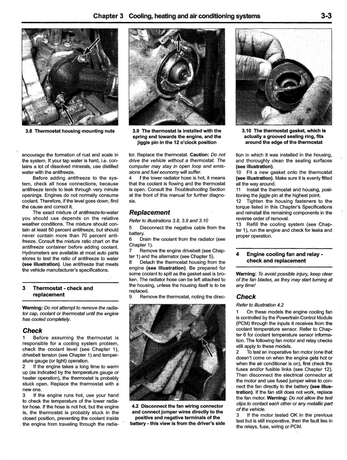
Ha
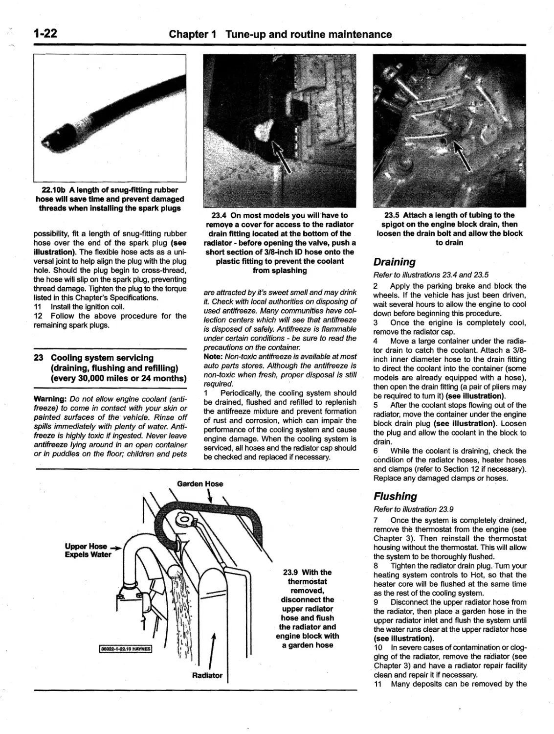
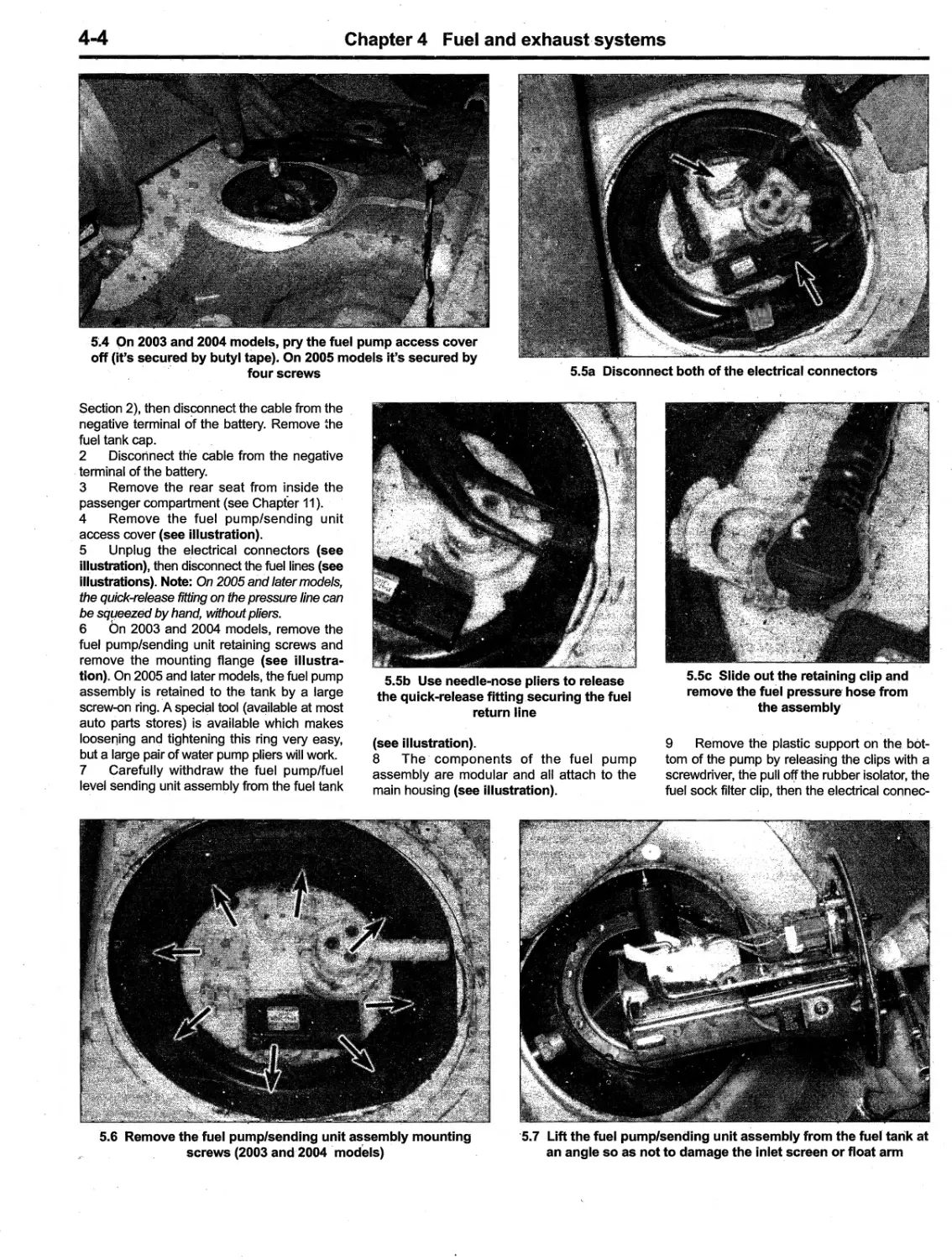
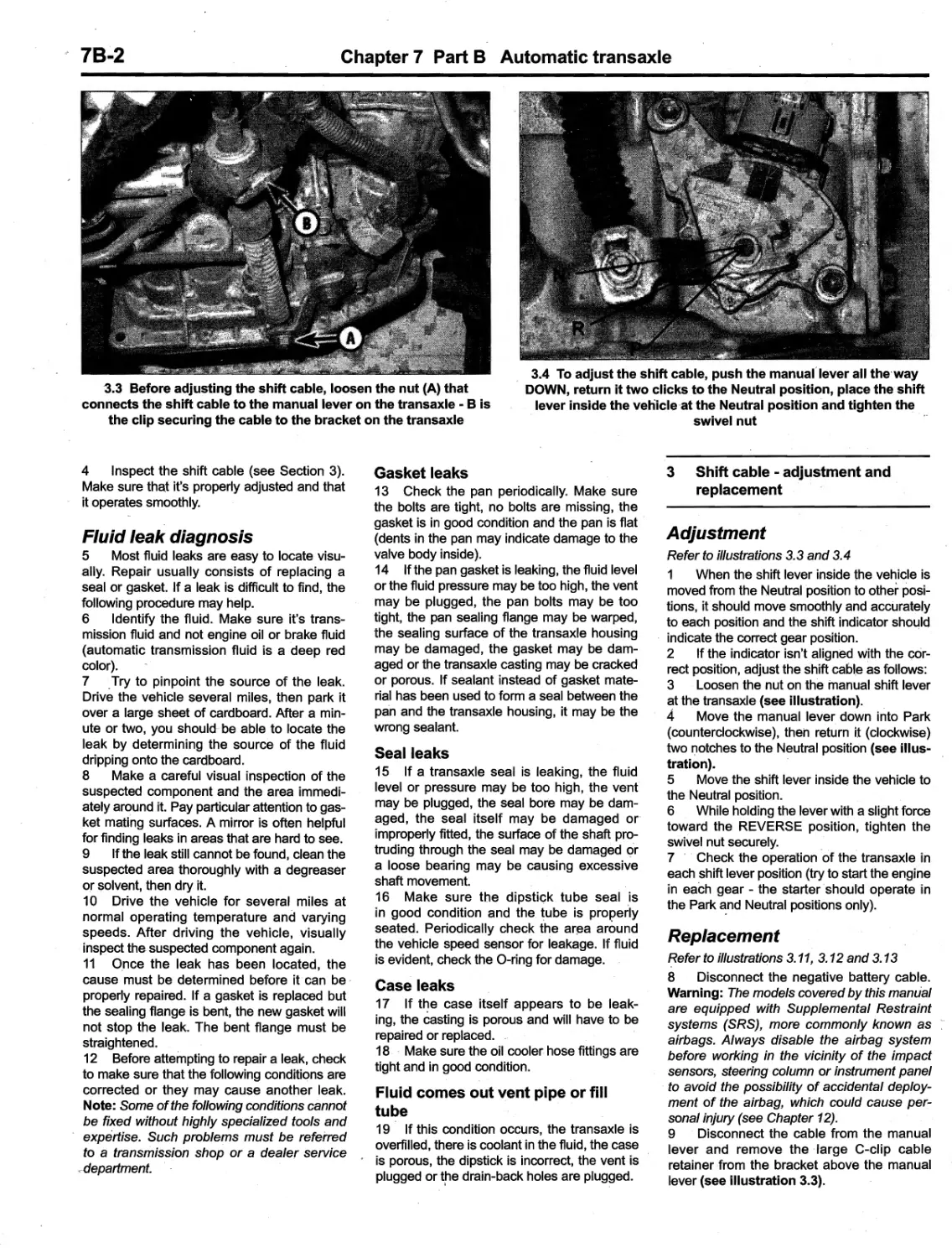
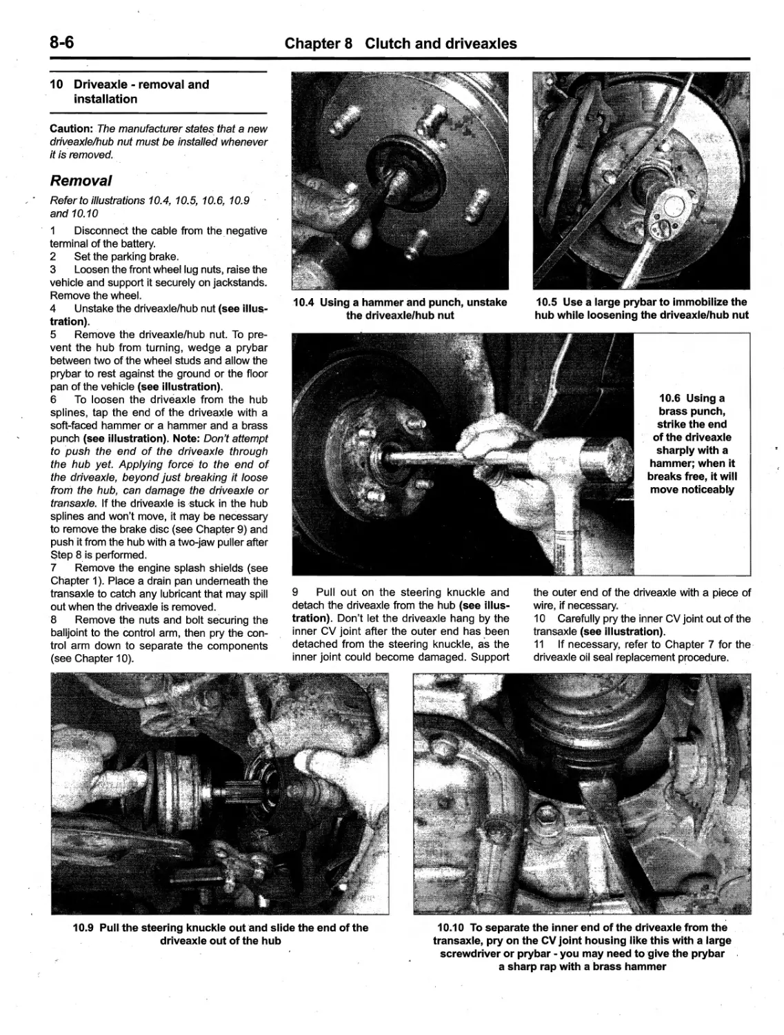
1
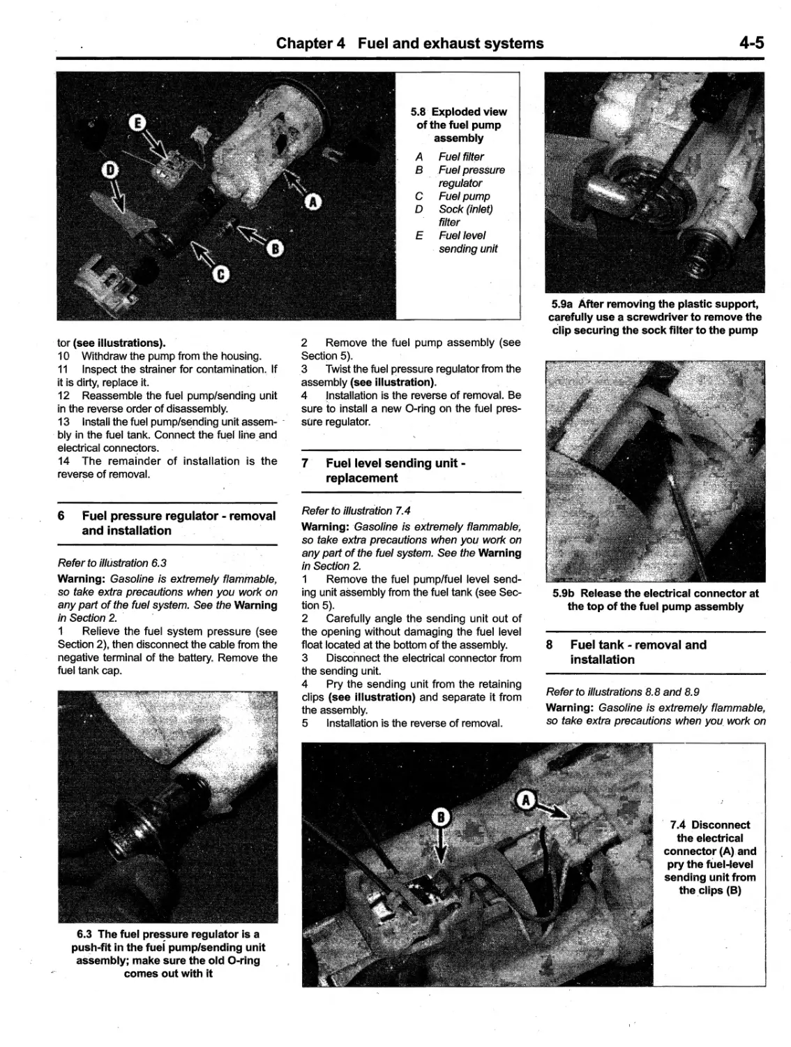
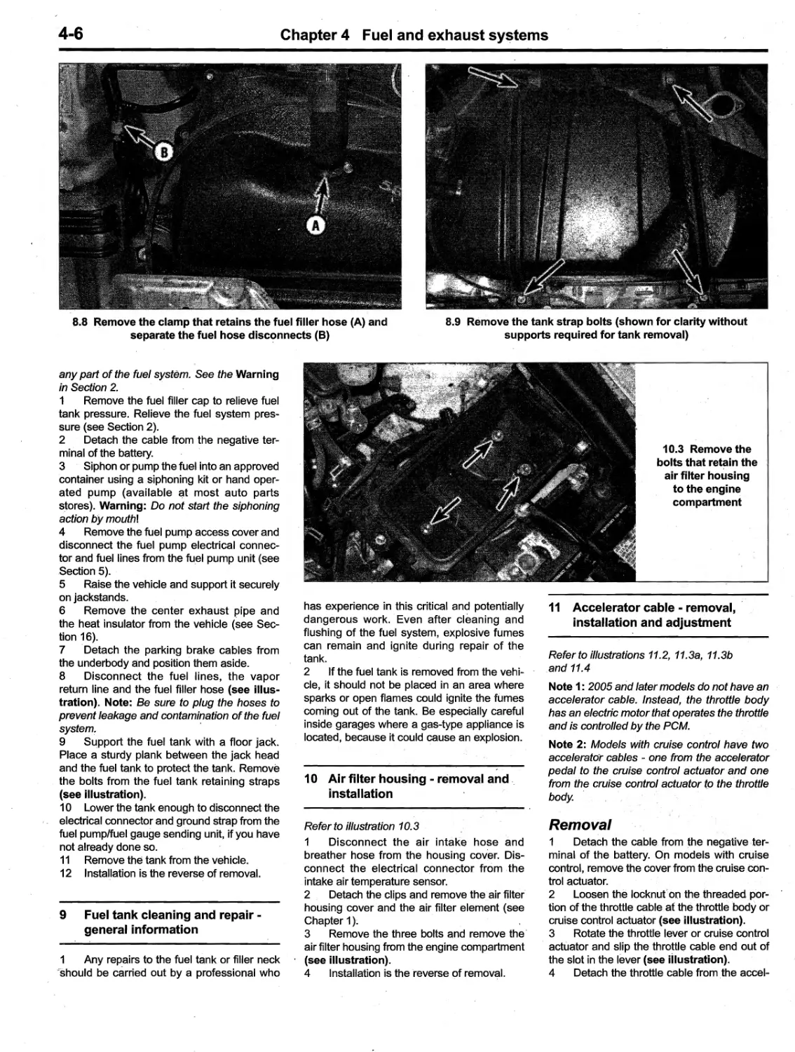
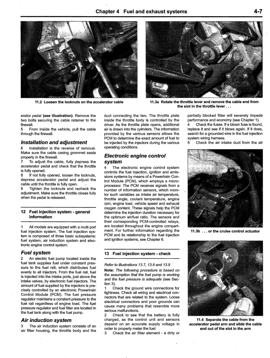
..... '-
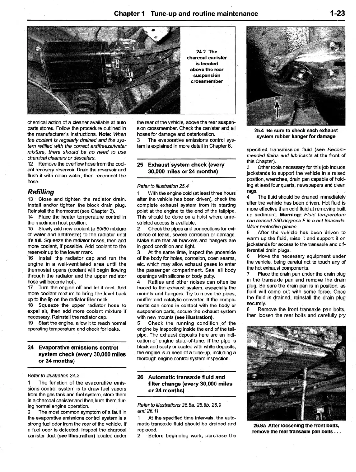
'.
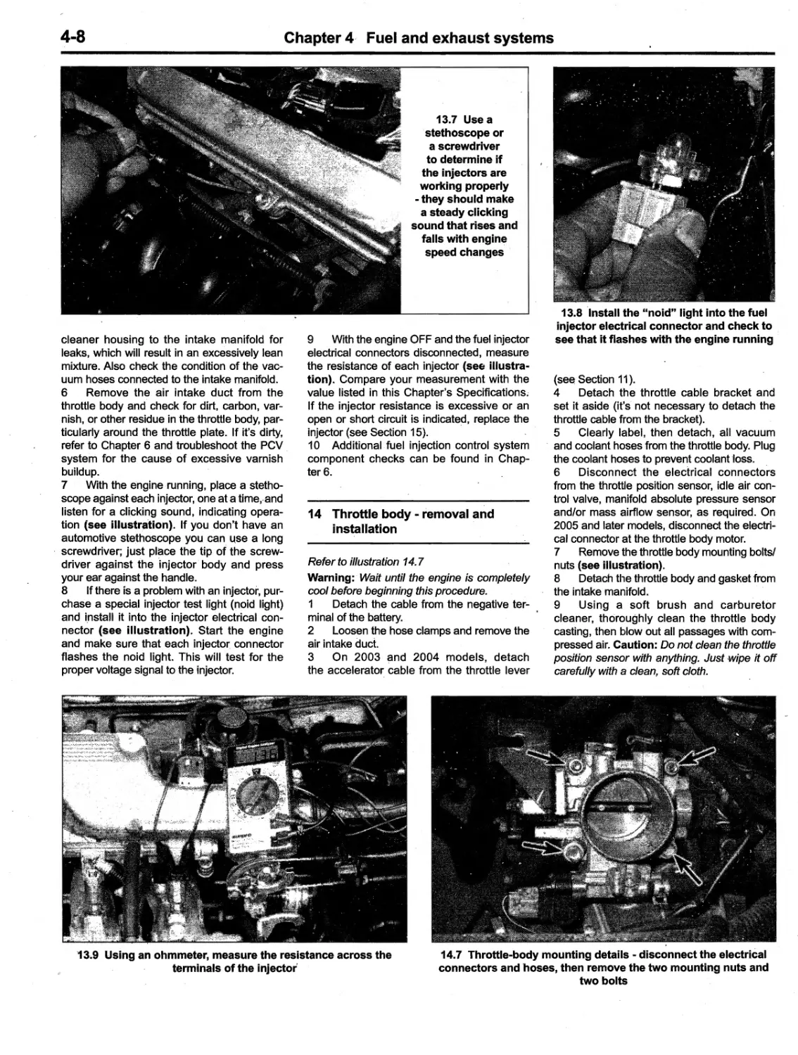
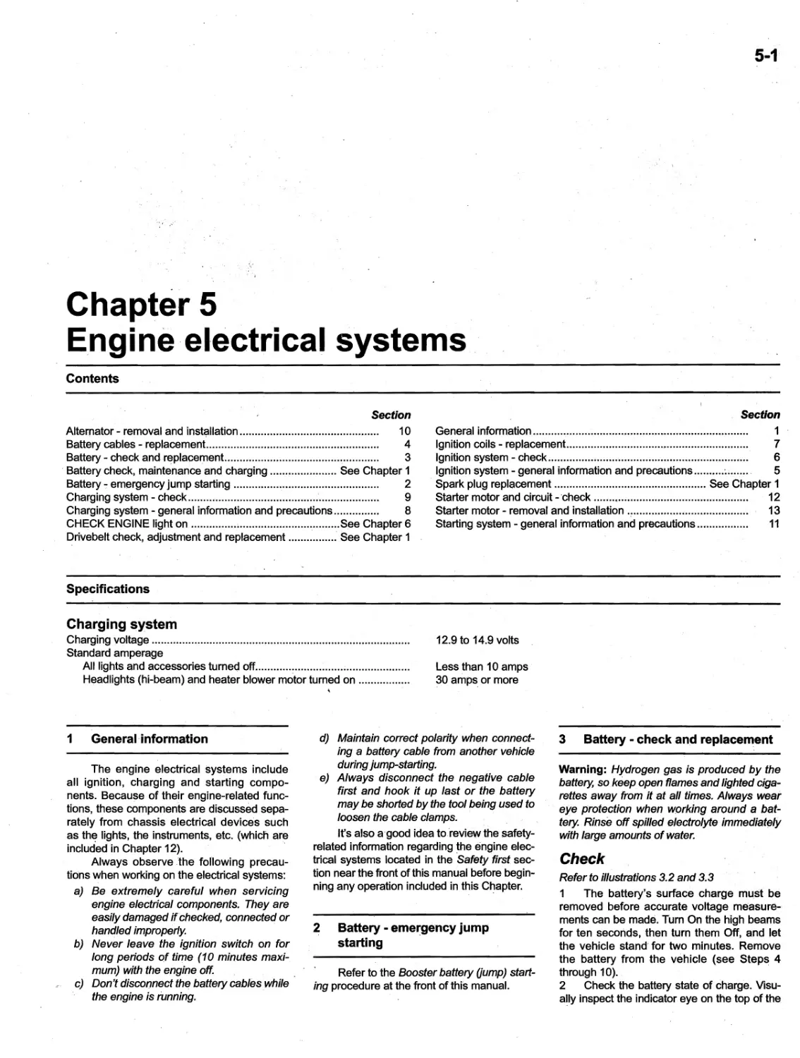
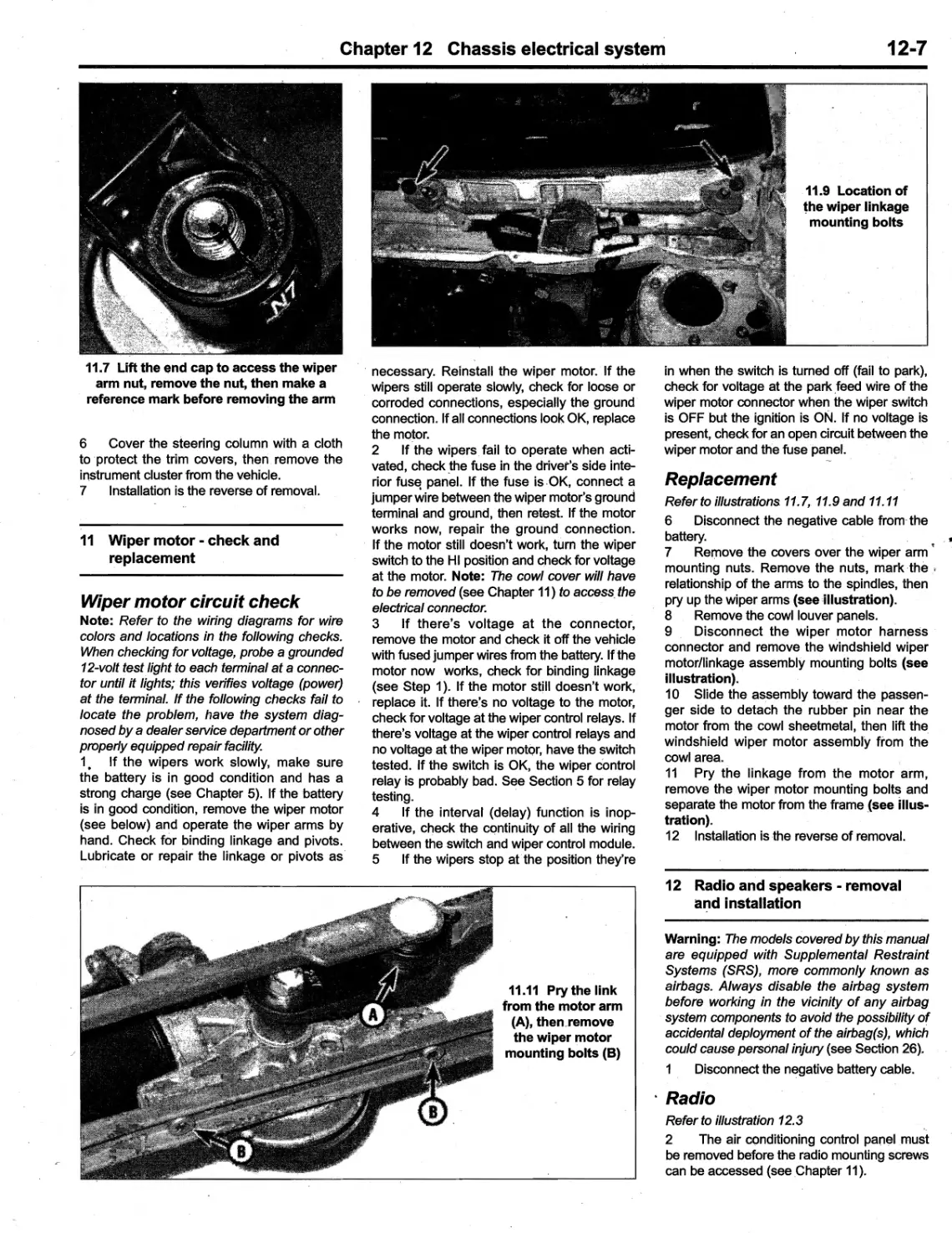
'-
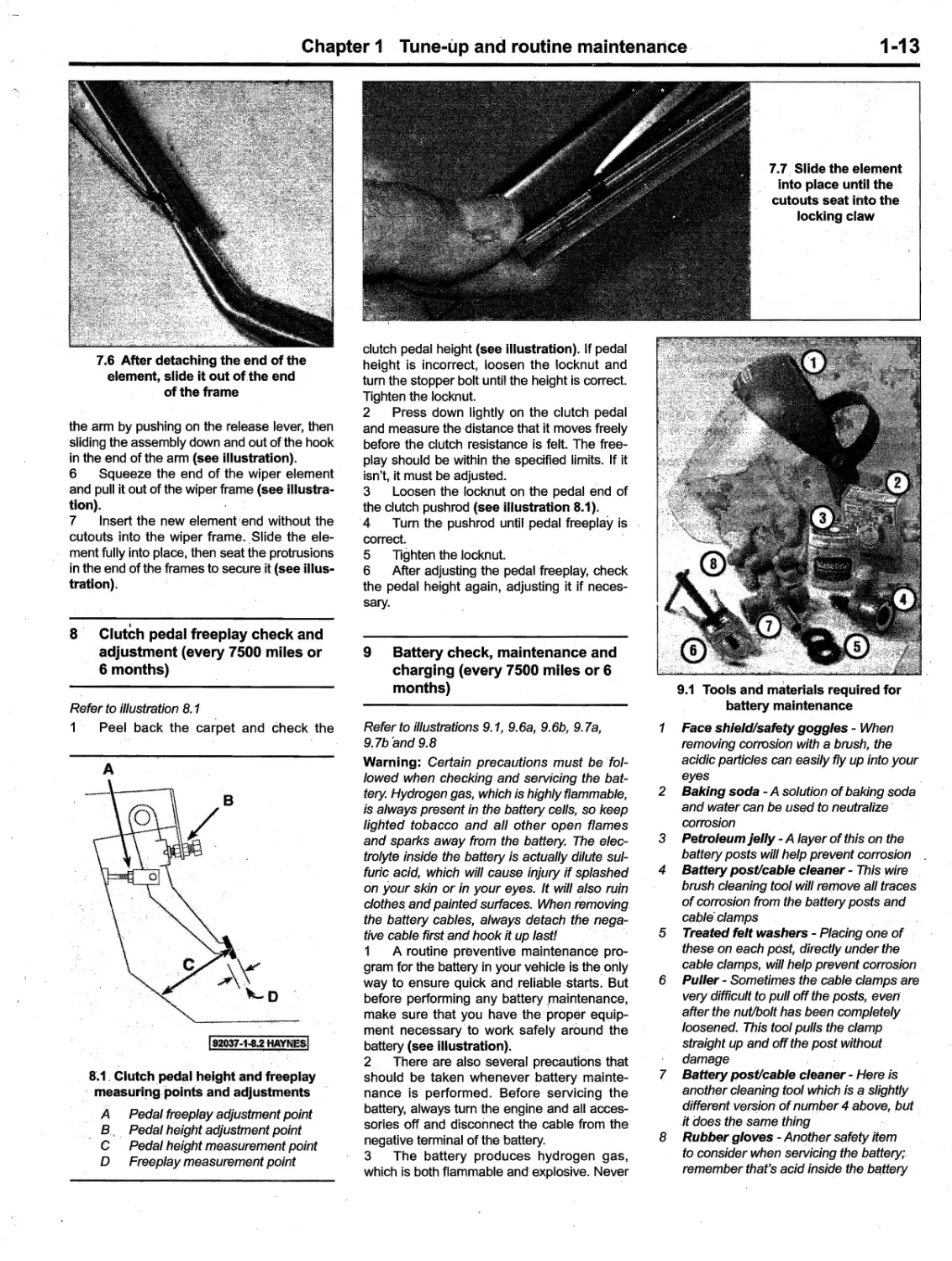
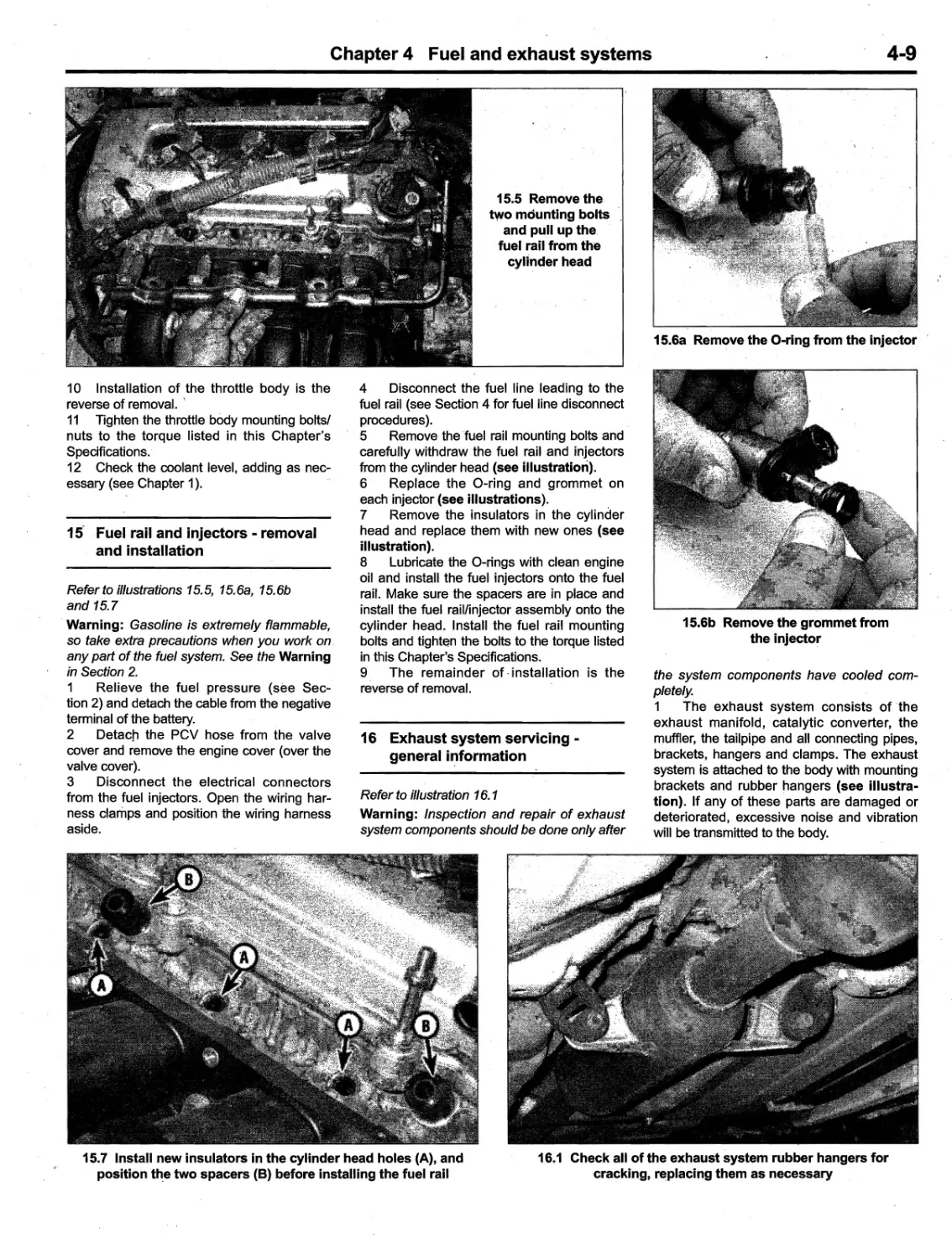
.
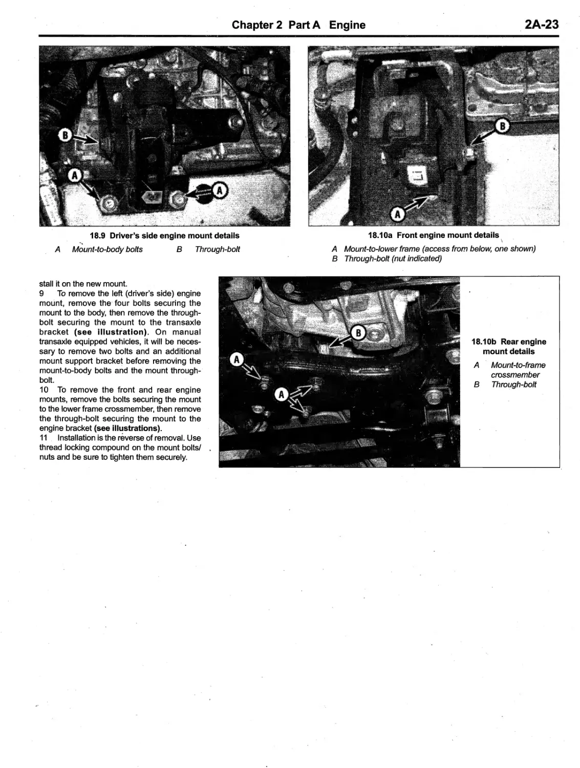
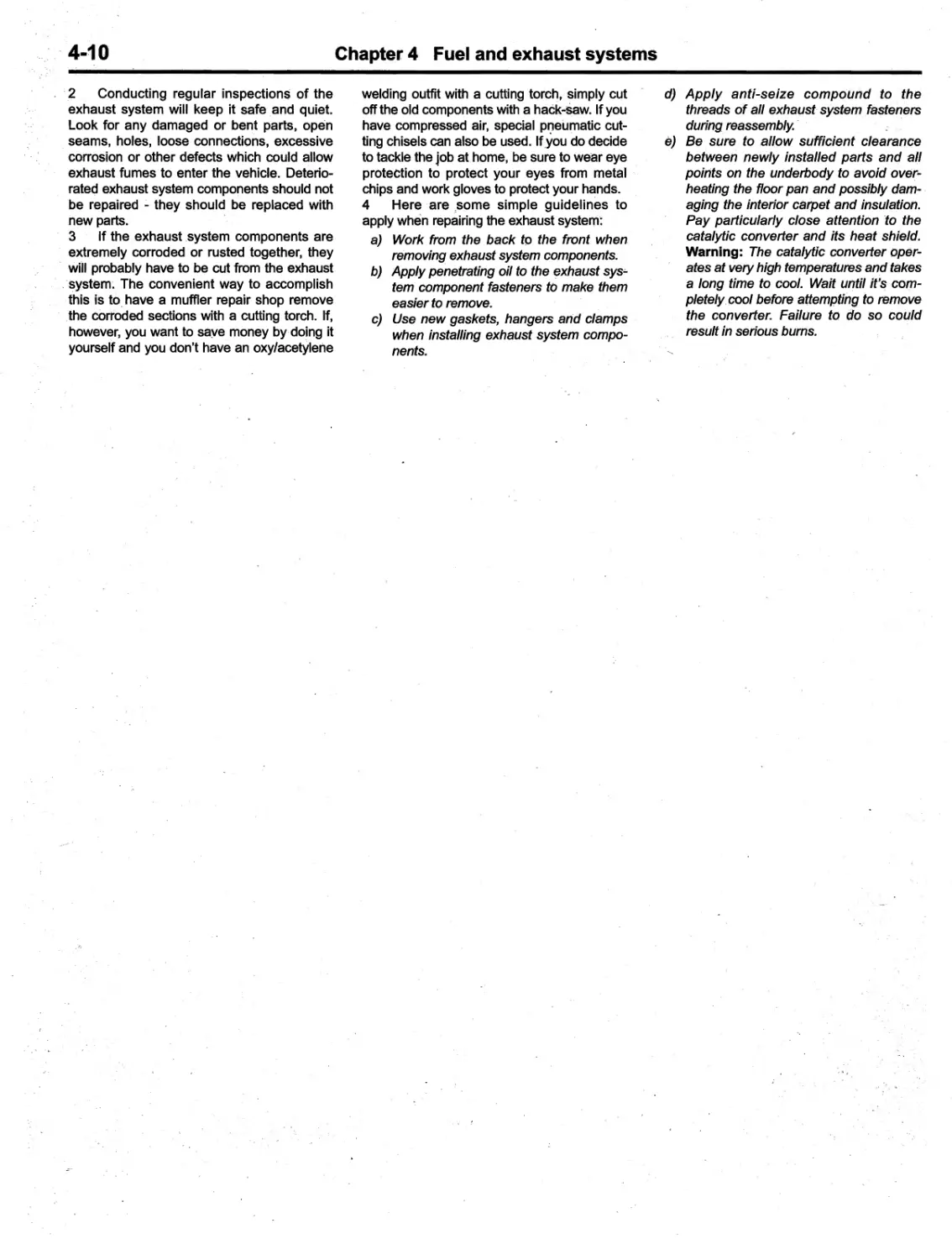
---....----
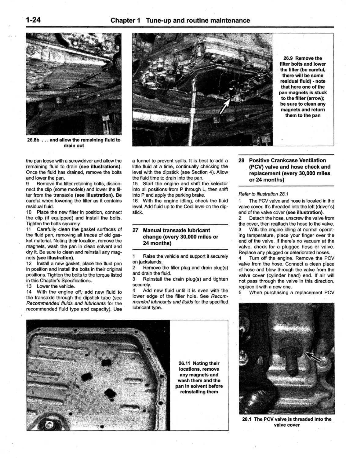
92037
· · t - · r .11-
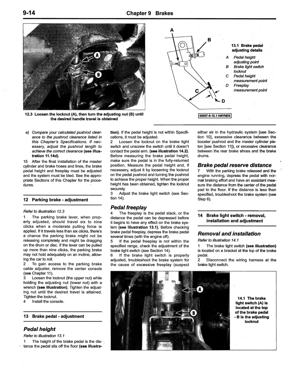
2003 thru 2008
'j;;)i/1,;.. ,,,,,;,;';;;';;',
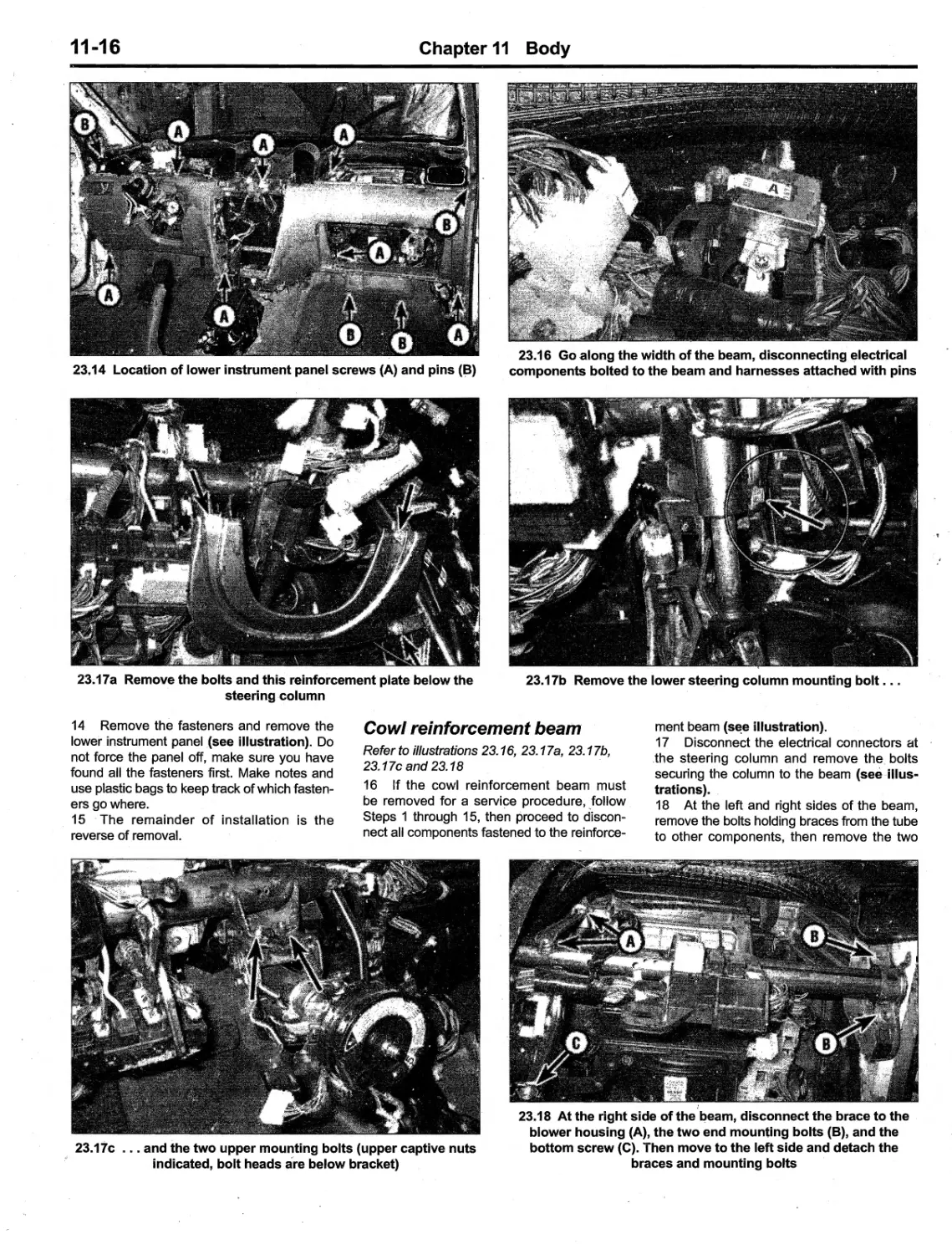
f/1'.?
t
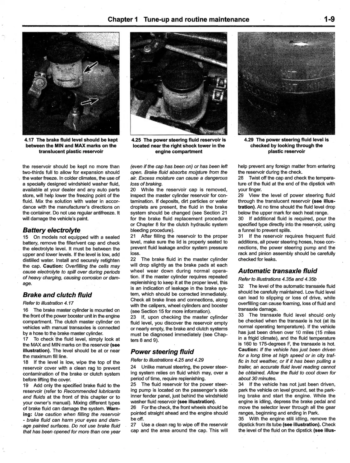
'
t
ayne ,
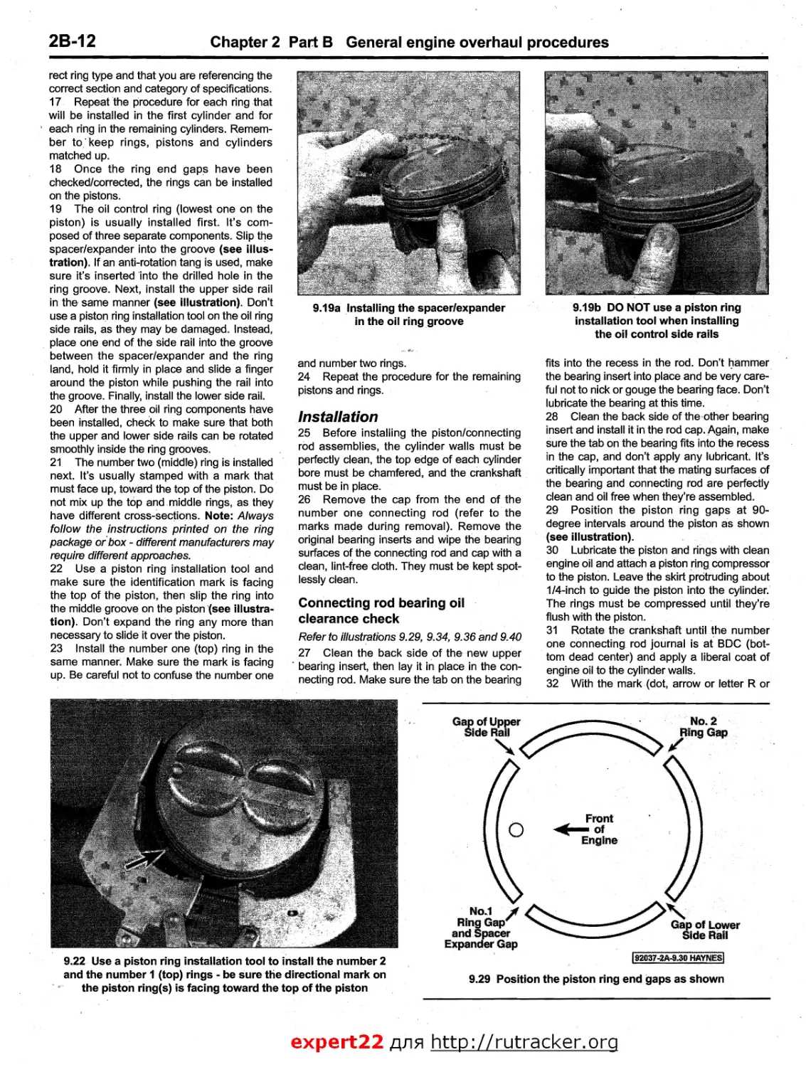
.
4":
l' '' -
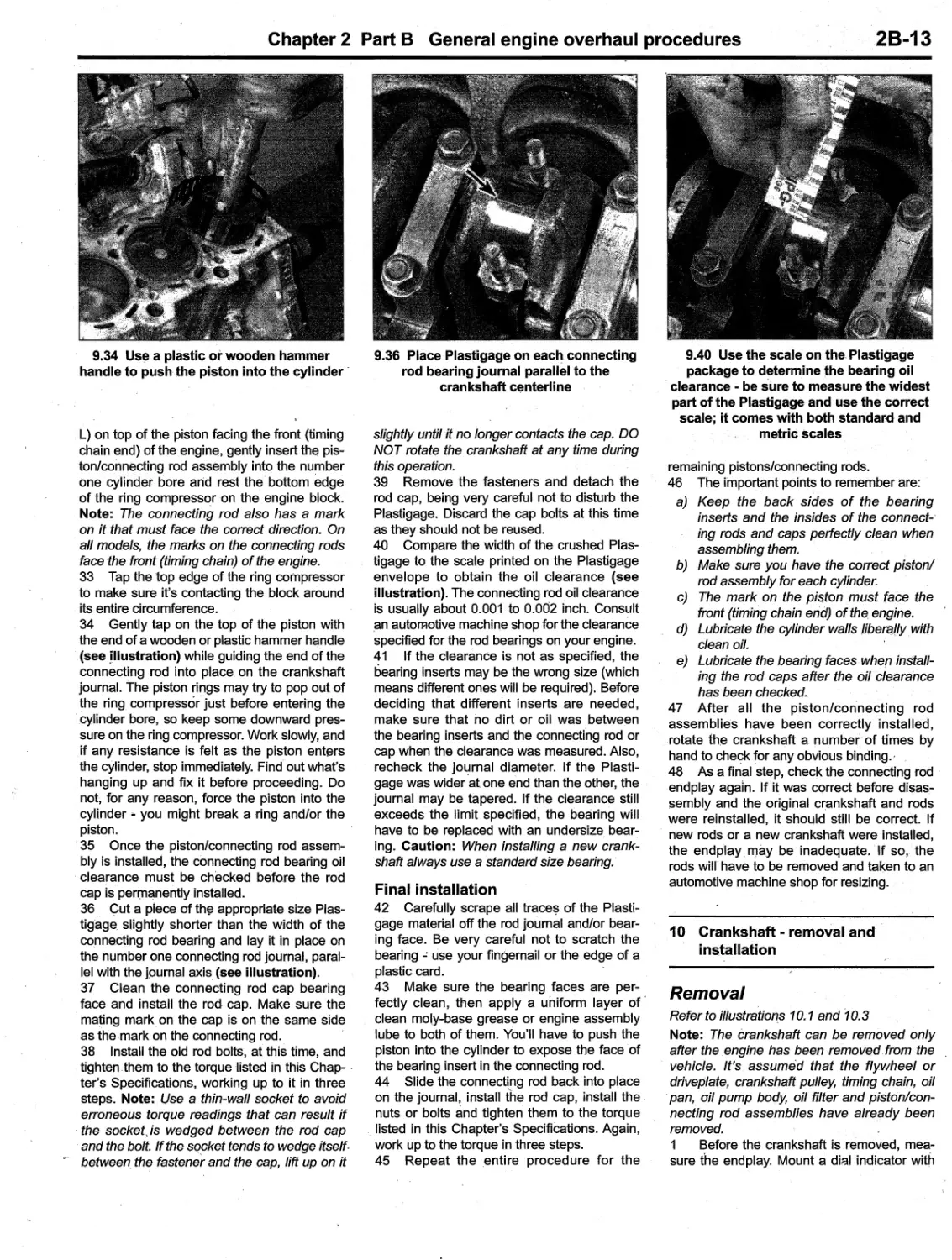
'\,,/
-, --_/
@
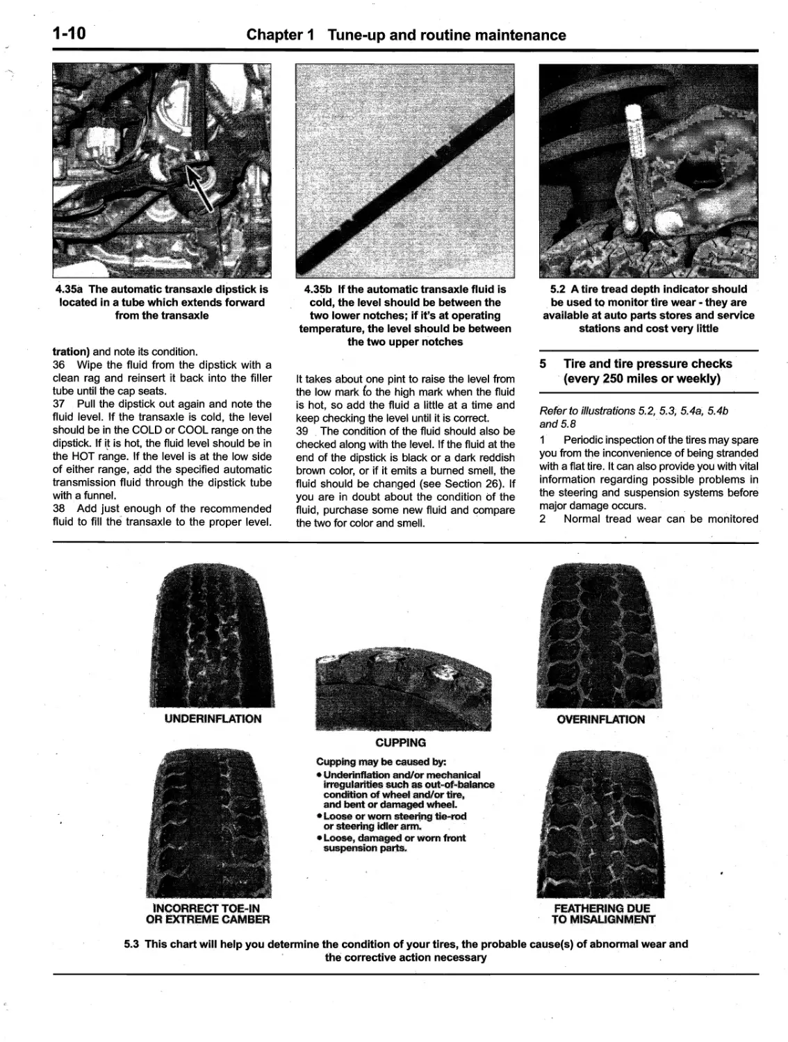
..
.
..
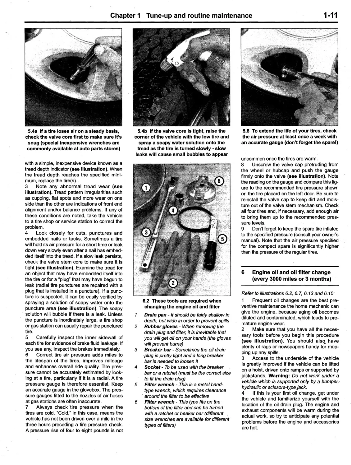
.
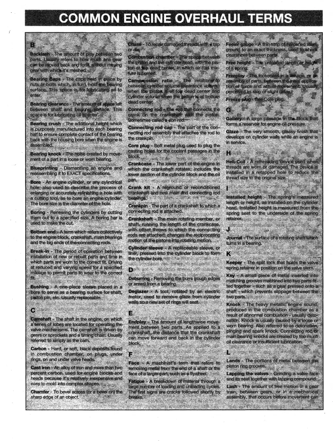
· ., If
tI/IJ
., I
fI/J
Based ona complete teardown and rebuild
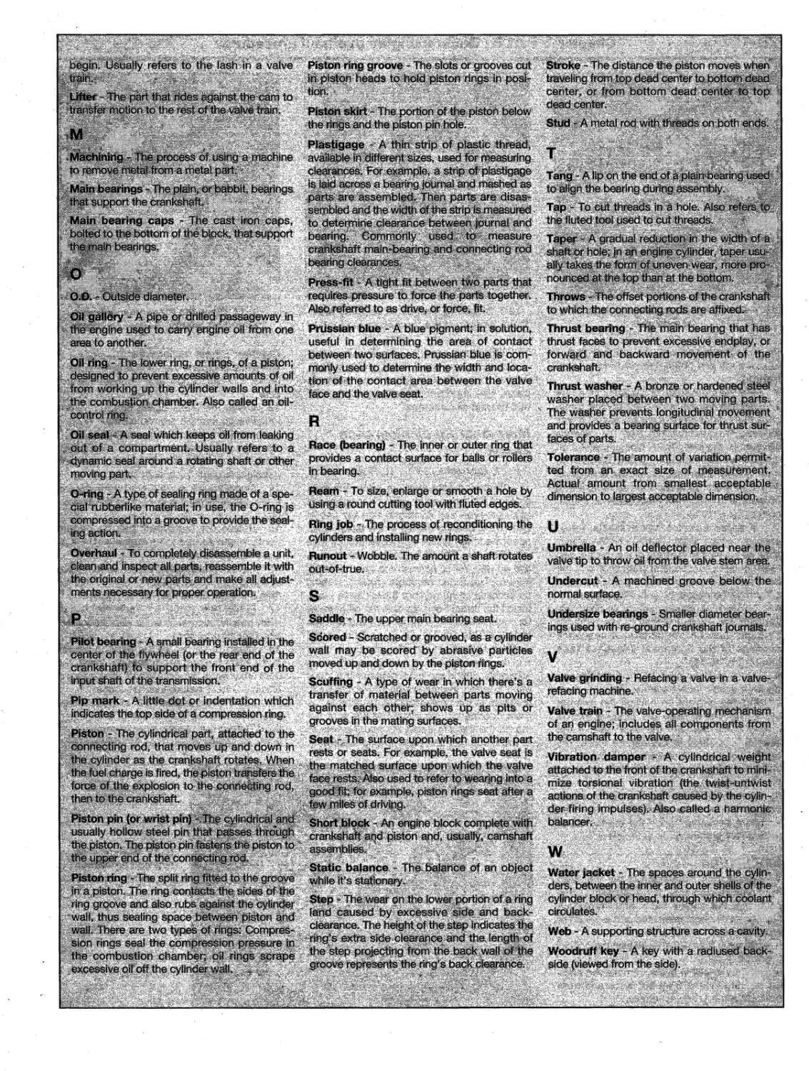
I
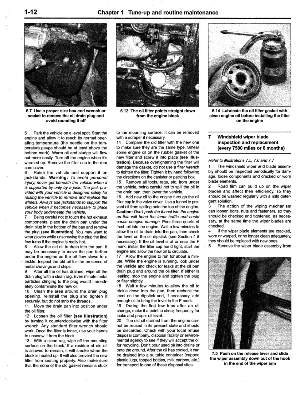
,.
',.
.
,..
"lit Ii
.... ,
..
.".
-
-.......,.
, ..
... ' IOU. . :tD'rre'.D 1s. ne
-_...
=".""_......,",,,
- .-..- , "'- --.
k,
'
"\
I
..
%...
", !
,expert22 An
htt rutracker.or
.
/_.....,t, _
..."'......'., 1-
.,'
'
" " <:
'i,"e: ,
i '
, -"--'-:a:t:.:;:.;:
r."
,::..,-
,''::'"",,
,----':.::::- ,
, "e"'"
, , , '".."
Includes essential information for today's more complex vehicles
Toyota
Corolla
Automotive
Repair Manua.1
by Jay Storer
and J.ohn H Haynes
Member of the Guild of Motoring Writers
Models covered:
Toyota Corolla models
, 2003 through 2008
Does not include information specific to XRS models
(1 N3 - 92037)
ABCDE
FGHIJ
KLMNO
PO
q j
,*
,
I . ,
Haynes
,g#JT
"l'.V
@
\
IWITS Et '
ACCESSCItII5S .
ASSOCIATION MEMBER
Haynes Publishin'g Group
, Sparkford Nr Yeovil
,
omerset BA22 7 JJ England
Haynes North America, Inc
861 Lawrence Drive
Newbury Park
, California 91320 USA
Acknowledgements
Wiring diagrams provided exclusively for Haynes North America,
Inc. by Solution Builders.
@ Haynes North America, Inc. 2006, 2010
With permission from J.H. Hayn'es & Co. Ltd.
A book in the Haynes Automotive Repair Manual Series
Printed in the U.S.A.
All rights reserved. No part of this book may be reproduced or transmitted
in any form or by any means, electronic or mechanical, including photo-
copying, recording or by any informatiQn storage or retrieval system, with-
out permissiQn in writing from the copyright holder.
ISBN.13: 978-1.56392.807.9
ISBN-1 0: 1.56392-8
7-8
Library of Congress Control Num
er 2009943517
While every attempt is made to ensure that the information in this man-
ual is correct, no liability can be accepted by the authors or publishers
for loss, damage or injury caused by any errors in, or omissions from,
the information given.
10-240
Contents
Introductory pages
About this manual 0-5
Introduction to the Toyota Corolla 0-5
Vehicle identification numbers 0-6
, Buying parts 0-7
Maintenance techniques, tools and working facilities 0...7
Jacking and'towing 0-14
Booster battery (jump) starting 0-15
Automotive chemicals and lubricants 0-16
Conversion factors 0..17
Fraction/decimal/millimeter equivalents 0-18
Safety first! 0-19
Troubleshooting 0-20
Chapter 1
Tune-up and routine maintenance 1-1
Chapter 2 Part A
Engines 2A-1
Chapter 2 Part B
General engine overhaul procedures 28-1
Chapter 3
Cooling, heating and air conditioning systems 3-1
Chapter 4
Fuel and exhaust systems 4-1
Chapter 5
Engine electrical systems 5
1
Chapter 6
Emissions and engine control systems 6-1
Chapter 7 Part A
Manual transaxle 7 A-1
Chapter 7 Part B
tomatic transaxle 78-1
Chapter 8
Clutch and driveaxles 8-1
Chapter 9
Brakes9-1
Chapter
0
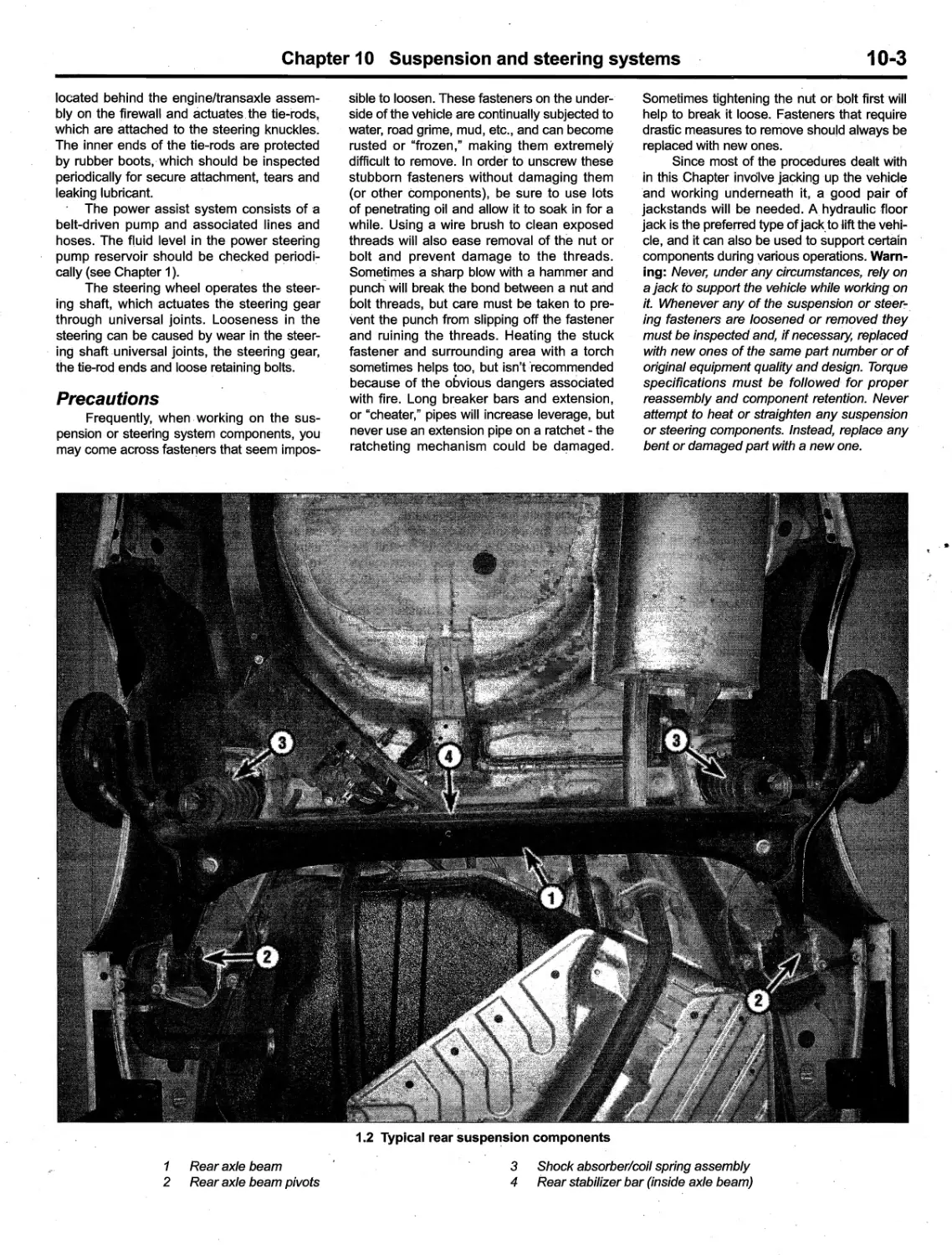
Sus'pension and steering systems 10-1
Chapter 11
Body 11-1
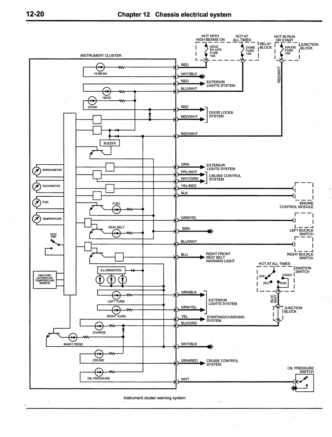
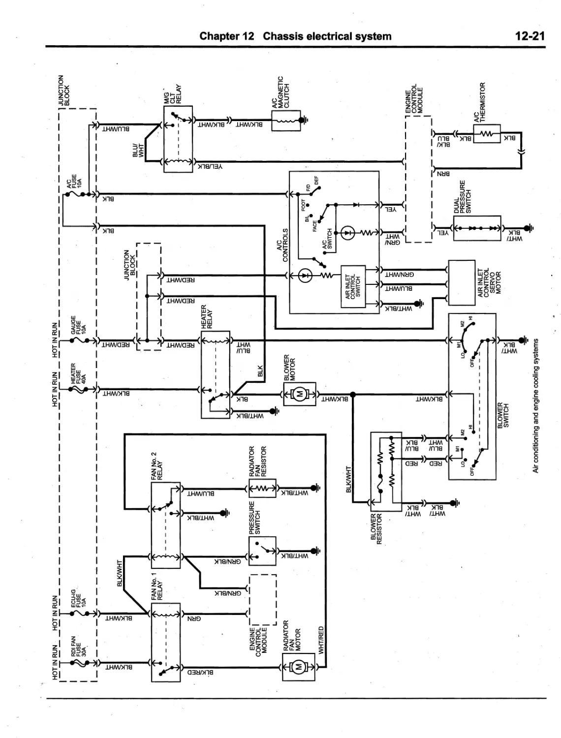
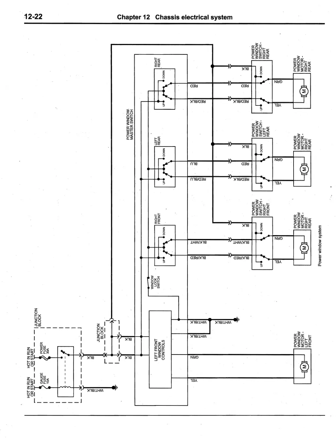
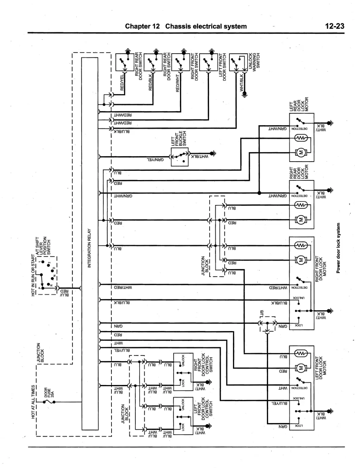
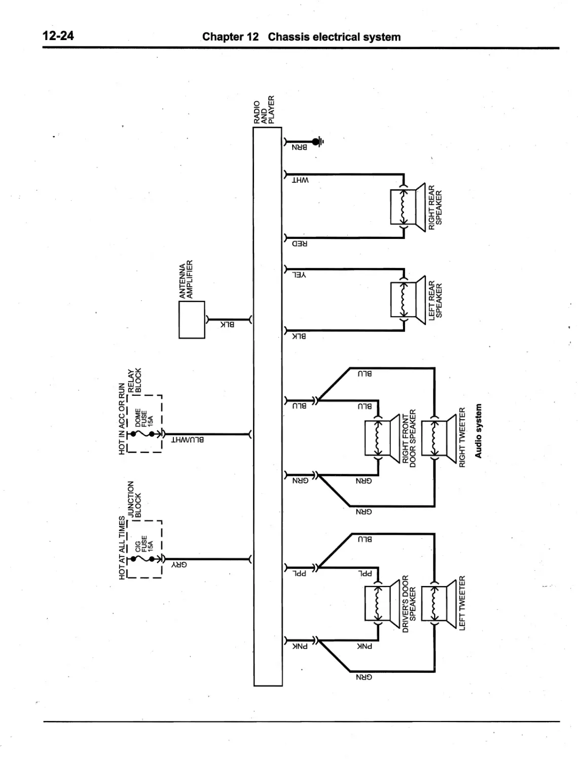
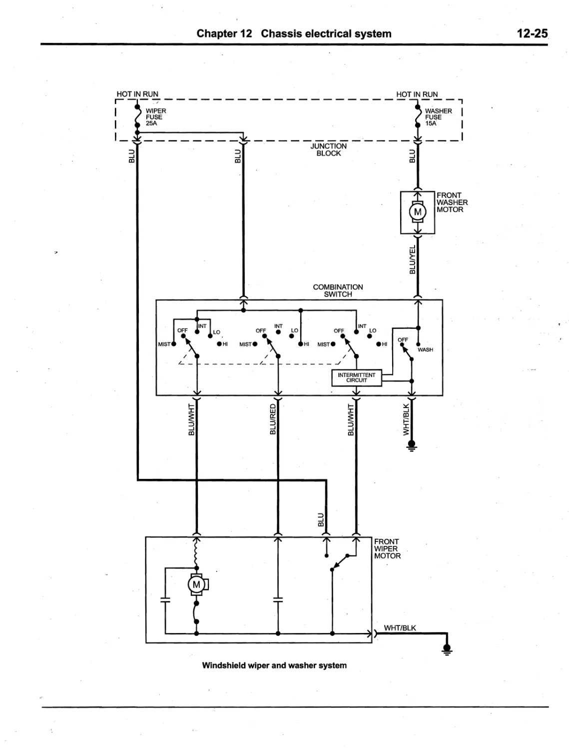
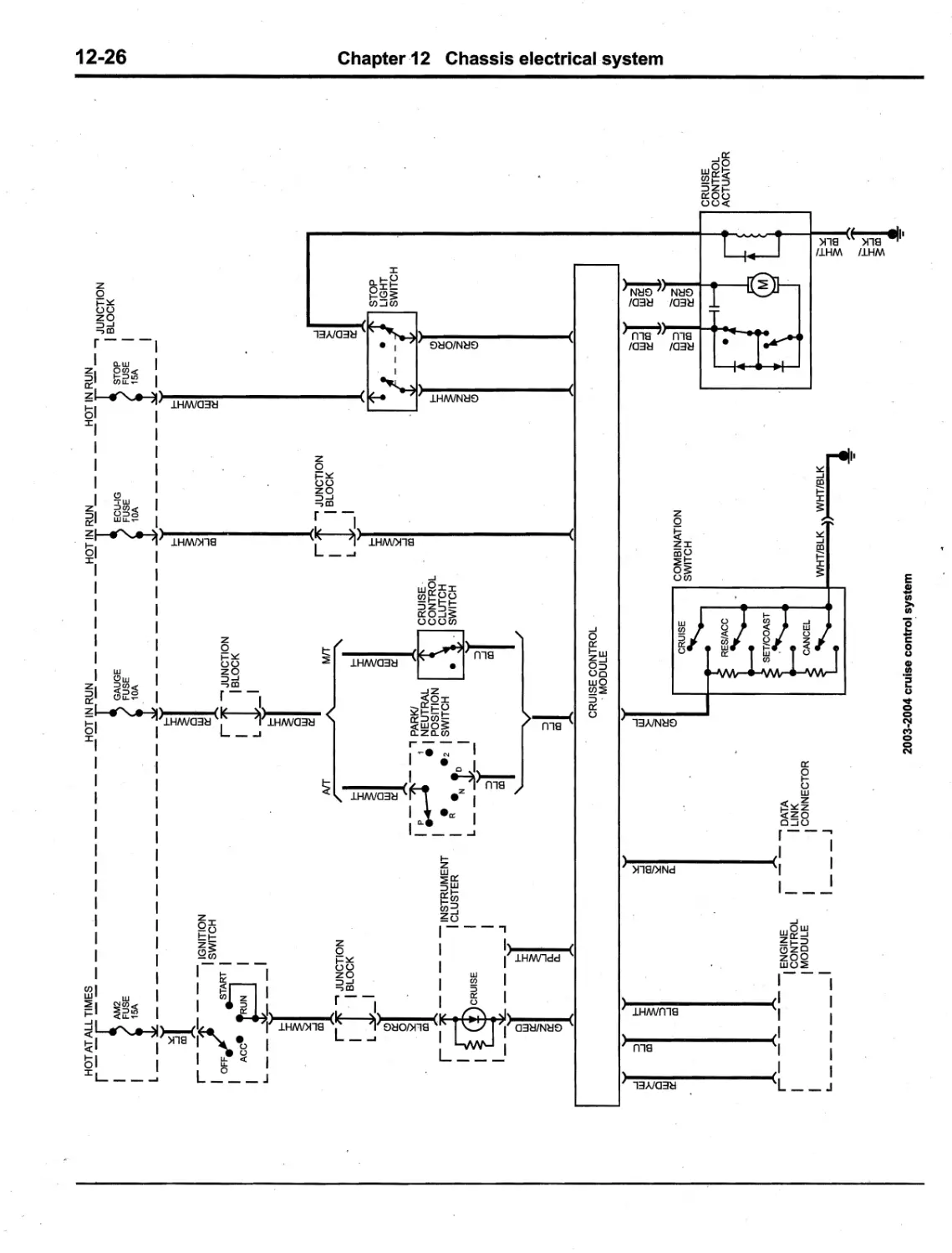
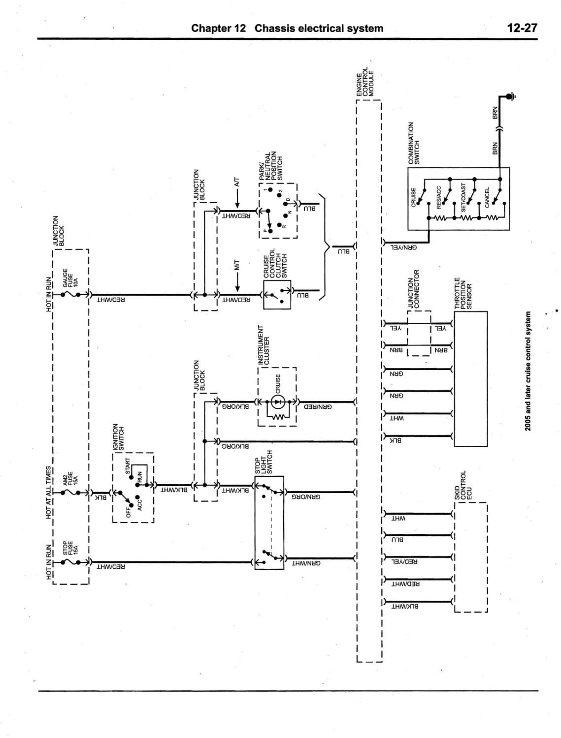
Chapter 12
Chassis electrical system 12
1
Wiring diagrams 12-16
Index IND-1
expert22 An
http://rutracker.org
0-4
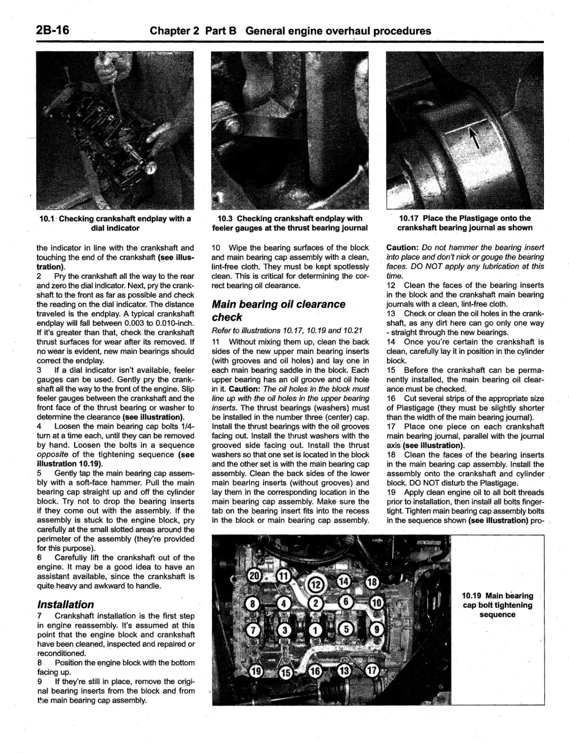
Haynes mechanic and photographer with a 2005 Toyota Corolla
About this manual
0-5
Its purpose
The purpose of this manual is to help you
get the best value from your vehicle. It can do
so in several ways. It can help you decide
what work must be done, even if you choose
to have it done, by a 'dealer service depart-
ment or a repair shop; it provides information
and procedures for routine maintenance and
servicing; and it offers diagnostic and repair
procedures to follow when trouble occurs.
We hope you use 'the m
nual to tackle
the work yourself. For many simpler jobs,
doing it yourself may be quicker than arrang-
ing an appointment to get the vehicle into a
shop and making the trips to leave it and pick
it up. More importantly, a lot of money can be
saved by avoiding the expense the shop must
pass on to you to cover its labor and overhead
costs. An added benefit is the sense of satis-
faction and accomplishment that you feel after
doing the job yourself.
Using the manual
The manual is divided into Chapters.
Each Chapter is divided into numbered Sec-
tions, which are headed in bold type between
horizontal lines. Each Section consists of con-
secutively numbered paragraphs.
At the beginning of each numbered Sec-
tion you will be referred to any illustrations
which apply to the procedures in that Section.
The reference numbers used in illustration
captions pinpoint the pertinent Section and
the Step within that Section. That is, illustra-
tion 3.2 means the illustration refers to Sec-
tion 3 and Step (or paragraph) 2 within tnat
S,ection.
Procedures, once described in the text,
are not normally repeated. When it's neces-
sary to refer to another Chapter, the reference
will be given as Chapter and Section number.
Cross references given without use of the
word "Chapter" apply to Sections and/or para-
graphs in the same Chapter. For e
ample,
"see Section 8" means in the same Chapter.
References to the left or right side of the
vehicle assume you are sitting in the driver's
seat, facing forward. ..
Even though we have prepared this
manual with extreme care, neither the pub-
lisher nor the author can accept responsibility
for any errors in, or omissions from, the infor-
mation given.
NOTE
A Note provides information necessary to properly complete a procedure or information which will
make the procedure easier to understand.
CAUTION
A Caution provides a special procedure or special steps which must be taken while completing th
procedure where the Caution is found. Not heeding a Caution can result in damage to the assembly
being worked on.
. WARNING
A Warning provides a special procedure or special steps which must be taken while completing the
procedure where the Warning is found. Not heeding a Warning ca,n result in personal injury.
Introduction to the Toyota Corolla
The Toyota Corolla models covered by
this manual are four-door sedans.
The transversely-mounted inline four-
cylinder engine' used in these vehicles is
equipped with electronic fuel injection.
The engine drives the front wheels
through either a five-speed manual transaxle
or a four-speed automatic transaxle via inde-
pendent driveaxles.
Independent suspension, featuring coil
spring/strut damper units, is used on the front
of the vehicle. The rack-and-pinion steering
unit is mounted behind the engine with power-
assist on most models. The rear suspension'
uses coi,l-over shock absorber assemblies,
connected to a pressed-steel beam-type axle.
The brakes are disc a
the front and
drums at the rear, 'with power-assist'standard.
An Anti-lock Brake System (ASS) is available
on all models", with optional Electronic Brake
Distribution (ESD) for better traction and han-
dling. ,
0-6
Vehicle identification numbers
Modifications are a continuing and
unpublicized process in vehicie manufactur-
ing. Since spare parts manuals and lists are
compiled on a numerical basis, the individual
vehicle numbers are essential to correctly
identify the component required.
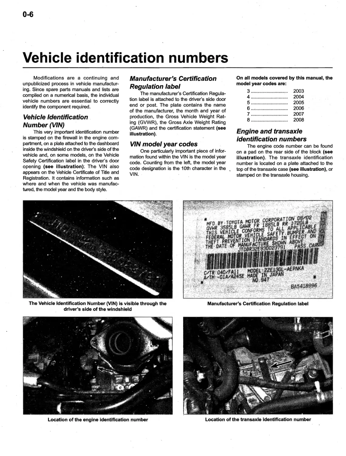
Vehicle Identification
Number (VIN)
this very important identification number
is stampe
on the firewall in the engine com-
partment, on a plate attached to the dashboard
inside the windshield on the driver's side of the
vehicle and, on some models, on the Vehicle
Safety Certification label in the driver's door
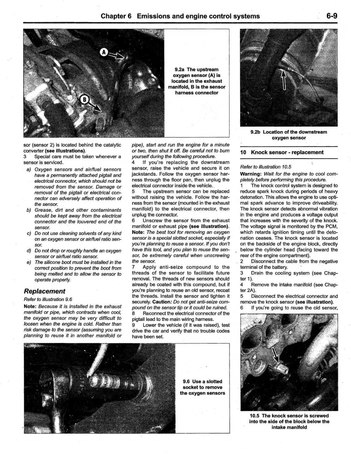
opening (see illustration): The VIN also
appears on the Vehicle" Certificate of Title and
Registration. It contains information such as
where and when' the veh icle was manufac-
bAred, the model year and the body style.
,#'",
,'# "
Manufacturer's Certification
Regulation label
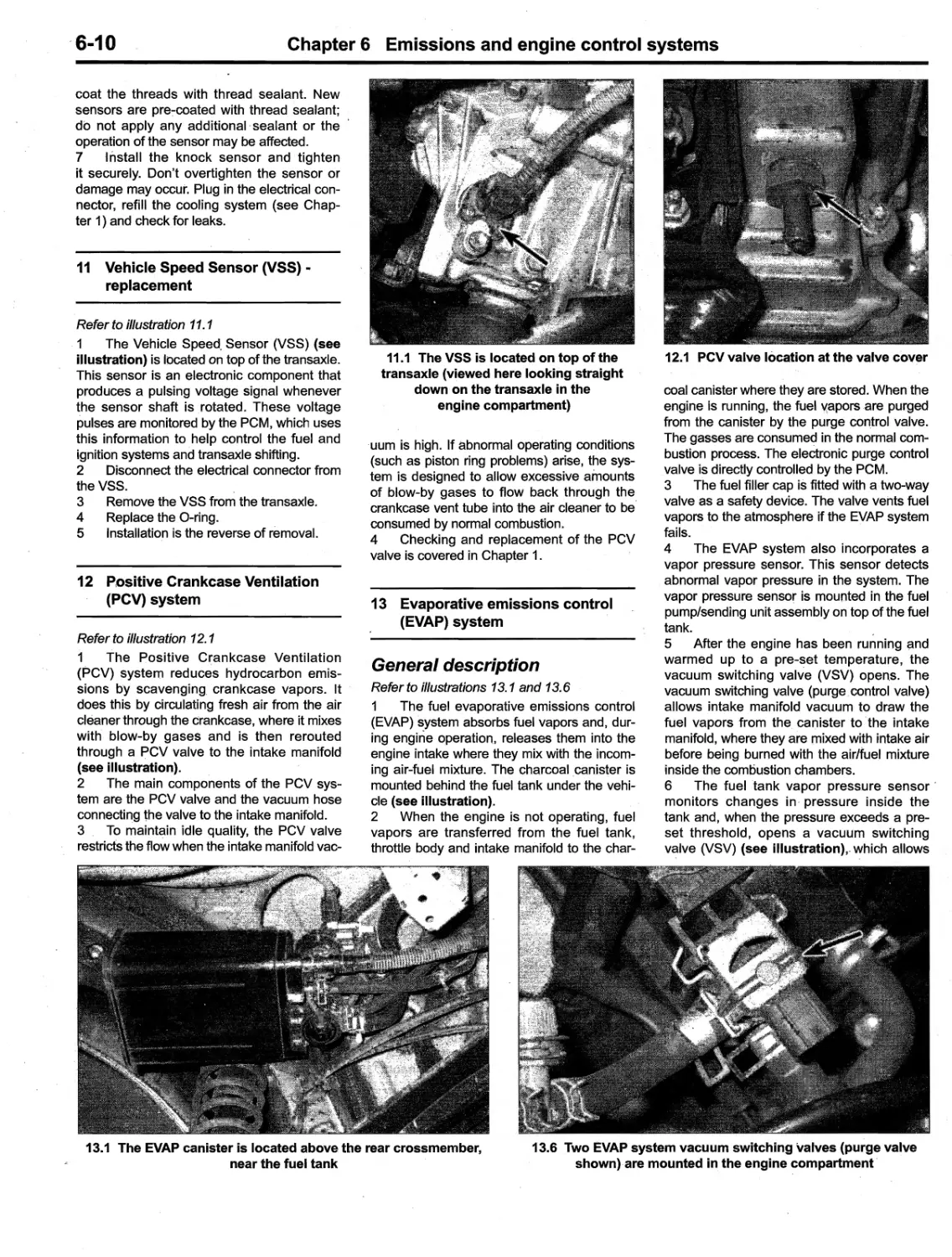
The manufacturer's Certification Regula-
tion label is attached to the driver's side door
end or post. The plate contains the name
of the manufacturer, the month and year of
production, the Gross Vehicle Weight Rat-
ing (GVWR), the Gross Axle Weight Rating
(GAWR) and the certification statement (see
illustration).
VIN model year codes
One particularly important piece of infor-
mation found within the VIN is the model year
code. Counting from the left, the model year
code designation is the 10th character in the ..
VIN.
. '.
The Vehicle Identification Number (VIN) is visible through the
driver's side of the windshield
w
.
};..t;.
,of
,.' "
Ji,
,.." , , :{
,, ':,
'-:::o::
: :-. -' . .
'W", :l
:
'
.'
':$'
'.."11_'11
""
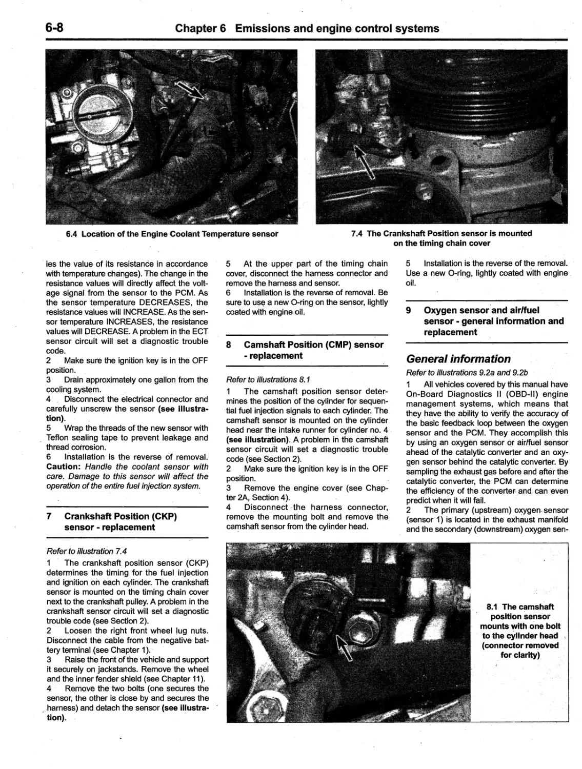
Location of the engine identification number
On all models covered by this manual, the
model year codes are:
3 ............................ 2003
4 .. ..... ..... ..... .... ....... 2004
5 ............................ 2005
6 ...'......................... 2006
7 ................... ......... 2007
8 ...........................;. 2008
Engine and transaxle
identification numbers
The engine code number can be found
on a pad on the rear side of the block (see
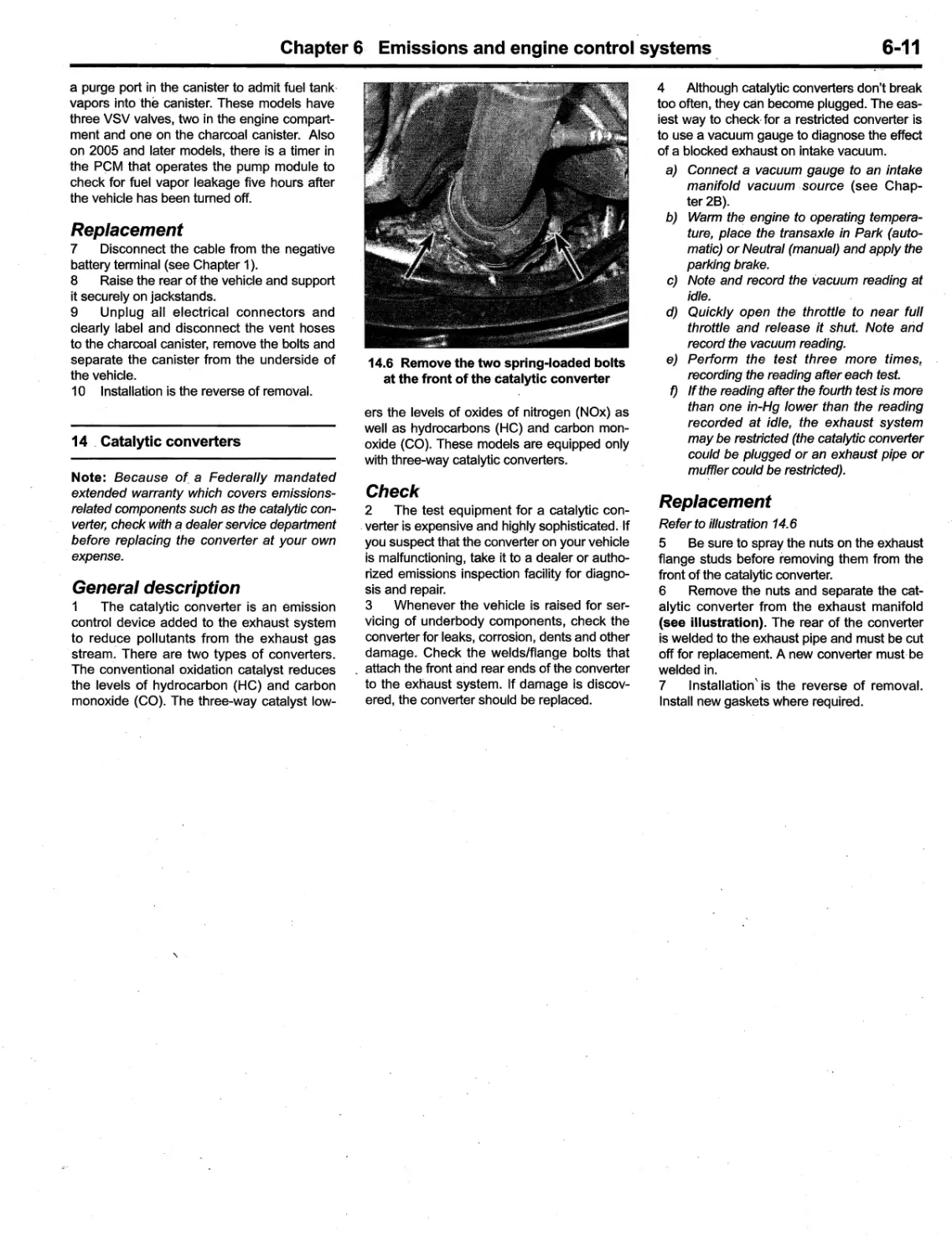
illustration). The transaxle identification
number is located on a plate attached to the
top of the transaxle case (see illustration), or
stamped on the trans
xle housing.
Manufacturer's Certification Regulation label
qIf..
\
Location of the transaxle identification number
Buying c parts
0-7
Replacement parts are available from
many sources, which generally fall into one
of -two categories - authorized deafer parts
departments and independent retail auto parts
stores. Our advice concerning these parts is
as fOllows:
Retail auto parts stores: Good auto
parts stores will stock frequently needed com-
ponents which wear out relatively fast, such
as clutch components, exhaust' systems,
brake parts, tune-up parts, e
c. These stores
often supply new or reconditioned parts on
an exchange basis, which can save a con-
siderable amount of money. Discount auto
parts stores are often very good places to
buy materials and parts needed for general
vehicle maintenance such as oil, grease, fil-
ters, spark plugs, belts, touch-up paint, bulbs,
etc. They also usually sell tools and general
accessories, have convenient hours, charge
lower prices and can often be found not far
from home.
Authorized dealer parts department:
-TJ)is is the best source for parts which are
Maintenance techniques,
tools and working facilities'
unique to the vehicle and not generally avail-
able elsewhere (such as major engine parts,
transmission parts, trim pieces, etc.).
Warranty information: If the vehicle
is still covered under warranty, be sure
that any replacement parts purchas-ed -
regardless of the source - do not invalidate
the warranty!
To be sure of obtaining the correct parts,
have engine and chassis numbers available
and, if possible, take the old parts along for
positive identification. '
, ,Maintenance techniques
There are a number of techniques
involved in maintenance and repair that will
be referred to throughout this manual. Appli-
cation of these techniques will enable the
home mechanic to be more efficient, better
organized and capable of performing the vari-
ous tasks properly, which will ensure that the
repair job is thorough and complete.
Fasteners
- Fasteners are nuts', bolts, studs and
screws used to hold two or more parts
together. There are a few things to keep in
mind when working with fasteners. Almost all
of them use a locking device of some type,
either a lockwasher, locknut, locking tab
or thread adhesive. AU threaded fasteners
should be clean "and straight, with undam-
, aged threads and undamaged corners on the
hex head where the wrench fits. Develop the
habit of replacing all damaged nuts and bolts
with 'new ones. Special locknuts with nylon or
fiber inserts can only be used once. If they are '.
removed, they lose their locking ability and
must be replaced with new ones.
Rusted nuts and bolts should be treated
with a penetrating fluid to ease removal and
prevent breakage. Some mechanics use tur-
pentine in a spout-type oil can, which works
, quite well. After applying the rust penetrant, -
let it work for a few minutes before trying to
loosen the nut or bolt. Badly' rusted fasten-
_ ers may have to be chiseled or sawed off or
removed with a special nut breaker, available
at tool stores.
If a bolt or stud breaks off in an assem-
bly, it can be drilled and removed with a spe-
cial tQol commonly available for this purpose.
Most automotive machine shops can perform
this task, as well as other repair procedures,
such as the repair of threaded holes that have
been stripped out.
Flat washers and lockwashers, when
removed from an assembly, should always
be replaced exactly as removed. Replace
any damaged washers with new ones. Never
use a lockwasher on any soft metal surface
(such as aluminum), thin sheet metal or
plastic.
Fastener sizes
For a number of reasons, automobile
manufacturers are making wider and wider
use of metric fasteners. Therefore, it is impor-
tant to be able to tell the -difference between
standard (sometimes called 'U.S. or SAE) and
metric hardware, since they cannot be inter-
changed.
All bolts, whether standard or metric, are
sized according to diameter, thread pitch and
length. 'For example, a standard 1/2 - 13 x 1
bolt is 1/2 inch in diameter, has 13 threads per
inch and is 1 inch long. An M12 - 1.75 x 25
metric bolt is 12 mm in diameter, has a thread ,
pitch of 1.75 mm (the distance between
threads) and is 25 mm long. The two bolts are
nearly identical, and easily confused, but they
are not interchC1lngeable. '
In addition to the differences in diameter,
thread pitch and length, metric and standard
bolts can also be distinguished by examining
the bolt heads. To, begin with, the distance
across the flats on a standard bolt head is
measured in inches, while the same dimen-
sion on a metric bolt is sized in millimeters,
0-8
Maintenance techniques, tools and working facilities
(the same is true for nuts). As a result, a stan-
dard wrench should not be used on a metric
bolt and a metric wrench should not be
used on a standard bolt. Also, most standard
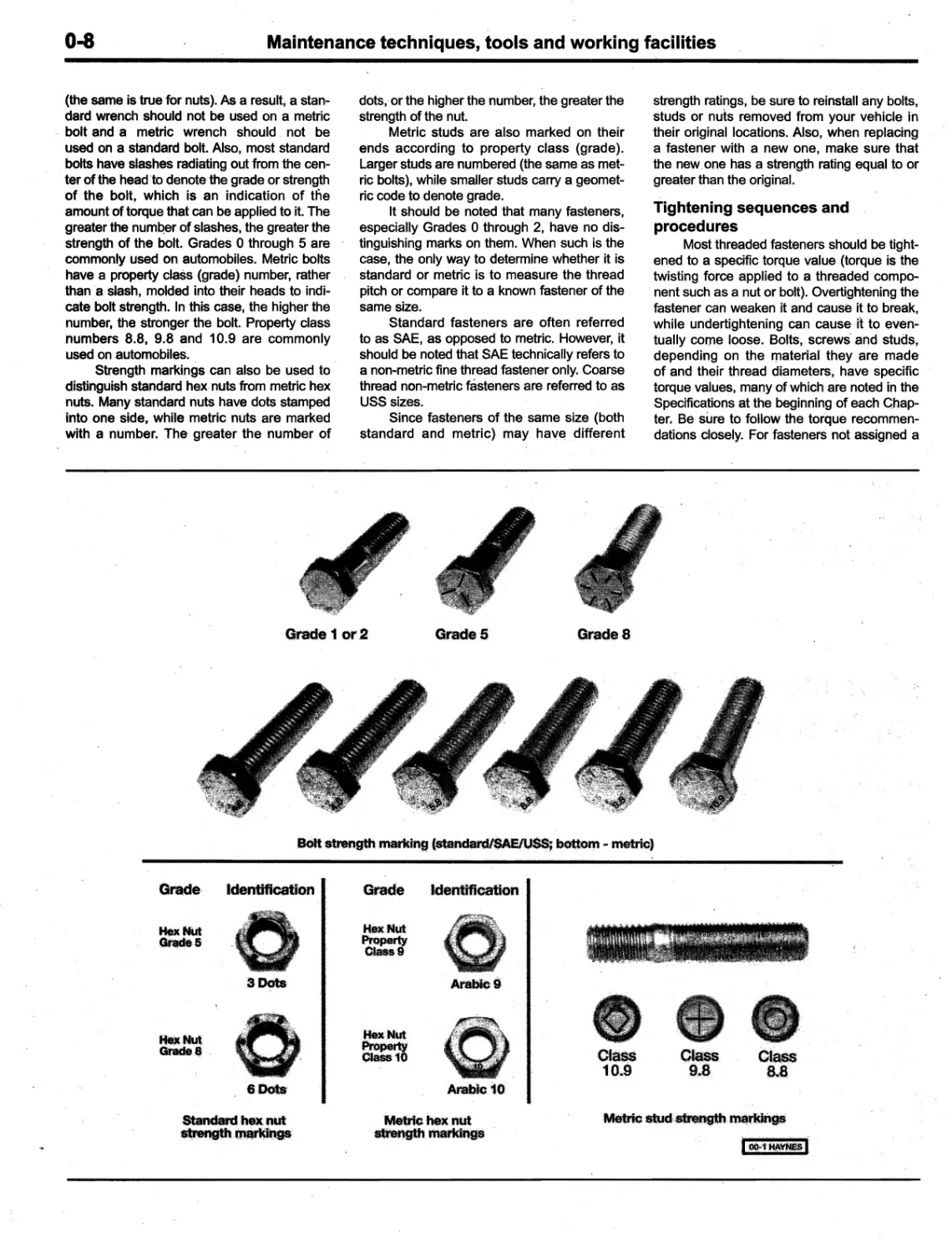
bolts have slashes radiating out from the cen-
, ter of the head 'to denote the grade or strength
of the bolt, which is an indication of tlie
amount of torque that can be applied to it. The
greater the numQer of slashes, the greater the
strength of the bolt. Grades 0 through 5 are
commonly used on automobiles. Metric bolts
have a property class (grade) number, rather
than a slash, molded into their heads to indi-
cate bolt strength. In this case, the higher the
number, the stronger the bolt. Property class
numbers 8.8, 9.8 and 10.9 are commonly
used on automobiles.
Strength markings can also be used to
distinguish standard hex nuts from metric hex
nuts. Many standard nuts have dots stamped
into one side, while metric nuts are marked
with a number. The gres'ter the number of
dots,'or the higher the number, the greater the
strength of the nut.
Metric studs are also marked on their
ends according to property class (grade).
Larger studs are numbered (the same as met-
ric bolts), while smaller studs carry a geomet-
ric code to denote grade.
It should be noted that many fasteners,
especially Grades 0 through 2, have no dis-
tinguishing marks on them. When such is the
case, the only way to determine whether it is
standard or metric is to measure the thread
pitch or compare it to a known fastener of the
same size.
Standard fasteners are often referred
to as SAE, as opposed to metric. However, it
should be noted that SAE technically refers to
a non-metric fine thread fastener only. Coarse
thread non-metric fasteners are referred to as
USS sizes.
Since fasteners of the same size (both
standard and metric) may have different
strength rati
gs, be sure to reinstall any bolts,
studs or nuts removed from your vehicle in
their original locations. Also, when replacing
a fastener with a new one, make sure that
the new, one has a strength rating equal to or
greater than the original.
Tightening sequences and
procedures
Most threaded fasteners should be tight-
ened to a specific torque value (torque is the
twisting force applied to a threaded compo-
nent such as a nut or bolt). Overtightening the
fastener can weaken it and cause it to break,
while undertightening can cause it to even-
tuallycome loose. Bolts, screws' and studs,
depending on the material they are made
of and their thread diameters, have specific
torque values, many of which are noted in the
Specifications at the beginning of each Chap-
ter. Be sure to follow the torque recommen-
dations closely. For fasteners not assigned a
Grade 1 or 2
GradeS
Grade 8
,BOlt strength marldngfstandardl8AElUSS; bottom", metric)
Grade, ldentificatian
Hex NUt
G_,6
3 Dots
Hex Nut,
Grade ..
: V'--_
.
_ :¥
\_ .,:.W);'
C-
:
."
?- ..
W
::
:
.f,."
:i/..." ,;
..;_. "__
\
6 Dots,
Standard,hex,!,ut
etrenGth .Q1arl(ir:ags
Grade
Hex Nut
perty
018889
Hex Nut
PropertY
01a$810
Identification
Arabic 9
Ctau
1 0..9
ArabIc 10
Class
9
8
Class
8.8
Metric hex nut
strength markings
Metric: &tud
U' , rtJ$rldl1_
It)O
1:
-t:
0-9
'Main.tenance techniques, tools and working facilities
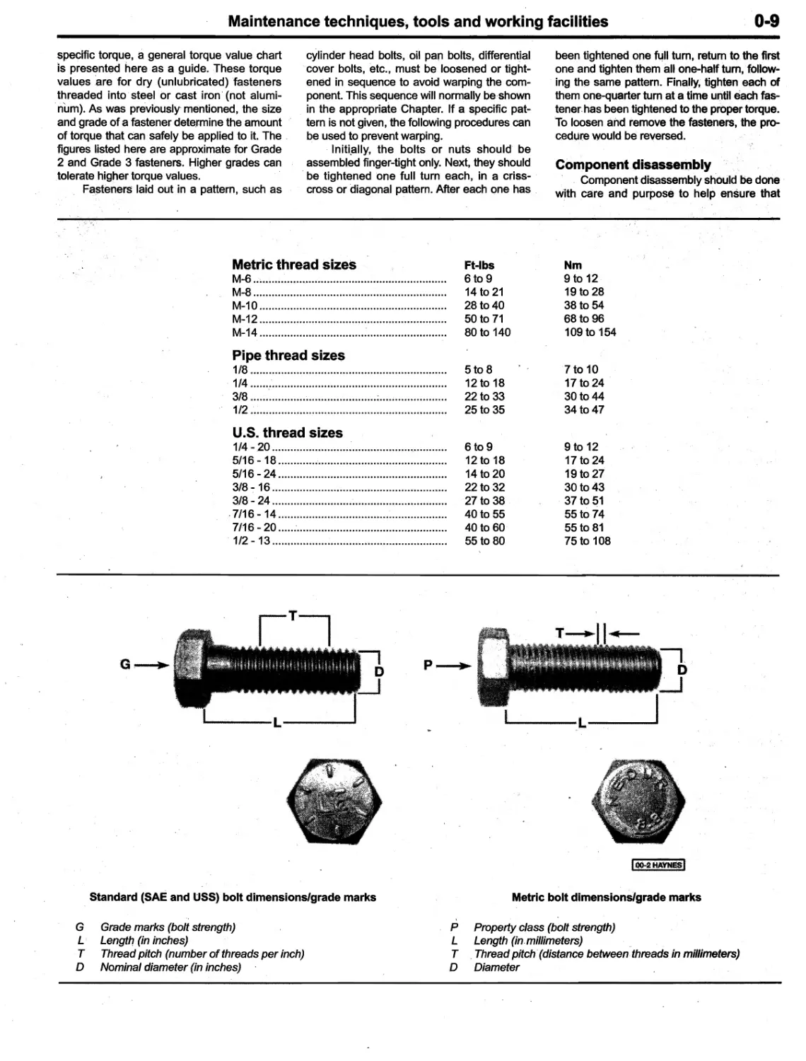
specific torque, a general torque value chart
is presented here as a guide. These torque
va,lues
are for dry (unlubricated) fasteners
threaded into steel or cast iron' (not alumi-
. num). As was previously'mentioned, the size
and grade of a fastener determine the amount
of torque that can safely be applied to it. The
figures listed here are approximate for Grade
2 and Grade 3 fasteners. Higher grades can
tolerate higher torque values.
Fasteners laid out in a pattern, such as
been tightened one f,-,II turn, return to the first
one and tighten them all one-half turn, follow-
ing the same pattern. Finally, tighten each of
them one-quarter turn at a time until each fas-
tener. has been tightened to the proper torque.
'To loosen and remove the fasteners, the pro-
cedure would be reversed.
cylinder head bolts, oil pan bolts, differential
cover bolts, etc., must be loosened or tight-
ened in sequence to avoid warping the com-
ponent. This sequence will normally be shown
in the appropriate Chapter. If a specific pat-
tern is not given, the following procedures can
be used to prevent warping.
, Inittally, the bolts or nuts should be
assembled finger-tight only. Next, they should
be tightened 'one full turn each, in a criss-
cross or diagonal pattern. After each one has
Component disassembly
Component disassembly shOuld be done
w
th care and purpose to help ensure that
Metric thread sizes
M-6 ..
..... ..
. .... .,................ .......... ....................
M-8 ...............................................................
M-1 0 .............................................................
M-12 .............................................................
M-14 .............................................................
Pipe thread sizes
1/8 ......... ........................................ ....... ........
1/4 ......:........................... ......... .....................
3/8 ........................................ .;........... ... ........
1/2 ;...............................................................
U.S. thread sizes
1/4 - .20 ..............................................,............
5/16 - 18........... ..'......... ... .......... .... ....... ...... ...
5/16 - 24.......................................................
3/8 ":' 16 ................... ...... .......... ......... ........ ......
3/8 - 24 .........................................................
,7/16 - 14.......................................................
71-16 - 20 ......'.......................................,.«......«.
, 1/2 - 13.......................................,..................
Ft-Ibs
6t09
14 to 21
28 to 40
50 to 71
80 to 140
Nm
9 to 12
19 to 28
38 to 54
68 to 96
109 to '154
5t08
12 to 18
22 to 33
25 to 35
7 to 10
17 to 24 '
30 to 44
34 to 47
6t09
12 to 18
14 to 20
22 to 32
27 to 38
40 to 55
40 to 60
55 to 80
9 to 12
17 to 24
19 to 27
30 to 43
. 37 to 51
55 to 74
55 to 81
75 to 108
..,LT
...
" ,.,""""',.,..,',.,",.,.."""..-,
hi : it ,, )! · D '
;.:
.;. o{- ': i-
f -.
..'t U
JJ'}"_
'U
-4 _ .
,
,>' ""'" n
,;; ...
:-
,... .. "
"
ft, 0
,..'
I
G,
p '..
..
H"
J
L
L
_ _. u. ._ _"'
1000tliAYNE$I
Metric bolt dimensions/grade marks
Standard (SAE and USS) bolt dimensions/grade marks
"
G Grade marks (bolt strength)
L Length (in inches)
T Thread pitch (number of threads per inch)
D Nominal diameter (in inches)
\
P Property class (bolt strength)
L Length (in. millimeters)
T Thread pitch' (distance between threads in millimeters)
D Diameter
O
10
Maintenance techniques, ,tools and working facilities
;;:
"
;,
;
'
(,
""
...,
L
""
..
.
.,;&.tf:
, ,
,4."
m"
%
1
:
'''.''1*
......'.:
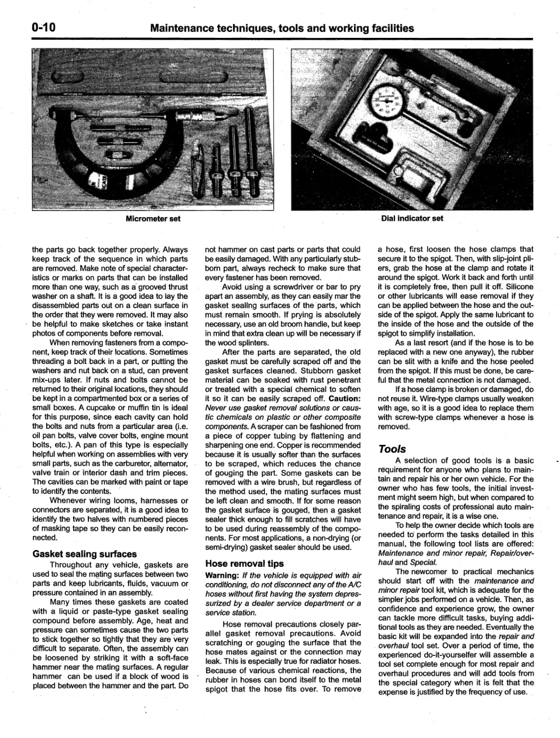
Micrometer set
the parts go back together properly. Always
keep track of the sequence in which parts
are removed. Make note of special character-
istics or marks on parts that can be installed
more than one way, such as a' grooved thrust
washer on a shaft. It is a good idea to lay the
disassembled parts out on a clean surface in
the order that they were removed. It may also
be helpful to make sketches or take instant
photos of components before removal.
When removing fasteners from a compo-
nent, keep track of their locations. Sometimes
threading a bolt back in a part, or putting the
washers and nut back on a stud, can prevent
mix-ups later. If nuts and bolts cannot be
, returned to their original locations, they should
be kept in a compartmented box or a series of
small boxes. A cupcake o
muffin tin is ideal
for this purpose, since each cavity can hold
the bolts and nuts from a particular area (I.e.
oil pan bolts, valve cover bolts, engine mount
bolts, etc.). A pan of this type is especially
helpful when working on assemblies with very
small parts, such as the carburetor, alternator,
valve train or interior dash and trim pieces.
The cavities can be marked with paint or tape
to identify the contents. "
Whenever wiring looms, harnesses or
connectors are separated, it is a good idea to
identify the two halves with numbered pieces
of masking tape so they can be easily recon-
nected.
Gasket sealing surfaces
Throughout any vehicle, gaskets are
used to seal the m@tingsurfaces between two
parts and keep lubricants, fluids, vacuum or
pressure contained in an ,as
,embly.
Many times these gaskets are coated
with a liquid or paste-type gasket sealing
compound before' assembly. Age, heat and
pressure can sometimes cause the two parts
to stick together so tightly that they are' very
difficult to separate. Often, the assembly can
be loosened by striking it with a soft-face
hammer near the mating surfaces. A regular
hammer can be used if a block of wood is
placed between the hammer and the part. Do
not hammer on cast parts or parts that could
be easily damaged. With any particularly stub-
born part, always recheck to make sure that
every fastener has been removed.
Avoid using a screwdriver or bar to pry
apart an assembly, as they can easily mar the
gasket sealing surfaces of the' parts, which
must remain smooth. If prying is absolutely
necessary, use an old broom handle, but keep
in mind that 'extra clean up will be necessary if
the wood splinters.
After the parts are separated, the. old
gasket must be carefully scraped off and the
gasket surfaces cleaned. Stubborn gasket
material can be so
ked with rust penetrant
or treated with a special chemical to soften
it so it can be easily scraped off. Caution:
Never use gasket removal solutions or caus-
tic chemicals on plastic or other composite
components. A scraper can be fashioned from
a piece of copper tubing by flattening and
sharpening one end. Copper is recommended
because it is usually softer than the surfaces
to be scraped, which reduces the chance
of gouging the part. Some gaskets can be
'removed with a wire brush, but regardless of
the method used, the mating surfaces must
be left clean and smooth. If for some reason
the gasket surface is gouged, then a gasket
sealer thick enough to fill scratches will have
to be used during reassembly of the compo-
nents. For most applications, a non-drying (or
semi-drying) gasket sealer should be used.
Hose removal tips
Warning: If the vehicle is equipped with air
conditioning, do not disconnect any of the AlC -
hoses without first having the system depres-
surized by a dealer serviC?e department or a
service station.
Hose removal precautions closely par-
allel gasket removal precautions. Avoid
scratching or gouging the surface that the
hose mates against or the connection may
leak. This is especially true for radiator hoses.
Because of various chemical reactions, the
rubber in hoses can bond itself to the metal
spigot that the hose fits over. To remove
Dial indicator set
a hose, f;rst loosen the hose clamps that
secure it to the spigot. Then, with slip-joint pli-
ers, grab the hose at the clamp and rotate it
around the spigot. Work it back and forth until
it is completely free, then pull it off. Silicone
or other lubricants will ease removal if they
can be applied between the hose and the out-
side of the spigot. Apply the same lubricant to
the inside of the hose and the outside of the
spigot to simplify installation.
As a last resort (and if the hose is to be
replaced with a new one anyway), the rubber
can be slit with a knife and the hose peeled
from the spigot. If this must be done, be care-
'ful that the metal connection is not damaged.
If a hose clamp is broken or damaged, do
not reuse it. Wire-type clamps usually weaken
with age, so it is a good idea to replace them
'with screw-type clamps whenever a hose is
removed.
Tools
A selection of good tools is a basic
requirement for anyone who plans to main-
, tain and repair his or her own vehicle. For the
owner who has ,few tools, the initial invest-
ment might seem high, but when compared to
the spiraling costs of professional auto main-
tenance and repair, it is a wise one.
To help the owner decide which tools are
needed to perform the tasks detailed in this
manual, tne following tool lists are offered:
Maintenance and minor repair, Repair/over-
haul and Special.
The newcomer to practical mechanics
should start off with the maintenance and
minor repair tool kit, which is adequate for the
simpler jobs performed on a vehicle. Then, as
confidence and experience grow, the owner
can tackle more difficult tasks, buying addi-
tional tools as they are needed. Eventually the
basic kit will be expanded into the, repair and
, overhaul tool set. Over a period of time, the
experienced' do-it-yourselfer win assemble a
tool set complete enough for most repair and
overhaul procedures and will add tools from
the special category when it is felt that the
expense is justified by the frequency of use. _
Maintenance techniques, tools and working facilities
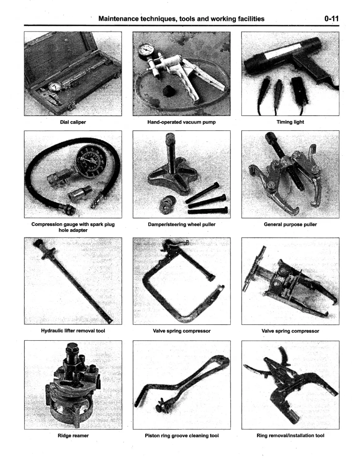
Dial caliper
Compression gauge with spark plug
hole adapter
Hydraulic lifter removal tool
Ridge reamer
Hand-operated vacuum pump
Damper/steering wheel puller
Valve spring compressor
Piston ring groove cleaning tool
0-11
Timing light
General purpose puller
Valve spring compressor
Ring removal/installation tool
0-12
Maintenance techniques, tools and working facilities
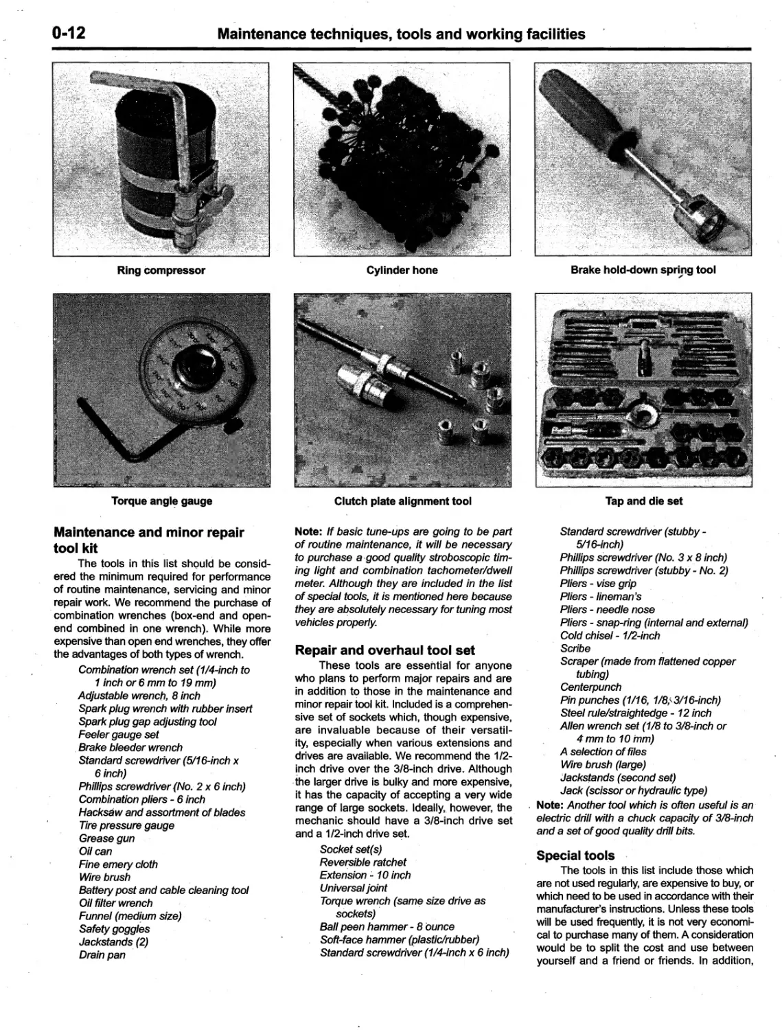
Ring compressor
I
I
I
i
I
I .
',,,,,,,!:'M':;;::'''-
.: "
:
Jc' , '/'_ '
"
i...«' . .;.(,W "
If
Y" 'j " '& , 't , ' , 2! , ..
r:?' ". '. :
.
....
::f.. '.
.
" ...
;:
i
,
i-ff:<
. ..
"
'l.c;
" ..'1:i!
.. ..t1."
:;.::
"""'"'J'¥
...,
"-"" ..'_".c
-i>.,,:-"".
-,:. '
"'-"';':n_.
Torque angl
gauge
Maintenance and minor repair
tool kit
The tools in this list shQuld be consid-
ered the minimum required for performance
of routine maintenance, servicing and minor
repair work. We recommend the purchase of
combination wrenches (box-end and open-
end combined in one wrench). While more
expensive than open end wrenches, they offer
the advantages of both types of wrench.
Combination wrench set (1/4-inch to
1 inch or 6 mm to 19 mm)
Adjustable wrencl1, 8 inch
Spark plug wrench with rubber insert
Spark plug gap adjusting tool
Feeler gauge set
Brake bleeder wrench
Standard screwdriver (5/16-inch x
6 inch)
Phillips screwdriver (No.2 x 6 inch)
Combination pliers - 6 inch
Hacksaw and assortment of blades
Tire pressure gauge
Grease gun
Oil can
Fine emery cloth
Wire brush
Battery post and cable cleaning tool
Oil filter wrench
Funnel (med!um size)
Safety goggles
Jackstands (2)
Drain pan
Cylinder hone
!!;
;" ...
l
t
l,
I
I
iO
t .J
;iJ
I
A
vn
:
w:
Clutch plate alignment tool
Note: If basic tune-ups are going to be part
of routine maintenance, it will be necessary
to purchase a .good quality stroboscopic tim-
ing light and combination tachometer/dwell
meter. Although they are included in the list
of special tools, it is mentioned here because
they are a
s(jJutely necessary for tuning most
vehicles properly.
Repai,r and overhaul tool set
These tools are essential for anyone
who plans to perform major repairs and are
in addition t<? those in the maintenance and
minor repair tool kit. Included is a comprehen-
sive set of sockets which, though expensive,
are invaluable because of their versatil-
ity, especially when various extensions and
drives are available. We recommend the 1/2-
!nch drive over the 3/8-inch drive. Although
-the larger drive is bulky and more expensive,
it has the capacity of accepting a very wide
range of large sockets. Ideally" however, the
mechanic should have a 3/8-inch drive set
and a 1/2-inch drive set.
Socket set(s)
Reve
sibJe ratchet
Extension:' 10 inch
Universal joint
Torque wren
h (sam
size drive as
sockets)
Ball peen hammer - 8 ounce
Soft-face hammer (plastic/rubber)
Standard screwdriver (1/4-inch x 6 inch)
Brake hold-down spring tool
,
H
Tap and die set
Standard screwdriver (stubby -
5/16-inch)
Phillips screwdriver (No. 3 x 8 inch)
Phillips screwdriver (stubby - No.2)
Pliers - vise grip
Pliers - /ineman
s
Pliers - needle nose
Pliers - snap-ring (internal and externaQ
Cold chisel - 1/2-inch
Scribe
Scraper (made from flattened copper
tubing)
Center punch
Pin punches (1/16, 1/8,\3/16-inch)
Steel rule/straightedge - 12 inch
Alien wrench set (1/B to 3lB-inch or
4 mm to 10 rom)
A selection of files
Wire brush (large)
Jackstands (second set)
Jack (scissor or hydraulic type)
Note: Another tool which is often useful is an
electric drill with a chuck capacity of 3/8-inch
and a set of good quality drill bits.
Special tools
The tools in this list include those which
are not used regularly, are expensive to buy, or
which need to be used in accordance with their
manufacturer's instructions. Unless these tools
will be used frequently, it is not veryeconomi-
cal to purchase many of them. A consideration
would be to split the cost and use between
yourself and a friend or friends. In addition,
M,aintenance techniques, tools and working facilities
0-13
most of these tools can be obtained from a tool
rental shop on a temporary basis.
This list primarily contains only those
tools and instruments widely available to the
public, and not those special tools produced
by the vehicle manufacturer for distribution
to dealer service departments. Occasionally,
references to the manufacturer's special tools
are included in the text of this manual. Gen-
erally, an alternative method of doing the job
without the special tool is offered. However,
sometimes there is no alternative to their use.
Where this is the case, and the toot cannot be
purchased or borrowed, the work should be
turned over to the dealer service department
or an automotive repair shop.
Valve spring compressor
Piston ring groove cleaning tool
Piston ring compressor
Piston ring installation tool
Cylinder compr
ssion gauge
Cylinder ridge reamer
Cylinder surfacing hone
Cylinder bore gauge
Micrometers and/or dial calipers
Hydraulic lifter removal tool
Balljoint separator
UniversaJ:-type puller
Impact screwdriver
Dial indicator set
Stroboscopic timing light (inductive
pick-up)
Hand operated vacuum/pressure pump
Tachometer/dwell meter '
Universal electrical multi meter
Cable hoist
Brake spring removal- and installation
tools
Floor jack
Buying tools
For the do-it-yourselfer who is just start-
ing to get involved in vehicle maintenance and
repair, there are a number of options av
ilable
when purchasing tools
If maintenance and
minor repair is the extent of the work to be .
done, the purchase of individual tools is satis-
factory. If, on the other hand, extensive work is
planned, it would be a good idea to purchase
a modest tool set from one of the large retail
chain stores. A set can usually be bought at
a substantial savings over the individual tool
prices, and they often come with a tool box.
As additional tools, are needed, add-on sets,
individual tools and a larger tool box can be
purchased to expand the tool selection. Build-
ing a tool set gradually allows the cost of the
tools to be. spread over a longer period of
time and gives the mechanic the freedom to
choose only those tools that will actually be
used.
Tool stores will often be the only source
of some of the special tools that are needed,
b':Jt regardless of where t90ls are bought, try
to avoid cheap ones, especiaily when buying
screwdrivers and sockets, because they won't
'Iast very long. The expense involved in replac-
ing cheap tools will eventually be greater than
the initial cost of quality tools.
Care and' maintenance of tools
Good tools are expensive, so it makes
sense to treat them with respect. Keep them
clean and in usable condition and store them
properly when not in use. Always wipe off -any
dirt, grease or metal chips before putting them
away. Never leave tools lying around in the
work area. Upon completion of a job, always
check closely under the hood for tools that
may have been left there so they won't get
lost during a test drive.
Some tools, such as screwdrivers, pli-
ers, wrenches ,and sockets, can be hung on
a panel mounted on the garage Qr workshop
wall, while others should be kept in a tool
box or tray. Measuring instruments, gauges,
meters, etc. must be carefully stored where
they cannot be damaged by weather or impact
from other tools.
When tools are used with care and
stored properly, they will last a very long time.
Even with the best of care, though, tools will
w.ear out if used frequently. When a tool is
damaged or worn out, replace it. Subsequent
jobs will be, safer and more enjoyable if you
do.
How to repair damaged
threads
Sometimes, the internal threads of a nut
or bolt hole can become stripped, usually from
overtightening. Stripping threads is an all-too-
common occurrence, ,especially when work-
ing' with aluminum parts, because aluminum
is so soft that it easily strips out.
Usually, external or internal threads are
only partially stripped. After - they've been
cleaned up with a tap or die, they'll still work.
Sometimes, however, threads are badly dam-
aged. When this happens, you've got three
choices:
1) Drill,and tap the hole to the next suitable
oversize and install a larger diameter
bolt, screw or stud.
2) Drill and tap the hole to accept a
threaded plug, then drill and tap the plug
to the original screw size. You can also
buy a plug already threaded to the origi-
nal size. Then you simply drill a hole to
the specified size, then run the threaded
plug into the hole with a bolt and jam nut.
Once the pJug is fully seated, remove the
jam nut and bolt.
3) The third method uses a patented thread
repair kit like He/i-Coil or SJimsert. these
easy-to-use kits are designed to repair
damaged threads in straight-through
holes and blind holes. Both are avail-
able as kits which can handle a variety of
sizes and thread patterns. Drill the hole,
tflen tap it with the special included tap.
Install the Heli-Coil and the hole is back
to its original diameter and thread pitch.
Regardless of which method you use,
be sure to proceed calmly and carefully. A
Httle impatience or carelessness during one
of these relatively simple procedures can ruin
your whole day's work and cost you a bundle
if you wreck an expensive part.
Working facilities
Not to be overlookeq when discussing
tools is the workshop. If anything more than
routine maintenance is to be carried out,
some sort of suitable work area is essential.
It 'is understood, and appreciated,' that
many home mechanics do not have a good
workshop or garage available, and end up
removing an engine or doing major repairs
outside. It is recommended, however, that the
overhaul or repair be completed under the
cover of a roof.
A clean, flat workbench or tab1e of com-
fortable working height is an absolute neces-
sity. The workbench should be equipped with
a vise that has a jaw opening of at least four
inches.
As, mentioned previously, some clean,
dry storage space is also required for too.ls,
as well as the' lubricants, fluids,cl
aning sol-
vents, etc. which soon become necessary.
Sometimes waste oil and fluids, drained
from the engine or cooling system during
normal maintenance or repairs, present a
disposal problem. To avoid pouring them on
the ground or into a sewage system, pour the
used fluids into large containers, seal them
with caps and take them to an authorized
disposal site or recycling center. Plastic jugs,
such' as old antifreeze containers, are ideal
for this purpose.
Always keep a supply of old newspa-
pers and clean rags available. Old towels
are excellent for mopping up spills. Many
mechanics use rolls of paper towels for most
work because they are readily available and
disposable. To help keep the area under the
vehicle clean, a large cardboard box can be
cut open and' flattened to protect the garage
or shop floor.
Whenever working over a painted sur-
face, such as when leaning over a fender to
service something under the hood, a,lways
cover it with an old blanket or bedspread to
protect the finish. Vinyl covered' pads, made
especially for this purpose; are 'available at
auto parts stC?res.
0-14
Jacking and to.
.
Ing
Jacking
Warning: The jack supplied with the vehicle
should only be used for changing a tire or
placing jackstands under the frame. Never
work under the vehicle or start the engine
while this jack is being used as the only
means of support.
The vehicle should be on level ground.
Place the shift lever in Park, if you have an
automatic, or Reverse if you have a manual
transaxle. Block the wheel diagonally oppo-
site the wheel being changed. Set the parking
brake.
Remove the spare tire and jack from
stowage. Remove the wheel cover and trim
ring (if so equipped) with the tapered end of
the lug nut wrench by inserting and twisting
the handle and then prying against the back of
the wheel cover. Loosen, but do not remove,
the lug nuts (one-half turn is sufficient).
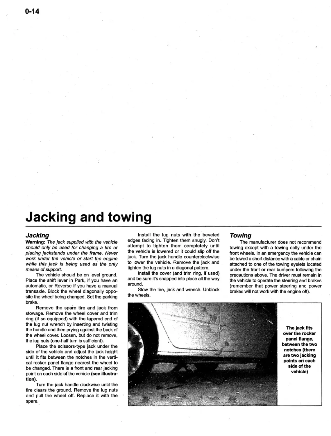
Place tne scissors-type jack under the
side of the vehicle and adjust the jack height
until it fits between the notches in the verti-
cal rocker panel flange nearest the wheel to
be changed. There is a front and rear jacking
point on each side ot'the vehicle (see illustra-
tion).
Turn the jack handle clockwise until the
tire clears the ground. Remove the lug nuts
and pull the wheel off. Replace it with the
spare.
I nstall the lug nuts with the beveled
edges facing in., Tighten them snugly. Don't
attempt to tighten them completely ,until
the vehicle is lowered or it could slip off the
jack. Turn the jack handle counterClockwise
to lower the vehicle. Remove the jack and
tighten the lug nuts in a diagonal pattern.
Install the cover (and trim ring, if used)
and be sure it's snapped into place all the way
around.
Stow the tire, jacJ< Cilnd wrench. Unblock
the wheels.
j"'
Towing
The manufacturer does not recommend
towing except with a towing dolly under the
front wheels. In an emergency the vehicle can
be towed a short distance with a cable or chain
attached to one of the towing eyelets located
under the front or rear bumpers following the
precautions above. The driver must remain in
the vehicle to operate the steering and brakes
(remember that power steering and power
brakes will not work with the engine off).
The jack fits
over the rocker
panel flange,
between the two
notches (there
are two jacking
points on l each
side of ,the
vehicle)
, ! .,
,0-15
Booster battery (jump) starting
. .
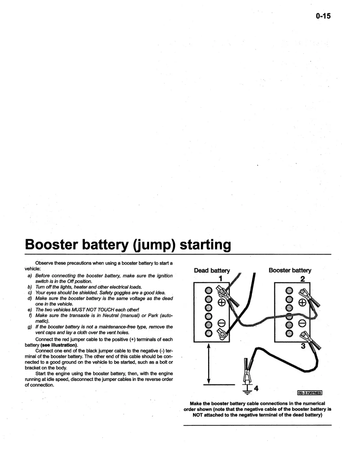
Observe these precautions when using a booster battery to start a
vehicle: .
a) . Befqre ' connecting the booster battery, make sure the ignition
switch is in the Off position.
b), Turnoff the lights, heater and other electrical loads.
c) Your eyes should be shielded. Safety goggles are a good idea.
d) Make sure the booster battery is the same voltage as the dead
one in the vehicle.
e) The two vehicles MUST NOT TOUCH each other!
f) Make sure the transaxle is in Neutral (manual) or Park (auto-
matic).
g) If the booster battery is not a maintenance-free type, remove the
vent caps and lay a cloth over the vent holes.
Connect the red jumper cable to the positive (+) terminals of each
battery (see illustration).
Connect one end of the black jumper cable to the negative (-) ter-
minal of the booster battery. The other end of this cable should be con-
nected to a good ground on the vehicle to be started, such as a bolt or
bracket on the body.
Start the engine using the booster battery, then, with the engine
running at ,idle speed, disconnect the jumper cables in the reverse order
of connection.
Dead battery
1
Booster battery
2
4
)Q&.3ftAVNUJ
---
-- '
Make the booster battery cable connections in the n_umerical
order shown (note that the negative cable of the booster battery is
NOT att
ched to the negative terminal of the' dead battery)
0-1,6
Automotive chemicals and lubricants
A number of automotive chemicals and
lubricants are available for use during vehicle
maintenance and repair. They include.a wide
variety of products ranging from cleaning sol-
vents and degreasers to lubricants and pro-
tective sprays for rubber, plastic and vinyl.
Cleaners
Carburetor cleaner and choke cleaner
is a strong solvent for gum, varnish and car-
bon. Most carburetor cleaners leave a dry-type
lubricant film which will not harden or gum up.
Because of this film it is not recommended for
use on electrical components.
Brake system cleaner is used to
remove brake dust, grease and brake fluid
from the brake system, where dean surfaces
are absolutely necessary. It leaves no residue
and often eliminates brake squeal caused by
contaminants.
Electrical cleaner removes oxidation,
corrosion an
carbon deposits from electrical
contacts, restoring full current flow. It can also
. be used to clean spark plugs, carburetor jets,
voltage regulators and other parts where an
oil-free surface is desired.
Demoisturants remove water and mois-
ture from electrical components such as alter-
nators, voltage regulators, electrical connec-
tors and fuse blocks. They are non-conductive
and non-corrosive.
Degreasers are heavy-duty solvents
used to remove grease from the outside of the
engine and from chassis components. They
can be sprayed or brushed on and, depending
on the type, are rinsed off either with water or
solvent.
Lubricants
Motor oil is the lubricant formulated for
use in engines. It normally contains a wide
variety of additives to prevent corrosion and
reduce foaming,
nd wear. Motor oil comes in
various weights (viscosity ratings) from 0 to 50. -
The recommended weight of the oil depends
on the season, temperature and the demands
on the engine. Light oil is u.sed in cold climates
and under light load conditions. Heavy oil is
, used in hot climates and where high loads are
encountered. Multi-viscosity oils are designed
to have characteristics of both light and heavy
oils and are available ,in a number of weights
from OW-20 to 20W-50.
Gear 011 is designed to be used in dif-
ferentials, manual transmissions and other
areas where high-temperature lubrication is
required.
Chassis and wheel bearing grease is
a heavy grease used where increased loads
and friction are encountered, such as for
wheel bearings, balljoints, tie-rod ends and
universal joints.
HIgh-temperature wheel bearing
grease is designed to withstand' the extreme
temperatures encountered by wheel bearings
in disc brake equipped vehicles. It usually
contains molybdenum disulfide (moly), which
is a dry-type lubricant.
White grease is a heavy grease for
metal-to-metal applications where water is a
problem. White grease stays soft under both
low and high temperatures (usually from -100
to + 190-degrees F), and will not wash off or
dilute in the presence of water.
Asse,!,bly lube is a special extreme
pressure lubricant, usually containing moly,
used to lubricate high-load parts (such as
main and rod bearings and cam lobes) for
initial start-up of a new engine. The assem-
bly lube lubricates the parts without being.
squeezed out or washed away until the engine
oiling system begins to function.
Silicone lubricants are used to protect
rubber, plastic, vinyl and nylon parts.
Graphite lubricants are used where /oils
cannot be used due to cO,ntamination prob-
lems, such as in locks. The dry graphite will
lubricate metal parts while remaining uncon-
taminated by dirt, water, oil or acids. It is,elec-
trically conductive and will not foul electrical
contacts in locks such as the ignition switch.
Moly penetrants loosen and lubricate
frozen, rusted and corroded fasteners and
prevent future rusting or freezing.
Heat-sink grease is a special electri-
cally non-conductive grease that is used for
mounting electronic ignition .modules where it
is essential that heat is transferred away from
the module.
Sealants
RTV- seala!"t is one of the most widely
used gasket compounds. Made from silicone,
RTV is air curing, it seals, bonds, waterproofs,
fills surface irregularities, remains flexible,
doesn't shrink, is relatively easy to remove,
and is used as a supplementary sealer with
almost all low and medium temperature .gas-
kets.
Anaerobic sealant is much like RTV in
t1)at it can be used either to seal gaskets or
to form gaskets by itself. It remains flexible,
is solvent resistant and fills surface imperfec-
tions. The difference between an' anaerobic
sealant and an RTV-type sealant is in the cur-
ing. RTV cures when exposed to air, while an
anaerobic sealant cures only in the absence
of air. This means that an anaerobic sealant
cures only after the assembly of parts, sealing
them tOgether.
Thread and pipe sealant is used for
sealing hydraulic and pneumatic fittings and
vacuum lines. It is usually made from a Teflon
compound, and comes in a spray, a paint-on
liquid and as a wrap-around tape. '
Chemicals
Anti-seize compound prevents seiz-
ing, galling, cold welding, rust and corrosion
in- fasteners. High-temperature ant-seize, usu-
ally made with copper and graphite lubricants,
is used for exhaust system and exhaust mani-
fold bolts.
Anaerobic locking compounds are
used to keep fasteners from vibrating or work-
ing loose and cure only after ,installation, in
the absence of air. Medium strength locking
compound is used for small nuts, bolts and
screws that may be removed later. High-
strength locking compound is for large nuts,
bolts and studs which aren't removed on a
regular basis.
Oil additives range from viscosity index
improvers to chemical treatments that claim
to reduce internal engine friction. It should
be noted that most oil manufacturers caution
against using additives with their oils.
Gas additives perform several func-
tions, depending on their chemical makeup.
They usually contain solvents that help dis-
solve gum and varnish that build up on car-
buretor, fuel injection and intake parts. They
also serve to break down carbon deposits that
form on the inside surfaces of the combus-
tion chambers. Some additives contain upper
cylinder lubricants for valves and piston rings,
and others contain chemicals to remove con-
densation from the gas tank.
Miscellaneous
'Brake fluid' is specially formulated
hydraulic fluid that can withstand the heat and
pressure encountered in brake systems. Care '
must be taken' so this' fluid does not come in
contact with painted surfaces or plastics. An
opened container should always be resealed
to prevent contamination by water or dirt.
Weatherstrip adhesive is used to bond
weatherstripping around doors, windows and
. trunk lids. It is sometimes used to attach trim
pieces.
Undercoating is a petrole'um-based,
tar-like substance that is designed to protect
metal surfaces on the underside of the vehicle
from corrOsion. It also acts as a sound-dead-
.ening agent by insulating the bottom of the
vehicle.
Waxes and polishes are used to help
protect painted and plated surfaces from the
weather. Different types, of paint may require
the use of different types of wax and polish.
Some polishes utilize a chemical or abrasive
cleaner to help remove the top layer of oxi-
dized (d.ull) paint on older vehicles. In recent
years many non-wax polishes that contain a
wide variety of chemicals such as polymers
and silicones have been introduced. These
non-wax polishes are usually easier to apply
and last longer than conventional' waxes and
polishes. -
0-17
Conversion factors
Length (distance)
Inches '(in) X 25.4 == Millimeters (mm) , X 0.0394 == I nches (in)
Feet (ft) X 0.305 == Meters (m) X 3.281 == Feet (ft)
Miles .. X 1.609 == Kilometers (km) X 0.621 = Miles
Volume (capacity) X 16.387 == Cubic centimeters (cc; cm 3 ) == Cubic inch
s (cu in;, in 3 )
Cubic inches (cu In; In 3 ) X 0.061
I mperlal pints (I mp pt) X 0.568 == Liters (I) X ' 1.76 = Imperial pints (Imp pt)
Imperial quarts (Imp qt) X 1.137 = Liters (I) X 0.88 = Imperial quarts (Imp qt)
, Imperial quarts (Imp qt) X 1.201 == US quarts (US qt) X 0.833 = I mperial quarts (Imp qt)
US quarts (US qt) X 0.946 = Liters (I) X 1.057 == US quarts (US qt)
Imperial gallons (Imp gal) X 4.546 == Liters (I) X 0.22 == Imperial gallons (Imp gal)
Imperial gallons (I mp gal) X 1 .201 == US gallons (US gal) X 0.833 == Imperial gallons (Imp gal)
US gallons (US gal) X 3.785 == Liters (I) X 0.264 == US gallons (US gal)
M
ss (weight) = Ounces (oz)
Ounces (oz) X
8.35 == Grams (g) X 0.035
Pounds (lb) X 0.454 = Kilograms (kg)' X 2.205 == Pounds (lb)
Force
Ounces-force (ozf; oz) ,X 0.278 == Newton
(N) X 3.6 - == Ounces-force (ozf; oz)
Pounds-force Ubf; Ib) X 4.448 == Newtons (N) X 0.225 == Pounds-force Ubf; Ib)
Newtons (N) X 0.1 == Kilograms-force (kgf; kg) X 9.81 == Newtons (N)
, Pressure
Pounds-force per square inch X 0.070 == Kilograms-:-force per square X 14.223 == Pounds-force per square inch
(psi; Ibf/in 2 ; Ib/in 2 ) centimeter (kgf/em 2 ; kg/em 2 ) (psi; Ibf/in 2 ; Ib/in 2 )
Pounds-force per square inch X 0.068 == Atmospheres (atm). X 14.696 == Pounds-force ,per square inch
(psi; Ibf/in 2 ; Ib/in 2 ) (psi; Ibf/in 2 ; Ib/in 2 )
Pounds-force per square inch X 0.069 == Bars X 14.5 = Pounds-force per square inch
(psl;lbf/in 2 ; Ib/in 2 ) (psi; Ibf/in2; Ib/in 2 )
Pounds-force per square inch X 6.895 == Kilopascals (kPa) X o. 146 == Pounds-force per square inch
(psi; Ibf/in 2 ; Ib/in 2 ) (psi; Ibf/in 2 ; Ib/in 2 )
KUopascals (kPa) X 0.01 = Kilograms-force per square X 98.1 == Kilopascals (kPa)
centimeter (kgf/cm 2 ; kg/cm 2 )
Torque (moment' of force)
Pounds-force inches X 1 . 1 52 == Kilograms-force centimeter X 0.868 Pounds-force inches
Ubf in; Ib in) (kgf em; kg em) (Ibf in; Ib in)
Pounds-force inches X o. 113 == Newton meters (Nm) X 8.85 == Pounds-:-force inches
(lbf in; Ib in) Ubf in; Ib in)
Pounds-force inches X 0.083 == Pounds-force feet (lbf ft; Ib ft) X, 12 == Pounds-force inches
(lbf in; Ib in) (lbf in; I
in)
Pounds-force feet (lbf ft; Ib ft) X 0.138 -:- Kilograms-force meters X 7.233 = Pounds-force feet Ubf ft; Ib ft)
, " (kgf m; kg m)
Pounds-force feet Ubf ft; Ib ft) X 1 .356 == Newton meters (Nm) X 0.738 = Pounds-force feet Ubf ft; Ib ft)
Newton meters (Nm) X 0.102 = Kilograms-force meters X 9.804 == Newton meters (Nm)
(kgf m; kg'm)
Vacuum
Inches mercury (in. Hg) X 3
377 = Kilopascals (kPa) X 0.2961 = Inches mercury
Inches mercury (in. Hg) X 25.4 = Millimeters mercury (mm Hg) X 0.0394 = Inches mercury
Power
Horsepower (hp) X 745.7 = Watts (W) X 0.0013 == Horsepower (hp)
Velocity (speed)
Miles per hour (miles/hr; mph) X 1.609 == Kilometers per hour (km/hr;- kph) X, 0.621 = Miles per hour (miles/hr; mph)
Fuel consumption*
Miles per gallon, Imperial (mpg) X 0.354 == Kilometers per liter (km/l) X 2.825 == Miles per gallon, Imperial (mpg)
,Miles per gallon, US (mpg) X 0.425 = Kilometers per liter (km/I) X 2.352 ' == Miles-per garton, US (mpg)
Temperature
Degrees Fahrenheit == (0 C x 1.8) + 32 Degrees Celsius (Degrees Centigrade; °C) == (6 F - 32) ,x ,0.66
.It Is common practice to convert from miles per gallon (mpg) to liters/100 kilometers (1/100km),
where mpg (Imperial) x 1/100 km == 282 and mpg (US) x 1/100 km == 235
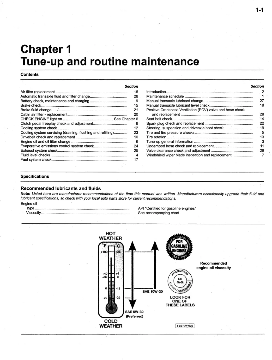
O
18
DECIMALS to MILLIMETERS
Decimal mm Decimal mm
0.00 1 0.0254 0.500 12.7000
0.002 0.0508 0.510 12.9540
0.003 0.0762 0.520 13.2080
0.004 0.1016 0.530 13.4620
0.005 ,0.1270 0.540 13.7160
0.006 0.1524 0.550 13.9700
0.007 0.1778' 0.560 14.2240
0.008 0.2032 , 0.570 14.4780
0.009 0.2286 0.580 14.7320
0.010 0.2540 0.590 14.9860
-,
0.020 0.5080
0.030 0.7620
0.040 1.0160 0.600 15.2400
0.050 1.2700 0.610 15.4940
0.060 1.5240 0.620 15.7480
0.070 1.7780 0.630 16.0020
0.080 2.0320 0.640 16.2560
0.090 2.2860 0.650 16.5100
0.660 16.7640
0.100 2.5400 0.670 17.0180
0.110 2.7940 0.680 17.2720
0.120 3.0480 0.690 17.5260
0.130 3.3020
0.140 3.5560
0.150 3.8100
0.160 4.0640 t).700 17.7800
0.170 4.3180 0.710 18.0340
0.180 4.5720 0.720 18.2880 '
0.190 4.8260 0.730 18.5420
0.740 18.7960
0.200 "5.0800 0.750 19.0500
0.210 5.3340 0.760 19.3040
0.220 5.5880 0.770 19.5580
0.230 5.8420 0.780 19.8120
0.240 6.0960 0.790 20.0660,
0.250 6.3500
0.260 6.6040
0.270 6.8580 0.800 20.3200
0.280 7.1120 0.810 20.5740
0.290 7.3660 0.820 21.8280
0.830 21.0820
/ 0.300 7.6200 0.840 .21.3360
0.310 7.8740 '0.850 21.5900
0.320 8.1280 0.860 21.8440
0.330 8.3820 0.870 22.0980
0.340 8.6360 0.880 22.3520
0.350 8.8900 0.890 22.6060
0.360 9.1440
0.370 9.3980
0.380 9.6520,
0.390 9.9060 0.900 22.8600
0.400 10.1600 0.910 23.1140
0.410 10.4140 0.920 23.3680
0.420 10.6680 0.930 23.6220
0.430 10.9220 0.940 23.8760
0.440 1 L 1760 0.950 24.1300
0.450 1 1.-4300 0.960 24.3840
0.460 11.6840 0.970 24.6380
0.470 11.9380 0.980 24.8920
0.480 12.1920 0.990 25
1460
0.490 12.4460 1.000 25.4000
FRACTIONS to DECIMALS to MilliMETERS
Fraction Decimal mm Fraction Decimal mm
1/64 0.0156 0.3969 33/64 0.5156 13.0969
1/32 0.0312 0.7938 17/32 0.5312 13.4938
3/64 0.0469 1.1906 35/64 0.5469 13.8906
1/16 0.0625 1.5875 ,9/16 0.5625 14.2875
5/64 0.0781 1.9844 37/64 0.5781 14.6844
3/32 0.0938 2.3812 19/32 0.5938 15.0812
7/M 0.1094 2.7781 39/64 0.6094 15.4781
1/8 0.1250 3.1750 5/8 0.6250 15.8750
9/64 0.1406 3.5719 41/64 0.6406 16.2719
5/32 0.1562 3.9688 21/32 0.6562 16.6688
11/64 0.1719 4.3656 43/64 0.6719 17.0656
3/16 0.1875 4.7625 11/16 0.6875 17.4625
13/64 0.2031 5.1594 45/64 0.7031 17.8594
7/32 0.2188 .5.5562 23/32 0.7188 18.2562
15/64 0.2344 5.9531 47/64 0.7344 18.6531
1/4 0.2500 6.3500 3/4 0.7500 19.0500
17/64 0.2656 6.7469 49/64 0.7656 19.4469
9/32 0.2812 7.1438 25/32 0.7812 19.8438
19/64 0.2969 7.5406 51/64 0.7969' 20.2406
5/16 0.3125 7.9375 13/16 0.8125 20.6375
21/64 0.3281 8.3344 53/64 0.8281 21.0344
11/32 0.3438 8.7312 27/32 0.8438 . 21.4312
23/64 0.3594 9.1281 55/64 0.8594 21.8281
3/8 0.3750 9.5250 7/8 . 0.8750 22.2250
25/64 0.3906 9.9219 57/64 0.8906 22.6219
13/32 0.4062 1'0.3188 29/32 0.9062 23.0188
27/64 0.4219 10.7156 59/64 0.9219 23.4156
-'
',"",
7/16 0.4375 11.1125 15/16 0.9375 23.8125
29/64 0.4531 11.5094 61/64 0.9531 24.2094
15/32 0.4688 11.9062 31/32 0.9688 24.6062
31/64 0.4844 12.3031 63/64 0.9844 25.0031
1/2 0.5000 12.7000 1 1.0000 25.4000
Safety first!
0-19
Regardless of how enthusiastic you
may be about getting on with the job at hand,
take the time to ensure that your safety is not
jeopardized. A moment's lack of attention can
result in an accident, as can failure to observe
certain simple safety precautions. The possi-
bility of an accident will always exist, and the
following points should not be considered a
comprehensive list of all dangers. Rather, they
are intended to make you aware of the risks,
and to encourage a safety conscious approach
to all work you carry out on your vehicle.
Essential DOs and DON'Ts
DON'T rely on a jack when working under the
vehicle. Always use approved jackstands to
support the weight of the vehicle and place
them under the recommended lift or support
points.
DON'T attempt to loosen extremely tight fas-
teners (Le. wheel lug nuts) while the vehicle is
on a jack - it may fall.
DON'T start the engine without first making
sure that the transmission is in Neutral (or Park
where applicable) and the parking brake is set.
DON'T remove the radiator cap from a
hot cooling system - let it cool or cover it
with a cloth and release the pressure gradually.
DON'T attempt to drain the engine oil until
you are sure it has cooled to the point that it
wilt not burn you.
DON'T touch any part of the engine or ex-
haust system until it has cooled sufficiently to
avoid bums.
DON'T siphon toxic liquids such as gasoline,
antifreeze and brake fluid by mouth, or allow
them to remain on your skin.
DON'T inhale brake lining dust - it is poten-
tially hazardous (see Asbestos below).
DON'T allow spilled oil or grease to remain on
the floor - wipe it up before someone slips on it.
DON'T use loose fitting wrenches or other
tools which may slip and cause injury.
DON'T push on wrenches when loosening or
tightening nuts or bolts. Always try to pull the
wrench toward you. If the situation calls for
pushing the wrench away, push with an open
hand to avoid scraped knuckles if the wrench
should slip.
DON'T attempt to lift a heavy component
alone - get someone to help you.
DON'T rush or take unsafe shortcuts to finish
a job.
DON'T allow children or animals in or around
the vehicle while you are working on it.
DO wear eye protection when using power
tools such as a drill, sander, bench grinder,
etc. and when working under a vehicle.
DO keep loose clothing and long hair well out
of the way of moving parts.
DO make sure that any hoist used has a safe
working load rating adequate for the job.
DO get someone to check on you periodically'
when working alone on a vehicle.
DO carry out work in a logical sequence and
make sure that everything is correctly assem-
bled and tightened.
DO keep chemicals and fluids tightly capped
and out of the reach of children and pets.
DO remember that your vehicle's safety
affects that of yourself and others. If in doubt
on any point, get professional advice.
Steering, suspension and brakes
These systems are essential to driv-
ing safety, so make sure you have a quali-
fied shop or individual check your work. Also,
compressed suspension springs can cause
injury if released suddenly - be sure to use a,
spring compressor.
Airbags
Airbags are explosive devices that can
CAUSE injury if they deploy while you're work-
ing on the vehicle. Follow the manufacturer's,
instructions to disable the airbag whenevet
you're working in the vicinity of airbag compo- ,
nents.
Asbestos
Certain friction, insulating, sealing, and
other products - such as brake linings, brake
bands, clutch linings,' torque converters, gas-
kets" etc. - may contain asbestos or other haz-
ardous friction material. Extreme care must
be taken to avoid inhalation of dust from such
products, since it is hazardous to health. If in
doubt, assume that they do contain asbestos.
Fire
Remember at all times that gasoline is
highly flammable. Never smoke or have 'any
kind of open flame around when working on
a'vehicle. But the risk does not end there. A
spark caus
d by an electrical short circuit, by
two metal surfaces contacting each other, or
even by static electricity built up in your body
under certain conditions, can ignite gasoline
vapors, which in a confined space are highly
explosive. Do not, under any circumstances,
use gasoline for cleaning parts. Use an
approved safety solvent.
Always disconnect the battery ground (-)
cable at the battery before working on any part
of the fuel system or electrical system. Never
risk spilling fuel on a hot engine or exhaust
component It is strongly recommended that
a fire extinguisher suitable for use on fuel and
electrical fires be kept handy in the garage or
workshop at all times. Never try to extinguish
a fuel or electrical fire with water.
Fumes
Certain fumes are highly toxic and can
quickly cause unconsciousness and even
death if inhaled to any extent. Gasoline vapor
falls into this category, as do the vapors from
some cleaning solvents. Any draining or pour-
ing of such volatile fluids should be done in a
well ventilated area.
When using cleaning fluids and solvents,
read the instructions on the container carefully.
Never use materials from unmarked containers.
Never run the engine in an enclosed
space, such as a garage. Exhaust fumes con-
tain carbon monoxide, which is extremely poi-
sonous. If you need to run the engine, always
do so in the open air, or at least have the rear
of the vehicle outside the work area.
The battery
Never create a spark or allow a bare
light bulb near a battery. They normally give
off a certain amount of hydrogen gas, which is
highly explosive.
Always disconnect the battery ground (-)
cable at the battery before working on the fuel
or electrical systems.
If possible, loosen the filler caps or cover
when charging the battery from' an external
source (this does not apply to sealed or main-
tenance-free batteries). Do not charge at an
excessive rate or the battery may burst.
Take care when adding water to a non
maintenance-free' battery and when carrying
a battery. The electrolyte, even when diluted,
is very corrosive and should not be allowed to
contact clothing or skin.
Always wear eye protection when clean-
ing the battery to prevent the caustic deposits
from entering your eyes.
Household current
When using, an electric power tool,
inspection light, etc., which operates on
household current, always make sure that the
tool is correctly connected to its plug and that,
where necessary, it is properly grounded. Do
not use such items in damp conditions and,
ag
in, do not create a spark or apply exces-
sive heat in the vicinity of fuel or fuel vapor.
Secondary ignition system
voltage
A severe electric shock can result from
touching certain parts of the ignition system
. (such as the spark plug wires) when the
engine is running or being cranked, ,particu-
larly if components are damp or the insulation
is defective. In the case of an electronic igni-
tion system, the secondary system voltage is
much higher and could prove fatal.
Hydrofluoric acid
This extremely corrosive acid is formep
when certain types of synthetic rubber, found
in some O-rings, oil seals, fuel hoses, etc. are
exposed to temperatures above 750-degrees
F (400-degrees C). The rubber changes into
a charred or sticky substance containing the
acid. Once formed, the acid remains danger-
ous for years. If it gets onto the skin, it may be
neces$ary to amputate the limb concerned.
When dealing with a vehicle which has
suffered a fire, or with components salvaged
from such a vehicle, wear protective gloves
and discard them after use.
0-20
Troubleshooting
Contents
Symptom
Section
Engine
CHECK ENGINE light on ................................................ See Chapter' 6
Engine' backfires,..... ............... ........ .... .................... ........... .......... ... 15
Engine diesels (continues to run) after switching off ..................... 18
Engine hard to start when cold ...................................................... 3
Engine hard to start when hot ....................................................... 4
Engine lacks power.... .... ...................... ... ..:..... ..... ....... ...
...... .... .... 14
Engine lopes while idling or idles erratically.................................. 8
Engine misses at idle speed ......'.................................................... 9
Engine misses throughout driving speed range ............................. 10
Engine rotates but will not start ..................................................... 2
Engine runs with oil pressure light on ............................................ 17
Engi ne stalls..........:.......... .'............................................................ 13
Engine starts but stops immediately..........................:...................' 6
Engine stumbles on acceleration .................................................. 11
Engine surges while holding accelerator steady........................... 12
Engine will not rotate when attempting to start.............................. 1
Oil puddle under engine ................................................................ 7
Pinging or
nocking engine sounds during
acceleration or uphill ... ................ ... ........... ............................ ..... 16
Starter motor noisy or excessively rough in engagement ...
......... 5
Engine electrical system
Alternator light fails to come on when key is turned on ................. 21
Alternator light fails to go out......................................................... 20
Battery will not hold a charge .................:...................................... 19
Fuel system
Excessive fuel consumption .......................................................... 22
Fuel leakage and/or f
el odor........................................................ 23
Cooling system
Coolant loss......... .............. ........... ........... ................. ........ .............. 28
External coolant leakage............................................................... 26
Internal coolant leakage ............... ....... ............. .......... ....... .... ........ 27
Overcooling ....................... ........ .............. ...... .... ........ ...... .............. 25
Overheating.................. ........ ......... ............... ..... ............. ............... 24
Poor coolant circulation.......... ................................ ..............
........ 29
Clutch
Clutch pedal stays on floor ............................................................ 39
Clutch sUps (engine speed increases with no increase
in vehicle speed) ..... ........... ........
.................... ..... .........
........... 35
Fluid in area of master cylinder dust cover and on pedal.............. 31
Fluid on release cylinder ............................................................... 32
Gr?,bbing (chattering) as clutch is engaged..................................., 36
High pedal
ffort....... ........ ......... ........ ....... ......... ...................... ...... 40
Noise in clutch area.......... ...... ................ ................ ..... ........ .......... 38
Pedal feels spongy when depressed ............................................. 33
Pedal travels tf:? floor - no pressure
or very little resistance .................. .......... ..:. .............. ......... .....'. 30
Transaxle rattring (clicking). ............... ........... ........... ...................... 37
Unable to select gears............... ......................:........ .......... ........... 34
Manual transaxle
Clicking noise in turns ..............................................:.................... 44
Symptom
Section
Clicking noise in turns ................................................................... 44
Clunk on acceleration or deceleration ........................................... 43
Knocki ng noise at low speeds................................ Oft..................... 41
Leaks lubricant. .......... ........ .... ..... ............. ................. .... ................ 50
Locked in gear ...................... .... .... ..... ....... ..... ..... ...... .....;. ........,...... 51
Noise most pronounced when turning ...................
....................... 42
Noisy in all gears ..........................................
................................ 48
Noisy in neutral with engine running ............................;................
46
Noisy in one particular gear........................................................... '47
Slips out of gear .....,.....................,.................................................. 49
Vibration ... .'................................... ....... ........ ................... .... ..
'... ..... 45
Automatic transaxle
Engine will start in gears other than Park or Neutral..................... 56
Fluid leakage ............ ............ .... ................................. .... .......... .....'. 52
General shift mechanism prqblems ............................................... 54
Transaxle fluid brown or has burned smell.................................... 53
Transaxle slips, shifts roughly, is noisy or has no drive
in forward or reverse gears ...................................................... 57
Transaxle will not downshift with accelerator pedal
pressed to the floor ............ ...... ...............'.... ............ .... .... ....
.... 55
Driveaxles
Clicking noise in turns .........'.........'................................................. 58
Shudder or vibration during acceleration ....................................... 59
Vibration at highway speeds.......;. ............................. .................... 60
Brakes
Brake pedal feels spongy when depressed................................... 68
Brake pedal travels to the floor with Uttle resistance ..................... 69
Brake roughness or chatter (ped
1 pulsates) ................................ 63
Dragging brakes ........... ..................... ....... ............................... ...,... 66
Excessive brake pedal travel.............. ....
.. .................. .... ........ ... ... 65
Excessive pedal effort required to stop vehicle ............................. 64
Grabl:iing or uneven braking action ............................................... 67
Noise (high-pitched squeal when the brakes are applied) ............ 62
Parking brake does not hold.................................................
........ 70
Vehicle pulls to one side during braking ........................................ ,61
Suspension and steering systems
Abnormal or excessive tire wear ......:............................................ 72
Abnormal noise at the front end ............................................:....... 77
Cupped tires. ...... .......... ........... .............. ......... ........................ ....... 82
Erratic steering when braking ........................................................ 79
Excessive pitching and/or rolling around corners or
during braking ............... ..... .... ................................. ............ ..... 80
Excessive play or looseness in steering $ystem ........................... 86
Excessive tire wear on inside edge ..................
........................-.... 84
Excessive tire wear on outside edge ............................................. 83
Hard steering........... ............. ......... ..... ............... ................,............ 75
Poor returnability of steering to center ........................................... 76
Rattling or clicking noise in steering gear ...................................... 87
Shimmy, shake or v
bration ............................................................ 74
Suspension bottoms...................................................................... 81
Tire tread yvo'rn in one place .......................................................... 85
Vehicle pulls to on
side ................................................................. 71
Wander or poor steering stability.......................,............................ 78
Wheel makes a thumping noise .................................................... ,73
Troubleshooting
0-21
, This section provides an easy refer-
ence guide to the rnore cornrnon problerns
which rnay occur during the operation of your
vehicle. These problems and their possible
causes 'are grouped under headings denot-
ing various Components or systerns, such as
Engine, Cooling systern, etc. They also refer
you to the chapter and/or section which deals
with the problern.
Remernber that successful troubleshoot-
ing is not a mysterious art practiced only by pro-
fessional
Iechanics. It is sirnply the result of the
right knowledge cornbined with an intelligent,
systematic approach to the problern. Always
work by a process of elirnination, starting with
the sirnplest solution and working through to the
rnost cornplex - and n
ver overlook the obvious.
Anyone can run the gas tank dry or leave the
lights on
vemight, so don't assurne that you
are exernpt ftorn such oversights.
,Finally, always establish a clear idea of
why a problem has occurred and take steps
"to ensure that it doesn't happen again. If the
electrical systern fails because of a poor con-
nection, check the other connections in ,the'
systern to rnake sure that they don't fail as
well. If a particular fuse continues to blow,
find out why - don't just replace one fuse after
another. Rernernber, failure of a srnall compo-
nent can often be indicativ.e of potential failure
or incorrect functioning of a more important
cornponent or systern.
Engine
1 Engine will not rotate wilen
attempting to start
1 Battery terrninal connections loose or
corroded (Chapter 1).
2 Battery discharged or faulty (Chapter 1 ).
3 Automatic transaxle not cornpletely
engaged in Park (Chapter 7) or clutch not
cornpletely depressed (Chapter 8).
4 Broken, loose or disconnected wiring in
the starting circuit (Chapters 5 and 12).
5 Starter rnotor pinion jarnrned in flywheel
ring gear (Chapter 5).
6 Starter solenoid faulty (Chapter 5).
7 Starter rnotor faulty (Chapter 5).
8 Ignition switch faulty (Ch
pter 12).
9 Starter pinion or flywheel teeth worn or
broken (Chapter 5).
2 Engine rotates but will not start
1 Fuel tank ernpty.
2 Battery discharged (engine rotates-
slowly) (Chapter 5).,
3 Leaking fuel injector(s), faulty fuel pump,
pressure regulator, etc. (Chapter 4).
4 Fuel not reaching fuel rail (Chapter 4).
5 Ignition cornponents damp or damaged
(Chapter 5).
6 Worn, faulty or incorrectly gapped spark
plugs (Chapter 1). '
7 Broken, loos'e or disconnected wires
at the ignition coil(s) or faulty coil(s) (Chap-
ter 5).
8 Faulty carnshaft -or crankshaft position
sensor.(Chapter 6).
3 Engine hard to start when cold
1 Battery discharged or low (Chapter 1).
2 Malfunctioning fuel systern (Chapter 4).
3 Injector(s) leaking (Chapter 4).
4 Faulty coolant tern perature sensor
(Chapter 6).
4 Engine hard to start when hot
1 Air filter clqgged (Chapter 1).
2 Fuel not reaching the fuel injection sys-
terrl (Chapter 4).
3 Corroded battery connections, especially
ground (Chapter 1).
5 Starter motor noisy or .
excessively rough in engagement
1 Pinion or flywheel gear teeth worn or
broken (Chapter 5).
2 Starter rrlotor, rrlounting bolts loose or
missing (Chapter 5).
6 Engine starts but stops
immediately
1 Loose or faulty electrical connections at
coil(s) or alternator (Chapter 5).
2 Insufficient fuel reaching the fuel in-
jector(s) (Chapters 1 and 4).
3 Vacuum leak at the gasket between
the intake rrlanifold/plenurrl and throttle body
(Chapters 1 and 4).
7 Oil puddle under engine
1 Oil pan gasket and/or oil pan drain bolt
washer leaking (Chapter 2).
2 Oil pressure sending unit leaking (Chap-
ter 2).
3 Valve cover leaking (Chapter 2).
4 Engine .oil seals leaking (Chapter 2).
5 Timing chain cover leaking (Chapter 2).
8 Engine lopes while idling or idles
erratically
1 Vacuurrlleakage (Chapters 2 and 4).
2 Air filter clogged (Chapter 1).
3 Fuel purrlp not delivering sufficient fuel to
the fuel injection systerrl (Chapter 4).
4 Leaking head gasket (Chapter 2).
5 Tirrling chain and/or sprockets worn
(Chapter 2).
6 Camshaft lobes worn (Chapter 2).
9 Engine misses at idle speed
1 Spark plugs worn or not gapped properly
(Chapter 1).
2 Faulty ignition coil (Chapter 5).
3 Vacuurrl leaks (Chapter 1).
4 Fault in engine rrlanagement systerrl
(Chapter 6).
5 Uneven or low cornpression (Chapter 2).
10 Engine misses throughout
driving speed range
1 Fuel filter clogged and/or impurities in
the fuel systerrl (Chapter 1). .
2 Low fuel output at the injector(s) (Chap-
ter 4).
3 Faulty or incorrectly gapped spark plugs
(Chapter 1 )
, ,
4 Fault in engine rrlanagement systerrl
(Chapter 6).
5' Faulty emission systerrl corrlponents
(Chapter 6).
6 Low or uneven cylinder compression
pressures (Chapter 2).
7 Weak or faulty ignition system (Chapter 5).
8 Vacuurrl leak in fuel injection system,
intake manifold/plenurrl, air control valve or
vacuurrl hoses (Chapter 4).
- ,
11 Engine stumbles on acceleration
1 Spark plugs fouled (Chapter 1).
2 Fuel injection systerrl faulty (Chapter 4)._
3 Fuel filter clogged (Chapters 1 and 4).
4 Fault in engine rrlanagement system
(Chapter 6).
5 Intake rrlanifold or plenurrl air leak (Chap-
ters 2 and 4).
12 Engine surges while holding
ac.celerator steady
1 Intake air leak (Chapter 4).
2 Fuel pLirrlp faulty (Chapter 4).
3 Loose fuel injector wire harness connec-
tors (Chapter 4).
4 Defective ECM or inforrriation sensor
(Chapter 6).
13 Engine stalls
1 Fuel filter clogged and/or water and
irrlpurities in tt\e fuel systerrl (Chapter 4).
-2 Ignition corrlponents darrlp or darrlaged
(Chapter 5).
3 Faulty errlissions systerrl corrlponents
(Chapter 6).
0-22
,4 Faulty or incorrectly gapped spark plugs
(Chapter 1).
5 Vacuum leak in. the fuel injection system,
intake manifold or vacuum hoses (Chapters 2
and 4).
6 Valve clearances incorrectly set (Chap-
ter 1).
14 Engine lacks power
1 Fault in engine management system
(Chapter 6).
2 Faulty or incorrectly gapped spark plugs
(Chapter 1).
3 Fuel injection system malfunction (Chap-
ter 4).
4 Faulty coil(s) (Chapter 5).
5 Brakes binding (Chapter 9).
6 Automatic transaxle fluid level incorrect
(Chapter 1).
7 Clutch slipping (Chapter 8).
8 Fuel filter clogged' and/or impurities in
the fuel system (Chapter 4).
9 Low or uneven cylinder compression
pressures (Chapter 2).
10 Obstructed exhaust system (Chapter 4).
15 Engine backfires
1 Emission control system not functioning
properly (Chapter 6).
2 Fault in engine management system
(Chapter 6).
3 Faulty secondary ignition system
(cracked spark plug insulator, faulty ignition
coil) (Chapters 1 and 5).
4 Fuel injection system malfunction (Chap-
ter 4). .
5 Vacuum leak at fuel injector(s), intake
manifold, air control valve or vacuum hoses
(Chapters 2 and 4).
6 Valve clearances incorrectly set and/or
valves sticking (Chapter 1 ).
16 Pinging or knocking engine
so
nds ,during acceleration or
uphill
1 Incorrect grade of fuel.
2 Fault in engine management system
(Chapter 6).
3 Fuel injection system faulty (Chapter 4).
4 Improper or damaged spark plugs (Chap-
ter 1).
5 Vacuum leak (Chapters 2 and 4).
6 Defective knock sensor (Chapter 6).
17 Engine runs with oil pressure
light on
1 . Low oil level (Chapter 1).
2 Idle rpm below specification (Chapter 4).
3 Short in wiring circuit (Chapter 12).
Troubleshooting
4 Faulty oil pressure sender (Chapter 2).
5 Worn engine bearings and/or oil pump
(Chapter 2).
18 Engine diesels (continues to run)
after switching off
1 ' Excessive engine operating temperature
(Chapter 3).
2 Fault in engine management system
(Chapter 6).
Engine electrical system
19 Battery will not hold a charge
1 Drivebelt or tensioner defective (Chap-
ter 1).
2 Battery electrolyte level low (Chapter 1).
3 Battery terminals loose or corroded,
(Chapter 1).
4 Alternator not charging properly (Chap-
ter 5).
5 Loose, broken or faulty wiring in the
, charging circuit (Chapter
).
6 Short in vehicle wiring (Chapter 12).
7 Internally defective battery (Chapters 1
and 5r
20 Alternator light fails to go out
1 Faulty alternator or charging circuit
(Chapter 5).
2 Alternator drivebelt defective or out of -
adjustment (Chapter 1).
3 Alternator voltage regulator inoperative
(Chapter 5).
21 Alternator light fails to come on
when key is turned on
1 Warning light bulb defective (Chap-
ter 12).
2 Fault in the printed circuit, dash wiring or
bulb holder (Chapter 12).
Fuel system
22 Excessive fuel consumption
1 Dirty or clogged air filter element (Chap-
ter 1).
2 Fault in ellgine nlanagement system
(Chapter 6).
3 Emissions systems not functioning prop-
erly (Chapter 6).
, 4 Fuel injection system not functioning
properly (Chapter 4).
5 Low tire pressure or incorre
t tire size
(Chapter 1 ). .
23 Fuel leakage and/or fuel odor
1 Leaking fuel feed or return line (Chap-
ters 1 and 4).
2 Tank overfilled.
3 Evaporative canister filter clogged
(Chapters 1 and 6).
, 4 Fuel injection system not functioning
properly (Chapter 4).
Cooling system
24 Overheating
1 Insufficient coolant in system (Chap-
ter 1 ).
2 Water pump defective (Chapter 3).
3 Radiator, core biocked or griUe restricted
(Chapter 3).
4 Thermostat faulty (Chapter 3).
5 Electric coolant fan blades broken or
cracked (Chapter 3).
6 Radiator cap not maintaining proper
pressure (Chapter 3).
7 Fault in engine management system
(Chapter 6).
25 Overcooling
1 Faulty
hermostat (Chapter 3).
2 Inaccuratt? temperature gauge sending
unit (Chapter 3)
26 External coolant leakage
1 Deteriorated/damaged hoses; loose
clamps (Chapters 1 and 3).
2 Water pump defective (Chapter 3).
3 Leakage from radiator core or coolant
reservoir bottle (Chapter 3).
4 Engine drain or water jacket core plugs
leaking (Chapter 2).
27 Internal coolant leakage
1 Leaking cylinder head gasket (Chap-
ter 2). '
2 Cracked cylinder bore or cylinder head
(Chapter 2).
28 Coolant loss
1 Too much coolant in system (Chapter 1).
2 Coolant boiling away because of over-
heating (Chapter 3).
3 Internal or external leakage (Chapter 3).
4 Faulty radiator cap (Chapter 3). '
,Troubleshooting
0-23
29 Poor coolant circulation
1 Inoperative water purnp (Chapter 3).
2 Restriction in cooling system (Chap-
ters 1 and 3).
3 Drivebelt or tensioner defective (Chap-
ter 1).
4 Thermostat sticking (Chapter 3).
Clutch
30 Pedal travels to floor - no
pressure or very little resistance
1 Master or release cylinder faulty (Chap-
ter 8).
2 Hose/pipe burst or leaking (Chapter 8).
3 Connections leaking (Chapter 8).
4 No'fluid in reservoir (Chapter 8).
51f fluid level in reservoir rises as pedal is
depressed, master cylinder center valve seal
is faulty (Chapter 8).
61f there is fluid on dust seal at master
cylinder, piston primary seal is leaking (Chap-
ter 8).
7 Broken reJ
ase bearing or fork (Chap-
ter 8).
31 Fluid in area of master cylinder
dust cover and on pedal
Rear seal failure in master cylinder
(Chapter 8).
32 Fluid on release cylinder
Release cylinder plunger seal faulty
(Chapter 8). '
33 Pedal feels spongy when
depressed
Air in system (Chapter 8).
34 Unable to select gears
1 Faulty transaxle (Chapter 7).
2 Faulty clutch disc (Chapter 8).
3 Release lever and bearing not assem-
bled properly (Chapter 8).
4 Faulty pressure plate (Chapter 8).
5 Pressure plate-to-fly
heel bolts loose
(Chapter 8).
35 Clutch slips (engine speed
/ increases with no increase in
vehicle speed)
1 Clutch plate worn (Chapter 8).
2 Clutch plate is oil soaked by leaking rear
main seal (Chapter 8).
3 Clutch plate not seated. It may take 30
or 40 normal starts for a new one to seat.
4 Warped pressure plate or flywheel
(Chapter 8).
5 Weak diaphragm spring (Chapter 8).
. 6 - Clutch plate overheated. Allow to cool.
36 Grabbing (chattering) as clutch is
engaged
1 Oil on clutch plate lining, burned or
glazed facings (Chapter 8).
2 Worn or loose engine or transaxle
mounts (Chapters 2 and 7).
3 Worn splines on clutch plate hub (Chap-
ter 8).
4 Warped pressure plate or flywheel
(Chapter 8).
5 Burned or smeared resin on flywheel or
pressure plate (Chapter 8).
37 Transaxle rattling (clicking)
1 Release lever loose (Chapter 8).
2 Clutch plate darnper spring failure (Chap-
ter 8).
3 Low engine idle speed (Chapter 1).
38 Noise in clutch area
1 Release fork improperly installed (Chap-
ter 8).
2 Faulty bearing (Ctiapt
r 8).
39 Clutch pedal stays on floor
1 Clutch rnaster cylinder piston binding in
bore (Chapter 8).
2 Broken release bearing or fork (Chap-
ter 8).
40 High pedal effort
, 1 Piston binding in bore (Chapter 8).
2 Pressure plate faulty (Chapter 8).
3 Incorrect size master or release cylinder
(Chapter 8).
Manual transaxle
41 Knocking noise at low speeds
1 Worn driveaxle constant velocity (CV)
joints (Chapter 8).
2 Worn side gear shaft counterbore in dif-
ferential case (Chapter 7 A). *
42 Noise most pronounced when
turning
Differential gear noise (Chapter 7 A). *
43 Clunk on acceleration or
deceleration
1 Loose engine or transaxle mounts
(Chapters 2 and 7A).
2 Worn differential pinion shaft in case.*
3 Worn side gear shaft' counterbore in dif-
ferential case (Chapter 7 A). *
4 Worn or damaged driveaxle inner c.V
joints (Chapter 8).
44 Clicking noise in turns
Wom or damaged outer CV joint (Chap-
ter 8).
45 Vibration
1 Rough 'wheel bearing (Chapters 1
and 10).
2 Damaged driveaxle (Chapter 8).
3 Out of round tires (Chapter 1).
4 Tire out of balance (Chapters 1 and 10).
5 Wom 'CV joint (Chapter 8).
46 Noisy in neutral with engine
running
1 Damaged input gear bearing (Chap-
ter 7 A).*
2 Damaged clutch release bearing (Chap-
ter 8).
47 Noisy in one particular gear
1 Damaged or wom constant mesh gears
(Chapter 7A).* '
2 Damaged or worn synchronizers (Chap-
ter'7A).*
3 Bent reverse fork (Chapter 7A).*
4 Damaged fourth sp'eed gear or output
gear (Chapter 7A).*
5 Worn or darnaged reverse idler gear or
idler bushing (Chapter 7A).*
48 Noisy in all gears
1 I nsufficient lubricant (Chapters 1
and 7 A).
2 Damaged or worn bearings (Chap-
ter 7A).*
3 Worn or, darnaged input ge
r shaft and/
or output gear shaft (Chapter 7A).*
0-24
Troubleshooting
49 Slips out of gear
1 Worn or improperly adjusted linkage
(Chapter 7A).
2 Transaxle loose on engine (Chapter 7 A)..
3 Shift linkage does not work freely, binds
(Chapter 7 A).
4. Input gear bearing retainer broken or
loose (Chapter 7A).*
5 Worn shift fork (Chapter 7A).*
50 Leaks lubricant
1 Side gear shaft seals worn (Chapter 7).
2 Excessive amount of lubricant in
transaxle (Chapters 1 and 7A).
3 Loose or broken input gear shaft bearing
retainer (Chapter 7A).*
. 4 Input gear bearing retainer O-ring and/or
lip seal damaged (Chapter 7A).*
51 Locked in gear
Lock pin or interlock pin missing- (Chap-
ter 7A).*
* Although the corrective action necessary to
remedy the symptoms described ;s beyond
the scope of this manual, the above informa-
tion should be helpful in isolating the cause of
, the condition so that the owner can communi-
cate clearly with a professional mechanic.
Automatic trarisaxle
ote: Due to the complexity of the automatic
transaxle, it is difficult for the home mechanic'
to properly diagnose and service this compo-
nent. For problems other than the following,
the vehicle should be taken to a dealer or
transaxle shop. '
52 Fluid leakage
1 Automatic transaxle fluid is a deep red
color. Fluid leaks should not be confused with
engine oil, which can easily be blown onto the
transaxle by air flow. "
2, To pinpoint a leak, first remove all built-up
dirt and grime from the transaxle housing with ,
degreasing agents, and/or steam cleaning.
Then drive the vehicle at low speeds so air
flow will not blow the leak far from its source.
Raise the vehicle and determine where the
leak is coming from. Common areas of leak-
age are:
, a) Pan (Chapters 1 and 7)
b) Dipstick tube (Chapters 1 and 7)
c) Transaxle ai/lines (Chapter 7)
d) Speed sensor (Chapter 7)
e) Differential' drain plug (Chapters '1
and 7B)
53 Transaxle fluid brown or has a
burned smell
Transaxl
fluid overheated (C
apter 1).
54 General shift mechanism
problems
1 _ Chapter 7, Part B, deals with checking,
and adjusting the shift linkag.e on automatic
transaxles. Common problems which may be
attributed to poorly adju
ted linkage are:
a) Engine starting in gears other than Park
or Neutral.
b) Indicator>6n shifter pointing to a ,gear
other th
n the one actually being used.
c) Vehicle moves when in Park.
2 Refer to Chapter 7B for the shift linkage
adjustment procedure.
55 Transaxle will not downshift with
accelerator pedal pressed to the
floor
Problem with the transmission electronic
control system (Chapter 78).
56 Engine will start in gears other
than Park or Neutral
Neutral start switch malfunctioning
(Chapter 7B).
57 Transaxle slip
, shifts roughly, is
noisy or ha's no drive in forward
or reverse gears
There are many probable causes for
the above problems, but the home mechanic
should be concerned with only one possibil-
ity - fluid level. Before taking the vehicle to a
repair shop, check the level and condition of
the fluid as described in Chapter 1. Correct
the fluid level as necessary or change the fluid
and filter if needed. If the problem persists,
have a professional diagnose the cause.
,Driveaxles
58 Clicking noise in turns
Worn or damaged outboard CV joint
(Chapter 8).
59 Shudder or vibration during
acceleration
1 Excessive toe-in (Chapter 10).
2 Incorrect spring heights (Chapter 10).
3 Worn or damaged inbba'rd or outboard
CV joints (Chapter 8).
4 Sticking inboard CV joint assembly
(Chapter 8).
60 Vibration
t highway speeds
1 Out of balance front wheels and/or tires
(Chapters 1 and 10).
2 Out of round front tires (Chapters 1
and 10). ,
3 Worn CV joint(s) (Chapter 8).
Brakes
Note: Before assuming that a brake problem
exists, make sure that:
a) The tires are in good condition and prop-
erly inflated (Chapter 1). "
b) The front end alignment is correct (Chap-
ter 10).
cJ The vehicle is not loaded with weight in
an unequal manner.
61 Vehicle pulls to one side during
braking
1 Incorrect tire pressures (Chapter 1).
2 Front end out of ali'gnment (have the
front end aligned).
3 Front or rear tires not matched to one
another.
4 'Restricted brake lines or hoses (Chap-
ter 9).
5 Malfunctioning drum brake or caliper
assembly (Chapter 9).
6 Loose suspension parts (Chapter 10).
7 Excessive wear of brake shoe or pad
, material or disc/drum on one side.
62 Noise (high-pitched
queal when
the brakes are applied)
Disc brake pads worn out. The, noise
comes from the wear sensor rubbing against
the disc (does not apply to all vehicles).
Replace' 'pads with new ones immediately
(Chapter 9).
63 Brake roughness or chatter
(pedal pulsates)
1 Excessive lateral runoul (Chapter 9).
2 Uneven pad wear (Chapter 9).
3 Defective disc (Chapter 9). f
64 Excessive brake pedal effort
required to .stop vehicle
1 Malfunctioning power brake booster
(Chapter 9)
Troubleshooting
0-25
2 Partial system failure (Chapter 9).
3 Excessively worn pads or shoes (Chap-
ter 9).
4 Piston. in caliper or wheel cylinder stuck
or sluggish (Chapter 9).
5 Brake pads or shoes contaminated with'
oil or grease (Chapter 9).
6 New pads- or shoes installed and not yet
seated. It will take a while for the new material
to seat against the disc or drum.
65 Excessive brake peda,1 travel
1 Partial brake system failure (Chapter 9)
2 Insufficient fluid in master cylinder (Chap-
ters 1 and 9).
3 Air trapped 'in system (Chapters 1
and 9).
66 Dragging brakes
1 Incorrect adjustment of brake light switch
(Chapter 9).
2 Master cylinder pistons not returning cor-
rectly (Chapter 9).
3 Restricted brakes lines or hoses (Chap-
ters 1 and 9).
4 Incorrect parking brake adjustment
(Chapter 9).
67 Grabbing or uneven braking
action
1 Malfunction of proportioning valve (Chap-
ter 9).
2 Malfunction of power brake booster unit
(Chapter 9).
3 Binding brake pedal mechanism (Chap-
ter 9).
68 Brake pedal feels spongy when
depressed
1 Air in
ydraulic lines (Chapter 9).
2 Master cylinder, mounting bolts loose
(Chapter 9).
3 Master cylinder defective (Chapter 9).
69 Brake pedal travels to the floor
with little resistance
1 Little or no fluid in the master cylinder
reservoir caused by leaking caliper piston(s)
(Chapter 9).
2 Loose, damaged or disconnected brake
lines (Chapter 9).
70 Parking' brake does not hold
Parking brake linka,ge improperly'
adjusted (Chapters 1 and 9).
Suspension and steering systems
Note: Before attempting to diagnose the sus-
pension and steering systems, perform the
following preliminary checks:
a) Tires for wrong pressure and uneven
wear.
b) Steering universal joints from the col-
umn to the rack and pinion for loose con-
nectors or wear.
c) Front and rear suspension an.d the rack
and pinion assembly for loose or dam-
aged parts. -
iJ) Out-of-round or out-of-balance tires, bent
rims and loose and/or rough wheel bear-
ings.
71 Vehicle pulls to one side
1 Mismatched or uneven tires (Chap-
ter 10).
2 Broken or sagging springs (Chapter 10).
3 Wheel alignment (Chapter 10).
4 Front brake dragging (Chapter 9).
72 Abnormal or excessive tire wear
1 Wheel alignment (Chapter 10).
2 Sagging or broken springs (Chapter 10).
3 Tire out of balance (Chapter 10).
4 Worn strut or shock absorber (Chap-
ter 10).
5 Overloaded vehicle.
6 Tires not rotated regularly.
73 Wheel makes a thumping noise
,
1 Blister or bump on tire (Chapt
r 10).
2 Improper strut or shock absorber action
(Chapter 10).
74 Shimmy, shake or vibration
1 Tire or wheel out-of-balance or out-of-
round (Chapter 10).
2 Loose or worn wheel bearings (9hap-
ters 1,8 and 10).
3 Worn tie-rod ends (Chapter 10).
4 Worn balljoints (Chapters 1 and 10).
5 Excessive wheel runout (Chapter 10).
6 Blister or bump on tire (Chapter 10).
7 Loose wheel lug nuts.
75 Hard steering
1 Lack of lubrication at balljoints, tie-rod
ends and rack and pinion assembly (Chap-
ter 10).
2 Front wheel alignment (Chapter 10).
3 Low tire pressure(s) (Chapters 1
and 10).
76 Poor returnability of steering to
center
1 Lack of lubrication at balljoints and tie-
rod ends (Chapter 10).
2 Binding in balljoints (Chapter 10).
3 Binding in steering column (Chapter 10).
4 Lack of lubricant in steering gear assem-
bly (Chapter 10).
5 Front wheel alignment (Chapter 10).
77 Abnormal noise at the front end
1 Lack of lubrication at balljoints and tie-
rod ends (Chapters 1 and 10).
2 Damaged strut mounting (Chapter 10).
3 Worn control arm bushings or tie-rod
ends (Chapter 10).
4 Loose stabilizer bar (Chapter 10).
5 Loose wheel nuts.
6 Loose suspension bolts (Chapter 10)
78 Wander or poor steering stability
1 Mismatched or uneven tires (Chap-
ter 10).
2 Lack of lubrication at balljoints and tie-
rod ends (Chapters 1 and 10).
3 Worn strut assemblies (Chapter 10).
4 Loose stabilizer bar (Chapter 10).
5 Broken ,or sagging springs (Chapter 10).
6 Wheels out of alignment (Chapter 10).
79 Erratic steering when braking
1 Wheel bear.ings worn (Chapter 10).
2 Broken or sagging springs (Chapter 10).
3 Leaking wheel cylinder or caliper (Chap-
ter 9).
, 4 Warped discs or drums (Chapter 9}.
80 Excessive pitching and/or rolling
around corners or during braking
1 Loose stabilizer bar (Chapter 10).
2 Worn strut/shock absorber or mountings
(Chapter-10).
3 Broken or sagging springs (Chapter 10).
4 Overloaded vehiCle.
81 Suspension bottoms
1 Overloaded, vehicle.
2 Worn struts or shock absorbers (Chap-
ter 10).
3 Incorrect, broken or sagging springs
(Chapter 10).
82 Cupped tires
1 Front wheel or rear wneel alignment
O
26
Troubleshooting
(Chapter 10). i
2 Worn struts or shock absorbers (Chap-
ter 10).
3 Wheel bearings worn (Chapter 10).
4 Excessive tire or wheel runout (Chap-,
ter 10).
5 Worn balljoints (Chapter 10).
83 Excessive tire wear on outside
edge
1 Inflation pressures incorrect (Chapter 1).
2 Excessive speed in turns. ,
3 Front end alignment incorrect (excessive
toe-in). Have professionally aligned.
4 Suspension arm bent or twisted (Chap-
ter 10).
84 Excessive tire wear on inside
edge
1 Inflation pressures incorrect (Chapter 1).
2 Front end alignment incorrect (toe-out).
Have professionally aligned.
3 Loose or damaged steering components
(Chapter 10).
85 Tire tread worn in one place
1 Tires out of balance.
2 Damaged or buckled wheel. Inspect and
replace if necessary.
3 Defective tire (Chapter 1).
86 Excessive play or looseness in
steering system
1 Wheel bearing(s)'worn (Chaptef"10).
2 Tie-rod end loose (Chapter 10).
3 Steering gear loose or worn (Chap-
ter 1 0).
4 Worn or loose steering intermediate
shaft (Chapter 1 0).
87 Rattling or clicking noise in
steering gear
1 Steering gear loose (Chapter 10).
2 Steering gear defective.
1-1
Chapter 1
Tune-up and routine maintenance
Contents
Section
Air filter replacement. ......... ............. ............ ..... ..... ................... ..... 16
Automatic transaxle fluid and filter change......................
............. 26
Battery check, maintenance and charging .........:.......................... 9
Brake check........................... ...... ................................... ....... ..... ... 15
Brake fluid change..... .:.. ........ ..... ..................... ....... ............ ... ......... 21
Cabin air filter - replacement ................-......................................... 20
CHECK ENGINE light on ................................................ See Chapter 6
, Clutch pedal freeplay check and adjustment...........'...................... 8
Cooling system check ..... ...... .............. ........ ........................... ........ 12
Cooling system servicing (draining, flushing and refilling)............. 23
Drivebelt check and replacement.................................................. 10
Engine oil and oil filter change .........
............................................ 6
Evaporative emissions control system check................................ 24
Exhaust system check...... ............................................ ... .............. 25
Fluid level checks......... ... ............. .................. .......... ..................... 4
Fuel
ystem check......................................................................... 17
Section
I ntrod u cti on . . . .. . . . . . . . .. . . . . . .. . .. .. . . . .. . . . .. . . . . .. . .. . .. . . .. .. . . . . . . . .. . . .. . . .. . .. .. . . .. .. . . 2
Maintenance schedule........ ............................... .'....... ..... .............. 1
Manual transaxle lubricant change................................................. 27
Manual transaxle lubricant level check..............................:........... 18
Positive' Crankcase Ventilation (PCV) valve and hose check
and replacement ...................................................................... 28
Seat belt check.............................................................................. 14
Spark plug check and replacement ............................................... 22
Steering, suspension and driveaxle boot check ............................ 19
Tire and tire pressure checks ....................................:................... 5
Tire rotation ............. eo...... ..... ...... ................................................... 13
Tune-up general information ............. ................. ........................... 3
U nderhood hose check and replacement............ ...................... ..... 11
Valve clearance check and adjustment ............................
...... ...... 29
Windshield wiper blade inspection and replacement .................... 7
Specifications
Recommended lubricants and fl.uids
Note: Listed here are manufacturer recommendations at the lime this manual was written. Manufacturers occasionally upgrade their fluid and
lubricant specifications, so check with your local auto parts store for current recommendations.
Engine oil
Type .......... .................................. ................................................
Viscosity. :................................ .. ....... ......... .................................
API "Certified for gasoline engines"
See accompanying chart
+1OC, "
I'
+4() I. ....
44 '
+32.' (}
Ilr
. [i>'
o f,'18
2() i 11- 29
-
:-
."",.-.: >
:::::.
-
-
, i ..
} : , : , ;
,
-'
-. :;.:':.::-"
- ..:i;
:..S}::> >?<.-
SAE 5W-30
(Preferred)
COLD
WEATHER
SAE 10W-3Q
Recommended
engine oil viscosity
LOOK FOR
ONE OF
THESE LABELS
11*83 HAYNES I
1-2
Chapter 1 Tune-up al1d routine maintenance
./
Recommended lubricants and fluids
Fuel.... . . ...... .. . .... ........ . . ...... ............... .. . ... . ..... .... . . .......... ............ .............. . .
Engine coolant...................................................................... ...................
Automatic transaxle fluid ............................... ..........................................
Manual transaxle lubricant.......................................................................
Brake fluid................................... ..'............................... ............................
Clutch fluid................................................................... ..,... ......................
Power steering' system........................................ ..................................
.
Unleaded gasoline, 87 octane or higher
Toyota Genuine Long Life Coolant or equivalent
Toyota ATF Type T-IV automatic transmission fluid
API GL-5 75W-90 gear oil
DOT 3 brake fluid
DOT 3 brake fluid
DEXRON III automatic transmission fluid
Capacities*
Engine oil (with filter change) ...................................................... .............
Coolant.......................... ..........................................................................
Transaxle (drain and refill)
Automatic.............. .,... ......................................................................... 3.2 qts
Manual ............................................................................................... 2.0 qts
*AII capacities approximate. Add as necessary to bring up to appropriate level.
Ignition system
Spark plug type .................................. .,.. ......... ............................ .............
Ga p . .. . . . . . . . . . . . .', . . . . . .. . . .. . . .. . . . . . . . . . . . . . . . . . . . . . . . . .. . . . .. . . . . . . . . . .. . .. . . . . . . . . . . . .. .. . . . . .. . .. . . . . ..
Firing orde
........... ............................................. ....... ..................... ..........
Cooling system
Thermostat rating fully open ........ n...... ...................................................
Clutch pedal
Freeplay.......;...... .................................
.... ......... .......... ...... ..... .................
Height.......................................................... ... .................. ..... ......... .........
Brakes
Disc brake pad thickness (minimum)... ..... ....:... ............... ............... ..........
Drum brake shoe lining thickness (minimum)..........................................
Parking brake adjustment.................................... .......................... ..........
Suspension and steering
Steering wheel freeplay limit ................ ......... .............................. .,...........
Balljointallowable movement..................................................................
Valve clearance (cold)
Intake.......................................................a................. .......... ....a... .
....
Exhaust .
.........
...a..............................................................................
3.9 qts
6.9 qts
Denso SK16R11 or NGK IFR5-A11
0.043 inch
1-3-4-2
203-degrees F
FRONT
OF
' VEHICLE
IO@(3)@1
3/16 to 5/8 inch
5.3 to 5.7 inches
.i'.4. l lcI;jt..t:I:j
:(1{.."I:'
\'4
I
4
Cylinder numbering diagram
3/32 inch
1/16 inch
6 to 9 clicks
1.2 inches
o inch
0.006 to 0.010 inch
0.010 to 0.014 inch
Torque specifications Ft-Ibs (unless otherwise indicated)
Note: One foot-pound (ft-Ib) of torque is equivalent to 12 inch-pounds (in-Ibs) of torque. Torque values below approximately 15 ft-Ibs are expressed
in inch-pounds, since most foot-pound torque wrenches are not accurate at these smaller values. '
Wheel lug nuts.......................................... ............................................... 76
Spark plugs............................................. .......... ....................................... 18
Seat bolts/nuts............................ ............... ................... .'........................... 27
Drivebelt tensioner
, To cylinder head.. ................ ...................... .........................................
To block..... ;'................ ........................................... ... ... .......................
Engine oil pan drain plug................................ ..... .... ........ ..... ...................
Automatic transaxle pan bolts ... ....... ..... ........................................... ... ....
utom.atic transaxle fluid pan drain plug..................................................
21
51
27
48,in-lbs
156 in-Ibs
- Chapter 1 Tune-up and routine maintenance
1-3
...,.,
j :
1!
'
r
,
J! J '
.,,
'
\H\\
.
.:;
ti. . (: .
.{:
"
,
..
.
.
:-t:-;....-.....
:?:."":
:
=
"%:::,":,.t'='"...t.._;
:,,
I
.."
;#.o.A
",'
"
Iii
:.,.:,:::.:..:.;::;:,.,'
1:.t
'J:;:.>t
;.
'*-
: .':
",,"....
Typical engine compartment ,components (engine cover removed)
1 , Engine oil dipstick
2 ,. Drivebelt
3 Fuse/relay block
. 4 Windshield washer fluid reservoir
5 Power steering fluid reservoir
6 Ignition coils
7 PCV valve
8 Oil filler cap
9 Brake fluid reservoir
10 Air filter housing
11 Battety
12 Automatic transaxle dipstick
13 Coolant reservoir
14 Radiator cap
15 Upper radiator hose
1-4
Chapter 1 Tune-up and routine m
intenance
ff;AA'
.
1(.
.\:t'
','> .
:,'4
.#
"
r-
.
,
Typical engine compartment underside components
1 Driveaxle boot
2 Automatic transaxle drain plug
3 Catalytic converter
4 Steering gear boot
5 Engine oil drain plug
6 Front suspension strut unit
7 R
diator drain fitting
8 Engine oil filter
9 Front disc brake caliper
J
,.
Chapter 1 Tune-up and routine maintenance
1-5
j ,.} j
" ,, ' , "".,.
,, ' , " .
,
, > .'
, , ;
, ,.1 ,.)'
-,".-}"
Ii
I
i
!
j
..
8
}MJi'
t
,'
l'
(f".." ' .,,,, ' , " ,., " ' ;;',.. ,, '
- ' ,
<'"
.. lJ
:
>.':'":.;
0.;.
;
ffi
2 ' ,,'-'
,...;
.
"':;;,,;
i
I ".
,:
''''''-; '.' . .....-
,:..".....,
;<
.
..:.,.
,
:;
"'V'''Q
,I
l1?3
. ':J
"
(
t!
Typical rear underside components
1 Gas tank filler pipe
2 Muffler
3 Shock absorber/coil spring assembly
4 Exhaust system
5 Gas tank
6 Rear brake assembly
7 Rear axle beam
1-6
Chapter 1 Tune-up and routine mai,ntenance
Toyota Corolla
Maintenance schedule
" Themaint
nance intervals in this manual are provided with 'the
assumption that YOu, not the dealer, will be doing the work. These are
he, minimum- maint
nance intervals recommended by the factory for
vehicles that are driven daily. If you wish to keep your vehicle in peak
condition at -all times_, you may wish to perform ,some of these proce-
dures even more often. Because frequent maintenance enhances the
efficiency, ,performance and resale value of your car, we encourage you
to do so. If you drive in dusty areasI' tow a trailer, ,idle or drive at low
speeds for extended periods or drive for shortdist
nces (less than four
miles) in below freezing temperatures, shorter intervals are also recom...
mended. '
When your vehicle is new, it should be serviced by a factory autho-
rized dealer service department to protect the
actory warranty. In. many ,
cases, the initial maintenance check is done at no co
t to the"owner.
Every 250 miles or we
kly,
whichever comes first
. Chec
the. engine on level (SectiQn 4)
. . Check the engine coolant level (Section 4)
Check the windshield washer fluid level (Section 4)
Check the brake fluid, level (Section 4)
, Check the power ste
ring fluid level (Section 4).
C
eck the: a.utom
tic.'transaxle fluid level-(Section 4)
Check the tires and tire pre
sures' (Section 5)
Every 3000 miles or 3 months,
whichever comes first
J
All items listed above plus:
. -
Change the engine oil-and oil filter (Section 6)
..
Every 7500 miles or 6 months,
whichever comes first
Inspect (and replace, if necessary) the windshield wiper
. plades (Section 7)
Check the clutch pedal for proper freeplay (Section 8)
. Check and service the battery (Section 9)
Check the engine drivebelt (Section 10)
. Inspect (and replace if, necessary) all underhood hoses
(Section 11)
Check the, cooling system (Section 12)
Rotate the tires (Section 13)
Check the seat belts (Section 14)
Every 15,000 miles or 12 months,
whichever comes first
All items listed above plus:
Inspect the brake system (Section 15)*
Replace t
e air filter (Section 16)
Inspect the fuel system (Section 17)
, Check the manual transaxle lubricant level (Section 18)
- Inspect the suspension and steering cor:nponents
(Section 19)*
Check the driveaxle boots (Section 19)
Replace the cabin air ,filter (Section 20)
EverY 30,000 miles or 24 months,
w,hichever comes first
, All items listed above plus:
Change the brake fluid (Section 21)
Check (and replace, if necessary) the spark plugs
(Section 22) ,
Se
ice the cooling system (drain, flush and re'
II)
(Section 23)
In
pect the evaporative emissions control system
(Section 24)
Inspect the exhausfsystem (Section 25) .
Change the automatic transaxle fluid and filter and differen-
tiallubricant (Sect
on 26)**
Change the manual transaxle lubricant (Section 27)**
Check and replace if necessary the PCV valve (Section 28)
Every 60,000 miles or 48 months,
whichever comes first
Check and adjust the valve clearances (Section 29)
. *This item is affected by "severe" operating conditions as described
,below. If your vehicle is operated under "severe" conditions, perform
all maintenance indicated with an asterisk (*) at 3000 mile/3 month
intervals. Severe conditions are in.dicated if you mainly operate your
vehicle under one or more of the following conditions:
Operating in dusty areas
Towing a trailer'
Idling for extended periods and/or low speed operation
Operating when outside temperatures remain below freez-
ing and when most trips are less tha.n'4 miles
** If operated under one or more of the following conditions, change
the manual or automatic transaxle fluid and differential lubricant
e,vety 15,000 miles:
In heavy city traffic where the outside temperature regularly
reaches 90-degrees F (32-degrees C) or high
r
In hilly or mountainous terrain
Frequent trailer pulling
Chapter 1 TU,ne-up and routine maintenance
1-7
2 Introduction
This .chapter is designed to help the
home mechanic' maintain the Toyota Corolla
for ,peak performance, economy, safety and
long life.
Included is a master maintenance
schedule, followed by sections dealing specif-
ically with each item ,on' the schedule. Visual
checks, adjustments, component replace-
merit a'nd other heipful'items are included.
Refer to the accompanying illustrations of
the engine compartment and the underside of
the vehicle for the location of'various compo-
nents.
Servicing your Corolla in accordance
with the mileage/time maintenance schedule
and the following Sections will provide it with
a planned maintenance program that should
result.in a long and rt3liable service life. This is
a comprehensive plan, so maintaining some
items but not others at the specified service
intervals will not produce the same results.
As you service your Corolla, you w
1t dis-
cover that many of the procedures can - and
should .;. be grouped together because of the
na,ture of the particular procedure you're per-
forming or because of the close proximity of
two otherwise unrelated components to one
another.
For example, if the vehicle is raised for
any reason, you should inspect the exhaust,
suspension, steering and fuel systems while
you're under the vehicle. When you're rotating
the tires, it makes good sense to' check the
brakes and whee.1 bearings since the wheels
are already removed.
Finally, let's suppose you have to borrow
or rent a torque wrench. Even if you only need
to tighten the spark plugs, you might as well
ch
ck the torque of as many critical fasteners
as time allows.
. The first step' of this maintenance pro-
gram is to prepare yourself before the actual
work begins. Read through all sections perti-
nent to the procedures YO,u're planning to do,
" then make a list of and gather tog
ther all the
part
and tQOls you will need to do the Job. If it
looks as if you might run into problems during
{11
"":::; ' ;1i'f;
:::0;':Q'",
, ',f",,"',*
i
J .>::;\t
-
,I\*i'}@>
, ,:;1.
a particular segment of s9me procedure, seek
advice from your local parts counterperson or
dealer service department.
3 Tune-up general information
The term tune-up is used in this manual
to represent a combination of individual oper-
ations rather than one specific procedure.
If, from the time the vehicle is new, the
routine maintenance schedule is foJlowed
closely and frequent checks are made of fluid
levels and high wear items, as suggested
throughout this manual, the engine will be kept
in relatively good running condition and the
need for additional work will be minimized.
More likely than not, however, there will
be times when the engine is running poorly
due to lack of regular maintenance. This is
even more likely if a used vehicle, which has
not received regular and frequent mainte-
nance checks, is purchased. In such cases,
an engine tune-up will be needed outside of
the regular routine maintenance 'intervals.
The first step in any tune-up or engine
diagnosis to help correct a poor running
engine' would be a cylinder compression
check. A check of the engine compression
(Chapter 2 Part B) will give valuable infor-
mation regarding the overall performance
of many internal components and should be
used as a basis for tune-up and repair proce-
dures. If, for instance, a compression check
indicates serious internal engine wear
a con-
ventional tune-up will not help the running
condition of the engine and would be a waste
of time and money. '.
The following series of operations are
those most often needed to bring a generally
poor running engine back into a proper state
of tune.
Minor tune-up
Check all engine related fluids (Section 4)
Clean, inspect and test the battery
(Section 9)
. Check the drivebelt (Section 10)
Check all under hood hoses (Section 11)
4.2 The engine
oil dipstick (A) is
located at the front
of the engine - the
oil filler cap (8) is
in the valve cover
Check the cooling system (Section 12)
Check the ,air filter (Section 16) ,
Replace the spark plugs (Section 24)
Major tune-up
All items listed under Minor tune-up, plus . . .
Replace the air filter (Section 16)
Check the fuel system (Section 17)
Check the charging system (Chapter 5)
4 Fluid level checks (every 250
miles or weekly)
1 Fluids are an essential part of thelubri-
cation, cooling, brake, clutch and other sys-
tems. Because these .nuids gradually become
depleted and/or contaminated during normal
operation of the vehicle, they must be periodi-
cally replenished. See Recommended lubri-
cants and fluids and Capacities at the begin-
ning of this Chapter before adding fluid to
any of the following components. Note: The
vehicle must be on level ground before fluid
levels can be checked.
Engine oil
Refer to illustrations 4.2, 4.4 and 4.6
2 'The engine oil level is checked with a
dipstick Ibcated at the front of the engine (see
illustration). The dipstick extends through a
metal tube from which it protrudes down into
the engine oil pan.
3 The oil level should be checked before
the vehicle has been driven, or about 5 min-
utes after the engine has been shut off. If
the oil is checked immediately after driving
the vehicle, some of the oil will remain in the
upper engine components, producing an inac-
curate reading on the dipstick.
4 Pull the dipstick from the tube and wipe
all the oil from the end with a clean rag or
paper tOWel. Insert the clean dipstick all the
way back into its metal tube and pull it out
again. Observe the oil at the end of the dip-
stick. At its highest point, the level should be
between the two dimples (see illustration).
5 It takes one quart of oil to raise the level
from the lower dimple to the upper dimple on
the dipstick. Do not allow the level to drop
below the lower dimple or oil starvation may
4.4 On 1998 and later models, the engine
oil dipstick has two dimples -keep the oil
level at or near the upper dimple
1-8
Chapter 1 Tune-up and routine maintenance
)j.Jj
...
Y''i
.jf'
.....
,
4.6 The threaded oil filler cap is located on the valve cover -
always make sure the area around the-opening is clean before
unscrewing the cap to prevent dirt from contaminating the engine
4.8 The coolant reservoir is at the right side of the radiator -
make sure the coolant level is between the Low and Full marks
on the reservoir
cause eF1gine damage. Convers
ly, overfill-
ing the engine (adding oil above the upper
dimple) may cause oil fouled spark plugs, on
leaks or oil seal failures.
6 Remove the threaded cap from the valve
cover to add oil (see illustration). Use a fun-
nel to prevent spills. After adding the oil, install
the fill
r cap hand tight. Start the engine and
look carefully for any small leaks around the
oil filter or drain plug. Stop the engine and
check the oil level again after it has had suf-
ficient time to drain .from the upper block and
cylinder head galleys.
7 Checking the oil level is an important
preventive maintenance step. A continu-
ally dropping oil level indicates oil leakage
through damaged seals, from loose connec-
tions, or past worn rings or valve guides. If the
ai-I looks milky in color or has water droplets in
it, a cylinder head gasket may be blown. The
engine should be checked immediateJy. The
condition of the oil should also be checked.
Each time you check the oil level, slide your
humb ,and index finger up the dipstick before
wiping off the oil. If you s
small dirt or metal
particles clinging to 'the dipstick, the oil should
be changed (see Section 6).
Engine coolant
Refer to illustration 4.8
Warning: Do not allow antifreeze to come in
contact with your skin or painted surfaces of
the vehicle. Flush contaminated areas imme-
, diately with plenty of water. Don't store new
coolant or I
ave old coolant lying around
where it's accessible to children or pets -
they.1 re attracted by its sweet smell and may
drink it. Ingestion of even a small amou.,nt of
coolant can be fatal! Wipe up garage floor and
drip pan spills immediately. Keep antifreeze
containers covered and repair cooling system
leaks as soon as they're noticed.
8 All vehicles 'cove'red by this manual are
equipp
d With a pressurized coolant recov- '
ery system. A white coolant reservoir located
at the right side of the radiator in the engine
compartment' is connected by a hose to the
base of the radiator filler neck (see illustra-
tion). If the coolant heats up during engine
operation, coblant can escape through a pres-
surized filler cap, then through a connecting
hose into the reservoir. As the engine cools,
the coolant is automatically drawn back into
the cool.ing system to maintain the correct
level.
9 The coolant level should be checked
regularly. It must be between the -Full and
Low lines on the tank. The level will vary with
the temperature of the engine. When the
engine is cold, the coolant level should be at
or slightly above the Low mark on t
-e tank.
Once the engine has warmed up, the level
should be at or near the Full mark. If it isn't,
allow the fluid in the tank to cool, then remove
the cap from the reservoir and add coolant to
bring the level up to the Full line. Use only the
coolant listed in this Chapter's Specifications,
or its equivalent. Do not use supplemental
inhibitor additives. If only a small amount of
coolant is required to bring the system up to
the proper level, water can be used. However,
repeated additions of water will dilute the rec-
ommended antifreeze and water solution. In
orqer to maintain the proper ratio of antifreeze
and water, it is advisable to top up the coolant
level with the correct mixture.
10 If the coolant level drops within a short
time after replenishment, there may be a leak
in the system. Inspect the radiator, hoses,
engine coolant filler cap, dr
in plugs, air
bleeder plugs and water pump. If no leak is
evident, have the radiator cap pressure tested
by your dealer. Warning: Never remove the
radiator cap or the coolant recovery reservoir
cap when the engine is running or has Just
been shut down, because the cooling system
is hot. Escaping steam and scalding liquid,
could cause seriolls injury.
11 If it is' necessary to open the radiator cap, ,
wait until the system has cooled completely,
, then wrap a thick cloth around the cap and
turn it to the first stop. If any steam escapes,
wait until the system has cooled further, then
remove the cap. .
12 When checking the coolant level, alw
ys
note its condition. It should be relatively clear.
If it is brown or rust colored, the system
should be drained, flushed and refilled. Even
if the coolant appears to be normal, the corro-
sion inhibitors wear out with use, so it must be
replaced at the specified intervals.
13 Do not allow antifreeze to come in con-
tact with your skin or painted surfaces of th
vehicle. Flush contacted areas immediately
with plenty of water.
Windshield washer fluid
Refer to illustration 4. 14
14 Fluid for the windshield washer system
is stored in a plastic reservoir which is located
on the right side of the engine compartment
(see illustration). In milder climates, plain
water can be used to top up the reservoir, but
I
;
(
.
..,
;
.
.
;:; "c,"
4.14 The windshield washer fluid
reservoir is located in the right front
corner of the engine compartment
Chapter 1 Tune-up and routine maintenance
1-9
"
$
" 7
"
.::
4.17 The brake fluid level should be kept
between the MIN and MAX marks on the
translucent plastic reservoir
the reservoir should be kept no more than
two-thirds full to allow for expansion should
the water freeze. In colder climates, the use of
a specially designed windshield washer fluid,
available at your dealer and any auto parts
store, will help lower the freezing point of the
fluid. Mix the
olution with water in accor-
dance with the manufacturer's directions on
the container. Do not use regular antifreeze. It
win damage the vehicle's paint.
Battery electrolyte,
15 On models not equipped with a sealed
battery, remove the filler/vent cap and check
the electrolyte level. It must be betwaen the
upper
nd lower levels. If the level is low, add
distilled water. Install and securely retighten
the cap. Caution: Overfilling the cells may
cause e/
ctrolyte to spillover during periods
of heavy 'charging, causing corrosion or dam-
age.
Brake and clutch fluid
Refer to illustration 4. 17
16 The brake master'cylinder is mounted on
the front of the power booster unit in the engine
compartment. The clutch master cylinder on
vehicles with manual transaxles is connected
by a hose to the brake master cylinder.
17 To check'the fluid level, simply look at
the MAX and MIN marks on the reservoir (see
illustration). The level should be at or near
the maximum till tine.
18 If the level is low, wipe the top of the
eservoir cover with a clean rag 'to prevent
contamination of the brake 'or clutch system
before lifting the cover.
19 Add only the specified brake fluid to the
reservoir (refer to Recommended lul)ricants
and fluids at the front of this chapter or to
your owner's manual). Mixing different types
of brake fluid can damage the system. Warn-
ing: Use caution when filling the reservoir
- brake fluid can harm your eyes and dam-
. age painted surfaces. Do not use brake fluid
that has been opened for more than one year
',"."",<+
',".
...."", ,
J
:$r.'
4.25 The power steering fluid reservoir is
located near the right shock tower in the
engine compartment
(even if the cap has been on) or has been left
open. Brake fluid absorbs mo(sture from the
, air. Excess moisture can cause a dangerous
loss of braking.
20 While the reserv.oir cap is removed,
inspect the master cylinder reservoir for con-
tamination. If deposits, dirt particles or water
dropl'ets are present, the fluid in the brake
system should be changed (see Section 21
for the brake fluid replacement procedure
or Chapter 8 for the clutch hydraulic system
bleeding procedure).
21 After filling the reservoir to the proper
level, make sure the lid is properly seated to
prevent fluid leakage and/or system pressure
loss.
22 The brake fluid in' the master cylinder
will drop slightly as the brake pads at each
wheel wear down during normal opera-
tion. If the master cylinder requires repeated
replenishing to keep it
t the proper level, this
is an indication of leakage in the brake sys-
tem, which .should be corrected immeqiately.
Check all brake lines and connections, along
with the calipers, wheel cylinders and booster
(see Section 15 for more information).
23 If, upon checking the master cylinder
fluid level, you discover the reservoir empty
or nearly empty, the brake and clutch systems
must be diagnos,ed immediately (see Chap-
ters 8 and 9).
Power steering fluid
Refer to illustrations 4.25 and 4.29
24 Unlike manual steering, the power steer-
ing system relies on fluid whicn may, over a
period of time, require replenishing.
25 The fluid reservoir for the power steer-
ing pump is located on the passenger's side
inner fender panel, just behind the windshield
washer fluid reservoir (see inustration).
26 For the check, the front wheels should be
pointed straight ahead and the engine should
be off.
27 Use a cI
an rag to wipe off the reservoir
cap and the area, around the cap. This will
.:"'-.fV:
":"""':
.
:
'
*-"
/$.£.
.
4.29 The power steering fluid level is
checked by looking through the
plastic reservoir
help prevent any foreign matter from entering
the reservoir during the check.
28 Twist off the cap and check the tempera-
ture of the fluid at the end of the dipstick with
your finger.
29 View the level of power steering fluid
through the translucent reservoir (see illus-
tration). At no time should the fluid level drop
below the upper mark for each heat range.
30 If additional fluid is required, pour the
specified type directly into the reservoir, using
a funnel to prevent spills. .'
31 If the reservoir requires fre,quent fluid.
additions, aU power steering hoses, hose con-
nections, the power steering pump and the
rack and pinion assembly should be carefully
checked-for leaks.
Automatic transaxle fluid
Refer to illustrations 4.35a and 4.35b
32 The level of the automatic transaxle fluid
should be carefully maintained. Low.fluid level
can lead to slippirlg or loss of drive, while
overfilling can cause foaming, loss of fluid and
transaxle damage.
. 33 The transaxle fluid level should, only
be checked when the transaxle is hot (at its
normal operating temperature). If the vehicle
has just been driven over 10 miles (15 miles
in a frigid -climate), and the fluid temperature
is 1
O to 175-degrees F, the transaxle is hot.
Caution: If the vehicle has just been driven
for a long time at high speed or in city traf-
fic in hot weather, or if it has been pulling a
trailer, an accurate fluid level reading cannot
be obtained. Allow the fluid to cool down for
about 30 minutes.
34 If the vehicle has not just been driven,
park the vehicle on level ground, set the park-
ing brake and start the engine. While the
engine is idling, depress the brake pedal and
move the selector lever through all the gear
ranges, beginning and ending in Park.
35 With the engine still idling, remove the
dipstick from its tube (see illustration). Check
the level of the fluid on the dipstick (see illus-
1-1-0
Chapter 1 Tune-up and routine maintenance
4.35a The automatic transaxle dipstick is
located in a tube which extends forward
from the transaxle
tration) and note its condition.
36 Wipe the fluid from the dipstick with a
clean rag and reinsert it back into the filler
tube until the cap seats.
37 Pull the dipstick out again and note the
fluid level. If the transaxle is cold, the level
should be in the COLD or COOL range on the
dipstick. If iJ is hot, the fluid leve1 should be in
the HOT range. If the level is at the low side
of either range, add the specified automatic
transmission fluid through the dipstick tube
with a funnel.
38 Add just enough of the recommended
fluid to fill the transaxle to the proper level.
4.35b If the automatic transaxle fluid is
cold, the level should be between the
two lower notches; if it's at operating
temperature, the level should be between
the two upper notches
It takes about one pint to raise the level from
the low mark (0 the high mark when the fluid
is hot, so add the fluid a little at a time and
keep checking the level until it is correct.
39 . The condition of the fluid should also be
checked along with the level. If the fluid at the
end of the dipstick is black or a dark reddish
brown color, or if it emits a burned smell, the
fluid should be changed (see Section 26). If
you are in doubt about the condition of the
fluid, purchase some new fluid and
ompare
the two for color and smell.
5.2 A tire tread depth indicator should
be used to monitor tire wear - they are
available at auto parts stores and service
stations and cost very little
5 Tire and tire pressure checks
(every 250 miles or weekly)
Refer to illustrations 5.2, 5.3, 5.4a, 5.4b
and 5.8
1 Periodic inspection of the tires may spare
you from the inconvenience of being stran
d
with a flat tire. It can also provide you with vital
information regarding possible problems in
the steering and suspension systems before
major damage occurs.
2 Normal tread wear can be monitored
-::
It
'f
it
i:;
,
"'::.;
"0
-« -
UNDERINFLATION
...; ."
.
_. .' .
:
.
" ...... , ,* ..,,<'.
.':
:
. ;..:.:»4.
,/
, '. j .,
',,' '. .
. . ... .
INCORRECT TOe
IN
OR EXTREME CAMBER
CUPPING
Cupping may be caused by:
. Underinflation and/or mechanical
irregularities such as out...of
balance
condition of wheel and/or tire,
and bent or damaged wheel..
. Loose or worn steering tie-rod
or steering idler arm..
. Loose, damaged Of wom front
suspension parts.,
,
',<
5
f
I
\f; '.
r
;:.
\;
\
,
.1
'\
<,'
.
.
.<
OVERINFLATJON
FEATHERING DUE
TO MISALIGNMENT
5.3 This chart will help you determine the condition of your tires, the probable cause(s) of abnormal wear and
the corrective action necessary
Chapter 1 Tune-up and routine maintenance
1-1'1
5.4a If a tire loses air on a steady basis,
check the valve core first to make sure it's
snug (special inexpensive wrenches are
commonly available at auto parts stores)
with a simple, inexpensive device known as a
tread depth indicator (see illustration). When
the tread depth reaches the specified mini-
mum, replace the tire(s). '
3 Note any abnormal tread wear (see
illustration). Tread pattern irregularities such
as cupping, flat spots and more wear on one
side than the other are indications of front end
alignment and/or balance problems. If any of
these conditions are noted, take the vehicle
to a tire shop or service station to correct the
problem.
4 Look closely for cuts, punctures and
embedded nails or tacks. Sometimes a tire
will hold its air pressure for a short time or leak
down very slowly even after a nail has embed-
ded itself into the trea'd. If a slow leak persists,
check the valve stem core to make sure it is
tight (see illustration). Examine the tread for
an object that may have embedded itself into
the tire or for a "plug" that may have begun to
leak (radial tire punctures are repaired with a
plug that is installed in a puncture). If a punc-
ture is suspected, it can be easily verified by
spraying a solution of soapy water onto the
puncture area (see illustration). The soapy
, solution will bubble if there is a leak. Unless
the puncture is inordinately large, a tire shop
or gas station can usually repair the punctured
tire.
5 Carefully inspect the inner sidewall of
each tire for evidence of brake fluid leakage. If
you see any, inspect the, brakes immediately.
6 Correct tire air pressure adds miles to
the lifespan of the tires, improves mileage
and enhances overall ride quality. Tire pres-
sure cannot be accurately estimated by look-
ing at a tire, particularly if it is a radial. A tire
pressure gauge is therefore essential. Keep
an accurate gauge in the g'lovebox. The, pres-
su re gauges fitted to the nozzles of air hoses
at gas stations are often inaccurate.
7 Always check' tire pressure when the
tires are cold. "Cold," in this case, means the
vehicle. has not been driven over a mile in the
-three hours preceding a tire pressure check.
A pressure rise of four to eight pounds is not
.
.
5.4b If the valve core is tight, raise the
corner of the vehicle with the low tire and
spray a soapy water solution onto the
tread as the tire is turned slowly - slow
leaks will cause small bubbles to appear
6.2 These tools are required when
changing the engine oil and filter
1 Drain pan - ./t should be fairly shallow in
depth, but wide in order to prevent spills
2 Rubber gloves - When removing the
drain plug and filter, it is inevitable that
you will get oil on your hands (the gloves
will prevent burns)
3 Breaker bar - Sometimes the oil drain
.plug is pretty tight and a long breaker
bar is needed to loosen it
4 Socket - To be used with the breaker .
bar or a ratchet (must be the correct size
to fit the drain plug)
5 Filter wrench - This is a metal band-
type wrench, which requires clearance
. around the filter to be effective
6 Filter wrench - This type fits on the
bottom of the filter and can be turned
with a ratchet or beaker bar (different
size wrenches are available for different
types of filters)
:y:
:».'
5.8 To extend the life of your tires, check
the air pressure at least once a week with
an accurate gauge (don't forget the sparel)
uncommon once the tires are warm.
8 Unscrew the valve cap protruding from
the wheel or hubcap and push the gauge
firmly onto the valve (see illustration). Note
the reading on the gauge and compare this.fig-
ure to the recommended tire pressure shown
on the tire placard on the left door. Be sure to
reinstall the valve cap to keep dirt and mois-
tureout of the valve stemmechanisrn. Check
all four tires and, if necessary, add enoug
air
to bring them up to the recommended pres-
su re levels.
9 Don't forget to keep the spare tire inflated
.to the specified pressure (cOnsult your owner's
manual). Note that the air pressure specified -
for the compact spare is significantly higher
than the pressure of the regular tires.
6 Engine oil and oil filter change
(every 3
OO miles or 3 months)
Refer to illustrations 6.2, 6.7, 6. 13 and 6. 15'
1 Frequent oil changes are the best pre-
ventive maintenance the home mechanic can
give the engine, because aging oil becomes
diluted and contaminated, which leads to pre-
mature engioe wear.
2 Make sure that you have all the neces-
sary tools' before you begin this procedure
(see illustration). You should alsq have
plenty of rags or newspapers handy for mop-
ping up any.spills. ,
3 Access to the underside of the vehicle
is greatly improved if the vehicle can be lifted
on a hoist, driven onto ramps or supported by
jcickstands. Warning: Do not work under a
vehic!e which is supported only by a bumper,'
hydraulic or scissors-type jack.
4 If this is your first oU change, get under
the vehicle and familiarize yourself with the
location of the oil drain plug. The engine and
exhaust components will be warm during the
actual work, so try to 'anticipate any potential
problems before the engine and accessories
are hot.
1-12
Chapte.r 1 Tune-up and routine maintenance
\k
, .'
b"""
«
6.1 Use a proper size box-end wrench or
socket to remove the oil' drain plug and
avoid rounding it off
5 Park the vehicle on a level spot. Start the
engine and allow it to reach its normal oper-
ating temperature (the needle on the tem-
perature gauge should be at least above the
bottQm mark). Warm oil and sludge will flow
out more easily. Turn off the engine when it's
warmed up. Remove the filler cap in the rear
carn cover.
. 6 Raise the vehicle and support it on
jackstands
Warning: To avoid personal
injury, never get beneath the vehicle when it
is supporled by only by a jack. The jack pro-
vided with your vehicle is designed solely for
raising the vehicle to remove and replace the
wheels. Always use jackstands to support the
vehicle when it becomes necessary to place
your body underne
th the vehicle.
7 Being careful not to touch the hot exhaust
components, place the drain pan under the
drain plug in the bottom of the pan and remove
the plug (see illustration). You may want to
wear gloves while unscrewing the plug the final
few turns if the engine is really hot.
8 Allow the old oil to drain into the pan. It
may be necessary to move the pan farther
under the engine as the oil flow slows to a
trickle. Inspect the old oil for the presence of
metal shavings and chips.
9 After all the oil has drained, wipe off the
drain plug with a clean rag. Even minute metal
particles clinging to th.e plug would immedi-
ately contaminate the new oil.
10 Clean the area around the drain plug
opening, reinstall the plug and tighten it
securely, but do not strip the threads. .
11 Move the drain pan into position under
the oil filter.
12 Loosen the oil filter (see illustration)
by turning it counterclockwise with the filter
wrench. Any standard filter wrench should
work. Once the filter is loose, use your hands
to unscrew it from the block.
13
itha clean rag, wipe off the mounting
su
ace on, the block: If a resid.ue of old oil
i
allowed to remain, it will smoke whe'n the
block .is heated up. It will also prevent the new
filter from seating properly. Also make sure
that the none of the old gasket remains stuck
6.12 The oil filter points straight down
from the engine block
to the mounting surface. It can be removed
with a
craper if necessary.
14 . Compare the old filter with the new one
to make sure they are the same type. Smear
some engine oil on the rubber gasket of the
new filter and screw it into place (see illus-
tration). Because overtightening the filter will
damage the gasket, do not use a filter wrench
to tighten the filter. Tighten' it by hand following
the directions on the canister or packing box.
15 Remove all tools, rags, etc. from under
the vehicle, being careful not to spill the oil in
the drain pan, then lower the vehicle.
16 Add new oil to the engine through the oil
filler cap in the valve cover. Use a funnel to pre-
vent oil from spilling onto the top of the engine.
Caution: Don't push the funnel into the engine
as this will bend the inner baffle and could
cause enegine damage. Pour three quarts of
fresh oil into the engine. Wait a few minutes to
allow the oil to drain into' the pan, then check
the level on the oil dipstick (see Section 4 if
necessary). If the oil level is at or near the F
mark, install the filler cap hand tight, start the
engine and allow the new oil to circulate.
17 Allow the engine to run for about a min-
ute. While the engine is running, look under
the vehicle and check for leaks at the oil pan
drain plug and around the oil filter. If either is
leaking, stop the engine and tighten the plug
or filter slightly.
18 Wait a few minutes to allow the oil to
trickle down into the pan, then recheck the
level on the dipstick and, if necessary, add
enough oil to bring the leyel to the F mark.
19 During the first few trips after an oil
change, make it a point to checl
frequently for
leaks and proper oil level.
20 The old oil drained from the engine can-
not be reused in its present state and should
be discarded. Check with your local refuse
disposal company, disposal facility or environ-
mental agency to see if they wiIJ accept the oil
for recycling. Don't pour used oil into drains or
onto the ground. After the oil has cooled, it can
be drained into a suitable container (capped
plastic jugs, topped bottles, milk cartons, etc.)
for transport to. one of these disposal sites.
6.14 Lubricate the oil filter gasket with
clean engine oil before installing the filter
on the engine
7 Windshield wiper bla
e
inspection and replacement
(every 7500 miies or6 months)
Refer to illustrations 7.5, 7.6 and 7.7
1 . The windshield wiper. and blade assem-
bly should be inspected periodically for dam-
age, loose components and cracked or worn
blade elements.
2 Road film can build up on the wiper
blades and affect their efficiency, so they.
should be washed regularly with a mild deter-
gent solution.
3 The action of the wiping mechanism '
can loosen bolts, nuts and fasteners, so they
should be checked and tightened, as neces-
sary, at the same time the wiper blades are
checked.
4 If the wiper blade element
are cracked,
worn or warped, or no longer clean adequately,
th
y should be replaced with new ones..
5 Remove the wiper blade assembly from
7.5 Push .on the release-lever and slide
the wiper assembly down out of the hook -
in the end of the wiper arm
Chapter 1 Tune-up and routine maintenance,
7.6 After detaching the end of the
element, slide it out of. the end
of the frame
the arm by pushing on the release lever, then
sliding the assembly down and out of the hook
in the end of the arm (see illustration).
6 Squeeze the end of the wiper element
and pull it out of the wiper frame (see il1ustra-
tion).
7 Insert the new element. end without the
cutouts into the wiper frame. < Slide the ele-
ment fully into place, then seat the protrusions
in the end of the frames to secure it (see illus-
tration).
,
8' CI'utch pedal freeplay check and
adjustment (every 7500 miles or
6 months)
Refer to illustration 8. 1
1 Peel back the carpet and check the
A
\y
'.LD
J'2037
1
' H
YNE
'
8
1 , Clutch .pedal height and freeplay
. measurl
g,points and
djustments
A Pedal freeplay adjustment point
B.. Pedal height adjustment point
C Pedal height measurement point
D Freeplay measurement point
clutch pedal height (see illustration). If pedal
height is incorrect, loosen the locknut and
turn the stopper bolt until the height is correct.
Tighten the locknut.
2 Press down lightly on the clutch pedal
and measure the distance that it moves freely
before the clutch' resistance is felt. The free-
play should be within the specified limits. If it
isn't, it must be adjusted.
3 Loosen the locknut on the pedal end of
the clutch pushrod (see illustration 8.1).
. 4 Turn the pushrod until pedal freeplay is
correct.
5 Tighten the locknut.
6 After adjusting the pedal freeplay, check
the pedal height again, adjusting it if neces-
sary.
9 Battery check, maintenance and
charging (every 7500 miles or 6
months)
Refer to illustrations 9.1, 9.6a, 9.6b, 9.7a,
9.7b and 9.8
Warning: Certain precautions must be fol-
lowed when checking and servicing the bat-
tery. Hydrogen gas, which is highly flammable,
is always present in the battery cells, so keep
lighted tobacco and all other open flames
and sparks away from the b!='ttery. The elec-
trolyte inside the battery is actually dilute sul-
furic. acid, which will cause injury if splashed
on your skin or in your eyes. It Will also ruin
clothes. and painted surfaces. When removing
the battery cables, always c!etach the' nega-
tive cable first .and hook it up ICJsti . ' ,
1 A routine preventive maintenance pro-
gram for the battery in your vehicle is the.oniy
way to ensure quick and .reliable cstarts. But
before performing any battery f11aintenance,
make sure that you have the' proper equip-
ment necessary' to work safely around the
battery (see illustration).
2 There are also several precautions that
should be taken whenever battery, mai nte-
nance is performed. Before serv.icing the
battery, always turn the engine and all acces-
sories off and disconnect the cable from the
negative terminal of the battery.
3 The battery produces. hydrogen gas,
which is both flammable and' explosive. Never
1-13
7.7: Slide the element
into place until the,
cutouts seat ioto the
locking claw
9.1 Tools and materials required for
battery maintenance
1 Face shield/safety goggles - When
removing corrosion with a brush, the
acidic particles can easily fly up into your
eyes
2 Baking soda - A solutio.n of baking soda
and water can be us
d to neutralize'
coffosion
3 Petroleum jelly - A layer of this on the
battery posts will help prevent corrosion .
4 Battery post/cable cleaner.. Thi$ wire
brush cleaning tool will remove all traces
of corrosion from the battery posts and
cable
clamps .
5 Treated felt washers - Placing one of
these on each post, directly under the
cable clamps, will help prevent corrosion
6 Pullf!r - Sometimes the cable clamps are
very difficult to pull off the posts, even
after the nut/bolt has be
n completely
loosened. This tool pulls the clamp
straight up and off the post without
damage
7 Battery post/cable cleaner - Here is
another cleaning tool which is a slightly
different ver
ion of number 4 above, but
. it does the same thing
8 Rubber gloves.. Another safety item
to consider when servicing the battery;.
remember that's acid inside the b
ttery
1-14
Chapter 1 . Tune-up and routine maintenance
9.6a Battery terminal corrosion usually
appears as light, fluffy powder .
create a spark, smoke or light a match around
the battery. Always charge the battery in a
ventilated area.
4 Electrolyte contains poisonous and cor-
rosive sulfuric acid. Do not allow it to get in
your eyes, on your skin on your clothes. Never
ingest it. Wea
protective safety glasses when
working near the battery. Keep children away
from the battery.
5 Note the external cond ition of the bat-
tery. If the positive terminal and cable clamp
on your vehicle's battery is
quipped with a
rubber protector
make sure that it's not tom
or d
maged. It should completely cover the
terminal. Look for any corroded or loose con-
nections, cracks, in the case or cover or loose
hold-down clamps. Also check the entire
length of each cable for cracks and frayed
conductors.
6 If corrosion, which looks like white, fluffy
deposits (see Illustration) is evident, particu-
larly around the terminals, the battery should
be removed for cleaning. Loosen the cable
clamp bolts with a wrench, being careful to
remove the ground cable first, and slide them .
off the terminals (see illustration). Then dis-
connect the hold-down clamp bolt and nut,
remove the clamp and lift the battery from the
engine' compartment.
7 Clean the cable clamps thoroughly with
a battery brush or a -terminal cleaner and a
solution of warm water and baking soda (see
illustration). Wash the terminals and the top
of the battery case with the same solution but
make sure that the solution doesn't get into
the battery. When cleaning the cables, termi-
nals and battery top, wear safety goggles and'
rubber gloves to prevent any solution from
coming in contact with your eyes or hands.
Wear old clothes too - even diluted sulfuric
. ('
aCid splashed onto clothes will bum holes in
them. If the terminals have been extensively
corroded, clean them up with a terminal
cleaner (see illustration). Thoroughly wash
all cleaned areas with plain water. .
8 Make sure that the battery tray is in
good condition and the hold-down nut and
bolt are tight (see illustration). If the battery
is removed from the tray, make sure no parts
9.6b Removing a cable from the battery
post with a wrench - sometimes a pair
of special battery pliers are required for
this procedure if corrosion has caused
deterioration of the nut hex (always
remove the ground (-) cable first and
hook it up lastl)
remain in the bottom of the tray when the bat-
tery is reinstalled. When reinstalling the hold-
down clamp bolt or nut, do not overtighten it.
9 Information 'on removing and installing
the battery can be found in Chapter '5. Infor-
mation on jump starting can be found at the
front of this manual. For more 'detailed bat-
tery checking procedures, refer to the Haynes
Automotive Electrical Manual.
Cleaning
10 Corrosion on the hold-down components,
battery case and surrounding areas can be
removed with a solution of water and baking
soda. Thoroughly rinse all cleaned areas with
plain water.
11 Any metal parts of the vehicle damaged
by corrosion should be covered with a zinc-
based primer, then painted.
Charging
Warning: When batteries are being charged,
hydrogen gas, which is very explos,ive and
,/
,
.,
. ,"
9.7b Regardless of the type of tool used
to clean the battery posts, a clean, shiny
surface should be the result
'J
9.7a When cleaning the cable clamps,
all corrosion must be removed (the
inside of the clamp is tapered to match
the taper on the post, so don't remove
too much material)
flammable, is produced. Do not smoke or
allow open flame's near a charging or a
recently charged battery. Wear eye protection
when near the battery during charging. Also,
make sure the charger is unplugged before
connecting or disconnecting the battery from
the charger.
12 Slow-rate charging is the best way to
restore a battery that's discharged to the point
where it will not start the engine. It's also a
good way to maintain the battery charge in a
vehicle that's only driven a few miles. between
starts. Maintaining the battery charge is par-
ticularly important in the winter when the bat-
tery must work harder to start the engine and
electrical accessories that drain the battery
are in greater use.
13 It's best to use a one or two-amp battery
charger (sometimes called a "trickle" char-
ger). They are the safest and put the least
strain on the battery. They are also the least
expensive. For a faster charge, you can use
a higher amperage charger, but don't use one
rated more than 1/10th the amp/hour fating of
the battery. Rapid boost charges that claim
. 9.8 Make sure the battery clamp nut and
olt are tight
-
Chapter 1 Tune-up and routine maintenance
1.15
AISt- ..
W'
"""
"
"'<"¥.«0ooY
«:
....,::
,,{
ACCEPTABLE
.
'-".:::.,::
. ::>::? {:s.
':'
':::':;':"".::;,:-:- ,. ....
..
:>
:.::-::;.:;:::.:;.:::.
::
:::::
:
':';'
::':
":;::x' .;'::: :::,>..;'
:;
:.:;: ," ..
\f'"
Cracks Running Acro8$
NV" Portions of Belt
." .
'.'.
..... ...
'f!
2
;;"
2
:i
:"..'
;'";',:
",,
,,;
1
1I2u
I
.
= Adjacent
UNACCEPTABLE"
10.3 Check the multi-ribbed belt for
signs of wear like these - if the belt
looks worn, replace it
.. - ... t .....
. y ". . . . .
..k
.ya.M ". ..
. .
',e.,-. ' .'.. ·
Cracks Running Paralel
to "V" Portions of Belt
to restore the power of the battery in one to
two hours are hardest on the battery and can
damage batteries not in good condition. This
type of charging should only be used in emer-
gency situations.
14 The average time necessary to charge a
battery should be listed iD the instructions that
come with the charger. As a general rule, a
trickle charger will charge a battery in 12 to 16
hours.
10 Drivebelt check and replacement
(every 7500 miles or 6 months)
Check
Refer to illustration 10.3
1 The alternator, power steering pump,
water pump and air-conditioning compressor
are all driven by one serpentine belt. Because
of their .composition and the stresses they are
subjected to, drivebelts stretch and deterio-
rate as they get'older. They must therefore be
inspe,cted periodically.
2 The serpentine belt has no adjustment
for tension, as with older systems with mul-
. tiple V-belts. The engine has a tensioner that
automatically applies the right belt tension
and compensates for belt stretch over time.
3 With the engine off, open the hood and
locate the drivebelt. With a flashlight, check
the belt for separation of the adhesive rub-
ber on both sides of the core, core separation
from the belt side, a severed core, separation
of the ribs from the adhesive rubber, cracking
or separation of the ribs, and torn or worn ribs
or cracks in the inner ridges of the ribs (see
illustration). Also check for fraying and glaz-
ing, which gives the belt a shiny appearance.
Both sides of the belt should be inspected,
which means you will have to twist the belt to
check the underside. Use your fingers to feel
the belt where you can't see it. If any of the
above conditions are evident, replace the belt
(go to Step 4).
POWER STEERING
PUMP
TENSIONER
PULLEY
10.5 Drivebelt
routing diagram
CRANKSHAFT
PULLEY
ALTERNATOR
AIR CONDITIONING
COMPRESSOR
192036-1-10.15 HAYNESf
10.4 To release the tension on the
drivebelt, place a long wrench or socket
and ratchet on the hex-shaped boss, then
turn the tensioner clockwise
Replacement
Refer to illustrations 10.4 and 10.5
4 Rotate the belt tensioner clockwise to
release the tension, then slip the belt off the
pulleys (see illustration). Slowly release the
tensioner.
5 Route the new belt over the pulleys (see
illustration), again rotating the tensioner to
allow the belt to be instarted, then re}ease the
belt tensioner.
6 M'ake sure the belt is properly centered
in the pulleys.
Drivebelt tensioner
replacement
Refer to illustration 10.7
7 To replace a tensioner that can't prop-
erly tension the belt, or one that exhibits
binding or a worn-Qut bearing/pulley, remove
the drivebelt (see Step 4) then unscrew the
mounting bolt and nut' (see illustration).
8 I nstallation is the reverse of the removal
procedure. Tighten the fasteners to the torque
values listed in this Chapter's Specifications.
9 Install the drivebelt (see Steps 5 and 6).
10.7 The drivebelt tensiolier is retained by
a nut and a bolt
1-16
Chapter1 Tune-up and routine maintenance
11
Underhood hose check and
replacement (every 7500 miles or
6 months)
Caution: Replacement of air conditioning
hoses must be left to a dealer service depart-
men't or air conditioning shop that has the
equipment to depressurize the system safely.
Never remove air conditioning components or
hoses until ttie system has been depressur-
ized.
General
1 High temperatures in the engine com-
partment can c8:use the deterioration of .the
rubber - and plastic hoses used for engine,
accessory and emission, systems opera-
tion..' Periodic inspection should be made for
cracks, loose clamps, material hardening and
leaks.
2 Information specific to the cooling sys-
tem hoses can be found in Section 12.
3 Some, but not all, hoses ar
secured to
the fittings with clamps. Where clamps are
used, check to be sure they haven't lost their
tension, allowing the hose to leak. If clamps
aren't used, make sure the hose has not
expanded and/or hardened where it slips over
the fitting, allowing it to leak.
Vacuum hoses
4 It's quite common for vacuum hoses,
especially those in the emissions system, to
be color coded or identified by colored stripes
molded into them. Various systems require
hoses with different wall thickness, collapse
resistance and temperature resistance. When
replacing hoses, be sure the new ones are
. made of the same material.
5 Often the only effective way to. check
a hose is to remove it completely from the
vehicle. If more than one hose is removed, be
sure to label the hoses and fittings' to ensure
. ,correct installation. '.
6 When checking vacuum hoses, be sure
to include any plastic T-fittings in the check.
Inspect the fittings for cracks and the hose
where it fits over the fitting for distortion, which
could cause leakage. .
7 A small piece of vacuum hose (1/4-inch
inside diameter) can be used as a.stethoscope
to detect vacuum leaks. Hold one end of the
hose to your ear and probe 'around vacuum
hoses and fittings, listening for the "hissing"
sound characteristic of a vacuum leak. Warn-
ing: When probing with the vacuum hose
stethoscope, be vety careful not to come into
contact with moving engine components such
f1s the drivebelt, cooling fan, etc.
Fue/hose
Warning: Gasoline is' extremely flamm.able,
SO tak.e extra precal!tions. when you work on
any'part of the fuel system. Don't smoke or
allow open flames or bare light bu/bsnear the
work area, and don't work in a garage where
a gas-type appliance (such as. a water heater \
or a clothes dryer) is present. Since gaso-
line is carcinogenic, wear latex gloves when
there's a possibility of being exposed to fuel,
and, if you spill any fuel on your skin, rinse
it off immediately with soap and water. Mop
up any spills immediately and do not store
fuel-soaked rags where they cOL!/d ignite. The
fuel system is under constant pressure, so, if
any fuel lines are to be disconnected, the fuel
pressure in the system must be relieved first.
When you perform any kind of work on the
fuel system, wear safety glasses and have a
Class B type fire extinguisher on hand.
8 Check all rubber fuel lines for deteriora-
tion and chafing. Check especially for cracks
in areas where the hose bends and just before
fittings, such as where a hose attaches to the
fuel filter.
9 High quality fuel "Hne, specifically de-
signed for fuel injection systems, must be
used for fuel line replacement. Warning:
Never use anything other than the proper fuel
line for fue/line replacement.
10 Spring-type clamps are commonly used
on fuel lines. These clamps often lose their
tension over a period of time, and can be
"sprung" during removal. Replace all spring-
type clamps with screw clamps whenever a
hose is replaced.
Meta/lines
11 Sections of metal line are often used for
fuel line between the fuel pump and fuel injec- ,
tion unit. Check carefully to be' sure the line
has not been bent or crimped and that cracks
have not started in the lin
.
12 If a section of metal fuel line must be
replaced, only seamless steel tubing sho
.Jld
be us.ed, since copper and aluminum tubing
don't have the strength necessary to with-
stand normal engine vibration.
13 Check the metal brake lines where they
enter the master cyHnder and brake propor-
tioning unit (if used) for cracks in the lines or
loose' fittings. Any sign of brake fluid leakage
calls for an immediate thorough inspection of
the brake system.
12 Cooling system check (every
7500 miles or '6 months)
Refer to illustration 12.4
1 Many major engine failures can be attrib-
uted to a faulty cooling system. If the vehicle
is equipped with an automatic transaxle, the
cooling system also cools the tr
nsaxle fluid
and thus plays an important role in prolonging
transaxle life.
2 The cooling system should ,be checked
with the engine cold. Do this before the vehi-
cle is driven for the day or after the engine
has been shut off for at least three hours.
3 Remove. the radiator cap by turning it to
the left until it reaches a stop. If you hear a
hissing sound (indicating there is still pressure
, in the system), wait until it stops. Now press
down on the cap with the palm of your hand
and continue turning to the left until the cap
Check for a chafed area that
, could fail prematurely.
Check fot a,fSoft area incticatin,
the'hoH h.. deteriotated'inalde.
.0." . _ ,
.... .. . ...p. . .
_. ....
_.._-..
.. .
".",
Overtightening ,the cl8JI1P on, a ,
hardened hose will damage the
hose and cause a leak.
Check each hose 'for swelling and
oil-soaked ends. Cracks and breaks
can be located by $queezing the hOse.
12.4 Hoses, like drivebelts, have a habit
of failing at the worst possible time · to
prevent the inconvenience of a blown
radiator or heater hose, inspect them
carefully as shown here
can be removed. Thoroughly clean the cap;
inside and out, with clean water. Also clean the
filler neck on the radiator. All traces of corro-
sion shou'ld be removed. The coolant inside
the radiator should be relatively transparent. If '
it's rust colored, the system should be drained'
and refilled' (see Section 23).. 'If the coolant
level' isn't up to the top, add additional anti-
, freeze/coolant mixture (see Section 4).
4 Carefully check the large upper and
lower radiator hoses along with the smaller
diameter heater hoses which run from the
engine to the firewall. Inspect each hose ?Io
g
its entire length, 'replacing any hose which IS
cracked, swollen or shows signs of deteriora-
tion. Cracks may become more apparent if the
hose is squeezed (see, illustration). Regard-
less of condition, it's a good idea to replace
hoses with new ones every two years.
5 Make sure that all hose connections are
Chapter 1 Tune-up and routine maintenance
1.17
LF
RF
LR
RR
11.AJ HAYNES'
, 13.2 The recommended tire rotation
pattern for these vehicles
tight. A leak in the cooling system will usually
shQw up as white or rust colored deposits
on.the areas adjoining the leak. If wire-type
clamps are used at the ends of the hoses,
it may be a good idea to replace them with
more secure screw-type clamps.
6 Use compressed air or a soft brush to
remove bugs
leaves, etc. from the front of
the radiator or air conditioning condenser. Be
careful not to damage the delicate cooling fins
or cut yourself on them.
7 Every other inspection, or at the first indi-
cation of cooling system problems, have the
cap and. system pressure tested. If you don't
have a pressure tester, most gas stations and
repair shops will do this for a minimal charge.
13 Tire rotation (every 7500 miles or
6 months)
Refer to illustration 13.2
1 The tires should be rotated at the speci-
fied intervals and whenever uneven wear is
noticed. Since the vehicle will be raised and
the tires removed anyway, check, the brakes
(see Section 15) at this time.
2 Radial tires mU$t be rotated in a specific
pattern (see illustration).
3 Refer to the information in Jacking and
towing at the front of this manual for the
proper procedures to follow when raising the
vehicle and changing a tire. If the brakes are
to be. checked, do not apply the parking brake
as stated. Make sure the tires are blocked to
prevent the vehicle from rolling.
4 Preferably, the entire vehicle should be
raised at the same time. This can be done
, on a hoist or by jacking up each comer and
then lowering the vehicle 'onto jack$tands
placed under the frame rails. Always use four
jackstands and make sure the vehicle is firmly
supported.
5 After rotation, check and adjust the tire
pressures as'necessary and be sure to check
the lug nut tightness.
€) For further information on the wheels
arid tires, refer to Chapter 10.
14 Seat belt check (every 7500 miles
or 6 months)
1 Check the seat belts, buckles, latch
plates and guide loops for obvious damage
and signs of wear. Seat belts th
t exhibit fray-
ing a'iong the edges should be replaced.
2 Where the seat belt receptacle bolts to
the floor of the vehicle, check that the bolts
are secure.
3 See if the seat belt reminder light comes
on when the key is turned to the Run or Start
position. A chime should also sound.
15 Brake check (every 15,000 miles
or 12 months)
Warning: Dust created by the brake system is
harmful to your health. Never blow it out with
compressed air and don't inhale any of it. An
approved filtering mask should be worn when
working on the brakes. Do not, under any cir-
cumstances, use petroleum-based solvents to
clean brake parts; Use brake system cleaner
only!
Note: For detailed photographs of the brake
system, refer to Chapter 9.
1 In addition to the specified intervals, the
brakes should be inspected every time -the
wheels are remo
ed or whenever a defect
is suspected. Any of the following symptoms
could indicate a potential brake system defect:
The vehicle pulls to one side when the brake
pedal is depressed; the brakes make squeal-
ing or draggi'ng noises when applied; brake
travel is excessive; the pedal pulsates; brake
fluid leaks, usually onto the inside of the tire
or wheel. -
2 The disc brake pads have built-in wear
indicators which should make a high-pitched
squealing .or .scraping noise when they are
worn to the replacement point. When you
hear this noise, replace the pads immediately
.or expansive damage to the discs can result.
3 Loosen the wheel lug nuts.
4 Raise the vehicle and place it securely
on jackstands.
5 Remove the wheels (see Jacking, and
towing at the front .of this book, or your own-
er's manual, if
ecessary).
Disc brakes
Refer to illustration 15.6
6 There are two pads - an outer and an
inner - in each caliper. ,The pads are visible
th
ough small inspection holes in each caliper
(see illustration).
7 C
eck the pad thickness by looking
at each end of the caliper and through the
inspection hole.in the caliper body. If the lining
material is less than the thickness listed in this
w.,,
:'-
,'@
.r.
::.t.'.
15..6 You will find an inspection hole like
this in each caliper - placing a rufer,across
the hole should enable you to determine,
the thickness of remaining pad material
for both inner and outer pads
Chapter's Specifications, replace t,he pads,.
Note: Keep in mind that the lining material
is riveted or bonded to a metal backing plate
and the metal portion i$ not included in this
measurement.
8 If it is difficult. to determine the exact
thickness of the remaining pad material by the
above method, or if you are at all concerned
about the condition of the pads, remove the
caliper(s), then remove the pads .for further
inspection (refer to Chapter 9).
9 Once the pads are removed from the
calipers, clean them with brake cleaner and
re-measure them.
10 Measure the disc thicknes's with a
micrometer to make sure that it still has, ser-
vice life remaining. If any disc is thinner than
the specified minimum thickness, replace it
(refer to Chapter 9). Even if the disc has ser-
vice life remaining, check its condition. Look
for scoring, gouging and burned spots. If,
these conditions exist, remove the disc and
have it resurfaced (see Chapter 9).
11 . Before installing the wheels., check all
brake lines and hoses for damage, wear,
deformation, ,cracks, corrosion, leakage,
bends and twists, particularly in the vicinity of
the rubber hoses at the calipers.
12 Check the clamps for tightness and the
connections for leakage. Make sure that all
hoses and 'lines are clear of sharp edges,
moving parts and the exhaust system. If any
of the above conditions are noted, repa,ir,
reroute or replace the lines and/or fittings as
necessary (see Chapter. 9).
Rear drum ,brakes
Refer to illustrations 15. 15 and 15. 17
, 13 To check the brake shoe lining thickness
'without' removing the brake drums, remove
the rubber plug from the backing plate and
use a flashlight to inspect the i linings. For a
more thorough brake inspection, follow the
procedure below.'
14 Refer to Chapter 9 and remove the rear
1-18
Chapter 1 Tune-up and routine maintenance
A
)(i,,,:
Ji :
.';
'::
Wf;
L'
v '
15.15 If the lining is bonded to the brake shoe, ,measure the lining
thickness from the outer surface to the metal shoe, as shown
here; if the lining is riveted to'the shoe, measure from the lining
outer surface to the rivet head
brake drums.
15 Note the thickness of the lining mate-
rial on the rear brake shoes (see illustra-
tion) and look for signs of contamination by
brake fluid and grease. If the lining material
is within 1/16-inch of the recessed rivets or
metal shoes, replace the brake shoes with
new ones. The shoes should also be replaced
if they are cracked, glazed (shiny lining sur-
faces) or contaminated with brake fluid or
grease. See Chapter 9 for the replacement
procedure.
16 Check the shoe return and hold-down
springs and the adjusting mechanism to make
sure they're installed correctly and in good
condition. Deteriorated or distorted springs, if
not replaced, could allow the linings to drag
and wear prematurely.
17 Check the wheel cylinders for leakage by
carefully peeling back the rubber boots (see
illustration). If brake fluid is noted behind the
boots, the wheel cylinders must be replaced
(see Chapter 9).
18 Check the drums for cracks, score
marks, deep scratches and hard spots, which
will appear as small discolored areas. If imper-
fections cannot be removed with emery cloth,
the drums must be resurfaced by an automo-
tive machine shop (see Chapter 9 for more
detailed information).
19 Install the brake drums.
20 Install the wheels and lug nuts.
21 Remove the jackstands and lower the
vehicle.
22 Tighten the wheel lug nuts to the torque
listed in this Chapter's Specifications.
Brake booster check
23 Sit in the driver's seat and perform the
following sequence of tests.
24 With the brake fully depressed, start the
engine - the pedal should move down a Iit
le
when the engine starts.
25. With the engine running, depress the
brake pedal several times - the travel distance '
should not change.
15.17 Carefully peel back the wheel cylinder boot and check for
leaking fluid indicating that the cylinder must be replaced
26 Depress the brake, stop the engine and
hold the pedal in for about 30 seconds - the
pedal should neither sink nor rise.
27 Restart the engine, run it for about a
minute and turn it off. Then firmly depress the
brake several times - the pedal travel should
decrease with each application.
28 If your brakes do not operate as
described above when the preceding tests
are performed, the brake booster has failed.
Refer to Chapter 9 for the replacement proce-
dure.
Parking ,brake
29 Slowly pull up on the parking brake and
count the number of clicks you hear until the '
handle is up .as far as it will go. The adjust-
ment is correct if you hear the specified num-
ber of clicks. If you hear more or fewer clicks,
it's time to adjust the parking brake (refer to
Chapter 9).
30 An alternative method of checking the
parking brake is to park the vehicle' on a
steep hill with the parking brake set and the
transaxle in Neutral (be sure to stay in the
vehicle for this procedure). If the parking
-i/"'"""'"
,
:
(!
,
1
'
!'
!: " . " ' \ ' . , .,: , ,
' , ; . ' .,.., " : " '. " ' ,:.. ' , ' ,., ' .., ' . ' . ' .:, ' :,'.., " " , ' .: ' :,..,:.,',.",',
. . .- ..
'..
...:/:
",'., :
16.2a Detach the clips and separate the
cover from the air cleaner housing
brake cannot prevent the vehicle from rolling,
it is in need of adjustment (see Chapter 9).
16 Air filter replacement (every
15,000 miles or 12 months)
Refer to illustrations 16.2a and 16
2b
1 The air filter is located inside a housing
at the left (driver's) side of the engine co.m-
partment.
2 To remove the air filter, release the
spring clips that keep the two halves of the air
cleaner -housing together, then lift the cover
up and remove the air filter element (see
illustrations). .
3 Inspect the outer surface of the filter ele-
ment. If it' is dirty, replace it. If it is only mod-
erately dusty, it can be reused by blowing it
clean from the back to the front surface with
compressed air. Because it is a pleated paper
type filter, it cannot be washed or oiled. If it
cannot be cleaned satisfactorily with cqm-
pressed air, discard and replace it. While the
cover is off, be careful not to drop anything
, ..,..',..,,''''''''\!i
'
'
%,
. :;
..t:
f
:;W"'-
:.\'
16.2b Hold the cover up out of the way
and lift the element out
Chapter 1 Tune-up and routine maintenance
1-19
17.2 Use a small s'crewdriver to carefully
pry out the old gasket - take care not to
damage the cap
down into the housing. Caution: Never drive
the vehicle with the air cleaner removed.
Excessive engine wear could result and bac.k-
firing could even cause a fire under the hood.
4 Wipe out the inside of the air cleaner
housing.
5 Place the new filter into the air cleaner
housing, making sure it seats properly.
6 I nstallation of the cover is the reverse of
removal.
17 Fuel system check (every 15,000
miles or 12 months)
Refer to illustrations 17.2 and 17.5
Warning: Gasoline is extremely flammab/
,
so take extra precautions when you work on
any part of the fuel system. Don't smoke or
allow open flames or bare light bulbs near the
work area, and don't work in a garage where
a gas-type appliance (such as a water heater
or a clothes dryer) is present. Since gaso-
line is carcinogenic; wear latex gloves when
there's a possibility of being exposed to fuel,
and, if you spill any fuel on your skin, rinse
it off immediately with soap and water. Mop
up any spills immediately and do not store
fuel-soaked rags where they could ignite. The
fuel system is under constant pressure, . so, if
any fuel lines are to be disconnected, the fuel
pressure in the system must be relieved first.
When you perform any kind of work on the
fuel system, wear safety 'glasses and have a
Class B type fire extinguisher on hand.
1 , If you smell gasoline while driving or after
the vehicle has been sitting in the sun, inspect
the fuel system immediately.
2 Remove the gas filler cap and inspect it
. for damage and corro
ion. The gasket st10uld
have an unbroken sealing imprint. If the gas-
ket is damaged or corroded, remove it and
install. a new one (see illustration).
3 . Inspect the fuel feed and return lines for
cracks. Make sure that the threaded flare-nut .
type connectors which secure the metal fuel
lines to the fuel injection system are tight.
17.5 Inspect the filler hose for cracks and
make sure the clamps are tight
4 Since some components of the fuel sys-
tem - the fuel tank and part of the fuel feed
and return lines, for example - are underneath
the vehicle, they can be inspected more eas-
ily with the vehicle raised on a hoist. If that's
not possible, raise the vehicle and support it
securely on jackstands.
5 With the vehicle raised and safely sup-
ported, inspect the gas tank and filler neck
for punctures, cracks and other damage. The
, connection between the filler neck and the
tank is particularly critical. Sometimes a rubber
filler neck will leak because of loose clamps or
deteriorated rubber (see illustration). These
are problems a home mechanic can usually
rectify. Warning: Do not, under any circum-
stances, try to repair a fuel tank (except rub-
ber components). A welding torch or any open
flame can easily cause fuel vapors inside the
tank to explode.
6 Carefully check all rubber hoses and
metal lines leading away from the fuel tank.
Check for loose connections, deteriorated
hoses, crirnped lines and other damage. Care-
fully inspect the lines from the tank to the fuel
injection system. Repair or replace damaged
sections as necessary (see Chapter 4).
18 M'anual transaxle lubricant level
check (every 15,000 miles or
12 months)
1 The manual transaxle does no
have
a dipstick. To check the fluid level, raise the
vehicle and support it securely
n jackstands.
On the lower front side of the transaxle hous-
ing, you will see a plug. Remove it. If the lubri-
cant level is correct, it should be up -to the
lower edge of the hole.
2 If the transaxle needs more, lubricant (if
the level is not up to the hale), use a syringe
or a gear oil pump to add more. Stop filling the
transaxle when the lubricant begins to run out
the hole.
3 Install the plug and tighten it securely.
Drive the vehicle a short distance, then check
for leaks.
19 Steering, suspension and
driveaxle boot check (every
15,000 miles or 12 months)
Refer to illustrations 19.7 and 19.8
Note: For detailed illustrations of the steering
and suspension components, refer to Chap-
ter 10.
Steering and suspension
check
With the wheels on the ground
1 With the vehicle stopped and the front
wheels pointed straight ahead, rock the steer-
ing wheel gently back and forth. If freeplay
(see ill.ustration) is excessive, a front wheel
bearing, main shaft yoke, intermediate s
aft
yoke, lower arm balljoint or- steeri.ng system
joint is worn or the steering gear is out of
adjustment or broken. Refer to Chapter 10 for
the appropriate repair procedure.
2 Other symptoms, such as excessive
vehicle body movement over rough roads,
swaying (leaning) around corners and binding
as the steering wheel is turn
d, may indicate
.faulty steering and/or suspension compo-
nents.
3 Chec
. the shock absorbers by push-
ing down and relea
ing the vehicle several
times at each corner. If the vehicle does not
come back to a level position within one or
two bounces, the shocks/struts are Worn and
rnust be replaced. When bouncing the Vehicle
up and down, listen for squeaks and noises
from the suspension components. Additional
information on suspension components can
be found in Chapter 10.
Under the vehicle
4 Raise the vehicle with a floor jack and
support it securely on jackstands. See Jack-
ing and towing at the front of this book for the
proper jacking points.
5 Check the tires for irregular wear pat-
terns and proper inflation. See Section 5 in
this Chapter for information regarding tire
wear and Chapter 10 for the wheel bearing
replacement procedures. "
6 Inspect the universal joint between the
steering shaft and the steering gear housing.
Check the steering gear hou,sing for grease
leakage or oozing. Make sure that the dust
seals and boots are not damaged and that the
boot clamps are not loose. Check the steer-
ing linkage for looseness or damage. Check.
the tie-rod ends for excessive pl
y. Look for
loose bolts, broken or disconnected parts
and deteriorated rubber bushings on all sus-
pension and steering components. While an
assistant turns the steering wheel frorn side to
side, check the steering components for free
movement, chafing and binding. If the steer-
ing components do not seem to be reacting
with the movement of the steering wheel, try
to determine where the slack is located.
7 Move each control arm up and down
1-20
Chapter 1 Tune-up and routine maintenance
with a pry bar (see illustration) to ensure that
its balljoint has no play. If any balljoint does
have play, replace it. See Chapter 10 for the
balljoirit replacement procedure.
8 Inspect the baliJoint boots for dam-
age and leaking grease (see illustration). \
Replace the balljoints with new ones if they
are damaged (see Chapter 10).
Driveaxle boot check
Refer to illustration 19.10
9 The driveaxle boots are very important
because they prevent dirt, water and foreig'n
material from entering and damaging the con-
stant velocity (CV) joints. Oil and grease can
. cause the boot material to deteriorate prema-
turely, so it's a good idea to wash the boots
with soap and water. Because it constantly
pivots back and forth following the steering
action of the front hub, the outer CV boot
wears out sooner and should be inspected
regularly.
10 Inspect the boots for tears and cracks
as well as loose clamps (see illustration).
If there is' any evidence of cracks or leaking ,
lubricant, they must be replaced as described
in Chapter 8.
,
j
'
-}
..,
&
':-
I
19.7 To check a
balljoint for wear,
try to move the
control arm up and
down with a prybar
to make sure there
is no play in the
balljoint (if there is,
replace it)
20 Cabin air filter - replacement
(every 15,000 miles or 12 months)
Refer to illustration 20.3
1 The covered models are equipped with a
cabin air filter in the blower housing. The filter
traps dust and ponen before the air enters the
passenger compartment.
2 For access to the cabin air filter, remove
the glove box (see Chapter 11).
3 Release the two clips on the filter door,
open the door and remove, the filter (see Ulus-
tration). .
4, I nstallation is the reverse of the removal
procedure.
21 Brake fluid change (every 30,000
miles or 24 months)
Warning: Brake fluid can harm your eyes and
damage painted surfaces, so use extreme
caution when handling or pouring it. Do not
use brake fluid that has been standing open
or is more than one' year old. Brake fluid
absorbs moisture from the air. Excess mois-
19.10 Flex the driveaxle boots by hand to check for cracks and/or
leaking grease
'l'i!'
;;"x"
t.i:f. "II' n
19.8 Push on the balljoint boot to check
for damage
ture can cause a dangerous loss of braking
effecuvenes&, ;
1 At the specified intervals, the brake fluid
should be drained and replaced. Since the
brake fluid may drip or splash when pouring
it, place plenty of rags around the master cylo.
inder to protect any surrounding painted sur...
faces.
2 Before beginning. work, purchase the
specified brake fluid (see Recommended
lubricants and fluids at the beginning of this
Chapter).
3 Remove the' cap from the master.cylin-
der reservoir.
4 Using a hand suction pump ,or similar
device, withdraw ttJe fluid from the master cyl-:-
inder reservoir.
5 Add new' fluid to the master cylinder until
it rises to the line indicated on the reservoir.
6 Bleed the brake system as described
in Chapter 9 at all four brakes until new and
uncontaminated fluid is expelled from the
bleeder screw. Be sure to maintain the fluid
level in the master cylinder as you perform the
bleeding process. If you allow the master cyl-
inder to run dry, air will enter the system.
7 Refill the master cylinder with fluid and
check the operation of the brakes. The pedal
/.
jQi '.
.1#'
..
20.3 Open the cabin air filter door and slide the filter out
Chapter 1 . Tune-up an.d routine maintenance
1-21
22.1 Tools required for changing
spark plugs
1 Spark plug socket - This will have
special padding inside to protect the
spark plug porcelain insulator
2 Torque wrench - Although not
mandatory, use of this tool is the
best way to ensure that the plugs are
tightened properly
3 Ratchet - Standard hand tool to. fit the,
plug socket
4 Extension - Depending on model and
accessories, you may need special
extensions and universal joints to reach
one or more of the plugs
5 Spark plug gap gauge, - This gauge
for checking the gap comes in a variety
of styles. Make sure the gap for your
engine is included
should feel solid when depressed,' with no
sponginess. Warning: Do not operate the
vehicle if you are in doubt about the effective-
ness of the brake system.
22 Spark,plug check and
replacement (every 30,000 miles
or 24 months)
Refer to illustrations 22.1, 22.4a, 22.4b, 22.6,
22.10a and 22.10b,
1 Spark plug replacement requires a spark
plug secket which fits ente a ratchet wrench.
This socket is lined with a rubber grommet to
protect the p
rcelain insulator of the spark
plug and to hold the plug while you insert it
into the spark plug hole. Yeu will also need
a wire-type feele
gauge to. check
nd adjust
the spark plug gap and a torque wrench to.
tighten the new plugs to. the specified terque
(see illustration).
2 If you are replacing the plugs, purchase
the new plugs, adjust them to the proper gap
and then replace each plug 'one at a time.
Note: When buying new spark plugs, it's
essential that you obtain the cerrect plugs
for your specific vehicle. This information
can be found in the Specifications Sectien at
the beginning of this Chapter, en the Vehicle
Emissions Control Information (VECI) label
located on the underside of the hood or in .
the owner's manual. If. these sources specify
different plugs, purchase the spark plug type
specified on the VECI label because that
22.4a Spark plug manufacturers
recommend using a' wire-type gaug
when
checking the gap - if the wire does not
slide between the electrodes with a slight
drag, adjustment is required
,Ii
i
infarmation is provided specifically for yeur
engine.
3 Inspect each of the' new plug$ fer
defects. If there are any signs ef cracks in the
porcelain insulator ef a plug, don't use it.
4 Check the electrode gaps ef the new
plugs. Check the gap by inserting the wire
gauge of the preper thickness between the
electrodes at the tip of the plug (see illus-
trations). The gap between the electredes
sheuld be identical to. that listed in this Chap-
ter's Specifications er en the VECllabet If the
gap is incorrect, use the, notched adjuster en
the feeler gauge body to bend the curved side
electrede slightly (see illustration). Caution:
Don't attempt to adjl!st the gap an a used irid-
ium-coated plug.
5 If the side electrode is net exactly .ever
the center electrode, use the notched adjuster
to align them. Caution: If the gap of a new
plug must be adjusted, bend only the base of
the ground electrode -:- do net touch the tip.
Removal'
6 Remeve the engine cover (see illustra-
. tion), then remeve the ignition coils (see Chap-
ter 5).
7 If corn pressed air is available, blew any
dirt or foreign rnaterial away frem the spark
plug area before preceeding.
8 Remove the spark plug.
. . { .
.
22.4b To change the gap, bend the side
electrode only, as indicated by the arrows,
and be very careful not to crack or chip
the porcelain insulator surrounding the
center electrode
,
,,
' 22.6 Engine cover
fastener locations
9 Whether you are replacing the plugs at
th is time or intend to reuse the eld plugs, com-
pare each old spark plug with the chart on the
inside back cover of this manual to determine
the overall running condition ,of the engine.
Installation
10 .Prier to installation, it's' a good idea to
coat the spark plug threads with anti-seize
compound (see illustration). Also., it's eften
difficult to insert spark plugs into. their holes
without cross-threading them. To avoid this
22.10a Apply a thin coat of anti-seize
compound to the spark plug threads
1-22
Chapter 1 Tune-up and routine maintenance
22.1Gb A length of snug-fitting rubber
hose will save time and prevent damaged
threads when installing the spark plugs
possibillty, fit a length of snug-fitting rubber
hose over the end of the spark plug (see
illustration). The flexible hose acts as a uni-
versal joint to help align the p'ug with the plug
hole. Should the plug begin to cross-thread,
the hose will slip on the spark plug, preventing
thread damage. Tighten the plug to the torque
listed in this Chapter's Specifications.
11 Install the ignition coil.
12 Follow the above procedure for the
remaining spark plugs.
23 Cooling system se
icing
(draining, flushing and refilling)
(every 30,000 miles or 24 months)
Warning: Do not allow engine coolant (anti-
freeze) to come in contact with your skin or
painted surfaces of the' vehicle. Rinse off
spills immediately with plenty of water. Anti-
freeze is highly toxic if ingested. Never leave
antifreeze lying around in an open container
or in puddles on the floor; children and pets
'..
'
'
.
:,',i
,.1
23.4 O'n most models you will-have to
remove a cover for access to the radiator
drain fitting located at the bottom of the
radiator - before opening the valve, push a
short section of 3/8-inch ID hose onto the
plastic fitting to prevent the coolant
from splashing
are attracted by it's sweet smell and may drink
it. Check with local authorities on disposing of
used antifreeze. Many communities have col-
lection centers Vv'hich will see that antifreeze
is disposed of safely. Antifreeze is flammable
under certain conditions - be sure to read the
precautions on the container.
Note: Non-toxic antifreeze is available at most
auto parts stores. Although the antifreeze is
non-toxic when fresh, proper disposal is still
required. '
1 Periodically, the cooling system should
be drained, flushed and refilled to replenish
the antifreeze mixture and prevent formation
of rust and corrosion, which can impair the
performance of the cooling system and cause
engine damage. When the cooling system is
serviced, all hoses and the radiator cap should
be checked and replaced if necessary.
r\
Upper Hose ..... '
Expels Water
J'
f
2ai10 HAYNEs )
\.
:"<:
;":
..::--.- ...;...,..... "
::::::::::.
.
:
.:;.:.:.: .
. .'..::.
;....:,.;:
::.;;-::,..,.
u""'."":"' .
',...."""
,::',../,"" ,
. .':.
. , " , ' . ' ." ::;
:: .,, ' ,
. :' .:'
,-, '::-
.. . ': "'
:. -
>,.. ".
.
;:,,,
23.9 With the
thermostat
removed,
disconnect the
upper radiato
hose and fiush
the radiator and
engine block with
a garden hose
'Radiator
J
AA*''''
"r:
',::," , ..,:.:(
:-...
" ....;; ,
\, ,.
"
\
,
Sf.
23.5 Attach a length of tubing to the
spigot on the engine block drain, then
loosen the drain bolt and allow the block
to drain
Draining
Refer to illustrations 23.4 and 23
5
2 Apply the parking brake and block the
wheels. If the vehicle has just been driven,
wait several hours to allow the engin
to cool
down before beginning this procedure.
3 Once the
rigine is completely cool,
remove the radiator cap.
4 Move a 1arge container
nder the radia-
tor drain to catch the coolant. Attach a 3/8-
inch inner diameter hose to the drain fitting
to direct the coolant into the' container (some
models are already equipped with a hose),
then open the drain fitting (a pair of pliers may
be required to turn it) (see illustration).
5 After the coolant stops flowing out of the
radiator, move the Container under the engine
block drain plug (see illustration). Loosen
the plug and allow the coolant in the block to
drain.
6. While the coolant is draining, check the
condition of the radiator hoses, heater hoses
and clamps (refer to Section 12 if necessary).
Replace any damaged clamps or ho
es.
Flushing
Refer to illustration 23.9
7 Once the system is completely'drained,
remove the thermostat from, the engine (see
Chapter 3). Then reinstall the thermostat
housing without the thermostat. This will allow
the system to be thoroughly flushed.
8 Tighten the radiator drain plug.,Tum your
heating system controls to Hot, so that the
heater core will be flushed at the same time
as the rest of the cooling system.
9 Disconnect the upper radiator. hose from
the radiator, then place a garden hose in the
upper radiator inlet and flush the system until
the water runs clear at the upper radiator hose
(see Illustration). .
10 In severe cases of contamination or clog-
ging of the radiator, remove the radiator (see
Chapter 3) and have a radiator repair facility
, clean and repair it if necessary.
11 Many deposits can be remoyed by the
Chapter 1 Tune-up and routine maintenance
1-23
chemical action of a cleaner available at auto
parts stores. Follow the procedure outlined in
the manufacturer's instructions. Note: When
the coolant is regularly drained and the sys-
tem refilled with the correct antifreeze/water
mixture, there should be no need to use
chemical cleaners or descalers.
12 Remove the overflow hose from the cool-
ant recovery reservoir. Drain the .reservoir and
flush it with clean water, then reconnect the
hose.
Refilling
13 Close and tighten the radiator drain.
Install and/or tighten the block drain plug.
Reinstall the thermostat (see Chapter 3).
14 Place the heater temperature control in
the maximum heat position.
15 Slowly add new coolant (a SO/50 mixture
of water and antifreeze) to the radiator until
it's full. Squeeze the radiator hoses, then add
more coolant, if possible. Add coolant to the
reservoir up to, the lower mark.
'16 Install th
radiator cap and run the
engine in a well-ventilated area until the
thermostat opens (coolant will begin flowing
through the radiator and the upper radiator
hose will become hot).
17 Turn the engine off and let it cool. Add
more coolant mixture to bring the level back
up to the lip on the radiator filler neck.
18 Squeeze the upper radiator hose to
expel air, then add more coolant mixture if
necessarY. Reinstall the radiator cap.
19 Start the engine, allow it to reach normal
operating temperature and check for leaks.
24 Evaporative emissions control
system check (every 30,000 miles
or 24 months)
Refer to illustration 24.2
1 The function of the evaporative emis-
sions control system is to draw fuel vapors
from the gas tank and fuel system, store them
in a charcoal canister and then bum them dur-
ing normal engine operation.
2 The. most common symptom of a fault in
the evaporative emissions control system is a
strong fuel odor from the rear of the vehicle. If
a fuel odor is detected, .inspect the charcoal
canister duct (see illustration) loCated u.nder
24.2 The
charcoal canister
is located
above the rear
s.uspension
crossmember
the rear of the vehicle, above the rear suspen-
sion crossmember. Check the canister and all
, hoses for damage and deterioration.
3 The evaporative emissions control sys-
tem is explained in more detail in Chapter 6.
25 Exhaust'system check (every
30,000 miles or 24 months)
Refer to illustration 25.4
1 With the engine cold (at least 'three hours
after the vehicle has been driven), check the
complete exhaust system from its starting
point at the engine to the end of the tailpipe.
This should be done on a hoist where unre-
stricted access is available.
2 Check the pipes and connections for evi-
dence of leaks, severe corrosion or damage.
Make sure that all brackets and hangers are
in good condition and tight. .
3 At the same time, inspect the underside
of the body for h.oles, corrosion, open seams,
etc. which may allow exhaust gases to enter
the passenger compartment. Seal all body
openings with silicone or body putty.
4 Rattles and other noises can often be
traced to the exhaust system, especially the
mounts and hangers. Try to move the pipes,
muffler and catalytic converter. If the compo-
nents can come in contact with the body or
suspension parts, secure the exhaust system
with new mounts (see illustration).
5 Check the running condition .of the
engine by inspecting inside the end of the tail-
pipe. The exhaust deposits here are an indi-
cation of engine state-of-tune. If the pipe is
black and sooty or coated with white depqsits,
, the engine is in need of a tune-up, including a
thorough engine control system inspection.
26 Automatic transaxle fluid and
filter change (every 30,000 miles
or 24 months)
Refer to illustrations 26.8a, 26.8b, 26.9
and 26.11
1 At the specified time intervals, the auto-
matic transaxle fluid should be drained and
replaced.
2 I?efore beginning work, purchase the
iii,:ji""",-' "i:<
25.4 Be sure to check each exhaust
system rubber hanger for damage
specified transmission fluid (see Recom-
mended fluids and lubricants at the front of
this Chapter).
3 Other tools necessary for this job include
jackstands to support the vehicle in a raised
position, wrenches, drain pan capable of hold-
ing at least four quarts, newspapers and clean
rags. ,
4 The fluid should be drained immediately
after the vehicle has been driven. Hot fluid is
more effective than cold fluid at removing built
up sediment. Warning: Fluid temperature
can exceed 350-degrees F in a hot transaxle.
Wear protective gloves. '
5 After the vehicle has been driven to
warm up the fluid, raise it and support it on
jackstands for access to the transaxle and dif-
ferential drain plugs.
6 Move the necessary equipment under
the vehicle, being careful not to touch any of
the hot exhaust components.
7 Place the drain. pan under the drain plug
in the transaxle pan and remove the drain
plug. Be sure the drain pan is in position, .as
fluid will come out with some force. Once
the fluid is
rained, reinstall the drain plug
securely.
8 Remove the front transaxle pan bolts,
then loosen the rear bolts and carefully pry
.."
,:-1
26.8a After loosening the front bolts,
remove the rear transaxle pan bolts. . .
1..24
Chapter 1 Tune-up and routine maintenance
f.",
i< _..,L,,,,, "..:'"
:,,. t ' ','
.......-.., .:::...."
/, ,. -{
;
" "
I
.
'f'"
Ki
' .,
,.IJ
i
k:
&ci
26.8b Ii.;, and allow the remaining fluid to
drain out
the pan toose with a screwdriver and allow the
remaining fluid to drain (see illustrations).
Once the fluid has drained, remove the bolts
and lower the pan.
g Remove the filter retaining bolts, discon-
nect. the clip (some models) and lower the fil-
ter from the transaxle (see illustration). Be
careful when lowering the filter as it contains
residual fluid.
10 Place the new filter in position, connect
the clip ,(if equipped) and install the bolts.
Tighten the borts securely.
11 Carefully clean the gasket surfaces of
the fluid pan, removing all traces of 01d gas-
ket material. Noting their location, remove the
magnets, wash the pan in clean solvent and
dry it. Be sure to clean and reinstall any mag-
nets (see illustration).
12 Install a new gasket, place the fluid pan
in position and install the bolts in their original
position
. Tight
n the bolts to the torque listed
in this Chapter's Specifications. ,
13 Lower the vehicle.
14 With the' engine off; add new fluid to
the transaxle through the dipstick tube (see
Recommended fluids and lubricants for the
recommended' fluid type and capacity). Use
a funnel to prevent spills. It is best to add a
little fluid at a time, continually checking the
level with the dipstick (see Section 4). Allow
the fluid time to drain into the pan.
.15 Start the engine a
d shift the selector
into all positions from P through L, then shift
into P and apply the parking brake.
16 With the engine idling, check the fluid
level. Add fluid up to the Cool level on the dip-
stick.
27 Manual transaxle lubricant
change (every
O,OOO miles or
24 months)
1 Raise the vehicle and support it securely
on jackstands.
2 Remove the filler plug and drain plug( s)
and drain the fluid.
3 R
install the drain plug(s) and tighten
securely.
4 Add new fluid until it is even with the
lower edge of the filler hole. See Recom-
mended lubricants and fluids for the specified
lubricant type.
. '
26.11 Noting their
locations, remove
any magnets and
wash them and,the
pan in solvent before
reinstalling them
26.9 Remove the
filter bolts and lower
the fi Iter (be careful;
there will be some
re
idual fluid)' - note
that "ere one of the
pan magnets is stuck
to the filter (arrow);
be sure to clean any
magnets and return
them to the pan
28 Positive Crankcase Ventilation
(PC V) valve and hose check and
replacement (every 3Q,OOO miles
or 24 months)
Refer to illustration 28. 1
1 The PCV valve and hose is located in the
valve cover. It's threaded into the left (driver's)
end of the valve cover- (see. illustration).
2 Detach the hose, unscrew the valve from
the cover, then reattach the hose to the valve.
3 With the engine idling at normal operat-
ing temperature, place your finger over the
end of the valve. If there's no vacuum at the
valve, check for a plugged hose or valve.
Replace any plugged or deteriorated hoses.
4 Turn off the engine. Remove the PCV
valve from the hose. Connect a clean piece
of hose and blow through the valve from the
valve cover (cylinder head) end. If air will
not pass through the valve in this direction,
replace it with a new one.
5 When purchasing a replacement PCV
..;;:.....:.:p.
.
.....:....z:.
"1'(-.{5;
31r:s:::. .
:
::y
:f
*=
.;tf.;{
.
- ::
.;:...:.
.:"
,'.£1
;-,
...
28.1 The PCV valve. is threaded into the
valve cover
. Chapter 1 Tune-up and routine rnai'ntenance
1-25
1 1
t-!
S 3
H
Ex.haust
..
Front,
-t- t-t-
1 1 2 2
Intake
192037..149.68 HAYNESI
29.6a When the No.1 piston is afTDC on the compression stroke,
the valve clearance for the No. 1 and No.3 cyli'nder exhaust
valves and the No. 1 and No.2 intake valves can be measured
.1
!
'
.
.
29.6b Check the clearance for
ach valve with a feeler gauge of
the specified thickness - if the clearance is correct; you should .
feel a slight drag on the gauge as you pull it out
Exhaust
2 2
i-1
4 4
i-
t-t t-t
3 3 44
192031-1-29..07 HAYNESI
Intake
29.7 When the No.4
piston is at TDC on the
compression stroke, the
valve clearance for the
No. 2 and No. 4 exhaust
valves and the No.3
and No.4 intake valves
can be measured
valve, make sure it's for your particular vehicle
and engine size. Compare the old valve with
the new one to make sure they're' the same.
29 Valve clearance check and
adjustment (every 60,000 miles or
48 months)
Warning: These models are equipped with
air bags. Always disable the air bag system
before working in the vicinity of any airbag
system component to avoid the possibility of
accidental deployment of the airbag(s), which
could cause personal injury (see Chapter 12).
Check
Refer to illustrations 29.6a 1 29.6b and 29.7
1 Disconnect the negative cable from the
battery.
2 Remove the ignition coils (see Chap-'
ter 5) and remove any other components that
will interfere with valve cover removal.
3 Blowout the recessed area around the
spark plug openings with compressed air,
if available, to remove any debris that might
fall into the cylinders, then remove the spark
plugs (see Section 22).
4 Remove the valve cover (refer to Chap-
ter 2A).
5 Refer to Chapter 2A and position the
number 1 piston at TDC on the compression
stroke.
6 Measure the clearances of the indicated
valves with feeler gauges .(see illustrations).
,Record the measur
ments which are out of
specification. They will be used later to deter-
mine the required replacement lifters.
7 Turn the crankshaft one complete revo-
lution and realign the timing marks. Measure
the remaining valves (see illustration).
Adjustment
Refer to illustrations 29.9 and 29.10
a If any of the valve clearances were out of
29.9 Measure the thickness of each lifter
head with a micrometer
adjustment, remove the camshaft(s) from over
the lifter(s) that was/were out of the specified
clearance range (see Chapter 2, Part B).
9 Measure the thickness of the lifter with
a micrometer (see illustration). To calculate
the correct thickness of a replacement shim or
lifter that will place the valve clearance within
t
e specified value, use the following formula:
N = T + (A .. V)
T = thickness of the old shim or lifter
A = valve clearance measured
N = thickness of the new shim or lifter
V = desired valve clearance (see this
Chapter's Specifications)
10 Select a lifter with a thickness as close
as possible to the valve clearance calculated.
The lifters are available in 35 sizes in incre-
ments of O.OOOa-inch (0.020 mm), rang
in .
size from 0.1992-inch (5.060 mm) to ,0.2260-
inch (5.740 mm) (see illustration). Note:
Through careful analysis of the lifter sizes
needed to bring the out-of-specification valve
clearance within specification, it is often pos-
1-26
Chapter 1 Tune-up and routine maintenance
LIFTER NO. THICKNESS LIFTER NO. THICKNESS LIFTER NO. THICKNESS
06 O. 1992 in. 30 0.2087 in. 54 0.2181 in.
08 0.2000 in. 32 0.2094 in. 56 0.2189 in.
10 0.2008 in. 34 0.2102 in. 58 . 0.2197 in.
12 0.2016 in. 36 0.2110 in. 60 0.2205 in.
14 0.2024 in. 38 0.2118 in. 62 0.2213 in.
16 0.2031 in. 40 0.2126 in. 64 0.2220 in.
18 0.2039 in. 42 0.2134 in. 66 0.2228 in.
20 0.2047 in. '44 0.2142 in. 68 0.2236 in.
22 0'.2055 in. 46 ,0.2150 in. 70 0.2244 in.
24 0.2063 in. 48 0.2157 in. 72 0.2252 in.
,
26 0.2071 in. 50 0.2165 in. 74 0.2260 in.
28 0.2079 in. 52 '0.2173 in.
29.10 Valve lifter thickness chart "
sible to simply move a lifter that has to come
out anyway to another location requiring a
lifter of that particular size, thereby reducing
the number of new lifters that must be pur-
chased.
11 Install the proper thickness lifter(s) in
position, making sure to lubricate them with
camshaft installation lube first. Note: Apply
the lubricant to the underside of the lifter
where it contacts the .valve stem, the walls of
the lifter and the face of the lifter.
12 Install the camshaft(s) (see Chapter 2A).
13 Recheck the valve clearances.
14 'Installation of the spark plugs, valve
cover, spark plug wires and boots (or ignition
coils), etc. is the reverse of removal.
"
Chapter 2
Engine
Part A
2A-1
Contents
Section
Camshafts and lifters - removal, inspection and installation.......... 8'
CHECK ENGINE light on................................................. See Chapter 6
Cran kshaft front oil seal - replacement.......................................... 13
Crankshaft pulley/vibration damper - removal and installation ....... 12
Cylinder compression check......................................... See Chapter 28
Cylinder head - removal and installation ....................................... 11
Drivebelt - check, adjustment and replacement .....
........ See Chapter 1
Engine oil and fiUer change ............................................. See Chapter 1
Engine overhaul - general information.......................... See Chapter 28
Engi'ne - removal and installation ................................. See Chapter 28
Exhaust manifold - removal and installation .................................. 10
Flywheel/driveplate - removal and installation............................... 16
General information............... .......... ................... .......... ........ ......... 1
. Intake manifold - removal and installation ....................................
. 9
Oil pan - removal and installation ....................................,.............. 14
Section
Oil pump - removal, inspection and installation ............................. 15
Powertrain mounts - check and replacement ................................ 18
Rear main oil seal - replacement................................................... 17
Repair operations possible with the engine in the vehicle............. 2
Spark plug replacement.....
......................................
...... See Chapter 1
Timing chain and sprockets - removal, inspection
and installation............ .... ..... ........... ..................... .... .......... ...... 7
Top Dead Center (TDC) for number one piston -locating ............. 3
Valve cover - removal and installation ........................................... 4
Valve springs, retainers and seals - replacement.......................... 6'
Valves - servicing................... .............. .......................... See Chapter 28
Variable Valve Timing (VVT) system - description and
co,mponent check. ........ .... ............ .... ................ ................... ..... 5
Water pump - removal and installation ............................ See Chapter 3
Specifications
General
Engine type........................ ......... ....... ........ .......... ........... ... ................ ......
Engine designation .... ...'... ............................. ......... ............................ ......
Cylinder numbers (drivebelt end-to-transaxle end) .................................
'Firing order..............................................................................................
Displacement....'............................. .... ............ ......................... ..... ............
Timing chain
Timing chain sprocket wear limit (minimum diameter)
Gamshaft sprbcket( s) (w/chain)
2003 and 2004........ ..... ....... .................... ..... ...... ...... .......... ...........
2005 and later..... ........ .... ............................. ..... .... ....... .................
Crankshaft sprocket (w/chain)
2003 and 2004. .................. ............ ... .................. ............... .... .......
2005 and later...............................................................................
Timing chain stretch limit
8 links (16 pins)
2003 and 2004... ............ .... ... ................. .... ................ .... ........ .......
2005 and later.................. ...... .... ............ ................. ...... .................
T " h . . d I . . t
Imlng cain gUI e wear Iml ....................................................
.............
DOHC, in line four-cylinder, four valves per cylinder
1ZZ-FE
1-2-3-4
1-3-4-2
1.8 liters (108 cu: in.)
FRONT
OF
VEHICLE
lo@@@1
Y..{ I }:I
:"'i:') :(t!-"'I: '.:.\Y
I
3,.831 inches
3.811 inches'
Cylinder numbering
2.032 inches
2.008 inches
4.827 inches
4.539 inches
0.039 inch,
2A-2
Chapter 2 Part A Engine
Torque specifications Ft-Ibs (unless otherwise indicated)
Note: One foot-pound (ft-lb) of torque is equivalent to 12 inch-pounds (in-Ibs) of torque. Torque values below approximately 15 ft-Ibs are expressed
in inch-pounds, since most foot-pound torque wrenches are not accurate at these smaller values.
Camshaft bearing cap bolts
Journal No.1......... :............n ....... ............ .......... ........... ....... ................
All others................................................ .,...........................................
Camshaft sprocket bolts............ ............. ..... ....... ....... ............ .......... ........
Crankshaft pulley/vibration damper bolt .................. ........ ........................
Cylinder head bolts
Step 1 ... .... ..... .... ......... ....... ..,....,...... .......... ........... ...........
....... ............
Step 2 .........................
. . ...
.... . . . ....... . . . ... .... . . . ..... ... . . .. . ...... . . . . ... . .. ........
Step 3 .................................................................................................
Drivebelt tensioner
Bo It . .. . .. . . . .. . . . .. . . . . . .. . . . . . . . . . . .. . .. . . . .. .. . . .. . . . .. . . . .. . . . .. .. . .. .. . .. .. .. . . .. . .. . .. . . .. .. .. . . . . .
Nut. . . .. .. . .. .. . . .. . .. . . .. . . .. . . . . .. . . . . .. . . .. . .. . . n . .. . . . '.' . .. . . .. . . .. .. .. . . .. . . . . .. ... . . . . . .. . . . . .. . . . .
Engine mounts
Passenger's side mount
Mount-to-frame bolts............ ...... ..... ......... .................... ......... ........
Mount.bracket-to engine mount bracket nuts/bolts.......................
Driver's side mount
Mount-to-frame bolts..... ....'.. ...... .............. ....... ...................... ..........
Mount through-bolt.... ........... ................... ..... ....... ..........................
Mount bracket (manual transaxle) ...... .......................... .......... ......
Front and rear mounts
Front through-bolt to insulator.................... ...... ................. ............
Rear through-bolt
2003 and 2004 ...... ............ ........ ............... .......... ..."... ..... .........
2005 and' later ........ .hO................ .............. ......... ............ ...........
Engine mount bracket-to timing chain cover bolts...................................
Exhaust manifold nuts... .'..... .......... ................................. ........ ....... .... ......
Exhaust manifold brace bolts........ ........... .......... .......................... .
..... ....
Exhaust manifold heat sh ield bolts.........................:....................
...........
Exhaust pipe-to-exhaust manifold bolts................... ............. ......... ..........
Camshaft and lifters
Journal diameter
No. 1 journal......................... ........... ........... ......... ................ ........ ........
All others ............................................................................................
Bearing oil clearance
Standard...................................... .... ...... ............ .... ..................... ........ .
Service limit (maximum)........... ................ ...... ............. ... ....................
Runout limit......................... ..................................... .......... ......... ......... .....
Thrust clearance (end play)
Standard.......................... ............ ..................... ............ ................... ...
Service limit (maximum)........... ............ .................... .................... ......
LQbe height
'Intake camshaft
Standard .......................................................................................
Service limit (minimum) .............. .................... ....... .......................
Exhaust camshaft
Standard .......................................................................................
Service limit (minimum) .......... ...................... ........... ........... ..........
Valve lifter
Diameter.... ... ....... ..................................... ............ .......... ....................
Bore diameter....... .......... ......... ............. ............ ..................................
Lifter oil clearance
Standard..... ...................... ...................................................... ............
Service Ii m it.... . . .. . ...... . . . .... .... . . .. ............ . .. ... ...... .. ... .... ......... .. . . . ... . . . .. .. .
Oil pump
Rotor-to-body clearance
Standard....... '.' ......... . . . .. . .... . ... ... .... . . . .. . . . .. .. . . . ........ ........ ... . . ..... ........ . . .. . .
Service Ii mit......... . ..:...........................................................................
Rotor tip clearance
Standard....................................... . . ....................................................
Service Ii mit...................... . .................... .. ...........................................
Rotor side clearance
Standard............................................................................................ .
Service limit.... ..... ....... .................. ......................... ........... ........ ..........
1.3563 to 1.3569 inch
0.9035 to 0.9041 inches
0.0014 to 0.0028 inch
0.0039 inch
0.0012 inch
0.0016 to 0.0037 inch
0.0043 inch
1.7454 to 1.7493 inches
1.7394 inches
1.7229 to 1.7268 inches
1.7169 inches
1.2191 to 1.2195 inches
1.2205 to 1.2215 inches
0.0009 to 0.0023 inch
0.0031 inch
0.0102 to 0.0128 inch
0.0128 inch
0.0016 to 0.0063 inch
0.0138 inch
0.0010 to 0.0028 inch
0.0028 inch
17
120 in-Ibs
40
102
18
36
Tighten an additional 90-degrees
51
21
40
40
44
44
15
38
64
48
35
27
36
156 in-Ibs
32
Chapter 2 Part A Engine
2A-3
Flywheel/driveplate bolts
Manual t
ansaxle
Step 1 ........................... .................... .... ........... ...... ... .... .......... ..... ....
. Step 2 ............... .......... ... ...................:........ ... ........ ............... ...... ....
Automatic transaxle ................................. ...... ................ ..... ...... .........
Intake manifold nuts/bracket bolts.. ........ .................... ...
.
.. .....................
on pump-to-engine block .bolts .............. ........................... .......... .
...........
Oil pick-up/strainer nuts/bolts .......... ........................ .... .............................
Oil pan bolts ................ ...... .......................... ......... ...... ..................... ........
Timing chain guide. bolts (stationary) ... ....... ............ ........... ..... .... ...... ........,
Timing chain tensioner pivot arm bolt......................................................
Timing chain cover bolts (see illustrations 7.14a and 7.14b)
10 mm head.........
.................. ..... ..... ..... ............ ..... .................... .......
12 mm head. .................. ..... ......... ...... ...,.............. ... ....... ......... ........
....
Timing ch
in tensioner nuts/bolts. .... ........... ..... ..................... ........ .... .......
Valve cover
Perimeter bolts and nuts........... ......... ................ ................................
Center two bolts ..................................................................................
1 General information
This Part of Chapter 2. is devoted t<;> in-,
vehicle repa,ir procedures for the 1.8L four-cyl-
inder engine. Information concerning engine
removal and overhaul or replacement can be
found in Chapter 2, Part B.
The following repair procedures are
ba,sed on the assumption that the engine is
installed in the vehicle. If the engine has been
removed from the vehicle and mounted on a
tand, many of the steps outlined;n this Part
of Chapter 2 will not apply.
, Th
pecjfications included in this Part
of Chapter 2 apply only to the procedures
Contained in this Part.
The four-cylinder .engines in the CoroUa .
mocels covered by this manual are, des-
ignated 1ZZ-FE (1.8L). It incorporates an
aluminum cylinder block with a bed plate to
strengthen the lower half of the block. The
Can:Tshaft
are driven from a single timing
chain, off 'the crankshaft, and alf models are
equipped with Variable Valve Timing (VVT) on
th
intak
. camshaft to increase horsepower
and deerease emissions.
2 Repair operations possible with
. the
ngine in the vehicle
Many major repair operations can be.
accomplished without removing the engine
from the yehicle.
36
Tighten an additional90-degrees
69
22
80 in-Ibs
80 in-Ibs
80 in-Ibs
80 in-Ibs
168 in-Ibs
120 in-Ibs
1,68 in-Ibs
168 in-Ibs
80 in-Ibs
96 in-Ibs
Clean the engine compartment and
the exterior of the engine with some type of
degreaser before any work is done. It will
make the job easier and help keep dirt out of
the internal areas of the engine.
, Depending on the components involved,
it may be helpful to 'remove the hood to
improve access to the engine as repairs are
performed (refer to Chapter 11 if necessary).
Cover 'the fenders to prevent damage to the
paint. Special pads are available, but an old
bedspread or blanket will also work.
If vacuum, exhaust, oil or coolant leaks
develop, indicating a need for gasket or seal
replacement, the repai rs can generally be
made with the engine in the vehicle. The
intake and exhaust manifold gaskets, oil pan
, gasket, crank
haft oil seals and .cylinder head
gasket are all accessible with the engine in
place. '
Exterior engine components, such as the
intake and exh
ust manifolds, the oil pan, the
oil pump, the water pump, the starter motor,
the alternator and the fuel system components
can be removed for repair with the engine in
place.
Since the cylinder head can be removed
without pulling the engine, camshaft. and
valve component servicing can also be
accomplished with the engine in the vehicle.
Replacement of the timing chain and sprock-
ets is also possible with the engine in the
vehicle.
In extreme cases caused by a lack of
necessary equipment, repair or replacement
of piston rings, pistons, connecting rods and
rod bearings is possible with the engine in the
vehicle. However, this practice is not recom-
mended because of the cleaning and prepa-
ration work that must be done to the compo-
nents involved.
3 Top Dead Center (TDC) for
number one piston -locating
Refer to illu$trations 3.5 and 3.8
1 Top Dead Center (TDC.) is the highest
point in the cylinder that each piston reaches
as it travels up the cylinder bore. Each piston
reaches TDC on the compression atroke and
again on the exhau
t stroke, but TDC gener..
ally refers to piston position on. the com pres...
sion stroke.
2 Posi
ioning the piston(s) at TDC is an
essential part of many procedures such as
valve timing, camshaft and timing chain/
sprocket removal. ,
3 Before beginning this procedure, be su're
,to place the transmission in -Neutral and apply
the parking brake or block the rear wheels
Disable the ignition system by disconnecting'
the primary electrical connectors at the igni-
tioncoils' and remove the spark plugs (see
Chapter' 1). Also,. remove the EFI fuse from
the underhood fuse/relay block (this is only
necessary if you Will be using the starter to
rotate the engine in the next step).
4 I n order to bring any piston to TOC, the
2A-4
Chapter 2 Part A Engine
3.5 A compression gauge can be used in
the number one plug hole to assist
in finding TDC
crankshaft must be turned using one of the
methods outlined below. When looking at the
front of the engine, normal crankshaft rotation
is clockwise.
a) The preferred method is to turn the
crankshaft with a socket and ratchet
attached to the bolt threaded into the
front of the crankshaft. Turn the bolt in a
clockwise direction only.
b) A remote starter switch, which may save
some time, can also be used. Follow the
instructions included with the switch.
Once the piston is close to TDC, use a
socket and ratchet as described in the
previous paragraph.
c) If an assistant is available to turn the
ignition switch to the Start position in
short bursts, you can get, the piston
close to TDC without a remote starter
switch. Make sure your assistant is out
of the vehicle, a.way from the ignition
switch, then use a socket and ratchet as
describecj in Paragraph (a) to complete
the procedure.
.-
3.8 Align the groove in the damper
with the "0" mark on the
timing chain cover
5 Install a compression gauge in the num-
ber one spark plug hole (see illustration). It
should be a gauge with a screw-in fitting and
a hose at least six inches long.
6 Rotate the cranksh,aft using one of the
methods described above while observing
for pressure on the compression gauge. The
moment the gauge shows pressure indicates
that the number one cylinder has begun the
compression stroke.
7 Once the compression stroke has begun,
TDC for the compression stroke is reached by
bringing the piston to the top of the cylinder.
8 Continue turning the crankshaft until the
notch in the crankshaft damper is aligned with
the "TDC" or the "0" mark on the'timing chain
cover (see illustration). At this point, the
number one cylinder is at TDC on the com-
pression stroke. If the marks are aligned but ..
there was no compression, the piston was
on the exhaust stroke; continue rotating the
crankshaft 360-degrees (1-turn) and realign
the marks. Note: If a compression gauge is
not available, you can simply place a blunt
.....
'
.
;{4
'.
object over the spark plug hole and listen for
compression as the engine is rotated. Once
compression at the NO.1 spark plug. hole is
noted the remainder of the Step is the same.
9 After the number one piston has been
positioned at TDC on the compression stroke;
TDC for any of the remaining cylinders can be
located by turning the crankshaft 180-degrees
(clockwise) and following the firing order (refer
to the Specifications). Rotating the engine
180-degrees past TDC #1 will put the engine
at TDC compression for cylinder #3.
4 Valve cover · removal and
installation
Removal
Refer to illustrations 4.2 and 4.5
1 Disconnect the cable from the negative
terminal of the battery.
2 Remove the engine cover (see illustra-
tion).
3 Disconnect the electrical connectors
from the ignition coils, remove the nuts secur-
ing the wiring harness. to the valve cover and
position the ignition coil wiring harness aside.
Then remove the ignition coil pack from each
of the spark plugs (see Chapter 5).
4 Detach the PCV hoses from the valve
cover.
5 Remove the valve cover mounting bolts
and nuts, then detach the valve cover and
gasket from the cylinder head (see illustra-
tion). If the valve cover is stuck to the cylinder
head, pump the end with a wood block and a
hammer to jar it loose. If that doesn't work, try
to slip a flexible putty knife between the cylin-:
der head and va1ve cover to break the ,seal.
'Caution: Don't pry at the valve cover-to-cyl-
inder head joint or damage to the sealing sur-
faces may occur, leading to oi/leaks after the
valve cover is reinstalled.
1 , ..... " . , ' , . , .. , : , .
"
'\1..
if}
" ' , ,. , " ., ' . ' r:f, 'u ' , .., ' , ' , .".,
'
, , .
';&...)
4.5 Valve cover fastener locations
fit'
4.2 Remove the engine cover - upp
r arrows indicate plastic
ret
ining clips, lower arrows indicate two retaining nuts
Chapter 2 Part A Engine
2A-5
;
..:
..
t
, : , "
.'
, ,
: ' ,,'1'
"',
..'
\
. .:;::
" \
;I.:.,:';2
:['
:
i
4.6 The valve cover gasket and the spark plug tube seals are
incorporated into a single rubber O-ring-like seal (arrow) - press
the gasket evenly into the grooves around the underside of the
valve cover and the spark plug openings
Installation
Refer to illustrations 4.6 and 4.7
6 Remove the valve cover gasket from
the valve cover and clean the mating sur-
faces with lacquer thinner or acetone. Install
a new rubber gasket, pressing it evenly into
the grooves, around the underside of the valve
cover. Note: Make sure the. spark plug tube
se
/s are in place on, the underside of the
valve cover before reinstalling it (see illustra-
tion). The mating surfaces. of the timing chain
cover, the cylinder head and valve cover must
be perfectly clean when the valve cover is
installed. If there's residue or oil on the mating
surfaces when the valve cover is installed, oil
leaks may develop.'
7 Apply RTV sealant at the timing chain
cover-to-cylinder head joint, then install the
valve cover and fasteners (see illustration).
8 Tighten the nuts/bolts to the torque listed
in this Chapter's Specifications in three or four
equal steps.
9 Reinstall the remaining parts, run the
engine and check for oil leaks.
5.9a The Variable Valve Timing (WT) oil
control valve and filter are located at the
front of the cylinder head
4.7 Apply sealant at the timing chain cover-to-cylinder head joint
before instaUing the valve cQver '
5 Variable Valve Timing (VVT)
system - description and
component check
1 The WT system is used on all models.
2 The WT system varies intake camshaft
timing by directing oil pressure to advance or
retard the intake camshaft sprocket/actuator
assembly. Changing the intake camshaft tim-
ing during certain engine conditions increases .
engine power output, fuel economy and
reduces emissions.
3 System components include the Power-
train Control Module (PCM), the VVT oil con-
trol valve (OCV), t
e WT oil control valve fil-
ter and the intake ca,mshaft sprocket/actuator
assembly.
4 The PCM uses inputs from the follow-
ing sensors to turn the oil controt valve ON or
OFF:
a) Vehicle Speed Sensor (VSS)
b) Throttle Position Sensor (TPS)
c) Mass Air Flow (MAF) sensor
d) Engine Coolant Temperature (ECT) sen-
sor
5 Once the WT oil control valve is actuated
by the PCM it directs the specified amount of
oil pressure from the engine to advance or
retard the intake camshaft sprocket/actuator
assembly.
6 The intake camshaft sprocket/actuator
assembly is equipped with an inner hub that
is attached to the camshaft. The inner hub
consists of a series of fixed vanes that use
oil pressure as a wedge against,the vanes to
rotate the camshaft. The higher the oil pres-
sure (or flow) the more the actuator assembly
will rotate, thereby advancing or retarding the
camshaft.
7 When oil is applied to the advance side
of the vanes, the actuator can advance the
camshaft up to 21-degrees in a clockwise
direction. When oil is applied to the retard
side of the vanes, the. actuator will start to
rotate the camshaft counterclockwise back
. to O-degrees which' is the normal position of
the actuator during engine operation under no
load or at idle. The PCM can also send a sig- .
nal to the oil control valve to stop oil flow to
both (advance and retard) passages to hold
camshaft advance in its current position. '
8 Under light engine' loads, the VVT
system will retard the camshaft timing to
decrease valve overlap and stabilize engine
output. Under medium engine loads, the WT
system will advance the camshaft timing to
increase valve overlap, thereby increasing
fuel economy and decreasing exhaust emis-
sions. Under heavy engine loads at low RPM,
the VVT system will advance the camshaft
timing to help close the intake valve faster,
which improves low to midrange torque.
Under heavy engine loads at high RPM, the
WT system will retard the camshaft timing to
slow the closing of the intake valve to improve
engine horsepower.
Component checks
VVT oil control valve and filter
Ref
r to illustrations 5.9a, 5.9b, 5.10 and 5.11
Note 1: A problem in the VVT oil control valve
circuit will set a diagnostic trouble code and
turn on tbe Check Engine light on the dash.
Refer te Chapter 6 for accessing trouble
codes.
Note 2= Most problems in the WT system are
with the oil control valve and its filter. Regular
engine oil and filter changes are necessary
for trouble-free operation of the valve.
Note 3: Some checks and inspections of
the VVT system require removal of the valve
cover, the intake camshaft sprocket/actuator
assembly and the intake camshaft.
9 The first check of theWT system com- .
ponents begins with removing the oil control
valve filter from the cylinder head and check
the filter/O-ring for clogging (see illustra-
tions). Clean and reinstall with a new O-ring.
A .clogged filter screen is often the c,ause' of
system problenls. '
2A-6
Chapter 2 Part A Engine
5.9b Whenever problems are suspected in the WT system, check
the oil control valve filter for clogging. note that the big end of
the filter must be installed in the direction shown
10 The second and third check of the WT
system .involve checking the operation of the
oil control valve. Disconnect the electrical
cOnnector from the oil control valve and mea-
sure the resistance between the terminals of
the control valve (see illustration). There
should be 6.9 to 7.9 ohms (approximately); if
not, replace the WT oil control valve.
11 If the resistance figures check out OK,
remove the oil control valve from the cylinder
head and check the operation of the control
valve plunger. Using a pair of fused jumper
wires, apply battery voltage to terminal No.
1 on the control valve, then apply ground to
terminal NO.2 on the oil control valve. With
battery voltage applied to the oil control
valve, check for free movement of the plunger
(see illustration). The plunger should move
out when voltage is applied and move back
inward when voltage is not applied. If the oil
control valve does not operate as described,
replace the WT oil control valve. Always use
a new O-ring when reinstalling the control
valve.'
WT camshaft sprocket/actuator
assembly
12 The fourth and final check of the WT
system requires removing the valve cover, the
5.10 -Measure the resistance between the terminals of
, the WT oil control valve
intake ca.mshaft and the camshaft sprocket!
actuator assembly from the engine. Refer to
Section 8 and perform Steps 1 through 10,
removing the intake camshaft and sprocket
from the engine' only. Do not remove the
exhaust camshaft or sprocket f
om the
engine.
13 Clean the snout of the intake camshaft
with lacquer thinner or acetone to remove all
traces of oil from the front journals and the
WT oil control orifices. Apply vinyl tape over
all the oil control orifices at the front of the
camshaft, except the advance side oil port.
Do not apply tape over the front of the cam-
shaft were the sprocket fits.
14 Install the intake camshaft sprocket!
actuator assembly onto the intake camshaft
and tighten the bolt to ,40 ft-Ibs. Check that
the actuator assembly will not rotate from the
locked position. The locked position is a neu-
tral position in which the actuator is placed
during idle and no load conditions or when the
WT system is not activated by the PCM.
15 Apply 14 psi of air pressure to the
advance side oil port and try to rotate the
actuator assembly by hand. The actuator
should rotate approximately 30-degrees in a
counterclockwise direction from the locked
position. Also check that it rotates freely with
5.11 The oil control
valve plunger (A) can be
seen through the slots in
the housing,. the plunger
should move outward
'when voltage is applied
and inward when
ce Is
eaHd
no obvious binding. Note: It is critical to have,
an airtight seal between the air gun nozzle
and the advance oil port hole to accomplish
. this task, as the lock pin in the actuator may
not be forced out of its locating hole. If leak-
age at the air gun nozzle occurs, it may be
necessary to apply a grea.ter amount of air
pressure to the advance side oil pori in order
to force the lock pin from the locating hole. >
16 If the actuator does not rotate freely
as described, replace the intake' camshaft
sprocket/actuator a'ssembly.
17 Reassembly is the reverse of removal.
6 Valve springs, retainers and
seals - replacement
Refer to illustrations 6.4 T 6.8a, 6.8b, 6.10,
6.15 and 6.17
Note: Broken valve springs and defective
valve stem seals can be replaC?ed without
removing the cylinder head. Two special tools
and a compressed air source are normally
required to perform this operation, so read
through this Section carefully. The universal
shaft-type valve spring compressor required
for the tightvalv
spring pockets of thi$ vehicle
may not be- available at all tool rental yards,
so check> on the availability before beginning
the job.
1 Remove the valve cover (see Sec-
tion 4). Refer to Section 7' and rempve the tim
ing chain, then refer to Se
tion 8 and remove
the camshafts and lifters from the cylinder
head.
2 Remove the spark plug from the, cylinder
th
t has the defective component. If all of the
valve stem seals are being replaced, all of the
spark plugs should be removed.
3 Turn the crankshaft until the piston in the
affected cylinder' is at top dead center (TDC)
on the. compression stroke (see Section.
for
instructions). If you're replacing aU of the valve
stem seals, beg'in with cylinder number one
expert22 AnTI .bllp:/ /rutracker. argo
Chapter 2 Part A Engine
i';:<;:
l
'"""'''':; '.
"..,
t
2A-7
.
-';;
"'':.:'
.
;'' -..P'
..,,;:
\
l
1
<, 'i
'
' i
ow.
'
.
>
!o" " fi
..
6.4 You'U need an air hose adapter this long to reach down
into the spark plug tubes - they're commonly available
from auto parts stores
6.8a Compress the valve spring. enough to release
the keepers . . .
and work on the valves for one cylinder at a
time. Move from cylinder-to-cylinder foitowing
the firing order sequence (see the' Specifica-
tions listed at the beginning of this Chapter).
4 Thread an adapter into the spark plug
ho.le (see illustration) and connect an air
hose from a compressed air source to it. Most
auto parts stores can supply the air hose
adapter. Note: Many cylinder compression
gauges utilize a screw-in fitting that may work
with your air hose quick-disconnect fitting.
5 Apply compressed air to the cylinder.
The valves should be held in place by the air
pressure
Warning: If the cylinder isn't exactly
at TDC, air, pressure may force the piston
down, causing the engine to quickly rotate.
DO NOT leave a wrench on the crankshaft
.drive sprocket bolt or you may be injured by
the tool.
6 Stuff shop rags into the cylinder head
holes around the valves to prevent parts and
tools from falling into the engine.
7 Using a socket and a hammer, gently tap
on the top of each valve spring retainer sev-
eral times. This will break the bond between
6.8b ... and lift the,m out with a magnet or
needle-nose pl
er5
the valve keepers and the spring retainer and
allow < the keepers to separate from the valve
spring retainer as the valve spring is com-
pressed.
8. Use a valve .spring compressor to com-
press the spring, then remove the keepers
with small needle-nose pliers or a magnet
(see illustrations,). Note: Several different
types of tools are available for compressing
the valve springs with the head in place" Be
sure to purchase or rent the l'import type"
that bolts to the top of the cylinder head. this
type uses a support bar across the Gylinder
head for leverage as the valve spring is com-
pressed. The lack of clearance surrounding
the valve springs' on these' engines prohib-
its typical types of valve spring compressors
from being used.
9 Remove the valve spring and .retainer.
Note: If air pressure fails.to retain the valve
in the closed position during this operation,
the valve face or seat may be damaged. If so,
the cylinder head will have to be removed for
repair.
10 Remove the old valve stem seals, noting
6.10 A pair of pliers will be required
to remov
the valve s
1 from
the valve guide
differences between the intake and 'exhaust
seals (see illus
ration).
11 Wrap a rubber band or tape around the
top of the valve stem so the valve won't fall
into the combustion chamber, then release
the air pressure.
12' Inspect the valve stem for damage.
Rotate the valve in the guide and check th
end for eccentric movement, which would
indicate that the valve is bent.
13. Move the valve up-and-down irithe
guide and make sure it doesn't bind. If the
valve
tem binds, eitner the valve is bent or
the guide is d.amaged. In either case, the
head will have to be removed for repair.
.14 Reapply air pressure to the cylinder to
retain the valve in the closed position, th
n
remove the tape or rubber band from the
valve stem.
15 Lubricate the valve stem with engine oil
and install a new seal on the valve guide (see
illustration).
16 Install the valve spring and the spring
retainer in position over the valve.
17 Compress the va,lve spring and care-
,
,-,=
'...,:"""=:,. ..'R."'....u..,'.
I
1
.'t
. ,
, .
6.15 Using a deep socket
nd hammer, .
_g
ntly tap the new seals onto the valve
guide only until seated
2A-8
Chapter 2 Part A, Engine
;..'
fully position.the keepers in the groove. Apply
a small dab of grease to the inside of each
keeper to old it in place (see illustration).
1a Remove the pressure from the spring
tool and make sure the keepers are seated.
19 Disconnect the air hose and remove the
adapter from the spark plug hole.
20 I nstall the camshaft, lifters, timing chain
and the valve cover by referring to the appro-
priate Sections.
21 Install the spark plugs and the ignition
coils.
22 Start and run the engine, then check for
oil leaks and unusual sounds coming from the
valve cover area.
Chapter 10 and remove th power steering
pump from the engine without disconnecting
the fluid lines. Tie the power steering pump to
the body with a piece of wire and position it
out of the way.
7 Position the number one piston at TDC
on the compression stroke (see Section 3).
Visually confirm the engine is at TDC on the
compression stroke by verifying, that the, tim-
ing mark on the crankshaft pulley/vibration
damper is aligned with the "0" mark on the
timing chain cover and the camshaft sprocket
marks are aligned and parallel with the top of
the timing chain cover (see illustration 3.8
and the accompanying illustration). Note:
There are two sets of marks on the camshaft
sprockets. The marks that align at TDG are
for TDG reference only; tlJe other two marks
are used to align the sprockets with the timing
chain during installation.
a Remove the crankshaft pulley/vibration
damper, being careful not to rotate the engine
from TDC (see Section 12). If the engine
rotates off TDC during this step, .reposition the
engine back to TDC before proceeding. The
engine should be left at TDC for the No. 1 pis-
ton during this entire procedure.
6.17 Apply a small dab of grease to each
keeper as shown here before installation -
it will hold them in place on the valve stem
as the spring is released
7 Timing chai.n and sprockets
- removal, inspection and
installation
Note: Special tools are required for this pro-
cedure.Read through the entire procedure
and acquire the necessary tools and equip-
ment before beginning work.
9 Support the engine from above, using
an engine support fixture (available at rental
yards), or from below using a floor jack. Use
a wood block between the floor jack and the
engine 'to prevent damage (see illustration).
Removal
Refer to illustrations 7.7, 7.9, 7. 11, 7. 13,
7.14a, 7. 14b, 7. 14c, 7.15, 7.16 and 7.19
1 Detach the cable from the negative ter-
mina of the battery.
2 Remove the 9rivebelt (see Chapter 1)
and the alternator (see Chapter 5).
3 Remove the windshield washer reservoir
and the, valve cover (see Section 4).
4 With the parking brake applied and the
shifter in Park (automatic) or in gear (manual),
loosen the lug nuts from the right front wheel,
then raise the front of the vehicle and support
it securely on jackstands. Remove the right
front wheel and the right splash shield from
the wheelwell.
5 Drain the cooling system (see Chap-
ter 1 ).
6 While the coolant is draining, refer to
7. '1 Verify the
engine is at TDC
by observing the
position of the
camshaft sprocket
marks (upper arrows)
- they must be in
a straight line and
parallel with the top
of the timing chain
cover (lower arrow)
4'l_ i\.
. i)J
t
,
",,'P'N
"-/'.
tt
1
l}
. ..... . --':-'-;';:.,: ,:- "", : .:?,€?, :-:.-:. :;,.,
7.11 Remove the drivebelt tensioner, the engine mount bracket
and the crankshaft position sensor from the timing chain cover
7.9 If an engine support fixture is not available, the engine can be
supported from below using a floor jack and a block of wood
2A-9
Chapter 2 Part A Engine
'"
7.14a Timing chain cover upper fasteners - this stud (A) will
. have to be removed with a Torx socket and tightened
to 82 in-Ibs during installation
7.13 Timing chain tensioner mounting nuts
:
t
i
t
i'
, .
r.':'
i .,}'f
,r':.
,
'11
, 1II!II!Il",.
"
7 .14b Timing chain cover lower fasteners - make a note of the
fastener sizes, locations and lengths as you're removing them, as
they must be installed back in their original position
7.14c Pry the timing chain cover off by the casting protrusion
r
10 Remove the passenger side engine
mount (see Section 18).
11 Remove the drivebelt tensioner, t e
engine mount bracket and the crankshaft
, position sen$or from the timing chain cover
(see illustration). Also remove the bolt secur-
ing the crankshaft position sensor wiring har-
ness to the timing chain cover.
12 Remove the water pump (see Chap-
ter 3).
13 Remove the timing chain ten.sioner from
the rear side of the timing chain' cover (see
illustration).
14 Remove the timing chain cover fasteners
and pry the cover off the engine (see illustra-
tions).
15 Slide the crankshaft position sensor
reluctor ring off the crankshaft (see Illustra-
tion).
16 Remove the timing chain tensioner pivot
arm/chain guide (see illustration').
;';:v.-'';;.' ''+ ..... ."
. :w........
.:;. .."..,. r
7.16 Timing chain guide mounting details
A Pivot bolt
B Tensioner pivot arm/chain guide
C Stationary chain guide mounting bolts
D Stationary chain guide
7.15 Slide the crankshaft position sensor
reluctor ring off the crankshaft - note the
"F" mark on the front (it must be facing
, outward upon installation)
2A 1 0
Chapter 2 Part A Engine
.-0,,,,>
/'
17 Lift the timing chain off the camshaft
sproc ets and remove the timing chain and
the crankshaft 'sprocket as an ass mbly from'
the engine. The crankshaft sprocket should
slip off the crankshaft by hand. If not, use sev-
eral flat bladed screwdrivers to evenly pry the
sprocket off the crankshaft. Note: If you intend
to reuse the timing chain, use white paint or
chalk to make a mark indicating the front of
the chain. If a used timing chain is reinstalled
with the wear pattern in the opposite direction
noise and increased wear may QCcur.
1"8 Remove the stationary timing chain
,guide (see illustratIon'. 7.16).
19 To remove the' camshaft sprockets,
loosen the bolts while holding the lug on the
cams aftwith a wrench (see 'illustration).
ote the identification marks on the camshaft
sprockets before removal, then remove the
bolts. Pull on the sprockets by hand until they
slip off the dowels. f necessary, use a small
puller, with the 1egs inserted in the relief holes,
to pull the sprockets off. Note: All models are
equipped with variable valve timing, which
consists of an actuator assembly attached to
the intake camshaft sprocket. When remov-
ing the intake camshaft sprocket only loosen
and r move the center bolt, which fastens the
sprocket to the camshaft.. Do not loosen the
outer four bolts that secure the actuator to the
sprocket.
Inspection
Refer to illustrations 7.20a,7.20b and 7:21
20 Visually inspect a 1 parts for wear and
damage. Check the timing chain for loose
pin.s, crack$, worn rollers' and side plates.
Check the sprockets for hook-shaped, chipped
and broken teeth. Also check the timing chain
for stretching and the diameter of the timing
sprockets for wear with the chain assembled
on the sprockets (see illustration). Be sure
to measure across the chain rollers when
checking the sprocket diameter and to mea-
sure chain stretch at three or more places
around the chain; if chain stretch exceeds the
specifications between any 8 links, the chain.
must be replaced (see ill stration). Maxi-
mum chain elongation and minimum sprocket
diameter (with chain) should not exceed the
amount listed in this Chapter's Specifications.
'\
v
, ,
. W 1 ; ] &\\\i' '
7.19 Hold the lug on the camshaft with
a wrench to keep it from rotating as the
sprocket bolts are loosened - on the
intake camshaft, loosen the center
bolt securing the WT sprocket
to the camshaft only
Replace the timing chain and sprockets as
a set if the engine has high mileage or fails
inspection.
21 Check the chain guides for excessive
w ar (see illustration). Replac 'the chain
guides if scoring or wear exceeds the mo nt
listed in this Chapter's Sp cifications.' Note
that some scoring of the timing chain guide
,shoes is normal. if excessive wear is indi-
cated, it will also be necessary to inspect
the chain guide oil hole on the front of- the oil
pump for clogging (see'Section 15).
Installation
Refer to illustrations 7.27, 7.28, 7.29, 7.32,
7.34, 7.35 and 7.37
22 Remove all traces of old sealant from the
timing chain cover and the. mating surfaces of
the engine block and cylinder head. ,
23 Make sure the camshafts are positioned '
with the dowel pins at the top in the 12 o'clock
position, then install both camshaft sprockets
in their original locations by aligning the dowel
pin. hole ,on the rear of the sprockets with
dowel pin on the cam$haft. Apply medium
strength thread locking compound to the cam-
7.20a Wrap the chain around,each of
the'timing sprockets and measure the
diameter of the sprockets across the
chain rollers - if the measurement
exceeds the minimum sprocket diameter,
the chain and the timing sprockets .
'must b replaced
shaft sprocket bolt threads and make 'sure the
washers are in place. Hold the camshaft from
turnlng as described in Step 19 and tighten
the bolts to the torque listed in this Chapter's
Specifications. '
24 Rotate the camshafts as necessary to
align the TDCmarks on the camshaft sprock...
ets (see illustration 7.7).'
25 If the crankshaft has been rotated off
TDC during this procedure, it win be .neces-
sary to rotate the crankshaft until the keyway
is pointing straight up in the 12 o'clock posi'-
tion with the centerline of the cylinder bqres.
26 Install t,he stationary timing 'chain guide
(see illustration 7.16). .
27 Loop the timing chain around the crank,;.
shaft sprocket and align the No.1 colored link
with the mark on the crankshaft sprocket.
Install the chain and crankshaft sprocket as
an assembly on the engine (see illustration).
Note: There are three colored links on the
timing chain. The No.1'co/ored link is the link
farthest away from the two colored links that
are closest together.
2 Slip the timing chain into the lip of the
stationary timing chain guide and over the
8 Links
(16 pins)
(
)1
t
WEAR
t 82008-2b-8..20a HAYNES 1
!
I' 920()8 2b-6..21HA VNEsl
7.20b Timing chain stretch is measured by checking the
length of th chain between Slinks (16 pins) at three
or more places around the chain
7.21 Timing chain guide wear is measured from th,e top of the
chain. contact surface to the bottom of the wear grooves
Chapter 2 Part A Engine
7.27 Loop the timing chain around the crankshaft sprocket
and align the No..1 colored ink with the mark, on the crankshaft
sprocket, then install the chain and crankshaft sprocket as an
assembly on he engine
intake camshaft sprocket, then around the
exhaust camshaft sprocket making sure to
align the remaining two colored links with the
marks on the camshaft sprockets, {see illus-
trati n)... Be sure to remove alf slack from the
right ide of the chain when doing so.
29 Use one hand to remove the slack from
th left side of the chain and install the timing
chain tensioner pivot arm/chain guide. Tighten
the pivot bolt to torque listed in this Chapter's
Specifications. After installation, make sure
the tab on the .pivot arm can't move past the
stopper on the cyUnder head. (see illustra-
tion).
30 Recol1firm that the number one piston
is still at TPC on the compression stroke and
that the timing marks on' the crankshaft and
camshaft sprockets are aligned with the col-
ored links on the chain.
31 I nstall the crankshaft position sensor
reluctor ring with .the "F" mark facing outward.
, 32 Apply a bead of RTV sealant to the tim-
ing chain cover sealing surfaces (see illustra-
tion). Place the timing chain cover in position
, 7.32' Apply a bead of sealant on each side
of the parting line between the cylinder
head and the engine block
2A-11
; .£
, J.i
:
....
7.28 Loop the,timing'chain up over the intake camshaft and
around the exhaust camshaft, while a igning th remain.ing'two
colored .links with the marks on the camshaft sprockets
on the engine and iostall the bolts in their orig-
inallocations. Tighten the bolts evenly in sev-
eral steps to the "torque listed in this Chapter's
Specifications (see illustrations 7.14a and
7.14b). Be sure to follow the sealant manu-
facturer's recommendations for assembly nd
sealant curing times.
33 Install the water pump a-ring, the water
pump and the engine mount bracket all within
the sealant manufacturer's specified dry- ,
ing times. Before installing the engine mount
bracket, apply a mall amount of RTV sf?al-
ant to the threads of the engine mount bracket
bolts.
34 Reload and lock the timing chain
tensioner to its zero position as follows:
a) Raise the ratchet pawl and push the
plunger inward until it bottoms out (see
illustration) .
b) Engage the hook on the tensioner body
with the pin on the tensioner plunger to
lock the plunger in place.
35 Lubricate the tension r a-ring with a
small amount of oil and install the tensiQner
7.34 Raise the ratchet pawl and push
the plunger inward until the hook on
the tensioner body can be engaged
with the pin on the plunger to lock the
plunger in place
,..l
\:
'."
. "
7 .29 After the tension r pivot arm is
installed, make sure the tab (arrow) on the
pivot arm can't move past the stopper on
the cylinder head
into the timing chain cover with the hook fac-
ing up (see illustration).
36 Install he crankshaft pulley/vibration
t:!,.."
J;;,J;' "
....... ..-
..' i
I
.
7.35 Apply a small amount of oil to the
tensioner O-ring and insert the ten!$loner
into the timing chain cover with the hook
facing upward,.
2A-12
C apter 2 Part A Engine
I
.
.
I
'" ,"
:."1,
"
, i
t
.
T
i
1
m
r:;
1
.... . .... __.u _ ..., . "
:Jj':f _ , ,- , ,.A;1i< V ''''''"''';>''''::\'_.''''''5tt,t: f.r:;' '' '';;'':. .
.;:
.: ".:
" 7 ." , " , '
'.
%
, w-r.
" ,
8.4 With the TDC marks aligned, apply a dab of paint to the
timing chain links where they meet the upper timing
marks on the camshaft sprockets
7.37 Depress the tensioner pivot arm and disengage the hook
from the plunger pin to set tension on the timing chain
damper (see Section 12).
37 Rotate the engine clockwise slightly to
set the chain tension. As the engine is rotated,
the hook on the tensioner body should release
itself from the pin on the 'plunger and allow the
plunger to spring out and apply., tension to the
timing chain. If the plunger does not spring
outward and apply tension to the timing chain,
press downward on the pivot arm and release
, the hook with a screwdriver (see illustra-
tion).
38 ' Rotate the engine clockwise several
turns and reposition the number' one piston
at TDC on the compression stroke (see Sec-
tion 3). Visually confirm that the timing mark
on the crankshaft pulley/vibration damper is
aligned with the "0" mark on the timing chain
cover and the camshaft sprocket marks are
aligned and parallel.with the top of the timing
chain cover as shown in illustration 7.7.
39 The remainder of the installation is the
reverse of removal.
8.7 With the
camshaft
sprockets
removed, hang the
timing chain out
of the way with a
piece of wire and
place a shop rag
in the timing chain
cover opening to
prevent foreign
objects from
falling into
the engine
aligned and parallel with the top of the timing
chain cover (see illustrations 3.8 and 7.7).
4 With the TDC marks aligned, apply a dab
of paint to the timing chain links where they
meet the upper timing marks on the camshaft
sprockets (see illustration) Note: There are
two sets of marks on the camshaft sprockets.
The marks that align at TDC are for TDC ref-
erence only, the other two marks are used to
align the sprockets with the timing chain dur-
ing installation.
5 Using a wrench to hold the camshaft
sprockets from turning, loosen the camshaft
sprocket bolts several turns (see illustra-
tion 7.19). If the camshaft sprockets have
rotated during the bolt "loosening process,
rotate the engine clockwise until the "TDC"
marks on the cam sprockets are realigned.
6 Remove the timing chain tensioner from
the timing chain cover (see illustration 7.13)
and the camshaft position sensor from the
cylinder head (see Chapter 6).
7 Remove the camshaft sprocket retain-
ing bolts. Disengage the timing chain from the
sprockets and remove the camshaft sprock-
ets from the engine. Make sure to note that
the sprockets are marked "IN" for intake or
. "EX" for exhaust and cannot be interchanged.
After removing the sprockets, hang the timing
chain up with a piece of wire and attach it to
an object on the firewall (see illustration).
This will prevent the timing chain from falling
into the engine as the remaining steps in this
procedure are performed. .Also place a rag
into the opening of the timing chain cqver to
prevent any foreign objects from falling into
the engine.
8 Verify the markings on the camshaft
bearing caps. The caps should be marked
from 1 to 5 with an ' I." or an "E" mark on the
cap indicating whether they're f r the it:1take
or exhaust camshaft (see illustra'tion).
9 Loosen the camshaft bearing caps
in two or three steps, in the, reverse order
of the tightening sequence (see illustra-
tion 8.22). C'aution: Keep the caps in order.
They must go back in the same location hey
were removed from.
10 Detach the bearing caps, then remove
the camshaft(s) from the cylinder head. Mark
the camshaft(s) "Intake" or "Exhausf' to avoid
mixing them up. Note: When looking at the
8 Camshafts and lifters - removal,
inspection and installation
Note: The, camshafts should always be thor-
o.ughly inspected before installation and cam-
shaft endplay should always be checked prior
to camshaft removal (see Step 13).
Removal
Refer to illustrations 8.4 y 8.7 and 8.8
1 D,isconnect the cable from the negative
terminal of the battery.
2 Rem ve the valve cover (see Section 4).
3 Refer to Section 3 and place the engine
on TDG for number 1 cylinder. Visually con-
firm the engine is at TDC on the compression
stroke by verifying that the timing mark on the
crankshaft pulley/vibration damper is aligned
with the "0" mark on the timing chain cover
and the camshaft sprocket TDC marks are
Chapter 2 Part A Engine
2A-13
- "Yfi ' ''''W=.
\
.
\ :', .::::
'tJ..
8.8 The camshaft bearing caps are numbered and have an arrow
that should face the timing chain end of the engine
, '
. '
;M;,,; * ;,"::: :;J:* tw-if' ""' M ':;"'1' ""'w.4> .ctt' "''''':''''o:r'i ,,.., '
t ;,
....:"... .. .
r '"
< JL
.
,.. 'm tfi
......:-...-_ , ;:;;.'W ... .:7.. .. ".
8.15 Measure each journal diameter with a micrometer - if any
journal measures less than the specified limit, replace
the camshaft
engine from the front of the vehicle, the for-
ward facing eam is the intake camshaft and
the cam nearest the firewall is the exhaust
camshaft. It is very important that the cam-
sh;3ff:s .are returned to their original locationS
during installation. '
11 'Remove the lifters from the cylinder
bead, keeping them in order with their respec-
tive valve and cylinder. Caution: Keep the Iift-.
ers in order. They must go back in the position
from which they were removed.
121,nspect the ,camshafts and lifters as
described be,low. Also inspect the camshaft
sprockets for wear .on the teeth. I nspect the
chains for cracks or excessive wear of the
rollers, and for stretching (see Section 7). If
any of ' the components show signs of exces-
sive wear they must be replaced.
Inspection
Ref " to illustrations 8. 13, 8. 15, 8. 16, 8. 18
and.'8.19
13 Before the camshafts are removed from ,
the engine, check the camshaft endplay by
(-
8.13 Mount a dial indicator as shown to measure camshaft
endplay - with the dial zeroed" pry the camshaft forward and back
and read the endplay on the dial
8.16 Measure the lobe heights on each camshaft - if any lobe
height is less than the specified allowable minimum, replace
that camshaft
placing a dial indicator with the stem in tine
with the camshaft and touching the snout (see
illustration). Push the camshaft all the way
to the rear and zero the dial. indicator. Next,
pry the camshaft to the front as far as pos-
sible and check the reading on the dial indica-
tor. The distance it moves is the endplay. Irit's
greater than the Specifications listed 'in this
Chapter, check the bearing 'caps for wear. If
the bearing caps are worn, the. cylinder head
must be replaced.
14 With the camshafts removed, visually
check the camshaft bearing surfaces in the
cylinder head for pitting, score marks, galling
and abnormal wear. .If the bearing surfaces
are damaged, the cylinder head may have to
be replaced. -
15 Measure the outside diameter of each
camshaft bearing journal and record your
measurements (see illustration). Compare
them to the journal outside diameter specified
in this Chapter, then measure the inside diam-
eter of each corresponding camshaft bearing
and record the measurements. Subtract each
cam journal outside diameter from its respec-
tive cam bearing bore inside diameter to
determine the oil clearance for each bearing.
Compare the results to the specified journal-
to-bearing clearance. If any of the measure-
ments fall outside the standard specified wear
limits in this Chapter, either the camshaft or
the cylinder head, or both, must be replaced.
Note: ,If precision m asuring tools are not
available, Plastigage may be used to deter-
I mine the bearing journal oil clearance (see
Chapter 28). ,
16 Using' a micrometer, measure the
height of each camshaft lobe (see illustra-
tion). Compare your measurements with thts
Chapter's Specifications. If the height for any
one lobe is less han the specified minimum,
replace the camshaft. ' ,
17 Check the camshaft runout by placing
the camshaft back into the cylinder head and
set up a dial indicator on the center journal.
Zero the dial indicator. Turn the camshaft
slowly and note the dial indiCator 'readings.
Runout should not exceed 0.0012 inch. If the
measured runout exceeds the specified run-
out, replace the camshaft.
2A-14
8.18 Wipe off the oil and inspect each
lifter for wear and scuffing
18 Inspect each lifter for scuffing and score
marks (see illustration).
19 Measure the outside diameter of each
lifter (see illustration) and the correspond-
ing lifter bore inside diameter. Subtract the
lifter diameter from the lifter bore diameter to
determine the oil clearance. Compare it to this
Chapter's Specifications. If the oil clearance
is excessive, a new cylinder head and/or new
lifters will be required.
Installation
Refer to illustrations 8.20 and 8.22
20 Apply moly-based engine assembly
lubricant to the camshaft lobes and journals
and in tall the camshaft into the cylinder head
with the NO.1 cylinder camshaft lobes pointing
inward toward each other and the dowel pins
facing upwa.rd (see illustration). If the old
camshafts are being used, make sure they're
installed in the exact location from which they
came.
21 Install the bearing caps and bolts and
tighten them hand tight.
Chapter 2 Part A Engine
>
I
i
I
I
t
8.19 Measure the .
, outside diameter of !
each lifter and the I
inside diameter of r,$'
each lifter bore to
determine the
oil clearance
measurement
__h_ '. . ._: _ _ >-:, _
:
,.
,::- .: '
22 Tighten the bearing cap bolts in several
equal steps, to the torque listed in this Chap-
ter's Specifications, using the proper tighten-
ing sequence (see illustration). Start with the
front cap (with three bolts), then tighten the
rast in sequence.
23 Engage the camshaft sprocket teeth with
the timing chain links so that the match marks
made during removal align with the upper tim-
ing marks on the sprockets, then position the
sprockets over the dowels on the camshaft
hubs and install the camshaft sprocket bolts
\ finger tight. At this point the mark on the crank-
shaft pulley should be aligned with the "0"
mark on the timing chair) cover, the' camshaft
sprocket TDC marks should be aligned and
parallel with the top of the timing chain cover
and the timing hain match marks should be
aligned with the upper timing sprocket marks
with all of the slack in the chain positioned
towards the tensroner side of the engine (see,
illustration 8.4).
24 Double check that the timing sprock-
ets are returned to the proper camshaft and
tighten the camshaft sprocket bolts to the
torque listed in this Chapter's' Specifications.
25 I nstall the timing chain tensioner a,s
described in Section 7, Steps 34 and 35.
26 The remainder of installation is the
reverse of removal.
9 Intake manifold - removal and
installation
Warning: Wait until the engine is, completely
cool before' eginning this procedure.
Removal
Refer to illustrations 9.4, 9.6a and 9.6b
1 Relieve the fuel system pressure (see
Chapter 4).
2 Disconnect the negativ cable from the
battery.
3 Remove the enginEt cover (see Sec-
tion 4), then release the two clamps and set
aside the fuel-injection wiring harness.
4 Remove the fuel rail and injectors as an
assembly (see Chapter 4). Also remove the
throttle body from the intake manifold (see
Chapter 4) (see illustration). Note: 2005 and
8.20 Place the camshafts in the cylinder 'head with the No.1
, cylinder lobes pointing inward at approximately a 30 degree angle
'$', ""
8.22' :Camshaft bearing cap bolt TIGHTENING sequence
2A-15
Chapter 2 Part A Engine
9.4 Label and
disconnect the following
components required for
intake manifold removal
1 PCV hose
2 Accelerator cable
3 Air intake .duct and
air filter cover
4 Throttle body
5 Fuel rail and
injectors
, ,
. -. -
-. .. . .
. - -. . ... ._. .."_.. ..__ .__"___. _'_n'..O' ..... .
later models have a "drive-by-wire" electronic
throttle control, which does not use a cable.
Disconnect the electrical connector at the
throttle motor on the throttle body. .
5 label and detach the PCV and vacuum
hoses connected to the rear of the intake
manifold.
6 Remove the intake manifold mount-
'ing nuts, bolts and support bracket bolts and
remove the man,ifold and the gasket from the
engine (see illustrations).
8 Install a new gasket over the manifold
studs, then position the manifold on the cylin-
der head and install the nuts/bolts and brack-
ets.
9 Tighten the manifold-to-cylinder head
nuts/bolts in three or four equal steps to the
torque listed in this Chapter's Specifications.
Work from the center out towards the ends to
avoid warping the manifold. After the mani-
fold-to-cylinder head bolts have been tight-
ened to the proper torque, tighten the lower
bracket bolts.
10 Install the remaining parts in the reverse
order of removal. Check the coolant level,
adding as necessary (see Chapter 1).
11 Before starting the eng.ine, check the
throttle linkage for smooth operation.
12 Run the engine and check for coolant
and vacuum leaks.
13 Road test the vehicle and check for
proper operation of all accessories, including
the cruise control system, if equipped.
10 Exhaust manifold - removal and
installation
Warning: The engine must be completely
cool before beginning this procedure.
Installation
7 ' Clean the mating surfaces of the intake
manifold and the cylinder head mounting sur-
face with lacquer thinner or acetone. If the
gasket shows signs of leaking, have the mani-
fold checked for warpage at an automotive
machine shop and resurfaced if necessary.
Removal
Refer to illustrations 10.3 and 10.5
1 Disconnect the negative cable from the
battery.
2 Raise the front of the vehicle and sup-
port it securely on jackstands.
, . /
: > "Ii'
b'-
;'>:7t:
1-
:.
9.6b ... and support bracket bolts
9.6a Intake manifold fastener locations . . .
2A..16
Chapter 2 Part A Engine
10.3 Working below the vehicle, remove the two spring-loaded
exhaust pipe bolts (A). Be careful not to damage the
oxygen sensor (8)
3 Working below the vehicle, apply pene-
trating oil to the bolts and springs retaining the
exhaust pipe to the manifold. After the bolts
have soaked, remove the bolts retaining the
exhaust pipe to the manifold. Separate the
front exhaust pipe from the manifold, being
careful not to damage the oxygen sensor (see
illustration). Note: It may be necessary to
remove the inner heat shield from above the
right driveaxle to access one of the exhaust
, pipe-to-manifold bolts.
4 Unbolt the lower exhaust manifold brace
and remove it from the engine.
5 Working in the engine compartment,
rem.ove the heat shield frqm-the manifold (see
illustrat on).
6 Remove the -nuts/bolts and detach the
manifold and gasket.
Installation
7 Use a scraper to remove all traces of
old gasket material and carbon deposits from
the. manifold and cylinder head mating sur-
faces. If the gasket was leaking, have the
manifold checked for warpage at an automo-
,
,AJ
10.5 Working from the engine compartment, disconnect and
remove the oxygen sensor (A), then remove the upper
heat shield mounting bolts (8)
tive machine shop and resurfaced if neces-
sary. Note: If the manifold is being replaced
with a new one it will be necessary to remove
the lower heat shield and fasten it to the new
manifold.
8 Position a new gasket over the cylinder
head studs noting any directional marks or
arrows on the gasket if equipped.
9 Install the manifold and thread the
mounting nuts into place.
10 Working from the center out, tighten the
nuts/bolts to the torque listed in this Chapter's
Specifications in three or four equal steps.
11 Reinstall the remaining parts in the
reverse order of removal.
12 Run the engine and check for exhaust
leaks.
11 Cylinder head - removal and
installation
Warning: The engine must be completely
cool before beginning this procedure.
11.11 Detach the
. grourad straps
(A), the ECT
sensor connector
(8), the coolant
hoses (C) and the
bracket retaining
bolts (D)
Removal
Refer to illustration 11. 11
1 Relieve the fuel system pressure (see
Chapter 4), then disconnect the cable from
the negative terminal of the battery.
2 Drain the cooling system (see Chap-
ter 1).
3 emove the alternator (see Chapter 5).
4 Remove the valve cover (see Section 4).
5 .Remove .the throttle body, fuel injectors
and fuel rail (see Chapter" 4).
6 Remove the intake manifold (see Sec-
tion 9).
7 Remove the exhaust manifol,d (see ec-
tion 10). Note: The cylinder head' can be
removed with the exhaust manifold attached,
but remember to disconnect the oxygen sen-
sor first.
8 Remove the timing chain and camshaft
sprockets (see Section 7).
9 Remove the camshafts and 'lifters (see'
Section 8).-
10 Refer to Section 5 and remove the vari-
able valve timing control valve ,and filter.
11 Label' and remove the coolant hoses,
tubes and electrical connections 'from the cyl-
inder head (see illustration). '
12 Loosen the' cylinder head bolts in 1/4...
turn increments until they can be removed by
hand. loosen the cyl'inder head bolts in the
reverse order of the recomrT,\erided tightening
sequence (see llustration 11.24) to, avoid
warping or cracking'the cylinder head. '
13 Lift the cylinder head off. the .engine -
block. If it's stuck, very ca'refully pry up' at the
transaxle end, beyond the gasket surface.
14 Remove any remaining external compo-
nents from the ylinder head to anew for thor
ough cleaning and inspection.
Installation
Refer to illustration 11.24
15 The mating$urfaces of the cylinder head
Chapter 2 Part A Engine
2A-17
11.24 Cylinder head bolt TIGHTENING sequence
and block must be perfectly clean when the
cylinder head is installed.
16 Use a gasket scraper to- remove all
traces of carbon and old gasket material, then
clean the mating surfaces with lacquer thin-
ner or acetone. If there's oil on the mating sur-
faces when the cylinder head is installed, the
gasket may not seal correctly and leaks could
develop. When working on the block, stuff
the cylinders with clean shop rags to keep
out debris. Use a vacuum cleaner to remove
material that falls into the cylinders.
17 Check the block and cylinder head mat-
ing surfaces for nicks, deep scratches and
other damage. If damage is -slight, it can be
removed with a file; if it's excessive, machin-
ing may be the only alternative.
18 Use a tap of the correct size to chase the
threads in the cylinder head bolt holes, then
clean the holes with compressed air - make
sure that nothing remains in the holes. Warn-
ing: Wear eye protection when using com-
pressed air!
19 Using a wire brush, clean the threads on
each bolt to remove corrosion and restore the
threads. Dirt, corrosion, sealant and damaged
, j'.
.
'.'
:. .,
-
12.4 A puller base and several spacers can be mounted to the
center hub of the pulley to k.ep the crankshaft from turning as
the pulley retaining, bolt is loosened - install the socket over the
crankshaft bolt head before installing the puller, then insert.the
extension through the cente,r hole of the puller
threads will affect torque readings. Also check
the cylinder head bolts for stretching. Mea-
sure the entire length of each bolt from the
underside of the head to the tip of the threads.
If the length of any bolt exceeds 5.846 inches,
it must be replaced.
20 Install the components that were
removed from the cylinder head.
21 Position the new gas t over the dowel
pins in the block. Position the gasket with the
"Lot #" mark facing up and near the timing
chain .end of the engine.
22 Carefully set the cylinder head on the
block without disturbing the gasket.
23 Before installing the cylinder head bolts,
apply a small amount of clean engine oil to
the threads and under the bolt heads.
24 Install the bolts in their original locations
and tighten them finger tight. Following the
recommended sequence, tighten the bolts in
three steps to the torque listed in this Chap-
ter's Specifications (see illustration). Step
3 of the tightening sequence requires each
b91t to be tightened an additional 90 degrees.
If you don't have an angle-torque attach-
ment for your torque wrench, simply apply a
'-S'E:k
,
:J
1
12.5 Reinstall
.. the. puller
back onto the
crankshaft pulley
with the center
bolt removed
and remove the
crankshaft pulley
paint mark at one edge of each cylinder' head
bolt and tighten the bolt until that mark is 90
degrees (1/4-turn) from where you started at
the beginning of Step 3.
25 The remaining installation steps are the
reverse of removal.
26 Check and adjust the valves as neces-
sary (see Chapter 1).
27 Change the engine oil and filter (se.e
Chapter 1.
28 Refill the cooling system (see Chap-
ter 1), run the engine and check for leaks.
,
12 Crankshaft pulley/vibration
damper - removal and installation
Refer to illustrations 12.4, 12.5 and 12.6
1 Detach the cable from th negative ter-
minal of the battery.
2 Remove the drivebelt (see Chapter 1).
3 With the parking brake applied and the
shifter in Park (automatic) or in gear (manual),
loosen the lug nuts from the right front wheel,
then raise the. front of the vehicle and support
it sec rely on jackstands. Remove the right
fron wheel and the right splash shield .from
the wheelwell.
4 Remove the bolt from the front of the
crankshaft. A br aker bar will probably be
necessary, since the bolt is very tight (see
illustration).
5 Using a puller that bolts to the crankshaft
pulley hub, remove the crankshaft pulley from
the crankshaft (see'illustration). Caution.:
Use the proper adapter on the end of the
puller screw to prevent damaging the crank-
shaft threads. Note: Depending on the type
of puller YQu have it may be necess ry to sup-
port the engine from above, remove the, right ,
side engine mount and lower to engine to gain
sufficient clearance to use the puller.
6 To install the crankshaft pulley, slide the
pulley onto the crankshaft as far as it will slide
on, then use a vibration damper installation
2A-18
12.6 Align the keyway in the crankshaft
pulley hub with the Woodruff key
in the crankshaft
tool to press the pulley onto the crankshaft.
Note that the slot (keyway) in the hub must
be aligned with the Woodruff key in the end of
the crankshaft (see illustration) and that the
crankshaft bolt can also be used to press the
crankshaft pulley into position.
7 Tighten the crankshaft bolt to the torque
listed in this Chapter's Specifications.
8 The remaini'ng installation steps are the
reverse of removal.
13 Crankshaft front oil seal.'
replacement
Refer to illustrations 13.2, 13.3 and 13.4-
1 Remove the crankshaft pulley (see Sec-
tion 12).
2 Note how the se 1 is installed - the new
one must be installed to the same depth and
facing the same way. Carefully pry the oil seal
out of the cover with a seal puller or a large
Chapter 2 Part A Engine
screwdriver (see illustration). Cut the lip of
the seal with a utility knife to make removal
easier. Be very careful not to distort the cover
or scratch the crankshaft! Wrap electrician's
tape around the tip of the screwdriver to avoid
damage to the crankshaft.
3 Apply clean engine oit or multi-purpose
grease to the outer edge of the new seal, then
install it in the cover with the lip (spring side)
facing IN Drive the seal into place with a seal
driver or a large socket and a hammer (see
illustration). Make sure the seal enters the
bore squarely and stop when the front face is
at the proper depth.
4 Check the surface on the pulley hub that
the oil seal rides on. if the surface has been
grooved from long-time contact ith the seal,
a press-on sleeve may be available to renew
the sealing surface (see illustration). This
sleeve is pressed into place with a hammer
and a block of wood and is commonly avail-
able at auto parts stores for various applica-
tions.
5 Lubri.cate the pulley hub with clean
engine oil and reinstall the crankshaft pulley
(see Section 12).
6 Install the crankshaft pulley retaining bolt
,13.2 Carefu lIy
pry the Id seal
out of the timing
chain cover - .
don't damage the':
crankshaft in the
process
and tighten it to the torque listed in this Chap-
ter's Specifications.
7 The remainder of Jnstallation is the
reverse of removal.
14 Oil pan · removal and 'installation
Removal
Refer to illustrations 14.4, 14.6a and 14.6b
1 Disconnect the cable from the negative
terminal of the battery.
2 Set the parking brake and ,block the rear
wheels.
3 Raise the front of the vehicle and sup-
port it securely on jackstands.
4 .Remove the two plastic splash shields
under the engine, if equipped. Support the
engine from above with a hoist or engine sup-
port fixture and remove the front crossmember
support (see illustration).
5 Drain the engine oil and remove the oil
filter (see Chapter. 1 ). Remove the oil, dipstick.
6 Remove the bolts and detach the oil pan.
If it's stuck, pry it loose very carefully with a
smalt screwdriver or putty knife (see illustra-
f ? '
, \. '.'
13.3 Drive the new seal into place with a large socket
and hammer
13.4 I( the sealing surface of the pulley hub has a wear groove
from contact with the seal, repair sleeves are available at most
auto parts stores, ,
Chapter 2 Part A. Engine
2A-19
"'r
. .
14.4 With the engine supported from above, remove the front
crossmember support
tions). Don't damage the mating surfaces of
the pan and block or oil leaks could develop.
Installation
7 Use a scraper to remove all traces of old
sealant from the block and oil pan. Clean the
mating surfaces with lacquer thinner or ace-
tone.
8 Make sure the threaded bolt holes in the
. block are clean.
. 9 Check the oil pan flange for distortion,
particularly around the bolt holes. Remove
any nicks or burrs as necessary. .
10 Inspect the oil pump pick-up tube assem-
bly for cracks and a blocked strainer. If the
pick-up was removed, clean it thoroughly and
install it now, using a new gasket. Tighten the
nuts/bolts to the torque listed in this Chapter's
.
Specifications.
11 Apply a 3/16-inch wide bead of RTV seal-
ant to the mating surface of the oil pan. Note:
Be sure to follow the sealant manufacturer's
recommendations for assembly and sealant
curing times.
12 Carefully position the oil pan on the
engine block and install' the oil pan-to-engine
block bolts loosely.
13 Working from the center out, tighten the
oil pan-to-engine block bolts to the torque
listed in this Chapter's Specifications in three
or four steps.
14 The remainder of installation is the
reverse of removal. Be sure to wait at least
one hour before adding oil to allow the sealant
to properly cure.
15 Run the engine and check for oil pres-
sure and leaks.
14.6a Oil pan mounting.:bolts
.f"
,
.
, ',
:
. ' } t
,::ik ::: ,:L
14.6b Pry the oil pan loose with a screwdriver or putty knife - be
careful not to damage the mating surfaces of the pan and block or
oil leaks may develop
15 Oil pump - removal, inspection
and installation
Removal
Refer to illustrations 15.2 end 15.4,
1 Refer to Section 7 and remove the timing
chain and the crankshaft sprocket.
2 Remove the five bolts and detach the
"' ' ,
15.2 Oil pump
mounting bolts
2A-20
Chapter 2 Part A Engine
15.4 Oil pump pressure relief valve component.s
A Pressure relief valve
B Spring
C Plug
15.8b Using a straightedge and feeler gauge, measure the rotor-
to cover clearance
< 7 ,-m , ,," ' I ' -- r - v,"',..''''''' _ __' -. ">-- -.,-,
y::: :::- <:;:t ,"'5'.Z '<If3'I:i1'
.
f (... '-""' "t-' 4
-
>'
r....
\
'"
_:
.AiI':
15.9 Check that the oil jet is free of debris
(here, oil is being squirted into the port) -
a blockage here will lead to an excessively,
worn timing chain and guides
, 15.8a Measure
the driven
rotor-to-body
clearance with a
fe ler gauge,
15.8c Measure the rotor tip clearance with a feeler gauge - install
the rotors with the marks facing out, against the cov r
oil pump body from the engine (see illustra
tion). You may have to pry carefully between
the front of the block and the pump body with
a screwdriver to remove it.
3 Use a scraper to remove all traces of
sealant and old gasket material from the pump
body and engine block, then clean the mating
urfaces with lacquer thinner or acetone.
4 Remove the oil pressure relief valve from
the pump body (see illustration).
5 Remove the three screws and separate
the pump cover from the body. Lift out the
drive and driven rotors.
Inspection
- Refer to illustrations 15.8a, 15. Bb, 15. Be .
and 15.9
6 Clean. all components with solvent, then
inspect them for wear and damage.
7 Check the oil pressure relief valve piston
sliding surface and valve spring. If either the
spring or the valve is damaged, they must be
replaced as a set.
8 Check the driven rotor-to-body cl ar-
ance, rotor-to-cover clearance and drive
. rotor tip clearance with a feeler gauge (see
illustrations) and compare the results to this
Chapter's Specifications. If any clearance is
excessive, replace the rotors as a set. If nec-
essary, replace the oil pump body.
9 Check the timing chain guide oil jet for
blockage, (see illustr tion).
Installation
Refer to illu tration 15. 14
10 Lubricate the drive and driven rotors with
clean engine oil and place them in the pump'
body with the marks facing out (see illustra-
tion 15.8c). , ,
11 Pack the pump cavity with petroleum
jelly and attach the pump cover, tighten the
screws to the torque listed in this Chapter's
Specifications. .
12 Lubricate the oil pressu re relief valve
piston with clean engine oil and reinstall the
valve components in the pump body.
Chapter 2 Part A Engine
2A-21
15.14 Place the gasket over the dowels (lower arrows) on the
engine block - when installing the oil pump, align the,flats in the
pump rotor with the flats on the crankshaft (upper arrows)
13 Place a new oil pump gasket on the
engine block.
14 Position the' pump assembly against the
block- and install the mounting bolts. Make
sure that the flats on the oil pump drive rotor
align' with the flats on the crankshaft (see
illustration). ,
15 Tighten,the bolts to the torque listed in
this Chapter's Specifications in three or four
steps. Follow a' criss-cross pattern to avoid
warping the body.
.16 Reinstall the remaining parts in the
reverse order of removal.
17 Add oil if necessary, start the engine and
check for oil pressure and leaks.
16 Flywheel/driveplate - removal and
installation
Removal
Refer to illustrations 16.3 and 16.
1 Raise the vehicle and support it securely
on jackstands, then refer to Chapter 7 and
remove the transaxle.
2 Remove the pressure plate and clutch
disc (see Chapter 8) (manual transaxle
equipped vehicles). '
3 Use a center punch or paint to make
alignment marks on the flywheel/driveplate
and crankshaft to ensure correct alignment
during reinstallation (see illustration).
4 Remove the bolts that secure the fly-
wheelldriveplate to the crankshaft. If the
crankshaft turns, have an assistant wedge a
screwdriver in the ring gear teeth to jam the
flywheel.
5 Rem.ove the flywheel/driveplate from the
crankshaft. Since the flywheel is fairly heavy,
be sure to support it while' removing. the last
bolt. Automatic transaxle equipped vehicles
=- have spacers on both sides of the driveplate
16.3 Mark the flywheel/driveplate and the crankshaft so they can
be reassembled in the same relative positions
(see illustration). Keep them with the drive-
plate. Warning: The ring-gear teeth may be
sharp; wear gloves to protect your hands.
Installation
6 Clean the flywheel to remove grease
and oil. Inspect the surface for cracks, ri et
grooves, burne areas and score marks. Light
scoring can be removed with emery cloth.
Check for cracked and broken ri ng gear teeth.
Lay the flywheel on a flat surface and use a
straightedge to check for warpage.
7 Clean and inspect the mating surfaces of
the flywheel/driveplate and the crankshaft. If
the crankshaft rear seal is leaking, replace it
before reinstalling the flywheelldriveplate (see
Section 17).
8 Position the flywheelldriveplate against
the crankshaft. Be sure to align the marks
made during removal. Note that some engines
have an- alignment dowel or staggered bolt
holes to ensure correct installation. Before
installing the bolts, apply thread-locking com-
16.5 On vehicles
equipped with a
spacer plate, note
the position of the
locating pin
pound to the threads.
9 Wedge a screwdriver in the ring gear
teeth to keep the flywheelldriveplate from
turning and tighten the bolts to the torque'
listed in this Chapter's Specifications. Follow
a criss-cross pattern and work, up to the final
'. torque in three or four steps.
10 The remainder of installation is the
reverse of the removal procedure.
17 Rear main oil seal - replacement
. Refer to illustration 17..3
1 Remove the transaxle (see Chapter 7 A
or 7B). , . ·
2 Remove the flywheel/driveplate (see
Section 16).
3 Pry the oil seal from the rear of the
engine with a screwdriver (see illustration).
Be careful not to nick or scratch the crank-
shaft or the seal bore. Be sure to note how far
it's recessed into the bore before removal so
2A-22
' I
I \f , '"
L
['
. _n'... '''', ,
.:-., .. ....Hd , ... -,'
)so -v . _"N""",,,,,,,""_'''.e.
Chapter 2 Part A Engine
I
17.3 Carefully pry out the old seal with a screwdriver - it may be
helpful to cut the seal lip with a razor'blade first to make removal
of the -seal easier
"
r1i2'! '; "".,
,... , '.' \:':;"' ",'
.r \ " .... :t :"
I
' ' ,,/-.,
" ,.
. :
'
,'.,.,
18.8a To remove the passenger's side mount, detach the three
mount-to-body bolts, the bolt at the engine. . .
the new seal can be installed to the same
depth. Thoroughly clean the seal bore k. the
. bloc with a shop towel. Remove all traces of
oil and dirt.
4 Lubricate the outside diameter of the
seal and, using a seal installation tool, instalf
the seal over the end of the crankshaft. Drive
the new seal square1y into the seal bore and
flush with the edge of tvhe seal retainer.
5 'Install the flywheel/driveplate (see Sec-
tion 16).
6 I nstall the transaxle (see Chapter 7 A
or 78).
18 Powertrain mounts.. check and
replacement
1 Engine mounts seldom require attention,
but broken or deteriorated mounts should
be replaced immediately or the added strain
placed on the driveline components may
"' cause damage or wear.
18.7 The preferred method to support the engine is with a
support fixture like this that allows maximum working room
around the engine top and bottom
t :' C "Y '. .
........;.,; . .,,»..:.:.... .-."
. ".c'-"":."",:........., .
. ",. ..,,:>..,..,.., ... " ' ""'1ii!..,j!@ii .r""" .'...--,"','
Ii
,..... :ot;.....: ...... ..T .
18.8b ... and the mount bracket-to-engine mount bracket nuts
(seen from below)
Check
Note: During the check, the engine must be
raised slightly to remove the weight from the
mounts.'
2 'Raise the vehicle and support it securely
on jackstands, then position a jack under
the engine oil pan. Place a large wood block
between the jack head and the oil pan, then
carefully raise the engine just enough to take
the weight off the mounts. Do not position the
wood block under the drain plug. Warning:
DO NOT place any part of your body under
the engine when it's supported only by a
jack!
3 Check the mounts to see if the rubber
is cracked, hardened or 'separated from the
metal casing, which would indicate the need
for replacement.
4 Check for relative movement between
the inner and outer portions of the mount
(use a large screwdriver or pry bar to attempt
to move the mounts). If movement is noted,
replace the mount.
5 Check the mount fasteners to make sure
they are tight.
6 Rubber preservative should be applied
to the mounts to slow deterioration.
Replacement
Refer to illustrations 18.7, 18.8a, 18.8b, 18.9,
18.10a and 18.10b
7 Disconnect the cable from the negative
terminal of the battery, then raise the vehicle
and support it securely on jackstands (if not
already done). The engine should be'sup-
ported from above, pr ferably with an engine
support fixture available from tool rental yards
(see illustration). .
8 To remove the right (passenger side)
engine mount, remove the three bolts secur-
ing the mount to the body, then remove the
three bolts and two nuts securing the mount
bracket to the engine bracket (see illustra-
tions). If the vehicle is eq ipped with air con-
ditioning, detach the refrigerant line bracket
retaining nut and remove the mount from the
engine compartment. Be sure to remove the
mount bracket from the old mount and rein-
Chapter 2 Part A Engine
2A-23
18.9 Driver's side engine mount details
.
A Mount-to-body bolts B Through-bolt
stall it on the new mount.
9 To remove the left (driver's side) engine
mount, remove the' four bolts securing the
mount to the body, then remove the through-
bolt securing the mount to the transaxle
bracket (see illustration). On manual.
transaxle equipped vehicles, it will be neces-
sary to remove two bolts and an additional
mount support bracket before removing the
mount-to-body bolts and the mount through-'
bolt.
10 To remove the front and rear engine
mounts, remove the bolts securing the mount
to the lower frame crossmember, then remove
the through-bolt securing the mount to the
engine bracket (see illustrations).
11 , Installation is the reverse of removal. Use
thread locking compound on the mount boltsl
nuts and be sure to tighten them securely.
1!(, ,
18.10a Front engine mount details.
\
A Mount-to-Iower frame (access from below, one shown)
B Through-bolt (nut indicated)
18.10b Rear engine
mount details
A Mount-to-frame
crossmember
B Through-bolt
2A-24
Chapter 2 Part A Engine
Notes
28..1
Chapter 2 Part B
General engine overhaul procedures
Contents
Section
CHECK ENGINE light on .....................:...........................See Chapter 6
Crankshaft - removal'and installation ............................................ 10
Cylinder compression check..... . .... ... ............................ .......... ..... 3
Engine - removal and installation............... ....... ............................ 7
Engine overhaul - disasser:nbly sequence ..................................... 8
Engine overhaul - reassembly sequence ...................................... 11
Engine rebuilding alternatives...;.,....................u.... ....................... 5
Engine removal -. methods and ,precautions .................................. 6
Section
General information - engine overhaul.............,...........u ............... 1
Initial start-up and break-in after overhaul..................... ................ 12
Oil pan - removal and installation ..............:................... See Chapter 2A
Oil pressure check............ .......... ..... ...... .............. ..... ... ...... ..... ....... 2
Oil pump - removal and installation ............................... See Chapter 2A
Pistons and connecting rods - removal and installation ................ 9
Vacuum gauge diagnostic checks ................................................. 4
Specifications
General
Dis,placement............................. .... .. ..;..................... ......... .......... ....:........
Cylinder compression pressure
Standard . ................................................ .......... ................. ..... ...........
Min'imum................................................... ..... ......................... .............
Maximum variation between cylinders ...............................................
Oil pressure.. '
At curb idle... ....................................... ........ ................... ................. ....
At 3000 rpm .................. ..'.. .............. ........... ..-......... ..... ........ ....... ..,.........
Torque specifications
Connecting rod bearing cap bolts
Step 1 .................................................................................................
Step 2"........................ .'.. ........................ . . .... . . .... ................ ..... . .. . . ... ......
Main bearing cap bolts (inner --'bolts 1 through 10)
Ste p 1 .............................'....................................................................
Step 2.............................................. .,.................:..................................
Main bearing cap bolts (outer - bolts 11 through 20) ..,.............................
108 cubic inches
189 psi
145 psi
14 psi
5.7 psi or more
43 to 78 psi
Ft-Ibs (unless otherwise indicated)
15
Tighten an additional 90-degrees (1/4 turn)
33
Tighten an additional 90-degrees (1/4 turn)
14
28-2
Chapter 2 Part B, General engine overhaul procedures
1 General information - engine
overhaul
Refer to illustrations 1.2, 1.3, 1.4, 1.5, 1.6
and 1.7
Included in this portion of Chapter 2
are general information and diagnostic test-
ing procedures for determining the overall
mechanical condition of your engine.
The information ranges from advice con-
cerning preparation for an overhaul and the
purchase of replacement parts and/or com-
ponents to detailed, step-by-step procedur s
covering removal and instal!ation.
The following Sections have been written
to help you determine whether your engine
needs to be overhauled and how to remove
and install it once you've determined it needs
to be rebuilt. For information concerning in-
vehicle ,engine repair, see Chapter 2A.
The Specifications included in this Part
are general in nature and include only those
necessary for testing the oil pressure and
checking the engine compression. Refer to
Chapter 2A for additional engine Specifica-
tions.
It's not always easy to determine when,
or if, an engine should be completely over-
"
Ii '
I '.
hauled, because a number of factors must be
considered.
High mileage is not necessarily an indi-
cation that an overhaul is needed, while low
mileage doesn't preclude the need for an
overhaul. Frequency of servicing is probably
the most important consideration. An engine
that's had regular and frequent oil and filter
changes, as well as other required mainte-
nance, will most likely give many thousands
of miles of reliable service. Conversely, a
neglected engine may require an overhaul
very early in its service life.
Excessive oil consumption is an indica-
tion that piston rings, valve seals and/or valve
guides are in need of attention. Make sure
that oil leaks aren't responsible before decid-
ing that the rings and/or guides are bad. Per-
form a cylinder compression check to deter-
.mine the extent of the work required (see
Section 3). Also check the vacuum readings
under various conditions (see Section 4).
Check the oil pressure with a gauge
installed in place of the oil pressure sending
unit and compare it to this Chapter's Specifi-
cations (see Section 2). If it's extremely low,
the bearings and/or oil pump are probably
worn out.
Loss of power, rough running, knocking
1.2 A", engine block being bored - an engine rebuilder will use
special machinery to recondition the cylinder bores
or metallic engine noises, excessive valve
train noise and high fuel consumption rates
may also point to the need for an overhaul,
especially if they're all present at the same
time. If a complete tune-up doesn't remedy
the situation, major mechan.ical work is the
only solution.
An engine overhaul involves restoring
the internal parts to the specifications of a
new engine. During an overhaul, the piston
rings are replaced and the cylinder walls are
reconditioned (rebored and/or honed) (see
illustrations 1.2 and. 1.3). If a rebore is done '
. by an automotive machine shop, new oversize
pistons will also be installed. The main bear-
ings, connecting rod bearings and camshaft
bearings are gener.ally replaced with new
ones and, if necessary, the crankshaft may be
reground to restore the journals (see illustra-
tion 1.4). Generally, the valves are serviced
as well, since they're usually in less-than-per-
feet condition at this. point. While the engine
is being overhauled, other components, such
as the distributor, starter and alternator, can
be rebuilt as well. The end result shpuld be
a like-new engine that will give many trouble-
free miles. Note: Critical cooling system com-
ponents such as' the hoses, drivebelts, .ther-
mostat and water pump should be replaced
.
1.3 If the cylinders are bored, the machine shop will normally
hone the engine on a machine like this
Chapter 2 Part B General engine overhaul procedures
28-3
1.4 A crankshaft having a main bearing journal ground
1.5 A machinist checks for a bent connecting rod, using
specialized equipment
with new parts when an engine is, overhauled.
The radiator should be checked carefully to
ensure that it- isn't clogged or leaking (see
. Chapter 3). If you purchase a rebuilt engine
or short block, some rebuilders will not war-
ranty their engines unless the 'fadiator has
been professionally flushed. Also, we don't
recommend overhauling the oil pump - always
install a new one when an engine is rebuilt
Overhauling the internal components
on today's engines is a difficult and time-
consuming task which requires a significant
amount of specialty tools and is' best left to a
professional engina rebuilder (see illustra-
tions 1.5, 1.6 and 1.7). A competent engine
rebuilder will handle the inspection of your old
parts and offer advice concerning the recondi-
tioning or replacement 0,1 the original engine.
N ver purchase parts or have machine work
done on other components until the block
h?Js been thoroughly inspected by a profes-
sional machine shop. As a general rule, time
is the primary cost of an overhaul, especially
sin e the vehicle may be tied up for a mini-
mum of two weeks or more. Be aware that
some engine builders only have the capabil-
"
\C
"'."".f;"
,,} ,.(-;., :-..'
. 11'''' .,
.J" -I
" ...,*............,..,,,,,,,,"""";'
. .' ..... ""/ <.:
. :.....;;-/:;;. '. . ....; ."
'". .....
.;.....: _t/ r ,
1.6 A bore gauge being used to check the
, main bearing bore,
ity to rebuild the engine you bring them while
other rebuilders have a large inventory of
rebuilt exchange engines in stock. Also be
aware that many machine shops could take
as much as two weeks time to completely
rebuild your engine depending on shop work-
load. Sometimes it makes more sense to sim-
ply exchange your engine for another engine
that's already rebuilt to save time.
2' Oil pressure check
Refer to illustration 2.2
1 Low engine oil pressure can be a sign
of an engine in need of rebuilding. A 'low oil
pressure' indicator (often called an 'idiot light')
is not a test of the oiling system. Such indi-
ca!ors only come' on when the oil pressure is
dangerously low. Even a factory oil pressure
gauge in the instrument panel is only a rela-
tive indication, although much better for driver
information than a warning light. A better test
is with a mechanical (not electrical) oil pres-
sure gauge.
, :' }'-<;' " .'-',i :> :,"
, . ',' -<;< n ,
..: . '. '4f; 1
... ." ,....
1.7 Uneven piston wear like this indicates
- a bent connecting rod
2 Locate the oil pressure indicator sending
unit on the engine block (see illustration).
3 Unscrew and remove the oil pressure
sending unit and then screw in the hose for
your oil pressure gauge. If necessary, install
an adapter fitting. Use Teflon tape or thread
sealant on the threads of the adapter and/or
the fitting on the end of your gauge's hose.
4 Connect an accurate tachometer to the
engine, according to the tachometer manu-
facturer's instructions.
5 Check the oil pressure with the engine
running (normal operating temperature) at the
specified eng ne speed, and compare it to this
Chapter's Specifications. If it's extremely low,
the bearings and/or oil pump are probably
worn out.
3 Cylinder compression check
Refer to illustration 3.6
1 A compression check win tell you what
mechanical condition the upper end of your
engine (pistons, rings, valves, head gaskets)
2.2 The oil-pressure sending unit is
located at the fro t of the engine block,
just above the oil filter
284
Chapter'2 Part B General engine overhaul procedures-
""""., ;,;, --"
3.6 Use a compression gauge with a
threaded fitting for the spark plug hole,
not he type that requires hand pressure
to maintain the seal · be sure to open
the throttle valve as far as possible
during the test
:..
.;.
.
%' ?'
M"<'"
r
. -t.
r<
4.4 A simpl vacuum gauge can be
handy in diagnosing engine
.. condition and performance
is ,in. Specifically, it can tell you if the compres-
sion is down due to leakage caused by worn
piston rings, defective valves and seats or' a
blown head gasket.- ote: The engine must
be a,t npr'!'al operating temperature and the
battery must be fully charged forthis check.
2 Begin by cleaning the area around the
spark plu'gs before you remove them (com-
--pressed air should be used, if available). The
idea is to prevent dirt from getting into the
cylinders as the compression check is being
done.
3 Remove all of the spark plugs from the
engine (see Chapter 1).
4 B'lock the throttle wide open.
5 Disable the fuel pump circuit by remov-
ing the circuit opening r lay from the fusel
relay' center in the engine compartment (see
Chapter 4).
6 Install a compression gauge in the spark
plug hole (see illustration).
7 Crank the engine over at least seven
pompression strokes and watch the gauge.
The compression should build up quickly in a
Low, steady reading
Low, fluctuating needle
Regular drops
Irregular drops
Rapid vibration
Large fluctuation
Slow fluctuation
I STD-O-OBR HAYNESI
4.6 Typical vacuum gauge readings
healthy engine. Low compression on the'first
stroke, followed by gradually increasing pres-
sure on successive strokes, indicates worn
piston rings. A low compression reading on
the first stroke, which doesn't build up during
successive trokes, indicates leaking valves
or a blown head gasket (a cracked head could
also be the cause). Deposits on the under-
sides of the valve heads can also cause low
compression. Record the highest gauge read-
ing obtained.
8 Repeat the procedure for the remain-
ing cylinders and compare the results to this
Chapter's Specifications
9 Add some engine oil (about three squirts
from a plunger-type oil can) to each, cylinder,
through the spark plug hole, and repeat the
test.
10 If the compression increases after< the oil
is added, the piston rings are definitely worn.
If the compression doesn't increase signifi-
cantly, the leakage is occurring at the valves
Of head gasket. Leakage past the valves may
be caused by burned valve s ats andlor faces
or warped, cracked ,or bent valves.
11 If two adjacent cylinders have equally
low compression, there's a strong possibility
that the head gasket between them is blown.
The appearance of coolant in the combustion
chambers or the crankcase would verify this
condition.
12 If one cylinder is slightly lower than the
others, and the engine has a slightly rough
idle, a worn lobe on the camshaft could be the
cause.
13 If the compression is unusually high, the
combustion chambers are probably oated
with carbon deposits. If that's the case, the
cylinder head'(s) should be removed and
decarbonized.
14 If compression is way down or varies
greatly between cyUnders, it would be a good
idea ,to have a leak-down test perfor.m d by
an automotive repair shop. This test will pin-
point exactly where the leakage is occurring.
and how severe it is.
,4 Vacuum gauge diagnostic"checks
Refer to illustrations 4.4 and 4.6
A vacuum gauge providesinexpensive
but valuable information about what is going
on in the engine. You c n .check for worn
rings or cylinder walls, lea.king head or intake
manifold g'askets, incorr ct carburetor adjust..,
ments, restricted exhaust, stuck or burned
valves, weak valve springs, improper ignition
or valve timing and ignition problems.
Unfortunately, vacuum gauge readings
are easy to misinterpret, so they should be
Chapter 2 Part B General engine overhaul procedures
2B 5
used in conjunction with other tests to confirm
the diagnosis.
Both the absolute -readings and the rate
of needle movement are important for accu-
rate interpretation. Most gauges measure
vacuum in inches of mercury (in-Hg). The
following references to vacuum assume the
diagnosis is being performed at sea level. As
elevation increases (or atmosp eric pressure
decreases), the reading will de rease. For
every 1,000 foot increase in elevation above
approximately 2000 feet, the gauge readings
will decrease about one inch of mercury
Connect the vacuum gauge directly to
the intake manifold vacuum, not to ported
(throttle body) vacuum (see iU stration). Be .
, $ure no hoses are left disconnected during
th;e test or false readings will result
Before, you begln the test,atlow the
engine to warm up completely. Block the
wheels and set the parking brake. With the
. transmission in Park, start the engine and
. allow it to run at normal idle speed. Warning:
Keep yourhands and the vacuum gauge clear
of the fans.
Read the vacuum gauge; an average,
healthy engine should normally produce about
17 to 22 in-Hg with a fairly steady needle (see
. illustration). Refer to the following vacuum
gauge readings and what they indicate about
the eng.ine's condition:
1 A low steady reading usually indicates a
leaking gasket between the intake manifold
and cylinder head(s) or throttle body, a leaky
vacuum hose, late ignition timing or incorrect
Cf:1mshaft timing. ,
2 If the reading is three to eight inches'
below normal' and it fluctuates at that Jow
reading, suspect an intake manifold gasket
leak at an intake port or a fautty fuel injector.'
3 If the needle has regular drops of about
two-to-four inches at a steady rate, the valves
are probably leaking. Perform a compression
check or leak-down test to confirm this.
4 An irregular drop or down-flick of the
needle can be caused by a sticking valve or
an ignition misfire. Perform a compression
check or leak-down test. and read the spark
plu.gs.
5 A rapid vibration of about four in-Hg
vibration at idle combined with exhaust smoke
indicates worn valve guides. Perform a leak-
down test to confirm this. If the rapid vibra-
tion occurs with an increase in engine speed,
check for a leaking intake manifold gasket
or head gasket, weak valve springs, burned
valves or ignition misfire.
6 A slight fluctuation, say -one -inch up and
down, may mean ignition problems. Check ail
the usual tune-up items and, if n cessary, run
the engine on an 'ignition analyzer.
7 If there is a large fluctuation, perform a
compression or' leak-down test to look for' a
weak or dead cylinder or a blown head gas-
ket.
8 If the needle moves slowly through a
wide range, check for a clogged PCV system,
incorrect idle fuel mixture, throttle body or
intake manifold gasket leaks.
9 Check for a slow return after revving the
v.
J!I!I!
:;'Jr.'
engine by quickly snapping the throttle open
until the engine reaches about 2,500 rpm and
let it shut. Normally the reading should drop
to near zero, rise above normal idlt? reading
(about 5 in-Hg over) and then return to the
previous idle reading. If the vacuum returns
slowly and doesn't peak when the throttle is
snapped shut, the rings may be worn. If there
is a long delay, look for a restricted exhaust
system (often the muffler or catalytic con-
verter). An easy way to check this is to tem-
porarily disconnect the exhaust ahead of the
suspected part and redo the test.
5 Engine rebui.lding alternatives
The' 'do-it-yourselfer is faced with a
number of options when purchasing a rebuilt
engine. The major considerations are cost,
warranty, parts availability and the ti me
required for the rebuilder to complete the proj- .
ect. The decision to replace the engine block,
piston/connecting rod assemblies and crank-
shaft depends on the final inspection results
of your engin . Only then can you make a
cost effective decision whether to have you r
engine overhauled or simply purcnase an
exchange engine for your vehicle.
Some of th rebuilding alternatives
include:
Individual parts - If the inspection pro-
cedures reveal that the engine block and most
engine components are in reusable condi-
tion, purchasing individual parts and having a
rebuilder rebuild your engine may be the most
economical alternative. The block, crankshaft
and piston/connecting rod assemblies should
all be inspected carefully by a machine shop
first.
Short block - A short block consists of
an'engine block with a crankshaft and piston/
connecting rod assemblies already installed.
All' new bearings are incorporated and all
clearances will be correct. The existing cam-
shafts, valve train components, cylinder head
and external parts can be bolted to the short
block with little or no machine shop work nec-
essary.
11
6.1 After tightly
wrapping water-
vulnerable
components, use
a spray cleaner
o.n everything,
with' particu lar
concentration on
the greasiest areas,
usually around the
valve cover and lower
edges of th block. If
one section dries out,
apply more cleaner
Long block - A long bl<;>ck consists of a
short block plus an oil pump, oil pan, cylinder
head, valve cover, camshaft and valve train
components, timing sprockets and chain or
gears and timing cover. All components are
installed with new bearings, seals and gas-
kets incorporated throughout. The instaUation
of manifolds and external parts is all that's
necessary.
Low mileage used engines - Som,e
companies now offer low mileage used
engines which is a very cost effective way to
get your vehicle up and running again. These
engines often come from vehicles that have
been in totaled in accidents or come from
other countries that have a igher vehicle turn
over rate. A low mileage used engine also
usually has a similar warranty like the newly
remanufactured engine .
Give careful thought to which alternative
is best for you and discuss the situation with
local automotive machine shops, auto parts
dealers and experienced rebuilders before
ordering or purchasing replacement parts.
, 6 Engine emoval - methods and
precautions
Refer to illustrations 6.1, 6 2, 6.3, 6.4 and 6.5
If you've decided that an engine must be
removed for overhaul or major repair work,
several preliminary steps should be taken.
Read all removal and installation procedures
carefully prior to committing this job. Some
engines are removed by lowering to the floor
and then raisi g the vehicle' sufficiently to
slide it out; this wUI require a vehicle 'hoist.
Locating a suitable place to ,work is
extremely important. Adequate work space,
along with storage space for the vehiCle, will
be needed. If a shop or garage isn't avaUab1e,
at the very least a flat, level, clean work sur-
face made of concrete or asphalt is required.
Cleaning the engine compartment and engine
before beginning the removal procedure will
help keep tools. clean and organized (see
illustrations 6.1 and 6.2l.
28-6
Chapter 2 Part B General engine overhaul procedures
.....>:.:.;.v... M>
":,,,'<' ,..:.<'+...... ...
An engine hoist or A-frame' will also
be necessary.. Make sure the equipment is
rated in excess of the combined weight of
the engine and transaxle. Safety is of primary
importance, considering the potential hazards
involved in lifting the engine out of the vehi-
cle.
I
If you're a novice at engine removal, get
at least one helper. One person cannot easily
do all the things you need to do to lift a big
heavy engine out of the engine compartment.
Also helpful is to seek advice and assistance
from someone who's experienced in engine
removal.
Plan the operation ahead of time.
Arrange for or' obtain all of the tools and
equipment you'll need prior to beginning the '
job (see illustrations 6.3, 6.4 and 6.5). Some
of the equipment necessary to perform engine
removal and installation safely and with rela-
tive ease are (in addition to an engine hoist)
a heavy duty floor jack, complete sets of
wrenches and sockets as described in the
front of this manual, wooden blocks, plenty
of rags and cleaning, solvent for mopping up
spilled oil, coolant and gasoline. If the hoist
must be rented, make sure that you arrange
for it in advance and have everything discon-
nected and/or removed before bringing the
it , .--:' 'z; ., ' ,
. ., ,
.q;m....f.. -
. ;
6.4 Get an engine stand sturdy enough
. to firmly support the engine while you're
working on it. Stay away from three-
wheeled models; they have 'a tendency
to tip over more easily, so get a
four-wheeled unit
6.2 Depending on
how dirty the engine
is, let the cleaner
soak in according to
the directions and
then hose off the
grime and cleaner.
Get the rinse water
down into every
area you can get at; ,
then dry important
components with
a hair dryer or
paper towels
hoist home. This will save you money and
time.
Plan for the vehicle to be out of use for
quite a while. A machine shop can do the
work that is beyond the scope of the home
mechanic. Machine shops often have a busy
schedule, so before removing the engine,
consult the shop for an estimate of how long
it will take to rebuild or repair the components
that may need work.
7 Engine - removal and installation
Refer to illustrations 7. 17a, 7.17b, 7.26
and 7.30
Warning 1: The models covered by this man-
ual are equipped with Supplemental Restraint
systems (SRS), more commonly known as
air bags. Always disable the air bag system
before working in the vicinity of the impact
sensors, steering column or instrument panel
to avoid the possibility of accidental deploy-
ment of the airbag, which could cause per-
sonal injury (see Chapter 12).
Warning 2: Gasoline' is extremely flammable,
so take extra precaution,s when you work on
any part of the fuel system. Don't smoke or
allow open flames or bare light bulbs near the
work area, and don't work in a garage where
a gas-type appliance (such as a water heater
or a clothes dryer) is present. Since gaso-
line is carcinogenic, wear latex gloves when
there's a possibility of being exposed to fuel,
and, if you spill any fuel on your skin, rinse
it off immediately with soap and water. Mop
.'
6.3 Get an engine hoist that's strong
enough to easily lift your engine in
and out of the engine compartment; an
adapter, like the one shown heres can be
used to change the angle of the engine as
it's being removed or installed
up any spills immediately and do not store
fuel-soaked rags where they could ignite. The
fuel system is under const nt pressure, so, if
any fuel lines are to be disconnected, the fuel
pressure in the system must be relieved first
(see Chapter 4 for more information). When
you perform any kind of work on the fuel sys-
tem, wear safety glasses and have a Class B
type fire extinguisher on hand.
Warning 3: Wait unti the engine is completely
cool before beginning this procedure
Note 1: Engine removal on these vehicles is
a difficu,t job, especially for the do-it-yourself
mechanic working at home. Because of the
vehicle's design, the manufacturer states that
the engine. and transaxle have to be removed
as a unit from the bottom of the vehicle, not
the top. With a floor jack and jackstands, the
vehicle can't be raised high enough or sup-
ported safely enough for the engine/transaxle
assembly to slide out from underneath. The
manufacturer recommends that removal of
6.5 A clutch
alignment tool is
necessary if you plan
to install a rebuilt
engine mated to a
manual transaxle
Chapter 2- Part B General engine overhaul procedures
28-7
r
,
q ,., A
,, (}"::;:::,-;:<ic i/",p
:";'
L::
" ,8, ' , "
. ,
J
'
7.17a Unplug these
electrical connectors
(A) from the
underhood fuse/relay
box, then slide the
harness up and out of
the slot in the side of
the box (8)
the engineltransaxle assembly only be per-
formed with the use of a frame-contact type
vehicle hoist.
Note 2: Keep in minq that during this proce-
dure you'll have, to adjust the height of the
vehicle with the vehicle hoist to perform cer-
tain operations.
, Removal
1 Park the vehicle on a frame-contact type
vehicle hoist, then engage the arms of the
hoist with - the jacking points ot'the vehicle.
Raise the, hoist arms until they contact the
v,ehicle, but not so much that the wheels come
off the ground.
2 Loosen the wheel lug nuts and the
driveaxle/hub nuts (see Chapter 8).
3 Relieve the fuel system pressure (see
Chapter 4).
4 Remove the battery and battery tray (see
Chapter 5). ,
5 Remove the air filter housing and air'
intake duct (see Chapter 4).
6 Drain the engine coolant (see Chap-
ter 1).
7 Drain the engine 'oil (see Chapter 1).
8 Drain the transaxle lubricant or fluid (see
Chapter 1).
9 Remove the engine cooling fan. Also
remove the radiator (see Chapter 3).
10 If equipped with an automatic transaxle,
disconnect the fluid cooler lines from the
transaxle.
11 , Disconnect the fuel feed hose from
the rigid line on the left (driver's) side of the
engine compartment (see Chapter 4). P,lug
the line and fitting.
12 If equipped with cruise control, detach
the cable from the throttle body, then remove
the cruise control actuator.
13 Detach the heater hoses from the heater
core tubes at the firewall (see Chapter 3).
14 Detach the shift cable(s) from the
transaxle (see Chapter 7 A or 78).
15 If equipped with a manual transaxle,
remove the clutch release cylinder (see Chap-
ter 8).
16 Remove the air conditioning compres-'
sor without disconnecting the refrigerant lines'
"...
.,
,J
..:1
'41!!
(se Chapter 3). Tie the compressor out of the
way.
17 Disconnect th engine wiring harness
from the underhood fuse/relay box (see illus-
tration). Also label and detach any other
electrical connectors/wiring harnesses and
vacuum hoses between the engine and the
vehicle (see illustration).
18 Remove the glove box door, then discon-
nect the electrical' connectors from the PCM
(see Chapter 6) and the junction block. Dis-
lodge the grommet from the firewall and pull
the harness into the engine compartment.
19 Using a suction gun, remove as much
fluid as possibl,e from the power steering fluid
reservoir. Unscrew the nut securing the power
steering gear pressure line to the right side of
the engine compartment (near the strut tower),
then disconnect the hose from the line. Also,
disconnect the supply (large diameter) hose
from the power steering fluid reservoir.
20 Disconnect the steering column interme-
diate shaft from the steering gear (see Chap-
ter 10).
21 Raise the vehicle on the hoist, the
remove the front wheels. Detach the tie-rod
ends. from the steering knuckles (see Chap-
ter 10). '
22 Unbolt the exhaust pipe from the exhaust
manifold (see Chapter 2A, Section 10).
23 Remove the driveaxle/hub nuts.
24 Unscrew the fasteners and separate the
balljoints from the' control arms (see Chap-
ter 10).
25 Remove the driveaxles (see Chapter 8).
26 Disconnect the stabilizer bar links from
the stabilizer bar (see Chapter 10).
27 Support the engine/tran axle assembly
from above with an engine hoist. Attach the
hoist chain to the lifting brackets. If no lifting
brackets or hooks are present, lifting hooks
may be available from your local auto parts
store or dealer parts department. If not, you
will have to fasten the chains to some sub-
stantiaf parts of the engine ... ones that are
strong enough to take the w ight, but in loca-
tions that will provide good balance. If you're
attaching a chain to a stud on the engine, or
are using a bolt passing through the chain and
I
.
['51
,." I,..
::-?.: .... . :..
.,.
.
:1
,
.
. '
'i :I
.
d
r ,
ii' .
.
7.17b Label both ends of each wire and
hose before disconnecting it · do the
same for vacuum hoses
{i,
l" J < ',
':$f
7.26 This engine was equipped with one
lifting hook, at the back of the cylinder
head near the transaxle. At the other end
of the head there was no hook, but there
was a large threaded hole that we used for
connecting the lifting chain
into a threaded hole, place a washer between
the nut or bolt head and the chain and tighten
the nut or bolt securely (see illustration).
Warning: Do not place any part of your body
under the engine/transaxle when it's sup-
ported only by a hoist or other lifting device.
28 Take up the slack until there is slight
tension on the engine hoist. Position the
chain on the hoist so it balanc s the engine
and the transaxle level with the vehicle.
Note 1: Depending on the design of the
engine hoist, it may be helpful to position the
hoist from the side of the vehicle, so that when
the engineltransaxle assembly is lowered, it
will fit between the legs of the hoist. Note 2:
The sling or chain must be long enough to
allow the engine hoist to lower the enginel
transaxle assembly to the ground, without let-
ting the hoist arm contact the vehicle.
29 Support the front suspension cross...
member with a pair of floor jacks. Recheck to
be sure that there aren't any hoses or wiring
harnesses between the engine, crossmember
and the vehicle. '
30 Remove the bolts securing the front sus-
28-8
Chapter 2 Part B General engine overhaul'procedures
f'
,
;
u,
, .
t
J
.;1;
';,dill/!'>:';
_:..;.:;: .: }3;k,.. l «< . ::..!:: : :.; :.;::::;'.
7.30 Locations of the front suspension crossmember and
longitudinal crossmember-to-vehicle bolts
9.1 Before you try to remove the pistons; use a ridge reamer to
remove the raised material (ridge) from the top of the cylinders
pension crossm.ember and the IQngitudinal
crossmember to the vehicle (see illustra-
tion) .
31 :Remove the through-bolt from the pow-
ertrain ,mount ecuring the transaxle to ,the left
(driver's) side of the engine compartment, and
the' mount-to-engine' bracket fasteners on the
right-side mount (see Chapter 2A).
32 Recheck to be sure nothing is still con-
necting the engine or transaxle to the vehicle.
Disconnect and label anything stm remaining.
. 33 Lowerthe engine/transaxle/crossmember
assembly. Once the assembly is on the floor,
disconnect, the engine lifting hoist and raise.
the vehicle untit it clears the engine/transaxle
assembly.
34 Reconnect the chain .or sling to support
the engine and transaxle.
35 Raise the eng,ine/transaxle assembly,
remove the fasteners connecting the remain-
ing' powertrain mounts to the cross member,'
then move the crossmember out of the way.
S.uPport the engine with blocks of wood or
another floor jack, while leaving the sling or
chain .attached. Support the tran.saxle with
another floor jack, pr ferably one ith a
transaxle jack head adapter. t this point the
transaxle can be unbolted and removed from
the engine. Be very careful to ensure that the
components are supported securely so they
won't topple off their supports during discon-
nection.
36 Reconnect the lifting chain to the engine,
then raise the engine and attach it to an
engine stand.
Installation
37 I nstallatjon is the reverse of removal,
noting the'following points:
a) Check the powertrain mounts. If they're
worn or damaged, replace thf:!m..
b) Attach the transaxle to the engine fol-
lowing the procedure described in Chap-
ter 7.
c) When installing the'crossmember, tighten
the mounting bolts, to the torque listed in .
the Chapter 10 Specifications.
d) Tighten, the driveaxle/hub nuts to the
torque listed in the Chapter 8 Specifica-
tions. Tighten all steering and suspen-
sion fasteners to the torque listed in the
Chapter 10 Specifications. Tighten the .
wheel lug nuts to the torque listed in the
Chapter 1 Specifications.
e) Refill the engine coolant, oil, power steer-
ing and tra,nsaxle fluids (see Chapter 1).
f) Run the engine and check for proper
operation and leaks. Shut off the engine
and rech'eck fluid levels.
8 Engine overhaul - disassembly
sequence
1 It's much easier to remove the exter-
nal components if it's mounted on a portable
engine stand.. A stand can often be rented
quite cheaply from an equipment rental yard.
Before the engine is mounted on a stand, the
flywheelldriveplate should be removed from
the engine.
2 If a stand is 't available, it's possible to
remove the external engine components with
it blocked up on the floor. Be extra careful not
to tip or drop the engine when working without
a stand.
3 If you're going' to obtain a rebuilt engine,
all external components must come off first,
to be transfer ed to the replacement engine.
These components include:
Clutch and flywheel (models with manual
transaxle)
Driveplate (models with 'automatic
tr:ansaxle)
.Ignition system components
Emissions-related components
Engine mounts and mount brackets
Fuel injection components
Intake/exhaust manifolds
Oil filter
Thermostat and housing assembly
Water pump .-
Note: When removing the external compo...
nents from the engine, pay close attention to
details that may be helpful or important during
installation. Note the installed position of gas-
kets, seals, spacers, pins, brackets, washers,
bolts and other small items.
4 If you're going to obtain a short block
(assembled engine block, crankshaft, pis-
tons and connecting rods), then you should
remove the timing belt, cylinder head, oil pan.
oil pump pick-up tube, oil pum'p and water
pump from your engine so that you can turn
in your old short block to the rebuilder as a
core. See Engine rebuilding alternatives for
additional information regarding the different
possibilities to be considered.
9 Pistons and connecting rods -
removal and installation
Removal
Refer to illustrations 9 1, 9.3 and 9.4
Note: Prior to removing the piston/connect-
ing rod assemblies, remove the cylinder head,
upper (aluminum) oil pan section and oil pan
(see Chapter 2A or 2A).
1 Use your fingernail to feel if a ridge has
formed at the upper limit of ring travel (about
1/4-inch down from the top of ach cylinder).
If carbon deposits or cylinder wear have
produced ridges, they must be completely
removed witt) a special tool (see illustra-
tion). Follow the manufacturer's instr:uctions
proyided with the tool. Failure to remove the
ridges before attempting to, remove the pis-
ton/connecting rod assemblies may result in
piston breakage.
2 After the cylind r ridges have been
removed, turn the engine so the crankshaft is
facing up.
3 Before the main bearing cap assembly
and connecting, rods are removed, check the
connecting rod end play witM feeler gauges. ,
Slide them between th,e first cOl1necting rod
and the crankshaft throw until the play is
, Chapter 2 Part B General engine overhaul p'rocedures
28.9
....>:. . :., ....
Ift:
iv' ,. .
/ ,','At lll
" " ,' ...""" .' ' ,, ',.. ,,'., " , ' . > , , , : , " ,
'.'.. '. ,i'@,
- . . . .
k"" 'oY.\':-:,
!' ) '
, ",':!\i;,:<WX:'"
9.3 Checking the connecting rod
endplay (side clearance)
removed (see illustration). Repeat this pro-
cedure for each connecting rod. The end-
play is equal to the thickness of the feeler
gauge(s). Check with an automotive machine
shop for the endplay service limit. If the play
exceeds the service limit, new connecting
rods will be required. If new rods (or a new
crankshaft) are installed, the end play may fall
under the minimum allowable clearance. If it
does, the rc;>ds will have to be 'machined to
restore it. If necessary, consult an automotive
machine shop for advice.
4 Check the connecting rods and caps
for identification marks (see illustration). If
they aren't plainly marked, use a small cen-
ter-punch to make the appropriate number
of indentations on each rod and cap (1, 2, 3,
etc., depending on the 'cylinder they're associ-
ated with).
5 Loosen each of the connecting rod
cap bolts'112-turn at a time until they can be
removed by hand. Remove the number one
connecting rod cap and bearing insert. Don't
drop the bearing insert out of the cap. Note:
Use new bolts when reassembling the engine,
but save the old ones for use when checking
«.
9.14 With t e ring square in the cylinder,
measure the ring end gap with a
feeler gauge
""""" ',
. ........;..';.:.{.
:::.: :.
... .:
J
\
'.J.
6; ,,6C,,'" '"
{;iI
9.4 If the connecting rods and caps
are not marked, use a center punch or
numbered impression stamps to mark the
caps to the rods by cylinder number - do
not confuse the markings shown here
with rod' numbers, these are bearing
size identification
the bearing oil clearance.
6 Remove the bearing insert and push the
connecting rod/piston assembly out through
the top of the engine. Use a wooden or plastic
hammer handle to push on the upper bearing
surface in the connecting rod. If resistance is
felt, double-check to make sure that all of the
ridge was removed from the cylinder.
7 Repeat the procedure for the remaining
cylinders. ..
8 Aft r removal, reassemble the con-
necting rod caps and bearing inserts in their
respective connecting rods and install the cap
bolts finger tight.
9 Leaving the old bearing inserts in place
until reassembly will help prevent the con-
necting rod bearing surfaces from being acci-
dentally nicked or gouged.
10 The pistons and connecting rods are
now ready for inspection and overhaul at an
automotive machine shop.
9.15 If the ring end gap is too small,
clamp a file in a vise as shown and file the
piston ring ends - be sure to file the ends
squarely and finish by removing all raised
material or burrs with a fine st.one
III
9.13 Install the piston ring into the
cylinder then push it down into position
using a piston so the ring will be
square in the cylinder
Piston ring installation
Refer to illustrations 9. 13, 9. 14 , 9. 15 , 9. 19a ,
9.19b and 9.22
.. .11 Before installing the new piston rings, the
ring end gaps must be checked. It's assumed
that the pis on ring side clearance has been
checked and verified correct. Note: Pistons
and rods can only be installed after the crank-
shaft has been installed (see Section 10).
12 Layout the piston/connecting rod assem-
blies and the new ring sets so the ring sets will
be matched with the same piston and cylinder
during the end gap measurement and engine
assembly.
13 Insert the top (number one) ring-into the
first cylinder and square it up with the cylinder
walls by pushing i in with the top of the piston
(see illustration). The ring" should be near
the bottom of the cylinder, at the lower limit of
ring travel. '
14 To measure the end, gap, slip feeler,
gauges between the ends of the ring until a
gau e equal to the gap width is found (see
illustration). The feeler gauge should slide
between the ring ends with a slight amount
9f drag. Check with an' -automotive machine
shop f9r the correct end gap for your engine.
If the gap is larger or smaller than specified,
double;..check to make sure you have the cor-
rect rings before proceeding.
15 If the gap is too small, it must be enlarged
or the ring ends may come in contact with
each other during engine operation, which
can cause serious damage to the engine. The
end gap can be increased by filing the ring
ends very carefully with a fine fUe. Mount the
file in a vise equipped with soft jaws, slip the
ring over the, file with the ends c9ntacting the
file face an,d slowly mpve the ring to, remove
material from the ends. When performing this
operation, file only by pushing the ring from
the outside end of the file towards the vise
(see illustration).
16 Excess end gap isn't critical unless it's
greater than approximately O.040-inch. Again,
double-check to make sure you have the cor-
"
.,<
.
'! '.
, A "
A'
. . . .. . . ..
. - .._ +'»-....' '""(-
The damage shown in these upper and lower
connecting rod bearings was caused by engine
operation at a high r-than-rated speed under load
@ 1986 Federal-Mogul Corporation
Copy and photographs courtesy of Federal Mogul Corporation
28..12
Chapter 2 Part B General engine overhaul procedures
rect ring type and that you are referencing the
correct section and category of specifications.
17 ' Repeat the procedure for each ring .that
wHi be installed in the first cylinder and for
) each ring in the remaining cylinders. Remem-
ber to,"keep rings, pistons and cylinders
matched up.
18 Once the ring end gap
have been
checked/corrected, the rings can be installed
on the pistons.
19 The oil control ring (lowest one on the
piston) is usually installed first. It's com-
posed of three separate components. Slip tf1e
spacer/expander into the groove (see illus-
tration). If an anti-rotation tang is used, make
sure it's inserted 'into the drilled hole in the
ring groove. Next, install the upper side rail
in the, same manner (see illustration). Don't
use a pistor) ring installation tool on the oil ring
side rails, as they may be damaged. Instead,
. place one end of the side rail into the groove
between the spacer/expander and the ring
land, hold it firmly in place and slide a finger
around the piston while pushing the rail into
the groove. Finally, install the lower side rail.
20 After the three oil ring components have
been installed, check to make sure that both
the upper and lower side rails can be rotated
smoothly inside the ring grooves.
21 The number two (middle) ring is installed
next. It's usually stamped with a mark that
must face up, toward the top of the piston. Do
not mix up the top and ,middle rings, as they
have different cross-sec
ions. Note: Always
follow the fnstructions printed on the ring
package or box - different manufacturers may
require different approaches.
22 Use a piston ring installation tool and
make sure the identification mark is facing
the top of the piston, then slip the ring into
the middle groove on the piston '(see illustra-
tion). Don't expand the ring any more than
necessary to slide it over the piston.
23 Install the number one (top) ring in the
same manner. Make sure the mark is facing
up. Be careful not to confuse the number one
I.. ,,!
¥,
j
;
;
i
"""::
OJ;
:.0
9.19a Installing the spacer/expander
in the oil ring ,groove
and number two rings.
24 Repeat the procedure for the remaining
pistons and rings.
Installation
25 Before installing the piston/connectin'g
rod assemblies, the cylinder walls must be
perfectly clean, the top edge of each cylinder
bore must be chamfered, and the crankshaft
must be in place.
26 Remove the cap from the end of the
number one connecting rod (refer to the
marks made during removal). Remove the
original bearing inserts and wipe the bearing
surfaces o
the connecting rod and cap with a
clean, lint-free cloth. They must be kept spot-
lessly clean.
Connecting rod bearing oil
clearance check
Refer to ilJust
ations 9.29, 9.34, 9.36 and 9.40
27 Clean the back side .of the. .new upper
. bearing insert, then lay it in place in the con-
necting rod. Make sure the tab on the bearing
.
I
I
I
i
w
;" 1"
J
d
q
!.
I
i
I
II
,
,
:
I¥.
)
Iv. .
<i._._fl'
'"
9.19b DO NOT use a piston ring
installation tool when installing
the oil control side rails
fits into the recess in the rod. Don't
ammer
the bearing insert into place and be very care-
ful not to nick or gouge the bearing face. Don't
lubricate the bearing at this time.
28 Clean the back side of the 'other bearing
insert and install it in the rod cap. Again, make
sure the tab on the bearing fits into the recess
in the cap, and don't apply any lubricant. It'g
critically important that the mating surfaces of
the bearing and connecting rod are perfectly
clean and oil free when they're assembled.
29 Position the piston ring gaps at 90-
degree intervals around the piston as shown
(see illustration).
30 Lubricate the piston and rhlgs with clean
engine aU and attach a piston ring, compressor
to the piston. Leave the skirt ,protruding about
1/4-inch to guide the piston into the cylinder;
The rings must be compressed until they're
flush with the piston.
31 Rotate the crankshaft until. ,the number
one connectin
rod journal is at BDC (bot-
tom dead center) and apply a liberal coat of
engine oil to the cylinder waUs.
32 With the mark . (dot, arrow or letter R or
Gap of U pper
" " , ,
Side Rail
" ".,
, . " No.2
,, ' " , RlngGJIP
'-, ,'1/
Front
of
Engine
No.1
Ri , n g G8 P ""." "
and.Spacer " ,
Expander Gap
.
.. .... .
&:
r
9.22 Use a piston ring installation tool to install the number 2
and the num,ber 1 (top) rings - be sure the directional mark on
the piston ring(s) is facing toward the top of the piston
1920314A..g.
OHAYNESI
9.29 Position the piston ring end gaps as shown
expert22 .Qn71 bll.p:/ /rutracker.org
Chapter 2 Part B General engine overhaul procedures
28-13
9.34 Us, a plastic or wooden hammer
handle to push the piston into the cylinder'
L) on top of the piston facing the front (timing
chain end) of the engine, gently insert the pis-
ton/connecting rod assembly into the nu ber
one cylinder bore arid rest the bottom edge
of the ring compressqr on the engine block.
. Note: The connecting rod also has a mark
on it that must face the correct direction. On
all models, the marks on the connecting rods
face .the front (timing chain) of the engine.
33 Tap the top edge of the ring compressor
to make sure it's contacting the block around
its entire circumference.
34 Gently tap on the top of the piston with
th end of a wooden or plastic hammer handle
(see lIustration) while guiding the end of the
connecting rod into place on the crankshaft
journal. The piston rings may try to pop out of
the ring compressor just before entering the
. cylinder bore, so keep some downward pres-
sure on the ring compressor. Work slowly, and
if any resistance is felt as the piston enters
the cylinder, stop immediately. Find out what's
hanging up and fix it before proceeding. Do
not, for any reason, force the piston into the
cylinder .. you might break a ring and/or the
piston.
35 Once the piston/connecting rod assem-
bly is installed, the connecting rod bearing oil
. clearance must be checked before the rod
cap is per01 nently installed.
36 Cut a piece of th appropriate size Plas-
tig'age. slightly shQrter than the width of the
conne.cting rod bearing and lay it in place on
the number one connecting rod journal, paral-
lel with the jpurnal axis (see illustration).
37 Clean the connecting rod cap bearing
face and install the rod cap. Make sure the
. ma ing mark. on the cap is on the same side
as the.mark on the connecting rod.
38 Install the old rod bolts, at this time, and
tighten.them to the torque listed in this Chap- .
ter's Specifications, working up to it in three
steps. Note: Use a thin-wall socket to avoid
erroneous torque readings that can result if
. the socket,is wedged between the rod cap
and the bolt. If the sQcket tends to wedge itself,
between the fastener and the cap, lift up on it
:.;;::t'''' FW,,....'''._, :,,,''''
... :
9.36 Place Plastigage on each connecting
rod bearing journal parallel to the
crankshaft cf;tnterline
slightly until it no ionger contacts the cap. DO
NOT rotate the crankshaft at any time during
this operation.
39 Remove the fasteners and detach the
rod cap, being very careful not to disturb the
Plastigage. Discard the cap bolts at this time
as they should not be reused.
40 Compare the width of the crushed Plas-
tigage to the scale printed on the Plastigage
envelope to obtain the oil clearance (see
illustration). The connecting rod oil clearance
is usually about 0.001 to 0.002 inch. Consult
an automotive machine shop for the clearance
specified for the rod bearings on your engine.
41 If the clearance is not as specified, the
bearing inserts may be the wrong size (which
means different ones will be required). Before
deciding that different inserts are needed,
make sure that no dirt or oil was between
the bearing inserts and the connecting rod or
cap when the clearance was measured. Also,
recheck the j0'-:lrnal diameter. If the Plasti-
gage was wider at one end than the other, the
journal may be tapered. If the clearance still
exceeds the limit specified, the bearh1g will
have to be replaced with an undersize bear-:-
ing. Caution: When installing a new crank-
shaft always use a standard size bearing.'
Final installation
42 Carefully scrape all trace of the Plasti-
gage material off the rod journal and/or bear-
ing face. Be very careful not to scratch the
bearing ..; use your fingernail or the edge of a
plastic card.
43 Make sure the bearing faces are per-
fectly clean, then apply a uniform layer of '
clean moly-base grease or engine assembly
lube to both of them. You'll have to push the
piston into the cyUnder to expose the face of
the bearing insert in the connecting rod.
44 Slide the connecting rod back into place
on the journal, install the rod cap, install the,
nuts or bolts and tighten them to the torque
listed in this Chapter's Specifications. Again,
work up to the torque in three steps.
45 Repeat the .entire procedure for the
9.40 Use the scale on the. Plastigage
package to determine the bearing oil
clearance - be sure to measure the widest
part of the Plastigage and use the correct
scale; it comes with both standard and
metric scales
remaining pistons/connecting rods.
46 The important points to remember are:
a) Keep the back sides of the bearing
inserts and the insides of the connect-.
ing rods and caps perfectly clean when
assembling them.
b) Make sure you have the correct piston/
rod assembly for each cylinder.
c) The mark on the piston must face the
front (timing chain en'd) or the. engine.
d) Lubricate the cylinder walls liberaJ/y with
clean oil.
e) Lubricate the bearing faces when install-
ing the rod caps after the oil clearance
has been checked.
47 After all the piston/con'necting rod
assemblies h ve been correctly installed,
.rotate the crankshaft a number of times by
hand to che<?k for any obvious binding.,
48 As a final step, check the connecting rod .
endplay again. If it was correct before disas-
sembly and the original c ankshaft and rods
were reinstalled, it should still be correct. If
new rods or a new crankshaft were installed,
the end play rT)8Y be inadequate. If so, the
rods will have to be removed and taken to an
automotive machine shop for resizing.
10 Crankshaft - removal and
installation
Removal
Refer to illustrations 10.1 and 10.3
Note: The crankshaft can be removed only
after the .engine has been removed.from the
. vehicle. Ifs assume'd that the flywheel or
driveplate, crankshaft pulley, timing chain, oil
'pan, ail pump body, oil filter and piston/con-
necting rod assemblies have already been
removed.
1 Before the crankshaft is removed, mea-
sure the end play. Mount a diR.1 indicator with
J
.'. " ..":< .":. .... .: ..:".:;. ....:/.::.:.:/... :.,:. ; '.';"; :';'.: '" :': .\:;;:. .-:::.:::. .":: '.:'.--:.. .::. '. '.:' <. ';'''''..::-.: :.,:. .y\.. ,.:. '.: :..:..:....... .....::. "':'; :.:.-.-..
" ..... , ." . , ' , ... , N , "".. , . , ... " ..N , ". " .. , : " , ... , .. " ,.. " . , G , . , . , .. , '.. , ' , : , ... , . . : , . , 1 , .. '1.'.0.':.
; . .; ..:'.:" : .;' .;':"':.'.:, .;' ..":.' . "
28-16
Chapter 2 Part B General engine overhaul procedures
10.1 . Checking crankshaft endplay with a
dial indicator
the indicator in Une with the, crankshaft and
touching the end of the crankshaft (see illus-
tration).
2 Pry the crankshaft all the way to the rear
and zero the dial indicator. Next, pry the crank-
shaft to the front as far as possible and check
the reading on the dial indicator. The distance
traveled is the end play. A typical crankshaft
endplay will fall between 0.003 to 0.010-inch.
If it's greater than that, check the crankshaft .
thrust surfaces for wear after its removed. If .
no wear is evident, new main bearings should
correct the end play. .
3 If a dial indicator isn't available, feeler
gauges can be used. Gently pry the crank-
shaft all the way to the front of the engine. Slip
feeler gauges between the crankshaft alJd the -
front face of the thrust bearing or washer to
determine the clearance (see illustration).
4 Loosen the main bearing cap bolts 1/4-
turn at a time each, until they can be removed
by hand. Loosen the bolts in a sequence
opposite of the tightening sequence (see
illustration 10.19).
5 Gently tap the main bearing cap assem-
bly with a soft-face hammer. Pull the main
bearing cap straight up and off the cylinder
block. Try not to drop the bearing inserts
if they come out with the assembly. If the
assembly is stuck to the engine block, pry
carefully at the small slotted areas around the
perimeter of the assembly (they're provided
for this purpose).
6 Carefully lift the crankshaft :out of the
engine: It may be a good idea to have an
assistant available,' since the crankshaft is
quite heavy and awkward to handle.
Installation
7 Crankshaft installation is the first step
in engine reassembly. It's assumed at this
point that the engine block and crankshaft
have been cleaned, ir;1spected and repaired or
reconditioned
8 Position the engine block with the bottom
facing up.
9 If they're still in place, remove the origi-
nal bearing inserts from the block and from
the main bearing cap assembly.
m
"it
10.3 Checking crankshaft endplay with
feeler gauges at the thrust bearing journal
10 Wipe the bearing surfaces of the block
and main bearing cap assembly with a clean,
lint-free cloth. They must be kept spotlessly
clean. This is critical for determining the cor-
rect bearing oil clearance.
Main bearing oil clearance
check
Refer to illustrations 10.,17, 10.19 and 10.21
1-1 Without mixing them up, Glean the back
sides of the new upper main bearing inserts
(with grooves and oil holes) and lay one in
each main bearing saddle in the block. Each
upper bearing has an oil groove and oil hol.e
in it. Caution: The oil.holes in the block must
line up with .the oil holes in the upper bearing
inserls. The thrust bearings (washers) must
be installed in the number three (center) cap.
Install the thrust bearings with the oil grooves
facing out. Install the thrust washers with the
grooved side facing out. Install the thrust
washers so that one set is located in the block
and the other set is with the main bearing cap
assembly. Clean the back sides of the lower
main bearing inserts (Without grooves) and
lay them in the corresponding location in'the
main bearing cap assembly. Make sure the
tab on the bearing insert fits into the recess
in the block or main bearing cap assembly.
',
-
10.17 Place the Plastigage onto the
crankshaft bearing journal as shown
Caution: Do not hammer the bearing inserl
into place and don't nick or gouge the bearing
faces. DO NOT apply any lubrication at this
time.
12 Clean the faces of the bearing inserts
in the block and the crankshaft main bearing
journals with a clean, lint-f ee cloth.
13 Check or clean the oil holes in the crank-
shaft, as any dirt here can go only one way
- straight through'the new bearings.
14 Once you're certain the cranks.haft is
clean, carefully lay it in position in,the cylinder
block.
15 Before the crankshaft can be perma-
nently installed, the main bearing oil clear-
ance must be checked.
16 Cut several strips of the apprC?priate size
of Plastigage (they must be slightly shorter
than the width of the main bearing journal).
17 Place one piece on each crankshaft
main bearing journal, parallel with the journal
axis (see illustration).
18 Clean the faces of the bearing inserts
in the main bearing c;ap assembly. Install the
assembly onto the crankshaft and ylinder
block. DO NOT disturb the Plastigage.
19 Apply clean engine oil to all bolt threads
prior to installation, then install all bolts finger-
tight. Tighten main be ring cap assembly bolts
in the sequence shown (see illustration) pro-
,,<t'«k
: ti;ft _ :. L.' _,. . .f
r" . '
'.' \: : ., J
#'
10.19 Main bearing
cap bolftightening
sequence
,
. .
f
Chapter 2 Part B General englneoverhaul procedure-s
28-17
10.21, Use the scale on the Plastigage
package to determine the bearing oil
clearance - be sure to measure the widest
part of the Plastigage and use the correct
scale; it comes with both standard and
, metric scales
gressing in two steps, to the torque listed in
this Chapter's Specifications. DO NOT rotate
the crankshaft at any time during this opera-
tion. Note: At this stage it is only necessary
to tighten. bolts 1 through 10, and don't apply
any sealant to "the surfaces until final installa-
tion.
20 Remove the bolts in the reverse order of
the tightening sequence and carefully lift the.
main bearing cap assembly straight up and
off the block. Do not disturb the Plastigage or
rotate the crankshaft. If the main bearing cap ,
assembly is difficult to remove, tap it gently
from side-to-side with a soft-face hammer to
loosen it.
21 Compare the width of the crushed Plas-
tigage on each journal to the scale printed
on the Plastigage envelope to determine the
main bearing oil clearance (see illustration).
A typical main bearing oil clearance should fall
between 0.0015 to 0.0023-inch. Check with
an automotive machine shop for the clear-
ance specified for your engine.
22 If the clearanGe is not as specified, the
bearing inserts may be the wrong size (which
means different ones will be required). Before
deciding if different inserts are needed, make
sure that no dirt or 'oil was between the bear-
ing inserts and the cap assembly or block
when the clearance was measu red. If the
Plastigage was wider at one end than the
other, the crankshaft journal may be tapered.
If the clearance still exceeds the limit speci-
fied, the bearing insert(s) will have to be.
replaced with an undersize bearing insert(s).
Caution : When installing a new crankshaft
always install a standard bearing insert set.
23 ' Carefully scrape all traces of the Plas-
tigage material off the main bearing journals
and/or the bearing insert faces. Be sure to
remove all residue from the oil holes. Use
your fingernail or the edge of a plastic card -
don't nick or scratch the bearing faces.
Final installation
24 Carefully lift the crankshaft out of the cyl-
inder block.
25 Clean the bearing lnsert faces in the cyl-
inder block, then apply a thin, uniform layer of
moly-base grease or engine assembly lube to
each of the bearing surfaces. Be sure to coat
the thrust faces as well as the journal face of
the thrust bearing.
26 Make sure the crankshaft jo rnals are
clean, then lay the crankshaft back in place in
the cylinder block.
27 Clean the bearing insert faces and then
apply the same lubricant to them.
28 Apply a 1/8-inch diameter bead of RTV
sealant to the main bearing cap mating sur-
face on the engine block, then place the main
bearing cap assembly over the crankshaft
and carefully tap it down into position on the
engine block.
29 Apply clean engine oil to the bolt threads,
wipe off any excess oil and then install the
bolts finger-tight.
30 Tighten the main bearing cap bolts in the
indicated sequence (see illustration 10.19),
to 10 or 12 foot-pounds.
31. Gently tap the crankshaft back-and-forth
with a soft face mallet to seat the thrust bear-
ing.
32 Tighten the inner main bearing cap bolts
(bolts 1 through 10) in two steps i,n the indi-
cated sequence (see illustration 10.19) and
to the torque and angle of rotation listed in
this Chapter's Specifications. Then tighten
the outer bolts (bolts 11 through 20) to the
torque listed in this Chapter's Specifications,
in sequence.
33 Recheck crankshaft end play with a feeler
gauge or a dial indicator. The endplay should
be correct if the crankshaft thrust faces aren't
worn or damaged and if new bearings have
been installed.
34 Rotate the crankshaft a number of times
by hand to check for any obvious binding. It
should rotate with a running torque of 50 in-
Ibs or less. If the running torque is too high,
correct the problem at this time.
35 I nstall the new ,rear main oil seal (see
Chapter 2A).
11 Engine overhaul - reassembly
sequence
1 Before beginning eng,ine reassembly,
make sure you have all the necessary new'
, parts, gaskets and seals a well as the follow-
ing items on hand:
Common hand tools
A 1/2-inch drive torque wrench
New engine oil
Gasket sealant
Thread locking compound
2 If you obtained a short block it will be
necessary to install the cylinder head, the oil
pump and pick-up tube, the oil pan, the water
I .
pump, the timing chain and cover, and the
valve cover (see Chapter 2A). In order to save
" time and avoid problems, the external compo-
nents must be installed in the following g n-
eral order:
Thermostat and housing cover
Water pump
Intake and exhaust manifolds
Fuel injection components
Emission control components
, Spark plugs
Ignition coils
Oil filter
Engine mounts and mount brackets
Flywheel and clutch (manual transaxle)
Driveplate (automatic transaxle)
12 Initial start-up and break-in after
overhaul.
Warning: H ve a fire extinguisher handy
when starting the engine for the first time.
1 Once the engine has been installed in
the vehicle, double-check the engine oil and
coolant levels.
2 With the spark plugs out of the engine
and the ignition system and fuel pump dis-
abled, crank the engine until oil pressure reg-
isters on the gauge or the light goes out.
3 Install the spark plugs, hook up the plug
wires and/or ignition coils and restore the igni-
tion system and fuel pump functions.
4 Start the engine. It may take a few
moments for the fuel system to build up pres-
sure, but the engine should start without a
great deal of effort.
5 After the engine starts, it should be
allowed to warm up to normal operating tem-
perature. While the engine is warmir'g up,
make a thorough check for fuel, oil and cool-
ant leaks.
6 Shut the engine off and recheck the .
engine oil and coolant levels.
7 Drive the vehicle to an area with mini-
mum traffic, accelerate from 30 to 50 mph,
then allow the vehicle to slow to 30 mph with
the throttle closed. Repeat the procedure 10
or'12 times. This will load the piston rings and
cause them to seat properly against the cyl-
inder walls. Check again for oil and coolant
leaks. _
8 Drive the vehicle gently for the first 500
miles (no sustained high speeds) and keep
a constant check on the oil level. It is not
unusual for an engine to use oil during the
break-in period.
9 At approximately 500 to 600 miles,
change the oil and filter.
10 For the next few hundred miles, drive the
venicle normally. Do not pamper it or abuse
it.
11 After 2000 miles, chapge the oil and filter
again and consider the engine broken'in.
28-18
Chapter 2 Part B General engine overhaul procedures
Notes'
3-1
Chapter 3
Coolin-., heatin.' and air conditioning systems
Contents
Section
. Air conditioning and heating system - check and
maintenance ................. ...... ......................................... ............. 12
Air conditioning compressor - removal and installation ................. 14
Air conditioning condenser removal and installation ................... 15
Air conditioning receiver-drier - removal and installation............... 13
Antifreeze - general information.... .............. .................................. 2
Blower motor - removal and installation ............................... ........ 9
Coolant level check ................................................ ........ See Chapter 1
Coolant temperature sensor - replacement................................... 8
Cooling $ystem check ............ ......................................... See Chapter 1
'CootilJg system servicing (draining, flushing
.' _ and refilling) ............................................................... See Chapter 1
Sectio.n
Drivebelt check, adjustment and replacement ................ See Chapter 1
Engine cooling fanes) - check and replacement ............................ 4
General informatio'n .......... .... ......................... .......... .... .... ............... 1
Heater and air conditioning control assembly -
removal and installation ..... .....'........ ... ................. ... ................. 11
Heater core - removal and installation ........................................... 10
Radiator - removal and installation ................................................ 5.
Thermostat - check and replacement.......................................... . 3
Underhood hose check and replacement........................ See Chapter 1
Water pump - check .......... ...... .,... ............. .'.. ..... .... ................. ....... 6
Water pump - removal and installation .......................................... 7
Specifications
General
,Radiator cap pressure rating...................................................................
Thermostat rating .................................................... .... .............. .,.............
Refrigerant type ..... ............. ................ ......... ... .<..... ..... ........ .... ... ...... .........
Refrigerant capacity .......... ..... ... .... ....................... ..... ..... ...... .... ......... .....
Torque specifications
Thermostat ,housing bolts..... .... .... . .. .......... ......... .... ......... ....... ..........:.....
Water pump-ta-block bolts
Smaller bolts. ..... .:.. ............ .............. ... .'..... ..:..... ..... ......... ... ................
Larger bolts ....... ..... ... ...'. .... ..... ............. ... ..... ..................... .................
10.7 to 14.9 psi
176 to 183 degrees F
R-134a
17 ounces
96 in-Ibs
80 in-Ibs
96 in-Ibs
3-2
Chapter 3 Cooling, heating and air conditioning systems
,:;:;";;: V ':lt,
. :..): . : : ; .: ;);:.;
.,5,'
. : -.:n;::<-::
1.2 Typical thermostat
1 Flange
2 Piston
3 Jiggle valve
4 Main coil
"Spring
5 Valve seat
6 Valve
7 Frame
8 Secondary
coil spring
1 General information
Engine cooling system
Refer to illustration 1.2
All vehicles covered by this manual
employ a pressurized engine cooling sys-
tem with thermostatically-controlled cool-
ant circulation. An impeller type water pump
mounted on the front of the block pumps
coolant through the engine. The coolant flows
around each cylinder and toward the rear of
the engine. Cast-in coolant passages direct
c{)olant around the intake and exhaust ports,
near the spark plug areas and in proximity to
the exhaust valve guides.
A wax-penet type thermostat is located in
the thermostat housing at the timing chain end
of the engine (see illustration). During warm
up, the closed thermostat prevents coolant
from circulating through the radiator. When
the engine reaches normal operating tem-
perature, the thermostat opens and allows hot
coolant to travel through the radiator, where it
is cooled before returning to the engine.
The cooling system is sealed by a pres-
sure-type radiator cap. This raises the boil-
ing point of the coolant, and the higher boil-
ing point of the coolant increases the cooling
efficiency of the radiator. If the system pres-
sure exceeds the cap pressure-relief valu ,
the excess pressure in the system forces the
spring-loaded valve inside the cap off its seat
and allows the coolant to escape through the
overflow tube into a coolant reservoir. When
the system cools, the xcess coolant is auto-
matically drawn from the reservoir back into
the radiator.
The coolant reservoir serves as both the
point at which fresh coolant is added to the
cooling system to maintain the proper fluid
level and as a holding tank for overheated
coolant. -
This type of cooling sy.stem is known as
a closed qesign because coolant that escapes
past the pressure cap is saved and reused.
Heating system
Refer to illustration 1.6
The heating system consists of a blower
fan and heater core located within the heater
box under the right end of the dashboard, the
inlet and outlet hoses connecting the heater
core to the engine cooling system and the
heater/a r conditioning control head on the
dashboard (see illustration). Hot engine
coolant is circulated through the heater core.
When the heater mode is activated, a flap
door opens to expose the heater box to the
passenger compartment. A fan switch on the
.cqntrol head activates the blower motor, which
forces air through the core, heating the air.
Air conditioning system
The air conditioning system consists of
a condenser mounted' in front of the radiator,
an evaporator mounted adjacent to the heater
core, a compressor mounted on the engine,
a filter-drier which contains a high pressure
"; "
relief valve and the' plumbing connecting all o'
the above.
A blower fan forces the warmer air of thE
passenger compartment through the evapora-
tor core (sort of a radiator-in-reverse), trans-
ferring the heat from the air to the refrigerant
The liquid refrigerant boils off into low pres-
sure vapor, taking the heat with it when i'
leaves the evaporator. The compressor keep
refrigerant circulating through the system
pumping the warmed coolant through the con.
denser where it is cooled and then circulatec
back to the evaporator.
2 Antifreeze - general information
Refer to illustration 2.4
Warning: Do not allow antifreeze to come if
contact with your skin or painted surfaces 0
the vehicle. Rinse off spills immediately witl
plenty of water.' Antifreeze is highly toxic ;
ingested. Never leave antifreeze lying aroun(
in an open container or in puddles on thE
floor; children and pets are attracted by it:
sweet smell and may drink it. Check witl
local authorities about disposing of used anti
freeze. Many communities h!3ve col/ectiol
centers that will see that antifreeze is dis
'posed of safely. Never dump used antifreezE
on the ground or into drains.
Note: Non-toxic antifreeze is now manufac
tured and available at local auto parts stores
but even these types should be disposed 0
properly.
The cooling system should be filled witt
a water/ethylene-glycol based antifreeze solu
tion, which will prevent freezing down to a
least -20 degrees F, or lower if local climatE
requires it. It also provides protection agains
corrosion and increases the coolant boilin(
. ...
point. .
The cooling system should be drained
flushed and refilled every 30,000 mUes 0
every two years (see Chapter 1). The USE
of antifreeze solutions for periods of longe
than two years is likely to cause damage an(
,"
1.6 Under-dash arrangement of the blower unit (A) and
evaporator/heater core housing (B) ,
2.4 An inexpensive hydrometer can be used to test
the condition of your coolant
Chapter 3 Cooling, heating and air conditioning systems,
3-3
3.8 Thermostat housing mounting nuts
encourage the formation of rust and scale in
the system. If your tap water is hard, Le. con-
tains a lot of dissolved minerals, use distiHed
water with the antifreeze.
Before adding antifreeze to the sys-
tem, check all hose connections, because
antifreeze tends to -leak through very minute
openings. Engines do not normally consume
coolant. Therefore, if the level goes down, find
the cause and 'correct it.
The exact mixture of antifreeze-to-water
you should use depends on the relative
weather conditions. The mixture should con-
tain at least 50 percent antifreeze, but should
never contain mo e than 70 percent anti-
freeze. Consult the mixture ratio chart on the
antifreeze container before adding coolant.
Hydrometers are available at most auto parts
stores to test the ratio of antifreeze to water
(see illustration). Use antifreeze that meets
the vehicle manufacturer's specifications.
3 Thermostat - check and
replacement
Warning: Do not attempt to remove the radia-
tor cap, coolant or thermostat until the engine
has cooled completely.
Check
1- Before assuming the thermostat is
responsible for a cooling system problem,
check the coolant level (see Chapter 1),
drivebelt tension (see Chapter 1) and temper-
ature gauge (or light) operation.
2 If the engine takes a long Ume to warm
, up (as indicated by the temperature gauge or
heater operation), the thermostat is probably
stuck open. Replace the thermostat with a'
new one.
3 If the engine runs hot" use your hand
to check the' temperature of the lower radia-
tor hose. If the hose is not hot, but the engine
is, the thermostat is probably stuck in the
closed position, preventing the coolant inside
the engine from traveling through the radia-
3.9 The thermostat is installed with the
spring end towards the engine, and the
jiggle pin in the 12 o'clock position
tor. Replace the thermostat. Caution: Do not-
drive the vehicle without a thermostat. The
computer may stay in open loop and emis-
sions and fuel economy will suffer.
4 f the lower radiator hose is hot, it means
that the coolant is flowing and the thermostat
is open. Consult the Troubleshooting Section
at the front of this manual for further diagno-
sis.
Replacement
Refer to illustrations 3.8, 3.9 and 3.10
5 Disconnect the negative cable from the
battery.
6 Drain the coolant from th radiator (see
Chapter 1).
7 Remove the engine drivebelt (see Chap-
ter 1) and the alternator (see Chapter 5).
8 Detach the thermostat housing from the
engine (see illustration). Be prepared for
some coolant to spill as the gasket seal is bro-
ken. The radiator hose can be left attached to
the housing, unless the housing itself is to be
replaced. .
9 Remove the thermostat, noting the direc-
\; .
r
'ill
4.2 Disconnect the fan wiring connector
and connect jumper wires directly to the
positive and negative terminals of the
battery - this view is from the driver's side
3.10 The thermostat gasket, which is
actually a grooved sealing ring, fits
around the edge of the thermostat
tiqn in which it was installed in the housing,
and' thoroughly clean the sealing surfaces
(see illustration).
10 Fit a new gasket onto the thermostat
(see illustration). Make sure it is evenly fitted
all the way around.
11 Install the thermostat and housing, posi-
tioning the jiggle pin at the highest point.
12 Tighten the housing fasteners to the
torque listed in this Chapter's Specifications
and reinstall the remaining components in the
reverse order of removal.
13 Refill the cooling system (see Chap-
ter 1), run the engirle and check for leaks and
proper operation.
4 Engine cooling fan and relay -
check and repla ement
Warning: To avoid possible injury, keep clear
of the fan blades, as they may start turning at
any time!
Check
Refer to illustration 4.2
1 On these models the engine cooling fan
is co ntroUed by the Powertrain,Control Module
(PCM) thr ugh the inputs it receives from the
coolant temperature sensor. Refer to Chap-
ter 6 for coolant temperature sensor informa-
tion. The following fan motor and relay checks
still apply to these models.
2 To test an inoperative fan motor (one that
doesn't come on when the engine gets hot or
when the air conditioner is on), first check the
fuses and/or fusible links (see Chapter 12).
Then disconnect the electrical connector at
the motor and use fused jumper wires to con-
. nect the fan dir ctly to the battery (see illus-
tration). If the fan still does not work, replace
the fan motor. Warning: qo not allow the test
clips to contact each other or any metallic part
of the vehicle.
3 If the motor tested OK in the previous
test but is stili inoperative, then the fault lies in
the relays, fuse, wiring or PCM.
.
3-4
Chapter 3 Cooling, heating and air conditioning systems
. .
r
.,'),
I
«,
n
.
,
4.7a Remove the left.side mounting bolt
for the fan assembly. . .
Replacement
Refer to illustr?tions 4.7a, 4.7b, 4.8 and 4.9
4 Disconnect the negative battery cable.
5 Disconnect the wiring connector at the
fan motor.
6 Disconnect, the coolant overflow hose
from the top of the radiator.
4.9 Remove the motor from the shroud
1!!!IIt
..
fo
4.7b ... and the right-side fan
assembly bolt
7 Unbolt the fan shroud from the radia-
tor and lift the fan/shroud/coolant reservoir
assembly from the vehicle (see illustra-
tions).
8 Hold the fan blades and remove the fan
retaining nut (and spacer, if equipped) (see
illustration).
9 Unbolt the fan motor from the shroud
(see illustration).
10 I nstallation is the reverse of removal.
5 Radiator - removal and
installation
Refer to illustrations 5.6, 5.7 and 5.8
Warning: Do not sta this procedure until the
engine is completely cool.
1 Disconnect the negative battery cable.
2 Drain the engine coolant (see Chap-
ter 1).
3 'Detach the upper and lower radiator
hoses from the radiator.
4 Disconnect the reservoir hose from the
radiator filler neck.
. ,
5.6 Remove the automatic transaxle cooler lines and the lower
radiator hose from the left side of the radiator
-I';
'A
'b!
4.8 Remove this .nut to detach the fan
blades from the motor
5 Remove the cooling fan (see Section 4).
6 If equipped with an automatic transaxle,
disconnect the cooler lines from the radiator
(see illustration). Place a drip pan to catch
the fluid and cap the fittings.
7 Remove the two upper radiator mounting
brackets (see illustration). Note: -The bottom
of the radiator is retained by grommeted pro-
jections that fit into holes in the body.' "
'f
8 Lift out the radiator (see .illustration). Be
aware of dripping fluids and the sharp fins.
9 With the radiator removed, it can be
inspected for leaks, damage and internal
blockage. If in need of repairs, have a profes-
sional radiator shop or dealer service depart-
ment perform the work a special techniques
are required.
, 10 Bugs and dirt can be cleaned from the
radiator with compressed air and a soft brush.
Don't bend the cooling fins as this is done.
Warning: Wear eye protection when using
compressed air.
11 I nstallation is the reverse of the removal
procedure. Be sure the rubber mounts are in
place on the bottom of the radiator.
12 After installation, fill the cooling system
. . .
5.7 Remove the upper hold-down clamps (A) from each end
of the radiator support - the other bolts (B) are for the
air conditioning condenser
Chapter 3 Cooling, heating and air conditioning systems
3-5
;"C'C ; ;i iif' Mt" T" : J""" ':"; ' 'W: . .. _I J , , . , j
;>',( t
-::';-. /,
:::\,;{:
, .' .' '::' .: .;: ',.,;:::::. . .:.'; .:,
c 'uuu :
11
;' f. :r Ii
" .
,"# ' , .
9;;?
5.8 Remove the radiator carefully, and do not lose the rubber
mounts - they must be in place on the bottom projections when
the radiator is reinstalled
7.4 Water pump bolt locations (rear and lower bolts not
visible in this photo)
with the proper mixt re of antifreeze and
water. Refer to Chapter 1 if necessary.
13 Start the engine and check for leak$.
Allow the engine to reach normal operating
temperature, indicated by both radiator hoses
becoming hot. Recheck the coolant level and
add more if required.
14 On automatic transmission equipped
models, check and add fluid as needed.
engine while it is running. Bearing wear can
be felt if the water pump pulley is rocked up
and down. Do not mistake drivebelt slippage,
which causes a squealing sound, for water
pump failure. Spray automotive drivebelt
dressing on the belt to eliminate the belt as a
possible cause of the noise.,
7 Water pump - removal and
installation
6 Water pump - check
1 A failure in the water pump can cause
serious engine damage due to overheating.
2 .With the engine running and warmed
to normal operating temperature, squeeze
the upper radiator hose. If the water pump is
working properly, a pressure surge should be
.'31t as the h'ose is re1eased. Warning: Keep
\ands away from fan blades!
. Water pumps are eq ipped with weep
vent holes. If a failure occurs in the pump
i'1 coolant will leak from this hole. In most
;s it will- be necessary to use a flashlight
d the hole on the water pump by look-
'j lrough the space behind the pulley just
the water pump shaft.
}f the water pump shaft bearings fail there
f be a howling sound at the front of the
1 -
I
j
4
f,,:' :;'
Refer to illustration 7.4
Warning: Do not start this procedure until the
engine is completely cool.
1 Disconnect the cable fro.m the negative
terminal of the battery. (see Chapter 1 ).
2 Referring to Chapter 1, drain the cooling
system and remove the engine drivebelt (see
Chapter 1).
3 Remove the alternator (see Chapter 5).
4 Remove the bolts retaining the water
pump to the engine block and remove the
water pump (see illustration). Note the length
and the position of the bolts as they were orig-
inally installed before removing them.
5 Thoroughly clean all sealing surfaces,
removing the O-ring from ttie groove in the
timing chain cover.
9.2 Blower motor
resistor location · the
resistor is retained by
two screws
6 Install a new O-ring in the timing chain
cover and place the water pump in position.
Install the bolts in their original positions and
tighten them to the torque listed in this Chap-
ter's Specifications.
7 Install the. remaining parts in the reverse
order of removal. Refill the cooling system
(see Chapter 1), run the engine and check for
leaks and proper operation.
8 Coolant temperature sensor - ,
replacement
On these vehicles there is only one coql-
ant temperature sensor - the Engine Coolant
Temperature (ECT) sensor, which provides
information to the PCM for engine manage-
, ment and also for the temperature gauge on
the instrument panel. Refer to Chapter 6 for
the ECT sensor replacement procedure.
9 Blower motor - removal and
installation
Refer to.iJ/ustrations 9.2 and 9.3
Warning: These models are equipped with a
Supplemental Restraint System , (SRS), more
commonly known as airbags. Always disable
the airbag system before working in the vicin-
ity of any airbag system component to avoid
the possibility of accidental deployment of the
airbag(s), which could cause personal injury
(s e Chapter 12).
1 The blower unit is located in the passen-
ger compartment under the glove box area. If '
the blower doesn't work, check the fuse and
aU connections in _ the circuit for looseness
,and corrosion. Make sure the battery 'is fully
charged.
2 If the blower motor operates at H.igh
speed, but not at one or more of the lower
speeds, check the blower motor, resistor,
located under the instrument panel on the
passenger side (see illustration).
3-6
Chapter 3 C ling, heating and air conditioning systems
'
'
,
'"8'",',,.
9.3 Disconnect the electrical connector
(A) then remove the three screws (B) and
lower the blower motor from the housing
3 If the blower motor must be replaced,
disconnect the wiring connector to the blower,
then remove the three mounting screws and
lower the blower assembly from the housing
(see illustration). The fan can be removed
and reused on the new blower motor.
4 Installation is the reverse of removal.
10 Heater core - removal and
installation
Refer to illustrations 10.3, 10.6, 10.8a, 10.8b,
10.8c, 10.9, 10.10, 10.11, 10. 12a, 10.12b
and 10.13
Warning 1: These models are equipped with
a Supplemental Restraint System (SRS),
more commonly known as airbags. Always
f:lisable the air bag system before working in
the vicinity of any airbag system component
to avoid the possibility of accidental deploy-
ment of the airbag(s), which could cause per-
sonal injury (see. Chapter 12).
Warning 2: Wait until the engine is completely
,"'f;.
1 0.3 Disconnect the heater hoses
at the firewall
cool before beginning this procedure.
Note: This procedure requires the removal of
the instrument panel, and the cross-cowl sup-
port tube and steering column. This involves
disconnecting numerOus electrical connec-
tors and there is the potential for breakage of
delicate plastic tabs on various components.
This is a difficult job for the average home
mechanic.
1 "Disconnect the negative cable from the
battery.
2 Drain the cooling system (see Chap-
ter 1). It's not necessary to have the refrig-
erant recovered because, for heater core
removal, the two refrigerant connections at
the firewall do not have to be disconnected.
However, moving the heatJAC unit away from
the firewall for heater core removal is made
easier by removing the screw securing the
two refrigerant lines to the right fenderwell in
the engine compartment.
3 Working in the engine compartment, dis-
connect the heater hoses at the firewall (see
illustration).
4 Refer to Chapters 11 and 12 and remove
the center console, glove compartment, glove
i.,tWr
"Iii
10.6 Remove.the pinch bolt at the bottom
of the steering column.
compartment liner, ashtray, radio and center
dash bezels.
5 Refer to Section 11 to remove the heaterl
air conditioning controls and the instrument .
panel.. -:
6 Remove the steering column pinch-bolt
at the joint near the firewall (see illustration).
7 Major electrical harnesses are attached
to the body and the cross-cowl support tube..
Disconnect the main electrical connectors at
either end of the instrument panel (near the
kick panels), and at the center area below the
instrument panel. Disconnect all harness con-
nectors from the body side, but leave all har-
nesses attached to the cross-cowl tube. Use
tape to tag and identify all connectors before
separating them-and take photos for later ref-
erence.
8 Remove all the fasteners securing the
cross-cowl support tube to the cowl and the
tube-ta-floor brace (see illustrations). When
the tube is loose, you can drop the cowl tube
down to the floor with the steering column sU
attached.
9 The heating/air-conditioning comr
nents are in several large plastic housir
::-
10.8b The cross-cowl support tube is secured to the ve icle
at each side - remove the bolts and clamp at each e td
(right side shown)
10.8a Remove the fasteners and the cowl-tube-to-floor brace(s}
""""
Chapter 3 Cooling, heating and air conditioning systems
3-7
"\
1 0.8c Remove this screw in the cen er of the cros -cowl tube
;:*",
'\ , " ,
II, ''&
l'
Ii
.'
10.10 Remove the defroster duct from the top of the
heatJAC housing
connected together and secured to the inte-
rior side of the firewall. To service the heater
core, the entire assembly does not have to be
remov d from the vehicle, but the assembly
must be unbolted and pulled out far enough
for the heater core tubes to come through the
firewall into the interior. Remove the number 1
-::
: .
I> u
.( .....,.,.,
10..12a Release this clip securing the
heater core tubes to the side of the case
,
..
10.9 Shown with the cowl tube and steering column removed for
clarity, remove the fasteners/clips and the num er 1 duct
' "
1"'
,
if
' #: $;: :;:::::.'''; : :f.: *"? ':=;"':7,. ;.;. :;: i:f.'::.t.=.:-"''t
10.11 Remove the four nuts and one bolt securing the
HVAC assembly to the firewall
air duct (see illustration).
10 Remove the defroster duct above the
heat/air housing (see illustration).
11 Remove the fasteners securing the com-
plete HVAC housing unit to the firewall (see
illustrations).
12 Disconnect the clips securing the tubes
I"
f
\
:>t«;,
. ,
". :;:-:.}
. \
10.12b Remove the pl'astic cover over the
left end of the heater core
to the housing (see illustrations).
13 Pull the heater unit out. away from the
firewall just enough for the heater core tubes
to come through the firewall all the way, then
remove the heater core from the housing (see
illustration). Keep plenty of t9wels or rags on
the carpeting to catch any coolant that may
Ji,
'. "
. -'
"
, r
F
l'
#f.
10.13 .Slide the heater core out of the
left side of the housing, making sure the
pipes clear obstructions on the firewall
3-8
,Chapter 3 Cooling, heating and air conditioning systems
"
-&
wJ
1k
0>"/""'........,
I , ';'
(\6;'
l/ ';
't. ,I dl
.: \Z' ''''.,. /
. \ ,"
t.
.
... . . .. .....w.""...?,.. ,.; :' v..,... ... n? .. . i$ . :
.11.2 Remove the center knob from the heatlAC control panel and
'remove the screw holding the trim panel
drip. C ution: ,Work slowly and carefully to
avoid breaking any plastic components dur-
ing removal. The ;;1ssembly must be pulled out
(toward the rear of the .vehicle) far enough for
the tubes to clear the brake assembly at the,
'. firewall.
14 'Installation is the reverse order of
removal.
'15 Refill the cooling system, reconnect the
" b ttery and run he engine. Check for leaks
and proper system operation.
11 Heater and air conditioning
control assembly - removal and
installation
Refer to illustrations 11.2, 11.3, 11.4a
and 11.4b
Warning: These models are equipped with a
Supplemental Restraint System (SRS), more
commonly known as airbags. Always disable
the airbag system before working in the vicin-
11.3 Pry the center instrument panel trim panel out, then
. disconnect the electrical connectors
ity of any airbag system component to avoid
the possibility of accidental deployment of the .
airbag(s), which could cause personal injury
(see Chapter 12).
1 Disconnect the negative cable from the
battery.
2 Pull off the center knob from the heatlAC
control unit (see illustration). This exposes
a scre securing the top of the center trim
panel, the rest of the panel is retained by
clips.
3 Remove the center cluster trim pariel
(see Chapter 11). Pull the center trim panel
out far enough to mark the electrical connec-
tors, then disconnect them (see illustration).
4 Pull the control unit out enough to dis-
connect the heater control cables from the
rear of the control unit. Disconnect the electri-
cal connectors from the blower speed switch
and the AlC switch (see illustrations).
5 I nstallation is the reverse of the removal
procedure.
6 Run the engine and check for proper
functioning of the heater (and air conditioning,
if equipped).
": ::"'M
. .
'12 Air conditioning and heating
system - check and maintenance
Air condition'ing system
Warning: The a r conditi ning system is
under high pressure. Do not loosen any h se
fittings or remove any components until the
system has been discharged. Air conditioning
refrigerant should be properly dischargecj into
an EPA-approved recovery/recycling unit by a
dealer service department or an automotive
air conditioning repair facility. Always wear
eye protection when disconnecting air condi--
tioning system fittings.
1 The following mainten'anc checks
should be performed on a regular basis to
ensure that the air conditioner continues to
operate at peak efficiency (see illustration):
a) Inspect the condition of the drivebelt. If
it is worn or deteriorated, replace it (see
Chapter 1).
b)' Inspect the system hoses. Look for
cracks, bubbles, hardening and .deterio-
11.4a Release the control panel from two claw-clips by
pulling it straight out'
11.4b Behind the control panel, disconnect the electrical
connectors and use a screwdriver the open the clips
holding the two control cables
3-9
Chapter, 3 Cooling, heating and air conditioning systems
12.9 With the system operating, the
evaporator outlet line (large tubing)
should feel colder than the smaller line
ration. Inspect the hoses and all fittings
for Oil bubbles or seepage. If there is any
evidence of wear, damage or leakage,
re,place the hose(s).
c) Inspect the condenser fins for leaves,
bugs and any other foreign material that
may have embedded itself in the fins.
Use a "fin comb" or compressed air to
remove debris from the condenser.
d) Make sure the system has the correct
refrigerant charge.
2 It's a good idea to operate the system
for about ten minutes 'at least once a month.
This is particularly important during the win-
, ter months because long term non-u e can
c;:ause hardening, and subsequent failure, of
the seals.
3 Leaks in the air conditioning system are
best spotted when the system is brought up
to operating temperature and pressure, by
running the engine with the air conditioning
ON for five minutes. Shut the engine off and
inspect the air conditioning hoses 'and con-
nections. Traces of oil usually indicate refrig-
erant leaks.
4 Because of the complexity of the air con-
ditioning syste.m and the special equipment
required to effectively work on it, accurate
troubleshooting of the .system should be left to
a professional technician.
5 If the air conditioning system doesn't
operate at all, ch ck the fuse panel and the
air cOnditioning relay, located in the fuse/relay
box in the engine compartment.
6 The most common cause of poor cooling
is simply a low system refrigerant charge. If a
noticeable drop in cool air output occurs, the
following quick check will help you determine
. if the refrigerant level is low. For more com-
plete information on the air conditioning sys-
tem, refer to the Haynes Automotive Heating
and Air Conditioning Manual.
Checking the refrigerant charge
Refer to illustrations 12.9 and 12. 10
7 Warm the engine up to normal operating ,
t mperature.
. & 1 t _ '
L,If
: /;; /:::. . ':
/::::;'!> .;' ;'::;::O:
.':; ::' :: ..':.: : .
.'::. :/ :', ;;;: }M
H
M
I ;-;
. .
& 'iA", j
-$£ 1f
:
;I»!IIw. W\W ,
12.10 Check the temperature of the
output air in the center register with a
thermometer.. it should be 35-40 degrees
below the ambient air temperature
8 Place the air conditioning temperature
selector at the coldest setting and put the
blower at the highest setting. Open the doors
(to make sure the air conditioning system
doesn't 'cycle off as soon as it cools the pas-
senger compartment).
9 With the compressor engaged ... the
clutch will make an audible click arid the cen-
ter of the clutch will rotate - feel the large pipe
exiting from the evaporator at the firewall (see
ill ustration).
,10 The large evaporator outlet pipe should
feel cOld. If the 'evaporator outlet is warm or'
moderately warm; the system need a charge.
Insert a thermometer in the center air distribu-
tion duct while operating the air conditioning
system (see illustration) - the temperature of
the output air should be 35 to 40 degrees F
below the ambient air temperature (down to
approximately 40 degrees F). If the ambient
(outside) air temperature is verJ high, say 110
. degrees F, the duct air temperature may be
as high as 60 degrees F, but generally the air
conditioning is 35 to 40 degrees F cooler than
the ambient air. If the air isn't as cold as it used
to be, the system probably needs a charge.
Further inspection or testing of the system is
beyond the scope of the home mechanic and
should be left to a professional.
11 Before any components are replaced, the
refrigerant should be discharged and recov-
ered by a licensed air conditioning technician
first. After your repairs, the shop can recharge
your system, giving you credit for the amount
they removed originally.
Adding refrigerant
Refer to illustrations 12. 12 and 12. 15
Caution: All models covered by this manual
use environmentally-friendly R-134a refriger-
ant. When replacing entire components, addi-
tional refrigerant oil should be added equal to
the amount that is removed with the compo-
nent being replaced. Be sure to read the. can
before adding any oil to the system, to make
sure it is compatible with an R-134a system.
12 Buy an automotive charging kit at an
.LI.
t
.: i;
.j
1
{
r'
'
't . \ '" , .
. ." ": ,"«"Ii:", ,
12.12 A basic charging kit is available at
most auto parts stores.. it must sayR-
134a and so must the cans of refriger8;nt
you buy
auto parts store. ,A charging kit includes a can
of R-134a refrigerant, a tap valve and a short
section of hose that can be attached between
the tap valve and the system low side service
valve (see illustration). '
13 Connect the charging kit by following the
manufacturer's instructions.
14 BaCk off the valve handle on the charg-
ing kit and screw the kit onto the refr gerant
can, making sure first that the O-ring or rub-
ber seal inside the threaded portion of the kit
is in place. Warning: Wear protective eye-
wear when dealing with pressurized refriger-
ant cans.
15 Remove the dust cap from the low-side
charging port and attach the quick-connect fit-
ting on the kit hose (see illustration). Warn-
ing: DO NOT hook the charging kit hose to
the system high side! The fittings on the
charging kit are designed to fit only on the'low
side of the system.
16 Warm the engine to norlllal operating
temperature and turn on the air conditioner.
Keep the charging kit hose away from the fan
and other moving parts.
,.
. :: i_
...,.
12.15 Add R-134a refrigerant to the low-
side port only - the procedure will go
faster if you wrap the can with.a warm wet
towel to prevent icing
3-10
Chapter 3 Cooling, heating and air conditioning systems
f ":
:N4
12.25 The drain hose from the heater/air-
c:;onditioning unit (arrow) should be kept
clear to allow drainage of condensation
- shown here from underneath, the hose
is on the right side, below the power
steering pump
17' Turn the valve handle on the kit until the
stem pierces the can, then back the handle
'out to release the refrigerant. You should be
able to hear the rush of gas. Add refrigerant
to the low side of the system until both the
outlet and the evaporator inlet pipe feel about
the same temperature. Allow stabilization time
between each addition. Warning: Never add
more than two cans of refrigerant to the sys- "
tem. The can may tend to frost up, slowing the
procedure. Wrap a shop towel wet with hot
water around the bottom of the can to'keep it
from frosting.
18 If you have an accurate thermometer,
you can place it in the center air conditioning
duct inside the vehicle to monitor the air tem-
perature A charged system that is working
properly, should output air down to approxi-
mately 40 degrees F. -
19 ,When the can is empty, turn the valve
handle to the closed position and release the
connection from the low-side port. Replace
the dust cap. ,
20 Remove the charging kit from the can
and store the kit for future use with the pierc-
ing valve. in the UP position, to prevent inad-
vertently piercing the can on the next use.
Heating systems
Refer to illustration 12.25
21 If the air coming out of the heater-vents
isn't hot, the problem could stem from any of
t e following causes:
a) The thermostat is stuck open, prevent-
ing.the engine coolant from warming up
enough to carry heat to the heater core.
Replace the thermostat (see Section 3).
b) A heater hose is blocked, preventing the
flow of coolant through the heater core.
Feel both heater hoses at the firewall.
They should be hot. If one of them is
cold, there is an obstruction in one of the
hoses or in the heater core, or the heater
.;i >
12.29 Remove the cabin' air filter, then
insert the disinfectar:at spray nozzle - be
sure to support the nozzle so it doesn't
get tangles in the blower fan
control valve is shut. Detach the hoses
and back flush the heater core with a
water hose. If the heater core is clear but
circulation is impeded, remove the two
hoses and flush them out with a water
hose.
c) If flushing fails to r move the blockage
from the heater core, the core must be
replaced. (see Section 10).
22 If the blower motor speed does not cor-
respond to the setting selected on the blower
switch, the problem cOuld be a bad fuse, cir-
cuit, switch, blower motor resistor or motor
(see Sections 9 and 11).
23 If there isn't any air coming out of the
vents:
a) Turn the ignition ON and activate the fan
control. Place your ear at the heating/air
conditioning register (vent) and listen.
Most motors are audible. Can you hear
the motor running?
b) If you can't (and have already verified
that the blower switch and the blower
motor resistor. are good), the blower
motor itself is probably bad (see Sec-
tion 9).
24 If the carpet under the heater core is
damp, or if antifreeze v por or steam is com-
ing through the vents, the heater core is leak-
ing. Remove it (see Section 10) and install a
new unit (most radiator shops will not repair a
leaking heater core).
25 Inspect the drain hose from the heater/
air conditioning assembly at th right side of
the firewall, making sure it is not clogged (see
illustration). .
Eliminating air-conditioning
odors
Refer to illustration 12.29
26 Unpleasant odors that often develop in
air-conditioning systems are caused by the
growth of a fungus: usually on the surface of
the evaporator core. The warm, humid env -
ronment there' is a perfect breeding ground
for mildew to develop. The evaporator core
in your Corolla has been factory-treated with
an anti.-bacterial coating to reduce this, but
climactic conditions can still cause odors to
develop.
27 Dealerships have a lengthy and often
expensive process for eliminating the fungus
by opening up the evaporator'case and using
a powerful disinfectant and rinse on the core
until the fungus is gone. You can service your
own system at home, but it takes som.ething
much stronger than basic household germ-
killers or deodorizers.
28' Aerosol disinfectants for ,automotive air-
conditioning systems are available in most
auto parts stores, but remember when shop,..
ping for them that the most effective treat-
ments are also the most expensive. :The basic
procedure for using these sprays is to start
by running the system in the RECIRC mode
for ten minutes with the blower on its highest
speed. Use the highest heat mode to dry out
the system and keep the' compressor from
engaging by disconnecting the wiring connec-
tor at the'compressor (see Section 14).
29 The disinfectant can usually comes with
a long spray hose. Remove the cabin air fil-
ter, point the nozzle inside the hole and to the
left towards the evaporator core, and spray
according to the manufacturer's recommen-
-dations (see illustration). Follow the manu-
facturer's recommendations for the length of
spray and waiting time between applications.
30 Once the evaporator has been cleaned,
the best way to prevent the mildew from com-
ing back again is to make sure your evapora-
tor housing drain tube is clear (see illustra-
tion 12.25) and to run the defrost cycle briefly
to dry the evaporator out after a long drive
with the air conditioning on.
13 Air conditioning receiver-drier -
removal and installation
Refer to illustration 13.3
Warning: The air cOIJditioning system is
under high pressure. Do not loosen any hose
fittings or remove any' components until the
system has been discharged. Air conditioning
refrigerant should be properly discharged into
an EPA-approved recovery/recycling unit by a
dealer service departmerit or an automotive
air conditioning repair facility. Always wear
eye protection when disconnecting air condi-
. tioning system fittings.
1 Have the refrigerant discharged and
recovered by an air conditioning technician.
2 The receiver-drier is mounted on the
passenger's side of the vehicle, at the end of
the condenser.
3 Using a Allen wrench, remove the large
plug at the bottom of the receiver-drier (see
illustration). Use needle-nose pliers to grip
and remove the filter-drier element inside the
receiver.
4 I nstallation is the reverse of removal.' ,
Install a new filter-drier element and lubricate
Chapter 3 Cooling, heating and air conditioning systems
3.11
"""" 1 """<'
; :::" :" ' , : , " ." " " :" ,..,. ' ,,.: ' .' , , . :,, ' ,. ' . . , ' , ' ,. ' ..., : .'
,;", :'';'
''';:.. :':.:"
":" ;:' "
,,'.. . ..:.
:; j'
"
i
13.3 After the system has been
discharged, remove the Allen plug at the
bottom of the receiver-drier
the plug's O...ring with a touch of refrigerant
oil.
5 Have the system evacuated, charged
and leak tested by the shop that discharged
it. If the receiver-drier or condenser was
replaced, have them add new refrigeration oil
to the system. Use only refrigerant oil compat-
ible with R-134a refrigerant.
14 Air conditiol1ing compressor -
removal and installation
Refer to illustration 14.4
Warning: The air conditioning system is
under high pressure: Do not loosen any hose
fittings or remove any components until the
system has been. discharged. Air conditioning
refrigerant should be properly discharged into
an EPA-approved recovery/recycling unit by a
dealer service department or an automotive
air conditioning repair facility. Always wear
eye' protection when disconnecting air condi-
tioning system fittings. . )
Caution: The receiver-drier element should
be replaced whenever a new compressor is
installed (see Section 13).
1 Have the refrigerant discharged by an
automotive air conditioning technician.
2 Disconnect the negative cable from the
battery.
3 Raise the front of the vehicle and sup-
port it securely on jackstands. Remove the
engine under cover (if equipped). Remove
the drivebelt from the compressor (see Chap-
ter 1 ). .
4 Detach the wiring connector and discon-
nect the refrigerant lines (see illustration).
5 Unbolt the compressor and lift it from the
vehicle.
6 If a new or rebuilt compressor is being
installed, foll0':V the directions supplied with
the compressor regarding the proper level of
aU prior to installation.
7 I nstallation is the reverse of removal.
Replace' any, O-rings with new ones specifi-
cally made for R-134a refrigerant and lubri-
cate them with the same oil.
8 Have the system evacuated, recharged
and le k tested by the shop that discharged
it.
15 Air conditioning condenser -
removal and installation
Refer to illustration 15.3
Warning 1: The air conditioning system is
under high pressure. Do not loosen any hose
fittings or remove any c;omponents until the
system has been discharged. Air conditioning
refrigerant. should be properly discharged into
. an EPA-approved recovery/recycling unit by a
"c
{;:A
'..(f r l
....,""';&'b 1 =: ,::.., :;,.'}ii';y, ,
14.4 Air conditioning compressor mounting details
A Electrical connector (unplugged)
B Refrigerant line flange bolts
C CC}mpressor mounting bolts
dealer service department or an automotive
air conditioning repair facility. Always wear
eye protection when disconnecting air condi-
tioning system fittings.
Warning 2: These models are equipped with
a Supplemental Restraint System (SRS),
more commonly known as.airbags. Always.,
disable the airbag system before working in
the vicinity of any airbag system component
to avoid the possibility of accidental deploy-
ment of the airbag(s), Which could cause per-
sonal injury (see Chapter 12).
Warning 3: Wait until the engine is completely
cool before beginning this procedure.
Caution: The receiver-drier element should
be replaCf3d if the condenser is being replaced
due to leakage (see Section 13).
1 Have the refrig rant discharged and
recovered by an air conditioning technician.
2 Remove the radiator as described in
Section 5.
3 Disconnect the condenser inlet and out-
let fittings (see illustration). Cap the open fit-
tings immediately to keep moisture and con-
tamination out of the system.
4 Remove the -condenser mounting bolts
(see illustration 5.7), angle the condenser
back and lift it out.
5 I nstall the condenser, brackets and bolts,
making sure the rubber cushions fit on the
mounting points properly.
6 Reconnect the refrigerant lines, using
new O-rings where needed. If a new con-
denser has been installed, add approximate-
ly 1.5 to .2.0 fluid ounces of new, R-134a":com-
patible refrigerant oil.
7 Reinstall the remaining parts in the
reverse order of removal.
8 Refill the cooling system (see Chap-
ter 1).
9 Have the system evacuated, charged
and leak tested by the shop that discharg d
it.
...-".....,;..:..;.
"'.' "'.". ::,
:;'.: '0':'
' -;,:"""."","".,.,.,,:,,:'I'
.' ".". .
.. - - - . -
,,:':,.., ,.":, "',,,,', : ..,,::,"' , ....
r; :. l '." . . . :. .::.::.
' );b;.;." . -::.-
1-5.3 Disconnect the refrigerant connections on the right
(passen er's) side of the condenser by removing the flange bolts
3-12
, Chapter 3. Cooling, heating and air conditioning ystems
Notes
4-1
,
.
Chapter 4
Fuel and exhaust systems
Contents
Section
Accelerator cable - removal, installation and adjustment ... .......... 11
Air filter housing - removal and installation.................................... 10
Air filter replacement......................................................... See Chapter 1
Catalytic converter........................................................... See Chapter 6
CHECK ENGINE light on.................................................. See Chapter 6
Exhaust system check..................................................... See Chapter 1
Exhaust system servicing - general information ............................ 16
Fuel injection system - check ......:................................................. 13
Fuel injection system - general information ................................... 12
Fuel level sending unit - replacement............................................ 7
Fuel lines and fittings - general information and replacement....... 4
Section
Fuel pressure regulator - removal and installation ........................ 6
Fuel pressure relief procedure.. ................ ..... ...... ........ .................. 2
Fuel pump/fuel pressure - check .......................................u ......... 3
Fuel pump - removal and in taUation............................................. 5
Fuel rail and injectors - removal and installation ........................... 15
Fuel system check........................................................... See Chapter 1
Fuel tank cleaning and repair - general information ......................'.. ,9
Fuel tank - removal and installation................................................ 8
General information.. ..... ..... ..... .... ............ ................... .... .............- . 1
Throttle body - removal and installation......................................... 14
Specifications
Torque specifications Ft-Ibs ,(unless, otherwise indicated)
Note: One foot-pound (ft-Ib) of torque is equivalent to 12 inch-pounds (in-Ibs) of tdrque. Torque values below approximately 15 ft-Il s are expressed
in inch-pounds, since most foot-pound torque wrenches are not accurate at these smaller values.
Intake manifold mounting bolts. .... ... ...... ..... ............ .......... ...... .... .... ......... 22
FlI I, raill110unting bolts
2003 and 2004 models..... ............... ........ .'........... ..............................,
, 2005 and later mo.dels........... .... ... .'.. ..... ... ...... ................. ... ....... .... .....
Throttle body mounting bolts/nuts"
2003 and 2004 ............ ............................... .,......................... ..,...........:.
- 2005 a,nd later models.. ............ .... .... .................... ........... ..... ...... .......
Throttle body upper bracket bolts (2003 and 2004
models with manLial transaxle only)...................................................
Fuel system
Fuel pressure (key On, engine Off) ...................................... ..................
Fuel injector resistance (at 68-degrees F)
. 2003 and 2004 models.....................:.......... ................ ......................
2005 and lat(3r model.s.............. ... .............. u............................... ........
44 to 50 psi
13.4 to 14.2 ohms
11.6 to 12.4 ohms
168 in-Ibs
21
22
80 in-Ibs
115 in-Ibs
4-2
Chapter 4 Fuel and exhaust systems
1 General information
The fuel system. consists of a fuel tank,
an electric fuel pump (located in the fuel tank),
an EFl/fuel pump relay, fuel injectors, a fuel
pressure regulator, an air filter assembly and
a throttle body unit. All models CQvered by this
manual are equipped with a multi port fuel
injection system.
Multi port fuel injection system
Multi p'ort fuel inj ction uses timed
impulses to sequentially inject the fuel directly
into the intake port of each cylinder. The injec-
tors are controlled by the PQwertrain Control
Module (PCM). The PCM monitors various
engine parameters and delivers the exact
amount of fuel, in the correct sequence, into
the intake ports. The throttle body serves only
to control the amount of air passing into the
system. Because each cylinder is equipped
with an injector mounted immediately adja-
cent to the intake valve, much better control of
the'fuel/air mixture ratio is possible.
Fuel pump and lines
Fuel is delivered from the fuel tank to
the fuel injection system through a metal line
running along the underside of the vehicle by
an electric fuel pump inside the fuel tank. ,The
fuel pressure regulator is located in the fuel
tank with the fuel pump, and excessive fuel
pressure is bled-off directly into the fuel tank.
The fuel pump will operate as long as the
engine is cranking or running and the PCM is
receiving ignition reference pulses from the
electronic ignition system (see Chapter 5). If
there are no reference pulses, the fuel pump
will shut off after 2 or 3 seconds.
Exhaust system
The exhaust system includes an exhaust
manifolds, a catalytic converter, an exhaust
pipe, and a muffler.
The catalytic converter is an emission
control device added to the exhaust system
to reduce pollutants. A three-way (reduction)
catalyst is used to reduce hydrocarbons (HC),
carbon monoxide (CO) and oxides of nitrogen
(NOx). Refer to Chapter 6 for more informa-
tion regarding the catalytic converter.
2 Fuel pressure relief procedure
Warning: Gasoline is extremely flammable,
so take extra precautions when you work on
any part of the fuel system. Don't smoke or
allow open flames or bare light bulbs near the
work area, and don't work in a garage where a
gas-type appliance (such as a water heater or
a clothes dryer) is present. Since gasoline is
carcinogenic, wear fuel-resistant gloves when
there's a possibility of being exposed to fuel,
.and, if you spill any fuel on your skin, .rinse
it off immediately with soap and water. Mop
up any spills immediately and do not store
, fuel-soaked rags iNhere they could ignite. The
fuel system is under constant pressure, so, if
any fuel lines are to be. disconnected, the fuel
pressure in the system must be relieved first.
When you perform any kind of work on the
fuel system, wear safety glasses and have a
Class B type fire extinguisher on hand.
1 Before servicing any fuel system com-
ponent, you' must relieve the fuel pressure to
minimize the risk of fire or personal injury. '
2 Remove the fuel filler cap - this will
relieve any pressure built up in the tank.
3 Remove the rear seat cushion (see
Chapter 11), then remove the cover and
unplug the fuel pump electrical connector
(see illustrations 5.4 and 5.5a).
4 Attempt to start the engine - the engine
will stall. Crank the engine for 3 or 4 seconds,
then turn the ignition key to Off.
5 The fuel system is now depressurized.
Note: Place a rag around the fuel line before
removing any hose clamp or fitting tf) pre-
vent any residual fuel from spilling onto the
engine:
6 Before working on the fuel system, dis-
connect the cable from the negative terminal
of the battery.
3 Fuel pump/fuel pressure - check
Warning: Gasoline is extremely flammable,
so .take extra precautions when you work on
any part of the fuel system. See the Warning
in Section 2.
General checks
1 Check that there is adequate fuel in the
fuel tank.
2 Verify the fuel pump actually runs. Have
an assistant turn the ignition switch to ON
- you should hear a brief whirring noise (for
approximately two seconds) as the pump
comes on and pressurizes the system.. Note:
The fuel pump i easily heard through the gas
tank filler neck. If there is no response from
the fuel pump (makes no sound) proceed to
3.3a A fuel pressure testing kit like this
should contain all the necessary fittings
, and adapters, along with the fuel pressure
gauge, to test most automotive systems
Step 8 and check the fuel pump electrical cir-
cuit. If the fuel pump runs, but a fuel system
problem is suspected, continue with the fuel
pump pressure check.
Fuel pump pre$sure check
Refer to illustration 3.3a and 3.3b
Note: In order to perform the fuel pressure
test, you will need to obtain a fuel pressure
gauge capable of measuring high fuel pres-
sure and the proper adapter set for the spe-
cific fuel injection system.
3 Relieve the fuel system pressure (see
Sectiol') 2). Remove the fuel line from the fuel
rail and where this line attaches to a steel line
near the master cylinder. A simple special tool
is used to separate the quick-connect fittings
(see Section 4). The fuel pressure test hose
temporarily replaces this factory hose (see
illustrations). Make sure the clamps are tight
on the hoses.
4 Turn all the accessories Off and switch
the ignition key On. The fuel pump should
run for about two seconds; note the reading
on the gauge. After the pump stops running,
the pressure should hold steady. After five
minutes it should not drop below the minimum
listed in this Chapter's Specification$. .'
5 Start the engine and let it idle at normal
operating temperature. The pressure should
remain the same. If all the pressure readings
are within the limits listed in this Chapter's
Specifications, the system is operating prop-
erly.
6 If the fuel pressure is not within specifi-
cations, check the following:
a) If the pressure is higher than specified,
replace the fuel pressure regulator (see
Section 6).
, b) If he pressure is lower than specified, the
fuel filter could be clogged, the fuel line
from the fuel rail to the fuel tank could
be restricted, the fuel, injectors could be
leaking, or the. uel pre:ssure regulator
and/or the fuel pump could be defective
(this is probably the most likely cause). ..
J
3.3b Attach the fuel pressure gauge with
fuel hose and clamps between the fuel rail
and the fuel feed line - turn the ignition
key ON and check the fu 1 pressure
Chapter 4 Fuel and exhaust systems
4-3
, I!.
t.
,',' " III-
"; ;' J :''';: ; <';
4.12b To disconnect a metal collar ,type quick-connect fitting,
remove the safety tether and place the tool squarely over the fuel
line; push the tool into the fitting and pull the lines apart (the tool
is not required to connect the fitting)
4.12a To disconnect a plastic type fitting, squeeze the retai ing
tabs in and pull the lines apart
In ibis situation, .it is recommended that
both the fuel pressure regulator and fuel
pump be repJE!ced to prevent any future
fuel pressure problems. Note: The fuel
filter is part of the fuel pump assembly.
Check with your local auto parts store or
dealer parts department regarding parts
availability. .
7 After the testing is done; relieve the fuel
pressure (see Section 2) and remove the fuel
pressure gauge.
Fuel pump electrical circuit
check
a If the pump does nat turn an (makes no.
sound) with the ignitian switch in the ON posi-
tion, check the EFI fuse located in the engine
campartment fuse center. If the fuse is blawn,
replace the fuse and see if the pump works.
If the pump now works, check far a shart in
the cirtuitbetween the' fuel pump relay (circuit
, . apening relay) and the fuel pump. Also. check
the EFI relay and the circuit opening relay (C/
OPN).
9, . If the relays are good and the fuel pump
does not operate, check the wiring from the
underhoo.d fuse/relay bax to. the fuel pump.
4 Fuel lines and fittings - general
information and replacement
Warning: Gasoline is extremely flammable,
so take extra precautions when you work on
any part of the fuel system. See the Warning
in Section 2. \
1 ' Always relieve the fuel pres ure befare
s rvicing fuel lines ar fittings (see Sectian 2). .
2. The fuel line extends fram the fuel tank to
the engine compartment. The line is secured
to.. the underbody with clip and screw assem-
, bUes. This line must be accasianally inspected
far leaks, kinks and dents.
3 If evidence af dirt is faund in the sys-
tern ar fuel filter during disassembly, the line
shauld be discannected and blawn aut. Check
the fuel strainer 'an the fuel gauge sending unit
(see Sectio.n.5) far damage and deterioratian.
Steel tubing
4 If replacement af a fuel line or emis-
sian line is called far, u e welded steel tubing
meeting the manufacturer's specificatians or.
its equivalen .
5 Dan't use capper or aluminum tubing to.
replace steel tubing. These materials cannat
withstand narmal vehicle vibratian.
6. Because fuel lines used an fuel-injected
vehicles are under high pressure, they require
special consideration.
7 Same fuel lines have threaded fittings
with O-rings. Any time the fittings are laas-
ened to. service ar replace campanents:
a) Use a backup 'wrench while loosening
and tightening the fittings.
b) Check all O-rings for cuts, cracks and
deterioration. Replace any that appear
hardened, worn or damaged.
c) If the lines are rep/ ced, alWays use orig-
inal equipment parts, or parts that meet
tne original equipment standards speci-
fied in this Section.
Flexible hose
Warning: Use only original equipment
replacement hoses or their equivalent. Others
may fail from the high pressures of this sys-
tem.
a Dan't raute fuel hase within 'faur inches
af any part af the exhaust system ar within ten
inches of the catalytic converter. Metal lines
and tubber hases must never be aHawed to.
chafe against the frame. A minimum af 1/4-
inch clearance must be maintained araund a
line ar hase to. prevent contact with the frame.
9 Same madels may be equipped with
nylan fuel line and quick-cannect fittings at
, the fuel filter and/ar fuel pump. The quick-can-
nect fittings cannat be serviced separately '
Do. nat attempt to service these types of fuel
lines in the event the retainer .tabs or th line
becames damaged. Replace the entire fuel
line as an assembly.
Replacement
Refer to illustrations 4.12a and' 4. 12b
10 In the event af any fuel line dam-
age (metal ar flexible Ii es) it is necessary
to. replace the damaged lines with factary
replacement parts. Others may fail, fro,m the
high pressures of this system.
11 Relieve the fuel pressure. ,
12 Remave all fasteners attaching the lines
to. the vehicle bady. On fuel lines so. equipped,
detach the clamp( s) that attacn the fuel hases
to. the metal lines, then pull the hase aff the
fitting. Twisting the hoses back and farth will
allaw them to. separate mare easily. To. sepa-
rate quick-cannect fittings, hold the cannec-
tar with ane hand and depress the retaining
tabs with the ather hand, then separate the
connector from the pipe (see illustrations).
Same fittings require the use af a dedicated
yet simple toal.
13 Installation is the reverse af removal,'
making sur to. use new O-rings. On plastic
quick-connect fittings, align the retainer lack":'
ing pawls .with the cannectorgraoves. Push
the cannecto. anta the pipe until bath' r tain-
ing pawls lock with a clicking sound, then rein-
stall the covers.
5 Fuel pump - removal and
installation
Referto illustrations 5.4, "5.5a, 5.5b, 5.5c, 5.6,
5.7" 5.8, 5.9a and 5.9b
Warning: Gasoline is extremely flammable, .
so take extra precautions Vtf,hen you work on
any part of the fuel system. See the Warning
in Section 2.
1 . Relieve' the fuel' system pressure ( e
4-4
Chapter 4 Fuel and exhaust. systems
t.J
,
.
<
:;
5 4 9n 2003 and 2004 models, pry the fuel pump access cover
off (it's secured by butyl tape).. On 2005 models it's secured by
" four screws
Section 2), then dis nnect the cable from the
negative terminal of the battery. Remove the
fuel tank cap.
2 Disconnect tHe cable from the negative
terminal of the battery.
3 Remove the rear seat from inside the
passenger compartment (see Chapter 11).
4 Remove the fuel pump/sending unit
, access cover (see illustration).
5 Unplug the electrical connectors (see
illustration), then disconnect the flJellines (see
illustrations). Note: On 2005 and later models
the quick-release fitting on the pressure line can
be sqljeezed by hand, withoutpliers.
6 On 2003 and 2004 models, remove the
'fuel pump/sending unit retaining screws and
remove the mounting flange (see illustra-
tion). On 2005 and later models, the fuel pump
assembly is retained to the tank by a Jarge
screw-on ring. A special tool (available at most
auto parts stores) is available which makes
loosening and tightening this ring very easy,
but a large pair of water pump pliers will work.
7 Carefully withdraw the fuel pump/fuel
level sending unit assembly from the fuel tank
F';'"
1'1
t
B.
i
3i ;.
kr.
'"
i
,
f
i
I
r i
f;
i", ','
l- ___ -L,,,,\
5.5a Disconnect both of the electrical connectors
"
... :;::.::.
5.5b Use needle-nose pliers to release
the quick-release fitting,securing the fuel
return line
5.5c Slide out the retaining clip and
remove the fuel pressure' hose from
the assembly
(see illustration).
8 The components of the fuel pump
assembly are modular and aU attach to the
main housing (see illustration).
5.6 Remove the fuel pump/sending unit a sembly mounting
screws (2003 and'2004 'modeIS)
9 Remove the plastic support on the bot-
tom of the pump by releasitlg the clips with a
screwdriver, the pull oifthe rubber isolator, the
fuel sock filter clip, then the el,ectrical connec-
'5.7 Lift the fuel pump/sending unit assembly from the fuer tank at
an angle so as not to damage the inlet screen or float arm
Chapter 4 Fuel and exhaust systems
4-5
" ' ,
>.,..i::*' ,,'
, ..",
.. €
\
. " :t\
, .
-" 7" ,
II!
.'11'
,I'
5.8 Exploded view
of the fuel pump
assembly
A Fuel filter
B .Fuel pressure
regulator
C Fuel pump
D Sock (inlet)
filter
E Fuel level
sending unit
'
tor (see illustrations).
10 Withdraw the pump from the housing.
11 Inspect the strainer for contamination. If
it is dirty, replace it.
12 Reassemble the fuel pump/sending unit
in the reverse order of disassembly.
13 Install the fuel pump/s nding unit assem-
, bly in the fuel tank. Connect the fu(:}lline, and
electrical connectors.
14 The remainder of installation is the
reverse of removal.
6 Fuel pressure regulator - removal
and installation
Refer to illustration 6.3
Warning: Gasoline is extremely flammable,
so take extra precautions when you work on
any pari of the fuel system. See the Warning
in Section 2. . ,
1 Relieve the fuel syste'm pressure (see
Section 2), then disconnect the cable from the
negative terminal of the battery. Remove the
fuel tank cap.
2 Remove the fuel pump assembly (see
Section 5).
3 Twist the fuel pressure regulatQrfrom the
assembly (see illustration).
4 nstallation is the reverse of remQval. Be
sure to install a new O-ring Qn the fuel pres-
sOre regulator.
7 Fuel level sending unit -
replacement
Refer to i/lustra'tion 7.4
Warning: 'Gasoline is extremely flammable
so take extra precautions when you work on
any part of the fuel system. See the Warning
in Section 2.
1 Remove the fuel pump/fuel level send-
ing unit assembly from the fuel tank (see Sec-
tion 5).
2 Carefully angle the sending unit Qut of
the opening without damaging the fuel level
float IQcated at the bottom of the assembly.
3 Disconnect the electrical connector from
the sending unit.
4 Pry the sending unit from the retaining
clips (see illustration) and separate it from
the assembly.
5 Installation is the reverse of removal.
o
. :P :::
. . ::t.
ow'/ '\' ;
tt ( ;. i'
6.3 The fuel pressure regulator is a
pu h-fit in the fuei pump/sending unit
assembly; make sure the old O-ring
comes out with it
'.
5.9a After removing the plastic support,
carefully use a screwdriver to remove the
clip securing the sock filter to the pump
5.9b Release the electrical connector at
the top of the fuel pump assembly
8 Fuel tank.. removal and
installation
Refer to illustrations 8.8 and 8.9
Warning: Gasoline is extrem /y flammable,
so take extra precautions when you, work on
,, <.
'''''A''(:"",
[J
.."
i
.
7.4 Disconnect
the electrical
connector (A) and
pry the fuel-level
sending unit from
the .clips (B)
.
. t
>: ..
;::..
4-6
Chapter 4 Fuel and exhaust sy tems
f!)
i"
8.8 Remove the clamp that retains the fuel filler hose (A) and
separate the fuel hose disc,?nnects (B)
8.9 Remove the tank strap bolts (shown for clarity without
supports required for tank removal)
any part of the fuel system. See the Warning
in Section 2.
1 Remove the fuel filler cap to relieve fuel
tank pressure. Relieve the fuel system pres-
sure (see Section 2).
2 Detach the cable from the negative ter-
minal of the battery.
3 Siphon or pump the fuel into an approved
container using a siphoning kit or hand oper-
ated pump (available t most auto parts
s ores). Warning: Do not start the siphoning
action by mouth!
4 Remove the fuel pump access cover and
disconnect the fuel pump electrical connec-
tor and fuel lines from the fU,el pump unit (see
Section 5).
5 Raise the vehicle and support it securely
on jackstands.
6 Remove the center exhaust pipe and
the heat insulator from the vehicle (see Sec-
tion 16).
7 . Detach the parking brake cables from
the underbody and position them aside.
8 Disconnect the fuel lines, the vapor
return line and the fuel filler hose (see i1lus-
tration). Note: Be sure to plug the hoses to
prevent leakage and contamination of the ,fuel
s mm .
9 S pport the fuel tank with a floor jack.
Place a sturdy plank between the jack head
and the fuel tank to protect the tank. Remove
the bolts from the fuel tank retaining straps
(see illustration).
10 Lower the tank enough to disconnect the
electrical connector and ground strap from the
fuel pump/fuel gauge sending unit, if you have
not already done so.
11 Remove the tank from the vehicle.
12 Installation is the reverse of removal.
9 Fuel tank cleaning and repair -
general information
1 Any repairs to the fuel tank or filler neck
;should be carried out by a professional who
, hn ,."""".,','."',.,:", " , ' ,,, ' : "' , : , ; , ? " : ", ' ,,: ' , ' . ' .,, : ,,, ' . ' ,. . . ' , . , ,, ' , '
W':'.:;
...... ..':.
;;1; ",'," :,'
., . '", "
:.".;i .
" ", ," . '. .
, , -: , $ ,, ',,' , .... i.........
: . ::.. .
:; .i ,
has experience in this critical and potentially
dangerous work. Even after cleaning and
flushing of the fuel system, explosive fumes
can remain and ignite during repair of the
tank.
2 If the fuel tank is removed from the vehi-
cle, it should not be placed in an area where
sparks or open flames could ignite the fumes
coming out of the tank. Be especially careful
inside garages where a gas-type appliance is
located, because it could cause an explosion.
10 Air filter housing - removal and.
installation
Refer to illustration 10.3
1 Disconnect the air intake hose and
breather hose from the housing cover. Dis-
connect the electrical c.onnector from the
intake air temperature sensor.
2 Detach the clips and remove the air filter'
housing cover and the air filter element (see
Chapter 1 )
3 Remove the three bolts and remove the-
air fiJter housing from the engine compartment
. (see illustration).
4 I nstallation is the reverse of removal.
.<
"1(
10.3 Remove the
bolts that retain the
air filter housing
to the engine
compartment
11 Accelerator cable - removal,
installation and adjustment
Refer to illustrations 11.2, 11.3a, 11.3b
and 11.4
Note 1: 2005 arid later models do not have an
accelerator cable. Instead, the throttle body
has an electric motor that operates the throttle
and is controlled by the PCM.
Note 2: Models with cruise control have two
accelerator cables - one from the accelerator
pedal to the cruise control actuator and one
from the cruise control actuator to the throttle
body. .
Removal
1 Detach the cable from the negative ter-
minal of the battery. On models with cruise
control, remove the cover from the cruise con-
trol actuator.
2 Loosen the locknufon the threaded por-
tion of the throttle cable af the throttle body or
cruise control actuator (see illustration).
3 Rotate the throttle lever or cruise control
actuator and slip the throttle cable end out of
the slot in the lever (see iilustration).
4 Detach the throttle cable from the accel-
Chapter 4 Fuel and exhaust systems
4-7
I,
I
il
11.2 Loosen the locknuts on the accelerator cable
Wk\; hhi';;;: . "
11.3a Rotate the :throttle lever and emove th, cable end from
the slot in the throttle lever. . .
erator pedal (see illustration). Remove the
two bolts securing the cabl retainer to the
firewall.
5 From inside the vehicle, pull the cable
through. the firewall.
Installation and adjustment
6 InstallaJion is the reverse of removal.
Make sure the cable casing grommet seats
properly in the firewall.
7 To adjust the cable, fully $iepress the
accelerator pedal and check that the throttle
is fully opened. .
8 If not fully opened, loosen the locknuts,
depress accelerator pedal and adjust the
cable until the throttle is fully open.
9 'Tighten the locknuts and recheck the
adjustment. Make sure the throttle closes fully
when the' pedal is released.
12 Fuel injection system · general
information
1 All models are equipped with a multi port
fuel injection system. The fuel injection sys-
tem is composed of three basic subsystems:
fuel system, air induction system and elec-
tronic engine control system.
Fuel system
2 An electric fuel pump located inside the
fuel tank supplies fuel under constant pres-
sure to the fuel rail, which distributes fuel
evenly to all injectors. From the fuel rail, fuel
is injected into the intake ports, just above the
intake valves, by electronic fuel injectors. The
amount of fuel supplied by the injectors is pre-'
cisely controlled by an electronic Powertrain
Control Module (PCM). The fuel pressure
regulator maintains a constant pressure to the
. fuel rail regardless of engine 'load. The fl:lel
pressure' regulator and fuel filter are located in
the fuel tank along with the fuel pump.
Air inductiQn system
3 The air induction system consists of an
'" air filter housing, the throttle body and the
duct connecting the two. The throttle plate
inside the throttle body is controlled by the
driver. As the throttle plate opens, additional
air is drawn into the cylinders. The information
provided by the various sensors allows the
PCM to determine the exact amount of fuel to
be injected by the injectors during the various
operati g conditions.
Electronic engine control
system
4 The electronic engine control system
controls the fuel injection, ignition and emis-
sions systems by means of a Powertrain Con-
trol Module (PCM), which employs a micro-
processor. The PCM receives signals from a
number of information sensors, which moni-
tor such variables as intake air temperature,
thro.ttle angle, coolant temperature, engine
rpm, engine load, vehicle speed and exhaust
oxygen content. These signals h lp the PCM
determine the injection duration necessary for
the optimum air/fuel ratio. The sensors and
their corresponding PCM-controlled relays,
are located throughout the engine compart-
ment. For further information regarding the
PCM and its relationship to the fuel injection
and ignition systems, see Chapter 6.
13 Fuel injection system - check
Refer to illustrations 13. 7, 13.8 and 13.9
Note: The following procedure is based on
the assumption that the fuel pump is working
and the fuel pressure is adequate (see Sec-
tion 3).
1 Check the ground wire connections for
tightness. Check all wiring and electrical con-
nectors that are related to the system. Loose
electrical connectors and poor grounds can
cause many problems that resemble .more
serious malfunctions.
, 2 Check to' see that the battery is fully
charged, as the control unit 'and sensors
depend on an accurate supply voltage in
order to properly meter the fuel.
, 3 Check the air filter element - a dirty or
partially bl'ockedfilter will severely impede
performance and eC9no'my (see Chapter 1 ).
4 Check the fuses. 1f a blown fuse is found,
replace it arid see if it blows again. If it does,
search for a grounded wire in the fuel injection
system wiring harness.
5 Check the air intake duct from the air
, ""
I '"
'- " ..' , ', , : ,
;,(1
', : - "',.
. "
.... t.
""''$;''
11.3b ... or the cruise control actuator
11.
L
;m I
i
"'iJii
-
to
I
,
11.4 Separate the cabl, from the
accelerator pedal arm and slide the cable
end out of the slot in the arm
4-8
Chapter 4. Fuel and exhaust systems
JI!!"
.cO\,"
..
J.>..
13.7 Use a
stethoscope or
a screwdriver
to determine if
the Injectors are
working properly
- they should make
a steady clicking
sound that rises and
falls with engine
speed changes
9 With the engine OFF and the fuel injector
electrical connectors disconnected, measure
the resistance of each injector (see illustra-
tion). Compare your measurement with the
value listed in this Chapter's Specifications
If the injector resistance is excessive or an
open or short circuit is indicate , replace the
injector (see Section 15).
10 Additional fuel injection control system
component checks can be found in Chap-
ter 6.
cleaner housing to the intake manifold for
leaks, ,which will result in an excessively lean
mixture. Also check the condition of the vac-
uum hoses connected to the intake manifold.
a Remove the air intake duct from the
throttle body and check for dirt, carbon, var-
nish, or other residue in the throttle body, par-
ticularly around the throttle plate. If it's dirty,
refer to Chapter 6 and troubleshoot the PCV
system for the cause of excessive varnish
buildup.
7 With the engine running, place a stetho-
scope against each injector, one at a time, and
listen for a clicking sound, indicating opera-
tion (see illustration). If you don't have an
automotive stethoscope you can use a long
. screwdriver; just pl ce the tip of the screw-
driver against the injector body and press
your ear against the handle.
8 If there i's a problem with an injector, pur-
chase a special injector test light (noid light)
and install it into the injector electrical con-
nector (see illustration). Start the engine
and make sure that each injector connector
flashes the noid light. This will test for the
proper voltage signal to the injector.
14 Throttle body - removal and
installation
Refer to illustration 14.7
Warning: Wait until the engine is completely
cool before beginning this procedure.
1 Detach the cable from the negative ter-
minal of the battery.
2 Loosen the hose clamps and remove the
air intake duct.
3 On 2003 ?lnd 2004 models, detach
the accelerator cable from the throttle lever
13..9 Using an ohmmeter, measure the resistance across the
terminals of the injector'
,. .. ' ' .\ , '.<
',
13.8 Install the "noid" light into the fuel
injector electrical connector and check to
see that it flashes with the engine running
(see Section 11).
4 Detach the throttle cable bracket and
set it aside (it's not necessary to detach the
throttle cable from the bracket).
5 Clearly label, then detach, all vacuum
and coolant hoses from the throttle body. Plug
the coolant hoses to prevent coolant'loss.
a Disconnect the electrical connectors
from the throttle position sensor, idle air con-
trol valve, manifold absolute pressure sensor
and/or mass airflow sensor, as required. On
2005 and later models, disconnect the electri-
cal connector at the throttle body motor.
7 Remove the throttle body mounting bolts!
nuts (see illustration).
8 Detach the throttle body and gasket from
the intake manifold.
9 Using a soft brush and carburetor
cleaner, thoroughly clean the throttle body
casting, then blowout all passag.es with com-
pressed air. Caution: Do not clean the throttle
position sensor with anything. Just -wipe it off
carefully with a clean, soft cloth.
' .'..".".
14.7 Throttle-body mounting details - disconnect the electrical
connectors and hoses, then remove the two mounting nuts and
two bolts
4-9
Chapter 4 Fuel and exhaust systems
f"' ="-'W' '"
t)lt
( , , ' , ; ., '"
fr'
,4
15.5 Remove the
two mounting bolts
and pull up the,
fuel rail from the
cylinder head
15.6a Remove the O-ring from the injector
4 Disconnect the fuel line leading to the
fuel rail (see Section 4 for fuel line disconnect
procedures ).
5 Remove the 'fuel rail mounting bolts and
carefully withdraw the fuel rail and injectors
from the cylinder head (see Ulustratiori).
6 Replace the O-ring and grommet on
each injector (see illustrations).
7 Remove the insulators in the cylinder
head and replace them with new ones (see
illustration).
8 Lubricate the O-rings with clean engine
oil and install the fuel injectors onto the fuel
rail. Make sure the spacers are in place and
install the fuel rail/injector assembly onto the
cylinder head. Install the fuel rail mounting
bolts and tighten the bolts to the torque listed
in this Chapter's Specifications.
9 The remainder of - installation is the
reverse of removal.
10 Installation of the throttle body is the
reverse of removal. "
11 Tighten the throttle body mounting bolts/
nuts to the torque listed in this Chapter's
Specifications.
12 Check the coolant level, adding as nec-
essary (see Chapter 1).
15- Fuel rail and injectors - removal
and installation
Refer to illustrations 15.5, 15.6a, 15.6b
and 15.7
, Warning: Gasoline is extremely flammable,
so take extra precautions when you work on
any part of the fuel system. See the Warning
in Section 2.
1 Relieve the fuel pressure (see Sec-
tion 2) and detach the cable from the negative
terminal of the battery.
2 Detac" the PCV hose from the valve
cover and remove the engine cover (over the
valve cover).
3 Disconnect the electrical connectors
from the fuel injectors. Open the wiring har-
ness clamps and position the wiring harness
aside.
15.6b Remove the grommet from
the injector
the system components have cooled com-
pletely.
1 The exhaust system consists of .the
exhaust manifold, catalytic converter, the
muffler, the tailpipe and all connecting pipes,
brackets, hangers and clamps. The exhaust
system is attached to the body with mounting
brackets and rubber hangers (see illustra-
tion). If any of these parts are damaged or
deteriorated, excessive noise and vibration
will be transmitted to the body.
16 Exhaust system servicing -
general i formation
Refer to illustration 16. 1
Warning: Inspection and repair of exhaust
system components should be done only after
.>..;<';: w , ' ' , : o t} :,:",', " 'V , '
;,-;-:::. },,- -.
f.fq1 ; <, . :
. ...'
16.1 Check all of the exhaust system rubber hangers for
cracking, replacing them as necessary
15.7 Install new insulators in the cylinder head holes (A), and
position th.e two spacers (8) before installing the fuel rail
, 4-10
Chapter 4 Fuel and exhaust syste,ms
'2 Conducting regular inspections of the
exhaust system will keep it safe and quiet.
Look for any damaged or bent parts, open
seams, holes, loose connections, excessive
corrosion or other defects which could allow
exhaust fumes to enter the vehicle. Deterio-
rated exhaust system components should not
be repaired - they should be replaced with
new parts.
3 If the exhaust ,system components are
extremely corroded or rusted together, they
will probably have to be cut from the exhaust
'system The convenient way to accomplish
this is to have a muffler repair shop remove
, .the corroded sections with a cutting torch. If,
however, you want to saye money by doing it
yourself and you don't have an oxy/acetyletie
welding outfit with a cutting torch, simply cut
off the old components with a hack-saw. If you
have compressed air, special pl)eumatic cut-
ting chisels can also be used. If,you do decide
to tackle the job at home, be sure to wear eye
protection to protect your eyes from metal
chips and work gloves to protect your h nds.
4 Here are ,some simple guidelines to
apply when repairing the exhaust system:
a) Work from the back to the front when
removing exhaust system components.
b) Apply penetrating oil to the f?xhaust sys,;.
tem component fasteners to make them
easier to remove.
c) Use new gaskets, hangers and clamps
when installing exhaust system compo-
nents.
d) Apply anti-seize compound to the
threads of all exhaust system fasteners
during reassembly. .
e) Be sure to aJ/ow sufficient clearance
between newly installed parts and all
points on the underbody to avoid over-
heating the floor pan and possibly dam-
aging the interior carpet and insulation.
Pay particularly close attention to the
catalytic converter and its heat shield.
Warning: The catalytic converter oper-
ates at very high temperatures and takes
a long time to cool. Wait until it's com-
pletely cool before attempting to remove
the converter. Failure to do so could
result in serious bums.
Chapter 5
E,ngine -electrical systems
5-1
Contents
Section
Alternator - removal and inst lIation .............................................. 10
Battery cables - replacement............... .......................................... 4
Battery - check and-r placement................................................... 3
Battery check, maintenance and charging ...................... See Chapter 1
Battery - emergency jump starting ................................................ 2
Charging system - check......................... ............ .......................... 9
Charging system - general information and precautions ............... 8
CHECK ENGINE light on ........................................,.........See Chapter 6
Drivebelt check, adjustment and replacement ................. See Chapter 1
Section
General information......... .......... ................... .... ................... ........... 1
Ignition coils - replacement............................... .......... ........... ........ 7
Ignition system - check .......... ........... .......... ............ .."...... .....,......... 6
Ignition system - general information and precautions ................... 5
Spark plug replacement ............................,...................... See Chapter 1
Starter motor and circuit - 'check .......H.......................................... 12
Starter motor - removal and installation ........................................ 13
Starting system - general information and precautions ................. 11
Specifications
Charging system
Charging voltage............................................... ............ ......... .................
Standard amperage
All lights and accessories turned off............ ...................... ................
Headlights (hi-beam) and heater blower motor turned on .................
"
1 General'information
The engine electrical systems include
all ignition, charging and starting compo-
nents. Because of their engine-related func-
tions, these components are discussed sepa-
rately from chassis electrical devices such
as th lights, the instruments, etc. (which are
included in Chapter 12). '
Always observe ,the following precau-
tions when working on the electrical systems:
a) Be extremely careful when servicing
'engine electrical components. They are
easily damaged ifchecked, connected or
handled improperly.
b) Never leave the ignition switch on for
long periods of time (10 minutes maxi-
mum) with the engine off.
c) Don't disconnect the battery cables while
the engine is running.
12.9 to 14.9 volts
Less than 10 amps
O amps. or more
d) Maintain correct polarity when connect-
ing a battery cable from another vehicle
during jump-starting.
e) Always disconnect the negative cable
first and hook it up last or the battery
may be shorted by the tool being used to
loosen the cable clamps.
It's also a'good idea to review the safety-
related information regarding the engineelec-
trical systems located in the Safety first sec-
tion near the front of this manual before begin-
ning any operation included in this C apter.
2 Battery - eme ge'ncy jump
starting
Refer to the Booster battery (jump) start-
ing procedure at the front of this manual.
3 Battery - check and replacement
Warning: Hydrogen gas is produced by the
battery, so keep open flames and lighted ciga-
rettes away from it at all times. Always wear
eye protection when working around a bat-
tery. Rinse off spilled electrolyte immediately
with large amounts of water.
Check
Refer to illustrations 3.2 and 3.3
1 The battery's surface charge must be
removed before accurate voltage measure-
ments can be made. Turn On the high beams
for ten seconds, then turn them Off, and let
the vehicle stand' for two minutes. Remove
the battery from the vehicle (see Step 4
through 10).
2 Check the battery state of charge. Visu-
a ly inspect the indicator eye on the top of the
5-2
Chapter 5 Engine electrical sy
tems
,
,
3.2 To test the open circuit voltage of t
e battery, connect a
voltmeter to the battery - a fully charged battery should measUre
at least 12.4 volts (depending on outside air temperature)
battery, if the indicator eye is clear, charge the
battery as described in Chapter 1. Next per-
form an open voltage cirpuit test using a digital
voltmeter (see illustration). With the e,ngine
and all accessories Off, connect the negative
probe of the voltmeter to the negative termi-
nal of the battery and the positive probe to
the positive tern1inal of the battery. The bat-
tery voltage should be 12.4 volts or more. If
the battery is less than the specified voltage,
charge the battery before proceeding to the
next test. Do not proceed with the battery load
test unless the battery charge is correct.
3 Perform a battery load test. An accurate
check of the battery condition can only be per-
formed with a load tester (available at most
auto parts stores). Th.is test evaluates the
ability of the battery to operate the starter and
other accessories during periods of heavy
amperage draw (load). Install a special bat-
tery load-testing tool onto the terminals (see
illustration). Load test the battery accord-
ing to the tool manufacturer's instructions.
This tool utilizes a carbon pile to increase the
load demand (amperage draw) on the bat-
tery. Maintain the load on the battery for 15
seconds or less and observe that the bat-
tery voltage does not drop below 9.6 volts. If
the battery condition is weak or defective,
3.3 Connecta battery load tester to the battery and check
the battery condition under lo,ad, following the tool
manufacturer's instructions .
the tool will indicate this condition immedi-
ately. Note: Cold temperatures will cause
the minimum voltage requirements to drop
'slightly. Follow the chart given in the tool
manufacturer's instructions to compensate for
cold climates. Minimum load voltage for freez-
ing temperatures (32-degrees F) should be
approximately 9.1 volts.
Replacement
Refer to illustration 3.6
4 Oisconne'ct the cable from the negative
battery terminal.
5 Disconnect the positive battery cable.
6 Remove the, battery hold-down cla
p
(see illustration).
7 Remove the battery and place it on a
workbench. Note: Battery handling tools are
available at most a,uto parts stores for a rea-
sonable price. They make it easier to remove
and carry the battery.
8, While the battery is removed, inspe'ct the
tray, retainer brackets and related fasteners
for corrosion or damage.
9 If corrosion is evident, remove the bat-
tery tray and use a baking soda/water solution
to clean the corroded area to prevent further
oxidation. Repaint the area as necessary
using rust resistant paint. '
3.6 To remove the
battery, detach the
negative battery
cable first (A), then
the positive cable (B),
then remove the hold-
down clamp nut and
bolt (C) and remove
'the hold.
down clamp
10 Clean and service the battery and cables'
(see Chapter 1 ).'
11 If you are replacing the battery, make
sure you purchase one that is identical to
yours, with the same dimensions, arnperag'e
rating, cold cranking amps rating, etc. Make
sure it is fully charged prior to install.ation in
the vehicle."
12 Instaflation is the reverse of removal.
Connect the positive cable first and the nega-
tive cable last.
13 After connecting the cables to the bat-
tery, apply a light coating of battery terminal
corrosion inhibitor to the connections to help
prevent corrosion.
4 Battery cables - replacement
1 Periodically inspect the entire length of
each battery cable for damage, cracked or
burned insulation and corrosion., Pqor battery
cable connections can cause starting prob-
lems and decreased engine performance.
2 Check the cable-to-terminal connections
at the ends of the cables for cracks, loose
wire strands and corrosion. The presence of
white, fluffy deposits under. the insulation at
the cable terminal connection is a sign that
the cable is, corroded and should be replaced.
Check tti'e terminals for distortion, missing
mounting bolts and corrosion.
3 When removing the cables, always dis-,:
connect the negative cable first ,and hook it up
last or the battery may be s.horted by the tool
used to loosen the cable clamps.. Even if only
the positive cable is being replaced, be sure
to disconnect the
egative cable. from the bat-
tery first (see Chapter 1 for further information
regarding battery cable removal). ".
4 Disconnect the old cables from the bat-
tery
then trace each of them to their opposite
ends and detach them from the starter sole-
noid and ground terminals. Note the routing of
each cable to ensure correct installation.
5 If you are replacing either or both of the'
old cables, take them with you when buying
expert22 .Qn
http://rutracker.org
Chapter 5 Engine electrical systems
5-3
new cables. It is vitally important that you
replace the cables with identical parts. Cables
have characteristics that make them easy to
identify: positive cables are usually red, larger
in cross-section and have a larger diameter
battery PQst clamp; ground cables are usu-
ally black, smaller in cross-section and have a
slightly smaller diameter clamp for the nega-
tive post.
S Clean the threads of the solenoid or
ground connection with a wire brush' to
remove rust and corrosion. Apply a light coat
of battery terminal corrosion inhibitor, or petro-
leum jelly, to the threads to prevent future cor-
rosion.
7 Attach the cable to the solenoid or
ground connection and tighten the mounting
nut/bolt securely.
8 B fore connecting a new cable to the
battery, make sure that it reaches the battery
post without having to be stretched.
9 Connect the positive cable first, followed
by the negative cable.
5 . Ignition system - general
information and precautions
1 All models are equipped with a distribu-
torless ignition system. The ignition system
c nsists of the battery, ignition coils, spark
plugs, camshaft position sensor, crankshaft
position sensor and the Powertrain Control
Module (PCM). The PGM controls' the ignition
timing and spark advance characteristics for
the engine. The ignition timing is not adjust-
able. .
2 The crankshaft position sensor 'and cam-
shaft position sensor generate pulses that are
input to the Powertrain Control Module. The
PCM determines piston position and engine
speed from these two ,sensors. The PCM cal-
culates injector sequence and ignition timing
from the piston position. Refer to Chapter 6
fQr testing and replacement procedures for
the crankshaft position sensor and camshaft
position sensor.
3 These models utilize an individual igni-
tion .coil for each cylinder. The unit is posi-
tioned directly over each spark plug. The
PCM fires each coil sequentially in the firing
order sequence.
4 The PCM controls the ignition system by
opening and closing the primary ignition coil
control circuit. The computerized ignition ,sys-
t provides comp1 te control of the ignition
timing by determining the optimum timing in
I response to engine speed, coolant tempera-
ture, throttle position and engine load. These
parameters are relayed to the PCM b'y the
camshaft position sensor, crankshaft position
sensor, throttle position sensor, coolant tem-
perature sensor and manifold absolute pres-
sure sensor or mass airflow sensor. Refer to
Chapter S fer additional information on the
various sensors.
5 The ignition system is aiso integrated
-"' with a knock sensor. The system uses a '
. knock sensor in conjunction with the PCM to
,I{i
'!% ....
"' "r >"""""''' #'' <'''''11 .,
i£,
control spark timing. The knock sensor'sys-
tem allows the engine to use maximum spark
advance without spark knock, which improves
driveability and fuel economy.
S When working on the ignition system,
take the following precautions:
a) . Do not keep the ignition switch on for
more than 10 seconds if the engine will
not start.
b) Always connect a tachometer in accor-
dance with the m'anufacturer's instruc-
tions. Some tachometers may be incom-
patible with this ignition system. Consult
the tachometer manufacturer's consul-
tant before buying a tachometer for use
with this vehicle.
c) Never allow the ignition coil terminals to
touch ground. Grounding the coil could
result in damage to the igniter and/or the
ignition coil.
d) Do not disconnect the battery when the
engine is running.
e) Make sure the igniter is properly
grounded.
6 Ignition system - check
Refer to illustrations 6.2 and 6.5
Warning: Because of the high voltage gen-
erated by the ignition system, extreme care
should be taken ,whenever an operation' is.
performed involving ignition components.
1 If a malfunction occurs and the vehicle
won't start, do not immediately assume that
tne ignitiQn system is causing the problem.
First, check the 'following items:
a) Make sure the battery cable clpmps,
where they connect to the battery, are
clean and tight.
b) Test the condition of the battery (see
Section 3). If it does not pass all the
tests, replace it with a new battery.
c) Check the ignition system wiring and
connections.
d) Check the related fuses inside the fuse
box (see Chapter 12). If they're burned,
determine the cause and repair the cir-
cu .
2 If the engine turns over but won't start,
6.2 To use a calibrated
ignition tester (available
at most auto parts stores),
remove one coil and plug
the tester into the boot,
clip the tester to it good
ground, then crank the
engine over - if there is
enough voltage to fire
the test plug, bright blue
spark will be clearly visible
between the electrode tip
and the tester body
make sure there is sufficient secondary igni-
tion voltage to fire the spark plug. Obtain a
calibrated ignition system tester (available at
most auto parts stores). Connect the clip on
the tester to a bolt or metal bracket on. the
engine (see illustration). Remove an ignition
coil (see Section 7) and attach the calibrated
ignition system tester to the spark plug boot.
Reconnect the electrical connector to the coil
and clip the tester to a good ground. Crank
the engine and watch the: end of the tester to
see if a bright blue, well-defined spark occurs
(weak spark or intermittent spark is the same
as no spark).
3 If spark occurs, sufficient voltage is
reaching the plug to fire it (repeat the check
at the remaining ignition coil to verify that'the
coils are good). If the ignition system is oper-
ating properly the problem lies elsewhere; Le.
a mechanical or fuel system .problem. How-
ever, the pJugs themselv s may be fouled,
so remove and check them as described in
Chapter 1.
4 If no spark occurs, remove the electrical
connector from the suspected ignition coil and
check the terminals for damage.
5 If no sparks or intermittent sparks occur,
check for battery voltage to the ignition coils
(see illustration).
, 6.5 Disconnect the electrical connector
from the ignition coil and check for
battery voltage at terminal no. 1 with
the ignition key On - also check for
continuity to a good engine ground
point at terminal no. 4
5-4
6 Refer to Chapter 6 and use a ,code-read-
ing tool to check for Diagnostic Trouble Codes
relating to the ignition ystem, the PCM, or
the camshaft and crankshaft position sensors
7 Ignition coils - replacement
Refer to illustration 7.2
Note: Toyota does not publish primary or
secondary resistance specifications for the
ignition cqils units used on these models.
The only way to check them is to substitute a
known good unit. But this option isn't feasible
for a home mechanic because you can't return
electrical components to a parts department
once' you have purchased them. If you have
already eliminated all other possible causes
of an ignition malfunction, a defective ignition
coil/igniter unit is the likely cause of the prob-
lem, but the only way to verify this is to substi-
tute a known good unit.
1 Remove the engine cover. Discon nect
the negative cable from the battery (see
Chapter 1 ).
2 Disconnect the electrical connector(s)
from the coil(s), then remove the mounting
bolt(s) (see illustration).
3 Carefully withdraw each coil from the
cylinder head.
4 Installation is the reverse of removal.
8 Charging system - general
inform'ation and precautions
The charging system includes the alter-
nator, an. internal voltage regulator, a charge
indicator, the battery, a fusible link and the
wiring between all the components. The
charging system supplies electrical power for
the ignition system, the lights, the radio, etc.
The alternator is driven by a drivebelt at the
front of the engine.
'The purpose of the voltage regulator is to
limit the alternator's voltage to a preset value.
This prevents power surges, circuit overloads,
etc., during peak voltage output.
The fusible link is a short length of insu-
lated wire integral with the engine compart-
ment wiring harness. The link is several wire
gauges smaller in diameter than the circuit it
protects. See Chapter 12 for additional infor-
mation. regarding fusible links.
The charging system doesn't ordinarily
require periodic maintenance. However, the
drivebelt, battery and wires and connections
should be inspected at the intervals outlined
in Chapter 1. ..
The dashboard warning light should
.come on when the ignition key is turned to
Start, then should go off immediately. If it
remains on, there is a, malfunction in the
charging system. Some vehicles are also
equipped with a voltage gauge.' If the volt-
age gauge indicates abnormally high or low
yoltage, check the charging system (see Sec-
-tion 9).
Chapter 5 Engine electrical systems
I
J
," >
'1.1
.
w
:
, " ;i'; ::
';
';f
Be very careful when making electrical
circuit connections to a vehicle equipped with
an alternator and note the following:
a) When reconnecting wires to the alterna-
tor'from the battery, be sure to note the
polarity.
b) Before using welding equipment to repair
any part of the ve,hicle, disconnect the
wires from the alternator and the battery
terminals.
c) Never start the engine with a battery
charger connected.
d) Always disconnect both battery leads
before using a battery charger.
e) The alternator is driven by an engine
drivebelt that could cause serious injury
if your hand, hair or clothes become
entangled in it with the engine running.
f) Because the alternator is connected
directly to the battery, it could arc or
cause a fire if overloaded or shorted out.
g) Wrap a plastic bag over the alternator
and 'secure it with rubber bands before
steam cleaning the engine.
9 Charging system - check
Refer to illustration 9.3
1 If a malfunction occurs in the charging
circuit, don't automatically assume that the
alternator is causing the problem. First check
the following items:
a) Check the drivebelt tension and its con-
dition. Replace it if worn or-deteriorated.
b) Make sure the alternator mounting bolts
are tight.
c) Inspect the alternator wiring harness and
the electrical connectors at the alternator
and voltage regulator. They must be in
good condition and tight.
d) Check the fusible link lopated at the posi-
tive battery cable or the large main fuses
in the engine compartment. If it's burned,
determine the cause, repair the circuit
and replace the link or fuse (the vehicle
won't start and/or the accessories won't
work if the fusible link or fuse blows).
*
7.2 Disconnect the
electrical connectors
(A) at each coil,
then remove the
mounting bolt (B)
.( ,,;;......,::.... .
e) Check all the fuses that are in series with
the charging system circuit. The loca..
tion of these fuses and fusible links may
vary from year and model but the desig-'
nations are the same; main fusible link
2.0L, Alt fuse (100 amp), A.M1 (25 amp),
AM2 (15 amp), Main fuse (30A), Gauge
(10A), and AL T-S (5 amp).
f) Start the engine and check the alterna-
tor for abnormal noises (a shrieking or
squealing sound indicates a bad bush-
ing).
g) Check the specific gravity of the battery
electrolyte. If it's loW, .charge the battery
(doesn't apply to maintenance free bat-
teries).
h) Make s!:lre that the battery is fully
charged (one bad cell in a ba'ttery can
cause overcharging by the alternator).
i) Disconnect the battery cables (negative
first; then positive). Inspect the battery
posts and the cable clamps for co"osion.
Clean them thoroughly if necessary (see
Section 4 and Chapter 1). Reconnect the
positive cable, then the negative cable.
2 With the ignition key off, check the bat:'
tery voltage with no accessories opeFating. It
should be approximately 12.5 volts.' It may be
slightly higher if the engine had been operat-
ing within the last hour.
3 Connect a, multimeter to the charg-
ing system following the tool manufacturer's
instructions. Start the engine, and check the
battery voltage and amperage. It should now
be approximately 13.2 to 15.0 volts at 10
amps or. less (see illustration).
4 Load the battery by turning on the high
bea headlights and the air conditioning (if
equipped and place the blower fan on HIGH.
Raise the engine speed to 2,000 rpm and
check the voltage and amperage. If the charg-
ing. system is working properly the voltage
should stay above 13.5 volts and the amper-
age should be 30 amps or more (depending
on the condition of the battery - it could be
less tha,n 30 amps).
5 If the voltage rises above 15.0 volts in
either test, th regulator is defective.
6 If the indicated voltage reading is less
Chapter 5 Engine ele trical systems
'5-5
II .,
.
;1
1 0.2 Disconn ct the electrical connections from the alternator
9.3 Connect a voltmeter to the battery terminals and check the
battery voltage with the engine Off, and then again
with the engine running
than the specified charge voltage, the alterna-
tor is probably defective. Have the charging
system checked at a dealer se ice depart-
ment or other properly equipped repair facil-
ity. Note: Many auto parts stores will bench
test an alternator off the vehicle. Refer to your
local auto parts store regarding their policy
(many stores will perform this service free of
charge).
10 Alternator - removal and
instal.lation
Refer to illustrations 10.2 and 10.3
1 Detach the cable from the negative ter-
minal of the battery. Remove the drivebelt
(see Chapter 1).
2 Disconnect the electrical connectors
from the alternator (see illustration).
3 Remove the alternator mounting bolts
(see illustration).
4 Remove the alternator from the engine.
5 If you are replacing the alternator, take
the old alte nator with you when purchasing
a replacem nt unit. Make sure that the new/
rebuilt unit is identical to the old alternator.
',
10.3 Alternator mounting bolts
Look at the terminals - they should be the
same in number, size and locations as the ter-
minals on the old alternator. Finally, look at the
identification markings - they will be stamped
in the, housing or printed on a tag or plaque
affixed to the housing. Make sure that these
numbers are the same on both alternators.
6 Many new/rebuilt alternators do not have
a pulley installed, sO you may have to switch
the pulley from the old unit to the newlrebuilt
one. When buying an alternator, find out the
shop's policy regarding installation of pulleys
- some shops will perform this service free of
charge.
7 Installation is the reverse of removal.
8 After the alternator is installed, install the
d rive belt.
9 Check the charging voltage to verify
proper operation of the alternator (see Sec-
tion 9).
11 Starting system - general
information and precautions
The starting system consists of the bat-
tery, the starter motor, the starter solenoid and
the electrical circuit connecting the compo-
nents. The solenoid is mounted directly on the
starter motor.
The starter motor assembly is installed
on the front (radiator) side of the engine on
the lower section oftransaxle bell housing.
When the ignition key is turned to the
START position, the starter solenoid is actu-
ated through 'the starter control circuIt. fhe
starter solenoid then cOnnects the battery to
the starter. "The battery supplies the. electrical
energy to the starter motor, which does the
actual work of cranking the engine.
The starter motor on a vehicle equipped
with a manual transaxl,e can be operated
only when the clutch pedal is depressed;
the starter on a vehicle equipped with an
aatomatic transaxle car) be operated only
when the transaxle selector lever is in Park or
Neutral.
'
If
Always observe the following precau- ,
tions when working on the starting system:
a) Excessive cranking of the starter motor
can overheat it and cause serious dam-
age. Never operate the starter motor for
more than 15 seconds at a time without
pausing to allow it to cool for at least two
minutes. .
b) The starter is connected directly to the
battery and could arc or cause a fire if
mishandled, overloaded or short-cir-
cuited. . f
c) Always detach the cable from the nega-
tive terminal of the battery before work-
ing on the starting system.
12 Starter motor and circuit - check
Refer to illustration'12. 3
Note: Before diagnosing starter problems,
make sure the battery is fully charged. .
1 If a malfunction occurs in the starting
circuit, do riot immediately assume that the
starter is causing the problem. First, check
the following items:
a) Make sure the battery cable clamps,
vyhere they connect to the batte are
clean and tight.
b) Check the pondition of the battery cables
(see Section 4). Replace any defective
battery cables with new parts.
c) Test' the condition of the battery (see
Section 3). If it does not pass all the
tests replace it with .a new battery.
d) Check the starter solenoid wiring and
connections. Refer to the wiring dia...
grfjms at the end of Chapter 12.
e) Check the starter mounting bolts for
tightness.
f) Check the fusible links near the posi-
tive battery terminal. If}hey're burned,
determine the cause 'and repair the
circuit. Also, check the ignition switch
circuit for correct operation (see Chap-
ter 12).
5-6
Chapter 5 Engine. electrical systems
;
. .
> '
,,
-
12.3 To use an inductive ammeter, simply hold the ammeter over
the positive or negative cable (whichever is more accessible)
13.4 Disconnect the electrical connector (A), then remove the nut
securing the starter cable (8)
g) Check the operation of the transmission
range sensor (automatic transax/e) or
clutch start switch (manual fransax/e).
Make sure the shift /ever.is in PARK
or NEUTRAL (automatic transaxle) or
the clutch pedal is pressed (manual
transax/e). Refer to Chapter 7 for the
transmission range sensor check and
adjustment procedure. Refer to Chap-
ter 12 wiring diagrams, if necessary,
when performing circuit checks. These
systems must operate correctly, to pro-
vide battery voltage to the ignition sole-
noid.
2 If the starter does not actuate when the
ignition switch is turned to the start position,
check for battery voltage to the solenoid. This
will determine if the solenoid is receiving the
correct voltage signal from the ignition switch.
Connect a test light or voltmeter to the starter
solenoid positive terminal and while an assis-
tant turns the ignition switch to the start posi-
tion.' If oltage is not available, refer to the
wiring diagrams in Chapter 12 and check all
the fuses and relays in series with the starting
system. If voltage is available but the starter
motor does not operate, remove the starter
from the engine compartment (see Sec-
tion 13) and bench test the starter (see
Step 4).
3 If the, starter turns over slowly, check the
starter cranking voltage and the current draw,
from the battery. This test must be performed
with the starter assembly on the engine. Crank
the engine over (for 10 seconds or less) and
bbserve the battery voltage. It should not
drop below 8.0 volts on manual transaxle
models or 8.5 volts on automatic transaxle
models. Also, observe the current draw using
an ammeter (see illustration). It should not
exceed 400 amps or drop below 250 amps. If
the starter motor cranking amp values are not
within the correct range, replace it with a new
unit. There are several conditions that may
affect the starter cranking potential. The bat-
tery must be in good condition and the battery
cold-cranking rating must not be under-rated
for the particular application. Be sure to check
the battery specifications carefully. The bat-
tery terminals and cables must be clean and
not corroded. Also, in cases of extreme cold
temperatures, make sure the battery and/or
engine block is warmed before performing the
tests.
4 If the starter is receiving voltage but does
not activate, remove and check the starter/
solenoid assembly on the bench. Most likely
the solenoid is defective. In some rare cases,
the engine may be seized so be sure to try
and rotate the crankshaft pulley (see Chap-
ter 2A) before proceeding. With the starter/.
solenoid assembly mounted in a vise on
the bench, install one jumper cable from the
A
13.5 Remove the starter mounting bolts
(lower bolt shown)
negative battery terminal to tne body of the
solenoid. Install the other jumper cable from
the positive battery terminal to the B+ terminal
on the solenoid. Install a starter switch and
apply battery' voltage to the solenoid S ter-
minal (for 10 seconds or less) and see if the
solenoid plunger, shift lever and overrunning
clutch extends and rotates the pinion drive. If
the pinion drive extends but does not rotate,
the solenoid is operating but the starter motor
is defective. If there is no movement but the
s6lenoid clicks, the solenoid andlor the starter
motor is defective. If the solenoid plunger
extends and rotates the pinio drive, the
starter/solenoid assembly is working properly.
13 Starter motor. removal and
installation
Refer to illustrations 13.4 and 13.5
Note: The starter motor and solenoid assem-
bly cannot be repaired using separate com-
ponents. In the event of failure, exchange the
starter/solenoid assembly for a new or rebuilt
complete unit.
1 Detach the cable from the negative ter-
minal of the battery (see Chapter 1).
2 Raise-the vehicle and support "it securely
on jackstands.
3 Remove the splash shield from under
the engine.
4 Disconnect the electrical connector from
the starter solenoid, then remove the nut and
disconnect the battery cable from the sole-
noid, too (see illustration).
5 Remove the starter motor mounting bolts
and remove the starter from the vehicle (see
illustration).
6 I nstallation is the reverse of removal.
6-1
Chapter 6
E. ..issions and engine control systems
Contents
Section
Camshaft Position (CMP) sensor - replacement ........................... . 8
, Catalytic converters............. ..........:... ....................... ..a..... ............. 14
CHECK ENGINE light on ................................................. See Section 2
Crankshaft Position (CKP) sensor - replacement.......................... 7
Engine Coolant Temperature (ECT) sensor - replacement ........ .. 6
Evaporative emissions control (EVAP) system.............................. 13
General information ..... .,..... ............. ..... ............. ............ .. .... ..... ..... 1
Knock sensor - replacement....... ......... .... ............. ....... ..... ............ 10
Mass Airflow' (MAF) sensor - replacement ................................... 5
Section
On-Board Diagnostic (OBD) system and trouble codes................ ' 2
Oxygen sensor and air/fuel sensor - general informati.on
, and replaceme'nt ......... ......... ..................... .......................... ..... 9
Positive Crankcase Ventilation (PCV) system ........................'....... 12
Powertrain Control Module (PCM) - removal and installation ....... 3
Throttle Position Sensor (TPS) and throttle control motor-
replacement.. ........... ............. ................. ............ ..... ............ ...... 4
Vehicle Speed Sensor (VSS) - replacement ................................. 11
1 General information
Refer to illustrations 1.6a and 1.6b
To prevent pollution of the atmosphere
from incompletely burned and evaporating
gases, and to maintain good driveabiJity and
fuel economy, a number of emission control
systems are incorporated. They include the:
On-Board Diagnostic (OBD) II system
Electronic Fuel Injection (EFI) system
Evaporative Emissions Control (EVAP)
system
Positive Crankcase Ventilation (PCV)
system
Catalytic converter
The Sections in this Chapter include gen-
eral descriptions, checking procedures within
the scope of the home mechanic and compo-
nent replacement proced ures (when possible)
for each of the systems listed above.
Before assuming that an emissions con-
trol system is malfunctioning, check the fuel
and' ignition systems carefully. The diagnosis
of some emission control devices requires
specialized, tools, equipment and training. If
checking and servicing become too difficult or
if a procedure is beyond your ability, consult
a dealer service department or other repair
shop. Remember, the most frequent caus of'
emissions problems is simply a loose or bro-
ken wire or vacuum hose, so always check
the hpse and w ring connections first.
This doesn't mean, however, that emis-
sions control systems are particularly difficult
to maintain and repair. You can quickly and
easily perform many checks. and do mo t of
the regular maintenance at home with com-
mon une-up and hand tools. Note: Because
of a Federally mandated waffanty which cov-
t:Jrs the emissions control system components,
check with your dealer about warranty cover-
age before working on any emissions-related
systems. Once the warranty has expired, you
may wish to perform some of the component
checks and/or replacement procedures in this
Chapter to save money.
Pay close attention to any special pre-
cautions outlined in this Chapter. It should
be noted that the illustrations of the various
systems may not exactly match the system
installed on your vehicle because of changes
made by the manufacturer during production
or from year-to-year.
A Vehicle Emissions Control Information
(VECI) label is attached to the underside .of
the hood (see illustration). This label con-
1.6a The Vehicle
Emission Control
Information
(VECI) label
contains such
essential
information
as the types
of emission
control systems ,
installed on the
engine, and the
valve clearance
specifications
6-2
-Chapter 6 Emissions and engine control systems
tains important emissions specifications and
adjustment information. Also under the hood,
the Vacuum Hose Routing Diagram (see illus-
tration), provides a vacuum hose schematic
with emissions components identified. When
servicing the engine or emissions systems,
the VECI label and the vacuum hose rout-
ing diagram in your particular vehicle should
always be checked for up-to-date information.
201i-Board Diagnostic (OBD)
. system and trouble codes
Scan tool information
Refer to illustration 2.2
1 Hand-held scanners are the most pow-
erful and versatile tools for analyzing engine
management' systems used on later -model
vehicles. Early model scanners handle codes
and some diagnostics for many systems. Each
brand scan tool must be examined carefully to
match the year, make and model of the vehi- ,
cle you are working on. Often, interchange-
ab e cartridges are available to access the
particular manufacturer (Ford, GM,Chrysler,
Toyota etc.). Some manufacturers will specify
by continent (Asia, Europe, USA, etc.).
2 With the arrival of the Federally mandated
emission control system (OBD-II), a specially
. designed scanner has been 'developed. Sev-
eral tool manufacturers have released OBD-II
scan tools for the home mechaniG (see illus-
tration).
OBD system general
description
3 All models are equipped with the sec-
ond generation OBD-II system. This system
consists of an on-board computer known as
the Powertrain Control Module (PCM), and
, information sensors, which monitor various
functions of the engine and -send data to the
PCM. , This system incorporates a _ series of
diagnostic monitors that detect and identify
fuel injection and emissions control systems
faults and store the information in the com-
puter memory. This updated system also tests
nsors and output' actuators, diagnoses
1.6b Vacuum
hose routing
diagram for a
2003 model
drive cycles, freezes data and clears codes.
This powerful diagnostic computer must. be
accessed using the new OBD-II scan tool and
16 pin Data Link Connector (DLC) located
under the driver's dash area. The PCM is the
"brain" of the electronically controlled fuel and
emis,sions system. It receives data from a
number of sensors and other electronic com-
ponents (switches, relays, etc.). Based on the
information it receives, the PCM generates
output signals to control various relays, sole-
noids (I.e. fuel injectors) and other actuators.
The PCM is specifically calibrated to optimize
the emissions, fuel economy and driveability
of the vehicle.
4 It isn't a good idea to attempt diagnosis
or replacement of the PCM or emission con-
trol components at home while the vehicle
is under warranty. Because of a Federally ..
mandated warranty which covers the emis-'
sions system components and because any
owner-induced damage to the PCM, the sen-
sors and/or the control devices may void this
warranty, take the vehicle to a dealer service
department if the PCM or a system compo-
nent malfunctions.
Information sensors
5 Oxygen sensors (02S) - The 02S gen-
erates a voltage signal that varies with the
difference between the oxygen content of the
exhaust and the oxygen in the, surrounding
air.
6 Crankshaft Position (CKP) sensor'-
The crankshaft sensor provides information
on crankshaft position' and the engine speed
ignal to the PCM.
7 Camshaft Position (CMP) sensor - The
camshaft sensor produces a signal in which
the PCM uses to identify number 1, cylinder
and to time the sequential fuel injection.
8 Air/Fuel Sensor - Some vehicles are
equipped with an air/fuel ratio sensor mounted
upstream of the cata ytic converter. These
sensors work similar to the 02 sensors.
9 Engine Coolant Temperature (ECT)
sensor - The coolant temperature (ECT) sen-
sor monitors engine co lant temperatur and
sends the PCM a voltage signal; that affects
. PCM control of the fuel mixture, ign tion t1m-
ing, and EGR operation (if equipped).
2.2 Scanners like these from Actron
Scantool and AutoXray are powe.rful
diagnostic aids - they can tell yotl just
about anything you want, to know about
. your engine management system
10 Throttle Position Sensor (TPS) - The
TPS senses throttle movement and position,
then transmits a voltage signal. to the PCM.
This signal enables the PCM to determine
when the throttle is closed, in a cruise posi- '
, tion, or wide open. On 2005 and later models,
. the TPS is part of the electronic throttle con-
trol on the throttle body.
11 Mass Airflow sensor (MAF) - The MAF
sensor measures the mass of the 1ntake air by
detecting volume and weight of the air from
, samples passing over the h9t wire element.
12 Knock sensor - The knock sensor is a
"piezoelectric" crystal that oscillates in pro-
portion to engine vibration. (The term piezo-
electric refers to the property of certain crys-
tals that produce a voltage when subjected
to a mechanical stress.) ',he oscillation of
the piezoelectric crystal produces a voltage
output that is monitored by the PCM, which
retards the ignition timing when the oscilla-
tidn exceeds a certain threshold. When the
engine is operating normally, the knock sen-
sor oscillates consistently and its voltage sig-
nal is steady. When detonation occurs, engine
vibration increases, and the oscillation of the
knock sensor exceeds a des gr1 threshold.
(Detonation is an uncontrolled explosion,
after the spark occurs at the spark plug, which
spontaneously combusts the remaining air/
fuel mixture, resulting in a "pinging'" or "knock-
ing" sound.) If allowed to continue, the engine
can be damaged. The knock sensor is located
. .
on the engine block.
. 13 Vehicle Speed Sensor (VSS) - The
vehicle speed sensor provides information to
the PCM to indicate vehicle speed.
14 Vapor pressure sensor - The vapor
, pressure sensor is part of the evaporative
emission control system and is used to moni-
tor vapor pressure in the EVAP system. The
PCM uses this information to turn on and off
the vacuum switching valves (VSV) of the
evaporative emission system. '
Ch:apter 6 Emissions a.nd engine control systems
&..3.
. ,.&;L ;
.:....<".: :::::, ;."
'"
tr... r$
I
.
1}wr}
",
2.23 16-pin Data
Link Connector
(DLC)
-$"
15 Power Steering Pressure (PSP) switch -
The PSP switch is used to increase engine idle
speed during low-speed vehicle maneuvers.
16 Transaxle sensors - I n addition to the
vehicle speed sensor, the PCM receives input
signals from the following sensors inside the
transaxle or connected to it: (a) the direct clutch
speed sensor (b) the vehicle speed sensor.
17 Accelerator pedal position sensor ..
2005 and later models do not have a throttle
cable, but rather "drive-by-wire" system with
an electronically- controlled throttle body. This
sensor informs the PCM of the driver's pedal
input, which is compared to the 9peration of
the throttle body to check for malfunctions.
18 Intake air temperature sensor.. The
Diagnostic Trouble Codes
Trouble code
PCM uses'information from this sensor to
control fuel flow and timing functions. The tAT
sensor is part of the MAF sensor module.
Output actuators
19 EFt main relay - The EFt main relay
activates power to the fuel pump relay (cir-
cuit opening relay). It is activated by the igni-
tion switch and supplies battery power to the
PCM and .the EFI system when the switch is
in the Start or Run position., It's located hi the
underhood fuse/relay box.
20 Fuel injectors - The PCM opens the fuel
injectors individually in firing order sequence.
The PCM also controls the time the injector
is open, called the "pulse width." The pulse
.width of -the, injector (measured in millisec-
Code identification
onds) determines the' amount of fuel deliv-
ered. For more information on the fuel deliv-
ery system and the fuel injectors, including
injector replacement, refer to Chapter 4.
21 EVAP vacuum switchi'ng valve (YSV).
- The EVAP vacuum switching valve is a sol
noid valve, operated by the PCM to purge the
fuel vapor canister and route fuel vapor to the
intake manifold for combustion. This valve is
also called the purge control valve.
Obtaining trouble codes
Refer to illustration 2.23
22 The PCM will illuminate the CHECK
ENGINE light (also called the Malfunction
Indicator Light) on the dash if it recognizes
a component fault for two consecutive drive
cycles. It will continue to set the light until
the PCM does not detect any malfunction for
three or more consecutive drive cycles.
23 The diagnostic codes for the OBD..lJsyste
. can be extracted from the PCM by. plugging a
generic OBD-II scan tool (see illustration 2.2) into
the PCM's data link connector (see illustration),
which is located under the left end of the dash.
24 Plug the scan tool into the 16-pin data
link connector (DLC), and then follow the
instructions included with the scan tool to
extract all the diagnostic codes.
25 After repairs have been made, use your
code reader or scan toot to erase the trouble
code(s).
P0010
Oil control valve circuit fault
P0011
WT camshaft timing system over-advanced
P0012
WT camshaft timing system over-retarded
P0016
WT camshaft timing system, chain stretch or failure
P0031
Open in A1F, sensor heater circuit
P0032
Short in A1F sensor heater circuit
P0037
Open in H02 sensor heater circuit
P0038
Short in H02 sensor heater circuit
P0100
Mass airflow sensor or circuit fault
P0101 .. P0103
Mass airflow sensor range or performance problem
P0110 - P0113
Intake air temperature sensor or circuit fault.
P011 B
Engine coolant temperatur/intake air temperature correlation problem
P0115 - P0118
Engine coolant temperature sensor or circuit fault
P0120 - P0123
Throttle position sensor or cir it fault
6-4
Chapter 6 Emissions and engine control systems
Di gnost;c Trouble Codes (continued)
i.
Trouble code
Code identification
P0125
Insufficient CQolant temperature for 'closea loop; oxygen' sensor heater maJfunction
P0128'
"
Thermostat malfunction
P013(j
Heated oxygen sensor circuit (sensor 1), circuit malfunction
P0133
Heated oxygen sensor, slow response (sensor 1)'
P0135
Heated oxygen sensor heater,. circuit malfunction, (sensor 1)
P0136 - P0138
Heated oxygen sensor circuit malfunction (sensor 2)
P0141
Heated oxygen sensor heater or circuit -fault (sensor 2)
P0171
Fuel injection system lean
P0172
Fuel injection system rich
P0220 - P0223
Throttle Position Sensor circuit
P0300
Multiple cylinder misfire detected
P0301
Cylinder no. 1 misfire detected
P0302 .
Cylinder no. 2 misfire detected
-P0303
Cylinder no. 3 misfire detected
P0304
Cylinder no. 4 misfire detected
P0325 - P0328
Knock sensor or circuit fault
P0335
Crankshaft position sensor or circuit fault
P0339
Crankshaft position sensor A circuit - intermittent
P0340 - P0341
Camshaft position sensor or circuit fault
P0351
Ignition coil #1 or circuit fault
P0352
Ignition coil #2 or circuit fault
P0353
Ignition coil #3 or circuit fault
P0354
Ignition coil #4 or circuit fault
P0420
Catalytic converter system fault
P043E
Evaporative emissions system reference orifice Iogged
P043F
Evaporative emissions system reference orifice high flow
P0440
EVAP system malfunction
P0441
EVAP system incorrect purge flow detected
P0450
EVAP system pressure sensor or circuit fault
P0451- P0453
EYAP system pressure sensor range or performance problem
Trouble code
P0455
P0456
P0500
P0504
P0505
P0560
P0601
P0604
P0606
P0607
P0617
P0630
P0657
P0705
P071 0
P0711
P0724
P0741
P0750 - P0751
P0753
P0755 - P0756
P0765
P0850
P0973 - P0974
P0976 - P0977
P1300
P1305
P1310
.P1315
P1335
P1346
Chapter 6 Emissions and engine co'ntrol systems
Code identification
VAP system gross leakage (leak or loose gas cap)
Evaporative emission (EVAP) control system leak detected (very small leak)
Vehicle speed sensor or circuit fault
Brake light switch circuit fault
Idle air control valve or circuit fault
Voltage supply problem to PCM
PCM internal memory problem
PCM random-access memory problem
PCM processor problem
PCM input signal problem
Starter relay circuit fault
VIN not programmed or mismatch - ECM/PCM
PCM actuator supply voltage fault
Automatic transmission range sensor circuit fault
Automatic transaxle fluid temperature sensor or circuit fault
Automatic transaxle fluid temperature sensor range performance or circuit fault
Automatic transaxle, brake light circuit fault
Automatic transaxle, torque converter clutch solenoid
Automatic transaxle st)ift solenoid A performance
Automatic transaxle shift solenoid A circuit fault
Automatic transaxle shift solenoid B performance
Automatic transaxle shift solenoid D stuck open or closed
Park/Neutral switch input circuit fault
Automatic transaxle shift solenoid A control circuit
Automatic transaxle shift solenoid B control circuit
Ignition system malfunction (#1 coil/igniter circuit fauJt)
Ignition system malfunction (#2 coil/igniter circuit fault)
Ignition system malfunction (#3 coil/igniter circuit fault)
Ignition system malfunction (#4 coil/igniter circuit fault)
Crankshaft position sensor or circuit fault
\lVT sensor circuiffault
6-5
6-6
Chapter 6 Em,issions and engine control systems
Diagnostic Trouble Codes (continued)
Trouble code Code identification
P1349
WT system malfunction
P1520
Brake light signal ,malfunction
P1600
PCM battery supply malfunction
P1656
OCV (oil control valve) circuit malfunction
P1780
Park/Neutral position switch malfunction
P2102
Throttle actuator control motor, circuit low (2005 a.nd later only)
'P2103
1hrottle actuator control motor, circuit-high (2005 and later only)
P2111
Throttle actuator control motor, stuck open (2005 and later only)
P2112
Throttle actuator control motor, stuck closed (2005 and later only)
P2118
Throttle actuator control motor, performance range (2005 and later only)
P2119
Throttle control system error (2005 and later only)
P2120- P2123
Throttle pedal position sensor, 0 circuit (2005 and later only)
P2125 - P2128
Throttle pedal position sensor, E circuit (2005' and later only)
P2135
Throttle pedal position sensor, switch A/B voltage (2005 and late'r only)
P2138
Throttle pedal position sensor, switch DIE voltage (2005 and later only)
P2195
Oxygen sensor 1, stuck lean
P2196
Oxygen sensor 1, stuck rich
P2237
Oxygen sensor 1, open circuit
P2238
Oxygen sensor 1, circuit current low
P2239
Oxygen sensor 1 , circuit current high
P2252
Oxygen sensor 1, reference ground low
P2253
Oxygen sensor 1, reference ground high
P2401
VAP leak detection pump circuit' low
P2402
EVAP leak detection pump circuit high
P2419
EVAP switching valve control circuit low
P2420
EVAP switching valve control circuit high
P261 0
PCM timer performance off
P2716
Automatic transaxle, pressure control solenoid 0
P2769
Automatic transaxle, OSL solenoid circuit low
P2770
Automatic transaxle, OSL solenoid circuit high
P2AOO
Oxygen sensor circuit slow response, sensor 1, bank 1
Chapter 6 Emissions and engine control systems
6 7
"
I ..;i
f)
, 3,.1 Typical PCM mounting location
under the glove box (there are two push-
fasteners securing the 'cover)
3 Powertrain Control Module (PCM)
, - removal and installation
Refer to illustration 3. 1
Warning: The models covered by this manual
are equipped with Supplemental Restraint
systems (SRS), more commonly known as
airbags. Always disable the airbag system
before working in the vicinity of a'nyairbag
system componel)ts to avoid the possibility
of accidental deployment of the airbag, which
could cause personal injury (see Chapter 12).
Caution: To avoid electrostatic discharge
damage to the PCM, handle the PCM only
by its case. Do not touch the electrical termi-
nals during removal and installation. If avail...
able, ground yourself to the vehicle with an
anti-s,tatic ground strap, available at computer
supply stores.
1 The PCM is located inside the passen-
ger compartment under the glove box (see
ill ustration).
2 Disconnect the cable from the negative
battery terminal (see Chapter 1).
3. Remove the glove box (see Chapter 11).
4 Use 'a trim tool to pry up the two clips
securing the plastic cover over the PCM.
5 Unplug the electrical connectors from
4.1 The TPS is mounted on the firewall- .
side of the throttle body
(2003 and 2004 models)
the PCM. Caution: The ignition switch. must
be turned OFF when pulling out or plugging in
the electrical connectors to prevent damage
to the PCM.
6 Remove the two mounting screws,
accessing them from the glove box area.
7 Release the two claw-clips and carefully
remove the PCM. Note: Avoid any static elec-
tricity damage to the computer by grounding
yourself to the body before touching the PCM
and using a special anti-static pad to store the.
PCM on once it is removed. '
8 Installation is the reverse of removal.
4 Throttle Position Sensor (TPS)
and throttle control motor -
replacement
Refer to illustration 4. 1
1 The Throttle Position Sensor (TPS) on
2003 and 2004 models is attached to the
firewall side of the throttle body (see illustra-
tion). Problems with the TPS and/or motor
can cause intermittent bursts of fuel from the
injectors and an unstable idle because the
PCM thinks the throttle is moving. The PCM
5.3 The MAF
sensor is located
on the air intake
housing (intake
tube removed for
clarity) - note the
two mounting
; screws (A) and
the electrical
f!>- ,' connector (8)
is con tantly comparing th driver'sinp from
the accelerator pedal pb ition sensor to the
actu 1 throttle position at the throttle body. A
problem with the TPS circuits will set a diag-
nostic trouble code (see Section 2). '
2 To replace a defective TPS, discoDned
the negative battery cable (see Chapter 1).
3 Disconnect the electrical connector at the
TPS and remove the two mounting screws.
4 I nstallation is the reverse of removal.
5 On 2005 and later models, the thrott1e
body is operated by an electric throttle control
motor instead of a cable. One these models,
the TPS is part of throttle motor assembly
nd cannot be replaced separately. If there
are problems with the throttle control motor or
the TPS, the complete throttle body must be
replaced (see Chapter 4).
5 Mass Airflow (MAF) sensor -
replacement
Refer to illustrations 5.3
1 The Mass Airflow (MAF) sensor is located
on the air filter housing. The MAF system cir-
cuit consists of a platihum hot wire, a thermis-
tor and a control circuit inside a plastic hous-
ing. The sensor uses a hot-wire sensing ele-
ment to measure the molecular mass (weight)
of air entering the engine. As the throttle
opens, increasing volume of air passes over
the hot wire, which cools the wire. The MAF
sensor circuit is designed to maintain the hot
wire at a constant preset temperature by con-
trolling the current flow through the hot wire.
So, as the wire cools, the PCM increases the
flow of current through the hot wire in orde,r- to
maintain the wire at a constant temperature.
The output voltage signal of the MAF sensor
varies in accordance with this current flow.
This voltage signal is measured by the PCM,
which converts this signal into a' digital wave-
form, calculates the fuel injector pulse width
(duration) and turns the injectors on and off
accordingly. A problem in the MAF sensor
circuit will set a diagnostic trouble code (see
Section 2):
2 Make sure the ignition key is in the OFF
position.
3 Disconnect the electrical connector from
the MAF sensor (see illustration).
4 Remove the two sensor retaining screws
and remove the MAF sensor and a-ring from
the air filter housing.
S Installation is the reverse of removal. Be
sure to install a new a-ring between the MAF
sensor and the filter housing.
6 Engine Coolant Temperature
(ECT) .sensor - replacement
Refer to illustration 6.4
Warning: Wait until the engine has cooled
completely before beginning this procedure.
1 The engine coolant temperature (ECT)
sensor is a thermistor (a resistor which var-
6-8
Chapter 6 Emissions and engine control systems
;
.
!:',will'..,...."
" .
, '" ':;
'x '
f;,;",.
t:
-
"'f]
..,
. :.;w' : :::«' "i'.. ...
.....1-:.: ...::..rffl. Jo;: <...;: :f':..-.';..
;.
:
' I
rA
:
:. ':::..0:"":'
&i
6.4 Location of the Engine Coolant Temperature sensor
7.4 The Crankshaft Position sensor is mounted
on the timing chain cover
ies the value of its resistance in accordance
with temperature changes). The change in the
resistance values will directly affect. the volt-
age signal from the sensor to the PCM. As
the sensor temperature DECREASES, the
resistance values will INCREASE. As the sen-
sor temperature INCREASES, the resistance
values will DECREASE. A problem in the ECT
sensor circuit will set a diagnos ic trouble
code.
2 Make sure the ignition key is in the OFF
position.
3 Drain approximately one gallon from the
cooling system.
4 . Disconnect the electrical connector nd
carefully unscr w the sensor (see illustra-
tion). .
5 Wrap the threads of the new sensor with
h Teflon sealing tape to prevent leakage and
thread corrosion.
6 hlstallati"on is the reverse of removal.
Caution: Handle the coolant sensor with
care Damage to this sensor will affect the
operation of the entire fuel injection system.
7 Crankshaft Position (CKP)
sensor · replacement
Refer to illustration 7.'4
1 The crankshaft. position sensor (CKP)
determines the timing for the fuel injection
and ignition on each cylinder. The crankshaft
sensor is mounted on the timing chain cover
next to the crankshaft pulley. A problem in the
crankshaft sensor circuit will set a diagnostic
trouble code (see Section 2).
2 Loosen the right front wheel lug nuts.
Disconnect the cable from the negative bat-
tery terminal (see Chapter 1). .
3 Raise the 'front of the vehicle and support
it securely on jackstands. Remove the wheel
and the inner fender shield (see Chapter 11).
4 Remove the two bolts (one secures the
sensor, the other is close by and secures the
:,harness) and. detach the sensor (see iI ustra- '
tion).
5 At the upper part of the timing chain
cover, disconnect the harness connector and
remove the,hamess and sensor.
6 Installation is the reverse of removal. Be
sure to use a new O-ring on the sensor, lightly
coated with engine oil.
8 Camshaft Position (CMP) sensor
- replacement
Refer to illustrations 8. 1
1 The camshaft position sensor deter-
mines the position of the cylinder fqr sequen-
,tiai fuel injection signals to each cylinder. The
camshaft sensor is mounted on the cylinder
head near the intake runner for cylinder no. 4 '
(see iliustration).,A problem in the camshaft
sensor circuit will set a diagnostic trouble
code (see Section 2).
2 Make sure the ignition key is in the OFF
position.
3 Remove the engine cover (see Chap-
ter 2A, Section 4).
4 Disconnect. the harness connector,
remove the mounting bolt and remove the
camshaft sensor from the cylinder head.
5 Installation is the reverse of the removal.
Use a new O-ring, lightly coated with engine.
oil. '
9 Oxygen sensor and air/fuel
sensor - general information and
replacement
General information
Refer to illustrations 9.2a and 9 2b
1 All vehicles covered by this manual have
On-Board Diagnostics II (OBD-II) engine
management systems, which means that
they have the ability to verify the accuracy of
the basic feedback loop between the oxygen
sensor and the PCM. They accomplish this
by using an oxygen sensor or airlfuel sensor
ahead of the catalytic converter and an oxy-
gen sensor behind the catalytic converter. By
sampling the exhaust gas before and after tha
catalytic converter, the PCM can determine
the efficiency of the converter, and can 'even
predict when it will fail.
2 The primary (upstream) o ygen,sensor
(sensor 1) is located in the exhaust manifold
and the seconda..y(downstream) oxygen sen-
""g,E,,9',-,-";;..;i;'; 7i,<":"
8.1 The camshaft
position se sor
mounts with one bolt
to the cylinder head
(connector ,ren:'lo'Ved
for clarity)
!
i
-
Chapter 6 Emissions and e gine control systems
r'
,p
.
j
"l=_
sor (sensor 2) is located behind the catalytic
converter (see illustrations).
3 Special care must be taken whenever a
sensor is serviced.
a) Oxygen sensors and air/fuel sensors
have a permanently attached pigtail and
electrical connector, which should not be
removed from the sensor. Damage or
removal of the pigtail or electrical con-
nector can adversely affect operation of
the sensor.
b) Gre'ase, dirt and other contaminants
should be kept away from the electrical
connector and the louvered end of the
senS9r.
c) Do not use cleaning solvents of any kind
on an oxygen sensor or air/fuel ratio sen-
sor.
d) Do not drop or roughly handle an oxygen
sensor or air/fuel ratio sensor.
e) The silicone boot must be installed in the
correct position to prevent the boot from
being melted and to allow the sensor to
operate properly.
Replacement
Refer to illustration 9.6
Note: Because it is installed in the exhaust
manifold or pipe, which contracts when cool,
the oxygen sensor may be very difficult to
loosen when the engine is cold. Rather than
risk :damage tc) .the sensor (assuming you are
planning to reuse it in another manifold or
. .
",'
I
9.2a The upstream
oxygen sensor (A) is
located in the exhaust
manifold, B is the sensor
harness connector
;
pipe), statt and run the engine for a minute
or two, then shut it off. Be careful not to bum
yourself during the following procedure.
4 If you're 'rep.lacing the downstream
sensor, raise the vehicle and secure it on
jackstands. Follow the oxygen sensor har-
ness through the floor pan, then unplug the
electrical connector inside the vehicle..
5 The upstream sensor can be replaced
without raising the vehicle. Follow the har-
ness from the sensor (mounted in the exhaust
manifold) to the electrical connector, then
unplug the connector.
6 Unscrew the sensor from the exhaust
manifold or exhaust pipe (see illustration).
Note: The best tool for removing an oxygen
sensor is a special slotted socket,. especially if
you're planning to reuse a sensor. If you don't
have this tool, and you plan to reuse the sen-
sor, be extremely careful when unscrewing
the sensor.
7 Apply anti-seize compound to the
threads of the sensor to facilitate future
removal. The threads of new sensors should
already be coated with this compound, but if
you re planning to reuse an old sensor, recoat
the threads. Install the sensor and tighten it
securely. Caution: Do not get anti-seize com-
pound on the sensor tip or it could be ruined.
8 Reconnect the electrical connector of the
pigtail lead to the main wiring, harness.
9 Lower the vehicle (if it was raised), test
drive the car and verify that no trouble codes
have been set.
9.6 Use a slotted
socket to remove
the oxygen sensors
4"
!Ii
;I
9.2b Location of the downstream
oxygen sensor
10 Knock sensor - replacement
Refer to illustration 10.5
Warning: Wait for the engine to cool com-
pletely before performing this procedure.
1 The knock control system is designed to
reduce spark knock during periods of heavy
detonation. This allows the engine to use opti-
mal spark advance to improve, driveability.
The knock sensor detects abnormal vibration
in the engine and produces a voltage output
that increases with the severity of the knock.
The voltage signal is monitored by the PCM,
which retards ignUion timing until the deto-
nation ceases. The knock sensor is located
on the backside of the engine block, directly
. below the cylinder head (facing toward the
rear of the engine compartmentf
_ 2 Disconnect the cable from the negative
terminal of the battery. .
3 Drain the cooling system (see Chap-
ter 1).
4 Remove the intake manifold (see Chap-
ter 2A).
5 Disconnect the electrical connector and
remove the knock sensor (see illustration).
6 If you're going to reuse the old sensor,
J ,
, n #f ;fr
10.5 The knock sensor is screwed
into the side of the block below the
intake manifold
6-9
ri
I
I
(,
I
j
°6-10
Chapter 6 Emissions and engine control systems
coat the threads with thread sealant. New
sensors are pre:-coated with thread sealant;
db not apply any additional' sealant or the
operation of the sensor may be affected.
7 h1stall the knock sensor and tighten
it securely. Don't overtighten the sensor or
damage may occur. Plug in the electrical con-
nector, refill the cooling system (see Chap-
ter 1) and check for leaks.
11 Vehicle Speed Sensor (VSS) -
replacement
Refer to illustration 11. 1
,1 The Vehicle Speed. Sensor (VSS) (see
illustration) is located on top of the transaxle.
This sensor is an electronic component that
produces a pulsing voltage signal whenever
the sensor shaft is rotated. These voltage
pulses are monitored by the PCM, which uses
this information to help control the fuel and
ignition systems and transaxle shifting.
2 Disconnect the electrical connector from
the VSS. .
3 Remove the VSS from the transaxle.
4 Replace the O-ring.
5 Installation is the reverse of removal.
12 P,.ositive Crankcase Ventilation
(PCV) system
Refer to illustration 12. 1
1 The Positive Crankcase Ventilation
(PCV) system reduces hydrocarbon emis-
sions by scavenging, crankcase vapors. It
does this by circulating fresh air from the air
cleaner through the crankcase, where it mixes
with blow-by gases and is then rerouted
through a PCV valve to the intake manifold
(see illustration).
2 The main components of the PCV sys-
tem are the PCV valve and the vacuum hose
connecting the valve to the intake manifold.
3 To maintain idle quality, the PCV valve
restricts the flow when the intake manifold vac-
11.1 The VSS is located on top of the
transaxle (viewed here looking straight
down on the transaxle in the
engine compartment)
'uum is high. If abnormal operating conditions
(such as piston ring problems) arise, the sys-
tem is designed to allow excessive amounts
of blow-by gases to flow back through the
crankcase vent tube into the air cleaner to be
consumed by normal combustion.
4 Checking and replacement of the PCV
valve is covered in Chapter 1.
13 Evaporative emissions control
(EVAP) system
General description
Refer to illustrations 13. 1 and 13.6
1 The fuel evaporative emissions control
(EVAP) system absorbs fuel vapors and, dur-
ing engine operation, releases them into the
engine intake where they mix with the incom-
ing air-fuel mixture. The charcoal .canister is
mounted behind the fuel tank under the vehi-
cle (see illustration).
2 When the engine is not operating, fuel
vapors are transferred from the fuel tank,
throttle body and intake manifold to the char-
13.1 The EVAP canister is located above the rear crossmember,
near the fuel tank
,
12.1 PCV valve location at the valve cover
coal canister where they are stored. When the
engine is running, the fuel vapors are purged
from the canister by the purge control valve.
The gasses are consume in the normal com-
bustion process. The electronic purge control
valve is directly controlled by the PCM.
3 The fuel filler cap is fitted with a two-way
valve as a safety device. The valve vents fuel
vapors to the atmosphere if the EVAP system
fails.
4 The EVAP system also incorporates a
vapor pressure sensor. This sensor detects
abnormal vapor pressure in the system. The
vapor pressure sensor is mounted in the fuel
pump/sending unit assembly on top of the fuel
tank. <
5 After the engine has been running nd
warmed up to a pre- et temperature, the
vacuum switching valve (VSV) opens. The
vacuum switching valve (purge control valve)
allows intake manifold vacuum to draw the
fuel vapors from the canister to ' the intake
manifold, where they are mixed with intake air
before being burned with the air/fuel mixture
inside the comDustion chambers.
6 The fuel tank vapor pressure sensor <
monitors changes in. pressure inside the
tank and, when the pressure exceeds a pre-
set threshold, opens a vacuum switching
valve (VSV) (see illustration),. which allows
. -
1
13.6 Two EVAP system vacuum switching valves (purge valve
shown) are mounted in the engine compartment'
Chapter 6 Emissions and engine control systems
6-11
a purge port in the canister to admit fuel tank,
vapors into 'the canister. These models have
three VSV valves, two in the engine compart-
ment and one on the charcoal canister. Also
on 2005 and later models, there is a timer in
the P M that operates the pump module to
check for fuel vapor leakage five hours after
the vehicle has been turned off.
Replacement
7 Disconnect the cable from the negative
battery terminal (see Chapter 1).
8 Raise the rear of the vehicle and support
it securely on jackstands.
9 Unplug all electrical connectors and
clearly label and disconnect the vent hoses
to the charcoal canister, remove the bolts and
separate the canister from the underside of
the vehicle.
10 Installation is the reverse of removal.
14 . Catalytic converters
Note: Because of a Federally mandated
extended warranty which covers emissions-
related components such as the catalytic con-
verter, check .with dealer service department
before replacing the converter at your own
expense.
General description
1 The catalytic converter is an emission
control device added to the exhaust system
to redu.ce pollutants from the exhaust gas
. stream. There are two types of converters.
The conventional oxidation catalyst reduces
the levels of hydrocarbon (HC) and carbon
monoxide (CO). The three-way catalyst low-
.....
' z:
14.6 Remove the two spring-loaded bolts
at the front of the catalytic converter
ers the levels of oxides of nitrogen (NOx) as
well as hydrocarbons (HC) and carbon mon-
'oxide (CO). These models are equipped only
with three-way catalytic converters.
Check
2 The test equipment for a catalytic con-
. verter is expensive and highly sophisticated..lf
you suspect that the converter on your vehicle
is malfunctioning, take it to a dealer or autho-
rized emissions inspection facility for diagno-
sis and repair.
3 Whenever the vehicle is raised for ser-
vicing of underbody components, check the
converter for leaks, corrosion, dents and other
damage. Check the welds/flange bolts that
. attach the front and rear ends of the converter
to the exhaust system. If damage is discov-
ered, the converter should be replaced.
4 Although catalytic converters don't break
too often, they can become plugged. The eas-
iest way to check. for a restricted converter is
to use a vacuum gauge to diagnose the effect
of a blocked exhaust on intake vacuum.
a) Connect a vacuum gauge to an intake
manifold vacuum source (see Chap-
ter 2B).
b) Warm the engine to operating tempera-
ture, place the transaxle in Park (auto-
matic) or Neutral (manual) and apply the
parking brake.
c) Note and record the vacuum reading at
idle.
d) Quickly open the throttle to near full
throttle and release it shut. Note arid
record the vacuum reading.
e) Perform the test three more times,-
recording the reading after each test.
t) If the reading after the fourth test is more
than one in-Hg lower than the reading
recorded at idle, the exhaust system
m beremricted e mM con rt
could be plugged or an exhaust pipe or
muffler could be restricted).
Replacement
Refer to illustration 14.6
5 Be sure to spray the nuts on the exhaust
flange studs before removing them from the
front of the catalytic converter.
6 Remove the nuts and separate the cat-
alytic converter from the exhaust manifold
(see illustration). The rear of the converter
is welded to the exhaust pipe and must be cut
off for replacement. A new converter must- be
welded in.
7 Installation \ is the reverse of removal.
Install new gaskets where required.
6-12
Chapter 6 ' Emissions and engine control sys ems
, "
Notes
,7A-1
ClJapter 7 Part A
Manual transaxle
Contents
Section
Back-up light switch - check and replacement ............................... 4
Engine mounts - check and replacement ...................... See Chapter 2A
General information................... ....... ...... .............. ..... .......... ... ........ 1
Manual transaxle lubricant change.................................. See Chapter 1
Manual transaxle lubricant level check............................ See Chapter 1
Section
Manual transaxle overhaul - general information ........................... 6
Manual transa>de - removal and i nstallation ..................................... 5
Shift and select cables - replacement.......................... ......... .......... 2
Shift lever - removal and installation.............................................. 3
Specifications
Torque specifications Ft-Ibs (unless otherwise indicated)
- Note: 'One foot-pound (ft-Ib) of torque is equivalent to 12 inch-pounds (in-Ibs) of torque. Torque values below approximately 15 ft-Ibs are expressed
in inch-pounds, since most foot-pound torque wrenches are not accurate at these smaller values.
Back-up light switch... ............ ..... ........... ... ... ...... .... ..... ................ ...... ... .... 30
Drain and filler plugs......... ..................................... ..................... ...... ... ..... . 29
Exhau'st manifold brace ....... ....................... .................. .............. .... .... .... 31
Floor pan brace nuts.............. ............ ................. ..1.... ............................ .... 22
ShJft lever mounting bolts.u ......................... ...... ..... ............ ...... .. ..... .... ... 108 in-Ibs
Subframe crossmember (see illustration 5.22)
Bolt A ......... ...... .......................... ............. .............. ........... ......... ...... .... 116
Bolt B ................ .'. .......... ............ .... .... ..... ............... ............ ..... ........... 83
Bolts/nuts C .... ... ... ... ...... ................ ... .......... e.. .................... ..... ........... 38
Balljoii1t bolts/nuts D...... .... .......................................... ..... ...... ..... ....... 66
Transaxle-to-engine bolts (see illustration 5.24)
Bolt A................. ......... .................. ............. ........... ... ......... ................ 47
Bolt B......... .......... ..... ................ ...,;... ........................ ..... ................ .... 35
Bolt C ... ............. .................. .... ..... ... ....... ............ ............ ........ ........... 17
1 General information
The manual transaxle is a compact, two-
piece, lightweight aluminum aUoy housing
containing both the transmission and differen-
tial assemblies.
Because of the complexity, unavailability
of replacement parts and special tools, neces...
sary, internal repair procedures for the manual
transaxle are not recommended for the home
mechan'ic. The bulk of information in this
Chapter is devoted to removal and installation
procedures.
2 Shift and select cables -
replacement
The v.ehicles covered by this manual are
equipped with either a 5-speed manual or a
4...speed automatic transaxle. The 5-speed
manual transaxle used in these models is
. named the C59. Information on the manual
transaxle is included in this Part of Chap-
",-ter 7. Service procedures for the automatic
transaxle are contained in Chapter 7, Part B.
1 Disconnect the cable from the negative
terminal of the battery.
2 Remove the center floor console (see
Chapter 11).
3 .Remove the. large clips and disconnect
the cable ends at the shifter mechanism.
4 Pull back the carpeting and remoVe the.
7A-2
Chapter 7 Part A' Manual transaxle
,£'
-.(,:
-" &i
4.1 The backup light switch is threaded into the top
of the transaxle case
three bolts securing the airbag ECU to the
floor and set the ECU aside.
5 Remove the plastic shield at the lower-
left of the heating/air conditioning unit.
Remove the nuts ,securing the shift cable
plate and grommet to the floor.
6 Remove the large clips that secure the
cable ends to the transaxle, then separate
the cables from the cable bracket on the
transaxle.
7 Under the vehicle, remove the two nuts
securing the cable bracket to the floor, then
pull the cables/grommet through the floor and
out.
8 I nstallation is the reverse of the removal
procedure.
3 Shift lever - removal and
installation
1 Remove the center console (see Chap-
ter 11).
2 Remove the shift and select cable retain-
ers and disconnect both cables from the shift
lever (see Section 2).
3 Remove the retaining bolts and detach
the shift lever assembly from the floor.
4 Installation is the reverse of removal.
4 Back-up light switch - check\ and
replacement .
Refer to illustration 4. 1
1 The backup light switch is mounted on
the transaxle (see illustration). With the igni-
tion key in t e On position, place the shift
lever in Reverse. The back-up lights should
come on.
, a) If the lights don't come on, check the
ignition switch, the GAUGE fuse, the
bulbs and the wire ham ss (see Chap- ,
ter 12).
"",'," ,.',,}
5.15 Support the engine with an engine support fixtur (these are
available at most tool rental yards and some auto parts stores)
b) If the lights remain on all the time, even
when the shift lever is not in REVERSE,
the . switch is m,ost likely defective.
c) If only one light comes on, but not the
other, check the bulb for that light and
check the harness.
2 To check the operation of the back-up
, light switch itself, disconnect the electrical
connector and unscrew the switch from the
top 01 the transaxle, then use an ohmmeter to
verify that there's continuity when the plunger
is depressed, and no continuity when the
plunger is released.
3 If the switch do sn't operate as de-
scribed, replace it. Disconnect the electrical
connector from the switch and unscrew it from
the case.
4 Test the new switch before installation
by depressing the plunger with an ohmmeter
connected across the switch terminals. There
should be continuity only when the plunger is
depressed.
5 Install the new switch and tighten it
securelY. I
5 Manual transaxle - removal and
installation
Removal
Refer to illustrations 5. 15, 5.22 and 5.25
1 Place protective covers on the fenders
and cowl and remove the hood (see Chap-
ter 11).
2 Relieve the fuel system 'pressure (see
Chapter 4).
3 Disconnect the negative cable from the
battery and drain the transaxle lubricant (see
Chapter 1 ).
4 If the vehicle is equipped with cruise
control, unplug the electrical connector for the
actuator and remove the actuator (see Chap-
ter 12).
5 Remove the battery and the battery tray
(see Chapter 5).
6 Remove the air intake duct and the air
cleaner housing (see Chapter 4).
7 Release the residual fuel pressure in the
tank 'by removing the gas cap, then discon-
nect the fuel lines connecting the engine to
the chassis (see Chapter 4). Plug or cap all
open fittings.
8 Remove' the starter (see Chapter 5).
9 Disconnect the ground cable from the
transaxle.
10 Disconnect the clutcn release cylinder
mounting bolts from the transaxle but do NOT
disconnect the hydraulic line. Remove the two
mounting bolts 'from the clutch line bracket.
11 Clearly label, then disconnect all vacuum
lines, coolant and emissions hoses, wiring
harness connectors (VSS and back-up light
switch) and ground straps.
12 Masking'tape and/or a touc ..up paint
applicator work well 'for .marking items. Take
instant photos or sketch the locations of com:"
ponents and brackets.
13 Disconnect the shift and select cables
(see Section 2).
14 Remove the exhaust manifold brace.
15 Loosen but do NOT remove the front
wheel lug nuts. Also loosen the driveaxle/hub
nuts (see Chapter 8). Raise the vehicle and
support it securely on jackstands. Secure the
engine using an engine support fixture that is
installed above the engine compartment (see
illustration). If an engine support fixture is
not available, install an engine lift and a lifting
chain assembly. This will keep the engine sta-
ble during the transaxle removal procedure.
Remove the front wheels.
16 Detach ,the exhaust pipe from the mani-
fold and, separate the front exhaust pipe
from the underside of the vehicle (see Chap-
ter 4). Remove the, floorpan brace to allow the
exhaust to drop out of the way.
17 Remove the splash shields.
18 Remove the driveaxles (see Chapter 8).
19 Disconnect the two power steering fluid
lines from the steering gear. Also detach the
tie-rod ends from the steering knuckles (see
Chapter 10).'
Chapter 7 Part A Manual transaxle
7A-3
....«.-
....' , / , ' ",
."",1
.
:('
,.,
\
'\
/.
.
, '"
1
( . . , " ',',,'
'"
,' 1, ,' , .,
, "
5.22 Remove the front suspension subframe bolts (with an overhead support for the engine and a floorjack under the transaxle) - refer
to the letter designations for torque specs when installing fasteners for the subframe (A and B), engine mount crossmember (C)
and the lower control ar!11 balljoint bolts (D)
20 Disconnect the stabilizer bar from the
links (see Chapter 10).
21 R move the mounting bolts from the
engine/transaxle mounts to the subframe.
Refer to Chapter 2A for engine and transaxle
mount replacement procedures.
22 Remove the subframe mounting bolts
from the chassis, using a floor jack to lower
the subframe (see illustration). Be sure to
note exactly the size and location of each
nut- and bolt to insure correct reassembly.
Note: The transaxle should be supported by
a floor jack immediately after the subframe
is removed from the vehicle. The transaxle
will tilt slightly but should remain steady if the
engine is properly secured with the engine
support fixture.
23 Support the transaxle with a floor jack,
preferably a floor jack w,ith a transmission
, adapter head. Safety chains will help steady
the transaxle ,on the jack.
24 Remove the transaxle-to-engine bolts
(see illustration).
25 Recheck to be sure nothing is connecting
. the engine to the vehicle or to the transaxle. '
, Disconnect and label anything still remaining.
c:
Front of
vehicle
5.24 Refer to these
letter designations
for torque specs
on the transaxle-to-
engine bolts
j 92038-1a..$.25 HAYNES'
26 Slowly lower the transaxle assembly
out of the vehicle: Keep the transaxle level as
you're separating it from the engine to prevent
damage to the input shaft. It may be neces-
sary to pry the mounts away from the frame
brackets. Caution: Do not depress the clutch
pedal while the transaxle is removed from
the vehicle. Warning: Do not place any part
of your body under the transaxle as it's being
removed.
27 Move the transaxle assembly away from
the vehicle and carefully place the transaxle
assembly on the floor onto wood blocks.
Leave enough room for a floor jack under-
neath the transaxle.
28 The clutch components can now be
7A-4
C.hapter'7 Part A Manual trans xle
inspected (see Chapter 8). In most cases,
new clutch components should be routinely
installed whenever the transaxle is removed.
. 29 Check the engine and transaxle mounts
and the transaxleshock absorber. If any of
these components are worn or damaged,
replace them. '
Installation
30 If removed, install the clutch components
(see Chapter 8). Apply a thin film of high tem-
perature grease to the input shaft splines and
the surface of the input shaft bearing retainer.
31 With the transaxle, secured to the jack
as on removal, raise it into position and then
carefully slide it forward, engaging the input
shaft with the clutch splines'. Do not use
excessive force to install the transaxle - if the
input shaft does not slide into place, readjust
the angle of the transaxle so it is level and!
or turn the input shaft so the splines engage
'properly with the clut h. Caution: Do NOT
use transaxle-to-engine bolts to force the
engine and transaxle into. alignme(lt. Doing
so could crack or damage major components:
If you experience difficulties 1 have an assls-
tant help you line up the dowel pins on the
block with the 'fransaxle. Some wiggling :of the
engine and/or thf3. transaxle will probably be
necessary to secure proper alignment of the
two.
32 InstalJ the r nsaxle-to-engine bolts and
the engine-to-tra saxle bolt. :Jighten the bolts
to the torque' listed in this Chapter's Specifica-
tions (see illustration 5.24).
\
33 Insta!1 the right engine mount, the front
engine mount, the left transaxle mount and
the re r engine mount Tighten all mounting
bolts and nuts securely.
34 Reinstall the remaining components in
the reverse order of removal. When installing
the subframe, use a rod of the same diam-
eter as the four subframe to-chassis bolts to
align each side until that side's bolts can be
inserted one at a time. Do not tighten any of
the bolts until all have been installed finger
tight, then. tighten to the Specifications in this
Chapter.
35 Remove the jack and support fixture and
10wer the vehicle. Tighten the wheel lug nuts
to the torque listed in the Chapter 1 Specifi-
cations. Tighten the Qriveaxle/hub nuts to the
torque listed in the Chapter 8 Specifications.
36 Refill the transaxle with the, proper lubri-
cant (see Chapter 1). ,
37 Road test the vehicle to check for proper
transaxle operation and check for leakage.
6 Manual transaxle overhaul '.
general informatio.n
1 Overhauling a manual transaxle is a dif-
ficult job for the do-it-yourselfer. It involves the
disassembly and reassembly of many small
parts. Numerous clearances must be pre-
cisely measured and, if necessary, changed
with select4it .spacers and: snap-rings. A.s a '
result, if transaxle problems a ise, it can be
removed and installed by a' competent do-
it-yourselfer, but overhaul should be, left to, a
transmission repair shop. Rebuilt transaxles
may be available - checK with your dealer
parts department and auto parts stores. At
any rate, the time and money involved in an
overhaul is almost sure to exceed the cost of
a rebuilt unit.
2 Nevertheless, irs not impossible for an
inexperienced mechanic to rebuild a transaxle
if the special tools are available and the job is
done in a deliberate step-by-step manner so
nothing is overlooked.
3 The tools necessary for an overhaul
include internal and external snap-ring pli-
ers, bearing puller, a slide hammer,' a set
of pin punches, a dial indicator and possibly
a hydraulic press. In addition, a large, sturdy
workbench and a vise or transaxle' stand will
be requir d.
4 'During disassembly of the transaxle,
make careful notes of how each component
was removed, where it fits in relation to other
components and what hoids it in place. Noting
how they are installed when you remove the
components will make it much easier to get
the transaxfe back together correctly.
5 B fore taking the transaxle apart for
repair, it will help if you have some idea what
area of the transaxle is malfunctioning. Cer-
tain problems can be closely tied to specific
areas in the transaxle, which can make com-
ponent examination ',and (eplacement easier.
Refer to the Troubleshooting section at the
front of this manual for information regarding'
possible sources of trouble.
' ,
Chapter 7 Part B
Automatic tra'nsaxle
78-1
Contents
Section
Automatic transaxle fluid change ...................................'. See Chapter 1
Automat!c transaxle fluid level check .............................. See Chapter 1
Automatlc'transaxle _0 emoval and installation ......'........................ 7
CHECK ENGINE lighfon ...........:.................................... See Chapter 6
Diagnosis - general ............ ...... ... .,............ ....... ......................... .'..... 2
Electronic control system ..... ...... ... .... ............ ...... .... ......... ..... ....... 8
Engine mounts -check and replacement ..................... See Chapter 2A
, '
.. ..General information..... ................. .... ...... ....................................... 1
Oil seal replacement...................... ... ...... .......................... ............. 6
Shift cable - adjustm nt and replacement ..................................:.. 3
Shift lock system - description and component replacement ........ 5
Trans":lission range sensor - replacement
and adjustment ............ ......... .......... ..... .... ................ ....... .... ... .... 4
Specifications
Torque speci'fications
Drain plug...... ......... ............................. .......... .......... ................ ..... ....... ...
o Subframe crossmember ................... ....... ......... ............ .... ... .......... .... .....
Transaxle-to-engine bolts (see illu tration 7.21 )
B I ' .
a t A ....................... .,......................... ................ ... ....... ......... ..... .........
B .
........ .'.......... .... s....."".... II"........."........" ..."""".. ...."". .......... .'..... .........."
Bolt C . ... ... . ..... . ........... .:.. . . ... . .... ... .. ... ................ ............ .... .... ........ .....
Torq.ue converter to driveplate bolts ........................................................
1 General information
On the covered vehicles, the automatic
. transaxle used s the A245E, an electronically-
controlled four-speed trqnsaxle with over-
drive. Information on the automatic transaxle
is included in this Part of Chapter 7. Service
procedures for the manual transaxle are con-
tained in Chapter 7, Part A.
. Due to the complexity of the automatic'
transaxles covered in this manual and to the
specializ d equipment necessary to perform'
most service operations, this Chapter con-
tains only hose prQcedures related to general
diagnosis, routine maintenance, adjustment
and removal and installation.
If the transaxle requires major repair
work, it should be left to a dealer service-
department or an automotive or transmission
shop. You can, howev.er, remove and install
the transaxle yourself and sav:e the expense,
even if a transmission shop does the repair
work (but be sure a proper diagnosis has
-- been made before removing the transaxle).
Ft-Ibs
See Chapter 1
See Chapter 7 A
47
34
17
20
2 Diagnosis - general
Automatic transaxle malfunctions may
be caused by five general conditions:
a) poor engine performance
b) improper adjustments
c) hydraulic malfunctions
d) mechanical malfunctions
e) malfunctions in the computer or its signal
network
Diagnosis of these problems should
always begin with a check of the easily
repaired items: fluid level and condition (see
Chapter 1) and shift cable adjustment. Next,
perform a road test to determine if the prob-
lem has been corrected or if more diagnosis
is necessary. If the problem persists after the
preliminary tests and corrections are com-
pleted, additional diagnosis should be done
by a dealer service department or transmis-
sion shop. Refer to the Troubleshooting sec-
tion ,at the front of this manual for information
on symptoms of transaxle problems.
Preliminary checks
1 Drive the vehicle to warm the transaxle
to normal operating temperature.
2 Check the fluid level as described in
Chapter 1:
a) If the fluid level is unusually low, add
enough fluid to bring the level within the
designated area of the dipstick, then
check .for external leaks (see below).
b) If the fluid level is abnormally high, drain'
off the excess, then check the drained
fluid for contamInation by coolant. ,The'
presence of engine coolant in the auto-
matic transaxle fluid indicates that a fail-
ure has' occurred in the internal radiator
walls that separate the coolant from the
transaxle fluid (see Chapter 3).
c) If the fluid is foaming, drain it and refill
the transaxle, then check for coolant in
the fluid, or a high fluid level.
3 Check the engine idle speed. Note: If
the engine i malfunctioning, do not proceed
with the preliminary checks until it has been
repaired and runs normally. .
78-2
Chapter 7 Part B Automatic transaxle
At
: ':
I
.
.:;\;.;.
":t w 1
';
1;:.':1
-'
II'
"
"'
I
'3.3 Before adjusting the shift cable, loosen the nut (A) that
connects the shift cable to the manual lever on the transaxle - B is
the clip securing the cable to the bracket on the transaxle
3.4 To adjust the shift cable, push the manual' lever aU the'way
DOWN, return it two clicks to the Neutral position, place the shift
lever inside the vehicle 'at the Neutral position and tighten the
swivel nut
4 Inspect the shift cable (see Section 3).
Make sure that it's properly adjusted and that
it operates smoothly.
Fluid leak diagnosis
5 Most fluid leaks are easy to locate visu-
ally. Repair usually consists of replacing a
seal or gasket. If a leak is difficult to find, the
following procedure may help.
6 Identify the fluid. Make sure it's trans-
mission fluid and not engine oil or brake fluid
(automatic transrTlission fluid is a deep red
color).
7 . Try to pinpoint the source of the leak.
Drive the vehicle several miles, then park it
over a large sheet of cardboard. After a min-
ute or two, you should be able to locate the
leak by determining the source of the fluid
dripping onto the cardboard.
8 Make a careful visual inspection of the
suspected component and the area immedi-
ately ar und it. Pay particular attention to gas-
ket mating surfaces. A mirror is often helpful
for finding leaks in areas that are hard to see.
9 If the leak still cannot be found, clean the
suspected area thoroughly with a degreaser
or solvent, then dry it.
10 Drive the vehicle for several miles at
normal operating temperature and varying
speeds. After driving the vehicle, visually
inspect the suspected component again.
11 O.nce the leak has been located, the
cause must be determined before it can be,
properly repaired. If a gasket is replaced but
the sealing flange is bent J the new gasket will
not stop the leak.. The bent flange must be
straightened.
12 Before attempting to repair a leak, check
to make sure that the following conditions are
corrected or they may cause another leak.
Note: Some of the following conditions cannot
be fixed without highly specialized tools and
expertise. Such problems must be referred
to a transmission shop or a dealer service
,rdepartment.
Gasket leaks
13 Check the pan periodically. Make sure
the bolts are tight, no bolts are missing, the
gasket is in good condition and the pan is flat .
(dents in the pan may indicate damage to the
valve body inside).
14 If the pan gasket is leaking, the fluid level
or the fluid pressure may be too high, the vent
may be plugged, the pan bolts may be too
tight, the pan sealing flange may be warped,
the sealing surface of the transaxle housing
may be damaged, the gasket may be dam-
aged or the transaxte casting may be cracked
or porous. If sealant instead of gasket mate-
rial has been used to form a seal between the
pa'n and the transaxle housing, it may be the
wrong sealant.
Seal leaks
15 If a transaxle seal is leaking, the fluid
level or pressure may be too high, the vent
may be plugged, the seal bore may be dam-
aged, the seal itself may be damaged or'
improperly fitted, the surface of the shaft pro-
truding through the seal may be damaged c;>'r
a loose bearing may be causing excessive
shaft movement.
16 Make sure the dipstick tube seal ,is
in good condition and the tube is properly
seated. Periodically check the ar a around
the vehicle speed sensor for leakage. If fluid
is evident, check the O-ring for damage.
Case leaks
17 If the case itself appears to be leak-
ing, the Casting is porous and will have to be
repaired or replaced. '
18 . Make sure the oil cooler hose fittings are
tight and in good condition.
Fluid comes out vent pipe or fill
tube
19 If this condition occurs, the transaxle is
overfilled, there is coolant in the fluid, the case
, is porous, the dipstick is incorrect, the vent is
plugged or tre drain-back holes are plugged.
3 Shift cable - adjustment and
replacement
Adjustment
Refer to illustrations 3.3 and 3.4
1 When the shift lever inside the vehicle is
moved from the Neutral position to other posi-
tions, it should move smoothly and acciJrately
to each position and the shift indicator should
indicate the correct gear position.
2 If the indicator isn't aligned with the cor-
rect position, adjust the shift cabl.e as follows:
3 Loosen the nut on the manual shift lever
at the transaxle (see illustration).
4 Move the manual lever down into Park
(counterclockwise), then return it (clockwise)
two r:-totches to the Neutral position (see illus-
tration).
5 Move the shift lever inside the vehicle to
the Neutral position.
6 While holding the lever with a slight force
toward the REVERSE position, tighten the
swivel nut securely. .
7 " Check the operation of the transaxle in
each shift lever position (try to start the engine
in each gear - the starter should operate in
the Park nd Neutral positions only).
Replacement
Refer to illustrations 3. 11, 3. 12 and 3.13
8 Disconnect the negative battery cable.
Warning: The models covered by this manual
are equipped with Supplemental Restraint
systems (SRS), more commonly known as
airbags. Always disable the airbag system
before working in the vicinity of the impact
sensors, steering column or instrument panel
to avoid the possibility of accidental deploy-
ment of the airbag, which could cause per-
sonal injury (see Chapter 1.2).
9 Disconnect the cable from the manual
lever and remove the 'Iarge C-clip cable
retainer from the bracket above the manual
lever (see illustration 3.3).
Chapter 7 Part B Automatic transaxle
78-3
...... . 't .y. M...
3.11 Remove the three bolts at the airbag ECU (two are shown
here)- and set the unit aside - the shift cable is under the ECU
10 Refer to Chapter 11 and remove the floor
cOnsole, then pull back the carpeting at the
front of the floor tunnel.
11 Remove the three bolts securing the
airbag ,ECU to the floor and set it aside (see
illustration).
12 Remove the bolts from the cable-hous-
ing ret iner on the floor inside the vehicle
(see illustration).
13 Pry off the cable ends from the shift .
housing and disconnect the cable eye from
the shifter (see illustration).
14 Pull the cable and grommet through the
floor pan.
15, Install tion is the reverse of removal.
16 Bf3. sure to adjust the cable when you're
done.
4 Transmission range sensor -
replacement and adjustment
1 The transmission range sensor incorpo-
rates the Park/Neutral function as well as the
back-up light switch 'and inputs transmission
gear position information to the PCM. - The
Park/Neutral function of the switch prevents
the engine from starting in-any gear other than
4.4 Remove the manual shift lever
'retaining nut (A), disconnect the electrical
connector (B), and remove the mounting
bolts (C)
3.12 To detach the cable boot seal from the floor under the heater
housing, remove Jhe'mounting bolts
3.13 To detach the
shift cables from the
shift lever assembly,
twist the flange (A) to
release its clips, then
remove the clips and
pry the cable eye (B)
from the shifter arm
Park or Neutral. If the engine starts with the
shift lever in any position other than Park or
Neutral, adjust the switch. The transmission
position switch is also an information sensor
for the Electronic Controlled Transaxle (ECT)
Powertrain Control Module (PCM). When the
shift lever is placed in position, the Park/Neu-
tral position switch sends a voltage signal to
the PCM.
4 Remove the manual lever retaining nut
and its lock plate (see illustration). Note: If'
equipped, bend the tabs flat on the lock plate
before removing it.
5 Disconnect the electrical connector from
the switch.
6 Remove the retaining bolts and the
switch (see illustration 4.4).
7 I nstallation is the reverse of removal. Be
sure to adjust the switch.
Repla ement
Refer to illustration 4.4
2 Raise the front of the vehicle and place it
securely on jackstands.
3 Disconnect the electrical connector.
. :i?;:r
:*t'r'" . .....
. .'...;../'
Adjustment
Refer to illustration 4.8
8 Loosen the switch retaining bolts and
rotate the switch until the flat on the shaft and
.'.. .r
Q,
,
4.8 Detach the
manual lever then
loosen the switch
retaining bolts (A)
- the flat on the shaft
(B) and the pointer
(C) should align with
the Neutral line on
the switch (D) when
installing the switch
l':"
,,- ;. .
l : :'!:
:
, "" B ''''.........''.-'K
...:t . :::::::
-;':-:'}. :
-". """-' ," .::.
"...: ,,,,,nO.' ..' ,,' . ' ,',
- /p:. -; :.. . . .:."., :-". >l
o
if
78-4
Chapter 7 p'art B Automatic transax,le
:....;;r
"
A
,
.. }'
' .:....
. ':':;
the neutral basic line on the switch are aligned
(see illustration). Hold the switch in this posi-'
tion and tighten the bolts. Note: The pointer
on the sheet metal lock plate will indicate the
alignment of the flat on the shaft with the Neu-
tra/line on the body of the, switch.
9 Refer to Section 3 for the cable adjus,t-
ment procedure.
5 Shift lock system - description
and component replacement
Description
1 . The shift lock system prevents the shift
lever from being shifted out of Park until the
brake pedal is applied. The system consists of
the brake light switch, a key interlock cable, a
shift lock override button, a shift lock solenoid,
and a shift lock control computer.
Component replacement
Refer to illustrations 5.3, 5.4 and 5.5
2 Remove the center console (see Chap-
ter 11).
"1""
i " , ,... , ' , " , ' , :...
f'
f'
5.5 Shift lock system computer location
iI'
:*
5.3 Disconnect
the shift lock
cable at the shifter
, end - squeeze the
clip (A), then pry
the cable eye' off
the stud (B)
3 To di connect the cable, push in' the
locking tab and separate the cable end' (see
illustration).
4 Refer to Chapter 11 and remove the
steering column covers. Where the cable
mounts at the steering column, disconnect the
clip and detach the cable from the lock cylin-
der housing (see illustration). Note: When-
ever this end of the cable is connected or dis-
connected, the ignition switch must be in the
ACC position.
5 The shift lock control computer is located
, at the bottom of the shift lever base on the
right side (see illustration). Disconnect the
electrical connector and unclip the shift-lock
computer from the shifter assembly.
6 Oil seal replacement
1. Fluid leaks frequently occur due to wear
of the driveaxle oil seals and/or the speedom-
eter driv ge r oil seal and O-rings. Replace-
ment of these seals is relatively easy, since
the repairs can usually be performed without
removing the transaxle from the vehicle.
....:i ..
...
* .
""" .ili
.wi;
5.4 Use a screwdriver to release the
clip securing the cable at the top of the
ignition lock cylinder housing on the
steering column
Driveaxle seals
Refer to illustrations 6.4 and 6.6
2 The driveaxle oil seals are located
in either sides of the transaxle, where the
driveaxl shaft is splined into the differential.
If leakage at th,e seal is suspected, raise the
vehicle and support it securely on jackstands.
If the eal is leaking, fluid will be found on the
side of the transaxle. '-
3 Remove the driveaxle assembly (see
Chapter 8).
4 Using a screwdriver or prybar, carefully
pry the oil seal out of the transaxle bore (see
illustration). .
5 If the oil seal cannot be removed with
a screwdriver or prybar, a special oil seal
removal tool (available at auto parts tores)
will be required.
6 Using a seal driver (preferabiy) or a large'
deep socket as'a drift, install the new oil seal.
Drive it into the bore squarely and make sure
that it is completely seated (see illustration).
Lubri ate the lip of the new seal with multi-
purpose grease.
6.4 Carefully pry out the old driveaxle seal with a pry bar,
screwdriver or a special seal removal tool; make sure you don't
gouge or nick the surface of the seal bore
Chapter 7 Part B Automatic.transaxle
78-5
7 Install the drlveaxle assembly (see Chap-
ter 8). Be careful not to damage the lip of the
new seal.
Speed sensor
Refer to illustration 6. 10
8. . The vehicle speed sensor is located on
the case of the transaxle. Look for lubricant
around the sensor housing to determine if an
O-r ng is leaking.
9 Disconnect the electrical connector from
the vehicle or transmission speed sensor and
remove it from the transaxle (see Chapter 6
for VSS location).
10 Remove the O-ring (see illustration).
11 Install a new O-ring and reinstall the
vehicle speed sensor. Tighten the hold-down
bolt securely.
7 Automatic transaxle removal
and installation
Removal
Refer to illustrations. 7. 12, 7.20 and 7.21
1 Place protective covers on the fenders
and cowl and remove the hood (see Chap-
ter 11 ).
2 Relieve the fuel system pressure (see
Chapter 4), and drain the transaxle fluid (see
Chapter 1).
3 Disconnect .the negative cable from the
battery.
4 Remove the battery and the battery tray"
(see Chapter 5).
5 Remove the air filter housing (see Chap-
ter 4).
6 Remove the starter (see Chapter 5).
7 Remove the fluid cooler hoses from the
rigid lines at the transaxle. Be sure to posi-
tion a pan below the line connections to catch
, any residual fluid. From the fluid, cooler lines,
remove the bolts and bracket securing the
transmission fluid filler pipe to the cooler lines,
then pull the filler tube from the transmission
case.
8 Disconnect the transmission range sen..,
sor electrical connector (see Section 4).
6.6 Drive in the new
driveaxle seal with
Ii large socket or a
special seal installer
9 Disconnect the vehicle speed sensor
(VSS) electrical connector.
10 Clearly label, then disconnect all vacuum
. lines, hoses, wiring harness connectors and
ground straps. Masking tape and/or a touch-
up paint applicator works well for marking
items. Take instant photos or sketch the loca-
tions of components and brackets.
11 Disconnect the shift cable (see Sec-
tion 3) fr9m the transaxle.
1'2 Loosen but do NOT remove the front
wheel lug nuts. Also loosen the driveaxle/hub
nuts (see Chapter 8). Secure the engine using
an engine support fixture that is installed
above the engine compartment (see illustra-
tion). If an engine support fixture is not avail-
able, install an engine lift and a lifting chain
assembly. This will keep the engine stable
during the transaxle removal procedure.
Raise the vehicle and support it securely on
jackstands, then remove the front wheels.
Warning: Be sure the engine/transaxle is
securely supported by the support fixture or
hoist. If it is not securely supported, it could
fall during the removal procedure, causing
injury or death.
13 Detach the exhaust pipe from the mani-
fold (s e Chapter 4). Remove the floor pan
brace under the car and drop the exhaust sys-
tem out of the way.
6.10 Remove the O-ring from the
speed sensor
14 Remove the under-vehicle splash
shields.
15 Disconnect the two power steering fluid
lines from the steering gear. Also separate the
tie-rod .ends from the steering knuckles (see
Chap-ter 10).
16 Disconnect the stabilizer bar from the
links (see Chapter 10).
Remove the stabilizer bar bracket bolts (see
Chapter 10).
17 Remove the mounting bolts from the
engine/transaxle mounts to the subframe.
Refer to Chapter 2A for engine and transaxle
mount replacement procedures.
18 Remove the subframe mounting bolts
from the chassis, .using a floor jack to lower
he subframe (see illustration 5.22 in Chap
ter 7, Part A). Be sure. to note exactly the size
and location of each nut and bolt to insure
correct reassem ly. Note: The transaxle
should be supported by a floor jack imme-
diately after the subframe is removed trom
.the vehicle. The transaxle will tilt slightly but
should remain steady if'the engine is properly
secured with the engine compartment brace.
19 Support the transaxle with an approved
transaxle jack and safety chains.' Floor" jacks
are often not stable enough to support and
lower the transaxle from the vehicle. .
7,.12 Support the
engine with an
engine support
fixture (these are
available at most
tool rental yards
and some auto
parts stores)
78-6
Chapter 7 Part B Automatic transaxle
c:
Front of
vehicle
19203' 7a..fi.u HAYNES I
7.20 Remove the torque converter-to-driveplate bolts - rotate the
engine by hand to gain access to successive bolts - also seen
clearly here are the lower transaxle-to-engine bolts
7.21 Transaxle-to-engine mounting bolts
30 Rel1love the jack and support fixture and '
, lower the vehicle. Tighten th wheel nuts to
the torque listed in the Chapter 1 Specifica-
tions.
31 Add t.he specified amount of new
transaxle fluid (see Chapter 1).
32 Connect-the negative battery cable. Road
"
test the vehicle to check for proper transrnis-
sion operation and check for leakage.
33 Recheck the fluid level. Note: Since
this an electronically controlled transaxle,
the manufacturer recommends that when a
transaxle has been replaced, you Should take
the vehicle to a dealer or other service facility
with a scan tool to perform a llreset memory"
procec;lure for optimum transmission perfor-
mance.
the bolt holes in the converter with the bolt
holes in the driveplate. Install the converter-
to-driveplate bolts, starting with the green bolt.
Note: Install all of the bolts before' tightening
any of them. Do not use excessive force to
install the transaxle - if something binds and
the transaxle won't mate with the engine, alter
the angle of the transaxle slightly until it- does
mate.
27 Install the transaxle-to-engine bolts.
Tighten the bolts to the torque listed in
this Chapter's Specifications (see illustra,.
tion 7.22). Caution: Do NOT use transaxle.,.
to-engine bolts to force the engine and
transaxle into alignment. Doing so could crack
or damage major components. If you experi-
ence difficulties, have an assistant help you
line up the dowel pins on the block with the
transaxle. Some wiggling of the engine and/
or the transaxle will probably be necessary to
secure proper alignment of the two.
28 Install tf1e right engine mount, the front
engine mount, the left transaxle mount and
the rear engine mount. Tighten all mounting
bolts and nuts securely.
29 Reinstall the remaining components in
the reverse order of removal. When installing
the subframe, use a rod of the same diam-
eter as the four subframe-to-chassis bolts to
align each side until that side's bolts can be
inserted and started. Do not'tighten any of the
four bolts until all have been installed finger
tight, then tighten to the Specifications in this
Chapter (see illustration 5.22 in Chapter 7,
Part A).
20 Remove the access cover in the
bell housing and rotate the engine until all of
the six converter-to-driveplate bolts can be
removed (see illustration). Have an assis-
tant keep the engine from turning by using a
socket and breaker bar on the crankshaft pul-
ley bolt. ,
21 Remove tne transaxle-to-engine bolts
(see illustration).
22 Reche.ck to be sure nothing is connecting
the engine to the vehicle or to the transaxle.
Disconnect and label anything still remaining.
23 Slowly lower the transaxte assembly out
of the vehicle. Keep the transaxle level as
you're separating it from the engine to prevent
damage to the input shaft. Caution: Do not
allow the transaxle to tilt forward very much
(toward the engine) or the converter may slide
out. Warning: Do not place any part of your
body under the transaxle assembly when it's
being removed.
24 Check the engine and transaxle mounts
and the transaxle shoC;;k absorber. If any of
these components are worn or damaged,
replace them.
8 Electronic control system
Trouble codes
1 The electronic control system for the
transaxle has some self-diagnostic capabili-
ties. If certain kinds of system malfunctions
occur, the PCM stores the appropriate diag-
nostic trouble code in its memory and the
CHECK ENGINE indicator light illuminates
to inform the driver. The diagnostic trouble
code can only be extracted from the PCM
using a scan tool that can be linked to the On
Board Diagnostic (OBD II) computer via the
16-pin diagnostic link. Codes are listed below
for reference (refer to Chapter 6 for additional
information). ,
Installation
25 If removed, install the torque converter
on he transaxle 'input shaft. Make sure the
converter hub splines are properly engaged
with the splines on the transaxle input shaft.
26 With the transaxle secured to the jack as
on removal, and with an assistant holding the
torque converter in place, raise the transaxle
into position and turn" the converter to align
Chapter 7 Part B 'Automatic transaxle
78-7
Trouble Code identification
P0500
Vehicle speed sensor or circuit fault
P0705 .
Transmission range sensor circuit fault
P0710
Transmission fluid temperature sensor fault
P0711
Transmission fluid temperature sensor, range or performance fault
P0724
Brake light switch circuit fault
P0741
Torque converter clutch solenoid performance
P0750 - P0751
Shift solenoid A fault
P0756
Shift solenoid B performance
P0850
Park/Neutral function performance
P0973 - P0974
Shift solenoid A control circuit
P0976 - P0977
Shift solenoid B control circuit
P2716
Pressure control solenoid 0 circuit
P02769
Torque converter clutch solenoid circuit, low
P02770
Torque converter clutch solenoid circuit, high
OlD OFF indicator light check
6 Turn the ignition switch to ON.
7 Verify that the 010 OFF indicator light
comes on when the 010 main switch is in the
Off (up) position, and goes out when the 010
main switch is pushed to the On p.osition.
8 If the 010 OFF indicator light does not
light up, or remains on all the time, have the
circuit checked out by a dealer service depart-
ment or other qualified repair shop.
Otl1er Electronic Control
System checks
Preliminary checks
2 heck the fluid level and condition. If
the fluid smells burne,d, replace it (see Chap-
ter 1). .
3 Check for fluid leaks (see Section 2).
4 Check and, if necessary, adjust the shift
cable (see Section 3).
5 Check and, if necessary, adjust the
transmission range sensor (see Section 5).
78-8
Chapter 7 Part B Automatic transaxle
Notes
.Chapter 8
Clutch and driveaxles
8-1
Contents
Section
Clutch - description and check ..................... ................................ 2
Clutch components - removal, inspection and installation............. 3
Clutch fluid level check .................................................... See 'Chapter 1
Clutch hydraulic system - - bleeding ... ............ ...... ....... ..... ... .... ......... 7
Clutc master cylinder - removal and .installation .......................... 5
C utch pedal height and freeplay check .
and adjustment. ......... ................ .... .....n... ...... ..............See Chapter 1
Clutch release bearing and lever - removal, inspection
and j,nstallation ..... ............................. ..... ... .... .............. .......... ... 4
Section
Clutch release cylinder - removal and installation ......................... 6
Clutch start switch - check and replacement................................. 8
Driveaxle - removal and installation............................. .................. 10
Driveaxle boot check ....................................................... See Cha p ter 1
.
Driveaxle. boot replacement.. ................ ...... ........ ........ .............. ..... 11
Driveaxle oil seal replacement....................................... {See Chapter 78 .
. ,
Driveaxles - general information and inspection............................ 9
Flywheel - removal and installation' ................................. See Chapter 2
General information ................... ....... .............................................. 1
Specifications
Clutch
Fluid type ............................................ ................................ ...... .......... .....
Pedal freeplay......................................... ....... .......................... ................
Driveaxle standard length
Left driveaxle......................... ...... .... ................. ......................... .........
Right driveaxle ................... ............. ....... .................. ..........................
See Chapter 1
See' Chapter 1
22.2 to 22.6 inches
33.2 to 33.6 inches
Torque speci ications ,Ft-Ibs (unless otherwise indicated)
Note: One foot-pound (ft-Ib) of torque is equivalent to 12 inch-pounds (in-Ibs) of torque. Torque values below approximately 15 ft-Ibs are expressed
in inch-pounds, since most foot-pound torque wrenches are not accurate at these smaller values. '
Clutch master cylinder mounting. nuts ......n.............................................. 108 in-Ibs
Clutch pressure plate-to-flywheel bolts.................................................... 168 in-Ibs
Clutch release cylinder mounting bolts.................................................... 108 in-Ibs
Clutch release cylinder line fitting ............................... ...u................ ....... 132 in-Ibs
Driveaxle/hub nut..................................................................................... 159
W,heellug nuts..... ............. ............... ..... ....... ..... ..... .......... ...... .... ....... ..... .... ,See Chapter 1
and driveaxles. Separate Sections within this
. Chapter offer general descriptions and check-
ing procedures for both groups.
Since nearly all the procedures covered
in this Chapter involve working under the
vehicle, make sure it's securely supported on
sturdy jackstands or a hoist where the vehicle
can be easily raised and lowered.
1 General information
The informa ion in this Chapter deals with
the components fro'm the rear of the engine
to the front wheels, except for the transaxle,
which is dealt with in Chapters 7Aand 78. For
the purposes of this Chapter, these compo-'
nents are grouped into two categories: clutch
2 Clutch - description and check,
Refer to illustration 2. 1
1 All vehicles with a manual transaxle
use a single dry plate, diaphragm spring type
clutch (see 'illustr tion). The clutch disc has
a splined hub that allows it to slide along the
splines of the transaxle input shaft. The clutch
8-2
Chapter 8 Clutch and driveaxles
and pressure plate are held in contact by
spring pressure exerted by the diaphragm in
the pressure plate.
2 The clutch release system is operated
by hydraulic pressure. The hydraulic release
system consists of the clutch pedal, a master
cylinder and fluid reservoir, the hydrauric line,
a slave cylinder which actuates the clutch
release lever and the clutch release (or throw-
out) bearing.
3 When pressure is applied to the clutch
pedal to release the clutch, hydraulic pressure
is exerted against the outer end of the clutch
release lever. As the lever pivots, the shaft
fingers push against the release bearing. The
bearing pushes against the fingers of the dia-
phragm spring of the pressure plate assem-
bly, which in turn releases the clutch plate.
4 Terminology can be a problem regard-
ing the clutch components because common
name$ have in some cases changed from
that used by the manufacturer. For example,
the driven plate is also called the clutch plate
or disc, the pressure plate assembly is some-
times referred to as the clutch cover, the clutch
release bearing is sometimes called a throw-
out bearing, and the release cylinder is some-
times called the operating or slave cylinder.
S Other than replacing comp'onents that
have obvious damage, some preliminary
checks should be performed to diagnose a
clutch'system failure.
a) The first check should be of the fluid level
in the clutch master cylinder (see Chap-
.' ter 1). If the fluid level is low, add fluid
as necessary and inspect the hydraulic
clutch system for leaks. If the master
cylinder reservoir has run dry, bleed the
system (see Section 7) and retest the
clutch operation. .
b) To check &&clutch spin down time,11 run
the engine at normal idle speed with the
transaxle in Neutral (clutch pedal up -
engaged). Disengage the clutch (pedal
down), wait several seconds and shift
the transaxle into Reverse. No grinding
noise should be heard. A grinding noise
would most likely indicate a problem in
the pressure plate or the clutch disc.
c) To check for complete clutch release,
run the engine (with the parking brake
applied to prevent movement) and hold
the clutch pedal approximately 1/2-
inch from the floor. Shift the transaxle
between 1st gear and Reverse several
times. If the shift is not smooth, com-
ponent failure is indica(ed. Check the
release cylinder pushrod travel. With the
clutch pedal depressed completely the
release cylinder pushrod should extend
substantially. If it doesn't, check the fluid
level in the clutch master cylinder.
d) Visually inspect the clutch pedal bush-
ing at the top of the clutch pedal to make
sure there is no sticking or excessiv
wear.
e) Under the vehicle, check 'that the clutch
release lever is solidly mounted on the
ball stud.
2.1 Typical clutch disc
1 Lining - this will wear down in use
2 Springs or dampers - check for
cracking and deformation
3 Sp/ined hub - the splines must not be
worn and should slide smoothly on the
transaxle input shaft splines
4 Rivets - these secure the lining and
will damage the flywheel or pressure
plate if a
/owed to contact the surfaces
3 Clutch components - removal,
inspection and installation
Warning: Dust produced by clutch wear and
deposited on clutch components is hazardous
to your health. DO NOT blow it out with com-
pressed air and DO NOT inhale it. DO NOT
use gasoline or petroleum based solvents
to rt;move the dust. Brake system cleaner
should be used to flush the dust into a drain
pan. After the clutch components are wiped
clean with a rag, dispose of the contaminated
rags and cleaner in a labeled, covered con-
tainer.
Removal
Refer to illustration 3.6
1 Access to the clutch components. is
normally accomplished by removing the
transaxle, leaving the engine in the vehicle.
If, of course, the engine is being removed for
major overhaul., then the opportunity should
always be taken to check the clutch for wear
and replace worn components as necessary.
However, the relatively low cost of the clutch
components compared to the time and labor
involved in gaining acc
ss to them warrants
their replacement any time th.e engine or
transaxle is removed, unless they are new or
in near-perfect condition. The following pro-
cedures assume that the engine will "stay in
place. '
2 Remove the release cylinder (see Sec-
tion 6). Hang it out of the way with a piece
of wire - it isn't necessary to disconnect the
hose.
3 Rem.ove the transaxle from the vehicle
(see Chapter 7 A). Support the engine while
the transaxle is out. Preferably, an engine
I
3.6 Mark the relationship of the pressure
plate to the flywheel (in case you're going
to reuse the same pressure plate)
hoist or support fixture should be used to sup-
port it from above. However, if a jack is used
underneath the engine, make sure a piece of
wood .'is used between the jack and oil pan to
spread the load. Caution: The pick-up for the
oil pump is very close to the bottom of the oil
pan. If the pan is bent or distorted in any wa}l,
engine oil starvation could occur.
4 The release fork and release bearing
can remain attached to the transaxle for the
time being.
S To support the clutch disc during removal,
install a clutch alignment tool through the
clutch disc hub. '
6 Carefully inspect the 'flywheel and pres-
sure plate for indexing marks. The marks are
usually an X, an 0 or a white letter. If they
cannot be found, scribe marks yourself so the
pressure plate and the flywheel will be in the
same. alignment during installation (see illus-
tration).
7 Slowly loosen the pressure plate-to-fly-
wheel bolts. Work in a diagonal pattern and
loosen each bolt a little at a time until all spring
pressure is relieved. Then hold the pres-'
sure plate securely and completely remove
the bolts, followed by the press'ure plate and
clutch disc.
Inspection
Refer to illustrations 3.10, 3.12a and 3.12b
8 Ordinarily, when a problem occurs in
the clutch, it can be attributed to wear ot'the
clutch driven plate assembly (clutch disc). '
However, all components should be inspected
at this time.
9 Inspect the flywheel .for cracks, heat
checking, score marks and other damage. If
the imperfections are slight, a machine shop
can resurface it to make it flat and smooth.
Refer to Chapter 2 for the flywheel removal
procedure.
10 Inspect the. lining on the clutch disc.
There should be at least 1/32-inch of lining
above the rivet heads (see ilh.1stration 2.1).
Check for. loose rivets, distortion, cracks,. bro-
ken springs and other obvious damage (see
expert22 An
http://rutracker.org
Chapter 8, Clutch and driveaxles' 8-3
3.1 o Examine the clutch disc for evidence
of excessive wear, such as smeared
friction material, loose rivets, worn
hub splines and distorted damper
cushions or springs
illustration). As mentioned above, ordinar-
ily tlie clutch disc is replaced as a matter of
course, so if in doubt about the condition,
replace it with a new one.
11 The release bearing should be replaced
along with the clutch disc (see Section 4).
12 Check the machined surface and the
diaphragm spring fingers of the pressure plate
(see illustrations). If the surface is grooved
or otherwise damaged, replace the pressure
plate assembly. Also check for obvio s dam-
age, distortion, cracking, etc. Light glazing
can be removed with emery cloth or sandpa-
per. If a new pressure plate is indicated, new
or factory rebuitt units are available.
Installation
Refer to illustration 3. 14
13 Before installation, carefully wipe the fly-'
wheel and pressure plate machined surfaces
clean. It's irrlportant that no oil or grease is on
these surfaces or the lining of the clutch disc.
Handle these parts only with clean hands.
NORMAL FINGER WEAR BROKEN OR BENT FINGERS
EXCESSIVE.
WEAR
: ;
i 19
EXCESSIVE FINGER WEAR
3.12a Replace the pressure plate if excessive wear or damage are noted
it
14 Position the clutch disc and pressure
plate with the clutch held in place with an
alignment tool (see illustration). Make sure
it's installed properly (most replacement
clutch plates will be marked "flywheel side" or
something si.milar - if not marked, install the
clutch disc with the damper springs or cush-
ion toward the transaxle).
15 Tighten the pressure plate-to-flywheel
bolts only finger tight, working around the
pressure plate.
16 ' Center the clutch disc by ensuring the
alignment tool is through the splined hub and
into the recess in the crankshaft. Wiggle the
tool up, down or side-to-side as needed to
bottom the tool. Tighten the pressure plate-to-
flywheel bolts a little at a time, working in a
criss-cross pattern to prevent distortion of the
cover. After all of the bol'ts are snug, tighten
them to the torque listed' in this Chapter's
Speci'fications. Remove the alignment tool.
17 Using high-temperature grease, lubricate
the inner groove of the release bearing (see
Section 4). Also place grease on the release
lever contact areas and the transaxle input-
shaft bearing retainer. .
18 Install the clutch release bearing (see
Section 4).
19 Install the transaxle, release cylinder and
all components removed previously, tighten-
ing all fasteners to the proper torque specifi-
cations.
;
\
,,
,t
t
, :-r:' :::. !f-» ::: .;..':":"' 1!
111!!!!"
'
''''\
i
;
; ;;:;;t
:t.
j,.,.
.!£I:!:
3.12b Examine the pressure plate friction surface for score
marks, cracks and evidence of overheating (blue spots)
3.14 Center the clutch disc in the pressure plate
with a clutch alignment tool
8-4,
4.4 To check the operation of the bearing,
, hold it by the outer race and rotate the ,
inner race while applying pressure -
the bearing should turn smoothly-
if it doesn't, replace it
4 Clutch release bearing and
lever · removal, inspection and
installation
Warning: Dust produced by clutch wear and
deposited on clutch components is hazardous
to your health. DO NOT blow it out with com-
pressed air and DO NOT inhale it. DO NOT
use gasoline or petroleum-based solvents
to remove the dust. Brake system cleaner
should be, used to flush it into a drain pan.
After the clutch components are wiped clean
with a rag, dispose of the contaminated rags
and cleaner in a labeled, covered container.
Removal
1, Disconnect the negative cable from the
battery. .
2 < Remove the transaxle (see Chapter 7).
3 Remove the clutch release lever from
the ball stud by pulling on the retention spring,
then remove the bearing and the lever. -
Inspection
Refer to illustration 4.4
4 Hold the bearing by the outer race and
rotate the inner race while applying pressure
(see illustration). If the bearing do sn't turn
smoothly or if ii's noisy, .replace the bearingl
hub Cissembly with a new one. Wipe the bear-
ing with a clean rag and inspect it for damage,
wear and cracks. Don't immerse the bearing
in solvent - it's sealed for life and to do so
would ruin it. Also check the release lever for
cracks and bends.
. Installation
Refer to illustrations 4.6a and 4.6b
5' . Fill the inner groove of the rel'ease
bearing with high-temperature grease. Also
apply a light coat of the same grease to t e
transaxle input shaft splines and the front
bsaring retainer.
Chapter 8 Clutch an,d d riveaxles
r- 1
4.6a Using high temperature grease,
lubricate the ball stud socket in the
back of the release lever _ .._
6 Lubricate the release lever ball socket,
lever ends and release cylinder push rod
socket with high-temperature grease (see
illustrations).
7 Attach the release bearing to the release
lever. On models that use a retaining clip,
make sure it engages properly with the lever.
B Slide the release bearing onto the
transaxle input shaft front bearing' retainer
while passing the end of the release lever
through the opening in the clutch housing.
Push the clutch release lever onto the ball
stud until it's firmly seated.
9 Apply a light coat of high-temperature
grease to the face of the release bearing
where it contacts the pressure plate dia-
phragm fingers.
10 The remainder of installation is the
reverse of the removal procedure.
5 Clutch master cylinder '. removal
and installation
Removal
Refer to illustration 5.2
1 Disconnect' 'the negative cable from the
battery. .
2 Remove the driver's side kn e bolster
(see Chapter. 11 ). Under the dashboard, dis-
connect the push rod from the top of the clutch'
pedal. It's held in place with a clevis pin. To
remove he clevis pin, remove the clip (see
illustration).
3 Remove the brake master cylinder and
the power brake booster (see C,hapter 9).
4 Disconnect the hydraulic line at the
clutch master cylinder. If available, use a flare-
nut wrench on the fitting, to protect .the fitting
-from being' rounded off. Have rags handy as
some fluid wilt be lost as the line is removed.
Caution: Don't allow brake fluid to' come into
contact with paint, as' it will damage the finish.
5 From under the dash, remove the
. . nuts which attach the master cylinder to the
4.6b ..'. the lever ends and the
depression for the cylinder pushrod
'firewall. Remove the master cylinder, again
being careful not to spill any of the. fluid.
Installation
6 Position the master cylinder on the
'firewall, installing the mounting nuts 'finger-
tight.
7 Connect the hydraulic line to the master
cylinder, moving the cylinder slightly as neces-
sary to thread the fitting properly int the bore.
Don't cross-thread the fitting as .it's installed.
8 Tighten the mounting nuts and the
hydraulic line fitting securely.
9 Connect the pushrod to the clutch pedal.
10 I nstall the power brake booster and
master cylinder (see Chapter 9). Connect the
clutch fluid feed line to the brake fluid reser-
voir.
11 Fill the brake fluid re$ervoir with the
proper brake fluid (see' Chapter 1) and bleed
the clutch system' (see Section 7) and the
brake system (see Chapter 9).
12 Check the clutch pedal height and free-
play (see Chapter 1).
. .
)'.
5.2 To release the clutch pushrod from
the clutch pedal, remove this clip
and the clevis pin
Chapter 8 Clutch and driveaxles
8-5
6 Clutch release cylinder - removal
. and installation .
Removal
Refer to illustration 6.3
1 Disconnect the negative cable from the.
battery.
2 Raise the vehicle and support it securely
, on jackstands.
3 Disconnect 'the hydraulic line at 'the
release cylinder. If available, use a flare-nut
wrench on the fitting, which will prevent the frt-
ting from being rounded off (see iI'lustration).
Hav , a sm.all can and rags handy, as some
fluid will' be spilled as the line is removed.
4 Remove the release cylinder mounting
bolts.
5 Remove the release cylin er.
Installation
6 Install the release cylinder on the clutch
housing. Make sure the pushrod is seated in
the release fork pocket.
7 Connect the hydraulic line to the release
cylinder. Tighten the connection securely.
8 Fill the brake master cylinder with the
proper brake fluid (see Chapter '1 ).
9 Bleed the system (see Section 7).
10 Lower the vehicle and connect the nega-
tive att ry cable.
7 Ch, tch hydraulic system -
bleeding'
1 , The hydraulic system should be bled of
all air whenever any part of the system has
been removed or if the fluid level has been
allowed to fall so. low that air has been drawn
into the m.aster cylinder. The procedure is
similar to bleeding a brake system.
2 Fill the brake master cylinder with new
brake fluid of the proper type (see. Chap-
ter 1). Caution: Do not re-use any of the fluid
coming from the system during, the bleeding
operation or use fluid which has been inside
an open container for an extended period of
time.
3 .Raise the vehicle and place it securely
on jackstands to gain access to the release
cylinder, which is located on the left side of
the clutch housing. .
4 Locate the"bleeder valve on the clutch
release cylinder (right above the fitting for the
hydraulic fluid line). Remove the dust cap that
fits over the bleeder valve and push a length
of clear tubing over the valve. Place the other
end of the hose into a clear container with
about two inches of brake fluid in it. The hose
end must be submerged in the fluid.
5 Have an assistant depress the clutch
pedal and hold it. Open the bleeder valve
on the release cylinder, allowing fluid to flow
through the hose. Close the bleeder valve
when fluid stops flowing from the hose. Once,
closed, have your assistant release the pedal.
""
1
:'
q
, '.' ':,:;'< :'1': ,:; I
)i
/J , <:t , . , ' : , . : ' , )
. .
I
6 Continue this process until all air is evac-
uated from the system, indicated by a full,
solid stream of fluid being ejected from, the.
bleeder valve each time and no air bubbles in
the hose or container. Keep' a close watch on
the fluid level inside t e clutch master cylinder
reservdir; if the I vel qrops too low, air will be
sucked back into the system and the process
will have to be started all over again. .
7 Install the dust cap and lower the vehicle.
Check carefully for proper operation befo're
placing the vehicle in normal service.
8 Clutch start switch - check and
replacement
1 , Check th pedal height, pedal freeplay
and pushrod play (see Chapter 1).
2 Verify that the engine will not start when
the clutch pedal is released.
3 Verify that the engine will start when the
clutch pedal is depressed all the way.
4 The clutch start switch is located on a
bracket forward of the clutch pedal (under the
dash).
5 If the switch fails either of the tests,
replace it. This is accomplished by removing
the nut nearest the plunger end of the sWitch
and unscrewing the switch. Disconnect the
wire harness. Installation is the reverse of
removal.
6 To adjust the clutch start, switch, depress
the clutch pedal completely and turn the
swUch in or out to achieve the spacing of the
original switch.
7 Verify that the switch operates properly
by performing Steps 2 and 3 again.
9 Driveaxles - general information
and insp,ction
1 Power is transmitted from the transaxle
to the wheels through a pair of driveaxles.
The inner end of each driveaxle is splined into
the differential side gears. The outer ends of
the driveaxles are splined to the axle hubs
and locked in place by a large nut.
; '
6.3 Use a flare-
nut wrench when
", disconnecting the
; r' hydraulic Une fitting
(left) to prevent
rounding off the
corners of the tubing
nut, then remove
the mounting 'bolts
(typical installation)
III
*rtl
..
2 The inner ends of the driveaxJes are
equipped with sliding constant velocity joints,
which are capable of both angular and axial
motion. Each inner joint assembly consists
of a tripod bearing and a joint housing (outer
race) in which the joint is free to slide ,in and
out as the driveaxle moves up and down wi,th
the wheel. The jo nts can be disassembled
and cleaned in the event of a boot failure (see
Section 11), but if any parts are damaged, Jr'
the joints must be replaced a a unit. When
buying parts for a driveaxle, or a complete .'
replacement driveaxle assembly, make sure
you get the right components. Some Corollas
may have Toyota-made axles, and some may
have axles from other s ppliers to Toyota.
3 The outer CV joints consi t of ball bear-
ings running between an inner race and an
outer cage, and are capable of angular but
not axial movement. The outer joints should
be cleaned, inspected and repacked, but they
cannot be disassembled. If an outer joint is
damaged, it must be replaced along ,with the
axles haft (the outer joint and axJeshaft are
sold as a single component).
4 The boots should be inspected periodi
cally for damage and leaking1ubricant. Torn
CV joint boots must be replaCed immediately
or the joints can be damaged. Boot replace-
ment involves removal of the driveaxle(see
Section 10.). Note: Some auto parts stores
carry split-type replacement boots, which can
be instg/led without removing the driveaxle
from the vehicle. This is a conyenient alter-
native; however, the drive axle , should be
removed and the CV joint disassembled and
cleaned to ensure the joint is. free from con-
taminants such as moisture and dirt which
will accelerate CV joint. wear. The most com-
mon symptom of Worn or damaged CV joints,
besides lubricant leaks, is a clicking noise in
turns, a clunk when accelerating after coast...
ing and vibration athighway speeds. To check
for wear in the Cv joints anddtiveaxle shafts,
grasp e ch axle (one at a time) and rotate it
in both directions while holding theCV joint
housing , feeling for play indicating worn
splines or sloppy CV joints. Also check the
driveaxle shafts for cracks, dents and distor-
tion.
8-6
Chapter 8 Clutch and driveaxles
10 Driveaxle - removal and
installation
Caution: The manufacturer states that a new
driveaxle/hub nut must be installed whenever
it is removed.
Removal
Refer to illustrations 10.4 , 10.5 , 10.6 , 10.9
and 10.10
1 Disconnect the cable from the, negative
terminal of the battery.
2 Set the parking brake.
3 Loosen the front wheel lug nuts, raise the
vehicle and support it securely on jackstands.
Remove the wheel.
4 Unstake the driveaxle/hub nut (see illus-
tration).
5 Remove the driveaxle/hub nut. To pre-
vent the hub from turning, wedge a prybar
between two of the wheel studs and allow the
prybar to rest against the ground or the floor
pan of the vehicle (see illustration).
6 To loosen the driveaxle from the hub
splines, tap the end of the driveaxle with a
soft-faced hammer or a hammer and a brass
punch (see illustration). Note: Don't attempt
to push the end of the driveaxle through
the hub yet. Applying force' to the end of
the driveaxle, beyond just breaking it loose
from the hub, can damage the driveaxle or
transaxle. If the driveaxle is ,stuck in the hub
splines and won't move, it may be necessary
to remove the brake disc (see Chapt r 9) and
push it from the' hub with a two-jaw puller after
$tep 8. is performed.
7 Remove the engine splash shields (see
Chapter 1). Place a drain pan underneath the
transaxle to catch any lubricant that may spill
out when the driveaxle is removed.
8 Remove the nuts and bolt securing the
balljoint to the control arm, then pry the con-
trol arm down to separate the components
(see Chapter 10).
m
. :.; i ,e :.::; :::-; : *-" Y }"
10.4 Using a hammer and punch, unstake
the driveaxle/hub nut
10.5 Use a large prybar to immobilize the
hub while loosening the driveaxle/hub nut
10.6 Using a
brass punch
strike the end
of the driveaxle
sharply with a
hammer; when it
breaks free, it will
move noticeabl¥
> ;
i
9 Pull out on the steering knuckle and
detach the driveaxle from the hub (see illus-
tration). Don't let the driveaxle hang by the
inner CV joint after the outer end has been
detached from the steering knuckle, as the
inner joint could become damaged. Support
the outer end of the driveaxle with a piece of
wire, if necessary.
10 Carefully pry the inner CV joint out of the
transaxle (see ill ustration).
11 If necessary, refer to Chapter 7 for the.
driveaxle oil seal replacement p ocedure.
.""'"'''<'''''''''''"'''Wt::, , ::"qr,.
;*i
...,l'£i¥'--¥;: "",,»,<.' ,
l
:1<
'< "
:<.-::. 'j;*i::; i
ir"" '"
1 0.1 0 To separate the inner end of the driveaxle, from the
transaxle, pry on the CV joint housing like this with a large
screwdriver or prybar - you may need to 'give the prybar
a sharp rap with a brass hammer
10.9 Pull the steering knuckle out 'and slide the end of the
driveaxle out of the hub
'\
Chapter 8 Clutch and driveaxles
8-7
t
I " .i'> .... , .. - '
I"..'
!
t
L-.lw
'11.3 Lift the tabs on all the boot clamps with a screwdriver,
then open the clamps
Installation
12 I nstallation is the reverse of the removal
procedure, but with the following additional
points:
a) Push the driveaxle sharply in to seat the
retaining ring on the inner CV joint in the
groove in the differential side gear.
b) Tighten the new driveaxle/hub nut to the
torque listed in this Chapter's Specifica-
tions, then stake the collar of the nut1nto
the groove in the driveaxle.
c) Tighten the lug nuts to the torque listed
in the Chapter 1 Specifications.
. d) Check the transaxle lubricant and add, -if
necessary, to bring it to the proper level
(see Chapter 1 ).
11 Driveaxle boot replacement
, Note: ../f the CV joint boots must be replaced,
explore all options before beginning the job.
Complete rebuilt driveaxles are available on
an exchange basis, which eliminates much
time and work. Whichever route you choose
to take, check on the cost. and availability of
'parts before disassembling the vehicle.
1 Remove the driveaxle (see Section 10).
Disassembly
Refer to illustrations 11.3, 11.4 and 11.6
2 Mount the driveaxle in a vise with wood
lined jaws (to prevent damage to the axle-
shaft). Che k the CV joint for excessive play
in the radial direction, which indicates worn
parts. Check for smooth operation throughout
the full range of motion for each CV joint. If a
boot is torn, disassemble the joint, clean the
components and inspect for damage due to
loss of lubrication and possible contamination
by foreign matter.
3 Using.a smali screwdriver, pry the retain-
ing tabs on the clamps up to loosen them and
slide them off (see illustration). .
4 Using a screwdriver, carefully pry up on
:::); ;:; ; ;.: : ::$S{ :\,::::. .
' t ' :f
II>
11.4 Remove the boot from the inner CV joint and slide
the joint housing from the tripod
the .edge of the outer boot and push it away
from the CV joint. Old and worn boots can be
cut off. pun the inner CV joint boot back from
the housing and slide the housing from the tri-
pod (see illustration).
5 Mark the tripod and axleshaft to ensure
that they are reassembled properly.
6 Remove the tripod joint snap-ring with a
pair of snap-ring p!iers (see illustration).
7 Remove the tripod joint from the
driveaxle, then remove the inner stop-ring
from its groove on the shaft.
8 If you haven't already cut them off,
.remove both boots. If you're working on a
right-side driveaxle, you'll also have to cut off .
the clamp for the dynamic damper and slide
the damper off. Note: Before removing the. '
damper, measure its distance from the end of
, the driveaxle - when reassembling, it must be
returned to the same spot.
Check
9 ' Thoroughly clean all components, includ-
ing the outer CV joint assembly, with solvent
until the old CV joint grease is completely
11.6 Remove the snap-ring with a pair of
snap-ring pliers
removed. Inspect the bearing surfaces of the
inner tripods and housings for cracks, pitting,
scoring and other signs of wear. It's very dif-
ficult to inspect the bearing surfaces of the
inner .and outer races of the outer CV joint,
but you can at least check the surfaces of the ,
ball bearings themselves. If they're n good It. ,
shape, the races probably are too; if they're
not, neither are the races. If the inner CV joint "
is wom,' you can buy a new inner CV joint and
install it on the old axleshaft; if the outer CV
joint is worn, you'll have to purchase a new
outer CV joint and axleshaft (they're sold pre-
assembled).
Reassembly .
Refer to illustrations 11.10a, 11. 1 Db, 11. 1 Dc,
11.12a and 11.12b
10 Wrap the splines on the end the axleshaft
with electrical tape to protect the boots from
the sharp edges of the spl,ines (see illustra-
tion). Slide the clamps and boot(s) onto the
axles haft, then place the inner stop-ring and
the tripod on the shaft, aligning the marks
;' ;OS1;'
.. })
... . /.:
11.10a Wrap the splined area of the
axleshaft with tape to prevent
damage to the boots when
, removing or installing them
8-8
Chapter 8. Clutch and driveaxles
11.10b Place grease' at the bottom of the CV joint housing
i1.10c Install the, boot and clamps onto the axles haft, then insert
the tripod into the housing, followed by the rest of the grease
made before removal. Note: If you removed
the dynamic damper, be sure to install it in
'its original location and secure it with a new
clamp before installing the inner boot. Pack
the CV joint(s) with CV joint grease, arid
also apply some to the inside of the boot( s).
Insert the tripod into the housing and pack
the remainder of the grease around the tripod
(see illustrations). Caution: Use CV joint
grease only.
11 Slide the boot into place, making sure
both ends seat in their grooves. When install-
ing the inner boot, position the CV joint mid-
way through its travel, then proceed to the
next Step.
12 Equalize the pressure in the boot, .then
tighten and secure the boot clamps (see illus-
trations).
. ';:;'; ;,...:: ;}3 ..",:
."
i, "" ."" " .' , ' :, '
"I! "..
:;", ' .
11.12a Equalize the pressure inside the boot by inserting a small
screwdriver between the boot and the outer race
c. ::+-L .w: '(.t. . i\':' '='A,,*: :;"
!t,
",
; v.':'., ':::L,:,
"3'::
::,;1
" I
)i- r
'
1-
i
t' '.
11.12b You'll need a special boot clamp installation tool like this
one to tighten the new clamps; follow the instructions provided
by the tool manufacturer
Chapter 9
.:rakes
'9..1
, Contents
Section
Anti-lock Brake System (ABS) - general informationu............... ... 2
Brake check.... ......... ................ ... ...... .......... ..... .... ... .... ..... See Chapter 1
Brake disc.. inspection, removal and installation........................:.. 5
Brake fluid level check..................................................... See Chapter 1
Brake hoses and lines - inspection and replacement............u...... 9
Brake hydraulic system - bleeding................................................. 10
Brake light switch - removal, installation and adjustment.............. 14
Brake pedal ... adjustment............................................. ................. 13
Section
Disc brake caliper - removal and installation .............. . ................ 4
Disc brake pads - replacement...................................................... 3
Drum brake shoes - replacement .............. .................................... 6
General information............ ... ......... ... .......... "}<' ........... .... .... ..:. ...... 1
Master cylinder - removal and installation ........................... ......... 8
Parking brake - adjustment............................... ....... . ..................... 12
Power brake booster - check, removal and installation........... ..... 11
Wheel cylinder - removal and installation ...................................... 7
.
J[
Specifications
General
Brake fluid type..............:........................ ............................ ...... ...............
Brake pedal height
Ma'nuaJ trar)smission models.............u................................................
Automatic transmission models....... .... ....... .................. ...... .... ...........
, Brake pedal freep'lay ........ .... .......... ......... ..... ................ ............ .... ......
Power brake booster pushrod-to-master cylinder piston clearance ........
Brake light switch plunger protrusion (from threaded portion of switch) ..
Disc brakes
Minimum brake pad thickness ........................................ .........................
Front disc thickness
. Standard....... ..,........................................................-............................
Minimum* . ........ ..................................... ...... ...... .............. ..... .... ..........
Disc runout limit............ .................... .... ................................ ................ ...
Parking brake shoe minimum thickness ..................................................
See Chapter 1
5-5/16 to 5-45/64 inches
5-11/32 to 5-3/4 inches
3/64 to 1/4 inch
0.0 inch
1/32 to 3/32 inch
See Chapter 1
0.984 inches
0.906 inches
0.0020 inch
1/32 inch
Drum brakes
Brake shoe minimum lining thickness ...................................................... See Chapter 1
Drum inside diameter
Standard..................................................................................... ........ 7.874 inches
Maximum* ...... ......... ............... ........................... ............ ..... ............ .... 7.913 inches
* Note: If different specifications are cast into the disc or drum, they supersede information printed here.
Torque spec,ifications Ft-Ibs (unless otherwise indicated)
Note: One foot-pound (ft-Ib) of torque is equivalent to 12 inch-pounds (in-Ibs) of torque. Torque values below approximately 15 ft-Ibs are expressed
in inch-pounds, since most foot-pound torque wrenches are not accurate at these smaller values.
Caliper mounting bolts...................... ...... ... .............................................. 25
Caliper torque plate bolts......................................................................... 79,
Brake hose-to-caliper banjo bolt................. ........... ..... ........... ......... ......... 21
Wheel cylinder mounting bolt.......... n.'................................... .................... 87 in-Ibs
- Master cylinder-to-brake booster nuts ........................ ...... ......... .............. 108 in-Ibs
Power brake booster mou nti ng nuts............... ..'.. . .. .. ..... ...... ....... ..... ..... . .. 1 08 in-I bs
Wheel lug nuts. .............. ............ .'.......................... ..................... ............. See Chapter 1
9-2
Chapter 9 Brakes
1 General information
The vehicles covered by this manual are
equipped with hydraulically operated front and
rear brake systems. The front brakes are disc
type and the rear brakes are drum type. Both
the front and rear brakes are self-adjusting.
The disc brakes automatically compensate for
pad wear, while the drum brakes incorporate
an adjustment mechanism that is activated as
t rking brake is applied.
Hydraulic system
The hydraulic system consists of two
separate circuits.. The master cylind r has
separate reservoirs for the two circuits, and,
in the event of a leak or failure in one hydrau-
lic circuit, the other circuit will remain opera-
tive. A dual proportioning valve on the firewall
provides brake balance between the front and
rear brakes.
Power brake booster
The power brake booster, utilizing engine
manifold vacuum and atmospheric pressure
to provide assistance to the hydraulically
operated brakes, is mounted on the firewall in
the engine compartment.
Parking brake
The parking brake lever operates the
rear brakes only, through cable actuation. It's
mounted in the center console.
Service
After completing any operation involv-
ing disassembly of any part of the brake sys-
tem, always test-drive the vehicle to check for
proper braking performance before resum-
ing normal driving. When testing the brakes,
perform the tests on a clean, dry, flat surface.
Conditions ,other than these can lead to inac-
curate test results.
Test the brakes at various speeds with
both light and heavy pedal pressure. The vehi-
cle should stop evenly without pulling to one
side or the other. Avoid locking the brakes,
because this slides the tires and diminishes
braking efficiency and control of the vehicle.
, Tires, vehicle load and wheel alignment
are factors which also affect braking perfor-
mance.
2 Anti-lock Brake System (ABS) -
general information
.-/
1 The AnU-lock Brake System (ABS) is.
designed to maintain vehicle steerabilty,
directional stability and optimum deceleration
under severe braking conditions and on most
road surfaces. It dqes so by monitoring the
rotational speed of each wheel and controlling
the brake line pressure to each wheel during
braking. This prevents the wheel from locking
up.
The ASS system is primarily designed
to prevent wheel' lockup during heavy brak-
ing, but the information provided by the wheel
speed sensors of the ABS system is shared
with an optional system that uses the data
to control vehicle handling. EBD (Electronic
Srakeforce Distribution), varies the front-to-
rear and side-to-side braking balance under
different vehicle loads.
Components
Actuator assembly
2 The actuator assembly is mounted in the
right front corner of the engine compartment
(behind the headlight housing), and consists
of the master cylinder, an electric hydraulic
pump and four solenoid valves. Note: The
actuator assembly for ABS brakes and ABS-
with EBD are similar, but the configuration of
actuator and ECU differ.
a) The electric pump provides hydraulic
pressure to charge the reservoirs in the
actuator,' which supplies pressure to the
braking system. The pump and reser-
voirs are housed in the actuator assem-
bly.
b) The solenoid valves modulate brake
line pressure during ABS operation. The
body contains four valves - one for each
wheel.
Speed sensors
3 These sensors are located at each wheel
and generate small electrical pulsations when
the toothed sensor rings are turning, sending
a signal to the electronic controller indicating
wheel rotational speed.
4 The front speed sensors are mounted to
the front steering knuckle in close relationship
to the toothed sensor rings, which are integral
with the front driveaxle outer CV joints.
5 The rear wheel sensors are bolted to the
axle carriers. The sensor rings are' integral
with the rear hub assemblies.
ABS computer
6 The ABS computer is mounted with the
actuator and is the "brain" for the ABS system.
The function of the computer is to accept and
process information received from the wheel
speed sensors to control the hydraulic line
pressure, , avoiding wheel lock up. The com-
puter also constantly monitors the system,
even under normal driving conditions, to find
faults within the system.
Diagnosis and repair
7 If a problem develops within the system,
an "ABS" light will glow on the dashboard. If
the dashboard warning light comes on and
stays on while the vehicle is in operation, the
ABS system requires attention. Here are few
simple checks you can perform:
a) Check the brake fluid level (n the master
cylinder reservoir.
b) Check that all electrical connectors are
securely connected.
c) Check all the applicable fuses.
If the above preliminary checks do not rectify
L
3.5 Before removing the caliper, be sure
to depress the piston into its bore in the
cali-per with a large C-clamp to make room '
for the new pads
the problem, the vehicle should be diagnosed
, and repaired by a dealer service department
or other qualified repair shop.
3 Disc brake pads - replacement
Refer to illustrations 3.5 and 3 6a
through 3.6r
, Warning: Disc brake pads must be replaced
on both front wheels at the same time - never
replace the pads on only one wheel. Also, the
dust created by the brake system is harmful to
your health. Never blow it out with compressed
air and don't inhale any of it. An approved fil-
tering mask should be worn when working on
the brakes. Do not, under any circumstances,
use petroleum-based solvents to clean brake
parts. Use brake system cleaner only!
Note: The manufacturer recommends replac-
ing the pad shims and wear-indicators when-
ever the pads are replaced.
1 Remove the cap from the brake fluid res-
ervoir
2 Loosen the wheel lug nuts, raise the
front of the vehicle and support it securely on
jackstands. Block the wheels at the opposite
end. '
3 Remove the wheels. Work on one brake
assembly -at a time, using the assembled
brake for reference if necessary.
4 Inspect the brake disc carefully as out-
lined in Section 5. If machining is neces-
sary, follow the information in that Section to
remove the disc, at which time the pads can
be removed as well.
5 Push the piston back into its bore to pro-
vid'e room for'the new brake pads. A C-clamp
can be used to accorrlplish this (see illustra-
tion). As the piston is depressed o the bottom
of the caliper bore, the fluid in the master cyl-
inder will rise. Make' sure that it doesn't over-
flow. If necessary, siphon off some of the fluid.
6 Follow the accompanying photos,
beginning with illustration 3.6a. Be sure
to stay in order and read the caption under
Chapter-g Brakes
9-3
f:
';::i 'J
'
3.6a Always wash the brakes with brake cleaner before
disassembling anything
3.6c Remove the caliper. . .
J
; q.
,M
. .
w u ,.,.
--'
3.6e Remove the outer shim . . .
3.6b To remove the calip r, remove the bolts indicated by the
upper and lower arrows (the center arrow points to the brake h.ose
banjo bolt, which shouldn't be unscre ed unless the caliper is
being completely removed from the vehicle)
.
It
'"-'
3.6d ... and hang it from the strut coil spring with a piece of wire;
do not allow the caliper to hang by the flexible brake hose
3.6f ... and the inner shim from the outer
brake 'pad
y
3.6g Remove the outer brake pad
9-4
Chapter 9 Brakes
3 6h Remove the outer shim. . .
3.6k Remove the upper and lower pad
support plates; inspect them for damage
and replace as necessary (the supports
should "snap" into place in the torque
plate; if they;re weak or distorted, they
shoUld be replaced)
each illustration.
7 When reinstalling the caliper, be sure to
tighten the mounting bolts to the torque listed
in this. Chapter's Specifications. After the
<
I,. ..
'j ,,
, '.'
'
, .
iti:-: ,.
3.6i. . . . and the inner shim from the inner
brake pad
",, ....."..
3 61 If equipped, pry the wear indicator off
the old inner brake pad and transfer it to
the new inner pad (if the wear indicator is
worn or bent, replace it)
job has been completed, firmly depress the
brake pedal a few times to bring the pads into
contact with the disc. Check the level of the
brake fluid, adding some if necessary. tighten
3.6j Remove the inner brake p d
\
if.
.-;"
3.6m Install the upper and lower pad
support plates, the new inner brak "pad
and the shims; make sure the ears on the
pad are properly engaged with the pad <
support plate as shown
the wheel lug nuts t6 the torque listed in the
Chapter 1 Specifications. Check the opera-
tion of the brakes carefully before placing the
vehicle into normal service.
flf1J?: /<:
rf
3.6n Install the outer pad and the shims, engaging the pad with
the support plates '
3.60 Pull out the upper an lower sliding pins and clean them off
(if either rubber boot is damaged, remove it by levering the flange
of the metal bushing that retains the boot) . . .
Chapter 9 Brakes
-\. .
9,.5
3.6p ... apply a coat of high-temperature
grease to the pins and install them
4 'Disc brake caliper - removal and
installation
. !
Warning: Dust created by the brake'system is
harmful to Y0l!r health. . Never blow it out with
compressed air and don't inhale any of it. An
approved filtering mask should be worn when
working on the brakes. Do not, under any cir-
cumstances, use petroleum-based solvents to
clean brake parts. Use brake system cleaner
only!
Note: Always replace the calipers in pairs -
never replace just one of them.
Removal
Refer to illustration 4.2
1 Loosen the wheel lug nuts, raise 'the
vehicle and support it securely on jackstands.
Remove the wheels.
2 Remove'the brake hose banjo bait and
disconnect the hose from the caliper. Plug the
hose to keep contaminants out of the brake
syst m and to prevent losing any more brake
fluid than is necessary (see illustration).
Note: If you're just removing the caliper for
access to other components, don't disconnect
the hose. . .
3 Remove the caliper mounting bolts (see
illustration 3.6b).
4 Remove the caliper. If necessary, remove
the caliper torque plate from the steering
knuckle (see illustration 5.2).
Installation
5 Install the caliper' by reversing the
removal procedure. Remember to, install new
sealing washers on either side of the brake
hose banjo fitting (they should be included
with the rebuild kit). Tighten the caliper mount-
ing bolts (and torque plate bolts, if removed)
to the torque listed in this Chapter's Specifica-
.tions.
6 If the hose was disconnected, bleed the
brake system (see Section 10).
7 Install the wheels and lug nuts. Lower
the vehicle, and tighten the Jug nuts to the ,
.c-' torque listed in the Chapter 1 Specifications.
...
,,81
3.6q Install the caliper and tighten 'the
caliper bolts to the torque listed in this
Chapter's Specifications
5 Brake disc - Jnspection, removal
and installation
Inspection
Refer to illustrations 5.2, 5.3, 5.4a, 5.4b, 5.5a
and 5.5b
.
1 Loosen the wheel lug nuts, raise the
vehicle and support it securely on jackstands.
Remove the wheel and install the lug nuts to
hold the disc in place.
2 Remove the brake caliper as outlined in
Section 4. It isn't necessary to disconnect the
brake hose. After removing the caliper' bolts,
suspend the caliper out of the way with a
piec of wire (see illustration 3.6.d). Remove
the torque plate mounting bolts and detach
the torque plate (see illustration).
3 Visually inspect the disc surface for score
marks and other damage. Light scratches and
shallow grooves are normal after use and may
not always be detrimental to brake operation,
but deep scoring requires disc removal and
refinishing by an automotive machine shop.
Be sure to check both sides of the disc (see
illustration). If pulsating has been noticed
5.2 To remove the caliper torque plate
from the steering knuckle, remove these
. . two bolts
.... ,.
..
3.6" If you have difficulty installing the
caliper over the new pads, use a C-clamp
to bottom the' piston in its bore, then try
again · it should now slip over the pads
;:::: .
. ' . ..
...
,
4.2 Using a piece of tubber hose of th
appropriate size, plug the brake Ii e banjo
fitting to prevent brake fluid from leaking
out and to prevent dirt and moist re from
contaminating the fluid in tl1.e hose
5.3 The brake pads on this vehicle were
obviously neglected, as they wore down
completely and cut deep grooves.into the
disc · wear this severe means the disc
must be replaced _
9-6
C.'hapter 9 Brakes
I
,J ",
"..
I
t
;
rif
5.4a Use a dial indicator to check disc
runout; if the reading exceeds the
maximum allowable runout limit, the disc
will have' to be machined or replaced
during application of the brakes, suspect disc
runout.
4 To check disc runout, place a dial indi-
cator at a point about 1/2-inch from the outer
. edge of the disc .(see illustration). Set the
indicator to zero and turn the disc. The indi-
cator reading should not exceed the speci-
fieq allowable runout limit. If it does, the
disc should pe refinished .by an automotive
machine shop. Note: The discs should be
resurfaced, regardless of the dial indicator
reading, as this will impart a smooth finis
and ensure a perfectly flat surface, eliminating
any brake pedal pulsation or other undesir-
able symptoms related to questionable discs. .
At the very least, if you elect 'not to have the
discs resurfaced, remove the glaze from th
surface with sandpaper or emery cloth using
a swirling motion (see illustration).
5 It's absolutely critical that the disc not be
machined to a thickness under the specified
minimum allowable refinish thickness. The
minimum wear (or discard) thickness is cast
into the inside of the disc (see illustration).
The disc thickness can be checked with a
micrometer ( ee illustration).
Removal
6 Remove the lug nuts that were put on. to
hold the disc in place and slide the disc from
the hub. '
Installation
7 Place the disc in position over the
threaded studs.
e Install the torque plate, tightening the
bolts to the torque listed in this Chapter's
Specifications.
9 ,Install the caliper, tightening the bolts to
the torque listed in this Chapter's Specifica-
tions. B.le ding won't be necessary unless the
brake hose was disconnected from the cali-
per.
10 Install the wheel and lug nuts. Lower the
vehicle and tighten the lug nuts to the torque
listed in the Chapter 1 ' Specifications. Depress '
the brake pedal a .few times to bring the brake
5.4b Using a swirling motion, remove
the glaze from the disc surface with
sandpaper or emery cloth
pads into contact with the disc. Check the
operation of the brakes carefully before driv-
ing the vehicle.
6 Drum brake shoes - replacement
Refer to illustrations 6.4a through 6.4y .
and 6.5
Warning: Drum brake shoes must be
replaced on both wheels at the same time -
never replace the shoes 9n only one wheel.
Also, the dust created by the brake system is
harmful to your health. Never blow it out with
compressed air and don't inhale any of it. An
approved filtering mask should be worn when
working on the brakes. Do not, under any cir-
cumstances, use petroleum-based solvents to
clean brake parts. Use brake system cleaner
only!
Caution: Whenever the brake shoes are
replaced, the return and hold-down springs
should also be replaced. Due to the continu-
ous heating/cooling cycle the springs are sub-
jected to, they lose tension over a period of
time and may allow the shoes to drag on the
drum and wear at a much faster rate than nor- '
mal.
Note: The accompanying photo sequence
illustrates a drum brake shoe replacement
procedure on a NUMMlffMMC-manufactured
drum brake, which is the most common type
of drum brake on the mode.ls covered by this
manual. Some 2005 and later modeJ$ are
equipped with a TMC-manufactured drum
brake. The differences lie in'the adjuster
mechanism and the upper return spring.
1 Loosen the wheel lug nuts, raise the
rear of the vehicle and s pport it securely on
jackstands. Block the front wheels to keep the
vehicle from rolling. '
2 Release the parking brake.
3 Remove the wheel. Note: All four rear
brake shoes must be replaced at the same
time, but to avoid mixing-up parts, work on the
brake assembly for only one side at a time.
.
:'
5.5a The minimum wear dimension is cast
into the back side of the disc (typical)
I U' " ; , ,
:<t
%'>?
,j J
iiI
n"'j
.
!{
5.5b Use a micrometer to measure
disc thickness
4 Follow the accompanying illustrations for
the brake shoe replacement procedure (see
illustrations 6.4a through 6.4y). Be sure to
stay in order and read the caption under each
illustration. Note: If the brake drum cannot be
easily removed, make sure the parking brake
is completely released. If the drum still can-
not be pulled off, the brake shoes will have
to be retracted. This is done by first removing
the plug from the backing plate. With the plug
removed, push the lever off the adjuster star
wheel with a narrow screwdriver while turning
the adjuster wheel with another screwdriver,
moving the shoes away from the drum. The
drum should now come off.
5 Before reinstalling the drum, it should
be checked for cracks, score marks, deep
scratches and hard spots, which will appear
as small discolored areas. If the hard spots
cannot be removed with fine emery cloth or
if any of the other conditions listed above
. exist, the drum must be taken to an a4to-
, motive machine shop to have it resurfaced.
N'ote: Professionals recommend resurfac-
Ing the drums each time a brake job is done.
Resurfacing will eliminate the possibility of
out-of-round drums. If the drums are worn so
Chapter 9 Brakes
9-7
6.4a Mark the relationship of the drum
to the hub to insure that the dynamic
balance is unaltered
6.4d Unhook the return spring from the
adjuster lever (Note: This is a NUMMII
TMMC brake - on 2005 and later models
with a TMC brak , the return spring is wound
around the adjuster screw assembly, and the
adjuster lever is on the front shoe)
r
j<
J,
I '
,
W
I _._ ,,"
'if. :
"
6.4g Depress the hold-down spring and
turn the retainer gO-degrees, then release
it; a pair of pliers will work, but a special
hold-down spring removal tool makes the
job easier (these inexpensive tools are
available at mos auto part!; stores)
,...<: -:i:iY); * ..,.:
6.4b Before removing anything, clean the
brake assembly with brake cleaner and
allow it to dry (position a drain pan 'under
the brake to catch the fluid and residue);
DO NOT USE COMPRESSED AIR TO
BLOW OFF BRAKE DUSTI
6.4e Remove the brake adjuster lever
from the stud at the top of the rear shoe
(Note: This is a NUMMI/TMMC brake - on
2005 and later models with a TMC brake, the
adjuster lever is on the front shoe)
6.4h Pull the front shoe away from the
adjuster mechanism and the wheel
cylinder while holding the adjuster
mechanism back - twist the shoe until the
spring end comes free of the shoe
"
:1 l f
6.4c This i the complete rear brake
assembly, refer to this photo during
your disassembly/assembly procedure
(NUMMI/TMMC-manufactured bra e)
..
6.4f Remove the lower spring between the
primary and secondary shoes
#;
6.4i With the front shoe removed,
disconnect the other end of the upper
return spring and remove it (Note: On 2005
and later models with a TMC brake, the spring
comes out with the adjuster screw assembly)
9-8
Chapter 9 Brakes
.x
",1"",,=,, ,"J::IIO,
6.4j Remove the hold-down spring from
the rear shoe
, . 11 ..
,- 1 ,., "
':.. . .
f '.
6.4k Remove the rear shoe and adjuster
assembly from the backing plate, then use
pliers to remoye the clip holding the park
brake lever to the stud on the rear shoe
'
.: '., . ... , ',' ..
'.. . : '
'
.....:".:, .
Ii!
&j
,; w
.
A: '
If"c\k".
:,;.
6.41 Remove the parking: brake lever from
the rear shoe .
j;;
!\"
6.4m Assemble the parking brake lever to the new rear shoe
and crimp the C-washer closed with a pair of pliers
(always use a new C-washer)
6.4n These points of shoe contact on the backing plate should
receive a small dab of high-temperature grease before 'installing
the new shoes
.. ............ .
6.40 Guide the hold-down pin through
while positioning the rear shoe
'A "
\
6.4p Secure the rear shoe with the hold-
down cup/spring/ outer cup over the pin
,II;
.
.;;
-:.. ; :'
6.4q Lubricate the moving parts of the
adjuster screw with a light coat of ;high-
temperature grease; the screw portion of
the adjuster will need t be threaded in
further than before to allow the drum
to fit over the new shoes
:'\
... :
,if..
(
.f:;::,:;
'\
,"'.,
,
' " "', ',,,,
J'i , i' ";'" ' , '\:' ,
..::; .:.;,
,:....
6.4r Install the adjuster assembly on the
rear shoe (make sure the end fits properly
into the slot in the shoe .
$;
Chapter 9 Brakes
....::. ::::- '
"' i._
-.;- =it i
" ,..
'" :" " , '
".: ":':, ..,
-. "',
'"
'"
.
6.4s Hook the spring into the hole in
the rear shoe (Note: NUMMI/TMMC brake
shown; on 2005 and later models with a TMC
brake, the spring is installed wi h the adjuster
and connects to the shoe from the front side)
m.,
r
6.4u Align the top of the front shoe with the adjuster and the slot
in the piston on the wheel cylinder
1
....: :
.:.
'",
..: ,.
6.4w Install the lever for ,the automatic
adjuster (Note: NUMMI/TMMC I?rake shown;
on 2005 and later models with a TMC brake,
the adjuster lever is on the front shoe)
, J
, .'rif"
,; ; {:H/.'
9-9
' h, ""'. :,lc
.".. '; .",,;..,.
6.4t Hold the front end of the spring with
pliers while guiding it through the front' ,
shoe (Note: NUMMIflMMC brake shown; on
2005 and later models with a TMC brake, the
spring connects to the shoe from the front side)
. .
" " f::
mT
Im
:.:t .
': .:,,-:; .tf::.%% :t::m: :; . :-: 'W - -v..$ _
. 6.4v Wiggle the shoe to make sure it's seated properly.against
the backing plate, then secure it with the hold-down spring
. *'
,%
"
. .
6.4x Install the upper spring and connect
, it to the adjuster lever, (N9te: NUMMII
TMMC brake shown;:'on 2005 and later
models w'th a TMC brake, he adjuster
, 'lever is on the front shoe)
'£1i'"
''>i. 1\${:;.*'w' .
fr- .
6.4y Install the lower spring between the
two shoes
9-10
Cha'pter 9 Brakes
t
, r,
"
6.5 The maximum drum diameter is cast into the inside of the rear
drums (typical)
7.4 To remove the wheel cylinder, unscrew the hydraulic
line-to-wheel cylinder threaded fitting (1), then remove the
mounting bolt (2)
much that they can't be resurfaced without
exceeding the maximum allowable diameter
(stamped into the drum), then new ones will
be required (see illustration). At the very
least, if you elect not to have the drums resur-
faced, remove the glaze from the surface with
emery cloth using a swirling motion.
6 Install the brake drum on the axle
flange.
7 Install the wheel and lug nuts, then lower
the vehicle. Tighten the lug nuts to the torque
listed in the Chapter 1 Specifications.
8 Make a number of forward and reverse
stops and operate the parking brake to adjust
the brakes' until satisfactory pedal action is
obtained.
9 Check the operation of the brakes care-
fully before driving the vehicle.
7 Wheel cylinder - removal and
installation
Note: Never replace only one wheel cylinder
- always replace both of them at the same
time.
Removal
Refer to illustration 7.4
1 Raise the rear of the vehicle and sup-
port it securely on jackstands. Block the front '
wheels to keep the vehicle from rolling.
2 Remove the brake shoe assembly (see
Section 6).
3 Remove all dirt and foreign material from
around the wheel cylinder.
4 Disconnect the brake line with a flare-nut
wrench, if available (see illustration). Don't
pull the brake line away from the wheel cylin-
der.
5 Remove the wheel cylinder mounting
bolt.
6 Detach the wheel cylinder from the
.brake backing plate and place it on a clean
workbench. Immediately plug the brake line to '
prevent fluid loss and contamination.
Installation
7 Place the wheel cylinder in position and
install the bolt finger tight. Con":lect the brake
line to the cylinder, being careful not to cross-'
thread the fitting. Tighten the wheel cylin-
der bolt to the torque listed in this Chapter's
Specifications.
8 Tighten the brake line fitting and install
the brake shoes and drum.
,9 Bleed the brakes (see ection 10). Install
the wheel and lug nuts. Low r the vehicle.
to the ground and tighten the lug nuts to the
torque listed in this Chapter's Specifications.
10 Check the operation of the brakes care;.,
fully before driving the vehicle.
8 Master cylinder - removal and
installation
.Removal
Refer to illustration 8. 1
1 Remove the cover from the air filter
housing. Unplug the electrical connector for
the brake fluid level warning switch (see illus-
tration). '
2 Remove as. much fluid as possible from
the reservoir with a syringe. If the vehicle is
equipped with a manual transaxle, clamp off
the fluid feed hose to the clutch master cylin-
der, then detach the hose from the brake fluid
reservoir. .
3 Place rags under the fittings and prepare
caps or plastic bags to cover the ends of the
lines once they're disconnected. Caution:
Brake fluid will damage paint. Cover all body
parts and, be careful not to spill fluid during
this procedure.
4 Loosen the 'fittings at the ends of the
brake lines where they enter the master cyl-
inder. To prevent rounding off the flats, use a
flare-nut wrench, which wraps around the fit-
ting hex. .
5 Pull the brake lines away from the mas-
ter cylinder and plug 'the ends to. prevent con-
tamination.
6 Remove the nuts attaching the master
cylinder to the power booster (see illustra-
tion 8.1). Pull the master cylinder off the studs
to remove it. Again, be carefu1 not to spill the
fluid as this 'is done.
, " " ' : ., "''': ' : ", ' , ' , ' : ''''''
.
:..",,8'
.' , ' c ..
.,.-.
.
:; .
!
I
i
" 8.1 Master cylinder
installation details
A Electrical
connector
B Brake line
fittings
C Mounting nut
(right shown)
II!!!<
"
?
- ,'fry
Chapter 9 Brakes
9-11
8.8 The best way to bleed air from the master cylinder before
installing it on the vehicle is with a pair of bleed tubes (typical
master cylinder)
Installation
Refer to illustrations 8.8 and B. 16
7 Bench bleed the new master cylinder
'b fare installing it. Because it will be neces-
sary to. apply pressure to. the master cylinder
pistan and, at the same time, cantral flaw fram
the brake line autlets, it is recammended that
the master cylinder be maunted in a vise, with
the jaws af the vise clamping an the maunting
flange.
8 Attach a pair af master cylinder bleeder
tubes to. the autlet parts af the master cylinder
(see illustration).
9 Fill the reservair with brake fluid af the
recammended type (see Chapter 1).
10 Slawly push the pistans into. the master
cylinder '(a large Phillips'screwdriver can be
used far this) - air will be expelled fram the
pressure chambers and into. the reservair.
Because the tubes are submerged in fluid, air
can't be drawn back into. the master cylinder
when yo.u release the pistans.
11 Repeat the pracedure until no. mare air
bubbles are present.
12 Remave the bleed tubes, ane at a time,
and install plugs in the apen parts to. prevent
fluid lea age and air fram entering. If install-
9.3 Unscrew the brake line threaded
fitting with a flare-nut wrench to protect
;--the fitting corners from being rounded off
: ; :dM!' .
.b
'i11i!!
), "l'.
,J;.WJ
8.16 Have an assistant depress the brake pedal and hold it
down, then loosen the fitting nut, allowing the air and fluid to
escape; 'repeat this procedure on both fittings until the fluid is
clear of air bubbles
ing a new master cylinder, adjust the baaster
pushrad length (see Sectian 11). Also. install a
- new O-ring an the master cylinder bady.
13 Install tha reservoir caver, then install the
master cylinder aver the studs an the pawer
brake baaster and tighten the attaching nuts
anly finger tight at this time.
14 Thread the brake line fittings into. the
master cylinder. Since the master cylinder
is still a bit laase, it can be maved slightly in
arder far the fittings to. thread in easily. Do. nat
strip the threads as the fittings are tightened.,
15 - Fully tighten the maunting nuts, then the
brake line fittings.
16 Fill the master cylinder reservair with
fluid, then bleed the master cylinder and the
brake system as described in Sectian 10.
To. blee'd the cylinder an the vehicle, have
an assistant deprass the brake pedal slawly
and then hald the pedal to. the flaar. Loasen
the. fitting nut to. allaw air and fluid to. escape
(see illustration). Repeat this procedure an
bath fittings until the fluid is clear af air bub-
bles. Caution: Have plenty of rags on hand
to catch the fluid - brake fluid will ruin painted,
surfaces.
17 Test the aperatian af the brake system
carefully befare placing the vehicle into. nar-
mal service. Warning: Do not operate the
vehic/ if you are in doubt about the effective-
ness of the brake system. '
9 Brake hoses and lines -
inspection and replacement
Inspection
1 Abaut every six manths, with the vehicle
raised and supparted securely an jackstands,
the rubber hases which connect the teel
brake lines with the frant and rear brake
assemblies shauld be inspected far 'cracks,
chafing af the auter cover, leaks, blisters and
ather damage. These are irt:1partant and vul-
nerable parts af the brake system and inspec-
tian shauld be camplete. A light and mirrar
will be helpful far a tharaugh check. If a hase
exhibits any af the abave canditians, replace
it with a new ane.
'l
Replacement
Front brake hose
Refer to illustrations 9.3 and 9.4
2 Laasen the ""he.el lug nuts,' raise the
vehicle and suppart it securely an jackstands.
Remave the wheel.
3 At the frame .bracket, unscrew the brake
line fitting fram the hase (see illustration).
Use a flare-nut wrench to. prevent raunding aff
the corners.
4 Remave the U-clip fram the female fit-
ting at the bracket with a pair af pliers (see
9.4 Remove the brake
hose-to-brake line U-
clip (A) with a pair of
pliers - B is the brake
hose bracket bolt on
the strut
9-12
illustration), then pass the hose through the
bracket.
5 At the caliper end of the hose, remove
the banjo fitting bolt (see illustration 3.6b),
then separate the hose from the caliper. Note
that there ,are two copper sealing washers
on either side of the fitting - they should be
replaced with new ones during installation.
6 Remove the U-clip from the strut bracket,
then feed the hose through the bracket.
7 To install the hose, pass the caliper fit-
ting end through the strut bracket, then con-
nec the fitting to the caliper with the banjo bolt
and copper washers. Make sure the _locating
lug on the fitting is engaged with the hole in
the caliper, then tighten the bolt to the torque
listed in this Chapter's Specifications.
8 Push the metal support into the strut
bracket ,and install the U-clip. Make sure the
hose isn't twisted between the caliper and the
strut bracket.
9 Route the hose into the frame bracket,
again making sure it isn't twisted, then connect
the brake line fitting, starting the threads by
hand. Install the clip and E-ring, if equipped,
_ then tighten the fitting securely.
10 Bleed the caliper ( ee Section 10).
11 Install the wheel and lug nuts, lower the
vehicle and tighten the lug nuts to the torque
specified in Chapter 1.
Rear brake hose
12 Perform Steps 2, 3 and 4 above, th n
repeat Steps 3 and 4 at the other end of the
hose. Be sure to bleed the-wheel cylinder (see
Section 10).
Metal brake lines
13 When replacing brake lines, be sure to
use the correct parts. Don't use copper tubing
for any brake system components. Purchase
genuine steel brake lines from a dealer or
auto parts store.
14 Prefabricated brake line" with the tube
ends already flared and fittings installed, is
available at auto parts stores and dealer parts
departments.
15 When installing the new line, make sure
it's securely supported in the brackets and
has plenty of clearance between moving or
hot components.
16 After installation, check the master cyl-
inder flui level and add fluid as necessary.
Bleed the brake system (see Section 10) and
test the brakes carefully before driving the
vehicle in traffic.
10 Brake hydraulic system -
bleeding
Refer to illustration 10.8
. Warning: Wear eye protection when bleeding
the brake system. If the fluid comes in contact
with your eyes, immediately rinse them with
water and seek medical attention.
Note: Bleeding the hydraulic system is neces-
sary to remove any air that manages to find .
its way into the system when it's been opened
Chapter 9 Brakes
during removal and installation of a hose, line,
caliper or master cylinder.
1 You'll probably have to bleed the system
at all four brakes if air has entered it due to
low fluid level, or if the brake lines have been
disconnected at the master cylinder.
2 If a brake line was disconnected only at
a wheel, then only'that caliper or wheel cylin-
der must be bled.
3 If a brake line is disconnected at a fitting
located between the master cylinder -and any
of the brakes, that part of the system served
by the disconnected line must be bled.
4 Remove any residual vacuum from the
brake power booster by applying the brake
several times with the engine off.
5 Remove the master cylinder reservoir
cover and fill the reservoir with brake fluid.
Reinstall the cover. Note: Check the fluid level
often during the bleeding operation and add
fluid as n'ecessary to prevent the fluid level
from falling low enough to 'allow air bubbles
into the master cylinder.
6 Have an assistant on hand, as well as
a supply of new brake fluid, a clear container
partiaUy filled with clean brake fluid, a length
of tubing to fit over the bleeder valve and a
wrench to open and close the bleeder valve.
7 Beginning at the right rear wheel, loosen
the bleeder valve slightly, then tighten it to a
point where it's snug but can still be loosened
quickly and easily.
8 Place one end of the tubing over the
bleeder valve and submerge the other end in
brake fluid in the container (see illustration)'.
9 Have the assistant depress the brake
pedal slowly, then hold the pedal down firmly.
10 While the pedal is held down, open the
bleeder valve just enough to lfow a flow of
fluid to leave the valve. Watch for air bubbles
to exit the submerged end of the tube. When
the fluid flow slows after a cou'ple of sec-
onds, close the valve and have your assistant
release the pedal.
11 Repeat Steps 9 and 10 until no more
air is seen leaving the tube, then tighten the
bleeder valve and proceed to the left rear
wheel, the right front wheel and the left front
wheel, in that order, and perform the same
procedure. Be sure to check the fluid in the
10.8 When bleeding
the brakes, a hose
is connected to '
the bleeder valve
at the caliper or
wheel cylinder and
then submerged in
brake fluid. Air will
be seen as bubbles
in the tube and
container. All air
must be expelled
before moving
to the next wheel
master cylinder reservoir frequently.
12 Never use old brake fluid. It contains
moisture that will deteriorate the brake system
components.
13 Refill the master cylinder with fluid at the
end of the operation.
1 Check the operation of the brakes. The
pedal should feel solid when depressed, with
no sponginess. If necessary, repeat the entire
process. Warning: Do not operate the vehicle
, 'l
if you're in doubt about the effectiveness of
the brake system. ,"
11 Power brake booster - check,
removal and installation
Operating check
1 Depress the brake pedal several times
with the engine off and make sure there's no '
change in the pedal reserve distance.
2 Depress the pedal and start the engine.
If the pedal goes down slightly, operation is
normal.
Airtightness check
3 Start the engine and turn it off after one
or two minutes. Depress the brake pedal
slowly several times. If the pedal depresses
less each timet the booster is airtight. .
4 Depress the brake pedal while the engine
is running, then stop the engine with the pedal
depressed. If there's no change in the pedal
reserve travel after holding the pedal for 3-0
seconds, the booster is airtight.
Removal
Refer to illustration 11.11
5 Power brake booster units shouldn't be
disassembled. They requir special tools not
normally found in most automotive repair $ta... '
tions or shops. They're -fairly cqmplex and,
because of their 'critical relationship to brake
performance, should be replaced with a new
or rebuilt one.
6 - Remove the brake master cylinder (see
Section 8).
Chapter 9 Brakes
9-13
"\;'"
\, " '?'-t;),, ;,;'>
t
,., .;:,; f;:;, )'f
r;
;, -:
11.11 To disconnect the power brake booster pushrod from the
brake pedal, remove the retaining clip and clevis pin (center); to
detach the booster from the firewall, remove the four mounting
nuts (three seen here)
11.14b Measure the distance from the mounting flange
to the end of the 'master cylinder
7 Remove the air filter housing (see Chap-
ter 4).
8 In the engine compartment, disconnect
the vacuum hose from the booster.
9 On models with cruise control, remove
toe cruise control actuator and bracket.
10 Unclip and/or detach any brake lines
around the booster, as necessary; to atlowthe
bopster to be removed without damaging the
lines.
11 Using a flashlight, locate the clevis which
connects the booster pushrod to the top of the
. brake pedal. Remove the clevis pin retaining
. clip with pliers and pull out the pin (see ,illus-
tration ).
12 Remove the four nuts and washers hold-
ing the brake booster to the firewall (you may
need a light to see them). Slide the booster
straight Qut from the firewall until the studs
clear the holes.
Installation
, Refer to illustrations 11. 14a, 11.14b, 11.14c
and 11.14d
r13 Installation procedures are basically.the
...,.
. .
11.14a Measure the distance that the pushrod protrudes from the
brake booster at the master-cylinder mounting surface (includ.ing
the gasket)
I I
I
"
If.
11.14c Measure the distance from the piston pocket to,
the end of the master cylinder
reverse of removal. Tighten the clevis locknut
securely and the booster mounting nuts to the
torque listed in this Chapter's Specifications.
14 U a new power brake booster unit is
being instaUed, the booster pushrod-to-mas-
. I
11 14d To adjust the length ofthe.booster
pushrod, hold the serrated portion , f
the rod with a pair of pliers and turn the
adjusting screw in or out, as necessary, to
achieve the desired setting
ter cylinder piston clearance must beat zero
- if there is interference between the two, the
brakes may drag. If there is too much clear-
ance, there will be excessive brake pedal
travel. Check the pushrod clearance as fol-
lows:
a) Measure the distance that the push-
rod protrudes from..the master cylinder
mounting surface on the front of the
power brake booster, including the gas-
ket. Write down this measurement (see
illustration). This is "dimension A. 11
b) Measure the distance from the mounting
flange to the end of the master cylinder
(see illustration). Write down this mea-
surement. This is lldimension' B."
c) Measure the distance from the end of
the master cylinder to the bottom of the
pocket in the piston (see illustration).
Write down this measurement. This is
"dimension C."
d) Subtract measurement B from measure-
ment C, then subtract measarement A
from the difference between Band C.
This is the pushrod clearance.
9-14
, Chapter 9 B,rakes
A
, 12.3 Loosen the locknut (A), then turn the adjusting nut (B) until
the desired handle travel is obtained
e) Compare your calculated pushrod clear-
ance to the pushrod clearance listed in
this Ch pter's Specifications. If nec-
essary, adjust the pushrod length to
, achieve the o"ect clearance (see illus-
tration 11.14d).
15 After the final installation of the master
cylinder and brake hoses and lines, the brake
pedal height and freeplay must be adjusted
and the system must be bled. See the appro-
priate $ections of this Chapter for the proce-
dures.
12 Parking brake - adjustment
Refer to illustration 12.3
1 The parking brake lever, when prop-
erly adjusted, should travel six to nine
clicks when a moderate pulling force is
applied. If it travels less than six clicks, there's
a chance the parking brake might not be
releasing completely and might be dragging
on the drum or disc. If the lever cafl be pulled
up more than nine clicks, the parking brake
may not hold adequately on an incline, allow-
ing the car to roll.
2 To gain access to the parking brake
cable adjuster, remove the center console
( e Chapter 11).
3 Loosen the locknut (the upper nut) while
holding the adjusting nut (lower nut) with a
wrench (see illustration). Tighten .the adjust-
ing nut until the desired travel is attained.
Tighten the locknut.
4 'Install the console.
13 Brake pedal - adjustment
Pec:!al height
Refer to illustration 13. 1
1 The height of the brake pedal is the dis- .
tance the pedal sits off the floor (see illustra-
\\¥
,#'\\
D
192037 -13..1 HAYNES I
A
13.1 Brake pedal
adjusting details
Pedal height
adjusting 'point
Brake light switch
locknut
Pedal height
measurement point
Freeplay
measurement point
B
C
D
tion). If the pedal height is not within Specifi-
cations, it must be adjusted.
2 Loosen the locknut on the brake light
switch and unscrew the switch until it doesn't
contact the pedal arm. (see illustration 14.2).
Before measuring the brake pedal height,
make sure the pedal is in the fully-returned
position. Measure the pedal height and, if
necessary, adjust it by loosening the locknut
on the pedal push rod and turning the push rod
to achieve the proper height. When the proper
height has been obtained, tighten the locknut
secu rely.
3 Adjust the brake light switch (see Sec-
tion 14).
Pedal freeplay
4 The freeplay is the pedal slack, or the
distance the pedal can be depressed before
it begins to have any effect on the brake sys-
tem (see illustration 13.1). Before checking
brake pedal freeplay, depress the brake pedal
several times (with the engine off).
5 If the pedal freeplay is not within the
specified range, check the adjustment of the
brake light switch (see Section 14).
6 If the brake light switch is properly
adjusted, troubleshoot the brake system for
the cause of excessive freeplay (suspect
either air in the hydraulic system [see Sec-
tion 10], excessive clearance between the
booster pushrod and the master cylinder pis-
ton [see Section 11]), or excessive clearance
between the rear brake shoes and the brake
drums.
Brake pedal reserve distance
7 With the parking brake released and the
engine running, depress the pedal with nor-
mal braking effort and have an assistant mea-
sure the distance from the center of the pedal
pad to the floor. If the distance is less than
specified, troubleshoot the brake system (see
Step 6).
14 Brake light switch - removal,
installation and adjust-:nent
Removal and installation
Refer to illustration 14. 1
1 The brake light switch (see illustration)
is located on a bracket at the top of the brake
pedal.
2 Disconnect the wiring harness at the
brake light switch.
14.1 The brake
light switch (A) is
located at the top
, of the brake pedal
- B is the adjusting
locknut
Chapter 9 Brakes
9-15
14.6 To adjust the brake light
switch, loosen the locknut
and rotate the switch until the
plunger distance (dimension A) .
is within the range listed in this
Chapter's Speci'fications, then
- tighten the locknut
192008-9-15.6 HAYNES I
3 Loosen the locknut and unscrew the
switch from the pedal bracket.
4 I nstallation is the reverse of removal.
Adjustment
Refer to illustration 14.6
5 Check and, if necessary, adjust rake
pedal height (see Chapter 1).
6 Loosen the switch' locknut, adjust the
switch so that the distance the plunger pro-
trudes (see illustration) is within the range
listed in this Chapter's Specific tions. (If
you're unable to measure this distance, adjust
the plunger so that it lightly contacts the pedal
stop.) Tighten the locknut.
7 Plug the electrical connector into the
switch and reconnect the battery. Make sure
th brake lights come on when the brake
pedal is depressed and go off when the pedal
is released. If n<?t, repeat the adjustment pro-
cedure until the brake lights function properly.
't.
9-16
Chapter 9 Brakes
Notes
10-1
Chapter 10
Suspension nd steering systems
Contents
Section
Balljoint - replacement................................................................... 6
Control arm removal, inspection and installation......................... 5
General information .... .......... ................. ........................................ 1
Hub and bearing assembly (front) - removal and installation ........ 8
Hub and bearing assembly (rear) - removal and installation ......... 11
PoWer steering fluid level. check ......................................, See Chapter 1
Power steering pump - removal and installation............................ 18
Power steering system - bleeding .................................................. 19
Rear axle beam - removal and installation ..................n................ 12
Shock absorber/coil spring assembly (rear) - removal,
, inspection and installation ......... ...... ................................:. .... ... 10
Stabilizer bar and bushings (front) - removal and installation........ 4
Stabilizer bar and bushings (rear) - removal and installation ........ 9
Steering and suspension chec ......_................................ See Chapter 1
Section
Steering gear... removal and installation ........................................ 17
Steering gear boots - replacement ................................................ 16
Steering knuckle and hub - removal and installation ..................... 7
Steering system - general information ........................................... 13
Steering wheel - removal and installation...................................... 14
Strut assembly (front) - removal, inspection and installation ......... 2
Strut or shock absorber/coil spring assembly - replacement......... 3
Tie"':rod ends - removal and installation ..................'........................ 15
Tire and tire pressure checks .........................'................. See Chapter 1
Tire rotation ..... ..... .... ...,...... ......................... . ............. ...... See Chapter l'
Wheel alignment - general information ........................................ . 22
Wheel studs - replacement................ ............. ............ ................... 20
Wheels and tires - general information ........................................... ' 2'1
1.
Specifications
Torque specifiqations Ft-Ibs (unless otherwise indicated)
Note: One foot-pound (ft-Ib) of torque is equivalent to 12 inch-pounds (in-Ibs) of torque. Torque values be/owapproximatf!/Y 15 ft-Ibs are expressed
in inch-pou,nds,' since most foot-pound tdrque wrenches are not. accurate at these smaller values. ' ,
Front suspension
Balljoints
Balljoint-to-control arm bolt/nuts.................................................. .......
B lIjoint-to-steering knuckle ,nut ........... ......... ............... ....... .... ...........
Control arm to crossmember .... ...... .......... .......... ...... ........... .......... ..........
Stabilizer bar
Bracket-to-crossmember bolts.............................. ..............................
Link nuts...... .............. ...... ...... .... .... ............ ... ......... .... ................. .........
Struts
Strut-te-steering knuckle bolts/nuts ...................................... n.............
Strut upper mounting nuts............................ ...... ................ ........ .........
Damper shaft nut... ... ....... .................. ......... ..... ........................... ..... .....
Subframe' crbssmember (see illustration 4.6)
Bolt A ... ............................ ."'... .,.. .... ................. .-: ......... .... ..... ................
Bolt B ..... ..'.. ..'..........:......... ................:................ .'........ ........................
- Bolts/nuts C..,. ..................... ...... .......... .... .......................... ............. .....
Rear suspension
Axle beam pivot bolts. ............... ............ ..... ..... ........... ...... .........................
Hub and bearing ,assembly-to-rear axle carrier bolts...............................
Stabilizer bar-to-axle bolts/nuts............ ......... ........ ...... .................. ...........
Shock absorber/coil spring assembly
Lower mounting nut......... ...................................................... ..,.............
Upper mounting nuts/bolt.............................:......................................
Damper shaft nut..................................................................................
66
76
101
168 in-Ibs
55
113
29
35
116
83
38
66
45
144
59
59
41
10-2
Chapter 10 Suspension and steering systems
Torque specifications (continued) Ft-Ibs (unless otherwise indicated)
Note: One foot-pound (ft-Ib) of torque is equivalent to 12 inch-pounds (in-Ibs) of torque. Torque values below approximately 15 ft-Ibs are expressed
in inch-pounds, since most foot-pound torque wrenches are not accurate at these smaller values.
Steering
Airbag module Torx screws....... ........... ........ ....... ....................................
Steering gear-to-crossmember b01ts .......................................................
Steering wheel nut........... ...................... ............... ..................... ....... .......
Tie-rod end-to-steering knuckle nut.... ...... ............... ..... .............. ... ..........
Tie-rod end locknuts.. .................. ................. ................ ...........................
U-joint-to-pinion shaft pinch bolt......... ............... ......................................
Power steering pressure line fitting-to-pump ...........................................
Power steering pump mounting bolts ......................................................
Pressure lines to steering gear......................... .......................................
78 in-Ibs
43
37
36
55
26
30
27
108 in-Ibs
1 General information
to the vehicle's body strut support. The lower
end of the strut assembly is connected to the
upper end of the steering knuckle. The steer-
ing knuckle is attached to a balljoint mounted
on the outer end of the suspension cbntrol
arm. A stabilizer bar reduces body roll.
The rear suspension (see illustration)
utilizes shock absorber/coil spring assem-
blies. The upper end of each assembly is
attached to the vehicle body. The lower ends
are attached to a beam axle. The axle has two
integral forward arms located to the chassis
by bolts through pivot bushings. , .
The rack-and-pinion steering gear is
Refer to illustrations 1. 1 and 1.2
The front suspension (see illustration)
IS a MacPherson strut design. The upper end
of each strut/coil spring ssembly is attached
'N'==
'< :".'M"
. ,11<
.. '
it
r
:'
r'"
;i
--4
1 'fJ',t , : , ..",
' T
if
''''''' . ...
<. .".. - . "'... ";.::: .t;
.} .
.
'\:
"'
t
....1/
..'3',.,
:f/1
'2
'
,0
.."M. .....
<J
"
' c;
" . a "
,...., ',' ,
' f'>.,.":..<',.."'.
1 Front stabilizer bar
2 Control arm
1.1 Front suspension anti steering components
3 Balljoint
4' Strut/coil spring assembly
5 Support brace
',6 Suspension crossmember
;.
't
Chapter 10 Suspension and steering systems
10-3
located behind the engine/transaxle assem-
bly on the firewall and actuates. the tie-rods
which are attached to the steering knuckles.
The inner ends of the tie-rods are protected
by rubber boots,' which should be inspected
periodically for secure attachment, tears and
leaking lubricant.
The power assist system consists of 'a
belt-driven pump and associated lines and
hoses. The f'uid level in the power steering
pump reservoir should be checked p riodi
cally (see Chapter 1 ).
The steering wheel operates the steer-
ing shaft, which actuates the steering gear
through universal joints. Looseness in the
steering can be caused by wear in the steer-
ing shaft .universal joints, the steering 'gear,
the tie-rod ends and loose retaining bolts.
Precautions
Frequently, when. working on the sus-
pension or steering system components, you
may come across fastel1ers that seem impos-
sible to loosen. These fasteners on the under-
side of the vehicle are continually subjected to
water, road grime, mud, etc., and can become
rusted or "frozen," making them extremely
difficult to remove. In orde'r to unscrew these
stubborn fasteners without damaging them
(or other Components), be sure to use lots
of penetrating oil and allow it to soak in for a
while. Using a wire brush to clean exposed
threads will also ease removal of the nut or
bolt and prevent damage to the threads.
Sometimes a sharp blow with a hammer and
punch will break the bond between a nut and
bolt threads, but care must be taken to pre-
vent the punch from slipping off the fastener
and ruining the threads. Heating the stuck
fastener and surrounding area with a torch
som'etimes helps too, but isn't 'recommended
because of the obvious dangers associated
with fire. Long breaker bars and extension,
or "cheater," pipes will increase leverage, but
never use an extension pipe on a ratchet - the
ratcheting mechanism could be d maged.
"« _:;. -.g;: - .. -.:- -.;.-;. ' &::' :... 7'..J ::...,s.:.r'- :- .... ......
: --- ... "';:Y .'-M.-""":i:- ".-'Z';:;Aev.-3t,. .,t 5s:'
I
,
t
"",.."' "' , " ""',.."'> , '
"»!X." Y
',' . i' '.
Nii: : ;
ii
ij
i
,
I
1
,;
1 Rear axle beam
2 Rear axle beam pivots
c
. '- i "'.: . '
.."........... .....W'.:'.,
Sometimes tightening the nut or bolt first will
help to break it loose. Fasteners that require
drastic measures to remove should always be
replaced with new ones.
Since most of the procedures dealt with
in this Chapter invOlve jacking up the vehicle
'and working underneath it, a good pair of
jackstands will be needed. A hydraulic ,floor
jack is the preferred type of jack, to -lift the vehi-
cle, and it can also be used to support certai'n
components during yarious operations. Warn-
ing: Never, under any circumstances, rely on
a jack to support the vehicle while working on
it. Whenever any of the suspension or steer-
ing fasteners are loosened or removed they
must be inspected and, if necessary, replaced
with new ones of the same part number or of
original equipment quality and design. Torque
specifications must be followed for proper
reassembly and component retention. Never
attempt to heat or straighten any suspension
or steering components. Instead, replace any
bent or damaged part with a new one.
!.;;iC.AII
..
'\
<,
,
,!
,
-1';
.
{ .
f'
-fIf" ,-,
1
1.2 Typical rear suspe sion components
3 Shock absorber/coil spring assembly
4 Rear stabilizer bar (inside axle beam)
10-4
Chapter 10 $uspension and steering systems
\I
. , ..
'c
, ", ,
.
. ..
"",;:;;
;'''4ii'''
..
2.3 To detach the strut assembly from the steering knuckle,
remove the two nuts, then knock out the bolts with a hammer and
punch - note marks of bolt/strut relationship
2 Strut assembly (front) - removal,
inspection and installation
Removal
Refer to illustrations 2.3 and 2.5
1 LoC?sen the wheel lug nuts, raise the
vehicle and support it securely on jackstands.
Remove the wheel.
2 Unbolt the brake hose bracket from the
strut. If the vehicle is equipped with ASS,
detach the speed sensor wiring harness from
the strut by removing the clamp bracket bolt.
Refer to Section.4 an disconnect the stabi-
lizer link from the strut.
3 Mark the relationship of the strut to th
steering knuckle. Note: Also mark the posi-
tions of the bolts, as special camber adjust-
ing bolts may have been fitted at some point.
Remove the strut-to-knuckle nuts (see illus-
tration) and knock the bolts out with a ham-
mer and punch.
4 Separate the strut from the steering
knuckle. Se careful not to overextend the inner
CV joint. Also, don't let the steering knuckle
fall outward and strain the brake hose.
5 Support the strut and spring assem-
bly (an' assistant would be helpful here) and
remove the three strut-to-body nuts (see
illustration). Remove the assembly out from
the fenderwell.
Inspection
6 Check the strut body for leakir:lg fluid,
dents, cracks' and other obvious damage that
would warrant repair .or replacement.
7 Check the coil spring for chips or cracks
in , the spring coating (this will cause prema-
ture spring failure due to corrosion). Inspect
the spring seat for cut , hardness and general
deterioration.
8 If any undesirable conditions exist, pro-
. .
ceed to the strut disassembly procedure (see
Section 3).
Installation
9 Guide the strut assembly up into the
2 5 To detach the upper end of the strut assembly from the body,
remove the upper mounting nuts
fenderwell and insert the upper mounting
studs through the holes in the body. Once the
studs protrude, install the nuts so the strut
won't fall back through. This is most easily
accomplished with the help of an assistant, as
the strut is quite heavy and awkward.
10 Slide the steering knuckle into the strut
flange and insert th two bolts.. Install the
nuts, align the previously made match-marks
and tighten them to the torque listed in this
Chapter's Specifications.
11 Connect the brake hose bracket to the
strut and tighten the bolt securely. If the vehi-
cle is equipped with ASS, install the speed
sensor wiring harness bracket.
12 Install the wheel and lug nuts, then lower
the vehicle and tighten the lug nuts to the
torque listed in the Chapter 1 Specifications.
13 Tighten the upper mounting nuts to the
torque listed 'in this Chapter's Specifications.
14 Drive the vehicle to n alignment shop to
have the front-end alignment checked, and if
necessary, adjusted.
3 Strut or shock absorber/coil
spring assembly - replacement
1 If the struts or coil springs exhibit the tell-
tale signs of wear (leaking fluid, loss of damp-
ing capability, chipped, sagging or cracked
coil springs) explore all options before begin-
ning any work. The strut/shock absorber
assemblies are not serviceable and must be
replaced if a problem develops. However,
strut assemblies complete with springs m y
be available on, an exchange basis, which
eliminates much time and work. Whichever t
route you choose to take, check on the cost
and availability of parts before disassembling
your vehicle. Warning: Disassembling a strut
is potentially dangerous and utmost attention
must be directed .to the jqb, or serious injury
, may result. Use only a high-quality spring
compressor and carefully follow the manu-
facturer's instructions furnished' with the tool.
After removing the coil spring from the strut
assembly, set it' aside in a safe, isolated area.
Disassembly
Refer to illustrations 3.3, 3.4; 3. , 3.6 and 3.7
2 Renl0ve the strut assembly following
the procedure described in Section 2 (front)
or if you're working on a rear shock .absorber!
coil spring assembly, Section 1 O Mount the
assembly in a vise. Line. the vise jaws with
wood or. rags to prev nt damage to the unit
and don't tighten the vise excessively.
3 Following the tool manufacturer's instruc-
tions, install the spring compressor (which
3.3 Install the
spring. compressor'
according'to the
tool manufacturer's
instructions and
compress the spring
until all pressure is
relieved from the
upper spring seat
, Chapter 10 Suspension and steering systems
10,-5
3.4 Remove the damper shaft nut - if the
upper spring seat turns while loosening
the nut, immobilize it with a chain wrench
or strap wrench
can be obtained at most auto parts stores
or equipment yards on a daily rental basis)
on the spring and compress it suffiCiently to
relieve all pressure from the upper spring seat
(see illustration). This can be verified by wig-
gling the spring.
4' Mark the positions of the upper and
lower spring seats and suspension support to
each other. Loosen the damper shaft nut ith
a socket (see illustration).
5 Remove the nut and suspension support
(see illustration). Inspect the bearing in the
suspension support for smooth operation.. If
it doesn't turn smoothly, replace the suspen-
'sian support. Check the rubber portion of the
suspension support for cracking and general
deterioration. If there is any separation of the
rubber, replace' it.
6 Lift'the spring seat and upper insula-
tor from the damper shaft (see illustration).
Check the rubber spring seat for cracking and
hardness, replacing it if necessary.
7 Carefully lift the compressed spring from
the assembly (see illustration) and set it in a
safe place. Warning: Never place your head
near the end of the spring!
8 Slide the rubber bumper off the damper
shaft.
9 Check the lower insulator (if equipped)
for wear, cracking and hardness and replace
it if necessary.
Reassembly
Refer to illustrations 3. 11 and 3. 12
10 If the lower insulator is being replaced,
set it into position with the dropped .portion
seated in the lowest part of the seat. Extend
the damper rod to its fulJ length and install the
rubber bumper.
11 Carefully place the coil spring onto the
lower insulator, with the end of the spring
resth1g in the lowest part of the insulator (see
illustration). .
12 Install the upper insulator and spring
seat, making sure that the flats in th hole in
",' the seat match up with the flats on the damper
shaft (see illustration).
3.5 Lift the suspension support off the
damper shaft
13 Install the dust seal and suspension sup-
port to the damper shaft. Make sure all of the
marks made in Step 4 are in alignment.
14 Install a new nut and tighten it to the
torque listed in this Chapter's Specifications.
Warning: The manufacturer states that a new
damper shaft nut must be installed.
15 Install the strut as embly following the
procedure outlined in Section 2 (front), or the
rear shock absorber/coil spring as described
in Section 10.
4 Stabilizer bar and bushings
(front) - removal and installation
Note: This. is a difficult procedure for the nov-
ice mechanic since the engine/transaxle must
be supported from above with an engine sup-
port fixture or hoist r while the front suspension
crossmember is unbolted and lowered.
Removal
Refer to illustrations 4.2 r 4.6 and 4.7
1 Loosen the front wheel lug nuts. Raise'
the front of the vehicle and support it securely
on jackstands. Apply the parking brake and
block the rear wheels to keep the vehicle
. 3.11 When installing the spring, make
sure the end fits into the recessed portion
of the lower seat
3.6 Remove the spring seat from the
damper shaft
'f ,
3.7 Remove the compressed spring
assembly - keep the ends of the spring
pointed away froin your body
; ", ",' 1 ;
, -...-
"""" 9 ""«i{,':"":,.,":;::-,,::y:.t.".l">;"':::{.': :' '12:-'(:';:;;' .;...""'?': i": :"':';' :"'':;';'..:''; ;';;N:. :..4 ';';:;-:C .<.a.' ?.(:. = 1<; $&"W'...-; .@':"; '-;,,,:s .1
3.12 The flats on the damper shaft must
match up with the flats. in the spring seat
1'0-6
Chapter 10 Suspension and steering systems
4.2 If you're removing the stabili.zer bar, .
detach the bar from the link by removing
the lower nut; if you're removing the strut,
'remove the upper nut and detach the link
from the strut
-;?
}
\\
"1'1
from rolling off the stands. Remove the front
wheels.
2 Detach the stabilizer bar link from the bar
(see illustration). If the ball stud turns with the
nut, use an Allen wrench to hold the stud.
3 Remove the steering shaft pinch bolt
(see Section 17).
4 Support the engine/transaxle assembly
from above with an engine hoist OF support
fixture (see illustration 17.3).
5 Remove the mounting bolts from the
engine/transaxle mounts to the crossmember.
Refer to Chapter 2A for engine and transaxle
m9unt replacement procedures.
6 Remove the subframe/crossmember
mounting bolts from the chassis, using a floor
jack to lower the crossmember enough to
access the stabilizer bar clamps (see illus-
tration). Be sure to note exactly the size and
location of each nut and bolt to insure correct
reassembly. Note: The transaxle should be
supported by a floor jack immediately after the
subframe is removed from the vehicle. The
transaxle will tilt slightly but should remain
steady if the engine is properly secured with
the engine compartment brace.
7 Unbolt the stabilizer bar bushing clamps
and remove the stabilizer bar (see illustra-
tion).
8 While the stabilizer bar is off the vehicle,
slide off the retainer bushings and inspect
them. If they're cracked, worn or deterio-
rated, replace them. nfs also a good idea to
inspect the stabilizer ,bar link. To check it, flip
the balljoint stud side-to-side five or six times,
then install the nut. Using an inch-pound
torque wrench, turn the nut continuously one
turn every two to four seconds and note the
torque reading on the fifth turn. It should be
about 0.4 to 8.7 in-Ibs.lf it isn't, replace the
link.
9 Clean the bushing area of the stabilizer
bar with a stiff wire brush to remove any rust
or dirt.
Installation
10 Lubricate the inside and outside of the
new bushing with vegetable oil (used in cook-
ing) to simplify reassembly. Caution: Don't
use petroleum or mineral-based lubricants or
brake fluid - they will lead to deterioration of
the bushings.
1 /
t ;.>:. ;_.:_:,/._j{:.;,
, ' " , , ': :" ";':.' :-"'''' , ' , '''
.:,' ::': :::f
':. ;\H '
4.6 Remove the front suspension subframe bolts (with an overhead support for the engine/transaxle and a floor jack under the
subframe - refer to the letter designations for torque specs when installing fasteners for the subframe (A and B), engine mount
crossmember (C) and the lower control arm balljoint bolts (D)
Chapter 10 Suspensio.n and steering systems
10-7
11 Installation is the reverse of removal.
Tighten all fasteners to the torque values
listed in this Chapter's Specifications. Note:
When installing the subframe, use a rod of the
same diameter as the four subframe to-chas-
sis bolts to align each side until that side's
bolts c.an be inserted one at a time. Do not
tighten any of the four bolts until all have been
installed finger tight, then tighten to the Speci-
fications in this Chapter.
12 Install the wheel and lug nuts, lower the
vehicle and tighten the lug nuts to the torque
listed in the Chapter 1 Specifications.
13 It's a good idea to have the front wheel
alignment checked, and if necessary, adjusted
after thi job has been performed.
5 Control arm - removal, inspection
and installation
Removal
Refer to illustrations 5.2a and 5.2b
1 Loosen the wheel lug nuts on the side to
be dismantled, raise the front of the vehicle,
support it securely on jackstands and remove
the wheel.
2 Remove the bolt and two nuts holding
the control arm to the steering knuckle. Use a
prybar to disconnect the control arm from the
steering knuckle (see illustrations).
3 Refer to Section 4 and unbolt and lower
the front suspension crossmember with a floor
jack.
4 Remove the control arm front pivot bolt.
5 Remove the rear bushing bolt.
6 Remove the control arm.
Inspectio,n
7 Check the control arm for distortion and
the bushings for wear, repl'acing parts as nec-
essary. Do not attempt to straighten a bent
control arm.
Installation
8 I nstalfation is the reverse of removal.
\;
4.7 Remove the bolts and the
stabilizer clamps
Tighten all o(the fasteners to the torque val-
ues listed in this Chapter's Specifications,. but
don't tighten the front pivot bolt until the outer
end of the control arm has been raised with a
floor jack to simulate normal ride height. Note:
When installing the subframe, use a rod of the
same diameter as the four subframe to-chas-
sis bolts to align each side until that side's
bolts can be inserted one .at a time. Do not
tighten any of the four bolts until all have been
installed finger tight, then tighten to the Speci-
fications in this Chapter.
9 Install the wheel and lug nuts, lower the
vehicle and tighten the lug nuts to the torque
listed in the Chapter 1 Specifications. .
10 It's a good idea to have the front wheel
alJgnment checked, and if necessary, adjusted
after this job has been performed.
6 Balljoint - replacement
Refer to illustration 6.3
1 Loosen the wheel lug nuts, raise the
vehicle and support it securely on jackstands.
Remove the wheel.
2 Remove the cotter pin from the balljoint
5.2b ... and pry the control arm and ballje>int apart with a large
prybar or screwdriver
5.2a To detach the control arm from the
steering knuckle balljoint, remove this
bolt and these two nuts ...
stud and loosen the nut (but don't remove it
yet). <
3 Separate the bal1joint from the-- steering
knuckle with a picklefork-type bal1joint sepa-
rator (see illustration). Remove the baUjoint
stud nut. The clearance between the bal1joint
stud and the CV joint is very tight. To. remove
the stud nut, you'll have to aJternately back off
the nut a turn or two, pull down the stud, turn
the nut another turn or two, etc. until th nut is
off.
4 Remove the bolt and nuts securing the
balljoint to the control arm, then separate the
balljoint from the control arm with a prybar
(see illustrations 5 a and 5.2bl.
5 To install' the balljoint, insert the balljoint
stud through the hole in the steering knuckle
and install the nut, but don't tighten it yet.
Don't push the balljoint stud' all the way up into
and through the hole; instead, thread the nut
onto the stud as soon as the stud protrudes
through the hole, then turn the nut to draw the
stud up through the hole.
6 Attach the balljoint to the control arm and
install the bolt and nuts, tightening them to the
torque listed in this Chapter's Specifications
7 Tighten the balljoint stud nut to the
't
"' M'_ . 19
6.3 Separate the balljoint from the steering knuckle with a
picklefork-type balljoint :$eparator
,
10-8
Chapt
r 10 S'uspension and steering systems
l"
*fj!'
7.8 Use a balljoint removal tool or small
pu lIer to remove the balljoint
torque listed in this Chapter's Specifications
and install a new cotter pin. "If the cotter pin
hole doesn't line up with the slots on the nut,
tighten the nut additionally until it does line up
- don't loosen the nut to insert the cotter pin.
8 Install the wheel and lug nuts. Lower the
vehicle and tighten the lug nuts to the torque
listed in the Chapter 1 Specifications.
7 St
ering knuckle and hub -
removal and installation
Warning: Dust created by the brake system
is harmful to your health. Never blow it out
with compresse
.air and don't inhale any of it.
Do not, under any circumstances, use petro-
leum-based solvents to clean brake parts.
Use brake syst
m cleaner on/
Removal
Refer to illustration 7.8
1 Loosen the wheel lug nuts, raise the
vehicle and support it securely on jackstands,
then remove the wheel.
2 Remove the brake caliper (don't discon-
nect the hose) and the brake disc (see Chap-
ter 9), and disconnect the brake hose from
, the strut. Hang the caliper from the coil spring
with a piece of wire - don't let it hang by the
brake hose.
3 If the vehicle is equipped with ASS, dis-
connect and remove the wheel speed sensor.
4 Mark the relationship of the strut to
, the steering knuckle (see illustration 2.3).
Loosen, but don't remove the strut-ta-steering
knuckle nuts and bolts (see Section 2).
5 Separate the tie-rod end from the steer-
ing knuckle arm (see Section 15).
6 Remove the balljoint-to-Iower arm bolt
and nuts (see illustrations 5.2a and 5.2b).
7 Remove the driveaxle/hub nut and push
the driveaxle from the hub as described in
Chapter 8. Support the end of the driveax1e
with a piece of wire. .
8 Since the axle is out in this case, you can
lfse a balljoint removal tool (see illustration)
or a small puller to remove the balljoint from
the steering knuckle. Note: If you're removing
the .steering knuckle to replace the hub bear-
ings, and the balljoint is in good condition, the
- balljoint can remain attached.
9 The strut,;,to-knuckle bolts can now be
removed.
10 Carefully separate the steering knuckle
from the strut.
Installation
11 Guide the knuckle and hub assembly
into position, inserting th
driveaxle into the'
hub.
12 Push the knuckle into the strut flange
and install the bolts and nuts, but don't tighten
them yet.
13 If you removed the balljoint from the
old knuckle, and are plal1ning to use it with
the new knuckle, connect the balljoint to the
knuckle and tighten the balljoint stud nut to
the torque listed in this Chapter's Specifica-
tions. Install a new cotter pin.
14 Attach the balljoint to the control arm, but
don't tighten the bolt and nuts yet.
15 Attach the tie-rod to the steering knuckle
arm (see Section 15). Tighten the strut bolt
nuts, the balljoint-to-control arm bolt and nuts
and the tie-rod nut to the torque listed in this
Chapter's Specifications.
16 Place the brake disc on the hub and
install the caliper as outlined in Chapter 9.
17 Install the driveaxle/hub nut and tighten
it to the torque listed in the Chapter 8 Specifi-
cations.
18 Install the wheel and I
g nuts. Lower the
vehicle and tighten the lug nuts to the torque
listed in the Chapter 1 Specifications.
19 Have the front-end alignment checked
and, if necessary, adjusted. .
8 Hub and bearing assembly (front)
- removal and installation
Due to the special tools and
xpertise
required to press the hub and bearing from
,the steering knuckle, this job should be -left
to a professional shop. However, the steer-
}""''''''=:»'7'''''_''''':
;'I2''
':"''
:.W'*'''''''''''';;;;
..
,
.
:
:
,j.
9.2 To detach the
rear stabilizer bar
(A) from the axle'
'beam, remove the
bolts/nuts (B, right
side shown)
ing knuckle and hub may be removed and the
assembly taken to an automotive machine
shop or other qualified repair facility equipped
with the necessary tools. See Section 7 for
the steering knuckle and hub removal proce-
dure.
9 Stabilizer bar and bushings (rear)
- removal and installation
Refer to illustration 9.2
1 .Loosen the rear wheel lug nuts. Raise
the rear of the vehicle and place it securely on
jackstands.
2 Remove the stabilizer bar-te-axle beam
bolts/nuts (see illustration).
3 The stabilizefbar is mounted inside the
open back of the U-channel axle beam. Once
the bolts are removed, you may. have to use
a prybar to remove the stabilizer bar from the
axle beam.
4 I nstallation is the reverse of the removal
procedure. When reinstalling the bar to the
axle beam, look for a distinctive mark on the
top of the bar at one side. When properly
installed, this mark will fac
Up and be on the
left side of the axle beam.
5 Tighten the bolts/nuts to the Specifica-
tions listed in this Chapter.
- .
10 Shock absorber/coil spring
assembly (rear) - removal,
inspection and installation
Note: Shock absorber/coil spring assemblies
should only be replaced in pairs.
Removal
Refer to illustrations 10.4 and 10.6
1 Open the trunk and remove the spare
tire.
2 Refer to Chapter 11 and remove the left
and right inner trim panels at the sides of the
trunk compartment, and the floor trim panel
ahead of the spare tire well.
3 Raise the rear of the vehicle and sup-
expert22 An71 http://rutracker.org
Chapter 10 Suspension and steering system$
10-9
'7t
:! r
10.4 Inside the trunk, remove the two nuts (A) securing the upper
part of the shock absorber - the bolt (8) is removed from below
port it securely on jackstarids Support the
axle beam with a floor jack, nearest the shock
absorber being removed.
4 From inside the trunk remove the two
nuts at the upper mount (see illustration).
Note: The shock absorber is still secured by
one bolt, which is accessed from below.
5 From below, remove the bolt securing
the upper part of the shock absorber to the
body.
6 Remove - the shock absorber lOWer
mounting nut and washer (see illustration).
7 Remove the shock absorber assembly.
It may be necessary to lower the floor jack far
enough to disengage the upper mount before
pulling the shock off the lower mounting stu .
Inspection
8 Follow the inspection procedures de-
scribed in Section 3. If you determine that the
. shock absorber assembly mU'st be di assem-
bled for replacement of the shock body or the
coil spring, refer to Section 3.
Installation
9 Maneuver the assembly up into the
fenderwelf and install the ,lower mount onto
the stud and guide the upper mounting. studs
into the hole in the body. Install the bolt from
below, tightening it to the torque listed in this
Chapter's Specifications.
10 Install the lower washer and nut. Raise
the axle beam with the floor jack to simulate
normal ride height, then tighten the nut to the
torque listed in this Chapter's Specifications.
11 Install the two upper mounting nuts and
tighten them to the' torque listed in this Chap-
ter's Specifications.
1 Install the spare tire and the trim panels
in the trunk.
11 Hub and bearing assembly (rear)
- removal and instan-ation
Warning: Dust created by the brake system'
is harmful to your health. Never blow it out
with compressed air and don't inhale any of it.
... . ' ',"'.:"1!;:',',' """ 'X;:' .
&; : :-1f.;"".;' ;;;: .::::.:. i. ;". .-;' :; . '.
""
1 0.6 To detach the rear shock absorber from the axle beam,
remove the nut and washer then pull the shock off the stud
Do not, under any circumstances; use petro-
leum-based solvents to clean brake parts.
Use brake system cleaner only.
Removal
Refer to illustration 11.3
1 Loosen the wheel lug nuts, raise the
vehicle and support it securely on jackstands.
Remove the wheel.
2 Remove the brake drum (see Chap-
ter 9). On models with ASS, disconnect the
wheel sensor.
3 Remove the four hub-to-axle beam bolts,
accessed from behind the brake backing plate
(see illustration). .
4 Remove the hub and bearing assembly
from its seat, maneuvering it o t through the
brake assembly.
5 If the hub exhibits looseness or exces-
sive runout, the hub and bearing assembly
must be replaced as a unit.
Installation
6 . Position th hub and bearing assembly
on the axle carrier and align the holes in the
backing plate. After all four bolts have been
installE?d, tighten them to the torque listed in
this Chapter's Specifications.
7 Install the brake drum (and ABS sensor
if equipped) and the wheel. Lower the vehicle
1 '---:;"
. :? }.
oK
11.3 Remove the
four bolts that
attach the hu and
bearing assembly to
the rear axle beam
. ...: *
."o-A:,:::.,
and tighten the lug nuts to the torque I d in
the Chapter 1 Specifications.
12 Rear axle beam-.. removal and
installation
Warning: Dust created by the brake sys(em
is harmful to your health. Never blow it out
with compressed air and don't inhale any of it.
Do not, under any circumstances, use petro-
leum-based solvents to clean brake parts.
Use brake system cleaner only.
Removal
Refer to illustration 12.7
1 Loosen the rear wheel lug nuts, raise the
vehicle and support it on jackstands. Block
the front wheels and remove .the rear wheels:
2 On models with ASS, disconnect 'the
sensors and unpolt the ABS wire harness on
each side from the axle beam. .
3 Remove the rear stabilize bar (see Sec-
tion 9).
4 Remove the rear hub and bearing
assembly on each side (see Section 11).
5 Detach the backing plate and rear'brake
assembly and brake lines from the ,axle beam.
It isn't necessary to disassemble the brake
shoe assembly or disconnect the p'arking
10-10
-Chapter 10 Suspension and steering systems
brake cable from the backing plate. Suspend
the backing plate and brake assembly from
the coil spring with a piece of wire. Be careful
not to kink the brake line.
6 Support the axle beam with a floor jack,
then disconnect the shock absorbers from the
studs on the axle beam (see Section 10).
7 Lower the axle beam down, then remove
the tWo bolts/nuts through the pivot bushings
and remove the axle beam (see illustration).
Installation
8 1nspect the axle beam bushings for
cracks, deformation and signs of wear. If
either is worn out, take the beam to a dealer
service department or other repa,ir shop to
have the old ones pressed out and new ones
pressed in. Note: - Only replace the bushings
as a pair.
9 Push the axle beam up to the vehicle
until the bolts can be inserted into the front
bushings and body. Install the nuts, but do not
tighten yet.
10 Raise the axle beam and push the bot-
tom of the shock absorbers onto the axle
, beam studs and secure with the washers and
nuts.
11 Raise the axle beam to simulate normal
'ride height, then tighten th bushing bolts/nuts
and the shock absorber lower mounting nuts
to the torque listed in this Chapter's Specifica-
tions.
12 The remainder of the installation is the
reverse of the removal procedure. Install the
"
'_..:1; ;';''' 4
:'\
,
.' " ,
, 12.7 On each side,
remove the bolt
and nut securing
the axle beam to
the body (right
side shown)
wheel and lug nuts. Lower the vehicle and
tighten the lug nuts to the torque listed in the
Chapter 1 Specifications.
13 Steering system - general
information
All models 'are equipped with rack-and-
pinion steering. The steering gear ope ates
the steering knuckles via tie-rods. The Inner
, ends of the tie-rods are protected by rubber
boots that should be inspected periodically for
secure attachment, tears and leaking lubri-
cant.
The power assist system consists of a
'- belt-driven pump and associated lines and
hoses. The fluid level in the power steering
pump reservoir should be checked periodi-
cally (see Chapter 1).
The steering wheel operates the steer-
ing shaft, which actuates the steerin gear
through universal joints. Looseness In the
steering can be caused by wear in the steer-
ing shaft universal joints, the steering gear,
the tie-rod ends, or loose retaining bolts.
14 Steering wheel - removal and
installation
Warning: These models are equipped with
a rbags. Always disable the air bag syst m
.
14.3 Lift the airbag
module straight
out from the
steering wheel,
then disconnect
the electrical
connectors at the
back of the module
"
"t£8;\
.
l$;:/}
14.2 Back out the Torx screws until the
airbag module is free, but don't try to
remove them from the screw case (left
side shown)
before working in the vicinity of any airbag
system component to avoid th? possibility. of
accidental deployment of the airbag(s), whIch
could cause personal injury (see Chapter 12).
Removal
Refer to illustrations 14.2, 14.3, 14.5 and 14.6
1 Turn the ignition key to Off, then discon-
nect the cabl from the negative terminal of
the battery. Wait at least two minutes before
proceeding.
2 Turn the steering wheel so the wheels
are pointing straight ahead, then loosen the
Torx screws that attach the airbag module to
the steering wheel (see illustration). Loosen
each screw until the groove in the circumfer-
ence of the screw catches on the screw case.
3 Pull the airbag module off the steering
wheel and disconnect the module electrical
connectors (see illustration}. To disconnect
the connectors, use a small screwdriver to pry
up the locks (center part), then disconnect the
connectors. Set the airbag module in a safe,
isolated area. Warning: Carry the airbag
module with the trim side facing away from
you, and set the airbag module down w th the
trim side facing up. Don't place anything on
' "'
i
I '
i
g<
I
,jii
:
S
. ' '
'1'
":1_
'r
14.5 Mark the relationship of the
steering wheel to the shaft before
removing the wheel
Chapter 10 Suspension and st ering systems
10-11
' ',
I
14.6 If the steering wheel is difficult to
remove from the shaft, use a steering
wheel puller to remove it .
. top of the airbag module.
4 Unplug the electrical connector for the
cruise control (if equipped).
5 . Mark the relationship of the steering
shaft to the .hub (if marks don't already exist
or don't line up) to simplify installation and
ensure steering wheel alignment, then remove
the steering wheel retaining nut (see illustra-
tion). -
6 Use a puller to disconnect the steering
wheel from the shaft (see illustration). Warn-
ing: Do not hammer on the shaft or the puller
in an attempt to loosen the wheel from the
shaft. Also, don't allow the steering shaft to
turn with the steering wheel removed. If the
shaft turns, the airbag spiral cable will become
uncentered, which may cause the wire inside
to break when the vehicle is returned to ser-
vice.
7 If.it is necessary to remove the airbag
spiral cable, follow the spiral cable wiring har-
ness arid unplug the electrical conn ctor, then
disengage the three claws and detach it from .
the combination switch.
Installation
Refer to illustration 14.8
8 Make su re that the front wheels are
pointing straight ahead. Depress the lock tab
or hub of the spiral cable and turn the spiral
cable countercloc ise by hand until it stops
.
:.
'
,
f,' ,
! .
ii.,
<'N
14.8 After properly centering the spiral
cable as described in the tex , make sure
the pointers are aligned
(don't apply too much force). Rotate the cable
clockwise about 2-1/2 turns and align the two
pointers (see illustration).
9 . ro install the wheel, align the mark on
the steering wheel hub with the mark on the
shaft and slip the wheel onto the shaft. Install
the nut and tighten it to the torqu listed in this
Chapter's Specifications.
10 Plug in the cruise control connector.
11 Plug in the electrical connectors for the
airbag module and press down the locking
tab.
12 Make sure the airbag module electrical
connector is positioned correctly and that the
wires don't interfere with anything, then install
the airbag module and tighten the retaining
screws to the torque listed in this Chapter's
. Specifications.
13 Connect the negative battery cable.
15 Tie-rod ends - removal and
installation
Removal
Refer to illustrations 15.2, 15.3a, 15.3b
and 15.4
1 Loosen the wheel lug nuts. Raise the
front. of the vehicle, support it securely on
jackstands, block the rear wheels and set the
15.3J3 ... then
mark the position
of the tie-rod end
in relation to the
threads
15.2 Remove the cotter pin from
the castle nut and loosen - but don't
remove - the nut
15.3a Loosen the jam nut. . .
parking brake. Remove the front wheel.
2 Remove the cotter pin (see illustration)
and loosen the nut on the tie-rod end stud.
3 Hold the tie-rod with a pair of locking pli-
ers or wrench and loosen the jam nut enough
to mark the position of the tie-rodend in rela-
tion to the threads (see illustrations).
4 Disconnect the tie-rod from the steering
knuckle arm with a puller (see illustration).
. 'm:"ii " "".':".; M.ww.vt.;>::,.., .".l's:.."t.
'.. 'J
15.4 Disconnect the tie-rod from the
steering knuckle arm with a puller _
1 0-12
Chapter 10. Suspension and steering ,systems
/ ,'
"\ t
t;,/
16.3a The outer ends of the steering gear
boots are secured by spring-tYpe clamps;
they're easily released with a pair of pliers
, Remove the nut and detach the tie-rod.
5 Unscrew the tie-rod end from the tie-rod.
Installation
6 Thread the tie-rod end on to the marked
position and insert the tie-rod stud into the
steering knuckle arm. Tighten the Jam nut
securely.
7 Install the castle nut on the stud and
tighten it to the torque listed in this Chapter's
Specifications. Install a new cotter pin. If the
hole for the cotter pin doesn't line up with one
of the slots in the nut, turn the nut an addi-
tiona.1 amount until it does. .
8 Install the wheel and lug nuts. Lower the
vehicle and tighten the lug nuts to the torque
listed in the Chapter 1 Specifications.
9 Have the alignment checked and, if nec-
essary, adjusted.
16 Steering gear'boots.'
replacement
Refer to illustrations 16:3a and 16.3b
1 Loosen the lug nuts, raise the vehicle and
\
,. '
support it securely on jackstands. Remove
the wheel.
2 Remove th tie-rod end and jam nut (see
Section 15).
3 Remove the outer steering gear boot
clamp with a pair of pliers (see illustration).
Cut off the inner boot clamp with a pair of
diagonal cutters (see iI ustration). Slide off
the bool. ,
4 Before installing the new boot, wrap
the threads and serrations on the end of the
steering rod with a layer of tape so the small
end of the new boot isn't damaged.
5 Slide the new boot into position on the
steering gear until it seats in the groove in the
steering rod and install neW clamps. .
6 Remove the tape and install the tie-rod
end (see Section 15).
7 Install thewheel and lug nuts. Lower the
vehicle and tighten the lug nuts to the torque ..
listed i!1 the Chapter 1 Specification .
17 Steering gear · removal and .
instaUation
Refer to illustrations 17.3, 17.5, 17.6a
and 17.6b
Warning: These models are equipped with
17.3 Support the engine from above with an engine
, support fixt,,!re
'4'
,
",
16.3b The inner
ends of the steering
gear boots are
retained by boot
clamps, which .
. must be cut off and
discarded
airbags. Always disable the air bag system
before working in the vicinity of any airbag
system component to avoid the. pO$sibility of
accidental deployment of the airbag(s), which
could cause personal injury (see Chapter 12).
1 Disconnect the cable from the negative
terminal of the battery.
2 Remove the steering wheel (see Sec-
tion 14). Note: This will prevent the .spi-
ral cable from being damaged in the event
the steering gear is not centered when it is
installed.
3 Support the engine from above wit an
ngine support fixture (see illustration). Th.is
tool can be obtained at most equipment rental
yards.
4 Loosen the front wheel lug nuts, raise
the front of the vehicle and support it securely
on jackstands. Apply th.e parking brake and
remove the wheels. Remove the engine under .
covers.
5 Place a drain pan under the steering
gear. Detach the po'wer steering pressure
and return lines (see Ulu$tration) and cap
the ends to prevent excessive fluid loss. and
contamination. Also nbolt the line clamp from
the top of the steering gear.
6 Remove the universal joint cover (see
illustration). Mark the relationship of the
lower universal joint to the steering tJear input
,.
17.5 Disconnect the power steering line fittings
Chapter 10 'Suspension and steering systems
1 0-13
17.6a Pull back the carpeting at the
bottom of the steering column and remove
the universal joint cover
shaft and remove the ,lower intermediate shaft
pinch-bolt (see illustration). Loosen the
upper universal joint bolt, then slide the joint
up and disconnect it from the steering gear
input shaft.
7 Separate the tie-rod ends from the steer-
ing knuckle arms (see Sectio 15). Separate
. the stabilizer bar links from the bar (see Sec-'
tion 4).
8 Disconnect the balljoints from the control
arms (see illustrations 5.2a and 5.2b).
g'Remove the front section of the exhaust
pipe. Unbolt the suspension crossmember
and lower it along with the control arms (see
illustration 4.6).
10 Remove the bolts securing the steering
gear to the crossmember (see illustration).
11 InstaJiation is the reverse of .removal,
noting the following points:
a) Tighten all steering and'suspension fas-
(eners to the torque listed in this Chap..
ter's Specifications.
b) Install the wheels and lug nuts. Lower
the vehicle and tighten the lug nuts to
the torque listed in the Chapter 1 Specifi-
cations.
c) Set the front wheels.inthe straight-ahead
position, then center the spiral cable and
install the steering wheel and air bag
module (see Section 14).
'>'
,x, i ft4, \ '
I'
'.
,
:::.;:
,.'....
._.
17.6b Mark the relationship of the
universal jQint to the steering gear input
. shaft, loosen the upper U-joint pinch bolt
(A) then remove the lower bolt (B) and
detach the joint from the steering gear
input shaft
d) Fill the power steering fluid reservoir
. with the recommended fluid (see Chap-
ter 1). Bleed the steering system (see Sec-
tion 19).
18 Power steering pump · removal
and installation
Refer to illustration 18.4
Removal
1 Disconnect the cable from the negative
battery terminal.
2 Using a .Iarge syringe or suction gun,
suck as much fluid out of tne power steering
fluid reservoir as possible. Place a drain pan
under the vehicle to catch any fluid that spills
out when the hoses are disconnected.
3 Remove the drivebelt (see Chapter 1).
Loosen the right front wheel lug nuts, raise the
front of the vehicle and support it securely on
jackstands. Remove the wheel and the right
side engine under cover.
18.4 Power steering
pump m unting
details
.A Power steering
pressure
switch
connector
B Pressure line
fitting
,
f!!!'
4 Unplug the electrical connector from
the power steering fluid pressure switch (see,
.illustration).
5 Unscrew the pressure line-to-pump fit-
ting using a flare-nut wrench, if available, to
avoid' rounding-off the corners of the fitting.
6 Loosen the hose clamp and detach the
return hose from the pump.
7.,' Remove the two mounting nuts and
detach the powe.r steering pump from the
engine. Note: The pump-fo-mounting bracket
nuts are accessible through the holes in the
pump pulley,. using a'.short extension and
socket.
Installation
8 Installation is the reverse of removal. Be
sure to tighten the mounting bolts/nuts and
the pressure line fitting to the torque listed in
this Chapter's Specifi.cations.
9 Install the engine under cover, wheel
and lug nuts. Lower the vehicle and tighten
the lug nuts to the torque listed in the Chap-
ter 1 Specifications.
10 Install the dri\lebelt (see Chapter 1). . ' '.
11 Top up the fluid level in the reservoir :(see
Chapter 1) and bleed the..system (see Sec-
tion 19).
19 Power steering system - bleeding
1 Following any operation in which the
power steering fluid lines have been discon-
nected, the power steering system must be
bled to remove all air and obtain proper steer-
ing performance.
2 With the front wheels in the straight
ahead position check the power steering, fluid
level and, if low, add fluid until it reaches the
Cold mark on the reservoir. .
3 Start the engine and allQw it to run at fast
idle. Recheck the fluid level and add more if
necessary to reach the Cold mark.
4 Bleed the system by turning 'the wheels
from side to side, without hitting the stops.
This will work the air out of the system. Keep
the reservoir full of fluid as this is done.
5 When the air is worked ut of the sys-
tem, return the wheels to the straight-ahead
position al1d leave the vehicle running for sev-
eral. more minutes before shutting it off. .
6 Road test the vehicle to be sure the
steering system is functioning normally and
noise free. . '
7 Recheck the fluid -level to be ,sure it is
up to .the Hot mark on the reservoir while the
engine is at normal operating temperature.
Add fluid if necessary (see Chapter 1).
20 Wheel, studs - replacement
Refer to illustrations 20.3 and 20.4
Note: This procedure ,applies to both the front
and rear wheel studs.
1 Loosen the wheel. lug nuts, raise the
10-14
Cha.pter 10 Suspension and steering systems
,
,
I
. 20.3 Use a press tool to push the stud out of the flange
, .
1 H,!b flange
2 Lug nut on stud
vehicle and support it securely on jackstands.
Remove the wheel.
2 Re'move the brake disc or drum (see
Chapter 9).
3 Install a lug nut part way onto the stud
being replaced. Push the stud out of the hub.
flange with a press tool (see illustrat'ion).
4 Insert the n w stud into the hub flange
from the back side and install some flat wash-
ers and a lug nut on the stud (se illustra-
tion).
5 Tighten the lug nut until the stud is
seated in the flange.
6 Reinstall the brake drum or disc. Install
the wheel and lug nuts. Lower the vehicle and
tighten the lug nuts to the torque nsted in the
Chapter 1 Specifica ions.
21 Wheels and tires - general
information.
Refer to illustration 21. 1
. 1 All vehicles.,covered by this manual are
equipped with metric-sized steel belted radial
tires (see illustration). Use of other size
or type of tir smay affect the ride and' han-
dling of the vehicle. Don't mix different types
of tires', such as radials and bias belted on
the same vehicle, as handling' may be seri-
ously affected. It's recommended that tires
be replaced in pairs on the same axle, but if
only one tire is being replaced, be sure it's the
same size, structure and tread design as the
other.
2 Because tire pressure has a substantial
effect on handling and wear, the pressure
on all tires should be checked at least once
,a month orbefore any e tended trips (see
Chapter 1 ).
3 _ Wheels must be replaced if they are
bent, dented, leak air, 'have elongated bolt
holes, are heavily rusted, out of vertical sym-
metry. or if the lug nuts won't stay tight. Wheel
3 Press tool
20.4 Install a spacer and a log nut on the stud, then tighten the
nut to draw the stud into place
1 Hub flange
repairs that use welding or peening are not
recommended.
4 Tire and wheel balance is important
in the' overall handling, braking and perfor-
mance of the vehicle. Unbalanced wheels can
adverse1y affect handling and rid character-
istics as well as tire life. Whenever a tire is
installed on a wheel, the tire and wheel should
be balanced by a shop with the proper equip-
ment.
2 Spacer
22 Wheel alignment - general
information
Refer to illustration 22. 1
A wheel alignment refers to the adjust-
ments made to the wheels so they are in
proper angular relationship to tbe suspension
and the ground. Wheels that are out of proper
alignment not only affect vehicle control, but
METRIC TIRE SIZES
J ' , ........
TIRE TYPE /' .. ... RIM DIAMETER
P-PASSENGER ' ASPECT RAnO (lNOHES)
T-TEMPORARY (SECTION, HEIGHT) :
c-coMMERCIAl {SECTION WlD'THJ 15
70
SECTION WIDTH = CON -I"U CTION,mE
(MI . LUMETE RS) , R RADIAL
'185 ' ,'" Boo.<BJAS .. BELTED
195 D-DIAGQNAL (BIASl
205
ETC
'SECTION,' ,
WIDTH
21.1 Metric tire
size code
SECTION
HEIGHT
.!
Chapter 10 Suspension and steering systems
1 0-15
CAMBER
..", ,'H. I ,......
.
-. '-\.::oi {
...
..... "
. - ' ""' -.
'.L..
. C
: ... '.
t
FRONT OF VEHICLE
x
TOE-IN (V-X)
HY
CASTER.
\ .," 1
:; ;\;. ;.-;-.- '-.
:"{ .,:
/l\ '
. H,Xi<
. :" :.'
.' '>
.....J.\ ."
H :"':
. ; ,
." -',:"
-i.;
'<
22.1 Camber, caster
and toe-in angles
Jr ,
..
also increase tire wear. The alignment angles
normally measured are camber, caster and
toe-in (see illustration). Toe-in and camber
are the only adjustable angles on the front.
Caster should be measured. to check for bent
or worn suspension parts. Camber and toe-in
. should be measured on the rear to check for a
bent axle.
Getting the proper wheel alignment is a
very exacting process, one in which compli-'
cated and expensive machines are necessary
to perform the job properly. Because of this,
you should have a technician with the proper
equipment perform these tasks. We will, how-
ever, use this space to give you a basic idea
of what is involved with a wheel alignment so
you can better understand the process and
deal intelligently with the shop that does the
work.
To -in is the' turning in of the wheels.
The purpose of a toe specification is to ensure
parallel rolling of .the wheels. In a vehicle
with zero toe-in, the distance between the
front edges of the wheels will be the same as
the distance' between the rear edges of the
wheels. The actual amount of toe-in is nor
many only a fraction of an inch. On the front
end, toe-in is controlled by the tie-rod end
position on the tie-rod. On the rear end, it's
not adjustable. Incorrect toe-in will cause the
tires to wear improperly by making them scrub
against the road surface.
Camber is the tilting qf the wheels from
vertical when viewed from one end of the
vehicle. When. the wheels tilt out at the top,
the camber is said to be positive (+). When the
wheels tilt in at the top the camber is negative
(-). The amount of tnt is measured in degrees
from vertical and this measurement is called
the camber angle. This angle affects the
amount of tire tread which contacts the road
and compensates for changes in the suspen-
sion geometry when the vehicle is cornering
or.traveling over an undulating surface. On the t ,.
front end, camber is adjusted by altering the
position of the steering knuckle i'n the strut' .-
flange. If camber can't be adjusted within the
specified range, special adju$ter bolts, which
replace the standard strut-to-knuckle bolts,
are available. On the rear end, camber is not
adjustable.
Caster is the tilting of the front steering
axis from the vertical. A tilt toward the rear is
positive caster and a tilt toward the front is
negative caster. Caster is not adjustable on
these vehicles
10-1.6
Chapter 10 Suspension and steering systems
Notes
. .
Chapter 11
Body
, 11.1
Contents
Section
Body - maintenance .......... '.......... ........ ............. ............ ................ 2
Body repair - major damage ........................................................... 6
Body repair - minor damage .......................................................... 5
umper covers - removal and installation ..................................... 15
Center trim panels - removal and installation ................................ 20
Console - removal and installation ..... .............................;,............ 22
Cowl louver panels - removal and installation ................................ 25
Door- removal, installation and adjustment................................... 12
Door latch, lock cylinder and handles - removal and installation... 13
Door trim panel - removal and installation ............... ............. ...... 11
Door WindoW glass - removal and. installation ............................... 14
Front fender - removal and installation .......................................... 27'
General information............................... .,.'................ ...................... 1
Glove box - removal and installation .............................................. 19
'1 General information
The models covered by this manual
feature a unibody co struction, using a floor
pan with front and rear frame side rails which
support the body components, front and rear
suspension systems and other mechanical
components. Certain components are particu-
larlY vulnerable, to accident damage and can
be unbolted and repaired or replaced. Among
these parts are the body moldings, bumpers,
hood and trunk lids and all glass.
Only general body maintenance prac-
tices and body panel repair procedures within
the scope of the do-it-yourselfer are included
in this Chapter.
2 Body - maintenance
1 The condition of your vehicle's body
is very important, because the resale value
depends a great deal on it. Ws much more dif-
ficult to repair a neglected or damaged body
than it is to repair mechanical components. '
The hidden areas of the body, such as the
Section
Hinges and locks - maintenance ................................................... 7
Hood - removal, installation and adjustment ................................. 9
Instrument cluster bezel- removal and installation ...................... 18
Instrument panel - removal and installation ................................... 23
Outside mirror - removal and installation ....................................... 16
Radiator grille - removal and installation ....................................... 24
Seat belts - check 1............................... .... .............. .... ......;............io 26
Seats - removal and installation ...................................................: 17
Steering column covers - removal and installation ........................ .21
Trunk lid - removal, installation and adjustment ............................ 10
Upholstery and 'carpets maintenance.......................................... 4
Vinyl trim - maintenance ..............................................:....u.......... 3
Windshield and fixed glass - replacement............... ............ io........ 8
wheel wells, the frame and the engine com-
partment, are equally important, Ithough they
don't require as frequent attention as the rest
of the body.
2 ,Once a year, or every 12,000 miles, it's
a good idea to have the underside of the body
steam cleaned. All traces of dirt and oil will be
removed and the area can then be inspected
carefully for rust, damaged brake lines, frayed
electrical wires, damaged cables and other
problems.. The front suspension components
should be greased .after cQmpletion of this
job. .
3 At the same time, clean the engine, and
the engine compartment with a steam cleaner
or water soluble degreaser. .
4 The wheel wells should be given close
attention, since undercoating can peel away
and stones and dirt thrown up by the tires can
cause the paint to chip and flake, allowing rust
to set ion. If rust is found, clean down to the
bare metal and apply an anti-rust paint.
5 ,The body should be washed about once
a week. Wet the vehicle thoroughly to soften
the dirt, then wash it down with a soft sponge
and plenty of clean soapy water. If the sur-
plus dirt is not washed off very carefully, it can
wear down the paint. .
6 Spots of tar or asphalt thrown. up from
. the road should be removed with a .cloth
soaked in solvent.
7 Once every six months, wax the body
and chrome trim. If a chrome cleaner is used
to remove rust from any of theyehicJe's
plated parts, remember that the cleaner also
removes '. part of the chrome, so use it 'spar-
ingly.
3 Vinyl trim - maintenance.
Don't clean vinyl trim with detergents,
caustic soap or petroleum-based cleaners.
Plain soap and water works just fine, with a
soft brush to clean dirt that may be ingrained.
Wash the vinyl as frequently as'the rest of the
vehicle.
After cleaning, application of a high qual-
ity rubber and vinyl prot ctant will help prevent
oxidation and cracks. The protectant can also
be appHed to weather-stripping, vacuum lines
and rubber hoses, which often fail as a result
of chemical degradation, and to the tires.
11-2
Chapter 11 Body
4 Upholstery and carpets -
maintenance
/"
1 Every three months remove the carpets
or mats and clean the interior of the vehicle
(more 'frequently if necessary). Vacuum the
uph91stery and carpets to remove loose dirt
and dust.
2 Leather upholstery requires special care.
Stains should be removed with warm water
and a very mild soap solution. Use a clean,
damp cloth to remove the soap, then wipe
again with a dry cloth. Never use alcohol, gas-
oline, nail polish remover or thinner to clean
leather upholstery.
3 After cleaning, regularly treat leather
upholstery with a leather wax. Never use car
wax on leather upholstery.
4 In areas where the interior of the vehi-
cle is subject to bright sunlight, cover leather
seats with a sheet if the vehicle is to be left
out for any length of time.
-----
5 Body repair - minor damage
See photo sequence
Repair of minor scratches
1 If the s ratch is superficial and does not
penetrate to the metal of the body, repair is
very simple. Lightly rub the scratched area
with a fine rubbing compound to remove
loose paint and built-up wax. Rinse the area
with clean water.
2 Apply touch-up paint to the scratch,
using a small brush. Continue to apply thin
layers of paint until. the surface of the paint
in the scratch is level with the surrounding
paint. Allow the new paint at Jea t two weeks
to harden, then blend it into the surround-
ing paint by rubbing with a very fine rubbing
compound. Finally, apply a coat of wax to the
scratch area.
3 If the scratch has penetrated the paint
and exposed the. metal of the body, causing
the metal to rust, a different repair technique
is required. Remove all loose rust from the
bottom of the scratch with a pocket knife,
then apply rust inhibiting paint to prevent the
formation ot'rust in the future. Using a rub-
ber or nylon applicator, coat the scratched
area with glaze-type filler. If required, the filler
can be mixed with thinner to provide a very
thin paste, which is ideal for filling narrow
scratches. Before the glaze filler in the scratch
hardens, wrap, a piece of smooth cotton cloth
around the tip of a finger. Dip the cloth in thin-
ner and then quickly wipe it along the surface
of the scratch. This will ensure that the sur-
face of the filler .is slightly hollow. The scratch
can now be painted over as described earlier
in this section.
. Repair of dents
4 When repairing dents, the first job is to
pull the dent out until the affected area is as
cIDse as possible to its original shape. There
is no point in trying to restore the original
shape completely as the metal in the dam-
aged area will have stretched on impact and
cannot be restored to its original contours. It
is better to bring the level of the dent up to
a point that is about 1/8-inch below the level
of the surrounding metal. I'n cases where the
dent is very shallow, it is not worth trying to
pull it out at all.
5 If the back side of the dent is acces-
sible, it can be hammered out gently from
behind using a soft-:face hammer. While doing
this, hold a block of wood firmly against the
opposite side of the metal to absorb the ham-
mer blows and prevent the metal from being
stretched.
6 If the dent is in a section of the body
which has double layers, qr some other fac-
tor makes it inaccessible from behind, a differ- ,
ent technique is required. Drill several small
holes through the metal inside the damaged
area, particularly in toe deeper sections.
Screw long, self-tapping screws into the holes
just enough for them to get a good grip in the
metal. Now the dent can be pulled out by pull-
ing on the protruding heads of the screws with
locking pliers. .
7 The next stage of repair is the removal
of paint from the damaged area and from
an inch or so of the surrounding metaL This
is done with a wire brush or sanding disk in
a drill motor, although it can be done just as
effectively by hand with sandpaper. To com-
plete the preparation for filling, score the
surface of the bare metal with a screwdriver
or the tang of a file, or drill small holes in the
affected area. This will provide a good grip for
the filler material. To complete the repair, see
. the subsection on filling and painting later in
this Section.
Repair of rust holes or gashes
8 Remove all paint from the affected
area and from an inch ,or so of the surround-
ing metal using a sanding disk or wire brush
mounted in a drill motor. If these are not avail-
able, a few sheets of sandpaper will do the
job just as effectively.
9 With the paint removed, you will be able
to determine the severity of the corrosion and
decide whether to replace the whole panel,
if possible, or repair the affected area. New
body panels are not as expensive as most
people think and it is often quicker to install a
new panel than to repair large areas of rust.
10 Remove all trim pieces from the affected
area except those which will act as a guide:to
the original shape of the damaged body, such
as headlight shells, etc. Using metal snips or
a hacksaw blade, remove all loose metal and
any other metal that is badly affected by rust.
Hammer the edges of the hole in to create a
slight depression for the filler material.
11 Wire brush the affected area to remove
the powdery rust from the surface of the
metal. If the back of the rusted area. is acces-
sible, treat it with rust inhibiting paint.
,1'2 Before filling is done, block the hole in
some way. This can be done with sheet metal
riveted or screwed into place, or by stuffing
the hole with wire mesh.
13 Once the hole is blocked off, the affected
area can be filled and painted. See the follow-
ing subsection on filling and painting.
Filling and painting
14 -Many types of body fillers are available,
but generally speaking, body repair kits which
contain filler paste and a tube of resin hard-
ener are best for this type of repair work. A
wide, flexible plastic or nylon applicator will be
necessary for imparting a smooth and con-
toured -finish to the surface of the filler mate-
rial. Mix up a small amount of filler on a clean
piece of wood or cardboard (use the hardener
sparingly) Follow the manufacturer's instruc..:
tions on the package, otherwise the filler will
set incorrectly. .
15 Using the applicator, apply the filler
paste to the prepared area. Draw the applica-
tor across the surface of the filler to achieve
the desired contour and to level the filler sur-
face. As soon as a contour that approximates
the original one is achieved, stop working the
paste. If you continue, the paste 'will begin to
stick to the applicator. Continue to add thin
layers of paste at 20-minute intervals until the
level of the filler is just above the surrounding
metal.
16 Once the filler has hardened, the excess
can be removed with a body file. From, then
on, progressively finer grades of sandpaper
should be used, starting with a 180-grit paper
and finishing with 600...grit wet-or-dry paper.
Always wrap the sandpaper around a flat rub-
ber or wooden block, otherwise the surface
of the filler will not be completely flat During
the sanding of the filler surface, the wet-or-dry
paper should be periodically rinsed in water.
This will ensure that a very smooth finish is
produced in the final stage.
17 At this point, the repair area should be
surrounded by a ring of bare metal, which in
turn should be encircled by the finely feath-
ered edge of good paint. Rinse the repair area
with clean water until all of the dust produced
by the sanding operation is gone.
18 Spray the entire area with a light coat of
primer. This will reveal any imperfections in
the surface of the filler. Repair the imperfec-
tions with fresh filler paste or glaze filler and
once more smooth the surface with sandpa-
per. Repeat this spray-and-repair procedure
until you are satisfied that the surface of the
filler and the feathered edge of the paint are
perfect. Rinse the area with clean water and
allow it to dry completely.
19 The re'pair area is now ready for paint-
ing. Spray painting must be carried out in
a warm,. dry, windless and dust free atmo-
sphere. These conditions can be created if
you have access to a large indoor work area;'
but if you are forced to work in the open, you
will have to pick the' day very carefully. If you
are working indoors, dousing the floor in the
work area with water will help settle the dust
that would otherwise be in the air. If the repair
area'is confined to one body panel, mask off
Chapter 11 Body
11-3
the surrounding panels. This will help mini-
miie the effects of a slight mismatch in paint
color. Trim pieces such as chrome strips, door
handles, etc., will also need to be masked off
or re'moved. Use masking tape and several
thickness of newspaper for the masking oper-
ations.
20 Before spr ying, shake the paint can
thoroughly, then spray a test area until the
spray painting technique is mastered. Cover
the _repair area with a thick coat of primer.
The thickness should be built up using sev-
eral thin layers of primer rather than one thick
one. Using SOO-grit wet-or-dry sandpaper,
rub down the surface of the primer until it is
very smooth While doing this, the work .area
should be thoroughly rinsed with water and
the wet-or-dry sandpaper periodically rinsed
as well. Allow the primer to dry before spray-
ing additional coats.
21 Spray on the top coat, again building
up the thickness by using several thin layers
of paint. Begin spraying in the center of the
repair area and then, using a circular motion,
wotk out until the whole repair area and about
two inches of the surrounding original paint is
covered. Remove all masking material 10 to
1!$ minutes after spray.ing on the final coat of
paint, Allow the new paint at least two weeks
to harden, .then use a very fine rubbing com-
pound to blend the edges of the new paint
.into the existing paint. Finally, apply a coat of
wax.
, 6 Body repair - major damage
1 Major damage must be repaired by an
auto body shop specifically equipped to per-
form unibody repairs. These shops have the
specialized equipment required tp do the job
properly.
2 If the damage 'is extensiv , the body
must be checked for proper alignment or
the vehicle's handling characteristics may
be adversely aff cted and other components
;iIIiJI;';jfp ::::? ";:'"
. ",
, r
,
9.1 'Before removing the hood, make
marks around the hinge plate
may wear at an accelerated rate.
3 Due to the fact that all of the major body
components (hood, fenders, etc.) are separate
and replaceable units, any seriously damaged
components should be replaced rather than
repaired. Sometimes the components can be
found in a wrecking yard that specializes in
used vehicle components, often at consider-
able savings over the cost of new parts.
7 Hinges and locks - maintenance
Once every 3000 miles, or every three.
months, the hinges and latch assemblies on
the doors, hood and trunk should be given a
few drops of light oil or lock lubricant. The door
latch strikers should also be lubricated with a
thin coat of grease to reduce wear and ensure
free movement. Lubricate the door and trunk
locks with spray-on graphite lubricant.
8 Windshield and fixed glass -
replacement
Replacement of the windshield and fixed
glass requires the use of special fa t-setting
adhesive/caulk materials and some special-
ized tools. It is recommended that these oper- -.
ations be left to a dealer or a shop specializ-
ing in glass work.
9 Hood - removal, installation and
adjustment
Refer to illustrations 9.1, 9.10 and 9.11
. Note: The hood is heavy and somewhat awk-
ward to remove 'and install - at least two peo-
ple should perform this procedure.
Removal and installation
1 Make marks around the hinge plate to
!t
9.10 Loosen the hood latch bolts, move
the latch and retighten bo.lts, then close
the hood to check the fit - repeat the
procedure until the hood is flush with
the fenders
ensure proper alignment during installation
(see illustration).
2 Use blankets or pads to cover the cowl
area of the body and. fenders. This will,protect
the body and paint as the hood is lifted off.
3 Disconnect any cables or wires that will
interfere with removal. On some models, it
may be necessary to remove the lower two
hood insulation retaining pins and peel the
insulation back enough 'to disconnect the
windshield washer hoses.
4 Have an assistant support one side of
the hood while you support t e other. Simulta-
neously remove the hinge-to-hood bolts.
5 Lift off the hood.
S Installation is the reverse- of removal.
Adjustment
7 Fore-and-aft and side-ta-side adjustment
of the hood is done by moving the hinge plate
slot after loosening the bolts.
8 Scribe a line around the entire hinge
plate so you can judge the amount of move-
ment (see illustration 9 1)
9 Loosen the bolts or nuts and move the
hood into correct alignment. Move it only a lit-
tle at a time. Tighten the hinge bolts and care-
fully lower the hood to check the position..
10 If necessary after installation, the entire
hood latch assembly can be adjusted up- 'I: ·
and-down as well as from side-to-side on the
'radiator support so the hood closes securely,
flush with the fenders. To make the adjust-
ment, scribe a line arou'nd the hood latch
mounting' bolts to provide a reference point,
then loosen them and reposition the latch
assembly, as necessary (see illustration).
Following adjustment, retighten the mounting
bolts. .
11 Finally, adjust the hood bumpers on the
radiator support so the hood, when-closed, is
flush with the fenders (see illustration).
12 The hood latch assembJy, as well as the
hinges, should be periodically lubricated with
white, lithium-base grease to prevent binding
and wear.
r;:v.x -.;
, r
:::
t,
I
,
i
.
;
" I
.,
::f..
«
I
;:1
. ;;:. ...."":
h
9.11 Adjust the hood height by sc ewing
the hood bumpers in-or-out
These photos illustrate a method of repairing simple dents. They are intended to supplement Body repair - minor
damage in this Chapter and should not be used as the sole instructions for body repair on these vehicles.
1 If you can't access the backside of the body panel to hammer
out the dent, pull it out with a slide-ham mer-type dent puller. In .
the deepest portion of the dent or along the crease line, drill or
punch hole(s) at least one inch apart. . .
I r;'
.
3 Using coarse-grit sandpaper, remove the paint down to the
bare metal. Hand sandin'g works fine, but the disc sander shown
here makes the job faster. Use finer (about 320-grit) sandpaper to
feather-edge the paint at least one inch around the dent area
,
r.$
· "--:t:
, 5 Following label instructions, mix up a batch of plastic filler and
hardener. The ratio of filler to hardener is critical, and, if you mix'
it 'incorrectly, it will either not cure properly ,or cure too quickly
(you won't have time to file and sand it into shape)
2 ... then screw the slide-hammer into the hole and operate it.
Tap with a hammer near the edge of the dent to help 'pop' the
metal back to its original shape. When you're finished, the
dent area should be close to its original contour and about
1/8-inch below the surface of the surrounding metal
4
4 When the paint is, removed, touch will prqbably be more helpful
than sight for telling if the metal is straight.. Hammer down the
high spots or raise the low spots as necessary. Clean
the repair area with wax/silicone remover
6 Working quickly so the .filler doesn't harden, use a plastic
applicator to press the body filler firmly into the metal, assuring
it bonds completely. Work the filler until it matches the original
contour and is slightly above the surrounding metal
7 Let the filler harden until you can just dent it with your
fingernail. Use a body file or Surform tool (shown here)
to rough-shape the filler
9 You shouldn't. be able to feel any ridge at the transition from the
filler to the bare metal or from the bare metal to the old paint.
As soon as the repair is flat and uniform, remove the dust
and mask off the adjacent panels or trim pieces
11 The primer will help reveal imperfections or scratches. Fill
these with glazing compound. Follow the label instructions
and sand it with 360 or 400-grit sandpaper until it's smooth.
Repeat the glazing, sanding and resRraying until the
primer reveals a perfectly smooth surface
8 Use coarse-grit sandpaper and a sanding board or .block to
work the filler down until it's smooth and even. Work down to
finer grits of sandpaper - always using a board or bloc -
ending up with 360' or 400 grit
..
10 Apply several layers of primer to the area. Don't spray the
primer on too heavy, so it sags or runs, and make sure.each coat
is dry before you spray on the next one. A professional-type spray
gun is being used here, but aerosol spray primer is availa le
.. . inexpensively from auto parts stores
'..
12 Finish sand the primer with very fine sandpaper (400 or 6OO-grit)
to remove the primer overs pray. Clean the area with water and
allow it to dry. Use a tack rag to remove any dust, then apply
the finish coat. Don't attempt to rub out or wax the repair area
until the paint has dried completely (at leas two weeks)
11-6
Chapter 11 Body
/
....
,L' ..,:,jt,;;:;/"
1'0.8 Loosen the bolts, then adjust the
latch and striker position
10 Trunk lid - removal, installation
, a d adjustment
Refer to illustrations 10.2, 10.3 and 10.8
1 Open the trunk lid and cover the edges
of the trunk compartment with pads or cloths
to protect the painted surfaces when the lid is
removed.
.
h r
11.2b ... until t e retaining clip is pushed
up so you can r:emove it
10.2 Remove the
plastic retainers
and the trunk lid
trim panel
11.2a Work a cloth up behind the
regulator handle and move it back-
and-forth . . .
2 Open' the trunk lid and remove the trLink
. lid trim cover (see illustrations). Follow the
wiring harness into the trunk lid, mark and dis-
connect all electrical connectors, then pull the
harness out of the lid.
3 Make alignment marks around the hinge
mounting bolts (see illustration).
4 While an assistant supports the lid,
11.2c Pry up on the power window switch_
and disconnect the electrical con'nector
, 10.3 Draw a mark around the bolt heads
to help with lid realignment on installation
remove the Iid-tQ-hinge bolts on both sides
and lift it off.
. 5 Installation is the reverse of removal.
I)jote: When reinstalling the trunk lid, align, the
lid-to-hinge bolts with the marks made during
removal.
6 After installation, close the lid and make
sure it's in pro'per alignment with the surround-
ing panels'.
7 Forward-and-backward andside-to-
side adjustments are made by loosening the
hinge-to-lid bolts and gently moving the lid
into correct alignment. '
8 To adjust the lid so it is flush with the
body when closed" loosen the mounting bolts
and move the lock and striker (see illustra-
tion).
11 Door trim panel - removal and
installation
Refer to illustrations 11.2a, 11.2b, 11.2c,
11.5a, 11.5b, 11.6 and 11.8
Removal
1 Disconnect the negative cable from the
battery.
2 On 'manual window regulator equipped
models, remove the window crank' by working .
a cloth back-and-forth behind the handle to
dislodge the retaining clip (see illustrations).
A special tqol is available for this purpose but
it's not essential. With the retainer removed,
. pull off the handle. On power window models',
'pry out the switch assembly, unplug the elec-
trical connector and remove it (see illustra-
tion).
3 Remove the outside mirror trim cover
(see Section 16).
4 Remove i the inside door handle trim
piece. One of the screws securing the door
, panel is in the handle. trim.
5 Pry up the armrest panel with a trim tool
and remove the two door panel screws under
the armrest (see illustrationsl
Chapter 11 Body
11-7
,11.5a Pry the armrest up with' a screwdriver or trim tool . . .
6 Insert a wide putty knife, a thin screw-
driver or a special trim panel removal tool
between the trim panel and door to disengage
the retaining clips. Work around the outer
edge until the panel is free (see illustration).
7 Once all of the clips are disengaged,
detach the trim panel, unplug any electrical
connectors and remove the trim panel from
the vehicle by gently pulling it up and out.
a For access to the inner door remove
the plastic watershield. Peel back the plastic
cover, taking care not to tear if (see illustra-
tion). Remove the plastic grommets, if neces-
sary.
. Installation
9 To install the trim panel, first press the
watershield back ,nto place. If necessary, add
more sealant to hold it in place.
10 Prior to installation of the door panel; be
sure to reinstall any clips in the panel which
may have come out during the removal proce-
dure and stayed in the door.
11 Plug in any electrical connectors and
.......:,,: -:.:: . ..:.:
c!fj ' l ]o,$';: ":""
.fi M ,"
.,.. .
r"".
, ,
11.5b ... and remove the door panel screws
F-"-' " '''' '_._'' ,
,
i,
place the panel in position. Press it into place
until the clips are seated and install any retain-
ing . screws and armrest/door pulls. Install the
manual regulator window crank or power
switch assembly.
12 Door - removal, installation and
adjustment
Removal and installation
Refer to illustrations 12.2, 12.3 and 12.4
1 Remove the door trim panel (see Sec-
tion 11). Disconnect any electrical connectors
and push them through the door opening so
they won't interfere with removal.
2 Position a jack or jackstands under the
door or have an assistant on hand to support
the door when the hinge bolts are removed
(see illustration). Note: If a jack or stand is
used, place a rag between it and .the door to
protect the dopr's paint.
11.8 If the plastic watershield is peel d off carefully
it can be reused -
11.6 Use a trim panel removal tool to
detach the trim panel retaining clips, then
pull the door trim up and out to remove it
12.2 Use two jackstands padded with rags (to protect the paint) to
support the door during the removal and installation procedures
11-8
12.3 Remove the bolt and detach the
stop strut
13.'3 Re.move the latch screws from the
end of the door
3 Remove the door stop strut bolf (see
illustration). .
4 Draw a mark around the hinges to aid in
alignment (see iilustration).
5 Remove the hinge-to-door bolts and
, 13.7 Remove the plastic cover, and
the outside handle cover/lock cylinder
retention screw can be reached through
the a'ccess in the door frame
Chapter 11 Body
;..._.
12.4 Mark the position of each hinge to
the door, then remoye the hinge bolts
carefully detach the door. Installation is the
reverse of removai.
Adjustment
Refer to illustration 12.6
6 Following installation, make sure the
door is aligned properly. Adjust it if necessary
as follows:
a) Up-and-down and fOlWard-and-backward
adjustments are made by loosening the
hinge-to-body bolts and moving the door,
as necessary. A special offset tool may
be required to reach some of the bolts.
b) In-and-out 'and up-and-down adjust-
ments are made by loosening the door
side hinge bolts and moving the door, as
necessary. A special offset tool may be
required to reach some of the bolts.
c) The door lock striker can also be
adjusted both up-and-down and side-
ways to provid y a positive engagement
with the locking mechanism. This is done
by loosening the screws and, moving the
striker, as necessary (see illustration).
... "Jl"o'--;
/"" .'
;'
,y'
.. , "
, : , -; : . ': . , }/".
. .. ..
'. .. "". .,. "
. . ':f: . ' ,. , ':
.....' . _. . :.,
-.. ." - "- . :
:.; / ''-" - ..;.;. ; .
} " "', ",, : ,, ',.. ,, " , " '
'. ',(" ':' "'\
. . ...
, , ,
:"
:.
13.8 Disconnect the rod and fasteners
from the outside handle
(shown inside door)
.;t
I>
\.
t
12.6 Adjust'the door lock striker by
loosening the mounting screws and gently
tapping the striker in the desired direction
13 Door latch, lock cylinder.
and handles - removal and
installation
1 Remove the door trim panel and. the
plastic water shield (see Section 11). .
Door latch
Refer to illustration 13.3
2 Reach inside the door and disconnect
the contiollinks from the latch.
3 Remove the latch retaihing screws from
the end of the door. (se illustration).
4 Detach the door latch and (if equipped)
the door lock solenoid.
5 I nstallation is the reverse of removal.
Lock cylinder and outside
handle
Refer to illustrations 13.7 and 13.8
6 Working through the access holes in the
door, disconnect the control rods from the lock
cylinder and outside handle.
7 Loosen the screw with a Torx bit and pull
the lock cover and lock cylinder from the out-
side of the door {see illustration}.
8 To remove the outside handle, discon-
nect the control rod and remove the two
mounting screws inside the door (see illus-
tration).
9 If the outside handle assembly is to be
replaced, disconnect the rod and, door oper-
atingcable from the handle assembly' and
transfer them to the new handle.
10 Use a screwdriver to' pry the retaining
clip off or remove the lock cylinder retaining
bolt. and remove the lock cylinder from the
handle.
11 Installation is the reverse of removal.
Inside handle
Refer to illustrations 13. 138 and 13. 13b
12 Remove the retaining screw ( ee illus-
tration 11.5b).
13 Pull the handle free, disconnect the
11-9
Chapter 11 Body
.
$;
'
'lF;:
Ik.
. .:
'I<, I"
"",.J'F' JJ
13.13a Rotate the handle clips out of the door and pull the handle
assembly away
13.. 13b Detach the control cables with a small screwdriver
15 Bumper covers - removal and.
installation
Warning: The models covered by this manual
are equipped with Supplemental Restraint
systems (SRS) , more commonly known as
air bags. Always disable the air bag system
before working in the vicinity of any air bag
system component to avoid the possibility of
accidental deployment of the airbag, which
could cause personafinjury (see Chapter 12).
14.2 Remove the.
screws and this
plate for access to
. one of the glass
mounting bolts
Front bumper
Refer to illustrations 15.3a, 15.3b 15.3c
and 15.4
1 Apply the parking brake, raise the vehi-
cle and support it securely on Jackstands.
2 Disconnect the negative battery cable,
then the positive battery cable and wait two
minutes before proceeding any further. On
models equipped with fog lights, disconnect
the electrical connectors at the fog lights on
the back of the bumper fascia.
3 Detach the screws and/or pushpi ns
securing the top, bottom, sides and top of the
bumper cover (see illustrations). Note 1:
Use a small screwdriver to pop the center but-
ca:bles from the inside handle control and
remove the handle from the door (see illus-
trations) .
14 I nstallation is the reverse of removal.
plastic watershield .(see Section 11).
2 Lower the window glass. Remove the
door access plate from the door frame (see
ill ustration).
3 Carefully pry the inner weatherstrip out
of the door window openin,g.
4 Place a rag inside the door panel to help
prevent scratching the glass, then remove the
two glass mounting bolts (see illustration).
5 .. Remove the glass by pulling it up.
6 Installation is the reverse of the removal
procedure.
14 Door window glass - removal and
installation
Refer to illustrations 14.2 and 14.4
1 Remove the door trim panel and the
. --- . ;-
i\ ....... -: .
1l i ....
. " ...."<,: , , , , ' ':"" ,, '
' ' " ;r ,
i' ,.1
!
"".; = .. £, !:,: I ;'9, < =. '>]lli),,3
'!J
14.4 Location f glass mounting bolts
15.3a . Remove the fasteners and the inner fenderweliliner
11-10
Chapter 11. Body
;"1t
.
'
' . )
it '
t
.
I
.
..
,..
::
..
w &1-
-:'\;
,;: ...,.n,......,.'_
f 0
r:
15.3b From below
(shown without
engine splash
panels) remove
the screws and
plastic pins .
securing the J
bumper cover
,
'"
'f!/;iIJ,'>i.lI
- -r:-.
"'t
::i
1
"..':. « tl.; . .
15.3c Remove the two screws (one
shown) at either side of the grille - these
screws also secure the bumper cover
,
15.4 Front bumper beam mounting nuts (access through holes)
ton up on the plastic fasteners, but do not try
to remove the center buttons. They stay in
the ferrules. Note 2: Don't try to remove the
cover until all fasteners have been located
and removed.
4 If the bumper beam itself is to be
replaced, remove the nuts and pull the beam
r
,15.7 With the rear of the fenderweliliner
pulled back, you can access the one
bumper cover screw on each side
15.6 Remove the fasteners securing the bottom lip of the rear
bumper cover
off its mounts (see illustration).
5 Installation is the reverse of removal.
Make sure the tabs on the back of the bumper
cover fit into the corresponding clips on the
body before attaching the bolts and screws.
. An assistant would be helpful at this point.
.. .n..' _n n....n... . 'd. ';;:',,"'
.
Rear bumper
Refer to illustrations 15.6, 15.7, 15.8a and
15.8b
6 Working under the vehicle, detach the
plastic clips and screws securing the lower
edge of the bumper cover (see illustration).
..
15.8a Pry out the '
plastic fasteners
(three shown) and '
remove the left
and right side trim
panels in the trunk
*:.:;
..,..
Chapter 11 Body
11-11
l'!
'
':..::
15.8b With a socket and extension remove the rear bumper
cover mounting nuts through the body holes (three of the four
are seen here)
';;P<'J!W' "",""',c'-__-"p -' - --',
16.1 b Detach the cover and lift it out
(power mirror shown)
7 In the rear fenderwells, remove the fas-
teners securing the rear of the fenderwell
liner, pull back the liner and remove the screw
securing the front edge of the bumper cover
to the fenderwell (see illustration).
8 Remove the fasteners securing the bum-
per cover in each corner inside the trunk, .and
those behind the rear trunk trim panef (see
illustrations). To access these fasteners, pull
up the trun mat, then use a trim tool to rele se
the clips securing the rear trunk trim panel and
the left and right rear corner panels.
9 t I nstallation is the reverse of removal.
16 Outside mirror - removal and
installation
Refer to illustrations 16.1a, 16.1b, 16.2a
and 16.2b
1 On manually operated mirrors, remove
the control handle (see illustration). On an
mQdels; detach the mirror cover by using a,
small screwdriver to pry the retainers free
from the door (see illu tration).
2 Remove the three retaining nuts and
detach the mirror (see Illustration). On power
mirrors, unplug the electrical connector (see
illustration). .
3 Installation is the reverse of removal.
J
":',:;.:,y:'" .:::.;..:'::;:';::. ::i;; '
16.1 a On manually operated side view mirrors, remove the screw
and detach the mirror'control handle
'.
16.2a Remove the three nuts securing
the outside mirror to the door - on
some models, the nuts also secure a
small speaker
17 Seats - removal and installation
Warning: These models are equipped with
air bags. Always disable the air bag system
before working in the vicinity of any air bag
system component to avoid the possibility of
.17.1 a Slide the seat rearward and remove
the front mounting bolts
I
I
,
I
I
1
t
?
.r '.<::":- - "'Ji:tt.-2::. .".: :
{A
'
I
:r:>h'
.lfF "
r: '.S
i -'
,';»......4
. 16.2b On vehicles equippe with
pow r side view mirror$, unplug the
electrical connector
accidental deployment of the airbag(s), which
could c use personal injury (see Chapter 12)!
Front seats
Refer to illustration 17. 1 a and 17. 1 b
1 Pry off the seat bolt Covers, if equipped,
and remove the retaining bolts, unplug any
electrical connectors and lift tne seats from
the vehicle (see illustrations).
2 Installation is the reverse of removal.
17.1b Slide the seat forward and remove
the two covers over the tracks, then
remove the two seat mounting bolts
11-12
17.3 Pull up on the seat bottom to release
the one clip at each side
17.6b Remove the mounting bolts
securing the seat-backs to the floor -
center bolts shown
Rear seats
Refer to illustrations 17.3, 17.5. 17.6a
and 17.6b
3 Lift the front of the cushion up, then pull
it out toward the front of the vehicle (see illus-
tration).
4 On models with a one-piece seatback,
remove the seat bacl5 retaining bolts at the
floor 1 then lift up on the back to' release the
seat back from the body.
5 On models with a split-back rear seat,
. .
$>.0:,;;'-:-. ,''i;, ;'!,, :?f ;:::.:}
..,X H."';"
18.2b Pop the center out of the pushpin,
then remove it from the bezel '
Chapter 11 Body
17.5 On split-back models, pull the
release cables for each half of
the seatback
.
: :: 'fi'1f
ji <
?' W
, -
open the trunk and release the two seatback
cables, allowing the seatbacks to fold down
(see illustrations).
6 Remove the bolts in the middle secur-
ing the seat-back assembly to the floor (see
illustration). Lift each section up and out to
disengage its pins from the brackets at each
side.
7 Installation is the reverse of removal.
18 Instrument cluster bezel !'"
removal and installation
Refer to illustrations 18.2a and 18.2b
Warning: These models are equippeq with
air bags. Always disable the airbag system
before working in the vicinity of .any airbag
system component to avoid the possibility of
accidental deployment of the airbag(s), which
could cause personal injury (see Chapter 12).
1 Disconnect the cable from the negative
battery terminal.
2 Tilt the steering column to its lowest
position. Remove the one pushpin at the top
of the Qezel, then detach the bezel cUps at the
lower e.dges by prying with a screwdriver to
release the clips (see illustrations).
3 Grasp the bezel securely and remove it.
4 Installation is the reverse of. the removal
procedure.
17.6a With the split seat-backs folded
down, pun back the carpet and remove
this trim piece
:;J
18.2a Remove
the one pushpin
fastener at the
center-top of the
instrume t bezel
\'
i
,;,}
tf'
1
19 Glove box - removal and
installation
Refer to illustration 19.1
Warning: These models are equipped with
airbags. Always disable the airbag system
before working in the vicinity of any airbag
system component to avoid 'the possibility of
accidental deployment of the airba.g(s), which
could cause personal injury (see Chapter 12).
1 Open the glove box and remove the
"';'$!
19.1 Remove the stop scre at the right
side of the glove box
Chapter 11 Body
11-13
i:, r
" ",
· ";; 4
'V
.
20.3 Pull off this
knob for access
to the panel screw
behind it
20.4a Use a trim tool to release the clips
holding the lower trim panel and pull it out
, ,f
, i.
t}t%
?:t 'l"
,:_..;rh "
20.4b After the lower center trim panel is detached from the
instrument panel, disconnect the electrical connectors at the back
20.6 Remove the four -bolts at the bottom of the upper trim panel
- the other fasteners are clips
screw at the lower right corner (see illustra-
, tion).
2 Squeeze the sides of the glove box
toward the center enough to clear the stop-
pers on each side. Remove the glove box.
3 Installation is the reverse of removal.
20 Center trim panels - removal and
in'stallatioli
Warning: , These models are equipped with
air bags. Always disable the airbag system
before working in the vicinity. of any' airbag
system component to avoid the possibility of
accidental deployment of the airbag(s), which
could cause personal injury (see Chapter 12).
1 Disconnect the c ble from the negative
battery terminal.
Lower trim panel
Refer to illustrations 20.3, 20.4a and 20.48
2 Refer to Section 23 and remove the top
trim panel at the front of the floor console.
3 Remove the center knob from the heat- ;
.o--ing/air-conditionillg control panel, then remove
",'
the screw behind it (see illustration).
4 Using a small screwdriver, detach the
retaining clips at each corner, then remove
the panel and unplug the electrical connectors
(see illustrations). .
Upper trim panel
Refer.to illustrations 20.6 and 20.7 .
5 Follow the Steps above and remove the
20.7 Pull the
upper panel
out far enough
to disconnect
the electrical
connectors and the
antenna cable
lower trim panel.
6 Remove the screws at the bottoJ11 of the
panel, then pry the panel from its clips with a
trim tool or taped screwdriver (see illustra-
tion).
7 Pull the upper trim panel out and unplug
the electrical connectors and antenna cable
from the radio (see illustration).
8' I nstallation is the reverse of the removal
procedure.
11-14
Chapter 11 Body
21.1 Remove th lower column ov r
screws (steering wheel removed
for clarity)
21Steer:ing column .covers -
removal and installation
Refer to illustration 21. 1
Warning: These models are equipped with
airbags. Always disable the airbag system
22.3a Carefully pry up the shift bezel to
release the clips. . .
before working in the vicinity of any airbag
system component to avoid the possibility of
accidental deployment of the airbag(s), which
could cause personal injl)ry (see Chapter 12).
1 Remove the -screws securing the lower
steerJng column cover (see illustration).
Note: These models have three screws in the
lower cover (two mounted horizontally and
one mounted vertically). It will be necessary
to rotate the steering wheel in order to access
the. forward facing (horizontally mounted)
screws on the lower cover.
2 Separate the cover halves and detach
them from the steering column.
3 Disconnect any electrical connections
and the covers.
4 Installation is the reverse of the removal
procedure.
22 Console - removal and
installation
Refer to illustrations 22.2, 22.3a, 22.3b
and 22.4
Warning: These models are equipped with
airbags. Always disable the airbag system
before working in the vicinity of any airbag
system component to avoid the possibility of
22.2 Remove the
retaining screws
in the console
storage box
accidental deployment of the airbag(s), which
could cause personal injury (see Chapter 12).
1 Disconnect the cable from the negative
battery terminal.
2 Lift up the console armrest and remove
the retaining screws from the storage com-
partment, then remove the mounting screws
(see illustration). '
3 Detach the shift bezel, using a plastic
trim tool, then disconnect the 12-volt power
source connector (see illustrations).
4 Remove the four screws, disconnect the
electrical connector and remove the floor con-
sqle. (see illustration).
5 Installation is the reverse of the removal
procepure.
23 Instrument panel - removal 'and
installation
Warning: These models are equipped with
airbags. Always disable the airbag system
before working in the vicinity of any airbag
system component to avoid the possibility of
accidental deployment of the airbag(s), which
could cause personal injury' (see Chapter 12).
Note: This procedure requires the removal
of the instrument panel, the cross-cowl sup-
22.3b ... then pull up the bezel and isconnect the
electrical connector
22.4 Remove the four screws securing the front portion of the
console to the floor, then disconnect the electrical connector
Chapter 11 Body
11-15
I
:v
r
.i .. f<.
;f.
, 'li, P
23.3 Typical passenger side airbag
module electrical connector
r&t
<i!>
: t
pbrt tube and steering column. This involves
disconnecting I]umerous electrical connec-
tors and there is the potential for breakage of
delicate plastic tabs on various components.
This is a difficult job for the average home
mechanic.
'Ins'trlJment panel
Refer to illustrations 23.3, 23.8, 23.10, 23.11,
23.'12, 23. 13 and 23. 14
1 Disconnect the cable from the negative
battery terminal.
2 Remove the driver's airbag module and
, the steering wheel (see Chapter 10).
3 Remove, the glove box assembly (see
Section" 19), disconnect the passenger airbag
module electrical connector (see illustration).
The electrical connectors used in the airbag
system are a twin-lock design; use th proper
method for disconnecting these connectors
or damage to the connector may occur (see
Chapter 12).
4 Remove the instrument cluster bezel
(see Section 18) -and remove the instrument
cluster (see Chapter 12).
5 Remove the center trim panels (see Sec-
Ii'i
.
{{). -
,
. } ..
'<:.-
'i 1
}: ..j::} :" i' :,,;$; ::r*x: « } .;.:.::.'*: ". ". : :'>3?;.: ". '; :...,:.k "" ':';" ::;"..-;:::>:..... .... "Y : ::.:
23.8 Pry up the scuff plate from the sill,
then remove the one screw and the kick
panel (right-side shown)
23.11 Indicated
here are the
clips (A), screws
(B) and the one
mounting bolt (C)
fO'r removal of the
upper instrument
panel
tion 20) and the' heater and air conditioning
control panel (see Chapter 3). .
6 Remove the steering column covers (see
Section 21).
7 Remove the center console (see Sec-
tion 22).
8 Remove the front door scuff plates and
the kick panels from both .sides (see illustra-
tion) .
9 Pry o t the left and right air vents in the
upper instrumentv panel.
10 Use a trim tool to remove the left and
right trim pieces along the inside of the wind-
shield pillars (see illustration).
11 Remove the three fasteners and release
the clips, then remove the upper instrul)1e t
panel (see illustration). Be sure to disconnect
any electrical connectors attached behind the
upper instrument panel.
12 On the left side of the lower instrument
panel, disconnect and remove the release
handle for'the hood (see' illustration). AI o,
separate the diagnostic connector under the
left edge of the instru ment panel.
, 13 Pry up the plastic pins securing the vent
ducts at the center and each side of the lower
instrument panel (see illustration).
:
'f
''g#
. t · "W"; .
23.10 Carefully pry off the windshield
pillar trim panels
: .>(+: '-r . :-.<N''''''''''''''''' , ,: :; .""-.... .;: «. -w ......xn....AX«.W A »'I-» .............w.... .......J'".
" ,
23.12 Pry open the clip and release the
cable end from the hood release handle,
then pry the plastic housing from the
lower instrument. panel
, ......"M...'<"'%."*... ;-....-:.:.:' . y..::..v;.: :;.;.;:":....
23.13 Remove the pins (A) sec.uring
the left, right and center (shown) ducts
- also-remove the center bolt (B) securing
the lower instrument p nel to the
reinforcement tube
11-16
Chapter 11 Body
23" 14 Location of lower instrument panel screws (A) and pins ( )
23.17a Remove the bolts and this reinforcement plate below the
steering column
14 Remove the fasteners and remove the
lower instrument panel (see illustration). Do
not force the panel off, make sure you have
found all the fasteners first. Make notes and
use plastic bags to keep track of which fasten-
ers go where.
15 The remainder of installation is the
reverse of removal.
23.16 Go .along the width of the beam, disconnecting electrical
components bolted to the beam and harnesses attached with pins
",
,
<'
.)
23.17b Remove the lower steering column mounting bolt. . .
Cowl reinforcement beam'
Refer to illustrations 23.16, 23.17a, 23. 17b,
23.17c and 23.18
16 If the cowl reinforcement beam must
be removed for a servi e procedure, ,follow
Steps 1 through 15, then proceed to discon-
nect all components fastened to the reinforce-
ment beam (s e illustration).
17 Disconnect the electrical connectors at
.the steering column and remove the. bolts
securing the column to the beam (seeillus-
trations).
18 At the left and right sides of the beam,
remove the bolts holding braces from the tube
to other components, then remove the two
23.17c ... and the two upper mounting bolts (upper captive nuts
indicated, bolt heads are below bracket)
23.18 At the right side of the eam, disconnect the brace to the
blower housing (A), the two end mounting bolts (B), and the
bottom screw (C). Then move to the left side and detach the
braces and mounting bolts
Chapter 11 Body
11-17
bolts holding the beam into the body saddles
at either end (see illustration). Remove the
beam from the vehicle.
19 I nstallation is the reverse of removal.
24, Radiator grille - removal and
installation
Refer to illustration 24. 1
1 Remove three fasteners along the top of
the grille (see illustration).
2 Pull the top of the. grille out for access
and disengage the lower retaining clips with a
screwdriver.
3 Installation is the reverse of removal.
25 Cowl louver panels - removal and
installation
1 Mark the position of the windshield wiper
blades on the windshield with a wax marking
pen.
2 Remove the wiper arms (see Chap-
ter 12). I
. 3 With a trim tool, release the clips and
peel up the cowl-to-hood rubber seal.
4 Remove the cowl louver retaining pins,
. disconnect the windshield washer hoses and
detach the cowl louver panels from the vehi-
cle. Note: Remove the right-side panel first,
then the left.
5 Installation is the reverse of removal.
Make sure to align the wiper blades with the
marks made during removal.
26 Seat belts - check
1 Check the seat belts, buckles, latch
plates and guide loops for any obvious dam-
age or signs of wear.
2 Make sure the seat belt reminder light
comes on when the key is turned on.
24.1 Along the
top of the grille,
remove the screws
at each side and
the pushpin at
the center, then
disengage the
clips at the bottom
and pull the grille
forward and out
3 ;.The seat belts are designed to lock up
during a sudden stop or impact, yet allow free
movement during normal driving. The retrac-
tors should hold the belt against your chest
while driving and rewind the belt when the
buckle is unlatched.
4 If any of the above checks reveal prob-
lems with the seat-belt system, replace parts
as necessary.
27 Front fender - removal and
installation
1 Raise the vehicle, support it securely on
jackstands and remove the front wheel.
2 Remove the headlight housing (see
Chapter 12).
3 Detach the inner fenderwell screws and
clips, then remove the inner fenderwell liner
(see illustration 15.3a).
4 Open the front door, and remove the
upper fender-.to-body bolt and the one bolt
inside the fenderwell.
5 Under the headlight housing area,
remove the two fender fasteners.
6 Remove the cowl louver panel and the
rubber hood sealing strip along the top of the
fender, then remove the remaining fender
mounting bolts.
7 Lift off the fender. It's.a good idea to
have an assistant support the fender while it's
being moved away from the vehicle to prevent
damage to the surrounding body panels.
8 I nstallation is the reverse of removal.
Check the alignment of the fender to the hood
and front edge of the door before final tighten-
ing of the fender fasteners.
11-18
Chapter 11 Body
Notes
Chapter 12
, ,
Chassis electrical system
12-1
Contents
Section
Airbag system - general information .................:............................ 26
Antenna - replacement.......... ...... ........ .... ..... ................................. 13
Bulb replacement......... ............................ ......................... ....... .... 19
Circuit breakers - general information ........................................... 4
Cruise co'ntrol system - description ............................................... 21
Daytime Running Lights (DRL) - general information.................... 25
Electric side view mirrors - description.......................................... 20
Electrical troubleshooting - general information ............................ 2
Fuses and fusible links - general information ......................... ...... 3
General information.. ........... .,....................... ................................. 1
Headlight housing - replacement................................................... 17
Headlights - adjustment................................................................. 16
Headlight bulb - replacement ........... ............................................ 15
, Horn - check and replacement ....................................................... 18
'1 General information
The electrical system is a 12-volt, nega-
tive ground type. Power for the lights and all
electrical accessories is supplied by a lead/
acid-type battery, which is charged by the
alternator.
This Chapter covers repair and service
. procedures for the various electrical compo-
nents not associated with the engine Infor-
mation on the battery, altern or and starter
motor can be found in Chapter 5.
It should be noted that when portions of
the electrical system are serviced, the cable
should be disconnected from the negative
battery terminal to prevent electrical shorts
and/or fires.
2 Electrical troubleshooting -
general information
Refer to illustrations 2.5a, 2.5b, 2.6 and 2.9
A typical electrical, circuit consists of an
electrical component, any switches, relays,
motors, fuses, fusible links or circuit breakers
. related to that corTJponent and the wiring and
connectors that .link the component to both the
battery and the chassis. To help you pinpoipt
an, electrical circuit problem, wiring diagrams.
are included'at the end of this Chapter.
Before tackling any troublesome elec-
trical circuit, first study the appropriate wir-
ing diagrams to get a complete understand-
- ing of what makes up that individual circuit.
.' :.. ".
,/./. ."
", . -"/ " v.':',
. H
n..'"' "
. Section
Ignition switch and lock cylinder - replacement ............................. 8
Instrument cluster - removal and installation ................................. 10
Instrument panel switches:'" replacement ....................................... '9
Power door lock system - description............. ............................... 23
Power sunroof - description........................................................... 24
Power window system - description .................... ......................... 22
Radio and speakers - removal and installation .............................. 12
Rear window defogger - check and repair...................................... 14
Relays - general information and testing ......................... .............. 5
Steering column switches - replacement....................................... 7
Turn signal and hazard flasher - check and replacement.............. 6
Wiper motor - check and replacement .......................................... 11
Wiring diagrams - general information .......................................... 27
, ,
'/X
i((r.....
n..'n, , ' "' , ' , "
, ..
, ,
J ",\<,
," i
, ,
n ' ,. n'/'
2.5a The most useful tool for electrical
troubleshooting is a digital multimeter that
can check volts, amps, an test continuity
Trouble spots, for instance, can often be nar-
rowed down by noting if other components
related to the circuit are operating properly.
If several components or circuits faU at one
time, chances are the problem is in a fuse br
ground connection, because several circuits
are often routed through the same fuse and
ground connections. .
Electrical problems usually stem fro I'!'
simple caus.es, such as loose or corroded
connections, a blown fuse, a melted fusible
link or a failed relay.' Visually inspect the con-
dition of all fuses, wires and connections in a
problem circuit before troubleshooting the cir-
cu it.
2.5b A simple test light is a very handy
tool for testing .voltage
If test equipment and instruments are
going to be utilized, use the diagrams to plan
ahead of time where you will make the nec-
essary connections in order to accurately pin-
point the trouble spot.
. The basic tools needed for electrical
troubleshooting include a circuit tester or
voltmeter (a 12-volt bulb with a set of test
leads can also be used), a continuity tester, :
which includes a bulb, battery and set of test
leads, and a jumper wire, preferably w'ith a
circuit breaker incorporated, which can be
used to bypass electrical components (see
illustrations). Before attempting to locate a
problem with test instruments, use the wiring
diagram(s) to decide where to make the con-
nections.
12-2
Chapter 12 Chassis electrical system
J
/'
->: >:_
lf :;, '.,..
. .: .J;
[t;
" .
;>
, ' i
,
, ,
2.6 In use, a basic test light's lead is clipped to a known good
ground, then the pointed probe can test connectors, wires or
electrical sockets -. if the bulb lights, the circuit being tested has
battery voltage
2.9 With a multimetea:- set to the ohms scale, resistance can be
checked across two terminals - when checking for continuity, '
a low reading indicates continuity, a high reading or infinity
indicates lack of continuity
Voltage checks
Voltage checks should be performed if
a circuit ,is not functioning properly. Connect
one lead of a circuit tester to either the nega-
tive battery terminal or a known good ground.
Connect the other lead to a connector in the
circuit being' tested, preferably nearest to the
battery or fuse (see illustration). If the bulb
of the tester lights, voltage is present, which
, means that the part of the circuit between the
connector and the battery is problem free.
Continue checking the rest of the circuit in
the same fashion. When you reach a point at
whi h no voltage is present, the problem lies
between that point and the last test point with
voltage. Most of the time the problem can be
traced to a loose connection. Note: Keep in
mind that some circuits receive voltage only
when the ignition key is in the Accessory or
Run position.
Finding a short
One methoq of finding shorts in a live cir-
cuit is to remove the fuse and connect a test
light in place of the fuse terminals (fabricate
two jumper wires with small spade terminals,
plug the jumper wires into the fuse box and
connect the test light). There should be volt-
age present in the circuit. Move the suspected
wiring harness from side-to-side while watch-
ing the test light. If the bulb goes off, there is a
short to ground somewhere in that.area, prob-
ably where the insulation has rubbed through.
Ground check
Perform a ground test to check whether
a component is properly grounded. Discon-
nect the battery and connect one lead of
a continuity tester or multi meter (set to the
ohms scale), to a known good ground. Con-
nect the other lead to the wire br ground con-
nection being tested. If the resistance is low
(less than 5 ohms), the ground is good. If the
bulb on a self-powered test light does not go
;c'on, the ground is not good.
Continuity check
A continuity check is done to determine if
there are any. breaks in a circuit - if it is pass-
ing electricity properly. With the circuit off (no
power in the circuit), a self-powered continuity
tester or multi meter can be used to check the
circuit. Connect the test leads to both ends of
the circuit (or to the "power" end and. a good
ground), and if the test light comes on the
circuit is passing current properly (see illus-
tration). If the resistance is low (less than 5
ohms), there is continuity; if the reading 'is
10,000 ohms or higher, there is a break some-
where in the circuit. The same procedure can
be used to test a switch, by connecting the
continuity tester to the switch terminals. With
the switch turned On, the test light should
come on (or low resistance should be indi-
cated on a meter).
Finding an open circuit
When diag'nosing for possible open
circuits, it is otten difficult to locate them by
sight because the connectors hide oxidation
or terminal misalignment. Merely wiggling a
connector on a sensor or in the wiring har-
ness may correct the open circuit condition.
Remember this when an open circuit is indi-
cated when troubleshooting a circuit. Intermit-
tent problems may also be caused by oxidized
or loose connections.
Electrical troubleshooting is simple if
you keep in mind that all electrical circuits
are basically electricity running. from the bat-
tery, through the wires, switches, relays, fuses
and fusible links to each electrical component
(light bulb, motor, etc.) and to ground, from
which it is passed back to the battery. Any
electrical problem is an interruption in the flow
of electricity to and from the battery.
Connectors
Most electrical connections "on these
vehicles are made with multi-wire plastic con-
nectors. The mating halves of many connec-
tors are secured with locking clips mo'ided
into the plastic connector shells. The 'mating
halves of large connectors, such as some of
those under the instrument panel, are held
together by a bolt through the center of the
connector. /
To separate a connector with locking
clips, use a small screwdriver to pry the clips
apart carefulfy, then separate the connec-
tor halves. Pull only on the shell, never pull
on the wiring harness as you may damage
the individual wires and terminals inside the
connectors. Look at the connector closely
before trying to separate the halves. Often the
locking clips are engaged in a way that is not
immediately clear. Additionally, many connec-
tors have more than one set of clips.
Each pair of connector terminals has a
male half and a female half. When you look at .
the end view of a connector in a diagram, be
sure to understand whether the view shows
the harness side or the component side of
the connector. Connector halves are mirror
images of each other, and a terminal shown
on the right side end-view of one half will be
on the left side end view of the other half.
3 Fuses and fusible links - genera'i
information
Fuses
Refer to illustrations 3. 1 a, 3. 1 band 3.3
The electrical circuits of the vehicle are
protected by a combination of fuses, circuit
breakers and fusible links. The fuse blocks
are located under the instrument panel and in
the engine compartment (see illustrations).
Each of the fuses is designed to protect
a specific circuit, and the various circuits are
identifted on the fuse panel cover.
Miniaturized fuses are employed in the
fuse blocks. These compact fuses, with blade
terminal design, allow fingertip removal and
Chapter 12 Chassis electrical system
12-3
r
replacement. If an electrical component fails,
always check the fuse first. The best way to,
check a fuse is with a test lig ht. Check for
power at the exposed terminal tips of each
fuse. If power is present on one side of the
fuse but not the other, the fuse is blown. A
I:?'own fuse can also be confirmed by visually
inspecting it (see illustration)..
. Be sure to replace blown fuses with the
correct type. Fuses of different ratings are
physically interchangeable, but only fuses of
the proper rating should be used. Replacing a
fuse with one of a higher or lower valLJe than
specified is not recommende.d. Each electrical
circuit needs 'a specific amount of protection.
The amperage value of each fuse is molded
into the fuse body.
If the replacement fuse immediately
fails, don't replace it again until the cause' of
the probl m is isolated and corrected. In most
cases, this will be a short circuit in the wiring
caused by a broken or deteriorated wire.
Fusible links
Some circuits are protected by fusible
links. The links are used in circuits which are
not ordinarily fused, such as the ignition cir-
cuit, or which carry 'high current.
Cartridge type fusible links are located
in the engine compartment fuse box and
are similar to a large fuse. After disconnect-
ing the negative battery bable, simply unplug
and. replace 'it with a fusible link of the same
amperage.
A wire-type fusible link, instatled in the
harness between the battery and the fuse/
...... ......."'....,..,"'. ;...... . .-- -
BAD
3.1a The interior
fuse box is tucked
up under the
instrument panel,
to the left of the
steering column
- it's fairly difficult
to reach
relay blocks, protects the entire chassis elec-
trical system. It's located near the positive
, battery terminal. If the fusible link melts, the
cause of the short must first be repaired, then
'the fusible link must be replaced with a fus-
ible link of the same gauge. Never substitute
a regular wire for a fusible link.
To replace a wire-type fusible link, dis-
connect the cable from the negative termi-
nal of the battery, cut the damaged link out
and solder a new one in its place. Cover the
exposed wires with shrink-wrap tubing or
plenty of electrical tape.
4 Circuit bre kers - general
information
Circuit breakers protect certain circuits
such as the power windows or heated seats.
Depending on the vehicle's accessories, there
may be one or two circuit breakers, located in
the fuse/relay box in the engine compartment
(see illustration 3.1,b). .
Because the circuit breakers reset auto-
matically, an electrical overload in a circuit-
breaker-protected, system will cause thecir-
cuit to fail momentarily, then come back on.
If the circuit does not come back on, check it
immediately. .
For a basic check, pull the circuit breaker
up out of its socket on the fuse panel, but just
far enough to probe with a voltmeter. The
breaker should still contact the sockets.
With the volt eter negative lead on a
good chassis ground, touch each end prong
\.
..:.#;.
3.3 When a fuse
blows, the element
between the
terminals melts
GOOD
3.1 b The main engine compartment
fuse/relay box is located near the left
strut tower
of the circuit breaker with the positive meter
probe. There should be battery voltage at each
end. If there is battery voltage only at one end,
the circuit breaker must be replaced.
Some circuit breakers must be reset
manually.
5 Relays - general information and
testi ng
.General information
1 Several electrical accessories in the vehi-
cle, such as the fuel injection system, horns,
starter, and fog lamps use relays to transmit
the electrical signal to t e component. Relays
use a low-current circuit (the control circuit)
to open and close a high-current circuit (the
power circuit). If the relay is de,fective, that
component will not operate prop rly. Most
relays are mountf:?d in the engine compart- .
ment fuse/relay box. If a faulty relay is sus-
pected, it can be removed and tested using
the procedure below or by a dealer service
department or a repair shop. Defective relays
must be replaced as a unit. Identification of
the circuit the relay controls is often marked
on the top of the relay, but the decal or imprint
inside the cover of the relay box should also
indicate which circuits they control. Note:
Some relays are an integral part of the inte...
rior fuse box. These include the starter relay,
the IG1 relay, the defroster relay, the power
window relay, the circuit opening relay and the
integration relay.
Testing
Refer to illustrations 5.3a, 5.3b and 5.6
2 Refer to the wiring diagrams for the cir-
cuit to determine the proper connections for
the relay you're testing. If you can't determine
the correct connection from the wiring .dia-
grams, however, you may be able to deter-
mine the test connections from the,informa-
tion that follows.
12-4 .
Chapter 12 Chassis electrical" system
1
5
1. 6 3
1 2 1 1
16 7
-
4 13
-
2 7 4
1 5 4
I
-
2
-3 51
, '
.1.1
2
1
6
3
3
I I
2
7
5
2
I
7 5
--
6 '3
--
172021-12-3.58 HAYNESI
2
5.3a These two relays are typical normally open types; the one
above completes a, single circuit (terminal 5 to terminal 3) when
energized - the lower relay type completes two circuits (6 and'7,
and 3 and 5) when energized
L
3
I 72021-12-5.3b HAVNE
5.3b These relays are normally closed types, where current flows
though one circuit until the relay is energized, which interrupts
that circuit and completes the second circuit
, 3 There are four basic types of relays used
on these models (see illustrations). Some
are normally open type and some normally
closed, while others include a circuit of each
type.
4 On most relays, two of the terminals are
the relay control circuit (they connect to the
relay coil which, when energized, closes the
large contacts to complete the circuit). The
other terminals are the power circuit (they are
connected together within the relay
hen the
control
circuit coil is energized).
5 Some relays may be marked as an aid
to help you determine which terminals make
. up the control circuit and which make up the
power circuit. If the relay is not marked, refer
to the wiring diagrams at the end of this Chap-
ter to determine the proper hook-ups 'for the
relay you're testing. .
6 To test a relay, connect an ohmmeter
across the two terminals of the power circuit,
continuity should not be indicated (see .illus-
tration). Now connect a fused jumper wire
between one of the two control circuit termi-
nals and the positive battery terminal. Connect
another jumper wire between the other control
circuit terminal and ground. When the connec-
tions are made, the relay should click and con-
tinuity should be indicated on the meter. On
some relays, polarity may be critical, so, if the
relay doesn't click, try swapping the jumper
wires on the control circuit terminals.
7 If the relay fails the above test, replace
it.
B+
,r
m:
c:J
IL
.
1 42025-12-5.5 HA YNES I
5.6 To test a typical four-terminal normally open relay, connect
an ohmmeter to the two terminals of the power circuit - the
meter should indicate continuity.with the relay energized and no
continuity with the relay not energized
6 Turn signal and hazard flasher
- check and replacement
Refer to illustration 6. 1
Warning: The models covered by this manual
are equipped with Supplemental Restraint
Systems (SRS), more commonly known as
airbags. Always disable the air bag system
before working in the vicinity of anyairbag
system components to avoid the possibility of
accidental deployment of the airbags, which
could cause personal injury (see Section 26).
1 The turn signal and hazard flasher is a
single combination unit, located on the interior
fuse/relay box (see illustration).
2 When the. flasher unit is functioning prop-
! ' , ' " .. "'.'.',",1f><"'''.
;
:';
Y.' :.;.:......
6.1 Location of the turn signal' and hazard flasher (seen here
through the opening for the sm.all utility compartment to the left of
the steering wheel)
expert22 .qn71 http://rutracker. org
Chapter 12 Chassis electrical system
12-5
Ft
, f,i
'10' ' A: 'ffl ..:1\.
!
,!f),
'. ",. _:i.
"iII
7.4 Release the switch retaining c1aw
with a plastic tool - wiper/washer switch
shown, headlight/turn signal"switch
similar (steering wheel removed for
clarity, but it isn't necessary to remove the
steering wheel for switch removal)
erly, an audible click can be heard during its
peration. If the turn signals'.fail on one side or
the other and the flasher unit does not make
its-characteristic clicking sound,. or if a bulb on
one side .of the vehicle flashes much faster
than normal but the bulb at the other end of
the vehicle (on the same side) doesn't light at
all, faulty turn signal bulb may be indicated.
3. If both turn signals fail to blink, the, prob-
lem may' be due to a blown fuse, a faulty
flasher unit, a defective switch or a loose or
open connection. If a quick check of the fuse
box indicates that the turn signal fuse has
blown, check the w'iring for a short before
installing a new fuse.
4 To replace the flasher; disconnect the
electricai connector and remove the flasher
unit from the electrical center.
5 Make sure that the replacement unit is
identical to the original. Compare the old one
to the new one before installing it.
6 Installation is the reverse of removal.
7 Steering column switches -
, replacement
Refer to illustration 7.4 .
Warning: The models covered by this manual
are equipped with Supplemental Restraint
Systems (SRS), more commonly known as
airbags. Always disable the air bag system
before working in the vicinity of any air bag
syst m Components to avoid the possibility of
accidental deployment of the airbag(s), which
could cause 'personal injury (see Section 26).
l' Disconnect the cable from the negative
terminal of the bc;ittery.
2 Remove the steering column covers (see
Chapter 11).
3 The steering column switches on these
models are two separate switch units con-
nected to a Gentral plastic housing. The left-'
side switch is for the headlight and turn sig-
»-
#"
8.3 Discp.nnect the electrical
connectors at the bottom of the
ignition switch housing
nal control, while the r ght-side sWitch is for
. the washer/wiper control. Either switch can
be replaced separately. 'Unplug. the electrical
connectors from the combination switch to be
replaced.
4 Depress the claw in the switch, then pull
.the switch from the steering column (see illus-
tration). Note: Excessive force may break the
claw.
5 ., Installation is the reverse of removal.
8 Ignition switch and key lock
cylinder - replacement
Warning: The models covered by this manual
are equipped with Supplemental Restraint
Systems (SRS), more commonly known as
air bags. Always disable the air bag system
before .working in the vicinity of any airbag
system components to avoid the possibility of
accidental deployment.of the -airbag(s), which
could cause personal injury (see Section 26).
1 Disconnect the cable from the negative
terminal f the battery.
2 Remove the steering column covers (see
Chapter 11).
Ignition switch
Refer to illustrations 8.3 and 8.4
3 Unplug the ignition switch wiring harness
connectors (see illustration).
4 Remove the switch retaining screws (see
illustration) then pull the switch from the lock
cylinder housing.
5 Installation is reverse of the removal.
Lock cylind.er
Refer to illustration 8.8
6 On models equipped with the engine
immobilizer system, gently pry off the plas-
tic shroud around the key-lock,. cylinder and
disconnect the electrical connector. Lift the
shroud edge from the locating tab only e'nough
to slip the shroud off. The shroud houses the
amplifier for the special transponder keys. Pry
"t, J$ ::;j",
8.4 Unscrew the retaining screws to
remove the electrical portion of the
,ignition switch
..
8.8 With the lock cylinder in the ACe
position, depress the retaining pin with a
small screwdriver, then pull the cylinder .
straight out
lightly to remove the illumination ring, then.
remove the unlock arming switch.
7 Insert the key and turn it to the ACe posi-
tion.
8 Use a small screwdriver or punch to
depress the lock cylinder retaining pin, then
withdraw the key cylinder (see illustration).
9 To .install the lock cylinder, depress the
retaining pin and guide the lock cyrinder into
the housing until the retaining pin extends
itself back into the locating hole in the hous-
ing.
10 The remainder of the installation is the
reverse of removal. ! \
9 Instrument panel switches -
replacement
Warning: The models covered bythismanu,al
are equipped with Supplemental Restraint
Systems (SRS), more commonly known as
airbags. Always disable'the airbag system
before working in the vicinity of any airbag
12.6
Chapter 12 . Chassis electrical system
\ t\
1
"
, "\ . ,.,.
,If " " " "
,r
.' ,
[ilia
..
. .:,:I . .
9.5' Use a trim tool to pry the dimmer/mirror switch panel from the
left side of the dash
/
//
,
III ,
J Iii :
/1-...
f<:/ ii'"
\
;.;! , <
"'
'- '
J Y;
10.3 Remove this screw at the top of the instrument cluster. . .
system components to avoid the possibility of
accidental deployment of the airbag(s), which
could cause personal injury (see Section 26).
Hazard warning switch
1 Disconnect. the negative battery cable
(see Chapter 1).
2 Carefully remove the center cluster finish
panel (see Chapter 11) from the instrument
panel and pu1l the assembly out until you can
disconnect the electrical connector at the rear
of the switch.
3 Use two screwdrivers to depress the
switch retaining tangs, then remove the switch
cluster from the panel.
4 Installation is the reverse of the removal
procedure.
Power mirror control switch
and dimmer switch
Refer to illustrations 9.5 and 9.6
5 The switches are located in a small panel
to the left of the steering column. Carefully pry
the panel from the dash with a trim tool (see
illustration).
6 Disconnect the electrical connector and
rempve the switches (see illustration).
7 I nstallation is the reverse of the removal
-procedure.
II
.
'M
:;' 1!
@)
""'''' 'Iii'' "
9.6 Disconnect the electrical connector and release the two clips
securing the light control switch - mirror switch removal is similar
( ,
' ::r
Jr
, ,
.IL:;/
fTht
10.4 ..... then release the clips and pull the cluster out
at the bottom
Defogger switch
8 The rear window defogger switch is
located in the heating and air conditioning
control panel.
9 Refer to Chapter 3 and remove the con-
. trol panel, then 'pull the assembly out until
you can disconnect the electrical connector
at the rear of the switch. Depress the tab and
remove the switch from the bezel.
10 I nstallation is the reverse of the removal
procedure.
10 Instrument cluster - removal and
installation
Refer to illustrations 10.3, 10.4 and 10.5
Warning: The models covered by this manual
are equipped with Supplemental Restraint
Systems (SRS), more commonly known as
air bags. Always disable the airbag system
before working in .the vicinity of any air bag
system component to avoid the possibility of
accidental deployment of the airbag(s), which
could cause personal injury (see Section 26).
1 Disconnect the negative battery cable.
Remove the steering wheel (see Chapter 10).
,2 Remove the instrument cluster trim panel
(see Chapter 11).
3 Remove the cluster mounting screw at
the top (see illustration).
4 Pry at the two bottom clips to release
them, then pull the cluster out (see illustra-
& .
5 Disconnect the electrical connectors
(see illustrati n).
..
1.0.5 Di connect the electrical connectors
at the back of the cluster
Chapter 12 Chassis electrical system
i
12-7
*
11.7 Lift the end cap to access the wiper
arm nut, remove the nut, then make a
reference mark before removing the arm
6 Cover the steering column with a cloth
to . protect the trim covers, then remove the
instrument cluster from the vehicle.
7' Installation is the reverse of removal.
11 Wiper motor - check and
replacement
Wiper motor circuit check
Note: Refer to the wiring diagrams for wire
colors and locations in the following checks.
When checking for voltage, probe a grounded
12-volt test light to each terminal at a connec-
tor until it lights; this verifies voltage (power)
at the terminal. If the following checks fail to
locate the problem, have the system diag-
nosed by a dealer service department or other
properly equipped repair facility.
1 If the wipers work slowly, make sure
the battery is in good condition and has a
strong charge (see Chapter 5). If the battery
is in good condition, remove the wiper motor
(see below) and operate the wiper arms by
hand. Check for binding linkage and pivots.
Lubricate or repair the linkage or pivots as'
. necessary. Reinstall the wiper motor. If the
wipers still operate slowly, check for loose or
corroded connections, especially the ground'
connection. If all connections look OK, replace
the motor.
2 If' the wipers, fail to operate when acti-
vated check the fuse in the driver's side inte-
,
rior fus panel. If the fuse is .OK, connect
jumper wire between the wiper motor's ground
terminal and ground, then retest. If the motor
works now, repair the ground connection.
If the motor still doesn't work, turn the wiper
switch to the HI position and check for voltage
at the motor. Note: The cowl cover will have
to be removed (see Chapter 11) to access. the
electrical connector.
3 If there's voltage at the connector,
remove the motor and check it off the vehicle
with fused jumper wires from the battery. If the
motor now works, check for binding linkage
(see Step 1). If the motor still doesn't work,
replace it. If there s no voltage to the motor,
check for voltage at the wiper control relays. If
there's voltage at the wiper control relays and
no voltage at the wiper motQr, have the switch
tested. If the switch is OK, the wiper control
relay is probably bad. See Section 5 for relay
testing.
4 If the interval (delay) function is inop-
erative, check the continuity of all the wiring
between the switch and wiper control module.
5 If the wipers stop at' the position they're
11.11 Pry the link
from the motor arm
(A), then..remove
the wiper motor
mounting bolts (8)
':' 8 ',
, ,
il' ' '
FJ 'j
I"
I
11.9 Location of
he wiper linkage
mounting bolts
in when the switch is turned off (fail to park),
check for voltage at the park ,feed wire of the
wiper motor connector whe the wiper swit h
is OFF but the ignition is ON. If no voltage IS
present, check for an open circuit between the
wiper motor and the fuse panel.
Replacem'ent
Refer to illustrations 11.7, 11.9 and 11. 11
6 Disconnect the negative cable from" the
battery. t
7 Remove the covers over the wiper arm
mounting nuts. Remove the nuts, mark .the i
relationship of the arms to the spindles, then
pry up the wiper arms (see illustration).
8 Remove the cowl louver panels.
9 Disconnect the wiper motor harness'
connector and remove the windshield wiper
motor/linkage assembly mounting bolts (see
illustration).
10 Slide the assembly toward the passen-
ger side to detach the rubber pin near the
motor from the cowl sh eetmeta I , then lift the
windshield wiper motor assembly from the
cowl area.
11 Pry the linkage from the motor arm,
remove the wiper motor mounting bolt and
separate the motor from the frame .(see illus-
tration).
12 Installation is the reverse of removal.
12 Radio and speakers - removal
and installation
Warning: The models covered by this manual
are equipped with Supplemental Restraint
Systems (SRS), more commonly known as
airbags. Always disable the air bag system
before working in the vicinity of any air bag
, system components to avoid the possibility of
accidental deployment of the airbag(s), which
could cause personal injury (see Section 26).
1 Disconnect the negative battery cable.
· Radio
Refer to illustration 12.3
2 The air conditioning control panel must
be removed before the radio mounting screws
can be accessed (see ,Chapter 11).
1'2.1
Chapter12 Chassis electrical system
'".:0.
Ih
. =- '.
fi
.
'k,*, "
(
..". ;'
;"'5;;::--.:.-;),-
:'::
:;-: ,. ::'
;
f
.
i
,
,
t
1- 4B?"
"
i
f.
I
"./p' II,
, x- ....
I
1'2.3, .The ra io comes out with this panel and two vents - release
the clips top and bottom to remove the radio from the vent panel
12.6 Drill out the rivets securing the door speaker, then pun the
. speaker out and disconnect the electrical connector
3 Remove the retaining screws and pull
the radio panel outward to access the back-
side, then disconnect the electrical connec-
tors and the antenna lead. Release the clips
and separate the radio from the panel (see
illustration).
4 Installation is the reverse of removal.
Door speakers
Refer to illustration 12.6
5 Remove the. door trim panel (see Chap-
ter 11). All models have speakers in both
front and rear doors. Rear door speakers are
mounted similarly to the front door speakers.
6 Remove the speaker mounting rivets
(see illustration). pisconnect the electrical
connector and remove the speaker from the
vehicle
7 Installation is the reverse of removal.
Tweeters
Refer to illustration 12.10
8 In addition to the standard door and
rear speakers, some models are equipped
with small tweeters for improved high-range
sound.
9 The ,tweeters are mounted in the front
of the doors under the mirror cover. Refer to
Chapter '11 and remove the outside mirror
covers. .
1 o Remove the tweeter mounting nuts and
disconnect the electrical connector (see illus-
tration).
11 Installation is the reverse of removal.
13 Antenna - replacement
1 " The vehicles covered by this manual are
equipped with a mast-type antenna attached
to the rear of the roof.
2 If the antenna mast is damaged, it can
be removed by tuming it counterclockwise.
Wrap'the antenna with tape for a good grip
apd it can be removed by hand.
12.10 The tweeters are the small speakers
located behind the outside mirror
mounting nut covers. They're secured by
two of the mirror mounting nuts
3 The antenna cable runs frOm the radio
up through the passenger-side windshield pil-
lar under the headliner at is joined with a con-
nector at the rear of the roof.
4 It's a difficult job for the home mechanic
to remove all the panels and the headliner for
access to the cables or replacement of the
antenna mast base. This procedure is best
left to a qualified shop.
14 Rear window defogger - check
and repair
1 The rear window defogger consists of a
number of horizontal Iements baked onto tl:1e
glass surface. If the defogger isn't working,
first check the defogger relay and fuse in the
interior fuselrelay box.
2 Small breaks in the element can be
'repaired without removing the rear window.
:w.'''X<¥l'«W<'' _ RI;
14.4 When measuring the voltage at the
rear window defogger grid, wrap a piece _
of aluminum foil around the positive probe
of the voltmeter and press the foil against
the wire with your finger
Che k
Refer to illustrations 14.4, 14.5 and 14.7
. 3, Turn the ignition switch and defogger
system switches to the ON position. Using a
voltmeter, place the positive probe against the
defogger grid positive terminal and the nega-
tive probe against the ground terminal. If bat-
tery voltage IS not indicated, check the defog-
ger switch and related wiring. If voltage is indi-
cated, but all or part of the defogger doesn't.
heat, proceed with the following tests.
4 When measuring voltage during the
next two tests, wrap a piece of aluminum foil
around the tip of the voltmeter positive probe
and press the foil against the hea ing element
with your finger (see illustration).- Place the
negative probe on the defogger grid ground
terminal.
5' Check the voltage at the center of each
heating element (see illustration). If the volt-
age'is 5 or 6-volts, the element is okay (there'
is no break). If the voltage is O-volts, the ete-
ment is broken between the center of the ele-
ment and the positive end. If the'ivoltage is
Chapter 12 Chassis electrical system
12.9
14.5 To determine if a heating element.
has broken, check the voltage at the'
center of each element - if the voltage is 5
or 6-volts, the element is unbroken - if .the
voltage is 10 or 12-volts, the element is
broken between the center and the ground
side - if there is no voltage, the element
is broken between the center and the
positive side
10 to 12-volts the element is broken between
the center of the element and ground. Check
each heating element.
6 Connect the negative lead to a good
body ground. The reading should stay. the
same. If it doesn't, the ground connection is
bad.
7 To find the break, place the voltmeter
negative probe against the defogger ground
. terminal. Place the voltmeter positive probe
with the foil strip aga.inst the h ating element
at the positive terminal end and slide it toward
the negative terminal end. The point at whjch
the voltmeter deflects from several volts to
zero is the point at which the heating element
is broken (see illustration).
Repair
Refer to illustration 14.13
8 Repair the break in the element using a
P''':
1"
:' 1 "
'I
11(,
q
},
'1
JI
,,'J{
.,
<'$
14.7 To find the ,break, place the voltmeter
negative lead against the defogger ground
terminal, place the voltmeter positive
lead with the foil strip against the heating
element at the positive terminal end and
slide it toward the negative terminal end
- the point at which the vol meter reading
changes abruptly is the point at which the
element is broken
repair kit specifically recommended for this
pUl:pose, available at most auto parts stores.
Included in this kit is plastic conductive epoxy.
9 Prior to repairing a brea , turn off the
system and allow it to cool off for a few min-
utes.
10 Lightly buff the element area with fine
steel wool, then clean it thoroughly with rub-
bing alcohol.
11 Use masking tape to mask off the area
being repaired.,
12 Thoroughly mix the epoxy, following the
instructions provided with the repair kit.
13 Apply the epoxy material to the slit in the
masking tape, overlapping the undamaged
area about 3/4-inch on either end (see illus-
tration).
14 Allow the repair to cure for 24 hours
before removing the tape and using the sys-
tem. '
15.1 Location of
the two headlight
bulbs (A) and the
aiming screw (8)
,
.
h
k
:. ""-""""_N""_ ""- __/""W'W__/'<"",",'<__
14.13 To use a'defogger repair kit, apply
masking tape to the inside, of the window
at the damaged area, then b ush on the
special conductive coating
15 Headlight bulb - replacement
Refer to illustrations 15. 1 and 15.2
Warning: Halogen gas filled bulbs are under
pressure and may shatter-;f the surface is
scratched or the bulb is dropped. Wear eye
protection and handle the bulbs carefully;
grasping only the base whenever possible..
Do not touch the surface of the bulb with your'
fingers because the oil from your skin could 't
cause if to overheat and fail prematurely. If
you do touch the bulb surface, clean it with
rubbing alcohol.
1 Open the hood. Reach behind the head-
light assembly and unplug the electrical con-
nector, depressing the clip on the harness
connector (see illustration). To access the
left-side headlight bulbs, remove the battery
(see Chapter 5), th n remove the pushpin
securing the air intake duct and set the duct
aside.
2 Grasp the bulb holder securely and
rotate it counterclockwise to remove it from
the housing (see illustration).
3 Pull straight out on the bulb to' remove
from it from the bulb holder. Without touching
the glass with your bare fingers, insert the new
bulb assembly into the headlight housing.
4 Plug in the electrical connector.
;&
I :if.::;' ;.o
,'1.P'
J
j
Ii ..v:,,,,;; ;,*,*:,,;;;
ill
.
.15.2 Disconnect the electrical
conne.ctor, then twist the bulb holder
counterclockwise;;tnd pull the holder out
12.-1-0
Chapter 12 Chassis electrical system
16 ,Hea lights - adjustment
Refer to illustration 16.3
Note,: The headlights must be aimed cor-
rectly; If adjusted incorrectly they could blind
the driver of an oncoming vehicle and cause
a serious accident or seriously reduce your
ability to see the road. The headlights should
be checked for proper aim every 12 months
and any time a new headlight is installed 'or
front-end bodywork is performed. It should be
emphasized that the following procedure 1s
only an interim 'step, which will provide tem-
poraryadjustment until the headlights can be
adjusted by a properly equipped shop.
1 The vertical adjustment screws are
located behind each headlight housing (see
illustration 15.1). (There. are no horizontal
adjustment screws.) .
2 There are several methods for adjusting
the headlights.. The simplest method requires
masking tape, a blank wall and a level floor.
3 Position masking tape vertically on the
wall in reference to the vehicle centerline and
the centerlines of both headlights (see illus-
tration).
4 Position a horizontal tape line in refer-
ence to the centerline of all the headlights.
Note: It might be easier to position the tape
on the wall with the vehicle parked only a few
inches awa}l.
5 Adjustment should be made with the
, vehicle parked 25 feet from the wall, sitting
level, the gas tank half-full and no heavy load
in the vehicle.
6 Starting with the low beam adjustment,
position the high intensity zone so it is two
inches below -the horizontal line. Adjustment
is made by turning the adjusting screw clock-
wise to raise the beam and counte'rclockwise
to lower the beam.
7 With the high beams on, the high inten-
sity zone should be vertically cent red with
the exact center just below the horizontal line.
Note: It might not be possible to position the
headlight 'aim exactly for both high and low,
beams. If a compromise must be made, keep
in mind that the low beams are the most used
and have the greatest effect on safety.
8 Have the headlights adjusted by a dealer
"Vehicle
Centerline
)r
r_ i i
1 11j C
»;;:::::
i
.25FT
;;;1' .
/,'
Front of Headlam.p ,
..i "'''' .
'S..
,"' , ',. .
"
,.
, 150029-12-19«3 HAYNESI
16.3 Headlight adjustment details
service department or service station at the
earliest .opportunity.
17 Headlight housing - replacement
Refer to illustration 17.2.
Warning: These vehicles are equipped with.
halogen gas-filled headlight bulbs that are
under pressure and may shatter if the sur-
face is damaged or the bulb is dropped. Wear
17.2 Headlight
housing mounting
screws
... . ..: h . ' ":... , H;. , : , k; , , , , , " , 't , ;l , '. , ,' , ;;., .
...
eye protection and handle the bulbs carefully,
grasping only the base whenever possible"
Do not touch the surface of the bulb with your
fingers because the oil from your skin could
cause it to overheat and fail prematurely. If
you do touch the bulb surface, clean it with
rubbing a/cohol.
Note: Headlight housings are expensive to
replace, but on most models repair kits are
available at Toyota dealerships that can save
a headlight housing that has broken mounting
tabs.
1 Remove the headlight bulbs (see Sec-
tion 15) and the parking Ught bulb (see Sec-
tion 19).
2 The front bumper cover must bErremoved
to access one of the headlight housing fasten-
ers (see Chapter 11). Remove the retaining
bolts, detach the housing and withdraw it from
the vehicle (see illustration).
3' I nstallation is the reverse of removal.. Be
sure to check headlight adjustment (see Sec-
tion 16).
18 Horn - check and replacement
Warning: The models covered by this manual
are equipped with Supplemental Restraint
Chapter 12 Chassis electrical system
12 11
18.9 Location of the horn mounting bolt (A) and electrical
connector (B) ,
Systems (SRS), more commonly known as
airbags. Always disable the air bag system
before working in the vicinity of any airbag
system components to avoid the possibility of
accidental deployment of the airbag(s), which
could cause personal injury (see Section 26).
Check
Note: Check the fuses before beginning elec-
trical diagfJosis.
1 Disconnect the electrical connector from
the horn.
2 To test the horn, connect battery voltage
. to the horn terminal with a jumper wire. If the
horn doesn't sound, replace it.
3 If the horn does sound, check for volt-
age at the terminal when the horn button is
depressed. If there's voltage at the terminal,
check for a bad ground at the horn.
4 If there's no voltage at the horn, check
the relay (see Section 5).
5 If the relay is OK, check for voltage to the
relay power and control circuits. If either of the
circuits is not receiving voltage, in pect the
wiring between the relay and the fuse panel.
6 If both relay circuits are receiving voltage,
depress the horn button and check the circuit
from the relay to the horn button for continuity
to. ground. If there's [10 continuity, check the
19.2 Rotate the bulb holder counterclockwise to remove the park!
turn/marker bulb from the headlight housing
circuit for an open. If there's no open circuit,
replace the horn button.
7 If there's continuity to ground through the
horn button, check for an open or short in the
circuit from the relay to the horn.
Replacement
Refer to illustration 18.9
8 To access' the horn, open the hood. The
horn is located in front of the radiator.
9 To replace the horn, disconnect the elec-
trical connector and remove the bracket bolt
(see illustration).
10 Installation is the reverse of removal.
19 Bulb replacement
Front park/turn signal lights
Refer to illustration 19.2
1 The park/turn signal' lights and side
marker' lights are all are part of the head-
light housing. These bulbs are accessible
from behind the headlight housing (in place),
although with some difficulty. If you have trou-
ble, refer to Section 17 and remove the head-
light housing for access to these bulbs.
19.4 Open the
access panel
inside the trunk
(panel removed
in this photo) to
access the bulbs
A Taillight/stop
and rear side
marker bulb
B Turn signal bulb
2 Rotate the bulb holder counterclock-
wise and pull the bulb out (see illustration).
R,emove the bulb from the holder. On some
models, the side marker light is a separate
unit mo'unted in the front fender. On these
models, access to the bulb is from underneath
the fender.
3 Installation is the reverse of removal.
Rear taillight/brake light/turn
signal/side marker/backup
Refer to illustrations 19.4 and 19.6
4 The taillight/brake/turn signal bulbs can
be accessed. by removing access panels in
the trunk interior (see illustration).
5 Rotate the bulb holders counterclock-
wise and pull the bulbs out to remove them.
Remove the bulb from the holder.
6 The backup lights in the trunk lid. are
accessible only after opening a cover on the
inside of the trunk lid, using a screwdriver to
release it. (see illustration). Twist the bulb
holder cou nterclockwise to remove it.
7 I nstallation is the reverse of remova1.
.'
.:'
t:".. . :
; '..
't-
1 Q It \Alinn nn4l:lln +hi hinn4l:ll" "'''''4I:IIr "" +hft '
12-12
Chapter'12 Chassis electri.cal system
..,:
-:
;.--
, 1
t;
i
,. , I
..
I
. 1
"I" =.= .". , . .,..__, .m..J
19.8 Rotate the bulb holder and
remove it from -the high-mounted brake
light assembly
Center high-mounted stop
, light
Refer to illustration 19.8
8 Open the trunk and crawl in enough to
, see the underside of the rear package shelf.
Reach the bulb' through the opening under
the CHMSL housing (see illustration).
9 Twist the bulb holder counterclockwise
to remove it, then pull the bulb straight out of
the holder.
10 I nstallation is the reverse of removal.
Instrument cluster lights
Refer to ilJustration19.12
, 11 To gain access to the instrument cluster
, illumination- bulbs, the' instrument cluster will
have to be removed (see Section 10). The
bulbs can then be removed and replaced from
the rear of the cluster.
12 f{otate the bulb. holder counterclockwise
to remove it (see illustration).
13 Installation is the reverse of removal.
Interior light
Refer to illustration 19.15
14 Pry the lens off the interior light housing.
."
, ;a
,11[ ": &':;"" : .
15 Detach the. bulb from the terminals (see
illustration). It may be necessary to pry the
bulb out ... if this is the case, pry only on the
ends of the bulb (otherwise the glass may
shatter).
16 Installation is the reverse of-removal.
License plate light
17 Remove the trun lid lock cylinder by
disconnecting the rods and removing the two
mounting bolts .
18 Release the four clips inside the trunk lid
and remove the outside trim panel.
19 On the outside, push the license light
bezel to the left to compress the clip, then
withdraw the bezel and bulb holder.
20 Installation is the reverse of removal.
Fog light
21 Raise the vehicle and secure it on
. jackstands.
22 Remove the splash shield. .
23 Twist the bulb holder from' the housing
and replace the bulb.
20 Electric side view mirrors -
description
1 Most electric rear view mirrors use
two motors to move the glass; one for up.
and down adjustments and one for left-right
adjustments.
2 The control switch has a selector portion
that sends voltage to the left or right side mir-
ror. With the ignition ON but the engine OFF,
roll down the windows and operate the mirror
control switcD through all functions (left-right
and up-down) for both the left and right side
mirrors.
3 Listen carefully for the sound of the elec-
tric motors running in the mirrors.
4 If the motors can be heard but the mir-
ror glass doesn't move, there's a problem with
the drive mechanism inside the mirror.
S' If the mirrors do not operate and no
sound comes from the mirrors, check the fuse
(see Chapter 1 ).
6 If the fuse is OK, remove the mirror
control switch from the dashboard. Have the
switch continuity checked by a dealership ser-'-
vice department or other qualified automobile
repair facility.
7 If the mirror still doesn't work, remove
the mirror and check the wires at the mirror
for voltage.
8 If there's not voltage in each switch posi-
tion, check the circuit belween the mirror and
control switch for opens and shorts.
9 . If there's voltage, remove the mirror
and test it off the vehicle with jumper wires.
Replace the mirror if it fails this test.
21 Cruise control system -
description
1 On 2003 and 2004 models the accelera-
tor pedal is linked to the throttle body with a
pair of cables; one running to the cruise con-
trol actuator and another running from the
actuator to the throttle body. 2005 .models
utilize an electric motor to operate the throt-
tle body, and wiring between the accelerator
pedal and the throttle body. The ECM com-
municates between them. Listed below are
some general procedures that may be used to
locate common problems.
2 With the ignition switch turned to the On
position, turn the cruise control main switch
On. The CRUISE light on the instrument panel
should light up, and turn off when you turn the
cruise control main switch back to Off.
3 Check the fuses (see Section 3).
4 If the check in Step 2 is abnormal, fur-
ther diagnosis requires a scan tool to read
diagnostic tro'uble codes for the cruise control
system. For more information on diagnostic
code retrieval, see Chapter 6. '
5 The cruise control system uses inputs
from the Vehicle Speed Sensor (VSS). Refer
to Chapter 6 for more information on the
VSS.
6 Test-drive the vehicle to determine if the
19..12 Twist the bulb holders counterclockwise to remove them
from the back of the instrument cluster
ff
19.15 Carefully pry off the dome light lens using a flat-bladed
screwdriver, then remove the bulb
Chapter 12 Chassis, electrical system
12-13
cruise contr 1 is now working. If it isn't, take it
to a dealer service department or an automo-
tive electrical specialist for further diagnosis.
22 Power window system -
descri ption
1 The power window system op.erates
electric motors, mounted in the doors, which
lower and raise the windows. The system
consists of the control switches, relays, the
motors, regulators, glass mechanisn1s and
associated wiring. .
2 The power windows can be lowered and
raised from the master control switch by the
driver or by remote switches located at the
individual windows. Each window has a sepa-
rate motor that is reversible. The position of
the control switch determines the polarity and
therefore the direction of operation.
3 The circuit is protected by a fuse and a
circuit breaker. Each motor is also equipped
with an internal circuit breaker; this prevents
. one stuck window from disabling the whole
system.
. 4 The power window system will only
operate when the ignition switch is ON. In
addition, many models have a window lock-
out switch at the master control switch that,
when activated, disables the switches at the
rear windows and, sometimes, the switch at
the passenger's window also. Always check
these items before troubleshooting a window
problem.
5 These procedures are general in nature,
so' if you can't find the problem using them,
take the vehicle to a dealer service depart-
ment or other properly equipped repair facil-
ity.
6 If the power windows won't operate,
always check the fuse and circuit breaker
fi rst.
7 If only the rear windows are inoperative,
or if the windows only operate from the master
control switch, check the rear window lockout
switch for continuity in the unlocked position.
Replace it if it doesn't have continuity.
8 Check the wiring between the switches
and fuse panel for continuity. Repair the wir-
ing, if necessary.
9 If only one window is inoperative from
the master control switch, try the other con-
trol switch at the window. Note: This doesn't
apply to the driver's door window.
10 If the same window works from one
switch, but not the other, check the switch
for continuity. Have the switch checked at a
dealer service department or other qualified
automobile repair facility.
11 If the switch tests OK, check for a short
or Qpen in the circuit between the affected
switch and the window motor.
12 If one window is in perative from both
switches, re ove the trim panel from the
affected door and check for voltage at the
switch and at the motor while the switch is
operated.
13 If voltage is reaching the motor, discon-
nect the glass from the regulator (see Chap-
ter 11). Move the window up and down by
hand while checking for binding and damage.
Also check for binding and damage to the
regulator. If the regulator is not dan1aged a d
the window moves-up and down smoothly,
replace the motor. If there's binding or dam-
age, lubricate, repair or replace parts, as nec-
essary.
14 If voltage isn't reaching the motor, check
the wiring in the circuit for continuity between
the switches and motors. You'll. need to con-
sult the wiring diagram for the vehicle. If the
circuit is equipped with a relay, check that the
relay is grounded properly and receiving volt-
age.
15 Test the windows after you are done to
confirm proper repairs.
23 Power door lock system -
description
1 A power door lock system operates the
door lock actuators mounted in each door. The
system consists of the switches, actuators, a
control unit and associated wiring. Diagnosis
can usually be limited te? simple checks of the
wiring connections and actuators for minor
faults that can be easHy repaired.
2 Power door lock systems are operated
by bi-directional solenoids located in the
doors. The lock switches have two oper ting
positions: Lock and Unlock. When activated,
the switch sends a ground signal to the door
lock control unit to lock or unlock the doors.
Depending on which way the switch is acti-
vated, the control unit r verses polarity to the
solenoids, allowing the two sides of the circuit
o be used alternately as the feed (positive)
and ground side.
3 Some vehicles may have an anti-theft
system incorporated into the power locks.
If you are unable to locate the trouble using
the following general Steps, consult a dealer
service d partment or other qualified repair
shop.
4 Always check the circuit protection first.
Some vehicles use a combination of circuit
0(. ._ ",¥: ..."" ..
._'-." \: :3..
breakers and fuses.-
5 Operate the door lock switches in both
directions (Lock and Unlock) .with the engine
off. Listen for the click of th solenoids operat..
ing.
6 Test the switches for continuity. Remove
the switches and have them checked by a
dealer service department or other quali'fied
auto,mobile repair facility...
7 Check the wiring between the switches,
control unit and solenoids for continuity.
Repair the wiring if there's no continuity.
8 Check for a'bad ground at the switches
or the control unit.
9 , If all but one lock solenoids operate,
remove the trim panel from the affected door
(see Chapter 11) and check for voltage at the
solenoid while the lock switch is operated One
of the wires should have voltage in the Lock
position; the other should have voltage in the
Unlock position.
10 If the inoperative solenoid is receiving
voltage, replace the solenoid. '
11 If the inoperative solenoid isn't receiving
yoltage, check the relay for an ppen or short
in the wire between the 'lock solenoid and the-'
control unit. Note: It's common for wires to
break in the portion of the harness between
the body and door (opening and closing the
door fatigues 'and eventually breaks the . .,.
wires) .
Keyless entry system
Refer to illustrations 23. 14 and 23. 15
12 The keyless entry system consists of a
remote control transmitter that sends a coded
infrared signal to a receiver that then oper-
ates the door lock system. On models so
equipped, the transmitter may also 'engage
the alarm system and provide a "panic" button
that flashes the lights and blows the horn for
emergencies.
13 Repl ce the transmitter batteries when
. the red LED light on the case doesn't light
when the button is pushed. As the batteries
deteriorate with age; the distance at which the
remote transmitter operates will diminish. .-
14 Use a coin or small screwdriver'to care-
fully separate the case halves for battery
replacement (see illustratio ).
23.14 Use a small
screwdriver or coin
to separate the
transmitter halves
12-.14
Chapter 12 Chassis electrical system
15 Replace the two l,ithium batteries with the
same type as originally installed, observing
the polarity diagram on the case (see illustra-
tion).
16 Snap the case halves together.
24 Power sunroof - description
'1 The power sunroof or sliding roof system
consists of the control switch; the module, the
roof motor and the glass and track mecha-
nism. The sunroof switch is located in a panel
in the headUner, above the rear-view mirror.
If there is a problem with sunroof operation,
first check the 30-amp "Power" and 10-amp
"Gauge" fuses in the instrument panel fuse/
relay box. If the fuse is OK, check the PIW
relay, also in the instrument panel fuselrelay
box, as this relay supplies power to the sun-
roof relay which is located in the module
behind the sunroof control switch bezel.
25 aytime Running Lights (DRL)
- general information
The Daytime Running Lights (DRL) sys-
tem illuminates the headlights whenever the
engine is funning. The only exception is with
the engine running and the parking, brake
engaged. Once the parking brake is released,
the lights will remain on as long as the ignition
switch is on, even if the parking brake is later
applied.
The .DRL system supplies reduced power
to the headlights so they won't be too bright
for daytime use, while prolonging headlight
life.
26 Airbag system - general
information
All models are equipped with a Supple-
mental Restraint System (SRS), more com-
monly known as an airbag. This system is
designed to protect the driver, and the front
seat passenger, from serious injury in the
event of a head-on or frontal collision. It con-
sists of two impact sensors behind the front
bumper, an airbag module in the nter of the
steering wheel and the right side of the instru-
ment panel and a sensing/diagnostic module
mounted in the center of the vehicle, ahead
23.15 Replace
the lithium
batteries with
the same type as
used originally
of the floor console,. Additionally, some mod-
I
els are equipped with side impact airbags and
side .curtain airbags.
Airbag module
Driver's side
The airbag inflator module contains a
housing incorporating the cushion (airbag)
and inflator unit, mounted in the center of
the steering wheel The inflator assembly is
mounted on the back of the housing over a
hole through which gas is expelled, inflating
the bag alm.ost instantaneously when an elec-
trical signal is sent from the system. A spiral
cable assembly on the steering column under
the steering wheel carries this signal to the
module.
This spiral cable assembly can trans
mit an electrical signal regardless of steering
wheel position. The igniter in the airbag con-
verts the electrical signal to heat and ignites
the powder, which inflates the bag.
Passenger's side,
The airbag is mounted above the glove
compartment and designated by the letters
SRS (Supplemental Restraint System). It
consists of an inflator containing an igniter, a
bag assembly, a reaction housing and a trim
cover.
. The airbag is considerably larger than
the steering wheel-mounted unit and is sup-
ported by the steel reaction housing. The trim
cover is textured and painted to match the
instrument panel and has a molded seam that
splits when the bag inflates.
Side impact airbags
Extra protection is provided on some
models with the addition of optional side...
impact airbags. These are smaller'devices
located in the seat backs on the side toward
the exterior of the vehicle. The impact sensors
for the side-impact airbags are located at the
bottom of the door pillars in the body, in the
bottom of the driver and passenger seats, or
in the driver arid passenger doors.
Side curtain airbags
Extra side-impact protection is provided
on some models with the addition of optional
side-curtain airbags (in addition to the side-
impact airbags in the seatbacks). These
. are long airbags that, in the event of a side
impact, come out of the headliner at each side
of the car and come down between the side
windows and the seats. They are designed to
protect the heads of both front seat and rear
seat passengers.
Sensing and diagnostic
module
The sensing and diagnostic module sup-
plies the current to the airbag system in 'the
event of the collision, even if battery power is
cut off. It checks this system every time the
vehicle is started, causing the "AIR BAG" light
to go on then off, if the system is operating
properly. If there is a fault in the system, the
light will go on and stay on, flash, or the dash
'will. make a beeping sound. If this happens,
the vehicle should be taken to your' dealer
immediately for service.
Disarming the system and
other precautions
Warning: Failure to follow these precautions
could result in accidental deployment of the
airbag and personal injury.
Whenever working in the vicinity of ,the
steering wheel, steering column or any of the
other SRS system components, the system
must be disarmed. To disarm the system:
a) Point the wheels straight ahead and turn
the key to the Lock position.
b) Disconnect the cable from the negative
battery terminal. Make sure the cable is
positioned so that .it cannot come into
contact with the battery terminal.
c) Wait at'least two minutes for the back-up
power supply to be depleted.
Whenever handling an airbag module',
always keep the airbag opening (the trim side)
pointed away from your body. Never place the
airbag module on a bench of other surface
with the airbag opening facing the surface.
Always place the airbag module in a safe
location with the airbag opening facing up.
Never measure the resistance of any
SRS component. An ohmmeter has a built-in
battery supply that could accidentally deploy
the airbag.
Never use electrical welding equipment ..
on a vehicle equipped with an airbag without
first disconnecting the yellow airbag connec-
tor, located under the steering column near
the combination switch connector (driver's air-
bag) and behind the glove box (pa senger's
airbag).
Never ispose of a live airbag module.
Return it to a dealer service department or
other qualified repair shop 'for safe deploy-
ment and disposal.
Componentrelnovaland
installation
Driver' side airbag module and
spiral cable
1 Refer to Chapter 10, Steering wheel -
removal and installation: for the driver's side
airbag module and spiral cable removal and
installation procedures.
Chapter 12 Chassis electrical system
12-15
Passenger's side airbag module
Refer to illustration 26.3
2 Disarm the airbag system as describes
previously in this Section. Under the right side
of the instrument panel, disconnect the yellow
connectors for the passenger airbag.
3 Remove the glove. box .(see Chapter 11).
The ,airbag is bolted to the underside of the
instrument panel. Remove the fasteners and
detach the airbag module from the instrument
panel (see illustration). Be sure to heed the
precautions' outlined previously in this Sec-
tion.
4 I nstallation is the reverse of the removal
procedure. Tighten the airbag module r'D0unt-
ing fasteners to 15 ft-Ibs (20 Nm).
27 Wiring diagrams - general
information
Since it isn't possible to include all wir-
ing diagrams for every year covered by this,
manual, the following diagrams are those that
are typical and most commonly needed.
26.3 Remove the
bolt and two nuts
to remove the
passenger airbag
from behind the
instrument panel
Prior to troubleshooting any circuits,
check the fuse and circuit breakers (if
equipped) to make sure they're in good condi-
tion. Make sure the battery is properly charged
and check the cable connections (see Chap-
ter 1 ).
When checking a circuit, make sure that
all connectors are clean, with no broken or
loose terminals. When unplugging a connec-
tor, do not pull on the wires. Pull only on the
connector housings themselves.
12-16
Chapter 12 Chassis electrical system
1-----1
a:::
I I
0::::) I
I W
I 000::: 1
1 I
I ) >118
. z I 1
51 I
00 I
z..J
:)m
.,
5
..JO
W..J
O:::m
r----
ZW I
< I
u..('I')
1
1
1
1
I
zl
I
<?W
!:i «
«LLu>
c
W
0:::
52
..J
m
>118
1
I
1
1
) >l18/.LHM el i l
W
Ne/)«
::>u>
«u..
W
C)w
::>e/)«
::>o
\.;.."J.,,
II.
zJ:
Qo
1::::1-
z-
(!)3:
_00
r----
I I
I ) a3
e/).L I
I 1'1
I . I
I ILL I
1 ILL 1
1 0
1 I 1
I I
I
1 Ie/) Z I
I I
( I ) .LHM
. 1 1>118
1 ()
1 H: 1
. 0 I
1_ _ _ _ ..J
.LHMla3
0:::
zf2
00
-w
t)z
zZ
::JO
.,0
---,
I O:R:I
I 1
I 1
I 1
. I
a3 1_ _ .J a3
0::: a:::
W o
I-
00
.... 1 . :--1
'. c 1
I. . 1
i1 .:1 1
! c.
1_ _ _..J >118
52..JZJ:
«OO
0:::-1-
cfl-I::::s;
::JOO:>
WOOO
za..
0:::
o
W
Z
W
(!)
13A,
.lHMla3
.LHM
N 91>118
II
..J
W OW
..J
61-::J
(!)zc
zOO
wO::E
1--'
I
I
I
1
I
I
I
I
I
1
I
I
I fJ)
L__
-
e/)
>.
fJ)
C)
r::::
.2>
co
.s:::.
o
"C
r::::
co
C)
r::::
1:=
S
CI)
'I' .
.LHM
N 91>118
I:::
::E
J: J:
01-0
1-0:::1-
:)--
..J 3:
00000
( N ) >118
O:nl t....J
II
»
I- -'
1 I
I I
9 O ( . I
1>118
I
L___
1-0:::
zw
WI-
::EOO
::J::J
0:::..J
t- 0
00
6
z
00
-w
I-z
Oz
Zo
;;0 .
1-- 1
L__
Chapter 12 Chassis electrical system
12..17
-I
m
a
-I W
m 0::
a
G
-10
W-I
O::m
I - - -I
en l CzW 1
UJ L5::e n «
«:EI :1:::Err I
I-i=
0-1
J:-I
<CL _ _ J
G
w O
o::ca
I - - -I
en l w 1
W Gen«
« oc::: 1 0 :::> 10 1
..:::; .u.. u.. -r-
bi=
J:::I I - "- 1
<CL _ _ J
0::
:E-I
_W
co::
a3
I-
Z
Wo::
G :EW:E
..J ::>I-W
w9 enl-
0::03 CJ)::>en
1 - -; - 1L 'c3 !i::I: ,
D.. I C)C)uJC)
1 :::>m« Z:I:
UJ:1::::>o
I :1: D:: u.. -r- I
I lB @ ) >4191.lHM el l'
1 1 l-
I 1 I-:I: :I:
tb wS2
I I -I :J: :I: -I
I ) J.HM <@) )l19/J.HM el lo
L _ _ _I la3
) .lHMla3
Z
o.
Z:I:
Ci50
:E!::'
03:
oen
-I
03
-
I-
J:
3:
II
I .
I
I
I
I -
.1 N
'0
I <t-
-
I E
i
I
I C)
c
1 =
.r::::.
I :9>
s-
o
"£:
w
) a3 /.lHM
I
( I
Z
o
-
50
zo
ca
I - - -I
ffil m« 1
;:
::I , ) 18/a3
<C 1 I
, 1
I gm« 1
0:: !d: I (5 :::> 0 1
Z u.. -r-
g ) .lHMla3
J:° L .
__J
e
<C-I
WW
J:O::
B
..JO'
W-I
o::m
,- -; - 1 5: 3: 9!i:
I c w 1 oUl
. « :...J en « 0:: -I J: -I
W:1::::>o
1 :1:D::u..T'" 1 Q
1 ) a3 . ( )118
1:1 la3
el-
I IX 1 t3:<cJ:
c w wow
1 L5 :.J en « 1 -I -I J: -I
:1::1::::>0 Q
_il.. - ) .LHM < )118
L _ _ _I la3 la3
18
la3
1
( I
1
,
1
1
I C)
Z
1 z
I Z-I
::>w
0::0::
( I WI-
1
1--
>---1
1
1
1
( I
1
1
1
1
1
1
I
I
I
I
I 1
L__J
Z
o
-
50
zo
::>-1
,(Q
<[ _ j) J.HMIa3
C)-I
OUJ
u.o::
Z
o
ZJ:
-0
aJl-
:E-
03:
oen
1---.....
1 1-5 I
C)J:!:::: 1
I o
L1.-Ien I
1
I- a..
J:C):E
S20<c
0::L1.-I
@ ) )l191J.HM el l'
tc)
wO<c
-IL1...J
@ ) )l191J.HM el l'
a3
1
I
-0 1
bO
Z -I 1
:>m
, 1
1
1
I
1
la3 L
_J
1
I
1
: ) J.HM/N EJ
I
I
O::J:
Wo
::EI-
:E-
-3:
cen
3: ,
g 1
I
I
I
I
J:
52.
J: I
'!
.....I
-I
OJ:
1-0::0
J:t-I-
Z-
C)03:
Oen
.....I
.
,
I
I
I
( I
1
1
1
L_______
12-18
Chapter 12. Chassis electrical system
Z
o
i=
uu
Zo
::>-1
...,m
,---
o I
.(1)1 w I
W I <
« Iu....... I
....-
) '.LHMlN E>
<CI I
1 I
z....1 w I
::> 0::: ::) (/) <C
0::<1 <3 I
z .
L ) .LHMla3
J:, __J
Z
°
-
Gu
zO
::>-1
...,m
OJ:
O::u
!::
J:
.-III
>l18/.LHM ..,.
i -I
>l18/13A '
<C w
l50::
-0:::
(l)w
zJ:
0::(1)
( LL
-
.1HM/a3 (
) 13A1N E>
) E) O/N E)
) a3 /N E>
Zr------
O:J: 1
-J: 1 u
t( u Z .... 1
Z.... 0::-
m 1 1
(I)I
8 I 1
( 1
< I- ) >t181.LHM . .
1 1
1
L______
) >l18/N E>
-I
o::z !:i:
C)<CO::C)C)
_w::>_
r - - 0:: 0:: .... (/) ::J
1 1 Q
I ) 13A <eJ) >t181.1HM el l'
1 I /N E> -I
I O:::z<C....
I t:<CO::l5a
I ww::>_
1 -JO:::....(I):::i
< : ) >t1S (8) >t181.1HM el it
1 1 IN E> .... ....
I J:zzz
I C!>
I ct:LL....OO::J
1 I ) 13A (8) >t181.LHMel l '
1 1 IN E) ....-1
zz<C....
Z I 1 t:OO::l5a
o wo::::>-_
i=U 1 1 -ILL....OO-l
uO 8 -
z-I
;;m 1 I ) '>118 ) 18/.LHM el i l
l _ _ /N E>
N
'5
N
-
<[ --
G
wO
o:::a:f
,- - -I
(1) 1 a.. w 1
to-: W 0 (/) <C
I 1
I
<C
.LHMla3
I
I
I
I
(I) w 1
I 1
6
:J:-I I
<CI _ _ _
....
:J:
Z
0::
C)
.LHMlN E> I
I
1
I I
L___
:J:
a......
O:J:-
.... C) .
(I):J(I)
-I
-w
o::
--,
z 1
0....
j::ul I
U W
5 21 I
..., ° I
u I
I
....
J:Za..a..
C)::> 0:::2:
_o....<!'
J: (I)..J
8 ) >t1S/.1HM . '
.LHMlN E>
ct:a..a..
8 ) >t1S/.LHM el l'
t: o::a..a..
wL5
-10::(1)...]
8 ) >t1S/.LHM el l '
E
(/)
C»
c:
:;:;
.s::::.
,2>
o::f - -
zO I
01-
-u
.... w 1
U z
z
::>Z l
...,0
U 1
1
I
I
.LHMlN E)
r....
o
'i::
.LHMlN E)
--,
z I
O I
j::U
uO I
z-I
::>m
..., 1
I
1
I
I
I
1 1
1
L___
N E>
C)
........ ....
:J:Z :J:
C) O::C)
cr:u. ::J
8 ) >t181.1HM el l'
1
1
1
I
I
1
L_..J
N E>
N E> N E>
C)
....z
....zS2....
LLOct::J:
WO:::
-ILLQ.;:-I
8 ) >t181.1HM . '
------,
z 1 -I
J: :J: I
!:i: g I 5:!zg 1
g t g8 1
1 _--, 0 1
.U 1
I 1 1 1
< I I ) .1HMIM:I€) < ) _ I'
1_ _ ...! I u. I >l18/.LHM"
I I
L_____.J
. Chapter 12 Chassis electrical system
z
o
-
bU
zo
' ffi
r------------l
I w _-_ I
w I d
' I , ) >t18/03
g I
b IX I I 13A103et
O, 1 1
I O::w I I
00 1 ow< I I
t-:W 8
1 I
01-
dl I )
« _ _ _ - - - - , I .LHMln18
I I
ffi .1 I
I-
)
.LHMl03C1 .....
I
I
) 03
z I I
Q 'I
g I I
ffi I I.
..... - - ,
W I Ww L :.... _' I
w< I
I 8 I .
1--
j 1 ) >118
. «L - - J I - - - - -
@
..
- -I
«
z
01-
OOJ:
IXC)
W_
a..-I
IX
o
0:=1-
W
I-C)
z-
--I
I-
IX
ww
::>1-1-
o:: oo
1--1>-
oouOO
z
o
z
-u
ct:Il-
-
03:
Uoo
-----
I -I
I O
I g
C)z
_O
I -IUOO
I
I
I
I
I
I
I
I
I 1
L____.J
c
«
w
::I:
NetS
-I
-w
IX
z
o
-
bu
ZO
::>-1
-,ct:I
..... - - ,
001 w I
t-:W ::::!W<
« I j! I
I-i=
0-1
-I
«L _ _ J
I-
J:
Z
0::
(!)
NetS
I-
Z
IX
(!)
>t18/NetS
Z
IX
(!)
-I
wOw
zO::-I
-I-::>
(!)Zc
zoO
WU
,--.,
I 1
I '
I
1__-
NetS
NetS
NetS
) >118 el i l
I.LHM
NetS
t)
o
W
:t:
IX
(
z
o
I-
!:!::......z
w..-
ooW
>::>
w-I
-I:::!
@
O:::I:
W u
3:1-
0-
-13:
ct:IOO
@
0::
W
3:(!)J:
. O(!)U
O::COI-
«zu.-
w-w3:
IX3:COO
@
IX
o w
aO
a..
---I
I I
I I
1__-
IX
o W
CC
a..
@
>t18/.LHM
z >t18/.LHM
w Q
I- !((
I-O:: Z
w_
«I-
C)J:::>
_(!).J
U --I
-1-
@
C:I:
IXU
oo
@
U
I-
U
<00
@
z
Q.J:
f-
U 0
«u. c
0::u.3:
1-000
@
>t18/.LHM
>t18/.LHM
>t18/.LHM
>t18/l.HM
>t18/.LHM
. >{18/.LHM
>t18/.LHM
>t18/.LHM
12-19
>t18/.LHM
II
E
i
en
c:
+::;
..c:
.2>
....
o
°C
S
.E
Z
0::
(!)
IX
!:iC)
I-
Zoo ZI-
Ooo«O::J:
IX W
u.D.:OO;;:>-I
NetS
NetS
NetS
NetS
, ) >t1 8 -41 11
/.LHM
NetS
N S
W(!)
«::>C)w
CO::::::iO::
1--'
1 I
1 I
I
1__-
12-20
Chapter 12 Chassis electrical system
) GRN ... EXTERIOR
LIGHTS SYSTEM
SPEEDOMETER PPUWHT J
) ... CRUISE CONTROL
) WHT/GRN ... SYSTEM r--I
) YEURED ( 1 I
) BLK ( I I
---
ENGINE
CONTROL MODULE
) GRNIYEL r--I
( I 1
) BRN L__...I
el i l LEFT BUCKLE
ODO/ SWITCH
TRIP r--I
) BLUIWHT ( I 1
L -_ _ ...I
RIGHT FRONT RIGHT BUCKLE
... SEAT BELT SWITCH
WARNING LIGHT HOT AT ALL TIMES
r-7 - - - I IGNITION
1 SWITCH
OOOfTRIPI 1 OFF START 1
OUTSIDE AIR _ ACC. _t N I J
TEMPERATURE
SENSOR
) GRN/BLK
... S2 1
EXTERIOR -II
LEFT TURN LIGHTS SYSTEM caS:
) GRNIYEL ... [I JUNCTION
1 BLOCK.
RIGHT TURN ) YEL ... STARTING/CHARGING L I
) BLK/ORG SYSTEM "
INSTRUMENT CLUSTER
HOT WITH HOT AT HOT IN RUN
HIGH BEAMS ON ALL TIMES OR START
' I HE - - - - £ DO 1 :E ' f G G; 1 gkION
1 SWR :E 1 1 :E 1
10A 1 I
L_ _____ __ ____
I
) RED
) WHT/BLK el i l
) RED EXTERIOR
... LIGHTS SYSTEM
HEAD
REDIWHT
l-
I
C
W
a::
BLUIWHT
RED
) .. ] DOOR LOCKS
) REDIWHT .. SYSTEM
OIL PRESSURE
SWITCP!
( Vl
EJ
) WHT/BLK el i l
) GRN/RED ..... CRUISE CONTROL
..... SYSTEM
) WHT
Instrument cluster warning system
Chapter .12 Chassis electrical system
12-21
....I n:
w f2
I-:::) (/)
C)ZC
zoo n:
wu::::!E ,,,w
1- -, iE
I I I ) m8 (
I 1>118 71 I L---1 ..n If;! !
( :: T
I I ) N 8
1 r
I :::):r:
I ....I U
) 13A ( I 1
I CQ..(/)
) ( : : ) 13A ( ) >118 I'
L _ _ L=:=I/.LHM
) >118 el i l
11.HM
(J)
C>
.E
(5
8
(J)
c:
"0
c:
(J)
""C
c:
m
C>
c:
"2
o
E
""C
c:
8
....
:a:
z
o
-
t50
zo
:::)....1
,£0
.
C) :5
.....:.Jw
::::!Eon:
u
i=:r:
W o
Zl-
C):::)
<....I
q.::::!EO
) iHMI>r18 » .LHMI>I18 H '
...----
) >l18n3
l.HMln18
W
u(l)<
:;:)o
.......LLT'"
1
I
I
1
I
I
I ) >118
I
I
I-
g.
u..
...J.
m w
u;:
u..
W
o
>118
1 r -
I z I I
1 I
1 gl- 1
:::) £0 I
I ' I
1 1
1 I
W I 1
z g < I I 1
:::) < :;:) 0 I
0:: C)LLT'" I I
' ) l.HMla3 ( [
I 1 . --
1 a: 1
W
I gs' I
) .LHMI>I18
6
:r:
(/)
....I
o
UO::
<I-
Z
o
U
l.HMla3
) l.HMlN E>
) l.HMln18
) >ll81l.HM el i l
(
(
1-....1
wooo::
Zwo
-OW::::iE
<u
l.HMla3
0::
w
:r:o::
l.HM
In18
l.HMla3
ffin:
....1 0
m::::!E
el i l
....I
£0
u..
o
(
l.HMJ>I18
l.HMJ>I18
O:::r:
Wu
3:1-
0-
....13:
m(/)
:E
N
.
Zw
Lfc::
c:: 0::
f2
« (/)
czen
Lf
( B ) >ll8!.LHM II
w
0::
:::):r:
(/)u
fflf:::
0::3:
Q..(/)
) >l18/iHM I'
) l.HMln18
I-
.:r:
....I
£0
) >l18/J.HM 111 1 1
0::0::
WO
-3:1-
o
....I(/)
£ow
0::
-I
I
C) I '
.w
Z ::>(1)< I
:::) U ::> 0
0:: WLLT'"
61 I
:r: 1 I
z
1 ifw I
z -(1)<"
1 irg 1
)
I-
1 1
I-
:r:
....I
cc
---.,
1 I
18/N E) 1 I
. 1 I
( I 1
1_ _.J
W....lW
zO.....l
-o::=>
C)I-C
Zzo
WO::::!E
U
0::
o C
c:: w
_ 0 c::
C':z I- j:::
Lf :r:
3:
(
>t18/N E)
Zw
Lfc::
l.HMJ>I18
(
) a3 1>118
l.HMJ>I18
'-1.2-22
Chapter 12 Chassis electrical system
$:1
z
::>
a:: <
zr;;
-en
I-a::
00
::I:
< a:: 0 ::I:
D::$:
I- ll..S:enD::D::
Lii "" g
" z
18 1l..S: D::D::
z
CI
CI 0-.
",. ¥ N E> $
-- a3 " a3 -
",.
- - >l18/a3 " >l18/a3 ""'
a.. -: 13A
;:)
::I: ;:)
0(.)
cd::
zs: D::s::i;
-en
S:D:: woo
a::w s:0l-I-
WI-
$:en o ;:u..w
0< t1: a..S:en D:: tt:S:
1l..:2E g
wLii ,"
..J " z
>118 a..$::2ED::D::
z
CI
CI 0-.. -
- - '" ,k'- N E> $
n18 " a3
"
- - n18/a3 " >l18/a3
-
a. -t 13A
;:)
;:)
s:1
ffig@
5 S2 ,D:: s: "
1-1- a..S:enD::u..
J:z WOOI-D::
Q "" S: I-:t:U)
(L " 0-0S2
>118 a.S::2ED::D::
z
CI
0 H -
r--e " N E> $
- .lHMI>I18 " .lHMI>I18
- a3 f)f18 " a3 J}f18 -
-
Q. 13A
=>
;:)
1 J:
0 0 0
Coe
..J
Cf)
,
z
0
i= -I.
00 . --"" 1 >l18/.lHM -.11
zo >l18/.lHM
::>...J z I , .
...,CQ
----- ..... QOI I
I I 1-0 S:I
'"""'I 4 " >l18/.lHM D::OD:: l-
I I ::>CQ r >118 I- lli
I I ..., I zs:
Ww I I °00 a..S::2E...Ju..
Cf)<c 0:::: cD::
I 0::>0 ,-I, u.. I-
a.(LC") - II '- t- z
I -". .- -I"!' l' >118 "., '1' >118 u..s:o N E> $
. - 0
I I I L__
I
I I I
I w I I
C)w
::>Cf)<c I
I ::>o I I 13A
(Lor-
.- --'-- ) el l-
-- >l18/.lHM
I I
l_______J
E
Q)
1;)
UJ
"C
c::
"3:
....
a.
z
::>
D::<
zr;;
-en
I-D::
00
::I:
Chapter 12 Chassis electrical system
12-23
--........-----
<0 <0 Zo ZO OZO
W Wr Or Or O-r
...Jz-
z
roo roo w w , ::> w
::I: 0::: ::I: r r
Go ' GO::: ,::I:O::: o:::
...J o 8 r g g iI
W 0...J 0 J: 0::: 0 0
£e
o 0 0
W W W
0::: 0::
0:::
ro::: f2
tti5og
...JO::O...J
>118 II
lHMlN E) NOI.L 3.L3Q /l.HM
>l18/n18 rW::I:
I ...Jo
rZ r
I oo-
wo:::::>3=
...J mw
I (E:;! >tlS/lHM . ',
) I
13JJN E)
0:::
0::: f2
L5ogo
O:::O:::O...J::E
>118 II
l.HMlN E) .LHMlN E) NOI.L 3.L3a . I.lHM
I
I n18
I
. ) a3 a3 E
I s
...J I
r Z W 0
O::I: 0:: I
::I: 0:::-0 Z (,)
wwt: r 0 ) n18 , n18 ..2
(fj ...
...Jo-w I I 0
b2--.-, !z 0
G I Z "'C
I . N w O I a3 0°0::: ...
r -0 ;
WI . I I tOI I 0::: 0 0
:11J z...J ...Jr 0
I mL _ _, n18 rD::O c..
::I:0:E
I .. I GO
I c
I Q. . I a3 /.lHM a3 f.lHM NOI.L 3.L3Q
o I I a3 I' I
::I: - - - In18
I )f OlNn
I >l18/n18
I m >118 II
I r---' /.lHM
I N E)
I a3
I
Z I l.HM
0
- I I 13JJn18
to ...J
zO I I r-- n18 r
::>...J (,). !i:!zg
) 0 ZO
,m ....J
_____..1 I n18 z 000
I :> g8 O::...J r
I a3 0:::0
I r0::E
CO O
I I O
I l.HM u
ffll ) 0
...J l.HM
O::w NOI.L 3.L3a
I 0(/)< I In18
O:::ho
CHL.N I
...J ...J )f OlNn
...J u °OJ:
« I 0 t:!zgo::: 13JJn18
I ...J
z
I :> w o::!z II
131 ...J 00 >118
::I: I I 00 00 Il.HM
c . .
I I II N E) )f Ol
u
I 9
I
---- -----_.....
12-24
. Chapter 12 Chassis electrical system
0::
o w
o o
c.
) N 8 el l-
) .lHM
) a3
«
Z w
Z!:!::
W..J
Q.
z
««
D )
) 13A
(
)f18
. ) )f18
«
ww
.«
....w
:J:c.
c> (/)
«w
w
«
w
LL.c.
Woo
..J
g n18
Z W..J
:J m
r - - , ) n18 )
I W w I n18 E
w S
U ::E (f.) <c I ZW III
I 8 o w
W III
z .lHMln1B ( LL.Q. 0
I (/) :s
J:
I- - - :J: ::s
C>O «
-0 c>
o
Z N €)
0
-
bU
zo N €)
:J..J
-,m
r - - ,
I. W I n18
::II S2 I
« U LL. T""
A €) ( ) 1dd )
I
I- - - 1dd
0 w
o
ow w
(/) w
- «
w
we.. ....
> (/) LL.
W
0 ..J
) )fNd ) )fNd
N €)
Chapter 12 Chassis electrical system 12-25.
HOT IN RUN HOT IN RUN
r -----------------------
./
:..
1
1
1-
WIPER
FUSE
25A
:J
...J
CD
INT
OFF LO
.HI MIST.
MIST
JUNCTION
BLOCK
:J
...J
CD
...J
W
C
:J
...J
CD
COMBINATION
SWITCH
INT
. LO
.
INT
OFF LO
.
WASHER I
FUSE
15A I
___I
FRONT
WASHER
MOTOR
!
:J
...J
CD
HI MIST.
.HI
WASH
I- 0 I-
J: W J: ...J
c::: CD
- j::::
:) :J :J J:
...J ...J ...J 3:
CD CD CD
-
-
FRONT
WIPER
MOTOR
) WHT/BLK
Windshield wiper and washer system
12-26
Chapter .12 Chassis electrical system
Z
a
-
Gu
zo
=>...J
.,00
J:
Cl.1-
f2a
(/):J(I)
13A1a3
) E> O/N E>
r - --,
I a..w I
Z I 0(/)«
tnir I
) .LHMla3
bl I
J: 1 1
I I
I 1
1 1
1 C)
Z 3m« I
I ir I
) .LHM/)i18
I-
I I
I I
I 1
I I
I I
I 1
I 1 5
I w zO
C) w I => ...J
z (/)« .,m
=>1 « o 1 r - -
C) I
) l.HMIa ( _ ) J.HMla
bl I _
J:, I
I,
I
I
I
I
I l-
I
I w
=>1-
I (/)
I-=>
(/)...J
I z u
'Qt; I - - - ,
I I- Z
I Q I- I I I ) .LHMfldd
- - - - uu I
I I I zO 1 m I
I -- =>...J -
(/) 1 i== , .,00
Ww W z r-- 1 c:: I
I I iE 1 IE I h2J1 0
:J 1 I ) J.HMf)t18 ( ) m:loJ>t18 ( I ) a3WN 8
I I>ma< I L - .... I
b I I I ti: « I L - - _,
J: L 0
L__.... ___J
(
) .LHMlN E>
Z
a
i=
uu
zo
=>...J
.,m
r--
I
(I( ) .lHMJ>f18
L_....
t:
...J
w°:J:J:
(/) u(.)
-1-1-1-
=>Z=>-
0...J3:
UUU(/)
B) n18
.LHMla3
...JZ
<COJ:
a::i=U
xl-- I-
a::=>(/)-
wo3:
a.: ZCl. (I)
1-- . ::
I ) n18
.LHMla3 ( f-4f .Z I
! a.t.£r 1
'___....1
...J
a
I-w
Z...J
o=>
Uc
wO
!:!2:i
=>.
I
U 14
(
(
...J
00
w !;(
!:!21-=>
=>ZI-
0:: aU
UU<C
>118 (>118 111 1-
I.LHM Il.HM
(
) N E> )
la3
) nl8' ) n18
la3 la3
.
II
Z
a
ZJ:
-U
ml-
-
03:
U(/)
...J
m
t::
J:
3:
(
(
n18 (
13A1N E>
...J
m
t::
J:
3:
E
CI)
...
en
-e'
....
c
o
Co)
G)
en
-;
...
Co)
o
o
(It)
c
o
N
) >l181>tNd
) .LHMln18
) n18
) 13A1a
w
(/)
5
c::
(J
(.)
w
z
Z
<cZO
C:JU
r - - .....
I
( I 1
I 1
1__-
...J
wOw
z ...J
-1-5
{!)Zo
zo
wU.c:::
,- --I
( I I
1 1
( I 1
I I
( I I
L__J
Chapter 12 'Chassis electrical system
12-27
z
°
-
....u
o
ffi
---,
: I
1 w I
z ::::>(1)« I
fEl
) 'J.HMla3
13,
::r:
Z
°
-
bU
zO
ffi
r--
1 )
, I J.HMla3
1 I
I I
I I
1 , I:::
: I II
1 I +
( 1 J.HMla3
L__
!
Z
°
i='
uu
zO
ffi
r--
I ,) m:I01>t18
I I
Z::r: I 1
QU I
1::1-
z-
S2 '_ _ _ 1 1 8 OJ)flS
1 I I
ffi w I [j] ' ' I 1
I S1(1)« I ::::> I
« ) (
k. I J.HMf)tlS. I J.HMI>I1S
I 1 >ilS '- 8 I L - -
131 I I tt « I
::r: I I L _0 _ _ J
1 I
1 n.w I
I ' I
0:::: (1)11......
) J.HMla3
13 , I
::r: L. _ _ _,
. ....JZ
<O:x:
O::::i=U
x.t--L-
O::::::)CJ)!;;;:
wo3:
a.:ZQ..(I)
, -- . ::
( 1 r1 >ms
e I
I Q. eo:: I
I___..J
....J
wO::r:::r:
CJ)O::::uu
_t-t-t-
=>Z=>-
0::0....J3:
uUUCJ)
) m8
t-
Z
Wo::::
::Ew
=>t-
0::::(1)
t-=>
CJ)....J
o
1---'
I I
1 5 .1
( ) a3WN 8
L___
::r:
Q..t- U
0:x:1::
t-S23:
CJ)....JCJ)
) 8 O/N 8
(
) J.HMlN 8
....J
WOW
zO::::s
_t- Q
C)Zo
8::E
r--
1 I
I I
I 1
I 1
I 1
I I
.1
I 1
I 1
I 1
I I
I
. 1 I
I ·
( I 1
nlS I 13A1N 8
I
I
I
,
I
1
I ) 13A
I 1
I ) I I (
1 N S l _ _, N S
1
I ) N 8
1 -,
, ) N 8
( 1
: \ ) J.HM
I 1
I t> >ns
I 1
I I
I 1
1 1
( I 1
1 1
1 I )
1 1 J.HM
1 I )
1 1 nlS
( I , )
I J 13A1a3H
I
1 , )
I I J.HMla3
1 I )
I J.HMI>I1S
I
1 1
1
1 1
I I
1
L__
Z
o
z:x:
-u
OOt-
-
03:
U(I)
r'l
Z
0::::
00
w
(I)
5
o
0::::
z
OU
-w
t- z
U z
Zo
U
,--
113A (
W
....JZo::::
t-° o
t--
01::CJ)
O::::(I)Z
::r:Ow
t-Q..CJ)
E
S
t/)
e
...
c
o
CJ
CD
t/)
"5
....
CJ
....
"'CJ
C
ca
It)
o
o
N
..
(
(
,(
(
....J
°
0::::
t-
oz=>
ou
CJ)uw
I - - -,
( , I
I 1
( I 1
1 1
(, 1 I
I I
(I I
I I
( I I
L__J
1:2-28
Chapter 12 Chassis electrical system
Notes
Index
IND-1
A
About this manual, 0-5
Accelerator cable, removal, installation and
adjustment, 4-6
Acknowledgements, 0-2
Air conditioning
and heating system, check and maintenance, 3-8
compressor, removal and installation, 3-11
condenser, rempval and installation, 3-11
control assembly, removal and installation, 3-8
receiver-drier, removal and installation, 3-10
Air filter housing, removal and, installation, 4-6
Air filter replacC!me.nt, 1-18
Airbag system, general information, 12-14
Alignment, wheel, general information, 10-14
Alternator, removal and installation, 5-5
Antenna, replacement, 12-8
Antifreeze, general information, 3-2
Anti-lock Brake Syste (ABS), general information, 9-2
Automatic transaxle, 7B-1 through 7B-8
diagnosis, general, '78-1
electronic control system, 78-6
fluid .
and filter change, 1-23
level check, 1-9
type, 1-2
oil seal replacement, 78-4
removal and installation, 78-5'
sh iff
cable, adjustment and replacement, 78-2
lock system, description and component r placement,
78-4
transmission range sensor, replacement and
adjustment, 78-3, '
Automotive chemicals and lubricants, 0-16
Axle beam, rear, removal and installation, 1'0-9
B
Back-up light switch, manual transaxle, check and
replacement, ,7 A-2
Balljoint, replacement, 10-7
Battery
cables, replacement, 5-2
check and replacement, 5-1
check, maintenance and charging, 1-13
Blower motor, removal and installation, 3-5
Body repair
major damage, 11-3
minor damage, '11-2
Body, 11-1 through 11-18
Body, maintenance, 11-1
Booster battery ijump) .starting, 0-15
IND-2
I'ndex
Brakes, 9-1 through 9-16
Anti-lock Brake System (ABS), general information, 9-2
caliper, removal and installation, 9-5
check, 1-17
disc, inspection, removal and installation, 9-5
fl u id
change, 1-20
level check, 1-9
type, 1-2
hoses and lines, inspection and replacement, 9-11
. hydraulic system, bleeding, 9 12 "
light switch, removal, installation and adjustment, 9-14
master cylind.er, removal' and installation, 9-10
.pads, replacement, 9-2
parking brake, adjustment, 9-14
pedal, adjustment, 9-14
power brake booster, check, removal and
installation, 9-12
shoes, replacement, 9-6
wheel cylinder, removal and installation, 9-10
Bul b replacement, 12-11
Bumper covers, removal and installation, 11-9
Buying parts, 0-7
C
Cabin air filter, replacement, 1-20
Cable replacement
accelerator, 4-6
, battery, 5-2
Caliper, disc brake, removal and installation, 9-5
Camshaft Position (CMP) sensor, replacement, 6-8
Camshafts and lifters, removal, inspection and
installation, 2A-12
Catalytic converters, 6-11
Center trim panels, removal and installation, 11-13
Charging system
alternator, removal and installation, 5-5
check, 5-4
general information and precautions, 5-4
Chassis electrical system, 12-1 through 12-15
Chemicals and lubricants, 0-16
Circuit breakers, general Information, 12-3
Clutch
components, removal, inspection and installation, 8-2
description and check, 8-1
fluid
level check, 1-9
type, 1-2
hydraulic system, bleeding, 8-5
master cylinder, removal and- installation, 8-4
pedal freeplay check and adjustment, 1-13
release
bearing and lever, removal, inspection and
installation, 8-4
cylinder, removal and installation, 8-5
start switch, check and replacement, 8-5
Clutch and driveaxles, 8-1 through 8-8
Coil spring, replacement, 10-4
Coil, ignition, replacement, 5-4
Compressor, air conditioning, removal and
installation, 3-11
Condenser, air conditioning, removal and
installation, 3-11
Console, removal and installation, 11-14
Control arm, removal, inspection and installation, 10-7
Conversion factors, 0-17
Coolant
general information, 3-2
level check, 1-8
type, 1-2
Coolant Temperature (ECT) sensor, replacement, 6-7
Cooling sys em
check, 1-16
servicing (draining, flushing and refilling), 1-22
Cooling, heating and air conditioning systems, 3-1
through 3-12
Cowl louver panels, removal and installation, 11-15
Crankshaft front oil seal, replacement, 2A-18
Crankshaft Position (CKP) sensor, replacement, 6-8
Crankshaft pulley/vibration damper, removal and
installation, 2A-17
Crankshaft, removal and installation, 2B-13
Cruise control system, description, 12-12
. Cylinder compression check, '2B-3 .
Cylinder head, removal and installation, 2A-16
D
Dashboard
center trim panels, removal and installation, 11-13
switches, replacem>ent, 12-5
Daytime Running Lights (DRL), general
information, 12-14
Defogger, rear window, check and repa.ir, 12-8
Diagnosis, 0-20
Diagnostic Trouble Codes (DTCs), accessing, 6..2
Disc brake
caliper, removal and installation, 9...5
disc, inspection, removal and installation, 9-5.
pads, replacement, 9-2
Door
latch, lock cylinder and handles, removal and
installation, 11-8
removal, installation and >adjustment, 11-7
trim panels, removal and .installation, 11-6
window glass, removal'and in.stallation, 11-9
Driveaxle
boot replacement, 8-7
general information and inspection, 8-5
removal and installation, 8-6
Drivebelt
check and replacement, 1-15
tensioner, replacement, 1-15
Driveplate, removal arid installation, 2A-21
Drum brake shoes, replacement, 9-6
E
Electric side view mirrors, description, 12-12
Electrical troubleshooting, general information, 12-1
Emissions, and engine control systems, 6-1
through 6-12
Engine Coolant Temperature (EC.T) sensor,
replacement, 6-7
Engine coolant, level check, 1-8'
Engine cooling fan and relay, check and
replacement, 3-3
Engine electrical systems, 5-1 through 5-6
Engine oil
and oil filter change, 1-11
level check, 1-7
. Engine overhaul
disassembly sequence, 28-8
general information, 28-2
reassemblY,sequence, 28.:.17
Engine rebuilding alternatives, 28-5
Engine removal, methods and precautions, 28-5
Engine, general overhaul procedures, 28-1
through 28-18
crankshaft, removal and installation, 28-13
cylinder compression check, 28-3
e.ngine, overhaul
disassembly sequence, 28-8
reassembly sequence, 28-17
engine rebuilding alternatives, 28-5
engine, removal afld installation, 28-6
initial start-up and bre'ak-in after overhaul, 28-17
oil pressure check, 28-3 ,
pistons and connecting rods, removal and
installation, 28-8
vacuum gaug diagnostic checks, 28-4
Engine, in-vehicle repair procedures, 2A-1
through 2A-24
camshafts and lifters, removal, inspection and
instaliation,2A-12
crankshaft front oil seal, replacement, 2A-18
'crankshaft pulley/vibration damper, removal and
installation, 2A-17
cylinder head, removal and installation, 2A-16
exhaust manifold, removal and installation, 2A-15
flywheel/driveplate, removal and instaUation, 2A-21
intake manifold, removal and installation, 2A-14
oil pan removal and installation, 2A-18
oil pump, removal, inspection and installation t 2A-19
oil type and viscosity, 1-1
powertrain mounts, check and replacement, 2A-22
rear main oil seal, replacement,' 2A-21
repair operations possible with the engine in
the vehicle, 2A-3
Index
IND.3
timing chain and sprockets, removal, inspection and
installation, 2A-8
Top Dead Center (TDG) for number 1 piston,
locating,2A-3
valve clearance check and adjustment, 1-25
valve cover, removal and installation, 2A-4
valve springs, retainers and seals, replacement, 2A-6 .
Variable Valve Timing (VVT) system, description and
componentcheck,2A-5
Engine, removal and installation, 28-6
Evaporativ emissions control (EVAP) system, 6-1
Evaporative emissions control system check, 1-23.
Exhaust manifold, removal and installation, 2A-15
Exhaust system
check, 1-23
servicing, general information, 4-9
F
Fan, engine cooling, check and replacement, 3-3
Fault finding, 0.20
Fender, front, removal and installation, 11.15
Filter replacement
engine air, 1-18
engine oil, 1-11
Fluid level checks, 1-7
automatic transaxle, 1-9
brake fluid, 1-9
clutch fluid, 1-9
engine coolant, 1,..8
engine oil, 1-7
manual transaxle, 1-19
power steering, 1 9
windshield washer, 1-8
Fluids and lubricants
capacities, 1-2
recommended, 1-1
Flywheel/driveplate, removal and installation, 2A..21
Fraction/decimal/millimeter equivalents, 0-18
Fuel and exhaust systems, 4-1 through 4-10
injection system
check, 4-7
general information, 4-7
level sending unit, replacement, 4-5
lines and fittings, general information and
replacement, 4-3
pressure regulator, removal and installation, 4-5
pressure relief procedure, 4-2
pump, removal and installation, 4-3
pump/fuel pressure, check, 4":2
rail and injectors, removal and installation, 4-9
system check, 1-19
tank
cleaning and repair, general information, 4-6
removal and installation, 4-5
Fuses and fusible links, general informati.on, 12-2
IND-4
Index
'G
General engine overhaul procedures, 2B-1
through 2B-18
crankshaft, removal and installation, 2B-13
cylinder compression check,. 28-3
engine. overhaul
disassembly sequence, 2B-8
reassembly sequence, 28-17
engine rebuilding alternatives, 2B-
engine, removal and i':1stallation, 2B...6
initial start-up and break-in fter overhaul, 2 -17
oil pressure check, 28-3 .
pistons. and connecting rods, removal and
installati'on, 28-8
vacuum gauge diagnostic checks, 2B-4
Glass, door window, removal and installation, 11-9
Glove box, removal and installation, 11 12
-H
Hazard flasher, check and replacement, 12-4,
Headlight
adjustment, 12-10
bulb, replacement, 12-9
housing, replacement, 12-10
Heater and'air conditioning control assembly, removal
and installation, 3-8
Heater core, removal and installation, 3-6
Hinges and locks, rtlai tenance, 11-3
Hood, removal, installation and adjustment, 11-3 -
Horn, check and replacement, 12-10
Hub and bearing assembly, removal and installation
front, 1 0-8
rear, 10-9
I
Ignition system
check, 5-3
coil, replacement, 5-4
general information and precautions, 5-3
switch and key lock cylinder, replacement, 12-5
Initial start-up and break-in after' overhaul, 2B-17 _
Injectors, fuel, removal and installation, 4-9
Instrument cluster bezel, removal and
installation, 11-12
Instrument cluster, removal and. installation, 12-6
Instrument panel switches, replacement, 12-5
Instrument panel, removal and installation, 11-14
Intake manifold, removal and installati n,- 2A-14
Interior ventilation filter replacement, 1-20
Introduction to the Toyota Corolla, 0-5
-
J
jacking and towing, 0-14
Jump startin'g, 0-15
K
Key lock cylinder, ignition, replacement, 12-5
Knock sensor, replacement, 6-9
L
Lubricants and ch'emicals, 0..16
Lubricants and fluids
capacities, 1-2
recommended, 1-1
M
Maintenance schedule, 1-6
Maintenance echniques, tools an.d working
facilities, 0-7 . .
Maintenance, routine, 1-1 through 1-26
Manual transaxle, 7 A-1 through 7 A-4
back-up light switch, replacement, 7 A-2 .
lubricant
change, 1-24
level check, 1-19
type, 1-2
overhaul, general information, 7A-4
removal and installation, 7 A-2
shift
cable, replacement" 7 A-1
lever, removal and installation, 7 A-2
Mass Airflow (MAF) sensor, replacement, 6-!
Master cylinder, removal and installation
brake, 9-10
clutch, 8-4
Mirrors
electric side view, description, 12-12
outside, removal and installation, 11-:'11
o
Oil pan,. removal and installation, 2A-18
Oil pressure check, 2B-3 , ,
Oil pump, removal, inspection and installation, 2A-19
Oil, engine, level check, 1-7
. On-Board Di.agnostie-(OBD) system and
trouble codes, 6-2
Outside mirror, removal and i.nstallation, 11-11
Oxygen sensor and air/fuel sensor, general information
and replacement, 6-8
Index
'IND 5
p
Pads, disc brake, replacement, .9.2
Parking brake, adjustment, 9-14
Parts, replacement, buying, 0-7
, Pistons and connecting rods, removal and
installation, 28-8
Positive Crankcase Ventilation (PCV) system
general information, 6-10
valve and hose check and replacement, 1-24
Power brake booster, check, removal and
installation, 9-12
Power door lock system, description, 12-13
Power steering
fluid
level check, 1-9
type, 1-2
_pump, removal and installation, 1'0-13
system, bleeding, 10-13
Power sunroof, description, 12-14
Power window system, description, 12-13
Powertrain Control -Module (PCM), removal and
installation, 6-7
Powertrain mo nts, check and replacement, 2A-22
R
adiator grille, removal and, installation, 11-15
Radiator, removal and installation, 3-4
,Radio and speakers, removal. and installation, 12-7
Rear axle beam, removal and installation, 10-9
Rear main oil seal, replacement, 2A-21
Rear window defogger, check and repair, 12-8
Receiver-drier, air conditioning,_removal and
installation, 3-10 '
Recommended lubricants and fluids, 1-1
Relays, general information and testing, 12-3
Releas bearing and lever, clutch, removal, inspection
and installation, 8-4'
Release cylinder, clutch, removal and installation, 8-5
Repair operations possible with the engine in the
vehicle,2A-3 '
Replacement parts, buying, 0-7
Rotor, brake, inspection, removal and installation, 9-5
Routine maintenance schedule, 1-6
, Routine maintenance, 1-1 through 1-26
S
Safety first!, 0-19
Scheduled maintenance, 1-1 through 1-26
Seat belt check, 1-17
Seat belts, check, 11-15
Seats, removal and installation, 11-11
Shift ca.ble, rep,lacement
automatic transaxle, 78-2
manual transaxle, 7 A-1
Shift lever, manual transaxle, removal and
instaliation,7A-2
Shift lock system, description and component
replacement, 78-4 ,
Shock absorber/coil spring assembly. (rear), removal,
inspection and installation, 10-8
Shoes, drum brake, replacement, 9-6
Side-view mirror, removal and installation, 11-11 "
Slave cylinder, clutch, removal and installat'ion, 8-5
Spare tire, installing, 0-14
Spark plug
. check and replacement, 1-21
torque, 1-2
type and gap, 1-2
Speakers, removal and. installation, 12-7
Stabilizer bar and bushings, removal and installation
front, 1 0-5
rear, 1 0-8
Starter motor
and circuit, check, 5.5
removal and installation, 5-6
Starting system, general information and
precautions, 5-5
Steering
column covers, removal and installation, 11-14
column switches, replacement, 12-5
gear boots, replacement, 10-12
gear, removal and installation, 10-12
knuckle and hub, removal and installation, 10-8
system, general information, 10-10
wheel, removal and installation, 10-10,
Steering, suspension and driveaxle boot ch ck, 1-19
top light switch, replacement, 9-14
trut assembly (front), removal, inspection and
installation, 10-4
Strut or shock absorber/coil spring assembly,
replacen:-eot, 10-4
Sunroof, description, 12-14
Suspension and steering systems, 10-1 through 10-16
T
Te perature gauge sending unit, check and
replacement, 3-5
Tensioner, drivebelt, replacement, 1-15
Thermostat, check an replacement, 3-3
Throttle body, removal and installation, 4-8
Throttle Position Sensor (TPS) and throttle control
motor, replacement, 6-7
Throwout bearing nd lever, clutch, removal, inspection
and installation, 8-4 '
IND-6
Index
Tie-rod ends, removal and instaJlation, 10-11
Timing chain and sprockets, removal, inspe
ion and
installation, 2A-8
Tire and tire pressure checks, 1.10
Tire rotation, 1-17
Tire, spare, installing, 0-14
Tools and working facilities, 0-7
Top Dea ,
enter (TDC) for numb , er one piston,
locati g, 2A-3 6'
Torque s ecifications-
brake- caliper mounting bolts, 9-1
cyliAder head bolts, 2A-2
spark plugs, 1-2
thermostat housing bolts, 3-1
water pump bolts, 3-1
wheel lug nuts, 1-2
Other torque specifications can be found in the chapter
that deals with the component being serviced
Towing, 0-14
Transaxle, au
omatic, 78-1 through 78-8
diagnosis, general, 78-1
electronic control system, 78-6
fluid
and filter change, 1-23
level check, 1-9
type, 1-2
oil seal replacement, 78-4
removal and installation, 78-5
. shift
cable, adjustment and replacement, 78-2
lock system, description and component
replacement, 78-4
tran
mi$sion range sensor, replacement and
adjustment, 78-3
Transaxle, manual, 7 A-1 through 7 A-4
back-up light switch, replacement, 7 A-2
lubricant
change, 1-24
level check, 1-19
type, 1-2
overhaul, general information, 7A-4
removal and installation, 7 A-2
shift
cable, replacement, 7A-1
lever, removal and installation, 7 A-2
Trim pane.ls, door, removal and installation, 11-6
Trouble codes, accessing, 6-2
Troubleshooting, 0-20
Trunk lid, removal, installation and adjustment, 11-6
Tune-up and routine maintenance, 1-1 through 1-26
Tune-up general information, 1-7
Turn signal and hazard flasher, check and
replacement, 12-4
U
Underhood hose check and replacement, 1-16
Upholstery and carpets, maintenance, 11-2
V.
Vacuum gauge diagnostic checks, 28-4
Valve clearance check and adjustment, 1-25
Valve cover, removal and installation, 2A-4
Valve springs, retainers and seals
replacement, 2A-6
Variable Valve Timing (WT) system, description and
component ch
ck, 2A-5 .
Vehicle identification numbers, 0-6
Vehicle Spe
d Sensor (VSS), replacement, 6-10
Vinyl trim, maintenance, 11-1
W
Water pump
check, 3-5
removal and installation, 3-5
Wheel alignment, general information, 10-14
Wheel bearing, removal and installation
front, 1 0-8
rear, 1 0-9
Wheel cylinder, removal and installation, 9'-10
Wheel studs, replacement, 10-13
Wheels and tires, general information, 10-14
Window glass, door, removal and installation, 11-9
Windshield and fixed glass, replacement, 11-3
Windshield washer fluid, level check, 1-8
Windshield wiper blade insp
ction and
replacement, 1-12
Wiper motor, Check and replacement, 12-7
Wiring diagrams, general information, 12.15
Working facilities, 0-7
expert22 An51 http://rutracker.org
Haynes Automotive Manuals
NOTE: If you do not see a, listing for you vehicle; consult your local Haynes dealer for the latest product information.
HAYNES XTREME CUSTOMIZING
11101 Sport Compact Customizing
11102 Sport Compact Performance
11110 In-car Entertainment
11150 Sport Utility Vehicle Customizing
11213 Acura
11255 GM Full-size Pick-ups
11314 Ford Focus
11315 Full-size Ford Pick-ups
11373 Honda Civic '
ACURA
12020 I,ntegra '86 thru '89 & Legend '86 thru '90
12021 Integra '90 thru '93 & Legend '91 thru '95
12050 Acura TL all models '99 thru '08
AMC
.Jeep c.J - see JEEP (50020)
14020 Mid-size models '70 thru '83
14026 (Renault) Alliance & Encore '83 thru '87
AUDI
15020 4000 all models '80 thru '87
15025 5000 all models '77 thru '83
15026 5000 all models '84 thru '88
AUSTIN-HEALEY, '
Sprite - see MG Midget (66015)
BMW
18020 3/5 Series '82 thru '92
18021 3-Series incl. Z3 models '92 thru '98
18022 3-Serles,'99 thru '05, Z4 models
18025 32 1 all 4 cyl models '75 thru '83
18050 1500 thru 2002 except Turbo '59 thru '77
BUICK
19010 Buick Century '97 thru '05
,Century (front-wheel drive) - see GM (38005)
19020 Buick, Oldsmobile & Pontiac Full-size
(Front-wheel drive) '85 thru '05
Buick Electra, LeSabre and Park Avenue;
Oldsmobile Delta 88 Royale,. Ninety Eight
and Regency; Pontiac Bonneville
19025 Buick Oldsmobile & Pontiac Full-size
(Rear wheel drive) '70 thru '90
Buick Estate, Electra, LeSabre, Limited,'
Oldsmobile Custom Cruiser, Delta 88,
Ninety-eight Pontiac Bonneville,
Catalina, Grandville, Parisferlne
19030 Mid-size Regal & Century all'rear-drive
models with V6, V8 and Turbo '74 thru '87
Regal - see GENERAL MOTORS (38010)
Riviera - see GENERAL MOTORS (38030)
Roadmaster - see CHEVROLET (24046)
Skyhawk... see GENERAL MOTORS (38015)
Skylark - see GM (38020, 38025)
Somerset - see GENERAL MOTORS (38025)
CADILLAC
21030 Cadillac Rear Wheel Drive
all gasoline models '70 thru '93
Clmarron .. see GENERAL MOTORS (38015)
DeVille... see GM (38031 & 38032)
Eldorado - see GM (38030 & 38031)
Fleetwood - see GM (38031) ,
Seville - see GM (38030, 38031 & 38032)
CHEVROLET
24010 Astro & GMC Safari. Mini-vans '85 thru '05
24015 Camaro V8 all models '70 thRJ '81
24016 Camaro 'all models '82thru '92
24017 Camaro & Firebird '93 thru '02
Cavalier... see GENERAL MOTORS (38016)
Celebrity - see GENERAL MOTORS (38005)
24020 Chevelle, Malibu & EI Camino '69 thru '87
24024 Chevette & Pontiac T1000 '76..thru '87
Citation - see GENERAL MOTORS (38020)
24027 Colorado & GMC Canyon '04 thru 'oa.
24032 Corsica/Beretta all models '87 thru '96
24040 Corvette all V8 models '68 thru '82
24041 C rvette all models '84 thnj '96
10305 Chevrolet Engine Overhaul Manual
24045 Full-size Sedans Caprice, Impala, Biscayne,
Bel Air & Wagons '69 thru '90
24046 Impala SS & Caprice and
Buick Roadmaster '.91 thru '96
Impala - see LUMINA (24048)
Lumina '90 thru '94 .. see GM (38010)
24047 Impala & Monte Carlo all models '06 thru '08
24048 Lumina & Monte Carlo '95 thru '05
Lumina APV .. see GM (38035)
24050 Luv Pick-up all 2WD & 4WD '72 thru '82
Malibu '97 thru '00 - see GM (38026)
24055 Monte Carlo all models '70 thru '88
Monte Carlo '95 thru '01 .. see LUMINA (24048)
24059 Nova all V8 models '69 thru '79
24060 ' Nova and Geo Prizm '85 thru '92
24064 Pick-ups '67 thru '87 .. Chevrolet & GMC,
all V8 & in-line 6 cyl, 2WD & 4WD '67 thru '87;
Suburbans, Blazers & Jimmys '67 thru '91
24065 Pick-ups '88 thru '98 .. Chevrolet & GMC,
full-size pick-ups '88 thru '98,
CIK Classic '99 & '00, Blazer &
Jimmy '92 thru '94; Suburban '92 thru '99;
Tahoe & Yukon '95 thru '99
24066 Pick-ups '99 th.,. '06 .. Chevrolet Silverado
& GMC Sierra '99 thru '06, SuburbanlTahoe/
Yukon/Yukon XL/Avalanche '00 thru '06
24070 S-10 S-15 Pick-ups '82 thru '93,
Blazer & .JImmy '83 thru '94,
24071 S-10 & Sonoma Pick-ups '94 thru '04,
including Blazer, .Jimmy & Hombre
24072 Chevrolet TrailBlazer & TrailBlazer EXT,
. GMC Envoy & Envoy XL, Oldsmobile
Bravada '02 thru '07
24075 Sprint '85 thru '88 & Geo Metro '89 thru '01
24080 Vans.. Chevrolet & GMC '68 thru '96
24081 Chevrolet Express & GMC Savana
Full-size Vans '96 thru '07
CHRYSLER
25015 Chrysler Cirrus, Dodge Stratus,
Plymouth Breeze '95 thru '00
10310 Chrysler Engine Overhaul Manual
25020 Full-size Front-Wh.el Drive '88 thru '93
K-Cars - see DODGE Aries (30008)
Laser.. see DODGE Daytona (30030)
25025 Chrysler LHS, Concorde, New Yorker,
Dodge Intrepid, Eagle Vision, '93 thru '97
25026 Chrysler LHS, Concorde, 300M,
Dodge Intrepid, '98 thru '04
25027 Chrysler 300, Dodge Charger &
Magnum '05 thru '07
25030 Chrysler & Plymouth Mid-size
front wheel drive '82 thru '95
Rear-wheel Drive - see Dodge (30050)
25035 PT Cruiser all'models '01 thru '03
25040 Chrysler Sebring, Dodge Avenger '95 thru '05
Dodge Stratus '01 thru 05
DATSUN
28005 200SX all models 'SO thru '83
28007 B-210 all models '73 thru '78
28009 210 all models '79 thru '82
28012, 240Z, 260Z & 280Z Coupe '70 thru '78
28014 280ZX Coupe & 2+2 '79 thru '83
300ZX - see NISSAN (72010)
28018 510 & PL521 Pipk-up '68 thru '73
28020 510 all models '78 thru '81
28022 620 Series Pick-up all models '73 thru '79
. 720 Series Pick-up -see NISSAN (72030)
28025 810/Maxima all gasoline models, '77 thru '84
DODGE .
400 & 600 .. see CHRYSLER (25030)'
30008 Aries & Plymouth Reliant '81 thru '89
30010 Caravan & Plymouth Voyager '84 thru '95
30011 Caravan & Plymouth Voyag r '96 thru '02
30012 Challenger/Plymouth Saporro '78 thru '83
30013 Caravan, Chrysler Voyager, Town &
Country '03 thru '06
30016 Colt & Plymouth Champ '78 thru '87
30020 Dakota Pick-ups all models '87 thru '96
30021 Durango '98 & '99, Dakota '97 thru '99
30022 Dodge Durango models '00 thru '03
Dodge I)akota models '00 thru '04
30023 Dodge Durango '04 thru '06, Dakota '05 and '06
30025 Dart, Demon, Plymout Barracuda,
Duster & Valiant 6 cyl models '67 thru '76
30030 Dayt na & Chrysler Laser '84 thru '89
Intrepid - see CHRYSLER (25025, 25026)
30034 Neon all models '95 thru '99
30035 Omni & Plymouth Horizon '78 thru '90
30036 Dodge and Plymouth Neon '00 thru'05
30040 Pick-ups all full-size models '74 thru '93
30041 Pick-ups all full-size models '94 thru '01
30042 Dodge Full-size Pick-ups '02 thru '08
30045 Ram 501D50 Pick-ups & Raider and
Plymouth Arrow Pick-ups '79 thru '93
30050 Dodge/Plymouth/Chrysler RWD '71 thru '89
30055 Shadow & Plymouth Sundance '87 thru '94
30060 Spirit & Plymouth Acclaim '89 thru '95
30065 Vans - DOdge & ,Plymouth '71 thru '03
EAGLE
Talon - see MITSUBISHI (68030, 68031)
Vision - see CHRYSLER (25025)
FIAT
34010 124 Sport Coupe & Spider '68 thru '78
34025 X1/9 all models '74 thru '80
FORD
10355 Ford Automatic Transmission Overhaul
36004 Aerostar Mini-vans all models '86 thru '97
36006 Contour & Mercury Mystique'95 thru '00
36008 Courier Pick-up all models '72 thru '82
36012 Crown Victoria & Mercury Grand
Marquis '88 thru '06 _
10320 Ford Engine Overhaul Manual
36016 Escort/Mercury Lynx aU models '81 thru '90
36020 Escort/Mercury Tracer '91 thru '00
36022 Ford Escape & Mazda TrIbute '01 thru '07
36024 ,Explorer & Mazda Navajo '91 thru '01
36025 Ford Explorer & Mercury
Mountaineer '02 thru '07
36028 Falrmont & Mercury Zephyr '78 thru '83
36030 Festiva & Aspire '88 ti1ru '97
36032 Fiesta all models '77 thru '80
36034 Focus all models '00 thru "07
36036 Ford & Mercury Full-size '75 thru '87
36044 Ford & Mercury Mid-size '75 thru '86
36048 Mustang V8 all models '64..1/2 thru '73
36049 Mustang 114 cyl, V6 & V8 models '74 thru'78
36050 Mustang & Mercury Capri '79 thru '86
36051 Mustang all models '94 thru '04
36052 Mustang '05 thru '07
36054 Pick-ups & Bronco '73 thru '79
36058 Pick-ups & Bronco 'SO thru '96
36059 F-150 & Expedition '97 thru '03, r-250 '97
thru '99 & Lincoln Navigator '98 thru '02
36060 Super Duty Pick-ups, Excursion '99 thru '06 '
36061 F-150 full-size '04 thru '06
36062 Pinto & Mercury Bobcat '75 thru-'SO
36066 Probe all models '89 thru '92
36070 RangerlBronco II gasoline models '83 thru '92
36071 R nger '93 thl'u '08 & '.
Mazda Pick-ups '94 thru '08
36074 Taurus & Mercury Sable '86 thru '95
36075 Taurus & Mercury Sable '96 thru '05
36078 Tempo & Mercury Topaz '84 thru '94
36082 Thunderbird/Mercury Cougar '83 thru '88
36086 ThunderbirdlMercury COugar '89-and '97
36090 Vans all V8 Econoline models '69 thru '91
36094 Vans full size '92 thru '05
36097 Windstar Mini-van '95 thru '07
GENERAL MOTORS
10360 GM Automatic Transmission Overhaul
38005 Buick Century, Chevrolet Celebrity,
Oldsmobile Cutlass Ciera & Pontiac 6000
all models 'a21hru '96
38010 Buick Regal, Chevrolet Lumina,
Oldsmobile Cutlass Supreme &'
Pontiac Grand Prix (FWD) '88 thru '07
38015 Buick Skyhawk, Cadillac Clmarron,
Chevrolet Cavalier, Oldsmobile Firenza &
Pontiac .J-2000 & Sunbird '82 thru'94
38016 Chevrolet Cavalier &
Pontiac Sunfire '95 thru '04
38017 Chevrolet Cobalt & Pontiac G5. '05 thru '09
38020 Buick Skylark, Chevrolet Citation,
Olds Omega, Pontiac Phoenix '80 thru '85
38025- Buick Skylark & Somerset,
Oldsmobile Achieva & Calais and
Pontiac Grand Am all models '85 thru '98
38026 Chevrolet Malibu, Olds 'Alero & Cutlass,
Pontiac Grand Am '97. thru '03
38027 Chevrolet Malibu '04 thru '07
38030 Cadillac Eldorado,Seville Oldsmobile
Toronado, Buick Riviera '71 thru '85
38031 Cadillac' Eldorado & Seville, beVille, Fleetwood
& Olds Toronado, Buick Riviera '86 thru '93
38032 Cadillac DeVine '94 thru '05 & Seville '92 thru '04
38035 Chevrolet Lumina AP\f, Olds Silhouette
& Pontiac Trans Sport all models '90 thru '96
38036 Chevrolet Venture, Olds Silhouette,
Pontiac Trans Sport & Montana '97 thru '05
General Motors Full-size ,
Rear-wheel Drive - see BUICK (19025)
GEO
Metro - see CHEVROLET Sprint (24075)
Prlzm - '85 thru '92 see CHEVY (24060),
'93 thru '02 see TOYOTA Corolla (92036)
40030 storm all models '90 thru '93
Tracker - see SUZUKI Samurai (90010)
(Continued on other side) ,
Haynes North America, Inc., 861 Lawrence Drive, Newbury Park, CA 91320-1514. (805) 498-6703. http://www.haynes.com
Haynes Automotive Manuals (continued)
NOTE: If you do not see a listing for your vehicle, consult your local Haynes dealer for the latest product information.
. > . " . . .
GMC \ '
Vans & Pick-ups - see f(HEVROLET
HONDA
42010 Accord CVCC all models '76 thru '83.
42011 Accord all models '84 thru '89
42012 Accord all models '90 thru '93
42013 Accord all models '94 thru '97
42014 Accord all models '98 thru '02
42015 Honda Accord models '03 thru '07
,42020 Civic 1200 all models '73 thru '79
42021 Civic 1300 & 1500 CVCC '80 thru '83
42022 Civic 1500 CVCC all models '75 thru '79
42023 Civic all models '84 thru '91
42024 Civic & del Sol '92 thru '95
42025 Civic '96 thru '00, CR-V '97 thru '01,
. Acura Integra '94 thru '00
42026 Civic ''()1 thru '05, CR-V '02 thru '06
42035 Honda Odyssey all models '99 thru '04
42037 Honda Pilot '03 thru'07, Acura MDX '01 thru .07
42040 Prelude CVCC all models '79 thru '89
HYUNDAI
43010 Elantra all models '96 thru '06
43015 Excel" Accent all models '86 thru '98
43050 Santa Fe all models '01 thru '06
43055 Sonata all models '99 thru '08
ISUZU
Hombre - see CHEVROLET 8-10 (24071)
47017 Rodeo, Amigo & Honda Passport '89 thru '02
47020 Trooper & Pick-up '81 thru '93
JAGUAR
49010 XJ6 all 6 cyl models '68 thru '86
4901.1 XJ6 all models '88 thru '94
49015 XJ12 & XJS all 12 cyl models '72 thru '85
JEEP
50010 Cherokee, Comanche & Wagoneer Limited
all models '84 thru '01
50020 CJ all models '49 thru '86
50025 Grand Cherokee all models '93 thru '04
50029 Grand Wagoneer & PIck-up '72 thru '91
Grand Wagoneer '84 thru '91, Cherokee &
Wagoneer '72 thru '83, Pick-up '72 thru '88
50030 Wrangler all models '87 thru '03
50035 Liberty '02 thru '04
KIA
54070 Sephia '94 thru '01, Spectra '00 thru '04
LEXUS
ES 300 - see TOYOTA Camry (92007)
LINCOLN
Navigator - see FORD Pick-up (36059)
59010 Rea....Wheel Drive all models '70 thru '05
MAZDA
61010 GLC Hatchback (rear-wheel drive) '77 thru '83
61011 GLC (front- heel drive) '81 thru '85
61015 323 & protoge '90 thru '00
61016 MX-5 M.ata'90 thru '97
61020 MPVall models '89 thru '98
Navajo - see Ford Explorer (36024)
61030 Pick-ups '72 thru '93
Pick-ups '94 thru '00 - see Ford Ranger (36071)
'61035 AX-7 all models '79 thru '85
61036 AX-7 all models'.'86 thru '91
61040 626 (rear-wheel drive) all models '79 thru '82
61041 626/MX-6 (front-wheel drive) '83 thru '92
61042 626, MX-61Ford Probe '93 thru. '01
MERCEDES-BENZ
63012 123 Series Diesel '76 thru '85
63015 190 Series four-cyl gas models, '84 thru '88
63020 2301250/280 6 cyl sohe models '68 thru '72
63025 280 123 Series gasoline models '77 thru '81
63030 _ 350 & 450 all models '71 ,thru '80
63040 C-CIass: C230/C240/C28OIC320/C350 '01 thru '07
MERCURY
64200 Villager & Nissan Quest '93 thru '01
All other titles, see FORD Listing.
MG
66010 MGB Roadster & GT Coupe '62 thru '80
66015 / MG Midget, Austin Healey Sprite '58 thru '80
MITSUBISHI
68020 Cordia, Tredia, Galant, Precis &
Mirage '83 thru ;93
68030 Eclipse, Eagle Talon & Ply. Laser '90 thru '94
68031 Eclipse '95 thru 'OS, Eagle Talon '9 thru '98
68035 Mitsubishi Galant '94 thru '03
68040 Pick- p '83 thru '96 & Montero '83 thru '93
NISSAN . ,
72010 300ZX all models including Turbo '84 thru '89
72011 350Z & Infiniti'G35 all models '03 thru '08
72015 Altima all models '93 thru '06
72020 Maxima aU models '85 thru '92
72021 . Maxima all models '93 thru '04
72030 Plck-ups'80 thru '97 Pathfinder '87 thru '95
72031 Frontier Pick-up, Xterra, Pathfinder '96 thru '04
72032 Nissan Frontier & XteR'a '05 thru '08
72040 Pulsar all models '83 thru '86
Quest - see MERCURY Villager (64200)
72050 Sentra all models '82 thru '94
72051 Sentra & 200SX all models '95 thru '04
72060 Stanza all models '82 thru '90 .
OLDSMOBILE
73015 Cutlass V6 & V8 gas models '74 thru '88
For other OLDSMOBILE titles, see BUICK,
CHEVROLET or GENERAL MOTOR$ listing.
PLYMOUTH
For PLYMOUTH titles, see DODGE listing.
PONTIAC
79008 Fiero all models '84 thru '88
79018 Firebird V8 models except Turbo '70 thru '81
79019 Firebird all models '82 thru '92 .
79040 Mid-size Rea....wheel Drive '70 thru '87
For other PONTIAC titles, see BUICK,
CHEVROLET or GENERAL MOTORS listing.
PORSCHE
80020 911 except Turbo & Carrera 4 '65 thru '89
8002-5 914 all 4 cyl models '69 thru '76 .
80030 924 all models including Turbo '76 thru '82
80035 944 all models including Turbo '83 thru '89
RENAULT
Alliance & Encore - see AMC (14020)
SAAB
84010 900 all models including Turbo ;79 thru '88
SATURN
87010 Saturn all models '91 thru '02
87011 Saturn Ion '03 thru '07
87020 Saturn all L-series models '00 thru '04
87040 Saturn VUE '02 thru '07
SUBARU
89002 1100, 1300, 1400 & 1600 '71 thru '79
89003 1600 & 1800 2WD & 4WD '80 thru '94
89100 Legacy all models '90 thru '99
89101. legacy & Forester '00 thru '06
SUZUKI
900'10 Samurai/Sidekick & Geo Tracker '86 thru '01
TOYOTA
92005 Camry all models '83 thru '91
92006 Camry all models '92 thru ;96
92007 Camry, Avalon, Solara, Lexus ES 300 '97 thru '01
92008 Toyota Camry, Ava10n and Solara and
Lexus ES 300/330 all models '02 thru '06
92015 Celiea Rear Wheel Drive '71 thr4 '85
92020 Celica' Front Wheel Drive '86 thru '99
92025 Cenca Supra all models '79 thru '92
92030 Corolla all models '75 thru '79
92032 Corolla all rear wheel drive models '80 thru '87
92035 Corolla all front wheel drive models '84 thru '92
92036 Corolla & Geo Prizm '93 thru '02
92037 Corolla models '03 thru '05
92040 Corolla Tercel all models '80 thru '82
92045 Corona all models '74 thru '82
92050 Cressida all models '78 thru '82
92055 Land Cruiser. FJ40, 43, 45, 55 '68 thru '82
92056 Land Cniiser FJ60, 62, 80, FZJ80 '80 thru '96
92060 Matrix &. Pontiac Vibe '03 thru '08
92065 MR2 all models '85 thru '87
92070 Pick-up all models '69 thru '78
92075 Pick-up all models '79 thru '95
92076 Ta oma, 4Runner, & T1 00 '93 thru '04
92077 Tacqma all models '05 thru '09
92078 Tundra '.()o thru '06 & Sequoia '01 thru '06
92079 4Runner all models '03 thru '09
92080 Previa all models '91 thru '95
92081 Prius all model '01 thry '08
92082 RAV4 all models '96 thru '05
92085 Tercel all models '87 thru '94
92090 Toyota Sienna all models '98 thru '06
92095 Highlander & Lexus RX-330 '99 thru '06
TRIUMPH
94007 Spitfire all models '62 thru '81
94010 TR7 all models '75 thru '81,
-.
VW
96008 Beetle ,& Karmann Ghia '54 thru '79
96009 New Beetle '98 thru '05 '
96016 Rabbit,' Jetta, Scirocco & Pick-up gas
models '75 thru '92 & Convertib1e '80 thru '92
96017 Golf, GTI & Jetta '93 thru '98
& Cabrio '95 thru '02
96018 Golf, GT', Jetta '99 thru '05
96020 Rabbit, Jetta & Pick-up diesel '77 thru '84
96023 Passat '98 thru '05, Audi A4 '96 thru '01
96030 Transporter 1600 all models '68 thru '79
96035 Transporter 1700, 1800 & 2000 72 thru '79
96040 Type 31500 & 1600 all models '63 thru '73
$6045 V nagon all ir-cooled models '80 thro '83
VOLVO
97010 120, 130 Series & 1800 Sports '61 thru '73
97015 140 Series all models'66 thru '74
97020 240 Series all models f76 thru '93'
97040 740 & 760 Series all models '82 thru '88
97050 850 Series all models '93 thru '97
TECH BOOK MANUALS
10205 Automotive Computer Codes .
10206 OBD-II & Electronic Engine Management
10210 Automotive Emissions Control Manual
10215 Fuel Injection Manual, 1978 thru 1985
10220 Fuel Injection Manual, 1986 thru 19,99
10225 Holley Carburetor Manual
10230 Rochester Carburetor Manual .
10240 WeberlZenlthlStromberg/SU Carburetors
10305 Chevrolet Engine Overhaul Manlial
10310 Chrysler Engine Overhaul Manual
10320 Ford Engine Overhaul Manual
10330 GM and Ford Diesel Engine Repai, Manual
10333 Engine Performance Manual ,
10340 Small Engine Repair ..,anua', 5 HP & less
10341 Small Engine Repair Manual, 5.5.. 20 HP
10345 Suspension, Steering & Dri\tellne Manual
10355 Ford Automatic Transmission Overhaul
10360 GM Automatic Tr n8mlssion Overhaul
10405 Automotive Body Repair & Painting
10410 Automotive Brake Manual
10411 Automotive Anti-lock Brake (ABS) Systems
10415 Automotive Detallng Manual
10420 Automotive Electrical Manual
10425 Automotive He ting ,& Air Conditioning
10430 Automotive Reference Manual & Dictionary
10435 Automotive Tools Manual
10440 Used Car Buying Guide
10445 Welding Manual
10450 ATV Basics
10452 Scooters, Automatic Transmission 50cc
to 250cc
SPANISH MANUALS
98903 Reparaci6n de Carrf:)ceria & Pintura
98904 Carburadores para los modelos
Holley & Rochester
98905 .C6dlgos Automotrlces de la Computadora
98910 Frenos Automotrlz
98913 Electricidad Automotriz'
98915 Inyecci6n de Combustible 1986 ,al 1999
99040 Chevrolet & GMC Camionetas '67 al '81 .
99041 Chevro,let & GMC Camionetas '88 al '98
99042 Chevrolet & GMC Camionetas
Cerradas '68 al '95
99055 Dodge Caravan & Plymouth Voyager '84 al '95
99075 Ford Camionetas y Bronco '80 aI '94
99077 Ford Oemloneta. Cerradas '69 al '91
99088 Ford Modelos de Tamafto Medlano '75al '86
99091 Ford Taurus & Mercury Sable -'86 al'95
99095 GM Modelos de Tamafio Grande '70 al '90
99100 GM Modelos de Tamafio Mediano '70 al '88
99106 Jeep..Cherokee, Wagoneer & Comanche
'84 al '00
99110 Nlssan Camioneta '80 al '96. Pathfinder '87 aI '95
99118 Nlssan Bentra'82 al '94
99125 ToyotaCamionetas y 4Runner '79 aI '95
,.
Over 100 Hayne$-
motorcycle manuals
also available 6-09
Haynes North America, Inc., 861 Lawrence Drive, Newbury Park, CA 91320-1514. (805) 498-6703. http://www.haynes com
: "
"-
. .....
,...;,.,r,.......,.
>c
s....
"'''' . . 1
. ,
.
I I
'. 1
NORMAL
Symptoms: Brown to grayish-tan color and slight
electrode wear. Correct heat range for engine and
operating conditions.
Recommendation: When new spark plugs are
installed, replace with plugs of the same heat range.
WORN
Symptoms: Rounded electrodes
with a small amount of deposits on
the firing end. Normal color. Causes
hard starting in damp or cold
weather and poor fuel economy.
Recommendation: Plugs have
been left in the engine too long.
Replace with new plugs of the
same heat range. Follow the rec-
ommended maintenance schedule.
CARBON DEPOSITS
Symptoms: Dry sooty deposits
indicate a rich mixture or weak igni-
tion. Causes misfiring, hard starting
and hesitation.
Recommendation: Make sure the
plug has the correct heat range.
Check for a dogged air filter or
problem in the fuel system or engine
management system. Also check
for ignition system problems.
ASH DEPOSITS
Symptoms: Light brown deposits
encrusted on the side or center
electrodes or both. Derived from oil
and/or fuel additives. Excessive
amounts may mask the spark,
causing misfiring and hesitation
during acceleration.
Recommendation: If excessive
deposits accumulate over a short
time or low mileage, install new
valve guide seals to prevent seep-
age of oil into the combustion
chambers. Also try changing gaso-
line brands.
OIL DEPOSITS
Symptoms: Oily coating caused
by poor oil control. Oil is leaking
past worn valve guides or piston
rings into the combustion chamber.
Causes hard starting, misfiring and
hesitation.
Recommendation: Correct the
mechanical condition with neces-
sary repairs and install new plugs.
:_-'!'
GAP BRIDGING
Symptoms: Combustion deposits
lodge between the electrodes.
Heavy deposits accumulate and
bridge the electrode gap. The plug
ceases to fire, resulting in a dead
cylinder.
Recommendation: Locate the
faulty plug and remove the deposits
from between the electrodes.
TOO HOT
Symptoms: Blistered, white insu-
lator, eroded electrode and absence
of deposits. Results in shortened
plug life.
Recommendation: Check for the
correct plug heat range, over-
advanced ignition timing, lean fuel
mixture, intake manifold vacuum
leaks, sticking valves and insuffi-
cient engine cooling.
PREIGNITION
Symptoms: Melted electrodes.
Insulators are white, but may be
dirty due to misfiring or flying detvris.
in the combustion chamber. Can
lead to engine damage.
Recommendation: Check for the
correct plug heat range, over-
advanced ignition timing, lean fuel
mixture, insufficient engine cooling
and lack of lubrication.
HIGH SPEED GLAZING
Symptoms: Insulator has yellow-
ish, glazed appearance. Indicates
that combustion chamber temper-
atures have risen suddenly during
hard acceleration. Normal deposits
melt to form a conductive coating.
Causes misfiring at high speeds.
Recommendation: Install new
plugs. Consider using a colder plug
if driving habits warrant.
it "':"'",,-_
,
DETONATION
Symptoms: Insulators may be
cracked or chipped. Improper gap
setting techniques can also result
in a fractured insulator tip. Can lead
to piston damage.
Recommendation: Make sure the
fuel anti-knock values meet engine
requirements. Use care when set-
ting the gaps on new plugs. Avoid
lugging the engine.
MECHANICAL DAMAGE
Symptoms: May be caused by a
foreign object in the combustion
chamber or the piston striking an
incorrect reach (too long) plug.
Causes a dead cylinder and could
result in piston damage.
Recommendation: Repair the
mechanical damage. Remove the
foreign object from the engine and/
or install the correct reach plug.
:. 'f".' .
-
/fIside this manual:
II Routine maintenance
II Tune-up procedures
. Engine repair
II Cooling and heating
II Air conditioning
II Fuel and exhaust
_Emissions control
II Ignition
II Brakes
.. Suspension and steering
II Electrical systems
II Wiring diagrams
)t:j
I
Q.,
'In
,.... .... or . ..
..
28-12 Chapter 2 Part B S.OL V6 engine
9.51> An exploded view
of the distributor drive
adapter assembly
12001:( 28 Uib HAnff!rS
9058 To remo... the tflSlributor drive
adapter, remove the distributor hofd-down
nut(upperorrow).remo\lBthedistributor 5 To replace tha seat on the front preventda.magingt.hepin.
and remove the three adapter relaining camshaft, it's a good Idea to replace the 0, 8 If you replaced the front cam seal. rein-
bolts (8I'1'OW$) ring between the distributor drive adapter stall the Inner timing belt cover.
andthecy!inderhead. Removethedlslrlbutor 9 When you install the sprocket, make
(see ChapterS) and the (see iIIustra- sure the R Of F marl< faces out! The side of
tions). Note: "you remove the adapIer, skip the puII<y with the deep recess must face the
the following Step3 describing 00-_ seal engine, which means the shallow recess
replacement. Pry out the old seal. ins!all a must face out
new seal with the adapter 011 the bench, real- 10 Use your sprocket holding tool to
tach the adapter. tighten the bafts securely, tighten the boft to the torque in this Chap!er's
and Install the dIsI1ibutor. SpeciIications.
6 ff you"re rep1adog a rear seal or you do 11 Installation of the remaining compo..
not want to remove the distributor drive nents is the reverse of removal.
adapter, drill a couple of small hofes in the
:,:::- c:::. = 10 Rocker.arm and hydraulic valve
oil seal with a screwdriver and a claw ham- lash adjusters - ched<, removal,
mer (see illustration). Don't nick or scra!cl1 inspection, and installation
the camshaft io the process.
eat =: : Check
9.6 To extract a _seal, drills described in Section 8 or use a very large RefertollJustraJion 10.1
couple of sma11 holes in the o1d sea1, socket with an inside: diameter large enough 1 Check the hydraulic lash adjusters for
_ a pair of _ screws into to dear the nose of the camshaft and care- freepIay by inserIing a smaI wire through the
the holes and pry the seal out with a fully drive the seal into place (see iIIustra- air bI_ hole in the rocker arm _lightly
screwdriver and a claw hammer lions). Remove the sprocket positioning pin pushing the check ball down (see illustra.-
from the nose of the earn. if necessary. to tion).
"
{.-
10.1 When performing the freepIay test,
9.7a You can press a new seal into place 9.7b As a last resort, you can a1so drive a make sure tne adjusterthat's being tested
with a section of pipe and a bolt of the cam seal into place with a hammer and a has the corresponding camshaft lobe
_rslze and thread pik:h (don't letthe large socket. but make sure you don't pointing awayfrom the rocker arm
camshaft turn as the bolt is tightened) damage the sprocket positioning pin on (closed valve)
the end of the camshaft
--. ,: ....;1:;.... ....;: .
-.....::"';;:."-
";.'
l
L
, : :,
-»" . - . ' ..ifi!!1 . .. . . ,. " .. "
: ".' ' ;;..t. ....::>.: :.;;, ./ "
'..'i'-':.:>fi:'':'' . .,.
'-' ; ?
· Step-by-step procedures Hnked to hundreds of
easy-to-followphotos .andillustrations
· Complete troubleshooting section helps identify
specific problems
· Written from hands- l1experiencebased on a
vehicle teardown using commonly available tools
· Haynes tips give valuable short cuts to make the job
easier and eliminate the need for special tools.
· Notes, Cautions and Warnings for the home mechanic
· Color spark plug diagnosis
· Easy to use index
, Models covered by this manual:
Toyota Corolla models
2003 thru 2008
Does not include information specific to XRS models
r_
!i;.J;;!.-.' ..;;.-:
;tJ; :; 7it7
I , ,,,
,Haynes-
'--k; AI!.Y
-l'.
- =- @
Visit www.haynes.com fo.r
FREE videos, tips and details
on our complete Haynes line
ABCDEFGHIJKLMNOPQ
799-3178
ISBN-10: 1-56392-807-8
. ISBN-13: 978-1-56392-807-9