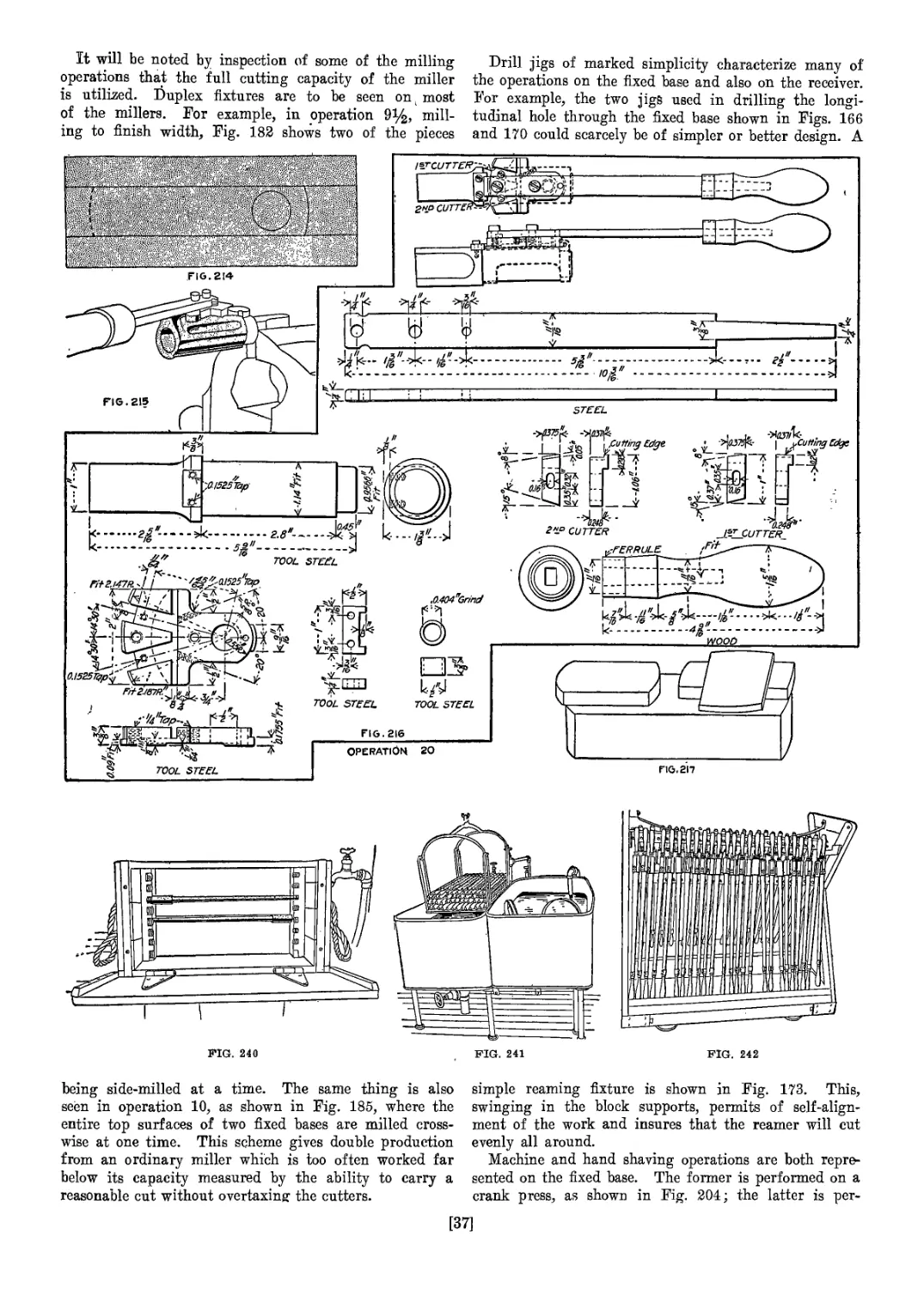
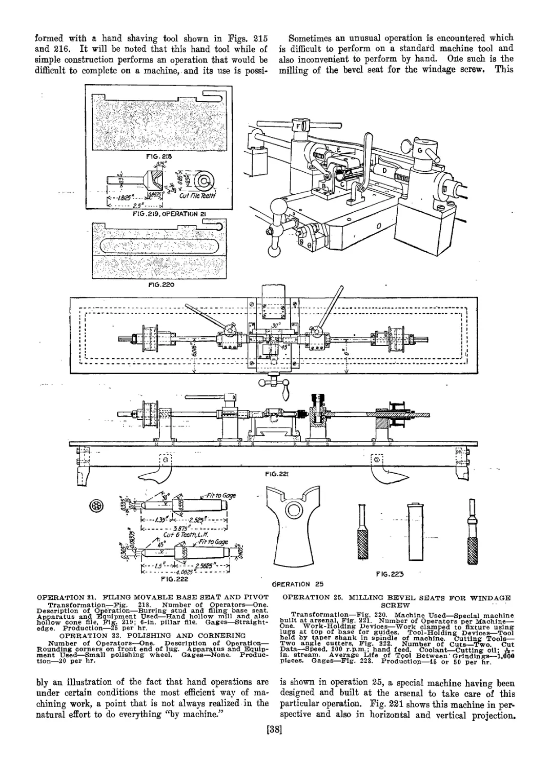
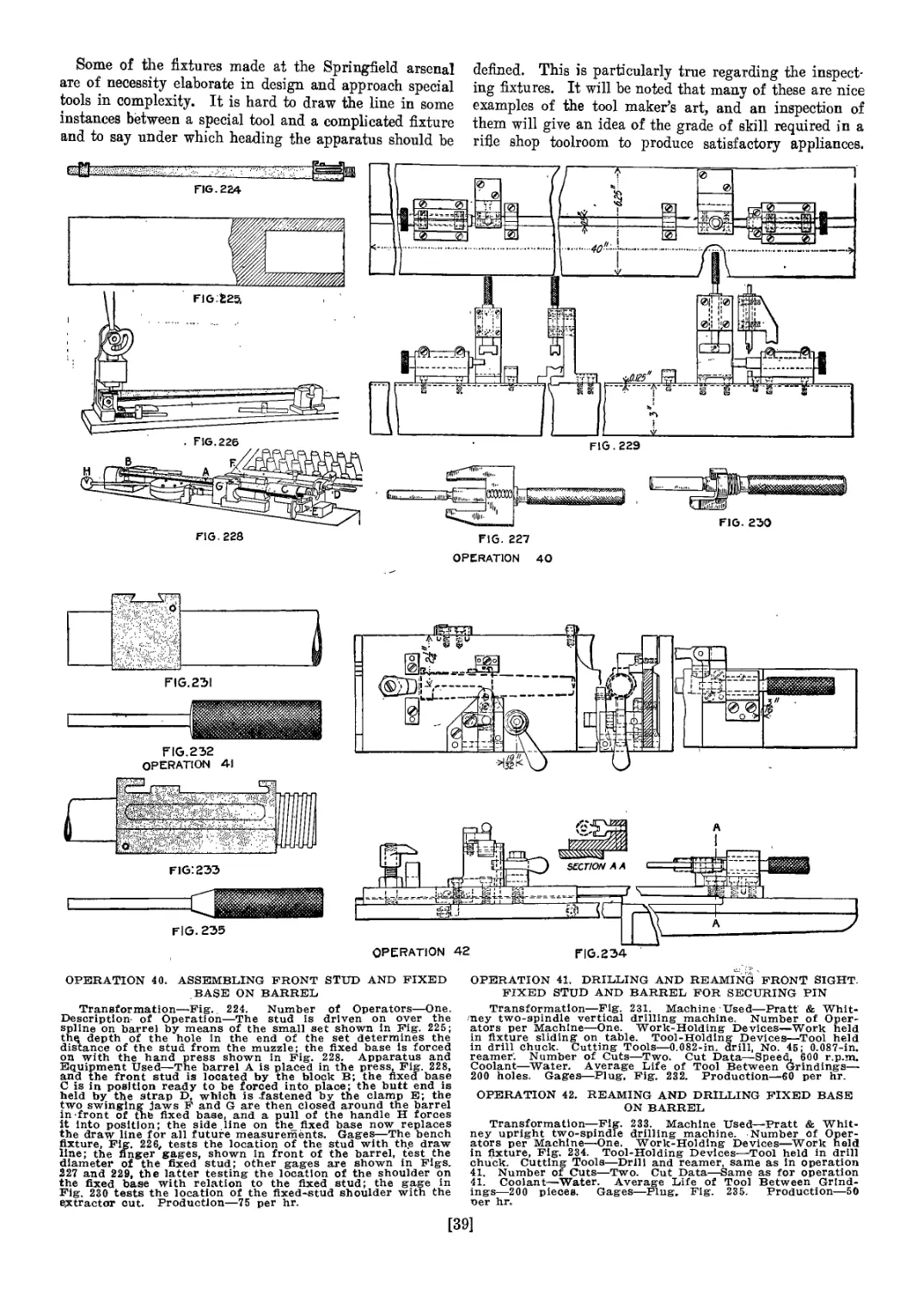
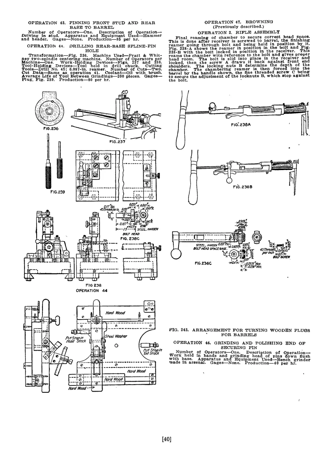
/


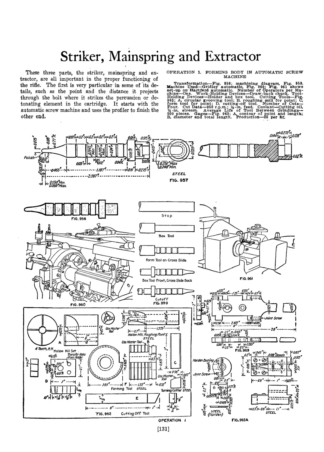


Text
QJnrni’ll Mniuersitg ffiihrarg
Stljara, Nem ^nrk
BOUGHT WITH THE INCOME OF THE
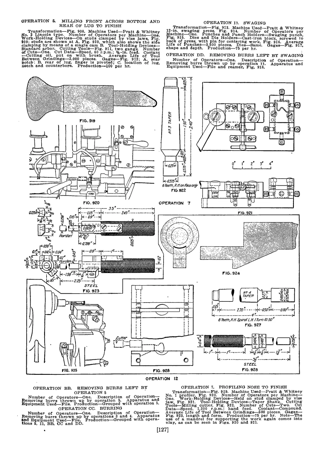
SAGE ENDOWMENT FUND
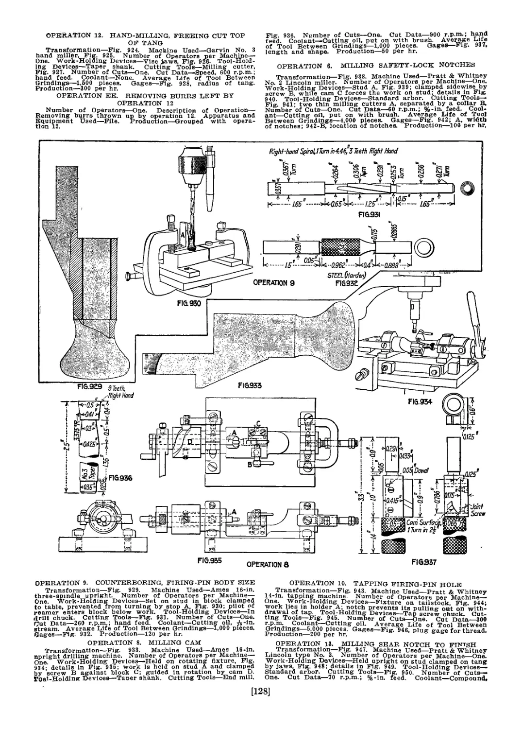
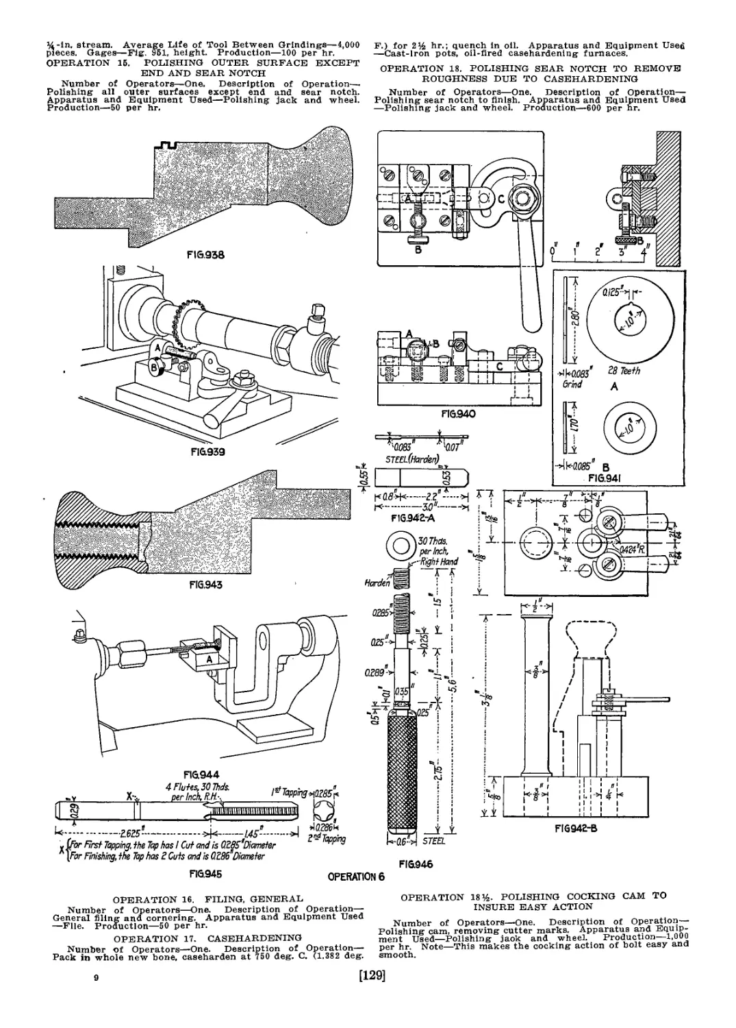
THE GIFT OF
HENRY W. SAGE
1891
UNITED STATES RIFLES
AND
MACHINE GUNS
I
% Qraw-MlBook &, Ine.
PUBLISHERS OF BOOKS F О FL—.
Coal Age v Electric Railway Journal
Electrical World v Engineering News-Record
Railway Age Gazette American Machinist
Electrical Merchandising The .Contractor
Engineering § Mining Journal Power
Metallurgical 8 Chemical Engineering
UNITED STATES RIFLES
AND
MACHINE GUNS
A DETAILED ACCOUNT OF THE METHODS USED IN MANUFAC-
TURING THE SPRINGFIELD, 1903 MODEL SERVICE
RIFLE; ALSO DESCRIPTIONS OF THE MODI-
FIED ENFIELD RIFLE AND THREE
TYPES OF MACHINE GUNS.
BY
FRED H. COLVIN
AND
ETHAN VIALL
ASSOCIATE EDITORS AMERICAN MACHINIST
MEMBERS AMERICAN SOCIETY OF MECHANICAL ENGINEERS
MEMBERS FRANKLIN INSTITUTE
First Edition
McGRAW-HILL BOOK COMPANY, Inc.
239 WEST 39TH STREET. NEW YORK
LONDON: HILL PUBLISHING CO., Ltd.
6 & 8 BOUVERIE ST., E. C.
1917
Copyright, 1917, by the McGraw-Hill Book Company, Inc.
PREFACE
The accompanying description of the methods used at the Spring-
field Armory in manufacturing the Springfield, 1903 Model Service
Rifle was undertaken at the request of the Ordnance Bureau of the
United States Army for the purpose of assisting manufacturers in
undertaking large contracts for this arm should necessity arise.
The immediate necessity arrived before this plan could be carried
out, but as the Springfield still remains the standard arm of the
United States Army, the work remains of value for the future. The
methods shown are those in use during the fall of 1916, some of these
being since modified in accordance with manufacturing require-
ments.
It is believed that this is the first instance of such an amount of
detailed information being gathered into such a small compass where
it is so readily available for use. The perspective drawings of oper-
ations are all from photographs, over 1000 being taken for this
purpose. Credit for the plan of securing the material in this form
belongs to John H. Van Deventer, Editor of the American Machinist,
and we also desire to thank Col. W. S. Peirce, Maj. G. H. Stewart,
Capt. R. R. Nix, T. H. Fletcher and Harry R. Johnson for valuable
assistance in securing the material here presented.
While this was secured primarily for its value to makers of mili-
tary rifles, it is hoped and believed that it will be found useful to
other manufacturers making parts which in some way resemble
those shown. Some of the uses of the profiler and miller should be
available in other classes of manufacture.
We have also included the descriptions of the operation and
mechanisms of the modified Enfield, the United States Machine
Rifle, the Lewis Machine Gun, and the Vickers Machine Gun.
The Authors
CONTENTS
Page
Preface........................................................... v
The Evolution of the American Military Rifle...................... 1
General Specifications and Barrel Operations...................... 9
Operations on the Barrel and the Fixed Stud...................... 20
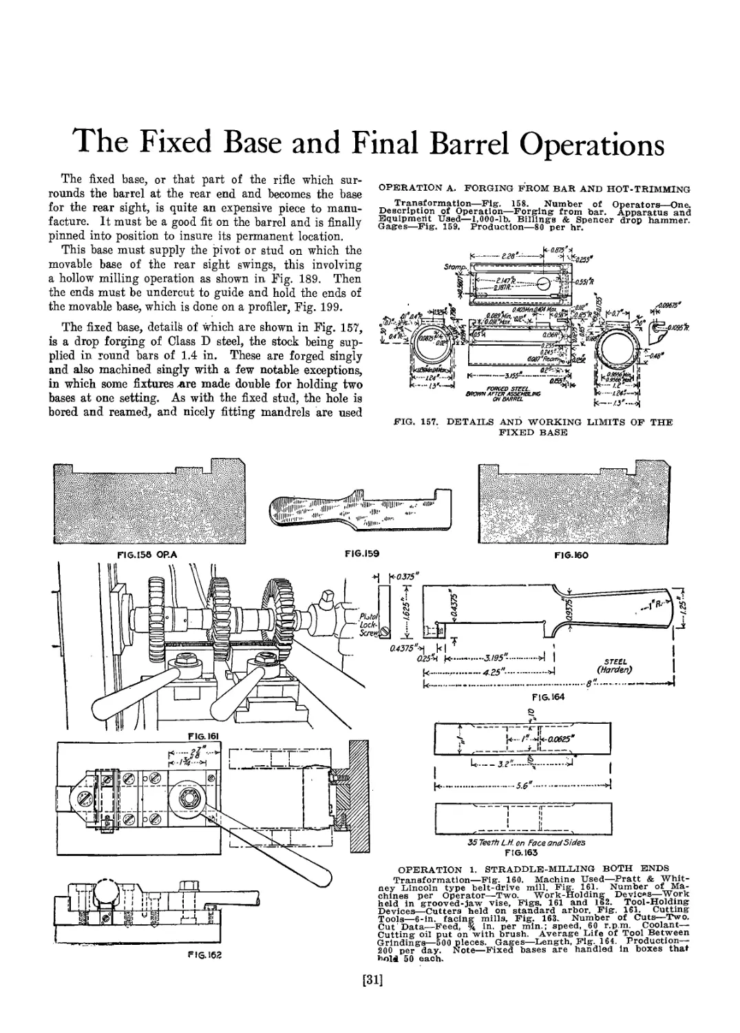
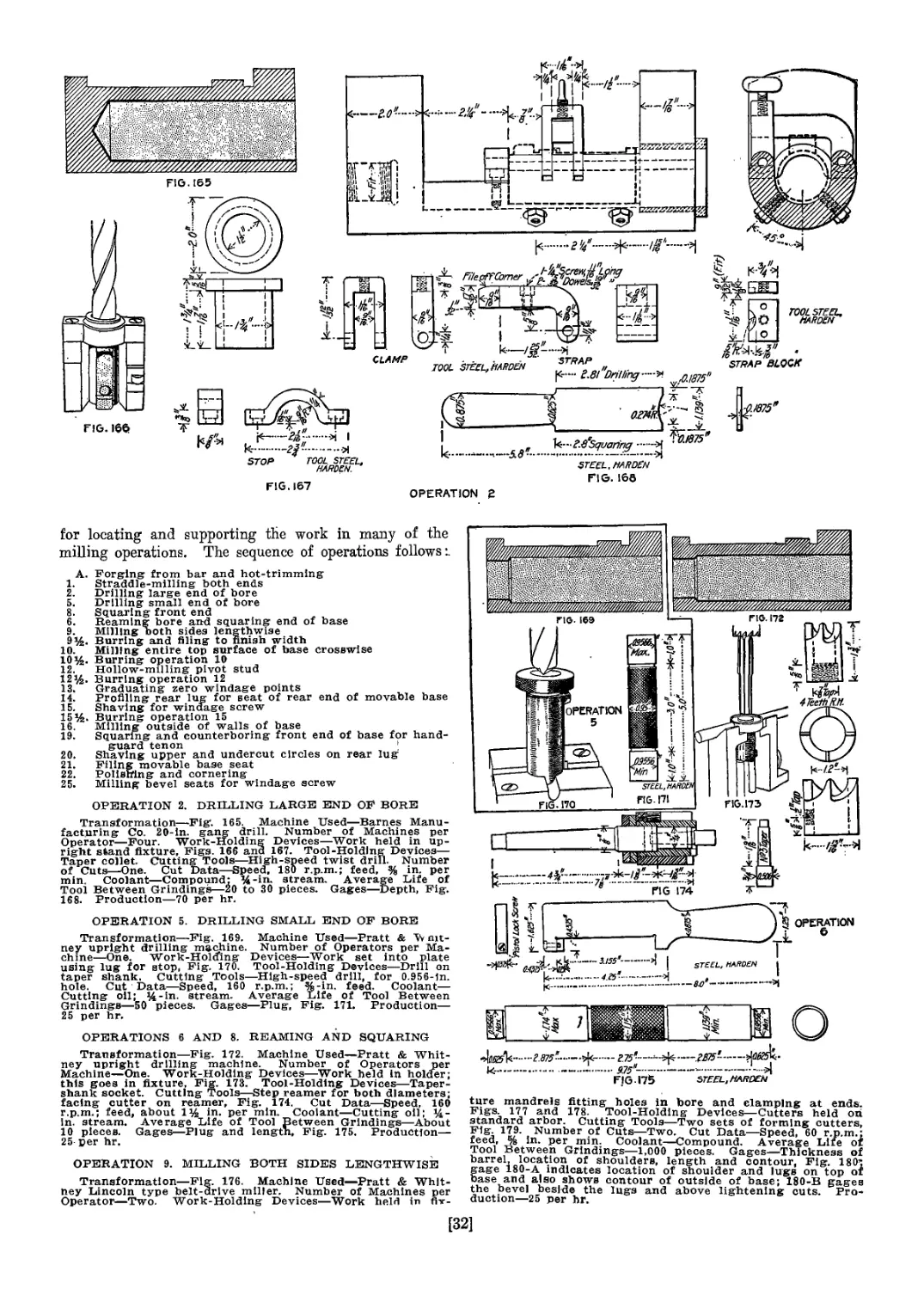
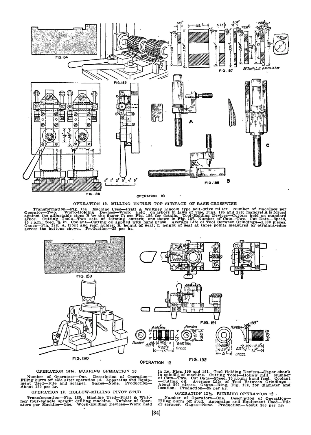
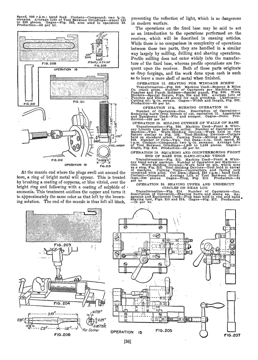
The Fixed Base and Final Barrel Operations....................... 31
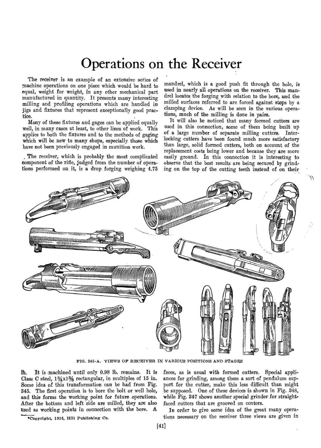
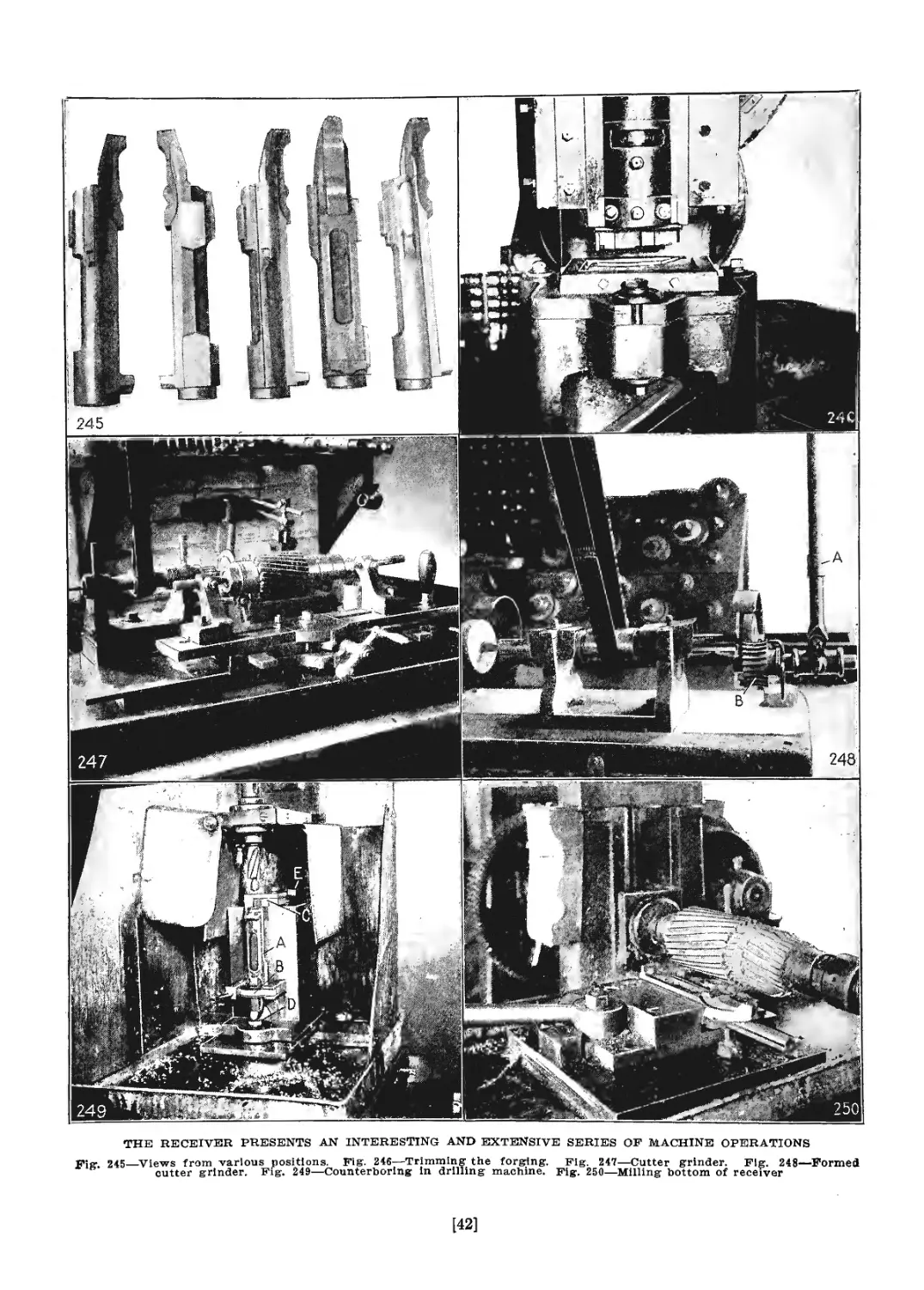
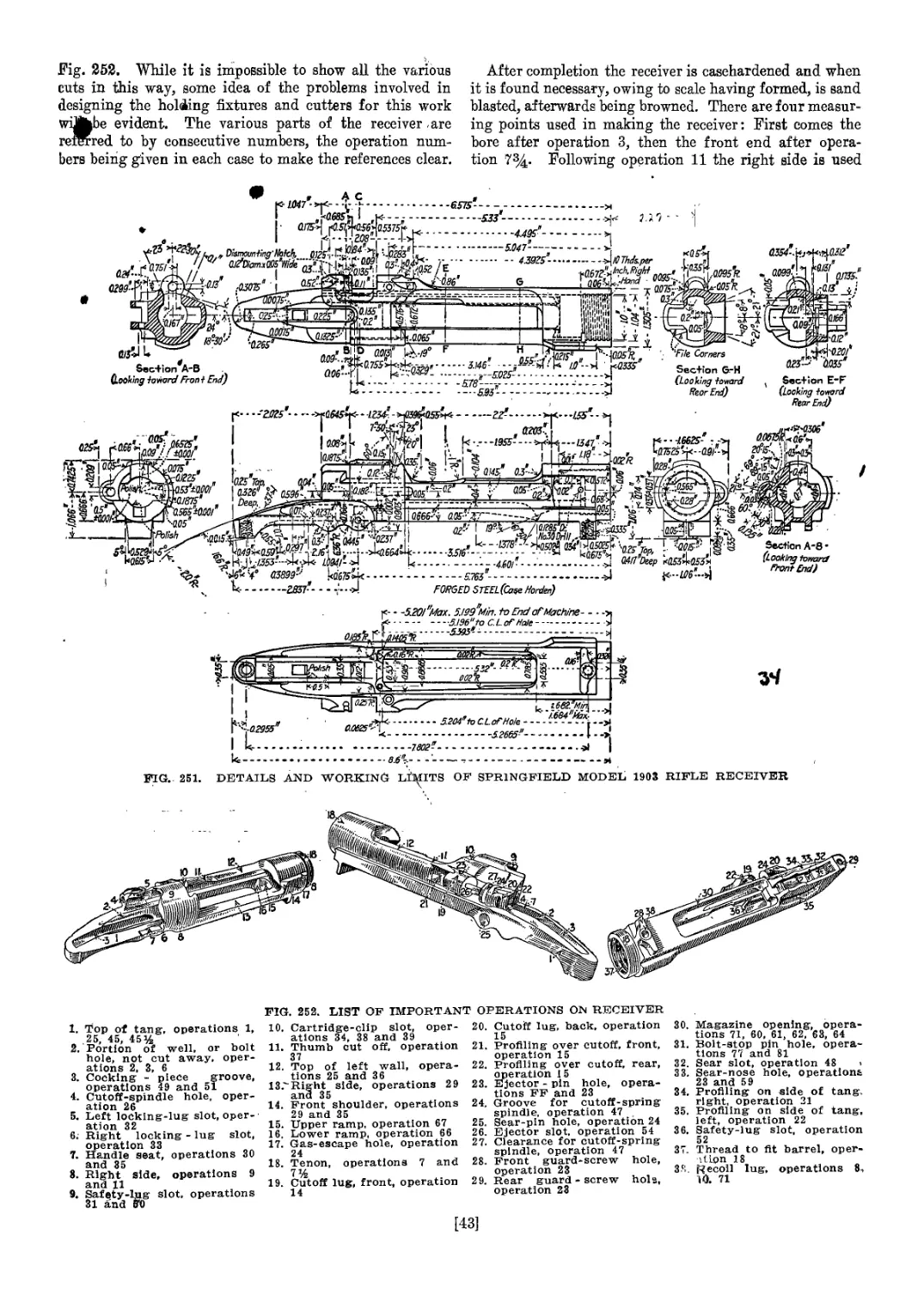
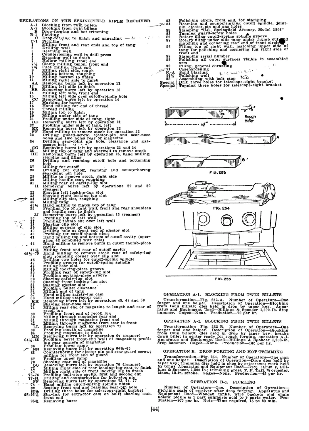
Operations on the Receiver....................................... 41
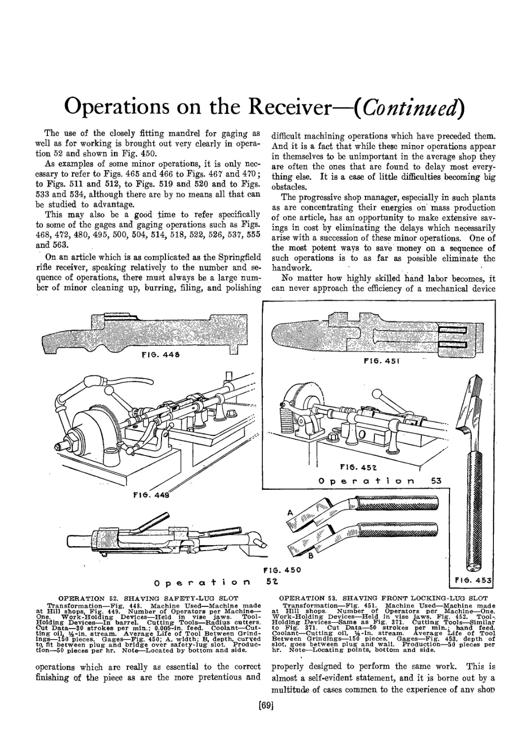
Operations on the Receiver {Continued).......................... 50
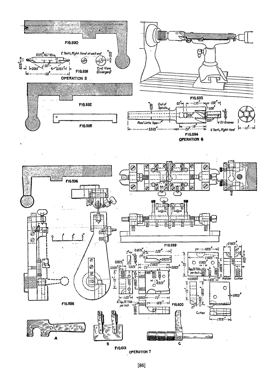
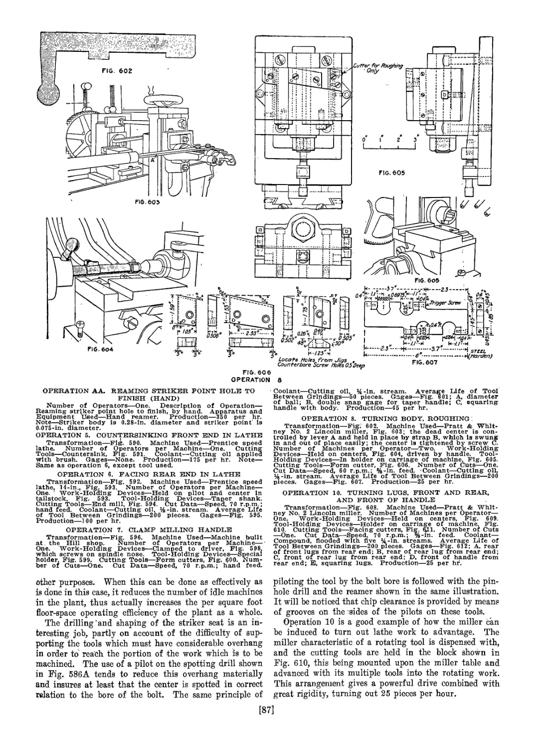
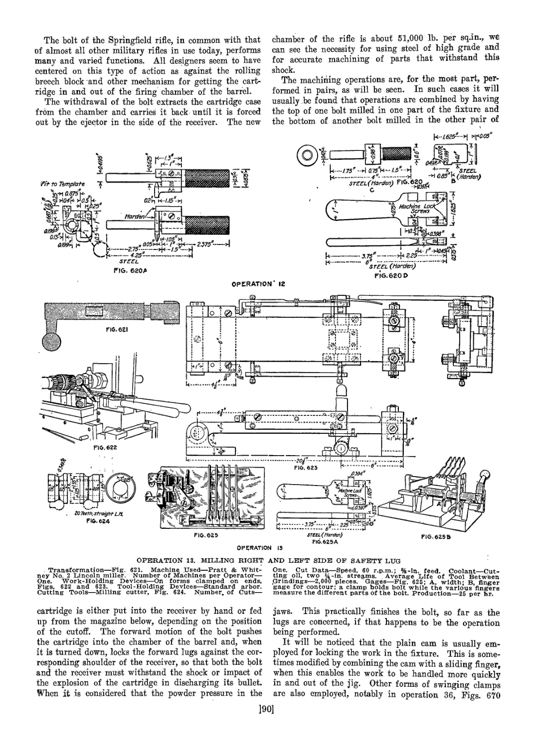
Machining Operations on the Bolt............................... 81
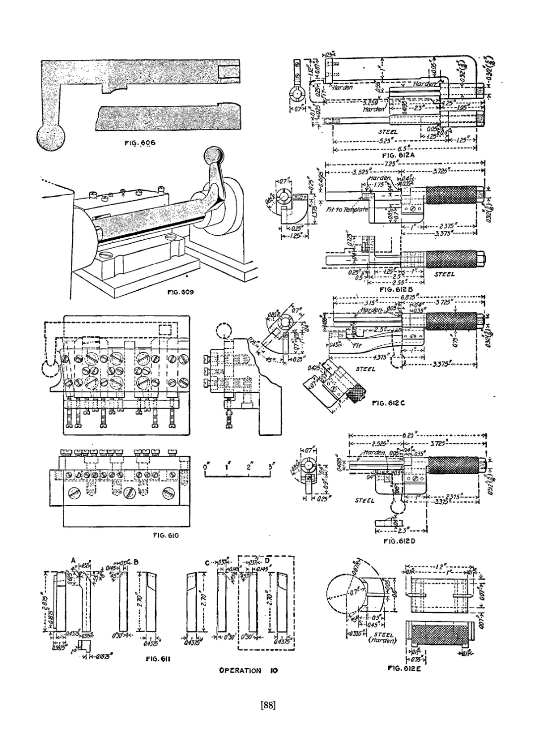
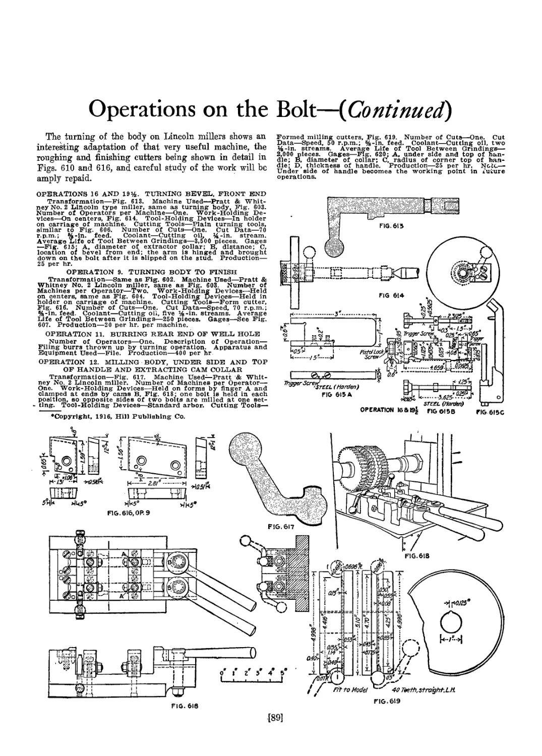
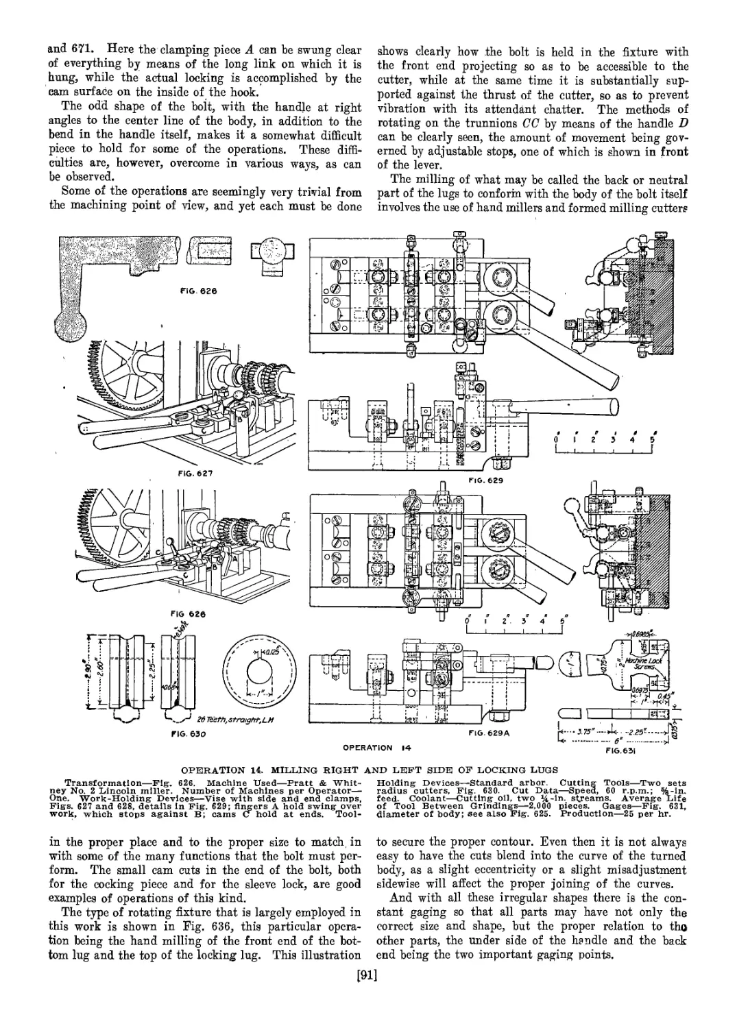
Operations on the Bolt {Continued)............................... 89
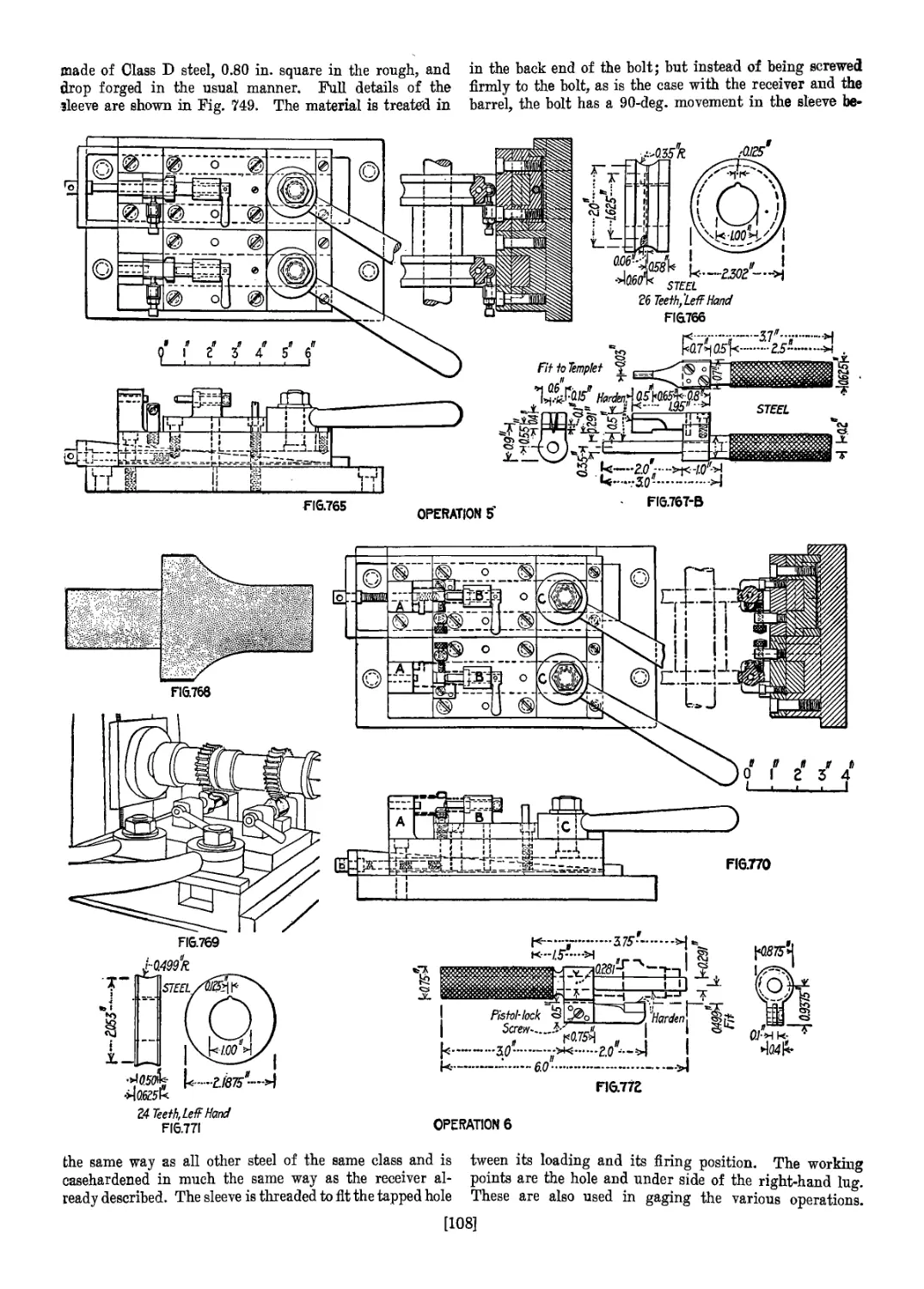
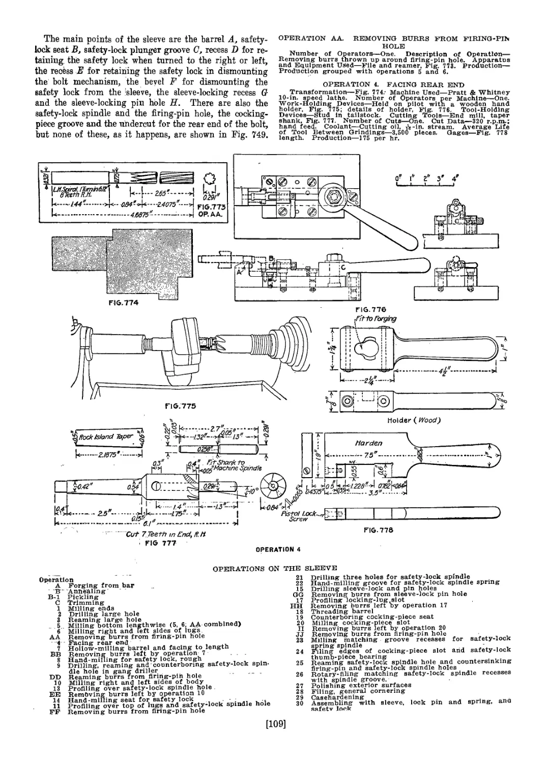
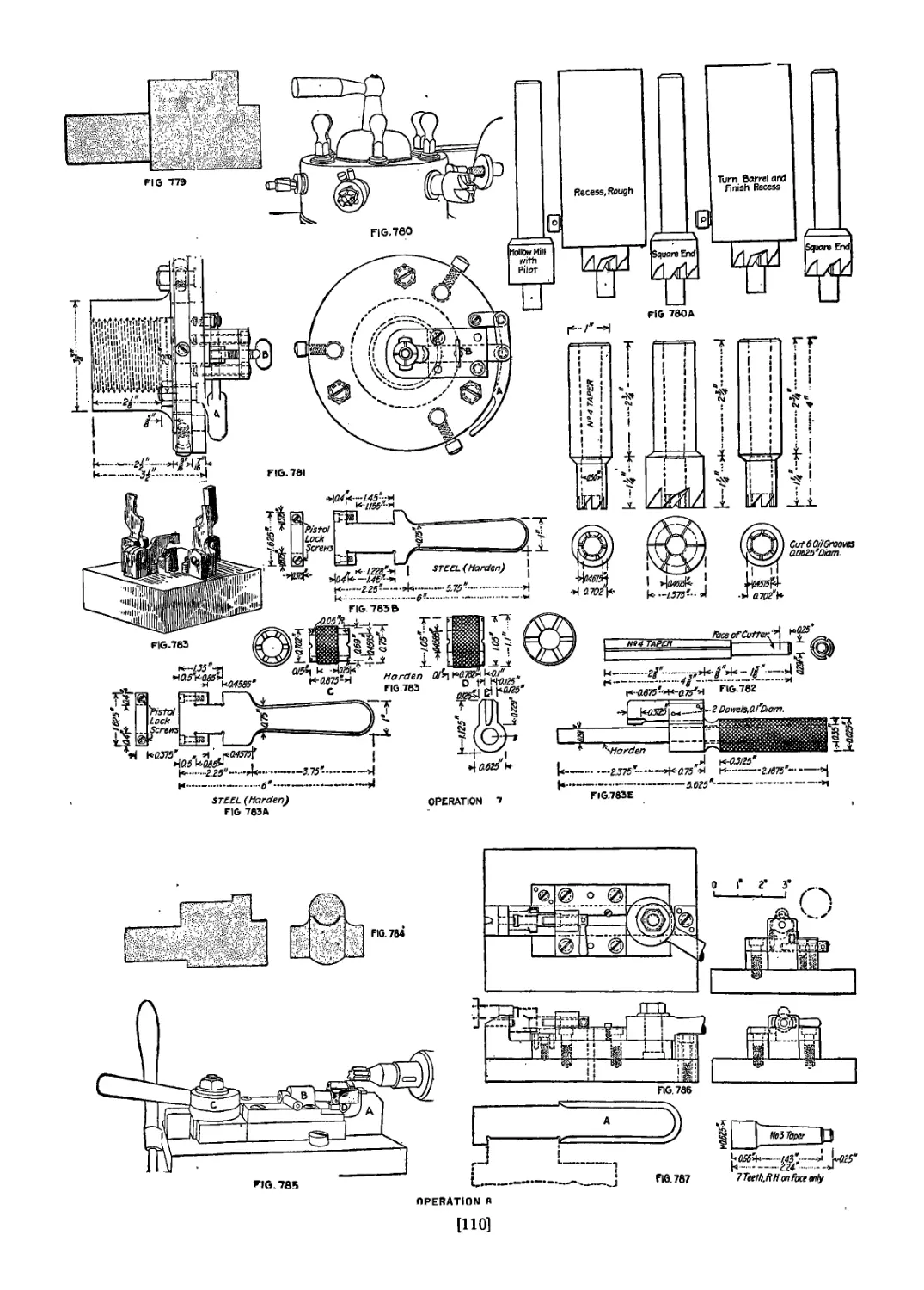
Operations on the Sleeve........................................ 106
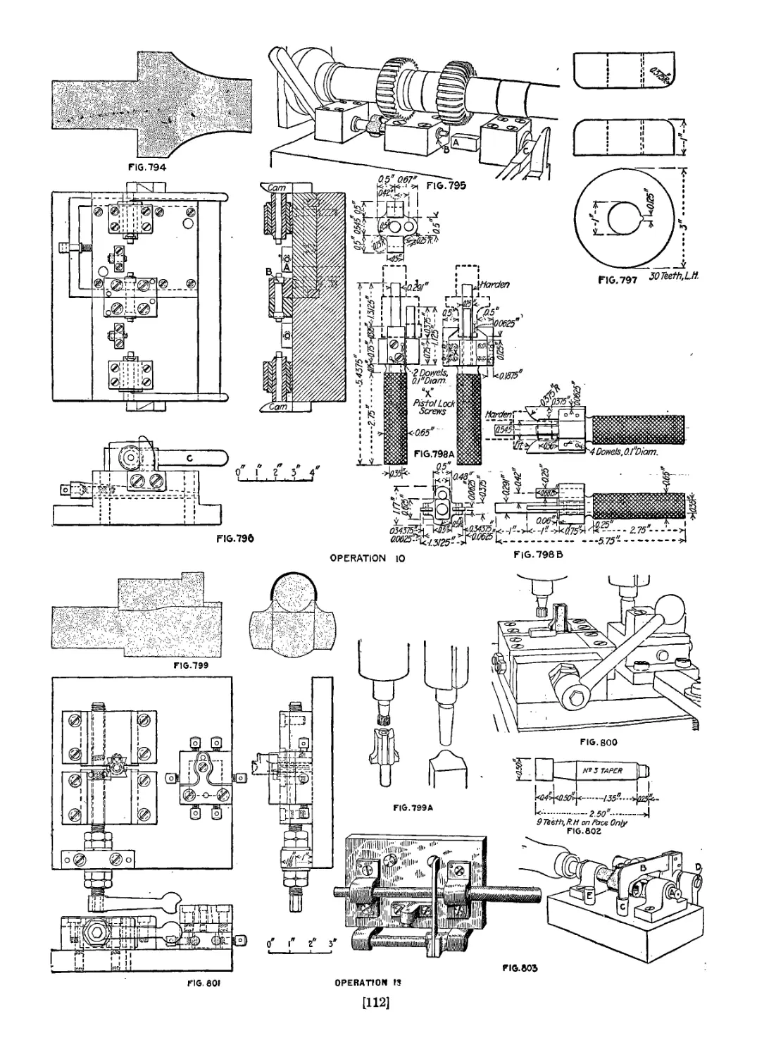
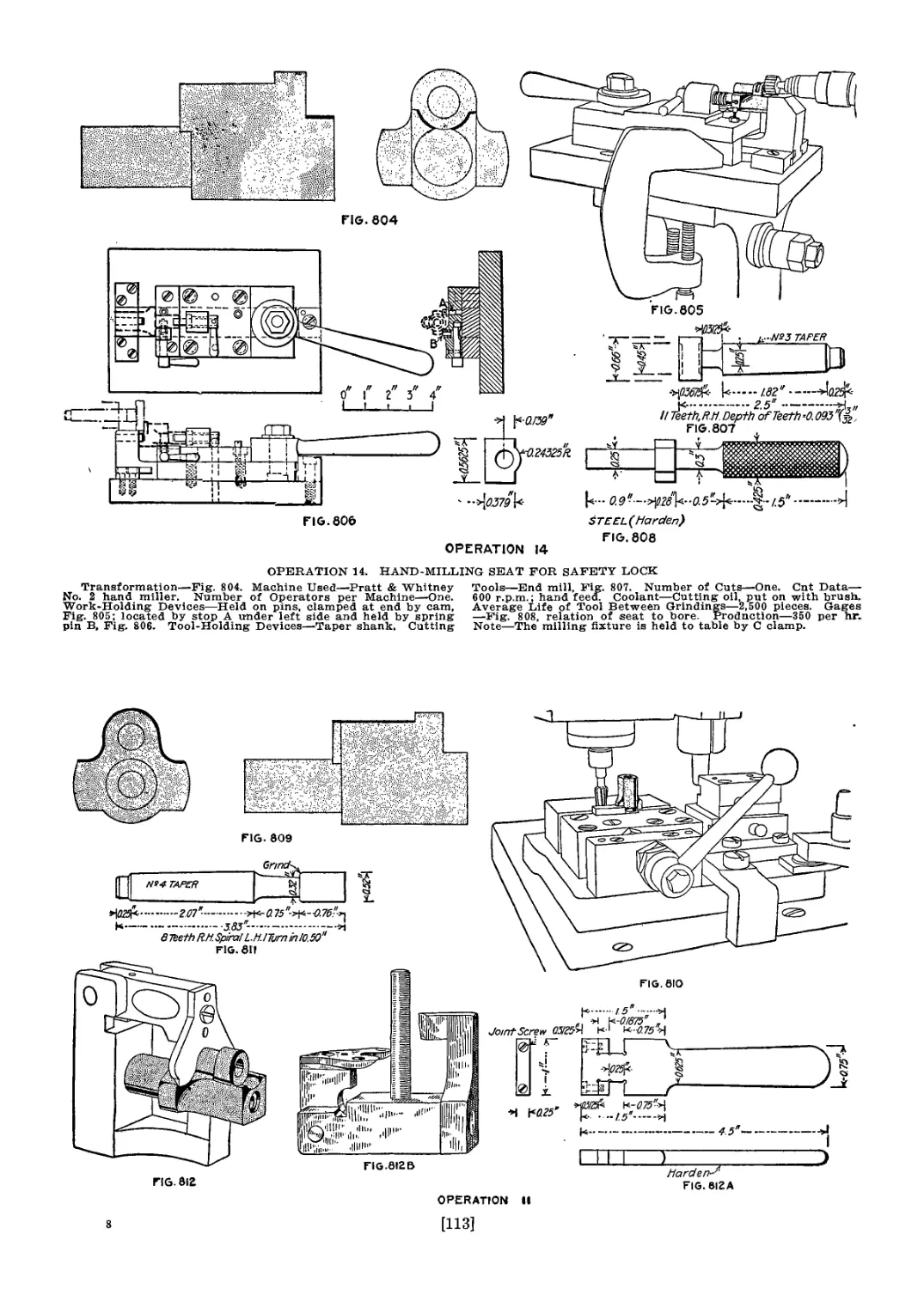
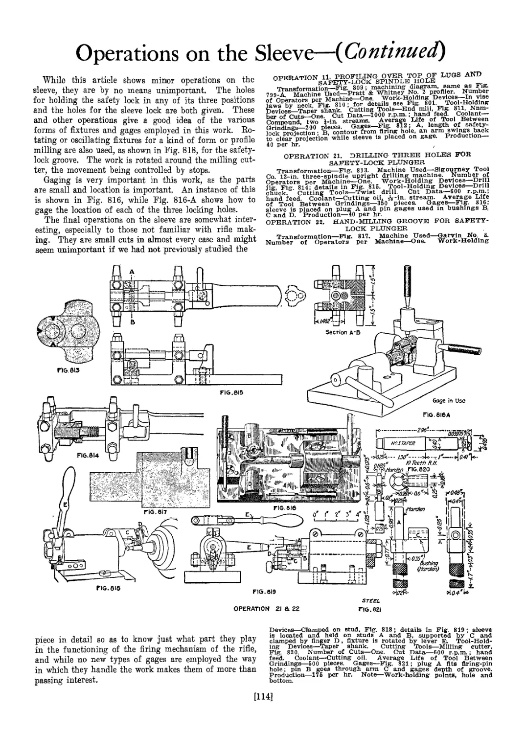
Operations on the Sleeve {Continued)............................ 114
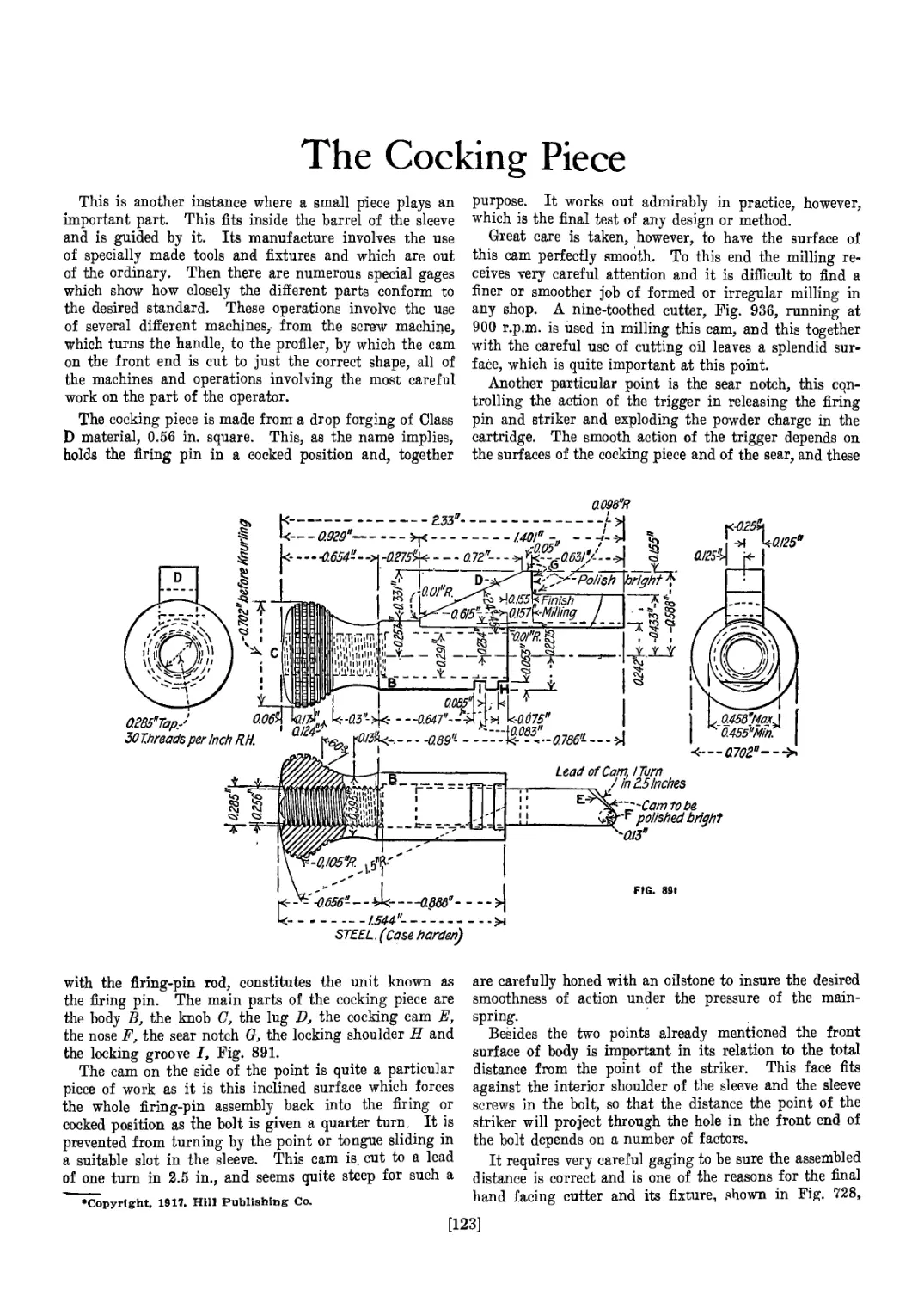
The Cocking Piece............................................... 123
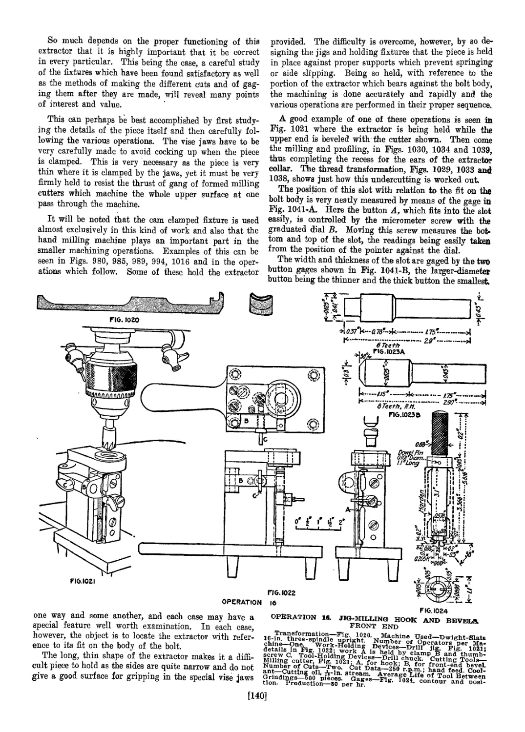
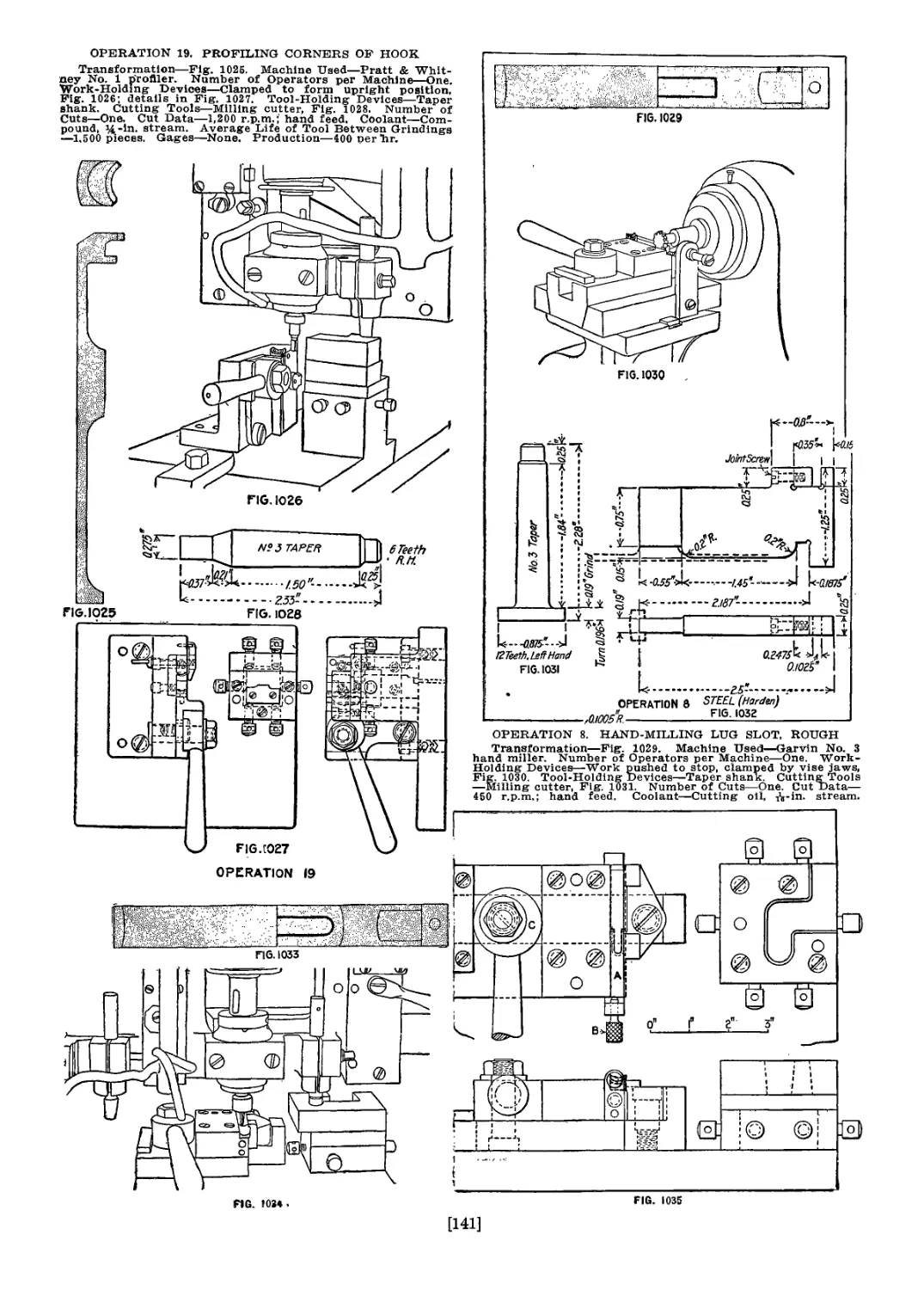
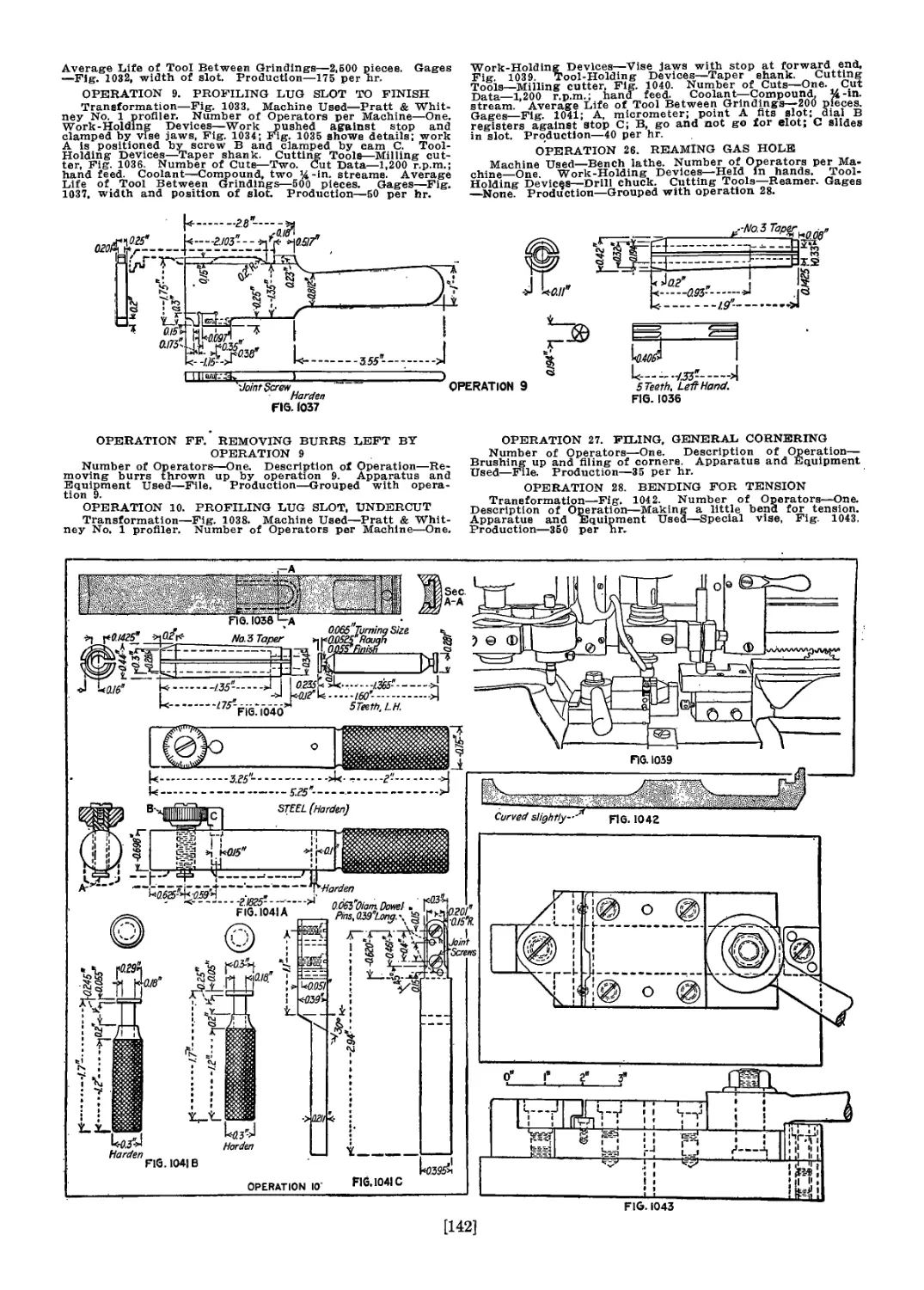
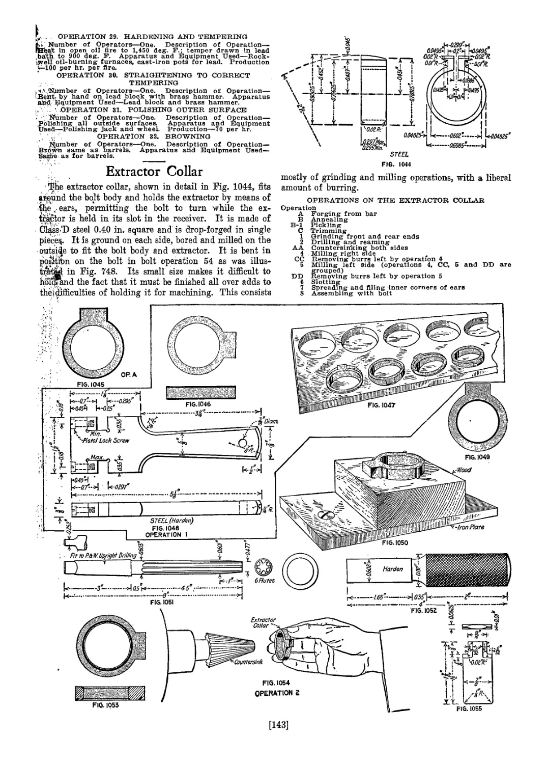
Striker, Mainspring and Extractor............................... 131
Safety-Lock Spindle and Plunger................................. 149
Making the Guard......../....................................... 155
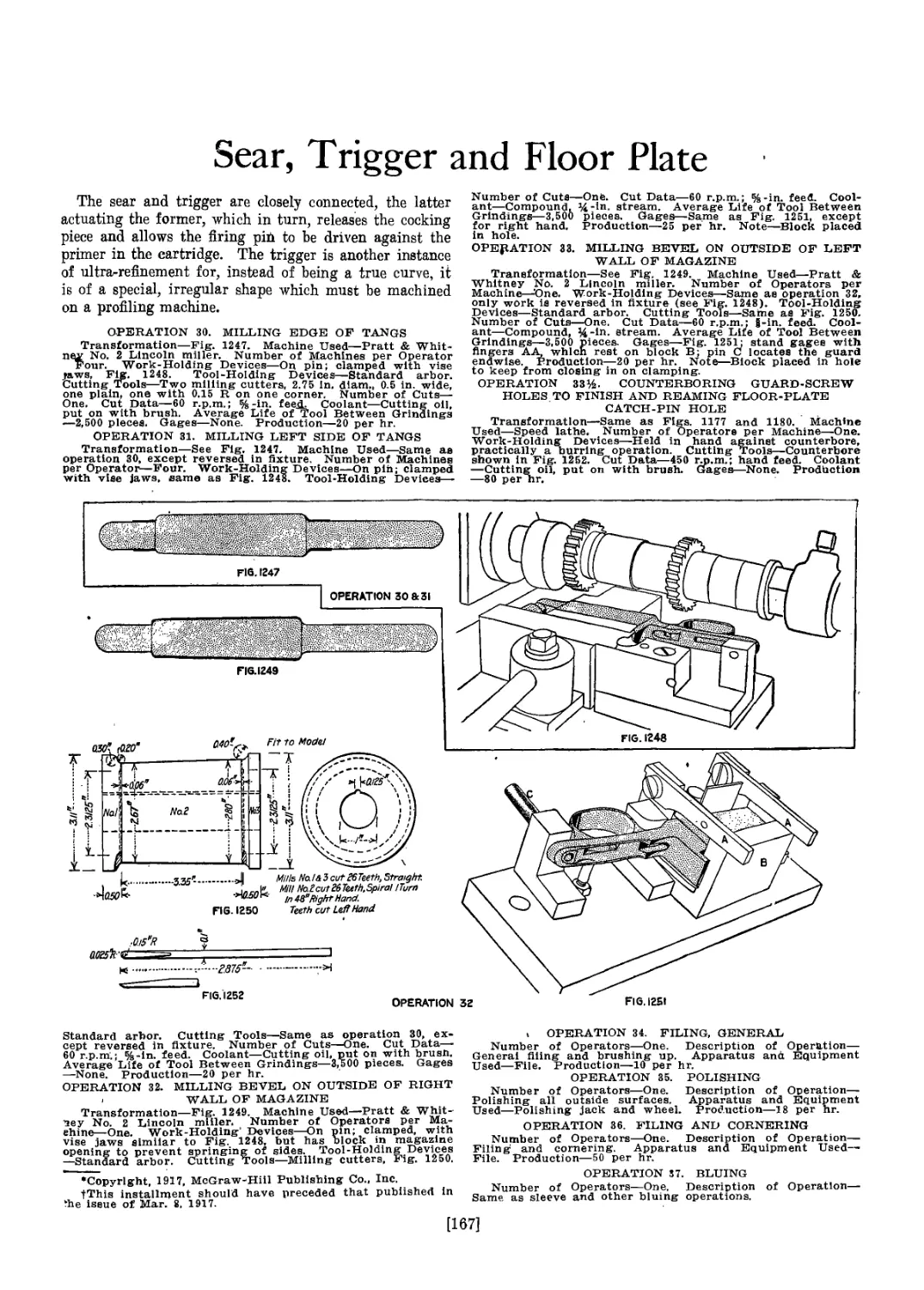
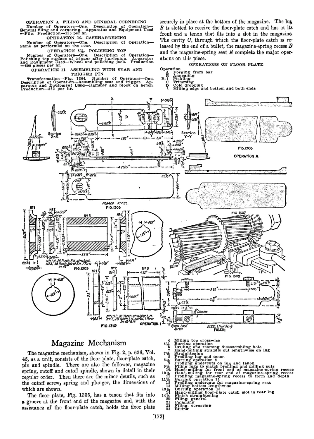
Sear, Trigger and Floor Plate................................... 167
Floor-Plate Catch, Magazine Spring, Cutoff and Follower........ 175
Movable Stud—Front Sight and Movable Base....................... 187
Slide and Cap./................................................. 202
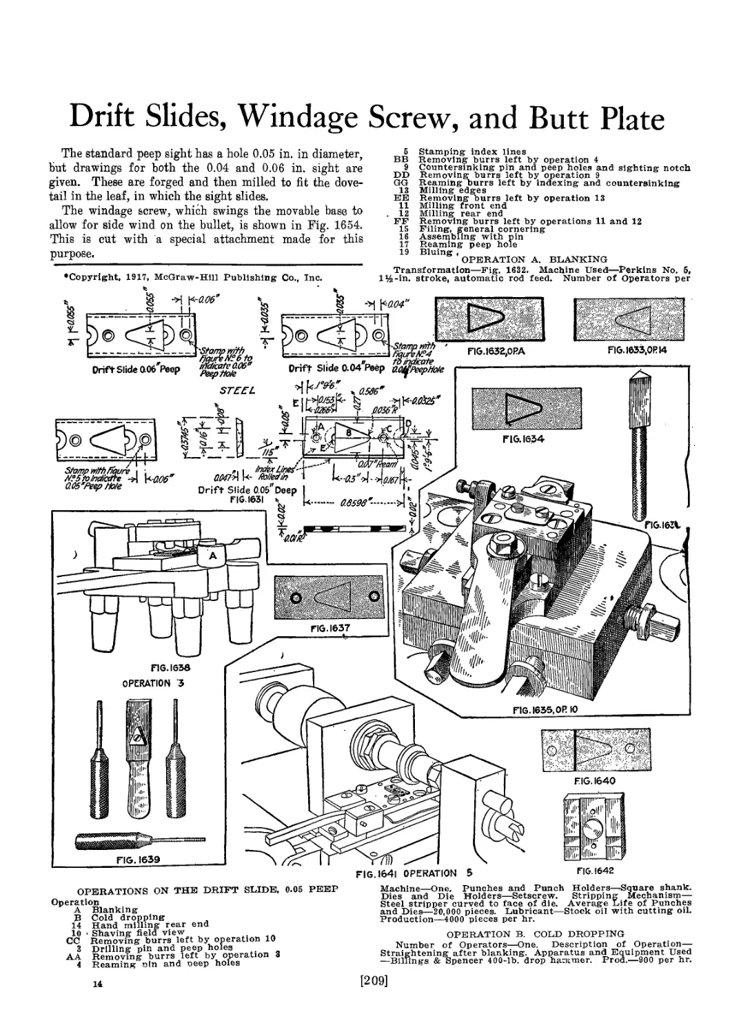
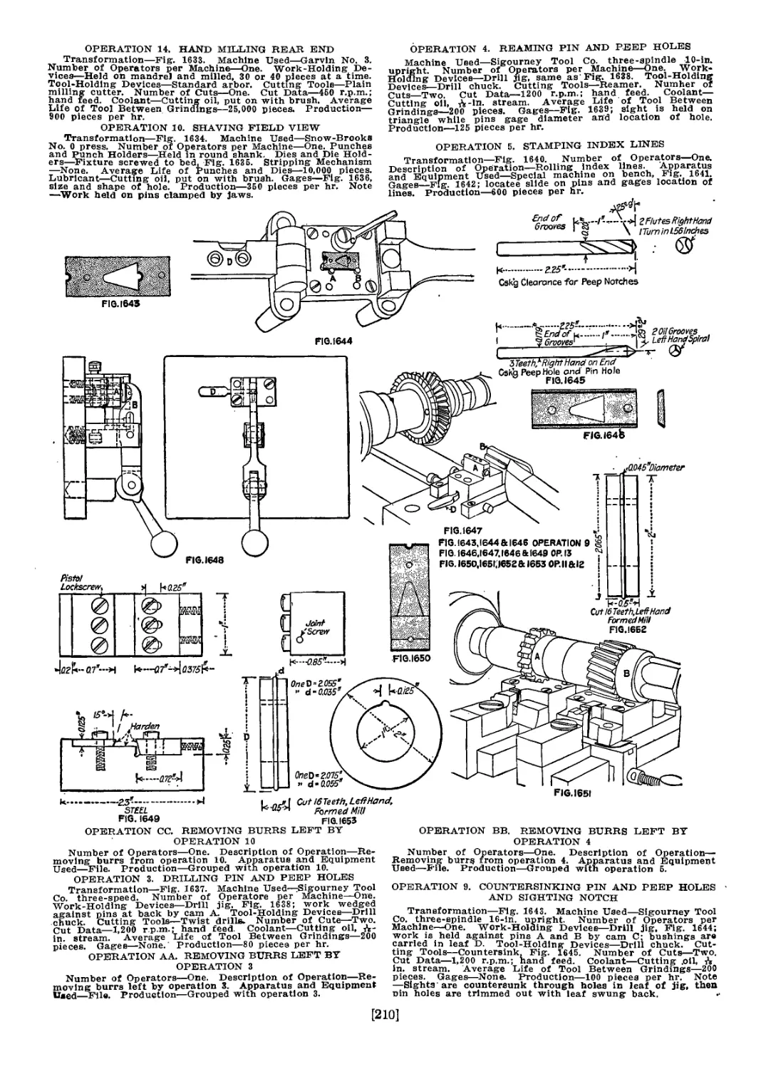
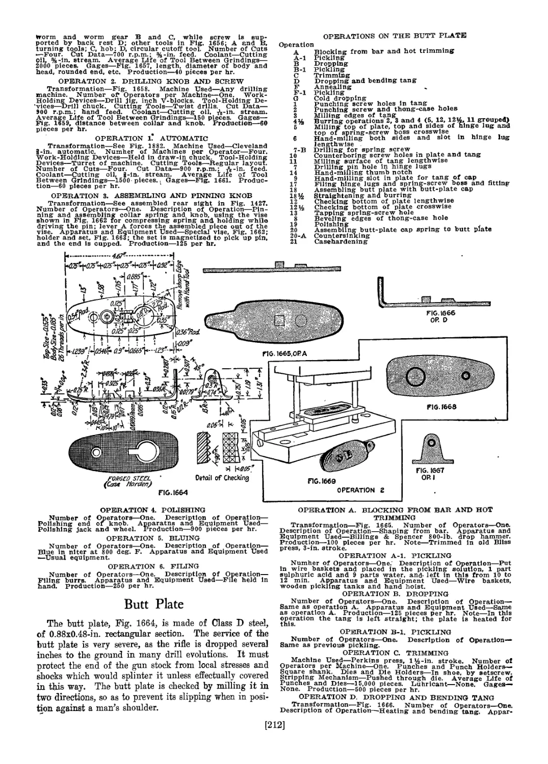
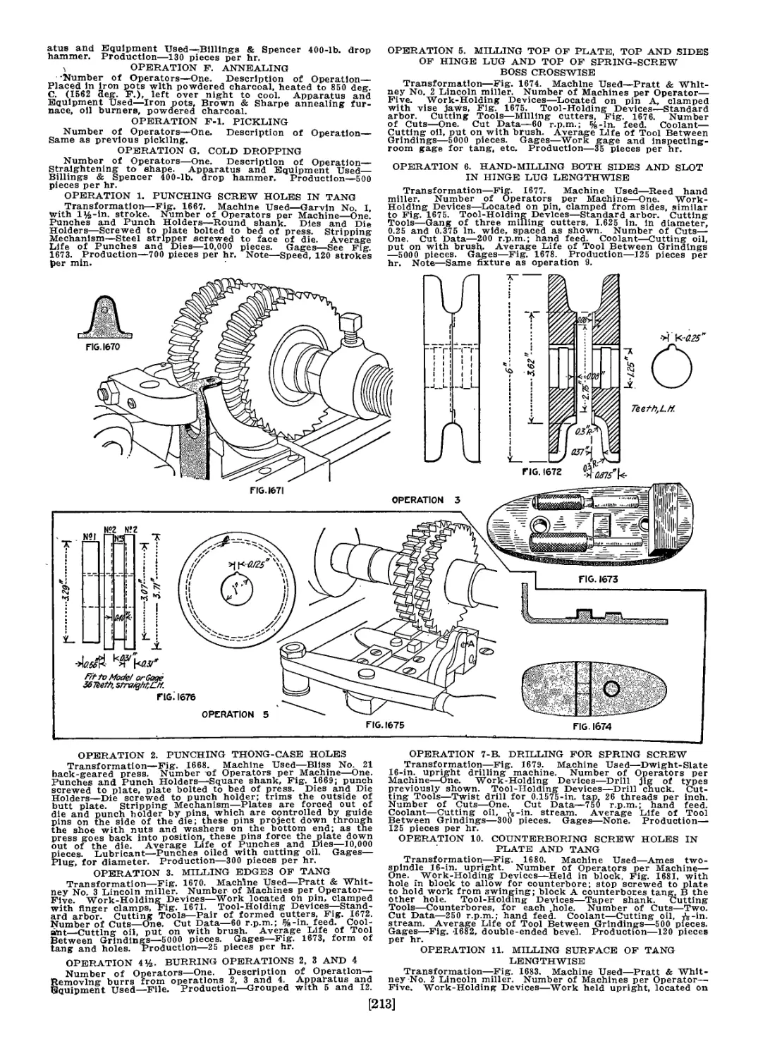
Drift Slides, Windage Screw, and Butt Plate................... 209
Stacking Swivel, Hand-Guard Clip, Front-Sight Cover, Cleaning Rods 231
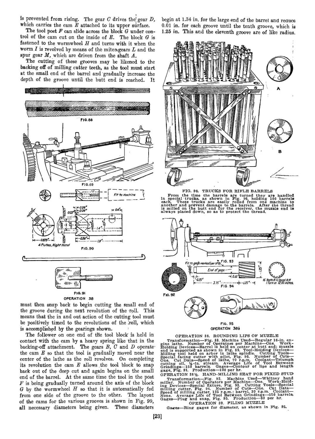
Oiler and Thong Case, Spare-Parts Container, Screw Driver...... 238
Making the Stock............................................... 244
Operations on the Hand Guard.................................... 269
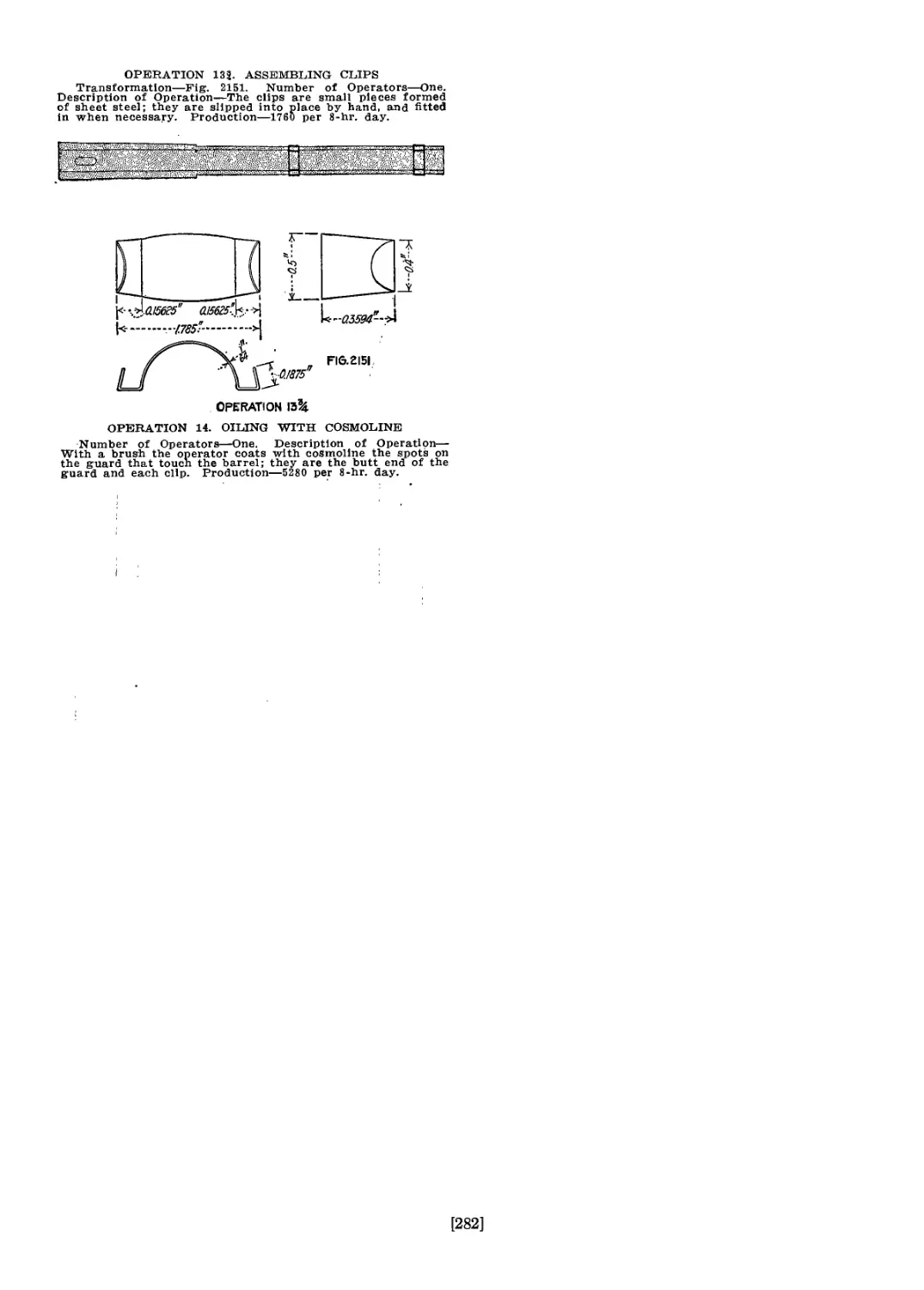
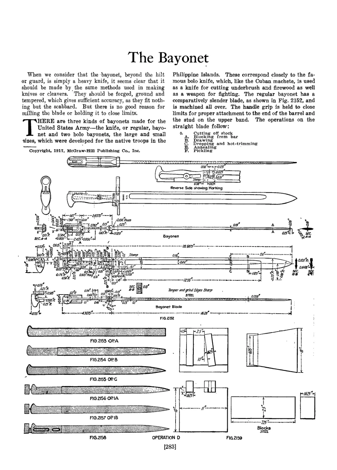
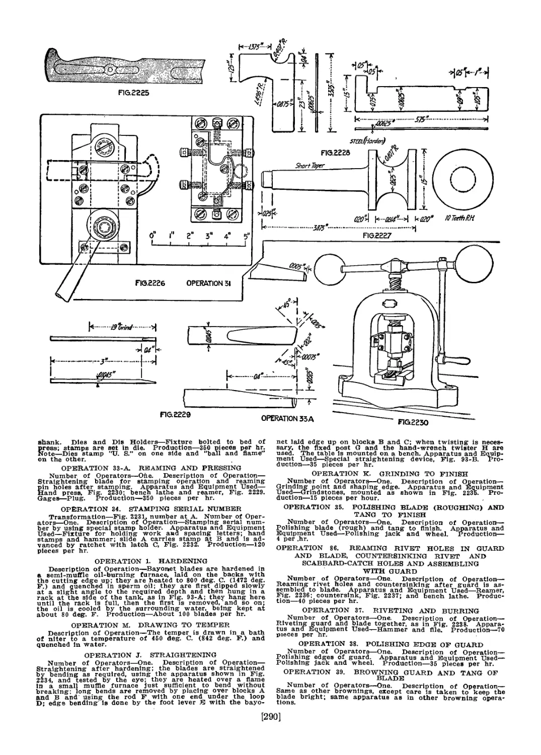
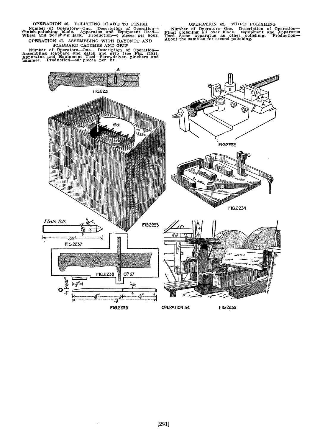
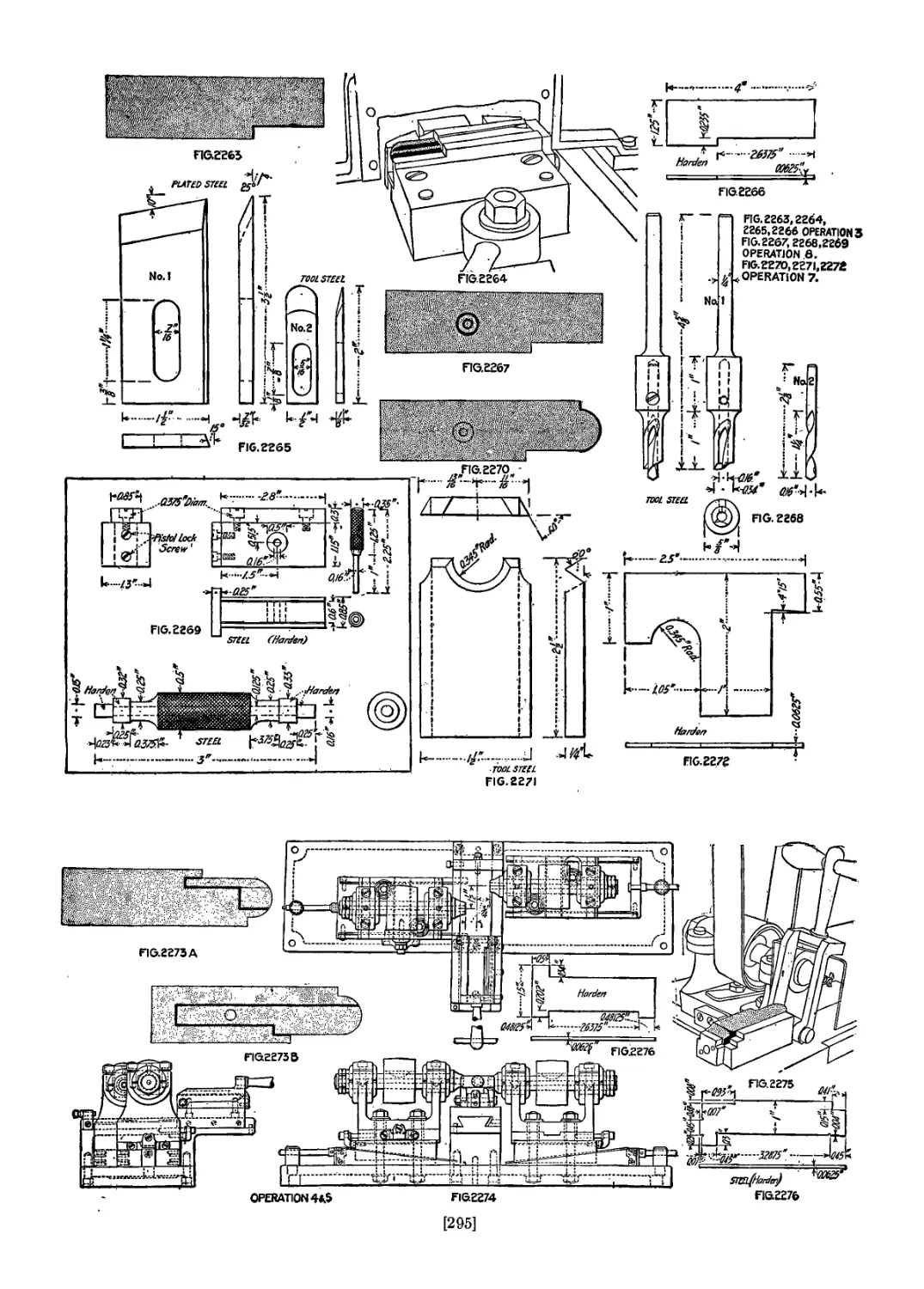
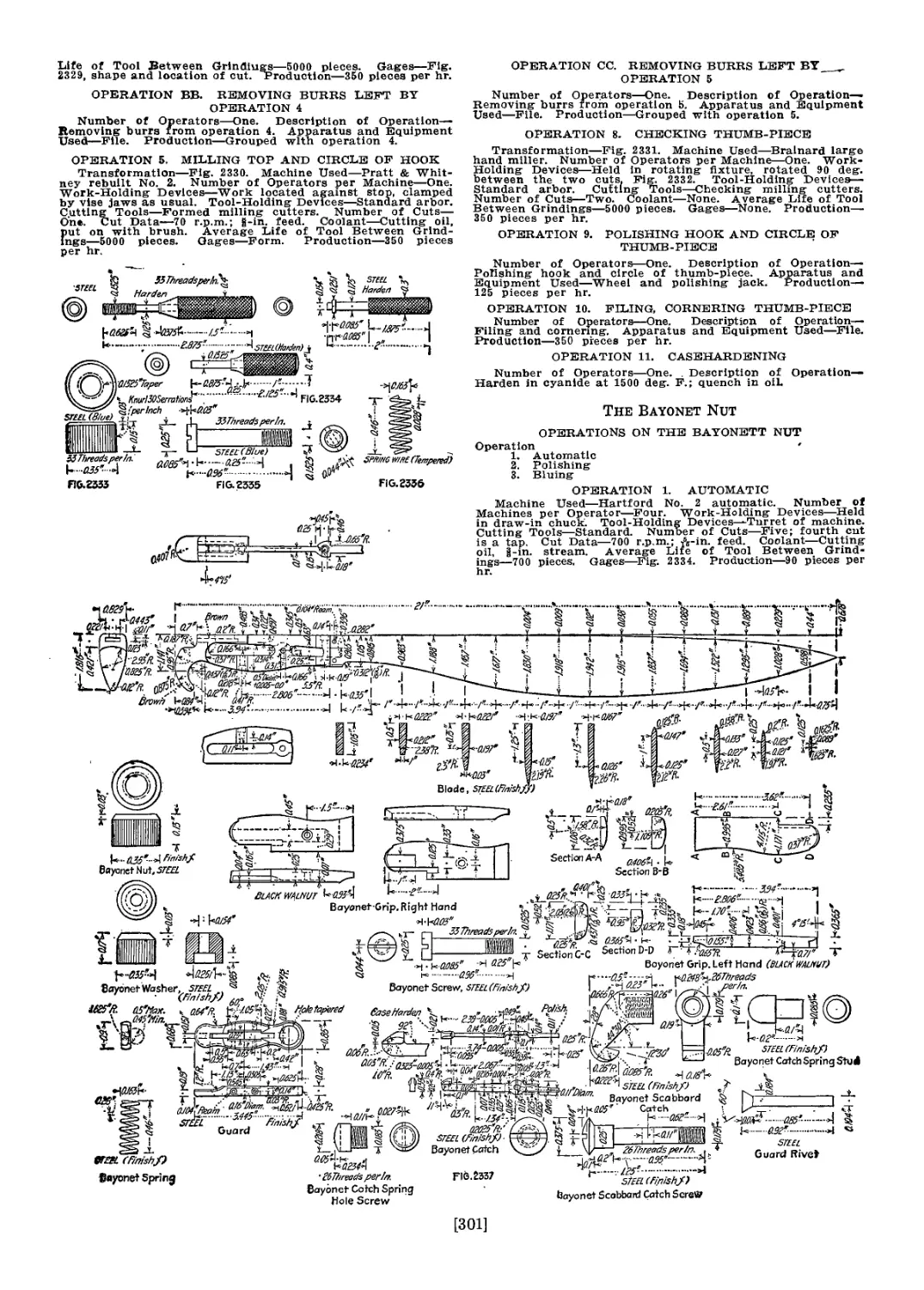
The Bayonet..................................................... 283
Bayonet Catch, Grip, Guard, Scabbard-Catch, Etc................. 292
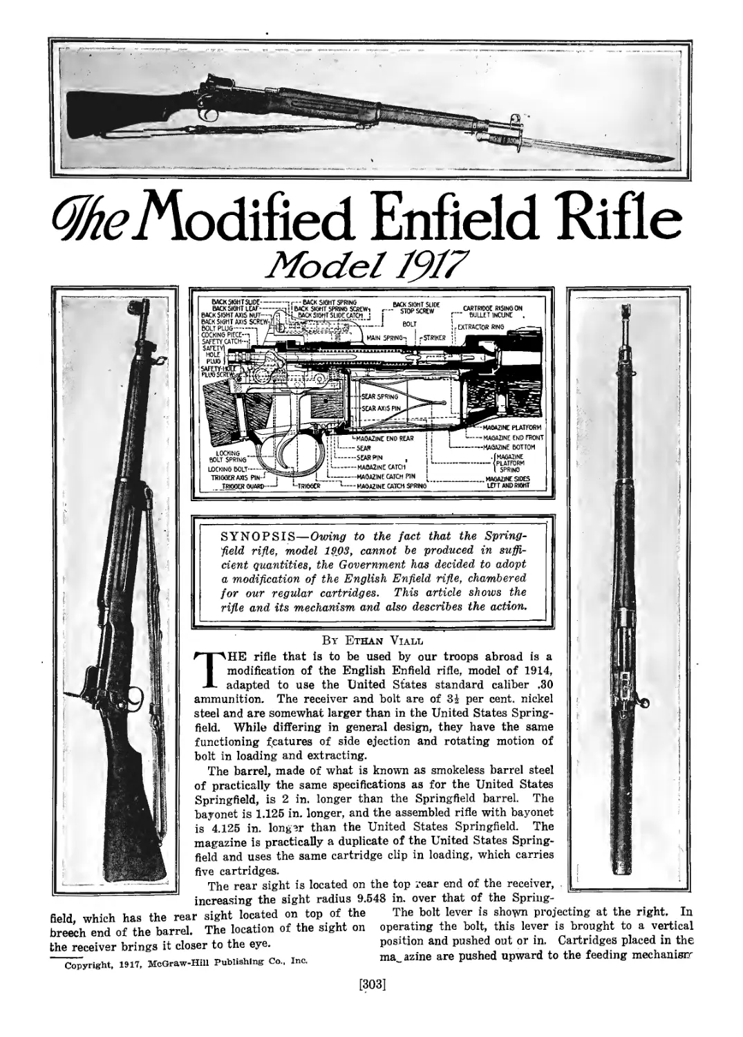
The Modified Enfield Rifle...................................... 303
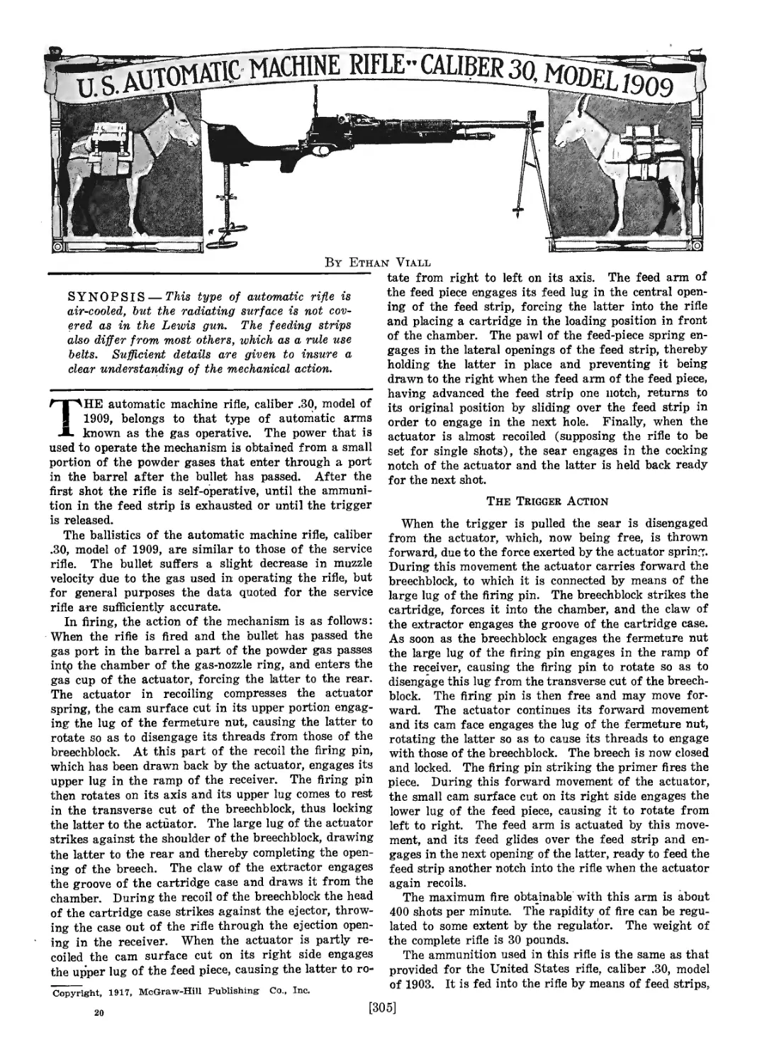
U. S. Automatic Machine Rifle................................... 305
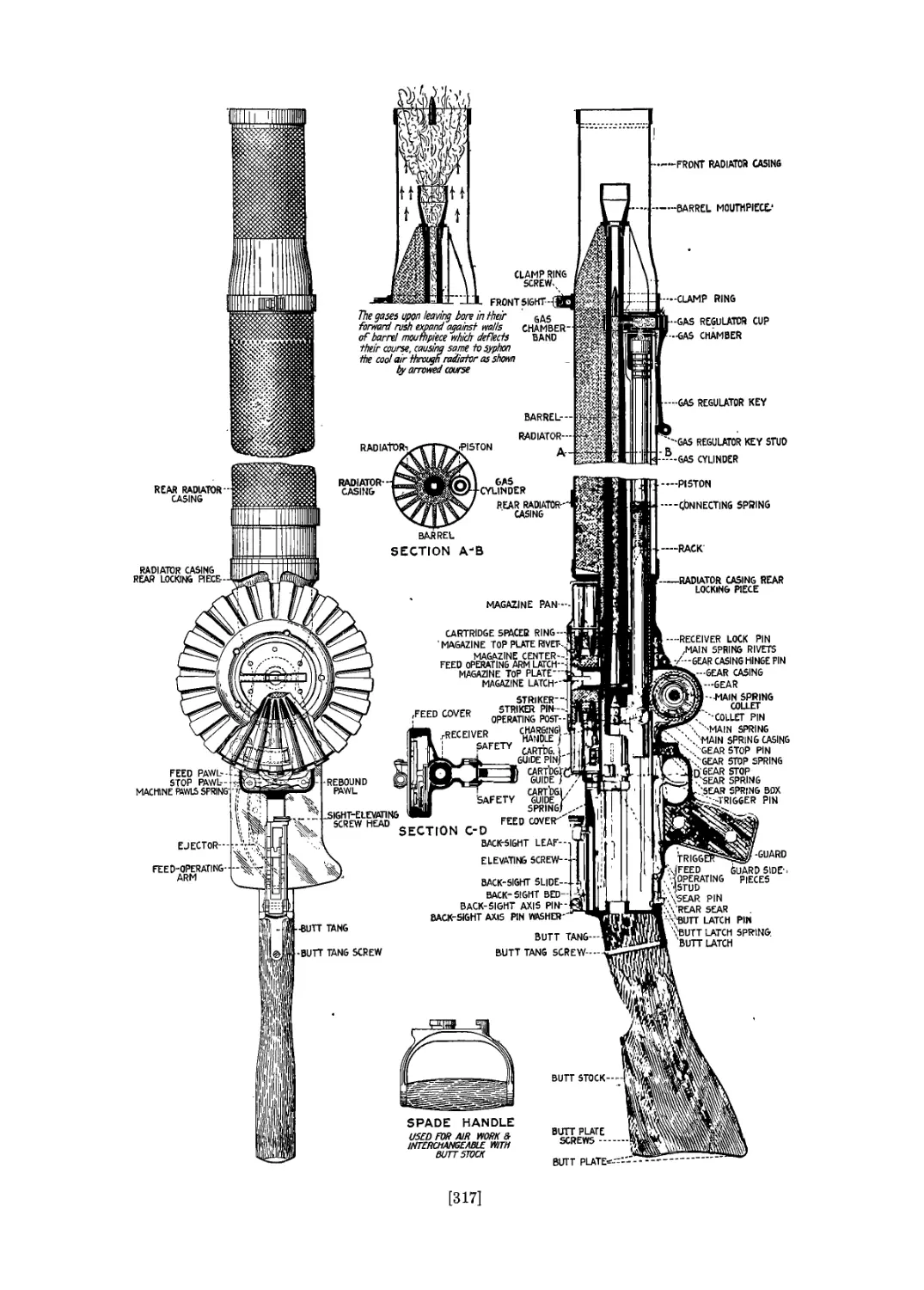
The Lewis Machine Gun........................................... 315
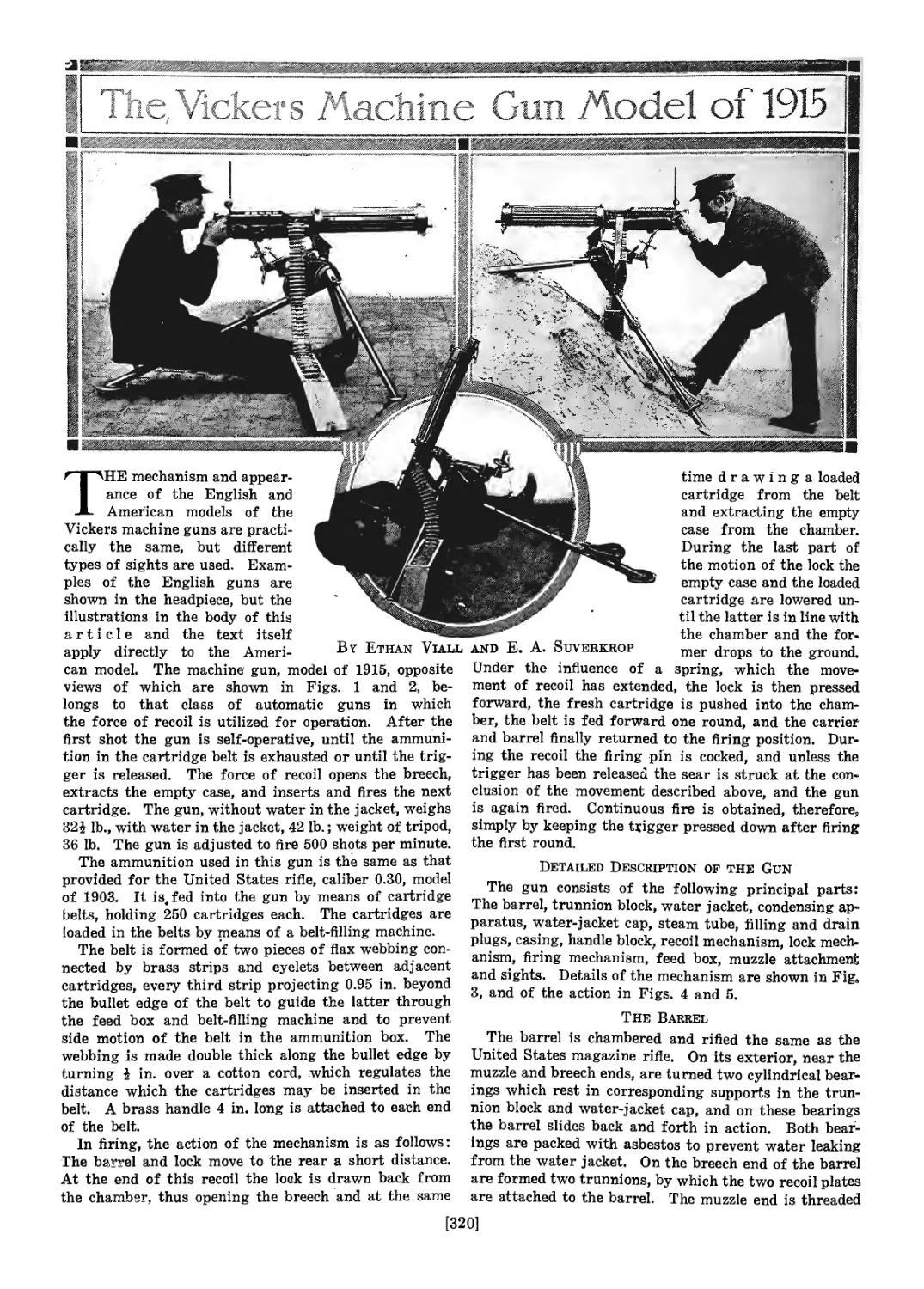
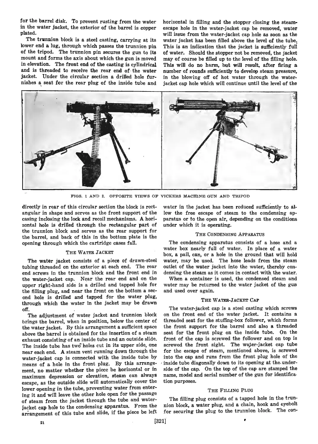
The Vickers Machine Gun......................................... 320
Index..................................................-........ 329
. vii
TKe Evolution of the American
Military Rifle
By Ethan Viall
SYNOPSIS—While a brief outline is given of
early small-arm developments, the main interest
centers around the American military rifle, and
especially on the gun made in the Springfield ar-
mory, which is the oldest in the United States.
It is from this arsenal that the present as well
as most of -the past army rifles take their name.
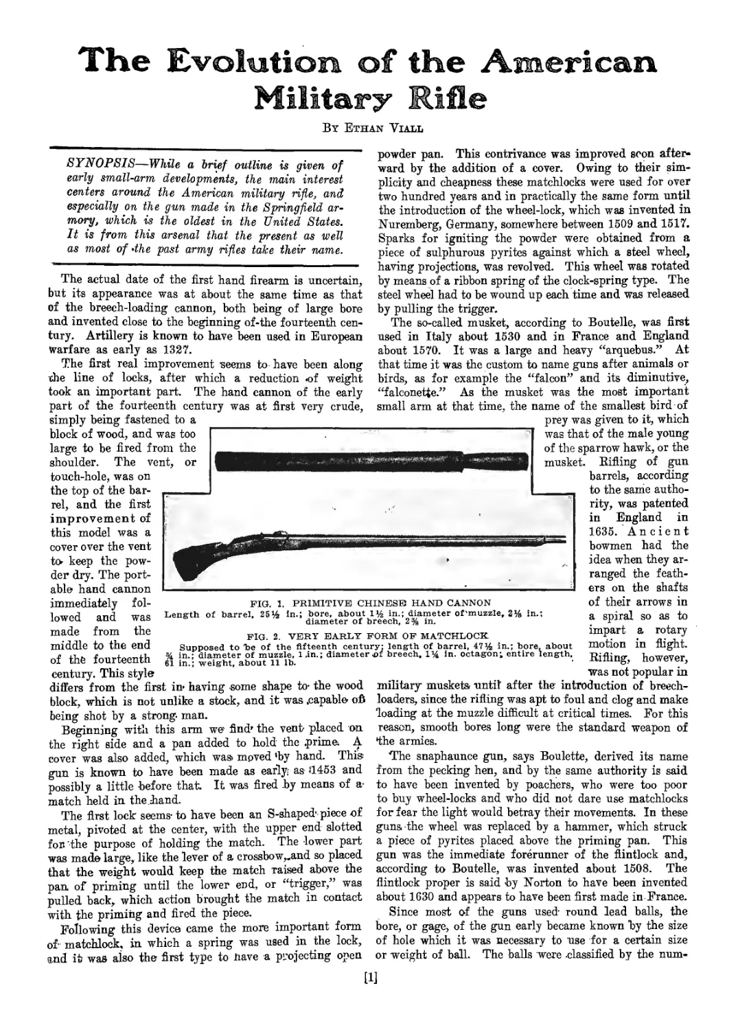
FIG. 1. PRIMITIVE CHINESE HAND CANNON
Length of barrel, 25% in.; bore, about 1% in.; diameter of'muzzle, 2% in.;
diameter of breech, 2% in.
FIG. 2. VERY EARLY FORM OF MATCHLOCK.
Supposed to he of the fifteenth century; length of barrel, 47% in.; bore, about
% in.; diameter of muzzle, 1 ,in.; diameter .of breech, 1% in. octagon; entire length,
61 in.; weight, about 11 lb.
The actual date of the first hand firearm, is uncertain,
but its appearance was at about the same time as that
of the breech-loading cannon, both being of large bore
and invented close to the beginning of-the fourteenth cen-
tury. Artillery is known to have been used in European
Warfare as early as 1327.
The first real improvement seems to have been along
the line of locks, after which a reduction «of weight
took an important part. The hand cannon of the early
part of the fourteenth century was at first very crude,
simply being fastened to a
block of wood, and was too
large to be fired from the
shoulder. The vent, or
touch-hole, was on
the top of the bar-
rel, and the first
improvement of
this model was a
cover over the vent
to- keep the pow-
der dry. The port-
able hand cannon
immediately fol-
lowed and was
made from the
middle to the end
of the fourteenth
century. This style
differs from the first in- having some shape to- the wood
block, which is not unlike a stock, and it was .capable ofi
being shot by a strong, man.
Beginning with this arm we- find’ the vent- placed on
the right side and a pan added to hold the .prime. A
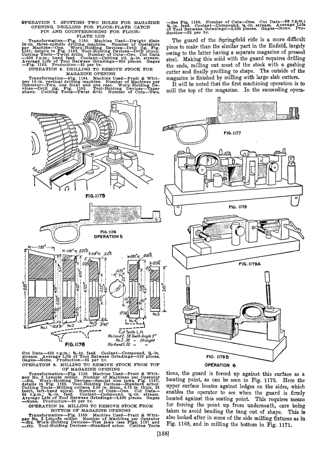
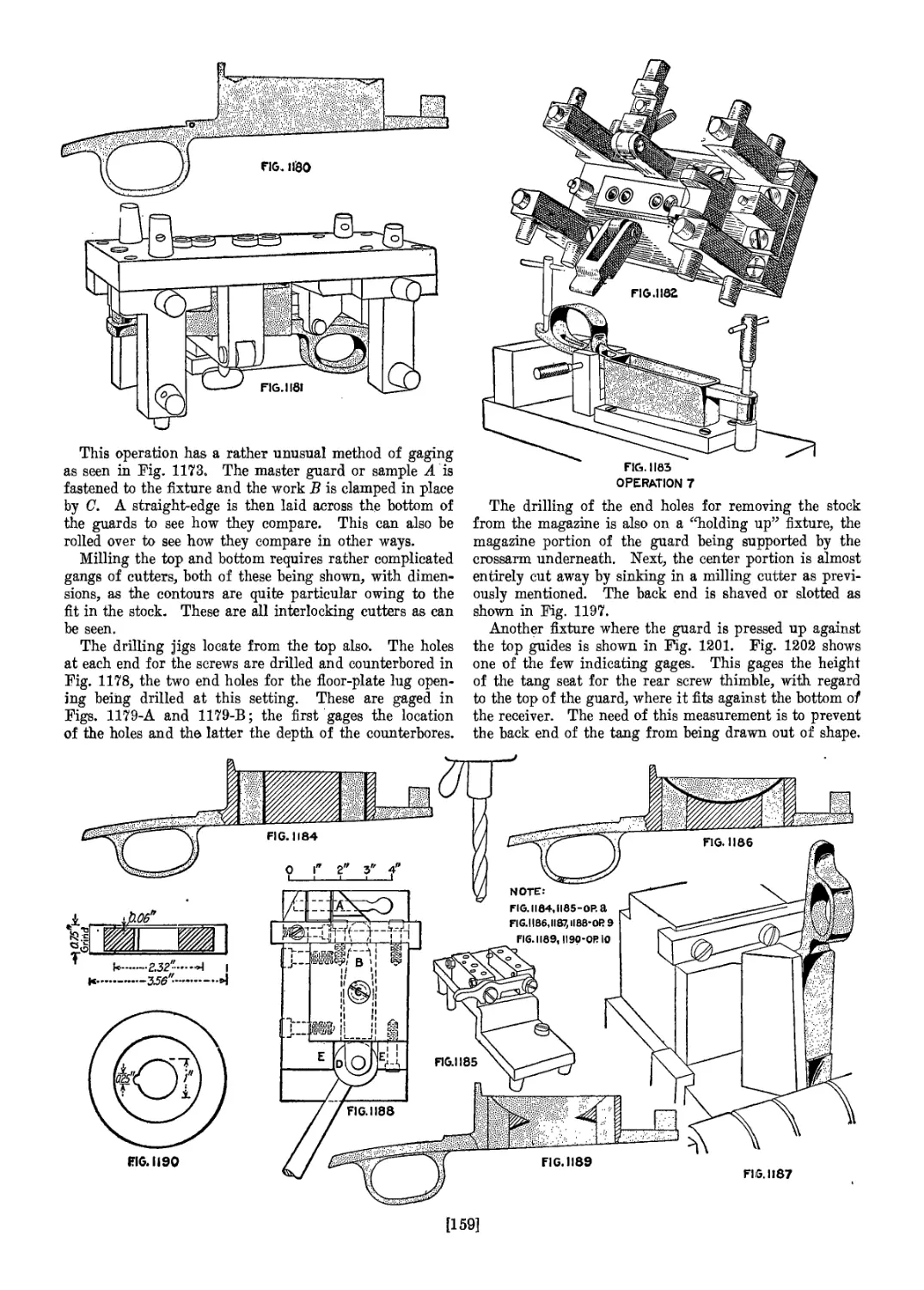
cover was also added, which was> moved 'by hand. This;
gun is known to have been made as early; as -1453 and
possibly a little before that. It was fired by means of a-
match held in the.hand.
The first lock seems- to have been an S-shaped- piece of
metal, pivoted at the center, with the upper end slotted
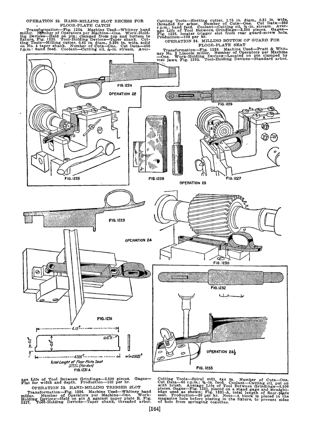
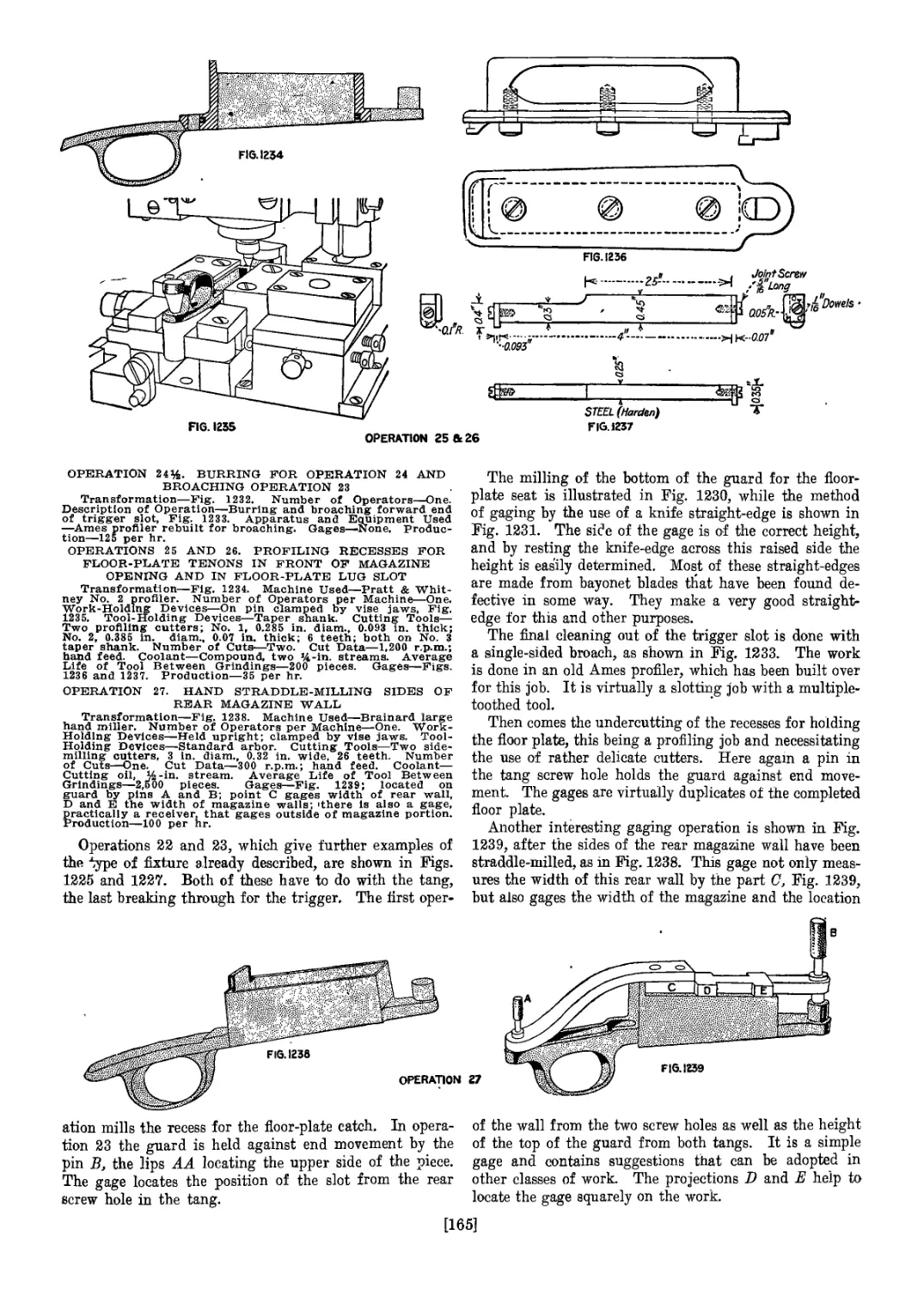
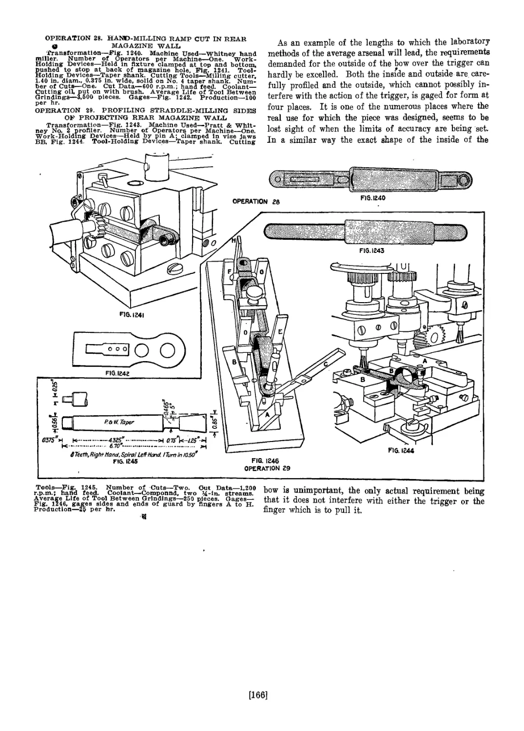
fon’the purpose of holding the match. The -lower part
was made large, like the lever of a crossbow,.and so placed
that the weight would keep the match raised above the
pan of priming until the lower end, or “trigger,” was
pulled back, which action brought the match in contact
with the priming and fired the piece.
Following this device came the more important form
of- matchlock, in which a spring was used in the lock,
and it was also the first type to nave a projecting open
powder pan. This contrivance was improved soon after-
ward by the addition of a cover. Owing to their sim-
plicity and cheapness these matchlocks were used for over
two hundred years and in practically the same form until
the introduction of the wheel-lock, which was invented in
Nuremberg, Germany, somewhere between 1509 and 1517.
Sparks for igniting the powder were obtained from a
piece of sulphurous pyrites against which a steel wheel,
having projections, was revolved. This wheel was rotated
by means of a ribbon spring of the clock-spring type. The
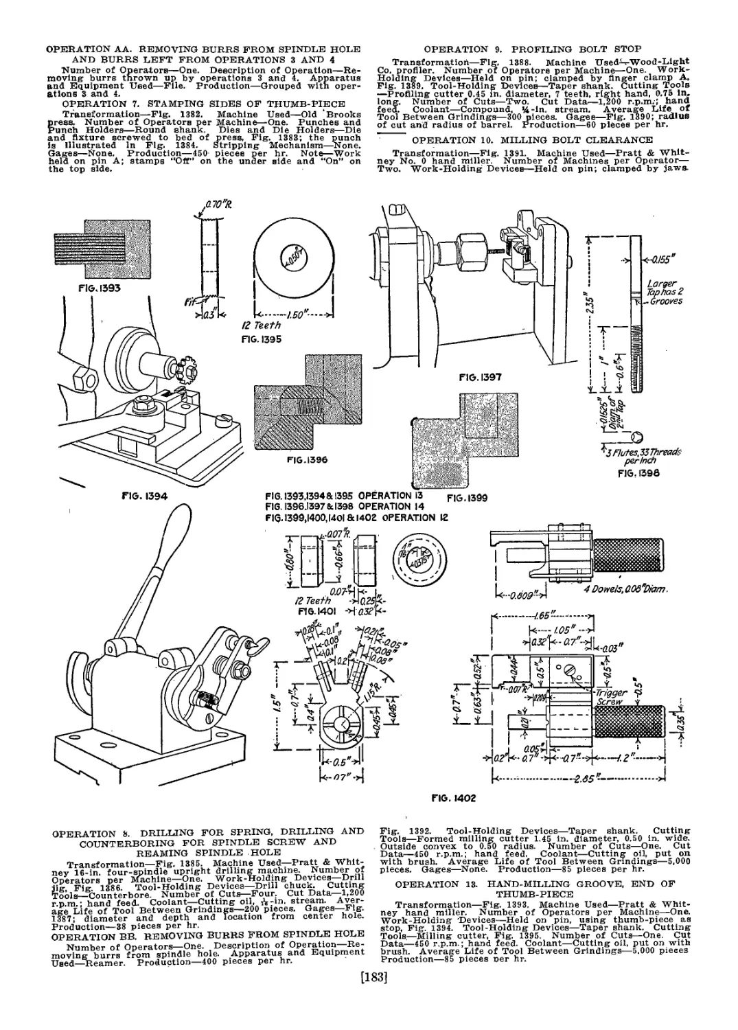
steel wheel had to be wound up each time and was released
by pulling the trigger.
The so-called musket, according to Boutelle, was first
used in Italy about 1530 and in France and England
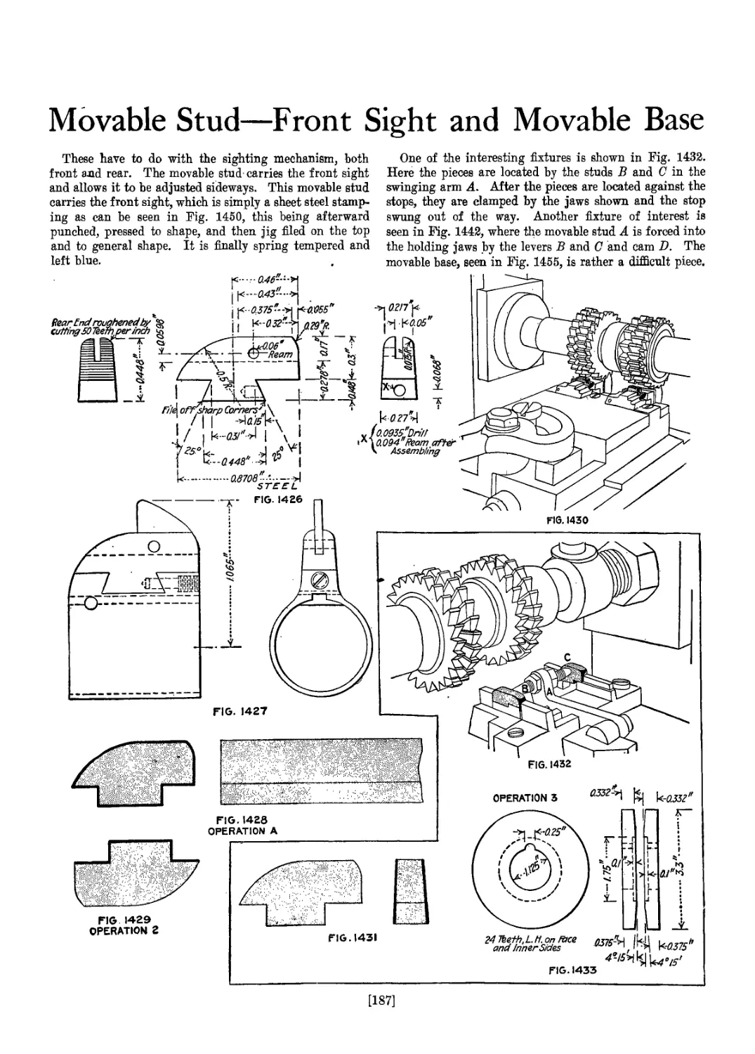
about 1570. It was a large and heavy “arquebus.” At
that time it was the custom to name guns after animals or
birds, as for example the “falcon” and its diminutive,
“falconette.” As the musket was the most important
small arm at that time, the name of the smallest bird of
prey was given to it, which
was that of the male young
of the sparrow hawk, or the
musket. Billing of gun
barrels, according
to the same autho-
rity, was patented
in England in
1635. Ancient
bowmen had the
idea when they ar-
ranged the feath-
ers on the shafts
of their arrows in
a spiral so as to
impart a rotary
motion in flight.
Rifling, however,
was not popular in
military muskets- until after the introduction of breech-
loaders, since the rifling was apt to foul and clog and make
loading at the muzzle difficult at critical times. For this
reason, smooth bores long were the standard weapon of
the armies.
The snaphaunce gun, says Boulette, derived its name
from the pecking hen, and by the same authority is said
to have been invented by poachers, who were too poor
to buy wheel-locks and who did not dare use matchlocks
for fear the light would betray their movements. In these
guns the wheel was replaced by a hammer, which struck
a piece of pyrites placed above the priming pan. This
gun was the immediate forerunner of the flintlock and,
according to Boutelle, was invented about 1508. The
flintlock proper is said by Norton to have been invented
about 1630 and appears to have been first made in France.
Since most of the guns used- round lead balls, the
bore, or gage, of the gun early became known by the size
of hole which it was necessary to use for a certain size
or weight of ball. The balls were .classified by the num-
11]
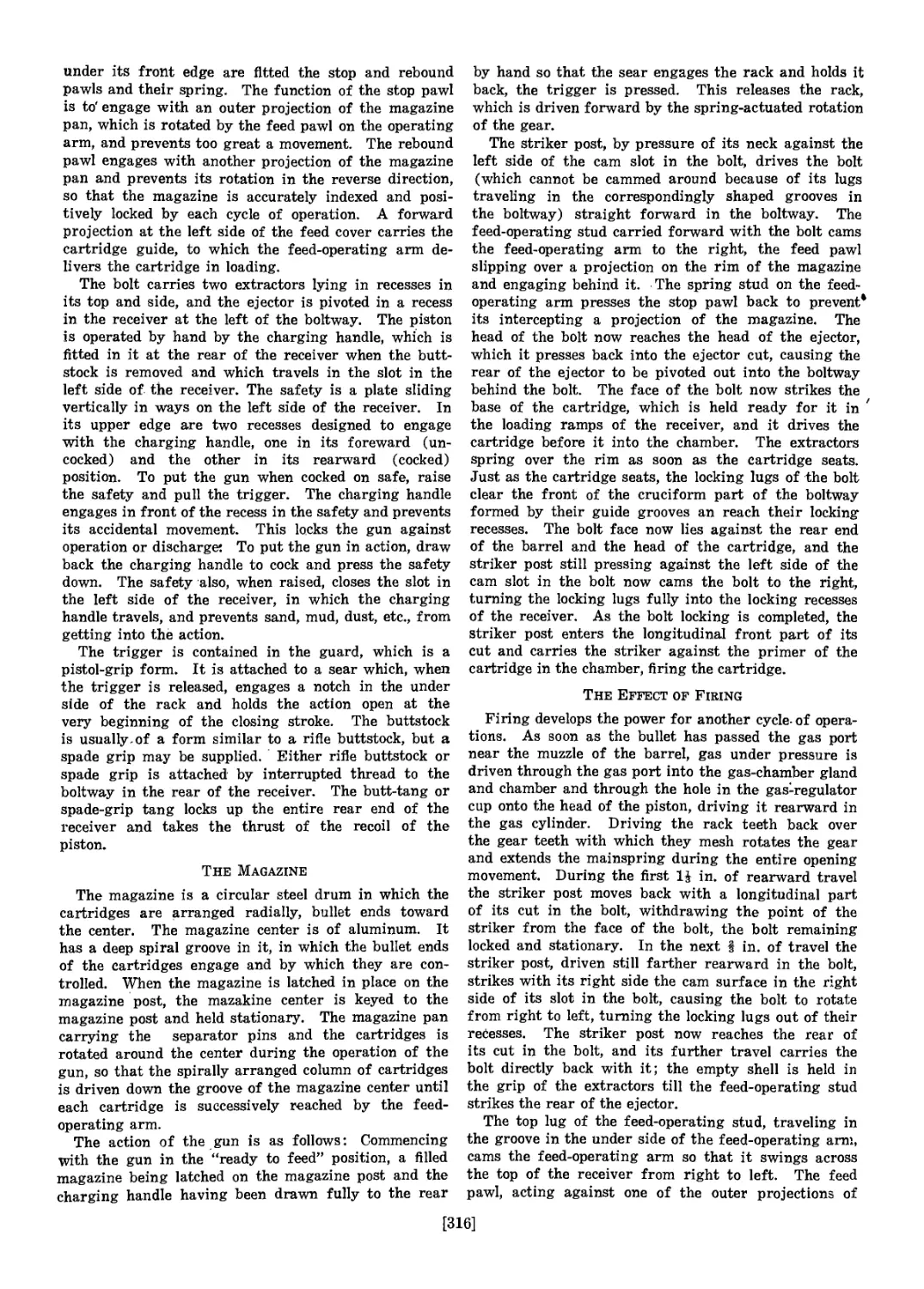
Movable
Base
-Leaf
Barrel—,
Hand
Guard
Receiver
i Spring
Striker
Firing-Pin r-Boit
Sleeve
-Stock
Guard"J
Guard-Screwr
Bushing
Bolt-
Stop Spring
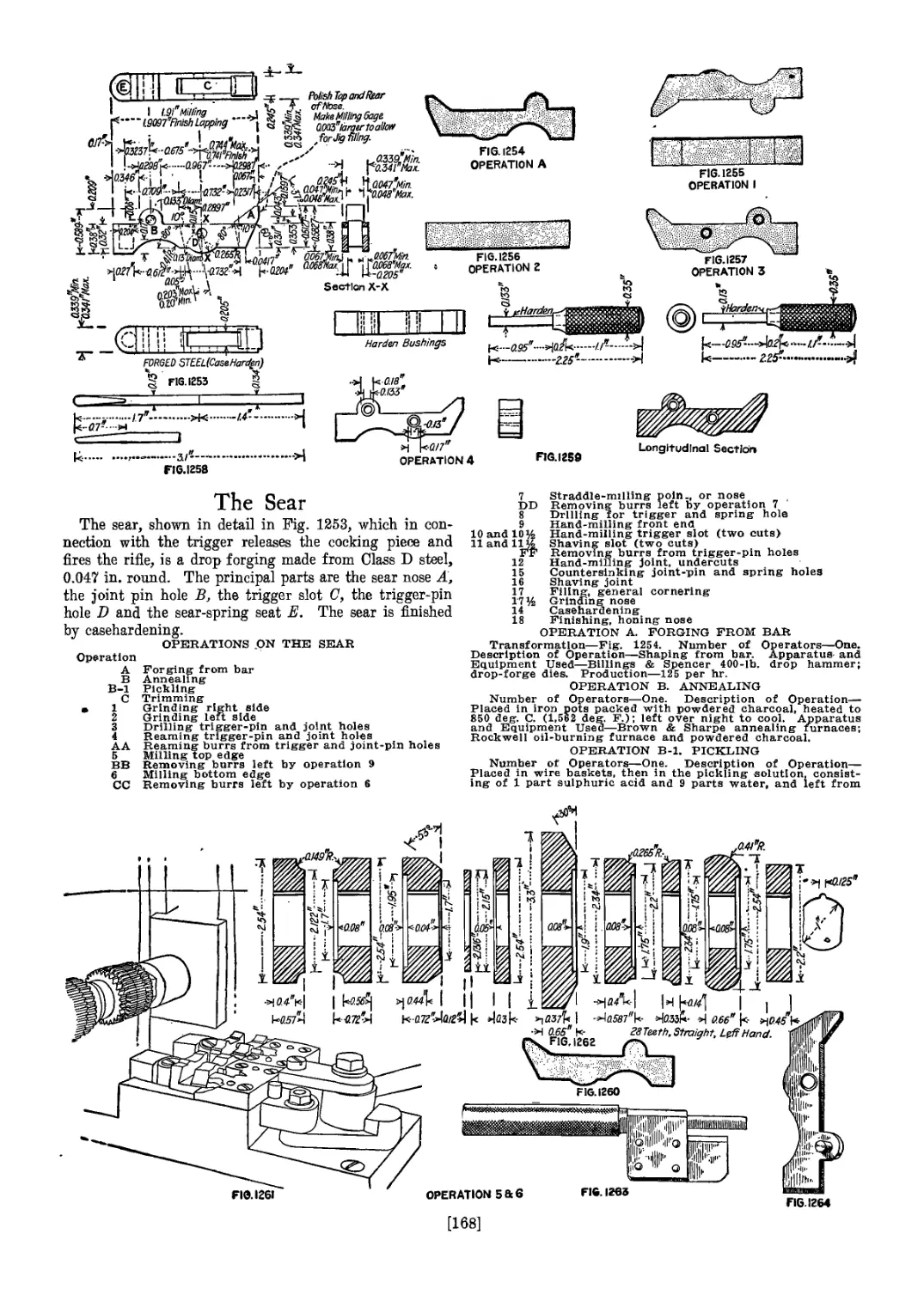
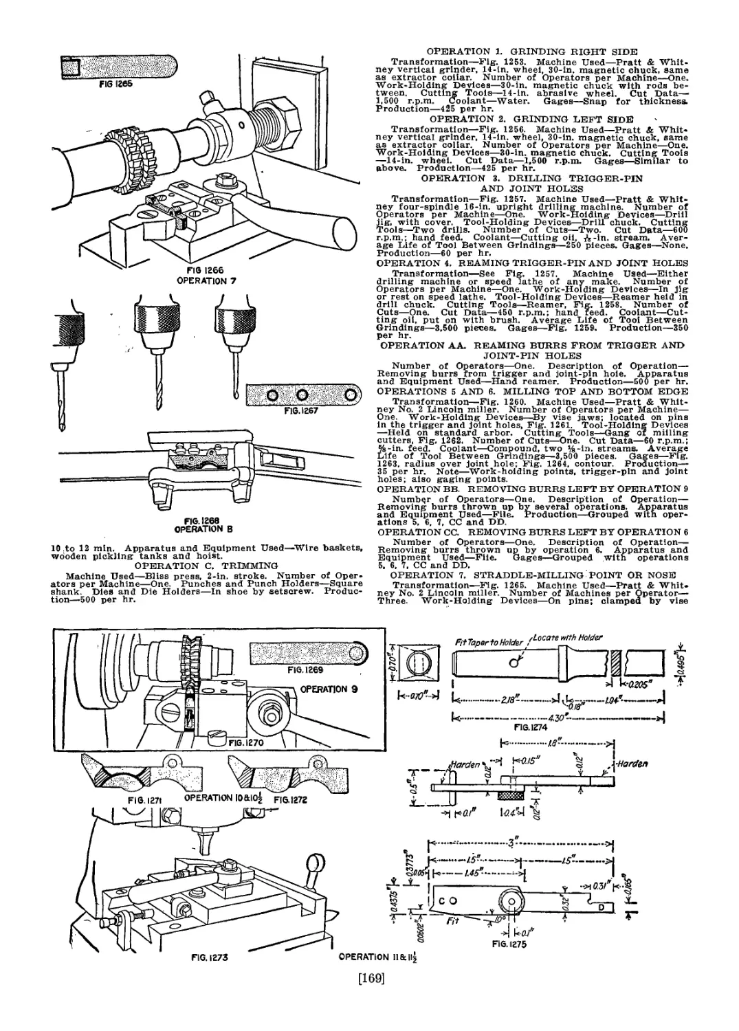
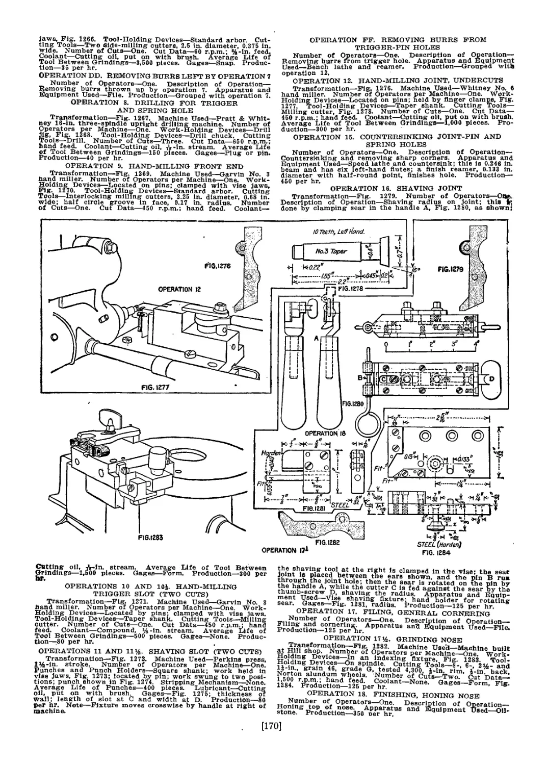
Sear
Safety Lock ^Sleeve-* Safety-Lock Main
Thumb Piece 1 i [ Spindle Ге~
Cocking piece
Firing-Pin.
Rod
Guard Screw, Rear^
'-Magazine '“‘Guard Screw, Front
-Magazine Spring
Floor Plate
'--Follower
Sear Spring
Floor-Plate Catch
'"-Stock Screw
Floor'Plate Spring
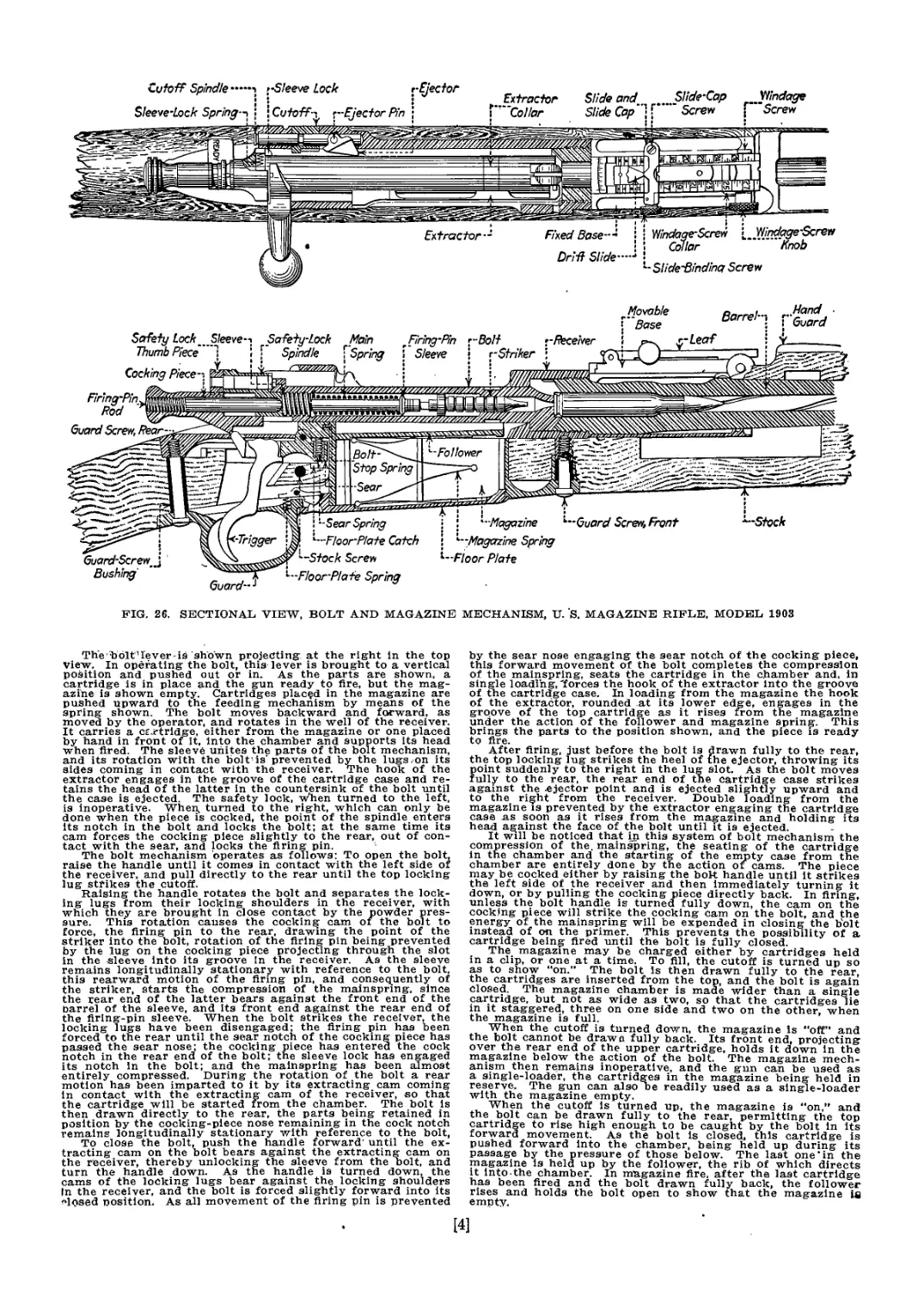
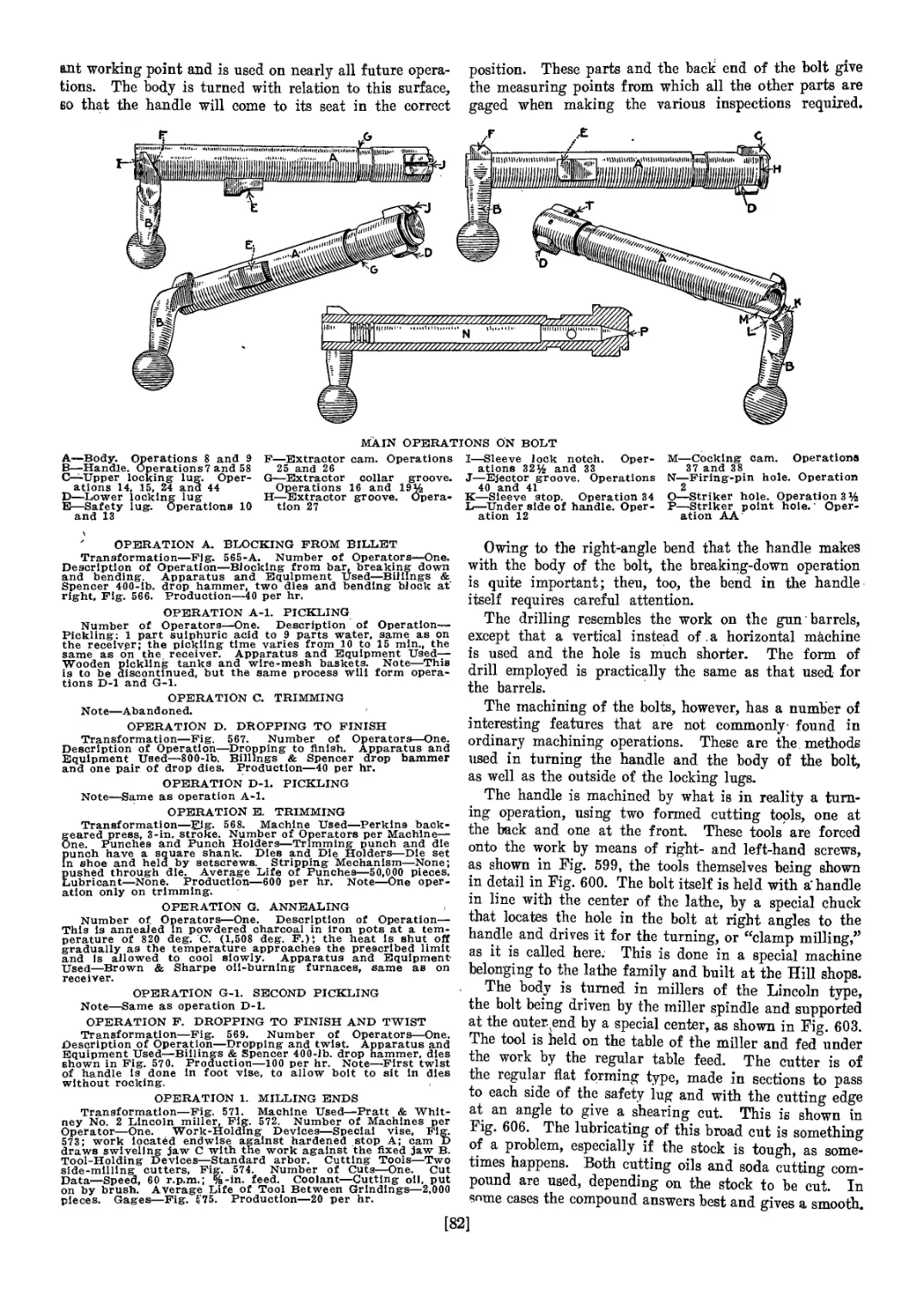
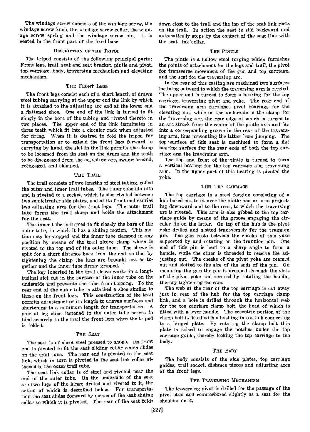
FIG. 26. SECTIONAL VIEW, BOLT AND MAGAZINE MECHANISM, U. S. MAGAZINE RIFLE, MODEL 1903
The bbltUever is shown projecting at the right in the top
View. In operating the bolt, this lever is brought to a vertical
position and pushed out or in. As the parts are shown, a
cartridge is in place and the gun ready to fire, but the mag-
azine is shown empty. Cartridges placed in the magazine are
pushed upward to the feeding mechanism by means of the
spring shown. The bolt moves backward and forward, as
moved by the operator, and rotates in the well of the receiver.
It carries a cartridge, either from the magazine or one placed
by hand in front of it, into the chamber and supports its head
when fired. The sleeve unites the parts of the bolt mechanism,
and its rotation with the bolt'is’prevented by the lugs .-on its
sides coming in contact with the receiver. The hook of the
extractor engages in the groove of the cartridge case and re-
tains the head of the latter in the countersink of the bolt until
the case is ejected. The safety lock, when turned to the left,
is inoperative. When, turned to the right, which can only be
done when the piece is cocked, the point of the spindle enters
its notch in the bolt and locks the bolt; at the same time its
cam forces the cocking piece slightly to the rear, out of con-
tact with the sear, and locks the firing pin.
The bolt mechanism operates as follows: To open the bolt,
raise the handle until it comes in contact with the left side of
the receiver, and pull directly to the rear until the top locking
lug strikes the cutoff.
Raising the handle rotates the bolt and separates the lock-
ing lugs from their locking shoulders in the receiver, with
which they are brought in close contact by the powder pres-
sure. This rotation causes the cocking cam or the bolt to
force, the firing pin to the rear, drawing the point of the
striker into the bolt, rotation of the firing pin being prevented
by the lug on the cocking piece projecting through the slot
in the sleeve into its groove In the receiver. As the sleeve
remains longitudinally stationary with reference to the bolt,
this rearward motion of the firing pin, and consequently of
the striker, starts the compression of the mainspring, since
the rear end of the latter bears against the front end of the
barrel of the sleeve, and its front end against the rear end of
the firing-pin sleeve. When the bolt strikes the receiver, the
locking lugs have been disengaged; the firing pin has been
forced to the rear until the sear notch of the cocking piece has
passed the sear nose: the cocking piece has entered the cock
notch in the rear end of the bolt; the sleeve lock has engaged
its notch in the bolt; and the mainspring has been almost
entirely compressed. During the rotation of the bolt a rear
motion has been imparted to it by its extracting cam coming
in contact with the extracting cam of the receiver, so that
the cartridge will be started from the chamber. The bolt is
then drawn directly to the rear, the parts being retained in
position by the cocking-piece nose remaining in the cock notch
remains longitudinally stationary with reference to the bolt,
To close the bolt, push the handle forward' until the ex-
tracting cam on the bolt bears against the extracting cam on
the receiver, thereby unlocking the sleeve from the bolt, and
turn the handle down. As the handle is turned down, the
cams of the locking lugs bear against the locking shoulders
In the receiver, and the bolt is forced slightly forward into its
Mosed position. As all movement of the firing pin is prevented
by the sear nose engaging the sear notch of the cocking piece,
this forward movement of the bolt completes the compression
of the mainspring, seats the cartridge in the chamber and, in
single loading, "forces the hook of the extractor Into the groove
of the cartridge case. In loading from the magazine the hook
of the extractor, rounded at its lower edge, engages in the
groove of the top cartridge as it rises from the magazine
under the action of the follower and magazine spring. This
brings the parts to the position shown, and the piece is ready
to fire.
After firing, just before the bolt is drawn fully to the rear,
the top locking lug strikes the heel of the ejector, throwing its
point suddenly to the right in the lug slot. As the bolt moves
fully to the rear, the rear end of the cartridge case strikes
against the .ejector point and is ejected slightly upward and
to the right from the receiver. Double loading from the
magazine is prevented by the extractor engaging the cartridge
case as soon as it rises from the magazine and holding its
head against the face of the bolt until it is ejected.
It will be noticed that in this system of bolt mechanism the
compression of the. mainspring, the seating of the cartridge
in the chamber and the starting of the empty case from the
chamber are entirely done by the action or cams. The piece
may be cocked either by raising the bolt handle until it strikes
the left side of the receiver and then immediately turning it
down, or by pulling the cocking piece directly back. In firing,
unless the bolt handle is turned fully down, the cam on the
cocking piece will strike the cocking cam on the bolt, and the
energy of the mainspring will be expended in closing the bolt
instead of on the primer. This prevents the possibility of a
cartridge being fired until the bolt is fully closed.
The magazine may be charged either by cartridges held
in a clip, or one at a time. To fill, the cutoff is turned up so
as to show "on.” The bolt is then drawn fully to the rear,
the cartridges are inserted from the top, and the bolt is again
closed. The magazine chamber is made wider than a single
cartridge, but not as wide as two, so that the cartridges lie
in it staggered, three on one side and two on the other, when
the magazine is full.
When the cutoff is turned down, the magazine Is "off” and
the bolt cannot be drawn fully back. Its front end, projecting
over the rear end of the upper cartridge, holds it down in the
magazine below the action of the bolt. The magazine mech-
anism then remains inoperative, and the gun can be used as
a single-loader, the cartridges in the magazine being held in
reserve. The gun can also be readily used as a single-loader
with the magazine empty.
When the cutoff is turned up, the magazine is "on,” and
the bolt can be drawn fully to the rear, permitting the top
cartridge to rise high enough to be caught by the bolt in its
forward movement. As the bolt is closed, this cartridge is
pushed forward into the chamber, being held up during its
passage by the pressure of those below. The last one*in the
magazine is held up by the follower, the rib of which directs
it into the chamber. In magazine fire, after the last cartridge
has been fired and the bolt drawn fully back, the follower
rises and holds the bolt open to show that the magazine is
empty.
[4]
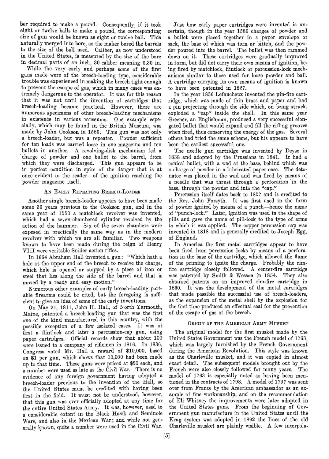
ber required to make a pound. Consequently, if it took
eight or twelve balls to make a pound, the corresponding
size of gun would be known as eight or twelve ball. This
naturally merged into bore, as the maker bored the barrels
to the size of the ball used. Caliber, as now understood
in the United States, is measured by the size of the bore
in decimal parts of an inch, 30-caliber meaning 0.30 in.
While the very early and perhaps some of the first
guns made were of the breech-loading type, considerable
trouble was experienced in making the breech tight enough
to prevent the escape of gas, which in many cases was ex-
tremely dangerous to the operator. It was for this reason
that it was not until the invention of cartridges that
breech-loading became practical. However, there are
numerous specimens of other breech-loading mechanisms
in existence in various museums. One example espe-
cially, which may be found in the British Museum, was
made by John Cookson in 1586. This gun was not only
a breech-loader, but was a repeater. Powder sufficient
for ten loads was carried loose in one magazine and ten
bullets in another. A revolving-disk mechanism fed a
charge of powder and one bullet to the barrel, from
which they were discharged. This gun appears to be
in perfect condition in spite of the danger that is at
once evident to the reader—of the ignition reaching the
powder magazine itself.
An Early Repeating Breech-Loader
Another single breech-loader appears to have been made
some 30 years previous to the Cookson gun, and in the
same year of 1550 a matchlock revolver was invented,
which had a seven-chambered cylinder revolved by the
action of the hammer. Six of the seven chambers were
exposed in practically the same way as in the modern
revolver with which we are all familiar. Two weapons
known to have been made during the reign of Henry
VIII were veritable Snider action rifles.
In 1664 Abraham Hall invented a gun: “Which hath a
hole at the upper end of the breech to receive the charge,
which hole is opened or stopped by a piece of iron or
steel that lies along the side of the barrel and that is
moved by a ready and easy motion.”
Numerous other examples of early breech-loading port-
able firearms could be cited, but the foregoing is suffi-
cient to give an idea of some of the early inventions.
On May 21, 1811, John H. Hall, of North Yarmouth,
Maine, patented a breech-loading gun that was the first
one of the kind manufactured in this country, with the
possible exception of a few isolated cases. It was at
first a flintlock and later a percussion-cap gun, using
paper cartridges. Official records show that about 100
were issued to a company of riflemen in 1816. In 1836,
Congress voted Mr. Hall a reward of $10,000, based
on $1 per gun, which shows that 10,000 had been made
up to that time. These guns were priced at $20 each, and
a number were used as late as the Civil War. There is no
evidence of any foreign government having adopted a
breech-loader previous to the invention of the Hall, so
the United States must be credited with having been
first in the field. It must not be understood, however,
that this gun was ever officially adopted at any time for
the entire United States Army. It was, however, used to
a considerable extent in the Black Hawk and Seminole
Wars, and also in the Mexican War; and while not gen-
erally known, quite a number were used in the Civil War.
Just how early paper cartridges were invented is un-
certain, though in the year 1586 charges of powder and
a bullet were placed together in a paper envelope or
sack, the base of which was torn or bitten, and the pow-
der poured into the barrel. The bullet was then rammed
down on it. These cartridges were gradually improved
in form, but did not carry their own means of ignition, be-
ing fired by matchlock, flintlock or percussion-lock mech-
anisms similar to those used for loose powder and ball.
A cartridge carrying its own means of ignition is known
to have been patented in 1827.
In the year 1836 Lefaucheux invented the pin-fire cart-
ridge, which was made of thin brass and paper and had
a pin projecting through the side which, on being struck,
exploded a “cap” inside the shell. In this same year
Greener, an Englishman, produced a very successful elon-
gated bullet that would expand and fill the rifling grooves
when fired, thus conserving the energy of the gas. Several
others had tried the same scheme, but his appears to have
been the earliest successful one.
The needle gun cartridge was invented by Deyse in
1838 and adopted by the Prussians in 1841. It had a
conical bullet, with a wad at the base, behind which was
a charge of powder in a lubricated paper case. The deto-
nator was placed in the wad and was fired by means of
a needle that was thrust through a perforation in the
base, through the powder and into the “cap.”
Percussion itself dates back to 1807 and is credited to
the Rev. John Forsyth. It was first used in the form
of powder ignited by means of a punch—hence the name
of “punch-lock.” Later, ignition was used in the shape of
pills and gave the name of pill-lock to the type of arms
to which it was applied. The copper percussion cap was
invented in 1818 and is generally credited to Joseph Egg,
of England.
In America the first metal cartridges appear to have
been fired from percussion locks by means of a perfora-
tion in the base of the cartridge, which allowed the flame
of the priming to ignite the charge. Probably the rim-
fire cartridge closely followed. A center-fire cartridge
was patented by Smith & Wesson in 1854. They also
obtained patents on an improved rim-fire cartridge in
1860. It was the development of the metal cartridges
that made possible the successful use of breech-loaders,
as the expansion of the metal shell by the explosion for
the first time produced an effectual seal for the prevention
of the escape of gas at the breech.
Origin of the American Army Musket
The original model for the first musket made by the
United States Government was the French model of 1763,
which was largely furnished by the French Government
during the American Revolution. This style was known
as the Charleville musket, and it was copied in almost
exact detail. The subsequent models brought out by the
French were also closely followed for many years. The
model of 1763 is especially noted as having been men-
tioned in the contracts of 1798. A model of 1797 was sent
over from France by the American ambassador as an ex-
ample of fine workmanship, and on the recommendation
of Eli Whitney the improvements were later adopted in
the United States guns. From the beginning of Gov-
ernment gun manufacture in the United States until the
Krag system was adopted in 1892 the lines of the old
Charleville musket are plainly visible. A few interpola-
te
tions were introduced to a limited extent, notably the
Remington in 1870, the bolt-action Ward-Burton in
1871 and the Chaffee-Reece bolt-action in 1884. None
of these were ever universally adopted for the regular
Declaration of Independence steps were taken looking
toward the establishment of an ammunition factory, but
it was not until after the close of the Revolution that
anything which could be called a Government small arm
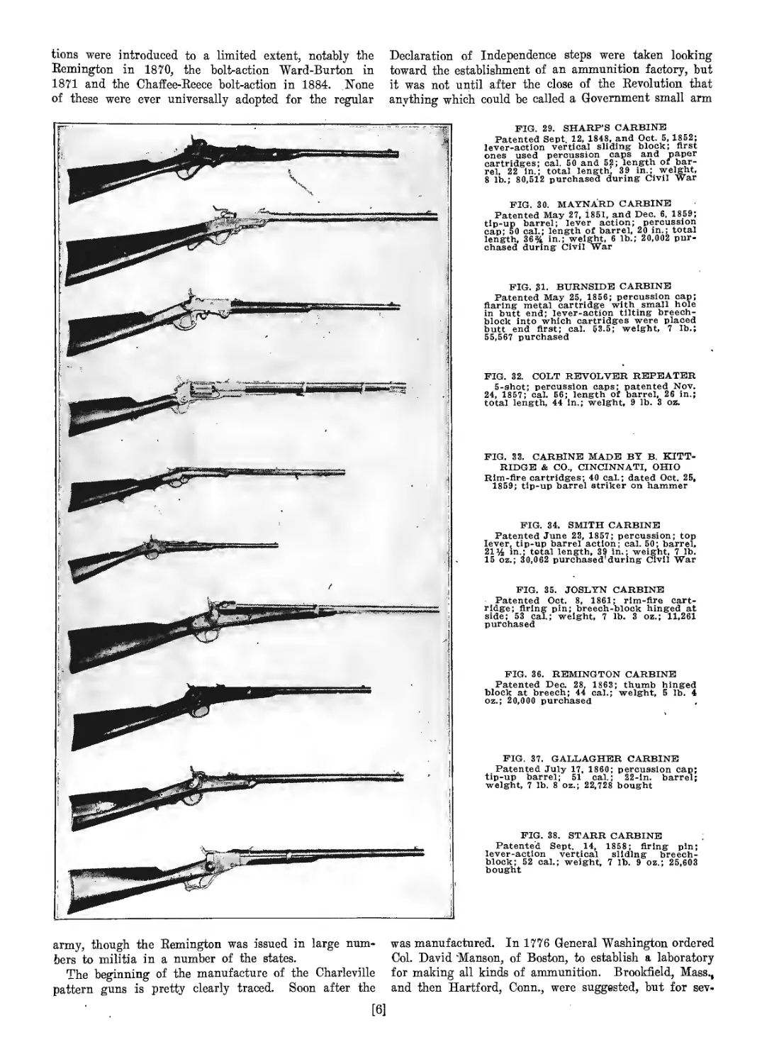
FIG. 29. SHARP’S CARBINE
Patented Sept, 12, 1848, and Oct. 5,1852;
lever-action vertical sliding block; first
ones used percussion caps and paper
cartridges; cal. 50 and 52; length of bar-
rel. 22 in,; total length’, 3 9 in.; weight,
8 lb.; 80,512 purchased during Civil War
FIG, 30. MAYNARD CARBINE
Patented May 27, 1851, and Dec. 6, 1859;
tip-up barrel; lever action; percussion
cap; 50 cal.; length of barrel, 20 in,; total
length, 36% in,; weight, 6 lb.; 20,002 pur-
chased during Civil War
FIG. 31. BURNSIDE CARBINE
Patented May 25, 1856; percussion cap;
flaring metal cartridge with small hole
in butt end; lever-action tilting breech-
block into which cartridges were placed
butt end first; cal. $3.5; weight, 7 lb.;
55,567 purchased
FIG. 32. COLT REVOLVER REPEATER
5-shot; percussion caps; patented Nov.
24, 1857; cal. 56; length of barrel, 26 in,;
total length, 44 in,; weight, 9 lb. 3 oz.
FIG. 33. CARBINE MADE BY B. KITT-
RIDGE & CO., CINCINNATI, OHIO
Rim-fire cartridges; 40 cal.; dated Oct. 25,
1859; tip-up barrel striker on hammer
FIG. 34. SMITH CARBINE
Patented June 23, 1857; percussion; top
lever, tip-up barrel action; cal. 50; barrel,
21^ in.; total length, 39 in.; weight, 7 lb.
15 oz.; 30,062 purchased'during Civil War
FIG. 35. JOSLYN CARBINE
Patented Oct. 8, 1861; rim-fire cart-
ridge; firing pin; breech-block hinged at
side; 53 cal,; weight, 7 lb. 3 oz.; 11,261
purchased
FIG. 36. REMINGTON CARBINE
Patented Dec. 28, 1863; thumb hinged
block at breech; 44 cal.; weight, 5 lb. 4
oz.; 20,000 purchased
FIG. 37. GALLAGHER CARBINE
Patented July 17, 1860; percussion cap;
tip-up barrel; 51 cal.; 22-ln. barrel;
weight, 7 lb, 8 oz.; 22,728 bought
FIG. 38. STARR CARBINE
Patented Sept, 14, 1858; firing pin;
lever-action vertical sliding breech-
block; 52 cal.; weight, 7 lb. 9 oz.; 25,603
bought
army, though the Remington was issued in large num-
bers to militia in a number of the states.
The beginning of the manufacture of the Charleville
pattern guns is pretty clearly traced. Soon after the
[6]
was manufactured. In 1776 General Washington ordered
Col. David "Manson, of Boston, to establish a laboratory
for making all kinds of ammunition. Brookfield, Mass.,
and then Hartford, Conn., were suggested, but for sev-
era! reasons were not selected. The final decision was
centered on Springfield, Mass., and early records show
that work was begun on this laboratory in April, 1778.
After the Revolutionary War was over, all the employees
were discharged and the buildings left in charge of a
storekeeper.
In April, 1794, Congress authorized the establishment
of two armories, one at Harper’s Ferry, Va., and the.
other at Springfield, Mass. The manufacture of small
arms began at Springfield in 1795 with 40 men, and 245
muskets were turned opt the first year. There is no rec-
ord of any small arms being produced at Harper’s Ferry
previous to 1801. In 1810 the Output at Springfield was
9,700 muskets and 602. carbines. At this arsenal in 1819
the cost of labor per musket was $6.57, which together
with the cost of the material brought the total cost to
$12.40 each. The output of this arsenal continued from
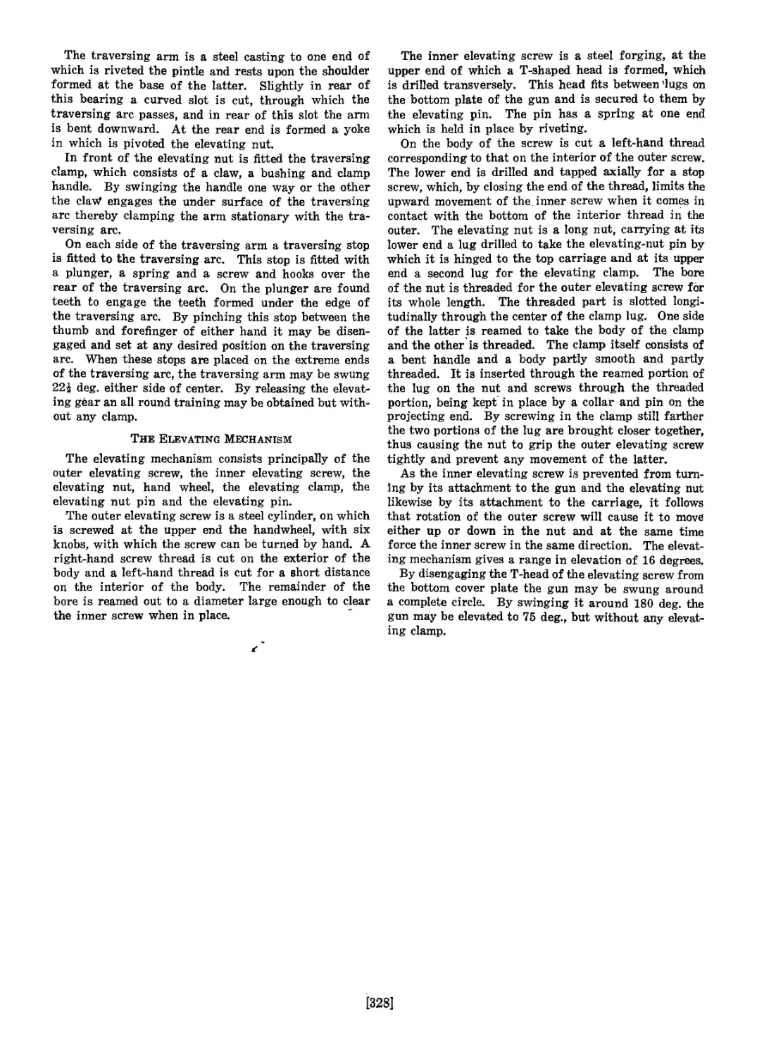
FIG. .27. TYPES OF BAYONETS ON UNITED STATES ARMY
’ MUSKETS AND RIFLES
A, bayonet 1803, hollow ground point, 16 in. long, % in. at
widest part of blade; B, bayonet 1865, hollow ground blade,
18 in. long, % in. wide at widest part of blade, % in. thick at
base of blade; C, rod bayonet 1888, when out projects 15 in.
from end of barrel, rod is A in. in diameter with triangular
point; D, Krag bayonet 1892; 11% in. long, % in. thick at
base; E, bayonet 1905, 16 in. long, lx% in. at base of blade,
handle 4% in. long; F, bayonet 1906, slight changes in handle
and catch
i
1811 to average about 1,000 per month. Twelve thousand
muskets and 250 rifles were produced in 1819. This av-
erage was not materially changed until 1862, when it
jumped to 102,410, and to 276,200 in 1864. The cost per
gun the latter year was $10.69. In 1865 the output
dropped to 195,341, and the cost rose to $14.12 each.
Besides the Government armories established, Congress
in 1808 enacted a law for the annual payment from the
United States Treasury of $200,000 for six private ar-
mories established that year. From among the more
prominent gun makers were selected Asa Waters, Sutton
(now Millbury), Mass.; Simeon North, Middletown,
Conn.; Nathan Starr, Middletown, Conn.; Eli Whitney,
Whitneyville (near New Haven), Conn.; Henry Der-
ringer, Philadelphia, Penn.; and Lemuel Pomeroy,
Pittsfield, Mass. Contracts were issued to these firms
for a term of years, which were renewed from time to
time until 1840. These private armories were regarded
as permanent, having been recognized by the Government
as a part of the United States industrial preparedness
measures for the insurance of a supply of arms.
The six private armories assured, the Government
proceeded to issue contracts for arms to supply the militia.
From June 30 to Nov. 13, 1808, nineteen contracts were
made; the total number of arms delivered by these nine-
teen firms to December, 1812, was 53,660.
In 1841 and 1842 the number of private armories was
seven, with an output as follows: Pomeroy, 1,200 mus-
kets; Whitney, 1,500 muskets; Starr, 1,200 rifles, Der-
ringer, 1,200 rifles; Waters, 3,000 pistols; Johnston,
.3,000 pistols; North, 2,000 Hall’s carbines. These made
a total of 13,100 annually. In 1845 the last of these
contracts expired, and the whole system was broken up
without notice.
Starting at the beginning, the strictly Government
muskets and rifles were made as follows. The changes in-
dicated can be easily traced by reference to the various
illustrations, shown and described separately:
French Charleville musket, model 1763; pattern only.
Flintlock musket, smooth bore, 1795 to 1822; minor changes:
bore reduced from 71 or more to 69 cal.
Musket altered to percussion, model 1822; cal. 69.
Musket, percussion; new nipple seat or boss; model 1842:
cal. 69; patterned after French Charleville, model 1840.
Springfield rified musket, model 1855; Maynard primer;
cal, 58.
Springfield rified musket, models 1861, 1863, 1864; different
mountings.
Springfield breech-loading rlfie; model 1865; Allen altera-
tion; cal. 58.
Springfield breech-loading rlfie, model 1866; cal. 50.
Springfield breech-loading rifle, models 18 68 and 1870; cal.
50. - I
Springfield breech-loading rifie, model 1873; cal, 45.
Springfield breech-loading rifie, model 1884; cal. 45; rod
bayonet.
' United States magazine rlfie, model 1892; cal, 30; Krag-
Jorgensen system.
United States magazine rifle, models 1896 and 1898; Krag
system.
United States magazine rifle, model 1903; cal, 30.
Briefly reviewing the various changes and interpola-
tions that took place from time to time, only minor altera-
tions were made in the muskets manufactured from 1795
until 1822, when the percussion system was adopted to
supersede the flintlocks. Many flintlocks were altered
later, so that frequently models of earlier years are en-
countered in museums, having the percussion system of
ignition. A large number of the old flintlocks were al-
lowed to accumulate at the various arsenals until in 1850
and 1851 a great many were changed to percussion. It
was during this period that the Hall breech-loader was
used to some extent, and many are to be found of both
systems.
The model of 1842 shows a new nipple seat or boss,
bulging out from the side of the barrel and an integral
part of it. The next change of importance was the
reduction of the bore from 69 to 58 caliber and the adop-
tion of the Maynard primer, which was done in 1855. The
Maynard primer consisted of a flat tape with an explo-
sive mixture, or caps, at intervals. This tape was wound
over a small drum, and the caps were fed one at a time
up over the nipple. The action of the hammer, as it
was cocked, brought a cap into position; and as it de-
scended, it cut off a piece of the tape and a cap. This
did away with the necessity of putting a cap on the nipple
at each loading, as it was taken care of automatically as
long as the priming tape lasted, when it was easily re-
placed. This system was later abandoned and return
was made to the percussion caps. With this exception,
few changes other than in the mountings were made for
years, the essential Darts remaining standard
[7]
Very few breech-loading arms except the Hall were
tried by the Government previous to the Civil War.
Among the principal ones were the Sharps, Burnside
and Spencer, of which a few were issued to troops be-
tween 1845 and 1860. Some Maynards were also is-
sued. The general opinion of the army boards of this
time was that the breech-loader was not perfected enough
for geileral adoption. Ati the outbreak of the Civil War
the Government found itself unable to furnish its troops
with arms, so they were purchased both here and abroad.
None of these weapons, however, seem to have influenced
the subsequent Government models to any noticeable ex-
tent. Since these guns had so little bearing on the regu-
lar army models and were so numerous, only a few
of the better known ones are shown in the illustrations.
In 1865 the Government adopted its first official breech-
loader. This was known as the Allen alteration and
consisted mainly in crossmilling a section out of the
top of the rear end of the barrel and fitting on a hinged
breech-block. This block is plainly shown in the illustra-
tion for that year. The model of 1866 was very similar,
but the caliber was reduced to 50, which was taken care
of in the guns already made by inserting a rifled tube
in the barrel to reduce it to the required size. Practical-
ly no change was made in the models of 1868 and 1870,
except that in 1870 the barrel was made to screw into
the receiver frame. It was also in this year that the
Bemington breech-loader was used to a limited extent.
This was followed the next year by another brief experi-
ment in the form of the Ward-Burton bolt-action rifle,
which was one of the earliest of this type.
The model of 1873 had the caliber reduced to 45. Some
of the officers’ models of this year also were fitted with a
three-cornered rod bayonet. Of course, it must be borne
in mind that all through these periods numerous carbines
for mounted troops, artillery, officers or others were
made, but had no bearing on the main issue. All sorts of
weapons were also being constantly tried out by the ord-
nance boards in the search for something better, but
through it all the old lines of the original Charleville
musket proved the more practical.
The Springfield model of 1884 carried the rod bayonet
as its principal change. This was a round pointed rod
that was carried in the rifle about like the old ramrod
and could be pulled out a certain distance, when a catch
would hold it until released and pushed back again. This
year also saw the introduction of another experiment in
the Chaffee-Reece bolt-action rifle, of which only a few
hundred were manufactured and issued for regular service.
The next change is a radical one, the caliber being re-
duced to 30 and a magazine rifle of the modified Krag-
Jorgensen type being adopted after extensive competitive
tests. It is not necessary to describe this model in detail,
though it continued in use with slight alterations until
the adoption of the present model of 1903, the action and
details of the latest type of which are described else-
where. ' This last rifle contains many of the best fea-
tures of both the Krag and the Mauser systems, and in
its present form is considered by army men to be one
of the best and hardest shooting rifles used by any army.
The big advantage of the bolt action is that it lends it-
self so easily to either magazine or hand loading.
• During the entire period of rifle evolution the bayo-
nets varied but little, except as they were made to conform
to the different sizes of barrels. Some special designs were
introduced for different branches of the service, but three
principal types only were used by the regular army, as
shown by the illustrations.
[8]
General Specifications and Barrel Operations
By Feed H. Colvin
This article begins a complete description of the manu-
facture of the Springfield rifle, showing each operation
on each component part and illustrating the machines,
tools, jigs, fixtures and production methods.
These methods and tools represent the present govern-
ment arsenal practice and enough details and data are
given to enable any good designer or toolmaker to produce
working jigs and fixtures for the parts designated or for
similar ones if it is desired to work along these lines.
The Springfield rifle, known as the model of 1903, has
a bore of 0.30 in. and uses a ball cartridge weighing
395.5 grains. The bullet weighs 150 grains, and the
is 0.004 in. deep. The total length of the gun is 43.212
in. without the bayonet, and its total weight, also without
bayonet, is 8.69 lb. The weights of the various parts
are given in Table 1.
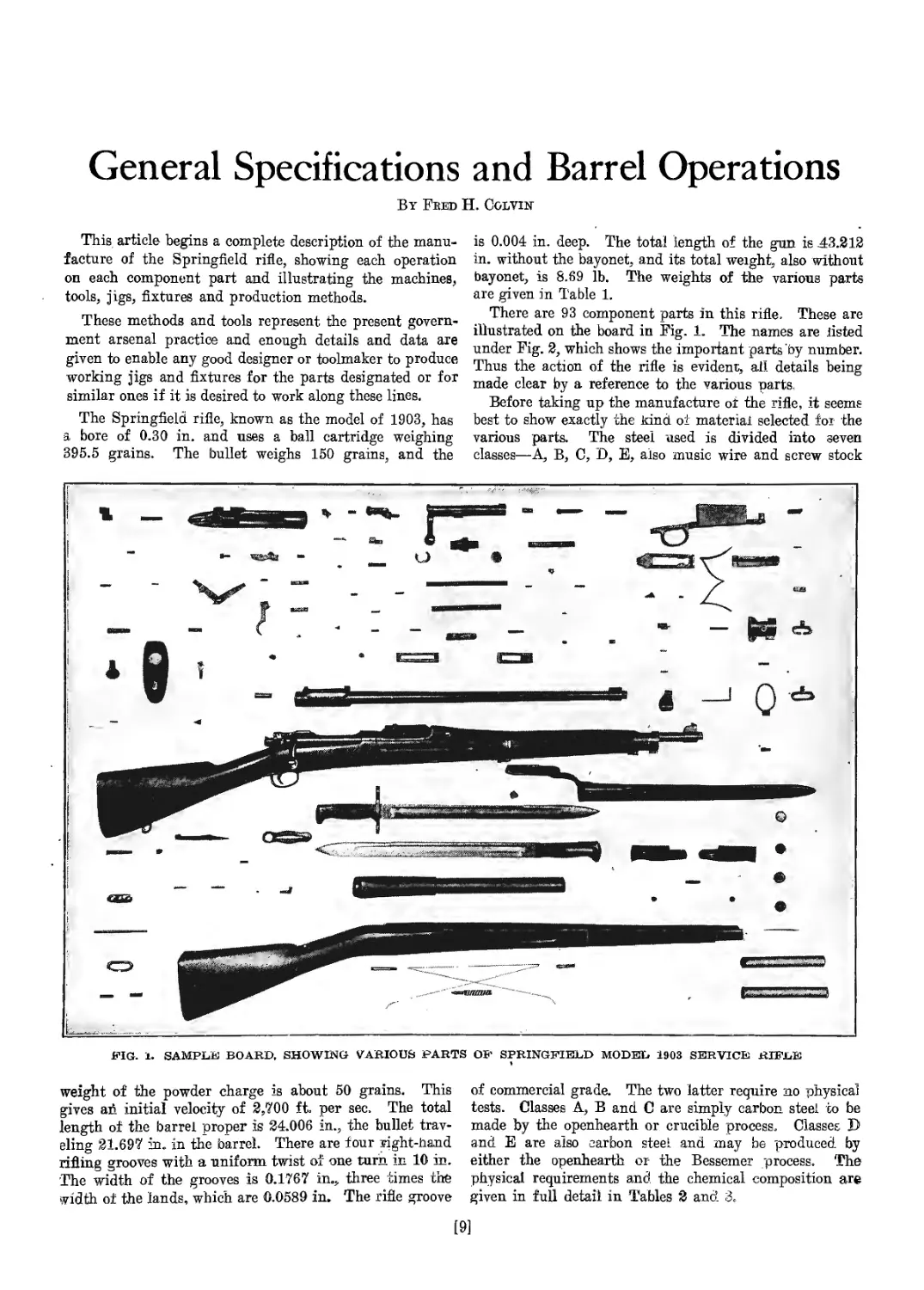
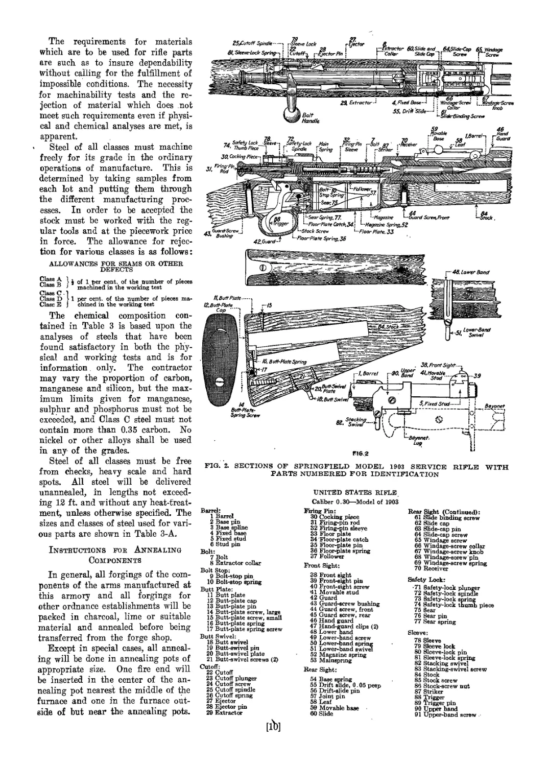
There are 93 component parts in this rifle. These are
illustrated on the board in Fig. 1. The names are listed
under Fig. 2, which shows the important parts by number.
Thus the action of the rifle is evident, all details being
made clear by a reference to the various parts.
Before taking up the manufacture of the rifle, it seems
best to show exactly the kind of material selected for the
various parts. The steel used is divided into seven
classes—А, В, C, D, E, also music wire and screw stock
FIG. 1. SAMPLE BOARD, SHOWING VARIOUS PARTS OB' SPRINGFIELD MODEL 1903 SERVICE RIFLE
»
weight of the powder charge is about 50 grains. This
gives ай initial velocity of 2,700 ft. per sec. The total
length of the barrel proper is 24.006 in., the bullet trav-
eling 21.697 in. in the barrel. There are four right-hand
rifling grooves with a uniform twist of one turn in 10 in.
The width of the grooves is 0.1767 in., three times the
width of the lands, which are 0.0589 in. The rifle groove
of commercial grade. The two latter require no physical
tests. Classes A, В and C are simply carbon steel to be
made by the openhearth or crucible process. Classes D
and E are also carbon steel and may be produced by
either the openhearth or- the Bessemer process. The
physical requirements and the chemical composition are
given in full detail in Tables 2 anol 3.
[9]
The requirements for materials
which are to be used for rifle parts
are such as to insure dependability
without calling for the fulfillment of
impossible conditions. The necessity
for machinability tests and the re-
jection of material which does not
meet such requirements even if physi-
cal and chemical analyses are met, is
apparent.
Steel of all classes must machine
freely for its grade in the ordinary
operations of manufacture. This is
determined by taking samples from
each lot and putting them through
the different manufacturing proc-
esses. In order to be accepted the
stock must be worked with the reg-
ular tools and at the piecework price
in force. The allowance for rejec-
tion for various classes is as follows:
ALLOWANCES FOR SEAMS OR OTHER
DEFECTS
pj®ss A | j of i j>er cent, of the number of pieces
viass a ) machined in the working test
Class C • ]
Class D !> 1 per cent, of the number of pieces ma*
Class E J chined in the working test
The chemical composition con-
tained in Table 3 is based upon the
analyses of steels that have been
found satisfactory in both the phy-
sical and working tests and is for
information. only. The contractor
may vary the proportion of carbon,
manganese and silicon, but the max-
imum limits given for manganese,
sulphur and phosphorus must not be
exceeded, and Class C steel must not
contain more than 0.35 carbon. No
nickel or other alloys shall be used
in any- of the grades.
Steel of all classes must be free
from checks, heavy scale and hard
spots. All steel will be delivered
unannealed, in lengths not exceed-
ing 12 ft. and without any heat-treat-
ment, unless otherwise specified. The
sizes and classes of steel used for vari-
ous parts are shown in Table 3-A.
Instructions for Annealing
Components
In general, all forgings of the com-
ponents of the arms manufactured at
this armory and all forgings for
other ordnance establishments will be
packed in charcoal, lime or suitable
material and annealed before being
transferred from the forge shop.
Except in special cases, all anneal-
ing will be done in annealing pots of
appropriate size. One fire end will
be inserted in the center of the an-
nealing pot nearest the middle of the
furnace and one in the furnace out-
side of but near the annealing pots.
FIG. 2. SECTIONS OF SPRINGFIELD MODEL 1903 SERVICE RIFLE WITH
PARTS NUMBERED FOR IDENTIFICATION
Barrel:
1 Barrel
2 Base pin
3 Base spline
4 Fixed base
5 Fixed stud
6 Stud pin
Bolt:
7 Bolt
8 Extractor collar
Bolt Stop:
9 Bolt-stop pin
10 Bolt-stop spring
Butt Plate:
11 Butt plate
12 Butt-plate cap
13 Butt-plate pin
14 Butt-plate screw, large
15 Butt-plate screw, small
16 Butt-plate spring
17 Butt-plate spring screw
Butt Swivel:
18 Butt swivel
19 Butt-swivel pin
20 Butt-swivel plate
21 Butt-swivel screws (2)
Cutoff:
22 Cutoff
23 Cutoff plunger
24 Cutoff screw
25 Cutoff spindle
26 Cutoff spring
27 Ejector
28 Ejector pin
29 Extractor
[lb]
UNITED STATES RIFLE
CaHber 0.30—Model of 1903
Firing Pin:
30 Cocking piece
31 Firing-pin rod
32 Firing-pin sleeve
33 Floor plate
34 Floor-plate catcb
35 Floor-plate pin
36 Floor-plate spring
37 Follower
Front Sight:
38 Front sight
39 Front-sight pin
40 Front-sight screw
41 Movable stud
42 Guard
43 Guard-screw bushing
44 Guard screw, front
45 Guard screw, rear
46 Hand guard
47 Hand-guard clips (2)
48 Lower hand
49 Lower-hand screw
50 Lower-band spring
51 Lower-band swivel
52 Magazine spring
53 Mainspring
Rear Sight:
54 Base spring
55 Drift slide, 0.05 peep
56 Drift-slide pin
57 Joint pin
58 Leaf
59 Movable base
60 Slide
Rear Sight (Continued):
61 Slide binding screw
62 Slide cap
63 Slide-cap pin
64 Slide-cap screw
65 Windage screw
66 Windage-screw collar
67 Windage-screw knob
68 Windage-sorew'pin
69 Windage-screw spring
70 Receiver
Safety Lock:
• 71 Safety-lock plunger
72 Safety-lock spindle
73 Safety-lock spring
74 Safety-lock tnumh piece
75 Sear
76 Sear pin
77 Sear spring
Sleeve:
78 Sleeve
79 Sleeve lock
80 Slceve-lock pin
81 Sleeve-lock spring
82 Stacking swivel
83 Stacking-swivel screw
84 Stock
85 Stock screw
86 Stock-screw nut
87 Striker
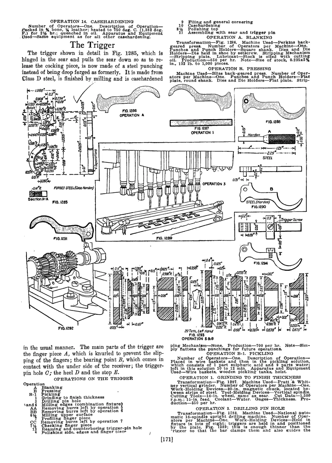
88 Trigger
89 Trigger pin
90 Tipper hand
91 Upper-band screw
FIGS. 3 TO 8.' SPECIALIZED OPERATIONS ARE FREQUENT IN MAKING THE SPRINGFIELD 1903 RIFLE BARREL
Fig 3—Rolling barrels. Fig. 4—Hammer for straightening barrels. Fig. 5—Sawing barrels to rough length.
Fig. 6—Turning outside of barrels. Fig. 7—Drilling holes in barb's Fig. 8—Reaming holes in barrels
[11]
The Leeds & Northrup 8-point recording pyrometer
will, in general, be used in keeping the
annealing
temperatures.
The
following
record of the
temperatures
These instructions have since been amended to author'
ize the annealing of components of Class D and Class E
stock in a muffler furnace without the use of annealing
sir
*
0.0875-
Extension
Section Showing Spline-..
Ю Threads per inch R H.
Proof Chamber^
CHAMBER
“>|Q34k-
Ajssr
’ia/s"
rtmsh Chamber
, n-uul
;-^5
•/.576'—
..........Я
к-—.............гз55'....->
к.............2.545“.....
н.............?.5&5*......
CHAMBER pF BARREL IN PROOF STAGE
, ,10 Threads per inch Я H.
L......олзр-!-—......../.o’-'-...-
..........г.555'....
0.I8H....1.....24.006’to End of Barrel -
This view shows changes to bemadei
for converting old barrels to take new
ammunition^Dotted lines show outline
of barrel before bang cut off. Make
chamber same as sflinn-below.
\<)87 Ream fcrMnaffer Assembling Base
24.CC6' Tobi .......
-22.21' to End of Barra-
A-0.5B90'
8-0.1767?
Steel Headspace ?
^е\(0.147 Min.
\0.i485Max.-
0.615’A -
0.063T~
horizontal
0Д5'
। i •
;Ream fbr Pin after Assembling
•OJL J
SECTION OF BARREL SHOWING RIFLING
Li
acTSR'i г
-|йГк
face of Muzzle snail not be polished.
..w
54 . SS к --глич-А Sfs'S?
it
*.....This dimension to be*left 0004 short until
barrel is assembled to receiver
x >r p.’ .5 5
ь
.K.
tHftina-4 plain amoves J rimes, the. ndth of the
landsOOwdeea-the twistnaht hand,
uniform, I turn in Ю inches.
ч- о '•Fnfflar'wffiHin.* ’/*•'
a/56*-h> ......-Д«^.^7447Г.
fi735*-| I-.................
°Я
s
-Й4?
.«к-----------5/W’
....
------r
•4<------4 44S'
...J :
Г-- ’‘3.256-—'-~H
..................................-
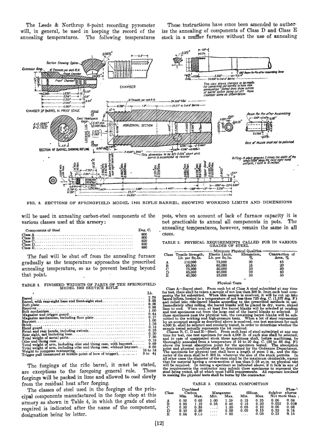
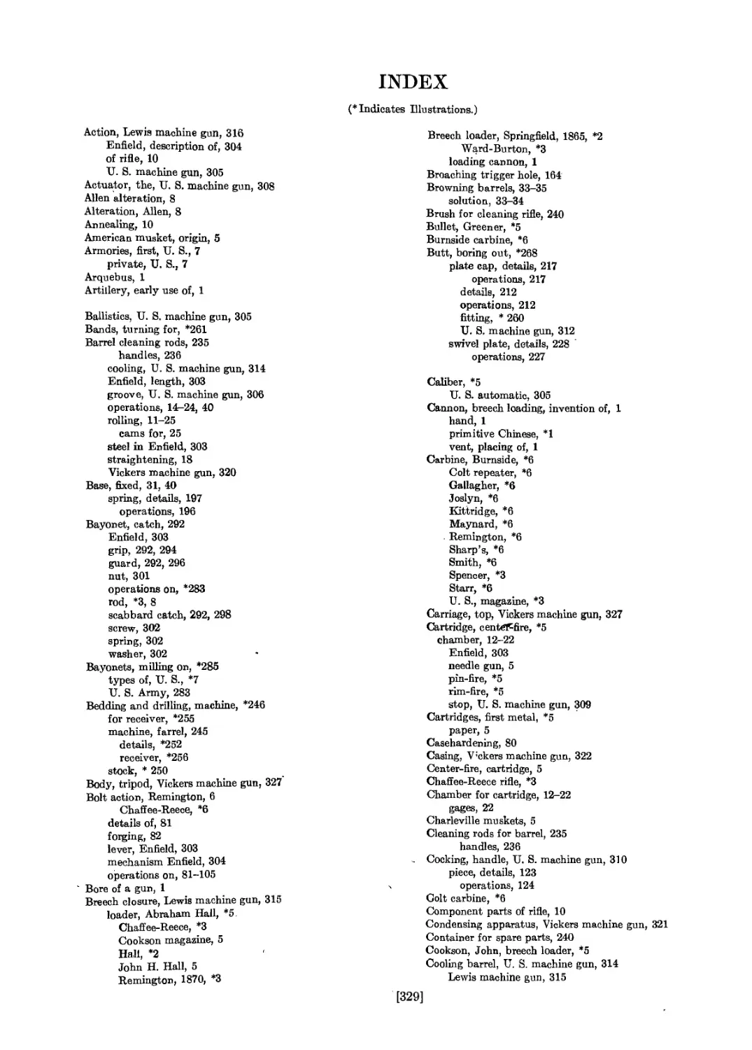
FIG. 9. SECTIONS OF SPRINGFIELD MODEL 1903 RIFLE
BARREL. SHOWING WORKING LIMITS AND DIMENSIONS
will be used in annealing carbon-steel components of the
various classes used at this armory:
Components of Steel Deg. C.
Class A....................................................... 800
Class В....................................................... 800
Class C....................................................... 820
Class D....................................................... 850
ClasaE...................................................... 880
pots, when on account of lack of furnace capacity it is
not practicable to anneal all components in pots. The
annealing temperatures, however, remain the same in all
cases.
The fuel will be shut off from the annealing furnace
gradually as the temperature approaches the prescribed
annealing temperature, so as to prevent heating beyond
that point.
TABLE 2. PHYSICAL REQUIREMENTS CALLED FOR IN VARIOUS
GRADES OF STEEL
Class . Minimum Physical Qualities ———————
Tensile Strength, Lb. per Sq.In. Elastic Limit, Lb. per Sq.In. Elongation, % Contraction of Area, %
A 110,000 75,000 20 45
В 90,000 60,000 15 20
c 75,000 50,000 25 50
D 65,000 40,000 23 40
E 40,000 25,000 33 55
TABLE 1. FINISHED WEIGHTS OF PARTS OF THE SPRINGFIELD
MODEL 1903 SERVICE RIFLE
Barrel.......................................................
Barrel, with rear-sight base and front-sight stud............
Butt plate...................................................
Receiver... 4................................................
Bolt mechanism ..............................................
Magazine and trigger guard. .................................
Magazine mechanism, including Boor plate.....................
Bayonet......................................................
Stock........................................................
Hand guard................t..................................
Front and rear bande, including swivels......................
Rear sight, not including base...............................
Total weight of metal parts..................................
Oiler and thong case.........................................
Total weight ol arm, including oiler and thong case, with bayonet,
Weight hTcompress mainspring.................................
Trigger pull (measured at middle point of bow of trigger)....
Lh.
2.79
3.00
0.26
0.98
1.00
0.44
0.17
1.00
1.58
0.13
0.25
0.20
7.30
0.19
9.69
8.69
Total weight of arm, including oiler and thong case, without bayonet....
---------------------------16 to 18
3 to 4|
The forgings of the rifle barrel, it must be stated,
are exceptions to the foregoing general rule. These
forgings will be packed in lime and allowed to cool slowly
from the residual heat after forging.
The classes of steel used in the forgings of the prin-
cipal components manufactured in the forge shop at this
armory as shown in Table 4, in which the grade of steel
required is indicated after the name of the component,
designation being by letter.
Physical Tests
Class A—Barrel steel: From each lot of Class A steel submitted at any time
for test, there shall be taken a sample of not less than 300 lb. from each heat com-
posing the lot submitted. When this sample is received, it will be cut up into
barrel billets, heated to a temperature of not lees than 725 deg. C. (1,337 deg. F.)
and rolled into rifle-barrel blanks according to the prescribed methods in use.
Immediately after rolling, the barrel blanks will be placed in dry, warm, slaked
lime to cool. When cool, at least five barrel blanks will be selected at random
and test specimens cut from the large end of. the barrel blanks so selected. If
these specimens pass the physical test, the remaining barrel blanks will be sub-
mitted to the working and high-pressure testa. When a lot of steel represented
by an accepted sample as described above is received, one test specimen for each
4,000 lb. shall be selected and similarly tested, in order to determine whether the
sample tested actually represents the lot received.
Classes В, C, D and E—Steel: From each beat of steel submitted at any one
time for test, one test specimen for each 4,000 lb. of each size shall be selected;
and in case of un&nnealed stock these specimens shall, before machining, be
thoroughly annealed from a temperature of 10 to 20 deg. C. (50 to 6S deg. F.)
above the lowest absorption point for the specimen tested. The absorption
point and physical qualities shall he determined by the Ordnance Department.
The specimens for physical test shall have a length cf stem 2 in., and the dia-
meter of the stem shall be 0.505 in. wherever the size of the stock permits. In
all other cases the diameter of the stem shall be the maximum obtainable, except
that for material having a cross-section of lees than 0.05 eq.in.' no physical test
will be required. In testing a specimen as indicated above, if it fails in any of
the requirements the contractor may submit three яряНтпрпя to represent the.
steel being tested, all of which must fulfill requirements. All expenses involved
in making the physical tests shall be borne by the contractor.
TABLE 3. CHEMICAL COMPOSITION
Class
A
В
C
D
E
Combined
Carbon
Mm. Max.
0.50 0.60
0.95 I.10
0.30 0.35
0.10 0.30
0.04 0.C8
Manganese
Min.
1.00
0.25
Max.
1.29
0.40
1.30-
0.50
0 50
Silicon
Min. Max.
0.15 0.25
0.15 0.20
0.05 0.10
0.02 0.15
0.05
Phoa-^
Sulphur phorus
Not more than
0.06 0.08
0.022 0.019
0.06 0.06
0.12 0.15
0.12 0.15
[12]
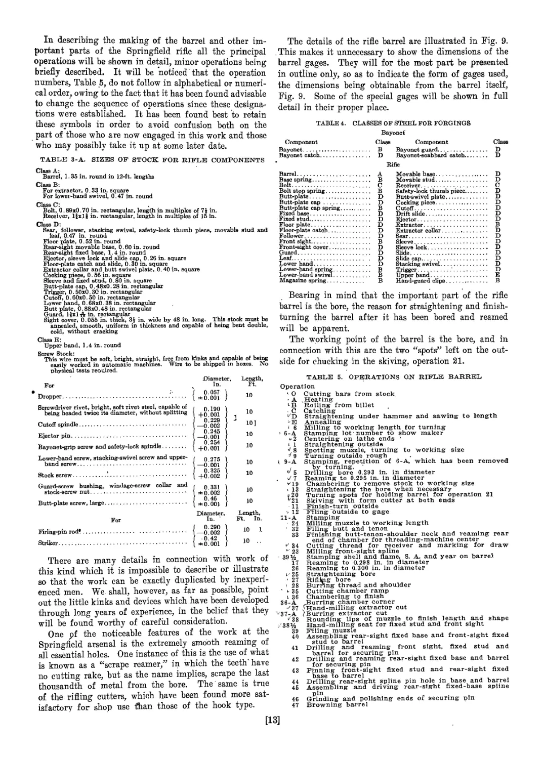
In describing the making of the barrel and other im-
portant parts of the Springfield rifle all the principal
operations will be shown in detail, minor operations being
briefly described. It will be noticed that the operation
numbers, Table 5, do not follow in alphabetical or numeri-
cal order, owing to the fact that it has been found advisable
to change the sequence of operations since these designa-
tions were established. It has been found best to retain
these symbols in order to avoid confusion both on the
part of those who are now engaged in this work and those
who may possibly take it up at some later date.
TABLE 3-A. SIZES OF STOCK FOR RIFLE COMPONENTS
Class A;
Barrel, 1.35 in. round in 12-ft. lengths
Class B-.
For extractor, 0.33 in. square
For lower-band swivel, 0.47 in. round
Class C:
Bolt, 0.89x0.70 in. rectangular, length in multiples of 7 J in.
Receiver, 11x1$ in- rectangular, length in multiples of 15 in.
Class D:
Sear, follower, stacking swivel, safety-lock thumb piece, movable stud and
leaf, 0.47 in. round
Floor plate, 0.52 in. round
Rear-sight movable base, 0.60 in. round
Rear-sight fixed base, 1.4 in. round
Ejector, sleeve lock and slide cap, 0.26 in. square
Floor-plats catch and slide, 0.30 in. square
Extractor collar and hutt swivel plate, 0.40 in. square
Cocking piece, 0.56 in. square
Sleeve and fixed stud, 0.80 in. square
Butt-plate cap, 0.48x0.28 in. rectangular
Trigger, 0.50x0.30 in. rectangular
Cutoff, 0.60x0.50 in. rectangular
Lower hand, 0.68x0.38 in. rectangular
Butt plate, 0.88x0.48 in. rectangular
Guard, l|xl^ in. rectangular
Sight cover, 0.055 in. thick, 3| in. wide by 48 in. long. This stock must be
annealed, smooth, uniform in thickness and capable of heing bent double,
cold, without cracking
Class E:
Upper band, 1.4 in. round
Screw Stock: , ‘
This wire must be soft, bright, straight, free from kinks and capable of being
easily worked in automatic machines. Wire to be shipped in boxes. No
physical tests reouired.
For
Dropper....................................'.....
Screwdriver rivet, bright, soft rivet steel, capable of
being headed twice its diameter, without splitting
Cutoff spindle...................................
Ejector pin......................................
Bayonet-grip screw and safety-lock spindle.......
Lower-band screw, stacking-swivel screw and upper-
band screw.......................................
Stock screw......................................
Guard-screw bushing, windage-screw collar and
stock-screw nut..................................
Butt-plate screw, large..........................
For
Firing-pin rod*..................................
Striker..........................................
Diameter,
In.
/ 0.057 1
I ±0.001 /
SO.190 1
4-0.001 J
0.229 I
—0.002 j
0.245 1
—0.001 /
0.254 1
4-0.001 J
( 0.275 1
1—0.001 I
I 0.325 1
t 4-0.002 J
/ 0.331 1
I ±0.002 /
I 0.46 I
( ±0.001 /
Diameter,
In.
f 0.290 1
1 —0.002 (
I -0.42 1
t ±0.001 J
Length,
Ft.
10
10
J 10]
10
10
10
10
10
10
Length,
Ft. In.
10 1.
10 ..
There are many details in connection with work of
this kind which it is impossible to describe or illustrate
so that the work can be exactly duplicated by inexperi-
enced men. We. shall, however, as far as possible, point
out the little kinks and devices which have been developed
through long years of experience, in the belief that they
will be found worthy of careful consideration.
One pf the noticeable features of the work at the
Springfield arsenal is the extremely smooth reaming of
all essential holes. One instance of this is the use of what
is known as a “scrape reamer,” in which the teeth'have
no cutting rake, but as the name implies, scrape the last
thousandth of metal from the bore. The same is true
of. the rifling cutters, which have been found more sat-
isfactory for shop use than those of the hook type.
The details of the rifle barrel are illustrated in Fig. 9.
. This makes it unnecessary to show the dimensions of the
barrel gages. They will for the most part be presented
in outline only, so as to indicate the form of gages used,
the dimensions being obtainable from the barrel itself,
Fig. 9. Some of the special gages will be shown in full
detail in their proper place.
TABLE 4. CLASSES OF STEEL FOR FORGINGS
Bayonet'
Component Class Component Class
Bayonet...................... В Bayonet guard............... D
Bayonet catch................ D Bayonet-scabbard catcb...... D
Rifle
Barrel......................... A
Base spring.................... В
Bolt........................... C
Bolt stop spring............... В
Butt-plate..................... D
Butt-plate cap................. D
Butt-plate cap spring.......... В
Fixed base..................... D
Fixed stud..................... D
Floor plate.................... D
Floor-plate catch.............. D
Follower....................... D
Front sight.................... В
Front-sight cover.............. D
Guard.......................... D
Leaf........................... D
Lower hand..................... D
Lower-band spring.............. В
Lower-band swivel.............. В
Magazine spring................ В
Movable base............... D
Movable stud............... D
Receiver........................ C
Safety-lock thumb piece......... D
Butt-swivel plate............... D
Cocking piece................... D
Cutoff.......................... D
Drift slide..................... D
Ejector......................... D
Extractor....................... В
Extractor collar................ D
Sear............................ D
Sleeve.......................... D
Sleeve lock..................... D
Slide........................... D
Slide cap....................... D
Stacking swivel................. D
Trigger........................ D
Upper band..................... E
Hand-guard clips............... В
Bearing in mind that the important part of the rifle
barrel is the bore, the reason for straightening and finish-
turning the barrel after it has been bored and reamed
will be apparent.
The working point of the barrel is the bore, and in
connection with this are the two “spots” left on the out-
side for chucking in the skiving, operation 21.
TABLE 5. OPERATIONS OJSI RIFLE BARREL
Operation
*- О Cutting bars from stock,
» A .Heating
LB Rolling from billet
C Catching
^D Straightening under hammer and sawing- to length
^E Annealing
' 6 Milling to working length for turning
- 6-A Stamping lot 'number to show maker
4-2 Centering on lathe ends '
i 1 Straightening outside
^ 8 Spotting muzzle, turning to working size
9 Turning outside rough
i 9-A Stamping, repetition of 6-A, which has been removed
! by turning.
V 5 Drilling bore 0.293 in. in diameter
. У 7 Reaming to 0.295 in. in diameter
’"'19 Chambering to remove stock to working size
* 13 Straightening the bore when necessary
к 20 Turning spots for holding barrel for operation 21
V21 Skiving with form cutter at both ends
11 Finish-turn outside
v 12 "Filing outside to gage
11-A Stamping
‘ 24 Milling muzzle to working length
32 Filing butt and tenon
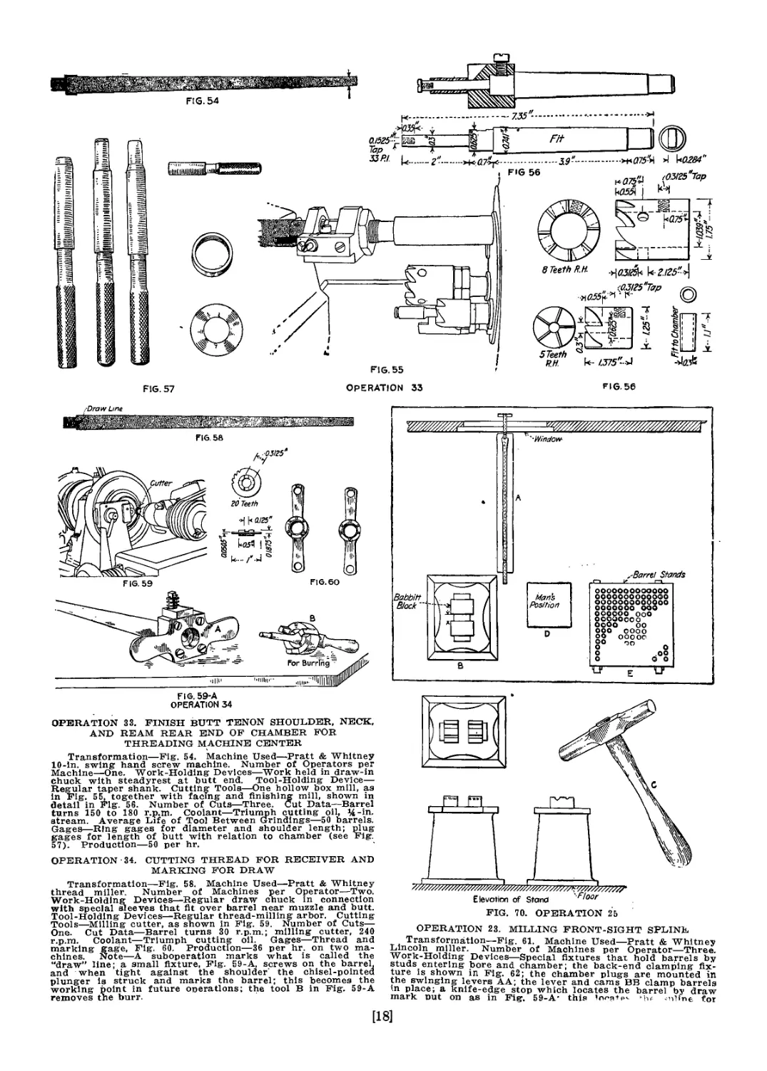
33 Finishing butt-tenon-shoulder neck and reaming rear
end of chamber for threading-machine center
*' 34 Cutting thread for receiver and marking for draw
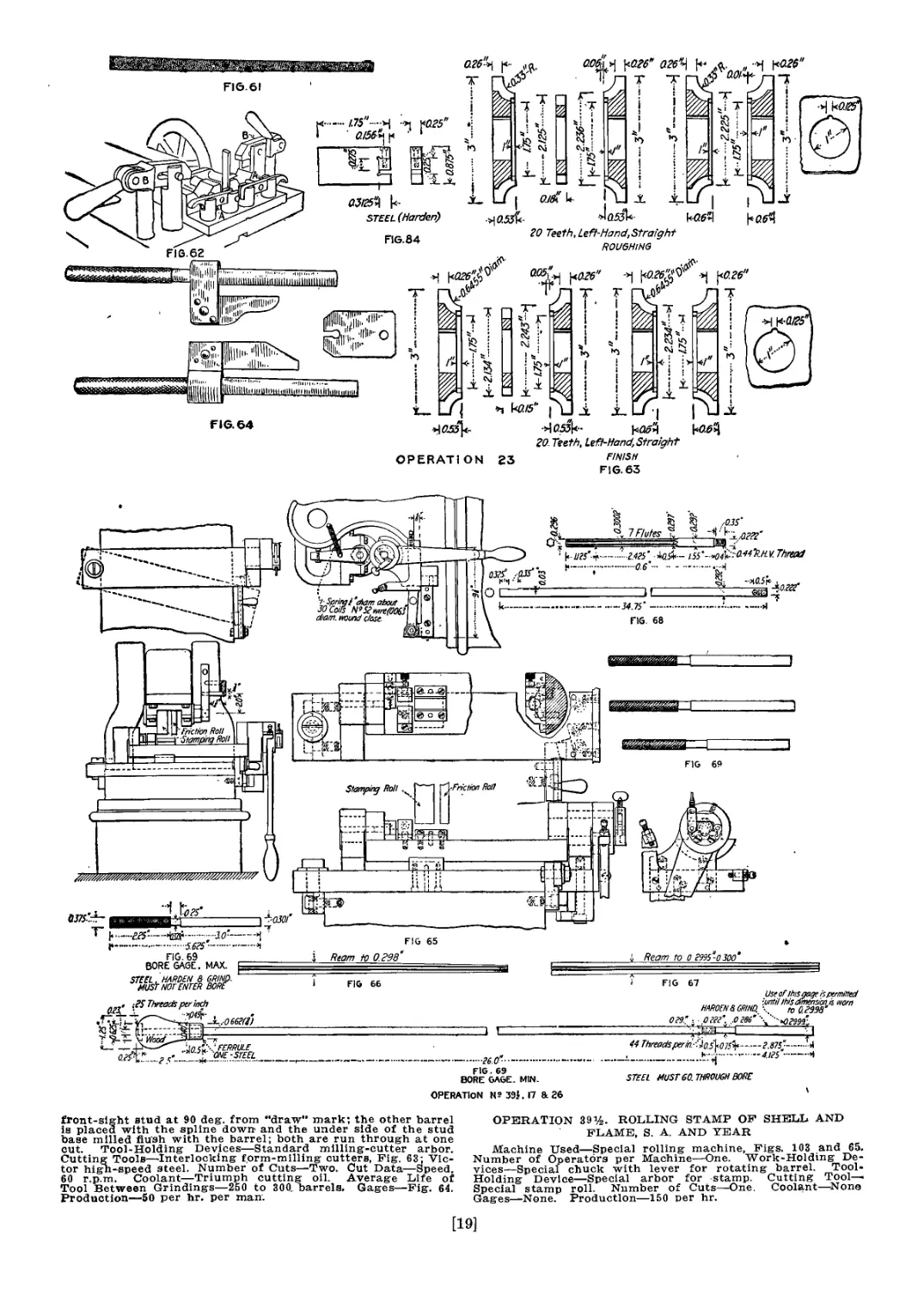
23 Milling front-sight spline
- 39% Stamping shell and name, S. A. and year on barrel
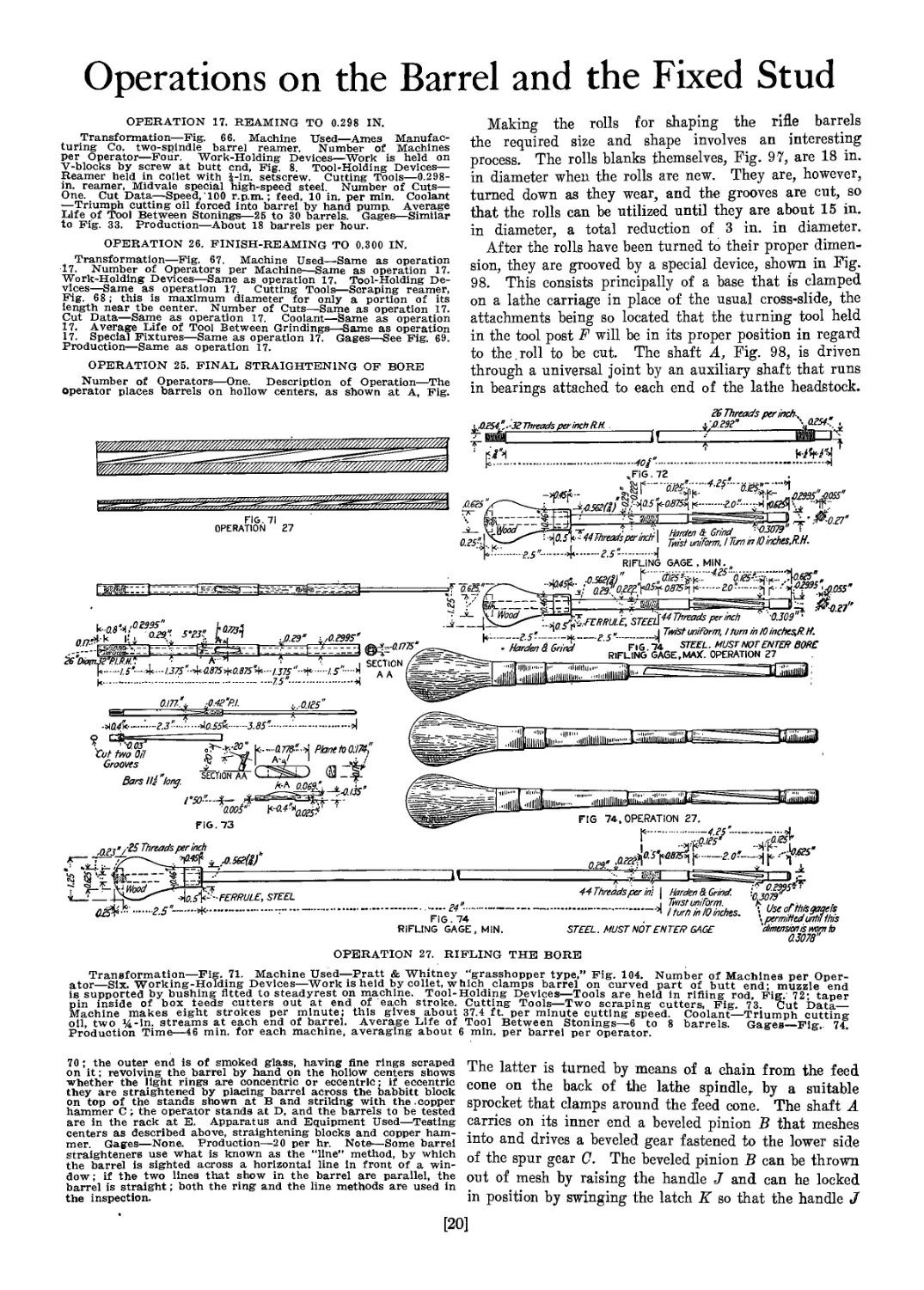
17 Reaming to 0.298 in. in diameter
26 Reaming to 0.300 in. in diameter
t-25 Straightening bore
1 27 Riflkig bore
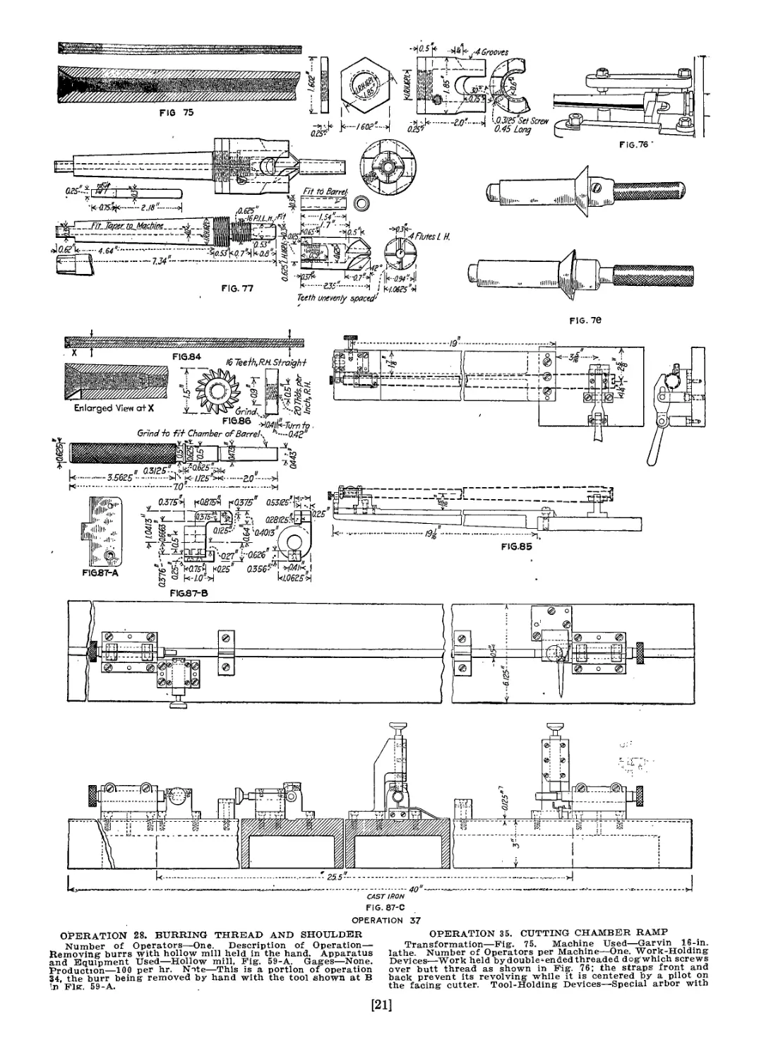
t 28 Burring thread and shoulder
' ь 35 Cutting chamber ramp
i 36 Chambering to finish
36-A Burring chamber corner
^37 /-Hand-milling extractor cut
1737-A (Burring extractor cut
^38 Rounding lips of muzzle to finish length and shape
l'38% Hand-milling seat for fixed stud and front sight
39 Filing muzzle
40 Assembling rear-sight fixed base and front-sight fixed
stud to barrel
41 Drilling and reaming front sight, fixed stud and
barrel for securing pin
42 Drilling and reaming rear-sight fixed base and barrel
for securing pin
43 Pinning front-sight fixed stud and rear-sight fixed
base to barrel
44 Drilling rear-sight spline pin hole in base and barrel
45 Assembling and driving rear-sight fixed-base spline
pin
46 Grinding and polishing ends of securing pin
47 Browning barrel
[13]
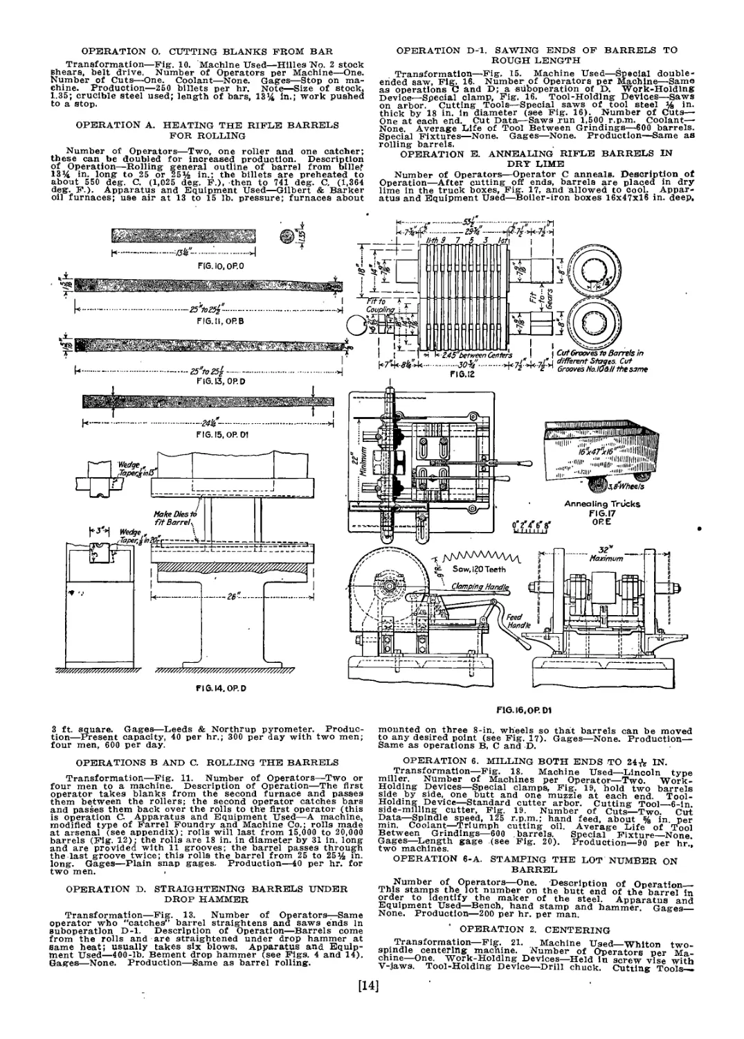
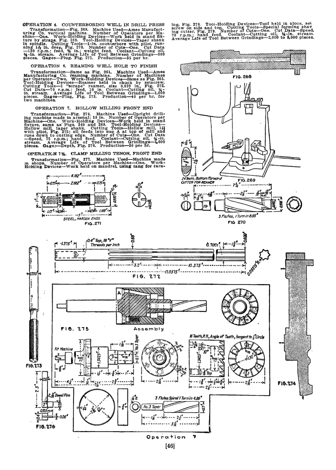
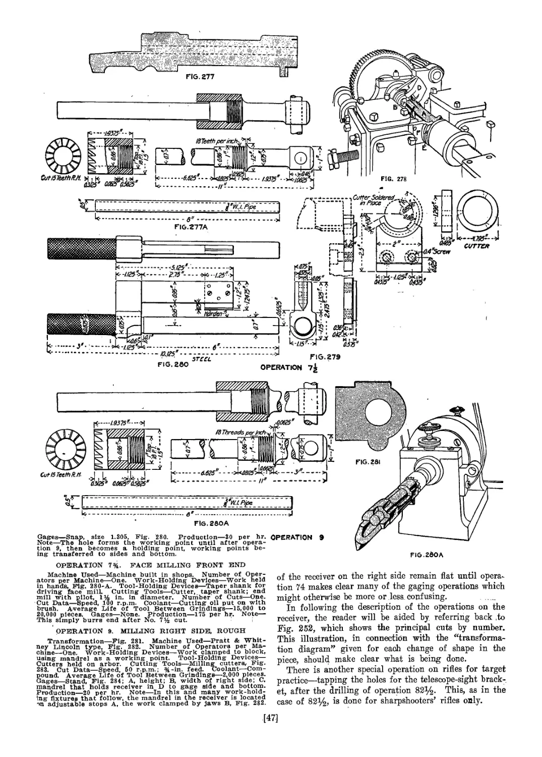
OPERATION О. CUTTING BLANKS FROM BAR
Transformation—Fig. 10. Machine Used—Hlllea No. 2 stock
shears, belt drive. Number of Operators per Machine—One.
Number of Cuts—One. Coolant—None. Gages—Stop on ma-
chine. Production—250 billets per hr. Note—Size of stock,
1.35; crucible steel used; length of bars, 13’4 in.; work pushed
to a stop.
OPERATION A. HEATING THE RIFLE BARRELS
FOR ROLLING
Number of Operators—Two, one roller and one catcher;
these can be doubled for increased production. Description
of Operation—Rolling general outline of barrel from billej
13% in. long to 25 or 25% in.; the billets are preheated to
about 550 deg. C. (1,025 deg. F.), then to 741 deg. C. (1,364
deg. F.). Apparatus and Equipment Used—Gilbert & Barker
oil furnaces; use air at 13 to 15 lb. pressure; furnaces about
OPERATION D-l. SAWING ENDS OF BARRELS TO
ROUGH LENGTH
Transformation—Fig. 15. Machine Used—Special double-
ended saw, Fig. 16. Number of Operators per Machine—Same
as operations C and D; a suboperation of D. Work-Holding
Device_Special clamp. Fig. 16. Tool-Holding Devices—Saws
on arbor. Cutting Tools—Special saws of tool steel % in.
thick by 18 in. in diameter (see Fig. 16). Number of Cuts—
One at each end. Cut Data—Saws run 1,500 r.p.m. Coolant—
None Average Life of Tool Between Grindings—600 barrels.
Special Fixtures—None. Gages—None. Production—Same as
rolling barrels.
OPERATION E. ANNEALING RIFLE BARRELS IN
DRY LIME
Number of Operators—Operator C anneals. Description of
Operation—After cutting off ends, barrels are placed in dry
lime in the truck boxes, Fig. 17, and allowed to cool. Appar-
atus and Equipment Used—Boiler-iron boxes 16x47x16 in. deep.
3 ft. square. Gages—Leeds & Northrup pyrometer. Produc-
tion—Present capacity, 40 per hr.; 300 per day with two men;
four men, 600 per day.
OPERATIONS В AND C. ROLLING THE BARRELS
Transformation—Fig. 11. Number of Operators—Two or
four men to a machine. Description of Operation—The first
operator takes blanks from the second furnace and passes
them between the rollers; the second operator catches bars
and passes them back over the rolls to the first operator (this
is operation C. Apparatus and Equipment Used—A machine,
modified type of Farrel Foundry and Machine Co.; rolls made
at arsenal (see appendix); roils will last from 15,000 to 20,000
barrels (Fig. 12); the rolls are 18 in. in diameter by 31 in. long
and are provided with 11 grooves; the barrel passes through
the last groove twice; this rolls the barrel from 25 to 25% in.
long. Gages—Plain snap gages. Production—40 per hr. for
two men.
OPERATION D. STRAIGHTENING BARRELS UNDER
DROP HAMMER
Transformation—Fig. 13. Number of Operators—Same
operator who "catches” barrel straightens and saws ends In
suboperatlon D-l. Description of Operation—Barrels come
from the rolls and are straightened under drop hammer at
same heat; usually takes six blows. Apparatus and Equip-
ment Used—400-lb. Bement drop hammer (see Figs. 4 and 14).
Gages—None. Production—Same as barrel rolling.
HG. 16, OP. DI
mounted on three 8-in. wheels so that barrels can be moved
to any desired point (see Fig. 17). Gages—None. Production—
Same as operations В, C and D.
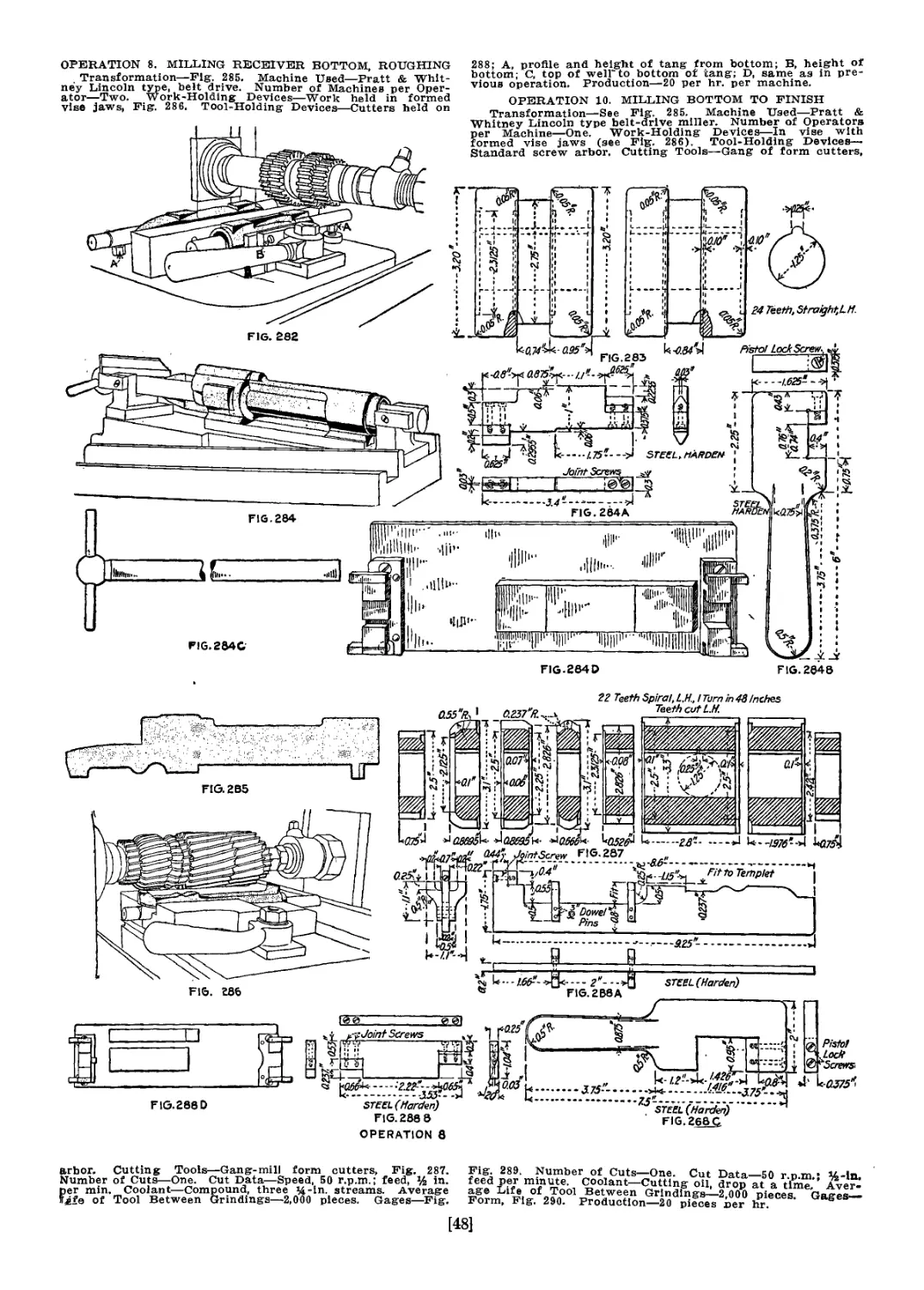
OPERATION 6. MILLING BOTH ENDS TO 24^ IN.
Transformation—Fig. 18. Machine Used—Lincoln type
miller. Number of Machines per Operator—Two. Work-
Holding Devices—Special clamps, Fig. 19, hold two barrels
side by side, one butt and one muzzle at each end. Tool-
Holding Device—Standard cutter arbor. Cutting Tool—6-ln
side-milling cutter, Fig. 19. Number of Cuts—Two. Cut
Data—Spindle speed, 125 r.p.m.; hand feed, about % in per
min. Coolant—Triumph cutting oil. Average Life of Tool
Between Grindings—600 barrels. Special Fixture—None
Gages—Length gage (see Fig. 20). Production—90 per hr.,
two machines.
OPERATION 6-A. STAMPING THE LOT NUMBER ON
BARREL
Number of Operators—One. Description of Operation
This stamps the lot number on the butt end of the barrel in
order to identify the maker of the steel. Apparatus and
Equipment Used—Bench, hand stamp and hammer. Gages__
None. Production—200 per hr. per man.
OPERATION 2. CENTERING
Transformation—Fig. 21. Machine Used—Whlton two-
spindle centering macnine. Number of Operators per Ma-
chine—One. Work-Holding Devices—Held in screw vise with
V-jaws. Tool-Holding Device—Drill chuck. Cutting Tools—
Drill and separate countersink; Midvale high-speed steel used.
Number of Cuts—Two. Cut Data—Speed, 400 rjp.m. Coolant-
Triumph cutting oil. Average Life of Tool Between Grind-
ings—300 barrels. Special Fixtures—None. Gages—None,
Production—45 per hr.
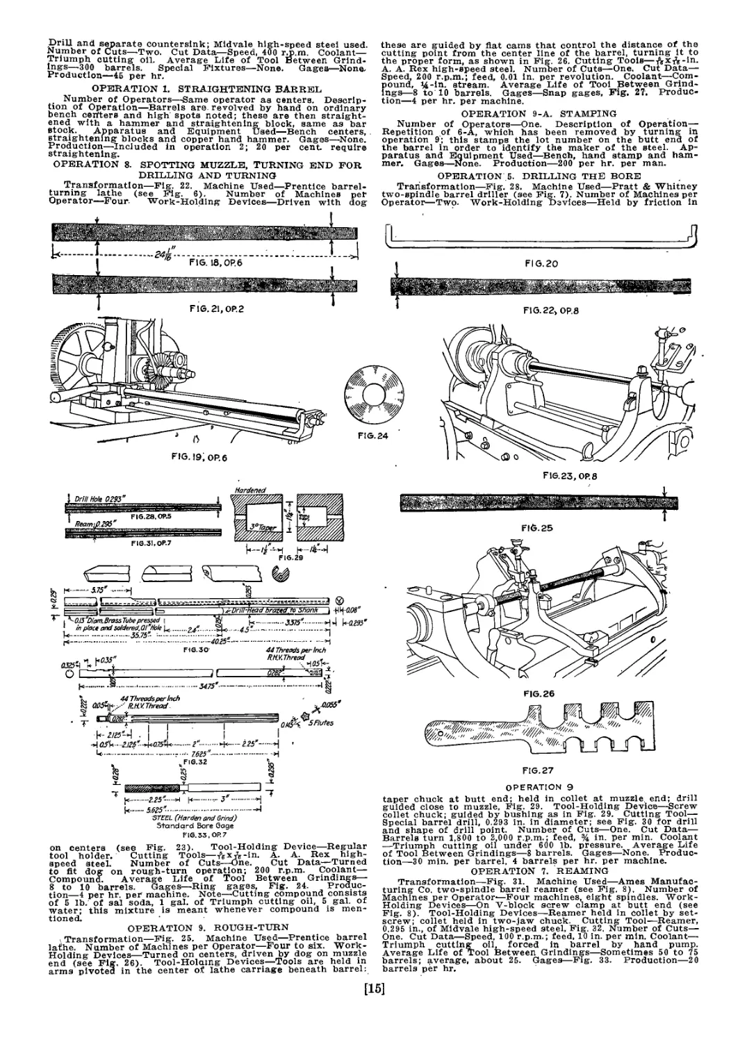
OPERATION 1. STRAIGHTENING BARREL
_ Number of Operators—Same operator as centers. Descrip-
tion of Operation—Barrels are. revolved by hand on ordinary
bench centers and high spots noted; these are then straight-
ened with a hammer and straightening block, same as bar
stock. Apparatus and Equipment Used—Bench centers,
straightening blocks and copper hand hammer. Gages—None.
Production—Included in operation 2; 20 per cent, require
straightening.
OPERATION 8. SPOTTING MUZZLE, TURNING END FOR
DRILLING AND TURNING
Transformation—Fig. 22. Machine Used—Prentice barrel-
turning lathe (see Fig. 6). Number of Machines pet
Operator—Four- Work-Holding Devices—Driven with dog
these are guided by flat cams that control the distance of the
cutting point from the center line of the barrel, turning it to
the proper form, as shown in Fig. 26. Cutting Tools—^xft-in.
A. A. Rex high-speed steel. Number of Cuts—One. Cut Data—
Speed, 200 r.p.m.; feed, 0.01 in. per revolution. Coolant—Com-
pound, >4-in. stream. Average Life of Tool Between Grind-
ings—8 to 10 barrels. Gages—Snap gages, Fig. 27. Produc-
tion—4 per hr. per machine.
OPERATION 9-A. STAMPING
Number of Operators—One. Description of Operation—
Repetition of 6-A, which has been removed by turning in
operation 9; this stamps the lot number on the butt end of
the barrel in order to identify the maker of the steel. Ap-
paratus and Equipment Used—Bench, hand stamp and ham-
mer. Gages—None. Production—200 per hr. per man.
OPERATION 5. DRILLING THE BORE
Transformation—Fig. 28. Machine Used—Pratt & Whitney
two-spindle barrel driller (see Fig. 7). Number of Machines per
Operator—Two. Work-Holding Devices—Held by friction in
F1G.23, OP.8
b— -ikt-A
FIS.29
*<0.l3"Dl№n.BrassTube pressed~\ t
1 in place and soldered.OI’Hole Ц.....24?......-Я*...4.5'
....-
Fie.30
©
/0 Shank 1 4Щ-а0в"
3375"-....kiW
..........-4
азгЛЛЛ^
О _
34.75"—
44 Threads per Inch
Rd.V.Thread „
агвт-
X, 44 Threads per Inch
aOSfy-.:-RMV.Thread.
I dah™
. 1 I
аЛ t.its-n-w.Ts&d.-
l....—.......—.
Flutes
—г"-....
- 7.615"-
Fie.32
•+-— its’-...H
I
3‘
jc----.1.15-
'STEEL (Harden and Grind)
Standard Bore Gage
FIG. 33.OP.7
on centers (see Fig. 23). Tool-Holding Device—Regular
tool holder. Cutting Tools—/^хЛ-in. A. A. Rex high-
speed steel. Number of Cuts—One. Cut Data—Turned
to fit dog on rough-turn operation; 200 r.p.m. Coolant—
Compound. Average Life of Tool Between Grindings—
8 to 10 barrels. Gages—Ring gages, Fig. 24. Produc-
tion—4 per hr. per machine. Note—Cutting compound consists
of 5 lb. of sal soda, 1 gal. of Triumph cutting oil, 5 gal. of
water; this mixture is meant whenever compound is men-
tioned.
OPERATION 9. ROUGH-TURN
, Transformation—Fig. 25. Machine Used—Prentice barrel
lathe. Number of Machines per Operator—Four to six. Work-
Holding Devices—Turned on centers, driven by dog on muzzle
end (see Fig. 26). Tool-Holaing Devices—Tools are held in
arms pivoted in the center of lathe carriage beneath barrel:
FIG. 27
OPERATION 9
taper chuck at butt end; held in collet at muzzle end; drill
guided close to muzzle, Fig. 29. Tool-Holding Device—Screw
collet chuck; guided by bushing as in Fig. 29. Cutting Tool—
Special barrel drill, 0.293 in. in diameter; see Fig. 30 for drill
and shape of drill point. Number of Cuts—One. Cut Data—
Barrels turn 1,800 to 2 000 r.p.m.; feed, % in. per min. Coolant
—Triumph cutting oil under 600 lb. pressure. Average Life
of Tool Between Grindings—8 barrels. Gages—None. Produc-
tion—30 min. per barrel. 4 barrels per hr. per machine.
OPERATION 7. REAMING
Transformation—Fig. 31. Machine Used—Ames Manufac-
turing Co. two-spindle barrel reamer (see Fig. 8). Number of
Machines per Operator,—Four machines, eight spindles. Work-
Holding Devices—On V-block screw clamp at butt end (see
Fig. 8). Tool-Holding Devices—Reamer held in collet by set-
screw; collet held in two-jaw chuck. Cutting Tool—Reamer,
0.295 in., of Midvale high-speed steel, Fig. 32. Number of Cuts—
One. Cut Data—Speed, 100 r.p.m.; feed, 10 in. per mln. Coolant—
Triumph cutting oil, forced in barrel by hand pump.
Average Life of Tool Between Grindings—Sometimes 50 to 75
barrels; average, about 25. Gages—Fig. 33. Production—20
barrels per hr.
[15]
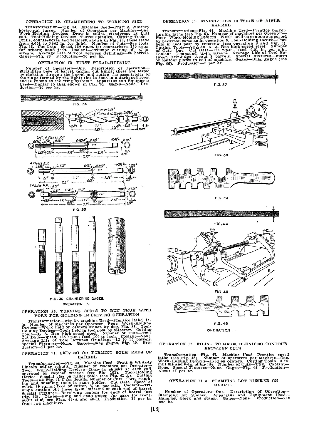
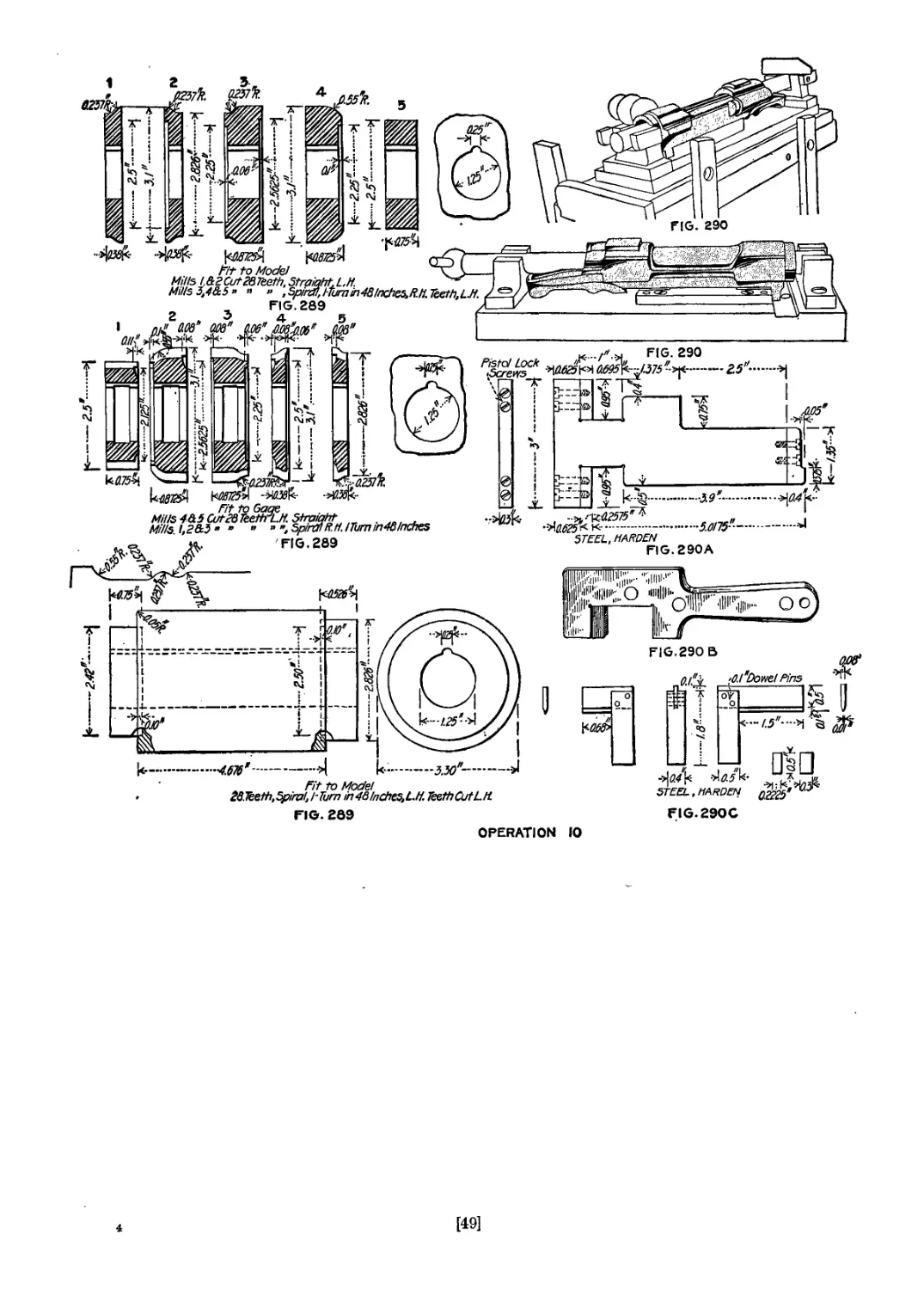
OPERATION 19. CHAMBERING TO WORKING SIZE
Transformation—34. Machine Used—Pratt & Whitney
horizontal turret. Number of Operators per Machine—One.
Work-Holding Devices—Draw-in collet, steadyrest at butt
end. Tool-Holding Devices—Turret spindles. Cutting Tools—
Drills, counterbores and reamers, shown in Fig. 35; these leave
from 0.001 to 0.002 in. for finish. Number of Cuts—-See tools,
Fig. 35. Cut Data—Speed, 180 r.p.m. for counterbore, 150 r.p.m.
for others; hand feed. Coolant—Triumph cutting oil, Up-
stream. Average Life of Tool Between Grindings—25 barrels.
Gages—Fig. 36. Production—20 per hr.
OPERATION 13. FIRST STRAIGHTENING
Number of Operators—One. Description of Operation—
Straighten bore of barrel, taking out kinks; these are tested
by sighting through the barrel and noting the eccentricity of
the rings formed by the light; this is done in a darkened room
and is known as the “ring system.” Apparatus and Equipment
Used—Similar to that shown in Fig. 70. Gages—None. Pro-
duction—30 per hr.
0J4{ 4 Hutes R.H.
M894a& .0.495е
----------
....
—.........— 7.17й-......—-
к--------------------
FIG.35
FIG. 36. CHAMBERING GAGES.
OPERATION 19
OPERATION 20. TURNING SPOTS TO RUN TRUE WITH
BORE FOR HOLDING IN SKIVING OPERATION
Transformation—Fig. 37. Machine Used—Prentice lathe, 14-
in. Number of Machines per Operator—Four. Work-Holding
Devices—Work held on centers driven by dog, Fig. 38. Tool-
Holding Devices—Tools held in tool post by setscrew. Cutting
Tools—A. A. Rex high-speed steel. Number of Cuts—Two.
Cut Data—Speed, 125 r.p.m.; feed, 100 to inch. Coolant—None.
Average Life of Tool Between Grindings—12 to 15 barrels.
Special Fixtures—None. Gages—Snap gages, Fig. 39. Pro-
duction—21 per hr.
OPERATION 21. SKIVING OR FORMING BOTH ENDS OF
BARREL
Transformation—Fig. 40. Machine Used—Pratt & Whitney
Lincoln miller rebuilt. Number of Machines per Operator-
Two. Work-Holding Devices—Draw-in chucks at each end,
operated by ratchet wrench (see Fig. 101). Tool-Holding
Device—Special vise on miller table (see Fig. 41-A). Cutting
Tools_See Fig. 41-C for details. Number of Cuts—Two, rough-
ing and finishing tools in same holder. Cut Data—Speed of
work, 60 r.p.m.; feed of cutter, % in. per min. Coolant—Tri-
umph cutting oil; three %-in. streams at each end of barrel.
Special Fixtures—Revolving centers for ends of barrel (see
Fig 42). Gages—Ring and snap gages; for gage for front-
sight stud, see Figs. 43-A and 43-B. Production—15 per hr.
from two machines.
OPERATION 11. FINISH-TURN OUTSIDE OF RIFLE
BARREL
Transformation—Fig. 44. Machine Used—Prentice barrel-
turning lathe (see Fig. 6). Number of machines per Operator—
Four. Work-Holding Devices—Work held on centers supported
by backrest, same as in operation 9. Tool-Holding Device—Toot
held in tool post by setscrew (see operation 9 and Fig, 6).
Cutting Tools—Лхйг-in. A. A. Rex high-speed steel. Number
of Cuts—One. Cut Data—125 r.p.m.; feed, 0.01 in. per min.
Coolant—Compound, %-in. stream. Average Life of Tool Be-
tween Grindings—About 8 barrels. Special Fixtures—Form
or contour plates to bed of machine. Gages—Snap gages (see
Fig. 46). Production—5 per hr.
FIG. 38
FIG.39
FIG. 4G
OPERATION I 1
OPERATION 12. FILING TO GAGE, BLENDING CONTOUR
BETWEEN CUTS
Transformation—Fig. 47. Machine Used—Prentice speed
lathe (see Fig. 48). Number of operators per Machine—One.
Work-Holding Devices—Held on centers. Cutting Tools—8-in.
mill file and 6-in. pillar file. Number of Cuts—Two. Coolant—
None. Special Fixtures—None. Gages—Fig. 49. Production—
About 53 per hr.
OPERATION 11-A. STAMPING LOT NUMBER ON
BARREL
Number of Operators—One. Description Of Operation—
Stamping lot number. Apparatus and Equipment Used—
Hammer, block and stamp. Gages—None. Production—200
per hr.
[16]
FIG.53, OP.32
OPERATION 24. MILLING MUZZLE TO WORKING LENGTH,
24 fa-IN. LONG
Transformation—Fig. 50. Machine Used—Springfield 24-in.
lathe. Number of Operators per Machine—One. Work-Holding
Devices—Work is held on pilot, of end mill and on tailstock
center; kept from turning by dog, Fig. 51. Tool-Holding
Devices—Held in taper of spindle hole of lathe. Cutting
Tools—End mill with 0.293 pilot. Number of Cuts—One.
Coolant—Triumph cutting oil. Average Life of Tool Be-
tween Grindings—About 75 barrels. Special Fixtures—None.
Gages—Length gage, Fig. 51-A. Production—100 per hr.
OPERATION 32. FILING BUTT AND TENON
Transformation—Fig. 52. Machine Used—Prentice speed
lathe. Number of Operators per Machine—One. Work-Hold-
ing Devices—Work held on center, driven by dog (see Fig.
48). Cutting Tools—8-in. mill and 6-in. pillar file. Number
of Cuts—Two. Cut Data—1,500 r.p.m. Coolant—None.
Gages—Snap gage, Fig. 53. Production—28 per hr.
^0.85
П»
§ =
T
+2.755-
л_____—
i -^aeaefr-
r-<n—г----------p i <? J ьТГГ1 %%
A / i.....1.4Л 8
1ч / I гаэетб'мя. 15? 3 T
—t------------1 ~ii3 Lxli A
'FlthTempkt
К.....278-------I.
, ? Ta be
Й ground
bn all
sides
k-
-над
4.7-......................
Turning (Butt End)
FI64I-B
Notch here only
tor roughing
о cutter
<>•' j
I ". aes’rap^THtk. Cen+ers
- I*'............ ^0-8 per lnch,Q38llDeep
*| flU85
-H kacg if
F1G.42
[<Q73>f 14
1
Harden ,
/ 025
Notch here only for
finish cutter
092 >i
STEEL X- l.7S-->\
Shouldering for
Fron+-Sigh+ S+ud
43-A
OPERATION 21
Fron+ of Barrel
Р16ДЗ-В
2
[17]
OPERATION 33. FINISH BUTT TENON SHOULDER, NECK,
AND REAM REAR END OF CHAMBER FOR
THREADING MACHINE CENTER
Transformation—Fig. 54. Machine Used—Pratt & Whitney
10-in. swing hand screw machine. Number of Operators per
Machine—One. Work-Holding Devices—Work held in draw-in
chuck with steadyrest at butt end. Tool-Holding Device—
Regular taper shank. Cutting- Tools—One hollow box mill, as
In Fig. 55, together with facing and finishing- mill, shown in
detail in Fig. 56. Number of Cuts—Three. Cut Data—Barrel
turns 150 to 180 r.p.m. Coolant—Triumph cutting oil, 4-in.
stream. Average Life of Tool Between Grindings—50 barrels.
Gages—Ring gages for diameter and shoulder length; plug
gages for length of butt with relation to chamber (see Fig.
57). Production—50 per hr.
OPERATION-34. CUTTING THREAD FOR RECEIVER AND
MARKING FOR DRAW
Transformation—Fig. 58. Machine Used—Pratt & Whitney
thread miller. Number of Machines per Operator—Two.
Work-Holding Devices—Regular draw chuck in connection
with special sleeves that fit over barrel near muzzle and butt.
Tool-Holding Devices—Regular thread-milling arbor. Cutting
Tools—Milling cutter, as shown in Fig. 59. Number of Cuts—
One. Cut Data—Barrel turns 30 r.p.m.; milling cutter, 240
r.p.m. Coolant—Triumph cutting oil. Gages—Thread and
marking gag:e. Fig. 60. Production—36 per hr. on two ma-
chines. Note—A suboperation marks what is called the
“draw” line; a small fixture, Fig. 59-A, screws on the barrel,
and when tight against the shoulder the chisel-pointed
plunger is struck and marks the barrel; this becomes the
working point in future operations; the tool В in Fig. 59-A
removes the burr.
,_________ v ] . I
Elevotion of Stand Floor
FIG. 70. OPERATION 25
OPERATION 23. MILLING FRONT-SIGHT SPLINK
Transformation—-Fig, 61. Machine Used—Pratt & Whitney
Lincoln miller. Number of Machines per Operator—Three.
Work-Holding Devices—Special fixtures that hold barrels by
studs entering bore and chamber; the back-end clamping fix-
ture is shown in Fig. 62; the chamber plugs are mounted in
the swinging levers AA; the lever and cams BB clamp barrels
in place; a knife-edge stop which locates the barrel by draw
mark put on as in Fig. 59-A’ this for
[18]
20- Teeth, Left-Hand, Straight
OPERAT? ON 23
FINISH
FIG. 63
STEEL, HARDEN & GRIND.
MUSt NOT ENTER BORE
, £5 Threads per inch
• ->O4^ , •
r '*.,-0662(3)
FIG 66
HARDENS GRIND
Use of this gage is pumitted
[until this dimension is worn
to 0.2Э9В'
J I
'AO S*'-.'FERRULE
* 'ONE-STEEL
—.....26.0*-•.......
FIG. 69
BORE GAGE. MIN.
029”, Q222\ ,0286“
- -fop1- л -Г н
ThKao/s/xrin/ios^jfif....-г.в7!“------it
K-7......-....4.H5....—-И
—------------------*1
STEEL MUST GO. THROUGH BORE
OPERATION № 39J. 17 & 26
front-sight stud at 90 deg. from “draw" mark; the other barrel
Is placed with the spline down' and the under side of the stud
base milled flush with the barrel; both are run through at one
out. Tool-Holding Devices—Standard milling-cutter arbor.
Cutting Tools—Interlocking form-milling cutters, Fig. 63; Vic-
tor high-speed steel. Number of Cuts—Two. Cut Data—Speed,
60 r.p.m. Coolant—Triumph cutting oil. Average Life of
Tool Between Grindings—250 to 300. barrels. Gages—Fig. 64.
Production—50 per hr. per man.
OPERATION 3914. ROLLING STAMP OF SHELL AND
FLAME, S. A. AND YEAR
Machine Used—Special rolling machine, Figs. 103 and 65.
Number of Operators per Machine—One. Work-Holding De-
vices—Special chuck with lever for rotating barrel. Tool-
Holding Device—Special arbor for stamp. Cutting Tool^
Special stamp roll. Number of Cuts—One. Coolant—Nona
Gages—None. Production—150 per hr.
[19]
Operations on the Barrel and the Fixed Stud
OPERATION 17. REAMING TO 0.298 IN.
Transformation—Fig. 66. Machine Used—Ames Manufac-
turing Co. two-spindle barrel reamer. Number of Machines
per Operator—Four. Work-Holding Devices—Work is held on
V-blocks by screw at butt end, Fig. 8. Tool-Holding Devices—
Reamer held in collet with J-in. setscrew. Cutting Tools—0.298-
in, reamer, Midvale special high-speed steel. Number of Cuts—
One. Cut Data—Speed,'100 r.p.m.; feed, 10 in. per min. Coolant
—Triumph cutting oil forced into barrel by hand pump. Average
Life of Tool Between Stonings—25 to 30 barrels. Gages—Similar
to Fig. 33. Production—About 18 barrels per hour.
OPERATION 26. FINISH-REAMING TO 0.300 IN.
Transformation—Fig. 67. Machine Used—Same as operation
17. Number of Operators per Machine—Same as operation 17.
Work-Holding Devices—Same as operation 17. Tool-Holding De-
vices—Same as operation 17. Cutting Tools—Scraping reamer,
Fig. 68; this is maximum diameter for only a portion of its
length near tbe center. Number of Cuts—Same as operation 17.
Cut Data—Same as operation 17. Coolant—Same as operation
17. Average Life of Tool Between Grindings—Same as operation
17. Special Fixtures—Same as operation 17. Gages—-See Fig. 69.
Production—Same as operation 17.
OPERATION 25. FINAL STRAIGHTENING OF BORE
Number of Operators—One. Description of Operation—The
operator places barrels on hollow centers, as shown at A, Fig.
Making the rolls for shaping the rifle barrels
the required size and shape involves an interesting
process. The rolls blanks themselves, Fig. 97, are 18 in.
in diameter when the rolls are new. They are, however,
turned down as they wear, and the grooves are cut, so
that the rolls can be utilized until they are about 15 in.
in diameter, a total reduction of 3 in. in diameter.
After the rolls have been turned to their proper dimen-
sion, they are grooved by a special device, shown in Fig.
98. This consists principally of a base that is clamped
on a lathe carriage in place of the usual cross-slide, the
attachments being so located that the turning tool held
in the tool post F will be in its proper position in regard
to the.roll to be cut. The shaft A, Fig. 98, is driven
through a universal joint by an auxiliary shaft that runs
in bearings attached to each end of the lathe headstock.
^№54*--32 threads perinch R.H. .
И
26 Threads per inch-'
глгзг" \аг54-. l
1 1
...................... -4
FIG. 71
OPERATION 27
....-........—
„FIG.72 ,
. ej^- 4'г' BOSS'
- ? ЛЛ562П) f--0-97&\ Г.2.0..гИ |СЙ^ "’fl*;
i^T—j 4 ’ &0.21
“ '' 3 G„:,J . '•
...— — Twist uniform, !Tum m Ю inches,Kn.
*...2.5-.....>|
RIFLING GAGE , MIN. №
^S!.EERRULE.STEEi44nreadslxr,'Kh "'0M“'
г у _ YTmst uniform,! turn into inchesfiH.
K Harden & 6rM~ HG?7» STEEL. MUST NOT ENTER BORE
naraenawma rifling GAGE,MAX. OPERATION 27
4 &—
f^&^^d^re^per^
2.5"-
3
ппл* i-i 1 д.гэ" ,,o.2$9s"
26 OiamSF-PtRH.''. " , - А-’t ; ~ ~ section
R..../,£'--+— L375 ^0.875*0.875 */.175 * 1.5—* д д
к...................-................ -.....7.5"
$ o.6^5:
M4*--2.3 —
tiz/ two OH
Grooves
Bars Иг "long.
0J77.', ,.04^‘P.I.
—J0.55&.....3.85"
SECTION AA
aoof“'
FIG. 73
l,.0.125
Plane to 0:174,
-2.0-
igUNIfflWl
I wKIl^UIl
•ffllffllJWIr
FIG 74, OPERATION 27.
г.....
л Threads per inch
— , W ±Л.582(1)‘
FERRULE, STEEL
...2-5"-----..............
It
.........24*........
FIG. 74
RIFLING GAGE, MIN.
", l'z—
44Threadsper iri: | Harden & Grind.
I Twist uniform.
.>| [ fa IQ inCfjSS.
STEEL. MUST NOT ENTER GAGE
0.2995^ •
''OJOTy
\ Use of this gage is
\permittedM this
'dimension is worn to
0,3078"
OPERATION 27. RIFLING THE BORE
Transformation—Fig. 71. Machine Used—Pratt & Whitney “grasshopper type,” Fig. 104. Number of Machines per Oper-
ator—Six. Working-Holding Devices—Work is held by collet, which clamps barrel on curved part of butt end; muzzle end
is supported by bushing fitted to steadyrest on machine. Tool-Holding Devices—Tools are held in rifling rod, Fig. 72* taper
pin inside of box teeds cutters out at end of each stroke. Cutting Tools—Two scraping cutters, Fig. 73 Cut Data_
Machine makes eight strokes per minute; this gives about 37.4 ft. per minute cutting speed. Coolant—Triumph cutting
oil, two ^4-ln. streams at each end of barrel. Average Life of Tool Between Stonings—6 to 8 barrels. Gages Fig 74
Production Time—46 min. for each machine, averaging about 6 min. per barrel per operator.
70 ; the outer end is of smoked glass, having fine rings scraped
on it; revolving the barrel by hand on the hollow centers shows
whether the light rings are concentric or eccentric; if eccentric
they are straightened by placing barrel across the babbitt block
on top of the stands shown at В and striking with the .copper
hammer C ; the operator stands at D, and the barrels to be tested
are in the rack at E. Apparatus and Equipment Used—Testing
centers as described above, straightening blocks and copper ham-
mer. Gages—None. Production—20 per hr. Note—Some barrel
straighteners use what is known as the “line” method, by which
the barrel is sighted across a horizontal line In front of a win-
dow ; if the two lines that show in the barrel are parallel, the
barrel is straight; both the ring and the line methods are used in
the inspection.
[20]
The latter is turned by means of a chain from the feed
cone on the back of the lathe spindle, by a suitable
sprocket that clamps around the feed cone. The shaft A
carries on its inner end a beveled pinion В that meshes
into and drives a beveled gear fastened to the lower side
of the spur gear C. The beveled pinion В can be thrown
out of mesh by raising the handle J and can he locked
in position by swinging the latch К so that the handle J
FIG. 76
CAST IRON
FIG. 87-C
OPERATION 37
OPERATION 28. BURRING THREAD AND SHOULDER
Number of Operators—One. Description of Operation—
Removing burrs with hollow mill held in the hand. Apparatus
and Equipment Used—Hollow mill, Fig. 59-A. Gages—None.
Production—100 per hr. Nnte—This is a portion of operation
34, the burr being removed by hand with the tool shown at В
’.I) Fig. 59-A.
OPERATION 35. CUTTING CHAMBER RAMP
Transformation—Fig. 75. Machine Used—Garvin 16-in.
lathe. Number of Operators per Machine—One. Work-Holding
Devices—Work held by double-ended threaded dogwhich screws
over butt thread as shown in Fig. 76; the straps front and
back prevent its revolving while it is centered by a pilot on
the facing cutter. Tool-Holding Devices—Special arbor with
[21]
pilot, Fig. 77. Cutting Tools—See Fig. 77. Number of Cuts—
One. Cut Data—Cutter runs 70 r.p.m., hand-feed. Coolant—
Triumph cutting oil. Average Life of Tool Between Grindings
—100 barrels. Gages—Plug gages, Fig. 78. Production—50
per hr.
OPERATION 36-A. BURRING CHAMBER
Number of Operators—One. Description of Operation—
Using hand mill to burr inside of chamber and outside of
chamber so gages will fit. Apparatus and Equipment Used—
Hand mill, with inserted cutter. Fig. 83. Gages—None. Pro-
duction—125 per hr.
chamber gages shown below are slipped through the
cup and the chamber depth gaged from the outer surface.
Production—20 per hr. Note—The swab shown in the ma-
chining diagram is run into the chamber before ths final
reaming, to clear out all chips; this is done in a number of
operations to prevent the possibility of chips getting on the
“scrape” reamer and scratching the surface.
OPERATION—37. HAND-MILLING EXTRACTOR CUT
Transformation—Fig. 84. Machine Used—Garvin hand
miller. Number of Operators per Machine—One. Work-
Holding Devices—Held in special fixture. Fig. 85; locates it by
0,494-m
4F!utesR.H. ^5
----
JBtfW 0.0P' \
5Flutes RM*
-..H, p.355"
2—^035;
Г....ZE04*.№’ m .
REAR ENDOF NECK GAGE
Й / Tap,43 Threads P^HU^Cut Serrations Юper inch
k-
5Flutes R.H.
........7.65
5 Flutes R.H. , 1
ййГ 7'13.05
--------->( 0J331
DEPTH OF EIP SHOULDER GAGE.
§
5
...rg’^a&4-Zi---E55‘-----«Г ^ПииХ
....j
NECK GAGE
... . J > ___________ 0355 SCREW
Wjs Fit (3} .Qjfop'43 Threads per inch
0.33" <^P-~l.6S’-JN-0.75\ 7 ’ >0.05"
gfe FitW L_iP@) ' к—24'------>] ОЕЭ^-' ’ WASHER
гб‘‘-А>.........г.зб’—.-Л^ front end of neck gage
aoF a®" ’Uisfc > ^!*--ы.гэб’
0^-’ DM0/' Q
| И-----------
гЛЖ^ --1.М4......И FINISH CHAMBER, MASTER MALE GAGE
SWAB
bjou’
(5> □
-Erf---J
.....—...A
3.6"--...ilk-
...7.65’-.....
FIG .81, OPERATION 36
*77? to
Chamber
£
1'
ллййййЛУ-
"
к—
к-..............
О=ы-
г...,
к-й?/'8
RINGSCREW
"*i I*”.~~г-55~.^.Ит'гар
f...Z,.....J
FIG. 83, OPERATION 36'A
Чл- 'ferrul
*а5*~ STEEL
O^H^BER-GAGE RING
.A R IE
FINISN CHAMBER MASTER FEMALE GAGE
n’i S7ra-
..JI HARDEN
0.33- ..—я
FINAL INSPECTTSfFCHAMBER GAGE
S fiESB".
0.1В5"Гар 43 Thread's -4о,735>
periKti. REAR END OF CHAMBER GAGE
к-----t.5'-...о]
I t } ,0,585*
5 □ • o
...гМв'~....3 ЙЗ^'Х
ЙЖ? aOE№
COMPLETE NECK GAGE
л 0.3045' ,
' FIG. 82, OPERATION 36 ~
CARTRIDGE HEADSPACE GAGE FIRSfSHOULD№ GAGE
йй^ -ф-г.зггб;......ч
57Ш Л/И?" ” *
HARDEN BULLET-SEAT GAGE
k-.......IJ/5 •••••*
OPERATION 36. CHAMBERING TO FINISH
Transformation—Fig. 79. Machine Used—Pratt & Whitney
hand screw machine, Fig. 80. Number of Operators per Ma-
chine—One. Work-Holding Devices—Draw-in chuck and
steadyrest at butt end; thread protected by nut, as shown in
Fig. 80. Tool-Holding Devices—Regular taper spindle. Cut-
ting Tools—One counterbore and the four reamers shown in
Fig. 81. Number of Cuts—Five. Cut Data—Speed, 90 and 100
r.p.m.; hand feed; first three cuts are made at 100 r.p.m., last
two at 90 r.p.m. Coolant—Triumph cutting oil, %-in.
stream. Average Life of Tool Between Grindings—50 barrels.
Gages—Fig. 82; chamber depth is gaged from the shoulder of
the butt; the cup gage A slips over the thread until the three
raised points bear against the shoulder, then tbe various
front spline. Tool-Holding Devices—Arbor and taper collet.
Cutting Tools—Milling cutter 1% in. in diameter, A in. wide,
made from Victor high-speed steel. Fig. 86. Number of Cuts—
One. Cut Data—125 r.p.m., hand feed. Coolant—Triumph
,ng о1Л Average Life of Tool Between Grindings—500 to
600 barrels. Gages—Fig. 87. Production—75 per hr. Note—
Gage 87-B not only gages the width of the extractor cut, but
also locates it with reference to the draw line; this Is further
tested by the stand gage, Fig. 87-C.
OPERATION 37-A. BURRING EXTRACTOR CUT
tt NJUI”ber. of Operators—One. Description of Operation—
Hand burring with file. Apparatus and Equipment Used-
File. Production—125 per hr.
[22].
is prevented from rising. The gear C drives the- gear D,
Which carries the cam E attached to its upper surface.
The tool post F can slide across the block G under con-
trol of the cam cut on the inside of E. The block G is
fastened to the wormwheel H and turns with it when the
worm I is revolved by means of the mite n gears L and the
spur gear M, which are driven from the shaft A.
The cutting of these grooves may be likened to the
backing off of milling cutter teeth, as the tool must start
at the small end of the barrel and gradually increase the
depth of the groove until the butt end is reached. It
Fig. 91
OPERATION 38
must then snap back to begin cutting the small end of
the groove during the next revolution of the roll. This
means that the in and out action of the cutting tool must
be positively timed to the revolutions of the iroll, which
is accomplished by the gearings shown.
The follower on one end of the tool block is held in
contact with the cam by a heavy spring like that in the
backing-off attachment. The gears В, 0 and D operate-
the cam E so that the tool is gradually moved near the
center of the lathe as the roll revolves. On completing
its revolution the cam E allows .the tool block to snap
back out of the deep cut and again begins on the small
end of the barrel. At the same time the tool in the post
F is being gradually turned around the axis of the block
G by the wormwheel H so that it is automatically fed
from one side of the groove to the other. The layout
of the cams for the various grooves is shown in Fig. 99,
all necessary diameters being given. These diameters
begin at 1.34 in. for the large end of the barrel and reduce
0.01 in. for each groove until the tenth groove, which is
1.25 in. This and the eleventh groove are of like radius.
FIG. 96; TRUCKS FOR RIFLE BARRELS
From the time the barrels are turned they are handled
In special trucks, as shown in Fig. 96, holding 100 barrels
each. These trucks are easily rolled from one machine to
another and prevent damage to the barrels. After the thread
is milled on the butt end for the receiver, the muzzle end is
always placed down, so as to protect the thread.
FIG. 95
OPERATION 384
OPERATION 38. ROUNDING LIPS OF MUZZLE
Transformation—Fig. 88. Machine Used—Regular 16-in. en-
gine lathe. Number of Operators per Machine—One. Work-
Holding Devices—Barrel is held on center at butt end; muzzle
end is supported as shown in Fig. 89. Tool-Holding Devices—
Milling tool held on arbor in lathe spindle. Cutting Tools—
Special facing cutter with pilot, Fig. 90. Number of Cuts—
One. Cut Data—Speed of lathe, 70 r.p.m. Coolant—Triumph
cutting oil, Ч-in. stream. Average Life of Tool Between
Grindings—150 barrels. Gages—Contour of lips and length
gage. Fig. 91. Production—100 per hr.
OPERATION 38%. HAND-MILLING SEAT FOR FIXED STUD
Transformation—Fig. 92. Machine Used—Whitney hand
miller. Number of Operators per Machine—One. Work-Hold-
ing Devices—Special fixture, Fig. 93. Cutting Tools—Special
milling cutter, Fig. 94. Number of Cuts—One. Cut Data
Speed of milling cutter, 125 r.p.m.; barrel, 30 r.p.m. Coolant—
None. Average Life of Tool Between Grindings—150 barrelsi
Gages—Plug and snap, Fig. 95. Production—60 per hr.
OPERATION 39. FILING MUZZLE
Gages—Ring gages for diameter, as shown in Fig. 95.
[23]
AS THE MANUFACTURE OF THE RIFLE BARREL PROCEEDS, THE OPERATIONS BECOME OF
INCREASING INTEREST
Fig. 100—Chambering. Fig. 101—Skiving. Fig. 102—Spline milling. Fig. 103—Stamping. Fig. 104—Rifling.
Fig. 105—Milling extractor cut
[24]
FIGS. 97 AND 99. BLANKS FOR BARREL ROLLS, AND CAMS USED IN GROOVING THEM
0.03^,
0.094*Ream I K--«?•-») .
, after assembling ^o.!7
O./5$-
..^fiie off sharp corners
' I 0.097"Ream K- 021"*
^nreSfsnerih. |M^I pjrf'R.,
’ 0.086
-SB
8;
\t^0.46~9\
\t--o.9f"----------н
-M-
I к..-0.6455е—
к-— 0.7055*-—>1
FIG. 106. THE FIXED STUD
The fixed stud, as shown in detail in Fig. 106, is forced
over the muzzle end of the barrel and forms the base for
the front sight. The fixed stud is made from a drop
A. Forging from bar
C. Annealing
C-l. Pickling
B. Trimming
1. Straddle - milling both
ends
2. Drilling bore for barrel
5. Form - milling outside
lengthwise
6. Milling top and stud
crosswise, cutting apart
3. Reaming bore for barrel
4. Sqnarlng ends to finish
length
10. Milling,serrations on rear
end of lug
9. Splining
7. Drilling screw holes
8. Tapping screw holes
12%. Filing and cornering
operations 8, 9 and 10
12. Profiling dovetail cut
and top of lug to finish
13. Burring screw hole and
filing to finish
14. Polishing
FIG. 98. RELIEVING ATTACHMENT FOR ROLL GROOVING
forging that is long enough to make six studs. These are
sawed apart after the hole is drilled and reamed and the
outside form-milled in operations 1, 2 and 5. When
finshed, the stud is a thin shell, the outside diameter
being 0.7055 and the bore 0.6455 in. It is made from
Class D steel, 0.80 in. square. The sequence of operations
is presented in the accompanying table.
[25]
The operations on the fixed stud are to a large extent
performed on milling machines, although there are a num-
ber in which the lathes have been arranged with special
attachments and a few in which special machines alto-
gether are used. The fixed stud also introduces the use
of Pratt & Whitney profiling machines, examples of which
FIG. 107
И>ШИК?|(1П11|1(1111ИП1|1ШП1ЖЖ11Ш1111Ш1П111|:||П1Пт!!ЯГ!;П||ИШ|1111Ш»|1111ШПИ1!Ш!П[Ц|»ПШ!П^
FIG. 1ОЭ, OPERATION В
sented by a small star. The templet is shown in connec-
tion with the profile finger and is represented as
approximately having the same outline as that required
in the piece. An example of this will be found in opera-
OPERATION A. FORGING FROM BAR, SIX IN A STRIP
Transformation—Fig, 107. Number of Operators—One.
Description bf Operation—Drop forging. Apparatus and
Equipment Used—Billings & Spencer 1,000-lb. drop hammer.
Gages—Fig. 108. Production—440 studs per hr.
OPERATION C. ANNEALING
Number of Operators—One. Description of Operation-
Heat to 850 deg. C. (1,562 deg. F) and allow it to cool down
with the furnace over night. Apparatus and Equipment Used
—Cast-iron annealing boxes or pots filled with charcoal and
heated in a Brown & Sharpe furnace. Gages—Pyrometer.
OPERATION C-l. PICKLING
Number of Operators—One. Description of Operation—
Pickled in 1 part sulphuric acid to 9 parts water; afterward
washed in water ana then lime. Apparatus and Equipment’
Used—Wooden pickling tank.
OPERATION B. COLD TRIMMING
Transformation—Fig. 109. Machine Used—Perkins back-
geared press. Number of Operators per Machine—One;
Punches and Punch Holders—Single punch and cast-iron
holder. Dies and Die Holders—Single trimming die and cast-
iron holder. Average Life of РипспёБ and Dies—20,000 pieces
between grindings. Production—450 blanks of 6 studs each
per hr. Note—Blank is pushed down through die.
OPERATION 1. STRADDLE-MILLING BOTH ENDS OF
STRIPS
Transformation—Fig. 110. Machine Used—Pratt & Whit-
ney Lincoln type miller, belt drive. Number of Operators per
Machine—One. Work-Holding Devices—Work held in vise
with formed jaws, Figs. Ill and 112. Tool-Holding Devices—
Cutters held on standard arbor. Cutting Tools—Two 4-in. side-
cutting mills, Fig. 113. Number of Cuts—Two. Cut Data—
Speed, 60 r.p.m.; feed, % in. Coolant—Cutting oil put on by
hand brush. Average Life of Tool Between Grindings—110 to
150 pieces. Gages—Length, Fig. 114. Production—25 per hr.
per machine. .Note—One man can run several machines; these
pieces are handled in boxes holding 40 etrips of 6 studs each.
will occur frequently in succeeding operations on various
rifle parts.
In order to make clear the actual work performed in
a profile milling operation, the operation is accompanied
by a diagram which shows the relation between the profil-
ing finger and the profiling cutter. The former is shown
by means of a solid black circle while the cutter is repre-
tion 12, in which the dovetail cut for the adjustable sight
is profiled.
Many interesting and valuable methods are to be noted
in the practice at Springfield. Some of these are well
adapted to use in shops working on other lines than the
production of munitions. An example of this is shown
in Fig. 126, in which a smalT brush is arranged at the
[26]
I-BINDER. TOOL STEEL
FIG. 117
OPERATION 2
OPERATION 2. DRILLING BORE OF FIXED STUD FOR
BARREL
Transformation—Fig. 115. Machine Used—Pratt & Whit-
ney automatic upright drill. Number of Machines per Oper-
ator—12. Work-Holding Devices—Work held in fixture by
strap and clamp, Figs. 116 and 117. Tool-Holding Devices—
Tool held in carriage of drill by setscrew. Cutting Tools—
Special 0.643-in. drill, high-speed steel, Fig. 118. Number of
Cuts—One. Cut Data—Speed, 600 r.p.m.; feed, & in. Coolant—
Cutting oil. Average Life of Tool Between Grindings—15 to
20 pieces. Gages—Fig. 119. Production—3 pieces per hr. per
machine.
OPERATION 5. FORM-MILLING OUTSIDE OF FIXED STUD
LENGTHWISE
Transformation—Fig. 120. Machine Used—Pratt & Whit-
ney Lincoln type miller, belt driven. Number of Operators
per Machine—One. Work-Holding Devices—Work held on pin
that lines cut with bore clamped on ends, Figs. 121 and 122.
Tool-Holding Devices—Cutters held on standard arbor. Cut-
ting Tools—Two form cutters, Fig. 123. Number of Cuts—
Two. Cut Data—Speed, 60 r.p.m.; feed, V2 in. Coolant—Com-
pound; %-ln. stream. Average Life of Tool Between Grind-
ings—200 pieces. Gages—Snap, Fig. 124. Production—15
per hr.
[27]
FIG. 125
top of a gang of slitting saws for the purpose of remov-
ing chips from saw-teeth.
Another simple but time-saving arrangement is shown
in Fig. 130, in which the fixed studs are reamed under
drilling machines. Considerable time is saved by holding
the reamer stationary as far as up-and-down movements
are concerned and feeding the piece by hand with the
crossbar arrangement shown.
A simple hand tapping machine which will be found of
considerable use in many shops is shown in Fig. 150.
OPERATION 6
OPERATION 6. MILLING TOP AND SIDE CROSSWISE
Transformation—Fig. 125. Machine Used—Pratt & Whit-
ney Lincoln type miller, belt drive. Number of Operators per
Machine—One. Work-Holding Devices—Work held in vise
form jaws, Fig. 126. Tool-Holding Devices—Tools held in
standard arbor, Fig. 126. Cutting Tools—Four %x4-in. saws,
Fig. 127; four 2%x/ff-in. slotting mills. Cut Data—Speed, 60
r.p.m.; %-ln. feed. Coolant—Cutting oil. Average Life of
Tool Between Grindings—100 pieces. Special Fixtures—
Standard vise, special jaws. Gages—Length and form. Fig.
128. Production—180 per hr.
FIG.132
OPERATION 3
OPERATION 3. REAMING BORE FOR BARREL
Transformation—Fig. 129. Machine Used—Ames Manufac-
turing Co. upright drilling machine. Number of Operators per
Machine—One. Work-Holding Devices—Work held in holder,
Fig. 131; holder held by hand. Tool-Holding Devices—Reamer
held by taper shank in spindle. Fig. 130. Cutting Tools—
Reamer, Fig. 132. Number of Cuts—One. Cut Data—Speed,
70 r.p.m.; hand feed. Coolant—Cutting oil; %-ln. stream.
Average Life of Tool Between Grindings—2,000 cuts. Gages—
Plug. Production—370 per hr.
OPERATION 4. SQUARING ENDS TO FINISH LENGTH
Transformation—Fig. 133. Machine Used—Special machine
built in shops, Fig. 134. Number of Operators per Machine—
One. Work-Holding Devices—Work held on pin In tailstock
of machine. Tool-Holding Devices—End mill held by taper
shattk. Cutting Tools—1%-in. mill with pilot, Fig, 135. Num-
ber of Cuts—Two. Cut Data—Speed, 70 r.p.m,: hand feed.
Coolant—Cutting oil; Л-in. stream. Average Life of Tool
Between Grindings—1,000. cuts. Gages—Snap, Fig. 136. Pro-
duction—120 per hr.
This can be placed in a bench vise, fastened to floor, post
or bench itself or held in a variety of other ways. Its
range as far as variety of work is concerned will be con-
siderably increased by means of an adjustable vise, in
place of the fixture at the left-hand end, which is used for
holding the stud. A close study of operations on the
rifle, many of which are the result of years of evolution,
will reveal a number of such useful methods worthy of
adoption as time savers.
[28]
FIG. 140
OPERATION 10
OPERATION 10. MILLING SERRATIONS ON REAR END
OF LUG
Transformation—Fig. 137. Machine Used—Pratt & Whit-
ney Lincoln type miller, belt drive. Number of Operators per
Machine—One. Work-Holding Devices—Work held on studs
set at angle with vise jaws that bind on stud, Fig. 13 9. Tool-
Holding Devices—Cutters held on standard arbor. Fig. 138.
Cutting Tools—Two 2%xA-in. serration cutters. Fig. 140.
Number of Cuts—Two. Cut Data—Speed, 60 r.p.m.; %-ln.
feed. Coolant—Cutting oil put on by hand brush. Average
Life of Tool Between Grindings—500 pieces. Gages—None.
Production—50 per hr.
The clamping devices used at the Springfield arsenal
are also worthy of note. Many of them are similar in
principle and are also the result of evolution and of
discarding what is in use for something better, going back
occasionally, however, to the original scheme.
OPERATION 9
[29]
OPERATION 12%. FILING AND CORNERING OPERATIONS
8, 9 AND 10
Number of Operators—One. Description of Operation—
Filing burrs off and touching up. Apparatus ana Equipment
Used—File and scraper. Production—150 per hr.
OPERATION 12. PROFILING DOVETAIL CUT AND TOP
OF LUG TO FINISH
Transformation—Fig. 152. Machine Used—Pratt & Whit-
ney belt-drive profiler. Number of Operators per Machine—
One Work-Holding Devices—Work held in vise fixture with
Special Jaws, Fig. 154. Tool-Holding Devices—Tool or cutters
driven by taper shank in spindle of machine. Cutting Tools—
Angle cutter. Fig. 155. Number of Cuts—One, Fig. 158. Cut
Data—Speed, 270 r.p.m.; hand feed. Coolant—Cutting oil.
Average Life of Tool Between Grindings—400 pieces. Gages—
Plug, Fig. 156. Production—40 per hr.
OPERATION 13. BURRING SCREW HOLE AND FILING
TO FINISH
Number of Operators—One. Description of Operation—
Burring the burr on screw hole. Apparatus and Equipment
Used—File and scraper. Production—90 per hr.
OPERATION 14. POLISHING
Number of Operators—One. Description of Operation—
Rounding corners and brushing up; finishing all over. Ap-
paratus and Equipment Used—Small-diameter polishing drill;
cloth wheel. Production—35 per hr.
&
Mediums
Water, heavy oil, a mixture of oil and water and many
special brands of quenching oils are advocated and used as
quenching mediums. Water has the advantage of confer-
ring excellent physical properties by reason of the rapid
cooling, but for the same reason will produce dangerous
shrinkage strains unless the cooling is very carefully
timed. Heavy oil, such as cylinder oil, greatly reduces the
danger from cracking, but quenches more slowly and
therefore does hot produce such good physical properties
in the steel. With a view to reducing the danger of
damage by water and at the same time to securing better
OPERATION IS
OPERATION 9. SPLINING
Transformation—Fig. 141. Machine Used—Spllner made
at Hill shops. Number of Operators per Machine—Onfe.
Work-Holding Devices—Work held in fixture clamped at
ends, Fig. 143. Tool-Holding Devices—Cutter at each end of
machine. Cutting Tools—Using studs or guider barrel tool,
Fig. 144. Number of Cuts—One. Cut Data—40 strokes per
minute. Coolant—Cutting oil; %-in. stream. Average Life of
Tool Between Grindings—200 pieces. Gages—Fig. 145. Pro-
duction—85 per hr. Note—One end of splining machine shown
in Fig. 142.
OPERATION 7. DRILLING SCREW HOLES
Transformation—Fig. 146. Machine Used—Pratt & Whit-
ney three-spindle 16-ln. drilling machine. Number of Oper-
ators per Machine—One. Work-Holding Devices—Work held
in drill jigs, Fig. 147. Tool-Holding Devices—Tools, drill and
reamer, held in Almond chuck. Cutting Tools—0.92-in. drill
and 0.97-in. reamer, Fig. 148. Number of Cuts—Two. Cut
Data—Speed, 150 r.p.m.; hand feed. Coolant—Cutting oil;
Й-in. stream. Average Life of Tool Between Grindings—50
eces. Gages—Locating, Fig. 148-A, No. 7. Production—62
per hr.
OPERATION 8. TAPPING SCREW HOLES
Transformation—Fig. 149. Machine Used—Hand-operated
tapping machine,' Fig. 150. Number of Operators per Machine
—One. Work-Holding Devices—Work held on stud with pin
for stop; stop held in little pivot chuck. Tool-Holding De-
vices—Tapping fixture held in vise at bench. Cutting Tools—
0.117-in. tap, 43 threads per inch, Fig. 151. Number of Cuts—
One. Coolant—Cutting oil put on with brush. Gages—Fig.
151-A. Production—150 per hr.
results than can be obtained with heavy oil, various other
quenching fluids are used. Some manufacturers use a
mixture of oil and water similar to a drilling compound,
while others use light oils of different grades.
The writer advocates the use of an inexpensive light
mineral oil with a fire point of about 390 deg. F., a flash
point of about 350 deg. F. and gravity about 29 deg. Be.
There should be separate quenching and storage tanks,
the latter to have ample capacity and to be provided with
cooling coils. The oil should be pumped from the storage
into the quenching tank and delivered into the latter in
such a way as to produce a vigorous and positive circula-
tion about the object to be quenched. A system of this
kind has many advantages, one of the most important
being that since the circulation of the oil is controlled
by the pump, the rate of circulation can be varied, and the
rate of cooling thus adapted to suit the needs of almost
any case.—L. H. Fry in Railway Mechanical Engineer.
[30]
The Fixed Base and Final Barrel Operations
The fixed base, or that part of the rifle which sur-
rounds the barrel at the rear end and becomes the base
for the rear sight, is quite an expensive piece to manu-
facture. It must be a good fit on the barrel and is finally
pinned into position to insure its permanent location.
This base must supply the pivot or stud on which the
movable base of the rear sight swings, this involving
a hollow milling operation as shown in Fig. 189. Then
the ends must be undercut to guide and hold the ends of
the movable base, which is done on a profiler, Fig. 199.
The fixed base, details of which are shown in Fig. 157,
is a drop forging of Class D steel, the stock being sup-
plied in round bars of 1.4 in. These are forged singly
and also machined singly with a few notable exceptions,
in which some fixtures Are made double for holding two
bases at one setting. As with the fixed stud, the hole is
bored and reamed, and nicely fitting mandrels are used
OPERATION A. FORGING FROM BAR AND HOT-TRIMMING
Transformation—Fig. 158. Number of Operators—One.
Description of Operation—Forging from bar. Apparatus and
Equipment Used—1,000-lb. Billings & Spencer drop hammer.
Gages—Fig. 159. Production—80 per hr.
FIG. 157. DETAILS AND WORKING LIMITS OF THE
FIXED BASE
FIG. 150 OP.A
FIG.159
FIG.I6O
<0.375
FIG. 162
35 Teeth L.H. on Face and Side's
FIG. 163
Pistol
'Lock-
<235-4 k-
к.....-
к-....-
3.195
4.25'
FIG. 164
FIG. 161
к------з.г
-5.9
STEEL
(Harc/en)
OPERATION 1. STRADDLE-MILLING BOTH ENDS
Transformation—Fig. 160. Machine Used—Pratt & Whit-
ney Lincoln type belt-drive mill, Fig. 161. Number of Ma-
chines per Operator—Two. Work-Holding Devices—Work
held in grooved-jaw vise, Figs. 161 and 162. Tool-Holding
Devices—Cutters held on standard arbor. Fig. 161. Cutting
Tools—6-in. facing mills, Fig. 163. Number of Cuts—Two.
Cut Data—Feed, % in. per mln.; speed, 60 r.p.m. Coolant—
Cutting oil put on with brush. Average Life of Tool Between
Grindings—500 pieces. Gages—Length, Fig. 164. Production—
200 per day. Note—Fixed bases are handled in boxes that
hold 50 each.
[31]
for locating and supporting the work in many of the
milling operations. The sequence of operations follows:.
A. Forging from bar and hot-trimming
1. Straddle-milling both ends
2. Drilling large end of bore
5. Drilling small end of bore
8. Squaring front end
6. Reaming bore and squaring end of base
9. Milling both sides lengthwise
9%. Burring and filing to finish width
10. Milling entire top surface of base crosswise
10%. Burring operation 10
12. Hollow-milling pivot stud
12%. Burring operation 12
13. Graduating zero windage points
14. Profiling rear lug for seat of rear end of movable base
15. Shaving for windage screw
15%. Burring operation 15
16. Milling outside of walls of base
19. Squaring and counterboring front end of base for hand-
guard tenon 1
20. Shaving upper and undercut circles on rear lug
21. Filing movable base seat
22. Polishing and cornering
25. Milling bevel seats for windage screw
OPERATION 2. DRILLING LARGE END OF BORE
Transformation—Fig. 165. Machine Used—Barnes Manu-
facturing Co. 20-in. gang drill. Number of Machines per
Operator—Four. Work-Holding Devices—Work held in up-
right stand fixture, Figs. 166 ana 167. Tool-Holding Devices—
Taper collet. Cutting Tools—High-speed twist drill. Number
of Cuts—One. Cut Data—Speed, 180 r.p.m.; feed. % in. per
min. Coolant—Compound: %-in. stream. Average Life of
Tool Between Grindings—20 to 30 pieces. Gages—Depth, Fig.
168. Production—70 per hr.
OPERATION 5. DRILLING SMALL END OF BORE
Transformation—Fig. 169. Machine Used—Pratt & Vv nit-
ney upright drilling machine. Number of Operators per Ma-
chine—One. Work-Holding Devices—Work set into plate
using lug for stop, Fig. 170. Tool-Holding Devices—Drill on
taper shank. Cutting Tools—High-speed drill, for 0.956-in.
hole. Cut Data—Speed, 160 r.p.m.; %-in. feed. Coolant—
Cutting oil; %-in. stream. Average Life of Tool Between
Grindings—50 pieces. Gages—Plug, Fig. 171. Production—
25 per hr.
OPERATIONS 6 AND 8. REAMING AND SQUARING
Transformation—Fig. 172. Machine Used—Pratt & Whit-
ney upright drilling machine. Number of Operators per
Machine—One. Work-Holding Devices—Work held in holder;
this goes in fixture, Fig. 173. Tool-Holding Devices—Taper-
shank socket. Cutting Tools—Step reamer for both diameters;
facing cutter on reamer. Fig. 174. Cut Data—Speed, 160
r.p.m.; feed, about 1% in. per min. Coolant—Cutting oil; %,-
In. stream. Average Life of Tool Between Grindings—About
10 pieces. Gages—Plug and length. Fig. 175. Production—
25 per hr.
OPERATION 9. MILLING BOTH SIDES LENGTHWISE
Transformation—Fig. 176. Machine Used—Pratt & Whit-
ney Lincoln type belt-drive miller. Number of Machines per
Operator—Two. Work-Holding Devices—Work held in fiv-
th&k tB75"- & г.75'~—-“--ф .105- №&<
к-—......................4Z?"------------------------->1
FIG-175 STEEL, HARDEH
ture mandrels fitting holes in bore and clamping at ends.
Figs. 177 and 178. Tool-Holding Devices—Cutters held on
standard arbor. Cutting Tools—Two sets of forming cutters,
Fig. 179. Number of Cuts—Two. Cut Data—Speed, 60 r.p.m.;
feed, % in. per min. Coolant—Compound. Average Life of
Tool Between Grindings—1,000 pieces. Gages—Thickness of
barrel, location of shoulders, length and contour. Fig. 1801:
gage 180-A indicates location of shoulder and lugs on top of
base and also shows contour of outside of base; 180-B gages
the bevel beside the lugs and above lightening cuts. Pro-
duction—25 per hr.
[32]
The operation of browning the rifle barrels is of con-
siderable interest, inasmuch as the subject has never been
fully described and the mixing of the solution has been
considered more or less of a mystery. This operation is
known as No. 47 and will be described now, although
actually a final operation.
The barrels come to the browning department packed
in boxes of 40 each. They are held from touching each
—ja----- E3
then carefully skimmed from the top of the water in the
tank, shown at A, Fig. 241.’ Should any pitch remain in
the plug and exude on any part of the barrel, it prevents
the browning solution from acting at that point. After
the plugs are firmly dried, they are driven into the barrel
so as to prevent either the water or the browning solution
from coming in contact with the bore. The barrels are
boiled from 10 to 15 min. and then placed in tanks of
OPERATION 9§
OPERATION 9%. MILLING TO FINISH WIDTH
Transformation—Fig. 181. Machine Used—Pratt & Whitney Lincoln type miller, belt drive. Number of Operators per
Machine—One. Work-Holding Devices—Work held in vise clamping on ends, Fig. 182. Tool-Holding Devices—Standard
arbor. Cutting Tools—Two sets of side-milling cutters, 3 in. in diameter. Number of Cuts—Two. Cut Data—Feed, 1 in.;
speed, 70 r.p.m. Coolant—Compound; %-ln, stream. Average Life of Tool Between Grindings—1,000 pieces. Gages—Width,
Fig. 183. Production—2-5 per hr.
other by suitable separators, the boxes holding five layers
of eight barrels each, as shown in Fig. 240.
The first operation after removal from these boxes is
to coat the inside of the barrel with a mineral lubricant
known as “Cosmoline,” which is applied with a brush.
This coating prevents any rusting action by the brown-
ing solution, should any of it leak past the plugs that are
driven into each end of the barrel.
These plugs are made of soft white pine and should be
free from pitch or resin. They are turned with the de-
vice shown in Fig. 243, and to insure the absence of pitch
they are placed in wire baskets and submerged in boil-
ing water for about 10 min. The pitch is boiled out and
lime water, as in Fig. 241. This treatment removes all
traces of grease and leaves the barrels clean for the action
of the browning solution. As soon as the barrels are cool
enough to be handled, the lime is brushed and wiped off,
the barrels being held by the plugs, to avoid contact with
the hands.
Bbowning Solution
Before making up the browning solution proper, it is
necessary to prepare what is known as a tincture of steel,
which forms an important ingredient of the browning
solution. To make the tincture of steel, put 3 lb. of car-
bonate of iron in a stone jar and add 3 qt. of muriatic
3J
[33]
OPERATION 10. MILLING ENTIRE TOP SURFACE OF BASE CROSSWISE
Transformation—Fig. 184. Machine Used—Pratt & Whitney Lincoln type belt-drive miller. Number of Machinea per
Operator—Two. Work-Holding Devices—Work held on arbors In jaws of vise. Figs. 185 and 186; mandrel A Is forced
against the adjustable stops В by the finger C; see Fig. 186. for details. Tool-Holding Devices—Cutters held on standard
arbor. Cutting Tools—Two sets of forming cutters: one shown In Fig. 187. Number of Cuts—Two. Cut Data—Speed,
60 r.p.m.; feed, % in. Coolant—Cutting oil applied with hand brush. Average Life of Tool Between Grindings—1,000 pieces.
Gages—Fig. 188; A, front and rear guides; B, height of Beat; C, height of seat at three points measured by otralght-edge
across the buttons shown. Production—25 per hr.
fits. 192
Operation 12
OPERATION 10%. BURRING OPERATION 10
Number of Operators—One. Description of Operation—
Filing burrs off side after operation 10. Apparatus and Equip-
ment Used—File and scraper. Gages—None. Production—
About 150 per hr.
OPERATION 12. HOLLOW-MILLING PIVOT STUD
Transformation—Fig. 189. Machine Used—Pratt & Whit-
ney four-splndle upright drilling machine. Number of Oper-
ators per Machine—One. Work-Holding Devices—Work held
In jig, Figs. 190 and 191. Tool-Holding Devices—Taper ehank
in spindle of machine. Cutting Tools—Hollow mill. Number
of Cuts—Two. Cut Data—Speed, 70 r.p.m.; hand feed. Coolant
—Cutting oil. Average Life of Tool Between Grindings—
About 500 pieces. Gages—Ring, Fig. 192, for diameter and
location. Production—35 per hr.
OPERATION 12%. BURRING OPERATION 12 •
Number of Operators—One. Description of Operation—
Filing burrs off stud. Apparatus and Equipment Used—File
or scraper. Gages—None. Production—About 300 per hr.
[34]
acid. Let this mixture stand (stirring it occasionally)
until the acid “cuts,” or takes up, all of the iron that it
will. After the muriatic acid becomes saturated with the
carbonate of iron, pour the acid off carefully into a glass
demijohn, being careful that none of the remaining sedi-
ment goes with it. Add 9 qt. of grain alcohol. This
completes the tincture of steel.
For making the browning solution proper, take 6 oz,
of this tincture of steel, 6 oz. sweet spirits of niter, 1 oz.
nitric acid, 1/2 oz- sulphate of copper, 1 oz. corrosive
sublimate, 2 qt. soft water. Mix them in a glass-stoppered
bottle, to prevent evaporation. Let the solution stand for
24 hr., if possible, although it can be used immediately,
but does not give as good results.
The browning solution is applied with a sponge, as
previously mentioned. This method is found much more
satisfactory than the dipping process. After the barrel,
is entirely covered, it is placed in a rack, Fig. 242. When
the rack is full, it is rolled into a steaming cabinet at the
end of the browning room. Here it is subjected to a
steam bath for about 1 hr. The length of time depends
largely upon the condition of the atmosphere, as in humid
weather a much shorter exposure is required. This steam
bath forms a coating of red oxide, or rust, all over the
barrel, which should not remain too long in the steam
cabinet, or a surplus coat of oxide will be formed and
have to be brushed off.
When the barrels are properly rusted, they are boiled
in clear hot water for about 5 min. in the tank, Fig. 241.
This “sets” the rust and turns the barrels a dull black.
They are next brushed with fine wire, or “card,” wheels
to get a smooth surface. The brushing also polishes the
barrels and prepares them for the next coating of the
browning solution. These operations are repeated until
the barrel has been through the process three times.
When the barrel ie finally brushed and polished, it has a
fine surface and a coating that will stand considerable
wear. The plugs are then pulled out from each end, and
the barrel is oiled on the outside, completing the work
on the barrel until it is brought out for assembling.
OPERATION 13. GRADUATING ZERO WINDAGE POINTS
Transformation—Fig.' 193. Machine Used—Snow, Brooks &
Co. trimming press. Number of Operators per Machine—One.
Punches and Punch Holders—Stamping punch, round Shank.
Work Holders—Cast-iron fixture with lug, pin and stock to
hold base and locate face for stamping. Figs. 194 and 195.
Average Life of Punches and Dies—75,000 pieces. Lubricant—
None. Gages—Fig. 196. Production—350 per hr.
OPERATION 14. PROFILING REAR LUG FOR SEAT OF
REAR END OF MOVABLE BASE !
Transformation—Fig. 197. Machine Used—Pratt & Whit-
ney profiler. Number of Operators per Machine—One. Work-
Holding Devices—Clamping fixture. Figs. 198 and 200, using
mandrel; machining diagram, Fig. 199. Tool-Holding Devices
—Taper shank. Cutting Tools—One &-in. slitting cutter; one
side and bottom mill, high-speed steel. Fig. 201. Cut Data—
135]
Speed, 900 r.p.m.; hand feed. Coolant—Compound; two %-in.
streams. Average Life of Tool Between Grindings—About 150
to 200 pieces. Gages—Fig. 202, also used in operation 20.
Production—50 per hr.
FIG. гое
OPERATION 16
FIG.2IO
OS'
-^\.os:
0J№
Spbne
№Tttth£ji2inSet
FIG.209
FIG. 211
OPERATION
19
FIG. 212
FIG. 213
At the muzzle end where the plugs swell out around the
bore, a ring of bright metal will appear. This is treated
by brushing a coating of copperas, or blue vitriol, over the
bright ring and following with a coating of sulphide of
ammonia. This treatment oxidizes the copper and turns it
to approximately the same color as that left by the brown-
ing solution. The end of the muzzle is thus left all black,
preventing the reflection of light, which is so dangerous
in modern warfare.
The operations on the fixed base may be said to act
as an introduction to the operations performed on the
receiver, which will be described in ensuing articles.
While there is no comparison in complexity of operations
between these two parts, they are handled in a similar
way largely by milling, drilling and shaving operations.
Profile milling does not enter widely into the manufac-
ture of the fixed base, whereas profile operations are fre-
quent upon the receiver. Both of these parts originate
as drop forgings, and the work done upon each is such
as to leave a mere shell of metal when finished.
OPERATION 15. SHAVING FOR WINDAGE SCREW
Transformation—Fig. 203. Machine Used—Bement & Miles
Co. crank press. Number of Operators per Machine—One.
Punches and Punch Holders—Special punch, Fig. 206. Work
Holders—Special fixture, Figs. 204 and 205. Average Life of
Punches and Dies—60 pieces for each grinding. Lubricant—
Cutting oil; %-in. stream. Gages—Width and length, Fig. 207.
Production—60 per hr.
OPERATION 15%. BURRING OPERATION 15
Number of Operators—One. Description of Operation—
Removing burrs from bottom of cut, operation 15. Apparatus
and Equipment Used—File and scraper. Gages—None. Pro-
duction—300 per hr.
OPERATION 16. MILLING OUTSIDE OF WALLS OF BASE
Transformation—Fig. 208. Machine Used—Pratt & Whit-
ney Lincoln type belt-drive miller. Number of Operators per
Machine—Two. Work-Holding Devices—Work held in vise
fixture similar to Fig. 182. Tool-Holding Devices—Cutters
held on standard arbor. Cutting Tools—Milling cutter, Fig.
209. Number of Cuts—Two. Cut Data—1-in. feed; speed, 90
r.p.m. Coolant—Compound; two %-in. streams. Average Life
of Tool Between Grindings—1,000 to 1,500 pieces. Gages—
Depth, Fig. 210. Production—-25 per hr.
OPERATION 19. SQUARING AND COUNTERBORING FRONT
END OF BASE FOR HAND-GUARD TENON
Transformation—Fig. 211. Machine Used—Pratt & Whit-
ney hand screw machine. Number of Operators per Machine—
One. Work-Holding Devices—Work held on pin, which acts
as a stop, Fig, 212. Tool-Holding Devices—Tool held in turret
of machine. Cutting Tools—Counterbore and facing mill
combined with pilot. Cut Data—Speed, 250 r.p.m.; hand feed.
Coolant—Compound. Average Life of Tool Between Grind-
ings—500 pieces. Gages—Plug, Fig. 213. Production—85
per hr.
OPERATION 20. SHAVING UPPER AND UNDERCUT
CIRCLES ON REAR LUG
Transformation—Fig. 214. Number of Operators—One.
Description of Operation—Shaving burrs and sizing up. Ap-
paratus and Equipment Used—Plug base held in vise and hand
shaving tool, Figs. 215 and 216. Gages—Fig. 217. Production
—75 per hr.
[36]
It will be noted by inspection of some of the milling
operations that the full cutting capacity of the miller
is utilized. Duplex fixtures are to be seen on k most
of the millers. For example, in operation 9^, mill-
ing to finish width, Fig. 182 shows two of the pieces
Drill jigs of marked simplicity characterize many of
the operations on the fixed base and also on the receiver.
For example, the two jigs used in drilling the longi-
tudinal hole through the fixed base shown in Figs. 166
and 170 could scarcely be of simpler or better design. A
FIG. 240
FIG. 241
FIG. 242
being side-milled at a time. The same thing is also
seen in operation 10, as shown in Fig. 185, where the
entire top surfaces of two fixed bases are milled cross-
wise at one time. This scheme gives double production
from an ordinary miller which is too often worked far
below its capacity measured by the ability to carry a
reasonable cut without overtaxing the cutters.
simple reaming fixture is shown in Fig. 173. This,
swinging in the block supports, permits of self-align-
ment of the work and insures that the reamer will cut
evenly all around.
Machine and hand shaving operations are both repre-
sented on the fixed base. The former is performed on a
crank press, as shown in Fig. 204; the latter is per-
[37]
formed with a hand shaving tool shown in Figs. 215
and 216. It will be noted that this hand tool while of
simple construction performs an operation that would be
difficult to complete on a machine, and its use is possi-
Sometimes an unusual operation is encountered which
is difficult to perform on a standard machine tool and
also inconvenient to perform by hand. (Me such is the
milling of the bevel seat for the windage screw. This
OPERATION 21. FILING MOVABLE BASE SEAT AND PIVOT
Transformation—Fig. 218. Number of Operators—One.
Description of Operation—Burring stud and filing base seat.
Apparatus and Equipment Used—Hand hollow mill and also
hollow cone file. Fig. 219; 6-in. pillar file. Gages—Straight-
edge. Production—25 per hr.
OPERATION 22. POLISHING AND CORNERING
Number of Operators—One. Description of Operation—
Rounding corners on front end of lug. Apparatus and Equip-
ment Used—Small polishing wheel. Gages—None. Produc-
tion—20 per hr.
OPERATION 25. MILLING BEVEL SEATS FOR WINDAGE
SCREW
Transformation—Fig. 220. Machine Used—Special machine
built at arsenal. Fig. 221. Number of Operators per Machine—
One. Work-Holding Devices—Work clamped to fixture using
lugs at top of base for guides. Tool-Holding Devices—Tool
held by taper shank in spindle of machine. Cutting Tools—
Two angle cutters. Fig. 222. Number of Cuts—Two. Cut
Data—Speed. 200 r.p.m.; hand feed. Coolant—Cutting oil: Л-
in. stream. Average Life of Tool Between' Grindings—1.000
pieces. Gages—Fig. 223. Production—45 or 50 per hr
bly an illustration of the fact that hand operations are
under certain conditions the most efficient way of ma-
chining work, a point that is not always realized in the
natural effort to do everything “by machine.”
is shown in operation 25, a special machine having been
designed and built at the arsenal to take care of this
particular operation. Fig. 221 shows this machine in per-
spective and also in horizontal and vertical projection.
[38]
Some of the fixtures made at the Springfield arsenal
ате of necessity elaborate in design and approach special
tools in complexity. It is hard to draw the line in some
instances between a special tool and a complicated fixture
and to say under which heading the apparatus should be
defined. This is particularly true regarding the inspect-
ing fixtures. It will be noted that many of these are nice
examples of the tool maker’s art, and an inspection of
them will give an idea of the grade of skill required in a
rifle shop toolroom to produce satisfactory appliances.
FIG. 228 FIG. 227
OPERATION 40
FIG. 231
FIG.232
OPERATION 41
fig: 233
FIG. 235
OPERATION 40. ASSEMBLING FRONT STUD AND FIXED
BASE ON BARREL
Transformation—Fig., 224. Number of Operators—One.
Description- of Operation—The stud is driven on over the
spline on barrel by means of the small set shown In Fig. 225;
the depth of the hole in the end of the set determines the
distance of the stud from the muzzle; the fixed base Is forced
on with the hand press shown in Fig. 228. Apparatus and
Equipment Used—The barrel A is placed in the press, Fig. 228,
and the front stud is located by the block B; the fixed base
C is in position ready to be forced into place; the butt end is
held by the strap D, which is fastened by the clamp E; the
two swinging Jaws F and G are then closed around the barrel
in front of the fixed base, and a pull of the handle H forces
it into position; the side line on the_ fixed base now replaces
the draw line for all future measurements. Gages—The bench
fixture, Fig. 22 6, tests the location of the stud with the draw
line; the finger gages, shown in front of the barrel, test the
diameter of the fixed stud; other gages are shown in Figs.
227 and 229, the latter testing the location of the shoulder on
the fixed base with relation to the fixed stud; the gage in
Fig. 230 tests the location of the fixed-stud shoulder with the
extractor cut. Production—75 per hr.
OPERATION 41. DRILLING AND REAMING FRONT SIGHT.
FIXED STUD AND BARREL FOR SECURING PIN
Transformation—Fig. 231. Machine Used—Pratt & Whit-
/ney two-spindle vertical drilling machine. Number of Oper-
ators per Machine—One. Work-Holding Devices—Work held
in fixture sliding on table. Tool-Holding Devices—Tool held
in drill chuck. Cutting Tools—0.082-in. drill, No. 45; 0.087-in.
reamer. Number of Cuts—Two. Cut Data—Speed, 600 r.p.m.
Coolant—Water. Average Life of Tool Between Grindings—
200 holes. Gages—Plug, Fig. 232. Production—60 per hr.
OPERATION 42. REAMING AND DRILLING FIXED BASE
ON BARREL
Transformation—Fig. 233. Machine Used—Pratt & Whit-
ney upright two-spindle drilling machine. Number of Oper-
ators per Machine—One. Work-Holding Devices—Work held
in fixture, Fig. 234. Tool-Holding Devices—Tool held in drill
chuck. Cutting Tools—Drill and reamer, same as In operation
41. Number of Cuts—Two. Cut Data—Same as for operation
41. Coolant—Water. Average Life of Tool Between Grind-
ings—200 pieces. Gages—Plug, Fig. 235. Production—50
oer hr.
[39]
OPERATION 43. PINNING FRONT STUD AND REAR
BASE TO BARREL
Number of Operators—One. Description of Operation—
Driving in stud. Apparatus and Equipment Used—Hammer
and header. Gages—None. Production—85 per hr.
OPERATION 44. DRILLING REAR-BASE SPLINE-PIN
HOLE
Transformation—Fig. 236. Machine Used—Pratt & Whit-
ney two-spindle centering machine. Number of Operators per
Machine—One. Work-Holding Devices—Figs. 237 and 238.
Tool-Holding Devices—Tool held in drill chuck. Cutting
Tools—Drill No. 45; 0.087-in. reamer. Number of Cuts—Two.
Cut Data—Same as operation 41. Coolant—Oil with brush.
Average Life of Tool Between Grindings—200 pieces. Gages—
Plug, Fig. 239. Production—80 per hr.
OPERATION 47. BROWNING
(Previously described.)
OPERATION 2. RIFLE ASSEMBLY
Final reaming of chamber to secure correct head Space.
This is done after receiver is screwed to barrel, the finishing
reamer going through bolt and being held in position by it.
Fig. 238-A shows the reamer in position in the bolt and Fig.
238-B with the bolt locked in position in the receiver. This
reams the chamber with reference to the bolt and gives proper
head room. The bolt is slid into place in the receiver and
locked, then the screw A draws it back against front end
shoulders. The locking nuts В determine the depth of the
chamber. The chambering reamer is then forced into the
barrel by the handle shown, the fine threaded screw C being
to secure the adjustment of the locknuts B, which stop against
the bolt.
FIG 238
OPERATION 44
FIG. 243. ARRANGEMENT FOR TURNING WOODEN PLUGS
' FOR BARRELS
OPERATION 46. GRINDING AND POLISHING END OF
SECURING PIN
Number of Operators—One. Description of Operation—
Work held In hands and grinding head of pins down flush
with base. Apparatus and Equipment Used—Bench grinder
made In arsenal. Gages—None. Production—40 per hr.
[40]
Operations on the Receiver
The receiver is an example of an extensive series of
machine operations on one piece which would be hard to
equal, weight for weight, in any other mechanical part
manufactured in quantity. It presents many interesting
milling and profiling operations which are handled in
jigs and fixtures that represent exceptionally good prac-
tice.
Many of these fixtures and gages can be applied equally
well, in many cases at least, to other lines of work. This
applies to both the fixtures and to the methods of gaging
which will be new to many shops, especially those which
have not been previously engaged in munition work.
. The receiver, which is probably the most complicated
component of the rifle, judged from the number of opera-
tions performed on it, is a drop forging weighing 4.75
mandrel, which is a good push fit through the hole, is
used in nearly all operations on the receiver. This man-
drel locates the forging with relation to the bore, and the
milled surfaces referred to are forced against stops by a
clamping device. As will be seen in the various opera-
tions, much of the milling is done in pairs.
It will also be noticed that many formed cutters are
used in this connection, some of them being built up
of a large number of separate milling cutters. Inter-
locking cutters have been found much more satisfactory
than large, solid formed cutters, both on account of the
replacement costs being lower and because they are more
easily ground. In this connection it is interesting to
observe that the best results are being secured by grind-
ing on the top of the cutting teeth instead of on their
FIG. 245-A. VIEWS OF RECEIVER I1S{ VARIOUS POSITIONS AND STAGES
lb. It is machined until only 0.98 lb. remains. It is
Class C steel, l%xl% rectangular, in multiples of 15 in.
Some idea of this transformation can be had from Fig.
245. The first operation is to bore the bolt or well hole,
and this forms the working point for future operations.
After the bottom and left side are milled, they are also
Used as working points in connection with the bore. A
•Copyright, 1916, Hill Publishing Co.
faces, as is usual with formed cutters. Special appli-
ances for grinding, among them a sort of pendulum sup-
port for the cutter, make this less difficult than might
be supposed. One of these device's is shown in Fig. 248,
while Fig. 247 shows another special grinder for straight-
faced cutters that are grooved on centers.
In order to give some idea of the great many opera-
tions necessary on the receiver three views are given in
[41]
THE RECEIVER PRESENTS AN INTERESTING AND EXTENSIVE SERIES OF MACHINE OPERATIONS
Fie. 245—Views from various positions. Fig. 246—Trimming the forging. Fig. 247—Cutter grinder. Fig. 248—Formed
cutter grinder. Fig. 249—Counterboring in drilling machine. Fig. 250—Milling bottom of receiver
[42]
Fig. 252. While it is impossible to show all the various
cuts in this way, some idea of the problems involved in
designing the holding fixtures and cutters for this work
wilhbe evident. The various parts of the receiver .are
re®red to by consecutive numbers, the operation num-
bers being given in each case to make the references clear.
After completion the receiver is casehardened and when
it is found necessary, owing to scale having formed, is sand
blasted, afterwards being browned. There are four measur-
ing points used in making the receiver: First comes the
bore after operation 3, then the front end after opera-
tion 7%. Following operation 11 the right side is used
“ л * 4 c
К- 1047->|<-- yf---
teesjji I ,
*
^гз 'jk
05375,
cas'-P
• 1
a/j’J I*
Sec+ion A-B
(Looking -toward Front End)
ю°30'у ‘-(USS'
,05575 1
АН. сгЛЗП! огй" 1^)?^
tte/e
- -esTs--------------
--------S33"--------
- - ---4495?-
......... 5.041--—f
4.39Z5-'*»*-*-—-> tOThd&per
0095?
полк ^Hand ywo j
- т m"-
G
5=
J.2 7 - '
Q06-ГЦ . К'
г ]
------ 3.146- • /
-------„-з.огз-
---.......£79—у--
.....--- --S.93---
H..
,609511.
-a>sk
ШБ-
' ‘File Corners
Sec+ion G-H
(Looking -toward
Rear End)
I f®-,
’□ г”"
-Off
0ff№ 0.035
Sec+ion E-F
(Looking toward
Rear End)
f - - - -гагз’- - - ->|<(г«5Д<- - /да’ - .......-гА
111"
fo:
.i.
й?5 тар „ ом-.
о.згб,Г& ми?.. т
Deep. >
tea"
tea
пт? <15-78w T237 ,!
kA-Z353-->l« awW к
i-a*.**» ___Hi \ a •
"Q05?~ *
outs' ,
-ones
Маякам
ism' ,
> 'aseSiODOi
'-605'
FIG. 251.
Ж l (<
. №
^0?
f
г • - - -1955-—1347/ ->
I ^0/45* 0.3-
л»" 0LJ
Лет
у Aj®
№
Section A-8 -
(Looking toward
Front End)
I
'»!«•« ‘'4° «3899:' ко‘б75Й<
V-........-Z8J7-’----,'-J
**-16695- -'.
wss’^-ag/-'.
_________I...400/________Qdfl Deep KflJjjcQSJw
------Е763Я-~-~.................-U
FORGED STEEL(Ca$e Harden)
DETAILS AND WORKING LIMITS OF SPRINGFIELD MODEL
ъч
1903 RIFLE RECEIVER
1. Top of tang, operations 1,
.25, 45, 45%
2. Portion of well, or bolt
hole, not cut away, oper-
ations 2, 3, 6
3. Cocking - niece groove,
operations 49 and 51
4. Cutoff-spindle hole, oper-
ation 26
5. Left locking-lug slot, oper-
ation 32
6. Right locking - lug slot,
operation 33
7. Handle seat, operations 30
and 35
8. Right side, operations 9
and 11
9. Safety-lug slot, operations
31 and uO
LIST OF IMPORTANT OPERATIONS ON RECEIVER
FIG. 252.
10. Cartridge-clip slot, oper-
ations 34, 38 and 39
11. Thumb cut off, operation
37
12. Top of left wall, opera-
tions 25 and 36
13,'Right side, operations 29
and 35
14. Front shoulder, operations
29 and 35
15. Upper ramp, operation 67
16. Lower ramp, operation 66
17. Gas-escape hole, operation
24
18. Tenon, operations 7 and
7%
19. Cutoff lug, front, operation
14
20. Cutoff lug, back, operation
15
21. Profiling over cutoff, front,
operation 15
22. Profiling over cutoff, rear,
operation 15
23. Ejector - pin hole, opera-
tions FF and 23
24. Groove for cutoff-spring
spindle, operation 47 ,
25. Sear-pin hole, operation 24
26. Ejector slot, operation 54
27. Clearance for cutoff-spring
spindle, operation 47
28. Front guard-screw hole,
operation 23
2 9. Rear guard - screw hols,
operation 23
30. Magazine opening, opera-
tions 71, 60, 61, 62, 63, 64
31. Bolt-stop pin hole, opera-
tions 77 and 81
32. Sear slot, operation 48 >
3 3. Sear-nose hole, operations
23 and 59
34. Profiling on side of tang,
right, operation 21
35. Profiling on side of tang,
left, operation 22
36. Safety-lug slot, operation
52
37. Thread to fit barrel, oper-
ition 18
34. Recoil lug, operations 8,
10. 71
[43]
A-2
В
B-l
C
2
3
4
6
7
7%
7%
9
8
10
11
AA
13
BB
14
15
CC
17
16
18
19
20
21
DD
22
EE
FF
23
OPERATIONS ON THE SPRINGFIELD RIFLE RECEIVER
Blocking from twin billets __
Blocking from twin billets
Drop-forging and hot trimming
Pickling
Drop-forging to finish and annealing — г-н ' 1
Pickling
Milling front and rear ends and top of tang
Drilling well
Reaming well
Counterboring well in drill press
Reaming well to finish
Hollow milling front end
Clamp milling tenon, front end
Face milling front end
Milling right side, rough
Milling bottom, roughing
Milling bottom to finish
Milling right side to finish
Removing burrs left by operation 11
Milling left side to finish
Removing burrs left by operation 13
Milling left side, front end
Milling left side over cutoff-spindle hole
Removing burrs left by operation 14
Marking for barrel
Hand milling for end of thread
Thread milling
Milling top to finish
Milling under side of tang
Profiling under side of tang, right
Removing burrs left by operation 21
Profiling under side of tang, left
Removing burrs left by operation 22
Hand milling to remove stock for operation 23
Drilling guard-screw, ejector-pin and sear-nose
holes and two holes rear of magazine
Drilling sear-joint pin hole, clearance and gas-
escape hole V ' -• •V
Removing burrs left by operations 23 and- 24
Milling top of tang ana overwell to remove stock
Removing burrs left by operation 25, hand milling,
reaming and filing
Drilling and reaming cutoff hole and bottoming
hole
Milling for cutoff
Drilling for cutoff, reaming and counterboring
sear-joint pin hole
Milling to remove stock, right side
Milling handle seat, roughing
Milling rear of safety-lug slot
Removing burrs left by operations 29 and 30
(reamer)
Shaving left locking-lug slot
Shaving right locking-lug slot
Milling clip slot, roughing
Mining tang
Hand milling to match top of tang
Profiling top of right wall, front and
and handle seat to finish
Removing burrs left by operation 35
Profiling top of left wall
Profiling thumb cut over left wall
Shaving clip slot
Milling corners of clip slot
Drilling hole at front end of ejector
Profiling for cutoff thumb piece
Hand milling top and bottom of cutoff cavity (oper-
ation 42 combined with this)
Hand milling to remove burrs in cutoff thumb-piece
cavity
Milling front and rear of cutoff cavity
Hand milling to remove stock rear of safety-lug
slot; rounding corner over clip slot
Drilling two holes for cutoff-spring spindle
Profiling groove for cutoff-spring spindle
Milling sear slot
Milling cocking-piece groove
Profiling rear of safety-lug slot
Profiling cocking-piece groove
Shaving safety-lug slot
Shaving front locking-lug slot
Shaving ejector slot
Profiling bullet clearance
Milling end of tang
Hand milling safety-lug cam
Hand milling extractor cam
Removing burrs left by operations 48, 49 and 56
Shaving sear-nose slot
Milling rear end of magazine to length and rear of
recoil lug
Profiling front end of recoil lug
Milling through magazine rear end
Milling through magazine front end
Milling through magazine from rear to front
Removing burrs left by operation 71
Profiling mouth of magazine
Profiling magazine to finish
Removing burrs left by operation 6» (Peamer)
Profiling bevel front-end wall of magazine; profil-
ing rear corners of magazine
Profiling lower ramp
Removing burrs left by operation 64%-65
Counterboring for ejector pin and rear guard screw;
milling for front end of guard
Profiling upper ramp
Shaving rear end of magazine
Removing burrs left by operation 70 (reamer)
Milling right side of rear locking-lug seat to finish
Milling right side of front locking lug to finish
Profiling bolt-stop cavity, first and second cut
Drilling and counterboring for bolt-stop pin
Removing burrs left by operations 73, 74, 77
Hand milling cutoff-spring spindle notch
Seating front end and reaming sear-pjn hole
Drilling three holes for telescope-stght bracket
Shaving for extractor cam on bolt; shaving cam,
front end
Removing burrs
24
GG
25
HH
26
27
28
29
30
31
II
32
33
34
45
rear shoulders
(reamer)
JJ
36
37
38
39
40
43
41
slot
44
44%
49%-79
46
47
48
49
50
51
52
53
54
55
56
57
58
KK
59
71
69
60
61
62
63
64
MM
64%-65
66
68
67
70
OO
73
74
75-76
77-81
PP
' - 78 -
82
82%
95-95%
95%
83
85
93
86
87
96
88
89
Polishing circle, front end, for otamplng
Reaming and countersinking cutoff spindle, joint-
pin, ejector-pin and gas holes
Stamping "U.S., Springfield Armory, Model 1903”
Tapping guard-screw holes л
Rotary filing cutoff-spring spindle groove
Rotary filing under side tang under thqmb cutgtod
matching and cornering rear end of front circl^F
Filing top of right wall, matching upper side of
tang for polishing and cornering lug right side of
front end
Stamping serial nnmber , ., _
Polishing all outer surfaces visible in assembled
arm
Filing, general
Casehardening
Sand blasting
Polishing well
Assembling with bolt stop
cornering
90
-,./91
91-A
94%
92
Special I Drill thre^ holes for telescope-sight bracket
Special । Tapping three holes for telescope-sight bracket
KJ <'
OPERATION A-I. BLOCKING FROM TWIN BILLETS
Transformation—Fig. 253-A. Number of Operators—Ono
forger and one helper. Description of Operation—Blocking
from twin billets; dies held in drop by taper key. Appa-
ratus and Equipment Used—Billings & Spencer 1,200-lb. drop
hammer. Gages—None. Production—70 per hr.
OPERATION A-2. BLOCKING FROM TWIN BILLETS
Transformation—Fig. 253-B. Number of Operators—One
forger and one helper. Description of Operation—Blocking
from twin billets; dies held in drop by taper key; breaks
down billet in center ready for rough forging, operation A-l.
Apparatus and Equipment Used—Billings & Spencer 1,200-lb.
drop hammer. Gages—None. Production—100 per hr.
OPERATION B. DROP FORGING AND HOT TRIMMING
Transformation—Fig. 254. Number of Operators—One man
and one helper. Description of Operation—Drop dies held by
taper key; trimming dies held in shoe by setscrews; work held
by tongs. Apparatus and Equipment Used—Drot, .lamm r, Bill-
ings & Spencer, 1,200 lb.; trimming press, T. F. Taft, Worcester.
Mass., 10-in. stroke. Gages—None. Production—45 per hr.
OPERATION B-l. PICKLING
Number of Operators—One. Description of Operation—
Pickling scale of receiver after drop forging. Appal atus and
Equipment Used—Wooden tanks, wire baskets and chain
hoists; pickle is 1 part sulphuric acid to 9 parts water. Pro-
duction—800 per hr. Note—Time required, 15 to 20 mtn.
[44]
in connection with the other two points, both in locating
and gaging. This right side remains flat and square
with the bottom until operation 74, when the flat por-
tions surrounding the barrel of the receiver are milled
to the proper radius. After this, all measurements from
the side are taken from the narrow flat surface that ex-
tends along the entire right side beside the magazine
opening. Bearing in mind that the front and rear end
OPERATION C. DROP FORGING TO FINISH AND AN-
NEALING
Number of Operators—One. Description of Operation—
Hammering block t.o finish shape. Apparatus and Equipment
Used—1,200-lb. Billings & Spencer drop hammer. Production
—47 per hr. Note—A suboperation C-l is to pickle again to
remove scale, less time being necessary than in operation
OPERATION D. TRIMMING
Transformation-^Same as Fig. 254.. Machine Used—Perkins
back-geared press. Number of Operators per Machine—One.
Punches and Punch Holders—Punch is a solid block with
square shank, which fits clapper-box die, held in shoe by set-
screws, Fig. 255. Average Life of Punches—20,000 pieces.
Lubricant—None. Gages—None. Production—>-350 per nr.
OPERATION 1. MILLING FRONT AND REAR ENDS AND
TOP OF TANG
Transformation—Fig. 256. Machine Used—Pratt & Whit-
ney Lincoln type miller, No. 2. Number of Machines per
Operator—Two. Work-Holding Devices—Work held in vise
with grooved jaws, Fig. 257. Tool-Holding Devices—Special
arbor. Cutting Tools—Three side-cutting mills. Figs. 258
and 259, 6 in., 7 in., 4 in. Cut Data—60 r.p.m., %-in. feed.
Coolant—Compound, %-in. stream. Average Life of Tool Be-
tween Grindings—1,000 pieces. Gages—Length, Fig. 260. Pro-
duction—30 per hr., one machine. Note—Receivers are handled
in boxes of 20 each, a compartment being provided for each
piece.
OPERATION 2. DRILLING WELL HOLE OR BORE
Transformation—Fig. 261. Machine Used—Pratt & Whit-
ney, similar to gun-barrel drilling machine. Number of Ma-
chines per Operator—14. Work-Holding Devices—Special fix-
ture, closed, Fig. 262, and open, Fig. 263. Tool-Holding De-
vices—Tool or drill held in carriage by s.etscrew. Cutting
Tools—Barrel drill, size 0.695, Fig. 264. Number of Cuts—One.
Cut Data—Receiver runs 1,500 r.p.m.; feed, -fy in. per min.
Coolant—Triumph cutting oil, under pressure from small
pump on lathe. Production—25 min. per machine.
OPERATION 3. REAMING WELL
Transformation—Same as Fig. 261. Machine Used—Ames
Manufacturing Co. reaming machine. Number of Operators
per Machine—One. Work-holding Devices—Work held оч
block by screw clamp, Fig. 265. Tool-Holding Devicep —
Reamer held in collet by setscrew. Cutting Tools—Readier
and facing tool, Fig. 266. Number of Cuts—One. Cut Datr.—
70 r.p.m.; feed, 10 in. per min. Coolant—Triumph cutting oil.
%-in. stream. Average Life of Tool Between Grindings—100
pieces. Gages—Plug, Fig. 267. Production—30 per hr.
[45]
OPERATION 4. COUNTERBORING WELL IN DRILL PRESS
Transformation—Fig. 268. Machine Used—Ames Manufact-
uring Co. vertical machine. Number of Operators per Ma-
chine—One. Work-Holding Devices—Work held in stand fix-
ture by straps, Fig. 269. Tool-Holding Devices—Taper shank
in spindle. Cutting Tools—1-in. counterbore with pilot, run-
ning 1ft in. deep, Fig. 270. Number of Cuts—One. Cut Data
—120 r.p.m.; feed, % ip.; weight feed. Coolant—Cutting oil,
4-in. stream. Average Life of Tool Between Grindings—300
pieces. Gages—Plug. Fig. 271. Production—35 per hr.
OPERATION 6. REAMING WELL HOLE TO FINISH
Transformation—Same as Fig. 261. Machine Used—Ames
Manufacturing Co. reaming machine. Number of Machines
per Operator—Two. Work-Holding Devices—Same as Fig. 265.
Tool-Holding Devices—Reamer held in chuck by setscrew.
Cutting Tools—1 “scrape" reamer, size 0,699 in., Fig. 272.
Cut Data—70 r.p.m.; feed, 10 in- Coolant—Cutting oil, %-
in. stream. Average Life of Tool Between Grindings—1,000
pieces. Gages—Plug, Fig. 273. Production—40 per hr. for
two machines.
OPERATION 7. HOLLOW MILLING FRONT END
Transformation—Fig. 274. Machine Used—Upright drill-
ing machine made in arsenal; 18 in. Number of Operators per
Machine—One. Work-Holding Devices—Work held in stand
fixture, same as' Figs. 249 and 269. Tool-Holding Devices—
Hollow mill, taper shank. Cutting Tools—Hollow mill, 1J4
with pilot, Fig. 275; oil feeds into cup A at top of mill and
runs down to cutting edge. Number of Cuts—One. Cut Data
—Speed, 75 r.p.m.; hand feed. Coolant—Cutting oil, 4-in.
stream. Average Life of Tool Between Grindings—1,000
pieces. Gages—Depth, Fig. 276. Production—30 per hr.
OPERATION 7%. CLAMP MILLING TENON, FRONT END
Transformation—Fig. 277. Machine Used—Machine made
in shops. Number of Operators per Machine—One. Work-
Holding Devices—Work held on mandrel, using tang for turn-
STEEL. HARDEN ENDS
FI6.271
Ing, Fig. 278. Tool-Holding Devices—Tool held in Ыоск, set
screw on side and top. Cutting Tools—-Special forming shav
ins cutter, Fig. 279. Number of Cuts—One. Cut Data—Speed,
70 r.p.m.: hand feed. Coolant—Cutting oil, %-in. stream.
Average Life of Tool Between Grindings—2,000 to 8,000 pieces.
Operation 7
[46]
FIG.aeO
OPERATION 7^
OPERATION 7%. FACE MILLING FRONT END
Machine Used—Machine built in shops. Number of Oper-
ators per Machine—One. Work-Holding Devices—Work held
in hands, Fig. 280-A. Tool-Holding Devices—Taper shank for
driving face mill. Cutting Tools—Cutter, taper shank; end
mill with pilot, in. in diameter. Number of Cuts—One.
Cut Data—Speed, 100 r.p.m. Coolant—Cutting oil put on with
brush. Average Life of Tool Between Grindings—15,000 to
20,000 pieces. Gages—None. Production—175 per hr. Note—
This simply burrs end after No. 7^ cut. ।
OPERATION 9. MILLING RIGHT SIDE, ROUGH
Transformation—Fig. 281. Machine Used—Pratt & Whit-
ney Lincoln type, Fig, 282. Number of Operators per Ma-
chine—One. Work-Holding Devices—Work clamped to block,
using mandrel as a working point. Tool-Holding Devices—
Cutters held on arbor. Cutting Tools—Milling cutters. Fig.
283. Cut Data—Speed, 50 r.p.m.; %-in. feed. Coolant—Com-
pound, Average Life of Tool Between Grindings—2,000 pieces.
Gages—Stand, Fig. 284; A, height; B, width of right side; C,
mandrel that holds receiver in D to gage side and bottom.
Production—20 per hr. Note—In this and many work-hold-
ing fixtures that follow, the mandrel in the receiver is located
m adjustable stops A, the work clamped by jaws B, Fig. 282.
of the receiver on the right side remain flat until opera-
tion 74 makes clear many of the gaging operations which
might otherwise be more or .less_ confusing. .
In following the description of the operations on the
receiver, the reader will be aided by. referring back ,to
Fig. 252, which shows the principal cuts by number.
This illustration, in connection with the “transforma-
tion diagram” given for each change of shape in the
piece, should make clear what is being done.
There is another special operation on rifles for target
practice—tapping the holes for the telescope-sight brack-,
et, after the drilling of operation 82%. This, as in the
case of 82%, is done for sharpshooters’ rifles only.
[47]
OPERATION 8. MILLING RECEIVER BOTTOM, ROUGHING
Transformation—Fig. 285. Machine Used—Pratt & Whit-
ney Lincoln type, belt drive. Number of Machines per Oper-
ator—Two. Work-Holding Devices—Work held in formed
vise jaws, Fig. 286. Tool-Holding Devices—Cutters held on
FIG. £82
F1G-264D
FIG. 2848
288; A, profile and height of tang from bottom; B, height of
bottom; C, top of well"to bottom of tang; D, same as in pre-
vious operation. Production—20 per hr. per machine.
OPERATION 10. MILLING BOTTOM TO FINISH
Transformation—See Fig. 285. Machine Used—Pratt &
Whitney Lincoln type belt-drive miller. Number of Operators
per Machine—One. "Work-Holding Devices—In vise with
formed vise jaws (see Fig. 286). Tool-Holding Devices—
Standard screw arbor. Cutting Tools—Gang of form cutters.
FIG. 288 D
STEEL (Harden)
FIG. 288 3
OPERATION fl
FIG. 268 C
arbor. Cutting Tools—Gang-mill form cutters. Fig. 287.
Number of Cuts—One. Cut Data—Speed, 50 r.p.m.; feed, % in.
per min. Coolant—Compound, three %-in. streams. Average
Fife of Tool Between Grindings—2,000 pieces. Gages—Fig.
Fig 289. Number of Cuts—One. Cut Data—50 r.p.m.; %-in.
feed per minute Coolant—Cutting oil, drop at a time. Aver-
age Ьri.?.oolJ54ween Grindings—2,000 pieces. Gages_
Form, Fig. 290. Production—20 pieces per hr.
[48]
1
S257M
'.55R.
Teeth.L.H.
2
0237%. Q237Jt.
аоб
0
т
кДЯЯ
3.9
’>\а4 к-
—-J
•F^-asiit.
I
ant
|WZ!$ Кйй2?»1
Fit to Model
Mills 1&2 Cut SBTeeth, Straight, LH.
Mills 3,4&5« « » ,Spirdl,ITurnin4Slnches,R.tt.
FIG. 289
4
&06
2 * 3
pjL
5 „
ЙЖ"
Кйяй5>1
Fit to Gage
Mills 4&5CutrBTeeitrL.H. Straight я .
Mills !,2&3 • ” « »", Spirin ft. ft Humm46Inches
H- FIG. 289
4.676'
Fit to Model
ZBTeeth, Spiral, l-Turn in48lnches,L.tt. Teeth Cut Lit
!
м ।
FIG.289
FIG. 29Q
^ew^ ^6^^'&69bK~I.375-><
* — 1 —I—I- “1 *- 1
§
X
0
0
, -^.yrA?575r^
..........-...-
STEEL, HARDEN
FIG.290A
5.0П5"
1<т'Я
T \0Ml
к—
3.30-
FIG.29OC
OPERATION Ю
i
[49]
Operations on the Receiver—(Continued)
While the first ten operations on the receiver have
brought it to the stage where it begins to show what the
finished piece is nearly like, the real work has only begun
as there are many more intricate as well as interesting
operations to be performed.
The use of mandrels for locating the work, both for
machining and for gaging the various cuts, is a notice-
able feature of the operations on the receiver, which lends
itself especially to this method of handling. This and
other features of the work should be helpful.
OPERATION 11. MILLING RIGHT SIDE TO FINISH
Transformation—Same as Fig. 281. Machine Used—Pratt
& Whitney Lincoln type belt-drive miller. Number of Oper-
ators per Machine—One. Work-Holding Devices—Work
clamped to block, using bottom as working points. Fig. 291.
Tool-Holding Devices—Cutters held on standard arbor. Cut-
ting Tools—^Similar to Fig. 283. Number of Cuts—One. Cut
Data—Speed, 50 r.p.m.; %-in. feed. Coolant—Cutting oil, drop
at a time. Average Life of Tool Between Grindings—2,000
pieces. Gages—Similar to Fig. 296; the Angers show if form
is right; other gages same as operation 9. Production—20
pieces per hour. Note—Stops A and jaws B, Fig. 291. Side
gaged by straight-edge across top of mandrel.
OPERATION AA. REMOVING BURRS AFTER OPERATION 11
Number of Operators—One. Description of Operation—
Scraping burrs left on edges from operation 11. Apparatus
and Equipment Used—File and scraper. Production—280
per hr.
OPERATION 13. MILLING LEFT SIDE TO FINISH
Transformation—Fig. 292. Machine Used—Pratt & Whit-
ney Lincoln type belt-drive miller. Number of Operators Per
Machine—One. Work-Holding Devices—Special vise. Fig. 293,
located by bottom. Tool-Holding Devices—Cutters held on
arbor. Cutting Tools—Form cutters, Fig. 294. Number of
Cuts—Two. Cut Data—Speed, 50 r.p.m.; %-in. feed. Coolant—
Cutting oil, drop at a time. Average Life of Tool Between
Grindings—2,000 pieces. Gages—Stand and form, Figa. 295
and 296. Production—20 pieces per hour.
FIG.295B
Fit to Gage. 24 Teeth, Straight, L.tl.
FIG.294 OPERATION О
[50]
OPERATION BB. REMOVING BURRS LEFT BY
OPERATION 13
Number of Operators—One. Description of Operation—
Filing burrs from edge after operation 13. Apparatus and
Equipment Used—Cut, file and scraper. Production—250 per
hr.
OPERATION 14. MILLING LEFT SIDE, FRONT END
Transformation—Fig. 297. Machine Used—Standard No.
4^ Universal. Number of Operators per Machine—One.
Work-Holding Devices—Fig. 298. Tool-Holding Devices—Held
on arbor. Cutting Tools—Hollow radius cutter, Fig. 299.
Number of Cuts—One. Cut Data—Speed, 270 r.p.m.; feed, 3 in.
per mln. Coolant—Compound. Average Life of Tool Between
Grindings—200 pieces. Gages—Fig. 300. Production—40 pieces
per hour. Note—Side and bottom are working points.
OPERATION 15. MILLING LEFT SIDE OVER CUTOFF-
SPINDLE HOLE
Transformation—Fig. 301. Machine Used—Whitney Man-
п. ftcturing Co. hand miller No. 6. Number of Operators per
Machine—One. Work-Holding Devices—Work held as in Fig.
303, working from hole and bottom. Tool-Holding Devices—
Cutters held In holder, taper hole. Cutting Tools—Form cut-
ter, Fig. 304. Number of Cuts—Two. Cut Data—Speed, 300
r.p.m.; .hand feed. Coolant—Compound, %-in. stream. Aver-
age Life of Tool Between Grindings—200 pieces. Gages—
Stand gage and templet,. Fig. 305; A, distance gage; B, form
gage of finger type. Production—40 pieces per hour. Note—
Machining diagram, Fig. 302.
OPERATION CC. REMOVING BURRS AFTER OPERATION 14
Number of Operators—One. Description of Operation—Fil-
ing burrs Iqft by cutter. Apparatus and Equipment Used—
File and scraper. Production—250 per hr.
OPERATION 17. MARKING BARREL
Transformation—Fig. 306. Number of Operators—One.
Description of Operation—Stamping "draw" line on receiver
for thread milling to match with that on barrel. Apparatus
and Equipment Used—Fixture with stamp, operated by hand
lever, Fig. 307. Gages—Gaging from side of lug, Fig. 308; also
ehown in place at A, Fig. 307. Production—350 per hr. Note
—Working points, hole and bottom.
FIG.3I2A ' FIG.3I2C
FIG 312'8
FIG, 299
"•Fit to template Ig
STEEL, HARDEN
-4J9es’-
Г1Ф.300
я
A Q
OPERATION 14
F1&. 7Ю7
[51]
II
5Teefh,R.H. *<--1.9375^
IS Threads per Inclr
FI6, 313
FIG. 314
^1.14^
CQ
•&
J3
!Y-/--gge ___
s—
| k-ag-4 i
8.Kl.04">\£-
Irf I irt . .1 Cs
Hk?
a8l3^56!5?<t~-l.g3T5-->^l.06T5^
-8.125’-.....—..............
FIG. 315 В
H
~l I
10Teetti,R.H. L-J ~-n0.3 Taper
7)—у, * л LJ
i
FIG. 3I5C H
No.3 Taper []
—3.5‘
Ww.l. Pipe
s
315-D
..Z.63--->1
OPERATION i8
03
йгу }<-^-1.56:'->]0.4^ 0^93Ч
H.....?.5J".......э**—
FIG. 316
04^
4’-
Wood
эъ * . •
£) § § ?8Thneacfc t
f V P°r Incfy^
r,& ®
----------Г WQ8T5>*.-Л.бвТ----^
,-W0^5 ZO Teeth l<—.MZ45^™-...Я
•**1* FIG. 315 A
OPERATION 16. HAND MILLING FOR END OF THREAD
Transformation—Fig. 309. Machine Used—Whitney hand
miller No. 6. Number of Operators per Machine—One. Work-
Holding Devices—Work held in a hand, rotating fixture, Fig.
310. Tool-Holding Devices—Taper shank. Cutting Tools—
Taper-shank cutter, Fig. 311. Number of Cuts—One. Cut
Data—Speed, 600 r.p.m.; hand feed. Coolant—Cutting oil, Л-in.
stream. Average Life of Tool Between Grindings—About 200
nieces. Gages—Distance, 0.572 in., Fig. 312-A; depth, Fig.
312-B; width of slot, 312-C. Production—About 100 per hr.
Note—Working points, outside of front end and bottom.
OPERATION 18. THREAD MILLING FOR BARREL
Transformation—Fig. 313. Machine Used—Pratt & Whit-
ney 14-in. thread miller. Number of Machines per Operator—
In manufacturing the Springfield rifle receiver, the
Lincoln type miller, the plain miller and the profiler
are much in evidence. Some of the operations are per-
formed in fixtures which hold a single receiver while at
other times, when the cutting capacity of the machine
permits, it will be noted that two receivers are machined
at once. Examples of single milling are shown in Figs.
293, 298, 303, 342, 350 and 366. .Examples of milling
in pairs are not as frequently found in the operations
illustrated in this particular section but one good ex-
ample of this practice is shown in Fig. 318 in. which
the top of the receiver is being milled to its finished
form.
The use of gang milling cutters on the receiver is evi-
dent in the illustrations accompanying this article and
will be further emphasized as the description proceeds.
A good example is shown in Fig. 342 in which the top
of tang and overwell are milled to remove the rough
stock. The machine used in this case is a Pratt &
Whitney No. 3 Lincoln type miller with belt drive. The
fixture used to hold the work for this operation is of a
type very generally used at the Springfield arsenal and
consists of a vise with a sliding jaw actuated by a cam
with a handle, the work itself being first accurately set
Two. Work-Holding Devices—Work hefld in fixture, using
front end and tang as guiding points, Fig. 314; Fig. 315-D
shows use for hand reaming, the tools used and the thread
gage in place. Tool-Holding Devices—Pratt & Whitney arbor,
315-A. Cutting Tools—Standard thread cutter, Fig. 315-A;
hand facing and counterboring tools, Figs. 315-B and 315-C.
Fig. 315; A. milling cutter; B. hand facing tool; C, hand
counterbore; D. use for handwork and gaging. Number of
Cuts—One. Cut Data—30 r.p.m. for the work; cutter, 450
r.p.m. Coolant—Cutting oil, ^-in. stream. Average Life of
Tool Between Grindings—200 pieces. Gages—Plug thread,
Fig. 316. Production—35 per hr., two machines. Note—Fig.
315-D also shows plug thread gage in place. The thread is
milled with a single cutter to insure an accurate duplication
of threads, which Is quite necessary to prevent gas leakage.
upon an arbor before being gripped in the vise jaws.
Sliding-jaw fixtures of this type are not only quick in
• action and allow the easy removal of the work but also
hold the piece rigid against a heavy cut which is par-
ticularly essential on roughing operations.
Another case of duplex milling is shown in Fig. 322
which is the set-up for operation 20, milling the under-
side of the tang. It will be noted that the same type
of sliding-jaw vise fixtures is used for this operation.
Among the interesting profiling operations is the one
shown in Fig. 327 in which the underside of the tang
on the rigfht hand side of the receiver is being profiled.
This illustrates another convenient form of holding de-
vice, also cam actuated, which has a quick release and
also sufficient leverage to resist the comparatively light
strain of profiling, although it would probably not have
holding power enough if applied to a heavier milling
operation.
The thread miller comes into play in cutting the in-
ternal thread which fastens the receiver to the rifle barrel.
Each operator on this work runs two machines while
the work is held in fixtures using the front end and the
tang as guiding points. A production of 35 pieces pel
hour for two machines and one operator is obtained.
[52]
FIG. 329
OPERATION 21
OPERATION 19, MILLING TOP TO FINISH
Transformation—Fig, 317. Machine Used—Pratt & Whit-
ney No. 2 Lincoln type miller. Number of Operators per
Machine—One. Work-Holding Devices—Work held in'vise,
Fig. 318; working points, hole, bottom and side. Tool-Holding
Devices—Cutters held on arbor. Cutting Tools—Form cutters,
Fig. 319, Number of Cuts—One, Cut Data—Speed, 60 r.p.m.;
%-in. feed. Coolant—Compound, two %-in. streams. Aver-
age Life of Tool Between Grindings—2,000 pieces. Gages—
Fig. 320; A, form of top, front and back; B, diameter, measured
from hole. Production—20 per hr. for one machine. Note—
One cutter mills the front, the other the back end.
OPERATION 20. MILLING UNDER SIDE OF TANG
Transformation—Fig. 321. Machine Used—Pratt & Whit-
ney Lincoln type miller No. 2. Number of Operators per Ma-
chine—One. Work-Holding Devices—Work held in vise, Fig.
322; working points, hole and side. Tool-Holding Devices—
FIG. 327
Cutter on arbor. Cutting Tools—Forming cutters, Fig, 323.
Number of Cuts—One. Cut Data—60 r.p.m.; %-in. feed per
minute. Coolant—Compound, %-in. stream. Average Life
of Tool Between Grindings—4,000 pieces. Gages—Stand, with
numerous fingers, Fig. 324. Production—20 per hr.
[53]
HG.334
F16.337
Operation ZZ
OPERATION 21. PROFILING UNDER SIDE OF TANG, RIGHT
Transformation—Fig. 325. Machine Used—Pratt & Whit-
ney profiler No. 2. Number of Operators per Machine—One.
Work-Holding Devices—Work held on mandrel, clamped in
fixture, Fig. 327; note the pivoted, swinging clamp with cam;
working points, hole and bottom. Tool-Holding Devices—
Taper shank. Cutting Tools—Round-nose profile cutter, right
hand, Fig. 328. Number of Cuts—Two. Cut Data—Speed, 1,200
rpm; hand feed. Coolant—Compound, %-in. stream. Aver-
age Life of Tool Between Grindings—200 pieces. Gages—
Form, Fig. 329. Production—65 per hr. Note—Machining dia-
gram, Fig. 326.
OPERATION DD. REMOVING BURRS LEFT BY
OPERATION 21
Number of Operators—One. Description of Operation—Fil-
ing burrs left on edge after operation 21. Apparatus and
Equipment Used—Flat file. Production—300 per hr.
OPERATION 22. PROFILING UNDER SIDE OF TANG, LEFT
Transformation—Fig. 330. Machine Used—Pratt & Whit-
ney profiler No. 2. Number of Operators per Machine—One.
Work-Holding Devices—Same as Fig. 327. Tool-Holding
Devices—Same as operation 21. Cutting Tools—Two, same as
Fig 328, except left hand. Number of Cuts—One. Cut Data—
Speed, 1,200 r.p.m.; hand feed. Coolant—Compound, two %-in.
streams. Average Life of Tool Between Grindings—200 pieces.
GaKea—Fig. 329, gages both sides. Production—65 per hr.
Note—Machining diagram, reverse of Fig. 326.
The intricate shape of the receiver and the many cuts
made upon it conspire to render the design of testing
fixtures rather difficult. It is interesting to note the
way in which these different things have been overcome
and the resulting fixtures which are used in gaging the
various out of the way surfaces. A good example of
this is shown in Fig. 324 for testing the milling of the
underside of the tang and also in. Fig. 337 where the
alignment of the guard screw, ejector pin and sear nose
is tested. It will be noted from the construction of this.
OPERATION EE. REMOVING BURRS LEFT BY OPER-
ATION 22
Number of Operators—One. Description of Operation—
Filing burrs off tang left by operation 22. Apparatus and
Equipment Used—Flat file. Production—30Q per hr.
OPERATION FF. HAND MILLING TO REMOVE STOCK
FOR OPERATION 23
Transformation—Fig. .331. Machine Used—Brainard hand
miller. Number of Operators per Machine—One. Work-
Holding Devices—Work held in vise jaws, locating from hole
and bottom, Fig. 332. Tool-Holding Devices—Taper shank.
Cutting Tools—End mill, Fig. 333. Number of Cuts—One. Cut
Data—Speed, 900 r.p.m.; hand feed. Coolant—Cutting oil put
on with brush. Average Life of Tool Between Grindings—
2,500 pieces. Production—175 per hr. Note—This simply mills
a flat spot for starting drill.
OPERATION 23. DRILLING GUARD-SCREW, EJECTOR-PIN
AND SEAR-NOSE HOLES
Transformation—Fig. 334. Machine Used—Pratt '& Whit-
ney four-spindle upright drilling machine. Number of Oper-
ators per Machine—One. Work-Holding Devices—Work held
in drill jig, Fig. 335; located by mandrel, held by clamp A;
bushings in swinging leaves. Tool-Holding Devices—Drill
held in drill chuck. Cutting Tools—Twist drills. Cut Data—
400 r.p.m.; hand feed. Coolant—Cutting oil, Л-in. stream.
Average Life of Tool Between Grindings—From 300 to 400
pieces. Gages—Stand, Fig. 336, and plug. Fig. 337. Produc-
tion—20 pieces per hr.
inspecting fixture or stand that a very slight discrepancy
between the centers of these holes may be instantly de-
tected. It should also be noted that the inspection fix-
tures as far as holding the work. i^ concerned, follow
in principle the jig illustrated in Fig. 335 which is a
good point to follow in shop practice in general.
This principle is often overlooked, especially in shops
where designing of tools and gages is not handled under
a central organization. In such cases one man is likely
to design the jig or holding fixture for the work and
[54]
OPERATION 24. DRILLING SEAR-JOINT PIN HOLE, ETC.
Transformation—Fig. 338. Machine Used—Dwight Slate
Co. three-spindle upright drilling machine. Number of Oper-
ators per Machine—One. Work-Holding Devices—Work held
in drill jig, Figs. 339-A and 339-B, located by mandrel A held
OPERATION 25. MILLING TOP OF TANG AND OVERWELL
Transformation—Fig. 341. Machine Used—Pratt & Whit-
ney No. 3 Lincoln type, belt drive. Number of Machines per
Operator—Two. Work-Holding Devlcee—Special fixture, Fig.
342. Tool-Holding Devices—Cutters held on standard arbor
Г1О.Л9А
against stops В by thumb-screw in swinging clamp C; Fig.
339-B shows jig empty, with mandrel in place.
Devices—Drill chucks. Cutting Tools—Twist drills. Cut Data
—Speed, 600 r.p.m.; hand feed. Coolant—Cutting o11, *-in.
stream. Average Life of Tool Between Grindings—200 to
400 pieces. Gages—Stand, Fig. 340. Production—35 pieces
per hr.
OPERATION GG. BURRING OPERATIONS 23 AND 24
Nnmber of Operators—One. Description of Operation—
Scraping burrs left by drill in operations 23 and 24. Appa-
ratus and Equipment Used—File and scraper. Production
300 per hr.
Cutting Tools—Two form cutters, Fig.'343. Number of Cuts
—One. Cut Data—50 r.p.m.; %-in. feed. Coolant—Compound,
two U-in. streams. Average Life of Tool Between Grindings
—1,000 pieces. Gages—Fig. 344; A. rear shoulder from front
end; B, contour and sides; use straight-edge resting on side.
Production—20 pieces per hr. Note—Working points, side and
bottom.
OPERATION HH. REMOVING BURRS LEFT BY OP. 25
Number of Operators—One. Description of Operation—
Milling burrs that are thrown up around well in operation
25. Apparatus and Equipment Used—Hand mill with pilot.
Gages—None. Production—Burred as they come from oper-
ation 25, 40 pieces per hr., two machines.
[55]
OPERATION 27
Fid. 352 В
FiG.349
STEEL
Men STEEL STEEL(Harden)
v.,*| kfl.Zj' itffSTS
Z7S-->i
,-a?99'
ELg
дай
FI&. 556
Орега+ion "LB
OPERATION 26. DRILLING AND REAMING CUTOFF HOLE
AND BOTTOMING HOLE
Transformation—Fig. 345. Machine Used—Pratt & Whit-
ney hand screw machine, 16 in. Number of Operators per
Machine—One. Work-Holding Devices—Work held in man-
drel in fixture bolted to head of machine; Fig. 346 shows gen-
eral view with details of holding fixture. Tool-Holding De-
vices—Drills held in chuck in turret of machine. Cutting
Tools—One 13/fl4 standard twist drill, two 13/m in., and reamer
0.209 In., Fig. 347. Number of Cuts—Three. Cut Data—Speed,
60 r.p.m.; hand feed. Coolant—Cutting oil, 14-in. stream.
Average Life of Tool Between Grindings—350 pieces. Gages
—Fig. 348; A, depth of hole; B, location with well hole. Pro-
duction—20 pieces per hr. Note—Working points, bottom and
hole; first drill spots hole for following drills.
OPERATION 27. MILLING FOR CUTOFF
Transformation—Fig. 349. Machine Used—Pratt & Whit-
ney No. 2 Lincoln type belt drive. Number of Machines per
Operator—Two. Work-Holding Devices—Work held on man-
drel, Fig. 350. Tool-Holding Devices—Cutter held on arbor.
Cutting Tools—Side-milling cutter, Fig. 351. Number of Cuts
—One. Cut Data—Speed, 60 r.p.m.; %-in. feed. Coolant—Com-
pound, %-in. stream. Average Life of Tool Between Grind-
ings—1,000 pieces. Gages—Fig. 352; A, length from front end,
and width of slot; B, depth of cut from left edge of bottom.
Production—40 pieces per hr.
OPERATION 28. DRILLING FOR CUTOFF, REAMING AND
COUNTERBORING SEAR-JOINT PIN HOLE
Transformation—Fig. 353. Machine Used—Dwight Slate
Co. 16-in. three-spindle upright drilling machine. Number
of Operators per Machine—One. Work-Holding Devices—
Drill jig, Fig. 354; located by mandrel and right side, held
by clamp A and thumb-screw B. Tool-Holding Devices—Drill
chuck. Cutting Tools—One twist drill, one reamer and count-
erbore, Fig. 355. Number of Cuts—Three. Cut Data—Speed,
800 r.p.m.; hand feed. Coolant—Cutting oil, -^-in. stream.
Average Life of Tool Between Grindings—140 pieces. Gages—
Fig. 356. Production—20 pieces per hr. Note—Drill jig has
two leaves with bushings, one for each size hole; one front
and one back.
another man, possibly in another department will design
the testing fixture for this same piece. Under such cir-
cumstances, where the inspection is at all complicated,
there is likely to fie a large number of rejections due
to the springing of the piece in the gaging fixture. If,
however, it is held in the same manner in the gaging
fixture as it is held in the jig and with about the same
amount of pressure on the holding screws, this trouble
is largely avoided and rejections will not be as frequent
provided the jig itself is properly made.
[56]
OPERATION 29. ROUGH MILLING TO REMOVE STOCK,
RIGHT SIDE
Transformation—Fig. 357. Machine Used—Pratt & Whit-
ney No. 2 Lincoln type, belt drive. Number of Operators per
Machine—One. Work-Hoiding Devices—Special vertical fix-
ture, Fig. 358. Toot-Holding Devices—Taper shank. Cutting
Tools—End mill. Fig. 359. Number of Cuts—One. Cut Data—
OPERATION 29
Speed, 50 r.p.m.; %-in. feed. Coolant—Compound, %-in. stream.
Average Life of Tool Between Grindings—1,000 pieces. Gages
—Fig. 360. Production—35 pieces per hr. Note—Work held
by pilot in front end and sides; located by pilot and bottom.
OPERATION 30. MILLING RECEIVER HANDLE SEAT,
ROUGHING
Transformation—Fig. 361. Machine Used—Pratt & Whit-
ney No. 2 rebuilt Lincoln type, belt drive. Number of Oper-
ators per Machine—One. Work-Holding Devices—Work held
in vise clamped to angle plate; located by nose and bottom
(Fig. 362); held by clamp A and vise jaws. Tool-Holding
Devices—Taper shank. Cutting Tools—End mill, Fig. 3631
Number of Cuts—One. Cut Data—Speed, 50 r.p.m.; %-in.
feed. Coolant—Compound, %-in. stream. Average Life of
Tool Between Grindings—1,500 pieces. Gages—Locating, Fig.
364. Production—30 per hr.
OPERATION 31. MILLING REAR OF RECEIVER SAFETY-
LUG SLOT
Transformation—Fig. 365. Machine Used—Pratt & Whit-
ney No. 2 Lincoln type, belt drive, rebuilt. Number of Oper-
ators per Machine—-One. Work-Holding Devices—Work held
in special lifting fixture. Fig. 366; pivoted at A; the front
end В is raised in the slide shown by means of the cam C,
located by sides of receiver. Tool-Holding Devices—Taper
shank. Cutting Tools—0.2-in. radius cutter. Fig. 367. Num-
ber of Cuts—One. Cut Data—60 r.p.m.: hand feed. Coolant—
Compound, %-In. stream. Average Life of Toot Between
Grindings—1,500 pieces. Gages—Depth, Fig. 368. Production
—30 pieces per hr.
OPERATION II. REMOVING BURRS LEFT BY OPERATIONS
29 AND 30 (REAMING)
Number of Operators—One. Description of Operation—
Running hand reamer through well of receiver to remove
burrs after operations 29 and 30. Apparatus and Equipment
Used—Hand reamer, Fig. 368-A. Production—300 per hr.
[57]
Operations on the Receiver—{Continued)
As the operations progress the receiver requires more
and more careful handling in order to avoid mistakes,
which would render all the previous work useless. These
machinery' operations are all accompanied by numerous
corresponding gaging operations which should also be
helpful in suggesting methods for other classes of work.
, The details of the tools used for the shaving operation
are clearly shown in Figs. 371, while Fig. 372 shows
some of the methods of gaging.
Devices—Work held in vise jaws, Fig. 370-A. Tool-Holding
Devices—Cutter held In bar; see A, ulg. 370-B. Cutting Tools
—Cutter; special radius cutter; see Figs. 370-B and 371.
Number of Cuts—One. Cut Data-:-Strokes of machine» 30 per
mln ; feed, about 0.003 in. per stroke; hand feed. Coolant—
Cutting oil, %-in. stream. Average Life of Tool Between
Grindings—250 pieces. Gages—Fig. 372; A,«width of slots;
B, height from bottom; C, use of gage. Production—20 per hr.,
two machines.
OPERATION 34. MILLING RECEIVER CLIP SLOT,
ROUGHING
Transformation—Fig. 373. Machine Used—Pratt & Whit-
ney No. 2 Lincoln type, belt drive. Number of Machines per
Operator—One. Work-Holding Devices—Work held in vise
FIG. 369
FIG .370A
TriggerScretrn tOTh'dper , ?053 Тар.ЮТЛЫ i Tap ЮПЯ
8 I'lngh, Double -mkJ iperlnch,DKll^p^Mi,DaMe
1
V3’n k*U<..../£'
\-r40 Drill *_______________
\©) о
к...........
~~ n J 01
..............
1.............
, lA k—4’
Us...—............
Arbor for Top Cut
LS Тару
.....-j2"
№iA
(©i и^а]~........
K^:;.-/#.,„..........
н .... я---и*—...........
Arbor for Forward Right Cut
2ZS3
юрег1п,ат&.\^^.-^‘^::2^ oxfy
^STapyO.^
W Ep / h..
Ml h -- -2^ >K......../^-4 4k(2/3 4-од«'
Й«3<теи- LorkstTW кГ^ It 0235'
,j& фн.;вЬ О
жив 1Н*Й1 ‘;-J
Ldckscrew § Lockscrew * 8C0//S, Wire fa Diam.
(Ж ‘Я O-
аи&№
з£-®---*\!№.гЦ-~-\^
.......
§ IOTHdperJn.lD. X:
Section
FIG, 371
J2t ~~~Section
Arbor for Right and Left Side and Ejector Cuts’
4 4
K-
7-u
s
О
•‘7'4'
325....—^й5\*-125->
-....... 5 --------->1
STCCL( Harden)
FIG. 372A
о о
FIG. 372 C*
OPERATION
*4*3
j-i-я 4 ^'aks'R. к..Л2Г-—
*0256' t-L liaH
k-ix K-0235" k0Z35’
аог'
~~T
Hock
° STEEL (Hardenf-^
ъгьъъ
Straight Edge
F1G.372B
OPERATION 32. SHAVING LEFT LOCKING-LUG SLOT
Transformation—Fig. 369. Machine Used—Horizontal
ehaving machine, made at the shops. Number of Operators
per Machine—One; two barrels at one setting. Work, is held
on angle plate; held by nose and sides, located against bot-
tom, Fig. 374. Tool-Holding Devices—Threaded arbor. Cut-
ting Tools—Side-milling cutters. Fig. 375. Number of Cuts—
One. Cut Data—Speed, 60 r.p.m.; %-irt. feed. Coolant—Com-
pound. Average Life of Tool Between Grindings—1,000
pieces. Gages—Fig. 376; A, depth from front end; B, width
of «lot and location f~om right side. Production—20 pieces
hr.
OPERATION 33. SHAVING RIGHT LOCKING-LUG SLOT
Transformation—Fig. 369. Machine Used—Horizontal
Shaving machine made in the shops. Number of Machines per
’Copyright, 1916, Hill Publishing Co.
Operator—Two. Work-Holding Devices—Same as Fig. 370-A.
Tool-Holdlng Devices—Same as operation 32. Cutting Tools—
Same as Figs. 370-B and 371. Number of Cuts—One. Cut
Data—Same as operation 32. Coolant—Cutting oil, %-in.
stream. Average Life of Tool Between Grindings—250 pieces.
Gages—Same as Fig. 372. Production—20 pieces per hr., two
machines.
OPERATION 35. PROFILING TOP OF RIGHT WALL, FRONT
AND REAR SHOULDERS AND HANDLE SEAT TO FINISH
Transformation—Fig. 377. Machine Used—Pratt & Whlb-
,pr5rfiI,eJi No’„2’ Number of Operators per Machine—One.
Work-Holding Devices—Work held In stud clamped by vise
jaws, clamped on sides, located by nose and bottom, Fig. 373.
Tool-Holding Devices—Taper shank. Cutting Tools—End-mill-
ing cutters, Fig, 380. Number of Cuts—Two. Cut Data—Speed
[58]
Operation 35
F1G.38£A
F1G.386D
FIG. 386 E
OPERATION 36 & 37
1,200 r.p.m.; hand feed. Coolant—Compound. Average Life
of Tool Between Grindings—120 pieces. Gages—-Fig. 381. A.
length and fillet gage; B, height from bottom and location of
front and rear shoulders. Production—20 pieces per hr. Note
—Machining diagram shown in Fig. 379.
OPERATION JJ. REMOVING BURRS LEFT BY OPERATION
35 (REAMER)
Number of Operators—One. Description of Operation-
Filing, burrs off top and sides and reaming burrs from hole.
Apparatus and Equipment Used—Hand reamer, Fig. 368-A, and
-'file. Production—250 per hr.
OPERATION 36. PROFILING TOP OF LEFT WALL
Transformation—Fig. 382. Machins Used—Pratt & Whit-
ney No. 2 profiler; machining diagranl Fig. 383. Number of
Operators per Machine—One. Work-1 Vklmg Devices—Work
held on stud by finger clamp. Fig. 381 1 lol-Holdlng Dei'ices
—Taper shank. Cutting Tools—Speifc li Tilling cutters, ng.
385. Number of Cuts—Two, one with s.ra Iht eutter for .ont
end- formed cutter. Fig. 385, for seoonc. cut. Cut Data—
Speed, 1,200 r.p.m.; hand feed. Coolant—Compound. %-In.
stream. Average Life of Tool Between Grindings—300 pieces.
Gage»—Fig. 386; A, position and shape of left wall; B, gage
in position. Production—50 pieces per hr.
[59]
FIG-376A
OPERATION 34
FIG. 376В
OPERATION 37. PROFILING THUMB CUT OVER
LEFT WALL
Transformation—Fig. 382-A. Machine Used—Pratt & Whit-
ney profiler; machining diagram, Fig. 383-A. Number of
Operators per Machine—One. Work-Holding Devices—Same
as Fig. 384. Tool-Holding Devices—Taper shank. Cutting
Tools—Special milling cutter, Fig. 385-A. Number of Cuts—
One. Cut Data—Speed, 1,200 r.p.m.; hand feed. Coolant—
Compound, %-in. stream. Average Life of Tool Between
Grindings—300 pieces. Gages—Fig. 386; C, shape and loca-
tion from lug slots; D, location of cut; E, use of gage. Pro-
duction—60 pieces per hr.
OPERATION 38. SHAVING CLIP SLOT
Transformation—Fig. 387. Machine Used—Bement, Miles
Co. slotter, 20-in. table. Number of Operators per Machine—
One. Work-Holding Devices—Work held on stud at A, Fig.
388, and between vise jaws B; located by thumb-screw C.
Tool-Holding Devices—Tool held in double tool post. Cutting
Tools—Shaving tool screwed to holder, high-speed steel. Fig.
389. Cut Data—Speed, 50 strokes per minute; feed, 0.003 in.
per stroke; hand feed. Coolant—Cutting oil put on with
brush. Average Life of Tool Between Grindings—400 pieces.
Gages—Fig. 390; A, width and location from right side; B,
distance from front end; plug goes in bore with finger A rest-
ing on the right side; finger В is raised to drop in slot, then
the end of plug is measured by a straight-edge across the
front end of the receiver. Production—40 per hr.
The operations shown herewith involve not only some
interesting machinery but also give a further insight into
the methods of gaging difficult and intricate work, which
have been developed during long years of experience in
making the same class of work. The shaving of the
locking-lug slots in operations 32 and 33 is. done in a spe-
cialmachine using hook cutters which are fed into the work
in the same way as the cutters in the rifling machine.
The details of this cutter and feeding mechanism are
shown in Fig. 371. This shaving might even be called
an intermittent broaching; in fact the broaching of such
a piece as the receiver at one cut, even with a long broach,
would be a difficult problem; both as to holding against
the cut and supporting the sides against bulging or
springing which would be a very serious drawback indeed.
The measuring of these slots is also of_ interest, the
mandrel, which plays such a part in machining the
receiver, being also used in measuring many of the opera-
tions performed. In the case of the locking-lug slots the
mandrel is first inserted in the hole, then the gage blocks,
mounted on handles bent at an angle of about 30 deg.,
are slid into place beside the mandrel.
OPERATION 39. MILLING CORNERS OF CLIP SLOT
Transformation—Fig. 391. Machine Used—Woodward &
Rogers 14-in. three-spindle upright miller. Number of Oper-
ators -per Machine—One. Work-Holding Devices—Drill 31g,
Fig. 392; located by front stud and at tang and aides; sup-
ported on the bottom; two leaves. A and B, carrying bushings,
swing oyer receiver to guide milling cutter C. Tool-Holding
Devices—Drill chuck. Cutting Tools—Special cutter, Fig.
3 92-A. Number of Cuts—Two. Cut Data—Speed, 600 r.p.m.;
hand feed. Coolant—Cutting oil. Average Life of Tool Be-
tween Grindings—450 pieces. Gages—Fig. 393, stand gage
with hardened plugs in bushings. Production—40 pieces
per hr.
OPERATION 40. DRILLING HOLE AT FRONT END OF
EJECTOR SLOT
Transformation—Fig. 394. Machine Used—Woodward- &
Rogers three-spindle upright drilling machine, 14 in. Number
of Operators per Machine—One. Work-Holding Devices—
Drill jig, Fig. 395. A and B; A, jig empty; B, with work; work
is held by jaws A against stop B; swinging stop C; bushing
held in D, which slips into well and is held by pin E; arm F
clamps it down, and screw G steadies it sidewise. Tool-
Holding Device—Drill chuck. Cutting Tools—0.182-ln. twist
drill, high-speed steel. Number of Cuts—One. Cut Data—
600 r.p.m.; hand feed. Coolant—Cutting oil, %-in. stream.
Average Life of Tool Between Grindings—400 pieces. Gages—
Fig. 396, position from front end. Production—100 pieces
per hr.
FIG.39OB
OPERATION 38
[60]
The straight-edge is also used to a considerable ex-
tent in gaging the various parts. An example of this
is shown in Fig. 381-B. Here the bottom of the receiver
rests on a steel support and against the side templet
shown. This templet is broad enough to steady a
straight-edge, which, when laid across it, shows whether
the side of the receiver matches the gage or not.
A different type of gage for a somewhat similar pur-
pose is seen in Fig. 386. Here the contour of the
opportunities for error in shifting from one to the other.
This is of course necessary at times, as in the case of
the receiver under consideration, but should be avoided
when possible.
In most cases it is necessary to have three working
points to the piece, either a hole and one side or two
sides at right angles, and one end. The hole makes a
good working point as can be seen in this instance, and
can in addition be used to advantage for measuring.
FIG.396 STEEL
Plug
OPERATION 40
FIG.393
OPERATION 39
other side is being gaged as well as the relation to the
lower right side, one of the important gaging points.
This brings up the importance of so planning the
progress of work through the shop that points can be
established from which to locate work and also as points
for gaging. The same points should be maintained
through all its operations if possible as there are always
The uses to which the hand milling machine are put
in this class of work are full of suggestions that should
be applicable to many other lines of work. They show
work held in both horizontal and vertical positions as
in Figs. 374 and 421. In the latter case, however, the
principles of the profiler are applied in a very simple
manner. This principle gives almost any desired form
[61]
FIG. 40Q В7
Section '
A A FIG. 400A '
OPERATION 4>
OPERATION 43. PROFILING
Transformation—Fig. 397. Machine Used—Pratt & Whit-
ney No. 2 profiler; machining diagram, Fig. 397-A. Number
of Operators per Machine—One. Work-Holding Devices—
Work held on mandrel clamped by Anger clamp, Fig. 398.
Tool-Holding Devices—Taper shank. Cutting Tools—%-in.
end mills; two cutters, rough and Anish, Fig. 399. Number of
FOR CUTOFF THUMB-PIECE
Cuts—Two. Cut Data—1,200 r.p.m.; hand feed. Coolant-
Compound, two %-in. streams. Average Life of Tool Between
Grindings—500 pieces. Gages—Fig. 400; A, location from
front end; B, depth, measured by putting the body in the cut-
off slot and slipping the rod through the gage; C, height.
Production—75 pieces per hr.
[62]
OPERATION 41. HAND MIDDING TOP AND BOTTOM OF
CUTOFF CAVITY COMBINED WITH OPERATION 42
Transformation—Fig. 401. Machine Used—Whitney Man-
ufacturing Co. No. 6. Number of Operators per Machine—
One. Work-Holding Devices—Rotating fixture. Fig. 402
Tool-Holding Devices—Taper shank. Cutting Tools—Milling
cutter, Fig. 403. Number of Cuts—One. Cuf Data—Speed, 700
r.p.m.; hand feed. Coolant—Cutting oil, A-ln. stream. Aver-
age Dife of Tool Between Grindings—1,000 pieces. Gages—
Fig. 404; A, bottom of cutoff cavity; B, top of cutoff cavity.
Production—100 pieces per hr. Note—Bottom and hole are
working points.
OPERATION 44. HAND MIDDING TO REMOVE BURRS IN
CUTOFF THUMB-PIECE CAVITY
Transformation—Fig. 405. Machine Used—Reed hand
miller No. 2. Number of Operators per Machine.—One. Work-
Holding Devices—Work held on mandrel, held by finger
clamp, Fig. 406. Tool-Holding Devices—Cutter arbor. Cut-
ting Tools—Facing mill with one round corner, Fig. 407. Num-
ber of Cuts—One. Cut Data—Speed, 360 r.p.m.; hand feed.
Coolant—Cutting oil put on with brush. Average Dife of Tool
Between Grindings—4,000 pieces. Gages—Not gaged till after
operation 44%. Production—175 pieces per hr. Note—Right
side of receiver is the working point, two pine in bottom plate
of fixture locate cut.
OPERATION 44%. MIDDING FRONT AND REAR OF
CUTOFF CAVITY
Transformation—Fig. 408. Machine Used—Special machine
built at Hill shop. Number of Operators per Machine—One.
Work-Holding Devices—Work held on mandrel using right
Side as centering point. Fig. 409. Tool-Holding Devices—Drill
chuck. Cutting Tools—Special cutter and special arbor, Fig.
410; pin in cutter locks bayonet joint in arbor; stops on
machine determine width of cutoff opening. Number of Cuts
—One. Cut Data—70 r.p.m.; hand feed. Coolant—Cutting oil
put on with brush. Average Dife of Tool Between Grindings—
2,000 pieces. Gfiges—Width, Fig, 411. Production—45 pieces
per hr.
OPERATIONS 49% AND 79. HAND MIDDING TO REMOVE
STOCK REAR OF SAFETY-DUG SDOT
Transformation—Fig. 412. Machine Used—Garvin No. 3
hand miller. Number of Operators per Machine—One. Work-
Hplding Devices—Rotating fixture; work held on stud and by
tang, supported on bottom, Fig. 413, Tpol-Holding Devices—
Milling cutter arbor. Cutting Tools—Two milling cutters.
Fig. 414. Number of Cuts—One. Cut Data—400 r.p.m.; hand
feed. Coolant—Cutting oil, two A-in. streams. Average Dife
of Tool Between Grindings—4,000 pieces. Gages—Fig. 415;
A, shape and location; B, round corner over clip slot. Pro-
duction—40 pieces per hr. Note—Working points, bottom and
hole of receiver.
OPERATION 45. MIDDING TANG
Transformation—Fig. 416. Machine Used—Pratt & Whit-
ney No. 2 belt-drive Dlncoln type. 'Number of Operators per
Machine—One. Work-Holding Devices—Vise fixture, Fig. 417;
locates by front end and bottom, clamps on sides; fixture
raises work to give proper contour, by what is known as
"bridge" milling. Tool-Holding Devices—Taper shank. Cut-
ting Tools—One form cutter, Fig. 418, Number of Cuts—One.
Cut Data.—50 r.p.m.; %-in. feed. Coolant—Compound, %-in.
stream. Average Dife of Tool Between Grindings—2,000
pieces. Gages—Fig. 419; contour gage with fingers; locates
from front end, sides and bottom. Production—40 pieces per
hr. Note—Working points, bottom, sides and hole.
without the use of complicated and expensive formed
cutters. It is well worth careful consideration and will
often save the use of more expensive machines.. The ele-
vating fixture also has its place in this work, operation
45, milling the tang, being an example of this. Here
the table is raised as it is fed forward by power, a cam
*
STEEL, HARDEN
F1G.4O4B
OPERATION 41
beneath giving the table the proper elevation at each
point. In other cases, the fixtures are elevated simply
to bring the work against the cutter in the proper posi-
tion, this being preferred to raising the table of the ma-
chine. The weight raised is much less and it is easier
to “feel” the stop than where a heavier weight is being
handled. A valuable feature is the use of the profiling
machine and cutter for securing slots of the desired
FIG.411
OPERATION 44j
[63]
width, such as the cocking-piece groove shown in opera-
tion 51, Figs. 444 and 445. Even where the end of
the groove does not need to be rounded as in this case,
the use of the profiling cutter and guide makes it pos-
sible to secure the desired width with more certainty than
with the usual milling cutters. Cutter wear can be
easily counteracted by simply moving the taper guiding
insure correct seating of the part in the next operation,
for milling cutters, drills and other cutting tools will
throw up burrs and these interfere with properly locating
work in a fixture. And this is a big factor in securing
accurate and duplicate work.
This, in fact, is one of the "personal” elements which
enter into this sort of work and which are too often over-
pin down toward the profiling form, while it is extremely
difficult to maintain accuracy in the width of cut with a
solid milling cutter.
The numerous filing and burring operations, trivial in
themselves, are in reality quite necessary in order to
looked in trying to find reasons for new men spoiling
work. It also affords a suggestion for fixture designs,
pointing out the advantages of so designing fixtures that
burrs and similar discrepancies will not affect the loca-
tion of the work in the fixture.
[64]
FIG.4Z3
OPERATION 451
rlG Threads per Inch. at^
-
i
„jilffl . ...il'.'Ai
H‘"IH JJ_J
да/И—
гФСз/г/
n jn m
$s В
He;
оДГк --------- ------ — — ,
^MifneyMillinpMachine ТарегМф' Spl™ Round К«У
К
-Xt
Q55zrf.k.- >1 kQIS75'~(S& k ,' >! G5‘ a
Endcf5pindle\
-7S::-&687s---
педгг
£wx
зви
-г/з'---г|<1в57^й,Ё
FIG. 417
r0.06‘
STEEL (Harden)
i\
STEEL
STEEL S
Cfljy Лй'
> *йВ
STEEL(tiarden)
Operation 46
OPERATION 45%. HAND MILLING TO MATCH TOP OF
TANG
*. Transformation—Fig. 420. Machine Used—Whitney Man-
ufacturing Co. No. 6. Number of Operators per Machine-
One. Work-Holding Devices—Vise fixture, Fig. 421, with
form A to guide roller В and give contour; stop C locates
tang, Tool-Holding Devices—Milling arbor, Fig. 422, fitted
with roll to guide cutter over the form. Cutting Tools—
Formed milling cutter, Fig. 423. Number of Cuts—One. Cut
Data—300 r.p.m.; hand feed. Coolant—Cutting oil, Л-in.
stream. Average Life of Tool Between Grindings—-4,000
pieces. Gages—None. Production—-175 pieces per hr. Note—
Working points are hole and sides of receiver.
OPERATION 46. DRILLING TWO HOLES TOR CUTOFF-
SPRING SPINDLE
Transformation—Fig. 424. Machine Used—Woodward 14-
in. three-spindle upright drilling machine. Number of Oper-
ators per Machine—One. Work-Holding Devices—Drill jig,
Fig. 425; bushing in A guides special drill; jig is turned over
and rests on legs BBBB to drill other side. Tool-Holding
Devices—Drill chuck. Cutting Tools—Round-nose drill, Fig.
426. Number of Cuts—Two. Cut Data—600 r.p.m.; hand feed.
Coolant—Cutting oil, 7V-in. stream. Average Life of Tool
Between Grindings—1,000 pieces. Gages—Fig. 427, locates
position of holes. Production—<50 pieces per hr. Note—
Working points, sides and hole.
6
[65]
The shaving operations typified by operation 38 are
done on slotters or punch presses. The cutters and cut-
ter holders are made so as to be readily removable and
easily kept to size. The feed in such work is something
of a problem, owing to the possibility of distortion df
the piece, as it is difficult to support the rear of the
receiver for this work. This necessitates a very light
feed1 per stroke, about 0.003 to 0.005 in. being found
best from all points of view. At 50 strokes per minute,
however, the clip slot can be finished at a fair rate of
speed. It is .gaged from the front end as in many receiver
operations. The finger is lifted to allow the gage 'to
be put in place, then the lug is drawn back and front
end measured across receiver, instead of gaging from the
гёаг end as might be surmised from the form of the
gage. Shaving operations such as these are often the
most feasible means of cleaning up out-of-the-way
surfaces hard to get at by any other means.
F1G.435C
OPERATION 47. PROFILING GROOVE FOR CUTOFF-
SPRING SPINDLE
Transformation—Fig. 428. Machine Used—Pratt & Whit-
ney No. 2 profiler; machine diagram, 428-A. Number of Oper-
ators per Machine—One. Work-Holding Devices—Held on
vertical mandrel by finger clamp, operated by lever A, Fig.
429; the profiling form В is adjustable by screws C and D.
Tool-Holding Devices—Taper shank. Cutting Tools—Round-
edge milling cutter. Fig. 430. Number of Cute—One.. Cut
Data—1,200 r.p.m.; hand feed. Coolant—Compound, %-in.
stream. Average Life of Tool Between Grindings—300 pieces.
Gages—Fig. 431. Production—80 pieces per hr. Note—
Working points, hole, front end and right side.
OPERATION 48. MILLING SEAR SLOT, ROUGH
ON RECEIVER
TI,ans»f0™»*}°!!—Fig. 432. Machine Used—Pratt & Whit-
ney No. 2 Lincoln type miller. Number of Machines per Oper-
ator-Two. Work-Holding Devices—Held on stud at front
end, vise jaws and plug at rear end, Fig. 433; fixture raises
work against cutter, as in Fig. 366. Tool-Holdine Devices__
WPeM!?RnkkFii 434jA ,CutJIn& Tools—Slde-mllHng cutter.
Fig. 434-B. Number of Cuts—One. Cut Data—Speed, 70 r.p.m.
%-in feed Coolant—Compound, %-in. stream. Average Life
°* лТо?? Be,yre?n Grindings—2,000 pieces. Gages—None.
Production—20 pieces per hr. per machine. Note—This Is an
example of the use of a fixture with auxiliary feed.
[66]
OPERATION 49 FIG. 439B
OPERATION SI
[67]
О р е г а
OPERATION 484. ^MILLING SEAR SLOT, FINISH
Transformation—Same as Fig. 432. Machine Used—Pratt
& Whitney No. 2 Lincolh type miller. Number of Machines
?er Operator—One. Wdrk-Holding Devices—Same as Fig.
33. Tool-Holding Devices—Same aa Fig. 434-A. Cutting
Tools—See finish-cutter dimensions in Fig. 434-B. Number
of Cuts—One. Cut Data—Speed, 70 r.p.m.; %-in. feed. Coolant
•—Compound, Ч-in. stream. Average Life of Tool Between
Grindings—2,000 pieces. Gages—Fig. 435; A, centering gage,
locates from right side; B, width of slot; C, depth; base A is
set across bottom of receiver and point В indicates by multi-
plying lever; bottom of both sear slot and receiver should be
the same. Production—40 pieces per hr.
OPERATION 49. MILLING COCKING-PIECB GROOVE
' IN RECEIVER
Transformation—Fig. 436. Machine Used—Pratt & Whit-
ney No. 2 Lincoln type miller. Number of Machines per Oper-
ator—Two. Work-Holding Devices—Held on stud and in vise
jaws, Fig. 437; locates by stud and top of sear lug. Tool-
Holding Devices—Taper shank, Fig. 438-A. Cutting Tools—
Side-milling cutter, Fig. 438-B. Number of Cuts—One. Cut
Data—Speed, 70 r.p.m.; %-in. feed. Coolant—Compound. 4-in.
stream. Average Life of Tool Between Grindings—200 pieces.
Gages—Fig. 439; A, length from front end of receiver; B,
width, depth and location from right side. Production—20
pieces per hr., one machine. Note—Working points, hole and
top of sear flange. - -
+ i о n 50
Compound, two %-In. streams. Average Life of Tool Between
Grindings—200 pieces. Gages—Fig. 447; A, width of groove;
B, depth; under side is curved to fit a plug, outside to fit
radius of groove; the gage must slide between plug and re-
ceiver wall; C, location; finger A rests on right side when
block В is In groove. Production—40 pieces per hr. Note—
Working points, hole and bottom.
OPERATION 50. PROFILING REAR OF SAFBTT-LUG SLOT
Transformation—Fig. 440. Machine Used—Pratt & Whit-
ney No. 2 profiler; machining diagram, Fig. 440-A. Number of
Operators per Machine—One. Work-Holding Devices—Held
by stud and vise jaws, Fig 441. Tool-Holding Devices—Taper
shank. Cutting Tools—End mills, Fig. 442. Number of Cuts—
Two. Cut Data—Speed, 1,200 r.p.m.; hand feed. Coolant—Com-
pound, two U-ln. streams. Average. Dife of Tool Between
Grindings—400 pieces. Gages—Fig. 443; A, location from
right side; B, plug goes in receiver, finger A locates яе-ainst
right side, while a block on top fits the slot;’ a Straight-edge
JTC™SS 4rron} ,measure® correct distance. Production—75 per hr.
Note—Working points, hole and bottom. p
OPERATION 51. PROFILING COCKING-PIECE GROOVE-
Transformation—Fig. 444. Machine Used—Pratt & Whit-
”Ss\No' Profiler; machining diagram, Fig. 444-A Number
of Operators per Machine—One. Work-Holding ' Devices—
Held on stud and vise jaws. Fig. 445. Tool-Holding Devices_
CuteГ Tnmnlt' CutUtnnF^ T°1°j-nTEnd m,11i Fis‘ 44e' dumber of
cuts Two. Cut Data—1.200 r.p.m.; hand feed. Coolant________
168]
Operations on the Receiver—(Continued)
The use of the closely fitting mandrel for gaging as
well as for working is brought out very clearly in opera-
tion 52 and shown in Fig. 450.
As examples of some minor operations, it is only nec-
essary to refer to Figs. 465 and 466 to Figs. 467 and 470;
to Figs. 511 and 512, to Figs. 519 and 520 and to Figs.
533 and 534, although there are by no means all that can
be studied to advantage.
This may also be a good time to refer specifically
to some of the gages and gaging operations such as Figs.
468, 472, 480, 495, 500, 504, 514, 518, 522, 526, 537, 555
and 563.
On an article which is as complicated as the Springfield
rifle receiver, speaking relatively to the number and se-
quence of operations, there must always be a large num-
ber of minor cleaning up, burring, filing, and polishing
difficult machining operations which have preceded them.
And it is a fact that while these minor operations appear
in themselves to be unimportant in the average shop they
are often the ones that are found to delay most every-
thing else. It is a case of little difficulties becoming big
obstacles.
The progressive shop manager, especially in such plants
as are concentrating their energies on' mass production
of one article, has an opportunity to make extensive sav-
ings in cost by eliminating the delays which necessarily
arise with a succession of these minor operations. One of
the most potent ways to save money on a sequence of
such operations is to as far as possible eliminate the
handwork.
No matter how highly skilled hand labor becomes, it
can never approach the efficiency of a mechanical device
OPERATION 52. SHAVING SAFETY-LUG SLOT
Transformation—Fig. 448. Machine Used—Machine made
at Hill shops, Fig. 449. Number of Operators per Machine—
One. Work-Holding Devices—Held in vise jaws. Tool-
Holding Devices—In barrel. Cutting Tools—Radius cutters.
Cut Data—30 strokes per mln.; 0.00&-in. feed. Coolant—Cut-
ting oil, %-in. stream. Average Life of Tool Between Grind-
ings—150 pieces. Gages—Fig. 450; A, width; B, depth, curved
to, fit between plug and bridge over safety-lug slot. Produc-
tion—50 pieces per hr. Note—Located by bottom and side.
OPERATION 53. SHAVING FRONT LOCKING-LUG SLOT
Transformation—Fig. 451. Machine Used—Machine made
at Hill shops. Number of Operators per Machine—One.
Work-Holding Devices—Held In vise jaws, Fig. 452. Tool-.
Holding Devices—Same as Fig. 371. Cutting Tools—Similar
to Fig. 371. Cut Data—50 strokes per min.; hand feed.
Coolant—Cutting oil, %-in. stream. Average Life of Tool
Between Grindings—150 pieces. Gages—Fig. 453, depth of
slot, goes between plug and wall. Production—50 pieces per
hr. Note—Locating points, bottom and side.
operations which are really as essential to the correct
finishing of the piece as are the more pretentious and
properly designed to perform the same work. This is
almost a self-evident statement, and it is borne out by a
multitude of cases common to the experience of anv shop
(69}
OPERATION 54. SHAVING EJECTOR SLOT
Transformation—Fig. 454. Machine Used—Machine made
at Hill shops, same as Fig. 370. Number of Operators per
Machine—One. Work-Holding Devices—Held in vise Jaws,
Fig. 455. Tool-Holding Devices—Same, as Fig. 370. Cutting
Tools—Similar to Fig. 371. Cut Data-^-Speed, 50 strokes per
minute; 0.005-in. feed. Coolant—Cutting oil, Ц-in. stream.
Average Life of Tool Between Grindings—120 pieces. Gages—
Fig. 456; A, width; B, centering with lug slot. Production—60
pieces per hr. Note—Locating points, bottom and side; observe
that this is a hand-operated device.
OPERATION 55. PROFILING BULLET CLEARANCE
Transformation—Fig. 457. Machine Used—Pratt & Whit*
ney No. 2 profiler; machining diagram, Fig. 457-A. Num-
ber of Operators per Machine—One. Work-Holding Devices
Held in stud and vise jaws, Fig.458.
Taper shank. " ”
Cuts—One. <_______ ...
—Compound, H -in. stream.
Grindings—350 pieces. Г*"
from f * ’ ”
eating
* *e. Tool-Holding Devices—
Cutting Tools—End mill, Fig. 459. Number of
Cut Data—Speed. 1,200 r.p.m.; hand feed. Coolant
Average Life of Tool Between
Gages—Fig. 460, shape and distance
front end? Production—75 pieces per hr. Note—Lo-
; points, hole and bottom.
OPERATION 56. MILLING END OF TANG
Transformation—Fig. 461. Machine Used—Pratt & Whit-
ney No. 2 Lincoln miller. Number of Operators per Machine
—One. Work-Holding Devices—Work held in stud and vise
jaws. Fig. 462, with locking latch over tang. Tool-Holding
Devices—Taper shank. Cutting Tools—Form cutter, Fig.
463. Number of Cuts—One. Cut Data—Speed, 120 r.p.m.; %-
in. feed. Coolant—Compound, %-in. stream. Average Life
of Tool Between Grindings—1,000 pieces. Gages—Fig, 464,
total length' of receiver. Production—65 pieces per hr. Note
—Locating points, hole and bottom point of tang; notice that
the receiver is held vertically during this operation.
OPERATION 57. HAND MILLING SAFETY-LUG CAM
Transformation—Fig. 465. Machine Used—Whitney Man-
ufacturing Co. No. 6 hand miller. Number of Operators per
Machine—One. ' Work-Holding Devices—Held on stud and
Anger clamp. Fig. 466" work is set at proper angle for milling
cam. Tool-Holaing Devices—Taper shank. Cutting Tools—
End’ mill, Fig. 467. Number of Cuts—One. Cut Data—600
r.p.m.; hand teed. Coolant—Cutting oil put on with brush.
Average Life of Tool Between Grindings—2,000 pieces. Gages
—Fig. 468, position of cam from front end of receiver;
straight-edge used at front end. Production—175 pieces per
hr. Note—Locating points are hole and bottom,
[701
OPERATION 56
FIG, 476 В
OPERATION 5«>
[71]
man. Possibly one of the reasons for the existence of
this fact is due to the slight but inevitable period of time
which must elapse between the Conception of an idea and
its manual execution. It may almost be said that foi
very simple repetitive operations which do not require a
high degree of intelligence, that the presence of intelli-
OPERAT1ON 7Г
OPERATION 58. HAND MILLING EXTRACTOR CAM
Transformation—Fig. 469. Machine Used—Standard No.
4% hand milling machine. Number of Operators per Ma-
chine—One. Work-Holding Devices—Held in rotating fixture,
Fig. 470. Tool-Holding Devices—Taper shank. Cutting Tools
—End mill. Fig. 471. Number of Cuts—One. Cut Data—Speed,
800 r.p.m.; hand feed. Coolant—Cutting oil, i^-in. stream.
Average Life of Tool Between Grindings—4,000 pieces. Gages
—Fig. 472, radius of recess behind cam and distance of cam
from front of receiver; edge A shows through cutoff opening
when distance is correct. Production—175 pieces per hr.
Note—Locating points are hole and- bottom.
OPERATION KK. REMOVING BURRS LEFT BY
OPERATIONS 48, 49 AND 56
Number of Operators—One. Description of Operation—Re-
moving burrs thrown up by operations 48, 49 and 56. Appa-
ratus and Equipment Used—File and reamer. Production—
150 pieces per hr.
OPERATION 59. SHAVING SEAR-NOSE SLOT
Transformation—Fig. 473. Machine Used—Bement Miles
Co. slotting machine. Number of Operators per Machine—
One. Work-Holding Devices—Held on a stud in vise jaws,
Fig. 474. Tool-Holding Devices—Cutter screwed to holder,
similar to Fig. 369. Cutting Tools—Slotting cutter, Fig. 475.
Cut Data—60 strokes per minute; hand feed. Coolant—Cut-
ting oil put on with brush. Average Life of Tool Between
Grindings—300 pieces. Gages—Fig. 476; A, size of slot; B,
position from front end of receiver. Production—75 pieces
per hr. Note—Locating points, hole and bottom.
OPERATION 71. MILLING REAR END OF MAGAZINE TO
LENGTH AND REAR OF RECOIL LUG
Transformation—Fig. 477. Machine Used—Pratt & Whit-
ney No. 2 Lincoln miller. Number of Machines per Operator—
Two. Work-Holding Devices—Held on mandrel and vise jaws,
Fig. 478. Tool-Holding Devices—Cutter arbor. Cutting Tools
—Facing mill and form cutter, Fig. 479. Number of Cuts—
One. Cut Data—Speed, 80 r.p.m.; %-In. feed. Coolant—Com-
pound, two %-in. streams. Average Life of Tool Between
Grindings—2,000 pieces. Gages—Fig. 480, contour and dist-
ance of lug from front end. Production—50 pieces per hr.
Note—Locating points, hole and sides.
OPERATION 69. PROFILING FRONT END OF RECOIL LUG
Transformation—Fig. 481. Machine Used—Pratt & Whit-
ney No. 2 profiler; machining diagram, Fig. 482. Number of
Operators per Machine—One. Work-Holding Devices—Held
on stud and vise jaws, Fig. 483. Tool-Holding Devices—
Taper shank. Cutting Tools—End mill, Fig. 484. Number of
Cuts—Two. Cut Data—1,200 r.p.m.; hand feed. Coolant-
Compound, two %-in. streams. Average Life of Tool Be-
tween Grindings—400 pieces. Gages—Fig. 485, form gage
that fits over lug. Production—80 pieces per hr. Not&—
Locating points, hole and side.
OPERATION 60. MILLING THROUGH MAGAZINE REAR
END (BREAKING THROUGH)
Transformation—Fig. 486. Machine Used—Pratt & Whit-
ney No. 2 Lincoln miller. Number of Machines per Operator
-—Two. Work-Holding Devices—Held on stud and vise jaws,
Fig. 487, on a rising and falling fixture to sink cutter into
work. Teol-Holding Devices—Cutter arbor, Fig. 488. Cut-
_ting_Tools--Side-milling cutter, Fig. 489. Number of Cuts—
One. Cut Data—Speed, 130 r.p.m.; %-in. feed. Coolant—Com-
pound, %-in. stream. Average Life of Tool Between Grind-
ings— 2,000 pieces. Gages—Fig. 490; A, width; B, location
from sides. Production—210 pieces per hr. Note—Locating
points, hole and sides.
OPERATION 61. MILLING THROUGH MAGAZJNE
FRONT END
. Transformation—Fig. 491. Machine Used—Garvin No. 2
Lincoln miller. Number of Machines per Operator—Two.
Work-Holding Devices—Same as Fig, 487. Tool-Holding De-
vices—Same as Fig. 488 except to fit Garvin miller. Cutting
Tools—Form cutters, Fig. 492. Number of Cuts—One. Cut
Data—Speed, 120 r.p.m.; %-in. feed. Coolant—Compound, %-
in. stream. Average Life of Tool Between Grindings—2,000
pieces. Gages—See Fig. 490. Production—40 pieces ner
hr.
[72]
OPERATION 62. MILLING THROUGH MAGAZINE FROM
' REAR TO FRONT
Transformation—Fig. 493. Machine Used—Garvin miller,
Lincoln type. Number of Machines per Operator—Two. Work-
Holding Devices—Same as Fig. 487. Tool-Holding Devices—
Same as Fig. 488, except fitted to machine. Cutting Tools—
Milling cutter, Fig. 494. Number of Cuts—One. Cut Data—
Speed, 120 r.p.m.; %-in. feed. Coolant—Compound, %-in.
stream. Average Life of Tool Between Grindings—2,000
OPERATION 60
|«07гЙ RightHand . .«mTeet^Straighi.R.Hfon Face and Sides)
F16.492 F1G.494
Fl 5.495
OPERATION 62
OPERATION 63
pieces. Gages—Fig. 495, length ot slot from front end; the
portion A gages width of slot and centers it with slide.
Production—40 pieces per hr.
OPERATION LL. REMOVING BURRS LEFT BY
OPERATION 71
Number of Operators—One. Description of Operation—
Filing burrs left by operation 71. Apparatus and Equipment
Used—File and scraper. Production—250 pieces per hr.
OPERATION 63. PROFILING MOUTH OF MAGAZINE,
ROUGH
Transformation—Fig. 496. Machine Used—Pratt & Whit-
ney No. 2 profiler; machining diagram, Fig. 497. Number Or
Operators per Machine.—One. Work-Holding Devices—Held
by studs in front end and by vise jaws at sides, Fig. 498.
Tool-Holding Devices—Taper shank. Cutting Tools—Milling
cutter, Fig. 499. Number of Cuts—Two. Cut Data—1,200
r.p.m.; hand feed. Coolant—Compound,’ two Ч-in. streams.
Average Life of Tool Between Grindings—150 pieces. Gages
—Fig. 500. width of magazine opening. Production—20 pieces
per hr.
[73]
Roughing Finish
I*—..........—......—-Ills'-........................ —>)<—
к-—...............—........iinf- -j...........—................-......
II Flutes in Circumference, Cut 7Flutes Q06lbDiam.Half Round)
Left-hand Spiral, ITurn in 667*
FIG. БОБ
OPERATION 64
OPERATION 64. PROFILING MAGAZINE TO FINISH
Transformation—Fig. 501. Machine Used—Pratt & Whit-
ney-No. 2 profiler; machining diagram, Fig. 502. Number of
Operators per Machine—One. Work-Holding Devices—Same
as Fig. 498. Tool-Holding Devices—Taper shank. Cutting
Tools—Milling cutters, Fig. 503. Number of Cuts—Two. Cut
Data—1,200 r.p.m.; hand feed. Coolant—Compound; two %-in.
streams. Average Life of Tool Between Grindings—150 pieces.
Gages—Fig. 504, size, position and shape. Production—20
pieces per hr.
OPERATION MM. REMOVING BURRS LEFT BY
OPERATION 63 (REAMER)
Number of Operators—One. Description of Operation—
Removing burrs thrown up by operation ,64. Apparatus and
Equipment Used—File and reamer, Fig. 505. Gages—None.
Production—250 pieces per hr.
OPERATIONS 64 % AND 65. PROFILING BEVEL FRONT-END
WALL OF MAGAZINE; PROFILING REAR CORNERS
OF MAGAZINE
Transformation—Fig. 506. Machine Used—Pratt & Whit-
ney No. 2 profiler; machining diagram, Fig. 507. Number of
Operators per Machine—One. Work-Holding Devices—Held
by front-end stud and vise jaws. Fig. 508. Tool-Holding De-
vices—Taper shank. Cutting Tools—Bevel cutter and end
mill. Fig. 509; A, bevel for front walls; B, for round corn-
ers in rear. Number of Cuts—Two. Cut Data—1,200 r.p.m.;
hand feed. Coolant—Compound, two %-in. streams. Average
Life of Tool Between Grindings—200 pieces. Gages—Fig.
510; A, angle of front end; B, shape of rear; C, rear corners.
Production—45 pieces per hr,
OPERATION 66. PROFILING LOWER RAMP
Transformation—Fig. 511. Machine Used—Pratt & Whitney
No. 2 profiler. Number of Operators per Machine—One. Work-
Holding Devices—Held on stud and finger clamp, Fig. 512,
operated by lever; tang is supported by clamp and thumb-
screw. Tool-Holding Devices—Taper shank. Cutting Tools
—End mill, Fig. 513. Number of Cuts—Two. Cut Data—
Speed, 1,200 r.p.m.; hand feed. Coolant—Compound, two Ц-
gence in the operator is a handicap. A machine does not
think, neither does it lose time by stopping to think.
Advantage has been taken of these simple but im-
portant facts m the arrangement of minor operations at
in. streams. Average Life of Tool Between Grindings—200
?ieces- Gages—Fig. 514, rests on bottom with tongue through
ront end; locates position of slot by straight-edge across
front end. Production—45 pieces per hr.
OPERATION NN. REMOVING BURRS LEFT BY
OPERATIONS 64% AND 65
Number of Operators—One. Description of Operation—
Removing burrs thrown up by operations 64% and 65. Ap-
paratus and Equipment Used—file and reamer, same as Fig.
505. Gages—None. Productlon-i-250 pieces per hr.
OPERATION 68. COUNTERBORING FOR EJECTOR PIN AND
REAR GUARD SCREW AND MILLING FOR FRONT
END OF GUARD
Transformation—Fig. 515. Machine Used—Pratt & Whit-
ney I4-ln. vertical four-spindl? drilling machine. Number
of Operators per Machine—One. Work-Holding Devices—Drill
jig, Fig. 516; held on mandrel and clamped down by finger
clamp; located by hole and, right side. Tool-Holding De-
vices—Drill chucks. Cutting Tools—Reamer a, two counter-
bores b and c and one hollow mill d with pilot, Fig.;517; a,
reamer for ejector pin; b, counterbore for pin; c, counterbore
for rear guard screw; d, hollow mill with pilot for front
guard screw on recoil lug. Number of Cuts—One each. Cut
Data—600 r.p.m.;, hand feed. Coolant—Cutting; qil, %-in.
stream. Average Life of Tool Between Grindings—200 pieces.
Gages—Fig. 51|8; a, depth of ejector-pin counterpore; b, diam-
eter of both ejector-pin holes; c, height of recoil lug from
bottom of receiver; d (back end of same gage), diameter of
boss; e, gages height of counterbore in tang with bottom of.
receiver. Production—40 pieces per hr.
OPERATION 67. PROFILING UPPER RAMP .
Transformation—Fig. 519. Machine Used—Ames Manufac-
turing Co. single-spinale profiler. Number of Operators per
Machine—One. Work-Holding Devices—Held against bottom
by finger clamp, Fig. 520, operated by cam A; located by upper
stop B; supported by a screw. Tool-Holding Devices—Taper
FIG.5IOA
FIG. 510 В
OPERATION 64| & 65
[74]
FlblalS
3 Hutes, Right-Hand
Spiral,! Turnjn 124" \<—U25- 0.7->j - ^y
' i .--..з=!'-~:'4-ж
*1 i n I b k-
k-..........7.55-----.........r-2./'
k—....................-3.75-.......
3 4F!utes,RH |<-ZW~>| .
k--W3W'-»l<-------Z8/25-'——>1^5
L............3.25’-.....--->1. °
5f7ute,^A7Ato/K-Zi?'->t< ae'>| ИЙ2'
л Spiral,fTurn/n324 1 * - A
'll 4. .J
U /.7£-'-—>U-..-Z0'
|<........-.......375--
Ua0375>
t3is’-^
2.23-
>рз]<- ^as’>\8Teeth,Righi-Hand
голая
per Inm
P.H J
Harden
>1 » ZOTh'ds.
y.per Inch,
3 Oil Grooves, Left Hand .n
Spiral, I Turn in 57- • 0n55\
"ST
flZ/3J
7.7J-"-—>k— Z/?5>|<-CZf>j
---------3.62г'-........
S
^k-zo'->i \>o.2s’
к— iz5-—>1
"J
*1 !
*1 i
j"S
i
FI6.SI7
Operation ьа
FI6.518.
FIG. 520
shank. Cutting Tools—End mill, Fig. 521: A, roughing; B,
finishing. Number of Cuts—Two. Cut Data—1,300 r.p.m.;
hand feed. Coolant—Triumph cutting oil. Average Life of
Tool Between Grindings—300 pieces. Gages—Fig. 522. used
same as gage in Fig. 514. Production—80 pieces per hr.
FIG.52O
FIG.5I9
175]
the Springfield armory. It is evidenced for instance in
this article in the large number of shaving operations for
which special machinery has been designed. As a rule an
operation of this kind replaces what would ordinarily be
handwork and does it efficiently as to cost.
OPERATION 70. SHAVING REAR END OF MAGAZINE
Transformation—Fig. 523. Machine Used—Bement Miles
slotting machine 28-in. table. Number of Operators per
Machine—One. Work-Holding Devices—Held on studs at each
end and by cam-operated vise jaws, Fig. 524; forced against
fixed stud A by thumb-screw B; clamped by cam C. Tool-
Holding Devices—Cutter screwed to-holder, same as operation
3 8. Cutting Tools—Slotting cutter, Fig. 525. Cut Data—
Speed, 60 strokes; hand feed. Coolant—Cutting oil put on
with brush. Average Life of Tool Between Grindings—
250 pieces. Gages—Fig. 526; goes on bottom and is meas-
ured from front end by straight-edge. Production—80 pieces
per hr.
OPERATION OO. REMOVING BURRS LEFT BY OPERATION
70 (REAMER)
Number of Operators—One. Description of Operation—Re-
moving burrs thrown up by operation 70. Apparatus and
Equipment Used—Reamer, same as Fig. 505. Production-
250 pieces per hr.
OPERATION 73. MILLING RIGHT SIDE OF REAR LOCKING-
LUG SEAT TO FINISH
Transformation—Fig. 527. Machine Used—Pratt & Whit-
ney No. 2 Lincoln miller. Number of Operators per Machine
—One. Work-Holding Devices—Held in double vise, same as
operation 74, Fig. 530. Tool-Holding Devices—Standard arbor.
Cutting Tools—Forming cutters, Fig. 528. Number of Cuts—
One. Cut Data—Speed, 60 r.p.m.; feed, % in. per min. Coolant
—Compound, two %-in. streams. Average Life of Tool Be-
tween Grindings—2,500 pieces. Gages—Similar to Fig. 532.
Production—30 pieces per hr. Note—Using bottom and hole
as working points.
OPERATION 74. MILLING RIGHT SIDE OF FRONT
LOCKING LUG TO FINISH
Transformation—Fig. 529. Machine Used—Pratt & Whit-
ney No. 2 Lincoln miller. Number of Operators per Machine—
One. Work-Holding Devices—Held in double vise on man-
drel, Fig. 530. Tool-Holding Devices—Standard arbor. Cut-
ting Tools—Forming cutters, Fig. 531. Number of Cuts—One.
Cut Data—Speed, 60 r.p.m.; %-in. feed. Coolant—Compound,
two %-in. streams. Average Life of Tool Between Grindings—
3,000 pieces. Gages—Fig, 532. Production—30 pieces per
hr. Note—Locating points, bottom and hole.
Operations 75 and 76. profiling bolt-stop cavity
(FIRST AND SECOND CUT)
Transformation—Fig. 533. Machine Used—Pratt & Whit-
ney No. 2 profiler; machining diagram, Fig. 534. Number of
Operators per Machine—One. Work-Holding Devices—Held on
stud and in vise jaws, Fig. 535. Tool-Holding Devices—Taper
shank. Cutting Tools—Slotting cutters, Fig. 536; A, first
cut; B, second cut. Number of Cuts—Two. Cut Data—
1,200 r.p.m.: hand feed. Coolant—Compound, %-in. stream.
Average Life of Tool Between Grindings—450 pieces. Gages
—Fig. 537; A, thickness of wide slot; B, thickness of narrow
slot; C, depth from bottom and front end; D,'location from
bottom; E, location from front end and side. Production—
60 pieces per hr.'
OPERATION 70
67eeth,LefhhandSpiral;! Turn in 370, Teeth Cut Hight Hand
k—- ......................3.81я-—----------—...........
FI6.52I-A
*.............................. 3.8I--................................->f
<................................................... 1.36-........015$
Ho.3 Taper
I * n
I 6 Teeth, Left-hand Spiral, I Turn in 3.7o';
<-Teeth Cut I •->] Teeth Cut Kight Hand
±
FI6.E22
OPERATION 67
Finishing Cu+ter
F16.52I-B
176]’
OPERATION 74
о 'О С
'-Work
гогт
fig; 534
.-Morden
FIG. 535
552'
0 o|
К
I
...52"--
й/->| i<04'H >, Й4"К^>1 кйб'я
-(иЙ'/н-
Frt to Template * —in;_______J
FIG.533
* ->| \<.a '09%\0.4"\‘.---.-./.б".>1 Rwgdgooe" M
, «--/5"..............„ \F,n's^009 5,i^Crind/\
>t0515^ >fe._...г" .™1537А л^йяя«1<-/'’->1 |<-ЙА5->1
4, ' 1 F1G- 536 А AND В
FIG. 53/ В ЙЙЗ F|G.537D
5.595"-
A 0.625 K-
Fit-to Template
^-l.l25--->^
|< йй Я
-1и
ask К
STEEL
STEEL (Harden)
FIG. 537C
г",-.J й5"к
OPERATION 75 ft 76
w
(Harden)
2575-
F1G. 537E
. The ideal manufacturing process is one in which hand-
work does not enter. Whether this is a possibility in as
far as the manufacture of a certain piece is concerned,
must be determined from the standpoint of financial de-
sirability. Owing to the flexibility of the human anatomy,
the replacement of some simple hand operations may in-
volve complicated and expensive machines. However, it
must be said that in so far as it has been advisable to
do so, this principle has been carried out at the Spring-
field armory, and at a comparatively low cost.
[77]
OPERATIONS 77 AND 81. DRILLING AND COUNTERBORING
FOR BOLT-STOP PIN
Transformation—Fig. 538. Machine Used—Woodward &
Rogers three-spindle vertical 14-in. drilling machine. Number
of Operators per Machine—One. Work-Holding Devices—
Drill jig, Fig. 533. Tool-Holding Devices—Drill chuck. Cut-
ting Tools—-Fig. 540; A, combined drill and reamer; B, count-
erbore. Number of Cuts—Two. Cut Data—900 r.p.m.; hand
feed. Coolant—Cutting oil, ?j-in. stream. Average Life of
Tool Between Grindings—300 pieces. Gages—Fig. 541; A,
depth; B, location and size of reamed hole. Production—70
pieces per hour. Note—Locating points, hole and right side.
OPERATION PP. REMOVING BURRS LEFT BY
OPERATIONS 73, 74 AND 77
Number of Operators—One. Description of Operation—Re-
moving burrs thrown up by operations 73, 74, 77. Apparatus
and Equipment Used—File and reamer, Fig. 505. Gages—
None. Production—70 pieces per hr.
OPERATION 78. HAND MILLING CUTOFF-SPRING
SPINDLE NOTCH
Transformation—Fig. 542. Machine Used—Whitney Manu-
facturing Co. No. 6 hand miller. Number of Operators per
Machine—One. Work-Holding Devices—Held by mandrel and.
clamp, Fig. 543. Tool-Holding Devices—Taper-shank collet.
Cutting Tools—Milling cutter, Fig. 544. Number of Cuts—
One. Cut Data—1,200 r.p.m., hand feed. Coolant—Cutting oil
put on with bru$h. Average Life of Tool Between Grindings—
2,000 pieces. Gages—Fig. 545. Production—175 pieces per hr.
Note—Locating points, hole arid side.
OPERATION 82. REAMING SEAR-PIN HOLE AND SEATING
FRONT END
Transformation—Fig 546. Machine Used—Prentice speed
lathe, 12 in. Number of Operators per machine—One. Work-
Holding Devices—Held against stop and steadyrest on pilot
of reamer, Fig. 547. Tool-Holding Devices—Held by taper
shank. Cutting Tools—Fig. 549; A, facing counterbore with
collar stop for end; B, reamer for sear-pin hole. Number of
Cuts—One. Cut Data—125 r.p.m.; hand feed by lever A, Fig.
547.< Coolant—Cutting oil. Average Life, of Tool Between
Grindings—2,000 pieces. Gages—Depth, Fig. 550. Production
—60 pieces per hr.
FIG. 538
FIG. 539
йО99Г>
FIG. 640A
....
СТП y. rfr Гл rar “
K-Z25--X
Э.
к-----гз".....>-
PJ п STea-
fe&rT’
— ~~L
..Н6.540Вй/^|<а
......
’««1
Bo d_y
FIG. 541 В
OPERATION 77 & 81
FIG. 54 5
OPERATION 78
OPERATION 82В. REAMING SEAR HOLE '
Transformation—Fig. 546. Machine Used—Bench lathe,
same as In operation 82. Number of Operators per Machine—
One. Work-Holding Devices—Held by hand on pilot of
reamer, Fig. 548. Tool-Holding Devices—Reamer held in
drill chuck. Cutting Tools—Reamer with pilot, Fig. 549-B.
Number of Cuts—One. Cut Data—Speed, 900 r.p.m.; hand feed.
Coolant—Cutting oil put on with brush. Average Life of Tool
Between Grindings—200 pieces. Gages—Plain plug gage for
diameter only. Production—Same as operation 82.
OPERATION 82У2. DRILLING THREE HOLES FOR
TELESCOPE-SIGHT BRACKET
Note—These holes are drilled' on sharpshooters' rifles only;
the same machine and the same drill jig are used as tn operation
28; a block with three bushing holes is screwed to the side
of the drill jig, drilling three holes on the left side.
[78]-
FIG. 549 A OPERATION
Harden-*. к---~2.!25-——Я
STH EL
FIG. 550
Spiral R.H. I Turn in KU*
6Tee+h RH.
FIG. 549 В
82
OPERATION 95 ft 95l
[79]
Galvd. Wire
FIG. 557, OP. 85 .
25 Round Threads к-- Г
реп'пЛН. \l__________
ПЛЛППППП(11111ППППППП Г
I CLIUUUUUUUlIlJIJUIIIHlIilHJF,
Jis
4Flutes ik- U875n—--U FIG,558A
5.625"------------1.125-------
4.75"-...............—-.......>|
INS! Tap 0.248
X&2 >-
к№3 ”
0.25'
0.255'
F1G.559.OP 86- FIG.560A,560B.560C,DP 87-FIG 56l.562.5680R96-FIG.5640f?94|
FIG. 558, OR 96
OPERATIONS 95 AND 95%. SHAVING FOR EXT. CAM
Transformation—Figs. 551 and 552. Machine Used—Double-
ended machine made at Hill shops. Fig. 553; bar rocked by
connecting-rod A; moved back and forth by cam cut in B,
working on stud C. Number of Operators per Machine—One.
Work-Holding Devices—Held on stud at front and by vise.
Tool-Holding Devices—Oscillating bar. Cutting Tools—Shav-
ing cutter, Fig. 554; A, for extractor- cam; B, tor front lock-
ing cams. Cut Data—Speed, 75 strokes per minute; feed,
0.005 per min.; ratchet feed mechanism, shown at D, Fig. 553.
Coolant—Cutting oil put on with brush. Average Life of
Tool Between Grindings—250 pieces. Gages—Fig. 555-A; plug
goes in hole, arm A rests against right side and В fits against
cam, while a straight-edge measures across front end; Figs?
555 В and 555-C, front-cam gages used in same way. Produc-
tion—45 pieces per hr. Note—Locating points, hole and bot-
tom.
OPERATION 95%. REMOVING BURRS
Number of Operators—One. Description of Operation—Re-
moving burrs thrown up by operations 95 and 95%. Apparatus
and Equipment Used—Scraper. Production—250 per hr.
OPERATION 33. POLISHING CIRCLE, FRONT END
Number of Operators—One. Description of Operation—
Polishing front end for stamping. Apparatus and Equipment
Used—Polishing jack and wheel. Production—80 pieces per hr.
OPERATION 84. REAMING AND COUNTERSINKING CUT-
OFF SPINDLE, JOINT-PIN, EJECTOR-PIN AND GAS HOLES
Machine Used—Prentice speed lathe, 14 in. Number of
Operators per Machine—One. Work-Holding Devices—Held
in hands. Tool-Holding Devices—Drill chuck. Cutting Tools
—Countersink and reamer, Figs. 556-A and 556-B. Number of
Cuts—One. Cut Data—Speed, 900 r.p.m.; hand feed. Coolant
,—Cutting oil put on with brush. Average Life of Tool Be-
tween Grindings—2,000 pieces. Gages—None. Production—
80 pieces per hr. Note—Practically a burring job.
OPERATION 85. STAMPING
Number of Operators—One. Description of Operation—
Stamping "U. S. Springfield Armory, Model 1903"; work rotated
by handle A, Fig. 557. Apparatus and Equipment Used—Roll
stamping machine, made at Hill shop, Fig. 557; supporting
fixtures as shown; stamping roll controlled by spring В
against arm C. Production—120 per hr.
OPERATION 93. TAPPING GUARD-SCREW HOLES
Number of Operators—One. Description of Operation—
Tapping screw holes for guard. Apparatus and Equipment
Used—Vise; holding fixture and hand brace; taps, Fig. 558,
three in set. Gages—558-A. Production—40 receivers per hr.
OPERATION 86. ROTARY FILING CUTOFF-SPRING GROOVE
Transformation—Same as Fig. 428. Number of^Operators—
One. Description of Operation—Filing out groove. Appa-
ratus and Equipment Used—Prentice speed lathe, 12 in.; ro-
tary file to round shape of groove, Fig. 559. Production—85
per hr.
OPERATION 87. ROTARY FILING UNDER SIDE OF TANG
Number of Operators—One. Description of Operation—
Rotary filing; blending side cuts together and filing under
side of tang and filing groove on under side of tang. Appa-
ratus and Equipment Used—Rotary file with taper shank;
files are hand cut, made at Hill shops, Fig. 560; A, under side
of tang; B, thumb cut; C, rear of fiont circle. Production—
20 per hr.
OPERATION 96. FILING TOP OF RIGHT WALL, ETC.
Number of Operators—One. Description of Operation—
Filing and blending cuts together and filing corners. Ap-
paiatus and Equipment Used—Rotary and fiat files; rotary
in Fig. 561. Gages—Fig. 562; this is practically a finished
bolt with hardened lugs and distance pieces. Production—
7 per hr.
OPERATION 88. STAMPING SERIAL NUMBER
Number of Operators—One. Description of Operation—
Stamping serial number. Apparatus and Equipment Used—
Hand stamp and hammer with work-holding fixture, Fig. 563;
receiver A is held by finger clamp B; stamp C fits in guide
in slide D; this is moved by handle E; there is a ratchet be-
neath slide, and there are guide lines at F. Production—120
per hr.
OPERATION 89. POLISHING ALL OUTER SURFACES
Number of Operators—One. Description of Operation—
Polishing all top surfaces that show. Apparatus and Equip-
ment Used—Polishing jack and wheel. Production—10 nieces
per hr.
OPERATION 90. FILING AND GENERAL CORNERING
Number of Operators—One. Description of Operation-
General filing and cornering. Apparatus and Equipment Used
—Hand file. Production—6 pieces per hr.
OPERATION 91. CASEHARDENING
Description of Operation—Packed in new, whole bone,
heated to 750 deg. C. (1,382 deg. F.) and heated for 2% to 3
hr. Apparatus and Equipment Used—Brown & Sharpe fur-
naces for crude oil, 10 to 14 lb. air pressure; firebox 30x48 in •
cast-steel boxes hold 42 receivers; quenched in oil.
OPERATION 91-A. SAND BLASTING
Description of Operation—Only used when scale forms in
casehardening or when work comes in for repair. Apparatus
and Equipment Used—Sand-blast house.
OPERATION 94%. POLISHING WELL
Description of Operation—Hold receiver in hand and
push well over a special lap. Apparatus and Equipment Used
—Bench lathe or polishing head. Gages—Fig. 564. Produc-
tion—80 per hr.
OPERATION 92. ASSEMBLING WITH BOLT STOP
Number of Operators—One. Description of Operation—As-
sembling bolt stop to receiver. Apparatus and Equipment
Used—Handwork. Production—400 oer hr. 4 P
[80].
Machining Operations on the Bolt
Next to the receiver, the bolt is probably the most dif-
ficult piece in the whole rifle. It is of odd shape and
one of the unexplained features of design is the slight
bend given to the bolt handle after the handle itself has
been turned in a lathe. This as can be seen in the detail
in Fig. 565 only gives an offset of less than 12 degrees
and seems to be solely for appearance.
The bolt, which fits inside the receiver, holds the cart-
tidge in position in the chamber and against the recoil
of the powder charge. It is a drop forging of Class C
steel, 0.89x0.70 rectangular section, in multiples of 7%
in. It is shown in detail in Fig. 565. The blanks are
first heated and bent, as in Fig. 565A, then drop-forged in
the dies shown in Fig. 567. Then follow the usual trim-
ming and pickling, after which the ends are milled and
the hole is drilled. This hole.becomes the first working
point for future operations. After the under side of the
handle is milled in operation 12 it becomes a very import-
0045R~b‘
<1ZS»I k\ \ Lead of Cocking “н>ДО85Ч к(И£Ч
Л-1-1-Тит in 85inches
С—“F~
§ V 03"Я
° Ъ '
x-rtjfib
* X
0.0SR.
0.401-
0456-
k—-L3X'-—bi
0415-
LS k-......................... 539.......
g> |<-.....: • - 4.87 Mas. 4.866' Mn---
•g ------за,».........
(g >*С5^£/|<-\>ПСЗЗо
1 ^00^ .lOThreads per lncli,RH
Vs
БвИТЙ..!
'Lead of xJ
Extractor
Cam*iTum
. in!S inches
FIG. 565.
045?R-
.0404R ’
lS^\fi60h'lta
I —I
к......
I*--;-----;
^QM4?feO49r
'am\ -x-l
DETAILS OF THE BOLT £
..5Н04/Л- ,
.*i , | ,.-t05795,
—>к--//г—hw t<-096-
, ‘ asofaifr
^..oms’r
—-лА| l.lil . ill .
T-<*-
.t\.t —
I
''04203Max.
Q4l96Min.
'awR.
O.E8i'Mm.
0-880‘Mm.
FORGED STEEL (Case Harden,Bram Outside)
......-4659---------
,-------4559'------
>f<- Я75--Ж.1859
а&'ч r- I
—L75--a-'&
гйо'.Т ’j
--I4 I , ,
IVH---1 i
№1
•y ।Ч WP rbhsh' V r
« । - 1 . LI
„j ,
--------------------------
------S3I3”---------------
------*..5861*------------
MR.
<f"W L________
k;.->j aio^- v* »
Q394'№n. '^S4
0297 Max.
QI45R!
Л 0S95tMm ,
xae.
k___/ooeten.
|. |й(165’ябп:
'-0395 Min.
ОЗЗТМт.
39'
OPERATIONS ON THE BOLT
A Blocking from billet
A-l Plbkling
C Trimming
D Dropping to finish
D-l Pickling
E Trimming
F Dropping to finish and twist
G Annealing
G-l Pickling
1 Milling ends
2 Drilling flring-pin hole
3% Drilling striker hole
43 Drilling and shaping striker seat
AA Reaming striker point hole, to finish (hand)
5 Countersinking front end in lathe
6 Facing rear end in lathe
7 Clamp milling handle (Watershop)
8 Turning body, roughing
10 Turning lugs, front and rear, and front of handle
on bolt
9 Turning body to finish
11 Burring , . . , „
12 Milling body, under side and top of handle, and
extracting cam
13 Milling right and left side of safety lug
14 Milling right and left side of locking lugs
19 Hand milling to remove stock left by operations 12
and 13 -
15-24 Hand milling front end of bottom lug and top of
locking lugs
20 Milling rear of handle to gage
46-39 Gronp capacity
48 Hand milling sides of locking Ings ....
BB Removing burrs from rear lugs and under handle
CC Stamping stock mark
23 Hand milling rear corners of rear lug
32 Drilling gas and bolt stop pin holes
16-19% Turning bevel, front end, and for extractor collar
DO Removing burrs from extractor-collar groove
21—28-29 Milling and counterboring for sleeve, and milling
for safety lock
25-26 • Profiling extractor cam, rough and finish
FF Removing burrs left by operation 28 with facing tool
GG Removing burrs left by operation 21, filing
36 Hand milling for cock-notch
32%-33 Hand milling for sleeve lock
22 Hand milling top of handle
27 Hand milling extractor groove
34 Hand milling sleeve stop
35 Hand milling for sleeve lock
31 Tapping for sleeve
37 Hand milling for cocking cam, roughing
38 Hand milling for cocking cam to finish
JJ Removing burrs left by operation 38 with reamer
39 Milling to remove stock, front end (run with opera-
tions 20 and 46)
44 Hand milling top of upper locking lug
40-41 Hand milling ejector slot top and bottom
LL Removing burrs from well with reamer
44% Removing burrs with hand tool, rear of front lugs
45-45% Counterboring for head space, rough and finish
46 Milling front end to finish
47 Profiling to finish (matching head and space)
KK Removing burrs left by operation 46 with hand
space tool
58 Bending handle
59 Reaming flring-pin hole
64 Filing cam, fitting to receiver and general cornering
53 Casehardening
54 Assembling with extractor collar
55 Freeing extractor collar in speed lathe
56 Filing ears of extractor collar
52 Polishing surface
57 Burring bolt stop notches (with oilstone)
65 Browning
6
[81]
ant working point and is used on nearly all future opera-
tions. The body is turned with relation to this surface,
so that the handle will come to its seat in the correct
position. These parts and the back end of the bolt give
the measuring points from which all the other parts are
gaged when making the various inspections required.
MAIN OPERATIONS ON BOLT
A—Body. Operations 8 and 9
В—Handle. Operations? and 58
C—-Upper locking lug. Oper-
ations 14, 15, 24 and 44
D—Lower locking lug
E—Safety lug. Operations 10
and 13
F—Extractor cam. Operations
25 and 26
G—Extractor collar groove.
Operations 16 and 19%
H—-Extractor groove. Opera-
tion 27
I—Sleeve lock notch. Oper-
ations 32% and 33
J—Ejector groove. Operations
40 and 41
К—Sleeve stop. Operation 34
L—Under side of handle. Oper-
ation 12
M—Cocking cam. Operations
37 and 38
N—Firing-pin hole. Operation
2
О—Striker hole. Operations %
P—Striker point hole.' Oper-
ation AA
' OPERATION A. BLOCKING FROM BILLET
Transformation—Fig. 565-A. Number of Operators^One.
Description of Operation—Blocking from bar, breaking down
and bending. Apparatus and Equipment Used—Billings &
Spencer 400-ib. drop hammer, two dies and bending block at
right. Fig. 566. Production—40 per hr.
OPERATION A-l. PICKLING
Number of Operators—One. Description of Operation—
Pickling: 1 part sulphuric acid to 9 parts water, same as on
the receiver; the pickling time varies from 10 to 15 min., the
same as o‘n the receiver. Apparatus and Equipment Used-
Wooden pickling tanks and wire-mesh baskets. Note—This
is to be discontinued, but the same process will form opera-
tions D-l and G-l.
OPERATION C. TRIMMING
Note—Abandoned.
OPERATION D. DROPPING TO FINISH
Transformation—Fig. 567. Number of Operators—One.
Description of Operation—Dropping to finish. Apparatus and
Equipment Used—800-Ib. Billings & Spencer drop hammer
and one pair of drop dies. Production—40 per hr.
OPERATION D-l. PICKLING
Note—Same as operation A-l.
OPERATION E. TRIMMING
Transformation—Fig. 568. Machine Used—Perkins back-
geared press, 3-in. stroke. Number of Operators per Machine—
One. Punches and Punch Holders—Trimming punch and die
flunch have a square shank. Dies and Die Holders—Die set
n shoe and held by setscrews. Stripping Mechanism—None;
pushed through die. Average Life of Punches—50,000 pieces.
Lubricant—None. Production—600 per hr. Note—One oper-
ation only on trimming.
OPERATION G. ANNEALING
Number of Operators—One. Description of Operation—
This is annealed Tn powdered charcoal in iron pots at a tem-
perature of 820 deg. C. (1,508 deg. F.); the heat is shut off
gradually as the temperature approaches the prescribed limit
and Is allowed to cool slowly. Apparatus and Equipment-
Used—Brown & Sharpe oil-burning furnaces, same as on
receiver.
OPERATION G-l. SECOND PICKLING
Note—Same as operation D-l.
OPERATION F. DROPPING TO FINISH AND TWIST
Transformation—Fig. 569. Number of Operators—One.
Description of Operation—Dropping and twist. Apparatus and
Equipment Used—Billings & Spencer 400-lb. drop hammer, dies
shown in Fig. 570. Production—100 per hr. Note—First twist
of handle is done in foot vise, to allow bolt to sit in dies
without rocking.
OPERATION 1. MILLING ENDS
Transformation—Fig. 571. Machine Used—Pratt & Whit-
ney No 2 Lincoln miller, Fig. 572. Number of Machines per
Operator—One. Work-Holding Devices—Special vise, Fig.
573- work located endwise against hardened stop A; cam D
draws swiveling jaw C with the work against the fixed jaw B.
Tool-Holding Devices—Standard arbor. Cutting Tools—Two
side-milling cutters, Fig. 574. Number of Cuts—One. Cut
Data—Speed, 60 r.p.m.; %-in. feed. Coolant—Cutting oil, put
on by brush. Average Life of Tool Between Grindings—2,000
pieces. Gages—Fig. £75. Production—20 per hr.
[82]
Owing to the right-angle bend that the handle makes
with the body of the bolt, the breaking-down operation
is quite important; then, too, the bend in the handle
itself requires careful attention.
The drilling resembles the work on the gun barrels,
except that a vertical instead of .a horizontal machine
is used and the hole is much shorter. The form of
drill employed is practically the same as that used for
the barrels.
The machining of the bolts, however, has a number of
interesting features that are not commonly- found in
ordinary machining operations. These are the methods
used in turning the handle and the body of the bolt,
as well as the outside of the locking lugs.
The handle is machined by what is in reality a turn-
ing operation, using two formed cutting topis, one at
the back and one at the front. These tools are forced
onto the work by means of right- and left-hand screws,
as shown in Fig. 599, the tools themselves being shown
in detail in Fig. 600. The bolt itself is held with a handle
in line with the center of the lathe, by a special chuck
that locates the hole in the bolt at right angles to the
handle and drives it for the turning, or “clamp milling,”
as it is called here. This is done in a special machine
belonging to the lathe family and built at the Hill shops.
The body is turned in millers of the Lincoln type,
the bolt being driven by the miller spindle and supported
at the outer- end by a special center, as shown in Fig. 603.
The tool is held on the table of the miller and fed under
the work by the regular table feed. The cutter is of
the regular flat forming type, made in sections to pass
to each side of the safety lug and with the cutting edge
at an angle to give a shearing cut. This is shown in
Fig. 606. The lubricating of this broad cut is something
of a problem, especially if the stock is tough, as some-
times happens. Both cutting oils and soda cutting com-
pound are used, depending on the stock to be cut. In
some cases the compound answers best and gives a smooth.
FIG.568
FIG.570
FIG.572
bright finish; in others the addition of more or less oil
gives better results. In all cases the work is flooded for
best results.
The diameter of the body is quite important, as it
fits the small arcs of the well hole, or bore, of the receiver
left by the various milling operations. This guides the
bolt • in its action, while the lugs slide through their
respective slots and lock against their shoulders in the
receiver. These lugs are faced by the same cutters as
turn the body, which locates them in proper relation to
1 the handle and the end of the bolt.
The lugs are milled with relation to the body, both
in order to serve the proper thickness and to blend with
the round body of the bolt itself. This makes it neces-
sary to accurately locate the bolt with relation to the cut-
ter, and even then requires a slight amount of drawfiling.
[83]
Profiling the cards on the Ings, and also the sleeve
Stop at the handle end of the bolt, are interesting
operations. In fact, the functions performed by the
various portions of the bolt make it a very important
piece of mechanism in the operation of the rifie. Its
proper action makes the arm extremely effective and
its failure renders it useless. In this connection the
ease with which the bolt, firing pin and cocking piece
can be disassembled and rendered useless is one of the
good, even brilliant features of its design.
The drilling of the firing-pin hole as performed in
operation 2 is another example of the use of simple fix-
tures in connection with Pratt & Whitney upright drills.
The cutting speed on the work is 600 r.p.m. and that the
cut is rather severe is indicated by the fact that fifteen
pieces only are averaged to a grinding. The drilling of
the striker hole in operation 3*4 is not as severe a test
as the above on the endurance of the cutting edge of the
tool, in spite of the fact that a speed of 900 r.p.m. is used
with the same feed as above. This latter operation is
OPERATION 2. DRILLING FIRING-PIN HOLE
Transformation—Fig. 576. Machine Used—Pratt & Whit-
ney upright drill. Fig. 577. Number of Machines per Operator
—10. Work-Holding Devices—Drilling fixture, Fig. 578.
Tool-Holding Devices—Drill held in collet by setscrew in
carriage of machine. Cutting Tools—Barrel drill. Fig. 579.
Cut Data—Speed, 600 r.p.m.; &-in. feed. Coolant—Cutting oil.
Ц-in. stream. Average Life of Tool Between Grindings—15
pieces. Gages—Fig. 580. Production—3 per hr. per machine;
30 per hr. per operator.
OPERATION 3%. DRILLING STRIKER HOLE
Transformation—Fig. 581. Machine Used—Pratt & Whit-
ney barrel driller. Number of Machines per Operator—Three.
Work-Holding Devices—Revolving fixture. Fig. 582. Tool-
Holding Devices—Setscrew in carriage of machine. Cutting
Tools—Barrel drill, Fig. 583. Number of Cuts—One. Cut
Data—Speed, 900 r.p.m.; ^,-in. min. feed. Coolant—Cutting oil.
Average Life of Tool Between Grindings—35 pieces. Gages—
Fig. 584. Production—12 per hr. per machine.
OPERATION 2
OPERATION З/2
an adaptation of the barrel-drilling machine for com-
paratively short-hole drilling. Apparently it is capable
of rather a high rate of production on this class of work
and may be said to do this job efficiently although pos-
sibly not from the viewpoint of floor-space efficiency,
considering that the larger part of the bed of the machine
is not utilized. It is, however, a very good example of the
adaptation of work to machines intended primarily for
[84]
*_______H-;---—— 4J5' ~.у...j ea}^
1I ©>
Г" -/.75 -Я*--5.5 — -• — и Д’ ,
f<.—.......-7.25----------->1
Spotting Drill
- » » . » Co I let
K~V75 VsH^ b. O.I85“UarnTap.26Tbrcl^erin. ,
FdrdW.№bper., | IBaXlS §& >- ^--Ы7^Кв25’
‘ X’
к....-2.25№-.....и mae «}<—Z25—4^
Reamer
Spring Chuck
FIG.588A
№3 TAPER
aart^'
Sporting Drill
3£
Drill for Pm Hole
-Я кй/’
--------Z75-->k
k.
---725 ----------
Col le +
4 Flutes,SaraLRH.
Drills lTumm524 RJ1.\
J> tcfT^
2Elutes, straight R.ft §
5poT Striker Seat
Reamer
FIG. 586A
K-.............2.8’-— Я
Striker*' Body Reamer
FIG. 583 В
!«W
>1
-Я
, 5s Harden--.^
Г"*~
1+...-2.01-—tJfljV—-'•-• 2.85--
H............-.-.53^.-..#ж-
. FIG. 589A
->|д5'{«-
•я
К—z/" -Яй-Л*-
K......-.....-......
^Harden
|<-....2.5 <...>|
f<--/"->f<-—Z5" -Ч
r...
H-—-
S
2.42"— -Ядг'к.....2.85"---
--------.—5 77"............
STEEL
FiG. 539 В
Яа/Ь"
•4
ktfdW:- 1.25 1.77 -^-1.25 >TtQ
К—--.......5 27я——----------H « STEEL
FIG. 539 E
stEEL.^t&rdenj
FIG. 589C
К....-2.5
К-/".-я
I k—/5 -
К--------28"—...
Striker Point "Reamer
-Я ‘
OPERATION
43
-Ядз'к
STEEL. (Harden)
FIG. 539 0
OPERATION 43. DRILLING AND SHAPING STRIKER SEAT
Transformation—Fig. 585. Machine Used—Pratt & Whit-
ney hand screw machine. 16-in., Fig. 586; machining diagram,
Fig. 5 86-A. Number of Operators per Machine—One.
Work-Holding Devices—Revolving flxtnre. Fig. 587. Tool-
Holding Devices—Drills In turret of machine. Cutting
Tools—Two drills, one countersink, one bottoming drill
and two small drills, Fig. 588; A, drill holder for striker point
hole; B, reaming striker point hole. Cut Data—Speed, 640
r.p.m. and 320 r.p.m.; hand feed. Coolant—Cutting oil, %-ln.
stream. Average Life of Tool Between Grindings—300 pieces.
(jageB—Fig. 589; A depth of straight part; B. depth on curve;
C, size and direction; D, position of striker point hole; E,
diameters and depth. Production—75 per hr.
[85]
C576S>| p
FI6.594
OPERATION $
РЮ.601
OPERATION 7
[86]
OPERATION в
OPERATION AA. REAMING STRIKER POINT HOLE TO
FINISH (HAND)
Number of Operators—One. Description of Operation—
Reaming striker point hole to finish, by hand. Apparatus and
Equipment Ueed—Hand reamer. Production—350 per hr.
Note—Striker body is 0.28-in. diameter and striker point is
0.075-in. diameter.
OPERATION 5. COUNTERSINKING FRONT END IN LATHE
Transformation—Fl^. 590. Machine Used—Prentice speed
lathe. Number of Operators per Machine—One. Cutting
Tools—Countersink, Fig. 591. Coolant—Cutting oil applied
with brush. Gages—None. Production—175 per hr. Note—
Same as operation 6, except tool used.
OPERATION 6. FACING REAR END IN LATHE
Transformation—Fig. 592. Machine Used—Prentice speed
lathe, 14-in., Fig. 593. Number of Operators per Machine—
Ons. ' Work-Holding Devices—Held on pilot and center in
tailstock. Fig. 593. Tool-Holding Devices—Taper shank.
Cutting Tools—End mill, Fig. 594. Cut Data—Speed, 70 r.p.m.;
hand feed. Coolant—Cutting oil, -in. stream. Average Life
of Tool Between Grindings—200 pieces. Gages—Fig. 595.
Production—100 per hr.
OPERATION 7. CLAMP MILLING HANDLE
Transformation—Fig. 596. Machine Used—Machine built
at. the Hill shop. Number of Operators per Machine—
One. Work-Holding Devices—Clamped to driver, Fig. 598,
which screws on spindle nose. Tool-Holding Devices—Special
holder. Fig. 599. Cutting Tools—Form cutters, Fig. 600. Num-
ber of Cuts—One. Cut Data—Speed, 70 r.p.m.; hand feed.
Coolant—Cutting oil, *4-In. stream. Average Life of Tool
Between Grindings—50 pieces. Gages—Fig. 601; A, diameter
of ball; B, double snap gage for taper handle; C, squaring
handle with body. Production—45 per hr.
OPERATION 8. TURNING BODY, ROUGHING:
Transformation—Fig; 602. Machine Used—Pratt & Whit-
ney No. 2 Lincoln miller, Fig. 603; the dead center is con-
trolled by lever A and held in place by strap B, which is swung
in and out of place easily; the center Is tightened by screw C.
Number of Machines per Operator—Two. Work-Holding
Devices—Held on centers, Fig. 604, driven by handle. Tool-
Holding Devices—In holder on carriage of machine, Fig. 605.
Cutting Tools—Form cutter, Fig. 606. Number of Cuts—One.
Cut Data—Speed, 60 r.p.m.; %-in. feed. Coolant—Cutting oil,
%-in. stream. Average Life of Tool Between Grindings—200
pieces. Gages—Fig. 607. Production—25 per hr.
OPERATION 10. TURNING LUGS, FRONT AND REAR,
AND FRONT OF HANDLE
Transformation—Fig. 608. Machine Used—Pratt & Whit-
ney No. 2 Lincoln miller. Number of Machines per Operator—
One. Work-Holding Devices—Held on centers, Fig. 609.
Tool-Holding Devices—Holder on carriage of machine, Fig.
610. Cutting Tools—Facing cutters, Fig. 6Д1. Number of Cuts
—One. Cut Data—Speed, 70 r.p.m.; %-in. feed. Coolant—
Compound, flooded with five ^4-in. streams. Average Life of
Tool Between Grindings—200 pieces. Gages—Fig. 612; A, rear
of front lugs from rear end; B, rear of rear lug from rear end;
C, front of rear lug from rear end; D, front of handle from
rear end; E, squaring lugs. Production—25 per hr.
other purposes. When this can be done as effectively as
is done in this case, it reduces the number of idle machines
in the plant, thus actually increases the per square foot
floor-space operating efficiency of the plant as a whole.
The drilling’and shaping of the striker seat is an in-
teresting job, partly on account of the difficulty of sup-
porting the tools which must have considerable overhang
in order to reach the portion of the work which is to be
machined. The use of a pilot on the spotting drill shown
in Fig. 586A tends to reduce this overhang materially
and insures at least that the center is spotted in correct
relation to the bore of the bolt. The same principle of
piloting the tool by the bolt bore is followed with the pin-
hole drill and the reamer shown in the same illustration.
It will be noticed that chip clearance is provided by means
of grooves on the sides of the pilots on these tools.
Operation 10 is a good example of how the miller can
be induced to turn out lathe work to advantage. The
miller characteristic of a rotating tool is dispensed with,
and the cutting tools are held in the block shown in
Fig. 610, this being mounted upon the miller table and
advanced with its multiple tools into the rotating work.
This arrangement gives a powerful drive combined with
great rigidity, turning out 25 pieces per hour.
[87]
М!в75
Operation io
FIG.6I2E
[88]
Operations on the Bolt—(Continued)
The turning of the body on Lincoln millers shows an
interesting adaptation of that very useful machine, the
roughing and finishing cutters being shown in detail in
Figs. 610 and 616, and careful study of the work will be
amply repaid.
Formed milling cutters. Fig. 619. Number of Cuts—One. Cut
Data—Speed, 50 r.p.m.; %-in. feed. Coolant—Cutting oil, two
%-in. streams. Average Life of Tool Between Grindings—
2,000 pieces. Gages—Fig. 620; A, under side and top of han-
dle; B, diameter of collar; C, radius of corner top of han-
dle; D, thickness of handle. Production—25 per hr. Note-
Under side of handle becomes the working point in future
operations.
OPERATIONS 16 AND 19%. TURNING BEVEL, FRONT END
Transformation—Fig. 613. Machine Used—Pratt & Whit-
ney No. 2 Lincoln type miller, same as turning body, Fig. 603.
Number of Operators per Machine—One. Work-Holding De-
vices—On centers, Fig. 614. Tool-Holding Devices—In holder
on carriage of machine. Cutting Tools—Plain turning tools,
similar to Fig. 606. Number of Cuts—One. Cut Data—70
r.p.m.; %-in. feed. Coolant—Cutting oil, %-in. stream.
Average Life of Tool Between Grindings—3,500 pieces. Gages
—Fig. 615: A, diameter of extractor collar; B, distance; C,
location of bevel from end; the arm is hinged and brought
down on the bolt after it is slipped on the stud. Production—
25 per hr.
OPERATION 9. TURNING BODY TO FINISH
Transformation—Same as Fig. 602. Machine Used—Pratt &
Whitney No. 2 Lincoln miller, same as Fig. 603. Number of
Machines per Operator—Two. Work-Holding Devices—Held
on centers, same as Fig. 604. Tool-Holding Devices—Held in
holder on carriage of machine. Cutting Tools—Form cutter,
Fig. 616. Number of Cuts—One. Cut Data—Speed, 70 r.p.m.;
%-in. feed. Coolant—Cutting oil, five %-in. streams. Average
Life of Tool Between Grindings—250 pieces. Gages—See Fig.
607. Production—20 per hr. per machine.
OPERATION 11. BURRING REAR END OF WELL HOLE
Number of Operators—One. Description of Operation—
Filing burrs thrown up by turning operation. Apparatus and
Equipment Used—File. Production—400 per hr
OPERATION 12. MILLING BODY, UNDER SIDE AND TOP
OF HANDLE AND EXTRACTING CAM COLLAR
Transformation—Fig. 617. Machine Used—Pratt & Whit-
ney No. 2 Lincoln miller. Number of Machines per Operator—
One. Work-Holding Devices—Held on forms by finger A and
clamped at ends by cams B, Fig. 618; one bolt is held in each
position, so opposite sides of two bolts are milled at one set-
- ting. Tool-Holding Devices—Standard arbor. Cutting Tools—
♦Copyright, 1916, Hill Publishing Co.
[89]
The bolt of the Springfield rifle, in common with that
of almost all other military rifles in use today, performs
many and varied functions. All designers seem to have
centered on this type of action as against the rolling
breech block and other mechanism for getting the cart-
ridge in and out of the firing chamber of the barrel.
The withdrawal of the bolt extracts the cartridge case
from the chamber and carries it back until it is forced
out by the ejector in the side of the receiver. The new
chamber of the rifle is about 51,000 lb. per sq.in., we
can see the necessity for using steel of high grade and
for accurate machining of parts that withstand this
shock.
The machining operations are, for the most part, per-
formed in pairs, as will be seen. In such cases it will
usually.be found that operations are combined by having
the top of one bolt milled in one part of the fixture and
the bottom of another bolt milled in the other pair of
FIG. 620Л
K-zeas"-*! ^ao5"
OPERATION' 12
к-— — 3.75"---------------->k?.r5......-....Я §
W... .......................->-| 45
STEEL (Harden)
FIG. 620 D
OPERATION 13. MILLING RIGHT
. Transformation—Fig. 621. Machine Used—Pratt & Whit-
ney No. 2 Lincoln miller. Number of Ntachines per Operator—
One. Work-Holding Devices—On forms clamped on ends,
Figs. 622 and 623. Tool-Holding Devices—Standard arbor.
Cutting Tools—Milling cutter, Fig, 624. Number, of Cuts—
AND LEFT SIDE OF SAFETY LUG
One. Cut Data—Speed, 60 r.p.m.; %-in. feed. Coolant—Cut-
ting oil, two %-in. streams. Average Life of Tool Between
.Grindings—2,000 pieces. Gages—Fig. 625; A, width; B, finger
gage for contour; a clamp bolds bolt while the various fingers
measure the different parts of the bolt. Production—25 per hr.
cartridge is either put into the receiver by hand or fed
up from the magazine below, depending on the position
of the cutoff. The forward motion of the bolt pushes
the cartridge into the chamber of the barrel and, when
it is turned down, locks the forward lugs against the cor-
responding shoulder of the receiver, so that both the bolt
and the receiver must withstand the shock or impact of
the explosion of the cartridge in discharging its bullet.
When it is considered that the powder pressure in the
190]
jaws. This practically finishes the bolt, so far as the
lugs are concerned, if that happens to be the operation
being performed.
It will be noticed that the plain cam is usually em-
ployed for locking the work in the fixture. This is some-
times modified by combining the cam with a sliding finger,
when this enables the work to be handled more quickly
in and out of the jig. Other forms of swinging clamps
are also employed, notably in operation 36, Figs. 670
and 671. Here the clamping piece A can be swung clear
of everything by means of the long link on which it is
hung, while the actual locking is accomplished by the
cam surface on the inside of the hook.
The odd shape of the bolt, with the handle at right
angles to the center line of the body, in addition to the
bend in the handle itself, makes it a somewhat difficult
piece to hold for some of the operations. These diffi-
culties are, however, overcome in various ways, as can
be observed.
Some of the operations are seemingly very trivial from
the machining point of view, and yet each must be done
shows clearly how the bolt is held in the fixture with
the front end projecting so as to be accessible to the
cutter, while at the same time it is substantially sup-
ported against the thrust of the cutter, so as to prevent
vibration with its attendant chatter. The methods of
rotating on the trunnions CC by means of the handle D
can be clearly seen, the amount of movement being gov-
erned by adjustable stops, one of which is shown in front
of the lever.
The milling of what may be called the back or neutral
part of the lugs to conform with the body of the bolt itself
involves the use of hand millers and formed milling cutters
FIG. 627
OPERATION 14. MILLING RIGHT AND LEFT SIDE OF LOCKING LUGS
Transformation—Fig. 626. Machine Used—Pratt & Whit-
ney No. 2 Lincoln miller. Number of Machines per Operator—
One. Work-Holding Devices—Vise with side and end clamps,
Figs. 627 and 628, details in Fig. 629; Angers A hold swing over
work, which stops against B; cams C hold at ends. Tool-
Holding Devices—Standard arbor. Cutting Tools—Two sets
radius cutters, Fig. 630. Cut Data—Speed, 60 r.p.m.; %-in.
feed. Coolant—Cutting oil, two %-in. streams. Average Life
of Tool Between Grindings—2,000 pieces. Gages—Fig. 631,
diameter of body; see also Fig. 625. Production—25 per hr.
in the proper place and to the proper size to match in
with some of the many functions that the bolt must per-
form. The small cam cuts in the end of the bolt, both
for the cocking piece and for the sleeve lock, are good
examples of operations of this kind.
The type of rotating fixture that is largely employed in
this work is shown in Fig. 636, this particular opera-
tion being the hand milling of the front end of the bot-
tom lug and the top of the locking lug. This illustration
to secure the proper contour. Even then it is not always
easy to have the cuts blend into the curve of the turned
body, as a slight eccentricity or a slight misadjustment
sidewise will affect the proper joining of the curves.
And with all these irregular shapes there is the con-
stant gaging so that all parts may have not only the
correct size and shape, but the proper relation to tho
other parts, the under side of the handle and the back
end being the two important gaging points.
[91]
In this connection the use of what may be called finger
gages can be clearly seen. One type of these is shown
in Fig. 615-C. Here the stud slips inside the firing-pin
rod hole to the shoulder at the back, the finger being held
out of the way until the gage is in place. Then the finger
is lowered onto the work and gages both the bevel of the
front end and its distance from the shoulder at the rear.
OPERATION 19. HAND MILLING TO REMOVE STOCK
LEFT BY OPERATIONS 12 AND 13
Transformation—Fig. 632. Machine Used—Garvin No. 3
hand miller. Number of Operators per Machine—One. Work-
Holding Devices—Vise; jaws clamped on end, Fig. 633. Tool-
Holding Devices—Taper shank. Cutting Tools—Radius mill-
ing cutter, Fig. 634. Number of Cuts—One. Cut Data—Speed,
300 r.p.m.; hand feed. Coolant—Cutting oil, A-In. stream.
Average Life of Tool Between Grindings—2,000 pieces. Pro-
duction—70 per hr.
OPERATIONS 15 AND 24. HAND MILLING FRONT END OF
BOTTOM LUG AND TOP OF LOCKING LUGS
Transformation—Fig. 635. Machine Used—Garvin No. 3
hand miller. Number of Operators per Machine—One. Work-
Holding Devices—Rotating fixture, Fig. 636; work held by
finger A; plate В is rotated on trunnion CC by handle D.
Tool-Holding Devices—Taper shank. Cutting Tools—Milling
cutters, Fig. 637. Number of Cuts—One. Cut Data—Speed,
85 r.p.m.; hand feed. Coolant—Cutting oil, A-in. stream.
Average Life of Tool Between Grindings—2,000 pieces. Gages
—Fig. 638; A, front end of bottom lug, radius and distance;
B, height of safety lug. Production—75 per hr.
OPERATION-19
|<-.............-..as'-.................. >1
E-ffW--------
к.....-..-tf.—
FIG.638
OPERATION'15 & 24
Another type of finger gage is shown in Fig. 625. This
might perhaps be called the cross-finger type, from the
location of the finger and the way in which it is used.
The fingers, as can be seen in Fig. 625-B, serve to gage
the shape of the lugs and of the body at various points.
The bolt is located in V’s with relation to the under
side of the handle, and the various fingers are dropped
into place as required. Suitable stops are placed to
hold them in proper position. If they touch the stops
before making contact with the work, the bolt is too small
at that point, and vice versa. It will also be noticed that
there are a pair of vertical fingers near the handle. These
stop against a suitable projection so as to gage the sides
of the safety lug at the same time the horizontal fingers
are gaging the other portion.
It will be noted that the V gage, or gages with V open-
ings for centering the work, are used to a considerable
extent, one instance being shown in Fig. 638. This gages
the radius of the bottom lug or its height from the body
and presupposes the body being the correct diameter.
Other gages for a somewhat similar purpose use the center
hole as the guiding point.
Few pointer or indicating gages are used, although one
is shown in Fig. 657. The tendency is toward positive
[92]
FIS.64a
STEO.(Harcfen)
— ~ OPERATION 23
FI6.652
OPERATION 20. MILLING REAR OF HANDLE TO GAGE
Transformation—Fig. 639. Machine Used—Pratt & Whit-
ney No. 2 Lincoln miller. Number of Machines per Operator-
Two. Work-Holding Devices—Work clamped to block in up-
right position, Fig. 640; details in Fig. 641; double fixtures are
also used. Tool-Holding Devices—Standard arbor. Cutting
Tools—Two side-milling cutters, Fig. 642. Number of Cuts—
One. Cut Data—Speed, 60 r.p.m.; %-in. feed. Coolant—Cutting
oil, put on by brush. Average Life of Tool Between Grindings
—-2,000 pieces. Gages—Fig. 643, thickness. Production—25
per hr.
OPERATION 48. HAND MILLING SIDES OF LOCKING LUGS
Transformation—Fig. 644. Machine Used—Garvin No. 3
hand miller. Number of Operators per Machine—One. Work-
Holding Devices—Forms and vise jaws, Fig. 645; details in
Fig. 646. Tool-Holding Devices—Standard arbor. Cutting
Tools—Two milling cutters, Fig. 647. Number of Cuts—One.
Cut Data—Speed, 300 r.p.m.; hand feed. Coolant—Cutting oil,
put on by brush. Average Life of Tool Between Grindings—
2,000 pieces. Gages—Fig. 648, thickness. Production—65
per hr.
[93]
OPERATION 32 „Г'П^Г i
steel (Harden)
FIG. 657
FIG. 66?
FIG.663B
OPERATION 21.28.2»
[94]
gages or those with direct readings instead of multiplica-
tion as with a pointer. “Feel” gages, depending on the
sense of touch, do not seem to have found their way into
the rifle field to any great extent.
As has been intimated before, the machines used are
not always those which would have been selected as best
OPERATION BB. REMOVING BURRS FROM REAR LUGS
AND UNDER HANDLE
Number of Operators—One. Description of Operation—
Removing- burrs thrown up around iugs and under handle.
Apparatus and Equipment Used—File and scraper. Production
—250 per hr.
OPERATION CC. STAMPING STOCK NUMBER
Number of Operators—One. Description of Operation—
Stamping stock number on under side of safety lug. Appar-
atus and Equipment Used—Stamp and hammer. Production—
450 per hr.
machines which were already in the shops, and this adap-
tation has been very skillfully done in nearly every in-
stance.
The casehardening of the bolt requires special atten-
tion as it must not be too soft nor yet so hard as to be
brittle. A hardness test, either by scleroscope or Brinell
OPERATIONS 21, 28, 29. HOLLOW MILLING AND COUN-
TERBORING FOR SLEEVE, AND MILLING
FOR SAFETY LOCK
Transformation—Fig. 658. Machine Used—Dwight-Slate
14-in. three-spindle upright drilling machine. Number of
Operators per Machine—One. Work-Holding Devices—Ver-
tical fixture, Fig. 659; for details eee Fig. 660, which holds
bolt for ail three operations. Tool-Holding Devices—Drill
chuck. Cutting Tools—Counterbore, Fig. 661; A, В and C,
counterbores; hollow mill. Fig. 662, A and В mills for safety
lock. Cut Data—Speed of hollow mills, 260 r.p.m.; of other tools,
540 r.p.m.; hand feed. Coolant—Cutting oil, A-in- stream.
F16.665
FI6.666
X
0348 R.
ОЗТ/Е/'<5 I fif to Template
90s [
/ Turn In kF
Inches
Fitts Mode!,
0.05-inch Allowance
,-f or Roughing.,
Fieser
< 432$ к-—1/эг->|
STEEL (Harder)
---........
MS--,-...>|
J^ELJ^Man.
1 i I ЛсГ 71 L
Lr" )Л(Л| 9 I И* -q,
-j .-ggg
’Joint Screws
STEEL (Steel)
В
F1Q.668
s
to
2
\<& <J°int
Screw
§ /ToFit
-ммоиг'
Operation as 8c as
K-67%1
STEEL (Harder)
OPERATION 23. HAND MILLING REAR CORNER OF
REAR LUG
Transformation—Fig. 649. Machine Used—Ames 16-in, up-
right drilling machine. Number of Operators per Machine-
One. Work-Holding Devices—Rotating fixture, Fig. 650.
Tool-Holding Devices—Taper shank. Cutting Tools—End mill.
Fig. 651. Number of Cuts—One. Cut Data—Speed, 6.00 r.p.m.;
hand feed. Coolant—Cutting oil, i^-in. stream. Average Life
of Tool Between Grindings—500 pieces. Gages—Fig. 652,
angle of corner. Production—100 per hr. •
OPERATION 32. DRILLING GAS AND BOLT-STOP
PIN HOLES
Transformation-—Fig. 653. Machine Used—Dwight-Slate
14-ln. three-spindle upright drilling machine. Number of
Operators per Machine—One. Work-Holding Devices—Drill
jig, Fig. 654; details In Fig. 655. Tool-Holding Devices—Drill
chuck. Cutting Tools—Two drills; one, Fig. 656, has a round-
ed point for bolt-stop pin holes. Cut Data—Speed, 1,500 r.p.m.;
hand feed. Coolant—Cutting oil, put on with brush. Average
Life of Tool Between Grindings—1,000 pieces. Gages-—Fig.
657, depth of stop-pin holes. Production—75 per hr.
OPERATION DD. REMOVING BURRS FROM EXTRACTOR-
COLLAR GROOVE
Number of Operators—One. Description of Operation—
Removing burrs thrown up at extractor collar. Apparatus
and Equipment Used—File and scraper. Production—300
*ter hr.
suited for the work had it been a case of buying new
machinery. But, as in the management of railway shops
to a large extent, it often becomes necessary to utilize
Average Life of Tool Between Grindings—500 pieces. Gages
—Fig. 663; A, limit gage for counterbore; B, location of safety
lock; C, depth of hollow milling at end. Production—40 per hr.
OPERATIONS 25 AND 26. PROFILING EXTRACTOR CAM,
ROUGH AND FINISH
Transformation—Fig. 664. Machine Used—Pratt & Whit-
ney No. 2 profiler. Fig. 665. Number of Operators per Machine
—One. Work-Holding Devices—Rotating fixture. Fig. 666;
cam at A gives proper profile. Tool-Holding Devices—Taper
shank. Cutting Tools—Two angle cutters, roughing and fin-
ishing, Fig. 667. Number of Cuts—Two. Cut Data—Speed,
900 r.p.m.: hand feed. Coolant—Cutting oil, %-in. stream.
Average Life of Tool Between Grindings—300 pieces. Gages—
Fig. 668; A, contour of cam; B, location from shoulder and
locking lug; C, angle of side of cam. Production—60 per hr.
OPERATION FF. REMOVING BURRS LEFT BY OPERATION
28, WITH FACING TOOL
Number of Operators—One. Description of Operation—
Removing burrs left by operation 28. Apparatus and Equip-
ment Used—Hand facing tool with pilot. Production—300
per hr.
OPERATION GG. REMOVING BURRS LEFT BY OPERATION
21, FILING
Number of Operators—One. Description of Operation-
Removing burrs thrown up by operation 21. Apparatus and
Equipment Used—File and scraper. Production—300 per hr.
method, is required on 25 per cent, of each of lot receiv-
ing the same heat treatment. This care is necessary
owing to the high pressure caused bv the explosion, this-
[95]
being 51,000 lb. with the regular cartridge and 71,000
lb. with the high-pressure testing cartridge, or “blue pill,”
as it is commonly called. Full directions for the case-
hardening treatment which has been found useful for the
bolt will appear in the remaining article on the manufac-
ture of the bolt.
The question of cutting lubricants or coolants in con-
nection with the making of rifles has had careful study
oil is used in making the soda or cutting compounds, al-
though at times Triumph and even fish oil may be added
to thicken it or give it a little more body.
The usual cutting compound is made from 3 gal. of
black oil, 8 gal. water and 10 lb. of sal soda, enough being
mixed in this proportion to fill the large tank from which
it is pumped to the various parts of the shop. This com-
pound is mixed up once a year, during the July vacation,
Section A-A
FIG.67I
OPERATION 36
OPERATION 36. HAND MILLING FOR COCK-NOTCH
Transformation—Fig. 669. Machine Used—Garvin No. 3
hand miller, Fig. 670. Number of Operators per Machine—
One. Work-Holding Devices—Clamped to fixture, Fig. 671.
Tool-Holding Devices—Standard cutter arbor. Cutting Tools
«—Round-nose slotting cutter, Fig. 672. Number of Cuts—One.
Cut Data—Speed. 450 r.p.m.; hand feed. Coolant—Cutting oil,
put on’with brush. Average Life of Tool Between Grindings—
1,000 pieces. Gages—Fig. 673, location of notch from under
side of handle. Production—175 per hr. Note—Work-holding
points, top and body; guiding point, under side of tall.
and has been the subject of much experiment. This has
resulted in the establishment of a number of cutting
mixtures to handle different grades of stock and different
kinds of work, each being used where experience has
shown it to be most suitable.
The coolants in use in the Springfield armory include
lard oil, Triumph oil, cutting oil, Nagle oil, fish oil and
soda. Then there is what is known as “black oil,” which
is the oil that has been used on machines and afterward
filtered. This is of course a mixture of all the kinds of
oils, the proportions of each being unknown. This black
and the scum is taken off as it rises from time to time.
There are also small tanks on or near some machines,
where a special mixture can be made, this generally con-
sisting of the addition of more oil to give it body for
handling tough stock.
A compound that is working out well for a particularly
tough bolt stock is made from 1 gal. of Nagle oil and 4
gal. of water, this seeming to make a better job and be
easier on the turning or shaving cutters. It proved to
be better than oil in the case in question, which might
have been an exceptional case.
[96]
Operations on the Bolt—{Continued)
As the bolt nears completion it begins to receive much
the same kind of attention as the receiver, in the shape
of fussy little milling cuts and similar operations to per-
form some special function or to make room for some
small piece of the sleeve, which works in close connection
with it, in fact, becoming a part of it so far as operation
in handling the rifle is concerned.
The next few pages take up the smaller operations
which are, however, of vital importance in the operation
of the rifle mechanism. The sleeve-lock cavity, for ex-
ample, is a small circular cut at the back end of the bolt,
having an angle on the upper side for the bevel of the
sleeve lock, thus serving to lock the sleeve to the bolt.
The usual type of rotating fixture, Fig. 676, makes this
a simple hand-milling operation.
In some' ways the bolt of the Springfield army rifle
very closely resembles the similar part of the well known
military rifles of other countries. In fact, what is known
as the- bolt action is now common in all rifles of this
OPERATIONS 32% AND 33. HAND MILLING FOR SLEEVE
LOCK
Transformation—Fig. 674. Machine Used—Whitney Manu-
facturing Co. hand miller, Fig. 675. Number of Operators per
Machine—One. Work-Holding Devices—Rotating fixture, Fig.
676; bolt is clamped by A, while bayonet locking cam В forces
It against hardened stop C: fixture is rotated between stops D
type. Many of these small operations have a close coun-
terpart in other work and for that reason the fixtures
used, the method of holding the work and the ways of
gaging have a direct bearing on other work than rifle
parts by a little modification and adaptation. It is this
possibility of using these methods in regular manufactur-
ing that makes them valuable to the average shop.
There is far too little interchange of ideas between
shops in different fields as can be seen by a careful com-
parative 'study of methods in shops engaged in different
lines of work. The machine shop can learn from the
rifle shop or the typewriter shop and both of these can
learn from each other as well as from the machine tool
builder. But it is of course necessary to adopt methods
to your use, they seldom fit as you find them, ready made.
Another small operation is milling the extractor groove,
as shown in operation 27. The method of doing this
is clearly given in Fig. 684, the gage, Fig. 686-A, being
also of interest. The body of the bolt lies in the V-grooves
Tool-Holding Devices—Taper shank. Cutting Tools—Slotting
cutter. Fig. 677. Number of Cuts—One. Cut Data—Speed, 600
r.p.m.; hand feed. Coolant—Cutting oil, Л-in. stream. Aver-
age Life of Tool Between Grindings—1,500 pieces. Gages—
Fig. 678; bevei tor sleeve lock; pin A fits safety-lock
groove and В measures oevei. while C. fits bottom л handle
Production—75 per hr. Note—Holding points, center bole =>.pd
oody
7
[97]
shown, w ile the pin at the-end fits into the groove and
measures lepth as well as location.
The sjicial tapping machine, seen in Fig. 696, was
built in Ле armory. It carries three taps, so set and
geared йэ ether as to divide the work up among them.
Each tapping spindle is threaded with the proper lead to
feed positively into the work and at the proper rate.
Each tap must, however, be accurately ,set with reference
to its lead, to secure good results. The method of hold-
ing the work is shown in Fig. 697, the lower side of the
handle being the locating point. The bolt is held by a
swinging clamp and screw.
One noticeable feature of most of the fixtures illustrated
is the simple manner in which they accomplish their pur-
OPERATION 22. HAND MILLING TOP OF HANDLE
Transformation—Fig. 679. Machine Used—Whitney Manu-
facturing Co. hand miller. Number of Operators per Machine
—One. Work-Holding Devices—Held on forms and clamped
at end, Fig. 680; roller A guides cutter on form В to give
proper contour. Tool-Holding Devices—Taper shank. Cutting
Tools—Form cutter, Fig. 681. Number of Cuts—One. Cut
Data—Speed, 180 r.p.m.; nand feed. Coolant—Cutting oil, Ve-
in. stream. Average Life of Tool Between Grindings—1,000
pieces. Gages—Fig. 682; A measures form along handle: B,
form crosswise. Production—75 per hr. Note—Work-holding
points, under side of handle, and ends.
OPERATION 27. HAND MILLING EXTRACTOR GROOVE
Transformation—Fig. 683. Machine Used—Whitney hand
miller. Number of Operators per Machine—One. Work-
Holding Devices—Rotating fixture, Fig. 684. Tool-Holding
Devices—Taper shank. Cutting Tools—Л-in. slotting cutter
Fig. 685. Number of Cuts—-One. Cut Data—Speed, 1,200
r.p.m.; hand feed. Coolant—Cutting oil, Л-in. stream. Aver-
age Life of Tool Between Grindings—1,000 pieces. Gages—
Fig. 686; A, depth of groove; B, width of slot and distance
from end. Production—100 per hr. Note—Work-holding
points, body and tail.
OPERATION 34. HAND MILLING SLEEVE STOP
Transformation—Fig. 687. Machine Used—Whitney Manu-
facturing Co. hand miller. Number of Operators per Machine
—One. Work-Holding Devices—Held on forms clamped on
top and at ends. Fig. 688. Tool-Holding Devices—Taper
shank. Cutting Tools—End mill. Fig. 689. Number of Cuts—
One. Cut Data—Speed, 900 r.p.m.; hand feed. Coolant—Cut-
ting oil, Л-in. stream. Average Life of Tool Between Grind-
ings—l.OOO pieces. Gages—Fig. 690; pin A locates cut while
finger В rests on under side of handle. Production—75 per hr.
Note—Form screwed to side of fixture; follower on cutter
arbor.
OPERATION 35. HAND MILLING FOR SLEEVE LOCK
Transformation—Fig. 691. Machine Used—Whitney Manu-
facturing Co. hand miller. Number of Operators per Machine
—One. Work-Holding Devices—Held in forms, clamped at
end, Fig. 692. Tool-Holding Devices—Drill chuck. Cutting
Tools—End mill. Fig. 693. Number of Cuts—One. Cut Data—
Speed, 1,200 r.p.m.; hand feed. Coolant—Cutting oil, Л-in.
stream. Average Life of Tool Between Grindings—1,000 pieces.
Gages—Fig. 694, location from under side of handle. Produc-
tion—100 per hr. Note—Working point, body and tail.
OPERATION 31. TAPPING FOR SLEEVE
Transformation—Fig. 695. Machine Used—Pratt & Whit-
ney special tapping machine. Number of Operators per Ma-
chine—One. Work-Holding Devices—Held on center and rest
at rear end, Fig. 696; details, Fig. 697. Tool-Holding Devices
—Taps held in collar by pin. Cutting Tools—Three taps, Fig.
598. Cut Data—Speed, 40 r.p.m. Coolant—Cutting oil, %-in.
stream. Average Life of Tool Between Grindings—2,000
pieces. Gages—Fig; 699, thread diameter and depth. Produc-
tion—40 per hr.
[98]
of Threadin'
FIG.698
[99]
FIG. 703
OPERATION 37
FlG.709
FIG.710
OPERATION 38
FIG. 707
OPERATION 37. ROUGH MILLING FOR COCKING CAM
Transformation—Fig. 700. Machine Used—-Garvin No 3
hand1 miller. Number of Operators per Machine—One. Work-
Holding Devices—Clamped to forms, Fig. 701; details in Fig.
702 Tool-Holding Devices—Taper shank. Cutting Tools—
Form cutter, Fig. 703. Cut Data—Speed, 200 r.p.m.; hand feed.
Coolant—Cutting oil, Л-in. stream. Average Life of Tool
Between Grindings—1,000 pieces. Gages—Fig. 704, location
from under side of handle. Production—80 per hr.
OPERATION 38. HAND MILLING FOR COCKING CAM
Transformation—Fig. 70b. Machine Used—Ames Manufac-
turing Co. 16-in. upright drilling machine. Number of Oper-
ators per Machine—One. Work-Holding Devices—Rotating
fixture, Fig. 706; details in Fig. 707; cam A controls movement
of bolt. Tool-Holding Devices—Taper shank. Cutting Tools—
End mill, Fig. 708. Number of Cuts—One. Cut Data—Speed,
600 r.p.m.; hand feed. Coolant—Cutting oil, Л-in. stream.
Average Life of Tool Betweeh Grindings—560 pieces.. Gages—
Elg. 709, shape and location. Production—40 per hr. '
OPERATION JJ. REMOVING BURRS LEFT BY OPERATION
38, WITH REAMER
Number of Operators—ЧЭпе. Description of Operation-
Removing burrs thrown up by operation 38. Apparatus and
Equipment Used—Reamer, Fig. 710. Production—500 per hr
poses. The fixtures or attachments used for cutting the
locking cams or inclining the bolt afford a good example
of this, the simplicity of the whole device being clearly
shown in Fig. 706., This is a rotating or rocking fixture,
in which the work holder is swung on trunnions. These
trunnions slide in their bearings, as well as rotating, the
[100]
ent morion being due so the cam slot shown at the left
end. The end movement can only take place as the piece
is rotated by means of the handle on the other trunnion,
and the amount of this movement is limited by suitable
stops at the bottom of the lever.
The predominance of millers is very noticeable, and on
these, machines are performed some operations that we
should be apt to consider lathe work. A case in point is
the milling of the front ends of the bolt, as shown in
way where a piece is to be finished all over, as in most
rifle parts. Usually, the hand or rotary file is the only
tool that can be used, but an exception is found in opera-
tions 40 and 41, where a special file comes into play, as
in Fig. 724-C. This is held in the hand, the bolt body
is slipped into the opening, and a few twists of the hands
clear away the burrs left in milling the ejector slot.
The length of the bolt is very important, as the front
end holds the cartridge in the chamber and there must be
FIG. 714
FIG. 718
FIG.711,712,713,714 0P.39-FI&.7I6,716,717,718 OP. 44
OPERATION 39. MILLING TO REMOVE STOCK, FRONT
END; RUN WITH OPERATIONS 20 AND 46
Transformation—Fig. 711. Machine Used—Pratt & Whit-
aey No. 2 Lincoln miller. Number of Machines per Operator—
One. Work-Holding Devices—Work clamped to angle plate
in upright position, Fig. 712; two at one setting. Tool-Holding
Devices—Standard arbor. Cutting Tools—Two cutters, Fig.
713. Number of Cuts—One. Cut Data—Speed, 50 r.p.m.; %-in,
feed. Coolant—Cutting oil, put on with brush. Average Life
of Tool Between Grindings—1,500 pieces. Gages—Fig. 714.
Production—50 per hr. Note—this is run with operation 46.
OPERATION 44. HAND MILLING TOP OF UPPER
LOCKING LUG
Transformation—Fig. 715. Machine Used—Garvin No. 3
hand miller. Number of Operators per Machine—One. Work-
Holding Devices—Held on forms, clamped at ends, Fig. 716.
Tool-Holding Devices—Taper-shank arbor. Cutting Tools—
Form cutters, Fig. 717. Number of Cuts—One. Cut Data—
Speed, 150 r.p.m.; hand feed. Coolant—Cutting oil, j^-ln.
steam. Average Life of Tool Between Grindings—2,000
pieces. Gages—Flg. 718, shape and height from body. Pro-
duction—100 per hr. Note—Working points, body and ends.
Fig. 712. This, together with the turning of the body of
the bolt, as previously shown, would probably be consid-
ered lathe jobs in most places. Yet the fact that gun and
similar shops are more plentifully supplied with millers
than lathes is probably largely responsible for this appar-
ent preference.
Burrs are one of the things that are always in evidence
after a machine operation, and they are always in the
no room for it to be forced back against the bolt. The
“head space” is one of the vital points, this holding the
cartridge firmly in place against the recoil of the dis-
charge. The counterboring of this head space is therefore
divided into a roughing and a finishing operation, the
first being done on a vertical drilling machine or miller
and the latter in a special fixture with a hand facing tool.
The latter has a stop that can be very easily adjusted.
[1011
FI6.7I9
FIG.722
STEEL
(Harden)
Fit to Templet
т
гпН
kin
1 la М
1_£
Ah7
Wire
Q4-F
>
STEEL
(Harder)
>] 0.4 [<- У
— I—' '•Joint Sere
0./7-4 W625i
0.06?5->
1W
FI6.723
Fit to
§ Templet
STEEL(Harden)
0
k-ZZf---^
FIG.724-C
Мк-ООв"
к-
2.0
В ..Joint Screw
-Q.062S Pins
Knife Edge
0.75*
=lX
0.435 Turn, 0.42"Grind,
azo
^Ов"
35'
______X
-4.25'-
- 8.5 --.....-.............—.....Ц
8Flutes Right Hand, Spiral Left Hand, I Turn in 3.24 Inches
,O.4I5___
'—?---------------------------r~~ ~~~
L4-J -0.4 Diam. ISThrcads per Inch Ь0.875*1
к--1.5-.-Я 0.SZ5- к----3.8J25"-..--—>\<-/.25-^
FI6.724-B
Q.025‘
' FI6.724-A
OPERATION 40 8c 41
OPERATIONS 40 AND 41. HAND MILLING EJECTOR SLOT,
TOP AND BOTTOM
Transformation—Fig. 719. Machine Used—Whitney Manu-
facturing Co. hand miller, Fig. 720, form and roller used.
Number of Operators per Machine—One. Work-Holding De-
vices—Held on forms, clamped at end. Fig. 721; form below
the roller guides cutter to proper contour. Tool-Holding De-
vices—Taper shank. Cutting Tools—J-in. slotting cutter, Fig.
722. Number of Cuts—One. Cut Data—Speed, 500 -r.p.m.;
hand feed. Coolant—Cutting oil, fs-ln. stream. Average Life
of Tool Between Grindings—1,000 pieces. Gages—Fig. 723;
A. location from side; B, width of slot; C, location with barrel;
D, contour of slot. Production—75 per hr. Note—Work-
holding points, body and ends.
The gage is practically a receiver with the addition of
an adjustable stop that locates the distance from the bot-
tom of the hand space to the back end, Fig. 730-A.
OPERATION LL. REMOVING BURRS FROM WELL WITH
REAMER
Number of Operators—One. Description of Operation—
Removing burrs from well. Apparatus and Equipment Used—
Hand reamer. Fig. 724-A; flring-pin reamer, Fig. 724-B. Pro-
duction—300 per hr.
OPERATION 44%. REMOVING BURRS WITH HAND TOOL,
REAR OF FRONT LUG
Number ot Operators—One. Description of Operation-
Removing burrs thrown up by operation 14. The special C-
shaped file is held in one band and the bolt in the other and
turned in opposite direction. Apparatus and Equipment Used
—Fig- 724-C. Production—175 per hr.
This method of using as a gage a piece into which the
part fits, or a duplicate of it, is quite common here and
has much to recommend it for general shop practice.
1Ю2]
The thread in the bolt is the only one in the whole rifle
in which the male screw turns while the rifle" is in use.
The sleeve is held from turning as the bolt is rolled up a
quarter turn, and brought back for loading and cocking.
This gives a quarter turn of the sleeve screw in the bolt
each time the bolt mechanism is operated and puts more
or less wear on the bolt thread in both the bolt and sleeve.
moves a quarter turn in its groove during the action of
the bolt. This holds the front end of the cartridge ex-
tractor to the bolt and allows the bolt to turn while the
extractor slides back in its groove.
In all work of this kind where close fits are demanded
and where only very small variations can be tolerated,
we see the great difficulty in getting away from the final
Holding Devices—Taper shank. Cutting Tools—Two counter-
bores with pilot, Fig. 729. Number of Cuts—Two. Cut Data—
Roughing speed, 260 r.p.m.; ha-d feed; finishing cut at 85
r.p.m. Coolant—Cutting oil, -fr-in. stream. Average Life of
Tool Between Grindings—1,000 pieces. Gages—Fig. 730; A,
total length from bottom of counterbore to back end; B,
diameter of counterbore and joncentricity with hole, also acts
as a straight-edge across end. Production—80 per hr. Note—
Lower end of bolt is centered by fixed plug.
OPERATIONS 4Б AND 45%. COUNTERBORING FOR HEAD
SPACE, ROUGH AND FINISH
Transformation—Fig. 725. Machine Used—Pratt & Whit-
ney 14-in. upright three-spindle drilling machine. Number of
Operators per Machine—One. Work-Holding Devices—Drill
jig, Fig. 726; bolt handle stops against a stop, while clamps
are drawndown on body by an equalizer bar; details in Fig.
727; final finishing is done in hand fixture. Fig. 728. Tool-
This is why the thread in this case is so much deeper
than the thread by which the receiver and barrel are fast-
ened together. It is also a fairly long thread, so as to dis-
tribute the wear as much as possible. The amount of
work done, however, is so slight that the wear is almost
negligible, the only pressure on the thread being due to
compressing the main spring.
In a similar way the extractor collar which encircles
the bolt, in the special shallow groove provided for it.
[ЮЗ]
hand-finishing touches. These are noticeable where all
the close-fitting operations come together, such as the
barrel and the receiver, the sleeve and the bolt, the final
length of the bolt when locked in place, the projection
of the firing pin and other similar places. Here, too, is
where the value of actual experience in handling this
work counts, as many have found to their sorrow. Long
experience with any fine mechanism gives a familiarity
and an ability that it is extremely difficult to duplicate.
FIG.733
V--
'll*
<aO6ZS"
S'
'cutter
FORM
FI0.736
FI6.737-A
Fit-
Fit
STEEL
(Harden)
STEELlHarden)
A
<0.48">] ।
FIG.740
|<-03У-->1
--------ЧТ-
FIG.73
FIG.732
FIG. 738
:—!------Г
X
к....--гл!
X=Cu7 28 Tee th, Spiral
left НапсЬ I Turn in4S
Inches,Teeth cut Left
Hand on Face and Right
Side
V-Cut ES Teeth,Spiral
Right Hand;, I Turn in
48 Inches, Teeth cut -
Right Hand on Face
and Left Side
OPERATION 46
OPERATION 47
<0.56*
FIG.735
[Ю4]
HG.747
FIG.741,742,745 0P.58.-FIG.744.7450P.59-FKi.746 0P.64
FIG. 747,748 OP 54-FIG.748A OR 55
OPERATION 46. MILLING FRONT END TO FINISH; RUN
WITH OPERATIONS 20 AND 39
Transformation—Fig. 731. Machine Used—Pratt & Whit-
ney No. 2 Lincoln miller. Number of Machines per Operator—
One. Work-Holding Devices—Work clamped upright on fix-
ture, Fig. 732; details in Fig. 733. Tool-Holding Devices—
Standard arbor. Cutting Tools—Two milling cutters, Fig. 734.
Cut Data—Speed, 50 r.p.m.; %-in. feed. Coolant—Cutting oil,
?ut on with brush. Average Life of Tool Between Grindings—
,000 pieces. Gages—Fig. 735; A and В gage the long and
short ends. Production—50 per hr.
OPERATION KK. REMOVING BURRS LEFT BY OPERATION
46, WITH HAND TOOL
Number of Operators—One. Description of Operation—
Removing burrs thrown up by operation 46. Apparatus and
Equipment Used—Hand tool used, similar to Fig. 729, but has
a handle. Production—500 per hr.
OPERATION 47. PROFILING TO FINISH (MATCHING
HEAD AND SPACE)
Transformation—Fig. 73 6. Machine Used—Pratt & Whit-
ney No. 2 profiler. Number of Operators per Machine—One.
Work-Holding Devices—Held upright on fixture shown in
Fig. 737; details in Fig. 738; machining diagram, Fig. 737-A.
Tool-Holding Devices—Taper shank. Cutting Tools—End mill,
Fig. 739. Number of Cuts—One. Cut Data—Speed, 600 r.p.m.;
hand feed. Coolant—Compound, %-in. stream. Average Life
of Tool Between Grindings—400 pieces. Gages—Fig. 740, con-
tour. Production—40 per hr.
OPERATION 58. BENDING HANDLE
Transformation—Fig. 741. Machine Used—Hoe hand screw
press, Fig. 742. Number of Operators per Machine—One.
Punches and Punch Holders—Bending dies, Fig. 742-A. Dies
and Die Holders—Square-shank punch holder, form-bending
die. Gages—Fig. 743, contour. Production—120 per hr. Note
—Bolt handle heated in lead pot to cherry red and offset in
press shown.
OPERATION 59. REAMING FIRING-PIN HOLE
Number of Operators—One. Description of Operation—
Reaming flrlng-pm hole. Apparatus and Equipment Used—
Speed lathe and reamer, Fig. 744. Gages—Fig. 745, diam-
eter. Production—125 pieces per hr. Note—Work held in
hand on center in tailstock.
OPERATION 64. FILING CAM, FITTING TO RECEIVER
Number of Operators—One. Description of Operation—
Filing and fitting cam. and cornering. Apparatus and Equip-
ment Used—File. Production—8 per hr. Gages—746-A and B.
OPERATION 53. CASEHARDENING
Number of Operators—One. Description of Operation—
Heat to 780 deg. C. (1,436 deg. F.) for 2% to 3 hr.; quench in
oil; pack with % bone and % leather. Apparatus and Equip-
ment Used—Same as for receiver.
OPERATION 54. ASSEMBLING WITH EXTRACTOR COLLAR
Transformation—Fig. 747. Number of Operators—One.
Description of Operation—Bending and assembling collar to
bolt; collar is heated to cherry red before bending. Apparatus
and Equipment Used—Rockwell oil-burning forge; stand fix-
ture for closing In coliar, Fig. 748. Production—200 per hr.
OPERATION 55. FREEING EXTRACTOR COLLAR IN
SPEED LATHE
Machine Used—Machine built at Hill shops. Number of
Operators per Machine—One. Work-Holding Devices—In
hand. Tool-Holding Devices—Round wooden holder on spin-
dle of machine, Fig. 748-A; brass plate on front catches ex-
tractor-collar lugs and turns collar on bolt, which Is held in
the hand; a loose belt on pulley allows the operator to stop
spindle by placing hand on outside of holder to change work.
Cut Data—450 r.p.m. Coolant—None. Production—400 per hr.
OPERATION 56. FILING EARS ON EXTRACTOR COLLAR
Number of Operators—One. Description of Operation—
Filing the top, sides of ears to fit extractor, and cornering.
Apparatus and Equipment Used—File. Production—80 per hr.
OPERATION 52. POLISHING SURFACE
Number of Operators—One. Description of Operation—
Polishing outside surface of bolt. Apparatus and Equipment
Used—Wheel and polishing jack. Production—70 per hr.
OPERATION 57. BURRING BOLT-STOP NOTCHES, WITH
OILSTONE
Number of' Operators—One. Description of Operation—
Burring stop notches. Apparatus and Equipment Used—Oil-
stone. Production—300 per hr.
OPERATION 65. BROWNING
Number of Operators—One. Description of Operation-
Same as with barrel. Apparatus and Equipment Used—Same
as with barrel.
[105]
Operations on the Sleeve
For a small piece this has an astonishing number of
operations, and most of them fairly particular at that,
as will be seen as the operations develop. It fits in the
end’ of the bolt and becomes a part of it so far as the
firing mechanism, is concerned. The threaded end of
R40 Лее C (1.562 deg. F.) and left over night to cool. Appar-
atus and Equipment Used—Cast-iron pots; Brown & Sharpe
annealing furnaces.
OPERATION B-l. PICKLING
Number of Operators—One. Description, of Operation-
Sleeves are placed in wire baskets and then in wooden
holding the pickling solution, in which the sleeves are left
about 10 min.; only one pickling; pickling solution Is 9 parts
the sleeve has to stand more or less wear as the bolt turns
on it at every operation of the loading and firing action.
As with the other parts, it is well to study the details
with considerable care so as to see just what the require-
ments are. This shows the groove and the indentations
for the detent springs plunger and other small cuts.
Forged Steel, Case Harden
>1 tdHlOs'biam.
vs
0.02 R
— ... i // /г ।
„ кЛМЮЗТ?, -
К-----z /35-- -у—>| -в- - -а 7вг—
К—0,885-'—>1<---------1.125’—-
<-----.-------2.0l"----------
Section A-A
FIG. 749
»
OPERATION A. FORGING FROM BAR
Transformation—Fig. 750. Number of Operators—One.
Description of Operation—Forging sleeve from bar; size of bar,
0 80 in. square. Apparatus and Equipment Used—Billings &
Spencer 400-lb. drop hammer. Production—120 per hr.
OPERATION B. ANNEALING
Number of Operators—One. Description of Operation—
Packed In cast-iron pots with powdered charcoal; heated to
water to 1 part sulphuric acid. Apparatus and Equipment
Used—Wire basket, wooden pickling tanks, hoisting-pulley
blocks.
OPERATION C. TRIMMING (COLD)
Machine Used—Bliss back-geared press. Number of Oper-
ators per Machine—One. Punches and Punch Holders—Punch
held by square shank. Dies and Die Holders—Held in shoe by
setscrew. Average Life of Punches—15.000 pieces at one
grinding. Dies—Same. Production—500 per hr.
[106]
OPERATION 1. MILLING ENDS
Transformation—Fig. 751. Machine Used—Pratt & Whitney
No. 2 Lincoln miller, Fig. 752. Number of Operators per
Machine—One. Work-Holding Devices—Cam-operated vise
iaws, Fig. 753. Tool-Holding Devices—Standard arbor. Cub-
ing Tools—Four slde-mllllng cutters. Fig. 754. Number of
Cuts—One. Cut Data—60 r.p.m.; %-in. feed. Coolant—Cutting
oil, A-in. stream. Average Life of Tool Between Grindings—
1,500 pieces. Gages—Fig. 755. Production—60 per hr.
OPERATION 5. MILLING BOTTOM LENGTHWISE
Transformation—Fig. 763. Machine Veed—Pratt & Whitney-
No. 2 Lincoln miller. Number of Operators per Machine—One.
Work-Holding Devicee—On stud at A and mandrel B: clamped
on ends by cam C, Fig. 764; details in Fig. 765. Tool-Holding
Devices—Standard arbor. Cutting Tools—Form cutters. Fig.
766. Number of Cuts—One. Cut Data—90 r.p.m.; %-in. feed.
Coolant—Compound, two Ч-ln. streams.. Average Life of Tool
Between Grindings—2,000 pieces. Gages—Fig. 767; A, position
OPERATION E
FI6.762
OPERATION 2. DRILLING LARGE HOLE
Transformation—Fig. 756. Machine Used—Pratt & Whitney
horizontal drilling machine, similar to Fig. 582. Number ot
Operators per Machine—One. Work-Holding Devices—Work
held on pins, clamped to revolving fixture. Fig. 757. Tool-
Holding Devices—Drill heid in collet by setscrew. Cutting
Tools—Barrel type of drill, Fig. 758. Number of Cuts—One.
Cut Data—1,200 r.p.m.; А-in. feed. Coolant—Cutting oil, }4-in.
stream. Average Life of Tool Between Grindings—25 pieces.
Gages—Fig. 759, diameter of hole. Production—40 per hr.
OPERATION 3. REAMING LARGE HOLE
Transformation—Same as Fig. 756. Machine Used—Drilling
machine made at shops. Number of Operators per Machine
One. Work-Holding Devices—Work held by hand in special
holder, Fig. 760. Tool-Holding Devices—Reamers held in
collet by setscrew. Cutting Tools—Scrape reamer, Fig. 761.
Number of Cuts—One. Gages—Fig. 762. Production—40 per hr.
of under side with relation to bore; B, radius of bottom. Pro-
duction—80 per hr. Note—Work-holding points, hole an©
under side.
OPERATION 6. Mil.LING RIGHT AND LEFT SIDES
OF LUGS
Transformation—Fig. 768. Machine Used—Pratt & Whitney
No. 2 Lincoln miller. Number of Operators per Machine—One.
Work-Holding Devices—On stud and mandrel clamped to end,
Fie 769’ Fie 770 shows details of fixed stud A, movable man-
drel В and cams C. Tool-Holding Devices—Standard arbor.
Cutting Tools—Two form outers, Fig. 771. Number of Cuts—-
One Cut Data—90 r.p.m.; %-in. feed. Coolant—Compound,
two Vi-in. streams. Average Life of Tool Between Grindings—
2,000 pieces. Gages—Fig. 772, ra,dius of right and left lugs.
Production—80 per hr. Note—Work-holding points, hole and
under side.
[107]
made of Class D steel, 0.80 in. square in the rough, and
drop forged in the usual manner. Full details of the
sleeve are shown in Fig. 749. The material is treated in
in the back end of the bolt; but instead of being screwed
firmly to the bolt, as is the case with the receiver and the
barrel, the bolt has a 90-deg. movement in the sleeve be-
FIG.769
24 Teeth, Left Hand
FIG.77I
FI6.772
OPERATION 6
the same way as all other steel of the same class and is tween its loading and its firing position. The working
casehardened in much the same way as the receiver al- points are the hole and under side of the right-hand lug.
ready described. The sleeve is threaded to fit the tapped hole These are also used in gaging the various operations.
[108]
The main points of the sleeve are the barrel A, safety-
lock seat B, safety-lock plunger groove C, recess D for re-
taining, the safety lock when turned to the right or left,
the recess E for retaining the safety lock in dismounting
the bolt mechanism, the bevel F for dismounting the
safety lock from the isleeve, the sleeve-locking recess G
and the sleeve-locking pin hole H. There are also the
safety-lock spindle and the firing-pin hole, the cocking-
piece groove and the undercut for the rear end of the bolt,
but none of these, as it happens, are shown in Fig. 749.
OPERATION AA. REMOVING BURRS FROM FIRING-PIN
HOLE
Number of Operators—One. Description of Operation—
Removing burrs thrown up around flring-pin hole. Apparatus
and Equipment Used—File and reamer, Fig. 773. Production—
Production grouped with operations 5 and 6.
OPERATION 4. FACING REAR END
Transformation—Fig. 774.’ Machine Used—Pratt & Whitney
10-in. speed lathe. Number of Operators per Machine—One.
Work-Holding Devices—Held on pilot with a wooden hand
holder, Fig. 775; details of holder, Fig. 776. Tool-Holding
Devices—Stud in tailstock. Cutting Tools—End mill, taper
shank, Fig. 777. Number of Cuts—One. Cut Data—320 r.p.m.;
hand feed. Coolant—Cutting oil, Л-in. stream. Average Life
of Tool Between Grindings—3,500 pieces. Gages—Fig. 778
length. Production—175 per hr.
FIG. 774
FIG.776
' Cut 77eetfr in End-, R.ti
FIG 777
OPERATION 4
OPERATIONS ON
Operation
A Forging from bar
В " Annealing
B-l Pickling
C Trimming
1 Milling ends
2 Drilling large hole
3 Reaming large hole
5 Milling bottom lengthwise (5, 6; AA combined)
6 Milling right and left sides of lugs
AA Removing burrs from firing-pin hole
-4 - Facing rear end ' , . . . .
7 Hollow-milling barrel and facing to length
BB Removing burrs left by operation, 7 ...
8 Hand-milling for safety lock, rough
9 Drilling, reaming and counterboring safety-lock spin-
dle hole in gang driller .
DD Reaming burrs from flring-pin hole
10 Milling right and left sides of body
13 Profiling over safety-lock spindle hole
EE Removing burrs left by operation 10
14 Hand-milling seat for safety lock . - ;
11 Profiling over top of lugs and safety-lock spindle hole
FF Removing burrs from flring-pin hole
THE SLEEVE
21 Drilling three holes for safety-lock spindle
22 Hand-milling groove for safety-lock spindle spring
15 Drilling sleeve-lock and pin holes
GG Removing burrs from sleeve-lock pin hole
17 Profiling locking-lug slot
HH Removing burrs left by operation 17
18 Threading barrel
19 Counterboring cocking-piece seat
20 Milling cocking-piece slot
II Removing burrs left by operation 20
JJ Removing burrs from firing-pin hole
23 Milling matching groove recesses for safety-lock
spring spindle < - , ,
24 Filing edges of cocking-piece slot and safety-lock
thumb-piece bearing .
25 Reaming safety-lock spindle hole and countersinking
firing-pin and safety-lock spindle holes
26 Rotary-filing matching safety-lock spindle recesses
with spindle groove.
27 Polishing exterior surfaces
28 Filing, general cornering
29 Casehardening A
30 Assembling with sleeve, lock pin and spring, ana
sa.fetv lock
[109]
OPERATION Я
[ПО]
OPERATION 7. HOLLOW-MILLING BARREL AND FACING
TO LENGTH
Transformation—Fig. 779.' Machine Used—Pratt & Whitney
16-ln. hand screw machine. Nnjnber-of Operators per Machine
—One. Work-Holding Devices—On stud in special chuck;
Fig. 781, which is fastened to faceplate by three setscrews
on studs; jaw is moved by lever A and held by thumb-screw B.
Tool-Holding Devices—Turret of machine. Fig. 780; machine
diagram, Fig. 780-A. Cutting Tools—Cntters, Fig. 782. Cut
Data—200 r.p.m.; hand feed. Coolant—Cutting oil, %-in.
stream. Average Life of Tool Between Grindings—200 pieces.
Gages—Fig. 783; A, barrel diameter; B, length of body; C,
length of barrel from undercut; D, length of barrel -from
shoulder; E, concentricity of barrel and hole. Production—
20 per hr.
OPERATION BB. REMOVING BURRS LEFT BY
OPERATION 7
Number of Operators—One. Description of Operation—
Removing burrs thrown up by operation 7. Apparatus and
Equipment Used—File. Production—Grouped with operation'8.
Cut Data—Two speeds (150 r.p.m. and 250 r.p.m.), fast for
drilling, slow for reaming; hand feed. Coolant—Cutting oil,
%-in. stream. Average Life of Tool Between Grindings—200
pieces. Gages—Ftg. 793; A, diameter of hole and connterbore;
B, alignment of both holes with working point on under side.
Production—40 per hr.
OPERATION DD. REMOVING BURRS FROM FIRING-PIN
HOLE
Number of Operators—One. Description of Operation—Re-
moving burrs from firing-pin hole left by operation 9. Appar-
atus and Equipment Used—Hand reamer (see Fig. 773) and
file. Production—Grouped with operation 9.
OPERATION 10. MILLING RIGHT AND LEFT SIDES
OF BODY
Transformation—Fig. 794. Machine Used—Pratt & Whitney
No. 2 Lincoln miller. Number of Operators per Machine—One.
Work-Holding Devices—On stud B, clamped at end by cam
lever C, Fig. 795; located by stop A; details In Fig. 796. Tool-
Holding Devices—Arbor. Cutting Tools—Form cutters, Fig.
797. Number of Cuts—One. Cut Data—60 r.p.m.; %-ln. feed.
FIG. 793B
Harden
FIG.793A
OPERATION 9
OPERATION 8. HAND-MILLING FOR SAFETY
LOCK, ROUGH
Transformation—Fig. 784. Machine Used—Pratt & Whitney
No. 2 hand miller. Number of Operators per Machine—One.
Work-Holding Devices—On stud in A, mandrel B, the jaw
carrying A being drawn in with cam C, the under side is
located by stop D, Fig. 785; details in Fig. 786. Tool-Holding
Devices—Taper shank, Fig. 787. Cutting Tools—One end mill.
Nnmber of Cuts—One. Cut Data—600 r.p.m.; hand feed. Cool-
ant—Cutting oil, drop at a time. Average Life of Tool
Between Grindings—500 pieces. Gages—Fig. 787; A, length of
top of body. Production—350 per hr.
OPERATION 9. DRILLING, REAMING AND COUNTERBOR-
ING SAFETY-LOCK SPINDLE HOLE IN GANG DRILLER
Transformation—Fig. 788; machining diagram, Fig. 788-A.
Machine Used—Pratt & Whitney 16-in. hand screw machine,
Fig. 789. Number of Operators per Machine—One. Work-
Holding Devices—In fixture on stud, Fig. 790; slide A carries
a stnd and is moved into the hole in sleeve by a cam operated
by knurled handle B; lever C is dropped behind the slide A
and locks it in place. Tool-Holding Devices—Holes in turret.
Cutting Tools—-Drill, counterbore and bottoming tool, Fig. 791;
A, reamer; B, counterbore shown in Figs. 792 A and В; C. count-
erbore for safety-lock seat; drill guided in bushing A, Fig. 789.
Coolant—-Cnttlng oil, put on with brush. Average Life ot
Tool Between Grindings—2,000 pieces. Gages—Fig. 798; A,
relation of sides to bore; B. contour of sides and bore. Pro-
duction—50 per hr. Note—Work-holding points, hole and side.
OPERATION 13. PROFILING OVER SAFETY-LOCK
SPINDLE HOLE
Transformation—Fig. 799; machining diagram, Fig. 799-A.
Machine Used—Pratt & Whitney No. 2 profiler. Number of
Operators per Machine—One. Work-Holding Devices—In vise
jaws at neck of sleeve. Fig. 800; details in Fig. 801; work is
located on pins in holes. Tool-Holding Devices—Taper shank.
Cutting Tools—End mill, Fig. 802. Cut Data—1,000 r.p.m.;
hand feed. Coolant—Compound, two Ч-in. streams. Average
Life of Tool Between Grindings—300 pieces. Gages—Fig. 803;
sleeve slides on plug A and under side of Sleeve seats against
a stop behind sleeve; finger В drops over sleeve and rests on
post C to show contour; the sleeve is then reversed, the finger
slid along on bar D until it seats on post E. and other side is
gaged. Production—70 per hr.
OPERATION EE. REMOVING BURRS LEFT BY
OPERATION 10
Number of Operators—One. Description of Operation—Re-
moving burrs thrown up by operation 10. Apparatus and
Equipment Used—File. Production—Grouped, with opera-
tion 14.
[Hl]
OPERATION 10 FIG.798В
FIG. 801 OPERATION IS
[112]
OPERATION 14. HAND-MILLING SEAT FOR SAFETY LOCK
Transformation—Fig. 804. Machine Used—Pratt & Whitney
No. 2 hand miller. Number of Operators per Machine—One.
Work-Holding Devices—Held on pins, clamped at end by cam,
Fig. 805; located by stop A under left side and held by spring
pin B, Fig. 806. Tool-Holding Devices—Taper shank. Cutting
Tools—End mill, Fig. 807. Number of Cuts—One. Cnt Data—
600 r.p.m.; hand feed. Coolant—Cutting oil, put on with brush.
Average Life of Tool Between Grindings—2,500 pieces. Gages
—Fig. 808, relation of seat to bore. Prodnction—350 per hr.
Note—The milling fixture is held to table by C clamp.
8
[ПЗ]
Operations on the Sleeve—(Continued)
While this article shows minor operations on the
sleeve, they are by no means unimportant. The holes
for holding the safety lock in any of its three positions
and the holes for the sleeve lock are both given. These
and other operations give a good idea of the various
forms of fixtures and gages employed in this work. Ro-
tating or oscillating fixtures for a kind of form or profile
milling are also used, as shown in Fig. 818, for the safety-
lock groove. The work is rotated around the milling cut-
ter, the movement being controlled by stops.
Gaging is very important in this work, as the parts
are small and location is important. An instance of this
is shown in Fig. 816, while Fig. 816-A shows how to
gage the location of each of the three locking holes.
The final operations on the sleeve are somewhat inter-
esting, especially to those not familiar with rifle mak-
ing. They are small cuts in almost every case and might
seem unimportant if we had not previously studied the
OPERATION 11. PROFILING OVER TOP OF LUGS AND
ОРЬКАИШ g^FBTY.LOCK SPINDLE HOLE
Transformation—Fig. 809 ; machining diagram, same as Fig.
799-A Machine Used—Pratt & Whitney No. 2 profiler. Number
of Oneratore per Machine—One. Work-Holding Devices—In vise
laws by n^k Fig 810 ; for details see Fig. 801. Too-Holding
Devices^—T^per shank. ’Cutting Tools—End mill Fig. 811. Num-
ber of Cuts_One. Cut Data—1000 r.p.m.; hand feed. Coolant
cSXuni rn, 4-in. streams. Average Life of Tool Between
Crrindines 200 pieces. Gages—Fig. 812, A, length or satety
took protection • B, contour from firing hole, an arm swings back
to clea? projection while sleeve is placed on gage. Production-
40 per hr. ,
OPERATION 21. DRILLING THREE HOLES FOR
SAFETY-LOCK PLUNGER
Transformation—Fig. 813. Machine Used—Sigourney Tool
Co. 12-in. three-spindle upright drilling machine. Number of
Operators per Machine—One, Work-Holding Devices Drill
Jig, Fig 814; details in Fig. 815. Tool-Holding Devices—Drill
chuck. Cutting Tools—Twist drill. Cut Data—600 r.p.m.;
hand feed. Coolant—Cutting oil, Л-in. stream. Average Life
of Tool Between Grindings—350 pieces. Gages—Fig. 816;
sleeve is placed on plug A and pin gages used in bushings B.
C and D. Production—40 per hr.
OPERATION 22. HAND-MILLING GROOVE FOR SAFETY-
LOCK PLUNGER
817. Machine Used—Garvin No. 3.
per Machine—One. Work-Holding
Transformation—Fig.
Number of
Operators
steel
OPERATION 21 & 22
FIG. 821
piece in detail so as to know just what part they play
in the functioning of the firing mechanism of the rifle,
and while no new types of gages are employed the way
in which they handle the work makes them of more than
passing interest.
Devices—Clamped on stud, Fig. 818 ; details In Fig. 819 ; sleeve
is located and held on studs A and B, supported by C and
clamped by finger D , fixture is rotated by lever E. Tool-Hold-
ing Devices—Taper shank. Cutting Tools—Milling cutter,
Fig. 820. Number of Cuts—One. Cut Data—600 r.p.m.; hand
feed. Coolant—Cutting oil. Average Life of Tool Between
Grindings—500 pieces. Gages—Fig, 821; plug A fits firing-pin
hole; pin В goes through arm C and gages depth of groove.
Production—175 per hr. Note—Work-hoiding points, hole and
bottom.
[114]
4TVeth,RH.
FIG. 831
g" f f f f
STEEL
FIG.832
[И5]
Threading the sleeve is somewhat similar to the same
operation on the barrel except that the lead of the screw
must start from a given point so as to tally with the
thread in the lock end of the bolt, while the barrel, being
round and threaded first, is the basis to which the receiver
must be threaded. The sleeve is held on centers but
located from the back end so as to start the thread cor-
rectly. A special machine is used for threading, this
being a sort of Fox lathe with the hob and leader con-
veniently arranged as can be seen from the different views
in Fig. 836. Two circular cutting tools are used, one for
use on the old and the other on the later machine, one of
which went to the Rock Island arsenal. A segmental
leader is used; the hob is on the lathe spindle, while the
tool cuts from above. The gage, Fig.. 838, is almost
identical with that for the thread on the rifle barrel.
Several operations prepare the sleeve for the cocking
piece, this sliding in the sleeve and being guided by it.
OPERATION 18
OPERATION 15. DRILLING SLEEVE-LOCK AND PIN HOLES
Transformation—Fig. 822. Machine Used—Pratt & Whitney
14-in. three-spindle upright drilling machine. Number of Oper-
ators per Machine—One. Work-Holding Devices—Drill jig, Fig.
823; details in Fig. 824; held on studs, and fixture has two
positions, 90 deg. apart. Tool-Holding Devices—Drill chuck. Cut-
ting Tools—Two drills and a bottoming tool, Fig. 825. Number
of Cuts—Three. Cut Data—600 r.p.m.; hand feed. Coolant—
Cutting oil, A-in. stream, Average Life of Tool Between Grind-
ings—300 pieces. Gages—Fig. 826; A, diameter and depth of
sleeve-lock hole; B, not-go gage; C, pin hole; D, location of holes.
Production—40 per hr.
OPERATION GG. BURRING SLEEVE-LOCK PIN HOLE
Number of Operators—One. Description of Operation—Re-
moving burrs from pin hole. Apparatus and Equipment Used-
File and small reamer, Fig. 827. Production—300 per hr.
OPERATION 17. PROFILING FOR SLEEVE-LOCK
LATCH
Transformation—Fig. 828. Machine Used—Pratt & Whitney
No. 1 profiler. Number of Operators per Machine—One. Work-
Holding Devices—On studs, clamped at ends, Fig. 829 ; details
in Fig. 830; held on studs A and B, located against stops C,
clamped by cam D ; profiling form at E. Tool-Holding Devices
—Taper shank. Cutting Tools—End mill, Fig. 831. Number
of Cuts—yOne. Cut Data—1200 r.p.m.; hand feed. Coolant-
Cutting oil, Л-ш. stream. Average Life of Tool Between Grind-
ings—500 pieces. Gages—Fig. 832 ; A, location of slot from sides;
B, width of slot; C, relation of slot to hole. Production_40
per hr.
OPERATION HH. REMOVING BURRS LEFT BY
OPERATION 17
Number of Operators—One. Description of Operation—Re-
moving burrs thrown up by operation 17. Apparatus and Equip-
ment Used—-File. Production—250 per hr, 4 p
OPERATION 18. THREADING BARREL OF SLEEVE
Transformation—Fig 833. Machine Used—Special Fox lath©
made at Hill shops. Number of Operators per Machin?—One
Work-Holding Devices—Held on center, Fig 8 34 - details кГ Kg
835; sleeve fits on stud A and is driven by stud В in safety-lock
hole; this also locates sleeve so as to start thread in cniwrt ™й-
tipn for bolt; details of machine in Kg 836 TooLHo7dingPDe-
vices—In holder Cutting Tools—Fig. 837, circular thread tool
ratchet feed, see Fig. 836. Number of Cuts—Five Coolant—Cut-
tlng oil, put on with brush. Average Life of Tool BetweenGrind-
Pr^t^n^O^per^r568^^ 838’ SiZe and ofenthGr^.
[П6]
Harden Ends
FIG.843A
wood-.
Handle
6S&.
к-------------2.815
---725.....-<•)
->|<—-!B5’—-Я
g *»1
SS Sv
-J
-J
Harden'
OPERATION Ю
^0.5 7
FERRULE(STEEL)
FIG. 643 В
OPERATION 19. COUNTERBORING COCKING-PIECE SEAT
Transformation—Fig. 8S9. Machine Used—Ames 16-in.
vertical drilling machine. Number of Operators per Machine—
One. Work-Holding Devices—Drill jig, Fig. 840; details of
another type in Fig. 841. Tool-Holding Devices—Drill chuck.
Cutting Toole—Counterbore, Fig. 842. Cut Data—150 r.p.m.;
hand feed. Coolant—Cutting oil. Л-in. stream. Average Life
of Tool Between Grindings—250 pieces. Gages—Fig. 843; A,
diameter and depth gage; B, concentricity of holes and coun-
terbore. Production—40 per hr.
OPERATION 20. MILLING COCKING-PIECE SLOT
Transformation—Fig. 844. Machine Used—Pratt & Whitney
No. 2 Lincoln miller. Nnmber of Operators per Machine—One.
Work-Holding Devices—On studs clamped at ends. Fig. 845;
details in Fig. 846, which shows two cams instead of one, as
now need. Tool-Holding Devices—Standard arbor. Cutting
Toole--Two radius cutters. Fig. 847. Number of Cuts—One.
Cut Data—60 r.p.m.; %-in. feed. Coolant—Compound, two
%-in. streams. Average Life of Tool Between Grindiugs—
2,000 pieces. Gages—Fig. 848. Production—50 per hr. Note—
Wdrk-hoiding points, hole and side.
OPERATION П. REMOVING BURRS LEFT BY
OPERATION 20
Number of Operators—One. Description of Operation—
Removing burrs from cocking-piece slot. Apparatus and
Equipment Used—File and reamer. Fig. 849. Production-
Grouped with operation 20.
OPERATION JJ. REMOVING BURRS FROM FIRING-PIN
HOLE
Number of Operators—One. Description of Operation—
Removing .burrs thrown up by operation 20. Apparatus and
Equipment Used—File and reamer. Production—Grouped With
operation 20.
OPERATION 23. MILLING MATCHING GROOVE RECESSES
FOR SAFETY-LOCK PLUNGER
Transformation—Fig. 850. Machine Used—Sigourney Tool
Co. four-spindle upright drilling machine. Number of Oper-
ators per Machine—One. Work-Holding Devices—Drill Jig,
Figs. 851 and 852. Tool-Holding Devices—Drill chuck. Cut-
ting Tools—Fig. 853. Number of Cuts—Two. Cut Data—600
r.p.m.; hand feed. Coolant—Cutting oil. Average Life of Tool
Between Grindings—600 pieces. Production—80 per hr.
OPERATION 24. FILING EDGES OF COCKING-PIECE SLOT
AND SAFETY-LOCK THUMB-PIECE BEARING
Number of Operators—One. Description of Operation-
General filing, cornering and brushing up. Apparatus and
Equipment Used—File. Production—100 per hr.
[117].
FIG. 854.0Р. 26
OPERATION 25. REAMING HOLE FOR SLEEVE LOCK,
BURRING SAFETY-LOCK SPINDLE HOLE AND COUN-
. TERSINKING SLEEVE-LOCK PIN HOLE, ETC.
Machine Used—Prentice 14-in. speed lathe. Number of
Operators per Machine—One. Work-Holding Devices—Work
held in hand. Tool-Holding Devices—Drill chuck. Cutting
Tools—Burring reamer. Number of Cuts—One. Cut Data—
About 250 r.p.m. Coolant—Cutting oil, put on with brush.
Average Life of Tool Between Grindings—1,500 pieces. Pro-
duction—400 per hr.
OPERATION 27. POLISHING EXTERIOR SURFACES
Number of Operators—One. Description of Operation—
Polishing all outside surfaces. Apparatus and Equipment
Used—Polishing jack and wheel. Production—25 per hr.
OPERATION 26. ROTARY FILING MATCHING SAFETY-
LOCK PLUNGER RECESSES WITH PLUNGER GROOVE
Number of Operators—One. Description of Operation—
Rotary filing lock-spindle recess to match with epindle groove.
Apparatus and Equipment Used—Rotary file, Fig. 854. Pro-
duction—120 per hr.
OPERATION 28. FILING. GENERAL CORNERING
Number of Operators—One. Description of Operation—
Cornering and general brushing up. Apparatus and Equip-
ment Used—File. Production—25 per hr.
FIG. 855
DETAILS OF SLEEVE LOCK
OPERATION 29. CASEHARDENING
Number of Operators—One. Description of Operation—
Packed in whole, new bone; heated to 750 deg. C. fl,382 deg.
F.) for 2% hr.; quenched in oil. Apparatus and Equipment
Used—Same apparatus as for the receiver and bolt.
OPERATION 30. ASSEMBLING WITH SLEEVE, LOCK PIN
AND SPRING, AND SAFETY LOCK
Number of Operators—One. Description of Operation—
Assembling safety lock and spring with sleeve. Production—r
50 per hr.
The Sleeve Lock
The sleeve lock is a small piece in the form of a hook
that fits in the left side of the sleeve and locks it to the
bolt in the proper position. It is a drop forging of Class
D steel, which comes in bars 0.26 in. square. It is an-
nealed and otherwise heat-treated in the same manner
as the sleeve itself, so far as the heat-treatment is con-
cerned. It is designed to prevent the accidental turning
of the sleeve when the bolt is pulled back.
As will be seen from the detail drawings, Fig. 855, it is
a small piece and is on this account handled in multiple
fixtures wherever possible. There are but few operations
that require detailed illustrations.
OPERATIONS ON THE SLEEVE LOCK
Operation
A Cutting off
A-l Forging from bar
C Annealing
D Pickling
В Trimming
2 Milling top of lug, roughing
1 Drilling, reaming and hollow-milling body, facing
right side of lug
3-4 Milling sides of lug and over body
5 Hand-milling, rounding top to match sleeve
7 Hand-milling, rounding bevel front end
AA Reaming pin hole
8 Hand-milling clearance for pin
9 Filing general cornering and matching
10 Casehardening
OPERATION A. CUTTING OFF
Number of Operators—One. Description of Operation—The
bars come too long to work easily, so are cut in two. Appar-
atus and Equipment Used—A pair of alligator shears.
OPERATION A-l. FORGING FROM BAR
Transformation—Fig. 856. Number of Operators—One.
Description of Operation—Blocking from bar. Apparatus and
Equipment Used—Billings & Spencer 400-lb. drop hammer.
Production—400 per hr.
OPERATION C. ANNEALING
Number of Operators—One. Description of Operation-
Pieces are packed in powdered charcoal placed in iron pots;
left in furnace over night to cool. Apparatus and Equipment
Used—Powdered charcoal, iron pots. Brown & Sharpe anneal-
ing fnrnaces.
[118]
Flfi.867
OPERATION 3&4
OPERATION D. PICKLING
Number ot Operators—One. Description or Operation—
Place “in wire baskets, put into the pickling sol
viously described, and left there for about 12 min. Apparatns
Mid Equipment deed—Wire basket, wooden tanks, hoist
OPERATION B. TRIMMING
Machine Used—Perkins & Snow power press No. 2, S-in.
stroke. Number of Operators per Machine—One. Punches ant
Punch Holders—Sqnare-shank punch holder. Die. and Dir
Holders—In shoe by setscrews. Production—600 вег hr.
[119]
FIG. 875
’ .OPERATION 5 & 7
OPERATION 2. MILLING TOP, ROUGHING
Transformation—Fig. 857. Machine Used—Pratt & Whitney
No. 2 Lincoln miller. Number of Operators per Machine—One.
Work-Holding Devices—Multiple vise; five are clamped by
stem at each setting, Fig. 858. Tool-Holding Devices—Stand-
ard arbor. Cutting Tools—Wide-face milling cutter. Number
of Cute—One. Cut Data—Speed, 70 r.p.m.; %-in. feed. Coolant
--Cutting oil, put on with brush. Average Life of Tool
Between Grindings—8,000 nieces. Production—45 per hr.
OPERATION 1. DRILLING. REAMING AND HOLLOW-
MILLING BOD¥, FACING RIGHT SIDE OF LUG
Transformation—Fig. 859. Machine Used—'Pratt & Whitney
No. 1 hand screw machine; machining diagram, Fig. 860.
Number of Operators per Machine—One. Work-Holding
Devices—Two formed ohuck jaws, Fig. 861; details in Fig. 862.
Tool-Holding Devices—Turret of machine. Cutting Tools—
Spotting drill, hollow mill, box tool and reamer. Number of
Cuts—Five. Cut Data—Speed. 900 r.p.m.; hand feed. Coolant
—Cutting oil. %-in. stream. Average Life of Tool Between
Grindings—850 nieces. Gages—Fig. 863; A, diameter and depth
of hole; B, thickness of bead; C, outside diameter of stem.
Production—66 oer hr.
OPERATIONS 3 AND 4. MILLING SIDES OF LUG
Transformation—Fig. 864. Machine Used—Pratt & Whitney
No. 2 Lincoln miller. Number of Operators per Machine—One.
Work-Holding Devices—Formed vise jaws, Fig. 865; details in
Fie. 866. Tool-Holding Devices—Standard arbor. Cutting
Tools—Formed milling cutters. Number of Cuts—One. Cut
Data—700 r.p.m.; %-in. feed. Coolant—Cutting oil, nut on
with brush. Average Life of Tool Between Grindings—15,00*
pieces. Gages—Fig. 867, sides of lug with hole in body; Fig.
868, limit gage for body and lug.
OPERATION 5. HAND-MILLING, ROUNDING TOP TO
MATCHING SLEEVE
Transformation—Fig. 869. Machine Used—Garvin No. 3
hand miller. Number of Operators per Machine—One. Work-
Holding Devices—Standard Vise with jaws formed to hold
shank, Fig. 870. Tool-Holding Devices—Taper shank. Cutting
Tools—Formed milling cutter, Fig. 871. Number of Cuts—-One.
Cut Data—900 r.p.m.; hand feed. Coolant—Cutting oil, put on
with brush. Average Life of Tool Between Grindings—5,000
pieces. Gages—See Fig. 872. Production—175 per hr.
OPERATION 7. HAND-MILLING, ROUNDING BEVEL
FRONT END
Transformation—Fig. 873. Machine Used—Garvin NO. 8
hand miller. Number of Operators per Machine—One. Work-
Holding Devices—Vise with formed jaws, Fig'. 874, or with
cam, as in Fig, 875; work held in grooves AA, to get bevel at
proper angle. Tool-Holding Device^—Taper shank. Cutting
Tools—Fig. 871. Number of Cuts—One. Cut Data—900 r.p.m.;
hand feed. Coolant—Cutting oil, out on with brush. Average
Life of Tool Between Grindings—5,000 pieces. Gages—Fig.
876, form and height gages for operations 2, 5 and 7. Produc-
tion—350 ner hr.
[120]
operation aa. reaming pin hole
Transformation—Fig. 871. Machine Used—Speeo lathe,
«lumber of Operators per Machine—One. Work-Holding
Devices—In holder. Fig, 877-A. Tool-Holding Devices—Drill
ehuck. Cutting Tools—Reamers, Average Life of Tool
Between Grindings—3,000 pieces. Production—350 per hr.
OPERATION 8. HAND-MILLING CLEARANCE FOR FIN
Transformation—Fig. 878. Machine Used—Garvin No. 3
aand miller. Number of Operators per Machine—One. Work-
Holding Devices—Held On pin A in rotating flxtnre, Fig. 879:
clamped between jaws В by lever C: rocked by handle D and
removed by ejecting rod E. Tool-Holding Devices—Taper
shank. Cutting Tools—Formed cutter. Number of Cuts—One.
Cut Data^—Speed, 900 r.p.m.; hand feed. Coolant—Cutting oil,
put on with brush. Average Life of Tool Between Grindings—
5,000 pieces. Gages—Fig. 880, lock is slipped on pin and
Anger drops on the milled spot. Production—350 per hr.
OPERATION 9. FILING, GENERAL CORNERING AND
MATCHING
Number of Operators—One. Description ot Operation—
General Aling, cornering and brushing up. Apparatus and
Equipment Used—File. Production—50 per hr.
OPERATION lb. CASEHARDENING
Number of Operators—One. Description of Operation-
Heated In cyanide to 1,500 deg. B„ quenched in ell. Apparatus
and Equipment Used—Crucible in oil furnace.
steel (Blue)
PIG. 881. DETAILS OF FIRING-PIN ROD
[121]
The firing-pin rod, Fig. 881, is made of Class В ma-
terial, 0.290 in. in diameter, with an allowance of minus
0.002 in. This is made from wire that must be annealed,
bright, straight, free from kinks and capable of being
easily worked in automatic machines. It must be suita-
ble for being handled in an open fire and is drawn to a
low temper in a lead bath. The pin is screwed into the
cocking piece and is riveted over the end, the length of
the rod being so adjusted that when the end of the cock-
ing piece bears against the interior shoulder of the sleeve
the striker point will project the proper distance beyond
the face of the bolt. The firing-pin rod and the cocking
piece when assembled make up the unit known as the “fir-
ing pin.” The firing-pin rod itself is only an automatic
screw-machine job, except for the heating and tempering
and the necessary burring operations.
OPERATIONS ON FIRING-PIN ROD
Operations
1 Cutting off and threading
3 Forming joint (3 and AA grouped)
AA Removing burrs left by operation 3
4 Tempering (two operations hardening)
5 Straightening
6 Polishing circle, except Ity in. of rear e'nd.
7 Bluing
1-A Assembling with cocking piece
8 Polishing rear end
9 Etching n_ar end
OPERATION 1. CUTTING OFF AND THREADING
Transformation—Fig. 882; machine diagram, Fig. 883-A,
Machine Used—Hartford Machine Screw Co. 1-in. automatic,
Fig. 883-A. Number of Operators per Machine—One. Work-
Holding Devices—Spring chuck. Tool-Holding Devices—Tur-
ret of machine. Cutting Tools—See Fig. 884. Number of Cuts
—Two. Cut Da’ta—250 r.p.m,; %-in. feed. Coolant—Cutting
oil. Average Life of Tool Between Grindings—300 pieces.
Gages—Fig. 885; A, length; B, diameter of wire; C, diameter
of pin and thread; D, thread gage. Production—35 per hr.
Note—These are cut off and threaded by the same macnine.
OPERATION 3. FORMING JOINT
Transformation—Fig. 886. Machine Used—Pratt & Whitney
hand screw machine. Number of Operators per Machine—One.
Work-Holding Devices—Draw-in chuck. Tool-Holding Devices
—Tool post A and back rest В on crossfeed carriage, Fig. 887.
Cutting Tools—Circular cross-slide tool, Fig. 888. Number of
Cuts—Two. Cut Data—900 r.p.m.; hand feed. Coolant—Cut-
ting oil, J4-in. stream. Average Life of Tool Between Grind-
ings—300 pieces. Gages—Fig. 889, width of groove, diameter
of head. Production—70 per hr.
OPERATION AA. REMOVING BURRS LEFT BY ,
' OPERATION 3
Number of Operators—One. Description of Operation—
Filing burrs thrown up by operation 3. Apparatus and Equip-
ment Used—File. Production—Grouped with operation 3.
OPERATION 4. TEMPERING (TWO OPERATIONS
HARDENING)
Number of Operators—One. Description of Operation—
Harden in open fire at 1,450 deg. F. and temper end of rod
that fits in striker; tempered in oil at 900 deg. F. Apparatus
and Equipment Used—Rockwell high-pressure oil furnace,
firebox about 12x24 in.; lead pot for drawing temper. Produc-
tion—200 per hr.
OPERATION 5. STRAIGHTENING
Number of Operators—One. Description of Operation—
Straightening after hardening; detect crooks by rolling on a
bench plate. Apparatus and Equipment Used—Cast-iron bench
plate, hammer and lead block. Produetion—175 per hr.
OPERATION 6. POLISHING CIRCLE, EXCEPT 1% IN. OF
REAR END
Number of Operators—One. Description of Operation—
Polishing end for bluing. Apparatus and Equipment Used—
Polishing jack and wheel. Production—200 per hr.
OPERATION 7. BLUING
Number of Operators—One. Description of Operation—
Bluing rod after ^polishing; blued at 800 deg. F.; kept in
solution from 2 to 4 mln., then dipped In hot water and after-
ward in cold water with a layer of oil on top to coat with
oil and prevent rusting. Apparatus and Equipment Used—
Crucible containing mixture of 10 parts refined niter (salt-
peter) to 1 part black oxide of manganese; heated to melting
point. Production—About 800 per hr.
OPERATION 1-A. ASSEMBLING WITH COCKING PIECE
Number of Operators—One. Description of Operation—Head-
ing over firing-pin rod after assembling with cocking piece.
Apparatus and Equipment Used—Vise and hammer. Gages—
Fig. 890, length of assembled pieces. Production—100 per hr.
OPERATION 8. POLISHING REAR END
Number of Operators—One. Description of Operation—
Polishing rear end after heading. Apparatus and Equipment
Usea—Polishing jack and wheel. Production—350 per hr.
OPERATION 9. ETCHING REAR END
Number of Operators—One. Description of Operation— ’
Etching end of cocking piece; there are a few pieces, such,
as the cocking piece, firing-pin rod and the safety lock, which
are riveted in place after being browned; as the riveting must
be smoothed down, thereby removing the browning, a special
etching acid is used for coloring the polished portions to
match the browning previously put on; this is done by putting
some of the etching acid in a shallow glass dish and dipping
into it the parts to be colored; in order to check the working
of this acid the piece is Immediately dipped in hot water, then
in a dish of ammonia at full strength and then thoroughly
covered with oil; the etching acid is composed of 1 qt.
"tincture of steel," previously mentioned in connection with
browning the barrel, on page 727, 2 oz. corrosive sublimate and
1 oz. nitric acid. Apparatus and Equipment Used—Etching
acid, earthenware plate. Production—1,000 per hr.
[122]
The Cocking Piece
This is another instance where a small piece plays an
important part. This fits inside the barrel of the sleeve
and is guided by it. Its manufacture involves the use
of specially made tools and fixtures and which are out
of the ordinary. Then there are numerous special gages
which show how closely the different parts conform to
the desired standard. These operations involve the use
of several different machines, from the screw machine,
which turns the handle, to the profiler, by which the cam
on the front end is cut to just the correct shape, all of
the machines and operations involving the most careful
work on the part of the operator.
The cocking piece is made from a drop forging of Class
D material, 0.56 in. square. This, as the name implies,
holds the firing pin in a cocked position and, together
purpose. It works out admirably in practice, however,
which is the final test of any design or method.
Great care is taken, however, to have the surface of
this cam perfectly smooth. To this end the milling re-
ceives very careful attention and it is difficult to find a
finer or smoother job of formed or irregular milling in
any shop. A nine-toothed cutter, Fig. 936, running at
900 r.p.m. is used in milling this cam, and this together
with the careful use of cutting oil leaves a splendid sur-
face, which is quite important at this point.
Another particular point is the sear notch, this con-
trolling the action of the trigger in releasing the firing
pin and striker and exploding the powder charge in the
cartridge. The smooth action of the trigger depends on
the surfaces of the cocking piece and of the sear, and these
-0275^----0.72”-
0.929*----
0.654’2—*
- - 2.33*-
ЛЧн-
Qi2ft‘
Q285”Tapy
0.06’2
30 Threads per inch R.H.
-0615-^^:0.157
-----
<Й/Зй<-------0.89”
в
FIG. 891
-X
- -0.656- — ^<r —0.888”- -
---------1544”------------
STEEL.. (Case harden)
-0,i05*R.
<-0.i25"
0.098"R
<-025*
-Я
1.401* -
^%0.63f.
Polish
& *№/55\< Finish
Lead of Cam,i Turn
' in 25 Inches
'"''Cam to be
t-r polished bright
''0./3*
И \<-0.075"
-^.-0.786”-
with the firing-pin rod, constitutes the unit known as
the firing pin. The main parts of the cocking piece are
the body B, the knob C, the lug D, the cocking cam E,
the nose F, the sear notch G> the locking shoulder H and
the locking groove I, Fig. 891.
The cam on the side of the point is quite a particular
piece of work as it is this inclined surface which forces
the whole firing-pin assembly back into the firing or
cocked position as the bolt is given a quarter turn. It is
prevented from turning by the point or tongue sliding in
a suitable slot in the sleeve. This cam is cut to a lead
of one turn in 2.5 in., and seems quite steep for such a
•Copyright, 1917, Hill Publishing Co.
are carefully honed with an oilstone to insure the desired
smoothness of action under the pressure of the main-
spring.
Besides the two points already mentioned the front
surface of body is important in its relation to the total
distance from the point of the striker. This face fits
against the interior shoulder of the sleeve and the sleeve
screws in the bolt, so that the distance the point of the
striker will project through the hole in the front end of
the bolt depends on a number of factors.
It requires very careful gaging to be sure the assembled
distance is correct and is one of the reasons for the final
hand facing cutter and its fixture, shown in Fig. 128,
[123]
operation 45% on the bolt itself. These parts tie together
so closely, in the final assembly and in the correct working
of the rifle, that they can almost be considered as a unit.
The method of countersinking the back end of the
knob for riveting over the firing pin rod is both simple
and efficient. A five sided punch, forced into the
hole in a punch press, gives ample space for riveting the
end of the pin and also locks it securely against turning.
Operation
13 Milling sear notch to finish
15 Polishing outer surface except rear end and sear notch
16 Filing, general
17 Casehardening
18 Polishing sear notch
18% Polishing cocking cam
19 Finishing; honing surface under sear notch
OPERATION A. FORGING FROM BAR
Transformation—Fig. 892. Number of Operators—One.
Description of Operation—Breaking down and blocking to
shape Apparatus and Equipment Used—Billings & Spencer
400-lb. drop hammer. Production—125 per hr.
t.^'stesIBalls-
t
r....зГ-—
I v Ч?
Й DRILL ROD (Harden)
<—Z7'-»|
---------4.9-
-*g-
д'
A
\<£ 0234/Ые
к —..............--з‘
р-08125"->\
I ->Ы* . „пП г<-ав/25">\
§
TOOL STEEL ^Harden)
_______________В
1
FIG. 896
TOOL STEEL
(Harden)
H"l и '
STEEL)Harden)
D
r.....
0255"
k-
r2375’-------J<«37A137A - - - -№IE5'
-----------43575»---------..--------
STEEL (Harden)
A
hn
^Ч-’-дга?'
STEEL(Harden)
FIG. 897
к-0.5/25?-жйЖ5?
E
4
->l
О
о
№
<
Section A-A
UstfMca. <-Q625'
Operation i
o.4< J \<ai‘
l<- , u к-0.455
u---------------49’-------
F7H I " . ;
STEEL^fHarden)
This is a much more simple method than we find em-
ployed in some other cases, but it answers every purpose
and ought to be applicable to other kinds of work.
OPERATIONS ON COCKING PIECE
Operation
A Forging from bar
В Annealing
3-1
c
D
1
2
4
3
AA
5
BB
CC
11
DD
7
12
Pickling
Trimming
Grinding head
Drilling, reaming, facing, grooving, turning and
knurling
Counterooring front end to length
Milling left side to finish 1
Milling right side to finish f 3, 4 and AA grouped
Reaming burrs left by operation 4 >
Milling front across bottom and rear of lug to finish
Removing burrs left by operation 5
Burring (group 5, BB, CC, 11 and DD)
Swaging
Removing burrs left by swaging
Profiling nose to finish
Hand-milling, freeing cut to top of tang (12 and ьь
EE
9
8
6
10
grouped)
Removing burrs left by operation 12
Counterboring, firing-pin body size
Milling cam
Milling safety-lock notches
Tapping firing-pin hole
OPERATION B. ANNEALING
Number of Operators—One. Description of Operation—
Placed in iron pots with powdered charcoal; heated to 850 deg.
C. (1,562 deg. F.) in Brown & Sharpe annealing furnaces; left
overnight to cool. Apparatus and Equipment Used—Iron
pots, Brown & Sharpe annealing furnaces.
OPERATION 3. PICKLING
Number of Operators—One. Description of Operation—
Placed in the pickling solution and left about 10 min.; the
pickling solution is 1 part sulphuric acid to 9 parts water.
Apparatus and Equipment Used—Wire baskets, cast lead tanks
and pulley block.
OPERATION C. TRIMMING
Machine Used:—Bliss press. Number of Operators per
Machine—One. Punches and Punch Holders—Square-shank
punch holder. Dies and Die Holders—Die set in shoe held by
setscrew. Stripping Mechanism—Pushed through die. Pro-
duction—600 per hr.
OPERATION D. GRINDING HEAD
Number of Operators—One. Description of Operation—
Grinding head to allow for spotting. Apparatus and equip-
ment Used—Abrasive wheel. Production—1,000 per hr.
OPERATION 1. DRILLING, REAMING, FACING, GROOVING,
TURNING AND KNURLING
Transformation—Fig. 893. Machine Used—New Britain
automatic. Number of Operators per Machine—One. Work-
Holding Devices—Held by two-jaw chuck, Fig. 894. Tool-
Holding Devices—Chuck on spindie of machine. Cutting Tools
[124]
FIG. 901
OPERATION 2
—Fig. 895; A, forming tool; B, circular grooving tool for head;
С» drill chucks and collet. Number of Cuts—Seven. Cut Data
—450 r.p.m.; %-in. feed. Coolant—Cutting oil, y±-in. stream.
Average Life of Tool Between Grindings—800 pieces. Special
Fixtures—Fig. 896, revolving center. Gages—Fig. 897; A,
diameter of hole; B, shape and diameter of neck; C, outside
diameter; D, large diameter; E, curve of knob. Production—
50 per hr.
OPERATION 2. COUNTERBORING FRONT END TO LENGTH
Transformation—Fig. 898. Machine Used—Pratt & Whitney
12-in, speed lathe. Number of Operators per Machine—One.
Work-Holding Devices—Held in centering fixture, Fig. 899,
on tailstock, guided by pilot; details in Fig. 900. Tool-Holding
Devices—Drill chuck. Cutting Tools—Fig. 900-A, counter-
bore. Number of Cuts—One. Cut Data—900 r.p.m.; hand feed.
Coolant—Cutting oil, put on with brush. Average Life of Tool
Between Grindings—5,000 pieces. Gages—Fig. 901, diameter
and depth of counterbore. Production—50 per hre
OPERATIONS 3 AND 4. MILLING RIGHT AND LEFT
SIDES TO FINISH
Transformation—Fig. 902. Machine Used—Pratt & Whitney
No. 2 Lincoln miller. Number of Machines per Operator—
Two. Work-Holding Devices—On stud clamped by vise jaws.
Fig. 903; details in Fig. 904; both vise jaws moved by one cam.
Tool-Holding Devices—Standard arbor. Cutting Tools—Fig.
905, milling cutter. Number of Cuts—One. Cut Data—60
r.p.m.; %-in. feed. Coolant—Compound, two У±-in. streams.
Average Life of Tool Between Grindings—3,000 pieces. Gages
—Fig. 906; A. width and central location of nose; 906-B, diam-
eter of barrel; 906-C, radius of body. Production—100 per hr.
OPERATION AA. REAMING BURRS LEFT BY OPERATION 4
Number of Operators—One. Description of Operation-
Reaming burrs thrown up by operations 3 and 4. Apparatus
and Equipment Used—Hand reamer, Fig. 907. Production-
Grouped with operations 3 and 4.
OPERATION 3&4
пе.эоб-с
[125]
J n J J! Л
о г з г
FIG.908
*W8
|W1
j i
—J<—-Q335--J Vaiss' STffi.(Harden)
'^45 |
1*068*1
Lozjil
1*068
rf
fl/5^
<Q75’>
I e
IQ/#>f |«-
fig 9l2_A
»1азв1«
Z67eefh, Left Hand
FlG.911
-----38-
-25
FIG.9I0
Section Д-А
FIG.909
U098H
T
f-5W^ Гаж"-1
щл п
*0.619
0K5X 4
(ИЗД
..^Dowel
STEEL(Harden
except Hdnd$
|<- ОЗЗ’->|<С67-^ 'ё
*1
K
—гт5-
ir~~f—nT
,* Q3Z5--4
^Dowe/s^.............
.Joint Screw
-/.7-
05|<
Qt№'A
i-*:
04375'
^-^-4965-
F16.9I2-B
OPERATION 5
615 -----
FIG.912-C
STEEL
] (Harden)
СИ?5>| р
[126]
OPERATION 5. MILLING FRONT ACROSS BOTTOM AND
REAR OF LUG TO FINISH
Transformation—Fig. 908. Machine Used—Pratt & Whitney
No. 2 Lincoln type. Number of Operators per Machine—One.
Work-Holding Devices—On studs clamped by vise jaws, Fig.
909; studs are shown at A, Fig. 910, which also shows the side
clamping by means of a single cam B. Tool-Holding Devices—
Standard arbor. Cutting Tools—Fig. 911, two gangs. Number
of Cuts—One. Cut Data—Speed, 60 r.p.m.; %-in. feed. Coolant
—Cutting oil, put on with brush. Average Life of Tool
Between Grindings—3,000 pieces. Gages—Fig. 912; A, sear
notcb; B, rear of lug, Anger is pivoted; C, location of lug,
siotch and counterbore. Production—100 per hr.
OPERATION 11. SWAGING
Transformation—Fig. 913. Machine Used—Pratt & Whitney
12-in. swaging press, Fig. 914. Number of Operators per
Machine—One. Punches and Punch Holders—Swaging punch,
Fig. л Dies and Die Holders—Cast-iron block, screwed to
back of press, with pin for centering work, Fig. 916. Average
Life of Punches—3,500 pieces. Dies—Same. Gages—Fig. 917,
shape and depth. Production—75 per hr.
OPERATION DD. REMOVING BURRS LEFT BY SWAGING
Number of Operators—One. Description of Operation—
Removing burrs thrown up by operation 11. Apparatus and
Equipment Used—File and reamer. Fig. 918.
OPERATION 12
OPERATION BB. REMOVING BURRS LEFT BY
OPERATION 5
Number of Operators—One. Description of Operation-
Removing burrs thrown up by operation 5. Apparatus and
Equipment Used—File. Production—Grouped with operation 5.
OPERATION CC. BURRING
Number of Operators—One. Description of Operation—
Removing burrs thrown up by operations 3 and 4. Apparatus
Bud Equipment Used—File. Production—Grouped with opera-
tions 5, 11, BB, GC and DD.
OPERATION 7. PROFILING NOSE TO FINISH
Transformation—Fig. 919. Machine Used—Pratt & Whitney
No. I profiler, Fig. 920. Number of Operators per Machine—
One. Work-Holding Devices—Held on stud clamped by vise
jaw. Fig. 921, Tool-Holding Devices—Taper Shank. Cutting
Tools—Milling cutter, Fig. 922. Number of Cuts—Two. Cut
Data—Speed, 1,200 r.p.m.; hand feed. Coolant—Compound.
Average Life of Tool Between Grindings—500 pieces. Gages—
Fig. 923, length and form. Production—75 per hr. Note—The
use of a mandrel for supporting the work again comes into
ulay, as can be seen in Figs. 920 and 921.
[127]
OPERATION 12. HAND-MILLING. FREEING CUT TOP
OF TANG
Transformation—Fig. 924. Maclaine Used—Garvin No. 3
hand miller. Fig. 925. Number of Operators per Machine—
One. Work-Holaing Devices—Vise Jaws, Fig. 926. Tool-Hold-
ing Devices—Taper shank. Cutting Tools—Milling cutter,
Fig. 927. Number of Cuts—One. Cut Data—Speed, 600 r.p.m.;
hand feed. Coolant—None. Average Life of Tool Between
Grindings—1,500 pieces. Gages—Fig. 928, radius of tang.
Production—300 per hr.
OPERATION EE. REMOVING BURRS LEFT BY
OPERATION 12
Number of Operators—One. Description of Operation—
Removing burrs thrown up by operation 12. Apparatus and
Equipment Used—File. Production—Grouped with opera-
tion 12.
Fig. 936. Number of Cuts—One. Cut Data—900 r.p.m.; hand
feed. Coolant—Cutting oil, put on with brush. Average Life
of Tool Between Grindings—1,000 pieces. Gages—Fig. 937,
length and shape. Production—50 per hr.
OPERATION 6. MILLING SAFETY-LOCK NOTCHES
Transformation—Fig. 938. Machine Used—Pratt & Whitney
No. 2 Lincoln miller. Number of Operators per Machine—One.
Work-Holding Devices—Stud A, Fig. 939; clamped sidewise by
screw B, while cam C forces the work on stud; details in Fig.
940. Tool-Holding Devices—Standard arbor. Cutting Tools—
Fig. 941' two thin milling cutters A, separated by a collar B.
Number of Cuts—One. Cut Data—60 r.p.m.; %-in. feed. Cool-
ant—Cutting oil, put on with brush. Average Life of Tool
Between Grindings—4,000 pieces. Gages—Fig. 942; A, width
of notches; 942-B, location of notches. Production—100 per hr,
OPERATION 9. COUNTERBORING, FIRING-PIN BODY SIZE
Transformation—Fig. 929. Machine Used—Ames 16-in.
three-spindle upright. Number of Operators per Machine—
One. Work-Holding Devices—Set on stud in block clamped
to table, prevented from turning by stop A, Fig. 930; pilot of
«•earner enters block below work. Tool-Holding Devices—In
drill chuck. Cutting Tools—Fig. 931. Number of Cuts—One.
Cut Data—260 r.p.m.; hand feed. Coolant—Cutting oil, /s-in.
stream. Average Life of Tool Between Grindings—1,000 pieces.
Gages—Fig. 932. Production—120 per hr.
OPERATION 8. MILLING CAM
Transformation—Fig. 933. Machine Used—Ames 16-in.
npright drilling machine. Number of Operators per Machine—
One. Work-Holding Devices—Held on rotating fixture, Fig.
934- details In Fig. 935; work Is held on stud A and clamped
by screw В against block C; guided in rotation by cam D.
Toel-Holdlng Devices—Taner shank. Cutting Tools—End mill.
OPERATION 10. TAPPING FIRING-PIN HOLE
Transformation—Fig. 943. Machine Used—Pratt & Whitney
14-in. tapping machine. Number of Operators per Machine-
One. Work-Holding Devices—Fixture on tailstock, Fig. 944;
work lies in holder A; notch prevents its pulling out on with-
drawal of tap. Tool-Holding Devices—Tap screw chuck. Cut-
ting Tools—Fig. 945. Number of Cuts—One. Cut Data—300
r-p.m. Coolant—Cutting oil. Average Life of Tool Between
Prroduc“fo^200 pPerOhr.- GaBes~Fie- 946, plug gage for thread.
OPERATION 13. MILLING SEAR NOTCH TO FINISH
Transformation—Fig. 947. Machine Used—Pratt & Whitney
Lincoln type No. 2. Number of Operators per Machine—One.
Work-Holding Devices—Held upright on stud clamped on tang
by jaws, Fig. 948; details in Fig. 949. Tool-Holding Devices—
Standard arbor. Cutting Tools—Fig. 950. Number of Cuts—
One. Cut Data—70 r.p.m.; %-in. feed. Coolant—Compound.
[128]
%-In. stream. Average Life of Tool Between Grindings—4,000
pieces. Gages—Fig. 951, height. Production—100 per hr.
OPERATION 15. POLISHING OUTER SURFACE EXCEPT
END AND SEAR NOTCH
Number of Operators—One. Description of Operation—
Polishing all outer surfaces except end and sear notch.
Apparatus and Equipment Used—Polishing jack and wheel.
Production—50 per hr.
F.) for 2% hr.; quench in oil. Apparatus and Equipment Used
—Cast-iron pots, oil-fired casehardening furnaces.
OPERATION 18. POLISHING SEAR NOTCH TO REMOVE
ROUGHNESS DUE TO CASEHARDENING
Number of Operators—One. Description of Operation—
Polishing sear notch to finish. Apparatus and Equipment Used
—Polishing jack and wheel. Production—600 per hr.
FIG. 944
4 Flutes, 30 Thds
per Inch, R.H-.
111Ш1Н111ПИН111ШШШ1111
l<-:------------2625--—.........—»j-4--------1.45-—
(For First Tapping, the Tap has I Cut and is ORBS1 Diameter
pvr Finishing, the Tap has 2 Cuts and is 0286 Diameter
Tapp«ig^K85^
2"-Tapping
FIG.946
FIG.945
OPERATION 6
OPERATION 16. FILING, GENERAL
Number of Operators—One. Description of Operation-
General filing and cornering, Apparatus and Equipment Used
—File. Production—50 per hr.
OPERATION 17. CASEHARDENING
Number of Operators—One. Description of Operation-
Pack in whole new bone, caseharden at 750 deg. C. (1.382 deg.
OPERATION 18%. POLISHING COCKING CAM TO
INSURE EASY ACTION
Number of Operators—One. Description of Operation—
Polishing cam, removing cutter marks. Apparatus and EQU^P"
ment Used—Polishing jaok and wheel. Production—1,000
per hr. Note—This makes the cocking action of bolt easy ana
smooth.
9
[129]
FIG. 950
OPERATION 13
STEEL
FlG.951
OPERATION 19. FINISHING; HONING SURFACE UNDER
SEAR NOTCH
Number of Operators—One. Description of Operation—
Honing point of sear notch. Apparatus and Equipment Used-
Oilstone in hand. Production—1,000 per hr.
Firing-Pin Sleeve
The firing-pin sleeve, as shown in detail in Fig. 952,
holds the striker in position on the end of the firing-pin
rod and is kept in place by the mainspring. It is made
of Class D steel. It is entirely an automatic screw-
machine job and is finished at one operation except for
burring and bluing.
This sleeve is part of an ingenious method of holding
the striker in place. The main or firing spring is first
slipped over the firing pin rod, then the firing pin sleeve
is put over the end of rod. The spring is compressed
until the sleeve can slide back far enough to clear the
groove in the end of the rod, the striker is slipped in place
and the sleeve released. The main spring forces it over
the end of the striker, effectually holding it in place, yet
allowing it to be easily disassembled by merely compress-
ing the main spring. This form of fastening may and
should have other applications in various machine parts.
OPERATION 1. AUTOMATIC TURNING
Transformation—Fig. 953; machining diagram, Fig. 954.
Machine Used—Cleveland 1-in. Number of Operators per Ma-
chine—One. Work-Holding Devices—Draw-back chuck. Tool-
Holding Devices—Turret of machine. Cutting Tools—Fig.
955; A, stop; B. large drill; C, smaller drill; D, counterbore; E,
form cutter on cross-slide; F, cutoff on cross-slide. Cut Data
—600 r.p.m.; %-ln. feed. Coolant—Cutting oil, %-ln. stream.
Average Life of Tools Between Grindings—300 pieces. Gages
—Fig. 956. Production—30 per hr.
Dri 11
Drill
Counter Bore
Farm Tool in Cross Slide
riG.956
Cutoff
FIG. 954 .
OPERATION I
[130]
Striker, Mainspring and Extractor
These three parts, the striker, mainspring and ex-
tractor, are all important in the proper functioning of
the rifle. The first is very particular in some of its de-
tails, such as the point and the distance it projects
through the bolt where it strikes the percussion or de-
tonating element in the cartridge. It starts with the
automatic screw machine and uses the profiler to finish the
other end.
OPERATION 1. FORMING BODY IN AUTOMATIC SCREW
MACHINE
Transformation—Fig. 958; machining diagram, Fig. 959.
Machine Used—Gridley automatic. Fig. 960; Fig. 961 shows
set-up on- Hartford automatic. Number of Operators per Ma-
chine—One. Work-Holding Devices—Draw-back chuck. Tool-
Holding Devices—Holder and box tool. Cutting Tools—Fig.
962; A, circular grooving tool; B. roughing mill for point; C,
form tool for point; D, cuttlng-off tool. Number of Cuts—
Four. Cut Data—350 r.p.m.; %-in. feed. Coolant—Cutting oil,
%-in. stream. Average Life of Tool Between Grindings—
500 pieces. Gages—Fig. 963; A, contour of point and length;
B, diameter ana total length. Production—25 per hr.
use Master
.00/5'
Harden Bustung-^
к
Joint ScrW‘~^±i
Turning Cutter STEEL
FIG.965A
|<—йй"->|<— /' №&—
-Я 056’ r<- ,
Use Master~~*r:0p7
Tnn!
K> STEEL
§ (Harden) e
енйЗК-йй-Я*— U
STEEL
’FIG. 962 Cutting Off Tool
>l2»KtfZS|
** i* 07’TSM^
tS^fcfa
ЯЖУ-н к- t* &0265’
->i IW
йг-я re ; ,0061 Dowels 1 | л/)ж
^SB
FIG. 956
FIG. 960
Hollow Mill Set .
Transfer Holes
^/^ rfrom Holder
Form Tool cn Cross Slide.
Box Tool Front, Gross Slide Back
FIG. 961
/25-
Cutoff
FIG. 959
7Г
т------ZJZ5—-
h-07'-H
наим Mill, Roughing marg
STEEL i
UseMxterTool-... В :
- 195.......>1 F k
forming Tool steel
OPERATION 1
j- 0" 0$.
"i§
JM
у К ...Я
V I о
-Яй4»'к§
n i
V
[131]
The Striker
The striker, as shown ih. detail in Fig. 957, is the piece
that actually comes in contact with the percussion cap
in the base of the rifle cartridge. It is held in position
on the end of the firing-pin rod by the firing-pin sleeve
and is made of Class В steel, C.42 in. in diameter. It
is wholly an automatic screw-machine job, with the ex-
ception of milling and profiling the side opening and
recess which receives the end of the firing-pin rod. This,
as has been shown in the assembly of the firing mechanism
in the first article, page 636, Vol. 45, allows the end of
OPERATIONS ON THE STRIKER
Operation
1 Forming body in automatic screw machine
2 Squaring and drilling rear end in hand screw machine
3 Profiling for firing-pin head
4 Filing, general cornering
5 Tempering and hardening
6 Finishing point (in lathe)
the firing-pin rod to be slid in sideways where it is held
by a sleeve, backed up by the mainspring which drives
the striker against the cartridge. The point of the striker
is hardened and the temper drawn in a lead bath to 900
deg. F. This is necessary to make it stand up against
the hundreds of blows to which it is subjected during the
life of the rifle.
Mainspring
The mainspring, as shown in detail in Fig. 973, is
made of 0.049-in. steel.music wire, wound on a special
machine^ the ends ground flat, compressed for a certain
period and then tested. The mainspring consists of
33y2 coils with a pitch of 6 turns per inch, the wire being
0.049 in. in diameter. The spring is wound to a length
OPERATION 2. SQUARING AND DRILLING REAR END IN
HAND SCREW MACHINE
Transformation—Fig. 964; machining diagram. Fig. 964-A.
Machine Used—Hand screw machine. Fig. 965. Number of
Operators per Machine—One. Work-Holding Devices—Draw-
back chuck. Tool-Holding Devices—Vertical turret. Cutting
Tools—Drill and squaring cutter, Fig. 966. Number of Cuts—
Three. Cut Data—1,200 r.p.m.: hand feed. Coolant—Cutting
oil, %-in. stream. Average Life of Tool Between Grindings—
800 pieces. Gages—Fig. 967; A, diameter of rear end and
length; B, size and depth of hole. Production—85 per hr.
OPERATION 3. PROFILING FOR FIRING-PIN HEAD
Transformation—Fig. 968. Machine Used—Pratt & Whit-
ney No. 1 profiler, Fig. 969. Number of Operators per Ma-
chine—One. Work-Holding Devices—Vise jaws grooved to
fit. Fig. 970. Tool-Holding Devices—Taper shank. Cutting
Tools—End mill. Fig. 971. Number of Cuts—Two. Cut Data—
1,200 r.p.m.; hand feed. Coolant—Compound, two %-in.
streams. Average Life of Tool Between Grindings—3,000
pieces. Gages—Fig. 972; A, length from point to bottom of
recess; B, depth and outline of recess; C, length from bottom
of recess to point. Production—45 per hr.
OPERATION 4. FILING, GENERAL CORNERING
Number of Operators—One. Description of Operation—Fil-
ing, cornering and generally brushing up. Apparatus and
Equipment Used—File. Production—85 per hr.
OPERATION 5. TEMPERING AND HARDENING
Number of Operators—One. Description of Operation—
Point of striker is heated in an open fire to 1,450 deg. F„ then
qnenched in water; it is drawn in lead bath to 900 deg. F.
Apparatus and Equipment Used—Oil-burning furnace and
lead bath.
OPERATION 6. FINISHING POINT IN LATHE
Number of Operators—One. Description of Operation—
Polishing end in lathe with emery cloth. Apparatus and
Equipment Used—Bench lathe and emery cloth. Production—
SOO per hr.
of 5.583 in. and acquires a set of something more than
an inch. It must sustain a load of 16 to 19 lb. at its
cocked length, which is 1.825 in.
The special coiling machine used on this work has a
very ingenious automatic cut-off. When the spring has
been wound to a length of 3314 coils, the outer end
makes a contact which energizes an electromagnet and
in so doing, liberates a knife that cuts off the spring to
the correct length.
OPERATIONS ON THE MAINSPRING
Operation
1 Coiling
2 Finishing
OPERATION 1. COILING
Machine Used—Special winding machine. Number of Oper-
ators per Machine—One. Work-Holding Devices—Wire wound
between rolls A, Fig. 974, makes contact at B; this operates
electromagnet C, which moves a cutoff knife at D and cuts
spring to proper length of 33% turns. Cut Data—50 r.p.m.
Production—500 per hr., coiled and finished.
OPERATION 2. FINISHING
Number of Operators—One. Description of Operation—
Springs are placed on a rod, Fig. 975, which will hold 22
springs compressed (with washers between) so the coils
touch, so as to set the springs, which are allowed to remain
for 48 hr.; before assembling the lock mechanism each spring
is tested in the bench machine, shown in Fig. 976; the spring
is slipped over a rod at A and compressed by means of a
handle B; a pointer at C shows the pull on the Spring: the
allowable limits are from 16 to 19 lb.
[132]
FIG. 972 В
OPERATION S
FIG. 972A
To Sustain a Load oftSto в tbs.at Cocked Не1дМ(Г.в26&У
FIG. 975 ’
OPERATION 3
[133]
The Extractor
The extractor, as shown in detail in Fig. 977, is made
of Class В steel, 0.33 in. square. This steel must take a
spring temper. The material is almost entirely cut
away by various milling operations. The hook A ex-
tracts the cartridge case from the rifle after firing. The
tongue В rides in the extractor groove in the end of the
bolt and prevents any movement of the extractor. The
lugs C are undercut to receive the ears of the extractor
collar. The hole D is for the escape of gas after firing,
While E is a backrest curved to fit against the bolt body.
This is a very particular piece of work as unless the
front end grips the cartridge flange properly the shell will
not be extracted and the rifle becomes inoperative. The
FF Removing burrs left by operation 9
10 Profiling lug slot, undercut
26 Reaming gas hole, in lathe (26 and 28 grouped)
27 Filing, general cornering
28 Bending for tension
29 Hardening and tempering
30 Straightening to correct tempering
31 Polishing outer surface
32 Browning
OPERATION A. FORGING FROM BAR
Transformation—Fig. 978. Number of Operators—One.
Description of Operation—Forging from bar. Apparatus and
Equipment Used—Billings & Spencer 400-lb. hammer. Pro-
duction:—120 per hr.
OPERATION B. ANNEALING
Number of Operators—One. Description of Operation—
Placed in iron pots packed with powdered charcoal; left
over night to cool. Apparatus and Equipment Used—Brown
& Sharpe annealing furnaces; oil burners.
OPERATION B-l. PICKLING
Number of Operators—One. Description of Operation—
Pickling scale from neck. Apparatus and Equipment Used—
Wood tanks, wire baskets and pulley block; time, 10 to 12
min.
0.П25
M&35'
pi I?
!<- DS' >
a
---ХЯ»' -
a2k S
OS
0290"ft
\.\£М49Ъ.
23325 Mm _ __ « _ s_____>,
-------------2X5 Mgx - g *|
— -v g
«Л;.
4(MX№
d ГТ
\аго2’№а.
Section X-X
пс’ S) v
5! В
de
ггаз?--
aaez
-З.Збб"-------
FORGED STEEL
FIG.977
•N-42 Drill
00955’
0S955Mm
ЪЗЗ&Л
0.197S*.-
-*0/975
* V
Corner remove#
Mth Fite
Section Y’Y
piece is of a difficult shape to hold, which makes the
special fixtures used of even greater interest than usual.
OPERATIONS ON EXTRACTOR
В
B-l
C
D
1
3
AA
4
Operation
Forging from bar
Annealing
Pickling
Trimming
Cold dropping
Milling bottom edge
Milling top edge
Removing burrs left by operation 3
Milling left side and front end to finish (4 and BB
grouped)
Removing burrs left by operation 4
Milling right side to finish
Straightening
Hand-milling circle over lug slot and rear end, rough-
ing (group 5 and 6%)
” ~— circle ovsr lug slot and rear end to
circle over lug slot on angle (group
BB
17
17%
5
6%
6
6
CC
7
DD
7%
II & 12
13
14
15
EE
18
15it
19
8
9
Hand-milling
finish
Hand-milling
and CC)
Removing burrs left by operation 6%
Drilling gas hole
Removing burrs left by Operation 7
Straightening
Hand-milling clearance on hook and rear of hook
Hand-mlillng slot for bolt
Hand-milling head space, rear of hook
Hand-mlliing clearance for bolt lug
Removing burrs left by operations 13 and 14
Hand-milling bevel on hook
Straightening
Jlg-mllling hook and bevels, front end
Profiling corners of hook
Hand-milling lug slot, rough
Profiling lug slot to finish (group 9 and FF)
OPERATION C. TRIMMING
Machine Used—Bliss three-stroke. Number of Operators
per Machine—One. Punches and Punch . Holders—Square
shank. Dies and Die Holders—Held in shoe by setscrew.
Stripping Mechanism—Pushed down through die. Average
Life of Punches and Dies—20,000 pieces. Lubricant—None.
Production—600 per hr.
OPERATION D. COLD DROPPING
Number of Operators—One. Description of Operation—
Cold dropping to straighten after trimming. Apparatus and
Equipment Used—Billings & Spencer 400-lb. hammer. Pro-
duction—800 per hr.
'OPERATION 1. MILLING BOTTOM EDGE
Transformation—Fig. 978. Machine Used—Pratt & Whit-
ney No. 2 Lincoln miller. Number of Operators per Machine—.
One. Work-Holding Devices—Vise jaws, Fig. 980; details in
Fig. 981. Tool-Holding Devices—Standard arbor. Cutting
Tools—Two side-milling cutters and two spiral mills, Fig. 982.
Number of Cute—One. Cut Data—60 r.p.m.; %-in. feed. Cool-
ant—Cutting oil, put on with brush. Average Life of Tool
Between Grindings—2,500 pieces. Gages—None. Production
—35 per hr.
OPERATION 3. MILLING TOP EDGE
Transformation—Fig. 979. Machine Used—Pratt & Whit-
ney No, 2 Lincoln miller. Number of Operators per Machine
—O“e. Work-Holding Devices—Vise jaws, Fig. 980; details
I? Fig. ?81. Tool-Holding Devices—Standard arbor. Cut-
r?^0 ®T7Two side-milling cutters, and two spiral mills.
Fig. 982. Number of Cuts—One. Cut Data—60 r.p.m.; %-in.
^e<L Coolant—Cutting oil, put on with brush. Average Life
of Tool Between Grindings—2,500 pieces. Gages—Fig. 98L
Production—30 per hr.
OPERATION AA. REMOVING BURRS LEFT BY
OPERATIONS I AND 3
Number of Operators—One. Description of Operatien—
Equipment иейЛпГ "P Ьу operat!on ’ Apparatus and
[134]
OPERATION 4. MILLING LEFT SIDE AND FRONT END
TO FINISH
Transformation—Fig. 984. Machine Used—Pratt & Whit-
ney No. 2 Lincoln miller. Number of Operators per Ma-
chine—One. Work-Holding Devices—Vise jaws against stop.
Fig. 985. Tool-Holding Devices—Standard arbor. Cutting
Tools—Gang miller, Fig. 986. Number of Cuts—One. Coolant
—Compound. Average Life of Tool Between Grindings—3,500
pieces. Gages—Fig. 987; A. length; B, contour and thickness
of ends. Note—Grouped with operations 1, 3 and 17.
OPERATION BB. REMOVING BURRS LEFT BY
OPERATION 4
Number of Operators—One. Description of Operation—
Removing burrs thrown up by operation 4. Apparatus and
Equipment Used—File. Production—Grouped with opera-
tion 17.
FIG. 984
м
o:oe"->
№1
№4
№5
№3
i<-
I
k-
2L_____
I J
№9
нов-*
'N
№7
^0.2"R.
№8
i_l___________
harden 987A—.^0lntScrv„
'r\XO.I5*-v>
03f
S'
^05^
a
-----il“t---S!----
z
<0.65->
аабг’№
\<0в52’>
Q5‘
QQ72-;'.
-3.566'
-0.25"
3
\*Q?5* me №--0.25'
FIG. 985 >f
Trigger-1) 0
Screw
''Dowel Pin, 0.075'Diam. 0.25’Lon'g
0:5'__________________c-Mnt Screw1
Z74--
•4.055'---
Harden
FIG. 987 В
OPERATION 4
I »
1Щ
Mills L2,.5,4,5.68.9.cut26Teeth,strajght,L.H. ,
Mills 7&3.cut26TeethL.H. spiral,Питin4!.l4RH.
/8Mills mSet
FIG. 988
[135]
The extractor, in common with many other parts of
the rifle, is machined in pairs in many of its operations.
In some of these the work is done in exact duplicate while
in others the work is done on different parts. The profil-
ing, both for forming the front end so as to insure its
always gripping the flange of the cartridge, and for the
undercutting of the flanges which receive the ears of the
extractor collar, is an extremely particular operation. The
undercutting is especially fussy owing to the slot or
undercut being only 0.056 in. deep, and it is rather a
which must be kept within close limits. The gages and
methods are shown with each operation. Many of these
have a central stem which represents the body of the bolt.
The piece fits against this and the various points are
gaged with relation to the fit on the central stems.
OPERATION 17. MILLING RIGHT SIDE TO FINISH
Transformation—Fig. 988. Machins Used—Pratt & Whit-
ney No. 2 Lincoln miller. Number of Operators per Machine—
One. Work-Holding Devices—Pushed to stop, clamped with vise
jaws. Fig. 989. Tool-Holding Devices—Standard arbor. Cutting
Tools—Milling cutters, Fig. 990. Number of Cuts—One. Cut
Data—60 r.p.m.; %-in. feed.- Coolant—Compound, two %-in.
streams. Average Life of Tool Between Grindings—8,009
OPERATION . 17
FIG. 990
difficult operation, as the cutters are delicate and must be
handled very carefully.
The use of a profiling form for this work affords a sug-
gestion to builders of various machines requiring small
and delicate T-slots for any purpose. The usual way
of milling is not so satisfactory where the slot is to be at
all accurate.
The piece is finished all over, some fairly heavy cuts
being taken as can be seen in Figs. 980 and 985 where
gangs of milling cutters are used in both cases. In the
latter case especially the cut is quite heavy, involving as
it does the use of nine cutters in each gang. This makes
the fixtures which hold such a slight piece against the
stresses of a cut of this size, of particular interest. Need-
less to say the piece must be bedded firmly in the fixture
as well as being securely clamped by the jaws; these are
cam controlled as is usual in the fixtures used in the
armory.
The gaging of this piece is also of interest as there are
many points bearing various relations to each other,
pieces. Gages—Fig. 991; thickness, contour of front. Pro-
duction—150 per hr.
OPERATION 17%. STRAIGHTENING
Number of Operators—One. Description of Operation—
Taking out kinks. Apparatus and Equipment Used—Lead
block, straight-edge and hammer. Production—175 per hr.
OPERATION 5. HAND-MILLING CIRCLE OVER LUG SLOT
AND REAR END, ROUGHING
Transformation—Fig. 992. Machine Used—Whitney hand
miller, Fig. 993. Number of Operators per Machine—One.
Work-Holding Devices—Vise jaws. Fig. 994. Tool-Holding
Devices—Taper shank. Cutting Tools—Milling cutter. Fig.
995. Number of Cuts—One. Cut Data—320 r.p.m.; hand feed.
Coolant—Cutting oil, put on with brush. Average Life of Tool
Between Grindings—1,000 pieces. Production—80 per hr.
OPERATION 6%. HAND-MILLING CIRCLE OVER LUG SLOT
AND REAR END TO FINISH
Transformation—Same as Fig. 992. Machine Used—Whit-
ney hand miller. Number of Operators per Machine—One.
Work-Holding Devices—Vise jaws, same as Figs. 993 and 994.
Tool-Holding Devices—Taper shank. Cutting Tools—Milling
cutter, same as Fig. 995. Cut Data—320 r.p.m.; hand feed.
Coolant—Cutting oil, put on with brush. Average Life of
Tool Between Grindings—1,000 pieces. Gages—Fig. 996; A,
thickness of lug slot; B, contour. Production—80 per hr.
OPERATION 6. HAND-MILLING CIRCLE OVER LUG SLOT
ON ANGLE
Transformation—Fig. 997. Machine Used—Whitney hand
miller. Number of Operators per Machine—One. Work-
Holding Devices—Vise Jaws, same as Fig. 994, except work Is
held at proper angle. Tool-Holding Devices—Taper shank.
[136]
Cutting Tools—Same as Fig. 995. Number of Cuts—One. Cut
Data—420 r.p.m.; hand feed. Coolant—None. Average Life of
Tool Between Grindings—20,000 pieces. Gages—Fig. 998, con*
tour. Production—200 per hr.
OPERATION CC. REMOVING BURRS LEFT BY
OPERATION 6%
Number of Operators—One. Description of Operation—
Removing burrs thrown up by operation 6%. Apparatus and
Equipment Used—File. Production—Grouped with opera-
tion 6.
OPERATION 7. DRILLING GAS HOLE
Transformation—Fig. 999. Machine Used—Woodard &
Rogers single-spindle drilling machine. Number of Operators
per Machine—One. Work-Holding Devices—Drill Jig, Figs.
1000 and 1001. Tool-Holding Devices—Drill chuck. Cutting
Tools—Twist driil. Number of Cuts—One. Cut Data—900
r.p.m.; hand feed. Coolant—Cutting oil, Л-in. stream. Aver-
age Life of Tool Between Grindings—250 pieces. Gages—
Fig. 1002. Production—120 per hr. Note—This hole is drilled
for the escape of gas generated or liberated at the firing of
the cartridge.
[137]
OPERATION ua ia
OPERATION DD. REMOVING BURRS LEFT BY
OPERATION 7
Number of Operators—One. Description of Operation—
Removing burrs thrown up by operation 7. Apparatus and
Equipment Used—File. Production—Grouped with opera-
OPERATION 7%. STRAIGHTENING
Number of Operators—One. Description of Operation—
Straightening for finishing operation. Apparatus and Equip-
ment Used—Lead block, straight-edge and hammer. Produc-
tion—170 per hr.
OPERATIONS 11 AND 12. HAND-MILLING CLEARANCE ON
HOOK AND REAR OF HOOK
Transformation—Fig. 1003. Machine Used—'Whitney hand
miller. Number of Operators per Machine—One. Work-
Holding Devices—Same fixture as Figs. 993 and 994, with
change of cutter; held in vise jaw. Tool-Holding Devices—
Taper shank. Cutting Tools—Miller cutters, Fig. 1004. Num-
ber of Cuts—One. Cut Data—360 r.p.m.; hand feed. Coolant
—-Cutting oil, put on with brush. Average Life of Tool Be-
tween Grindings—10.000 pieces. Gages—Fig. 1005; A, loca-
tion from side; B, lining up with extractor lug and rear
end. Production—175 per hr.
OPERATION 13. HAND-MILLING SLOT FOR BOLT;
Transformation—Fig. 1006. Machine Used—Whitney hand
miller. Number of Operators per Machine—One. Work-
Holding Devices—Vise jaws; same fixture as Figs. 993 and 994,
with change of cutters, Tool-Holding Devices—-Taper shank.
Cutting Tools—Milling cutter, Fig. 1007. Number of Cuts—
One. Cut Data—860 r.p.m.; hand feed. Coolant—Cutting oil,
put on with brush. Average Life of Tool Between Grindings—
10,000 pieces. Gages—Fig. 1008; A, thickness of hook; B, lo-
cation of slot from back end; C, relation to extractor lugs.
Production—175 per hr.
OPERATION 14. HAND-MILLING HEAD SPACE, REAR
OF HOOK
Transformation—Fig. 1009. Machine Used—Whitney hand
miller. Number of Operators per Machine—One. Work-Hold-
ing Devices—Vise jaws; same fixture as Figs. 993 and 994,
with change of cutter. Tool-Holding Devices—Taper shank.
Cutting Tools—Milling cutter, Fig. 1010. Number of Cuts—
One. Cut Data—360 r.p.m.; hand Teed. Coolant—Cutting oil,
put on with brush. Average Life of Tool Between Grindings—
10,000 pieces. Gages—Fig. 1011. Production—175 per hr.
OPERATION 15. HAND-MILLING CLEARANCE FOR
BOLT LUG
Transformation—Fig. 1012. Machine Used—Whitney hand
miller. Number of Operators per Machine—One, Work-Hold-
ing Devices—Vise jaws; same fixture as Figs. 993 and 994, with
change of cutter. Tool-Holding Devices—Taper shank. Cut-
ting Tools—Milling cutter, Fig. 1013. Number of Cuts—One.
Cut Data—360 r.p.m.; hand feed. Coolant—Cutting oil, put
on with brush. Average Life of Tool Between Grindings—
10,000 pieces. Gages—Fig. 1014, radius of clearance. Pro-
duction—175 per hr.
[138]
OPERATION EE. REMOVING BURRS LEFT BY OPERA-
TIONS 13 AND 14
Number of Operators—One. Description of Operation—
Removing burrs thrown up by operations 13 and 14. Apparatus
and Equipment Used—File. Production—Grouped with oper-
ation 15.
OPERATION 18. HAND-MILLING BEVEL ON HOOK
Transformation—Fig. 1015. Machine Used—Garvin No.
3 hand miller. Number of Operators per machine—One. Work-
Holding Devices—Clamped to form, at proper angle, Fig. 1016;
details in Fig. 1017; work held against A by shoe В and
cam C, Tool^Holding Devices—Taper shank. Cutting Tools
—Milling cutter, Fig. 1018. Number of Cuts—One. Cut Data—
320 r.p.m.; hand feed. Coolant—Cutting oil, put on with brush.
Average Life of Tool Between Grindings—5,000 pieces. Gages
—Fig. 1019, relation of bevel to back and eud. Production—
400 per hr.
OPERATION 15%. STRAIGHTENING
Number of Operators—One. Description of Operation—
Same as operation 17%. Apparatus and Equipment Used—
Same as operation 17%. Production—Same as operation 17%.
"-O.OSS'R §
К— 0.95-—>4
14 Teeth, RH, Spiral L H.
f Turn In 10.50
FIG. 1013
[139]
So much depends on the proper functioning of this
extractor that it is highly important that it be correct
in every particular. This being the case, a careful study
of the fixtures which have been found satisfactory as well
as the methods of making the different cuts and of gag-
ing them after they are made, will reveal many points
of interest and value.
This can perhaps be best accomplished by first study-
ing the details of the piece itself and then carefully fol-
lowing the various operations. The vise jaws have to be
very carefully made to avoid cocking up when the piece
is clamped. This is very necessary as the piece is very
thin where it is clamped by the jaws, yet it must be very
firmly held to resist the thrust of gang of formed milling
cutters which machine the whole upper surface at one
pass through the machine.
It will be noted that the cam clamped fixture is used
almost exclusively in this kind of work and also that the
hand milling machine plays an important part in the
smaller machining operations. Examples of this can be
seen in Figs. 980, 985, 989, 994, 1016 and in the oper-
ations which follow. Some of these hold the extractor
one way and some another, and each case may have a
special feature well worth examination. In each case,
however, the object is to locate the extractor with refer-
ence to its fit on the body of the bolt.
The long, thin shape of the extractor makes it a diffi-
cult piece to hold as the sides are quite narrow and do not
give a good surface for gripping in the special vise jaws
provided. The difficulty is overcome, however, by so de-
signing the jigs and holding fixtures that the piece is held
in place against proper supports which prevent springing
or side slipping. Being so held, with reference to the
portion of the extractor which bears against the bolt body,
the machining is done accurately and rapidly and the
various operations are performed in their proper sequence.
A good example of one of these operations is seen in
Fig. 1021 where the extractor is being held while the
upper end is beveled with the cutter shown. Then come
the milling and profiling, in Figs. 1030, 1034 and 1039,
thus completing the recess for the ears of the extractor
collar. The thread transformation, Figs. 1029, 1033 and
1038, shows just how this undercutting is worked out.
The position of this slot with relation to the fit on the
bolt body is very neatly measured by means of the gage in
Fig. 1041-A. Here the button A, which fits into the slot
easily, is controlled by the micrometer screw with the
graduated dial B. Moving this screw measures the bot-
tom and top of the slot, the readings being easily taken
from the position of the pointer against the dial.
The width and thickness of the slot are gaged by the two
button gages shown in Fig. 1041-B, the larger-diameter
button being the thinner and the thick button the smallest
FIG. 1024
OPERATION IS. JIG-MILLING HOOK AND BEVELS,
FRONT END
it ;Tra?Hf?rmaV°21—Fis'- 1Л20-.. Machine Used—Dwight-Slate
three-spindle upright. Number of Operators per Ma*
chine—One. Work-Holding Devices_____Drlir He wv
details in Fig, 1022; work A is heldI by clampJ & and thumb’
screw C. Tool-Holding Devices—Drill chuck. Cutting Tools—
Milling cutter Fig. 1023; A, for hook; B, for frSnt-endI beveL
^“fmb.2r ofCuts—Two. Cut Data—250 r.p.m.; hand feed. Cool-
ant~Cutt!ng Л"'п' stream. Average Life of Tool Between
Uom pfoduction-WS’perGh®eS~F1S- 1024, COnt0ur and Dosi'
[140]
OPERATION 19. PROFILING CORNERS OF HOOK
Transformation—Fig. 1025. Machine Used—Pratt & Whit-
ney No. 1 profiler. Number of Operators per Machine—One.
Work-Holding Devices—Clamped to form upright position.
Fig. 1026; details in Fig. 1027. Tool-Holding Devices—Taper
shank. Cutting Tools—Milling cutter, Fig. 1028. Number of
Cuts—One. Cut Data—1,200 r.p.m.; hand feed. Coolant—Com-
pound, У^-ln. stream. Average Life of Tool Between Grindings
—1.500 pieces. Gages—None. Production—400 per "hr.
гй35'« |«й/5
FIG.(027
OPERATION 19
FIG. 1033
о
FIG. 1025
FIG. 1026
Ж.
Ж
--------------,0.l005R.
OPERATION 8. HAND-MILLING LUG SLOT, ROUGH
Transformation—Fig. 1029. Machine Used—Garvin No. 3
hand miller. Number of Operators per Machine—One. Work-
Holding Devices—Work pushed to stop, clamped by vise jaws,
Fig. 1030. Tool-Holding Devices—Taper shank. Cutting Tools
—Milling cutter, Fig. 1031. Number of Cuts—One. Cut Data—
450 r.p.m.; hand feed. Coolant—Cutting oil, Л-in. stream.
FIG. 103*.
FIG. 1035
[141]
Average Life of Tool Between Grindings—2,500 pieces. Gages
—Fig. 1032, width of slot. Production—175 per hr.
OPERATION 9. PROFILING LUG SLOT TO FINISH
Transformation—Fig. 1033. Machine Used—Pratt & Whit-
ney No. 1 profiler. Number of Operators per Machine—One.
Work-Holding Devices—Work pushed against stop and
clamped by vise jaws, Fig. 1034; Fig. 1035 shows details; work
A is positioned by screw В and clamped by cam C. Tool-
Holding Devices—Taper shank. Cutting Tools—Milling cut-
ter, Fig. 1036. Number of Cuts—Two. Cut Data—1,200 r.p.m.;
hand feed. Coolant—Compound, two &-in. streams. Average
Life of Tool Between Grindings—50o pieces. Gages—Fig.
1037, width and position of slot. Production—50 per hr.
Work-Holding Devices—Vise jaws with stop at forward end,
Fig 1039. Tool-Holding Devices—Taper shank. Cutting
Tools—Milling cutter. Fig. 1040. Number of Cuts—One. Cut
Data—1,200 r.p.m.; hand feed. Coolant—Compound }4-in-
stream. Average Life of Tool Between Grindings—200 pieces.
Gages—Fig. 1041; A, micrometer; point A fits slot- dial В
registers against etop С; B, go and not go for clots C slides
in slot. Production—40 per hr.
OPERATION 26. REAMING GAS HOLE
Machine Used—Bench lathe. Number of Operators per Ma-
chine-One. Work-Holding Devices—Held fn hands. Tool-
Holding Devices—Drill chuck. Cutting Tools—Reamer. Gages
—None. Production—Grouped with operation 28.
OPERATION FF. REMOVING BURRS LEFT BY
OPERATION 9
Number of Operators—One. Description of Operation—Re-
moving burrs thrown up by operation 9. Apparatus and
Equipment Used—File. Production—Grouped with opera-
tion 9.
OPERATION 10. PROFILING LUG SLOT, UNDERCUT
Transformation—Fig. 1038. Machine Used—Pratt & Whit-
ney No. 1 profiler. Number of Operators per Machine—One.
OPERATION 27. FILING, GENERAL CORNERING
Number of Operators—One. Description of Operation—
Brushing up and filing of corners. Apparatus and Equipment
Used—File. Production—35 per hr.
OPERATION 28. BENDING FOR TENSION
Transformation—Fig. 1042. Number of Operators—One.
Description of Operation—Making a little bend for tension.
Apparatus and Equipment Used—Special vise, Fig. 1043.
Production—350 per hr.
FIG. 1043
[142]
[у... . OPERATION 29. HARDENING AND TEMPERING
Number of Operators—One. Description of Operation—
eat in open oil Are to 1,450 deg. F.; temper drawn in lead
,ba!tn to 900 deg. F. Apparatus and Equipment Used—Rock-
i.well oil-burning furnaces, cast-iron pots for lead. Production
J—100 per hr. per Are.
OPERATION 30. STRAIGHTENING TO CORRECT
. TEMPERING
.«.'./Number ot Operators—One. Description of Operation—
IBe’nt. by hand on lead block with brass hammer. Apparatus
ahd Equipment Used—Lead block and brass hammer.
i, '.OPERATION 31. POLISHING OUTER SURFACE
.Number of Operators—One. Description of Operation—
.Polishing all outside surfaces. Apparatus and Equipment
Used—Polishing jack and wheel. Production—70 per hr.
', .. . OPERATION 32. BROWNING
Number of Operators—One. Description of Operation—
Brown same as barrels. Apparatus and Equipment Used—
Same as for barrels.
Extractor Collar
' The extractor collar, shown in detail in Fig. 1044, fits
abound the bolt body and holds the extractor by means of
the г ears, permitting the bolt to turn while the ex-
t^ajctor is held in its slot in the receiver. It is made of
dlass-D steel 0.40 in. square and is drop-forged in single
pieces It is ground on each side, bored and milled on the
outside to fit the bolt body and extractor. It is bent in
positibn on the bolt in bolt operation 54 as was illus-
trate in Fig. 748. Its small size makes it difficult to
holcsand the fact that it must be finished all over adds to
thej difficulties of holding it for machining. This consists
STEEL
FIG. 1044
mostly of grinding and milling operations, with a liberal
amount of burring.
OPERATIONS ON THE EXTRACTOR COLLAR
Operation
A Forging from bar
В Annealing
B-l Pickling
C Trimming
1 Grinding front and rear ends
2 Drilling and reaming
AA Countersinking both sides
4 . Milling right side
CC Removing burrs left by operation 4
5 Milling left side (operations 4, CC, 5 and DD are
grouped)
DD Removing burrs left by operation 5
6 Slotting
7 Spreading and tiling inner corners of ears
8 Assembling with bolt
[143]
OPERATION A. FORGING FROM BAR
Transformation—Fig. 1045. Number of Operators—One.
Description of Operation—Blocking from bar. Apparatus and
Equipment Used—Billings & Spencer 400-lb. drop hammer.
Production—200 per hr.
OPERATION B. ANNEALING
Number of Operators—One. Description of Operation—
Placed in iron pots with powdered charcoal and heated to 850
deg. C. (1,562 deg. F.); left overnight to cool. Apparatus and
Equipment Used-—Iron pots, powdered charcoal. Brown &
Sharpe annealing furnaces.
OPERATION B-l. PICKLING
Number of Operators—One. Description of Operation—
Placed in wire baskets and left in the pickling solution, which
consists of 1 part sulphuric acid and 9 parts water for 10 or
12 min. Apparatus and Equipment Used—Wire baskets, pick-
ling tanks (wooden) and pulley block.
Cut Data—350 r.p.m.; %-ln. teed. Coolant—Cutting oil. &-4П.
stream. Gages—Fig. 1052. Production—30 per hr.
OPERATION AA. COUNTERSINKING BOTH SIDES
Transformation—Fig. 1053. Number of Operators—One.
Description of Operation—Rounding corners on both sides
of collar. Apparatus and Equipment Used—Speed lathe and
countersink, Fig. 1054. Gages—Contour, Fig. 1055. Produc-
tion—350 pieces per hr.
OPERATIONS 4 AND 5. MILLING RIGHT AND LEFT SIDES
Transformation—Fig. 1056. Machine Used—Pratt & Whit-
ney No 2 Lincoln miller. Number of Operators per Machine—
One Work-Holding Devices—In stud clamped with vise jaws.
Fig 1057. Tool-Holding Devices—Standard arbor. Cutting
Tools—Milling cutters, Fig. 1053. Mumper oi uuis—iwo. c-ut
Data—60 r.p.m; %-in. feed. Coolant—Cutting oil, put on with
л.гагоо-с T.ifo nf Tnnl Between Grindings—2.500 pieces.
Gages—Fig. 1059; A,~inside and outside diameters; B. width of
ears; C, width under ears. Production—35 per hr.
>\ai98
om\-
Г {0.0724^ _
fW лг
азоб^Ч
a/V
mfr
OPERATION 445
STEEL (Harden)
FIG. 1059 C
4101'R-
24Teeth,26angs K&L
FIG. 1056
OPERATION C. TRIMMING
Machine Used—Bliss back-geared press. Number of Oper-
ators per Machine—One. Punches and Punch Holders—Square
shank. Dies and Die Holders—In shoe, by setscrew. Stripping
Mechanism—Punched down through die. Production—600
per hr.
OPERATION 1. GRINDING- FRONT AND REAR ENDS
Transformation—Fig. 1046. Machine Used—Pratt & Whit-
ney vertical grinder, 36-in. table. Number of Operators per
Machine—One. Work-Holding Devices—Magnetic chuck, with
frame to hold work. Fig. 1047. Cutting Tools—Cup grinding
wheel. Number of Cuts—20. Cut Data—1,500 r.p.m.; 15-in. per
min. feed. Gages—Fig. 1048, thickness. Production—200 per hr.
OPERATION 2. DRILLING AND REAMING
Transformation—Fig. 1049. Machine Used—Pratt &
Whitney automatic, 16-in. upright. Number of Operators
per Machine—One. Work-Holding Devices—In jig clamped
by Anger clamp, Fig. 1050. Tool-Holding Devices—Taper
shank. Cutting Tools—Fig. 1051. Number of Cuts—One.
OPERATION CC. REMOVING BURRS LEFT BY OPERATION 4
Number of Operators—One. Description of Operation—Re-
moving burrs thrown up by operation 4. Apparatus and
Equipment Used—.File. Production—Grouped with opera-
tions 4 and 5. *
OPERATION DD. REMOVING BURRS LEFT BY
OPERATION 5
Number of Operators—One. Description or Operation-
Removing burrs thrown up by operation 5. Apparatus and
Equipment Used—File. Production—Grouped with operation 5.
OPERATION 6, SLOTTING
Transformation—Fig. 1060. Machine Used—Garvin NO. 4
band miller. Number of Operators per Machine—One. Work-
Holding Devices—Work is held on stud and clamped by
vise Jaws, the stop locates work, Fig. 1061 Tool-Holdine
Devices—Taper shank. Cutting Tools—Slitting saw. Fig 10?f
N“xmb^rx?? Cuts—One. Cut Data—600 r.p.m.; hand feed. Cool-
ant—Cutting ©il, put on with brush. Averaee TJfe nf 'T'nnl
uIrnhrGrin^ ngS“5°° pleces‘ Gages—NonJ Production—
[144]
OPERATION 7. SPREADING AND FILING INNER CORNERS
OF EARS
Number of Operators—One. Description of Operation—
Spreading collar for assembling with bolt. Apparatus and
Equipment Used—Spreading fixture. Fig. 1063-A. Production-
350 pieces per hr.
OPERATION 8. ASSEMBLING WITH BOLT
Transformation—Fig. 1063. Number of Operators—One.
Description of Operation—Heated to a cherry red. closed
together on the bolt. Apparatus and Equipment Used—Fur-
nace and fixture (see Fig. 748); Rockwell oil furnace.
Ejector
The ejector, as shown in detail in Fig. 1064, throws
the cartridge case out of the receiver after it has been
drawn back by the extractor. It. is made of Class D mate-
rial 0.26 in. square and is drop-forged to shape. It has
three important points—the point A, the heel В and the
pin hole C. It is hinged on the ejector pin in its recess
on the left side of the receiver, ejection being accom-
plished by the slot lug of the bolt coming in contact with
the heel when the bolt is drawn to the rear.
Although a small piece, its manufacture is even more
difficult on that account as it is not an easy, piece to
handle. The dimensions and angles are held within very
close limits as it plays an important part in a small space.
It is rather difficult to hold for some of the operations
but the hole, which is the first machining operation, serves
for holding as well as for locating in subsequent opera-
tions. This hole is used in all future operations and is
also the gaging point as can be seen by following the
illustrations.
Milling the sides, as in Fig. 1078, is a case where the
use of two cutters balances the thrust of one against the
other and makes it much easier to hold the piece than if
a .single cutter were used.
Some of the gages and the way in which they are used
are shown in Figs. 1076, 1080 and 1094, the pins being
used to locate the piece in each case. Fig. 1075 shows
how the gangs of cutters give the desired shape to both
sides of the ejector and also insure the correct outline.
OPERATIONS ON EJECTOR
Operation
A Blanking
В Pressing to thickness
B-l Pickling
3 Drilling pin hole
4 Reaming pin hole
5and6 Mining edges; front, rear and both sides
7 Straddle-milling tongue
AA Removing burrs left by operation 7 (operation BB
occurs in operation CC)
9 Profiling right edge of tongue
10 Hand-milling left front corner
CC Removing burrs from pin hole (reamer)
8 Jig-miller rear end
16 Reaming and countersinking ejector-pin hole
11 Polishing upper and lower sides of bearing and front
end
18 Filing, general cornering
13 Caseharaening
OPERATION A. BLANKING
Transformation—Fig. 1065. Machine Used—Perkins No. 19,
1%-in. stroke. Number of Operators per Machine—One.
Punches and Punch Holders—Square shank. Dies and Die
Holders—Held by setscrew in shoe. Stripping Mechanism—
Steel stripper screwed to face of die. Lubricant—Stock oil
with cutting oil. Production—600 pieces per hr. Note—
Blanking two at a time.
OPERATION B. PRESSING
Machine Used—Perkins No. 19, 1%-in. stroke. Number of
Operators per Machine—One. Punches and Punch Holders—
Square shank. Dies and Die Holders—Die plate screwed to
shoe; shoe bolted to bed of press. Production—600 pieces per
hr. Note—Pressing burrs and trying to straighten up corn-
ers.
r
i &
50------
Counterbore for
Machine Screw
5
fc
L7 —03 K”
005 xi<- ,
у.-ОВ/Д
ИМИ)'. *
Ejector <f-Q76--
•L D
Н-07----Я
Fl 6,1072
FIG. 1071
F16.1070
gjbJ------is—
>1 I
->1 095~-4
-22?-........—M
FI6. Ю68-А
s
OPERATION 4
a/?7i t>
Trigger Screw or te-ZQ2H
Ttids., Hat Fibster-
OPERATION A ПЛ
_________Long_____________F18.I066
Fl 6.1065
Dowel Pins, 006б"п'ют.
034 "Longf
Oval Fih'sterhead Machine Screw
апг’а-<т,487№.
Drill for Dowel Pins and Tap
for Machine Screw when
assembled with Hot Piece S £
F16.I069
J
я
r.16.1067
т I i я.1*
C/?>j HMZMi/Mreffb&r
*033 к DowePPins
OPERATION 3
Г16.1068
10
[145]
OPERATION B-l. PICKLING
Number of Operators—One. Description of Operation—Put
into the pickling solution, consisting of 1 part sulphuric acid
and 9 parts water, and left for 10 or 12 mln. Apparatus and
Equipment Used—Wire baskets, wooden pickling tanks and
pulley block.
OPERATION 3. DRILLING PIN HOLE
Transformation—Fig. 1067. Machine Used—Sigourney Tool
Co. three-spindle 12-in. upright drilling machine. Number of
Operators per Machine—One, Work~Holdiner Devices—Drill jig,
Fig. 1068; work held in leaf A, which is locked in place by
OPERATIONS 5 AND 6. MILLING EDGES, FRONT, REAR
AND BOTH SIDES
Transformation—Fig. 1073. Machine Used—Pratt & Whit-
ney No. 2 Lincoln mliler. Number of Operators per Machine-
One. Work-Holding Devices—Held on pin clamped by vise
jaws Fig. 1074; this holds work in two positions, A and B.
Tool-Holding Devices—Standard arbor. Cutting Tools—Fig.
1075, gang of milling cutters. Number of Cuts—One. Cut
Data—70 r.pm.; %-in. feed. Coolant—Cutting oil, put on with
brush. Average Life of Tool Between Grindings—6,000 pieces.
Gages__Fig. 1076; ejector fits over pin, and three slides A, В
and C measure the three sides. Production 45 per hr. Note-
Work held on pin.
arm B; bushing at C. Tool-Holding Devices—Drill chuck.
Cutting Tools—Twist drill. Number of Cuts—One. Cut Data
__900 r.p.m.; hand feed. Coolant—Cutting oil, Л-in. stream.
Average Life of Tool Between Grindings—600 pieces. Gages—
Fig. 1069, diameter of hole and location. Production—125
per hr.
OPERATION 4. REAMING PIN HOLE
Transformation—Same as Fig. 1067. Machine Used—
Sigourney Tool Co. three-spindle 12-in. upright. Number of
Operators per Machine—One. Work-Holding Devices—Held
in block, block held in hand, Fig. 1070. Tooi-Holding Devices
__Drill chuck. Cutting Tools—Reamer, Fig. 1071. Number
of Cuts—One. Cut Data—900 r.p.m.; hand feed. Coolant—Cut-
ting oil, Л-ln. stream. Average Life of Tooi Between Grind-
ings—600 pieces. Gages—Fig. 1072. Production—350 per hr.
OPERATION 7. STRADDLE-MILLING TONGUE
Transformation—Fig. 1077. Machine Used—Pratt & Whit-
ney No. 2 Lincoln miller. Number of Operators per Machine—
One. Work-Holding Devices—Held on pin, clamped by vise
jaws, Fig. 1078. Tool-Holding Devices—Standard arbor. Cut-
ting- Tools—Two side-milling cutters, Fig. 1079. Number of
Cuts—One. Cut Data—80 r.p.m.; %-in. feed. Coolant—Cutting
oil, Л-in. stream. Average Life of Tool Between Grindings—
5,000 pieces. Gages—Fig. 1080; A, width of tongue and body;
B, radius of side of tongue. Production—40 per hr.
OPERATION AA. REMOVING BURRS LEFT BY
OPERATION 7
Number of Operators—One. Description of Operation—
Removing burrs thrown up by operation 7. Apparatus and
Equipment Used—File. Production—Grouped with operation 7.
[146]
OPERATION 9. PROFILING RIGHT EDGE OF TONGUE
Transformation—Fig. 1081. Machine Used—Pratt & Whit-
ney No. 1 profiler. Number of Operators per Machine—One.
Work-Holding Devices—Held on pin clamped with finger
clamp, Fig. 1082; details in Fig. 1083; work located on pin A
against stop B; clamp C and cam D hold In place; profile form
at E. Tool-Holding Devices—Taper shank. Cutting Tools—
Milling cutters. Fig. 1084. Number of Cuts—Two. Cut Data—
1,200 r.p.m.; hand feed. Coolant—Compound, %-in. stream.
Average Life of Tool Between Grindings—500 pieces. Gages—
Fig. 1076, slide C. Production—80 per hr.
OPERATION 10. HAND-MILLING LEFT FRONT CORNER
Transformation—Fig. 1085. Machine Used—Garvin No. 3
hand miller. Number of Operators per Machine—One. Work-
Holding Devices—Rotating fixture, Fig. 1086; details in Fig.
1087; corner A is rounded as fixture rotates; work held on pin
B, located by stop C. Tool-Holding Devices—Taper shank.
Cutting Tools—Milling cutter, Fig. 1088. Number of Cuts—
One. Cut Data—600 r.p.m.; hand feed. Coolant—Cutting oil,
put on with brush. Average Life of Tool Between Grindings—
5,000 pieces. Gages—Finger gage, Fig. 1089; held on pin A,
located by pin B; finger C swings over the work. Production
•—325 per hr.
OPERATION CC. REMOVING BURRS FROM PIN HOLE
(REAMER)
Number of Operators—One. Description of Operation—
Removing burrs and reaming hole squeezed together by
fixture in operation 10. Apparatus and Equipment Used—Hand
reamer. Production—Grouped with operation 8.
OPERATION 8. JIG-MILLING REAR END
Transformation—Fig. 1090. Machine Used—Sigourney Tool
Co. three-spindle 12-in. upright. Number of Operators per
Machine—One. Work-Holding Devices—Drill jig, Fig. 1091;
work A is held on pin B, and clamped by arm C; guide bush-
ing at D; details in Fig. 1092. Tool-Holding Devices—Drill
chuck. Cutting Tools—Milling cutter, Fig. 1093. Number of
Cuts—One. Cut Data—650 r.p.m.; hand reed. Coolant—Cut-
ting oil, jV-ln. stream. Average Life of Tool Between Grind-
ings—1,500 pieces. Gages—Fig. 1094, location of groove with
relation to pin hole. Production—100 per hr.
OPERATION 16. REAMING AND COUNTERSINKING
EJECTOR-PIN HOLE
Machine Used—Bench lathe. Number of Operators per
Machine—One. .WorkrHolding Devices—In hand against the
countersink. Tool-Holding Devices—In drill chuck in bench
lathe. Cutting Tools—Fig. 1095, A and B. Cut Data—900 r.p.m.
Coolant—None. Gages—Fig. 1096. Production—250 per hr.
OPERATION 11. POLISHING UPPER AND LOWER SIDES
OF BEARING AND FRONT END
Number of Operators—One. Description of Operation—
Polishing upper and lower sides of bearing and front end.
Apparatus and Equipment Used—Polishing jack and wheel.
Production—300 per hr.
OPERATION 18. FILING, GENERAL CORNERING
Number of Operators—One. Description of Operation—
General filing and cornering. Apparatus and Equipment Used
—File. Production—120 per hr.
OPERATION 13. CASEHARDENING
Number of Operators—One. Description of Operation—
Caseharden in cyanide at 1,500 deg. F.; quench in oil. Appar-
atus and Equipment Used—Crucibles In oil-burning furnaces.
Ejector Pin
The ejector pin is an automatic-machine job and holds
the ejector in place in the receiver. The head is slotted
so as to be able to control the pin easily during the as-
sembling, the head being spread to fit the hole tightly.
OPERATIONS ON THE EJECTOR PIN
Operation
1 Automatic
2 Slitting (hand and automatic)
3 Crowning
4 Spreading slot
OPERATION 1. AUTOMATIC
Machine Used—Brown & Sharpe automatic; tool layout.
Fig. 1098. Number of Operators per Machine—One. Work-
Holding Devices—Draw-back chuck. Tool-Holding Devices—
Holder on crossfeed carriage. Number of Cuts—Two. Cut
Data—1,500 r.p.m. Coolant—Cutting oil U-in. stream. Aver-
age Life of Tool Between Grindings—3,000 pieces. Gages—
Fig. 1099; A, total length; B, length of body; C and D, diam-
eters; E and F, radius of end and head. Production—125 per
hr. Note—Size of stock, 0.245 in., slotted in Whitney hand
miller; pins are blued in the usual way.
FIG. 1099
It is made of screw stock 0.245 in. in diameter and comes
in 10-ft. lengths. The limit is —0.001 in. Full details
are given in Figs. 1097, 1098 and 1099.
148]
Safety-Lock Spindle and Plunger
These are small details but require several interesting
operations. The spindle is largely an automatic screw
machine job, the plunger entirely so. The thumb-piece
is a drop forging and is finished all over, mostly by mill-
ing operations.
A number of interesting holding fixtures and gages can
be found in connection with these smaller parts. The
profiling of the cam on the spindle in Fig. 1106 and the
gage in 1107 are the main points of interest in this
piece.
One of the difficulties of these small parts is to hold
them while being machined. Special-jawed fixtures are
♦Copyright, 1917, Hill Publishing Co.
used so as to insure their being held firmly and in proper
position. The irregular outline of the thumb-piece makes
it a bit troublesome but it is held easily in the various
fixtures which have been designed with all the difficulties
in view.
OPERATIONS ON SAFETY-LOCK SPINDLE
Operation
1 Automatic
2 Profiling
3 Burring
OPERATION 1. AUTOMATIC
Transformation—Fig. 1101; sequence of operations, Fig.
1102. Machine Used—Gridley automatic, 1-in. stock. Number
of Operators per Machine—One. Work-Holding Devices—
Draw-back chuck. Tool-Holding Devices—Regular tool hold-
er. Cutting Tools—See Fig. 1102. Number of Cuts—Four.
Cut Data—300 r.p.m.; %-in. feed. Coolant—Cutting oil, %-in.
stream. Average Life of Tool Between Grindings—1,500
pieces. Gages—Fig. 1103; A, lengths and one diameter; B,
diameters and shoulders. Production—112 per hr.
OPERATION 2. PROFILING
Transformation—Fig. 1104. Machine Used—Pratt & Whit-
ney No. 1 propeller, Fig. 1105; work at A, form at B; machining
diagram, Fig. 1106. Number of Operators per Machine—One.
Work-Holding Devices—Vise jaws. Tool-Holding Devices—
Taper shank. Cutting Tools—End mill. Number of Cuts—
One. Cut Data—1,200 r.p.m.; hand feed. Coolant—Compound,
%-in. stream. Average Life of Tool Between Grindings—350
pieces. Gages—Fig. 1107, profile. Production—125 per hr.
OPERATION 3. BURRING
Number of Operators—One. Description of Operation—
Removing burrs thrown up by profile cutter. Apparatus and
Equipment Used—File and speed lathe. Production—1,000
per hr.
STEEL
FIG. 1100
FIG.IlOl,1102,1103, OP I TIG. 1104,1105,
1106,1107 OP. 2
[149]
OPERATIONS ON SAFETY-LOCK PLUNGER
Operation
1 Automatic
2 Burring
OPERATION 1. AUTOMATIC
Transformation—See tool layout, Fig. 1108-A. Machine
Used—Hartford automatic, ^-in. hole in spindle. Number of
Operators per Machine—One. Work-Holding Devices—Draw-
back chuck. Cutting Tools—Box tools and cutoff. Number of
Cuts—Three. Cut Data—900 r.p.m.; %-in. feed. Coolant—
Cutting oil, %-in. stream. Average Life of Tools Between
Grindings—800 pieces. Gages—Ring and length. Production
—60 per hr.
OPERATION 2 steelmre
FIG.1109
j Safety Lock and Component Parts
The safety lock controls the firing mechanism and
locks the bolt either in a safe position or so it can be fired
at will. It consists of a thumb-piece, spring, spindle and
Plunger for holding it in either position. It has the
'cam A, Fig. 1110, locking groove B, the cocking-piece
clearance groove C and the plunger hole D. The spring
and plunger are at right angles to the spindle and hold
it in either “safe” or “ready” position, as may be desired.
The thumb-piece is riveted to the end of the spindle^
Fig. 1100. Safety lock, plunger and spring are shown in
Figs. 1108 and 1109.
This riveting is done in a special fixture shown in Fig.
1157, the end of the spindle being headed over into the
recess cut in the outer end of the thumb-piece and shown
in Fig. 1110. This recess is cut in a special fixture, Fig.
1129, with a double angular cutter, Fig. 1130, instead of
being punched or swaged as in the case of the cocking
piece.
Several rotating or oscillating fixtures are used for
rounding comers and there is likewise a side counter-
boring operation for clearing the bolt cocking piece on the
STEEL (Case Harden)
F1&. 1И9
[150]
bolt. This is easily done in the fixture shown in Fig.
1141.
Leaf jigs are used for drilling and have several ad-
vantages for work of this kind on small pieces. Leaf
gqges are also used to gage test the cams and other im-
portant comers of the thumb-piece.
The stamping of both sides at once is also of interest.
A. special holder carries one punch while the ram carries
fhe other. By laying the thumb-piece in position on the
lower punch and tripping the press, both names “Ready”
and “Safe” are stamped at the one operation.
The nesting or interlocking of cutters is practiced
quite extensively in nearly all milling operations on rifle
work. The milling-cutter illustrations, such as Fig. 1123,
show exactly how this is done and give all dimensions
OPERATION A. FORGING FROM BAR
Transformation—Fig. 1111. Number of Operators—One.
Description of Operation—Shaping from bar. Apparatus and
Equipment Used—Billings & Spencer 400-ib. drop hammer.
Production—250 per hr.
OPERATION B. ANNEALING
Number, of Operators—One. Description of Operation-
Placed In iron pots packed with powdered charcoal; heated
to 850 deg. C. (1.562 deg. F.); left overnight to cooL Appa-
ratus and Equipment Used—Brown & Sharpe annealing fur-
naces; oil burner and powdered charcoal.
OPERATION B-l. PICKLING
Number of Operators—One. Description of Operation—
Placed in wire baskets and then left In the pickling solution
(1 part sulphuric acid and 9 parts water) for 10 or 12 mln.
Apparatus and Equipment Used—Wire baskets, wooden pick-
ling tanks and hand hoist.
OPERATION C. TRIMMING
Machine Used—Perkins press, 2 %-in. stroke. Number of
Operators per Machine—One. Punches and Punch Holders—
Square shank. Dies and Die Holders—Held in shoe by set-
screw. Stripping Mechanism—Punched down through die.
Production—600 per hr.
necessary for making cutters. Where cutters are regular,
with no special features, it is only necessary to mention
them by diameter and width in the text.
OPERATIONS ON SAFETY-LOCK THUMB-PIECE
Operation
A Forging from bar
В Annealing
B-l Pickling
C Trimming
1 Milling rear end
5 Milling front edge
2 Drilling and reaming spindle hole
2-A Countersinking hole for operations 3 ana 4
AA Removing burrs from spindle
3 Milling top
4 Milling bottom
CC Removing burrs left by operation 4
10 Counterboring front of hub
7 Hand-milling for riveting spindle
11 Drilling and reaming spnng-splndle hole
12 Hand-milling front and rear corners
EE Removing burrs left by operation 12
14 Hand-milling circle over sprlng-splndle hols
9 Jig-milling clearance for cocking piece (operations 9
and FF grouped)
FF Removing burrs left by operation 9
15 Profiling slot
13 Hand-milling rear cam
16 Milling front cam (on drilling machine)
6 Stamping "Ready" and "Safe” (operations 6, 8 and GG
gronped)
8 Hana-milling rear end to finish
GG . Removing burrs from sprlng-splndle hole
17 Countersinking sprlng-splndle hole
18 Polishing sides, lower end and over circle
19 Filing, general cornering, matching milling cuts front
of joint
20 Casehardening
21 Assembling with spindle, spring and spring spindle
22 Polishing rear end
23 Etching rear end
OPERATION 1. MILLING REAR END
Transformation—Fig. 1112. Machine Used—Pratt & Whit-
ney No. 2 Lincoln miller. Fig. 1113. Number of Operators per
Machine—One. Work-Holding Devices—In formed vise jaws,
Tool-Holding Devices—Standard arbor. Cutting Tools—Spiral
milling cutter. Number of Cuts—One. Cut Data— 60 r.p.m.;
%-in. feed. Coolant—Cutting oil, put on with brnsh. Average
Life of Tool Between Grindings—5,000 pieces. Gages—None.
Prodnction—125 per hr.
OPERATION 5. MILLING FRONT EDGE
Transformation—Fig. 1114. Machine Used—Pratt & Whit-
ney No. 2 Lincoln miller. Fig. 1115. Number of Operators per
Machine—One. Work-Holding Devices—Special vise jaws,
Tool-Holding Devices—Standard arbor. Cutting Tools—Two
spiral milling cutters, Fig. 1116. Number of Cuts—One.
Cut Data—60 r.p.m.; %-in. _.feed. Coolant—Cutting oil, put
on with brush. Average Life of Tool Between Grindings—
5,000 pieces. Gages—For thickness of round end. Pro-
duction—125 per hr.
OPERATION 2. DRILLING AND REAMING SPINDLE HOLE
Transformation—Fig. 1117. Machine Used—Run on any
two-splndle upright drilling machine. Number of Operators
per Machine—One. Work-Holding Devices—Drill jig, Figs.
1118 and 1119. Tool-Holding Devices—In drill chuck Cutting
Tools—Drill and reamer. Number of Cuts—Two. Cut Data—
450 r.p.m.; hand feed. Coolant—Cutting oil, Л-ln. stream.
Average Life of Tool Between Grindings—200 pieces. Gages
—Plug, 0.02 in. In diameter. Production—125 per hr.
OPERATION 2-A. COUNTERSINKING HOLE FOR OPER-
ATIONS 3 AND 4
Transformation—Fig. 1120. Machine Used—Bench lathe.
Number of Operators per Machine—One. Work-Holding De-
vices—In hand. Tool-Holding Devices—Drill chuck. Cutting
Tools—Countersink. Cut Data—600 r.p.m.; hand feed. Coolant
—Cutting oil, put on with brush. Average Life of Tool Be-
tween Grindings—1,500 pieces. Gages—None. Production—
Grouped with operation 2.
OPERATION AA. REMOVING BURRS FROM SPINDLE
HOLE
Number of Operators—One. Description of Operation-
Removing burrs from spindle hole. Apparatus and Equipment
Used—Hand reamer. Production—Grouped with operation 2
FIG II28,1I29,H3O,-OP.7. FIG.1131,1132,U32A,0Rll
FIG.II33,1I34,II35,OP. 12
OPERATION 3. MILLING TOP
Transformation—Fig. 1121. Machine Used—Pratt & Whit-
ney No. 2 Lincoln miller, Fig. 1122. Number of Machines per
Operator—Two. Work-Holding Devices—On stud clamped
with vise jaws. Tool-Holding Devices—Standard arbor. Cut-
ting Tools—Gang of milling cutters. Fig. 1123. Number of
Cuts—One. Cut Data—80 r.p.m.; %-in. feed. Coolant—Com-
pound, %-in. stream. Average Life of Tool Between Grind-
ings—5,000 pieces. Gages—See Fig. 1124; thickness and loca-
tion of side with center hole. Production—125 per hr.
OPERATION.4. MILLING BOTTOM
Transformation—See Fig. 1121. Machine Used—Pratt &
Whitney No. 2 Lincoln type. Number of Machines per Oper-
ator—Two. Work-Holding Devices—On stud clamped with
vise jaws. Tool-Holding Devices—Standard arbor. Cutting
Tools—Milling cutters, see Fig. 1123. Number of Cuts—One.
Cut Data—30 r.p.m.; %-in. feed. Coolant—Compound, J4-in.
stream. Average Life of Tool Between Grindings—5,000 pieces.
Gages—Fig. 1124. Production—125 per hr.
OPERATION CC. REMOVING BURRS LEFT BY
OPERATION 4
Number of Operators—One. Description of Operation—
Removing burrs thrown up by operation 4. Apparatus and
Equipment Used—File. Production—Grouped with operation 4.
OPERATION 10. COUNTERBORING FRONT OF HUB
Transformation—Fig. 1125. Machine Used—Ames three-
spindle 16-in. upright. Number of Operators per Machine—
One. Work-Holding Devices—Drill jig, Fig. 1126. Tool-
Holding Devices—Drill chuck. Cutting Tools—Counterbore,
Fig. 1126. Number of Cuts—One. Cut Data—250 r.p.m.; hand
feed. Coolant—Cutting oil, ^-ln. stream. Average Life of
Tool Between Grinding—3,500 pieces. Gages—Fig. 1127; thick-
ness and diameter of counterbore. Production—-300 per hr.
OPERATION 7. HAND-MILLING FOR RIVETING SPINDLE
Transformation—Fig. 1128. Machine Used—Garvin No. 3
hand miller, Fig. 1129. Number of Operators per Machine—
One. Work-Holding Devices—On stud in indexing fixture;
jaw A is operated by cam B; index at C; see Fig. 1129. Tool-
1152]
Holding Devices—Taper shank. Cutting Tools—Milling cutter.
Fig. 113d, Number of Cuts—Three. Cut Data—650 r.p.m.;
hand feed. Coolant—Cutting oil, put on with brush. Average
Life of Tool Between Grindings—5,000 pieces. Gages—None.
Production—325 per hr.
OPERATION 11. DRILLING AND REAMING SPRING-
SPINDLE HOLE
Transformation—Fig. 1131. Machine Used—Ames two-
epindle 14-in. upright drilling machine. Number of Operators
per Machine—One. Work-Holding Devices—Drill jig. Figs.
1132 and 1132-A. Tool-Holding Devices—Drill chuck. Cutting
Tools—Bottoming reamer. Number of Cuts—Two. Cut
Data—600 r.p.m.; hand feed. Coolant—Cutting oil, Л-in.
stream. Average Life of Tool Between Grindings—250 pieces.
Gages—Diameter and depth. Production—75 per hr.
OPERATION 12. HAND-MILLING FRONT AND REAR
CORNERS
Transformation—Fig. 1133. Machine Used—Garvin No. 3
hand miller. Number of Operators per Machine—One. Work-
Holding Devices—Rotating fixture, Fig. 1134; work held at
A by finger clamp В and screw C; rotated by handle D. Tool-
Holding Devices—Taper shank. Cutting Tools—Fig. 1135.
Number of Cuts—One. Cut Data—450 r.p.m.; hand feed.
Coolant—Cutting oilj put on with brush. Average Life of
Tool Between Grindings—1,500 pieces. Gages—Form. Pro-
duction—350 per hr.
OPERATION EE. REMOVING BURRS LEFT BY
OPERATION 12
Number of Operators—One. Description of Operation—
Removing burrs thrown up by operation 12. Apparatus and
Equipment Used—File. Production—Grouped with operation
12.
OPERATION 15. PROFILING SLOT
Transformation—Fig. 1142. Machine Used—Pratt & Whit-
ney No. 1 profiler, Fig. 1143. Work_-Holding Devices—Stud
andti finger clamps. Tool-Holding Devices—Taper shank.
Cutting Tools—Milling cutter, Fig. 1144. Number of Cuts—
Two. Cut Data—1,200 r.p.m.; hand feed. Coolant—Compound,
two %-in. streams. Average Life of Tool Between Grindings
—200 pieces. Gages—Width and depth of groove. Production
—75 per hr.
OPERATION 13. HAND-MILLING REAR CAM
Transformation—Fig. 1145. Machine Used—Whitney hand
miller. Number of Operators per Machine—One. Work-
Holding Devices—On stud by screw clamp. Fig. 1146. Tooi-
Holdlng Devices—Taper shank. Cutting Tools—Smail mill-
ing cutter. Number of Cuts—One. Cut Data—900 r.p.m.;
hand feed. Coolant—Cutting oil, put on with brush. Average
Life of Tool Between Grindings—3,500 pieces. Gages—See Fig.
1150. Production—350 per hr.
OPERATION 16. MILLING FRONT CAM (ON DRILLING
MACHINE)
Transformation—Fig. 1147. Machine Used—Ames 16-in.
single-spindle upright drilling machine, Fig. 1148. Number
of Operators per Machine—One. Work-Holding Devices—
Rotating jig. Tool-Holding Devices—Taper shank. Cutting
Tools—Milling cutter, Fig. 1149. Number of Cuts—Three. Cut
Data—1,800 r.p.m.; hand feed. Coolant—Cutting oil, put on
with brush. Average Life of Tool Between Grindings—350
pieces. Gages—Fig. 1150; A, gaging rear cam; B, gaging
front cam. Production—75 per nr.
OPERATION 6. STAMPING ‘‘READY” AND "SAFE”
Machine Used—Snow-Brooks press, 1-in. stroke, Fig. 1151.
Number of Operators per Machine—One. Punches and Punch
OPERATION 16
OPERATION 14. HAND-MILLING CIRCLE OVER SPRING-
SPINDLE HOLE
Transformation—Fig. 1136. Machine Used—Garvin No. 3
hand miller. Number of Operators per Machine—One. Work-
Holding Devices—On stud in rotating fixture, Fig. 1137. Tool-
Holding Devices—Taper shank. Cutting Tools—Milling cutter,
Fig. 1138. Number of Cuts—One. Cut Data—450 r.p.m.; hand
feed. Coolant—Cutting oil, put on with brush. Average Life
of Tool Between Grindings—1,500 pieces. Gages—Fig. 1139.
Production—350 per hr.
OPERATION 9. JIG-MILLING CLEARANCE FOR
COCKING PIECE
Transformation—Fig. 1140. Machine Used—Ames three-
spindle 16-in. drill. Number of Operators per Machine-
One. Work-Holding Devices—Drill jig. Fig. 1141; pilot of
counterbore fits a hardened bushing in the jig. Tool-Holding
Devices—Drill chuck. Cutting Tools—Counterbore with pilot.
Number of Cuts—One. Cut Data—650 r.p.m.; hand feed. Cool-
ant—Cutting oil, Л-in. stream. Average Life of Tool Between
Grindings—3,500 pieces. Gages—None. Production—250 per hr.
OPERATION FF. REMOVING BURRS LEFT BY
OPERATION 9
Number of Operators—One. Description of Operation-
Removing burrs thrown up by operation 9. Apparatus and
Equipment Used—File. Production—Grouped with operation 9.
Holders—Square shank; sta:mps "Ready” and “Safe,” Fig. 1152.
Dies and Die Holders—Centered on pin. Average Life of
Punches—Indefinite; been used three years already. Produc-
tion—400 per hr.
OPERATION 8. HAND-MILLING REAR END TO FINISH
Transformation—Fig. 1153. Machine Used—Whitney hand
miller. Number of Operators per Machin..—One. Work-
Holding Devices—Vise jaws, Fig. 1154. Tool-Holding Devices—
Taper shank. Cutting Tools—Milling cutter, '.гб in. in diam-
eter, 0.5 in. wide. Number of Cuts—One. Cut Data—450 r.p.m.;
hand feed. Coolant—Cutting oil, put oi. with brush. Average
Life of Tool Between Grindings—3,500 pieces. Gages—
Length, Fig. 1155; work goes over a stud. Production—250
per hr.
OPERATION GG. REMOVING BURRS FROM SPRING-
SPINDLE HOLE
Number of Operators—One. Description of Operation—
Removing burrs thrown up around spring hole. Apparatus
and Equipment Used—Scraper. Production—Grouped with
operation 8.
OPERATION 17. COUNTERSINKING SPRING-SPINDLE
HOLE
Number of Operators—One. Description of Operation-
Removing sharp corners. Apparatus and Equipment Used-
Speed lathe and countersink. Production—425 пег hr.
[153]
OPERATION 18. POLISHING SIDES, LOWER END AND
OVER CIRCLE
Number of Operators—One. Description of Operation—
Polishing all outside surfaces. Apparatus and Equipment
Used—Polishing jack and wheel. Production—50 per hr.
OPERATION 19. FILING, GENERAL CORNERING, MATCH-
ING MILLING CUTS FRONT OF JOINT
Number of Operators—One. Description of Operation—
General filing and cornering. Apparatus and Equipment
Used—File. Production—125 per hr.
OPERATION 20. CASEHARDEN
Number of Operators—One. Description of Operation—
Packed in % bone and M leather; heated in oil furnace to
750 deg. C. (1,382 deg. F?) for 2% hr.; quenched in water.
Apparatus and Equipment Used—Rockwell furnaces.
OPERATION 21. ASSEMBLING WITH SPINDLE, SPRING
AND SPRING SPINDLE
Transformation—Fig, 1156. Number of Operators—One.
Description of Operation—Assembling spindle and spring.
Apparatus and Equipment Used—Special press. Fig. 1157.
Production—50 per hr.
OPERATION 22. POLISHING REAR END
Number of Operators—One. Description of Operation—
Polishing rear end. Apparatus and Equipment Used—Pol-
ishing jack and wheel. Production—1,200 per hr.
OPERATION 23. ETCHING REAR END
Number of Operators—One. Description of Operation-
Same as cocking piece. Production—700 per hr.
[154]
Making the Guard
While this piece carries the sear and trigger mechanism
as well as the magazine, it is under no particular stress
from the firing of the cartridge. It is, however, a rather
intricate piece on account of its being finished, all over,
and particularly because of the very thin walls of the
magazine. These as well as the trigger guard and other
parts are all carefully profiled.
It would be difficult to design a piece of this kind which
would be more difficult or more expensive to make than
this, nor one which presents greater possibilities for re-
ducing these difficulties by a little re-designing, without
affecting the action of the rifle in the least.
The guard, which forms the body for the magazine, is
shown in detail in Fig. 1158. This is a drop forging that
weighs ЗУ2 lb. After machining, it weighs less than V2
lb. It is made from Class D steel, and its dimensions are
is/sxl^ in. Its main parts are the trigger-guard bow A,
front tang B, rear tang C, front screw stud D, magazine
walls E, rear end of magazine F, floor-plate pin hole G,
D Dropping to finish
D-l Pickling
E First trimming (Inside of bow)
E-l Second trimming (outside)
F Cold dropping and straightening
1 Milling top crosswise
2 Milling left side crosswise
3 Milling right side crosswise
4 Milling bottom crosswise
4% Burring operations 2, 3 and 4
5 Milling top of tangs crosswise
5% Burring operation 5
6 Drilling, reaming and counterboring guard-screw
holes and drilling for floor-plate lug
1 Spotting two holes for magazine opening, drilling
for floor-plate catch pin and counterboring for floor-
plate lug
8 Drilling to remove stock for magazine opening
9 Milling to remove stock from top of magazine open-
ing
10 Milling to remove stock from bottom of magazine
opening
11 Profiling rough to remove stock from magazine
opening
12 Profiling inside of magazine to finish
13 Shaving rear end of magazine opening
13% Filing to finish operation 13
14 Drilling floor-plate catch-spring cavity anil counter-
boring for head of guard screw, rear
15 Hollow-milling and counterboring front guard-
screw stud
16 Hand-milling to remove stock in rear of front
fuard-screw stud
rofiling outside of guard bow
Q37D&I
SB
End af
•>1^ £*4
-алгб-...........
......IJKSf-......
---an-
---5564'
---3,394?..
__________! J _ _ Е-УН"-..../75-----H
Ц'1' Lir«*ld ^^p-7-45?-—>|
I , I
|<-l
I ШН&
«Ж»
WS5^-
IК
ч.ггогвЦ
к
->l
Ч Я
* I
ИГНРИ
4 .
All sharp Edges removed with File
except lower Edges of Front and
Rear Tangs which are left sharp
to obviate any Space between
* the Steel and the Wood
si
8
.......................
7 Holes for Floor Plate
v Lug Slot Drilled 4°,
Profiled _
*0539 4
FIG. 1158
LT_ J
'•OISSB
Sfiagfcr left in
4->l
33l’StrolgM-
r-aies
=3
M97" , I
[<067-'>|
N'x
-......5095
—3.53’-.....
-......-5346-
65?...........
s §
Section Y-Y's ^Section Z“Z
E
к, iSi_
4 «
*9317^
065nr(5dg^ left In Milling
notremoJed'i
..............>:
Guord (Forged Steely Blued)
front guard-screw hole H, rear guard-screw hole I, trigger
slot J, floor-plate lug slot K, floor-plate spring hole. A,
floor-plate catch slot ramp N and the lightening
cuts 0.
The working points are the top and bottom of the
magazine walls E and the front and rear guard-screw
holes H and I. As the walls are very thin after being
profiled, a steel block is used to fill the space between the
walls so as to avoid springing in some of the clamping
operations. The guard is finished by bluing.
OPERATIONS ON THE GUARD
Operation
A-l First blocking from billet
В First dropping
B-l Pickling
C Trimming
1
19
21
22
23
24
24%
25 and 26
27
28
29
30
31
32
33
33%
34
35
36
37
Profiling inside of guard bow
Milling lightening cut in top of rear tang
Profiling fioor-plate lUg slot and rear-end floor-
?Iand-milling slot recess for floor-plate catch
Hand-milling trigger slot
Milling bottom of guard for floor-plate seat
Burring for operation 24 and broaching operation
23
Profiling recesses for floor-plate tenons in front
of magazine opening and in floor-plate lug slot
Hand straddle-milling sides of projecting rear mag-
azine wall .
Hand-milling ramp cut in rear magazine wall
Profiling edges of guard bow and of front and
rear tangs
Milling edge of tangs
Milling left side of tangs „ „
Milling bevel on outside of right wall of maga-
MiHing bevel on outside of left wall of magazine
Counterboring guard-screw holes to finish and
reaming floor-plate catch-pin hole
Filing, general
Polishing
Filing, cornering
Bluing
[155]
•>| 5й1<-
FIG. 1169
4
J
FIG. 1166
OPERATION t
[156]
OPERATION A. FIRST BLOCKING FROM BILLET
Transformation—Fig. 1159. Number of Operators—One.
Description of Operation—Shaping from billet. Apparatus
and Equipment Used—Billings & Spencer 1,000-lb. drop ham*
mer. Production—40 per hr.
OPERATION B. FIRST DROP FORGING
Transformation—Fig. 1160. Number of Operators—One.
Description of Operation—Drop forging to shape. Apparatus
and Equipment Used—Biliings & Spencer 1,000-lb. drop ham-
mer. Production—35 per hr.
OPERATION B-l. PICKLING
Nnmber of Operators—One. Description of Operation—
Placed in wire baskets in the pickling solution, which con-
sists of 1 part sulphuric acid and 9 parts water, and left from
10 to 12 mln. Apparatus and Equipment Used—Wire baskets,
wooden pickling tanks, hoists.
OPERATION C. TRIMMING
Transformation—Fig. 1161. Machine Used—Bliss press,
3%-in. stroke. Number of Operators per Machine—One.
Punches and Punch Holders—Square shank. Dies and Die
Holders—In shoe by setscrew. Stripping Mechanism—Punch
down through die. Average Life of Punches and Dies—15,000
pieces. Production—Grouped with operation B.
One. Work-Holding Devices—Vise jaws, Fig. 1168; details In
Fig. 1169. Tool-Holding Devices—Standard arbor. Cutting
Tools—Interlocking milling cutter 3.22 in. diam., center cutter
2.78 in. diam., 28 teeth, left-hand spiral, one turn in 48 in.,
right hand. Number of Cuts—One. Cut Data—60 r.p.m.;
%-in. feed. Coolant—Cutting oil, two Л-in. streams. Average
Life of Tool Between Grindings—3,500 pieces. Gages—A form
gage with guard laid on side. Production—20 per hr.
OPERATION 3. MILLING RIGHT SIDE CROSSWISE
Transformation—Fig. 1167. Machine Used—Pratt & Whit-
ney No. 2 Lincoln miller. Number of Operators per Machine
—One. Work-Holding Devices—Vise jaws, same as Fig 1169,
but reversed. Tool-Holding Devices—Standard arbor. Cut-
ting Tools—Same as operation 2. Number of Cuts—One. Cut
Data—60 r.p.m.; %-in. feed. Coolant—Cutting oil, two Л-in.
streams. Average Life of Tool Between Grindings—3,500
pieces. Gages—Same as in operation 2. Production—20 per hr.
OPERATION 4. MILLING BOTTOM CROSSWISE
Transformation—Fig. 1170. Machine Used—Pratt & Whit-
ney No. 2 Lincoln miller, Fig. 1171. Number of Machines per
Operator—Five. Work-Holding Devices—Special vise jaws.
Tool-Holding Devices—Standard arbor. Cutting Tools—Gang
mill. Fig. 1172. Number of Cuts—50 r.p.m.; %-in. feed.
Cut data—One. Coolant—Cutting oil? Л-in. stream. Average
Cuf32Tee+h L.H.
M7ll No./Teeth L.H. Spiral ITumin48lnches.
»Nn2-3-4„ R.H. I „ ,.48 . -
OPERATION D. DROPPING TO FINISH
Number of Operators—One forger and one helper. De-
scription of Operation—Finished drop forging; simply sizes
the guard to closer limits than first dies. Apparatus and
Equipment Used—Billings & Spencer 1,000-lb. drop hammer.
Production—50 per hr.
OPERATION D-l. PICKLING
Number of Operators—One. Description of Operation—
Same as previous pickling operation.
OPERATION E. FIRST TRIMMING (INSIDE OF BOW)
Transformation—Fig. 1162. Machine Used—Bliss back-
₽eared press. Number of Operators per Machine—One.
unches and Punch Holders—Square shank. Dies and Die
Holders—In shoe by setscrew. Stripping Mechanism—Piece
of stock screwed to shoe in back of punch. Average Life of
Punches—20,000 pieces. Production—450 per hr.
OPERATION E-l. SECOND TRIMMING (OUTSIDE)
Transformation—‘Fig. 1163. Machine Used—Bliss back-
geared press. Number of Operators per Machine—One. Punches
and Punch Holders—Square shank. Dies and Die Holders—
In shoe by setscrew. Stripping Mechanism—Punched down
through die. Average Life of Punches and Dies—1,500 pieces.
Production—400 per hr.
OPERATION F. COLD DROPPING AND STRAIGHTENING
Number of Operators—One. Description of Operation—
Straightening after being trimmed. Apparatus and Equip-
ment Used—Billings & Spencer 400-lb. drop hammer. Pro-
duction—300 per hr.
OPERATION 1. MILLING TOP CROSSWISE
Transformation—Fig. 1164. Machine Used—Pratt & Whit-
ney No. 2 Lincoln miller. Number of Machines per Operator
—Four. Work-Holding Devices—In vise jaws, Fig. 1165.
Tool-Holding Devices—Standard arbor. Cutting Tools—Two
spiral mills, one 3.375 in. diam. by 3.75 in. long; one 2.75 in.
diam., 0.50 in. long; 30 teeth left hand. Number of Cuts
—One. Cut Data—60 r.p.m.; %-in. feed. Cooiant—Cutting oil,
two Л-in. streams. Average Life of Tool Between Grindings—
.3,500 pieces. Gages—Fig. 1166; A, surface and projection with
relation to underside or guard; B, thickness of projection; C,
contour of tang to see if it will finish up in future operations;
If not, a little bending is permissible at this stage of the
process; D, squareness of sides. Production—20 per hr.
OPERATION 2. MILLING LEFT SIDE CROSSWISE
Transformation—Fig. 1167. Machine Used—Pratt & whit-
tiey No. 2 Lincoln miller. Number of Operators per Machine—
Life of Tool Between Grindings—3,500 pieces. Gages—
Fig. 1173; a master guard is fastened at A; work is clamped
at В by clamp C; gaging is done by laying a straight-edge
across the work and the master; can be turned over to gage
other sides. Production—20 per hr.
OPERATION 4%. BURRING OPERATIONS 2, 3 AND 4
Number of Operators—One. Description of Operation—
Removing burrs thrown up by operations 2, 3 and 4. Appa-
ratus and Equipment Used—Fiie. Production—75 per hr.
OPERATION 5. MILLING TOP OF TANGS CROSSWISE
Transformation—Fig. 1174. Machine Used—Garvin No. 17
miller. Number of Machines per Operator—Four. Work-
Holding Devices—Special vise; vise jaws, Fig. 1175. Tool-
Holding Devices—Standard arbor. Cutting Tools—Gang of
milling cutters. Fig. 1176. Number of Cuts—One. Cut Data
—80 r.p.m.; %-in. feed. Coolant—Cutting oil, Л-ln. stream.
Average Life of Tool Between Grindings—3,500 pieces. Gages
—For contour, thickness and front tang. Production—20
per hr.
OPERATION 5%. BURRING OPERATION 5
Number of Operators—One. Description of Operation—
Removing burrs thrown up by operation 5. Apparatus and
Equipment Used—File. Production—125 per hr.
OPERATION 6. DRILLING, REAMING AND COUNTER-
BORING GUARD-SCREW HOLES AND DRILLING
FOR FLOOR-PLATE LUG
Transformation—Fig. 1177. Machine Used—Pratt & Whit-
ney four-spindle 16-in. vertical drilling machine. Number of
Operators per Machine—One. Work-Holding Devices—Drill
jig, Fig. 1178. Tool-Holding Devices—Drill chuck. Cutting
Tools—Counterbore for screw hole; reamer for guard-screw
hole. Number of Cuts—Four. Cut Data—350 r.p.m.; hand
feed. Coolant—Cutting oil, %-in. stream. Average Life of
Tool Between Grindings—350 pieces. Gages—Fig. 1179; A,
location of holes; B, depth of counterbores gaged from top of
guard. Production—15 per hr.
[157]
OPERATION 7. SPOTTING TWO HOLES FOR MAGAZINE
OPENING, DRILLING FOR FLOOR-PLATE CATCH
PIN AND COUNTERBORING FOR FLOOR-
PLATE LUG
Transformation—Fig, 1180. Machine Used—Dwight Slate
16-ln. three-spindle drilling machine. Number of Operators
per Machine—One. Work-Holding Devices—Drill jig, Fig.
1181; details in Fig. 1182. Tool-Holding Devices—Drill chuck.
Cutting Tools—Twist drills. Number of Ciits—One. Cut Data
•—600 r.p.m.; hand feed. Coolant—Cutting oil, Л-in. stream.
Average Life of Tool Between Grindings—350 pieces. Gages
—Fig. 1183. Production—35 per hr.
OPERATION 8. DRILLING TO REMOVE STOCK FOR
MAGAZINE OPENING
Transformation—Fig. 1184. Machine Used—Pratt & Whit-
ney 16-in. vertical drilling machine. Number of Machines per
Operator—Two, one front and one rear. Work-Holding De-
vices—Drill jig, Fig. 1185. Tool-Holding Devices—Taper
shank. Cutting Tools—Twist drill. Number of Cuts—Two.
OF MAGAZINE OPENING
Transformation—Fig. 1186. Machine Used—Pratt & Whit-
ney No. 2 Lincoln miller. Number of Machines per Operator
—Six. Work-Holding Devices—Special vise jaws, Fig. 1187;
details in Fig. 1188. Tool-Holding Devices—Standard arbor.
Cutting Tools—Milling cutters, 3.56 in. dlam., 0.75 In. thick, 28
teeth, left-hand spiral. Number of Cuts—One. Cut Data—
60 r.p.m.; %-in. feed. Coolant—Compound, Ц-ln. stream.
Average Life of Tool Between Grindings—3,500 pieces. Gages
—None. Production—30 per hr.
OPERATION 10. MILLING TO REMOVE STOCK FROM
BOTTOM OF MAGAZINE OPENING
Transformation—Fig. 1189. Machine Used—Pratt & Whit-
ney No. 2 Lincoln miller. Number of Machines per Operator
*^Slx. Work-Holding Devices—Vise jaws (see Figs. 1187 and
«,«38). Tool-Holding Devices—Standard arbor. Cutting Tools
—See Fig. 1190. Number of Cuts—One. Cut Data—60 r.p.m.;
%-in. feed. Coolant—Compound, U-in. stream. Average Life
of Tool Between Grindings—3,500 pieces. Gages—None. Pro-
duction—25 per hr.
The guard of the Springfield rifle is a more difficult
piece to make than the similar part in the Enfield, largely
owing to the latter having a separate magazine of pressed
steel. Making this solid with the guard requires drilling
the ends, milling out most of the stock with a gashing
cutter and finally profiling to shape. The outside of the
magazine is finished by milling with large slab cutters.
It will be noted that the first machining operation is to
mill the top of the magazine. In the succeeding opera-
tions, the guard is forced up against' this surface as a
locating point, as can be seen in Fig. 1175. Here the
upper surface locates against ledges on the sides, which
enables the operator to see when the guard is firmly
located against this seating point. This requires means
for forcing the point up from underneath, care being
taken to avoid bending the tang out of shape. This is
also looked after in some of the side milling fixtures as in
Fig. 1169, and in milling the bottom in Fig. 1171.
[158]
This operation has a rather unusual method of gaging
as seen in Fig. 1173. The master guard or sample A is
fastened to the fixture and the work В is clamped in place
by C. A straight-edge is then laid across the bottom of
the guards to see how they compare. This can also be
rolled over to see how they compare in other ways.
Milling the top and bottom requires rather complicated
gangs of cutters, both of these being shown, with dimen-
sions, as the contours are quite particular owing to the
fit in the stock. These are all interlocking cutters as can
be seen.
The drilling jigs locate from the top also. The holes
at each end for the screws are drilled and counterbored in
Fig. 1178, the two end holes for the floor-plate lug open-
ing being drilled at this setting. These are gaged in
Figs. 1179-A and 1179-B; the first gages the location
of the holes and the latter the depth of the counterbores.
FIG. 1103
OPERATION 7
The drilling of the end holes for removing the stock
from the magazine is also on a “holding up” fixture, the
magazine portion of the guard being supported by the
crossarm underneath. Next, the center portion is almost
entirely cut away by sinking in a milling cutter as previ-
ously mentioned. The back end is shaved or slotted as
shown in Fig. 1197.
Another fixture where the guard is pressed up against
the top guides is shown in Fig. 1201. Fig. 1202 shows
one of the few indicating gages. This gages the height
of the tang seat for the rear screw thimble, with regard
to the top of the guard, where it fits against the bottom of
the receiver. The need of this measurement is to prevent
the back end of the tang from being drawn out of shape.
[159]
OPERATION 11. PROFILING ROUGH, TO REMOVE STOCK
FROM MAGAZINE OPENING
Transformation—Fig. Й91. Machine Used—Pratt & Whit-
ney No. 2 profiler. Number of Operators per Machine—One.
Work-Holding Devices—Clamped by vise jaws; located by pin
A, Fig. 1192. Tool-Holding Devices—Taper shank. Cutting
Tools—Milling cutters. Number of Cuts—Two. Cut Data—
OPERATION 13. SHAVING REAR END OF MAGAZINE
Transformation—Fig. 1196. Machine Used—Bement-Miles
slotter, 24-in. table. Number of Operators per Machine—One.
Work-Holding Devices—Clamped by vise jaws: located by
pin, Fig. 1197. Tool-Holding Devices—Regular holder. Cut-
ting Tools—Shaving tool, Fig. 1198. Number of Cuts—One.
Cut Data—50 strokes; hand feed. Coolant—Cutting oil, Л-in.
OPERATION 12
OPERATION II
FIG. 1199
Transformation—Similar to Fig. 1191. Machine Used—
Pratt & Whitney No. 2 profiler. Number of Operators per
Machine—One. Work-Holding Devices—See Fig. 1192. Tool-
Holding Devices—Taper shank. Cutting Tools—Roughing
and finishing cutters; same as operation 11. Number of Cuts—
Two. Cut Data—1,200 r.p.m.; hand feed. Coolant—Compound,
м -in. stream. Average Life of Tool Between Grindings—250
pieces. Gages—Figs. 1193 to 1195; pins locating guard on
gage, opening is compared with hole in gage; plug for hole
through guard; form of end. Production—20 per hr.
t,Averag? T,°o1 Between Grindings—150 pieces.
Gages—Form, Fig. 1199. Production—35 per hr.
OPERATION 13%. FILING TO FINISH OPERATION 13
Or.o°i Operators—One. Description of Operation—
Operation 13 leaves the piece rough, and 13% smooths it up.
Apparatus and Equipment Used—File. Production—125 per
nr,
[1601
OPERATION 14. DRILLING FLOOR-PLATE CATCH-SPRING
CAVITY AND COUNTERBORING FOR HEAD OF
REAR GUARD SCREW
Transformation—Fig. 1200. Machine Used—Dwight-Slate
three-spindle 16-in. vertical drilling machine. Number of Oper-
per Machine—One. Work-Holding Devices—Drill jig, Fig.
',в,иаГ? “ he,ld a°wn by latch A, Is supported by wedge В
and held sidewise by thumb-screw C and D. Tool-Holding Devices
—Drill chuck. Cutting Tools—Counterbore and drill. Number
or Cuts- Two. Cut Data—Speed of drill, 600 r.p.m.; speed of
counterbore, 450 r.p.m. Coolant—Cutting oil, Л-in. stream.
Average Life of Tool Between Grindings—350 pieces. Gages—
P ig. 1202, needle gage for locating rear screw hole from the maga-
zine Ripening; also, gage for catch-spring cavity. Production—50
г
FIG. 1202
OPERATION 14
OPERATION 15
The operations here illustrated show more of the fix-
tures for holding the work up against a plate or plates,
so as to locate by the upper edge. A good example of
this is shown in Figs. 1204 and 1205, which are two
views of the same fixture to show exactly how the wedging
up is accomplished in this particular case. Here the lips,
or top plates, A form the upper clamping. surface, the
guard being forced up in front by the wedge D while the
tang rests on the plate C at the other end.
OPERATION 15. HOLLOW-MILLING TO REMOVE STOCK IN
REAR OF FRONT GUARD-SCREW STUD
Transformation—Fig. 1203. Machine Used—Dwight-Slate 16-
in. three-spindle upright. Number of Operators per Machcine—
One. Work-Holding Devices—Drill jig, Figs. 1204 and 1205 ;
guard is pressed up against ledges A by wedges C and D ; latch
В locates guard endwise. Tool-Holding Devices—Drill chuck.
Cutting Tools—Fig. 1206; A, counterbore; B, facing counterbore;
hollow mill for outside. Number of Cuts—Three. Cut Data—
Speed of counterbore, 450 r.p.m.; speed of hollow mill, 350 r.p.m.
Coolant—Cutting oil, -Л-in. stream. Average Life of Tool Be-
tween Grindings—350 pieces. Gages—Fig. 1207 ; A, diameter and
depth of counterbore; B, outside and length of screw stud. Pro-
duction—35 per hr.
11
[161]
OPERATION 16. HAND-MILLING TO REMOVE STCfCK IN
REAR OF FRONT GUARD-SCREW STUD
Transformation—Fig. 1208. Machine Used—Becker-Brain-
ard large hand miller. Number of Operators per Machine—
One. Work-Holding Devices—Held upright, clamped by vise
jaws, Fig. 1209; guard is located endwise by stops and held
up against the top plate by the eccentric A. Tool-Holding
Devices—Taper shank. Cutting Tools—Milling cutter, 0.84 in.
dlam., 0.505 in. wide, solid on shank. Number of Cuts—One.
Cut Data—450 r.p.m.; hand feed. Coolant—Cutting oil, 4-ln.
stream. Average Life of Tool Between Grindings—2,500
nieces. Gages—Thickness of walls beside lightening cut.
Production—85 per hr.
stream. Average Life of Tool Between Grindings—250 pieces.
Gages—Fig. 1216, form of opening; also gage for thickness of
trigger guard. Production—30 per hr.
OPERATION 19. MILLING LIGHTENING CUT IN TOP OF
REAR TANG
Transformation—Fig. 1217. Machine Used—Pratt & Whit,
ney No. 2 Lincoln miller. Number of Machines per Operator
__Four. Work-Holding Devices—Held in fixture, Fig. 1218;
clamped at ton and bottom of magazine against plates A,
by cam B; back end is supported by wedge C; this is mounted
on elevating table, shown in Fig. 1219, which brings the
g-iard up against the cutter. Tool-Holding Devices—Tanei
OPERATION 17. PROFILING OUTSIDE OF GUARD BOW
Transformation—Fig. 1210. Machine Used—Pratt & Whit-
ney No. 2 profiler, Fig. 1211. Number of Operators per Ma-
chine—One. Work-Holding Devices—Clamped by vise jaws,
located by pins. Tool-Holding Devices—Taper shank. Cut-
ting Tools—Profiling cutter, Fig. 1212. Number of Cuts—
Two. Cut Data—1,200 r.p.m.; hand feed. Coolant—Compound,
%-in. stream. Average Life of Tool Between Grindings—250
pieces. Gages—Form, Fig. 1213; fingers А, В, C and D swing
down to stop pins; other fingers E, F, G and H gage later
operations. Production—35 per hr.
OPERATION 18. PROFILING INSIDE OF GUARD BOW
Transformation—Fig. 1214. Machine Used—Pratt & Whit-
ney No. 2 profiler. Number of Operators per Machine—One.
Work-Holding Devices—Clamped with vise jaws; held on
pin, Fig. 12157 Tool-Holding Devices—Taper shank. Cutting
Tools—Similar to Fig. 1212. Number of Cuts—Two. Cut
Data—1,200 r.p.m.; hand feed. Coolant—Compound, %-in.
shank. Cutting Tools—Milling cutter, 0.90 in. diam., 0.505 in.
wide, solid on shank. Number of Cuts—One. Cut Data—60
r.p.m.; %-in. feed. Coolant—Compound, %-in. stream. Aver-
age Life of Tool Between Grindings—3,500 pieces. Gages—
Form, Fig. 1220. Production—9 per hr. per machine.
OPERATION 21. PROFILING FLOOR-PLATE LUG SLOT AND
REAR-END FLOOR-PLATE SEAT
Transformation—Fig. 1221. Machine Used—Pratt & Whit-
ney No. 2 profiler. Number of Operators per Machine—One.
J*or dlnB ,d?v1,9?b—Held on pins; clamped with jaws.
Fig. 1222; work held upside down against plates A: locat-
ing pointe, В and C; profiling form D for finishing; arm В
ewings over and is used for the roughing cut. Tool-Holding
Pevi^^^TTTaper ehank. Cutting Toole—Straight profiling cut-
ter, 0.25 in. dlam.; solid on No. 3 taper shank. Number of Cuts
—Two. Cut Data—1,200 r.p.m.* hand feed. Coolant—Com-
pound, %-in. stream. Average Life of Tool Between Grind-
mgs—200 pieces. Gages—Fig. 1223, form of slot. Production
—40 пег hr.
[162[
The profiling for the inner surface of the low, or trig-
ger,1 guard is shown in Fig. 1215. The holding fixture
is the same and the cutter very similar. The guide for
the profiling is of course of slightly different contour;
the gage is simply a flat disk of proper shape mounted on
the tang, the miller table feeds it under the cuttei
The gage, Fig. 1220, shows when the cut is correct
The profiling of the next operation, represented by Fig.
1222, shows one of the little kinks developed in connec-
tion with various kinds of work. There are two cuts, a
FIG. 1221
OPERATION 2!
FIG. 1223
FIG, 1222
a plug for easily testing the contour of the inside of the
bow.
The following operation is a lightening cut, as illustrated
in Fig. 1217. The guard is again located against the top
by plates A, Fig. 1218, by the cam B, while the tang is
supported as at C. This involves the use of the elevating
table, shown in Fig. 1219. The fixture is mounted on
this table; and after the work is clamped in the fixture,
the whole attachment is raised into contact with the cut-
ter" by raising the end of the elevating table. Then,
after the cutter is sunk deen enough into the top of
roughing and a finishing, which are controlled by the pro-
filing form D. On top of this is an arm or plate E,
which swings across the opening so as to limit the move-
ment of the guide during the roughing cut. This plate
is located, as to position, by the notch shown coming in
contact with a pin that projects from the form D,
[163]
OPERATION 22. HAND-MILLING SLOT RECESS FOR
. FLOOR-PLATE CATCH
Transformation—Fig, 1224. Machine Used—Whitney hand
rpiller. Number of Operators per Machine—One. Work-Hold-
ing Devices—Held on pin; clamped from top and bottom in
?X^UILS> Fig. 1225. Tool-Holding Devices—Taper shank. Cut-
ting Tools—Milling cutter, 0.85 in. diam., 0.296 in. wide, solid
on No. 4 taper shank. Number of Cuts—One. Cut Data—450
r.p.m.: hand feed. Coolant—Cutting oil. Л-in. stream. Aver-
r.
Cutting Tools—Slotting cutter, 1.75 in. diam., 0.21 in. wide,
threaded for arbor. Number of Cuts—One. Cut Data—350
r.p.m.; hand feed. Coolant—Cutting oil, %-in. stream. Aver-
age Life of Tool Between Grindings—2,500 pieces. Gages—
Fig. 1228, locates trigger slot from rear guard-screw hole.
Production—100 per hr.
OPERATION 24. MILLING BOTTOM OF GUARD FOR
FLOOR-PLATE SEAT
Transformation—Fig. 1229. Machine Used—Pratt & Whit-
ney No. 2 Lincoln miller. Number of Operators per Machine
—One. Work-Holding Devices—Located on pin clamped by
vise jaws, Fig. 1230. Tool-Holding Devices—Standard arbor.
FIG.1225
OPERATION Z3
age Life of Too! Between Grindings—2,500 pieces. Gages—
Flat for width and depth. Production—100 per hr.
OPERATION 23. HAND-MILLING TRIGGER SLOT
Transformation—Fig. 1226. Machine Used—Whitney hand
miller. Number of Operators per Machine—One. Work-
Holding devices—Held on pin A against upper plate B, Fig.
1227. Tool-Holding Devices—Taper shank, threaded arbor.
Cutting Topis—Spiral mill, 4x4 in. Number of Cuts—One
Cut Data >,60 f-P.m.; %-in. feed. Coolant—Cutting oil put on
pieces6Gages AFieai231Jlneie?eJr°o1 B®tw§en Grindings—3,500
pieces, images fig. 1*31» placed on a stand gage and straight-
edge used as shown; Fig. 1231-A. total length of floor-plate
seat. Production—20 per hr. Note—A block is placed inthl
hole be^or? Placing in the fixture, to prevent sides
of hole from springing together. pi event sioes
[164]
OPERATION 24%. BURRING FOR OPERATION 24 AND
BROACHING OPERATION 23
Transformation—Fig. 1232. Number of Operators—One.
Description of Operation—Burring and broaching forward end
of trigger slot. Fig. 1233. Apparatus and Equipment Used
—Ames profiler rebuilt for broaching. Gages—None. Produc-
tion—125 per hr.
OPERATIONS 25 AND 26. PROFILING RECESSES FOR
FLOOR-PLATE TENONS IN FRONT OF MAGAZINE
OPENING AND IN FLOOR-PLATE LUG SLOT
Transformation—Fig. 1234. Machine Used—Pratt & Whit-
ney No. 2 profiler. Number of Operators per Machine—One.
Work-Holding Devices—On pin clamped by vise jaws, Fig.
1235. Tool-Holding Devices—Taper shank. Cutting Tools—
Two profiling cutters; No. 1, 0.285 in. diam., 0.093 in. thick;
No. 2, 0.385 in. diam., 0.07 in. thick; 6 teeth; both on No. 3
taper shank. Number of Cuts—Two. Cut Data—1,200 r.p.m.;
hand feed. Coolant—Compound, two 14-in. streams. Average
Life of Tool Between Grindings—200 pieces. Gages—Figs.
1236 and 1237. Production—35 per hr.
OPERATION 27. HAND STRADDLE-MILLING SIDES OF
REAR MAGAZINE WALL
Transformation—Fig. 1238. Machine Used—Brainard large
hand miller. Number of Operators per Machine—One. Work-
Holding Devices—Held upright; clamped by vise jaws. Tool-
Holding Devices—Standard arbor. Cutting Tools—Two side-
milling cutters, 3 in. diam., 0.32 in. wide, 26 teeth. Number
of Cuts—One. Cut Data—300 r.p.m.; hand feed. Coolant—
Cutting oil, %-in. stream. Average Life of Tool Between
Grindings—2,500 pieces. Gages—Fig. 1239; located on
guard by pins A and B; point C gages width of rear wall,
D and E the width of magazine walls; 'there is also a gage,
practically a receiver, that gages outside of magazine portion.
Production—100 per hr.
Operations 22 and 23, which give further examples of
the type of fixture already described, are shown in Figs.
1225 and 1227. Both of these have to do with the tang,
the last breaking through for the trigger. The first oper-
The milling of the bottom of the guard for the floor-
plate seat is illustrated in Fig. 1230, while the method
of gaging by the use of a knife straight-edge is shown in
Fig. 1231. The side of the gage is of the correct height,
and by resting the knife-edge across this raised side the
height is easily determined. Most of these straight-edges
are made from bayonet blades that have been found de-
fective in some way. They make a very good straight-
edge for this and other purposes.
The final cleaning out of the trigger slot is done with
a single-sided broach, as shown in Fig. 1233. The work
is done in an old Ames profiler, which has been built over
for this job. It is virtually a slotting job with a multiple-
toothed tool.
Then comes the undercutting of the recesses for holding
the floor plate, this being a profiling job and necessitating
the use of rather delicate cutters. Here again a pin in
the tang screw hole holds the guard against end move-
ment. The gages are virtually duplicates of the completed
floor plate.
Another interesting gaging operation is shown in Fig.
1239, after the sides of the rear magazine wall have been
straddle-milled, as in Fig. 1238. This gage not only meas-
ures the width of this rear wall by the part C, Fig. 1239,
but also gages the width of the magazine and the location
ation mills the recess for the floor-plate catch. In opera-
tion 23 the guard is held against end movement by the
pin B, the lips AA locating the upper side of the piece.
The gage locates the position of the slot from the rear
screw hole in the tang.
of the wall from the two screw holes as well as the height
of the top of the guard from both tangs. It is a simple
gage and contains suggestions that can be adopted in
other classes of work. The projections D and E help to
locate the gage squarely on the work.
[165]
OPERATION 28. HAND-MILLING RAMP CUT IN REAR
О MAGAZINE WALL
Transformation—Fig. 1240. Machine Used—Whitney hand
miller. Number of Operators per Machine—One. Work-
Holding Devices—Held in fixture clamped at top and bottom,
gushed to stop at back of magazine hole. Fig. 1241. Tool-
tolding Devices—Taper shank. Cutting Tools—Milling cutter,
1.40 in. dlam., 0.375 in. wide, solid on No. 4 taper shank. Num-
ber of Cuts—One. Cut Data—600 r.p.m.; hand feed. Coolant—
Cutting oil, put on with brush. Average Life of Tool Between
Grindings—3,500 pieces. Gages—Fig. 1242. Production—100
per hr.
OPERATION 29. PROFILING STRADDLE-MILLING SIDES
OF PROJECTING REAR MAGAZINE WALL
Transformation—Fig. 1243. Machine Used—Pratt & Whit-
ney No. 2 profiler. Number ot' Operators per Machine-One.
Work-Holding Devices—Held by pin A; clamped In vise jaws
BB, Fig. 1244. Tool-Holding Devices—Taper shank. Cutting
As an example of the lengths to which the laboratory
methods of the average arsenal will lead, the requirements
demanded for the outside of the bow over the trigger can
hardly be excelled. Both the inside and outside are. care-
fully profiled and the outside, which cannot possibly in-
terfere with the action of the trigger, is gaged for form at
four places. It is one of the numerous places where the
real use for which the piece was designed, seems to be
lost sight of when the limits of accuracy are being set.
In a similar way the exact shape of the inside of the
rTp°SJ.r£nd fVed. Cooiant-Comp^d^two bow is unimportant, the only actual requirement being
WiE that it does not interfere with either the trigger or the
Production—25 per hr. finger which is to pull it.
[166]
Sear, Trigger and Floor Plate
The sear and trigger are closely connected, the latter
actuating the former, which in turn, releases the cocking
piece and allows the firing pin to be driven against the
primer in the cartridge. The trigger is another instance
of ultra-refinement for, instead of being a true curve, it
is of a special, irregular shape which must be machined
on a profiling machine.
OPERATION 30. MILLING EDGE OF TANGS
Transformation—Fig. 1247. Machine Used—Pratt & Whit-
new No. 2 Lincoln miller. Number of Machines per Operator
Four. Work-Holding Devices—On pin; clamped with vise
raws, Fig. 1248. Tool-Holding Devices—Standard arbor.
Cutting Tools—Two milling cutters, 2.75 in. diam., 0.5 in. wide,
one plain, one with 0.15 R on one corner. Number of Cuts—
One. Cut Data—60 r.p.m.; %-in. feed. Coolant—Cutting oil,
put on with brush. Average Life of Tool Between Grindings
—2,500 pieces. Gages—None. Production—20 per hr.
OPERATION 31. MILLING LEFT SIDE OF TANGS
Transformation—See Fig. 1247. Machine Used—Same ae
operation 30, except reversed in fixture. Number of Machines
per Operator—Four. Work-Holding Devices—On pin; clamped
with vise jaws, same as Fig. 1248. Tool-Holding Devices—
Number of Cuts—One. Cut Data—60 r.p.m.; %-in. feed. Cool-
ant—Compound, %-in. stream. Average Life of Tool Between
Grindings—3,500 pieces. Gages—Same as Fig. 1251, except
for right hand. Production—25 per hr. Note—Block placed
in hole.
OPERATION 33. MILLING BEVEL ON OUTSIDE OF LEFT
WALL OF MAGAZINE
Transformation—See Fig. 1249. Machine Used—Pratt &
Whitney No. 2 Lincoln miller. Number of Operators per
Machine—-One. Work-Holding Devices—Same ae operation 32,
only work is reversed in fixture (see Fig. 1248). Tool-Holding
Devices—Standard arbor. Cutting Tools—Same as Fig. 1250.
Number of Cuts—One. Cut Data—60 r.p.m.; g-in. feed. Cool-
ant—Compound, %-In. stream. Average Life of Too! Between
Grindings—3,500 pieces. Gages—Fig. 1251: stand gages with
fingers AA, which rest on block B; pin C locates the guard
endwise. Production—20 per hr. Note—Block placed in hole
to keep from closing in on clamping.
OPERATION 33%. COUNTERBORING GUARD-SCREW
HOLES TO FINISH AND REAMING FLOOR-PLATE
CATCH-PIN HOLE
Transformation—Same as Figs. 1177 and 1180. Machine
Used—Speed lathe. Number of Operators per Machine—One.
Work-Holding Devices—Held in hand against counterbore,
practically a burring operation. Cutting Tools—Counterbore
shown in Fig. 1252. Cut Data—450 i\p.m.; hand feed. Coolant
—Cutting oil, put on with brush. Gages—None. Production
—80 per nr.
OPERATION 34. FILING, GENERAL
Standard arbor. Cutting Tools—Same as operation 30, ex-
cept reversed in fixture. Number of Cuts—One. Cut Data—
60 r.p.m.; %-ln. feed. Coolant—Cutting oil, put on with brush.
Average Life of Tool Between Grindings—3,500 pieces. Gages
—None. Production—20 per hr.
OPERATION 32. MILLING BEVEL ON OUTSIDE OF RIGHT
. WALL OF MAGAZINE
Transformation—Fig. 1249. Machine Used—Pratt & Whit-
ley No. 2 Lincoln miiler. Number of Operators per Ma-
ehine—One. Work-Holding' Devices—On pin; clamped, with
vise jaws similar to Fig. 1248, but has block in magazine
opening to prevent springing of sides. Tool-Holding Devices
—Standard arbor. Cutting Tools—Milling cutters, Fig. 1250.
•Copyright, 1917, McGraw-Hiil Publishing Co., Inc.
jThis installment should have preceded that published In
Mie issue of Mar. 8. 1917.
Number of Operators—One. Description of Operation—
General filing and brushing up. Apparatus ana Equipment
Used—File. Production—10 per hr.
OPERATION 35. POLISHING
Number of Operators—One.
Polishing all outside surfaces.
Used—Polishing jack and wheel.
Description of Operation—
Apparatus and Equipment
Production—18 per hr.
OPERATION 36. FILING AND CORNERING
Number of Operators—One. Description of Operation—
Filing: and cornering. Apparatus and Equipment Used-
File. Production—50 per hr.
OPERATION S7. BLUING
Number of Operators—One. Description of Operation—
Same as sleeve and other bluing operations.
[167]
af>
1.9091 Finish Lapping
l-W*.......as67-—Лгзв:
C346|<-i , I рй
\a732->^Z
Polish Tap and Rear
of Nose.
Make Milling Gag&
Q0Q3nlarger to allo#
/or Jig tiling.
>i ивзза’ж
*J ^0.341’Max.
i%7c.
1*—1 I 11
FIG. 1254
OPERATION A
FIG. 1255
OPERATION I
t8 B # > ж 4 v/feb !
«? 88 [ !>-^SVW?." j! / rt§ ;
T ^а/злДх \*ao4n" ,
^агм'
сЛ-
FIG. 1256
OPERATION 2
0057M „ „ JOSTMin.
|£йСЙЯ$х
Section X-X
Harden Bushings
L—у
К—аеГ-^рА*-
H--------W
О
О
y »t Harden^
FIG. 1257
OPERATION 3
>1
Ц—0.95"—>1о&<-
k-------2,^!....
и*-
>!
->i
FORGED STEEUCaseHarcfgn)
5 FIG. 1253 Я
©.-0J3*
OPERATION 4
FIG.1258
Longitudinal Section
F1G.I2S9
тЛ П—к л Л+Т-7TS
The Sear
The sear, shown in detail in Fig. 1253, which in con-
nection with the trigger releases the cocking piece and
fires the rifle, is a drop forging made from Class D steel,
0.047 in. round. The principal parts are the sear nose A,
the joint pin hole B, the trigger slot C, the trigger-pin
hole D and the sear-spring seat E. The sear is finished
by casehardening.
OPERATIONS .ON THE SEAR
Operation
A Forging from bar
В Annealing
B-l Pickling
C Trimming
1 Grinding right side
2 Grinding left side
3 Drilling trigger-pin and joint holes
4 Reaming trigger-pin and joint holes
AA Reaming burrs from trigger and joint-pin holes
5 Milling top edge
BB Removing burrs left by operation 9
6 Milling bottom edge
CC Removing burrs left by operation 6
7
DD
10 and 10%
11 and ll1^
12
15
16
17
17%
14
18
8
9
Straddle-milling poin., or nose
Removing burrs left by operation 7
Drilling for trigger and spring hole
Hand-milling front end
Hand-milling trigger slot (two cuts)
Shaving slot (two cuts)
Removing burrs from trigger-pin holes
Hand-milling joint, undercuts
Countersinking joint-pin and spring holes
Shaving joint
Filing, general cornering
Grinding nose
Casehardening
Finishing, honing nose
OPERATION A. FORGING FROM BAR
Transformation—Fig. 1254. Number of Operators—One.
Description of Operation—Shaping from bar. Apparatus and
Equipment Used—Billings & Spencer 400-lb. drop hammer;
drop-forge dies. Production—125 per hr.
OPERATION B. ANNEALING
Number of Operators—One. Description of Operation—
Placed in iron pots packed with powdered charcoal, heated to
850 deg. C. (1,562 deg. F.); left over night to cool. Apparatus
and Equipment Used—Brown & Sharpe annealing furnaces;
Rockwell oil-burning furnace and powdered charcoal.
OPERATION B-l. PICKLING
Number of Operators—One. Description of Operation—
Placed in wire baskets, then in the pickling solution, consist-
ing of 1 part sulphuric acid and 9 parts water, and left from
[168]
FIG. 1268
OPERATION В
10 to 12 mln. Apparatus and Equipment Used—Wire baskets,
wooden pickling tanks and hoist.
OPERATION C. TRIMMING
Machine Used—Bliss press, 2-in. stroke. Number of Oper-
ators per Machine—One. Punches and Punch Holders—Square
shank. Dies and Die Holders—In shoe by setscrew. Produc-
tion—500 per hr.
OPERATION 1. GRINDING RIGHT SIDE
Transformation—Fig. 1253. Machine Used—Pratt & Whit-
ney vertical grinder, 14-in. wheel, 30-in. magnetic chuck, same
as extractor collar. Number of Operators per Machine—One.
Work-Holding Devices—30-in. magnetic chuck with rods be-
tween, Cutting Tools—14-in. abrasive wheel. Cut Data—
1,500 r.p.m. Coolant—Water. Gages—Snap for thickness.
Production—425 per hr.
OPERATION 2. GRINDING LEFT SIDE
Transformation—Fig. 1256. Machine Used—Pratt & Whit-
ney vertical grinder, 14-ln. wheel, 30-ln. magnetic chuck, same
as extractor collar. Number of Operators per Machine—One.
Work-Holding Devices—30-in. magnetic chuck. Cutting Tools
—14-in. wheel. Cut Data—1,500 r.p.m. Gages—Similar to
above. Production—425 per hr.
OPERATION 3. DRILLING TRIGGER-PIN
AND JOINT HOLES
Transformation—Fig. 1257. Machine Used—Pratt & Whit-
ney four-spindle 16-in. upright drilling machine. Number of
Operators per Machine—One. Work-Holding Devices—Drill
jig, with cover. Tool-Holding Devices—Drill chuck. Cutting
Tools—Two drills. Number of Cuts—Two. Cut Data—600
r.p.m.; hand feed. Coolant—Cutting oil, Л-in. stream. Aver-
age Life of Tool Between Grindings—250 pieces. Gages—None.
Production—60 per hr.
OPERATION 4. REAMING TRIGGER-PIN AND JOINT HOLES
Transformation—See Fig. 1257. Machine Used—Either
drilling machine or speed lathe of any make. Number of
Operators per Machine—One. Work-Holding Devices—In jig
or rest on speed lathe. Tool-Holding Devices—Reamer held in
drill chuck. Cutting Tools—Reamer, Fig. 1258. Number of
Cuts—One. Cut Data—450 r.p.m.; hand feed. Cooiant—Cut-
ting oii, put on with brush. Average Life of Tooi Between
Grindings—3,500 pieces. Gages—Fig. 1259. Production—350
per hr.
OPERATION AA. REAMING BURRS FROM TRIGGER AND
JOINT-PIN HOLES
Number of Operators—One. Description of Operation—
Removing burrs from trigger and joint-pin hole. Apparatus
and Equipment Used—Hand reamer. Production—500 per hr.
OPERATIONS 5 AND 6. MILLING TOP AND BOTTOM EDGE
Transformation—Fig. 1260. Machine Used—Pratt & Whit-
ney No. 2 Lincoln miller. Number of Operators per Machine—
One. Work-Holding Devices—By vise jaws; located on pins
in the trigger and joint holes. Fig. 1261. Tool-Holding Devices
—Held on standard arbor. Cutting Tools—Gang or milling
cutters, Fig. 1262. Number of Cuts—One. Cut Data—60 r.p.m.;
%-in. feed. Coolant—Compound, two %-in. streams. Average
Life of Tool Between Grindings—3,500 pieces. Gages—Fig.
1263, radius over joint hole; Fig. 1264, contour. Production—
35 per hr. Note—Work-holding points, trigger-pin and joint
holes; also gaging points.
OPERATION BB. REMOVING BURRS LEFT BY OPERATION 9
Number of Operators—One. Description of Operation—
Removing burrs thrown up by several operations. Apparatus
and Equipment Used—File. Production—Grouped with oper-
ations 5, 6, 7. CC and DD.
OPERATION CC. REMOVING BURRS LEFT BY OPERATION 6
Number of Operators—One. Description of Operation—
Removing burrs thrown up by operation 6. Apparatus and
Equipment Used—File. Gages—Grouped with operations
5, 6. 7, CC and DD.
OPERATION 7. STRADDLE-MILLING POINT OR NOSE
Transformation—Fig. 1265. Machine Used—Pratt & Whit-
ney No. 2 Lincoln miller. Number of Machines per Operator—
Three. Work-Holding Devices—On pins: clamped by vise
jaws. Fig. 1266. Tool-Holding Devices—Standard arbor. Cut-
ting Tools—Two side-milling cutters, 2.5 in. diameter, 0.375 In.
wide. Number of Cuts—One. Cut Data—60 r.p.m.; %-in. feed.
Coolant—Cutting oii, put on with brush. Average Life of
Tool Between Grindings—3,500 pieces. Gages-—Snap. Produc-
tion—35 per hr.
OPERATION DD. REMOVING BURRS LEFT BY OPERATION 7
Number of Operatore—One. Description of Operation—
Removing burrs thrown up by operation 7. Apparatue and
Equipment Used—File. Production—Grouped with operation 7.
OPERATION 8. DRILLING FOR TRIGGER
AND SPRING HOLE
Transformation—Fig. 1267. Machine Used—Pratt & Whit-
ney 16-in. three-spindle upright drilling machine. Number of
Operators per Machine—One. Work-Holding Devices—Drill
jig. Fig. 1268. Tool-Holding Devices—Drill chuck. Cutting
Tools—Drill. Number of Cuts—Three. Cut Data—650 r.p.m.;
hand feed. Coolant—Cutting oil, Л-in. stream. Average Life
of Tool Between Grindings—150 pieces. Gages—Plug or pin.
Production—40 per hr.
OPERATION 9. HAND-MILLING FRONT END
Transformation—Fig. 1269. Machine Used—Garvin No. 3
hand miller. Number of Operators per Machine—One. Work-
Holding Devices—Located on pins; clamped with vise jaws.
Fig. 1270. Tool-Holding Devices—Standard arbor. Cutting
Tools—Interlocking mining cutters, 2.25 in. diameter, 0.68 in.
wide; half circle groove in face, 0.17 in. radius. Number
of Cuts—One. Cut Data—450 r.p.m.; hand feed. Coolant—
OPERATION FF. REMOVING BURRS FROM
TRIGGER-PIN HOLES
Number of Operators—One. Description of Operation—
Removing burrs from trigger hole. Apparatus and Equipment
Used—Bench lathe and reamer. Production—Grouped with
operation 12.
OPERATION 12. HAND-MILLING JOINT, UNDERCUTS
Transformation—Fig. 1276. Machine Used—Whitney No. 6
hand miller. Number of Operators per Machine—One. Work-
Holding Devices—Located on pins; held by finger clamps, Fig.
1277 Tool-Holding Devices—Taper shank. Cutting Tools—
Milling cutter. Fig. 1278. Number of Cuts—One. Cut Data—
450 r.p.m.; hand feed. Coolant—Cutting oil, put on with brush.
Average Life of Tool Between Grindings—1,000 pieces. Pro-
duction—300 per hr.
OPERATION 15. COUNTERSINKING JOINT-PIN AND
SPRING HOLES
Number of Operators—One. Description of Operation—
Countersinking and removing sharp corners. Apparatus and
Equipment Used—Speed lathe and countersink; this is 0.246 In.
beam and has six left-hand flutes; a finish reamer, 0.133 in.
diameter with half-round point, finishes hole. Production—
450 per hr.
OPERATION 16. SHAVING JOINT
Transformation—Fig. 1279. Number of Operators—Oh®.
Description of Operation—Shaving radius on joint; this flf;
done by clamping sear in the handle A, Fig. 1280, as shown;
Cutting oil, Л-in. stream. Average Life of Tool Between
Grindings—1,500 pieces. Gages—Form. Production—300 per
hr,
OPERATIONS 10 AND 10J. HAND-MILLING
TRIGGER SLOT (TWO CUTS)
Transformation—Fig. 1271. Machine Used—Garvin No. 3
hand miller. Number of Operators per Machine—One. Work-
Holding Devices—Located by pins; clamped with vise jaws.
Tool-Holding Devices—Taper shank. Cutting Tools—Milling
cutter. Number of Cuts—One. Cut Data—450 r.p.m.; hand
feed. Coolant—Compound, %-in. stream. Average Life of
Tool Between Grindings—500 pieces. Gages—None. Produc-
tion—;80 per hr.
OPERATIONS 11 AND 11%. SHAVING SLOT (TWO CUTS)
Transformation—Fig. 1272. Machine Used—Perkins press,
1%-ln. stroke. Number of Operators per Machine—One.
Punches and Punch Holders—Square shank; work held in
vise jaws, Fig. 1273; located by pin; work swung to two posi-
tions; punch shown in Fig. 1274. Stripping Mechanism—None.
Average Life of Punches—400 pieces. Lubrlcant-^Cutting
oil, put on with brush. Gages—Fig. 1275; thickness of
Wall: length of slot at C and width at D. Production—80
per hr. Note—Fixture moves crosswise by handle at right of
machine.
uaJ the rl?ht ,s clamped in the vise; the sear
ft™*Ju Jbe .tars Shown, and the pin В ru«
’ then the sear is rotated on the pin by
fhuxhllu th® cuUer C Iе! fed aeatnst the sear by the
^AJ^h-ecreshaving the radius. Apparatus and Equlp-
“ent s?£ying ?.xture; hand holder for rotating
sear. Gages—Fig. 1281, radius. Production—125 per hr. “
OPERATION 17. FILING, GENERAL CORNERING
of Operators—One. Description of Operation—
piodfctaion-?25eplnrghr.APParatUe апИ BfifitPhseht Used-File.
OPERATION 17%. GRINDING NOSE
пшП±?па»№ГИб, A282' Machine Use’d—Machine built
tt H’i 1 shop. Number of Operators per Machine—One. Work-
Holding Devices—In an Indexing fixture, Fig. 1283. Tool-
Holding Devices—On spindle. Cutting Tools—8-, 6- 2%- and
li-in„ grain 46, grade G, tested 4,300, J-in. rim, i-ln back
Norton alundum wheels. Number of duts—Two. Cut Data—
1284? rpPr^ducUon-lf2e5dperChOrOlant~None' G^s-Form, Fig.
OPERATION 18. FINISHING, HONING NOSE
Operators—One. Description of Operation—
stone?S Production—350 and ^Quipment Bsed-Oll-
[170]
OPERATION 14. CASEHARDENING
Number of Operators—One. Description of Operation—
Packed In % bone, % leather; heated to 750 deg. C. (1,382 deg.
F.) for 2% hr.; quenched In oil. Apparatus and Equipment
Used—Same equipment as for all other casehardenfng.
The Trigger
The trigger shown in detail in Fig. 1285, which is
hinged in the sear and pulls the sear down so as to re-
lease the cocking piece, is now made of a steel punching
instead of being drop forged as formerly. It is made from
Class D steel, is finished by milling and is casehardened
FIG. 1293
OPERATION 5&©
in the usual manner. The main parts of the trigger are
the finger piece 4, which is knurled to prevent the slip-
ping of the fingers; the bearing point B, which comes in
contact with the under side of the receiver; the trigger-
pin hole C; the heel D and the stop E.
OPERATIONS ON THE TRIGGER
Operation
A Blanking
В Pressing
B-l Pickling
1 Grinding to finish thickness
3 Drilling pin hole
5and6 Milling edges (combination fixture)
AA Removing burrs left by operation 5
BB Removing burrs left by operation 6
6% Milling upper surface
7 Profiling finger piece
CC Removing burrs left by operation 7
7% Checking finger piece
13 Reaming and counterboring trigger-pin hole
« Polishing side, edges and finger niece .
9 Filing and general cornering
10 Casehardening
8% Polishing top
11 Assembling wjth sear and trigger pin
OPERATION A. BLANKING
Transformation—Fig. 1286. Machine Used—Perkins back-
geared press, Number of Operators per Machine—One.
Punches- and Punch Holders—Square shank. Dies and Die
Holders—Die held In shoe by setscrew. Stripping Mechanism
—Stripping plate. Lubricant—Stock is oiled with cutting
oil. Production—550 per hr. Note—Size of stock, 0.235x2%
in., 132 lb. to 1,000 pieces.
OPERATION B. PRESSING
Machine Used—Bliss back-geared press. Number of Oper-
ators per Machine—One. Punches and Punch Holders—Flat
plate, round shank. Dies and Die Holders—Flat plate. Strlp-
ping Mechanism—None. Production—700 per hr. Note—Sim-
ply flattens the punchings for future operations.
OPERATION B-l. PICKLING
Number of Operators—One. Description of Operation-
Placed in wire baskets and then in the pickling solution,
which consists of 1 part sulphuric acid and 9 parts water;
left in this solution 10 to 12 min. Apparatus ana Equipment
Used—Wire baskets, wooden pickling tanks, hoist.
OPERATION 1. GRINDING TO FINISH THICKNESS
Transformation—Fig. 1287. Machine Used—Pratt '& Whit-
ney vertical grinder. Number of Operators per Machine—One.
Work-Holding Devices—30-in. magnetic chuck, located be-
tween strips of steel. Tool-Holding Devices—Vertical spindle.
Cutting Tools—14-in. wheel, same as sear. Cut Data—1,500
r.p.m.; 15-in. feed. Coolant—Water. Gages—Thickness. Pro-
duction—350 per hr.
OPERATION 3. DRILLING PIN HOLE
Transformation—Fig. 1288. Machine Used—National auto-
matic 16-spindle upright drilling machine. Number of Oper-
ators per Machine—One. Work-Holding Devices—Held in
fixture in lots of eight; triggers are held in and positioned
by the plate, Fig. 1289; this is enough thinner than the
-rigger so that the bar clamps them and also guides the
[171]
eight drills. Tool-Holding Devices—Drill chuck. Cutting
Tools—Twist drills. Number of Cuts—One. Cut Data—900
r.p.m.; Л-in. feed. Coolant—Cutting oil, Л-in. stream. Aver-
age Life of Toot Between Grindings—200 pieces. Gages—
Fig. 1290; A, plug; B, form. Production—125 per hr.
OPERATIONS 5 AND 6. MILLING EDGES
Transformation—Fig. 1291. Machine Used—Pratt &Whit-
ney No. 2 Lincoln miller. Number of Machines per Operator-
Two. Work-Holding Devices—On pin and stop; clamped by
vise jaws. Fig. 1292. Tool-Holding Devices—Standard arbor.
Cutting Tools—Gang milling cutter, Fig. 1293; the cutters
for the Anger .pull are shown. Number of Cuts—One. Cut
Data—60 r.p.m.; §-in. feed. Coolant—Cutting oil, put on with
brush. Average Life of Tool Between Grindings—3,500 pieces.
Gages—Fig. 1294; the pin locates the trigger on form gage;
the stop positions it and enables the outline to be compared.
Production—35 per hr.
OPERATION AA. REMOVING BURRS LEFT BY
OPERATION 5
Number of Operators—One. Description of Operation-
Removing burrs thrown up by operation 5. Apparatus and
Equipment Used—Fite. Production—Grouped with operations
5 and 6. Note—This is rough-bnrring,
OPERATION BB. REMOVING BURRS LEFT BY
OPERATION 6
Number of Operators—One. Description of Operation—Re-
moving burrs thrown up by operation 6. Apparatus and
Equipment Used—File. Production—Grouped with operations
5 and 6. Note—This is finish-burring.
OPERATION 6%. MILLING UPPER SURFACE
Transformation—Fig. 1295. Machine Used—Pratt & Whit-
ney No. 2 Lincoln miller. Number of Operators per Machine
—One. Work-Holding Devices—Trigger located by pin;
clamped by cam. Fig. 1296; details in Ffg. 1297. Tool-Holding
Devices-^Standard arbor. Cutting Tools—Milling cutter, Fig.
1298. Nnmber of Cuts—One. Cut Data—60 r.p.m.; g-in. feed.
Coolant—Cutting oil, put on with brush. Average Life of Tool
Between Grindings—3,500 pieces. Gages—See Fig. 1294. Pro-
duction—30 per hr.
OPERATION 7. PROFILING FINGER PIECE
Transformation—Fig, 1299. Machine Used—Pratt & Whit-
ney No. 1 profiler. Fig, 1300. Number of Operators per Ma-
chine—One. Work-Holding Devices—Work held on pin A,
against stop В by clamp C, operated by cam D. Tool-Holding
Devices—Taper shank. Cutting Tools—Formed profile cutter
to round edge. Number of Cuts—Two. Cut Data—1,200 r.p.m.;
hand feed. Coolant—Compound, two %-in. streams. Average
Life of Tool Between Grindings—350 pieces. Gages—Fig. 1301;
the trigger pivots on pin X and stops against pin Y to show
correct form; form of finger pull. Production—70 per hr.
OPERATION CC, REMOVING BURRS LEFT BY
OPERATION 7
Number of Operators—One. Description of Operation—
Removing burrs thrown up by operation 7. Apparatus and
Equipment Used—File. Production—Grouped with operation
7%.
OPERATION 7%. CHECKING FINGER PIECE
Transformation—Fig. 1302. Machine Used—Whitney hand
miller. Number of Operators per Machine—One. Work-Hold-
ing Devices—Located on pin; clamped by vise jaws, Fig. 1303;
the work projects as at A; the cutter В is guided in its proper
path by form C bolted to the table, which controls movement
of the guide roller D, as in former operations. Tool-Holding
Devices—Special taper shank; arbor with roller. Cutting Tools
—Milling cutter for corrugating. Number of Cuts-—One. Cut
Data—600 r.p.m.; hand feed. Coolant—Cutting oil, put on
with brush. Average Life of Tool Between Grindings—3,500
pieces. Gages—None. Production—475 per hr.
OPERATION 13. REAMING AND COUNTERBORING
TRIGGER-PIN HOLE
Number of Operators—One. Description of Operation—
Reaming pin hole to finish. Apparatus and Equipment Used-
Reamer, 0.133 in. diameter, with half-round point; and bencb
lathe. Gages—Plug. Production—500 per hr.
OPERATION 8. POLISHING SIDE,'EDGES
AND FINGER PIECE
Number of Operators—One. Description of Operation—
Polishing sides and finger piece. Apparatus and Equipment
Used—Polishing jack and wheel. Production—125 per hr.
Fig. 1301
[172]
OPERATION J. FILING AND GENERAL CORNERING
Number of Operators—One. Description of Operation—
General filing and cornering. Apparatus and Equipment Used
—File. Production—125 per hr.
OPERATION 10. CASEHARDENING
Number of Operators—One. Description of Operation-
Same as performed on the sear.
OPERATION 8%. POLISHING TOP
Number of Operators—One. Description of Operation—
Polishing top surface of trigger after hardening. Apparatus
and Equipment Used—Wheel and polishing jack. Production
—600 pieces per hr.
OPERATION 11. ASSEMBLING WITH SEAR AND
TRIGGER PIN
Transformation—Fig. 1304. Number of Operators—One.
Description of Operation—Assembling sear and trigger. Ap-
paratus and Equipment Used—Hammer and block on bench.
Production—350 per hr.
securely in place at the bottom of the magazine. The lu&
В is slotted to receive the floor-plate catch and has at its
front end a tenon that fits into a slot in the magazine,
The cavity C, through which the floor-plate catch is re-
leased by the end of a bullet, the magazine-spring recess I)
and the magazine-spring seat E complete the major oper-
ations on this piece.
OPERATIONS ON FLOOR PLATE
Operation
A Forging from bar
В Annealing
B-l Pickiing
C Trimming
D Cold dropping
1 Milling edge and bottom and both ends
аоз’л.
/ • » Section
•ЙЙЙ5К- X-X
fl *-
/ • I’ ' V J
В Й
, §
*• N?2
Д. /дЁ-ДйкйЯб?1
'io w. I
§ _ !
i
2/»
8
•Й03
Section
LS8‘
4.2565
0A:^\
T
N94J
FORGED STEEL
FIG. 1305
•*.....-H
•>
E-
•K-Y- i/6" —>1 r
FIG. 1307
•Я W
—за
% ',>f<W5‘
STEEL (Harden)
FIG. 1311
[' \£a>irels
OPERA-nON^W^-T'1'
Scretr
ye —I./165"
к
FIG. 1306
OPERATION A
№3
йй/’ i
ZTi.
я
^Lfr^W- K'"........3}7S'
КI -Яаз»
•Иййй5^- in4S" FIG. 1309 1 N?2
•я к-ла
&з5
ne.isior
№3
4.22"
FIG. 1308
s\t/6265‘
Magazine Mechanism
The magazine mechanism, shown in Fig. 2, p. 636, Vol.
45, as a unit, consists of the floor plate, floor-plate catch,
pin and spindle. There are also the follower, magazine
spring, cutoff and cutoff spindle, shown in detail in their
regular order. Then there are the minor details, such as
the cutoff screwj spring and plunger, the dimensions of
which are shown.
The floor plate, Fig. 1305, has a tenon that fits into
a groove at the front end of the magazine and, with the
assistance of the floor-plate catch, holds the floor plate
4 Milling top crosswise
4% Burring operation
6 Drilling and reaming disassembling hole
7 Hand-milling straddle cut lengthwise on lug
7% Straightening
8 Profiling lug and tenon
8% Burring operation 8
9 Profiling undercuts on lug and tenon
9% Filing lugs to match profiling and milling cuts
l(t Hand-milling for front end of magazine-spring recess
10% Hand-milling for rear end of magazine-spring recess
11 Profiling magazine-spring recess to form and depth
11% Burring operation 11
12 Profiling undercuts for magazine-spring seat
13 Milling bottom lengthwise
13% Burring operation 13
14 Hand-milling fioor-plate catch slot in rear lug
14% Finish straightening
20 Filing, general
21 Polishing
22 Filing, comerlnr
83 Bluing
[173]
OPERATION A. FORGING FROM BAR
Transformation—Fig. 1306. Number of Operators—One.
DescriptloB of Operation—Shaping from bar. Apparatus and
Equipment Used—Billings & Spencer 1,000-lb. drop hammer.
Production—120 per hr.
OPERATION B. ANNEALING
Number of Operators—One. Description of Operation—
Placed in iron pots packed with powdered charcoal; heated to
850 deg. C. (1,562 deg. F.); left over night to cool. Appa-
ratus and Equipment Used—Brown & Sharpe annealing fur-
naces; oil burner and powdered charcOai.
OPERATION B-l. PICKLING
Number of Operators—One. Description of Operation—
Placed in wire baskets and then put in the pickling solution.
OPERATION 4. MILLING TOP CROSSWISE
Transformation—Fig. 1312. Machine Used—Pratt & Whit-
ney No. 2 Lincoln miller. Number of Operators per Machine
—One. Work-Holding Devices—Vise jaws; work pushed to
stop, Fig. 1313. Tool-Holding Devices—Standard arbor. Cut-
ting Tools—Milling cutters. Fig. 1314. Number of Cuts—One.
Cut Data—60 r.p.m.; %-i,n. feed. Coolant—Cutting oil, put on
with brush. Average Life of Tool Between Grindings—5,000
pieces. Gages—Fig. 1315, contour of top, also height of lug.
Production—20 per hr.
OPERATION 4%. BURRING OPERATION 4
Number of Operators—One. Description of Operation-
Removing burrs thrown up by operation 4. Apparatus and
Equipment Used—File. Production—400 per hr.
8
—r №2
FIG. 1313
FIG. 1312
N?3
Ki
T
N«7T
№6
J
й«5>|
<^7^
I
i.
if
K-
। л |_j v _ w V
..-JrnL .
O/t Mills N4Z35&6 straight,
Cut Mill ^J^^ai^.hlTumir>4e’Ltl. .*
FIG. 1314
k--z/'
j-------
л «i—
i в®
M''' 4-
F-я
ЯйЗЗ KWW-
..........
-3‘
I 1Г
<mj?i к
8
------------v .
47J’....—....................H
OPERATION 4
STEEL(Harden)
FIG. 1315
which consists of 1 part sulphuric acid and 9 parts water;
left in this from 10 to 12 min. Apparatus and Equipment
Used—Wire baskets, wooden pickiing tanks, hand hoist.
OPERATION C. TRIMMING
Machine Used—Bliss back-geared press, 2-In. stroke. Num-
ber of Operators per Machine—One. Punches and Punch
Holders—Square shank. Dies and Die Holders—Held in shoe
by setscrew. Average Life of Punches and Dies—15,000 pieces.
Production—500 per hr.
OPERATION D. COLD DROPPING
Number of Operators—One. Description of Operation—
Straightening after trimming. Apparatus and Equipment
Used—400-lb. Billings & Spencer drop hammer. Production
—500 per hr.
OPERATION 1. MILLING EDGE AND BOTTOM AND
BOTH ENDS
Transformation—Fig. 1307. Machine Used—Pratt & Whit-
ney No. 2 Lincoln miller. Number of Operators per Machine—
One. Work-Holding Devices—Held in vise jaws two at a time:
one is shown in place at A in Fig. 1308; the other jaws В are
empty; these mill two plates on the edge. Tool-Holding De-
vices—Standard arbor. Cutting Tools—Mining cutters, Fig.
1309, for the edges;' Fig. 1310, for the bottom. Number of
Cuts—One. Cut Data—60 r.p.m.; %-in. feed. Coolant—Cut-
ting oii, put on with brush. Average Life of Tool Between
Grindings—5,000 pieces. Gages—Fig. 1311; contour of out-
side by form gage with side and end stops; contour of back.
Production—20 per hr. Note—Mlii bottom, one plate; mill
edge, two plates.
[174]
Floor-Plate Catch, Magazine Spring,
Cutoff and Follower
As Jias been seen, this is a piece which requires many
operations, some of them being rather fussy and incon-
venient owing to the piece being very thin and difficult
to hold. When we realize that it is a drop forging, that
is machined all over and contains some very delicate un-
dercuts which require small, thin and easily broken mill-
ing cutters, we are apt to wonder if there is not some
simpler method by which it can be made.
Experts in sheet metal work will find it interesting to
plan other ways and means of making these pieces.
One of the interesting features of the design of the
floor plate is the way in which the catch which holds it
•Copyright, 1917, Hill Publishing Co.
in place is released by simply inserting the ball end of a
cartridge in the recess shown in Figs. 1316 and 1317.
The leaf on the catch comes through the opening milled
in operation 14, Fig. 1338, and is easily operated by the
cartridge point.
The undercutting for the end of the magazine spring
in Figs. 1333 and 1334 is of special interest as the pro-
filing cutter is but 0.44 in. in diameter and only 0.035 in.
thick. The method of gaging this is to have two buttons
or disks on the end of a plug. The one for measuring the
depth of the slot also acts as the minimum width gage
while the width gage gives the minimum for the depth.
This tells the inspector which dimension is incorrect.
7i'>i Й351*---------1- 77"-----
4-0.1525”Diam. Screws
4-00625 Dowel Pins
{Harden all Parts J
FIG. 1324
₽*> 1325
[175]
OPERATION 6. DRILLING AND REAMING DISASSEMBLING
HOLE
Transformation—Fig. 1316. Machine Used—Dwight-Slate
16-in. three-spindle upright drilling machine. Number of
Operators per Machine—One. Work-Holding Devices—Drill
jig, Fig- 1317. Tool-Holding Devices—Drill chuck. Cutting
Tools—Hlrlil, Fig. 1318; shoulder drill and forming drill.
Number of Cuts—Two. Cut Data—750 r.p.m.; hand feed.
2.75 in. diam., 0.3 In. thick. Number of Cuts—One. Cut Data—.
300 r.p.m.; hand feed. • Coolant—Compound, %-ln. stream.
Average Life of Tool Between Grindings—5,000 pieces. Gages
—Snap for width. Production—125 per hr.
OPERATION 7%. STRAIGHTENING
Number of Operators—One. Description of Operation—
Straightening. Apparatus and Equipment Used—Hammer,
lead block and straight-edge. Production—175 per hr.
Coolant—Cutting oil, Л-in. stream. Average Life of Tool
Between Grindings—Two roughers and one finisher, good for
250 pieces. Gages—Form and location. Fig. 1319. Production
—75 per hr.
OPERATION 7. HAND-MILLING STRADDLE CUT LENGTH-
WISE ON LUG
Transformation—Fig. 1319. Machine Used—Garvin No. 3
hand miller. Number of Operators per Machine—One. Work-
Holding Devices—Held by vise jaws; pushed up against top
by lever A; clamped by cam B, Fig. 1321. Tool-Holding De-
vices—Standard arbor. Cutting Tools—Pair of straddle mills.
OPERATION 8. PROFILING LUG AND TENON
Transformation—Fig. 1322. Machine Used—Pratt & Whit-
ney No 2 profiler. Number of Operators per Machine—One.
Work-Holding Devices—Pushed up to stop; clamped with vise
jaws, Fig. 1323. Tool-Holding Devices—Taper shank. Cutting
Tools—Profiling cutter, 0.40 in. diam., 6 right-hand teeth, 0.32
in. long. Number of Cuts—Two. Cut Data—1,200 r.p.m.; hand
feed. Coolant—Compound, two %-in. streams. Average Life
of Tool Between Grindings—200 pieces. Gages—Fig. 1324,
length from lug to end; Fig. 1325, length from disassembling
hole. Also for width and length of lug, and for contour of lug.
Production—50 per hr.
[176]
OPERATION 8%. BURRING OPERATION 8
Number of Operators—One. Description of Operation—Re-
moving burrs thrown up by operation 8. Apparatus and
Equipment Used—File. Production—600 per hr.
OPERATION 9. PROFILING UNDERCUTS ON LUG
AND TENON
Transformation—Fig. 1326. Machine Used—Pratt & Whit-
ney No. 2 profiler. Number of Operators per Machine—One.
Work-Holding Devices—Held In vise jaws; pushed up to stop
at top by cam. Fig. 1327; uotice profiling forms. Tool-Holding
Devices—Taper shank. Cutting Tools—Two small milling
cutters, one for tenon on front end, the other for tenon on
lug. Number of Cuts—Two. Cut Data—1,200 r.p.m.; hand
feed. Coolant—Compound, two Ц-in. streams. Average Life
of Tool Between Grindings—200 pieces. Gages—One for front
tenon; one for width of slots; one for position of undercut;
and one for width of undercut on lug. Production—40 per hr.
slot. Production—75 pieces per hr. Note—Work held against
upper face by cam.
OPERATION 13. MILLING BOTTOM LENGTHWISE
Transformation—Fig. 1335. Machine Used—Pratt & Whit-
ney No. 2 Lincoln miller. Number of Operators per Machine
—One. Work-Holding Devices—Held lengthwise, clamped on
lug at rear, Fig. 1336, Tool-Holding Devices—Standard arbor.
Cutting Tools—Formed milling cutter, 2.70 In. diameter, 1.25
in. wide, face hollow with 1.795 in. radius, 24 straight teeth.
Number of Cuts—One. Cut Data—60 r.p.m.; %-in. feed.
Coolant—Compound, Ц-in. stream. Average Life of Tool
Between Grindings—5000 pieces. Gages—Form of bottom.
Fig. 1337. Production—20 per hr. Note—Two at a time.
OPERATION 13Ц. BURRING OPERATION 13
Number of Operators—One. Description of Operation—Re-
moving burrs thrown up by operation 13. Apparatus and
Equipment Used—File. Production—450 per hr.
OPERATION 9%. FILING LUGS TO MATCH PROFILING
AND MILLING CUTS
Number of Operators—One. Description of Operation—
Blending cuts together. Apparatus and Equipment Used—
File. Production—125 per hr.
OPERATIONS 10 AND 10%. HAND-MILLING FOR FRONT
AND REAR END OF MAGAZINE-SPRING RECESS
Transformation—Figs. 1328 and 1329. Machine Used—
Whitney hand miller. Number of Operators per Machine—
One. Work-Holding Devices—Vise jaws; work pushed to stop
(see operation 14). Tool-Holding Devices—Taper shank. Cut-
ting Tools—Milling cutter 2.1875 in. diam. and 0.365 in. wide
for operation 10, and one 2.68 in. diam. and 0.6 in. wide, with
radins of 0.05 in. on corners for operation 10%. Number of
Cuts—One. Cut Data—450 r.p.m.; hand feed.- Coolant—Cut-
ting oil, put on with brush. Average Life of Tool Between
Grindings—300 pieces. Gages—Depth and width. Production
—125 pieces per hr. Note—Same fixture as operation 14; oper-
ations 10 and 10% use same machine and fixture with a
change of cutters.
OPERATION 11. PROFILING MAGAZINE-SPRING RECESS
TO FORM AND DEPTH
Transformation—Fig. 1330. Machine Used—Pratt & Whit-
ney No. 2 profiler. Number of Operators per Machine—One.
Work-Holding Devices—Vise jaws; stop at end, Fig. 1331.
Tool-Holding Devices—Taper shank. Cutting Tools—Profil-
ing cutters for spring recess. Number of Cuts—Two. Cut
Data—1,200 r.p.m.; hand feed. Coolant—Compound, two Ц-in.
streams. Average Life of Tool Between Grindings—200 pieces.
Gages—Form, Fig. 1332. Production—35 per hr.
OPERATION 11%. BURRING OPERATION 11
Number of Operators—One. Description of Operation—
Removing burrs thrown up by operation 11. Apparatus and
Equipment Used—File. Production—900 per hr.
OPERATION 12. PROFILING UNDERCUTS FOR MAGAZINE-
SPRING SEAT
Transformation—Fig. 1333. Machine Used—Pratt & Whit-
ney No 2 profiler. Number of Operators per Machine—One.
Work-Holding Devices—By cam-operated vise jaws; pushed
to stop at rear end, Fig. 1334; also carries profiling form.
Tool-Holding Devices—Taper shank. Cutting Tools—Small
undercut milling cutter, 0.44 in, diameter, 0.035 in. thick.
Nnmber of Cuts—One. Cut Data—1,200 r.p.m.; hand feed.
Coolant—Compound, Ц-in. stream. Average Life of Tool
Between Grindings—250 pieces. Gages—Width and depth of
OPERATION 14. HAND-MILLING FLOOR-PLATE CATCH
SLOT IN REAR LUG
Transformation—Fig. 1338. Machine Used—Whitney hand
miller. Number of Operators per Machine—One. Work-Hold-
ing Devices—Held by vise jaws; work pushed to stop and
up against top, Fig. 1339. Tool-Holding Devices—Taper
shank. Cntting Tools—Milling cutter, for undercutting, 0.84
in. diameter, 0.07 in. thick, 14 teeth. Number of Cuts—One.
Cut Data—450 r.p.m.; hand feed. Coolant—Cutting oil, put
on with brush. Average Life of Tool Between Grindings—
300 pieces. Gages—Fig. 1340. Production—125 pieces per hr.
OPERATION 14%. FINISH STRAIGHTENING
Number of Operators—One. Description of Operation—
Straightening to finish lead block. Apparatus and Equipment
Used—Hammer, straight-edge copper hammer. Gages—
Straight-edge. Production—80 pieces per hr.
OPERATION 20. FILING, GENERAL
Number of Operators—One. Description of Operation—
Filing and finishing. Apparatus and Equipment Used—Files.
Gages—One for gaging top; a second for front and rear tenons
to gage; and a duplicate of guard to see how plate fits. Pro-
duction—20 per hr.
OPERATION 21. POLISHING
Number of Operators—One. Description of Operation—
Polishing outside surfaces of floor plate. Apparatus and
Equipment Used—Polishing jack and wheel. Production—35
per hr.
OPERATION 22. FILING, CORNERING
Number of Operators—One. Description of Operation—Fil-
ing and general cornering. Apparatus and Equipment Used
—Files. Production—125 per hr.
OPERATION 23. BLUING ’.
Number of Operators—One. Description of Operation—
Same as all other bluing operations on other parts.'
FLOOR-PLATE PIN OPERATION
Machine Used—Hartford automatic. Number of Machines
per Operator—Five. Work-Holding Devices—Held in draw-in
chuck. Tool-Holding Devices—Box tool in turret; cutoff
crossfeed carriage. Cutting Tools—Box tool and formed
cutting-off tool. Number of Cuts—Two. Cut Data. 1500
r.p.m.; Ц-in. feed. Coolant—Cutting oil, %-in. stream. Aver-
age Life of Tool Between Grindings—3,000 pieces. Gages—
For length; round end; and diameter. Production—180 pieces
per hr.
12
[177]
The Floor-Plate Catch
The floor-plate catch hinges on the floor-plate pin and
is operated by a small spring known as the floor-plate
spindle. The function of the floor-plate catch is to retain
the floor plate in its seat.
While a small piece it is all the more difficult to handle
on that account, but the special fixtures shown herewith
enable it to be machined at a good production rate. As
with many other parts these are handled two at a time, as
in Fig. 1351, where both the top and bottom are milled.
OPERATION B. ANNEALING
Number of Operators—One. Description of Operation—
Placed in iron pots packed with powdered charcoal heated
to 850 deg. C. (1,562 deg. F.); left overnight to cool. Ap-
paratus and Equipment Used—Brown & Sharpe annealing
furnaces; oil burner and powdered charcoal.
OPERATION B-l. PICKLING
Number of Operators—One. Description of Operation-
Placed in wire baskets and then in the pickling solution,
which consists of 1 part sulphuric acid to 9 parts water; left
in this from 10 to 12 mln. Apparatus and Equipment Used-
Wire baskets, pickling tanks, hand hoist.
OPERATION C. TRIMMING
Machine Used—Perkins No. 19 press, 1%-ln. stroke. Num-
ber of Operators per Machine—One. Punches and Punch Hold-
ers—Square shank. Dies and Die Holders—Setscrew in shoe.
Stripping Mechanism—Work punched through die. Average
FIG. 1351
OPERATIONS ON FLOOR-PLATE CATCH
Operation
A Forging from bar
В Annealing
B-l Pickling
C Trimming
1 Straddle-milling both sides
3 Drilling pin hole
t Reaming pin hole
Б Milling top
AA Removing burrs left by operation о
6 Milling bottom
BB Removing burrs left by operation 6
7 Milling tongue straddle
CO Removing burrs left by operation 7
8 Hand-milling rear end
DD Removing burrs from pin hole
10 Countersinking, reaming pin hole (10 and 11 grouped)
11 Rotary filing upper corners and circle of tongue
9 Filing front end (in jig) and general cornering
12 Case hardening
OPERATION A. FORGING FROM BAR
Transformation—Fig. 1343. Number of Operators—One.
Description of Operation—Shaping from bar. Apparatus and
Equipment Used—Billings & Spencer 400-lb. drop hammer.
Production—160 per hr.
Life of Punches and Dies—15,000 pieces. Production—650
per hr.
OPERATION 1. STRADDLE-MILLING BOTH SIDES
Transformation—Fig. ,1344. Machine Used—Whitney hand
miller. Number of Operators per Machine—One. Work-
Holding Devices—Special vise jaws, Fig. 1345. Tool-Holding
Devices—Standard arbor. Cutting Tools—Two ЗхА-in. side-
milling cutters. Number of Cuts—One. Cut Data—450 r.p.m.;
hand feed. Coolant—Cutting oil, Л-in. stream. Average Life
of Tool Between Grindings—1,500 pieces. Gages—Thickness.
OPERATION 3. DRILLING PIN HOLE
Transformation—Fig. 1346. Machine Used—Woodward
single-spindle 16-in. upright. Number of Operators per Ma-
chine—One. Work-Holding Devices—Drill jig, Fig. 1347; A
shows jig open, В with one holding leaf closed. Tool-Holding
Devices—Drill chuck. Cutting Tools—No. 40 drill. Number
of Cuts—One. Cut Data—750 r.p.m.; hand feed. Coolant—
Cutting oil, Л-in. stream. Average Life of Tool Between
Grindings—200 pieces. Production—90 pieces per hr.
OPERATION 4. REAMING PIN HOLE
Machine Used—Woodward single-spindle 16-in. upright.
Number of Operators per Machine—One. Work-Holding De-
vices—Held by pins; steel block. Tool-Holding Devices—Drill
chuck. Cutting Tools—Reamer, round end, 0.1005 in. diameter
[178]
Number of Cuts—One. Cut Data—750 r.p.m.; hand feed.
Coolant—Cutting oil, Л-!п. stream. Average Life of Tool
Between Grindings—200 pieces. Gages—Fig. 1348, diameter
of hole and squareness of hole with body. Production—450
pieces per hr.
OPERATIONS 5 AND 6. MILLING TOP AND BOTTOM
Transformation—Fig. 1349. Machine Used—Pratt & Whit-
ney No. 2 Lincoln miller. Number of Machines per Operator
—Four. Work-Holding Devices—Held on pins; clamped by
jaws; Fig. 1350 shows niece In left jaws X for milling top; the
other jaws for milling bottom. Tool-Holding Devices—
Standard arbor. Cutting Tools—Milling cutters, Fig. 1351.
Number of Cuts—One. Cut Data—70 r.p.m.; %-in. feed.
Coolant—Cutting oil, put on with brush. Average Life of
Tool Between Grindings—5,000 pieces. Gages—Fig. 1352.
Production—40 pieces per hr.
OPERATION AA. REMOVING BURRS LEFT BY
OPERATION 5
Number of Operators—One. Description of Operation—Re-
moving burrs thrown up by operation 5. Apparatus and
Equipment Used—File. Production—Grouped with opera-
tions 5 and 6.
OPERATION BB. REMOVING BURRS LEFT BY
OPERATION 6
Number of Operators—One. Description of Operation—Re-
moving burrs thrown up by operation 6. Apparatus and
Equipment Used—File. Production—300 pieces per hr.
OPERATION 7. MILLING TONGUE STRADDLE
Transformation—Fig. 1353. Machine Used—Pratt & Whit-
ney No. 2 Lincoln miller. Number of Machines per Operator
—Three. Work-Holding Devices—Held on pin; clamped by
OPERATION 11. ROTARY FILING UPPER CORNERS AND ’
CIRCLE OF TONGUE.
Number of Operators—One. Description of Operation-
Rotary filing corners and circle of tongue. Apparatus and
Equipment Used—Rotary file. Production—175 per hr.
OPERATION 9. FILING FRONT END (IN JIG) AND
GENERAL CORNERING
Number of Operators—One. Description of Operation—Fil-
ing (in jig) front end. Apparatus and Equipment Used-
Jig and file. Production—70 pieces per hr.
OPERATION 12. CASEHARDENING
Number of Operators—One. Description of Operation-
Packed in whole new bone, heated to 750 deg. C. (1,382 deg.
F.) for 2% hr., quenched In oil. Apparatus and Equipment
Used—Same equipment as for other casehardening.
The Magazine Spring
The magazine spring is of somewhat peculiar construc-
tion, so made as to have a long range of action with a com-
paratively light tension at all points. The small end
slides into the undercut on the follower, and the large end
fits the undercuts in the floor plate in a similar manner.
This spring is somewhat peculiar in its ease and uni-
formity of action, as well as its freedom from breakage in
Fl 6.1356
F1G.1357
OPERATION 8
. I „
g \tyU475 R.
-»[ к-одагз" ]<---го"-——v->|
F16.I359 ~
vise jaws, Fig. 1354. Tool-Holding Devices—Standard arbor.
Cutting Tools—Straddle milling cutters 2.50 in. diameter, 0.375
in. wide, 26 teeth. Number of Cuts—One. Cut Data—70 r.p.m.;
%-in. feed. Coolant—Cutting oil, put on with brush. Average
Life of Tool Between Grindings—5,000 pieces. Gages—Width
and location of tongue, Fig. 1355. Production—40 pieces
per hr.
OPERATION CC. REMOVING BURRS LEFT BY
OPERATION 7
Number of Operators—One. Description of Operation—
Removing burre thrown up by operation 7. Apparatus and
Equipment Used—File. Production—Grouped with opera-
tion 7.
OPERATION 8. HAND-MILLING REAR END
Transformation—Fig. 1356. Machine Used—Goes on any
hand miller. Number of Operators per Machine—One. Work-
Holding Devices—Held upright on pin; clamped by jaws, Fig.
• 1357 Tool-Holding Devices—Taper shank. Cutting Tools—
Milling cutters, Fig. 1358. Number of Cuts—One. Cut Data—
650 rpm.- hand feed. Coolant—Cutting oil, put on with
brush Average Life of Tool Between Grindings—5,000 pieces.
Gages—Form of end, Fig. 1359. Production—300 pieces per hr.
OPERATION DD. REMOVING BURRS FROM PIN HOLE
Number of Operators—One. Description of Operation—Re-
moving burrs thrown up around pin hole. Apparatus and
. Equipment Used—Speed lathe and reamer. Production—400
per .hr, _
OPERATION 10. COUNTERSINKING, REAMING PIN HOLE
Number of Operators—One. Description of Operation-
Rounding corners of pin hole and reaming. Apparatus and
Equipment Used—Speed lathe, countersink and reamer. Pro-
duction—1.000 nieces per hr-
spite of being doubled back on itself. The roughing of the
comers over a pin, as in Fig. 1367, accounts for much of
this, and although the apparatus is simple in design it
does the work admirably. The dies for bending the
spring into its 2И shape are also of special interest. Fig.
1364 shows the dies open and a spring laid on them
just as it leaves the die, while Fig. 1365 shows the dies
closed. These show the way in which the bending forms
are made in sections and fastened to the proper sliding
shoes. This makes them easily renewable for wear, as
well as adjustable for position. The operation of these
dies is very easy and rapid, the blank strip being laid in
between the dies and against stops to insure correct
bending.
The final shaping of the ends in Fig. 1372 is the last
touch which seems to be necessary to make the spring
just right. The bending dies do not seem to be able to
get just the proper set to have the spring hold firmly and
fit easily under the lugs in the floor plate and follower.
[179]
OPERATIONS ON MAGAZINE SPRING
Operation
A Blanking from sheet cast steel
_ I Burring operation A
В First bending
C Second bending to form eyes
D Cutting off spring to finish shape
E Third bending to finish shape
F Hardening
G Tempering
H Correcting shape
OPERATION A. BLANKING FROM SHEET CAST STEEL
Transformation—Fig. 1361. Machine Used—Perkins No. 19
press. Number of Operators per Machine—One. Punches and
Pnnch Holders—Round-shank pivot holder. Dies aud Die
OPERATION C. SECOND BENDING TO FORM EYES
Transformation—Fig. 13 66. Number of Operators—One.
Description of Operation—Forming eyes to shape with bench
fixture; Fig. 1367; bend of spring is placed over the pin, and
the block is swung down; then a light hammer blow Bets
the spring over the pin and forms the eye. Apparatus and
Equipment Used—Fig. 1367 fixture. Production—350 per hr.
OPERATION D. CUTTING OFF SPRING TO FINISH SHAPE
Transformation—Fig. 1368. Machine Used—Old Perkins
press I%-in. stroke. Number of Operators per Machine—One.
Punches and Punch Holders—Round shank; punch and dies
are centered by two pins at each end, Fig. 1369; spring Is set
with bend against a stop; a knife cuts the end against the
lower blade. Dies and Die Holders—Screwed to plate and bed
FIG.1361,1362,OP.AtFIG .1363,1364,1365,02 8;FIG.1366,1367,ORC
FIG. 1368,1369,1370, OR D - FIG. 1371,1372 ORE
FIG. 1372
Holders—Held in shoe by taper key. Stripping Mechanism-
Steel stripper, screwed to ' face of die. Average Life of
Punches—15,000 pieces. Lubricant—Stock coated with cut-
ting oil. Gages—Width at different points, Fig. 1362. Pro-
duction—500 pieces per hr.
OPERATION I. BURRING OPERATION A
Number of Operators—One. Description of Operation—Re-
moving burrs from operation A. Apparatus and Equipment
Used—Abrasive wheel. Production—350 pieces per hr.
OPERATION B. FIRST BENDING
Transformation—Fig. 1363. Number of Operators—One.
Description of Operation—Bending spring to shape; strip is
laid between dies; foot treadle closes the formers, making
the center bend; a handwheel closes the side forms, thus
completing the first bend (see Figs. 1364 and 1365). Appa-
ratus and Equipment Used—Bending fixture. Fig. 1364, dies
open; Fig. 1365, dies closed. Production—32Б per hr.
of press. Stripping Mechanism—None. Gages—Length of ends,
Fig. 1370. Production—600 pieces per hr. Note—Three holes
for cutting end; when one hole is dull, holder is moved along
to next hole.
OPERATION E. THIRD BENDING TO FINISH SHAPE
Transformation—Fig. 1371. Number of Operators—One.
Description of Operation—Curving the ends of spring on band
fixture, Fig. 1372; spring is placed with eye in notch and the
end bent over the roll, as shown; this is done for each end.
Apparatus and Equipment Used—Curved block screwed to
bench, Fig. 1372. Production—325 pieces per hr. _
OPERATION F. HARDENING
Number of Operators—One. Description of Operation—
The spring is heated in an open oil fire to 1,450 deg. F„ It is
then quenched in oil and is ready for tempering. Apparatus
and Equipment Used—Rockwell oil furnace and oil bath.
[180]
OPERATION G. TEMPERING
Number of Operators—One. Description of Operation—
Heated in bath of niter (saltpeter) to 800 deg. F.; quenched in
water. Apparatus and Equipment Used—Equipment is regular
bluing equipment, same as for other parts.
OPERATION H. CORRECTING SHAPE
Number of Operators—One. Description of Operation—The
spring is apt to get out of shape in hardening and tempering,
and as the different portions of the spring must be in line
when compressed, they often require straightening; the
straightness Is tested by laying the spring on a fiat plate,
and if It must be straightened the operator takes a pair of
Silers in each hand, holds the spring over an open flame, to
eat sufficiently to avoid breaking, and bends the spring into
its correct shape. Apparatus and Equipment Used—Bench
plate and two pairs of pliers.
Cutoff
The cutoff that determines whether the rifle shall be
Used as a single shot or as a magazine is illustrated in Fig.
1373. It consists of a thumb-piece, the body, the mag-
azine fire groove, the dismounting groove, the cutoff-
’spindle hole, the cutoff-plunger hole, the cutoff-screw
hole and the serration on the thumb-piece. The opposite
iside of the thumb-piece carries the words “On” and
“Off” to show whether or not the magazine is in po-
BB Removing burrs from spindle hole (operations 3. 6,
11, AA and BB grouped)
11 Profiling under side of thumb-piece (combined with
operation 2)
9 Profiling bolt stop
10 Milling bolt clearance
13 Hand-milling groove, end of thumb-piece
EE Removing burrs left by operation 10
FF Removing burrs from spring spindle and screw holes
and those left by operation 13
14 Tapping spindle screw hole
CC Removing burrs from spindle hole
12 Hand-milling corners, front and rear
DD Removing burrs left by operation 12
15 Reaming and countersinking spindle hole
16 Polishing outer surface
17 Filing, general cornering
18 Casehardening
19 Polishing "On” side of thumb-piece
20 Assembling with screw, spring plunger and spindle
OPERATION A. FORGING FROM BAR
Transformation—Fig. 1374. Number of Operators—One.
Description of Operation—Shaping from bar. Apparatus and
Equipment Used—Billings & Spencer 400-lb. drop hammer.
Production—175 per hr.
OPERATION B. ANNEALING
Number of Operators—One. Description of Operation—
Placed in iron pots, packed with powdered charcoal, heated
to 850 deg. C. (1,562 deg. F.) and left over night to cool. Ap-
paratus and Equipment Used—Brown & Sharpe annealing fur-
nace, oil burner, powdered charcoal.
OPERATION B-l. PICKLING
Number of Operators—One. Description of Operation—
Placed in wire baskets and then put in the pickling solution.
аогя,-
SectlonA-A,
FIG.1374
Fl 6.1377
>jCW
0.1495
TH
Ъ Polish this
—]
1 a i!
FWsh Ъ
this Side
X
—0.809 —----->j
-0553?—>. dZ57*|*
ore
l1 ' 1 “ '-
i
o/L- 4 I
ОЩЧаЗО Drill
01525 Ta^SbThreadsfxrm^..
‘0155* ♦
—0$..
ST55L (Harden)
*0.081 №}.460rilt
->l
f FIG. 1373
-0.025 R,
0.085'
0.05'72
0.07 n.
FIG. 1374 OPERATION A
FIG. 1375 & 1376 OPERATION I
FIG. 1377 OPERATION 2
FIG. 1378,1379,1380 8c 1381 OPERATION 3&4
FIG. 1378
sition to be used. When the cutoff thumb-piece is
turned down and the word “Off” shows, the • rear end
of the slotted locking lug of the bolt strikes against
the projecting front end of the cutoff body. This prevents
the cartridge from coming up from the magazine, and the
arm is in position to be used as a single-shot rifle. The
other position of the thumb-piece allows the cartridge to
feed up from the magazine.
OPERATIONS ON THE CUTOFF’
Operation
A Forging from bar
В Annealing
B-l Pickling
C Trimming
1 Drilling, reaming, facing and hollow-milling
2 Milling rear end of thumb-piece (operations 2, 6 and
11 combined)
3 Milling right side
4 Milling left side
AA Removing burrs from spindle hole and burrs left
from operations 3 and 4 • ...
6 Counterboring rear end of body (operation 6 combined
with operations 2 and 11) .......
7 Stamping sides of thumb-piece ("On” and "Off")
8 Drilling for spring, drilling and counterboring for
spindle screw and reaming spindle hole
which consists of 1 part sulphuric acid to 9 parts water, and
left in this from 10 to 12 min. Apparatus and Equipment
Used—Wire baskets, pickling tanks, hand hoist.
OPERATION C. TRIMMING
Machine Used—Bliss back-geared press, 2-in. stroke. Num-
ber of Operators per Machine—One. Production—700 per hr
OPERATION 1. DRILLING, REAMING, FACING AND
HOLLOW-MILLING
Transformation—Fig. 1375. Machine Used—Pratt & Whit-
ney No. 2% hand screw machine. Number of Operators per
Machine—One. Work-Holding Devices—Held in two-jaw
chuck, Fig. 1376. Tool-Holding Devices—In turret. Cutting
Tools—Turret tools; reamer; box-turning tool; facing mill-
stem and collet for hollow and facing mills, and hollow milL
Number of Cuts—Six. Coolant—Cutting oil, %-in. stream.
Average Life of Tool Between Grindings—250 pieces. Gages__
For diameter of hole and depth of counterbore. Production_
25 pieces per hr.
OPERATIONS 2, 6, 11. MILLING REAR END OF THUMB-
PIECE; COUNTERBORING REAR END OF BODY;
PROFILING UNDER SIDE OF THUMB-PIECE
Transformation—Fig. 1377. Machine Used—Whitney hand
miller. Number of Operators per Machine—One Work-
HoldlngDevices—Held by formed jaws. Tool-HoldingDevlces—
Taper shank. Cutting Tools—Double milling cutter, large cutter
screwed on shank behind front cutter. Number of Cuts_One
Cut Data—450 r.p.m.; hand feed. Coolant—Compound 14-in
stream. Average Life of Tool Between Grindings—5,000
pieces. Gages—For relation of wing to body- length- diam-
eter; and diameter of counterbore. Production—800' niece*
ner hr
[181]
<-Spot
FIG. 1376
5-Turn 6-SquareEnd
П I tu IVUUfft.
28 Teeth, Straight, Left Hand
FIG. 1360
FIG. 1381
OPERATIONS 3 AND 4. MILLING RIGHT AND LEFT SIDES
Transformation—Fig. 1378. Machine Used—Pratt & Whit-
ney No. 2 Lincoln miller. Number of Machines per Operator—
Five. Work-Holding Devicee—Held by double vise jaws, Fig.
1379. Tool-Holding Devices—Standard arbor. Cutting Tools
—Gang of milling cntters. Fig. 1380. Nnmber of Cuts—One.
Cut Data—60 r.p.m.; %-in. feed. Coolant—Cutting oil, Л-in.
stream. Average Life of Tool Between Grindings—5,000
pieces. Gages—Fig. 1381; radius of barrel and relation of
wing to hole. Prodnction—75 pieces per hr.
[182]
OPERATION AA. REMOVING BURRS FROM SPINDLE HOLE
AND BURRS LEFT FROM OPERATIONS 3 AND 4
Number of Operators—One. Description of Operation—Re-
moving burrs thrown up by operations 3 and 4. Apparatus
and Equipment Used—File. Production—Grouped with oper-
ations 3 and 4.
OPERATION 7. STAMPING SIDES OF THUMB-PIECE
Tra.neforma.tion—Fig. 1382. Machine Used—Old ‘Brooks
press. Number of Operators per Machine—One. Punches and
Punch Holders—Round shank. Dies and Die Holders—Die
and fixture screwed to bed of press, Fig. 1383; the punch
is Illustrated In Fig. 1384. Stripping Mechanism—-None.
Gages—None. Production—450 pieces per hr. Note—Work
held on pin A; stamps “Off” on the under side and "On” on
the top side.
OPERATION 9. PROFILING BOLT STOP
Transformation—Fig. 1388. Machine Used^-r-Wood-Llght
Co. profiler. Number of Operators per Machine—One. Work-
Holding Devices—Held on pin; clamped by finger clamp A,
Fig. 1389. Tool-Holding Devices—Taper shank. Cutting Tools
—Profiling cutter 0.45 in. diameter, 7 teeth, right hand, 0.75 In.
long. Number of Cuts—Two. Cut Data—1,200 r.p.m.; hand
feed. Coolant—Compound, %-in. stream. Average Life of
Tool Between Grindings—300 pieces. Gages—Fig. 1390; radius
of cut and radius of barrel. Production—60 pieces per hr.
OPERATION 10. MILLING BOLT CLEARANCE
Transformation—Fig. 1391. Machine Used—Pratt & Whit-
ney No. 0 hand miller. Number of Machines per Operator—
Two. Work-Holding Devices—Held on pin; clamped by jaws
FIG. 1395
<0.155'
1
F|G. 1396
FIG. 1394
V Flutes,^Threads
perInch
FIG, 1396
FIG. 1397
Larger
has 2
^0.07И.
7
FIG. 1393,1394& 1395 OPERATION 13 F|G |3gg
FIG. 1396.1397 8c 1398 OPERATION 14
FIG. 1399,1400,1401 & 1402 OPERATION 12
4 Dowels, 0.08’Diam.
*?s
i.K—
<-aos"
.... ges---.- —>
I.051' —F
ao7’>
12 Teeth ->
IQ25K-
F1G.I4OI
Trigger
Screw
FIG. 1402
OPERATION 8. DRILLING FOR SPRING, DRILLING AND
COUNTERBORING FOR SPINDLE SCREW AND
REAMING SPINDLE HOLE
Transformation—Fig. 1385. Machine Used—Pratt & Whit-
ney 16-in. four-spindle upright drilling machine. Number of
Operators per Machine—One. Work-Holding Devices—Drill
jig. Fig. 1386. Tool-Holding Devices—Drill chuck. Cutting
Tools— Counterbore. Number of Cuts—Four. Cut Data—1,200
r.p.m.: hand feed. Coolant—Cutting oil, Л -in. stream. Aver-
age Life of Tool Between Grindings—200 pieces. Gages—Fig.
1387; diameter and depth and location from center hole.
Production—38 pieces per hr.
OPERATION BB. REMOVING BURRS FROM SPINDLE HOLE
Number of Operators—One. Description of Operation—Re-
moving burrs from spindle hole. Apparatus and Equipment
Used—Reamer. Production—400 pieces per hr.
Fig. 1392. Tool-Holding Devices—Taper shank. Cutting
Tools—Formed milling cutter 1.45 in. diameter, 0.50 in. wide.
Outside convex to 0.50 radius. Number of Cuts—One. Cut
Data—450 r.p.m.; hand feed. Coolant—Cutting oil, put on
with brush. Average Life of Tool Between Grindings—5,000
pieces. Gages—None. Production—85 pieces per hr.
OPERATION 13. HAND-MILLING GROOVE, END OF
THUMB-PIECE
Transformation—Fig. 1393. Machine Used—Pratt & Whit-
ney hand miller. Number of Operators per Machine—One.
Work-Holding 'Devices—Held on pin, using thumb-piece as
stop, Fig. 1394. Tool-Holding Devices—Taper shank. Cutting
Tools:—Milling cutter, Fig. 1395. Number of Cuts—One. Cut
Data—450 r.p.m.; hand feed. Coolant—Cutting oil, put on with
brush. Average Life of Tool Between Grindings—5.000 pieces
Production—85 pieces per hr.
[183]
<---------------3.375"--------
<-0.714--^---0,065-"—^-05t"^
> 1254^--j-L/46* ->| |
аг/"^
г» 1 '
» §
JM
->
<0.035"
0.035
'll
0Л6*-...-
-----.--!Л76
STEEL (Case Harden)? Vi.WOZ
g ST
• I
X-Y-
Л/'""*
s A
Aii
—l.22l"'
Cutoff and round End with Cross'Slide Tool
FIG. 1404
i
<a
\ ~ '.л —T
1 Ъ *1
OPERATION EE. REMOVING BURRS LEFT BY
OPERATION 10
Number of Operators—One. Description of Operation—Re-
moving burrs thrown up by operation 10. Apparatus and
Equipment Used—File. Production—Grouped with operations
10 and 13.
OPERATION FF. REMOVING BURRS FROM SPRING
SPINDLE AND SCREW HOLES
Number of Operators—One. Description of Operation—Re-
moving burrs thrown up around spindle hole. Apparatus and
Equipment Used—-Speed lathe and reamer, 0.1495 in. diameter.
Production—Grouped with operations 10 and B.
OPERATION 14. TAPPING SPINDLE SCREW HOLE
Transformation—Fig. 1396. Machine Used—Tapping .ma-
chine built at the Hill shop. Number of Operators per Ma-
chine—One. Work-Holding Devices—Held on pin; clamped
by screw; fixture held in special tapping machine. Fig. 1397.
Tool-Holding Devices—Taper screw chuck. Cutting Tools—
Three fluted taps, Fig. 1398. Number of Cuts—One. Cut Data
—150 r.p.m. Coolant—Cutting oil, -At-in. stream. Average Life
of Tool Between Grindings—5,000 pieces. Gages—Plug thread.
Production—350 pieces per hr.
OPERATION CC. REMOVING BURRS FROM SPINDLE HOLE
Number of Operators—One. Description of Operation—Re-
moving burrs thrown up around spindle hole. Apparatus and
Equipment Used—Speed lathe and reamer. Production—800
nieces per hr.
N?l
FIG. 1407,1408 AND 1409 OPERATION I AND 3
FIG. 1410 AND 1411 OPERATION 2
M7/S <V-7&fi!5cut78Teeth, straight LU
" '• ' Ltt.&inil RM
[turn-in 48
FIG. 1408
FIG. 1411
[184]
OPERATION 12. HAND-MILLING CORNERS, FRONT AND
REAR END
Transformation—Fig. 1399. Machine Used—Garvin No. 2
hand miller Number of Operators per Machine—One. Work-
Holding Devices—On pin in rotating fixture, Fig. 1400. Tool-
Holding Devices—Taper shank Cutting Toois—Pair of mill-
ing cutters, Fig. 1401. Number of Cuts—One. Cut Data—650
r.p.m.; hand feed. Coolant—Cutting oil, put on with brush.
Average Life of Tool Between Grindings—5,000 pieces. Gages
—Fig. 1402, corners gaged from center hole. Production—350
pieces per hr.
OPERATION DD. REMOVING BURRS LEFT BY
OPERATION 12
Number of Operators—One. Description of Operation—Re-
moving burrs thrown up by operation 12. Apparatus and
Equipment Used—File. Production—500 pieces per hr.
OPERATION 15. REAMING AND COUNTERSINKING
SPINDLE HOLE
Number of Operators—One. Description of Operation—
Reaming and countersinking hole. Apparatus and Equipment
Used—Speed lathe, reamer and countersink. Production—500
pieces per hr.
OPERATION 16. POLISHING OUTER SURFACES
Number of Operators—One. Description of Operation—
Polishing all outside surfaces. Apparatus and Equipment
Used—Wheel and polishing jack. Production—50 pieces per
hr.
OPERATION 17. FILING, GENERAL CORNERING
Number of Operators—One. Description of Operation—Fil-
ing and general cornering. Apparatus and Equipment Used—
File. Production—90 pieces per hr.
OPERATION 18. CASEHARDENING
Number of Operators—One. Description of Operation—
Packed in % bone and Vt leather; heated to 750 deg. C. (1,382
deg. F.) for 2% hr.; quenched in water. Apparatus and Equip-
ment Used—Same equipment as previously described.
OPERATION 19. POLISHING "ON” SIDE OF THUMB-PIECE
Number of Operators—One. Description of Operation—
Polishing side of thumb-piece stamped "On.” Apparatus and
Equipment Used—Polishing jack and wheel. Production—
350 pieces per hr.
OPERATION 20. ASSEMBLING WITH SCREW, SPRING
PLUNGER AND SPINDLE
Number of Operators—One. Description of Operation—
Assembling plunger and spring. Apparatus and Equipment
Used—Pinchers and hands. Production—150 pieces per hr.
OPERATIONS ON CUTOFF SPINDLE
Operation
1 Automatic
2 Polishing
OPERATION I. AUTOMATIC
Transformation—See Fig. 1404. Machine Used—Acme auto-
matic No. 515; tool layout, Fig. 1404. Number of Machines per
Operator—Four. Work-Holding Devices—Held in draw-in
chuck. Tool-Holding Devices—In turret. Cutting Tools—
Tools for automatic, Fig. 1404; forming and cutting-off
tools; also, shaving or turning tool. Number of Cuts—Four.
Cut Data—1,200 r.p.m.; -&-in. feed. Coolant—Cutting oil, %-in.
stream. Average Life of Tool Between Grindings—1,200
pieces. Gages—For diameter; length; groove at one end, and
groove at other end. Production—140 pieces per hr.
OPERATION 2. POLISHING
Number of Operators—One. Description of Operation—
Polishing rear end. Apparatus and Equipment Used—Polish-
ing jack and wheel. Production—1,430 pieces per hr. Note—
Polish round end.
The Follower
The follower, shown in detail in Fig. 1405, has a rib A
that serves to locate the cartridge in the magazine and
guides the last cartridge into the chamber above. The
front stop В is for the magazine spring, as is the rear
stop C. The lugs D are the undercuts that hold the small
end of the magazine spring.
OPERATIONS ON FOLLOWER
Operation
A Forging from bar
В Annealing
B-l Pickling
C Trimming
D Cold dropping
1 and 3 Milling right and left edges and rear end
2 Milling bottom and front end
AA Removing burrs left by operation 2
4 Milling top lengthwise (straddle rib)
CC Removing burrs left by operation 4
5 Profiling for spring, rough (operations 5 and 6
grouped)
6 Profiling for spring, finish
7 Profiling clearance left by rib
DD Removing burrs left by operation 7
9 Milling top of rib
10 Polishing top, rib, edges and end
11 Filing, general ?ornering
12 Casehardening
OPERATION A. FORGING FROM BAR
Transformation—Fig. 1406. Number of Operators—One,
Description of Operation—Shaping from bar. Apparatus and
Equipment Used—Billings & Spencer 400-lb. drop hammer.
Production—120 per hr.
OPERATION B. ANNEALING '
Transformation—See Fig. 1406. Number of Operators—One.
Description of Operation—Placed in iron pots, packed with
powdered charcoal, heated to 850 deg. C. (1,562 deg. F.),'left
over night to cool. Apparatus and Equipment Used—Brown
& Sharpe annealing furnace; oil burner and powdered char-
coal.
OPERATION B-l. PICKLING
Number of Operators—One. Description of Operation—
Placed in wire baskets and then put into the pickling solution,
which consists of 1 part sulphuric acid to 9 parts water; left
in this from 10 to 12 min. Apparatus and Equipment Used—
Wire baskets, wooden pickling tanks, hand hoist.
OPERATION C. TRIMMING
Machine Used—Bliss back-geared press, 2-in. stroke. Num-
ber of Operators per Machine—One. Punches and Punch
Holders—Square shank. Dies and Die Holders—Held by set-
screw on shoe. Average Life of Punches—15,000 pieces. Dies
—15,000 pieces. Production—500 per hr,
OPERATION D. COLD DROPPING
Number of Operators—One. Description of Operation—
Straightening after trimming. Apparatus and Equipment
Used—Billings & Spencer 400-lb. drop ha!mmer. Production—
600 per hr.
OPERATIONS 1 AND 3. MILLING RIGHT AND LEFT EDGES
AND REAR END
Transformation—Fig. 1407. Machine Used—Pratt & Whit-
ney No. 2 Lincoln miller. Number of Machines per Operator
—Six. Work-Holding Devices—Clamped by vise jaws; the
same vise holds follower for operations 1, 2 and 3. Tool-
Holding Devices—Standard arbor. Cutting Tools—Gang of
milling cutters, Figs. 1408 and 1409; one for left, one for right
side. Number of Cuts—One. Cut Data—60 r.p.m.; %-in. feed.
Coolant—Cutting oil, put on with brush. Average Life of Tool
Between Grindings—5,000 pieces. Gages—Form. Production
—35 pieces per hr.
OPERATION 2. MILLING BOTTOM AND FRONT END
Transformation—Fig. 1410. Machine Used—Pratt & Whit-
ney Lincoln miller No. 2. Number of Machines per Operator
—Five. Work-Holding Devices—Vise jaws, same as before.
Tool-Holding Devices—Standard arbor. Cutting Tools—Gang
of milling cutters, Fig. 1411. Number of Cuts—One. Cut Data
—60 r.p.m.; %-in. feed. Coolant—Cutting oil, %-in. stream.
Average Life of Tool Between Grindings—-5,000 pieces. Gages
—Profile. Production—35 pieces per hr.
OPERATION AA. REMOVING BURRS LEFT BY
OPERATION 2
Number of Operators—One. Description of Operation—
Removing burrs thrown up by operation 2. Apparatus and
Equipment Used—File. Production—Grouped with opera-
tion 2.
OPERATION 4. MILLING TOP LENGTHWISE
Transformation—Fig. 1412. Machine Used—Pratt & Whit-
ney No. 2 Lincoln miller. Number of Machines per Operator
—Five. Work-Holding Devices—Clamped by vise jaws. Tool-
Holding Devices—Standard arbor. Cutting Tools—'Straddle
milling cutters, 3 in. diameter; one 0.375 in. wide, other 0.50
in. wide. Inside corners rounded with 0.06 radius. Number
of Cuts—One. Cut Data—60 r.p.m.; %-in. feed. Coolant—Cut-
ting oil, put on with brush. Average Life of Tool Between
Grindings—5,000 pieces. Gages—Fig. 1413; thickness of sides
and thickness of rib. Production—35 pieces per hr.
OPERATION CC. REMOVING BURRS LEFT BY
OPERATION 4
Number of Operators—One. Description of Operation—Re-
moving burrs thrown up by operation 4. Apparatus and
Equipment Used—File. Production—Grouped with opera-
tion 7.
OPERATIONS 5 AND 6. PROFILING FOR SPRING (ROUGH
AND FINISH)
Transformation—Figs. 1414 and 1415, rough and finish.
Machine Used—Pratt & Whitney No. 2 profiler. Number of
Operators per Machine—One. Work-Holding Devices—Held
by vise jaws; pushed to a stop, Fig. 1416; this also shows
profiling form. Tool-Hoiding Devices—Cutter, taper shank.
Cutting Tools—Milling Cutters, Fig. 1417; roughing and
undercutting for spring. Number of Cuts—Two. Cut Data—
1,200 r.p.m.; hand feed. Coolant—Cutting oil, %-in. stream.
Average Life of Tool Between Grindings—350 pieces. Gages
—Fig. 1418; width of slot and depth of spring undercut.
Production—175 pieces per hr. Note—Operation 6 undercuts
the lugs for holding the magazine spring.
OPERATION 7. PROFILING CLEARANCE LEFT BY RIB
Transformation—Fig. 1419. Machine Used—Pratt & Whit-
ney No. 2 profiler. Number of Operators per Machine—One.
Work-Holding Devices—On form, held by finger clamp, Fig.
1420; a movable finger is operated by a cam. Tool-Holding
Devices—Taper shank. Cutting Tools—Milling, Fig. 1421.
Cut Data—1,200 r.p.m.; hand feed. Coolant—Cutting oil, %-in.
stream. Average Life of Tool Between Grindings—300 pieces.
Gages—Profile. Production—80 pieces per hr.
OPERATION DD. REMOVING BURRS LEFT BY
OPERATION 7
Number of Operators—One. Description of Operation—Re-
moving burrs left by operation 7. Apparatus and Equipment
Used—File. Production—600 pieces per hr
[185]
OPERATION 9. MILLING TOP OF RIB
Transformation—Fig. 1422. Machine Used—Pratt & Whit-
ney No. 2 Lincoln miller. Number of Machines per Operator
—Five. Work-Holding Devices—Clamped by vise jaws, Fig.
1423. Tool-Holding Devices—Standard arbor. Cutting Tools—
Milling cutter, Fig. 1424. Number of Cuts—One. Cut Data—
60 r.p.m.; %-in. feed. Coolant—Cutting oil, %-in. stream.
Average Life of Tool Between Grindings—500 pieces. Gages—
big. 1425; for height of rib. Production—85 pieces per hr.,
two at a time. Note—Same style of fixture as in operation 4.
OPERATION 10. POLISHING TOP, RIB, EDGES AND END
Number of Operators—One. Description of Operation—
Polishing top, edges and ends. Apparatus and Equipment
Used—Polishing jack and wheel. Production—35 pieces per
hr.
OPERATION 11. FILING, GENERAL CORNERING
Nnmber of Operators—One. Description of Operation—Fin-
ishing and cornering. Apparatus and Equipment Used—File.
Production—40 pieces per hr. ,
, OPERATION 12. CASEHARDENING
Number of Operators—One. Description of Operation-
Packed in whole, new bone; heated to 750 deg. C. (1,382 deg.
F.) for 2% hr.; quenched in oii. Apparatus and Equipment
Used—Same as other casehardening equipment.
/ГТ NaS Taper
r~4-
CSh >!»•—LSI
О
F G. 1420
FIG. 1422
Section
X-X
FIG. 1412
FIG. 1414
FIG. 1413
FIG.1416
FIG. 1415
Д| Wa3To^er']~^~'_|o.O^K'j^
.......LSz’—ri'MS&axQ й
•256’.....-J k '..........— ......J a
GTeeth, Left Hand an face & End 6TeethtLefiHerndon Face & End
Roughing Large Centers grind
FIG. 1421 Finl8h
,Grind
Г—
FIG. 1418
R3 8
CM 1
FIG. 1419
lETeeth, Left Hand
FIG. 1417 A
1 C&a
RTeeth, Right Hand
FIG. 1417 В
FIG. 1423
FIG. 1412 a 1413 OPERATION 4, FIG. 1414 OPERATION 5, FIG. 1415,1416,
1417 a 1418 OPERATION 6, FIG. 1419,1420 a 1421 OPERATION 7.FIG.1422,
4/423,1424 a 1425 OPERATION 9
к Аая*
ZSTeetft, straight, Leif Hand
FIG. 1424
FIG. 1425
[186]
Movable Stud—Front Sight and Movable Base
These have to do with the sighting mechanism, both
front and rear. The movable stud carries the front sight
and allows it to be adjusted sideways. This movable stud
carries the front sight, which is simply a sheet steel stamp-
ing as can be seen in Fig. 1450, this being afterward
punched, pressed to shape, and then jig filed on the top
and to general shape. It is finally spring tempered and
left blue.
One of the interesting fixtures is shown in Fig. 1432.
Here the pieces are located by the studs В and C in the
swinging arm A. After the pieces are located against the
stops, they are clamped by the jaws shown and the stop
swung out of the way. Another fixture of interest is
seen in Fig. 1442, where the movable stud A is forced into
the holding jaws by the levers В and C and cam D. The
movable base, seen in Fig. 1455, is rather a difficult piece.
[187]
OPERATIONS ON THE MOVABLE STUD
Operations
A Forging from bar
C Annealing
D Pickling
В Trimming
2 Milling bottom crosswise
3 Straddle-milling both sides
4 Milling across top
4 % Burring for operation 4
5 Profiling dovetail
5 % Filing and cornering for operation 5
7 Drilling and reaming pin hole
8 Slotting for front sight
9 Milling serrations on rear face of stud
10 Filing to finish
11 Polishing
12 Bluing
Operation A. FORGING FROM BAR
Transformation—Fig. 1428. Number of Operators—One.
Description of Operation—Shaping from bar. Apparatus and
Equipment Used—400-lb. Billings & Spencer drop hammer.
Production—200 per hr.
OPERATION 3. STRADDLE-MILLING BOTH SIDES
Transformation—Fig. 1431. Machine Used—Pratt & Whit-
ney No! 2 Lincoln miller. Number of Machines per Operator-
Four. Work-Holding Devices—Special vise jaws. Fig. 1432.
Tool-Holding Devices—Standard arbor. Cutting Tools-Mill-
ing cutters, Fig. 1433. Number of Cuts—One. Cut Data—60
rmm.; %-in. feed. Coolant—Cutting oil, dropped from tube.
Average Life of Tool Between Grindings—5,000 pieces. Gages
—Width. Production—60 per hr.
OPERATION 4. MILLING ACROSS TOP
Transformation—Fig. 1434. Machine Used—Pratt & Whit-
ney Lincoln miller. Number of Machines per Operator—Four.
Work-Holding Devices—Special fixture, Fig. 1435. .Tool-Hold-
ing Devices—Standard arbor. Cntting Tools—Milling cutters,
Fig. 1436. Number of Cuts—One. Cut Data—60 r.p.m.; %-in.
feed. Coolant—Cutting oil,' put on with brush. Average Life
of Tool Between Grindings—5,000 pieces. Gages—Form. Pro-
duction—60 per hr.
OPERATION 414. BURRING FOR OPERATION 4
Number of Operators—One. Description of Operation—
Removing burrs left by cutters in operation 4. Apparatus and
Equipment Used—File. Production—300 per hr.
OPERATION C. ANNEALING
Description of Operation—Same as all annealing. Appa-
ratus ana Equipment Used—Same as all annealing.
OPERATION D. PICKLING
Description of Operation—Same as before. Apparatus and
Equipment Used—Same as before.
OPERATION B. TRIMMING
Machine Used—Perkins 3-in. stroke press. Number of
Operators per Machine—One. Punches and Punch Holders—
Square-shank punch. Dies and Die Holders—Dies held by set-
screw in shoe; shoe bolted to bed of press. Stripping Mechan-
ism—Punched down through die. Production—700 per hr.
OPERATION 2. MILLING BOTTOM CROSSWISE
Transformation—Fig. 1429. Machine Used—Pratt & Whit-
ney No. 2 Lincoln miller. Number of Machines per Operator—
Four. Work-Holding Devices—Special vise jaws, Fig. 1430.
Tool-Holding Devices—Standard arbor. Cutting Tools—Gang
of milling cutters. Number of Cuts—One. Cut Data—60
r.p.m.; %-in. feed per minute. Coolant—Cutting oil, put on
with brush. Average Life of Tool Between Grindings—5,000
pieces. Gages—Length. Production—60 per hr.
OPERATION 5. PROFILING DOVETAIL
Transformation—Fig. 1437. Machine Used—Pratt & Whit-
ney No. 1 profiler. Number of Operators per Machine—One.
Work-Holding Devices—Special vise and jaws, Fig. 1438.
Tool-Holding Devices—Taper shank. Cutting Tools—Profiling
cutter, Fig. 1439. Number of Cuts—Two. Cut Data—1,200
r.p.m.; hand feed. Coolant—Cutting oil, %-in. stream. Aver-
age Life of Tool Between Grindings—500 pieces. Gages—Fig.
1440. Production—35 per hr.
OPERATION 5%. FILING AND CORNERING
Number of Operators—One. Description of Operation—
Filing edges and corners. Apparatus and Equipment Used—
File. Production—200 per hr.
OPERATION 7. DRILLING AND REAMING PIN HOLE
Transformation—Fig. 1441. Machine Used—Pratt & Whit-
ney three-spindle 16-in. vertical drilling machine. Number of
Operators per Machine—One. Work-Holding Devices—Drill
jig, Fig. 1442. Tool-Holding Devices—Drill chuck. Cutting
Tools—Drills and half-round reamer. Number of Cuts_Three
Cut Data—750 r.p.m.; hand feed. Coolant—Cutting oil, Л in.
stream. Average Life of Tool Between Grindings—200. Gages
—Plug. Production—60 per hr.
[188]
OPERATION 8. SLOTTING FOR FRONT SIGHT
Transformation—Fig. 1443. Machine Used—Whitney hand
miller. Number of Operators per Machine—One. Work-Hold-
ing Devices—Special vise jaws. Fig. 1444. Tool-Holding
Devices—Standard arbor. Cutting Tools—Slotting cutters,
Fig. 1445. Number of Cuts—One. Cut Data—450 r.p.m.; hand
feed. Coolant—Cutting oil, Л-in. stream. Average Life of
Tool Between Grindings—5,000 pieces. Gages—Width of slot.
Production—75 per hr.
OPERATION 9. MILLING SERRATIONS ON REAR FACE
OF STUD
Transformation—Fig. 1446. Machine Used—Pratt & Whit-
ney No. 2 Lincoln miller. Number of Machines per Operator—
Four. Work-Holding Devices—Special vise jaws, Fig. 1447.
Tool-Holding Devices—Standard arbor. Cutting Tools—Mill-
ing cutters. Fig. 1448. Number of Cuts—One. Cut Data—60
r.p.m.; %'-in. feed. Coolant—Cutting oil, put on with brush.
Average Life of Tool Between Grindings—5,000 pieces. Gages
—None. Production—60 per hr.
OPERATION 10. . FILING TO FINISH
Number of Operators—One. Description of Operation—File
off burrs from milling cutters. Apparatus and Equipment
Used—File. Production—200 per hr.
OPERATION 11. POLISHING
Number of Operators—One. Description of Operation—
Polish all over. Apparatus and Equipment Used—Polishing
jack and wheel. Production—50 per hr.
к-ЛЙВ-'-уН- 0.43"->
'0.06’Re am *
-0.78S“....-J
steel (SpringTemper)
FIG. 1449
> плА. 1
FIG. 1450
OPERATION I
Push Pin
STEEL (Harden)
„Off
FIG. 1451
OPERATIONS
FIG.1452
,7"
зг
Rivet End^y
after Assembling
*»;
-Hew k-
•> кд/*
055
Rivet End—\Lo a
afterAssembling *•—
'I
''Spring, 8 Coils
jbdoie STEEL
steel
(Harden)
FIG. 1453
STEEL
FIG. 1454
-»12!>л-''$рПпд.6Ш$
(Steel)
OPERATION 4
Sight Pin,
STEEL(Harden)
v". or
к- >1 к-я/
Pu sh
STEEL
к
£
->||<ЙЙ5‘
§
/ *
о
[189]
OPERATION 12. BLUING
Description of Operation—Same as previous bluing opera-
tions. Apparatus and Equipment Used—Same as before.
OPERATIONS ON THE FRONT SIGHT
Operations
1 Blanking from sheet cast steel
3 Punching pin hole
4 Pressing top and bottom to shape
5 Jig-filing top edges to finish height and shape
6 Jlg-flllng to finish thickness
7 Spring tempering
OPERATION 1. BLACKING FROM SHEET CAST STEEL
Transformation—Fig. 1450. Machine Used—Perkins punch
press with roll feed. Number of Machines per Operator—Two.
Punches and Punch Holders—Square-shank punch. Dies and
Die Holders-—Die held in shoe by setscrew. Stripping Mechan-
ism—Steel stripper screwed to face of die. Lubricant—Stock
in coils is oiled with cutting oil. Production—1,250 per hr.
OPERATION 3. PUNCHING PIN HOLE
Transformation—Fig. 1451. Machine Used—Perkins No. 19
press, 1%-in. stroke. Number of Machines per Operator—One.
Punches and Punch Holders—Square-shank pu.ich. Dies and
Die Holders—Die held in shoe by eetecraw. Stripping Mechan-
ism—Steel stripper screwed to face of die. Gages—Pin. Pro-
duction—600 per hr.
The Movable Base
OPERATIONS ON THE MOVABLE BASIS
Operation
A Forging from bar
В Annealing
B-l Pickling
,C Trimming
D Cold dropping
1 Grinding bottom
2 Milling right edge and rear end
3 Milling left edge
A A Removing burrs left by operation 2
BB Removing burrs left by operation 3
4 Drilling Joint and small hole for pivot
5 Reaming Joint and drilling pivot hole, roughing
CC17% Chambering pivot hole . .
6 Milling npper snrface crosswise to nnish
DD Removing burrs left by operation 6
, 7 Hand milling stud, roughing
9 Hand milling spring opening '
10 Shaving spring, opening
FF Removing burrs left by operation 10
10% Straightening _ . . ,
GG Removing burrs from Joint hole, reaming
— x .
I i
i -j®
j I "X-Q
ТТЛ
-qodb’r
FIG. 1458
Нагк
fl3356f4<-
1
24#
FORGED
Q
...................“ Inch, Right Hand
1.606
..... 2/5" —
, . .....1.8504’
ЙСВ^Ь Detail o^hread
Derail от Tnreoa
Section X-X
£
FIG. 1461
OPERATION 2
FIG. 1456
OPERATION A
FIG. 1457
OPERATION I
FIG. 1459
FIG. 1460
OPERATION 3
FIG. 1462
OPERATION 4
FIG. 1463
FIG. 1464
OPERATION 4. PRESSING TOP AND BOTTOM TO SHAPE
Transformation—Fig. 1452. Machine Used—Punch press,
1%-in. stroke. Number of Operators per Machine-One.
Punches and Punch Holders—Square-shank punch and holder.
Dies and Die Holders—Shoe bolted to bed ofpreee; piece to be
pressed is laid in die, which shapes the top of the sight.
Stripping Mechanism—None. Gages—Form. Production—350
per hr.
OPERATION 5. JIG-FILING TOP EDGES TO FINISH
HEIGHT AND SHAPE
Number of Operators—One. Description of Operation—
Filing upper edges to match gage. Apparatus and Equipment
Used—File. Gages—Fig. 1454. Production—80 per hr.
OPERATION 6. JIG-FILING TO THICKNESS
Number of Operators—One. Description of Operation-
Filing to correct thickness. Apparatus and Equipment Used
—Filing and jig for holding the work. Gages—Thickness;
Production—175 per hr.
OPERATION 7. SPRING TEMPERING
Description of Operation—Heating and quenching In usual
manner to secure the desired amount of temper. Apparatus
and Equipment Used—Muffle furnaces, oil burning; quenching
tanks. ,
12 Hand milling spring seat, roughing; drilling spring
roughing; profiling spring seat, npper cut
13 Profiling spring seat, under cut
15 Profiling joint ana rear end, top and bottom
roughing
14 Hand milling rear of joint
HH Removing burrs left by operation 14
16 Stamping graduations
JI Reaming joint and pivot hole to finish
23 Hand milling rear end to finish
24 Hand milling front end to finish
20 Milling stud to finish
22 Threading front end for windage screw
JJ Removing burrs left by operation 2 4
16% bottom and burring spring seat
15% Filing rear of joint for graduations <
25 Polishing sides
26 Filing top between ears to gage and general corn-
ering
27 Spinning In machine
28 Cleaning graduation
29 Casehardening
30 Polishing graduation
31 Assembling with spring
32 Straightening
33 Assembling with slid*
[190]
FIG. 1471
FIG.1465 & 1466 OPERATION I7|,FIGJ4G7,
1468 & 1489 OPERATION 6, FIG.1470,
1471 & 1472 OPERATION 7
FIG. 1473 AND 1474 OPERATION 9, FIG. 1475.
1476 8:1477 OPERATION 10, FIG. 147Й.
'’TO. 1480&14Я1 OPERATION «Р
[191]
OPERATION A, FORGING FROM BAR
Transformation—Fig, 1456. Number of Operators—One,
Description of Operation—-Shaping from bar. Apparatus and
Equipment Used—Billings & Spencer 600-lb. drop hammer.
Production—125 pieces per hr.
* OPERATION B. ANNEALING
Number of Operators—One, Description of Operation—
Placed in iron pots packed with powdered charcoal, heated
to 850 deg. C. (1,562 deg. F.), left over night to cool. Appa-
ratus and Equipment Used—Brown & Sharpe annealing fur-
nace, oil burner, powdered charcoal.
OPERATION B-l. PICKLING
Number of Operators—One. Description of Operation—
Placed in wire baskets and then in the pickling eolation,
which consists of 1 part sulphuric acid to 9 parts water;
left in this from 10 to 12 min. Apparatus and Equipment
Used—Wire baskets, wooden pickling tanks and hand hoist,
OPERATION C. TRIMMING
Machine Used—Perkins No. 19 press. Number of Operators
ger Machine—One. Punches and Punch Holders—Square shank,
'ies and Die Holders—Setscrew. Stripping Mechanism—
Pushed through die. Average Life of Punches—15,000 pieces.
Production—450 pieces per hr.
and Equipment Used—File. Production—Grouped with oper-
ations 2 and 3.
OPERATION 3. MILLING LEFT EDGE
Transformation — Fig. 1460. Machine Used — Pratt &
Whitney No. 2 Lincoln miller. Number of Machines per
Operator—Five. Work-Holding Devices—Same as Fig. 1459,
except reversed. Tool-Holding Devices—Standard arbor. Cut-
ting Tools—Slab milling cutter. Number of Cuts—One. Cut
Data—60 r.p.m.; %-in. feed. Coolant—Cutting oil, put on with
brush. Average Life of Tool Between Grindings—5,000 pieces.
Gages—width. Production—40 pieces per hr. per machine.
OPERATIONS CC AND 17J. CHAMBERING PIVOT HOLE
FOR PIVOT ---
Transformation—Fig. 1461. Machine Used—Sigourney Tool
Co. Number of Operators per Machine—One. Work-Holding
Devices—Drill jig, Fig. 1462; work is forced to place by the
cam A and held down by the floating lever B, while the arm C
is locked by the swing link. Tool-Holding Devices—Drill
chuck. Cutting Tools—Twist drills. Number of Cuts—Two.
Cut Data—750 r.p.m.; hand feed. Coolant—Cutting oil, -fo-in.
stream. Average Life of Tool Between Grindings—200 pieces.
Gages—See Fig. 1464. Production—60 pieces per hr.
OPERATION D. COLD DROPPING
Number of Operators—One. Description of Operation—
Straightening after trimming. Apparatus and Equipment
Used—Billings & Spencer 400-lb. drop hammer. Production
—600 pieces per hr.
OPERATION 1. GRINDING BOTTOM
Transformation—Fig. 1457. Machine Used—Pratt & Whit-
ney vertical grinder. Number of Operators per Machine—
One. Work-Holding Devices—Held on a 30-in. magnetic
chuck, between strips of steel. Tool-Holding Devices—Vert-
ical spindle. Cutting Toole—14-in. wheel. Cut Data—1,500
r.p.m.; 15-in. feed. Coolant—Water. Gages—None. Produc-
tion—250 pieces per hr.
OPERATION 2. MILLING RIGHT EDGE AND REAR END
Transformation—Fig. 1458. Machine Used—Pratt & Whit-
ney No. 2 Lincoln miller. Number of Machines per Operator—
Five. Work-Holding Devices—Clamped by special vise jaws,
Fig. 1459. Tool-Holding Devices—Standard arbor. Cutting
Toole—Milling cutter. Number of Cuts—One. Cut Data—60
r.p.m.; %-in. feed. Coolant—Cutting oil, put on with brush.
Average Life of Tool Between Grindings—5,000 pieces. Gages
—None. Production—40 pieces per hr. per machine.
OPERATIONS AA AND BB. REMOVING BURRS LEFT
BY OPERATIONS 2 AND 3
Number of Operators—One. Description of Operation—
Removing burrs thrown up by operations 2 and 3. Apparatus
OPERATION 5. REAMING JOINT AND DRILLING PIVOT
HOLE, ROUGHING
Transformation — Fig. 1463. Machine Used — Pratt &
Whitney No. 2 four-spindle upright drill. Number of Oper-
ators per Machine—One. Work-Holding Devices—Drill jig,
same as Fig. 1462. Tool-Holding Devices—Drill chuck. Cut-
ting Tools—Reamer; also, square-pointed drill for pivot hole.
Number of Cuts—Two. Cut Data—Reamer, 650 r.p.m.; bottom-
ing drill, 450 r.p.m. Coolant—Cutting oil. %-in. stream. Aver-
age Life of Tool Between Grindings—300 pieces. Gages—Fig.
1464; A, location and diameter of holes; B, depth. Production
—60 pieces per hr.
OPERATIONS CC AND 17J. CHAMBERING PIVOT HOLE
Transformation—Fig. 1465. Number of Operators—One.
Description of Operation—Rounding corner and burring pivot
Ч?1е- „ Apparatus and Equipment Used—Bench lathe and
chamfering tool, Fig, 1466, Production—500 pieces per hr.
OPERATION 6. MILLING UPPER SURFACE CROSSWISE
TO FINISH
Transformation—Fig. 1467. Machine Used—Pratt & Whit-
ney No. 2 Lincoln miller. Number of Machines per Oper-
at.°r—?lve- Work-Holding Devices—Held on pin, clamped
vls^. F,lg- ,/.??• Tool-Holding Devices—Standard arbor.
Cutting Tools—Milling cutters, Fig. 1469. Number of Cuts—
One. Cut Data—60 r.p.m,; %-in. feed. Coolant—Cutting oil
[192]
fut on with brush. Average Life of Tool Between Grindings—
,000 pieces. Gages—Form, outline gaged from pin hole In
ear; location of all holes. Production—40 pieces per hr.
OPERATION DD. REMOVING BURRS LEFT BY
OPERATION 6
Number of Operators—One. Description of Operation—Re-
moving burrs thrown up by operation 6. Apparatus and
Equipment Used—File. Production—500 pieces per hr.'
OPERATION 7. HAND MILLING STUD, ROUGHING
Transformation—Fig. 1470. Machine Used—Pratt & Whit-
ney No. 2 hand miller. Number of Operators per Machine—
One. Work-Holding Devices—Pushed to stop, clamped with
vise jaws. Fig. 1471. Tool-Holding Devices—Standard arbor.
Cutting Tools—Milling cutters. Number of Cuts—One. Cut
Data—450 r.p.m.; hand feed. Coolant—Cutting oil, put on
with brush. Average Life of Tool Between Grindings—5,000
pieces. Gages—Fig. 1472, form. Production—115 pieces per hr.
OPERATION 9. HAND MILLING SPRING OPENING
Transformation—Fig. 1473. Machine Used—Garvin No. 3
hand miller. Number of Operators per Machine—One. Work-
Holding Devices—Held vertically by vise jaws, Fig. 1474.
Tool-Holding Devices—Standard arbor. Cutting Tools—Two
%x%-in. milling cutters. Number of Cuts—One. Cut Data—
350 r.p.m.; hand feed. Coolant—Compound, 14-in. stream.
Average Life of Tool Between Grindings—5,000 nieces. Gage
—Thickness Of side wall. Production—120 pieces per hr.
OPERATION 10. SHAVING SPRING OPENING
Transformation—Fig. 1475. Machine Used—Snow-Brooks
No. 2. Number of Operators per Machine—One. Work-Hold-
ing Devices—Held on fixture by finger clamps at each end.
Fig. 1476; removed by knock-out levers A and B. Tool-
Holding Devices—Held in clapper box of press. Cutting Tools
—Shaving tool. Cut Data—80 strokes per minute. Coolant—
Cutting oil, put on with brush. Average Life of Tool Between
Grindings—500 pieces. Gages—Fig. 1477, size of opening,
thickness of wall and distance from pivot hole to spring
slot. Production—80 pieces per hr.
OPERATION FF. REMOVING BURRS LEFT BY
OPERATION 10
Number of Operators—One. Description of Operation—Re-
moving burrs thrown up by operation 10. Apparatus and
Equipment Used—File. Production—400 pieces per hr.
OPERATION 10%. STRAIGHTENING
Number of Operators—One. Description of Operation-
Straightening. Apparatus and Equipment Used—Lead block,
straight-edge and hammer. Production—175 nieces ner hr.
13
[193]
OPERATION GG. REMOVING BURRS FROM JOINT HOLE,
REAMING
Number of Operators—One. Description of Operation—Re-
.moving burrs thrown around hole. Apparatus ana Equip-
ment Used—Hand reamer. Production—500 pieces per hr.
OPERATION 12. HAND MILLING SPRING SEAT, ROUGH-
ING; DRILLING SPRING SEAT, ROUGHING; PROFILING
SPRING SEAT, UPPER CUT
Transformation—Fig. 1478. Machine Used—Pratt & Whit-
ney No. I profiler. Number of Operators per Machine—One.
Work-Holding Devices—Centered on side pin, clamped by vise
jaws, Fig. 1479. Tool-Holding Devices—Taper shank. Cutting
Tools—Milling cutter, Fig. 1480. Number of Cuts—Two. Cut
Data—1,200 r.p.m.; hand feed. Coolant—Compound, 4-in.
stream. Average Life of Tool Between Grindings—300 pieces.
Gages—Fig. 1481; thickness of spring seat; length and width
of spring seat; side location of spring seat with side of spring
opening. Production—50 pieces per hr.
OPERATION 13. PROFILING SPRING SEAT, UNDER CUT
Transformation—Fig. 1482. Machine Used—Pratt & Whit-
ney No. I profiler. Number of Operators per Machine—One.
Work-Holding Devices—Centered on side pin clamped by vise
jaws, Fig. 1483. Tool-Holding Devices—Taper shank. Cutting
Tools—Under-cut milling cutter, Fig. 1484. Number of Cuts—
One. Cut Data—1,200 r.p.m.; hand feed. Coolant—Cutting oil,
Vis-in. stream. Average Life of Tool Between Grindings—200
pieces. Gages—Fig. 1485; thickness of spring seat; thickness
and width of undercut; side location of undercut. Production
—60 pieces per hr.
OPERATION 15. PROFILING JOINT AND REAR END, TOP
AND BOTTOM ROUGHING
Transformation—Fig. I486. Machine Used—Pratt & Whit-
ney No. 2 profiler. Number of Operators per Machine—One.
Work-Holding Devices—Held by vise jaws, Fig. 1487. Tool-
Holding Devices—Taper shank. Cutting Tools—Milling cutter.
Number of Cuts—Two. Cut Data—1,200 r.p.m.; hand feed.
Coolant—Cutting oil, 4-in. stream. Average Life of Tool
Between Grindings—500 pieces. Gages—Fig. 1488; two
thicknesses of end; front end from pivot; rear end from pivot;
groove for hobbing; finishing for same. Production—80 pieces
per hr ____________________________________
OPERATION 17. REAMING JOINT AND PIVOT HOLE
TO FINISH
Machine Used—Sigourney Tool Co. 3-spindle 16-in. upright
drilling machine. Number of Operators per Machlne^-One.
Work-Holding Devices—Drill jig, same as Fig. 1462. Tool-
Holding Devices—Drill chuck. Cutting Tools—Reamers, for
pivot hole and for joint holes. Number of Cuts—Two. Cut
Data—750 r.p.m.; hand feed. Coolant—Cutting oil, A-ln.
stream. Average Life of Tool Between Grindings—500 pieces.
Gages—Depth of pivot hole. Production—90 pieces per hr.
OPERATION 23. HAND MILLING REAR END TO FINISH
Transformation—Fig. 1496. Machine Used—Whitney hand
miller. Number of Operators per Machine—One. Work-Hold-
ing Devices—Rotating fixture, Fig. 1499. Tool-Holding De-
vices—Taper shank. Cutting Tools—Milling cutter. Number
of Cuts—One. Cut Data—650 r.p.m.; hand feed. Coolant—
Cutting oil, put on with brush. Average Life of Tool Between
Grindings—1500 pieces. Gages—Fig. 1497, profile gage. Pro-
duction—300 pieces per hr.
OPERATION 24. HAND MILLING FRONT END TO FINISH
Transformation—Fig. 1498. Machine Used—Whitney hand
miller. Number of Operators per Machine—One. Work-Hold-
ing Devices—Rotating fixture, Fig. 1499; lever forced against
work by screws. Tool-Holding ’Devices—Taper shank. Cut-
ting Tools—Pair of milling cutters, Fig. 1500. Number of
Cuts—One. Cut Data—650 r.p.m.; hand feed. Coolant—Cut-
ting oil, Л-In. stream. Average Life of Tool Between Grind-
ings—1500 pieces. Gages—Fig. 1501; location of shoulder;
radius; thickness of tongue. Production—300 pieces per hr.
OPERATION 20. MILLING STUD TO FINISH,
Transformation—Fig. 1502. Machine Used—Standard No.
4% universal. Number of Operators per Machine—One. Work-
Holding Devices—Located by stop at end, clamped by vise
jaws, double fixture, Fig. 1503. Tool-Holding Devices—Stand-
ard arbor. Cutting Tools—Facing and slotting cutters, Fig.
1504. Number of Cuts—One. CutTData—350 r.p.m.; g-in. feed.
<0J0
025
FIG.1493
1
<-0125
Section A-A
1G
OPERATION
। STEEL (Harden)
FIG. 1495
1.502^-
^05607?/
Г5 A 1
I'M ** „
Hark two Unes&£G07eWidth between the
an Cage to indicate Graduation
FI6.1489
OPERATION 14
FIG. 1490
-3.545-
FIG. 1494
I'&ss’y-
E-----Г
fit to Model гг Teeth m Гскв'
<0245 Left Hand and Side
FiG. 1491
FIG.1492
OPERATION 14. HAND MILLING REAR OF JOINT
Transformation—Fig. 1489. Machine Used—Whitney hand
miller. Number of Operators per Machine—One. Work-
Holding Devices—Held on pin, clamped by vise jaws, Fig.
1490. Tool-Holding Devices—Standard arbor. Cutting Tools
—Formed cutter, Fig. 1491. Number' of Cuts—One. Cut Data
—650 r.p.m.; hand feed. Coolant—Cutting oil, put on with
brush. Average Life of Tool Between Grindings—5,000 pieces.
Gages—Height of under cut from bottom; work goes over
block and is gaged by straight-edge across top. Production
—175 pieces per hr.
OPERATION HH. REMOVING BURRS LEFT BY
OPERATION 14
Number of Operators—One. Description of Operation—Re-
moving burrs thrown up by operation 14. Apparatus and
Equipment Used—File. Production—600 pieces per hr.
OPERATION 16. STAMPING GRADUATIONS
Transformation—Fig. 1492. Machine Used—Snow-Brooks
No 0 Number of Operators per Machine—One. Punches and
Punch Holders—Square-shank punch, Fig. 1493; punch details
in Fig. 1494. Dies and Die Holders—Bolted to bed of press.
Gages—Fig. 1495. Production—500 pieces per hr. Note—
Fixture screwed to bed of press.
Coolant—Cutting oil, put on with brush. Average Life of Tool
Between Grindings—1500 pieces. Gages—Fig. 1505, location
of stud at A; width of stud at В and C, limit gages. Produc-
tion—175 pieces per hr.
OPERATION 22. THREADING FRONT END FOR
WINDAGE SCREW
Transformation—Fig. 1506. Machine Used—Special hob-
bing machine built at shops. Number of Operators per Ma-
chine-One. Work-Holding Devices—Clamped by strap A,
Figs. 1507 and 1508, to rotating table. Tool-Holding Devices—
Taper driver H and female center I, Figs. 1508 and 1509. Cut-
ting Tools—Special hob, Fig. 1509. Number of Cute—One.
Cut Data—70‘ r.p.m. Coolant—Cutting oil, put on with brush.
Special Fixtures—Hobbing machine; hob is driven by pulley
C; worm D on same shaft drive gears E F G, which rotate
work at proper speed for hobbing; these gears are kept in
mesh by spring during feed movement of work; feed lever J
gives predetermined feeds for each cut. Production—90
per hr.
OPERATION JJ. REMOVING BURRS LEFT BY
OPERATION 24
Number of Operators—One. Description of Operation—Re-
moving burrs thrown up by operation 24. Apparatus and
Equipment Used—File. Production—500 pieces per hr.
[194]
OPERATION 23
STEELfHarden)
,ir
STEEL (Harden)
k-
[ у.-г.мб'Ъ.
FIG. 1499
Grind-’
0.0385
"Max.
24 Teeth, Left Hand’’
FIG. 1500
OPERATION 24
л
ft: I
Чл
''^Dowels 'Joint Screws
FIG. 1501
I-
Joint Screws
4.5"-
<3
FIG. 1497
FIG. 1496
£0875
J1in.
FIG. 1498
0£&\
aas-’u
u ж >\0.315\*
0.065 Spline)_____I
OPERATION 15%.' FILING REAR OF JOINT FOR
' GRADUATIONS
Number of Operators—One. Description of Operation—
Filing joint at rear for graduations. Apparatus and Equip-
ment Used—File. Production—375 pieces per hr.
OPERATION 16%. FILING BOTTOM AND BURRING
SPRING SEAT
Number of Operators—One. Description of Operation—Fil-
ing bottom and burring. Apparatus and Equipment Used-
File. Production—125 pieces per hr.
OPERATION 25. POLISHING SIDES
Number of Operators—One. Description of Operation—Pol-
ishing sides. Apparatus and Equipment Used—Polishing
jack and wheel. Production—400 pieces per hr.
OPERATION 26. FILING TOP BETWEEN EARS TO GAGE
AND GENERAL CORNERING
Number of Operators—One. Description of Operation—
Cornering and filing to gage between ears. Apparatus and
Equipment Used—File and gage. Gages—For spring open-
ing in base and thickness of side wall. Production—15
pieces per hr.
OPERATION 27. SPINNING IN MACHINE
Machine Used—Machine built in shop. Fig. 1510. Number
of Operators per Machine—One. Work-Holding Devices—
Pivoted In fixture by stud of fixed base forms holder. Tool-
Holding Devices—-In splndlej by setscrew. Cutting Tools—
None; the teeth are smoothed out by-a hardened worm.
Number of Cuts—None. Cut Data—1,200 r;p.m.; hand feed.
Production—350 pieces per hr. Note—Spindle A-of machine
drives a hardened worm B, which is a counterpart , of’the
windage screw; movable base pivots on C; as the base is
turned by worm, it strikes one of the springs D or E and
throws a clutch that reverses the spindle and the direc-
tion of rotation of the worm.
OPERATION 28. CLEANING GRADUATIONS
Number of Operators—One. Description of Operation-
Cleaning. graduations. Apparatus and Equipment Used—Hand
brush. Production—175 pieces per hr.
OPERATION 29. CASEHARDENING ----------
Number of Operators—One. Description of Operation—
Pack in bone %, leather %; heat to 750 deg. C. (1,382 deg. F.)
for 2% hr.; quench in oil. Apparatus and Equipment Used—
Same as other casehardening equipment;
OPERATION 30. POLISHING GRADUATIONS
Number of Operators—One. Description of Operation-
Polishing graduations. Apparatus and Equipment Used-
Polishing jack and wheel. Production—375 pieces per hr.
OPERATION 20
HO. 1505
[195]
OPERATION 31. ASSEMBLING WITH SPRING
Number of Operators—One. Description of Operation—As-
sembling spring. Apparatus and Equipment Used—Hand and
pliers. Production—175 pieces per hr.
OPERATION 32. STRAIGHTENING
Number of Operators—One. Description of Operation—
Straightening. Apparatus and Equipment Used—Lead block,
hammer and straight-edge. Production—95 pieces per hr.
OPERATION 33. ASSEMBLING WITH SLIDE
Number of Operators—One. Description of Operation—
Assembling with slide. Apparatus and Equipment Used—
Hands. Production—35 pieces per hr.
The Base Spring
This is a short, stiff spring, which holds the sight leaf
in either its horizontal or vertical position. It is blanked
out from sheet steel, slides into a groove in the movable
base and has a hole in the base end. The spring being
of the cantilever type is supported at one end only.
OPERATION 6. GRINDING
Transformation—Fig. 1514. Machine Used-Same as was
used In grinding operation previously described. Number of
Operators per Machine—One. Work-Holding Devices—Fix-
ture, Fig. 1515. Production—144 pieces to a batch, four
batches per hr.
OPERATION DD. REAMING ASSEMBLING HOLE
Number of Operators—One. Description of Operation-
Reaming assembling hole. Apparatus and Equipment Used—
Drilling machine and block. Gages—Fig. 1515, diameter of
hole. Production—600 pieces per hr.
OPERATIONS 4 AND 5. MILLING RIGHT EDGE AND
FRONT END
Transformation—Fig. 1516. Machine Used—Pratt & Whit-
ney No. 2 Lincoln miller. Number of Machines per Operator—
Four. Work-Holding Devices—Held on pins, clamped by vise
jaws, Fig. 1517; double fixture, one tight and left. Tool-
Holding Devices—Standard arbor. Cutting Tools—Milling
cutters, Fig. 1518. Number of Cuts—One. Cut Data—60
r.p.m.; %-in. feed. Coolant—Cutting oil, put on with brush.
Average Life of Tool Between Grindings—5,000 pieces. Gages
—Fig. 1519; opening gages width; other openings gage thick-
ness in operation 7; also gage for form of spring and working
gage used at machine. Production—80 pieces per hr.
FIG. 1509
OPERATION гг
OPERATIONS ON THE BASE SPRING
Operation
A Blanking out spring from sheet cast steel
A-l Punching dismounting hole
6 Grinding
DD Reaming assembling hole
4 Milling left edge and front end
5 Milling right edge and front end
7 Milling top and rear end
AA Reaming burrs on end left by operation 7
BB Removing burrs on edge left by operation 7
EE Removing burrs from assembling hole
8 Profiling front end
CC Removing burrs left by operation 8
C-l Polishing free end and burring fixed end
9 Bending
10 Tempering and hardening
11 Setting
OPERATION A. BLANKING OUT SPRING FROM
SHEET CAST STEEL
Transformation—Fig. 1512. Machine Used—Perkins No. 19
tress. Number of Operators per Machine—One. Punches and
Punch Holders—Round shank. Dies and Die Holders—Held
in shoe by setscrew, compound die. Stripping Mechanism—
Steel stripper, screwed to face of die. Average Life of Punches
and Dies—25,000 pieces. Lubricant—Stock oil and cutting oil.
Production—3,500 pieces per hr.
OPERATION A-I. PUNCHING DISMOUNTING HOLES
Transformation—Fig. 1513. Machine Used—Stiles No. 1
press. Number of Operators per Machine—One. Punches and
Punch Holders—Square shank. Dies and Die Holders—Held
In shoe by setscrew. Stripping Mechanism—Stripper screwed
to face of die. Average Life of Punches and Dies—5,000
pieces. Lubricant—Oil, put on with brush. Production—900
pieces per hr.
OPERATION 7. MILLING TOP AND REAR END
Transformation—Fig. 1520. Machine Used—Pratt & Whit-
ney No. 2 Lincoln miller. Number of Machines per Operator—
Four. Work-Holding Devices—Held in double vise jaws. Fig.
1521. Tool-Holding Devices—Standard arbor. Cutting Tools—
Milling cutter, Fig. 1522. Number of Cuts—One. Cut Data—
60 r.p.m.; %-in. feed. Coolant—Cutting oil, put on with brush.
Average Life of Tool Between Grindings—5,000 pieces. Gages
—See Fig. 1519. Production—80 pieces per hr.
OPERATION AA. REAMING BURRS ON END LEFT BY
OPERATION 7
Number of Operators—One. Description of Operation—
Reaming burrs from end left by operation 7. Apparatus and
Equipment Used—Hand scraper. Production—700 pieces per hr.
OPERATION BB. REMOVING BURRS ON EDGE LEFT BY
OPERATION 7
Number of Operators—One. Description of Operation—
Removing burrs from edge left by operation 7. Apparatus and
Equipment Used—File. Production—Grouped with operation 8.
OPERATION EE. REMOVING BURRS FROM
ASSEMBLING HOLE
Number of Operators—One. Description of Operation—1
Removing burrs from assembling hole. Apparatus and Equip-
ment Used—Hand reamer. Production—Grouped with oper-
ation 8.
OPERATION 8. PROFILING FRONT END
Transformation—Fig, 1523. Machine Used—Pratt & Whit-
ney No. 1 profiler. Number of Operators per Machine—One.
Work-Holding Devices—On pin held by finger clamps Fig.
1524; cams lock in place; profile form at side Tool-
Holding Devices—Taper shank. Cutting Tools—Milling cut-
ters and holder. Number of Cuts—Two. Cut Data—1200
r.p.m.; hand feed. Coolant—Cutting oil, }-ln. stream. Average
[196]
Life of Tool Between Grindings—250 pieces. Gages—Width
of narrow part and relation to width of spring itself. Pro-
duction—60 pieces per hr.
OPERATION CC. REMOVING BURRS LEFT ВТ
OPERATION 8
Number of Operators—One. Description of Operation—
Removing burrs left by operation 8. Apparatus and Equip-
ment Used—File. Production—Grouped with operation 8.
F1&.I5I6
FIXED STUD
OPERATION C-l. POLISHING FREE END AND BURRING
Number of Operators—One. Description of Operation-
Polishing free end. burring fixed stud. Apparatus and Equip-
ment Used—Polishing jack and wheel. Production 350 pieces
per hr.
OPERATION 9. BENDING
Transformation—Fig. • 1525. Machine Used—Stiles No. 1
press. 1^4-ln. stroke. Number of Operators per Machine One.
Punches and Punch Holders—Fig. 1526. Dies and Pie Holders
—Fig. 1526. Stripping Mechanism—None. Average Life ot
Punches and Dies—Indefinite. Lubricant—None. Gages—Fig.
1527, contour. Production—960 pieces per hr.
OPERATION 10. TEMPERING AND HARDENING
Number of Operators—One. Description of Operation—
Heat in open fire to 1,450 deg. F.; quench in oil; temper in
lead bath at 900 deg. F. Apparatus and Equipment Used-
Same as other equipment for tempering and hardening.
: Fl 6.1515
OPERATION At
FIS. 1515
OPERATION 6
OPERATION 11. SETTING BASE SPRING AFTER
ASSEMBLY
Number of Operators—One. Description of Operation—•
Leaf is opened and tested for squareness with movable base
leg gage, Fig. 1529; if not square, the sight is placed on block,
Fig. 1528, with leaf in notch of block; a blunt chisel and a
light hammer are used to set spring in either direction, as
may he necessary, when it is again tested. Apparatus and
Equipment Used—Block, Fig. 1528; gage, Fig. 1529; hammer
and blunt chisel. Gages—Fig. 1529. Production—100 per hr.
[197]
i,
OPERATIONS ON THE LEAF
Operation
A Forging from bar
В Annealing
B-l Pickling —
: C Trimming
D Cold dropping
1 Grinding top
2 Milling right edge and rear end
. 3 Milling left edge. '
5 Drilling joint pin hole
6 Reaming joint pin hole
7 Milling /bottom, roughing
8 Milling bottom to finish
CC Removing burrs left by operation 8
8% Draw filing for graduation
Stamping graduations
Filing edge to remove burrs left by operation 9
Removing burrs from joint pin hole (reamer)
Milling top of joint, crossing
Removing burrs left by operation 10%
Milling slide slot
Removing burrs left by operation 12
Shaving slide slot
Removing burrs left by Operation 13
Straightening.
Countersinking sighting-notch clearance
Hand milling sighting notch
Removing burrs left by operation 18
Hand milling rear end of joint
Filing graduation
Profiling drift-slide notch
Removing burrs left by operation 16
19
21
22
23
24
<235%-
FIG. 1530
-> Q346<- Point of Zero DrUf
0045^1 к
Y0.I95'
DriftAngle
|X
Ь , |
Wt
i
^Section
i I
------->1
Wb................-......-3.^5’--
\*-05l9 •'V . FORGED STEEL
Я (Case Harden)
Counterboring joint
Hand milling straddle joint
Hand milling joint, swing fixture
Countersinking and reaming joint pin hole
Filing to gage for thickness, width, width of straight
slot, width of joint and general cornering
Cleaning graduation
Filing edges of drift slot to remove burrs
Casehardening
Straightening
Polishing graduations with emery cloth
Assembling with movable base.
25
26
27
28
29
30
[198]
OPERATION A. FORGING FROM BAR
Transformation—Fig. 1531. Number of Operators—One.
Description of Operation—Shaping from bar. Apparatus and
Equipment Used—Billings & Spencer 600-lb. drop hammer.
Production—125 pieces per hr.
OPERATION B. ANNEALING
Number of Operators—One. Description of Operation—
Placed in iron pots packed with powdered charcoal, heated
to 850 deg. C. (1,562 deg. F.), left over night to cool. Ap-
paratus and Equipment Used—Brown & Sharpe annealing fur-
nace, oil burner and powdered charcoal.
OPERATION B-l. PICKLING
Number of Operators—One. Description of Operation—
Placed In wire baskets and then in the pickling solution
which consists of 1 part sulphuric acid to 9 parts water, and
left In this from 10 to 12 min. Apparatus and Equipment
Used—Wire basket, wooden pickling tanks, hand hoist.
OPERATION C. TRIMMING
Machine Used—Snow-Brooks No. 2 two-lnch stroke. Num-
ber of Operators per Machins—One. Punches and Punch
Holders—Round shank. Dies and Die Holders—Held In shoe
by setscrew. Stripping Mechanism—Punched down through
die. Production—500 pieces per hr.
OPERATION D. COLD DROPPING
Number of Operators—One. _____________________
Straightening after trimming. Apparatus and Equipment
Used—Billings & Spencer 400-lb. drop hammer. Production—
600 pieces per hr.
5000 pieces. Gages—Fig. 1536, width. Production—75 pieces
per hr.
OPERATION 5. DRILLING JOINT PIN HOLE
Transformation—Fig. 1537. Machine Used—Ames two-
spindle 16-m. upright drilling machine. Number of Opera-
tors per Machine—One. Work-Holding Devices—-Drill jig.
Fig. 1538. Tool-Holding Devices—Drill chuck. Number of
Cuts—One. Cut Data—1200 r.p.m.; hand feed. Coolant—Cut-
ting oli, Л-ln. stream. Average Life of Tools Between Grind-
ings—250 pieces. Production—60 pieces per hr.
OPERATION 6. REAMING JOINT PIN HOLE
Machine Used—Ames two-spindle 16-ln. upright. Number
of Operators per Machine—One. Work-Holding Devices—
Work held in block by thumb-screw, Fig. 1539. Tool-Holding
Devices—Drlli chuck. Cutting Tools—Reamer, Fig. 1540.
Description of Operation—
И
FIG. 1538
OPERATION 5
FIG. 1531
OPERATION A
FIG. 1534
OPERATION Z
FIG.1535
-я pF-
' I I . I
I*—-....
1 FIG. 1536 A
OPERATION 3
FIG. 1537
FIG. 1536
OPERATION 1. GRINDING TOP
Transformation—Fig. 1532. Machine Used—Pratt & Whit-
ney vertical grinder. Number of Operators per Machine—One.
Work-Holding Devices—30-in. magnetic chuck between strips.
Tool-Holding Devices—Vertical spindle. Cutting Tools—14-in.
wheel. Number of Cuts—About 15 trips of table. Cut Data—
1500 r.p.m.; 15-in. feed. Coolant—Water. Gages—Fig. 1533,
lay leaf on arms and see if it will clean up in future opera-
tions. Production—550 per hr.
OPERATION 2. MILLING RIGHT EDGE AND REAR END
Transformation—Fig. 1534. Machine Used—Pratt & Whit-
ney No. 2 Lincoln miller. Number of Machines per Operator
—Five. Work-Holding Devices—Special vise Jaws. Tool-
Hblding Devices—Standard arbor. Cutting Tools—Milling
cutter. Number of Cuts—One. Cut Data—70 r.p.m.; g-in.
feed. Coolant—Cutting oil, put on with brush. Aver-
age Life of Tool Between Grindings—5,000 pieces. Gages—
None. Production—75 pieces per hr.
OPERATION 3. MILLING LEFT EDGE
Transformation—Fig. 1535. Machine Used—Pratt & Whit-
ney No. 2 Lincoln miller. Number of Machines per Oper-
ator—Five. Work-Holding Devices—Vise jaws, same as for
operation 2. Tool-Holding Devices—Standard arbor. Cutting
Tools—Milling cutter similar to operation 2. Number of Cuts—
One. Cut Data—76 r.p.m.: g-in. feed. Coolant—Cutting oil, put
on with brush. Average Life of Tool Between Grindings—
Number of Cuts—One. Cut Data—1,200 r.p.m.; hand feed.
Coolant—Cutting oil, ^-in. stream. Average Life of Tool Be-
tween Grindings—250 pieces. Gages—Fig 1541; diameter of
hole; squareness of hole with side of leaf. Production—350
pieces per hr.
OPERATIONS 7 AND 8. MILLING BOTTOM, ROUGHING
AND FINISHING
Transformation—Fig. 1542. Machine Used—Pratt & Whit-
ney No. 2 Lincoln miller. Number of Machines per Operator
—Four. Work-Holding Devices—Special vise jaws. Tool-
Holding Devices—Standard arbor. Cutting Tools—Milling
cutters, Fig. 1543. Number of Cuts—One. Cut Data—70 r.p.m.;
%-in. feed. Coolant—Cutting oil, put on with brush. Aver-
age Life of Tool Between Grindings—5,000 pieces. Gages—
Width and thickness. Production—50 pieces per hr. of each
operation.
OPERATION CC. REMOVING BURRS LEFT ВТ
OPERATION 8
Number of Operators—One. Description of Operation—Re-
moving burrs from operation 8. Apparatus and Equipment
Used—File. Production—Grouped with operation 8'.
OPERATION 8У2. DRAW FILING FOR GRADUATIONS
Number of Operators—One. Description of Operation—
Draw filing for graduations. Apparatus and Equipment Used
—File. Production—275 pieces per hr.
[199]
OPERATION 9. STAMPING GRADUATIONS
Transformation—Fig. 1544. Machine Used—Roll stamping
machine rebuilt at Hill shop, similar to machine for receiv-
ers. Number of Operators per Machine—One. Work-Holding
Devices—Set in fixture, centered by pin in joint hole, Fig. 1545.
Tool-Holding Devices—Roll; see Fig. 1546. Number of Cuts—
One. Gages—Fig. 1547. Production—175 pieces per hr.
OPERATION 10. FILING EDGE TO REMOVE BURRS LEFT
BY OPERATION 9
Number of Operators—One. Description of Operation—Fil-
ing edges. Apparatus and Equipment Used—File. Production
-—Grouped with operation 9.
OPERATION FF. REMOVING BURRS LEFT BY
OPERATION 10%
Numher of Operators—One. Description of Operation—Re-
moving burrs from operation 10%. Apparatus and Equipment
Used—File. Production—Grouped with operation 10%.
Transformation—Fig. 1550.
ney No. 2 Lincoln miller. T’
—One. ' ' ”
vise ;
bor.
OPERATION 12. MILLING SLIDE SLOT
Machine Used—Pratt & Whit-
л uu.tv.i. Number of Operators per Machine
- ” Work-Holding Devices—In elevating fixture, held by
jaws. Fig. 1551. Tool-Holding Devices—Standard ar-
Cutting Tools—Milling cutter. Number of Cute—
as
к
£
arm.
FIG. 1539
S Teeth
Q e
k-—-zj-'-
k—ze"—->J
Binding Screw
FZS-dff.. . Aiis’fo
OOES'r ,0035'
4
• ZJ-—»]Д4к?5Я '
, V Base Block
f -Z65-»j
, -t,-]
...us’--—J’W Л/з"
....-1.5----
Used for Correcting
-L25---H 4&3fiutes, Teeth on End, R.H.
~ P
4
'ООГ
Til
Д
FIG.I546
for бад/пд WidthJ Ug/
” af Janf |
r
la
0075
о
FIG.I549-A
STEEL
FIG. 1542,1543, OR 7 & 8
FIG. 1544,1546,1547 OR 9
FIG. 1548,1549 OR 10^
ЙГ---------
FIG.I549-B
k-
-L5-—
^==|
Joint Screw
г.64-......—
for Gaging Milling Top
of Joint Crossing
* "жЛ
¥
FIG 1548
,<2/575-.. ,00625 .,
1.25 .....--------------------
(£)
STEEL
FIG. 1541
6/-
narden
[• ->lkaw'
>K13№ к-..........................z/з"
L .J
1.18-
«Й25Д
i a
Й39И I
26 Teeth Lett Hand, Mills 2&5 Spiral Left Hand, One Turn in 48 Inches,
others Straight^ 24 Teeth hr Operation 7, Roughing
FIS. 1543
FIG. 1547
0125’/?.
Joint Screw-'' at
QH5 ->T1<-
k-
к
175------>k.....-l5‘.
....-3.25-—.......
FIG 1540
§ 4
Q
FIG.1545
STEEL
'fir:0725
I Cut hr Graduations by
| Drawing erf Leaf
i
-Harden^I
----—.... zrf..........J
---->k- (2Z5-->k--to’.....J
01875’^ k-->| f-01875"
a/zf
OPERATION GG. REMOVING BURRS FROM JOINT PIN
HOLE (REAMER)
Number of Operators—One. Description of Operation—Re-
moving burrs from pin hole. Apparatus and Equipment Used
—Hand reamer. Production—Grouped with operations 9
and 10.
OPERATION 10%. MILLING TOP OF JOINT, CROSSING
Transformation—Fig. 1548. Machine Used—Pratt & Whit-
ney No. 2 Lincoln miller. Number of Machines per Operator—
Four. Work-Holding Devices—Held in vise jaws on pin.
Tool-Holding Devices—Standard arbor. Cutting Tools—Mill-
ing Cutter. Number of Cuts—One. Cut Data—70 r.p.m.; g-in.
feed Coolant—Cutting oil, put on with brush. Average Life
of Tool Between Grindings—5000 pieces. Gages—Fig. 1549;
A, radius over joint on each side; B, across both ears. Pro-
duction—40 pieces per hr.
One. Cut Data—70 r.p.m.; hand feed. Coolant—Cutting oil,
rit-in. stream. Average Life of Tool Between Grindings—5,000
pieces. Gages—Width of slot. Production—100 pieces per hr.
Note—Handle at rear of fixture is for elevating fixture for
width of slot.
OPERATION DD. REMOVING BURRS LEFT BY
OPERATION 12
Number of Operators—One. Description of Operation—Re-
moving burrs from operation 12. Apparatus and Equipment
Used—File. Production—Grouped with operation 12.
OPERATION 13. SHAVING SLIDE SLOT
Transformation—Fig. 1552. Machine Used—Perkins-Snow
No. 2 one-inch stroke press. Number of Operators per Ma-
Piches and Punch Holders—Round shank, Fig.
1553. Dies and Die Holders—Fixture screwed to bed of press,
Fig. 1554. Stripping Mechanism—None. Average Life o*
[200]
Punches and Dies—700 pieces. Lubricant—Cutting or flsh
oil, put on with brush. Gages—Fig. 1555; width of slot; end
of slot from pin; length of slot. Production—75 pieces per hr.
OPERATION 14. REMOVING BURRS LEFT BY
OPERATION 13
Number of Operators—One. Description of Operation—Re-
moving burrs from operation 13. Apparatus and Equipment
Weed—File. Production—Grouped with operation 13.
OPERATION 15. STRAIGHTENING
Number of Operators—One. Description of Operation—
Straightening. Apparatus and Equipment Used—Lead block,
hammer and straight-edge. Production—350 pieces per hr.
OPERATION 17. COUNTERSINKING SIGHTING-NOTCH
CLEARANCE
Transformation—Fig. 1556. Machine Used—Sigourney
three-spindle 13-ln. upright drilling machine. Number of
Operators per Machine—One. Work-Holding Devices—Drill
jig. Fig. 1557. Tool-Holding Devices—Drill chuck. Cut-
ting Tools—Special twist drill. Number of Cuts—One.
Cut Data—900 r.p.m.; hand feed. Coolant—Cutting oil, Л-in.
stream. Average Life of Tool Between Grindings—500 pieces.
Gages—Fig. 1558; depth of counterbore; the point must
cover the counterbore to give distance from end. Produc-
tion—75 pieces per hr.
$
[201]
Slide and Cap
This gets us down to the smaller, if not the smallest,
parts of the rifle. The slide and cap dovetail together
and make practically one piece, joined around the leaf-
There is no strain on these parts and it seems as though
die castings would answer equally well, in which case the
cost as well as the production time would be greatly re-
duced in making these small parts.
OPERATION EE. REMOVING BURRS LEFT ВТ
OPERATION 18
Number of Operators—One. Description of Operation—Re-
moving1 burrs from operation 18. Apparatus and Equipment
Used_File. Production—Grouped with operation 18.
OPERATION 20. HAND MILLING REAR END OF JOINT
Transformation—Fig. 1563.’ Machine Used—Whitney hand
miller Number of Operators per Machine—One. Work-
Holding Devices—Held in vise jaws, Fig. 1564. Tool-Holding
Devices—Standard arbor. Cutting Tools—Form milling cutter.
*05075>\ §
a - --T ’
FIG. 1560
JointScrews r v
1.5'
-d
OPERATION 18
0.075-
-2.8275'
S
|-> <-0.H5'
FIS. 1566
->| h-8203’
STEEL(Harden)
' FIG. 1562 В
1 025~ъ\ k
,i FZjr
0.1575--^ U- I
\~JfL3l2&<...............,
......-.....-2'
-3.66-^......
STEEL
FIG. 1562 A
k-/.3«---?-4
Iе Trigger Screw
FIG. 1564
•H, ^-QI52’> ‘
kk k-
>1
T k-C554 w
<f Хч
Ik виз’ a!
к
FIG. 1563
-4 к-й/25
k
0034’2 0015’2^^
-0.467-......
। f«— 0267’- •-*>1 1
!2Teeth, Left Hand. Formed Mill
FIG. 1565
STEEL (Harder)
if
Locate & 0.06г
fit Pin '
ПTv*--------
I .->1 Trigger Scred
kC63/4 Э
I „ к..........085--M
1*—L675--------—-H
STEEL(Harden)
FIG. 1566 A
к-Г-Ч к
....3^;:
° 16.
FIG. 1566 В
OPERATION 20
OPERATION 18. HAND MILLING SIGHTING NOTCH
Transformation—Fig. 1559. Machine Used—Garvin No. 3
hand miller. Number of Operators per Machine—One. Work-
Holding Devices—Held upright In vise jaws, Fig. 1560. Tool-
Holding Devices—Standard arbor. Cutting Tools—Milling
cutter. Fig. 1561. Number of Cuts—One. Cut Data—450 r.p.m.;
hand feed. Coolant—Cutting oil, put on with brush. Average
Life of Tool Between Grindings—5000 pieces. Gages—Fig.
1562; A, location from side; B, location from hole. Production
—350 pieces ner hr.
Fig. 1565. Number of Cuts—One. Cut Data—600 r.p.m.; hand
feed. Coolant—Cutting oil, Л-in. stream. Average Life oi
Tool Between Grindings—5000 pieces. Gages—Fig. 1566; A,
contour of end; B, squareness with hole. Production—lie
pieces per hr.
OPERATION 15%. FILING GRADUATIONS
Number of Operators—One. Description of Operation—.
Filing burrs from graduations. Apparatus and Equipment
Used—File. Production—350 nieces ner hr.
[202]
OPERATION 16. PROFILING DRIFT-SLIDE NOTCH
Transformation—Fig. 1567. Machine Used—Pratt & Whit-
ney No. 1 profiler. Number of Operators per Machine—One.
Work-Holding Devices—Vise jaws, Fig. 1568. Tool-Holding
Devices—Taper shank. Cutting Tools—Profiling cutter, Fig.
1569. Number of Cuts—Two. Cut Data—1200 r.p.m.; hand
feed. Coolant—Cutting oil, J-ln. stream. Average Life of
Tool Between Grindings—500 pieces. Gages—Fig. 1570; A,
size and angle of slot; B, angle of drift slot with sides. Pro-
duction—45 pieces per hr.
OPERATION HH. REMOVING BURRS LEFT BY
OPERATION 16
Number of Operators—One. Description of Operation—Re-
moving burrs from operation 16. Apparatus and Equipment
Used—File. Production—Grouped with operation 16.
OPERATION 19. COUNTERBORING JOINT
Transformation—Fig. 1571. Machine Used—Sigourney 16-
in. three-spindle upright. Number of Operators per Ma-
chine—One. Work-Holding Devices—Drill jig, Fig. 1572.
Tool-Holding Devices—Drill chuck. Cutting Tools—Counter-
bore. Number of Cuts—Two. Cut Data—750 r.p.m.; hand feed.
Holding Devices—Pushed to stop, clamped by jaws A, cam В
and knock-out C, indexing fixture, Fig. 1577. Tool-Holding
Devices—Standard arbor. Cutting Tools—Milling cutter, Fig.
1578. Number of Cuts—One. Cut Data—450 r.p.m.; hand feed.
Coolant—None. Average Life of Tool Between Grindings—
5000 pieces. Gages—Upper edge of joint. Production—350
pieces per hr.
OPERATION 23. COUNTERSINKING AND REAMING JOINT
PIN HOLE
Number of Operators—One. Description of Operation-
Countersinking and reaming pin hole. Apparatus and Equip-
ment Used—Countersink, Fig. 1579, reamer and bench lathe.
Gages—Pin. Production—450 pieces per hr.
OPERATION 24. FILING TO GAGE FOR THICKNESS,
WIDTH, WIDTH OF STRAIGHT SLOT, WIDTH OF
JOINT AND GENERAL CORNERING
Number of Operators—One. Description of Operation—Fll-
Ing thickness to gage and width of slot, joint and. general
cornering. Apparatus and Equipment Used—File ana gage.
Gages—Width. Production—13 pieces per hr.
FIG. 1571
FIG. 1574
-4.15-
------3.125---
FIG.1573
^Q44*\Q25f
L
S *-/.525---
\>0.425^—0.70/-^\0^- -
025
025
FIG. 1575
Coolant—Cutting oil, Л-in. stream. Average Lite of Tool
Between Grindings—500 pieces. Gages—Diameter of counter-
bore. Production—55 pieces per hr.
OPERATION 21. HAND MILLING STRADDLE JOINT
Transformation—Fig. 1573. Machine Used—Whitney hand
miller. Number of Operators per Machine—One. Work-Hold-
ing Devices—Pushed to stop, clamped by vise jaws, Fig.
1574. Tool-Holding Devices—Standard arbor. Cutting
Tools—Straddle mills. Number of Cuts—One. Cut Data—
650 r.p.m.; hand feed. Coolant—Cutting oil, put on
with brush. Average Life of. Tool Between Grindings—5,000
pieces. Gages—Fig. 1575; width of joint, and also Its relation
to the leaf; thickness. Production—175 pieces per hr.
OPERATION 22. HAND MILLING JOINT, SWING FIXTURE
Transformation—Fig. 1576. Machine Used—Garvin No. 3
land miller. Number of Operators oer Machine—One Work-
OPERATION 25. CLEANING GRADUATIONS
Number of Operators—One. Description of Operation-
Cleaning graduations. Apparatus and Equipment Used—Hand
pick. Production—35 pieces per.hr.
OPERATION 26. FILING EDGES OF DRIFT SLOT TO
REMOVE BURRS
Number of Operators—One. Description of Operation—-
Removing burrs from drift-slot edges. Apparatus and Equip-
ment Used—File. Production—350 pieces per hr.
OPERATION 27. CASEHARDENING
Number of Operators—One. Description of Operation—Pack
in % bone, % leather; heat to 750 deg. C. (1,382 deg F.) for
2% hr.; quench in oil. Apparatus and Eouinment Used—Same
as for all other casehardening.
[203]
ig
FIG.1579
(OPERATION 22
OPERATION 28. STRAIGHTENING
Number of Operators—One. Description of Operation—
Straightening after hardening. Apparatus and Equipment
Used—Lead block, hammer and straight-edge. Production—
350 pieces per hr.
OPERATION 29. POLISHING GRADUATIONS
WITH EMERY CLOTH
Number of Operators—One. Description of Operation—
Polishing graduations. Apparatus and Equipment Used—
Emery cloth, 000 grit. Production—350 pieces per hr.
OPERATION 30. ASSEMBLING WITH MOVABLE BASE
Number of Operators—One. Description of Operation-
Assembling with movable base. Apparatus and Equipment
Used—Hand and light hammer. Production—90 pieces per hr,
OPERATIONS ON THE SLIDE—FIG. 1580
Operation
A Forging from bar
В Annealing
B-l Pickling
C Trimming
1 Grinding bottom
AA Removing burrs left by operation 2 .
3 Drilling capscrew, blndlng-screw and pin holes
BB Removing burrs left by operation 3
4 Reaming capscrew and binding-screw holes
CC Removing burrs left by operation 4
2. 5, 6 Milling front and rear and both ends
DD Removing burrs left by operation 5
EE Removing burrs left by operation 6
7, 8 Milling top and leaf slot, rough and finish
FF Removing burrs left by operation 7
GG Removing burrs left by operation 8
9,12 Tapping binding-screw holes
10, 11 Profiling cap slot
13 Tapping capscrew holes
13-A Reaming pin hole
14 Filing to gage
15 Assembling with cap
16 Polishing ends, sides and bottom
17 Filing top and general cornering
18 Reaming pin hole, tapping slide-screw hole ano
turning back assembling screws
18-A Bluing
OPERATION A. FORGING FROM BAR
Transformation—Fig. 1581. Number of Operators—One.
Description of Operation—Shaping from bar. Apparatus and
Equipment Used—Billings & Spencer 400-lb. drop hammer.
Production—200 pieces per hr.
OPERATION B. ANNEALING
Number of Operators—One. Description of Operation-
Packed in Iron pots with powdered charcoal and heated to
850 deg. C. (1,562 deg. F.); left Over night to cool. Apparatus
and Equipment Used—Brown & Sharpe annealing furnace, oil
burner and powdered charcoal.
OPERATION B-l. PICKLING
Number of Operators—One. Description of Operation—
Placed in wire baskets and then In the pickling solution (1
part sulphuric acid and 9 parts water); left in this from 10 to
12 min. Apparatus and Equipment Used—Wire baskets,
wooden pickling tanks and hand hoist.
>|
aus2’->
I
.-Д7.......
IJ>. IS Tap, 40 Threads
I ....-per inch\
--Z/<S-"......
STEEL
FIG. 1580
s
F G. 584
FIG. 1589
Z2/-X k-
FIG,1567
inillllllilll
Cut 2S Teeth L/t Min “a’l.H. Spiral. Пит in 45
Other Miffs Straight
FIGJ588
IF
k;
(S3
7 , ,
<A.Z4"^l).Te6^<0.ie^T34^<aT4’>\..0ll7"rap,43nireads
л-,п nor inrh
FIG.I585
FIG.I58IOPA-FIG.1582 OP. I-FIG.I583,1564,1585 OP. 3
FIG.1586.1587,1588,1589 OP 2,5 86
FIG. 1581
per inch
Affow for Grinding
0.546’ _ qte" ase” „
I -И '
,0.1
<0l7\
аЛГ'
BiffiiHinnnmiiui
X
[204]
FIG.1591
FIG. 1592
OPERATION C. TRIMMING
Machine Used—Perkins No. 19 press. Number of Operators
per Machine—One. ‘ Punches and Punch Holders—-Square
shank. Dies and Die Holders—Held in shoe by setscrew.
Stripping Mechanism—Pushed down through die. Average
Life of Punches and Dies—15,000 pieces. Production—650
pieces per hr.
OPERATION 1. GRINDING
Transformation—Fig. 1582. Machine Used—Pratt & Whit-
ney vertical grinder. Number of Operators per Machine—One.
Work-Holding Devices—30-in. magnetic chuck, between strips.
Tool-Holding Devices—Vertical spindle. Cutting Tools—14-
in. wheel. Number of Cuts—15 passes. Cut Data—1,500 r.p.m.;
15-in. feed. Coolant—Water. Gages—None. Productions—
350 per hr.
OPERATION AA. REMOVING BURRS LEFT BY OPERATION- 2
Number of Operators—One. Description of Operation—
Removing burrs from operation 1. Apparatus and Equip-
ment Used—File. Production—Grouped with operation 3.
OPERATION 3. DRILLING CAPSCREW, BINDING-SCREW
AND PIN HOLES
Transformation—Fig. 1583. Machine Used—Sigourney 16-
in. three-spindle. Number of Operators per Machine-One.
Work-Holding Devices—Drill jig. Fig. 1584. Tool-Holding
Devices—Drill chuck. Cutting Tools—Twist drills. Number
of Cuts—Two. Cut Data—900 r.p.m. Coolant—Cutting oil,
Л-in. stream. Average Life of Tool Between Grindings—250
pieces. Gages—Fig. 1585. Production—80 pieces per hr.
OPERATION BB. REMOVING BURRS LEFT BY OPERATION 4
Number of Operators—One. Description of Operation-
Removing burrs left by operation 3. Apparatus and Equip-
ment Used—File. Production—Grouped with operations 3
and 4.
OPERATION 4. REAMING CAPSCREW AND BINDING-
SCREW HOLES
Machine Used—Sigourney 16-in. three-spindle. Number of
Operators per Machine—One. Work-Holding Devices—Drill
jig. Tool-Holding Devices—Drill chuck. Cutting Tools—
Reamer. Number of Cuts—Two. Cut Data—900 r.p.m. Cool-
ant—Cutting oil, ;k-in. stream. Average Life of Tool Between
Grindings—250 pieces. Gages—See Fig. 1585. Production-
175 pieces per hr.
OPERATION CC. REMOVING BURRS LEFT BY OPERATION 4
Number of Operators—One. Description of Operation-
Removing burrs thrown up by operation 4. Apparatus and
Equipment Used—File. Production—Grouped with operations
3 and 4.
OPERATIONS 2, 5, 6. MILLING FRONT AND REAR AND
BOTH ENDS
Transformation—Fig. 1586. Machine Used—Pratt & Whit-
ney No. 2 Lincoln miller. Number of Machines per Operator—
Five. Work-Holding Devices—Miller vise jaws. Fig. 1587.
[205]
Tool-Holding Devices—Standard arbor. Cutting Tools—Two
gangs of cutters, Fig. 1588. Number of Cuts—One. Cut Data
•—70 r.p.m.; 8-in. feed. Coolant—Cutting oil, put on with
brush. Average Life of Tool Between Grindings—5000 pieces.
Gages—Fig. 1589. Production—30 pieces per hr.
OPERATION DD. REMOVING BURRS LEFT BY OPERATION 5
Number of Operators—One. Description, of Operation—
Removing burrs thrown up by operation 5. Apparatus and
Equipment Used—File. Production—Grouped with operations
2, 5 and 6. '
OPERATION EE. REMOVING BURRS LEFT BY OPERATION 6
Number of Operators—One. Description of Operation—
Removing burrs from operation 6. Apparatus and Equip-
ment Used—File. Production—-Grouped with operations 2, 5
and 6.
OPERATIONS 7 AND 8. MILLING TOP AND LEAF SLOT,
ROUGH AND FINISH
Transformation—-Fig. 1590. Machine Used—Pratt & Whit-
ney No. 2 Lincoln miller. Number of Machines per Operator—
Five. Work-Holdjng Devices—Special vise jaws, Fig. 1591;
w®rk located on pin. Tool-Holding Devices—Standard arbor.
Cutting Tools—Fig. 1592. Number of Cuts—One. Cut Data—
70. r.p.m.; 8-in. feed. Coolant—Cutting oil, put on with brush.
Average Life of Tool Between Grindings—5000 pieces. Gages
—Width of slot. Production—30 pieces per hr.
OPERATION 15. ASSEMBLING WITH CAP
Number of Operators—One. Description of Operation—
Assembling with cap. Apparatus and Equipment Used—Hand
screwdriver. Production—350 pieces per hr.
OPERATION 16. POLISHING ENDS, SIDE AND BOTTOM
Number of Operators—One. Description of Operation—
Polishing outside. Apparatus and Equipment Used—Polishing
jack and wheel. Production—80 pieces per hr.
OPERATION 17. FILING TOP AND GENERAL CORNERING
Number of Operators—One. Description of Operation—
Filing and cornering. Apparatus and Equipment Used—File.
Production—35 pieces per hr.
OPERATION 18-A. BLUING
Number of Operators—One. Description of Operation—
Heated to 800 deg. F. in niter. Apparatus and Equipment
Used—Same as for other bluing operations.
OPERATION 18. REAMING PIN HOLE, TAPPING SLIDE-
SCREW HOLE AND TURNING BACK ASSEMBLING SCREWS
Number of Operators—One. Description of Operation—
Reaming pin and tap hole, tapping slide-screw hole, retapping
hole. Apparatus and Equipment Used—Speed lathe and
reamer. Gages—None. Prodnction—175 pieces per hr.
OPERATION FF. REMOVING BURRS LEFT BY OPERATION 7
Number of Operators—One. Description of Operation—
Removing burrs from operation 7. Apparatus and Equip-
ment Used—File. Production—Grouped with operations 7
and 8.
OPERATION GG. REMOVING BURRS LEFT BY OPERATION 8
Number of Operators—One. Description of Operation—
Removing burrs from operation 8. Apparatus and Equip-
ment Used—File. Production—Grouped with operations 7
and 8.
OPERATIONS 9 AND 12. TAPPING CAPSCREW HOLES
Transformation—Fig. 1593. Machine Used—Garvin upright
tapping machine. Number of Operators per Machine—One.
Work-Holding Devices—Tapping jig, Fig. 1594. Tool-Holding
Devices—Drill chuck. Cutting Tools—Tap. Number of Cuts—
One. Cut Data—50 r.p.m. Coolant—Cutting oil, Л-in. stream.
Average Life of Tool Between Grindings—300 pieces. Gages—
Threaded plug. Production—350 pieces per hr.
OPERATIONS 10 AND 11. PROFILING CAP SLOT
Transformation—Fig. 1595. Machine Used—Pratt & Whit-
ney No. 1 profiler; milling attachment in Fig. 1596. Number
of Operators per Machine—One. Work-Holding Devices—
Held on pin, clamped by vise jaws; milling fixture, profiling
fixture and form in Fig. 1597. Tool-Holding Devices—Taper
shank. Cutting Tools—Milling cutter, Fig. 1598; profiling cut-
ter. Number of Cuts—Two. Cut Data—1200 r.p.m.; hand feed.
Coolant—Cutting oil, i-in. stream. Average Life of Tool Be-
tween Grindings—300 pieces. Gages—Form of slot. Produc-
tion—65 pieces per hr.
OPERATION 13. TAPPING CAPSCREW HOLES
Transformation—Fig. 1599. Machine Used—Garvin upright
tapping machine. Number of Operators per Machine—One.
Work-Holding Devices—Tapping jig, Fig. 1600. Tool-Holding
Devices—Drill chuck. Cutting Tools—Tap. Number of Cuts
—One. Cut Data—50 r.p.m. Coolant—Cutting oil, /,-in.
stream. Average Life of Tool Between Grindings—300 pieces.
Gages—Threaded plug. Production—400 pieces per hr.
OPERATION 13-A. REAMING PIN HOLE
Number of Operators—One. Description of Operation—
Reaming pin hole and removing burrs thrown down by mill-
ing. Apparatus and Equipment Used—Bench lathe and reamer.
Production—350 pieces per hr.
OPERATION 14. FILING TO GAGE
Number of Operators—One. Description of Operation—
Filing inside of slide to gage. Apparatus and Equipment
Used—File and gage. Gages—Fig. 1601, size of leaf. Pro-
duction—125 pieces per hr.
OPERATIONS ON SLIDE CAP—FIG. 1602
Operation
A Forging from bar
В Annealing
B-l Pickling
C Trimming
1 Grinding bottom
3 Drilling capscrew and pin holes
4 Reaming capscrew hole
BB Removing burrs left by operation 4
5 and 6 Milling front and rear edges and both ends
CC Removing burrs left by operation 5
DD Removing burrs left by operation 6
7 Milling top, lengthwise
EE Removing burrs left by operation 7
II Removing burrs from capscrew hole (reamer)
8. End milling peep-notch clearance
9 Countersinking field-view clearance
10 Milling top, buckhorn and peep notch
FF Removing burrs left by operation 10
11 Hand milling dovetail
12 Hand milling slot for drift-slide pin
GG Removing burrs left by operations 11 and 12
13 Counterboring screw hole
HH Removing burrs left by operation 13
14 Filing off burrs
15 Filing in jig
OPERATION A. FORGING FROM BAR
Transformation—Fig. 1603. Number of Operators—One.
Description of Operation—Shaping from bar. Apparatus and
Equipment Used—Billings & Spencer 400-lb. drop hammer.
Production—200 pieces per hr.
OPERATION B. ANNEALING
Number of Operators—One. Description of Operation—
Placed in iron pots packed with powdered charcoal and
heated to 850 deg. C. (1,562 deg. F.); left over night to cool.
Apparatus and Equipment Used—Brown & Sharpe annealing
furnace. Oil burner and powdered charcoal.
OPERATION B-l. PICKLING
Number of Operators—One. Description of Operation—Pnt
in wire baskets and placed in the pickling solution (1 part
sulphuric acid to 9 parts water) and left in this from 10 to
12 min. Apparatus and Equipment Used—Wire baskets,
wooden pickling tanks, hand hoist.
OPERATION C. TRIMMING
Machine Used—Perkins No. 19 press, 1%-in. stroke. Num-
ber of Operators per Machine—One. Punches and Punch
Holders—Square shank. Dies and Die Holders—In shoe by
setscrew. Stripping Mechanism—Pushed down through die.
Average Life of Punches and Dies—15,000 pieces. Production
—600 pieces per hr.
[206]
OPERATION 1. GRINDING BOTTOM
Transformation—Fig. 1604. Machine Used—Pratt & Whit-
ney vertical grinder. Number of Operators per Machine—One.
Work-Holding Devices—30-ln. magnetic chuck, between steel
strips. Tool-Holding Devices—Vertical spindle. Cutting Tools
—14-in. wheel. Number of Cuts—15 trips of table. Cut
Data—1,500 r.p.m.; 15-ln. feed. Coolant—Water. Production
—574 per hr.
OPERATIONS 3 AND 4. DRILLING AND REAMING CAP-
SCREW AND PIN HOLES
Transformation—Fig. 1605. Machine Used—Sigourney 16-
in. three-spindle drill. Number of Operators per Machine—
One. Work-Holding Devices—Drill jig, Fig. 1606; work held
at A by plunger B; moved by cam C; positioned by thumb-
screw D; bushings are in leaf E, which is held between ears
F; positioned by studs GG. Tool-Holding Devices—Drill
chuck. Cutting Tools—Reamer. Number of Cuts—Two. Cut
Data—750 r.p.m.; hand feed. Coolant—Cutting oil, Л-in.
stream. Average Life of Tool Between Grindings—250 pieces.
Gages—Location and diameter of holes. Fig. 1607. Production
—350 pieces per hr.
OPERATION BB. REMOVING BURRS LEFT BY
OPERATION 4
Number of Operators—One. Description of Operation—
Removing burrs thrown up by operation 4. Apparatus and
Equipment Used—File. Production—Grouped with opera-
tion 4.
OPERATIONS 5 AND 6. MILLING FRONT AND REAR
EDGES AND BOTH ENDS
Transformation—Fig. 1608. Machine Used—Pratt & Whit-
ney No. 2 Lincoln miller. Number of Machines per Operator
.цйг8%--»1 flSF’r-
aos-^-,,.
ЛМ1' й/Чк
U-
-> азец
пг£
ip-
Nah\
Nor
FIG. 1611
т:
FIG.I608 fit 1609 OPERATION 5&6
FIG.I6IO,161181612 OPERATION 7
FIG. 1613,161481615 OPERATION 8
Mills No. l&3LefiHandSpirallTurnlnl6.67lnches
Mills No. Right Hand Spiral I Turn in 16.67Inches
FIG. 1612
41
FIG. 1613
FIG. 1606
FIG.16-0
i^&tvtllowfor6nnding'
........................_____............f
— zLe/fHand Spiral bneTum in \
48lnches,,other Mills Straight
FIG. 1609
RBTeeth,
Left Hand
FIG. 1614
FIG. 1615
S I1
—Five. Work-Holding Devices—Held on pin, clamped by
vise jaws. Tool-Holding Devices—Standard arbor. Cutting
Tools—Gang of milling cutters. Fig. 1603. Number of Cuts
—One. Cut Data—70 r.p.m.; g-in. feed. Coolant—Cutting oil,
put on with brush. Average Life of Tool Between Grindings
—10,000 pieces. Gages—Length and width; location of slot
from pin.’ Production—30 pieces per hr. Note—Work is lo-
cated from hole at end.
OPERATION CC. REMOVING BURRS LEFT BY
OPERATION 5
Number of Operators—One. ^Description of Operation—Re-
moving burrs from operations 5 and 6. Apparatus and Equip-
ment Used—File. Production—Grouped with operations 5
and 6.
OPERATION DD. REMOVING BURRS FROM
OPERATION 6
Number» of Operators—One. Description of Operation—Re-
moving burrs* from operation 6. Apparatus and Equipment
Used—-File. Production—Grouped with operations 5 and 6.
OPERATION 7. MILLING TOP LENGTHWISE
Transformation—Fig. 1610. Machine Used—Pratt & Whit-
ney No. 2 Lincoln miller. Number of Machines per Operator
—Five. Work-Holding Devices—Held on pin, clamped by vise
jaws, Fig. 1611. Tool-Holding Devices—Standard arbor. Cut-
ting Toole—Milling cutter, Fig. 1612. Number of Cuts—One.
Cut Data—70 r.p.m; g-in. feed. Coolant—Cutting, oil, put on
with brush. Average Life of Tool Between Grindings—10,000
pieces. Gages—Thickness. Production—30 pieces per hr.
OPERATION EE. REMOVING BURRS LEFT BY
OPERATION 7 «
Number of Operators—One. Description of Operation—Re-
movlhg burrs from operation 7. Apparatus and Equipment
Used—File. Production—Grouped with operation 7.
OPERATION II. REMOVING BURRS FROM CAPSCREW
HOLE
Number of Operators—One. Description of Operation—Re-
moving burrs from capscrew hole. Apparatus and Equip-
ment Used—Hand reamer. Production—-Grouped with oper-
ation 8.
OPERATION 8. END MILLING PEEP-NOTCH CLEARANCE
Transformation—Fig. 1613. Machine Used—Sigourney 16-
in. three-spindle. Number of Operators per Machine—-One.
Work-Holding Devices—Drill jig; work held on pin, Fig. 1614.
Tool-Holding Device’s—Drill chuck. Cutting Tools—Counter-
bore or end mill. Number of Cuts—One. Cut Data—900
r.p.m.; hand feed. Coolant—Cutting oil, Л-in. stream.
Average Life of Tool Between Grindings—500 pieces. Gages—
Fig. 1615, location of counterbore from pin hole. Production
—200 pieces per hr.
OPERATION 9. COUNTERSINKING FIELD-VIEW
CLEARANCE
Transformation—Fig. 1616. Machine Used—Sigourney Tool
Co. 16-in. three-spindle. Number of Operators per Machine—
One. Work-Holding Devices—Drill jig. Fig. 1617; work held
by clamp A, which also guides end of countersink, in connec-
tion with swinging leaf B. Tool-Holding Devices—Drill
chuck. Cutting Tools—Round-ended countersink, Fig. 1618.
Number of Cuts—One. Cut Data—750 r.p.m.; hand feed. Cool-
ant—Cutting oil, Л-in- stream. Average Life of Tool Between
Grindings—500 pieces. Gages—Contour and angle of counter-
sink. Production—350 pieces per hr.
OPERATION 10. MILLING TOP, BUCKHORN AND
PEEP NOTCH
Transformation—Fig. 1619. Machine Used—Pratt & Whit-
ney No. 2 Lincoln miller. Number of Machines per Operator
—Five. Work-Holding Devices—Held on pin, clamped by vise
jaws, Fig. 1620. Tool-Holding Devices—Standard arbor. Cut-
ting Tools—Milling cutters. Fig. .1621. Number of Cuts—One.
Cut Data—70 r.p.m.; g-in. feed. Coolant—Cutting oil, put on
with brush. Average Life of Tool Between Grindings—10,000
pieces. Gages—Fig. 1622; contour; location of notch; cap fits
over pin X at end, and plug Y gages and locates. Production
—30 pieces per hr.
OPERATION FF. REMOVING BURRS LEFT BY
OPERATION 10
Number of Operators—One. Description of Operation—
Removing burrs thrown up by operation 10. Apparatus and
Equipment Used—File. Production—Grouped with opera-
tion 11.
OPERATION 11. HAND MILLING DOVETAIL
Transformation—Fig. 1623. Machine Used—Whitney hand
miller. Number of Operators per Machine—One. Work-
Holding Devices—Held on pin, indexing fixture, Fig. 1624;
work located on pin, held by bar A, which is locked by clamp
B; fixture indexes in two positions to mill both sides of dove-
tail. Tool-Holding Devices—Taper shank. Cutting Tools—
Milling cutters. Number of Cuts—One. Cut Data—650 r.p.m,;
hand feed. Coolant—Cutting oil. Average Life of Tool Be-
tween Grindings—5000 pieces. Gages—Fig. 1625, size of dove-
tail. Production—350 pieces per hr.
OPERATION 12. HAND MILLING SLOT FOR DRIFT-
SLIDE PIN
Transformation—Fig. 1626. Machine Used—Whitney hand
miller. Number of Operators per Machine—One. Work-
Holding Devices—Held on pin, clamped by vise jaws, Fig.
1627; vise has stops A and В to limit movement. Tool-Holding
Devices—Taper shank. Cutting Tools—Milling cutter, Fig.
1628. Cut Data—900 r.p.m.; hand feed. Coolant—Cutting oil,'
Л-in. stream. Average Life of Tool Between Grindings—
11500 pieces. Gages—Fig. 1629; location of slot from side, and
width of slot. Production—350 pieces ner hr.
[207]
к-
....-Oil Grooves-
50il Grooves
Lit Spiral\
Zp.—0.13151 1
0.065
FIG. 1620
,.\P
I -^0385^-
:-Ий35"|<-
ГН11
---------- ->i tu/U-
0.73-"-^ /6 Teeth, straight,L.H.
FIG. 1621-CenterMiH formed
FIG. 1619
FIG. 1616
A0225R
FIG. 1617
Drit/0.03
.-...gS0"—~---------
7Teeth. R.H. on End, straight
FIG. 161$
OPERATION
REMOVING BURRS
GG.
OPERATIONS 11 AND 12
Number of Operators—One. Description
Removing burrs left by operations 11 and 12.
Equipment Used—File. Production—Grouped
11 and 12.
FIG.1616,1617’, I6I8-0P9
FIG.1619,1620,1621,1622 OR 10
LEFT BY
of Operation—
Apparatus and
with operations
OPERATION 13. COUNTERBORING SCREW HOLES
Transformation—Fig-. 1630. Machine Used—Bench lathe.
Number of Operators per Machine—One. Cutting Tools_
Counterbore. Gages—Diameter and depth, for screw body and
head. Production—500 pieces ner hr.
FIG. 1625
- 266
N?3 TAPER
6 Teeth straight L tt. andon Pace,
<-up End
FIG.. 1628'
FIG. 1623
FIG. 1624
FIG. 1629
•y\0.2.
FIG. 1622
OPERATION HH. REMOVING BURRS
Number of Operators—One. Description of Operation-
Removing burrs from operation 13. Apparatus and Equipment
Used—File. Production—Grouped with operations 11. 12
and 13.
OPERATION 14. FILING OFF BURRS
. Number of Operators—One. Description of Operation—Fil-
ing off burrs. Apparatus and Equipment Used—File. Pro-
duction—Grouped with operation 15.
OPERATION 15. FILING IN JIG
Number of Operators—One. Description of Operation—Jig
filing to shape. Apparatus and Equipment Used—File and
jig. Production—350 pieces per hr.
FIG. 1626
FK>. 1627
FIG. 1630
FIG. 1623,1624,1625 OP 11
FIG.1626,1627,1628,1629 OR 12
FIG. 1630
[208]
Drift Slides, Windage Screw, and Butt Plate
The standard peep sight has a hole 0.05 in. in diameter,
but drawings for both the 0.04 and 0.06 in. sight are
given. These are forged and then milled to fit the dove-
tail in the leaf, in which the sight slides.
The windage screw, which swings the movable base to
allow for side wind on the bullet, is shown in Fig. 1654.
This is cut with a special attachment made for this
purpose.
•Copyright, 1917, McGraw-Hill Publishing Co., Inc.
5 Stamping index lines
BB Removing burrs left by operation 4
9 Countersinking pin and peep holes and sighting notch
DD Removing burrs left by operation 9
GG Reaming burrs left by indexing and countersinking
13 Milling edges
EE Removing burrs left by operation 13
11 Milling front end
. 12 Milling rear end
FF Removing burrs left by operations 11 and 12
15 Filing, general cornering
16 Assembling with pin
17 Reaming peep hole
19 Bluing ,
OPERATION A. BLANKING
Transformation—Fig. 1632. Machine Used—Perkins No. 5,
1%-in. stroke, automatic rod feed. Number of Operators per
FIG. 1642
FIG. 1641 OPERATION 5
OPERATIONS ON THE DRIFT SLIDE, 0.05 PEEP
Operation
A Blanking
В Cold dropping
14 Hand milling rear end
10 Shaving field view
CC Removing burrs left by operation 10
3 Drilling pin and peep holes
AA Removing burrs left by operation 3
4 Reaming ntn and peep holes
Machine—One, Punches and Punch Holders—Square shank.
Dies and Die Holders—Setscrew. Stripping Mechanism—
Steel stripper curved to face of die. Average Life of Punches
and Dies—20,000 pieces. Lubricant—Stock oil with cutting oil.
Production—4000 pieces per hr.
OPERATION B. COLD DROPPING
Number of Operators—One. Description of Operation—
Straightening after blanking. Apparatus and Equipment Used
—Billings & Spencer 400-lb. drop hantmer. Prod.—900 per hr.
14
[209]
OPERATION 14. HAND MILLING REAR END
Transformation—Fig. 1633. Machine Used—Garvin No. 3.
Number of Operators per Machine—One. Work-Holding De-
vices—Held on mandrel and milled. 30 or 40 pieces at a time.
Tool-Holding Devices—Standard arbor. Cutting Tools—Plain
milling cutter. Number of Cuts—One. Cut Data—450 r.p.m.;
hand feed. Coolant—Cutting oil, put on with brush. Average
Life of Tool Between Grindings—25,000 pieces. Production—
900 pieces per hr.
OPERATION 10. SHAVING FIELD VIEW
OPERATION 4. REAMING PIN AND PEEP HOLES
Machine Used—Sigourney Tool Co. three-spindle 10-in.
upright. Number of Operators per Machine—One. Work-
Holding Devices—Drill jig, same as'Fig. 1638. Tool-Holding
Devices—Drill chuck. Cutting Tools—Reamer. Numher of
Cuts—Two. Cut Data—1200 r.p.m.; hand feed. Coolant—
Cutting oil, Л-ln. stream. Average Life of Tool Between
Grindings—200 pieces. Gages—Fig. 1639; sight is held on
triangle while pins gage diameter and location of hole.
Production—125 pieces per hr.
Transformation—Fig. 1634. Machine Used—Snow-Brooks
No. 0 press. Number of Operators per Machine—One. Punches
and Punch Holders—Held in round shank. Dies and Die Hold-
ers—Fixture screwed to bed, Fig. 1635. Stripping Mechanism
—None. Average Life of Punches and Dies—10,000 pieces.
Lubricant—Cutting oil, put on with brush. Gages—Fig. 1636,
size and shape of hole. Production—350 pieces per hr. Note
—Work held on pins clamped by jaws.
INDEX LINES
13. Number of Operators—One.
Rolling index lines. Apparatus
• ' “ chine on bench, Fig. 1641.
—rig. ion, luvaiee O11M4 pins and gages location of
Production—600 pieces per hr.
OPERATION 5. STAMPING
Transformation—Fig. 1640.
Description of Operation—Rolling Ind
and Equipment Used—Special machine
Gages—Fig. 1642; locatee slide on pins
lines. 1 ’
FIG. 1645
FIG. 1648
.0375^-
Piste/
Lockscrew,
a?
/ Harden
t
0O
One 0=2055
d- 0.035
k-..гг5!-
EzEndofu.
? Grooves'
droori ZFlutesRightHand
Grooves \ ITuminl.56 inches
-----------------Г"
-------г.25'-..........>|
Csk’g Clearance far Peep Notches
K
FIG.I64&
FIG. 1651
OneD= Z.075
* d-0.055
Cut 16 Teeth,LeftHand
Formed MM
FIG. 1652
] Joint
J Screw
K— -0.85’-
i „ Cut !6 Teeth, Lett Hand,
к-сз-я Formed Mil!
FIG. 1653
0o
FIG.1644
0
FIG.1650
.... J$> 2 OH Grooves ,
Ti. LeftHandSpira!
- ^7- Of
STeeth'Right Hand on End
Cskq Peep Hole and Pin Hole
FIG. 1645
FIG. 1647
FIG. 1643,1644&I646 OPERATION 9
FIG. 1646,1647.1646 8t 1649 OP. 13
FIG. 1650,1651;1652 & 1653 OP. II&I2
0.045 Diameter
2.3’------
STEEL
FIG. 1649
->l
OPERATION CC. REMOVING BURRS LEFT BY
OPERATION 10
Number of Operators—One. Description of Operation—Re-
moving burrs from operation 10. Apparatus and Equipment
Used—File. Production—Grouped with operation 10.
OPERATION 3. DRILLING PIN AND PEEP HOLES
Transformation—Fig. 1637. Machine Used—^Sigourney Tool
Co. three-speed. Number of Operatore per Machine—One.
Work-Holding Devices—Drill jig. Fig. 1638; work wedged
against pins at back by cam A. Tool-Holding Devices—Drill
chuck. Cutting Tools—Twist drills. Number of Cute—Two.
Cut Data—1,200 r.p.m.; hand feed. Coolant—Cutting oil, Л-
in. stream. Average Life of Tool Between Grindings—200
pieces. Gages—None.' Production—80 pieces per hr.
OPERATION AA. REMOVING BURRS LEFT BY
OPERATION 3
Number of Operators—One. Description of Operation—Re-
moving burrs left by operation 3. Apparatus and Equipment
Used—File. Production—Grouped with operation 3.
OPERATION BB. REMOVING BURRS LEFT BY
OPERATION 4
Number of Operators—One. Description of Operation—
Removing burrs from operation 4. Apparatus and Equipment
Used—File. Production—Grouped with operation 5.
OPERATION 9. COUNTERSINKING PIN AND PEEP HOLES
AND SIGHTING NOTCH
Transformation—Fig. 1643. Machine Used—Sigourney Tool
Co. three-spindle 16-lri. upright. Number of Operators per
Machine—One. Work-Holding Devices—Drill jig. Fig. 1644;
work is held against pins A and В by cam C; bushings are
carried in leaf D. Tool-Holding Devices—Drill chuck. Cut-
ting Tools—Countersink, Fig. 1645. Number of Cuts—Two.
Cut Data—1,200 r.p.m.; hand feed. Coolant—Cutting .oil, Л
in. stream. Average Life of Tool Between Grindings—200
pieces. Gages—None. Production—100 pieces per hr. Note
—Sights'are countersunk through holes in leaf of jig, then
pin holes are trimmed out with leaf swung back.
[210]
OPERATION DD. REMOVING BURRS LEFT ВТ
OPERATION 9
Number of Operators—One.' Description of Operation—Remov-
ing burrs from operation 9. Apparatus and equipment Used—File,
Production—Grouped with operation 9,
OPERATION GG. REAMING BURRS LEFT BY INDEXING
AND COUNTERSINKING
Number of Operators—One. Description of Operation—Remov-
ing burrs from pin and peep holes. Apparatus and Equipment
Uged—Hand reamer. Production—Grouped with operation 9.
OPERATION 13. MILLING EDGES
Transformation—Fig. 1646. Machine Used—Whitney hand
miller. Number of Operators per Machine—One. Work-Holding
Devices—Located on pins, clamped by Anger clamp, Fig. 1647 ;
pins are shown at A, holding Anger at В ; mills C straddle work
and mill both sides at once ; lever D operates a knock-off; details
in Fig. 1648. Tool-Holding Devices—Standard arbor. Cutting
Tools—Side-cutting rivets to give 15-deg. angle to sides of elide.
Number of Cuts—One. Cut Data—4S0 r.p.m.; hand feed. Coolant
—Cutting oil, put on with brush. Average Life of Tool Between
Grindings—5000 pieces. Gages—Fig. 1649, sides of dovetail.
Production—120 pieces per hr. Note—This operation was formerly
proAled.
OPERATION FF. REMOVING BURRS LEFT BY
OPERATIONS 11 AND 12
Number of Operators—One. Description of Operation—Remov-
ing burrs from operations 11 and 12. Apparatus and Equipment
Used—File, Production—Grouped with operations 11 and 12.
OPERATION 15. FILING, GENERAL CORNERING
Number of Operators—One. Description of Operation—Filing
and cornering. Apparatus and Equipment. Used—File Production
—75 pieces per hr.
OPERATION 16. ASSEMBLING WITH PIN
Number of Operators—One. Description of Operation—Rivet-
ing in place. Apparatus and Equipment Used—Riveting hammer
and block. Production—125 pieces per hr.
OPERATION 17. REAMING PEEP HOLE
Number of Operators—One. Description of Operation—Ream-
ing peep hole. Apparatus and Equipment Used—Speed lathe and
reamer. Fig. 1873. Production—1900 pieces per hr.
OPERATION 19. BLUING
Number of Operators—One. Description of Operation—Blue
in niter at 800 deg. F. Apparatus and Equipment Used—Usual
equipment.
“g *a/5"^—..
..--мззв
Use Master Too/-—
w
0.05"Ream'
---/ПвбмГ
STEEL
'( FIG. 1654
-23788*-----------------H
-26 Threads per in. j
SPINDLE48SP/RAL49-SPUR 2/-/33 SPUR-SPUR/9-/44 SPUR
SP/RAL /3-36 SPIRAL „
45 Spiral 3RD.
49 " SgRO
2/ Spur 0S75"Rp.
/33 " 554/6?. D.
•—J9Spura79/5m.
FIG. 1655
©
w
§
> 0.5 к ,
JOI
S’ - L> I
\ Is. I
Kono of warm
Ilto98 Pite/i •
/ Diom. of mb. ,
1.1991’
OPERATION il&IZ
0575R-
— 2.Г
-------
Vs
, _ UseMasterToo/
*--/25-Я В
Turning Cutter, Finish
_________STEEL
; к
V % ...
93TeethaiSS46CP§ §k- /.25
Cutting OFF Tool 1 Тя
STEEL.------
FiG.I656|
I 'I
‘^Threading Tool _
*l/^y»^0.5’ k 1
F~—----------1
Turning^Cuiter, Rough.
_______*036”
№(10625"
FG. 658
ГР-
OPERATION 2
FIG. 1662
^0.6875^ a°625^ FIG. 1659
и в
.. а п i §
________I Н.Ч !! й 1~
0 о 0 |
f-0.9IZ8"-f\
FIG. 1661
ггГл..
x гиь г
Ж)
S7YZZ (Harden)
FIG. 1657
аоеН к-
_ X
*—02б"- ->Ws- STEEL (Harden)
FIG. 1660
OPERATION EE. REMOVING BURRS LEFT BY
OPERATION 13
Number of Operators—One. Description of Operation—Remov-
ing burrs thrown up by operation 13. Apparatus and Equipment
Used_File. Production—Grouped with operation 13.
OPERATIONS 11 'AND 12. MILLING FRONT AND
REAR ENDS
Transformation—Fig. 1650. Machine Used—Standard No. 4J
universal. Number of Operators per Machine— One. Work-Hold-
ing Devices—Located on pins, clamped by vise jaws, Fig. 1651.
Tool-Holding Devices—Standard arbor. Cutting Tools—Two mill-
ing cutters, Fig. 1652, for upper and for lower end; a special cutter
is shown in Fig. 1653. Number of Cuts—One. Cut Data—450
r.p.m • hand feed. Coolant—None. Average Life of Tool Between
Grindings—5000 pieces. Gages—None. Production—120 pieces
per hr.
OPERATIONS OF THE WINDAGE SCREW
Operation
1 Automatic
2 Drilling knob and screw
7 Windage screw collar on automatic
3 Pinning
4 Polishing
5 Bluing
6 Filing
OPERATION 1. AUTOMATIC
Machine Used — Pratt & Whitney automatic with special
hpbbing attachment. Number of Machines per Operator —
Four. Work-Hoiding Devices — Held in draw-in chuck.
Tool-Holding Devices — Turret of machine. Cutting Tools
— Hobbing attachment, Fig. 1655; hob A is revolved by
[211]
Worm and worm gear В and C, while screw is sup-
ported by back rest D; other tools in Fig. 1656; A and B,
turning tools; C, hob; D, circular cutoff tool. Number of Cuts
—Four. Cut Data—700 r.p.m.; %-in. feed. Coolant—Cutting
Oil, %-in. stream. Average Life of Tool Between Grindings—
2000 pieces. Gages—Fig. 1657, length, diameter of body and
head, rounded end, etc. Production—40 pieces per hr.
OPERATION 2. DRILLING KNOB AND SCREW
Transformation—Fig. 1658. Machine Used—Any drilling
machine. Number of Operators per Machine—One. Work-
Holding Devices—Drill jig, inch V-blocks. Tool-Hoidlng De-
‘vices—Drill chuck. Cutting Tools—Twist drills. Cut Data—
900 r.p.m.; hand feed. Coolant—Cutting oil. Л-in. stream.
Average Life of Tool Between Grindings—150 pieces. Gages—
Fig. 1659, distance between collar and knob. Production—60
pieces per hr.
OPERATION Г. AUTOMATIC
Transformation—See Fig. 1882. Machine Used—Cleveland
g-in. automatic. Number of Machines per Operator—Four.
Work-Holding Devices—Held in draw-in chuck. Tool-Holding
Devices—Turret of machine. Cutting Tools—Regular layout.
Number of Cuts—Four. Cut Data—900 r.p.m.; Л-in. feed.
Coolant—Cutting oil, 8-ln. stream. Average Life of Tool
Between Grindings—1500 pieces.. Gages—Fig. 1661. Produc-
tion—60 pieces per hr.
OPERATION 3. ASSEMBLING AND PINNING KNOB
Transformation—See assembled rear sight in Fig. 1427.
Number of Operators—One. Description of Operation—Pin-
ning and assembling collar spring and knob, using the vise
shown in Fig. 1662 for compressing spring and, holding while
driving the pin; lever A forces the assembled piece out of the
vise. Apparatus and Equipment Used—Special vise, Fig. 1662;
holder and set. Fig. 1663; the set is magnetized to pick up pin,
and the end is cupped. Production—125 per hr.
OPERATIONS ON THE BUTT PLATE
Operation
A Blocking from bar and hot trimming
A-l Pickling
В Dropping
B-l Pickling
C Trimming
D Dropping and bending tang
F Annealing
F-l Pickling
G Cold dropping
1 Punching screw holes in tang
2 Punching screw and thong-case holes
3 Milling edges of tang
4% Burring operations 2, 3 and 4 (5, 12, 12%, 11 grouped)
5 Milling top of plate, top and sides of hinge lug and
top of spring-screw boss crosswise
6 Hand-milling both sides and slot in hinge lug
lengthwise .
7-B Drilling for spring screw
10 Counterboring screw holes in plate and tang
11 Milling surface of tang lengthwise
7 Drilling pin hole in hinge lugs
14 Hand-milling thumb notch
9 Hand-milling slot in plate for tang of cap
17 Filing hinge lugs and spring-screw boss and fitting
18 Assembling butt plate with butt-plate cap
18% Straightening and burring
12 Checking bottom of plate lengthwise
12% Checking bottom of plate crosswise
13 Tapping spring-screw hole
8 Beveling edges of thong-case hole
19 Polishing , j
20 Assembling butt-plate cap spring to butt plate
20-A Countersinking
21 Casehardening
OPERATION 4. POLISHING
Number of Operators—One. Description of Operation—
Polishing end of knob. Apparatus and Equipment Used—
Polishing jack and wheel. Production—900 pieces per hr.
OPERATION 5. BLUING
Number of Operators—One. Description of Operation—
Blue in niter at 800 deg. F. Apparatus and Equipment Used
—Usual equipment.
OPERATION 6. FILING
Number of Operators—One. Description Of Operation—
Filing burrs. Apparatus and Equipment Used—File held in
hand. Production—250 per hr.
Butt Plate
The butt plate, Fig. 1664, is made of Class D steel,
of 0.88x0.48-in. rectangular section. The service of the
butt plate is very severe, as the rifle is dropped several
inches to the ground in many drill evolutions. It must
protect the end of the gun stock from local stresses and
shocks which would splinter it unless effectually covered
in this way. The butt plate is checked by milling it in
two directions, so as to prevent its slipping when in posi-
tion against a man’s shoulder.
OPERATION A. BLOCKING FROM BAR AND HOT
TRIMMING
Transformation—Fig. 1665. Number of Operators—One.
Description of Operation—Shaping from bar. Apparatus and
Equipment Used—Billings & Spencer 800-lb. drop hammer.
Production—100 pieces per hr. Note—Trimmed in old Bliss
press, 3-in. stroke.
OPERATION A-l. PICKLING
Numher of Operators—One.' Description of Operation—Put
in wire baskets and placed in the pickling solution, 1 part
sulphuric acid and 9 parts water, and' left in this from 10 to
12 min. Apparatus and Equipment Used—Wire baskets,
wooden pickling tanks and hand hoist.
OPERATION B. DROPPING
Number of Operators—One. Description of Operation—
Same as operation A. Apparatus and Equipment Used—Same
as operation A. Production—125 pieces per hr. Note—In this
operation the tang is left straight; the plate is heated tor
this.
OPERATION B-l. PICKLING
Number of Operators—One. Description of Operation-
Same as previous pickling.
OPERATION C. TRIMMING
Machine Used—Perkins press, 1%-in. stroke. Number of
Operators per Machine—One. Punches and Punch Holders—
Square shank. Dies and Die Holders—In shoe, by setscrew.
Stripping Mechanism—Pushed through die. Average Life of
Punches and Dies—15,000 pieces. Luhricant—None. Gages—
None. Production—500 pieces per hr.
OPERATION D, DROPPING AND BENDING TANG
Transformation—Fig. 1666. Number of Operators—One.
Description of Operation—Heating and bending tang. Appar-
[212]
atus and Equipment Used—Billings & Spencer 400-lb. drop
hammer. Production—130 pieces per hr.
, OPERATION F. ANNEALING
•Number of Operators—One. Description of Operation—
Placed In Iron pots with powdered charcoal, heated to 8S0 deg.
C. (1562 deg. F.), left over night to cool. Apparatus and
Equipment Used—Iron pots, Brown & Sharpe annealing fur-
nace, oil burners, powdered charcoal.
OPERATION F-l. PICKLING
Number of Operators—One. Description of Operation—
Same as previous pickling.
OPERATION G. COLD DROPPING
Number of Operators—One. Description of Operation—
Straightening to shape. Apparatus and Equipment Used—
Billings & Spencer 400-lb. drop hammer. Production—500
pieces per hr.
OPERATION 1. PUNCHING SCREW HOLES IN TANG
Transformation—Fig. 1667. Machine Used—Garvin No. I
With 1%-in. stroke. Number of Operators per Machine—One.
Punches and Punch Holders—Round shank. Dies and Die
Holders—Screwed to plate bolted to bed of press. Stripping
Mechanism—Steel stripper screwed to face of die. Average
Life of Punches and Dies—10,000 pieces. Gages—See Fig.
1673. Production—700 pieces per hr. Note—Speed, 120 strokes
per min.
OPERATION 5. MILLING TOP OF PLATE, TOP AND SIDES
OF HINGE LUG AND TOP OF SPRING-SCREW
BOSS CROSSWISE
Transformation—Fig. 1674. Machine Used—Pratt & Whit-
ney No. 2 Lincoln miller. Number of Machines per Operator—
Five. Work-Holding Devices—Located on pin A, clamped
with vise jaws, Fig. 1675. Tool-Holding Devices—Standard
arbor. Cutting Tools—Milling cutters, Fig. 1676. Number
of Cuts—One. Cut Data—60 r.p.m.; %-in. feed. Coolant—
Cutting oil, put on with brush. Average Life of Tool Between
Grindings—5000 pieces. Gages—Work gage and Inspectlng-
room gage for tang, etc. Production—35 pieces per hr.
OPERATION 6. HAND-MILLING BOTH SIDES AND SLOT
IN HINGE LUG LENGTHWISE
Transformation—Fig. 1677. Machine Used—Reed hand
miller. Number of Operators per Machine—One. Work-
Holding Devices—Located on pin, clamped from sides, similar
to Fig. 1675. Tool-Holding Devices—Standard arbor. Cutting
Tools—Gang of three milling cutters, 1.625 in. In diameter,
0.25 and 0.375 In. wide, spaced as shown. Number of Cuts—
One. Cut Data—200 r.p.m.; hand feed. Coolant—Cutting oil,
put on with brush. Average Life of Tool Between Grindings
—5000 pieces. Gages—Fig. 1678. Production—125 pieces per
hr. Note—Same fixture as operation 9.
OPERATION 2. PUNCHING THONG-CASE HOLES
Transformation—Fig. 1668. Machine Used—Bliss No. 21
back-geared press. Number -of Operators per Machine—One.
Punches and Punch Holders—Square shank. Fig. 1669; punch
screwed to plate, plate bolted to bed of press. Dies and Die
Holders—Die screwed to punch holder; trims the outside of
butt plate. Stripping Mechanism—Plates are forced out of
die and punch holder by pins, which are controlled by guide
pins on the side of the die; these pins project down through
the shoe with nuts and washers on the bottom end; as the
press goes back into position, these pins force the plate down
out of the die. Average Life of Punches and Dies—10,000
pieces. Lubricant—Punches oiled with cutting oil. Gages—
Plug, for diameter. Production—300 pieces per hr.
OPERATION 3. MILLING EDGES OF TANG
Transformation—Fig. 1670. Machine Used—Pratt & Whit-
ney No 3 Lincoln miller. Number of Machines per Operator—
Five Work-Holding Devices—Work located oh pin, clamped
with finger clamps, Fig. 1671. Tool-Holding Devices—Stand-
ard arbor. Cutting Tools—Pair of formed cutters. Fig. 1672.
Number of Cuts—One. Cut Data—60 r.p.m.; %-in. feed. Cool-
int—Cutting oil, put on with brush. Average Life of Tool
Between Grindings—5000 pieces. Gages—Fig. 1673, form of
tang and holes. Production—25 pieces per hr.
OPERATION 4%. BURRING OPERATIONS 2, 3 AND 4
Number of Operators—One. Description of Operation—
Removing burrs from operations 2, 3 and 4. Apparatus and
Equipment Used—File. Production—Grouped with 5 and 12.
OPERATION 7-B. DRILLING FOR SPRING SCREW
Transformation—Fig. 1679. Machine Used—Dwight-Slate
16-in. upright drilling machine. Number of Operators per
Machine—One. Work-Holding Devices—Drill jig of types
previously shown. Tool-Holding Devices—Drill chuck. Cut-
ting Tools—Twist drill for 0.1575-in. tap 26 threads per inch.
Number of Cuts—One. Cut Data—750 r.p.m.; hand feed.
Coolant—Cutting oil, i,s-in. stream. Average Life of Tool
Between Grindings—300 pieces. Gages—None. Production—
125 pieces per hr.
OPERATION 10. COUNTERBORING SCREW HOLES IN
PLATE AND TANG
Transformation—Fig. 1680. Machine Used—Ames two-
spindle 16-in. upright. Number of Operators per Machine—
One. Work-Holding Devices—Held in block, Fig. 1681, with
hole in block to allow for counterbore; stop screwed to plate
to hold work from swinging; block A counterbores tang, В the
other hole. Tool-Holding Devices—Taper shank. Cutting
Tools—Counterbores, for each .hole. Number of Cuts—Two.
Cut Data—250 r.p.m.; hand feed. Coolant—Cutting oil, fs-in.
stream. Average Life of Tool Between Grindings—500 pieces.
Gages—Fig. -1682, double-ended bevel. Production—120 pieces
per hr.
OPERATION 11. MILLING SURFACE OF TANG
LENGTHWISE
Transformation—Fig. 1683. Machine Used—Pratt & Whit-
ney No. 2 Lincoln miller. Number of Machines per Operator—
Five. Work-Holding Devices—Work held upright, located on
FIG. 1683,1684,1685,1686 OP.II
pin A, clamped by jaws, Fig. 1684. Tool-Holding Devices—
Standard arbor. Cutting Tools—Milling cutters, Fig. 1685.
Number of Cuts—One. Cut Data—60 r.p.m.; %-in. feed. Cool-
ant—Cutting oli, put on with brush. Average Life of Tool
Between Grindings—5000 pieces. Gages—Fig. 1686, contour
and thickness of tang. Production—50 pieces per hr.
OPERATION 8. BEVELING EDGES OF THONG-CASE HOLE
FIG. 1685
Transformation—Fig. 1687. Machine Used—Ames three-
spindle 16-in. upright. Number of Operators per Machine—
One. Work-Holding Devices—Drill jig. Fig. 1688. Tool-
Holding Devices—Taper shank. Cutting Tools—Counterbore
with pilot. Number of Cuts—One. Cut Data—250 r.p.m.; hand
feed. Coolant—Cutting oil, Л-in. stream. Average Life of
Tool Between Grindings—5000 pieces. Gages—Fig. 1689; two
plugs, "go” and “not go"; plate is put over plug and straight-
edge A used on the inside, also a workman's bevel plug
gage. Production—120 pieces per hr.
OPERATION 7. DRILLING PIN HOLE IN HINGE LUGS
Transformation—Fig. 1690. Machine Used—Sigourney
Tool Co. 16-in. three-spindle drilling machine. Number of
Operators per Machine—One. Work-Holding Devices—Drill
jig, Fig. 1691. Cutting Tools—Twist drill. Cut Data—750
r.p.m.; hand feed. Coolant—Cutting oil, Л-ln. stream. Aver-
age Life of Tool Between Grindings—250 pieces. Gages—
Plug for diameter and a location gage. Production—90 per hr.
OPERATION 14. HAND-MILLING THUMB NOTCH
Transformation—Fig. 1692. Machine Used—Garvin No. 2
hand miller. Number of Operators per Machine—One. Work-
Holding Devices—Held on pin by screw clamp B, Fig. 1693.
Tool-Holding Devices—Taper shank. Cutting Tools—No. 4
taper-shank milling cutter, 1.03 in. in diameter by 0.75 in.
wide; 12 left-hand teeth. Number of Cuts—One. Cut Data—
250 r.p.m.; hand feed. Coolant—Cutting oil. Gages—Fig.
1694, angle of thumb notch. Production—350 per hr.
[214]
The butt-plate cap is another part which seems to be
made more expensively than necessary. This simply
covers the opening in the stock which holds the thong or
oiler and is not subjected to any special stress requiring
a drop forging. It seems to be a case where either sheet
metal or a die casting would answer the requirements ad-
mirably. With a die casting the pin hole could be cast
in place and the piece assembled without any machining
whatever.
' Both the butt-plate and the cap present rather difficult
problems for holding the work. The way in which this is
OPERATION 9. HAND-MILLING SLOT IN PLATE
Transformation—Fig. 1695. Machine Used—Garvin No. 3 Number of Operators—One. Description of Operation-
hand miller. Number of Operators per Machine'—One. Work- Straightening, If needed, and burring. Apparatus and Equip-
accomplished is shown in Figs. 1704, 1707, 1712 and
1718. The thinness of the plate and cap add to the
difficulty but the fixtures indicate how the work is held.
OPERATION 17. FILING HINGE LUGS AND SPRING-
SCREW BOSS AND FITTING
Number of Operators—One. Description of Operation-
Filing lugs and spring-screw boss, also reaming pin hole.
Apparatus and Equipment Used—File and four-fluted reamer.
0.10189 in. Production—45 pieces per hr.
OPERATION 18. ASSEMBLING BUTT PLATE WITH
BUTT-PLATE CAP
Number of Operators—One. Description of Operation—
Assembling butt plate and cap. Apparatus and Equipment
Used—Hammer. Production—70 pieces per hr.
OPERATION 18 J. STRAIGHTENING AND BURRING
FI6.ITOI
Holding Devices—Held on pin A, clamped on, sides, Fig. 1696.
Tool-Holding Devices—Standard arbor. Cutting Tools—Mill-
ing cutter, 2 in. in diameter, 0.251 in. wide. Number of Cuts—
One. Cut Data—150 r.p.m.; hand feed. Coolant—Compound,
%-in. stream. Average Life of Tool Between Grindings—5000
pieces. Gages—Fig. 1697; gage is put in place with pin to
see fit. Production—325 pieces per hr.
ment Used—File and lead block, brass hammer. Production—
70 pieces per hr.
OPERATION 12. CHECKING BOTTOM OF PLATE
LENGTHWISE
Transformation—Fig. 1698. Machine Used—Pratt & Whit-
ney No. 2 Lincoln miller. Number of Machines per Operator—
Five. Work-Holding Devices—Located on pin, clamped on
tang, Fig. 1699; bridge-milling fixture in Fig. .1700; this pivots
at A and has a hardened-steel shoe at B, which rides on the
block C as table moves forward; work is held by pin in tang-
[215[
screw hole and by studs DD, which are pulled down by slides
EE, moved by levers FF. Tool-Holding Devices—Standard
arbor. Cutting Tools—Formed milling cutter. Fig. 1701.
Number of Cuts—One. Cut Data—60 r.p.m.; %-in. feed. Cool-
ant—Compound, two %-in. streams. Average Life of Tool
Between Grindings—8000 pieces. Gages—Thickness, Fig.
1702. Production—25 pieces per hr.
OPERATION 12%. CROSS-CHECKING BOTTOM OF PLATE
Transformation—Fig. 1703. Machine Used—Pratt & Whit-
ney No. 2 Lincoln miller. Number of Machines per Operator—
Five. Work-Holding Devices—Held on pin damped by vise
jaws; jaws on formed elevating fixture Fig. 1704. Tool-
Holding Devices—Standard arbor. Cutting Tools—Pair of
formed? sectional cutters. Fig. 1705. Number of Cuts—One.
Cut Data—60 r.p.m.; %-in. feed. Coolant—Compound, two
%-in. streams. Average Life of Tool Between Grindings—
8000 pieces. Gages—None. Production—25 pieces per hr.
OPERATION 13. TAPPING SPRING-SCREW HOLE
Transformation—Fig. 1706. Number of Operators—One.
Description of Operation—Tapping spring-screw holes. Ap-
paratus and Equipment Used—Tapping fixture with hand-
wheel on spindle, work held in vise, Fig. 1707; details in Fig.
1708: tap with three right-hand spiral flutes, diameter 0.185
in., 26 threads per in. Gages—Plug thread. Prod.—125 per hr.
OPERATION 19. POLISHING
Number of Operators—One. Description of Operation—
Polishing tang and edges. Apparatus and Equipment Used—
Polishing jack and wheel. Production—35 pieces per hr.
1 Milling tang to thickness (1% and 2% grouped for
750)
1% Burring tang and match bevel
2 Drilling and reaming pin hole
2% Countersinking pin hole
4 Milling top crosswise
5 Filing and fitting tang of bevel
7 Grinding corner of tang for spring
8 Assembling to butt plate
9 Checking separate caps
OPERATION A. FORGING FROM BAR
Transformation—Fig. 1710. Number of Operators—One.
Description of Operation—Shaping from bar. Apparatus and
Equipment Used—Billings & Spencer 400-lb. drop hammer.
Production—175 pieces per hr.
OPERATION B. ANNEALING
Number of Operators—One. Description of Operation-4
Placed in iron pots and packed with powdered charcoal,
heated to 850 deg. C. (1562 deg. F.) and left over night to
cool. Apparatus and Equipment Used—Brown & Sharpe an*
nealing furnace, oil burner, powdered charcoal.
OPERATION B-l. PICKLING
Number of Operators—One. Description of Operation-
Placed in wire baskets and put in the pickling solution (1
part sulphuric acid to 9 parts water) and left in this for from
10 to 12 min. Apparatus and Equipment Used—Wire baskets,
wooden pickling tanks and hand hoist.
OPERATION 20. ASSEMBLING BUTT-PLATE CAP SPRING
TO BUTT PLATE
Numher of Operators—One. Description of Operation—
Assembling cap spring. Apparatus and Equipment Used—
Hands. Production—125 pieces per hr. .
OPERATION 20-A. COUNTERSINKING
Number of Operators—One. Description of Operation—
Countersinking screw holes. Apparatus and Equipment Used
—Speed lathe and countersink. Production—700 pieces per hr.
OPERATION 21. CASEHARDENING
Number of Operators—One. Description of Operation—
Pack in % bone, % leather; heat to 750 deg, C. (1382 deg. F.)
for 2% hr.; quench in oil.
Butt-Plate Cap
The butt-plate caps, Fig. 1709, are finish forged on
the bevels by a second cold dropping and require no ma-
chining on this surface. The operations given do not in-
clude the checking of the caps on the outside, as this is
done with the butt plate after assembling. It is some-
times necessary to make the caps separately, and in that
case they are checked in a special fixture which holds them
fipnaratelv. *
OPERATIONS ON THE BUTT-PLATE CAP
Operation
A Forging from bar
В Annealing
B-l Pickling
C Trimming
D Cold dropping
OPERATION C. TRIMMING
Machine Used—Snow-Brooks No. 1; 1%-in. stroke. Num-
ber of Operators per Machine—One. Punches and Punch
Holders—Round shank. Dies and Die Holders—Held in shoe
by setscrew. Stripping Mechanism—Pushed down through
die. Average Life of Punches—15,000 pieces. Dies—Same.
Gages—None. Production—600 pieces per hr.
OPERATION D. COLD DROPPING
Number of Operators—One. Description of Operation—
Straightening after trimming. Apparatus and Equipment
Used—Billings & Spencer 400-lb. drop hammer. Production—
900 pieces per hr.
OPERATION 1. MILLING TANG TO THICKNESS *
Transformation-Fig. 1711. Machine Used—Pratt & Whit-
ney No. 2 Lincoln miller. Number of Machines per Operator-
Four. Work-Holding Devices—Held upright, clamped by
Anger clamp, Fig. 1712. Tool-Holding Devices—Standard
arbor. Cutting Tools—Milling cutters, Fig. 171'3. Number of
Cuts—One. Cut Data—70 r.p.m.; %-in. feed. Coolant—Cut-
ting oil. Average Life of Tool Between Grindings—5000
pieces. Gages—Thickness of tang. Production—50 per hr.
per machine.
OPERATION 1%. BURRING TANG TO MATCH BEVEL
Number of Operators—One. Description of Operation—
Matching bevel with tang and burring. Apparatus and
Equipment Used—File. Production—350 pieces per hr.
OPERATION 2. DRILLING AND REAMING PIN HOLE
Transformation—Fig. 1714. Machine Used—Pratt & Whit-
ney 16-in. two-spindle upright drilling machine. Number of
Operators per Machine—One. Work-Holding Devices—Drill
jig, Fig. 1715; a cap is shown at A and in position, as at B;
leaf C, with bushing, is swung up into position for drilling
through side. Tool-Holding Devices—Drill chuck. Cutting
Tools—Twist drill and reamer, 0.10239 in. in diameter; four
straight flutes, 1.3 in. long. Number of Cuts—One. Cut Data
—750 r.p.m.; hand feed. Coolant—Cutting oil. Average Life
of Tool Between Grindings—250 pieces. Gages—Fig. 1716.
[216]
OPERATIVE 2%. COUNTERSINKING PIN HOLE
Number of Operators—One. Description of Operation-
Countersinking pin hole on both sides. Apparatus and Equip-
ment Used—Bench lathe and countersink. Production—350
pieces per hr.
OPERATION 4. MILLING TOP CROSSWISE
Transformation—Fig. 1717. Machine Used—Pratt & Whit-
ney No. 2 Lincoln miller. Number of Machines per Operator—
Four. Work-Holding Devices—Held on pin, clamped by vise
jaws, Fig. 1718. Tool-Holding Devices—Standard arbor.
Cutting Tools—Milling cutters Fig. 1719. Number of Cuts—
One. Cut Data—70 r.p.m.; %-in. feed. Coolant—Cutting oil,
put on with brush. Average Life of Tool Between Grindings—
5000 pieces. Gages—Thickness and height of lug. Produc-
tion—50 per hr. per machine.
OPERATION 5. FILING AND FITTING TANG FOR SPRING
Number of Operators—One. Description of Operation—
Filing and fitting tang for spring. Apparatus and Equipment
Used—File. Production—45 pieces per hr.
Upper Band
The upper band, Fig. 1720, is a drop forging of Class E
steel, 1.4 in. round, and is forged on a formed mandrel
to give the correct size and shape. This band holds the
front -end of the stock and of the hand guard together,
with the barrel between. It also carries the lug that holds
the lower end of the bayonet.
This piece requires considerable forging, owing to the
irregular or nonsymmetric shape of the interior where it
fits around the gun stock and the hand guard with the
-нозгн-
K-2.75"-^;-»--?
farden I
steel
Rug
FIG.I7I6 - .
/WFSSfReam Af-0.07"
-H- M/25
FIG.I7I4
О
FIG.I7I7
И93Ч1
55
<№
э
^033* *” Fit to Mode! огбаде
FIG. 1718
FIB.I7I0 OPERATION
FIG. 1711,1712 M7I3 OPERATION I
FIG. 1714,1715 8c 1716 OPERATION 2
FIG.17I7J7I88J7I9 0PERATION4
•(ИЙ. I
I i-Q32* ^ee^> Left Hand
FIG-I7I9
_/ rF J
FORGED steel (Case harden)
FIG.I709
-ЙР77-’—>4|
S’3
at hight Point
FIG-1711
FIG. 1710
Fit to Temp/efe---ifflS-
‘"«575
Spiral, ITurnindeinchesT^FoT1
fiiqes „ ,-^Sides
— УТ/ Al
<да'>
FIG. 712
1.03
№
Fit to Model
огбаде
I / I L \\FSTeeth, Straight, Left Hand on Face and Sides
TheseMiHsare reversable. TeethonSides
^3S'^ Q3^~n^Qf^ace are a/t0PPostte-
u25'
FIG.I7I5
OPERATION 7. GRINDING CORNER OF TANG FOR SPRING
Number of Operators—One. Description of Operation—
Rounding corners of tang. Apparatus and Equipment Used—
Bench grinder or file. Production—350 pieces per hr.
OPERATION 8. ASSEMBLING TO BUTT PLATE
Number of Operators—One. Note—See butt plate.
OPERATION 9. CHECKING SEPARATE CAPS
Machine Used—Pratt & Whitney No. 2 Lincoln miller.
Number of Machines per Operator—Four. Work-Holding
Devices—Held by pin through hole in lug in indexing fixture.
Tool-Holding Devices—Standard arbor. Cutting Tools—Ser-
rated milling cutters. Number of Cuts—Two. Cut Data—
120 r.p.m.; g-ln. feed. Coolant—Cutting oil, put on with
brush. Average Life of Tool Between Grindings—5000 pieces.
Gages—None. Production—40 pieces per hr.
barrel between. The irregular interior is secured by first
drilling a round hole and then swaging, or “mandreling,”
as it is called at the Water shops, using a series of man-
drels to secure the desired shape. It is necessary for this
band to have considerable strength, not only on account
of its holding the rifle together at the front, but because
it acts as the support of the bayonet. The bayonet lug
at the front of the band on the lower side is subjected
to considerable strain and is casehardened to resist wear.
[217]
OPERATIONS ON THE UPPER BAND
Operation
A Blocking from billet
A-l Pickling
В First trimming
1 Drilling to remove stock
3 Mandrellrig to inside shape
3-A Pickling
4 Dropping on mandrel edgewise
5 Milling flash from both ends and sides
5% Burring operation 5
6% Mandreling to working size
6%-A Pickling
21 Tapping screw holes
22 Milling across top to remove stock
21% Reaming barrel seat and mandreling to correct »•
side shape
23 Slotting
23% Stamping letter H
24 Filing to finish
24% Rotary-milling outside
24% Rotary-milling outside of barrel
25 Polishing
28 Cornering
29 Bluing, hardening lug, browning .
30 Assembling with swivel and screw
05675-
S3
OTUTR-
SJfc-g-zffif
- 0985'4
i §
AIM
§,?
к<ц4|
ra?sfz>.srai
FI0.1720
0069
ootf-.
OOf.
%“
0516 R.
05544 R.
*0.0946
,.\004R... :
I
. .Juzk-
U-cseH
Araiss’bpstd. 26Thds.perM. USM
.& " 25 » •’ » "
x......Я—....
.•>1 0.45^ _ К (14*1
fa. JL _ Л.
rS.^-0035
Fj
FIG. 1721
£
4.T5-
Л07
OSS. ,0455.
FIG.I723
Illi
f *025
k-dayil
05544R:
015’R-
кату»! Ц
к-
SECTION A~A
FIG. 1725 .
kz/36->l
Templet
2Sets in балд,
20 leeth,Left Hand
L LrUi
йА, к 1
(«азз-Я
FIG. 1726
4-
*0.45417*
i>wj I
j й!а |
! «3 ' r ’
'Case K-——Z/6-
Harden
FIG.1722
FIG. 1724
'Fit to Templet.
W
55-- 223-"- -J~М795^а!'£)
1051.....—A.-------------»| 0565R
। section s-a
FIG. 1727
FIG. 1726
0125 6tiod*\ i»
Cut 44 Teeth
FIG. I73O-B
41/
-1
FIG. 1729
FIG. 1721, OPERATION A
FIG. 1724,1725,1726 OPERATION 3
•ЯпЛ-
te
§
ГлйТ
S *075» '§ .
kW25iJ *1.0625*] S
Mill NaL cut 28 Jeeth, Straight on face and Side
** Na2 » 24 * " •» » »
2 Gangs of Mills in Set, (Double Fixture)
Fl б. 1730-A
FIG. 1722,1723 OPERATION 1
FIG. 1727 OPERATION 4
FIG. 1726,1729,1730 OPERATION Б
я
? №. >
У
-F
1 Dropping on mandrel flatwise to finish
9 Trimming
9% Annealing
1%-A Pickling
10 Straddle-milling both ends
13 Edging to finished length
14 Milling bottom crosswise and front end of bayonet
lug , , ,
15 Milling swivel lug
16 Milling bayonet lug
17 Profiling bayonet lug _ _ .
18 Hand-nulling swing cut to remove stock Between
lugs
18% Burring for operations 14. 15, 16. 17 and 18
19 Drilling screw holes and face-milling bosses
20 Profiling undercut for hand tenon or hand guard
80% Burring operations 19 and 20
OPERATION A. BLOCKING FROM BILLET
Transformation—Fig. 1721. Number of Operators—Ons.
Description of Operation—Shaping from billet. Apparatus
and Equipment Used—Billings & Spencer 1000-lb. drop ham-
mer. Production—650 pieces per hr. Note—Blanked solid.
OPERATION A-l. PICKLING
Number of Operators—One. Description of Operation—
Placed In wire baskets and put in the pickling solution (1
part sulphuric acid to 9 parts water) and left in this from 10
to 12 mln. Apparatus and Equipment Used—Wire baskets,
wooden pickling tanks and hand hoist.
OPERATION B. FIRST TRIMMING
Machine Used—Bliss back-geared press, 1%-ln. stroke.
Number of Operators per Machine—One. Punches and Punch
Holders—Square shank. Dies and Die Holders—Setscrew In
[218]
hoe; placed on mandrel for trimming. Stripping Mechanism
•—Pushed down through die'. Average Life of Punches—15,000
pieces. Production—500 pieces per hr.
OPERATION 1. DRILLING TO REMOVE STOCK
Transformation—Fig. 1722. Machine Used—Barnes upright
drilling machine. Number of Machines per Operator—Seven.
Work-Holding Devices—Drill jig. Fig. 1723; screws A position
the forging: the floating shoe В and the clamp C hold it.
Tool-Holding Devices—Taper shank. Cutting Tools—Twist
drill, 1Л In. Cut Data—-250 r.p.m.; %-In. feed. Coolant—
Compound, %-in. stream. Average Life of Tool Between
Grindings—100 pieces. Gages—None. Production—30 pieces
per hr.
OPERATION 3. MANDRELING TO SHAPE
Transformation—Fig. 1724. Number -of Operators—One.
Description of Operation—The upper band, having the hole
drilled, is heated and placed under a drop hammer; the man-
drel, Fig. 1725, is then forced through the band, giving It the
approximate shape of the barrel and stock. Apparatus and
Equipment Used—Billings & Spencer 400-lb. drop hammer and
mandrel, Fig. 1725. Production—200 per hr. Note—Fig. 1726
OPERATION 5%. BURRING OPERATION 6
Number of Operators—One. Description of Operation—
Removing burrs from operation 5. Apparatus and Equipment
Used—File. Production—150 pieces per hr.
OPERATION 6 %. MANDRELING TO WORKING SIZE
Transformation—Fig. 1731. Number of Operators—One.
Description of Operation—Driving mandrel in board to Insure
correct working size. Apparatus and Equipment Used—
Billings & Spencer 400-lb. drop hammer; mandrel similar to
Fig. 1725. Gages—Fig. 1732; A, length; B, diameter; C, clamp-
ing lug; D, bayonet lug. Production—350 pieces per hr.
OPERATION 6 %-A. PICKLING
Number of Operators—One. Description of Operation—
Same as previous picklings.
OPERATION 7. DROPPING ON MANDREL FLATWISE
TO FINISH
Transformation—Fig. 1733. Number of Operators—One.
Description of Operation—Dropping band flatwise to finish,
using mandrel shown. Apparatus and Equipment Used—
shows the milling cutter used in making these mandrels; this
cutter is used In different operations to bring the band to the
correct size and shape.
OPERATION 3-A. PICKLING
Number of Operators—One. Description of Operation—
Same as previous pickling.
OPERATION 4. DROPPING ON MANDREL EDGEWISE
Transformation—Fig. 1723. Number of Operators—One.
Description of Operation—Dropping edgewise on mandrel by
turning first on the side and then with lugs down. Apparatus
and Equipment Used—Billings & Spencer 400-lb. drop hammer.
Production—80 pieces per hr.
OPERATION 5. MILLING END AND SIDE FLASH
Transformation—Fig. 1728. Machine Used—Pratt & Whit-
ney No. 2 Lincoln miller. Number of Machines per Operator-
Four. Work-Holding Devices—By vise jaws, Fig. 1729. Tool-
Holding Devices—Standard arbor. Cutting Tools—43-ang of
cutters. Fig. 1730. Number of Cuts—One. Cut Data—70 r.p.m.;
%-in. feed. Coolant—Compound. %-In, stream. Average Life
of Tool Between Grindings—5000 pieces. Gages—None. Pro-
duction—40 pieces per hr. Note—Reversed in jaws to trim
both sides and both ends.
Billings & Spencer 400-lb. drop hammer; mandrel, Fig. 1734.
Gages—None. Production—65 pieces per hr.
OPERATION 9. TRIMMING
Machine Used—Bliss back-geared press. Number of Oper-
ators per Machine—One. Punches and Punch Holders—Square
shank. Dies and Die Holders—In shoe by setscrew. Stripping
Mechanism—Pushed down through die. Average Life of
Punches and Dies—15,000 pieces. Production—500 pieces per
hr. Note—Trimmed on mandrel.
OPERATION 9%. ANNEALING
Number of Operators—One. Description of Operation—
Placed In iron pots packed with powdered charcoal, heated to
850 deg. C. (1562 deg. F.) and left over night to cool. Appar-
atus and Equipment Used—Brown & Sharpe annealing furnace,
oil burners, powdered charcoal.
OPERATION 9 y2-A. PICKLING
Number of Operators—One. Description of Operation—
Same as previous picklings.
OPERATION 10. STRADDLE-MILLING BOTH ENDS
Transformation—Fig. 1735. Machine Used—Pratt & Whit-
ney No. 2 Lincoln miller. Number of Machines per Operator—
Four. Work-Holding Devices—In special vise jaws to hoid
[219]
two at oae Betting; Tool-Holding Devices—Standard arbor.
Cutting Tools—Side-cutting milling cutters. Number of Cuts—
One. Cut Data—70 r.p.m.; %-in. feed. Coolant—Cutting oil,
put on with brush. Average Life of Tool Between Grindings—
6000 pieces. Gages—Form. Production—30 pieces per hr.
OPERATION 13. EDGING TO FINISHED LENGTH
Transformation—Fig. 1736. Machine Used—Special ma-
chine built at Hill shops. Number of Operators per Machine—
OPERATION 14. MILLING BOTTOM CROSSWISE AND
FRONT end of bayonet lug
Transformation—Fig. 1740. Machine Used—Pratt & Whit*
ney No. 2 Lincoln miller. Number of Machines per Operator-
Four. Work-Holding Devices—Held on stud clamped by vise
jaws, Fig. 1741. • Tool-Holding Devices—Standard arbor. Cut-
ting Tools—Gang of milling cutters, Fig. 1742. Numberof
Cuts—One. Cut Data—60 r.p.m.; %-in. feed. Coolant—Com-
Tool-Holding
1737. Cutting
_.=_____ left, Fig. 1738.
mg—une. Cut Data—250 r.p.m.; hand feed. Cool-
Average Life of Tool Between Grindings—200
One Work-Holding Devices—Held on arbor.
Devices—Tool holder on crossfeed slide, Fig.
Tools__Two hand-forged side tools, right and
Number of Cuts—One. C ‘
p?etcesN0IGagesL-^fS'17397 A^'length; distance'of lug from
end. Production—125 pieces per hr.
pound, U-in. stream Average Life of Tool Between Grind'
ings—5000 pieces. Gages—Contour of lug. Production—КГ
pieces per hr.
OPERATION 15. MILLING SWIVEL LUG
Transformation—Fig. 1743. Machine Used—Pratt & Whit-
ney No. 2 Lincoln miller. Number of Machines per Operator-
Four. Work-Holding Devices—Held on stud clamped by vise
[220]
jaws, Fig; 1744. Tool-Holding Devices—Standard arbor. Cut-
ting Tools—Milling cutters, Fig. 1.745. Number of Cuts—One.
Cut Data—70 r.p.m.; %-in. feed. Coolant—Compound, %-ln.
stream. Average Life of Tool Between Grindings—5000 pieces.
Gages—Width of swivel lug. Production—50 pieces per hr.
OPERATION 16. MILLING BAYONET LUG
Transformation—Fig. 1746. Machine Used—Pratt & Whit-
ney No. 2 Lincoln miller. Number of Machines per Operator—
Four. Work-Holding Devices—Held on stud clamped by vise
jaws, similar to Fig. 1744. Tool-Holding Devices—Standard
arbor. Cutting Tools—Milling cutters. Fig. 1747. Number of
Cuts—One. Cut Data—70 r.p.m.; %-in. feed. Coolant—Com-
pound, %-in. stream. Average Life of Tool Between Grind-
ings—b000 pieces. Gages—Fig. 1.748; A, height from Inside of
band; B, width. Production—50 pieces per hr.
OPERATION 17. PROFILING BAYONET LUG
Transformation—Fig. 1749. Machine Used—Pratt & Whit-
ney No. 2 profiler. Number of Operators per Machine—One.
Work-Holding Devices—Held on stud, clamped by ylse jaws,
Fig. 1750. Tool-Holding Devices—Taper shank. Cutting Tools
—Profiling cutters, Fig. 1751; A, first cut on outside; B, under-
cutting. Number of Cuts—Two. Cut Data—1200 r.p.m.; hand
feed. Coolant—Compound, Ч-in. stream. Average Life of
Tool Between Grindings—300 pieces. Gages—Length, width
and undercut. Production—35 pieces per hr.
OPERATION 18. HAND-MILLING SWING CUT TO REMOVE
STOCK BETWEEN LUGS
Transformation—Fig. 1752. Machine Used—Brainard large
hand miller. Number of Operators per Machine—One. Work-
Holding Devices—Held In rotating fixture, Fig. 1753. Tool-
Holding Devices—Standard arbor. Cutting Tools—Milling
cutters, Fig. 1754. Number of Cuts—One. Cut Data—450
r.p.m.; hand feed. Coolant—Cutting oil, Л-in. stream. Aver-
age Life of Tool Between Grindings—5000 pieces. Gages—
None. Production—125 pieces per hr.
OPERATION 18%. BURRING FOR OPERATIONS 14, 15, 16
17 AND 18
Number of Operators—One. Description of Operation—
Removing burrs from previous operations. Apparatus and
Equipment Used—File. Production—100 pieces per hr.
[221]
The upper hand requires quite a number of operations
and the shape of the piece requires somewhat unusual fix-
tures for holding it. One of these is shown in Fig. 1723.
For trimming the ends square and to length, the spe-
cial tool block, Fig. 1737, has been devised. This car-
ries two tools, each in a separate tool post and actuated
by a double lobed cam at the back. The band is held on
and rotated by a mandrel as shown, during this opera-
tion. Some of the gaging operations are also of interest
as well as the profile undercutting shown in Fig. 1749.
The drilling jig for the seven holes is shown in Figs.
1756 and 1757, the bushings being held in the swing leaf
A and held by the arm B, The clamping is done by the
OPERATION 19. DRILLING SCREW HOLES AND
FACE-MILLING BOSSES
Transformation—Fig. 1755. Machine Used—Pratt & Whit-
ney three-spindle 16-in. upright miller. Number of Operators
per Machine—One. Work-Holding Devices—Drill jig; closed
in Fig. 1756, open in Fig. 1757; the leaf A swings over : ' '
held by the arm B. Tool-Holding Devices—Drill chuck.
О ;
FIG. 1756
Section of Blonk
П6.1760
к—-0.075"
3 Teeth. RH.
FIG. 1755
FIG. 1757
i p - 1 i_i_-
\<42sfa- Ш75?—’10375’\<
OPERATION 19
FIG. 1758A
FIG. 1762
FIG. 1761 - OP 20
Jting Tools—Drif and counterbore. Fig. 1758; A for side screw
lug; В for clamp ig lug. Number of Cuts—Three. Cut Data—
750 r.p.m.: hand feed. Coolant—Cutting oil, Л-ln. stream.
Average Life of Tool Between Grindings—200 pieces. Gages—
Fig. 1759, location of holes; also plug form and radius gages.
Production—35 pieces per hr.
hook cam in the arm and the jig has feet on the side for
holding the work level under the drill. The gaging for
this is shown in Fig. 1759, while another form of cam
actuated clamp is shown in Fig. 1761.
OPERATION 20. PROFILING UNDERCUT FOR HAND
TENON OF HAND GUARD
Transformation—Fig. 1760. Machine Used—Pratt & Whit-
ney No. 2 proflier. Number of Operators per Machine—One.
Work-Holding Devices—Held on stud, upright at A, clamped
by finger В and cam C, Fig. 1761; cam D clamps work at outer
end; E is profiling form. Tool-Holding Devices—Taper shank.
Cutting Tools—Profiling cutter, 0.5 in. in diameter, teeth 0.5
in. long; six teeth for roughing cutter, seven for finishing
cutter, both right-hand; teeth cut on face and end. Number
of Cuts—Two. Cut Data—1200 r.p.m." hand feed. Coolant—
Compound, %-in. stream. Average Life of Tool Between
Grindings—200 pieces. Gages—Form. Production—35 pieces
per hr.
OPERATION 20%. BURRING OPERATIONS 19 AND 20.
Number of Operators—One. Description of Operation—
Removing burrs from operations 19 and 20. Apparatus and
Equipment Used—File. Production—75 pieces per hr.
FIG. 1759
2.05
-i - i R; Cut4Teeth,R.H.
'еазз&'.-о.б''-*
FIG. 1758 В „
aitS’Ta/xnHRin...^^
• • • -2625
Cut 3 Teeth,RH.
OPBRATION 21. TAPPING SCREW HOLES
Transformation—Fig. 1762. Number of Operators—One.
Description of Operation—Tapping screw holes In special fix-
ture, partly shown in Fig. 1763; the tapping spindle is mounted
on the same base as the work-hoidlng fixture and operated by
a handwheel. Apparatus and Equipment Used—Tapping fix-
ture, Fig, 1763, and tap, which Is 0.185 in. in diameter, 26
threads per Inch; it has three right-hand spiral flutes; thread-
[222]
ed part is 1.4 In. long. Gages—Threaded plug gage. Produc-
tion—350 pieces per hr.
OPERATION 22. MILLING ACROSS TOP TO REMOVE STOCK
Transformation—Fig. 1764. Machine Used—Pratt & Whit-
ney No. 2 Lincoln miller. Number of Machines per Operator—
Four. Work-Holding Devices—Held on mandrel, clamped by
jaws. Fig. 1765; mandrel Is shown at A. Tool-Holding Devices
—Standard arbor. Cutting Tools—Milling cutters. Fig. 1766.
Number of Cuts—One. Cut Data—60 r.p.m.; %-in. feed. Cool-
ant—Compound, %-ln. stream. Average Life of Tool Between
Grindings—5000 pieces. Gages—None. Production—50 pieces
per hr.
OPERATION 21%. REAMING BARREL SEAT AND MAN-
DRELING TO CORRECT INSIDE SHAPE
Transformation—Fig. 1767. Number of Operators—One.
Description of Operation—Reaming barrel seat and correcting
inside shape. Apparatus and Equipment Used—Bench lathe
and block to hold band from turning; reamer is 0.6584 in. in
diameter, 14 right-hand spiral flutes, one turn in 7.41 in.;
fluted portion is 5.70 in. long. Gages—Fig. 1768; this Is also
used for operation 6%. Production—150 pieces per hr. Note—
A mandrel is drawn through the hole to correct shape.
OPERATION 23. SLOTTING
Transformation—Fig. 1769. Machine Used—Whitney hand
miller. Number of Operators per Machine—One. Work-Hold-
ing Devices—Held on stud to prevent distortion; clamped by.
vise jaws. Tool-Holding Devices—Standard arbor. Cutting
Tools—Slitting saw, 2 In. in diameter, 0.05 in. thick. Number
of Cuts—One. Cut Data—650 r.p.m.; hand feed. Coolant—
Cutting oil, put on with brush. Average Life of Tool Between
Grindings—1500 pieces. Gages—Width of slot. Production—
350 pieces per hr.
OPERATION 28. CORNERING
Number of Operators—One. Description of Operation-
Filing and cornering. Apparatus and Equipment Used—File.
Production—100 pieces per hr.
OPERATION 29. BLUING, HARDENING AND BROWNING
Description of Operation—The upper band is blued in the
regular way, then the bayonet lug or stud is hardened in
cyanide at 1500 deg. F.; after this the band is browned in the
regular way; the object of bluing is to insure a rustproof
coating on every part in case the browning solution should
not be brushed into every corner, such as between the lugs;
the bluing also effectually prevents a bright spot being left
to reflect light In any direction.
OPERATION 30. ASSEMBLING
Number of Operators—One. Description of Operation—
Assembling screw and swivel. Apparatus and Equipment
Used—Screwdriver and hands. Production—350 pieces per hr.
The Lower Band
The lower band, Fig. 1773, holds the back end of the
upper or hand guard in place on the barrel and the stock.
It also carries the front swivel for the strap by which the
rifle is swung over the shoulder. As made at present,
it is a drop forging and goes through the 28 operations
shown. Experiments looking to the making of these
bands from sheet steel are now under way.
OPERATION 23%. STAMPING LETTER H
Number of Operators—One. Description of Operation—
Stamping letter H. Apparatus and Equipment Used—Hand
stamp and hammer. Production—600 pieces per hr.
OPERATION 24. FILING TO FINISH
Number of Operators—One. Description of Operation—
Finish-filing. Apparatus and Equipment Used.—File. Produc-
tion—100 pieces per hr.
OPERATION 24%. ROTARY-MILLING OUTSIDE
1770. Machine Used—Brainard large
Operators per Machine—One. Work-
-------- -----
Tool-Holding Devices
Cutting Tools—Milling cutters, Fig. 1772.
Cut Data—450 r.p.m. Coolant—Cutting
'Average Life of Tool Between Grindings—
Production—100 pieces per hr.
Transformation—Fig.
hand miller. Number of ---
Holding Devices—Rotating fixture, Fig. 1771; the form A, in
contact with B, gives proper shape. T—l-unMim- nevmes
—Taper shank. C_'A‘
Number of Cuts—One.
oil. Л-in. stream. A.
5000 pieces. Gages—None.
OPERATION 25. POLISHING
Number of Operators—One. Description of Operation—
Polishing outside surface. Apparatus and Equipment Used—
Polishing lack and wheel. Production—60 pieces per hr.
OPERATIONS ON THE LOWER BAND
Operation
A Blocking from bar
A—1 Pickling
C Trimming outside
В Mandreling to shape
В—1 Pickling
D Dropping on mandrel
D-l Pickling
E Trimming ends
1 Edging sides to remove stock for forging1
F Dropping on mandrel to finish
F—1 Pickling
G Trimming ends
2 Edging sides to width
H Annealing
3 Pressing to size and shape and stamping U
3% Straightening and correcting lug
4 Buffing to finish thickness
5 Milling lugs to finish
6% Burring
7 Drilling screw hole in lugs and counterboring
7% Filing inside and outside of lug
8 Tapping lug for screw
8% Burring
[223]
10 Polishing
10% Slotting
11 Filing inside and cornering
12 Assembling lower band and lower-band swivel
13 Bluing
OPERATION A. BLOCKING FROM BAR
Transformation—Fig. 1774. Number of Operators—One.
Description of Operation—Shaping from bar. Apparatus and
Equipment Used—Billings & Spencer 800-Ib. drop hammer.
Production—185 pieces per hr.
OPERATION A-I. PICKLING
Number of Operators—One. Description of Operation—
Placed in wire baskets and put in the pickling solution, which
consists of 1 part sulphuric acid and 9 parts water; left in
this for from 10 to 12 min. Apparatus and Equipment Used—
Wire baskets, wooden pickling tanks, hand hoist.
OPERATION C. TRIMMING OUTSIDE
Machine Used—Snow-Brooks No. 1; 1%-in. stroke. Number
of Operators per Machine—One. Punches and Punch Holders
—Round shank. Dies and Die Holders—Held In shoe by set-
screw. Stripping Mechanism—Pushed down through die.
Average Life of Punches and Dies—15,000 pieces. Production
—450 pieces per hr. Note—This punch and die trims outside
and Inside in one operation.
OPERATION B. MANDRELING TO SHAPE
FIG. 1777
FiG.1779
6 FIG. 1781
Transformation—Fig. 1775. Number of Operators—One.
Description of Operation—Mandreling to shape, as with upper
band. Apparatus and Equipment Used—Billings & Spencer
400-lb. drop hammerf taper mandrel of proper size and shape.
Gages—None. Production—125 pieces per hr.
OPERATION B-l. PICKLING
Number of Operators—One. Description of Operation—
$'ame as previous pickling.
OPERATION D. DROPPING ON MANDREL
Number of Operators—One. Description of Operation—
Shaping flatwise on mandrel. Apparatus and Equipment
Used—Billings & Spencer 400-lb. drop hammer; mandrel sim-
ilar to operation B. Gages—None. Production—125 pieces
per hr.
OPERATION D-l. PICKLING
Description of Operation—Same as previous pickling.
OPERATION E. TRIMMING ENDS
Machine Used—Perkins No. 19; 1%-in. stroke. Number of
Cperatore per Machine—One. Punches and Punch Holders—
Square shank. Dies and Die Holders—Held In shoe by set-
screw. Stripping Mechanism—Pushed down through dies.
Average Life of Punches and Dies—About 15,000 pieces. Gages
—None. Production—500 pieces per hr.
OPERATION 1. EDGING SIDES TO REMOVE STOCK FOR
FORGING
Transformation—Fig. 1776. Machine Used—Machine built
at Hill shop. Number of Operators per Machine—One. Work-
Holding Devices—On mandrel A, Figs. 1777 and 1778. Tool-
Holding Devices—Tools held in crossfeed of carriage, Fig.
1778; tool posts В and C are pivoted at D; the tails E and F
are controlled by the cam G and moved into position to give
correct width. Cutting Tools—Side tools, right and left.
Number of Cuts—Two. Cut Data—250 r.p.m.; hand feed.
Coolant—Compound, %-in. stream. Average Life of Tool
Between Grindings—250 pieces. Gages—Width. Production—
85 pieces per hr.
OPERATION F. DROPPING ON MANDREL TO FINISH
Transformation—Same as Fig. 1775. Number of Operators
—One. Description of Operation—Dropping to finish, using
mandrel similar to operation B. Apparatus and Equipment
Used—Billings & Spencer 400-lb. drop hammer. Gages—Width
and thickness. Production—125 pieces per hr.
OPERATION F-l. PICKLING
Description of Operation—Same as previous operations on
pickling.
OPERATION G. TRIMMING ENDS
Transformation—Fig. 1779. Machine Used—Perkins No. 19;
1%-in. stroke. Number of Operators per Machine—One.
Punches and Punch Holders—Square shank. Dies and Die
Holders—Held in shoe by setscrew. Stripping Mechanism—
Pushed down through dies. Gages—None. Production—500
pieces per hr.
OPERATION 2. EDGING SIDES TO WIDTH
Transformation—Fig. 1780. Machine Used—Machine built
at Hill shop, same as for upper band. Number of Operators
per Machine—On,e. Work-Holding Devices—On arbor, Fig.
1781. Tool-Holding Devices—Cutters held In crossfeed car-
riage, same as Fig. 1778. Cutting Tools—Side tools, right and
left. Number of Cuts—Two. Cut Data—250 r.p.m.; hand feed.
Coolant—Compound, %-In. stream. Average Life of Tool Be-
tween Grindings—250 pieces. Gages—Width. Production—85
pieces per hr.
OPERATION H. ANNEALING
Number of Operators—One. Description of Operation—
Placed in iron pots packed with powdered charcoal and heated
to 850 deg. C. (1562 deg. F.); left over night to cool. Appar-
atus and Equipment Used—Iron pots. Brown & Sharpe anneal-
ing furnace, oil burner, powdered charcoal.
OPERATION 3. PRESSING TO SIZE AND SHAPE AND
STAMPING U
Machine Used—Perkins No. 19 press, 1%-in. stroke. Num-
ber of Operators per Machine—One. Punches and Punch
Holders—Square shank. Dies and Die Holders—In shoe, by
setscrew placed on mandrel pressed to shape. Lubricant—
None. Gages—For size arid shape of inside and size of lug.
Production—150 pieces per hr. Note—Hand stamp and ham-
mer are used to stamp letter U.
OPERATION 3%- STRAIGHTENING AND CORRECTING
Number of Operators—One. Description of Operation—
Straightening lugs. Apparatus and Equipment Used—Ham-
mer and block. Gages—None. Production—200 pieces per hr.
OPERATION 4. BUFFING TO FINISH THICKNESS
Number of Operators—One. Description of Operation—
Buffing to thickness. Apparatus and Equipment Used—
Buffing wheel. Production—125 pieces-per hr.
OPERATION 5. MILLING LUGS TO FINISH
Transformation—Fig. 1782. Machine Used—Pratt & Whit-
ney No. 2 Lincoln miller. Number of Machine^ per Operator—
[224]
Four. Work-Holding Devices—A double fixture, held on
studs clamped by vise jaws, Fig. 1783; for crossmilling, cam
A holds band; for sides the stop В takes thrust of cutters,
clamp C swings sidewise against work and locks on latch D;
Fig. J053 gives details, though side fixture Is now changed.
Tool-Holding Devices—Standard arbor. Cutting Tools—Mill-
ing cutters, Fig. 1784. Number of Cuts—One. Cut Data—70
r.p.m.; hand feed. Coolant—Cutting oil, put< on with brush.
Average Life of Tool Between Grindings—5000 pieces. Gages
Fig. 2055; ears from side; others for form of ears, width and
thickness. Production—50 pieces per hr.
OPERATION 6%. BURRING
Number of Operators—One. Description of Operation—
Removing burrs from operation 5. Apparatus and Equipment
Used—File. Production—300 pieces per hr.
OPERATION 7. DRILLING SCREW HOLE IN LUGS AND
COUNTERBORING
Transformation—Fig. 1786. Machine Used—Pratt & Whit-
ney three-spindle 16-ln. upright drilling machine. Number
Fig. 1789. Number of Cuts—One. Cut Data—250 r.p.m. Cool-
ant—Cutting oil, put on with brush. Average Life of Tool
Between Grindings—1500 pieces. Gages—Plug thread gage.
Production—350 pieces per hr.
OPERATION 8%. BURRING
Number of Operators—One. Description of Operation—
Removing burrs from previous operations. Apparatus and
Equipment Used—File. Production—400 pieces per hr.
OPERATION 10. POLISHING
Number of Operators—One. Description of Operation—
Polishing Й.11 outside surfaces. Apparatus and Equipment
Used—Wheel and polishing jack. Production—20 pieces per hr.
OPERATION 10%. SLOTTING
Transformation—Fig. 1790. Machine Used—Whitney hand
miller. Number of Operators per Machine—One. Work-Hold-
ing Devices—Work A is held on stud by clamp B, operated
by cam C, Fig. 1791; the cars D prevent spreading of ears.
Tool-Holding Devices—Standard arbor. Cutting Tools—Slit-
ting saw. Fig. 1792. Number of Cuts—One. Cut Data—650
of Operators per Machine—One. Work-Holding Devices—
Drill jig Fig. 1787; work located on plug A, held down by
plate B. locked by hook C; bushing on side; knockout for re-
moving work. Tool-Holding Devices—Drill chuck. Cutting
Tools_Twist drill, and counterbore for screw head. Number
Of Cuts_Three. Cut Data—750 r.p.m. for drill; 450 r.p.m. for
counterbore. Coolant—Cutting oil, Л-in. stream. Average
Life of Tool Between Grindings—300 pieces. Gages—Diameter
of both holes and radius of ear. Production—60 pieces per hr.
OPERATION 7%. FILING INSIDE AND OUTSIDE OF LUG
Number of Operators—One. Description of Operation—
Filing lug inside and out. Apparatus and Equipment Used—
File., Production—200 pieces per hr.
OPERATION 8. TAPPING LUG FOR SCREW
Transformation—Fig. 1788. Machine Usdd—Pratt & Whit-
ney tapping machine. Number of Operators per Machine
One. Work-Holding Devices—Held In hands. Tool-Holding
Devices—Tap-screw chuck. Cutting Tools—Double ended.
r.p.m.; hand feed. Coolant—Cutting oil, put on with brush.
Average Life of Tool Between Grindings—5000 pieces. Gages
None. Production—350 pieces per hr.
OPERATION 11. FILING INSIDE AND CORNERING
Number of Operators—One. Description of Operation—
General filing and cornering. Apparatus and Equipment Used
—File. Production—90 pieces per hr.
OPERATION 12. ASSEMBLING LOWER BAND AND
LOWER-BAND SWIVEL
Number of Operators—One. Description of Operation—
Assembling lower band and swivel. Apparatus and Equipment
Used—Brace screwdriver and wooden block to hold band.
Production—350 pieces per hr.
OPERATION 13. BLUING
Description of operation—Blue In niter at 800 deg. F., same
as .other bluing operations.
15
[225]
Lower-Band Spring
The lower-band spring, as shown in Fig. 1793, is to
prevent the band from sliding down on the gunstock, if
for any reason the binding screw should be loosened.
This spring allows the band to be slid over it, but catches
it in the notch shown and prevents its removal unless the
spring is pushed into the stock.
This piece, which is rather difficult to machine, owing
to the round stud at right angles to the spring itself, is
finished with a hand mill; and the spring itself is ma-
Equipment Used—Billings & Spencer 400-lb. drop hammer
Production—125 pieces per hr.
OPERATION B. ANNEALING
Number of Operators—One. Description of Operation—
Same as all previous annealing operations; same equipment,
etc., used.
OPERATION B-l. PICKLING
Number of Operators—One. Description of Operation-
Same as all previous pickling operations; same equipment,
etc., used as previously described.
OPERATION C. TRIMMING
Machine Used—Snow-Brooks No. 1 press, 1 %-in. stroke.
Numhpr of Operators per Machine—One._PunCx*cs^an— - uno..
Holders—Round shank. and . —
shoe. Stripping Mechanism—Pushed down through die. Aver-
age Life of Punches and Dies^—15,000 pieces. Гго«ис^.оп ~~~
pieces per hr.
......._ Punches and Punch
Dies^ and Die Holders--Setscrew In
Dies-—15,000 pieces. Production—650
chined all over. It is then necessary to “set” the spring,
and an ingenious little bench fixture is used for this
purpose.
OPERATIONS ON THE LOWER-BAND SPRING
Operation
A Forging from bar
В Annealing
B-l Pickling
C Trimming
D Coid dropping
2 Milling pivot to size
4 Milling right side lengthwise
5 Milling ends and shoulder to length
AA Removing burrs left by operation 5
1 Buffing left side
2 % Buffing top and bottom edges
3 Filing, general cornering
6 Setting spindle on angle
7 Tempering and hardening
8 Polishing right side and top and bottom edges and
cornering end of spindle (on buff wheel)
9 Bluing
OPERATION A. FORGING FROM BAR
Transformation—Fig. 1794. Number of Operators—One.
Description of Operation—Shaping from bar. Apparatus and
OPERATION D. COLD DROPPING
Number of Operators—One. Description of Operation—
Straightening after trimming. Apparatus and Equipment
Used—Billings & Spencer 400-lb. drop hammer. Production—
—600 pieces per hr.
OPERATION 2. MILLING PIVOT TO SIZE
Transformation—Fig. 1795. Machine Used—Machine built
at Hill shop. Number of Operators per Machine—One. Work-
Holding Devices—Set on block in tailstock, Fig. 1796. Tooi-
Holdlng Devices—In screw chuck. Cutting Tools—Hollow
mill, 0.102 in. in inside diameter. Number of Cuts—One. Cut
Data—450 r.p.m.; hand feed. Coolant—Cutting oil, -fo-ln.
stream. Average Life of Tool Between Grindings—250 pieces.
Gages—Diameter and length of pivot. Production—350 pieces
per hr.
OPERATION 4. MILLING RIGHT SIDE LENGTHWISE
Transformation—Fig. 1797. Machine Used—Ames Manu-
facturing Co. Number of Operators per Machine—One. Work-
Holding Devices—Work held in block, 10 to a block, Fig. 1798;
block clamped by vise jaws; a bridge fixture is raised to give
proper form. Tool-Holding Devices—Standard arbor. Cutting
Tools—Multiple milling cutter, Fig. 1799. Number of Cuts—
One. Cut Data—70 r.p.m.; %-in. feed. Coolant—Cutting oil.
^lth br4?K Average Life of Tool Between Grindings
—5000 pieces. Gages—Thickness and form. Production—175
pieces per hr.
[226]
OPERATION 5. MILLING ENDS AND SHOULDER TO LENGTH
Transformation—Fig. 1800. Machine Used—Miller built at
Hill shop. Number of Machines per Operator—Two. Work-
Holding Devices—Held by vise jaws, Fig. 1801. Tool-Holding
Devices—On arbor. Cutting Tools—Milling cutters. Fig. 1802.
Nuftiber of Cuts—One. Cut Data—70 r.p.m.; %-In. feed. Cool-
ant—Cutting oil. put on with brush. Average Life of Tool
Between Grindings—5000 pieces. Gages—Thickness and
length. Production—100 pieces per hr.
OPERATION AA. REMOVING BURRS LEFT BY OPERATION 5
Number of Operators—One. Description of Operation—
Removing burrs left by operation 5. Apparatus and Equip-
ment Used—File. Production—Grouped with operation 5.
OPERATION 1. BUFFING LEFT SIDE
Transformation—Fig. 1803. Number of Operators—One.
Description of Operation—Buffing sides. Apparatus and
Equipment Used—Buff wheel on special vertical spindle, Fig.
1804. Gages—None. Production—350 pieces per hr.
OPERATION 2%. BUFFING TOP AND BOTTOM
Transformation—Fig. 1805. Number of Operators—One.
Description of Operation—Buffing top and bottom. Apparatus
and Equipment Used—Similar to Fig. 1804, but with special
holder. Gages—Thickness. Production—60 pieces per hr.
OPERATION 3. FILING, GENERAL CORNERING
Number of Operators—One. Description of Operation—
Filing and general cornering. Apparatus and Equipment Used
—File. Production—90 pieces per hr.
in the under side of the gunstock, just in front of the butt
plate, and carries the lower swivel for the band by which
the rifle is slung over the shoulder. This swivel is bent
up from a straight rod about 0.16 in. in diameter and
assembled in place. An opening is left between the points
of the swivel so that a pin, forced into the plate between
these points, effectually prevents end movement.
Both the lower-band swivel, Fig. 1825, and the stacking
swivel, detail in Fig. 1838, are made from drop forgings.
The lower-band swivel is of Class В steel, 0.47 in. round,
while the stacking swivel is of Class D steel of the same
size. These parts are drop forged, trimmed and swaged
with suitable punches and dies, so that the only machin-
ing is on the lugs that fit between the ears of the upper
and lower bands.
The stacking swivel has a piece cut out so as to allow
three guns to be stacked by hooking the swivels together.
OPERATION 6. SETTING SPINDLE ON ANGLE
Number of Operators—One. Description of Operation—
The spindle of the spring is placed in the opening of jaws B,
and the jaw A is drawn in by the cam C, working against the
block D, Fig. 1807. Apparatus and Equipment Used—Bench
bending fixture, shown in Fig. 1807-A; jaw A and cam C fastened
to a slide, so that the slide is moved in both directions by
cam C.
OPERATION 7. TEMPERING AND HARDENING
Number of Operators—One. Description of Operation-
Hardened In open oil fire at 1450 deg. F.; tempered in lead
bath at 900 deg. F.
OPERATION 8. POLISHING RIGHT SIDE AND TOP AND
BOTTOM EDGES AND CORNERING END OF SPINDLE
(ON BUFF WHEEL)
Number of Operators—One. Description of Operation—
Polishing sides and top. Apparatus and Equipment Used—
Polishing jack and wheel. Production—90 pieces per hr.
OPERATION 9. BLUING
Description of Operation—Same as all other bluings.
Butt Swivel Plate
The butt swivel plate, as shown in detail in Fig. 1808,
is made of Class D steel, 0.40 in. square, the same size
and quality of material as was used for the extractor col-
lar. This piece is a drop forging in which the screw holes
are punched. The hole for the swivel and the retaining
pin are both drilled in a suitable jig. The plate is located
The lower-band swivel has the thin slot through the lug to
afford a spring or friction tension when tightened by the
lower-band screw.
OPERATIONS ON THE BUTT SWIVEL PLATE
Operation
A Forging from bar
В Annealing
B-l Pickling
C Trimming
D Cold dropping
E Surfacing
1 Punching screw holes
1 % Drilling swivel and pin holes
2 Reaming swivel and pin holes (1%, 2 and 3 grouped)
3 Counterboring screw holes
4 Profiling edges
CC Removing burrs left by operation 4
5 Countersinking swivel hole
6 Polishing outer surface
7 Assembling with swivel and pin
8 Bluing
OPERATION A. FORGING FROM BAR
Transformation—Fig. 1809. Number of Operators—One.
Description of Operation—Shaping from bar. Apparatus and
Equipment Used—Billings & Spencer 400-lb. drop hammer.
Production—350 pieces per hr.
OPERATION B. ANNEALING
Description of Operation—Same as previous annealing
operations.
OPERATION B-l. PICKLING
Description of Operation—Same as all previous picklings.
[227]
operation c. trimming
Machine Used—Snow-Brooks No. 1; 1%-in. stroke. Number
of Operators per Machine—One. Punches and Punch Holders
—Round shank. Dies and Dio Holders—In shoe, by setscrews.
Stripping Mechanism—Pushed down through die. Average
Life of Punches and Dies—About 15,000 pieces, Production—
350 pieces per hr.
OPERATION Di COLD DROPPING
Number of Operators—One. Description of Operation—
Straightening after trimming. Apparatus and Eguipment
Used—Billings & Spencer 400-lb. drop hammer. Production—
600 pieces per hr.
OPERATION E. SURFACING
Transformation—Fig. 1810. Number of Operators—One.
Description of Operation—Polishing bottom surface of butt
swivel plate. Apparatus and Equipment Used—Horizontal
Solishing machine, built at Hill shops, and wood holder,
ages—None. Production—850 per hr.
OPERATION 3. COUNTERBORING SCREW HOLES,
Transformation—Fig. 1815. Machine Used—Ames .16-In„
single spindle. Number of Operators per Machine—One.
Work-Holding Devices—Work held on block with pin to hold
from swinging. Tool-Holding Devices—Drill chuck. Cutting
Tools—Double-size fonr-flute reamer; point, 0.2126 in. in diam-
eter; body, 0.2187 in. in diameter. Number of Cuts—One. Cut
Data—450 r.p.m.; hand feed. Coolant—Cutting oil, ^s-in.
stream. Average Life of Tool Between Grindings—500 pieces.
Gages—Plug for hole and counterbore. Production—350 pieces
per hr. ,
OPERATION 4. PROFLING EDGES
Transformation—Fig. 1816. Machine Used—Garvin profiler.
Number of Operators per Machine—One. Work-Holding De-
vices—Held on pins, which are also used to bind, Fig. 1817.
Tool-Holding Devices—Taper shank. Cutting Tools—Taper
profiling cutter. Number of Cuts—Two. Cut Data—1200 r.p.m.;
hand feed. Coolant—Compound, %-in. stream. Average Life
of Tool Between Grindings—200 pieces. Gages—Fig. 1818.
form, diameter and location of holes with the profiling. Pro-
duction—90 pieces per hr.
OPERATION 1. PUNCHING SCREW HOLES
Transformation—Fig. 1811. Machine Used—Garvin No. 1;
1%-in. stroke. Number of Operators per Machine—One.
Punches and Punch Holders—Round shank. Dies and Die
Holders—Held in shoe by setscrew. Stripping Mechanism—
Steel strippers screwed to face of die. Average Life of
Pnnches and Dies—5000 pieces. Production—650 pieces per hr.
OPERATIONS li AND 2. DRILLING SWIVEL AND PIN
HOLES; REAMING SWIVEL AND PIN HOLES
Transformation—Fig. 1812. Machine Used—Sigourney 16-
in. two-spindle drilling machine. Number of Operators per
Machine—One. Work-Hoidlng Devices—Drill jig, Fig. 1813;
work is located at A by pins in screw holes and held by plate
B; hook C locks into D and holds work for drilling in two
directions. Tool-Holding Devices—Drill chnck. Cutting Tools
—Twist drills and two round-nose half-round reamers, one
0.0916 In., the other 0.163 in. In diameter. Number of Cuts—
Two. Cut Data—750 r.p.m.; hand feed. Coolant—Cutting oil.
Й-in. Stream. Average Life of Tool Between Grindings—250
eces. Gages—Fig. 1814, diameter and location of holes.
Production—85 pieces per hr.
OPERATION CC. REMOVING BURRS LEFT BY OPERATION 4
Number of Operators—One. Description of Operation-
Removing bnrrs from operation 4. Apparatus and Equipment
Used—File. Production—Grouped' with operation 4.
OPERATION 5. COUNTERSINKING SWIVEL HOLE
Transformation—Fig. 1819. Number of Operators—One.
Description of Operation—Countersinking swivel hole. Ap-
paratus and Equipment Used—Countersink and bench lathe;
countersink, Fig. 1820. Gages—None. Production—2500 pieces
per hr.
OPERATION 6. POLISHING OUTER SURFACE
P Number of. Operators—One. Description of Operation—
{«и ng ontside surface. Apparatus and Equipment Used-
Polishing jack and wheel. Production—50 pieces per hr.
OPERATION 7. BENDING SWIVEL AND ASSEMBLING
U21- Number of Operators—One.
Description of Operation;—Bending swivel from straight wire
Fnnlnrnont тт Flss’ 1882 an^ 1823. Apparatus and
U® l-\SlxtJ^-screw4d t0 bench; Fig. 1822 shows
fixture open, and Fig. 1-823, closed; ths wire Is clamped at the
[228]
Fleiezs FIG. 1824
OPERATION 7
center by block A, operated by cam B; then levers C and D
bend the ends of swivel to form around the center block.
Gages—Fig. 1824, diameter,, length and rounded end of butt
swivel. Production—90 pieces per hr.
OPERATION 8. BLUING
Number of Operators—One. Description of Operation-
Blue butt swivel plate In niter at 800 deg. F.
OPERATIONS ON THE LOWER-BAND SWIVEL,
FIG. 1825
Operation
A Blocking from bar
A-l Pickling
В First trimming, outside
C Dropping to finish
C-l Pickling
D Second trimming, outside
D-l Trimming
E Annealing
E-l Pickling
F Cold dropping
DD Swaging to size
1 Hana-milling both sides of lug
2 Drilling screw hole
3 Reaming screw hole
AA Removing burrs left by operation 3
4 Milling first side of lug
5 . Milling second side of lug
6 Milling friction slot
CC Removing with reamers the burrs left by operation 6
A-l Rotary-filing circle, inside
B-2 Bufling.clrcle, outside
C-3 Tumbling
7 Filing both sides of lug and matching circle, out-
side, near lug
8 Polishing lug and circle, outside, near lug
8% Spreading lug for tension
9 Tempering, hardening
[229]
OPERATION A.'BLOCKING FROM BAR
Transformation—Fig. 1826.’ Number of Operators—One.
Description of Operation—Shaping from bar. Apparatus and
Equipment Used—Billings & Spencer 400-lb. drop hammer.
Production—175 pieces per hr.
OPERATION A-I. PICKLING
Description of Operation—Same as pickling previously de-
scribed.
OPERATION B. FIRST TRIMMING, OUTSIDE
Machine Used—Niagara No. 36 press, IVfe-ln. stroke. Num-
ber of Operators per Machine—One. , Punches and Punch
Holders—Square shank. Dies and Die Holders—Held In shoe
by setscrew. Stripping Mechanism—Pushed down through die.
Average Life of Punches and Dies—15,000 pieces. Production
—700 pieces per hr.
OPERATION C. DROPPING TO FINISH
Numbed of Operators—One. Description of Operation—
Finish ehaping. Apparatus and Equipment Used—Billings &
Spencer 400-lb. drop hammer. Production—175 pieces per hr.
bPERATION C-l. PICKLING
Number of Operators—One. Description of Operation—,
Placed in wire baskets and put in the pickling solution, which,
consists of 1 patt sulphuric acid and 9 parts water; left in;
this for from 10 to 12 mln. Apparatus and Equipment Used—<
Wire baskets, wooden pickling tanks, hand hoist.
OPERATIONS • D AND D-l. SECOND TRIMMING, INSIDE
AND OUTSIDE
Machine Used—Perkins No. 40 press. Number of Operators
per Machine—One. Punches and, Pu#ch Holders—Round
shank. Dies and Die Holders—In Shoe, by setscrews; trim-
ming outside an'di inside..alFqne operation; dies shown in Fig.
1827. Stripping Mechanism—Guide pins at side of die are
used in stripping; the collar, which lies over the die, is forced
3S
up by the pins on the return of the press, forcing the work oft
the die. Production—650 pieces per hr.
OPERATION E. ANNEALING ‘
Number of Operators—One. Description of Operation—
Put in iron pots packed with powdered charcoal and heated to
850 deg. C. (1562 deg. F.) and left over night to cool. Appar-
atus and Equipment Used—Cast-Iron pots, Brown & Sharpe
annealing furnace, oil burner, powdered charcoal.
OPERATION E-l. PICKLING
Description of Operation—Same as previous pickling.
OPERATION F. COLD DROPPING
Number of Operators—One. Description of Operation—
Straightening after trimming. Apparatus and Equipment
Used—Billings & Spencer 400-lb. drop hammer. Production—
600 pieces per hr.
OPERATION DD. SWAGING TO SIZE
Machine Used—Old crank draw press, made in Frankfort.
Number of Operators per Machine—One. Punches and Punch
Holders—Round shank, which holds punch A, Fig. 1828. Dies
and Die Holders—Screwed to plate, bolted to bed of press B,
Fig. 1828. Stripping Mechanism—Steel stripper screwed to
face of die. Production—350 pieces per hr.
OPERATION 1. HAND-MILLING BOTH SIDES OF LUG
Transformation—Fig. 1829. Machine Used—Garvin No. 3
hand miller. Number of Operators per Machine—One. Work-
Holding Devices—Held In rotating fixture, Fig. 1830; thumb-
screws A and В hold work to plate C, while lever D rotates
the work under the milling cutters. Tool-Holding Devices—
Standard arbor. Cutting Tools—Straddle-milling cutters.
Number of Cuts—One. Cut Data—450 r.p.m.; hand feed. Cool-
ant—Cutting oil, put on with brush. Average Life of Tool
Between Grindings—5000 pieces. Gages—Fig. 1831, width of
lug and location from ends. Production—350 pieces per hr.
3S
[230]
Stacking Swivel, Hand-Guard Clip, Front-Sight
Cover, Cleaning Rods
These are small parts which could easily be made in
small shops in case of emergency. The swivels could be
made more cheaply by being built up with oxyacetylene
instead of from forgings. The hand guard clips, and
front sight cover are sheet metal stampings and are pro-
duced as shown. The cleaning rods are largely automatic
screw machine jobs.
OPERATIONS 2 AND 3. DRILLING SCREW HOLE AND
REAMING
Transformation—Fig. 1832. Machine Used—Pratt & Whit-
ney four-spindle 16-ln. upright drilling machine. Number of
Operators per Machine—One. Work-Holding Devices—Drill
jig, Fig. 1833; work held by button A, pushed to place by
screw B. Toql-Holdlng Devices—Drill chuck. Cutting Tools
—Twist dtlli.1 Number of Cuts—One. Cut Data—750 r.p.m.;
hand feed. Coolant—Cutting oil, Л-ln. stream. Average Life
of Tool Between Grindings—200 pieces. Gages—Plugs for
hole and surface. Production—120 pieces per hr.
OPERATION AA. REMOVING BURRS FROM OPERATION 3
Number of Operators—One. Description of Operation—
Removing burrs from operation 3. Apparatus and Equipment
Used—File. Production—Grouped with operations 4 and 5.
OPERATIONS 4 AND 5. MILLING FIRST AND SECOND
SIDES OF LUG
Transformation—Fig. 1834. Machine Used—Pratt & Whit-
ney No. 2 Lincoln miller. Number of Machines per Operator—
Four. Work-Holding Devices—Held on pin clamped by vise
jaws. Fig. 1835; one cutter mills one side while other handles
the reverse. Tool-Holding Devices—Standard arbor. Cutting
Tools—Formed milling cutters. Number of Cuts—One. Cut
Data—70 r.p.m.; %-In. feed. Coolant—Cutting oil, put on
with brush. Average Life of Tool Between Grindings—5000
pieces. Gages—Radius from screw hole, and contour. Pro-
duction—120 pieces per hr.
OPERATION 6. MILLING FRICTION SLOT
Transformation—Fig. 1836. Machine Used—Garvin No. 3
hand miller. Number of Operators per Machine—One. Work-
Holding Devices—Held on pin clamped by jaws A and В and
screw C, Fig. 1837. Tool-Holding Devices—Standard arbor.
Cutting Tools—Slitting saws, 2.5625 in. in diameter, 0.04 in.
thick 40 teeth. Number of Cuts—One. Cut Data—450 r.p.m.;
hand feed. Coolant—Cutting oil, Л-in. stream. Average
•Copyright, 1917, McGraw-Hill Publishing Co., Inc.
Life of Tool Between Grindings—1500 pieces. Gages—Nona
Production—125 pieces per hr.
OPERATION CC. REMOVING WITH REAMER THE BURRS
LEFT BY OPERATION 6
Number of Operators—One. Description of Operation—
Removing burrs from operation 6. Apparatus and Equipment
Used—Hand reamer. Production—700 pieces per hr.
OPERATION A-l. ROTARY-FILING CIRCLES INSIDE
Number of Operators—One. Description of Operation—
Rotary-filing inside of circle. Apparatus and Equipment Used
—Small rotary file. Gages—None. Production—175 pieces
per hr.
OPERATION B-2. BUFFING CIRCLE, OUTSIDE
Number of Operators—One. Description of Operation—
Buffing outside and ends of band. Apparatus and Equipment
Used—Polishing jack and wheel. Production—350 pieces per hr.
OPERATION C-3. TUMBLING
Number of Operators—One. Description of Operation—
Tumbling. Apparatus and Equipment Used—Tumbling boxes.
Production—500 pieces per hr.
OPERATION 7. FILING BOTH SIDES OF LUG AND
MATCHING CIRCLE. OUTSIDE, NEAR LUG
Number of Operators—One. Description of Operation—
Filing sides of lug and matching circle. Apparatus and
Equipment Used—File. Production—190 pieces per hr.
OPERATION 8. POLISHING LUG AND CIRCLE, OUTSIDE.
NEAR LUG
Number of Operators—One. Description of Operation—
Polishing circle and lug. Apparatus and Equipment Used—
Buffing wheel. Production—175 pieces per hr.
OPERATION 8%. SPREADING LUG FOR TENSION
Number of Operators—One. Description of Operation—
Spreading lugs. Apparatus and Equipment Used—Hammer
and wedge. Production—500 pieces per hr.
OPERATION 9. TEMPERING AND HARDENING
Number of Operators—One. Description of Operation—
Hardened in open fire at 1450 deg. F.; tempered in lead bath
at 900 deg. F.
Stacking Swivel
The stacking swivel is a small part that requires many
operations. It is made from a drop forging and is
finished all over. Its function is to allow the stacking of
three rifles, either in camp or during halts on the march.
[231]
В
C
C-l
E
E—1
F
CC
2
3
AA
4
5
6
BB
OPERATIONS ON THE STACKING SWIVEL
Operation
Blocking from bar
Pickling
First trimming outside
Dropping to finish
Pickling
Third trimming, outside
Annealing
Pickling
Cold dropping
Swaging to size
Hand-milling both sides of lug (straddle)
Drilling screw hole
Reaming screw hole
Removing burrs left by operation 3
Milling first side of lug
Milling side of lug
Milling stacking slot
Removing burrs left by operations 4 and 5 (reamer)
Rotary-filing circle, inside
Buffing circle,' outside
Tumbling
Milling, rounding ends of stacking slot (In lathe)
Filing both sides of lug and latching circle, outside,
near lug
Polishing
Bluing
OPERATION A.
Transformation—Fig. 1839. i’_—
Description of Operation—Shaping from bar.
Equipment Used—Billings & Spencer 400-lb.
Production—175 pieces per hr.
OPERATION A-l. PICKLING
Number of Operators—One. Description
Put in wire baskets and placed in the pickling
л-а/75*
FI6.I839
OPERATION A
^osr£eL
FIG. 1838
9
10
В-2
С-2
7
8
of Operation—
* UV V* 1± маоль.а <xi,u р.лъеи 111 LUC pilxivilllg Solution, Which
consists of 1 part sulphuric acid and 9 parts water, and left
In this for from 10 to 12 mln. Apparatus and Equipment Used
—Wire baskets, wooden pickling tanks, hand hoist.
BLOCKING FROM BAR
Number of Operators—One.
Apparatus and
drop hammer.
FIG.I843
OJc
do»'
c6Teeth,LeffHand,Straight
FIG. 1845
OPERATION!
FIG.1840
FIG. 1842
OPERATION 2AND3
FIG.1841
FIG. 1846
oz’r. oz'n
-> “ад
FIG. 1844
FIG. 1843,1844 & 1845 OPERATION 48c5
FIG. 1846 8c 1847 OPERATION 6
FIG. 18488c 1849 OPERATION?
FIG. 1847
[232]
OPERATION В. FIRST TRIMMING
Machine Used—Perkins No. 40 press. Number of Operators
psr Machine—One. Punches and Punch Holders—Square
Shank. Dies and Die Holders—In shoe, by setscrew. Average
Life of Punches and Dies—15,000 pieces. Production—700
pieces per hr.
OPERATION C,. DROPPING TO FINISH
Number of Operators—One. Description of Operation—
Finish shaping. Apparatus and Equipment Used—Billings &
Spencer 400-lb. drop hammer. Production—175 pieces per hr.
OPERATION C-l. PICKLING
Description of Operation—Same as previous pickling.
OPERATION D. THIRD TRIMMING, OUTSIDE
Description of Operation—Same as operation B, already
described.
OPERATION E. ANNEALING
Number of Operators—One. Description of Operation—
Placed in iron pots packed with powdered charcoal and heated
to 850 deg. C. (1562 deg. F.) and left over night to cool. Ap-
paratus and Equipment Used—Iron pots, Brown & Sharpe
annealing furnace, oil burners, powdered charcoal.
OPERATION E-l. PICKLING
Number of Operators—One. Description of Operation—
Same as previous pickling.
OPERATION F. COLD DROPPING
Number of Operators—One. Description of Operation—
Straightening after trimming. Apparatus and Equipment
Used—Billings & Spencer 400-lb. drop hammer. Production—
600 pieces per hr. '
OPERATION CC. SWAGING TO SIZE
Machine Used—Old crank draw press. Number of Oper-
ators per Machine—One. Punches and Punch Holders—Round-
Г.03
Number of Operators—One.
Rotary-filing
—Rotary file.
- --------- ----- Description of Operation-
Inside of circle. Apparatus and Equipment Used
Gages—None. Production—125 pieces per hr.
QS
FIG.I852
FIS. 1851
FIG.1854
----------
FIG. 1850
§
SHEET. steel, (Spring temper)
Q.0i6S"Thick
L185!
FIG. 1855
FIS.I653
FIG. 1851 OPERATION 1
FIG. 1852 &18бЗ OPERATION 2
FIG. I854&I855 OPERATION 3
shank swaging punch. Dies and Die Holders—Die screwed to
plate; plate bolted to bed of press. Stripping Mechanism—
Steel stripper screwed to face of die. Lubricant—A little oil
on punch. Production—350 pieces per hr.
OPERATION 1. HAND-MILLING BOTH SIDES OF LUG
(STRADDLE)
Transformation—Fig. 1840. Machine Used—Garvin No. 3
hand miller. Number of Operators per Machine—One. Work-
Holding Devices—Rotating fixture, similar to those shown
previously. Tool-Holding Devices—Standard arbor. Cutting
Tools—Cutting mills. Number of Cuts—One. Cut Data—450
r.p.m.; hand feed. Coolant—Cutting oil, put on with brush.
Average Life of Tool Between Grindings—5000 pieces. Gages
—Similar to gage, Fig. 1831. Production—350 pieces per hr.
OPERATIONS 2 AND 3. DRILLING AND REAMING
SCREW HOLES
Transformation—Fig. 1841. Machine Used—Pratt & Whit-
ney 16-in. three-spindle upright drilling machine. Number of
Operators per Machine—One. Work-Holding Devices—Drill
jig. Fig 1842. Tool-Holding Devices—Drill chuck. Cutting
Tools—Twist drill and reamer. Number of Cuts—One. Cut
Data—750 r.p.m.; hand feed. Coolant—Cutting oil, /a-in.
stream. Average Life of Tool Between Grindings—200 pieces.
Gages—Diameter and clearance for outside of boss. Produc-
tion_120 pieces per hr. Note—Feed is obtained by means of
foot lever; while hole Is being drilled, the operator reams by
hand on next spindle, holding work in hand.
OPERATION AA. REMOVING BURRS LEFT BY OPERATION 3
Number of Operators—One. Description of Operation—
Removing burrs from operation 3. Apparatus and Equipment
Used—File. Production—Grouped with operations 4 and 5.
OPERATIONS 4 AND 5. MILLING SIDES OF LUG
Transformation—Fig. 1843. Machine Used—Pratt & Whit-
ney No. 2 Lincoln miller. Number of Machines per Operator-
Four. Work-Holding Devices—Held on pin clamped by vise
jaws, similar to Fig. 1830; details in Fig. 1844. Tool-Holding
Devices—Standard arbor. Cutting Tools—Formed milling cut-
ters, Fig. 1845. Number of Cuts—One. Cut Data—70 r.p.m.;
%-ln. feed. Coolant—Cutting oil, put on with brush. Average
Life of Tool Between Grindings—5000 pieces. Gages—Same as
for lower-band swivel, Fig. 1831. Production—120 pieces
per hr.
OPERATION 6. MILLING STACKING SLOT
Transformation—Fig. 1846. Machine Used—Garvin No. d
hand miller. Number of Operators per Machine—One. Work-
Holding Devices—Held on pin A, clamped by vise jaws В and
cam C in upright position With support at rear of swivel.
Fig. 1847. Tool-Holding Devices—Standard arbor. Cutting
Tools—Slotting cutter, 2.25 in. in diameter, 0.2 in. thick, 20
teeth, left hand. Number of Cuts—One. Cut Data—450 r.p.m.;
hand feed. Coolant—Cutting oil, put on with brush. Average
Life of Tool Between Grindings—5000 pieces. Gages—None.
Production—350 pieces per hr.
OPERATION BB. REMOVING BURRS LEFT BY
OPERATIONS 4 AND 5 (REAMER)
Number of Operators—One. Description of Operation-
Removing burrs from operations 4 and 5. Apparatus and
Equipment Used—File. Production—Grouped with operation 6.
OPERATION A-l. ROTARY-FILING CIRCLE, INSIDE
OPERATION B-2. BUFFING CIRCLE, OUTSIDE
Number of Operators—One. Description of Operation-
Buffing outside of swivel. Apparatus and Equipment Used—
Buffing wheel. Gages—None. Production—350 pieces per hr.
OPERATION C-2. TUMBLING
Number of Operators—One. Description of Operation-
Brightened by tumbling. Apparatus and Equipment Used—
Home-made tumbling machine; tumbled In old screws, wash-
ers, then later in sawdust and pieces of belting.
OPERATION 7. MILLING, ROUNDING ENDS OF STACKING
SLOT (IN LATHE)
Transformation—Fig. 1848. Machine Used—Prentice speed
lathe. Number of Operators per Machine—One. Work-Hold-
ing Devices—Held in holder A, Fig. 1849, by thumb-screw in
tailstock of lathe. Tool-Holding Devices—Drill chuck. Cut-
ting Tools—Formed hollow mill B, Fig. 2143. Cut Data—450
r.p.m.;'hand feed. Coolant—Cutting oil, put on with brush.
Average Life of Tool Between Grindings—350 pieces. Gages—
None. Production—170 pieces per hr. Npte—The end is offset
for this operation and bent back after the work is finished.
OPERATION 8. FILING BOTH SIDES OF LUG AND
LATCHING CIRCLE, OUTSIDE, NEAR LUG
Number of Operators—One. Description of Operation—
Filing lugs at sides and blending circle near lug. Apparatus
and Equipment Used—File. Production—125 pieces per hr.
OPERATION 9. POLISHING
Number of Operators—One. Description of Operation—
Polishing outside surfaces. Apparatus and Equipment Used—
Polishing jack and wheel. Production—125 pieces per hr.
[233]
OPERATION 10. BLUING
Number of Operators—One. Description of Operation-
Blue In niter at 800 deg. F. Apparatus and Equipment Used—
Same as for all other bluing.
Hand-Guard Clips
The hand-guard clips, as shown in detail in Fig. 1850,
are made from sheet spring steel so formed as to fit re-
cesses in the hand guard, their object heing to prevent
the hand guard from splitting or to hold it together in
case it should become split in service. These hand guards
are quite thin and are made of black walnut or whatever
per screwed to face of die. Lubricant—Stock oiled with cut*
ting oil. Production—1250 per hr.
OPERATION 2. FIRST BENDING
Transformation—Fig. 1852. Machine Used—Niagara No.
36, 1%-ln. stroke. Number of Operators per Machine—One.
Punches and Punch Holders—Square shank, punch shown in
Fig. 1853. Dies and Die Holders—Held on plate by setscrews;
plate screwed to bed of press; stops on each side of die.
Stripping Mechanism—None. Gages—None. Production—800
pieces per hr.
OPERATION 3. SECOND BENDING
Transformation—Fig. 1854. Machine Used—Same press аь
operation 2. Number of Operators per Machine—One. Punches
and Punch Holders—Square-shank punch, Fig. 1855. Dies and
Die Holders—Held on plate by setscrews; plate bolted to bed
of press. Stripping Mechanism—None. Lubricant—None.
Production—800 pieces per hr. Note—A holder or form A,
wood is used for the stock. Two of these clips are used
on each guard, being fitted into recesses that prevent the
interference of the hand guard and the barrel. They are
made in a punch press with a simple bending die.
OPERATIONS ON THE HAND-GUARD CLIPS
Operation
1 Blanking
2 First bending
3 Second bending
4 Tempering and hardening
5 Assembling to hand guard
OPERATION 1. BLANKING
Machine Used—Perkins automatic No. 5, roll feed, 1%-ln.
stroke Number of Machines per Operator—Two. Punches
and Punch Holders—Square shank. Dies and-Die Holders—
Held in shoe bv setscrew. Stripping Mechanism—Steel strin-
Fig. 1855, is held in hand and placed over spring which elves
shape to ears.
OPERATION 4. TEMPERING AND HARDENING
Number of Operators—One. Description of Operation-
Hardened In open Are at 1450 deg. F.; tempered in niter at
800 deg. F.
OPERATION 5. ASSEMBLING TO HAND GUARD
The clip is simply put in place by hand, the recess in guard
being coated with Cosmoline.
Front-Sight Cover
The front-sight cover, Fig. 1856, is used to protect the
front sight in field and other service. This was formerly
made of sheet brass but is now of sheet steel pressed into
place and has the lower ends bent so as to spring round
[234]
the front-sight stud. It is made from a sheet-steel stamp-
ing and pressed into shape with suitable forming dies.
OPERATIONS ON THE FRONT-SIGHT COVER
Operations
1 Blanking from low sheet steel
1% Pressing radii on edges, rounding corner of top and
bend sight prong
2 Bending flanks to fit barrel and bending prongs
3 Bending flanks together to fit barrel
4 Bending down front prongs
5 Bending down rear prongs
7-A Correcting
9 Caseharden
OPERATION 1. BLANKING FROM LOW SHEET STEEL
Transformation—Fig, 1856. Machine Used—Perkins No.
19 press. Number of Operators per Machine—One. Punches
and Punch Holders—Round shank. Dies and Die Holders—
Held in shoe between screws; pierce and blank, using finger
Punches and Punch Holders—Round shank. Dies and Die
Holders—In shoe by setscrews; die shown in Fig. 1863. Strip-
ping Mechanism—None. Gages—None. Production—650 pieces
per hr. Note—A mandrel is placed at center point which gives
top circle and shapes ends. Pieces on side of die close in,
bending prongs together.
OPERATION 4. BENDING DOWN FRONT PRONGS
Transformation—Fig. 1864. Machine Used—Old draw press,
maker not known. Number of 'Operators per Machine—One.
Punches and Punch Holders—Round shank. Fig. 1865. Dies
and Die Holders—Screwed to plate which is bolted to bed of
press: a holder Is placed inside of cover to keep it from closing
together; punch forces end over and down. Stripping Mechan-
ism—None. Gages—None. Production—800 pieces per hr.
OPERATION 5. BENDING DOWN REAR PRONGS
Transformation—Fig. 1866. Machine Used—Old draw press,
maker not known. Number of Operators per Machine—One.
Punches and Punch Holders—Round shank. Dies and Die
Holders—Screwed to plate which is bolted to bed of press:
holder in this operation is similar to but of a different size
"'Knob
Knob Pin, STEEL 00875’x0.45’(Driven in)
.‘Handle Section
3f
.Second Section
•’SwivelSection
---------
35.857—
0.437Гф
Cleoning Rod
(Swivel ^Patih Section
\ -(р
I
....................F'J
0.2"Rad: »
—t—.J §
*025’
^tyjS’Diam '
QOSETDiam.
0.375--.
ai87"(£)
Q086"Diam.
-4 0.75 '!**•
ALUM! NUM ALLOY) Buff
ZFbrfsAlumjfbrtZinc
Hr
'19&Г
----,------------------------------------
Handle Section (half-hardbrass) Finish
3BThreadsperln.VSld.-.rX‘*\ 1 ?
...“'...SidfiaZ
id
1
§ ЙЛ?\ L
у SZThreadsperln VSfdX" 1
§ к--...................-——-as’.............-................. I&d
Second Section (half-hard BRASS) Finish
st ¥? r-L7S—d £
I? g. & § S
'4911=?.
j\ 1 Г
XThreadsperh. OS/tf.
g
&
I
§
Г
I
г.?-
.........
______л-Stamp______
--.1^3=^0082^)
32Threadsperin. VShd.
Чб>
u-......-------зобг’(з£>---
Patch Section (HALF-HARD BRASS) Finish
.—
—i—4-t
• Stamp j
г-
J
s J
32 Threads per in. И5/Й
057-— -
Wt’thd
-1045-............. -J
Swivel (HALF-HARDBRASS)
H87(£)
0.2515’fieam
Finish
ъ
O375’Diam. - a2^D;a„,
T
Kii-i. ,
§ 0.545
32Threadsp^rln.VSt^^^'^‘ ^Д27п-^
45Threadsperln. VStd.-’’
Ф-
..............Э875-...............-—.....
Swivel Section • (HALF-HARD BRASS) Finish k
I
I*
§|?-'-|й/Н-‘- L^.^SIhreodspeiln.VStd^X^ g
U----pe/»----«к.-.л»»-------..-»| <s
43 Threads per In, VShd
ВЙДИИИШД1
-------0.67*-
Brush Section
(HALF-HARD BRASS) Finish
I*...052—r-l
к.............0.383’—
Swivel Screw (STEEL)
й/5'к-
3255’
---------------------
-------------34".....
Barrack Cleaning Rad
-Handle (BRDtiZE)
Stop. Stripping Mechanism—Steel strippers screwed to face
of die. Average Life of Punches and Dies—plVrmSn
Lubricant—Stock oiled with cutting ' oil. Production—1500
pieces per hr.
OPERATION 1%. PRESSING RADII ON EDGES, ROUNDING
CORNER OF TOP AND BEND SIGHT PRONG
Transformation—Fig. 1858. Machine Used—Niagara No.
36 1%-in. stroke. Number of Operators per Machine—One.
Punches and Punch Holders—Square shank. Dies and Die
Holders_Held in shoe by setscrew; shoe bolted, to bed of
press. Fig. 1859. Stripping Mechanism—Two spring pins in
•punch to strip work from punch. Lubricant—None. Produc-
tion—600 pieces per hr. •
OPERATION 2. BENDING FLANKS TO FIT BARREL AND
BENDING PRONGS
Transformation—Fig. 1860. Machine Used—Niagara No.
46 iu in stroke Number of Operators per Machine—One.
Punches and Punch Holders—RouAd shank A, Fig. 1861. Dies
and Die Holders—Dies screwed to plate which is bolted to bed
B, Fig. 1861. Stripping Mechanism—None. Production 650
P OPERATION 3. BENDING FLANKS TOGETHER TO
FIT BARREL
5
'004"ftad.
OOB-’-
Collar (STEEL)
Rod (BRASS)*
FIG. 1866
'dZ5'J
Sleeve (BRASS)
Sfamp^ .
f ’ cjjjgG 1913 11
Brush Section
--------------4 u,
2.48"- — ->j £
Gages—None. Production—
from that
800 pieces
CORRECTING
Description of Operation—
and Equipment Used—Piece
of hands. Gages—Fig. 1867.
used in operation 4.
per hr.
OPERATION 7-A.
Number of Operators—One.
Testing springiness. Apparatus
of stock size of barrel and pair
Production—1200 pieces per hr.
OPERATION 9. CASEHARDEN
Number of Operators—One. Description of Operation—
Pack in bone and leather and caseharden in usual way. Ap-
paratus and Equipment Used—Usual equipment.
Operations on Barrel-Cleaning Rods
There are two types of cleaning rods, the solid rod for
use in barracks, the jointed rod and the thong cleaner.
These are all shown in detail in Fig. 1868, the greater
part of the work being done on a screw machine. The
operations are shown in connection with the transforma-
Transformation—Fig. 1862. Machine Used—Niagara No. jj0I1 drawingS and SO require HO explanation whatever.
36. 1%-in. stroke. Number of Operators per Machine—One. 6 4 r
[235]
OPERATIONS ON THE CLEANING ROD, KNOB
Operation
. 1 Forming, drilling, reaming and cutting off
2 Stamping 1903
OPERATION 1. FORMING, DRILLING, REAMING AND
CUTTING OFF
Transformation—Fig. 1869. Machine Used—Hartford No. 2
automatic. Number of Machines per Operator—Four. Work-
Holding Devices—Draw-in chuck. Tool-Holding Devices—
Turret and crossforming tool drill. Cutting Tools—Drill,
reamer, forming tool and cutoff. Number of Cuts—Three.
Cut Data—900 r.p.m.; A-in. feed. Coolant—Cutting oil, %-in.
stream. Average Life of Tool Between Grindings—1000
pieces. Production—315 pieces per hr. Note—This Is made
from an aluminum alloy; blds for die casting have been asked
for, which will eliminate machinery.
OPERATION 2. STAMPING 1903
Description of Operation—Stamping 1903 on end of knob.
Apparatus and Equipment Used—Hammer and stamp. Pro-
duction—500 pieces per hr. Note—This would aleo be elim-
inated by the use of die castings.
OPERATIONS ON THE BARRACK CLEANING-ROD HANDLE
Operation
1 Drill, ream and face both sides
OPERATION 1. BARRACK CLEANING ROD, HANDLE
Transformation—Fig. 1871. Machine Used—Pratt & Whit-
ney No. 1 hand screw machine. Number of Operators per
Machine—One. Work-Holding Devices—Work held in fixture,
screwed to spindle in head, clamped by chuck jaws, Fig. 1872;
counterweight is shown. Tool-Holding Devices—Turret of ma-
chine. Cutting Tools—Spot drill, drill, reamer, facing and back-
facing toole; back-facing tool is held in same way as cutter
for facing cutoff slot in receiver. Fig. 410. Number of Cuts—
Three. Cut Data—900 r.p.m.; hand feed. Coolant—None.
Average Life of Tool Between Grindings—800 pieces. Gages—
Plug and length. Production—150 pieces per nr.
Life of Tool Between Grindings—500 pieces. Gages—Plug,
Production—90 pieces per hr. Note—Held in hand to ream.
OPERATION 5. ASSEMBLING WITH PIN
Description of Operation—Assembling knob with pin.
Apparatus and Equipment Used—Bench and hand hammer.
Gages—None. Production—125 pieces per hr.
OPERATION 6. POLISHING
Number of Operators—One. Description of Operation-
Polishing ends of rivet In knob. Apparatus and Equipment
Used—Buffing and polishing wheels. Production—600 pieces
per hr.
OPERATION 7. ASSEMBLING ROD AND STAMPING
ALL PARTS EXCEPT KNOB
Number of Operators—One. Description of Operation-
Assembling and stamping 1903. Apparatus and Equipment
Used—Hand stamp and hammer. Production—55 pieces per hr.
OPERATIONS ON THE CLEANING ROD, SECOND SECTION
Operation
1 Cutting to length
2 Threading male end
3 Drilling, tapping and counterboring
OPERATION 1. CUTTING TO LENGTH
Transformation—Fig. 1875. Machine Used—Pratt & Whit-
ney hand screw machine. Number of Operators per Machins
—One. Work-Holding Devices—Draw-in. chuck, hollow-
spindle lathe. Tool-Holding Devices—Crossfeed. Cutting
Tools—Cutting-off tool, hand forged. Number of Cuts—One.
Cut Data—900 r.p.m.; hand feed. Average Life of Tool
Between Grindings—500 pieces. Gages—Length. Production
—350 pieces pernr.
OPERATION 2. THREADING MALE END
Transformation—Fig. 1875. Machine Used—Pratt & Whit-
ney hand screw machine. Number of Operators per Machine-
One. Work-Holding Devices—Draw-in chuck. Tool-Holding
Devices—Turret of machine.' Cutting Tools—Threading die.
OPERATIONS ON THE CLEANING ROD, HANDLE SECTION
Operation
1 Cutting to length
2 Threading one end
3 Assembling knob
4 Drilling and reaming pin hole
5 Assembling with pin
6 Pollehing
7 Assembling rod and stamping all parts except knob
OPERATION 1. CUTTING TO LENGTH
Machine Used—Pratt & Whitney hand screw machine.
Number of Operators per Machine—One. Work-Holding
Devices—Draw-in chuck. Tool-Holding Devices—Crossfeed.
Cutting Tools—Cutting-off tool. Number of Cuts—One. Cut
Data—900 rjl.m.; hand feed. Average Life of Tool Between
Grindings—500 pieces. Gages—Length. Production—350
pieces per hr.
OPERATION 2. THREADING ONE END
Transformation—Fig. 1873. Machine Used—Pratt & Whit-
ney hand screw machine. Number of Operators per Machine—
One. Work-Holding Devices—Draw-in chuck. Tool-Holding
Devices—Held in turret of machine. Cutting Tools—Hollow
mill, threading die, forming tool (rounding end). Number
of Cuts—Three. Cut Data—900 r.p.m.; hand feed. Average
Life of Tool Between Grindings—500 pieces. Gages—Ring,
thread and length. Production—70 pieces per hr.
OPERATION 3. ASSEMBLING KNOB FOR DRILLING
Number of Operators—One. Description of Operation—
Assembling knob to rod. Apparatus and Equipment Used—
Hammer and bench block. Production—125 pieces per hr.
OPERATION 4. DRILLING AND REAMING PIN HOLE
Transformation—Fig. 1874. Machine Used—Any drilling
machine. Number of Operators per Machine—One. Work-
Holding Devices—Held in V-block. Tool-Holding Devices—
Drill chuck. Cutting Tools—Twist drill and reamer. Number
of Cuts—Two. Cut Data—900 r.p.m.; hand feed. Average
[236]
Number of Cuts—Three. Cut Data—900 r.p.m.; hand feed.
Average Life of Tool Between Grindings—500 pieces. Gages
—Thread and length. Production—75 pieces per hr.
OPERATION 3. DRILLING, TAPPING AND
COUNTERBORING
Transformation—Fig. 1875. Machine Used—Pratt & Whit-
ney hand screw machine. Number of Operators per Machine—
One. Work-Holding Devices—Draw-ln chuck. Tool-Holding
Devices—Turret of machine. Cutting Tools—Drill, tap and coun-
terbore. Number of Cuts—Three. Cut Data—900 r.p.m.; hand
feed. Average Life of Tool Between Grindiugs—500 pieces.
Gages—Plug, thread and depth. Production—50 pieces per hr,
OPERATIONS ON THE SWIVEL SECTION, CLEANING
ROD, 1903
Operation
1 Drilling, counterboring, tapping first end and cutting off
2 Drilling, counterboring, tapping second end
OPERATION 1. TAPPING FIRST END
Transformation—Fig. 1876. Machine Used—Pratt & Whit-
ney hand screw machine. Number of Operators per Machine—
One. Work-Holding Devices—Draw-ln chuck. Tool-Holding
Devices—Turret. Cutting Tools—DrilL counterbore and tap.
Number of Cuts—Three. Cut Data—950 r.p.m. Gages—Plug,
thread and depth. Production—150 per hr.
OPERATION 2. TAPPING SECOND END
Transformation—Fig. 1876. Machine Used—Pratt & Whit-
ney hand screw machine. Number of Operators per Machine—
One. Work-Holding Devices—Draw-in chuck. Tool-Holding
Devices—Turret of machine. Cutting Tools—Similar to oper-
ation 1. Number of Cuts—Three. Cut Data—950 r.p.m. Gages
—Same as operation 1. Production 150 per hr.
OPERATIONS ON THE SWIVEL, CLEANING ROD. 1903
Operation
1 Drilling, reaming, threading one end and cutting tp
working length
3 Polishing joint corners
4 Stamping 1903
OPERATION 1. DRILLING, REAMING, THREADING ONE
END AND CUTTING TO WORKING LENGTH
Transformation—Fig. 1877. Machine Used—Pratt & Whit-
ney No. 1 hand screw machine. Number of Operators per
Machine — One. Work-Holding Devices — Draw-in chuck.
Tool-Holding Devices—Turret of machine. Cutting Tool?—
Drill, reamer, threader and cutoff. Number of Cute—Four.
Cut Data—900 r.p.m.; hand feed. Average Life of Tool
Between Grindings—500 pieces. Gages—Diameter, thread,
length and depth of recess. Production—150 pieces per hr.
OPERATION 3. POLISHING JOINT CORNERS
Number of Operators—One. Description of Operation—
Rounding corners. Apparatus and Equipment Used—Polish-
ing stand and wheel. Production—650 pieces per hr.
OPERATION 4. STAMPING 1903
Number of Operators—One. Description of Operation—
Stamping 1903. Apparatus and Equipment Used—Hammer
and stamp. Production—700 pieces per hr.
OPERATIONS ON THE CLEANING ROD, SWIVEL SCREW
Operation
1 Trimming, threading and cutting off
2 Slotting
3 Polishing
OPERATION 1. TRIMMING, THREADING AND
CUTTING OFF
Transformation—Fig. 1878. Machine Used—Hartford No. 2
automatic. Number of Machines per Operator—Four. Work-
OPERATION 2. CLAMP-MILLING BOTTOM END
Transformation—Fig. 1879-B. Machine Used—Machine
ouilt at the Hill shops. Number of Operators per Machine—
One. Work-Holding Devices—Held In draw-in chuck. Tool-
Holding Devices—Crossfeed. Cutting Tools—Clamp-mllllng
cutters, Fig. 1880. Number of Cuts—One. Cut Data—250
r.p.m.; hand feed. Coolant—None. Average Life of Tool
Between Grindings—1500 pieces. Gages—Form. Production
—150 pieces per hr.
OPERATION 3. TRIMMING, THREADING AND
. ROUNDING ENDS
Transformation—Fig. 1879-C. Machine Used—Pratt &
Whitney hand screw machine. Number of Operators per
Machine—One. Work-Holding Devices—Draw-in chuck. Tool-
Holding Devices—Turret of machine. Cutting Tools—Hollow
mill, threading die and forming tool. Number of Cuts—Three.
Cut . Data—900 r.p.m.; hand feed. Average Life of Tool
Between Grindings—500 pieces. Gages—Length, diameter and
thread. Production—70 pieces per hr.
OPERATIONS ON THE CLEANING ROD, BRUSH SECTION
Operation
1 Forming, threading and cutting to length
2 Drilling and tapping
4 Stamping 1903
FIG.1076
FJG.IB77
OPERATION I,Swivel
FIG. 1870
FiG.1881
OPERATION I, Brush Section
Holding Devices—Work held in draw-in chuck. Tool-Holding
Devices—Turret of machine. Cutting Tools—Trimming, box
tool, threading die and cutoff. Number of Cuts—Three. Cut
Data—1200 r.p.m.- A-in. feed. Coolant—Cutting oil, %-in.
stream. Average Life of Tool Between Grindings—400 pieces.
Gages—Ring, thread and length. Production—50 pieces per hr.
OPERATION 2. SLOTTING
Number of Operators—One. Description of Operation—
Slotting head of screw. Apparatus and Equipment Used—
Hand slotting or Manville automatic slotter and saw. Pro-
duction—700 pieces per hr.
OPERATION 3. POLISHING
Number of Operators—One. Description of Operation—
Polishing and burring. Apparatus and Equipment Used—
Wheel and polishing stand. Production—1000 pieces per hr.
OPERATIONS ON THE CLEANING RQD, PATCH SECTION
Operation
1 Cutting to length
2 Clamp-milling bottom end
3 Trimming, threading and rounding ends
OPERATION 1. CUTTING TO LENGTH
Transformation—Fig. 1879-A. Machine Used—Pratt &
Whitney hand screw machine. Number of Operators per
Machine—One. Work-Holding Devices—Draw-in chuck. Tool-
Holding Devices—Turret and cross-slide. Cutting Tools—
Cutting-ofi! tool. Number of Cuts—One. Cut Data—900 r.p.m.;
hand feed. Average Life of Tool Between Grindings—500
pieces. Gages—Length. Production—350 pieces per hr.
OPERATION 1. FORMING, THREADING AND CUTTING
TO LENGTH
Transformation—Fig. 1881-A. Machine Used—Acme No. 2
automatic screw machine. Number of Machines per Operator
—Four. Work-Holding Devices—Draw-in chuck. Tool-Hold-
ing Devices—Turret of machine. Cutting Tools—Hollow mill,
die, end-forming tool, cutoff. Number of Cuts—Three. Cut
Data—1200 r.p.m.; yi-in. feed. Average Life of Tool Between
Grindings—1000 pieces. Gages—Diameter and length of
thread. Production—160 pieces per hr.
OPERATION 2. DRILLING AND TAPPING
Transformation—Fig. 1881-B. Machine Used—Pratt &
Whitney hand screw machine. Number of Operators per
Machine—One. Work-Holding Devices—Draw-in chuck. Tool-
Holding Devices—Turret of machine. Cutting Tools—Drill
and tap. Number of Cuts—Two. Cut Data—900 r.p.m.; hand
feed. Average Life of Tool Between Grindings—1000 pieces.
Gages—Diameter and depth. Production—75 pieces per hr.
OPERATION 4. STAMPING 1903
Transformation—Fig. 1881-C. Number of Operators—One.
Description of Operation—Stamping 1903 on rod. Apparatus
and Equipment Used—Hammer and stamp. Production—650
pieces per hr.
[237]
Oiler and Thong Case, Spare-Parts
Container, Screwdriver
With the completion of the parts in this section, the
machine work on the rifle proper has been finished and
assembly to the stock is next in order. This naturally
brings us to the making of the stock itself, which follows
this section. This will also include the hand guard,
which covers the top of the barrel and is really part of
the stock itself.
Oiler and Thong Case
This fits into an opening in the stock of the rifle, this
opening being covered by the butt-plate cap. These parts
are furnished for every alternate rifle only, the spare-
parts container being supplied with the remaining rifles.
OPERATIONS 3 AND 4. SOLDERING COLLAR AND
PARTITION
Transformation—See complete case, Fig. 1882. Number of
Operators—One. Description of Operation—Soldering end
collar and partition; strip solder in form of a ring; heat ap-
plied by torch at side; revolved slowly by belt beneath. Ap-
paratus and Equipment Used—Soldering machine and torch,
Fig. 1886. Gages—None. Production—200 pieces per hr.
OPERATION 4%. OILER COLLAR
Transformation—See Fig. 1882. Machine Used—Cleveland
automatic. Number of Operators per Machine—One. Work-
Holding Devices—Draw-ln chuck. Cutting Tools—Drill,
counterbore and tap; cutoff. Number of Cuts—Four. Cut
Data—600 r.p.m. Gages—Diameter, length and plug thread.
Production—140 pieces per hr.
OPERATION 5. SQUARE END, THREAD AND
COUNTERSINK
Transformation—Fig. 1887. Machine Used—Pratt & Whit-
ney hand screw machine. Number of Operators per Machine—
One. Work-Holding Devices—Draw-in chuck. Tool-Holding
Devices—Turret of machine. Cutting Tools—Facing cutter,
tap and countersink. Number of Cuts—Three. Cut Data—900
r.p.m.; hand feed. Average Life of Tool Between Grindings—
p ®
-ИЙ69351*;
BmSS LEBTHHt HKTHERflO^nidr
Thong-cose Partition Q(/e,'i/1ick Oiler-cap Washer
Thong-cose Rad
Corner slightly
Bere/edf^r^^-
'Ж Threads
perInch
BRffss,NickelPlate
Thong-case Cap r”J
FIG.1883
S й^2^'<гй®'
“Ч345,, 24 Threads
-HutSh" per Inch
BffiSS
Oiler Collar
Й 74 ’Tap,32 Threads
(per Inch j-jy
'-4Й~
....."-SS3’-................—Я'
bmss tubing,- Nickel Plate
Thong-case Body FIG. 1882
—242'—..........................., I
bhhsssmi steel wise .Nickel Plate ]*—-0.764—*
' Oil Dropper,
24Threads,--'', Ш |f'!s5=s*
Soldered in Place-—
'"lA^tdTopaf/brtition^
flZ9 14 r>....-.......563
Oiler ond Thong Case
OPERATION 2
OPERATIONS ON THE OILER AND THONG CASE
Operation
1 Cutting off
2 ^^ssembling’
2-A Making partition In punch press
3 Soldering collar
4 Soldering partition
5 Square end, thread and countersink
6 Thread thong-case end
7 Assembling
OPERATION 1. CUTTING OFF
Machine Used—Pratt & Whitney hand screw machine.
Number of Operators per Machine—One. Work-Holding De-
vices—Draw-in chuck. Tool-Holding Devices—Crossfeed.
Cutting Tools—Cutting-off tool. Number of Cuts—One. Cut
Data—750 r.p.m.; hand feed. Average Life of Tool Between
Grindings—1000 pieces. Gages—Length, 3% in. Production—
350 pieces per hr.
OPERATION 2. ASSEMBLING PARTITION
Transformation—Fig. 1883. Number of Operators—One.
Description of Operation—Assembling partition and case. Ap-
paratus and Equipment Used—Vise in punch press. Fig. 1884;
is also done with hammer and block. Gages—Position of
partition. Production—350 pieces per hr.
OPERATION 2-A. PUNCHING AND FORMING PARTITION
DISKS
Maehine Used—Niagara No. 31 press. Number of Operators
ner Machine—One. Punches and Punch Holders—Round
shank. Dies and Die Holders—Held in shoe by setscrew, Fig.
1885. Stripping Mechanism—Forced out of die by spring
knock-out. Production—650 pieces per hr. Note—Disk
punched from strip and cuppsd at one operation.
1000 pieces. Gages—Length and thread. Production—150
pieces per hr.
OPERATION 6. THREAD THONG-CASE END
Transformation—Fig. 1888. Machine Used—Pratt & Whit-
ney hand screw machine. Number of Operators per Machine—
One. Work-Holding Devices—Draw-in chuck. Tool-Holding
Devices—Turret of machine. Cutting Tools—Tap. Number
of Cuts—One. Cut Data—250 r.p.m. Average Life of Tool
Between Grindings—5000 piece_s. Gages—Threaded plug.
Production—350 pieces per hr.
OPERATIONS ON THE THONG-CASE CAP
Operation
1 Automatic
2 Forming end
3 Swaging and assembling leather
OPERATION 1. AUTOMATIC
Transformation—Fig. 1889-A. Machine Used—Pratt &
Whitney or Acme automatic. Number of Machines per Oper-
ator—Four. Work-Holding Devices—Draw-in chuck. Tool-
Holding Devices—Turret of machine. Cutting Tools—Spot,
form, drill, knurling tool, thread and cutoff. Number of Cuts
—Six. Cut Data—1200 r.p.m.; ft-in. feed. Average Life of
Tool Between Grindings—900 nieces. Gages—Diameter, depth
and thread. Production—35 pieces per hr.
OPERATION 2. FORMING END
Transformation—Fig. 1889-B. Machine Used—Pratt &
Whitney No. 1 hand screw machine. Number of Operators per
Machine—One. Work-Holding Devices—Draw-in chuck. Tool-
Holding Devices—Turret of machine. Cutting Tools—Forming
tool. Number of Cuts—One. Cut Data—750 r.p.m.; hand feed.
Average Life of Tool Between Grindings—500 pieces per hr.
Gages—Dlametsr and form. Production—150 pleass per hr.
[238]
FIG. 1886
OPERATION 3. SWAGING AND ASSEMBLING LEATHER
Transformation—Fig. 1889-C. Machine Used—Old 10-ln.
Prentice lathe. Number of Operators per Machine—One.
Work-Holding Devices—Draw-in chuck. Tool-Holding De-
vices—Grossfeed. Cutting Tools—Swaging or spinning tool.
Number of Cuts—One. Cut Data—250 r.p.m.; hand feed. Pro-
duction—350 pieces per hr.
OPERATION 1. AUTOMATIC
Transformation—Fig. 1890. Machine Used—Any automatic
screw machine. Number of Machines per Operator—Four.
Work-Holding Devices—Draw-in chuck. Tool-Holding De-
vices—Turret of machine. Cutting Tools—Spot, former, drill
and cutoff. Number of Cuts—Four. Cut Data—1200 r.p.m.;
A-ln. feed. Average Life of Tool Between Grindings—1000
pieces. Gages—Thread, diameter and thickness of head. Pro-
duction—125 pieces per hr.
OPERATION 7. ASSEMBLING
Transformation—Fig. 1892. Number of Operators—One.
Description of Operation—Assembling cap to case and wire,
with end flattened, to cap. Apparatus and Equipment Used—
Special vise for holding wire while cap is forced on. Gages—
Assembled length. Fig. 1893. Production—350 pieces per hr.
OPERATIONS ON THE THONG TIP
Operation
1 Automatic
2 Milling
3 Punching thong hole and rag slot
4 Straightening
5 Countersinking
6 Polishing
8 Dipping
OPERATION 1. AUTOMATIC
Transformation—Fig. 1895. Machine Used—Any small au-
tomatic screw machine. Number of Machines per Operator—
FIG. 1891
FIS. 1887
OPERATION 5
FIG. 1888
OPERATION 6
FIG. 1889
Four. Work-Holding Devices—Held in draw-ln chuck. Tool-
Holding Devices—Tool in turret of machine. Cutting Tools—
Spot drill, tap and cutoff. Number of Cuts—Four. Cut Data—•
1500 r.p.m.; Л-in. feed. Coolant—None. Average Life of Tool
Between Grindings—1000 pieces. Gages—Diameter, length,
depth of hole and counterbore; threaded plug. Production—
215 pieces per hr.
OPERATION 2. MILLING
Transformation—Fig. 1896. Machine Used—Pratt & Whit-
ney No. 2 Lincoln miller. Number of Machines per Operator—
Two. Work-Holding Devices—Vise jaws. Tool-Holding De-
vices—Standard arbor. Cutting Tools—Milling cutters. Num-
ber of Cuts—One. Cut Data—125 r.p.m.; %-in. feed. Average
Life of Tool Between Grindings—5000 pieces. Gages—Thick-
ness and contour. Production—125 pieces per hr.
OPERATION 3. PUNCHING THONG HOLE AND RAG SLOT
Transformation—Fig. 1897. Machine Used—Snow-Brooks
No. 1 punch press. Number of Operators per Machine—One.
Punches and Punch Holders—Square shank. Dies and Die
Holders—Die fixture bolted' to bed of press. Stripping
Mechanism—Stripper held by jaws. Average Life of Punches
and Dies—1500 pieces. Gages—Fig. 1898, location and size of
holes. Production—400 pieces per hr.
OPERATION 4. STRAIGHTENING
Number of Operators—One. Description of Operation—
Straightening after punching. Apparatus and Equipment
Used—Lead hammer and block. Gages—Contour. Production
—350 pieces per hr.
OPERATION 5. COUNTERSINKING
Number of Operators—One. Description of Operation—
Countersinking thong hole and patch slot. Apparatus and
Equipment Used—Bench lathe and countersink. Production—
350 pieces per hr.
OPERATION 6. POLISHING
Number of Operators—One. Description of Operation—
Polishing or burring. Apparatus and Equipment Used—Pol-
ishing jack and wheel. Production—600 pieces per hr.
Z65’-........-Я С/?Д|ч-
35---------------4
STEEL, (Harefen)
FI6.I893
FIG. 1692
OPERATION 7
[239]
OPERATION 8'. DIPPING
Number of Operators—One. Description of Operation—
Washed In potash and then dipped in a solution consisting of
1 part sulphuric acid and 1 part nitric acid; just dipped and
taken right out. Apparatus and Equipment Used—Wooden
tanks, wire baskets.
OPERATIONS ON THE THONG WEIGHT
1 Automatic
2 Straddle-milling
3 Punching for thong
4 Countersinking
Б Polishing
7 Dipping
OPERATION 1. AUTOMATIC
Transformation—Fig. 1899. Machine Used—Cleveland,
Hartford, National-Acme or Pratt & Whitney. Number of
Machines per Operator—Four. Work-Holding Devices—
Draw-ln chuck. Tool-Holding Devices—Turret of machine.
Cutting Tools—Hollow mill, threading die and cutoff. Num-
ber of Cuts—Three. Cut Data—1200 r.p.m.; Д-ln. feed. Aver-
OPERATION 1. AUTOMATIC
Transformation—Fig. 1904. Machine Used—Acme No. л.
automatic screw machine. Number of Machines per Operator
—Four. Work-Holding Devices—Draw-in chuck. Tool-Hold-
ing Devices—Turret of machine. Cutting Tools—Hollow mill,
threader and cutoff. Number of Cuts—Three. Cut Data—
1200 r.p.m.; Л-in. feed. Average Life of Tool Between Grind-
ings—1000 pieces. Gages—Diameter length, form of end and
thread, similar to Fig. 1900. Production—250 pieces per hr.
OPERATION 2. PROFILING. GROOVE FOR WIRE
Transformation—Fig. 1905. Machine Used—Pratt & Whit-
ney No. 1 profiler. Number of Operators per Machine—One.
Work-Holding. Devices—Vise Jaws. Tool-Holding Devices—
Taper shank. Cutting Tools—Profiler. Number of Cuts—One.
Cut Data—1200 r.p.m.; hand feed. Average Life of Tool Be-
tween Grindings—500 pieces. Gages—Snap gage for size and
depth of grooves. Production—150 pieces per hr.
OPERATION 3. DRILLING HOLE FOR WIRE
Transformation—Fig. 1906. Machine Used—‘Any drilling
machine. Number of Operators per Machine—One. Work-
§ ^Threads Thong Cord-.
pertnch^ .H-Z4Cableh'id ttalianCord
W—
®г/ЕХ-.-/к'-—J
<?. Bristles
a auoL-^BuamLEs
33 Threads.. •
у perInch "
e/Ztyl*- *1 Thong Brushed I/
0EES'Eip,S5Thread5perlndi> g § Jip .
опНм .....29*'
’ [ '•Thong Brush
«W Wire
BRUSSWlRE
i Spot
г&5’
S i
o I •* “x
FIG-1894 Thong Brush Section
♦! KQ//_______________2__,
BRUSSWRE r
.№VxmJ№StubbsN
TVS 6.15'Laig- (_
Thong
Thong Weight
BUHSS
FIG. 1096
ThongTip ।
BRRSS
o-r
*1
Trigger
Screw"
FIG. 1097
XKG/1
Of
Hollow Mill
Threading Die
Cutoff
FIG. 1099
Drill
Cutoff
FIG. 1095
Counterbore
Tap
(garden) _
FIG 1098 FIG. 1895 OPERATION 1
‘ ’ fe&.-’l FIG. 1896 OPERATION Z
. § FIG. 1897& 1898 OPERATION 3
.. л_£. FIG. 10990:1890 OPERATION I
t ’ Lv_llLg FIQ.I09I&I892 OR £ -Lf
ffiZ’-ij r „ V t FIG. 1893 OPERATIONsJM
ffA.Jjgf’jkA
(Harden)
Joint.' г.......... --------w
. Screw FIG. 1900
гКз.19ОЗ
whreadsT'
1 per Inch §
FIG.I90I
.ass'
.азтв’в. Lfe-'Sa^it
Ту
. J5
. ffl7>l W'
STEEL (Harden)
FI6.l90e
age Life of Tool Between Grindings—1000 pieces. Gages—
Fig. 1900, length, diameter and rounded end. Production—
200' pieces per hr.
OPERATION 2. STRADDLE-MILLING
Transformation—Fig. 1901. Machine Used—Whitney hand
miller. Number of Operators per Machine—One. Work-
Holding Devices—Vise jaws. Tool-Holding Devices—Stand-
ard arbor. Cutting Tools—Two facing cutters. Number of
Cuts—One. Cut Data—900 r.p.m.; hand feed. Average Life of
Tool Between Grindings—5000 pieces. Gages—Fig. 1902, thlck-
iiess and contour. Production—350 pieces per hr.
OPERATION 3. PUNCHING FOR THONG
Transformation—Fig. 1903. Machine Used—Snow-Brooks
No. 1 punch press. Number of Operators per Machine—One.
Punches and Punch Holders—Square shank. Dies and Die
Holders—Held on plate screwed to bed of press. Stripping
Mechanism—Steel strippers screwed to face of die. Average
Life of Punches and Dies—1000 pieces. Production—1000
pieces per hr.
OPERATION 4. COUNTERSINKING
Number of Operators—One. Description of Operation—
Countersinking thong hole. ' Apparatus and Equipment Used—
Bench lathe and countersink. Production—350 pieces per hr.
OPERATION 5. POLISHING
Number of Operators—One. Description of Operation—
Polishing, burring. Apparatus and Equipment Used—Polish-
ing’ stand and wheel. Production—500 pieces per hr.
OPERATION 7. DIPPING
Number of Operators—One. Description of Operation—
Washed in potash and then dipped In a solution consisting of
1 part sulphuric acid and 1 part nitric acid to clean thoroughly.
Apparatus and Equipment Used—Wooden tanks, wire baskets.
OPERATION ON THE THONG BRUSH, TIP
Operation
1 Automatic
2 Profiling groove for wire
3 Drilling hole for wire
5 Colling and trimming bristles
Holding Devices—Drill jig. Tool-Holding Devices—Drill
chuck. Cutting Tools—Twist drill. Number of Cuts—One.
Cut Data—900 r.p.m.; hand feed. Average Life of Tool Be-
tween Grindings—350 pieces. Gages—Diameter of hole. Pro-
duction—150. pieces per hr.
OPERATION 5. COILING AND TRIMMING BRISTLES
Number of Operators—One. Description of Operation-
Special colling and trimming machine built at the Hill shop.
Fig. 1907; the bristles are held at A by clamp B; the brush tip
Is held In C and the wires in D; the wire is looped through
the hole in the brush tips, and the ends are caught in the
chuck D; then the bristles are pushed forward between the
wires, against the stop J In Fig. 1908, and cut off by the knife
H; the wires are now twisted to hold the bristles In place, as
in Fig. 1909, and then the stop J drops out of the way and the
slide moves back so that the cutter E can trim' the ends of
the bristles against the knife G, Fig. 1910. Production—
Average about 40 per hr.
Spare-Parts Container
The spare-parts containers are made from waste wood
that is unsuitable for stocks. The details are shown in
Fig. 1911. The other operations follow.
OPERATIONS ON THE SPARE-PARTS CONTAINER
Operation
A Planing
В Cutting oft
C Jointing
D Resawing to thickness
1 Resawing to width
2 Turning
3 Cutting off to length
4 Swaging to size
5 Drilling
6 Profiling
7 Oiling with linseed
8 Packing spares in container
[240]
OPERATION И. TORNINu
Transtormation—Fig. 1912. Machine Used—Wood-turning
machine. Number of Operators per Machine—One. Work-
Holding Devices—Held between rolls. Cutting Tools—Fly
cutters. Cut Data—3500 r.p.m.; hand feed. Average Life of
Tool Between Grindings—1500 pieces per hr. Production-
400 pieces per hr.
OPERATION 3. CUTTING OFF TO LENGTH
Number ot Operators—One. Description ot Operation—
dawing to length, 5% in. Apparatus and Equipment Used—
Table saw; speed. 3500 r.p.m. Gages—Length. Production-
400 pieces per hr.
OPERATION 4. SWAGING TO SIZE
Number ot Operators—One. Description of Operation—
ewaging to size. The containers are swaged to size by beinb
forcec through a round steel die about 4 in. long and of the
proper diameter for the finished piece; the front end of the hole
is tapered about % in. to the foot and is bolted to the bed of a
eld planer; the pusher, which is a stud that is fastened to th
crossrail by a speeisn forging, forces the container through
the die as the table moves under the rail; these pieces are
handled as fast as the planer can travel, as the operator only
has to insert, the end in the tapered portion of the die; this
operation reduces tbe diameter approximately & in. Appa-
I he Screwdriver
The screwdriver consists of two blades, hinged together
so that one forms the handle for the other. One blade is
larger than the other, and they are designated as the
small and the large blade. The assembling of the com-
plete screwdriver is shown in Fig. 1924. The blades are
machined all over instead, of being swaged to size and
ground where necessary.
OPERATIONS ON THE SCREWDRIVER BLADE, SMALL
Operation
и Cutting oft
A Forging from bar
В Annealing
B-l Pickling
C Trimming
0-1 Cold dropping
D Butting
ratue and Equipment Used—As described above. Production
—SOO pieces oer hr.
OPERATION 5. DRILLING
Transformation—Fig. 1913. Machine Used—Horizontal
three-spindle drilling machine. Number of Operators per
Machine—One. Work-Holding Devices—Vise jaws on machine,
Fig. 1914. Tool-Holding Devices—Taper shank. Cutting
Tools—Twist drills. Number of Cuts—Three. Cut Data—3500
r.p.m.; hand feed. Average Life of Tool Between Grindings—
500 pieces. Production—35 pieces per hr.
OPERATION t>. PROFILING
Transformation—Fig. ,.915. Maehjne Used—Wood profiler.
Number of Operators per Maeidne—One. Work-Holding De-
vices—Work held in rotating fixture, Fig. 1916 Tool-Holding
Devices—Taper shank. Cutting Tools—Two-point fly cutters.
Number ot Cuts—Four. Cut Data—3300 r.p.m.; hand feed.
Average Life of Tool Between Grindings—500 pieces. Gages
—Use an extracto' Production—40 pieces o«r hr.
OPERATION 1. OILING WITH LINSEED OIL
Number ot Operators—One. Description ot Operation—
Dipped in linseed oil and left over night to dry. Apparatus
and Equipment Osed—Trays Ailed with boiled linseed OIL
Production—1000 pieces per hr.
OPERATION 8, PACKING SPARES IN CONTAINER
Number or Operators--One. Description of Operation—
Packing spare parts (cooking piece, striker and extractor) in
•ontainer. Apparatus and Equipment Used—Hands. Produc
tfori—100 пег hr
1 Punching joint pin bole
1% Burring operation 1
2 Milling edges and sides
3 Finish-grinding to thickness and shape
4 Burring hole
OPERATION 0. CUTTING OFF
Number ot Operators—One. Description of Operation—
Cutting bars In two. Apparatus and Equipment Used—Hilles
No. 2 stock shears. Production—175 pieces per hr.
OPERATION A. FORGING FROM BAR
Transformation—Fig. 1918. Number of Operators—One.
Description of Operation—Shaping from bar. Apparatus and
Equipment Used—Billings & Spencer 400-lb. drop hammer.
Gages—Fig. 1919, width, thickness and length. Production--
160 pieces per hr.
OPERATION B. ANNEALING
Number ot Operators—One. Description of Operation- .
Same 'as all other annealing operations. Aoparatus and
Equipment Used—Same as before.
OPEPATION B-l. PICKLING
Number or Operators—One. Description ot Operation ,
Same as ail other picklings. Apparatus and Equipment Usfc'
—Same apparatus as before.
OPERATION C. TRIMMING
Machine Osed—Snow-Brooks No. 1 press. Number ot
Operators per Machine—One. Punches and Punch Holders—
Round shank. Dies and Die Holders—In shoe, by setscrew.
Stripping Mechanism—Down through die. Average Life of
Punches and Dies—15,000 pieces. Production—600 pieces per hr.
16
[241]
OPERATION C-l. COLD DROPPING
Number of Operators—One. Description of Operation—
Straightening after trimming. Apparatus and Equipment
Used—Billings & Spencer 400-lb. drop hammer. Production—
700 pieces per hr.
OPERATION D._ BUFFING _ _ .___
Number of Operators—One. Description of Operation—
Buffing sides. Apparatus and Equipment Used—Buffing wheel
and holder. Production—350 pieces per hr.
OPERATION 1. PUNCHING JOINT PIN HOLES
Transformation—Fig. 1920. Machine Used—Garvin press,
1-in. stroke. Number of Operators per Machine—One. Punches
and Punch Holders—Round shank. Dies and Die Holders—
Held in shoe by setscrews. Stripping Mechanism—Steel strip-
per screwed to face of die. Average Life of Punches and Dies
—1500 pieces between grindings. Lubricant—Oil on punches.
Gages—Plug, for diameter. Production—650 pieces per hr.
OPERATION 1J. BURRING OPERATION 1
Number of Operators—One. Description of Operation—
Removing burrs from operation 1. Apparatus and Equipment
Used—File. Production—600 pieces per hr.
OPERATION 2. MILLING EDGES AND SIDES
Transformation—Fig. 1921. Machine Used—Pratt & Whit-
ney No. 2 Lincoln miller. Number of Machines per Operator—
Four. Work-Holding Devices—Heid by vise jaws. Fig. 1922 and
1923. Tool-Holding . Devices—Standard arbor. Cutting Tools—
Gang of milling cutters, Figs, 1922 and 1923. Number of Cuts—
One. Cut Data—70 r.p.m.; 8-in. feed. Coolant—Cutting oil, put
on with brush. Average Life of Tool Between Grindings—5000
pieces. Gages—Fig. 1924, width, thickness and length. Produc-
tion—45 pieces per hr.
OPERATION 3. FINISH-GRINDING TO THICKNESS
AND SHAPE
Number of Operators—One. Description of Operation—Grind-
ing to thickness and shape. Apparatus and Equipment Used—
Polishing jack and holder, wheel. Gages—Thickness and shape.
Production—90 pieces per hr.
of operators per Machine—One. Punches and Punch Holders—
Round shank. Dies and Die Holders—In shoe, by setscrews.
Stripping Mechanism—Down through die. Average Dife of
Punches and Dies—15,000 pieces. Production—60 pieces per hr.
OPERATION 1. PUNCHING JOINT PIN HOLE
Transformation—Fig. 1926. Machine Used—Stiles 1-in. stroke.
Number of Operators per Machine—One. Punches and Punch
Holders—Round shank. Dies and Die Holders—Heid in shoe by
setscrew. Stripping Mechanism—Steel strippers screwed to face
of die. Lubricant—Punches oiled with cutting oil. Gages—Fig.
1927 ; also plug gage for hole. Production—650 pieces per hr.
OPERATION 1J. BURRING OPERATION 1
OPERATION 4. BURRING HOLE
Number of Operators—One. Description of Operation—Remov-
ing burrs from hole. Apparatus and Equipment Used—Reamer.
Production—300 pieces per hr.
OPERATION ON THE SCREWDRIVER BLADE, LARGE
Operation
0
В
B-l
C
Cutting oft
Forging from bar
Annealing
Pickling
Trimming
г-®*
I । \rStamp
[<• «ч
f №35 Drill.
©
etcf, re’*- "V9 .STEEL,(Spring-temper)
ЯЕЕЦВргтд temper) Screw<lriver Rn 7
Screwdriver Rivet
FIG.1924
Rivet headed over
afterAssembling
in Blades
h........
(1254
Slue after Assembling
Screw Driver
r............
T- STEEL,(Spring temper) '
Screw-driver Blode.f Large)
4.E5'
FIG. 1932
§1
STEELTHardenff
a
.....’J/’’ FI6.I929A ”йг5’
4,K-M5’
FIG.1926
к ..............1625"—---.....Ж—
FIG.I933
aois't
„>й35« '.г.77‘
Number of Operators—,One. Description' of Operation —
Removing burrs from operation 1. Apparatus and Equipment
Used—File. Production—650 pieces per nr.
OPERATION 2. MILLING EDGES AND SIDES OF BLOCK
Transformation—Fig. 1928. Machine Used—Pratt & Whitney
No. 2 Lincoln miller. Number of Machines per Operator—Four.
Work-Hoiding Devices—Special vise jaws, similar to Figs. 1922
and 1923 ; work located on pins in punched holes, held by cams.
Tool-Holding Devices—Standard arbor. . Cutting Tools—Formed
milling cutters; see Figs. 1922 and 1923. Number of Cuts—Two.
Cut Data—70 r.p.m.; 8-in. feed. Coolant—Cutting oli, put on with
FIG.1926
FiG.ieeS
к-гд5
аг-
.....----.....•7/25’-......
STEEL, (Harden)
FIG. 1927
k, FittoTemplet
STEEL. (Harden)
K-fl/SZf"
a&>
—inn “
•Ц- J I 't-'as ’
fl/5~ И'
4 k«/5’
STEEL,(Harden)
к....;.....г"-
STEEL.)Harden)
FIG. 1930
--------------—8375
FIG. 1929 В
FIG.1931
FIG. 1925 OPERATION A
FIG. 1926 8:1927 OPERATION 1
FIG. 1928,19298:1930 OPERATION 2
FIG.1931,19328:1933 OPERATIONS
. 8
i
1 Punching joint pin hole
1J Burring operation 1 .
2 Milling edges and sides of block
3 Stamping letters U.S.
4 Finish-grinding to thickness and shape
5 Drilling pin hole
8 Riveting small blade to large blade
9 Bluing
10 Assembling pin to large blade
11 Polishing blades
OPERATION 0. CUTTING OFF
Number of Operators—One. Description of Operation—Cutting
stock in half. Apparatus and Equipment Used—Hilles No. 2 stock
shear. Production—3000 pieces per hr.
OPERATION A. FORGING FROM BAR
Transformation—-Fig. 1925. Number of Operators — One.
Description of Operation—Shaping from bar. Apparatus and
Equipment Used—Billings & Spencer 400-lb. drop hammer. Gages
—Fig.T1927. Production—125 pieces per hr.
OPERATION B. ANNEALING
Number of Operators—One. Description of Operation—Same
all other annealings. Apparatus and Equipment Used—Same
before.
OPERATION B-l. PICKLING
Number of Operators—One. Description of Operation—Same
other pickling operations. Apparatus and Equipment Used—
OPERATION C. TRIMMING
as
as
as _____ .
Same as before.
Machine Used—Snow-Brooks No. 1; li-in. stroke. Number
brush. Average Life of Tool Between Grindings—5000 pieces.
Gages—Fig. 1929, length and form. Production—125 pieces per hr.
OPERATION 3. STAMPING LETTERS U.S.
Number of Operators—One. Description of Operation—Stamp-
ing U.S. Apparatus and Equipment Used—Hand stamp and
hammer. Production—500 pieces per hr.
OPERATION 4. FINISH-GRINDING TO THICKNESS
AND SHAPE
Number of Operators—One. Description of Operation—Grind-
ing side to finish. Apparatus and Equipment Used—Polishing
jack and wheel. Gages—Fig. 1930 ; thickness and width of hlade.
Production—120 pieces per hr.
OPERATION 5. DRILLING PIN HOLE
Transformation—Fig. 1931. Machine Used—Pratt & Whitney
16-in. upright drilling machine. Number Of Operators per Machine
—One. Work-Holding Devices—Drill jig, Fig. 1932 ; work is
located on pin A, held by clamp B, while drill bushing is in the
swinging arm C. Tool-Holding Devices—Drill chuck. Cutting
Tools—Twist drill. Number of Cuts—One. Cut Data—750 r.p.m.;
hand feed. Coolant—Cutting oil, A-in. stream. Average Life of
Tool Between Grindings—250 pieces per grind. Gages—Fig. 1933,
diameter and depth. Production—125 pieces per hr.
OPERATION 8. RIVETING SMALL BLADE TO LARGE BLADE
Number of Operators—One. Description of Op'eration—Rivet-
ing blades together. Apparatus and Equipment Used—Hammer,
header and block. Production—125 pieces per hr.
[243]
Making the Stock
By Ethan Viall
The walnut stock of the Springfield rifle extends for-
ward under nearly the entire length of the barrel, only a
short part of the muzzle end being uncovered where the
bayonet is attached. The'machine work is unusually ac-
curate and exacting and is largely done on specially made
machines. Some of these were made in the arsenal shop
though most of them were made by outside shops, the
names of which are mentioned, where important.
The Government specifications for the blanks from
which stocks for the military rifle are made are as fol-
lows: Black walnut in the rough, in. thick, 45| in.
long, measured in a straight line on top of stock, 6 in. wide
at butt end and l|f in. at the tip end, and otherwise to
conform in other dimensions and shape to an iron form,
actual size, which is furnished to successful bidders. All
stocks showing wormholes, sapwood, wind shakes, splits,
checks, cracks, knots, crooked grain, any evidence of
brashy wood, unseasonable nge, belted timber or dry rot
will be rejected. The wood ’must be hard, straight-
grained and sound in every particular. Ends of stock
must be painted.
The shape and dimensions of the rough blanks just re-
ferred to are given in Fig. 1934. The approximate line
of grain is also indicated. The shape and dimensions of
the finished stock are given in Fig. 1935, and in many
cases these dimensions will be all that is needed to under-
stand certain gaging or machining operations, when taken
together with the other data accompanying them. Many
of the machines used for various operations on both the
stock and the hand guard are similar, and in these cases
the reader desiring more complete data can refer to like
machines used on one or the other of the pieces. The
sequence of operations, on the stock of the Springfield
rifle, regardless of how the numbers run, is as follows:
•Copyright, 1917, McGraw-Hill Publishing Co., Inc.
[244]
1 Square one side
2 Plane to thickness
3—A Rough-face top
3—В Trim ends
3-C Center muzzle end; drill butt for driver pins
4 Mark and saw to pattern to remove stock
4i Cornering
5-A Rough-turn front end (first rough-turn)
5—В Press in driver plate
5-C Rough-turn rear end (second rough-turn)
5i Straighten
Inspect
6 Spot for working points
7 Groove for barrel
8 Rough-cut for receiver
9 Profile sides and bottom and top of butt to finish lines
10 , Profile top edge to finish
12 Shape butt for plate and trim to length '
13 Cut top of butt for tang of plate and bore screw holes
11 Cut for cutoff thumb-piece ।
14 Turn butt and stock under receiver for iflnish
22 Cut right top oft edge at receiver opening
15 Finish-turn for bands \
16
20
18
17
21
23
19
24
25
26
27
30
28
29
32
33
34
35
Turn between bands
Bore for upper-band screw
Inspect
Cut grasping groove
Cut for guard, bore guard screw holes and trigger slot
Cut for lower-band spring
Round edge under upper band (hand)
Cut for swivel plate and bore screw holes
Fit receiver (hand)
Fit guard (hand)
Shape to tang of receiver, edges of barrel groove to
hand guard, and to guard and swivel plate (hand)
Inspect
Shape to butt plate and sand to finish (hand)
Oil (boiled linseed)
Boring for oiler and thong case, and to lighten stock
Fit lower-band spring (hand)
Drilling for stock screw
Assembling with stock screw
Oil with cosmoline
Bore for spare-parts container
Inspect
FIGS. 1936 TO 1941. VARIOUS OPERATIONS ON THE STOCK
ши____The first rough-turn, operation 5-A. Fig. 1937—The second rough-turn, operation 5-C. Fig. 1938—Spotting for
working points operation 6. Fig. 1939—Right-hand end of barrel-bedding machine. Fig. 1940—Left-hand end of barrel-
bedding machine. Fig. 1941—Special shaping machine used for operation 9
[245]
FIG. 1942. BEDDING AND DRILLING MACHINE FIG. 1943. CUTTING GRASPING GROOVES, OPERATION 18
FIG.I948
OPERATION 1. SQUARE ONE SIDE
Transformation—-Fig. 1945. Machine Used—Buzz planer,
hand feed, Fig. 1946. Number of Operators per Machine—
One. Work-Holding Devices—None. Tool-Holding Devices—
Oliver safety planer head. Cutting Tools—Knives in planer
head. Number of Cuts—Enough to clean up. Cut Data—Head
runs about 3800 r.p.m. Average Life of Tool Between Grind-
ings—700 nieces. Production—1584 in 8 hr.
OPERATION 2. PLANE TO THICKNESS
Transformation—Fig. 1947. Machine Used—Roll-feed planer,
Fig. 1948. Number of Operators per Machine—Two. Tool-
Holding Devices—Regular planer head. Number of Cuts—
One. Cut Data—Head runs about 3800 r.p.m. Average Life
of Tool Between Grindings—Stoned, 1000 pieces; ground every
26-hr. run. Gages—Fig. 1949, Production—4840 pieces per
S hr.
[246]
OPERATION 3-A. ROUGH-FACE TOP
Transformation—Fig. 1950. Machine Used—Circular saw,
automatic feed. Fig. 1951. Number of Operators per Machine—
One. Work-Holding Devices—Handwheel clamps on carriage.
Cutting Tools—Circular saw, 20 in. in diameter, 0.12 in. thick,
2-ln. pitch. Number of Cuts—One. Cut Data—Runs about
3000 r.p.m. Average Life of Tool Between Grindings—700
pieces. Production—85 per hr.
OPERATION 3-B. TRIMMING ENDS
Transformation—Fig. 1952. Machine Used—Circular saw,
sliding carriage, Fig. 1953. Number of Operators per Machine
—One. Work-Holding Devices—Saw carriage. Cutting Tools
—Circular saw, 17 in. in diameter by 0.09 in. thick, g pitch.
Number of Cuts—Two, one on each end. Cut Data—Saw runs
about 4000 r.p.m. Average Life of Tool Between Grindings—
1500 pieces. Special Fixtures—Top edge stop; end stop;
hinged hold-down hand lever, as shown. Gages—Common
rule. Production—85 per hr.
OPERATION 3-C. CENTER MUZZLE END; DRILL BUTT
FOR DRIVER PINS
Transformation—Fig. 1954. Machine Used—Special double-
end drill. Fig. 1955. Number of Operators per Machine—One.
Work-Holding Devices—Bed stops and hand-lever clamp, as
shown. Cutting Tools—One i-in. triangular-point center drill
and two 0.306-in. diameter wood bits; three tools fed in at
once by foot lever, one enough to make a center and the two
in the butt to a depth of 0.3 in. Average Life of Tool Between
Grindings—7000 to 8000 pieces. Gages—Fig. 1956. Production
—85 per hr.
OPERATION 4. MARK AND SAW TO PATTERN
Transformation—Fig. 1957. Machine Used—Band saw. Fig.
1958. Number of Operators per Machine—One. Cutting Tools
—Band saw. Number of Cuts—One on each edge. Average
Life of Tool Between Grindings—About 4 or 5 hr. steady
sawing. Gages—Fig. 1959. Production—704 per 8 hr. Note—.
Operator lays templet on stock and marks outline with pencil,
then saws to lines.
OPERATION 4J. CORNERING
Transformation—F4g. 1960. Machine Used—Buzz planer.
Number of Operators per Machine—One. Number of Cuts—
One or two light cuts. Production—2640 per 8 hr. Note—This
is simply the removing of the left-hand top edge, in order
that the wood will not splinter oft in the subsequent turning
operation.
OPERATION 5-A. FIRST ROUGH-TURN
Transformation—Fig. 1961. Machine Used—Blanchard type
lathe, Fig. 1936. Number of Machines per Operator—Three.
Work-Holding Devices—Revolving fixture with two centers
and two clamp screws. Tool-Holding Devices—Two wood-
milling cutter heads. Cutting Tools—Fig. 1962. Number of
Cuts—Two; first cutter is started about 6 In. from end and
[247]
AQ54^--/.95-....->( Q75"[<-^6’->\ 05^-
I I I | •
FIG. 1967
0PERATI0N5C
[248]
FIG. 1972
1815’-
FIG. 1973
feeds toward butt; second cutter begins when first has fed
along 6 in., the total cut being about 18J in. Cut Data—work
tfurns about 50 r.p.m., cutters about 5000 r.p.m. 1 Average Life
of Tool Between Grindings—Stpned every 8 hr. Gages—Fig.
1963. Production—300 in 8 hr. for three machines. Note—One
operator runs one lathe on this work and two on butts.
OPERATION 5-B. PRESS IN DRIVER PLATE
Transformation—Fig. 1964. Machine Used—Foot press.
Fig. 1965. Number of Operators per Machine—One. Special
Fixtures—Fig. 1965-A.
OPERATION 5-C. SECOND ROUGH-TURN
Transformation—Fig. 1966. Machine Used—Blanchard
type lathe. Fig. 1937. Number of Machines per Operator—
Three. Work-Holding Devices—Wedge chuck and driving
plate on center, as shown. Tool-Holding Devices—Cutter
head. Number of Cuts—One. Cut Data—Work turns about
50 r.p.m., cutter 5000 r.p.m. Average Life of Tool Between
Grindings—Stoned every 8 hr. Gages—Fig. 1967, and master
form on machine. Production—300 in 8 hr. for three ma-
chines.
[249]
/1 Cutter, No Gage
B^Cutter. -Floor cut hr Receiver. Gage 7D
C "Cutter- Sear Cut and § "deep on Floor of Receiver Bed. Gage 7and 7C
"D "Cutter-Gage 7A
Mill Rod Cutter finish with Mill Rod toShoulder*
Heading Rod Cutter ''---------. Heading Rod finishes Shoulder and
all round parts back of it
E 'Cutter -Lightning Cuts - Gage 76
F
FIG.I976
E'CiMcr - Tang Cut-6age7
FIG.I974
•’izi
* I —=T~I
§
OPERATION 5i. STRAIGHTEN
Transformation—Fig. 1968. Machine Used—Buzz planer.
Number of Operators per Machine—One. Number of Cuts—
Just enough to straighten top edge. Production—2640 per 8
hr. Note—This operation is merely to straighten and smooth
the top after the rough-turning is done; after this is done, the
inspector goes over all the stocks carefully for the first gen-
eral inspection, using the various gages and looking for flaws
of any kind.
OPERATION 6. SPOT FOR WORKING POINTS
Transformation—Fig. 1969. Machine Used—Special spot-
ting machine, Figs. 1938 and 1970. Number of Operators per
Machine—One. Work-Holding Devices—Clamping jig on car-
rier of vertical slide. Fig. 1971. Tool-Holding Devices—Cuttef
heads. Cutting Tools—Fig. 1972. Number of Cuts—Seven at
once. Average Life of Tool Between Grindings—2000 pieces.
Gages—Fig. 1973. Production—1760 per 8 .hr. Note—Work Is
carried down past the cutters and back, stopping above them.
[250]
OPERATION 7. GROOVE FOR BARREL
Transformation—Fig. 1974. Machine Used—Special, made
by Ames Manufacturing Co., Chicopee, Mass., Figs. 1939 and
1940. Number of Operators per Machine—One. Work-Holding
Devices—Fixture, Fig. 1975. Cutting Tools—Profile tools, Fig.
1976- heading rod, Fig. 1977. Cut Data—Spindles run about
4200 r p m. Average Life of Tool Between Grindings—Stoned
twice a day. Special Fixtures—Carriage, Fig. 1978; master
form Fig. 1979; mill rod, Fig. 1980; profile spindle heads. Fig.
1981; heading rod frame, Ffg. 1982. Gages—Fig. 1983. Pro-
duction—104 in 8 hr.
In studying the work, it will be seen that under or-
dinary shop conditions a number of the operations, while
listed separately, are done in a “group” by one man who
may use several machines or fixtures in succession.
The inspections indicated at various points in the list
of operations are of two kinds. The first is what the
workman himself gives his output, using the gages fur-
nished for this purpose; and the other is by special in-
spectors who work in a separate room by themselves. All
the work is brought to them at different stages of the
process, and it is to the test by these inspectors that ref-
erence is made where the word “Inspect” occurs.
The first operation on the rough-sawed stocks is to
square one side on a buzz planer, as shown in Fig. 1946,
the cut being enough to clean up one side completely.
Naturally, no gages are needed. The planing to thickness
is done on a roll-feed planer, Fig. 1948, and the sheet-
metal gage, Fig. 1949, is used.
For the third operation, or rough-facing the top, a cir-
cular saw with automatic feed, Fig. 1951, is used. A
thin strip is sawed off the top, squaring it, and with the
two planed sides forming temporary working points.
Following this, the ends are trimmed in a specially fitted
circular saw, Fig. 1953, with stops so arranged that the
stock may be reversed and the ends trimmed separately
with the same saw.
In centering the muzzle end and drilling the butt end
for driver-plate pins, a double-end drilling machine, Fig.
1955, is used. The machine is so arranged that, as the
operator presses the lever clamp down, a wire pulls the
shifter over and starts the machine. The two drill heads
[251]
FIG. I960
FIG.I98I 0P7
are fed in from opposite directions by means of a foot
treadle. As the treadle is released, the heads recede; and
as the lever is raised to release the work, the machine is
stopped. One head carries two wood bits, which feed in
about 0.3 in.; the other head carries a triangular-point
center drill, which goes in just far enough to make a
good center. The size and position of the driver-plate
holes are gaged with the gages shown in Fig. 1956.
A templet is laid on the stock and, with the top and ends
used to locate from, the lower outline and top of the butt
are marked with a pencil and then sawed, out with a band
saw, Fig. 1958. The templet is illustrated in Fig. 1959.
The “cornering” is the planing off of the left-hand top
edge and is done so that the wood will have less tendency
to splinter in the following turning operation. The first
rough-turning consists in removing the surplus wood
under where the barrel of the rifle is to be placed. The
rough stock is placed in a revolving fixture on the Blanch-
ard type of lathe, Fig. 1936. The top edge rests on a
guide bar and the end center over a center pin. A locat-
ing center pin carried on a hinged bracket supports the
butt. The machine has two revolving cutters, thereby
materially reducing the turning time. A master form
guides the cutters, and the gage, Fig. 1963, is used.
[252]
A metal driver plate is next pressed into the butt end,
using the foot press shown in Figs. 1965 and 1965-A.
Then the stock is placed in the lathe, Fig. 1937, and the
rest of it is roughed off. The part first turned is wedged
into a revolving sleeve to hold it, and the pressed-in driver
plate is held in a driving center. One front-end and two
tween the cutting heads. The cutting tools used are
illustrated in Fig. 1972. Originally, the cutter heads
were made in the form of a sort of large end mill, and
the shafts were run at right angles to the work; but the
present form uses regular cutter heads running parallel
to the work. The thickness of the wood through the
ч * an"
Section A-A
rXil
в
F
-J a
Use a partly finished Receiver
srEELj(6age№7I)
FIS. 1983
OPERATION 7
-----yjgl.......—
steel, (Sage N--7H)
75/7^'"' -----------
butt-end turning lathes are worked together, as the first
one will turn twice as many pieces as the others. For the
second rough-turn, the gage, Fig. 1967, is used.
Straightening is done on a buzz planer and is to smooth
up any roughness or slight warp developed in the previous
operations. A smooth surface results, to be used in con-
junction with the ends for locating in the spotting ma-
chine.
This spotting machine is shown in Figs. 1938 and 1970.
The stock is placed in a vertical sliding carrier, detailed
in Fig. 1971, and is clamped in by means of an eccentri-
cally operated spring clamp. The operator presses down
on the foot treadle, and the work is carried downward be-
different working spots is tested by the gage shown in
Fig. 1973.
The most complicated operation, or, rather series of
operations, done on a stock is the bedding for the barrel.
The stock is locked in the carriage of the machine shown
in Fig. 1939. The channel of the bed is first roughed
out as close to the finished size as practical without dan-
ger of undercutting. The various parallel cuts are then
made, using the different vertical cutters in turn, each
being guided by a master form set close to the work. The
remaining surplus stock is worked out by running the
carriage to the right out under the single horizontal cutter
or mill rod, which is worked from side to side and up and
[253]
down in the bed channel by the hand lever at the right,
the carriage being run back and forth by means of the
cranks shown hanging down from the front, of the bed.
Next, the carriage is run through under the vertical
spindle head to the opposite end of the machine, Fig.
1940. Here the revolving heading rod is pressed down
into the bed by means of the two handles, finishing the
cylindrical surfaces and shoulders.
The transformation, Fig. 1974, will give a good idea
of the various steps, and the tools used are illustrated in
Figs. 1976 and 1977. The carriage details, forms, rods
and the like, may be seen in Figs. 1978 to 1982, and the
gages in Fig. 1983.
STLEL
Gage №7E&7F
ог-ч к-
5°4V •/h-i1
m йй/н-
S7KL
6age №7
о
i
wees’»
STUL
Gage№76
--*1
аг*--* к
—Т|Ъ
I
.i
Is
srecL ”
Gage №7A
Trigger Screw
Front of Rear-sight Base
Gage №7E
H। h|W5'
I*-—•£#'- Я
I .чмюбгв‘
S’
I..
iroaaa»;
§ §
1 4
f 4 У I
* I V
......—ЦЛ56’-
•яй5%
-Joint Screw
И...23/*-—-ЧОЗв'^-ОВЗб^
-Щ’Н
Ч
[<•..-331-
‘485’..*1 Gage №7B
FIG. 1963
OPERATION 7
S.67‘
1254]
The rough cut for the receiver is made with the turret-
head bedding machine, Fig. 1985, the work holder being
shown in detail in Fig. 1986 and the cutting tools in
Fig. 1987. These tools are guided by a master form, Fig.
1988. Gages for this operation are shown in Fig. 1989.
The bedding machine used, like many of the others, is
a special type of profiling machine, the cutting tools be-
ing guided by means of master forms placed at one side
of the work. A guide pin, or finger, set parallel with
the cutting tool, is made to follow the outline of the
master form by means of a hand lever shown at each tool
position. As the finger follows the master form a similar
outline is cut in the wood of the rifle stock. The great
advantage of the turret type of profiling, or bedding ma-
chine as it is called, is that both roughing and finishing
cuts may be taken at one setting; holes may be drilled;
special cuts taken or both plain and formed cutters used.
The holding fixture used with the bedding machine is
very simple and will be easily understood from the draw-
at the left, and in detail in Fig. 1992. The one for the
top and bottom of the butt is shown at the right on the
machine and in detail in Fig. 1993. The gages used are
shown in Fig. 1994. The top edge is next finish profiled
in the same type of machine, the work holder being illus-
trated in Fig. 1997.
While the three-spindle wood shaper is used for this
work only one spindle is used for the separate jobs. In
this case the left hand spindle only is used for profiling
or shaping the sides and the right hand one for profiling
the top and bottom of the butt. By using a machine
of this type the work can be easily shifted from' one hold-
ing fixture to another with the minimum delay and the
proper cutters are always ready.
A combination saw and wood shaper, Fig. 2000, is used
for the final trimming to length and shaping of the butt
for the plate. The fixture is shown in Fig. 2002.
The multispindle bedding machine, Fig. 1942, is used
to cut the top of the butt for the tang of the plate. As
ing, the principal,feature being a quick-acting eccentric
clamp.
Profiling of the sides and the top and bottom of the
butt is done in the three-spindle shaping machines, Fig.
1941. Two holding fixtures clamp the work to master
forms. The fixture for the side profiling is illustrated
in most of these operations, a master form serves to guide
the tool. The screw holes for the plate are bored at the
same setting by means of a horizontal attachment shown
[255]
[256]
I FIGI992
x OPERATION 9
FIG. 1994
OPERATION 9
17
[257]
at the right. Details of the work-holding and profile
fixture are given in Fig. 2006.
OPERATION 8. ROUGH-CUT FOR RECEIVER
Transformation—Fig. 1984. Machine Used—Tnrret-head
bedding machine, Fig. 1985. Number of Operators per Machine
—One. Work-Holding Devices—Fig. 1986. Cutting Tools—
Fig. 1987. Cut Data—Spindle, 7000 r.p.m. Average Life of
Tool Between Grindings—100 pieces. Special Fixtures—Master
form, Fig. 1988. Gages—Fig. 1989. Production—528 per day.
OPERATION 9. PROFILE SIDES, BOTTOM, TOP OF BUTT
Transformation—Fig. 1990. Machine Used—Special shaping
machine. Fig. 1941. Number of Operators per Machine—One.
Tool-Holding Devices—Standard heads. Cutting Tools—Fig
1991. Cut Data—3800 r.p.m. Average Life of Tool Betweer
Grindings—Stoned every day; ground once a week. Special
Fixtures—Side-profiling form and work holder. Fig. 1992'.
top and bottom profiling form and work holder, Fig. 1993
Gages—Fig. 1994. Production—363 per 8-hr. day.
OPERATION 10. PROFILE TOP EDGE TO FINISH
Transformation—Fig. 1995. Machine Used—Same type ma-
chine as for operation 9. Number of Operators per Machine-
One. Cutting Tools—Fig. 1996. Special Fixtures—Mastei
form and work holder, Fig. 1997. Gages—Fig. 1998. Produc-
tion—1144 per 8-hr. day.
FIG 2009
[258]
[259]
[260]
OPERATION 12. SHAPE BUTT FOR PLATE AND TRIM
TO LENGTH
Transformation—Fig. 1999. Machine Used—Combination
saw and wood shaper, Fig. 2000. Number of Operators per
Machine—One. Cutting Tools—Fig. 2001, saw, 8i in. in diam-
eter, No. 12 gage, i-in. pitch. Cut Data—Saw, 3000 r.p.m.;
shaper head, 3800 r.p.m. Average Life of Tool Between Grind-
ings—Saw, one week; head, one week, but stoned daily. Spe-
cial Fixtures—Work-holding and profiling fixtures, Fig. 2002.
Gages—Cutting off muzzle end and butt shape, Fig. 2003.
Production—1100 per day. Note—Operator trims muzzle end
on front fixture with saw, then places stock in rear fixture
and shapes butt.
OPERATION 13. CUT TOP OF BUTT FOR TONG OF PLATE
AND BORE SCREW HOLES
Transformation—Fig. 2004. Machine Used—Multi-spindle
bedding machine, Fig. 1942. Number of Operators ner Ma-
cnlne—One. Cutting Tools—Fig. 2005. Cut Data—Spindles
run about 4500 r.p.m. Average Life of Tool Between Grind-
ings—200 pieces. Special Fixtures—Work-holding and profile
fixture. Fig. 2006. Gages—Fig. 2007. Production—660 per 8-hr.
day.
OPERATION 11. CUT FOR CUTOFF THUMB-PIECE
Transformation—Fig. 2008. Machine Used—Special turret
bedding machine, Fig. 2009. Number of Operators per Ma-
chine—One. Cutting Tools—Fig. 2010. Cut Data—Spindle
runs about 5000 r.p.m. Average Life of Tool Between Grind-
ings—500 pieces. Special Fixtures—Fig. 2011. Gages—Fig.
2012. Production—1716 per 8 hr.
OPERATION 14. TURN BUTT AND STOCK UNDER
RECEIVER FOR FINISH
Transformation—Fig. 2013. Machine Used—Blanchard type
lathe. Fig. 2014. Number of Machines per Operator—Three.
Tool-Holding Devices—Regular cutter head. Cutting Tools—
Fig. 2015. Cut Data—Cutter runs about 5500 r.p.m.; work
about 50 r.p.m. Average Life of Tool Between Grindings—
Stone every day, grind 700 pieces. Gages—Fig. 2016. Pro-
duction—300 per 8-hr. day. Note—Before placing in the lathe
a driver plate Is screwed on, as shown in Fig. 2017.
OPERATION 22. CUTTING RIGHT TOP OF EDGE AT
RECEIVER OPENING
Transformation—Fig. 2018. Machine Used—Wood shaper.
Number of Operators per Machine—One. Cutting Tools—Fig.
2019. Cut Data—Spindle runs about 4500 r.p.m. Average Life
of Tool Between Grindings—Stoned once a day. Special Fix-
tures—Fig. 2020. Gages—Figs. 2021 and 1989. Production—
1061 per 8 hr.
OPERATION 15. FINISH-TURN FOR BANDS
Transformation—Fig. 2022. Machine Used—Modified Blanch-
ard, Figs. 2023 and 2024. Number of Operators per Machine—
One. Cutting Tools—Fig. 2025. Number of Cuts—Three at
once. Cut Data—4000 r.p.m. Average Life of Tool Between
Grindings—Stoned once a day, ground once a week. Gages—
Fig. 2026. Production—670 per day. Note—Operator feeds
work by hand, according to grain of wood.
The machine illustrated in Fig. 2009 is similar in
many ways to others shown. On it the cut for the cutoff
thumh-piece is made, using the tool shown in Fig. 2010
and the fixture in Fig. 2011.
The hutt and stock under the receiver are next finish
turned in the lathe, Fig. 2014, and then the right top
edge at the receiver opening is shaped off, using the hold-
ing fixture seen in Fig. 2020.
In finish turning for the hands only a narrow strip is
turned in the three places where the hands are to be
placed. A modified type of Blanchard lathe, Figs. 2023
and 2024, is used, the three cuts being made at once.
The work is revolved by hand, the speed of the feeding
depending upon the hardness and the grain of the wood.
FIG2024
[261]
The modified Blanchard type of lathe referred to for
finish cutting for the hands is fitted with cams for guid-
ing the inserted tooth circular cutters instead of the con-
tinuous master form of the stock turning machine.
The work is thrust in through, and is carried hy,
special hearings, into which it is wedged or clamped
against a formed piece fitting the barrel groove.
The hand wheel by which the work is revolved, is large
and affords a firm grip as the operator slowly turns the
work with it.
Cutter heads are placed in the machine so that one
head works on one side and two on the other. These
cutter heads are counterbalanced to draw them away from
the work and are set into the cams by means of a foot
lever.
2028. Cutters wide enough for each unturned strip are
used, and the work is completed in one revolution, the
feeding being done by hand as in the previous operation.
No gages are needed, care being used not to turn below
the band cuts, to allow for the scraping and sanding.
The hole for the upper-band screw is bored in the
machine illustrated in Fig. 2031, the work being held in
the fixture shown in Fig. 2032.
This machine is a vertical drilling machine, with two
opposed spindles operated by levers which move the drills
in toward the work which is held in a special jig. The
work is located in the jig by means of the barrel groove
which fits over a regular scrap rifle barrel screwed to
the jig plate.
Following the finish turning for the bands, the surplus
stock between is removed in a similar type of lathe, Fig.
Two grasping grooves are cut, one on each side of the
stock as shown in Fig. 2035. They are intended
OPERATION 20
[262]
to give a good grip for the left hand. These grooves are
cut in the wood shaper, Fig. 1943, using the work holder
and form, Fig. 2036.
The bedding machine, Fig. 2040, is used to cut for the
guard, bore guard screw holes and cut the trigger slot.
Master forms guide the cutters as in a regular profiling
hole is first bored, then the slot is sawed out. Following
this, the hand tool, Fig. 2048, is used to finish the spring
Gage 18
Fig. 2043, are used.
The hole and slot for the lower-band spring are made seat to exact size and shape. Rounding the edge under
in the machine shown in Figs. 2045 and 2 045-A. The the upper band is a hand operation with a spoke shave.
[263]
OPERATION 16. TURN BETWEEN BANDS
Transformation—Fig. 2027. Machine Used—Modified Blanch-
ard lathe, Fig. 2028. Number of Operators per Machine—One.
Cutting Tools—Fig. 2029. Number of Cuts—Three at once.
Cut Data—Heads run about 4000 r.p.m. Production—748 per
8-hr. day. Note—Hand feed, according to grain; operator is
careful not to turn below band cuts.
OPERATION 20. BORE FOR UPPER BAND SCREW
Transformation—Fig. 2030. Machine Used—Special drilling
machine, Fig. 2031. Number of Operators per Machine—<>ne.
Work-Holding Devices—Fig. 2032. Cutting Tools—Fig. 2033.
Cut Data—4000 r.p.m. Gages—Fig. 2034. Production—2200
per 8 hr.
OPERATION 18. CUT GRASPING GROOVE
Transformation—Fig. 2035. Machine Used—Wood shaper,
Fig. 1943. Number of Operators per Machine—One. Work-
Holding Devices—Fig. 2036. Cutting Tools—Fig. 2037. Cut
Data—Spindle runs 5 000 r.p.m. Gages—Fig. 2038. Production
—1210 per 8 hr.
OPERATION 17. CUT FOR GUARD, BORE GUARD SCREW
HOLES AND TRIGGER SLOT
Transformation—Fig. 2039. Machine Used—Bedding ma-
chine, Fig. 2040. Number of Operators per Machine—One.
Tool-Holding Devices—Five-tool turret. Cutting Tools—Fig.
2041. Cut Data—Spindle runs 7000 r.p.m. Special Fixtures—
Fig. 2042. Gages—Fig. 2043. Production—517 per 8-hr. day.
OPERATION 21. CUT FOR LOWER BAND SPRING
Transformation—Fig. 2044. Machine Used—Special ma-
chine, Figs. 2045 and 2045-A. Number of Operators per Ma-
chine—One. Cutting Tools—Fig. 2046. Cut Data—Drill and
saw run about 5000 r.p.m. Gages—Fig. 2047. Production—
1452 per 8 hr. Note—Pin hole is first drilled with vertical
spindle, then slot is sawed out, after which the tool in Fig.
2048 is used by hand.
OPERATION 23. ROUND EDGE UNDER UPPER BAND
Transformation—Fig. 2049. Number of Operators—One.
Description of Operation—Operator puts stock in padded vise
and rounds edges indicated with spoke shave. Gages—Fig.
2050. Production—1210 per 8 hr.
[264]
bed-
OPERATION 19. CUT FOR SWIVEL PLATE AND
BORE SCREW HOLES
Transformation—Fig. 20S1. Machine Used—Special
ding machine Fig 20S2. Number of Operators per Machine—
ding machine, r Special Fixtures—Master
form and woFk hofder. Fig. 20S3-A. Gages-Fig. 20S4. Pro-
duction-1210 per 8 hr.
OPERATION 24. FIT RECEIVER TO PLACE IN END
OF STOCK
Transformation—Fig. 2055. Description of Operation—
With the stock held in a padded vise, the workman fits in
the master form or gage by cutting away the wood where
necessary with chisels, gouges or scrapers. Gages—Fig. 2056-
Production—280 per 8 hr.
[265]
FIG 2062 . OPERATION 26
[266]
OPERATION 25. FIT GUARD
Transformation—Fig. 2057. Description of Operation—
With stock in padded vise, operator fits in gage and shaves
wood level with outside edges. Gages—Fig. 2058. Production
—220 per 8 hr.
OPERATION 26. SHAPE TO TANG OF RECEIVER, EDGES
OF BARREL GROOVE TO HAND GUARD, AND TO
GUARD AND SWIVEL PLATE
Transformation—Fig. 2059. Number of Operators—One.
Description of Operation—Operator puts the receiver templet
in the barrel groove and the receiver templet in place, then
screws the two together and with spoke shave trims wood to
templet edges; he also shaves to match edges of swivel plate;
these shaved edges serve as guides for the subsequent scrap-
ing and sanding operations; the method of working is shown
in Fig. 2060. Apparatus and Equipment Used—Bench vise
places it in a rack to dry over night. Apparatus and Equip-
ment Used—One tank, 48 in. long, 16 in. wide and 16 in. deep.
Fig. 2066. Production—150 per hr.
OPERATION 28. BORING FOR OILER AND THONG CASE
AND TO LIGHTEN STOCK
Transformation—Fig. 2067. Machine Used—Special hori-
zontal boring machine, Fig. 2068. Number of Operators per
Machine—One. Cutting Tools—Two drille, Fig. 2069; one
slotting tool, 0.655 In. in diameter. Average Life of Tool Be-
tween Grindings—2500 pieces. Special Fixtures—Fig. 2070.
Gages—Fig. 2071. Production—528 per 8 hr., with three
changes of tools.
OPERATION 29. FIT LOWER BAND SPRING
Description of Operation—Operator presses band spring
Into its seat as slotted in operation 21 and sees that it seats
and works properly. Production—1540 per day. .
with wooden jaws and support tor butt, Fig. 2061. Gages—
Fig. 2062. Production—137 per 8 hr.
OPERATION 27. SHAPE TO BUTT PLATE AND SAND
TO FINISH
Transformation—Fig. 2063. Number of Operators—One.
Description of Operation—Operator holds work as shown in
Fig. 2064; shaves butt to edges of butt plate and top to form
templet, then scrapes and sandpapers all over to finish. Ap-
paratus and Equipment Used—Set of spoke shaves, scrapers
and sandpaper Nos. 1, 0, 00 and 000 used, according to grain
of wood and finish. Gages—Pig. 2065. Production—22 per 8 hr.
OPERATION 30. OIL (BOILED LINSEED)
Number of Operators—One. Description of Operation—
Operator dips stock In boiled linseed oil, lets it drain and then
OPERATION 32. DRILLING FOR STOCK SCREW
Transformation—Fig. 2072. Machine Used—Two-splndle
opposed drilling machine, Fig.' 2073. Number of Operators per
Machine—One. Cutting Tools—Fig. 2074. Cut Data—Drills
run about 3500 r.p.m. Gages—Fig. 2075. Production—1100
per 8 hr.
OPERATION 33. ASSEMBLING WITH STOCK SCREW
Transformation—Fig. 2076. Number of Operators—One.
Description of Operation—Operator puts in screw, screws
down nut and smooths with file or sandpaper, if necessary.
Apparatus and Equipment Used—Forked screwdriver. Pro-
duction—550 per 8 hr.
OPERATION 34. OIL WITH COSMOLINE
Number of Operators—One. Description of Operation-
Operator brushes cosmoline on parts of stock where barrel
and metal parts contact. Production—1100 per 8 hr.
[267]
OPERATION 3S. BORING FOR SPARE-PARTS CONTAINER
Transformation—Fig. 2077. Machine Used—Horizontal
drilling machine, Fig. 2078. Number of Operators per Ma-
chine—One. Cutting Tools—Drill, 0.33 in. in diameter. Aver-
age Life of Tool Between Grindings—500 pieces. Special
Fixtures—Grooved plug to guide drill, which is a part of the
holding fixture. Gages—Fig. 2079. Production—150 per hr.
The special bedding machine, Fig. 2052, is for making
the cut for the swivel plate and boring the screw holes.
Fig. 2053-A shows the master form and work holder in
detail.
Fitting the receiver is entirely a hand operation, as the
workman fits in a master gage or receiver by means of
minutes and next placed in a rack to dry for several
hours—usually over night.
Boring for the oiler and thong case is done in a special
machine, Fig. 2068. The two holes are drilled, then the
web in between the two is partly cut out with a slotting
tool to lighten the stock. The lower-band spring is next
fitted in by hand, and then the hole for the stock screw
is drilled through, after which the screw is put in and
smoothed down with file and sandpaper.
All parts where metal contacts with the stock are
brushed with cosmoline, then the hole for the spare-parts
chisels, gages and scrapers. The guard is also fitted in
the same way.
The shaping of the tang of the receiver, the edges of
the barrel groove to the hand guard and to the guard and
swivel plate is done by placing the master forms or tem-
plets in position and then cutting away the wood even
with the templets by using spoke shaves.
The butt end is next shaped to a master plate in the
same way. These shaved edges and surfaces are used as
guides for the workman as he scrapes and sandpapers the
rest of the stock to a final finish.
The oiling of the stock is effected by dipping it into a
tank of boiled linseed oil. It is then drained for a few
container is bored. This is done in a horizontal drilling
machine, Fig. 2078. The drill used is guided by a
grooved plug that fits into a large hole in the butt. The
work is tested by a gage, Fig. 2079.
[268]
Operations on the Hand Guard
By Ethan Viall
The handguard is a piece of walnut fitted to the top
of the rifle barrel and covering approximately about
three-quarters of the length of the barrel proper. It
protects the hand from the heat of the barrel in con-
tinued firing and affords a firm ample grip for the rifle-
man. The machining of the handguard is as exacting
as on the stock and the machines used are of a very
similar type.
A far as quality is concerned, the walnut used for
hand guards is the same as for stocks, but the pieces
may be sawed from planks or made from other pieces
large enough to form two blanks. The approximate size
of the blocks is given in the transformation of operation
1-A. The shape, dimensions and various cuts made on
the hand guard are shown in Fig. 2080. After the
blocks are sawed into hand-guard blanks, the latter are
trimmed to working length on a double saw, as shown
in Fig. 2081. This is just an ordinary double-end cir-
cular saw fitted with a sliding table to which an angle
stop is screwed. Against this stop the blank to be
FIGS. 2081 TO 2088. VARIOUS OPERATIONS ON THE HAND GUARD
Fie- 2081_Cutting to length for machinery. Fig. 2082—Grooving for barrel—second cut. Fig. 2083—Turning to remove stock.
Fig 2084__Cutting to match stock for width. Fig. 208S—Turning between bands. Fig. 2086—Cutting to finish length. Fig. 2087—
Cutting clearance for windage screw. Fig. 208 8—Finish-turning rear end
[269]
Q5534H-
S
SHEET STEEL, WM'Thick
(Spring temper)
Hand-guard Clip
"Oevelopmentof Clip
-Hza/k
FIG.2089
OPERATION IA
FIG. 2080
FIG.2090 OP IB
[270]
ГТГ-ГТ______„______„________________1Г«
Г ,- ----~ ---------------11--—ML------„„ZTTTE
...4/7*’-—-»p //">!<.-4.4575-’—1\ /аф -44575--—-^/5675”
. с
* K#«
<---4.0”-..Я
_________мН>
/>1 ----6---------->|
~а?5?
5fo
• |<Vr"-
.0-56’
:zet:
X
s£
чм
.A’r „
—г$
JiDlo/n.\^gx
ш v 4,
•, •УС.--...............
-!9g-----------------------------
Cam for Springfield Fixture
FIS. 2097
OPERATION 3
4?l
Stop Screw
Ш.
£-4
Locating Spring
-r-j “ ------v—_— ;Л- --. ,0
L______a_j______,.eJ 0 45 ъ 1—
» .чсц --------- о у_____________________
нА
4я?
from walnut plank or other stock
blanks
to length for machinery
groove for barrel—first cut
groove for barrel—second cut
Cutting
Cutting
Cutting =---
Turning^*to remove stock—first cut (full length)
Cutting to match stock for width
Turning for bands
Turning between bands
Cutting to finish length and crosscutting for clips
Cutting clearance for windage screw
Turning rear end from lower band to sight base
Cutting field view
" Sanding and finishing
Oiling with linseed oil
trimmed is held and fed. to the saws. From this point
the real machining begins, the order of operation being
as follows:
l-a. Sawing
1-b. Sawing
2. ----
3.
3J.
4.
5.
11.
6.
7.
8.
9.
10.
Ill <
Inspect
12.
13. ----„ ------.
13J. Cutting for clips
Inspect
13^. Assembling clips
14. Oiling with cosmoline
The rough-sawed blanks are placed in a bedding ma-
chine, Figs. 2096 and 2096-A. They are held in a fix-
ture, Fig. 2097, to which a master profiling form is at-
tached. The tools used are illustrated in Fig. 2098.
Following the rough grooving, the piece is placed
in a special heading machine, shown in Fig. 2082 and
detailed in Fig. 2100. The heading tool, Fig. 2107, re-
volves at a high rate of speed and is pressed down into
the groove by means of the two handles shown in Fig.
2082. This finishes the shoulder and circular parts of
the groove to’ size.
The squaring of the edges is done on a wood shaper,
Fig. 2104, using the work holder seen in Fig. 2105. As
the barrel groove fits. over a formed mandrel on the
work holder, this operation not only squares the edges,
but gages the depth of the groove.
In turning to remove surplus stock, the lathe shown
in Fig. 2083 is used. Two pieces are clamped on the
mandrel C, and then the tools at A are fed along, guided
by the form B. There are two turning tools at A, one
first hogging off the corners and most of the stock,
while the second profiles the work. After the pieces
have been rough-turned, the slide at the back is fed
[271]
[272]
->1 клав ->1[<й<и’ >tr<w" ->]|»й<м' „ ^аои"
.0 $ Г....Zf....1 6 !Tf"...........{4
® "l Г' оГ
к...z!?’-»
caS|’*l.l'<2SJ‘
w/fx ютя / । J / ‘г-
9i
ЛйжЛ H-Za^>l
9
•ч/1<.
!<$>
-аж
нгж?Я !<
1
,4 мггхзз
н?&
/tQw«a сйтз=4
ч/К
ьч ®7
*?<№? ^-аолг’ ,
Г"'?"....i г________Г—Т
•Ч
£ ?
Q27\ >1 d* к
J \U8Tip
а^З <ь»?Т{«ГйЖЯУ
1Л0О ,Q)ezsQ
kWZ-M k— /#'—4 kW^ k---Z«'--4 кшй кй/У/м k-zZ—Ч k<raJ
*1
...ш iwu...............................
1..5...................................6
________________________FIS.ZIOI_____________________.
i—Z7/'—*4 *0£65&
Ю
OPERATION з£
>< «! 7й?
F1G.2I05 OPERATION 4
downward and the formed tool D cuts a beaded shoulder
on the larger ends of the pieces. As in most cases where
it is possible, the chips are carried off through a suction
hood.
The machine shown in Fig. 2084 is used to profile-
trim the edges to match those of the stock for width and
outline. Two pieces are trimmed at a time, the work
holder being shown in Figs. 2113 and 2115. After the
edges are trimmed on one side, the work is indexed
halfway over by means of the handle A, Fig. 2084, and
the opposite edges are finished.
OPERATION 1-A. SAWING FROM WALNUT PLANK
OR OTHER STOCK
Transformation—Fig. 2089. Machine Used—Buzz saw.
Number of Operators per Machine—One. Gages—Common
rule. Production—1210 per 8-hr. day. Note—The length given
is practically correct, but the other dimensions vary consid-
erably according* to what the piece Is cut from, the main Idea
being to obtain a block large enough to make two blanks.
OPERATION 1-B. SAWING BLANKS
Transformation—Fig. 2090. Machine Used—Buzz saw, Fig.
2091. Number of Operators per Machine—One. Work-Holding
Devices—Handled blocks A, Fig. 2091, tapered to suit. Gages—
Fig. 2092. Production—605 per day.
OPERATION 2. CUTTING TO LENGTH FOR MACHINERY
Transformation—Fig. 2093. Machine Used—Special duplex
saw. Fig. 2081. Number of Operators per Machine—One.
Work-Holding Devices—Angle plate on saw carriage. Special
Fixtures—Angle plate bolted to saw table. Gages—Fig. 2094.
Production—5280 per day.
OPERATION 3. CUTTING GROOVE FOR BARREL
(FIRST CUT)
Transformation—Fig. 2095. Machine Used—Garvin special
bedding machine, Figs. 2096 and 2096-A. Number of Operators
per Machine—One. Work-Holding Devices—Work Holder and
master form. Fig. 2097. Cutting Tools—Round-nose hogging-
out and small slotting tools. Fig. 2098. Number of Cuts—Two.
Average Life of Tool Between Grindings—500 pieces. Gages—
See operation 31. Production—660 per day.
OPERATION 31. CUTTING GROOVE FOR BARREL
(SECOND CUT)
Transformation—Fig. 2099. Machine Used—Special head-
ing machine, Figs. 2082 and 2100. Number of Operators per
Machine—One. Work-Holding Devices—See operation 3.
Cutting Tools—Heading rod, Fig. 2101. Gages—Fig. 2102.
Production—2640 per day.
OPERATION 4. SQUARING EDGES
Transformation—Fig. 2103. Machine Used—Wood shaper.
Fig. 2104. Number of Operators per Machine—One. Work-
18
[273]
и
1
FIG.ZIOB
<14 Per Inch кпд
k.------.z®zr---------я
FIG.2III 5TEEL(Harden) 'MPerlnch-.fr/g
FIG.2IIZ
P'&eis'P p7
Broniet,
267eetri
’L'44
| oi io
fa. Cut Teeth here
ФУ) Teeth
^45°-_ke/wa/^x^'
A \ A 7n ,
i Wide beep Key
..........-................-РОА
*Г 2^ ? Rjt Bushing on here.
I*'—Sfe ---ptifcdce in hatvesandrivet
<0172 i
<Й2?/
*00625
/ZZT/?-
1
STEEtfriarden)
FIG.2IO9
21ъ
Ms ,
I
TOOL 5TEEL
FIGZIIO
§
k-r-a«-
Г
к.
si"—
—i.
... 4-j—
oi i&p--
— H
Locate by lenwtefk
2Pistol Lack Screws
'я 58ЯФ'
0.56Г.
Section A-A
A
’Л&’я"
OPERATION 5
-JgCg
on'-
^<4
Л.54Г 05352
n nO/35"- 3
,0.588
U—-.—
,КйЖ?>|*-
С$2&г
—5.5------------>l<-Z0->l<-
-----58-g......----
—-575-.......>|
—575-’—
steel (Harden)
0218"..
- ejzs-
steeth
flG.2111
Barre! cat off as shown
n Ц f
K-------------4.6875"----^-I.I87^\ ,
|<—}-------60685---------------|«й5У
j. j 1.________'1__________________1 -.»1®? Ль
-------J \*0468‘
к-----
878185— ->(<—
K-
..оегЛр
IGThreatPPper-lKhdeQHand
FI6.2I14
'"No.38 Oowel Pin, 05/85 Long
7CJ
FIG.E1I6
'as । i
t I i
-ITi—-
FIG. £115
OPERATION П
-----------------
Mandrel
.„p FI6.2II5
-7s4f-------------—
ст-Яп
1
[274]
Holding Devices—Fig. 2105. Tool-Holding Devices—Cutter head.
Cutting Tools—Fig. 2106. Average Life of Tool Between Grind-
ings—2000 pieces. Gages—Fig. 2107. Production—2420 per day.
OPERATION 5. TURNING TO REMOVE STOCK
Transformation—Fig. 2108. Machine Used—Special lathe. Fig.
2083. Number of Operators per Machine—One. Work-Holding
Devices—Special mandrel, Fig. 2109. Cutting Tools—Tools for
body turn and beading, Fig. 2110. Number of Cuts—Three. Aver-
age Xjife of Tool Between Grindings—600 pieces. Gages—Fig.
2111. Production—550 per day.
OPERATION 11> CUTTING TO MATCH STOCK FOR WIDTH
Transformation—Fig. 2112. Machine Used—Wood shaper, Fig.
2084. Number of Operators per Machine—One. Work-Holding
Devices—Mandrel, Fig. 2113. Cutting Tools—Fig. 2114. Average
Life of Tool Between Grindings—600 pieces. Special Fixtures—
Mandrel cradle and master form; see Figs. 2084 and 2115. Gages
—Fig. 2116. Production—1232 per day. Note—The gage shown
Is used to test width of small end, and master form is depended
upon for the rest.
A MODIFIED Blanchard lathe, Figs. 2118 and 2119,
is used to turn for the bands, and a similar lathe,
Fig. 2085, is used to turn between the bands. The
work is turned or fed by hand, by means of the large
handwheel shown. The rate of feed depends on the
hardness and grain of the wood.
The hand guard is cut to finish length in the duplex
saw, Figs. 2086 and 2129. The piece is held down over
a locating form by means of a hand lever and spring
clamping piece, and then the work is fed to the saws by
a lever in front, which operates the sliding carriage.
Clearance for the windage screw is cut as shown in Fig.
2087, wi|th the tool ih Fig. 21Bj6. '-r-
Again, a modified Blanchard type of lathe is used to
finish-tiirn the hand guard from the lower band to the
sight base; Two pieces are placed on the mandrel and
clamped by cupped collars at each end. A spring clamp
is slipped over the pieces on the part not turned to pre-
vent spring or chatter.
Following this, the field view is cut in a special wood
shaper, Fig. 2141. The field view is a groove cut in the
top side of the handguard in order to give a clear line
from the rear to the front sight. The handguard is
held in a special shaping fixture as shown. The piece
is located by the barrel groove which fits over a part of
an old barrel. A clamp holds it securely in place as the
operator pushes it past the tongued cutter.
The final handwork of sanding and finishing opera-
tion is very similar to that on the stock previously de-
scribed, as the workman first shaves the wood to the
edges of a templet, Fig. 2144, and then scrapes, and
sands to a finish. After the finish-scraping, the work
is dipped in boiled linseed oil, drained and dried in the
air overnight.
Clips are small formed spring-steel pieces that contact
with the barrel. The seats for the ends of these clips
are cut in the machine shown in Fig. 2147, using the
workholder,. Fig. 2148. Next, the clips are slipped into
place by hand and then, "together with the butt end of
the guard,' are coated with cosmoline put on With p.
brush. '
[275]
No.5 Coms Na6 FIG.2II9 QOg
OPERATIONS
Tip Stop
FI6XI25
QPERATIQtl 1
[276]
Camshoft
Fl 6.2124
OPERATION 6. TURNING FOR BANDS
Transformation—Fig. 2117. Machine Used—Special cam
lathe, Figs. 2118 and 2119. Number of Operators per Machine—
One. Tool-Holdirig Devices—Tool heads, Fig. 2120. Cutting
Tools Fig. 2121. Gages—Fig. 2122. Production—880 per day.
OPERATION 7. TURNING BETWEEN BANDS
Transformation—Figs. 2123 and 2124.
cial cam lathe, Fig. 2085. IT™™
One. Work-Holding Devices—Fig 2125. _
Vices—Cutter heads. Fig. 2126. Cutting Tools. Fig.
Average Life of Tool Between Grindings—600 pieces,
duction—880 per day. Note—Operator is careful not to
below cuts for bands.
OPERATION 8. CUTTING TO FINISH LENGTH
Transformation—Fig. 2128. Machine Used—Special duplex
saw, Figs. 2086 and 2129. Number of Operators per Machine—
212C „..d 2221. Machine Used—Spe-
Number of Operators per Machine—
— --- Tool-Holding De-
“ — 2127.
Pro-
turn
One. Tool-Holding Devices—Fig. 2130. Cutting Tools—Fig
2131. Average Life of Tool Between Grindings—2000 pieces
Gages—Machine operator’s gage. Fig. 2132; Inspector’s gage.
Fig. 2133. Production—3850 per 8-hr. day.
OPERATION 9. CUTTING CLEARANCE FOR WINDAGE
SCREW
Transformation—Fig. 2134. Machine Used—Special ma-
chine, Fig. 2087. Number of Operators per Machine—One.
Work-Holding Devices—Fig. 2135. Cutting Tools—Fig. 2136.
Average Life of Tool Between Grindings—2000 pieces. Gages—
Fig. 2137. Production—4950 per 8-hr. day.
OPERATION 10. TURNING REAR END FROM LOWER
BAND TO SIGHT BASE
Transformation—Fig. 2138 Machine Used—Blanchard type
lathe. Fig. 2088. Number of Operators per Machine—One.
[277]
[278]
OPERATION 6
[279]
2.0
•ч
к
М—।
k-—75"-.-Ч*--С7"~>|
No. 2 Two In Set
FIG. 2132
OPERATION 8
FI6. 2148
OPERATION I5|
Average Life of Tool Between Grindings—500 to 700 pieces.
Gages—Fig. 2139. Production—1210 per 8-hr. day. Note—
Two pieces are turned at once; clip shown on work is to
prevent spring and chatter during cut.
OPERATION Hi. CUTTING FIELD VIEW
Transformation—Fig. 2140. Machine Used—Special wood
shaper. Fig. 2141. Number of Operators per Machine—One.
Cutting Tools—Fig. 2142. Average Life of Tool Between
Grindings—1000 pieces. Gages—Fig. 2143. Production—3300
per 8-hr. day.
OPERATION 12. SANDING AND FINISHING
Number of Operators—One. Description of Operation-
Operator holds work as shown in Fig. 2144 and shaves to
edges of templet, then scrapes and sandpapers all over, using
spoke shaver scrapers and Nos. 1, 0, 00 and 000 sandpaper.
Gages—Fig. 2145. Production—121 per 8-hr. day. * *
[280]
Fl б. 2149
*—->K-09665 "*\
^oozs"
C.Q4*F—Q9665---Ж— LOST'
I I
00525 >
<—09755"— Ж—1.049
ST££L(Harden)
FI6.2I5O
т!
OPERATION 13. OILING WITH LINSEED OIL
Number of Operators—One. Description of Operation—
Operator dips piece in boiled linseed oil and places in rackf
to drain and dry over night. Apparatus and Equipment Used
—Tank of boiled linseed oil and draining rack. Production—1
990 per 8-hr. day.
OPERATION 13 J. CUTTING FOR CLIPS
Transformation—Fig. 2146. Machine Used—Special ma-
chine, Fig. 2147. Number of Operators per Machine—One.
Work-Holding Devices—Fig. 2148. Cutting Tools—Fig. 2149.
Average Life of Tool Between Grindings—1000 pieces. Gages
—Fig. 2150. Production—1232 per 8-hr. day.
[281]
OPERATION 13t ASSEMBLING CLIPS
Transformation—Fig. 2151. Number of Operators—One.
Description of Operation—The clips are small pieces formed
of sheet steel; they are slipped into place by hand, and fitted
in when necessary. Production—1760 per 8-hr. day.
OPERATION 13%
OPERATION 14. OILING WITH COSMOLINE
Number of Operators—One. Description of Operation—
With a brush the operator coats with cosmollne the spots on
the guard that touch the barrel; they are the butt end of the
guard and each clip. Production—5280 per 8-hr. day.
[282]
The Bayonet
When we consider that the bayonet, heyond the hilt
or guard, is simply a heavy knife, it seems clear that it
should be made by the same methods used in making
knives or cleavers. They should be forged, ground and
tempered, which gives sufficient accuracy, as they fit noth-
ing but the scabbard. But there is no good reason for
milling the blade or holding it to close limits.
HERE are three kinds of bayonets made for the
United States Army—the knife, or regular, bayo-
net and two bolo bayonets, the large and small
sizes, which were developed for the native troops in the
Copyright. 1917, McGraw-Hill Publishing Co., Inc.
Philippine Islands. These correspond closely to the fa-
mous bolo knife, which, like the Cuban machete, is used
as a knife for cutting underbrush and firewood as well
as a weapon for fighting. The regular bayonet has a
comparatively slender blade, as shown in Fig. 2152, and
is machined all over. The handle grip is held to close
limits for proper attachment to the end of the barrel and
the stud on the upper band. The operations on the
straight blade follow:
0. Cutting off stock
A. Blocking from bar
B. Drawing
C. Dropping and hot-trimming
E. Annealing
F. Pickling
FIG.2I55 OPA
FIG.2I54 OP В
FIG. 2155 OP C
FIG 2156 OP IA
F1G.2I57 OP IB
OPERATION D
FI&2I59
FIG.2I58
[283]
D. Trimming 'bayonet-catch slots
1. Straightening forging
1-A. Correcting
1-B. Grinding pommel
2-3. Milling Back and edge
AA. Removing burrs left by operation 2
4-5. Milling side of tang
5-A. Burring
25. Hand-milling front of bolster
7. Milling edges of point
8. Milling bevel and groove
8-A. Filing to match
9. Milling sides of point
9-A. Straightening
20. Milling sides of pommel
20-A.
10.
11.
12.
13.
14.
15.
16.
18.
22.
19.
28.
GG.
26.
27.
Profiling right side of tang, upper cut
Profiling left side of tang, upper cut
Profiling right side of tang, under cut
Profiling left side of tang, under cut
Milling slot for band lug, roughing
Profiling slot for band lug to finish
Profiling slot for band lug, under cut
Drilling and bottoming scabbard-catch holt
Profiling slot for bayonet catch
Punching for hook of bayonet eaten
Hand-milling groove in tang
r. Removing burrs left by operation 28
Drilling rivet and -------
Counterboring for
screw holes
bayonet catch
FIG. 2160
FIG2I6I OPERATION 2 & Ъ
[284]
26-A. Burring
24. Milling lower edge ot tang
24-A. Burring
31. Profiling end and under side of pommel
33. Stamping U. S. and “ball and flame"
33-A. Reaming and pressing
34. Stamping serial number
I. Hardening
M. Drawing to temper
J. Straightening
K. Grinding to finish
35. Polishing blade (roughing) and tang to finish
36. Reaming rivet holes in guard and blade, counter-
sinking rivet and scabbard-catch holes and as-
sembling with guard
37. Riveting and burring
38. Polishing edge of guard
39. Browning guard and tang of blade
40. Polishing blade to finish
41. Assembling with bayonet and scabbard catches and
grip
42. Third polishing
OPERATION 0. CUTTING OFF STOCK
Number of Operators—One. Description of Operation—
Cutting the bar in half. Apparatus and Equipment Used—
Hilles No. 2 stock shears. Production—700 pieces per hr.
OPERATION A. BLOCKING FROM BAR
Transformation—Fig. 2153. Number of Operators—One.
Description of Operation—Blocking or shaping handle from
bar; blade is left about 3J in. long from the tang, which is
drawn to length in next forging operation. Apparatus and
Equipment Used—Billings & Spencer 400-lb. drop hammer.
Production—50 pieces per hr.
OPERATION B. DRAWING
Transformation—Fig. 2154. Number of Operators—One,
Description of Operation—Drawing out block to proper length.
Apparatus and Equipment Used—Bradley 60-lb. helve hammer.
Production—35 pieces per hr.
OPERATION C. DROPPING AND HOT-TRIMMING
Transformation—Fig. 2155. Number of Operators—One.
Description of Operation—Dropping to finish and hot-trim-
ming.; after trimming, it is given two or three blows under
the drop at the same heat; this leaves a slight flash, which
is ground oft in the next operation. Apparatus and Equipment
Used—Billings & Spencer 1400-lb. drop hammer and Bliss press.
Production—40 pieces per hr.
OPERATION E. ANNEALING
Number of Operators—One. Description of Operation—
Packed in iron pots with powdered charcoal, heated to 850
deg. C. (1562 deg. F.) and left over night to cool. Apparatus
and Equipment Used—Brown & Sharpe annealing furnace, oil
burners, cast-iron pots and powdered charcoal.
OPERATION F. PICKLING
Number of Operators—One. Description of Operation—
Placed In wire baskets and put in the pickling solution,
which consists of 1 part sulphuric acid to 9 parts water, and
left in this from 10 to 12 min. Apparatus and Equipment
Used—Wire baskets, wooden pickling tanks and hand hoist.
FIS.2I72
FIS.2I75
-Я k(2£5
O.c-
Fie.ei76
Cut 22 Teeth,
Lett. Hand
0.2! Diam. _ „ oZl'Dian -
, r , „ ua ingm. ozruiam:-'. , „
Na4Step, OOOT’Feed, 55°and 0°Targe Fillet
FIG. 2177
n OKS’Max.
O.O95Min.--
O.(rf
ao5.
steel
STEEL (Harden)
Fit BeveJ-.
i-i
3.5
.....’etO.s'r.-.'r O.lfy) кбЖ'
» ’-агз’ 4 Pistol Lockscrew
0.0..................... и
FIG.ZI7B-A’
'Harden
0.0625\
M375.\t,- .)M4375‘
0.2Б"
lets
'ifaezrf*-
STEEL (Harden)
FI&ZI78-C
0.3 0.2-
i025
Э ©
. , ".025’
к------2375*-— J
FIG.2I78-B
*3
к
т
OPERATION 8
[285]
OPERATION D. TRIMMING BAYONET-CATCH SLOTS
Transformation—Fig. 2158. Machine Used—Perkins No.
19, IJ-in. stroke. Number of Operators per Machine—One.
Punches and Punch Holders—Square shank. Dies and Die
Holders—In shoe, by setscrew. Stripping Mechanism—Two
pieces of stock screwed to side of shoe. Average Life of
Punches and Dies—15,000 pieces. Production—350 pieces
per hr.
OPERATION 1. STRAIGHTENING THE FORGING
Number, of Operators—One. Description of Operation—
Straightening after forging and trimming, previous to ma-
chining. Apparatus and Equipment Used—Cast-iron block,
Fig. 2L59, hammer and straight-edge. Production—45 pieces
per hr.
OPERATION 1-A. CORRECTING
Transformation—Fig. 2156. Number of Operators—One.
Description of Operation—Grinding flash on cutting edge.
Apparatus and Equipment Used—Grindstone. Production—
120 pieces per hr.
OPERATION 1-B. GRINDING POMMEL
Transformation—Fig. 2157. Number of Operators—One.
Description of Operation—Breaking off end from pommel and
grinding pommel end. Apparatus and Equipment Used—
Hammer and grindstone. Production—125 pieces per hr.
OPERATIONS 2 AND 3. MILLING BACK AND EDGES
Transformation—Fig. 2160. Machine Used—Pratt & Whit-
ney No. 2 Lincoln miller. Number of Machines per Operator—
Four. Work-Holding Devices—Vise jaws hold four at a cut,
Fig. 2161; two are held in each position. Tool-Holding De-
vices—Standard arbor. Cutting Tools—Spiral mills, Fig.
2162. Number of Cuts—One. Cut Data—70 r.p.m.; g-in. feed.
Coolant—Compound, i-in. stream. Average Life of Tool Be-
tween Grindings—5000 .pieces. Gages—None. Production—20
pieces per hr., one machine.
OPERATION AA. REMOVING BURRS LEFT BY
OPERATIONS 2 AND 3
dumber of Operators—One. Description of Operation—
Removing burrs left by operations 2 and 3. Apparatus and
Equipment Used—File. Production—Grouped with operations
2 and 3.
: OPERATIONS 4 AND 5. MILLING SIDE OF TANG'
Transformation—Fig., 2163. Machine Used—Pratt & Whit-
ney |No; 2 Lincoln miller- Number of Machines per Operator—
Five. Work-Holding Devices—Held in -Hse jaws, Fig. 2164.
Tool-Holding Devices—Standard arbor. Cutting Tools—
Gang of forward cutters (see Fig. 2164). Number of cut»—
One. Cut Data—70 r.p.m.; g-in. feed. Coolant—Cutting oil,
Л-in. stream. Average Life of Tool Between Grindings—
5000 pieces. Gages—Fig. 2165, thickness of blade; Fig. 2166,
form and thickness of tang. Production—25 pieces per
hr.
OPERATION 5-A. BURRING
Number of Operators—One. Description of Operation-
Burring from operations 4 and 5. Apparatus and Equipment
Used—File. Production—Grouped with operations 4 and 5.
OPERATION 25. HAND-MILLING FRONT OF BOLSTER
Transformation—Fig^ 2167. Machine Used—Whitney hand
miller. Number of Operators per Machine—One. Work-Hold-
ing Devices—Indexing fixture, work held by jaws, Fig. 2168.
Tool-Holding Devices—Taper shank. Cutting Tools—End-
milling cutter, Fig. 2169. Number of Cuts—Two. Cut Data—
450 r.p.m.; hand feed. Coolant—None. Average Life of Tool
Between Grindings—5000 pieces. Gages—Fig. 2170. Produc-
tion—125 pieces per. hr.
OPERATION 7. MILLING EDGES OF J*OINT
Transformation—Fig. 2171. Machine Used—Pratt & Whit-
ney No. 2 Lincoln miller. Number of Machines per Opera-
tor—Five. Work-Holding Devices—Held in block clamped
by vise jaws, on a bridge-milling fixture, Fig. 2172. Tool-
Holding Devices—Standard arbor. Cutting Tools—Milling
cutters, Fig. 2173. Number of Cuts—Two. Cut Data—70
r.p.m.; g-in. feed. Coolant—Cutting oil, Л-i^- stream. Aver-
age Life of Tool Between Grindings—5000 pieces. Gages—
Fig. 2174, length of point from bolster and shape of point.
Production—40 pieces per hr. per machine.
OPERATION 8. MILLING BEVEL AND GROOVE
Transformation—Fig. 2175. Machine Used—Pratt & Whit-
ney No. 2 Lincoln miller. Number of Machines per. Operator—
Five. Work-Holding Devices—Held in a block, clamped by
vise jaws; two at a time, one each way, Fig. 2176. Tool-
Holding Devices—Standard arbor. Cutting Tools—Gang of
milling cutters, Fig. 2177. Number of Cuts—Two. Cut Data
—60 r.p.m.; g-in. feed. Coolant—Compound, i-in. stream.
Average Life of Tool Between Grindings—5000 pieces. Gages
—Fig. 2178; A, angle of blade; B, thickness at bottom of
groove; C, contour. Production—40 pieces per hr. per ma-
chine.
OPERATION 8-A. FILING TO MATCH J
Number of Operators—One. Description of Operation-^
Blending cuts together. Apparatus and Equipment Used-
File. Production—75 pieces per hr. i
FG.279
ж
25
Joint 5crew;
FI0.2185
oi6$j4o25\
225"-
&
<S3
Fit to Template
FIG.2187
--U25-4 \<-u254
Cut28 Teeth FIG2I8O
FIG.ZI84
FIG 2185
STEEi(Harden)
FIG.2I86
0754
~59575
'~6"Blank
FIG. 2179,2180,2181,-OPERATION 9
FIG.2I85,2184= OPERATION 20.FIG2I82 OR9A«
FIG.2I852I86.2I87 “OPERATION 108.11 _________
'Dowels
[286]
[287]
OPERATION 9. MILLING SIDES OF POINT
Transformation—Fig. 2179. Machine Used—Pratt & "Whit-
ney No. 2 Lincoln miller. Number of Machines per Operator—
Five. Work-Holding Devices—Held in block, clamped by vise
jaws, same as operation 8. Tool-Holding Devices—Standard
arbor. Cutting Tools—Milling cutters, Fig. 2180. Number of
Cuts—Two. Cut Data—70 r.p.m.; g-in. feed. Coolant—Com-
pound, i-in. stream. Average Life of Tool Between Grind-
ings—5000 pieces. Gages—Fig. 2181, curve of sides. Produc-
tion—40 pieces per hr. per machine.
OPERATION 9-A. STRAIGHTENING
Number of Operator^—One. Description of-Operation—
Straightening after milling. Apparatus and Equipment Used
—Cast-iron block, hammer and straight-edge. Gages—Fig.
2182; a plate with ridges or spots that show whether blade
is straight. Production—80 pieces per hr.
OPERATION 20. MILLING SIDES OF POMMEL
Transformation—Fig. 2183. Machine Used—Pratt & Whit-
ney No. 2 Lincoln miller. Number of Machines per Operator—
Five. Work-Holding Devices—Held in block, clamped by cam-
operated vise jaws; similar to other previously shown. Tool-
Holding Devices—Standard arbor. Cutting Tools—Milling
cutters. Number of Cuts—One. Cut Data—70 r.p.m.; g-in.
feed. Coolant—Cutting oil, ^-in. stream. Average Life of
Tool Between Grindings—5000 pieces. Gages—Fig. 2184, form.
Production—40 pieces per hr. per machine.
OPERATION 20-A. BURRING
Number of Operators—One. Description of Operation-
Removing burrs from . operation 20. Apparatus and Equip-
ment Used—File. Production—300 pieces per hr.
OPERATION 10. PROFILING RIGHT SIDE OF TANG
UPPER CUT. OPERATION 11. PROFILING LEFT .
SIDE OF TANG, UPPER CUT
Transformation—Fig. 2185. Machine Used—Pratt & Whit-
ney No. 2 profiler. Number of Operators per'Machine—One.
Work-Holding Devices—Held pn block clamped by vise jaws,
Fig. 2186; profiling form at A. Tool-Holding Devices—Taper
shank. Cutting Tools—Profiling cutter. Number of Cuts—
Two. Cut Data—1200 r.p.m.; hand feed. Coolant—Compound,
i-in. stream. Average Life of Tool Between Grindings—250
Sieces. Gages—Fig. 2187, form, from edge of handle. Pro-
uction—40 pieces per hr.
OPERATION 12. PROFILING RIGHT SIDE OF TANG,
UNDER CUT. OPERATION 13. PROFILING
LEFT SIDE OF TANG, UNDER CUT
Transformation—Figs. 2188 and 2189. Machine Used—
Pratt & Whitney No. 2 profiler. Number -of Operators per
Machine—One. Work-Holding Devices—Held in block,
clamped by vise jaws, same as before. Tool-Holding Devices
—Taper .shank. Cutting Tools—Undercut profile (cutter.
Number of Cuts—Two. Cut Data—1200 r.p.m.: hand feed.
Coolant—Cutting oil, i-in. stream. Average Life of Tool
Between Grindings—200 pieces. Gages—Fig. 2190; A and B,
right and left, for under cut. Production—40 pieces per hr.
OPERATION 14. MILLING SLOT FOR HAND LUG.
ROUGHING
Transformation—Fig. 2191. Machine Used—Pratt & Whit-
ney No. 2 Lincoln miller. Number of Machines per Operator—
Five. Work-Holding Devices—Held by cam-operated, double
vise jaws, Fig. 2192. Tool-Holding Devices—Standard ar-
bor. Cutting TTools—A pair of milling cutters, 2.25 in. in
diameter; 0.202 thick; 24 teeth, on face and sides. Number of
Cuts—One. Cut Data—70 r.p.m.; 8-in. feed. Coolant—Cut-
ting oil. Average Life of Tool Between Grindings—5000
pieces. Gages—Fig. 2193, length and width of slot. Produc-
tion—40 pieces per hour per machine. Note—Same style fix-
ture as usfid in operation 20.
OPERATION 15. PROFILING SLOT FOR BAND LUG TO
FINISH
Transformation—Fig. 2194. Machine Used—Pratt & Whit-
ney No. 2 profiler. Number of Operators per Machine—One.
Work-Holding Devices—Held by vise with formed jaws, simi-
lar to previous operations. Tool-Holding Devices—Taper
shank. Cutting Tools—End-milling cutters. Fig. 2195. Num-
ber of Cuts—One. Cut Data—1200 r.p.m.: hand feed. Cool-
ant—Cutting oil. i-in. stream. Average Life of Tool Between
Grindings—250 pieces. Gages—Fig. 2196. width and length.
Production—35 pieces per nr.
OPERATION 16. PROFILING SLOT FOR BAND LUG.
• UNDER CUT
Transformation—Fig. 2197. Machine Used—Pratt & Whit-
ney No. 2 profiler. Number of Operators per Machine—One.
Work-Holding Devices—Held by special vise jaws, Fig. 2198,
profile form at right. Tool-Holding Devices—Taper shank.
Fie.2EI4 OPERATION га
[288]
Cutting Tools—Undercutting profile cutter, Fig. 2199. Num-
ber of Cuts—Two. Cut Data—1200 r.p.m.; hand feed. Cool-
ant—Cutting oil, i-in. stream. Average Life of Tool Between
Grindings—-200 pieces. Gages—Fig. 2200, form and size. Pro-
duction—35 pieces per hr. Note—Same style fixture used as
In operation 15.
OPERATION 18. DRILLING AND BOTTOMING SCABBARD-
CATCH HOLE
Transformation—Fig. 2201. Machine Used—Ames 16-in.
three-spindle drill. Number of Operators per Machine—One.
Work-Holding Devices—Drill jig, Fig. 2202. Tool-Holding
Devices—Drill chuck. Cutting Tools—Fig. 2203-A, drill bot-
toming and counterbore. Number of Cuts—Two. Cut Data—
650' r.p.m.; hand feed. Coolant—Cutting oil, Л-in. stream.
Average Life of Tool Between Grindings—250 pieces. Gages
—Fig. 2204; A, location of hole; B, size of hole and counter-
bore. Production—35 pieces per hr.
OPERATION 22. PROFILING SLOT FOR BAYONET CATCH
Transformation—Fig. 2205. Machine Used—Pratt & Whit-
ney No. 2 profiler. Number of Operators per Machine—One.
Work-Holding Devices—Held in block, by vise jaws, Fig.
2206; profile form at right. Tool-Holding Devices—Taper
shank. Cutting Tools—Milling cutter and holder, Fig. 2207.
Number of Cuts—Two. Cut Data—1200 r.p.m.; hand feed.
Coolant—Cutting oil, i-in. stream. Average Life of Tool
Between Grindings—250 pieces. Gages—Fig. 2208 ; a pin fits
in screw hole, a block in slot and a projection gages from back
of handle. Production—20 pieces per hr.
OPERATION 19. PUNCHING FOR HOOK OF BAYONET
CATCH
Transformation—Fig. 2209. Machine Used—Snow No. 2,
i-in. stroke. Number of Operators per Machine—One.
Punches and Punch Holders—In holder with square shank;
punch is 2 in. long, 0.27 in. wide and 0.221 in. thick. Dies and
Die Holders—Fig. 2210. Stripping Mechanism—None. Av-
erage Life of Punches and Dies—300 pieces. Lubricant—Cut-
ting oil, put on with brush. Gages—Fig. 2211, size of slot.
Production—60 pieces per hr. Note—Work held in fixture
bolted to bed of press.
OPERATION 28. HAND-MILLING GROOVE IN TANG
Transformation—Fig. 2212. Machine Used—Whitney hand
miller. Number of Operators per Machine—One. Work-
Holding Devices—Vise jaws, Fig. 2213. Tool-Holding Devices
—Taper shank. Cutting Tools—Small milling cutter on
threaded arbor, Fig. 2214. Number of Cuts—One. Cut Data
—650 r.p.m.; hand feed. Coolant—Cutting oil, Л-in. stream.
Average Life of 'Tool Between Grindings—5000 pieces. Gages
—Fig. 2215, thickness of web. Production—100 pieces per
hour.
OPERATION GG. REMOVING BURRS LEFT BY
OPERATION 28
Number of Operators—One. Description of Operation—
Removing burrs thrown up by operation 28. Apparatus and
Equipment Used—File. Production—400 pieces per hour.
OPERATION 27. COUNTERBORING FOR BAYONET CATCH
Transformation—Fig. 2219. Machine Used—Ames 16-ln.
single-spindle upright drilling machine. Number of Opera-
tors per Machine—One. Work-Holding Devices—Cam-oper-
ated drill jig. Tool-Holding Devices—Drill chuck. Cutting
Tools—Counterbore, Fig. 2220. Number of Cuts—One. Cut
Data—650 r.p.m.; hand feed. Coolant—Cutting oil, A-in.
stream. Average Life of Tool Between Grindings—500 piecea
Gages—Fig. 2221, diameter and concentricity of counterbore.
Production—120 pieces per hr.
OPERATION 26. DRILLING RIVET AND SCREW HOLES
Transformation—Fig. 2216. Machine Used—Ames 16-in.
three-spindle upright drilling machine. Number of Operators
per Machine—One. Work-Holding Devices—Drill jig, Fig.
2217; swinging leaf carries drill bushings. Tool-Holding De-
vices—Drill chuck. Cutting Tools—Twist'drills. Number of
Cuts—Two. Cut Data—750 r.p.m.; hand feed. Coolant—Cut-
ting oil, Л-in. stream. Average Life of Tool Between Grind-
ings—250 pieces. Gages—Fig. 2218, location of rivet holes.
Production—40 pieces per hr.
OPERATION 26-A. BURRING
Number of Operators—One. Description of Operation—
Burring operation 26-A. Apparatus and Equipment Used-i—
File. Production—300 pieces per hr.
OPERATION 24. MILLING LOWER EDGE OF TANG
Transformation—Fig. 2222. Machine Used—Pratt & Whit-
ney No. 2 Lincoln miller. Number of Machines per Operator-
Five. Work-Holding Devices—Work held in vise jaws, same
style as in operations 4 and 5. Tool-Holding Devices—Stand-
ard arbor. Cutting Tools—Formed milling cutter, Fig. 2223.
Number of Cuts—One. Cut Data—70 r.p.m.; 8-in. feed. Cool-
ant—Cutting oil, Л-in. stream. Average Life of Tool Be-
tween Grindings—5000 pieces. Sages—Fig. 83, contour. Pro-
duction—40 pieces per hr.
OPERATION 24-A. BURRING
Number of Operators—Ofce. -Description of Operation—
Removing burrs from previous operation. Apparatus and
Equipment Used—File. Production—90 pieces per hr.
OPERATION 31. PROFILING END AND UNDER SIDE OF
POMMEL
Transformation—Fig. 2225. Machine Used—Pratt & Whit-
ney No. 2 profiler. Number of Operators per Machine—One.
Work-Holding Devices—Held in block, by vise jaws, Fig.
2226; profile form at right. Tool-Holding Devices—Taper
shank. Cutting Tools—Forward cutter, Fig. 2227. Number
of Cuts—One. Cut Data—1200 r.p.m.; hand feed. Coolant—
Cutting oil, i-in stream. Average Life of Tool Between
Grindings—200 pieces. Gages—Form, Fig. 2228. Production—
60 pieces per hr.
OPERATION 33. STAMPING “U. S." AND "BALL AND
FLAME”
Machine Used—Stiles No. 2 press. Number of Operators
per Machine—One. Punches and Punch Holders—Round
19
[289]
shank. Dies and Dis Holders—Fixture bolted to bed of
Sross; stamps are sot in die. Production—350 pieces per hr.
ote—Dies stamp "U. S.” on one side and “ball and flame”
on the other.
OPERATION 33-A. REAMING AND PRESSING
Number of Operators—One. Description of Operation—
Straightening blade for stamping operation and reaming
pin holes after stamping. Apparatus and Equipment Used—
Hand press, Fig. 2230; bench lathe and reamer, Fig. 2229.
Gages—Plug. Production—350 pieces per hr.
OPERATION 34. STAMPING SERIAL NUMBER
Transformation—Fig. 2231, number at A. Number of Oper-
ators—One. Description of Operation—Stamping serial num-
ber by using special stamp holder. Apparatus and Equipment
Used—Fixture for holding work and spacing letters; hand
stamps and hammer; slide A carries stamp at В and is ad-
vanced by ratchet with latch C, Fig. 2232. Production—120
pieces per hr.
OPERATION 1. HARDENING
Description of Operation—Bayonet blades are hardened in
a semi-muffle oil-burning furnace, laid on the backs with
the cutting edge up; they are heated to 800 deg. C. (1472 deg.
F.) and quenched in sperm oil; they are first dipped slowly
at a slight angle to the required depth and then hung in a
rack at the side of the tank, as in Fig. 93-A; they hang here
until the rack is full, then the first is removed, and so on:
the oil is cooled by the surrounding water, being kept at
about 80 deg. F. Production—About 100 blades per hr.
OPERATION M. DRAWING TO TEMPER
Description of Operation—The temper is drawn in a bath
of niter to a temperature of 450 deg. C. (842 deg. F.) and
quenched in water.
OPERATION J. STRAIGHTENING
Number of Operators—One. Description of Operation—
Straightening after hardening; the blades are straightened
by bending as required, using the apparatus shown in Fig.
2234, and tested by the eye; they are heated over a flame
in a small muffle furnace just sufficient to bend without
breaking; long bends are removed by placing over blocks A
and В and' using the rod F with one end under the loop
D; edge bending' is done by the foot lever E with the bayo-
net laid edge up on blocks В and C; when twisting is neces-
sary. the fixed post G and the hand-wronch twister H are
used. The table is mounted on a bench. Apparatus and Equip-
ment Used—Special straightening device, Fig. 93-B. Pro-
duction—35 pieces per hr.
OPERATION K. GRINDING TO FINISH
Number of Operators—One. Description of Operation—
Grinding point and shaping edge. Apparatus and Equipment
Used—Grindstones, mounted as shown in Fig. 2235. Pro-
duction—15 pieces per hour.
OPERATION 35. POLISHING BLADE (ROUGHING) AND
TANG TO FINISH
Number of Operators—One. Description of Operation—
Polishing blade (rough) and tang to finish. Apparatus and
Equipment Used—Polishing jack and wheel. Production—
4 per .hr.
OPERATION 86. REAMING RIVET HOLES IN GUARD
AND BLADE, COUNTERSINKING RIVET AND
SCABBARD-CATCH HOLES AND ASSEMBLING
WITH GUARD
Number of Operators—One. Description of Operation—
Reaming rivet holes and countersinking after guard is as-
sembled to blade. Apparatus and Equipment Used—Reamer,
Fig. 2236; countersink, Fig. 2237; and bench lathe. Produc-
tion—40 pieces per hr.
OPERATION 37. RIVETING AND BURRING
Number of Operators—One. Description of Operation—
Riveting guard and blade together, as in Fig. 2238. Appara-
tus ana Equipment Used^Hammer and file. Production—70
pieces per nr.
OPERATION 38. POLISHING EDGE OF GUARD
Number of Operators—One. Description of Operation—
Polishing edges of guard. Apparatus and Equipment Used—
Polishing jack and wheel. Production—35 pieces per hr.
OPERATION 39. BROWNING GUARD AND TANG OF
BLADE
Number of Operators—One. Description of Operation-
Same as other brownings, except care Is taken to keep the
blade bright; same apparatus as in other browning opera-
tions.
[290]
OPERATION 40. POLISHING BLADE TO FINISH
Number of Operators—One. Description of Operation—
Flnlsh-pollshlng blade. Apparatus and Equipment Used—
Wheel and polishing jack. Production—5 pieces per hour.
OPERATION 41. ASSEMBLING WITH BAYONET AND
SCABBARD CATCHES AND GRIP
Number of Operators—One. Description of Operation—
Assembling scabbard and datch and grip (see Fig. 2152).
Apparatus and Equipment Used—Screwdriver, pinchers and
hammer. Production—40 ' pieces per hr.
OPERATION 42. THIRD POLISHING
Number of Operators—One. Description of Operation—
Final polishing all over blade. Equipment and Apparatus
Used—Same apparatus as other polishing. Production—
About' the same as for second polishing.
[291]
Bayonet Catch, Grip, Guard,
Scabbard-Catch, Etc.
These small parts require many machining operations
and, being small, they are not easy to hold for machining,
especially when the cuts are broad as in Fig. 2244. Two
other interesting holding devices are shown in Fig. 2247-
and Fig. 2252, one for form milling and the other for
turning the end with a hollow milling cutter. The grip
is of wood, and several interesting machines and fixtures
are employed. The guard and the catch involves several
machining operations, with interesting holding fixtures
and gages. The details of the bolo bayonet are also
given in Fig. 2337.
OPERATIONS ON THE BAYONET CATCH
Operation
A. Forging from bar
B. Annealing
B-l Pickling
C Trimming*
D Cold-dropping
2 Punching screw holes
3-4 Milling top and bottom edges
BB. Removing burrs left by operation 3
CC. Removing burrs left by operation 4
5 Hand-milling sides of hook
6 Hollow-milling front end in lathe
8 Polishing sides and end of hook
9 Filing hook and joint
9-A Bluing
10 Harden in cyanide (hook end, J in.), quench in water
OPERATION A. FORGING FROM BAR
Transformation—Fig. 2240. Number of Operators—One.
Description of Operation—Shaping from bar. Apparatus and
Equipment Used—Billings & Spencer 400-lb. drop hammer.
Production—125 pieces per hr.
OPERATION B. ANNEALING
Number of Operators—One. Description of Operation—
Packed in iron pots with powdered charcoal, heated to 850
deg. C. (1562 deg. F.) and left over night to cool. Apparatus
and Equipment Used—Cast-iron pots, Brown & Sharpe an-
nealing furnaces and oil burners.
OPERATION B-l. PICKLING
Number of Operators—One. Description of Operation—
Same as all other picklings, as already described; same
apparatus, etc., used as before. »
OPERATION C. TRIMMING
Machine Used—Bliss back-geared IJ-in. stroke press. Num-
ber of Operators per Machine—One. Punches and Punch
Holders—Square snank. Dies and Die Holders—Held in
shoe, by setscrews. Stripping Mechanism—Down through
die. Average Life of Punches and Dies—15,000 pieces. Pro-
duction—650 pieces per hr.
OPERATION D. COLD-DROPPING
Number of Operators—One. Description of Operation—
Straightening after trimming. Apparatus and Equipmeut
Used—Billings & Spencer 400-lb. drop hammer. Production—
900 pieces per hr.
OPERATION 2. PUNCHING SCREW HOLES
Transformation—Fig. 2241. Machine Used—Garvin press,
IJ-in. stroke. Number of Operators per Machine — One.
Punches and Punch Holders—Round shank. Dies and Die
Holders—In shoe, by setscrew. Stripping Mechanism—Steel
stripper screwed to face of die. Lubricant—Cutting oil on
punch. Gages—Fig. 2242; form, hole location and diameter.
Production—900 pieces per hr.
OPERATIONS 8 AND 4. MILLING TOP AND BOTTOM
EDGES
Transformation—Fig. 2243. Machine Used—Pratt & Whit-
ney No. 2 Lincoln miller. Number of Machines per Operator—
Three. Work-Holding Devices—On pin, clamped by vise
jaws, Fig. 2244. Tool-Holding Devices—Standard arbor. Cut-
ting Tools—Milling cutters, Fig. 2245. Number of Cuts—One.
Cut Data—70 r.p.m.; g-in. feed. Coolant—Cutting oil, put on
with brush. Average Life of Tool Between Grindings—5000
pieces. Gages—Form. Production—75 pieces per hr.
•Copyright, 1917, McGraw-Hill Publishing Co., Inc.
[292]
OPERATIONS BB AND CC. REMOVING BURRS LEFT BY
OPERATIONS 3 AND 4
Number of Operators—One. Description of Operation-
Removing burrs from operations 3 ana 4. Apparatus and
Equipment Used—File. Prodnction—Grouped with operations
3 and 4.
OPERATION 5. HAND-MILLING SIDES OF HOOK
Transformation—Fig. 2246. Machine Used—Garvin No. 3
hand miller. Number of Operators per Machine—One. Work-
Holding Devices—Held on pin in rotating fixture, clamped
by finger clamps. Fig. 2247; details in Fig. 2248. Tool-Hold-
ing Devices—Taper shank. Cutting Tools—Milling cutter,
Fig. 2249. Number of Cuts—One. Cut Data—450 r.p.m.; hand
feed. Coolant—Cutting oil, т^-in. stream. Average Life of
Tool Between Grindings»—5000 pieces. Gages—Fig. 2250.
Production—350 pieces per hr.
OPERATION 6. HOLLOW-MILLING FRONT END IN
LATHE
Transformation—Fig. 2251. Machine Used—Built at Hill
shop. Number of Operators per Machine—One. Work-Hold-
ing Devices—Held on pin, clamped by finger clamps, Fig.
2252. Tool-Holding Devices—Taper shank. Cutting Tools—
Hollow mill, Fig. 2253. Number of Cuts—One. Cut Data—
900 r.p.m.; hand feed. Coolant—Cutting oil, Л-in. stream.
Average Life of Tool Between Grindings—5000 pieces. Gages
—Fig. 2254, diameter and length. Production—175 pieces per
hr.
OPERATION 8. POLISHING SIDES AND END OF HOOK
Number of Operators—One. Description of Operation—Pol-
ishing sides of hook. Apparatus and Equipment Used—Pol-
ishing jack and wheel. Production—175 pieces per hr.
OPERATION 9. FILING HOOK AND JOINT
Number of Operators—One. Description of Operation-
Filing hook and joint. Apparatus and Equipment Used—File.
Production—75 pieces per hr.
OPERATION 9-A. BLUING
Number of Operators—One. Description of Operation-
Same as all other bluing operations. Equipment and Appa-
ratus Used—Same as all other bluing operations.
OPERATION 10. HARDEN IN CYANIDE
Description of Operation—Harden in cyanide at 1500 deg.
F.; quenched in oil.
•мйА
-*1 •'дат"'
§ MI&
7z^.'fe3“
* »ад?-
Ml-
Section A-A
Н«ж
5"R. I
ЙЙ5Л1 ________u_ _____
Й^1Л*1 Rear End
Dimensions taken afX)
^M” -»|йй
fi/бгЦ
ai5”->
lx-
l-k
b-T
*W.33$-
FIG. 2256
OPERATION A
к
r
MZSZyeSfr .........2.6375”.........
A k---Z5?-B -
’ i. : «ЧА
4
Harden
0345’R/
I 4/5 »
^7-
r..£
A
ЧйЛ?^
>г0ир-
^йлт--^ l?
Section C'C
. |«й/а‘
-i-hfl/"
—I Й^’К-
'азг"н
Front End
Bayonet Gri p, Rig ht. Section B-B
(DENSE WELL SEASONED BLACK WALNUT)
FIG. 2255
азг"н:^\
FIG-2257
FIG. 2258
i47L_S
-г?5?%
*0.065"
OPERATION 1
r !•
ЙЙЛ;
&
T
§5 ?
*tM-
The Bayonet Grip
OPERATIONS ON THE BAYONET GRIP, RIGHT
Operation
A. Sawing blanks
1. Sawing blocks, day work, from condemned stocks
2. Cutting circle, inside, front end
3. Cutting to fit pommel, top, rear end
8. Boring and counterboring screw holes
7. Cutting circle, rear end
4-5. Cutting grooves, inside
6. Turning two together
6-A.. Oiling with linseed oil
9. Assembling washer
OPERATION A. SAWING BLANKS
Transformation—Fig. 2258. Machine Used—Regular saw.
Number of Operators per Machine—One. Work-Holding De-
vices—Held in hand, pushed to stop. Tool-Holding Devices—
On spindle. Cutting Tools—Saw. Number of Cuts—One. Cut
Data—3500 r.p.m.; Hand feed. Gages—Fig. 2257; width, thick-
ness and length. Production—1000 pieces per hr.
OPERATION 1. SAWING BLOCKS
Transformation—Fig. 2258. Machine Used—Regular saw
table. Number of Operations per Machine—One. Work-Hold-
ing Devices—Hand. Tool-Holding Devices—Circular saw ar-
bor. Cutting Tools—Saw. Number of Cuts—One. Produc-
tion—350 pieces per Hr.
OPERATION 2. CUTTING CIRCLE, INSIDE FRONT END
Transformation—Fig. 2259. Machine Used—Wood miller
built at Hill shop. Number of Operators per Machine_One'
Work-Holding Devices—Held on block by hand clamp A, Fig^
2260. Tool-Holding Devices—Cutter held in tool head. Cut-
ting Tools—Fly cutters. Fig. 2261. Number of Cuts—One.
Cut Data—4500 r.p.m.; hand feed. Coolant—None. Average
Life of Tool Between Grindings—2500 pieces. Gages—Fig.
2262, form. Production—700 pieces per hr.
OPERATION 3. CUTTING TO FIT POMMEL TOP, REAR END
Transformation—Fig. 2263. Machine Used—Wood miller,
built at Hill shop. Number of Operators per Machine.—One.
Work-Holding Devices—Work held by right and left vise
jaws, Fig. 2264. Tool-Holding Devices^-Cutttr in holder
Cutting Tools—Fly cutter, Fig. 2265. Number of Cuts—One.
Cut Data—3500 r.p.m.; hand feed. Average Life of Tool Be-
tween Grindings—1500 pieces. Gages—Fig. 2 266, form. Pro-
duction—700 pieces per hr.
OPERATION 8. BORING AND COUNTERBORING SCREW
HOLES
Transformation—Fig. 2267. Machine Used—Ames profiler.
Number of Operators per Machine—One. Work-Holding De-
sh1Ло? ?ГУ hl^dil?g Wn®' Tool-Holding Devices—Taper
shank. Cutting Tools—Drills and counterbores, Fig. 2268.
Number of Cuts—One. Cut Data—3500 r.p.m.; hand feed.
Average Life of Tool Between Grindings—500 pieces. Gages
piles' plr9hr? ‘ and locat,on of h°le. Production—450
OPERATION 7. CUTTING CIRCLE, REAR END
Transformation—Fig. 2270. Machine Used—Ames Manu-
facturing Co wood miller. Number of Operators per Ma-
chine—One. Work-Holding Devices—Held in fixture by fta-
Ser ci?mP- .Tool-Holding Devices—Fly-cutter holder Cut-
CnF „ Number . of Cuts—One.
I К» ^?‘^Гл6150и Г-р-т-: hand feed. Coolant—None. Average
F £ 1>975Т В ?etY-een Grindings—500 pieces. Gages—Form
Mg. 2272. Production—450 pieces per hr. xuhu.
[294]
неггбб
2
2.8
FIG. £269
2TstoHod<
Screw'
jed".
k-Z3'-J
|*ЙЙ~г* ...азя’аат..
j:
n
TOOL STEEL
Й/6.Т
Q375&-
T
FIQ2273B
FIG. 2275
v H
IMWW
S^Harden) '
F1GZ276
tjUS—*-
пе.ггь5
PLATED STEEL
TOOL STEEL
FIGE264
FIG.2267
4
Harden
!$ ------4
_*_________/5°
j" A*’ I*
FIG.2265
STici (Harden)
^Harden
j г
FIG.2273 A
© •
FIG. £270 -
TOOL STEEL
FIG. 2271
A %
F^R7
№№>
Harden
FIG. 2263,2264,
2265,2266 OPERATIONS
FIG.2267,2268,2269
OPERATION 8.
FIG.2270,2271,2274
«OPERATION 7.
Na I
! Na
X?
I Г
J
й^'4-к
FIG. 2268
Harden
FIG.227?
7-26375"-
FIG2276
OPERATIONS
FIG2274
[295]
OPERATIONS 4 AND 5. CUTTING GROOVES, INSIDE
Transformation—Fig. 2273, A and B. Machine Used—Wood
miller, built in Hill shop. Fig. 2274. Number of Operators
per Machine—One. Work-Holding Devices—Held on block
by hand clamp, at rear end, Fig. 2275. Tool-Holding Devices
—Taper shank. Cutting Tools—Coarse-tooth cutters. Num-
ber of Cuts—One. Cut Data—4500 r.p.m.; hand feed. Aver-
age Life of Tool Between Grindings—5000 pieces. Gages—
Fig. 2276, location and width of cuts. Production—350 pieces
per hr.
OPERATION 6. TURNING TWO TOGETHER
Transformation—Fig. 2277. Machine Used—Ames form
trimmer, similar to turning gunstocks. Number of Operators
per Machihe—One. Work-Holding Devices—Held in arbor
clamped at ends. Fig. 2278; turning form shown in Fig. 2279;
details of working in Fig. 2280. Tool-Holding Devices—Fly
cutters held in holder. Cutting Tools—Hook cutters, Fig.
2281. Number of Cuts—One. Cut Data—Speed of cutter, 6500
r.p.m.; speed of work. 60 r.p.m. Average Life of Tool Be-
tween Grindings—5500 grips. Gages—Fig. 2282; A and B,
fprm; C, thickness. Production—125 pieces per hr.
OPERATION 6-A. OILING WITH LINSEED OIL
Number of Operators—One^ Description of Operation—
Placed in trays and dipped in linseed oil; left over night to
dry. Apparatus and Equipment Used—Wire trays, tanks and
linseed oil.
OPERATION 9. ASSEMBLING
Number of Operators—One. Description of Operation—
Assembling grips to blade. Apparatus and Equipment Used
—Screwdriver. Gages—General gage, similar to Fig. 2282»
Production—450 pieces per hr.
The Bayonet Guaed
OPERATIONS ON THE BAYONET GUARD
Operation
O. Cutting off
A. Forging from bar
B. Annealing
D. Pickling
C. Trimming and punching barrel holes
3. Grinding rear side and front side
6. Hand-milling slot for blade
7. Shaving for blade
DD. Burring operation 71
10. R'eaming barrel hole to finish
12. Drilling rivet holes
EE. Burring operation 12
13. Profiling edges
15. Hand-milling rear side, lower edge
17. Hand-milling for scabbard catch
14. Hand-milling for bolster on blade
16. Chambering barrel hole
. 18, Polishing sides and edges except at rivet holes
OPERATION O. CUTTING OFF
Number of Operators—One. Description of Operation-
Bars come about 10 ft. long and are cut in half for drop-
forging. Apparatus and Equipment Used—Hilles No. 2
stock shears. Production—900 pieces per hr.
OPERATION A. FORGING FROM BAR
Transformation—Fig. 2284. Number of Operators—One.
Description of Operation—Shaping from bar. Apparatus and
Equipment Used—Billings & Spencer 400-lb. drop hammer.
Production—125 pieces per hr.
OPERATION B. ANNEALING
Number of Operators—One. Description of Operation—
Placed In iron pots packed with powdered charcoal, heated
to 8Б0 deg. C. (1562 deg. F.), left over night to cool. Appa-
ratus and Equipment Used—Brown & Sharpe annealing, oil-
burning furnaces; powdered charcoal.
OPERATION D. PICKLING
Number of Operators—One. Description of Operation—Put
in wfre baskets and placed In the pickling solution, which
consists of 1 part sulphuric acid and 9 parts water; left
in this from 10 to 12 min. Apparatus and Equipment Used—
Wire baskets, wooden pickling tanks, hand hoist.
OPERATION C. TRIMMING AND PUNCHING BARREL
HOLES
Transformation—Fig. 2285. Machine Used—Bliss No. 21
tip-over press, Ifc-in. stroke. Number of Operators per
Machine—-One. Punches and Punch Holders—Square shank
Dies and Die Holders—Held in shoe by setscrew. Stripping
Mechanism—Same stripping as butt plate. Average Life of
Punches and Dies—15,000 pieces. Lubricant—Punches oiled
with cutting oil. Production—600 pieces per hr. Note—This
is the same style of die as for trimming butt plate.
OPERATION 3. GRINDING REAR AND FRONT SIDES
Transformation—Fig. 2286. Machine Used—Same Pratt &
Whitney vertical grinder as all others. Number of Operators
per Machine—One. Work-Holding Devices—Held between
strips of steel on sides and ends of magnetic chuck. Cut
Data—Same as previous grinding on this machine. Produc-
tion—165 pieces per hr.
OPERATION 6. HAND-MILL SLOT FOR BLADE
Transformation—Fig. 2287. Machine Used—Garvin No. 8
hand miller. Number of Operators per Machine—One. Work-
Holding Devices—On pin, clamped by vise jaws, Fig. 2288.
Tool-Holding Devices—Standard arbor. Cutting Tools—Mill.
Ing cutter, Fig. 2289. Number of Cuts—One. Cut Data—456
r.p.m.; hand feed. Coolant—Cutting oil, ^-in. stream.
Average Life of Tool Between Grindings—5000 pieces.
Gages—Length and width of slot. Production—350 pieces
per hr.
OPERATION 7. SHAVING FOR BLADE
Transformation—Fig. 2290. Machine Used—Snow-Brooks
No. 2, IJ-in. stroke. Number of Operators per Machine—
One. Punches and Punch Holders—Square shank. Dies and
Die Holders—Fixture bolted to bed of press; pins in fixture
locate the work, Fig. 2291. Average Life of Punches—500
pieces. Lubricant—Cutting oil, put on with brush. Gages—
Width, length and location of slot from barrel hole, Fig.
2292. Production—120 pieces per hr.
OPERATION DD. BURRING OPERATION
Number of Operators—One. Description of Operation—
Removing burrs from operation 7. Apparatus and Equip-
ment Used—File. Production—400 pieces per hr.
OPERATION 10. REAMING BARREL HOLE TO FINISH
Transformation—Fig. 2293. Machine Used—Ames single-
spindle 16-in. upright drilling machine. Number of Operators
oer Machine—One. Work-Holding Devices—Work set in
block with pin for stop; lever across top to keep work down.
Fig, 2294. Tool-Holding Devices—Taper shank. Cutting
Tools—Fig. 2295; A, counterbore; B, reamer. Number of
Outs—Two. Cut Data—450 r.p.m.; hand feed. Coolant—Cut-
ting oil, Л-in. stream. Average Life of Tool Between
Grindings—1500 pieces. Gages—Plug for diameter. Produc-
tion—100 pieces per hr. Note—Counterbored and reamed at
one setting.
OPERATION 12. DRILLING RIVET HOLES
Transformation—Fig. 2296. Machine Used—Pratt & Whit-
ney three-spindle upright 16-in. drilling machine. Number of
Operators per Machine—One. Work-Holding Devices—Drill
jig» Fig. 2297; cam A locates and holds guard. Tool-Holding
Devices—Drill chuck. Cutting Tools—Twist drills. Number
of Cuts—Two. Cut Data—750 r.p.m.; hand feed. Coolant—
Cutting oil, т\г-ш. stream. Average Life of Tool Between
Grindings—360 pieces. Gages—Fig. 2298, diameter and loca-
tion of holes. Production—50 pieces per hr.
J
[297]
OPERATION EE. BURRING OPERATION
Number of Operators—One. Description of Operation—
Removing burrs from operation 12. Apparatus and Equipment
Used—File. Production—300 pieces per hr.
OPERATION 13. PROFILING EDGES
Transformation—Fig. 2299. Machine Used—Pratt & Whit-
ney No. 2 profiler. Number of Operators per Machine—One.
Work-Holding Devices—Held on pin, clamped by finger clamp,
which comes up through hole in blade, Fig. 12300. Tool-
Holding Devices—Taper shank. Cutting Tools—Milling cut-
ters, Fig. 2301. Number of Cuts—One. Cut Data^—1200 r.p.m.;
hand feed. Coolant—Cutting oil, i-in. stream. Average Life
of Tool Between Grindings—300 pieces. Gages—Form, Fig.
2302. Production—40 pieces per hr.
OPERATION 15. HAND-MILLING REAR SIDE, LOWER
EDGE
Transformation—Fig. 2303. Machine Used—Brainard large
hand miller. Number of Operators per Machine—One. Work-
Holding Devices—Held on stud with pin to center work, Fig.
2303. Tool-Holding Devices—Taper shank. Cutting Tools—
Fig. 2305, hand miller. Number of Cuts—One. Cut Data—
250 r.p.m.; hand feed. Coolant—Cutting oil, ?»-In. stream.
Average Life of Tool Between Grindings—-5000 pieces.
Gages—Fig. 2306, contour and length. Production—175 pieces
per hr.
OPERATION 17. HAND-MILLING FOR SCABBARD CATCH
Transformation—Fig. 2307. Machine Used—Whitney hand
miller. Number of Operators per Machine—One. Work-
Holding Devices—Work held against pin by key In block
hole; fixture is held lengthwise; details in Fig. 2308. Tool-
Holding Devices—Taper shank. Cutting Tools—Milling,
cutter, Fig. 2309. Number of Cuts—One. Cut Data—450
r.p.m.; hand feed. Coolant—Cutting oil, put on with brush,
Average Life of Tool Between Grindings—3500 pieces,
Gages—Form and depth. Production—350 pieces per nr.
OPERATION 14. HAND-MILLING FOR BOLSTER ON
BLADE
Transformation—Fig. 2310. Machine Used—Whitney hand
miller. Number of Operators per Machine—One. Work-
Holding Devices—Work held by key in block hole, Fig. 2311.
Tool-Holding Devices—Taper snank. Cutting Tools—Milling
cutter, Fig. 2312. Number of Cuts—One. Cut Data—450
r.p.m.; hand feed. Coolant—Cutting oil, put on with brush.
Average Life of Tool Between Grindings—3500 pieces.
Gages—Form and slse. Production—200 pieces per hr.
OPERATION 16. CHAMBERING BARREL HOLE
Transformation—Fig. 2313. Number of Operators—One.
Description of Operation—Chambering barrel hole. Apparatus
and Equipment Used—Bench lathe and counterbore; work
held by hand; cutter, Fig. 2314. Gages—Fig. 2315, diameter
and depth. Production—350 pieces per hr.
OPERATION 18. POLISHING SIDES AND EDGES
EXCEPT AT RIVET HOLES
Number of Operators—One. Description of Operation-
Polishing sides and edges. Apparatus and Equipment Used-
Polishing jack and wheel. Production—35 pieces per hr.
The Bayonet-Scabbard Catch
OPERATIONS ON THE BAYONET-SCABBARD CATCH
Operation
0. Cutting off
A. Forging from bar
B. Annealing •
B-l. Pickling
C. Trimming
1. Milling pivot (screw machine)
7. Milling thumb-piece for bedding
2-3. Milling right and left sides
6. Drilling for bayonet catch
. 4. Milling thumb-piece (on angle) and hook
BB. Removing burrs left by operation 4
5. Milling top and circle of hook
CC. Removing burrs left by operation 6
8. Checking thumb-piece
9. Polishing hook and circle of thumb-piece
10. Filing, cornering thumb-piece
11. Casehardening
OPERATION 0. CUTTING OFF
Number of Operators—One. Description of Operation—
Cutting stock In half. Apparatus and Equipment Used—
Hilles stock shears No. 2. Production—1200 pieces per hr.
v OPERATION A. FORGING FROM BAR
Transformation—Fig. 2317. Number of Operators—Ons.
Description of Operation—Shaping from bar. Apparatus and
Equipment Used—Billings & Spencer 400-lb. drop hammer.
Production—500 pieces per hr.
[298]
OPERATION В. ANNEALING
Number of Operators—One. Description of Operation—
Packed in iron pots with powdered charcoal and heated
to 850 deg. C. (1562 deg. F.), left over night to cool. Appa-
ratus and Equipment Used—Brown & Sharpe annealing fur-
naces, oil burner and powdered charcoal.
OPERATION B-l. PICKLING
Number of Operators—One. Description of Operation—
Placed in wire baskets and then in the pickling solution,
which consists of 1 part sulphuric acid and 9 parts water,
and left In this from 10 to 12 min. Apparatus and Equip-
ment Used—Wire baskets, wooden pickling tanks, hand hoist.
OPERATION C. TRIMMING
Machine Used—Snow-Brooks No. 1, li-in. stroke. Number
of Operators per Machine—One. Punches and Punch Hold-
ers—Round shank. Dies and Die Holders—Held in shoe by
setscrsw. Stripping Mechanism—Pushed down through die.
Production—650 pieces per hr.
OPERATION 1. MILLING PIVOT (SCREW MACHINE)
Transformation—Fig. 2318. Machine Used—Pratt & Whit-
ney hand screw machine. Number ot Operators per Machine—
One. Work-Holding Devices—Held in two-jaw chuck. Tool-
Holding Devices—Turret of machine. Cutting Tools—Hollow-
mill and cross-slide tools. Number of Cuts—Three. Cut
Data—750 r.p.m.; hand feed. Coolant—.Cutting oil, i-ln.
stream. Average Life of Tool Between Grindings—500 pieces
per hr. Gages—Fig. 2319, diameter and length. Production—
45 pieces per hr.
OPERATION 7. MILLING THUMB-PIECE FOR BEDDING
Transformation—Fig. 2320. Machine Used—Whitney hand
miller. Number of Operators per Machine—One. Work-
Helding Devices—Special vise jaws. Tool-Holding Devices—
Taper shank. Cutting Tools—Side mill, li x i in. Number of
Cuts—One. Cut Data—450 r.p.m.; hand feed. Coolant—None.
Average Life ot Tool Between Grindings—10,000 pieces.
Gages—None. Production—350 pieces per hr.
OPERATIONS 2 AND 3. MILLING RIGHT AND LEFT SIDES
Transformation—Fig. 2321. Machine Used—Pratt & Whit-
ney No. 2 Lincoln miller. Number of Machines per Operator-
Two. Work-Holding Devices—Held by pivot, on catch
damped by vise jaws, Fig. 2322. Tool-Holding Devices—
Standard arbor. Cutting Tools—Formed milling cutter as
shown. Number of Cuts—One. Cut Data—120 r.p.m.; 8-in.
feqd. Coolant—Cutting oil, put on with brush. Gages—
Fig. 2323, form and thickness of lug. Production—100 pieces
per hr.
OPERATION 6. DRILLING FOR BAYONET CATCH
Transformation—Fig. 2324. Machine Used—Sigourney 16-in.
two-spindle. Number of Operators per Machine—One. Work-
FIG. 2305
Fl G. 2303
lOTeeth-L.H. Spiral ITurn in 544 In. R.H
f6TeefhR.il.
FIG, 2315
FIG. 2314
•/Г'
FIG. 2304
FIG. 2308
FIG. 2311
FIG,2307
l| FIG.2307,2308.&2309 OR 17
FIG. 2310,2311 & 2312 OP. 14
FIG. 2313,23l48c23l5 OP. 16
10 Teeth L.H.
FIG. 2309
ao65^^QO65'
а/г”
FIG. 2306
FIG. 2310
FIG. 2313
Grind
105'
1/5-
FIG. 2312
4.55--
1 Г] 1 '
V *n । I ।
ъ.
[299]
Holding Devices—Drill jig, Fig. 2325; holds work in V-block,
by finger В and cam C; drill bushing in surveying leaf D.
Tool-Holding Devices—Drill chuck. Cutting Tools—Twist
drill. Number of Cuts—One. Cut Data—750 r.p.m.; hand feed.
Coolant—Cutting oil, Ar-in. stream. Average Life of Tool
Between Grindings—500 pieces per grind. Gages—Fig. 2326,
diameter of hole and location by using block. Production—
125 pieces per hr.
OPERATION 4. MILLING THUMB-PIECE (ON ANGLE)
AND HOOK
Transformation—Fig. 2327. Machine Used—Standard No.
4i universal miller. Number of Operators per Machine-
One- Work-Holding Devices—Upright by vise jaws, Fig.
2328. Tool-Holding Devices—Standard arbor. Cutting Tools—
Formed cutters. Number of Cuts—One. Cut Data—120 r.p.m.;
g-in. feed. Coolant—Cutting’ oil. put on with brush. Avera^
[300]
Life of Tool Between Grindings—5000 pieces. Gages—Fig.
2329, shape and location of cut. Production—350 pieces per hr.
OPERATION BB. REMOVING BURRS LEFT BY
OPERATION 4
Number of Operators—One. Description of Operation—
Removing burrs from operation 4. Apparatus and Equipment
Used-—File. Production—Grouped with operation 4.
OPERATION 5. MILLING TOP AND CIRCLE OF HOOK
Transformation—Fig. 2330. Machine Used—Pratt & Whit-
ney rebuilt No. 2. Number of Operators per Machine—One.
Work-Holding Devices—Work located against stop, clamped
by vise jaws as usual. Tool-Holding Devices—Standard arbor.
Cutting Tools—Formed milling cutters. Number of Cuts—
One. Cut Data—70 r.p.m.; g-in. feed. Coolant—Cutting oil,
put on with brush. Average Life of Tool Between Grind-
ings—5000 pieces. Gages—Form. Production—350 pieces
per hr.
OPERATION CC. REMOVING BURRS LEFT BY______
OPERATION 5
Number of Operators—One. Description of Operation-
Removing burrs from operation 5. Apparatus and Equipment
Used—File. Production—Grouped with operation 5.
OPERATION 8. CHECKING THUMB-PIECE
Transformation—Fig. 2331. Machine Used—Brainard large
hand miller. Number of Operators per Machine—One. Work-
Holding Devices—Held in rotating fixture, rotated 90 deg.
between the two cuts. Fig. 2332. Tool-Holding Devices—
Standard arbor. Cutting Tools—Checking milling cutters.
Number of Cuts—Two. Coolant—None. Average Life of Tool
Between Grindings—5000 pieces. Gages—None. Production—
350 pieces per hr.
steel
53 Threadsper/пУ^
Harden
..-/j--...>i
у UDO
Harden
n
u...............p ipK*.. *1
*^Knurl30Serrations . ’ ~ FIG.2334
- го, i ^iperlnch
~1 ;T Д1 33Threadsper/n.
OPERATION 9. POLISHING HOOK AND CIRCLE OF
THUMB-PIECE
Number of Operators—One. Description of Operation—
Polishing hook and circle of thumb-piece. Apparatus and
Equipment Used—Wheel and polishing jack. Production—
125 pieces per hr.
OPERATION 10. FILING, CORNERING THUMB-PIECE
Number of Operators—One. Description of Operation—
Filing and cornering. Apparatus and Equipment Used—File.
Production—350 pieces per hr.
OPERATION 11. CASEHARDENING
Number of Operators—One. . Description of Operation—
Harden in cyanide at 1500 deg. F.; quench in oiL
53 Threads per In.
FIG.2353
-j— STEEL (Blue)
ao8s"h - I*—ла- - 4
(<036..........
FIG. 2555
'*3
SPRING W/RE (Tempered)
FIG. 2356
The Bayonet Nut
*\H829\- I*.......
U • Дй«Г I . S
OPERATIONS ON THE BAYONETT NUT
Operation
1. Automatic
2. Polishing
3. Bluing
OPERATION 1. AUTOMATIC
Machine Used—Hartford No. 2 automatic. Number of
Machines per Operator—Four. Work-Holding Devices—Held
in draw-in chuck. Tool-Holding Devices—Turret of machine.
Cutting Tools—Standard. Number of Cuts—Five; fourth cut
is a tap. Cut Data—700 r.p.m.; А-in. feed. Coolant—Cutting
oil, I-in. stream. Average Lite of Tool Between Grind-
ings—700 pieces. Gages—Fig. 2334. Production—90 pieces per
hr.
, ; §
v tg
//-гя'л -I w
»*•••• '594“—* ..-*l К •/"•>£
налгчрн. ।
^..агвг'
i?
li
л-^сю'
Г
К^..Г)М7'
я-Н-й-г/'
. kzj » Kj (El
^aaE' § В
Ут'гзГЯ. 1->й*-й/97’
^-003“
Blade, STEEL (Finishj})
Bayonet N ut, STEEL
!?=*=-
4-/'rl ,
к...
BLACK WALNUT
Bayanet Grip. Right Hand
•Н’КЛ?"
«0126*
i,
I Чггк-
| -
idfraiz’ ыЕ-ййГ уём?
’ few. Ж
Д—
F I'M
Section A-A
Й/W- _
T
к-йи’Ч <
Bayonet 'Ha&ie.rSTEEL
и&Ъ. aS’Hax.
— 0.45’Hin.^
\LS'“a/
И: Rz»'
£1
$ £
, ЕМГ»
_/г_а25н.Г. '
35 Threads per Tn.
~ ~ №!
-3.62‘-
asm
№>6r к
Section B-B
ЗтЭГ-
щ-->)
ним I о
T SecCV’
Boyonet Grip. Left Hand (BLACK WALNUT)
tf№8*>k26Threads
f>\0.23 r- •______..-i per/n.
1 й/у-Ч
«er
$
'•H • Н ЙЙЛ5" p O25''\< '
re---------TL95n-.....Я
Bayonet Screw, STEELifinish/)
60*
064*R. ttpkfytetd
§
I
l/tea-in- ^oai^aia'h.
sria...-^ flnishf
Guard 4 i
terse Harden V
§ 92°-. M
i I 1?W T* O&W
аобн.^^т.—j a -яФ-жи'
ййГя/д^^
02025"R:' (
STEEL (finish/) • I
Bayonet Catch
" ! кй/Я
к-й^.....я
0.05аВ. STEEL (Finish/)
Bayonet Catch Spring Stu4
^/Л). • b d ST££L (f'histf)
^aiffiam. B?yonet Scabbord
Ч.Н'НЙЙ?’’' Catch
—^-Г к-й^-Ч
WSK (finishf)
Bayonet Spring
• 26Threads pep tn.
Bayonet Catch Spring
Hole Screw
Fife.2337
26Threadsper/n. »
STEEL (finish/)
bayonet Scabbard Catch Screw
- DBS'--->1
j,—axr---------»i
STEEL
Guard Rivet
[301]
OPERATION 2. POLISHING
Number of Operators—One. Description of Operation—
Removing burrs. Apparatus and Equipment Used—Wheel and
polishing jack. Production—1500 pieces per hr.
OPERATION 3. BLUING
Number of Operators—One. Description of Operation—
Blued In niter at 800 deg. F., as usual.
The bayonet screw is an automatic screw machine
job, details being shown in Fig. 2335. The bayonet
rivets are purchased.
The Bayonet Screw
OPERATIONS ON BAYONET SCREW
Operation
1. Automatic, Hart/No. 2 and Acme
2. Slitting, hand and automatic
3. Crowning hand
4. Bluing
OPERATION 1. AUTOMATIC, ACME
Machine Used—Acme No. 1. Number of Machines per Oper-
ator—Four. Work-Holding Devices—Held In draw-in chuck.
Tool-Holding Devices—In turret of machine. Number of
Cuts—Five. Cut Data—1100 r.p.m.; Л-in. feed. Coolant—
Cutting oil, 1-ln. stream. Average Life of Tool Between
Grindings—800 pieces. Production—100 pietes per hr.
OPERATION 2. SLITTING
Machine Used—Manville automatic screw slotter. Number
of Machines per Operator—Four. Work-Holding Devices—
Special jaws. Tool-Holding Devices—Standard arbor. Cut-
ting Tools—Slitting saw, .0.044 in. thick. Number of Cuts—
One. Cut Data—450 r.p.m. Average Life of Tool Between
Grindings—5000 pieces. Production—120 pieces per hr.
The Bayonet Washer «
OPERATIONS ON THE BAYONET WASHER
Operation
1. Automatic
2. Bluing
The spring is coiled in a speed lathe and cut to length
after coiling at the rate of about 350 per hour. One end
is then closed in with a special punch, so as to fit the
catch, at the rate of about 500 per hour. Details of the
spring are shown in Fig. 2336.
The Bayonet Spring
OPERATIONS ON THE BAYONET SPRING
Operation
1. Coiling and cutting
2. Crimping
The bolo bayonet is shown in detail in Fig. 2337, the
peculiar cross-section of the blade necessitating some
very interesting milling fixtures. These are of the
bridge-milling type, in which the lengthwise contour is
determined by the rise and fall of the bridge that car-
ries the work. In addition to this, the blade is given a
side rocking motion by means of properly shaped cams
on the sides of the bridge, so that the blade rolls under
the cutter from point to pommel. Special formed mill-
ing cutters are used for the various operations, as with
the regular bayonet, but varied to suit the different
shape of the bolo.
[302]
^Modified Enfield Rifle
Model 1917
BACK 5ЮНТ SLIDE-—
BACK SIGHT LEAF-
BACK SIGHT AXIS NUT—
BACK SIGHT AXIS SCREW
BOLT PLUG--------i
COCKING PIECE-i
SAFETY CATCH-i! I
BOLT
EXTRACTOR RING
CARTRIDGE RISING ON
' BULLET INCLINE .
BACK SIGHT SLIDE
' STOP SCREW
HOLE
PLUG
SAFETY-
PLUG SCR
r" BACK SIGHT SPRING
I BACK SIGHT SPRING SCREWi
BACK SIGHT SLIDE CATCH J
MAIN SPRING-; I .STRIKER
SEAR SPRING
SEAR AXIS PIN
“-TRIGGER
S'!u™S
LOCKING
BOLT SPRING
LOCKING BOLT-
TRIGGER AXIS PIN-
TRIGGER GUARD-
i-MAGAZlNE ENO REAR |
- SEAR i
--SEAR PIN , I
--MAGAZINE CATCH |
—MAGAZINE CATCH PIN I
- MAGAZINE CATCH SPRING
-MAGAZINE PLATFORM
— MAGAZINE END FRONT
—MAGAZINE BOTTOM
.(MAGAZINE
-----(PLATFORM
I SPRING
...MAGAZINE SIDES
LEFT AND RIGHT
SYNOPSIS—Owing to the fact that the Spring-
field rifle, model 1903, cannot be produced in suffi-
cient quantities, the Government has decided to adopt
a modification of the English Enfield rifle, chambered
for our regular cartridges. This article shows the
rifle and its mechanism and also describes the action.
By Ethan Viall
THE rifle that is to be used by our troops abroad is a
modification of the English Enfield rifle, model of 1914,
adapted to use the United States standard caliber ,30
ammunition. The receiver and bolt are of 31 per cent, nickel
steel and are somewhat larger than in the United States Spring-
field. While differing in general design, they have the same
functioning features of side ejection and rotating motion of
bolt in loading and extracting.
The barrel, made of what is known as smokeless barrel steel
of practically the same specifications as for the United States
Springfield, is 2 in. longer than the Springfield barrel. The
bayonet is 1.125 in. longer, and the assembled rifle with bayonet
is 4.125 in. longer than the United States Springfield. The
magazine is practically a duplicate of the United States Spring-
field and uses the same cartridge clip in loading, which carries
five cartridges.
The rear sight is located on the top rear end of the receiver,
increasing the sight radius 9.548 in. over that of the Spring-
field, which has the rear sight located on top of the
breech end of the barrel. The location of the sight on
the receiver brings it closer to the eye.
Copyright, 1917, McGraw-Hill Publishing Co., Inc.
The bolt lever is shown projecting at the right. In
operating the bolt, this lever is brought to a vertical
position and pushed out or in. Cartridges placed in the
magazine are pushed upward to the feeding mechanisnr
[303]
by means of the spring shown, , .i&e bolt moves back-
ward and forward, as moved by K.;e operator, and rotates
in the well of the body. It carries either a cartridge
from the magazine or one placed by hand in front of it
into the chamber and supports the head of the cartridge
when fired. The bolt plug unites the parts of the bolt
mechanism, and its rotation with the bolt is prevented
by lugs on its sides coming in contact with the body.
The hook of the extractor engages in the groove of
the cartridge case and retains the head of the latter in
the countersink of the bolt until the case is ejected. The
safety catch, when pushed forward, causes the mechan-
ism to become inoperative. When drawn rearward, the
end of the locking bolt enters a hole in the shank of the
bolt lever and locks the bolt. At the same time the inner
end of the spindle of the safety catch engages a cam
cut in the cocking piece and draws the latter slightly
to the rear, out of contact with the sear, and locks the
striker.
The Bolt Mechanism
The bolt mechanism operates as follows: To open
the bolt, raise the handle until it comes in contact with
the left side of the body and pull directly to the rear
until the top locking lug on the bolt strikes the bolt
stop. Raising the handle rotates the bolt and sepa-
rates the locking lugs from their locking fehoulders in
the body, with which they are brought in close contact
by the gas pressure. This rotation causes the cocking
cam of the bolt to force the striker to the rear,, drawing
the point of the striker into the bolt, rotation of the
cocking piece being prevented by the rib on its lower
side projecting through the slot in the bolt plug into its
groove in the body. As the bolt plug remains longi-
tudinally stationary with reference to the bolt, this rear-
ward motion of the striker starts the compression of
the mainspring, since the rear end of the latter bears
against the front end of the barrel of the bolt plug, and
its front end against the collar near the front of the
striker. When the bolt strikes the body, the locking
lugs have been disengaged, the striker has been forced
about i in. to the rear and the nose of the cocking piece
catches in a notch at the terminus of the ’cam on the
bolt. During the rotation of the bolt a rearward motion
has been imparted to it by its extracting cam coming in
contact with the extracting cam on the body, so that the
cartridge will be started from the chamber. The bolt
is then drawn directly rearward, the parts being re-
tained in position by the nose of the cocking piece re-
maining seated in the notch in the bolt. To close the
bolt, push the handle forward until the extracting cam
on the bolt bears against the extracting cam on the
body.
Ejection of the Shell
During the forward movement of the bolt the sear
engages the cocking piece, the compression of the main-
spring io completed and the nose of the cocking piece
disengaged from the notch in the bolt, permitting the
bolt handle to be turned down to the locked position.
After firing, when the bolt is drawn rearward, the
ejector is forced by its spring to the right, into the
path of the cartridge, the rear end of which strikes
the ejector and is ejected to the right from the body.
It will be noticed that in this system of bolt mechan-
ism the seating of the cartridge in the chamber and the
starting of the empty case from the chamber are en-
tirely done by cams, the compression of the mainspring
being accomplished partly by cams and partly by the
pushing forward of the bolt. The arm may be cocked
only by raising the bolt handle, pulling the bolt rear-
ward and again closing, there being no knob on the
cocking piece whereby it can be pulled back by hand.
In firing, unless the bolt handle is turned fully down,
the upward projecting stem on the front portion of the
sear strikes the under side of the bolt and prevents
pulling the sear out of engagement with the cocking
piece. When the bolt handle is turned fully down, this
stem enters a slot in the under side of the bolt, per-
mitting the complete disengagement of the sear from the
cocking piece. This prevents the possibility of a cart-
ridge being fired, and causing injury to the user, be-
fore the bolt is fully closed.
Charging the Magazine
The magazine may be charged either by cartridges
held in a clip, or one at a time. To fill the magazine,
the bolt is drawn fully to the rear, the cartridges are in-
serted at the top and the bolt again closed, the top
cartridge being pushed thereby out of the magazine
and into the chamber. When the bolt is again drawn
rearward, the second cartridge in the magazine rises
in front of the bolt, and so on until the magazine is
emptied. As the bolt is closed, the top cartridge is
held up during its passage forward by the pressure of
those below. The last one in the magazine is held up
by the magazine platform, the rib of which directs it
into the chamber.
The magazine chamber is made wider than a single
cartridge, but not wide enough for two, so that the
cartridges lie in it staggered, three on one side and two
on the other, when the magazine is full. There is no
magazine cutoff on this arm; and in order to use it as a
single loader when the magazine is full, it is necessary
to place a cartridge in the chamber by hand and then
depress the column of cartridges in the magazine with
the thumb while the bolt is pushed forward over the
head of the top cartridge. The arm can be readily
used as a single loader with the magazine empty. In
magazine fire, when the last cartridge has been fired and
the bolt drawn fully back, the magazine platform rises
and holds the bolt open to show that the magazine is
empty.
[304]
By Ethan Viall
SYNOPSIS — This type of automatic rifle is
air-cooled, but the radiating surface is not cov-
ered as in the Lewis gun. The feeding strips
also differ from most others, which as a rule use
belts. Sufficient details are given to insure a
clear understanding of the mechanical action.
THE automatic machine rifle, caliber .30, model of
1909, belongs to that type of automatic arms
known as the gas operative. The power that is
used to operate the mechanism is obtained from a small
portion of the powder gases that enter through a port
in the barrel after the bullet has passed. After the
first shot the rifle is self-operative, until the ammuni-
tion in the feed strip is exhausted or until the trigger
is released.
The ballistics of the automatic machine rifle, caliber
.30, model of 1909, are similar to those of the service
rifle. The bullet suffers a slight decrease in muzzle
velocity due to the gas used in operating the rifle, but
for general purposes the data quoted for the service
rifle are sufficiently accurate.
In firing, the action of the mechanism is as follows:
When the rifle is fired and the bullet has passed the
gas port in the barrel a part of the powder gas passes
intp the chamber of the gas-nozzle ring, and enters the
gas cup of the actuator, forcing the latter to the rear.
The actuator in recoiling compresses the actuator
spring, the cam surface cut in its upper portion engag-
ing the lug of the fermeture nut, causing the latter to
rotate so as to disengage its threads from those of the
breechblock. At this part of the recoil the firing pin,
which has been drawn back by the actuator, engages its
upper lug in the ramp of the receiver. The firing pin
then rotates on its axis and its upper lug comes to rest
in the transverse cut of the breechblock, thus locking
the latter to the actuator. The large lug of the actuator
strikes against the shoulder of the breechblock, drawing
the latter to the rear and thereby completing the open-
ing of the breech. The claw of the extractor engages
the groove of the cartridge case and draws it from the
chamber. During the recoil of the breechblock the head
of the cartridge case strikes against the ejector, throw-
ing the case out of the rifle through the ejection open-
ing in the receiver. When the actuator is partly re-
coiled the cam surface cut on its right side engages
the upper lug of the feed piece, causing the latter to ro-
Copyright, 1917, McGraw-Hill Publishing Co., Inc.
tate from right to left on its axis. The feed arm of
the feed piece engages its feed lug in the central open-
ing of the feed strip, forcing the latter into the rifle
and placing a cartridge in the loading position in front
of the chamber. The pawl of the feed-piece spring en-
gages in the lateral openings of the feed strip, thereby
holding the latter in place and preventing it being
drawn to the right when the feed arm of the feed piece,
having advanced the feed strip one notch, returns to
its original position by sliding over the feed strip in
order to engage in the next hole. Finally, when the
actuator is almost recoiled (supposing the rifle to be
set for single shots), the sear engages in the cocking
notch of the actuator and the latter is held back ready
for the next shot.
The Trigger Action
When the trigger is pulled the sear is disengaged
from the actuator, which, now being free, is thrown
forward, due to the force exerted by the actuator spring.
During this movement the actuator carries forward the
breechblock, to which it is connected by means of the
large lug of the firing pin. The breechblock strikes the
cartridge, forces it into the chamber, and the claw of
the extractor engages the groove of the cartridge case.
As soon as the breechblock engages the fermeture nut
the large lug of the firing pin engages in the ramp of
the receiver, causing the firing pin to rotate so as to
disengage this lug from the transverse cut of the breech-
block. The firing pin is then free and may move for-
ward. The actuator continues its forward movement
and its cam face engages the lug of the fermeture nut,
rotating the latter so as to cause its threads to engage
with those of the breechblock. The breech is now closed
and locked. The firing pin striking the primer fires the
piece. During this forward movement of the actuator,
the small cam surface cut on its right side engages the
lower lug of the feed piece, causing it to rotate from
left to right. The feed arm is actuated by this move-
ment, and its feed glides over the feed strip and en-
gages in the next opening of the latter, ready to feed the
feed strip another notch into the rifle when the actuator
again recoils.
The maximum fire obtainable with this arm is about
400 shots per minute. The rapidity of fire can be regu-
lated to some extent by the regulator. The weight of
the complete rifle is 30 pounds.
The ammunition used in this rifle is the same as that
provided for the United States rifle, caliber .30, model
of 1903. It is fed into the rifle by means of feed strips,
20
[305]
Molding 30 cartridges each. The cartridges are located
in the feed strips by means of a loading tool. The
feed strips are made of sheet steel, spring tempered.
On each strip are punched three rows of large clips,
which hold the cartridges longitudinally, and one row
of small clips, which align and hold the cartridges trans-
versely. Ten feed strips are packed in each ammunition
bojf.
The parts of the rifle are assembled into the follow-
ing groups: The barrel group, the receiver group, the
firing-mechanism group, the feed-mechanism group, the
locking-mechanism group, the guard group, the stock
group, the elevating-mechanism group, the hand-guard
group, the barrel-rest group and the rear-sight group.
The Barrel Group
The barrel group contains the barrel, radiator, gas-
nozzle ring, front-sight carrier, gas-cylinder support,
regulator and front sight, front-sight cover, front-sight
screws and cover-screws.
The barrel is chambered and rifled the same as the
barrel for the United States rifle, caliber .30, model of
1903. The rear portion of the barrel is turned down to
provide seats for the radiator and the gas-nozzle ring,
and the front end for the seat for the front-sight car-
rier. In rear of the radiator seat are the locking lugs,
two interrupted annular rings divided into three sectors,
which engage in similar lugs of the locking nut and
secure the barrel to the receiver. On the lower exterior
surface of the barrel and in the rear of these locking
lugs is a small lug which fits in a slot in the receiver.
This small lug assures the alignment of the receiver
and the barrel, also of the gas-nozzle ring and the actu-
ator. The rear end of the barrel is turned down for the
fermeture nut, which fits over the end of the barrel in
assembling. On the upper surface of the rear end of the
barrel is a small bevel cut which guides the cartridge
into the chamber, and on the left side is the clearance
cut for the claw of the extractor and extractor housing
on the breechblock. A gas orifice or port is drilled
through the underside of the barrel at the seat for the
gas-nozzle ring.
The radiator is about 71 in. in length and has cut on
its exterior surface a series of deep grooves. The center
of the radiator is bored out to a diameter somewhat
less than that of its seat on the barrel and is shrunk
in place and secured by the radiator pin. The bottom
of the radiator is slabbed off for clearance. To its rear
end, near the bottom, is assembled the locking-nut stop.
The purpose of the radiator is to aid in the rapid radia-
tion of the heat developed during firing.
Details of Gas-Nozzle Ring
The gas-nozzle ring is assembled to the barrel in front
of the radiator and is shrunk in place and secured by the
gas-nozzle ring pin. A small hole is drilled from the
bottom of the gas-nozzle ring to connect with the gas
port in the barrel. The exterior of the hole is closed by
the orifice screw. The rear end of the lower portion
of the gas-nozzle ring is shaped to form a nozzle and
the front end is shaped to form a gas chamber. The
nozzle is of circular shape to fit the gas cup of the actu-
ator, and through its center is drilled a small hols into
the gas chamber, intersecting the vertical hole drilled
from the bottom of the gas-nozzle ring to the gas port
in the barrel. The interior of tiie gas chamber is
bored out and tapped near rhe front end for the regu-
lator piston, and its exterior is graduated to aid in
adjusting the regulator sleeve. On the rear upper face
of the gas-nozzle ring is a horizontal lug on which the
front stiffening piece of the hand guard rests when the
latter is assembled.
The front-sight carrier is secured to the front of the
barrel by the sight-carrier pin. On the upper part of
the front-sight carrier is a dovetailed transverse slot
for the front sight. In front of this slot is drilled and
tapped a hole for the front-sight screw. On the under-
side of the front-sight carrier is a pivot which provides
the means for the attachment of the barrel rest. On
the front of the pivot is a recess into which the plunger
of the barrel rest enters and secures the latter in
position.
The gas-cylinder support, designed to prevent injury
to the gas-nozzle ring during transportation, is assem-
bled to the gas chamber of the gas-nozzle ring, and is
secured by the gas-cylinder support pin, the ring on its
lower part slipping over the gas chamber and the U-
shaped upper part resting against the barrel.
Regulator Has Several Parts
The regulator consists of the regulator sleeve secured
to the regulator piston by the regulator sleeve pin. The
regulator piston is a cylindrical bar having on its rear
end three annular piston rings which fit the gas chamber
of the gas-nozzle ring. The purpose of these rings is
to check the escape of gas to the front and to collect
dirt, etc. The center section of the regulator piston
is threaded to fit the thread in the gas-nozzle ring;
its front end has a square head to aid in adjusting, dis-
assembling and assembling. The regulator sleeve fits
the cylindrical part of the regulator piston in rear of
the square head and is pinned thereto. The regulator
sleeve covers the piston back to and including the thread
on the center section, sufficient space being had be-
tween the regulator piston and the regulator sleeve to
permit the front portion of the gas-nozzle ring entering
with a reasonably close fit. A tongue is milled in the
barrel of the regulator sleeve and provided with a
small projection on the inside, near the rear, which en-
gages in a longitudinal groove on the underside of the
gas-nozzle ring and prevents the sleeve from rotating
after adjustment. The front end of the regulator sleeve
is knurled, so that it can be more easily turned by the
hand.
Purpose of the Regulator
The purpose of the regulator is to increase or decrease
the size of the gas chamber of the gas-nozzle ring, thus
controlling the velocity of the rearward movement of
the actuator in order to allow for adjustments for
various powder pressures, or for a desired increase or
decrease in the rapidity of fire.
The front sight has on its upper portion a thin leaf
slightly beveled to the front, and on each side is cut a
circular groove to better define the sight proper. On
the lower portion is a dovetail lug which engages in the
dovetail groove of the front-sight carrier. This method
of assembling the front sight and front-sight carrier
permits of adjustment for deflection, and after the rifle
is targeted the hole in the front-sight carrier for the
[306]
front-sight screw is extended into the front sight and
the front-sight screw inserted. Over the front sight
is placed the front-sight cover, secured by the cover
screws.
The receiver group consists of the receiver, ejector
bushing, rear feed guide, front feed guide, bottom plate,
feed-piece housing cover and rear-sight fixed base; these
parts constitute a receiver when issued, and are perma-
nently attached to the receiver by rivets or screws. In
assembling, components are assembled as follows: Clos-
ing spring, ejector, ejector spring, ejector cap, cart-
ridge stop, cartridge-stop spring, cartridge-stop holder,
cover plate, cover-plate washer, cover-plate screw, feed
piece, feed-piece spring, windage screw, rear sight, tele-
scopic sight bracket, fermeture nut and locking nut.
The Receiver
The receiver is a large steel forging, which contains
the firing, feed and locking mechanisms, and also pro-
vides means for the assembling of the barrel, the guard,
the hand guard and the rear sight. In the front end
of the receiver is drilled a large hole which is the seat
for the fermeture nut and the barrel. A slot on the
lower side of this hole is for the purpose of locating
the barrel and for assembling the fermeture nut. In
rear of this slot is a recess for the lug of the fermeture
nut. The front end of the receiver is threaded on the
exterior for the locking nut, which secures the barrel
to the receiver.
In rear of the threaded section is drilled a small hole,
into which the end of the locking screw enters. On the
top and directly in the rear are permanently assembled,
by means of the feed-guide assembling screws, the front
and rear feed guides, between which slides the feed
strip during the firing. The front feed guide contains
a narrow slot, in which the feed strip slides, and a large
opening on the right for the cartridges. On top and
at the right are two undercut slots, slightly beveled, into
which is assembled the feed-piece spring. On the left
is drilled and tapped a hole for the cover-plate screw.
The rear feed guide has a narrow slot for the feed
strip and also the cartridge opening on the right. On
the left is a dovetailed groove for the cover plate and
on the right the seat for the feed piece. This seat con-
sists of a hole drilled vertically in the rear feed guide
with an opening in its rear for assembling the feed
piece. A large lug to the left of this hole, on which the
feed piece slides during the firing, and a smaller lug on
the right inclose the seat. On top to the right of dove-
tail groove is an opening under large lug through which
the feed-piece spring pawl passes in assembling.
Cover Plates and Screw
The feed guides are braced on the left by the cover
plate, which is secured to the front feed guide by the
cover-plate screw and to the rear feed guide by the dove-
tail slot. The cover-plate screw is held securely by
means of a split washer under head of screw, preventing
its working loose from vibration in firing. On the front
of the rear feed guide, just below and to the right of
the dovetail slot, is assembled the cartridge base stop,
which limits the movement of the cartridges to the left.
In front of the rear feed guide is a tongue which enters
between the feed strip and the cartridge and forces
the latter downward. To the bottom and the front half
of the receiver is securely riveted the bottom plate; The
latter has on its lower surface two locking lugs, into
which fit the trunnions of the guard. On top of the
receiver and directly in rear of the feed guides is an
undercut dovetail groove, in which is assembled the
rear-sight fixed base, the latter being secured in posi-
tion by the fixed base screw. The rear-sight fixed base
contains the pivot lug for the movable, base, the under-
cut for the windage screw and the lip on the front end
of the movable base, and a lug on the rear end, which
forms the undercut for the lip on the rear end of the
movable base.
Wind-Gage Graduations
Upon its rear upper surface are two zero marks for
the wind-gage graduations. On the left side of the
receiver is the ejection opening. Above this opening is
drilled and tapped the seat for the cartridge stop. In
the rear of the ejection opening is the dovetail seat for
the telescopic sight bracket, the latter being secured to
the receiver by three sight-bracket screws. On the
right side of the receiver is the feed-piece housing cover,
which is attached to the bottom plate by the hinge pin.
The former is held in its closed position by the closing
spring which is inserted in the housing of the bottom
plate. In the bottom of the housing of the bottom plate
is drilled a small vertical hole in which is inserted the
lower end of the feed piece. The ejector bushing is
driven into a seat directly below the rear feed guide and
has an opening on its left end for the ejector, while on
the right are four small lugs, recessed to receive the
lugs of the ejector cap.
The interior of the receiver has in its front section
the seat for the fermeture nut, which is beveled in the
rear to insure that the fermeture nut is always centered.
Within the rear section on the sides are the breech-
block guide slots, while on the top and to the left is
the guide for the firing pin which, ending in two cams,
causes the firing pin to rotate in and out of its recess
in the breechblock.
In the rear and bottom part of the receiver are the
locking-lug seats for the guard. On the left of the
receiver near the rear end is a small hole, drilled and
tapped, into which is screwed the locking screw for
securing the guard to the receiver. A small slot in
front holds the locking screw in place. Two beveled
undercut grooves in the front of the receiver provide
seats for the assembling of the hand guard.
The Firing-Mechanism Group
The firing-mechanism group consists of the actuator,
actuator spring, breechblock, firing pin, extractor and
extractor spring. The actuator is located below and
parallel to the barrel and is the piston which drives the
mechanism of the rifle. It has on its upper surface a
long straight cut and in the rear two diagonal cam cuts
in which moves the lug of the fermeture nut. In the
rear of these cams is cut a deep recess in order to re-
duce the weight of the actuator. In rear of this recess
is a large lug, the center section of which is cut away
for the lower lug of the firing pin. On the front end
of the actuator is the gas cup, which fits over the nozzle
end of the gas nozzle ring. On the right side of the
actuator are two cam surfaces, upon which move the
upper and lower lugs of the feed piece in recoiling and
[307]
counter-recoiling. Near the front end of the upper cam
surface is a dismounting notch for the feed piece. On
the left side of the actuator is the clearance cut for
the trigger and on the bottom is the sear notch in which
the sear engages when the rifle is cocked. On the lower
surface, at the rear end is a slight ramp on which the
sear rides near the end of recoil. On the right and left
sides, and also on the lower surface of the actuator, are
guides or bearing surfaces to control the movement of
the actuator during recoil and counter-recoil.
The Actuator and Spring
The actuator is hollow nearly its entire length, the
rear portion forming a housing for the actuator spring.
About midway between the ends of the actuator is se-
cured the actuator bushing. This bushing, which is
threaded and screwed in position and secured with a
pin, serves as the front seat for the actuator spring and
also forms a seat for the lugs on the front end of the
cocking handle when the latter is used to retract the
actuator.
The actuator spring is a long spiral spring located in
the interior of the actuator, with its front end resting
against the actuator bushing and its rear end against
the actuator spring seat in the guard. As the actuator
recoils, this spring is compressed and the energy stored
up is used to move the actuator forward at the end of
the recoil.
The breechblock contains the firing pin, extractor and
extractor spring. The breechblock rests on the bottom
of the guide slots in the receiver, the large lug on the
actuator entering a long longitudinal slot in the rear
part of the breechblock. At the rear end and left side
of this long slot is a deep recess into which the upper
lug of the firing pin rotates whenever the breechblock
is in motion. In front of this long slot the breechblock
is cut away as clearance for the cartridge stop, while at
the top and rear end of the slot is a small ramp to aid
in disassembling and assembling the firing pin. On the
right and left sides of the breechblock at the rear are
guides that move in the guide slots of the receiver. On
the front section of the breechblock are interrupted
threads divided into three sectors, which engage those
of the fermeture nut and securely lock the former to
the latter during firing.
Extracting Mechanism
On the right side of the breechblock is a long clear-
ance cut for the ejector. On the left-hand side of
breechblock at the front end is the housing for the
extractor; under this housing at the end of the breech-
block is a stud, which acts as a seat for the curved sur-
face on the bottom of the extractor at the rear of the
extractor claw, preventing extractor from pitching too
far toward center of breechblock to readily pass over
cartridge case. On the inside of the housing a bevel
cut is the working point for the bevel cut on top of the
extractor when firing the rifle. The rear end of the
housing forms a seat for the shoulder on the extractor
after the extractor is worn on the bevel surface and on
the bottom, thus increasing the life of the extractor.
At the rear of the housing is a slot for the extractor
and extractor spring; at the rear end of this slot is
the extractor spring seat. On the left side back of the
extractor spring seat the breechblock is cut away to fa-
FRONT SIGHT CARRIER-’^,
SIGHT CARRIER PIN.»
FRONT SIGHT SCREW—
COVER SCREW-
BARREL-
RADIATOR--
RADIATOR PIN—
LOCKING NUT-
STOCK BOLT
STOCK-
BUTT PLATE-
GAS NOZZLE'
RING PIN
WINDAGE SCREW—\
LEAF.....] I
HALF NUT...—-
SLIDE CAP SCREW.SMALl
APERTURE DISC-” l-r
SLIDE CAP—
MOVABLE BASE-”
LEAF JOINT PIN-—;
-regulator piston
REGULATOR SLEEVE PIN
REGULATOR SLEEVE
GAS CYLINDER SUPPORT PIE
GAS CYLINDER SUPPORT
GAS NOZZLE RING
-ORIFICE SCREW
--BODY STIFFENING PIECE
FRONT STIFFENING PIECE
— HAND GUARD
—ACTUATOR BUSHING
—-ACTUATOR
—COCKING HANDLE SHANK
-ACTUATOR SPRING
-BOTTOM PLATE
BINDING LEVER
-BINDING LEVER PIVOT
•SLIDE SPRING
CAP-
— BINDER
----INNER
ELEVATING SCREW
a----- ELEVATING
MECHANISM FOOT
. .. ELEVATING
MECHANISM GUIDE ROD
-—OUTER
ELEVATING SCREW
END PLUG
BUTT • BUTT PLATE', L-------SLIDE GUIDE PIN
atpfw W°0D 5Crcwilelevating SCREW TUBE WASHEI
5CREW SLIDE GUIDE-PIN PIN
DETAILS OF UNITED STATES AUTOMATIC MACHINB
RIFLE, CALIBER 30, MODEL 1909
The view above shows the details of the principal working
parts, with the proper name for each
FRONT SIGHT COVER-
FRONT SIGHT-
.PLUNGER
I .PLUNGER RING .SEPARATOR
•PLUNGER SPRING I r-FRONTLEG
BARRELREST HEAD! I
'CONNECTING^-'V
I PIECE FEMALE ;
l! CONNECTING i
I PIECE MALE -
'-SIGHT CARRIER
SEPARATOR
SPLIT PIN FRONT LEG FOOt
SEPARATOR NUT
-SEPARATOR BOLT
Blfil
EXTRACTOR-
BREECH BLOCK-
FRONT FEED GUIDE
COVER PLATE SCREW-,
FERMETURE NUT-
FIRING PIN---1
COVER PLATE-—’
CARTRIDGE BASE STOP
REAR FEED GUIDE-—
WINDAGE SCREW KNOB
ELEVATING SCREW HEAD
REAR SIGHT
FIXED BASE
RECEIVER----2 i
ACTUATOR SPRING SEAT'
COCKING HANDLE KNOB—
-SEAR
-SEAR SPRING LEVER
— SEAR SPRING
- SEAR SPRING PIN
-GUARD
-TRIGGER
SPRING SEAT PIN
— GUARD SCREW
=—SPRING SCREW
-LATCH SPRING
LATCH PLATE SCREW
r—LATCH PLATE
ELEVATING SCREW TUBE—П
[308]
sffitate the assembling and dismounting of the ex-
tractor and extractor spring.
At the front end of the breechblock on the upper rim
a shallow seat is cut for carrying the cartridge into
the chamber. The ends of, rim on each side of ejector
groove are slightly closed toward center of the breech-
block to insure a good, grip of cartridge case. The
front end of the breechblock is counterbored for the
head of the cartridge, and in the center of this head
space is drilled a small hole for the firing-pin point. The
interior of the breechblock is bored out for the barrel
of the firing pin.
The firing pin is seated within the breechblock. The
front portion is cylindrical, terminating at the front
end of the firing-pin point, and has on its rear end a
small and a large lug. The small lug is on the under-
side and rests, when assembled, in the recess of the
large lug on the upper part of the actuator. This small
lug causes the firing pin to move to the rear in the first
motion of recoil. The large lug is on the upper side and
has on its top two cam cuts, which move in the cam cuts
in the receiver and serve to rotate the firing pin in
and out of the recess in the breechblock. The front
shoulder of this upper lug rests against the front of
this recess during counter-recoil and carries the breech-
block forward, the upper lug on the actuator bearing
against the rear end of the barrel of the firing pin.
The bottom and rear end of the upper lug is beveled to
permit assembling and disassembling.
The extractor is an irregular bar having on the under-
side of its forward end a claw and on the upper side of
the forward end an incline which seats against the un-
derside of extractor housing of the breechblock, when
passing over rim of cartridge case. At the rear end
of the extractor is a pivot on which the extractor spring
«eats and forces the extractor downward over the cart-
ridge head. When the breechblock strikes the cartridge
in loading, the extractor is forced backward until the
claw drops jnto the cannelure of the cartridge.
The extractor is assembled to the breechblock by
slipping the extractor spring over the pivot on the rear
of the extractor, inserting the front end of the ex-
tractor in the opening in rear of the extractor housing
and gradually forcing the extractor and spring into
place with the dismounting tool. The position of the
extractor is determined by the small bevel cut on top
of the extractor, the convex cut on underside of ex-
tractor housing and shoulder on the extractor. When in
action the pivot on the extractor is bent slightly, so
the pressure of the extractor spring forces it into proper
location. The extractor and spring may be dismounted
either by use of the dismounting tool or by engaging
a small screwdriver behind the extractor spring in the
small slot provided in the extractor seat of the breech-
block.
The Feed-Mechanism Group
The feed-mechanism group consists of the feed piece,
the feed-piece spring, the cartridge stop, the cartridge-
stop spring, the cartridge-stop holder, the ejector, the
ejector spring and the ejector cap.
The feed piece is of irregular shape, having at its up-
per end a feed arm, on the end of which is a pointed
lug which engages in the central opening of the feed
’«.trip. On the top of the feed piece is a small lug, which
holds the feed-piece spring in position. On the feed
arm, near this lug, is a small cut into which the feed-
pie^e spring stud drops when the feed arm is moved to
the Чей. Near the lower end on the shaft of the feed
piece are two lugs, one above the other, that move on
the cam surfaces of the actuator and give rotation to
the feed piece. When the last cartridge in a feed strip
has been fired the feed piece drops down, due to pres-
sure of the feed-piece spring, and the lower lug then
prevents forward movement of the actuator. The lower
end of the feed piece is cross-milled to prevent the finger
slipping when the feed piece is raised. Between the
lugs and the feed arm a portion of the shaft is made
flat, in order to facilitate assembling. The feed piece
when assembled in the rifle is held in a vertical position
by the opening in the bottom of the housing on the
bottom plate and the circular opening in the rear feed
guide on the receiver.
Feed-Piece Spring Is Made of Sheet Steel
The feed-piece spring is an irregularly curved spring
of sheet steel. On its front end is riveted the feed-
piece spring button, for use in the disassembling and
assembling of the spring, and at the rear and left side
is riveted the feed-piece spring pawl. The latter is
pointed on its left side; and as the feed strip moves to
the left, the feed-piece spring pawl engages in the rear
openings of the strip, thus preventing the feed strip
from moving to the right. At the same time the pawl
forces the cartridge slightly downward out of the feed
strip. On the right side, near the rear, is riveted the
feed-piece spring stud, while directly in rear of this
stud is a small opening through which passes the small
lug of the feed piece. As the feed piece rotates, the
upper surface of the feed arm strikes against this spring
stud and slightly raises the feed-piece spring, thus al-
lowing the *pawl to ride over the feed strip. The feed-
piece spring is assembled to the receiver by forcing it
into the under-cut grooves on the right side of the front
feed guide.
The Cartridge Stop
The cartridge stop is a short cylindrical piece with a
blunt conical point, and is seated in the receiver just
above the ejection opening. It is held in position by the
cartridge-stop spring and the cartridge-stop holder, the
latter containing a small opening through which the
end of the cartridge stop projects. The holder is also
threaded for the purpose of assembling it to the re-
ceiver. The principal function of the cartridge stop is
to limit the movement of the cartridges to the left and to
properly align them. It also indicates, in loading,
whether or not the feed strip has been fully inserted.
The ejector is assembled in the ejector bushing of
the receiver and is held in position by the ejector spring
and the ejector cap. The ejector cap is circular in
shape, having on its circumference four small lugs which
engage in corresponding slots in the ejector bushing.
Special attention should be paid to the assembling of
the ejector cap, being sure the small lugs on the sides
of the cap are properly located in the slots provided for
them in the ejector bushing; failure to properly locate
these lugs will result in the ejector cap being forced
outward against the feed piece and prevent the for-
ward movement of the firing mechanism. On the ton
[309]
of the ejector cap are cut two slots at right angles to
each other, into which fit the ejector, key used in dis-
mounting and assembling. In the center of the cap is a
small hole which allows the end of the ejector to pro-
trude.
The Locking-Mechanism Group
The locking-mechanism group is made up of the lock-
ing nut, the fermeture nut and the locking screws. The
locking of the mechanism by the locking nut is more
permanent in its nature, while that of the fermeture
nut is a continuous locking and unlocking for each round
fired.
The locking nut is cylindrical in shape, having two
interrupted annular rings of three sectors each on the
inside to provide means for locking the barrel to the
receiver. In rear of these locking rings is cut the
thread for assembling the locking nut to the receiver.
Two small recess cuts are made on the front end of the
locking nut for dismounting wrench, and also a large
cut for clearance and stops for the locking-nut stop on
the radiator.
After the barrel is locked in position, the locking nut
is secured by one of the locking screws, which is in-
serted in the small hole drilled and tapped on the left
side near the rear end of the locking nut, the end of the
locking screw entering a small hole on the left side
of the receiver directly in the rear of the threads. The
other locking screw is used for locking the guard to
the receiver. In front of the locking -screw seat in the
locking nut is a small lug with a shallow slot which
secures the locking screw in position. On the right
side of the locking nut is the hand-guard stud, which
holds the hand guard in place while the barrel is being
removed. The rear of the locking nut has seven slots,
which insure a tight fit on the receiver.
The fermeture nut is cylindrical in shape and has
on its underside a large lug which moves in the cam
cuts on the upper surface of the actuator. The front
end of the fermeture nut is counterbored to receive the
barrel, while directly in rear are interrupted threads
divided into three sectors for locking the breechblock.
The left sector of the fermeture nut is enlarged to
allow passage of the extractor housing of the breech-
block. An enlarged recess is provided as clearance for
the extractor housing as the fermeture nut rotates. Be-
tween the lower and right-hand sectors is a deep cut
which provides a cavity into which primers may drop
should they become dislodged from the cartridge case
during firing.
Function of the Fermeture Nut
On the top of the fermeture nut there is a long
longitudinal cut from the rear, providing clearance for
the cartridge in loading; near the left rear end is a
semicircular cut, providing clearance for the front clip
of the feed strip; and on the top and right is the clear-
ance for the feed strip. The rear shoulder of the ferme-
ture nut is beveled to enter the corresponding bevel in
the receiver. The function of the fermeture nut is to
'lock the breechblock at the instant of firing and to un-
lock it immediately after firing. The fermeture nut
is located in the forward part of the receiver, directly
in rear of the barrel, and is held by a shoulder on the
barrel and a similar shoulder in the receiver, so as to
prevent any longitudinal movement but to permit of
rotation about its axis.
The guard group consists of the guard, actuator-
spring seat, latch spring, cocking handle, sear, sear
spring and trigger. The guard, when assembled, closes
the rear end of the receiver and supports the stock. It
is secured to the receiver by trunnions on its front end
which enter the locking lugs on the bottom plate, and
also by locking lugs on each side in the upper part of
the guard near .the rear, which enter seats on the inte-
rior of the receiver. It is secured in its seat by one
of the locking screws, which enters the guard through
the locking-screw hole of the receiver. Within the guard
are the recess and seat for the sear, and in rear of this
a long slot for the trigger. Under the latter slot is the
trigger bow. In the upper part of the guard is a
longitudinal hole in the top and bottom of which are
two slots, in which the actuator-spring seat is placed.
The latter is held in position by two large lugs on its
perimeter and by two spring-seat pins which are as-
sembled to the guard directly in front of the actuator-
spring seat. Through the center of the actuator-spring
seat is drilled and slotted a small hole with two small
lugs 180 deg. apart. Through this hole passes the shank
of the cocking handle, the lugs sliding in the longitudi-
nal grooves of the latter. Three semicircular grooves
cross the rear surface of the actuator-spring seat, by
means of which the cocking handle is locked into its
three positions. In rear of the actuator-spring seat is
the locking-lug seat of the cocking handle. Under the
opening for the actuator-spring seat is a rectangular
opening for the tongue of the trigger. An arrow is
stamped over the cocking-handle opening to aid in set-
ting the latter in the desired position. On the rear of
the guard are a short tang and a long tang, by means
of which it is assembled to the stock. The latch spring
is a flat steel spring assembled near the bottom of the
long tang by the spring screw.
Cocking Handle Is a Member of the
Guard Group
The cocking handle, consisting of the shank and knob
riveted together, is located within the actuator and ex-
tends to the rear through the actuator-spring seat open-
ing of the guard.
The front end of the cocking-handle shank extends in-
to the actuator and terminates in a double-locking lug.
In retracing the actuator by hand this lug bears against
the actuator bushing. The rear portion of shank is
provided with grooves which engage the two lugs on the
interior of actuator-spring seat.
The cocking-handle knob has two locking lugs which
serve to lock the guard to the receiver. These locking
lugs are made with two projections which engage in
the notches of the actuator-spring seat and thereby de-
termine the position of “safety” or the kind of fire de-
sired. On the rear of the cocking-handle knob is a
circular disk, on the face and near the perimeter of
which are stamped arrows which show the various firing
positions. The position for firing automatically is
marked “A,” that for firing semiautomatically is
marked “R,” and that for safety is marked “S.” An
arm extends out from this disk with a ball Randle by
means of which the cocking handle is rotated into these
positions and also assists in dismounting and assem-
ble]
<91ing. The disK of the cocking-handle knob is retained
in position by means of two conical surfaces on its front
face which engage in corresponding surfaces on the rear
end of receiver. The disk of the cocking-handle knob
has two notches cut therein. With the knob set at A,
the position of the lower notch permits the tongue of
the trigger to pass through,' thereby allowing the trigger
to be pulled directly to the rear. The hook on the for-
ward end of the trigger engages the cocking arm of
the sear, holding the cocking toe on the sear below the
sear notch on the actuator. This position of knob will
therefore give continuous or automatic fire.
With the knob set at R, the position of upper notch,
which is provided with a cam surface, forces the tongue
of the trigger downward as the trigger is pulled to the
the hook of the trigger arm engages. On the spindle
are two flat cuts by which the sear is dismounted and
assembled.
The trigger is of irregular shape, having a trigger
arm with a hook on its forward end which engages in
the cut on the cocking arm of the sear. This arm ex-
tends to the rear sufficiently far to limit the motion to
the rear of the trigger, and is connected to the body
of the trigger by a curved arm which offsets the trigger
arm to the left, so that it will clear the actuator. The
body of the trigger has a circular bevel cut in the front
end where the sear-spring pin is assembled. From the
bottom of the body extends the finger piece which passes
through the slot in the guard. On the rear of this
body is a tongue having on its upper surface a small
SIDE AND TOP VIEWS OF THE UNITED STATES AUTOMATIC MACHINE RIFLE
rear, thereby causing the trigger to release the sear
for each shot. This position of knob will therefore
give single shots. With the knob set at S, neither of
the notches is opposite the tongue of trigger, and the
latter can not, therefore, be pulled, and this position
of knob is therefore known as the “safety position."
With the knob set at C and D, tfie cocking handle can
be drawn to the rear. This position of knob is used
when it is desired to cock or draw back the actuator
by hand and is also used when the mechanism is to be
dismounted. To set for the different positions, the
cocking handle is rotated until the particular letter cor-
responding to the position desired comes opposite an
arrow marked on the guard.
The sear is made with a knurled button head and a
spindle on which is the cocking toe, which engages in
the sear notch of the actuator. The cocking toe has on
its under side a deep recess; the spindle is made hollow
and the head countersunk in order to reduce its weight.
Underneath the cocking toe, assembled and riveted to the
spindle, is the sear-spring lever, by means of which the
sear spring is attached to the sear. Between the cock-
ing toe and the knurled button head is the cocking arm,
which stands in an upright position when the sear is as-
sembled in the guard. On its top is a small cut in which
ramp. This ramp, when the trigger is pulled to the
rear, slides into slots cut in the disk on the cocking
handle, which permits the trigger to move straight to
the rear or causes it to tilt slightly downward or pre-
vent it moving at all. These are the positions of auto-
matic A, semiautomatic R, and safety S, respectively.
The Stock Group
The stock group consists of the stock, latch plate,
elevating-screw tube and butt plate. The stock is made
of well-seasoned black walnut, cut down in front so as
not to interfere with the sighting. It has a pistol grip
and is recessed in front for the tangs of the guard,
a small hole being drilled at an angle about midway in
the recess for the lower tang of the guard for the guard
screw, and a larger hole being drilled perpendicularly
through the stock near the rear end of the recess for
the upper tang for the stock bolt. In the bottom and
rear of this grip is a small recess for the end plug,
a shallow groove for the latch spring, and the seat for
the latch plate, the latter being secured by the latch-
plate screw, a transverse hole being drilled for that
purpose. In the rear end of the stock is assembled the
elevating-screw tube with cap, in a hole drilled for this
purpose, and the lower end then spun out over the
[311]
washer. In the bottom and rear of the stock are drilled
two holes for the slide-guide pins and two smaller trans-
verse holes, through the above holes, for the slide-guide-
pin pins. Between the large holes and in front of the
elevating-screw-tube opening is cut a small recess for
the slide spring. On the front end of the stock is a
small tenon which extends into the guard, taking the
shock of recoil in firing.
The butt plate has two side tangs and is secured to the
butt of the stock by two butt-plate wood screws and one
butt-plate screw which passes through the tangs, holes
being drilled in the rear end of the stock for the wood
screws and a smaller hole drilled through the stock
hear its rear end for the butt-plate screw. On the
upper end of the butt plate is a long tang for support-
ing the weight of the rifle on tfie shoulder when firing
without the elevating mechanism.
The Elevating-Mechanism Group
The elevating-mechanism group consists of the inner
elevating screw, the outer elevating screw, and the ele-
vating-screw slide. The inner elevating screw consists
of the elevating-mechanism guide rod, the end plugs,
the elevating-mechanism feet and the inner elevating
screw. The elevating-mechanism feet are flat pieces, ob-
long in shape, having on the top a large lug to which
the elevating-mechanism guide rod is assembled. On
the underside is a large recess, in the center of which
is a small conical lug to prevent slipping. The end
plugs are notched on the top so as to engage in the
latch plate on the stock and thereby secure the elevating
mechanism when in the traveling position. On the ele-
vating-mechanism guide rod is assembled the inner ele-
vating screw, and to its ends are riveted, by means of the
elevating-mechanism foot pins, the end plugs and the
elevating-mechanism feet. The body of the inner ele-
vating screw is hollow, in order to reduce its weight,
and has cut on its exterior a right-hand thread. At
the lower end is a square head, through which a small
hole has been drilled for the elevating-mechanism guide
rod.
The outer elevating screw has on the exterior of its
body a left-hand thread extending nearly to the bottom.
On the lower end are four radial arms by means of
which the outer elevating screw is rotated. On the in-
terior of the body, near the bottom, is cut a right-hand
thread to fit the corresponding thread on the inner
elevating screw. Below and above this thread the in-
terior is counterbored for clearance.
The elevating-screw slide is designed to lock the ele-
vating mechanism when firing, and consists of the ele-
vating-screw slide, the binder, the binder lever, the
binder-lever pivot and the binder spring. To the ele-‘
vating screw slide are assembled the parts just men-
tioned. Slightly in the rear of its center is the ele-
vating screw opening, the rear end of which forms a
half nut, which engages in the thread of the outer
elevating screw. In front of this opening is a dovetail
groove for the binder. In the rear end of this groove
is assembled the elevating screw slide pin against which
rests the binder spring, while in the front part is drilled
a small hole for assembling the spring. In front of the
binder slot is also drilled a hole into which is driven
the binder lever pivot. Near each end of the elevating
screw slide are the slots for the two slide guide pins.
which secure the elevating screw slide to the stock. After
the slide guide pins have been assembled the slide guide-
pin pins are driven transversely through the stock and
through a small hole in the slide guide pins, thereby
securing the latter in position. In the recess of the
stock under the elevating screw slide is assembled the
slide spring.
The binder has on its upper side a dovetail lug con-
taining a recess for the binder spring and the rear end
is made to fit the body of the outer elevating screw.
The binder is assembled to the elevating screw slide by
means of the dovetail lug engaging in the corresponding
groove on the slide.
The binder lever has on its left side a circular cam
surface which moves against the front end of the binder.
In the center of the circular cam surface is drilled a
hole for the binder lever pivot, and to the right extends
the lever arm, which is curved to the front so as to fit
the finger. The rear of this arm is cross-milled to aid
in operating the clamping device. A small lug on the
upper surface of the binder lever limits the motion of
the lever arm to the rear.
The binder lever pivot is the axis for the binder lever,
and has its upper end turned down so as to have a driv-
ing fit in the pivot hole of the elevating screw slide,
while its lower end forms an eccentric about which the
binder lever rotates, the purpose of the eccentric being
to take up the wear between the binder and the binder
lever. On the bottom or head of the pivot is stamped
an arrow which indicates the high point of the cam.
The outer elevating screw can be quickly inserted into
or removed from the stock by drawing the elevating
screw slide to the rear by the binder lever. In the trav-
eling position the elevating mechanism is secured in
front by the end plug engaging the latch plate on the
stock and in the rear by the clamping device.
The Hand-Guard Group
The hand-guard group consists of the hand-guard
body, front and body stiffening pieces, assembling
plates, leg catches, and leg catch springs. The hand-
guard body is made from a drawn-steel tube or from
sheet steel pressed to shape and brazed. It is reinforced
at the front end by the front and the body stiffening
pieces which are securely riveted and brazed to the
hand-guard body. In the forward -part of the hand-
guard body are punched a number of small holes which
permit the powder gases to escape after impinging on
the actuator. On the rear end of the hand guard are riv-
eted the two assembling plates which seat in the undercut
grooves in the front of the receiver. On each side of
the hand guard are riveted the leg catches, under which
the leg-catch springs are assembled. These catches sup-
port the front legs of the barrel rest when in the travel-
ing position. When assembled the hand guard is held
in position by the undercut grooves in the front of the
receiver and the horizontal lug on the upper part of
the gas nozzle ring. The purpose of the hand guard is
to protect the gunner from escaping gases and also to
provide protection from the moving actuator, thus in-
suring that all moving parts of the rifle are inclosed.
The barrel-rest group is* made up of the following
principal parts: The barrel-rest head, the plunger, the
connecting piece male, the connecting piece female, the
front legs, the front-leg feet, and the separators. The
[312]
barrel-rest head is a steel piece which serves as a sleeve
to the connecting pieces, male and female, and into which
the plunger, plunger ring and plunger spring are as-
sembled. In the body of this head are two holes, one
being a small, vertical hole for the pivot on the front
sight carrier and the other a larger transverse hole for
the male and female connecting pieces. On the top at
each side the body of the head is cut away for the lug
on the top of the front leg. In front of the pivot hole
is drilled a longitudinal hole in which are assembled the
plunger and plunger spring. The plunger secures the
barrel seat to the pivot at the bottom of the front sight
carrier. The plunger is held in place by the plunger
ring, the latter being assembled through a hole in the
front part of the plunger.
The connecting piece, female, is drilled and tapped
on one end to match the thread which is cut on the body
of the connecting piece, male. The outer ends of both
connecting pieces are slotted for the front legs. The
connecting pieces are assembled in the barrel-rest head,
the front legs are then inserted into the slots and riveted
in position by the front-leg axis.
The front leg is a long bar having at the top a flat
lug. A notch is cut across this lug which bears against
the connecting piece, and the barrel-rest head when the
front legs are extended, and a hole is drilled through
this lug for the front-leg axis. Above the center of
the front leg is a section, larger in diameter than the
remainder of the bar, in which is cut a deep slot for the
separators, and at right angles to this slot is drilled
the separator axis hole. At the lower end of the front
leg is riveted, by the foot rivet, the front-leg foot, the
latter being made with a flat plate, which prevents the
front leg from sinking in soft ground.
The separators which hold the front legs in the ex-
tended position are riveted to the front legs by the
separator axes. The separators are secured to each
other by the separator bolt. The separator bolt is
secured by the separator nut and the latter by the
separator split pin. A small lug on the end of each
separator enters a slot in the other separator and holds
the legs extended.
The Rear-Sight Group
The rear-sight group is made up of the following
principal parts: The movable base, the base spring, the
leaf, the elevating screw, the slide, the half nut, the
slide cap, the drift slide, the aperture disk and the
windage screw. The movable base has on its upper
surface two ears in which are the holes for the joint
pin which serves as a hinge for the leaf. On the rear
end of the movable base are the wind-gage graduations,
each point of which corresponds to a lateral deviation
of 4 in. for each 100 yd. Both ends have lips which fit
the undercuts of the fixed base, the front lip having also
a worm gear for engaging the thread of the windage
screw. The base spring fits in the spring seat of the
movable base.
The leaf is graduated from 0 to 2800 yd. On the
right side of the sighting opening in the leaf are the
groove and seat for the elevating screw, which is a
long, thin screw, extending from the bottom of the
sighting opening to the top of the leaf, where it is se-
cured in the elevating screw head by the elevating
screw pin. This elevating screw allows minute correc-
tions for elevation and also holds the slide in position on
the leaf by-means of a half nut which is seated in the
slide and the half-nut spring, the latter forcing the half
nut againsi the thread on the elevating screw. The
outer end of this half nut is knurled, and by pressing
in on the knurled head the half nut can be released
from the elevating screw and the slide quickly raised or
lowered. '
The rear face of the slide is cut out for the leaf, and
the drift slide and the right half are made with a seal
for the half-nut spring and the half nut. The right anc
left ends are drilled and tapped for the small slide-cap
screw and the large slide-cap screw, which secure the
slide cap to the slide. The front face of the slide is
slotted and recessed for the pivot.
The slide cap has a circular cut in its upper surface
which forms a recess for rotating the aperture disk,
and also apertures for sighting and for reading the
graduation on the leaf. The center is slotted for the
pivot. On the right and left sides are drilled the holes
for the small and large slide-cap screws. On the rear
face at the bottom of the slide cap is the open sight.
The drift slide moves in the drift slots in the leaf.
At the top is a small open sight, while just below are
two openings, the upper for the pivot and circular lug
on the aperture disk and the lower for a sighting aper-
ture. The drift slide is held in place by a lug on its
front face, which bears against the slide and by the
lug which contains the open sight. This latter lug ex-
tends to the rear and bears against the top of the
slide cap. On the lower edge of the open-sight lug is
another small lug, which engages in the notches on the
perimeter of the aperture disk, locking the latter in the
desired position.
The aperture disk is a circular piece containing five
sight openings, namely: Four peepholes, 0.04, 0.06, 0.08,
and 0.10 in. in diameter, and one large aperture which
contains an open sight. A circular lug on the front
face engages in the central opening of the drift slide,
thus causing the aperture disk to conform to the move-
ment of the former. This lug is drilled and tapped for
the pivot spring and the pivot. The purpose of the pivot
spring is to force the aperture disk to the rear, so that
one of the notches, which are cut on its perimeter, will
engage in the small lug and prevent rotation.
The windage screw consists of the windage screw, the
windage screw knob, the windage screw collar, the wind-
age screw spring, and the windage screw pin. It is
seated in the front part of the fixed base.
Preparing the Rifle for Firing
1. Remove rifle from the pack.
2. Free the front legs from the leg catches on the
hand guard. Carry the legs forward until they are at
right angles to the barrel, and then by a quick move-
ment separate the legs to their full extent. Place the
legs so that the muzzle points in the desired direction
and force the feet into the ground.
3. Disengage the elevating-mechanism feet from the
latch plate on the stock and turn them so that they will
lie at right angles to the direction of fire.
4. Raise the rear-sight leaf. Cock the rifle by rotat-
ing the cocking-handle knob to the vertical position and
then drawing the latter to the rear until the sear en-
gages in the sear notch of the actuator.
[313]
5. Push the cocking handle forward, turn to the right
and set at S, safety, until ready to fire.
6. Remove the feed strips from the ammunition box
and place conveniently for loading.
Firing
1. Set rear sight for range and deflection.
2. Raise the feed piece to its highest position.
3. Load by inserting the loaded feed strip into the
feed guides and push the former to the left until the
first cartridge is against the cartridge stop, which is
shown by the protrusion of the left end of the cart-
ridge stop from the holder. Under normal conditions
;he rifle will be operated by two men, one doing the fir-
ing and the other doing the loading.
4. Unlock the elevating mechanism by rotating the
binder lever to the right and rear. Raise or lower the
stock to approximately the proper elevation. Release
the elevating-screw slide, adjust the outer elevating
screw to the proper elevation, and clamp by pushing the
binder lever forward.
5. Turn cocking handle to R, repeater, or A, auto-
matic, and fire the piece by drawing the trigger directly
to the rear. By releasing the trigger while firing, with
the cocking handle set at A, the firing can be stopped.
The rate of fire can be controlled to some extent by the
proper adjustment of the regulator. Upon normal con-
ditions and for accurate firing the regulator should be
so adjusted that there will be a minimum vibration. The
maximum effect of the gas on the actuator occurs with
the regulator set at 0.
There is no normal setting for the regulator in the
sense that settings for all guns under any conditions
may be alike. The amount of lubrication, wear of parts,
stiffness of springs, resizing of feed strips, temperature
and various other conditions demand that varying ad-
justments for gas be made accordingly, regardless of
settings for other guns or even of previous settings for
the same gun. Vse only sufficient gas for the proper
operation of the mechanism, and no more. The proper
setting will ordinarily be found anywhere between
(first) the smallest setting that will give sufficient ejec-
tion of fired cases without cutting of the ejector into
their heads, and (second) the largest setting which will
still give enough travel to the actuator to prevent auto-
matic firing with the cocking handle at R.
6. The barrel should be cooled by means of the cooling
sponge after about 300 rounds of continuous firing.
The rifle may be fired 1000 rounds without cooling,
without serious injury to the barrel, but this should be
avoided as far as possible.
[314]
THE barrel is surrounded
by, and throughout its
length is in direct metallic
contact with, an aluminum radi-
ator. The radiator has high
longitudinal radial fins, and it is
inclosed in a steel radiator cas-
ing that is open at both ends
and extends forward beyond the
muzzle of the barrel. The barrel
mouthpiece, secured to the barrel
by a left-handed thread, contains
a cup-shaped aperture designed
to direct the
muzzle blast in-
to the forward
extension of the
radiator casing
so as to induce
suction of air
from breech to
muzzle inside
the radiator
casing and along
The Lewis Machine Gun
By E. A. Suverkrop
SYNOPSIS—The Lewis automatic machine gun, which has proved
its worth in the present war, is a gas-operated device with a posi-
tive air-cooling system. The magazine is of the rotating-drum type,
with a capacity of kt cartridges. Its net weight is 26 pounds 12
ounces, while equipped with tripod mount and magazine it weights 30
pounds 2i ounces.
the surface of the fins. Near the barrel muzzle and in
its under side is a port through which powder gas at
barrel pressure is admitted during the time required
for the bullet to pass from the port to the muzzle. The
powder gas passes into a gas chamber and thence into a
gas cylinder beneath the barrel and parallel with it, in
which it drives a piston rearward. The piston is pinned
securely to the rack, which is provided with teeth on
its lower surface meshing with teeth in the periphery
of the gear.
The receiver is secured to the barrel by a large
square thread and is pierced longitudinally by two
bores, one above the other. These bores are connected
by a narrow slot from the rear of the receiver almost
to its front end. The piston travels in the lower bore
of the receiver, which forms a rearward extension of
the gas cylinder under the barrel. The upper bore in
the receiver forms the boltway in which the bolt travels.
The bolt is suspended on and operated by the striker
post at the rear end of the rack. The striker is pinned
in the striker post, which fits into a cam slot in the
bottom of the bolt. This slot is cut away toward the
axis of the bolt for the striker, and the face of the
bolt is pierced axially from this
slot to permit the striker to
reach the primer of the cart-
ridge in the chamber. Suitable
delays in the action, after lock-
ing the bolt and before firing,
and after firing and before un-
locking,. are provided by the
longitudinal portion of the slot
for the striker post in the bot-
tom of the bolt. Locking and
unlocking are accomplished by
the cam angles at the rear of the
slot in the bolt.
the receiver at its front end
Breech closure is
by rotary lock-
ing, the breech
bolt having four
locking lugs that
are turned in
the correspond-
ing locking re-
cesses in the re-
ceiver. Under
is fitted the gear
case, which contains the gear and the mainspring.
The latter is of the ribbon type and is wound up on
the opening, or rearward, stroke of the action by the
meshing of the teeth of the gear with the corresponding
teeth under the rack. The spring tension so obtained
is the means for the closing stroke of the action by
rotating the gear in the opposite direction and so driv-
ing the rack, which is part of the piston, forward.
Above the receiver and pivoted on the magazine post
is the feed-operating arm. It is driven by the upper
lug of the feed-operating stud (attached to the rear of
the bolt and with its upper lug traveling in a slot
through the upper surface of the receiver), which
engages a groove under its curved rearward extension
so as to swing the feed-operating arm to the left dur-
ing the opening movement of the bolt and to the right
during its closing movement. The feed pawl on the
feed-operating arm engages and rotates the magazine,
and the cartridge opening in the feed-operating arm
receives and guides the cartridge delivered to it.
The feed cover is secured to the top of the receiver.
At the rear end it carries the rear sight base, and
[315]
under its front edge are fitted the stop and rebound
pawls and their spring. The function of the stop pawl
is to' engage with an outer projection of the magazine
pan, which is rotated by the feed pawl on the operating
arm, and prevents too great a movement. The rebound
pawl engages with another projection of the magazine
pan and prevents its rotation in the reverse direction,
so that the magazine is accurately indexed and posi-
tively locked by each cycle of operation. A forward
projection at the left side of the feed cover carries the
cartridge guide, to which the feed-operating arm de-
livers the cartridge in loading.
The bolt carries two extractors lying in recesses in
its top and side, and the ejector is pivoted in a recess
in the receiver at the left of the boltway. The piston
is operated by hand by the charging handle, which is
fitted in it at the rear of the receiver when the butt-
stock is removed and which travels in the slot in the
left side of the receiver. The safety is a plate sliding
vertically in ways on the left side of the receiver. In
its upper edge are two recesses designed to engage
with the charging handle, one in its foreward (un-
cocked) and the other in its rearward (cocked)
position. To put the gun when cocked on safe, raise
the safety and pull the trigger. The charging handle
engages in front of the recess in the safety and prevents
its accidental movement. This locks the gun against
operation or discharge: To put the gun in action, draw
back the charging handle to cock and press the safety
down. The safety also, when raised, closes the slot in
the left side of the receiver, in which the charging
handle travels, and prevents sand, mud, dust, etc., from
getting into the action.
The trigger is contained in the guard, which is a
pistol-grip form. It is attached to a sear which, when
the trigger is released, engages a notch in the under
side of the rack and holds the action open at the
very beginning of the closing stroke. The buttstock
is usually.of a form similar to a rifle buttstock, but a
spade grip may be supplied. Either rifle buttstock or
spade grip is attached by interrupted thread to the
boltway in the rear of the receiver. The butt-tang or
spade-grip tang locks up the entire rear end of the
receiver and takes the thrust of the recoil of the
piston.
The Magazine
The magazine is a circular steel drum in which the
cartridges are arranged radially, bullet ends toward
the center. The magazine center is of aluminum. It
has a deep spiral groove in it, in which the bullet ends
of the cartridges engage and by which they are con-
trolled. When the magazine is latched in place on the
magazine post, the mazakine center is keyed to the
magazine post and held stationary. The magazine pan
carrying the separator pins and the cartridges is
rotated around the center during the operation of the
gun, so that the spirally arranged column of cartridges
is driven down the groove of the magazine center until
each cartridge is successively reached by the feed-
operating arm.
The action of the gun is as follows: Commencing
with the gun in the “ready to feed” position, a filled
magazine being latched on the magazine post and the
charging handle having been drawn fully to the rear
by hand so that the sear engages the rack and holds it
back, the trigger is pressed. This releases the rack,
which is driven forward by the spring-actuated rotation
of the gear.
The striker post, by pressure of its neck against the
left side of the cam slot in the bolt, drives the bolt
(which cannot be cammed around because of its lugs
traveling in the correspondingly shaped grooves in
the boltway) straight forward in the boltway. The
feed-operating stud carried forward with the bolt cams
the feed-operating arm to the right, the feed pawl
slipping over a projection on the rim of the magazine
and engaging behind it. The spring stud on the feed-
operating arm presses the stop pawl back to prevent*
its intercepting a projection of the magazine. The
head of the bolt now reaches the head of the ejector,
which it presses back into the ejector cut, causing the
rear of the ejector to be pivoted out into the boltway
behind the bolt. The face of the bolt now strikes the
base of the cartridge, which is held ready for it in
the loading ramps of the receiver, and it drives the
cartridge before it into the chamber. The extractors
spring over the rim as soon as the cartridge seats.
Just as the cartridge seats, the locking lugs of the bolt
clear the front of the cruciform part of the boltway
formed by their guide grooves an reach their locking
recesses. The bolt face now lies against the rear end
of the barrel and the head of the cartridge, and the
striker post still pressing against the left side of the
cam slot in the bolt now cams the bolt to the right,
turning the locking lugs fully into the locking recesses
of the receiver. As the bolt locking is completed, the
striker post enters the longitudinal front part of its
cut and carries the striker against the primer of the
cartridge in the chamber, firing the cartridge.
The Effect of Firing
Firing develops the power for another cycle- of opera-
tions. As soon as the bullet has passed the gas port
near the muzzle of the barrel, gas under pressure is
driven through the gas port into the gas-chamber gland
and chamber and through the hole in the gas-regulator
cup onto the head of the piston, driving it rearward in
the gas cylinder. Driving the rack teeth back over
the gear teeth with which they mesh rotates the gear
and extends the mainspring during the entire opening
movement. During the first in. of rearward travel
the striker post moves back with a longitudinal part
of its cut in the bolt, withdrawing the point of the
striker from the face of the bolt, the bolt remaining
locked and stationary. In the next § in. of travel the
striker post, driven still farther rearward in the bolt,
strikes with its right side the cam surface in the right
side of its slot in the bolt, causing the bolt to rotate
from right to left, turning the locking lugs out of their
recesses. The striker post now reaches the rear of
its cut in the bolt, and its further travel carries the
bolt directly back with it; the empty shell is held in
the grip of the extractors till the feed-operating stud
strikes the rear of the ejector.
The top lug of the feed-operating stud, traveling in
the groove in the under side of the feed-operating arm,
cams the feed-operating arm so that it swings across
the top of the receiver from right to left. The feed
pawl, acting against one of the outer projections of
[316]
RADIATOR^
RADIATOR-
CASING
RADIATOR CASING
REAR LOCKING PIECE-
REAR RADIATOR -
CASING
MAGAZINE PAN—-
EJECTOR-
ELEVATING SCREW—
-BUTT TANG
•BUTT TANG SCREW
CLAMP RING
SCREW.
BACK-SIGHT SLIDE-
BACK-SIGHT BED-
BACK-SIGHT AXIS PIN--
BACK-SIGHT AXIS PIN WASHER'^
-TY GUIDE
SPRING
FEED COVER-" •
BUTT TANG-
BUTT TANG SCREW-
FEED-OPERATING-
ARM
FRONTSIGHT--
The gases upon leaving bore in their
forward rush expand against waits
of barret mouthpiece which deflects
their course, causing same to syphon
the coot air through radiator as shown
by arrowed course
BARREL
SECTION A-B
Q’ Л 1 GAS
4- CYLINDER
REAR RADIATOR-
CASING
CARTRIDGE SPACER RING--
' MAGAZINE TOP PLATE RIVEF.J
MAGAZINE CENTER-
FEED OPERATING ARM LATCH-
MAGAZINE TOP PLATE-
MAGAZINE LATCH-’
FEED PAWL--
5TOP PAWL-
MACHINE PAWLS SPRING
-REBOUND
PAWL
STRIKER-'
pppn rnvrp STRIKER PIN
.FEED COVER OPERATING P05T-
PFfFIVFR CHARGING) _
SAFETY
rAr L1T CARTDG.) .
GUIDE PINf
CART’DGT
GUIDE J
.SIGHT-ELEVATING
SCREW HEAD „
SECTION C-D
BACK-SIGHT LEAF--
SPADE HANDLE
USED FOR AIR WORK &
INTERCHANGEABLE WITH
BUTTSTOCK
FRONT RADIATOR CASING
—BARREL MOUTHPIECE*
BARREL---
-GAS REGULATOR CUP
—GAS CHAMBER
GA5
CHAMBER-
BAND
RADIATOR—
A
—CLAMP RING
—-GA5 REGULATOR KEY
——PISTON
•—CONNECTING SPRING
-—RACK
BUTT STOCK-
BUTT PLATE*-
BUTT PLATE
SCREWS --
PIN
SPRING.
----RADIATOR CASING REAR
LOCKING PIECE
""GAS REGULATOR KEY STUD
a
—•GAS CYLINDER
-—RECEIVER LOCK PIN
/MAIN SPRING RIVETS
GEAR CASING HINGE PIN
-GEAR CASING
—GEAR
-••MAIN SPRING
COLLET
’‘•COLLET PIN
'''MAIN SPRING
. 'MAIN SPRING CASING
.'GEAR STOP PIN
/'GEAR STOP SPRING
n'GEAR STOP
.SEAR SPRING
‘ SEAR SPRING BOX
’ 'TRIGGER PIN
FEED |
OPERATING
STUD
\5EAR PIN
.’REAR SEAR
/'BUTT LATCH
'/BUTT LATCH
'BUTT LATCH
-GUARD
GUARD SIDE-.
PIECES
[317]
the magazine pan, carries the magazine around
sufficiently to drive the first cartridge down into the
cartridge opening in the feed-operating arm by the
rotation of the magazine pan and interior separators
around the stationary, spirally grooved magazine center.
The cartridge opening of the feed-operating arm, with
the cartridge it has just received, now commences to
pass under the upward projecting arms of the feed
cover, which carry the cartridge guide; and these arms
commence to control the cartridge as soon as it leaves
the magazine. Further leftward travel of the feed-
operating arm brings the cartridge under the cartridge
guide and its downward spring tension. At this point,
the spring stud on the feed-operating arm clears the
feed” position. If pressure has been maintained on
the trigger, the closing stroke will instantly be re-
peated; and automatic operation of the gun will con-
tinue until the cartridges in the magazine are exhausted
or pressure is removed from the trigger.
Feed is absolutely positive and unaffected by the
position of the gun. The cartridge is under complete
mechanical control during every stage of feeding. The
functioning of the gun is unaffected by pointing it
straight up or straight down or turning it on its side'
or upside down. Ejection is also positive.
The forms of gas port, regulator cup, cylinder and
piston permit functioning the gun by a materially
smaller volume of gas and at much lower pressure than
THREE views of the lewis machine gun
stop pawl, which is then pressed forward by its spring
and prevents further rotation of the magazine.
The lug on the left of the feed-operating stud now
strikes the rear end of the ejector, driving it into its
slot and pivoting the head of the ejector out so that it
strikes the side of the empty shell, which has still been
carried by the extractor, and throws it through the
ejector port out of the receiver to the right.
Toward the end of the rearward travel of the rack,
the bent (downward projection of the lower surface of
the rack whose space forms the cocking notch) rides
over the nose of the sear, temporarily depressing it
against the tension of the sear spring, which immediate-
ly rises again. The rear end of the rack then strikes
the butt tang, terminating the opening stroke. The
feed-operating arm is now at the extreme left, the cart-
ridge has been brought over the cartridge opening in
the top of the receiver against which the cartridge
guide presses it, the rebound pawl engages an exterior
projection of the magazine so as to prevent backward
rotation, and the mainspring is in full tension.
If after its first pressure the trigger has been in-
stantly released, the piston arid rack will be intercepted
by the engagement of the nose of the sear with the
cocking notch or bent in the lower edge of the rack,
suspending the operation of the gun in the “ready to
in gas-operated mechanisms of previous design. As a
result, shock and strain of parts are minimized, and re-
traction of the breech mechanism by hand is facilitated.
The gun may be entirely dismounted without other
tools than a cartridge and a small spanner. Removing
the buttstock and withdrawing the rack, piston and
bolt leave the barrel and cylinder ready for cleaning.
This permits inspection of the barrel or insertion of
the cleaning rod into the barrel from either end.
Semi-automatic fire (single shots) or automatic fire
may be obtained at will without extra parts or special
adjustment.
Vibration of the barrel is so damped and broken up
by the radial support afforded the barrel by the mass
and structure of the radiator that single shots are fired
on the same line of sight as that of full automatic fire.
The muzzle blast, directed by the barrel mouthpiece
onto the interior of the radiator casing in front of the
muzzle to induce the air current through the radiator,
exerts a forward pull on the radiator casing which
neutralizes the recoil to such an extent that the gun
may be fired from the shoulder with accuracy and with-
out inconvenience.
The absence of recoil and vibration permits satis-
factory use with a very light mount or with no mount.
The bipod mount furnished with the gun weighs only
[318]
1 lb. 141 oz. and is intended to remain attached to
the gun during transportation. It does not interfere
with carrying, operation or cleaning and is adapted
to satisfactory use under widely varying conditions.
Mounts especially designed for naval and aerial use
may be supplied, and the gun may be adapted to any
existing form of tripod, if desired.
The gun is absolutely mobile. Besides its ability to
function normally at any angle or in any position, it
may be carried, loaded and locked by one man, who can
commence firing as quickly and easily as with the Model
1903 service rifle.
A magazine may be placed on the magazine post and
latched, or may be unlatched and removed with one
hand. The magazine latch is conveniently operated by
the thumb of the hand that puts the magazine on the
magazine post or removes it from the post. No delicate
adjustment is necessary in putting the magazine on
the post and preparing to fire, and it may be done
with as much speed in total darkness as in daylight.
[319]
The,Vickers Machine Gun Model of 1915
By Ethan Viall
AND E. A. SuVERKROP
THE mechanism and appear-
ance of the English and
American models of the
Vickers machine guns are practi-
cally the same, but different
types of sights are used. Exam-
ples of the English guns are
shown in the headpiece, but the
illustrations in the body of this
article and the text itself
apply directly to the Ameri-
can model. The machine gun, model of 1915, opposite
views of which are shown in Figs. 1 and 2, be-
longs to that class of automatic guns in which
the force of recoil is utilized for operation. After the
first shot the gun is self-operative, until the ammuni-
tion in the cartridge belt is exhausted or until the trig-
ger is released. The force of recoil opens the breech,
extracts the empty case, and inserts and fires the next
cartridge. The gun, without water in the jacket, weighs
32 i lb., with water in the jacket, 42 lb.; weight of tripod,
36 lb. The gun is adjusted to fire 500 shots per minute.
The ammunition used in this gun is the same as that
provided for the United States rifle, caliber 0.30, model
of 1903. It is, fed into the gun by means of cartridge
belts, holding 250 cartridges each. The cartridges are
loaded in the belts by means of a belt-filling machine.
The belt is formed of two pieces of flax webbing con-
nected by brass strips and eyelets between adjacent
cartridges, every third strip projecting 0.95 in. beyond
the bullet edge of the belt to guide the latter through
the feed box and belt-filling machine and to prevent
side motion of the belt in the ammunition box. The
webbing is made double thick along the bullet edge by
turning i in. over a cotton cord, which regulates the
distance which the cartridges may be inserted in the
belt. A brass handle 4 in. long is attached to each end
of the belt.
In firing, the action of the mechanism is as follows:
The barrel and lock move to the rear a short distance.
At the end of this recoil the lock is drawn back from
the chamber, thus opening the breech and at the same
time drawing a loaded
cartridge from the belt
and extracting the empty
case from the chamber.
During the last part of
the motion of the lock the
empty case and the loaded
cartridge are lowered un-
til the latter is in line with
the chamber and the for-
mer drops to the ground.
Under the influence of a spring, which the move-
ment of recoil has extended, the lock is then pressed
forward, the fresh cartridge is pushed into the cham-
ber, the belt is fed forward one round, and the carrier
and barrel finally returned to the firing position. Dur-
ing the recoil the firing pin is cocked, and unless the
trigger has been released the sear is struck at the con-
clusion of the movement described above, and the gun
is again fired. Continuous fire is obtained, therefore,
simply by keeping the trigger pressed down after firing
the first round.
Detailed Description of the Gun
The gun consists of the following principal parts:
The barrel, trunnion block, water jacket, condensing ap-
paratus, water-jacket cap, steam tube, filling and drain
plugs, casing, handle block, recoil mechanism, lock mech-
anism, firing mechanism, feed box, muzzle attachment
and sights. Details of the mechanism are shown in Fig,
3, and of the action in Figs. 4 and 5.
The Barrel
The barrel is chambered and rifled the same as the
United States magazine rifle. On its exterior, near the
muzzle and breech ends, are turned two cylindrical bear-
ings which rest in corresponding supports in the trun-
nion block and water-jacket cap, and on these bearings
the barrel slides back and forth in action. Both bear-
ings are packed with asbestos to prevent water leaking
from the water jacket. On the breech end of the barrel
are formed two trunnions, by which the two recoil plates
are attached to the barrel. The muzzle end is threaded
[320]
for the barrel disk. To prevent rusting from the water
in the water jacket, the exterior of the barrel is copper
plated.
The trunnion block is a steel casting, carrying at its
lower end a lug, through which passes the trunnion pin
of the tripod. The trunnion pin secures the gun to its
mount and forms the axis about which the gun is moved
in elevation. The front end of the casting is cylindrical
and is threaded to receive the rear end of the water
jacket. Under the circular section a drilled hole fur-
nishes a seat for the rear plug of the inside tube and
horizontal in filling and the stopper closing the steam-
escape hole in the water-jacket cap be removed, water
will issue from the water-jacket cap hole as soon as the
water jacket has been filled above the level of the tube.
This is an indication that the jacket is sufficiently full
of water. Should the stopper not be removed, the jacket
may of course be filled up to the level of the filling hole.
This will do no harm, but will result, after firing a
number of rounds sufficiently to develop steam pressure,
in the blowing off of hot water through the water-
jacket cap hole which will continue until the level of the
FIGS. 1 AND 2.
OPPOSITE VIEWS OF
VICKERS MACHINE GUN AND TRIPOD
directly in rear of this circular section the block is rect-
angular in shape and serves as the front support of the
casing inclosing the lock and recoil mechanisms. A hori-
zontal hole is drilled through the rectangular part of
the trunnion block and serves as the rear support for
the barrel, and back of this in the bottom plate is the
opening through which the cartridge cases fall.
The Water Jacket
The water jacket consists of a piece of drawn-steel
tubing threaded on the exterior at each end. The rear
end screws in the trunnion block and the front end in
the water-jacket cap. Near the rear end and on the
upper right-hand side is a drilled and tapped hole for
the filling plug, and near the front on the bottom a sec-
ond hole is drilled and tapped for the water plug,
through which the water in the jacket may be drawn
off.
The adjustment of water jacket and trunnion block
brings the barrel, when in position, below the center of
the water jacket. By this arrangement a sufficient space
above the barrel is obtained for the insertion of a steam
exhaust consisting of an inside tube and an outside slide.
The inside tube has two' holes cut in its upper side, one
near each end. A steam vent running down through the
water-jacket cap is connected with the inside tube by
means of a hole in the front plug. By this arrange-
ment, no matter whether the piece be horizontal or in
maximum depression or elevation, steam can always
escape, as the outside slide will automatically cover the
lower opening in the tube, preventing water from enter-
ing it and will leave the other hole open for the passage
of steam from the jacket through the tube and water-
jacket cap hole to the condensing apparatus. From the
arrangement of this tube and slide, if the piece be left
water in the jacket has been reduced sufficiently to al-
low the free escape of steam to the condensing ap-
paratus or to the open air, depending on the conditions
under which it is operating.
The Condensing Apparatus
The condensing apparatus consists of a hose and a
water box nearly full of water. In place of a water
box, a pail, can, or a hole in the ground that will hold
water, may be used. The hose leads from the steam
outlet of the water jacket into the water, thereby con-
densing the steam as it comes in contact with the water.
When a container is used, the condensed steam and
water may be returned to the water jacket of the gun
and used over again.
The Water-Jacket Cap
The water-jacket cap is a steel casting which screws
on the front end of the water jacket. It contains a
threaded seat for the stuffing-box follower, which forms
the front support for the barrel and also a threaded
seat for the front plug on the inside tube. On the
front of the cap is screwed the follower and on top is
screwed the front sight. The waiter-jacket cap tube
for the escape of steam, mentioned above, is screwed
into the cap and runs from the front plug hole of the
- inside tube diagonally down to its opening at the. under-
side of the cap. On the top of the cap are stamped the
name, model and serial number of the gun for identifica-
tion purposes.
The Filling Plug
The filling plug consists of a tapped hole in the trun-
nion block, a water plug, and a chain, hook and eyebolt
for securing the plug to the trunnion block. The con-
21
[321]
struction is such as to allow the easy unscrewing of the
plug for insertion of the nozzle of the filling cup. When
the nozzle is withdrawn the plug is screwed again into
place.
The Casing
The casing consists of the right and left outside
plates, the bottom plate, slide and two covers, which are
all made of steel. The outside plates are slotted to per-
mit the free movement of the projecting parts of the
recoil mechanism and to guide them in recoil. They are
drilled for the pins and rivets by which they are at-
tached to the handle block, trunnion block, covers and
bottom plate. The bottom plate is of channel cross-
section, the side flanges providing a support for the
outside plates. The space beneath the flanges serves as
a sliding seat for the slide. On the underside are the
lugs to which the head of the elevating screw is pinned.
The covers are hinged to each other and to the side
plates, and are held closed by a spring catch at the rear
end and a rotating bolt at the front end. On the under-
side of the rear cover the cover guides are riveted for
guiding the carrier in recoil. On top of the front cover
is riveted the rear sight. On the underside of the rear
cover the trigger bar is guided in a groove.
The Handle Block
The handle block is a steel casting which closes the
rear end of the casing and carries the handles by which
the gun is held during firing. Between these handles
is pivoted the trigger, which consists of a straight
lever, on the upper end of which a thumbpiece is riveted.
The trigger is pointed to engage the safety catch. The
npper end of the trigger engages a projection on a catch
which is pivoted between the handles and prevents acci-
dental movement of the trigger. The handle block is
pivoted about a bolt passing through its lower end and
the two side plates. The upper end is held in place by
a T-headed pin passing through it from the left side
plate and screwing into the right side plate.
On the inside of the handle block the trigger lever is
pivoted, the lower end of which engages a pawl which
in turn is pivoted to the trigger. Between the upper
end of the trigger lever and the safety catch is a com-
pression spring which keeps these parts in constant
contact. The upper end of the trigger lever engages the
rear end of the trigger bar between two projections on
its lower side.
The Recoil Mechanism
The recoil mechanism consists of the recoil plates,
crank, roller handle, fusee, crosshead, dead stop, crank-
slot filler pieces, recoil spring, recoil-spring tension
screw and spring box.
The recoil plates are two parallel steel plates which
embrace the trunnions of the barrel at their front ends,
and at their rear ends include and furnish bearings for
the crank. On their inner surfaces are formed guides in
which the lock frame slides back and forth in action.
The crank consists of a shaft which extends through
the side plates on both sides and carries at its center,
between the recoil plates, a slotted arm to which the
crosshead is pinned and about which pin the crosshead
rotates. Its right end is hexagonal in shape and carries
the roller handle secured to it by a pin. On the left
end is a short arm called the fusee, to which is pinned
the link chain for connecting the recoil spring with the
fusee. The crosshead is a short piece pivoted at the
rear end to the arm on the crank and secured at its
front end to the side levers of the locking mechanism
by a bayonet joint. It serves simply as a link to connect
the crank arm with the side levers. On its shank near
the center is screwed the crank-adjusting nut. By in-
serting thin washers between the shoulder on the shank
and the nut the position of the side levers with reference
to the crosshead can be varied. This causes a change
in the location of the lock frame, and by this means
an accurate adjustment of the head space required by
the cartridges can be obtained. The dead stop is a steel
cam pivoted on the right side plate and serves to limit
the movement of the roller handle in counter recoil. The
recoil-spring is a helical tension spring inclosed in the
spring box attached to the left side plate by means
of two small studs in front and one in the rear. The
rear end of the spring is held by two short links to the
fusee and the front end is secured to the box by means
of the tension screw threaded to the recoil-spring nut
and passing through a hole in the spring box. The ten-
sion of the recoil spring is regulated with the tension
screw which is turned by a sliding pin handle.
The Lock Mechanism
The lock mechanism is contained between the recoil
plates and consists of the lock frame, filler piece, carrier,
gib, gib spring, gib-spring plate, side levers and pins,
lifting levers, firing pin and striker point, mainspring,
tumbler and pin, safety sear and pin, and hand sear and
pin. All these parts are contained in or assembled to
the lock frame. The latter is a steel forging having at
its front a narrow vertical face about 3.25 in. long in
which are cut the guide ribs which mount the carrier.
The filler piece is located in the center of the narrow
vertical face. On the bottom part of the lock frame are
formed two horizontal ribs on each side that support the
lock in the recoil plates and are the bearings on which
it moves during recoil. Above these ribs the frame is
slotted out horizontally to form a seat for the firing
pin. The top of these ribs forms a seat for the lifting
levers.
The carrier has a vertical sliding motion on the front
face of the lock frame. Its face is provided with flanges
which, with the gib projecting through from the rear,
embrace the base of the cartridge case in the operations
of withdrawing it from the belt, inserting it in the
chamber and extracting it after firing. Near the bot-
tom a conical hole is drilled to permit the passage of
the point of the firing pin.
The side levers consist of a fork-shaped shank, the
solid end of which is bored out to fit the crosshead, while
each arm of the forked end terminates in a lever ex-
tending upward and to the rear. The fork embraces
the lock frame, and the piece is pinned to the latter
at the front end of the fork.
The lifting levers consist of two plates pivoted near
one end on a pin. This pin passes through the rear part
of the lock frame, the levers lying outside the frame.
The firing pin is a rectangular-shaped forging, whose
front end has the case-hardened striker point secured
to it by a screw. On the sides are formed parallel
shoulders, by which the pin is supported in the lock
[322]
frame. The top edge is cut away irregularly, forming
a shoulder, against which the mainspring abuts, and also
a bearing for the tumbler. The latter, an L-shaped
piece, is pivoted to the lock frame at the angle. The
shorter arm fits the notch in the upper edge of the firing
pin and serves to retract and hold the firing pin in
the cocked position. The longer arm is pushed up by
the side lever shank as the latter is raised in recoiling,
thus forcing the shorter arm to retract and cock the
firing pin.
The mainspring is a leaf spring placed vertically in
the upper part of the lock frame, the longer end engag-
ing a boss on the firing pin and the shorter abutting
against the hand sear. The latter is a straight lever
secured near the lower end by a pin passing through
the sides of the lock frame, and about which it rotates.
The lower end engages a notch on the tumbler, and the
upper end fits into the long slot of the trigger bar and
is engaged by the front end or shoulder of the slot. In
the firing position the side-lever shank is horizontal in
prolongation of the crosshead. The carrier is there-
fore dropped to its lowest position by the lifting levers,
so that the firing-pin hole is opposite the corresponding
hole in the lock frame. Upon firing, the carrier first re-
ceives the shock of recoil, distributes it along its bear-
ing surfaces to the lock frame, which in turn transmits
it to the side levers, side-lever shank, crosshead, crank,
recoil plates, fusee, and finally through the recoil spring
to the casing and mount.
The Firing Mechanism
The firing mechanism consists of the trigger, trigger
spring, trigger-lever safety catch and trigger bar. As
described above, the trigger is a straight lever secured
near its lower end to the handle block by a pin, about
which it rotates. The upper end engages the safety
catch, which holds it to the rear until it is released by
lifting the catch and is pressed in. The trigger bar is
a long, narrow plate lying in the channel of the rear
cover plate. It contains one long slot. The trigger
spring is a small helical spring mounted on a stud in
the front face of the safety catch and tends to separate
the trigger and trigger lever. It presses the upper
part of the trigger to the rear, so that the trigger bar
can move forward under the action of the mainspring
transmitted through the hand sear and permit the latter
to engage the shoulder on the tumbler when the piece is
cocked. In continuous firing, as the trigger bar is
held back by the trigger, the hand sear will never be
able to engage the shoulder on the tumbler, but, being
kept out of engagement, will allow the firing pin to
move forward again as soon as the cycle of movement
which ends with its cocking or retraction is completed.
The Feed Box
The feed box is a hollow steel casting extending trans-
versely through the casing near its forward end. On
the right side it projects beyond the casing, and its
lower edge is curved to facilitate the feeding of the cart-
ridge belt. On the front edge of the feed box a vertical
bearing is provided in which is seated the arbor of
the feed-box lever. This lever is held in place by the
feed-box bearing cap, which slides into place after in-
serting the lever. At the end of the lower arm of the
lever is a stud which engages in a slot near the front
end of the left recoil plate. In the end of the lypper
arm of the lever is a stud which takes a slot on tjie top
of the feed-box slide. The feed-box slide is a flat stee'
SERIAL list of component parts
(Numbers before components refer
4A Trunnion block
5A Outside plate, right
5B Outside plate, left
6A Bottom plate
6B Bottom plate slide
6C Bottom plate slide stop
6D Slide catch head
6E Bottom plate slide catch
6F Roller bracket
6G Outside plate filling piece
6H Front cover stop
7A Water-jacket cap
7B Steam outlet tuoe
7C Trunnion block distance piece
7D Stuffing box
8A Water jacket
8B Outer steam tube
8C Steam tube plug
8D Inner steam tube
3E Steam tube socket
8F Water-jacket trougb
9A Barrel
IOA Recoil plate, left band
IOB Recoil plate, right band
11A Crank
I IB Crosshead
I1C . Fusee link (rear)
1 ID Fusee link (front)
12A Roller handle
I2B Dead stop plunger
12C Roller handle knob
12D Dead atop
12E Dead-stop bracket
I2F Roller
I ЗА Lock frame
13B Filling piece
13C Hand sear
13D Tumbler
13E Firing pin
I3F Safety aear
I3G Distance piece for lock frame
I3H Striker point
I4A Side lever
I4B Lifting lever, right hand
14C Lifting lever, left band
14D Carrier
I4E Gib
I4F Gih spring plate
I5A Handle block
i 5B Handle grip
15C Oil reservoir cap
15D Reservoir cap washer
15E Handle block oil reservoir
15F Brush holder
I5G Brush
16A Trigger lever
I6B Trigger pawl
16C Safety catch
I6D Thumb piece
16E Handle block pin
16F Trigger
17A Rear cover
17B Trigger bar
I7C Rear cover catch
17D Rear guide stud
I8A Front cover
18B Front cover catch cap
I8C Front cover catch snib
18D Cover guide, right hand
I8E Cover guide, left hand
18F Front cover catcb bracket
I8G Front cover catch
19 A Feed hox
20A Bottom pawl, left band
20B Bottom pawl, right hand
20C Bottom pawl connecting plate
20D Feed-hox lever
20E Feed-box slide
20F Cartridge guide and atop
20G Feed-hox bearing cap
20H Upper pawl, left hand
20J Upper pawl, rigbt hand
2IA Front sight
21C Deflection leaf
2 IE Front-sight carrier
22A Sight cam
22B Rear sight bracket
22C Rear eight stem
22D Catch button
22E Slide
23A Water plug '
23B Water-plug, top piece
23C Stem covering
23D Water-plug fastening link
23E Water-plug fastening ring
23F Water-jacket cap hose connection
23G Stem
23H Eyebolt
23J Securing S hook
23K Securing chain (6 links)
23L Securing chain (12 links)
24A Spring hox
24B Spring-box fixing (front)
to numbers shown in Figs. 3 and 4.)
24C Spring-box fixing (rear)
24D Fusee
24E Recoil-spring hook
24F Recoil-spring nut
25A Sleeve
25B Front disk
25C Muzzle , attachment securing
chain'
25D Securing chain ring
25E Muzzle gland
25F Front disk cap
25G Barrel disk
25H Barrel-disk clamping screw
25K Follower
26B Locking pin
26C Side-lever pin
26D Trigger pin
26E Bottom pawl rivet
26F Rivet
26G Rivet
26H Bottom and outside plate rivet
26J Bottom and outside plate rivet
26K Dead-stop bracket and outside
plate rivet
26L Carrier supporting spring rivet
26M Fusee rivet
26N Chain-link rivet
26P Lock-frame rivet
26Q Adjusting washer (thick)
26R Adjusting washer (thin)
26S Stem washer
26T Tension screw bandle washer
26U Water plug washer
26V Belleville washer
26W Defiection-screw washer
26X Roller washer
' 26Y Side lever-pin bushing
27A Deflection-screw washer pin
27B Rear-aigbt stem pin
27C Dead-atop pin
27D Slide-catch pin
27E Trigger-pawl pin
27F Ena-Iink pin
27G Crank pin
27H Crank-pin fastening link
27J Upper-pawl pin
27K Fuling-picce pin
27L Safety-sear pin
27M Trunnion block and outaide platt
pin
27N Rear rivet for rear sight
27P Front rivet for rear aight
27Q Cartridge guide and atop rivet
27R Cartridge guide rivet
27S Spring box rear stud
27T Spring box front stud
27U Tumhler pin
27V Hand-sear pin
27W Muzzle attachment atop pin
27X Bottom pawl pin
27Y Trunnion block and outaide plate
rivet
27Z Tension-screw handle
28A Handle block hinge pin
28B Cover-hinge pin
28C Rear-cover catch binge pin
28D Front-plug acrew
28E Steam tube front plug
28F Front-sight carrier acrew
28G Hose-connection screw
28H Safety-catch pin
28J Recoil spring tension screw
28K Screw-securing crank bandle
28L Deflection screw
28M Trunnion block and outside plate
screw .
28N Cover-hinge pin nut
28P Sight-cam securing acrew
28Q Dead-stop plunger stop
28R Adjusting nut
28S Trigger-bar spring plunger
29A Carrier supporting spring, left
hand
29B Carrier supporting spring, right
hand
29C Gib spring
29E Rear cover catch spring
29F Bottom-pawl spring
29G Bullet-guide spring
29H Upper-pawl spring
29J Mainspring
29K Safety-sear spring
29L Recoil spring
29M Dead-stop plunger spring
29N Trigger-lever spring
29P Trigger^bar spring
29Q Front-cover catcb snib spring
29R Catcb-hutton spring
29S Slide-catch spring
BIA Trunnion pin
BIB Trunnion pin collar
В IC Trunnion pin adjusting nut
plate seated in grooves in the feed-box casting, which
permit it to have a transverse movement. At its right-
hand end, on the underside, are formed two lugs. These
[323]
FIG. 3. GENERAL ARRANGEMENTS AND SECTIONAL VIEW OF GUN
[324]
lugs are drilled for the upper pawl pin, which serves
as an arbor for the upper pawls. The long arms of the
pawls are pressed downward by a double leaf spring
consisting of two parallel leaves joined at the base and
secured to the underside of the slide by an undercut lip.
Beneath the curved lower edge of the right-hand end
of the feed box are formed two lugs drilled to take the
bottom pawl pin. The bottom pawls are mounted on
this pin as an arbor, their long arms projecting through
slots in the bottom of the feed box. The shorter arms
are slotted at the end in which a finger plate connecting
the two arms is riveted for easy manipulation by the
fingers. The pawls are kept in position by a peculiar
shaped double leaf spring mounted at the center of the
pawl pin.
The action of the feed box is as follows: During the
recoil of the parts the slot near the front end of the left
recoil plate pulls the stud on the end of the lower arm
recoil on the system. The barrel disk consists of a hub
which screws on the muzzle of the barrel and carries a
disk concaved to the front. The follower is secured to
the water-jacket cap by a screw thread. Through the
front disk a hole is drilled just large enough to permit
passage of the bullet, while the sides of the sleeve are
cut away as much as possible to allow free escape of the
powder gas. The front disk cap can easily be removed
when heavily coated with the products of combustion
by unscrewing the front disk and prying it out, after
which a new cap may be inserted.
> Sights
The front sight, complete, is composed of the front
sight, front-sight carrier and front-sight carrier screw.
The front sight is a forged-steel piece dovetailed into
the front-sight carrier, thus allowing lateral adjustment
of the sight. It is shaded by the front-sight cover.
Firing Position
Lock, barrel and recoil plates fully home. Firing pin cocked on to handsear
and carrier engaging with two live cartridges, one in barrel, one in feed box.
Fired Position
Lock, barrel and recoil plates fully home. Firing pin released and
the carrier engaging with a live cartridge in -the feed box, and -
with the empty case in the barrel
FIG. 4. THE ACTION IN FIRING AND FIRED POSITIONS
of the lever to the rear. This causes a counterclockwise
revolution of the vertical arbor of the lever, resulting in
throwing of the feed-box slide plate from left to right
by the upper arm, so that the pawls on the underside of
the slide plate are pushed back and engage in rear of
the next cartridge in the belt. During the counter recoil
the movement is reversed, resulting in the feeding of the
next round in the belt to the position for engagement
with the carrier grooves. The under pawls prevent the
movement of the belt from left to right unless depressed
from beneath by hand.
The muzzle attachment consists of the follower, barrel
disk, front disk, disk cap and sleeve, which are steel
forgings whose functions are to regulate the effect of
The rear-sight group is made up of the following
principal parts: The movable base, the base spring, the
leaf, the elevating screw, the slide, the half nut, the
slide cap, the drift slide, the aperture disk and the
windage screw.
The movable base has on its upper surface two ears,
in which are the holes for the joint pin which serves as
a hinge for the leaf. On the rear end of the movable
base are the wind-gage graduations, each point of which
corresponds to a lateral deviation of 4 in. for each 100
yd. Both ends have lips which fit the undercuts of
the fixed base, the front lip having also a worm gear
for engaging the thread of the windage screw. The oase
spring fits in the spring seat of the movable base.
[325]
The rear face of the leaf is graduated from 0 to 2600
yd. and its right edge is graduated in mils. On the right
side of the sighting opening in the leaf is the groove
and seat for the elevating screw, which is a long, thin
screw, extending from the bottom of the sighting open-
ing to the top of the leaf, where it is secured in the
elevating screw head by the elevating screw pin. This
elevating screw allows minute corrections for elevation
and also holds the slide in position on the leaf by means
of a half nut which is seated in the slide and the half-
nut spring, the latter forcing the half nut against the
thread on the elevating screw. The pitch of the screw
is such that one complete turn corresponds to a change
of one mil. The outer end of this half nut is knurled.
for the small and large slide-cap screws. On the rear
face at the bottom of the slide cap is the open or battle
sight.
The drift slide moves in the drift slots in the leaf. At
the top is a small open sight, while just below are two
openings, the upper for the pivot and circular lug on
the aperture disk and the lower for a sighting aperture.
The drift slide is held in place by a lug on its front face,
which bears against the slide and by the lug which con-
tains the open sight. This latter lug extends to the
rear and bears against the top of the slide cap. On the
lower edge of the open sight lug is another small lug,
which engages in the notches on the perimeter of the
aperture disk, locking the latter in the desired position.
Recoiling Position
Returning Position
Lock fully recoiled and on the point of returning. Firing
pin cocked on to safety sear Extractor m dropped position
bringing live cartridge in line with the chamber of the barrel
Barrel and recoil plates fully returned and new cartridge
brought into feed box
FIG. 5. THE ACTION IN RECOILING AND RETURNING POSITIONS
and by pressing in on the knurled head the half nut can
be released from the elevating screw and the slide
quickly raised or lowered.
The rear face of the slide is cut out for the leaf, and
the drift slide and the right half are made with a seat
for the half-nut spring and the half nut. The right and
left ends are drilled and tapped for the small slide-cap
screw and the large slide-cap screw, which secure the
slide cap to the slide. The front face of the slide is
slotted and recessed for the pivot.
The slide cap has a circular cut in its upper surface
which forms a recess for rotating the aperture disk,
and also apertures for sighting and for reading the
graduation on the leaf. The center is slotted for the
pivot. On the right and left sides are drilled the holes
The aperture disk is a circular piece containing five
sight openings, namely: Four peepholes, 0.04, 0.06, 0.08,
and 0.10 in. in diameter, and one large aperture which
contains an open sight. A circular lug on the front
face engages in the central opening of the drift slide,
thus causing the aperture disk to conform to the move-
ment of the former. This lug is drilled and tapped for
the pivot spring and the pivot. The purpose of the
pivot spring is to force the aperture disk to the rear,
so that one of the notches, which are cut on its perim-
eter, will engage in the small lug on the drift slide and
prevent rotation. By pressing inward, the aperture
disk can be released and rotated until the desired aper-
ture is opposite the sighting openings, located in the
drift slide.
[326]
The windage screw consists of the windage screw, the
windage screw knob, the windage screw collar, the wind-
age screw spring and the windage screw pin. It is
seated in the front part of the fixed base.
Description of the Tripod
The tripod consists of the following principal parts:
Front legs, trail, seat and seat bracket, pintle and pivot,
top carriage, body, traversing mechanism and elevating
mechanism.
The Front Legs
The front legs consist each of a short length of drawn
steel tubing carrying at the upper end the link by which
it is attached to the adjusting arc and at the lower end
a flattened shoe. One end of the link is turned to fit
snugly in the bore of the tubing and riveted thereto in
two places. The upper end of the link terminates in
three teeth which fit into a circular rack when adjusted
for firing. When it is desired to fold the tripod for
transportation or to extend the front legs forward in
carrying by hand, the slot in the link permits the clamp
to be loosened from its seat on the drum and the teeth
to be disengaged from the adjusting arc, swung around,
reengaged, and clamped.
The Trail
The trail consists of two lengths of steel tubing, called
the outer and inner trail tubes. The inner tube fits into
and is riveted to a socket, which is also riveted between
two semicircular side plates, and at its front end carries
two adjusting arcs for the front legs. The outer trail
tube forms the trail clamp and holds the attachment
for the seat.
The inner tube is turned to fit closely the bore of the
outer tube, in which it has a sliding motion. This mo-
tion may be stopped and the inner tube clamped in any
position by means of the trail sleeve clamp which is
riveted to the top end of the outer tube. The sleeve is
split for a short distance back from the end, so that by
tightening the clamp the lugs are brought nearer to-
gether and the inner tube firmly gripped.
The key inserted in the trail sleeve works in a longi-
tudinal slot cut in the surface of the inner tube on the
underside and prevents the tube from turning. To the
rear end of the outer tube is attached a shoe similar to
those on the front legs. This construction of the trail
permits adjustment of its length to uneven surfaces and
shortening to a minimum length for transportation. A
pair of leg clips fastened to the outer tube serves to
bind securely to the trail the front legs when the tripod
is folded.
The Seat
The seat is of sheet steel pressed to shape. Its front
end is pivoted to fit the seat sliding collar which slides
on the trail tube. The rear end is pivoted to the seat
link, which in turn is pivoted to the seat link collar at-
tached to the outer trail tube.
The seat link collar is of steel and riveted near the
end of the outer tube. On the underside of the seat
are two lugs of the hinge drilled and riveted to it, the
action of which is described below. For transporta-
tion the seat slides forward by means of the seat sliding
collar to which it is pivoted. The rear of the seat folds
down close to the trail and the top of the seat link rests
on the trail. In action the seat is slid backward and
automatically stops by the contact of the seat link with
the seat link collar.
The Pintle
The pintle is a hollow steel forging which furnishes
the points of attachment for the legs and trail, the pivot
for transverse movement of the gun and top carriage,
and the seat for the traversing arc.
In the rear of this casting are machined two Surfaces
inclining outward to which the traversing arm is riveted.
The upper end is turned to form a bearing for the top
carriage, traversing pivot and yoke. The rear end of
the traversing arm furnishes pivot bearings for the
elevating nut, while on the underside is the clamp for
the traversing arc, the rear edge of which is turned to
an arc struck from the center of the pintle axis and fits
into a corresponding groove in the rear of the travers-
ing arm, thus preventing the latter from jumping. The
top surface of this seat is machined to form a flat
bearing surface for the rear ends of both the top car-
riage and the traversing arm.
The top and front of the pintle is turned to form
a vertical bearing for the top carriage and traversing
arm. In the upper part of this bearing is pivoted the
yoke.
The Top Carriage
The top carriage is a steel forging consisting of a
hub bored out to fit over the pintle and an arm project-
ing downward and to the rear, to which the traversing
arc is riveted. This arm is also gibbed to the top car-
riage guide by means of the groove engaging the cir-
cular lip on the latter. On top of the hub is the pivot
yoke drilled and slotted transversely for the trunnion
pin. The gun rests between the cheeks of this yoke
supported by and rotating on the trunnion pin. One
end of this pin is bent to a sharp angle to form a
handle, while the other is threaded to receive the ad-
justing nut. The cheeks of the pivot yoke are reamed
out and slotted to the size of the ends of the pin. On
mounting the gun the pin is dropped through the slots
of the pivot yoke and secured by rotating the handle,
thereby tightening the cam.
The web at the rear of the top carriage is cut away
just in rear of the hub for the top carriage clamp
link, and a hole is drilled through the horizontal web
for the top carriage clamp bolt, the head of which is
fitted with a lever handle. The eccentric portion of the
clamp bolt is fitted with a bushing into a link connecting
to a hinged plate. By rotating the clamp bolt this
plate is raised to engage the notches under the top
carriage guide, thereby locking the top carriage to the
body.
The Body
The body consists of the side plates, top carriage
guides, trail socket, distance pieces and adjusting arcs
of the front legs.
The Traversing Mechanism
The traversing pivot is drilled for the passage of the
pivot stud and counterbored slightly as a seat for the
shoulder on it.
[327]
The traversing arm is a steel casting to one end of
which is riveted the pintle and rests upon the shoulder
formed at the base of the latter. Slightly in rear of
this bearing a curved slot is cut, through which the
traversing arc passes, and in rear of this slot the arm
is bent downward. At the rear end is formed a yoke
in which is pivoted the elevating nut.
In front of the elevating nut is fitted the traversing
clamp, which consists of a claw, a bushing and clamp
handle. By swinging the handle one way or the other
the claW engages the under surface of the traversing
arc thereby clamping the arm stationary with the tra-
versing arc.
On each side of the traversing arm a traversing stop
is fitted to the traversing arc. This stop is fitted with
a plunger, a spring and a screw and hooks over the
rear of the traversing arc. On the plunger are found
teeth to engage the teeth formed under the edge of
the traversing arc. By pinching this stop between the
thumb and forefinger of either hand it may be disen-
gaged and set at any desired position on the traversing
arc. When these stops are placed on the extreme ends
of the traversing arc, the traversing arm may be swung
22J deg. either side of center. By releasing the elevat-
ing gear an all round training may be obtained but with-
out any clamp.
The Elevating Mechanism
The elevating mechanism consists principally of the
outer elevating screw, the inner elevating screw, the
elevating nut, hand wheel, the elevating clamp, the
elevating nut pin and the elevating pin.
The outer elevating screw is a steel cylinder, on which
is screwed at the upper end the handwheel, with six
knobs, with which the screw can be turned by hand. A
right-hand screw thread is cut on the exterior of the
body and a left-hand thread is cut for a short distance
on the interior of the body. The remainder of the
bore is reamed out to a diameter large enough to clear
the inner screw when in place.
The inner elevating screw is a steel forging, at the
upper end of which a T-shaped head is formed, which
is drilled transversely. This head fits between 'lugs on
the bottom plate of the gun and is secured to them by
the elevating pin. The pin has a spring at one end
which is held in place by riveting.
On the body of the screw is cut a left-hand thread
corresponding to that on the interior of the outer screw.
The lower end is drilled and tapped axially for a stop
screw, which, by closing the end of the thread, limits the
upward movement of the inner screw when it comes in
contact with the bottom of the interior thread in the
outer. The elevating nut is a long nut, carrying at its
lower end a lug drilled to take the elevating-nut pin by
which it is hinged to the top carriage and at its upper
end a second lug for the elevating clamp. The bore
of the nut is threaded for the outer elevating screw for
its whole length. The threaded part is slotted longi-
tudinally through the center of the clamp lug. One side
of the latter is reamed to take the body of the clamp
and the other is threaded. The clamp itself consists of
a bent handle and a body partly smooth and partly
threaded. It is inserted through the reamed portion of
the lug on the nut and screws through the threaded
portion, being kept in place by a collar and pin on the
projecting end. By screwing in the clamp still farther
the two portions of the lug are brought closer together,
thus causing the nut to grip the outer elevating screw
tightly and prevent any movement of the latter.
As the inner elevating screw is prevented from turn-
ing by its attachment to the gun and the elevating nut
likewise by its attachment to the carriage, it follows
that rotation of the outer screw will cause it to move
either up or down in the nut and at the same time
force the inner screw in the same direction. The elevat-
ing mechanism gives a range in elevation of 16 degrees.
By disengaging the T-head of the elevating screw from
the bottom cover plate the gun may be swung around
a complete circle. By swinging it around 180 deg. the
gun may be elevated to 75 deg., but without any elevat-
ing clamp.
[328]
INDEX (*Indicates Illustrations.)
Action, Lewis machine gun, 316 Enfield, description of, 304 of rifle, 10 U. S. machine gun, 305 Actuator, the, U. S. machine gun, 308 Allen alteration, 8 Alteration, Allen, 8 Annealing, 10 American musket, origin, 5 Armories, first, U. S., 7 private, U. S., 7 Arquebus, 1 Artillery, early use of, 1 Breech loader, Springfield, 1865, *2 Ward-Burton, *3 loading cannon, 1 Broaching trigger hole, 164 Browning barrels, 33-35 solution, 33-34 Brush for cleaning rifle, 240 Bullet, Greener, *5 Burnside carbine, *6 Butt, boring out, *268 plate cap, details, 217 operations, 217 details, 212 operations, 212
Ballistics, U. S. machine gun, 305 Bands, turning for, *261 Barrel cleaning rods, 235 handles, 236 cooling, U. S. machine gun, 314 Enfield, length, 303 groove, U. S. machine gun, 306 operations, 14^24, 40 rolling, 11-25 cams for, 25 steel in Enfield, 303 straightening, 18 Vickers machine gun, 320 Base, fixed, 31, 40 spring, details, 197 operations, 196 Bayonet, catch, 292 Enfield, 303 grip, 292, 294 guard, 292, 296 nut, 301 operations on, *283 rod, *3, 8 scabbard catch, 292, 298 screw, 302 spring, 302 washer, 302 Bayonets, milling on, *285 types of, U. 8., *7 U. 8. Army, 283 Bedding and drilling, machine, *246 for receiver, *255 machine, farrel, 245 details, *252 receiver, *256 stock, * 250 Body, tripod, Vickers machine gun, 327 Bolt action, Remington, 6 Chaffee-Reece, *6 details of, 81 forging, 82 lever, Enfield, 303 mechanism Enfield, 304 operations on, 81-105 ' Bore of a gun, 1 Breech closure, Lewis machine gun, 315 loader, Abraham Hall, *5. Chaffee-Reece, *3 Cookson magazine, 5 Hall, *2 John H. Hall, 5 Remington, 1870, *3 fitting, * 260 U. S. machine gun, 312 swivel plate, details, 228 operations, 227 Caliber, *5 U. S. automatic, 305 Cannon, breech loading, invention of, 1 hand, 1 primitive Chinese, *1 vent, placing of, 1 Carbine, Burnside, *6 Colt repeater, *6 Gallagher, *6 Joslyn, *6 Kittridge, *6 Maynard, *6 Remington, *6 Sharp’s, *6 Smith, *6 Spencer, *3 Starr, *6 U. 8., magazine, *3 Carriage, top, Vickers machine gun, 327 Cartridge, center fire, *5 chamber, 12-22 Enfield, 303 needle gun, 5 pin-fire, *5 rim-fire, *5 stop, U. 8. machine gun, 309 Cartridges, first metal, *5 paper, 5 Casehardening, 80 Casing, V’ckers machine gun, 322 Center-fire, cartridge, 5 Chaffee-Reece rifle, *3 Chamber for cartridge, 12-22 gages, 22 Charleville muskets, 5 Cleaning rods for barrel, 235 handles, 236 - Cocking, handle, U. S. machine gun, 310 piece, details, 123 . operations, 124 Colt carbine, *6 Component parts of rifle, 10 Condensing apparatus, Vickers machine gun, 321 Container for spare parts, 240 Cookson, John, breech loader, *5 Cooling barrel, U. 8. machine gun, 314 Lewis machine gun, 315
[329]
Co7er plates, U. F. machine gun, 307
Cut-off, details, 181
operations, 181
Cutting grasping grooves, *246
Derringer, Henry, 7
Details, Lewis machine gun, *31 <
U. S. machine gun, *308
Vickers machine gim, *324
Deyse needle cartridge, 5
Drift slides, details, 209
operations, 209
Ejection of shell, Enfield, 304
Ejector details, 145
operations, 145
pin, details, 148
operations, 148
Elevating mechanism, U. S. machine gun, 312
Vickers machine gun, 328
Enfield barrel steel, 303
. bolt lever, 303
cartridge, 303
rifle, 1917, *303
sight, 303
Extracting mechanism, U. S. machine gun, 308
Extractor, details of, 134
operations on, 134
Extractor collar, details of, 143
operations on, 143
Enfield, 304
Falcon and falconette, 1
Feed box, Vickers machine gun, 323
mechanism, U. S. machine gun, 309
piece, U. S. machine gun, 309
strips, U. S. machine gun, 306
Fermeture nut, U. S. machine gun, 310
Filling plug, Vickers machine gun, 321
Firing action, details of, Vickers machine gun, 325, 326
Lewis machine gun, 316
mechanism, Vickers machine gun, 323
group, U. S. machine gun, 307
pin rod, details, 121
operations, 122
sleeve, details, 130
U. S. machine gun, 313, 314
Fixed base and final barrel operations, 31-40
stud, 20
operations on, 26-31
Flintlock, 1
U. S., *2
Flintlocks, altered, 7
Floor plate, details, 173
operations on, 173
catch, details, 178
operations, 178
Follower, details, 184
operation, 185
Forsyth, percussion ignition, 5
Front sight, details, 189
operations, 190
cover, details, 234
operations, 235
Gage of a gun, 1
Gages for screw driver, 243
and tools for barrel, 14, 24, 40
for base spring, 197
of the bolt, 81-105
for butt ) late, 212-216
cap, 216-217
Gages for butt swivel plate, 228
for cocking piece, 124^130 _
for cut-off, 182-183
for drift slide, 209-210
for ejector, 145-148
for extractor, 134-143
collar, 143-145
for firing pin rod, 121, 122
sleeve, 130
for fixed stud, 26-31
for floor plate, 173-177
catch, 178, 179
for follower, 185-186
for front sight cover, 234
for guard, 156, 167
for leaf, 198-201
for lower band, 224-225
spring, 226-227
swivel, 229-230
for magazine spring, 180
for movable base, 190-195
stud, 187-189
for receiver, 45-80
for safety lock spindle and plunger, 149
thumb piece, 151-154
for sear, 168-170
for sleeve, 106-118
for sleeve lock, 118-121
for slide, 204r-206
cap, 206-208
for stocking swivel, 232
for striker, 131-133
for trigger, 171-173
for upper band, 218-223 .
for windage screw, 211
Gallagher carbine, *6
Gas-cylinder, U. S. machine gun, 306
nozzel ring, U. S. machine gun, 306
Greener bullet, 5
Guard, details, 155
operations, 155
forging for, 156
Gun lock, first, 1
rifling, 1
Hand finishing, handguards, *281
Handguard, bedding machine, *270
clearance for windage screw, *269
clip, details, 233
operations, 234
cutting for bands, *275
to finished length, *269
to length, *269
width, *269
finish turning, 269
grooving, *269
specifications, 269
turning, *269
between bands, *269
U. S. machine gun, 312
windage screw clearance, *275
Handle block, Vickers machine gun, 322
Joselyn carbine, *6
Kittridge, carbine, *6
Krag-Jorgensen rifle, *3, 8
Leaf, details, 198
operations, 198
Legs, Vickers machine gun, 327
[330]
Lewis machine gun, details, *317
views of, 318
Lock, Enfield rifle, *303
flint, 1
gun, first, 1
match, 1
Vickers machine gun, 322
wheel, 1
Locking mechanism, U. S. machine gun, 310
Lower band spring, details, 226
operations, 226
swivel, details, 228
operations, 229 ’
Lower bands, details, 224
operation, 223
Magazine charging, Enfield, 304
Lewis machine gun, 316
mechanism, 173
Enfield, *303
rifle, U. S., *3
experimental, *3
spring, 179
details, 180
operations, 180
Mainspring, details of, 133
winding, 133
Match-lock, 1
early form, *1
Mauser system, 8
Maynard carbine, *6
primer, 7
Metal cartridges, first, 5
Movable base, details, 190
operations, 190
stud, details, 187
operations, 188
Musket, American, origin, *5
Charleville, *5
first use of, 1
Hall breech loader, 1831, *2
Springfield, *2
U. 8., 1803, *2
U. S. 1805, *2
U. S. 1821, *2
U. S. 1825, *2
Musketoon of 1842, *2
Needle gun, cartridge, *5
North, Simeon, 7
Oiler and thong case, 238
Operatidns on stock, 245
Paper cartridges, invented, *5
Parts, list of, Vickers machine gun, 323
of the rifle, 9, 10
Percussion, ignition, *5
Pin-fire cartridge, 5
Pintle, Vickers machine gun, 327
Pomeroy, Lemuel, 7
Primer, Maynard, 7
Profiling fixtures, *257
Quenching mediums, 30
Ramp, U. S. machine gun, 311
Rear sights, U. S. machine gun, 313
Receiver, bedding for, *255
Enfield, *303
Lewis machine gun, 315
operation on, 41, 43, 44-80
U. S. machine gun, 307
Recoil, Vickers machine gun, 322
Regulator, U. S. machine gun, 306
Remington, bolt action, *6
carbine, *6
breech loader of, 1870, *3
Rifle, Enfield sights, 303
mechanism, U. S., *4
Rifled musket, Springfield, 1855, *2
Springfield, 1863, *2
Rifles, U. S. early cost, 7
changes in, 7
Rifling the barrel, 20-24
gun barrels, 1
Rim-fire cartridge, 5
Rod bayonet, *3, 8
Rods for cleaning barrels, 235
handles, 236
Rolling barrels, 11-25
cams for, 25
Rough turn stock, *245
Safety lock and parts, details, 150
operation, 151
spindle and plunger, details, 149
operation, 149
Sawing stock blanks, 251
Screw driver, 241
Sear, details of, 168
operations on, 168
U. S. machine gun, 311
Seat, Vickers machine gun, 327
Shaping machine, stock, *245
Sharp’s carbine, *6
Shell, ejection, Enfield, 304
Shots per minute, U. S. machine gun, 305
Sights, Vickers machine gun, 325
Size of stock, 13
Sleeve, details of, 106
operations on, 109
Sleeve lock, details, 118
operations, 118
Slide and cap of sight, details, 202
operations, 204
cap, details, 206
operations, 206
Smith carbine, *6
Smith & Wesson, 5
Snaphaunce gun, 1
Spare parts container, 240
Specification, 9-13
for handguard, 269
Spencer carbine, *3
Springfield, stock specifications, 244
Starr carbine, *6
Starr, Nathan, 7
Steel for forgings, 13
Steels used in rifle, 12
Stock, bedding, *250
centering, 251
first rough turn, *245
hand finishing, *266
shaping machine, 245
operations on, 245
roughing operatio'is, 247
second rough turn, *245
spotting, *245
truck, *246
U. S. machine gun, 311
U. S. specification, 244
Stocking swivel, details, 232
operations, 232
Straightening barrel, 18
[331]
Striker, details of, 131
operations on, 132
seat, 85
Stud, fixed, 20
operations on, 26-31
Swivel plate, drilling for, *265
Thong brush, 240
and oiler case, 238
weight, 240
Thumb piece, safety lock, 151
Tools for hand guard clip, 233
Tools and gages for barrel, 14-24, 4G
for base spring, 197
of the bolt, 81-105
for butt plate, 212-216
cap, 216-217
for butt swivel plate, 228
for cocking piece, 124—130
for cut-off, 182, 183
for drift slide, 209, 210
for ejector, 145-148
for extractor, 134^143
collar, 143-145
for firing pin rod, 121, 122
sleeve, 130
for fixed stud, 26-31
for floor plate, 173-177
catch, 178, 179
for follower, 185-186
for front sight cover, 2341
for guard, 156-167
for leaf, 198-201
for lower band, 224^225
spring, 226-227
swivel, 229-230
for magazine, spring, 180
for movable bases, 190-195
stud, 187-189
for receiver, 45-80
for safety lock spindle and plunger, 149
thumb piece, 151-154
for sear, 168-170
for sleeve, 106-118
lock, 118-121
for slide, 204^206
cap, 206-208
for stocking swivel, 232
Tools and gages for striker, 131-133
for trigger, 171-173
for upper band, 218-223
for windage screw, 211
Trail, Vickers machine gun, 327
Traverse, Vickers machine gun, 327
arc, Vickers machine gun, 328
Trigger, action, U. S. machine gun, 305
details, 171
operations on, 171
Lewis machine gun, 316
Tripod, Vickers machine gun, *321, 327
Truck, stock, *246
Turning on milling machine, 87, 88
stobk, 249
Types, bayonets, U. S. *7
U. S. automatic caliber, 305
machine rifle, 1909, 305
machine gun, details, 308
side and top views, *311
rifle mechanism, *4
Upper band, details, 218
operations, 218
Vent, common, 1
Vickers machine gun, 1915, *320
description of, 320
details of, 324
firing action, details of, *325, 326
and tripod, *321
weight, 320
Views of Lewis machine gun, 318
Ward-Burton breech loader, *3
Water jacket, Vickers machine gun, 321
cap, Vickers machine gun, 321
Waters, Asa, 7
Weight, Lewis machine gun, 315
of rifle parts, 12
U. S. machine gun, 305
Vickers machine gun weight, 320
Wheel-lock, invention, 1
Whitney, Eli, 7
Wind gage, U. S. machine gun, 307
Windage screw, details, 211
operations, 211
[332]