/

Tags: weapons military affairs patent
Year: 1940

Text
Nov. 26, 1940.
V. HOLEK
2,223,004
AUTOMATIC FIREARM
Filed Feb. 8, 1938
Patented Nov. 26, 1940
2,223,004
UNITED STATES PATENT OFFICE
2,223,004
AUTOMATIC FIREARM
Vaclav Holek, Brunn-Zaboresky, Czechoslovakia,
assignor to Ceskoslovenska Zbrojovka, A. S.,
Brno, Brunn, Czechoslovakia, a company of
Czechoslovakia
Application February 8,1938, Serial No. 189,427
In Czechoslovakia February 12,1937
5 Claims.
This invention relates to automatic firearms
and more particularly to automatic firearms of
the kind provided with recoiling barrels and hav-
ing a device adapted to cock the barrel prior to
firing, the cocking of the barrel being necessary
either on account of the particular functioning
of the breech mechanism in view of the locking
or for some other reason. Hitherto, the cocking
. of the barrel has been effected by means of a
M special automatic mechanism or directly by
means of the breech mechanism. The construc-
tion of a special mechanism, however, compli-
cated the firearm and rendered the working
thereof difficult on account of the addition of
i'5 further components which projected from the
firearm. The cocking of the barrel by means
of the breech mechanism is not advantageous,
especially if the casing of the breech mechanism
is connected with the barrel, since it is necessary
2(1 to overcome great frictional resistances due to
the considerable weight of the moving masses
and the arrangement of the lever transmission
of the breech mechanism is unsuitable for the
transmission of great forces. In addition, the
23 cocking of the barrel is not suitable for breech
mechanism comprising swinging breech blocks,
in which case the functioning of the breech block
causes difficulties in the construction of the
cocking device.
. The above mentioned disadvantages are ob-
viated by the present invention, in which there
is provided an automatic firearm comprising a
casing, a recoiling barrel, breech mechanism, an
aperture in said casing, an openable closure for
5* said aperture, and means connecting said closure
and said barrel, said means permitting cocking
of the barrel upon movement of the closure to
open said aperture without interfering with the
normal recoil movements of said barrel when said
«П aperture is closed.
The firearm according to the present inven-
tion is considerably simplified, as, on account of
the utilisation of the opening movement of the
closure for the purpose of cocking the barrel, no
i further special cocking mechanism is necessary.
In addition, the cocking of the barrel is
readily effected, as the closure, which is of rela-
tively large dimensions with a view to permit-
ting, when, desired, the removal of the firearm
.*1 components, constitutes a substantial lever
transmission. A further advantage is that, on
opening the closure, substantially only frictional
resistances are overcome on the recoil movement
of the barrel with the casing of the breech mech-
anism, whilst the compression of the return
(Cl. 42—4)
spring of the barrel is effected on the closing of
the closure, so that the action of the forces is
distributed over the two movements of the lid.
The device according to the invention is espe-
cially suitable for firearms of large calibre in 5
which the barrel with the casing is of consider-
able weight and for the cocking of which consid-
erable transmission of energy is necessary.
In order that the said invention may be clear-
ly understood and readily carried into effect, the 10
same will now be described more fully, by way of
example, with reference to the accompanying
drawing, in which:
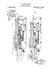
Figure 1 is a fragmentary longitudinal sec-
tional view of an automatic firearm embodying 15
the invention, with the operative parts at rest;
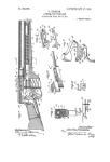
Figure 2 is a similar view to Figure 1 but show-
ing the cocking closure opened and the barrel
cocked;
Figure 3 is a similar view to Figure 2 but show- 20
ing the cocking closure closed;
Figures 4 and 5 are fragmentary detail sec-
tional views, on an enlarged scale, showing the
cocking closure in two positions and having
mounted thereon a sighting device. 25
Referring to the drawing, I denotes the fire-
arm casing in which the barrel 2, which is rigidly
connected with the casing 3 of the breech mech-
anism, is movably mounted. The breech mech-
anism includes a swinging breech block 4 which 30
is operated and controlled by a breech-block car-
rier 5. The said carrier is extended forward in
the form of a rod having a piston adapted to be
acted upon in known manner within a cylinder
to which the exhaust gases pass from the barrel 35
after firing. The breech-block carrier 5 is load-
ed by a return spring 6 which rests against the
back wall of the casing I or against a collar on
a guiding rod 7 which is fixed in the casing and
around which the return spring is concentrically 49
arranged. 8 denotes the sear of the firing mech-
anism which co-operates with the breech-block
carrier.
The casing 3 of the breech-block carrier co-
operates with a device which permits firing to be 45
effected during the forward movement of the
barrel. The said device comprises a frame 30
which is displaceably mounted in the casing I
of the firearm and is loaded by a spring 32 one
end of which rests against a removable lid 33. 50
Through the frame 30 is passed an extension of
the breech-block carrier 5 a projection 5' on,
which, during the movement of the breech-block
carrier, controls the movements of the frame 30
with which a stop face 30' of the casing 3 of the Б5
2,223,004
5
10
15
20
25
30
35
40
45
50
55
60
65
70
75
2
breech mechanism co-operates in known manner.
The casing I is open at the top and covered by
a closure or lid 10 which is rotatable on a pin 12
mounted in bearings 11 on the said casing. The
other end of the lid is provided with a projection
13 which, when the lid is closed, engages with a
counter-projection 14 formed on the back wall
of the casing I. Handles 17 permit the lid to be
operated readily.
The lid 10 forms the cocking member for the
barrel 2 which is rigidly connected with the
casing 3 of the breech mechanism. For this
purpose, the casing 3 is connected with the lid
by means of a device x which is also constituted
as a damping and returning device for the bar-
rel. The said device comprises a hollow cylin-
der 22 which is hingedly connected with the cas-
ing 3 by means of a pin 21 and eyes 20. In the
cylinder there is displaceably mounted a piston
34 provided with a rod 25 which terminates in
an. eye through which a pin 27 mounted in ribs
15 on the lid 10 passes for half the length of the
lid in order that a suitable arm for efficient trans-
mission may be obtained.
The piston 24 is loaded by a spring 28 located
within the cylinder 22 and maintained therein
by means of stops 23 on the cylinder 22, the said
stops also affording means by which, when the
lid is opened, the force of the lid is transmitted
to the casing 3 and consequently also to the
barrel 2.
On the lid 10 a frame sight 43 is arranged in a
hinged or foldable manner so as to provide
against its being an obstacle and also against
being damaged in transit. The mounting of
the foldable sight is such that the connecting
device x forms the setting and securing device
for the frame sight. For this purpose, the lid
10 is provided with an opening 40 through which
passes the hub 44 of the sight 43, which hub is
rotatably mounted on a pin 42 fixed in eyes
on the lid. The hub 44 is provided with a pro-
jection 45 which co-operates with a counter-
projection 25 at the outer extremity of the piston
rod of the device x.
When the firearm is in the condition of rest,
its individual components are in the position
shown in Figure 1. The barrel 2 with the casing
3 and the breech mechanism are in the forward
position. The frame 31 is out of engagement
with the face 30' since it is kept in a bottom in-
operative position by the thickened part of the
breech-block carrier 5. The lid 10 is closed and
the sight is folded down. Before firing is com-
menced, the breech mechanism is first cocked
against the action of the return spring 6 by
means of a cocking device which is not shown.
On cocking the breech mechanism, the projec-
tion on the breech-block carrier releases the
frame 30, which is pressed upwards by the action
of the spring. In the cocked position, Figures 2
and 3, the sear 8 engages the breech-lock car-
rier and holds it until the sear is actuated by the
trigger.
After the breech mechanism is cocked, the
lid 10, Figure 2, is opened and during this move-
ment the piston 24 of the device x strikes and
stops 23 and the movement is transmitted by
means of the cylinder 22 and the hinged con-
nection to the casing 3 of the breech mechanism
and consequently also to the barrel 2 which is
rigidly connected with the said casing. The
casing 3 then participates in a sliding move-
ment with the barrel, during which movement
the stop face 30' of the casing 3 of the breech
mechanism passes over the frame 30 which, un-
der the action of the spring 32, is caused to be
in the path of the casing, so that the barrel to-
gether with the casing is caught by the frame
and retained in the position shown in Figures z
2 and 3.
On folding down the lid 10 into the closed
position, Figure 3, the spring 28 is compressed
so that there is stored in the said spring the
energy necessary to cause the forward movement 10
of the barrel upon firing.
The foldable sight 43 is set into the operative
position by being rotated about the pin 42. The
rotation of the sight can be effected both when
the lid is open and when it is closed. During 15
the rotation of the sight from the folded down
position, the projection 45 strikes the projection
25 on the piston rod which is displaced through a
distance "s” and, during this displacement, com-
presses the spring 28. Owing to the pressure 20
of the compressed spring, the projection 25 is
caused to engage the projection 45 on the sight
in such manner that the sight is locked in the
upright position. The displacement of the pis-
ton rod 25 in the axial direction of the cylinder 25
22 during the action of the projection 45 on the
projection 26 on the rotation of the sight is ren-
dered possible by slots 16 which are formed in
the ribs 15 of the lid 10 and in which the pin 27
of the piston rod 25 is mounted. 30
After the trigger is pressed, the sear 8 releases
the breech-block carrier 5 which, under the
action of the compressed return spring 6, is
moved forward, the breech block being brought
into the locked position during such movement. 35
During the forward movement of the carrier 5,
the projection 5' thereon strikes the frame 30
and depresses it, so that the path of the cocked
barrel 2 with the casing 3 of the breech mecha-
nism, which likewise are moved forward under
the action of the compressed spring 28, is freed.
During this forward movement, firing takes place
with the breech block locked and the energy
of the parts which are moving forward overcomes
the energy of the recoil resulting from the firing. ...
The barrel with the casing of the breech mecha-
nism recoil without reaching the foremost fixed
stops. Although the recoil energy, which is con-
siderably smaller owing to the action of the
energy imparted in the forward movement, is gg
sufficient to open the breech mechanism, it is
not great enough to produce harmful blows; on
the contrary, as far as the barrel and the casing
of the breech mechanism are concerned, it is so
small that the comparatively weak spring 23 of 55
the device x is sufficient for the accumulation
of energy and for braking the components that
recoil back. On series or continuous firing, the
breech mechanism, after recoil, carries out the
forward movement, during which the breech- 60
block carrier controls the frame 38 in known
manner and the operation is repeated. After
firing, the sight is folded down into the normal
position, in which it is retained by the action
of the spring 28 when the lid is closed. ®5
The firearm described and shown in the draw-
ing is obviously only one example of an embodi-
ment of the invention, and the details thereof,
whether they are concerned with the cocking de-
vice or with the device for damping the recoil 70
movements of the barrel may be modified in
various ways without affecting the scope of the in-
vention.
What I claim is:
1. An automatic firearm, comprising a casing, 75
2,223,004
said casing having an aperture therein, a recoiling
barrel, breech mechanism Including a breech cas-
ing rigidly connected with said barrel, an open-
able closure for said aperture and means includ-
, ing a device for damping the recoil of said bar-
rel and the recoiling parts connected therewith
connecting said closure and said breech casing, in
such manner that said barrel may be cocked upon
movement of the closure to open said aperture
j without interfering with the normal recoil move-
ments of said barrel when said aperture is closed.
2. An automatic firearm, comprising a casing, a
recoiling barrel, breech mechanism, said casing
having an aperture therein, an openable closure
5 for said aperture and means connecting said
closure and said barrel, in such manner that said
barrel may be cocked upon movement of the
closure to open said aperture without interfering
with the normal recoil movements of said barrel,
° when said aperture is closed and said means com-
prising a cylinder, a piston in said cylinder, and
stop means on said cylinder to co-operate with
said piston for transmitting force in one direc-
tion.
5 3. An automatic firearm, comprising a casing,
said casing having an aperture therein, a recoiling
barrel, breech mechanism including a breech cas-
ing rigidly connected with said barrel, an openable
closure for said aperture, a cylinder hingedly con-
3 nected with said breech casing, a piston in said
cylinder hingedly connected with said closure, and
stop means on said cylinder to co-operate with
said piston for transmitting force in one direction,
whereby the barrel is cocked upon movement of
3 the closure to open said aperture but normal
3
recoil movements of said barrel are permitted
when said aperture is closed.
4. An automatic firearm, comprising a casing,
said casing having an aperture therein, a recoiling
barrel, breech mechanism including a breech cas- 5
ing rigidly connected with said barrel, an open-
able closure for said aperture, a cylinder hingedly
connected with said casing, a piston in said cylin-
der hingedly connected with said closure, a spring
interposed between one end of said cylinder and 10
said piston, and stop means on said cylinder to
co-operate with said piston for transmitting force
in one direction, whereby the barrel is cocked
upon movement of the closure to open said aper-
ture but normal recoil movements of said barrel 15
are permitted when said aperture is closed.
5. An automatic firearm, comprising a casing,
said casing having an aperture therein, a recoil-
ing barrel, breech mechanism including a breech
casing rigidly connected with said barrel, an 20
openable closure for said aperture, a cylinder
hingedly connected with said breech casing, a
piston in said cylinder hingedly connected with
said closure, a spring interposed between one end
of said cylinder and said piston, stop means on 25
said cylinder to co-operate with said piston for
transmitting force in one direction, a sighting de-
vice hingedly mounted on said closure, means on
said sighting device adjacent the hinge connec-
tion thereof with said closure and co-operating 30
means adjacent the hinge connection of said pis-
ton with said closure for retaining said sighting
device in operative or inoperative position.
VACLAV HOLEK. 35