/

Tags: weapons military affairs patent
Year: 1929

Text
April 16, 1929. f. herlach et al 1,709,399
AUTOMATIC FIREARM
Filed May 19, 1928 2 Sheets-Sheet 1
/ПТП FINELY.
April 16, 1929.
F. HERLACH ET AL
AUTOMATIC FIREARM
Filed May 19, 1928
1,709,399
2 Sheets-Sheet 2
Patented Apr. 16, 1929.
1,709,399
UNITED STATES PATENT OFFICE.
FRITZ HERLACH AND THEODOR RAKULA, OF DUSSELDORF, GERMANY, ASSIGNORS TO
RHELNISCHE METALLWAAREN- UND MASCHINENFABRIK, OF DUSSELDOBF-DEREN-
DORF, GERMANY.
AUTOMATIC FIREARM.
Application filed May 19, 1928, Serial No. 279,131, and in Germany April 27, 1926'.
Our invention relates to an automatic fire
arm to which the cartridges are fed from the
side, and has for its object to afford the possi-
bility of a great number of shots to be fired
5 uninterruptedly, and to avoid, notwith-
standing, the employment of voluminous and
heavy magazines hitherto required therefor.
The invention substantially consists in the
fact, that the fire arm is designed to simul-
10 taneously receive two separate cartridge
magazines, adapted to be exchanged inde-
pendently of one another and to be brought
by suitable means successively into the range
of the members of the arm that shift the
15 cartridges in the direction of the bore of the
barrel into the cartridge chamber of the
latter.
The invention further comprises means for
alternately adjusting automatically the one
20 or the other of the two magazines for the
feed of the cartridges and to cause, when one
magazine is empty, the fire to be continued
from the other magazine. Means are further
provided, by which the feed from a maga-
25 zine may be interrupted at any time, even
if it is not yet emptied, whereupon the other
magazine automatically undertakes the fur-
ther feed of cartridges.
Furthermore, in order to not have extended
30 undesiredly, after both magazines have been
emptied, the interruption of the fire that
arises due to the insertion of new full maga-
zines, by starting anew the automatic opera-
tion of the arm by hand, whereby much time
35 is occupied, a mechanism is provided, by
which the firing of the last present cartridge,
after being shifted into the cartridge cham-
ber, is automatically rendered impossible, by
the trigger mechanism of the arm being
40 locked. Only by the insertion of a full maga-
zine in the magazine chamber the possibility
. of uninterruptedly firing is re-established.
In order to allow of our invention to be
more easily understood, a preferred embodi-
45 ment of same is illustrated in the accompany-
ing drawings as applied to an automatic
barrel recoil firm arm. In these drawings:
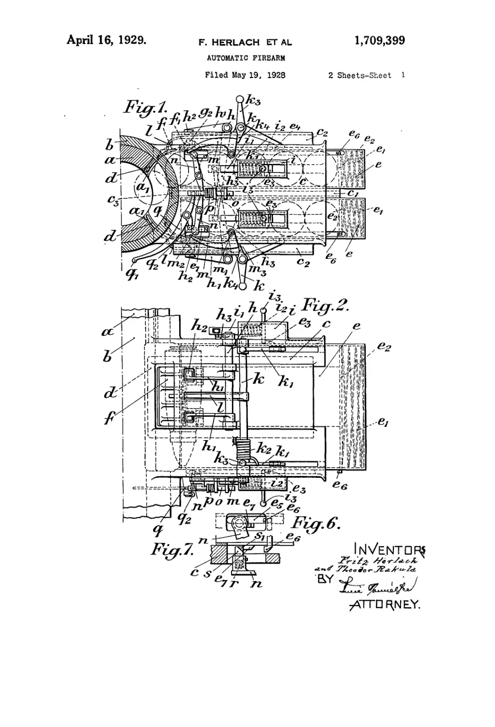
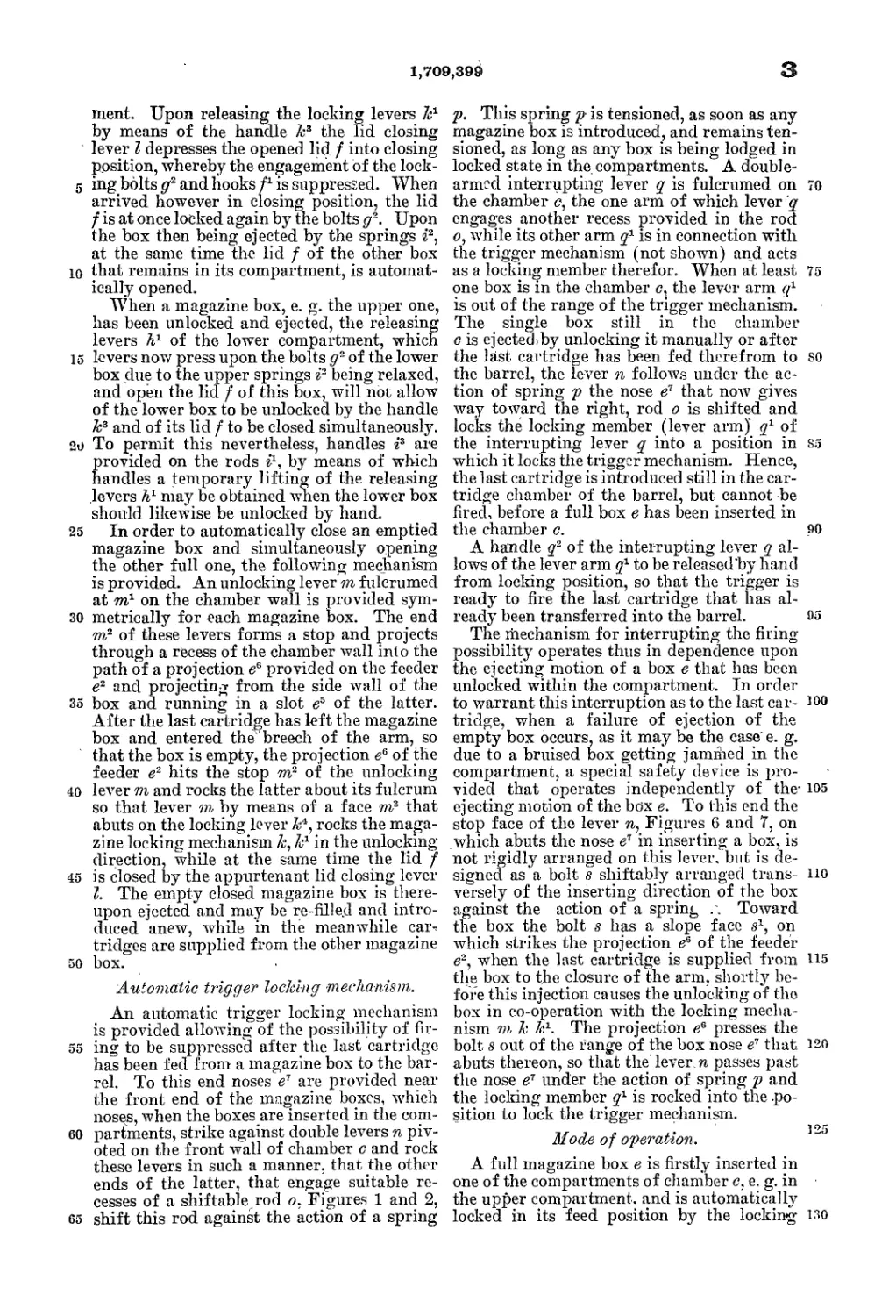
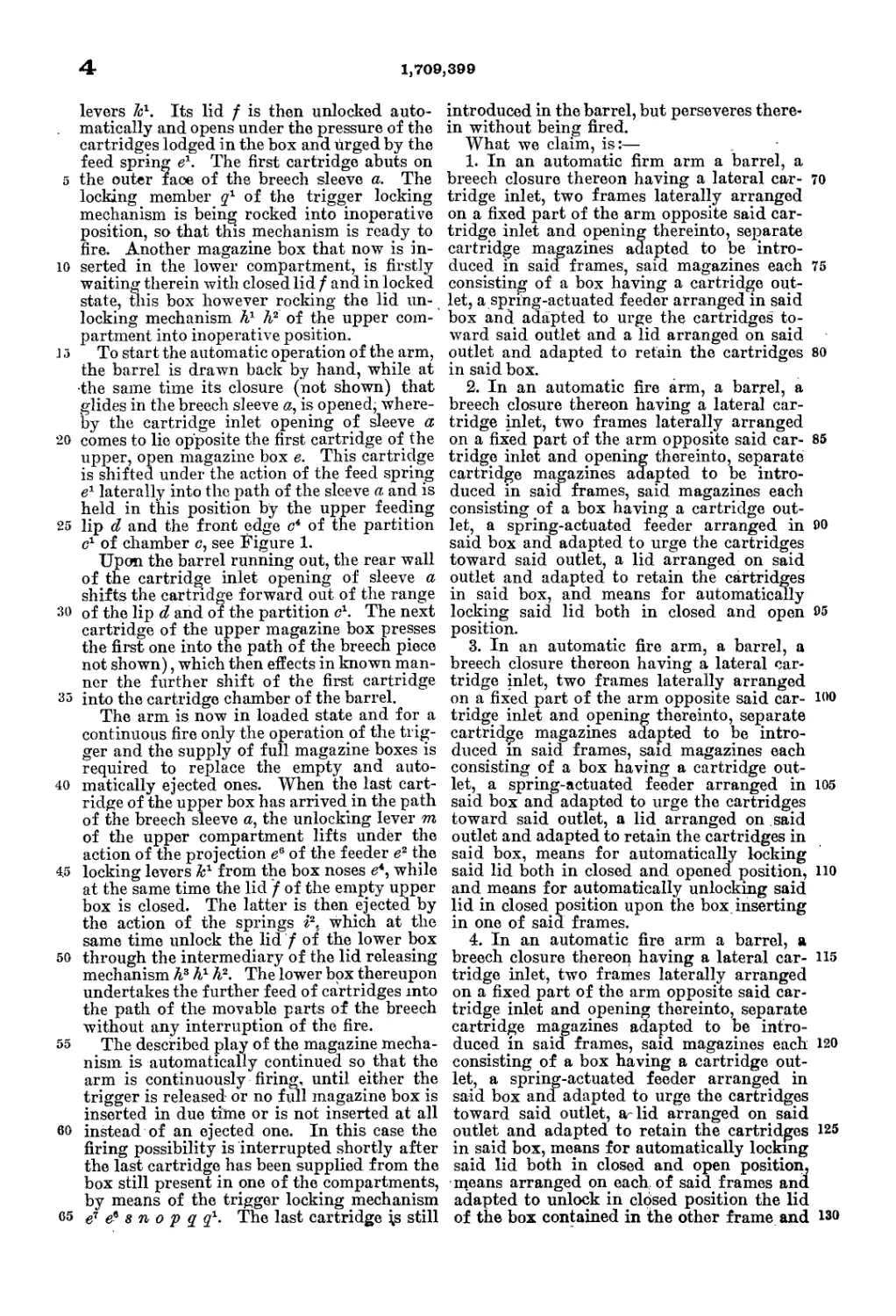
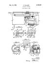
Figure 1 is a cross section of the arm seen
from the muzzle toward the magazine mech-
50 anism, two cartridge magazines being in-
serted,
Figure 2 is a top view of ti e magazine
mechanism,
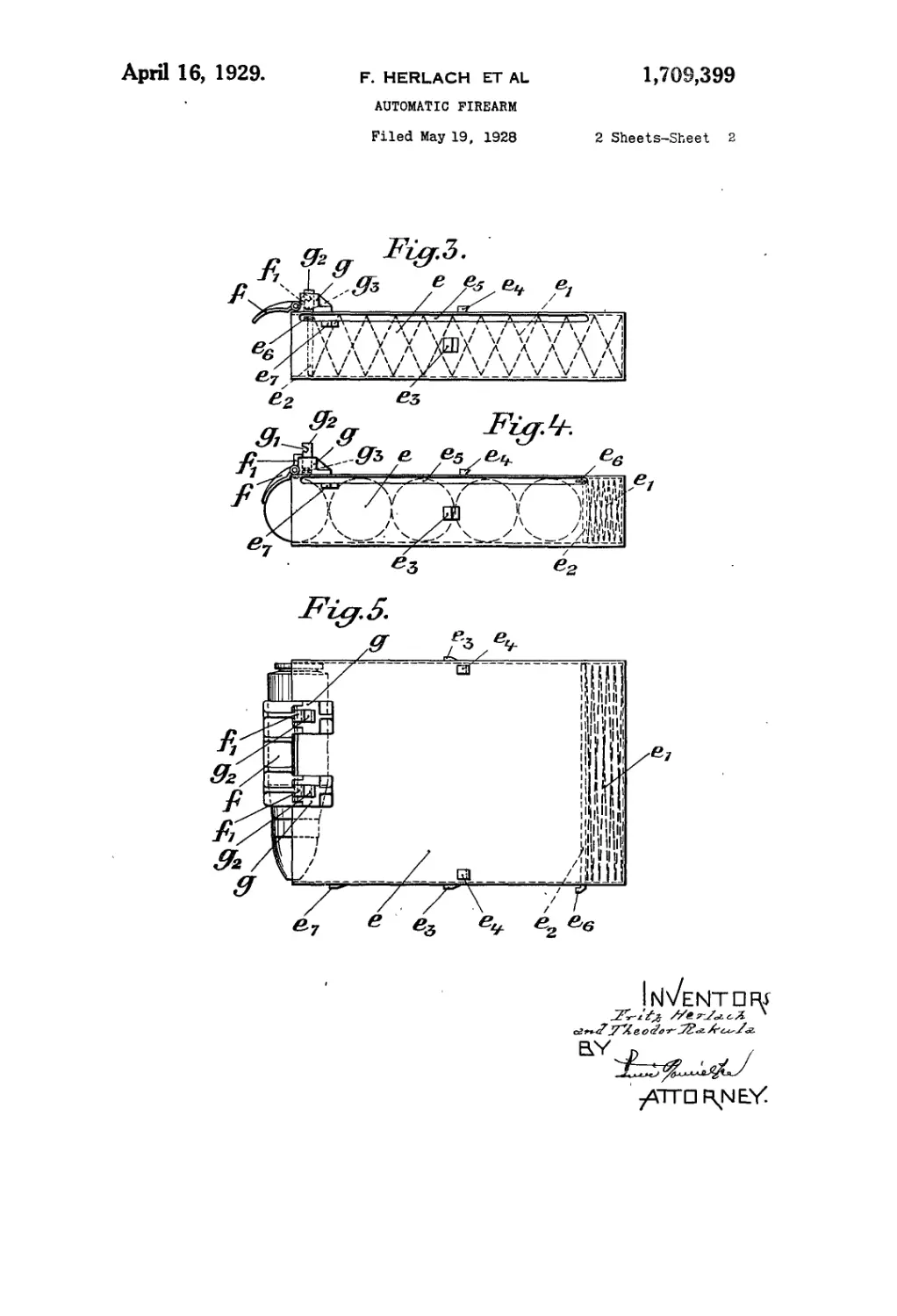
Figure 3 is the lateral view of an empty
opened magazine, 55
Figure 4 is a similar view of a full maga-
zine,
Figure 5 is a top view of a full magazine,
Figures 6 and 7 are a lateral and top view,
respectively, of a detail of the magazine go
chamber.
The magazine chamber.
A case Ъ serves as slide for the barrel and
for the breech sleeve a connected thereto, 65
which case has laterally arranged on it the
magazine chamber c which is open on its outer
end. A horizontal partition c1 divides the
chamber c into two compartments each adapt-
ed to lodge a cartridge magazine. The upper 70
and lower wall of the chamber c has pocket-
like rises c2 to enable parts projecting from
the magazines to freely pass.
When the barrel assumes the firing or run
out position, the passage opening, leading to 75
the bore of case Z>, of the magazine chamber c
is closed by the outer wall of the breech sleeve
<z, whilst with the barrel in recoil position,
an aperture forming the cartridge inlet, of
sleeve a registers with said chamber opening, so
both compartments of the magazine chamber
opening into the cartridge inlet. Two lip-
shaped cartridge feeders cZ, d project, re-
spectively, from the upper and lower cham-
ber Avail into the path of the breech sleeve a, 85
which feeders are mounted on these walls
and, when the barrel is in firing position,
pass into slots ah provided in sleeve a.
The cartridge magazines.
The cartridge magazines e, Figures 3-5,
consist of thin-walled sheet metal boxes open
on one of their narrow sides' and are each
provided with a feeder e2 adapted to be shift-
ed under the action of a feed spring e1 in the 95
direction toward their opening. The cart-
ridges are inserted in tne magazine trans-
versely of their longitudinal axis, whereby
the feeder e2 is urged back and the feed
spring e1 is tensioned. . mo
The opening of the magazine box is closed
by a lid f that is provided with means for
locking it in open and closed position. To
this end locking bolts g2 are vertically shift-
ably mounted in guidc blocks g on those of 105
the broad sides / of the box^s, which, after ।
2 1,709,399
the box has been inserted in the chamber c,
abut on the upper and lower wall thereof,
see also Figure 1. The locking bolts g2 are
provided with notches ff1 and pressed out-
5 ward by flat springs g3 arranged below them.
In this outer position the bolts g2 lock the
lid f in the closing position against an open-
ing motion, by hooks abutting on the stem
of the bolts g2. Upon depressing however the
10 bolts g2, the notches g1 arrive opposite the
hooks 71 of the lid f. The latter is then lifted
by hand or by the pressure exerted by the
cartridges contained in the box, and is se-
cured against an automatic closing motion
15 by its hooks Z1 engaging the notches g1. Upon
a pressure being exerted on the lid f, the
hooks Z1 release the notches g1, the lid passes
to closing position and is again locked therein
by the locking bolts g2 being lifted under the
20 action of the springs g3.
Mechanism, for alternately and automatically
adjusting to feed position the introduced
magazine boxes.
25 The adjustment of a full cartridge maga-
zine box e in a condition to feed a cartridge
to the barrel takes place by opening the lid
Z by the action of a releasing mechanism pro-
vided on each magazine compartment. When
30 a magazine box e is inserted in a compart-
ment, its lid Z is in closed position and the
upwardly projecting locking bolts g2 glide
unhinderedly into the above-mentioned
' pocket c2.
35 A shaft h is mounted each on the upper and
lower chamber wall, see Figures 1 and 2, each
of which shafts has so fixed on it twTo releas-
ing levers A1 that their cam-shaped ends A2,
that project into recesses of the chamber
40 walls, are opposite the above described lock-
ing bolts g2 of the magazine boxes e. . The
rocking motion of the shafts h is derived
from the inserting and withdrawing motion
of the magazine boxes.
45 On the side walls of the compartments are
arranged casings i in which rods i1 are lodged
so as to be shifted toward the barrel under
the action of springs i2. Levers h3 fixed on
each shaft h engages each a slot of the re-
50 spective rod i1 and thus serve to transmit the
shifting motion of the rods i1 to the shafts h
in one or other direction and to convert it
into a rocking motion of these shafts. The
shaft h mounted on the upper compartment
55 and acting by its releasing levers h1 upon
the inserted magazine box, is in mesh with
the rod i1 of the lower coihpartment and
vice-versa.
- When the compartments are empty, the
60 cam ends h2 of all releasing levers h1 project
under the action of the springs i2 into the
path of (the magazine locking bolts g2 of the
lids Z;_ which bolts assume their upper posi-
tion. When a box e is inserted in one of the
65 compartments, e. g. in the upper one, noses
e3. that project on the box wall, see Figures
3 to 5, take with them the rods i1, whereby
the springs i2 are tensioned, and thereby rock
the shaft h of the lower compartment and
therewith the lower releasing levers hl out 70
of their operative position. At the same time
the locking bolts g2 of the inserted upper box
hit the cams h2 of the upper releasing levers
and are depressed by them. Consequently
the lid Z of the upper box is lifted under the 75
pressure acting upon it by the cartridges and
is locked in open position by the bolts g2 and
hooks Z1, as above described.
The magazine box e introduced in the up-
per compartment is thus adjusted for feeding 80
a cartridge, whilst the releasing mechanism
of the lower compartment has been brought
into an inoperative position. The lid f of
a box introduced later on in the lower com-
partment remains closed. This lower box 85
however rocks out of operation the releasing
levers A1 for the lid f of the upper box e.
This lid thus remains unacted upon in the
locked open position.
When the upper box is withdrawn, the fit)
springs i2 of the upper compartment are re-
laxed by the simultaneous withdrawal of the
noses e3, while the lid f of the lower box e
is automatically opened by the lower releas-
ing levers A1 being rocked. Only one single 05
box is thus open and adapted to supply cart-
ridges.
In order to fix the boxes in their extreme
position within the compartments against the
action of the feed springs e1 and springs i2, 100
two locking levers k1 are rigidly fixed on an
upper and lower shaft k, the hook-shaped
ends of which levers engage through suitable
slots of the compartment walls each a nose
e* of the box walls. By springs k2 coiled on 105
the shaft к the locking levers k1 are pressed
toward the box wall, see Figure 1. When a
box e is introduced, its noses e* lift the lock-
ing levers k1, whereupon the hook ends of the
latter engage behind the noses e4 and thus 110
lock the box against the action of the springs
i2 and e1.
The locking levers k1 may be. disengaged
by hand by means of the handles k3 rigid on
the shaft A. When the locking levers k1 are 45
disengaged by manipulating the handles k3,
the respective box e is automatically ejected
from its compartment by the action of the
springs i2.
The described release of the magazine lock- 120
ing mechanism may only be executed after the
lid Z of the respective box has been closed,
as otherwise the cartridges still contained in
the box would be ejected by the feed spring
e1 and would deposit in the respective com- 125
partment. To prevent this, a lid closing lever
I is fixed on each shaft k, the curved end of
which lever abuts on the open lid f in the
midst thereof, of a box that is present in
locked position in the respective compart- 130
1,709,390
3
5
10
15
20
25
30
35
40
45
50
55
60
65
ment. Upon releasing the locking levers 7г1
by means of the handle k3 the lid closing
lever I depresses the opened lid f into closing
position, whereby the engagement of the lock-
ing bolts g2 and hooks f1 is suppressed. When
arrived however in closing position, the lid
/ is at once locked again by the bolts g~. Upon
the box then being ejected by the springs г'2,
at the same time the lid f of the other box
that remains in its compartment, is automat-
ically opened.
When a magazine box, e. g. the upper one,
lias been unlocked and ejected, the releasing
levers h1 of the lower compartment, which
levers now press upon the bolts g- of the lower
box due to the upper springs i2 being relaxed,
and open the lid f of this box, will not allow
of the lower box to be unlocked by the handle
k3 and of its lid f to be closed simultaneously.
To permit this nevertheless, handles г3 are
jrovided on the rods г1, by means of which
handles a temporary lifting of the releasing
, evers h1 may be obtained when the lower box
should likewise be unlocked by hand.
In order to automatically close an emptied
magazine box and simultaneously opening
the other full one, the following mechanism
is provided. An unlocking lever m fulcrumed
at m7 on the chamber wall is provided sym-
metrically for each magazine box. The end
m2 of these levers forms a stop and projects
through a recess of the chamber wall into the
path of a projection e6 provided on the feeder
e2 and projecting from the side wall of the
box and running in a slot e5 of the latter.
After the last cartridge has left the magazine
box and entered the breech of the arm, so
that the box is empty, the projection ee of the
feeder e2 hits the stop m2 of the unlocking
lever m and rocks the latter about its fulcrum
so that lever m by means of a face m3 that
abuts on the locking lever k'1, rocks the maga-
zine locking mechanism k, k1 in the unlocking
direction, while at the same time the lid /
is closed by the appurtenant lid closing lever
1. The empty closed magazine box is there-
upon ejected and may be re-filled and intro-
duced anew, while in the meanwhile car-
tridges are supplied from the other magazine
box.
Automatic trigger locking mechanism.
An automatic trigger locking mechanism
is provided allowing of the possibility of fir-
ing to be suppressed after the last cartridge
has been fed from a magazine box to the bar-
rel. To this end noses e7 are provided near
the front end of the magazine boxes, which
noses, when the boxes are inserted in the com-
partments, strike against double levers n piv-
oted on the front wall of chamber c and rock
these levers in such a manner, that the other
ends of the latter, that engage suitable re-
cesses of a shiftable rod o, Figures 1 and 2,
shift this rod against the action of a spring
p. This spring p is tensioned, as soon as any
magazine box is introduced, and remains ten-
sioned, as long as any box is being lodged in
locked state in the compartments. A double-
armed interrupting lever q is fulcrumed on 70
the chamber c, the one arm of which lever q
engages another recess provided in the rod
<?, while its other arm q7 is in connection with
the trigger mechanism (not shown) and acts
as a locking member therefor. When at least 75
one box is in the chamber c, the lever arm q1
is out of the range of the trigger mechanism.
The single box still in the chamber
c is ejected)by unlocking it manually or after
the last cartridge has been fed therefrom to so
the barrel, the lever n follows under the ac-
tion of spring p the nose e7 that now gives
way toward the right, rod о is shifted and
locks the locking member (lever arm) q1 of
the interrupting lever q into a position in S5
which it locks the trigger mechanism. Hence,
the last cartridge is introduced still in the car-
tridge chamber of the barrel, but cannot be
fired, before a full box e has been inserted in
the chamber c. 90
A handle q2 of the interrupting lever q al-
lows of the lever arm q1 to be released'by hand
from locking position, so that the trigger is
ready to fire the last cartridge that has al-
ready been transferred into the barrel. 95
The mechanism for interrupting the firing
possibility operates thus in dependence upon
the ejecting motion of a box e that has been
unlocked within the compartment. In order
to warrant this interruption as to the last car- J00
tridge, when a failure of ejection of the
empty box occurs, as it may be the case' e. g.
due to a bruised box getting jamibed in the
compartment, a special safety device is pro-
vided that operates independently of the- 105
ejecting motion of the box e. To this end the
stop face of the lever n, Figures 6 and 7, on
which abuts the nose e7 in inserting a box, is
not rigidly arranged on this lever, but is de-
signed as a bolt s shiftably arranged trans- no
versely of the inserting direction of the box
against the action of a spring .. Toward
the box the bolt s has a slope face s1, on
which strikes the projection ea of the feeder
e2, when the last cartridge is supplied from 115
the box to the closure of the arm, shortly be-
fore this injection causes the unlocking of the
box in co-operation with the locking mecha-
nism m к к1. The projection e6 presses the
bolt s out of the range of the box nose e7 that 120
abuts thereon, so that the leverя passes past
the nose e7 under the action of spring p and
the locking member q1 is rocked into the po-
sition to lock the trigger mechanism.
1 °5
Mode of operation.
A full magazine box e is firstly inserted in
one of the compartments of chamber c, e. g. in
the upper compartment, and is automatically
locked in its feed position by the locking i"0
4
1,709,399
levers 7г1. Its lid f is then unlocked auto-
matically and opens under the pressure of the
cartridges lodged in the box and lirged by the
feed spring e1. The first cartridge abuts on
5 the outer face of the breech sleeve a. The
locking member q1 of the trigger locking
mechanism is being rocked into inoperative
position, so that this mechanism is ready to
fire. Another magazine box that now is in-
10 serted in the lower compartment, is firstly
waiting therein with closed lid / and in locked
state, this box however rocking the lid un-
locking mechanism A1 h2 of the upper com-
partment into inoperative position.
15 To start the automatic operation of the arm,
the barrel is drawn back by hand, while at
•the same time its closure (not shown) that
glides in the breech sleeve a, is opened, where-
by the cartridge inlet opening of sleeve a
20 comes to lie opposite the first cartridge of the
upper, open magazine box e. This cartridge
is shifted under the action of the feed spring
e1 laterally into the path of the sleeve a and is
held in this position by the upper feeding
25 lip d and the front edge c4 of the partition
c1 of chamber c, see Figure 1.
Upon the barrel running out, the rear wall
of the cartridge inlet opening of sleeve a
shifts the cartridge forward out of the range
30 of the lip d and of the partition c1. The next
cartridge of the upper magazine box presses
the first one into the path of the breech piece
not shown), which then effects in known man-
ner the further shift of the first cartridge
35 into the cartridge chamber of the barrel.
The arm is now in loaded state and for a
continuous fire only the operation of the trig-
ger and the supply of full magazine boxes is
required to replace the empty and auto-
40 matically ejected ones. When the last cart-
ridge of the upper box has arrived in the path
of the breech sleeve a, the unlocking lever m
of the upper compartment lifts under the
action of the projection e6 of the feeder e2 the
4.5 locking levers k1 from the box noses e4, while
at the same time the lid f of the empty upper
box is closed. The latter is then ejected by
the action of the springs г2, which at the
same time unlock the lid f of the lower box
50 through the intermediary of the lid releasing
mechanism Л3 A1 h2. The lower box thereupon
undertakes the further feed of cartridges into
the path of the movable parts of the breech
without any interruption of the fire.
55 The described play of the magazine mecha-
nism is automatically continued so that the
arm is continuously firing;, until either the
trigger is released or no full magazine box is
inserted in due time or is not inserted at all
60 instead of an ejected one. In this case the
firing possibility is interrupted shortly after
the last cartridge has been supplied from the
box still present in one of the compartments,
by means of the trigger locking mechanism
65 e7 s n 0 p q q1. The last cartridge is still
introduced in the barrel, but perseveres there-
in without being fired.
What we claim, is:—
1. In an automatic firm arm a barrel, a
breech closure thereon having a lateral car- 70
tridge inlet, two frames laterally arranged
on a fixed part of the arm opposite said car-
tridge inlet and opening thereinto, separate
cartridge magazines adapted to be intro-
duced in saia frames, said magazines each 75
consisting of a box having a cartridge out-
let, a spring-actuated feeder arranged in said
box and adapted to urge the cartridges to-
ward said outlet and a lid arranged on said
outlet and adapted to retain the cartridges 80
in said box.
2. In an automatic fire arm, a barrel, a
breech closure thereon having a lateral car-
tridge inlet, two frames laterally arranged
on a fixed part of the arm opposite said car- 85
tridge inlet and opening thereinto, separate
cartridge magazines adapted to be intro-
duced in said frames, said magazines each
consisting of a box having a cartridge out-
let, a spring-actuated feeder arranged in 90
said box and adapted to urge the cartridges
toward said outlet, a lid arranged on said
outlet and adapted to retain the cartridges
in said box, and means for automatically
locking said lid both in closed and open 95
position.
3. In an automatic fire arm, a barrel, a
breech closure thereon having a lateral car-
tridge inlet, two frames laterally arranged
on a fixed part of the arm opposite said car- 100
tridge inlet and opening thereinto, separate
cartridge magazines adapted to be intro-
duced m said frames, said magazines each
consisting of a box having a cartridge out-
let, a spring-actuated feeder arranged in 105
said box and adapted to urge the cartridges
toward said outlet, a lid arranged on said
outlet and adapted to retain the cartridges in
said box, means for automatically locking
said lid both in closed and opened position, 110
and means for automatically unlocking said
lid in closed position upon the box inserting
in one of said frames.
4. In an automatic fire arm a barrel, a
breech closure thereon having a lateral car- 115
tridge inlet, two frames laterally arranged
on a fixed part of the arm opposite said car-
tridge inlet and opening thereinto, separate
cartridge magazines adapted to be intro-
duced in said frames, said magazines each 120
consisting of a box having a cartridge out-
let, a spring-actuated feeder arranged in
said box and adapted to urge the cartridges
toward said outlet, ar lid arranged on said
outlet and adapted to retain the cartridges 125
in said box, means for automatically locking
said lid both in closed and open position,
means arranged on each of said frames and
adapted to unlock in closed position the lid
of the box contained in the other frame and 130
1,709,899
5
5
10
15
20
25
30
35
40
45
50
55
60
©5
for leaving unacted upon the lid locking
means of the box contained in the own frame,
and vice versa, and for unlocking in closed
position the lid of the box contained in said
own frame upon the box of the other frame
being withdrawn therefrom.
5. In an automatic fire arm a barrel, a
breech closure thereon having a lateral car-
tridge inlet, two frames laterally arranged
on a fixed part of the arm opposite said car-
tridge inlet and opening thereinto, separate
cartridge magazines adapted to be intro-
duced in said frames, said magazines each
consisting of a box having a cartridge out-
let, a spring-actuated feeder arranged in
said box ana adapted to urge the cartridges
toward said outlet, a lid arranged on said
outlet and adapted to retain the cartridges
in said box, means for automatically locking
said lid both in closed and open position, a
projection on each of said boxes, a. member
arranged on each of said frames and adapted
to be shifted thereon by said projection upon
a box being inserted in said frame, a spring
adapted to act against this shift, a lever ful-
crumed on each frame and adapted to be
rocked by said shiftable member of the
other frame, and another lever positively
connected to said first-named one and
adapted to act, when rocked, upon said lid
locking means to unlock said lid in closed
position.
6. In an automatic fire arm a barrel, a
breech closure thereon having a lateral car-
tridge inlet, two frames laterally arranged
on a fixed part of the arm opposite said car-
tridge inlet and opening thereinto, separate
cartridge magazines adapted to be intro-
duced in said frames, said magazines each
consisting of a box having a cartridge out-
let, a spring-actuated feeder arranged in
said box and adapted to urge the cartridges
toward said outlet, a lid arranged on said
outlet and adapted to retain the cartridges
in said box, means for automatically locking
said lid both in closed and open position, a
projection on each of said boxes, a member
arranged on each of said frames and adapted
to be shifted thereon by said projection upon
a box being inserted in said frame, a spring
adapted to act against this shift, a lever ful-
crumed on each frame and adapted to be
rocked by said shiftable member of the other
frame, another lever positively connected
to said first-named one and adapted to act,
when rocked, upon said lid locking means
to unlock said lid in closed position, means
for locking said boxes in said frames in feed-
ing position, releasing means for said box
locking means, and means for ejecting the
emptied boxes from said frames.
7. In an automatic fire arm a barrel, a
breech closure thereon having a lateral car-
tridge inlet, two frames laterally arranged
on a fixed part of the arm opposite said car-
tridge inlet and opening thereinto, separate
cartridge magazines adapted to be introduced
in said frames, said magazines each consist-
ing of a box having a cartridge outlet, a
spring-actuated feeder arranged in said box 70
and adapted to urge the cartridges toward
said outlet, a lid arranged on said outlet and
adapted to retain the cartridges in said box,
means for automatically locking said lid
both in closed and open position, a projec- 75
tion on each of said boxes, a member ar-
ranged on each of said frames and adapted
to be shifted thereon by said projection upon
a box being inserted in said frame, a spring
adapted to act against this shift, a lever ful- 80
crumed on each frame and adapted to be
rocked by said shiftable member of the other
frame, another lever positively connected to
said first-named one and adapted to act, when
rocked, upon said lid locking means to unlock 85
said lid in closed position, means for locking
said boxes in said frames in feeding position,
releasing means for said box locking means,
and means for ejecting the emptied boxes
from said frames, these meaps being formed 90
by said spring-actuated shiftable m,ember
and said box projection.
8. In an automatic fire arm a barrel, a
breech closure thereon having a lateral car-
tridge inlet, two frames laterally arranged 95
on a fixed part of the arm opposite said car-
tridge inlet and opening thereinto, separate
cartridge magazines adapted to be intro-
duced m said frames, said magazines each
consisting of a box having a cartridge outlet, 100
a spring-actuated feeder arranged in said
box and adapted to urge the cartridges to-
ward said outlet, a lid arranged on said out-
let and adapted to retain the cartridges in
said box, means for automatically locking 105
said lid both in closed and open position, a
projection on each of said boxes, a member
arranged on each frame and adapted to be
shifted in the box inserting direction and
adapted to be shifted by said projection upon 110
a box being inserted in said frame, a spring
adapted to act against this shift, a lever ful-
сгшпеф on each frame and adapted to be
rocked by said shiftable member of the other
frame, another lever positively connected to 115
said first-named one and adapted to act, when
rocked, upon said lid locking means to unlock
said lid in closed position, means for locking
said boxes in said frames in feeding position,
releasing means for said box locking means. 120
and means for ejecting the emptied boxes
from said frames, these means being formed
by said spring-actuated shiftable member
and said box projection.
9. In an automatic-fire arm a barrel, a 125
breech closure thereon having a lateral car-
tridge inlet, two frames laterally arranged
on a fixed part of the arm opposite said car-
tridge inlet and opening thereinto, separate
cartridge magazines adapted to be introduced 13©
в 1,709,399
in said frames, said magazines each consist-
ing of a box having a cartridge outlet, a
spring-actuated feёder arranged in said box
and adapted to urge the cartridges toward
5 said outlet, a lid arranged on said outlet and
adapted to retain the cartridges in said box,
means for automatically locking said lid both
in closed and open position, a projection on
each of said boxes, a member arranged on
10 each frame and adapted to be shifted by said
projection upon a box being inserted in said
frame, a spring adapted to act against this
shift, a lever fulcrumed on- each frame and
adapted to be rocked by said shiftable mem-
15 ber of the other frame, another lever posi-
tively connected to said first-named one and
adapted to act, when rocked, upon said lid
locking means to unlock said lid in closed
position, a pawl pivoted on each frame, a
20 stop face on each box adapted to co-operate
therewith so as to lock said box in feeding
position, a lever positively connected to said
pawl and adapted to act upon the open lid
of the respective box so as to unlock said lid
25 in open position upon said pawl being disen-
gaged from said stop face, and means for
ejecting the emptied boxes from said frame.
10. In an automatic fire arm a barrel, a
breech closure thereon having a lateral car-
30 tridge inlet, two frames laterally arranged on
a fixed part of the arm opposite said cartridge
inlet and opening thereinto, separate car-
” tridge magazines adapted to be introduced
in said frames, said magazines each consist-
35 ing of a box having a cartridge outlet, a
spring-actuated feeder arranged in said box
and adapted to urge the cartridges toward
said outlet, a lid arranged on said outlet and
adapted to retain the cartridges in said box,
40 means for automatically locking said lid both
in closed and open position, a projection on
each of said boxes, a member arranged on
each frame and adapted to be shifted by said
projection upon a box being inserted therein,
45 a spring adapted to act against this shift, a
lever fulcrumed on each irame and adapted
to be rocked by said shift-able member of the
other frame, another lever positively con-
nected to said first-named one and adapted
50 to act, when rocked, upon said lid locking
means to unlock said lid in closed position, a
pawl pivoted on each frame, a stop face on
. each box adapted to co-operate therewith so
as to lock said box in feeding position, a third
55 lever positively connected to said pawl and
adapted to act upon the open lid of the re-
spective box so as- to unlock said lid in open
position upon said pawl being disengaged
from said stop face, and means for ejecting
60 the emptied boxes from said frames, these
means being formed by said spring-actuated
shiftable member and said box projection.
11. In an automatic fire arm a barrel, a
breech closure thereon having a lateral car-
65 tridge inlet, two frames laterally arranged
on a fixed part of the arm opposite said car-
tridge inlet and opening thereinto, separate
cartridge magazines adapted to be introduced
in said frames, said magazines each consist-
ing of a box having a cartridge outlet, a 70
spring-actuated feeder arranged in said box
and adapted to urge the cartridges toward
said outlet, a lid arranged on said outlet and
adapted to retain the cartridges in said box,
means for automatically locking said lid both 75
in closed and open position, a projection on
each of said boxes, a member arranged on
each- frame and adapted to be shifted by said
projection upon a box being inserted therein,
a spring adapted to act against this shift, a 80
lever fulcrumed on each frame and adapted
to be rocked by said shiftable member of the
other frame, another lever positively con-
nected to said first-named one and adapted to
act, when rocked, upon said lid locking means 85
to unlock said lid in closed position, a pawl
pivoted on each frame, a stop face on each
box adapted to co-operate therewith so as to
lock said box in feeding position, a third lever
positively connected to said pawl and adapt- "
ed to act upon the open lid of the respective
box so as to unlock said lid in open position
upon said pawl being disengaged from said
stop face, manipulative releasing means for
said pawl and said third lever connected 95
thereto, and means for ejecting the emptied
boxes from said frames, these means being
formed by said spring-actuated shiftable
member and said box projection.
12. In an automatic fire arm a barrel, a 1110
breech closure thereon having a lateral car-
tridge inlet, two frames laterally arranged on
a fixed part of the arm opposite said car-
tridge inlet and opening thereinto1, separate
cartridge magazines adapted to be introduced lf>5
in said frames, said magazines each consist-
ing of a box having a cartridge outlet, a
spring-actuated feeder arranged in said box
and adapted to urge the cartridges toward
said outlet, a lid arranged on said outlet and 1,0
adapted to retain the cartridges in said box,
means for automatically locking said lid both •
in closed and open position, a projection on
each of said boxes, a member arranged on
each'frame and adapted to be shifted by said 115
projection upon a box being inserted therein,
a spring adapted to act against this shift, a
lever fulcrumed on each frame and adapted
to be rocked by said shiftable member of the
other frame, another lever positively connect- 120
ed to said first-nained one and adapted to act,
when rocked, upon said lid locking means to
unlock said.lid in closed position, a pawl piv-
oted on each frame, a stop fasce on each box
adapted to co-operate therewith so as to lock 125
said box in feeding position, a third lever
positively connected to said pawl and adapt-
ed to act upon the open lid of the respective
box so as to unlock said lid in open position
upon said pawl being disengaged from said 130
1,709,399
7
stop face, means for automatically disengag-
ing said pawl and actuating said third lever
after the last cartridge has been supplied to
the closure of the arm, and means for ejecting
5 the emptied boxes from said frames.
13. In an automatic fire arm a barrel, a
breech closure thereon having a lateral car-
tridge inlet, two frames laterally arranged
on a fixed part of the arm opposite said car-
lo tridge inlet and opening thereinto, separate
cartridge magazines adapted to be intro-
duced in said frames, said magazines each
consisting of a box having a cartridge outlet,
a spring-actuated feeder arranged in said
15 box and adapted to urge the cartridges to-
ward said outlet, a lid arranged on said out-
let and adapted to retain the cartridges in
said box, means for automatically locking
said lid both in closed and open position, a
20 projection on each of said boxes, a member
arranged on each frame and adapted to be
shifted by said projection upon a box being
inserted therein, a spring adapted to act
against this shift, a lever fulcrumed on each
25 frame and adapted to be rocked by said shift-
able member of the other frame, another lever
positively connected to said first-named one
and adapted to act, when rocked, upon said
lid locking means to unlock said lid in closed
30 position, a pawl pivoted on each frame, a
stop face on each box adapted to co-operate
therewith so as to lock said box in' feeding
position, a third lever positively connected
to said pawl and adapted to act upon the open
35 lid of the respective box so as to unlock said
lid in open position upon said pawl being dis-
engaged from said stop face, a rocking lever
adapted to lift by its rocking motion said
pawl from said stop face and to actuate said
third lever, a nose arranged on said spring-
actuated feeder of each box and adapted to
rock said rocking lever, and means for eject-
ing the emptied boxes from said frames.
14. In an automatic fire arm a barrel, a
45 breech closure thereon having a lateral car-
tridge inlet, two frames laterally arranged on
a fixed part of the arm opposite said car-
tridge inlet and opening thereinto, separate
cartridge magazines adapted to be introduced
50 in said frames, said magazines each consist-
ing of a box having a cartridge outlet, a
spring-actuated feeder arranged in said box
and adapted to urge the cartridges toward
said outlet, a lid arrang id on said outlet and
55 adapted to retain the cartridges in said box,
means for automatically locking said lid
both in closed and open position, a projec-
tion on each of said boxes, a member arranged
on each frame and adapted to be shifted by
co said projection upon a box being inserted
therein, a spring adapted to act against this
shift, a lever fulcrumed on each frame and
adapted to be rocked by said shiftable mem-
ber of the other frame, another lever posi-
es tively connected to said first-named one and
adapted to act, when rocked, upon said lid
locking means to unlock said lid in closed
position, a pawl pivoted op each frame, a
stop face on each box adapted to co-operate
therewith so as to- lock said box in feeding 70
position, a third lever positively connected
to said pawl and adapted to act upon the open
lid of the respective box so as to unlock said
lid in open position upon said pawl being
disengaged from said stop face, means for 75
automatically disengaging said pawl and ac-
tuating said third lever after the last car-
tridge has been supplied to the closure of the
arm, means for ejecting the emptied boxes
from said frames, and manipulative means so
arranged on said shiftable members and
adapted to allow of said lid unlocking levers
to be thrown out of their operative position.
15. In an automatic fire arm a barrel, a
breech closure thereon having a lateral car- 85
tridge inlet, two frames laterally arranged
on a fixed part of the arm opposite said car-
tridge inlet and opening thereinto, separate
cartridge magazines each consisting of a box
having a cartridge outlet, a spring-actuated ,J0
feeder arranged in said box and adapted to
urge the cartridges toward said outlet, a lid
arranged on said outlet and adapted to retain
the cartridges in said box; means for auto-
matically locking said lid both in closed and 95
open position, a projection on each of said
boxes, a member arranged on each frame and
adapted to be shifted by said projection upon
a box being inserted therein, a spring adapted
to act against this shift, a lever fulcrumed on 100
each frame and adapted to be rocked by said
shiftable member of the other frame, another
lever positively connected to said first-named
one and adapted to act, when rocked, upon
said lid locking means to unlock said lid in 105
closed position, a pawl pivoted on each frame,
a stop face on each box adapted to co-operate
therewith so as to lock said box in feeding
position, a third lever positively connected
to said pawl and adapted to act upon the open no
lid of the respective box so as to unlock said
lid in open position upon said pawl being dis-
engaged from said stop face, means for auto-
matically disengaging said pawl and actuat-
ing said third lever after the last cartridge 115
has been supplied to the closure of the arm,
means for ejecting the emptied boxes from
said .frames,v manipulative means arranged
on said shiftable members and adapted to
allow of said lid unlocking levers to be thrown 120
out of their operative position, and means
for crippling the trigger mechanism after
a last cartridge has been supplied to the
closure.
16. In an automatic fire arm a barrel, a 125
breech closure thereon having a lateral car-
tridge inlet, two frames laterally arranged
on a fixed part of the arm opposite said car-
tridge inlet and opcning thereinto, separate
cartridge magazines each consisting of a box 130
8
1,709,399
5
10
15
20
25
30
35
40
45
50
55
60
65
having a cartridge outlet, a spring-actuated
feeder arranged in said box and adapted to
urge the cartridges toward said,outlet, a lid
arranged on said outlet and adapted to re-
tain the cartridges in said box, means for
automatically locking said lid both in closed
and open position, a projection on each of
said boxes, a member arranged on each frame
and adapted to be shifted by said projec-
tion upon a box being inserted therein, a
spring adapted to act against this shift, a
lever fulcrumed on each frame and adapted
to be rocked by said shiftable member of the
other/frame, another lever positively con-
nected to said first-named one and adapted to
act, when rocked, upon said lid locking means
to unlock said lid in closed position, a pawl
pivoted on each frame, a stop face on each
box adapted to co-operate therewith so as to
lock said box in feeding position, a third
lever positively connected to said pawl and
adapted to act upon the open lid of the re-
spective box so as to unlock said lid in open
position upon said pawl being disengaged
from said stop face, means for automatically
disengaging said pawl and actuating said
third lever after the last cartridge has been
supplied to the closure of the arm, means for
ejecting the emptied boxes from said frames,
manipulative means arranged on said shift-
able members and adapted to allow of said
lid unlocking levers to be thrown out of their
operative position, another nose near the for-
ward end of each box, a crippling lever for
the trigger mechanism of the arm, and adapt-
ed to be rocked'into inoperative position by
said last-named nose, upon a box being in-
serted in one of the frames, and a spring
adapted to be held tensioned by said nose and
to rock said crippling lever into operative
position when relaxed by said nose releasing
it, that is when the respective box is ejected.
17; In an automatic fire arm a barrel, a
breech closure thereon having a lateral car-
tridge inlet, two frames laterally arranged
on a fixed part of the,arm opposite said car-
tridge inlet and opening thereinto, separate
cartridge magazines each consisting of a box
having a cartridge outlet, a spring-actuated
feeder arranged in said box and adapted to
urge the cartridges toward said outlet, a lid
arranged on said outlet and adapted to re-
tain the cartridges in said box, means for
automatically locking said lid both in closed
and open position, a projection on each of
said boxes, a member arranged on each frame
and adapted-to be shifted by said projection
upon a box being inserted therein, a spring
adapted to act against this shift, a lever ful-
crumed on each frame and adapted to be
rocked by said shiftable member of the other
frame, another lever positively connected to
said first-named one and adapted to act, when
rocked, upon said lid locking means to unlock
said lid in closed position, a pawl pivoted
on each frame, a stop face on each box adapt-
ed to co-operate therewith so as to lock said
box in .feeding position, a third lever posi-
tively connected to said pawl and adapted to
act upon the open lid of the respective box so 70
as to unlock said lid in open position upon
said pawl being disengaged from said stop
face, means for automatically disengaging
said pawl and actuating said third lever after
the last cartridge has been supplied to the 75
closure of the arm, means for ejecting the
emptied boxes from said frames, manipula-
tive means arranged on said shiftable mem-
bers and adapted to allow of said lid unlock-
ing levers to be thrown out of their operative 80
position, another nose near the forward end
of each box, a 'crippling lever for the trigger
mechanism of the arm, and adapted to be
rocked into inoperative position by said last-
named nose, upon a box being inserted in one 85
of the frames, a spring adapted to be held
tensioned by said nose and to rock said crip-
pling lever into operative position when
relaxed by said nose releasing it, and manipu-
lative means arranged on said crippling lever ob
and adapted to rock it into inoperative posi-
tion independently of said nose.
18. In an automatic fire arm a barrel, a
breech closure thereon having a lateral cart-
ridge inlet, two frames laterally arranged on 95
a fixed part of the arm opposite said cart-'
ridge inlet and opening thereinto, separate
cartridge magazines each consisting of a box
having a cartridge outlet, a spring-actuated
feeder arranged m said box and adapted to 100
urge the cartridges toward said outlet, a lid
arranged on said outlet and adapted to re-
tain the cartridges in said box, means for
automatically locking said lid both in closed
and open position, a projection on each of 105
said boxes, a member arranged on each frame
and adapted to be shifted by said projection
upon a box being inserted therein, a spring
adapted to act against this shift, a lever ful-
crumed on each frame and adapted to be 110
rocked by said shiftable member of the other
frame, another lever positively connected to
said first-named, one and adapted to act,
when rocked, upon said lid locking means to
unlock said lid in closed position, a pawl 115
pivoted on each frame, a stop face on each
box adapted to co-operate therewith so as
to lock said box in feeding position, a third
lever positively connected to said pawl and
adapted to act upon the open lid of the re- 120
spective box so as to unlock said lid in open
position upon said pawl being disengaged
from said stop face, means for automatically
disengaging said pawl and actuating said
third lever after the last cartridge has been 125
supplied to the closure of the arm, means
for ^ejecting the emptied boxes from said
frames, manipulative means arranged on
said shiftable members and adapted to allow
of said lid unlocking lever to be thrown out 130
1,709,809
5
10
15
20
25
30
35
40
45
of their operative position, another nose near
the forward end. of each box, a crippling
lever for the trigger mechanism of the arm,
and adapted to be rocked into operative po-
sition by said last-named nose, upon a box
being inserted in one of the frames, a spring
adapted to be held tensioned by said nose and
to rock said crippling lever into operative
position when relaxed by said .nose releas-
ing it, that is when the respective box is
ejected, and means for rocking said crippling
lever into operative' position in case of fail-
ure of the box ejection.
19. In an automatic fire arm a barrel, a
breech closure thereon having a lateral cart-
ridge inlet, two frames laterally arranged on
a fixed part of the arm opposite said cart-
ridge inlet and opening thereinto, separate
cartridge magazines each consisting of a box
having a cartridge outlet, a spring-actuated
feeder arranged in said box and adapted to
urge the cartridges toward said outlet, a lid
arranged on said outlet and adapted to retain
the cartridges in said box, means for auto-
matically locking said lid both in closed and
open position, a projection on each of said
boxes, a member arranged on each frame and
adapted to be shifted by said projection upon
a box being inserted therein, a spring adapt-
ed to act against this shift, a lever fulcrumed
on each frame and adapted to be rocked by
said shiftable member of the other frame,
another lever positively connected to said
first-named one and adapted to act, when
rocked, upon said lid locking means to un-
lock said lid in closed position, a pawl piv-
oted on each frame, a stop face on each box
adapted to co-operate therewith so as to lock
said box in feeding position, a third lever
positively connected to said pawl and adapt-
ed to act upon the open lid of the respective
box so as to unlock said lid in open position
upon said pawl being disengaged from said
stop face, means for automatically disengag-
ing said pawl and actuating said third lever
©
after the last cartridge has been supplied to
the closure of the arm, means for ejecting
the emptied boxes from said frames, manip-
ulative means arranged on said shiftable
members and adapted to allow of said lid un- 50
locking lever to be thrown out of their oper-
ative position, another nose near the forward
end of each box, a crippling lever for the
trigger mechanism of the arm, and adapted
to be rocked into operative position by said 55
last-named nose, upon a box being inserted
in one of the frames, a spring adapted to be
held tensioned by said nose, an intermediate
lever adapted to be rocked by said spring and
to transmit this rocking motion to said crip- 60
ling lever so as to rock the latter into oper-
ative position upon said spring being re-
laxed by said nose releasing said intermedi-
ate lever, a spring-actuated sliding bolt on
said intermediate lever and adapted to co- 65
operate with said nose for rocking said inter-
mediate lever, said bolt having a slope face
adapted to co-operate with said feeder nose
and to be depressed by it shortly before said
feeder nose unlocks its box for ejection, so 70
as to throw said sliding bolt out of the range
of said first-named nose.
20. In an automatic fire arm, two maga-
zine chambers, a cartridge magazine adapted
to be inserted in each of said chambers and 75
having a cartridge outlet and a spring actu-
lated cartridge feeder, means for securing
t’ ? cartridge magazine in the magazine
chamber, means for automatically cutting
out the cartridge feeder of one magazine 80
when the other magazine is feeding cart-
ridges, and means for automatically releas-
ing and ejecting the magazine from which
all cartridges have been fired and simultane-
ously bringing the other magazine into ac- 85
tion to feed cartridges therefrom.
In testimony whereof we have affixed our
signatures.
FRITZ HERLACH.
THEODOR RAKULA.