/
Tags: weapons military affairs patent
Year: 1920


Text
H. W. GABBETT-FAIRFAX.
AUTOMATIC FIREARM.
1,346,012,
APPLICATION FILED APR. 22, 1920.
Patented July 6,1920.
2 SHEETS-SHEET I.
1,346,012.
H. W. GABBETT-FAIRFAX.
AUTOMATIC FIREARM.
APPLICATION TILED АРЯ. 22, 1920.
Patented July 6,1920.
2 SHEETS-SHEET 2.
UNITED STATES PATENT OFFICE.
HUGH WILLIAM GABBETT-FAIBFAX, OF LONDON, ENGLAND.
AUTOMATIC FIBEABM.
1,346,012. Specification of Letters Patent. Patented July 6,1920.
Application filed April 22, 1920. Serial No. 375,824.
To all whom it may concern:
Be it known that I, Hugh William
Gabbett-Fairfax, a subject of the King of
Great Britain, residing at London, England,
5 have invented new and useful Improvements
in Automatic Firearms, of which the follow-
ing is a specification.
This invention relates to automatic or
semi-automatic firearms in general (whether
10 machine guns or small arms) of the kind in
which the firearm is operated by the shock
of recoil and in which the breech, barrel,
and breech-closing mechanism recoil while
firmly locked together, and provides means
15 for uncoupling the breech mechanism from
the breech at any desired point in the re-
coil of the latter, after which the breech is
opened and the empty cartridge case is
ejected in the usual manner and the barrel
20 and breech return to their forward position
of rest.
Hitherto the practice in the design of re-
coil-operated firearms has been that the
mechanism for maintaining the cartridge in
25 place in the breech has been liberated by
one of two methods; either the mechanism
for maintaining the cartridge in place in
the breech has been liberated at an early
stage in the recoil of the breech, the breech
30 being checked while the bolt or breech-clos-
ing mechanism has still sufficient rearward
velocity to unlock the breech, withdraw the
cartridge case from the chamber and com-
press a spring for returning the mechanism
3 5 and closing the breech, and in this ease the
limited recoil available hasled to unlocking
of the breech and extraction of the car-
tridge case while there was still consider-
able pressure in the chamber with attendant
10 troubles due to torn cartridge cases and
faulty extraction; or the breech has been
allowed to recoil to its full limit after which
the breech closing mechanism has been lib-
erated and held back while allowing the
45 breech to return to its position of rest,
the breech-closing mechanism being subse-
quently carried forward and again con-
nected with the breech. In this case the long
travel bf the breech causes loss of time be-
50 tween successive shots arid considerably de-
creases the possible rate of. fire of the
weapon.
It is the object of the present invention to
provide means for allowing sufficient time
55 to elapse between the firing of the weapon
and the unlocking of the breech without
using a longer recoil than is actually neces-
sary. For this purpose I attach to the bar-
rel, breech, or sliding carriage connected
thereto, a piston so arranged that the effort GO
of recoil will compress a volume of air in a
cylinder from which, at any desired point
in the recoil, a quantity of compressed air
is taken sufficient to uncouple the breech
mechanism from the barrel and to force the 6 5
said mechanism to the desired length of its
travel and to return the barrel to its posi-
tion of rest. The compressed air may also
be made to compress springs for returning
the barrel and breech mechanism at any de- 70
sired point. Also, if the energy of recoil be
sufficient, the compressed air may be made
to return the breech mechanism, and reload,
close and lock the breech.
The accompanying drawings show two 75
methods of applying the above principles
to a machine gun, and it is evident that a
similar method of operation may be applied
to any other automatic or semi-automatic
firearm operated by means of a recoiling 80
breech.
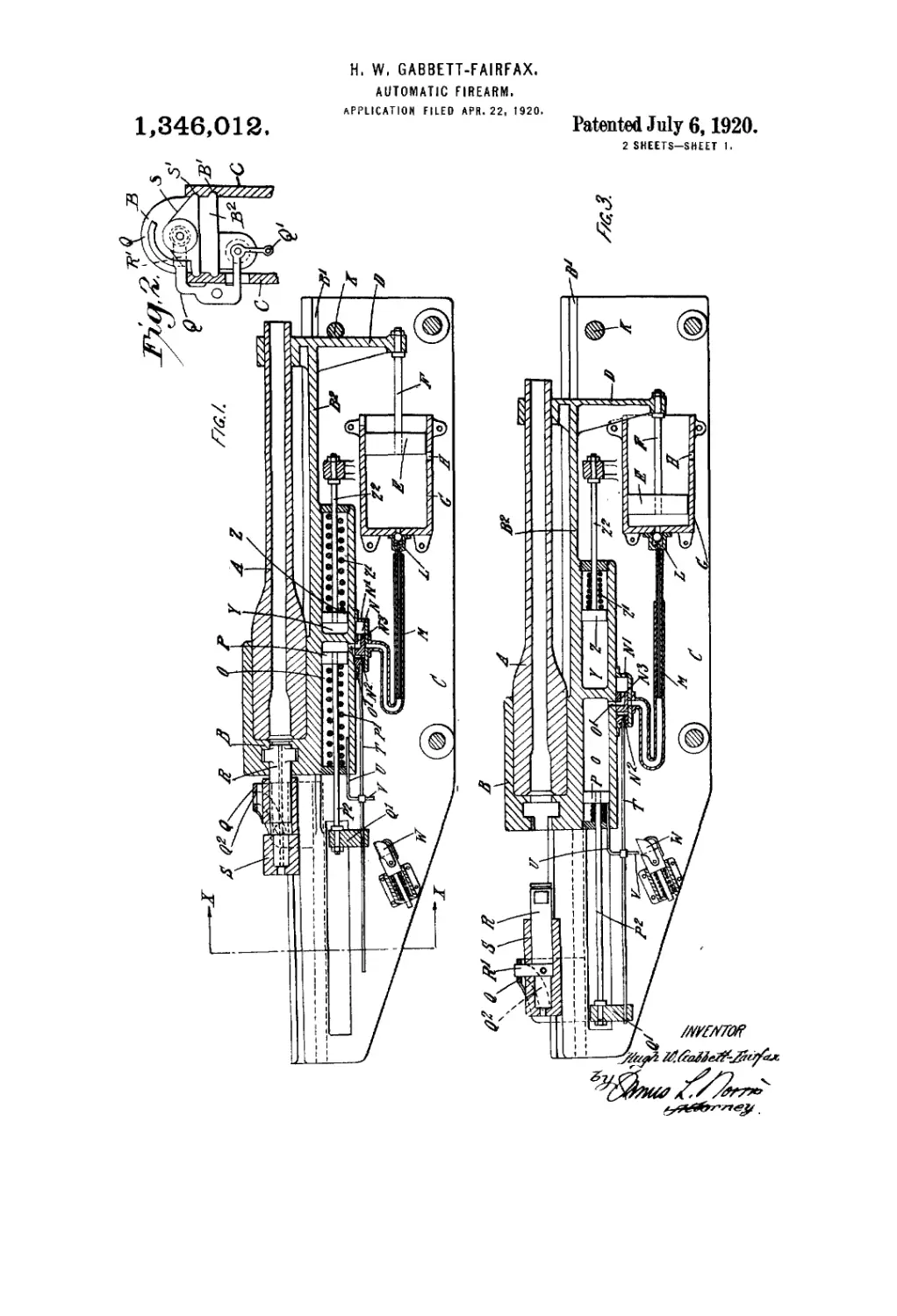
Figure 1 is a longitudinal section show-
ing one method of applying my invention
to a firearm of the kind in which the breech
and barrel recoil while firmly locked to- 85
gether as already described. The breech in
this arrangement is opened by compressed
air and closed by a return spring. It is
shown closed in the drawing.
Fig. 2 is a transverse section taken on 90
X—X (Fig. 1) showing one method of
arranging the breech-closing mechanism
shown in Fig 1.
Fig. 3 is a longitudinal section showing
the same firearm as in Fig. 1 but with the 95
breech open.
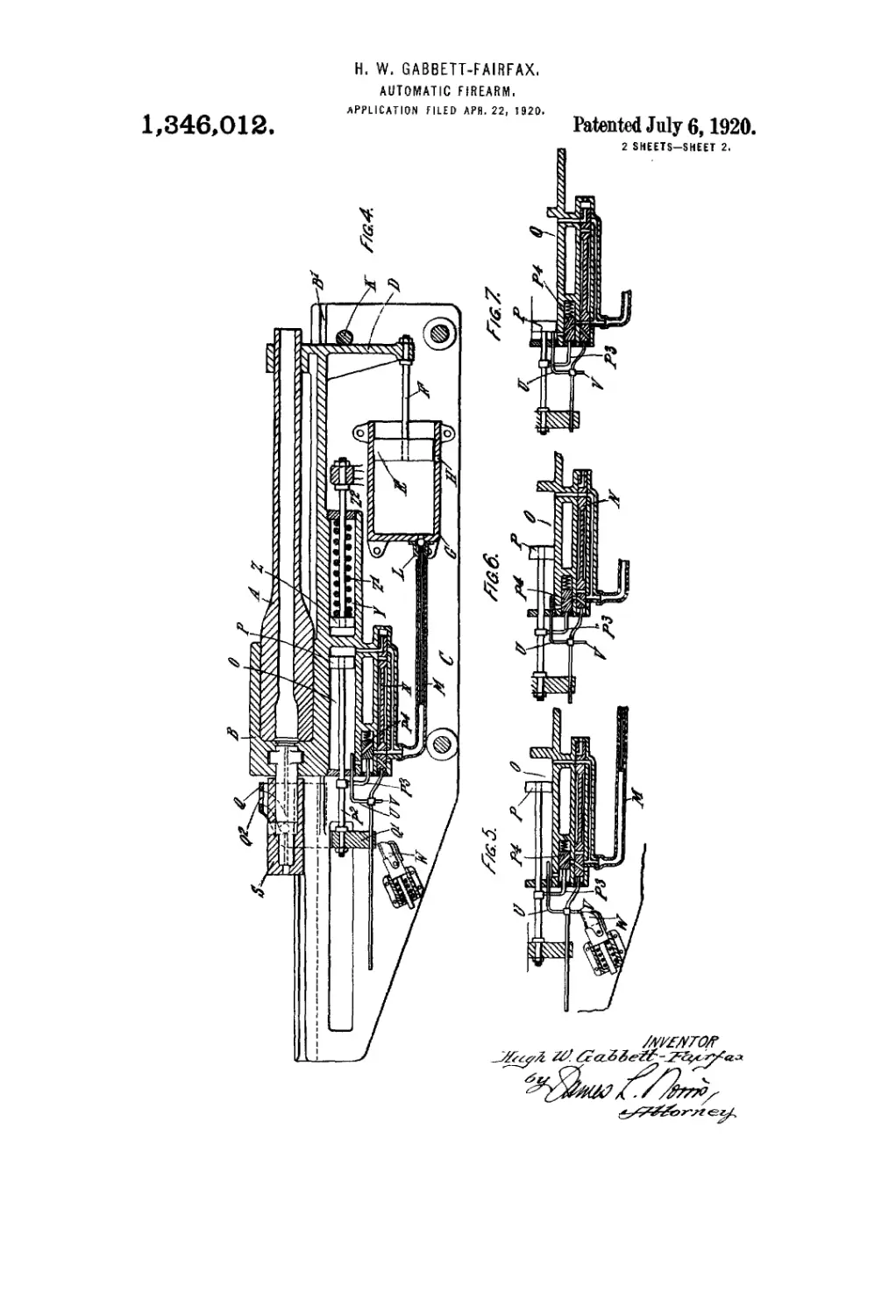
Fig. 4 illustrates in longitudinal section
a modified arrangement in which the breech
is both opened and closed by compressed
air. 100
Figs. 5, 6 and 7 show various positions of
the valves employed in the arrangement
shown in Fig. 4 for a purpose hereinafter
described.
Referring to Figs. 1, 2 and 3, the barrel 105
A is carried in, or is integral with a breech
В which may fie integral with, or attached
to a carriage B2 sliding in guides B' in the
main framing C. The said carriage B2 car-
ries at its forward end a bracket D which 110
£3
1,346,012
5
10
15
20
25
30
Д5
40
45
50
55
60
65
may be ipt^ral with or attached to the car-
riage. A piston E working in a fixed cyl-
inder (t is attached by the rod F to the
bracket D and therefore moves with the
breech and barrel. The cylinder (1 is open
to the atmosphere by a port U in the side
of the cylinder when the barrel is in its for-
ward position <(see Fig. 1) but is closed as
soon as recoil begins.
The barrel is registered in its forward po-
sition by a stop К which may be a fixed
stop as shown, or any suitable form of hy-
draulic, pneumatic or spring buffer.
The air compressed by the piston E passes
through a non-return valve D into a tube M
which is arranged with a sliding joint.
Said tube M communicates through a valve
N witli a cylinder О which is preferably in-
tegral with, or attached to, the carriage B2
but can be attached to tlw framework of the
gun if ..suitable modifications are made in the
connection M and valve N. The said valve
N maybe a sliding valve as shown or of any
other suitable type which will perform the
same functions.
A piston P works in the cylinder О and is
normally held in its forward position by a
spring 1’' and said piston is attached by a
rod P2 to an arm Q' formed on., or attached
to a known form of cam plate Q which
serves to unlock the breech bolt.
The bolt К is preferably carried in a
sleeve S which slides in guides S' forined in,
or on, the main framing C, and a radial arm
R' rigidly attached to the bolt R works in a
slot Q2 formed in the cam plate Q. The
bolt R ca-n rotate in the sleeve S but has no
motion of translation relative ftp it.
When the cam plate Q is drawn back rel-
atively to the sleeve S the bolt R is rotated
and the. breech js unlocked, and when the
cam plate Q is drawn forward relatively to
the sleeve S the bolt is rotated, locking said
bolt into the ’breech. The cam plate Q slides
in guides formed in or on or attached to the
main framing C or the sleeve S.
The valve N is operate,d by means of a
rod T which is attached to said valve, and
slides in a bearing forined in the cam plate
arm Q’’ as shown, -or in the main framing.
Said rod T has two arms IT and V attached
to it; the arm IT projects into the .cylinder
О and is pushed backward by the piston P
when said piston reaches the .end of its back-
ward stroke, and the arm V is arranged to
come into contact with a spring .stop W for
the purpose of actuating the valve N at any
desired point in the recoil.
A cylinder ¥ is formed in the breech car-
riage B2 and a piston Z works in it. Said
fusion Z is connected by a rod 'Z2 to the
ramework of the ^un and has a rpturp
spring Z' introduced hetween it and the for-
ward find of the cylinder.
If preferred, the piston may be attached
to the Jbr«ech carriage .and may werik in a
fixed cylinder attached to the framework of
the gum The functioning is as follows:—
When a shot is fired, Уке barrel A and
bree-’b В with the bolt R securely locked 70
into it, recoil, and the piston E is driven
back- compressing the air in the cylinder (1
and forcing the compressed air through the
non-return valve В into the tube M. The
recoil also compresses the spring Z' and this 75
spring seines to return the barrel to its for-
ward position.
During the first .part of the recoil, the
valve N is set so that the cylinder-G) is open
to the atmosphere through ports O' and N3 80
and opening N', as shown in Fig. I, and is
not in communication with .the .tube M. The
breech therefore remains locked.
When the arm V engages with a stop W
the valve N is momentarily checked, while 85
the cylinder () continues to recoil, thus (dos-
ing the cylinder to atmosphere .and connect
ing it with the tube M through a port N2.
Further recoil of the cylinder О causes the
arm V to push the stop W biick.ward and 9Ю
downward against the action of its spring,
and after a shout backward .movement the
arm V becomes disengaged from the stop
IV and rides over it.
The compressed air in front of .the piston 95
P drives the piston back relatively to the
breech-compressing spring P' and also
drives hack the cam pla.te Q which first ro-
tates and unlocks the bolt E -and -then re-
tracts it, thus opening the breech. 100
The breech can be allowed a further .short
recoil after the breech is opened, or it may
be checked at once, -either by a. fixed stop
or by so proportioning the spring Z' that
the energy or recoil is expended just after 105
the breech is -opened- In either case. the.
spring Z' expands and returns the breech
to its forward position against the stop K.
The piston P is driven back by the .cam-
pressed air tjll it reaches the end of its 110
travel and then pushes back the arm IT
which shifts the valve N and thus closes the
communication between the cylinder Chand
the tube M and opens said cylinder to (the
atmosphere. The spring P'now .expands 115
thus closing the -breech and locking the ,holt.
During the forward motion, the arm V
treads down the spring toe of the stop W
and runs oner it. The stop W may have any
suitable form but must be capable of trip- 120
ping the valve N a,t аду desired point да
the recoil without interfering with the sub-
sequent motion,
goading may be performed by any suit-
able mechanism actuated by the sleeve 3 in 125
its forward movement, and .the cycle pf op-
erations is then repeated. Suitable .spring
stops or detents may be introduced to retain
the valve jji position between оде -move-
ment and the next. 13,0
1,346,012
8
5
10
15
20
25
30
35
40
45
50
55
60
65
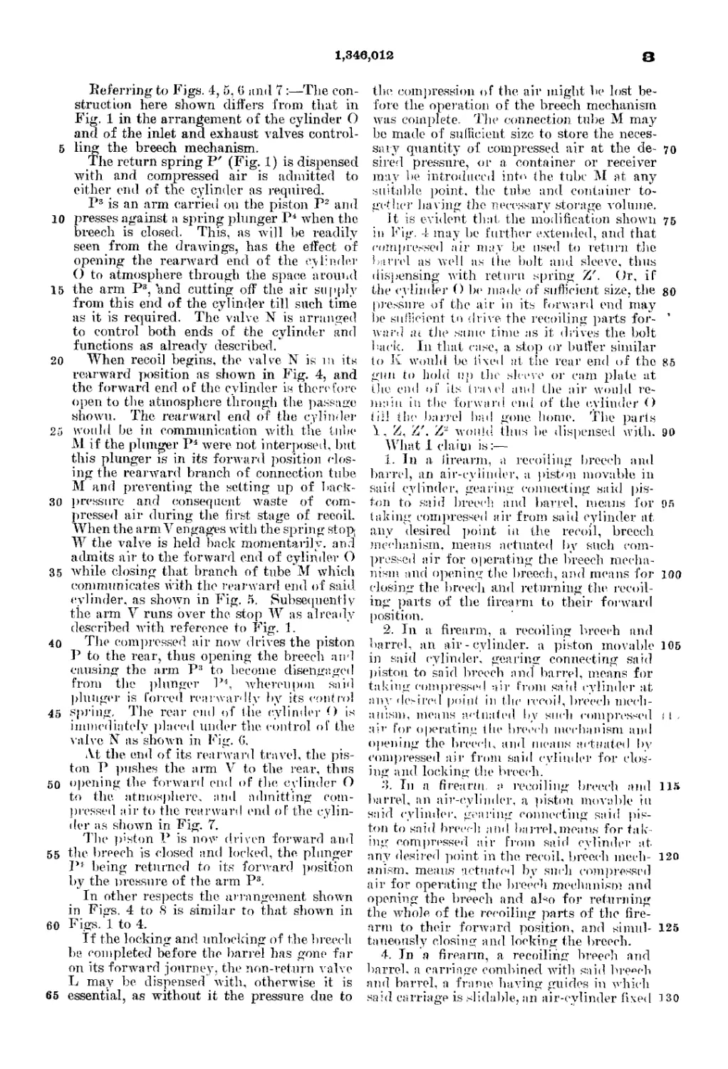
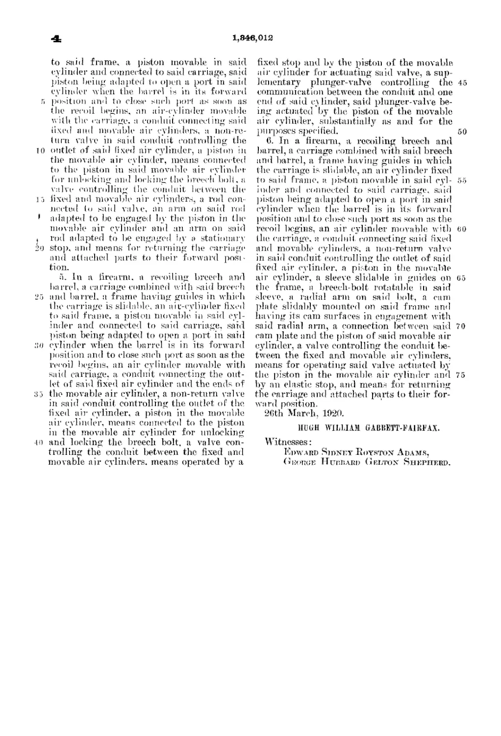
Referring to Figs. 4, 5, 6 and 7:—The con-
struction here shown differs from that in
Fig. 1 in the arrangement of the cylinder О
and of the inlet and exhaust valves control-
ling the breech mechanism.
The return spring P' (Fig. 1) is dispensed
with and compressed air is admitted to
either end of the cylinder as required.
P3 is an arm carried on the piston P2 and
presses against a spring plunger P+ when the
breech is closed. This, as will be readily
seen from the drawings, has the effect of
opening the rearward end of the cylinder
О to atmosphere through the space around
the arm P3, and cutting off the air supply
from this end of the cylinder till such time
as it is required. The valve. N is arranged
to control both ends of the cylinder and
functions as already described.
When recoil begins, the valve N is in its
rearward position as shown in Fig. 4, and
the forward end of the cylinder is therefore
open to the atmosphere through the passage
shown. The rearward end of the cylinder
would be in communication with the tube
M if the plunger P4 were not interposed, but
this plunger is in its forward position clos-
ing the rearward branch of connection tube
M and preventing the setting up of back-
pressure and consequent waste of com-
pressed air during the first stage of recoil.
When the armVengages with the spring stop
W the valve is held back momentarily, and
admits air to the forward end of cylinder О
while closing that branch of tube M which
communicates with the rearward end of said
cylinder, as shown in Fig. 5. Subsequently
the arm V runs over the stop W as already
described with reference to Fig. 1.
The compressed air now drives the piston
P to the rear, thus opening the breech arid
causing the arm P3 to become disengaged
from the plunger P4, whereupon said
plunger is forced renrwardly by its control
spring. The rear end of the cylinder О is
immediately placed under the. control of the
valve N as shown in Fig. G.
At the end of its rearward travel, the pis-
ton P pushes the arm V to the rear, thus
opening the forward end of the, cylinder О
to the. atmosphere, and admitting coin-
pressed air to the rearward end of the cylin-
der as shown in Fig. 7.
The piston P is now driven forward and
the breech is closed and locked, the. plunger
P1 being returned to its forward position
by the pressure of the arm P3.
In other respects the. arrangement shown
in Figs. 4 to 8 is similar to that shown in
Figs. 1 to 4.
If the locking and unlocking of the breech
be completed before the barrel has gone far
on its forward journey, the non-return valve
L may be dispensed with, otherwise it is
essential, as without it the pressure due to
the. compression of the. air might be lost be-
fore the operation of the breech mechanism
was complete. The connection tube M may
be made of sufficient size to store the neces-
sary quantity of compressed air at the de- 70
sired pressure, or a container or receiver
may be introduced into (he tube M at any
suitable point, the tube and container to-
gether having the necessary storage volume.
It is evident that the modification shown 75
in Fig. 4 may be further extended, and that
compressed air may be used to return the
barrel as well as the bolt and sleeve, thus
dispensing with return spring Z'. (Jr, if
the cylinder О be made of sufficient size, the 80
pressure of the air in its Forward end may
be sufficient to drive the recoiling parts for-
ward in the same time as it drives the bolt
back. In that case, a. stop or buffer similar
to К would be fixed at the rear end of the 85
gun to hold up the sleeve or cam plate at
tiie end of its traiel and the air would re-
main iti the forward end of the cylinder О
(ill the barrel had gone home. The parts
\, Z. Z'. Z~ would thus be dispensed with. 90
What I claim is:—
1. In a firearm, a recoiling breech and
barrel, an air-cylinder, a piston movable in
said cylinder, gearing connecting said pis-
ton to said breech and barrel, means for 95
taking compressed air from said cylinder at
any desired point in the recoil, breech
mechanism, means actuated by such com-
pressed air for operating the breech mecha-
nism and opening the bre.eeh, and means for 100
closing the breech and returning the. recoil-
ing parts of the firearm to their forward
position.
2. In a firearm, a recoiling breech and
barrel, an air - cylinder, a piston movable 105
in said cylinder, gearing connecting said
piston to said breech and barrel, means for
taking compressed air from said cylinder at
any desired point in the recoil, breech mech-
anism, means actuated by such compressed < 1 .
air for operating the breech mechanism anil
opening the breech, and means actuated by
compressed air from said cylinder for clos-
ing and locking the breech.
3. In a firearm, a recoiling breech ami 115
barrel, an air-cylinder, a piston movable in
said cylinder, gearing connecting said pis-
ton to said breech ami barrel,means for tak-
ing compressed air from said cylinder at
any desired point in the, recoil, breech much- 120
anism. means actuated by such compressed
air for operating the breech mechanism and
opening the breech and abo for returning
the whole of the recoiling parts of the fire-
arm to their forward position, and siinul- 125
taneously closing and locking the breech.
4. In a firearm, a recoiling breech and
barrel, a carriage combined with said breech
and barrel, a frame, having guides in which
said carriage is slidable, an air-cylinder fixed 1 30
4
1,846,012
to said frame, a piston movable in said
cylinder and connected to said carriage, said
piston being adapted to open a port in said
cylinder when the barrel is in its forward
5 position and tn close such port as soon as
the recoil begins, nn air-cylinder movable
with the carriage, a conduit connecting said
fixed and movable air cylinders, a noii-re-
turri valve in said conduit controlling the
10 outlet of said fixed air cylinder, a piston in
the movable air cylinder, means connected
to the piston in said movable air cylinder
for unlocking and locking the breech bolt, a
valve controlling the conduit between the
15 lived and movable air cylinders, a rod con-
nected to said val\e, an arm on said rod
1 adapted to be engaged by the piston in the
mowable air cylinder and an arm on said
। rod adapted to be engaged by a stationary
20 stop, and means for returning the carriage
and attached parts to their forward posi-
tion.
a. In a firearm, a recoiling breech and
barrel, a carriage combined with said breech
25 and barrel, a frame having guides in which
the carriage is slidable, an air-cylinder fixed
to said frame, a piston movable in said cyl-
inder and connected to said carriage, said
piston being adapted to open a, port in said
:if) cylinder when the barrel is in its forward
position and to close such port as soon as the
recoil begins, an air cylinder movable with
said carriage, a conduit connecting the out-
let of said fixed air cylinder ami the ends of
35 the movable air cylinder, a non-return valve
in said conduit controlling the outlet of the,
fixed air cylinder, a piston in the movable
air cylinder, means connected to the piston
in the movable air cylinder for unlocking
40 and locking the breech bolt, a valve con-
trolling the conduit between the fixed and
movable air cylinders, means operated by a
fixed stop and by the piston of the movable
aii' cylinder for actuating said valve, a sup-
leinentary plunger-valve controlling the 45
communication between the conduit and one
end of said cylinder, said plunger-valve be-
ing actuated by the piston of the movable
air cylinder, substantially as and for the
purposes specified. 50
C. In a firearm, a. recoiling breech and
barrel, a carriage combined with said breech
and barrel, a frame having guides in which
the carriage is slidable, an air cylinder fixed
to said frame, it piston movable in said cyl- 55
inder an<l connected to said carriage, said
]listen being adapted to open a port in said
cylinder when the barrel is in its forward
position and to close such port as soon as the
recoil begins, an air cylinder movable with 60
the carriage, a conduit connecting said fixed
and movable cylinders, a non-rcturn valve
in said conduit controlling the outlet of said
fixed air cylinder, a piston in the movable
air cylinder, a sleeve slidable in guides on 65
the frame, a breech-bolt rotatable in said
sleeve, a radial arm on said bolt, a cam
plate slidably mounted on said frame and
having its cam surfaces in engagement with
said radial arm, a connection between said 70
cam plate and the piston of said movable air
cylinder, a valve controlling the conduit be-
tween the fixed and movable air cylinders,
means for operating said valve actuated by
the piston in the movable air cylinder and 75
by an elastic stop, and means for returning
the carriage and attached parts to their for-
ward position.
26th March, 1920.
HUGH WILLIAM GABBETT-Г AIRFAX.
Witnesses:
Howard Sjdney Boyrtox Adams,
Gijouge Hubbard Geetox Shepherd.