/


Tags: weapons military affairs patent
Year: 1905


Text
No. 802,033.
PATENTED OCT. 17, 1905.
C. FREEMAN.
AUTOMATIC FIREARM.
APPLIOATIOU FILED AUG. 15, 1904.
Wo. 802,033.
PATENTED OCT. 17, 1905,
C. FREEMAN.
AUTOMATIC FIREARM.
APPLICATION FILED AUG 15, 1904.
2 SHEETS—SHEET 2,
UNITED STATES PATENT OFFICE.
CHARLES FREEMAN, OF LOS ANGELES, CALIFORNIA.
AUTOMATIC FIREARM.
Ho. 802,033.
Specification, of Letters Patent.
Application filed August 15,1904. Serial Ko. 220,740.
Patented Oct. 17, 1905.
To all whom it may concern:
Be it known that I, Ciiakles Freeman, a
citizen of the United States, residing at Los
Angeles, in the co.unty of Los Angeles and
5 State of .California, have invented a new and
useful Automatic Firearm, of which the fol-
1 wing is a specification.
This invention embodies a new principle in
automatic firearms, which consists in employ-
io ing a barrel and allowing a device—such, >for
instance, as the breech-block—a short back-
ward primary movement upon the discharge
of the arm, this movement being stopped by
suitable locking means. The great bulk of
iS the backward thrust from the explosion in
the barrel is solidly opposed by this locking
device and the breech-block. Meanwhile a
momentum-block, which while the parts -are
in their closed and locked position is in inti-
2o mate contact with the breech-block, (which, in
fact, it holds in its forward position through
pressure exerted by a reaction-spring,) re-
r ceives an impulse from the short primary
* movementof the breech-block, the momentum
jyj—thus imparted to the momentum-block being
4 ' sufficient to reciprocate it along the frame,
unlock the breech-block, pull it backward
from the breech, compress a reaction-spring,
and operate the arm. The pressure of the
3° reaction-spring then reverses the movement
of the momentum-block, which then operates
to close the breech and leave the arm in its
normal closed position. As carried out by
the form of mechanism shown herein the bar-
35 rel remains stationary. The initial force de-
rived from the discharge of the cartridge gives
a slight rearward movement to the breech-
block, which movement is checked by a suit-
able- locking device engaging both breech-
40 block and frame. Amomentum-block mounted
in contact with the breech-block receives the
momentum of the breech-block and the mo-
mentum of the breech-block is transferred to
the momentum-block, so that the latter con-
45 tinues backward after the breech-block is in-
terrupted,, and this continued retraction of
the momentum-block unlocks the breech-block
from the frame and pulls the breech-block
back with the momentum-block, thereby open-
5° ing the breech and removing the empty shell.
Part of the energy of the reaction-block has
in the meantime been expended in compress-
ing the recoil-spring, which at the termina-
tion of the backward movement of the mo-
>5 mentum-block reacts, forcing the momentum-
block forward to close the breech and to op-
erate the locking device and restore the parts
to original position.
Among the advantages of the principle here
employed are these: It is possible to use a 60
cartridge of any desired size in a barrel of.
any length and weight, the barrel being im-
movable and the backward thrust of the car-
tridge being solidly opposed by the lock after
just sufficient backward movement has been 65
allowed to give momentum to the momentum-
block, which operates the parts. The backward
movement is very slight, and the more pow-
erful the cartridge employed the shorter will
this movement be required. The barrel be- 70
ijng immovable, no return-spring is required,
therefore no brake to retard its movement
and no large abutment to stop its backward
and forward movement. As only sufficient of
the force of the explosion is employed to op- 75
erate the parts, the breech is opened and the
cartridge ejected without undue force.
The main object of the invention is to carry
out the foregoing principle with a simple and
effective mechanism; but I do not confine my- 80
self to the exact mechanism here employed,
but claim all that may justly come within the
scope of my invention.
Another object of the invention is to pro-
vide a novel trigger mechanism for use in au- 85
tomatic firearms.
Other objects and advantages of the inven-
tion will appear in the following description.
The accompanying drawings illustrate the
invention, and referring thereto— 90
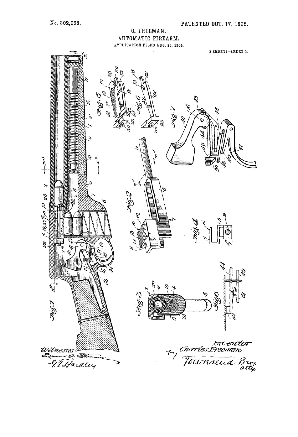
Figure 1 is a vertical longitudinal section
through the breech of the firearm, illustrating
the principle as applied to a rifle. Fig. 2 is
a perspective view of the momentum-block,
part of its stem being broken away. Fig. 3 95
is a sectional view taken on line X’’1 Xs, Fig‘.
1. Fig. 4 is a sectional view taken on lineX4
X4, Fig. 2. Fig. 5 is a perspective view of
the breech-block and locking-pin, showing the
two parts in the relative positions which they 100
occupy immediately preceding the discharge
of the gun. Fig. 6 is a perspective view of
the locking-pin. Fig. 7 is a perspective view
of the trigger mechanism with the hammer-
spring, sear-springs, and trigger-spring re- 10.5
moved. Fig. 8 is a plan of the trigger mech-
anism taken immediately below the hammer.
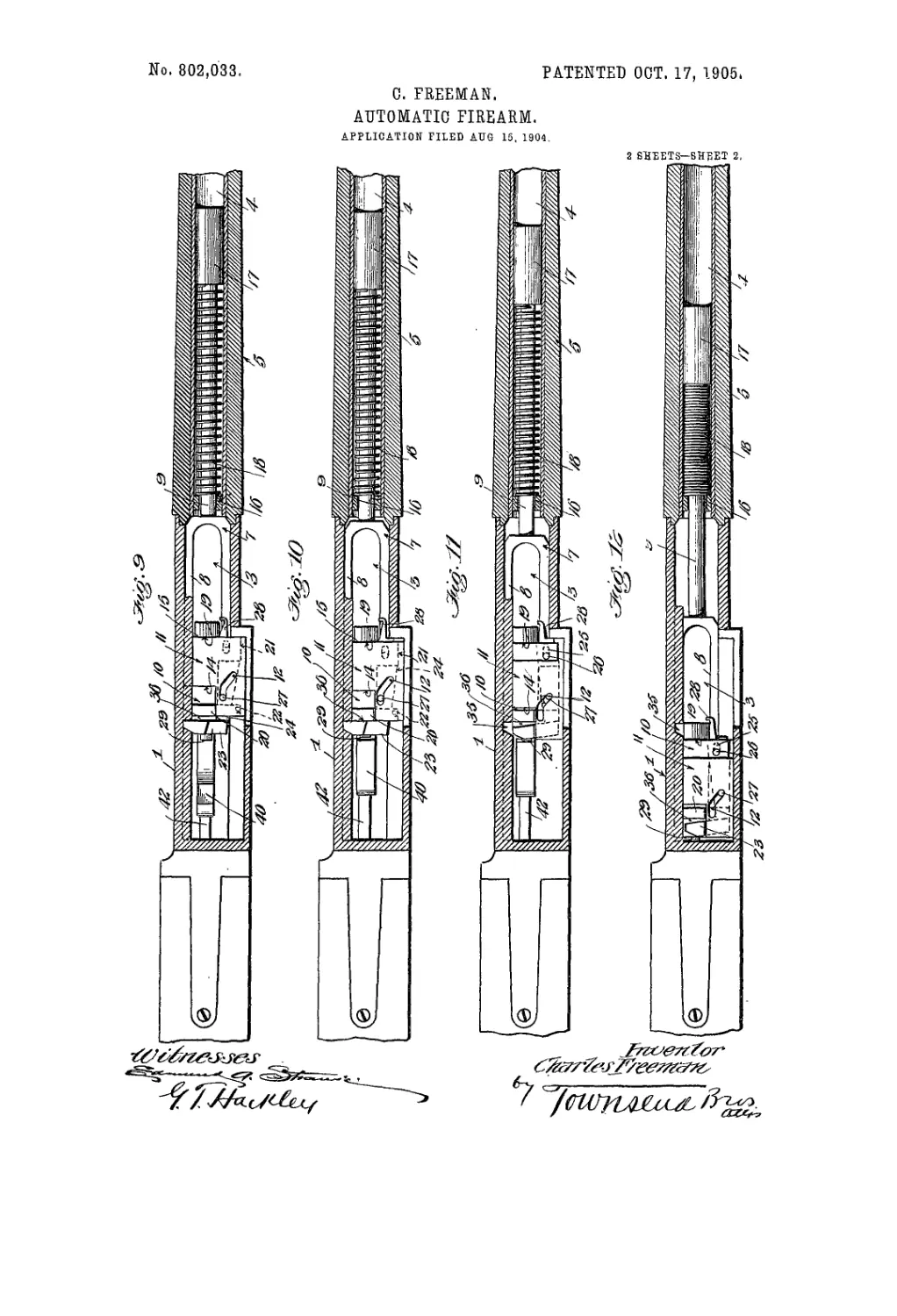
Fig. .9 is a sectional view taken on line X’ X9,
Fig. 1, showing the parts in the position they
have before firing. Fig. 10 is a similar view' no
showing the breech-block having been moved
back a slight distance by the recoil and brought
&02,038
5
IO
15
20
25
3°
35
40
45
5°
55
60
65
into operative contact with the locking-dog.
Fig. 11 is a similar view showing the breech-
block in a similar position to the preceding
and the recoil-block having moved back suffi-
ciently to unlock the locking-dog from en-
gagement with the frame. Fig. 12 is a simi-
lar view showing the breech-block, locking-
dog, and momentum - block at the extreme
rearward position which they have after the
discharge.
1 designates the frame, to which the barrel
2 is rigidly attached. The lower front part
of the frame 1 is provided with a way 3, while
a tube 4 is joined to the frame 1 adjacent the
way 3, being incased in a wooden fore-arm 5
below the barrel. The main portion of the
frame 1 is chambered to provide a way for
thereciprocatingmovementof the parts there-
in, and the lower part of the frame 1 is cham-
bered to receive a magazine 6, which may be
of the common box-magazine type, as shown.
7 designates in general a momentum-block
which comprises a forked member 8, having
a stem 9, the forked portion being slidably
mounted within the way 3 and the stem 9 ly-
ing within the tube 4. A breech-block 10 is
slidably mounted upon the momentum-block,
the momentum-block being chambered to re-
ceive the same and having a plate 11, L-sbaped
in cross-section. (See Figs. 2 and 4.)
The plate 11 is provided with an angular
slot 12, and the momentum-block has an off-
set portion 13, forming oppositely-disposed
abutments 14 and 15. A spring-stop 16 is
provided within the tube 4, and the stem 9
has a head 17, while the coil compression-
spring 18 is interposed between the head 17
and the stop 16 and serves to normally bold
the momentum-block in the'position shown in
Figs. 1 and 9.
The breech-block 10 is slidably mounted
within the plate 11 of the momentum-block,
the breech-block being recessed to form shoul-
ders 19 and 20, which are adapted to respec-
tively engage with abutments 15 and 14 to
limit the sliding movement in either direction
of the breech-block relatively to the momen-
tum-block. The breech-block is provided at
one end with a slotted lug 21 and at the other
end with a slotted lug 22. A locking-dog 23
is provided with a flat shank 24, which is
mounted within the slotted lugs 21 and 22
and which has an elongated slot 25, which re-
ceives a pin 26 in the slotted lug 21. A short
pin 27 projects up from the shank 24 and lies
within the angular slot 12 of the momentum-
block.
The shank 24 at its forward end is also pro-
vided with a cartridge-extracting hook 28.
The breech-block 10 is bored centrally to re-
ceive the firing-pin 29, and the locking-dog
23 is provided with a slot 30 to receive the
firing-pin. In the operation of the mechan-
ism the locking-dog 23 has a lateral move-
ment relatively to the breech-block, and for
that reason the slot 30 is made elongated, as
shown, so that the .firing-pin will not impede
its lateral movement.
40 designates the hammer, which is pivoted
at 41 and operated by the usual spring 42 70
and has a single cocking-notch 43. Pivoted
to the frame just below the hammer is an aux-
iliary ’sear 44 and a regular sear 45. Both
sears are adapted to consecutively engage
the cocking-notch 43, the detent of the aux- 75
iliary sear 44 being longer from its fulcrum
than the detent of the sear 45. . (See Figs. 7
and 8.)
The rear end of the auxiliary sear 44 is pro-
vided with a toe 46, and while both sears nor- .80
mally lie substantially in the same horizontal
plane the toe 46 of the auxiliary sear 44 pro-
jects below the plane.
47 designates the trigger, which is provided
with an auxiliary pivoted finger 48 and with a 85
rigid regular finger 49. The pivoted auxil-
iary finger 48 is longer than the finger 49,
and when the parts are in the position shown
in Fig. 7 the auxiliary linger 48 lies directly
under the toe 16 of the auxiliary sear 44, 90
while the finger 49 lies under but slightly '
below the sear 45. An inclined abutment 50
projects from the frame 1 adjacent to the end
of the pivoted finger 48. A spring 51 serves
to normally hold the pivoted linger 48 under 95
the toe 46.
In operation when the hammer has been
moved back into the position shown in Figs. |
1 and 7 the auxiliary sear 44 engages the
cocking - notch 43 and retains the hammer^
in position. Upon pulling the trigger 47 as
the finger 48 rises it presses upon the toe 46
and tilts the sear 44, which releases the ham-
mer which moves slightly forward and is
caught by the scar 45 after a slight move- 10,
ment. Continued pulling on the'trigger, how-
ever, will quickly bring the finger 49 into en-
gagement with the sear 45, so that the latter
is tilted and the hammer thereby released,'
and in the meantime as the finger 48 moves и
up it is shunted from the toe 46 by the in-
clined abutment 50, so that the sear 44 will
immediately spring’ back to position, with its
detent riding against the rounded hub of the
•hammer in position to catch the hammer as и
soon as the cocking-notch again arrives in
place, upon the next backward movement of
the hammer. As soon as the trigger 47 is re-
leased it returns to its normal position, the
finger 48 riding down the side of the toe 46, a
under which it is snapped by the spring 51
upon the completion of the return movement
of the trigger. Thus the hammer is always
caught by the auxiliary sear 44 when thrown
back. 1:
Referring to Fig. 1, a cartridge is shown in
place ready to be discharged and the hammer
is cocked.
Fig. 9 shows the breech-block, momentum-
block, and locking-dog in the positions they 1;
802,038
have corresponding to the view in Fig’. 1. In
this position the locking-dog is in engagement
with a locking-notch 35 in the frame, and the
breech-block is shown slightly ahead of the
5 locking-dog, leaving a narrow space 36, the
abutment 15 lying close against the shoulder
19, with the cartridge abutting against the end
of the breech-block, as shown, the cartridge-
extracting hook being Out of engagement with
jo the rim of the cartridge. By pulling the trig-
ger the hammer is released, and it strikes the
tiring-pin, which explodes the cartridge. The
recoil drives the breech-block backward, clos-
ing the space 36, where it is interrupted by its
15 coming into contact with the locking-dog.
The parts now have the position shown in Fig.
10. Up to this time the locking-dog is still in
engagement with the frame, and thus the back-
ward movement of the breech-block is posi-
20 tively arrested; but the momentum-block un-
der the impulse derived from the initial recoil
of the breech-block-continues on backward,
and as the angular slot 12 moves along the pin
27 it rocks the locking-dog upon the pin 26 and
25 disengages the locking-dog from the frame,
whereupon the breech-block and locking-dog
are both bodily moved backward by the mo-
mentum-block to the end of its rear stroke.
The hook 28 on the locking-dog, which catches
30 over the rim of the cartridge-shell, carries the
shell back also with the parts, and during this
backward movement the rim of the shell
у strikes an ejector (not shown) and is ejected in
j the well-known manner. As soon as the parts
\15reach this position, as shown in Fig. 12, the
(Cartridge is ejected through the side of the
frame through the action of a cartridge-stop,
(not shown,) and a fresh cartridge from the
magazine springs into place. During the
4.0 rearward movement of the momentum-block
the spring 18 is compressed, and at the termi-
nation of the rear movement it reacts and
drives the momentum-block forward, carry-
ing with it the breech-block and locking-pin
45 and the fresh cartridge. It will be observed
that the breech-block and locking-dog do not
lag behind this forward movement of the mo-
mentum-block, as lost motion is obviated, for
the reason that the slot 12 cannot slide along
5° the pin 27« as the pin 27 is held from lateral
movement by reason of the locking-dog bear-
ing against the inside face of the frame; but as
soon as the locking-dog is sufficiently moved
forward until its side comes opposite the lock-
55 ing-notch 35 the front end of the shoulder 32
strikes the frame, which arrests the forward
movement of the locking - dog, and the con-
tinued forward movement of the momentum-
block and breech-block throws the locking-dog
60 into the locking-notch 35 by reason of the in-
clined slot 12 sliding over the pin 27, and after
the locking-dog is seated in the locking-notch
the momentum-block and breech-block have a
further slight movement forward, which
65 brings the breech-block out of contact with
theshoulder of the locking-dog, thus providing
for the slight backward thrust which trans-
mits the recoil energy to the momentum-block,
which operates the arm.
What I claim is— 7°
1. In an automatic firearm, a frame, a barrel
mounted on said frame, a breech-block mount-
ed in the frame, a momentum-block mounted
in the frame, the breech-block having a short
primary movement imparted by an explosion 75
in the barrel and a subsequent longer move-
ment derived from the momentum-block, a re-
coil-spring,and means for stopping the breech-,
block after the short primary movement, en-
ergy derived from the recoil being imparted 80
to .the momentum-block to again actuate the
breech-block, compress the recoil-spring and
operate the arm.
2. In an automatic firearm, a frame, a barrel
rigidly mounted on said frame, a breech-block 85
mounted in the frame, a momentum-block
mounted in the frame, the breech-block hav-
ing a short primary movement imparted by
an explosion in the barrel and a subsequent
longer movement derived from the mo- 90
mentum-block, a recoil-spring, and means for
stopping the breech-block after- the short pri-
mary movement, energy derived from the dis-
charge being imparted through the short pri-
mary movement of the breech-block to the 95
momentum-block to release the breech-block
and again actuate the breech-block, compress
the recoil-spring, and operate the arm.
3. In an automatic firearm a frame, a barrel
rigidly mounted in said frame, a breech-block 100
slidably mounted in the frame, a momentum-
block slidably mounted in the frame and in
operative contact with the breech-block, a re-
coil-spring,and means for stopping the breech-
block after a short primary movement im- 105
parted by an explosion in the barrel and im-
parting energy to the momentum-block
through the short primary movement of the
breech-block to release the breech-block and
retract it along the frame, compress the re- no
coil-spring and operate the arm.
4. In an automatic firearm, a frame, a barrel
fixed in said frame, a breech-block having an
interrupted movement slidably mounted in
said frame, a momentum-block mounted in 115
contact with the breech-block and holding the
breech-block in forward position when said
parts are in closed position and receiving a re-
coil momentum from the breech-block upon
the discharge of the arm, a spring in oper- 120
alive contact with the momentum-block, a
locking-dog in operative contact with the
breech-block and frame when said parts are
in locked position and allowing.a slight back-
ward movement of the breech-block, said mo- 125
mentum-block being provided with means to
operate the locking-dog into and out of locked
position upon its backward and forward move-
ments and to reciprocate the breech-block on
the frame. 130
802.033
5. In a firearm, aframe. a breech-block slid-
ably mounted in said frame, a locking-dog
pivoted to said breech-block, and having at its
forward end a cartridge-extracting hook, and
5 means for reciprocating the breech-block and
causing the hook to engage the cantridge and
extract the same.
6. In an automatic firearm, af ranie,a breech-
block slidably mounted in said frame, a ham-
io rner having a cocking-notch pivotally mount-
ed in said frame, two sears of unequal length
forwardly pivotally mounted in said frame
so as to engage separately the notch on the
hammer, a trigger pivoted to said frame and
15 having an extension formed thereon in the
path of the shortest sear, and a member piv-
oted thereon and yieldingly held in the path
of the longer sear, an inclined abutment on
the frame to throw the movable member on
20 the trigger out of engagement with the longer
sear, and means for cocking the hammer and
allowing the sears to consecutively engage the
notch in the hammer upon the trigger being
pulled.
25 7. In an automatic firearm, a frame, a barrel
mounted in said frame, a breech-block mount-
ed in said frame, a momentum-block mounted
in said frame in operative contact with said
breech-block, the breech-block having a short
30 primary movement imparted by an explosion
in the barrel and a longer secondary move-
ment derived from the momentum-block, and
means to transfer the energy of an explosion
in the barrel through the short primary move-
35 ment of the breech-block'.to the momentum-
block to operate the arm.
8. In an automatic firearm, a frame, a barrel
mounted in said frame, a breech-block mount-
ed in the frame and having a short backward
4° primary movement given it by an explosion
in the barrel, means for stopping this primary
movement, said breech-block also having a
secondary longer movement, a momentum-
block mounted in said frame and receiving suf-
ficient energy from the shott primary move- 45
ment of the breech-block to unlock the breech-
block. impart to it the longer secondary move-
ment thus opening the breech of the arm and
operating the other parts of the mechanism.
9. In an automatic firearm, aframe, abarrel 5°
mounted on the frame, a breech-block mount-
ed in the frame, means for stoppingthe breech-
block after it has been moved back a definite
distance by an explosion, and a device coop-
erating with the breech-block and receiving 55
movement therefrom to release the breech-
block and carry it farther backward and op-
erate the arm.
10. In an automatic firearm’, a frame, a bar-
rel mounted on the frame, a breech-block 60
mounted in the frame and movable backward
by successive steps, the movement of the
breech-block through the first step being ac-
complished by the explosion, and means de-
riving energy from the breech-block during 65
its first step for moving backward and for
pulling the breech-block therewith through
its next step.
11. In an automatic firearm, a frame, abar-
rel mounted on the frame, a breech-block 7.0
mounted in the frame and movable through
consecutive steps, means normally looked for
stopping the breech-block at the end of its
first step which is caused by the explosion,
and a device deriving energy from the breech- 75
block as it moves through the said first step
for unlocking said means, thereby releasing
said breech-block, and for moving the breech- „
block through its said second step and operat- r .
ing the arm. 80
In testimony whereof I have hereunto set
my hand, at Los Angeles, California, this 4th
day of August, 1904.
CHARLES FREEMAN.
In presence of—
George T. Hackley,
Arthur P. Knight.