/


Tags: weapons military affairs patent
Year: 1940

Text
June 11, 1940.
2,204,289
D. M. WILLIAMS
EXTRACTOR MECHANISM FOR FIREARMS
Original Filed Feb. 7, 1931
Patented June 11, 1940
2,204,289
UNITED STATES PATENT OFFICE
2,204,289
EXTRACTOR MECHANISM FOR FIREARMS
David M. Williams, Godwin, N. C.
Original application February 7, 1931, Serial No.
514,252. Divided and this application August
21, 1937, Serial No. 160,322
5 Claims.
The present invention relates to firearms and
more particularly to a novel extractor mechanism
therefor.
The extractor mechanism, as commonly used
5 in present day rifles and other firearms, comprises
either a single extractor or a pair of extractors.
In the case of the gun having two extractors,
these are usually termed the “right hand ex-
, tractor” and “left hand extractor,” respectively.
j'(! In the usual gun having two extractors, the
left hand extractor does not have a positive en-
gaging hook for the rim of the cartridge. In
other words, the right hand extractor has a posi-
tive hook, which makes a positive engagement
I.' with the rim of the cartridge and functions to
extract or withdraw the cartridge from the bore.
The engagement of the left hand extractor, how-
ever, with the rim of the cartridge is a mere fric-
tional engagement, since the left hand extractor
Vh usually has a sloping or negative hook and does
not make a positive engagement with the rim of
the cartridge.
The reason that the left hand extractor does
not have a positive hook in a gun of the afore-
25 mentioned type, is to enable the ejector to push
the shell out of engagement. Upon the ejector
pushing the shell, the shell slides out of engage-
ment with the negative hook of the left hand ex-
tractor and pivots about and away from the pos-
i!0 itive hook of the right hand extractor. It may,
therefore, be seen that in this arrangement, the
shell is only firmly held by one extractor, and the
extraction is not as positive as may sometimes be
desired. In a firearm in accordance with the
present invention, two extractors, each having
a positive hook, are provided, the provision of two
extractors each having a positive hook means for
engaging the rim of a cartridge gives in addition
f to a balanced pull upon the head of the cartridge,
f:) about double the extraction effort as compared
to a gun having two extractors, one of which has
a negative hook means. Also, the chances of a
malfunction due to the fired shell or cartridge
becoming lost or removed from the grasp of the
•!5 extractors before being struck or acted upon by
the ejector is eliminated.
It is one of the objects of the present inven-
tion, therefore, to provide a more positive means
... for extracting the shell from the bore of a flre-
In1) arm.
Another object of the present invention is to
provide a firearm having a pair of extractors,
both of which have a positive hook engagement
with the rim of a cartridge.
55 Still another object of the present invention
(CI. 42—25)
is to provide means for disengaging one of the
extractors from a cartridge rim in order to allow
ejection thereof by the ejector.
A fourth object of the invention is to provide
cam means for disengaging one of the extractors
of a firearm from the cartridge rim. 6
Other objects of the invention will be apparent
from the disclosure as hereinafter set forth.
Referring to the accompanying drawing:
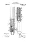
Figure 1 is a longitudinal section of a portion
of a firearm showing the cartridge in position 1
ready to fire.
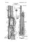
Figure 2 is a longitudinal section of a firearm
in open position during ejection.
Figure 3 is a section of a firearm showing the
face of the bolt with the cartridge removed.
Figure 4 is a side elevation of a portion of a
gun receiver according to this invention, illus-
trating the lug and slot cooperation.
Referring to Figure 1 of the drawing, I repre-
sents a firearm bolt held in a closed position by
a spring 2 bearing against the face 3 of element
4 carried by the bolt. The bolt has a central
aperture indicated at 5 in which is slidably ar-
ranged an ejector 6. Mounted in the bolt is a
striker 7 which in the position shown in Figures
1 and 2, is urged in a forward direction by a
striker spring 8, bearing against the face 9 of the
striker. It may be noted that the striker nose
is not shown in any of the figures of the draw- 3U
ing, since this application is not concerned with
the type of striker used. It may be assumed that
the gun is provided with a suitable striker for
firing the cartridge.
In Figure 1, a cartridge indicated in general
at C and provided with a shell S is shown in °°
position in the chamber of the firearm. In this
position, the rim 10 of the cartridge is engaged
on one side by hook 11 of left hand extractor 12
and on the other by hook 13 of right hand ex- ,
tractor 14, and the rim 10 of the cartridge is 4
seated against the front end of the bolt I. Right
hand extractor !4 is pivoted on a pin 15 carried
by the bolt and is urged to engaging position by
a spring !0. Left hand extractor 12 is similarly
pivoted on a pin 17 carried by the bolt and is
similarly urged to engaging position by a spring
18.
The end of the extractor 12 remote from the
hook carries a cam lug 19 provided with a cam &0
face 20 constructed and arranged to engage the
receiver 21 at the rear end of slot 22 at point
23, as shown in Figure 4.
Figure 2 shows a gun similar to Figure 1 dur-
ing ejection of the shell. In this figure, the car- 6B
2,204,289
tridge has been fired and the empty shell has
been extracted from the chamber. The empty
shell S is indicated in dotted lines. It may be
noted that the left hand extractor 12 has been
5 disengaged from the shell by the camming action
of the lug 1Э against receiver 21 and that the
lug is shown in depressed or inside position rela-
tive to the receiver 21.
Referring further to Figure 1, the cartridge C
10 and shell S are shown in position in a chamber
of a gun ready to fire. It is assumed that the
striker shown at 7 is provided with a point for
firing the cartridge and that the striker is held
in a cocked position, as shown in Figure 1, by a
15 suitable sear and trigger. It may be noted that
in the position shown in Figure 1, both extractor
hooks II and 13 grasp the cartridge rim IS.
Upon firing of the cartridge, the bolt I is forced
back carrying both the right hand extractor 14
20 and left hand extractor 12 in a rearward direc-
tion. As before pointed out, these extractors
are carried and pivoted on pins 15 and 17 on
the bolt.
Towards the end of the rearward movement,
25 the cam face 20 of the lug 19 engages point 23
*' of the receiver at the rear end of the slot 22.
This moves the rear end of the extractor 12 in
an inward direction, and the hook of the ex-
tractor 12, is, therefore, disengaged from the
30 cartridge rim 10. The disengaged position of
extractor 12 is shown in Figure 2. It may be
noted, however, that this disengagement does
not take place until just before the ejector 6
has come into contact with the base of the shell
35 which has been carried rearwards against the
ejector by the bolt and extractors. Continued
rearward motion of the bolt causes the point
of the ejector to protrude through the end
of the bolt and the shell is thus caused to pivot
40 around and away from the right hand extractor
14, since as before stated, the left hand extractor
12 has been disengaged from the rim of the car-
tridge just prior to this point. It may be noted
that the action of the ejector is sufficiently fast
45 during the gun operation to throw the shell clear
of the gun in the usual manner.
It may be further noted that although in the
derice as shown in the drawing and heretofore
described, two extractors are shown, one of which
50 is detachable from the cartridge rim, it is within
the scope of the present invention to provide
more than two extractors. Preferably, where
more than two extractors are provided, they
are spaced so as to exert a balanced pull on the
55 shell and all or one of them are capable of be-
ing moved to a shell-releasing position. In some
instances, it may be desirable to provide a re-
leasable positive hook extractor in combination
with and in addition to the usual left hand nega-
60 tive extractor well known in the art. These
and other modifications are well within the
scope of the present invention, as obviously the
cam released positive hook extractor herein dis-
closed may take various forms and may be com-
65 bined with any of the extractors well known in
the art. It is also within the scope of the pres-
ent invention to provide a gun of the forward
sliding barrel type with a releasable extractor.
In such event, the barrel or chamber will move
away from the extractor, and the extractor will
be similarly released just prior to ejection.
This application is a division of my prior ap-
plication Serial No. 514,252, filed February 7,
1931, which has matured into Patent No.
2,090,656, dated August 24, 1937.
I claim:
1. I. In a gun, the combination with extractor
means, shell engaging members carried by said 5
extractor means, ejector means, means on a
stationary portion of said gun for moving the
extractor means to a shell-releasing position
slightly in advance of the shell-ejecting action
of the ejector means, said means for moving the 10
extractor means being entirely independent of
the ejector means.
2. In a gun having the usual receiver and
ejector, the combination with extractor means,
shell engaging members carried by said extractor 15
means, said shell engaging members comprising
a plurality of positive hook means, means inde-
pendent of said ejector for moving the extractor
means to a shell releasing position slightly in
advance of the shell ejecting action of the ejector, 2®
said means comprising a cam carried by said
extractor means and a stationary shoulder on
the receiver of the gun cooperating therewith.
3. In a gun having the usual receiver and
ejector, the combination with extractor means, 2&
shell-engaging members carried by said extrac-
tor means, said shell-engaging members com-
prising a plurality of positive hook means, and
means for moving the extractor means to a
shell-releasing position slightly in advance of
the shell-ejecting action of the ejector including
means for moving one of said hook means out
of shell-engaging position, said last mentioned
means comprising a portion of said receiver
spaced from and independent of the ejector.
4. In a gun of the kind described, a receiver,
a bolt slidably mounted in said receiver, an ejec-
tor pin, mounted in said bolt and arranged to
permit sliding movement of the bolt thereon,
said ejector pin having its forward end project-
ing forwardly of the bolt upon full retraction of
the latter, a pair of extractor levers pivoted to
the bolt and hawing forwardly projecting car-
tridge engaging hook noses, springs urging said
noses toward each other, said receiver having a
slot extending longitudinally of the receiver, said
slot having a shoulder at its rear end, and a cam
lug on one of the levers sliding in the slot and
engageable with said shoulder upon retraction
of the bolt to move the lever to cartridge releas-
ing position against the action of the respec-
tive spring.
5. In a. gun having the usual receiver, ejector
and chamber, extractor means for removing the
shell out of the chamber, shell-engaging mem-
bers carried by said extractor means including
a plurality of positive hook means, one of said
hook means being movable into and out of
shell releasing position, a slot in said receiver
receiving a portion of said last-mentioned hook 80
means when said hook means is in shell-en-
gaging position, means to move said extractor
and said last-mentioned hook means to extract
said shell from the chamber and means to urge __
said hook means into shell-engaging position, W
and a shoulder at the end of said slot cooperating
with said portion to move said last-mentioned
hook means out of shell-engaging position, said
slot being of such length that said portion is re- ?(.
tained therein during substantially the entire ™
period of extraction.
DAVID M. WILLIAMS.