/

Tags: weapons military affairs patent
Year: 1914
Text
A. D. CHRONIS.
BREECH MECHANISM FOR AUTOMATIC FIREARMS.
APPLICATION PILED NOV, 28, 1911.
1,096,679. Patented May 12,1914.
3 SHEETS-SHEET 1..
A. D. CHRONIS.
BBEEOH MECHANISM FOB?AUTOMATIC FI₽EARMS.
APPLICATION PILED NOV. 28, 1911.
1,096,679. Patented May 12, 1914.
' 3 SHEETS—SHEET 2,
- Fty. 7, Ftj.8.
A. D. CHRONIS.
BREECH MECHANISM FOR AUTOMATIC FIREARMS;
APPLICATION FILED NOV. 28, 1911.
1,096,679. Patented Mdy 12,1914,
3 SHEETS-SHEET 3.
UNITED STATES PATENT OFFICE.
ARIS D. CHRONIS, OF LARISSA, GREECE, ASSIGNOR TO THE FIRM OF RHEINTSCHE
METALLWAAREN- ЕГО MASCHINENFABRIK, OF DUSSELDORF-DERENDORF, GER-
MANY.
BREECH MECHANISM FOR AUTOMATIC FIREARMS.
1,096,679. specification of letters Patent. Patented May 12,1914.
Application filed November 28. 1911. Serial No. 662,865.
To all whom it may concern:
Be it known that I. Aris D. Ciihonis, lieu-
tenant, a subject of the King of Greece, re-
siding at Larissa, Greece, have invented cer-
5 tain new and useful Improvements in
Breech Mechanism for Automatic ffirearms;
and I do hereby declare the following to be
a full, clear, and exact description of the
invention, such as will enable others skilled
10 in the art to which it appertains to make
and use the same.
The invention relates to automata fire-
arms with fixed barrel and locked breech
block, in which the unlocking is effected by
15 the recoil of the whole weapon as set forth
in my Patent Ko. 1,043,670, and the object
is to reduce to a minimum the effort re-
quired for unlocking the block.
The advantages of the device consist u
20 the fact that the mass of the displaceable
member can be considerably reduced and
also the unlocking can be effected in weap-
ons in which the recoil is not sufficient to
bring about the automatic action. The
25 locking is positive and is not due to friction,
which would cause an immediate shifting of
the- cartridge case on firing due to gas pres-
sure.
The invention is illustrated, by way of
30 example In the accompanying drawings.
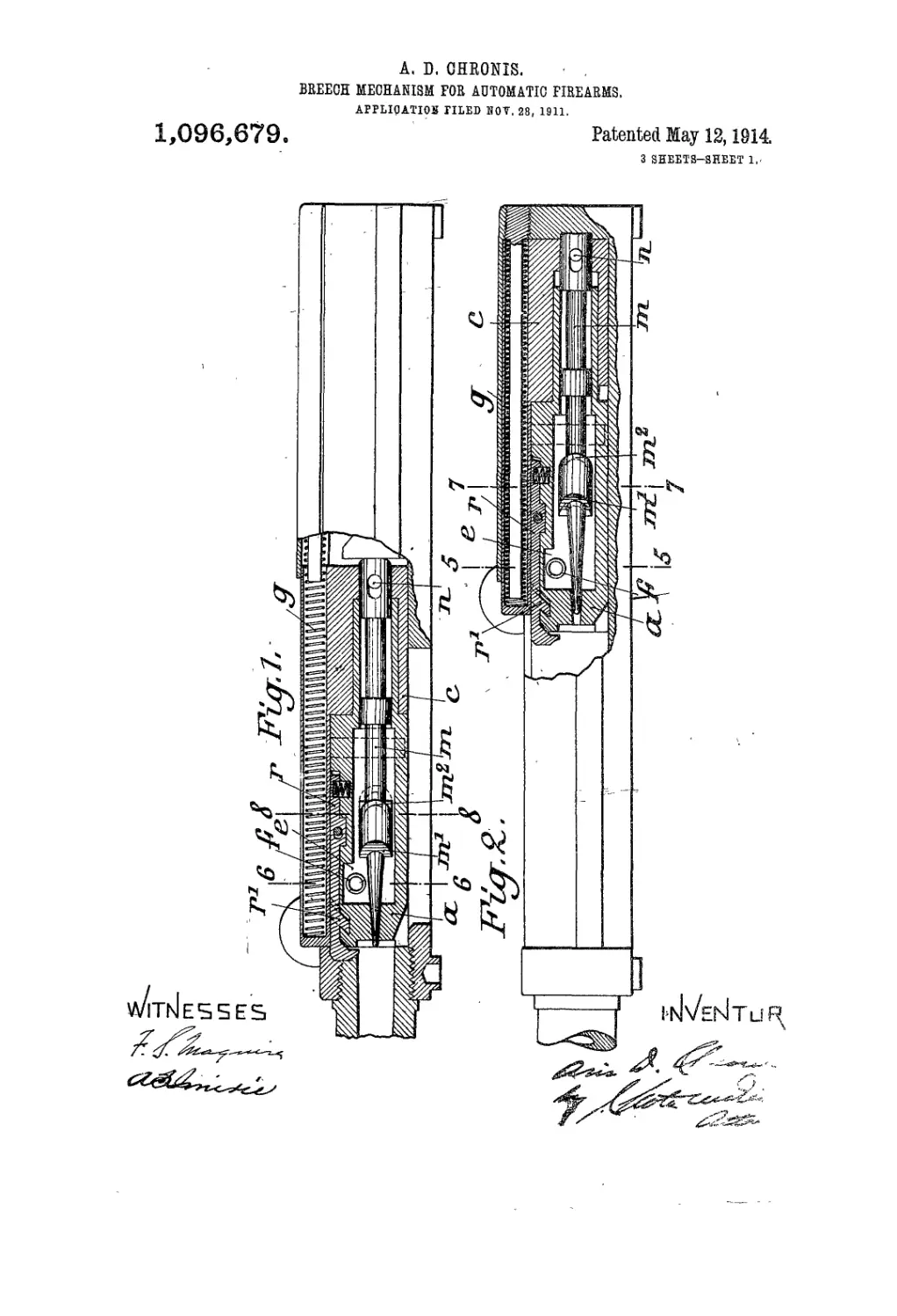
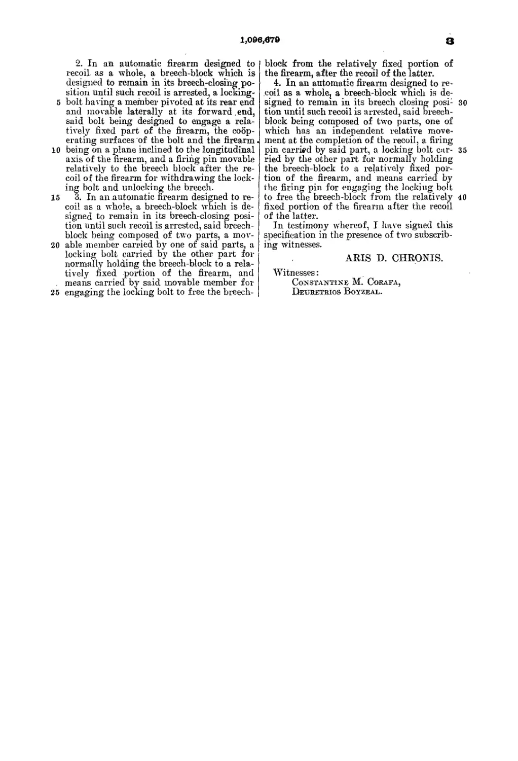
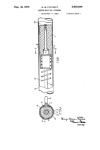
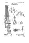
Figure 1 is a longitudinal section .through
a weapon provided with a locked breech
block at the moment of firing. Fig. 2 is the
same view after firing, when the breech is
35 unlocked and has reached its most rearward
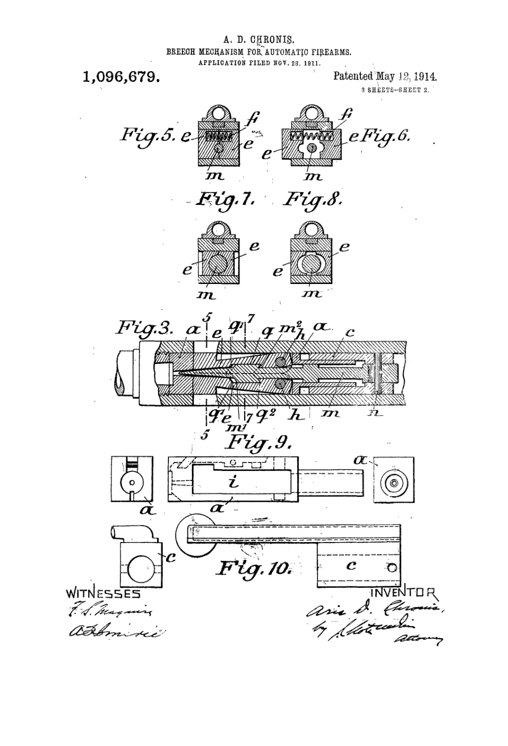
position. Fig. 3 is a horizontal longitudi-
nal section after firing when the breech
block is unlocked. Fig. 4 is the same sec-
tion at the moment of firing, eorrespond-
40 ing to the condition shown in Fig. 1. Figs.
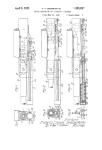
5, 6, 7 8 are cross sections on the lines 5—5.
6—6, 7—7 and 8—8 of Figs. 1, 2, 3 and 4.'
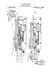
Figs. 9 and 10 are front, side and rear views
of the fore and rear parts of the breech
45 block. Fig. 11 shows two views of the fir-
ing pin. Fig. 12 shows three views of one
of the locking bolts. Fig. 13 is a diagram-
matic representation of the forces acting on
ilia bolts.
50 ‘ The breech block consists of two rela-
tively movable parts, a fore part a (Figs.
1, 2, 3, 4 and 9) and a rear part c (Figs. 1,
2, 3, 4 and 10). The closing spring g is
situated in the after part c (Figs. 1 and 2).
The. fore part of the breech block a (Fig. 55
9) is provided with an internal space ) to
receive the locking bolts’c (Figs. 1. 2, 3. 4,
5, 6. 7 and 8) which can turn on the pins
h (Fig<. 3 and 4) on the fore part a of the
block. In both bolts there are recesses q 60
with inclined surfaces y', y2 (Figs. 3, 4 and
12); The firing pin m. engages in these re-
cesses y, and is connected with the rear
part e of the breech block by the pin n
(Figs. 1, 2, 3 and 4). 65
The connection between the two parts a
and e of the breech block is such that the
parts can be. pushed one into the other after
the firing pin m and the locking bolts e are
inserted in the fore part « and the firing pin 70
m, connected to the after part through pin
n'. All these parts are then held in their
places. When the rear part c of the breech
block moves to the rear, the locking bolts
e, are drawn together by the engagement be- 75
tween the inclined surfaces q~ thereof and
the correspondingly inclined surfaces m- of
the firing pin in and are forced apart, when
the rear part c of the breech block is moved
forward again by a spring / (Figs. 1, 2, 3, 80
4,5,6).
The action is as follows: When the breech
block is closed the parts are in the positions
shown in Figs. 1 and 4, that is, the two parts
a and c of the breech block are maintained 85
in contact by the closing spring g and the
locking bolts e are held in breech locking
position by the spring f and the firing pin
m. When the weapon is fired, the backward
impulse on the breech block, due to the pow- 90
dor gases, is exerted on the fore part a of
the breech-block and transmitted to the pins
h. and by the engagement of the locking
bolts « this force is transmitted to the in-
clined surface IT of the frame. This force 95
D,—indicated in Fig. 13, in which 1 rep-
resents a pin h and 2 the machine surface
Zd,—gives rise to a reaction Б, which can be
, resolved iiiicy two components В'. B2, of
which B' is at right angles to (he surface IT 100
and B2 is tangential to the surface, and
draws the bolts e inward. B2 will depend
upon the inclination of the surface ЛЛ that
is, upon the angle у between the direction
of tlie force В and the normal to the sur- 105
face IT. The. force of the recoil is thus
transmitted, not only from the part a, but,
in the same way as in my Patent No.
1,098,879
1,043,$70; by the firing pin and the part c,
to the locking bolts. At the instant at
which the gun is stopped, the part c con-
tinues to move farther tailing with it the
5 firing pin, which then acts through the ob-
lique surfaces m2, on the locking-bolts. In
consequence of the shape of the locking sur-
faces h! and the action caused thereby, the
element c has only a part of the unlocking
10 work to perform and can consequently be
less massive than in my before mentioned
patent;
The angle у can be so determined, that B2
is&qual to the force required for overcoming
friction or equal to the effort necessary for
unlocking. The invention causes the work
necessary for the unlocking of the weapon
by the movable member c to be reduced to
the lowest limit and the member c can be
held with less force, since the effort .required
for unlocking is diminished.
In weapons in which the gas pressure pro-
duced on firing quickly disappears, for in-
stance with pistols and the like in which the
initial velocity is very high, so that a prema-
ture unlocking is not likely to occur, the
angle у can be made so great that the force
B2 can be not only as great as the. force
necessary for unlocking, but somewhat
greater, so that the unlocking can be effected
without the assistance of any displaceable
member. With this assumption the breech
block can consist of a single piece. If the
unlocking is completed before the weapon
comes to rest, that is before the recoil of the
whole weapon has been received on the
shoulder, the breech block would perform
the same function-as the moving member.
The velocity of the breech block, which is
the same as the velocity of the recoiling
weapon, drives the block farther to the rear
after the weapon has been brought to rest
on the shoulder, so that the empty cartridge
case can be ejected and the closing spring
compressed. If the' unlocking were com-
pleted after the weapon has come to rest
against the shoulder, the block would
possess no backward velocity at the moment
of unlocking, so that the closing spring
would not be compressed. A premature fire
is impossible; if the locking bolts e are not
properly locked, the firing pin cannot be
urged forward. By the act of firing the
bolts are forced into their position by the
' firing pin.
Besides the simplicity of the arrangement,
there is the additional advantage that the
cartridge case is not in the least shifted by
the gas pressure during the unlocking of the
* breech block. It is known that with weapons
in which there is a large gas pressure and
cross locking the friqtion between the lock-
ing surfaces is so great that no force is sufii-
15
20
25
SO
B5
40
45
50
55
60
for unlocking is soon used u,p. In order to
avoid this drawback, the inclination of the
locking surfaces was limited to 9° (the limit
of automatic locking) to diminish the work
spent in unlocking and in order that the .
breech block might be more easily moved
backward. In such constructions two draw-
backs arise, which are not easily overcome,
in the first place the danger that after some
hundreds of shots have been fired, the breech ,
block would become a friction block, in
which the wear of the locking surfaces
would always increase so that the breech
block would gradually be unlocked more
quickly. In the second place the cartridge
cases would always be slightly shifted and
this shifting would gradually increase with
the wear of the bolts, so that the cartridge
cases after fire would no longer fit in the
cartridge chambers. These drawbacks are
entirely obviated by the present invention.
The effort required can be lessened by the
proper choice of the angle у (Fig. 13) with-
out any shifting of the cartridge case.
Since according to the invention the car-
tridge cases remain in their chambers until
the unlocking is completed and the breech
block after the unlocking is suddenly set in
motion, it might happen that the Cartridge
cases might not be extracted by the cartridge
extractor, but remain in the barrel. To
remedy this drawback the extractor r (Figs.
1 and 2) can be displaced in the axial direc-
tion by about a millimeter and is provided
with a projection r' which engages in a cor-
responding recess of the fore part a of the
breech block. If there is a cartridge in the
chamber, the extractor is pushed in about
a millimeter, when the breech is being closed,
so as to give upward and fasten into the
rim of the cartridge case. On the rearward
motion of the breech block the extractor is
held forward by the cartridge case, so that
the shoulder r1 engages in the corresponding
recess of the breech block, so as to prevent
any yielding of the extractor.
I claim as my invention:—
1. In an automatic firearm designed to
recoil as a whole, a breech-block which is
' designed to remain in its breech-closing po-
• sition until such recoil is arrested, a locking-
i bolt carried by the breech-block, means for
> normally holding -the locking bolt outwardly
s in engagement with a relatively fixed por-
tion of the firearm, the cooperating surfaces
, of the locking bolt and said relatively fixed
s portion of the firearm being on a plane in-
' clined to the longitudinal axis of the weapon
so that the forces acting on the locking bolt
will exert a turning moment for initiating
the unlocking of the breech, and means mov-
able independently of the breech block after
the recoil of the firearm for drawing said
> un-
70
76
80
86
90
95
160
105
110
115
120
125
_ j ш- 'iic iccuu ui ше игеагш ±or «rawing
cient to unlock the breech block at the right locking bolt inwardly to complete the
time, and that therefore the force available * locking of the bolt.
65
1,09в|679
3
5
10
15
20
25
2. In an automatic firearm designed to
recoil as a whole, a breech-block which is
designed to remain in its breech-closing po-
sition until such recoil is arrested, a locking-
bolt having a member pivoted at its rear end
and movable laterally at its forward .end,
said bolt being designed to engage a rela-
tively fixed part of the firearm, the coop-
erating surfaces of the bolt and the firearm
being on a plane inclined to the longitudinal
axis of the firearm, and a firing pin movable
relatively to the breech block after the re-
coil of the firearm for withdrawing the lock-
ing bolt and unlocking the breech.
3. In an automatic firearm designed to re-
coil as a whole, a breech-block which is de-
signed to remain in its breech-closing posi-
tion until such recoil is arrested, said breech-
block being composed of two parts, a mov-
able member carried by one of said parts, a
locking bolt carried by the other part for
normally holding the breech-block to a rela-
tively fixed portion of the firearm, and
means carried by said movable member for
engaging the locking bolt to free the breech-
block from the relatively fixed portion of
the firearm, after the recoil of the latter.
4. In an automatic firearm designed to re-
coil as a whole; a breech-block which is de-
signed to remain in its breech closing posi- 30
tion until such recoil is arrested, said breech-
block being composed of two parts, one of
which has an independent relative move-
ment at the completion of the recoil, a firing
pin carried by said part, a locking bolt car- 35
ried by the other part for normally holding
the breech-block to a relatively fixed por-
tion of the firearm, and means carried by
the firing pin for engaging the locking bolt
to free the breech-block from the relatively 40
fixed portion of the firearm after the recoil
of the latter.
In testimony whereof, I have signed this
specification in the presence of two subscrib-
ing witnesses.
ARIS D. CHRONIS.
Witnesses:
Constantine M. Corafa,
Deuretrios Boyzeal.