/
Tags: weapons military affairs patent
Year: 1932
Text
April 5, 1932. f. t. moore etal 1,852,057
SPRING MECHANISM FOR AUTOMATIC FIREARMS
Filed May 31, 1930
2 Sheets-Sheet 1
' inverters
jdrsdsrick T. Maars ChristianPfeiffer
Jdy "T~-Moix dlttarnsy
F T MOORE ET AL
1,852,057
MECHANISM FOR AUTOMATIC FIREARMS
Inventors
Frederick?Maars CkristiarPfeiffer
. si. Mttnrnejr
PatesSed S, 1932
1ДЮ
UNITED STATES PATENT OFFICE
FREDERICK T. MOORE, OS’ EAST HARTFORD, AND CHRISTIAN PFEIFFER, OS’ HARTFORD,
CONNECTICUT, ASSIGNORS TO COLT’S PATENT FIRE ARMS MANUFACTURING CO.,
OF WARTPORT), CONNECTICUT, A CORPORATION OF CONNECTICUT
SPRING MECHANISM FOR AUTOMATIC FIREARMS
Application filed May 31,
The invention is particularly applicable to
an automatic firearm of the type disclosed
in the J. M. Browning Patents Nos. 1,525,065
and l,525?066 both issued February 3,1925.
5 The principal object of the invention is to
provide an improved spring mechanism for
restoring the mechanism of the gun to its
normal firing position after recoil. In ac-
cordance with the invention the reaction
10 spring for the reciprocating lock frame or
member is located at the front of the gun in-
stead of at the rear of the gun within the main
breech casing as disclosed in the said patents.
As the result of the invention additional space
15 is provided within the breech casing; a guide
tube is provided for the reaction spring to
prevent any possible buckling thereof; and
the tension of the spring is varied as the result
of the barrel movement, this variation having
20 certain advantages as will more fully appear
from the detailed description.
In the accompanying drawings we have
illustrated a mechanism as applied to a fire-
arm of the type shown in the said Browning
25 patents ana we have shown the specific
spring mechanism which we now deem pref-
erable. It will be understood, however, that
the drawings are intended for illustrative
purposes only and that there may be wide
30 variation not only as concerns the detailed
construction of the firearm but also as con-
cerns the detailed construction of the spring
mechanism itself. The drawings are in-
tended for illustrative purposes only and are
35 not to be construed as limiting or defining the
scope of the invention^ the claims forming a
part of this specification being relied upon
for that purpose.
Of the drawings:
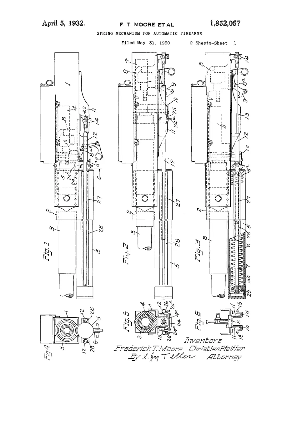
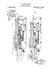
40 Fig. 1 is a side view of an automatic firearm
having a spring mechanism embodying the
invention.
Fig. 2 is a view similar to Fig. 1 but show-
ing the parts in their recoil positions.
45 Fig. 3 is a view similar to Fig. 1 but
showing the parts in the positions to which
they may be moved manually for loading
purposes.
Tig. 4 is a front view.
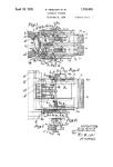
60 Fig. 5 is a fragmentary transverse sec-
1930. Serial No. 459,168.
tional view taken along the line 5—5 of
Fig.. I-
Fig. 6 is a fragmentary rear end view with
the back plate removed.
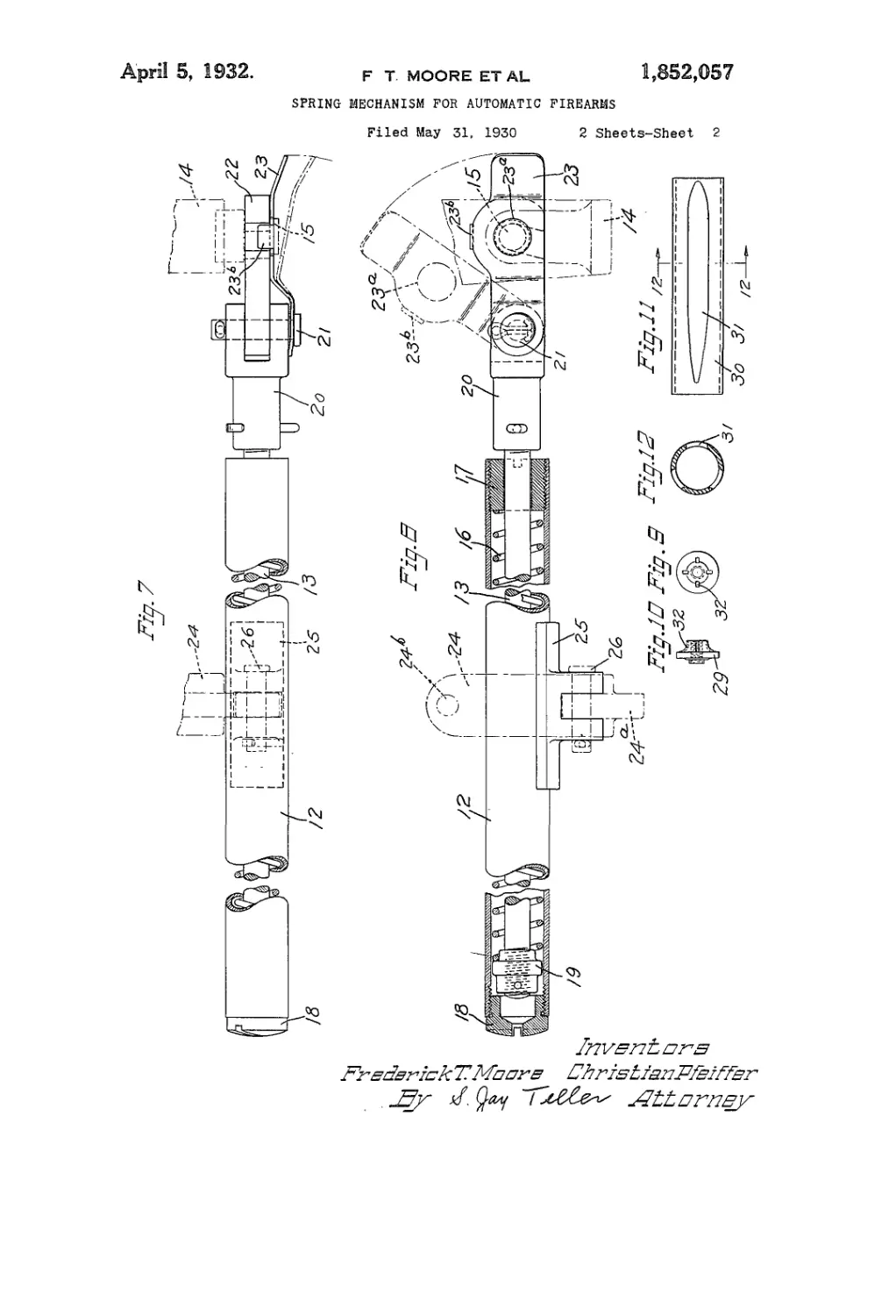
Fig. 7 is an enlarged broken plan view gg
of the left hand spring mechanism.
Fig. 8 is a side view, partly in central sec-
tion, of the spring mechanism shown in
Fig. 7.
Figs. 9 and 10 are rear and side views re- gg
spectively of the recouperator piston.
Fig. 11 is a detailed side view of the
recouperator bushing.
Fig. 12 is a sectional view taken along the
line 12—12 of Fig. 11.
Referring to the drawings, 1 represents
the main breech casing, and 2 represents the
trunnion block at the front end of the casing.
The barrel 3 is longitudinally reciprocable
with respect to the casing and trunnion block, 70
moving rearward upon recoil and being re-
turned to its normal forward position as
shown in Fig. 1 after recoil. Connected with
the barrel is a barrel extension 4, this barrel
extension being bodily movable with the bar- 7g
rel and having a downward projecting por-
tion 4a.
For controlling the movements of the bar-
rel and barrel extension, and particularly for
returning these parts to normal positions eo
after recoil, there is provided a recoupera-
tor mechanism enclosed within a casing or
tube 5 projecting forward from the main
breech casing. Located within the tube 5
is a spring 6 having a rigid abutment 6a at its 8S
rear end. The forward end of the spring
6 is connected by means of a tension rod 7
with the before-mentioned downward extend-
ing portion 4a of the barrel extension. The
spring 6 being of the compression type main- 80
tains the rod 7 under tension and thus serves
to return the barrel and barrel extension to
their normal forward positions after recoil.
Mounted at the rear of the barrel and bar-
rel extension is a reciprocable lock frame or 85
member 8 which is suitably guided in the
breech casing. This lock member 8 initially
moves rearward with the barrel and barrel
extension and is then released for further
separate rearward movement. The lock W
2
1,852,057
•member is provided with depending lugs 8a
to which is pivoted an actuating lever 9 for
controlling the vertical movements of the
breech bolt 10. The actuating lever is con-
д trolled by means of the cam mechanism in-
dicated as an entirety at 11. As the parts
move rearward during recoil the actuating
lever 9 is rotated in a counter-clockwise di-
rection carrying the breech bolt 10 down-
10 ward to its lowermost position. The lock
frame 8 then moves rearward approximately
to the position shown in Fig. 2. After the
barrel and barrel extension and the lock
member have been moved rearward to ap-
25 proximately the relative positions shown in
Fig. 2 they are then independently returned
to their forward positions, the barrel and
barrel extension being returned by the re-
couperator mechanism and the lock member
2Q being returned by the spring mechanism
which will now be described in detail. Dur-
ing the return movement of the lock mem-
ber the actuating lever 9 is moved in the op-
posite direction so as to move the breech bolt
25 10 upward to its normal operative position.
When it is desired to operate the breech
mechanism by hand for loading purposes or
otherwise, the lever 9 is operated manually
to move the breech bolt downward to the
30 position shown in Fig. 3 and then the lock
frame is drawn rearward to the position
shown in the same figure.
For moving the lock frame in the forward
direction, after it has been moved rearward
35 either automatically or manually, we pro-
vide one or more reaction springs. In ac-
cordance with the present invention we locate
the reaction spring or springs in the main at
the front of a transverse plane through the
40 rear part of the barrel. Preferably there
are two reaction springs, and preferably the
springs are enclosed in tubes 12, 12 located
at the sides of the gun and below the breech
casing 1. Connected with each spring is a
45 tension rod 13 which is connected at its rear
end with a lug 14 projecting downward from
the lock frame 8. As clearly shown in Fig.
6 each lug 14 is approximately U-shaped in
order to provide clearance for the cam mem-
50 bers 11, 11. Each lug 14 is provided with a
headed stud 15 with which the rod 13 is con-
nected in the manner to be described.
One of the tubes 12 and the enclosed spring
and associated parts are shown in detail in
55 Figs. 7 and 8. The spring is of the compres-
sion type, being represented at 16. At its
rear end the spring 16 abuts against a bush-
ing 17 which is threaded into the rear end
of the tube 12. The forward end of the tube
во is preferably closed by a cap 18. Extending
through the bushing 17 and through the
spring 16 is the before-mentioned tension
rod 13 which carries a nut 19 at its forward
end, the said spring 16 abutting at its for-
es ward end against the said nut.
Connected with the rod 13 at its rear end is
a clevis 20. Pivotally connected with the
clevis 20 by means of a headed pivot pin 21
is a latch 22 having a slot therein which en-
ables it to fit over and engage the correspond- 70
ing headed stud 15. For holding the latch 22
in engagement with the said stud 15 there is
provided a spring retainer 23 which is also
pivotally mounted on the pin 21. The re-
tainer 23 has a hole 23“ through which the 75
head of the stud 15 projects. An extension
23b on the retainer overlies the latch as clear-
ly shown in Fig. 7. With the spring retainer
in its normal position as shown by full lines in
Figs. 7 and 8 the latch is prevented from 80
moving upward. When it is desired to re-
lease the latch the spring retainer 23 is first
moved outward as shown in Fig. 7 and then
swung upward as shown in Fig. 8. This re-
leases the latch 23 so that it can be swung 85
upward to disengage the stud 15.
The rear abutments for the spring 16 are
preferably mounted or connected so as to be
bodily movable with the barrel and barrel
extension. When the rear abutments for the 90
springs are bushings at the rear ends of tubes
such as 12,12 the said tubes serve as the means
for connecting the abutments with the barrel
extension.
Preferably the tubes 12, 12, whether con- M
nected with the barrel extension or otherwise,
are readily detachable from the firearm. As
clearly shown in Fig. 5 the downward pro-
jection 4a on the barrel extension has con-
nected with it a bracket 24 having lateral 1W
projections 24a, 24a thereon. As shown the
bracket 24 is held in place by means of a
transverse pin 24b. Connected with each tube
12 by brazing or otherwise is a bifurcated
member 25 having longitudinal holes adapted 10!
to register with a hole in the corresponding
bracket extension 24a. Through these holes
there extends a pin 26 which serves to con-
nect the member 25 and the corresponding
tube 12 to the bracket 24. It will be obvious H<
that in this way the two tubes are connected
with the barrel and barrel extension so as to
move rearward with them as clearly indi-
cated in Fig. 2.
It will be obvious that, by disconnecting Ш
the rod 13 at the rear and by removing the
corresponding pin 26 in order to disconnect
the tube 12, the entire spring assembly can
be removed from the firearm for adjustment,
replacement of parts or for any other pur- 12>
pose as may be desired.
In order that the front portions of the
tubes 12 may be properly supported and
guided we preferably provide guideways 27
and 28 located at the proper positions at the 12
sides of the gun. It will be apparent that
the recouperator tube 5 serves as the means
for supporting the forward guideways 28,28.
From the foregoing description it will be
apparent that we have not only provided a 13'
1,852,087
б
10
10
20
25
50
3S
о
5
О
5
О
3
novel spring construction for moving the
lock frame, but have also provided a con-
struction wherein there are two separate
springs or sets of springs parallel with each
other and serving respectively to restore the
barrel and barrel extension and the lock
member to their forward positions after re-
coil. The recouperator spring has a rela-
tively fixed abutment at the rear whereas the
reaction spring has its rear abutment con-
nected with the barrel and barrel extension
so as to be bodily movable therewith. This
bodily movable rear abutment for the re-
action spring has certain advantages. As
will be apparent from an inspection of Fig. 2,
the lock member is in approximately its ex-
treme rearward position but the spring 16
is only partly compressed. The barrel and
barrel extension move forward prior to the
forward movement of the lock member and
it will be obvious that this forward move-
ment of the barrel and barrel extension effects
a further compression of the reaction spring
16. Therefore, when the lock member is
finally released for forward movement, addi-
tional spring tension is provided for effect-
ing such movement very quickly.
Preferably the recouperator comprises not
only the spring 6 and its connections but
also comprises additional means for absorb-
ing a part of the force of recoil. There is
provided at the front end of the spring a
piston 29 which is connected by threads or
otherwise with the forward end of the tension
element 7 and which serves as a front abut-
ment for the spring 6. This piston 29 ap-
proximately fits the interior of the recouper-
ator casing 5. The said casing is filled or
nearly filled with oil and this oil retards the
rearward movement of the piston and asso-
ciated parts thus absorbing some of the force
of recoil. To prevent oil leakage the tension
element 7 extends through a stuffing box at
the rear end of the recouperator casing. In
order that the recoil movement may be prop-
erly regulated and controlled the walls of the
recouperator casing are preferably provided
with grooves to permit a limited amount of
oil to move past the piston during the recoil
movement. These grooves may be cut di-
rectly in the main body of the casing wall
but it is preferred to provide a separate liner
or bushing 30 having slots 31, 31 cut therein.
These slots vary in cross section as shown,
preferably tapering toward the rear. The
result is that relatively free movement is per-
mitted at the beginning of recoil which
movement is gradually retarded as the piston
reaches the narrower parts of the slots 31, 31.
In order to permit the free flow of oil into
the slots 31, 31 the piston may be provided
with grooves or depressions 32,32. From the
foregoing it will be apparent that the recoil
action is controlled and gradually retarded
by the spring 6 and the piston 29 in a definite
3
predetermined manner, and that after recoil
the barrel and barrel extension are returned
forward to their normal positions by means
of the spring 6.
Some of the features of the present inven- 70
tion are disclosed in our formerly copend-
ing but now abandoned application for
spring mechanism for automatic firearms,
Serial No. 335,004, filed January 25? 1929.
As to these features the present application 75
bears a continuing relationship with the
said application.
What we claim is:
1. In an automatic firearm, the combina-
tion of a breech casing, a barrel movable 80
rearward with respect to the casing upon
recoil, a lock member mounted at the rear of
the barrel and movable rearward separately
therefrom upon recoil, two compression coil
springs parallel with the barrel at opposite 85
sides of the firearm and located in the main
at the front of a transverse plane through
the rear part of the barrel, two tension rods
connected with the respective springs at their
forward ends, and means for connecting the 00
said rods at their rear ends with the lock
member to enable the springs to return the
lock member to its forward position after
recoil.
2. In an automatic firearm, the combina- 95
tion of a breech casing, a barrel movable rear-
ward with respect to the casing upon recoil,
a lock member mounted at the rear of the
barrel and movable rearward separately
therefrom upon recoil, a compression spring 100
parallel with the barrel and located in the
main at the front of a transverse plane
through the rear part of the barrel, a tension
rod connected with the spring at its forward
end, and means for connecting the said rod 105
at its rear end with the lock member to en-
able the spring to return the lock member
to its forward position after recoil, the said
connecting means enabling the tension rod
to be readily detached from or attached to HO
the lock member.
3. In an automatic firearm, the combina-
tion of a breech casing, a barrel movable rear-
ward with respect to the casing upon recoil,
a lock member mounted at the rear of the H5
barrel and movable rearward separately
therefrom upon recoil, two separate compres-
sion coil springs parallel with each other and
located in the main at the front of a trans-
verse plane through the rear part of the bar- 120
rel, two tension rods connected with the re-
spective springs at their forward ends, and
means for connecting the said rods at their
rear ends with the barrel and lock member
respectively to enable the springs to return 125
the barrel and lock member to their for-
ward positions after recoil.
4. In an automatic firearm, the combina-
tion of a breech casing, a barrel movable rear-
ward with respect to the casing upon recoil, 130
4
1,862,057
5
10
15
20
25
80
85
40
45
50
55
60
65
a lock member mounted at the rear of the
barrel and movable rearward separately
therefrom upon recoil, a compression coil
spring parallel with the barrel and located
in the main at the front of a transverse plane
through the rear part of the barrel, an abut-
ment for the rear end of the spring connected
with the barrel and bodily movable there-
with, a tension rod connected with the spring
at its forward end, and means for connect-
ing the said rod at its rear end with the lock
member to enable the spring to return the
lock member to its forward position after
recoil.
5. An automatic firearm as set forth in
claim 4, wherein there are two similar springs
and two similar tension rods located at oppo-
site sides of the firearm.
6. In an automatic firearm, the combina-
tion of a breech casing, a barrel movable rear-
ward with respect to the casing upon recoil,
a lock member mounted at the rear of the
barrel and movable rearward separately
therefrom upon recoil, a compression coil
spring parallel with the barrel and located in
the main at the front of a transverse plane
through the rear part of the barrel, a longi-
tudinal tube for enclosing the spring, means
for connecting the tube with the barrel for
bodily movement therewith, an abutment for
the rear end of the spring connected with the
tube at the rear end thereof, a tension rod
extending through the abutment and the tube
and connected with the spring at its forward
end, and means for connecting the said rod
at its rear end with the lock member to en-
able the spring to return the lock member
to its forward position after recoil.
7. In an automatic firearm, the combination
of a breech casing, a barrel movable rearward
with respect to the casing upon recoil, a lock
member mounted at the rear of the barrel and
movable rearward separately therefrom upon
recoil, and a reaction spring assembly detach-
ably connectible with the firearm, the said
assembly comprising a longitudinal tube
parallel with the barrel, a compression coil
spring within the tube and located in the
main at the front of a transverse plane
through the rear part of the barrel, an abut-
ment for the rear end of the spring connected
with the tube at the rear end thereof, and a
tension rod extending through the abutment
and the tube and connected with the spring
at its forward end, the said tension rod being
detachably connectible at its rear end with
the lock member to enable the spring to re-
turn the lock member to its forward position
after recoil.
8. In an automatic firearm, the combination
of a breech casing, a barrel movable rearward
with respect to the casing upon recoil, a lock
member mounted at the rear of the barrel and
movable rearward separately therefrom upon
recoil, two separate compression coil springs
parallel with each other and located in the
main at the front of a transverse plane
through the rear part of the barrel, means
connected with the breech casing forming a
rear abutment for one spring, and means con- 70
nected with the barrel forming a rear abut-
ment for the other spring, and two tension
rods connected with the respective springs
at their forward ends, the rod connected with
the first spring being connected at its rear IS
end with the barrel and the rod connected with
the second spring being connected at its rear
end with the lock member.
9. In an automatic firearm, the combination
of a breech casing, a barrel movable rear- 80
ward with respect to the casing upon
recoil, a recouperator mechanism including
an enclosing tube projecting forward from
the casing, a lock member mounted at the rear
of the barrel and movable rearward separate- 85
ly therefrom upon recoil, a compression coil
spring parallel with the barrel and located in
the main at the front of a transverse plane
through the rear part of the barrel, a tube
within which the spring is enclosed, the said 00
tube being connected with the barrel for
movement therewith, an abutment for the
spring at the rear end of the tube, means on
the recouperator tube for guiding the said
spring tube for longitudinal movement, a 05
tension rod extending within the spring tube
and connected with the spring at its forward
end, and means for connecting the said rod
at its rear end with the lock member to enable
the spring to return the lock member to its 10C
forward position after recoil.
In testimony whereof we have hereunto set
our hands this 29th day of May, 1930.
FREDERICK T. MOORE.
CHRISTIAN PFEIFFER.
lie
11(
12(
12J
IM