/
Tags: weapons military affairs patent
Year: 1947
Text
Aug. 12, 1947,
2,425,684
G. W. PATCHETT
BREECH BOLT FOR FIREARMS
2 Sheets-Sheet 1
Filed Feb. 7. 1944
Attorneys
Aug. 12, 1947.
G. W. PATCHETT
BREECH BOLT FOR FIREARMS
Filed Feb. 7, 1944
2,425,684
2 Sheets-Sheet 2
A Homey s
Patented Aug. 12, 1947
2,425,684
UNITED STATES PATENT OFFICE
2,425,684
BREECH BOLT FOR FIREARMS
George William Patchett, Chigwell, England
Application February 7, 1944, Serial No. 521,402
In Great Britain October 25, 1943
4 Claims.
1
This invention relates to improvements in con-
nection with firearms and has more particular
reference to breech blocks or bolts used in such
arms, and finds particular use in automatic
weapons, that fill a military necessity between
the rifle and the pistol. In such weapons the
breech block or bolt, hereinafter referred to as
the bolt, with its firing pin explodes the cartridge,
provides the abutment for reaction of the ex-
ploded charge and in turn and under recoil moves
rearward in the bolt race against resilient pres-
sure to repeat or be latent to repeat the same
operation again. It follows that unrestricted
movement in its race is essential for operation,
and, whilst such movement may be prevented in
design by a sear under manual or selective con-
trol, adventitious material such as sand, mud or
dirt can also provide a total impediment to move-
ment, particularly when the arm is used in desert
warfare or when the weapon has been in contact
with mud, dust, sea water, or exposed to tropical
rain or mist. The entry of adventitious material
to the bolt race is facilitated by direct openings
or passages thereto. Thus, the axial slot of the
cocking device, the aperture of the ejection orifice
and the magazine mouthpiece itself all communi-
cate with the bolt race. Additionally, the trigger
seldom has a dust-tight arc of movement, and
sand in a sand storm will penetrate at any open-
ing however minute, and all such matters tend to
detract from the readiness or reliability of the
weapon to operate at instant call.
The object of the present invention is to over-
come these difficulties and to render the bolt self-
clearing in its backward and forward movement
and to provide a positive tendency to eject any
adventitious lodgment.
The invention consists in the combination with
a bolt as employed in firearms of the types set
forth of raised bearing surfaces or lands formed
upon the said bolt and adapted to engage upon
their outer surfaces with the inner surface of said
bolt race, said lands having pointed or like ex-
tremities formed to clear a gritless surface for
subsequent continuous or other movement.
The said lands are arranged helically on the
periphery of the bolt, and are provided with
pointed or plough-shaped extremities, fore and
aft. The number of said bearing surfaces or their
width may vary, and to prevent undue wear, and
for other reasons more fully set out hereafter, the
lands are formed as a helix upon the bolt’s longi-
tudinal circumference, or right or left handed
helical lands may be used so that any tendency
for the bolt to have angular movement as with a
(CI. 42—16)
2
helical land of unidirectional pitch, may be
avoided.
Since the movement of any bolt with helical
lands will expose the land edges to the axial cock-
5 ing lever slot or the like, impurities will tend to
be ejected. In less positive degree foreign mat-
ter displaced by reciprocation of a bolt with the
sharp nosed axial bolt lands is also ejected
through one or other, or all, of the several open-
10 ings or passages in the bolt race.
In order that the invention may be more fully
and particularly described, reference is made to
the accompanying drawings wherein the inven-
tion is illustrated as applied to a known type of
15 automatic firearm, and wherein—
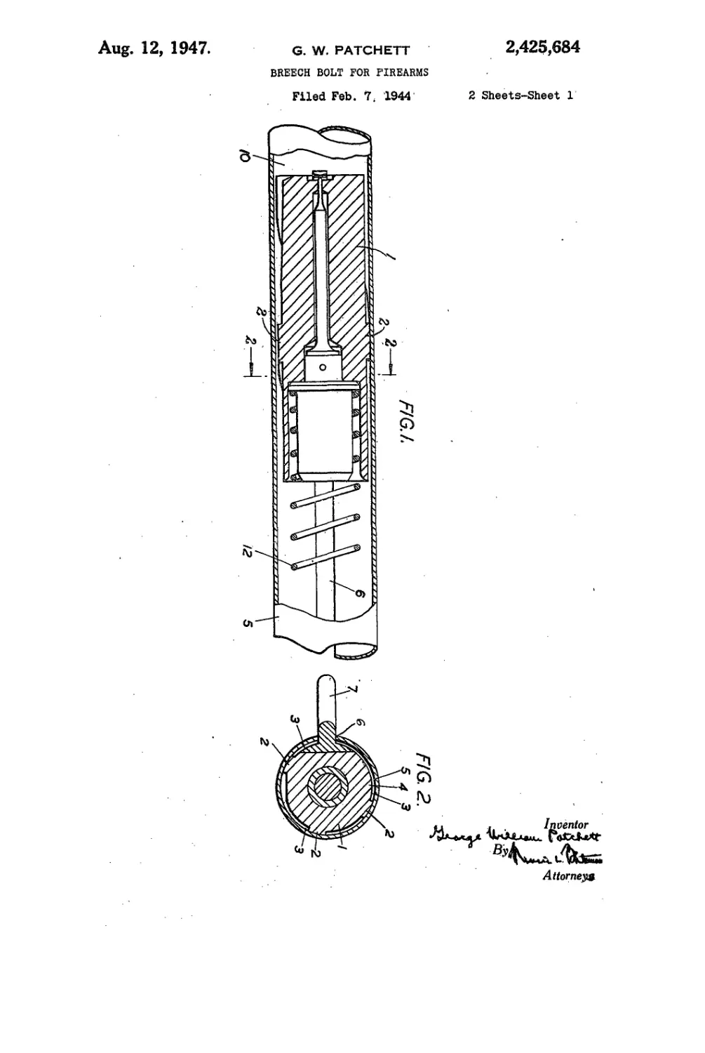
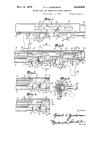
Fig. 1 is a longitudinal section of a bolt and a
bolt race, showing one form of the invention.
Fig. 2 is a section on the line 2—2 in Fig. 1.
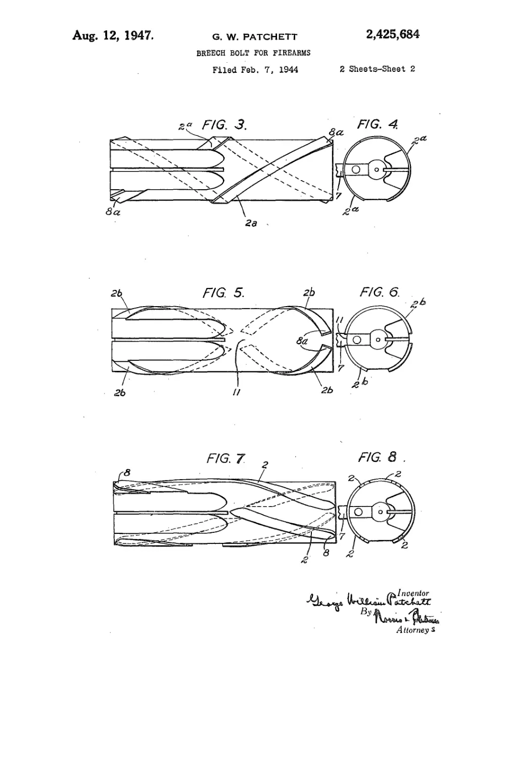
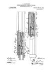
Fig. 3 is an elevation of a bolt with two-start
20 helical lands.
Fig, 4 is an end view of Fig. 3.
Fig. 5 is an elevation of a bolt with two-start
reversed helical land.
Fig. 6 is an end view of Fig. 5.
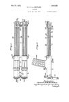
25 Fig. 7 is an elevation of a bolt having four lands
arranged helically so that their ends are in line
or overlap the opposite end of the adjoining land.
Fig. 8 is an end view of Fig. 7.
In the drawings the bolt i may be of any re-
30 quired pattern; it may be pertinent to rifles or to
automatic arms. The particular form shown is
suitable for automatic weapons and is given by
way of illustration only.
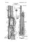
Referring to Figs. 1, 2, 7 and 8, the raised bear-
35 ing surfaces or lands 2 are formed or applied
helically to the axis of the bolt i, and leave spaces
3 intermediate between the bolt body perimeter
4 and the bolt race or casing 5 (see Figs. 1 and 2).
The spaces 3 are made sufficiently large for rm-
40 wanted intruding matter to have free movement,
with opportunity, under disturbance, of escape
through the slot 6 (see Fig. 1) of cocking lever 7
fixed to the bolt (see Fig. 2) or other opening
communicating with the bolt race. The extremi-
45 ties 8 of the said lands or raised portions may be
curved from both sides as shown at 8 in Fig. 7, or
be of coned appearance, or chisel shaped as
shown at 82 in Figs. 3 and 5, to provide a con-
tour for shearing and clearing, for instance, dried
50 mud from the bolt race 10.
Figs. 3 to 8 inclusive show the raised surfaces
or lands helically cut on the bolt periphery. This
arrangement provides for cylindrical wear of the
bolt race, and equally assists in quickly convey-
55 ing unwanted matter to the longitudinal opening
2,425,684
3
Б. If helical lands of unidirectional pitch are em-
ployed as shown at 2 in Figs. 7 and 8 or at 22 in
Figs. 3 and 4, the compression spring 12 may be
wound to resist any tendency of the bolt to turn
about its axis or press the cocking lever 7 upon the
upper or lower edge of the slot 6. Should in some
arms this prove difficult, then two-start right and
left handed helical lands 2b (Fig. 5) may be
formed upon the bolt periphery, gaps I i, (Fig. 5)
being cut at the crossings for matter otherwise
wedged in to escape.
In operation and whether the bolt is cocked
or not, movement of said bolt by recoil, spring
or hand manipulation, clears by a shearing action
the bolt race face 10 of adherent or loose ad-
ventitious matter, which, being disturbed, is then
free to escape from the opening whereby it en-
tered or any other opening available.
It is found that weapons not constructed in
accordance with this invention, and which have
been immersed in mud, when warm, will fail, since
the heat of the weapon solidifies the earth matter
on the surface of the bolt race. By means of the
prevent invention, however, a clean path is cut
by the initial longitudinal movement of the bolt,
rendering subsequent movement a certainty.
I claim:
1. A firearm comprising, in combination, a bolt
race having a longitudinally continuous interior
surface and a longitudinal slot in a side and open
to the exterior thereof, and a breech bolt recipro-
cable longitudinally in said race and having a
cocking handle connected thereto and extending
through said slot to the exterior of the race, the
breech bolt having lands extending helically on
and. projecting from its periphery and providing
5
10
15
20
25
30
35
4
peripheral bearing surfaces which slidably engage
the interior surface of the bolt race to support the
breech bolt therein and clear foreign matter from
said surface, said lands providing a space between
them to receive foreign matter cleared from said
interior surface and communicating with said
slot in the bolt race for conveyance of such foreign
matter thereto.
2. A firearm as defined in claim 1, wherein said
helical lands have unidirectional pitch along the
periphery of said breech bolt, and said cocking
handle engaging in said slot in said bolt race
prevents rotation of said bolt in said race.
3. A firearm as defined in claim 1, wherein said
helical lands have respectively relatively reverse
pitches along the periphery of said breech bolt,
and have ends which are spaced apart to leave
openings between them.
4. A firearm as defined in claim 1, wherein said
helical lands are arranged in a pair and are re-
spectively at diametrically opposite sides of the
periphery of said breech bolt.
GEORGE WILLIAM PATCHETT.
REFERENCES CITED
The following references are of record in the
file of this patent:
UNITED STATES PATENTS
Number Name Date
1,083,384 Browning_____________Jan. 6, 1914
1,586,048 Schmeisser___________May 25, 1926
2,049,776 Hyde-------------------Aug. 4, 1936
2,096,028 Burton et al._________Oct. 19, 1937
1,291,689 Sheppard______________Jan. 14, 1919
1,470,029 Pedersen_______________Oct. 9, 1923