/
Tags: weapons military affairs patent
Year: 1907

Text
No. 854,771.
PATENTED MAY 28, 1907.
C. A. STRASBURG.
AUTOMATIC FIREARM.
APPLICATION FILED SEPT. 27, 1908.
.1 TTORNEYS
No. 854,771.
PATENTED MAY 28, 1907.
C, A. STRASBURG.
AUTOMATIC FIREARM.
APPLICATION FILED SEPT, 27, 1908.
2 SHEETS-SHEET 2
UNITED STATES PATENT OFFICE
CHARLES ALVIN STRASBURG, OF CRIDERSVILLE, OHIO.
AUTOMATIC FIREARM.
Wo. 854,771. Specification of Letters Patent. Patented May 28,1907.
Application filed September 27,1906. Serial No. 336,470.
5
ю
i5
20
-=5
30
35
40
45
5°
5'5
To all whom it may concern.-
Be it known that I, Charles Alvin Stras-
burg, a citizen of the United States, residing
at Cridersville, in the county of Auglaize and
State of Ohio, have invented a new and use-
ful Automatic Firearm, of which the follow-
ing is a specification.
This invention relates to automatic fire-
arms of that type in which a spring is adapt-
ed to be placed under tension by the recoil of
the breech block and subsequently to exert
its force for closing the breech block after a
new cartridge has been supplied to the
breech.
The objects of the invention are to im-
prove and simplify the construction of such
devices; furthermore, to increase their effi-
ciency in operation and to decrease the ex-
pense attending,their manufacture.
With the foregoing and other objects in
view, which will appear as the description
proceeds, the invention resides in the combi-
nation and arrangement of parts and in the
details of construction hereinafter described
and claimed, it being understood that
changes in the precise embodiment of inven-
tion herein disclosed can be made within the
scope of the following claims without depart-
ing from the spirit of the invention or sacri-
ficing any of its advantages.
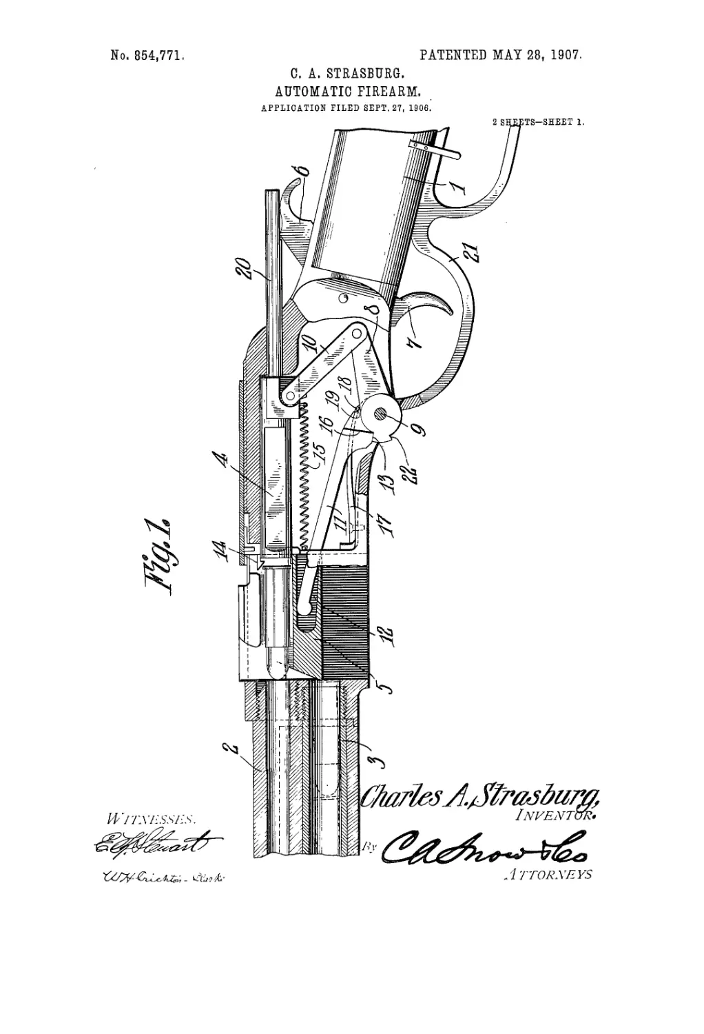
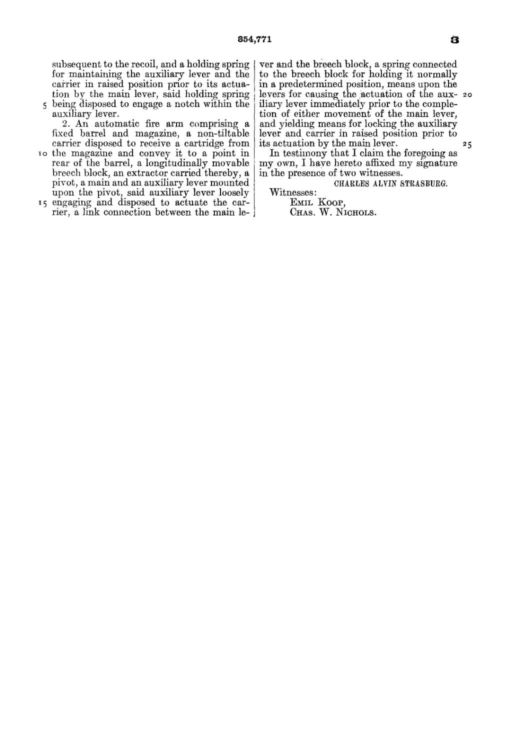
, In the accompanying drawmgs forming
part of this specification:—Figure 1 is a ver-
tical section, partly in side elevation, of a
firearm equipped with the improvements of
the present invention, the action being open;
and Fig. 2 is a view similar to Fig. 1, showing
the action closed.
Like reference numerals indicate corre-
sponding parts in the different figures of the
drawings.
The reference numeral 1 indicates a por-
tion of the stock of a firearm; 2, the barrel;
3, the magazine, which is in the nature of a
second barrel and is adapted to contain a
number of cartridges in a well-known manner
which are thrown rearwardly by means of a
spring; 4-, the breech block, which is mov-
able toward and away from the breech of the
barrel 2; and 5, the earner, which is adapted
to receive a cartridge from the magazine 3
and to elevate the same until it is m Ime with
the barrel 2, at the same time throwing out the
empty cartridge which has been withdrawn
from the barrel 2 upon the rearward move-
ment of the breech block. The parts thus
far described may be of any suitable form )
and construction as in the well-known type
of Winchester repeating rifle. The hammer
6, together with the trigger 7 for controlling
the same, may also be of any suitable form 6o
and construction which it is not necessary
herein to illustrate in detail.
It is proposed, in carrying out the present
invention, that the breech block 4 snail be
permitted to be thrown rearwardly by the re- 6 5
coil of the cartridge in the barrel 2 when dis-
charged. For the purpose of utilizing this
recoil movement of the breech block 4 to ex-
pand a suitable spring which will restore the
breech block to its forward position after the 70
carrier 5 has supplied a new cartridge to the
barrel 2, it is preferred to employ the follow-
ing mechanism :
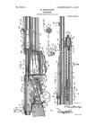
The reference numeral 8 indicates a main
lever which is pivotally mounted at 9 in any 75
suitable manner. The main lever 8 is con-
nected by means such as the link 10 with the
breech block 4, whereby; the recoil movement
of the breech block will be communicated
through the link 10 to the main lever 8 to 80
rock the same in a rearward direction. For
the purpose of utilizing the rearward rock-
ing movement of the main lever 8 to raise
the carrier 5 into position to supply a new
cartridge to the barrel 2, an auxiliary lever 85
11 is fmcrumed upon the pivot point 9 of the
main lever 8. The free end of the auxiliary
lever 11 projects loosely into a socket 12
formed in the rear lower end of the carrier 5.
The main lever 8, at its lower end, is formed 90
with a shoulder 13 which, when said main
lever has been thrown almost to the limit of
its rearward movement by the recoil of the
breech block, is adapted to engage the under
surface of the auxiliary lever 11, as indicated 95
in Fig. 2, so as to throw the free end of said
lever upward in such manner as to raise the
carrier 5 from the position illustrated in Fig.
2 to that illustrated in Fig. 1. It will be un-
derstood that as the breech block 4 recoils, 10c
an extractor 14, carried by said breech block,
serves to draw the empty cartridge shell rear-
wardly until it is disposed above the carrier
5, whereby said carrier in its upward move-
ment strikes the under surface of the empty т о;
cartridge and throws it out of the gun, at the
same time bringing up a new cartridge which
will be pushed into the barrel 2 by the for-
ward movement of the breech block 4.
Having thus set forth the manner in which 11
the recon consequent upon the explosion of.
a cartridge is utilized tlirough the breech
884,771
block 4, link 10, main lever 8, and auxiliary I
lever 11 to raise the carrier 5 so as simultane-
ously to eject the empty shell and to dispose
a fresh cartridge directly in line with thebar-
5 rel 2, the means for automatically throwing
the breech block forward so . as to push the
fresh cartridge into the barrel 2 and for lower-
ing the carrier 5 into position to receive from
the magazine 3 a cartridge for the next dis-
io charge, will now be described. Suitablycon-
nected at its rear end with the breech block
4 is a coil spring 15 which is' secured at its
forward end in any convenient manner to a
stationary part of the firearm. If desired,
15 two coil sprmgs 15 can be employed, one be-
ing mounted on each side of the breech block.
When the breech block 4 is thrown rear-
wardly by the recoil so as to rock the main
lever 8 and raise the carrier 5 as described,
го the coil spring 15 is placed under tension, and
when the rearward movement of the breech
block 4 has been arrested, the coil spring 15
exerts its force to move the breech block 4 in
a forward direction so as to force into the
я 5 barrel 2 the fresh cartridge contained in the
carrier 5. When the breech"block 4 has al-
most reached the limit of its forward move-
ment, the main lever 8 moves into contact
with a shoulder 16 formed on the auxiliary
30 lever 11 and depresses the forward end of
said auxiliary lever so as to lower the carrier
5 into position to receive another cartridge
from the magazine 3.
For the purpose of holding the carrier 5
35 steadily in its raised position during the for-
ward movement of the breech block, or, in
other words, to prevent the carrier 5 from
descending by gravity into its lowermost po-
sition during the time that the breech block
40 4 is being moved forward by the (foil spring
15 and the shoulder 13 of the main lever 8 is
consequently out of engagement with the
auxiliary lever 11, a flat spring 17 is secured
in the gun casing in such manner that its en-
45 larged free end 18 will snap into a notch 19
in the auxiliary lever 11 when said auxiliary
lever is in raised position. The engagement
of the spring 17 with the notch 19 will hold
the carrier 5 in its elevated position until the
50 main lever 8 engages the shoulder 16 under
the action of the spring 15 with sufficient
force to throw the auxiliary lever 11 and the
carrier 5 downward into lowermost position,
the spring 17 becoming disengaged from the
55 notch 19 as will be understood.
For the purpose of raising the hammer 6
to cock the firearm upon each recoil move-
ment of the breech block 4, a firing pin 20 is
rearwardly extended for a sufficient distance
60 to engage the hammer 6 and raise the same
into cocked position during the recoil of the
breech block.
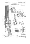
The cartridges may be supplied to the
magazine 3 in the manner usual in Winches-
65 ter rifles. In order to avoid any difficulty in
working the cartridge into the barrel 2 when
said barrel is empty, it is preferred con-
stantly to maintain a loaded cartridge in the
barrel 2. Fot example, if the magazine 3 be
intended to contain ten cartridges, only nine 70
of said cartridges should be fired before sup-
plying more cartridges to the magazine. In
this way the discharge.of the tenth cartridge
which has been automatically fed to the bar-
rel 2 will feed the first cartridge of the new 75
supply of cartridges to the barrel.
In order that the first cartridge from the
magazine may be worked by hand into the
barrel 2 in the event that it be not desired to
maintain a cartridge constantly in said bar- 80
rel, a hand lever 21 may be loosely fulcrumed .
upon the pivot point 9 and may be held nor-
mally against the lower surface of the stock
1 in any suitable manner as by means of a
catch. The hand lever 21, when pushed 85
downward, is adapted to engage a shoulder
22 on the main lever 8 so as to throw said
hand lever rearwardly, thus withdrawing
the breech block 4 and raising the carrier 5.
When the hand lever 21 is again thrown rear- 90
wardly and upwardly against the stock, the
coil spring 15, which has been placed under
tension by the forward and downward move-
ment of the hand lever 21, will restore the
breech block 4 and the carrier 5 to their nor- 95
mal positions. It will be obvious that by
reason of the fact that the hand lever 21 is
loosely pivoted upon the pivot pin 9 and is
not rigidly connected with the main lever 8,
the operation of the automatic mechanism 100
will not be interfered with in any way by the
presence of said hand lever.
The improved firearm of the present in-
vention is strong, simple, durable and inex-
pensive in construction, as well as thoroughly 105
efficient in operation.
What is claimed is:
1. An automatic fire arm having a stock, a
barrel fixed in relation thereto, a magazine
disposed longitudinally of and adjacent the no
barrel, a non-tiltable carrier movable across
the end of and designed to receive a car-
tridge from the magazine, a longitudinally
movable recoil operated breech block dis-
posed in alinement with the barrel, an ex- 115
tractor extending from and movable with
said block and disposed to draw a shell from
the barrel during the recoil, a pivot, a main
lever and an auxiliary lever mounted upon
said pivot, said auxiliary lever projecting J20
into and loosely engaging the carrier and
having shoulders adjacent its pivot, said
main lever being disposed to contact with one
of the shoulders to lower the auxiliary lever
and having a shoulder disposed to bear 125
against the other shoulder of the auxiliary
lever to raise said lever, a link connection be-
tween the main lever and the breech block, a
spring connected to the breech block and
disposed to return it to its initial position 13c
854,771 3
subsequent to the recoil, and a holding spring
for maintaining the auxiliary lever and the
carrier in raised position prior to its actua-
tion by the main lever, said holding spring
5 being disposed to engage a notch within the
auxiliary lever.
2. An automatic fire arm comprising a
fixed barrel and magazine, a non-tiltable
carrier disposed to receive a cartridge from
io the magazine and convey it to a point in
rear of the barrel, a longitudinally movable
breech block, an extractor carried thereby, a
pivot, a main and an auxiliary lever mounted
upon the pivot, said auxiliary lever loosely
15 engaging and disposed to actuate the car-
rier, a link connection between the main le- ]
ver and the breech block, a spring connected
to the breech block for holding it normally
in a predetermined position, means upon the
levers for causing the actuation of the aux- 20
iliary lever immediately prior to the comple-
tion of either movement of the main lever,
and yielding means for locking the auxiliary
lever and carrier in raised position prior to
its actuation by the main lever. 25
In testimony that I claim the foregoing as
my own, I have hereto affixed my signature
in the presence of two witnesses.
CHARLES ALVIN STRASBURG.
Witnesses:
Emil Koop,
Chas. W. Nichols.