


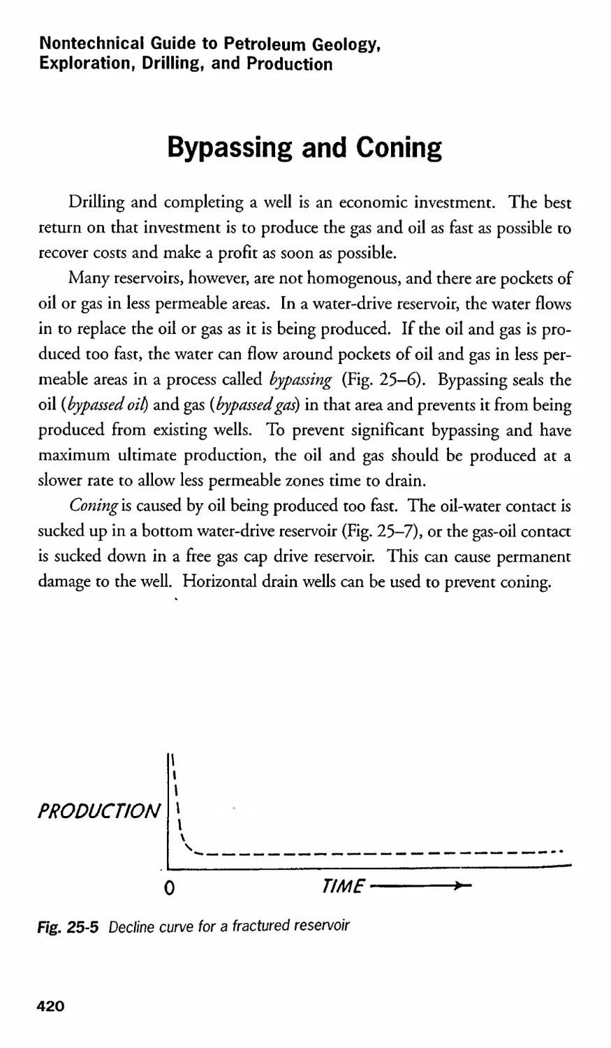


Text
k\
I
introduction
Both crude oil and natural gas are mixtures of molecules formed by car-
carbon and hydrogen atoms. There are many different types of crude oils and
natural gases, some more valuable than others. Heavy crude oils are very
thick and viscous and are difficult or impossible to produce, whereas light
crude oils are very fluid and relatively easy to produce. Less valuable are sour
crude oils that contain sulfur and sour natural gasses that contain hydrogen
sulfide. Some natural gases burn with more heat than others, contain natu-
natural gas liquids and gasoline, and are more valuable.
In order to have a commercial deposit of gas or oil, three geological con-
conditions must have been met. First, there must be a source rock in the sub-
subsurface of that area that generated the gas or oil at some time in the geolog-
geological past. Second, there must be a separate, subsurface reservoir rock to hold
the gas or oil. Third, there must be a trap on the reservoir rock to concen-
concentrate the gas or oil into commercial quantities.
The uppermost crust of the earth in oil- and gas-producing areas is com-
composed of sedimentary rock layers. Sedimentary rocks are the source and
reservoir rocks for gas and oil. These rocks are called sedimentary rocks
because they are composed of sediments. Sediments are 1) particles such as
sand grains that were formed by the breakdown of pre-existing rocks and
transported, 2) seashells, or 3) salt that precipitated from of water. The sed-
sedimentary rocks that make up the earths crust are millions and sometimes bil-
xxxiii
Nontechnical Guide to Petroleum Geology,
Exploration, Drilling, and Production
lions of years old. During the vast expanse of geological time, sea level has
not been constant. Many times in the past, the seas have risen to cover the
land and then fallen to expose the land. During these times, sediments were
deposited. These sediments are relatively simple materials such as sands
deposited along beaches, mud on the sea bottom, and beds of seashells.
These ancient sediments, piled layer upon layer, form the sedimentary rocks
that are drilled to find and produce oil and gas.
The source of gas and oil is the organic matter that is buried and pre-
preserved in the ancient sedimentary rocks. These rocks contain not only inor-
inorganic particles such as sand grains and mud, but also dead plant and animal
material. The most common organic-rich sedimentary rock (the source rock
for most of the gas and oil) is black shale. It was deposited as organic-rich
mud on an ancient ocean bottom. In the subsurface, temperature is the
most important factor in turning organic matter into oil. As the source rock
is covered with more sediments and buried deeper in the earth, it becomes
hotter and hotter. The minimum temperature for the formation of oil,
about 150°F F5°C), occurs at a depth of about 7000 ft B130 m) below the
surface (Fig. 1-1). Oil is generated from there and down to about 300°F
A50°C) at about 18,000 ft E500 m). The reactions that change organic
matter into oil are complex and take a long time. If the source rock is buried
deeper where the temperatures are above 300°F A50°C), the remaining
organic matter will generate natural gas.
Gas and oil are relatively light in density compared to water that also
occurs in the subsurface sedimentary rocks. After oil and gas have been gen-
generated, they rise due to buoyancy through fractures in the subsurface rocks.
The rising gas and oil can intersect a layer of reservoir rock. A reservoir rock
is a sedimentary rock that contains billions of tiny spaces called pores. A
common sedimentary rock is sandstone composed of sand grains similar to
the sand grains on a beach or in a river channel. Sand grains are like spheres,
and there is no way the grains will fit together perfectly. There are pore
spaces between the sand grains on a beach and in a sandstone rock.
Limestone, another common sedimentary rock, is deposited as shell beds or
reefs, and there are pores between the shells and corals. The gas and oil flow
into the pores of the reservoir rock layer.
XXXIV
Introduction
300T
15O'C
7,000 ft.
2,100 m.
Source Rock
¦18,000 ft.
GAS 5,500 m.
Water
Fig. M Generation and migration of gas and oil
Any fluid (water, gas, or oil), either on the surface or in the subsurface,
will always flow along the path of least resistance, the easiest route. In the
subsurface, the path of least resistance is along a reservoir rock layer. This is
because most of the pore spaces interconnect, and the fluid can flow from
pore to pore to pore up the angle of the rock layer toward the surface. The
ease in which the fluid can flow through the rock is called permeability, and
the movement of the gas and oil up the angle of the reservoir rock toward
the surface is called migration. Because of migration, the gas and oil can end
up a considerable distance, both vertically and horizontally, from where it
was originally formed. (Fig. 1-1)
As the gas and oil migrates up along the reservoir rock, it can encounter a
trap. A trap is a high point in the reservoir rock where the gas or oil is stopped
and concentrated. Because the pores in the reservoir rock are filled with water,
the gas and oil will flow to the highest part of the reservoir rock. One type of
trap is a natural arch in the reservoir rock (Fig. 1-2) called a dome or anticline.
In the trap, the fluids separate according to their density. The gas is
the lightest and goes to the top of the trap to form the free gas cap. The
Nontechnical Guide to Petroleum Geology,
Exploration, Drilling, and Production
oil goes to the middle to form the oil reservoir. The salt water, the heav-
heaviest, goes to the bottom.
To complete the trap, a caprock must overlie the reservoir rock. The
caprock is a seal and doesn't allow fluids to flow through it. Without a caprock,
the oil and gas would leak up to the surface of the ground. Two common sed-
sedimentary rocks that can be seals are shale and salt.
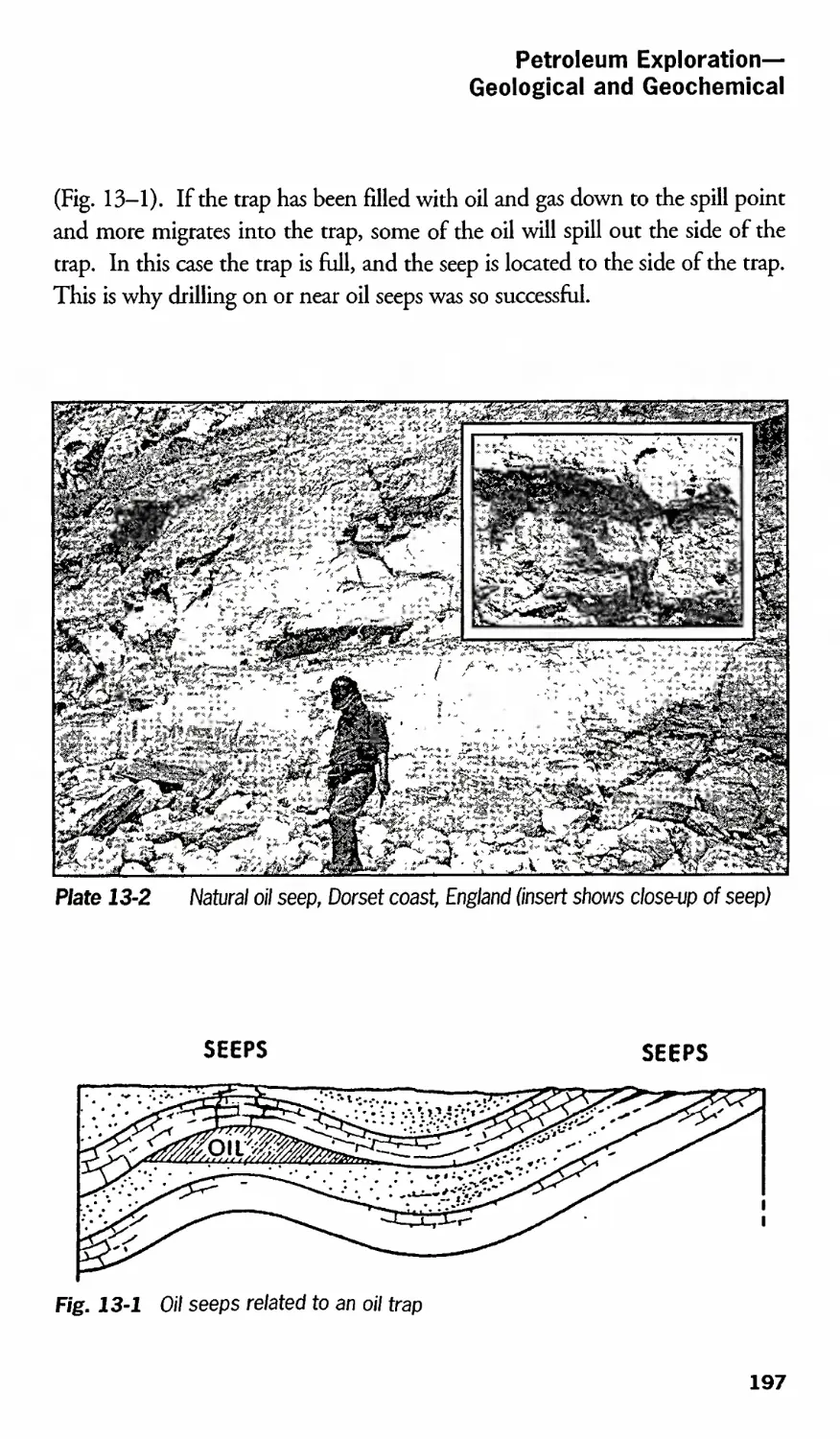
How are subsurface deposits of gas and oil located? During the early
days of drilling, it was thought that there were large, flowing underground
rivers and subsurface pools of oil. Early drillers, however, had some success
because many subsurface traps are leaky. There are small fractures in the
caprock, and some of the oil and gas leaks up and seeps onto the surface.
The early drillers located their wells on the seeps.
By the early 1900s, the principles of subsurface gas and oil deposits were
becoming better known. Oil companies realized that by mapping how the
sedimentary rock layers crop out on the surface of the ground, the rock lay-
layers could be projected into the subsurface, and traps could be located (Fig.
1-3). Geologists were hired to map rock outcrops.
Later, seismic mediod was developed to detect hidden traps in the subsur-
subsurface. Seismic exploration uses a source and detector (Fig. 1-4). The source,
such as dynamite, is located on or near the surface and gives off an impulse of
Oil
Reservoir
Free
Gas Cap
Cap Rock
Water
Reservoir
Rock
Fig. 1-2 Petroleum trap
xxxvi
Introduction
sound energy into the subsurface. The sound energy bounces off sedimentary
rock layers and returns to the surface to be recorded by the detector, Sound
echoes are used to make an image of the subsurface rock layers.
Fig. /-3 Rock outcrops
SOURCE
DETECTOR
Fig. 1-4 The seismic method
xxxvii
Nontechnical Guide to Petroleum Geology,
Exploration, Drilling, and Production
The only way to know for sure if a trap contains commercial amounts
of gas and oil is to drill a well. A well drilled to find a new gas or oil field
is called a wildcat well. Most wildcat wells are dry holes with no com-
commercial amounts of gas or oil. The well is drilled using a rotary drilling
rig (Fig. 1-5). There can be thousands of feet of drillpipe with a bit on
the end, called the drillstring, suspended in the well. By rotating the
drillstring from the surface, the bit on the bottom is turned and cuts the
derrick
drillpipe
drillstring
bit
Fig. 1-5 Rotary drilling rig
XXXVIII
Introduction
hole. As the well is drilled deeper, more drillpipe is added. The power is
supplied by diesel engines. A steel tower above the well, the derrick, is
used to raise and lower equipment. The well can be drilled either almost
straight down as a straight hole or out at an angle as a deviated well.
An important system on the rig is the circulating mud system. The
drilling mud is pumped down the inside of the drillpipe where it jets out
from nozzles in the bit and returns up the outside of the drillpipe to the sur-
surface (Fig. 1-6). The drilling mud removes the rock chips made by the bit,
called well cuttings, from the bottom of the hole. This prevents them from
clogging up the bottom of the well. The well is always kept filled to the top
with heavy drilling mud as it is being drilled. This prevents any fluids such
as water, gas, and oil from flowing out of the subsurface rocks and into the
well. If gas and oil flowed up onto the floor of the drilling rig, it could catch
fire. Even if only water flowed out of the surrounding rock into the well, the
sides of the well could cave in and the well could be lost. The drilling mud
keeps the fluids back in the surrounding rocks. Offshore wells are drilled the
same as on land. For offshore wildcat wells, the rig is mounted on a barge,
floating platform, or ship that can be moved. Once an offshore field is locat-
located, a production platform is then installed to drill the rest of the wells and
produce the gas and oil.
Because the drilling mud keeps gas and oil back in the rocks, a sub-
subsurface deposit of gas or oil can be drilled without any indication of the
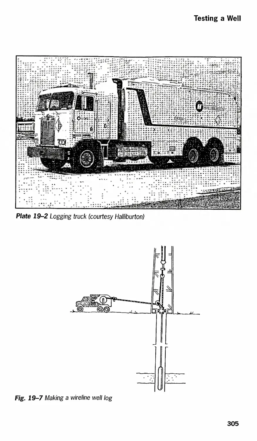
gas or oil. To evaluate the well, a service company runs a wireline well
log. A logging truck is driven out to the well. A long cylinder contain-
containing instruments called a sonde is unloaded from the truck and lowered
down the well on a wireline (Fig. 1-7). As the sonde is brought back up
the well, the instruments remotely sense the electrical, sonic, and radioac-
radioactive properties of the surrounding rocks and their fluids. These measure-
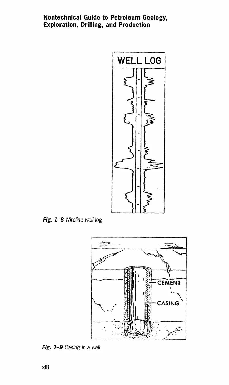
measurements are recorded on a long strip of paper called a well log (Fig. 1-8). It
is used to determine the composition of each rock layer, whether the rock
layer has pores, and what fluid (water, gas, or oil) is in the pores.
Depending on the test results, the well can be plugged and abandoned
as a dry hole or completed as a producer. Setting pipe is synonymous with
completing a well. To set pipe, a long length of large diameter steel pipe
(casing) is lowered down the hole. Wet cement is then pumped between the
xxxix
Nontechnical Guide to Petroleum Geology,
Exploration, Drilling, and Production
1
0
i
V
A
o
r>
1 .
i
\
1
%
1
I
1
iL/i
i 'ii
i iii
t
w
o
f
Fig. 1-6 Well-cutting removal by circulating drilling mud
casing and the well walls and allowed to set (Fig. 1-9). This stabilizes the
hole. In most wells, the casing is done in stages called a casing program dur-
during which the well is drilled, cased, drilled deeper, cased again, drilled deep-
deeper, and cased again.
In order for the gas or oil to flow into the well, the casing is shot with
explosives to form holes called perforations (Fig* I—10)* A long length of
narrow diameter steel pipe (tubing) is then suspended down the center
of the well. The produced fluids (water, gas, and oil) are brought up the
tubing string to the surface to prevent them from touching and corrod-
corroding the casing that is harder to repair. The tubing is relatively easy to
repair during a workover.
In a gas well, gas flows to the surface by itself. There are some oil wells,
early in the development of the oilfield, in which the oil has enough pressure
to flow up to the surface. Gas wells and flowing oil wells are completed with
a series of fittings and valves called a Christmas tree on the surface to con-
control the flow (Fig. I—11).
xl
Introduction
logging
truck
well
wireline —«*
sonde
w_
—•¦«.'..•¦•» ¦¦•-: ML . . ._;—i.
I
F/g. 1-7 Well logging
Most oil wells, however, do not have enough pressure for the oil to flow
to the surface and artificial lift must be used. A common artificial lift sys-
system is a sucker-rod pump (Fig. 1-11). A downhole pump on the bottom of
the tubing string is driven by a beam-pumping unit on the surface. The
pump lifts the oil up the tubing to the surface.
On the surface, gas is prepared for delivery to a pipeline by gas-condi-
gas-conditioning equipment that removes impurities such as water vapor and corro-
corrosive gasses. Valuable natural gas liquids are removed from the gas in a natu-
xli
Nontechnical Guide to Petroleum Geology,
Exploration, Drilling, and Production
WELL LOG
Fig. 1-8 Wireline well log
CEMENT
\
CASING
Fig. 1-9 Casing in a well
xlii
Introduction
CASING
TUBING
PERFORATIONS
Fig. 1-10 Perforations and tubing in a well
ral gas processing plant. For oil, a long, steel tank, called a separator, is used
to separate natural gas and salt water from the oil. The oil is then stored in
steel stock tanks.
Production from wells can be increased by acid and frac jobs. Acid is
pumped down a well to dissolve some of the reservoir rock adjacent to the
wellbore during an acid job. During a frac job, the reservoir rock is hydrauli-
cally fractured with a liquid pumped under high pressure down the well.
Periodically, production from the well must be interrupted for repairs or
remedial work during a workover.
As fluids are produced from the subsurface reservoir, the pressure on the
remaining fluids drops. The production of oil and gas from a well or a field
xliii
Nontechnical Guide to Petroleum Geology,
Exploration, Drilling, and Production
CHRISTMAS
TREE
(a)
PUMPER
(b)
Fig. 1-11 Gas (a) and oil well (b) completions
decreases with time on a decline curve. The shape of the decline curve and
the ultimate amount of oil or gas produced depend on the reservoir drive,
the natural energy that forces the oil or gas through the subsurface reservoir
and into the well. Ultimate recovery of gas from a gas reservoir is often
about 80% of the gas in the reservoir. Oil reservoirs, however, are far more
variable and less efficient. They range from 5% to 80% recovery but aver-
average only 30% of the oil in the reservoir. This leaves 70% of the oil remain-
remaining in the pressure-depleted reservoir.
After the natural reservoir drive has been depleted in an oilfield, water-
flood, and enhanced oil recovery can be attempted to produce some of the
remaining oil. During a waterflood, water is pumped under pressure down
injection wells into the depleted reservoir to force some of the remaining oil
through the reservoir toward producing wells (Fig. 1-12). Enhanced oil recov-
recovery involves pumping fluids that are not natural to the reservoir, such as car-
carbon dioxide or steam, down injections wells to obtain more production.
xliv
Introduction
injection
well
INJECTION
WELL
Fig. 1-12 Waterflood
After the well has been depleted, it is plugged and abandoned. Cement
must be poured down the well to seal the depleted reservoir and to protect
any subsurface fresh water reservoirs. A steel plate is then welded to the top
of the well.
xlv
THE NATURE OF OIL AND GAS
Petroleum
The word petroleum comes from the Greeks. Petro means rock, and
oleum means oil. In it strictest sense, petroleum includes only crude oil. By-
usage, however, petroleum includes both crude oil and natural gas.
Chemical Composition
The chemical composition by weight of typical crude oil and natural gas
is shown in Table 1-1. The two most important elements in both crude oil
The chemical
Carbon
Hydrogen
Sulfur
Nitrogen
Oxygen
Table 1-1
composition of typical crude oil and natural gas
crude oil
84-87%
11-14%
0.06-2%
0.1-2%
0.1-2%
(modified from Levorsen, 1967)
natural gas
65-80%
1-25%
0-0.2%
1-15%
0%
Nontechnical Guide to Petroleum Geology,
Exploration, Drilling, and Production
and natural gas are carbon and hydrogen. Because of this, crude oil and nat-
natural gas are called hydrocarbons.
The difference between crude oil and natural gas is the size of the hydro-
hydrocarbon molecules. Under surface temperature and pressure, any hydrocarbon
molecule that has one, two, three, or four carbon atoms occurs as a gas.
Natural gas is composed of a mixture of the four short hydrocarbon molecules.
Any hydrocarbon molecule with five or more carbon atoms occurs as a liquid.
Crude oil is a mixture of more than 100 hydrocarbon molecules that range in
size from 5 to more than 60 carbons in length. The hydrocarbon molecules
in oil form straight chains, chains with side branches, and circles.
Crude oil
Hydrocarbon Molecules
Four types of hydrocarbon molecules, called the hydrocarbon series, occur
in each crude oil. The relative percentage of each hydrocarbon series mole-
molecule varies from oil to oil, controlling the chemical and physical properties
of that oil. The hydrocarbons series includes paraffins, naphthenes, aromat-
ics, and asphaltics. Hydrocarbons that have only single bonds between car-
carbon atoms are called saturated. If they contain one or more double bonds,
they are unsaturated.
The paraffin or alkane molecule is
lj u u u a straight chain of carbon atoms with
nnnn . f . . t
I | | | saturated (single) bonds between the
H —C — C — C — C — H carbon atoms (Fig. 1-1). The general
u u u u formula for paraffins is CnH2n+2-
They are five carbon atoms and longer
Fig. 1-1 Paraffin molecule in length. If the paraffin molecule is
longer than 18 carbons injength, it is
a wax and forms a waxy crude oil
The naphthene or cycloparaffin molecule is a closed circle with saturated
bonds between the carbon atoms (Fig. 1—2). The general formula for naph-
The Nature of Oil and Gas
thenes is CnH2n- These molecules are five carbon atoms and longer in
length. Oils with high naphthene content tend to have a large asphalt con-
content that reduces the value of the oil.
U The aromatic or benzene molecule
v / is a closed ring with some unsaturated
\ C / (double) bonds between carbon atoms
H — C C "" H (Fig- 1-3). Their general formula is
I I CnH2n-6- Aromatic molecules are six
u _ q Q |-j carbon atoms and longer in length. At
/ p \ the refinery, an aromatic-rich crude oil
H H
n / \ n yields the highest-octane gasoline and
H H makes a valuable feedstock for the
Fig. 1-2 Naphthene molecule petrochemical industry. The refiner
often pays a premium for aromatic
crude oil. Fresh from the well, normal crude oil has a pungent odor of gaso-
gasoline. An aromatic-rich crude oil, however, has a fruity odor.
The asphaltic molecule has 40 to
• more than 60 carbon atoms. Asphalt
I, q ,, is brown to black in color and is solid
q Q to semisolid under surface conditions.
II I It has a high boiling point.
p p Table 1-2 shows the hydrocarbon
\\ ^ C ^ H series content of crude oil.
I There are two types of crude
|^ oils at the refinery. An asphalt-
. based crude oil contains little or no
Fig. 1-3 Aromatic molecule
paraffin wax. It is usually black.
When refined, it yields a large percentage of high-grade gasoline and
asphalt. A paraffin-based crude oil contains little or no asphalt. It is usu-
usually greenish. When refined, it yields a large percentage of paraffin wax,
high-quality lubricating oil, and kerosene. A mixed-base crude oil is a
combination of both types.
Nontechnical Guide to Petroleum Geology,
Exploration, Drilling, and Production
Table 1-2
Average and range of hydrocarbon series molecules in crude oil
paraffins
naphthenes
aromatics
asphaltics
weight percent
30
49
15
6
percent range
15 to 60
30 to 60
3 to 30
remainder
(modified from Levorsen, 1967 and Bruce and Schmidt, 1994)
°APl
Crude oils are compared and described by density. The most common-
commonly used density scale is °APL API stands for the American Petroleum
Institute, based in Washington, D.C. It standardizes petroleum industry
equipment and procedures. The formula for computing °API is:
°API = [A41.5 + specific gravity at 60°F) - 131.5].
Fresh water, for example, has an °API of 10. The °API of crude oils
varies from 5 to 55. Average weight crude oils are 25 to 35. Light oils are
35 to 45. Light oils are very fluid, often transparent, rich in gasoline, and
are the most valuable. Heavy oils are below 25. They are very viscous, dark-
colored, contain considerable asphalt, and are less valuable.
Sulfur
Sulfur is an undesirable impurity in fossil fuels such as crude oil, natu-
natural gas, and coal. When sulfur is burned, it forms sulfur dioxide, a gas that
pollutes the air and forms acid rain. During the refining process, the refin-
refiner must remove the sulfur as the crude oil is being processed. If not, the sul-
sulfur will harm some of the chemical equipment in the refinery. Crude oils
are classified as sweet and sour on the basis of their sulfur content. Sweet
crudes have less than 1% sulfur by weight, whereas sour crudes have more
The Nature of Oil and Gas
than 1% sulfur. The refiner usually pays a US $1 to $3 per barrel premium
for sweet crude. In general, heavy oils tend to be sour, whereas light oils tend
to be sweet. At a refinery, low sulfur crude\vzs 0 to 0.6% sulfur. Intermediate
sulfur crude has 0.6 to 1.7% sulfur, and high sulfur crude has above 1.7% sul-
sulfur. Most of the sulfur in crude oil occurs bonded to the carbon atoms. A
very small amount can occur as elemental sulfur in solution and as H2S gas.
Benchmark Crude Oils
A benchmark crude oil is a standard against which other crude oils are
compared, and prices are set. In the United States, West Texas Intermediate
(WTI) is 38 to 40 °API and 0.3% S, whereas West Texas Sour, a secondary
benchmark, is 33 °API and 1.6% S. Brent, the benchmark crude oil for the
North Sea is very similar to WTI and is 38 °API and 0.3% S. Dubai is the
benchmark crude oil for the Middle East. It is 31 °API and 2% S.
Pour Point
All crude oils contain some paraffin molecules. If the paraffin molecules
are 18 carbon atoms or longer in length, they are waxes. Waxes are solid at
surface temperature. A crude oil that containing a significant amount of wax
is called a waxy crude oil In the subsurface reservoir where it is very hot,
waxy crude oil occurs as a liquid. As it is being brought up the well, it cools,
and the waxes can solidify. This can clog the tubing in the well and flow-
lines on the surface. The well then has to be shut in for a workover to clean
out the wax.
The amount of wax in crude oil is indicated by the pour point of the oil.
A sample of the oil is heated in the laboratory. It is then poured from a con-
container as it is being cooled. The lowest temperature at which the oil will still
pour before it solidifies is called the pour point Crude oil pour points vary
between +125° to -75°F (+52° to -60°C). Higher pour points reflect high-
er oil wax content. Cloud point is related to pour point. It is the tempera-
temperature at which the oil first appears cloudy as wax forms when the temperature
is lowered. It is 2° to 5°F A° to 3°C) above the pour point. Very waxy crude
oils are yellow in color. Slightly waxy crude oils can have a greenish color.
Low or no wax oils are black.
Nontechnical Guide to Petroleum Geology,
Exploration, Drilling, and Production
In the North Sea, Ekofisk oil has a pour point of + 10°F (~12°C). Brent
oil has a pour point of +27°F (-3°C) whereas oil from the Statfjord field is
+40°F (+4.5°C) and has a higher wax content. Crude oils from the
Altamont area in the Uinta basin of Utah have very high pour points
between +65° and +125°F (+18° to +52°C) and range from heavy A9 °API)
to light E4 °API) oil
Properties
The color of crude oil ranges from colorless through greenish-yellow,
reddish, and brown to black. In general, the darker the crude oil, the lower
the °API. The smell varies from gasoline (sweet crude) to foul (sour crude)
to fruity (aromatic crude). Crude oil has a calorific heat value of 18,300 to
19,500 Btu/lb.
Crude Streams
A crude stream is oil that can be purchased from an oil-exporting coun-
country. It can be from a single field or a blend of oils from several fields. Table
1-3 describes some crude streams.
Table 1-3
Properties of selected crude streams
crude stream
Arabian light
Bachequero
Bonny light
Brass River
Dubai
Ekofisk
Iranian light
Kuwait
North Slope
country
Saudi Arabia
Venezuela
Nigeria
Nigeria
Dubai
Norway
Iran
Kuwait
USA
°API
33.4
16.8
37.6
43.0
32.5
35.8
33.5
31.2
26.8
S%
1.80
2.40
0.13
0.08
1.68
0.18
1.40
2.50
1.04
pour point
-30°F
-10°F
+36°F
-5°F
-5°F
+15°F
-20°F
0°F
-5°F
The Nature of Oil and Gas
Measurement
The English unit of crude oil measurement is a barrel(bbl) that holds 42
U.S. gallons or 34.97 Imperial gallons. Oil well production is measured in
barrels of oil per day (bopdoi bid). The metric units of oil measurement are
metric tons and cubic meters. A metric ton of average crude oil C0 °API)
equals 7-19 barrels. A metric ton of heavy oil B0 °API) equals 6.75 barrels
whereas a metric ton of light oil D0 °API) equals 7.64 barrels. A cubic meter
(m3) of oil equals 6.29 barrels of oil.
Refining
During the refining process, various components of crude oil are sepa-
separated by their boiling points. In general, the longer the hydrocarbon mole-
molecule, the higher its boiling temperature. At the refinery, crude oil is first
heated in a furnace until most is vaporized. The hot vapor is then sprayed
into a distilling column. Gasses rise in the distilling column and any
remaining liquid falls. In the distilling column are bubble trays filled with
liquid (Fig. l^i). The rising vapors bubble up through the trays and are
cooled. The cooling vapors condense into liquid on the trays where they are
then removed by sidedraws. Each liquid removed by cooling is called a cut
(Fig. 1-5). Heavy cuts come out at high temperatures, whereas light cuts
come out at low temperatures. In order of cooling temperatures, the cuts are
heavy gas oil, light gas oil, kerosene, naphtha, and straight run gasoline.
Gasoline is the refining product in most demand. A process called
cracking is used to make gasoline from the other cuts. Gasoline is composed
of short molecules with 5 to 10 carbon atoms. The longer, less valuable,
niolecules of other cuts are used as cracking stock. Cracking stock is put into
cracking towers at the refinery where high temperatures and pressures and
caustic chemicals split the longer molecules to form gasoline.
Refineries also produce pure chemicals, called feedstocks, from crude
oil. Some common feedstocks are methane, ethylene, propylene, butylene,
and naphthene. These feedstocks are sold to the petrochemical industries,
where the molecules are reformed, and a large variety of products are made.
Plastics, synthetic fibers, fertilizers, Teflon, polystyrene, drugs, dyes, explo-
explosives, antifreeze, and synthetic rubber are examples.
The average percent yield of crude oil in a refinery is shown in Table 1-4.
Nontechnical Guide to Petroleum Geology,
Exploration, Drilling, and Production
85
S
8
SL SIDEDRAW
Fig. 1-4 Bubble trays in a distilling column
Natural Gas
Composition
Natural gas is composed of hydrocarbon molecules that range from one
to four carbon atoms in length. The gas with one carbon atom in the mol-
molecule is methane (CH4), two is ethane (C2H6), three is propane (C3H8), and
four is butane (C4H10). All are paraffin-type hydrocarbon molecules. Atyp-
Atypical natural gas composition is shown in Table 1-5.
8
The Nature of Oil and Gas
curs
->- STRAIGHT RUN GASOLINE
NAPTHA
KEROSENE
»- LIGHT GAS OIL
HEAVY GAS OIL
BOTTOM OF THE BARREL
Fig. 1-5 Distilling column cuts
LIGHT CUTS
HEAVY CUTS
Table 1-4 ^
Percent yield of crude oil
gasoline
fuel oil
jet fuel
coke u)^c
liquefied gasses
petrochemical feedstocks
asphalt
lubricants
kerosene
(American Petroleum Institute)
46%
27%
10%
5%
4%
3%
3%
1%
1%
Nontechnical Guide to Petroleum Geology,
Exploration, Drilling, and Production
Typical natural
methane
ethane
propane
butane
Table 1-5
gas hydrocarbon composition
70 to 98%
1 to 10%
trace to 5%
trace to 2%
These percentages vary from field to field, but methane gas is by far the
most common hydrocarbon. Many natural gas fields contain almost pure
methane. The gas from pipelines that i^ burned in homes and industry is
methane gas. Propane and butane burn givmg off more heat than methane.
They are often distilled from natural gas and sold separately. Liquefied petro-
petroleum gas (LPG) is made from propane gas.
The nonhydrocarbon, gaseous impurities that don't burn in natural gas
are called inerts. A common inert is water vapor (ste4m). Another inert is
p
carbon dioxide (CO2), a colorless, odorless, gas. Because it doesnt burn, the
more carbon dioxide natural gas contains, the less valuable the gas is. In
some gas reservoirs, carbon dioxide is greater than 99% of the gas. Large
fields of almost pure carbon dioxide probably formed by the chemical reac-
reaction of volcanic heat on limestone rock. Carbon dioxide can be used for
inert gas injection, an enhanced oil recovery process, in depleted oil fields.
Nitrogen (N), another inert, is also a colorless, odorless gas that can be used
for inert gas injection. Helium is a light gas used in electronic manufactur-
manufacturing and filling dirigibles. Gas from the Hugoton gas field in western Texas,
Oklahoma, and Kansas contains 0.5 to 2% helium. It is thought to have
formed by the radioactive decay of K40 in granite. Amarillo, Texas, near the
giant gas field, is called the "helium capital of the world."
Hydrogen sulfide (H2S) is a gas that can occuj: mixed with natural gas or
by itself. It is not an inert and is a very poisonous gas that is letnal in very
low concentrations. The gas has the foul odor of rotten eggs and can be
10
The Nature of Oil and Gas
smelled in extremely small amounts. It is associated with the salt ctSmes of
the Gulf of Mexico 4and ancient limestone reefs of Mexico, West Texas, and
Louisiana. Hydrogen sulfide is common in Alberta, the overthrust belt of
Wyoming, offshore Southern California, Utah, and the Middle East.
Hydrogen sulfide gas is very corrosive. When it occurs mixed with natural
gas, it causes corrosion of the metal tubing, fittings, and valves in the well.
Hydrogen sulfide must be removed before the natural gas can be delivered
to a pipeline. Sweet natural gas has no detectable hydrogen sulfide, whereas
sour natural gas has detectable amounts of hydrogen sulfide.
(Irrurrpncp Acuuut/VMAM^
Because of high pressure in the suBsurface reservoir, a considerable vol-
volume of natural gas occurs dissolved in crude oil. The formation, dissolved or
solution gas/oil ratio is the cubic feet of natural gas dissolved in one barrel of
oil in that reservoir under subsurface conditions. The volume measurements
are reported under surface conditions. In general, as the pressure of the
. .4&O0Mt? .,,11 r i i 11.
reservoir increases with depth, the amount or natural gas that can be dis-
dissolved in crude oil increases. When crude oil is lifted up a well to the sur-
surface (Fig. 1-6), the pressure is relieved, and the natural gas, called solution
gas, bubbles out of the oil. The producing gas-oil ratio {GOR) of a well is the
number of cubic feet of gas the well produces per barrel of oil.
Nonassociated natural gas is gas that is not in contact with oil in the sub-
subsurface. A nonassociated gas well produces almost pure methane. Associated
natural gas occurs in contact with crude oil in the subsurface. It occurs both
as gas in the free gas cap above the oil and gas dissolved in the crude oil.
Associated gas contains other hydrocarbons besides methane.
Condensate
In some subsurface gas reservoirs, at high temperatures, shorter-chain
liquid hydrocarbons, primarily those with five to seven carbon atoms in
length, occur as a gas. When this gas is produced, the temperature decreas-
decreases, and the liquid hydrocarbons condense out of the gas. This liquid, called
condensate, is almost pure gasoline, is clear to yellowish to bluish in color and
has 45 °AP1 to 62 °API. Condensate is commonly called casingheadgasoline,
drip gasoline, white gas, or natural gasoline. Condensate can be added to
11
Nontechnical Guide to Petroleum Geology,
Exploration, Drilling, and Production
Fig. 1-6 Solution gas
crude oil in the field in a process called spiking to decrease the °API and
increase the volume of the oil Condensate removed from natural gas in the
field is classified as crude oil by regulatory agencies.
Refiners pay almost as much for condensate as crude oil. It doesn't have
a high octane and must be mixed with high-octane gasoline made by crack-
cracking in the refinery. Because of the low octane, the posted price for conden-
condensate is usually slightly less than that for crude oil Natural gas that contains
condensate is called wet gas> whereas natural gas lacking the condensate is
called dry gas. The condensate along with butane, propane, and ethane that
can be removed from natural gas is called natural gas liquids (NGL).
Measurement
The English unit of volume measurement for natural gas is a cubic foot
{cfi. Because gas expands and contracts with pressure and temperature
changes, the measurement is made under or is converted to standard condi-
12
The Nature of Oil and Gas
tions defined by law. It is usually 60°F and 14.65 psi A5°C and 101.325
kPa) and is called standard cubic feet {scfi. The abbreviation for 1000 cubic
feet is Mcf a million cubic feet is MMcfi a billion cubic feet is Bcf and a tril-
trillion cubic feet is Tcfi Condensate content is measured in barrels per million
cubic feet of gas (BCPMM).
The unit used to measure heat content of fuel in the English system is the
British thermal unit {Btu). One Btu is about the amount of heat given off by
burning one wooden match. Pipeline natural gas ranges from 900 to 1200
Btus per cubic foot and is commonly 1000 Btu. The heat content varies with
the hydrocarbon composition and the amount of inerts in the natural gas.
Natural gas is sold to a pipeline by volume in thousands of cubic feet, by the
amount of heat when burned in Btus or by a combination of both. If the
pipeline contract has a Btu adjustment clause, the gas is bought at a certain price
per Mcf, and the price is then adjusted for the Btu content of the gas.
In the metric system, the volume of gas is measured in cubic meters
(m3). A cubic meter is equal to 35.315 cf. Heat is measured in kilojoules.
A kilojoule is equal to about 1 Btu.
The Btus in one average barrel of crude oil are equivalent to the Btus in
6040 cubic feet of average natural gas and is called barrel of oil equivalent
{BOB). Different companies often have a slightly different BOE numbers
depending on the oil and gas composition of their production.
Reservoir Hydrocarbons
Chemists classify reservoir hydrocarbons into 1) black oil, 2) volatile oil,
3) retrograde gas^ 4) wet gas, and 5) dry gas. Laboratory analysis of a sam-
sample is used to det^rmmelhe type.
Both black and volatile oils are liquid in the subsurface reservoir. Black
oil or low-shrinkage oil has a relatively high percentage of long, heavy, non-
nonvolatile molecules. It is usually black but can have a greenish or brownish
color. Black oil has an initial producing gas-oil ratio of 2000 scf/bbl or less.
The °API is below 45.
Volatile oil or high-shrinkage oil has relatively more intermediate size
molecules and less longer size molecules than black oil. The color is brown,
orange, or green. Volatile oil has an initial producing gas-oil ratio between
2000 and 3300 scf/bbl. The °API is 40 or above.
13
Nontechnical Guide to Petroleum Geology,
Exploration, Drilling, and Production
Retrograde gas is a gas in the reservoir under original pressure but liquid
condensate forms in the subsurface reservoir as the pressure decreases with
production. The initial gas-oil ratio is 3300 scf/bbl or higher.
Wet gas occurs entirely as a gas in the reservoir, even during production,
but produces a liquid condensate on the surface. It often has an initial pro-
producing gas-oil ratio of 50,000 scf/bbl or higher.
Dry gas is pure methane. It does not produce condensate either in the
reservoir or on the surface
14
two
THE EARTH'S CRUST—WHEiE WE FiiO IT
Hocks and Minerals
The earth is composed of rocks, which are aggregates of small grains or
crystals called minerals (Fig, 2-1). Minerals are naturally occurring, rela-
relatively pure chemical compounds. Examples of minerals are quartz
q
and calcite (CaCC>3). Rocks can be composed of numerous grains of sever-
several different minerals, TJie rock granite, for example, is composed of the min-
minerals quartz, feldspar, hornblende, and biotite. Rocks can also be composed
of numerous grains of the same mineral The rock limestone consists only
of calcite mineral grains. »&^n"
Rocks have been formed throughout the billions of years of earths his-
history. The same chemical and physical process that form rocks today formed
rocks throughout geological time. The molten lava flowing out a volcano in
Hawaii or Italy today is forming lava rock similar to lava rock formed mil-
millions and billions of years ago. Ancient sandstone rock composed of sand
grains was formed the same way sand is deposited today: along beaches, in
river channels, and on desert dunes. There is nothing unusual about ancient
rocks. They formed the same way rocks are forming today
15
Nontechnical Guide to Petroleum Geology,
Exploration, Drilling, and Production
Types of Rocks
Three types of rocks make up the earths crust: igneous, sedimentary,
and metamorphic. Igneous rocks have crystallized from a hot, molten liquid.
Sedimentary rocks are composed of sediments that were deposited on the sur-
surface of the ground or bottom of the ocean or salts that precipitated out of
water. Metamorphic rocks have been recrystallized from other rocks under
high temperatures and pressures.
Igneous Rocks
Igneous rocks are formed when a molten melt is cooled. Two types of
igneous rocks are plu!tonic and volcanic, depending on where they formed.
Fig. 2-1 Mineral grains in a rock
16
The Earth's Crust—Where We Find It
Plutonic igneous rocks crystallized and solidified while still below the surface
of the earth. Because the rocks that surround the cooling plutonic rocks are
good insulators, plutonic rocks often take thousands of years to solidify.^,
When a cooling melt is given a long time to crystallize, large mineral crys-
crystals are formed. Plutonic igneous rocks are easy to identify because the min-
mineral crystals are all large enough to be seen by the naked eye. Plutonic rocks
formed as hot liquids that were injected into and displaced preexisting rocks
in the subsurface* Because of this, plutonic rock bodies are called intrusions, t
Volcanic igneous rocks crystallize on the surface of the earth as lava. As
the lava flows out of a volcano, it immediately comes in contact with air or
water and rapialy solidifies. The rapid crystallization forms very small crys-
crystals that are difficult to distinguish with the naked eye.
Sedimentary Rocks
Sedimentary rocks are composed of sediments of which there are three
types. Clastic sediments are whole particles that were formed by the break-
breakdown of rocks and were transported and deposited as whole particles.
Boulders, sand grains, and mud particles are examples. Organic sediments
are formed biologically such as seashells. Crystalline sediments are formed
by the precipitation or salt out or water. As sediments are buried in the
subsurface, they become solid, sedimentary rocks. Sedimentary rocks are
the rocks that are drilled to find gas and oil. They are the source and reser-
reservoir rocks for gas and oil.
Loose sediments {unconsolidated sediments) become relatively hard sedi-
sedimentary rocks {consolidated sediments) in the subsurface by the processes of
cementation and compaction. No matter how some sediments such as sand
grains are packed together, there will be pore spaces between the grains (Fig.
2-2). Once the grains have been buried in the subsurface, the pore spaces
are filled with water that can be very salty. Under the higher temperatures
and pressures of the subsurface, salts often precipitate out of the subsurface
Waters to coat the grains. These coatings grow together to bridge the loose
grains. This process, called cementation, bonds the loose grains into a solid
sedimentary rock. Two common cements are the minerals calcite (CaCO3)
and quartz (SiOa). Also, as the sediments are buried deeper, the increasing
Weight of overlying rocks exerts more pressure on the grains. This compacts
the sediments that also solidify the rock.
17
Nontechnical Guide to Petroleum Geology,
Exploration, Drilling, and Production
sediment
pore XX i. ^ grain
Fig. 2-2 Pores between sediment grains
Clastic sedimentary rocks often consist of three parts when examined
under a microscope (Fig. 2-3). First, there are sediment grains. These are com-
composed of minerals such as quartz or feldspar or seashells. Second, there are nat-
natural cements coating and bonding the grains together. Third, there are pore
spaces. The pores are filled with fluids (water, gas, or oil) in the subsurface.
There is an enormous amount of water below the surface of the ground,
called ground water, in the pores of the sedimentary rocks (Fig. 2-4).
Ground water is described by salt content in parts per thousand (ppt). Fresh
water contains so little salt @-1 ppt) that it can be used for drinking water.
Brines are subsurface waters that contain more salt than seawater C5-300
ppt). Brackish waters are mixtures of fresh waters and brines A-35 ppt).
Below the surface is a boundary called the water table between the dry pores
above and pores that are filled with water below. The water table can be on
the surface or very deep depending on how much rain falls in that area. Just
below the water table, the ground water is usually fresh because of rain water
that percolates down from the surface. Deep waters, however, are usually
brines. When a well is drilled, completed, and producing, near-surface fresh
waters must be protected. Meteoric water is fresh, subsurface water. Connate
18
The Earth's Crust—Where We Find It
Natural cement
--Ca C03
Si 02
Fig. 2-3 Clastic sedimentary rock under a microscope
Mineral grain
quartz
feldspar
water is saline, subsurface water that has been out of contact with the atmos-
atmosphere for a long time. Connate water is often water that was originally
trapped in the sediments when they were deposited.
The sizes of the clastic grains that make up an ancient sedimentary rock
are important. The rock is often classified according to the grain size.
Sandstones are composed of sand-sized grains whereas shales are composed
of fine-grained (clay-sized) particles. Also, the size of the grains controls the
size of the pore spaces and the quality of the oil or gas reservoir. Larger
grains have larger pores between them. It is easier for fluids, such as gas and
oil, to flow through larger pores. Clastic grains in sedimentary rocks are clas-
classified by th^ir diameters in millimeters (Fig.2-5). They are called Soulder,
wwxwy i\*w) 'lAjjfl i *^*i Vy , av^^m .
cobble, pebble, gmnule, sand, silt, and clay-sized particles. I he finest grains
U.e.y sand, silt, and clay-sized) are the most common.^ kM,u.M^
Sorting is the range of particle sizes in the rock (Fig. 2-6). A will-sorted
rock is composed of particles of approximately the same size (Fig. 2-6a). A
poorly-sorted rock is composed of particles with a wide range of sizes (Fig. 2-6b).
Sorting is the most important factor in determining the amount of original pore
space in a clastic sedimentary rock. Finer-sized particles in a poorly sorted rock
19
Nontechnical Guide to Petroleum Geology,
Exploration, Drilling, and Production
GROUND WATER
dry pores
saturated pores
Salinity
0-1 %o
Sea water 35%q
300 %o
,,^~^ water
fresh water
brackish
brine
Fig. 2-4 Ground water
occupy the spaces between the larger-sized particles and reduce the volume of
the pores. Poorly sorted rocks can hold less fluids and are lower-quality reser-
reservoir rocks than well-sorted rocks. Well-sorted sandstones are called clean sands.
Because sand grains are light in color, clean sandstones are usually light in colon
Poorly sorted sandstones with significant amounts of silt- and day-sized grains
are called dirty sands. Because silt- and clay-sized particles are usually dark in
color, dirty sandstones are dark colored.
Sedimentary rocks are identified by their layering, called stratification
or bedding (Plate 2-1). As the sediments are deposited, there are frequent
variations in the amount and composition of sediment supply and the level
of the ocean that cause the layering. Sediment layers are originally deposit-
deposited horizontal in water.
20
The Earth's Crust—Where We Find It
64mm 2mm 1/256mm
4mm l/16mm
Boulder Cobble Pebble Granule Sand Silt Clay
Fig. 2-5 Grain sizes in millimeters (lmm = 1/25 in.)
(a) ^ -^ ib)
Fig. 2-6 Particle sorting (a) well sorted (b) poorly sorted
<\CjjJA&h
Geologists can interpret how sedimentary rocks were deposited.
Lithology (rock composition) is an important clue as to how a sedimenta-
sedimentary rock was formed. Sand grains, mud particles, and shell beds each form
different sedimentary rocks. Each is originally deposited in a^very differ-
different environment. Sedimentary structures such as tipple marks} mud
cracks, and flow marks help to visualize the environment in which the
rock was deposited. Another aid to interpretation is fossils, preserved
remains of plants and animals.
21
Nontechnical Guide to Petroleum Geology,
Exploration, Drilling, and Production
Plate 2-1 Layering in sedimentary rocks, Dead Horse Point, Utah
Metamorphic Rocks
Metamorphic rocks are any rocks that have been altered by high heat
and pressure. Marble (CaCC^), a metamorphic rock, is metamorphosed
limestone (CaCC^), and quartzite (S1O2) is metamorphosed quartz sand-
sandstone (SiC>2). Since temperatures and pressures become greater with depth,
a rock often becomes metamorphosed when buried deep in the earth.
Structure of the Earth's Crust
The earth is estimated to be about 4.5 billion years old. Even the sedi-
sedimentary rocks that generated and hold the gas and oil are millions to hun-
hundreds of millions of years old. During that vast expanse of geological time,
sea level has not been constant. Sea level has been rising and falling. During
22
The Earth's Crust—Where We Find It
the rise and fall of sea level, sediments were deposited in layers. Sands were
deposited along the ancient beaches. Mud was deposited in the shallow seas
offshore. Seashells were deposited in shell beds. These ancient sediments
form the sedimentary rocks that are drilled to find gas and oil. The rise and
fall of sea level has occurred in numerous cycles (Fig. 2-7). The largest cycles
occurred every few hundreds of millions of years. There are shorter cycles
on the large cycles and even shorter cycles on them. At lease five orders of
sea level cycles have occurred, with the shortest occurring every few tens of
thousands of years. The shorter cycles are thought to be caused by the freez-
ing and melting or glaciers.
In a typical section of the earths crust such as Tulsa, Oklahoma, about
5000 ft A500 m) of well-layered sedimentary rocks are underlain by very
old metamorphic or igneous rocks (Fig. 2-8). There are about one hun-
hundred layers of sedimentary rocks. Sands form the rock sandstone. Mud
forms the rock shale. Sea shells form the rock limestone. The unproduc-
0.1 to 0.2 Minion years f=M^ Fifth Order Cycles
o.2 to 0.5 Million years Pm Fourth Order Cycles
*
0.5 to 3 Minion years xf\JC Third Order Cycles
3 to 50
Million years
Second
SEA LEVEL
I
K— 50+ Million years-
fig. 2-7 Sea level cycles (Hyne, 1995)
-H
First
Order
Cycles
23
Nontechnical Guide to Petroleum Geology,
Exploration, Drilling, and Production
SANDSTONE
SANDS
BASEMENT ROCK
Fig. 2-8 Cross section of earth's crust
PORES-
(WATER,
gas;-
OR OIL)
tive rocks, usually igneous and metamorphic rocks underlying the sedi-
sedimentary rocks, are called basement rocks. When drilling encounters base-
basement rock, the drilling is usually stopped.
In some areas of the earth, there are no sedimentary rocks, and the base-
basement is on the surface. These areas are called shields, and there is no gas or
oil. Every continent of the world has at least one shield area (Fig. 2-9). A
shield, such as the Canadian shield in eastern Canada, tends to be a large,
low-lying area. O?e minerals such as iron, copper, lead, zinc, gold, and sil-
silver are mined from the basement rock in shield areas. The southwest por-
portion of Saudi Arabia is a shield. All the Saudi Arabian oil fields are located
in sedimentary rocks to the northeast of the Arabian Shield.
In other areas called basins, the sedimentary rocks are very thick. The
Caspian basin (Caspian Sea) has about 85,000 ft B6,000 m) of sedimen-
sedimentary rock cover. However, 20,000 to 40,000 ft F,000 to 12,000 m) of sed-
sedimentary rocks is typical of many basins. Basins such as the Gulf of
Mexico, the Anadarko basin of southwestern Oklahoma, and the Denver-
Julesburg basin of Colorado are large areas that are often more than 100
miles A60 km) across.
24
The Earth's Crust—Where We Find It
Fig. 2-9 Map of world showing location of shields and areas where very old
(Precambrian age) rocks occur on the surface in black
\ ,
basement >
Fig. 2-10 Cross section of sedimentary rock basin
It is in the sedimentary rock basins that the most gas and oil is found and
produced. Because of the thick sedimentary rock, most basins have source
rocks that have been buried deep enough in the geological past to generate gas
25
Nontechnical Guide to Petroleum Geology,
Exploration, Drilling, and Production
and oil (Fig. 2-10). The deep part of the basin where the gas and oil forms is
called the kitchen or oven. After the gas and oil is generated, it flows upward
in the overlying rocks. If it intersects a layer of reservoir rock, the gas and oil
then migrates through the interconnected pores of the reservoir rock layer up
the flanks of the basin where it can be trapped and concentrated. The trap,
such as an anticline, is a relatively small feature compared to the basin.
Numerous traps can occur along the flanks of the basin.
There are about 600 sedimentary rock basins in the world. Of the basins
that have been explored and drilled, about 40% are very productive. About
90% of the worlds oil occurs in only 30 of those basins. The other 60% of the
explored basins are barren. The unproductive basins either have no source
rocks, the source rocks have never been buried deep enough to generate gas and
oil, or the basin has was overheated, and the oil was destroyed.
26
IDENTIFICATION OF
COMMON ROCKS AND MINERALS
Just a few rocks and minerals make up the bulk of the earths crust. All
of these are readily identifiable by simple tests that can be made in the field
such as at the drillsite without elaborate equipment.
Identification of Minerals
Minerals occur as crystals and grains in rocks. Color is the first proper-
property that is noticed in a mineral. Many colors, such as the brassy yellow of
pyrite and the steel gray of galena, are diagnostic. Some transparent miner-
minerals are tinted by slight impurities such as gas bubbles, iron, or titanium.
Rose quartz, milky quartz, and smoky quartz are examples. Luster is the
appearance of light reflected from the surface of a mineral. Two common
lusters are metallic and nonmetallic. Nonmetallic lusters have descriptive
names as greasy, glassy, and earthy. A few minerals are transparent in thin
sheets, and others are translucent (they transmit light but not an image), but
most are opaque.
The form that a mineral crystal takes such as cubes or pyramids can
also be diagnostic. Other minerals have no crystal form and are called
amorphous. The tendency for some minerals to break along smooth sur-
surfaces is called cleavage. Cleavage is described by three properties (Fig.
Nontechnical Guide to Petroleum Geology,
Exploration, Drilling, and Production
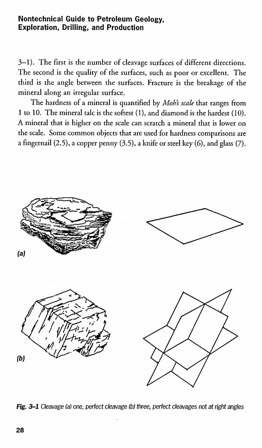
3-1). The first is the number of cleavage surfaces of different directions.
The second is the quality of the surfaces, such as poor or excellent. The
third is the angle between the surfaces. Fracture is the breakage of the
mineral along an irregular surface.
The hardness of a mineral is quantified by Mobs scale that ranges from
1 to 10. The mineral talc is the softest A), and diamond is the hardest A0).
A mineral that is higher on the scale can scratch a mineral that is lower on
the scale. Some common objects that are used for hardness comparisons are
a fingernail B.5), a copper penny C.5), a knife or steel key F), and glass G).
Fig. 3-1 Cleavage (a) one, perfect cleavage (b) three, perfect cleavages not at right angles
28
Identification of Common Rocks and Minerals
Specific gravity is the relative weight of a mineral compared to the weight
of an equal volume of water. A specific gravity of 2.5 means the mineral
weighs 2.5 times an equal volume of water. The specific gravity of an aver-
average rock or mineral is about 2,5, whereas metallic ore minerals often have
specific gravities above 3.5. Ore minerals mined for metals, such as iron,
copper, or nickel, are heavy.
The mineral halite (common table salt) can be identified by its taste. A
very important test is the application of cold, dilute hydrochloric acid to a
sample. Only the mineral calcite or the sedimentary rock limestone, formed
by calcite grains, will bubble.
Minerals
Mica is a common mineral that breaks along one perfect cleavage plane,
forming very thin, elastic flakes. Two types of mica are white mica and black
mica. White mica, (muscovite) is composed of KAl3Si30io(OHJ- It is color-
colorless and is transparent in thin flakes (Plate 3-la). Black mica {biotite) is com-
composed of K(Mg,FeKAlSi30io(OHJ. It is brown to black in color (Plate 3-lb).
Quartz (SiO2) is a very common mineral (Plate 3-1 c) that is colorless
when pure. It is often, however, tinted by impurities. Common varieties
include rose, cloudy, milky, and smoky quartz. Quartz is the hardest of the
common minerals G on the scale). It will scratch all other common miner-
minerals and a knife. It forms six-sided, prismatic crystals but can occur as amor-
amorphous grains. Most sand grains on a beach or in sandstone rock are com-
composed of quartz.
Calcite (CaCO3) is a common mineral that is either colorless or white.
Calcite breaks along three perfect cleavage planes that are not at right angles
to form rhombs (Plate 3-1 d). Calcite is relatively soft C) and can be
scratched by a knife. Calcite crystals are dog-tooth or flat shaped. Calcite
will bubble in cold, dilute acid. Most sea shells are composed of calcite.
Halite (NaCl) is common table salt. It is colorless to white (Plate 3-1 e).
Halite forms a granular mass or crystallizes in cubes. It breaks along three
perfect cleavage planes at right angles, forming rectangles and cubes. Halite
tastes salty. The mineral halite forms from the evaporation of sea water. It
is very common in ancient salt deposits.
29
Nontechnical Guide to Petroleum Geology,
Exploration, Drilling, and Production
Gypsum (CaSO4#2H20) is colorless to white (Plate 3-If)- It forms tab-
tabular crystals and has one perfect cleavage plane. Gypsum is very soft B) and
can be scratched by a fingernail. It has a specific gravity of 2.3. Gypsum is
also called selenite or alabaster. Gypsum and a similar mineral, anhydrite
(CaSO^h form by the evaporation of sea water.
Pyrite (FeS2) is known as fool's gold. It has a brassy yellow color and a
metallic luster (Plate 3-lg). Pyrite forms either cubes or an earthy mass and
is relatively heavy, with a specific gravity of 5. Pyrite is an iron ore and can
sometimes be found as grains in river sands.
Galena (PbS) is a lead ore. It has a silvery-gray color with a metallic lus-
luster (Plate 3-lh). Galena forms cubic crystals. It has a hardness of 2.5.
Galena is very heavy, with a specific gravity of 7.5.
Table 3-1 lists the properties of these minerals.
Each of these minerals has one or two characteristic tests that readily dis-
distinguish it from other minerals. For example, quartz is the hardest of the
common minerals and cannot be scratched by a knife. Calcite is relatively
soft, can be scratched with a knife, and will bubble in cold, dilute acid.
name
white mica
black mica
quartz
calcite
halite
gypsum
pyrite
galena
hardness
2 to 3
2.5 to 3
7
3
2 to 2.5
2
6 to 6.5
2.5
Table 3-1
Mineral properties
specific gravity
3
3
2.65
2.72
2.1
2.3
5
7.5
luster
pearly to vitreous
pearly to vitreous
vitreous to greasy
vitreous to dull
vitreous
vitreous, pearly, oily
metallic
metallic
30
Identification of Common Rocks and Minerals
Identification of Rocks
Rocks are classified and identified by their textures and mineral compo-
compositions. Igneous rock textures are based on the size of the mineral crystals.
The grain sizes range from large enough to see with the naked eye to glassy
with no crystals. Metamorphic rock textures are based on the size and ori-
entation of the mineral crystals. A foliated metamorphic rock has parallel,
platy crystals (Fig. 3-2a). Nonfoliatedmetamorphic rock has either uniform-
sized crystals or a nonparallel orientation of platy crystals (Fig. 3-2b).
Sedimentary rock textures are based on the nature, size, and shape of the
grains and how they are bound together.
Rocks
Igneous Rocks
Granite is the most common intrusive, igneous rock. It has the coarse-
coarsegrained texture characteristic of all plutonic rocks. Granite is composed of
the minerals quartz, feldspar, biotite, and hornblende. Quartz grains are
most common, giving granite a light color (Plate 3-2a). Dark-colored min-
fig. 3-2 Metamorphic rock textures (a) foliated (b) nonfoliated
31
Nontechnical Guide to Petroleum Geology,
Exploration, Drilling, and Production
eral grains give it a spectaed texture. Some granites are reddish or pinkish
from iron impurities. Granite ^commonly used for building stone.
Basalt is the most abundant volcanic rock. It has the fine-grained tex-
texture characteristic of lava. Basalt is black to gray in color (Plate 3-2 b). In
some instances, the basalt coming out of the volcano cooled so rapidly that
gas bubbles were frozen in the basalt. Fragments of basalt with numerous
gas bubbles are called wkU^'a^ *»*** '
Metamorphic Rock
Gneiss is a product of intense metamorphism. It is easily identified by
its foliated texture of alternating, wide bands of light- and dark-colored
^coarse mineral grains (Plate 3-2c). Feldspar and quartz are the most com-
common light-colored minerals. Amphibole, garnet, and mica are the most
common dark-colored minerals.
Sedimentary Rocks
Conglomerate is a clastic rock with a wide range of pebble- to clay-size
grains (Plate 3-2d). The coarse grains distinguish it from other clastic sedi-
sedimentary rocks. The particles are all well-rounded. A conglomerate is com-
commonly deposited in a river channel or on an alluvial fan formed where a
mountain stream empties into the desert. If the particles are angular, the
rock is called breccia.
Sandstone is composed primarily of sand grains (Plate 3-2e) that have
been naturally cemented together. The sand grains can be broken off if the
rock is loosely cemented. Sandstone is rough to the touch. The rock can be
white to buff to dark in color. Sandstones are commonly deposited on
beaches, river channels, or dunes. It is a common reservoir rock for gas and
oil and is the most important reservoir rock in North America.
Shale is composed of clay-sized particles (Plate 3-2f) and is the most
common sedimentary rock. It is usually well-layered and relatively soft.
Shale breaks down into mud when exposed to water. The color of shale
ranges from green and gray to black, depending on the organic content. The
darker the shale, the higher the organic content. Shale is commonly deposit-
deposited on river floodplains and on the bottom of oceans, lakes, or lagoons. Black
shales are common source rocks for gas and oil. A gray shale can be a
caprock on a reservoir rock in a petroleum trap. Mudstone is similar to shale
but is composed of both silt- and clay-sized grains.
32
Identification of Common Rocks and Minerals
Limestone is composed of calcite mineral grains that range in size from
very fine to large, sparkling crystals (Plate 2-2g). The rock is commonly
white or gray in color. The calcite mineral grains are soft enough to be
scratched by a knife and will bubble in cold, dilute acid. Limestones often
have fossil fragments that are also usually composed of calcite. Limestone is
a common reservoir rock and is the most important reservoir rock in the oil
and gas fields of the Middle East, An organic-rich, dark-colored limestone
can also be a source rock for gas and oil.
Coal is brown to black in color and very brittle (Plate 3—2h). It has few,
if any layers. Coal is composed of plant remains that were buried in the sub-
subsurface and transformed by heat and time. Lignite, bituminous, and
anthracite are varieties of coal formed by increasing heat that causes the coal
to become harder and change in texture and composition.
Chert or flint \s amorphous quartz (Plate 3—2i). It is very hard and cannot
be scratched by a knife. Being amorphous (without crystals), chert breaks along
smooth, curved surfaces, forming sharp edges and points. American Indians
used chert to make arrowheads. Colored varieties of chert include jasper, chal-
chalcedony, and agate. Chert can be formed by precipitation directly out of ground
water or by recrystallization of fossil shells composed of SiO2 by heat and pres-
pressure. Chert is the hardest of all sedimentary rock to drill.
Ninety-nine percent of the sedimentary rocks that make up the earths
crust are shales, sandstones, and limestones. Many sedimentary rocks are a
combination of these three types. Sedimentary rock mixtures are described
as sandy, shaly, and limey or calcareous (Fig. 3-3).
33
Nontechnical Guide to Petroleum Geology,
Exploration, Drilling, and Production
SHALE
CALCAREOUS SHALE
(LIMEY)
SHALEY SANDSTONE
\"
¦SHALEY LIMESTONE
SANDSTONE
CALCAREOUS SANDSTONE
(LIMEY)
Fig. 3-3 Common sedimentary rocks
i
LIMESTONE
SANDY LIMESTONE
34
PLATE 3-1: MINERALS
3-la white mica
3-lb black mica
3-lc quartz
3-1 d caldte
3-le halite
3-1 f gypsum
3-lg pyrite
3-lfi galena
PLATE 3-2: ROCKS
3-2a granite
3-2b basalt
3-2c gne/ss
».-u?*- >¦/.
€*
...
3-2d conglomerate
3-2e sandstone
3-2f black shale and gray shale
%u- K
3-2g limestone
3-2h coa/
3-2/ chert
four
GEOLOGICAL TIME
Two methods for dating the formation of the rocks and events in the
earth's crust are absolute and relative age dating. Absolute age dating puts
an exact time (e.g., 253 million years ago) on the formation of a rock or
an event. Relative age datingarranges the rocks and events into a sequence
of older to younger^
Radioactive Age Dating
Exact dates for the formation of rocks are made by radioactive analysis.
Radioactivity is the spontaneous aecay of radioactive atoms that occur natu-
naturally in rocks (Fig. 4-1). The atoms decay by giving off atomic particles and
energy. For example, uranium (U238) decays by giving off atomic particles
to form lead (Pb206). The original atom, uranium (U238), is called the par-
parent. The product of radioactive decay, lead (Pb206), is the daughter. There
are four relatively abundant radioactive atoms that occur in rocks. These are
two isotopes of uranium (U238 and U235), potassium (K40), and rubidium
(Rb87). Each decays at a different rate. The rate of radioactive decay is meas-
measured in half-lives. A half-life is the time in years that it takes one-half of the
parent atoms to decay into daughter atoms (Fig. 4-2). The half-lives are
shown in Table 4-1.
35
Nontechnical Guide to Petroleum Geology,
Exploration, Drilling, and Production
ATOMIC
PARTICLES
fie
URANIUM 238
PARENT
LEAD 206
DAUGHTER
Fig. 4-1 Radioactive decay
100% -
AMOUNT
OF
ORIGINAL
PARENT
50% -
25% -
12 V2% -
6>/4% -
0% -
1 2
HALF LIVES
3
Fig. 4-2 Radioactive decay half-life
36
Geological Time
Half-lives of
atom
u238
u235
Rb87
K40
Table 4-1
common radioactive
4
0
4
1
atoms
years
5x
7x
7x
3x
109
109
1010
109
One daughter atom is formed by the decay of each parent atom. As time
goes on, the amount of radioactive parent atoms decreases, and the amount of
daughter atoms increases. By measuring the amount of parent atoms left and
daughter atoms created, the age of the mineral grains in a rock can be deter-
determined. This parent-daughter technique is used in the potassium-argon
method. Potassium is a common element. A potassium isotope (K40) decays
into argon (Ar40) with a half-life of 1.3 billion years. The assumption is made
that when a mineral crystal forms, only potassium is accepted into the crystal
structure, never argon because it is an inert gas. Any argon that is found in the
crystal today could have come only from the radioactive decay of potassium.
By measuring the amount of K40 and Ar40 in the mineral, the ratio can be
applied to the radioactive decay curve, and the age of the mineral determined.
For example, if the ratio of K40 to Ar40 is 3 to 1, the age of the mineral grain
is 2 half-lives, or 2.6 billion years (Fig. 4-3).
Carbon (C14) decays very quickly and is not useful for most rocks. The
half-life is only 5710 years. After about 10 half-lives or 60 thousand years,
there is not enough parent left to date the material. It is used for archeolo-
archeology where ages are much younger.
Radioactive age dating is used primarily on igneous and metamorphic
rocks and cannot be used directly on sedimentary rocks. Sedimentary rocks are
derived from the erosion of pre-existing rocks. Absolute age dating of sedi-
sedimentary rock grains will tell the age of the formation of the mineral grains but
37
Nontechnical Guide to Petroleum Geology,
Exploration, Drilling, and Production
100
75
50
25
0
<
z
o
o
v
\l/2/
"-/
yam
* «
t
^^1/4
1
^ ^1/8
1 _
~7%[UGHTER
f V ^ ^
0 1.3 2.6 3.9 5,2 6.5 7.8
BILLION YEARS (ONE HALF LIFE *1.3 BILLION YEARS)
Fig. 4-3 Using half-lives to determine age
not the time the sediments were deposited. However, igneous intrusions that
cut sedimentary rocks or lava flows that cover sedimentary rocks can be dated.
In that way, the age of the affected sedimentary rocks can be estimated. A lava
flow will be older than any sedimentary rock that covers it. An intrusion will
be younger than any sedimentary rock that it intrudes.
Relative Age Dating
In sedimentary rock sequences, relative age dating is used. Sedimentary
rocks and events are put in order from oldest to youngest. In a sequence of
undisturbed sedimentary rock layers, the youngest rock is on top, and the
oldest is on the bottom. Events such as faulting, folding, intrusions, and
erosion, can also be relative age dated. If any one of those eveijts affects a
sedimentary rock layer, the event must be younger than the arrected rock.
The sequence in Figure 4-4, from oldest to youngest is a) deposition of sed-
sedimentary rocks 7, 2, and 3, b) faulting, c) erosion (unconformity), and d)
deposition of sedimentary rocks 4 and 5.
38
Geological Time
Fossils
An important tool in relative age dating of sedimentary rocks is fossils.
Fossils are the preserved remains of plants and animals in the rocks (Fig.
4-5)* There are several ways in which fossils are preserved. Many animals
that live in the sea such as corals and dams°secrete shells of lime (CaCC^).
The shells can be preserved unaltered in sedimentary rocks. Other animals
have bones that can be preserved, rlants can be preserved as hlms or carbon
in mud, which becomes shale. Sometimes the pore spaces of bone or shell
are filled with minerals deposited by groundwater in a process similar to the
cementation of clastic grains into sedimentary rock. Other fossils are pre-
preserved when the original matter is completely replaced by another mineral in
the subsurface. Petrified wood is formed by the replacement of wood by sil-
silicon dioxide that preserves the grain structure of the wood. Trace fossils, such
as burrows, tracks, or trails, are indirect evidence of ancient life.
Certain species of plants and animals lived during certain geologic
times. They eventually became extinct (disappeared from the earth) and
replaced by newer plants and animals. This continuous succession of organ-
FAULT
Fig. 4-4 Relative age dating
39
Nontechnical Guide to Petroleum Geology,
Exploration, Drilling, and Production
isms throughout geologic time is known as evolution. Vertical sequences of
sedimentary rock layers that have been relative age dated can be used to
determine the relative ages of the fossils in those rock layers (Fig, 4-6).
Geologists have collected and established the relative ages of most fossils.
The evolutionary sequence of the fossils can be used to relative age date any
sedimentary rocks that contain those fossils. In Figure 4-7, the rocks labeled
A are older than those labeled B.
A guide or index jvssilis a distinctive plant or animal that lived during a
g jvp g
relatively short Span ofgeologic time. This fossil species identifies the age of
any sedimentary rock in which it occurs. A fossil assemtrfageis a group of fos-
fossils found in the same sedimentary rocks. It identifies that zone of rocks and
the geologic time during which those rocks and fossils were deposited.
Fossils can also be used to determine the deposmonal environment
of the sediments. Different plants and animals live in different environ-
environments such as beach, marsh, and deep ocean.
Fossils, like sedimentary rocks,
can be indirectly dated by radioactiv-
ity (Fig. 4-8). If volcanic ish layers
that occur above and below the fossil
are dated, the fossil is younger than
the underlying ash layer and older
than the overlying ash layer.
Microfossils
A well is drilled down to a
drilling target, a potential reservoir
rock. But as the well is drilled, it
Penetrates hundreds of sedimentary
rock layers consisting of shales,
sandstones and limestones that
look very similar. How can each
sedimentary rock layer and the
drilling target be identified while
Fig. 4-5 Fossils drilling through them?
40
Geological Time
SEDIMENTARY
ROCKS
YOUNGEST
OLDEST
Fig. 4-6 Relative age dating of fossils
YOUNGEST N
OLDEST
FOSSIL
YOUNGEST
OLDEST
t
Fig. 4-7 Relative age dating using fossils (A) older (B) younger
41
Nontechnical Guide to Petroleum Geology,
Exploration, Drilling, and Production
volcanic ash layer
Fig. 4-8 Indirect age dating of a fossils by radioactive age dating volcanic ash layers
Each sedimentary rock layer was deposited during a different time and
has different fossils that are the key to identifying die subsurface rock layers.
Large fossils such asxlams and corals, however, are broken into small chips
(well cuttings) by the chill bit. It is almost impossible to identify the pieces
when they are finally flushed to the surface by the drilling mud. The sedi-
sedimentary rocks, however, also contain abundant microfossils.
Microfossils are fossils that are so small that they can rbe identified only
with a microscope (Plate 4-1). They are often unaamaged By the drill bit
and are flushed unbroken in the well cuttings up to the surface. Microfossils
are used in biostratigraphy to identify the rocks and their ages. Rock layers
that contain a characteristic microfossil are often named after that microfos-
sil and called a zone or biozone. The Siphonia davisi zone is composed of
sedimentary rock layers that contain the microfossil Siphonia davisi (Fig.
4-9). A horizon in a well that is identified by the first appearance, most
42
Geological Time
abundant occurrence, or last appearance of a microfossil is called apaleopick.
Paleo picks can also be used to determine if the sedimentary rock layers in a
well are higher or lower in elevation than those in a well that has already
been drilled (Fig. 4-10).
Many micro fossils are shells of single-celled plants and animals that live
in the ocean. Foraminifera {forams) are single-celled animals with shells
(Plate 4-1 a) composed primarily of CaCG3. They live by either floating in
the ocean or growing attached to the bottom. More than 30,000 species of
forams have existed throughout geologic time.
Radiolaria are single-celled, floating animals that live in the ocean and
have shells (Plate 4-lc) of SiC>2. Some cherts were formed by alteration of
radiolarian shells deposits.
Coccoliths are plates from the spherical CaCO3 shell (coccolithophore)
of algae that floats in the ocean. They are so small that they can be identi-
identified only with a scanning electron microscope. Ancient, relatively pure
CaCC>3 deposits of coccoliths or foraminifera microfossils are called chalks.
Diatoms are single-celled plants that float in water and have shells of
SiO2 (Plate 4-lb). Ancient deposits of relatively pure diatom microfossils
are called diatomaceous earth. Some cherts formed from ancient diatom
shell deposits. Spores and pollens given off by plants to reproduce also are
good microfossils.
Plate 4-1 Magnified microfossils (a) foraminifera, (b) diatom, and (c) radiolaria
43
Nontechnical Guide to Petroleum Geology,
Exploration, Drilling, and Production
SIPHONIA
DAVISI
ZONE
FIRST APPEARANCE
LAST APPEARANCE
Fig. 4-9 Microfossil zone
HIGH
LOW
-SEA LEVEL
It
Fig. 4-10 High and low wells
44
Geological Time
Scientists who study fossils are called paleontologists, and those who spe-
specialize in microfossils are micropaleontologists. Because they pick microfossils
(bugs) from well cuttings to examine them under a microscope, they are
often called bug pickers. Micropaleontologists specializing in spores and pol-
pollens are called palynologists or weed and seed people.
The Geologic Time Scale
The geologic time scale was developed during the early 1800$ by relative
age dating sedimentary rocks and fossils in Europe. Large divisions of geo-
geologic time are called eras. Eras are subdivided into periods, and periods into
epochs. The geologic time scale is presented in Table 4-2, In Europe, the
Mississippian and Pennsylvanian periods are combined into the
Carboniferous Period.
Earth History
It is known by radioactive age dating that the earth is about 4.5 billion
years old. For the first part of the Precambrian Era, there is no fossil evi-
evidence that life existed on earth. The first life, probably bacteria followed
later by algae floating in the ocean, appeared approximately 3.5 billion years
ago. The fossil record throughout the later part of the Precambrian is sparse.
A great abundance of diverse plants and animals were living in the ocean
at the start of the Paleozoic Era E70 million years ago) as shown in the fos-
fossil record. All the major animal phyla that we know today in the oceans,
except the vertebrates, were present. Nothing, however, existed on the land.
During the Ordovician Period, fish, the first vertebrates, came into existence.
Plants and animals finally adapted to life on the land in the next period, the
Silurian. During the Pennsylvanian Period, swamps covered large areas of
the land. Primitive plants, such a ferns and horsetail rushes, grew to great
heights. These Pennsylvanian swamp deposits formed many of the world s
coal deposits. During the last period of the Paleozoic, the Permian, the cli-
climate was very dry and warm, and the lands were covered with deserts.
45
Nontechnical Guide to Petroleum Geology,
Exploration, Drilling, and Production
Era
Cenozoic
Mesozoic
Paleozoic
Precambrian
Table 4-2
Geological time scale
Period Epoch
Quaternary
Tertiary
Cretaceous
Jurassic
Triassic
Permian
Pennsylvanian
Mississippian
Devonian
Silurian
Ordovician
Cambrian
Holocene
Pleistocene
Pliocene
Miocene
Oligocene
Eocene
Paleocene
Absolute age (years)
• 0
¦ 10,000 thousand
• 1.8 million
¦ 5.3 million
¦ 24 million
¦ 34 million
¦ 55 million
• 65 million
144 million
206 million
248 million
290 million
320 million
365 million
405 million
425 million
500 million
570 million
4.5 billion
46
Geological Time
During the Permian Period, egg-laying reptiles appeared. At the end of the
Permian, the greatest extinction (90%) of plants and animals in the history
of the earth occurred. There have been four great extinctions during geolog-
geological time but this was the most extensive
The Mesozoic Era, starting about 248 million years ago, is known as the
age of reptiles. These animals, which include the dinosaurs, dominated the
earth. They filled a great diversity of ecological niches for more than 150
million years. Most dinosaurs were plant eaters, but some were carnivores.
During this time, great reptiles lived in the oceans, while others flew through
the air with wingspans more than 50 ft A6 m). During the Jurassic Period,
the middle period of the Mesozoic, mammals and birds appeared. They
were small and were dominated by the reptiles throughout the remainder of
the Mesozoic.
At the very end of the Mesozoic Era F5 million years ago), one of the
most complete and sudden extinction of life in the history of the earth
occurred. All the dinosaurs died out, along with the flying reptiles, most
swimming reptiles, and 75% of all species of plants and animals. The extinc-
extinction was remarkable because reptiles apparently dominated their environ-
environment until the very end. They then disappeared in an instant of geologic
time called the great killing.
This extinction was caused when a comet or meteorite hit the earth. It
was at least 10 miles A6 kms) in diameter and hit the earth head on with a
speed of about 100,000 miles per hour A60,000 km/hr). In every location
throughout the world, the thin clay layer separating the Mesozoic and
Cenozoic sedimentary rocks has an abnormally large concentration of iridi-
um 121 (Ir121). This rare, radioactive element is also found in abundance in
meteorites. The Ir121 layer is thickest in the Caribbean, indicating that the
impact occurred in that area. A crater, now filled with sediments and buried
3000 ft A000 m) deep, occurs under the fishing village of Chicxulub on the
Yucatan peninsula of Mexico (Fig. 4-11). It is 130 miles B08 km) in diam-
diameter and is the same age as the great killing.
Soot is common in the iridium 121 layer, indicating that the surface of the
earth was consumed in a fire storm caused by the heat of the impact after the
collision* The soot and dust caused by the collision and ejected into the atmos-
atmosphere must have thrown the earth into total darkness for several months.
Evidence in Texas and other areas, indicates that the waters of the Gulf of Mexico
47
Nontechnical Guide to Petroleum Geology,
Exploration, Drilling, and Production
were thrown up into a great wave which swept across North America. Large
amounts of sulfur dioxide were vaporized during the impact. It mixed with
water in the atmosphere to form sulfiiric acid that rained down on the earth.
Some mammals survived the great killing at the end of the Mesozoic
Era. They flourished after their reptilian competition was eliminated, and
the Cenozoic Era is known as the age of mammals. Grasses evolved during
the Cenozoic and became an important food source for the mammals. Late
in the Cenozoic, during the Pleistocene Epoch, or Ice Age, the climate was
colder than it is today. Extensive ice sheets, thousands of feet thick, covered
approximately one-third of the land. During four separate times, the glaciers
advanced across the land and then retreated. The last ice sheet did not
retreat until the end of the Pleistocene, just 10,000 years ago.
Fig. 4-11 Cretaceous-Tertiary impact site
48
r
five
DEFORMATION OF SEDIMENTARY ROCKS
Sedimentary rocks are originally deposited in horizontal layers. A type
of oil and gas trap, called a structural mlp, is formed by the deformation of
these rock layers.
Weathering, Erosion, and Unconformities
Weathering is the breakdown of solid rock. Once a rock is exposed on
the surface of the earth, either to the atmosphere or ocean JbottQip, it will
eventually be mechanically broken into particles or chemically dissolved by
the forces of weathering. Some sedimentary rocks are more resistant to
weathering (?.?., sandstones or even limestones in and climates). Other
rocks (e.g., shales) readily break down. Erosional processes are those that
transport and deposits sediments. These processes include gravity (land-
slides), wind, glaciers, waves, and rivers.
, vut , Sea level has been rising and falling throughout geological time.
Whenever sea level was lower, the land was exposed to erosion, and some of
the sedimentary rocks were stripped off the surface 6 of the land. Buried,
ancient erosional surfaces are called unconformities, lwo types are discon-
formities and angular unconformities.
A disconformity is an erosional channel in which the sedimentary rock lay- -
ers above and below the erosional^surface parallel (Fig. 5-1). It is an ancient^
river channel that is usually filled with sand that has become sandstone.
49
Nontechnical Guide to Petroleum Geology,
Exploration, Drilling, and Production
Fig. 5-1 Disconformity
An angular unconformity is an ancient erosional surface in which the sedi-
sedimentary rock layers l>elow the unconformity are tilted at an angle to the layers
above the unconformity (Plate 5-1). The formation of an angular unconfor-
unconformity starts with the deposition of horizontal sediment layers as ancient seas
cover the earth. After the seas have retreated, exposing the earth, the sedimen-
tary rocks are tilted to form hills and mountains. The hills and mountains are
then eroded down, leaving an erosional surface. The seas again covet the land,
aw:** ,. 5, , , • i r jar*.^
depositing sedimentary rock layers on the erosional surface and bury it in the
subsurface. An angular unconformity represents a time of mountain building
followed by erosion. It often covers a large subsurface area.
Angular unconformities can form gas and oil traps (Fig. 5-2). One of the sed-
sedimentary rock layers below it must be a reservoir rock that can store gas and oil;
usually a sandstone or limestone. 1 he sedimentary rock layer above it must be a
capJock that acts as a leal; usually a shale or salt layer. The gas and oil forms below
the unconformity in a source rock such as black shale. It migrates up into and then
through the pore spaces of the reservoir rock until it reaches the angular uncon-
unconformity surface where it is trapped below the caprock^sK^ v ^ffr** ** ^
Because angular unconformities can cow large subsurface areas, they
can form giant gas and oil fields. The two largest oil fields in North
America, the East Texas field and the Prudhoe Bay field in Alaska, are both
50
Deformation of Sedimentary Rocks
Plate 5-1 Angular unconformity showing flat sedimentary rocks above and sedimen-
sedimentary rocks tilted at an angle below (sea cliff England)
Fig. 5-2 Angular unconformity trap
51
Nontechnical Guide to Petroleum Geology,
Exploration, Drilling, and Production
in angular unconformity traps. In both fields, the horizontal rock layers on
the surface of the ground don't give any indication of the subsurface angular
unconformities and their giant oil accumulations.
The East Texas field originally contained more than 7 billion bbls A.1
billion m3) of oil. The oil is located in the Woodbine Sandstone below the
angular unconformity (Fig. 5-3), at a depth below about 3500 ft A070 m).
The Austin Chalk, the (iaprrfck, directly overlies the angular unconformity.
The Woodbine Sandstone was originally deposited as a horizontal layer of
sands when shallow seas covered East Texas about 100 million years ago (Fig.
5-4a). The sandstone was then buried in the subsurface as it was covered
with other sediments (Fig. 5-4b). Later, the Sabine uplift, along the Texas-
Louisiana bQraer, arched up and exposecrthe Woodbine Sandstone (Fig.
5-4c). Erosion removed the Woodbine Sandstone from the top of the arch
(Fig. 5-4d). After that, the seas <iriva?led the area, depositing the Austin
Chalk and other sediments, (covering the angular unconformity (Fig. 5-4e).
The oil formed in the Eagle Ford Shale source rock below and migrated up
into the Woodbine Sandstone. It then flowed along the porous sandstone
toward the east until it was trapped under the angular unconformity, unable
to flow into the Austin Chalk,
10CW-
20001-
300QT-
aeocr-
west
-
____———~
Austin Chalk
i
i - »
— o
east
- —¦
il-water contact
' . Woodbine Sandstone •
Fig. 5-3 East-west cross section of East Texas oil field
52
Deformation of Sedimentary Rocks
The discovery of the East Texas oil field in 1930 is a classical story of
petroleum history. Oil companies explored this area in the early 1900s.
There were no oil seeps in the area, and they became discouraged after
drilling some dry holes. They abandoned this area by the mid-1920s to drill
in the newly discovered giant West Texas oil fields. Because of this, Charlie
Joiner, a driller and promoter, was able to obtain leases for drilling on a large
area of eastern Texas at a very low cost.
He started to drill in the area in the late 1920s with what is best
described as "random drilling." His only geological help was from a veteri-
veterinarian by the name of Dr. A. D. Lloyd. It was poor farm land, and the local
ws$r
EAST
.JWOQDBINE'.'SS.
v ;*v" / ::\ WOODBINE >;. SS. V;yV - **V.
5-4 Formation of East Texas oil field trap
53
Nontechnical Guide to Petroleum Geology,
Exploration, Drilling, and Production
cotton farmers would often volunteer to help drill the well. Because Charlie
Joiner had little money, he traded shares in the well for room and board,
repairing equipment, buying supplies and hiring help.
The No. 3 Daisy Bradford well finally reached below the angular uncon-
unconformity at 3725 ft A135 m) after 16 months of drilling and blew in the East
Texas oil field. The well initially tested 6800 bbl/day A080 m3/day) and was
completed to produce 300 bbl/day D8 m /day). Unfortunately, Charlie
GLADEWATER
OVERTON
D LONGV1EW
KILGORE
DAISY BRADFORD #31
JOINERVILLE
5 10
MILES
Fig. 5-5 Map of East Texas oil field (modified from Halbouty, 1991)
54
Deformation of Sedimentary Rocks
Joiner in his financial need during drilling, had sold 300% of the Daisy
Bradford well and was in legal trouble. H.L. Hunt negotiated a deal with
Charlie to settle his legal problems and pay him US $1,335,000, mostly in
future oil production for 5000 acres of prime leases in the field.
The East Texas oil field is 45 miles G2 km) long and 5 miles (8 km)
wide (Fig. 5-5). Almost instantly, many poor farming families that had land
in the field became Texas millionaires. More than 30,000 wells were drilled
in the field that has now produced more than 5 billion bbls (800 million m3)
of light, sweet crude oil.
Anticlines and Synclines
An anticline is a large, upward arch of sedimentary rocks (Fig. 5-6),
whereas a syncline is a large, downward arch of rocks. Anticlines (but not
synclines) form gas and oil traps. Folds such as anticlines expose the rocks
to erosion. If the anticlines are relatively young, they haven't been eroded and
appear as topographic ridges on the surface. A series of young rising anti-
anticlines that are also prolific petroleum producers occur as a line of hills that
cross the Los Angeles basin (Fig. 5-7). These trend from Beverly Hills in the
north, through the Inglewood (Baldwin Hills) and Dominguez fields, south-
southward to Long Beach, and offshore into the Huntington Beach field.
Most anticlines and synclines are not level and are tilted with respect to
the surface of the earth. These are called plunging anticlines (Fig. 5-8) and
synclines. During and after folding, erosion rapidly levels the folds. The pat-
pattern of an eroded plunging anticline or syncline is lobate-shaped, called a
nose (Fig. 5-9).
The formation of anticlines and synclines results in shortening of the
earths crust (Fig. 5-10). Forces that shorten the earths crust are compres-
sional. If an area of the earths crust is compressed, the rocks will be folded
lrtto anticlines and synclines. If folds are present in the rocks of the earths
crust, that area probably has been compressed some time in the past.
55
Nontechnical Guide to Petroleum Geology,
Exploration, Drilling, and Production
Fig. 5-6 Anticline
SANTA
MONICA
BEVERLY 3^
\ HILLSO?C ATM
PNGLEWOOD -ttA 1\J MI
\0OMINGUE2rv
\ HILL s^
y SIGNAL HILL -^
-
0 5 10MIIF$
SAN GABRIEL MTS.
SANTA
\7
r
ANA
'-*
\
Fig. 5-7 Los Angeles basin showing trend of anticline oil fields
56
Deformation of Sedimentary Rocks
Fig. 5-8 Plunging anticline
Domes
A dome is a circular or elliptical uplift* When eroded flat, a dome forms
a bulls eye pattern of concentric rock layers with the oldest rock in the cen-
center (Fig. 5-11). Domes also form gas and oil traps. Oil was first discovered
in the Middle East in Bahrain, an island in the Persian Gulf, in 1932. The
traps in Bahrain were domes with a low hill on the surface above each of
them. A similar low hill above a dome in Saudi Arabia was drilled to find
the first oil field there in 1937.
Anticlines and domes were the first type of petroleum trap recognized.
They form many of the giant oil and gas fields of the world. Most of the
Middle East oil fields are in anticline and dome traps. The Cushing oil field
°f Oklahoma, discovered in 1912, is located to the southwest ofTulsa. The
trap is an anticline with three domes superimposed on it (Fig. 5-12). The
reservoir rock is the Bartlesville Sandstone along with several other sand-
sandstones and a limestone. The best producing wells are on the domes. The
Cushing oil field will produce 450 million bbls G2 million m3) of oil. It was
the largest oil field in the world during World War I.
57
Nontechnical Guide to Petroleum Geology,
Exploration, Drilling, and Production
Fig. 5-9 Surface pattern of eroded, plunging anticline
Fig. 5-10 Formation of anticlines and synclines by compression
58
Deformation of Sedimentary Rocks
fig. 5-11 Surface pattern of eroded dome
lUMRtGHt
V#: 'SHAMROCK
DOME
km
¦ 5-12 Cashing oil field, Oklahoma (a) map (b) cross section
59
Nontechnical Guide to Petroleum Geology,
Exploration, Drilling, and Production
Homoclines
Sedimentary rocks dipping uniformly in one direction are known as a
homocline (Fig. 5-13). Alternating layers of hard and soft: sedimentary rocks
in a homocline will be eroded to form a series of parallel ridges on the sur-
surface of the ground.
Fractures
Joints
A joint is a fracture in the rocks without any movement of one side rel-
relative to the other (Plate 5-2). Joints in sedimentary rocks improve the reser-
reservoir qualities of the rock. They increase the fluid storage capacity of the rock
(porosity) and the ability of the fluid to flow through the rock (permeabili-
(permeability). Any naturally fractured rock is a potential reservoir rock.
Fig. 5-13 Homocline
60
Deformation of Sedimentary Rocks
¦
•
&-¦¦:.' ¦ :,
-.
¦•
-¦¦? -:v
¦ -^.
-
.
C -: •
Plate 5-2 Joints /n a sandstone, Winding Stair Mountains, Oklahoma
61
Nontechnical Guide to Petroleum Geology,
Exploration, Drilling, and Production
Faults
Faults are breaks in the rocks along which one side has moved relative to
the other (Plate 5-3). The relative movement of each side is used to classi-
classify faults (Fig. 5-14). Dip-slip faults move primarily up and down, whereas
strike-slip faults move primarily horizontal. Oblique-slip faults have roughly
equal dip-slip and strike-slip displacements.
The side of a fault that extends under the fault plane is called the foot-
wall (Fig. 5-15), and the side that protrudes above the fault plane is the
hanging wall Throw (Fig. 5-16) is the vertical displacement on a dip-slip
fault. The side of the dip-slip fault that goes down is called the downthrown
side, and the side that goes up is called the upthrown side.
^^^/(mIk^
Plate 5-3 Fault showing displacement of sedimentary rock layers, Austin Chalk, Texas
62
Deformation of Sedimentary Rocks
DIP SUP
STRIKE SUP
OBLIQUE SLIP
Fig. 5-14 Types of faults
Fig. 5-15 The sides of a fault
63
Nontechnical Guide to Petroleum Geology,
Exploration, Drilling, and Production
Up Thrown Side
THROW
Down Thrown Side
\
FAULT
Fig. 5-16 Dip-slip fault terminology
Two types of dip-slip faults are normal and reverse. If the hanging wall
has moved down relative to the footwall, it is a normal dip-slip fault (Fig.
5-17). In a normal dip-slip fault, the beds are separated and pulled apart.
A normal dip-slip fault is identified in the subsurface by a lost section, a miss-
missing layer, or layers of rocks (Fig. 5-18).
A series of parallel, normal dip-slip faults forms a structure called horst
and graben (Fig. 5-19). A graben is the down-dropped block between two
normal faults. A horst is the ridge left standing between two grabens. These
can range in size from inches to tens of miles across.
64
Nontechnical Guide to Petroleum Geology,
Exploration, Drilling, and Production
Fig. 5-19 Horst and graben
If the hanging wall has moved up relative to the footwall, it is a reverse
dip-slip fault In a reverse dip-slip fault, some subsurface beds overlap. It is
possible to drill through this fault and encounter the same rock layers twice
in a double section (Fig. 5-20).
A thrust fault is a reverse fault with a fault plane less than 45° from horizon-
horizontal (Fig. 5-21). On a thrust fault, the upper part (the hanging wall) has been
thrust up and over the lower part (the footwall). There are some thrust faults in
the earths crust where the hanging wall has been thrust horizontally tens of miles
over the footwall. A series of large thrust faults, called the Rocky Mountain
Overthrust Belt, occurs in a band along the eastern side of the Rocky Mountains.
A series of large gas and oil traps are located in the overthrust belt.
A normal dip-slip fault is formed when the rocks are pulled apart by ten-
sional forces (Fig. 5-22). A reverse dip-slip fault is formed by shortening the
rocks with compressional forces (Fig. 5-22). When the earths crust is pulled
apart, normal dip-slip faults with horsts and grabens are formed. When the
earths crust is squeezed, reverse dip-slip and thrust faults and folds, such as
anticlines and synclines, are formed.
66
Deformation of Sedimentary Rocks
Fig. 5-20 Double section on a reverse dip-slip fault
Fig. 5-21 Thrust fault
67
Nontechnical Guide to Petroleum Geology,
Exploration, Drilling, and Production
compression
tension
reverse fault normal fault
Fig. 5-22 Forces that form a reverse dip-slip fault and normal dip-slip fault
Faults can be both active and inactive. When a fault moves, it can pro-
produce shock waves called an earthquake. Many faults, however, moved a long
time ago and are inactive today. Two very large faults occur in Oklahoma,
the Seneca and Nemaha faults. Both were active hundreds of millions of
years ago but are inactive today.
Dip-slip faults form traps by displacing the reservoir rock (Fig. 5-23).
The fault must be a sealing fault, which means it prevents fluid flow across
or along the fault. Any gas and oil migrating up a reservoir rock will be
trapped under the sealing fault. Fault traps are common but are usually rel-
relatively small because a single fault is linear and doesn't have sides to contain
large volumes of petroleum. The Bridge pool oil field of Santa Paula,
68
Deformation of Sedimentary Rocks
Fig. 5-23 Fault trap
S. SOUTH
MOUNTAIN
FIELI? BRIDGE
iPOOL
SANTA
PAULA
Sea Level
5,000
MILES
Fig. 5-24 North-south cross section through South Mountain and Bridge Pool oil
fields, California
69
Nontechnical Guide to Petroleum Geology,
Exploration, Drilling, and Production
Wytch Farm
Tertiary
MODSTONS GROUP
SHESWOOO SANDSTONl' G^P
2000
m
fig. 5-25 Wytch Farm oil field, England (modified from Colter and Harvard, 1981)
California is a fault trap (Fig. 5-24). The reservoir rock is the Oligiocene
age sandstones in the Sespe Formation that is terminated against the Santa
Clara Fault. The largest oil field on land in England is the Wytch Farm field
located southwest of London on the South Dorset coast. There are natural
oil seeps along the coast, and the field was discovered in 1973. The trap was
formed by a fault cutting the Sherwood Sandstone reservoir rocks (Fig.
5-25). It contains 286 million bbls D5 million m3) of oil.
A strike-slip fault is described by the horizontal movement of one side
relative to the other (Fig. 5-26). If the opposite side of the fault moves to
the right, it is a right-lateral strike-slip fault If it moves to the left, it is a left-
lateral strike-slip fault. The San Andreas Fault of California is an active right-
70
Deformation of Sedimentary Rocks
FAULT—*
LEFT LATERAL
F/g. 5-26 Strike slip faults
RIGHT LATERAL
lateral strike-slip fault. It is hundreds of miles long and has moved many tens
of miles over a long time.
The Potrero oil field in California (Fig. 5-27) is formed by an anticline
on sandstone reservoir rocks. The crest of the anticline is displaced 1200 ft
C65 m) by the Potrero fault, a right-lateral strike slip fault.
Buried, tilted fault blocks can form large petroleum traps. During the
geological past, horizontal sedimentary rocks (Fig. 5-28a) were broken by
normal faults into large, tilted fault blocks (Fig. 5-28b). Some of the blocks
can contain reservoir rocks. Later, the seas covered the tilted fault blocks and
deposited a caprock of shale or salt on them (Fig. 5-28c). The oil and gas
then formed and migrated up along the reservoir rock to below the sealing
fault or caprock.
The Statford oil field, the largest oil field in the North Sea, is located in
both the United Kingdom and Norway sectors. It was discovered by seismic
exploration and drilled in 1974. The trap is a westward-tilted fault block
(Fig. 5-29). The two, very porous and permeable sandstone reservoirs rocks
(Brent and Statfjord sandstones) are several hundred feet thick. The seal is
the overlying shale. The ultimate production will be 3 billion bbls E00 mil-
million m3) of light, sweet crude oil.
71
Nontechnical Guide to Petroleum Geology,
Exploration, Drilling, and Production
Jt
FAULT-
Fig. 5-27 Map ofPotrero oil field, California
F/g. 5-28 Formation of tilt-
tilted fault block traps
NORTHWEST
SOUTHEAST
NORTH SEA
5000
10000
15000
ffg. 5-29 Cross sect/on of Statfjord field, North Sea (modified from Kirk, 1980)
72
SIX
SANDSTONE RESERVOIR ROCKS
The two most common petroleum reservoir rocks are sandstones and
carbonates (limestones and dolomites). Most sandstones and limestones,
however, are not reservoir rocks. Sandstones and limestones show a wide
variety of textures and were deposited in a variety of environments* Some
reservoir rocks, such as limestone reefs and river channel sandstones, were
deposited completely encased in shale. Because the shale below is a source
rock for gas and oil and the shale above is a caprock, the reef or channel con-
contains gas and oil. This is called a primary stratigraphic trap.
Dune Sandstones
Sand dunes are formed by wind in both desert and coastal environ-
environments. The wind picks up and suspends only clay- and silt-sized particles in
the air. The only other size particle moved by the wind is fine sand that is
bounced along the ground and deposited locally Coarser grained sediments
cannot be moved by the wind. Because of this, sand dunes are composed of
very well-sorted fine sand and can be excellent reservoir rock.
Sand dunes have a distinctive shape and internal structure. During peri-
periods of low wind velocity, wind and bouncing fine sand flow smoothly over
any surface irregularity such as a hill (Fig. 6-1 a). As the wind velocity
73
Nontechnical Guide to Petroleum Geology,
Exploration, Drilling, and Production
increases, an eddy current forms downwind from the crest of the hill (Fig.
6-1 b). The eddy current flows opposite the wind direction, causing the fine
sand to pile up on the crest of the hill. Eventually, the sand becomes unsta-
unstable and avalanches down the back side of the hill depositing a layer of sand
on the avalanche or slip face of the dune (Fig. 6-1 c). This process contin-
continues as long as the wind is blowing fast enough to maintain the eddy current*
Fig. 6-1 Formation of a sand dune a) wind blowing at relatively low speed across a sand
dune, b) wind blowing at a faster speed, forming an eddy current on tfie backside of the
dune, and c) sand avalanching down the backside of the dune
74
Sandstone Reservoir Rocks
The sand layers formed by the avalanching sands have a characteristic
shape and are called crossbeds (Fig. 6-2). They are steep at the top and are
almost horizontal at the bottom. As the wind blows, sand is eroded off the
windward side of the dune and is deposited on the opposite side of the dune.
This causes the dune to migrate in the direction of the slip face and the
wind. Dune sand is characterized by internal crossbeds.
Ancient dune sandstones form extensive subsurface sandstone reservoirs.
One example is the Jurassic age Nugget Sandstone, the primary reservoir in
the Rocky Mountain overthrust belt oil and gas fields of the United States.
It was deposited as sand dunes in a desert that covered much of the western
part of the United States during Jurassic time.
During the Permian time, sea level fell to expose the bottom of the North
Sea, and a desert climate occurred. A large salt lake surrounded by sand dunes
formed in the center of the North Sea. These sand dunes are now buried by
other sediments on the bottom of the North Sea and form the Rotliegend
Sandstone. It underlies the southern portion of the North Sea and parts of
England and Europe, where it is the reservoir for several North Sea gas and oil
fields and the giant Groningen gas field in the Netherlands.
Shoreline Sandstones
Beaches are long, narrow deposits of well-sorted sand. Waves wash the
finer-grained silt and clay particles out of the beach sands. The muddy water
is carried offshore where the mud settles out of the water and is deposited in
deep water. Waves shape the beach into a long strip of sand.
Fig. 6-2 Crossbeds
75
Nontechnical Guide to Petroleum Geology,
Exploration, Drilling, and Production
In the South Texas coastal plain (Fig. 6-3). there is a series of buried
shoreline sandstones that are oil and gas reservoirs. The Yegua-Jackson sands
of Eocene age are located inland, and the Frio-Vicksburg sands of Oligocene
age are located on the Gulf of Mexico side.
The Clinton oil and gas fields run north to south through the state of
Ohio (Fig. 6-4). The reservoir rock is the Silurian Age Clinton Sandstone.
It was deposited as a shoreline sandstone and is completely encased in shale,
which is the source rock below the sandstone and the caprock above the
sandstone. Drilling into the Clinton sandstone started in the 1890s with
cable tool drilling rigs.
Beach sands, called buttress sands, can be deposited on an angular uncon-
unconformity during rising seas (Fig. 6-5) and form giant oil and gas field reser-
reservoirs. The Bolivar Coastal fields of Lake Maracaibo, Venezuela (Fig. 6-6a),
containing more than 30 billion bbls E billion m3) of recoverable oil, are
examples. A cross section (Fig. 6—6b) from west to east shows the Oligiocene
•; . ;>SAN ANTONIO' g '¦'",•"'*<&
/
BROWNSVILLE I
Fig. 6-3 South Texas coastal plain oil fields (modified from Landes, 1970)
76
Sandstone Reservoir Rocks
a
COLUMBUS
{ 0 25 50 MILES
V.
~ J
Fig. 6-4 Clinton Sandstone gas fields, Ohio (modified from State of Ohio, 1966)
age angular unconformity dipping down to the west under Lake Maracaibo.
Miocene age reservoir sandstones directly overlay the unconformity under
Lake Maracaibo. Some of the oil leaks out along the unconformity to form
a line of oil seeps along the eastern shore of Lake Maracaibo. The Bolivar
Coastal fields were discovered in 1917 and produce from wells on platforms
in the shallow lake.
Pembina, the largest oil field in Canada (Fig. 6-7) also produces from a
beach sandstone and conglomerate reservoir, the Cretaceous age Cardium
Formation, overlying an unconformity. The field was discovered in 1953 by
drilling to a deeper seismic anomaly that was thought to be a Devonian age
ree? The reef was not there, but the wellsite geologist tested the 20 feet F
m) of oil sandstone encountered higher in the well and discovered the field.
The field covers 900 sq miles B330 sq km), making it one of the largest
fields in the world by surface area. There are 7.5 billion bbls A.2 billion m3)
°f oil in place. Pembina will eventually yield 1.56 billion bbls B50 million
m ) of sweet, 37 °API gravity oil. There is no gas cap, and the average net
pay is only about 20 ft F m).
77
Nontechnical Guide to Petroleum Geology,
Exploration, Drilling, and Production
Fig. 6-5 (a) Rising seas depositing beach sands (b) buttress sands
WEST
Fig. 6-6 Bolivar Coastal oil fields, Lake Maracaibo, Venezuela (a) map (b) cross
section (modified from Martinez, 1970)
River Sandstones
Most rivers flow through loops and bends (Fig. 6-8) called meanders.
These are caused by friction of water flowing along the bottom of the chan-
channel. In a meander, water must flow further along the outside of the mean-
meander bend to keep up with the water on the inside of the meander. Water on
78
Sandstone Reservoir Rocks
MAP VIEW
MONTANA -7000'J
Fig. 6-7 Map and cross section of Pembina oil field, Alberta
POINT BARS
fig. 6-8 Meandering river
F/g. 6-9 Point bar sands
79
Nontechnical Guide to Petroleum Geology,
Exploration, Drilling, and Production
the outside of the meander bend flows faster and erodes the outer bank.
Water on the inside of the meander slows down, depositing the coarsest sed-
sediment (sand) that was suspended in the water. The pattern of erosion and
deposition on a meander causes the meander form to grow. The crescent-
shaped, well-sorted sand bars deposited on the inside of the river meanders
(Fig. 6-9) are called point bars. After the river abandons a meander, a clay
plug that will become shale is deposited in the channel.
Buried point bar sandstones are often good oil and gas reservoirs. The
Miller Creek field in the Powder River basin of Wyoming (Fig. 6-10) is an
example. It produces out of the Cretaceous age Fall River Sandstone.
Expected production is 5 million bbls @.8 million m3) of 33 °API oil. The
sandstone is tilted 2° to the southwest. The oil is trapped in the sandstone
against the shale channel fill to the east. There is 35 ft A1 m) of pay with
good porosity and permeability.
G.-O.C
MAP AREA-
WYOMING
OIL
CHANNEL FILL SHALE
GAS CAP JL— D
POINT BAR SANDSTONE
50
100
FEET
0 MILE 1
Fig. 6-10 Map and cross section of Miller Creek field, Wyoming (modified from
Berg, 1968)
80
Sandstone Reservoir Rocks
The Bush City oil field of eastern Kansas (Fig. 6-11) was formed in a
river channel segment. The Pennsylvanian age sandstone reservoir rock is 13
miles B1 km) long, about l/4 of a mile @.4 km) wide and up to 50 ft A5
m) thick. The entire channel segment, which is only about 600 ft A80 m)
deep, is productive.
Most river channel sandstones are deposited and preserved as incised
valley fills during a fall and rise of sea level. During sea level fall, the river
incises (erodes) a valley; and during sea level rise, the valley is filled with
sands. If the sands are overlain by a caprock, it can form a gas or oil trap.
R 20 E
20
R 21 E
580
600
620
640
1 1 _l
i i i
. 6-11 Map and cross section of Bush City oil field, Kansas (modified from
Charles, 1941)
81
Nontechnical Guide to Petroleum Geology,
Exploration, Drilling, and Production
The Stockholm Southwest field in Kansas, discovered in 1979, is an
example of an incised-valley fill (Fig. 6—12). The Pennsylvanian age
Stockholm Sandstone is the reservoir rock at a depth of about 5000 ft A500
m). The caprock is the overlying shale, and the source rock is a deeper shale.
The field contains 27 million bbls D million m3) of oil and will eventually
produce 11 million bbls B million m3) of light, sweet oil.
A braided river forms with interconnecting channels separated by sand
and gravel bars (Fig. 6-13). Braided rivers are caused by an overload of sed-
sediments that the river cannot transport. The Triassic age Sadlerochit
Sandstone, the primary reservoir rock in the Prudhoe Bay Field, Alaska, was
deposited partially by a braided river.
COLORADO
NEBRASKA
LOCATION
KANSAS
ARAPAHOEKAN
I (—\ )STOCKHOLM
OKLAHOMA
STOCKHOLM ftW.
0 12 3 4 5
SCALE IN MILES
Fig. 6-12 Map of Pennsylvanian age sandstone fields, Colorado and Kansas and
cross section of Stockholm SW field (modified from Shumard, 1991)
82
Sandstone Reservoir Rocks
Fig. 6-13 Braided river
Delta Sandstones
A delta is a mass of sediments deposited by a river flowing into a body
of water, such as a lake or ocean. There are several environments on a delta
(Fig. 6-14), The river often bifurcates or divides into numerous channels,
called distributaries, on the delta. The distributaries are located on low-lying
swamps and marshes that are covered with river water during floods.
Two important processes occur on a delta. The river deposits sediments,
which is a constructive force. Waves erode the sediments, which is a destruc-
destructive force. The geometry of the delta that forms is a result of the relative
importance of river deposition and wave erosion. A constructive delta (Fig.
6-15a) is shaped by river deposition. Wave erosion is relatively minor. A
constructive delta has lobes of sediments that protrude into the ocean. The
Mississippi River Delta is an example. A destructive delta (Fig. 6- 15 b) is
shaped by wave erosion. It hardly protrudes from the shoreline. Wave ero-
erosion forms well-developed beaches in front of a destructive delta. The Niger
River Delta and the Nile River Delta are examples.
Deltas can be good environments for the formation and accumulation
°f gas and oil (Fig. 6-16). Nutrient-rich, river water flowing into the ocean
c^uses large, offshore algal blooms. The organic matter eventually falls to the
Sea bottom, forming an organic mud that is preserved as black shale in front
83
Nontechnical Guide to Petroleum Geology,
Exploration, Drilling, and Production
RIVER CHANNEL
LAND
ABANDONED
DISTRIBUTARY
^J.
\
OCEAN \
Fig. 6-14 Delta environments
(a)
(b)
Fig. 6-15 (a) constructive delta (b) destructive delta
84
Sandstone Reservoir Rocks
of the delta. Sediments cover the black shale source rock as the delta is
deposited out into the ocean. The overlying delta sediments contain beach,
and river channel sandstone reservoir rocks. As the loose shales compact, the
delta surface subsides and is covered with marsh, swamp and river deposits.
The gas and oil forms in the underlying black shale source rock and migrates
up into the sandstone reservoir rocks.
The Pennsylvanian age Booch Sandstone in Oklahoma (Fig. 6—17) is a
good reservoir rock. It was deposited as a southward-flowing river channel and
distributary channel sandstone on a constructive delta in the Arkoma basin.
The Booch Sandstone is productive where the sandstone crosses anticlines.
The Bell Creek oil field reservoir in Montana is a destructive delta.
During the Cretaceous, the area bordered by Montana, Wyoming, and
South Dakota was occupied by the water-filled Powder River basin. The
Black Hills uplift was located to the east. A meandering river flowed out of
the Black Hills and emptied into the Powder River basin, forming a destruc-
destructive delta (Fig. 6-18a). The beach and channel sands, called the Muddy
Sandstone, are encased in shale and form the reservoir rock for the Bell
Creek oil field (Fig. 6—18b). The producing sandstone at a depth of 4500 ft
A400 m) is 20 to 40 ft F to 12 m) thick. The field will ultimately produce
more than 200 million bbls C2 million m3) of oil.
PROGRADATION >
COMPACTION
Swamps-Marshes Channels
Beaches Algae
Reservoir Rock
Black shale
Source Rock
Fig. 6-16 Cross section of delta showing source and reservoir rocks
85
Nontechnical Guide to Petroleum Geology,
Exploration, Drilling, and Production
RIVER
CHANNEL
FILL
DELTA
DISTRIBUTARY
FILL
1 2 =3
MILES =
Fig. 6-17 Map of the Booch Sandstone of Oklahoma [modified from Busch, 1974)
(b)
POWDER RIVER BASIN #* \
LAKE
MONTANA |
f Wyoming
Fig. 6-18 (a) shoreline of Powder River basin, Montana during Cretaceous time (b) map
of the Bell Creek oil field, Montana (modified from McGreger and Biggs, 1970)
86
Sandstone Reservoir Rocks
A process that occurs on constructive deltas is delta switching (Fig.
6-19a). After a delta progrades out into a basin, the river becomes more
inefficient as the river must flow over the flat delta to empty into the ocean.
During a flood, the river can break through to a shorter, more efficient route
to the sea. It will then abandon its older, less efficient route. A new delta
will form to the side of the old delta, and the old delta will be eroded back
by waves and covered with shallow water. The old delta will also subside due
to sediment compaction. The process of delta switching by a river can
deposit a thick mass of deltaic sediments along the margin of a basin. On a
destructive delta, switching is confined to the major river channel that jumps
about the shoreline (Fig. 6-19b).
The Mississippi River Delta province of Louisiana will produce more than
22 billion bbls C.5 billion m3) of oil. Most of the offshore gas and oil pro-
production in the Gulf of Mexico is located in shallow water to the southwest of
Fig. 6-19 (a) delta switching on a constructive delta (b) distributary switching on a
destructive delta
87
Nontechnical Guide to Petroleum Geology,
Exploration, Drilling, and Production
the modern Mississippi River Delta. Several million years ago, sea level was
lower by about 300 ft (90 m). At that time, the Mississippi River Delta
switched back and forth off southwestern Louisiana (Fig. 6-20). Rising sea
level covered these Miocene, Pliocene, and Pleistocene Age deltas. Much of
the offshore production is from sandstone reservoirs in the ancient deltas.
By using carbon 14 (C14) age dating, it has been determined there have
been six previous deltas (Fig. 6-21) of the Mississippi River during the past
5000 years. Each prograded out into the Gulf of Mexico and was aban-
abandoned by delta switching. A new route, the Atchafalaya River route by
Morgan City, is forming today. This route is only 140 miles B25 km) to the
Gulf. The present route by Baton Rouge and New Orleans is inefficient and
300 miles D80 km) long. Some time in the future, the Mississippi River will
abandon its present route and switch down the Atchafalaya River route.
A map of the Niger River Delta, a destructive delta in central western
Africa shows the present and ancient shorelines (Fig. 6-22). The deposition
of the delta by the Niger River into the Atlantic Ocean is shown by the pro-
progression of shorelines with time. Ancient shorelines E and 2 million years
ago) located offshore from the present shoreline occurred when sea level was
lower. The Niger River Delta is one of the world s greatest oil producing
areas with more than 41 billion bbls F.5 billion m3) of recoverable oil in
ancient beach and river channel sandstones.
TEXAS
v
' SHORELINES
Fig. 6-20 Ancient, offshore Louisiana Mississippi River deltas
PRESENT
SHORELINE
88
Sandstone Reservoir Rocks
o
Fig. 6-21 Last 5000 years of Mississippi River Delta history (modified from Kolb
andVanLopik, 1996)
5 m.Y.
ENUGU
\ \
\ \
\ \
\ \
2 M.Y. >\ \
\ \
\ \
\ \
SHORELINE \\
M.Y. MILLIONS
OF YEARS AGO
CALABAR
\\
VOO MILE
\ \
\
\
Fig. 6-22 Present day and ancient shorelines of the Niger River Delta, Nigeria
(modified from Burke, 1972)
89
seven
CARBONATE RESERVOIR ROCKS
The sedimentary rock limestone is common in the ancient rock record.
This is because lime (CaCC^) is secreted as shells by many animals and
plants that live in the ocean. Most limestones were deposited on the bottom
of shallow, tropical seas that covered the land many times in the geological
past. Carbonates are limestones and dolomites.
Reefs
Reefs are mounds of shells. All reefs have a wave-resistant, calcium car-
carbonate framework of overlapping organic branches formed by a plant or ani-
animal. Other plants and animals live in the protection of the framework.
Modern reefs often have corals as the framework. During the Paleozoic and
Mesozoic eras, corals were not as important as they are today, and sponges,
calcareous algae, clams called rudistids, and other organisms formed the
teefs. Modern reefs grow only in clear, shallow, warm waters.
There are several types of reefs based on shape (Fig. 7-1). Barrier reefs
grow parallel to a shoreline but are separated from the land by a lagoon.
Both modern and ancient barrier reefs tend to be large. The Great Barrier
Reef off eastern Australia is more than 1000 miles A600 km) long. An atoll
is a circular or elliptical reef surrounding a central lagoon. Atolls are com-
common in the Pacific Ocean. Pinnacle reefi are smaller, steep-sided reefs.
91
Nontechnical Guide to Petroleum Geology,
Exploration, Drilling, and Production
BARRIER
•octReef
Land
Lagoon
Basin
BARRIER REEF
ATOLL
PINNACLE
JlL
PINNACLE
PINNACLE
O ./•
Basin
Fig. 7-1 Reef types in cross section and map view
Ancient barrier reefs and atolls are prolific petroleum reservoirs, espe-
especially in North America. The reef rock has the most original pore spaces.
These spaces are often enhanced in the subsurface when fresh waters perco-
percolate through the pores and dissolve the limestone. In the lagoon, limestone
mud called micritewzs deposited. It is not reservoir rock. If the ancient reef
is covered with a shale or salt caprock, it forms a gas and oil trap.
During the Permian Period, the climate of the world was hot and dry, a
desert climate. The eastern and central portions of North America were
exposed above sea level. Large areas were covered with sand dunes and salt
flats. The last area covered with water was three, deep, tropical-water basins
in west Texas, New Mexico and Mexico (Fig. 7-2). They are the Midland,
Marfa and Delaware basins, known as the Permian basins. During the late
Pennsylvanian and throughout most of the Permian time, thick limestones
were deposited in and between these basins.
A barrier reef grew along the margin of the Delaware basin. The
Capitan reef, more than 600 ft A80 m) thick, is exposed today in the
Guadalupe Mountains of west Texas (Plate 7—1). To the north of the
92
Carbonate Reservoir Rocks
TEXAS
/
Fig. 7-2 Permian basins of west Texas and New Mexico
Capitan reef, is the Abo reef (Fig. 7-3). Along the top of the buried Abo reef
are numerous oil fields. One of the largest of these fields is the Empire Abo
field (Fig. 7-4) that will produce more than 250 million bbls D0 million
m3) of oil. The caprock is shale. It is bounded on the north by imperme-
impermeable micrite limestones of the former lagoon.
During the Silurian Period, two large basins, the Illinois and Michigan
basins, occurred in north central United States (Fig. 7-5). A barrier reef grew
along the northern edge of the Michigan basin. This barrier reef, now exposed
on the surface of the ground, has been unproductive. However, the hundreds
of smaller, pinnacle reefs that grew basinward of the barrier reef are still buried
in the subsurface and are productive (Fig. 7-6). The pinnacle reefs are hun-
hundreds of feet to several miles across and hundreds of feet thick. Each is overlain
by a salt layer caprock. More than 1200 of the pinnacle reefs have been drilled
in Michigan. Of these, more than 900 are productive for gas or oil.
93
Nontechnical Guide to Petroleum Geology,
Exploration, Drilling, and Production
Plate 7-1 Capitan reef on Guadalupe Mountains, Midland basin, Texas
ROSWELL
10 20 30
MILES
OIL FIELDS
Fig. 7-3 Abo reef trend and Empire Abo field, New Mexico (modified from
LeMay, 1972)
94
Carbonate Reservoir Rocks
Fig. 7-4 Empire Abo field, New Mexico (a) map (b) cross section
NIAGAXAN REEF
•ANKS ~
Fig. 7-5 Map of Illinois and
Michigan basin
Fig. 7-6 Pinnacle reefs growing basin-
ward from the barrier reeff Michigan basin
The Belle River Mills gas field near Detroit (Fig. 7-7a) is an example of
a Silurian pinnacle reef field. It is 3 miles E km) long, 1 mile A.6 km) wide
and 400 ft A20 m) high (Fig. 7-7b). This field will eventually produce 50
bcf A.4 billion m3) of natural gas.
A large portion of the oil production in Canada comes from buried
Devonian age atolls and barrier reefs, located primarily in Alberta (Fig. 7-8).
Leduc was the first of these discovered in 1947. It was located by seismic
exploration but was originally thought to be an anticline until it was drilled.
95
Nontechnical Guide to Petroleum Geology,
Exploration, Drilling, and Production
(a)
(b)
p oil or gas
production
0 miles 4
Belle River/
Mills field i
0 ^»0 Mills fi
!
I BELIE RIVER MILLS GAS FIELD
Fig. 7-7 (a) Location of pinnacle reefs near Detroit, Michigan (b) map and cross
section of Belle River Mills gas field (modified from Gill, 1985)
96
Carbonate Reservoir Rocks
The Redwater oil field of Alberta, the second largest oil field in Canada, was
discovered in 1948. A map (Fig. 7-9a) shows the elliptical shape of the
large, subsurface atoll that covers 200 sq miles E20 sq km) and is 15 miles
B4 km) across. The reef rock, the reservoir rock, is located on the outside,
whereas the lagoonal micrite limestone is located on the inside of the reef
(Fig. 7-9b). The reef is tilted down to the west. The oil occurs in the high-
highest part of the reservoir rock located to the east. The field will eventually
yield 850 million bbls A35 million m3) of oil.
Limestone Platforms
A limestone platform is a large area covered with shallow tropical seas
where limestones are being deposited. The Bahaman banks, a modern
example of a limestone platform, is located to the southeast of Florida.
Sand-, silt- and clay-sized limestone particles are being deposited and
reworked by waves and currents.
Edmonton
Calgary
Fig. 7-8 Devonian reefs of Alberta (modified from Procter, Taylor, and Wade, 1983)
97
Nontechnical Guide to Petroleum Geology,
Exploration, Drilling, and Production
On some limestone platforms, strong tidal currents flow back and forth.
The tropical water is saturated with calcium carbonate. As it flows over the
limestone platform, calcium carbonate precipitates out of the water forming
sand- and silt-sized spheres called oolites. Limestones composed of oolites are
called oolitic limestones. They have excellent original porosity and can be
good reservoir rock.
The Magnolia oil field in Arkansas (Fig. 7-10) was discovered in 1938
by surface mapping and seismic exploration. The trap is an anticline about
6 miles A0 km) long and 1 xli B lli km) miles wide. It produces from
the Reynolds Oolite Member of the Jurassic age Smackover Formation that
is 300 ft (91 m) thick. Production has totaled 140 million bbls B2 mil-
million m3) of oil.
(a)
~~" SHALE
SHALE
MILES
SHALE
(b)
OIL/WATER CONTACT
Fig. 7-9 Redwater oil field, Alberta (a) map (b) east-west cross section (modified
from Jardine, Andrews, Wishart, and Young, 1977)
98
Carbonate Reservoir Rocks
6 mi
Fig. 7-10 Map and East-west cross section of Magnolia oil field, Arkansas
A rimmed platform is formed by a beach of broken sea shells and/or oolites
deposited by waves along the platform margin. The rim can be good reservoir
rock During the Permian time, the Midland, Marfa, and Delaware basins in west
Texas and New Mexico were separated by the Diablo and Central Basin platforms.
A rim was deposited along the eastern margin of the Central Basin platform (Fig.
7-11). This rim forms the reservoir rock for many of the major West Texas oil
fields such as Yates, McEIroy, and Means (Fig. 7-12). The McElroy field will pro-
produce 601 million bbls (96 million m3) of oil.
REEF
RIM
MARFA
BASIN
MIDLAND
BASIN
CENTRAL BASIN PLATFORM
Fig. 7-11 East-west cross section of Central basin platform, west Texas dur-
during Permian time
99
Nontechnical Guide to Petroleum Geology,
Exploration, Drilling, and Production
F/g. 7-12 Map of oil fields along eastern rim of Central basin platform, west
Texas (modified from Harris and Walker, 1990)
Karst Limestone
Limestone is very soluble in fresh water, especially in warm, humid cli-
climates. This is because rain and soil water absorb carbon dioxide, a common
gas, to form carbonic acid that dissolves limestones. A highly dissolved lime-
limestone is called karst limestone and can have excellent porosity and permeabil-
permeability. Some karst limestones' have caves but more often they have solution
pores up to several inches in diameter called vugs. The great Middle East oil
fields are primarily in limestone reservoir rocks. Their excellent porosity and
permeability come from vugs in the karst limestone.
The prolific Golden Lane oil fields, both onshore and offshore, near
Tampico, Mexico (Fig. 7-13) produce from karst limestone reservoir rock.
The reservoir rock is a large, Cretaceous age atoll. The limestone atoll (El
100
Carbonate Reservoir Rocks
Abra reef) was buried in the subsurface by sediments. Later, the sedimenta-
sedimentary rocks covering the reef were eroded, exposing the reef. The top of the reef
was dissolved, forming cavernous pores. After that, the reef was again buried
in the subsurface by sediments. Finally, the oil migrated up into the karst
limestone. The fields were discovered in the early 1900s by drilling on oil
seeps. One field on the trend, Cerro Azul, has 1 V4 billion bbls B00 mil-
million m3) of recoverable oil. The El Abra reef limestone is extremely porous
and permeable. One well (Potero del Llano # 4) on the reef produced a total
of more than 115,000,000 bbls A8 million m3) of oil in 40 years.
The Dollarhide pool oil field, located north of Odessa, Texas, is in a
limestone cave that ranges from 3 to 16 ft A to 5 m) high. The reservoir
rock is the Silurian Age Fusselman Limestone. Fifteen wells have been
drilled into this cave.
Limestones caves cannot be detected from the surface using the seis-
seismic method and are usually found by chance. Karst limestone, however,
often occurs directly below a subsurface angular unconformity. An angu-
angular unconformity is an ancient erosional surface that was exposed on the
TAMPICO I
V
m tiWan \
^GOLDEN LANE - *V \ % o 10 to ao m so to
>*JL I! ' *—' ^ "
Fig. 7-13 Map of Golden Lane oil fields, Mexico (modified from Viniegra and
Castillo-Tejero, 1970)
101
Nontechnical Guide to Petroleum Geology,
Exploration, Drilling, and Production
surface. Any limestone directly below it is often highly dissolved. In the
Sooner trend of oil fields to the southwest of Oklahoma City, Oklahoma,
one of the reservoir rocks is the Hunton Limestone, a karst limestone
directly under an angular unconformity.
Chalk
Chalks are extremely fine-grained limestones composed of microfossil
shells. Single-celled animals called foraminifera and plants called coccol-
ithophores grow floating in tropical seas. Both have shells of calcium car-
carbonate. When they die, their shells fall to the ocean bottom. If they are not
dissolved or diluted by other sediments, a chalk is formed. During the
Cretaceous time, several chalks were deposited that include the Austin Chalk
of Texas and Louisiana, the Niobrara Chalk of South Dakota, Nebraska and
Kansas, the Selma Chalk of Alabama, the chalk cliffs of Dover, England, and
the Ekofisk Chalk underlying the North Sea.
Dolomite
Dolomite [CaMg(CO3J] is a sedimentary rock that forms only by the
alteration of a pre-existing limestone. Magnesium-rich waters percolating
through subsurface limestone (CaCO3) replace calcium atoms with magne-
magnesium (Mg) to form dolomite. Often entire beds of permeable limestone
have been transformed into dolomite. In impermeable limestones such as
micrite or crystalline limestone, dolomite formation is resrricred to areas
along fractures through which the magnesium waters were able to flow.
Dolomite is difficult to distinguish from limestone in the field.
Dolomite and limestone have a similar crystal shape, color, and hardness.
Limestone will bubble in cold, dilute acid. Dolomite, however, will bubble
only in hot, concentrated acid. Rhomb-shaped crystals that will not bubble
in cold, dilute acid are the best field indication of dolomite. In the labora-
laboratory, they are easy to identify.
Dolomite is often a good reservoir rock. Limestones tend to lose poros-
porosity when they are buried deeper due to compaction. Dolomites, however,
are harder and less soluble than limestones and retain porosity. The
102
Carbonate Reservoir Rocks
dolomite crystals are often larger then the limestones particles that they
replace, increasing the permeability of the rock. The dolomitized oil field
reefs of western Canada have an average of 1% more porosity and 10 times
greater permeabilities than the limestone reefs.
The Jay field in northwest Florida is located on an anticline at 15,000 ft
B400 m) deep. Only about one-half of the structure is productive. The
original Jurassic age Smackover Limestone of dense micrite is not reservoir
rock on the unproductive side of the anticline (Fig. 7-14). On the produc-
productive side, dolomite has replaced micrite. There are 730 million bbls A16
million m3) of 51 °API oil in place. Ultimately, more than 346 million bbls
E5 million m3) of oil will be produced from the Jay field. The average net
pay is 95 ft B9 m).
The Scipio-Albian field, discovered in 1957, is the largest oil field in
Michigan. It is located in dolomitized Trenton Limestone at a depth of about
3550 ft A080 m). A large strike-slip fault in the basement (Fig. 7-15) folded
Ffe. 7-14 Cross section of Jay field, Florida (modified from Ottman, Hayes, and
Ziegler, 1976)
103
Nontechnical Guide to Petroleum Geology,
Exploration, Drilling, and Production
^^^^M FAULT ^E^I
ALBION
MILES
Fig. 7-15 East-west cross section
of Scipio field, Michigan
Fig. 7-16 Map of Scipio-Albion trend,
Michigan (modified from Hurley and
Biedros, 1990)
and fractured the Trenton Limestone above it. The fractures allowed magne-
magnesium-rich waters to flow into the limestone and change it into dolomite.
Because of this, the field is no wider than a mile A.6 km) as it follows the sub-
subsurface fault (Fig. 7-16). The caprock is the Utica Shale that overlies the
dolomite. The Scipio-Albian field will ultimately produce more than 150 mil-
million bbls B4 million m3) of oil and 200 billion cf F billion m3) of gas.
The discovery well (#1 Houseknecht) was drilled by the landowner,
Feme Bradford (maiden name of Houseknecht), on the advise of a psychic
friend, "Ma" Zulah Larkin. The nearest oil production was more than 50
miles (80 kms) away when the well was spudded in 1955. Twenty months
later, in 1957, the well encountered an oil reservoir and came in at the rate
of 140 bbls of oil/day with considerable gas. Continental Oil Co. had
104
Carbonate Reservoir Rocks
drilled and tested the Scipio oil reservoir in 1943 but decided to plug the
well and complete in a shallower gas zone. The adjacent Stoney Point field,
located five miles to the east, was not discovered until 1982.
The Yates oil field in West Texas just to the west of the Pecos River, is a
giant oil field that produces from both karst and dolomite. The primary reser-
reservoir rock is the Permian age Grayburg Dolomite that contains caverns that are
up to 21 ft F m) high. These were formed when the area was a tropical island,
and fresh waters percolated through the limestone. The dolomite formed later.
The caprock is salt in the overlying Seven Sisters Formation.
There were oil seeps on the Yates Ranch, and a large anticline was mapped
on the surface (Fig. 7-17). The field was discovered in 1926 by drilling to 997
ft C04 m) where the well blew out. The well was later deepened to 1032 ft
C15 m) where it tested at 72,000 bbls A1,500 m3) of oil per day. One well on
the Yates oil field had an initial production test that yielded more than 8500
bbls A350 m3) of oil per hour. The field has already produced more than 1 bil-
billion bbls A60 million m3) of oil and is expected to produce another billion bar-
barrels with a recovery of 50% of the oil in the reservoir.
caves
'Seven Rivers
Anhydrite
Queen
Sandstone
- Grayburg
Dolomite
WEST EAST
Fig. 7-17 Yates field, west Texas (a) map (b) cross section (modified from Craig, 1988)
105
eight
SEDIMENTARY ROCK DISTRIBUTION
Petroleum is not evenly distributed throughout the world. Sweden has
virtually none, whereas the Middle East has more than one-third of the
world's known oil supply Sedimentary rocks are both source and reservoir
rocks for petroleum. Where the sedimentary rocks are thick, a large
amount of petroleum is likely to occur. Where there are no sedimentary
rocks, there is no petroleum.
Basin Formation
A basin is a large area with thick sedimentary rocks. It is where most gas
and oil is found. There are several ways to form a basin.
A basin can be formed by subsidence of the basement rock. The depres-
depression is originally filled with ocean water and, eventually, with sediments.
The Michigan basin is an example of this type of basin (Fig. 7-5 and Fig.
8-1), Subsidence occurred during the Paleozoic time and very thick car-
carbonates and evaporates accumulated during the Silurian time. Petroleum
occurs in reefs that surrounded the basin during that time.
The southern California oil basins were formed by grabens. Some basins
are located on land (Los Angeles and Ventura basins), whereas others are off-
offshore (Santa Barbara and San Pedro basins). An east to west cross section (Fig.
107
Nontechnical Guide to Petroleum Geology,
Exploration, Drilling, and Production
West Lake Michfean Lake
Michigan Huron
East
basement
Fig. 8-1 East-west cross section of Michigan basin
8-2) of the basins shows that the area was subjected to tensional forces that
formed a series of parallel normal dip-slip faults with north-south horsts and
grabens in the basement rock The grabens were originally filled with ocean
water, and many of the horsts stood above sea level to form islands.
Sediments filling the grabens came primarily from the east, where land
was being eroded Because of the easterly source of sediments, the eastern
grabens (Los Angeles and Ventura basins) were the first to be filled and are now
dry land. The city of Los Angeles is located on the Los Angeles basin. To the
northwest is the Ventura basin. Presently, the sediments are filling the next
basins to the west (San Pedro and Santa Barbara basins). The basins furthest
to the west will be the last to be filled. The sedimentary rocks, rich in source
rocks and reservoir rocks, are tens of thousands of feet thick in the eastern
basins. Numerous traps were formed by anticlines, domes, and faults.
The Los Angeles basin (Fig. 8-3) is the most prolific petroleum basin on
earth. There is more known gas and oil per cubic mile of sedimentary rocks
here than anywhere else in the world. The 61 fields in the Los Angeles basin
have produced a total of 7.8 billion bbls A.2 billion m3) of oil and 7.1 Tcf
B00 billion m3) of gas.
Half-graben basins are formed by subsidence along one side of a normal
fault (Fig. 8-4). These basins are common and are productive in the North
Sea, offshore western Africa, and offshore Brazil.
Intermontane basins form when mountain ranges are created. The basin
is located between the mountain peaks and is often occupied by a lake.
108
Sedimentary Rock Distribution
Santa
Tanner Catalina San Pedro Los Angeles
basin basin basin basin
Fig. 8-2 East-west cross section of Southern California graben basins
Santa Monica Mtns.
San Gabriel Mtns.
Santa Ana
Mtns.
Fig. 8-3 Oil fields of the Los Angeles basin
109
Nontechnical Guide to Petroleum Geology,
Exploration, Drilling, and Production
x x
Fig. 8-4 Half-graben basin
Algae growing in the lake contribute
organic matter to the bottom sedi-
sediments for source rocks. Streams,
eroding the surrounding mountains,
deposit numerous channel and beach
sandstone reservoir rocks in the basin.
When the Rocky Mountains were
uplifted during the Cretaceous time,
several intermontane basins were
formed (Fig. 8-5). Many of these
basins such as the Big Horn, Powder
River, Green River, and Uinta basins
are good petroleum producers today.
New
Mexico
Fig. 8-5 Rocky Mountain intermontane basins
110
Sedimentary Rock Distribution
Basins also form along the edges of mountains. As the mountains are erod-
eroded by streams, sediments fill in the areas adjacent to the mountains. The
Alberta, Denver-Julesburg, and Raton basins formed in this manner (Fig. 8-5).
Coastal plains are formed by thick sediments deposited adjacent to an
ocean (Fig. 8-6). They originate when mountains are uplifted adjacent to a
coast. As erosion lowers the mountains, streams deposit sands along the
beaches, and waves carry the silts and clays offshore. The sandy beaches are
deposited (prograde) out into the ocean, forming the coastal plain. The Gulf
of Mexico coastal plain was created by this process. Because the sediments
on the surface are young and have never been buried, they are loose and
uncemented (unconsolidated).
The oldest sediments on the surface of a coastal plain are furthest inland
from the modern beach. A well drilled on a modern coastal plain beach
encounters older and older sedimentary rocks with depth. Near the surface
it will penetrate beach and near-shore sands. At deeper depths, the well pen-
penetrates sedimentary rocks that were deposited in deeper waters.
The Atlantic and Gulf coastal plains of the United States were deposit-
deposited by sediments eroded from the Appalachian and Ouachita mountains,
which rose during the Pennsylvanian Period. Underlying the Gulf of Mexico
coastal plain is 40,000 to 60,000 ft A2,000 to 18,000 m) of sedimentary
F'ig. 8-6 Coastal plain
111
Nontechnical Guide to Petroleum Geology,
Exploration, Drilling, and Production
rocks. This area is one of the most prolific petroleum producing areas of the
world. The Atlantic coastal plain is barren for gas and oil, possibly due to
the lack of source rocks.
Most mountain ranges on land were formed by the compression of sed-
sedimentary rocks. They display large compressional features such as anticlines,
synclines, reverse faults, and thrust faults. Mountain ranges, however, are
relatively unproductive because most petroleum reservoirs have been
breached by erosion, and the oil and gas has leaked out. In many areas, the
sedimentary rocks have been eroded away, exposing the basement rock.
Many of the remaining sedimentary rocks in the mountains have been meta-
metamorphosed by the high heat and pressure that occurred during the com-
compression. Only intermontane basins are good areas to explore for oil and gas.
Sedimentary Rock Facies
Sedimentary rock layers are not deposited uniformly. A single layer can
be composed of several different rock types (Fig. 8-7)- Each is a facies, a dis-
distinctive portion of the rock layer. The change between rock types is called a
facies change.
Sediments being deposited along the margin of an ocean have both a
sandstone and shale facies. As waves wash ashore, silt and clay are suspend-
suspended in the water. The mud is carried offshore and deposited in deep water to
become shale. Sand, too heavy to be suspended in the water by the waves,
is deposited on the beach to become sandstone. This forms a layer of sedi-
sediments with a shale (deep-water) and sandstone (beach) facies.
The Jurassic age Smackover Limestone occurs in the subsurface of the
northern Gulf of Mexico coastal plain. It is 15,000 to 20,000 ft D600 to
6100 m) deep and in some areas is a good reservoir rock. A facies map the
Upper Smackover (Fig. 8-8) illustrates the different depositional environ-
environments and textures of the limestone. The best reservoir rock is the oolite
facies that was deposited on a tropical, shallow-water shelf and has 20 to
25% porosity in Arkansas. In Texas, parts of the oolite facies have been
dolomitized, increasing the porosity to 30%. The salt facies, in contrast, is
impermeable and acts as a caprock.
112
Sedimentary Rock Distribution
T f
* SHALE
FACIE
SANDSTONE
FACIES ..&-.
Fig. 8-7 Sedimentary rock fades
MILES
SHORELINE SALTS AND $S.
SHALLOW WATER SHELF,
OOLITES DOMINANT
OCEAN SLOPE, LIMESTONE
SANDS WITH MICR1TE
DEEP WATER MICR1TE
SALTS
Fig. 8-8 Fades of the Smackover Limestone in the Gulf Coast (modified from
Bishop, 1968)
113
Nontechnical Guide to Petroleum Geology,
Exploration, Drilling, and Production
The largest gas field on the North American continent, the Hugoton
field of Texas, Oklahoma, and Kansas (Fig. 8-9a) was formed by a facies
change. The field covers an enormous area that is 275 miles D43 km) long
and from 8 to 57 miles A3 to 92 km) wide. It will eventually produce 70
Tcf B trillion m3) of gas. In Texas there is also oil production along the east-
eastern margin of the field. This is called the Panhandle field and will eventu-
eventually produce 1.4 billion bbls B00 million m3) of oil.
The reservoir rocks are primarily limestones and dolomites known as
the Chase Group of Permian age. The Wichita Formation, containing salt
layers, lies directly over the reservoir rocks and forms the seal. The Chase
Group was deposited as limestone reservoir rocks to the east and imperme-
impermeable, red-colored shales and sands to the west in a facies change (Fig.
8-9b-1). A later uplift to the west, the Stratford arch completed the trap
(Fig. 8-9b-2). Enormous volumes of gas formed in the deep Anadarko
basin to the southeast. The gas was trapped as it migrated updip to the west
by the change from permeable into impermeable Chase Group limestones.
Subsurface Rock Layers
Few sedimentary rock layers are uniform in thickness and rock type. A
rock layer often thins in one direction and thickens in another (Fig 8-10).
It can grade from one facies into another facies. Sometimes the boundary
between two facies is sharp, and the rocks interfinger or wedge out into each
other. Often a single rock layer will pinch or wedge out (Fig. 8-11) in anoth-
another rock layer. Sandstone wedges, deposited as beaches or river channels, are
common in shale layers.
An updip pinch out of a reservoir rock in a shale or salt layer can form
a petroleum trap. Pinch outs of dolomite reservoir rocks in salt occurs along
the northern edge of the Midland basin in west Texas (Fig. 7-2 and Fig.
8-12) to trap oil.
The Glenn Pool oil field, located just south of Tulsa, Oklahoma, is
formed by an updip pinch out of a sandstone wedge in a shale layer (Fig.
8-13). The Pennsylvanian age reservoir rock, the Bartlesville Sandstone, is
an incised valley fill that is tilted up to the east at 1°. The wells are only
about 1500 ft E00 m) deep. The field has already produced 327 million
bbls E3 million m3) of sweet, 36 to 41 °API oil. The Glenn Pool was dis-
discovered in 1905 and started the Oklahoma oil boom.
114
Sedimentary Rock Distribution
COLO.
GAS
OIL
MILES
WEST
shaly -IMPERMEABLE
EAST
WICHITA FM, (SALTS) % -^sglf
¦ ¦ ^ ¦¦ CHASE GROUP
-^y^-f LIMESTONgSl
SHALY
STRATFORD
ARCH
fig. 8-9 Hugoton gas field and Panhandle oil field, Kansas, Oklahoma, and Texas
(a) map (b) formation (modified from Pippen, 1970)
115
Nontechnical Guide to Petroleum Geology,
Exploration, Drilling, and Production
INTERFINGER
Fig. 8-10 Variations in a sedimentary rock layer
GRADE
Fig. 8-11 Sandstone pinch or wedge out in a shale layer
116
Sedimentary Rock Distribution
dolomite
Fig. 8-12 Pinch out of dolomite in salt along the edge of a basin
West
East
Bartlesville Sandstone
8-13 East-west cross section of Glenn Pool oil field, Oklahoma
+500 ft
sea level
--500 ft
-1,000 ft
117
nine
MAPPING
An important tool that geologists use to find gas and oil is maps of both
the surface and the subsurface. All maps are oriented with north to the top,
south to the bottom, east to the right and west to the left.
Topographic Maps
A topographic map shows the elevation of the earths surface (Fig. 9-1).
To illustrate the third dimension (elevation) on a flat, two-dimensional map,
contour lines are used. A contour line is a line of equal value on a map, and
a contour line on a topographic map is a line of equal elevation. A contour
line is always labeled with an elevation that is above or below sea level. All
along that contour line, the elevation is exactly the same. For example, any-
anywhere along the +400 ft contour line on a topographic map, the elevation is
exactly 400 ft above sea level. The contour interval of a topographic map is
the difference in elevation between two adjacent contour lines. The contour
interval of the topographic map in Figure 9-1 is 100 ft.
If the contour line elevations increase in a direction, the slope is rising
(Fig. 9-2). If the contours are spaced relatively close together, the elevation
is changing rapidly, and the slope is steep. If the contours are relatively far
apart, the slope is gentle. There are some important characteristics of con-
119
Nontechnical Guide to Petroleum Geology,
Exploration, Drilling, and Production
tours on a topographic map. Contour lines never cross. Contour lines are
single lines; they never branch. Contour lines are continuous; they always
close or run off the map and never end on the map.
Elevations can be accurately estimated from a topographic map. If a point
is on the +300 ft contour, it must be, by definition, exactly 300 ft above sea
level. If the point is about halfway between the +300 and +400 ft contour, an
elevation of+350 ft is a good estimate. The shape of the contours is character-
characteristic for many topographic features such as hills, ridges, and canyons.
Fig. 9-1 Land and a topographic map of the land
SOUTH
Fig. 9-2 Contoured topographic map showing steep and gentle slope
Mapping
A topographic map (or any contoured map) cannot be drawn without
some accurately surveyed points. After the elevations or values are located
on a map, contours can be drawn between the points. Contouring of any
map can be done either by hand or computer. The position of a contour line
between two data points can be accurately located by using proportions. For
example, the 400 contour must run between data points of 402 and 399
(Fig. 9-3). A straight line is drawn between the two data points. Because
there is a difference of 3 between the data points D02 and 399), the line is
divided into three equal segments. The 400 contour is located one segment
from the 399 point and two segments from the 402 point. Anything that
can be expressed by mathematics can be programmed into a computer, and
computer-generated contour maps can be made.
Geologic Maps
A geologic map (Fig. 9-4) shows where each rock layer crops out on the
surface of the earth. Each rock layer is given a different pattern, color, and
symbol on the map. The basic sedimentary rock layer used for geologic map-
mapping is a formation. A formation is a mapable rock layer with a definite top
and bottom. Geologists have divided all sedimentary rocks into formations.
Each formation has a two-part
name. The first part is a town,
400 where the layer crops out on the
surface. The second part is the
dominant rock type, such as
sandstone or limestone. San
Andres Limestone, Bartlesville
Sandstone, and Mancos Shale are
formation names. If the sedimen-
sedimentary rock layer is a mixture of rock
types, the word formation is used.
The Coffeyville Formation, com-
composed of both sandstone and
Fig. 9-3 Locating a contour using proportions shale, is an example.
402
399
Nontechnical Guide to Petroleum Geology,
Exploration, Drilling, and Production
Fig. 89-4Geologic map
Formations can be subdivided into smaller units called members. A
member is a distinctive but local bed in a formation. It is also given a for-
formal, two-part name. For example, the Layton Sandstone Member is part of
the Coffeyville Formation. If the member is found only in the subsurface,
it is given a letter and number such as the H5 Sands Member. Adjacent for-
formations of similar rocks can be joined to form a group and given a geo-
geographic name (i.e.y the Chase Group).
A geologic map is a flat, two-dimensional representation of the earths
surface. The orientation of rock layers, the third dimension, is shown with
a strike-and-dip symbol. Strike (Fig. 9-5a) is the horizontal orientation of a
plane, such as a sedimentary rock layer or a fault. It is measured with a com-
compass orientation, such as North 30° East. Strike is shown as a short line on
the geological map (Fig. 9—5b) that is oriented in the measured compass
direction. Dip is the direction and vertical angle of the plane. It is measured
perpendicular to the strike (Fig. 9-5a). The dip symbol on the map is a
small bar attached to the middle of the strike line (Fig. 9-5b). It points in
the direction that the plane goes down into the earth. The angle in degrees
is often on the dip symbol.
The dip of a rock layer is the angle and direction it goes into the sub-
subsurface. Drilling updip means that the drillsite will be up the angle (dip) of
122
Mapping
(a)
¦ 1
i i
if
. • [301
r
DO
i
WN
1 1
•
I 1
Fig. 9-5 (a) strike and dip of a sedimentary rock layer (b) strike and dip symbol
on a geologic map
the rock layer from the last drillsite. Updip in a gas or oil reservoir is usual-
usually a favorable position as gas and oil rises in a reservoir filled with water.
A stratigraphic column (Fig, 9-6) is a convenient method for presenting
the vertical sequence of rocks on a geologic map. Any deformation of the
rocks, such as faulting, has been removed. The youngest formation in the
geologic map area is at the top of the column, and the oldest is located at the
bottom. The column is drawn as a cliff of weathered rocks with the weaker
rock types (e.g., shales) indented. Stronger rock types, such as sandstones,
protrude outward as they would weather in nature.
Common geological symbols (Fig. 9-7) are used for rocks, structures,
and wells on a geological map.
123
Nontechnical Guide to Petroleum Geology,
Exploration, Drilling, and Production
NOWATA
SHAIE
MUSKOGEE
LIMESTONE
BROKEN ARROW
FORMATION
COFFEYVWE
FORMATION
1
I
1
s
i
j
rlOO
50 fEET
SHALE
SANDSTONE
LIMESTONE
DOLOMITE
CONGLOMERATE
CHERT
SALT
COAL
STRIKE AND DIP
HORIZONTAL B60S
¦
j— SYNCLIN6
—?5— DIP SUP fAUU
•"y^" STRIKE SLIP FALJIT
A A * JHRUSr FAULT
O LOCATION
<^> ORY HOl?
0 oil wen
<J> CAS W«l
BASEMENT
\kX\ igneous
0 A8AN0ONED OIL WEll
•0 asanoonedoas weu
METAMORPHIC A 1 injection w?US
F/g. 9-6 Stratigraphic column
Fig. 9-7 Common geological symbols
Base Maps
A base map is a map that shows the position of all the wells that have
been drilled in an area. Spotting a well involves the location of a wellsite and
placing the well symbol (Fig. 9-7) on a base map. Base maps can also
include seismic lines and other data.
Subsurface Maps
Three important types of subsurface maps are structural, isopach, and
percentage. All three maps use contours to describe the subsurface rock.
Structural Map
A structural map uses contours to show the elevation of the top of a sub-
subsurface sedimentary rock layer (Fig. 9-8). The contours are usually in feet
below sea level, as most rocks are located below sea level. An important
structural map would be one contoured on the top of a potential reservoir
rock or drilling target.
124
Mapping
Fig. 9-8 Structural map
Domes, anticlines, and faults can be identified on structural maps. Both
a hill on a topographic map and a dome on structural map have a bull's eye
pattern (Fig. 9-9) with the highest elevation in the center. Both a ridge on
a topographic map and an anticline on a structural map have a concentric
but oblong pattern (Fig. 9-10) with the highest elevation in the center.
Fig. 9-9 Topographic map of a hill and structural map of a dome
RIDGE
ANTICLINE
\J
JI
Fig. 9-10 Topographic map of a ridge and structural map of an anticline
125
Nontechnical Guide to Petroleum Geology,
Exploration, Drilling, and Production
Faults are characterized by a rapid change in elevation along a rela-
relatively straight line (Fig. 9-11). A normal dip-slip fault that causes a lost
section in the rock layer being mapped (Fig. 5-18) is seen on the map as
two lines separating the contours (Fig. 9-12).
\
¦*¦
X
\
7
\
V
\
\
s
\
\
Fig. 9-11 Fault on a structural map
-5000
Fig. 9-12 Normal dip-slip fault on a structural map
126
Mapping
Isopach Map
An isopach map (Fig. 9-13) uses contours to show the thickness of a sub-
subsurface layer. If an oil or gas field has been drilled, an isopach map can be
made of the pay zone. The pay zone is the vertical distance in a well that pro-
produces gas and/or oil. Gross pay contours the entire reservoir thickness includ-
including nonproductive water-bearing and tight zones. Net pay contours only the
productive thickness of the reservoir. A net pay isopach map of a reservoir
is used to calculate the reservoir volume and the oil and gas reserves.
Fig. 9-13 Isopach map
la)
9-14 Isopach map of (a) a sandstone pinch out and (b) a shoestring sandstone
127
Nontechnical Guide to Petroleum Geology,
Exploration, Drilling, and Production
Fig. 9-15 Isopach map of a barrier
reef (a) and a pinnacle reef (b)
An isopach map can be used in
exploration to delineate a sandstone pinch
or wedge out (Fig. 9-14a) where the
isopach contour becomes zero. The aeri-
aerial patterns of beach and channel sand-
sandstones (shoestring sandstones) are seen on
an isopach map (Fig. 9-l4b).
An isopach map of a limestone layer
can be used to locate a reef. A reef is a
mound and is shown by thick contours
(Fig. 9-15). Barrier reefs, which are long,
can be distinguished from pinnacle reefs,
which are more circular.
Percentage Map
A percentage map (Fig. 9-16) plots the percentage of a specific rock type
such as sandstone in a formation. Higher percentages of reservoir quality
rocks, such as sandstones and carbonates, imply a larger reservoir net pay.
X SANDSTONE MAP
Fig. 9-16 Sandstone percentage map of a formation composed of sandstone and shale
128
ten
OCEAN ENVIRONMENT
AND PLATE TECTONICS
Ocean Topography
Shallow Water
The continents are surrounded by a shallow, almost flat platform, the
continental shelf "(Fig. 10-1). It extends from the beach out with a slope of
less than 1° to the shelf break. At the shelf break the ocean bottom sharply
increases in the slope. The shelf break is located in an average water depth
of 450 ft A40 m). The width of the continental shelf varies from xh mile
@.8 km) to more than 500 miles (800 km) with an average width of 50
miles (80 km).
The continental shelf is geologically part of the continents. Sedimentary
rocks that are encountered in drilling along the beach extend out under the
continental shelf. Many large structures such as faults and folds continue from
the land onto the continental shelf. The giant Wilmington oil field is formed
by an anticline that lies partially under land (Long Beach, California) and par-
partially offshore. The San Andres fault extends offshore onto the continental
shelf in northern California. Throughout geologic time, sea level has been ris-
*ftg and falling, and the seas are now covering this part of land, the continen-
continental shelves. The continental shelf is a very active petroleum exploration and
production area. The same source rocks, reservoir rocks, and traps that pro-
produce on land are found on the continental shelves.
129
Nontechnical Guide to Petroleum Geology,
Exploration, Drilling, and Production
Seaward of the continental shelf and slope break is the continental slope.
The continental slope leading down to the bottom of the ocean has a slope
of about 4° and is the geological edge of the continents.
Eroded into the continental shelves and slopes in many areas are sub-
submarine canyons (Fig. 10-2). They often extend from shallow depths off the
beach down to the bottom of the continental slope, thousands of feet deep.
Submarine canyons are relatively common throughout the world and often
occur offshore from rivers. The Mississippi, Amazon, Ganges, Niger, Nile,
and many other rivers have submarine canyons offshore.
Submarine canyons are eroded, and sediments are transported down
submarine canyons by turbidity currents. Turbidity currents are masses of
water with suspended sediments such as sand, silt, and clay. The turbidity
current is denser than the surrounding sea water and is pulled by gravity
down the submarine canyon similar to river water being pulled by gravity
down a river channel on land. Turbidity currents can originate from rivers
with a large sediment load flowing into the ocean. They are thought to
erode the submarine canyons.
A turbidity current will continue to flow down a submarine canyon as
long as a slope exists. When the turbidity current flows onto the relatively
flat ocean bottom, it stops, and the sediments settle out of the water. The
CONTINENT
CONTINENTAL SHELF
SHELF
BREAK
CONTINENTAL SLOPE
Fig. 10-1 Cross section of a continental shelf
130
Ocean Environment and Plate Tectonics
Fig. 10-2 Submarine canyon and fan
coarsest sediments (usually sand) set-
settle out first. The finest sediments (silt
and then clay) settle out last. This
deposits a graded bed (Fig. 10-3) with
the coarsest sediments on the bottom
and the finest on the top.
Accumulations of turbidity current
sediments at the base of the subma-
submarine canyon form a large sedimentary
deposit called a submarine fan (Fig.
10-2). A channel usually leads out of the submarine canyon and divides
into smaller distributary channels on the submarine fan.
Turbidity current deposits are called turbidites and can be sandstone
reservoirs (Fig. 10-4). Relatively thin sandstones separated by shales are
characteristic of submarine fan reservoirs. Relatively thick sandstones were
deposited in submarine canyons and channels where currents eroded away
the finer-grained sediments. Deep-water production on the continental
slopes of the Gulf of Mexico, western Africa, and Brazil are from turbidite
sands deposited in submarine canyons and submarine fan distributary
channels now buried in the subsurface. The sands are relatively young and
haven't been buried too deep. Because of this, they often have porosities
of 20 to 30%, thousands of millidarcy permeabilities, and are excellent
reservoir rocks. They yield oil and gas at a high rate to wells to justify the
cost of drilling in deep water.
10-3 Graded bed
131
Nontechnical Guide to Petroleum Geology,
Exploration, Drilling, and Production
channel
fan
Fig. lO-4Sandstone reservoirs in submarine canyons and fans
The Sante Fe Springs oil field in the Los Angeles basin, California is a
symmetrical dome (Fig. 10-5). It produces gas and oil from 25 sandstones,
each located at the base of Miocene and Pliocene age graded beds. The field
has 622 million bbls (99 million m3) of recoverable oil and 0.87 Tcf B8 mil-
million m ) of gas.
SEA LEVEL
(a)
MILE
mi oh
¦1 Gas
(b)
-1000-
.2000-
-3000-
•4000-
-sooo-
-6000-
•7000-
-8000-
Fig. 10-5 Santa Fe Springs field, Los Angeles basin, California (a) map and (b) cross section
132
Ocean Environment and Plate Tectonics
During the Miocene time, the San Joaquin Valley of California was
occupied by a deep ocean. Streams carried sediments off the high Sierra
Nevada Mountains to the east. They emptied into the deep ocean, eroding
submarine canyons and depositing a series of submarine fans. Today these
sand-rich submarine fans are buried in the subsurface. They are called the
Stevens sands of Miocene age, a prolific petroleum producer.
The largest, producing offshore gas field in the world is the Frigg field
located in both the United Kingdom and Norwegian sectors of the North
Sea (Fig. 10-6a). A map of the reservoir rock (Fig. 10-6b) shows it produces
from an ancient submarine canyon and fan sandstone (the Frigg Sandstone
of Paleocene age) at a depth of about 6000 ft A800 m) below the bottom of
the North Sea. The sandstone is completely encased in shale, which is both
the source rock for the gas and the caprock for the reservoir (Fig. 10-7). The
field will eventually produce 7 Tcf B00 million m3) of natural gas.
When sediments prograde out into a basin, shallow-water sediments are
deposited on deep-water submarine canyon and fan sediments. In the north-
northeastern Texas Gulf Coast, the Hackberry Sandstone Member of the Oligocene
age Frio Formation is an excellent reservoir rock (Fig. 10-8) that occurs at a
(a)
(b)
FRIGG SAND
SHAIE
SUBMARINE FAN
CHANNEL FILL
SUBMARINE CANYON FILL
. 10-6 Frigg gas field, North Sea (a) location map and (b) map of reservoir
rock (modified from Heritiert Lassel, and Wathne, 1980)
133
Nontechnical Guide to Petroleum Geology,
Exploration, Drilling, and Production
WEST
UNITED
NORWAY
EAST
m
Fig. 10-7 Frigg gas field, North sea cross section (modified from Heritier, Lossel,
andWathne, 1980)
depth of about 10,000 ft C000 m). It was deposited as sands filling subma-
submarine canyons and distributary channels on submarine fans millions of years
ago. Salt structures, anticlines, faults, and pinch outs form many traps in the
sandstone. The Port Acres field in this trend will eventually produce 326 Bcf
(9 billion m3) of natural gas and
10.5 million bbls AJ million m3)
of condensate. There the
Hackberry Sandstone has an aver-
average net pay of 26 ft (8 m),
River channels and deltas are
closely related to submarine
canyons and fans. During rela-
relatively high sea levels, such as
today, the sediments are deposited
in deltas, and the submarine
canyons and fans are inactive.
This is evident by recent
Mississippi River Delta switching
(Fig. 6-21). During relatively low
sea level, the sediments are
deposited on submarine fans, and
little is deposited in deltas.
¦i OIL FIELD
KS OIL & GAS FIELD
1—I GAS FIELD
Fig. 10-8 Oil and gas field map of Hackberry
Sandstone Member of Frio Formation, Texas
Gulf Coast (modified from Jackson, 1991)
134
Ocean Environment and Plate Tectonics
Deep Water
The deepest parts of the seafloor are ocean trenches. Ocean trenches are
long, narrow depressions usually located along the margins of the oceans.
Adjacent to many deep ocean trenches are active volcanic islands.
Located almost in the very center of the Atlantic Ocean, is a segment of the
mid-ocean ridge. The mid-ocean ridge is the worlds longest mountain chain
that can be traced for 50,000 miles (80,000 km). It extends down the Atlantic
Ocean, around south Africa, into the Indian Ocean and continues between
Australia and Antarctica and up into the eastern Pacific Ocean (Fig. 10-9).
The ridge bifurcates in several locations. In the Indian Ocean, one seg-
segment extends into the Gulf of Aden and the Red Sea. The ridge is very wide,
averaging 1000 miles A600 km) and rises about 1 to 2 miles A.6 to 3 km)
above the adjacent ocean floor. The center of the ridge typically has a rift
valley (graben). The ridge protrudes through the surface of the ocean at
Iceland and the Azores, both formed by active, basalt volcanoes.
Observations from submarines have shown that active volcanoes occur all
along the submerged graben on the crest of the mid-ocean ridge.
<~*~h>
mid-ocean ridge
mid-ocean ridge
Fig. 10-9 Map of the mid-ocean ridge
135
Nontechnical Guide to Petroleum Geology,
Exploration, Drilling, and Production
Ocean Sediments
Seismic exploration of the ocean basins has shown that the average sed-
sediment thickness on the ocean bottom is about one-half mile @.8 km). This
is unevenly distributed. Sediments are very thick along the edge of the
oceans and thin or absent on the mid-ocean ridge. The oldest sedimentary
rocks in the ocean basins anywhere in the world are only Jurassic in age,
about 150 million years old. Many sedimentary rocks found on land are
considerably older than the oldest ocean-bottom sediments.
Earth's Interior
The basement rock that forms the crust of the earth (Fig. 10-10) is
basalt lava rock. It averages 5 miles (8 km) in thickness. Continents are high
in elevation because they also have granite, averaging 17 miles B7 km) thick,
on the basalt basement rock, Granite is relatively light in density compared
to basalt and floats higher on the rocks in the interior of the earth. Because
no one has drilled or mined very deep into basement rock, there is little
direct evidence of what occurs below the crust of the earth. However, tem-
temperature and pressure both increase with depth. Because of the high tem-
temperatures, rocks below the crust of the earth are partially melted and behave
as thick, viscous liquids.
Continent
Granite 17 mi
5 mi
Sediments
Fig. 10-10 Cross section of the earth's crust
136
Ocean Environment and Plate Tectonics
Continental Drift
The theory of continental drift dates back to the early 1900s.
Continental drift suggests that all the present-day continents were previous-
previously joined into one super continent, Pangaea (Fig. 10-11). During the
Mesozoic Era, about 150 million years ago, Pangaea broke up. The frag-
fragments of the super continent drifted (moved) across the face of the earth into
their present positions to form the modern continents.
The theory was not widely accepted at first. It was not known what
process would cause Pangaea to break up and the continents to move.
Seafloor Spreading
A new theory, seafloor spreading, was presented in the early 1960s.
This theory provided the processes for the breakup of Pangaea and the
drifting of the continents.
10-11 Pangaea
137
Nontechnical Guide to Petroleum Geology,
Exploration, Drilling, and Production
Seafloor spreading postulates that large convection currents occur in the
interior of the earth (Fig. 10-12) where rocks act as viscous liquids. A con-
convection current is a cell of flowing liquid caused by heating and cooling.
Where the liquid is heated, it becomes less dense and rises. Where the liq-
liquid is cooled, it becomes more dense and sinks. Convection currents cause
the interior of the earth to be constantly moving.
A rising hot current from the interior of the earth cannot penetrate the
crust of the earth. It arches the crust up to form the mid-ocean ridge (Fig.
10-13). The hot, molten current then divides and flows to either side of the
mid-ocean ridge. This splits the solid crust of the earth at the ridge crest and
drags it to either side of the ridge. The name seafloor spreading comes from
the seafloor being spread out at right angles from the crest of the mid-ocean
ridge. The existence of a graben, a tensional feature that runs along the cen-
center of the mid-ocean ridge, supports this idea. The graben contains erupt-
erupting volcanoes that produce basalt lava. This new basalt crust of the earth is
split and spread out from the ridge crest.
The seafloor is spreading out from several mid-ocean ridges in different
oceans. Areas where seafloors from two different mid-ocean ridges collide
and are being destroyed are called subduction zones.
There are three types of subduction zones. First, if two seafloors from
different mid-ocean ridges meet (Fig. 10-14), one seafloor is thrust below
the other. This forms a long, narrow depression, an ocean trench. The deep-
deeper the seafloor is thrust into the inte-
interior of the earth, the hotter it
becomes. When the subducted
seafloor becomes too hot, it melts,
and the light, molten rock rises to the
surface to form a series of volcanoes
adjacent to the ocean trench. The
Aleutian trench and islands off Alaska
is an example.
Second, where one seafloor meets
another seafloor with a continent rid-
riding on it (Fig. 10-15), the seafloor
Fig. 10-12 Convection currents in ru L . . . «
the interior of the earth Wlthout the continent is thrust under
138
Ocean Environment and Plate Tectonics
fig. 10-13 Formation of the mid-ocean ridge
fig. 10-14 Subduction zone with two seafloors
the one with the continent. This forms an ocean trench off the coast of the
continent. The edge of the continent is compressed to form a coastal moun-
mountain range. Molten rock from the subducted seafloor under the edge of the
continent rises to form volcanoes in the coastal mountains. The west coast
of South America is an example of this. The Peru-Chile trench occurs just
offshore, and the volcanic Andes Mountains occur along the coast.
Nontechnical Guide to Petroleum Geology,
Exploration, Drilling, and Production
CONTINENT
Fig. 10-15 Subduction zone with two seafloors, one with a continent
Third, when two seafloors meet, both carrying continents (Fig. 10-16),
neither continent is subducted into the interior because both are composed
of relatively light granite. The colliding continents are compressed to form
a mountain range between the continents. The Himalayan Mountains
between India and Asia are an example of this.
MOUNTAINS
Fig. 10-16 Subduction zone with two seafloors, both with continents
140
Ocean Environment and Plate Tectonics
Since the early 1960s, considerable evidence has accumulated to sup-
support the theory of seafloor spreading. By dividing the distance of the
basalt crust from the mid-ocean ridge where it formed, into the basalt
seafloor's age, the seafloor spreading rate can be calculated. Spreading rates
vary with the location of the ridge and range from 7 in/yr A7 cm/yr) to
0.5 in/yr A cm/yr). These are very fast rates for geologic processes. The
mid-ocean ridge in the North Atlantic Ocean is spreading at the rate of 1
in/yr B.5 cm/yr). Because of this, the North Atlantic Ocean is getting
wider by the rate of 2 in/yr E cm/yr). The North American continent is
moving at the rate of 1 in/yr B.5 cm/yr) to the west whereas the European
continent is moving at the rate of 1 in/yr B.5 cm/yr) to the east.
Seafloor spreading and continental drift are compatible theories. A mid-
ocean ridge formed under Pangaea during the Jurassic time and caused it to
break up. The continents, riding on the spreading seafloor, would have been
carried to their present positions as the Atlantic Ocean became wider.
There are modern examples of a newly formed ocean and a continent
that is breaking up. A segment of the mid-ocean ridge from the Indian
Ocean enters the Gulf of Aden and bifurcates into two sections. One sec-
section is located on the bottom of the Red Sea (Fig. 10-9). The Red Sea is a
long, narrow arm of the ocean that separates Egypt and Sudan, in Africa,
from Saudi Arabia. Africa and Saudi Arabia were joined millions of years
ago. A mid-ocean ridge rose beneath then, split them apart and created the
Red Sea. The Red Sea is growing wider by inches each year. It is similar to
the Atlantic Ocean when Pangaea first broke up.
Another section of the mid-ocean ridge underlies the Great Rift
Valley of East Africa. The valley is a series of large, long grabens, with
active volcanoes, earthquakes, and deep lakes. Apparently East Africa is
breaking up today. A long, narrow arm of the ocean, similar to the Red
Sea, will eventually occupy the rift valley in the next few thousands of
years, forming two Africas.
Nontechnical Guide to Petroleum Geology,
Exploration, Drilling, and Production
Plate Tectonics
The modern day theory of plate tectonics, suggested in 1967, combines
the ideas of seafloor spreading and continental drift. Plate tectonics postu-
postulates that the crust of the earth is divided into large, moving places (Fig.
10-17) that are about 60 miles A00 km) thick.
V
MID-OCEAN
RIDGE
TRENCH
MOUNTAINS
Fig. 10-17 Cross section of plates
Every location on the earths surface, whether a continent or a seafloor,
is on a moving plate. Each plate originates at a mid-ocean ridge where new
seafloor is being formed. The plate is moving at right angles away from the
crest of the ridge. Each plate is moving at the spreading rate of that ridge.
At the opposite side of the plate from the mid-ocean ridge is a subduction
zone, an ocean trench, and/or mountain range. Large strike-slip faults and
earthquakes occur where different plates scrape against each other.
Continents ride along on the moving plates.
142
Ocean Environment and Plate Tectonics
At the present, there are 16 large plates (Fig. 10-18). The North
American Plate is moving to the west at 1 in/yr B.5 cm/yr) per yean Below
California and off the west coast of the United States and Canada, the North
American Plate is colliding with the Pacific Plate that is moving to the north-
northwest. The subduction zone has formed the San Andreas Fault (Fig. 10-19),
earthquakes, volcanoes such as Mount St. Helens, and a mountain range
(Coastal Ranges).
The major features of the earths surface, both modern and ancient, can
be explained by moving plates. In the geologic past, the number and size of
the plates have varied along with their rates and directions. Mountains are
formed by the collision of plates. For hundreds of millions of years, thick
sediments accumulate along continental margins on two different seafloor
150° I«OC 150° »20° 90° 60* 30° 0° 30° 60° 90°
ANTARCTIC PLATE
JC
Fig. 10-18 Plate tectonics
Nontechnical Guide to Petroleum Geology,
Exploration, Drilling, and Production
ML ST. HELENS-
TYPE VOLCANO
SAN ANDREAS FAULT
Fig. 10-19 Cross section of California showing underlying subduction zone
plates (Fig. 10-20). The continents eventually collide, and the sediments are
compressed, forming a mountain range such as the Himalayan Mountains.
Mt. Everest is composed of sedimentary rocks deposited in the seas between
India and Asia before they collided. The collision between one seafloor plate
with a continent and another seafloor plate (Fig. 10-21) forms a coastal
mountain range. The Andes Mountains along the west coast of South
America are an example.
Failed Arm Basins
The initial breakup of a continent by plate tectonics can take the
form of a triple junction. A triple junction has three rifts (arms) that join
in the center (Fig. 10-22). Usually, two of the arms unite and continue
rifting to form an ocean. The other arm stops spreading and is called a
failed arm. A failed arm is a graben that can be filled with sediments.
Several are oil and gas producers.
144
Ocean Environment and Plate Tectonics
Rg. 10-20 Formation of a mountain range by two colliding plates, each with a continent
SEA LEVEL -
Rg. 10-21 Formation of a mountain range by two colliding plates, one with a continent
145
Nontechnical Guide to Petroleum Geology,
Exploration, Drilling, and Production
Fig. 10-22 Triple junction
Scotland
During the Mesozoic breakup of the super continent Pangaea, several
triple-junctions with failed arms formed As North America separated from
Europe, a triple junction formed near the present day North Sea. Two arms
joined to become the North
Atlantic Ocean. The failed arm
became the Central Graben that
runs down the center of the
North Sea (Fig. 10-23). The
Central Graben and other related
grabens are now filled with sedi-
sedimentary rocks that are 3000 to
6000 ft A000 to 2000 m) thick-
thicker than the sedimentary rocks in
adjacent areas on the North Sea
bottom. Many of the North Sea
gas and oil fields are in sedimen-
sedimentary rocks filling this graben.
nmark
England
Netherlands
1 - central graben
2 - viking graben
3 - witch ground graben
Fig. 10-23 North Sea grabens
146
Ocean Environment and Plate Tectonics
As South America pulled away from Africa, a triple junction formed
under Nigeria. Two arms joined to become the South Atlantic Ocean. The
other arm, the Benue Trough, failed and is located under Nigeria. The Niger
River deposited its delta along the length of the Benue Trough out into the
Atlantic Ocean. Most of the Nigerian oil production comes from the sedi-
sedimentary rocks on the Niger River Delta filling the Benue Trough.
Middle East Oil Fields
The large petroleum traps of the Middle East (Fig. 10-24) were formed
by plate tectonics. The mid-ocean ridge in the Red Sea (Fig. 10-9) is caus-
causing Saudi Arabia on the Arabian Plate to move northeastward and collide
with the Eurasian Plate. The Persian Gulf area is being compressed between
the two plates, forming the folded traps of the Middle East fields. The
deformation becomes more intense in a northeastward direction from Saudi
Arabia toward Iran and Iraq and forms the Zargos Mountains.
The Ghawar oil field in Saudi Arabia is the largest conventional oil field
on earth. The trap is an anticline 145 miles B33 km) long and 13 miles B1
km) wide (Fig. 10-25a). The
reservoir rock is fractured lime-
limestone, the Jurassic age Arab D
Limestone with an average pay
zone of 260 ft G9 m). The reser-
reservoir rock is not very deep (-1500 ft
or -500 m below sea level), and the
oil/water contact occurs at a depth
of -1800 ft (-600 m). Salt layers
in the overlying Hith Formation
are the seal (Fig. 10-25b). The
average production of a Ghawar
well is 11,400 bbls A800 m3) of oil
per day, and the field will eventual-
eventually produce 82 billion bbls A3 bil-
billion m3) of oil.
Iran
Gashsaran
~ Oil Field
Saudi Arabia
U.A.E. %*m
Fig. 10-24 Map of Middle East oil
fields (modified from Beydown, 1991)
147
Nontechnical Guide to Petroleum Geology,
Exploration, Drilling, and Production
(a)
(b)
Fig. 10-25 Ghawar oil field, Saudi Arabia (a) structural contour map on Arab D lime-
limestone and (b) cross section (modified from Arabian American Oil Company staff, 1959)
The Gashsaran oil field in Iran is a deformed anticline (Fig. 10-26). Large
thrust and reverse faults associated with the anticline are also the result of the
compression between the moving plates. The reservoir rock, the Asmari
Limestone of Oligocene-Miocene age, is 1000 to 1500 ft C00 to 450 m)
thick. The limestone is overlain by salt that forms the seal. On the steep side
of the anticline, the thick, steep-dipping limestone reservoir rock forms a 6000
ft A800 m) net oil pay zone. Ultimate production from this field will be 8.5
billion bbls A.35 billion m3) of oil.
FAULT
FEET
S.L.
5000
10JOOO
15,000
MILES
Fig. 10-26 Cross section of Gashsaran oil field, Iran (modified from Hull and
Warman, 1970)
148
eleven
SOURCE ROCKS, GENERATION,
MIGRATION, AND ACCUMULATION
OF PETROLEUM
Source Rocks
A source rock is a rock that forms gas or oil. The source of gas and oil
is organic matter preserved in sedimentary rocks. As sediments are
deposited, both inorganic mineral grains such as sands and mud and
organic matter (dead plants and animals) are mixed. Some of the organic
matter is lost on the surface by decay, a process of oxidation. The decay-
decaying organic matter on land gets oxygen from the air and the decaying
organic matter on the ocean bottom gets the oxygen from out of the water.
Some organic matter, however, is preserved. It was either rapidly buried
by other sediments before it decayed or was deposited on the bottom of a
sea with stagnant, oxygen-free waters.
The black color of sedimentary rocks comes primarily from its organic
content. Black-colored, organic-rich sedimentary rocks include coal, shale
and some limestones.
Plant material is transformed into coal by temperature and time. Wood
and coal have a specific chemistry that can generate only methane gas
(CH4). This is why coal mines are dangerous; they contain methane gas and
sometimes explode. Wells are often drilled into coal beds to produce coal bed
or coal seam gas that is pure methane gas. The gas occurs adsorbed to the
surface of the coal along natural fractures called dints. A coal seam gas well
149
Nontechnical Guide to Petroleum Geology,
Exploration, Drilling, and Production
first produces water for a period of time up to a year as the fractures drain.
As the pressure in the coal decreases, the methane gas is released from the
surface of the coal.
Shale is the most common sedimentary rock, and many are black. Black
shale commonly has 1 to 3% organic matter by weight and can have up to
20%. Green or gray shale has only about 0.5% organic matter. Black shales
contain a large variety of plant and animal organic matter including non-
woody plant matter such as algae. They have the right chemical composition
to generate both natural gas and crude oil. In some areas such as North Africa
and the Middle East, organic-rich, dark limestones are also source rocks.
Some sedimentary basins are gas-prone and produce primarily natural
gas. Examples of these are the Sacramento basin of northern California, the
Arkoma basin of southern Oklahoma and Arkansas, and the southern por-
portion of the North Sea. This is because the only effective source rock is coal.
Generation
The most important factor in the generation of crude oil from
organic matter in sedimentary rocks is temperature. A minimum tem-
temperature of about 150°F F5°C) is necessary for oil generation under typ-
typical sedimentary basin conditions (Fig. 11-1). This temperature is
obtained by burying the organic-rich source rocks. The deeper the
depth: the higher the temperature.
At relatively shallow depths, the temperature is not sufficient to gener-
generate oil. There, just a couple of feet below the surface, bacterial action on the
organic matter forms large volumes of biogenic or tnicrobial gas. It is gener-
generated very fast and is almost pure methane gas. This gas is commonly known
as swamp or marsh gas. Biogenic gas is rarely trapped and usually leaks into
the atmosphere in enormous volumes. However, the largest gas field in the
world, Urengoy in Siberia, is believed to be filled with biogenic gas. The gas
is trapped below the permanently frozen ground (permafrost). The field
contains 285 Tcf (8 trillion m3) of gas. Generation of biogenic gas decreas-
decreases with depth as bacterial action decreases with increasing temperature.
150
Source Rocks, Generation, Migration,
and Accumulation of Petroleum
1
150*F —
200*F-
250'F-
300* F —
350'F -
CRUDE OIL
HEAVY ^\
OIL \
(IMMATURE) \
OIL WINDOW
LIGHT OIL /
(MATUR|K
NATURAL GAS t
6IOGENICJ
WET GAS^V
DRY GAS
— 700011
Fig. 11-1 Generation of gas and oil
In a typical sedimentary basin, oil generation starts at about 150°F
F5°C) and ends at about 300°F A50°C). If the source rock is buried deep-
deeper, where temperatures are above 300°F A50°C), thermogenic gas is generat-
generated from organic matter left in the source rock. Thermogenic gas is the gas
that can be trapped and is either dry or wet gas.
The zone in the earths crust where the oil is generated is called the oil
window. It occurs from about 7000 to 18,000 ft B130 to 5500 m) deep.
Heavy oil, called immature oil is generated at lower temperatures in the oil
window whereas light oil, called mature oil, is generated at higher tempera-
temperatures. At lower temperatures where thermogenic gas is generated, wet gas is
formed. Under higher temperatures at deeper depths, dry gas is formed.
Time is also a generation factor. Both biogenic and thermogenic gas
form very fast, but oil takes a long time to form. Because chemical reactions
double in speed for each 10°F E.5°C) temperature increase, the time at
which the source rock is exposed to each temperature as it is buried deeper
also influences oil formation. Oil can be generated at lower temperatures if
the source rock is exposed to those temperatures for a longer time. Higher
temperatures need shorter times to generate oil.
151
Nontechnical Guide to Petroleum Geology,
Exploration, Drilling, and Production
At temperatures higher than about 300°F A50°C), crude oil is irreversibly
transformed into graphite (carbon) and natural gas. The process is similar to
thermal cracking in a refinery. This temperature occurs at a depth of about
18,000 ft E500 m) in a sedimentary rock basin. This is a floor, below which
only gas can occur in the reservoir. Deep wells are drilled for natural gas. The
deepest sustained oil production is from 17,192 ft E240 m) in the Bulla-More
field of offshore Baku, Caspian Sea. In several instances, a deep well has dis-
discovered a gas reservoir, and the sand grains in the sandstone reservoir rock are
coated with carbon. Apparently, there was oil originally in the reservoir, but it
was buried too deep and was thermally cracked.
Many sedimentary basins are unproductive. An unproductive basin
might not have an organic-rich source rock that could generate petroleum.
Even if an unproductive basin has a source rock, it might never have been
buried into the oil window. Maturity is the degree to which petroleum gener-
generation has occurred in a source rock. A mature source rock has experienced the
temperature and time to generate petroleum in contrast to an immature source
rock. In sedimentary rock basins, between 30 to 70% of the organic matter
in the source rock that has been buried deep enough generates gas and oil.
Migration
After gas and oil is generated in shale source rock, some is expelled from
the impermeable shale. The generation of a liquid (crude oil) or gas (natu-
(natural gas) from a solid (organic matter) causes a large increase in volume. This
stresses the source rock and fractures the shale. The hydrocarbons escape
upward through the fractures. After the pressure is released, the fractures
close, and the shale becomes impermeable again.
Because gas and oil are light in density compared to water that also
occurs in the pores of the subsurface rocks, petroleum rises (Fig. 11-2). Oil
and gas can flow upward along faults and fractures. It can also flow lateral-
laterally and upwards along unconformities and through carrier beds. Carrier beds
are rock layers that are very permeable and transmit fluids.
The vertical and lateral flow of the petroleum from the source rock is
called migration. If there is no trap on the migration route, the gas and oil
will flow out onto the surface as a gas or oil seep. If there is a trap along the
152
Source Rocks, Generation, Migration,
and Accumulation of Petroleum
Fig. 11-2 Migration of gas and oil in a sedimentary rock basin
migration route, the gas and oil will accumulate in the trap. Of all the gas
and oil that forms in a sedimentary rock basins, only from 0.3 to 36% is ever
trapped. On the average, only 10% of the gas and oil is trapped. The rest of
the gas and oil either did not get out of the source rock, was lost during
migration, or seeped into the earths surface.
Because of migration, where the petroleum formed in the deep basin and
where it ends up in the trap are different both vertically and horizontally. This
is why a reservoir of light oil and ihermogenic gas that originally formed deep,
can be found at shallow depths. In the Williston basin of Montana, the oil
has migrated more than 200 miles C20 km) horizontally out from the source
area in the deep basin to the traps on the flanks of the basin.
Accumulation
The trap must be in position before the gas and oil migrates through
the area. If the trap forms after the migration, no gas and oil will occur in
the trap (Fig. 11-3).
153
Nontechnical Guide to Petroleum Geology,
Exploration, Drilling, and Production
la)
Fig. 11-3 (a) generation, migration, and accumulation of oil in a sandstone pinch
out (b) later formation of an anticline that is barren of oil
Once the gas and oil migrate into the trap, they separate according to den-
density. The gas, being lightest, goes to the top of the trap to form the free gas cap
where the pores of the reservoir rock are occupied by gas. The oil goes to the
middle of the trap, the oil reservoir. Salt water, the heaviest, goes to the bottom.
The most common trap is a saturatedpool'that always has a free gas cap on
top of the oil reservoir (Fig. 1 l-4a). The oil in the reservoir has dissolved all the
natural gas it can hold and is saturated. An unsaturatedpoollacks a free gas cap
(Fig. 1 l-4b). The oil has some dissolved gas but it can hold more and is unsat-
unsaturated. Sometimes there is only a gas reservoir on water (Fig. 11—4c).
la)
(o)
SATURATED
POOL
UNDERSATURATED
POOL
Fig. 11-4 Types of hydrocarbon traps
154
Source Rocks, Generation, Migration,
and Accumulation of Petroleum
The boundary in the reservoir between the free gas cap and the oil is the
gas-oil contact (Fig. 11-5). The boundary between the oil and water reser-
reservoir is the oil-water contact. The gas-oil and oil-water contacts are either rel-
relatively sharp or gradational and are usually level.
The top of the trap is called the crest The first exploratory well is usu-
usually drilled on structure, on the crest of the structure where the probability is
highest to encounter petroleum (Fig. 11-5). When a well is drilled to the
side of the crest, it is drilled off structure. If a well is drilled too far off struc-
structure, it might not encounter commercial amounts of oil or gas and is called
a dry hole, duster, or wet well
In a trap, the reservoir rock must be overlain by a caprock or seal (Fig.
11-5), an impermeable rock layer that doesn't allow fluids to flow through
it. Without a caprock or seal, the gas and oil would leak onto the surface.
Two common caprocks are shales and salt layers. Well-cemented or shaly
rocks, micrite, chalk, and permafrost can also be caprocks.
ON STRUCTURE
OFF STRUCTURE
DRY HOLE
\
Fig. 11-5 Details of a saturated pool
155
Nontechnical Guide to Petroleum Geology,
Exploration, Drilling, and Production
Age
The time in which the crude oil was generated, migrated through the
rocks, and accumulated in the trap can be very old to very recent. Oil in
Oklahoma was generated and trapped during the Pennsylvanian time. In the
North Slope of Alaska, it was during the Cretaceous time. In the Gulf of
Mexico, however, some of the oils are very young, just a couple million years
old, and some oil is probably still forming and accumulating today.
Reservoir Rocks
A reservoir rock is a rock that can both store and transmit fluids. A reser-
reservoir rock must have both porosity and permeability. Porosity is the percent
volume of the rock that is not occupied by solids. These spaces are called
pores. In the subsurface, the pores are filled with fluids such as water, gas and
oil. Porosity measures the fluid storage capacity of a reservoir rock. There
are several accurate methods to measure porosity using well cuttings, cores,
and wireline well logs.
First, when a well is drilled, the rock chips (well cuttings) made by the
drill bit are flushed up the well by the drilling mud. The well cuttings are
sampled at regular intervals. A geologist examines them under a binocular
microscope to identify the rock types and see the pores. The geologist can
often accurately estimate the porosity of the rock to within 1 to 2%.
Second, a core is a cylinder of rock that is drilled from the well. A small
plug in the shape of a cylinder, 1 to IV2 in. B.5 to 3.8 cm) in diameter and
1 to 3 in. B.5 to 7.6 cm) long, is cut from the core. The plug is then dried
to remove the fluids from the pores. An instrument called a porosimeter is
used to measure the porosity of the plug.
Third, accurate porosity measurements can also be made after the well
is drilled without taking samples of the rock by a service company that runs
one of three wireline well logs (neutron porosity, formation density, and
sonic-velocity logs).
Typical porosity values for an oil reservoir are shown in Table 11-1.
Natural gas compresses and needs less porosity than an oil reservoir. Very
deep gas reservoirs need very little porosity because of the very high pressure.
156
Source Rocks, Generation, Migration,
and Accumulation of Petroleum
Table
11-1
Porosity values for an oil reservoir
0-5%
5-10%
10-15%
15-20%
20-25%
insignificant
poor
fair
good
excellent
(modified from Levorsen, 1967)
Porosity is a relatively easy and accurate measurement to make. Because
of this, a porosity cutoff, a minimum porosity value is often used to help
decide whether or not to complete an oil well. For sandstones, a typical
porosity cutoff is 8 to 10%. Limestones often have less porosity than sand-
sandstones but have fractures that drain larger areas. For limestones, a typical
porosity cutoff of 3 to 5% is used. These values vary depending on the
depth and economics of the well.
Permeability is a measure of the ease with which a fluid can flow through
a rock. Permeability is measured in units of darcies (D) or millidarcies (md).
A millidarcy is 1/1000th of a darcy. A darcy is the permeability that will
allow a flow of 1 cubic centimeter per second of a fluid with 1 centipoise vis-
viscosity (resistance to flow) through a distance of 1 centimeter through an area
of 1 square centimeter under a differential pressure of 1 atmosphere. The
greater the permeability of a rock, the easier it is for the fluids to flow
through the rock.
The only way to make a quantitative permeability measurement is to drill
a core of the reservoir rock and cut a plug. The plug is dried to remove any
liquids. An instrument called a permeameter is used to measure the perme-
permeability of the dried plug by measuring the flow of air or nitrogen through it.
Typical permeability values of an oil reservoir rock are given in Table 11-2.
Gas is more fluid than oil and needs less permeability than an oil reservoir.
157
Nontechnical Guide to Petroleum Geology,
Exploration, Drilling, and Production
Table 11-2
Permeability values for an oil reservoir
l-10md poor
10-100md good
100-lOOOmd excellent
(modified from Levorsen, 1967)
Porosity and permeability in a single sedimentary rock layer are relat-
related. In general: the higher the porosity, the greater the permeability (Fig.
11-6). Permeability, however, is also controlled by the grain size. The
hardest place for the oil or gas to flow through the rock is the narrow con-
connections (pore throats) between the pores (Fig. 11-7). The smaller the pore
throats, the harder it is for the oil or gas to flow. Smaller grain sizes have
smaller pore throats. Because of this, porous, coarse-grained rocks such as
sandstones that have large pore throats are usually very permeable. A
porous, fine-grained rock such as shale or chalk has small pore throats and
little or no permeability
PERMEABILITY
POROSITY
Fig. 11-6 Porosity-permeability relationship in a single reservoir rock
158
Source Rocks, Generation, Migration,
and Accumulation of Petroleum
Fig. 11-7 Magnified view of sand-
sandstone showing two sand grains and
the pore throat between them
Most reservoir rocks are sandstone
and carbonates, but most sandstones and
carbonates are not reservoir rocks. A
very low or no permeability sandstone or
carbonate is called tight or tight sands.
The Spraberry field in the Midland
basin of Texas is a series of oil fields in
tight sand reservoir rocks of the Permian
age Spraberry Formation at a depth of
7000 ft B130 m). The field covers an
area of 150 by 75 miles B40 by 120 km).
The reservoir rock is about 1000 ft C00
m) thick with 300 ft (90 m) of pay and
contains 594 million bbls (94 million
m3) of recoverable oil Because the reser-
reservoir rock is fine-grained (e.g., shale and
silts tones), it has an average permeability
of only 0.5 millidarcy.
Any fractured rock can be a reservoir rock. Fractured shales, cherts, and
chalks are reservoir rocks in many fields. Even fractured basement rock can
be reservoir rock. When an anticline or dome is originally folded, the brit-
brittle basement rock is often fractured along the crest of the fold. Oil and gas
forms in source rock along the flanks of the anticline at a lower elevation
than the crest (Fig. 11-8) and migrate up into the fractured basement rock.
The Wilmington Oil Field of California is formed by an anticline and pro-
produces out of seven sandstone reservoir rocks and the top of the fractured,
metamorphic basement rock.
Point Arguello oil field in offshore southern California (Fig. 11-9) pro-
produces from an anticline in the Miocene age Monterey Formation. The
Monterey Formation is composed of alternating layers of fractured chert and
shale at a depth of 6000 to 8000 ft A800 to 2450 m) below the seafloor.
Net pay is about 700 ft B10 m). The average porosity is 15%, and the per-
permeability varies from 0.1 to 3000 md due to fractures. Without the frac-
fractures, the Monterey formation would not be a reservoir rock. The field will
eventually produce 300 million bbls D8 million m3) of oil.
Nontechnical Guide to Petroleum Geology,
Exploration, Drilling, and Production
Fig. 11-8 Accumulation of gas and oil in fractured basement rock on an anti-
anticline or dome
C A I I
PI AAGUEllQ <
F O R N 1 A
?. . SANTA SAJttAMA
Fig. 11-9 Map and cross section of Po/nt Arguello oil field, offshore California
(modified from Mero, 1991)
160
Source Rocks, Generation, Migration,
and Accumulation of Petroleum
In the subsurface, to the east of Austin, Texas, there are several ancient
volcanoes that produce oil. When the volcanoes erupted during the
Cretaceous time, the area was covered with Gulf of Mexico waters. The
submarine lava spread out along the ocean bottom, forming mushroom-
shaped deposits of basalt. The surface of the basalt was highly fractured and
weathered by seawater, giving it porosity and permeability. Sediments then
covered the volcanoes that are now buried in the Texas coastal plain. Oil
later migrated up into the weathered basalt that is called serpentine by the
drillers. Fourteen of these fields, such as the Lyton Springs field (Fig.
11-10), have been found.
Granite wash is a potential reservoir rock formed by the weathering of
granite. Granite is composed of large, well-sorted, sand-sized mineral grains
and weathers to form well-sorted sandstone that can be very thick. After the
granite and granite wash have been buried in the subsurface, oil and gas can
form in source rocks at a lower elevation. The oil and gas can then migrate
up and into the granite wash (Fig. 11-11). Granite wash reservoir rocks are
common in the subsurface of southern and western Oklahoma and the
Panhandle of Texas. The Elk City field of Oklahoma produces from granite
wash where it has been uplifted by an anticline (Fig. 11-12).
500.
sea level-
1000-
2000-
Fig. 11-10 Cross section of Lyton Springs field, Texas (modified from Collingwood
andRettgen, 1926)
Nontechnical Guide to Petroleum Geology,
Exploration, Drilling, and Production
:' -> r << r^ssssr---
Fig. 11-11 Migration of gas and oil up into a granite wash reservoir
»onth
Elk City field
1,000
feet
2,000
3,000
Fig. 11-12 Elk City field, Oklahoma (a) map and (b) cross section (modified
fromLyday, 1990)
The Cretaceous age Austin Chalk is productive in Texas and Louisiana
(Fig. 1 l-13a). The Giddings and Pearsall fields of Texas were first discov-
discovered in the 1930s, and the trend now extends into Louisiana. In the
Giddings field of south-central Texas (Fig. 11—13b), the Austin Chalk occurs
162
Source Rocks, Generation, Migration,
and Accumulation of Petroleum
w
6,500*
12,000'
Fig. 11-13 (a) map of Austin Chalk trend (b)
east-west cross section of Giddings Field, Texas
(modified from Galloway, Ewing, Garrett, Tyler
andBebout, 1983)
at a depth of 6500 to 12,000 ft
B000 to 3660 m) and is
underlain by the Eagle Ford
Shale that is the source rock for
the oil along with organic mat-
matter in the chalk itself Vertical
fractures in the chalk allowed
the gas and oil to migrate up
into the chalk. Without the
fractures, permeability in the
Austin Chalk is less than lmd.
The Niobrara chalk and
Bakken shale in Colorado and
Kansas also produce from frac-
fractures. Oil seeps in southeastern
Colorado near Canon City lead
to the discovery of the Florence
field in 1876. It produces from
fractures in the Pierre Shale.
Saturation
In the oil or gas reservoir, the oil or gas always shares the pore spaces with
water (Fig. 11-14). The relative amount of the oil/gas and water sharing the
pores of the reservoir will vary from reservoir to reservoir and is called satu-
saturation. It is expressed as a percent and always adds up to 100%. Saturation
is why most oil wells pump not only oil, but also water called oilfield brine.
Oilfield brine is very salty water that shared the pores with the oil.
The fluid that occupies the outside of the pore and is in contact with the
rock surface is called the wetting fluid. Sandstones usually have oil in the cen-
center of the pore, and water is on the outside of the pore in contact with the
sand grains. Because of this, most sandstones are water wet (water coats the
sand grains). In contrast, limestones and dolomites are usually oil wet (oil
163
Nontechnical Guide to Petroleum Geology,
Exploration, Drilling, and Production
Fig. 11-14 Magnified view of oil and water saturation in the pores of a sandstone oil
reservoir. Note the 100% water saturation in the pores below the oil-water contact
coats the rock surfaces). The percentage oil recovery tends to be greater in
sandstone reservoirs than in limestone reservoirs. This is because the fluid in
the center of the pore will flow easier than the fluid on the outside of the pore
that is being held to the rock surface by surface tension.
Oil Shales
Oil shales are sedimentary rocks rich in a type of organic matter called kero-
gen. When the oil shale is heated to about 660°F C50°C), kerogen is trans-
transformed into crude oil called shale oil Oil shales are organic-rich source rocks
that are old enough but have never been buried deep enough for heat to trans-
transform the organic matter into oil. They are immature source rocks. The inor-
inorganic sediments are commonly clay fine-grained quartz and calcite, and salts.
Very large oil shale deposits are located in Australia, Brazil, Russia, and
the United States. High-grade oil shales yield more than 25 bbls D m3) of
oil per ton of shale. Some are located in the Eocene Age Green River
Formation of the Rocky Mountains. These oil shales are actually calcareous
muds and salts that were deposited in a lake and algae was a major source of
the organic matter. In the Piceance basin of northwestern Colorado (Fig.
8-5), the Green River Formation is estimated to hold about 600 billion bbls
164
Source Rocks, Generation, Migration,
and Accumulation of Petroleum
(95 billion m3) of oil in high-grade oil shale* Large oil shale deposits are also
located in the Green River and Washakie basins of Wyoming and the Uinta
basin of Utah. Because the oil shale crops out, it can be surface-mined.
Another production method is to dig a large cavern in the oil shale. The oil
shale on the sides of the cavern is set on fire for heat to generate oil in the
subsurface. High production cost is a major factor preventing the commer-
commercial development of oil shales.
i
i
ATHAMSKA v
q/i:.:\:y.{
Tar Sands
Tar sands are composed of very heavy oil mixed with sands. The oil is too
viscous to be produced by conventional methods. Very large tar sand deposits
occur in northern Alberta and Venezuela. It is thought that the tar originated
as good quality crude oil that was
r^^ degraded on the surface during the
/ "" — • - geological past into tar.
/ / The Athabaska tar sands in
/ LBb*ta / Alberta (Fig. 11-15, contain 800
billion bbls A25 billion m3) of oil.
The tar sands occur along an angu-
angular unconformity (Fig. 11-16).
They are thought to have formed
from the same high-quality oil
located in the Devonian reef fields
of Alberta (Fig. 7-8). The oil, how-
/ ever, seeped on the surface during
\ acaigary ' the Cretaceous time and was
\ ; degraded into tar. The surface
Vn / deposits are being mined with large
steam shovels and treated with
steam to remove sand from the tar.
Rg. 11-15 Location map of Athabaska The syncrude Produced from the
tar sands, Alberta Canadian tar sands is commercial.
/
L
A EDMONTON
I
J
I
\
165
Nontechnical Guide to Petroleum Geology,
Exploration, Drilling, and Production
west
CAST
LIMESTONE
SALT
DOLOMITE
GRANITE
Fig. 11-16 Cross section ofAthabaska tar sands, Mberta (modified from Jardine, 1974)
166
twelve
PETROLEUM TRAPS
Description
Petroleum traps were originally filled with water. The gas and oil flows into
the trap later to replace the water. Because both gas and oil are both lighter than
water, the trap is filled from the top downward. The trap can be filled down to
a level, called the spill point, at which it cannot hold any more (Fig. 12-1). It
is the highest point on the rim of an anticline or dome. The vertical distance
from the crest of the reservoir rock down to the spill point is the closure of the
trap. Closure is the maximum vertical amount of gas and oil that the trap can
theoretically hold. The closure of a trap is a measure of the potential size of the
field. Traps must have four-sided closure to be effective. The trap must go down
or be sealed on all four sides to hold petroleum.
The field is the surface area directly above one or more producing reser-
reservoirs on the same trap such as an anticline (Fig. 12-2). The field is com-
commonly given a geographic name such as a town, hill or creek. A reservoir is
a subsurface zone that produces oil and gas but does not communicate with
other reservoirs. Fluids cannot flow from one reservoir to another.
The oil or gas in a single reservoir has the same characteristics, but can
be very different between reservoirs in the same field. The Wilmington oil
field of California produces from several separate reservoirs. The oil is the
same in each reservoir but varies between reservoirs in the field from 12 °API
to 34 °API and is both sweet and sour. Reservoirs are usually named after
the reservoir rock such as the Bartlesville Sandstone reservoir.
167
Nontechnical Guide to Petroleum Geology,
Exploration, Drilling, and Production
spill point
Fig. 12-1 Description of trap
TULSA OIL FIELD
reservoirs:
Oojogah Limestone
Wflcox Sandstone
Fig. 12-2 Field and reservoir names
Two types of petroleum traps are structural and stratigraphic. Structural
traps are formed by deformation of the reservoir rock, such as a fold or fault.
Primary stratigraphic traps are formed by deposition of the reservoir rock, such
as a river channel sandstone or limestone reef that is often completely encased
in shale. A secondary stratigraphic trap is formed by an angular unconformity.
A combination trap has both structural and stratigraphic elements.
168
Petroleum Traps
Structural Traps
Anticlines and Domes
A characteristic of a dome or anticline is the potential for multiple pro-
producing zones. The Santa Fe Springs field near Los Angeles, California, has 25
producing zones (Fig. 10-5). Each is a sandstone reservoir separated by shale.
Most anticlines and domes are asymmetrical (Fig. 12-3), with a
steep and a gentle side. The crest of an asymmetrical structure will
migrate with depth. A well that is drilled on structure at the crest of a
fold on the surface could be too far off structure at reservoir rock depth
to encounter petroleum.
The Salt Creek field in the Powder River basin of Wyoming is formed
by a large, asymmetrical anticline. The elliptical-shaped anticline is steepest
on the west (where the contours on the structural contour map are closest
together) and gentlest on the east (Fig. 12-4). The field has five producing
zones, all sandstones, of which the Cretaceous Age Second Wall Creek
Sandstone is the most important. A large oil seep was located over the trap,
leading to its discovery in 1907. The field will produce 766 million bbls
A22 million m3) of oil and 750 Bcf B1 billion m3) of gas.
AXIS
Fig. 12-3 Asymmetric anticline
169.
Nontechnical Guide to Petroleum Geology,
Exploration, Drilling, and Production
1 MILE
Fig. 12-4 Structure contour map on
reservoir rock, Salt Creek field,
Wyoming (depth in ft.) (modified from
Barlow and HaunT 1970)
As the reservoir rocks are deformed
into an anticline or dome trap, they are
often cut by faults. The faults can some-
sometimes be barriers to fluid flow and are
called sealing faults. Sealing faults will
divide the structure into individual pro-
producing compartments or pools (Fig.
12-5). Petroleum production from one
side of the sealing fault will not affect pro-
production on the other side.
Two observations can determine if a
fault is a sealing fault and has divided the
structure into separate producing compart-
compartments. Oil-water and gas-oil contacts in
reservoirs are level. If the contacts are at dif-
different elevations in the same reservoir rock on
opposite sides of the fault, the fault is a seal-
sealing fault. If there are different fluid pressures
at the same elevation on opposite side of the
Fig. 12-5 Sealing fault cutting an anticline
170
Petroleum Traps
fault, the fault is a sealing fault. Many faults in deltas and coastal and offshore areas
are sealing faults because the shales are soft. When the fault moves, the soft shale
is smeared along the fault plane to form a clay or shale smear that acts as a seal.
The Wilmington field, just to the southeast of Los Angeles is the largest
oil field in California. The trap is a large anticline, 11 miles A8 km) long
and 3 miles E km) wide (Fig. 12-6). The anticline is overlain by an angu-
angular unconformity at 2000 ft F00 m) depth and flat sedimentary rocks above
that (Fig. 12-7). There are seven sandstone-producing zones along with the
fractured metamorphic basement that also produces. Miocene to Pliocene
Age turbidity currents deposited the sandstones.
JY of LONG BEACH
PACIFIC OCEAN
Fig. 12-6 Structure contour map on a sandstone reservoir rock, Wilmington oil
field, California (depth in ft,) (modified from Mayuga, 1970)
NORTHWEST
Long Beach
Long Beach Harbor
: METAMORPHIC
BASEMENT
- 2000
- 4000
SOUTHEAST
-SEA LEVEL
- 6000
- 8000
L- 10.000
Fig. 12-7 Cross section along length of Wilmington oil field, California showing
sandstone reservoir rocks (depth in ft.) (modified from Mayuga, 1970)
171
Nontechnical Guide to Petroleum Geology,
Exploration, Drilling, and Production
The anticline is cut by seven sealing faults that separate it into seven pro-
producing compartments. The four southwestern compartments under Long
Beach Harbor were never fully developed until the completion of four arti-
artificial islands for drilling and production in 1965. The islands were devel-
developed by a Texaco, Humble (Exxon), Union of California, Mobile, and Shell
consortium called THUMS. The Wilmington field will ultimately pro-
produced 2.75 billion bbls D50 million m3) of primarily heavy sour oil and one
Tcf B8 million m3) of gas.
Growth Faults and Rollover Anticlines
In an area where large volumes of loose sediments are rapidly deposited,
such as deltas and coastal plains, a unique type of fault and anticline forms
(Fig, 12-8). A growth or down-to-the-basin faultmoves as the sediments are
being deposited. The fault is always parallel to and located just inland from
the shoreline. The weight of the sediments being deposited along the shore-
shoreline pulls the basin side of the fault down. A growth fault is similar to a giant
slump. It is called a growth fault because it moves as the sediments are being
deposited. This is in contrast to other faults such as normal, reverse, and
strike-slip faults that occur in sedimentary rocks millions of years old. It is
also called a down-to-the-basin fault, because the basin side is moving down.
Four unique aspects of the growth fault distinguish it from faults in solid rocks.
roll over
anticline
Fig. 12-8 Growth fault with a rollover anticline
172
Petroleum Traps
First, it has a curved fault plane that is concave toward the basin. The
fault becomes less steep with depth. Faults in solid rocks tend to have linear
fault planes. The growth fault, however, occurs in loose sediments. As the
sediments are buried, weight compacts the sediments causing the steep,
near-surface fault plane to become flatter with depth.
Second, the growth fault has thicker sediment layers on the basin side of
the fault. Because the fault is moving as the sediments are being deposited,
a topographic low area forms on the basin side of the fault. This accommo-
accommodates thicker layers on the down side than on the up side (land) of the fault.
Third, the deeper the sediments, the larger the fault displacement. This is
because the deeper sediments are older and have experienced more fault movement.
Fourth, a rollover anticline, a large, potential gas and oil trap, common-
commonly occurs on the basin side of the growth fault (Fig. 12-8). This anticline is
caused by the curved fault plane, which is almost horizontal with depth (Fig.
12-9a). As the growth fault moves, a gap forms between the near-surface
sediments on either side of the fault (Fig. 12-9b). The relatively loose sedi-
sediments roll over into the gap to form the anticline (Fig. 12-9c). Rollover
anticlines are prolific petroleum traps along the Gulf of Mexico coastal plain
and in the Mississippi and Niger River deltas.
(a)
(b)
(c)
*OU OVER
FAULT
12-9 Formation of a rollover anticline
basjn
173
Nontechnical Guide to Petroleum Geology,
Exploration, Drilling, and Production
Growth faults will become inactive and buried in the subsurface as the
shoreline progrades out into the basin. Ancient growth faults are found both
inland and offshore (Fig. 12-10). Offshore growth faults were active during
times of lower sea levels.
The Vicksburg oil and gas field trend along the south Texas coastal plain
is along a buried, inactive growth fault (Fig. 12-11). Rollover anticlines
form a series of gas and oil fields that parallel the Vicksburg fault on the Gulf
of Mexico side. The trend will produce more than 3 billion bbls @.5 billion
m3) of oil and 20 Tcf @.5 trillion m3) of gas. Exploration and production
started in 1934 with the discovery of the Tom O'Conner field.
FALUNG SEA LEVEL f
100 Million Years 30 Million Years
RISING SEA LEVEL f
60 Million Years
TODAY
Fig. 12-10 Cross sections showing the migration of growth faults with prograd-
ing shorelines and rising and falling sea levels. The thick line is the active growth
fault and the thin lines are inactive growth faults.
We.t
Fig. 12-11 Map and cross section of Vicksburg fault trend, Texas Gulf Coast
(modified from Stanley, 1970)
174
Petroleum Traps
The trap for the Tom O'Connor field is a rollover anticline, 10 by 3
miles A6 by 5 km) in size (Fig. 12-12) on the down-thrown (Gulf of
Mexico) side of the Vicksburg fault. The field has several Oligocene to
pliocene age sandstone reservoirs. Because the coastal plain sands are rela-
relatively young and haven't been buried very deep, porosities average 31% and
permeabilities range up to 6500 millidarcies. The Tom O'Conner field will
ultimately produce more than 500 million bbls (80 million m3) of oil and 1
Tcf B8 million m3) of gas.
The Tuscaloosa trend of wet gas fields in Louisiana is similar. The traps
are rollover anticlines on the Cretaceous age Tuscaloosa Sandstone at depths
of 16,000 to 22,000 ft E000 to 6700 m).
Rollover anticlines on growth faults are often cut by smaller faults called
secondary faults (Fig. 12-13) that displace the reservoir rocks. These sec-
secondary faults often are sealing faults that divide the field into numerous
smaller reservoirs.
A cross section of the Niger River Delta, Nigeria (Fig. 12-14) shows the
underlying Akata Formation, the black shale source rock. It was deposited
in deep waters off the delta but has been covered by younger delta sediments.
The reservoir rocks are in the overlying Agbada Formation that was deposit-
deposited in shallow water and on the delta. The formation consists primarily of
shale but it contains numerous distributary and river channel and beach
sandstone reservoir rocks.
I TOM O'CONNER FIELD )
-10 MILES
F'g. 12-12 Map of Tom O'Conner field, Texas (modified from Mills, 1970)
175
Nontechnical Guide to Petroleum Geology,
Exploration, Drilling, and Production
OIL
The traps are rollover anticlines
that are often cut by secondary-
faults that are sealing faults. The
only active growth faults are the
ones located just inland from the
present shoreline. The growth
faults that are buried and located
further inland were active when the
shoreline was inland. The inactive
growth faults located offshore were
active when sea level was lower
(Fig. 6-22).
On the top of the delta is the
Benin Formation. It consists of
river channel sands and marsh and
swamp deposits that are still being
deposited today on the subaerial top
of the delta. There are about 100 fields, each with more than 50 million bbls
(8 million m ) of recoverable oil in the delta. However, only 12 fields have
more than 500 million bbls (80 million m3) of recoverable oil, and there is no
field that has one billion bbls A60 million m3) of recoverable oil.
Hibernia, the largest oil field in eastern Canada, is a rollover anticline
trap located offshore from Newfoundland (Fig. 12-15a). The Murre fault,
a growth fault, was active when sea level was lower, and the area was exposed.
Fig. 12-13 Cross section showing second-
secondary faults on a rollover anticline
south
Niger River Delta
north
Atlantic
Ocean
anticlines
beach and river
channel sandstones
black shale
source rock
Fig. 12-14 North-south cross section of the Niger River Delta, Nigeria
176
Petroleum Traps
The rollover anticline is cut by several secondary faults (Fig. 12-15b). The
reservoir rocks are the Cretaceous age Avalon G200 ft or 2200 m deep) and
Hibernia A2,200 ft or 3700 m deep) sandstones. The Avalon Sandstone
averages 20% porosity and 220 md permeability whereas the Hibernia sand-
sandstone averages 16% porosity and 700 md permeability The field will pro-
produce 615 million bbls A00 million m3) of 32 to 35 °API, sweet oil
(a)
0 50 100 150
km*
NEWFOUNDLAND-
Sr. John's
# HIBERNIA
W
r-0
-5000
(b)
MURRE
FAULT "^
HIBERNIA
ZONE
4 km
12-15 Hibernia oil field, offshore eastern Canada (a) map and (b) cross sec-
section (modified from MacKay and Tankard, 1990)
177
Nontechnical Guide to Petroleum Geology,
Exploration, Drilling, and Production
drag fold
drag fold
Fig. 12-16 Drag folds along a fault
Drag Folds
Drag folds are formed by friction generated along a fault plane when a
fault moves. Friction causes the beds on either side of the fault to be dragged
up on one side and down on the other side of the fault (Fig. 12-16).
Most mountain ranges on
land were formed by compres-
sional forces and display com-
pressional features such as folds,
reverse faults, and thrust faults.
The thrust faults occur in zones
called overthrust or disturbed
belts. The most drilled of these
overthrust belts is the Rocky
Mountain or Western over-
overthrust or disturbed belt of the
United States and Canada (Fig.
12-17). Thrust faulting
occurred from the Cretaceous
through Eocene time during the
formation of the mountains.
A west to east cross section
shows the deformation of the
earths crust (Fig. 12-18). Several
of the thrust faults moved tens of
miles horizontally. In Wyoming
and Utah, the 1000 ft C00 m)
thick Jurassic age Nugget
Sandstone, has been deformed
into large subsurface drag folds
along the thrust faults. These are
the targets for Rocky Mountain
overthrust drilling.
DI$TURBED BELT
A
MEXICO
Fig. 12-17 Map of Rocky Mountain or
Western Overthrust Belt
The Painter Reservoir field,
Wyoming, discovered in 1977, is
a typical overthrust field. A large-
178
Petroleum Traps
WEST
EAST
Fig. 12-18 East-west cross section of overthrust belt
scale, east to west cross section (Fig. 12-19), shows the numerous thrust
faults and the drag fold trap in the Nugget Sandstone at 10,000 ft C000 m)
below the surface, A smaller scale, east to west cross section of the field (Fig.
12-20) shows more faulting and the complex deformation. The oil and gas
pay zone is more than 770 ft B35 m) thick.
wesr
EAST
+8000
Sea Uvtl
-8000J
F*g-12-19 East-west cross section of Painter Reservoir field, Wyoming (modi-
(modified from Lamb, 1980)
179
Nontechnical Guide to Petroleum Geology,
Exploration, Drilling, and Production
Fig. 12-20 Small scale, east-west cross section
of Painter Reservoir field, Wyoming (modified from
Lamb, 1980)
All the drag fold fields are
located just to the west of a
thrust fault (Fig. 12-21). The
largest oil field is the Anschutz
Ranch East field that will pro-
produce 180 million bbls B9
million m3) of oil and 4 Tcf
A10 million m3) of gas. The
largest gas field is Whitney-
Canyon field that will pro-
produce 5.9 Tcf A67 m3) of sour
gas and 115 million bbls A8
million m3) of oil.
WHITNEY CANYON-
CARTER CREEK I
RED CANYON j<
YELLOW CREEK -
CAVE CREEK
EAST ANSCHUTZ
ANSCHUTZ RANCH
PINEVIEW
ELKHORN
LODGEPOLE
RYCKMAN CREEK
CLEAR CREEK
PAINTER RESERVOIR
EAST PAINTER
RESERVOIR
GLASSCOCK
HOLLOW
I—I OIL OR GAS FIELD
miles
Fig. 12-21 Map of oil and gas fields in the Western Overthrust Belt of Wyoming
and Utah (modified from Sieverding and Royse, 1990
180
Petroleum Traps
Production on the same disturbed belt in Alberta includes Turner Valley
and Jumping Pond. The Canadian production is primarily sour wet gas
from Mississippian age limestones.
The location of drag folds in the subsurface cannot be predicted from
the rock outcrops on the surface because of the intense deformation. It was
not until the 1970s that improvements in seismic acquisition and processing
opened exploration and drilling in overthrust belts.
Stratigraphic Traps
Secondary Stratigraphic Traps - Angular Unconformities
Angular unconformities can form giant gas and oil traps when a reser-
reservoir rock is terminated under an angular unconformity and overlain by a
seal. The two largest oil fields on the North American continent, the East
Texas field with 5 billion bbls @.8 billion m3) of recoverable oil and Prudhoe
Bay field with 13 billion bbls B.1 billion m3) of recoverable oil are in angu-
angular unconformity traps.
For centuries, the Eskimos had known and used the numerous oil seeps
on the tundra along the Arctic coast of Alaska for fuel. Very little exploration
for oil occurred on the North Slope of Alaska until the 1960s, because the
Arctic Ocean is frozen most of the year, and tankers cannot get into that
area. If oil were discovered, the only way to get the oil to market would be
to lay an 800-mile A290 km) pipeline across the state of Alaska to a south-
southern port (Valdez). The Trans Alaska pipeline would cost billions of dollars.
Because of this, only a super giant oil field with more than a billion barrels
of recoverable oil would be commercial.
During the early 1960s, a seismic survey was run over the North Slope, and
the angular unconformity trap was revealed (Fig. 12-22). The obvious traps,
however, were the anticlines in the foothills of the Brooks Range. Six explorato-
exploratory wells were drilled into the anticlines during the early 1960s. All were dry
holes. Adantic Richfield then drilled a wildcat well on the angular unconfor-
unconformity during the winter of 1967-68 when the ground was frozen and could sup-
support a drilling rig. They put a 5% probability of success on a commercial dis-
discovery. The nearest well to it was a dry hole located 60 miles (97 km) away. At
a depth of 8200 ft B500 m), they discovered the Prudhoe Bay reservoir.
181
Nontechnical Guide to Petroleum Geology,
Exploration, Drilling, and Production
BROOKS
RANGE
Fig. 12-22 North-south cross section of Prudhoe Bay oil field, Alaska (modified
from Morgridge and Smith, 1972)
Thirteen billion bbls B.1 billion m3) of oil will be produced from
the Permian-Triassic age Sadlerochit Sandstone, the primary reservoir
that is about 500 ft A50 m) thick, along with several smaller reservoirs
including some limestones. The sandstone was deposited as horizontal
layers of river and delta sands when shallow seas covered the area.
Deposition of other sediment layers covered the sandstone and buried it
in the subsurface. Later, an uplift occurred along the northern coast of
Alaska, the Barrow arch, raising the Sadlerochit Sandstone (Fig. 12-22).
This exposed the sandstone to erosion that removed it from the top of
the arch. Seas later invaded the area, covering the angular unconformi-
unconformity with shale and other sediments, burying it in the subsurface. The oil
and gas later formed in a black shale source rock. It migrated up along
the unconformity until it met and filled the Sadlerochit Sandstone below
the unconformity. Shale on the unconformity is the caprock.
There were 25 billion bbls D billion m3) of 27 °API gravity, sour A.04%
S) crude oil in place with an enormous free gas cap B7 Tcf or 760 million m3)
above the oil (Fig. 12-23). Because of the size of the free gas cap that covers
the top of the trap, even leases far to the sides of the trap produce oil.
182
Petroleum Traps
WATER
MILES
Fig. 12-23 Map of Prudhoe Bay oil field, Alaska (modified from Jameson, Brockett
andMclntosh, 1980)
Not all angular unconformities, however, are productive, Mukluk, the
worlds most expensive dry hole, was drilled in 1983 on an angular uncon-
unconformity trap that was very similar to Prudhoe Bay. The trap was located by
seismic exploration not far from Prudhoe Bay in Alaska's Beaufort Sea. The
potential reservoir rock was the same Sadlerochit Sandstone, and the caprock
was shale. The leases sold for 1.5 billion dollars. A gravel island had to be
constructed in the Beaufort Sea to drill a well. The dry hole cost $120 mil-
million. Why the oil was not there may never be known. Perhaps the shale
caprock was not effective and the oil leaked out or perhaps the trap was not
!n position before the oil migrated through the area.
Primary Stratigraphic Traps
Reefs, beaches, river channels and incised valley fills, and updip pinch
°uts of sandstones form primary stratigraphic traps.
Reefs. Reefs are prolific gas and oil traps in North America. Permian
age reefs in West Texas and New Mexico (Figs. 7-2, 7-3, and 7-4),
183
Nontechnical Guide to Petroleum Geology,
Exploration, Drilling, and Production
Devonian age reefs of Alberta (Figs* 7-8 and 7-9) and Cretaceous age reefs
of Mexico (Fig. 7-13) form giant oil fields.
Petroleum production can come not only from the reef but also from a
compaction anticline overlying the reef (Fig. 12-24). The compaction anti-
anticline forms in porous sediments, such as sands and shales, deposited on a
hard rock mound or ridge, such as a limestone reef or bedrock hill. The sed-
sediments are deposited thicker to the sides of the reef than directly over the
top. When the sediments are buried deeper, the weight of the overlying sed-
sediments compacts the loose sediments. The reef, composed of resistant lime-
limestone, compacts less. Because more compaction occurs in the thicker sedi-
sediments along the flanks of the reef, a broad anticline forms in the sediments
over the reef. Any reservoir rocks in the sedimentary rocks overlying the reef
can trap petroleum.
Horseshoe atoll, a buried Pennsylvanian-Permian age reef, is located in
northeastern Midland basin, part of the Permian basins (Fig. 7-2). The
circular reef (Fig. 12-25) covers a large area. High points along the reef
form oil fields.
Fig. 12-24 Compaction anticline
Petroleum Traps
) MILES
KELLY-SNYDER
Fig. 12-25 Map of Horseshoe Atoll, Texas showing oil fields (modified from
Stafford, 1959)
The largest field on Horseshoe atoll is the Kelly-Snyder oil field, which
will ultimately produce 1.7 billion bbls B70 million m3) of oil and is located
at a depth of 5000 ft A500 m). A cross section through the field (Fig, 12-26)
shows that the major production comes from the reef that has pores enhanced
by solution. Production also comes from the compaction anticline in thin
sandstone layers in the overlying shale of the Canyon Formation.
west
mile
east
i i i i <. > . \. i, i,«
rTr\' i' i ' \' i Strawn Fny
JLZIE
it
i r i 1 i i i i
I i ili \ \
i . i
l
.i, i , 1 i .i. i ,.I . i , i, l,i ,, \ , \ , i . t . i , l .
> I l J I I I I I j l 1 I I ' I I i
F'g. 12-26 Cross section of Snyder field, Texas showing reef and overlying com-
compaction anticline (modified from Stafford, 1957)
185
Nontechnical Guide to Petroleum Geology,
Exploration, Drilling, and Production
The Leduc oil and gas field of Alberta (Fig. 12-27) produces from both a
dolomitized reef (Leduc Formation, the D-3 zone) and the younger, overlying
dolomite layers in the Nisku Formation, the D-2 zone. The Nisku Formation
contains shales, sandstones and dolomites that were compacted over the reef.
The field will produce more than 200 million bbls C2 million m3) of oil. The
D-2 pay averages 63 ft A9 m) whereas the D-3 pay averages 35 ft A1 m).
Leduc was discovered in 1947 when Imperial Oil Company drilled a seismic
anomaly that was interpreted as an anticline. The discovery of Leduc started
the oil boom in Alberta with drilling for Devonian age reefs.
The Cotton Valley Lime pinnacle reef trend of east Texas (Fig. 12-28) is
a gas play. The Jurassic age reefs are 400 to 500 ft A20 to 150 m) high and
15,000 ft E000 m) deep. The reservoir quality part of the reef, the sweet spot,
covers only 20 to 80 acres and is 1000 to 2000 ft C00 to 600 m) on a side.
Reef reserves range from 0.8 to 105 Bcf @.02 to 3 billion m3) of sour gas with
CO2. The first pinnacle reef discovery was made in 1980 but because of the
small drilling target at such great depth, it was not until 3-D seismic explo-
exploration became common in the 1990s that the trend was exploited.
Combination Traps
Combination traps have both structural and stratigraphic trapping ele-
elements such as the Hugo ton-Panhandle Field (Fig. 8-9)
LEDUC
WATER
D-3 DOLOMITE
10km
Fig. 12-27 Cross section of Leduc oil field, Alberta (modified from Baugh, 1951)
186
Petroleum Traps
20-80
ACRES
PINNACLE REEF
100 to
800 Ft.
Sweet Spot
1,000-2,000 Ft.
Fig. 12-28 Cotton Valley Lime pinnacle reef trend, east Texas map and cross section
Bald-headed structures
When an anticline or dome is formed (Fig.l2-29a) the crest of the
structure is exposed to erosion. Most or all of the potential reservoir rocks
can be removed from the top of the structure (Fig. 12-29b). Seas later
cover the area, and sediments are deposited, burying the eroded structure
in the subsurface (Fig. 12-29c). When the petroleum migrates up the
reservoir rocks, it is trapped below the angular unconformity. Because the
crest of the structure is barren but the flanks are productive, it is called a
bald-headed structure or anticline.
la)
(c)
^^yyr^v
Z ~ ^
. 12-29 Formation of a bald-headed anticline
187
Nontechnical Guide to Petroleum Geology,
Exploration, Drilling, and Production
The Oklahoma City field, just south of Oklahoma City is almost a bald-
headed structure. A large north-south, strike-slip fault—the Nemaha fault—
caused folding of the sedimentary rocks into a steep dome west of the fault
(Fig. 12-30). Most of the potential reservoir rocks were eroded off the top of
the structure, leaving an angular unconformity and only the Arbuckle
Limestone as a reservoir rock on structure over the granite basement rock. Seas
covered the area and deposited more sedimentary rocks. The unconformity
and structure were uplifted again, forming a broad dome on the surface just
southeast of downtown Oklahoma City. Gas and oil then migrated up the
reservoir rocks and was trapped in 29 reservoir rocks under the angular uncon-
unconformity and in the Arbuckle Limestone on the top of the dome.
In 1928, Indian Territory Illuminating Oil Company mapped the subtle
dome on the surface (Fig. 12-31) and drilled the first well on structure. The
well came in as a gusher, flowing 6500 bbls A000 m3) of oil per day from the
Ordovician age Arbuckle dolomite at 6600 ft B000 m). Although highest on
the structure (Figs. 12-30 and 12-32), the Arbuckle dolomite has produced
only about 18 million bbls C million m3) of oil and the discovery well went to
water by the end of 1928. Drilling out from the center of die structure locat-
located the more prolific pay zones.
In 1930, Indian
Territory Illuminating Oil
IWW Company drilled the No. 1
Mary Sudik far to the south
of the Arbuckle dolomite
1000 discovery well. It was the
2000 first well into the
3000 Ordovician age Wilcox
sand, a very well sorted
4000 7 '
sandstone with 20 to 30%
5000
porosity. The well blew out
at the rate of 200 MMcf F
million m3) of gas and
20,000 bbls C200 m3) of oil
Fig. 12-30 Cross section of Oklahoma City oil , _ , wrl
field, Oklahoma (depth in ft.) (modified from Per da7- Because the WllcoX
Gatewood, 1970)
MAKY SUDIK NO. 1A930)
188
Petroleum Traps
MILES
Fig. 12-31 12-31 Structure contour map on
Garber Sandstone showing the dome southeast
of Oklahoma City (contours in ft.) (modified from
Gatewood, 1970)
MILES
F'g. 12-32 Map ofArbuckte production,
Oklahoma City oil field, Oklahoma (modified
from Gatewood, 1970)
sand was loosely cemented,
large quantities of loose sand
blew up the well with the gas
and oil, inhibiting the
blowout preventers (BOP)
from being thrown to control
the well. Norman,
Oklahoma, to the south, and
then Oklahoma City to the
north, were covered with oil
for 11 days. It was called the
Wild Mary Sudik Well The
well was finally capped by
lowering and clamping a valve
to the top of it.
The Wilcox sand is the
most prolific reservoir rock on
the structure (Figs. 12-30 and
12-33) producing more than
250 million bbls D0 million
m3) of oil. The Oklahoma
City field has 755 million bbls
A20 million m3) of recover-
recoverable oil. Both the Oklahoma
City and East Texas oil fields
were developed with unre-
unrestricted production in the
early 1930s. The market was
glutted with crude oil, and the
price fell to 16 cents a barrel.
Salt Domes
A salt dome is a large mass
of salt, often miles across, rising
from the subsurface through
189
Nontechnical Guide to Petroleum Geology,
Exploration, Drilling, and Production
OKLA. STATE
CAPITOL
BI.T.LO.
SUOIK
MILES
Fig. 12-33 Map of Wilcox production,
Oklahoma City oil field, Oklahoma, (modified
from Gatewood, 1970)
overlying sedimentary rocks to
form a plug-shaped structure
(Fig. 12-34). Salt, composed
primarily of halite, is a solid
that flows slowly as a viscous
liquid under pressure. A salt
layer is formed by the evapora-
evaporation of water. When sands and
shales are deposited on the salt
layer, the weight of the overly-
overlying sediments presses down on
the salt layer. The salt lifts up a
weak area in the overlying sedi-
sedimentary rocks. As the salt rises,
it uplifts and pierces overlying
sedimentary rocks to form a
piercement dome. Because the
salt is lighter in density than the
surrounding sediments, buoy-
buoyancy also helps the salt rise.
Fig. 12-34 Cross section of a salt dome
190
Petroleum Traps
The salt is composed primarily of halite that is highly soluble. Large
amounts of salt are dissolved as the rising salt dome comes in contact with
water in the overlying sediments. However, 1 to 5% of the salt is insoluble
anhydrite. As the salt dissolves, an insoluble layer called the caprock builds
up on the top of the dome (Fig. 12-34). This caprock ranges from 100 to
1000 ft C0 to 300 m) thick. Some of the anhydrite is altered by bacterial
and chemical reactions to gypsum, limestone, dolomite, and sulfur. The
caprock is often highly fractured and has vugular pores.
Many subsurface salt domes have mounds, one to two miles A.6 to 3.2
kms) in diameter, on the surface above the rising dome. The highest of
these—Avery Island—Louisiana, rises 150 ft E0 m) and the salt is only 16
ft E m) below the surface.
There are two areas for drilling on salt domes (Fig. 12-35). Above the salt
dome, any shallow reservoir rocks such as sandstones are domed. Near the top
of the salt dome, uplift has caused the overlying sedimentary rocks to be fault-
faulted with normal faults that sometimes form grabens. These form fault traps.
Because the caprock is often fractured and porous, it can be productive reser-
reservoir rock. Deep, along the flanks of the salt dome, reservoir rocks that were
uplifted and pierced formed traps against the impermeable salt dome.
CAP
FLANK
F'g. 12-35 Salt dome gas and oil traps
191
Nontechnical Guide to Petroleum Geology,
Exploration, Drilling, and Production
Individual salt domes often have numerous petroleum traps. Bay Marchand
is a salt dome in the shallow waters of the Gulf of Mexico south of New Orleans
(Fig. 12-36). This salt dome has more than 125 separate producing reservoirs
that have been discovered and will eventually yield 615 million bbls (98 million
m3) of oil. Bay Marchand is part of a 27 mile D3 km) long salt ridge that also
includes the Caillou Island and Timbalier Bay salt domes.
Some salt domes form overhangs of salt on the top of the dome. Upbent
sandstones under the salt overhangs form prolific oil and gas reservoirs. The
Barbers Hill salt dome of Texas (Fig. 12-37) has salt overhangs on all four
sides. It will produce more than 100 million bbls A6 million m3) of oil from
under the overhangs.
25 miles
B*y Marchand
•20.000 FT.
Fig. 12-36 Bay Marchand, Timbalier Bay and Caillou Island salt domes, offshore
Louisiana (a) map (b) cross section (modified from Frey and Grimes, 1970)
NORTH
Fig. 12-37 North-south cross section of Barbers Hill salt dome, Texas (modified
from Halbouty, 1979)
192
Petroleum Traps
A large part of the bottom of the Gulf of Mexico is underlain by patch-
patches of the Jurassic age Louann Salt. The Louann Salt also underlies extensive
areas of the Texas, Louisiana, and Mississippi coastal plains that were part of
the Gulf of Mexico when the salt was deposited. This salt has formed more
than 500 salt domes throughout the Gulf coastal plain and on the bottom
of the Gulf of Mexico.
The Spindletop salt dome near Beaumont, Texas (Fig. 12-38), was the first
salt dome successfully drilled for petroleum A901). Up to that time, no highly
productive wells had been discovered anywhere in the world. No one had ever
drilled a gusher west of the Mississippi River; all the wells had to be pumped.
A large mound with gas seeps marked the surface expression of the
Spindletop salt dome. A well on that mound was drilled into the Spindletop
caprock at just below 1000 ft C00 m) in 1901. The caprock was very cav-
cavernous dolomite with high-pressure oil in it. The well blew out as the
worlds first great gusher at the rate of 100,000 bbls A6,000 m3) of green-
black oil per day to a height of 100 ft C0 m) above the derrick. It came in
at a rate greater than the production rate of all the other wells in the United
States combined.
I UKIOOO
1-2000
12-38 Cross section of Spindletop salt dome, Texas (modified from Hatboufy, 1979)
193
Nontechnical Guide to Petroleum Geology,
Exploration, Drilling, and Production
Within 9 months, 64 more wells were completed into the Spindletop
caprock, each producing a gusher, Caprock production from Spindletop rap-
rapidly declined and was depleted by 1903 because of unrestricted production. It
was not until 1925 that the deeper oil along the flanks of Spindletop was dis-
discovered. Spindletop eventually produced more than 49 million bbls (8 mil-
million m3) of oil from the caprock and 82 million bbls A3 million m3) from the
flank traps. It was the worlds first great oil field.
Spindletop oil resulted in the creation of more than 100 companies,
including Gulf and the Texas Company (Texaco), to drill, produce, trans-
transport, refine, and/or market the oil. Crude oil had become cheap and plen-
plentiful, and gasoline refined from crude oil for internal combustion engines
had become popular. Salt domes also occur in Kansas, Utah, and Michigan
but are unproductive.
A thick salt layer, the Permian age Zechstein Salt, underlies the North
Sea and forms salt domes. Until the giant Gronigen gas field was discovered
on land in the Netherlands in 1959, no exploration was done in the North
Sea. During the late 1960s, more than 200 exploratory wells were drilled in
the North Sea. Some small gas fields were found in the southern, United
Kingdom sector but most, however, were dry holes. Many companies were
abandoning the North Sea when a well being drilled by Phillips Petroleum
in 1969 encountered a 600 ft A83 m) column of oil above the Ekofisk salt
dome in the Norwegian sector. It was the first major oil discovery in the
North Sea. The reservoir rock, the Ekofisk Chalk, has 25-48% porosity but
is permeable only because of fractures that were probably caused by the salt
dome uplift. Chalk permeability is only 1 to 5 md, but with fractures it is
1 to 100 md. The caprock is the overlying shale. Ultimate oil production
from the Ekofisk field will be 1.7 billion bbls B70 million m3) and 3.9 Tcf
A10 million m3) of gas.
194
thirteen
PETROLEUM EXPLORATION-
GEOLOGICAL AND GEOCHEMICAL
A geologist is a scientist who studies the earth by examining rocks and
interpreting their history. A petroleum geologist specializes in the exploration
and development of petroleum reservoirs. An exploration geologist searches
for new gas and oil fields. A development geologist directs the drilling of wells
to exploit a field. A petroleum geochemist uses chemistry to explore for and
develop petroleum reservoirs.
Seeps
The first commercial oil well was drilled in 1859 to a depth of 69 V2 ft
B1 m) with a cable tool drilling rig along the banks of Oil Creek in
Pennsylvania (Plate 13-1). The driller was William "Uncle Billy" Smith,
and the operator was Edwin L. Drake for the Seneca Oil Company. The site
was chosen because of a natural oil seep, and the purpose of the drilling was
to increase the flow of oil to the surface. The well initially flowed 20 barrels
C m3) of oil per day from the sandstone reservoir rock. In the previous year
A858), an oil pit was dug on an oil seep to a depth of 60 ft A8 m) at
Oilsprings, Ontario, Canada by James M. Williams. The pit was lined with
timber to prevent caving.
195
Nontechnical Guide to Petroleum Geology,
Exploration, Drilling, and Production
Plate 13-1 Drake well (cable tool rig), Titusville, Pennsylvania
How petroleum formed, migrated through subsurface rock, and accu-
accumulated in traps was not understood at that time. For the next 50 years,
exploration wells were randomly drilled or located next to seeps; a technique
that was relatively successful. The creekology theory, which promoted creeks
as drilling sites, was also popular for a time. Drillers selected the drillsites
while envisioning large, flowing underground rivers and subterranean cre-
crevasses filled with oil Geologists were seldom used to select drillsites. Once
an oil field was discovered, the "closeology" principle applied. The closer a
proposed well was to a producing well, the better the well proposed was.
Every major petroleum-bearing basin of the world has numerous oil seeps
or seepages where oil is leaking on the surface (Plate 13-2). This is because not
all the oil is trapped as it migrates up from the source rock (Fig. 11-2). Even
if the petroleum is trapped, the seal above the reservoir often has been fractured
by folding or another process. Some of the gas and oil from the trap leaks
through the fractures and onto the surface to form a seep above the leaky trap
196
Petroleum Exploration-
Geological and Geochemical
(Fig. 13-1). If the trap has been filled with oil and gas down to the spill point
and more migrates into the trap, some of the oil will spill out the side of the
trap. In this case the trap is full, and the seep is located to the side of the trap.
This is why drilling on or near oil seeps was so successful.
P/ate 13-2 Natural o/7 seep, Dorset coast, England (insert shows close-up of seep)
SEEPS
SEEPS
F/g. 13-1 Oil seeps related to an oil trap
197
Exploration, Drilling, and Production
When oil seeps on the surface, three processes degrade the crude oil to
heavy oil, tar, and asphalt. These are water washing, evaporation, and bac-
bacteria. Water flowing by the oil will "wash it" by dissolving and removing
some of the soluble, lighter fractions. Heating by the sun causes evaporation
of the lighter fractions. Bacteria on the surface consume the lighter frac-
fractions. The effect of these processes is to increase the relative percentage the
heavy fractions of the oil. The Athabaska tar sands in Alberta (Figs. 11-15
and 11-16) are thought to be a Cretaceous age oil seep.
Geological Techniques
In the early 1900s, it was finally accepted that oil accumulated in high
areas of reservoir rocks such as anticlines and domes. This was known as the
anticlinal theory that was originally suggested in the late 1800s but was not
immediately accepted. Oil companies then hired geologists to map sedi-
sedimentary rock layers cropping out on the surface. Bulls-eye (Fig. 5-11) and
nose patterns (Fig. 5-9) were used to locate subsurface traps such as domes
and anticlines. With the development of airplanes and aerial photography,
surface mapping became more efficient. Vertical black-and-white aerial pho-
photographs were made into geologic maps. Spot checks of selected areas on the
surface, called ground truthing> identify the rocks seen on the aerial photo-
photographs. Aerial photography can also be done with radar. The ground image
is similar to a black-and-white photograph. Radar has the advantage that it
can see through clouds and can be run at night.
Since the 1970s, satellites have been orbiting the earth at distances of
several hundred miles in space. Some of these satellites photograph the sur-
surface of the earth in infrared, visible, and ultraviolet light and transmit these
images back to earth. Many of these are spy satellites. However, five United
States Landsat satellites that were launched between 1972 and 1984, and a
new one was launched in 1999, are orbiting the earth at altitudes of 438 to
570 miles G05 to 917 km). They operate under the open-sky policy. The
images for almost everywhere on the earth are made available at a uniform
price to anyone without restrictions. The images can be digitally enhanced
198
Petroleum txpioration—
Geological and Geochemical
Plate 13-3 Radar image of Kalimantan, Indonesia (note the eroded dome and fault)
(Courtesy RADARSAT International)
by computer. They are useful in mapping remote areas and for giving a dif-
different perspective to a previously mapped area. There are two similar French
satellites called SPOT. A Canadian satellite, RADARSAT, is making radar
images of the earths surface (Plate 13-3).
Geological reasoning can be used to find gas and oil. During the mid-
1950s, several wells were drilled in eastern New Mexico. It was recognized
from well samples that all wells drilled to the north of a line had drilled
199
Nontechnical Guide to Petroleum Geology,
Exploration, Drilling, and Production
through lagoonal facies limestones deposited during a specific time in the
Permian (Fig. 13-2). All the wells to the south of that line drilled through
relatively deep-water reef facies limestones deposits called fore reef that were
deposited at the exactly the same time. There had to be a reef located
between these two facies.
In 1957, Pan American Petroleum Co. drilled a well between the two
facies and discovered the Empire Abo field (Figs. 7-3 and 7-4). The first
few wells missed the top of the reef and had a relatively thin pay from 20 to
60 ft F to 18 m). A later well, however, drilled into the reef crest and had
725 ft B21 m) of pay proving it to be a major discovery with more than 250
million bbls D0 million m3) of recoverable oil.
In a frontier basin where relatively few wells have been drilled, a geolo-
geologist starts by looking for large structural traps. First, the size and shape of
the basin is determined. The stratigraphy (i.e., sequence of rock layers) in
the basin is established to identify potential source rocks, reservoir rocks, and
seals. Structures that can be identified by field mapping and reconnaissance
(large scale) seismic surveys are located.
BASIN
Fig. 13-2 The recognition of reef facies that led to the discovery of the Empire
Abo oil field, New Mexico (modified from LeMay, 1972)
200
Petroleum Exploration-
Geological and Geochemical
In mature areas that have been relatively well drilled, geologists spend
most of their effort in subsurface mapping and constructing cross sections.
Most of the large structural traps have been found leaving the more subtle
stratigraphic traps. Subsurface maps (i.e., structural and isopach) are made
of potential reservoir rocks with scales ranging from the entire basin to a sin-
single field. Every time a new well is drilled in that area, more information is
obtained. This new data is then plotted on the maps, and the maps are
recontoured and reinterpreted. Common geological principles are applied
to predict where hidden subsurface structures and facies changes might form
petroleum traps.
Correlation
Constructing cross sections to find gas and oil is done by correlation.
Correlation is the matching of rocks from one area to another. On the sur-
surface, correlation of sedimentary rocks is often started with a marker bed (Fig.
13-3). A marker bed is a distinctive rock layer that is easy to identify.
Volcanic ash layers, thin beds of coal, limestone, or sandstone, and fossil
zones are good marker beds. After correlating the marker bed, the rock lay-
layers above and below the maker bed can then be correlated on physical simi-
similarity and their position in the sequence of layers. The boundary between
two rock layers is called a contact
Marker beds are also used in subsurface correlation. A key horizon, the
top or bottom of a thick, distinctive rock layer, can also be used to start the
correlation. In areas complicated by faulting, facies changes, or unconfor-
marker bed
Fig. 13-3 The use of a marker bed to start correlation
201
uuiue 10 rturuieum ideology,
Exploration, Drilling, and Production
mities, the most accurate correlation is done by matching microfossil
between wells (Fig. 13-4). Wireline well logs and seismic surveys can also
be used to trace rock layers in the subsurface.
A cross section is a vertical slice or panel of the subsurface rocks. It is
made by correlating the rock layers from one well to another. When a well
is drilled, a record of rocks in the well, called a well log, is made. Comparison
of rock layers on well logs is used to correlate between wells. There are two
types of cross sections, depending on how the well logs are arranged to make
the correlation. Each well log must be arranged or hung along a common
horizontal surface going through the well logs.
A structural cross section is made by hanging the well logs by modern sea level
in each well (Fig. 13-5). The well logs are then correlated. Structures such as
folds and faults and potential traps are illustrated on structural cross sections.
Structural cross sections are used to find structural petroleum traps.
Fig. 13-4 The use oi microfossils ior correlation between wells
202
reiroieurn tiApiurciuuii—
Geological and Geochemical
Fig. 13-5 A structural cross section with well logs hung from modern sea level
A stmtigraphic cross section is made by hanging the well logs from the
same marker bed in each well (Fig. 13-6). Because the marker bed was orig-
originally deposited horizontal, a stratigraphic cross section restores the rocks to
their original horizontal position before they were deformed. Stratigraphic
cross sections are used to illustrate the relationship between rock layers such
as facies changes and to locate stratigraphic petroleum traps.
STRATIGRAPHIC CROSS SECTION
,,-L, i
•V
1 i
1 '
MARKER BED
w.
W.:-
: l.
13-6 A stratigraph/c cross section with well logs hung from a common marker bed
203
Nontechnical Guide to Petroleum Geology,
Exploration, Drilling, and Production
A fence diagram is used to show how wells correlate in three dimensions
(Fig. 13-7). The diagram is arranged like a map. North is at the top, south
at the bottom, east to the right, and west to the left. Each well is located
{spotted) on the map. The well log for each well is drawn vertically under the
wells position. The rock layers are then correlated from one log to another.
Each set of correlations forms a panel. The panels extend from well to well
to form a closure. The entire diagram is called a fence diagram.
A lot of subsurface information from wells, no matter who drilled them,
eventually becomes public. A company drilling an exploratory well in a new
area might want to keep as must information as secret as possible by running
a tight hole. The information can then be used by the tight hole operator to
locate other wells and leasing any land that is still open {loose acreage).
However, state, provincial, and federal laws require that a specific suite
of well logs be released to the government regulatory agency within a certain
time. This time limit varies, but is six months in the states of Oklahoma and
Texas. For United States offshore federal land, it is 5 or 10 years. This is
immediately public information. In many countries, there is a national oil
company that is a partner with any foreign oil company drilling in that
country. Because the foreign oil companies have a common partner in the
national oil company, well information can be obtained through that source.
PANEL OF FENCE
Fig. 13-7 Fence diagram
204
Petroleum Exploration-
Geological and Geochemical
An important source of subsurface well information is wireline well logs.
Well-log libraries collect copies of wireline logs for regional areas. There is a
well-log library in almost every oil patch city in the United States and
Canada. Well-log library members can review, copy and even check out well
logs and other well information from the library. The major oil companies
have been digitizing well logs for their computers. A company geologist can
call up logs on a workstation.
Large oil companies use scouts who gather information on any petrole-
petroleum-related activity in their assigned region. A scout uses all kinds of "ethi-
"ethical" methods to find out where competitors are exploring, leasing, and
drilling. Every time a well is drilled, the scout obtains as much information
as possible about the well. The scout fills out a form, called a scout ticket It
usually includes the well name, location, operator, spud and completion
dates, casing and cement data, production test data, completion informa-
information, the tops of certain zones or formations, and a chronology of the well.
Because a single company scout cannot keep an eye on all the activity going
on in their assigned region, scouts from different oil companies meet peri-
periodically to coordinate their efforts and exchange information in scout checks
or meetings. A czar or bull scout is elected to conduct the meetings. An
organization known today as the International Oil Scouts Association annu-
annually publishes the statistical information gathered by the scouts.
Commercial scouting firms publish daily, weekly, and monthly reports on
regional drilling activity. Some publish completion cards for each well drilled in
the United States and Canada. The information on the completion card
includes name, location, spud date, total depth drilled, depths to the tops of for-
formations in the wells, intervals completed, completion techniques and initial
petroleum production. The source of the information is scout tickets and gov-
government regulatory agencies. For a fee, the firm will provide completion cards
for a regional area and update the information periodically.
Well-cutting libraries collect well cutting for a regional area. Well cut-
cuttings can be sold to the library, and well cuttings in the library can be exam-
examined for a fee. Well-core libraries collect cores drilled in that state, province,
or country. In Canada, all cores must be eventually submitted to a central
facility in each province for storage and examination.
205
Nontechnical Guide to Petroleum Geology,
Exploration, Drilling, and Production
Each state in the United States and each province in Canada has a geologi-
geological survey that publishes reports and maps on the petroleum geology of that
area. The federal government in almost every country has a geological survey.
Geochemical Techniques
Geochemistry is the application of chemistry to the study of the earth.
Traces of hydrocarbons in soil and water are often good indications of the
proximity of a petroleum trap (Fig. 13-8). In an exploratory area, surface
samples of waters and soils are taken. These samples are analyzed in the lab-
laboratory with instruments such as gas chromatographs for minute traces of
hydrocarbons. Many subsurface petroleum reservoirs are leaky and have
obvious seeps on the surface. Some traps, however, are not as leaky and have
only microseeps on the surface that cannot be detected visually. The
microseeps often occur in a pattern called a hydrocarbon halo that outlines
the subsurface trap. Seeps are also common in the ocean. Ships towing
water sampling equipment and shipboard hydrocarbon sensing devices
called sniffers are used to detect their locations.
Fig. 13-8 Geochemical exploration for microseeps
206
Petroleum Exploration—
Geological and Geochemical
Water samples can be taken from subsurface rocks for chemical analysis.
The subsurface water salinity must be known before some wireline well-log
calculations, such as oil saturation, can be accurately made. Traces of hydro-
hydrocarbons in the subsurface waters of a dry hole could indicate the presence of
a petroleum reservoir in the area. No traces of hydrocarbons were found in
subsurface waters from wells drilled in the 1960s on the Destin anticline
located offshore from the Florida panhandle. This discouraged further
exploration in that area.
Vitrenite reflectance is a method used to determine the maturity of a
source rock. Vitrenite is a type of plant organic matter often found in shale.
The source rock sample is polished and then examined under a reflectance
microscope. The percentage of light reflected from the vitrenite is depend-
dependent on the maturity of the source rock. Vitrenite reflectance can determine
if oil and gas have been generated. If all the source rock samples from an
unexplored basin show that hydrocarbons were never generated in that
basin, further exploration would be discouraged.
Geochemistry can also be used to identify the source rock for a specific
crude oil. The crude oils in traps can then be correlated with source rocks
to determine the migration path for the petroleum.
Plays and Trends
A play is a combination of trap, reservoir rock, and seal that has been
shown by previously discovered fields to contain commercial petroleum
deposits in an area. An example is the Tuscaloosa trend play in Louisiana.
The Cretaceous age Tuscaloosa Sandstone generally ranges from 35 to 200
ft A1 to 61 m) thick in Louisiana and is reservoir rock quality. A shale seal
overlies it. In the Louisiana coastal plain, large growth (down to the basin)
faults cut the Tuscaloosa Sandstone. On the basin (Gulf of Mexico) side of
the growth fault, the Tuscaloosa Sandstone can form a rollover anticline. By
drilling 16,000 to 22,000 ft D900 to 6700 m) to the Tuscaloosa Sandstone
rollovers, gas and condensate fields can be discovered. This is known
because several fields have already been discovered.
A trend or fairway is the area along which the play has been proven, and
more fields could be found. The Tuscaloosa trend extends from Texas,
through Louisiana, and into Mississippi (Fig. 13-9). The trend was opened
up by the discovery of the False River field in 1974.
207
txpioration, Drilling, and Production
A prospect is the exact location where the geological and economic condi-
conditions are favorable for drilling an exploratory well. A prospect can be present-
presented by using prospect maps that illustrate the reasoning for selecting that drilling
location. The maps include at least a structure and isopach map of the drilling
target and a map of test results and fluid recoveries from wells in the area.
There are four major geological factors in the success of a particular
prospect. First, there must have been a source rock that generated petrole-
petroleum. Second, there must be a reservoir rock to hold the petroleum. Third,
there must be a trap. This includes a reservoir rock configuration that has
four-sided closure, a seal on the reservoir rock, and no breach of the trap.
Fourth, the timing must be right. The trap had to be in position before the
petroleum migrated through the area. An economic analysis of the prospect
should include reserves and risk calculations.
LOUISIANA
^
\
•EXAS / TUSCALOOSA
(
(
j
Fig. 13-9 Tuscaloosa trend for deep, wet gas in Louisiana
208
fourteen
PETROLEUM EXPLORATION—GEOPHYSICAL
Geophysics is the application of physics and mathematics to the study of
the earth. Geophysicists, who are trained in mathematics and physics, com-
commonly use three surface methods - gravity, magnetic, and seismic - to
explore the subsurface. Most of the exploration money is being spent on
seismic exploration, where the most technology advances are being made.
Gravity and Magnetic Exploration
Gravity meters and magnetometers are relatively inexpensive, portable,
and easy-to-use instruments. A gravity meter or gravimeter measures the accel-
acceleration of the earths gravity at that location. A magnetometer measures the
strength of the earths magnetic field at that location. Both are small enough
to be transported in the back of a pickup truck. A magnetometer can be oper-
operated in an airplane to conduct an aeromagnetic survey. The magnetometer can
also operate while being towed behind a boat. The gravity meter doesn't work
well in either an airplane or the ocean because of vibrations.
The gravity meter is very sensitive to the density of the rocks in the sub-
subsurface. It measures gravity in units of acceleration called milligak Over a
typical area of earths crust with 5000 feet of sedimentary rocks underlain by
basement rock that is very dense, the gravity measurement is predictable
(Fig. 14-1). A mass of relatively light rocks such as a salt dome or porous
reef can be detected by the gravity meter because of lower than normal grav-
209
Nontechnical Guide to Petroleum Geology,
Exploration, Drilling, and Production
ity values over it. A mass of relatively heavy rocks near the surface such as
basement rock in the core of a dome or anticline can be detected by higher
than normal gravity values.
The magnetometer measures the earths magnetic field in units called
gauss or nanoteslas. It is very sensitive to rocks containing a very magnetic
mineral called magnetite. If a large mass of magnetite-bearing rock (e.g.,
basement rock) occurs near the surface, it is detected by a larger magnetic
force than the normal, regional value (Fig. 14-2). The magnetometer is pri-
primarily used to detect variations basement rock depth and composition. It
can be used to estimate the thickness of sedimentary rocks filling a basin and
to locate faults that displace basement rock.
Normal-***
DENSITY:
. to
Normal
Light
Normal
/ +
y x
^x x
X x BASEMENT (DENSE)
x
Fig. 14-1 Gravity meter measurements over an area
Normal-z
MAGNETITE
CONTENT: Normal L«ss Normal
x x BASEMENT—{MAGNETIC) x x
x
Fig. 14-2 Magnetometer measurements over an area
210
Petroleum Exploration—Geophysical
In order to explore the subsurface of an area using a gravity meter, a grid
pattern of points is located on the surface. A gravity reading is made at each
point. The gravity values are then plotted on a base map and contoured sim-
similarly to a topographic map. With an aeromagnetic survey, the plane flows
in two sets of parallel lines that intersect at right angles. The magnetic data
is also contoured. Most of the area will have "normal" gravity and magnet-
magnetic measurements. Anomalies of abnormally high (maximum) or low (mini-
(minimum) gravity and magnetics are noted.
A subsurface salt dome is seen as a surface anomaly of relatively low
gravity and magnetics because the salt is light in density and has no mag-
magnetite mineral grains compared to the surrounding sedimentary rocks (Fig.
14-3). Many salt domes in the coastal areas of Texas and Louisiana were dis-
discovered in the 1920s by gravity meter surveys.
A subsurface reef can have a gravity anomaly that ranges from abnor-
abnormally high to abnormally low. The abnormally high anomaly is caused by
a dense (non-reservoir) limestone reef, and the abnormally low anomaly
is caused by a porous limestone reef. Magnetics are generally not useful
in locating reefs.
-GRAVITY
-MAGNETICS
LIGHT-
NON MAGNETIC
SALT
Fig. 14-3 Gravity and magnetic anomalies over a salt dome
211
Nontechnical Guide to Petroleum Geology,
Exploration, Drilling, and Production
A dome or anticline can be identified by both a high gravity and high
magnetic anomaly. This is caused by dense and magnetite-bearing basement
rock that is close to the surface in the center of the structure (Fig. 14-4)
Ghawar, the largest conventional oil field in the world, was found by a grav-
gravity survey in Saudi Arabia in 1948. The surface of the ground there was cov-
covered by sand dunes, but there was a large gravity maximum anomaly.
A subsurface dip-slip fault can produce a sharp change in both gravity
and magnetic values along a line because the basement rock is higher on one
side of the fault than on the other side (Fig. 14-5).
+ GRAVITY + MAGNETICS
DENSE-MAGNETIC ' s
BASEMENT
Fig. 14-4 Gravity and magnetic anomalies over a dome or anticline
MAGNETICS
NORMAL
GRAVITY
Fig. 14-5 Gravity and magnetic anomalies over a fault
212
Petroleum Exploration—Geophysical
Small features at shallow depths and large features at deep depth have
similarly sized gravity and magnetic anomalies. Because of this, it is difficult
t0 determine the size and depth of a feature causing the anomaly
Seismic Exploration
The first oil field found by seismic exploration alone was the Seminole
field of Oklahoma in 1928. The seismic data, however, was originally
recorded by analog in the field on a sheet of paper. It was noisy and not very
accurate. The greatest improvements in petroleum exploration in the last
several decades have involved new seismic acquisition techniques and com-
computer processing of digital seismic data.
Acquisition
The seismic method uses sound energy that is put into the earth. The
energy travels down through the subsurface rocks, is reflected off subsurface
rock layers, and returns to the surface to be recorded. Seismic exploration
images the shape of the subsurface sedimentary rocks and locates petroleum
traps. A source and a detector are used. The source emits an impulse of
sound energy either at or near the surface of the ground or at the surface of
the ocean. The sound energy is reflected off subsurface rock layers. Like a
mirror, the maximum reflection occurs when the angle of incidence between
the seismic energy and reflector is equal to the angle of reflection (Fig.
14-6). The reflected sound energy then returns to the surface to be record-
recorded on a detector.
The detector on the surface records both the signal, wanted information
from the subsurface rock layers, and noise, unwanted energy. Noise can be
caused by surface traffic, wind, surface and air waves, and subsurface reflec-
reflections that are not direct {primary) reflections from a subsurface rock layer. A
Jgh signal/noise ratio is desired. A noise survey, which is a small seismic sur-
y> can be run first to determine the nature of noise in that area and plan
e optimum seismic program to reduce noise.
Un land, the most common seismic sources are explosives and Vibroseis.
ynamite was the first seismic source but is not as common today.
Plosives are used where the surface is covered with loose sediments,
213
Nontechnical Guide to Petroleum Geology,
Exploration, Drilling, and Production
SOURCE DETECTOR
/ \/\
REFLECTOR
Fig. 14-6 A seismic reflection with the angle of incidence (i) equal to the angle of
reflection (r)
swamps, or marshes. To use explosives, a small, truck-mounted drilling rig
often accompanies the seismic crew to drill a shot hole, usually 60 to 100 ft
A8 to 30 m) deep, to below the soil. The explosives are planted in solid rock
on the bottom of the hole. Primacord, a length of explosive cord, can be
planted in a trench about 1 ft @.3 m) deep or suspended in air as a seismic
source. Explosives as a seismic source are expensive.
About 70% of the seismic exploration run on land today is done by
VibroseiSy a technique developed by Conoco. In Vibroseis, a vibrator truck
(Plate 14-1) with hydraulic motors mounted on the bed of a truck and a
plate called a pad or baseplate located below the motors is used. The vibra-
vibrator truck drives to the shot point and lowers the pad until most of the weight
of the truck is on the pad. The hydraulic motors use the weight of the truck
to shake the ground for a time {sweep length) that is often 7 to 20 seconds.
A range of frequencies, called the sweep, is imparted into the subsurface.
Vibroseis is very portable and can be run in populated areas. Other less com-
common, land seismic sources include weight drop, gas gun, land air gun, and
guns such as a shotgun.
The location of the seismic source is called the shot point To reduce the
noise generated from the source, several linked explosive shots or vibrators
can be used simultaneously in a shot point array. The seismic energy com-
214
Petroleum Exploration—Geophysical
Plate 14-1 Vibrator truck
monly has a useable frequency of 8 to 120 Hertz (Hz) or cycles per second.
The human ear can hear 20 to 20,000 Hz,
At sea, a common seismic source is an air gun. The air gun is a metal
cylinder that is several feet long. It is towed in the water at a depth of 20 to
30 ft F to 9 m) behind the ship. On the ship are air compressors. High-
pressure air at 2000 psi A40 kg/cm2) is pumped through a flexible, hollow
tube into the air gun in the water. On electronic command, ports are
opened on the air gun. An expanding, high-pressure air bubble in the water
provides a seismic source that is not harmful to marine life.
Air guns are described by the capacity of their air chamber, such as 200
in.3 C000 cm3). Air guns of different sizes (tuned air gun array) are often
fired at the same time to cancel any noise from the source such as the air
bubble expanding and contracting after the first impulse. The air gun is also
used in some applications in swamps and marshes. Other seismic sources
used at sea include water gun, sleeve gun and sparker.
A seismic contractor who owns and operates the seismic equipment runs
the seismic survey. The seismic contractor can run the seismic survey under
contract with an exploration company. A spec survey can also be run by a
seismic contractor. A limited number of exploration companies then pays
215
Nontechnical Guide to Petroleum Geology,
Exploration, Drilling, and Production
for and views the non-exclusive seismic records. In another method, several
exploration companies can share the cost and results of a seismic survey run
by a seismic contractor in a group shoot
Before seismic exploration is run on private land in countries such as the
United States and Canada, a permit man obtains permission from the surface
rights owners of the land. A fee per shot hole or seismic line mile is paid,
and damage fees are negotiated. A survey crew then cuts a path through the
trees and brush (if necessary), accurately locates and flags the shot points and
geophone locations, and records them in the survey log book. Members of
the seismic crew called jug hustlers lay the cable and arrange and plant the
geophones.
At sea, permitting is not necessary The ship's crew does the navigation
while the seismic crew runs the seismic equipment. Surveying at sea is done
by global positioning using navigational satellites.
The seismic energy travels down through the subsurface rocks (Fig.
14-7). Each time the sound impulse strikes the top of a subsurface layer,
part of the sound is reflected back to the surface as an echo. The rest of the
sound impulse travels deeper into the subsurface to bounce off deeper and
deeper layers or to dissipate. The returning echoes are recorded on land by
vibration detectors called geophones or jugs. They detect vertical ground
motion and translate it into electrical voltage.
EXPLOSIVES
VIBROSEIS-VIBRATOR
(SOURCE)
li
SPREAD ARRAY
GEOPHONES--JUGS
RECORDING TRUCK
Fig. 14-7 The seismic method on land
216
Petroleum Exploration—Geophysical
The geophone often has a spike on the bottom so it can be planted in the
ground (Plate 14-2). One to dozens of geophones are connected to form a
group that records as a single unit called a channel By using several geophones
in a group, noise is reduced. The geophones in a group are arranged in a line,
several parallel lines, a star, a rectangle, or another geometric pattern. The
groups of geophones are deployed in a larger geometric pattern called the
spread. The large number of geophone groups is used to cover a large area of
the subsurface with each seismic shot (Fig. 14-7). A reading of 96 channel or
trace data means 96 geophone groups were used for each shot point. Forty-
eight to 96 geophone groups, each located 55 to 110 ft A7 to 34 m) apart, are
commonly used. The geophones are all connected to the lead cable that goes
to the recording truck or doghouse. The data can also be transmitted digitally
by a radio telemetry system that uses radio signals to make the connection. The
recording truck {doghouse) contains the equipment such as a high-quality tape
recorder used to record and store the seismic data digitally on magnetic tape and
run field checks on the quality of the data.
P/ate 14-2 Geophone (courtesy /American Petroleum Institute)
217
Nontechnical Guide to Petroleum Geology,
Exploration, Drilling, and Production
A common spread consists of a long main cable stretched out in a line
several miles long. Shorter cables at specific intervals connect the individual
geophone groups located at equal distances with the main cable. This is
called a linear spread m which the geophone groups are arranged in a line. A
split spread with the source in the middle of the linear spread is commonly
used on land (Fig. l4-8a).
The roll along technique \s often used to move the geophones. After each
seismic shot, a portion of the geophone cable is detached from one end of
the linear spread and moved to the other end. The shot point is then moved
an equal distance in the same direction.
At sea, the source is towed in the water behind a boat (Fig. 14-9) that
steams at about five knots E nautical miles per hour). The seismic energy is
powerful enough for much of the sound to penetrate the ocean bottom. The
returning reflections are recorded on vibration detectors, called hydrophones,
contained in a long, plastic tube (the streamer) that is towed behind the boat.
Wires run from the hydrophones through the streamer to the doghouse on
the ship where the recording equipment is located.
The streamer is filled with a clear liquid such as kerosene to be neutral-
neutrally buoyant. It is strung out for up to 5 miles (8 kms) in a straight line behind
the boat. Several hundred hydrophones are used in evenly spaced groups of
t
(a) INLINE SPREAD
t
(b) SPLIT SPREAD
• GEOPHONE GROUP f SOURCE
Fig. 14-8 Linear spread of geophone groups (a) split spread (b) inline or end on spreadv
218
Petroleum Exploration—Geophysical
AIR GUN
HYDROPHONES
STREAMER
SHIP
Fig. 14-9 The seismic method at sea
25 to 40 hydrophones. There are two, three, or four hydrophone groups in
a cable section with connections at each end of the section. Several sections
are joined to form the streamer of 96 to 240 groups. Devices called birds
or depth controllers are used to keep the streamer at a depth of 20 to 50 ft F
to 16 m). A buoy with a light and positioning equipment is located on the
end of the streamer.
Offshore seismic is acquired by an inline spread with the source at the
end of a linear spread (Fig. 14—8b). To cover a large area, the seismic ship
can often tow 12 parallel streamers and 4 source arrays (Plate 14-3). In a
variation called seafloor seismic the hydrophone streamer is located on the
ocean bottom. The seismic source ship steams parallel to the ocean bottom
cable or cables. This is used where there are obstructions such as production
platforms, or in shallow water or areas of limited zcccss.
Common-depth-point (CDP) or common-mid-point (CMP) stacking is a
process used to improve the signal/noise ratio by reinforcing actual reflections
and minimizing random noise. It involves recording reflections for each sub-
subsurface point from different source and detector distances {offsets) and combin-
combining (stacking the reflections {traces). The number of times that each subsurface
point is recorded is called the fold. It is the number of reflections (traces) that
are combined in stacking to produce one stacked reflection. A 48 fold or
4800% stack uses 48 reflections (traces) off the same subsurface point at differ-
different offset distances to form one stacked reflection (trace).
Seismic exploration is most expensive on land, especially in rugged ter-
terrain. It is less expensive and of better quality at sea.
219
Nontechnical Guide to Petroleum Geology,
Exploration, Drilling, and Production
Plate 14-3 Seismic ships towing air gun arrays and streamers (courtesy Western
Geophysical Division of Baker Hughes)
Seismic Record
A seismic or record section on which the seismic data is displayed is simi-
similar to a vertical cross section of the earth (Fig. 14-10). The original vertical
scale is in seconds. Zero seconds is always at or near the surface of the
ground or exactly at the surface of the ocean. Time lines, usually in 1/100s
of a second, run horizontally across the section. The 1/1 Oth second lines are
heavier, and the full second lines are heaviest.
SHOT POINTS
80 101 121 142 163 184 205 226 247 268 289 310
SECONDS
0.5
1.0
1.5
2.0
2.5
3.0
HEADER
LINE 1
FIELD DATA
PROCESSING
DISPLAY
Fig. 14-10 Seismic record format
220
Petroleum Exploration—Geophysical
Across the top of the record are the shot point locations. On the side of
the record is the header. The header displays information such as the seismic
line number and how the data was acquired, processed and displayed. A shot
point base map (Fig. 14-11) accurately shows the location of the seismic lines
and individual shot points.
Line 4
Line 5
Line 6
Line 7
Line 3
Line 2
Linei
-
:
101
121
<
jcT 163
142
205
184
y
226
247
i
289
268
<
310
Fig. 14-11 Shot point base map
Depth to a seismic reflector on a seismic record is measured in milliseconds
A/1000th of a second). The seismic energy travels down, is reflected off a sub-
subsurface rock layer, and returns to the surface. Because it travels twice the depth
(down and up), time on a seismic record is two-way travel time. The deeper
the reflecting layer, the longer it takes the echo to return to the surface.
Seismic data can be recorded three ways. A variable area wiggle trace (Fig.
14-12a) uses vertical lines with wiggles to the left or right to record seismic
energy. Wiggles to the right are reflections from the subsurface (the geophone
detected an upward motion) and are usually shaded black. Wiggles to the left
(the geophone detected a downward motion) are left blank. A variable density
display (Fig. 14-12b) uses shades of gray to represent seismic energy amplitude.
The darker the shade: the stronger the reflection.
221
Nontechnical Guide to Petroleum Geology,
Exploration, Drilling, and Production
Fig. 14-12 (a) variable area wiggle trace (b) variable density display
Colored seismic displays have become common (Plate 14-4). The
human eye can distinguish many different colors and see more information
on a colored display. Seismic interpreters can identify far more subtle trends
on a colored display than with shades of gray. In one method, peaks and
troughs of reflections are colored blue or red on a white background (Plate
14-4a). In another method, a larger spectrum of colors is used. An exam-
example would be cyan-blue-white-red-yellow with cyan and yellow the maxi-
maximum peak and trough amplitudes.
Interpretation
Each reflection diat can be traced across a seismic section is called a seismic
horizon. Layered rocks on a seismic record are sedimentary rocks (Fig. 14-13).
The area with no good, continuous reflections below die layered sedimentary rocks
is basement. Basement has short, discontinuous, and disordered reflections. Salt
domes and reefs, however, do not show layered reflectors.
222
Petroleum Exploration—Geophysical
SOUTHWEST
1 Ml,
NORTHEAST
Fig. 14-13 A seismic record in the Wind River basin of Wyoming. Well-layered sedi-
sedimentary rocks are seen dipping down to the northeast. Unlayered basement rock is
located below the sedimentary rocks, (courtesy of Conoco)
Any deformation such as tilting, faulting, or folding is apparent on a
seismic record (Fig. 14-14). The primary purpose of seismic exploration is
to determine the structure of the subsurface rocks. Reefs are identified on a
seismic record as a mound without internal layering (Fig. 14-15). Salt
domes are seen as an unlayered plug (Fig. 14-16). Salt dome edges are
defined by uplifted and terminated sedimentary rocks.
Contoured maps of the subsurface can be made using seismic sections.
A map of depth in milliseconds to a seismic horizon is called a structure-con-
structure-contour map. It is very similar to a structural map made from well data. An
isotimey isocbron, or time interval map uses contours to show the time inter-
interval in milliseconds between two seismic horizons (Fig. 14-17). It is similar
to an isopach map made from well data. If the seismic velocities through the
rocks are known, the structure-contour and isotime maps can be converted
into structural and isopach maps.
223
Nontechnical Guide to Petroleum Geology,
Exploration, Drilling, and Production
WMT
EAST
1km.
Fig. 14-14 A seismic record in the Big Horn basin of Wyoming. A drag fold occu
on a curving thrust fault This is the Elk Basin oil field, (courtesy of Conoco)
1 MILE
REEF BUILDUP
1km
n-0
^S8
Fig. 14-15 A seismic record in the Midland basin, Texas. A reef, part of
Horseshoe Atoll, is shown, (courtesy of Conoco)
224
Petroleum Exploration—Geophysical
fig. 14-16 A seismic record in the Gulf of Mexico south of Galveston, Texas. Note
the salt dome, (courtesy of TGS Calibre Geophysical Company and GECO/Prakla)
Fig. 14-17 An isochron map contoured in milliseconds (courtesy of TGS Calibre
Geophysical Company and GECO/Prakla)
225
Nontechnical Guide to Petroleum Geology,
Exploration, Drilling, and Production
The amplitude of the seismic echo off the top of a surface depends pri-
primarily on the contrast in acoustic impedance (sound velocity times density)
between the upper and lower rock layers that form the surface. The greater
the contrast, the larger the reflection. The percent of seismic energy reflect-
reflected is called the reflection coefficient. Typical sedimentary layers have a reflec-
reflection coefficient of 2 to 4%.
Because gas has a very slow velocity, the slowest velocity sedimentary rock is
an unconsolidated gas sand. If overlain by a seal, the acoustic impedance con-
contrast will produce an echo of about 16% of the seismic energy, called a bright spot
It is seen as an intense reflector on the seismic profile (Fig. 14-18).
Bright spots have been used very successfully to locate gas reservoirs and
free gas caps on saturated oil fields. Not all bright spots, however, are com-
commercial deposits of natural gas. A dim spot where the reflection amplitude
becomes less, occurs over some reefs.
If a sonic log is used to compute the velocity, and a density log is
used to compute the density of each rock layer in a well that is located
1 MILE
Fig. 14-18 A seismic record in the Gulf Coast over a gas field. Note the bright
spot on the gas sand, (courtesy of Conoco)
226
Petroleum Exploration—Geophysical
on a seismic line or its vicinity, the acoustic impedance of each surface
can be computed. A synthetic seismogram, an artificial, computer-gener-
computer-generated seismic record, can be made from the computed reflections caused
by differences in acoustic impedances. It is compared to the actual seis-
seismic record. The composition of the various rock layers on the seismic
record can be identified. The reflection response of seismic energy to
various rock layer configurations can be modeled.
Two types of direct hydrocarbon indicators on a seismic record are bright
spots and flat spots. A flat spot is a level, flat seismic reflector in a petroleum
trap formed by rock layers that are not flat such as an anticline (Plate l4-4a).
The flat spot is a reflection off a gas-oil.
Processing
Digital recording of seismic data in the field and computer processing of
the seismic data has greatly improved the accuracy and usefulness of seismic
exploration. A correction (statics) is made on the seismic data for elevation
changes and the thickness and velocity of the near-surface, loose sediments
called the weathering layer or low-velocity zone.
As the seismic energy travel through the subsurface rocks, the relatively
sharp impulse of seismic energy tends to become spread out, and some por-
portions of the energy is lost. Deconvolution is a computer process that com-
compresses and restores the recorded subsurface reflections so that they are sim-
similar to the original seismic energy impulse. This makes the reflections sharp-
sharper and reduces some of the noise.
A seismic section is accurate only over flat, horizontal rock layers.
Dipping rock layers have a different path for the seismic energy from source
to detector than horizontal rock layers in the same position. Because of this,
dipping rock layers do not appear on the seismic record in their actual posi-
positions. They are shifted to a down dip position and appear flatter than they
are. This effect causes anticlines to look larger, and synclines look smaller
than they actually are. It causes the rock layers in a deep, steeply dipping
syncline to cross forming a bow tie (Fig. 14-19a). Rock layers sharply ter-
terminated against a fault, appear to cross with rock layers on the other side of
the fault (Fig. 14-19b). A computer process called migration moves the dip-
dipping rock layers into a more accurate position on the seismic record.
227
Nontechnical Guide to Petroleum Geology,
Exploration, Drilling, and Production
(a)
WMMV
Fig. 14-19 Unmigrated seismic events (a) a bow tie as a result of a deep, steep
syncline (b) crossing events due to a fault
Many basins such as the Gulf of Mexico and the North Sea have exten-
extensive salt layers. Passage of seismic energy through the salt blurs the seismic
image of any potential petroleum structures below the salt. A computer pro-
processing technique called prestack migration of subsalt seismic data results in a
clearer seismic image of the deeper structures but involves significantly more
computer time. The first subsalt discovery in the Gulf of Mexico was
Mahogany in 1993. The trap is an anticline with a sandstone reservoir locat-
located at a depth of 18,500 ft E600 m). The Louann Salt is located above it at
a depth of 15,000 ft D600 m).
Each seismic line is run to intersect another seismic line {tie in) so that the
reflections can be correlated from one record to another. If the reflections from
two intersecting seismic records do not correlate, it is called a mis-tie.
A typical seismic record shows the structure of the subsurface rocks and
identifies sedimentary rocks by their characteristic layering. It does not,
however, identify the individual sedimentary rocks layers, such as San
Andres Limestone or even the rock type. A seismic record is more valuable
when the individual sedimentary rock layers have been identified, and
potential reservoir rocks and seals can be traced. To do this, the seismic line
is often run through a well {tied in) that has been already drilled. The well
logs from that well then provide the basis for identifying subsurface rock lay-
layers on the seismic record. If no well is available, a stratigraphic test well or
strat test is drilled on the seismic line. The primary purpose of the well is to
collect subsurface samples and run wireline well logs. This identifies the ages
and composition of reflections on the seismic profile.
228
Petroleum Exploration—Geophysical
In reprocessing, new methods of computer processing are applied to old
digital data that were recorded on magnetic tapes. Because new fields can be
found by reprocessing old data, the seismic data is not given away. Any
information kept secret is called proprietary. Seismic brokers are used to sell
and buy seismic data.
Time-to-Depth Conversion J
Seismic data is recorded in seconds {time domain), and a well log is
recorded in feet or meters {depth domain). Because of this, the vertical scales
on both are different and cannot be directly compared. If the seismic veloc-
velocity though each rock layer is known, a time-to-depth conversion can be made
on the seismic data.
Two ways to do this is by checkshot survey or vertical seismic profiling.
In a checkshot survey, a geophone is lowered down the well. The seismic
source {e.g., dynamite, air gun, or Vibroseis) is then detonated on the sur-
surface. The geophone is then raised up the well a distance of 200, 500, or
1,000 ft F1, 152 or 305 m), and another measurement is made. This is
repeated until the geophone is on the surface. Vertical seismic profiling {VSP)
is the same as a checkshot survey except the geophone interval is shorter E0
to 100 ft or 15 to 30 m).
Amplitude Versus Offset
Amplitude versus offset {AVO) is an analysis of seismic data to locate gas
reservoirs and help identify the composition of the rock layers. Offset is the
distance between the seismic source and the receiver. The amplitude of a
reflection usually decreases with increasing offset distance. Gas reservoirs
and different sedimentary rocks such as sandstones, limestones, and shales
have different reflection amplitudes versus offsets. Some increase, and oth-
others decrease with offset.
3-D Seismic Exploration
In the 1980s and '90s, 3-D seismic exploration (Fig. 14-20) that gives
a three-dimensional seismic image of the subsurface was developed. On
land, 3-D seismic data is often acquired by swath shooting with receiver
cables laid out in parallel lines, and the shot points run in a perpendicular
direction. In the ocean, 3-D seismic exploration is often run with line shoot-
shootingin closely spaced, parallel lines from a single ship towing several arrays of
air guns and streamers.
229
Nontechnical Guide to Petroleum Geology,
Exploration, Drilling, and Production
Fig. 14-20 3-D seismic image with two time slices
There are many different patterns of sources and geophones that can be
used for 3-D seismic acquisition. In undershooting, the sources and geo-
geophones are not even located on the land being surveyed. The source is locat-
located on one side, and the geophones are located on the other side of the land.
The 3-D seismic survey is divided into horizontal squares called bins.
All reflections whose midpoints fall within a particular bin are combined for
common-mid-point (CMP) stacking. The CMP fold is the number of mid-
midpoints in each bin. Bins are commonly 55 by 55 ft., 110 by 110 ft., 20 by
20 m, or 30 by 30 m.
After computer processing, a 3-D view of the subsurface is produced.
Rock layers are migrated more accurately, and details are shown better than
on a 2-D seismic image. A cube display is very common (Plate l4-4b). The
cube can be made transparent so that only the highest amplitude reflectors
are shown. The 3-D seismic image on a computer monitor can be rotated
and viewed from different directions. A time or horizontal slice (Fig. 14-20
and Plate l4-4c) of the subsurface is a flat seismic picture made at a specif-
specific depth in time (milliseconds). Various reflectors that intersect the slice are
shown. A single seismic reflection can be displayed as a horizon slicey and a
fault surface can be shown as a fault slice.
230
Petroleum Exploration—Geophysical
Special rooms called visualization centers (and several other names) are
used to display the 3-D seismic images in three dimensions (Plate 14-5). In
one type of 3-D seismic visualization room, there are screens on the walls.
The viewers wear stereoscopic glasses and sit in chairs. A computer opera-
operator projects the seismic image on the screens and can move the image (Plate
l4-5a). In another type, there are screen on three walls and the floor. The
viewer uses stereoscopic glasses. The viewer is immersed in the 3-D seismic
image and can walk through the subsurface (Plate 14—5b). As the viewer
turns his head and moves, the subsurface perspective moves with the viewer
Three-D C-D) seismic exploration is expensive because of acquisition
costs and computer processing. A 3-D seismic survey can have 500 giga-
gigabytes of information. However, more 3-D seismic exploration, both on land
and in the ocean, is being run today than 2-D seismic exploration. It saves
money by decreasing the percentage of exploration dry holes. It also saves
money during developmental drilling by accurately imaging and defining
the subsurface reservoir. The optimum number of developmental wells can
then be drilled into the best locations to drain the reservoir efficiently.
4-D and 4-C Seismic Exploration
Four-D DD) or time lapse seismic exploration uses several 3-D seismic
surveys over the same producing reservoir at various time intervals such as
two years to trace the flow of fluids though the reservoir. As a reservoir is
drained, the temperature, pressure, and composition of the fluids change.
Gas bubbles out of the oil, and water replaces gas and oil as it is being pro-
produced. Time slices of the reservoir are compared, and changes in the seismic
response such as amplitude can document the drainage. Undrained pockets
of oil can be located and wells drilled to drain them.
Four-C {4-Q or multicomponent seismic exploration records both
compressional and shear waves that are given off by a seismic source. A
compressional wave (P-wave) is how sound travels through the air.
Particles through which the compressional wave is traveling move closer
together and then farther apart (Fig 14-2la). A shear wave {S-wave) is
like a wave on the surface of the ocean. The particles move up and down
(Fig. l4-21b). Shear waves are slower than compressional waves and can-
cannot pass through a liquid or gas.
Nontechnical Guide to Petroleum Geology,
Exploration, Drilling, and Production
a) compressions! waves
particle
motion
wave travel direction
>
Fig. 14-21 Seismic waves a) compressional waves, b) shear waves
The conventional seismic method records only the compressional waves
with a one-component geophone. The 4-C seismic method records both the
compressional wave (one component) and also uses three geophones that are
perpendicular to each other to record the shear wave (three components).
Four-C seismic exploration is used to locate and determine the orienta-
orientation of subsurface fractures and determine the composition of the sedimen-
sedimentary rock layers and their fluids through which the seismic energy passes.
Compressional waves are distorted by gas in sedimentary rocks, but shear
waves are not affected. Seismic shear wave recording produces a more accu-
accurate picture of any sedimentary rocks that contain gas.
232
PLATE 14-4
PLATE 14-5:
THREE-D VISUALIZATION CENTERS
14-5a (Courtesy ARCO and Silicon Graphics)
14-55 (Courtesy Landmark Graphics, a Halliburton Company)
fifteen
DRILLING PRELIMINARIES
A geologist, geophysicist, and/or engineer will locate the welhite or drill-
site, a location to drill and possibly find commercial oil and gas. A drilling
target or targets are identified. A drilling target is a potential reservoir such
as the Bartlesville Sandstone. Depth to the drilling target is estimated.
The American Petroleum Institute reported that in the United States in
1998, the average exploratory oil well on land was drilled to 5080 ft A549 m)
and cost an average of $87/ft, and the average exploratory gas well on land was
drilled to 6220 ft A896 m) and cost an average of$99/ft. In 1999, there were
42,709 wells drilled for gas and oil in the world. Of those, 28% A2,023) were
drilled in the United States, 27% A1,531) were drilled in Canada, with 224
wells @.5%) drilled in Saudi Arabia, 134 in Iran, and 99 in Kuwait. The deep-
deepest well drilled for petroleum was the Bertha Rogers No. 1 to a depth of 31,441
ft (9,583 m) in Oklahoma during 1974. It was a dry hole.
Land and Leasing
In the United States and parts of Canada, private land is called fee land
and has two, separate ownerships, a surface rights and a mineral rights
owner. The surface rights owner can build a house, ranch, or farm on the
land. The mineral rights owner can explore and drill for gas and oil and owns
and can produce the gas and oil. The surface and mineral rights owner are
Nontechnical Guide to Petroleum Geology,
Exploration, Drilling, and Production
not necessarily the same person. The mineral rights can have been separat-
separated from the surface rights and sold. In every other country of the world, the
federal government owns the mineral rights to the land. About one-third of
the mineral rights on land in the United States is owned by the federal or
state government in public land. In Canada, land owned by the federal or
provincial government is called crown land.
It is the job of a landman to identify and locate the mineral rights owner of
fee land. This is done by searching through the county or parish courthouse
records or by using a commercial title company. Commercial land ownership
maps that are frequently updated are used to determine the status of leases, the
names of lessees, and the identity of surface rights and mineral rights owners.
A title opinion can be obtained from an attorney who determines the
mineral rights ownership history of the land. The landman then approach-
approaches the mineral rights owner and attempts to persuade the owner to sign a
lease. A lease is a legal document that grants the right to explore, drill and
produce oil and gas during the life of the lease. The mineral rights owner
(the lessor) receives a bonus and a royalty, both negotiated. A bonus is money
for signing the lease. Typical bonuses today are $25 to $50 per acre and can
be up to $250, depending upon how promising the land is. A royalty is a
promised fraction of the gross revenue from the oil and gas that will be pro-
produced, free and clear of any production costs. A standard royalty used to be
l/8th but now is commonly either 3/16th or a l/5th. The exploration com-
company, the lessee, is granted the right to explore and drill on that land during
the time of the lease. If petroleum is found, the company has the right to
produce it for the life of the field. Leases are printed on standard forms.
Leases have a definite time period for exploration, called the primary
term. Between one to five years is common. If commercial petroleum in
paying quantities is not established and production started by the end of
the primary term, the lease expires. If commercial production is estab-
established, the lease is automatically extended into the secondary term to cover
future production. Two types of leases are paid up and delay rental. In
the delay rental lease, a specific sum {delay rental) must be paid to the les-
lessor if drilling has not commenced by the end of each year during the pri-
primary term to maintain the lease. If not, the lease expires. The paid-up
lease does not require delay rentals.
234
Drilling Preliminaries
Leases are real property. They can be bought, sold, and traded. One
company can transfer {farm out) a lease for a royalty (such as V4th) or some
other consideration to another company that will drill the lease. Leases
accepted from another company are farmed in.
Producing properties have both royalty and working interest owners.
The royalty interest receives a fraction of the gross oil and gas revenue, free
and clear of the cost of production. A landowner's royalty is granted to the
mineral rights owner when the lease is signed. Other royalties might go to
the landman, geologist, or promoter who put the deal together. This is
called an overriding royalty that was created from the working interest. The
net revenue interest is the percentage such as 87.5% that is left after all royal-
royalties have been deducted. The working interest owners receive the remaining
portion of oil and gas revenue after the royalty interest owners have taken
their share and production expenses have been paid. Working interest own-
owners are responsible for all drilling and production costs. After a discovery is
made, the operating company files division orders on that well or unit.
Division orders establish the distribution of oil and gas revenues to the royal-
royalty and working interest owners.
Foreign Contracts
An oil company that operates in many countries is called a multinational
or international company. A company that is owned by a federal government
and operates only in that country is called a national ot host company. There are
three phases of oil and gas operations. The exploration phase includes geological,
geochemical, and geophysical exploration and drilling of exploration wells. The
exploitation phase involves the development of newly discovered fields. The
production phase occurs during oil and gas production.
A contract by a foreign government gives an international oil company
the right to explore for gas and oil in a specific area. If commercial amounts
of gas or oil are found, the international oil company has the right to devel-
develop the field and produce the gas or oil. The contract states how the interna-
international oil company will be reimbursed for their expenses and how the gas or
oil will be shared. If no commercial amounts of gas or oil are found, the
international oil company cannot recover any costs.
Nontechnical Guide to Petroleum Geology,
Exploration, Drilling, and Production
Several types of contracts (concession agreement, production sharing
agreement, service contract and production contract) can be negotiated
between a multinational company and a foreign government. The oldest is a
concession agreement (also known as license/concession agreement or a tax
and royalty agreement). A multinational company is granted an exclusive
concession and bears the entire cost and risk of exploration, exploitation and
production. The host country is paid bonuses, taxes, and royalties on pro-
production. In a variation of this contract, the multinational company still bears
the costs and risks of exploration but the host country will share the cost and
risk of exploitation.
A production-sharing contract is common today. The multinational con-
contractor explores, exploits and produces the gas and oil, bearing the entire cost
and risk. If commercial amounts of oil or gas are found, an agreed share of the
gross oil and gas production, called cost oily goes to the contractor to recover
the costs of exploration, drilling and production. After costs have been recov-
recovered, the remaining oil, called profit oil> is split by an agreed formula between
the multinational company and the host government or company.
A service contract provides a contractor with a fee for specific services
such as exploration or production. A production contract involves a contrac-
contractor taking over an existing or underdeveloped field and improving produc-
production. The contractor is paid a portion of the increased production.
Authority for Expenditure
Before a well is drilled, an authority or authorization for expenditure
(AFE) is completed (Fig. 15-1). This form estimates the cost of drilling and
completing the well, both as a dry hole and a producer. Costs such as
drilling intangibles, completion intangibles, and equipment are listed.
Intangibles are salaries, services, and equipment that cannot be salvaged after
the well is drilled. The AFE includes the cost of the drilling rig, mud, log-
logging, testing, cementing, casing, well stimulation, prime movers, pumps,
tubing, separator, and other services and expenses.
The AFE is used to economically evaluate the well before it is drilled.
The operator and any other financial contributors to the well approve the
AFE. The operator then uses the AFE as a guideline for expenditures.
236
Drilling Preliminaries
AFE
(Authority For Expenditure)
Drilling Intangibles
Site Preparation
Drilling Footage
Cement and Surface Casing
Logging
Mud
Completion Intangibles
Cement
Perforating
Frac or Acid
Equipment
Casing
Tubing
Pump Jack
Separator
Tanks
Dry Hole Completed Well
Total W«H Cost $_
Fig. 15-1 Authority for expenditure (AFE)
Drilling Contracts
Drilling rigs are usually owned and operated by drilling contractors.
The exploration company signs a drilling contract with the drilling contrac-
contractor to drill the well to a specific depth or horizon (drilling target) at a spe-
specific location (drillsite). The drilling contract includes the spud date (when
937
Nontechnical Guide to Petroleum Geology,
Exploration, Drilling, and Production
the well is to be started), hole diameters, how much the well can deviate
from vertical, drilling mud to be used, logging and testing to be done, cas-
casing sizes and depth of each casing string, cementing, how the well is to be
completed, the drill collars to be used, and the subsurface formations to be
drilled. The drilling contract also contains rates for when the well is not
being drilled, such as during standby or logging operations.
There are three common types of drilling contracts. A footage drilling con-
contract is very common on land. It is based on a cost per foot to drill down to
the contract depth. A daywork contract is common offshore and is based on a
cost per day to drill down to contract depth. A turnkey contract has an exact
cost to drill down to the contract depth. A combination contract has a footage
rate to a certain depth and a daywork rate below that. Standard drilling con-
contracts by the American Petroleum Institute (API) and the American
Association of Drilling Contractors (AAODC) are commonly used.
Service and supply companies are contracted. A service company per-
performs a specific service such as wireline logging or mud engineering. A sup-
supply company will furnish equipment such as casing.
Joint Operating Agreements
and Support Agreements
There are several ways to develop an area with a limited budget, to
encourage a well to be drilled or to reduce the financial impact of possibly
drilling a dry hole or holes. A company can enter into a joint operating
agreement with one or more other companies. A joint operating agreement
(JOA) can be for drilling a single well or the development of a larger work-
working interest area. The joint operating agreement defines the rights and duties
of each party including each party's share of expenses. An operatorwho is in
charge of the day-to-day operations is identified. The well or wells are
drilled. The joint operating agreement defines how the production is to be
shared by the parties.
A support agreement or contribution agreement can be used to encourage
and support drilling a well. There are three types. In a dry hole agreement, a
party agrees to make a cash contribution if the well being drilled by anoth-
238
Drilling Preliminaries
er party is a dry hole. In return that party receives the geological and drilling
information from that well whether or not the well is a dry hole. In a bot-
bottom-hole contribution agreement, a party agrees to make a cash contribution
to the party drilling of a well to a certain depth in return for geological and
drilling information on that well. In an acreage contribution agreement^ a
party contributes leases or interests to another party who is drilling a well in
that area in return for geological and drilling information on that well
Site Preparation
To stake a well, a surveyor accurately determines the well location and
elevation. A plat (map) of the site is prepared and registered with the appro-
appropriate government agency. A bulldozer can be used to grade an access road
to the site and make a turnaround. The bulldozer then clears and levels the
site. Boards might be laid if the ground is wet. A matting, often made of 3
x 12 in. G.5 x 30 cm) timbers, can be spread on the surface to support the
rig and improve drainage. A gravel pad is used on permafrost ground to pre-
prevent melting. A large pit, the reserve pit, is dug and lined with plastic next
to the drilling rig. It will hold unneeded drilling mud, cuttings, and other
materials from the well.
If it is going to be deep well, a rectangular pit {cellar) can be dug (Fig.
15-2) and lined with boards or cement. The cellar provides space below the
drilling platform for the blowout preventers. Provisions are made for a water
supply at the drilling site by drilling a water well or by laying a water pipeline.
If the well is shallow (to 3000 ft or 1000 m), the entire drilling rig comes
on the back of a truck or trailer. This is a truck-mounted ox portable rig. If the
well is deeper, the rig comes in modules on the back of several tractor-trailers.
The modules are specifically designed to be trucked and be quickly fitted
together at the drillsite with large pins secured with cotter pins (Plate 15-1).
The deeper the well, the larger and stronger the rig has to be to sup-
support the drillpipe on the derrick floor as the pipe is being pulled out of
the well. Each drilling rig is rated for maximum depth.
In very remote areas, a helirig is used. It is made of specially
designed modules that are transported by helicopter.
239
Nontechnical Guide to Petroleum Geology,
Exploration, Drilling, and Production
CELLAR
Fig. 15-2 Cellar and conductor casing for a well
Plate 15-1 Pin with cotter pin used to secure drilling rig modules
240
Drilling Preliminaries
A rig is assembled during rig up and disassembled during rig down. The
start of drilling a well is called spudding in. To spud a medium or deep well
usually begins with a small, truck-mounted rig that drills a large-diameter
but shallow hole B0 to 100 ft or 7 to 30 m) called the conductor hole. Large-
diameter pipe B0 in. or 50 cm), called conductor casing or pipe, is then low-
lowered and cemented into the conductor hole (Fig. 15-2). In soft ground, the
conductor casing can be pile-driven without drilling. The conductor casing
stabilizes the top of the well and provides an attachment for the blowout pre-
preventers in areas where shallow gas could be encountered.
Types of Wells
A well drilled to discover new oil or gas reserves (Plate 15-2) is called a
wildcat or controlled exploratory well The exploratory well can be drilled to
1) test a trap that has never produced {new-field wildcat), 2) test a reservoir
that has never produced in a known field that is deeper or shallower than the
producing reservoir(s), or 3) extend the known limits of a producing reser-
reservoir in a field. A rank wildcat is drilled at least 2 miles C kms) away from
any known production. If the well does discover a new field, it is called the
discovery well for that field.
As soon as possible after a discovery, the size of the field must be deter-
determined. If this is private fee land, it must be determined which leases need
to be drilled to maintain the leases and which can be abandoned. If this is
an offshore field or in a remote area or foreign country, the size of the field
needs to be established to compute the amount of oil and gas that can be
produced. This will determine if the field is large enough to economically
justify further development. Field size is determined by step out, delineation,
or appraisal wells that are drilled to the sides of the discovery well. If the oil-
water or gas-water contact can be located on all four sides of the discovery
well, the area of the field can be determined.
Wells drilled in the known extent of the field are called developmental
welk Wells drilled between producing wells in an established field to
increase the production rate are called infill wells.
241
Nontechnical Guide to Petroleum Geology,
Exploration, Drilling, and Production
P/ate 15-2 VW/dcat we// being cfr/7/ed by a rotary dri///ng rig (courtesy Parker Drilling)
Government Regulations
Before the 1930s in the United States, there were no regulations as to
how close the wells could be located or how fast the oil could be produced.
Today governments prevent the exploitation of a field with excessive drilling
and production rates. Each well in a field is given a drilling and spacing unit
(DSU), a square (sometimes a rectangle) of a certain area on which only one
well can be drilled and completed (Fig. 15-3). Typical for an oil well is 40
or 80 acres. Oil viscosity and reservoir permeability are two important fac-
242
Drilling Preliminaries
tors in well spacing. Higher viscosity oils and lower permeability reservoirs
need smaller spacing for efficient drainage. Gas wells drain a larger area, and
DSUs of 640 acres are common. Usually the well does not have to located
in the center of the DSU but cannot be located on the edge.
In some countries production is limited by an allowable to prevent
excessive production rates. An allowable Is the maximum amount of oil and
gas production that is permitted from a single well, lease, or field during a
specific unit of time such as a month.
Cable Tool Rigs
When the first commercial oil well was drilled at Titusville,
Pennsylvania, in 1859, a cable tool rig was used (Plate 13-1). Cable tool rigs
had been in use for hundreds of years before that to drill for fresh water or
for brines that were evaporated for salt.
A cable tool rig is relatively simple (Fig. 15-4). The hoisting system con-
consists of a tower with four legs called the derrick that was originally wooden
and 72 to 87 ft B2 to 27 m) high. An engine, originally a steam engine,
0
- —
•
•
#
,
•
o
1
• : •
I
Fig. 15-3 Drilling and spacing units
243
Nontechnical Guide to Petroleum Geology,
Exploration, Drilling, and Production
causes a wooden walking beam to pivot up and down on the Sampson post
The bit, a solid, steel rod about 4 ft A 1/3 m) long with a chisel point on it,
is suspended down the well from the opposite end of the Sampson post by a
rope or cable. As the walking beam pivots, it causes the rope and bit to rise
and fall. The bit pounds the well down by pulverizing the rock. The rope
or cable is wound around a reel called a bull wheel The rope or cable goes
up over a single wheel {crown block) at the top of the derrick and then down
to a temper screw on the walking beam and down the well to the bit. As the
well is pounded deeper, more rope or cable is let out by turning the temper
screw on the end of the walking beam.
gin pole
crown block-
engino
sand reel
Fig. 15-4 Cable tool drilling rig (Hyne, 1991)
244
Drilling Preliminaries
After drilling 3 to 8 ft. A to 2V2 m), the bottom of the well becomes
clogged with rock chips. The bit is then raised, and a bailer is lowered into
the well on a sand line to remove the rock chips and water. After the bailer
is raised and emptied, the bit is lowered into the well to pound deeper.
Heavy casing is run down the well from wire rope wound around the
calf wheel The wire rope runs through a multiple sheave crown block at the
top of the derrick. The casing (large diameter pipe) is used in the well to
keep water from filling the well and to prevent the sides from caving in.
Lighter equipment, such as the bailer, is run in the well on a sand line from
the sand reel
Cable tool drilling is very slow with 25 ft. {Jlli m) per day being an
average and 60 ft. B0 m) being very good. It does not effectively control
subsurface pressures, and blowouts were common during cable tool opera-
operations. However, all fields that were discovered during the 1800s were drilled
by cable tool rigs. A cable tool rig in New York drilled a well to a depth of
11,145 ft. C397 m) in 1953.
The rotary drilling rig that replaced the cable tool drilling rig was intro-
introduced in various areas throughout the world during the period of 1895 to
1930, The greatest advantage of the rotary drilling rig is that it could drill
the well considerably faster (several hundred to several thousand feet per
day). There were, however, some major problems to be worked out with the
early rotary drilling rigs, and they were not immediately accepted. In 1950,
there was an equal number of active cable tool and rotary drilling rigs in the
United States. Today, almost all well are drilled with rotary drilling rigs.
245
Sixteen
DRILLING A WELL—THE MECHANICS
Today, almost all wells are drilled with rotary drilling rigs (Plate 16-1). The
rotary drilling rc? rotates a long length of steel pipe with a bit on the end of it to
cut the hole called the wellbore. The rotary rig consists of four major systems.
These include the power, hoisting, rotating, and circulating systems (Fig. 16-1).
Power
The prime movers are diesel engines that supply power to the rig and are
usually located on the ground in back of the rig. Diesel fuel is stored in tanks
near the engines. Most of the power goes to the hoisting and circulating sys-
systems. Some also goes to the rotating system, rig lights and other motors.
Depending on the size of the rig and the drilling depth, there are one,
two, or four engines. The engines are rated by their horsepower and fuel
consumption. They commonly develop 1000 to 3000 horsepower (hp).
Power from the diesel engines is transmitted to the rig mechanically by a sys-
system of pulleys, belts, shafts, gears, and chains called a compounded
On some new and on most marine rigs, a silicon controlled rectifier {SCR) is
used in a diesel-electrical system. The diesel engines are coupled to an alternating
current (AC) generator that supplies AC electrical power by cables to the rig
where it is converted to direct current power in the SCR to drive the equipment.
247
Nontechnical Guide to Petroleum Geology,
Exploration, Drilling, and Production
1
2
3
4
5
6
7
8
9
10
11
12
13
14
accumulators
annular blowout preventer
blowout preventer stack
brace
cathead
catline boom
cellar
choke manifold
crown block
crown platform (crow's nest)
degasser
derrick (mast)
desanders and desilters
doghouse
15
16
17
18
19
20
21
22
23
24
25
26
27
28
drawworks
driller's console
drill (derrick) floor
drilling line
drill pipe
duck's nest
elevators
fingers
fuel tank
Geronimo line
gin
hoisting line
hook
kcily
29
30
31
32
33
34
3$
36
37
38
39
40
41
42
leg
monkey board
mouse hole
mud discharge line
mud gas separator
mud (rotary) hose
mud pumps (hogs)
mud return line
mud tanks (pits)
pigpen
pipe rack
pipe ramp
prime movers
pulsation dampeners
43 ram blowout preventers
44 rat hole
45 reserve pit
46 reserve tanks
47 rotary table
48 shale shaker
49 shock hose
50 stairways
51 standpipe
52 substructure
53 swivel
54 tongs
55 traveling block
56 trip tank 57 water table
Fig. 16-1 Rotary drilling rig (Hyne, 1991)
248
Drilling a Well—The Mechanics
Plate 16-1 Rotary drilling rig (courtesy Parker Drilling)
249
Nontechnical Guide to Petroleum Geology,
Exploration, Drilling, and Production
Hoisting System
The hoisting system is used to raise and lower and to suspend equip-
equipment in the well (Fig. 16-2). The derrick or mast is the steel tower directly
above the well that supports the crown block at the top and provides sup-
support for the drillpipe to be stacked vertically as it is pulled from the well. If
the tower comes on a tractor-trailer and is jacked up as a unit, it is a mast.
On a cantilevered mast rig, the mast is assembled horizontally (Fig. 16-3) and
then pivoted up to a vertical position using the traveling block and draw-
works. If the tower is erected on the site, it is a derrick. A derrick that can
hold only two lengths of drillpipe vertically is a double derrick Most, how-
however, are treble derricks that can hold three lengths of drillpipe. They are 80
to 187 ft B4V2 to 57 m) tall.
Derricks and masts have four vertical legs made of structural steel. The hor-
horizontal structural members between the legs are called girts (Fig. 16-4). The
diagonal members are braces. An inverted, V-shaped opening in the front of the
derrick or mast called the V-
door allows drillpipe and cas-
casing to be pulled up the pipe
ramp onto the drill floor.
Derricks are rated for
maximum drillpipe load and
have capacities of 86,000 to
1,392,000 lb C9,000 to
631,000 kg). Derricks and
masts are also rated for wind
load and can commonly
withstand 100- to 130-miles
per hour A60 to 208
km/hr) winds. The base of
the mast or derrick is a flat,
steel surface called the drill
or derrick floor where most
of the drilling activity
CROWN BLOCK
TRAVELING BLOCK
HOOK
HOISTING LINE
DRAWWORKS
Fig. 16-2 Hoisting system
250
Drilling a Well—The Mechanics
Fig. 16-3 Cantilevered mast rig
— brace
occurs. Two substructures made of a
steel framework 10 to 30 ft C to 10
m) high are used to raise the derrick
floor above the ground (Plate 16-1).
This is to provide space for wellhead
equipment below the drill floor such
as the blowout preventers.
The drilling or hoisting line is made
of braided steel wire about 1 1/8 in. C
cm) in diameter. The line consists of sev-
several strands of braided steel wire wound
around a fiber or steel core. The hoisting
line is described by the type of core,
number of strands around the core, and
the individual wires per strand. There
are several ways to wrap the strands that
are wound around the core.
The hoisting line is spooled around a revolving reel on a horizontal shaft in
a steel frame called the dmwworks on the drill floor. The prime movers drive
the drawworks to wind and unwind the drilling line. There are several speeds
and both forward and reverse on the reel The driller controls the drawworks
Fig. 16-4 Part of derrick showing
vertical legs, horizontal grits, and
diagonal braces
251
Nontechnical Guide to Petroleum Geology,
Exploration, Drilling, and Production
from a brake> a hand lever, on the drill floor. Drawworks are often rated by
input horsepower that ranges from 500 to 3000 hp. Small spools called cat-
catheads are attached to a catshafi that runs horizontally through the drawworks.
They are used to pull lines such as the jerk or spinning line.
On the drilling rig, there are two sets of wheels on horizontal shafts in
steel frames called blocks. The drilling line from the drawworks goes over a
wheel in the crown block that is fixed at the top of the derrick. It then goes
down to the traveling block that is suspended in the derrick. The drilling line
goes back and forth through wheels in the crown and traveling block 4 to 12
times. The end of the drilling line is fixed to a deadline anchorlocated under
the drill floor substructure. After a certain amount of usage, the drilling line
is moved 30 ft. (9 m) through the anchor to prevent wear on any particular
spot along the line. Below the traveling block is a hook for attaching equip-
equipment. As the drilling line is reeled in or out of the drawworks, the traveling
block rises and falls in the derrick to raise and lower equipment in the well.
Rotating System
The rotating system is used to cut the hole (Fig. 16-5). The turning
drillpipe, bit and related equipment is called the drillstring. Suspended from
the hook directly below the traveling block is the swivel The swivel allows
the drillstring below it to rotate on bearings in the swivel while the weight
of the pipe is suspended from the derrick.
Below the swivel is located a very strong, four- or six-sided, high-grade
molybdenum steel pipe called the kelly that is 40 or 54 ft A2 or I6V2 m)
long (Plate 16-2). The kelly has sides to enable it to be gripped and turned
by the rotary table. The kelly turns all the pipe below it to drill the hole.
The rotary table is a circular table in the derrick floor that is turned
clockwise {to the right) by the prime movers. If it were turned in the oppo-
opposite direction, the drillpipe would unscrew. The kelly goes through a fitting
called the kelly bushing (Plate 16-2 and Fig. 16-6a), which fits onto to the
master bushing (Fig. l6-6b) in the rotary table. Rollers in the kelly bushing
252
Drilling a Well—The Mechanics
crown block
traveling
block
hook
swivel
drawworks
>drill collar
Fig. 16-5 Rotating system
p'ate 16-2 Kelly, kelly bushing, and rotary table on drill floor
253
Nontechnical Guide to Petroleum Geology,
Exploration, Drilling, and Production
allow the kelly to slide down through the kelly bushing as the well is drilled
deeper. The rotary table, master bushing, kelly bushing and kelly rotate as a
unit. Turning to the right and making hole are terms for drilling a well.
Below the kelly is the drillpipe (Fig, 16-7). The round, heat-treated alloy
steel drillpipe ranges from 18 to 45 ft (9li to 14 m) long but is commonly 30
ft A0 m). The pipe ranges in outer diameter from 2 7/8 to 5V2 in G to 14
cm) and is threaded with male (pin) connections on each end. The larger
diameter portion on one end is the tool joint that has been screwed and weld-
welded onto the drillpipe. It has a female (box) connection. The threaded ends are
tapered for easy connection and to keep the drillpipe screwed.
(a)
(b)
1
i
"'!!:T'I
••V
i '
•
¦
jjD
Fig. 16-6 (a) keily bushing (b) master bushing
Fig. 16-7 Joint of drillpipe
254
Drilling a Well—The Mechanics
Pipe dope, a lubricant such as grease, is applied to the threads of each
joint of pipe as it is being added to the drillstring. The drillpipe wall is thick-
thicker with an upset where it is threaded on each end to strengthen that area.
Most upsets are internal in that they decrease the inner diameter of the pipe.
API specifications of drillpipe include three length ranges and five grades
for strength. Drillpipe is also described by nominal weight per foot, inner
diameter, collapse resistance, internal yield strength and pipe body yield
strength. Each section of drillpipe is called a joint The drillpipe is reused after
each well is drilled and is graded for wear. There are five API drillpipe wear
grades. After the drillpipe is worn, it is replaced with new pipe.
The kelly must always be located on top of the drillpipe. After drilling
the well down 30 ft A0 m), another joint of drillpipe must be added to the
drillstring to make it longer in a process called making a connection. The
next joint of drillpipe, however, must be added to the bottom of the kelly to
keep the kelly at the top of the drillstring.
The pipe is raised from the well by pipe elevators that are attached to the
bottom of the traveling block and are designed to clamp onto the pipe. The
tongs and spinning wrench are large clamp and wrench devices that are sus-
suspended from cables above the drill floor (Plate 16-3). They are used to
screw {make up) and unscrew {break out) pipe. A steel wedge with handles
(Fig. 16-8), the slips, can be placed in the rotary table bowl to hold the pipe
with teeth and prevent the drillpipe from falling down the hole.
Fig. 16-8 Slips
255
Nontechnical Guide to Petroleum Geology,
Exploration, Drilling, and Production
Plate 16-3 Tongs and spinning wrench being used on drillpipe (courtesy American
Petroleum Institute and Chevron)
The next joint of drillpipe used to make a connection (Fig. l6-9a) is
kept in a hole in the drill floor called the mouse hole. The drillstring is raised
until the entire kelly is above the rotary table. The slips are then put into
the rotary table bowl, and the kelly is unscrewed from the top of the drill-
string (Fig. 16—9b). The kelly is then swung over to the mouse hole and
screwed into the next joint of pipe. The drillpipe is then raised out of the
mouse hole and swung over to the rotary table where it is screwed into the
drillstring (Fig. l6-9c). The slips are then removed from the bowl in the
rotary table. The well is drilled another 30 ft A0 m) deeper, and another
connection is made again. A spinning chain used to be used to wrap around
a joint of pipe and pulled to start screwing two joints together. This, how-
however, is dangerous and is being eliminated.
Drillpipe is stored horizontally on the pipe rack located on the ground
next to the front of the rig. Individual joints are dragged up to the drill floor
along the pipe ramp and through an opening in the derrick, the V-door.
256
Drilling a Well—The Mechanics
SWINGING KELLY AND
SWIVEL OVER FOR
MOUS6HOLE CON-
CONNECTION
STA861NG'NEW PIPE
INTO DRILL PIPE
DRILL PIPE ALREADY IN PLACE
Fig. 16-9 Making a connection (modified from Baker, 1979)
The section of the drillstring below the drillpipe is called the bollomhole
assembly. Below the drillpipe are thicker-walled, heavier, stronger pipes
called drill collars (Fig, 16—10)* Drill collars are made of heat-treated alloy
steel and are 31 ft. (9 74 m) long. Box and pin connections are cut into each
end. Drill collars are designed to put weight on the bottom of the drillstring
to drill straight down and prevent the drillpipe from kinking and breaking.
Two to ten joints of drill collars are often used.
Heavyweight drillpipe is intermediate in strength and weight between
drillpipe and drill collars. It has the same outer diameter but a smaller inner
diameter than drillpipe and comes in 30 lli ft (9 lU m) joints. Heavyweight
drillpipe is often run between the drillpipe and drill collars to minimize
stress between the two and prevent drillstring failure in that area.
Fig. 16-10 Joint of drill collar
257
Nontechnical Guide to Petroleum Geology,
Exploration, Drilling, and Production
Fig. 16-11 Stabilizer
Fig. 16-12 Hole opener
Smaller sections of pipe called subs can be
run between and below the drill collars to do
various functions. A stabilizer is a common
sub (Fig. 16-11) that uses blades to contact
the well walls. It is designed to keep the drill-
string central in the well.
A vibration dampener or shock sub uses
rubber, springs, or compressed gas to absorb
vibrations from the bit. It is usually run just
above the bit. A bit sub is used to make the
connection between a bit and the drill collar
or sub above it. A crossover sub is used to
make a connection between two different
sizes of pipe or two different thread types. A
hole opener (Fig. 16-12) uses roller cones to
enlarge the wellbore. A reamer has three or
six tungsten steel rollers along its sides and is
often run above the bit to provide a gauge
hole. A gauge hole is a hole with a specific
minimum diameter.
The bit has a pin connection on the top
that screws into the bit sub on the bottom
of the drillstring. The most common bit
used is a rotary cone bit with three rotating
cones, called a tricone ^/V (Fig. 16-13). The
body of the tricone bit is made of three legs
of heat-treated steel alloy that have been
welded together. Each leg has a jet and
channel for drilling mud to flow though it.
Each cone is mounted on a bearing pin that
protrudes from the leg. The cones rotate on
sealed and self-lubricating bearings and
rollers in a race. Some surfaces on the bit are
hard-faced with tungsten carbide to increase
resistance to abrasion wear.
258
Drilling a Well—The Mechanics
pin
connection
leg
cone
Fig. 16-13 Tricone drill bit
As the bit is turned on the bottom of the drillstring, the cones rotate.
Teeth or buttons on the cones are designed to either flake or crush the rock
on the bottom of the well. The rock chips that are formed are called well cut-
cuttings or cuttings.
There are hundreds of different tricone bits that are classified as either
milled teeth or insert bits. The milled teeth or steel tooth type of tricone bit
has teeth machined out of the solid cones that are designed to flake the rock
(Plate 16-4). The teeth of adjacent cones fit between each other to clean out
cuttings. This bit is used for relatively soft (long, widely spaced teeth) and
medium (short, closely spaced teeth) hardness rocks.
The insert or button type of tricone bit has holes drilled into the solid
cones (Plate 16-5). Buttons of tungsten carbide stick out of the holes and
are designed to crush the rock. It is used to drill relatively hard rocks.
259
Nontechnical Guide to Petroleum Geology,
Exploration, Drilling, and Production
Plate 16-4 Milled teeth tricone drill bit
(courtesy American Petroleum Institute)
Plate 16-5 Insert tricone drill bit
A diamond bitis made of solid steel with no moving parts (Fig. 16-14).
Hundreds of industrial diamonds are attached in geometric patterns on the
bottom and sides of the bit. Grooves in the face of the bit (watercourses)
allow drilling mud to flow out of the center of the bit, across the diamonds,
and to the side of the bit. Diamond bits are used for drilling very hard rocks.
K poly crystalline diamond compact (PDQ bit is also a solid metal bit with
no moving parts (Fig. 16-15). It has metal cutters on the bottom that are
faced with blanks containing man-made industrial diamonds designed to
shear away the rocks to produce cuttings. These are the most expensive bits.
A PDC bit, however, can often be used for several hundred hours and drill
more footage in a well than with other types of bits.
Bits commonly come in diameters of 3 5U to 26 in. (9 lli to 66 cm). The
International Association of Drilling Contractors identifies bits with three numbers
such as 334. These numbers are based on 1) cutting structure such as milled teeth
or inserts, 2) hardness of formation to be drilled, and 3) mechanical design.
260
Drilling a Well—The Mechanics
Fig. 16-14 Diamond bit
Fig. 16-15 Poly crystalline diamond
compact (PDC) bit
The bit is turned at a rate of 50 to
100 rpm. It is generally turned slight-
slightly faster at shallow depths and slower at
deeper depths. Not all the weight of
the drillstring is let down on the bit
because that would crush it. The larg-
larger the bit, the more weight is applied.
About 3000 to 10,000 psi per inch of
bit diameter is used.
A tricone bit wears out after 8 to
200 hours of rotation, with 24 to 48
hours being common. A worn bit can
be detected from the change in noise
that the drillpipe makes on the derrick
floor and by a decrease in rate of pene-
penetration. The bit is changed by making
a trip during which the drillstring is
pulled from the well, the bit changed,
and the drillstring is put back in the
well (Fig. 16-16).
First, the kelly is raised above the
rotary table. The slips are put in the
rotary table bowl, and the kelly is
unscrewed from the top of the drill-
string. The kelly is then put in a hole
in the drill floor called the rat hole. A
member of the crew called the derrick-
many climbs up and onto a small plat-
platform called the monkeyboard'located 90
ft. B7 m) above the drill floor near the
top of the derrick. The drillpipe is then
pulled from the well in a process called
tripping outy unscrewed and stacked in
the derrick. The pipe is usually pulled
and unscrewed three joints (a tribble)
261
Nontechnical Guide to Petroleum Geology,
Exploration, Drilling, and Production
MONKEY BOARD
FINGER BOARD
STAND (THREE JOINT$)"TRIBBtE"
Fig. 16-16 Changing a bit (modified from Baker, 1979)
at a time, and is called a stand. A stand could also be two or four joints on
some rigs. The derrickman guides the stands between the fingers in a finger
boardlocated under the monkeyboard. The bottom of the stand rests on the
drill floor. The bit is then changed, and the pipe run back into the hole in a
process called tripping in. This process takes rig time and the deeper the
well, the longer making a trip take.
To unscrew a bit, a bit breaker (Fig. 16-17) is placed in the rotary table
to grip the bit. The rotary table is then turned to screw and unscrew the bit
from the drillstring.
Circulating System
The circulating system pumps drilling mud in and out of the hole.
Drilling mud is stored in steel mud tanks on the ground beside the rig (Plate
16-6). The drilling mud is kept mixed in the tanks by rotating paddles on
a shaft called a mud agitator or by a high pressure jet in a mud gun.
262
Drilling a Well—The Mechanics
Fig. 16-17 Bit breaker
Large pumps driven by the prime
movers, called mud hogs, use pistons in
cylinders to pump the drilling mud
from the mud tank. The mud pumps
are either duplex or triplex. A duplex
pump uses two double-acting pistons in
cylinders that drive the mud on both
the forward and backward strokes. A
triplex pump uses three single-acting pis-
pistons in cylinders that drive the mud
only during the forward stroke.
The mud flows from the pumps, through a long, rubber tube, the mud
hose, and into the swivel. The drilling mud then flows down through the
hollow, rotating drillstring and jets out through the holes in the drilling bit
on the bottom of the well. The holes, called nozzles or jets, are located
between each pair of cones (Fig. 16-13). On a diamond bit, the drilling
mud flows through the bit into grooves, called watercourses, on the face of
the bit, and across the diamonds (Fig. 16-14). The drilling mud picks the
rock chips (cuttings) off the bottom of the well and flows up the well in the
space (annulus) between the rotating drillstring and well walls.
Plate 16-6 Mud tanks and reserve pit
263
Nontechnical Guide to Petroleum Geology,
Exploration, Drilling, and Production
At the top of the well, the mud flows through the blowout preventers
(BOPs), along the mud return line and on to a series of vibrating screens
made of woven screen cloth in a steel frame called the shale shaker. The shale
shaker is located on the mud tanks and is designed to separate the coarser
well cuttings from the drilling mud. It can be either single or double deck.
The double deck shaker has a coarser screen above a finer screen. The screens
are tilted 10° from horizontal to cause the cuttings to vibrate down the
screen and into the reserve pit. The mud then flows through other solids-
control devices such as cone-shaped desanders and desilters (Plate 16-7) that
centrifuge the mud to remove finer particles. The mud then flows back into
the mud tanks to be recirculated down the well.
The mud tanks are 6 ft B m) high, up to 8 ft B V2 m) wide and are usually
26 ft (8 m) long. They have two, three, four, or more compartments. A common
mud tank configuration has the shaker tank receiving the drilling mud from the
well after the cuttings have been removed. The drilling mud flows from the shak-
shaker tank to the reserve tank and then to the suction tank Drilling mud from the suc-
suction tank goes to the mud hogs. On the shaker tank is a mud-gas separator that
removes any subsurface gas that was dissolved in the drilling mud.
Plate 16-7 Desanders and desilters
264
Drilling a Well—The Mechanics
Adjacent to the mud tanks but away from the rig is a large earthen pit
called the reserve pit (Plate 16-6). It holds discarded mud for reuse and the
cuttings from the shale shakers.
Drilling mud Is a mixture of clay with either water {water-based drilling
mud), oil {oil-based drilling mud), a mixture of oil and water {emulsion mud)
or a synthetic organic matter and water mixture {synthetic-based drilling
mud). The water is usually fresh but can be saline. Oil-based drilling mud
is made from diesel, mineral, or synthetic oil and brine. It has excellent bit
lubricating properties and does not affect the formations being drilled. It is,
however, expensive, hard to dispose of after drilling, and can be flammable.
The emulsion mud with 8 to 12% oil in water has advantages of both. The
synthetic-based drilling mud has the oil-based drilling mud advantages and
is relatively easy to dispose.
A common drilling mud is made of fresh water and bentonite. Bentonite
is a type of clay that forms a colloid and will stay suspended in the water a
long time after agitation has stopped. Drilling mud viscosity can be
increased by adding more bentonite {mud up) or decreased by adding water
{water back). Chemicals mixed with the mud for various effects are called
additives. A mass of additives put into drilling mud to remedy a situation is
called a pill. Heavier drilling mud used to exert more pressure in the well is
made by mixing in high-density substances called weighting material such, as
barite (BaSO^ or galena (PbS).
Other mud additives include:
• alkalinity or pH control agents
• bactericidcs
• defoamers
• emulsifiers
• flocculants
• filtrate reducers
• foaming agents
• shale control agents
• surface active agents
• thinners
• lost circulation material
265
Nontechnical Guide to Petroleum Geology,
Exploration, Drilling, and Production
The clay and additives are brought onto the drill site in dry sacks and
are stored in the mud house. They can be added to the mud in the mud tanks
though a hopper, a funnel-shaped device.
Drilling mud is described by weight. Fresh water weighs 8.3 pounds per
gallon. Typical bentonite drilling mud weighs 9 to 10 pounds per gallon. A
heavy drilling mud designed to exert a greater pressure on the bottom of the
well can weight 15 to 20 pounds per gallon.
The density, viscosity, and other properties of the drilling mud are fre-
frequently checked during drilling by a mud man or drilling fluids engineer.
The mud man is often a service company employee.
A Marsh funnel (Fig. 16-18) is used to determine mud viscosity (the
resistance to flow). The time the mud takes to flow through the funnel in
seconds is calibrated to mud viscosity. In the laboratory, an instrument
called a viscometer is used to determine mud viscosity and gel strength. Gel
strength is the ability of the mud to suspend solids. A filtration test is made
by passing the mud through a filter in a filter press. It measures the thick-
thickness and consistency of the mud cake on the filter and the amount of liquid
(filtrate) that passed through the filter. The pH (alkalinity) and solid con-
content of the mud are also measured.
Circulating drilling mud in a well serves
several purposes. The mud removes well cut-
cuttings from the bottom of the well to allow
drilling to continue. Without removing the
cuttings, drilling would have to stop every
few feet to remove the cuttings that clog up
the bottom of the well as has to be done on a
cable tool drilling rig. As the mud flows
across the bit, it cleans the cuttings from the
teeth. The drilling mud also cools and lubri-
lubricates the bit. In very soft sediments, the jet-
jetting action of the drilling mud squirting out
of the bit helps cut the well.
The drilling mud also controls pressures
in the well and prevents blowouts. At the
bottom of the well, there are two fluid pres-
pressures. Pressure on fluids in the pores of the
Fig. 16-18 Marsh funnel rock (reservoir or fluid pressure) tries to force
266
Drilling a Well—The Mechanics
the fluids to flow through the rock and into the well (Fig. 16-19). Pressure
exerted by the weight of the drilling mud filling the well tries to force the
drilling mud into the surrounding rocks. If the pressure on the fluid in the
subsurface rock is greater than the pressure of the drilling mud {underbal-
ance), water, gas, or oil will flow out of the rock into the well. This can cause
the sides of the well to cave in {sluffiri)^ trapping the equipment. In extreme
cases, it can cause a blowout where fluids flow uncontrolled and often vio-
violently onto the surface.
In order to control subsurface fluid pressure, the weight of the drilling
mud is adjusted to exert a greater pressure on the bottom of the well than
the pressure on the fluid in the rocks {overbalance). Some of the drilling
mud is then forced into the surrounding rocks during drilling. The rocks act
as a filter, and the solid mud particles are plastered to the sides of the well to
form & filter or mud cake as the fluids enter the rock. The filter cake is very
hard. It stabilizes the sides of the well and prevents subsurface fluids from
flowing into the well.
Fig. 16-19 Pressures on the bottom of a well
267
Nontechnical Guide to Petroleum Geology,
Exploration, Drilling, and Production
After a well has been drilled, the drilling mud is disposed of and not
reused. If it is fresh water drilling mud, it can be spread on the adjacent
land to fertilize the crops (landfarming). Salt water, oil-based, and emul-
emulsion drilling mud, however, usually have to be trucked away to a disposal
site. On an offshore drilling rig, a barge can be used to bring the mud
ashore to a disposal site.
The kelly cock (Fig. 16-20), a valve, is used either above or below the
kelly. It allows drilling mud to be circulated down the drillstring but can be
closed by hand with a hexagonal wrench to prevent fluids from flowing up
the drillstring. The kelly cock is closed during making a connection to pre-
prevent mud from spilling out of the kelly.
Blowout preventers (BOPs) are used to close off the top of the well. They
are bolted (nippled up) to the top of the well and are located below the der-
derrick floor (Fig. 16-21). Arranged vertically in the blowout preventer stack are
a series of rams and a preventer.
Blind rams are two large blocks of steel
that can close over the well. Because they
have flat surfaces, they can be thrown only
when the drillstring is not in the well. Pipe
rams are two large blocks of steel that are
designed to close around pipe in the well.
They have inserts cut into the surfaces to fit
around a specific size pipe. Variable-bore
rams can be thrown around a range of pipe
sizes. Blind, pipe, and variable-bore rams
have rubber coatings on their metal closing
surfaces to prevent pipe damage and
improve the seal. Shear rams are designed to
cut across the pipe to close the well quickly
They are used primarily on offshore wells.
The annular preventer is made of synthetic
rubber with steel ribs in a doughnut-shape
that fills a steel body. It is compressed by
pistons to fit around any size and shaped
equipment in the well. It goes in a cylinder
on the top of the BOP stack and is the first
one closed. If it is not effective, the rams
Fig. 16-20 Kelly cock with wrench are then thrown.
268
Drilling a Well—The Mechanics
BLIND RAMS
PIPE RAMS
CHOKE MAN1F01D-
KILL LINE
CASINGHEAD
Fig. 16-21 Blowout preventer stack showing rams (modified from Baker, 1979)
A typical blowout preventer stack has an annular preventer at the top
with one or more rams in line below it. Between the rams and the annular
preventer are drilling spools. A drilling spool is a spool-shaped fitting that
permits attachment of kill and choke lines to the stack.
The power to activate the blowout preventers is stored pneumatical-
pneumatically in cylinders called the accumulator that are mounted on skids next to
the rig. The cylinders contain hydraulic fluid and nitrogen gas. A charg-
charging pump always keeps pressure in the cylinders so that the blowout pre-
preventers can be thrown even if the rig's prime movers are down. There is
a blowout preventer panel on the drill floor and another one a safe dis-
distance away from the rig. Handles on the panel are used to thrown indi-
individual rams or the annular preventer.
Blowout preventer stacks are designed to API standards. The API describes
blowout preventers by 1) working pressure, 2) inside bore diameter, and 3) type
°f rams and annual preventer. Working pressure is the maximum pressure diat
e<}uipment is designed to operate under. As the well is drilled deeper, blowout
Preventers with higher working pressures are installed to replace those with
269
Nontechnical Guide to Petroleum Geology,
Exploration, Drilling, and Production
lower working pressures. Working pressures range from 2000 to 15,000
A40 to 1050 kg/cm2). The substructure, a steel framework, raises the elevati
of the derrick floor to make space for the BOP stack (Plate 16-1). A cellar (R
15-2) can also be used to provide space for the BOP stack.
The choke manifold is a series of lines, automatic valves, gauges and
chokes on the ground next to the drilling rig. It is connected to the blowout
preventer stack outlet by a choke line. The choke manifold is used to direct
flow from the well to the reserve pit, burning pit, mud tank, or mud condi-
conditioning equipment. It can be used to relieve pressure buildup in a well after
the BOP stack has been thrown and to circulate heavier drilling mud into the
well through a kill line. It is operated from a control panel on the drill floor.
Drilling Operations
Operating a drilling rig is very expensive. Except for small, shallow rigs,
drilling occurs 24 hours a day. Three 8-hour shifts of workers usually oper-
operate the rig. Each shift is called a tour (pronounced tower). The graveyard oil
morning tour is from midnight to 8 a.m. The day tour is from 8 a.m. to 4^
p.m. The evening tour is from 4 p.m. to midnight. In remote areas and on^
offshore rigs, two 12-hour tours are used each day.
The drilling contractor is the company that owns and operates the ng.;j
The tool pusher \s a drilling company employee who is similar in authority to;
the captain of a ship. The tool pusher supervises the drilling operations and
usually lives at the drill site 24 hours a day. Each morning the tool pusher
compiles the results of the past 24 hours of drilling into a daily drilling ot
morning report The report is transmitted back to the drilling superintenden .
at the drilling contractor's office and to the operator. The report includes t
depth of the well at 6 a.m., footage drilled during the last 24 hours, rig tun*.
spent on different activities, supplies used, and other drilling and geologJ
data. If the drilling contract specifies it, the tool pusher can make sure ^
drilling supplies are ordered and delivered to the rig on time. ^ # Jj
The operator is the company that organizes and finances the dn 'j
selects the drill site and contracts with the drilling contractor to drill the $
The operator has a company representative or company man at the drill site
270
Drilling a Well—The Mechanics
works with the tool pusher to make sure the well is being drilled to specifica-
specifications. The company man can also be responsible for the daily drilling report.
If the drilling contract specifies it, an employee of the operator called the mate-
materials man can be responsible for calculating the amount and ordering and
supervising the timely delivery of supplies to the rig.
A driller is in charge of each tour. The driller operates the drilling
machinery from a drilling console on the derrick floor and gives orders to
the crew (Plate 16-8). The drilling console contains instruments and controls
for the rotary table, drawworks, mud pumps and chain drives. Dials on the
console include a weight indicator, mud pump pressure gauge, rotary
tachometer, rotary torque indicator, pump stroke indicator, and rate of pen-
penetration recorder. The weight indicator shows the weight of the drillstring
suspended from the hook on the bottom of the traveling block. Too much
weight could cause the derrick to collapse. The rotary tachometer shows the
rotary table speed. The rotary torque indicator measures stress on the
drillpipe, and is used to prevent pipe twist-off. The rate of penetration indi-
indicator shows how fast the drill is penetrating the rocks, usually recorded in
Driller and drilling console (courtesy American Petroleum Institute)
271
Nontechnical Guide to Petroleum Geology,
Exploration, Drilling, and Production
minutes per foot or meter. The driller stands in front of the drilling console
with one hand on the drawworks brake, a control lever used to raise and
lower equipment and apply weight to the bit. After each tour, the driller fills
out a tour report describing the activities during that tour. Tour reports are
used to make the daily drilling reports.
The derrickman is second in command of each tour. The derrickman can
also monitor the drilling mud and circulating equipment. On the derrick
floor, there are two to four roughnecks or rotary helpers, depending on the size
of the rig. They handle and maintain the drilling equipment. On a large rig,
one person called the motorman is responsible for the prime movers.
272
seventeen
DRILLING PROBLEMS
Risk
There are two outcomes after drilling and testing a well. The well could
be a dry hole that did not encounter commercial amount of gas and oil and is
plugged and abandoned. The well could also encounter commercial amounts
of gas and oil and be completed as a producer. Risk or success rate of drilling is
defined as the number of successful wells completed as producers divided by
the total number of wells drilled. It is expressed as a percentage or decimal.
Another way of expressing risk is success ratio, the number of wells drilled divid-
divided by those completed as producers and then multiplying by 100.
The American Petroleum Institute reported that the success rate for new
field wildcats during 2000 in the United States was 33% and for all types of
exploratory wells was 39%. Nine percent of the all developmental wells
drilled in the United States in 1999 were plugged and abandoned because of
engineering (mechanical) problems.
Subsurface Conditions
Both temperature and pressure increase with depth. The temperature
increase is called the geothermalgradient It averages 2° F/100 ft C.6°C/100 m)
for the earth but varies between 0.5° to 5°F/100 ft A° to 9°C/100 m). In a
273
Nontechnical Guide to Petroleum Geology,
Exploration, Drilling, and Production
well, the geothermal gradient can be measured by a temperature bomb that is
lowered to the bottom of the well to record the temperature or by a temper-
temperature log that continuously records temperatures as it is being raised in the
well. An average geothermal gradient for a sedimentary basin is about
1.4°F/100ftB.5°C/100m).
The average surface temperature in Oklahoma is 55°F A3°C). Oil in a
reservoir at 10,000 ft C000 m) in the Anadarko basin of Oklahoma should
have a temperature of about 195°F or 90°C (Fig. 17-1). When oil and gas
come up a well, they are hot.
There are two separate pressures in the subsurface. The pressure on the
rock is called earth or lithostaticpressure. It increases at an average rate of 100
psi/100 ft B3 kg/cm2/100 m). The pressure on the fluids in the pores of the
rock is reservoir, formation ox fluid pressure. It depends on the density of the
overlying water but averages 45 psi/100 ft A0 kg/cm2/100 m). The pressure
on oil in reservoir at 10,000 ft C000 m) should be about 4500 psi C16
kg/cm2/100m)(Fig. 17-2).
Depth
(Ft.)
Surface
5000
10,000
15,000
20,000
25,000
30,000
/
55
\\
\
V
V
\
V
V
V
si
^
1
1
up
I
1
I
erature Grad
.4°F/100Pt.
Al
\
1
^"
I 1
JJ
ien
A
t
100 200 300 400 500 600
Temperature (°F)
Fig. 17-1 Geothermal gradient
274
Drilling Problems
Surface
5000
10,000
Depth
(Ft.)
15,000
20,000
25,000
30,000
\
s
N
s
N
S
\
I
>ressi
45p
ire
siy
V
G
1C
radiei
OFL
V
it
V
\
s
-
0 2 4 6 8 10 12
Pressure 1000'spsi
Fig. 17-2 Fluid pressure gradient
The normal or hydrostatic pressure on the fluids in the rock is caused by
the weight of the overlying water in the pores of the rocks. During drilling,
the pressure of the drilling mud is usually slightly higher (overbalance) than
hydrostatic pressure to keep the fluids back in the rocks.
Problems While Drilling
Fishing
A common drilling problem is that something breaks in or falls down
, e ^e^ during drilling. For example, the drillstring twists off and falls to
°ttom. A cone can break off the tricone bit or a tool such as a pipe
ch rails from the rig floor into the well. This is called ^fish or junk and
to I Ot dr'Uecl with a normal drill bit. Drilling is suspended and special
fl$i . c*"t(* fishing tools are leased from a service company to grapple for the
m a process called fishing.
275
Nontechnical Guide to Petroleum Geology,
Exploration, Drilling, and Production
To retrieve pipe in a well, either a spear, or overshoot is used It •
screwed into the bottom of a fishing string composed of drillpipe and ru
into the well. The spear is designed to fit into and grip the inside of the pit)
(Fig. 17-3a) whereas the overshoot fits around and grips the outside of the
pipe (Fig. 17-3b). A washover pipe or washpipe consists of a section of large
diameter pipe (casing) with a cutting edge (Fig. 17-3c). The cutting edge
grinds (dresses) the surface of a fish smooth. Drilling mud is pumped
through the washover pipe to clear debris from around the fish to prepare it
for another fishing tool.
A tapered mill reamer (Fig. 17 -3d) is rotated to open collapsed casing and
mill irregular-shaped fish. A junk mill (Fig. 17-3e) is run on a fishing string
and rotated to grind a fish into small pieces. The pieces can be then retrieved
by a junk or boot basket (Fig. 17-3f) that is run on a fishing string to just above
the bottom of the well. Drilling mud is then pumped down either down the
center or along the outside of the fishing string. Turbulence picks up the metal
pieces and they fall into a container or basket. A wireline spear (Fig. 17—3g) uses
barbs to hook a broken wireline. Both permanent and electric magnets (Fig.
17-3h) can retrieve magnetic fish. An impression block (Fig. 17-3i) is used to'
(b) (c) (d) (e)
(f)
(g)
(h) AH
\L
Fig. 17-3 Fishing tools (a) spear (b) overshoot (c) washpipe (d) tapered mill reamer
junk mill (f) boot basket (g) wireline spear (h) fishing magnet (i) impression block
276
Drilling Problems
determine the nature of a fish in the well to select the correct fishing tool It is
weight with soft lead or wax on the bottom. The tool is run in the well on a
wireline or tubing string to give an impression of the fish.
Apr is often used in the fishing string above the tool The jar is a section
of pipe that either mechanically or hydraulically imparts a sharp upward or
downward jolt to the tool on command (Fig. 17—4). Explosives can be used to
blow up the junk. The pieces are then retrieved with a magnet or junk basket.
Fishing takes time (often days) while the drilling rig is not drilling. The
operator, however, is still paying for the rig during fishing. Many drilling
contractors sell fishing insurance. For a fee, the operator is not financially
responsible for fishing operations.
Fig. 17-4 Jar
Stuck Pipe
The drillstring can become stuck in a well due to either mechanical prob-
problems or differential wall pipe sticking. This is called stuck pipe. During differ-
differential wall pipe sticking, the drillpipe adheres to the well walls due to suction.
The driller first tries to free the pipe by sudden jarring. The impact can be pro-
provided by a jar in the drillstring. A lubricant called a spotting fluid, often a mix-
mixture of diesel or mineral oil and a surfactant, can be applied along the well
k. The drilling mud can also be made lighter to decrease the suction.
Mechanical pipe sticking is often caused by a dogleg in the well. A dog-
egis an7 deviation in the well greater than 3° per 100 ft. C0 m). Doglegs
caused by dipping hard rock layers or a change in the weight on the bit
k § drilling. A dogleg can result in keyseating, the formation of a well-
drilf Cr°SS Section in the form of a kc7 hoIe (Fi§* 17~5)- lt is caused by the
drill A^ ac^n§ a groove in the side of the well that is smaller that the hole
Se y the bit. Larger diameter drill collars cannot pass through the key-
he well has to be enlarged by reamers.
277
Nontechnical Guide to Petroleum Geology,
Exploration, Drilling, and Production
Ledges are hard rock layers
that ring the wellbore and can
cause pipe sticking. They are
formed when drilling through
alternating layers of hard and soft
rocks. The soft rock washes out
above and below the hard rock
layers to form ledges.
A stuck-point indicator tool or
stuck-pipe log can be run to deter-
determine exactly where the pipe is
stuck. A back off operation is per-
performed as a last resort. The stuck
pipe can be cut with either a
string shot or a chemical cutter.
A string shot uses an explosive cord that is detonated one joint above the
stuck point while the pipe is being unscrewed. A chemical cutter(Fig. 17-6)
is run on a wireline and activated by an electrical signal. It uses a chemical
propellant, a hot, corrosive fluid that jets out of the cutter under high pres-
pressure to slice through the pipe. After the pipe is cut, a washpipe (Fig. 17-3c)
is then run on a fishing string to wash around the stuck pipe and detach it
from the well wall.
Wall sticking can be prevented by using spiral-grooved drill collars
(Fig. 17-7). The three grooves, located 120° apart, decrease the area of
pipe in contact with the well walls but have little effect on the weight and
strength of the pipe.
Fig. 17-5 Key seat
Fig. 17-6 Chemical cutter
278
Drilling Problems
Fig. 17-7 Spiral-grooved drill collar
Sloughing Shale
Sloughing shale is soft shale along the wellbore that adsorbs water from
the drilling mud. It expands out into the well and falls to the bottom of the
well in large balls that are not easily removed by the drilling mud. Chemicals
such as potassium salts added to the drilling mud or oil-base drilling muds
are used to inhibit sloughing shales.
Lost Circulation
If a very porous, cavernous or highly fractured zone is encountered while
drilling, an excessive amount of drilling mud is lost to that zone during lost
circulation. The zone is called a thief or lost circulation zone. A pill of lost
circulation additive or control agent can be mixed with th? drilling mud and
pumped down the well to clog up the lost circulation zone.
Lost circulation additives are fibers, flakes, granular masses, or mixtures.
They include ground pecan hulls, redwood and cedar shavings, hay, pig
hairs, shredded leather, mica flakes, laminated plastic, cellophane, sugar cane
hulls, ground pecan nut hulls, ground coal, ground tires, and asbestos. After
the lost circulation zone has been drilled, it can be isolated by running and
cementing a string of protection casing into the well
Formation Damage
When drilling a well with overbalance, part of the drilling mud liquid
with some fines called mud filtrate is forced into any permeable rock adja-
adjacent to the wellbore. The mud filtrate can decrease or destroy the perme-
permeability of a reservoir rock near the wellbore {formation damage or skin dam-
damage). Formation damage in a well can be treated by well stimulation such as
acidizing (wash job) or hydraulic fracturing.
279
Nontechnical Guide to Petroleum Geology,
Exploration, Drilling, and Production
Formation damage can be prevented by drilling the formation using brine
(very salty water) or an oil-base, emulsion or synthetic-base drilling mud. It
can also be avoided by drilling with a light-weight drilling mud that exerts less
pressure than formation pressure {underbalance drilling). The well can be
drilled faster using underbalanced drilling but it will not prevent fluids from
flowing out of the rocks and into the well. To maintain pressure control dur-
during underbalanced drilling, a rotating control head is used on the rotating table.
It has a rotating inner seal assembly that fits around the kelly in a stationary
outer housing. Underbalanced drilling is usually done only during part of the
entire drilling operation. The well has to be killed by filling with heavier
drilling mud before tripping out when drilling with underbalance.
Corrosive Gasses
In some areas, corrosive gasses such as carbon dioxide (CO2) and hydro-
hydrogen sulfide (H2S) can flow out of the rocks and into the well as it is being
drilled. These gasses can weaken the steel drillstring and cause hydrogen sul-
sulfide embrittlement To prevent corrosion, a drillstring made of more resist-
resistant and expensive steel can be used, and chemicals can be added to the
drilling mud.
Abnormal High Pressure
Unexpected abnormal high pressure in the subsurface can cause a
blowout, an uncontrolled flow of fluids up the well. Natural gas flowing out
the well can catch fire (Plate 17-1), causing the loss of the drilling rig.
Abnormal high pressure is fluid pressure that is higher than expected hydro-
hydrostatic pressure for that depth (Fig. 17-2). The drilling mud pressure may
not be able to contain the formation fluids. Fluids flow out of the subsur-
subsurface rocks into the well in what is called a kick As the water, gas, or oil flows
into the well, it mixes with the drilling mud, causing it to become even
lighter and exert less pressure on the bottom of the well. The diluted drilling
mud is called gas cut, water cut, and oil cut,
A kick and possible blowout can be detected by several different meth-
methods during drilling. As subsurface fluids flow into the well during a kick,
more fluids will be flowing out of the top of the well than are being pumped
280
Drilling Problems
Plate 17-1 Blowout on an offshore drilling rig (courtesy American Petroleum Institute)
into the well. The sudden increase of fluid flow out of the well and the rise
of fluid level in the mud pit are detected by an instrument called a pit-vol-
pit-volume totalizer. The pit-volume totalizer uses floats in the mud tanks to con-
continuously monitor and record drilling mud volume. It sounds an alarm if
the mud volume decreases due to lost circulation or increases due to a kick.
The drilling mud can also be continuously monitored for sudden
changes in weight, temperature, or electrical resistivity that would indicate
the mud is being cut by subsurface fluids. Another detection method is
281
Nontechnical Guide to Petroleum Geology,
Exploration, Drilling, and Production
based on the principle that shale should become more dense and less porous
with depth as it is compacted. The density and porosity of shale can be
determined from both well cuttings and well logs. If the shale density
increase and porosity decrease are less than predicted from computations
based on normal conditions, abnormally high pressures can be expected.
The drilling rate of penetration also increases in undercompacted shales.
Abnormal high pressures often occur in isolated reservoirs of limited
extent. As a reservoir of large, aerial extent is buried in the subsurface, it reacts
to increased overburden pressure by compacting. The reservoir compacts by
decreasing porosity and squeezing some of the fluids out of the pore spaces.
This maintains normal, hydrostatic pressure. If the reservoir is isolated and
limited in extent, such as encased in shale or cut by sealing faults, it cannot
compact because fluids cannot be expelled from the reservoir. The pressure on
the overlying rocks is then transferred to the pressure on the fluids. Abnormal
high pressure can be more than twice hydrostatic pressure (Fig. 17-8).
Fluids cannot flow uncontrolled up the center of the drillstring during
a kick because of the kelly cock (Fig. 16-20). Where fluids can flow up the
well is along the outside of the drillstring in the space called the annulus.
SURFACE
10,000
20,000
-PRESSURE
Fig. 17-8 Abnormal high pressure
282
Drilling Problems
After a kick is detected, the well is killed (flow from the well is stopped) by
throwing the blowout preventers. Heavier drilling mud {kill mud) is pumped
into the well through the choke manifold, kill line, and a valve in the
blowout preventer stack {kill connection) to circulate the kick out of the well.
Two methods to control the kick are used, depending on whether the
heavy (kill) mud is ready to be circulated. The kill mud is stored next to the
rig. If it is already mixed and ready to use, the kick is controlled by the
driller s method. If the kill mud is in dry sacks and needs to be mixed, the
wait-and-weigh method is used.
In the wait-and-weigh methody the well is shut in as the kill mud is being
prepared. The mud pumps are started, and using a slower pumping speed,
the original mud and kick fluids are replaced with the heavier kill mud dur-
during one circulation. In the driller's method^ the first circulation by the mud
pumps is used to replace the original drilling mud under high pressure that
was cut by kick fluids with original drilling mud without the kick fluids.
The second circulation replaces the undiluted, original mud with kill mud.
The abnormal high-pressure zone is then drilled, and protection casing is
run and cemented into the well to isolate the zone.
About 50% of the blowouts occur during tripping out. The drillstring
displaces a volume of drilling mud in the well. As the drillstring is raised, the
level of drilling mud falls in the well, and the pressure is decreased on the bot-
bottom of the well. If the level of the drilling mud is not maintained in the well,
overbalance is lost, and a kick could occur. A trip tank (a 10- to 40-barrel-
volume steel tank that holds drilling mud on the drill floor) is used to keep
the well filled with mud during tripping out. Also, if the drillstring is pulled
from the well too fast, it could suck gas out of the formation to start the kick.
Blowout-preventer tests are periodically run on drilling rigs to test the equip-
equipment and crew response.
283
eig
hteenI
DRILLING TECHNIQUES
Straight Hole
Drilling contracts often have a clause stipulating that the well deviates
no more than 3° per 100 ft C0 m) and is contained within a cone with a
maximum angle of 5° (Fig. 18-1). This is called a straight hole. Because the
bit is being turned clockwise (to the right), the wellbore tends to walk to the
right in a clockwise corkscrew pattern as it goes down.
When rotary drilling rigs were originally introduced* the drillers often
could not drill the well straight down because of dipping beds of hard rocks
such as limestone (Fig. 18-2). If the bit hits a subsurface rock layer with a
dip greater than 45°, the bit tends to be deflected down dip. If the hard rock
layer dips less than 45°, the bit tends to be deflected updip.
A well with an excessive angle in it that has not been drilled on purpose
that way is called a crooked hole. An area that has dipping rock layers that
cause crooked holes is called crooked hole country. A slick bottomhole assembly
that has no stabilizers can be used to attempt to drill a straight hole.
Directional Drilling
Modern rotary rigs can be controlled so that the well is drilled out at a pre-
predetermined angle during directional or deviation drilling and ends up in a pre-
predetermined location called the target The angle in which the well goes out
285
Nontechnical Guide to Petroleum Geology,
Exploration, Drilling, and Production
from vertical is called the deviation. Two
types of deviated wells are straight-in (Fig.
18-3a) and S-shaped wells (Fig. 18-3b).
Starting a straight well out at an
angle is called kicking off the well If the
well has been cased, a hole, called a win-
window, is cut in the casing with a casing
mill to kick off the well The first device
used to kick off a well was a whipstock
(Fig. 18—4)> a long, steel wedge designed
to bend the drillstring. The whipstock is
run into the well on a drillstring and ori-
oriented by survey instruments. Weight is
then applied to the drillstring to break a
shear pin and separate the whipstock
from the drillstring that is then pulled
out. A small diameter bit is then run in
the hole on a drillstring to drill a pilot
hole out for 10 to 15 ft C to 5 m). The
pilot hole is then surveyed. If it has the
right orientation, the hole is then
enlarged with a normal bit.
In relatively soft sediments, a jet bit
can be used to kick off the well. A jet bit
is a tricone bit that has one large and two
small nozzles. It is run into the well and
then oriented with a surveying instru-
instrument. If the orientation is correct, mud
is circulated at maximum possible flow
rate without rotating the drillstring. The
hydraulic action of mud jetting out of the large nozzle erodes the well out at
that angle. The drillstring is then pulled and the pilot hole is surveyed. If it
is orientated right, the pilot hole is then drilled out with a normal tricone bit.
A modern method used to kick off a deviated well is to run a downhole
assembly with a bent sub, a downhole mud motor and a diamond bit (Fig.
Fig. 18-1 A straight hole
286
Drilling Techniques
>45#
Fig. 18-2 Cause of crooked holes
Fig. 18-3 Deviated wells (a) straight in (fa) S-shaped
18-5). A bent sub is a short section of pipe with an angle of V2 to 2Y2O in it.
Drilling mud flowing down the drillstring drives the turbine or downhole mud
motor. The mud strikes either a spiral shaft or blades in a turbine motor to acti-
activate the motor. A diamond bit is usually used with a downhole mud motor.
The assembly is lowered into the well and oriented in the right direction
by survey instruments. The drillstring remains stationary as the mud motor
287
Nontechnical Guide to Petroleum Geology,
Exploration, Drilling, and Production
Whipstock
Fig. 18-4 Whipstock
is activated to drill a pilot hole. The drillstring is then pulled, and the well is
surveyed. If it is oriented right, the well is then drilled out with a normal bit.
After the pilot hole has been drilled out, the deviated well can then be
drilled out straight {maintain angle) or drilled to increase the well deviation
{buildangle) or decrease the well deviation {drop angle). A steerable downhole
assembly (Fig. 18-6) is a combination of stabilizers, bent subs, downhole tur-
turbine motor, and diamond bit that can maintain, drop, or build angle. To
maintain angle, the assembly is rotated similarly to normal rotary drilling in
the rotating mode (Fig. 18-7a). To build or drop angle, the assembly is ori-
oriented in the right direction and not rotated. The downhole turbine motor is
activated to drill the well out in the direction the assembly is pointing in the
sliding mode (Fig. 18-7b) as the assembly slides along the bottom of the well-
bore. The well is drilled slower in the sliding mode than in the rotating
288
Drilling Techniques
BENT SUB
DOWN HOLE
MOTOR
Fig. 18-5 Downhole assembly used to kick off a deviated well. The angle on the
bent sub is exaggerated.
mode. Some steerable downhole assemblies have adjustable bent subs in
which the angle in the bent sub can be adjusted from the surface as the
assembly is in the well
Some wells have been "accidentally" drilled to drain oil out from under
adjacent leases in what is called subsurface trespass. Deviation drilling, how-
however, is commonly done for legitimate reasons (Fig. 18-8).
Drilling offshore is considerably more expensive than drilling on land.
An oil field in very shallow waters can often be more economically developed
by deviation drilling from the beach. Offshore drilling and production plat-
289
Nontechnical Guide to Petroleum Geology,
Exploration, Drilling, and Production
Stabilizer
Bent Sub
Turbine Motor
Diamond Bit
Fig. 18-6 Steerable downhole assembly
forms are very expensive. A deep-water offshore petroleum field is best devel-
developed using a large production platform with numerous, deviated wells that
radiate out to the sides* Cognac, a production platform off the Mississippi
River delta, has 62 deviated wells.
If a well is on fire, the wild well can be brought under control by two
methods. The fire is first extinguished, often by detonating an explosive on
top of the well to remove oxygen. Then, a valve can be lowered and attached
to the wellhead and closed. Another method is to drill a relief well at a safe
distance from the wild well. The relief well does not have to intersect the
wild well in the subsurface but just come close. It drills into the abnormal
high pressure zone that causes the blowout, and the pressure is relieved by
producing the gas. After the pressure has been reduced, heavy drilling mud
290
Drilling Techniques
SLIDING
MODE
BUILD
ANGLE
MAINTAIN
ANGLE
DROP
ANGLE
Fig. 18-7 {a) rotating mode (b) sliding mode
{kill mud) is then pumped from the relief well through subsurface rocks and
into the wild well to control it.
If something breaks off or falls down the well and cannot be removed by
fishing, the well can be drilled around the fish {sidetracked). A deviated well
can be drilled to test several potential petroleum reservoirs rather than drill
several straight holes to test each reservoir. Deviation drilling is also used to
overcome a poor drilling location.
Directional surveys that measure both angle {deviation) and compass ori-
orientation {azimuth) were originally run on deviated wells when they were first
being drilled (Fig. 18-9). The surveys were either single (one measurement) or
multi-shot. The survey instrument contained a magnetic compass or gyro-
gyroscope. The magnetic instrument was run when the downhole assembly was
291
Nontechnical Guide to Petroleum Geology,
Exploration, Drilling, and Production
OFFSHORE SHORELINE RELIEF SIDETRACKING INACCESSIBLE SITE
< MULTIPLE ZONES
Fig. 18-8 Deviated well uses (modified from Beebe, 1961)
600' 1/2'
400' 3/4°
.800' 1/2°
O2000' 21/4°
O 200' 1/2°
1000' 3/4°
Fig. 18-9 Directional survey showing depth, deviation, and location of the wellbore
292
Drilling Techniques
Fig. 18-10 (a) extended reach well (b) horizontal drain well
made of non-magnetic drill collars called K-Monel The gyroscope instrument
was used with magnetic drill collars or when there was magnetic iron such as
casing in the area. Today a directional log is continuously made as the well is
being drilled by a system called measurements-while-drilling.
An extended reach well is a deviated well that has one bend in the well
and bottoms out several thousand feet horizontally from its surface location
(Fig. 18- 10a). The world record for the horizontal reach on an extended
reach well is more than 6 miles A0 kms).
A horizontal drain well is a deviated well that is drilled along the pay
zone parallel to the reservoir (Fig. 18-1 Ob). The horizontal part of the well
is called the horizontal section, A horizontal drain well contains both a geo-
geometric and geosteering section. The top {geometric section) is drilled to a pre-
preset plan as a normal straight hole. The non-vertical geosteering section uses
real time logs (logging measurements-while-drilling) to show the driller
where the drill bit is in relation to the top or bottom of the target formation.
The driller then adjusts the steerable downhole assembly to continue drilling
to and through the target.
Horizontal drain wells are described by their build angle. It is the rate of
change in degrees per unit length as the well goes from vertical to horizon-
horizontal such as 8°/100 ft. The wells are classified as short radius, medium radius,
and long radius horizontal wells, depending on how sharp the build angle is.
Generally, a horizontal drain hole will ultimately produce three to five
times more oil or 5 to 20 times more gas than a straight hole and produce it
293
Nontechnical Guide to Petroleum Geology,
Exploration, Drilling, and Production
Fig. 18-11 Laterals
at higher rates. Horizontal drain wells have been most successful in drilling
fractured reservoirs such as the Austin Chalk in Texas because most fractures
that drain that reservoir tend to be vertical. A horizontal drain well should
penetrate considerably more vertical fractures than a vertical, straight well.
Horizontal drain holes are also used in low permeability (tight) forma-
formations to increase ultimate recovery from the reservoir. They are also used to
prevent coning that produces excessive gas or water from above or below the
oil reservoir. Horizontal drain wells are not much more expensive to drill than
a comparable, vertical well but are more difficult to log and complete.
294
Drilling Techniques
fig. 18-12 Depth of a Well
Laterals (Fig. 18-11) are short, horizontal branches drilled from a well.
The depth of a well can be measured two ways (Fig. 18-12). Total (TD),
measured, logged, or drillers depth is measured along the length of the well-
bore. True vertical depth (TVD) is measured straight down and is less than
total depth.
Air and Foam Drilling
Air drilling uses a rotary drilling rig with a skid-mounted or trailer-
mounted compressor that circulates air instead of drilling mud (Plate 18-1).
The rig and operations are almost exactly the same as a rotary drilling rig
except without the circulating drilling mud system. Air is pumped down the
295
Nontechnical Guide to Petroleum Geology,
Exploration, Drilling, and Production
drillstring and out the bit. It picks up well cuttings on the bottom of the well
and returns up the annulus to blow out a blooie line into a pit adjacent to the
rig. A rotating head is used on the top of the well to allow the kelly to rotate
through it while maintaining a pressure seal around the kelly.
Air drilling has a faster bit penetration rate than using drilling mud and
helps avoid formation damage. It, however, does not build up a filter cake
along the well walls to stabilize the well. This may allow the sides to sluff in.
Air drilling also cannot control formation fluids that flow into the well.
Natural gas flowing into the well can cause a flammable mixture with the air.
Foam drilling is similar to air drilling but uses detergents in the air to
form foam that better lifts water from the well. Soap and water are mixed
and injected by a small pump into the air circulating into the well. The foam
also does a better job of lifting the well cuttings than air.
....
Plate 18-1 Truck-mounted air drilling rig. Note trailer with air compressor
296
nineteen
TESTING A WELL
Completing a well usually costs more money than drilling a well.
Because of this, a well must be accurately tested after it has been drilled. Will
the well produce enough gas and/or oil to make it worthwhile to complete
the well? Old pictures and movies show gushers. Those, however, were on
cable tool drilling rigs and dont occur today. Well testing is now based on
well logs, record of the rocks, and their fluids in the well.
Sample or Lithologic Log
A sample or lithologic log> recorded on a long strip of thick paper, is a
physical description of the rocks through which the well was drilled. At the
top of the sample log will be a header (Fig. 19-1) with information about the
well such as the operator, well name, and location. A depth strip, usually
along the left edge, lists depths in the well. In the next column, geological
symbols for various rocks are used to identify the composition of each rock
drilled (Fig. 9-7). The rock symbols can be colored with yellow for sand-
sandstone, blue for limestone, and gray for shale. Next to the symbols, the rock
is described. Rock texture, color, grain size, sorting, cementation, porosity,
oil staining, and microfossil content can be noted.
297
Nontechnical Guide to Petroleum Geology,
Exploration, Drilling, and Production
Fig. 19-1 Sample log
The source of information for the sample log is primarily from well cut-
cuttings, the small rock chips that are made by the drill bit and flushed up the
well by the drilling mud. The coarser cuttings are caught on the shale shaker
screen and sampled at regular intervals by the wellsite geologists (who is at the
drilling rig 24 hours a day), the mud logger, or the driller. The well cuttings
are typically sampled as a composite sample over each 10 ft. C m) of depth.
The sample interval is shortened as the reservoir rock is drilled. The well cut-
cuttings are washed to remove the drilling mud and stored in cloth or paper
298
Testing a Well
bags. The cuttings are examined under a binocular microscope. If oil stains
are present in the cuttings, they can be verified with ultraviolet light. Differ-
Different °API gravity oils fluoresce with different colors.
The cuttings take time {lag time) to circulate from the bottom of the
well to the shaker screens. Lag time is estimated by timing tracers such as
corn and rice that are inserted into the circulating mud. Engineering calcu-
calculations using the flow from the mud pumps, and the volume of the well can
also be used to estimate lag time. As a rule of thumb, in an 8-in B0-cm)
hole, it takes about 10 minutes for mud to circulate each 1000 ft. C00 m).
A core, a cylinder of rock drilled from the well, is the most accurate
source of information about the reservoir. To take a core, drilling must stop
at the top of the subsurface interval to be cored. The drillstring is then run
from the hole, and the drill bit is replaced with a rotary coring bit. The drill-
string is then run back into the hole.
The most common rotary core bits are solid metal with either industrial
diamonds or tungsten steel inserts for cutting. The rotary coring bit cuts in
a circle (Fig. 19-2) around the outside of the well and is hollow. The core is
left to pass up into the hollow core bit and pipe. The core is retained in the
core barrel located above the bit (Fig. 19-3). The core barrel consists of an
inner and outer barrel separated by ball bearings. This allows the inner bar-
barrel to remain stationary to receive the core
while the outer barrel is rotated by the
drillstring to cut the core. The inner barrel
has a core catcher with flexible fingers
pointing upward and a check valve to
retain the core.
During coring, drilling mud is circu-
circulated down the space between the inner
and outer core barrel. After the core has
been cut, the drillstring is raised to the sur-
surface and the rotary cone bit, core barrel
and core removed. The cores are usually
stored in cardboard boxes. The normal
drill bit is then reattached, the drillstring is
Fig. 19-2 Rotary coring bit run into the well, and drilling is resumed.
299
Nontechnical Guide to Petroleum Geology,
Exploration, Drilling, and Production
la)
(b)
BEARINGS
CHECK VALVE
INNER BARREL
-STABILIZER
OUTER BARREL
CORE CATCHER
CORE BIT
Because of the extra rig
time involved, cores are expen-
expensive. The deeper the well is, the
more expensive the core. This is
why usually only the reservoir
interval is cored.
A full-diameter core ranges
in diameter from 1% to 5/4 in
DY2 to 13^4 cm) and can be up
to 400 ft A20 m) long but is
commonly 20 to 90 ft F to
27V2 m) long. Subsurface rocks
that are highly fractured, very
porous, or unconsolidated are
not usually retained in the core
barrel. Loss of core can indicate
good reservoir rock.
Oriented cores are made with
reference to geographic or mag-
magnetic north by cutting a groove along the length of the core as it is being
drilled, A native state core is enclosed in a rubber sleeve as it is being drilled
to retain all the fluids in the core under reservoir conditions.
A faster and less expensive way to take samples is sidewall coring. After
the well has been drilled, a sidewall coring device is lowered down the well
until it is adjacent to the sample interval (Fig. 19-4). A percussion sidewall
coring tool commonly has 30 small core tubes called bullets with explosive
charges behind them. These are detonated, and the bullets are shot into the
sidewall to take samples. The bullets are attached to the tool by wires so that
the bullets and their samples are brought to the surface with the sidewall cor-
coring tool. The percussion method can disturb the grains and alter the poros-
porosity and permeability of the sample.
During rotary sidewall coring, the tube is drilled into the well wall to min-
minimize sample alteration. The rotary sidewall coring tool is lowered into posi-
position in the well, and a small bit pivots out to drill the sample. The sample then
falls into the tool. The tool can be moved to take another sample. The sam-
Fig. 19-3 Rotary coring barrel (a) outside
(b) cross section
300
Testing a Well
pies are kept separate by discs in the tool. A
limitation of sidewall cores is that they are
very small, 1 in. BV2 cm) in diameter and
1% in. DY2 cm) long.
Many older sample logs were made by
drillers with little or no training in geology.
These are called driller's logs and display a
considerable range of accuracy and useful-
usefulness. Drillers could usually distinguish
between limestone, sandstone, and shale.
Unfortunately, they would often use
ambiguous terms such as "gumbo."
Drilling Time Log
A drilling-time log is a record of the rate
of drill bit penetration through the rocks
(rate of penetration or ROP). It is recorded in
minutes per foot or meter drilled on a paper
chart around a drum in a geolograph or
drilling recorder on the drill floor. Because
this log is recorded as the well is drilled, the drilling-time log is a real time log.
Changes in the subsurface rocks are recorded instantaneously.
The rate of bit penetration depends on both drilling parameters and rock
properties. Revolutions per minute, weight on bit, and bit type affect the
drilling rate. If the drilling parameters are relatively constant, then rock proper-
properties will cause the dominant variations in drilling rate. With a tricone drill bit,
sandstones have the fastest drilling rate, shales are intermediate, and carbonates
are slowest (Fig. 19-5).
A sudden change in the drilling rate is called a drilling break It occurs
when the bit penetrates the top of a different rock layer. Drilling breaks on
a drilling-time log are used to accurately determine the top and bottom ele-
elevations of subsurface formations. Because porous zones are less dense and
easier to drill, drilling breaks can also be used to locate porous zones in a
dense rock (Fig. 19-5).
bullet
Fig. 19-4 Percussion sidewall
coring tool
301
Nontechnical Guide to Petroleum Geology,
Exploration, Drilling, and Production
MINUTES / FOOT
SLOW
JIMESTONE
'AND T
DOLOMITE
Fig. 19-5 Drilling-time log
Mud Log
A mud log is a chemical analysis of the drilling mud and well cuttings for
traces of subsurface gas and oil as the well is being drilled* It is made by a
service company in a mud logging trailer at the wellsite (Plate 19-1). The
purpose of the mud log is to identify oil and/or gas bearing rocks in the sub-
subsurface. Drilling mud circulating out of the well is sampled from a gas trap
in the shale shaker along with well cuttings from the shaker screens.
A mud log (Fig. 19-6) will have a header at the top with operator, well
name, location, elevation, and other information. A depth strip, showing
depth in the well, will run down near the middle of the log. To the left of
the depth strip can be a rate of penetration and a sample log. To the right of
the depth strip will be the mud log showing amounts of gas and oil detect-
detected in the drilling mud and well cuttings.
302
Testing a Well
Plate 19-1 Mud logging trailer
Oil or gas in the drilling mud is called oil-cut and gas-cut mud. Any oil
or gas above the normal expected background is called a show. A more
detailed chemical analysis (show evaluation) can be made of a show. This
includes a gas analysis showing the percentages of methane (C,), ethane (C2)>
propane (C3), butane (C4), and pentane (C5).
Wireline Well Logs
A well log made by running an instrument down a well on a wireline is
called a wireline well log. They were invented in France in the mid-1920s and
were first applied to the oil fields in California and Oklahoma in 1930. The
first log was a resistivity log that was hand-recorded, point by point, on a
strip of paper. The wireline well logs helped rotary drilling become accept-
accepted. Because the early logs could be run in wells with filter cakes along their
wellbore and still filled with drilling mud, they could be used to evaluate
wells drilled with a rotary drilling rig.
303
Nontechnical Guide to Petroleum Geology,
Exploration, Drilling, and Production
Fig. 19-6 Mud log
To make a wireline well log after the well is drilled, the hole is first cleaned
by circulating drilling mud and then the drilling equipment is pulled from the
well. A sonde is lowered down the well (which is still filled with drilling mud)
on a logging cable (Fig. 19-7). The logging cable is an armored cable with steel
cables surrounding conductor cables in insulation (Fig. 19-8a). It is reeled out
from a drum in the back of a logging truck (Plate 19-2).
The sonde or tool is a cylinder (Fig. 19-8), commonly 27 to 60 ft (8 to
19 m) long and sometimes up to 90 ft B714 m) long that is 3 to 4 in. (8 to
304
Testing a Well
Plate 19-2 Logging truck (courtesy Halliburton)
Fig. 19-7 Making a wireline well log
305
Nontechnical Guide to Petroleum Geology,
Exploration, Drilling, and Production
0)
a
o
V)
10 cm) in diameter and is filled with
instruments. Several instrument pack-
packages such as formation density, neu-
neutron porosity and gamma ray can be
screwed together to form the sonde.
The sonde has either one expandable
arm or bow spring the puts the sensors
in contact with the well walls or three
expandable arms or bow springs that
centers the sonde in the well (Fig.
19-8b and 19-8c). As the sonde is
run back up the well, it remotely sens-
senses the electrical, acoustical, and/or
radioactive properties of the rocks and
their fluids and sometimes the geome-
geometry of the wellbore. In a directional
well with a high deviation or a hori-
horizontal drain hole, the sonde must be
pushed down the well with tubing or
the drillstring. One trip down and up
with a sonde is called a run.
The data from the sonde are trans-
transmitted up the cable to instruments in
the logging truck where they are
recorded on a strip of paper called the
field print The data are also processed later, and a cleaner log {final print) is
made. The logging data are digitized and recorded on magnetic tapes in the
logging truck. The data can also be encoded and sent by radio telemetry
back to the logging company office. There the data is decoded, and a server
puts the log information on the Internet where it can be viewed with limit-
limited access. On an offshore drilling rig, a permanent, small cabin is used for
logging. Logging a well can take from several hours to several days.
A wireline well log is commonly recorded on one of two common for-
formats (Fig. 19-9). A headers the top of the log contains well information,
followed by logging information. A depth strip or track runs down near the
Fig. 19-8 Sonde on wireline a)
cross section of the armored cable,
b) sondes with arm(s), and c) sondes
with bow spring(s)
306
Testing a Well
middle of both formats. The depth is measured from below kelly bushing
(KB), rotary table (RT), or ground level (GL). On the left side of the depth
strip on both formats is a graph called track L On the right side of the depth
strip in both formats is another graph called track 2. On some logs, a third
graph is located on the far right {track 3).
HEADER
TRACK 1
-TRACK2
TRACK1
TRACK 2
TRACK 3*
DEPTH TRACK
Fig. 19-9 Wireline well-log formats
At least one line in each track records some property of the rocks and
their fluids in the well or the geometry of the wellbore. The caption at the
top of each track (Fig. 19-10) identifies the property being recorded. Each
measurement line is also labeled in the track. There can be one, two, or
307
Nontechnical Guide to Petroleum Geology,
Exploration, Drilling, and Production
three different measurements in each track. If more than one property is
being recorded in the same track, a different line (heavy or light, solid or
dashed) is used for each. When a measurement in a track goes from one
side to the other, it is called a kick. An accurate scale for each measurement
(either linear or logarithmetic) is located on the top of each track. Two
common vertical scales are used. A correlation log uses 1 in. to 100 ft, and
a detail log uses 5 in. to 100 ft.
WELL DATA
LOGGING DATA
SPONTANEOUS
POTENTIAL
MILLIVOLTS
10
- H
RESISTIVJTY
OHMS-M2/M
LONG NORMAL
^ ifiL-JJS. J26P-
""short normal""
V 1,0 tQO 1000
LONG NORMAL
SHORT NORMAL
RESISTIVITY
Fig. 19-10 Wireline well log
308
Testing a Well
Most wireline well logs are open-hole\ogs> which can be run only in wells
with bare rock walls. Cased-hole logs are less common and can be run accu-
accurately both in open holes and wells in which pipe (casing) has been cement-
cemented into the well. Compensated logs are measurements that have been adjust-
adjusted for irregularities in the shape and roughness of the wellbore sides.
Certain measurements are usually recorded in specific tracks. Sponta-
Spontaneous potential, natural gamma ray, and caliper logs are usually recorded in
track 1. Resistivity (electrical and induction), formation density, neutron
porosity, and sonic logs are usually recorded in tracks 2 and 3-
Electrical log
The first wireline log was an electrical log that measured resistivity. An
electrical sonde with electrodes in contact with the rocks along the wellbore
was raised in the well (Fig. 19-11). An electrical current was passed through
the rocks, and the resistivity (R) of the rocks and their fluids to that current
was measured.
Two or more resistivities were often measured. Short normal resistivity
was measured with electrodes closely spaced, 16 in. D0Y2 cm). Long normal
resistivity was measured with electrodes spaced far apart, 64 in A62!^ cm).
Short normal resistivity was recorded in track 2 on the electrical log (Fig.
19-12) with resistivity increasing to the right* Long normal resistivity was
usually recorded in track 3 wiih resistivity also increasing to the right.
Because of the short distance between the electrodes used in short normal
resistivity, the curve sharply recorded the top and bottom of subsurface layers.
It was used to accurately determine the subsurface elevation of rock layers.
An important factor in the resistivity of porous rock is the fluid in the
rock. By measuring the resistivity of the rock, the fluid (water, gas, or oil) in
the pores can be identified. However, when drilling with a rotary drilling rig,
permeable rocks adjacent to the well have been flushed with drilling mud.
Because of the pressure on the drilling mud, some of the large, solid particles
in the mud are plastered against the well walls to form the mud cake, and some
of the drilling mud liquid along with finer, solid particles (mud filtrate) is
forced into the rock. The area adjacent to the wellbore is flushed with mud fil-
filtrate {invade zone) and goes from 0 to 100 in @ to 254 cm) back from the well-
wellbore, depending on the porosity and permeability of the rock.
309
Nontechnical Guide to Petroleum Geology,
Exploration, Drilling, and Production
\
s
o
N
D
E
WELLBORE
Fig. 19-11 Making a resistivity
measurement
Electric Log
SP
R R
SHORT IONQ
Fig. 19-12 Electrical log
Long normal resistivity puts the electrical current back behind the
invade zone to measure the true resistivity of the rock and determine the nat-
natural fluids in the pores of the rock. Salt water conducts some electricity and
has moderately low resistivity (Fig. 19-13). Oil and gas, however, have very
high resistivity. An oil or gas reservoir will have a long normal resistivity kick
to the right in track 3.
Oil and gas cannot be differentiated on a resistivity log. However, an oil-
water or gas-water contact will appear as a kick on the resistivity curve (Fig
19-14). Also, if the resistivity of the salt water is known, the oil saturation
in a reservoir can be calculated from a resistivity log (Fig. 19-15). The high-
higher the oil saturation, the greater the resistivity. Electrical log resistivity has
been replaced by induction and focused log resistivity measurements.
310
Testing a Well
R
SHORT
R
UONQ
r
SALT
WATER
GAS
OR OIL
JErE
1
—~
1
2rE
F/g. 19-13 Resistivity responses
Oil or Gat
OW. Contact
F/g. 19-14 An oil-water contact on a resistivity curve
311
Nontechnical Guide to Petroleum Geology,
Exploration, Drilling, and Production
I 80% OIL SATURATION
Fig. 19-15 Resistivity responses to different oil saturations
A common measurement made along with resistivity on an electrical log
is spontaneous or self potential (SP). It is made with an electrode that was
grounded on the surface and connected to another electrode in the sonde.
As the sonde is run back up the well, the electrode is in contact with the
rocks along the wellbore.
When two fluids of different salinities are in contact, a potential electrical
current is created. A permeable reservoir rock drilled with a rotary drilling rig
using mud overbalance has an invade zone flushed with mud filtrate adjacent to
the wellbore. The mud filtrate usually has a different salinity than the water in
the pores of the rock. This creates a potential electrical current along the top and
bottom of the reservoir rock where it is in contact with shales (Fig. 19-16).
Spontaneous potential measures the magnitude of this current to iden-
identify potential reservoir rocks in the well. It is recorded in track 1 with posi-
positive on the right and negative on the left (Fig. 19-17). The SP curve kicks
312
Testing a Well
WELLBORE
— - SHALE — —
DRILLING
MUD
FILTRATE
SHALE
Fig. 19-16 Spontaneous potential
to the left to identify a potential reservoir rock and to the right for non-reser-
non-reservoir rocks such as shale, tight sand or dense limestone. Spontaneous poten-
potential is still commonly run today.
Tight sands, dense limestones, and shales have a characteristic signature
on SP and R logs (Fig. 19-18). Shales cause both curves to kick to the cen-
center of the log with the SP kicking to the right and the R kicking to the left.
Tight sands and dense limestones also cause the SP to kick to the right, but
they have high resistivities and cause R to kick to the right. There is no way
to distinguish between a tight sand and dense limestone on these logs.
An important use for electric logs is the correlation of subsurface rocks
(Fig. 19-19). A pick is the top or bottom of a sedimentary rock layer on a
wireline well log. It is located at the deflection of a SP, R, or other measure-
measurement. Lines are drawn along the same picks to correlate between well logs.
The wireline well log is often the only record of the rocks in the well avail-
available for correlation.
313
Nontechnical Guide to Petroleum Geology,
Exploration, Drilling, and Production
-SP+
1
1
-
SANDSTONE
RESERVOIR
ROCK
SHALE
LIMESTONE
RESERVOIR
ROCK
."¦'
1
1
—
EZE-E
i
1
i
i
zZE-E
Fig. 19-17 Spontaneous potential responses
SP
TIGHT
SANDS
SHALE
DENSE
LIMESTONES
1
I I
1 1
Fig. 19-18 The responses of a tight sand, dense limestone, and shah
314
Testing a Well
"SEA LEVEL—
Fig. 19-19 Correlation with electrical logs
Induction and Guard Logs
Resistivity is a valuable measurement as it is the only common log that
identifies the fluid in the pores of the rock. In the 1950s, wells were being
drilled with oil-base mud to prevent formation damage. A normal resistiv-
resistivity measurement could not be run in those wells because oil does not con-
conduct electricity.
Today, resistivity is commonly measured by an induction or a focused
log. An induction log uses coils in the sonde to focus and induce an electri-
electrical current in the rocks adjacent to the wellbore. A focused log, known as a
hzterolog or guard log, uses guard electrodes in the sonde to focus an electri-
electrical current into the rocks. The resistivity for both types of logs is plotted in
track 2 in a format similar to an electrical log (Fig. 19-20).
Deep, medium, or shallow resistivity describes how far back into the rock
from the wellbore the resistivity measurement was made. A dual induction log
and dual laterolog measures deep and medium resistivities. A microresistivity log
does not penetrate very deep and measures the resistivity of the rocks along the
wellbore. Sometimes conductivity) the inverse of resistivity, is recorded.
315
Nontechnical Guide to Petroleum Geology,
Exploration, Drilling, and Production
RESISTIVITY OHMS M2 /M
DEEP
MEDIUM
SHALLOW
1111
1 10 100 1000
I M—MEDIUM
DEEP -MvT P'
l| SHALLOW
Fig. 19-20 induction log
Natural Gamma Ray Log
A gamma ray or natural gamma ray log (GR) uses a scintillation counter
to measure the natural radioactivity from potassium, thorium and uranium
in the rocks along the wellbore. Of the three most common sedimentary
rocks, only shale is radioactive. The gamma ray log is plotted in track 1 (Fig.
19-21) with low radioactivity to the left and high radioactivity to the right.
Shales are "hot" and kick to the right. Sandstones and limestones, potential
reservoir rocks, kick to the left. The amount of shale in a sandstone or lime-
limestone can be computed from its radioactivity on a gamma ray log.
A natural gamma ray log is relatively inexpensive and can be run accu-
accurately in both an open-hole and cased-hole. A spectral gamma ray log is a type
of gamma ray log that also identifies the source of the radiation (potassium,
thorium, and uranium).
316
Testing a Well
GAMMA
RAY
L H
j
--
SHALE
SANDSTONE
SHALE
LIMESTONE
SHALE
SHALY SANDS
——
1
1
Itlihl
—^_
_ztzl
1
Fig. 19-21 Gamma ray log responses
In most logs, either an SP or gamma ray curve will be located in track 1.
Both logs are used to locate potential reservoir rocks, which have characteris-
characteristic kicks to the left.
Radioactive Logs
A radioactive log is made by running a radioactive source into the well.
The radioactive source is stored in a compartment in the back of the logging
truck. The logging engineer uses a metal pole to screw into the radioactive
source and remove it from the compartment. The radioactive source is then
screwed into the sonde and lowered down the well. Two types are commonly
run today.
Neutron Porosity Log. The neutron or neutron porosity log (NL) is used
to measure the porosity of rocks in the well. The tool has a radioactive source
that bombards the rocks adjacent to the well with high-speed atomic parti-
317
Nontechnical Guide to Petroleum Geology,
Exploration, Drilling, and Production
cles (neutrons) as the tool is raised in the well. If a high-speed neutron col-
collides with a large rock atom, the atom will bounce the high-speed neutron
back with almost no loss of energy. If the high-speed neutron collides with a
hydrogen atom (a very small atom), the hydrogen atom absorbs some of the
neutrons energy. The neutron will bounce back as a slow-moving neutron.
The slow-moving neutron can be captured by another atom in the rock,
causing that atom to emit gamma rays. The more hydrogen atoms in a rock,
the more slow-moving neutrons and gamma rays the rock will produce when
bombarded by fast-moving neutrons. The less hydrogen atoms in a rock, the
more fast-moving neutrons will bounce back as the rock is bombarded.
Hydrogen atoms occur in water, gas, or oil in the pores of a subsurface rock.
Each rock is bombarded with a certain number of high-speed neutrons. Either
the number of gamma rays or slow neutrons is counted. The more porous a rock,
the more slow neutrons and gamma rays will be emitted and counted.
GAMMA RAY
30 130
DEPTH
NEUTRON POROSITY
60 50 40 30 20 10 0 %
Fig. 19-22 A neutron porosity log in track two
318
Testing a Well
The log is calibrated and recorded as percent porosity in track 2 with 0%
porosity on the right side and 60% porosity on the left (Fig. 19-22). The cali-
calibration assumes there is a liquid (oil or water) in the pores. If a gas occupies the
pores, the neutron porosity log will record a low porosity value. The neutron
porosity log is accurate in both open-holes and cased-holes. It is usually adjust-
adjusted {compensated neutron porosity log— CNP) for wellbore irregularities.
Formation Density or Gamma-Gamma Log, The gamma-gamma or
formation density log (FDL) is another type of porosity log. A radioactive
source bombards the rocks in the well with gamma rays as the tool is being
raised. If a gamma ray collides with a large rock atom that has a high elec-
electron density, part of the gamma ray energy is absorbed, and the weakened
gamma ray is scattered back. Gamma rays are not significantly affected by
small atoms such as hydrogen. Dense rocks have more rock atoms per unit
POROSITY % 20-
DENSITY flm/cc
Fig. 19-23 The relationship between rock density and porosity (modified from
Gearhart-Owen)
319
Nontechnical Guide to Petroleum Geology,
Exploration, Drilling, and Production
volume than porous rocks. The denser and less porous a rock, the more
gamma ray energy will be absorbed and less scattered gamma rays will
return to the detector in the logging tool. The more porous a rock, the
more the gamma rays are able to return by scattering through the rock and
back to the detector.
The formation density log measures the density of the subsurface rock.
The porosity of the rock (sandstone or limestone) can be computed from
the density (Fig. 19-23). The formation density log is recorded in track 2
in one of three ways. First, it can record bulk density in units of
1
BULK DENSITY
GM/CC
2.5 3.0
1
POROSITY %
30 20 10 0
POROSITY
Fig. 19-24 Formation density log
320
Testing a Well
grams/cubic centimeter. Second, it can record porosity that was calculated
assuming a limestone and is labeled limestone matrix. There will be a per-
percent porosity scale with 0% on the right side of the track. If the rock is a
sandstone, the actual porosity is slightly lower than the porosity shown on
the porosity scale. Third, both bulk density and porosity can both be dis-
displayed in track 2 (Fig. 19-24).
Gas Effect
There are two states of matter that can occupy the pores of a subsurface
rock, liquid (water and oil) and gas (natural gas). The neutron porosity log
is calibrated to measure porosity assuming a liquid is in the pores. It will
yield an inaccurate, low porosity reading on a gas reservoir. The formation
density log will give a more accurate but slightly high porosity calculation on
a gas-filled rock. It is most affected by the density of the rock atoms, not the
hydrogen atoms in the pores.
Natural gas is detected in subsurface reservoir rocks by running both
porosity logs (formation density and neutron porosity), side by side in the
well. They are plotted as porosity in track 2 on the log. If natural gas is pres-
present, the neutron porosity log will read low, and the formation density log
will read high (Fig. 19-25). The divergence of the two curves is called the
gas effect A correction can be applied to the formation density log to calcu-
calculate the accurate porosity of the natural gas reservoir rock.
Caliper Log
A caliper log measures the diameter of the hole. The size of the hole
depends upon the size of the drill bit, the strength of the well walls, and
the thickness of the filter cake. Soft rocks, such as shale and coal, break
off and sluff (cave) into the well, forming a wide hole. Strong rocks such
as limestones, dolomites, and well-cemented sandstones, have wellbores
about the size of the drill bit. Salt layers are often dissolved by fresh-water
drilling mud, forming caverns that create serious drilling problems in cer-
certain areas of west Texas.
The caliper logging tool has four arms that are expanded to touch the
sides of the well. As the caliper tool is run up the well, the arms expand and
321
Nontechnical Guide to Petroleum Geology,
Exploration, Drilling, and Production
POROSITY %
30 20
I i
FORMATION DENSITY LOG
Fig. 19-25 Gas effect
Hole
Diameter
10
i
NEUTRON POROSITY LOG
GAS EFFECT
Fig. 19-26 Caliperlog
322
Testing a Well
contract to fit the well, and an electrical signal is generated to record the
wellbore size. The caliper log is recorded in track 1 (Fig, 19-26). The units
are inches (centimeters) of diameter with a larger diameter wellbore to the
right and smaller to the left.
Caliper logs are commonly run for two reasons. First, it is necessary to
know the size of the hole for future engineering calculations. If the well is
going to be cased (pipe cemented to the sidewall) or plugged and aban-
abandoned, the volume of the well must be computed to order the right number
of sacks of cement. Second, many of the other logs, called compensated logs,
need to be calibrated for wellbore size to yield accurate results.
Also, because permeable formations will accept more drilling mud fil-
filtrate during drilling, they will have a thicker mud cake (Fig. 19-27). The
caliper log can be used to locate thick filter cakes that form smaller diame-
diameter wellbores and identify permeable zones.
IMPERMEABLE
PERMEABLE
SLIGHTLY
PERMEABLE
19-27 Wellbore diameters
323
Nontechnical Guide to Petroleum Geology,
Exploration, Drilling, and Production
Sonic or Acoustic Velocity Log
The sonic (SL) or acoustic velocity log (AVL) measures the sound veloc-
velocity through each rock layer in the well. The logging tool has a sound
transmitter at the top of the tool and two sound receivers spaced along the
tool (Fig. 19-28). An impulse of sound is emitted by the transmitter and
is recorded on the two receivers. The time it takes the sound to travel
from one receiver through the rocks to the other receiver is recorded in
units of microseconds per foot. This velocity is called the interval transit
time or A* of the rock.
Table 19-1 shows the common ranges of sound velocities through sed-
sedimentary rocks, water and natural gas. Of the common sedimentary rocks,
shales has the lowest sonic velocities, sandstones have higher velocities, and
limestone and dolomite have the highest. There is a wide range of sonic
velocities for sedimentary rocks because sound velocity through gas and liq-
liquid is less than through solids such as rocks. The more porous a rock, the
more gas or liquid it contains and the slower its sonic velocity will be.
shale
sandstone
limestone
dolomite
natural gas
water
Table
Typical sonic
velocity (ft/second)
7,000 to 17,000
11,500 to 16,000
13,000 to 18,500
15,000 to 20,000
1500
5000
(modified from
19-1
log velocities
(m/second)
2,134 to 5,182
3,505 to 4,877
3,962 to 5,639
4,475 to 6,096
456
1,524
Gerhart-Owen)
At(Asecond/ft)
144 to 59
87 to 62
77 to 54
67 to 50
667
200
324
Testing a Well
CXXXxxx
O Q GO
O O O O
foot
At or Interval
Transit Time
¦ ^ **, .-
Fig. 19-28 Making a sonic log measurement
The sonic log is plotted as interval transit time in track 2 or 3 (Fig. 19-29).
Fast interval transit time is on the right and slow on the left. If the composition
of the rock is known, the porosity of the rock can be computed from the inter-
interval transit time of the rock (Fig. 19-30). Porosities calculated from sonic logs
usually do not include any porosity formed by fractures in the rock.
Fractures greatly attenuate (decrease) the amplitude of the sonic waves
through rock. A type of sonic log, the sonic amplitude log> measures the atten-
attenuation of the sound and detects the presence of fractures.
Dipmeter
The dipmeter ox dip log is a logging tool used to determine the orientation
of rock layers in a well. The dipmeter consists of four arms, each with either
two closely spaced electrodes or pads of electrodes that record resistivity The
arms expand in the well to touch the sides of the well. As the dipmeter is
brought up the well, the electrodes on each arm are in contact with the rock
layers (Fig. 19-31). If the rock layer is dipping, different arms will contact the
layer at different depths. The orientation of the dipmeter in the well is known
from a gyroscope. The sequence of contacts between individual arms and each
layer can be used to compute the dip of the layer. If the layer is horizontal, all
arms of the dipmeter contact the layer at the same time.
325
Nontechnical Guide to Petroleum Geology,
Exploration, Drilling, and Production
Fig. 19-29 Sonic logs
POROSITYV. 20-
SONIC TRANSIT TIME
Fig. 19-30 The relationship between interval transit time and porosity (me
from Gearhart-Owen)
326
Testing a Well
Two ways to present dipmeter data are tadpole and stick plots. On a tad-
tadpole plot (Fig. 19-32), dip is plotted on the horizontal axis with zero dip on the
left. Depth in the well is the vertical axis. A small circle on the log gives the
depth and dip of each measurement. A small line, similar to a tadpole tail, is
oriented in the compass direction of the dip with north at the top of the log.
A stick plot uses lines (sticks) to show the dip measurements (Fig.
19-33). Depth is recorded on the vertical axis with the well represented by
a vertical line. The depth of each dip measurement is where the stick inter-
intersects the well. The angle on the stick is the dip measurement.
Nuclear Magnetic Resonance Log
A nuclear magnetic resonance {NMR) log uses magnetic fields to orient
hydrogen atom protons in the rock. This is used to measure both porosity
and pore sizes in the reservoir. It can be used to compute the formation per-
Fig. 19-31 Making a dipmeter measurement Fig. 19-32 Tadpole plot
327
Nontechnical Guide to Petroleum Geology,
Exploration, Drilling, and Production
Fig. 19-33 Stick plot
meability, types of fluids in the forma-
formation, the volume of the fluid that will
flow (movable) and the irreducible
water saturation.
Wellbore Imaging Logs
Wellbore imaging logs make a pic-
picture of the rocks along the wellbore
using either resistivity or ultrasonics.
The resistivity tool uses a large number
of small, button electrodes that are
closely spaced on pads mounted on
four arms. The resistivity picture of the
wellbore images sedimentary rock lay-
layers including thin shale layers, uncon-
unconformities, fractures (both natural and
induced by drilling), and vugs. It can
be used to calculate the strike and dip
of rock layers and fractures.
Table 19-2 summarizes the uses and
limitations of the common wireline logs.
Computer-Generated Log
A computer-generated log is a combi-
combination of two or more logging measure-
measurements that have been calculated by a computer on the logging truck at the well-
site or in a computing center. The wellsite computer logs are called quick-look logs
and can show water saturation, porosity, percentage of limestone, sandstone, and
shale, the presence of fractures and true vertical depth. Computer center logs are
similar to quick-look logs but are more accurate and detailed.
Measurements and Logging-While-Drilling
Wireline well logs are run after the well has been drilled. In the 1980s,
sensors for the bottom of the drillstring and a data transmitting process were
328
Testing a Well
Table 19-2
The names, track recorded in, and uses of common wireline well logs
track uses
name
Spontaneous Potential
SP
Gamma Ray
GR
1 identify potential reservoir rocks
1 measure natural radioactivity
identify potential reservoir rocks
correlate formations
determine elevation of formations
determine shale content of rock
Resistivity
Electric and Induction
R
Short Normal or Shallow 2
Long Normal or Deep 23
Neutron or Neuron Porosity 2
NorNL
Gamma-Gamma or 2
Formation Density
GG or FDL
Sonic or Acoustic Velocity 2 or 3
SL or AVL
Caliper
CAL
1
determine elevation of formations
identify pore fluid
determine formation porosity
determine formation density
and porosity
determine sound velocity
calculate porosity
determine lithology
measure diameter of wellbore
calculate wellbore-volume
developed to give a real time log as the well is being drilled called measure-
ments-while-drilling (MWD) and logging-while-drilling (LWD). Measure-
Measurements-while-drilling measures well properties such as azimuth and deviation
and logging-while-drilling measures rock and fluid properties such as short
and long normal resistivity, natural gamma ray, formation density, and neu-
neutron porosity.
The sensors are located just above the drill bit on the drillstring. The
power to the sensors is supplied either by a turbine driven by the circulating
drilling mud or electrical batteries. The data can be transmitted to the sur-
329
Nontechnical Guide to Petroleum Geology,
Exploration, Drilling, and Production
face by fluid pulse telemetry. The data are coded digitally in pressure pulses
that are sent up the well through the drilling mud. They are recorded on a
pressure transducer on the surface where they are decoded by a computer.
MWD is very useful in drilling deviation and horizontal drain wells. It
records a directional log that shows the orientation of the drill bit {tool face),
the direction in which the well is being drilled, in real time. The measure-
measurement is made with a magnetometer in the downhole tool that measures the
direction of the earths magnetic field.
Geosteering is the drilling of a horizontal drain well while continuously
adjusting the direction of the bit to keep the well within the target forma-
formation. A LWD system is used to sense the target formation top or bottom. The
MWD system shows the orientation of the bit. A steerable downhole assem-
assembly (Fig. 18-6) is used to adjust the direction the well is being drilled to keep
the well within a target formation that can be as thin as 7 feet B m).
Drillstem Test
A drillstem test Is a temporary completion of a well. As the well is drilled
and logged, it is kept filled with drilling mud. Drilling mud pressure keeps
any fluids back in the pores of the rock adjacent to the wellbore. If the logs
indicate a potential reservoir, a drillstem test can be run to further evaluate
that reservoir. A drillstem, usually a drillstring of drillpipe, is run in the well.
It has one or two packers, perforated pipe, pressure gauges and a valve assem-
assembly (Fig, 19-34). Packers are cylinders made of a rubber-like material that
can be compressed to expand against the well walls to seal that portion of the
well. The packers prevent any vertical flow of fluid in that section of the well.
If the formation is located on the bottom of the well, only one packer is
used (Fig. 19-34). If the formation is located above the bottom of the well,
two packers {straddlepackers) are used (Fig. 19-35).
The packer(s) eliminate the drilling mud pressure on that formation.
After the packer(s) have been seated, then water, gas, or oil can then flow out
of the formation and into the well. A valve is opened on the drillstem, and
the formation fluids flow into and up the drillstem. If gas is present, it will
flow up the drillstem and onto the surface where it is measured and flared
(burned). Sometimes oil has enough pressure to flow to the surface during a
drillstem test. Usually, however, the oil fills the drillstem only to a certain
height that is measured.
330
Testing a Well
During the drillstem test, pressure on the fluid flowing into the drillstem
is continuously measured. The valve on the drillstem is opened and closed
several times, and fluid pressure build-up and drop-off are recorded on a
chart (Fig. 19-36) of pressure versus time called a pressure buildup curve.
Engineers use these pressure records to calculate formation permeability, reser-
reservoir fluid pressure, and the extent of any formation damage. The test can take 20
minutes to three days. Longer tests are more accurate, but are also more expensive.
The test can be run in either an open-hole or a cased well that has been perforat-
perforated. It should not be run in a formation with unconsolidated sands that could col-
collapse into the well during the test and trap the equipment.
BACKER
Fig. 19-34 Drillstem tool with
one packer
Fig. 19-35 Drillstem test with strad-
straddle packers
331
Nontechnical Guide to Petroleum Geology,
Exploration, Drilling, and Production
PRESSUfcE
•TIME
TRIP IN
i THE
.HOLE
Fig. 19-36 Drillstem test record
Repeat Formation Tester
A repeat formation tester (RFT) is a wireline tool, several tens of feet long
that is used to sample reservoir fluids and measure formation pressure versus
time. It can test several levels in a well. At the zone to be tested, a backup
shoe from the tool is pressed against the well wall to force a rubber pad with
a valve against the opposite wall The valve is opened, and formation fluids
can flow into the tool as the pressures are measured. The pressure records are
used to calculate formation permeability. Two large sample chambers, each
holding several gallons, are used to obtain a sample of formation fluids at
that level. This can be repeated at several locations in the well.
332
twenty
COMPLETING A WELL
After a well has been drilled and tested, there are two options. The well
is either plugged and abandoned as a dry hole or completed as a producer by
setting pipe.
Casing
A well is always cased {setpipe) to complete the well Casing is relatively
thin-walled, steel pipe. Numerous joints of the same size casing are screwed
together to form a long length of casing, called a casing string. The casing has
an outer diameter of at least 2 in. E cm) less the wellbore diameter. The cas-
casing string is run into the well and cemented to the sides of the well (Fig, I-
9) in a cement job.
Casing stabilizes the well and prevents the sides from caving into the
well. It protects fresh water reservoirs from the oil, gas, and salt water
brought up the well during production. Casing also prevents the production
from being diluted by waters from other formations in the well.
Casing is seamless pipe made to API standards. It ranges in lengths from
16 ft E m) to greater than 42 ft A3 m) but is commonly about 30 ft A0 m)
and is called a joint of casing. Diameters range from AV2 to 36 in. A1V2 to
333
Nontechnical Guide to Petroleum Geology,
Exploration, Drilling, and Production
91/4 cm) but are commonly 5V2 to 13% in. A4 to 35 cm). Casing is graded
by the API for 1) outer diameter and wall thickness, 2) weight per unit
length, 3) type of coupling, 4) length, and 5) grade of steeL
The end of each casing joint has male threads that are protected by a
plastic or metal cap called a thread protector until the casing is ready for use.
A collar or coupling, a short section of cylindrical, steel pipe with female
threads on the inside and a diameter slightly larger than the casing is used to
connect joints of casing.
Before a cement job, the well is conditioned by running a drillstring
with a used bit into the well. Mud is then circulated for a period of time to
remove any remaining cuttings. In order to scrape the filter cake off the well
sides to prepare it for the cement, wall scratchers with protruding wires (Fig.
20-1) are attached by collars or clamps to the casing string and run up and
down or rotated in the well.
Fig. 20-1 Wall scratcher
334
Completing a Well
A service company casing crew
with one to five members usually
cases the well. They have specialized
equipment such as hydraulic casing
tongs and a casing stabbing board. A
guide shoe> a short section of rounded
pipe with a hole in the end, is
screwed into the end of the casing
string to guide the casing string down
the well. Spring-like devices called
centralizers (Fig. 20-2) are attached
to the outside of the casing as it is run
into the well to position the string in
the center of the well.
The casing is stored horizontally
on the pipe rack on the ground next
to the rig (Plate 20-1 a). It is pulled a
joint at a time up the pipe ramp,
through the V-door in the derrick
and onto the derrick floor (Plate
20-1 b). Each casing joint is lifted by
casing elevators on the traveling block
and guided {stabbed) into the casing
string already being suspended in the
well. A thread compound is applied
to the threads to make a tight seal. Casing tongs hung by cable above the drill
floor are used to screw the casing joint onto the string. To assist in stabbing
the joint of casing, a derrickman from the casing crew stands on the stabbing
board located in the derrick. The casing string is run into the well (Plate
20-1 c) and finally landed by transferring the weight of the string to the cas-
casing hangers in the casinghead on the top of the well. Casing hangers use
either slips (wedges) or threads to suspend the casing in the well.
Fig. 20-2 Centralizes
335
Nontechnical Guide to Petroleum Geology,
Exploration, Drilling, and Production
The service company that
provides the cementing equip-
equipment (Plate 20-2) prepares the
wet cement called slurry for the
cement job by mixing sacks of
dry cement and water together at
the wellsite in a hydraulic jet
mixer, recirculating mixer, or
batch mixer. The cement is Port-
Portland cement made to one of
eight API classes with additives
for various situations.
Common cement additives
that come in sacks include accel-
accelerators that shorten cement set-
setting time, retarders that lengthen
the time, lightweight additives
that decrease the slurry density,
and heavyweight additives that
increase the density Other addi-
additives are used to change the
cements compressive strength,
flow properties, and dehydration
rate and to cause the cement to expand, to reduce the cost of the cement
[extenders), and to prevent foaming [antifoani). Bridging materials can be
used to plug lost circulation zones.
The thickening time or pumpability time of the cement is the time the
cement is fluid and can be pumped before it sets. Special cements are avail-
available for very corrosive environments and for setting (hardening) at deep
depths under high temperature.
After the casing has been run into the well to just above the bottom, an L-
shaped fitting [cementing head) is attached to the top of the wellhead to receive the
slurry through a line from the pumps. It contains two wiper plugs. A wiper plug
(Fig. 20-3), made of cast aluminum and rubber, is designed to wipe the inside of
the casing and separate two different liquids to prevent mixing.
Plate 20-1 a) casing racked in front of a well
(courtesy Parker Drilling)
336
Completing a Well
Plate 20-1 b) casing being run up the pipe ramp onto the drill floor
(courtesy American Petroleum Institute)
Plate 20-1 c) casing being run into the well
(courtesy American Petroleum Institute)
337
Nontechnical Guide to Petroleum Geology,
Exploration, Drilling, and Production
Plate 20-2 Cement job (courtesy HaJJ/burtonJ
The first wiper plug pumped down the casing is the bottom plug. It sep-
separates the drilling mud from the cement slurry. The cement slurry is pumped
down the casing until the bottom plug is caught in a float collar located one
or more casing joints above the guide shoe (Fig. 20-4). The float collar is a
short pipe with the same diameter as the casing. It contains a constriction to
stop the wiper plug and also acts as a one-way valve. This allows the casing
string to be run in the well without the drilling mud flowing up the inside
of the casing. Because of this, the casing string floats in the drilling mud to
partially support its weight. It does, however, allow liquid cement to be
pumped down the casing.
338
Completing a Well
CASINO
FLOAT COLLAR
CEMENT SLURRY
CENTRALIZER
DISPLACEMENT
FLUID
BOTTOM PLUG
Fig. 20-3 Wiper plug
Fig. 20-4 Bottom of well showing
cement plug
After the bottom plug has landed in the float collar, the pump pressure
is increased until the cement slurry ruptures a diaphragm in the bottom plug
and flows through it. The slurry flows out the guide shoe and up the outside
of the casing string. After a predetermined volume of slurry has been
pumped down the well, the top plug is pumped down the casing followed by
a displacement fluid, which is usually drilling mud. When the top plug hits
the bottom plug and all the slurry has been displaced between them, the
pumps are shut down, and the cement is allowed to set {waiting on cement -
WOQ for 8 to 12 hours.
The wiper plugs, guide shoe, and cement on the bottom are then drilled
out. A temperature log can be run to locate the top of the setting cement
behind the casing by the heat given off by setting cement.
Multistage cementing is used on long casing strings when the required
pump pressures would be too high if the entire length of casing was cement-
cemented at once. Two or more sections of a single string are cemented separately.
339
Nontechnical Guide to Petroleum Geology,
Exploration, Drilling, and Production
surface
intermediate
production
cross section
Fig. 20-5 Well showing types of casing
First the lower section is cemented. Next, holes in a coupling located on the
casing string are opened for the cement to flow through, and the section
above the coupling is cemented. This can be repeated several times at vari-
various levels up the casing string.
A well is drilled in stages called a casing program. During the casing pro-
program, the well is drilled to a certain depth and then cased, drilled deeper and
cased again, drilled deeper and cased again. Each time the well is drilled
deeper, a bit is used that is at least V2 in. A cm) smaller in diameter than the
casing. The casing program defines the grades, lengths, and sizes of casing
that are going to be used before the well is drilled. The casing is ordered and
delivered to the drillsite as the well is being drilled.
340
Completing a Well
A well commonly contains three or more concentric casing strings (Fig.
20-5). Shallow wells can have two or even just one casing string. Deeper
wells have more casing strings. Each casing string runs back up to the sur-
surface. The largest diameter and shortest length string is on the outside. The
smallest diameter and longest length string is on the inside. The outside
string is cemented first and the inside string last.
Conductor pipe is the largest diameter casing string C0 to 42 in. or 76
to 107 cm offshore and 16 in. or 40V2 cm onshore) and is often several hun-
hundred feet long. Either a hole for the conductor pipe is drilled into hard rock,
or the conductor pipe is pile-driven into soft ground. Conductor pipe serves
as a route for the drilling mud coming from the well to the mud tanks, pre-
prevents the top of the well from caving in, and isolates any near surface, fresh
water, and gas zones. The blowout preventers are attached to the top of the
pipe if shallow gas is present.
The next casing string is surface casing, often 13% in. C5 cm) in diame-
diameter and several hundred to several thousand ft. in length. It prevents soft,
near-surface sediments from caving into the well. It also protects fresh water
reservoirs from further contamination by drilling mud.
Protection or intermediate casing can be set to isolate problem zones in
the well such as abnormal high pressure, lost circulation, or a salt layer. It is
typically 8% in. B2 cm) in diameter. In some wells there is no intermediate
casing string.
The final string of casing is the production or oil string that runs down
to the producing zone. It is typically 5J^ in. A4 cm) in diameter.
Instead of a casing string, a liner string can be set on the bottom of the
well to save money. A liner string is similar to a casing string and is made of
liner joints that are the same as casing joints. A liner string, however, never
runs all the way up the well to the surface as a casing string does. It is sus-
suspended in the well by a liner hanger using slips in a casing string and can be
cemented in. A liner string is often used in deep wells to save the cost of run-
running a long casing string.
In New Mexico, special care must be taken during drilling into the
Pennsylvanian age Morrow sands for gas. Drilling into the Morrow sands
with heavy drilling mud causes extensive formation damage. Overlying the
Morrow sands, however, is the Atoka Formation that has abnormal high
341
Nontechnical Guide to Petroleum Geology,
Exploration, Drilling, and Production
pressure. Heavy drilling mud must be used when drilling the Atoka Forma-
Formation to prevent blowouts. After the Atoka Formation is drilled, a string of
intermediate or protection casing is cemented into place to seal off the Atoka
Formation. Lighter drilling mud is then used to drill into the Morrow sands
and complete the well.
The casing and cement is pressure-tested during a mechanical integrity
test (MIT). The well is shut in, and a liquid (water or drilling mud) is
pumped into the well until the maximum casing pressure is reached. The
pumps are then stopped, and the pressure is monitored. A pressure drop
indicates a leak in the casing.
After the Yates field in west Texas (Fig. 7-17) was developed in the late
1920s, several new oil seeps were observed in the adjacent Pecos River. It
became apparent that the substandard casing used to complete the wells was
leaking. Until the casing was repaired, an estimated 70 million barrels A1
million m3) of oil was lost.
Bottom-Hole Completions
The bottom of the well is completed with either an open-hole or cased-
hole completion. A open-hole, top set, or barefoot completion (Fig. 20-6) is
made by drilling down to the top of the producing formation and the well
is then cased. The well is then drilled through the producing formation, leav-
leaving the bottom of the well open. This completion is used primarily in devel-
developing a field with a known reservoir and reduces the cost of casing. Open-
hole completions are commonly used in coal bed gas wells, where the bot-
bottom of the wells are enlarged by reaming.
An open-hole completion, however, cannot be used in soft formations
that might cave into the well and doesn't isolate selective zones in the pro-
producing formation. Because the casing is 'set in the dark" in an open-hole
completion before the pay is drilled, the casing cannot be salvaged if the pay
proves to be unproductive.
If the producing formation is composed of unconsolidated sands that
can cave into the well (a sand control problem), a gravel pack completion can
be used. A gravel pack completion starts similar to an open-hole completion
342
Completing a Well
r
J •
Fig. 20-6 Open-hole completion
Fig. 20-7 Underreamer
with casing set to the top of the producing formation, and the producing
formation is then drilled through. A tool called an underreamer is then run
on a drillstring down the hole and rotated in the soft formation. The under-
underreamer (Fig. 20-7) has arms on it that are expanded and used to ream out a
cavity in the formation.
The cavity is then filled with very well-sorted, coarse sand, called a grav-
gravel pack It is pumped down the well suspended in a carrier fluid that leaks off
into the formation, leaving the gravel pack on the bottom of the well. The
gravel pack is very porous and permeable. A section of slotted or screen liner
is then run into the gravel pack (Fig. 20-8). A screen liner has holes in the
liner wall and wire wrapping around the liner to prevent loose sediments
343
Nontechnical Guide to Petroleum Geology,
Exploration, Drilling, and Production
Screen or
Slotted
Liner
rfi
Underreamed
Hole
Fig. 20-8 Gravel pack completion
(a)
Fig. 20-9 a) perforated liner com-
completion (b) perforated casing liner
from flowing through the holes into the liner. A slotted liner has several long
openings (slots) cut into it to allow fluids, but not sediments to flow into the
liner. A prepacked slotted liner is a liner that is filled with a gravel pack that is
held together with a resin coating.
Another completion technique is an uncemented slotted liner that is set
in an open hole. It is used if there is a sluffing shale problem. Horizontal
drain wells are commonly completed either open-hole or with a slotted liner.
A set-through completion in which a liner string (Fig. 20-9a) or a casing
string (Fig. 20-9b) is cemented into the producing reservoir is very com-
commonly done today. Holes called perforations are then shot through the liner
or casing and cement and into the producing formation.
A perforating gun is run into the well on a wireline or tubing string to
make the perforations. The original perforating guns used steel bullets, but
jet perforators that use shaped explosive charges are more commonly used
344
Completing a Well
today. When detonated, the cone-shaped explosives produce extremely fast
jets of gasses that blow the perforations into the casing, cement, and pro-
producing formation. The explosives can be shaped to give either a maximum
diameter or maximum length of penetration.
Perforating guns are either expendable, which disintegrates and leaves the
debris in the well, or retrievable, which can be removed from the well. Perfo-
Perforations are described in shots per foot {density) and angular separation {phas-
{phasing). Perforated completions are commonly used for multiple completions.
WELLHEAD
TUBINGHEAD
CASINGHEAD
Tubing
Small-diameter pipe called tubing is run into the well to just above the
bottom to conduct the water, gas, and oil (produced fluids) to the surface
(Fig. 20-10). Tubing is special steel pipe that ranges from V/4 to 4Y2 in. C to
1114 cm) in diameter and comes in lengths of about 30 ft. A0 m) long (Plate
20-3). The API grades tubing according to dimensions, strength, perform-
performance, and required threads.
The thicker section with
male joints on the ends of tubing
joints is called the upset Tubing
joints are joined together with
collars (short steel cylinders with
female threads) to form a tubing
string. A tubing or completion
packer is used near the bottom of
the tubing string (Fig. 20-10).
The packer is made of hollow
rubber that is compressed to seal
the casing-tubing annulus. It
keeps the tubing string central in
the well and prevents the pro-
produced fluids from flowing up the
outside of the tubing string.
CASING
—COMPLETION FLUID
PACKER
Fig. 20-10 Completed well
345
Nontechnical Guide to Petroleum Geology,
Exploration, Drilling, and Production
Plate 20-3 Tubing being run in a well
Tubing protects the casing from corrosion by the produced fluids.
Because the casing has been cemented in the well, it is very difficult to repair
the casing* The tubing string, however, is suspended in the well and can be
pulled from the well to repair or replace it during a workover. A completion
fluid, commonly treated water or diesel oil, can be used to fill the annulus
between the tubing and casing string to prevent corrosion.
If the well needs to be pumped, a downhole pump is put on the end of
the tubing string. A tubing anchor that uses slips can be used to secure the
tubing to the casing on the bottom of the well. A seating nipple is a special
joint of tubing used near the bottom of the tubing string. It has a narrow
inner diameter designed to stop any equipment that is dropped or run down
the tubing string. A tubingless completion, used on very high volume wells,
brings the produced fluids up the casing string without tubing.
346
Completing a Well
On offshore wells, a subsurface safety valve is used in the tubing to stop
flow during an emergency. The valve is held open by pressure. A drop in
pressure automatically closes the valve. The surface-controlled subsurface safe-
safety valve is operated with hydraulic lines that run down the well.
Wellhead
The wellhead is the permanent, large, forged or cast steel fitting on the
surface of the ground on top of the well (Fig. 20-10). It consists of casing-
heads and a tubing head.
The larger, lower casingheads seal off the annulus between the casing
strings and contain the casing hangers for the top of each casing string. Cas-
Casing hangers are used to suspend the casing strings in the well. They either
screw onto the top of each casing string or are held by slips (wedges). There
is a casinghead and casing hanger for each casing string.
The casinghead for the surface casing is the largest in diameter and is
located on the bottom. The deepest and longest string casing is hung in the
uppermost casinghead with the smallest diameter. Each casinghead is bolted
to the one below and has a gas outlet to provide pressure relief. Each time
the well is drilled deeper and cased, the BOP stack is removed and reinstalled
{nippled up) on the new casinghead. A unitized wellhead uses only one cas-
casinghead for all the casing strings.
The smaller tubinghead located on the casingheads, suspends the tubing
string down the well and seals the casing-tubing annulus. A tubing hanger
uses slips or a bolted flange to hold the tubing string and fits as a wedge in
the tubinghead.
The wellhead is bolted or welded to the conductor pipe or surface cas-
casing. Wellhead equipment is the equipment attached to the top of the tubing
and casing. It supports the strings, seals the annulus between the strings and
controls the production. Wellhead equipment includes the casingheads, tub-
tubinghead, Christmas tree, stuffing box and pressure gauges.
347
Nontechnical Guide to Petroleum Geology,
Exploration, Drilling, and Production
Chokes
A flowing well is seldom produced at an unlimited rate. It could result
in a too-rapid depletion of reservoir pressure and a decrease in ultimate pro-
production. An excessive production rate creates a large pressure drop between
the reservoir and wellbore, causing gas to bubble out of the oil and block the
reservoir rock pores adjacent to the wellbore. Flow rates are limited by sur-
surface or subsurface chokes, which are valves that cause the fluid to flow
through a small hole called an orifice. The smaller the orifice, the lower the
flow rate. Chokes can be either positive with a fixed orifice size or adjustable
to permit changing the flow rate.
Surface Equipment
Gas wells flow to the surface by themselves. There are some oil wells D%
in the United States), early in the development of an oil field, in which the oil
has enough pressure to flow up the tubing string to the surface. For gas wells
and flowing oil wells, a series of pipes, fittings, valves, and gauges are used on
the wellhead to control the flow (Fig. 20-11). This plumbing is called a Christ-
Christmas or production tree> and is bolted to the wellhead (Plate 20-4).
All Christmas trees have a master valve sticking out of the lower part to
turn the well off during an emergency. The plumbing going off the side of
the Christmas tree to the flowline is called the wing. If there is only one pro-
producing zone in the well, it is a single wing tree. Two producing zones require
a double wing tree with two wings on opposite sides. On the wing is a wing
or flow valve that is turned to regulate flow through that flowline. A swab
valve on the upper part of the tree is used to open the well to allow wireline
equipment to be lowered down the well during a workover. A pressure gauge
at the top of the tree measures tubing pressure. Most Christmas trees are
machined out of a solid block of metal.
348
Completing a Well
PRESSURE GAUGE
MASTER VALVE
TUBING HEAD
CASINGHEAD
F/g. 20-11 Christmas tree (modified from Baker, 1983)
In many oil wells (96% in the United States), the oil does not have
enough pressure to flow all the way up the tubing to the surface. The pro-
produced water and oil has to be lifted to the surface in one of several methods
called artificial lift (Plate 20—5). Even with a flowing oil well, as more fluids
are produced from the subsurface reservoir, the pressure on the remaining oil
decreases until it no longer flows to the surface. When this happens, the
Christmas tree has to be removed, and a surface pumper installed in a
process called putting the well on pump.
349
Nontechnical Guide to Petroleum Geology,
Exploration, Drilling, and Production
Plate 20-4 Christmas tree
P/ate 20-5 Artificial lift with a sucker-rod pumping unit
350
Completing a Well
The most common artificial lift system is a sucker-rod pump. A sucker-
rod pump or rod-pumping system uses a sucker rod pump on the bottom of the
tubing string, a surface pumping unit and a sucker-rod string that runs down
the well to connect them. The sucker-rod pump is built to API specifications
and has a standing valve and traveling valve (Fig. 20—12).
The traveling valve moves up and down while the standing valve remains
stationary. Both valves consist of a ball, a seat (a plate with a hole) and a cage
to hold the ball over the seat. The steel ball allows the oil to flow up but not
back down through the valve. Fluid flowing upward lifts the ball off the seat
and opens the valve (Fig. 20—13a). Fluid cannot flow down because gravity
holds the ball in the seat. Each upward stroke of the traveling valve lifts the
oil and water up the tubing (Fig. 20-13b). There are commonly 10 to 20
strokes per minute.
DOWN
Lo
Fig. 20-12 A sucker-rod pump on
the bottom of a well (modified from
Baker, 1983)
Fig. 20-13 A sucker-rod pump
showing oil flowing during the (a)
downstroke and (b) up stroke
351
Nontechnical Guide to Petroleum Geology,
Exploration, Drilling, and Production
Three types of sucker-rod pumps are insert or rod pump, tubing
pump, and casing pump. The insert or rod pump (the most common of the
sucker-rod-pumps) is run in the well as a complete unit on the sucker-rod
string through the tubing string. It is usually held in place by a bottom
anchor. The insert pump is the smallest of the pumps and has the lowest
capacity. The tubing pump is run as part of the tubing string. The plunger
and traveling valve are run on the sucker-rod string. A casing pump is a rel-
relatively large version of an insert pump that pumps the produced fluids up
the casing. It is held in position by a packer and has a much larger volume
than an insert pump.
Fluid pound is a problem caused when the produced liquid is pumped
faster than it is flowing into the well. Gas enters the pump, and the pump can
be damaged. Gas lock is an extreme case of fluid pound. Gas accumulates in
the pump and prevents the pump from working.
The most common surface pumping unit is the beam pumping unit
(Fig. 20-14). It is mounted on a heavy, steel I-beam base or a concrete
base. The beam pumping unit has a steel beam {walking beam) that piv-
pivots up and down on bearings on top of a Samson post It is usually driven
by an electric motor but could also be driven by a motor that uses natu-
natural gas produced from the well.
If an electrical motor is used, it can have a timer to periodically turn the
pumping system on and off. This conserves electricity and prevents the pump
from working when there isn't enough liquid in the well. The motor is con-
connected by a V-belt drive to a gear reducer that decreases the rotational speed.
The gear reducer rotates a crank on either side. Two steel beams {pitmans) and
a cross bar {equalizer) connect the cranks on the gear reducer to the walking
beam and cause the end of the walking beam to rise and fall.
Attached to the opposite side of the walking beam is the sucker-rod string
that runs down the tubing string to the downhole pump. Sucker rods (Fig.
20-15a) are solid steel alloy rods between Y2 and 1J^ in. A to 3 cm) in diam-
diameter and are usually 25 ft G14 *n) long. The API grades sucker rods according
to their alloy composition, recommended well depth, maximum allowable
stress and environment. The rods have male threads on both ends. They are
connected together with a short, steel cylinder with female threads on the
inside called sucker-rod couplings (Fig. 20-15b). Flat areas {wrench flats) allow
a wrench to grip the coupling without harming it.
352
Completing a Well
walking beam y center bearing
equalizer bearing
equalizer
prime mover
counterweight
crank pin bearing
Samson post
horsehead
bridle
polished rod damp
carrier bar
polished rod
stuffing box
casing head
Fig. 20-14 Beam pumping unit (modified from Gerding, 1986)
(a)
WRENCH FLAT
_SUCKER ROD
COUPLING
-WRENCH FLAT
—SUCKER ROD
Fig. 20-15 (a) sucker rod (b) sucker-rod couple
353
Nontechnical Guide to Petroleum Geology,
Exploration, Drilling, and Production
The sucker-rod string is kept central in the tubing string by sucker-rod
guides (Fig. 20-12) that are made of rubber, plastic, nylon, or metal They
move up and down with the sucker-rod string as produced fluids flow up the
tubing through slots in the guides. Shorter lengths of sucker rods {pony rods)
can be used to adjust the length of the sucker-rod string. The string can be
either untapered (all one diameter) or tapered with a decrease in rod diame-
diameter down the well.
Counterweights of steel are used to balance the weight of the sucker-rod
string on the walking beam of a beam pumping unit during the upstroke.
Two rotating counterweights are located on both sides of the rotary crank on
a crank-balanced pumper (Fig. 20-14). The counterweights on a beam-bal-
beam-balanced pumper, used for shallow wells, are located on the walking beam oppo-
opposite the wellhead (Fig. 20-16). They are adjustable by moving then along the
walking beam.
A large, curved steel plate called a horsehead is used on the well side of
the walking beam to keep the pull on the sucker rod string vertical (Fig.
20-14). Two wire ropes {bridals) and a steel bar {carrier) are used to connect
the horsehead to the top of the sucker-rod string.
Fig. 20-16 Beam-balanced rod pumping unit
354
Completing a Well
The polished rodis used at the top of the sucker-rod string. It is a smooth
length of brass or steel rod with a diameter of V/4 to V/2 in. C to 4 cm) that
ranges from 8 to 22 ft BY2 to 6Y2 m) long. The polished rod moves up and
down through the stuffing box, a steel container on the wellhead that con-
contains flexible material or packing such as rubber that provided a seal around
the polished rod.
A variation is the air-balanced beam pumping unit that uses a piston and
rod in a cylinder filled with compressed air to balance the weight of the suck-
sucker-rod string (Fig. 20-17). It is more compact and lighter than the crank and
beam balanced units. Another type, the Mark //uses a lever system to coun-
counterbalance the sucker-rod string weight (Fig. 20-18).
In gas lift> another type of artificial lift, a compressed, inert gas {lift gas)
is injected into the annulus in the well between the casing and tubing (Fig.
20-19). The lift gas is usually natural gas that was produced from the well.
Gas lift valves are pressure valves that open and close and are spaced along the
tubing string. They allow the gas to flow into the tubing where it dissolves
in the produced liquid and also forms bubbles. This lightens the liquid den-
density, which, along with the expanding bubbles, forces the produced liquid up
the tubing string to the surface where the gas can be recycled.
Fig. 20-17 Air-balanced beam pumping unit
355
Nontechnical Guide to Petroleum Geology,
Exploration, Drilling, and Production
Fig. 20-18 Mark II rod pumping unit
OUTLET
GAS CONTXOUE*
Fig. 20-19 A gas lift well
356
Completing a Well
The advantages of gas lift are that there is very little surface equipment
and few moving parts* Gas lift is a very inexpensive technique when many
wells are serviced by one central compressor facility. However, it is effective
only in relatively shallow wells. Offshore oil wells that need artificial lift are
usually completed with gas lift. Gas lift is either continuous or they are inter-
intermittent (periodically on and off) for wells with low production.
An electric submersible pump (ESP) uses an electric motor that drives a
centrifugal pump with a series of rotating blades on a shaft on the bottom of
the tubing (Fig. 20-20). An armored electrical cable runs up the well,
strapped to the tubing string. The electricity comes from a surface trans-
transformer. The electric motor has a variable speed that can be adjusted for lift-
lifting different volumes of liquids. Electric submersible pumps are used for lift-
ELECTRIC CABLE
CASING
TUBING
t5zh=L'. .. fQRMATION
PRODUCING
Fig. 20-20 A electric submersible pump on the bottom of a well
357
Nontechnical Guide to Petroleum Geology,
Exploration, Drilling, and Production
ing large volumes of liquid up the well and for crooked and deviated wells.
A gas separator is often used on the bottom of the pump to prevent gas from
forming in the pump and decreasing the pumps efficiency.
A hydraulic pump is identical to a sucker-rod pump except it is driven by-
hydraulic pressure from a liquid pumped down the well. It uses two recip-
reciprocating pumps. One pump on the surface injects high-pressure power oil ox
fluid(usually crude oil from a storage tank) down a tubing string in the well.
The power fluid drives a reciprocating hydraulic motor on the bottom of the
tubing. It is coupled to a pump, similar to a sucker-rod pump, located below
the fluid level in the well. The pump lifts both the spent power fluid and the
produced fluid from the well up another tubing string. The power fluid
causes the upstroke, and the release of pressure causes the downstroke. This
type is called a parallel-free pump.
In another variation, the casing-free pump> the power fluid is pumped
down a tubing string, and the produced liquid is pumped up the casing-tub-
casing-tubing annulus. The stroke in a hydraulic pump is very similar to a sucker-rod
pump stroke except it is shorter.
Hydraulic pumps can be either y?m/ (screwed onto the tubing string) or
free (pumped up and down the well). They can be either open, with down-
hole mixing of power and produced fluids, or closed^ with no mixing. Most
hydraulic pumps are free and open.
Artificial lift in the United States consists of 82% beam pumper, 10%
gas lift, 4% electric submersible pump, and 2% hydraulic pump.
Multiple Completions
Production from two or more zones in a well can be mixed {commingled)
and brought up the same tubing string. Usually, however, the production is
kept separate. If there are two producing zones, two packers and two tubing
strings are used in a dual completion (Fig. 20-21). Sometimes only one pack-
packer and tubing string are used in a dual completion, and the production from
one zone is brought up the casing-tubing annulus. If it is a flowing well,
358
Completing a Well
TUBING
STRINGS
CASING
Fig. 20-21 The bottom of a dual completion well
P/ate 20-6 Doub/e-w/ng Christmas tree
359
Nontechnical Guide to Petroleum Geology,
Exploration, Drilling, and Production
there will be a double-wing tree (Plate 20-6). If beam pumping is used, there
will be two beam pumpers and sucker-rod strings per well. Triple comple-
completions are the most completions that can be made in one welL
Intelligent Wells
An intelligent or smart well is a well that has downhole sensors that can
measure well flow properties such as rate, pressure, and gas-oil ratio. An
adjustable choke on the bottom of the well can be either automatically or man-
manually adjusted, usually by hydraulics, to obtain an optimum production rate.
360
twenty-one
SURFACE TREATMENT AND STORAGE
Flowlines
Kflowlinels a pipe made of steel, plastic, or fiberglass that conducts the
produced fluids from the wing on a Christmas tree or the tee on the wellhead
of an artificial lift well (Fig. 21-1) to the separation, treatment and storage
equipment. The flowline is located either on the surface or buried in the soil
below the freeze line for protection from the weather.
Each well can have its own separation and storage facilities, or a central
processing unit (CPU) can be used to service a group of wells. A gathering sys-
system of flowlines connects the wells to a central processing unit. Headers are
larger pipes that collect the fluids from several smaller flowlines. A radial
gathering system has the flowlines converging on a central processing unit
(Fig. 21-2a). An axial ox trunk-line gathering system has flowlines emptying
into several headers that flow into a larger trunk line that takes the produced
fluids to the central processing unit (Fig 21-2b).
Valves are gates on the flowlines that are designed to regulate the rate of
flow through the line and open and close the line (Fig. 21-3). They can be
either manual or automatic. Valves are named by their construction such as
butterfly, needle, plug, ball, gate, bellows, or globe or by their use such as
metering, check, safety, relief, regulating, pilot, or shut off.
361
Nontechnical Guide to Petroleum Geology,
Exploration, Drilling, and Production
polished
rod
stuffing
box
Fig. 21-1 Wellhead with tee for flowline
If both natural gas and water
vapor flow through the flowline, the
expanding gas cools with dropping
pressure. This can chill the water to
form a hydrate that blocks the flow-
line. Hydrates are similar in appear-
appearance to snow and contain methane
molecules trapped in the ice crystals.
They form between 30° and 70°F (-1°
to 20°C), depending on the pressure.
Hydrates can clog the flowline. Dry-
Drying the gas before it enters the flow-
line can prevent the formation of
hydrates. Heaters can be installed on
the flowlines or chemicals such as gly-
col or methanol can be added to the
produced fluids to prevent the forma-
formation of hydrates.
@ Central Processing Unit
• Producing Well
T
i I
T
i r
Flowline
Header
Fig. 21-2 Flowline patterns (a) radial (b) axial or trunk
362
Surface Treatment and Storage
Fig. 21-3 Gate valve
Separators
Most oil wells produce salt water along with gas bubbling out of the oil.
They are separated in a long, cylindrical steel tank called a separator. On each
separator there is an inlet for fluids from the flowline and separate outlets at
different elevations for each of the separated fluids. Every separator has a dif-
fuser section that makes an initial separation of the gas and liquid from the
inlet. The gas rises to the gas-scrubbing section at the top of the separator
where most of the remaining liquid is removed from the gas before it goes
out the gas outlet The liquid falls to the bottom where the liquid-residence
section removes most of the remaining gas from the liquid before it goes out
the liquid outlet
The separator can be either vertical (up to 12 ft or 3V2 m high) or hori-
horizontal (up to 16 ft or 5 m in diameter). It is either a two-phase separator that
separates gas from liquid (Fig. 21-4) or a three-phase separator that separates
gas, oil, and water.
363
Nontechnical Guide to Petroleum Geology,
Exploration, Drilling, and Production
GAS/OIL
MIXTURE
GAS- .
OIL LEVEL
t CONTROL
Fig. 21-4 Vertical two-phase separator (modified from Baker, 1983)
If gravity readily separates the produced oil and water, the water is called
free water. In contrast, an emulsion has droplets of one liquid that are com-
completely suspended in another liquid. A water-in-oil or reverse emulsion that
has droplets of water suspended in oil is the most common emulsion pro-
produced from a well Less common is an oil-in-water emulsion that has droplets
of oil suspended in water. The tightness of an emulsion is the degree to which
the droplets are held in suspension and resists separation. An emulsion can
be tight and resist separation or loose and readily separate.
All separators use gravity to separate gas, oil, and water. In the diffuser
section of a vertical separator, the fluids from the inlet are spun around the
shell of the vessel to let centrifugal force help the initial separation. In a hor-
horizontal separator, the fluids from the inlet strike a flat, metal plate or angle
irons to slow and divert the flow direction to let impingement help the ini-
initial separation.
364
Surface Treatment and Storage
In the gas-scrubbing section, the mist extractors ait often used to coalesce
and remove liquid droplets before the gas flows out the gas outlet. The wire-
mesh pad type of mist extractor uses finely woven mats of stainless steel wire
packed in a cylinder. Vanes that are parallel metal plates with collection
pockets for the liquid can also be used.
The liquid residence section is often a relatively empty chamber that lets
gravity make the separation. Baffles—Rat plates over which the liquid flows
as a thin film—can be utilized. A weir is a dam in the lower, liquid-residence
section of the separator that impounds liquid behind it. It aids in separation
by allowing only the lightest liquid, such as oil floating on water, to flow over
the weir.
Separators have liquid level controls, which are floats on the oil/gas and
water/oil surfaces that control the level of those fluids by opening and clos-
closing valves. Controls on a separator include liquid level, high- and low-pres-
low-pressure, high- and low-temperature, a safety relief valve, and a safety head or
rupture disc that breaks at a set pressure. A back-pressure valve on the gas out-
outlet maintains gas pressure in the separator.
A free water knockout (FWKO) is a three-phase, horizontal, or vertical
separator used to separate gas, oil and free water by gravity (Fig. 21-5).
Water is drawn out the bottom, oil from the middle and gas from the top.
GAS
** • • • • ¦
¦•/-"•¦• ou ¦;•••¦••
« •
WATER
[J M tLr~z=z+» WATER
. 22-5 Horizontal free-water knockout (modified from Baker, 1983)
365
Nontechnical Guide to Petroleum Geology,
Exploration, Drilling, and Production
A double-barrel or double-tube-horizontal separator has two horizontal
vessels mounted vertically (Fig. 21-6). The produced fluid enters into the
upper vessel where it flows over baffles to make an initial gas-liquid separa-
separation. The liquid then flows to the lower vessel to complete the oil-water sep-
separation. Oil-free gas flows out the upper barrel and gas-free oil flows out the
bottom. A double barrel separator can process a higher volume of produced
fluids than a single horizontal separator.
Fig. 21-6 Double-barrel separator
To separate or break an emulsion, the emulsion has to be heated. It is
treated in a heater treater, a vertical or horizontal separator that has a fire tube
(Fig. 21-7) where natural gas is burned. The fire tube can be either in con-
contact with the emulsion {direct-fired) or in contact with a water bath that
transfers the heat to the emulsion {indirect-fired). Gravity then separates the
heated emulsion.
Electrode plates and electricity can also be used in an electrostaticprecip-
itatorto separate emulsions. If the emulsion is not very stable (loose), a large,
settling tank called a gun barrel or wash tank is used for gravity separation. A
demulsifier is a chemical that can be injected into a treating vessel to separate
emulsions.
366
Surface Treatment and Storage
INLET-
OIL.WATER.GAS
fig. 21-7 Heater treater (modified from Baker, 1983)
Separators are rated by operating pressures that are between 20 and 1500
psi A/4 and \50V2 kg/cm2). To maximize the retention of highly volatile
components of oil, stage separation with several separators operating at
decreasing pressures is used. The produced fluids flow first into a high-pres-
high-pressure separator and then through progressively lower pressure separators. The
stock tanks are considered one stage in the separation. Three-stage separation
(Fig. 21-8a) uses a high- and a low-pressure separator along with the stock
tanks. Four-stage separation (Fig. 21—8b) uses high-, medium-, and low-pres-
low-pressure separators and the stock tanks. Retention time, the time that the fluids
ate in the separator, varies from one minute for light oils to five or six min-
minutes for heavy oils in three phase separators.
SEPARATORS
STOCK TANKS
SEPARATORS
STOCK TANKS
21-8 Stage separation (a) three-stage (b) four-stage
367
Nontechnical Guide to Petroleum Geology,
Exploration, Drilling, and Production
Gas Treatment
Gas with minimal processing in the field so that it can be transported to
a final processing plant is called transportable gas. Gas that has had final pro-
processing and is ready to be sold is called sales-quality or pipeline-quality gas.
Natural gas is sold to a pipeline and must meet the specifications of the gas
pipeline purchase contract. Pipeline-quality gas is dry enough so that liquids
will not condense out in the pipeline and does not contain corrosive gasses.
It has a minimum heat content (calorific value) that is usually between 900
and 1050 Btu/cf. The pressure must at least match pipeline pressure that is
usually between 700 and 1000 psi D9 to 70 kg/cm2). A maximum dew
point for both water and hydrocarbons is specified. Dew point is the tem-
temperature at which a gas becomes a liquid as the temperature decreases.
The impurities in natural gas are removed by gas conditioning in the field
before the gas can be sold to a pipeline (Plate 21-1). Removal of a liquid
from a gas is called stripping
??? sT^f^F^
Plate 21-1 Christmas tree and gas conditioning equipment
368
Surface Treatment and Storage
Gas conditioning equipment usually includes dehydration in which
water is removed down to pipeline specifications that are often 7 lb of water
vapor per MMcf. To remove the water, the gas can be bubbled up through
bubble trays (Fig. 1-4) filled with a liquid desiccant such as glycol in a ves-
vessel called a glycol absorber tower. Triethylene glycol (TEG) is commonly used.
When the glycol becomes saturated with water, the water is removed by
heating in a vessel called a reboiler. The gas can also be dehydrated by pass-
passing it through solid desiccant beds of silica or alumina gel in a steel vessel
called a contactor. Two contactors are used so that one can be kept on line
while the other has water being removed from the desiccant by heating.
Corrosive gasses such as carbon dioxide (CO2) and hydrogen sulfide
(H2S), called acid gasses, are removed by sweetening. The natural gas is passed
through a sweetening unitthat contains iron sponge (wood chips with impreg-
impregnated iron) or chemical organic bases called amines. After the iron sponge or
chemicals have become saturated, they are regenerated with heat to be
reused. Pipeline specification often require the H2S content to be reduced to
4 ppm by volume and CO2 to 1 to 2% of the volume.
Solids in the gas are removed by filters which are metal cylinders packed
with very fine glass fibers. They are designed to remove just solids or both
solids and liquids on mist extracting baffles.
If the gas is wet gas, the valuable hydrocarbon liquids can be removed
in a natural gas processing plant ox gas plant. The gas plant uses either cool-
cooling or absorption to remove condensate, butane, propane, and ethane,
called natural gas liquids (NGLs). In one cooling method, a heat exchang-
exchanger vessel (chiller) uses propane as a refrigerant to cool the wet gas. Expan-
Expansion also causes the gas to cool. A low-temperature separator (LTX) unit
passes the gas through an expansion or choke valve. Expansion turbines or
turboexpanders in a cryogenic or expander plant cause the gas to rotate tur-
turbine blades to cool the gas.
Absorption of natural gas liquids can also be done in an absorption tower
as the gas is bubbled up through bubble trays (Fig. 1-4) containing a light
hydrocarbon liquid that is similar to gasoline and kerosene. The natural gas is
then removed by distillation. A hydrocarbon recovery unit uses beds of silica,
activated charcoal or molecular sieves made of zeolites to remove the liquids.
369
Nontechnical Guide to Petroleum Geology,
Exploration, Drilling, and Production
The gas remaining after the natural gas liquids have been removed is
called residue or tail gas and is primarily composed of methane that goes to
the pipeline. A straddle plant on a high-pressure pipeline recovers condensate
from the gas and returns the residual gas to the pipeline.
The salt water and/or condensate that is separated from natural gas is
stored in the field next to the gas wells in steel tanks. They are similar but
smaller in size than oil stock tanks.
Compressors are used to increase gas pressure and cause the gas to flow. A
positive displacement compressor uses reciprocating pistons in cylinders. A cen-
centrifugal compressor uses spinning, turbine-like propellers on a shaft driven by
a gas engine, gas turbine, or an electrical motor. The compressor is described
by the compression ratio (CR). This is the gas volume before compression
divided by the gas volume after compression, such as 10:1. Multiple stage
compressors are compressors that are joined together to compress gas in
increasing increments. They are necessary for high pressures.
Storage and Measurement
Oil from the separator goes through a flowline to the stock tanks to be
stored (Plate 21-2). Stock tanks arc made cither of bolted or welded sheets
of carbon steel in sizes holding 90 to several thousand barrels of oil. They can
be made to API specifications.
Bolted steel tanks are usually made of 12- or 10-gauge steel that is galva-
galvanized or painted. They come in many sizes and have the advantage that they
can be assembled and repaired on the site. Welded steel tanks are prefabricat-
prefabricated of 3/16 in. (Y2 cm) or thicker steel and transported to the site. The tank
has either a flat or cone-shaped bottom to collect sediments.
Stock tanks can have a vapor recovery system to prevent loss of volatile
hydrocarbons. The system is often a compressor vacuum line that takes the
vapors from the stock tank to a suction separator where hydrocarbons liq-
liquids are separated from the gas. The liquids are then returned to the stock
tank. The gas can be used in the field for an engine or sent to a pipeline.
370
Surface Treatment and Storage
Plate 21-2 Stock tanks
A minimum of two and usually three or four stock tanks are connected
by pipe in a tank battery (Fig. 21-9) and are filled in sequence. The tank bat-
battery should hold a minimum of 4-days production. When the tanks are
filled, either a service company will truck the oil to the refinery or the oil is
transferred into a pipeline. About 1 ft A/3 m) above the bottom of each tank
is an oil sales outlet that allows the oil to be drained from the tank.
A steel stairway leads up to the catwalk that runs along the top of the stock
tanks (Plate 21-2 and Fig. 21-9)- This allows a person called a ganger to meas-
measure {gauge) the amount and quality of the oil in each stock tank. On the top of
each tank is a thief hatch that can be opened. The gauger lowers a gauge tape
Marked each V8 or Yl0 in. with a brass weight on the end, down into the tank
from a reel (Fig. 21-10). A gauge or tank tableis used to relate the height of oil
to the volume of oil in the stock tank. The gauger also samples the oil by using
a thiefi either a brass or glass cylinder about 15 in. C8 cm) long or with a 1-
quart bottle with a stopper that is lowered in the tank. Samples can also be
°btained from valves {sample cocks) that are located on the shells of some tanks.
371
Nontechnical Guide to Petroleum Geology,
Exploration, Drilling, and Production
STOCK TANKS
PUMPER
WELLHEAD
SEPARATOR
Fig. 21-9 Pumper, separator and tank battery connected by flowlines
Fig. 21-10 Gauge tape
Fig. 21-11 Shake-out machine
372
Surface Treatment and Storage
The temperature of the oil is measured and the sample is centrifuged in
a glass tube with a shake-out machine (Fig. 21-11) during a shake-out test The
sediment and water are spun to the bottom of a glass container as the lighter
oil rises. These impurities are called the basic sediment and water {BS&W)
content of the oil. Generally, a pipeline or refinery will not accept oil with
greater than 1% BS&W. Oil that is acceptable is called clean ox pipeline oil
Turbine meters can also be used to measure the volume of oil being trans-
transferred. They measure volume by the number of spins on the turbine shaft as
the oil flows through the turbine and turns the blades on shaft. A positive dis-
displacement meter can also measure the volume of oil in separate, equal units.
When the oil is transferred from a tank battery to a tank truck or
pipeline, a run ticket (a receipt) is made in triplicate by the gauger and wit-
witnessed by the pumper. A copy goes to the oil purchaser, and it is the legal
instrument by which the operator is paid. It includes the well number, oper-
operator, °API of the oil, tank size, and gauge readings, BS&W content and tem-
temperature of the oil, seal number on the outlet, and time of transfer. Division
orders listing each well owners name, address, and percent interest are used
by the operator for payments to each party.
Natural gas is also sampled, tested and measured. Common gas tests
include compression and charcoal tests and a fractional analysis. A compres-
compression test uses a truck with a compressor and refrigerant to remove and meas-
measure the amount of condensate in the gas. A charcoal test also measures the
condensate content of the gas by passing the gas over activated charcoal to
adsorb the condensate. The condensate is then removed by distillation and
measured. A fractional analysis of natural gas from a well is made by a labo-
laboratory. It is a chemical analysis of the gas sample by a gas chromatograph.
The analysis includes a percentage of each hydrocarbon and water compo-
component, the GPM (gallons per 1000 cu ft.) of propane and higher gasses, and
the heating value.
Gas volume is measured by a gas meter on the flowline. An orifice gas
meter is commonly used. It measures the difference in gas pressures on gas
lowing though an orifice (a round hole in a plate) on both sides of the ori-
hce. The higher the flow rate, the greater the pressure drop across the orifice.
* he gas velocity is recorded on a circular gas meter chart in a chart house. The
373
Nontechnical Guide to Petroleum Geology,
Exploration, Drilling, and Production
gas velocity has been calibrated to gas volume by a meter prover. Meter
provers are used for both gas and liquid meters. They compare the volume
of fluid flowing through the accurately calibrated meter prover with the
same volume of fluid flowing through the meter being tested. The gas meter
chart also shows the location of the meter, size of the orifice, date, and time.
It is used to determine gas payments to the operator.
On many modern gas wells, equipment monitors the wells performance
and the amount of gas being transferred {electronic flow measurement —,
EFM). It can be powered by a solar panel on the well.
A field superintendent is in charge of a producing field and gives orders
to production foremen who work for him. Production foremen direct the
crews that work in the field. A pumper is responsible for keeping the pro-
production equipment in operating order. Roustabouts help the pumper with the
general labor.
A lease automatic custody transfer (LACT) unit uses automatic equipment
to measure, sample, test, and transfer oil to a pipeline in the field and elim-
eliminate some of the labor. A probe in the LACT unit records the temperature
and °AP1 and BS&W content of the oil. If the BS&W content is too high,
it can automatically send the oil back through the separation system. A pos-
positive displacement meter measures the volume of oil. The unit can also shut
down the operation by closing a divert valve to the pipeline if there is too
high a BS&W content. The LACT unit keeps records of all this. :
The data collection and well control for both gas and oil wells has been
modernized by the use of the Internet. Information such as electronic flow
meter rates, compressor status, tank levels, run times, and casing and tubing
pressures are measured automatically at the wells. The system is often pow-
powered by solar panels at the wellsite. The data can be automatically (or on
command) sent digitally by telephone line or satellite to a server. This data
is then made available with limited access to people who work on those
wells. The system can issue an alarm call-out if equipment such as a com-
compressor is down or not working at optimum. Commands can be sent back to
the well to activate or adjust equipment such as speeding up or slowing
down a compressor, opening or closing a choke or dumping a tank.
374
twenty-two
OFFSHORE DRILLING AND COMPLETION
During 1998 in the United States, the American Petroleum Institute
reported that the average offshore oil well was drilled to 10,845 ft- C306 m)
at an average cost of $585/ft. whereas the average offshore gas well was
drilled to 11,135 ft C395 m) at an average cost of$632/ft. Offshore drilling
operations and equipment are similar to those on land. The major differ-
difference is a top drive and the platform upon which the rig is mounted.
Preliminaries
In an offshore area in the United States, the states own the mineral
rights out to three nautical miles from the shoreline (Fig. 22-1). Mineral
rights for the states of Texas and Florida extend out to three leagues (nine
nautical miles). The federal government owns the sea-bottom mineral
rights from the state limit out to 200 nautical miles. This federal, offshore
land is called the outer continental shelf (OCS). Blocks on the OCS, often
nine square nautical miles in size, are offered in periodic, closed-bid sales,
usually going to the highest bonus offer. There is a one-sixth royalty and
a 5-year primary term except for deep-water leases that have a 10-year
term. In Canada, the offshore extent of mineral rights ownership varies
considerably between different provinces.
375
Nontechnical Guide to Petroleum Geology,
Exploration, Drilling, and Production
TEXAS-FLORIDA
3 LEAGUES (9 N. M.)
PCS-OUTER CONTINENTAL SHELF
FEDERAL
ECONOMIC ZONE
200 ^-
NAUTICAL MILES
Fig. 22-1 Mineral rights in offshore United States waters
\
BRENT
NORWAY
ERGEN
SHETLAND
IS.
UK sector
FRIGG
In 1959, the Gronigen Gas Field that has 58 trillion cu ft A.8 trillion
m3) of recoverable natural gas was discovered on land in the Netherlands.
The trap is a faulted dome. The reservoir rock is Permian age sand dune
sandstone (Rotliegendes Formation), the caprock is Permian salt
(Zechstein Salt), and the source rock was the underlying Pennsylvanian
age coals. The same rock
layers underlie the North
Sea, and it was immediately
realized that there could be
gas and oil fields in the
North Sea. In 1964, miner-
mineral rights in the North Sea
were divided amongst the
countries that border the
North Sea (Fig. 22-2).
Before the offshore rig is
positioned, a subsea site or
soil investigation of the bot-
bottom slope, composition, and
load-bearing capacity is made
to make sure it can support
the rig. Buoys are then used
to mark the site.
\
Norwegian
sector
ST. FERGUS
SCOT.
NORTH \ SEA . ^ . ^
EKOFlSKfl\'^y Danish
*" sector
V
t
\ German
Dutch\sector
MDEN
ENGLAND
/Germany
Fig. 22-2 North Sea mineral rights
376
OFFSHORE DRILLING AND COMPLETION
Top Drive
The drilling rig on an offshore rig is similar to a drilling rig on land. A
major difference is the top drive used on an offshore drilling rig (Plate 22-1).
A top drive is a power swivel located below the traveling block that drives the
drillstring. It is either a large electrical or hydraulic motor that generates
more than 1000 horsepower. It is hung from the hook on the traveling
block and turns a shaft into which the drillstring is screwed. The top drive
moves up and down vertical rails to prevent it from swaying with any motion
from waves. Drillpipe is added to the drillstring three joints at a time when
using a top drive. The top drive saves time during making a connection.
Slips are still used in the master bushing on a stationary rotary table to pre-
prevent the drillstring from falling down the well.
Plate 22-1 Top Drive
377
Nontechnical Guide to Petroleum Geology,
Exploration, Drilling, and Production
Offshore Crews
There are usually three crews on an offshore rig (Plate 22-2), two work-
working on the rig and one off duty ashore. An onshore and an offshore crew are
rotated once every two weeks. The crews work 12 hours from 11 a.m. to 11
p.m. and 11 p.m. to 11 a.m.
An offshore crew can have a driller, assistant driller, derrickman, rough-
roughnecks, motorman, diesel engine operator, pump operator, mud man, crane
operator, and roustabouts. The driller handles the rotary controls, draw-
works and pumps, while the assistant drillerhandles the pipe and racking sys-
system and the iron roughnecks. The assistant driller can also relieve the driller
when necessary. The crane operator operates the crane used to lift equipment
and supplies from supply ships and barges onto the offshore rig. He is also
usually the head roustabout m charge of the roustabouts who handle the sup-
supplies and equipment. A tool pusher and company man will also be aboard.
On some offshore rigs, a pit watcher can be responsible for the drilling mud
and circulating equipment. There are often rig mechanics and electricians
to maintain die rig.
On a large drillship, there can be quarters for 200 people. If the pro-
production platform is close to a port, the crew can be ferried out to the plat-
platform on fast crew boats for a crew change every two weeks. On many, how-
however, the crew and other personnel are transported to and from the produc-
production platform by helicopters that land on the helideck (a flat platform).
Exploratory Drilling
In shallow, protected waters such as lagoons and canals up to about 25
ft G.5 m) deep, the rig can be mounted on a drilling barge. Drilling barges
have been very successful in canals on the Mississippi River delta marshes. A
posted barge is a drilling barge designed to be sunk and rest on the bottom
while drilling. The drilling deck is mounted on posts to keep it above the
surface of the ocean.
Offshore, a mobile offshore drilling unit (MODU) is used. Three types
are jackup, semisubmersible, and drillship.
378
OFFSHORE DRILLING AND COMPLETION
•/ " * " • ,:;
Plate 22-2 Fixed production platform (courtesy American Petroleum Institute)
A jackup rig usually has two barge-like hulls and at least three vertical
legs through the hulls (Fig. 22-3)- The legs are either 1) open-truss with
tubular steel members that are cross braced, or 2) columnar made of large-
diameter steel tubes. The cantilevered jackup rig is most common with the
derrick mounted on two large steel beams that protrude over the edge of the
deck. Occasionally the derrick is mounted on the deck over a slot or key-
way in the deck.
The jackup rig is usually towed into position although some are self-pro-
self-propelled. While moving, both hulls are together and float like a barge with the
legs raised high. At the drillsite, the lower hull (mat) is flooded and posi-
positioned on the seafloor. On each of the legs is a jack bouse that uses a rack-
379
Nontechnical Guide to Petroleum Geology,
Exploration, Drilling, and Production
Fig. 22-3 Jackup rig (modified from Exploration Logging Inc., 1979)
and-pinion arrangement powered by an electric or hydraulic motor to raise
and lower the upper hull. The upper hull is jacked up on the legs until usu-
usually about 25 ft (8 m) above the sea surface. The drilling rig on the upper
hull is then secure above the waves, and the mat acts as a stable foundation,
even with a soft bottom. If the ocean bottom is relatively hard, smaller cylin-
cylinders (cams) with a point on the bottom can be used on the bottom of each
leg instead of a mat. After drilling, the hulls can be joined again and the rig
towed or steamed to another site.
Legs on these rigs are constructed up to 550 ft A70 m) high. Jackups
are generally used in water depths up to 300 ft (91 m) although some can
drill in deeper waters.
380
OFFSHORE DRILLING AND COMPLETION
For deep-water drilling, a floater, a semisubmersible, or drillship is used.
A semisubmersible (or semi as it is commonly called) is a floating, rectangu-
rectangular-shaped drilling platform (Fig. 22-4). The most common type is the col-
column-stabilized semisubmersible. Most of the rig flotation is in the pontoons,
located 30 to 50 ft (9 to 15 m) below sea level when on station. Square or
circular columns connect the drilling platform to the pontoons.
If it is relatively shallow water, the semisubmersible is anchored on sta-
station with a mooring pattern of anchors and chains radiating out from the
rig. In deeper waters, it uses dynamic positioning. Because most of the
flotation is below sea level in the pontoons, the rig is very stable even during
high seas and winds.
Fig. 22-4 Semisubmersible rig (modified from Exploration Logging inc., 1979)
381
Nontechnical Guide to Petroleum Geology,
Exploration, Drilling, and Production
Once drilling is completed, the semisubmersible can be towed to anoth-
another drillsite. To move the semisubmersible, the pontoons are emptied, and
the rig floats high in the transit mode for easier towing. A ballast-control spe-
specialist supervises the raising and lowering of the semi and keeps it stable. For
long-distance transport, the semi can be carried on the deck of a special ship
during a dry tow. Some semis can drill in water depths up to 10,000 ft.
C050 m).
A drillship is a ship with a drilling rig mounted in the center (Fig. 22-5).
The ship steams out to the drillsite and then drills through a hole in the hull,
called the moon pool The ship floats over the drillsite.
On the drillship, a satellite dish is used to track navigational satellites.
A computer aboard the drillship constantly recalculates the drillship's
location. If the drillship drifts off the drillsite, the computer engages the
ship's propellers and puts the drillship back on location. Drillships have
propellers on the side of the ship {bow and stern thrusters) and can move
both back and forth and sideways. Keeping on station by computer is
called dynamic positioning.
The driller on a semisubmersible or drillship usually sits in a chair at the
driller's station in a temperature-controlled enclosure with large windows fac-
facing the drill floor. In front of the driller are computer monitors showing
drilling parameters. Weight on bit, revolutions per minute, and other
drilling factors can be adjusted from the drillers station using a joystick and
touch screen. Mechanical devices, such as the pipe-handling unit that con-
consists of elevator and torque wrench systems to manipulate the drillpipe, are
controlled by the assistant driller who also uses a joystick and touch screen.
Drillships are very expensive. For efficiency, some modern drillships
have the equipment and ability to drill two wells at the same time from one
derrick. The derrick contains two traveling blocks and top drives, and the
ship has two independent driller's and assistant driller's stations and two set-
setback areas to rack the pipe. Some drill ships have the capability of drilling in
35,000 ft A0,670 m) water depth.
382
OFFSHORE DRILLING AND COMPLETION
Fig. 22-5 Drillship (modified from Exploration Logging Inc., 1979)
Spudding an Offshore Exploratory Well
On a well drilled by a jackup rig, several hundred feet of large diameter
B6 or 30 in. - 66 or 76 cm), conductor casing is set into the sea bottom. On
a very soft sea bottom, the conductor casing is jetted into the bottom by
pumping seawater through the center. On a harder bottom, the conductor
casing is pile-driven into the bottom. On a very hard bottom, a hole is
drilled, and then the casing is run into the hole and cemented.
The conductor casing extends above sea level to just below the drilling
deck. A smaller diameter hole is then drilled through the casing into the
seafloor to several hundred feet below the bottom of the conductor casing.
Surface casing is run into the hole and cemented. Next, a blowout preven-
preventer stack is bolted to the top of the surface casing. The rest of the well is then
drilled and cased similar to a well on land.
On a well drilled by a floater (a semi or drillship), a temporary guide base or
drilling template is installed on the sea bottom. The temporary guide base is a
hexagonal-shaped steel framework with a hole in the center for the well. It is
attached to bottom of a drillstring and lowered to the sea bottom. Four steel
guidelines run from the sides of the temporary guide base up to the floater. They
^e used to lower and position other equipment in and on the well.
383
Nontechnical Guide to Petroleum Geology,
Exploration, Drilling, and Production
The drillstring is then raised back up to the floater leaving the tempo-
temporary guide base on the sea bottom, A guide frame is then attached to the bot-
bottom of the drillstring. It has two or four arms through which the guidelines
run. The drillstring and guide frame is then lowered down the guidelines to
the temporary guide base. A large diameter hole C0 or 36 in. - 76 or 91
cm.) is drilled through the center of the temporary guide base to about 100
ft C0 m) below the seafloor.
The drillstring and guide frame are then raised back to the floater.
The guide frame is then attached to the lowest joint on the foundation
pile, the first casing string run into the well. A foundation pile housingznd
permanent guide structure is attached to the top foundation pile joint. The
foundation pile is then run into the hole and cemented. The permanent
guide structure is attached to the temporary guide base on the sea bottom.
The hole is then drilled deeper, and a string of conductor casing is run
and cemented into the hole.
A subsea blowout prevent stack that can be activated from the floater is
then lowered and locked onto the wellhead with a hydraulic wellhead con-
connector. The drilling rig is then connected to the blowout preventers by a
flexible, metal hollow tube {marine riser). The drillstring goes through the
marine riser into the well. A tensioner system of wire rope and pulleys on the
floater supports the upper part of the marine riser. The marine riser com-
completes a closed system to circulate drilling mud down the drillstring and up
the annulus between the drillstring and marine riser.
To compensate for the up-down motion {heave) of the floater on the sur-
surface, a telescoping joint that expands and contracts is used on the top of the
marine riser. A heave compensator is also located between the traveling block
and hook on the drilling rig. The compensator has pistons in cylinders that
hold the hook and drillstring stationary as the floater heaves.
During an emergency such as severe weather, the blowout preventers can
be closed and the marine riser disconnected from the BOP stack. The floater
can then be moved off station to safety. After the emergency has passed, the
well can be relocated and reentered.
384
OFFSHORE DRILLING AND COMPLETION
Developmental Drilling and Production
After a commercial, offshore field has been discovered, it can be devel-
developed with a fixed production, tension leg, or compliant platform. A fixed
production platform has legs and sits on the bottom. One type is called a
gravity-base platform because it has a large mass of steel-reinforced concrete
on the bottom of the legs, and gravity holds it in position (Fig. 22-6). The
massive base has hollow cells that can be used for floatation when assembling
and towing the platform into position. On location, the cells can be used
for ballast or storage of crude and diesel oil. It is constructed in a sheltered,
deep-water port along the shoreline and then towed into position. This type
is used in areas of very rough seas.
22-6 Gravity-base production platform (modified from Exploration Logging
1979)
385
Nontechnical Guide to Petroleum Geology,
Exploration, Drilling, and Production
A more common type is the steel-jacket platform that has legs, the steel
jacket, that sit on the bottom (Plate 22-2 and Fig. 22-7). It is constructed on
land and either floated horizontally or carried on a barge out into position. It
is then flooded and rotated vertically. Piles are driven into the sea bottom and
bolted, welded, or cemented to the legs to hold it in position. A crane is used
to lift the deck and modules such as power generation, crew quarters, and mud
storage ofFdeck barges and position them on the platform.
Fig. 22-7 Steel-jacket production platform (modified from Exploration Logging
Inc., 1979)
Offshore platforms often have several decks (flat surfaces) on top of
each other to serve various functions such as power and drilling (Plate
22-2), Wellheads are usually located on the lower cellar deck Separators,
treaters, and gas compressors are located on the platform. The treated oil
or gas is then usually sent ashore through a submarine pipeline. A crane
386
OFFSHORE DRILLING AND COMPLETION
is used to lift supplies and equipment aboard the platform. Usually one or
two derricks are left on deep-water platforms after the wells have been
drilled to use for workovers.
The deepest water depth for a production platform is 1350 ft. D11 m).
In relatively shallow waters, there can be a separate quarters platform for the
crew next to the production platform as a safety precaution, A bridge connects
the platforms.
A tension-leg platform (TLP) floats above the offshore field. It is held in
position by heavy weights on the seafloor (Fig. 22-8). The weights are con-
connected to the tension-leg platform by hollow, steel tubes, 1 to 2 ft @.3 to 0.6
m) in diameter, called tendons. The tendons pull the platform down in the
water to prevent it from rising and falling with waves and tides.
Fig. 22-8 Tension-leg platform
387
Nontechnical Guide to Petroleum Geology,
Exploration, Drilling, and Production
Tension leg platforms can be installed in water depths up to about 3500
ft A065 m). A tension-leg well platform, in contrast, has only wellheads and
no production treating facilities onboard. The produced fluids are sent by
seabed pipeline to a production platform in shallow water for treatment.
A compliant platform (Fig. 22-9) is a relatively light production platform
that is designed to sway with wind, waves, and currents. One type, a guyed-
tower, is attached to a pivot on the ocean bottom. Another type, a spar, is a
floating production platform in the shape of a closed, vertical cylinder like a
buoy. The spar is designed to not rise and fall with the waves. Both the
guyed-tower and spar are held in position with radiating guy wires and ocean
bottom weights.
Fig. 22-9 Compliant tower
388
OFFSHORE DRILLING AND COMPLETION
Wells, often 32 to 40, are drilled through a well template on the ocean
bottom that is used to position and separate the wells. The template is a steel
frame with slots for each well. It can be either 1) on the bottom of a leg and
the wells are drilled through the leg or 2) on the sea bottom between the legs
or tendons. It supports the equipment necessary to drill and produce the
wells. Each slot on the template locates and standardizes the instillation of
a well. There are usually one or two extra slots left undrilled on the template
for any further field development.
The offshore field is developed by deviation drilling from one platform.
If the offshore well flows, it is completed with a Christmas tree. An offshore
oil well that needs artificial lift is usually completed with gas lift. Offshore
wells are required by law to be equipped with storm chokes. The choke is
installed on the bottom of the well and is closed either manually or auto-
automatically during an emergency.
Subsea Work
Installation and work on a well underwater can be done by three meth-
methods: a diver, a diver in a one-atmosphere diving suit and a remotely operat-
operated vehicle. A saturation diver breathing a helium and oxygen mix can work
down to 1000 ft C00 m). The one-atmosphere diving suit (ADS) is a hard
diving suit with one atmosphere air pressure in it and human-powered
limbs. It can operate down to 2300 ft G00 m). A remotely operated vehicle
(ROV) is an unmanned submersible that can effectively operate down to
15,000 ft D600 in). It is connected to a mother ship on the surface by a
cable {umbilical), A closed-circuit television camera on the ROV allows
operators on the surface to manipulate the ROV with thrusters and do work
with manipulator arms. ROVs used to work on offshore wells are very sim-
similar to those used to discover and explore sunken ships.
389
Nontechnical Guide to Petroleum Geology,
Exploration, Drilling, and Production
Subsea Completions and Wells
A subsea completion consists of a wellhead and production equipment
such as a Christmas tree or gas lift on the bottom of the ocean. The subsea
well is drilled from a floater instead of a production platform* The comple-
completion can be either dry> with an atmospheric chamber surrounding the equip-
equipment (Fig. 22-10a), or wet, which is exposed to sea water (Fig, 22-10b).
Divers are used to service dry completion wells.
(a)
Fig. 22-10 Subsea wells (a) dry (b) wet
(b)
The production from a subsea well can be taken by flowline to a subsea
manifoldwhere it is commingled with production from other subsea wells.
It is then taken by a flowline to a production platform in shallow water, a
tension leg platform, a semisubmersible facility, a spar tower, or up a pro-
production riser to a floating production, storage, and offloading vessel (Fig.
22-11) for processing. The floating production, storage, and offloading
(FPSO) vessel is a converted tanker, a semisubmersible or a specially built
ship that contains separation and treating facilities. It can be kept on posi-
position by an anchoring system or by dynamic positioning. The treated oil is
then transferred from the FPSO to a shuttle tanker to be brought ashore.
Ultra deep-water wells are done with subsea completions.
390
OFFSHORE DRILLING AND COMPLETION
FPSO shuttle
vessel tanker
vertical riser
subsea
wells
Fig. 22-11 Subsea wells tied in to an FPSO vessel
Remote portions of an offshore field and smaller fields that are not eco-
economic by themselves can be developed by satellite wells. The satellite well is
drilled by a mobile offshore drilling unit and completed as a subsea well.
The satellite well is then tied to an existing production platform by flowline.
Unstable Sea Bed
The seabed is very unstable off deltas where landslides called submarine
mudflows are common in the loose sediments. During a large hurricane off
the Mississippi River delta in 1969, several offshore oil platforms failed. At
391
Nontechnical Guide to Petroleum Geology,
Exploration, Drilling, and Production
first it was thought that the large hurricane waves and high winds were
directly responsible for the failure of the rigs. It was later shown, however,
that the hurricane waves caused large submarine mudflows that flowed down
the Mississippi River delta bottom, knocking the legs out from under the rig.
Because of the instability of the sea bottom off the Mississippi River delta, a
total of 23 rigs have failed and, in an average year, 110 pipelines fail.
392
twenty-three
WORKOVER
There are times in the life of a producing well in which the well must be
shut in (production stopped) and remedial work done on the well to main-
maintain, restore, or improve production by a workover. Workover includes both
solving mechanical problems and cleaning out the well.
Equipment
In the past, when a well was drilled and completed, the derrick was often
left standing above the well to raise and lower equipment into the well dur-
during a workover. Today, a service company does a workover with a produc-
production rig that is either a workover rig for more extensive work or a smaller
service or pulling unit.
A workover rig looks similar to a drilling rig. It can drill using a work-
string of drillpipe or tubing and circulate with either a water-base or oil-base
mud or foam made of air or nitrogen. A service, well-servicing, ox pulling unit
uses hoisting equipment mounted on a truck body (Fig. 23-1) or on a trail-
trailer. A winch and mast system is mounted on the truck or trailer. The winch
is driven off the truck engine. There is a crown block, traveling block, and
hoisting line similar to a small drilling rig.
393
Nontechnical Guide to Petroleum Geology,
Exploration, Drilling, and Production
Fig. 23-1 Service unit
The hoisting line is either a wireline made of steel braided wire or a slick
line of one solid, steel wire. Elevators on the traveling block are used to
clamp onto joints of tubing and sucker rods. Hydraulic slips and hydraulic
tongs (both sucker rod and tubing) are used to make up and break out con-
connections. A swivel and rotating head with a small kelly can be used to rotate
a workstring.
Two types of service unit masts are pole and structural. A pole mast is
made of tubular steel that can both pivot and telescope up and down on a
wire rope system as the unit is rigged up and torn down. It is either single-
pole 01 double-poky depending on the number of tubulars. A single-pole unit
requires that any tubing or sucker rods that are pulled from the well be laid
on the ground. A double-pole unit has either a single racking platform or
394
Workover
Plate 23-1 Well service unit pulling tubing. Note the tubing platform (lower) and
the rod basket (higher)
395
Nontechnical Guide to Petroleum Geology,
Exploration, Drilling, and Production
Fig. 23-2 Coiled tubing unit
both a rod basket and hanger and a tubing platform. A person can stand on
the racking platform and rack the tubing or sucker rods vertically in metal
fingers on the racking platform. A rod basket, banger, or rack is located fur-
further up on the mast and is used to rack three sucker rods at a time. The tub-
tubing platform, used to rack tubing, is located lower on the mast (Plate 23-1).
A structural mast is made of angular steel. It can also telescope up
and also has a single racking platform or both rod basket and tubing
platform. Masts are stabilized with radiating guy wire attached to
anchors in the ground.
A service unit has a three- or four-man crew consisting of a service unit
operator, derrickman, and one or two floormen. Unlike a drillihg rig, work
is done on a service unit only during daylight, except offshore.
A carrier unit is a highway vehicle designed for the workover engine-
hoist-mast system. The hoist is driven by one or two diesel engines on the
unit. Unlike a service unit, the power to drive the carrier unit on the high-
highway comes from the hoist engines. Hydraulic pumps pivot and raise the
mast. Some carrier units have the mast on the back {back-in unit), and oth-
others have the mast and cab on the same end (jront-in unify for better driver
visibility. Hydraulic leveling jacks adjust the unit on uneven ground.
A coiled tubing unit (Fig. 23-2) is a service unit that uses tubing wound
around a reel on the truck to raise and lower equipment in the well. Coiled
tubing is a continuous length of flexible, steel tubing up to 19,000 ft F000 m)
long with a diameter that is often IV4 in. C cm). It is unwound from a reel,
gripped by friction blocks and fed into an injector as it goes into the well.
396
Workover
A coiled tubing unit reduces trip time compared to using straight tub-
tubing joints that have to be screwed on or off the workstring each 30 ft A0 m)
on a common service unit. Because the tubing is injected into the well
through a control head that maintains a pressure seal, coiled tubing can be
used on high-pressure wells. Drilling can also be done with a coiled tubing
unit using larger diameter tubing. Coiled tubing, however, cannot be rotat-
rotated, and a turbine mud motor is used to drive the bit.
A concentric tubing workover uses smaller diameter and lighter equipment
than normal that is run down the tubing string. A lightweight macaroni rig is
designed to run XU and 1 in. B and 2lli cm) diameter tubing into the well.
Snubbing units are designed for workovers in wells under high pressure.
They use unidirectional slips to grip and force tubulars into or out of a well
as one of the two preventers are alternately engaged or while using a solid
rubber stripper head. The tubulars are forced into the well using blocks and
wireline or hydraulic power.
Well Intervention on Offshore Wells
Well intervention is work on a producing well. It can include repairing,
replacing, or installing equipment, workover, well stimulation, and produc-
production logging. Well intervention on offshore wells can be very expensive, and
an interruption in production can be very costly if the well is shut in.
Offshore well intervention is designed to be very efficient and, if possible,
done without shutting down production.
For offshore well servicing, a service company is often contracted. On
a small production platform, a wireline unit and small hoist can be used. A
socket with a sinker bar (a weight) is attached to the end of the wireline to
run it down the well. On larger platforms, satellite wells and subsea wells, a
barge, jackup, or semisubmersible with workover equipment and living
quarters for the workover crews is employed* The mast is located on two
steel beams that project over the side of the vessel to position the mast over
the well to be serviced.
Deep-water production platforms have one or two derricks that are left
on the platform for workovers and the barge, jackup, or semi is not needed.
For highly deviated and subsea wells, through-the-flowline (TFL) or pump-
down equipment has been developed to workover wells. The equipment is
397
Nontechnical Guide to Petroleum Geology,
Exploration, Drilling, and Production
circulated down the flowline into the production tubing, activated by pres-
pressure, and then recirculated out the tubing. For well simulation, a specially
designed ship with frac equipment can be used.
Preparing the Well
The well is killed {Row is stopped) by filling the well with a kill fluid
such as brine, drilling mud, oil, or a special liquid before most
workovers. Often the kill fluid is pumped down the casing-tubing annu-
lus and back up the tubing string. After the well has been killed,
blowout preventers are usually installed, and the tubing string and other
downhole equipment are removed. The blowout preventers may not be
necessary on a low-pressure well.
Well Problems
Sand Cleanout
Loose sand from unconsolidated sandstone reservoirs can clog the bot-
bottom of the well, causing a sand control problem. Without removing the pro-
production tubing, either a coiled tubing or macaroni rig can be used to run a
small diameter workstring of tubing down the production tubing. Salt water
pumped down the workstring tubing picks up the sand and circulates back
up the workstring tubing-production tubing annulus.
If the production tubing is removed, a workstring of larger diameter,
tubing is run down the well. The salt water is pumped down the casing-
tubing annulus, and the sand and water is circulated up the tubing. A
bailer or sand pump on a wireline can also be run down the tubing string
to remove the sand.
Loose sand grains in a reservoir can be stabilized by pumping an epoxy
resin into the well to glue the sand grains together adjacent to the well. The
Wild Mary Sudik Well in the Oklahoma City field is a famous example of a
sand control problem
398
Workover
Well Cleanout
Because of the rapid drop in temperature and pressure between the
reservoir and the bottom of the well, calcium carbonate, barium sulfate, cal-
calcium sulfate and magnesium sulfate can precipitate out of oilfield brine to
form scale (a salt coating) in the tubing. Chemicals, called scale inhibitors,
can be pumped down the well to dissolve and remove the scale.
Tubing can be clogged with waxes from a waxy crude. A paraffin knife
(Fig. 23-3a) or paraffin scraper (Fig. 23-3b) run on a wireline through the
tubing can be used to remove the wax. A hot oil treatment uses heated oil,
usually from the separators, that is pumped down the well by a service com-
company {a hot oiler) to dissolve the wax. The oil is then pumped back out of
the well. Chemicals {paraffin solvents) can be pumped into the well and
flowlines to remove wax.
Pulling Rods
The sucker-rod string on a beam-pumping unit can break due to corro-
corrosion or wear. The intact, upper portion of the sucker-rod string is pulled
(pulling rods) and unscrewed using with a power rod tong or manually with a
metal circle called a back-off wheel or circle wrench. A fishing tool, either a
V
(a)
(b)
Fig. 23-3 (a) paraffin knife (b) paraffin scratcher
399
Nontechnical Guide to Petroleum Geology,
Exploration, Drilling, and Production
sucker-rod overshoot or mousetrap is used to remove the lower, broken part of
the sucker-rod string.
The rods also have to be pulled when repairing the tubing or downhole
pump. When they are pulled, they are either laid on the ground when using
a single-mast unit or are racked vertically, three at a time, in the rod hanger
when using a double-pole or structural mast unit. If the well is under pres-
pressure, a rod blowout preventer is attached to the top of the well for safety when
pulling rods.
Pulling and Repairing Tubing
When production in a well falls, it could be due to a leak in the tubing
string caused by corrosion or stress or abrasion on the tubing string from the
sucker-rod string. The tubing is pulled and inspected. As the tubing is
being run back into the well, it can be pressure-tested with a portable
hydraulic pressure rig. Collapsed tubing can be opened with a tubing swage
(Fig. 23-4) run on a wireline several times through the tubing string.
Downhole Pump
Falling production in a well can also be due to a malfunctioning down-
hole pump. The sucker-rod string is pulled to retrieve a rod or insert pump.
Both the sucker-rod and tubing string are pulled to retrieve a tubing pump.
The pump seals, and parts are then inspected and repaired if necessary.
Fig. 23-4 Tubing swage
400
Workover
Casing Repair
Collapsed casing in the well can be opened with a casing roller (Fig.
23-5a) that uses a series of rollers on the sides. It can also be reamed out with
a tapered mill (Fig, 23-5b), that is run on a workstring and rotated. If the
collapsed casing cannot be opened, the well will have to be sidetracked
(drilled out around the collapsed casing). Leaks in the casing can be locat-
located with pressure tests in the well. Casing holes are repaired with a metal cas-
casing patch glued in place with epoxy resin.
If the upper part of the casing string is damaged but not cemented into
the well, it can be cut with a chemical cutter (Fig. 17-6) and retrieved. The
chemical cutter is run into the well on a wireline. A chemical propellant in
the tool is activated by an electrical signal, and high-temperature, corrosive
fluid jets out of the cutter ports ressure to slice through the casing. The cas-
casing is then pulled from the well. A casing overshot or patch tool and new
casing is then run in the well.
Secondary Cementing
Primary cementing is the cement job done on casing when it is original-
originally run. Secondary cementing is done on a well during a workover. A cement
bond log, a type of sonic log, can be run in a cased well to determine where
and how well the cement has set behind the casing.
Fig. 23-5 (a) casing roller (b) tapered mill
401
Nontechnical Guide to Petroleum Geology,
Exploration, Drilling, and Production
Gaps in the cement behind the casing are called holidays and can be
filled by squeeze cementing (Fig, 23-6). The casing adjacent to the holiday is
perforated, and the zone is isolated with packers. Cement is then pumped
under pressure down the well, through the perforations and into the holiday.
Cement squeezing can also be used to repair casing leaks.
A cement squeeze job is either a bradenhead squeeze or packer squeeze.
A bradenhead squeeze is z relatively low-pressure cement squeeze job in which
the cement is pumped down a tubing string or drillstring (workstring). The
workstring is positioned just above the zone to be squeezed. The workstring-
casinghead {bradenhead) annulus is closed. Pressure is applied through the
workstring to squeeze cement through the perforations. A packer squeeze is
POOR CEMENT JOB SHOWN
BY CEMENT BOND LOG
PACKER
CEMENT FORCED
BETWEEN PACKERS
PACKER
HOUIDAY (CAVITY)
PERFORATIONS
CEMENT
CASING
Fig. 23-6 Cement squeeze job
402
Workover
a relatively high-pressure cement squeeze job. A packer is used to seal the
workstring-casing annulus above the zone to be squeezed. The cement is
pumped down the workstring, and pressure is applied.
Swabbing
Swabbing is the removal of water or drilling mud from a well {unload-
ing} so that the oil and gas can flow into a well. A swab job is done both after
the well is completed to remove the last of the drilling mud or completion
fluid and to restore production in a producing well.
A truck-mounted swabbing unitwith a short mast is used to lower a swab
tool down the tubing string on a wireline (Fig. 23-7). A swab tool is a hollow
steel rod with rubber swab cups. When the swab tool is raised, the swab cups
seal against the tubing to act as a piston and lift {swab out) the liquid out of
the well. A lubricator (a length of casing or tubing) is temporarily attached
above the valve on the tubing head or casinghead to provide a pressure seal.
The swab tool can be run into a well under pressure through the lubricator so
the well doesn't have to be killed during swabbing. An oil saver is used on top
of the lubricator to retain any oil coming up on the wireline.
Sometimes a gas well will not flow because of water filling the well.
Soap sticks can be dropped into the tubing {soaping the well) to form gas
bubbles in the water to help lift the water out of the well.
CASING-
IUHNG-
Fig. 23-7 Swab job
403
Nontechnical Guide to Petroleum Geology,
Exploration, Drilling, and Production
Replacing Gas-Lift Valves
Gas-lift valves can stick in an open or closed position. If the gas lift valve
was installed in a gas-lift mandrel, a side pocket in the tubing, it can be
retrieved and run back in on a wireline. If not, the tubing string must be
pulled to retrieve the valve.
Replacing Packers
Packers are designed to seal the casing-tubing annulus. A tubing or
completion packer is commonly used in well completion and sometimes has
to be repaired or replaced. Packers are retrievable or nonretrievable. The
retrievable packer is easily removed by pulling the tubing string. The nonre-
nonretrievable packer \s made of drillable material such as soft metal and has to be
milled out.
Recompletion
A well is recompleted by abandoning the original producing zone and
completing in another zone. The well can be either drilled deeper to com-
complete in a deeper zone or plugged back to complete in a higher zone. The
original producing zone must be sealed with cement in one of three meth-
methods. A cement squeeze job can be used to plug perforations in the depleted
zone. Cement can be pumped down a workstring until it fills the well to the
desired level (a cement plug). Also, a bridge plug can be used to mechanical-
ly seal that level of the well, and then a dump bailer, a long cylinder filled
with cement can be run into the well to place the cement on top of the
bridge plug.
404
twenty-four
RESERVOIR MECHANICS
Reservoir Drives
Pressure on the fluids in a reservoir rock causes the fluids to flow
through the pores into the well. This energy that produces the oil and gas is
called the reservoir drive or reservoir energy and comes from fluid expansion,
rock expansion and/or gravity. The type of reservoir drive controls the pro-
production characteristics of that reservoir.
There are four different types of reservoir drives for oil reservoirs. Every
oil reservoir has at least one and sometimes two of these reservoir drives. The
relative importance of each reservoir drive can change with production. Gas
reservoirs have only one of two types of reservoir drives.
0/7 Reservoir Drives
A dissolved-gas, solution-gasy or depletion drive is driven by gas dissolved
in the oil. In the subsurface, the oil is under high pressure and has a con-
considerable amount of natural gas dissolved in it. When a well is drilled into
the reservoir and production is initiated, pressure on the oil in the reservoir
decreases, and gas can bubble out of the oil. Expanding gas bubbles in the
pores of the reservoir force the oil through the rock into the well. The
expanding volume of oil and rock as the pressure drops also helps the drive.
405
Nontechnical Guide to Petroleum Geology,
Exploration, Drilling, and Production
A dissolved-gas drive reservoir has a very rapid decline in both reser-
reservoir pressure and oil production rate as the oil is produced (Fig. 24-1).
Because of the rapid reservoir pressure drop, any flowing wells have to be
put on pumps early. Little or no water is produced during production
from this type of reservoir. There is a very rapid gas/oil ratio increase near
the end of production. A dissolved gas drive is very inefficient and will
produce relatively little of the original oil in place from the reservoir. A
secondary gas cap located on the subsurface oil reservoir can be formed by
gas bubbling out of the oil.
A free gas-cap expansion drive reservoir is driven by gas pressure in the
free gas cap above the oil. The expanding free gas cap pushes the oil into the
wells. Any solution gas bubbling out of the oil adds additional energy. A
free gas-cap expansion drive reservoir has a moderate decline in both reser-
reservoir fluid pressure and production rate as the oil is produced (Fig. 24-2). A
sharp rise in the gas/oil ratio as the oil is produced from a well shows that
10 20
30 40 50 60 70 80
% ULTIMATE PRODUCTION
90 100
Fig. 24-1 Characteristics of a dissolved gas drive oil field with time (modified
from Murphy, 1952)
406
Reservoir Mechanics
RESERVOIR PRESSURE
PRODUCTION RATE
0 % ULTIMATE PRODUCTION 100
(PRIMARY RECOVERY)
Fig. 24-2 Characteristics of a free-gas cap expansion drive oil field with time
(modified from Murphy, 1952)
the expanding free gas cap has reached the well, and further oil production
will be very limited from that well. This type of reservoir is best developed
with wells producing only from the oil portion of the reservoir, leaving the
gas in the free gas cap to supply the energy. Usually little or no water is pro-
produced. The recovery of oil in place from this type of reservoir is moderate.
Water drive reservoirs are driven by the expansion of water adjacent to
or below the oil reservoir. The produced oil is replaced in the reservoir
pores by water. The water can either come from below the oil reservoir in
a bottomwater drive or from the side in an edge water drive. An active water
drive maintains an almost constant reservoir pressure and oil production
through the life of the wells (Fig. 24-3). The amount of water produced
from a well sharply increases when the expanding water reaches the well
and the well goes to water. The recovery of oil in place from a water-drive
reservoir is relatively high.
407
Nontechnical Guide to Petroleum Geology,
Exploration, Drilling, and Production
10 20
30 40 50 60 70 80
% ULTIMATE PRODUCTION
90 100
Fig. 24-3 Characteristics of a water drive oil field with time (modified from
Murphy, 1952)
Gravity is also a drive mechanism. It is present in all reservoirs, as the
weight of the oil column causes oil to flow down into the well. It is most
effective in very permeable reservoirs with a thick oil column or with a
steep dip. Gravity drive is common in old fields that have depleted their
original reservoir drive. Down dip wells will have higher production rates
than those updip. In a gravity drainage pool, the rate of oil production is
usually low compared to other drives but oil recovery can be very high over
a long period of time.
Many oil reservoirs have several reservoir drives and are called combina-
combination or mixed-drive reservoirs. The relative importance of the reservoir drive
will change with time during production. In the later stages of oil produc-
production in a dissolved-gas drive reservoir, gravity drainage becomes significant.
The most efficient reservoir drive system is a combination of free gas and
water drives sweeping the oil from both above and below into the wells.
The East Texas oil field has an active water drive. The oil reservoir is in
contact with a very extensive aquifer below it in the Woodbine Sandstone.
408
Reservoir Mechanics
WEST
GONE TO WATER-
EAST
ORIGINAL OIL-WATER CONTACT
Fig. 24-4 East-west cross section of the East Texas oil field showing the
movement of the oil-water contact with production from 1930 to 1965 (modified
fromLandes, 1970)
The expanding water forces the oil up into the wells. The original oil-water
contact in the East Texas field, when the field was discovered in 1930, was
at 3320 ft A012 m) below sea level (Fig. 24-4). As oil was produced, the
bottomwater drive caused the oil-water contact to rise to a level of 3245 ft
(989 m) below sea level by 1965.
Wells on the west side of the field went to water first. Wells on the east side
will have the longest production history and go to water last (Fig. 24-5). Water
invading a reservoir is called water encroachment By 1993, the field had pro-
produced 5135 million bbls (816 million m3) of oil. Only 4% of the fields origi-
original reserves, about 210 million bbls C3 million m3) of oil, was left to be pro-
produced in the next 10 to 15 years. The recovery will be more than 82% of the
oil in place. This extremely high oil recovery is due to 1) the strong water drive
and 2) the high porosity (about 30%) and permeability A000 s of md) of the
Woodbine Sandstone reservoir, and 3) the low-viscosity oil.
409
Nontechnical Guide to Petroleum Geology,
Exploration, Drilling, and Production
Gladewatec
iLongview
10
MILES
Jolnerville
Fig. 24-5 Map of the East Texas oil field showing west to east water encroach-
encroachment from 1930 to 1965 (modified from Landes, 1970)
The Turner Valley field, located to the southwest of Calgary, Alberta, is
formed by a large drag fold on a thrust fault along the disturbed belt (Fig.
24-6a). The reservoir rock is primarily Mississippian age limestone. The
field was discovered in 1913 by drilling with a cable tool drilling rig next to
a gas seep. Because the oil reservoir was 2000 ft F00 m) deeper and locat-
located to the west of the free gas cap, it was first believed that it was just a gas
field. The gas was wet and was produced in large quantities. The conden-
condensate was removed in a gas processing plant at Turner Valley and sold for gaso-
gasoline. It was called skunk gas because it contained sulfur and stunk like a
skunk when burned in an automobile. There was little use of natural gas.
Almost all the dry gas from the gas processing plant was flared in a location
called Hells Half Acre.
410
Reservoir Mechanics
(b)
Fig. 24-6 East-west cross section of Turner Valley field, Alberta (a) during gas
production from free gas cap A9134930) (b) during oil production (after 1930)
(modified from Gallup, 1982)
In 1930, oil was discovered below the gas cap (Fig. 24-6b).
Unfortunately, although Turner Valley holds about 1 billion bbls A60 mil-
million m3) of oil, the free gas cap, which was the oil reservoir drive, was deplet-
depleted. Less than 12% of the oil will ultimately be produced. The reservoir is
too deep to economically repressure it. The gas in a free gas cap should never
be produced before or during oil production as it supplies the energy to pro-
produce the oil.
The reservoir drive of an oil field can be determined from both the
nature of the reservoir and from production characteristics. Isolated reser-
reservoirs that are encased in shales such as shoestring sandstones and reefs or
those cut by sealing faults often have dissolved gas drives. If the reservoir has
a large free gas cap, it has a free gas cap drive; if not, it probably has a dis-
dissolved gas drive. Extensive sandstones and other reservoirs that connect to
large aquifers often have water drives. Abnormally high pressure suggests
that the reservoir is isolated and does not have a water drive.
Reservoir pressures and oil production will also indicate the type of
reservoir drive. A rapid decrease in both reservoir pressure and oil produc-
production is characteristic of a dissolved gas drive. Shutting in wells will not cause
the reservoir pressure to build up. An active water drive has almost constant
reservoir pressure and oil production. If the reservoir pressure does decrease,
shutting in the wells allows the reservoir pressure to increase to almost its
original pressure.
411
Nontechnical Guide to Petroleum Geology,
Exploration, Drilling, and Production
Gas Reservoir Drives
Gas reservoirs have either an expansion-gas or water drive. An expansion-
gas or volumetric drive is due to the pressure on the gas in the reservoir. The
high-pressure gas in the pores of the reservoir expands outs into the well. This
drive recovers a relatively large amount of original gas in place in the reservoir.
A water-drive gas reservoir is similar to a water-drive oil reservoir and is
due to expanding water adjacent to the reservoir. It is not as effective as an
expansion-gas drive because the water flows around and traps pockets of gas
in the reservoir. It has a moderate recovery of gas in place.
Maximum Efficient Rate
The maximum efficient rate (MER) is the maximum rate at which a well
or field can be produced without wasting reservoir energy or leaving
bypassed oil in the reservoir. It generally ranges from 3 to 8% of the recov-
recoverable oil reserves per year. This rate provides for an even rise in the oil-water
contact (water encroachment) along the bottom of the reservoir and holds
the gas-oil ratio to a minimum. The MER of a field can be accurately deter-
determined only after reservoir drives have been identified and productivity tests
have been run.
412
twenty-five
PETROLEUM PRODUCTION
In 1999, there were 914,127 producing oil wells in the world. Of those,
554,385 F1%) were in the United States, 48,258 E%) in Canada, 1685 in
Iraq (<0.2%), 1560 in Saudi Arabia, 1120 in Iran, and 790 in Kuwait. Of
the 861,834 producing wells in the United States, 36% are gas wells and
64% are oil wells.
A petroleum engineer is an engineer who is trained in drilling, testing,
and completing a well and producing oil and gas. A reservoir petroleum engi-
engineer is in charge of maximizing the production from a field to obtain the best
economic return.
Well and Reservoir Pressures
Tubing pressure is measured on the fluid in the tubing, whereas casing
pressure is measured on the fluid in the tubing-casing annulus. The pres-
pressure gauge at the top of a Christmas tree measures tubing pressure.
Bottomhole pressure is measured at the bottom of the well The pressure is
Measured either as flowing, with the well producing, or shut-in or static,
after the well has been shut-in and stabilized for a period of time such as
24 hours (Fig. 25-1). Downdraw is the difference between shut-in and
flowing pressure in a well
413
Nontechnical Guide to Petroleum Geology,
Exploration, Drilling, and Production
ORIGINAL PRESSURE
PRESSURE
SHUT IN PRESSURE
SHUT IN
TIME
Fig. 25-1 Flowing and shut-in pressure in a well
The original pressure in a reservoir before any production has occurred is
called virgin, initial, or original pressure. During production, reservoir pressure
decreases. Reservoir pressure can be measured at any time during production
by shut-in bottomhole pressure in a well. A pressure bomb, an instrument that
measures bottomhole pressure, can be run into the well on a wireline. A com-
common pressure gauge consists of a pressure sensor, recorder, and a clock-driven
mechanism for the recorder. It is contained in a metal tube about 6 ft B m)
long. The chart records pressure with time as the test is being conducted.
Temperature can also be recorded on a similar instrument. Another type, an
electronic pressure recorder, can be run on a conductor wire.
Well Testing
Tests are run on a well to determine the optimum production rate. The
tests are run by the well operator, a specialized well tester, or a service company.
They can use equipment available on the site or portable test equipment.
414
Petroleum Production
After the well has been completed, a potential test can be run. The
potential test determines the maximum gas and oil that the well can produce
in a 24-hour period. It uses the separator and tank battery on the site to
hold the produced fluids. Potential tests can also run periodically during
production and can be required by some government regulatory agencies.
A productivity test is run to determine the effect of different produc-
production rates on the reservoir. It is made with portable well test equipment
(Fig. 25-2) that measures the fluid pressure at the bottom of the well
when it is shut-in and then during several different stabilized rates of pro-
production. The measurements are used to calculate the absolute open flow
rate and the maximum production rate that the well can produce without
damaging the reservoir.
PORTABLE POWER DRIVEN WINCH
WIRELINE
STUFFING
X AND
LUBRICATOR
WIRELINE-
BOTTOM HOLE
PRESSURE GAUGE *
F'g. 25-2 Productivity test equipment
415
Nontechnical Guide to Petroleum Geology,
Exploration, Drilling, and Production
For wells that have a central processing unit, periodic production tests can
be made to determine how much each well is producing. These tests are run
manually or automatically. Oil well test data typically includes oil produc-
production, water production, gas rate, gas-oil ratio and flowing tubing pressure.
Gas well test data typically includes gas rate, condensate production, water
production, flowing tubing pressure and condensate-gas ratio.
Pressure transient testing on a well involves measuring pressures and
flow rates. One type, a drawdown test measures the shut-in bottomhole
pressure and then the pressure change as the well is put on production and
the pressure drops to a stable, flowing pressure. A buildup test measures the
flowing bottomhole pressure and then the pressure change as the well is
shut-in and the pressure rises to a stable, shut-in pressure. A multirate test>
such as a four-point test, measures the flowing bottomhole pressure at dif-
different, stabilized flow rates.
Deliverability is the ability of the reservoir at a given flowing bottomhole
pressure to move fluids into the well. Maximum potential flow or absolute
open flow (AOF) is the maximum flow rate into a well when the bottomhole
pressure is zero. It is a theoretical flow rate that is calculated from a mulii-
variate test. The production index (PI) of a well is the downhole pressure
drawdown in psi divided by the production in bbls/d. Wells on land usual-
usually have a PI of greater than 0.1 psi/bbl/day whereas offshore wells have a PI
greater than 0.5. Inflow performance relationship (IPR) is similar to PI
because it plots drawdown against production but is more accurate in that it
also accounts for reservoir drive, increasing gas-oil ratios, and relative per-
permeability changes with production.
Gas wells are tested with routine production tests that measure the
amount of gas, condensate and water produced. A back-pressure test meas-
measures the shut-in pressure and the pressures at different stabilized flow rates to
determine the well deliverability.
Cased-hole Logs
After a reservoir in a well has been depleted, a decision must be made to
either plug and abandon or recomplete the well. To recomplete, an oil or gas
416
Petroleum Production
reservoir must be identified behind the casing. Only the natural gamma ray
and neutron porosity logs can be run in a cased-hole. A pulsed neutron log
is a type of neutron log that emits pulses of neutrons into the formation and
measures returning gamma rays. It can distinguish gas and oil from water in
the reservoir and is used to find gas and oil located behind the casing.
Production Logs
Production logs are run in producing wells to evaluate a problem. They
are run either on a wireline through the tubing or on a tubing string. There
are several types of production logs.
Tracer logs are used to detect fluid movement in a well. A radioactive
tracer is injected into the well at a specific location, and its movement is
tracked by recording gamma rays. A continuous flowmeter uses propellers on
a vertical shaft to measure fluid flow up a well to make a continuous record
of flow versus depths in the well. A packer flowmeternsts a packer to seal the
well at that depth to ensure that all the fluids flow up through the flowme-
ter in the packer and are measured.
A noise log uses a microphone to detect and amplify any sounds in a well.
The log can locate where fluids are flowing into the well, and the frequency
of the sound can be used to distinguish between liquid and gas. A tempera-
temperature /^measures the temperature of fluid filling a well. Before the temper-
temperature log is run, the well is shut in for a period of time to allow the temper-
temperatures to come to equilibrium. Because expanding gas cools when entering
a well, it can be located by a temperature log.
A manometer measures pressure in the well at a specific depth, and a gra-
diometer measures a continuous profile of the pressure gradient. A water-
cutmeter measures the amount of water in the fluid filling the well. A collar
logYizs a casing-collar locator that uses either a magnetic detector or scratch-
er to locate the casing collars in a well. It is used to accurately find locations
in the well. A collar log is used with a natural gamma ray log to locate where
to perforate the casing.
417
Nontechnical Guide to Petroleum Geology,
Exploration, Drilling, and Production
Decline Curves
A decline curve is a plot of oil or gas production rate with time made for
a single well or an entire field (Fig. 25-3). Production rate will decline with
time as the reservoir pressure decreases.
The initial production (IP) of a well is the first 24 hours of production
and is usually the highest. As the production rate declines, the well eventu-
eventually becomes a stripper ziW/that is barely profitable. Stripper wells are defined
in the United States as producing less than 10 bbls A.6 m3) of oil or 60 mcf
B000 m3) of gas per day and receive special tax advantages. In 1999, there
were 422,730 stripper oil wells in the United States G6% of the total wells).
These stripper wells represent 46% of the total producing gas and oil wells
in the world.
The economic limit of a well is when production costs equal net produc-
production revenue. It depends on how deep the well is, how much water it pro-
produces, where the well is located and several other factors. When the eco-
economic limit of a well is reached, it is either plugged and abandoned, or a
waterflood or enhanced oil recovery is initiated. Most wells are designed
with a 15- to 20-year life.
The shape of the oil decline curve depends on the reservoir drive (Fig.
25-4). Solution-gas reservoirs have a very sharp decline, whereas water-drive
reservoirs have almost constant production for the life of the wells. The
shape of a free gas cap drive curve is between the curves for solution gas and
water drive reservoirs.
The decline curves for wells producing from a fractured reservoir in a
tight sandstone or dense limestone such as the Spraberry field of Texas are
very distinctive (Fig, 25-5). The well can have a high initial production as
oil drains through the very permeable fractures. As the fractures drain, the
production rapidly drops. Within a short period, the production settles to
a long and steady rate as the oil drains slowly from the relatively imperme-
impermeable rock into the fractures.
418
Petroleum Production
YEARS
F/g. 25-3 Decline curve
BARRELS OF
OIL/DAY
\
\
\
o o o
o o o
\
FREE GAS CAP
DRIVE
\
\
\
DISSOLVED <5v
GAS DRIVE <
\
WATER DRIVE
o o
o o
0 1 2 3 4 5 6 7 8 no I! 12 13 14 15
YEARS
25-4 Reservoir drive decline curves
419
Nontechnical Guide to Petroleum Geology,
Exploration, Drilling, and Production
Bypassing and Coning
Drilling and completing a well is an economic investment. The best
return on that investment is to produce the gas and oil as fast as possible to
recover costs and make a profit as soon as possible.
Many reservoirs, however, are not homogenous, and there are pockets of
oil or gas in less permeable areas. In a water-drive reservoir, the water flows
in to replace the oil or gas as it is being produced. If the oil and gas is pro-
produced too fast, the water can flow around pockets of oil and gas in less per-
permeable areas in a process called bypassing (Fig. 25-6). Bypassing seals the
oil {bypassed oil) and gas {bypassedgas) in that area and prevents it from being
produced from existing wells. To prevent significant bypassing and have
maximum ultimate production, the oil and gas should be produced at a
slower rate to allow less permeable zones time to drain.
Coning is caused by oil being produced too fast. The oil-water contact is
sucked up in a bottom water-drive reservoir (Fig. 25-7), or the gas-oil contact
is sucked down in a free gas cap drive reservoir. This can cause permanent
damage to the well. Horizontal drain wells can be used to prevent coning.
PRODUCTION
\
\
\
\
\
0 TIME *¦
Fig. 25-5 Decline curve for a fractured reservoir
420
Petroleum Production
F/g. 25-6 Bypassing (a) before production (b) after production
Cycling
As reservoir pressure drops during gas production from a retrograde gas
reservoir, condensate separates out of the gas in the reservoir. The liquid
coats the pore surfaces and is very difficult, if not impossible, to recover. To
25-7 Coning
421
Nontechnical Guide to Petroleum Geology,
Exploration, Drilling, and Production
prevent condensate from separating in the reservoir, cycling is used.
Produced gas is stripped of natural gas liquids on the surface. The dry gas is
then reinjected through injection wells into the reservoir to maintain the
reservoir pressure.
Well Stimulation
Several well stimulation methods can be used to increase the well production
rate. These include acidizing, explosive fracturing, and hydraulic fracturing.
Acidizing
The well can be acidizedov given an acid job by pumping acid down into
the well to dissolve limestone, dolomite, or any calcite cement between sed-
sediment grains. HC1 {regular acid), HC1 mixed with HF {mud acid) and HF
{hydrofluoric acid) are acids that are commonly used. HC1 is effective on
limestones and dolomites and HF is used for sandstones. For formations
with high temperatures, acetic and formic acids are used. To prevent the
acid from corroding>the steel casing and tubing in the well, an additive called
an inhibitor is used. A sequestering agent is an additive used to prevent the
formation of gels or precipitates of iron that would clog the pores of the
reservoir during an acid job.
Two types of acid treatment are matrix and fracture acidizing. During
matrix acidizing, the acid is pumped down the well and enlarges the natural
pores of the reservoir. During fracture acidizing, the acid is pumped down
the well under higher pressure to fracture and dissolve the reservoir rock.
After an acid job, the spent acid, dissolved rock and sediments are pumped
back out the well during the backflusk An acid job used to remedy skin
damage on a wellbore is called a wash job.
Explosive Fracturing
From the 1860s until the late 1940s, explosives were commonly used in
wells to increase production. Well shooting or explosive fracturingwas done
with liquid nitroglycerin in a tin cylinder called a torpedo. It was lowered
422
Petroleum Production
down the well and detonated. The explosion created a large cavity that was
then cleaned out and the well was completed as an open hole. The person
in charge of the nitro was called the shooter. The technique was both effec-
effective and dangerous.
Hydraulic Fracturing
Hydraulic fracturing was developed in 1948 and has effectively replaced
explosive fracturing. During a frac job or hydraulic fracturing (Fig. 25-8), a
service company injects large volumes of frac fluids under high pressure into
the well to fracture the reservoir rock (Plate 25-1) ¦ Frac jobs are done either
in an open-hole or a cased well with perforations.
A common frac fluidis a gel formed by water and polymers, long, organ-
organic molecules that form a thick liquid when mixed with water. Oil-based frac
fluid and foam-based frac fluids using bubbles of nitrogen, or carbon diox-
dioxide can also be used to minimize formation damage. The frac fluid is trans-
transported out to the frac job in large trailers.
25-8 Hydraulic fracturing
423
Nontechnical Guide to Petroleum Geology,
Exploration, Drilling, and Production
Pfate 25-1 Hydraulic fracturing an oil well
A frac job is done in three steps. First, a pad of frac fluid is injected into
the well by several, large, pumping units mounted on trucks to initiate frac-
fracturing the reservoir. Next, a slurry of frac fluid and propping agents are
pumped down the well to extend the fractures and fill them with propping
agents. Propping agents or proppants are small spheres that hold open the
fractures after pumping has stopped. The propping agents are usually well-
sorted quartz sand grains, ceramic spheres, or aluminum oxide pellets. The
well is then back flushedin the third stage to remove the frac fluid.
Crosslinked frac fluids that have a high viscosity to carry the propping
agents when pumped down the well can be used. A breaker fluid Is injected
into the well to make the crosslinked frac fluid more fluid during backflush.
Medium and hard formations are best for fracturing, as loose formations
do not permit the propping agents to hold open the fractures. A frac job
using propping agents is often called zfrac/pack.
424
Petroleum Production
All the equipment used during the frac job is driven onto the site. The
frac fluid is mixed and stored in frac tanks. The frac fluid is mixed with
proppants in a blender. Pump trucks are connected to a manifold to pres-
pressurize the pad and the slurry and pump them down the well. A wellhead iso-
isolation tool can be connected to the top of the well to protect the wellhead
from the high pressures and abrasive propping agents. The frac job is moni-
monitored and regulated from the frac van.
Frac jobs are described by the amount of frac fluid and proppants used.
A typical frac job would use 43,000 gallons of frac fluid and 68,000 pounds
of sand. A massive frac job is a very large frac job using more than 1,000,000
gallons D million liters) of frac fluid and 3000,000 lbs (IV2 million kilo-
kilograms) of sand (Plate 25-2).
Hydraulic fracturing is a very common well stimulation technique that
increases both the rate of production and ultimate production. It increases
the production rate from IV2 to 30 times the initial rate with the highest
increases in tight reservoirs. Ultimate production is increased from 5 to
15%. About 50% of the gas wells and 30% of the oil wells drilled in the
United States are fraced. It is used in all tight gas sand reservoirs and as a
common remedy for skin damage in a wellbore.
Plate 25-2 Aerial photograph of a massive frac job. The well is in the center with
lines of pumping units and frac fluid trailers on either side, (courtesy Halliburton)
425
Nontechnical Guide to Petroleum Geology,
Exploration, Drilling, and Production
A well can be fraced several times during its life. In some instances,
however, hydraulic fracturing can harm a well by fracing into water. The
hydraulically induced fractures extend vertically into a water reservoir that
floods the well with water.
Oilfield Brine and Solution Gas Disposal
Natural gas produced with oil is often a disposal problem. It comes
from the separators at very low (atmospheric) pressure, and there is often no
market for it. In the past, it was usually burned {flared) in the oil fields. This
is against the law today in many countries. It still occurs in some situations
when any other gas disposal method is not practical or during well testing.
The natural gas can be used to increase the ultimate oil production from
the field by reinjecting it into the subsurface reservoir in a pressure mainte-
maintenance system (Fig. 25-9). Produced wet gas is first gathered and is usually
stripped of valuable natural gas liquids before injection. It is then com-
compressed and pumped into an injection well In a saturated oil field, the gas is
injected into the free gas cap. In an undersaturated oil field, the gas is inject-
injected into the oil reservoir.
Gas from the separators can also be given to the landowner to heat his
home and operate irrigation pumps. This farmer's gas can be part of the lease
agreement before any wells are drilled. Gas from the separator could also be
used to operate equipment in the field such as the engine used to drive a
beam pumping unit.
Oilfield brine from the separators can be pumped down another injec-
injection well into the subsurface reservoir below the oil-water contact as part of
the pressure maintenance system. If there is no injection well system avail-
available for the well or field, the oilfield brine or water removed from natural gas
is stored in a metal or fiberglass tank. A disposal well is used to pump the
brine into a subsurface reservoir rock.
The disposal well has to be permitted by a government agency and must
meet specific criteria. The oilfield brine cannot be injected into a subsurface,
426
Petroleum Production
injection wells separator
F/g. 25-9 Pressure maintenance system
fresh water reservoir. The reservoir must already contain naturally saline
waters that cannot be used for drinking or irrigation. The reservoir also
must also be able to sustain the increased pressure of the injected water with-
without leaking into other fresh water reservoirs.
If there is no disposal well, the brine is stored in an open, fiberglass, or
metal tank to evaporate and reduce the volume. When the tank is filled,
a service company (a water hauler) is used to transport the brine to a salt
water disposal well.
Surface Subsidence
During production, reservoir pressure decreases, and water usually flows
in from the sides and bottom to replace the produced fluids. If water does
427
Nontechnical Guide to Petroleum Geology,
Exploration, Drilling, and Production
not replace the produced fluids, the subsurface reservoir rock can compact
and the surface of the ground subsides (Fig, 25-10).
This has happened in the Wilmington oil field in Long Beach,
California that has been producing since the 1930s. Beginning in the 1940s,
surface subsidence in the shape of a bowl was noted. The center of the bowl
has now subsided a total of 29 ft- (9 m) leaving much of the city below sea
level. A massive water injection program has stopped the subsidence, and
the city is now protected from seawater flooding by a dike.
The bottom of the North Sea above the Ekofisk oil field has subsided
several tens of feet because of compaction of the Ekofisk Chalk reservoir.
The subsidence was first noticed in 1984 after the casing in several wells had
collapsed, and the level of the boat dock on the platform became submerged.
The elevation of the Ekofish production platform had dropped to a danger-
dangerous level. In 1987, the legs of the platform had to be cut, the deck jacked
up, and extensions spliced into the legs to raise the deck.
Fig. 25-10 Surface subsidence due to production
428
Petroleum Production
Corrosion
Corrosion is the chemical degradation of metal. It can be a problem
during both drilling and production. Corrosion occurs when metal is
exposed to air, moisture or seawater or by chemicals such as oxygen, car-
carbon dioxide {sweet corrosion), or hydrogen sulfide {sour corrosion) in the
produced fluids. Total acid number is a measure of the acidity and corro-
siveness of a crude oil. It is a number expressed in mg KOH/g. Higher
numbers are more corrosive.
Exposed metal surfaces on equipment are painted for protection.
Inhibitors are chemicals that are injected to coat steel in the well and the pro-
production facilities with a thin film. The inhibitor can be injected either auto-
automatically or manually in periodic batches into the casing-tubing annulus of
the well. A concrete coating can be used to protect the insides of flowlines.
The tubing in injection and disposal wells is often lined with plastic. Large
metal structures such as pipelines and offshore production structures can be
shielded by cathodic protection. It involves charging the structure with an
electrical charge to prevent corrosion.
Production Maps
A well status map is used to analyze production from a field and identi-
identify problem wells. The map shows the location of all wells in a field.
Producing wells have the well number, barrels of oil and water production
per day, and the gas/oil ratio next to them. Injection wells have the well
number, barrels of water injected per day, pressure, and cumulative injection
in thousands of barrels. A cumulative production map lists the total amount
of water, gas, and oil that each well has produced up to a specific date.
Bubble maps are used to show how much wells have produced (Fig. 25-11).
A circle is drawn around each well with the radius of the circle (bubble) pro-
proportional to the wells cumulative production of gas, oil, or water.
429
Nontechnical Guide to Petroleum Geology,
Exploration, Drilling, and Production
Stranded Gas
Stranded gas is natural gas that has no market. Large reservoirs of stranded
gas occur in western Siberia, northwestern Canada, Alaska, and the Middle
East. Natural gas can be transformed into a liquid to decrease its volume and
transport it to a market either as liquefied natural gas or synthetic crude oil.
When methane is compressed and cooled to —269°F (-167°C), it
becomes a liquid called liquefied natural gas (LNG). LNG occupies 1/645th
the volume of natural gas. Special tankers can then be used to transport the
LNG across the sea to markets.
Gas-to-Liquid involves mixing natural gas and air in a reactor to form
synthesis gas (CO and HJL The synthesis gas is then put in another reactor to
form synthetic crude oil.
SCALE
<S- day hole @ O-lTcf*a«
• oil wen (§) l-2Tcfga.
<J> gas weu (<>) 2-3 Tcf gas
0-1 MM bbU oil
l-2MMbbUoll
2-3 MM bbl» oil
Fig. 25-11 Bubble map
430
twenty-six
RESERVES
There are 1,016,041 million bbls of proven oil reserves in the world- Of
these, 675,636 million bbls {66%) are in the Middle East, 21,034 million
bbls B%) in the United States and 4931 million bbls @.5%) in Canada.
There are 5179 trillion cubic feet of proven gas reserves in the world. Of
these, 1749 trillion C4%) are in the Middle East, 164 trillion C%) are in
the United States and 64 trillion A%) are in Canada.
Recovery Factor
The amount of oil or gas in the subsurface reservoir is called oil in place (OIP)
or gas in place (GIP). Recovery factor is the percentage of OIP or GIP that the
reservoir will produce. The recovery factor for an oil reservoir depends on 1) the
viscosity of the oil, 2) the permeability of the reservoir, and 3) the reservoir drive.
Typical values for oil and gas reservoir drives are shown in Table 26-1.
Shrinkage Factor and
Formation Volume Factor
The amount of natural gas dissolved in crude oil in the subsurface reser-
reservoir is called the dissolved, reservoir, or solution gas-oil ratio and is expressed
431
Nontechnical Guide to Petroleum Geology,
Exploration, Drilling, and Production
o/7 reservoir drives
solution gas
free gas cap
water
gravity
gas reservoir drives
expansion gas •
water
Table 26-1
Recovery Factors
recovery
(modified from Sills, 1992)
5
20
35
factors
to
to
to
50 to
75
to
30%
40%
75%
70%
85%
60%
in scf/bbl. It depends upon the temperature and pressure of the reservoir
and the chemistry of the oil. In general, deeper reservoirs have higher dis-
dissolved gas-oil ratios. If the oil has dissolved all the gas it can hold under
those conditions, it is saturated. An oil reservoir with a free gas cap is satu-
saturated. If there is no free gas cap, the oil reservoir is undersaturated and can
hold more gas.
When the oil is produced, the high reservoir temperature and pressure
decreases to surface conditions, and gas bubbles out of the oil. The amount
of gas and oil produced on the surface is called the producing gas-oil ratio. It
is similar to the dissolved gas-oil ratio but can be higher if some gas is being
produced from the free gas cap.
As gas bubbles out of the oil on the surface, the volume of the oil decreas-
decreases. The amount to which one barrel of oil decreases in volume on the surface
is called the shrinkage factor (Fig. 26-1). It is expressed as a decimal that ranges
from 1.0 to 0.6 and depends on the amount of gas that bubbles out of the oil.
A stabilized barrel of oil under surface conditions F0°F temperature and 14.7
psi pressure or 15°C and 101.325 kPa) is called a stock tank barrel of oil The
number of barrels of oil under reservoir conditions that need to be produced to
432
Reserves
shrink to a stock tank barrel of oil is called the formation volume factor (FVF)
(Fig. 26-1). It usually varies from LO to 1.7 and is the inverse of the shrinkage
factor. A formation volume factor of 1.4 is characteristic of high-shrinkage
crude oil, and 1.2 is low-shrinkage crude oil. The formation volume factor can
be estimated from the producing gas-oil ratio. The higher the producing gas-
oil ratio: the larger the formation volume factor.
SHRINKAGE FACTOR
A.0 to 0.6)
1000cu.lt. GAS
0,6 BARREL
OF OIL
STOCK TANK BARREL
1 BARREL OF OIL
1 BARREL OF OIL
AND
DISSOLVED GAS
1
FORMATION
GAS/OIL RATIO
1.7 BARRELS
OF OIL
Co. ft gaj/bbt. oil
FORMA T1ON- VOL UME FA CTOR
Fig. 26-1 Shrinkage factor and formation volume factor
Gas in a subsurface reservoir is under high pressure and temperature.
When the gas is produced, the pressure and temperature decrease to surface
conditions, and the gas expands in volume. The volume of natural gas in the
subsurface reservoir that expands to one cu ft on the surface is called the gas
formation volume factor (Bg)> It depends on reservoir temperature and pres-
pressure and gas composition. Natural gas is measured in standard cubic feet (scf)y
the cubic feet of natural gas under surface conditions defined by law.
433
Nontechnical Guide to Petroleum Geology,
Exploration, Drilling, and Production
Reserve Calculations
Reserves are the amount of oil and gas that can be produced from a well
or field in the future under current economic conditions using current tech-
technology. Reserves are always reported in stock tank barrels of oil and standard
cubic feet of gas.
0/7 Reserves
Oil reserves can be computed both volumetrically and by decline curves.
The volumetric or engineering formula for oil reserves for a single well or an
entire oil field is:
stock tank bbls of oil = V x 7758 x0xS.xR
FVF
Vis the volume of the oil pay zone drained by a well or wells expressed
in units of acre-feet. One acre-foot is the volume generated by a surface one
acre in area and one foot deep (Fig. 26-2). An acre-foot of volume can hold
7758 barrels of oil. The porosity @) of the reservoir is expressed as a deci-
decimal. It is usually determined from well logs or cores. So is oil saturation
expressed as a decimal. It is determined from electrical resistivity well logs
or cores. R is the recovery factor that is estimated from the reservoir drive,
reservoir permeability, and oil viscosity, and it is expressed as a decimal. The
FVF can be estimated from the producing gas-oil ratio or determined from
laboratory analysis of produced fluids.
434
Reserves
The decline curve method uses production data to fit a decline curve and
estimate future oil production. It is assumed that the production will
decline on a reasonably smooth curve with allowances for well(s) shut in or
temporary production restrictions. The curve can be expressed by mathe-
mathematics or plotted on graph paper with an arithmetic production scale to esti-
estimate future production (Fig. 26-3a), If the well produces with a dissolved
gas or free gas cap drive, plotting the curve on a logarithmic production scale
can yield a straight line for the decline curve (Fig. 26-3b).
(a)
100
i 80
Ui
2 3 4 5
CUMULATIVE PRODUCTION
( MILLIONS OF BARRELS OF OIL)
(b)
100
10
__ECONOMjCJ.IMlT_
2 3 4 5
CUMULATIVE PRODUCTION
( MILLIONS OF BARRELS OF OIL)
Fig. 26-3 Decline curve method of estimating reserves (a) arithmetic scale (b) log-
logarithmic scale
435
Nontechnical Guide to Petroleum Geology,
Exploration, Drilling, and Production
Gas Reserves
Gas reserves are computed volumetrically and by P/Z plots. For a gas
reservoir without any oil, the engineering or volumetric formula is:
standard cubic feet of gas = V x 43,560 x0xSgxR
Vis the volume of the gas reservoir in acre-feet (one acre foot can hold
43,560 cubic feet) 0is reservoir porosity, Sg is water saturation, R is the recov-
recovery factor that is determined from the reservoir drive and permeability, and Bg
is the gas formation volume factor that is determined from tables of reservoir
temperature and pressure and gas composition.
Gas from an associated gas reservoir with oil is more difficult to calcu-
calculate because the gas comes from both the free gas cap and solution gas that
bubbles out of the oil as the reservoir pressure drops.
For a single gas well, reserves are estimated from a P/Z plot (Fig. 26-4).
Pis the reservoir pressure measured in the well. It will decrease as gas is pro-
produced from the well. Zis the compressibility factor that compensates for nat-
natural gas not behaving as an ideal gas under high pressure and temperature
conditions of the subsurface reservoir. It varies between 1.2 and 0.7 and is
determined from tables of temperature, pressure, and gas composition. P/Z
plotted against cumulative production is a straight line. Where it intersects
the abandonment pressure is the ultimate gas production from that well.
Abandonment pressure is the lowest gas reservoir pressure at which the
well is plugged and abandoned. It is usually the lowest pressure that the gas
pipeline will accept. This is between 700 to 1000 psi D9 to 70 kg/cm2).
When economics permits, the life of a gas well can be extended with a com-
compressor to increase the produced gas pressure to pipeline pressure.
Materials Balance Method
The materials balance method'for a gas or oil field uses an equation that
relates the volume of oil, water, and gas that has been produced from a reser-
436
Reserves
P/Z
b .
ultimate
production
p.
cumulative gas production
Fig. 26-4 P/Z method of estimating gas reserves
la) P
(b) p
INJECTED
WATER
ORIGINAL VOLUMES m
OH. GAS. & WATER
PRODUCED VOLUMES
OIL, GAS, & WATER
CURRENT VOLUMES
OIL. GAS. A WATER
MIGRATED VOLUMES
OIL. GAS & WATER
Fig. 26-5 Model of materials balance equation (a) reservoir before production (b)
reservoir during production
437
Nontechnical Guide to Petroleum Geology,
Exploration, Drilling, and Production
voir and the change in reservoir pressure to calculate the remaining oil and
gas. It assumes that as fluids from the reservoir are produced, there will be
a corresponding change in the reservoir pressure that depends on the remain-
remaining volume of oil and gas (Fig. 26-5).
Types of Reserves
There are several types of reserves. Proven reserves are reserves that can
be calculated with reasonable certainly because the field has been defined by
appraisal wells that have been tested. Proven reserves can be either developed
or undeveloped. Developed reserves can be produced from existing wells.
Undeveloped reserves will have to be produced from wells that have not yet
been drilled or from zones that are behind the pipe (behind casing that is not
perforated in that zone). They can be developed later by perforating the cas-
casing. Unproven reserves are calculated similar to proven reserves but because
of technical or economic uncertainties, their production is not as certain as
proven reserves. They can be either probable or possible reserves*
Depending on the probability of the reserves existing, proven reserves are
>90%, probable reserves are >50%, and possible reserves are >10%.
438
twenty-seven
IMPROVED OIL RECOVERY
Primary production is the oil produced by the original reservoir drive
energy. It depends on the type of reservoir drive, oil viscosity, and reservoir
permeability but averages 30 to 35% of the oil in place and can be as low as
5%. This leaves a considerable amount of oil in the reservoir after the pres-
pressure has been depleted. Because of this, improved oil recovery (engineering
techniques that include waterflood and enhanced oil recovery) is often used
to recover more oil. Ultimate oil recovery is the total production from a well
or field by primary production, waterflood and enhanced oil recovery, if jus-
justified by economic conditions.
A typical gas reservoir will produce 80% of the gas by primary produc-
production. Because so little gas is left in the depleted reservoir, gas fields are
plugged and abandoned after primary production.
Waterflood
A waterfloodInvolves injecting water through injection wells (Fig. 27-1)
into the depleted oil reservoir It can be initiated either before or after the
reservoir drive has been fully depleted. The water sweeps some of the
remaining oil through the reservoir to producing wells. A waterflood can
recover 5 to 50% of the remaining oil in place.
439
Nontechnical Guide to Petroleum Geology,
Exploration, Drilling, and Production
injection well
injection well
watey,
Fig. 27-1 Waterfiood
Plate 27-1 Water injection well, Burbank oil field waterfiood, Oklahoma
440
Improved Oil Recovery
The injected water is often oilfield brine from the separators but can also
be water from other sources that has been treated. The injected water must
be compatible with the producing formations and not cause reactions that
decrease the permeability of the formation being flooded. Suspended solids
that can plug the pores are removed from the injection water by filtration.
Organic matter and bacteria that produce slimes are neutralized by biocides.
Oxygen is removed from the water to prevent corrosion.
The water is either pumped under pressure down the well or is fed by
gravity from storage tanks on a higher elevation such as a hill. The injection
wells can be either drilled or converted from producing wells (Plate 27-1).
Waterfloods are described by the aerial pattern of the wells and are either
spot or line drives. The common five-spot pattern has four water-injecting
wells located at the corners of a square with a producing well at the center (Fig.
27—2a), The pattern is repeated in the field so that four injection wells sur-
surround each producing well and four producing wells surround each injection
well. A seven-spot pattern has six injector wells surrounding a producer (Fig.
27-2b); whereas an inverted seven-spot pattern has six producer wells sur-
surrounding an injector (Fig. 27-2c). A line drive has alternating lines of pro-
producers and injectors and can be either direct (Fig. 27—2d) or staggered (Fig.
27-2e). An edge waterflood uses injection wells along the margin of the field.
The injected water drives oil up and toward the producing wells in the center.
The waterflood usually becomes uneconomical and is abandoned when
the water cut reaches 90 to 99%. Waterfloods are most effective in solution-
gas drive reservoirs where there is relatively litde primary production. Some
waterfloods may take up to two years of injection before any increase in pro-
production occurs. This fill-up time is caused by the gas bubbles in the pores of
the reservoir being compressed and redissolved in the remaining oil.
In many oilfields, however, the reservoir is not homogenous, and the
waterflood is not efficient. Fluids such as water will always flow along the
route of least resistance. A reservoir rock might have a zone of high perme-
permeability, such as a well-sorted bed of sandstone or a porous or fractured zone
in limestone. As the water sweeps through the reservoir, the injected water
flows fastest through the most permeable zone (a thief zone) and reaches the
producing well to cause a breakthrough. Once a breakthrough occurs, the
rest of the water will tend to flow through that permeable zone bypassing oil
in the less permeable portions of the reservoir. The sooner the water breaks
through, the less efficient the waterflood.
441
Nontechnical Guide to Petroleum Geology,
Exploration, Drilling, and Production
O Producing well A Injection well
(a)
?>
\
O A
-- A O
& A O
/ \
o o a o
N /
a o o
o o a o~~ —
A O O A
/ \
o o a o—
o— o — o—o— o
i i i I
—o—o—o~--o
i>—o—o—o—o
-O-H
a A A
I--O-4-O-*-- O-4--O--1
(o)
(d)
fej
F/g. 27-2 Waterflood patterns (a) five-spot (b) seven-spot (c) inverted seven-spot
(d) direct line drive (e) staggered line drive
Gravity also affects waterflooding. Because the water is heavier than oil,
water tends to flow furthest along the bottom of the reservoir because of
gravity segregation. This leaves oil untouched in the top of the reservoir.
In one variation of a waterflood, heated water is injected to make the oil
more fluid. The water can also be treated with polymers (long, chain-like,
high-weight molecules) that increase the viscosity of the water. Alkaline or
caustic flooding uses an alkaline chemical such as sodium hydroxide mixed
with the injected water. The chemicals react with the oil in the reservoir to
improve the amount of recovery.
442
Improved Oil Recovery
Enhanced Oil Recovery
During enhanced oil recovery (EOR), substances that are not naturally
found in the reservoir are injected into the reservoir. Enhanced oil recovery
includes thermal, chemical, and gas miscible processes. It can be initiated
after either primary production or waterflooding.
Miscible Gas Drive
A gas miscible process involves injecting a gas into the reservoir that dis-
dissolves in the oil. Inert gas injection uses either carbon dioxide (CC>2)> nitro-
nitrogen, or liquefied petroleum gas (LPG). The injected gas should not corrode
metal equipment in the well, should not mix with natural gas in the reser-
reservoir to form an explosive combination, and should be relatively inexpensive.
During a carbon dioxide flood, carbon dioxide gas is usually brought to
the project by pipeline from carbon dioxide wells or trucked in as a liquid.
Large, natural reservoirs of carbon dioxide gas occur in many areas. It is also
available as a byproduct of power, chemical and fertilizer plants, and coal
gasification. When carbon dioxide is injected into the reservoir, it is misci-
miscible with the oil (dissolving in the oil), making the oil more fluid. The car-
carbon dioxide gas then pushes the fluid oil through the reservoir toward pro-
producing wells. It can often recover about 35% of the remaining oil. The
largest carbon dioxide flood project in the United States was initiated in
1972 on the Kelly-Snyder oil field in Texas.
Because of the very low viscosity of the carbon dioxide, it tends to fin-
finger and break through to producing wells leaving unswept areas in the reser-
reservoir. To prevent this, alternating volumes of water and gas can be injected
into the reservoir in a water-alternating-gas (WAG) process.
Liquefied petroleum gas is also miscible with oil and is used in a LPG drive.
The source of the LPG (propane, or propane-butane mixture) is usually wet
gas* Under some reservoir conditions, nitrogen is used to flood the reservoir.
Chemical Flood
A chemical flood is a process in which different fluids are injected into
the depleted reservoir in separate batches (slugs). The fluids, each serving a
different purpose, move as separate fronts from the injection wells, through
the reservoir rock toward the producing wells (Fig. 27-3),
443
Nontechnical Guide to Petroleum Geology,
Exploration, Drilling, and Production
INJECTION WELL
PRODUCING WELL
• . • *~ « • • • • •**••* • • -••
,•..••.••¦•••••.••• •••••••••
• «
Fig. 27-3 Chemical flood S is surfactant P /s polymer
In a rnicellar-polymer flood, a slug of reservoir water is first injected to
condition the reservoir as it moves ahead of other slugs of injected chemi-
chemicals. Next, a slug of surfactant solution is injected into the reservoir. The
surfactant acts as a detergent, reducing the surface tension of the oil and
washing the oil out of the reservoir pore spaces. The oil forms small droplets
suspended in the water called a microemulsion. The next slug is water thick-
ened by polymers. Pressure on the polymer water from the injection well
drives the surfactant and oil microemulsion front ahead through the reser-
reservoir rock toward producing wells (Fig. 27-3).
A chemical flood can be used only for sandstone reservoirs because car-
carbonates absorb the surfactants. It can recover about 40% of the remaining
oil but is an expensive process.
444
Improved Oil Recovery
Thermal Recovery
Thermal recovery techniques utilize heat to make heavy oil (< 20°API)
more fluid for recovery. Cyclic steam injection or the huffand puff"method
uses single wells to inject steam into the heavy oil reservoir for a period of
time such as two weeks during the injection period'(Fig, 27-4a). During the
following soak period, the well is shut in for several days to allow the steam
to heat the heavy oil and make it more fluid. The same well is then used to
produce the heated heavy oil with a sucker-rod pump during the production
period for a similar period of time to the injection period (Fig. 27-4b).
Steam injection and pumping are alternated for up to 20 cycles until it
becomes ineffective.
A steamflood or steam drive uses both injection and production wells
(Plate 27-2). The superheated steam in pumped down injection wells into
a heavy oil reservoir. The steam heats the heavy oil to greatly reduce its vis-
viscosity. As the steam gives up its heat, it condenses into hot water that drives
the oil toward producing wells. The pattern of injection and producing wells
in a steam flood is similar to that of a waterflood but are very closely spaced.
The recovery will vary between 25 to 65% of the oil in place.
(a)
(b)
Fig. 27-4 Cyclic steam injection (a) injection-huff (b) production-puff
445
Nontechnical Guide to Petroleum Geology,
Exploration, Drilling, and Production
A steamflood is being used in the Kern River field, Bakersfield,
California (Plate 27-2). The field was discovered in 1899 by digging a pit
on the banks of the Kern River next to an oil seep. The oil is 12 to 16 °API.
The reservoir, 500 to 1300 ft. deep A50 to 400 m) deep consists of uncon-
solidated sands with 1 to 5 D permeability and 28 to 30% porosity. Primary
recovery was 15%, but with the steamflood, begun in the mid 1950s, the
recovery will be 55%. Steamflooding is also being used on several Bolivar
Coastal fields in Venezuela and in Alberta.
Plate 27-2 Kern River field steamflood, California
Kfireflood or in situ combustion involves setting the subsurface oil on fire.
If the well is shallow, the fire can be started with either a phosphorous bomb
or a gas burner lowered down the well. Pumping air into the reservoir to start
the fire by spontaneous combustion works in deeper reservoirs. Once the oil
is burning, large volumes of air must by injected into the reservoir to sustain
the fire. Air pumping is a large expense in a fireflood and increases with depth
of the producing formation as more and bigger compressors are required.
446
Improved Oil Recovery
The fire generates heat, causing the oil to become more fluid. The large
volume of hot gasses generated by the fire drives the heated oil toward pro-
producing wells (Fig. 27-5). A fireflood will fail if there is not enough oil in
place to sustain the fire.
The most common fireflood is forward combustion in which the fire and
injected air originate at the injection well. The oil flows toward the pro-
producing wells. In dry combustion, only air is injected. In wet combustion or
combination of forward combustion and waterflooding (COFCAW), water and
air are injected either together or alternately. The generated steam from
water helps drive the oil.
The recovery from a fireflood can be 30 to 40% of the oil in place.
Corrosion of equipment is a problem because of the high temperatures and
corrosive gasses that are generated. Time-lapse seismic methods can be used
to trace the movement of the subsurface fire front.
AIR INJECTION WELL
PRODUCING WELL
• •
• «
1
•
•
I
t
•
•
1
1
•
i
• * •
• • •
1
i
•* * • •*
« ¦
i
__.
1
• ¦ . • •
~*TI " lr '" * •
•' » T™*
¦t— «. ¦¦ l tmmm * —
• • — • .—
X.Vj)
*i
.••••*• •••".•/•• •"•:
• •• * ,*#* • •• • • • * •
• •
• *•
*
1
I
• • * *
|
• • • ¦*,
*
¦BW — • —.
__• _ _
1
¦ ¦ •
1 i
1 1
1
•.\v •:•¦.:•.:
•• • • * v •• *¦
• • •
1 1
, |
1 1
1
J
• ••••• ¦¦*
. v •!%•/.-
¦ • *
i
T
I
1
1 1
r
rV:v;.v.;;.;::V.:v;v
F/g. 27-5 Firef/ood
447
Nontechnical Guide to Petroleum Geology,
Exploration, Drilling, and Production
Efficiency
The effectiveness of a waterflood or enhanced oil recovery project is
described by sweep and displacement efficiencies. Sweep efficiency is a ratio of
the pore volumes that are contacted by the injected fluid to the total reservoir
pore volume. Both horizontal and vertical sweep efficiencies are computed.
Sweep efficiency is strongly influenced by the mobility ratio, the ratio of the
driving fluid viscosity to the oil viscosity being displaced. Mobility ratios close
to one are most efficient. Displacement efficiency is ratio of the volume of oil
that is swept by the process to the volume of oil in place before the process.
Unitization
When more than one company is operating in a field, the field can be
unitized'to coordinate a field-wide effort to increase ultimate production. A
unit operator is appointed to direct a pressure maintenance, waterflood, or
enhanced oil recovery project in that field. The costs and production are
shared proportional to each members acreage or reserve position in the field.
Unitization can be either voluntary or forced by government decree.
The Prudhoe Bay oil field, Alaska, is unitized for pressure maintenance
and waterflood. Produced gas and water, along with treated sea water, are
being injected into the reservoir. The original reserve estimate for Prudhoe
Bay was 9.6 billion bbls A.5 billion m3) of oil but because of the pressure
maintenance and waterflood, along with reservoir management, the reserve
estimate is now 13 billion bbls B.1 billion m3) of oil.
Plug and Abandon
Both dry holes and producing wells, either onshore or offshore, that
have been depleted must be plugged and abandoned (P &A). The procedure
is required by law to prevent salt water from the well from polluting fresh
ground waters and involves cementing the borehole.
448
Improved Oil Recovery
steel plate Vi
fresh water aquifers
mechanical plug
depleted zone
Fig. 27-6 A plugged and abandoned well
First, if possible, casing is cut and pulled for salvage. All depleted, pro-
producing formations are sealed by placing cement plugs at those levels (Fig*
27-6). Near surface fresh water reservoirs are also protected by cement. A
mechanical plug is used to bridge the wellbore at a specific depth to control
the cement level. The upper portion of the well containing the freshwater
reservoirs is then cemented. The job can be as simple as cementing the upper
100 ft C0 m) of the well. A more complex job also might involve cement-
cementing above and below all high-pressure and all permeable zones in the well.
The casing is cut 6 ft B m) below the surface, and a steel plate is weld-
welded to the top of the casing. The hole is then filled with dirt, and a marker
is installed.
Offshore wells are plugged and abandoned just like land wells, All the sub-
sea equipment is retrieved. Any part of the well that sticks above the mudline,
such as casing, is cut off to not leave a navigational hazard. On an abandoned
offshore production platform, usually only the deck equipment such as the
modules are salvaged. The jacket can be either tipped over to lie on the ocean
bottom or cut off below sea level to prevent an obstruction to navigation. The
abandoned structure on the ocean bottom makes an excellent fish reef.
449
glossary
A. 1) ampere or 2) area.
A/, acidized with.
ab. above.
abandonment pressure* the lowest gas pressure before a gas well must be abandoned.
abd. 1) abandoned or 2) abundant.
abnormal high pressure* pressure in a subsurface reservoir that is higher than
expected from hydrostatic pressure at that depth.
absolute open flow, the maximum rate at zero bottomhole pressure that a well
can produce. (AOF) (maximum potential flow)
absorption tower, a vertical, steel vessel where natural gas bubbles up through
a light hydrocarbon liquid that removes the natural gas liquids.
abt. about.
ac, acid or acidizing.
accelerator, an additive that increases the rate of a process such as cement setting.
accumulator, skid-mounted, steel cylinders that contain hydraulic fluid under
pressure. They are located next to a drilling rig and are used to operated the
rams on the blowout preventers.
ac-ft. acre-foot.
acid gas. a gas such as hydrogen sulfide or carbon dioxide that forms an acid
with water. It can cause corrosion of metal equipment.
451
Nontechnical Guide to Petroleum Geology,
Exploration, Drilling, and Production
acidizing or acid job, a well stimulation technique used primarily on limestone
reservoirs. Acid is poured or pumped down the well to dissolve the lime-
limestone and increase fluid flow.
acoustic impedance, sound velocity times density of a rock.
acoustic velocity log. a wireline well log that measures sound velocity. The
porosities of the rocks can be calculated from the log. (sonic log) (AVL.
acre, an area of 43,560 square feet.
acreage, leased land.
acre-foot, the volume formed by a surface area of one acre that is one foot deep.
This volume can hold 7758 barrels of oil. Acre-feet is used to describe
reservoirs and to calculate reserves, (ac-ft)
additive, a substance that is added to cause an effect.
aeromagnetics. the use of a magnetometer to measure the strength of the
earths magnetic field from an airplane.
AFE. authority for expenditure.
air balanced beam pumping unit, an oil well beam pumping unit with a piston
in a compressed air cylinder that offsets the weight of the sucker-rod string.
air drilling, rotary drilling with air pumped down the drillstring instead of cir-
circulating drilling mud. (pneumatic drilling)
air gun. a seismic source used in the ocean. It is a metal cylinder that is towed
behind a boat and is continuously being filled with high-pressure air. A
high-pressure air bubble is periodically released into the water from the air
gun for the energy impulse.
algorithm, the precise procedure for a numerical or algebraic procedure.
Algorithms are used for computer processing of seismic data.
alkaline flood, an improved oil recovery method using alkaline chemicals in
the injection water to improve oil recovery, (caustic flood)
allowable, the amount of gas or oil that a regulatory agency permits a well,
lease, or field to produce during a period of time such as a month.
amine unit, natural gas processing equipment that uses organic bases (amines)
to absorb and remove hydrogen sulfide and carbon dioxide.
amplitude anomaly, a brightening (bright spot) or dimming (dim spot) of a
seismic reflector over a local area.
452
Glossary
amplitude versus offset analysis, a seismic method in which the amplitude of
a reflector is compared at different offsets (source to detector distances).
(AVO analysis)
ang. angular.
angular unconformity, an ancient erosional surface with the sedimentary rock
layers below the unconformity tilted at an angle to those above.
anhydrite, a salt mineral composed of CaSO4. (Anhy or anhy)
annular preventer, a cylinder at the top of a blowout preventer stack contain-
containing rubber with steel ribs. Pistons compress the rubber to close around any
size or shape pipe in the well.
annulus. the space between two concentric cylinders such as between the tub-
tubing and casing strings.
anoxic basin, a basin in which the bottom waters lack oxygen, and organic
matter can be preserved.
anticline, a large, long, upward fold of sedimentary rocks. It can trap petroleum.
antifoam. an additive used to reduce foam.
AOF. absolute open flow.
API. American Petroleum Institute.
appraisal well, a well drilled our from the side of a discovery well to determine
the area of a new field, (step out or delineation well)
aquifer. 1) a water-bearing rock or 2) a permeable rock.
aquitard. a rock through which fluids cannot pass, (impermeable)
arch, a long uplift in rocks.
arenaceous, sandy, (aren)
argillaceous, shaly. (arg)
arkose or arkosic sandstone, sandstone derived from the weathering of gran-
granite, (granite wash) (Ark or ark)
array, several geophones connected to a single channel. Arrays are described by
their geometry such as in-line, perpendicular, cross, and diamond. Several
arrays make a spread.
artesian well, a well from which water flows to the surface under its own pressure.
453
Nontechnical Guide to Petroleum Geology,
Exploration, Drilling, and Production
artificial lift* a system to raise oil up the tubing string in a well that will not
flow by itself to the surface. Examples, rod pumping, electrical submersible
pump, gas lift, and hydraulic pump.
asphalt, a brown to black, solid hydrocarbon formed by molecules of high
molecular weight. (Asph or asph)
asphalt-base crude oil. a refiners term for crude oil that contains little paraf-
paraffin wax and has a residue of asphalt. It will yield a relatively high percent-
percentage of high-grade gasoline and asphalt when refined.
assoc* associated.
associated gas. natural gas that is in contact with crude oil in the reservoir.
atm. atmospheric.
atoll, a circular or elliptical reef with a central lagoon.
aulacogen. a long, narrow rift in a continent, often filled with thick sediments.
authigenic. a mineral that was formed by a chemical reaction in the subsur-
subsurface, (authg)
authority or authorization for expenditure, a cost estimate of something such
as drilling a specific well, both as a dry hole and a completed well. (AFE)
Av or av. average.
AVL. acoustic velocity log
AVO. amplitude versus offset.
AW. acid water.
axis, the center of a fold.
asimuth. horizontal direction measured in degrees clockwise from north.
B or b* barrel.
B. formation volume factor.
B/. base of.
B/D. barrels per day.
BA. barrels of acid.
back off operation, a method used to remove stuck pipe from a well. A string
shot located above the stuck point is exploded on the drillstring as torque is
applied to unscrew the pipe. A fishing tool is then used to retrieve the pipe
left in the well.
backflush. to pump an injected fluid back out of a well.
454
Glossary
back-pressure test, a gas well test that measures pressures at different flow rates
to determine well deliverability.
bacterial degradation, the removal of lighter, shorter molecules from crude oil
by bacteria.
bailer, a device lowered down a well by a sand line on a cable tool rig to remove
well cuttings and water from the hole.
bald-headed anticline- an anticline with production along the flanks but no
production on the crest due to erosional removal of the reservoir rocks from
the crest, (scalped anticline)
bald-headed structures, a petroleum trap in which erosion has removed the
reservoir rocks from the top of the trap.
bar finger sand, a long, narrow sand body deposited by the distributary mouth
bar of a prograding delta.
barefoot completion, a well with casing run and cemented down to the top of the
reservoir rock, which is left uncased, (open-hole or top set completion)
barite. a mineral composed of BaSC>4. It is used to weight drilling mud.
barrel, the English system measure of crude oil volume. A barrel contains 42
U.S. gallons and is equivalent to 0.159 cubic meters. 7.5 barrels of average
weight oil weighs about one metric ton. (B> b or bbl)
barrels of oil equivalent, the amount of natural gas that has the same heat con-
content as an average barrel of oil. It is about 6000 cf of gas. (oil equivalent
gas or energy equivalent barrels) (BOE)
Bas or bas. basalt.
basal conglomerate, a soil zone located on an unconformity.
basalt, the most common volcanic rock. It is very fine grained, dark in color
and can contain gas bubbles. (Bas or bas)
base map. a map that shows the location of A) wells that have been drilled or
B) seismic lines and shot points.
basement rock, unproductive rocks underlying sedimentary rocks. It is usual-
usually an igneous or metamorphic rock. (Bm or bsmt)
basic sediment and water, the solid and water impurities in crude oil. (BS&W)
basin, a large area with a thick accumulation of sedimentary rocks.
batch, a single treatment in contrast to continuous.
455
Nontechnical Guide to Petroleum Geology,
Exploration, Drilling, and Production
batholith. a large, irregular subsurface intrusion of igneous rock,
bbL barrel.
bbl/D. barrels per day.
bbl/min. barrels per minute.
BC. barrels of condensate.
Bcf. billion cubic feet.
Bcf/D. billion cubic feet per day.
BCPMM. barrels of condensate per million cubic feet of gas.
Bdorbd. bedded.
Bdg. bedding.
Bdst. boundstone.
beam pumping unit, an oil well rod pumping unit with a walking beam that
pivots on a Samson post.
bedding* layers in sedimentary rocks. (Bdg)
behind the pipe* located in the rock behind casing in a well.
benchmark crude oil. a crude oil used by a country as a standard for compar-
comparing the properties of other oils and for setting prices. West Texas
Intermediate is the benchmark for the United States and North Sea Brent
for Great Britain.
bent sub. a short section of pipe with an angle machined into it. It is used on
a drillstring to kick off a deviated well.
bentonite. a clay mineral used to make common drilling mud. (Bent or bent)
BE barrels of fluid.
BFO. barrels of frac oil.
BFPD. barrels of fluid per day.
BFW. barrels of formation water.
BHA. bottomhole assembly.
BHC. bottomhole choke.
BHCS. borehole-compensated.
BHP. bottomhole pressure.
456
Glossary
BHX bottomhole temperature.
bi-center bit. a drilling bit with both a pilot bit on the bottom and a reamer
on one side. It is designed to drill and ream a larger diameter hole than the
inner diameter of the casing through which it passes.
billing interest, see working interest.
bin. the area (square or rectangular) in which all seismic reflection midpoints
that fall within it are used to make a common midpoint gather for a 3-D
seismic survey.
bioclastic. composed of shell fragments, (biocl)
biogenic gas. methane gas produced by bacterial action on organic matter at
shallow depths, (microbial gas)
biostratigraphy. the use of microfossils to study and identify sedimentary rocks.
biotite. black mica (Biot)
bioturbation. the disturbance and mixing of sediments by burrowing animals
and plant roots.
birdfoot delta, a delta with several lobes protruding out into a basin.
Bit or bit. bitumen.
bit. the rock cutting tool used in drilling. A tricone bit is commonly used
in rotary drilling.
bit breaker, a plate placed in the rotary table to grip the bit. It enables the
rotary table to screw or unscrew the bit from the drillstring.
bitumen, solid hydrocarbons such as tar in sedimentary rocks. (Bit or bit)
BL. barrels of load.
black oil. an oil that contains a relatively high percentage of long, heavy, non-
nonvolatile hydrocarbon molecules.
Bid. boulder.
blind rams, two, large metal blocks with flat surfaces that are closed across the
top of well to shut it in during drilling. They are used in a blowout pre-
preventer stack.
blk. black.
BLO. barrels of load oil.
block, a pulley on a drilling rig.
blowout, an uncontrolled flow of fluid from a well.
457
Nontechnical Guide to Petroleum Geology,
Exploration, Drilling, and Production
blowout preventer stack, a series of rams and spools mounted vertically on top
of a well below the drill floor. They are designed to close the well when
drilling. (BOP stack)
BLPW. barrels of liquid per day.
. barrels of load water.
Bm, basement.
Bnd or bnd, banded.
BOE. barrels of oil equivalent.
BOL. barrels of oil load.
boll weevil, an inexperienced oilfield worker.
bonus, money paid to a mineral rights owner for signing a lease.
boot sub. a fishing tool. Drilling mud is circulated down the inside of the tool
to flow out the bottom and pick up small pieces of junk on the bottom of
the well. The mud then circulates up along the outside of the tool where
the junk falls into a basket.
BOP. blowout preventer.
BOPD. barrels of oil per day.
bottomhole assembly, the drill collars, subs and bit on the bottom of the drill-
string. (BHA)
bottomhole pressure, fluid pressure on the bottom of a well. It can be either
static or flowing.
bottomwater. water located in the reservoir below the oil.
boundstone. a type of limestone formed by organisms still in their original
positions such as reef rock. (Bdst)
box. a female-threaded connection that mates with a pin.
BPD. barrels per day.
brackish water, a mixture of fresh water and brine, (brksh)
braided stream, a stream with numerous, intertwining channels separated
by gravel bars.
brak. brackish.
break, to separate an emulsion such as oil-in-water.
break out. to unscrew pipe.
458
Glossary
breakthrough, to have injected water flow through a reservoir and reach a pro-
producing well.
breccia, a conglomerate with angular particles. (Brec or brec)
bridging material, see lost circulation material.
bright spot an intense seismic reflection. It can be off the top of a gas reservoir.
brine, water that has more salt than sea water that has 35 parts per thousand.
brit. brittle.
British thermal unit, the English system unit used to measure the heat con-
content of natural gas. It is equal to about one kilojoule. (Btu)
Brk or brk. break.
brksh. brackish.
brn. brown.
brt. bright.
BS. basic sediment.
BS&W. basic sediment and water.
bsmt. basement.
Btu. British thermal unit.
bu. buff.
bug picker, see micropaleontologist.
build angle, to increase the deviation of a deviated well.
bull wheeL a spool of drilling line on a cable tool rig.
Bur or bur. burrow.
butane, a hydrocarbon composed of C4H10. It is a gas under surface conditions
and is found in natural gas. (C4)
button tricone bit. a tricone bit in which holes have been drilled into the steel
cones and buttons of hard tungsten-steel carbide have been inserted, {see
insert tricone bit)
buttress sand, sand deposited on top of an unconformity.
BWL. barrels of water load.
BWPD. barrels of water per day.
459
Nontechnical Guide to Petroleum Geology,
Exploration, Drilling, and Production
bypassing, water flow around relatively impermeable rocks containing oil and
gas in the reservoir.
c. core.
C. 1) concentration or 2) coal.
C & C. circulation and conditioning.
C/H. cased-hole.
C\. methane.
C2* ethane.
C3. propane.
C4. butane.
C5. pentane.
C<s. hexane.
C7. heptane.
cable tool rig. an older type of drilling rig that pounds a hole in the ground by
raising and lowering a bit on a cable.
calcareous, containing calcium carbonate. ( calc)
calcite. a common mineral composed of CaCO3. Most sea shells and the rock
limestone are composed of calcite. (Ca, Calc or calc)
caliper log. a wireline log that measures the diameter of the wellbore. (CL,
CAP, CAL, cal or CALP)
calorific value, the heat content per unit volume of natural gas. It can be meas-
measured in Btus per cubic feet.
Cambrian, a period of geological time from 570 to 500 million years ago. It
is part of the Paleozoic Era.
cantilevered mast, a mast that is assembled horizontally and then pivoted ver-
vertical into place by the drawworks and traveling block on the rig.
caprock. 1) an impermeable rock layer that forms the seal on top of an oil or
gas reservoir (seal) or 2) the insoluble rock on the top of a salt plug.
carbonaceous, containing carbon, (carb)
Carboniferous* a time period from 365 to 290 million years ago. It is divided
into Mississippian and Pennsylvanian periods in- the United States and
Canada and is part of the Paleozoic Era.
460
Glossary
carrier bed, a permeable rock layer along which fluids can flow.
carrier unit, a self-propelled workover rig.
cased-hole log. a wireline well log that can be run in a well that has been cased.
The natural gamma ray log is an example.
casing, relatively thin walled, large diameter (commonly between 5 1/2 to 13
3/8 inches), steel pipe. Joints of casing are screwed together to form a cas-
casing string, run into a well and cemented to the sides of the well (csg)
casing point. 1) the depth to which a casing string has been set in a well (CP
or csg pt) or 2) the time after drilling and testing a well that a decision has
to be made to either complete (case) the well or plug and abandon.
casing pressure, pressure on the fluid in the casing-tubing annulus. It can be
either flowing or static. (CP or csg prss)
casing program, the lengths, diameters and other specifications of different
casing strings that are to be used in a well.
casing pump, a large sucker-rod pump held in position on the bottom of a well
by a packer.
casing roller, a long, tapered tool with rollers on the sides that is run on a drill-
string to roll out collapsed casing in a well.
casing string, a long length of casing made by screwing many joints of cas-
casing together.
casing-free pump, a hydraulic pump that uses only one tubing string. The
power oil goes down the tubing string and the produced fluids come up the
tubing-casing annulus.
casinghead. a forged or cast steel fitting on the lower part of the wellhead that
seals the annulus between two casing strings. The casing hanger that sus-
suspends a casing string is located in the casinghead. Each casing string has a
casinghead. (CH)
casinghead gas. natural gas that bubbles out of oil on the surface at the well.
(CHG)
casinghead gasoline, see condensate.
catheads, a hub on a shaft (catshaft) on the drawworks of a drilling rig that is
used to pull a line (catline) to lift or pull equipment.
cathodic protection, a method that applies an electrical charge to a metal
structure such as a pipeline or offshore platform to prevent corrosion.
461
Nontechnical Guide to Petroleum Geology,
Exploration, Drilling, and Production
catwalk, a flat, steel walkway that is elevated and connects stock tanks or instal-
installations.
caustic flood, see alkaline flood.
Cav or cav. cavern.
cave, the collapse of well walls into the hole, (sluff)
cavings. small rock particles that have fallen off the well walls and down the well.
CB. core barrel.
CDR common-depth-point.
cellar, a rectangular pit dug below the floor of a large drilling rig to hold the
blowout preventers. It is usually lined with boards or cement.
cem. cement.
cement. 1) minerals that naturally grow between clastic grains and solidify a
sedimentary rock or 2) Portland cement used to bind the casing strings to
the well walls. (Cmt, cmt or cem)
cement bond log. a type of sonic log that determines where and how well
cement has set behind casing. (CBL)
cement job. to cement casing into a well.
cementing head, an L-shaped fitting that is attached to a wellhead for a cement
job. It conducts the wet cement from the cement pumps down the well.
Cenozoic. an era of time from 65 million years ago to today.
centipoises. a unit of viscosity (cp).
central processing unit. 1) a common separator and tank battery for several oil
wells or 2) common gas conditioning equipment for several gas wells.
(CPU)
centralizes an attachment to the outside of a casing string that uses steel bands
to keep the string central in the well.
cf. cubic foot.
eg. coring.
Cgl or cgl. conglomerate.
ch. choke.
CH. casinghead.
462
Glossary
chalk, an extremely fine-grained limestone composed of microfossils such as
coccoliths. (Chk or chk)
channel. 1) a single seismic recording unit. The geophones in an array that are
recorded together on one channel or 2) a cavity in the cement behind cas-
casing in a well
charcoal test, a test used to measure the amount of condensate in natural gas.
Activated charcoal is used to absorb the condensate from a volume of nat-
natural gas.
chat, a driller $ term for conglomerate.
check shot, a method used to determine the seismic velocities of rock layers in
a well. The seismic source is located on the surface next to the well. A geo-
phone is raised in the well to measure seismic velocities at various depths.
chemical cutter, a tool used to cut pipe in a well with jets of hot, caustic chem-
chemicals under high pressure.
chemical flood, an enhanced oil recovery method in which batches of chemi-
chemicals are injected into a depleted oil reservoir. A micellar-polymer flood is an
example.
chert, a sedimentary rock composed of amorphous quartz, (flint) (Chtorcht)
CHG. casinghead gas.
chiller, a heat exchanger vessel that uses cooling to remove natural gas liquids
from natural gas.
chk. choke.
Chk or chk. chalk.
choke, a constriction in a line that restricts flow. It is described by its diame-
diameter in l/64th of an inch, (ch or chk)
choke manifold, a series of pipes and valves located next to a drilling rig. It is
designed to guide fluids from the well to the mud tanks, reserve pit and
other areas and to direct kill mud into the well.
CHR casinghead pressure.
Christmas tree, the fittings, values and gauges that are bolted to the wellhead of a
flowing well to control the flow from the well, (production tree) (Xtree)
Cht or cht. chert.
Circ or circ. circulate.
463
Nontechnical Guide to Petroleum Geology,
Exploration, Drilling, and Production
circulate, to pump drilling mud down the drillstring. (circ)
circulation* the movement of drilling mud down through the drillstring and
back up through the drillstring-casing annulus.
Cl or cl. clay.
clastic, a sedimentary grain that has been transported and deposited as a whole
particle such as a sand grain, (clas)
clastic ratio map* a map that uses contours to show the ratio of conglomerates,
sandstones and shales to limestones, dolomites and salts in a formation.
clay, a fine-grained particle less than 1/256 mm in diameter. (Cl or cl)
clay mineral, a fine-grained mineral formed by a layered molecular structure of
aluminum, silicon and oxygen atoms. Bentonite is a clay mineral used to
make drilling mud.
clean oil. crude oil that is below a maximum basic sediment and water content
and meets pipeline specifications, (pipeline oil)
dean sands, well sorted sands.
clints. fractures in coal.
cln. clean.
closure, the vertical distance between the top of a reservoir rock down to the
spill point in a trap.
Clvg. cleavage.
CMP. common-mid-point.
Cmt or cmt. cement, cemented or cementing.
cmtd. cemented.
cmtg. cementing.
CNL. compensated neutron log.
cntrt. contorted.
CO. 1) clean out or 2) circulate out.
coal, a sedimentary rock composed primarily of carbonaceous material formed
by plant remains transformed by heat and time, (c)
coal bed or coal seam gas. methane gas generated during coal formation. It is
adsorbed to the natural fracture surfaces in coal.
464
Glossary
coastal plain, a plain with underlying thick sediments deposited along an
ocean margin.
coccolith. A calcium carbonate plate from a small, single-cell animal (coccol*
ithopore) that lives floating in the ocean and can only be identified by a
scanning electron microscope. A pure coccolith deposit is called chalk.
COFCAVK combination of forward combustion and waterflooding.
COH. coming out of hole.
coiled tubing unit, a well service unit that has a reel of coiled tubing for run-
running equipment down a well during workover or for drilling. Before the
coiled tubing goes in the well it goes through a pipe straightener.
coiled tubing, high-strength, flexible, steel tubing that is often 11/4 inches in
diameter. It comes in a long, continuous length wrapped around a reel.
collar, a short, steel cylinder with female threads. It is used to join pipe joints
with male threads, (coupling or tool joint)
collar log. a production log that records the depth of each casing collar in a well.
com. common.
combination of forward combustion and waterflooding. a fireflood in which
air and water are alternately injected into the reservoir. The steam generat-
generated from the water helps drive the oil toward producing wells, (wet com-
combustion) (COFCAW)
commingle, to mix production from A) two or more zone in a well (subsurface
commingling) or from B) two or more wells (surface commingling).
common-depth-point stacking or common-mid-point stacking, a seismic
acquisition and processing method in which numerous, different reflections
off the same subsurface point within a bin are combined to reduce noise
and reinforce the reflector. (CDP or CMP stacking)
compaction, the volume decrease of sediments by pressure due to burial.
compaction anticline, an anticline formed by compaction of softer sediments
over and along a harder reef or bedrock hill.
company man or representative, an employee of the operator who works with
the tool pusher to make sure a well is being drilled to specifications.
compensated log. a wireline well log that has been adjusted to irregularities in
wellbore size and roughness.
compensated neutron log. see neutron log. (CNL)
465
Nontechnical Guide to Petroleum Geology,
Exploration, Drilling, and Production
completion card, a form published by a commercial firm containing informa-
information on the drilling and testing history and the geological and producing
characteristics of a specific well
completion fluid, an inert fluid, usually treated water or diesel oil, used in the
casing-tubing annulus of a well to prevent casing corrosion.
completion packer, a packer run on the bottom of the tubing to seal the space
between the tubing and casing, (tubing packer)
completion rig or unit, a derrick and hoisting unit used after the drilling rig
has been released to run the final string of casing.
compliant platform or tower, an offshore production facility that is anchored
on the bottom but the upper end is free to move within a restricted radius.
Spars and tension leg platforms are examples.
compounder. a system of pulleys, belts, shafts, chains and gears that transmit
power from the prime movers to the drilling rig.
compressibility factor, see Z factor.
compression ratio, a ratio of the volume of uncompressed gas divided by the
volume of the same gas compressed by a compressor such as 10.1.
compression test, a test used to determine the condensate content of natural
gas. A gas sample is compressed and then allowed to expand to cool it.
Condensate separates from the cooling gas.
compressor, a device that increases the pressure of gas and can cause the gas to
flow. Compressors use pistons in cylinders, rotating vanes on a shaft and
other methods.
computer generated log. a log made by a computer from two or more logging
measurements. It can be generated at the wellsite (a quick-look log) or in a
computing center.
concentric tubing workover. a workover that uses smaller than normal equip-
equipment that can be run down a tubing string.
concession agreement, see tax royalty participation contract.
condensate. A hydrocarbon mixture composed primarily of molecules with 5>
6 and 7 carbon atoms. It is a liquid under surface conditions but is a gas
mixed with natural gas under subsurface reservoir conditions. Condensate
is very light in density and is transparent to yellowish in color. It is almost
pure gasoline in composition, (natural gasoline, drip gasoline, casinghead
gasoline and white oil).
466
Glossary
conditioning. 1) preparing and altering drilling mud or 2) circulating drilling
mud in a well for a period of time to prepare the well for logging or anoth-
another process.
conductor casing or pipe, a length of large diameter, steel pipe that is pile driv-
driven or drilled into the ocean floor before drilling. The blowout preventer
stack is attached to it. (structural casing)
conductor hole, a large diameter, shallow hole drilled to hold the conductor pipe.
conductor pipe, large diameter pipe that is cemented into the conductor hole.
It is used to stabilize the soil as a well is being drilled and to attach the
blowout preventers.
confirmation well, a well drilled after the discovery well to prove the extent of
a new petroleum deposit.
conglomerate, a poorly-sorted sedimentary rock with rounded, pebble- to clay-
sized grains. (Cgl or cgl)
coning, the drawing of A) the oil-water contact up or B) the gas-oil contact
down into an oil reservoir. The contact has the shape of a cone around the
well and is caused by too rapid oil production.
connate water, saline, subsurface water,
cons, considerable.
consolidated sediments, sediments bound together into a relatively hard sedi-
sedimentary rock, (indurated sediments) (consol)
contact, the boundary between two rock layers. (Ctc)
contactor, a metal vessel that causes a gas passing through it to come in con-
contact with a chemical on a bed. A contactor can use a solid desiccant to
remove water from natural gas.
Contain or contain. 1) contamination or 2) contaminated.
continental drift, a relatively old theory that the continents were all joined in
one supercontinent that broke up during the Mesozoic with the fragments
drifting across the earth.
continental rise, an enormous wedge of sediments at the base of a continent
slope in water depths of 5000 to 13,000 feet.
continental shelf, a shallow platform that surrounds the continents. It extend-
extending from the beach out to an ocean depth of about 450 feet where the shelf
break (an abrupt change of slope) is located. Most offshore drilling and
production occurs on the continental shelf.
467
Nontechnical Guide to Petroleum Geology,
Exploration, Drilling, and Production
continental slope, the slope C to 4°) leading down from the shelf break on the
edge of continental shelf to the deep ocean bottom.
continuous flowmeter. an instrument that measures fluid flow versus depth in a well.
contour, a line of equal value on a map.
contract depth, the depth to which a well is to be drilled as stated in a
drilling contract.
controlled exploratory well, a well drilled to find new gas or oil reserves. It
can be drilled to 1) test a trap that has never produced (new-field wildcat),
2) test a reservoir that has never produced in a field and is shallower or
deeper than the producing reservoir(s) or 3) extend the known limits of a
producing reservoir in a field, (wildcat well)
coquina. a sedimentary rock composed of broken shells. (Coq)
Cor. coral.
core. 1) a cylinder of rock drilled from a well. It can be either A) a full diam-
diameter C 1/2 to 5 in.) or B) a sidewall core A in.) (c or cr) or 2) to drill a core.
core barrel, a tubular used above a rotary coring bit. It has both an outer core
barrel to rotate and cut the core and an inner barrel to remain stationary
and receive the core. They are separated by ball bearings. (CB)
correlation, the matching of rock layers.
corrosion, the chemical degradation of metal. Sweet corrosion is due to CO2
and sour corrosion is due to H2S.
corrosion inhibitor, a chemical that is applied in batch or continuous form to
prevent corrosion in a well. It usually coats the metal.
cost oil. oil that is available to a multinational company to reimburse previous
expenditures.
coupling, a short, steel cylinder with female threads. It is used to connect pipe
joints with male threads, (collar or tool joint)
cp. centipoises.
CP. 1) casing point or 2) casing pressure.
CPU. central processing unit.
cr. core.
cracking, a refining process that breaks long-chained hydrocarbons into more
valuable short-chained hydrocarbons.
468
Glossary
craton. land covered by sedimentary rocks surrounding a shield*
crest, the top of a structure such as an anticline.
Cretaceous, a period of geological time from 144 to 65 million years ago. It is
part of the Mesozoic Era.
crevasse splay* sediments deposited to the side of a delta through a break in the levee.
crooked hole, a well with a large deviation along the wellbore that was not
made on purpose,
crooked hole country, an area with dipping hard rock layers that cause wells
to be drilled out at an angle.
cross beds* sedimentary rock layers deposited by a current at an angle to hori-
horizontal in dunes or ripples.
crossbeded* a sedimentary rock that displays cross beds, (x-bd, x-bdd, X-bdd
orXBD)
crossover sub* a short section of pipe used in a downhole assembly to connect
pipes of different sizes or thread types.
crown block* a fixed, steel frame with steel wheels on a horizontal shaft. It is
located at the top of a derrick or mast.
crown land* land owned by the federal or provincial government in Canada.
crude oil. a liquid composed of over one hundred different types of hydrocar-
hydrocarbon molecules. The molecules range from 5 to more than 60 carbon atoms
in length. Crude oil colors range from black to greenish to yellowish to
transparent.
crude stream* crude oil from a single field or a mixture from fields that is
offered for sale by an exporting country.
cryogenic plant* an installation that uses a natural gas driven turbine to cool
the gas and remove natural gas liquids, (expander plant)
CSA* casing set at.
csg. casing.
press, casing pressure.
pt. casing point.
Ctc* contact.
Ctgs. cuttings.
469
Nontechnical Guide to Petroleum Geology,
Exploration, Drilling, and Production
cubic foot, the English system unit of natural gas volume measurement. It is
the volume of a cube, one foot on a side, (cf)
cubic meter, the metric system unit of natural gas and crude oil volume meas-
measurement. It is the volume of a cube, one meter on a side. One cubic meter
is equal to 6.29 barrels of oil or 35.3 cubic feet of gas. (m3)
cuesta. a ridge formed by a resistant, dipping rock layer.
cut. to dilute something.
cuttings, rock flakes made by the drill bit. (Ctgs)
Cvg. caving.
cyclic steam injection, an enhanced oil recovery method used for heavy oil. A
well is used to first pump steam into the subsurface reservoir to heat the oil
and make it more fluid. The same well is then used to pump the heated,
heavy oil. (huff and puff)
cycling, the injection of produced gas back into a retrograde condensate reser-
reservoir to slow the drop of reservoir pressure and the separation of condensate
in the reservoir.
cyclothem, alternating marine and nonmarine sedimentary rocks.
d. diameter.
D. depth.
D.O.. division orders.
daily drilling report, a report made by the tool pusher or company man on the
last 24 hours of activity on a drilling rig such as footage drilled and supplies
used, (morning report) (DDR)
darcy. the unit of permeability. One darcy permeability in a porous medium
allows one cubic centimeter of fluid of one centipoise viscosity to flow in
one second through a pressure differential of one atmosphere through a
cross section of one square centimeter and a length of one centimeter.
dat. datum.
datum, a level surface to which contours are referred to such as sea level, (dat)
daywork contract, a drilling contract based on a cost per day during drilling
to contract depth.
DB. diamond bit.
dd. dead.
470
Glossary
DDR. daily drilling report.
dead oiL crude oil in a rock that will not flow.
decline curve, a plot of oil production rate versus time.
deconvolution. a computer process that makes subsurface reflections sharper
and reduces noise.
°API or °API gravity, A measure of the density or weight of a crude oil. Average
weight oil is 25 - 35, heavy oil is below 25 and light oil is 35 - 45. (gr API)
dehydrator. a vessel that uses either a solid or liquid desiccant to remove water
from natural gas.
delay rental lease, a type of lease in which a delay rental payment must be
made each year during the primary term to the lessor if drilling has not
commenced.
delineation well, a well drilled to the side of a discovery well to determine the
extent of the new field, (step out or appraisal well)
deliverability. the ability of a reservoir to move fluids into a well at a given,
flowing bottomhole pressure.
delta, sediments deposited by a river emptying into an ocean.
delta switching, a process in which a river abandons an old delta for a shorter
route to the ocean and builds a new delta.
demulsifier. a chemical used to break an emulsion.
dense limestone, limestone with little or no permeability.
density. 1) weight per unit volume (p) or 2) perforations per foot.
density log. see formation density log. (DL)
depletion drive, see dissolved gas drive.
derrick, the steel tower with four legs that sits on the drill floor of a drilling rig.
A derrick must be raised in sections in contrast to a mast.
derrick floor, see drill floor. (DF)
derrickman. a member of the drilling crew who is second in charge. The der-
rickman stands on the monkeyboard when making a trip, (monkeyman)
desander and desilter. metal cones used on a drilling rig to centrifuge drilling
mud from a well to remove the well cuttings.
detrital. a sediment grain that has been transported and deposited as a whole
particle such as a sand grain, (detr)
471
Nontechnical Guide to Petroleum Geology,
Exploration, Drilling, and Production
developmental geologist* a geologist who specialized in the exploitation of
petroleum fields.
developmental well, a well drilled in the known extent of a field.
deviation, the angle of a wellbore from vertical, (drift angle)
deviation drilling, drilling a well out at an angle on purpose, (directional
drilling)
Devonian, a period of geological time between 405 and 365 million years ago.
It is part of the Paleozoic Era.
dew point, the temperature at which a liquid starts to separate out of a gas as
it is being cooled.
DE drill floor.
diagenesis. the processes that form sedimentary rock from loose sediments.
(Diag or diag)
diamond bit. a steel bit with no moving parts. Hundreds of small, industrial
diamonds have been attached to the bottom and sides of the bit in geo-
geometric patterns. (DB)
diatom, a single-cell plant that floats in water. It has a silicon dioxide shell.
diatomaceous earth, a sedimentary rock composed primarily of siliceous
diatom shells.
differential wall pipe sticking, the adherence of a drillstring to the sides of a
well due to suction.
dike, a layer of igneous intrusion that cuts preexisting layers.
DIL. dual induction log.
dim spot, a portion of a seismic reflector with a less intense reflection ampli-
amplitude. A porous or gas-saturated reef overlain by shale can cause a dim spot.
dip, the angle and direction in which a plane such as a sedimentary rock layer
or fault goes down in the ground. It is measured at right angles to the
strike.
dipmeter or dip log. a wireline well log that measures the orientation of each
rock layer in a well. (DM or DIP)
dip-slip fault, a fault with predominately vertical displacement. It can be
either a normal or reverse dip-slip fault.
472
Glossary
direct hydrocarbon indicator, a bright spot, flat spot or other evidence of
petroleum on a seismic record.
directional drilling, drilling a well out at an angle on purpose, (deviation drilling)
directional survey; a well survey that measures the angle and orientation of the
wellbore using a magnetic compass or gyroscope. (DS)
dirty sands, poorly sorted sands.
disconformity. an ancient, erosional channel. The sedimentary rock layers
above and below the disconformity are parallel.
discovery well, a well that locates a new petroleum deposit, either a new field
or a new reservoir.
displacement efficiency, the ratio of volume of oil sweep divided by the volume of
oil in place in a reservoir during waterflood or enhanced oil recovery.
disposal well, a well used to inject an unwanted fluid, usually oilfield brine,
into the subsurface
dissolved gas drive, a reservoir drive in which the drop in reservoir pressure
during production causes dissolved gas to bubble our of the oil and force
the oil through the rock. It has a very low oil recovery efficiency, (solution
gas or depletion drive)
dissolved gas-oil ratio, the standard cubic feet of natural gas dissolved in one
barrel of oil in the reservoir* (formation or solution gas-oil ratio)
distributary, a river channel outlet on a delta.
distributary mouth bar. a sand bar deposited in front of a distributary on a delta.
disturbed belt, a zone of thrust faults that moved during the formation of a
mountain range, (overthrust belt)
division orders, a form that establishes the distribution of production revenues
and the assessment of costs royalty and working interest owners. (D.O.)
dns. dense.
doghouse, the room or vehicle that houses the seismic recording equipment.
dogleg, a relatively sharp turn in a well.
dolomite, a mineral composed of CaMg(CO3J. It is formed by the natural
alteration of calcite. A rock composed of dolomite is called dolostone and
can be a reservoir rock. (Dol or dol)
473
Nontechnical Guide to Petroleum Geology,
Exploration, Drilling, and Production
dolostone. a sedimentary rock composed primarily of dolomite mineral grains.
It forms from the natural, chemical alteration of limestone and is often a
reservoir rock.
dom. dominate.
dome, a circular or elliptical uplift in sedimentary rocks. It can form a petro-
petroleum trap.
double, two joints of drillpipe.
double barrel separator, a separator with two, horizontal steel cylinders
mounted vertically The upper cylinder receives the produced fluids and
makes an initial gas-liquid separation. The lower cylinder completes the
oil-water separation, (double tube separator)
double section, the same section of rock encountered twice by drilling through
a reverse fault, (repeated section)
double tube separator, see double barrel separator.
down dip. in a direction located down the angle of a plane such as a sedimen-
sedimentary rock layer.
down-to-the-basin fault, a dip-slip fault that moves down on the basin side
(see growth fault).
downdraw. the difference between static and flowing pressure in a well.
downhole mud or turbine motor, a motor that is driven by drilling mud
pumped down the drillstring. It drives the bit located below it.
downthrown. the side of a dip-slip fault that moved down.
dpg. deepening.
drag fold, a fold formed along a fault plane. It is caused by friction of one side
of the fault against the other when it moved.
drawworks. a drum in a steel frame used on the floor of a drilling rig to raise
and lower equipment in a well. It is driven by the prime movers. Hoisting
line is wound around the reel.
dress. 1) to mill a fish to prepare the surface for a fishing tool or 2) to sharpen
a drag bit.
drift angle, the angle of a wellbore from vertical, (deviation)
drill break, a change in drill penetration rate; usually the result of drilling into
a different rock such as from shale into limestone.
474
Glossary
drill collar, a heavy, large-diameter pipe run on the bottom of a drills tring. It comes
in 31 ft. sections with both a male-threaded and female-threaded end,
drill floor, the elevated flat, steel surface on which the derrick or mast sits and
most of the drilling activity occurs. It is supported by the substructure,
(derrick floor) (DF)
driller, the person in charge of the drilling rig crew on that tour. The driller
operates the machinery.
driller's depth, see total depth.
driller's method, a technique used to control a well that has a kick. After the
blowout preventers have been thrown, the kick-diluted mud is replaced with
original mud under pressure during the first circulation. The original mud
under pressure is then replaced with kill mud during the second circulation.
drilling and spacing unit, the area, such as 40 acres, upon which one produc-
producing well can be located. It is declared by a regulatory agency. (DSU)
drilling barge, a barge with a drilling rig mounted on it. It is used for
exploratory drilling in shallow, protected waters.
drilling break, a sudden change in the rate of penetration.
drilling console, a metal panel on the drill floor. It contains the weight indi-
indicator, mud pump pressure, rotary table torque, pump strokes, rate of pene-
penetration and other indicators.
drilling contractor, a company that owns and operates drilling rigs.
drilling fluid engineer, a service or oil company employee who monitors the
properties of drilling mud being used on a well. The engineer is responsi-
responsible for making changes in the mud properties (conditioning) when neces-
necessary, (mud man)
drilling line, wire rope made of strands of steel, braided cable wound around a fiber
or steel core. It is commonly between 1 and 1 5/8 inches in diameter. The line
is used to raise and lower equipment on a drilling rig. (hoisting line)
drilling mud. a viscous mixture of clay (usually bentonite) and additives with
either A) water (usually fresh), B) oil, C) an emulsion of water with droplets
of oil or D) a synthetic organic fluid. Mud is circulated on a rotary drilling
rig to cool the bit, remove rock chips, and control subsurface fluids.
drilling spool, a steel spool used between the rams on a blowout preventer
stack to attach the kill and choke lines.
475
Nontechnical Guide to Petroleum Geology,
Exploration, Drilling, and Production
drilling time log, a log showing the rate of drill bit penetration with depth,
usually in minutes per foot or meter.
drillpipe. steel pipe that comes in 18 to 45 ft sections but is commonly 30 ft:
long. It is threaded on both ends. Each section is called a joint.
drillship. a ship with drilling rig aboard that drills through a hole (moon pool)
in its hull. It is kept on position by a computer.
drillsite. the location for a drilling rig.
drillstem test* a test made by running a drillstem with packers in a well. The
packers isolate the zone to be tested. A valve is opened in the drillstem and
fluids from the zone can flow into the drillstem. It is a temporary comple-
completion of the well. (DST)
drillstring. the rotating kelly, drillpipe, drill collars, subs and bit in the well.
drip gasoline, see condensate.
drl. drill.
drld. drilled.
drlg. drilling.
drop angle, to decrease the deviation of a well.
dry gas. pure methane (CH4) gas. It is a gas under both subsurface reservoir
and surface conditions.
dry hole, a well that was drilled and did not encounter commercial amounts of
petroleum, (duster)
DS. directional survey.
DSL drilling suspended indefinitely.
DST. drillstem test.
DSU. drilling and spacing unit.
At. The sound velocity through a rock measured by a sonic log. The units are
in microseconds per foot, (interval transit time)
dual completion, a system to keep the production from two zone in a well sep-
separate. Usually two tubing strings and two packers are used. There will be
two surface pumping units or a double wing production tree on the well.
dual induction log. an wireline log that gives a medium and a deep induction
resistivity measurement. (DIL)
476
Glossary
dune, a hill of sand shaped by blowing wind or flowing water,
duplex pump, a mud pump with two double-acting pistons in cylinders. The
mud is pumped on both the forward and backward strokes of the pistons.
duster, a well that did not encounter commercial amounts of petroleum, (dry hole)
DWT. deadweight ton.
dynamic positioning, the use of a computer that continuously plots a drill-
ships location to keep the drillship on station.
ea. earthy.
earth pressure, the pressure on rocks at a specific depth. It is caused by the
weight of the overlying rocks, (lithostatic pressure)
economic limit, the time in the history of a well in which the revenue from
production equals production costs.
edge water, water located in the reservoir to the side of the oil.
EEB. energy equivalent barrel.
effective permeability, the permeability of a fluid when it shares the pore space
with another fluid.
effective porosity, the percent porosity including only interconnecting pores.
elastomer, rubberlike material.
electric submersible pump, an electrical motor that drives a centrifugal pump
with rotating blades on a shaft. It is located on the bottom of a tubing
string and is used for oil well artificial lift. (ESP)
electrical log. a wireline resistivity log. It is often run with a spontaneous
potential or natural gamma ray log. (EL or E log)
electrostatic precipitator. a separator that uses charged electrode plates to sep-
separate an emulsion.
emul. emulsion.
emulsion, droplets of one liquid suspended in a different liquid such as water-
in-oil. (emul)
emulsion mud. drilling mud made with water containing suspended droplets
of oil. The oil improves the lubricating qualities of the mud.
energy equivalent barrel, see barrels of oil equivalent. (EEB)
477
Nontechnical Guide to Petroleum Geology,
Exploration, Drilling, and Production
enhanced oil recovery* the injection of fluids that are not found naturally in a
producing reservoir down injection wells into the depleted reservoir to
recover more oil. (EOR)
Eocene, an epoch of geological time from 55 to 34 million years ago. It is part
of the Tertiary Period.
eolian. formed by blowing wind.
EOR. enhanced oil recovery
epoch, a time subdivision of periods such as Miocene.
era. a major time division of earth history such as Paleozoic.
ESR electric submersible pump.
ethane, a hydrocarbon composed of C2H6. It is a gas under surface conditions
and is found in natural gas. (C2)
Evap or evap. evaporate.
ex. excellent.
expandable casing, casing that can be run into a well and then have its diam-
diameter expanded by hydraulically pumping an expander plug through it.
expander plant, an installation that uses natural gas to drive a turbine to cool
the gas and remove natural gas liquids, (cryogenic plant)
expansion-gas drive, a gas field reservoir drive in which the expanding gas pro-
produces the energy to force the gas through the rocks, (volumetric drive)
exploration geologist, a geologist who specialized in the search for petroleum.
exploratory well, see controlled exploratory well.
explosive fracturing, to explode nitroglycerin in a torpedo at reservoir depth
in a well to fracture the reservoir and stimulate production, (well shooting)
extended-reach well, a deviated well with a relatively large horizontal distance
between the surface location of the well and the bottom of the well.
extender, an additive to a fluid such as bentonite in cement slurry that reduces
its cost.
extension well, a well that significantly increases the productive area of a field.
It is called an outpost well before it is successful.
extr. extremely
f. fine.
478
Glossary
F. factor.
F/. flowed or flowing.
F/GOR. formation gas-oil ratio.
fades, a distinctive part of a rock layer such as a sandstone facies.
fairway, the area along which a petroleum play occurs, (trend)
farmer's gas. the produced gas that goes to the lessor for his use as part of the
lease agreement.
farmin. 1) a lease obtained from another company for drilling in return for a
consideration such as a royalty or 2) to receive a farmin. (FI)
farmout. 1) a lease given to another company for drilling in return for a con-
consideration such as a royalty or 2) to give a farmout. (FO).
FARO, flowed at rate of.
fault, a break in the rocks along which there has been movement of one side
relative to the other side. Faults are either dip-slip or strike slip. (Fit or fit)
FBHR flowing bottomhole pressure.
FCR flowing casing pressure.
FDC. formation density compensated log,
fee land, private land that has both a surface and mineral rights owner.
feedstock, a chemical refined from hydrocarbons and used to produce petro-
petrochemicals.
fence diagram, a three-dimensional representation of wells and the geological
cross sections between them. Cross sections between the wells are called
panels that close to form the fence.
FI. farmin.
field, the surface area directly above one or more producing reservoirs on the
same trap such as an anticline.
field print, the original copy of a wireline well log that is made in the logging
truck.
field superintendent, an engineer who is in charge of production from a field.
The field superintendent gives orders to the production foremen.
filter cake, the solid ring made of clay particles that were plastered against the
sides of the well by drilling mud. (mud cake)
479
Nontechnical Guide to Petroleum Geology,
Exploration, Drilling, and Production
filtrate, see mud filtrate.
final print, the last copy of a wireline well log that has been cleaned up, com-
computer processed and printed in the office.
fireflood. an enhanced oil recovery process in which the subsurface oil is set
afire. The heat makes the oil more fluid and the gasses generated by the fire
drives the oil to producing wells as air is pumped down injection wells, (in
situ combustion)
fish, a) a tool or broken pipe that has fallen to the bottom of a well (junk), b)
fishing.
fishing, a process in which fishing tools are used to retrieve an object (fish) on
the bottom of the well, (fish or fsg)
fishing string, a length of tubulars that are run in a well with a fishing tool on
the end.
fishing tools, tools leased from a service company to fish for a fish in a well.
five-spot pattern, a common pattern of injector and producing wells used for
a waterflood. Four injecting wells are located at the corners of a square and
the producing well is in the center.
fixed cutter bit. a steel bit with no moving parts. Man-made diamonds in
blanks on the bottom and sides of the bit shear the rocks, (polycrystalline
diamond compact bit)
fixed production platform, a relatively permanent offshore platform with
treaters for produced fluids. It has legs that sit on the ocean bottom. Two
types are A) steel jacket and B) gravity based.
fl. fluid.
fl/. flowed or flowing.
flare. 1) burning gas or 2) to burn gas.
flat spot, a flat, seismic reflector in sedimentary rock layers that are not hori-
horizontal. It can be off a gas-liquid contact.
flint, a sedimentary rock composed of amorphous quartz, (chert)
float collar, a short length of tubular that is run just above the bottom of a cas-
casing string. A one-way valve allows the casing string to float in the drilling
mud as it is being run in the well. A constriction in the float collar stops
the wiper plug as it is being pumped down the string during a cement job.
floater, a floating, drilling platform such as a semisubmersible or drillship.
480
Glossary
flowing pressure, pressure on a fluid as the fluid is flowing, (FP)
flowline. a steel, plastic or fiberglass pipe that conducts A) produced fluids
from the wellhead to the separators, B) oil from the separators to the stock
tanks or C) gas to the treaters.
Fit or fit. fault.
fluid pound, a problem caused by gas in a downhole, sucker-rod pump.
fluid pressure, the pressure on fluids in the pores of rock at a specific depth.
Normal fluid pressure is due to the weight of the overlying waters, (reser-
(reservoir or formation pressure)
Fluor or fluor. fluorescent
Fm. formation.
filly, finely.
FO* farmout.
foam drilling, air drilling with a detergent to form a foam and lift water from
the well.
fold. 1) the number of reflections (traces) off the same subsurface point that are
combined in common depth point stacking to form a single reflection
(trace) or 2) a bend in sedimentary rock layers such as an anticline or syn-
cline.
footwall. the side of the fault that protrudes under the other side.
footage contract a drilling contract based on a cost per foot to drill to contract depth.
foraminifera. small, one-cell animals with primarily calcium carbonate shells
that float in the ocean or live on the bottom of the ocean. They are com-
common microfossils. (forams) (Foram or foram)
formation, a mappable rock layer. It has a sharp top and bottom. The forma-
formation is given a two-part name such as Bartlesville Sandstone. Formations
can be subdivided into members and combined to form a group. (Fm)
formation damage, a decrease in the permeability of a reservoir rock adjacent
to a wellbore. It can be caused by mud filtrate that is forced into the pores
during drilling, (skin damage)
formation density log. a radioactive wireline well log used to determine ihe
density and porosity of rocks. (FDL) (gamma-gamma log)
formation gas-oil ratio, see dissolved gas-oil ratio. (F/GOR)
481
Nontechnical Guide to Petroleum Geology,
Exploration, Drilling, and Production
Formation MicroScanner™. a wireline well log that images the wellbore
using resistivity.
formation pressure, see fluid pressure.
formation volume factor* the number of barrels of reservoir oil that shrinks to one
stock tank barrel of oil on the surface after the pressure has decreased and the gas
has bubbled out. (FVF or B) {see reservoir and stock tank barrels df oil)
fossil, the preserved remains of an ancient plant or animal. Fossils can be either
macrofossils or microfossils, depending on their size. (Foss or foss)
fossil assemblage, a group of fossils that identifies a particular geologic time or
a rock zone.
4-C seismic, a seismic survey that records not only the usual compressional
waves (P waves) but also shear waves (S waves). It is used to better deter-
determine rock types and locate fractures.
4-D seismic, the seismic differences between several 3-D seismic surveys run at
different times over the same reservoir during production from that oil
field. Changes in seismic responses from the reservoir such as amplitude
can show the flow of fluids through the reservoir, (time lapse seismic)
FP. flowing pressure.
fpso. floating production, storage and offloading.
fpso vessel, a ship that is stationed above or near an offshore oil field. Produced
fluids from subsea completion wells are brought by flowlines to the vessel
where they are separated and treated.
fr. fair.
frac job. a well stimulation method in which high pressure liquid is pumped
down a well to fracture the reservoir rock adjacent to the wellbore. Propping
agents suspended in the liquid are used to keep the fractures open,
(hydraulic fracturing, frac-pac, frac/pack, frac pack, and sand frac)
Frac or frac. fracture.
frac/pack. see frac job.
fractionating, the separation of crude oil by heating and boiling off different
components at different temperatures.
free gas cap expansion drive, a reservoir drive in which the expanding gas
in the free gas cap drives the oil through the rocks. It has a moderate
oil recovery efficiency.
482
Glossary
free gas cap. the uppermost portion of a saturated oil reservoir. The pores of
the reservoir rock are occupied by natural gas.
free water, water that readily separates from oil by gravity.
freewater knockout, a horizontal or vertical separator that uses gravity to sep-
separate gas, oil and water. (FWKO)
freq. frequent.
fresh water, drinking quality water. It contains less than one part per thousand salt.
frs. fresh.
fsg. fishing.
ft/min. feet per minute.
ft/sec, feet per second
ft-lbf. foot-pound.
FTP. flowing tubing pressure.
fulcrum assembly, a downhole assembly that uses the sag caused by the weight
of a drill collar between two stabilizers to lift the bit and increase the angle
(make angle) on a deviated well.
full diameter core, a cylinder of rock that was drilled from a well. It is between
3 1/2 and 5 inches in diameter.
FVR formation volume factor.
FWKO. freewater knockout.
g- gram.
G. gas.
G & OCM. gas and oil-cut mud.
G.W.. granite wash.
G/L. gathering line.
gage, see gauge.
gal/min. gallons per minute.
gamma ray log. see natural gamma ray log (GR or GRL)
gamma-gamma log. see formation density log.
gas. see natural gas. (G)
483
Nontechnical Guide to Petroleum Geology,
Exploration, Drilling, and Production
gas cap. see free gas cap,
gas cap drive, see free gas cap expansion drive.
gas conditioning, the removal of impurities such as water, acid gasses and
solids from natural gas to meet pipeline contract specifications.
gas cut. diluted with gas.
gas effect, a divergence of porosities calculated from the neutron porosity and for-
formation density logs on the same rock. It is caused by gas in the pore spaces.
gas in place, the amount of gas in the pores of a reservoir. (GIP)
gas injection, injection of natural gas into an oil reservoir or a free gas cap to
maintain reservoir pressure and produce more oil.
gas lift, an artificial lift method for oil wells. An inert gas called lift gas that is usu-
usually natural gas is injected into the casing-tubing annulus, through gas lift
valves and into the tubing to form bubbles that raise the produced liquids.
gas lift valve, a pressure-activated valve in the tubing string of a gas lift welL It
allows lift gas to flow into the tubing.
gas lock, the failure of a downhole, sucker-rod pump because of gas filling the pump.
gas plant, an installation that removes natural gas liquids from natural gas by
cooling or absorption, (natural gas processing plant)
gas sand, a drillers term for sandstone that contains gas.
gas-oil contact, the boundary between oil and gas in a reservoir. (GOC)
gas-oil ratio, the amount of natural gas per barrel of oil. The amount of nat-
natural gas in standard cubic feet dissolved in a barrel of oil in the subsurface
reservoir is the dissolved, reservoir, or solution gas-oil ratio. The amount of
natural gas in standard cubic feet produced with each barrel of oil is the pro-
producing gas-oil ratio. (GOR)
gathering system, a system of flowlines that conducts produced fluids from
wells to a central processing unit.
gauge. 1) to measure, 2) the diameter of a bit, wellbore or tubular or 3) a meas-
measuring instrument, (gage)
gauge hole, a wellbore that meets a minimum diameter.
gauge table, a table that relates the height of oil in a stock tank to the volume
of the oil. (tank table)
gauge tape, a metal tape on a reel with a brass weight on the end. It is marked
in 1/8 in. increments and is used to measure the height of oil in a stock tank.
484
Glossary
gauger. a person responsible for measuring the amount and quality of oil in
stock tanks.
GC gas cut.
GCM. gas-cut mud.
gd* good.
gel. see drilling mud.
gel strength, the ability of a fluid to suspend solids.
gen. generally.
geochemist a geologist who uses chemistry to study rocks and search for petroleum.
geographic information system, computer manipulation of geographical map
data. Geological, physical, cultural and political maps can be superim-
superimposed. (GIS)
geologic map. a map showing where rock layers, usually formations, crop out
on the surface of the earth.
geologist, a scientist who identifies and studies rocks. A petroleum geologist
searches for and exploits oil and gas deposits.
geolograph. a drilling recorder used on the floor of a drilling rig.
geophone. a vibration detector used on land to detect subsurface echoes dur-
during a seismic survey, (jug)
geophysicist. a scientist who uses physics and mathematics to study the earth.
A geophysicist uses surface methods such as seismic, magnetic and gravity
to image the subsurface and explore for petroleum.
geopressured. a reservoir rock with abnormal high pressure.
geosteering. the use of a measurements-while-drilling system, a logging-while-
drilling system and a steerable downhole assembly to drill a horizontal drain
well that stays in the oil pay zone.
geothermal gradient* the rate of temperature increase with depth in the earth.
GI. gas injection.
going in hole.
geographic information system,
ground level.
485
Nontechnical Guide to Petroleum Geology,
Exploration, Drilling, and Production
global positioning system, a worldwide navigation method that uses satellites
to obtain precise latitude and longitude and less precise altitude. It is espe-
especially useful in locating seismic lines. (GPS)
glycol absorber tower, a vertical, metal vessel that causes natural gas to bubble
up through a liquid desiccant (glycol) to remove water.
gn. green.
gneiss, a metamorphic rock that has light and dark bands of coarse grained
minerals. It is a basement rock.
GOC. gas-oil contact.
gone to water, a producing well that started to produce large amounts of water.
GOR. gas-oil ratio.
gouge zone, the fractured mass of rocks along a fault plane.
GPM. gallons (natural gas liquids) per thousand standard cubic feet (natural gas).
GPS. global positioning system.
grAPI. °API gravity.
Gr or gr. grain.
GR. gamma ray.
GR Log. natural gamma ray log.
graben. the valley formed by the down-dropped block between two normal faults.
grad. grading.
graded bed. a clastic sedimentary rock layer that is coarse on the bottom and grades
upward to fine on the top. Turbidity currents can deposit a graded bed.
grainstone. a type of limestone in which large sand-sized grains are in contact
with each other and fine-grained material is absent. (Grst)
gram. The unit of weight in the metric system. There are 454 grams in a
pound, (g)
Gran or gran, granule.
granite, the most common igneous rock that crystallizes in the subsurface.
Granite is coarse grained with a light, speckled texture. It is a common
basement rock. (Grt)
granite wash, a sandstone composed of sand grains from weathered granite. (G.W.)
486
Glossary
grav. gravity.
gravel pack completion, a well completion used for unconsolidated reservoirs.
A large cavity is reamed out in the reservoir. It is then filled with very well
sorted, loose sand (gravel pack). A slotted or screen liner is run in the grav-
gravel pack. (GVLPK)
gravimeter. see gravity meter.
gravity, see °API gravity.
gravity drainage pool, an oil field in which the reservoir drive is gravity pulling
the oil down into the wells. It can be very effective over a long period of
time.
gravity meter, an instrument that measures the acceleration of gravity. It is
able to detect variations in the density of the earths crust. The units of
measurement are milligals. (gravimeter)
gravity-base production platform, a fixed production platform that has a large
mass of steel and concrete on the bottom to hold it in position.
graywacke. a poorly sorted, dark-colored sandstone.
ground truthing. to compare surface observations with remote sensing meas-
measurements such as satellite photographs.
ground water, water that occurs in the subsurface pores of sedimentary rocks.
group. 1) several geophones that are connected together to record as a single
channel or 2) several adjacent formations that are similar in rock type. It is
given a formal name such as Chase Group.
group shoot, a seismic survey paid for and shared by several different explo-
exploration companies.
growth fault, a fault that occurs where sediments have been rapidly deposited
in a basin. It is parallel to the shoreline and has a curved fault plane that is
steepest near the surface and flattens with depth toward the basin, (down
to the basin fault)
Grst. grainstone.
Grt. granite.
Grv. gravel.
gry. gray.
487
Nontechnical Guide to Petroleum Geology,
Exploration, Drilling, and Production
GS. gas show.
guide fossil, a distinctive fossil that represents a particular geologic time,
guide shoe, a short, metal cylinder with a rounded nose having a hole in the
end. It is run on the end of a casing string to guide the string into the well.
gun. see perforating gun.
gun barrel separator, a settling tank that uses gravity to separate a loose emul-
emulsion, (wash tank)
GVLPK. gravel packed.
GWL gross working interest.
gypsum, a common salt mineral composed of CaSO4#2H2O. (Gyp or gyp)
h. thickness.
halite, a common salt mineral composed of NaCL (Hal or hal)
hang, to arrange well logs according to a common level reference surface such
as sea level going as a straight line through the logs.
hanger, a circular device that suspends a casing, tubing or liner string in a well.
It is attached to the top of the tubular by threads or slips.
hanging wall, the side of the fault that protrudes over the opposite side.
HBP. held by production.
hd. hard.
header. 1) a large pipe into which several, smaller flowlines feed, 2) the well
information at the top of a well log or 3) the seismic information at the side
of a seismic record.
heater-treater. a separator that uses heat from a fire tube to separate emulsions.
heave, the horizontal displacement on a fault.
heavy oil. viscous, high-density oil with an °API less than 25.
heavyweight additive, an additive such as galena that is used to increase the
density of a fluid.
heavyweight drillpipe. drillpipe that is intermediate in strength and weight
between drill collars and drillpipe. It has the same outer diameter as
drillpipe and comes in 30 1/2 ft. sections. It is run on the drillstring
between the drill collars and drillpipe.
488
Glossary
helirig. a drilling rig that can be broken down in modules and transported by
a helicopter.
hertz* one cycle per second. Seismic source frequencies are described in hertz. (Hz)
hetr. heterogenous.
hoisting line, wire rope made of strands of steel, braided cable wound around a fiber
or steel core. It is commonly between 1 and 1 5/8 inches in diameter. The line
is used to raise and lower equipment on a drilling rig. (drilling line)
hole opener, a sub that uses roller cones to enlarge a well.
holiday, an area behind casing with no cement.
Holocene. an epoch of geological time from 10,000 years ago until the pres-
present. It is part of the Quaternary Period. (Recent)
horn, homogenous.
homodine. inclined sedimentary rock layers with a constant dip.
hook, a curved steel fastener located below the traveling block on a drilling rig.
It is used to suspend the swivel and drillstring in the well.
hor. horizontal.
horizon, a surface.
horizontal drain well, a highly deviated well drilled along the pay zone and
parallel to the bedding of a reservoir.
horizontal section, the relatively flat portion of a horizontal drain well.
horizontal slice, a flat, seismic section made at a specific depth in time from 3-D seis-
seismic data. It shows where each seismic reflector intersects the slice, (time slice)
horsehead. a steel plate used on the end of a walking beam to keep the pull on
the sucker-rod string vertical.
horst. the ridge between two normal faults.
host company, an oil company owned by a federal government. It operates
only in that country.
hot oiler, a service company that removes wax from tubing in wells. A heat-
heated tank truck is used to heat crude oil. The heated crude oil is pumped
down the well to dissolve the wax and is them pumped out.
HR 1) hydrostatic pressure or 2) horsepower.
hp-hr. horsepower-hour.
489
Nontechnical Guide to Petroleum Geology,
Exploration, Drilling, and Production
huff and puff, an enhanced oil recovery method used for heavy oil. A well is
used to first pump steam into the subsurface reservoir to heat the oil and
make it more fluid. The same well is then used to pump the heated, heavy
oil. (cyclic steam injection)
hvy. heavy.
Hyde hydrocarbons.
hydrate, a snow-like substance that can form from water in a flowline as the
temperature of natural gas falls. It is composed of ice with methane in the
ice crystals.
hydraulic fracturing* a well stimulation method in which liquid under high
pressure is pumped down a well to fracture the reservoir rock adjacent to
the wellbore. Propping agents are used to keep the fractures open, (frac job,
frac-pac, frac/pack and sand frac)
hydraulic pump, an artificial lift system. A pump on the surface injects power
oil into the well. The power oil drives a pump that is coupled to a sucker-
rod pump on the bottom of the tubing string.
hydrocarbon recovery unit, a vessel that uses silica, activated charcoal or
molecular sieves to remove natural gas liquids from natural gas.
hydrocarbons, molecules formed primarily by carbon and hydrogen atoms.
Crude oil and natural gas are composed of hydrocarbon molecules. (Hyde)
hydrogen sulfide. H2S; a poisonous and corrosive gas that can be found mixed
with natural gas. (sour gas)
hydrogen sulfide embrittlement. the weakening of steel by contact with H2S.
hydrophone, a vibration detector used at sea to detect subsurface echoes dur-
during seismic exploration,
hydrostatic pressure, fluid pressure in subsurface rocks due to the weight of
the overlying fluids, (normal pressure) (HP)
Hz. hertz.
I.P.. in part.
Ice Ages, an epoch of time from about 1.8 million years to 10,000 years ago
during which glaciers occupied much of the land area. It is part of the
Quaternary Period. (Pleistocene)
ID. inner diameter.
igneous rock, rock formed by cooling and solidifying a hot, molten liquid.
Granite and basalt are examples. (Ig or ig)
490
Glossary
immature oil. heavy oil generated at shallow depths in the oil window.
impermeable, rock that does not allow fluids to flow through it (aquitard)
impression block, a tool used during fishing to determine the shape of a fish.
It is a weight with wax or lead on the bottom.
improved oil recovery, the methods of waterflood and enhanced oil recovery
that are used to produce more oil from a depleted reservoir.
in situ combustion, an enhanced oil recovery process in which the subsurface
oil is set afire. The heat makes the oil more fluid and the gasses generated
by the fire drives the oil to producing wells as air is pumped down injection
wells, (fireflood).
in./sec. inches per second.
incr. increasing.
ind. indurated.
induction log. a wireline well log that measures the resistivity of the rocks and
their fluids with an induced current. (I, IL or IEL)
indurated sediments, see consolidated sediments.
inert, a gas that doesn't burn such as steam, carbon dioxide or nitrogen.
inert gas injection, an enhanced oil recovery method in which an inert gas
such as carbon dioxide or nitrogen is injected into a depleted reservoir to
produce more oil.
infill drilling, drilling between producing wells in a developed field to produce
petroleum at a faster rate.
inhibitor, an additive to a fluid to retard a reaction.
initial pressure, the original reservoir pressure before any production, (virgin
or original pressure)
initial production, the first 24 hours of production from a well. (IP)
inj. 1) injection or 2) injected.
injection well, a well used to pump fluids down into a producing reservoir for
pressure maintenance, waterflood or enhanced oil recovery. (IW)
insert pump, a common type of oil well downhole pump driven by a sucker-
rod string. It is run as a complete unit on the sucker-rod string through the
tubing string, (rod pump)
491
Nontechnical Guide to Petroleum Geology,
Exploration, Drilling, and Production
insert tricone bit. a tricone bit in which holes have been drilled into the steel
cones and buttons of hard tungsten-steel carbide have been inserted, (but-
(button tricone bit)
insol. insoluble.
intangible drilling costs, expenditures for drilling and completing a well that
cannot be salvaged or recovered. They receive a very favorable tax consid-
consideration. (IDC'S)
intbed. interbedded.
intelligent well completion, a well with downhole sensors for temperature,
pressure and flow velocity. A surface-controlled, downhole adjustable
choke is used to regulate flow based on downhole conditions.
interfinger. a boundary between two rock types in which both form distinctive
wedges protruding into each other.
intermediate casing, see protection casing.
interval transit time, the sound velocity through a rock measured by a sonic
log. The units are in microseconds per foot. (At)
intrusive body, an igneous rock mass that was injected in a molten state into
preexisting rock. (Intr or intr)
Intvl. interval.
invade zone, the area in a reservoir rock adjacent to the wellbore that has been
flushed and filled or diluted with mud filtrate.
IP. initial production.
IR. injection rate.
irreducible water, pore water that will not move, (residual water)
isochron map. a map that uses contours to show the thickness in time (mil-
(milliseconds) between two seismic horizons, (isotime or time interval map)
isolith map. a map that uses contours to show the thickness of one rock type
such as sandstone in a formation.
isopach map. a map that uses contours to show the thickness of a subsurface
rock layer.
isotime map. see isochron map.
ISP. initial shut-in pressure.
492
Glossary
IW. injection well.
J. productivity index.
jacket, the legs on an offshore production platform.
jackup rig. an exploratory offshore drilling system with a two hulls and at least
three tall legs through the hulls. It is towed into position similar to a barge.
The lower hull rests on the bottom of the ocean and the upper hull is jacked
up the legs. The drilling rig is mounted on the upper hull.
jar. a tubular run on a drillstring or fishing string that is designed to impart a
sharp, upward or downward blow to the string on command.
jet bit. a tricone drilling bit with one large and two small nozzles. The jetting
action of the drilling mud from the large nozzle is used to start drilling the
well out at an angle.
jnk. junk.
JOA» joint operating agreement.
joint. 1) a natural fracture in rock along which there has been no movement or
2) a section of a tubular such as drillpipe. (Jt or jt)
joint operating agreement, an agreement between several companies to
explore, drill and develop a common area called the working interest area.
The agreement defines how the costs and revenues are to be shared among
the parties and who is the operator. (JOA)
jts. joints.
jug. a vibration detector used on land to detect subsurface echoes during a seis-
seismic survey, (geophone)
jug hustler, a seismic crew member who lays cable and plants geophones.
junk, a tool or broken pipe that has fallen to the bottom of a well, (fish) (jnk)
junk basket, a fishing tool. Drilling mud is circulated down along the outside of
the tool to pick up pieces of junk on the bottom of the well. The mud then
circulates up along the inside of the tool where the junk is caught in a basket.
junk mill, a fishing tool that is rotated A) to dress a fish in preparation for
another fishing tool or B) to reduce the fish to metal flakes.
Jurassic, a period of geological time from 206 to 144 million years ago. It is
part of the Mesozoic Era.
k. permeability.
493
Nontechnical Guide to Petroleum Geology,
Exploration, Drilling, and Production
K. coefficient.
K-MoneL a nonmagnetic metal used in some drill collars. It is used on well
surveys made with a magnetic compass.
karst. a highly dissolved limestone.
KB. kelly bushing.
kelly. a strong, four- or six-sided steel pipe that is located at the top of the drill-
string. It runs through the kelly bushing.
kelly bushing, a device that is fitted on the master bushing and rotating table.
The kelly runs through the kelly bushing. (KB)
kelly cock, a valve run on a drillstring just above or below the kelly. A wrench
is used to open and close it. It is used to stop fluids from flowing up the
drillstring.
kerogen. insoluble organic matter in sedimentary rocks.
keyseat. a section in a well being drilled that has a cross section similar to a key
hole. The smaller diameter portion was abraded by the drillpipe and the
larger portion by the bit. Drill collars can become stuck in the smaller por-
portion of the keyseat.
kick. 1) the flow of subsurface fluids into a well or 2) a distinctive deflection
on a well-log curve.
kick off point, the location in a well where it begins to deviate. (KOP)
kick off. to start to drill a well out at an angle.
kill, to stop and halt,
kill fluid, a liquid used in a well to stop reservoir fluids from flowing into the
well in preparation for a workover.
kill mud. heavy drilling mud used to stop a kick and control a well.
kilogram, a unit of weight in the metric system. It is each to 1000 grams or
2.2 pounds.
kilojoule. the metric system unit of heat used to measure the heat content of nat-
natural gas. It is 1000 joules and is equal to about one British thermal unit, (kj)
kitchen, the deep part of a basin where gas and oil are formed.
KOP. kick off point.
1. lower.
494
Glossary
L. 1) liter or 2) length.
LACT. lease automatic custody transfer.
LACT unit* see lease automatic custody transfer unit.
lag time, the time that it takes the well cuttings to circulate from the bottom
of the well, up the well to the screens on the shale shaker.
land, to transfer the weight of a casing string to the casing hangers.
landed at. depth to which a casing string was set in a well.
landman, an oil company employee or independent who identifies mineral
rights owners and negotiates leases.
land farming, spreading used, fresh water-based drilling mud out on agricul-
agricultural land to improve the crop.
Landsat. one of six, unmanned, remote-sensing satellites operated by the
United States. Landsat pictures of the earth are made in visible light and
infrared and are transmitted back to earth.
Laterolog. a type of wireline electrical log used in conductive muds to measure
the true resistivity of the rocks. (LL)
lava, molten rock on the surface of the earth.
Ibm/cu ft. pounds per cubic foot.
lbm/gal. pounds per gallon.
LC. lost circulation.
LCM. lost circulation material.
lean gas. 1) natural gas containing a minor amount of liquid condensate in
contrast to rich gas or dry gas or 2) natural gas with less than 2.5 gallons of
natural gas liquids per thousand standard cubic feet of natural gas.
lease, a legal document between an oil company (lessee) and a mineral rights
owner (lessor) for the purpose of obtaining drilling and production rights
on the land under lease, (lse)
lease automatic custody transfer unit, a system that uses automatic equip-
equipment to measure, sample, test and transfer oil in the field and to record that
transaction. (LACT unit)
left-lateral strike-slip fault, a fault that moves horizontally, with the opposite
side of the fault moving toward the left as you face the fault.
495
Nontechnical Guide to Petroleum Geology,
Exploration, Drilling, and Production
Len. lens.
lent, lenticular.
lessee, the recipient of a lease.
lessor, the mineral rights owner who grants a lease.
lge. large.
lift gas. inert gas, usually natural gas, that is used for gas lift.
Lig or lig. lignite.
light oil. fluid, low-density oil with a °API above 35.
lightweight additive, an additive used to decrease the density of a fluid.
lignite, soft coal. (Lig or lig)
LIH. left in hole.
limb, one side of a fold in sedimentary rocks.
lime, a drillers term for limestone.
lime mudstone. a type of limestone with a very small percentage of large, sand-
sized grains and a considerable amount of fine-grained material.
limestone, a common sedimentary rock composed of CaCC^. It can range
from fine to coarse grained and can be a reservoir rock. (Ls or Is)
line shooting, a method used to acquire data for a 3-D seismic survey at sea.
The seismic is acquired by running the seismic sources and hydrophone
streamers in closely spaced, parallel lines. The ship tows at least two arrays
of air guns or twin streamers.
linear spread, a geometric pattern of geophone groups that are arranged in a line.
line pressure, the pressure on a fluid in a flowline or pipeline/
liner string, a string of tubulars similar to casing in a well but the liner does
not run all the way up to the surface as a casing string does. It may or may
not be cemented into the well, (lnr)
liquefied natural gas. methane gas (CH4) that has been compressed and super
cooled into a liquid. (LNG)
liquefied petroleum gas. propane gas in liquid form in the United States. It
can be a propane/butane mixture in Europe. (LPG or LP-Gas)
liter, the unit of volume in the metric system. It is equal to 1000 cm3 or 0.264
U.S. gallons in the English system. (L)
496
Glossary
Lith or lith. lithology
lithofacies. one particular rock type such as a sandstone in a rock layer.
lithofacies map. a subsurface map showing changes in the physical properties
of a particular rock layer such as an isolith map.
lithologlc log. a record of the physical properties of rocks in a well. It includes com-
composition, texture, color, presence of pore spaces and oil staining, (sample log)
lithology; the composition of a rock such as sandstone. (Lith or lith)
lithostatic pressure, the pressure on rocks at a specific depth. It is caused by
the weight of the overlying rocks, (earth pressure)
lmy. limy.
LNG. liquefied natural gas.
Inr. liner.
LO. load oil.
load water or load oil. water or oil filling a well to maintain pressure on the
bottom of the well. (LW or LO)
loc abnd. location abandoned.
log. a record of rock properties in a well.
logged depth, see total depth.
logging-while-drilling, a real time log made by sensors in the drillstring above
the bit. Measurements include gamma ray, resistivity, neutron porosity and
formation density. The measurements are digitized and transmitted to the
surface by pressure pulses in the drilling mud. It is used on directional wells
and with measurements-while-drilling. (LWD)
long normal resistivity, a wireline resistivity measurement made with elec-
electrodes spaced far apart F4 in.).
loose, an emulsion that readily separates.
LORAN. a ocean navigational system that uses angles and distances from fixed
radio transmitters.
lost circulation, a drilling problem in which large quantities of drilling mud
flow into a permeable rock layer in the well. Very little, if any, drilling mud
circulates back up the well. (LC)
lost circulation additive, control agent or material, an additive to drilling
mud or cement slurry that clogs the pores of a lost circulation zone, (bridg-
(bridging material) (LCM)
497
Nontechnical Guide to Petroleum Geology,
Exploration, Drilling, and Production
lost circulation zone* a very permeable rock layer in a well. It takes large
amounts of drilling mud during drilling, (thief zone)
lost section* the section of rock that is missing when drilling through a normal fault.
low-temperature separator* an installation that passes natural gas through a
expansion choke to cool the gas and separate the natural gas liquids, (LTX)
low-velocity zone, the layer of loose sediments that occurs near the surface of
the earth and has a relatively low seismic velocity Statics corrects seismic
data for the low-velocity zone, (weathering layer)
LP. low pressure.
LPG or LP-Gas. liquefied petroleum gas.
LPG Drive, an enhanced oil recovery method in which liquefied petroleum gas
is injected into a depleted oil reservoir. The LPG is miscible with the oil
and makes it more fluid.
Ls or Is. limestone.
lse. lease.
It* light.
LtL little.
LTX, low-temperature separator.
1W. load water.
OXD. logging-while-drilling.
m* 1) slope or 2) medium
jx. viscosity.
m3. cubic meter.
magnetometer* an instrument that measures the earths magnetic field intensi-
intensity. It is able to detect variations in the magnetite content of the rocks. The
units of measurement are gauss or nanotelsas*
maintain angle* to drill a deviated well out straight.
make up* to screw together pipe.
making a connection, to add another joint of drill pipe to a drillstring.
making a trip, to pull the drillstring from the well and put it back in.
making hole* drilling a well.
498
Glossary
manometer, an instrument that measures fluid pressure in a well.
marble, metamorphosed limestone. (Mbl)
marine riser, a long length of flexible, steel tubular used to connect the
blowout preventer stack on the bottom of the ocean to a floating drilling
rig. The drillstring is run down the marine riser.
Mark II. an oil well beam pumping unit that uses levers to balance the weight
of the sucker rod string.
marker bed. a thin, distinctive sedimentary rock layer such as volcanic ash used
in correlation.
marn. marine.
Marsh funnel, a funnel used on a drilling rig to measure the viscosity of drilling
mud. The time in seconds that the mud takes to drain through the funnel
is related to the mud viscosity.
mass, massive.
mast. 1) the steel tower that sits on the drill floor of a drilling or workover rig
or 2) the steel tower on the bed of a service unit. A mast is raised as a sin-
single unit in contrast to a derrick.
master bushing, a device that attaches to the rotary table. The kelly bushing
fits on the master bushing.
materials balance equation, an equation that relates the volume of produced
fluids from a reservoir to the change of reservoir pressure to calculate the
remaining oil and gas.
materials man. an employee of the operator who is responsible for calculating
the amount and ordering the supplies and supervising their timely delivery
to a drilling rig.
matrix, the fine-grained particles that bind a poorly sorted sedimentary rock.
(Mtrx)
mature area, an area in which many wells have been drilled.
mature oil. light oil generated at deep depths in the oil window
max. maximum.
maximum efficient rate, a production rate for a field that balances the eco-
economics of rapid production against the waste caused by bypassing of sub-
subsurface oil during rapid production. (MER)
499
Nontechnical Guide to Petroleum Geology,
Exploration, Drilling, and Production
maximum potential flow, the maximum rate a well can produce with zero bot-
tomhole pressure, (absolute open flow)
Mbl. marble.
Mbr. member.
Mc? 1000 cubic feet.
md. millidarcy.
Mdst. mudstone.
meander, a river channel bend.
measured depth, see total depth.
measurements-while-drilling, a real time log made by sensors in the drillstring
above the bit. It measures bit orientation (azimuth and inclination) and
tool face direction. The measurements are digitized and transmitted to the
surface by pressure pulses in the drilling mud. It is used on all directional
wells and is often used with logging-while-drilling. (MWD)
mechanical integrity test, a test used to determine if casing in a well is leak-
leaking. A liquid is pumped down the well under pressure. The pumping is
stopped and the liquid pressure is monitored for a period of time. If the
pressure drops, the casing is leaking. (MIT)
med.. medium.
member, a distinctive but local bed that occurs in a formation. It is given a
formal, two-part name, similar to a formation name. (Mbr)
MER. maximum efficient rate.
Mesozoic. an era of geological time from 248 to 65 million years ago.
metamorphic rock, a rock that has been altered by heat and/or pressure.
Gneiss and marble are examples. (Meta)
meteoric water, fresh, subsurface water.
meter prover. a device that calibrates a meter. It compares the amount of gas
or liquid flowing through the meter prover to the meter reading on a meter
as the same or equal amount of fluid flows through it. (prover)
methane, a hydrocarbon composed of CH4. It is a gas under surface condi-
conditions and is a major component of natural gas. (Ci)
metric ton. the metric system unit for measurement of crude oil weight. A
metric ton weighs 2240 pounds and is the equivalent of 7.5 barrels of aver-
average weight oil.
500
Glossary
mica, a common mineral that occurs as thin, elastic flakes. Two types are white
mica and black mica. (Mic or mic)
micellar-polymer flood, an enhanced oil recovery method in which a surfac-
surfactant is injected into a depleted oil reservoir to form a microemulsion of the
remaining oil. Polymer-thickened water is then injected to drive the oil to
producing wells.
micrite. a very fine-grained limestone. (Micr or micr)
microbial gas. see biogenic gas.
microemulsion. an emulsion in which oil occurs as very small droplets sus-
suspended in water.
microfossil. the preserved remains of a plant or animal that are so small that a
microscope is needed for identification. (Microfos or microfos)
micropaleontologist, a person who studies and identifies microfossils. (bug picker)
microresistivity. resistivity measured over a very short distance.
MICU. moving in completion unit.
Mid. middle.
migration. 1) the vertical and horizontal flow of oil and gas from the source
rock to the trap or its ultimate destination or 2) a computer process that
moves dipping seismic reflections into more accurate positions on a seismic
record.
mill. 1) to grind up or pulverize or 2) a fishing tool with diamond or tungsten-
carbide cutting edges used to grind a fish.
milled-teeth tricone bit. a tricone drill bit in which the teeth have been
machined out of the steel cones, (steel-tooth tricone bit)
millidarcy. one thousandth of a darcy, a permeability unit, (md)
milligals. the units of gravity measurement.
MIM. moving in materials.
mineral, a naturally occurring, relatively pure chemical compound. It can
occur as either a crystal or an amorphous grain. Rocks are composed of
minerals. Quartz and calcite are examples. (Min or min)
mineral rights, the legal ownership of oil and gas below fee land. The miner-
mineral rights owner can explore and drill for gas and oil on that land. The min-
mineral rights owner also owns and can produce the gas and oil. Mineral rights
can be transferred by a lease.
501
Nontechnical Guide to Petroleum Geology,
Exploration, Drilling, and Production
Miocene, an epoch of time from 24 to 5.3 million years ago. It is part of the
Tertiary Period.
MIPU. moving in pulling unit.
MIR. moving in rig.
MIRT. moving in rotary tools.
MIRU. moving in and rigging up.
mis-tie, a problem in correlating seismic horizons between intersecting seis-
seismic lines.
miscible gas drive, an enhanced oil recovery method in which gasses that mix
with oil in reservoir, such as carbon dioxide or liquefied petroleum gas, are
injected into a depleted reservoir to produce more oil.
MISR. moving in service rig.
Mississippian. a period of geological time from 365 to 320 million years ago.
It is part of the Paleozoic Era.
mist extractor, wire mesh or vanes that are used to separate liquid droplets from gas.
MIT. mechanical integrity test.
mixed-base crude oil. a refiner's term for crude oil that contains both paraffin
and asphalt.
ML. mud logger.
MLU. mud logging unit.
MMcf. 1,000,000 cubic feet.
MMS. Minerals Management Service.
mnr. minor.
MO. moving out.
MOCU. moving out completion unit.
mod. moderate.
MODU. mobile offshore drilling unit.
molecular sieve, a substance, such as the mineral zeolite, that can filter mole-
molecules based on size or structure.
Moll, mollusk.
502
Glossary
monkeyboard. a small platform located near the top of a derrick or mast on a
drilling rig. The derrickman stands on the monkeyboard when making a trip.
monobore. a well with only one inner diameter from the top to the bottom.
moon pool, the hole in a drillship through which the drillstring runs.
MOR. moving out rig.
morning report, a report made by the tool pusher or company man on the last
24 hours of activity on a drilling rig such as footage drilled and supplies
used, (daily drilling report)
MORX moving out rotary tools.
motorman. the person in charge of maintaining the prime movers on a drilling rig.
mott. mottled.
mouse hole, a hole in the drill floor used to hold the next joint of drillpipe to
make a connection.
Mtrx. matrix.
mud. see drilling mud.
mud acid, a mixture of hydrochloric and hydrofluoric acids,
mud cake, the solid ring made of clay particles that were plastered against the
sides of the well by drilling mud. (filter cake)
mud filtrate* the liquid and fines from drilling mud that are forced into the
pores of rocks adjacent to the wellbore as a well is drilled.
niud hogs, mud pumps on a drilling rig. (slush pumps)
mud hose, the rubber hose that connects the mud pumps to the swivel on a
drilling rig. (rotary hose)
mud log. a record of hydrocarbons in the drilling mud and well cuttings made
when a well is being drilled by a service company.
niud man. see drilling fluids engineer.
niud motor, see downhole mud motor.
pit. an earthen excavation near the drilling rig where drilling mud is tem-
temporarily stored.
**iud tanks, several steel tanks in a line that hold drilling mud. They are locat-
located on the ground next to a drilling rig.
503
Nontechnical Guide to Petroleum Geology,
Exploration, Drilling, and Production
mud up. to increase the density of drilling mud.
mud-gas separator, a vessel mounted on the mud tanks that is used to separate
any gas out of the drilling mud coming from the well.
mudstone. a sedimentary rock composed of silt- and clay-sized particles, (mdst)
multi-component seismic, see nine-component seismic.
multilateral well, a well with several, smaller branches (laterals) drilled out
from the main well.
multinational, an oil company that operates in several countries.
multiple stage compressors, several, in line compressors that increase gas pres-
pressure in increments.
multistage cementing, a cement job in which several sections of a casing string
are cemented in successive stages.
muscovite. white mica. (Muse)
MWD. measurements-while-drilling.
N. 1) dimensionless number or 2) neutron log.
n.s.. no sample.
n.v.p.. no visible porosity.
n/s. no show.
nanoteslas. the units of magnetic measurement*
national company, see host company.
natural gamma ray log. a wireline well log that measures the natural radioac-
radioactivity of rocks. (GR Log) (gamma ray log)
natural gas. a gas composed of a mixture of hydrocarbon molecules that have
one, two, three and four carbon atoms.
natural gas liquids, condensate, butane, propane and ethane that have been
removed from natural gas in a natural gas processing plant. (NGL)
natural gas processing plant, an installation that removes natural gas liquids
from natural gas by cooling or absorption, (gas plant)
natural gasoline, see condensate.
NB. new bit.
net revenue interest. 100% minus all royalties on a well or property. (NRI)
504
Glossary
neutron log or neutron porosity log. a radioactive wireline well log that is
used to measure porosity. (N or NL)
NGL. natural gas liquids.
nine-component seismic, seismic exploration that uses three vibrator sources
(vertical, inline horizontal and cross-line horizontal) and three detectors
(vertical, inline horizontal and cross-line horizontal) at each station. It
emits and detects both P and S waves, (vector component or multi-com-
multi-component seismic exploration)
nipple up. to connect equipment such as blowout preventers. (NU)
NL* neutron log.
NMR. nuclear magnetic resonance.
no returns, no well cuttings were obtained for that interval in the well. (NR)
noise, unwanted seismic energy recorded with the signal. It is everything
except direct (primary) reflections that represent the subsurface geology.
noise log. a production log that records sounds with depth in a well.
nominal weight, calculated weight.
nonassociated gas* natural gas that is not in contact with crude oil in the reservoir.
nonexclusive, data shared by several parties.
normal fault, a fault with predominantly vertical movement (dip-slip), in
which the hanging wall has been lowered in relation to the footwall. It cre-
creates a lost section.
normal pressure, fluid pressure in subsurface rocks due to the weight of the
overlying fluids, (hydrostatic pressure)
nose, the lobate surface pattern of an eroded, plunging anticline.
nozzle, an orifice in a tricone drill bit between two cones. Drilling mud jets
out the nozzle.
NR. 1) no report, 2) no recovery or 3) no returns.
NRI. net revenue interest.
NS. no show.
NU. nippling up.
nuclear magnetic resonance log. a wireline well log that uses magnetism to
measure porosity and pore sizes. It can be used to calculate permeability
and determine types of fluids in the reservoir. (NMR log)
505
Nontechnical Guide to Petroleum Geology,
Exploration, Drilling, and Production
num. numerous.
(X oil.
O & G. oil and gas.
OC oil cut.
occ. occasional.
OCM. oil-cut mud.
OCS. outer continental shelf.
OD. outer diameter.
OEG. oil equivalent gas.
OR open flow.
off structure, located off the top of a trap.
offset, the horizontal distance from the seismic source to the receiver.
offshore production platform, see production platform.
oil. see crude oil. (O)
oil cut. diluted with oil.
oil equivalent gas. the number of barrels of oil that is equal in heat content
(Btus) to a volume of natural gas. The ratio is about 1 barrel of oil to 6000
cubic feet of natural gas. (barrels of oil equivalent or energy equivalent bar-
barrel) (OEG)
oil in place, the total amount of oil located in the pores of a subsurface reser-
reservoir in an oil field. (OIP)
oil sand: a common term for sandstone containing oil.
oil shale, a fine-grained sedimentary rock containing organic matter called
kerogen which, when heated, forms oil.
oil string, the smallest diameter and longest casing string in a well, (produc-
(production casing)
oil wet. a reservoir rock in which water occurs in the center of the pores and oil
coats the rock surfaces.
oil window, the zone in the earth where crude oil is generated from organic
matter in source rocks.
oilfield brine, very saline water that is produced with oil.
506
Glossary
oil-in-water emulsion, droplets of oil suspended in water.
oil-water contact, the boundary between oil and water in a reservoir. (OWC)
OIR oil in place.
Oligocene. an epoch of time from 34 to 24 million years ago. It is part of the
Tertiary Period.
on structure, located on top of a trap.
OOIR original oil in place.
oolite, a sand- or silt-sized sphere of calcium carbonate precipitated from water.
(Ool or ool)
oolitic limestone, a limestone composed predominately of oolites.
op. opaque.
open-hole completion, a well with casing run and cemented down to the top
of the reservoir rock, which is left uncased, (barefoot or top set completion)
open-hole log. a wireline well log such as an electric log that can only be run
in a well without casing.
operator, the company who A) contracts to drill a well, B) is responsible for
maintaining a producing lease or C) is in charge of operations in a working
interest area..
Ordovician. a period of geological time from 500 to 425 million years ago. It
is part of the Paleozoic Era.
org. organic.
orifice, a hole in a plate through which fluids can flow. An orifice is described
by its diameter.
orifice gas meter, a meter that measures the volume of natural gas flowing
through a line by passing the gas through a specific size orifice. The drop
in pressure through the orifice is related to the velocity of the gas.
original pressure, see initial pressure.
ORR# overriding royalty.
ORRL overriding royalty interest.
orthoquartzite. a sandstone composed of well-sorted quartz sand grains. It can
be an excellent reservoir rock.
OS. oil show.
507
Nontechnical Guide to Petroleum Geology,
Exploration, Drilling, and Production
OSR. oil source rock.
outer continental shelf, the portion of the sea bottom where the federal gov-
government owns the mineral rights. It is from the state limit C nautical miles
from the shoreline) to 200 nautical miles from the shoreline. (OCS)
outpost well, a well drilled to significantly increase the area of a producing
field. If the outpost well is successful, it is called an.extension well.
overbalance, the condition in a well in which the pressure of the drilling mud
is more than the pressure of the fluids in the surrounding rocks.
override or overriding royalty interest, an interest in production that is free
and clear of any costs. (ORRI)
overshoot, a fishing tool that is run around down and around a pipe (fish) on
the bottom of the well. It grips the outside of the pipe to pull the fish out
of the well.
overthrust belt, a zone of thrust faults that moved during the formation of a
mountain range, (disturbed belt)
overturned fold, a fold in sedimentary rocks in which the axis is not vertical
and the limbs are not symmetrical.
ox. oxidized.
p. pressure.
0. porosity.
P & A. plugged and abandoned.
P & P. porosity and permeability.
packed hole assembly, a downhole assembly that uses several stabilizers to
make the well be drilled out straight.
packer, a cylinder of rubberlike material which is run on a tubular string and
compressed to expand and seal the well at that level, (pkr)
packer flowmeter. an instrument used to force fluid to flow up the well
through an orifice in a packer to measure the flow.
packstone. a type of limestone with large, sand-sized grains touching each
other and having fine-grained material in between. (Pkst)
paid up lease, a type of lease that does not require delay rental payments to
maintain the lease during the primary term.
paleo pick, a horizon in sedimentary rocks defined by fossils.
508
Glossary
Paleocene. an epoch of geological time from 65 to 55 million years ago. It is
part of the Tertiary Period.
paleogeographic map, an interpretation of the land surface during a certain
time of earth history.
paleontologist, a geologist who studies fossils.
paleontology, a branch of geology that studies fossils.
Paleozoic, an era of geological time from 570 to 248 million years ago.
palynologist. a person who studies fossil spores and pollen, (weed and seed person)
Par or par. particle.
paraffin, a member of the hydrocarbon series of molecules. They are straight
chains with single bonds. All hydrocarbon molecules in natural gas and
some in crude oil are paraffins. Long paraffins are waxes that are solids at
low temperatures.
paraffin inhibitor, an additive to crude oil that prevents formation of waxes
during production.
paraffin knife and paraffin scratcher. tools that use knives to scrape wax out
of a tubing string.
paraffin-base crude oil. a refiners term for crude oil with little or no asphalt.
It will yield a relatively high percentage of paraffin wax, high quality lubri-
lubricating oil and kerosene when refined.
parallel-free pump, an oil well hydraulic pump system that uses two tubing
strings. One is for the power oil that drives the pump and the other is for
the produced fluids.
patch reef, a small detached reef.
pay. 1) the zone producing gas and/or oil in a well or 2) the vertical thickness
of the producing zone. Pay can be measured as either gross pay, including
nonproductive zones or net pay, including only productive zones.
pay sand, a sandstone that produces gas and/or oil.
pay zone, the vertical portion of a reservoir in a well that produces gas and/or oil.
payout, a criteria used to evaluate an investment in an oil or gas well. It is the
time necessary for the net production revenue (minus royalties) to equal the
costs of drilling, completing and operating the well up to that time.
PB« plugged back.
509
Nontechnical Guide to Petroleum Geology,
Exploration, Drilling, and Production
Pbl or pbL pebble.
Pc. capillary pressure.
PDCB. polycrystalline diamond compact bit.
pendulum assembly, a downhole assembly that uses the weight of a drill col-
collar below a stabilizer to cause the bit to drop and decrease the angle (drop
angle) of a deviated well.
Pennsylvanian. a period of geological time from 320 to 290 million years ago.
It is part of the Paleozoic Era.
percentage map. a map that uses contours to show the percentage of a specif-
specific rock type such as sandstone in a formation.
PERE perforated.
perf. perforate.
perf csg. perforated casing.
perforating gun. a tool run on a wireline or tubing string that shoots perfora-
perforations (holes) in the casing or liner. It uses either steel bullets or shaped-
explosive charges. The gun is either expendable or retrievable, (gun)
perforation, a hole shot in casing or liner and cement to allow oil and/or gas
to flow into the well.
period, a subdivision of an era of geological time.
permeability, a measure of the ease with which a fluid flows through a rock.
The units are millidarcies or darcies. (Perm, perm or k)
permeameter. an instrument used to measure the permeability of a rock sample.
Permian, a period of geological time from 290 and 250 million years ago.
permit man. a seismic contractor employee who obtains permission from
landowners to run seismic exploration across their land.
Pet or pet. petroleum.
petrochemicals, products made from petroleum feedstocks.
petroleum, crude oil and natural gas. (Pet or pet)
petroleum engineer, an engineer who is trained to drill and complete wells and
produce petroleum.
petroleum geologist, a geologist who specializes in the search for and exploita-
exploitation of petroleum.
510
Glossary
petrophysics. the study of the physical properties of rocks and their fluids.
phase, the angular separation of perforations,
Phos or phos. 1) phosphate or 2) phosphatic.
PL production index.
pick* an interpretation of where the top or bottom of a subsurface rock layer
occurs on a well log.
piercement salt dome, a salt dome that has risen to breakthrough overlying sed-
sedimentary rocks.
pill, a batch of a substance or additive such as lost circulation material.
pilot hole, a small diameter wellbore drilled out from a well to kick off the well
at an angle.
pin. a male-threaded connection that mates with a box.
pinch out. a rock such as sandstone which thins to zero thickness in another
rock such as shale, (wedge out)
pinnacle reef, a small, cone-shaped reef.
pipe elevators, clamp-like devices that are attached to the traveling block.
They are designed to attach onto the drillpipe.
pipe rack, a steel framework on the ground next to a drilling rig. It is used to
store horizontal joints of drillpipe.
pipe ramp, a flat, steel incline in the front of a drilling rig. It is used to drag
drillpipe and casing up through the V-door and onto the drill floor.
pipe rams, two, large blocks of metal with inserts cut into then. They are
designed to close around drillpipe in a well to close the well. Pipe rams are
used in a blowout preventer stack.
pipeline oil. crude oil that does not exceed a maximum basic sediment and
water content and meets pipeline transportation specifications, (sales-
quality oil)
pipeline-quality gas. natural gas that has been processed to remove impurities
and meets pipeline contract specifications including chemical composition
and pressure (sales-quality gas)
pit volume totalizer, a series of floats in the mud tanks of a drilling rig. They
record the volume of mud in the tanks and send an alarm when the volume
is decreasing or increasing.
511
Nontechnical Guide to Petroleum Geology,
Exploration, Drilling, and Production
pitman, the steel beam that connects the rotary counterbalance with the walk-
walking beam on a beam pumping unit.
pkr. packer.
Pkst. packstone.
plant, to position a geophone for a seismic survey.
plate tectonics, a theory in which the crust of the earth is divided into large
plates which are moving.
play, a proven combination of reservoir rock, caprock and trap type that con-
contains commercial amounts of petroleum in an area.
pld. pulled.
Pleistocene, an epoch of time, from about L8 million years ago to 10,000 years
ago, during which glaciers occupied much of the land area. It is part of the
Quaternary Period. (Ice Ages)
pig. pulling.
plgd. plugged.
Pliocene, an epoch of geological time from 5.3 to 1.8 million years ago. It is
part of the Tertiary Period.
plug. 1) a small cylinder of rock drilled from a core. It is used to measure
porosity and permeability or 2) to place cement in a well to abandon the
well sealor a depleted zone in the well.
plug back, to plug and abandon one zone and complete another zone higher
in the well. (PB)
plugged and abandoned, a well that has had a cement plug(s) placed in it to
close the well. The depleted zone and the upper part of the well where fresh
water reservoirs occur are sealed by cement. A steel plate is welded to the
top of the well Dry holes and depleted wells are plugged and abandoned.
(P&A)
plunging anticline, an anticline oriented at an angle to horizontal.
plutonic rock, an igneous rock which crystallized from a hot melt below the
surface of the ground such as granite.
pneumatic drilling, drilling with either A) air or B) air and water (mist) as the
circulating fluid.
point bar. a sand bar deposited on the inside of a river meander.
512
Glossary
polished rod. the polished, brass or steel rod that oscillates up and down
through the stuffing box of an oil well rod pumping unit. It is located at
the top of the sucker-rod string.
polycrystalline diamond compact bit. see fixed cutter bit. (PDCB)
polymer, a long-chain, high-weight molecule. When mixed with water, poly-
polymers form a thick, viscous fluid.
pony rod. a short sucker rod.
pool, a separate reservoir of gas and/or oil.
poorly sorted, a rock or sediments with clastic grains having a large range of sizes.
POP. put on pump.
Por or por. porosity.
pore, the space between solid particles in a rock.
porosimeter. an instrument used to measure porosity in a rock.
porosity, the percent volume of a rock that is pore space. (Por, por or 0)
porosity cutoff, a minimum porosity value such as 8% for reservoir rock that
is used as a guideline in deciding whether or not to complete a well or for
reserve computations.
positive-displacement meter, a meter that measures the volume of a fluid in
specific increments of a volume, one at a time.
poss. possible.
potential test, a test that measures the maximum amount of fluids that a well
can produce in 24 hours. (PT)
pour point, the lowest temperature at which a particular crude oil will still
flow. It is an indication of the wax content of the oil.
PP. pulled pipe.
ppg. pounds per gallon.
PPM or ppm. parts per million.
PR. poor returns.
PR&T. pulled rods and tubing.
Precambrian. an era of geological time from the beginning of the earth D.5
billion years ago) until 570 million years ago.
513
Nontechnical Guide to Petroleum Geology,
Exploration, Drilling, and Production
precipitated, crystallized from dissolved salts in water.
pred. predominant.
prepacked liner, a double wall liner with permeable, synthetic sandstone fill-
filling the space between the walls.
pres. preserved.
pressure bomb, an instrument run on a wireline in a well to record pressures.
It consists of a pressure sensor, recorder and clock drive.
pressure buildup curve, a plot of pressure increase after a gas well has been shut in.
pressure maintenance, a system in which produced gas is injected into the free
gas cap and produced water is injected into the reservoir below the oil-water
contact. It is used during primary production to maintain pressure on the
remaining oil and increase ultimate production.
pressure transient test, a test that measures pressures and flow rates in a well.
prestack migration, the migration of seismic data before the data is stacked.
prim, primary.
primacord. an explosive cord used as a seismic source on land and for a back
off operation on stuck pipe in a well.
primary cementing, a cement job done as the casing is being run.
primary drive, the original force which causes oil to flow through the reservoir
rock and into a well.
primary production, the oil that naturally flows into the well due to the reser-
reservoir drive. It does not include oil produced during waterflood or enhanced
oil recovery.
primary stratigraphic trap, a petroleum trap formed by the deposition of a
reservoir rock such as a reef that is encased in shale.
primary term, the time granted in a lease for exploration and drilling.
prime movers, the diesel engines that .supply the power to a drilling rig.
prob. probable.
Prod, production.
producer, a well that can produce commercial amounts of petroleum.
producing gas-oil ratio, the number of standard cubic feet of natural gas that
a well produces per barrel of oil.
514
Glossary
production casing, the smallest diameter and longest casing string in a well,
(oil string)
production foreman* an employee of the operator of a field who receives orders
from the field superintendent and gives orders to the pumpers and work crews.
production index, the downhole pressure drawdown in psi divided by the pro-
production in bbls/D from a well. (PI)
production log. a log run in a producing well to evaluate a problem.
production platform, an offshore platform that treats and separates produced
fluids from offshore wells. It can have the wellheads on the platform or
receive the produced fluids through flowlines from satellite wells or a well-
wellhead platform in deeper water. The oil or gas goes ashore through a sub-
submarine pipeline. Two types are steel jacket and gravity based.
production rig, a portable well service or workover hoisting unit.
production sharing contract, a contract between a foreign government and a
multinational company. The multinational company bears the entire cost
of exploration, drilling and production. The multinational company is
reimbursed for expenditures from the oil that is produced. After reim-
reimbursement, the oil is split by an agreed formula.
production test, a test that measures the amount of gas, oil and water that a
well contributes to a central processing unit.
production tree, the fittings, values and gauges that are bolted to the wellhead
of a flowing well to control the flow from the well (Christmas tree)
productivity index, the flow rate that a well can produce per psi difference
between reservoir and bottomhole pressures. It is an indicator of that well s
ability to produce oil. (J)
productivity test, a well test that determines the effect of different flow rates
on the reservoir. Fluid pressure is measured with the well shut-in and at dif-
different, stabilized rates.
profit oil. produced oil that is split between a host company and a multina-
multinational company by an agreed formula after the multinational company has
been reimbursed for expenditures.
prograde. to deposit sediments out into a basin.
prom, prominent.
propane, a hydrocarbon composed of C3H8. It is a gas under surface condi-
conditions and is found in natural gas. (C3)
515
Nontechnical Guide to Petroleum Geology,
Exploration, Drilling, and Production
proppants or propping agents, small spheres suspended in the frac fluid that
is pumped down a well during a frac job. They hold the fractures open.
proprietary, secret.
prospect, a location where both geological and economic conditions favor
drilling a well.
protection casing, a casing string with an intermediate length and diameter. It
is used to isolate a problem zone in the well as the well is being drilled,
(intermediate casing)
prover. see meter proven
ps. pseudo-.
PSA. packer set at.
psi. pounds per square inch.
psia. pounds per square inch absolute.
Pt or pt. part.
PX potential test.
PTR. pulled tubing and rods
pull rods, to pull the sucker rods out of a well during a workover.
pulling unit, a winch and mast on a truck that is used to work over a well. The
crew usually consists of an operator, derrickman and floorman. (service unit)
pulsed neutron log. a type of neutron log that can be used to distinguish gas
and oil from water behind casing in a well.
pumpability time, the time a cement slurry remains fluid enough to be
pumped, (thickening time)
pumpdown. to pump equipment down a producing well to service the well.
pumper. 1) a well that requires a pump to bring the oil to the surface or 2) a
mechanic who is responsible for maintaining producing equipment in the
field. The pumper receives orders from a production foreman.
putting the well on pump, to replace the production tree on a well that has
lost pressure with a sucker-rod pumping unit.
pyrobitumen. a naturally-occurring, hard, dark hydrocarbon such as tar. (Pybit)
q, rate.
Qtz or qtz. quartz.
516
Glossary
Qtzt or qtzt. quartzite.
quartz, a common mineral composed of SiCh. Sandstones are usually com-
composed of quartz sand grains. (Qtz or qtz)
quartzarenite. a sandstone composed of more than 95% quartz sand grains. It
can be an excellent reservoir rock.
quartzite. a very hard sandstone composed primarily of quartz sand grains.
(Qtzt or qtzt)
Quaternary, a period of geological time from 1.8 million years ago to the pres-
present. It is part of the Cenozoic Era.
quick-look log. a wellsite computer generated log that uses two or more log-
logging measurements. It can show water saturation, porosity, percentages of
sandstone, limestone and shale and the location of fractures.
r. 1) radius or 2) rare.
p. density.
R. resistivity.
R/H. ran in hole.
radioactivity log. a wireline log that uses a radioactive source to bombard the
rock with either atomic particles or energy. Examples are the neutron
porosity and formation density logs.
radiolaria. a single-cell animal that floats in the ocean and has a silicon diox-
dioxide shell. It is a type of microfossil.
range. 1) a system of north-south strips six miles wide that are used in land subdivi-
subdivision or 2) the geological time extent that a fossil species existed, (rng)
rank wildcat, an exploratory well drilled at least two miles away from the near-
nearest production.
raster, scanned. Raster well logs have been scanned into a computer data base.
rat hole, a hole in the drill floor used to hold the swivel and kelly when trip-
tripping out.
RB/D. reservoir barrels per day.
rd. red.
RD. 1) rigged down or 2) rigging down.
reamer, a sub used to enlarge the wellbore or casing.
517
Nontechnical Guide to Petroleum Geology,
Exploration, Drilling, and Production
reboiler. a distillation vessel that heats wet glycol to separate glycol and water.
Rec or rec. recovered.
Recent, an epoch of geological time from 10,000 years ago until the present.
It is part of the Quaternary Period. (Holocene)
recharge area* an aquifer outcrop where fresh water enters.
recomp. recomplete.
recomplete. to plug and abandon one zone in a well and complete in another.
This can be done during a workover by either plugging back or drilling
deeper, (recomp)
recoverable oil, the amount of oil that can be produced from a reservoir under
current economic conditions. It is a fraction of the oil in place.
recovery factor, the percentage of oil and/or gas in place that will be produced
from a reservoir.
red bed. red-colored sedimentary rocks with an iron oxide coating thought to
be originally deposited in a desert environment.
reef, a ridge or mound-like structure with wave-resistant, framework building
organisms such as corals. (Rf or rf)
reflection coefficient, the percentage of seismic energy reflected off a surface.
regression, a retreat of the sea from the land.
regular acid, hydrochloric acid.
relative permeability, the ratio between effective permeability of a fluid at partial
saturation to the permeability of that fluid had it been at 100% saturation.
relief well, a well drilled close to a blowout well in order to decrease the pres-
pressure on the abnormal high pressure zone that is causing the blowout. Heavy
drilling mud (kill mud) is then pumped into the uncontrolled well.
Rem. remains.
repeat formation tester, a wireline tool that samples reservoir fluids and meas-
measures reservoir pressures at several levels in a well. (RFT)
repeated section, see double section.
Repl or rep. replaced.
reprocess, the application of new computer processing methods to older seis-
seismic data that was recorded digitally.
518
Glossary
Res or res. residue.
reserve pit. an earthen pit, often lined with plastic, located next to a drilling
rig. It holds drilling mud that is not being used and well cuttings.
reserves, the calculated amount of gas and/or oil that is expected to be pro-
produced from a well or a field. Proven reserves are calculated with reasonable
certainty. Developed reserves can be produced from existing wells whereas
undeveloped reserves cannot. Unproven reserves are not as certain due to
technical and economic reasons as proven reserves. Probable and possible
reserves are even less certain.
reservoir, the subsurface deposit of oil and/or gas located in the pores of a reser-
reservoir rock. Fluids cannot flow from one reservoir to another.
reservoir barrel, one liquid barrel of oil in the subsurface reservoir. When
brought to the surface and gas bubbles out, the volume of oil will shrink.
(see formation volume factor and stock barrel of oil) (res bbl)
reservoir drive, the source of pressure on subsurface fluids that forces them
through the reservoir rock and into the well. It comes from fluid expan-
expansion, rock expansion and gravity. Some types are solution gas, free gas cap,
water, gravity and expansion gas.
reservoir pressure, the pressure on fluids in the pores of rock at a specific
depth. Normal reservoir pressure is due to the weight of the overlying
waters, (fluid or formation pressure)
reservoir rock, a rock that has porosity and permeability. It can hold and trans-
transmit fluids.
residual gas. the gas that exits a natural gas processing plant after the natural
gas liquids have been separated, (tail gas)
residual water, pore water that will not move, (irreducible water)
resistivity, the opposition of a substance to the flow of an electrical current. It
is a measurement made on an electric and induction wireline log.
restricted basin, a body of water which is separated from the ocean by a shal-
shallow sill or bar at the entrance and has limited water circulation.
retarder. an additive that slows a process such as cement setting.
retention time, the time produced fluids spend in a separator.
retrograde gas. A hydrocarbon gas under initial, subsurface reservoir condi-
conditions. A liquid condensate forms in the reservoir as production decreases
the reservoir pressure.
519
Nontechnical Guide to Petroleum Geology,
Exploration, Drilling, and Production
return on investment, a criteria used to evaluate an investment in an oil or gas
well. It is the estimated net production revenue during the life of the well
divided by the drilling and completion costs.
returns, drilling mud and well cuttings that flows up a well as it is being drilled.
reverse fault, a fault with predominantly vertical movement (dip-slip) in which
the hanging wall has moved up in relation to the footwall. It creates a dou-
double or repeated section.
rexlzd. recrystallized.
Rf or rf. reef.
RFT. repeat formation tester.
RL royalty interest.
rich gas. natural gas that contains a significant amount of condensate in con-
contrast to lean gas or dry gas or 2) moderately rich gas that contains between
2.5 and 5 GPM and very rich gas that contains more than 5 GPM.
rift, a large fault with predominantly horizontal movement.
rift valley, a deep, wide fracture.
rig down, to disassemble a drilling rig. (RD)
rig up. to assemble a drilling rig. (RU)
right-lateral strike-slip fault, a fault that moves horizontally, with the oppo-
opposite side of the fault moving toward the right as you face the fault.
risk, the number of wells completed as producers divided by the number of
wells drilled. It is expressed as a decimal or percent, (success rate)
rng. range.
rock, a naturally occurring aggregate of mineral grains and crystals such as
sandstone or granite.
rod basket, a steel platform with sides that is located near the top of the mast
on a well service unit. The derrickman stands in the rod basket to place the
sucker rods in the rod fingers as the rods are pulled from the well.
rod pump, a common type of oil well downhole pump driven by a sucker-rod
string. It is run as a complete unit on the sucker-rod string through the tub-
tubing string, (insert pump)
520
Glossary
rod pumping system, a common artificial lift system for an oil well. A surface
pumping unit drives a sucker-rod pump on the bottom of the tubing string.
A sucker-rod string that runs down the tubing connects the surface pump-
pumping unit with the sucker-rod pump.
ROL. rig on location.
roller cone bit. a rotary drilling bit that has rotating cones mounted on bear-
bearings. A tricone bit is very common.
rollover anticline, a large fold formed in sedimentary rocks on the basin side
of a growth fault. It can be a petroleum trap.
ROP. rate of penetration.
rotary drilling rig. a drilling rig that rotates a long length of steel pipe with a
bit on the bottom to cut the well. Four major systems on the rig are power,
hoisting, rotating and circulating.
rotary helper, see roughneck.
rotary hose, see mud hose.
rotary table, a revolving plate on the drill floor that is driven by the prime
movers. The master and kelly bushings are attached to it. It turns the drill-
string which runs down through the center of it. (RT)
roughneck, a drilling crew member who operates and maintains the equipment
under orders from the driller, (rotary helper)
roustabout. 1) a general helper on producing wells and well service units or 2)
a member of the offshore drilling crew who helps bring supplies and equip-
equipment aboard under orders from the head roustabout.
royalty, a percentage of the revenue from oil and gas production that is paid to
the mineral rights owner and any other royalty owner. It is free and clear
of the costs of production.
royalty interest, an ownership in production that bears no cost of production.
The royalty interest owners receive their share of production revenue before
the working interest owners. (RI)
RT. rotary table.
RU. 1) rigged up or 2) rigging up.
run. 1) to raise and lower equipment in a well or 2) to just lower equipment
into a well.
521
Nontechnical Guide to Petroleum Geology,
Exploration, Drilling, and Production
run ticket, a form filled out when oil is transferred from stock tanks to a tank
truck or pipeline. It lists the quality and quantity of the oil and is used to
pay the operator of the wells.
RUR. rigging up rotary.
RURT. rigging up rotary tools.
S. saturation.
S/. swabbed.
Sa or sa. salt.
sack, a container for dry cement (94 lbs), bentonite clay A00 lbs), barite A00
lbs) and other dry supplies, (sk or sx)
sales-quality gas. see pipeline-quality gas.
sales-quality oil. see pipeline-quality oil.
salt dome, a large mass of salt (salt plug) which is or has been flowing upward
through the overlying sedimentary rocks. The salt dome also includes the
surrounding and overlying sedimentary rocks that have been deformed.
sample log. a record of the physical properties of rocks in a well. It includes
composition, texture, color, presence of pore spaces and oil staining, (litho-
logic log)
Samson post, the steel beam assembly on which the walking beam pivots on
an oil well beam pumping unit.
sand, a clastic particle between 2 and 1/16 mm in diameter, (sd)
sand cleanout. a workover in which saltwater or drilling mud is circulated to
remove loose sand from the bottom of a well.
sand control problem, loose sand clogging the bottom of a well.
sand frac. see hydraulic fracturing.
sand/shale ratio map. a map that uses contours to show the ratio of sandstone
to shale in a formation.
sandstone, a common sedimentary rock composed primarily of sand grains. It
can be a reservoir rock. (Sst or ss)
satellite well, a subsea well in a remote part of an offshore field or marginal
field with a flowline that conducts produced fluids to a production platform
for treating. The well was not drilled from the platform. It was drilled from
a jackup rig or floater.
saturated, the condition in which a liquid has dissolved all the gas or salt it can
hold. (Sat or sat)
522
Glossary
saturated pool, an oil reservoir with a free gas cap.
saturation* the percentage of different fluids such as gas, oil and water in the
pore space of a rock. (S)
scale, salts that have precipitated out of water. Calcium carbonate, barium sul-
fate and calcium sulfate are common in oil fields.
scale inhibitors* a chemical used to prevent salt formation in a well.
scalped anticline* see bald-headed anticline.
scf* standard cubic foot.
scf/D. standard cubic feet per day.
scout card or scout ticket* a form completed by an oil company scout on engi-
engineering and geological information gathered on a specific well being drilled.
scout* an oil company or commercial scouting company employee who gathers
information on petroleum related activities of other companies in a region-
regional area.
SCR* silicon controlled rectifier.
scratchers* wires on a collar that are attacked to the lower part of a casing string
being run into a well to remove the mud cake from the well walls.
screen liner* a short section of pipe similar to casing that is set in the bottom
of a well. Screens wrapped around the liner prevent sediments from flow-
flowing through holes in the liner during production.
scrubber, equipment used to remove liquid from gas.
scs. scarce.
sd. sand.
SD. shut down.
sdtrk* sidetrack.
sdy. sandy
seafloor seismic method* seismic exploration at sea with hydrophone stream-
streamers positioned on the seabed.
seafloor spreading, a theory in which the earths crust (seafloor) is formed by
basalt volcanoes along the mid-ocean ridge. It is then split and spreads to
either side of the ridge because of convection currents in the molten interi-
interior of the earth. The crust is destroyed in subduction zones.
523
Nontechnical Guide to Petroleum Geology,
Exploration, Drilling, and Production
seal, an impermeable rock layer that forms the cap on top of an oil or gas reser-
reservoir, (caprock)
sealing fault, a fault that does not allow fluid flow along or across the fault.
seating nipple, a small fitting that is run on a tubing string. It has a constricted
inner diameter that stops any tool that has fallen down the tubing string.
sec. secondary.
secondary cementing, a cement job done as a workover on a producing well
secondary faults, a relatively minor fault oriented parallel to a major fault.
secondary gas cap. a free gas cap that forms from the solution gas that bubbles
out of the oil as reservoir pressure drops during production.
secondary recovery, a process of injecting gas or water into a reservoir to restore
production when the primary drive has been depleted.
secondary stratigraphic trap, a petroleum trap formed by an angular unconformity
secondary term, the time granted in a lease for production. It occurs after the
primary term and continues as long as commercial amounts of petroleum
are being produced.
section, a surveyed square of land one mile on a side. Thirty six sections make
a township.
sediment, loose particles or salts. Sediments are deposited out of water, air, or
ice. (Sed or sed)
sedimentary rock, a rock composed of sediments deposited on the surface of
the ground or bottom of the ocean. Sandstone, limestone and shale are
examples. Salts precipitated out of water also form sedimentary rocks.
seep or seepage, a natural occurrence of oil and/or gas that has leaked onto the
surface.
seismic contractor, a company that maintains and operates seismic equipment.
seismic horizon, a reflection that can be traced on a seismic record.
seismic method, a petroleum exploration method in which sound energy put into
the earth with a source. The sound energy reflects off subsurface sedimentary
rock layers and is recorded by detectors on the surface. An image of the sub-
subsurface rock layers is made with seismic data to find petroleum traps.
seismic option, a type of mineral rights acquisition in which the lessee pays the
lessor a bonus for the right to run seismic exploration on the land and to
have the option of leasing the land after reviewing the seismic data.
524
Glossary
seismic record or section* a record of seismic reflections recorded off sub-
subsurface rock layers displayed similar to a vertical cross section of the
earth. Shot points are located along the top of the section. The original
vertical scale is in seconds. Zero seconds is always at or near the surface
of the earth or at the surface of the ocean. A header with seismic infor-
information is located on the record.
seismic stratigraphy* the recognition and use of unconformities on seismic
records to correlate and map sedimentary rock packets called sequences.
Each sequence was deposited during a major cycle of sea level fall, rise and
fall. Seismic facies (seismic reflection characteristics) identify the deposi-
tional environments in each sequence, (see sequence stratigraphy)
selenite. see gypsum.
self potential* ^spontaneous potential
semisubmersible (semi), a type of floating, offshore, exploratory drilling rig
system anchored above the drill site. It has large, submerged flotation
chambers (pontoons) located on short columns below the drilling platform.
sep, separator.
separator, a long, steel tank used to separate produced fluids from oil wells.
Separators use gravity, impingement, centrifugal force, filters and other
methods. They can be either horizontal or vertical, (sep)
sequence stratigraphy, the use of timelines such as unconformities to map and
correlate packets of sedimentary rocks called sequences. A sequence was
deposited during an interval of geologic time and can be subdivided in
parasequence sets and further into parasequences. (see seismic stratigraphy)
sequestering agent, an additive used during acidizing a well to prevent the for-
formation of an iron gel or precipitate.
series, a time-rock division of rocks deposited during an epoch.
service company, a company that supplies services such as logging or mud
engineering.
service unit, a winch and mast on a truck that is used to work over a well. The
crew usually consists of an operator, derrickman and floorman. (pulling unit)
set. 1) to position such as set pipe in a well or 2) to harden such as set cement.
set in the dark, to run and cement a string of casing to the top of the reservoir
rock in a well without first drilling and testing the reservoir rock.
set pipe, to case and complete a well.
525
Nontechnical Guide to Petroleum Geology,
Exploration, Drilling, and Production
set through completion, a well completion in which casing or liner has been
cemented into the reservoir. The casing or liner is then perforated.
sft. soft.
Sg. gas saturation.
SG&O. show of gas and oil.
Sh or sh. shale.
shake-out test, a method used to determine the basic sediment and water con-
content of oil by centrifuging a sample.
shaker, see shale shaker.
shale, a very common sedimentary rock composed of clay-sized particles. Black
shales are source rocks for petroleum, (sh)
shale oil. an organic-rich shale that is old enough but has never been buried
deep enough for heat to generate oil.
shale shaker, a set of vibrating screens in a steel frame on the mud tanks of a
drilling rig. It is used to separate well cuttings from drilling mud coming
from the well.
shear rams, two, large blocks of metal with chisel edges. They are designed to
shear across any drillpipe in the well and close the well. Shear rams are used
in a blowout preventer stack.
shield, a low-lying, stable area of basement rocks on the surface of the earth.
shock sub. see vibration dampener.
shoestring sandstone, a long, narrow, lens-shaped sandstone usually encased in
shale and originally deposited as a barrier island, river channel, bar finger or
valley fill.
short normal resistivity, a wireline resistivity measurement made with elec-
electrodes spaced close together.
shot. 1) an explosion used to artificially fracture reservoir rocks in a well to
stimulate production or 2) an explosion used as a seismic exploration source
to put sound energy into the ground.
shot hole, a shallow hole drilled through loose surface sediments into hard sed-
sedimentary rocks. An explosive used for a seismic source is planted on or near
the bottom of the hole.
shot point array, the pattern of several seismic sources used simultaneously at
a shot point to reduce source noise.
526
Glossary
shot point, the location at which a seismic source such as dynamite, Vibroseis
or air gun was activated.
show, hydrocarbons in an amount above background. (Shw)
show evaluation, a detailed analysis of the composition of hydrocarbons in a show.
shrinkage factor, the decimal amount to which a barrel of reservoir oil shrinks
to on the surface of the ground after the pressure has dropped and the gas
has bubbled out of the oil, (see reservoir factor and stock tank barrels of oil)
shut in. to cease production from a well. (SI)
shut-in pressure, pressure on a fluid that is not moving, (static pressure)
Shw. show.
SI. shut in.
SIBHR shut-in bottomhole pressure.
SICP. shut-in casing pressure.
sidetrack. 1) a new section of wellbore drilled from an existing well. It is often
the deviated portion of a well drilled around a fish or 2) to drill a sidetrack
(sdtrkor ST).
sidewall core, a 1 in. diameter core from the sides of a well. It is obtained by
either by an explosive-propelled tube or by drilling. (SWC or S.W.C.)
sieve, a screen used to size particles.
signal, the desired seismic energy (direct or primary reflections) received from
the subsurface in contrast to noise.
Sil or sil. siliceous.
silicon controlled rectifier, a device that converts alternating current to direct
current. It is used on a diesel-electrical drilling rig. (SCR)
sill, an igneous rock that was injected as a molten liquid between sedimentary
rock layers.
silt, a clastic particle between 1/16 and 1/256 mm in diameter. (Sit)
siltstone. a sedimentary rock composed primarily of silt-sized particles. (Sltst)
Silurian, a period of geological time that occurred from 425 to 405 million
years ago. It is part of the Paleozoic Era.
sim. similar.
SIP. shut-in pressure.
527
Nontechnical Guide to Petroleum Geology,
Exploration, Drilling, and Production
sk. sacks.
skeletal sands* sands formed by fragments of shells.
skin damage, see formation damage.
SL. sea level.
SLAR. side-looking airborne radar.
sli. slight
slick assembly; a downhole assembly that has no stabilizers. It is used to drill
a straight hole.
slick line, a single strand of wire that is used to raise and lower equipment in
a well in contrast to a wireline.
slim hole, a well with a small diameter wellbore F 3/4 to 4 3/4 in). Slim holes
are less expensive to drill than normal diameter wells and are often used for
exploration.
slips, a steel wedge with teeth used in the bowl of a rotary table to grip and pre-
prevent the drillstring from falling down the well.
slotted liner, a short section of pipe similar to casing that is set in the bottom
of a well. Long, narrow slots in the liner prevent sediments from flowing
into the liner during production.
Sit. silt.
Sltst. siltstone.
shy. silty.
sluff. the collapse of well walls into the hole, (cave)
sloughing shale, shale along the walls of a well that absorbs water and expands.
slug, a batch of chemicals.
slurry, wet cement.
slush pumps, see mud hogs.
sml. small.
smwt. somewhat.
sniffers, a chemical devise towed behind a ship to detect hydrocarbons in ocean water.
snub, to run tools or pipe into a high pressure well that is still flowing.
So. oil saturation.
528
Glossary
SO, show of oil.
SO&G. show of oil and gas.
soil investigation, see subsea site investigation.
soil, a surface layer of weathered rock particles.
SOL. % solids.
solution gas. the dissolved natural gas that bubbles out of crude oil on the sur-
surface when the pressure drops during production.
solution gas drive, a reservoir drive in which the drop in reservoir pressure dur-
during production causes dissolved gas to bubble out of the oil and force the
oil through the rock. It has a very low oil recovery efficiency, (dissolved gas
or depletion drive)
solution gas-oil ratio, the scf of natural gas dissolved in one barrel of oil in the
reservoir, (formation or dissolved gas-oil ratio)
sonde. a cylinder filled with instruments that is run in a well on a wireline to
make a well log. It senses the electrical, radioactive and sonic properties of
the rocks and their fluids and the diameter of the wellbore.
sonic amplitude log. a wireline well log that measures the attenuation of sound
through rocks to detect fractures.
sonic log. a wireline well log that measures the sound velocity through rocks in
a well. It can be used to calculate the porosities of the rocks, (acoustic
velocity log) (SL or SONL)
sorting, a measure of the range of different size particles in a clastic rock.
sour, gas or oil with a high sulfur content.
source rock, a sedimentary rock rich in organic matter which can or has been
transformed under certain geological conditions into gas and/or oil.
SP. spontaneous potential.
spacing, see drilling and spacing unit.
spar, a long, vertical, buoy-like vessel that is anchored above or near an offshore
oil or gas field. Flowlines from subsea completion wells bring produced flu-
fluids to the spar where they are separated and treated.
spear, a fishing tool that is run into pipe (fish) on the bottom of the well It
grips the inside of the pipe as the fish is being pulled out of the well.
spec survey, a seismic survey paid for and run by a seismic contractor. Various
exploration companies can pay to view the nonexclusive data.
529
Nontechnical Guide to Petroleum Geology,
Exploration, Drilling, and Production
specific gravity, the ratio between the weight of a solid or liquid and the weight
of an equal volume of water.
spiking, to add condensate to crude oil to lighten the density of the oil.
spill point, the lowest elevation down to which a trap can be filled with gas and
oil. If the structure is filled down to the spill point, the addition of more
gas or oil will cause the oil to flow out at this point.
spinning chain, a chain used on the floor of a drilling rig to wrap around
drillpipe to start screwing together or finish unscrewing the pipe.
spinning wrench, a pneumatic or hydraulic operated wrench that is suspend-
suspended above the drill floor by a cable. It is used to grip and turn the drillpipe
when screwing together and unscrewing the pipe.
spiral-grooved drill collar* a drill collar with three, spiraling grooves cut into
the outer wall. It is used to reduce the drill collar surface area in contact
with the well walls to prevent stuck pipe.
Spl. sample.
spontaneous potential, a wireline measurement of the electrical current caused
by the contact of mud filtrate in the pores of a reservoir rock with the nat-
natural waters in the rock, (self potential) (SP)
spot, to place.
SPOT, one of two unmanned, remote-sensing satellites operated by France.
They take pictures of the earth in visible light and infrared*
spot a well, to locate and put a well on a base map.
spotting fluid, a lubricant put in a well to loosen struck pipe.
spread, the geometric pattern of geophone groups in relation to the seismic
source. They are described by names such as split spread, cross, end-on and
in-line offset.
sps. sparse.
spsly. sparsely.
spud or spudding in. starting to drill a well.
spud date, the day a well is started.
squeeze cementing, to pump cement under pressure down a cased well to force
the cement through casing perforations.
srt. sorted.
530
Glossary
srtg. sorting.
Sst or ss. sandstone.
ST. sidetrack.
stab, a) stabilized, or b) to guide the end of a pipe such as casing into a cou-
coupling or tool joint to make a connection.
stabilized, steady, (stab)
stabilizer, a sub with blades running along the length of it. It is designed to
keep the downhole assembly in the center of the well.
stack, the number of seismic reflections used in stacking to make a common-
mid-point stack. It can be expressed either as a number or a percentage
with 100% equal to 1.
stacking, the combining of several different seismic reflections off the same
point in the subsurface.
stage, a time-rock subdivision of rocks deposited during an age.
stage separation, the use of two or more, decreasing-pressure separators in line
to treat oil and retain more of the lighter fractions in the liquid.
stake a well, to survey the exact location and elevation of a proposed well and
make a map of the site.
stand, two, three, or four joints of drillpipe.
standard cubic foot, the English system unit of natural gas volume measure-
measurement under standard temperature and pressure (STP) which is defined by
law. It is often a surface temperature of 60°F and a surface pressure of 14.65
psia. (scf)
standing valve, one of two valves in a downhole pump driven by a sucker-rod
string. The standing valve does not move up and down.
stands, lengths of drillpipe racked in the derrick of a drilling rig. A stand can be
composed of two, three, or four joints of drillpipe.
static pressure, pressure on a fluid that is not moving, (shut-in pressure)
statics, corrections applied to seismic data for elevation and the thickness and
velocity of the loose sediments near the surface in the low-velocity zone.
STB. stock tank barrel.
STB/D. stock tank barrels per day
531
Nontechnical Guide to Petroleum Geology,
Exploration, Drilling, and Production
steam flood, an enhanced oil recovery method used on heavy oil reservoirs.
Very hot steam is pumped down injection wells to heat the heavy oil and
make it more fluid. The steam condenses into hot water that drives the
heated, heavy oil to producing wells.
steam injection, see cyclic steam injection.
steel jacket, the legs on an offshore, fixed production platform.
steel jacket production platform, an offshore production platform that is held
in place by piles driven into the ocean bottom. They are bolted, welded or
cemented to the legs (steel jacket).
steel-tooth tricone bit. a tricone drill bit in which the teeth have been
machined out of the steel cones, (milled-teeth tricone bit)
steerable downhole assembly, a downhole assembly that includes a bent sub,
stabilizers, a downhole turbine motor and diamond bit. It is used in the
rotating mode to maintain angle and in the sliding mode to drop or build
angle in deviated wells.
step out well, a well drilled to the side of a discovery well to determine the
extent of the new field, (appraisal or delineation well)
stepping out. drilling to the sides of a discovery well to determine the limits of
the reservoir.
Stn or stn. stain.
stock tank, a large, bolted or welded, steel tank that holds oil in the field. It
has a thief hatch on the top for sampling and an oil sales outlet near the bot-
bottom for transferring the oil.
stock tank barrel, one stabilized barrel of oil on the surface after the gas has
bubbled out. {see reservoir barrel) (STB)
STR standard temperature and pressure.
straddle packers, two packers on a drillstem. They are expanded above and
below a zone to be tested to isolate that zone.
straddle plant, an installation on a pipeline that removes condensate from
natural gas.
straight hole, a vertical well that nowhere deviates more than 3°/100 ft and
stays within a vertical cone with a 5° angle.
strapping, to measure the height and volume of oil in a specific tank to prepare
a tank table.
532
Glossary
strat test* see stratigraphic test well
strata* layers of rocks. (Strat or strat)
stratigraphic column* a column showing the vertical succession of rock layers
in an area.
stratigraphic cross section* a cross section made by correlating well logs that
have been hung from a common marker bed or horizon in each well.
stratigraphic test well, a well drilled primarily to determine the characteristics
of the subsurface rocks, (strat test)
stratigraphic trap, a petroleum trap formed during the deposition of the reser-
reservoir rock such as a limestone reef (primary stratigraphic trap) or by erosion
of the reservoir rock such as an angular unconformity (secondary strati-
stratigraphic trap).
streamer, a long, plastic tube containing hydrophones and a cable connecting
them. It is towed behind a boat or left on the bottom for seismic explo-
exploration at sea.
strike, the horizontal, compass direction of a plane such as a sedimentary rock
layer or fault.
strike-slip fault, a break in the rocks with horizontal movement of one
side with respect to the other. It can be either a right or left lateral
strike slip fault.
string, a long length of tubulars such as casing, tubing or drillpipe made by
screwing together joints.
strip, to remove a liquid from a gas.
stripper well, a well that is barely profitable.
Strk or strk* 1) streak or 2) streaking.
structural casing* see conductor casing.
structural cross section, a cross section made by correlating well logs that have
been hung by modern sea level in each well.
structural map. a map that uses contours to show the elevation of the top of a
subsurface rock layer. It is made from well data, (structure-countour map)
structural trap, a petroleum trap formed by the deformation of the reservoir
rock such as a fold or fault.
533
Nontechnical Guide to Petroleum Geology,
Exploration, Drilling, and Production
structure-contour map, a map that uses contours to show the elevation of the
top of a subsurface rock layer. It is made from well data (structured map).
stuck pipe, a drillstring stuck along the sides of a well.
stuffing box, the steel container on the wellhead of a rod pumping unit on an
oil well It contains packing that seals around the polished rod that oscil-
oscillates up and down through it.
Su or su. sulfur.
sub, a short section of pipe run on the drillstring between or below the drill col-
collars. A stabilizer is a common sub.
subcrop map. a geologic map of rock layers cropping out under an angular
unconformity.
subduction zone, an area described in the seafloor spreading theory as the place
two opposite-moving seafloors collide.
submarine fan. a large wedge of sediments deposited in deep water at the base
of a submarine canyon.
submersible electrical pump, see electric submersible pump.
subsalt. sedimentary rock structures located below a layer of salt.
subsea completion or well, a well with the wellhead equipment such as the
production tree located on the bottom of the ocean. It can be either wet or
dry. It is drilled from a jackup or floater rig and is tied to a production plat-
platform, semi or fpso vessel by flowline.
subsea site investigation, a survey of the ocean bottom to determine slope,
composition and load-bearing capacity for a drilling rig or platform, (soil
investigation)
substructure, the steel framework used to elevate the drill floor on a drilling rig
above the ground,
subsurface safety valve, a valve run in a tubing string for a well located in the
ocean. The valve closes when pressure drops below a specific level.
subsurface trespass, to illegally drill a well under land without permission from
the mineral rights owner.
success rate, the number of wells completed as producers divided by the num-
number of wells drilled. It is expressed as a decimal or percent, (risk)
sucker rod. a narrow diameter, solid metal rod with threaded ends. A sucker-
rod string is run in a well down the tubing to connect a rod pumping unit
on the surface with a downhole pump.
534
Glossary
sucker-rod pumping system, see rod pumping system.
supply company* a company that provides materials such as casing*
surface casing* the largest diameter and shortest string of casing in a well. It is
used to protect freshwater aquifers and prevent the sides of the well from
collapsing.
surface rights, the legal ownership of the surface of fee land. The surface right
owner can build, ranch or farm on that land.
surfactant a detergent-like chemical used in enhanced oil recovery to reduce the
surface tension of oil and wash it from the rock surfaces and out of small pores.
susp. suspended.
suspended well, a well that has been producing but is shut-in. It eventually
will have to be put on production again or plugged and abandoned.
Sw. water saturation. Gas or oil saturation is equal to 100% minus Sw.
SW or S.W.. salt water.
swab, to remove liquids from a well with a swabbing tool, (swb)
swage, a tapered tool that is run on a workstring to reopen collapsed casing in
a well
swath shooting, a method used to acquire data for 3-D seismic exploration on
land. The receiver cables are laid out in parallel lines. The shot points are
run perpendicular to the receiver lines.
swbd. swabbed.
swbg. swabbing.
SWC or S.W.C.. sidewall core.
sweep, the frequency range that is injected into the subsurface by a vibrator
truck at a shot point for seismic exploration.
sweep efficiency, the ratio of pore volume contacted by an injected fluid to the
total pore volume in a reservoir during waterflood or enhanced oil recovery.
sweep length, the time during which a vibrator truck shakes the ground at a
shot point for seismic exploration.
sweet, gas or oil with a low sulfur content.
sweetening, removal of acid gasses such as hydrogen sulfide and carbon diox-
dioxide from natural gas.
535
Nontechnical Guide to Petroleum Geology,
Exploration, Drilling, and Production
swivel, a device on a drilling rig which allows the drillstring to rotate while
being suspended from the derrick. It is located at the top of the kelly and
hangs from the hook on the traveling block.
SWU. swabbing unit.
sx. sacks.
syncline. a large, long fold of sedimentary rocks that are bent downward.
syncrude. a crude oil made from processing tar sands.
synthetic seismogram. an artificial, computer-generated seismic record made
from the acoustical impedances of subsurface rock layer contacts.
system, a time-rock division of rocks deposited during a period.
t. time.
X temperature.
t.b.. thin-bedded.
T/. top of.
T/pay. top of pay.
tadpole plot, a diagram which shows the dip of subsurface rock layers in a well
as determined by a dipmeter.
tail gas. the gas that exits a natural gas processing plant after the natural gas liq-
liquids have been separated, (residual gas)
tank battery, two or more stock tanks connected in line.
tank table, a table that relates the height of oil in a stock tank to the volume
of the oil. (gauge table)
tar* a viscous material composed of very heavy, high-molecular weight hydro-
hydrocarbons.
tar sands, a natural deposit of very heavy oil mixed with sand.
target. 1) the potential reservoir rock to which a well is drilled, or 2) the pro-
proposed bottomhole location for a deviated well.
tax royalty participation contract, a contract between a foreign government
and a multinational company. The multinational company receives an
exclusive concession and bears the entire cost of exploration, drilling and
production. The host government is paid bonuses, taxes and royalties from
production, (concession agreement)
536
Glossary
tbg. tubing.
Tcf. trillion cubic feet.
TD. total depth.
temperature log* a production log that records fluid temperatures at various
levels in a well (TL)
tendon, one of many long, steel tubes about 2 ft in diameter that connects a
tension leg platform to the anchor weights on the bottom of the ocean.
tension leg platform, a floating, wellhead and production platform held in
place by large weights on the bottom of the ocean. (TLP)
tension leg well platform, a floating, wellhead platform. It is similar to a ten-
tension leg platform except production is sent by submarine pipeline to a pro-
processing platform in shallow water for treating. (TLWP)
ter. terrigenous.
Tertiary, a period of geological time from 65 to 1.8 million years ago. It is part
of the Cenozoic Era.
tertiary recovery, a process used after the primary drive mechanism has been
depleied and secondary recovery has been completed on an oil reservoir.
Either A) chemicals or steam is injected into a reservoir or B) the subsurface
oil is set afire.
Tex or tex. texture.
tgh. tough.
TH. tight hole.
thermogenic gas. natural gas formed by subsurface heat on organic matter or
by the thermal breakdown of oil. It can be either dry or wet gas.
thickening time, the time a cement slurry remains fluid enough to be pumped,
(pumpability time)
thief. 1) a brass or glass container that is used to obtain an oil sample from a
stock tank or 2) to obtain an oil sample.
thief hatch, the hatch on the roof of a stock tank. It is used to gain access to
the tank to measure the height of the oil and obtain a sample.
thief zone. 1) a highly permeable zone in reservoir rock through which water-
flood or enhanced oil recovery fluids flow, bypassing oil in other parts of the
reservoir or 2) a very permeable rock layer in a well that takes large amounts
of drilling mud during drilling, (lost circulation zone)
537
Nontechnical Guide to Petroleum Geology,
Exploration, Drilling, and Production
thin section, a paper-thin slice of rock mounted on a glass slide.
thk. thick.
thn. thin.
thread protector, a plastic or metal cap screwed to the ends of tubulars such
casing and drillpipe to prevent damage to the threads.
3-D seismic method, a petroleum exploration method that shows the seismic
reflectors in three dimensions. It is usually displayed on a computer mon-
monitor. The record can be rotated and slices (time or horizontal slices) taken
out at various levels.
throw, the vertical displacement on a fault.
thru, throughout.
thrust fault, a reverse fault with a dip of less than 45° from horizontal. The
hanging wall has been thrust over the footwall.
ti. tight.
tie back, to connect something such as a subsea well by flowline to a produc-
production platform.
tie in. 1) to run seismic lines together or 2) to run a seismic line through a well.
tight. 1) an emulsion that resists separation or 2) an impermeable rock.
tight hole, a well being drilled in which the results are being kept secret. (TH)
tight sands. 1) a sandstone with little or no permeability or 2) a general term
for a reservoir rock of any composition with very low permeability.
tightness, the degree to which an emulsion resists separation.
TIH. trip in hole.
time interval map. a map that uses contours to show the span in time (mil-
(milliseconds) between two seismic horizons, (isotime or isochron map)
time slice, a flat, horizontal section made at a specific depth in time from 3-D
seismic data. It shows where each seismic reflector intersects the slice, (hor-
(horizontal slice)
time-lapse seismic. The seismic differences between several 3-D seismic sur-
surveys run at different times over the same reservoir during production from
that oil field. Changes in seismic responses from the reservoir such as
amplitude can show the flow of fluids through the reservoir. D-D seismic)
time-structure map. a map that uses contours to show the depth in time (mil-
(milliseconds) to a seismic horizon.
538
Glossary
time-to-depth conversion, a seismic process in which the vertical scale on a seis-
seismic record is converted from time in milliseconds to depth in feet or meters.
title opinion, a legal history of mineral rights ownerships on a parcel of land.
tn. tan.
to the right, clockwise.
TOC. top of cement.
TOR top of fish.
TOH. trip out of hole.
TOL. top of liner,
tongs, a wrench-like device that is suspended above the drill floor by a cable.
It is used to grip and hold the drillpipe as it is being screwed together and
unscrewed by the spinning wrench.
tool face, the direction the drill bit is facing.
tool joint, a short, steel cylinder with female-threads. It is used to connect
joints of pipe, (collar or coupling)
tool pusher, a drilling company employee at the drill site who is in charge of
the drilling crews and the rig.
top drive. 1) a hydraulic or electrical motor that drives the drillstring from the
swivel. It replaces the rotary table and kelly bushing or 2) a drilling rig with
a top drive motor.
top set completion, see open-hole completion.
topographic map. a map that uses contours to show the elevation of the sur-
surface of the ground.
total acid number, a measure of the acidity and corrosiveness of a crude oil It
is reported in units of mg KOH/g. Higher numbers are more corrosive.
total depth, the depth of a well measured along the wellbore. (measured,
logged or drillers depth) (TD)
tour, a crew shift on a drilling rig. There are usually three 8-hour tours on a
land rig and two 12-hour tours on an offshore rig.
township, a surveyed square of land 6 miles on aside. Townships are divided
into 36 sections.
Tp. top.
tr. trace.
539
Nontechnical Guide to Petroleum Geology,
Exploration, Drilling, and Production
trace, the response of the seismic detector due to seismic energy such as a reflec-
reflection. It is recorded as a vertical line with peaks and troughs to the right and
left sides that represent recorded seismic energy, (wiggle trace)
trace fossil, indirect remains of a plant or animal in a sedimentary rock. Tracks,
burrows, root casts and trails are examples.
tracer log. a log that uses a radioactive tracer and detector to measure fluid flow
characteristics in a well.
transgression, the advance of seas onto the land.
transportable gas. natural gas that has had minimal field processing so that it
can be transported to a final processing plant.
trap, a high area on the reservoir rock such as a dome or reef that is overlain by
caprock. Oil and gas can accumulate in a trap. Structural, stratographic and
combination are types of traps.
traveling block, a steel frame with steel wheels on a horizontal shaft. It is sus-
suspended in the derrick or mast by the hoisting line.
traveling valve, one of two valves in a downhole pump driven by a sucker-rod
string. The traveling valve moves up and down with the sucker-rod string.
treater. a vessel used to separate an emulsion. A heater-treater uses heat and an
electrostatic treater uses high-voltage electric grids. Chemicals, called emul-
emulsion breakers, can also be used.
trend, the area along which a petroleum play occurs, (fairway)
Triassic. a period of geological time from 248 to 206 million years ago. It is
part of the Mesozoic Era.
tribble. three joints of drillpipe,
tricone bit. a common drill bit with three rotating cones on the bottom. Two
types are milled teeth and insert.
trip, a complete cycle of pulling the drillstring out of the well (trip out) and
putting it back in (trip in).
trip tank, a small tank, usually on the floor of a drilling rig, that holds drilling
.mud that is added to a well during tripping out.
triplex pump, a mud pump with three single-acting pistons in cylinders. The
mud is pumped only on the forward stroke of the pistons.
tripping in. putting the drillstring into the hole.
tripping out. pulling the drillstring out of the hole.
540
Glossary
trnsl, translucent,
trnsp, transparent.
trt. treat.
trtd. treated.
trtg. treating.
true vertical depth, the depth of a well measured straight down. (TVD)
truncated, the lateral termination of rocks, usually either by erosion or faulting.
tst. test.
tstd. tested.
tstg. testing.
tubing, a small diameter C/4 to 4 1/2 in.), steel tubular that is used in a well
to conduct the produced fluids up the well, (tbg)
tubing anchor* a device that grips the casing to secure the bottom of the tubing string.
tubing packer, a packer run on the bottom of the tubing to seal the space
between the tubing and casing, (completion packer)
tubing pressure, pressure on the fluid in the tubing string. It can be either
flowing or static.
tubing pump, a sucker-rod pump that is run on the tubing string.
tubing swage, a tool with a cylindrical body that tapers toward the bottom. It
is run on a wireline to open collapsed tubing.
tubinghead. the forged or cast steel fitting on the top part of the wellhead. It
contains the tubing hangers that suspend the tubing string in the well.
tubingless completion, an oil well completion in which the production is
brought up the casing without using a tubing string.
tubular, a long metal cylinder such as a joint of drillpipe, casing, tubing
or drill collar.
tungsten carbide, an extremely hard alloy (W2Q used in granular form to
hardface drilling tools.
turbidite. a layer of sedimentary rocks deposited by a turbidity current coming
to rest. It can be graded with the coarsest grains such as sand on the bot-
bottom and the finest on the top.
turbidity current, a dense mixture of water and sediment flowing down a sub-
submarine slope.
541
Nontechnical Guide to Petroleum Geology,
Exploration, Drilling, and Production
turbine, a motor driven by fluid flowing through revolving vanes on a shaft.
turbine meter, a gas or liquid meter that measures the volume by the turns per
unit time on the turbine shaft.
turbine motor, see downhole turbine motor.
turn to the right, to drill a well.
turnkey contract, a drilling contract based on a fixed fee to drill to contract
depth.
TVD. true vertical depth.
twin, to drill a well adjacent to an existing well.
two-way travel time, the recorded time from the seismic source to the reflec-
reflector and back to the surface detector.
u. upper.
ultimate oil recovery or production, the oil that can be economically recovered from
a reservoir by primary production, waterflood and enhanced oil recovery.
unconformity, an ancient erosional surface. (Unconf)
unconsolidated sediments, loose sediments, (uncons)
underbalance. the condition in a well in which the pressure on the drilling
mud is less than the pressure on fluids in the surrounding rocks.
undercompacted. sediments that have not compressed as much as would be
expected at that depth,
underreamer. a tool run on a drillstring to enlarge the bottom of a well using cones
on arms that expand. The drillstring is rotated to ream out the cavity.
under saturated, a liquid which can dissolve more of a gas or a salt.
undershoot, to make a 3-D seismicimage of the subsurface of an area without
the seismic equipment ever being on that land. The geophones are posi-
positioned on one side and the source(s) on the other side of the land.
undly. underlying.
uni. uniform.
unitize. the coordination of all operators in a unit or field to increase ultimate
oil production with a common pressure maintenance, waterflood or
enhanced oil recovery project.
unload, to remove liquid from a well.
542
Glossary
unsaturated pooL an oil reservoir without a free gas cap.
updip. in a direction located up the angle of a plane such as a sedimentary rock layer.
uplift* an area which has been forced upward.
upset, a thicker section on a tubular. It is used to strengthen the pipe where it
has been threaded.
upstream, petroleum exploration, drilling and production. Downstream
involves transportation, refining and marketing.
upthrown. the side of a dip-slip fault that moved up.
v, 1) velocity or 2) very.
V. 1) volt, 2) volume or 3) mud viscosity in API seconds.
V.P.S.* very poor sample.
valve, a gate used to regulate fluid flow.
variable area wiggle trace, a method of displaying seismic data. It uses verti-
vertical lines with wiggles to the right and left. Wiggles to the right are reflec-
reflections and are often colored black, (see variable density display)
variable bore rams, two, large blocks of metal with inserts cut into them. They
are designed to close around a range of different size drillpipes and collars
to close a well. Variable bore rams are used in a blowout preventer stack.
variable density display, a method of displaying seismic data using shades of
gray to show reflections. The darker the color, the stronger the reflection.
(see variable area wiggle trace)
V-door. the inverted, V-shaped opening in the front of a mast or derrick. It
allows the drillpipe and casing to be brought onto the drill floor.
vector component seismic, see nine-component seismic.
vert, vertical.
vertical seismic profiling, a method used to measure seismic velocities of rock
layers in a well. The seismic source is located on the surface next to the well.
A borehole geophone is raised in the well to measure seismic velocities at
various depths. It is similar to a check shot but the geophone stations are
closer together. (VSP)
vgt. variegated.
vibration dampener. a sub used in a downhole assembly to reduce vibrations,
(shock sub)
543
Nontechnical Guide to Petroleum Geology,
Exploration, Drilling, and Production
vibrator, a truck with hydraulic motors on the bed of the truck and a steel pad below
the motors. It is used as a seismic source to shake the ground by Vibroseis.
Vibroseis. a seismic method in which the energy is put into the ground with a
vibrator truck or trucks that shake the ground.
virgin pressure, the original reservoir pressure before any production, (initial
or original pressure)
vis. visible.
viscometer. a laboratory instrument used to measure the viscosity and gel
strength of drilling mud.
viscosity, the resistance of a fluid to flow. The units of dynamic viscosity are
centipoises (cp). Kinematic viscosity is viscosity divided by fluid density
and is measured in centistokes (cs). (p)
visualization center, a room used to project and display 3-D seismic data.
There are several other names such as visionarium, decisionarium and visu-
visualization station for these rooms.
vitrenite reflectance, a method that uses a microscope to measure the amount
of light reflected off a type of organic matter (vitrenite) in shale to deter-
determine if the shale has generated oil or gas.
vol %. volume percent.
volat. volatile.
volatile oil. an oil that contains a relatively high percentage of intermediate and
short hydrocarbon molecules.
Vole or vole, volcanic rock.
volumetric drive, a gas field reservoir drive in which the expanding gas pro-
produces the energy to force the gas through the rocks, (gas-expansion drive)
VSR vertical seismic profiling.
vug. a roughly-spherical solution pore in limestone. (Vug or vug)
W. 1) watt or 2) mud weight in ppg.
w/. with.
w/o. without.
wackestone. a type of limestone with significant amounts of large, sand-sized
particles supported in fine-grained material. (Wkst)
WAG. water-alternating-gas.
544
Glossary
wait-and-weigh method, a method used to control a well with a kick. After
the blowout preventers have been thrown, kill mud is prepared and the
kick-diluted mud is replaced by kill mud during one circulation.
waiting on cement, the time that operations on a well are shut down as the
cement sets behind a casing string. (WOC)
walking beam, the steel beam that pivots up and down on the Samson post of
an oil well beam pumping unit.
wall scratcher or scraper* a ring of metal wires that is attached to the outside
of a casing string. It is rotated or reciprocated to scratch the mud cake off
the well walls.
wash job. acidizing a well to remedy skin damage on the wellbore.
wash tank, a settling tank that uses gravity to separate a loose emulsion, (gun
barrel separator)
washout. 1) excessive erosion and enlargement of the wellbore by drilling mud
or 2) damage on a drillstring caused by fluids flowing through the walls of
a tubular.
washover pipe or washpipe. a fishing tool that consists of a section of casing.
It is run onto the fish. Drilling mud is pumped out the bottom of the
washover pipe to clear debris from around the fish. Another tool is then
used to retrieve the fish.
water back, to dilute drilling mud with water.
water cut, 1) diluted with water or 2) the percentage of water than an oil well
produces.
water drive, a reservoir drive in which the expansion of water beneath or
besides an oil or gas reservoir forces the oil or gas through the rocks. It has
a high oil recovery efficiency but moderate gas recovery efficiency.
water encroachment, water flowing into the oil-producing part of a reservoir.
water hauler, a service company that uses a tank truck to pick up and take oil-
oilfield brine to a disposal well.
water table, the subsurface level below which the pores in the soil or rock are
filled with water.
water washing, a process in which water flowing by crude oil removes the
lighter fractions by solution.
water wet. a reservoir rock in which oil or gas occupies the center of the pores
and water coats the rock surfaces.
545
Nontechnical Guide to Petroleum Geology,
Exploration, Drilling, and Production
water-alternating-gas, an enhanced oil recovery method in which slugs of inert gas
and water are alternately injected into a depleted oil reservoir. The water helps
prevent fingering of the gas and early breakthrough. (WAG)
watercutmeter. an instrument used to measure the water content of fluids in a well.
waterflood. a method used to produce more oil from a depleted reservoir.
Water is pumped down injection wells into the reservoir in order to force
oil through the reservoir to producing wells.
water-in-oil emulsion, droplets of water suspended in oil. It is the most com-
common emulsion produced from an oil well.
waxy crude, crude oil with a high wax (paraffin) content. It has a high
pour point.
weathering, the physical and chemical breakdown of rock.
weathering layer, see low-velocity zone.
wedge out. see pinch out.
weed and seed person, see palynologist.
weighting material, a drilling mud additive such as barite used to increase the
density of the mud.
well cuttings, rock flakes made by the drill bit.
well intervention, a general term for work on a producing well. It includes
repairing, replacing, and installing equipment and well stimulation.
well log. a continuous record of rock properties measured in a well. Some types
are sample, mud and wireline.
well shooting, to explode nitroglycerin in a torpedo at reservoir depth in a well
to fracture the reservoir and stimulate production, (explosive fracturing)
well site geologist or well sitter, a geologist at the drill site who is responsible
for sampling and testing.
well spotting, to locate wells on a base map.
well stimulation, an engineering method used to increase the permeability of
a reservoir around the wellbore to increase production. It includes acidiz-
acidizing and hydraulic fracturing.
wellbore. the hole made by a drilling rig.
wellhead, the forged or cast steel fitting on the top of a well. It consists of cas-
ingheads located on the bottom and a tubinghead on the top. It is bolted
or welded to the top of the surface casing.
546
Glossary
wellhead equipment, equipment attached to the top of the tubing and casing
strings in a well. It includes the casingheads, tubinghead, Christmas tree,
stuffing box and pressure gauges.
well-log library, a place where copies of well logs from a region are on file.
well-sorted, a rock or sediments composed of clastic grains that are all about
the same size.
West Texas Intermediate, the benchmark crude oil for the United States. It
has 38 - 40 °API and 0.3% S. (WTI)
wet. 1) a reservoir that produces only water or 2) a well that encountered no
commercial hydrocarbons.
wet combustion, a fireflood in which air and water are alternately injected
into the reservoir. The steam generated from the water helps drive the
oil to producing wells, (combination of forward combustion and water-
flooding)
wet gas. a hydrocarbon gas under both initial reservoir conditions and during
production as the pressure decreases in the reservoir. A liquid condensate
separates from the gas after production under surface conditions but not in
the reservoir.
wetting fluid, the fluid such as oil or water that coats the rock surfaces of pores
in a reservoir. A water wet oil reservoir has water located on the outside of
the pores and oil in the center.
wh. white.
whip, whipstock.
whipstock. a long, metal wedge used in a well to bend the drillstring and kick
off a deviated well, (whip or WS)
white oil. see condensate.
WI. 1) working interest or 2) water injection.
wiggle trace, see trace.
wild well, a well that is blowing out of control.
wildcat well, a well drilled to find new gas or oil reserves. It can be drilled to
1) test a trap that has never produced (new-field wildcat), 2) test a reservoir
that has never produced in a field and is shallower or deeper than the pro-
producing reservoir(s) or 3) extend the known limits of a producing reservoir
in a field, (controlled exploratory well)
547
Nontechnical Guide to Petroleum Geology,
Exploration, Drilling, and Production
wind gas* nitrogen.
window* a hole cut in casing to kick off a deviated well.
wing, the fittings on the side of a production tree that directs the produced flu-
fluids to a flowline. It can be either a single or double wing tree.
wiper plug, a cylinder of aluminum and rubber used during a cement job. It
is pumped down the casing to remove the cement slurry from the casing
and to separate fluids in the casing. A top and bottom plug is used.
wireline, wire rope, usually between 5/16 to 7/16 inches in diameter, made of
numerous twisted-strands of steel wires. It is used to raise and lower tools
in a well. Less commonly used is a slick line.
wireline log. a record of rock properties and their fluids that are measured by an
instrument (sonde) raised up the well on a wireline. The diameter of the wellbore
can also be measured. The properties are recorded as curves on a long strip of
paper called a well log. Examples are electrical, gamma ray, and neutron porosity.
wireline spear, a fishing tool that uses barbs to engage and remove a wireline
fish from a well.
wk. weak.
wko. workover.
wkor. workover rig.
Wkst. wackestone.
WlorwL well.
WO. 1) waiting on or 2) workover.
WOB. weight on bit.
WOC. waiting on cement.
WOCR. waiting on completion rig.
WOO. waiting on orders.
WOPL. waiting on pipeline.
WOR. waiting on rig.
work over, to have a service company do work (a workover) such as pull rods
or sand cleanout on a producing well. A production rig, either a workover
rig or a smaller service or pulling unit is used, (wko or WO)
548
Glossary
working interest, an ownership in a well that bears 100% of the cost of pro-
production* The working interest owners receive their share of the production
revenue after the royalty owners have taken their share and after expenses
have been deducted, (billing interest) (WI)
working pressure, the maximum pressure that equipment is designed to oper-
operate under. (WP)
workover. the methods used to maintain, restore or improve production from
a well (wkoorWO)
workover rig. A portable rig with a mast and hoisting system used in the
workover of a well A workover rig can drill and circulate, (wkor)
workstring. a length of tubulars run in a well during a workover.
WORX waiting on rotary tools.
WOX waiting on tools.
WOW, waiting on weather.
WP. working pressure.
WS. whipstock.
WSRX well sorted.
wt%. weight percent.
wthd. weathered.
WTL West Texas Intermediate.
wtr* water.
WW 1) wash water or 2) water well.
wxy. waxy.
X-hvy. extra heavy.
X-stg. extra strong.
XBD, X-bd, X-bdd or x-bdd. crossbedded.
Xln or xln. crystalline.
XTAL or xtal. crystal.
Xtree. Christmas tree.
yel. yellow.
549
Nontechnical Guide to Petroleum Geology,
Exploration, Drilling, and Production
YTD. year to date.
Z. 1) elevation or 2) compressibility or Z factor.
ZorZn. zone.
Z factor, a number, usually between 1.2 and 0.7, that compensates for natural
gas not being an ideal gas under high pressure. It is used in gas reserve equa-
equations and can is found in tables of gas composition, temperature and pres-
pressure, (compressibility factor) (Z)
zeolyte. a naturally occurring aluminosilic mineral that can also be manufac-
manufactured. It is used in treating crude oil and natural gas.
zone* 1) a rock layer identified by a characteristic microfossil species such as the
Siphonia davisi zone (Z or Zn) or 2) see pay zone.
550
figure
references
All line drawings in this book are original. Many have been modified,
especially simplified, from the sources listed below:
Arabian American Oil Company staff, 1959 Ghawar Oil Field, Saudi
Arabia, AAPG Bull v. 43, 434-454.
Baker, R., 1979, A Primer of Oil-Well Drilling* Petroleum Extension
Service, University of Texas at Austin, 94 p.
Baker, R., 1983, The Production Story, Petroleum Extension Service,
University of Texas at Austin, 81 p.
Barlow, JAJr., and J.D. Haun, 1970, Salt Creek Field, Wyoming, in M.T
Halbouty, ed., Geology of Giant Petroleum Fields, AAPG Memoir 14,147-157.
Baugh, J.E., 1951, Leduc D-3 zone pool, World Oil, v. 132, p. 210-214.
Beebe, B.W., 1961, Drilling the exploratory well, in G.B. Moody, ed., Petroleum
Exploration Handbook, McGraw-Hill Book Co., New York, 17-1-17-36.
Berg, R.R., 1968, Point-bar origin of Fall River Sandstone reservoirs, north-
northeastern Wyoming, AAPG Bull, v. 52, 2116-2122.
Beydown, Z.R., 1991, Arabian Plate Hydrocarbons Geology and Potential -
A Plate Tectonics Approach, AAPG Studies in Geology, v. 33, 77 p.
551