/
Tags: weapons military affairs patent
Year: 1931
Text
July 28, 1931.
H. SCHMEISSER
1,816,091
July 28, 1931
H. SCHMEISSER
1,816,091
REPEATING AIR GUN
Filed Dec. 11, 1923
2 Sheets-Sheet 2
Patented July 28, 1931
1,816,091
UNITED STATES PATENT OFFICE
HUGO SCHMEISSER, OF SUHL, GERMANY
REPEATING AIR GUN
Application filed December 11, 1928, Serial No. 325,179, and in Germany December 13, 1927.
My invention relates to repeating air guns
or pistols and more particularly to an air
gun of the said character having a movable
magazine for projectiles which is automat-
5 ically fed upon operation of the cocking
mechanism.
The main object of my invention is to
provide a particularly advantageous con-
struction and arrangement of the magazine,
10 so that both spherical bullets, and, if desired
or preferred, cylindrical projectiles or so-
called diabolo-projectiles may be fired, and
the invention consists essentially in con-
. strutting and arranging the magazine on the
15 barrel over and above the axis of the bore
thereof in a manner that the. several cham-
bers or pockets of the magazine receiving
the single projectiles, will be adjustable over
or with relation to the aperture of a charg-
20 ing valve provided in the barrel for the pur-
pose of transferring the projectiles singly
from the magazine to the bore of the barrel.
With the above recited and other objects
in view reference is had to the following
25 specification and the annexed drawings in
which there is exhibited one example or em-
bodiment of the invention which is in no way
intended as a limitation upon the scope of
the subjoined claims as it is to be clearly
so understood that variations and modifica-
tions which fairly fall within the true scope
of said claims may be resorted to when found
expedient.
In the accompanying drawings forming a
35 part of this specification and showing, as
above stated, for purposes of exemplification
only2 a preferred form and manner in which
the invention may be embodied and prac-
tised, but without limiting the claimed in-
40 vention to such illustrative instance:
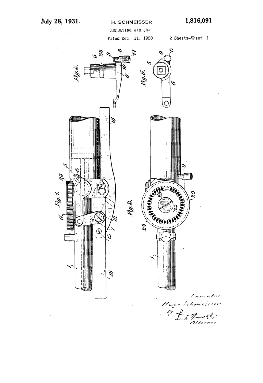
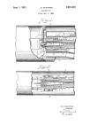
Figure 1 represents a side elevation of that
portion of an air rifle constructed according
to the present invention, to which the in-
vention relates, with the air-plunger in its
45 frontal end position or position of rest;
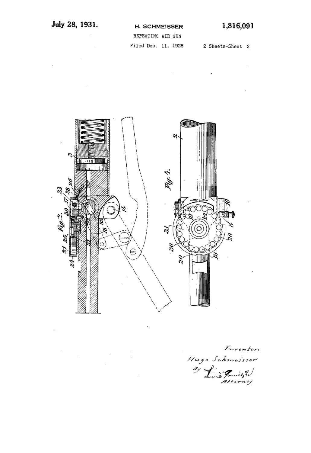
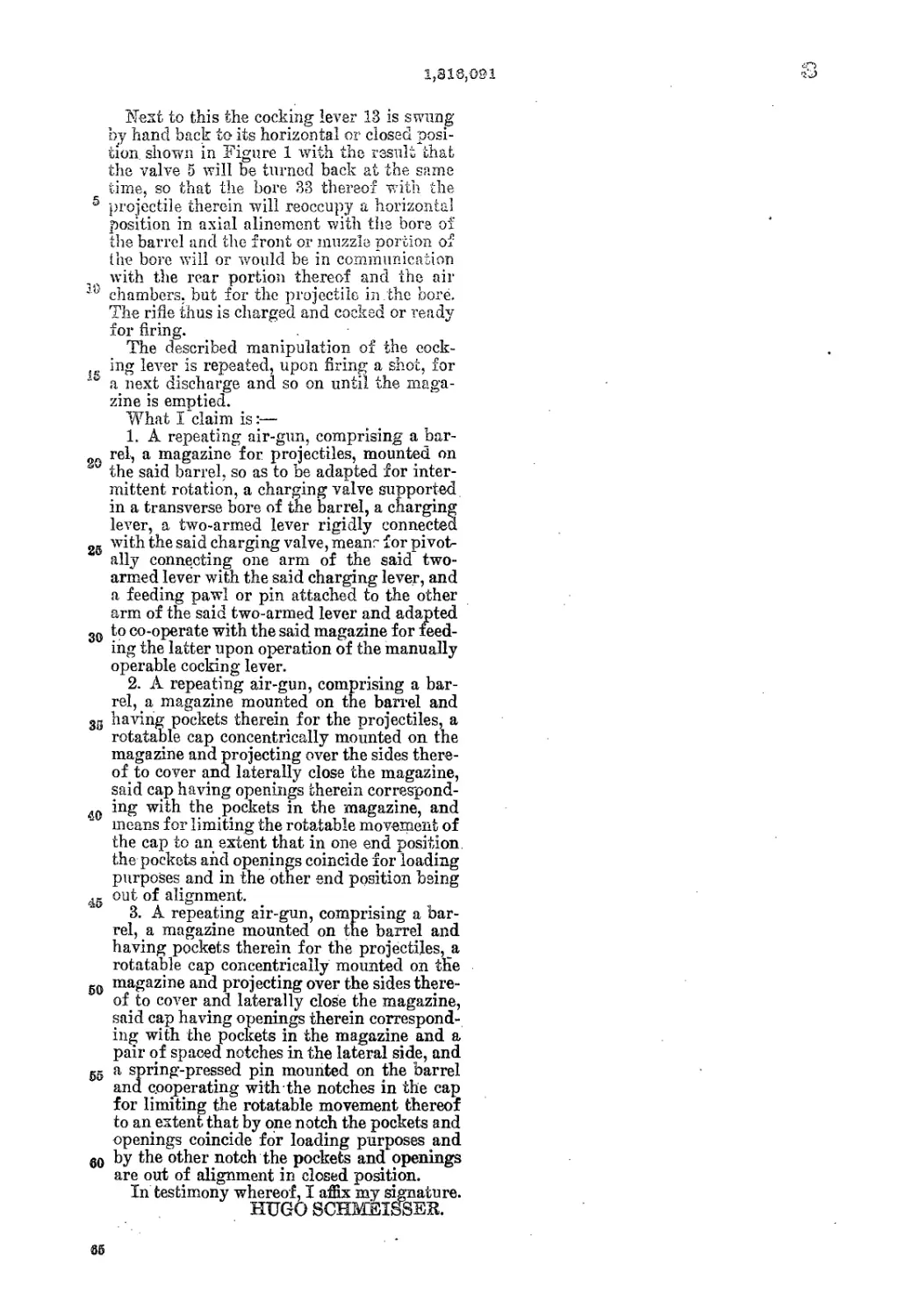
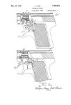
Figure 2 is a view in longitudinal section
thereof with the air-pliinger in an interme-
diate position and the correspondingly dis-
placed cocking lever, the cocking bar and
so other co-operating members shown in dotted
lines. Figure 3 is a view in top plan of the
same with the magazine filled with bullets
and the cover plate thereof so turned that
the filling or show apertures thereof are dis-
placed with relation to the pockets of the M
magazine and the bullets thus are prevented
from escaping therefrom accidentally: Fig-
ure 4 is a view similar to Figure 3, but with
the cover plate removed from the magazine,
so that the inner construction thereof, espe- ад
cially that of the charging pockets and the
feeding mechanism are exposed; Figure 5 is
a view in top plan of the charging valve;
and Figure 6 is a side elevation thereof.
Corresponding and like parts are referred ад
to in the following description and indicated
in all the views of the drawings by the same
reference characters.
The barrel 1 is rigidly connected or in-
tegral with the cylinder 2 forming the air 70
chamber and enclosing the air-plunger 3 in
the usual manner so that the latter is adapted
to be displaced towards the rear end of the
cylinder or air chamber and forced towards
the front end thereof by the main spring 4. 75
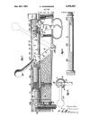
Mounted in the plane of the bore of the
barrel and transversely thereto at a point
near the rear end of the barrel is a charging
valve 5 having a conical bore 33 in a vertical
plane coinciding with the vertical plane of ад
the bore of the barrel, the front or bottom end
of the bore 33 which is somewhat narrower
than the rear or top end thereof, being of a
somewhat greater diameter than the bore of
the barrel. The charging valve 5 is adapted 85
to be turned and firmly connected, at its left-
hand outer end, with a two-armed lever
whereof the longer front arm 6 is pivoted to
a link 7, while the shorter rear arm 8 thereof,
is provided with a bore for the accommoda- 90
tion of a feeding pin 9 equipped with a cofled .
spring 10 encirding the same, and a screw 11
in its one end as will be seen in Figure 5.
The link 7 is pivotally connected with the
cocking lever 13 by means of a screw-pivot 95
12 so that when the lever 13 is moved and dis-
placed for about 90° the charging valve 5
will also be positively displaced for 90° or
from its horizontal position, as shown in Fig-
ure 1, to a vertical position, not fully shown 100
2 1,816,091
in Figure 2, or vice versa. The cocking lever
13 is adapted to rotate about the pivot 14 and
pivotally attached to the cocking bar or sear
16 by means of a pivot 15. When the cocking
5 lever 13 is manually moved downwards or off
the barrel 1, as shown in Figure 2, the sear
16 connected with the plunger 3 in the usual
manner, will act to force the plunger into the
cocked position.
10 Mounted on the rear end of the barrel in
a plane parallel to the horizontal plane of the
bore , is a magazine comprising a stationary
bottom plate 21, a revoluble cylindrical con-
tainer or magazine 17, properly speaking, and
15 a cap or cover 24. The magazine 17 is adapt-
ed to revolve about a vertical stud 18 rigidly
connected with the barrel, and provided with
a number of peripheral chambers or pockets
19 for the reception of a corresponding num-
20 ber of projectiles. The periphery of the mag-
azine 17 is serrated and the number of the
marginal teeth 20 thus produced corresponds
to the number of pockets 19. The revoluble
. magazine 17 is supported by the stationary
25 plate or disk 21 which is prevented from ro-
tation by a pin 22 fixed in the barrel and en-
gaging in a hole of the plate 21.. Further
the plate 21 is provided with an aperture in
axial alinement with a vertical bore 23 of the
30 barrel which in turn is in axial alinement
with the conical bore 33 of the valve when the
latter is fully opened for allowing a projec-
tile to drop into the valve bore, as will be
readily understood on inspection of Figure 2.
, The cover plate or cap 24 is pivotally at-
tached ‘to the stud 18 by means of a screw
25 so as to cover and laterally enclose the
magazine 17 in concentric superposition
with relation to the latter. The plate or
v cap 24, however^ is adapted to revolve for a
small range of about one half of the diameter
of a projectile only, suitable stops, abut-
ments or notches and an arresting pin 26 be-
ing provided for arresting the cap 24 in the
45 two end positions of the said revolving range.
To this end the pin 26 it movably housed in
a slanting bore of the rear end of the barrel
and supported therein by a coiled spring 27
tending to force the pin 26 out of the slant-
во ing bore and hereby causing the outer end
or point thereof to engage in the one or the
other one of two notches 28 provided in the
Eripheral surface of the cover or cap 24.
the top of the latter there are provided
5S show and filling openings 29 arranged in a
circle so as to conform to the underlying
pockets 19 and occupying a position in ver-
tical alinement with the latter, when the ro-
tatable cap 24 is in its filling position, that is
Ю to say, when the cap has been turned by hand
in counterclockwise direction as far as to be
arrested by the stop or abutment, the show
openings 29 will accurately register with the
pockets 19 of the magazine so as to allow of
filling the magazine’ by dropping the pro-
jectiles through the openings 29 into the
pockets 19, whereupon the cap 24 is turned in
clockwise direction as far as to be arrested
by the second stop or abutment. The extent
or range of the angular movement of the 70
cap is determined by the distance between
the two stops or abutments and amounts, in
the common circular centre line of the open-
ings 29, to about one half of the diameter of
the openings 29, or the pockets 19 only so 76
that when the cap has been turned in clock-
wise direction to the end of its moving range,
the pockets 19 and the projectiles therein
will be or lie partially covered by the cap,
as shown in Figure 3, and the projectiles be 80
prevented from dropping out of the pockets
19 upon turning the rifle upside down.
The outer surface of the annular part of
the cap is knurled to afford a better grip.
The springy rings 30 and 31 surrounding the 86
stud 18 are adapted to contact with and exert
a slight pressure against the cap 24, but the
main purpose of the rings resides in the
braking action they exercise upon the maga- .
zine in order that the latter be prevented 80
from accidental or. automatic feeding move-
ments.
In the embodiment shown the magazine is
of cylindrical or drum shape. Obviously the
same may be given any other appropriate 85
configuration and may be disposed in in-
clined position, that is at an angle to the axis
of the bore of the barrel, instead of parallel
thereto as shown. Furthermore, there may
be provided mechanical means for operating
the magazine by means of spring action or
the like in connection with a releasable ratch-
et pawl, in lieu of operating the same manual-
ly as in the embodiment illustrated and de-
scribed.
When the magazine 17 has been supplied
with projectiles and the cap 29 has been
turned in clockwise direction in the man-
ner hereinbefore described, so that the pock-
ets 19 and the projectiles therein are par- 110
tially covered, the charging of the rifle for
the firing purpose is effected in the follow-
ing manner.
The cocking lever 13 is swung by hand to
the rear whereby the charging valve 5 will И5
be turned for 90° through the agency of the
link 7 and the valve lever 6, 8 pivotally con-
nected therewith. Consequently the bore 33
of the valve then will occupy a vertical posi-
tion exactly below and in vertical alinement 180
with the first pocket 19 of the magazine so
that the projectile will drop, due to gravity,
into the Ъоге 33. Simultaneously with the
rotation of the charging valve 5 the feeding
pin 9 of the short arm 8 of the valve lever W
is operated to feed the magazine by the width
of one tooth corresponding'to the angular
length of one pocket 19, in order that the
first pocket be brought into vertical aline-
ment with the bore 33.
1,818,091
Next to this the cocking lever 13 is swung
by hand back to its horizontal or closed posi-
tion. shown in Figure 1 with the result that
the valve 5 will be turned back at the same
time, so that the bore 33 thereof with the
5 projectile therein will reoccupy a horizontal
position in axial alinement with the bore of
the barrel and the front or muzzle portion of
the bore will or would be in communication
with the rear portion thereof and the air
chambers, but for the projectile in.the bore.
The rifle thus is charged and cocked or ready
for firing.
The described manipulation of the eock-
jt. lever is repeated, upon firing a shot, for
a next discharge and so on until the maga-
zine is emptied.
What I claim is:—
1. A repeating air-gun, comprising a bar-
rel, a magazine for projectiles, mounted on
w the said barrel, so as to be adapted for inter-
mittent rotation, a charging valve supported
in a transverse bore of the barrel, a charging
lever, a two-armed lever rigidly connected
2g with the said charging valve, means for pivot-
ally connecting one arm of the said two-
armed lever with the said charging lever, and
a feeding pawl or pin attached to the other
arm of the said two-armed lever and adapted
30 to co-operate with the said magazine for feed-
ing the latter upon operation of the manually
operable cocking lever.
2. A repeating air-gun, comprising a bar-
rel, a magazine mounted on the barrel and
3S having pockets therein for the projectiles, a
rotatable cap concentrically mounted on the
magazine and projecting over the sides there-
of to cover and laterally close the magazine,
said cap having openings therein correspond-
40 ing with the pockets in the magazine, and
means for limiting the rotatable movement of
the cap to an extent that in one end position,
the pockets and openings coincide for loading
purposes and in the other end position being
out of alignment.
3. A repeating air-gun, comprising a bar-
rel, a magazine mounted on the barrel and
having pockets therein for the projectiles, a
rotatable cap concentrically mounted on the
g0 magazine and projecting over the sides there-
of to cover and laterally close the magazine,
said cap having openings therein correspond-
ing with the pockets in the magazine and a
pair of spaced notches in the lateral side, and
55 a spring-pressed pin mounted on the barrel
and cooperating with the notches in the cap
for limiting the rotatable movement thereof
to an extent that by one notch the pockets and
openings coincide for loading purposes and
eo by the other notch the pockets and openings
are out of alignment in closed position.
In testimony whereof, I affix my signature.
HUGO SCHMEISSEB.
se